Honeywell Sensing and Control Pressure Sensors - Steven ...
229
Pressure Sensors 22PC Series Gage/Unamplified-Noncompensated 10 Honeywell 1 MICRO SWITCH Sensing and Control 1 1-800-537-6945 USA 1F1-815-235-6847 International 1 1-800-737-3360 Canada Basic Sensors FEATURES 1 Lowest priced pressure sensor 1 Miniature package 1 Can be used to measure with vacuum or positive pressure 1 Operable after exposure to frozen conditions 1 2 mA constant current excitation signifi- cantly reduces sensitivity shift over temperature* 22PC SERIES PERFORMANCE CHARACTERISTICS at 10.0 ±0.01 VDC Excitation, 25°C Min. Typ. Max. Units Excitation --- 10 12 VDC Null Shift, 25° to 0°, 25° to 50°C --- ±2.0 --- mV Null Offset -30 0 +30 mV Linearity, P2 > P1, BFSL --- ±0.25 ±1.0 %Span Span Shift, 25° to 0°, 25° to 50°C --- ±6.0 --- %Span Repeatability & Hysteresis --- ±0.15 --- %Span Response Time --- --- 1.0 msec Input Resistance 4.0 K 5.0 K 6.0 K ohms Output Resistance 4.0 K 5.0 K 6.0 K ohms Weight --- 2 --- grams ENVIRONMENTAL SPECIFICATIONS Operating Temperature -40° to +85°C (-40° to +185°F) Storage Temperature -55° to +100°C (-67° to +212°F) Shock Qualification tested to 150 g Vibration Qualification tested to 0 to 2 kHz, 20 g sine Media (P1 & P2) Limited only to those media which will not attack polyetherimide, silicon, fluorosilicone, silicone, EPDM, and neoprene seals 22PC SERIES ORDER GUIDE Span, mV Catalog Listing Pressure Range psi Min. Typ. Max. Sensitivity mV/psi Typ. Overpressure psi, Max. 22PCA Type 1.0 25 42 59 42 20 22PCC Type 15 156 225 294 15 45 22PCF Type 100 147 225 303 2.3 200 SENSOR SELECTION GUIDE 2 2 PC A F A 6 G Product Circuit Pressure Pressure Type of Type of Termination Pressure Family Type Transducer Range Seal Port Style Measurement 2 20PC Family 2 Noncompen- sated low cost A 1 psi C 15 psi F 100 psi E EPDM F Fluorosilicone N Neoprene S Silicone A Straight B Barbed D Modular J Needle 2 2 x 2 6 1 x 4 (.600N) G Gage Example: 22PCAFA6G Non-compensated low cost 1 psi sensor with fluorosilicone seal, straight port, 1 x 4 termination and gage pressure measurement. See Accessory Guide, page 27. Note: Not all catalog listings are established. Please refer to the Order Guides, or contact the MICRO SWITCH Application Center at the 800 number. * Non-compensated pressure sensors, excited by constant current instead of voltage, exhibit temperature compensation of Span. Application Note #1 briefly discusses current excitation. Constant current excitation has an additional benefit of temperature mea- surement. When driven by a constant current source, a silicon pressure sensor’s terminal voltage will rise with increased temperature. The rise in voltage not only compensates the Span, but is also an indication of die temperature. Constant Current Excitation Schematic Courtesy of Steven Engineering, Inc.-230 Ryan Way, South San Francisco, CA 94080-6370-Main Office: (650) 588-9200-Outside Local Area: (800) 258-9200-www.stevenengineering.com
-
Upload
khangminh22 -
Category
Documents
-
view
1 -
download
0
Transcript of Honeywell Sensing and Control Pressure Sensors - Steven ...

Pressure Sensors 22PC SeriesGage/Unamplified-Noncompensated
10 Honeywell 1 MICRO SWITCH Sensing and Control 1 1-800-537-6945 USA 1 F1-815-235-6847 International 1 1-800-737-3360 Canada
Basic Sensors FEATURES1 Lowest priced pressure sensor1 Miniature package1 Can be used to measure with vacuum
or positive pressure
1 Operable after exposure to frozenconditions
1 2 mA constant current excitation signifi-cantly reduces sensitivity shift overtemperature*
22PC SERIES PERFORMANCE CHARACTERISTICS at 10.0 ±0.01 VDCExcitation, 25°C
Min. Typ. Max. Units
Excitation --- 10 12 VDC
Null Shift, 25° to 0°, 25° to 50°C --- ±2.0 --- mV
Null Offset −30 0 +30 mV
Linearity, P2 > P1, BFSL --- ±0.25 ±1.0 %Span
Span Shift, 25° to 0°, 25° to 50°C --- ±6.0 --- %Span
Repeatability & Hysteresis --- ±0.15 --- %Span
Response Time --- --- 1.0 msec
Input Resistance 4.0 K 5.0 K 6.0 K ohms
Output Resistance 4.0 K 5.0 K 6.0 K ohms
Weight --- 2 --- grams
ENVIRONMENTAL SPECIFICATIONSOperating Temperature −40° to +85°C (−40° to +185°F)
Storage Temperature −55° to +100°C (−67° to +212°F)
Shock Qualification tested to 150 g
Vibration Qualification tested to 0 to 2 kHz, 20 g sine
Media (P1 & P2) Limited only to those media which will not attackpolyetherimide, silicon, fluorosilicone, silicone,EPDM, and neoprene seals
22PC SERIES ORDER GUIDE
Span, mVCatalogListing
PressureRange
psi Min. Typ. Max.
SensitivitymV/psi
Typ.Overpressure
psi, Max.
22PCA Type 1.0 25 42 59 42 20
22PCC Type 15 156 225 294 15 45
22PCF Type 100 147 225 303 2.3 200
SENSOR SELECTION GUIDE
2 2 PC A F A 6 GProduct Circuit Pressure Pressure Type of Type of Termination PressureFamily Type Transducer Range Seal Port Style Measurement
2 20PCFamily
2 Noncompen-sated low cost
A 1 psiC 15 psiF 100 psi
E EPDMF FluorosiliconeN NeopreneS Silicone
A StraightB BarbedD ModularJ Needle
2 2 x 26 1 x 4(.600N)
G Gage
Example: 22PCAFA6GNon-compensated low cost 1 psi sensor with fluorosilicone seal, straight port, 1 x 4 termination and gage pressure measurement.See Accessory Guide, page 27.
Note: Not all catalog listings are established. Please refer to the Order Guides, or contact the MICRO SWITCH Application Center at the800 number.
*Non-compensated pressure sensors, excited by constant current instead ofvoltage, exhibit temperature compensation of Span. Application Note #1briefly discusses current excitation.
Constant current excitation has an additional benefit of temperature mea-surement. When driven by a constant current source, a silicon pressuresensor’s terminal voltage will rise with increased temperature. The rise involtage not only compensates the Span, but is also an indication of dietemperature.
Constant Current Excitation Schematic
Courtesy of Steven Engineering, Inc.-230 Ryan Way, South San Francisco, CA 94080-6370-Main Office: (650) 588-9200-Outside Local Area: (800) 258-9200-www.stevenengineering.com

Pressure Sensors 24PC SeriesGage and Differential/Unamplified-Noncompensated
Honeywell 1 MICRO SWITCH Sensing and Control 1 1-800-537-6945 USA 1 F1-815-235-6847 International 1 1-800-737-3360 Canada 11
Basic Sensors FEATURES1 Miniature package1 Variety of gage pressure port config-
urations - easily and quickly modifiedfor your special needs
1 Operable after exposure to frozenconditions
1 Ideal for wet/wet differentialapplications
1 Choice of termination for gage sensors1 2 mA constant current excitation signif-
icantly reduces sensitivity shift overtemperature*
1 Can be used to measure vacuum orpositive pressure
24PC SERIES PERFORMANCE CHARACTERISTICS at 10.0 ±0.01 VDCExcitation, 25°C
Min. Typ. Max. Units
Excitation --- 10 12 VDC
Null Offset −30 0 +30 mV
Null Shift, 25° to 0°, 25° to 50°C --- ±2.0 --- mV
Linearity, P2 > P1, BFSL --- ±0.25 ±1.0 %Span
Span Shift, 25° to 0°, 25° to 50°C --- ±5.0* --- %Span
Repeatability & Hysteresis --- ±0.15 --- %Span
Response Time --- --- 1.0 msec
Input Resistance 4.0 K 5.0 K 6.0 K ohms
Output Resistance 4.0 K 5.0 K 6.0 K ohms
Stability over One Year --- ±0.5 --- %Span
Weight --- 2 --- grams
ENVIRONMENTAL SPECIFICATIONSOperating Temperature −40° to +85°C (−40° to +185°F)
Storage Temperature −55° to +100°C (−67° to +212°F)
Shock Qualification tested to 150 g
Vibration Qualification tested to 0 to 2 kHz, 20 g sine
Media (P1 & P2) Limited only to those media which will not attackpolyetherimide, silicon, fluorosilicone, silicone,EPDM and neoprene seals.
24PC SERIES ORDER GUIDE
Span, mVCatalogListing
PressureRange
psi Min. Typ. Max.
SensitivitymV/psi
Typ.Overpressure
psi Max.
24PCE Type 0.5 24 35 46 70 20
24PCA Type 1.0 30 45 60 45 20
24PCB Type 5.0 85 115 145 23 20
24PCC Type 15 165 225 285 15 45
24PCD Type 30 240 330 420 11 60
24PCF Type 100 156 225 294 2.25 200
24PCG Type 250 145 212 280 0.85 500
*Non-compensated pressure sensors, excited by constant current instead ofvoltage, exhibit temperature compensation of Span. Application Note #1briefly discusses current excitation.
Constant current excitation has an additional benefit of temperature mea-surement. When driven by a constant current source, a silicon pressuresensor’s terminal voltage will rise with increased temperature. The rise involtage not only compensates the Span, but is also an indication of dietemperature.
Constant Current Excitation Schematic
Unam
plified
Courtesy of Steven Engineering, Inc.-230 Ryan Way, South San Francisco, CA 94080-6370-Main Office: (650) 588-9200-Outside Local Area: (800) 258-9200-www.stevenengineering.com
Pressure Sensors 24PC SeriesGage and Differential/Unamplified-Noncompensated
12 Honeywell 1 MICRO SWITCH Sensing and Control 1 1-800-537-6945 USA 1 F1-815-235-6847 International 1 1-800-737-3360 Canada
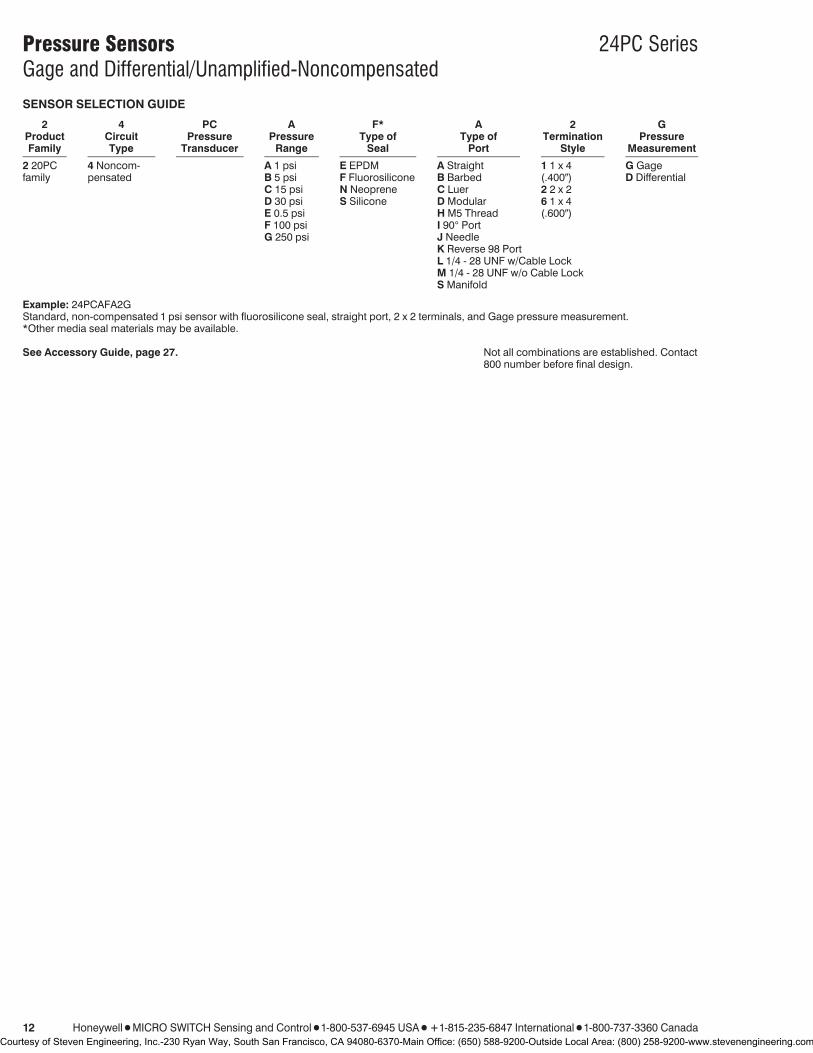
SENSOR SELECTION GUIDE
2 4 PC A F* A 2 GProduct Circuit Pressure Pressure Type of Type of Termination PressureFamily Type Transducer Range Seal Port Style Measurement
2 20PCfamily
4 Noncom-pensated
A 1 psiB 5 psiC 15 psiD 30 psiE 0.5 psi
E EPDMF FluorosiliconeN NeopreneS Silicone
A StraightB BarbedC LuerD ModularH M5 Thread
F 100 psi I 90° PortG 250 psi J Needle
K Reverse 98 PortL 1/4 - 28 UNF w/Cable LockM 1/4 - 28 UNF w/o Cable LockS Manifold
1 1 x 4(.400N)2 2 x 26 1 x 4(.600N)
G GageD Differential
Example: 24PCAFA2GStandard, non-compensated 1 psi sensor with fluorosilicone seal, straight port, 2 x 2 terminals, and Gage pressure measurement.*Other media seal materials may be available.
See Accessory Guide, page 27. Not all combinations are established. Contact800 number before final design.
Courtesy of Steven Engineering, Inc.-230 Ryan Way, South San Francisco, CA 94080-6370-Main Office: (650) 588-9200-Outside Local Area: (800) 258-9200-www.stevenengineering.com

Pressure Sensors 24PC SeriesAbsolute Unamplified Noncompensated
Honeywell 1 MICRO SWITCH Sensing and Control 1 1-800-537-6945 USA 1 F1-815-235-6847 International 1 1-800-737-3360 Canada 13
FEATURES1 Absolute pressure measurement1 Miniature package1 2-15 and 2-30 psi pressure ranges1 2 mA constant current excitation signif-
icantly reduces sensitivity shift overtemperature*
24PC PERFORMANCE SPECIFICATIONSAccuracy Specifications @ 10.0 ± .01 VDC Excitation, 25°C
Parameter Range Min. Typ. Max. Unitspsia bar
Excitation — 10 12 VDC
Null Shift 2-15 1 ±2.0 ±4.0 mV
0 to 25°C, 25 to 50°C 2-30 2 ±2.0 ±5.5
Linearity 2-15 1 .10 .20 % Span
B.F.S.L. P2 < P1** 2-30 2 .15 .30
Sensitivity Shift0 to 25°C, 25 to 50°C All ±5.0 ±6.5 % Span
Repeatability & Hysteresis All ±0.5 % Span
Input Resistance 4.0 K 5.0 K 6.0 K Ohms
Output Resistance 4.0 K 5.0 K 6.0 K Ohms
Weight — 2.0 — grams
ENVIRONMENTAL SPECIFICATIONSOperating Temperature −40 to +85°C (−40 to +185°F)
Storage Temperature −55 to +100°C (−67 to +212°F)
Shock Qualification tested to 150 G
Vibration Qualification tested to 0 to 2 kHz, 20 G sine
Media Compatibility Limited only to those media which will not attack polyetherimide,silicon, fluorosilicone and silicone seals.
*Span: the algebraic difference between output end points**B.F.S.L.: Best Fit Straight Line
24PC ABSOLUTE ORDER GUIDE
Catalog Pressure Null Offset Sensitivity Over-Listing Range Span, mV mV mV/psi pressureType psia Min. Typ. Max. Min. Typ. Max. Typ. psia Typ.
24PCC 2-15 −140 −200 −260 −46 −16 +14 15 45
24PCD 2-30 −160 −300 −440 −61 −16 +29 11 60
*Non-compensated pressure sensors, excited by constant current instead ofvoltage, exhibit temperature compensation of Span. Application Note #1briefly discusses current excitation.
Constant current excitation has an additional benefit of temperature mea-surement. When driven by a constant current source, a silicon pressuresensor’s terminal voltage will rise with increased temperature. The rise involtage not only compensates the Span, but is also an indication of dietemperature.
Constant Current Excitation Schematic
Unam
plified
Courtesy of Steven Engineering, Inc.-230 Ryan Way, South San Francisco, CA 94080-6370-Main Office: (650) 588-9200-Outside Local Area: (800) 258-9200-www.stevenengineering.com

Pressure Sensors 24PC SeriesAbsolute Unamplified Noncompensated
14 Honeywell 1 MICRO SWITCH Sensing and Control 1 1-800-537-6945 USA 1 F1-815-235-6847 International 1 1-800-737-3360 Canada
24PC SERIES ABSOLUTE PRESSURE SENSOR OUTPUT CURVEEXCITATION SCHEMATIC TERMINATION
STYLEStyle 6 - 1 x 4Pin 1 J Vs (+)Pin 2 J Output (+)Pin 3 J Ground (−)Pin 4 J Output (−)
Pin 1 is notchedPin 2 is next toPin 1, etc.
SENSOR SELECTION GUIDE
2 4 PC C F** D* 6 AProduct Circuit Pressure Pressure Type of Type of Termination PressureFamily Type Transducer Range Seal Port (P1) Style Measurement
2 20PCFamily
4 Standardnoncompensated
C 2-15 psia 1 barD 2-30 psia 2 bar
F Fluoro-silicone
A StraightD Modular
6 1 x 4 (.600Nlong)
A Absolute
*Port type refers to P1**Media seal is on P1 side and will not be in contact with media
Example: 24PCCFD6ANon-compensated 15 psi Absolute sensor with fluorosilicone seal, modular port, 1 x 4 terminals, .600N long.See Accessory Guide, page 27.
MOUNTING DIMENSIONS (for reference only)
A Straight Port D Modular Port
Courtesy of Steven Engineering, Inc.-230 Ryan Way, South San Francisco, CA 94080-6370-Main Office: (650) 588-9200-Outside Local Area: (800) 258-9200-www.stevenengineering.com

Pressure Sensors 26PC SeriesGage and Differential/Unamplified-Compensated
Honeywell 1 MICRO SWITCH Sensing and Control 1 1-800-537-6945 USA 1 F1-815-235-6847 International 1 1-800-737-3360 Canada 15
Temperature Compensated SensorsFEATURES1 Lowest priced sensor with temperature
compensation and calibration1 Variety of gage pressure port config-
urations - easily and quickly modifiedfor your special needs
1 Operable after exposure to frozenconditions
1 Choice of termination for gage sensors1 Calibrated Null and Span1 Temperature compensated for Span
over 0 to 50°C1 Provides interchangeability1 Can be used to measure vacuum or
positive pressure1 Ideal for wet/wet differential
applications
26PC SERIES PERFORMANCE CHARACTERISTICS at 10.0 ±0.01 VDCExcitation, 25°C
Min. Typ. Max. Units
Excitation --- 10 16 VDC
Repeatability & Hysteresis --- ±0.20 --- %Span
Response Time --- --- 1.0 msec
Input Resistance 5.5 K 7.5 K 11.5 K ohms
Output Resistance 1.5 K 2.5 K 3.0 K ohms
Stability over One Year --- ±0.5 --- %Span
Weight --- 2 --- grams
Total error calculation, see page 105.
ENVIRONMENTAL SPECIFICATIONSOperating Temperature −40° to 85°C (−40° to +185°F)
Storage Temperature −55° to +100°C (−67° to +212°F)
Compensated Temperature 0° to +50°C (32° to +122°F)
Shock Qualification tested to 150 g
Vibration MIL-STD-202. Method 213 (150g halfsine,11 msec)
Media (P1 & P2) Limited only to those media which will not attackpolyetherimide, silicon, fluorosilicone, silicone,EPDM, and neoprene seals.
26PC SERIES ORDER GUIDE
Pressure Over-Catalog Range Linearity Null Shift Null Offset Span Shift Span Sensitivity pressureListing (psi) (% span) (mV) (mV) (% span) (mV) mV/psi psi
Typ. Max Typ. Max Min. Typ. Max. Typ. Max. Min. Typ. Max. Typ. Max.
26PCA TYPE 1 0.25 0.5 ±0.5 ±1.0 −1.5 0 +1.5 ±1.0 ±2.0 14.7 16.7 18.7 16.7 20
26PCB TYPE 5 0.4 0.5 ±0.5 ±1.0 −1.5 0 +1.5 ±1.0 ±1.5 47 50 53 10.0 20
26PCC TYPE 15 0.25 0.5 ±0.5 ±1.0 −1.5 0 +1.5 ±0.75 ±1.5 97 100 103 6.67 45
26PCD TYPE 30 0.1 0.2 ±0.75 ±1.5 −1.5 0 +1.5 ±0.75 ±1.5 97 100 103 3.33 60
26PCF TYPE 100 0.1 0.2 ±1.0 ±2.0 −2.0 0 +2.0 ±0.5 ±1.5 95 100 105 1.0 200
26PCJ TYPE 38* 0.1 0.5 ±0.7 ±1.5 −1.5 0 +1.5 ±1.0 ±1.5 37.5 39.5 41.5 2.63 60
26PCK TYPE 38* 0.1 0.5 ±0.7 ±1.5 −1.5 0 +1.5 ±1.0 ±1.5 37.5 39.5 41.5 2.63 60
*Accuracy specifications calculated at 15 psi.
Unam
plified
Courtesy of Steven Engineering, Inc.-230 Ryan Way, South San Francisco, CA 94080-6370-Main Office: (650) 588-9200-Outside Local Area: (800) 258-9200-www.stevenengineering.com
Pressure Sensors 26PC SeriesGage and Differential/Unamplified-Compensated
16 Honeywell 1 MICRO SWITCH Sensing and Control 1 1-800-537-6945 USA 1 F1-815-235-6847 International 1 1-800-737-3360 Canada
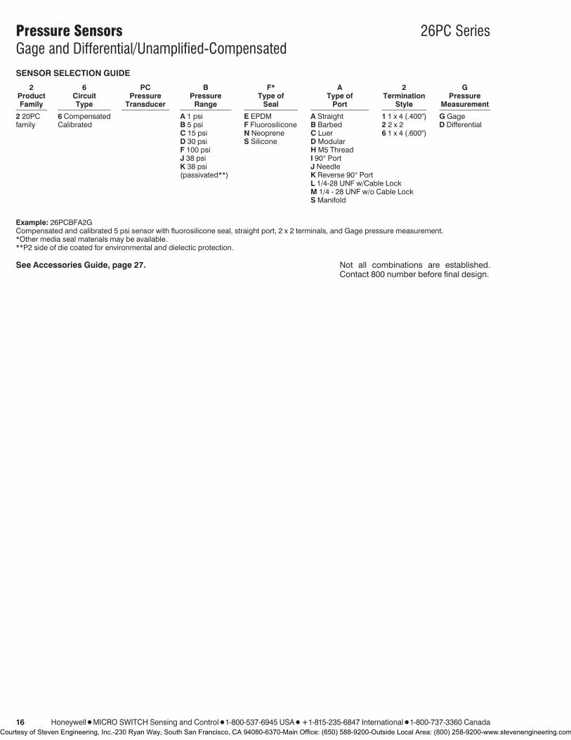
SENSOR SELECTION GUIDE
2 6 PC B F* A 2 GProduct Circuit Pressure Pressure Type of Type of Termination PressureFamily Type Transducer Range Seal Port Style Measurement
2 20PCfamily
6 CompensatedCalibrated
A 1 psiB 5 psiC 15 psiD 30 psiF 100 psiJ 38 psiK 38 psi(passivated**)
E EPDMF FluorosiliconeN NeopreneS Silicone
A StraightB BarbedC LuerD ModularH M5 ThreadI 90° PortJ NeedleK Reverse 90° PortL 1/4-28 UNF w/Cable LockM 1/4 - 28 UNF w/o Cable LockS Manifold
1 1 x 4 (.400N)2 2 x 26 1 x 4 (.600N)
G GageD Differential
Example: 26PCBFA2GCompensated and calibrated 5 psi sensor with fluorosilicone seal, straight port, 2 x 2 terminals, and Gage pressure measurement.*Other media seal materials may be available.**P2 side of die coated for environmental and dielectic protection.
See Accessories Guide, page 27. Not all combinations are established.Contact 800 number before final design.
Courtesy of Steven Engineering, Inc.-230 Ryan Way, South San Francisco, CA 94080-6370-Main Office: (650) 588-9200-Outside Local Area: (800) 258-9200-www.stevenengineering.com
Pressure Sensors 22/24/26PC SeriesGage and Differential/Unamplified
Honeywell 1 MICRO SWITCH Sensing and Control 1 1-800-537-6945 USA 1 F1-815-235-6847 International 1 1-800-737-3360 Canada 17
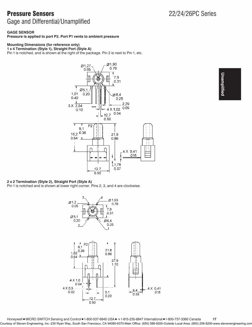
GAGE SENSORPressure is applied to port P2. Port P1 vents to ambient pressure
Mounting Dimensions (for reference only)1 x 4 Termination (Style 1), Straight Port (Style A)Pin 1 is notched, and is shown at the right of the package. Pin 2 is next to Pin 1, etc.
2 x 2 Termination (Style 2), Straight Port (Style A)Pin 1 is notched and is shown at lower right corner. Pins 2, 3, and 4 are clockwise.
Unam
plified
Courtesy of Steven Engineering, Inc.-230 Ryan Way, South San Francisco, CA 94080-6370-Main Office: (650) 588-9200-Outside Local Area: (800) 258-9200-www.stevenengineering.com

Pressure Sensors 22/24/26PC SeriesGage and Differential/Unamplified
18 Honeywell 1 MICRO SWITCH Sensing and Control 1 1-800-537-6945 USA 1 F1-815-235-6847 International 1 1-800-737-3360 Canada
Straight Port, 1 x 4 Termination (Style 1) ONLYPort 1 is near terminals
Absolute Sensor1 x 4 Termination (Style 1), Port 1 is near terminals
Courtesy of Steven Engineering, Inc.-230 Ryan Way, South San Francisco, CA 94080-6370-Main Office: (650) 588-9200-Outside Local Area: (800) 258-9200-www.stevenengineering.com
Pressure Sensors 22/24/26PC SeriesGage and Differential/Unamplified
Honeywell 1 MICRO SWITCH Sensing and Control 1 1-800-537-6945 USA 1 F1-815-235-6847 International 1 1-800-737-3360 Canada 19
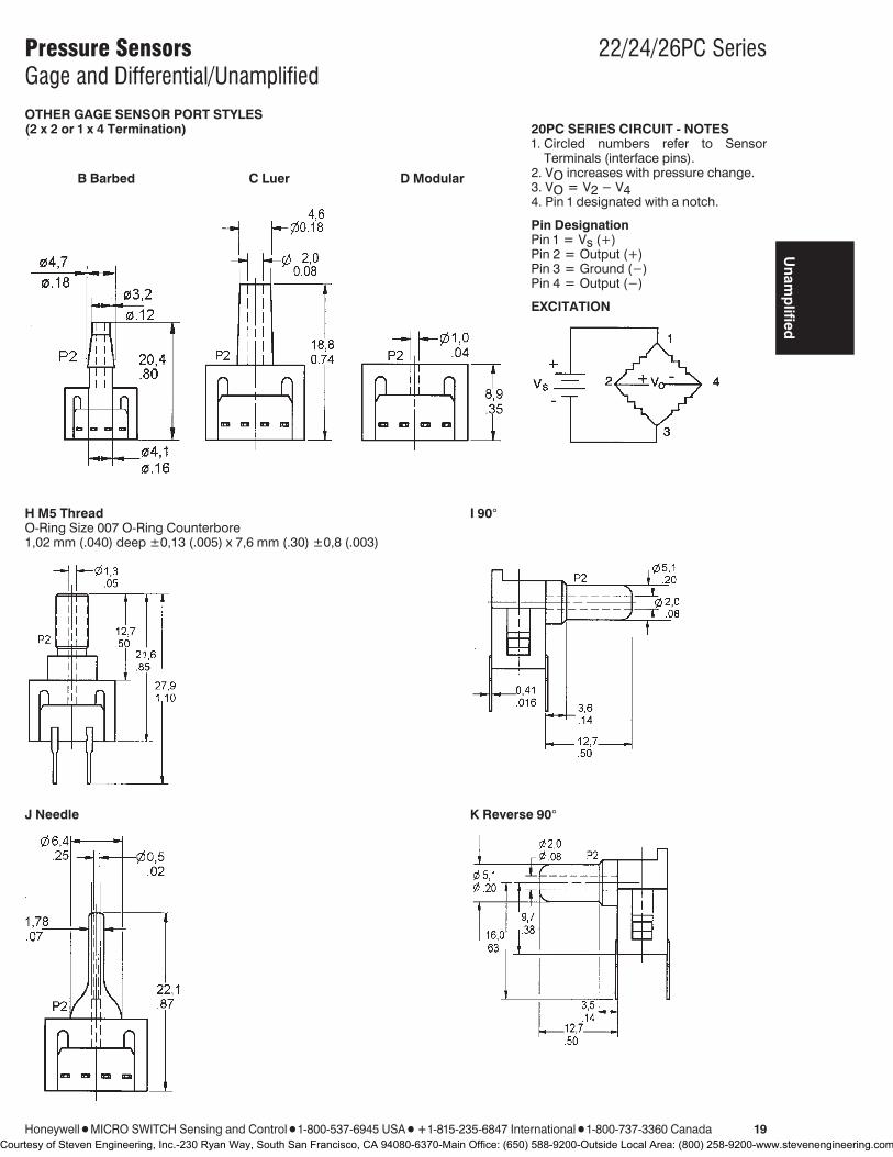
OTHER GAGE SENSOR PORT STYLES(2 x 2 or 1 x 4 Termination)
B Barbed C Luer D Modular
H M5 ThreadO-Ring Size 007 O-Ring Counterbore1,02 mm (.040) deep ±0,13 (.005) x 7,6 mm (.30) ±0,8 (.003)
I 90°
J Needle K Reverse 90°
20PC SERIES CIRCUIT - NOTES1. Circled numbers refer to Sensor
Terminals (interface pins).2. VO increases with pressure change.3. VO J V2 − V44. Pin 1 designated with a notch.
Pin DesignationPin 1 J Vs (+)Pin 2 J Output (+)Pin 3 J Ground (−)Pin 4 J Output (−)
EXCITATION
Unam
plified
Courtesy of Steven Engineering, Inc.-230 Ryan Way, South San Francisco, CA 94080-6370-Main Office: (650) 588-9200-Outside Local Area: (800) 258-9200-www.stevenengineering.com

Pressure Sensors 22/24/26PC SeriesGage and Differential/Unamplified
20 Honeywell 1 MICRO SWITCH Sensing and Control 1 1-800-537-6945 USA 1 F1-815-235-6847 International 1 1-800-737-3360 Canada
OTHER GAGE SENSOR PORT STYLES(2 x 2 or 1 x 4 Termination)
M 1/4-28 UNF ThreadO-Ring Size 009 O-Ring Counterbore1,02 mm (.040) deep ±0,05 (.002) x 9,1 mm (.360) ±0,8 (.003)
S Manifold
20PC Construction
Courtesy of Steven Engineering, Inc.-230 Ryan Way, South San Francisco, CA 94080-6370-Main Office: (650) 588-9200-Outside Local Area: (800) 258-9200-www.stevenengineering.com

Pressure Sensors 24PC SeriesGage Unamplified Noncompensated Flow-Through
Honeywell 1 MICRO SWITCH Sensing and Control 1 1-800-537-6945 USA 1 F1-815-235-6847 International 1 1-800-737-3360 Canada 21
FEATURES1 Measures positive and negative gage
pressures1 Flow-through port design fits in-line
with application1 Popular port sizes:
- 8 mm (.315 in.) OD (1/4 in. ID tubing orstandard connectors)
- 0.144 in. OD (1/8 in. ID tubing)
1 Medical grade ISO 10993-1 (USP Class6) port material
1 Silicon sensor chip1 24 inch wire harness with splash proof
connector1 Minimal deadspace — efficient cleans-
ing and disinfecting
24PC SERIES PERFORMANCE CHARACTERISTICS at 10.0 ±0.01 VDCEXCITATION, 25°C
Min. Typ. Max. Units
Excitation --- 10 12 VDC
Null Shift, 25° to 0°, 25° to 50°C --- ±2.0 --- mV
Null Offset −30 0 +30 mV
Linearity, P2 > P1, BFSL --- ±0.5 --- %Span
Span Shift, 25° to 0°, 25° to 50°C --- ±5.0 --- %Span
Repeatability & Hysteresis --- ±0.2 --- %Span
Response Time --- --- 1.0 msec
Input Resistance 4.0 K 5.0 K 6.0 K ohms
Output Resistance 4.0 K 5.0 K 6.0 K ohms
Stability over One Year --- ±0.5 --- %Span
ENVIRONMENTAL SPECIFICATIONSOperating Temperature −40° to +85°C (−40° to +185°F)
Storage Temperature −55° to +100°C (−67° to +212°F)
Shock Qualification tested to 150 g
Vibration Qualification tested to 0 to 2 kHz, 20 g sine
Media Compatibility Limited only to those media which will not attackpolysulfone, silicon, fluorosilicone, silicone,EPDM, and neoprene seals
24PC SERIES FLOW THROUGH ORDER GUIDE
Span, mVCatalogListing
PressureRange
psi Min. Typ. Max.
SensitivitymV/psi
Typ.Overpressure
psi Max.
24PCE Type 0.5 25 35 45 70 20
24PCA Type 1.0 30 45 60 45 20
24PCB Type 5.0 85 115 145 23 20
24PCC Type 15 165 225 285 15 45
24PCD Type 30 240 330 420 11 60
24PCF Type 100 156 225 294 2.25 200
24PCG Type 250 145 212 280 0.85 500
Unam
plified
Courtesy of Steven Engineering, Inc.-230 Ryan Way, South San Francisco, CA 94080-6370-Main Office: (650) 588-9200-Outside Local Area: (800) 258-9200-www.stevenengineering.com

Pressure Sensors 24PC SeriesGage Unamplified Noncompensated Flow-Through
22 Honeywell 1 MICRO SWITCH Sensing and Control 1 1-800-537-6945 USA 1 F1-815-235-6847 International 1 1-800-737-3360 Canada
SENSOR SELECTION GUIDE
2 4 PC A F* N 5 GProduct Circuit Pressure Pressure Type of Port Termination PressureFamily Type Transducer Range Seal Type Style Measurement
2 20PCFamily
4 Noncom-pensated
A 1 psiB 5 psiC 15 psiD 30 psiE 0.5 psiF 100 psiG 250 psi
E EPDMF FluorosiliconeN NeopreneS Silicone
G SmallN Large(.350 dia.)P Large(.315 dia.)
2 4-pin DIP5 Wireharness6 4-pin SIP
G Gage
Example: 24PCBFG5GNon-compensated 5 psi sensor, fluorosilicone seal, small flow-through ports, wire harness, and gage pressure measurement.*Other media seal materials may be available.
Note: Not all combinations are established. Contact 800 number before final design.
See Accessory Guide, page 27.
Courtesy of Steven Engineering, Inc.-230 Ryan Way, South San Francisco, CA 94080-6370-Main Office: (650) 588-9200-Outside Local Area: (800) 258-9200-www.stevenengineering.com
Pressure Sensors 26PC SeriesGage Unamplified Compensated Flow-Through
Honeywell 1 MICRO SWITCH Sensing and Control 1 1-800-537-6945 USA 1 F1-815-235-6847 International 1 1-800-737-3360 Canada 23
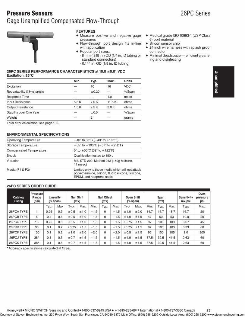
FEATURES1 Measure positive and negative gage
pressures1 Flow-through port design fits in-line
with application1 Popular port sizes:
- 8 mm (.315 in.) OD (1/4 in. ID tubing orstandard connectors)
- 0.144 in. OD (1/8 in. ID tubing)
1 Medical grade ISO 10993-1 (USP Class6) port material
1 Silicon sensor chip1 24 inch wire harness with splash proof
connector1 Minimal deadspace — efficient cleans-
ing and disinfecting
26PC SERIES PERFORMANCE CHARACTERISTICS at 10.0 ±0.01 VDCExcitation, 25°C
Min. Typ. Max. Units
Excitation --- 10 16 VDC
Repeatability & Hysteresis --- ±0.20 --- %Span
Response Time --- --- 1.0 msec
Input Resistance 5.5 K 7.5 K 11.5 K ohms
Output Resistance 1.5 K 2.5 K 3.0 K ohms
Stability over One Year --- ±0.5 --- %Span
Weight --- 2 --- grams
Total error calculation, see page 105.
ENVIRONMENTAL SPECIFICATIONSOperating Temperature −40° to 85°C (−40° to +185°F)
Storage Temperature −55° to +100°C (−67° to +212°F)
Compensated Temperature 0° to +50°C (32° to +122°F)
Shock Qualification tested to 150 g
Vibration MIL-STD-202. Method 213 (150g halfsine,11 msec)
Media (P1 & P2) Limited only to those media which will not attackpolyetherimide, silicon, fluorosilicone, silicone,EPDM, and neoprene seals.
26PC SERIES ORDER GUIDE
Pressure Over-Catalog Range Linearity Null Shift Null Offset Span Shift Span Sensitivity pressureListing (psi) (% span) (mV) (mV) (% span) (mV) mV/psi psi
Typ. Max Typ. Max Min. Typ. Max. Typ. Max. Min. Typ. Max. Typ. Max.
26PCA TYPE 1 0.25 0.5 ±0.5 ±1.0 −1.5 0 +1.5 ±1.0 ±2.0 14.7 16.7 18.7 16.7 20
26PCB TYPE 5 0.4 0.5 ±0.5 ±1.0 −1.5 0 +1.5 ±1.0 ±1.5 47 50 53 10.0 20
26PCC TYPE 15 0.25 0.5 ±0.5 ±1.0 −1.5 0 +1.5 ±0.75 ±1.5 97 100 103 6.67 45
26PCD TYPE 30 0.1 0.2 ±0.75 ±1.5 −1.5 0 +1.5 ±0.75 ±1.5 97 100 103 3.33 60
26PCF TYPE 100 0.1 0.2 ±1.0 ±2.0 −2.0 0 +2.0 ±0.5 ±1.5 95 100 105 1.0 200
26PCJ TYPE 38* 0.1 0.5 ±0.7 ±1.5 −1.5 0 +1.5 ±1.0 ±1.5 37.5 39.5 41.5 2.63 60
26PCK TYPE 38* 0.1 0.5 ±0.7 ±1.5 −1.5 0 +1.5 ±1.0 ±1.5 37.5 39.5 41.5 2.63 60
*Accuracy specifications calculated at 15 psi.
Unam
plified
Courtesy of Steven Engineering, Inc.-230 Ryan Way, South San Francisco, CA 94080-6370-Main Office: (650) 588-9200-Outside Local Area: (800) 258-9200-www.stevenengineering.com
Pressure Sensors 26PC SeriesGage Unamplified Compensated Flow-Through
24 Honeywell 1 MICRO SWITCH Sensing and Control 1 1-800-537-6945 USA 1 F1-815-235-6847 International 1 1-800-737-3360 Canada
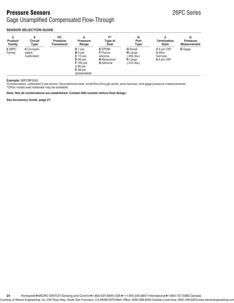
SENSOR SELECTION GUIDE
2 6 PC A F* N 5 GProduct Circuit Pressure Pressure Type of Port Termination PressureFamily Type Transducer Range Seal Type Style Measurement
2 20PCFamily
6 Compen-sated,Calibrated
A 1 psiB 5 psiC 15 psiD 30 psiF 100 psiJ 38 psiK 38 psi(passivated)
E EPDMF Fluoro-siliconeN NeopreneS Silicone
G SmallN Large(.350 dia.)P Large(.315 dia.)
2 4-pin DIP5 Wireharness6 4-pin SIP
G Gage
Example: 26PCBFG5GCompensated, calibrated 5 psi sensor, fluorosilicone seal, small flow-through ports, wire harness, and gage pressure measurements.*Other media seal materials may be available.
Note: Not all combinations are established. Contact 800 number before final design.
See Accessory Guide, page 27.
Courtesy of Steven Engineering, Inc.-230 Ryan Way, South San Francisco, CA 94080-6370-Main Office: (650) 588-9200-Outside Local Area: (800) 258-9200-www.stevenengineering.com

Pressure Sensors 24/26PC SeriesGage Unamplified Flow-Through
Honeywell 1 MICRO SWITCH Sensing and Control 1 1-800-537-6945 USA 1 F1-815-235-6847 International 1 1-800-737-3360 Canada 25
MOUNTING DIMENSIONS (for reference only)
Large Port Sensor N
Large Port Sensor P
NOTE: Wire harness (PC-15175) may be purchased separately.
20PC CIRCUIT NOTES1. Circled numbers refer to Sensor
Terminals (interface pins).2. V0 increases with pressure change.3. V0 J V2 − V4
PIN DESIGNATIONPin 1 J Vs (Red)Pin 2 J Output, + (White)Pin 3 J Ground, − (Black)Pin 4 J Output, − (Green)
EXCITATION
Flow-Through Construction
Unam
plified
Courtesy of Steven Engineering, Inc.-230 Ryan Way, South San Francisco, CA 94080-6370-Main Office: (650) 588-9200-Outside Local Area: (800) 258-9200-www.stevenengineering.com
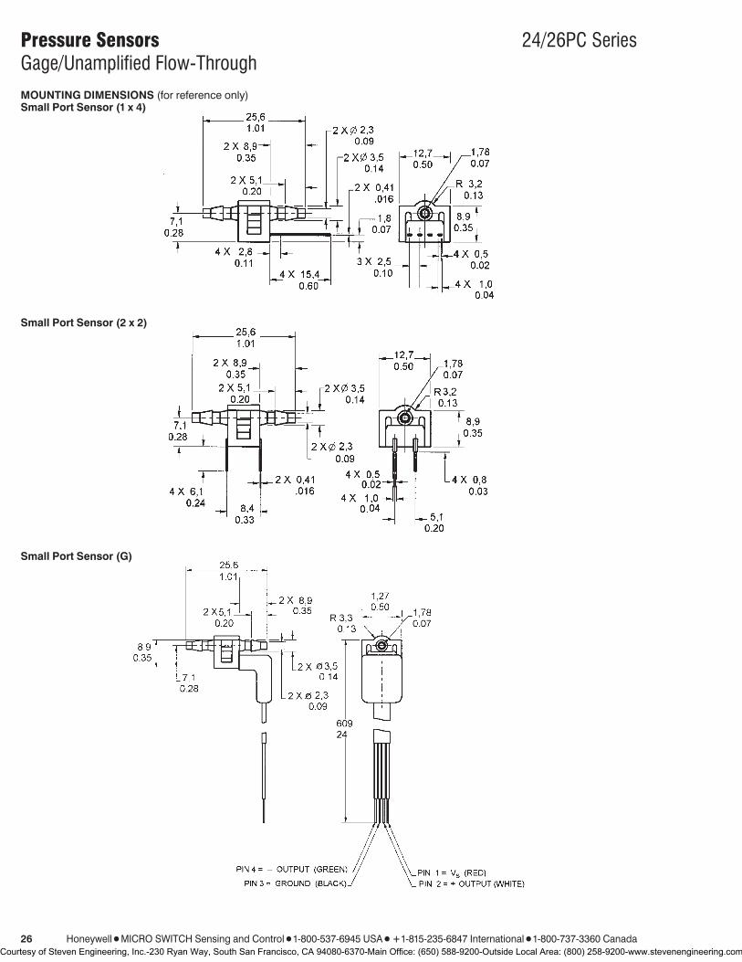
Pressure Sensors 24/26PC SeriesGage/Unamplified Flow-Through
26 Honeywell 1 MICRO SWITCH Sensing and Control 1 1-800-537-6945 USA 1 F1-815-235-6847 International 1 1-800-737-3360 Canada
MOUNTING DIMENSIONS (for reference only)Small Port Sensor (1 x 4)
Small Port Sensor (2 x 2)
Small Port Sensor (G)
Courtesy of Steven Engineering, Inc.-230 Ryan Way, South San Francisco, CA 94080-6370-Main Office: (650) 588-9200-Outside Local Area: (800) 258-9200-www.stevenengineering.com

Pressure Sensors 22/24/26PC SeriesAccessories
Honeywell 1 MICRO SWITCH Sensing and Control 1 1-800-537-6945 USA 1 F1-815-235-6847 International 1 1-800-737-3360 Canada 27
ACCESSORIES SELECTION GUIDE
CatalogListing Description Drawing
PC-10182 Steel lockring (included with Port Style A, 1 x 4 terminals only) 22, 24, 26PC only Figure 1
PC-15111 Cable retaining clip for large port Flow-Through sensor only Figure 4
PC-15110 Single hole plastic bracket Figure 3
PC-15015 Mounting bracket Figure 6
PC-15132 Plastic Mounting bracket Figure 5
20PCWHRC Flow-Through wire harness and retaining clip Figure 2
26PCBKT Mounting bracket for large port Flow-Through sensor only Figure 7
PC-15202 Mounting bracket for Luer Port Figure 8
PC-15204 Mounting bracket for Straight Port Figure 9
Figure 1 PC-10182Steel Lockring
Figure 2 20PCWHRCWire Harness and Retaining Clip
Figure 3 PC-15110Single Hole Plastic Bracket
Figure 4 PC-15111Cable Retaining Clip
Figure 5 PC-15132Plastic Mounting Bracket
Unam
plified
Courtesy of Steven Engineering, Inc.-230 Ryan Way, South San Francisco, CA 94080-6370-Main Office: (650) 588-9200-Outside Local Area: (800) 258-9200-www.stevenengineering.com
Pressure Sensors 22/24/26PC SeriesAccessories
28 Honeywell 1 MICRO SWITCH Sensing and Control 1 1-800-537-6945 USA 1 F1-815-235-6847 International 1 1-800-737-3360 Canada
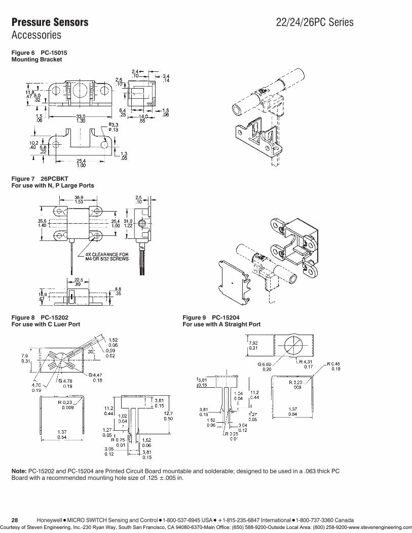
Figure 6 PC-15015Mounting Bracket
Figure 7 26PCBKTFor use with N, P Large Ports
Figure 8 PC-15202For use with C Luer Port
Figure 9 PC-15204For use with A Straight Port
Note: PC-15202 and PC-15204 are Printed Circuit Board mountable and solderable; designed to be used in a .063 thick PCBoard with a recommended mounting hole size of .125 ±.005 in.
Courtesy of Steven Engineering, Inc.-230 Ryan Way, South San Francisco, CA 94080-6370-Main Office: (650) 588-9200-Outside Local Area: (800) 258-9200-www.stevenengineering.com

Pressure Sensors 170PC SeriesLow Pressure Gage & Differential/Unamplified
Honeywell 1 MICRO SWITCH Sensing and Control 1 1-800-537-6945 USA 1 F1-815-235-6847 International 1 1-800-737-3360 Canada 29
Temperature Compensated SensorsFEATURES1 Miniature package1 Low pressure measurement1 Calibrated Null and Span1 Temperature compensated for Span
over 0 to 50°C1 Provides interchangeability
176PC SERIES PERFORMANCE CHARACTERISTICS at 10.0 ±0.01 VDCExcitation, 25°C
Min. Typ. Max. UnitsExcitation --- 10 16 VDC
Null Offset –2 0 +2 mV
Null Shift, 25° to 0°, 25° to 50°C --- ±3.0 --- mV
Sensitivity Shift, 25° to 0°, 25° to 50°C --- --- ±4.01 %Span--- --- ±3.52 %Span
Repeatability & Hysteresis --- ±0.25 --- %Span
Response Time --- --- 1.0 msec
Input Resistance --- 6.3 K --- ohms
Output Resistance --- 4.0 K --- ohms
Stability over One Year --- ±0.5 --- %Span
Weight --- 7 --- grams
Key: 1 J 0-7N, 0-14N H2O only2 J 0-28N H2O only
ENVIRONMENTAL SPECIFICATIONSOperating Temperature –40° to +85°C (–40° to +185°F)
Storage Temperature –55° to +125°C (–67° to +257°F)
Compensated Temperature 0° to +50°C (32° to +122°F)
Shock MIL-STD-202, Method 213 (150 g, half sine, 11 msec)
Vibration MIL-STD-202, Method 204 (10 to 2000 Hz at 20 g)
Media P2 port Wetted materials; polyester housing, epoxy adhesive,silicon, borosilicate glass, and silicon-to-glass bond*
P1 port Dry gases only* Liquid media containing some highly ionic solutions could potentially neutralize the chip-to-glass tubebond.
176PC SERIES ORDER GUIDE
Span, mVLinearity, %Span
CatalogListing
PressureRange
H2O Min. Typ. Max.
SensitivitymV/NH2O
Typ.
OverpressureNH2OMax.
P2 > P1Max.
P2 < P1Max.
176PC07HG2 0-7 26 28 30 4.00 140 ±3.00 ±1.50
176PC07HD2 0-7 26 28 30 4.00 140 ±3.00 ±1.50
176PC14HG2 0-14 33 35 37 2.50 140 ±3.00 ±1.50
176PC14HD2 0-14 33 35 37 2.50 140 ±3.00 ±1.50
ELECTRICAL CONNECTIONS
(Internal Circuitry Shown)
NOTES1. Circled numbers refer to sensor
termination.2. V0 J V2 – V4 (referenced to pin 3).3. RB J Strain gage resistors (∼4.8 kV).4. RT J Sensitivity temperature compen-
sation resistor.5. RS J Sensitivity calibration resistor.
When a positive pressure is applied toport P2, the differential voltage V2 – V4
(voltage at pin 2, with respect to ground,increases and voltage at pin 4 decreases)increases linearly with respect to the inputpressure. When a vacuum pressure ispulled at port P2 (or positive pressureapplied to port P1) the voltage V2 – V4
decreases linearly with respect to the in-put pressure.
Unam
plified
Courtesy of Steven Engineering, Inc.-230 Ryan Way, South San Francisco, CA 94080-6370-Main Office: (650) 588-9200-Outside Local Area: (800) 258-9200-www.stevenengineering.com

Pressure Sensors 170PC SeriesLow Pressure Gage & Differential/Unamplified
30 Honeywell 1 MICRO SWITCH Sensing and Control 1 1-800-537-6945 USA 1 F1-815-235-6847 International 1 1-800-737-3360 Canada
MOUNTING DIMENSIONS (For reference only)
Differential TypesTerminals1 – Vs (+)2 – Output A3 – Ground (–)4 – Output B
Gage TypesMounting Hardware - PC10198
170PC CONSTRUCTION
Courtesy of Steven Engineering, Inc.-230 Ryan Way, South San Francisco, CA 94080-6370-Main Office: (650) 588-9200-Outside Local Area: (800) 258-9200-www.stevenengineering.com

Pressure Sensors 40PC SeriesMiniature Signal Conditioned
Honeywell 1 MICRO SWITCH Sensing and Control 1 1-800-537-6945 USA 1 F1-815-235-6847 International 1 1-800-737-3360 Canada 31
FEATURES1 Smallest amplified sensor package1 Minimal PCB space1 Fully signal conditioned1 Operating temperature range from −45° to +125°C1 Silicon piezoresistive technology1 Monolithic design1 6 Pin DIP package1 Port designed for O-ring interface1 Excellent media compatibility1 Accuracy of 0.2%
PERFORMANCE CHARACTERISTICSPressure Range ±50 mm Hg 0-15 psi 0-100 psi 0-150 psi 0-250 psi
Overpressure, max. ±170 mm Hg 45 psi 200 psi 300 psi 500 psi
Supply Voltage 5 VDC ±0.25
Supply Current 10 mA max.
Output Source Current 0.5 mA max.
Output Sink Current 1.0 mA max.
Operating Temperature −45° to +125°C (−49° to +257°F)
Storage Temperature −55° to +125°C (−67° to +257°F)
Hysteresis & Repeatability 0.15% Span, Typ.
Ratiometricity (at 4.75 to5.25 Supply Voltage) ±0.25% Span, Typ.
Output Load Capacitance 0.05 microtarads, max.
Full Scale−50 mm Hg 0.50 VDC Typ.
+50 mm Hg 4.50 VDC Typ.
All other pressure ranges 4.50 VDC Typ.
Media DRY GASES ONLY: Media must be compatible withCompatibility P1 port epoxy based adhesive
Media must be compatible with glass, silicon,P2 port stainless steel, invar, Sn/Ni plating or Sn/Ag solder
40PC SERIES ORDER GUIDE
CatalogListing
Pressure Rangepsi
PressureType Lead Style
40PC001B1A ±50 mm Hg Bi-directional 1-unformed
40PC001B2A ±50 mm Hg Bi-directional 2-formed away from port
40PC001B3A ±50 mm Hg Bi-directional 3-formed towards port
40PC015G1A 0-15 Gage 1-unformed
40PC015G2A 0-15 Gage 2-formed away from port
40PC015G3A 0-15 Gage 3-formed towards port
40PC100G1A 0-100 Gage 1-unformed
40PC100G2A 0-100 Gage 2-formed away from port
40PC100G3A 0-100 Gage 3-formed towards port
40PC150G1A 0-150 Gage 1-unformed
40PC150G2A 0-150 Gage 2-formed away from port
40PC150G3A 0-150 Gage 3-formed towards port
40PC250G1A 0-250 Gage 1-unformed
40PC250G2A 0-250 Gage 2-formed away from port
40PC250G3A 0-250 Gage 3-formed towards port
Note: For tubing and O-Ring interface recommendations, see the 40PC Application Note in the Reference Section.
Am
plified
Courtesy of Steven Engineering, Inc.-230 Ryan Way, South San Francisco, CA 94080-6370-Main Office: (650) 588-9200-Outside Local Area: (800) 258-9200-www.stevenengineering.com

Pressure Sensors 40PC SeriesMiniature Signal Conditioned
32 Honeywell 1 MICRO SWITCH Sensing and Control 1 1-800-537-6945 USA 1 F1-815-235-6847 International 1 1-800-737-3360 Canada
OUTPUT PERFORMANCE CHARACTERISTICS @ 25°C, 5VDC (unless otherwise noted)Linearity, Null Shift Span ShIft Combined Null
Pressure Null Span Sensitivity, B.F.S.L. (% Span) (% Span) and Span ShiftRange (VDC) (VDC) Typ. (% Span) Max. Max. Max. (% Span) Max.
±50 mm Hg 2.50 ± 0.050 4.00 Typ. 40.0 mV/mm Hg 0.80 +25° to +50°C ±1.50 ±1.50 —
+25° to 0°C ±1.50 ±1.50 —
+25° to −18°C ±2.00 ±0.75 ±2.00
+25° to +63°C ±2.00 ±0.75 ±2.00
0 to 15 psi 0.50 ± 0.11 4.00 ± 0.11 266.6 mV/psi 0.20 +25° to −45°C ±2.75 ±1.00 ±3.00
+25° to +85°C ±2.75 ±1.00 ±3.00
+25° to +125°C — — —
+25° to −18°C ±1.25 ±0.75 ±1.50
+25° to +63°C ±1.25 ±0.75 ±1.50
0 to 100 psi 0.50 ± 0.04 4.00 ± 0.09 40.0 mV/psi 0.10 +25° to −45°C ±2.00 ±1.00 ±2.50
+25° to +85°C ±2.00 ±1.00 ±2.50
+25° to +125°C ±3.00 ±2.00 ±3.00
+25° to −18°C ±0.75 ±0.75 ±0.75
+25° to +63°C ±0.75 ±0.75 ±0.75
0 to 150 psi 0.50 ± 0.04 4.00 ± 0.07 26.6 mV/psi 0.10 +25° to −45°C ±1.00 ±1.00 ±1.00
+25° to +85°C ±1.00 ±1.00 ±1.00
+25° to +125°C ±1.50 ±1.50 ±1.50
+25° to −18°C ±0.75 ±0.75 ±0.75
+25° to +63°C ±0.75 ±0.75 ±0.75
0 to 250 psi 0.50 ± 0.04 4.00 ± 0.07 16.0 mV/psi 0.10 +25° to −45°C ±1.00 ±1.00 ±1.00
+25° to +85°C ±1.00 ±1.00 ±1.00
+25° to +125°C ±2.00 ±2.00 ±3.00
PERFORMANCE SPECIFICATIONS, TEMPERATURE/ACCURACYTemperatureRange Total Accuracy (% Span) Max.
0 to 15 psi 0 to 100 psi 0 to 150 psi 0 to 250 psi
25°C ±0.4 (RSS) ±0.2 (RSS) ±0.2 (RSS) ±0.2 (RSS)
−18° to +63°C ±4.0 ±2.5 ±2.0 ±2.0
−45° to +85°C ±4.0 ±2.5 ±2.0 ±2.0
−45° to +125°C ±3.0 ±2.5 ±3.0
Note 1: Accuracy at 25°C is defined as RSS error for linearity, hysteresis, andrepeatability.
Note 2: Total accuracy is the maximum deviation from the 25°C reference transferfunction at any pressure or temperature over the specified ranges. Thiscalculation includes null, span, linearity, hysteresis, repeatability, null shift,and span shift.
Courtesy of Steven Engineering, Inc.-230 Ryan Way, South San Francisco, CA 94080-6370-Main Office: (650) 588-9200-Outside Local Area: (800) 258-9200-www.stevenengineering.com

Pressure Sensors 40PC SeriesMiniature Signal Conditioned
Honeywell 1 MICRO SWITCH Sensing and Control 1 1-800-537-6945 USA 1 F1-815-235-6847 International 1 1-800-737-3360 Canada 33
ELECTRICAL CONNECTION
NOTES:1. Square corner marks pin 1 (Vs).2. Output is short circuit protected.
MOUNTING DIMENSIONS (for reference only) mm/In.
Lead Style 1
NOTE:P1 - DRY GASES ONLY: Media must be compatible with epoxy based adhesive.P2 - Media must be compatible with glass, silicon, stainless steel, invar, Sn/Ni plating orSn/Ag solder.
Lead Style 2 Lead Style 3
Am
plified
Courtesy of Steven Engineering, Inc.-230 Ryan Way, South San Francisco, CA 94080-6370-Main Office: (650) 588-9200-Outside Local Area: (800) 258-9200-www.stevenengineering.com

Pressure Sensors 4000PC SeriesMonolithic Signal Conditioned
34 Honeywell 1 MICRO SWITCH Sensing and Control 1 1-800-537-6945 USA 1 F1-815-235-6847 International 1 1-800-737-3360 Canada
FEATURES1 Operating temperature range –
−45° to +125°C (−49° to +257°F)1 Monolithic design1 Compatible with media from dry air and
water to refrigerant coolants and en-gine fuels
1 0.2% accuracy1 Rugged stainless steel and brass
construction
The 4000 PC Series Package allows usein harsh environmental conditions, suchas industrial and off-road applications.The sensor is available with a PackardConnector 12078090 or a connector har-ness with leadwires.
PERFORMANCE CHARACTERISTICSPressure Range ±50 mm Hg 0-15 psi 0-100 psi 0-150 psi 0-250 psi
Overpressure, max. ±170 mm Hg 45 psi 200 psi 300 psi 500 psi
Supply Voltage 5 VDC ±0.25
Supply Current 10 mA max.
Output Source Current 0.5 mA max.
Output Sink Current 1.0 mA max.
Operating Temperature −45° to +125°C (−49° to +257°F)
Storage Temperature −55° to +125°C (−67° to +257°F)
Hysteresis & Repeatability 0.15% Span, Typ.
Ratiometricity (at 4.75 to5.25 Supply Voltage) ±0.25% Span, Typ.
Output Load Capacitance 0.05 microfarads, max.
Full Scale−50 mm Hg 0.50 VDC Typ.
+50 mm Hg 4.50 ± 0.12 VDC Typ.
All other pressure ranges 4.50 VDC Typ.
Media Compatibility Media must be compatible with fluorosilicone, fluorocarbon, glass,silicon, stainless steel, invar, Sn/Ni plating or Sn/Ag solder
4000PC SERIES ORDER GUIDE
Catalog Gage PressureListing Range Termination
4040PC001B4D ±50 mm Hg Packard Connector
4040PC001B5D ±50 mm Hg Connector with Leadwires
4040PC015G4D 0 to 15 psi Packard Connector
4040PC015G5D 0 to 15 psi Connector with Leadwires
4040PC100G4D 0 to 100 psi Packard Connector
4040PC100G5D 0 to 100 psi Connector with Leadwires
4040PC150G4D 0 to 150 psi Packard Connector
4040PC150G5D 0 to 150 psi Connector with Leadwires
4040PC250G4D 0 to 250 psi Packard Connector
4040PC250G5D 0 to 250 psi Connector with Leadwires
MOUNTING DIMENSIONS(for reference only)
ELECTRICAL CONNECTIONS Leadwire Color CodeRED – Supply Voltage (+)BLACK – Ground (−)GREEN – Output
NOTE:Output is short circuit protected.
Courtesy of Steven Engineering, Inc.-230 Ryan Way, South San Francisco, CA 94080-6370-Main Office: (650) 588-9200-Outside Local Area: (800) 258-9200-www.stevenengineering.com

Pressure Sensors 4000PC SeriesMonolithic Signal Conditioned
Honeywell 1 MICRO SWITCH Sensing and Control 1 1-800-537-6945 USA 1 F1-815-235-6847 International 1 1-800-737-3360 Canada 35
OUTPUT PERFORMANCE CHARACTERISTICS @ 25°C, 5VDC (unless otherwise noted)Linearity, Null Shift Span ShIft Combined Null
Pressure Null Span Sensitivity, B.F.S.L. (% Span) (% Span) and Span ShiftRange (VDC) (VDC) Typ. (% Span) Max. Max. Max. (% Span) Max.
±50 mm Hg 2.50 ± 0.050 4.00 Typ. 40.0 mV/mm Hg 0.80 +25° to +50°C ±1.50 ±1.50 —
+25° to 0°C ±1.50 ±1.50 —
+25° to −18°C ±2.00 ±0.75 ±2.00
+25° to +63°C ±2.00 ±0.75 ±2.00
0 to 15 psi 0.50 ± 0.11 4.00 ± 0.11 266.6 mV/psi 0.20 +25° to −45°C ±2.75 ±1.00 ±3.00
+25° to +85°C ±2.75 ±1.00 ±3.00
+25° to +125°C — — —
+25° to −18°C ±1.25 ±0.75 ±1.50
+25° to +63°C ±1.25 ±0.75 ±1.50
0 to 100 psi 0.50 ± 0.04 4.00 ± 0.09 40.0 mV/psi 0.10 +25° to −45°C ±2.00 ±1.00 ±2.50
+25° to +85°C ±2.00 ±1.00 ±2.50
+25° to +125°C ±3.00 ±2.00 ±3.00
+25° to −18°C ±0.75 ±0.75 ±0.75
+25° to +63°C ±0.75 ±0.75 ±0.75
0 to 150 psi 0.50 ± 0.04 4.00 ± 0.07 26.6 mV/psi 0.10 +25° to −45°C ±1.00 ±1.00 ±1.00
+25° to +85°C ±1.00 ±1.00 ±1.00
+25° to +125°C ±1.50 ±1.50 ±1.50
+25° to −18°C ±0.75 ±0.75 ±0.75
+25° to +63°C ±0.75 ±0.75 ±0.75
0 to 250 psi 0.50 ± 0.04 4.00 ± 0.07 16.0 mV/psi 0.10 +25° to −45°C ±1.00 ±1.00 ±1.00
+25° to +85°C ±1.00 ±1.00 ±1.00
+25° to +125°C ±2.00 ±2.00 ±3.00
PERFORMANCE SPECIFICATIONS, TEMPERATURE/ACCURACYTemperatureRange Total Accuracy (% Span) Max.
0 to 15 psi 0 to 100 psi 0 to 150 psi 0 to 250 psi
25°C ±0.4 (RSS) ±0.2 (RSS) ±0.2 (RSS) ±0.2 (RSS)
−18° to +63°C ±4.0 ±2.5 ±2.0 ±2.0
−45° to +85°C ±4.0 ±2.5 ±2.0 ±2.0
−45° to +125°C ±3.0 ±2.5 ±3.0
Note 1: Accuracy at 25°C is defined as RSS error for linearity, hysteresis, andrepeatability.
Note 2: Total accuracy is the maximum deviation from the 25°C reference transferfunction at any pressure or temperature over the specified ranges. Thiscalculation includes null, span, linearity, hysteresis, repeatability, null shift,and span shift.
PC-15191 4000PC CONNECTOR HARNESS (for reference only)
Am
plified
Courtesy of Steven Engineering, Inc.-230 Ryan Way, South San Francisco, CA 94080-6370-Main Office: (650) 588-9200-Outside Local Area: (800) 258-9200-www.stevenengineering.com
Pressure Sensors 5000PC SeriesMonolithic Signal Conditioned
36 Honeywell 1 MICRO SWITCH Sensing and Control 1 1-800-537-6945 USA 1 F1-815-235-6847 International 1 1-800-737-3360 Canada
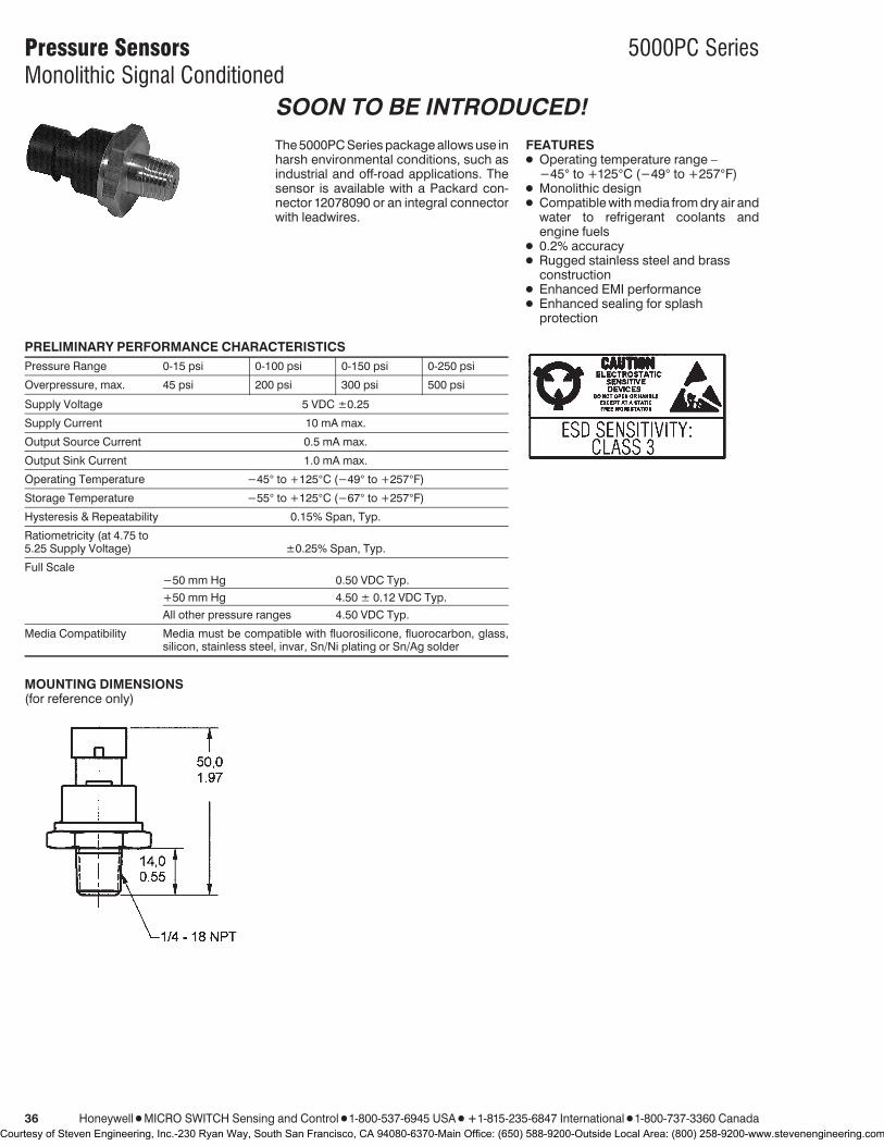
SOON TO BE INTRODUCED!The 5000PC Series package allows use inharsh environmental conditions, such asindustrial and off-road applications. Thesensor is available with a Packard con-nector 12078090 or an integral connectorwith leadwires.
FEATURES1 Operating temperature range –
−45° to +125°C (−49° to +257°F)1 Monolithic design1 Compatible with media from dry air and
water to refrigerant coolants and engine fuels
1 0.2% accuracy1 Rugged stainless steel and brass
construction1 Enhanced EMI performance1 Enhanced sealing for splash
protection
PRELIMINARY PERFORMANCE CHARACTERISTICSPressure Range 0-15 psi 0-100 psi 0-150 psi 0-250 psi
Overpressure, max. 45 psi 200 psi 300 psi 500 psi
Supply Voltage 5 VDC ±0.25
Supply Current 10 mA max.
Output Source Current 0.5 mA max.
Output Sink Current 1.0 mA max.
Operating Temperature −45° to +125°C (−49° to +257°F)
Storage Temperature −55° to +125°C (−67° to +257°F)
Hysteresis & Repeatability 0.15% Span, Typ.
Ratiometricity (at 4.75 to5.25 Supply Voltage) ±0.25% Span, Typ.
Full Scale−50 mm Hg 0.50 VDC Typ.
+50 mm Hg 4.50 ± 0.12 VDC Typ.
All other pressure ranges 4.50 VDC Typ.
Media Compatibility Media must be compatible with fluorosilicone, fluorocarbon, glass,silicon, stainless steel, invar, Sn/Ni plating or Sn/Ag solder
MOUNTING DIMENSIONS(for reference only)
Courtesy of Steven Engineering, Inc.-230 Ryan Way, South San Francisco, CA 94080-6370-Main Office: (650) 588-9200-Outside Local Area: (800) 258-9200-www.stevenengineering.com

Pressure Sensors 140PC SeriesAbsolute, Differential, Gage, Vacuum Gage/Amplified
Honeywell 1 MICRO SWITCH Sensing and Control 1 1-800-537-6945 USA 1 F1-815-235-6847 International 1 1-800-737-3360 Canada 37
FEATURES1 PCB terminals on opposite side from
the ports1 Fully signal conditioned
140PC SERIES PERFORMANCE CHARACTERISTICS at 8.0 ±0.01 VDCExcitation, 25°C
Min. Typ. Max. UnitsExcitation 7.00 8.00 16.0 VDC
Supply Current --- 8.00 20.0 mA
Current Sourcing Output --- --- 10 mA
Null Offset (141/142PC) 0.95 1.00 1.05 V
Null Offset (143PC)* 3.45 3.50 3.55 V
Null Offset142PC15A @ 2 psia 1.62 1.67 1.72 V142PC30A @ 2 psia 1.28 1.33 1.38 V
Output at Full Pressure 5.90 6.00 6.10 V
Span† (141/142PC) 4.95 5.00 5.05 V
Span† (143PC)* --- 5.00 --- V
Span142PC15A (2 to 15 psia) 4.28 4.33 4.48 V142PC30A (2 to 30 psia) 4.62 4.67 4.72 V
Ratiometricity Error7 to 8 V or 8 to 9 V --- ±0.50 --- %Span9 to 12 V --- ±2.00 ---
Stability over One Year --- ±0.50 --- %Span
Response Time --- --- 1.00 msec
Common Mode Pressure** --- --- 40 psi
Weight --- 28 --- grams
Short Circuit Protection Output may be shorted indefinitely to ground
Output Ripple None, DC device
Ground Reference Supply and output are common*Positive and negative pressure measurement.**Higher common mode pressures possible if sensor is not used over entire operating temperature range.†Span is defined as the algebraic difference between end points. Please note: actual output is 1V to 6 V (at 8.00
±0.01 VDC). Span is then 5V.
ENVIRONMENTAL SPECIFICATIONSOperating Temperature −40° to +85°C (−40° to +185°F)
Storage Temperature −55° to +125°C (−67° to +257°F)
Compensated Temperature −18° to +63°C (0° to +145°F)
Shock MIL-STD-202, Method 213 (50 g, half sine, 6 msec)
Vibration MIL-STD-202, Method 204 (10 to 2000 Hz at 10 g)
Media P2 port Wetted materials; polyester housing, epoxyadhesive, silicon, borosilicate glass, and silicon-to-glass bond*
P1 port Dry gases only*Liquid media containing some highly ionic solutions could potentially neutralize the chip-to-glass tubebond.
Am
plified
Courtesy of Steven Engineering, Inc.-230 Ryan Way, South San Francisco, CA 94080-6370-Main Office: (650) 588-9200-Outside Local Area: (800) 258-9200-www.stevenengineering.com

Pressure Sensors 140PC SeriesAbsolute, Differential, Gage, Vacuum Gage/Amplified
38 Honeywell 1 MICRO SWITCH Sensing and Control 1 1-800-537-6945 USA 1 F1-815-235-6847 International 1 1-800-737-3360 Canada
140PC SERIES ORDER GUIDE, VACUUM GAGE TYPE
ShiftNull, Sensitivity, Combined** Linearity, B.F.S.L.
25 to 5° 25 to −18° 25 to −40° P2 > P1 P2 < P1
25 to 45°C 25 to +63°C 25 to 85°C %SpanCatalogListing
PressureRange
psi Typ. Max. Max. Max.Sensitivity
V/psi
Overpressurepsi
Max. Max. Max.
Repeatability& Hysteresis
%SpanTyp.
141PC01G 0-−1 --- ±1.50 --- --- 5.000 20 --- ±0.75 ±0.30
141PC05G 0-−5 ±0.50 --- ±1.00 ±2.00 1.000 20 --- ±0.75 ±0.25
141PC15G 0-−15 ±0.50 --- ±1.00 ±2.00 0.333 45 --- ±0.40 ±0.15
140PC SERIES ORDER GUIDE, GAGE TYPE
ShiftNull, Sensitivity, Combined** Linearity, B.S.F.L.
25 to 5° 25 to −18° 25 to −40° P2 > P1 P2 < P1
25 to 45°C 25 to +63°C 25 to 85°C %SpanCatalogListing
PressureRange
psi Typ. Max. Max. Max.Sensitivity
V/psi
Overpressurepsi
Max. Max. Max.
Repeatability& Hysteresis
%SpanTyp.
142PC01G 0-1 --- ±1.50 --- --- 5.000 20 ±0.75 --- ±0.30
142PC02G 0-2 --- ±1.50 --- --- 2.500 20 ±0.75 --- ±0.30
142PC05G 0-5 ±0.50 --- ±1.00 ±2.00 1.000 20 ±1.50 --- ±0.25
142PC15G 0-15 ±0.50 --- ±1.00 ±2.00 0.333 45 ±0.75 --- ±0.15
142PC30G 0-30 ±0.50 --- ±1.00 ±2.00 0.167 60 ±0.75 --- ±0.15
143PC03G ±2.5 --- --- ±1.00 ±1.50 1.000 20 ±0.75 --- ±0.25
143PC05G ±5 --- --- ±1.00 ±1.50 0.500 30 ±0.75 --- ±0.15
143PC15G ±15 --- --- ±1.00 ±1.50 0.177 50 ±0.75 --- ±0.15
140PC SERIES ORDER GUIDE, DIFFERENTIAL TYPE
ShiftNull, Sensitivity, Combined** Linearity, B.F.S.L.
25 to 5° 25 to −18° 25 to −40° P2 > P1 P2 < P1
25 to 45°C 25 to +63°C 25 to 85°C %SpanCatalogListing
PressureRange
psi Typ. Max. Max. Max.Sensitivity
V/psi
Overpressurepsi
Max. Max. Max.
Repeatability& Hysteresis
%SpanTyp.
142PC01D 0-1 --- ±1.50 --- --- 5.000 20 ±0.75 ±0.40 ±0.30
142PC02D 0-2 --- ±1.50 --- --- 2.500 20 ±0.75 ±0.40 ±0.30
142PC05D 0-5 ±0.50 --- ±1.00 ±2.00 1.000 20 ±1.50 ±0.75 ±0.25
142PC15D 0-15 ±0.50 --- ±1.00 ±2.00 0.333 45 ±0.75 ±0.40 ±0.15
142PC30D 0-30 ±0.50 --- ±1.00 ±2.00 0.167 60 ±0.75 ±0.40 ±0.15
143PC03D ±2.5 --- --- ±1.00 ±1.50 1.000 20 ±0.75 ±0.40 ±0.25
143PC05D ±5 --- --- ±1.00 ±1.50 0.500 30 ±0.75 ±0.40 ±0.15
143PC15D ±15 --- --- ±1.00 ±1.50 0.177 50 ±0.75 ±0.40 ±0.15
140PC SERIES ORDER GUIDE, ABSOLUTE TYPE*
ShiftNull, Sensitivity, Combined** Linearity, B.F.S.L.
25 to 5° 25 to −18° 25 to −40° P2 > P1 P2 < P1
25 to 45°C 25 to +63°C 25 to 85°C %SpanCatalogListing
PressureRangepsia Typ. Max. Max. Max.
SensitivityV/psi
Overpressurepsi
Max. Max. Max.
Repeatability& Hysteresis
%SpanTyp.
142PC15A 0-15 ±0.50 --- ±1.00 ±2.00 0.333 45 --- ±0.40 ±0.15
142PC30A 0-30 ±0.50 --- ±1.00 ±2.00 0.167 60 --- ±0.40 ±0.15
*Tested at 2 psia reference**% Span specification applies to each shift independently. (Null, sensitivity, or combined).
Courtesy of Steven Engineering, Inc.-230 Ryan Way, South San Francisco, CA 94080-6370-Main Office: (650) 588-9200-Outside Local Area: (800) 258-9200-www.stevenengineering.com

Pressure Sensors 140PC SeriesAbsolute, Differential, Gage, Vacuum Gage/Amplified
Honeywell 1 MICRO SWITCH Sensing and Control 1 1-800-537-6945 USA 1 F1-815-235-6847 International 1 1-800-737-3360 Canada 39
ELECTRICAL CONNECTIONVoltage Excitation
NOTES1. Terminals are labeled on the sensor.2. Input and output share a common
ground.3. RL must be greater than or equal to
3000 ohms.
INTERNAL CIRCUITRY
RATIOMETRICITY
Ratiometricity refers to the output voltagebeing directly proportional to the supplyvoltage. 140PC sensors in this catalog arecalibrated at 8 VDC supply voltage to pro-vide a 1-6 volt (5V Span) output swing. Forexample, if supply increases by 50% to 12VDC, the output voltage increases by50% to 1.5-9 volts (7.5 V Span).
NOTEThe output is not perfectly ratiometric.See specifications for the degree of error.
NULL AND SENSITIVITYTEMPERATURE SHIFTAmplified pressure sensors are 100%tested to insure that the maximum nulland sensitivity temperature shift does notexceed the specification. The diagrambelow illustrates how null and sensitivityshift relates to temperature. Note that themaximum shift occurs at temperature ex-tremes. Therefore, if a sensor is not ex-
posed to the entire temperature range,the maximum null and sensitivity shift willactually be less than the value specified.
This diagram indicates the temperatureshift pertaining to a few listings. Maximumnull and sensitivity shift varies from listingto listing.
SCALING OF 140PC SERIES SENSORS WITH 8V EXCITATION
142PC15A Absolute VO J 1 V at 0 psia & 6 V at 15 psia
142PC30A Absolute VO J 1 V at 0 psia & 6 V at 30 psia
142PC15G Gage VO J 1 V at 0 psig & 6 V at 15 psig
141PC15G Vacuum Gage VO J 1 V at 0 psig & 6 V at −15 psig
143PC05D Differential VO J 1 V at −5 psig & 6 V at 5 psig
143PC15D Differential VO J 1 V at −15 psig & 6 V at 15 psig
NOTE: 141PC sensors are scaled for vacuum pressure on P2.142PC sensors are scaled for greater pressure on the P2 side of the chip. Input pressures onabsolute units are applied to the P1 port.Other scalings available upon request.
Am
plified
Courtesy of Steven Engineering, Inc.-230 Ryan Way, South San Francisco, CA 94080-6370-Main Office: (650) 588-9200-Outside Local Area: (800) 258-9200-www.stevenengineering.com

Pressure Sensors 140PC SeriesAbsolute, Differential, Gage, Vacuum Gage/Amplified
40 Honeywell 1 MICRO SWITCH Sensing and Control 1 1-800-537-6945 USA 1 F1-815-235-6847 International 1 1-800-737-3360 Canada
MOUNTING DIMENSIONS (For reference only)
Dimensions shown apply to Differential and Absolute versions. Gage units are identical, except the P1 port is absent.
140PC CONSTRUCTION
Courtesy of Steven Engineering, Inc.-230 Ryan Way, South San Francisco, CA 94080-6370-Main Office: (650) 588-9200-Outside Local Area: (800) 258-9200-www.stevenengineering.com

Pressure Sensors 160PC SeriesLow Pressure Differential, Gage, Vacuum Gage/Amplified
Honeywell 1 MICRO SWITCH Sensing and Control 1 1-800-537-6945 USA 1 F1-815-235-6847 International 1 1-800-737-3360 Canada 41
FEATURES1 Low pressure measurement1 PCB terminals on opposite side from
the ports1 Fully signal conditioned
160PC SERIES PERFORMANCE CHARACTERISTICS at 8.0 ±0.01 VDCExcitation, 25°C (Exception 163PC at 10 ±0.01 VDC Excitation, 25°C)
Min. Typ. Max. Units
Excitation 6.00 8.00 16 VDC
Supply Current --- 8.00 20 mA
Current Sourcing Output --- --- 10 mA
Null Offset (161/162/164PC)* 0.95 1.00 1.05 V
Null Offset (163PC)** 3.45 3.50 3.55 V
Output at Full Pressure (161/162/164PC) 5.90 6.00 6.10 V
Output at Full Vacuum (163PC) 0.80 1.00 1.20 V
Span (161/162/164PC) 4.85 5.00 5.15 V
Span (163PC)** --- 5.00 --- V
Ratiometricity Error7 to 8 V or 8 to 9 V --- ±0.50 --- %Span9 to 12 V --- ±2.00 ---
Stability over One Year --- ±0.50 --- %Span
Response Time --- --- 1.00 msec
Weight --- 28 --- grams
Short Circuit Protection Output may be shorted indefinitely to ground
Output Ripple None, DC device
Ground Reference Supply and output are common*Positive (or negative) pressure measurement.**Positive AND negative pressure measurement.
ENVIRONMENTAL SPECIFICATIONSOperating Temperature −40° to +85°C (−40° to +185°F)
Storage Temperature −55° to +125°C (−67° to +257°F)
Compensated Temperature −18° to +63°C (0° to +145°F)
Shock MIL-STD-202, Method 213 (50 g, half sine, 6 msec)
Vibration MIL-STD-202, Method 204 (10 to 2000 Hz at 10 g)
Media P2 port Wetted materials; polyester housing, epoxyadhesive, silicon, borosilicate glass,and silicon-to-glass bond*
P1 port Dry gases only*Liquid media containing some highly ionic solutions could potentially neutralize the chip-to-glass tubebond.
Am
plified
Courtesy of Steven Engineering, Inc.-230 Ryan Way, South San Francisco, CA 94080-6370-Main Office: (650) 588-9200-Outside Local Area: (800) 258-9200-www.stevenengineering.com

Pressure Sensors 160PC SeriesLow Pressure Differential, Gage, Vacuum Gage/Amplified
42 Honeywell 1 MICRO SWITCH Sensing and Control 1 1-800-537-6945 USA 1 F1-815-235-6847 International 1 1-800-737-3360 Canada
160PC SERIES ORDER GUIDE, VACUUM GAGE AND GAGE TYPE
ShiftNull, Sensitivity, Combined** Linearity, B.F.S.L.
25 to 5° 25 to −18° 25 to −40° P2 > P1 P2 < P1
25 to 45°C 25 to +63°C 25 to 85°C %SpanCatalogListing
PressureRangeNH2O Max. Max. Max.
SensitivityV/NH2O
Overpressurepsi
Max. Max. Max.
Repeatability& Hysteresis
%SpanTyp.
161PC01D 0-27.68 --- ±1.00 ±2.00 0.18 5 --- ±1.00 ±0.15 VacuumGage
162PC01G 0-27.68 --- ±1.00 ±2.00 0.18 5 --- ±1.00 ±0.15 Gage
160PC SERIES ORDER GUIDE, DIFFERENTIAL TYPE
ShiftNull, Sensitivity, Combined** Linearity, B.F.S.L.
25 to 5° 25 to −18° 25 to −40° P2 > P1 P2 < P1
25 to 45°C 25 to +63°C 25 to 85°C %SpanCatalogListing
PressureRangeNH2O Max. Max. Max.
SensitivityV/NH2O
Overpressurepsi
Max. Max. Max.
Repeatability& Hysteresis
%SpanTyp.
162PC01D 0-27.68 --- ±1.00 ±2.00 0.18 5 ±2.00 --- ±0.15
163PC01D36 ±5 ±1.00 --- --- 0.50 5 ±2.00 ±1.00 ±0.25
164PC01D37 0-10 ±1.00 --- --- 0.50 5 ±2.00 --- ±0.25
163PC01D75 ±2.5 ±1.25 --- --- 1.00 5 ±2.00 ±1.00 ±0.25
164PC01D76 0-5 ±1.25 --- --- 1.00 5 ±2.00 --- ±0.25
160PC SERIES ORDER GUIDE, DIFFERENTIAL TYPE @ 10 VDC ±0.01 EXCITATION, 25°C
ShiftNull, Sensitivity, Combined** Linearity, B.F.S.L.
25 to 5° 25 to −18° 25 to −40° P2 > P1 P2 < P1
25 to 45°C 25 to +63°C 25 to 85°C %SpanCatalogListing
PressureRangecmH2O Max. Max. Max.
SensitivityV/cmH2O
OverpressurecmH2OMax. Max. Max.
Repeatability& Hysteresis
%SpanTyp.
163PC01D48 −20 to +120 ±0.75* --- --- 0.36 350 ±1.5 --- ±0.15
*Null shift. Span shift is ±1.00/Span**% Span specification applies to each shift independently (Null, Sensitivity, or Combined)
Courtesy of Steven Engineering, Inc.-230 Ryan Way, South San Francisco, CA 94080-6370-Main Office: (650) 588-9200-Outside Local Area: (800) 258-9200-www.stevenengineering.com
Pressure Sensors 160PC SeriesLow Pressure Differential, Gage, Vacuum Gage/Amplified
Honeywell 1 MICRO SWITCH Sensing and Control 1 1-800-537-6945 USA 1 F1-815-235-6847 International 1 1-800-737-3360 Canada 43
INTERNAL CIRCUITRY
NOTES1. Terminals are labeled on the sensor.2. Input and output share a common
ground.3. RL must be greater than or equal to
3000 ohms.
RATIOMETRICITY
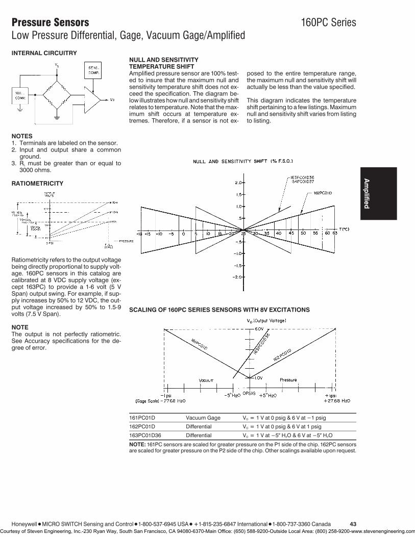
Ratiometricity refers to the output voltagebeing directly proportional to supply volt-age. 160PC sensors in this catalog arecalibrated at 8 VDC supply voltage (ex-cept 163PC) to provide a 1-6 volt (5 VSpan) output swing. For example, if sup-ply increases by 50% to 12 VDC, the out-put voltage increased by 50% to 1.5-9volts (7.5 V Span).
NOTEThe output is not perfectly ratiometric.See Accuracy specifications for the de-gree of error.
NULL AND SENSITIVITYTEMPERATURE SHIFTAmplified pressure sensor are 100% test-ed to insure that the maximum null andsensitivity temperature shift does not ex-ceed the specification. The diagram be-low illustrates how null and sensitivity shiftrelates to temperature. Note that the max-imum shift occurs at temperature ex-tremes. Therefore, if a sensor is not ex-
posed to the entire temperature range,the maximum null and sensitivity shift willactually be less than the value specified.
This diagram indicates the temperatureshift pertaining to a few listings. Maximumnull and sensitivity shift varies from listingto listing.
SCALING OF 160PC SERIES SENSORS WITH 8V EXCITATIONS
161PC01D Vacuum Gage VO J 1 V at 0 psig & 6 V at −1 psig
162PC01D Differential VO J 1 V at 0 psig & 6 V at 1 psig
163PC01D36 Differential VO J 1 V at −5N H2O & 6 V at −5N H2O
NOTE: 161PC sensors are scaled for greater pressure on the P1 side of the chip. 162PC sensorsare scaled for greater pressure on the P2 side of the chip. Other scalings available upon request.
Am
plified
Courtesy of Steven Engineering, Inc.-230 Ryan Way, South San Francisco, CA 94080-6370-Main Office: (650) 588-9200-Outside Local Area: (800) 258-9200-www.stevenengineering.com

Pressure Sensors 160PC SeriesLow Pressure Differential, Gage, Vacuum Gage/Amplified
44 Honeywell 1 MICRO SWITCH Sensing and Control 1 1-800-537-6945 USA 1 F1-815-235-6847 International 1 1-800-737-3360 Canada
MOUNTING DIMENSIONS (For reference only)
160PC CONSTRUCTION
Courtesy of Steven Engineering, Inc.-230 Ryan Way, South San Francisco, CA 94080-6370-Main Office: (650) 588-9200-Outside Local Area: (800) 258-9200-www.stevenengineering.com

Pressure Sensors 180PC SeriesMiniature Absolute, Differential, Gage/Amplified
Honeywell 1 MICRO SWITCH Sensing and Control 1 1-800-537-6945 USA 1 F1-815-235-6847 International 1 1-800-737-3360 Canada 45
Terminal Mount Housing Mount
FEATURES1 Miniature plastic package1 Terminal and housing mount styles1 PCB termination1 Fully signal conditioned
180PC SERIES PERFORMANCE CHARACTERISTICS at 8.0 ±0.01 VDCExcitation, 25°C
Min. Typ. Max. UnitsExcitation 7.00 8.00 16 VDC
Supply Current --- --- 6 mA
Current Sourcing Output --- --- 10 mA
Null Offset (184/185PC) 0.95 1.00 1.05 V
Null Offset (186PC) 3.45 3.50 3.55 V
Null Offset185PC15AT @ 2 psia 1.62 1.67 1.72 V185PC30AT @ 2 psia 1.28 1.33 1.38 V
Output at Full Pressure (184/185PC, G,D) 5.90 6.00 6.15 V
Output at Full Pressure (185PC, A only) 5.85 6.00 6.15 V
Output at Full Pressure (186PC) 5.90 6.00 6.10 V
Span (184/185PC, G,D) 4.95 5.00 5.05 V
Span (185PC, A only) 4.90 5.00 5.10 V
Span (186PC) --- 5.00 --- V
Span (185PC15AT) 4.28 4.33 4.38 V
Span (185PC30AT) 4.62 4.67 4.72 V
Ratiometricity Error7 to 8V or 8 to 9V --- ±0.50 --- % Span9 to 12V --- ±2.00 --- % Span
Temperature Error (Combined null and span) −2% 0 +2% % Span
Stability over One Year --- ±0.50 --- % Span
Response Time --- --- 1.00 msec
Weight --- 12 --- grams
Short Circuit Protection Output may be shorted indefinately toground
Output Ripple None, DC device
Ground Reference Supply and output are common
ENVIRONMENTAL SPECIFICATIONSOperating Temperature −40° to +85°C (−40° to +185°F)
Storage Temperature −55° to +125°C (−67° to +257°F)
Compensated Temperature 0° to +50°C (32° to +122°F)
Shock MIL-STD-202, Method 213 (50 g, half sine, 6 msec)
Vibration MIL-STD-202, Method 204 (10 to 2000 Hz at 10 g)
Media P2 port Wetted materials; polyester housing, epoxyadhesive, silicon, borosilicate glass, and silicon-to-glass bond*
P2 port Absolute only: Factory sealed vacuum reference, noconnection
P1 port Dry gases only*Liquid media containing some highly ionic solutions could potentially neutralize the chip-to-glass tubebond.
Am
plified
Courtesy of Steven Engineering, Inc.-230 Ryan Way, South San Francisco, CA 94080-6370-Main Office: (650) 588-9200-Outside Local Area: (800) 258-9200-www.stevenengineering.com

Pressure Sensors 180PC SeriesMiniature Absolute, Differential, Gage/Amplified
46 Honeywell 1 MICRO SWITCH Sensing and Control 1 1-800-537-6945 USA 1 F1-815-235-6847 International 1 1-800-737-3360 Canada
184PC SERIES ORDER GUIDE, VACUUM GAGE TYPE
Linearity, %Span
CatalogListing
PressureRange
psi
Overpressurepsi
Max.P2 > P1
Max.P2 < P1
Max.
184PC05GT 0-−5 20 --- ±1.00
184PC15GT 0-−15 45 --- ±1.00
185PC SERIES ORDER GUIDE, DIFFERENTIAL TYPE, P2 > P1
Linearity, %Span
CatalogListing
PressureRange
psi
Overpressurepsi
Max.P2 > P1
Max.P2 < P1
Max.
185PC05DT 0-5 20 ±2.00 ±1.00
185PC15DT 0-15 45 ±2.00 ±1.00
185PC30DT 0-30 60 ±1.50 ±0.75
186PC SERIES ORDER GUIDE, BI-DIRECTIONAL TYPE, P2-P1
Linearity, %Span
CatalogListing
PressureRange
psi
Overpressurepsi
Max.P2 > P1
Max.P2 < P1
Max.
186PC03DT ±2.5 20 ±2.00 ±1.00
186PC05DT ±5.0 20 ±2.00 ±1.00
186PC15DT ±15 45 ±2.00 ±1.00
185PC SERIES ORDER GUIDE, ABSOLUTE TYPE
Linearity, %Span
CatalogListing
PressureRange
psi
Overpressurepsi
Max.P2 > P1
Max.P2 < P1
Max.
185PC15AT 0-15 45 --- ±1.00
185PC30AT 0-30 60 --- ±0.75
HOW TO ORDERCatalog listings in the order guide are shownwith mounting version T (terminal mount). H(housing mount) also available. Contact 800number.
Courtesy of Steven Engineering, Inc.-230 Ryan Way, South San Francisco, CA 94080-6370-Main Office: (650) 588-9200-Outside Local Area: (800) 258-9200-www.stevenengineering.com

Pressure Sensors 180PC SeriesMiniature Absolute, Differential, Gage/Amplified
Honeywell 1 MICRO SWITCH Sensing and Control 1 1-800-537-6945 USA 1 F1-815-235-6847 International 1 1-800-737-3360 Canada 47
ELECTRICAL CONNECTIONS
Voltage Excitation
NOTES1. Terminals are labeled on the sensor.2. Input and output share a common ground.3. RL must be greater than or equal to 3000
ohms.
IDEAL OUTPUT AT VsJ8.00±0.01 VDC
DifferentialExample: 185PC15DT when PIN JP2-P1
Vacuum GageExample: 184PC05GT where P2JPIN P1JAmbient
Bi-directionalExample: 186PC05DH where PIN JP2-P1
AbsoluteExample: 185PC15AP where P1JPIN P2JFactory sealed vacuum
Am
plified
Courtesy of Steven Engineering, Inc.-230 Ryan Way, South San Francisco, CA 94080-6370-Main Office: (650) 588-9200-Outside Local Area: (800) 258-9200-www.stevenengineering.com

Pressure Sensors 180PC SeriesMiniature Absolute, Differential, Gage Sensored/Amplified
48 Honeywell 1 MICRO SWITCH Sensing and Control 1 1-800-537-6945 USA 1 F1-815-235-6847 International 1 1-800-737-3360 Canada
MOUNTING DIMENSIONS 0.0 J mm0.00 J in.
Terminal Mount (Differential ‘‘D’’ or Absolute ‘‘A’’ Housing)
(Gage ‘‘G’’ Housing) Housing Mount
Courtesy of Steven Engineering, Inc.-230 Ryan Way, South San Francisco, CA 94080-6370-Main Office: (650) 588-9200-Outside Local Area: (800) 258-9200-www.stevenengineering.com

Pressure Sensors 189PC SeriesGage Amplified
Honeywell 1 MICRO SWITCH Sensing and Control 1 1-800-537-6945 USA 1 F1-815-235-6847 International 1 1-800-737-3360 Canada 49
FEATURES1 Manifold mount/O-ring sealed 1 Fully signal conditioned1 PCB termination1 Operating temperature up to 125°C1 Glass chip tube (non-outgassing)
189PC PERFORMANCE CHARACTERISTICS @ 8.0 ±0.01 VDC Excitation, 25°CMin Typ Max Units
Excitation 7.00 8.00 16.0 VDC
Supply Current — — 6 mA
Current Sourcing Output — — 10 mA
Null Offset 0.95 1.00 1.05 V
Output at Full Pressure 5.80 6.00 6.15 V
Ratiometricity Error7 to 8V or 8 to 9V — ±0.50 — % Span9 to 12 V — ±2.00 — % Span
Temperature Error(Combined null and span) −2 0 +2 % Span
Stability over One Year — ±0.50 — %Span
Response Time — — 1.00 mS
Weight — 12 — grams
Short Circuit Protection Output may be shorted indefinitely to ground
Output Ripple None, DC Device
Ground Reference Supply and output are common
ENVIRONMENTAL SPECIFICATIONS
Operating Temperature −40°C to +85°C (−40° to +185°F)
Storage Temperature −55° to +125°C (−67° to +257°F)
Compensated Temperature 0° to +50°C (32° to +122°F)
Shock MIL-STD-202, Method 213 (50g, half sine, 6 msec)
Vibration MIL-STD-202, Method 204 (10 to 2000 Hz at 10 g)
Media P2 port Wetted materials; polyester housing, epoxy adhesive,silicon, borosilicate glass, and silicon-to-glass bond*
*Liquid media containing some highly ionic solutions could potentially neutralize the chip-to-glass tubebond.
Am
plified
Courtesy of Steven Engineering, Inc.-230 Ryan Way, South San Francisco, CA 94080-6370-Main Office: (650) 588-9200-Outside Local Area: (800) 258-9200-www.stevenengineering.com

Pressure Sensors 189PC SeriesGage Amplified
50 Honeywell 1 MICRO SWITCH Sensing and Control 1 1-800-537-6945 USA 1 F1-815-235-6847 International 1 1-800-737-3360 Canada
189PC SERIES ORDER GUIDE GAGE TYPE
Linearity, %Span
CatalogListing
PressureRange
psi
Overpressurepsi
Max.P2 > P1
Max.
189PC15GM 0-15 45 ±2.00
189PC100GM 0-100 250 ±1.50
189PC150GM 0-150 250 ±1.50
Electrical Connections
NOTES1. Input and output share a common ground.2. RL must be greater than or equal to 3000
ohms.
Pin DesignationPin 1 J VssPin 2 J VoutPin 3 J GNDPin 4 J No ConnectPin 5 J Vcc
Pressure Reference Gage
MOUNTING DIMENSIONS (for reference only)
O-Ring provided with sensor.O-Ring Part Number: SS-12168.O.D. of .114 in. and a cross section of .070 in.Material is 70 Durometer Fluorocarbon.
Courtesy of Steven Engineering, Inc.-230 Ryan Way, South San Francisco, CA 94080-6370-Main Office: (650) 588-9200-Outside Local Area: (800) 258-9200-www.stevenengineering.com

Pressure Sensors 240PC SeriesHigh Pressure Gage, Vacuum Gage/Amplified
Honeywell 1 MICRO SWITCH Sensing and Control 1 1-800-537-6945 USA 1 F1-815-235-6847 International 1 1-800-737-3360 Canada 51
FEATURES1 Internal O-Ring seals for contamination
resistance1 Screw-in or flat-pack mounting1 Rugged aluminum housing
240PC SERIES PERFORMANCE CHARACTERISTICS at 8.0 ±0.01 VDCExcitation, 25°C
Min. Typ. Max. UnitsExcitation 7.00 8.00 16.0 VDC
Supply Current --- 8.00 20.0 mA
Current Sourcing Output --- --- 10 mA
Null Offset (241/242PC)* 0.95 1.00 1.05 V
Null Offset (243PC)** 3.45 3.50 3.55 V
Output at Full Pressure** 5.80 6.00 6.20 V
Span (241/242PC) 4.80 5.00 5.20 V
Span (243PC) --- ±2.5 --- V
Ratiometricity Error7 to 8 V or 8 to 9 V --- ±0.50 --- %Span9 to 12 V --- ±2.00 ---
Stability over One Year --- ±0.50 --- %Span
Response Time --- --- 1.00 msec
Weight --- 85 --- grams
Short Circuit Protection Output may be shorted indefinitely to ground
Output Ripple None, DC device
Ground Reference Supply and output are common*Positive (or negative) pressure measurement**Positive and negative pressure measurement
ENVIRONMENTAL SPECIFICATIONSOperating Temperature −40° to +85°C (−40° to +185°F)
Storage Temperature −40° to +85°C (−40° to +185°F)
Compensated Temperature −18° to +63°C (0° to +145°F)
Shock MIL-STD-202, Method 213 (50 g, half sine, 6 msec)
Vibration MIL-STD-202, Method 204 (10 to 2000 Hz at 10 g)
Media P2 port Wetted materials; die-cast aluminum housing,O-ring seal, silicon, borosilicate glass, and silicon-to-glass bond*
*Liquid media containing some highly ionic solutions could potentially neutralize the chip-to-glass tubebond.
Am
plified
Courtesy of Steven Engineering, Inc.-230 Ryan Way, South San Francisco, CA 94080-6370-Main Office: (650) 588-9200-Outside Local Area: (800) 258-9200-www.stevenengineering.com
Pressure Sensors 240PC SeriesHigh Pressure Gage, Vacuum Gage/Amplified
52 Honeywell 1 MICRO SWITCH Sensing and Control 1 1-800-537-6945 USA 1 F1-815-235-6847 International 1 1-800-737-3360 Canada
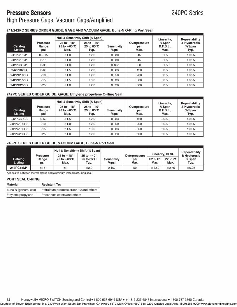
241/242PC SERIES ORDER GUIDE, GAGE AND VACUUM GAGE, Buna-N O-Ring Port Seal
Null & Sensitivity Shift (%Span)
CatalogListing
PressureRange
psi
25 to −18°25 to +63°C
Max.
25 to −40°25 to 85°C
Typ.Sensitivity
V/psi
Overpressurepsi
Max.
Linearity,%Span
B.F.S.L.,Max.
Repeatability& Hysteresis
%SpanTyp.
241PC15M* 0-−15 ±1.0 ±2.0 0.330 45 ±1.50 ±0.25
242PC15M* 0-15 ±1.0 ±2.0 0.330 45 ±1.50 ±0.25
242PC30M* 0-30 ±1.0 ±2.0 0.167 60 ±1.50 ±0.25
242PC60G 0-60 ±1.5 ±2.0 0.083 120 ±0.50 ±0.25
242PC100G 0-100 ±1.0 ±2.0 0.050 200 ±0.50 ±0.25
242PC150G 0-150 ±1.5 ±3.0 0.033 300 ±0.50 ±0.25
242PC250G 0-250 ±1.0 ±2.0 0.020 500 ±0.50 ±0.25
242PC SERIES ORDER GUIDE, GAGE, Ethylene propylene O-Ring Seal
Null & Sensitivity Shift (%Span)
CatalogListing
PressureRange
psi
25 to −18°25 to +63°C
Max.
25 to −40°25 to 85°C
Typ.Sensitivity
V/psi
Overpressurepsi
Max.
Linearity,%Span
B.F.S.L.,Max.
Repeatability& Hysteresis
%SpanTyp.
242PC60GS 0-60 ±1.5 ±2.0 0.083 120 ±0.50 ±0.25
242PC100GS 0-100 ±1.0 ±2.0 0.050 200 ±0.50 ±0.25
242PC150GS 0-150 ±1.5 ±3.0 0.033 300 ±0.50 ±0.25
242PC250GS 0-250 ±1.0 ±2.0 0.020 500 ±0.50 ±0.25
243PC SERIES ORDER GUIDE, VACUUM GAGE, Buna-N Port Seal
Null & Sensitivity Shift (%Span)Linearity, BFSL
CatalogListing
PressureRange
psi
25 to −18°25 to +63°C
Max.
25 to −40°25 to 85°C
Typ.Sensitivity
V/psi
Overpressurepsi
Max.P2 > P1
Max.P2 < P1
Max.
Repeatability& Hysteresis
%SpanTyp.
243PC15M* ±15 ±1 ±2.0 0.167 50 ±1.50 ±0.75 ±0.25
*Adhesive between thermoplastic and aluminum instead of O-ring seal.
PORT SEAL O-RINGMaterial Resistant To:
Buna-N (general use) Petroleum products, freon 12 and others
Ethylene propylene Phosphate esters and others
Courtesy of Steven Engineering, Inc.-230 Ryan Way, South San Francisco, CA 94080-6370-Main Office: (650) 588-9200-Outside Local Area: (800) 258-9200-www.stevenengineering.com

Pressure Sensors 240PC SeriesHigh Pressure Gage, Vacuum Gage/Amplified
Honeywell 1 MICRO SWITCH Sensing and Control 1 1-800-537-6945 USA 1 F1-815-235-6847 International 1 1-800-737-3360 Canada 53
SCALING OF 240PC SERIES WITH 8V EXCITATIONRATIOMETRICITY
Ratiometricity refers to the output voltagebeing directly proportional to supply volt-age. 240PC sensors in this catalog arecalibrated at 8 VDC supply voltage to pro-vide a 1-6 volt (5 V Span) output swing.For example, if supply increases by 50%to 12 VDC, the output voltage increasedby 50% to 1.5-9 volts (7.5 V Span).
NOTEThe output is not perfectly ratiometric.See Accuracy specifications for the de-gree of error.
242PC15M Gage VO J 1 V at 0 psig & 6 V at 15 psig
241PC15M Vacuum Gage VO J 1 V at 0 psig & 6 V at −15 psig
243PC15M Gage VO J 1 V at −15 psig & 6 V at 15 psig
NOTE: 241PC sensors are scaled for greater pressure on the P1 side of the chip. 242PC sensorsare scaled for greater pressure on the P2 side of the chip.Other scalings available upon request.
Am
plified
Courtesy of Steven Engineering, Inc.-230 Ryan Way, South San Francisco, CA 94080-6370-Main Office: (650) 588-9200-Outside Local Area: (800) 258-9200-www.stevenengineering.com

Pressure Sensors 240PC SeriesHigh Pressure Gage, Vacuum Gage/Amplified
54 Honeywell 1 MICRO SWITCH Sensing and Control 1 1-800-537-6945 USA 1 F1-815-235-6847 International 1 1-800-737-3360 Canada
NULL AND SENSITIVITYTEMPERATURE SHIFTAmplified pressure sensors are 100%tested to ensure that the maximum nulland sensitivity temperature shift does notexceed the specification. The diagram il-lustrates how null and sensitivity shift re-lates to temperature. Note that the maxi-mum shift occurs at temperature ex-tremes. Therefore, if a sensor is not ex-posed to the entire temperature range,the maximum null and sensitivity shift willactually be less than the value specified.
This diagram indicates the temperatureshift pertaining to a few listings. Maximumnull and sensitivity shift varies from listingto listing.
ELECTRICAL CONNECTIONS
Voltage Excitation
NOTES1. Terminals are labeled on the sensor.2. Input and output share a common
ground.3. RL must be greater than or equal to
3000 ohms.
INTERNAL CIRCUITRY
Null and Sensitivity Shift (%Span)
MOUNTING DIMENSIONS (For reference only)Leadwires1 - Red, Vs2 - Black, Ground (−)3 - Green, Output
Courtesy of Steven Engineering, Inc.-230 Ryan Way, South San Francisco, CA 94080-6370-Main Office: (650) 588-9200-Outside Local Area: (800) 258-9200-www.stevenengineering.com

Pressure Sensors 249PC SeriesPressure-to-Current/Amplified
Honeywell 1 MICRO SWITCH Sensing and Control 1 1-800-537-6945 USA 1 F1-815-235-6847 International 1 1-800-737-3360 Canada 55
FEATURES1 Unidirectional gage pressure measure-
ment1 2-wire, causes a 4-20 mA change in cur-
rent, linearly proportional to pressureinput
1 Screw-in or flat-pack mounting1 Rugged die-cast aluminum housing
249PC SERIES PERFORMANCE CHARACTERISTICS at 24.0 ±0.01 VDCExcitation, 25 Ohm Load, 25°C
Min. Typ. Max. UnitsExcitation 10.0 24.0 32.0 VDC
Response Time --- --- 1.00 msec
Supply Voltage Sensitivity 20-24 VDC and24-28 VDC --- ±0.15 --- %Span
Stability over One Year --- ±1.0 --- %Span
Current Output249PC15G at 3 psig 3.7 4.0 4.3 mA249PC15G at 15 psig 19.7 20.0 20.3Null (0-100 & 0-250 psig) 3.7 4.0 4.3Full pressure (0-100 & 0-250 psig) 19.5 20.0 20.5
Weight --- 85 --- grams
Output Ripple None, DC device
ENVIRONMENTAL SPECIFICATIONSOperating Temperature −40° to +85°C (−40° to +185°F)
Storage Temperature −40° to +85°C (−40° to +185°F)
Compensated Temperature −18° to +63°C (0° to +145°F)
Shock MIL-STD-202, Method 213 (50 g, half sine, 6 msec)
Vibration MIL-STD-202, Method 204 (10 to 2000 Hz at 10 g)
Media P2 port Wetted materials; die-cast aluminum housing,O-ring seal, silicon, borosilicate glass, and silicon-to-glass bond*
*Liquid media containing some highly ionic solutions could potentially neutralize the chip-to-glass tubebond.
249PC SERIES ORDER GUIDE, GAGE, Buna-N O-Ring Port Seal
CatalogListing
PressureRange
psi
Null & Sensitivity Shift25 to 0°C, 25 to 50°C
Max.Sensitivity
mA/psi
Overpressurepsi
%Span Max.
Linearity& Hysteresis%Span Max.
RepeatabilityB.F.S.L.
Typ.
249PC15M* 3-15 ±1.0 1.330 45 ±0.75 ±0.25
249PC100G 0-100 ±1.0 0.160 200 ±0.75 ±0.25
249PC250G 0-250 ±1.0 0.064 500 ±1.00 ±0.25
*Adhesive between thermoplastic and aluminum instead of O-ring seal.
249PC SERIES ORDER GUIDE, GAGE, Ethylene Propylene O-Ring Port Seal
CatalogListing
PressureRange
psi
Null & Sensitivity Shift25 to 0°C, 25 to 50°C
Max.Sensitivity
mA/psi
Overpressurepsi
%Span Max.
Linearity& Hysteresis%Span Max.
RepeatabilityB.F.S.L.
Typ.
249PC100GS 0-100 ±1.0 0.160 200 ±0.75 ±0.25
249PC250GS 0-250 ±1.0 0.064 500 ±1.00 ±0.25
Am
plified
Courtesy of Steven Engineering, Inc.-230 Ryan Way, South San Francisco, CA 94080-6370-Main Office: (650) 588-9200-Outside Local Area: (800) 258-9200-www.stevenengineering.com
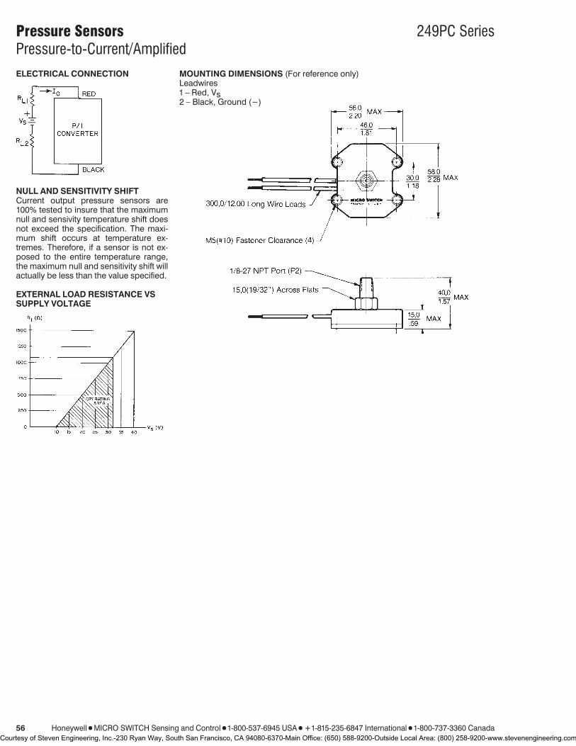
Pressure Sensors 249PC SeriesPressure-to-Current/Amplified
56 Honeywell 1 MICRO SWITCH Sensing and Control 1 1-800-537-6945 USA 1 F1-815-235-6847 International 1 1-800-737-3360 Canada
ELECTRICAL CONNECTION
NULL AND SENSITIVITY SHIFTCurrent output pressure sensors are100% tested to insure that the maximumnull and sensivity temperature shift doesnot exceed the specification. The maxi-mum shift occurs at temperature ex-tremes. Therefore, if a sensor is not ex-posed to the entire temperature range,the maximum null and sensitivity shift willactually be less than the value specified.
EXTERNAL LOAD RESISTANCE VSSUPPLY VOLTAGE
MOUNTING DIMENSIONS (For reference only)Leadwires1 – Red, Vs2 – Black, Ground (−)
Courtesy of Steven Engineering, Inc.-230 Ryan Way, South San Francisco, CA 94080-6370-Main Office: (650) 588-9200-Outside Local Area: (800) 258-9200-www.stevenengineering.com

Pressure Sensors SSPB SeriesHeavy Duty DC Adjustable, 2-Wire Analog
Honeywell 1 MICRO SWITCH Sensing and Control 1 1-800-537-6945 USA 1 F1-815-235-6847 International 1 1-800-737-3360 Canada 57
FEATURES1 Silicon sensor chip is enclosed in stain-
less steel welded diaphragm1 Rugged diecast zinc plug-in limit
switch style housing1 2-wire, 4-20 mA output current linearly
proportional to pressure1 Sealed to meet NEMA 1, 3, 3R, 4, 6, 6P,
12, 131 Field adjustable null and span1 Protected against false pulse, tran-
sients and industrial noise1 0 to +50°C operating and compen-
sated temperature1 UL Listed.
SSPB SERIES PERFORMANCE CHARACTERISTICS, 25°CMin. Typ. Max. Units
Supply Voltage 12.0 --- 36.0 VDCHysteresis & Repeatability
@ nominal span --- --- ±0.5 %Span@ max. span comp. --- --- ±1.5
Temperature Error @ nom. span & max. comp. --- ±6.0 ±10.0 %SpanResponse Time --- --- 2.0 msecWeight 414 grams (.91 lb.) Note: w/o receptacleChange in Current 4 to 20 mA proportional to pressureNull Pressure Setting (4 mA output) Can be adjusted from 0 to 25% of full pressure
rangeFull Pressure Setting (20 mA output) Can be adjusted from 75 to 100% of full pres-
sure range
ENVIRONMENTAL SPECIFICATIONSStorage Temperature −25° to +85°C (−13° to +185°F)Operating and Compensated Temperature 0° to 50°C (32° to 122°F)Sealing NEMA 1, 3, 3R, 4, 6, 6P, 12, 13*Media Limited only to those media which will not
attack 316 stainless steel
*Application Note: Enclosures are based, in general, on the broad definitions outlined in NEMAstandards. Therefore, it will be necessary for the user to determine that a particular enclosure isadequate when exposed to the specific conditions that might exist in intended applications.Except as might otherwise be noted, all references to products relative to NEMA enclosure typesare based on MICRO SWITCH evaluation only.
SSPB SERIES ORDER GUIDE, GAGE PRESSURE
CatalogListing
NominalPressure
Range psig
OverPressureMax. psi
Sensitivity (1)RangemA/psi
SSPB0015V 0-15 30 1.07 to 4.27SSPB0100V 0-100 200 0.16 to 0.64SSPB0250V 0-250 500 0.064 to 0.256
Mating Receptacle LSZ 4001(1) NOTE: Sensitivity J
16 mA
Upper Pressure Setting - Lower Pressure Setting
ELECTRICAL CONNECTIONSAn ammeter, resistor (current output gen-erates a voltage drop across the resistor)or any current sensing device is placed inseries with a DC voltage source and thepressure sensor for proper operation.The load, represented by RL, can beplaced on either or both sides of the volt-age source. Total load resistance must bewithin operating area. Output and PowerLEDs do not require separate wiring.
RL(max.) J VS - 12 volts
0.020 Amps
MAXIMUM EXTERNAL LOAD RESIST-ANCE VERSUS SUPPLY VOLTAGE
MOUNTING DIMENSIONS(for reference only)
Am
plified
Courtesy of Steven Engineering, Inc.-230 Ryan Way, South San Francisco, CA 94080-6370-Main Office: (650) 588-9200-Outside Local Area: (800) 258-9200-www.stevenengineering.com

Pressure Sensors SSPC SeriesHeavy Duty AC Adjustable Setpoint/2-Wire Digital
58 Honeywell 1 MICRO SWITCH Sensing and Control 1 1-800-537-6945 USA 1 F1-815-235-6847 International 1 1-800-737-3360 Canada
FEATURES1 Silicon sensor chip is enclosed in stain-
less steel welded diaphragm1 Rugged diecast zinc plug-in limit
switch style housing1 Field adjustable setpoint and
differential1 Sealed to meet NEMA 1, 3, 3R, 4, 6, 6P,
12, 131 Protected against false pulse, tran-
sients, industrial noise and NEMAnoise
1 −25 to +85°C storage temperature1 0 to +50°C operating and compen-
sated temperature1 UL Listed
SSPC SERIES PERFORMANCE CHARACTERISTICS, 25°CMin. Typ. Max. Units
Supply Voltage 92.0 115 132 VAC
Repeatability@ 25°C --- --- ±0.5 % of Adjustable rangeComp. temp. range --- --- ±3.0
Response Time Max (no time delay) On - 20 msec Off - 10 msec
Rate of Operation --- --- 900 per minute
Power Dissipation 0.35 VA excluding load
Saturation Voltage 9V max with 0.5 Amp load
Load Current (N.O.) 0.5 Amp max. continuous over full temperature range2.7 Amp. max. inrush
Leakage Current (Off state) 2.0 mA RMS, max.
Protection False pulse, transients, Industrial noise, NEMA noise
Weight 414 grams (.91 lb.) Note: w/o receptacle
ENVIRONMENTAL SPECIFICATIONSStorage Temperature −25° to +85°C (−13° to 185°F)
Operating and Compensated Temperature 0° to 50°C (32° to 122°F)
Sealing NEMA 1, 3, 3R, 4, 6, 6P, 12, 13*
Media Limited only to those media which will notattack 316 stainless steel
*Application Note: Enclosures are based, in general, on the broad definitionsoutlined in NEMA standards. Therefore, it will be necessary for the user todetermine that a particular enclosure is adequate when exposed to the specificconditions that might exist in intended applications. Except as might otherwisebe noted, all references to products relative to NEMA enclosure types arebased on MICRO SWITCH evaluation only.
SSPC SERIES ORDER GUIDE, GAGE PRESSURE
CatalogListing
NominalPressure
Range psig
Over-PressureMax. psi
AdjustableSetpointRange
DifferentialMin.
SSPC0015V 0-15 30 1.5-15 30% @ 1.5 psi,10% @ F.S.
SSPC0100V 0-100 200 10-100 10%
SSPC0250V 0-250 500 25-250 10%
Mating Receptacle LSZ 4001
WIRING DIAGRAM
Output and Power LEDs do not requireseparate wiring.
MOUNTING DIMENSIONS (for reference only)
Courtesy of Steven Engineering, Inc.-230 Ryan Way, South San Francisco, CA 94080-6370-Main Office: (650) 588-9200-Outside Local Area: (800) 258-9200-www.stevenengineering.com

Pressure Sensors SSPD SeriesHeavy Duty DC Adjustable Setpoint, 4-Wire Current Sinking
Honeywell 1 MICRO SWITCH Sensing and Control 1 1-800-537-6945 USA 1 F1-815-235-6847 International 1 1-800-737-3360 Canada 59
FEATURES1 Silicon sensor chip is enclosed in stain-
less steel welded diaphragm1 Rugged diecast zinc plug-in limit
switch style housing1 Field Adjustable setpoint and
differential1 Sealed to meet NEMA 1, 3, 3R, 4, 6, 6P,
12, 131 Protected against false pulse, tran-
sients and industrial noise1 −25 to +85°C storage temperature1 0 to +50° operating and compensated
temperature1 UL Listed
SSPD SERIES PERFORMANCE CHARACTERISTICS, 25°CSupply Voltage 10 to 30 VDC
Load Current (N.O. & N.C.) 200 mA Max (NPN)
Leakage current, N.C. state 10 µA Max
Voltage Drop, Max 1.25V with 200 mA load
Response Time, Max 15 Milliseconds
Protection Power up protection, transients, industrial noise
Repeatability (Stability) ±0.5% of Set Points (@25°C)±3.0% of Set Points (0°C to +50°C)
ENVIRONMENTAL SPECIFICATIONSStorage Temperature −25° to +85°C (−13° to 185°F)
Operating and Compensated Temperature 0° to 50°C (32° to 122°F)
Sealing NEMA 1, 3, 3R, 4, 6, 6P, 12, 13*
Media Limited only to those media which will notattack 316 stainless steel
*Application Note: Enclosures are based, in general, on the broad definitions outlined in NEMAstandards. Therefore, it will be necessary for the user to determine that a particular enclosure isadequate when exposed to the specific conditions that might exist in intended applications.Except as might otherwise be noted, all references to products relative to NEMA enclosure typesare based on MICRO SWITCH evaluation only.
SSPD SERIES ORDER GUIDE, GAGE PRESSURE
CatalogListing
InputPressureMax. psig
Over-PressureMax. psi
AdjustableSetpointRange
DifferentialMin.
SSPD0015V 1.5-15 30 15 30% @ 1.5 psi,10% @ F.S.
SSPD0100V 100 200 10-100 10%
SSPD0250V 250 500 25-250 10%
Mating Receptacle LSZ 4001
SSPD Series has one bicolor Output LED.
WIRING DIAGRAM
MOUNTING DIMENSIONS(for reference only)
Am
plified
Courtesy of Steven Engineering, Inc.-230 Ryan Way, South San Francisco, CA 94080-6370-Main Office: (650) 588-9200-Outside Local Area: (800) 258-9200-www.stevenengineering.com

Pressure Sensors SSPE SeriesHeavy Duty DC Adjustable Setpoint, 4-Wire Current Sourcing
60 Honeywell 1 MICRO SWITCH Sensing and Control 1 1-800-537-6945 USA 1 F1-815-235-6847 International 1 1-800-737-3360 Canada
FEATURES1 Silicon sensor chip is enclosed in stain-
less steel welded diaphragm1 Rugged diecast zinc plug-in limit
switch style housing1 Field Adjustable setpoint and
differential1 Sealed to meet NEMA 1, 3, 3R, 4, 6, 6P,
12, 131 Protected against false pulse, tran-
sients and industrial noise1 −25 to +85°C storage temperature1 0 to +50° operating and compensated
temperature1 UL Listed
SSPE SERIES PERFORMANCE CHARACTERISTICS, 25°CSupply Voltage 10 to 30 VDC
Load Current (N.O. & N.C.) 200 mA Max (sourcing)
Leakage current, N.C. state 10 µA Max
Voltage Drop, Max 1.25V with 200 mA load
Response Time, Max 15 Milliseconds
Protection Power up protection, transients, industrial noise
Repeatability (Stability) ±0.5% of Set Points (@25°C)±3.0% of Set Points (0°C to +50°C)
ENVIRONMENTAL SPECIFICATIONSStorage Temperature −25° to +85°C (−13° to 185°F)
Operating and Compensated Temperature 0° to 50°C (32° to 122°F)
Sealing NEMA 1, 3, 3R, 4, 6, 6P, 12, 13*
Media Limited only to those media which will notattack 316 stainless steel
*Application Note: Enclosures are based, in general, on the broad definitions outlined in NEMAstandards. Therefore, it will be necessary for the user to determine that a particular enclosure isadequate when exposed to the specific conditions that might exist in intended applications.Except as might otherwise be noted, all references to products relative to NEMA enclosure typesare based on MICRO SWITCH evaluation only.
SSPE SERIES ORDER GUIDE, GAGE PRESSURE
CatalogListing
InputPressureMax. psig
Over-PressureMax. psi
AdjustableSetpointRange
DifferentialMin.
SSPE0015V 15 30 1.5-15 30% @ 1.5 psi,10% @ F.S.
SSPE0100V 100 200 10-100 10%
SSPE0250V 250 500 25-250 10%
Mating Receptacle LSZ 4001
SSPE Series has one bicolor Output LED
WIRING DIAGRAM
MOUNTING DIMENSIONS(for reference only)
Courtesy of Steven Engineering, Inc.-230 Ryan Way, South San Francisco, CA 94080-6370-Main Office: (650) 588-9200-Outside Local Area: (800) 258-9200-www.stevenengineering.com

Commercial Grade High Pressure Sensors 20PC Family 20PC Series
Sensing and Control
FEATURES • Lowest priced sensor with
temperature compensation and calibration
• Variety of gage pressure port configurations; easily modified for special needs
• Operable after exposure to frozen conditions
• Choice of terminations for gage sensors
• Calibrated Null and Span • Temperature compensated
for Span over 0ºC to 50ºC provides interchangeability
• Measures vacuum or positive pressure
• Ideal for wet/wet applications
TYPICAL APPLICATIONS Medical • Oxygen and nitrogen gas
distribution in hospitals • Dental chairs • Water flow measurement Environmental • Water control valves • Instrumentation • Irrigation equipment • Filter monitoring equipment Industrial Instrumentation • Robotics • Pressure valves • Leak detection • Air compressors Analytical Instrumentation • Gas chromatography
The 20PC family has added a new range to its already high pressure
sensor family. The 250 psi range is now being offered in our 26PC family. This pressure range completes a full complement of pressure ranges that are compensated over temperature and calibrated at zero and full scale. The addition of the 250 psi pressure range permits greater flexibility in the design of this product family.
The factory calibrated 26PC Series sensors are temperature compensated (0 to 50°C), allowing part interchangeability, high performance, reliability, and accuracy. The lower cost noncompensated 24PC Series sensors are ideal for on-system calibration applications. These versatile 20PC Series products can meet many pressure sensing requirements in the commercial/consumer marketplace. Pressure ranges are from 0.5 psi to 250 psi in the 20PC family.
The extensive port options available for the 20PC Series sensors promote the application flexibility of Honeywell’s commercial grade high pressure sensing options.
WARNING MISUSE OF DOCUMENTATION • The information presented in this product sheet is for reference only. Do
not use this document as product installation information. • Complete installation, operation, and maintenance information is
provided in the instructions supplied with each product. Failure to comply with these instructions could result in death or serious injury.
WARNING PERSONAL INJURY • DO NOT USE these products as safety or emergency stop devices or in
any other application where failure of the product could result in personal injury.
Failure to comply with these instructions could result in death or serious injury.
Courtesy of Steven Engineering, Inc.-230 Ryan Way, South San Francisco, CA 94080-6370-Main Office: (650) 588-9200-Outside Local Area: (800) 258-9200-www.stevenengineering.com

Commercial Grade High Pressure Sensors 20PC Family 20PC Series
2 Honeywell • Sensing and Control www.honeywell.com/sensing
26PC Series Performance Characteristics at 10.0 ±±±± 0.01 Vdc Excitation, 25°°°°C Min. Typ. Max. Units Excitation — 10 16 Vdc Response Time — — 1.0 ms Input Resistance 5.5 k 7.5 k 11.5 k Ohm Output Resistance 1.5 k 2.5 k 3.0 k Ohm Weight 2 gram Environmental Specifications Operating Temperature -40°C to +85°C (-40°F to +185°F) Storage Temperature -55°C to +100°C (-67°F to +212°F) Compensated Temperature 0°C to +50°C (32°F to +122°F) Shock Qualification tested to 150 g Vibration MIL-STD-202, Method 213
(0 to 2 kHz, 20 G sine) NOTE: For media compatibility specifications, refer to Catalog 15, 007908-11, or web site: www.honeywell.com/sensing
26PC PORT VARIATIONS (dimensions for reference only) mm/in B Barbed H M5 Thread* M ¼-28 Thread** S Manifold
*Recommended torque for sealing is 4 in-lb. Do not exceed 6 in-lb of torque. Use size 007 O-Ring. O-Ring counterbore dimensions are 0.04 ± .005 in D x 0.300 ± .003 in Dia.
**Recommended torque for sealing is 8 in-lb. Do not exceed 12 in-lb. Use size 009 O-Ring. O-Ring counterbore dimensions are .040 ± .002 in D x 0.360 ± .003 in Dia.
26PC CIRCUIT TERMINATION
Pin 1 = Vs (+) Pin 2 = Output (+) Pin 3 = Ground (-) Pin 4 = Output (-) Pin 1 is notched, Pin 2 is next to Pin 1, etc.
Courtesy of Steven Engineering, Inc.-230 Ryan Way, South San Francisco, CA 94080-6370-Main Office: (650) 588-9200-Outside Local Area: (800) 258-9200-www.stevenengineering.com

Commercial Grade High Pressure Sensors 20PC Family 20PC Series
www.honeywell.com/sensing Honeywell • Sensing and Control 3
MOUNTING DIMENSIONS (for reference only) mm/in GAGE SENSOR 1 x 4 Termination (Style 6) Port Style A, Straight Pin 1 is notched, Pin 2 is next to Pin 1, etc.
2 x 2 Termination (Style 2) Port Style A, Straight Pin 1 is notched, Pin 1 is shown at lower right corner. Pins 2, 3, 4 are clockwise.
DIFFERENTIAL SENSOR 1 X 4 Termination (Style 6) Port Style A, Straight (Only)
Courtesy of Steven Engineering, Inc.-230 Ryan Way, South San Francisco, CA 94080-6370-Main Office: (650) 588-9200-Outside Local Area: (800) 258-9200-www.stevenengineering.com
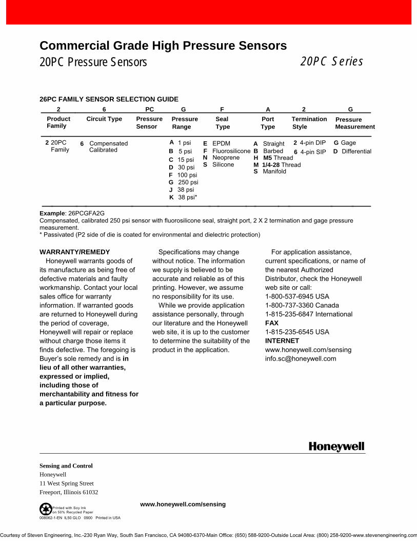
Commercial Grade High Pressure Sensors 20PC Pressure Sensors 20PC Series
Sensing and Control Honeywell 11 West Spring Street Freeport, Illinois 61032
Printed with Soy Inkon 50% Recycled Paper
008062-1-EN IL50 GLO 0900 Printed in USA
www.honeywell.com/sensing
26PC FAMILY SENSOR SELECTION GUIDE
2 6 PC G F A 2 GProductFamily
Circuit Type PressureSensor
PressureRange
SealType
PortType
TerminationStyle
PressureMeasurement
2 20PCFamily
AB
1 psi5 psi
6 CompensatedCalibrated
CDFG
15 psi30 psi100 psi250 psi
G6 4-pin SIP
M 1/4-28 ThreadS Manifold
H M5 ThreadB Barbed
Gage2 4-pin DIPD Differential
A StraightE EPDMF FluorosiliconeN NeopreneS Silicone
38 psiJ38 psi*K
Example: 26PCGFA2G Compensated, calibrated 250 psi sensor with fluorosilicone seal, straight port, 2 X 2 termination and gage pressure measurement. * Passivated (P2 side of die is coated for environmental and dielectric protection) WARRANTY/REMEDY
Honeywell warrants goods of its manufacture as being free of defective materials and faulty workmanship. Contact your local sales office for warranty information. If warranted goods are returned to Honeywell during the period of coverage, Honeywell will repair or replace without charge those items it finds defective. The foregoing is Buyer’s sole remedy and is in lieu of all other warranties, expressed or implied, including those of merchantability and fitness for a particular purpose.
Specifications may change without notice. The information we supply is believed to be accurate and reliable as of this printing. However, we assume no responsibility for its use.
While we provide application assistance personally, through our literature and the Honeywell web site, it is up to the customer to determine the suitability of the product in the application.
For application assistance, current specifications, or name of the nearest Authorized Distributor, check the Honeywell web site or call: 1-800-537-6945 USA 1-800-737-3360 Canada 1-815-235-6847 International FAX 1-815-235-6545 USA INTERNET www.honeywell.com/sensing [email protected]
Courtesy of Steven Engineering, Inc.-230 Ryan Way, South San Francisco, CA 94080-6370-Main Office: (650) 588-9200-Outside Local Area: (800) 258-9200-www.stevenengineering.com

Microstructure Pressure Sensors
24PC SMT (1 psi, 5 psi, 15 psi) 24PC SMT Series
FEATURES • Alignment pins for position
accuracy • Small package size (less than
one half the size of the 24PC) and compact surface mount profile
• 3,18 mm [0.125 in] diameter pick-up feature for use in pick and place machines
• Max peak reflow temperature of 260 °C [500 °F]
• Gage, vacuum gage, differential, wet/wet differential sensing available in one package
• True wet/wet differential sensing
• Proven elastomeric interconnections of the 20PC family
• Sensor consists of only five components
• Elastomeric construction • Wide operating temperature
range of -40 °C to 85 °C [-40 °F to 185 °F]
TYPICAL APPLICATIONS • Blood glucose monitors • Oxygen conservers • Infusion pumps • Ventilators • CPAP (Continuous Positive
Airway Pressure) equipment • Residential fuel cells
The 24PC SMT (Surface Mount Technology) Series provides a small,
low cost, high value, pressure sensing solution for use with printed circuit boards (PCBs). Based on the long established reliability and accuracy of the 24PC pressure sensor, the 24PC SMT offers reduced size with true surface mount capability. The smaller size reduces the sensor’s footprint on the PCB, thereby reducing the size of the PCB. The 24PC SMT been designed to be used with other PCB SMT components, helping to lower installation costs and eliminate secondary operations.
The sensor features Wheatstone bridge construction, silicon piezoresistive technology, and ratiometric output for proven application flexibility, design simplicity and ease of manufacture.
Although primarily designed for the medical industry, the SMT Series of pressure sensors may be applied in almost any industry that requires a surface mount pressure sensor.
WARNING PERSONAL INJURY DO NOT USE these products as safety or emergency stop devices, or in any other application where failure of the product could result in personal injury. Failure to comply with these instructions could result in death or serious injury.
WARNING MISUSE OF DOCUMENTATION • The information presented in this product sheet is for reference only.
Do not use this document as system installation information. • Complete installation, operation, and maintenance information is
provided in the instructions supplied with each product. Failure to comply with these instructions could result in death or serious injury.
Sensing and Control Courtesy of Steven Engineering, Inc.-230 Ryan Way, South San Francisco, CA 94080-6370-Main Office: (650) 588-9200-Outside Local Area: (800) 258-9200-www.stevenengineering.com

Microstructure Pressure Sensors 24PC SMT (1 psi, 5 psi, 15 psi) 24PC SMT Series 24PC SMT PERFORMANCE CHARACTERISTICS (AT 10 VDC ±0.01 VDC EXCITATION, 25 °C [77 °F]) Min. Typ. Max. Units Excitation Voltage — 10.0 12.0 Vdc Response Time — — 1.0 ms Input Resistance 4.5 k 5.0 k 5.5 k Ohm Output Resistance 4.5 k 5.0 k 5.5 k Ohm Span P2>P1(1) Min. Typ. Max. 0 to 1 25.0 45.0 65.0 mV 0 to 5 60.0 115.0 150.0 mV 0 to 15 160.0 225.0 290.0 mV Null Offset Min. Typ. Max. 0 to 1 -30.0 0 +30.0 mV 0 to 5 -30.0 0 +30.0 mV 0 to 15 -30.0 0 +30.0 mV Linearity (BFSL P2>P1) Typ. Max. 0 to 1 — ±0.15 ±0.4 % span 0 to 5 — ±0.10 ±0.2 % span 0 to 15 — ±0.10 ±0.3 % span Null Shift 25 °C to 0 °C, 25 °C to 50 °C(2) Typ. Max. 0 to 1 — ±1.0 --- mV 0 to 5 — ±1.0 --- mV 0 to 15 — ±1.0 --- mV Span Shift 25 °C to 0 °C, 25 °C to 50 °C(2) Typ. Max. 0 to 1 — ±5.0 --- % span 0 to 5 — ±5.0 --- % span 0 to 15 — ±5.0 --- % span Repeatability and Hysteresis Typ. Max. 0 to 1 — ±0.15 — % span 0 to 5 — ±0.15 — % span 0 to 15 — ±0.15 — % span Overpressure P2>P1; P1>P2 Typ. Max. 0 to 1 — — 20 psi 0 to 5 — — 20 psi 0 to 15 — — 45 psi
Notes: 1. Span is the algebraic difference between output at maximum rated operating pressures and output at 0 psi. 2. Temperature error is calculated with respect to 25 °C [77 °F].
SPECIFICATIONS Characteristic Description Storage Temperature -55 °C to 100 °C [-67 °F to 212 °F] Operating Temperature -40 °C to 85 °C [-40 °F to 185 °F] Compensated Temperature None Alignment Pins 0,86 mm [0.034 in] diameter pins extend through PCB Port Diameter 1,88 mm [0.074 in] diameter uses standard 0,59 mm [0.0625 in] ID tubing Port Orientation Parallel to PCB (low profile on board) Pick Up Feature 3,18 mm [0.125 in] feature on port cover SMT Solder • Sn 96.5 Ag 3.5 No Clean Flux
• Sn 63 Pb 37 No Clean Flux SMT Reflow Profile Max peak temperature of 260 °C [500 °F] for 10 seconds Media Compatibility Both ports are limited to media that are compatible with polyphthalamide,
fluorosilicone and silicon. Shock Qualification tested to 150 g Vibration MIL-STD-202. Method 213
(150 g half sine 11 ms) Weight 0.5 grams [0.0176 oz]
2 Honeywell • Sensing and Control
Courtesy of Steven Engineering, Inc.-230 Ryan Way, South San Francisco, CA 94080-6370-Main Office: (650) 588-9200-Outside Local Area: (800) 258-9200-www.stevenengineering.com

Microstructure Pressure Sensors 24PC SMT (1 psi, 5 psi, 15 psi) 24PC SMT Series MOUNTING DIMENSIONS mm[in] (for reference only)
6,10[0.240]
7,11[0.280]5,08
[0.200]
1,02[0.040]
3
4
2
1
10,41[0.41]
4,83[0.190]
2,74[0.108]
1,91[0.075]
5,08[0.200]
3,81[0.15]
2X 0,94[0.037]
7,87[0.31]
2X 1,40[0.055]
0,13[0.005]
0,41[0.016]
P2
P1
3,18[0.125]
2X 0,86[0.034]
2X 1,88[0.074]
SUGGESTED LAND PATTERN CIRCUIT DIAGRAM OUTPUT VOLTAGE
5,08[0.200]
2X 0,99[0.039]4X 1,83
[0.072]
6,73[0.265]
11,23[0.442]
1Vcc
2OUTPUT
A
3GND
4OUTPUT
B
Output A increases as P2 pressure increases. Output B decreases as P2 pressure increases.
Honeywell • Sensing and Control 3 Courtesy of Steven Engineering, Inc.-230 Ryan Way, South San Francisco, CA 94080-6370-Main Office: (650) 588-9200-Outside Local Area: (800) 258-9200-www.stevenengineering.com

Microstructure Pressure Sensors 24PC SMT (1 psi, 5 psi,15 psi) 24PC SMT Series DATE CODE _ _ _ _ _ _ Week: Two Digits Year: Four Digits
CATALOG LISTING NOMENCLATURE
24 PC __ SMT Package Style: SMT (Surface Mount Technology) Pressure Range: 01 = 1.0 psi 05 = 5.0 psi 15 = 15.0 psi Family: PC Type: Uncompensated
BRANDING SCHEME
4 __ F Seal: Fluorosilicone Pressure Range: 01 = 1.0 psi 05 = 5.0 psi 15 = 15.0 psi Type: Uncompensated
TECHNICAL NOTES Technical Notes that provide further application information on the 24PC SMT are available on the Honeywell web site at: http://www.honeywell.com/sensing/prodinfo/pressure/20pc WARRANTY/REMEDY
Honeywell warrants goods of its manufacture as being free of defective materials and faulty workmanship. Contact your local sales office for warranty information. If warranted goods are returned to Honeywell during the period of coverage, Honeywell will repair or replace without charge those items it finds defective. The foregoing is Buyer’s sole remedy and is in lieu of all other warranties, expressed or implied, including those of merchantability and fitness for a particular purpose.
Specifications may change without notice. The information we supply is believed to be accurate and reliable as of this printing. However, we assume no responsibility for its use.
While we provide application assistance personally, through our literature and the Honeywell web site, it is up to the customer to determine the suitability of the product in the application.
For application assistance, current specifications, or name of the nearest Authorized Distributor, check the Honeywell web site or call: 1-800-537-6945 USA 1-800-737-3360 Canada 1-815-235-6847 International FAX 1-815-235-6545 USA INTERNET www.honeywell.com/sensing [email protected]
Sensing and Control Honeywell 11 West Spring Street Freeport, Illinois 61032 008082-2-EN IL50 GLO 0803 Printed in USA
Copyright 2003 Honeywell International Inc.
www.honeywell.com/sensing
Courtesy of Steven Engineering, Inc.-230 Ryan Way, South San Francisco, CA 94080-6370-Main Office: (650) 588-9200-Outside Local Area: (800) 258-9200-www.stevenengineering.com

Microstructure Pressure Sensors 26PC SMT (1 psi, 5 psi, 15 psi) 26PC SMT Series
Sensing and Control
FEATURES • Alignment pins for position
accuracy • Small package size (less
than one half the size of the 26PC) and compact surface mount profile
• 3,18 mm [0.125 in] diameter pick-up feature for use in pick and place machines
• Max peak reflow temperature of 260 °C [500 °F]
• Gage, vacuum gage, differential, wet/wet differential sensing available in one package
• True wet/wet differential sensing
• Proven elastomeric interconnections of the 20PC family
• Temperature compensation • End point calibration • Sensor consists of only five
components • Elastomeric construction • Wide operating temperature
range of -40 °C to 85 °C [-40 °F to 185 °F]
TYPICAL APPLICATIONS • Blood glucose monitors • Oxygen conservers • Infusion pumps • Ventilators • CPAP (Continuous Positive
Airway Pressure) equipment
• Residential fuel cells
The 26PC SMT (Surface Mount Technology) Series pressure sensor, the
first offering in the 20PC SMT family of pressure sensors, is a small, low cost, high value, pressure sensing solution for use with printed circuit boards (PCBs). Based on the long established reliability and accuracy of the 26PC pressure sensor, the 26PC SMT offers reduced size with true SMT capability. The smaller size reduces the sensor’s footprint on the PCB, thereby reducing the size of the PCB. The 26PC SMT is the first pressure sensor capable of being used with other SMT components on the PCB, helping to lower installation costs and eliminate secondary operations.
The sensor features Wheatstone bridge construction, silicon piezoresistive technology, and ratiometric output for proven application flexibility, design simplicity and ease of manufacture.
Although primarily designed for the medical industry, the 20PC SMT pressure sensor may be applied in any industry that requires a surface mount pressure sensor.
WARNING PERSONAL INJURY • DO NOT USE these products as safety or emergency stop devices, or in
any other application where failure of the product could result in personal injury.
Failure to comply with these instructions could result in death or serious injury.
WARNING MISUSE OF DOCUMENTATION • The information presented in this product sheet is for reference only. Do
not use this document as system installation information. • Complete installation, operation, and maintenance information is
provided in the instructions supplied with each product. Failure to comply with these instructions could result in death or serious injury.
Courtesy of Steven Engineering, Inc.-230 Ryan Way, South San Francisco, CA 94080-6370-Main Office: (650) 588-9200-Outside Local Area: (800) 258-9200-www.stevenengineering.com

Microstructure Pressure Sensors 26PC SMT (1 psi, 5 psi, 15 psi) 26PC SMT Series
2 Honeywell • Sensing and Control www.honeywell.com/sensing
26PC SMT PERFORMANCE CHARACTERISTICS (AT 10 VDC ±0.01 VDC EXCITATION, 25 °C) Min. Typ. Max. Units Excitation Voltage — 10.0 16.0 Vdc Response Time — — 1.0 ms Input Resistance 5.5 k 7.5 k 11.5 k Ohm Output Resistance 1.5 k 2.5 k 3.0 k Ohm Span P2>P1(1) Min. Typ. Max. 0 to 1 14.7 16.7 18.7 mV 0 to 5 47 50 53 mV 0 to 15 96 100 104 mV Null Offset Min. Typ. Max. 0 to 1 -2.0 0 +2.0 mV 0 to 5 -2.0 0 +2.0 mV 0 to 15 -2.0 0 +2.0 mV Linearity (BFSL P2>P1) Typ. Max. 0 to 1 — ±0.50 ±1.75 % span 0 to 5 — ±0.50 ±1.5 % span 0 to 15 — ±0.50 ±1.0 % span Null Shift 25 °C to 0 °C, 25 °C to 50°C(2) Typ. Max. 0 to 1 — — ±1.0 mV 0 to 5 — — ±1.0 mV 0 to 15 — — ±1.0 mV Span Shift 25 °C to 0 °C, 25 °C to 50°C(2) Typ. Max. 0 to 1 — ±1.5 ±4.5 % span 0 to 5 — ±1.0 ±1.7 % span 0 to 15 — ±0.75 ±1.5 % span Repeatability and Hysteresis Typ. Max. 0 to 1 — ±0.2 — % span 0 to 5 — ±0.2 — % span 0 to 15 — ±0.2 — % span Overpressure P2>P1; P1>P2 Typ. Max. 0 to 1 — — 20 psi 0 to 5 — — 20 psi 0 to 15 — — 45 psi Notes: 1. Span is the algebraic difference between output at maximum rated operating pressures and output at 0 psi. 2. Temperature error is calculated with respect to 25 °C. SPECIFICATIONS Characteristic Description Storage Temperature -55 °C to 100 °C [-67 °F to 212 °F] Operating Temperature -40 °C to 85 °C [-40 °F to 185 °F] Compensated Temperature 0 °C to 50 °C [32 °F to 122 °F] Alignment Pins 0,86 mm [0.034 in] diameter pins extend through PCB Port Diameter 1,88 mm [0.074 in] diameter uses standard 0,59 mm [0.0625 in] ID tubing Port Orientation Parallel to PCB (low profile on board) Pick Up Feature 3,18 mm [0.125 in] feature on port cover SMT Solder • Sn 96.5 Ag 3.5 No Clean Flux
• Sn 63 Pb 37 No Clean Flux SMT Reflow Profile Max peak temperature of 260 °C [500 °F] for 10 seconds Media Compatibility Both ports are limited to media that are compatible with polyphthalamide,
fluorosilicone and silicon. Shock Qualification tested to 150 g Vibration MIL-STD-202. Method 213
(150 g half sine 11 ms) Weight 0.5 grams [0.0176 oz]
Courtesy of Steven Engineering, Inc.-230 Ryan Way, South San Francisco, CA 94080-6370-Main Office: (650) 588-9200-Outside Local Area: (800) 258-9200-www.stevenengineering.com
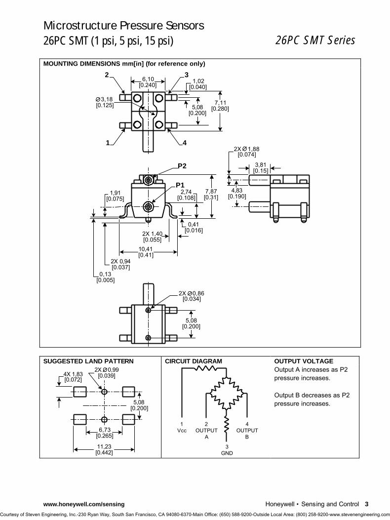
Microstructure Pressure Sensors 26PC SMT (1 psi, 5 psi, 15 psi) 26PC SMT Series
www.honeywell.com/sensing Honeywell • Sensing and Control 3
MOUNTING DIMENSIONS mm[in] (for reference only)
6,10[0.240]
7,11[0.280]5,08
[0.200]
1,02[0.040]
3
4
2
1
10,41[0.41]
4,83[0.190]
2,74[0.108]
1,91[0.075]
5,08[0.200]
3,81[0.15]
2X 0,94[0.037]
7,87[0.31]
2X 1,40[0.055]
0,13[0.005]
0,41[0.016]
P2
P1
3,18[0.125]
2X 0,86[0.034]
2X 1,88[0.074]
SUGGESTED LAND PATTERN CIRCUIT DIAGRAM OUTPUT VOLTAGE
5,08[0.200]
2X 0,99[0.039]4X 1,83
[0.072]
6,73[0.265]
11,23[0.442]
1Vcc
2OUTPUT
A
3GND
4OUTPUT
B
Output A increases as P2 pressure increases. Output B decreases as P2 pressure increases.
Courtesy of Steven Engineering, Inc.-230 Ryan Way, South San Francisco, CA 94080-6370-Main Office: (650) 588-9200-Outside Local Area: (800) 258-9200-www.stevenengineering.com

Microstructure Pressure Sensors 26PC SMT (1 psi, 5 psi,15 psi) 26PC SMT Series
Sensing and Control Honeywell 11 West Spring Street Freeport, Illinois 61032
Printed with Soy Inkon 50% Recycled Paper
008065-1-EN IL50 GLO 0601 Printed in USA
www.honeywell.com/sensing
DATE CODE _ _ _ _ _ _ Week: Two Digits Year: Four Digits
CATALOG LISTING NOMENCLATURE
26 PC __ SMT Package Style: SMT (Surface Mount Technology) Pressure Range: 01 = 1 psi 05 = 5 psi 15 = 15 psi Family: PC Type: Compensated
BRANDING SCHEME
6 __ F Seal: Fluorosilicone Pressure Range: 01 = 1 psi 05 = 5 psi 15 = 15 psi Type: Compensated
TECHNICAL NOTES Technical Notes that provide further application information on the 26PC SMT are available on the Honeywell web site at: http://www.honeywell.com/sensing/prodinfo/pressure/20pc WARRANTY/REMEDY
Honeywell warrants goods of its manufacture as being free of defective materials and faulty workmanship. Contact your local sales office for warranty information. If warranted goods are returned to Honeywell during the period of coverage, Honeywell will repair or replace without charge those items it finds defective. The foregoing is Buyer’s sole remedy and is in lieu of all other warranties, expressed or implied, including those of
merchantability and fitness for a particular purpose.
Specifications may change without notice. The information we supply is believed to be accurate and reliable as of this printing. However, we assume no responsibility for its use.
While we provide application assistance personally, through our literature and the Honeywell web site, it is up to the customer to determine the suitability of the product in the application.
For application assistance, current specifications, or name of the nearest Authorized Distributor, check the Honeywell web site or call: 1-800-537-6945 USA 1-800-737-3360 Canada 1-815-235-6847 International FAX 1-815-235-6545 USA INTERNET www.honeywell.com/sensing [email protected]
Courtesy of Steven Engineering, Inc.-230 Ryan Way, South San Francisco, CA 94080-6370-Main Office: (650) 588-9200-Outside Local Area: (800) 258-9200-www.stevenengineering.com
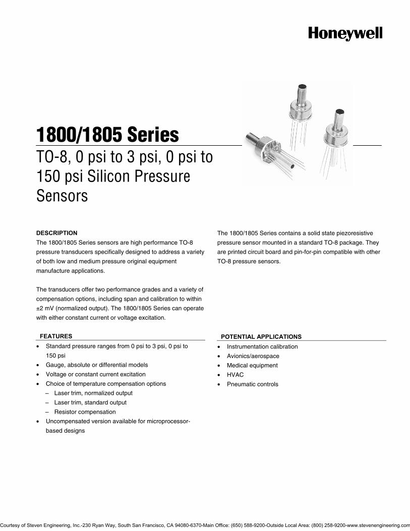
1800/1805 Series
TO-8, 0 psi to 3 psi, 0 psi to 150 psi Silicon Pressure Sensors
DESCRIPTION The 1800/1805 Series sensors are high performance TO-8
pressure transducers specifically designed to address a variety
of both low and medium pressure original equipment
manufacture applications.
The transducers offer two performance grades and a variety of
compensation options, including span and calibration to within
±2 mV (normalized output). The 1800/1805 Series can operate
with either constant current or voltage excitation.
The 1800/1805 Series contains a solid state piezoresistive
pressure sensor mounted in a standard TO-8 package. They
are printed circuit board and pin-for-pin compatible with other
TO-8 pressure sensors.
FEATURES • Standard pressure ranges from 0 psi to 3 psi, 0 psi to
150 psi
• Gauge, absolute or differential models
• Voltage or constant current excitation
• Choice of temperature compensation options
Laser trim, normalized output
Laser trim, standard output
Resistor compensation
• Uncompensated version available for microprocessor-
based designs
POTENTIAL APPLICATIONS
• Instrumentation calibration
• Avionics/aerospace
• Medical equipment
• HVAC
• Pneumatic controls
Courtesy of Steven Engineering, Inc.-230 Ryan Way, South San Francisco, CA 94080-6370-Main Office: (650) 588-9200-Outside Local Area: (800) 258-9200-www.stevenengineering.com

1800/1805 Series TO-8, 0 psi to 3 psi, 0 psi to 150 psi
2 www.honeywell.com/sensing
ENVIRONMENTAL SPECIFICATIONS (All devices) Characteristic Parameter Characteristic Parameter Supply voltage, VS 10 Vdc Insulation resistance 100 MOhm at 50 Vdc Compensated temperature range -1 °C to 54 °C [34 °F to 129 °F] Humidity 50 % ± 10 % Operating temperature tange -40 °C to 121 °C [-40 °F to 257 °F] Common-mode pressure 150 psig Vibration 10 g rms at 20 Hz to 200 Hz Max. soldering temperature 260 °C [500 °F] 10 s max. Shock 100 g for 11 ms Excitation voltage VS Supply voltage Vs =15 Vdc max. Life 100 million cycles Excitation current Supply current Is = 2 mA max. PERFORMANCE CHARACTERISTICS(1) Characteristic Min. Typ. Max. Unit Zero pressure offset(1) – – ±0.5 mV Zero pressure offset (3 psi to 5 only) (1) – – ±1 mV Full-scale span(2) Standard output–current excitation 75 – 150 mV Standard output–voltage excitation 40 – 120 mV Normalized output–current excitation 98 – 102 mV Normalized output–current excitation (3 psi only) 73 – 77 mV Normalized output–voltage excitation 38 – 42 mV Pressure non-linearity(3) – ±0.15 ±0.20 %FSS Pressure hysteresis(3) – – ±0.0125 %FSS Repeatability – – ±0.0125 %FSS Temperature effect on offset(4) – – ±0.5 mV Temperature effect on offset (3 psi and 5 psi only) (4) – – ±1 mV Temperature effect on span – – ±0.5 mV Temperature effect on span (3 psi and 5 psi only) (4) – ±1 mV Thermal hysteresis – ±0.1 – %FSS Response time(5) – – 1 ms Long term stability of offset and span(6) – – ±0.2 %FSS Common mode voltage(7) Standard output–current excitation – 50 % – input Standard output–voltage excitation – 50 % – input Normalized output–current excitation – 35 % – input Normalized output–voltage excitation – 25 % – input Input resistance – – – – Current excitation 2.0 – 8.0 kΩ Voltage excitation 8.0 – 40 kΩ Output resistance 3.5 – 6.0 kΩ
PRESSURE RANGE SPECIFICATIONS Catalog Listing Pressure Range Top Side Overpressure(8) Bottom Side Overpressure(9) 1805-00 (G,D) - (K,L) (0..4) (M,L,N) 0 psi to 3 psi 15 psi 9 psi 1805-01 (G,D) - (K,L) (0..4) (M,L,N) 0 psi to 5 psi 25 psi 15 psi 1800-02 (G,D) - (K,L) (0..4) (M,L,N) 0 psi to 10 psi 50 psi 30 psi 1800-03 (G,D) - (K,L) (0..4) (M,L,N) 0 psi to 15 psi 65 psi 45 psi 1800-07 (G,D) - (K,L) (0..4) (M,L,N) 0 psi to 30 psi 250 psi 50 psi 1800-08 (G,D) - (K,L) (0..4) (M,L,N) 0 psi to 50 psi 350 psi 50 psi 1800-09 (G,D) - (K,L) (0..4) (M,L,N) 0 psi to 100 psi 350 psi 50 psi 1800-10 (G,D) - (K,L) (0..4) (M,L,N) 0 psi to 150 psi 350 psi 50 psi
Notes: 1. Reference conditions (unless otherwise noted); TA = 25 °C [77 °F], Supply VS = 10 Vdc ±0.01 Vdc or IS = 1.5 mA ±0.0015 mA. 2. Full-scale span (FSS) is the algebraic difference between the output voltage at full-scale pressure and the output at zero pressure. FFS is
ratiometric to the supply voltage. 3. Pressure non-linearity is based on best-fit straight line from the zero to the full-scale pressure. Pressure hysteresis is the maximum output
difference at any point within the operating pressure range for increasing and decreasing pressure. 4. Maximum error band of the offset voltage or span over the compensated temperature range, relative to the 25 °C [77 °F] reading. 5. Response time for a 0 psi to full-scale span pressure step change, 10 % to 90 % rise time. 6. Long term stability over a six month period. 7. Common mode voltage as measured from output to ground. For higher levels of common mode voltage, contact the factory. 8. Pressure overrange: Top: 5 x full-scale pressure or ≤350 psi, whichever is less. 9. Pressure overrange: Bottom: 3 x full-scale or ≤50 psi, whichever is less.
Courtesy of Steven Engineering, Inc.-230 Ryan Way, South San Francisco, CA 94080-6370-Main Office: (650) 588-9200-Outside Local Area: (800) 258-9200-www.stevenengineering.com

Silicon Pressure Sensors
Honeywell Sensing and Control 3
STANDARD COMPENSATION AND TRIM CHOICES For maximum convenience, the 1800/1805 Series is temperature compensated from -1 °C to 54 °C [34 °F to 129 °F]. Other temperature ranges are available upon request. Normalized Output Option: For design convenience and sensor interchangeability, the 1800/1805 Series is available with normalized output (100 ±2 mV dc in current excited versions with pressure range >3 psi). Normalized output for current excited 3 psi devices is 75 ±2 mV dc.
Laser Trim: Compensation is accomplished by using an in-house laser trim facility that allows for tighter product performance control and improved flexibility in response to special customer performance requirements. Resistors: This option includes a printout of suggested temperature compensation and zero offset resistor values for each individual sensor.
ELECTRICAL CONNECTIONS CURRENT EXCITATION VOLTAGE EXCITATION
Pin 1 on normalized and voltage excited standard output.
Normalized output shown. Standard output on pin 5 R6 shorted.
R5 open for standard output.
EXTERNAL CONNECTIONS
POSITIVE PRESSURE ON TOP AND BOTTOM SIDES Current Excitation Standard Output Voltage Excitation Standard Output
Current or Voltage Excitation Normalized Output
Discrete Resistor Laser Trim Board Discrete Resistor Laser Trim Board Laser Trim Board Pin Connection Pin Connection Pin Connection Pin Connection Pin Connection 4 + Output 4 + Output 4 + Output 4 + Output 4 + Output 5 + Input 5 + Input 5 + Input 5 NC 5 NC 6 - Input 6 - Input 6 - Input 6 - Input 6 - Input 10 - Output 10 - Output 10 - Output 10 - Output 10 + Output 11 NC 11 NC 11 NC 11 NC 11 NC 12 NC 12 NC 12 NC 12 NC 12 NC 1 + Input 1 + Input
PRESSURE CONNECTION OPTIONS OPTION 0 OPTION 1 OPTION 2 OPTION 4
Courtesy of Steven Engineering, Inc.-230 Ryan Way, South San Francisco, CA 94080-6370-Main Office: (650) 588-9200-Outside Local Area: (800) 258-9200-www.stevenengineering.com
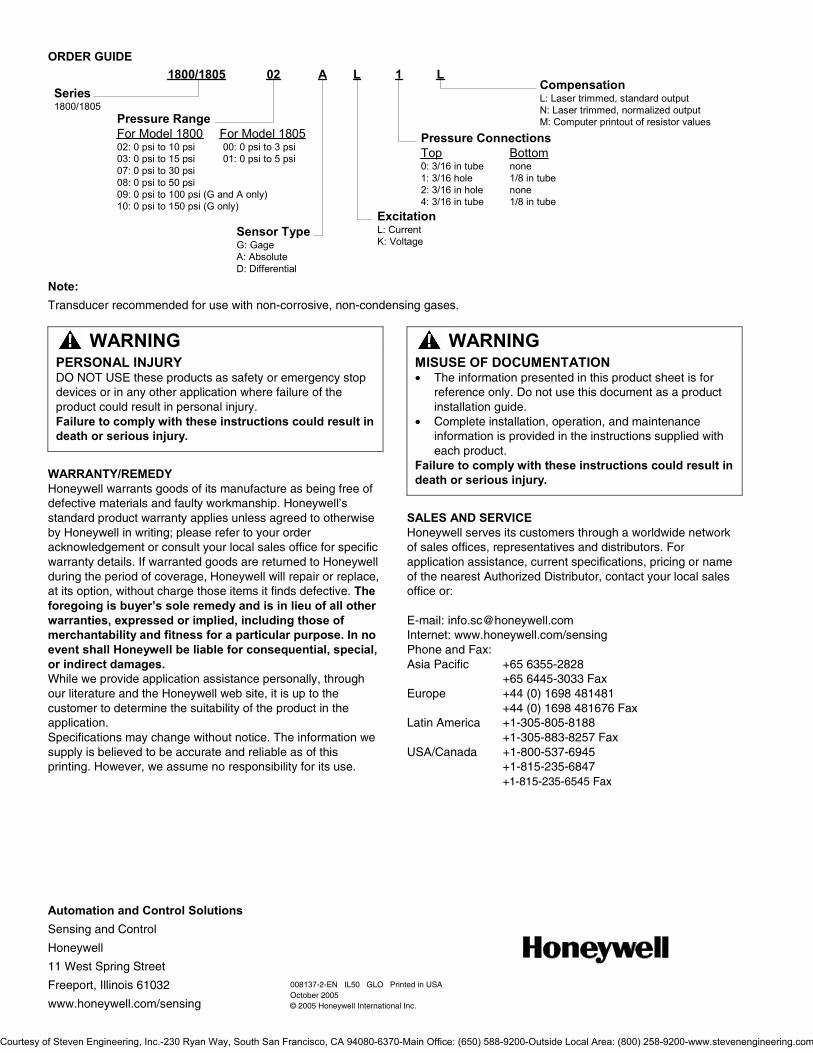
Automation and Control Solutions Sensing and Control
Honeywell
11 West Spring Street
Freeport, Illinois 61032
www.honeywell.com/sensing
008137-2-EN IL50 GLO Printed in USA October 2005 © 2005 Honeywell International Inc.
ORDER GUIDE
Series1800/1805
Pressure RangeFor Model 1800 For Model 180502: 0 psi to 10 psi 00: 0 psi to 3 psi03: 0 psi to 15 psi 01: 0 psi to 5 psi07: 0 psi to 30 psi08: 0 psi to 50 psi09: 0 psi to 100 psi (G and A only)10: 0 psi to 150 psi (G only)
Sensor TypeG: GageA: AbsoluteD: Differential
ExcitationL: CurrentK: Voltage
CompensationL: Laser trimmed, standard outputN: Laser trimmed, normalized outputM: Computer printout of resistor values
1800/1805 02 A L 1 L
Pressure ConnectionsTop Bottom0: 3/16 in tube none1: 3/16 hole 1/8 in tube2: 3/16 in hole none4: 3/16 in tube 1/8 in tube
Note: Transducer recommended for use with non-corrosive, non-condensing gases.
WARNING PERSONAL INJURY DO NOT USE these products as safety or emergency stop devices or in any other application where failure of the product could result in personal injury. Failure to comply with these instructions could result in death or serious injury.
WARRANTY/REMEDY Honeywell warrants goods of its manufacture as being free of defective materials and faulty workmanship. Honeywell’s standard product warranty applies unless agreed to otherwise by Honeywell in writing; please refer to your order acknowledgement or consult your local sales office for specific warranty details. If warranted goods are returned to Honeywell during the period of coverage, Honeywell will repair or replace, at its option, without charge those items it finds defective. The foregoing is buyers sole remedy and is in lieu of all other warranties, expressed or implied, including those of merchantability and fitness for a particular purpose. In no event shall Honeywell be liable for consequential, special, or indirect damages. While we provide application assistance personally, through our literature and the Honeywell web site, it is up to the customer to determine the suitability of the product in the application. Specifications may change without notice. The information we supply is believed to be accurate and reliable as of this printing. However, we assume no responsibility for its use.
WARNING MISUSE OF DOCUMENTATION • The information presented in this product sheet is for
reference only. Do not use this document as a product installation guide.
• Complete installation, operation, and maintenance information is provided in the instructions supplied with each product.
Failure to comply with these instructions could result in death or serious injury.
SALES AND SERVICE Honeywell serves its customers through a worldwide network of sales offices, representatives and distributors. For application assistance, current specifications, pricing or name of the nearest Authorized Distributor, contact your local sales office or: E-mail: [email protected] Internet: www.honeywell.com/sensing Phone and Fax: Asia Pacific +65 6355-2828 +65 6445-3033 Fax Europe +44 (0) 1698 481481 +44 (0) 1698 481676 Fax Latin America +1-305-805-8188 +1-305-883-8257 Fax USA/Canada +1-800-537-6945 +1-815-235-6847 +1-815-235-6545 Fax
Courtesy of Steven Engineering, Inc.-230 Ryan Way, South San Francisco, CA 94080-6370-Main Office: (650) 588-9200-Outside Local Area: (800) 258-9200-www.stevenengineering.com
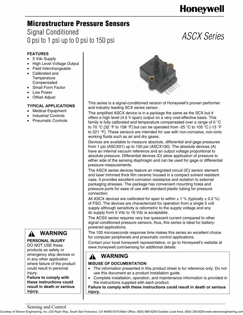
Microstructure Pressure Sensors Signal Conditioned 0 psi to 1 psi up to 0 psi to 150 psi ASCX Series FEATURES • 5 Vdc Supply • High Level Voltage Output • Field Interchangeable • Calibrated and
Temperature Compensated
• Small Form Factor • Low Power • Offset Adjust TYPICAL APPLICATIONS • Medical Equipment • Industrial Controls • Pneumatic Controls
WARNING PERSONAL INJURY DO NOT USE these products as safety or emergency stop devices or in any other application where failure of the product could result in personal injury. Failure to comply with these instructions could result in death or serious injury.
This series is a signal-conditioned version of Honeywell’s proven performer and industry leading SCX series sensor. This amplified ASCX device is in a package the same as the SCX but it offers a high level (4.5 V span) output on a very cost-effective basis. This family is fully calibrated and temperature compensated over a range of 0 °C to 70 °C [32 °F to 158 °F] but can be operated from -25 °C to 105 °C [-13 °F to 221 °F]. These sensors are intended for use with non-corrosive, non-ionic working fluids such as air and dry gases. Devices are available to measure absolute, differential and gage pressures from 1 psi (ASCX01) up to 150 psi (ASCX150). The absolute devices (A) have an internal vacuum reference and an output voltage proportional to absolute pressure. Differential devices (D) allow application of pressure to either side of the sensing diaphragm and can be used for gage or differential pressure measurements. The ASCX series devices feature an integrated circuit (IC) sensor element and laser trimmed thick film ceramic housed in a compact solvent resistant case. It provides excellent corrosion resistance and isolation to external packaging stresses. The package has convenient mounting holes and pressure ports for ease of use with standard plastic tubing for pressure connection. All ASCX devices are calibrated for span to within ± 1 % (typically ± 0.2 %) of FSO. The devices are characterized for operation from a single 5 volt supply although sensitivity is ratiometric to the supply voltage and any dc supply from 5 Vdc to 16 Vdc is acceptable. The ACSX series requires very low quiescent current compared to other signal conditioned pressure sensors, thus, this series is ideal for battery-powered applications. The 100 microseconds response time makes this series an excellent choice for computer peripherals and pneumatic control applications. Contact your local honeywell representative, or go to Honeywell’s website at www.honeywell.com/sensing for additional details.
WARNING MISUSE OF DOCUMENTATION • The information presented in this product sheet is for reference only. Do not
use this document as a product installation guide. • Complete installation, operation, and maintenance information is provided in
the instructions supplied with each product. Failure to comply with these instructions could result in death or serious injury.
Sensing and Control Courtesy of Steven Engineering, Inc.-230 Ryan Way, South San Francisco, CA 94080-6370-Main Office: (650) 588-9200-Outside Local Area: (800) 258-9200-www.stevenengineering.com

Microstructure Pressure Sensors Signal Conditioned 0 psi to 1 psi up to 0 psi to 150 psi ASCX Series PRESSURE RANGE SPECIFICATIONS
Full-Scale Span (1)
Model * Operating Pressure
Proof Pressure (2) Sensitivity (3) Min. Typ. Max.
ASCX01DN 0 psid to 1 psid 20 psid 4.5V/psi ASCX05DN 0 psid to 5 psid 20 psid 0.9V/psi
4.43 V 4.50 V 4.57 V
ASCX15AN 0 psia to 15 psia 30 psia 0.3V/psi ASCX15DN 0 psid to 15 psid 30 psid 0.3V/psi ASCX30AN 0 psia to 30 psia 60 psia 0.15V/psi ASCX30DN 0 psid to 30 psid 60 psid 0.15V/psi ASCX100AN 0 psia to 100 psia 150 psia 45mV/psi ASCX100DN 0 psid to 100 psid 150 psid 45mV/psi ASCX150AN 0 psia to 150 psia 150 psia 30mV/psi ASCX150DN 0 psid to 150 psid 150 psid 30mV/psi
4.455 V
4.50 V
4.545 V
* Ordering information: Order model number. MAXIMUM RATINGS Characteristic Description Supply Voltage (VS) 4.5 Vdc to 16 Vdc Output Current Source Sink
5 mA 3 mA
Lead Soldering Temperature (2 seconds to 4 seconds)
250 °C [482 °F]
Maximum Pressure On Any Port 150 psi Quiescent Current 4 mA PARAMETER REFERENCE CONDITIONS Model Reference Conditions Supply Voltage 5.01 ± 0.01 Vdc Reference Temperature 25 °C [77 °F] Load Condition 200 kOhm Common Mode Pressure 0 psig
ENVIRONMENTAL SPECIFICATIONS Characteristic Description (Maximum Ratings) All Devices Compensated Operating Temperature 0 °C to 70 °C [32 °F to 158 °F] Operating Temperature -25 °C to 105 °C [-13 °F to 221 °F] Storage Temperature -55 °C to 125 °C [-67 °F to 257 °F]
2 Honeywell • Sensing and Control Courtesy of Steven Engineering, Inc.-230 Ryan Way, South San Francisco, CA 94080-6370-Main Office: (650) 588-9200-Outside Local Area: (800) 258-9200-www.stevenengineering.com
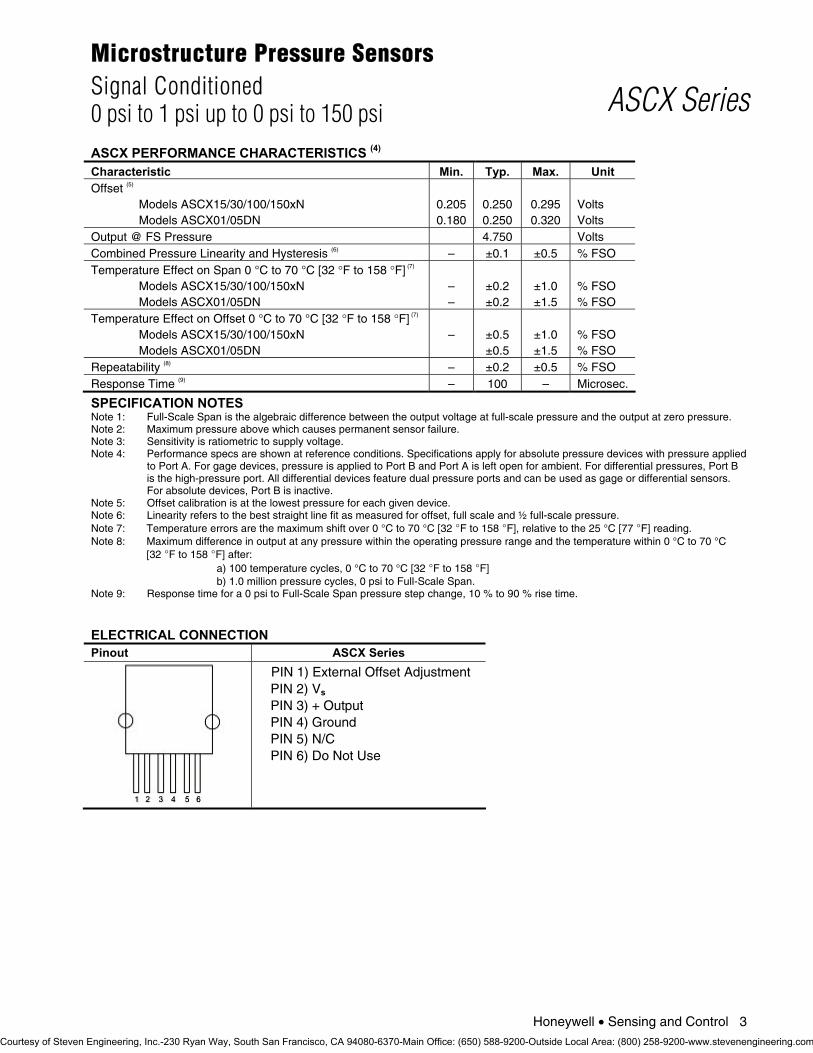
Microstructure Pressure Sensors Signal Conditioned 0 psi to 1 psi up to 0 psi to 150 psi ASCX Series ASCX PERFORMANCE CHARACTERISTICS (4) Characteristic Min. Typ. Max. Unit Offset (5)
Models ASCX15/30/100/150xN Models ASCX01/05DN
0.2050.180
0.2500.250
0.2950.320
Volts Volts
Output @ FS Pressure 4.750 Volts Combined Pressure Linearity and Hysteresis (6) – ±0.1 ±0.5 % FSO Temperature Effect on Span 0 °C to 70 °C [32 °F to 158 °F] (7)
Models ASCX15/30/100/150xN Models ASCX01/05DN
– –
±0.2 ±0.2
±1.0 ±1.5
% FSO % FSO
Temperature Effect on Offset 0 °C to 70 °C [32 °F to 158 °F] (7)
Models ASCX15/30/100/150xN Models ASCX01/05DN
–
±0.5 ±0.5
±1.0 ±1.5
% FSO % FSO
Repeatability (8) – ±0.2 ±0.5 % FSO Response Time (9) – 100 – Microsec.
SPECIFICATION NOTES Note 1: Full-Scale Span is the algebraic difference between the output voltage at full-scale pressure and the output at zero pressure. Note 2: Maximum pressure above which causes permanent sensor failure. Note 3: Sensitivity is ratiometric to supply voltage. Note 4: Performance specs are shown at reference conditions. Specifications apply for absolute pressure devices with pressure applied
to Port A. For gage devices, pressure is applied to Port B and Port A is left open for ambient. For differential pressures, Port B is the high-pressure port. All differential devices feature dual pressure ports and can be used as gage or differential sensors. For absolute devices, Port B is inactive.
Note 5: Offset calibration is at the lowest pressure for each given device. Note 6: Linearity refers to the best straight line fit as measured for offset, full scale and ½ full-scale pressure. Note 7: Temperature errors are the maximum shift over 0 °C to 70 °C [32 °F to 158 °F], relative to the 25 °C [77 °F] reading. Note 8: Maximum difference in output at any pressure within the operating pressure range and the temperature within 0 °C to 70 °C
[32 °F to 158 °F] after: a) 100 temperature cycles, 0 °C to 70 °C [32 °F to 158 °F] b) 1.0 million pressure cycles, 0 psi to Full-Scale Span. Note 9: Response time for a 0 psi to Full-Scale Span pressure step change, 10 % to 90 % rise time. ELECTRICAL CONNECTION Pinout ASCX Series
PIN 1) External Offset Adjustment PIN 2) Vs PIN 3) + Output PIN 4) Ground PIN 5) N/C PIN 6) Do Not Use
Honeywell • Sensing and Control 3 Courtesy of Steven Engineering, Inc.-230 Ryan Way, South San Francisco, CA 94080-6370-Main Office: (650) 588-9200-Outside Local Area: (800) 258-9200-www.stevenengineering.com

Microstructure Pressure Sensors Signal Conditioned 0 psi to 1 psi up to 0 psi to 150 psi
ASCX Series PHYSICAL DIMENSIONS for Reference Only (mm/in)
WARRANTY/REMEDY Honeywell warrants goods of its manufacture as being free of defective materials and faulty workmanship. Contact your local sales office for warranty information. If warranted goods are returned to Honeywell during the period of coverage, Honeywell will repair or replace without charge those items it finds defective. The foregoing is Buyer’s sole remedy and is in lieu of all other warranties, expressed or implied, including those of merchantability and fitness for a particular purpose. Specifications may change without notice. The information we supply is believed to be accurate and reliable as of this printing. However, we assume no responsibility for its use.
While we provide application assistance personally, through our literature and the Honeywell web site, it is up to the customer to determine the suitability of the product in the application. For application assistance, current specifications, or name of the nearest Authorized Distributor, contact a nearby sales office. Or call: 1-800-537-6945 USA/Canada 1-815-235-6847 International FAX 1-815-235-6545 USA INTERNET www.honeywell.com/sensing [email protected]
Sensing and Control www.honeywell.com/sensing Honeywell 11 West Spring Street Freeport, Illinois 61032 008104-1-EN IL50 GLO 1203 Printed in USA Copyright 2003 Honeywell International Inc. All Rights Reserved
Courtesy of Steven Engineering, Inc.-230 Ryan Way, South San Francisco, CA 94080-6370-Main Office: (650) 588-9200-Outside Local Area: (800) 258-9200-www.stevenengineering.com

ASDX Series
Pressure Sensors 0 psi to 1 psi through 0 psi to 30 psi
DESCRIPTION
The ASDX Series is an amplified version of Honeywell’s
proven performer and industry leading SDX Series sensor. The
ASDX sensor’s footprint is slightly larger than the SDX;
however, it offers a high level output (4.0 Vdc span) on a very
cost-effective basis. This series is fully calibrated and
temperature compensated with on-board Application Specific
Integrated Circuitry (ASIC).
These DIP (Dual In-line Package) sensors are designed for
use with non-corrosive, non-ionic working fluids; such as air
and dry gases.
Sensors are available to measure absolute, differential and
gage pressures. The absolute sensors have an internal
vacuum reference and an output voltage proportional to
absolute pressure. The differential sensors allow application of
pressure to either side of the sensing diaphragm and may used
for differential or gage measurements. Bidirectional versions
are also available.
All ASDX Series sensors are accurate to within ±2.0% full
scale and are designed for operation from a single 5.0 Vdc
supply.
FEATURES
• ASIC-enhanced output
• Wide compensated temperature range 0 °C to 85 °C
[32 °F to 185 °F]
• Available in absolute, differential and gage types
• Pressure ranges from 0 psi to 1 psi through 0 psi to 30 psi
• Accuracy ±2.0% max. V full scale
• Quantization step of 3 mV
• Response time of 8 ms
POTENTIAL APPLICATIONS
• Flow calibrators
• Ventilation and air flow monitors
• Gas flow instrumentation
• Dialysis equipment
• Sleep apnea monitoring and therapy equipment
• Barometry
• HVAC controls
• Pneumatic controls
Courtesy of Steven Engineering, Inc.-230 Ryan Way, South San Francisco, CA 94080-6370-Main Office: (650) 588-9200-Outside Local Area: (800) 258-9200-www.stevenengineering.com

ASDX Series
2 www.honeywell.com/sensing
TABLE 1. GENERAL SPECIFICATIONS Supply voltage (Vs)(1) 4.75 Vdc to 5.25 Vdc Maximum supply voltage(1) 6.50 Vdc (max.) Consumption current 6 mA (typ.) Output current (sink) 2 mA (max.) Output current (source) 2 mA (max.) Lead temperature 2 s to 4 s at 250 °C [482 °F] Compensated temp. range 0 °C to 85 °C [32 °F to 185 °F] Operating temp. range -20 °C to 105 °C [-4 °F to 221 °F] Storage temp. range -40 °C to 125 °C [-40 °F to 257 °F] Vibration 10 g at 20 Hz to 2000 Hz Shock 100 g for 11 ms Life 1 million cycles minimum
Note: 1. The sensor is not reverse polarity protected. Incorrect application of excitation voltage or ground to the wrong pin can cause electrical failure. Application of supply
voltage above the maximum can cause electrical failure.
TABLE 2. PRESSURE RANGE SPECIFICATIONS
Catalog Listing Pressure Range Burst Pressure(1) Sensitivity ASDX001 0 psi to 1 psi 5 psi 4.00 V/psi ASDX005 0 psi to 5 psi 20 psi 0.80 V/psi ASDX015 0 psi to 15 psi 30 psi 0.267 V/psi ASDX030 0 psi to 30 psi 60 psi 0.133 V/psi
Note: 1. If the maximum burst pressure is exceeded, even momentarily, the package may leak or burst, or the pressure sensing die may fracture.
TABLE 3. PERFORMANCE SPECIFICATIONS(1)
Characteristic Symbol Min. Typ. Max. Unit Note Zero pressure offset Voff 0.420 0.500 0.580 Vdc – Full scale span Vfss 4.00 – Vdc 2 Output at FS pressure Vfso 4.420 4.500 4.580 Vdc – Accuracy – – – ±2.0 %V 3 Response time – – 8 – ms 4 Quantization step – – 3 – mV 5
Notes: 1. Reference conditions (unless otherwise noted): Supply voltage, V
S=5.0 ±0.01 Vdc; T
A=25 °C [77 °F]. Output is ratiometric within the supply voltage range (Vs).
2. Span is the algebraic difference between the output voltage at the specified pressure and the output at zero pressure. Span is ratiometric to the supply voltage. 3. Accuracy is the combined errors from offset and span calibration, linearity, pressure hysteresis, and temperature effects. Linearity is the measured deviation based on
a straight line. Hysteresis is the maximum output difference at any point within the operating pressure range for increasing and decreasing pressure. Calibration errors include the deviation of offset and full scale from nominal values.
4. Response time for a 0 psi to full-scale pressure step change, 10% to 90% rise time. 5. The smallest change in the output voltage, given any change in pressure.
FIGURE 1. BLOCK DIAGRAM
Note: 1. 220 nF capacitor is required between +Vs and GND. 15 nF capacitor between Vout and ground is optional.
Courtesy of Steven Engineering, Inc.-230 Ryan Way, South San Francisco, CA 94080-6370-Main Office: (650) 588-9200-Outside Local Area: (800) 258-9200-www.stevenengineering.com
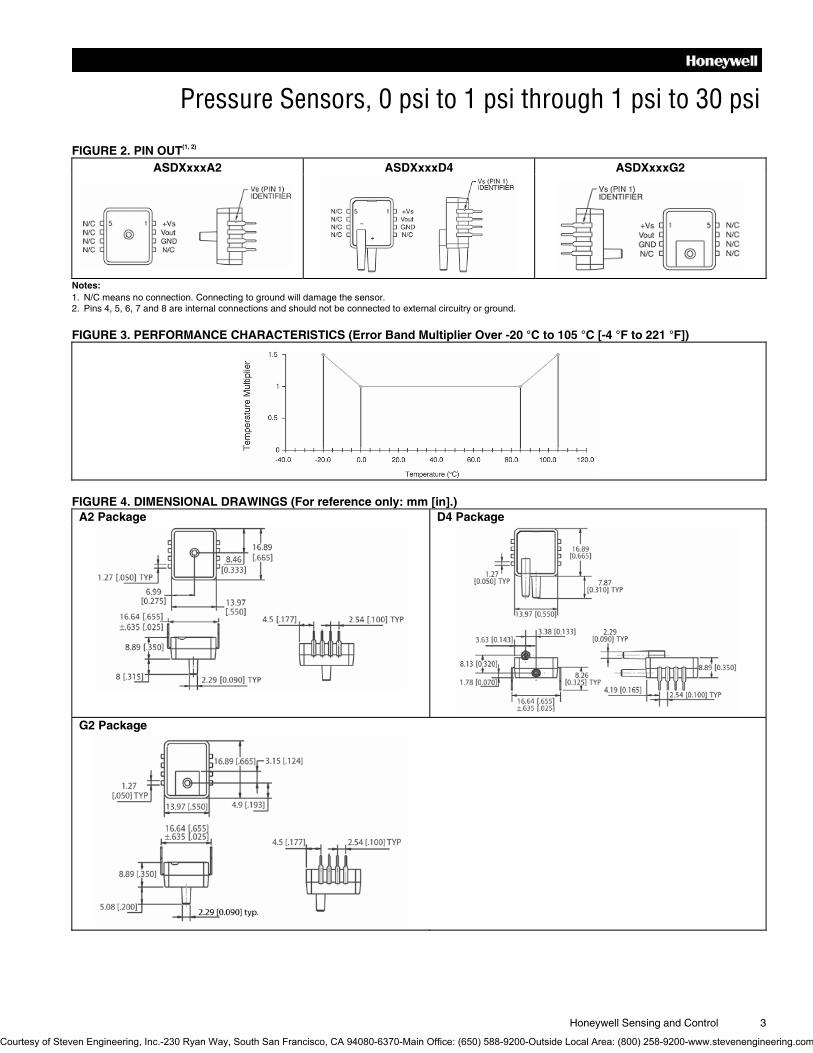
Pressure Sensors, 0 psi to 1 psi through 1 psi to 30 psi
Honeywell Sensing and Control 3
FIGURE 2. PIN OUT(1, 2) ASDXxxxA2 ASDXxxxD4 ASDXxxxG2
Notes: 1. N/C means no connection. Connecting to ground will damage the sensor. 2. Pins 4, 5, 6, 7 and 8 are internal connections and should not be connected to external circuitry or ground. FIGURE 3. PERFORMANCE CHARACTERISTICS (Error Band Multiplier Over -20 °C to 105 °C [-4 °F to 221 °F])
FIGURE 4. DIMENSIONAL DRAWINGS (For reference only: mm [in].)
A2 Package D4 Package
G2 Package
Courtesy of Steven Engineering, Inc.-230 Ryan Way, South San Francisco, CA 94080-6370-Main Office: (650) 588-9200-Outside Local Area: (800) 258-9200-www.stevenengineering.com

Sensing and Control
Honeywell
1985 Douglas Drive North
Golden Valley, Minnesota 55422
www.honeywell.com/sensing
008090-5-EN IL50 GLO Printed in USA December 2007 Copyright © 2007 Honeywell International Inc. All rights reserved.
FIGURE 5. NOMENCLATURE TREE
ORDER GUIDE
Absolute Catalog LIsting
Differential(1)
Catalog LIsting Gage
Catalog Listing Bidirectional
Catalog Listing Pressure Range
– ASDX001D44R ASDX001G24R ASDX001D44D 0 psi to 1 psi – ASDX005D44R ASDX005G24R ASDX005D44D 0 psi to 5 psi
ASDX015A24R ASDX015D44R ASDX015G24R ASDX015D44D 0 psi to 15 psi ASDX030A24R ASDX030D44R ASDX030G24R ASDX030D44D 0 psi to 30 psi
Note: 1. May also be used in gage applications.
WARNING PERSONAL INJURY DO NOT USE these products as safety or emergency stop devices or in any other application where failure of the product could result in personal injury. Failure to comply with these instructions could result in death or serious injury.
WARRANTY/REMEDY Honeywell warrants goods of its manufacture as being free of defective materials and faulty workmanship. Honeywell’s standard product warranty applies unless agreed to otherwise by Honeywell in writing; please refer to your order acknowledgement or consult your local sales office for specific warranty details. If warranted goods are returned to Honeywell during the period of coverage, Honeywell will repair or replace, at its option, without charge those items it finds defective. The foregoing is buyer’s sole remedy and is in lieu of all other warranties, expressed or implied, including those of merchantability and fitness for a particular purpose. In no event shall Honeywell be liable for consequential, special, or indirect damages. While we provide application assistance personally, through our literature and the Honeywell web site, it is up to the customer to determine the suitability of the product in the application. Specifications may change without notice. The information we supply is believed to be accurate and reliable as of this printing. However, we assume no responsibility for its use.
WARNING MISUSE OF DOCUMENTATION • The information presented in this product sheet is for
reference only. Do not use this document as a product installation guide.
• Complete installation, operation, and maintenance information is provided in the instructions supplied with each product.
Failure to comply with these instructions could result in death or serious injury.
SALES AND SERVICE Honeywell serves its customers through a worldwide network of sales offices, representatives and distributors. For application assistance, current specifications, pricing or name of the nearest Authorized Distributor, contact your local sales office or: E-mail: [email protected] Internet: www.honeywell.com/sensing Phone and Fax: Asia Pacific +65 6355-2828; +65 6445-3033 Fax Europe +44 (0) 1698 481481; +44 (0) 1698 481676 Fax Latin America +1-305-805-8188; +1-305-883-8257 Fax USA/Canada +1-800-537-6945; +1-815-235-6847 +1-815-235-6545 Fax
Courtesy of Steven Engineering, Inc.-230 Ryan Way, South San Francisco, CA 94080-6370-Main Office: (650) 588-9200-Outside Local Area: (800) 258-9200-www.stevenengineering.com

ASDX DO Series
Digital Output Pressure Sensors 0 psi to 1 psi through 0 psi to 30 psi
DESCRIPTION The ASDX DO Series pressure sensors are fully calibrated and temperature compensated with on-board Application Specific Integrated Circuitry (ASIC). These DIP (Dual In-line Package) sensors provide digital correction of sensor offset, sensitivity, temperature coefficients and non-linearity and are designed for use with non-corrosive, non-ionic working fluids such as air and dry gases. The ASDX DO Series uses I2C-compatible protocol, which allows easy interfacing to most commonly used microcontrollers and microprocessors, without additional components and electronic circuitry.
The 2-wire I2C interface has a Serial Clock Line (SCL) input and serial digital output data line. Sensor output is a corrected pressure value in hexadecimal format with 12-bit resolution. Sensors are available to measure absolute, differential and gage pressures. The absolute versions have an internal vacuum reference and an output voltage proportional to absolute pressure. Differential versions allow application of pressure to either side of the sensing diaphragm and may be used for differential or gage measurements. All ASDX DO Sensors are accurate to within ±2.0% full scale and are designed for operation from a single 5 Vdc supply.
FEATURES
• I2C-compatible protocol
• ASIC-enhanced output
• Calibrated and temperature-compensated output
• Wide compensated temperature range 0 °C to 85 °C
[32 °F to 185 °F]
• Available in absolute, differential and gage types
• Pressure ranges from 0 psi to 1 psi through
0 psi to 30 psi
• Response time of 8 ms
POTENTIAL APPLICATIONS
• Flow calibrators
• Ventilation and air flow monitors
• Gas flow instrumentation
• Dialysis equipment
• Sleep apnea monitoring and therapy equipment
• Barometry
• HVAC controls
• Pneumatic controls
Courtesy of Steven Engineering, Inc.-230 Ryan Way, South San Francisco, CA 94080-6370-Main Office: (650) 588-9200-Outside Local Area: (800) 258-9200-www.stevenengineering.com

ASDX DO Series
2 www.honeywell.com/sensing
TABLE 1. GENERAL SPECIFICATIONS Characteristic Parameter Characteristic Parameter Supply voltage (Vs)(1) 4.75 Vdc to 5.25 Vdc Compensated temp. range 0 °C to 85 °C [32 °F to 185 °F] Maximum supply voltage(1) 6.50 Vdc (max.) Operating temp. range -20 °C to 105 °C [-4 °F to 221 °F] Consumption current 6 mA (typ.) Storage temp. range -40 °C to 125 °C [-40 °F to 257 °F]Output current (sink) 2 mA (max.) Vibration 10 g at 20 Hz to 2000 Hz Output current (source) 2 mA (max.) Shock 100 g for 11 ms Lead soldering temperature 2 s to 4 s at 250 °C [482 °F] Life 1 million cycles minimum
Note: 1. The sensor is not reverse polarity protected. Incorrect application of excitation voltage or ground to the wrong pin can cause electrical failure. Application of supply
voltage above the maximum can cause electrical failure.
TABLE 2. PERFORMANCE CHARACTERISTICS Characteristic Symbol Min. Typ. Max. Unit Note 4R DO 1, 2
Zero pressure offset Hoff 158 19A 1DB counts hex – Full scale span (FSS) Hfss – CCC – counts hex 3 Output at full scale pressure Hfso E25 E66 EA8 counts hex – Accuracy – – – ±2.0 %H full scale 4 Response time – – 8 11 ms 5
4R DO 1, 2 Zero pressure offset Hoff 7BE 800 841 counts hex – Full scale span (FSS) Hfss – CCC – counts hex 3 Output at full scale pressure (P2) Hfso E25 E66 EB8 counts hex 6 Output at full scale pressure (P1) Hfso 158 19A 1DB counts hex 6 Accuracy – – – ±2.0 % FSS 4 Output resolution – – 12 – bit – Response time – – 8 11 ms 5
Notes: 1. Reference conditions (unless otherwise noted): supply voltage, V
S=5.0 ±0.01 Vdc, Ta=25 °C [77 °F].
2. Read operation: Start, Slave Address, R/W =1, Data Byte 1 (MSB), Ackn Bit, Data Byte 2 (LSB). The output is corrected pressure as unsigned 12 bits. Slave Address is F0h.
Acknowledge Bit - pull data line LOW, master generates an extra clock pulse for this purpose.
3. Span is the algebraic difference between the output voltage at the specified high pressure and the output at lowest pressure. Span is ratiometric to the supply voltage. 4. Accuracy is the combined errors from offset and span calibration, linearity, pressure hysteresis, and temperature effects. Calibration errors include the deviation of
offset and full scale from nominal values Linearity is the measured deviation based on a straight line. Hysteresis is the maximum output difference at any point within the operating pressure range for increasing and decreasing pressure and temperature.
5. Response time for 0 PSI to full scale pressure step change, 10% to 90% rise time. 6. Sensor output when maximum positive pressure is applied on the back side (P2) or the front side (P1) of the sensing element.
TABLE 3. PRESSURE RANGE SPECIFICATIONS
Catalog Listing Pressure Range Burst Pressure(1) ASDX001xxxx-DO 0 psi to 1 psi 5 psi ASDX005xxxx-DO 0 psi to 5 psi 20 psi ASDX015xxxx-DO 0 psi to 15 psi 30 psi ASDX030xxxx-DO 0 psi to 30 psi 60 psi
Note: 1. If maximum burst pressure is exceeded, even momentarily, the package may leak or burst, or the pressure sensing die may fracture. FIGURE 1. PERFORMANCE CHARACTERISTICS (Error Band Multiplier Over -20 °C to 105 °C [-4 °F to 221 °F])
FIGURE 2. SERIAL INTERFACE TIMING CHARACTERISTICS
Courtesy of Steven Engineering, Inc.-230 Ryan Way, South San Francisco, CA 94080-6370-Main Office: (650) 588-9200-Outside Local Area: (800) 258-9200-www.stevenengineering.com

Digital Output Pressure Sensors, 0 psi to 1 psi thru 0 psi to 30 psi
Honeywell Sensing and Control 3
FIGURE 3. PINOUT(1, 2) ASDXxxxA2DO ASDXxxxD4DO ASDXxxxG2DO
Notes: 1. N/C means no connection. Connecting to ground will damage the sensor. 2. Pin 6 must be left open.
TABLE 4. SERIAL INTERFACE PARAMETERS Parameter Symbol Condition Min. Typ. Max. Unit Input high level VIH – 4.5 – 1 Vs Input low level VIL – 0 – 0.5 Vs Output low level VOL open drain IOL = -4 mA – – 0.1 Vs Pull up current VOH pin SCL and SDA 5 – 20 µA Load capacitance SDA CLSDA – – – 400 pF SCL clock frequency fSCL – – – 100 kHz Bus free time between STOP and START condition
tBUF – 4.7 – – µs
Hold time (repeated) START condition tHD, STA to first clock pulse 4.0 – – µs LOW period of SCL tLOW – 4.7 – – µs High period of SCL tHIGH – 4.0 – – µs Setup time repeated START condition tSU, STA – 4.7 – – µs Data hold time tHD, DAT – 0 – – ns Data setup time tSU, DAT – 250 – – ns Rise time of both SDA and SCL tR – – – 300 ns Fall time of both SDA and SCL tF – – – 300 ns Setup time for STOP condition tSU, STO – 4 – – µs
Input filter spike suppression tsp spikes on SDA or SCL of
that length are suppressed
– – 50 µs
FIGURE 4. DIMESIONAL DRAWING (For reference only: mm [in].)
A2 Package D4 Package
G2 Package FIGURE 5. BLOCK DIAGRAM
Note: 1. 220 nF capacitor is required between +Vs and GND.
Courtesy of Steven Engineering, Inc.-230 Ryan Way, South San Francisco, CA 94080-6370-Main Office: (650) 588-9200-Outside Local Area: (800) 258-9200-www.stevenengineering.com
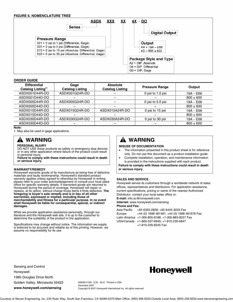
Sensing and Control
Honeywell
1985 Douglas Drive North
Golden Valley, Minnesota 55422
www.honeywell.com/sensing
008095-5-EN IL50 GLO Printed in USA December 2007 Copyright © 2007 Honeywell International Inc. All rights reserved.
FIGURE 6. NOMENCLATURE TREE
ORDER GUIDE
Differential Catalog Listing(1)
Gage Catalog Listing
Absolute Catalog Listing
Pressure Range Output
ASDX001D44R-DO ASDX001G24R-DO – 0 psi to 1.0 psi 19A − E66 ASDX001D44D-DO – – – 800 ± 600 ASDX005D44R-DO ASDX005G24R-DO – 0 psi to 5.0 psi 19A − E66 ASDX005D44D-DO – – – 800 ± 600 ASDX015D44R-DO ASDX015G24R-DO ASDX015A24R-DO 0 psi to 15 psi 19A − E66 ASDX015D44D-DO – – – 800 ± 600 ASDX030D44R-DO ASDX030G24R-DO ASDX030A24R-DO 0 psi to 30 psi 19A − E66 ASDX030D44D-DO – – – 800 ± 600
Note: 1. May also be used in gage applications.
WARNING PERSONAL INJURY DO NOT USE these products as safety or emergency stop devices or in any other application where failure of the product could result in personal injury. Failure to comply with these instructions could result in death or serious injury.
WARRANTY/REMEDY Honeywell warrants goods of its manufacture as being free of defective materials and faulty workmanship. Honeywell’s standard product warranty applies unless agreed to otherwise by Honeywell in writing; please refer to your order acknowledgement or consult your local sales office for specific warranty details. If warranted goods are returned to Honeywell during the period of coverage, Honeywell will repair or replace, at its option, without charge those items it finds defective. The foregoing is buyer’s sole remedy and is in lieu of all other warranties, expressed or implied, including those of merchantability and fitness for a particular purpose. In no event shall Honeywell be liable for consequential, special, or indirect damages. While we provide application assistance personally, through our literature and the Honeywell web site, it is up to the customer to determine the suitability of the product in the application. Specifications may change without notice. The information we supply is believed to be accurate and reliable as of this printing. However, we assume no responsibility for its use.
WARNING MISUSE OF DOCUMENTATION • The information presented in this product sheet is for reference
only. Do not use this document as a product installation guide. • Complete installation, operation, and maintenance information
is provided in the instructions supplied with each product. Failure to comply with these instructions could result in death or serious injury.
SALES AND SERVICE Honeywell serves its customers through a worldwide network of sales offices, representatives and distributors. For application assistance, current specifications, pricing or name of the nearest Authorized Distributor, contact your local sales office or: E-mail: [email protected] Internet: www.honeywell.com/sensing Phone and Fax: Asia Pacific +65 6355-2828; +65 6445-3033 Fax Europe +44 (0) 1698 481481; +44 (0) 1698 481676 Fax Latin America +1-305-805-8188; +1-305-883-8257 Fax USA/Canada +1-800-537-6945; +1-815-235-6847 +1-815-235-6545 Fax
Courtesy of Steven Engineering, Inc.-230 Ryan Way, South San Francisco, CA 94080-6370-Main Office: (650) 588-9200-Outside Local Area: (800) 258-9200-www.stevenengineering.com
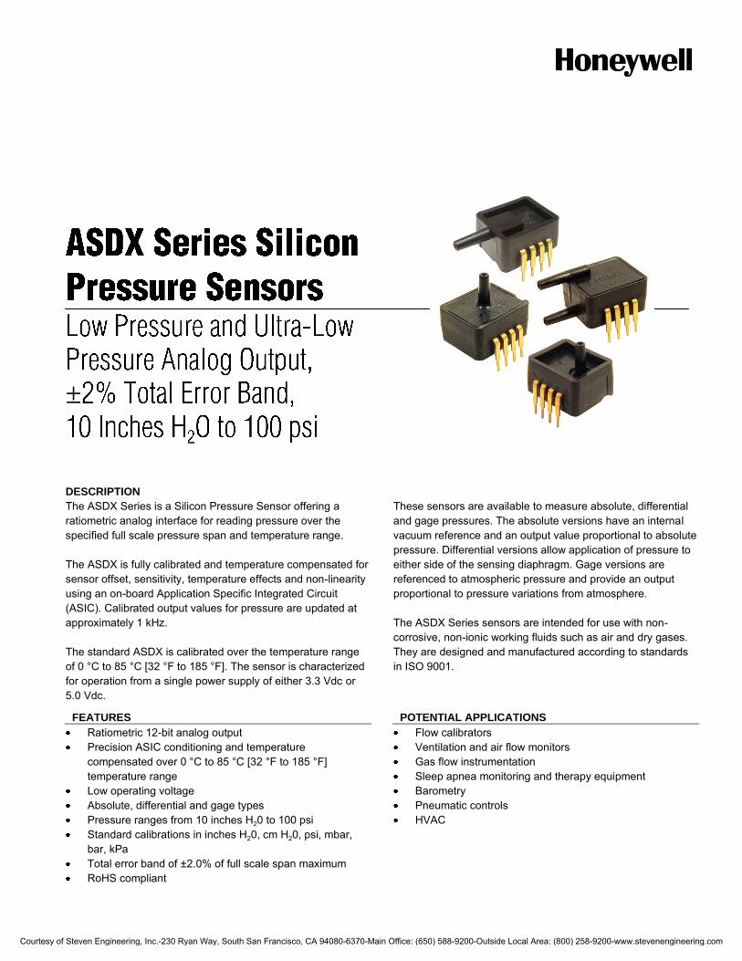
±
DESCRIPTION The ASDX Series is a Silicon Pressure Sensor offering a ratiometric analog interface for reading pressure over the specified full scale pressure span and temperature range. The ASDX is fully calibrated and temperature compensated for sensor offset, sensitivity, temperature effects and non-linearity using an on-board Application Specific Integrated Circuit (ASIC). Calibrated output values for pressure are updated at approximately 1 kHz. The standard ASDX is calibrated over the temperature range of 0 °C to 85 °C [32 °F to 185 °F]. The sensor is characterized for operation from a single power supply of either 3.3 Vdc or 5.0 Vdc.
These sensors are available to measure absolute, differential and gage pressures. The absolute versions have an internal vacuum reference and an output value proportional to absolute pressure. Differential versions allow application of pressure to either side of the sensing diaphragm. Gage versions are referenced to atmospheric pressure and provide an output proportional to pressure variations from atmosphere. The ASDX Series sensors are intended for use with non-corrosive, non-ionic working fluids such as air and dry gases. They are designed and manufactured according to standards in ISO 9001.
FEATURES Ratiometric 12-bit analog output Precision ASIC conditioning and temperature
compensated over 0 °C to 85 °C [32 °F to 185 °F] temperature range
Low operating voltage Absolute, differential and gage types Pressure ranges from 10 inches H20 to 100 psi Standard calibrations in inches H20, cm H20, psi, mbar,
bar, kPa Total error band of ±2.0% of full scale span maximum RoHS compliant
POTENTIAL APPLICATIONS Flow calibrators Ventilation and air flow monitors Gas flow instrumentation Sleep apnea monitoring and therapy equipment Barometry Pneumatic controls HVAC
Courtesy of Steven Engineering, Inc.-230 Ryan Way, South San Francisco, CA 94080-6370-Main Office: (650) 588-9200-Outside Local Area: (800) 258-9200-www.stevenengineering.com

2 www.honeywell.com/sensing
Table 1. Absolute Maximum Ratings1 Parameter Min Max Unit Supply voltage (Vsupply) -0.3 6.0 Vdc Voltage to any pin -0.3 Vsupply + 0.3 Vdc ESD susceptibility (human body model) 3 kV Storage temperature -50 [-58] 125 [257] °C [°F] Lead temperature (2 s to 4 s) 250 [482] °C [°F] External capacitance between Vsupply and ground2 100 470 nF
Table 2. Operating Specifications
Parameter Min. Typ. Max. Unit Supply voltage: (Vsupply)3 3.3 Vdc 5.0 Vdc Sensors are either 3.3 Vdc or 5.0 Vdc per the order guide (see Figure 1).
3.0
4.75
3.34
5.04
3.6
5.25 Vdc
Supply current 1.5 2.5 3.5 mA Compensated temperature range5 0 [32] 85 [185] °C [°F] Operating temperature range6 -20 [-4] 105 [221] °C [°F] Overpressure7 2X operating pressure range minimum Burst pressure8 3X operating pressure range minimum Startup time (power up to data ready) - 5 ms Response time 1.0 ms Upper output clipping limit 97.5 - Vsupply Lower output clipping limit - 2.5 Vsupply Minimum load resistance 5.0 kOhm Total error band9 2.0 %FSS10 Output resolution 12 bits
Table 3. Environmental Specifications
Parameter Characteristic Humidity 0% to 95% RH non-condensing Vibration 10 G at 20 Hz to 2000 Hz Shock 100 G for 11 ms Life 1 million cycles minimum
Table 4. Wetted Materials11
Parameter Port 1 (Pressure Port)12 Port 2 (Reference Port)12 Covers glass-filled PBT glass-filled PBT Adhesives silicone silicone and epoxy Electronic components silicon and glass silicon, glass, and gold
Notes: 1. Absolute maximum ratings are the extreme limits that the device will withstand without damage to the device. 2. An external bypass capacitor is required across the supply voltage (Pins 1 and 3 – see Figure 4) as close to the sensor supply pin as possible
for correct sensor operation. 3. Ratiometricity of the sensor (the ability of the output to scale to the input voltage) is achieved within the specified operating voltage for each
option. Other custom supply voltages are available, please contact Honeywell Customer Service. 4. The sensor is not reverse polarity protected. Incorrect application of excitation voltage or ground to the wrong pin may cause electrical failure. 5. The compensated temperature range is the temperature range (or ranges) over which the sensor will produce an output proportional to
pressure within the specified performance limits. 6. The operating temperature range is the temperature range over which the sensor will produce an output proportional to pressure but may not
remain within the specified performance limits. 7. Overpressure is the maximum pressure which may safely be applied to the product for it to remain in specification once pressure is returned to
the operating pressure range. Exposure to higher pressures may cause permanent damage to the product. 8. Burst pressure is the maximum pressure that may be applied to any port of the product without causing escape of pressure media. Product
should not be expected to function after exposure to any pressure beyond the burst pressure. 9. Total error band is the maximum deviation in output from ideal transfer function over the entire compensated temperature and pressure range.
Includes all errors due to offset, full scale span, pressure non-linearity, pressure hysteresis, repeatability, thermal effect on offset, thermal effect on span and thermal hysteresis. Specification units are in percent of full scale span (%FSS).
10. Full scale span (FSS) is the algebraic difference between the output signal measured at the maximum (Pmax.) and minimum (Pmin.) limits of the pressure range.
11. Consult Honeywell Customer Service for detailed material information. 12. For AC pressure port configuration, the “pressure” and “reference” ports are reversed.
Courtesy of Steven Engineering, Inc.-230 Ryan Way, South San Francisco, CA 94080-6370-Main Office: (650) 588-9200-Outside Local Area: (800) 258-9200-www.stevenengineering.com
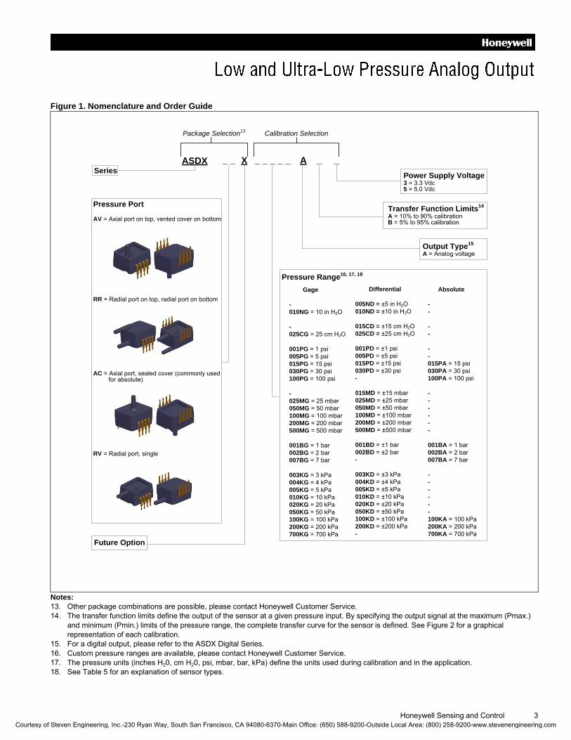
Honeywell Sensing and Control 3
Figure 1. Nomenclature and Order Guide
ASDX _ _ _ _ _ _ _ A _Power Supply Voltage3 = 3.3 Vdc5 = 5.0 Vdc
Package Selection13
Calibration Selection
Series
Pressure Port
AV = Axial port on top, vented cover on bottom
RR = Radial port on top, radial port on bottom
AC = Axial port, sealed cover (commonly used for absolute)
RV = Radial port, single
Gage
- 010NG = 10 in H2O
-025CG = 25 cm H2O
001PG = 1 psi005PG = 5 psi015PG = 15 psi030PG = 30 psi100PG = 100 psi
-025MG = 25 mbar050MG = 50 mbar100MG = 100 mbar200MG = 200 mbar500MG = 500 mbar
001BG = 1 bar002BG = 2 bar007BG = 7 bar
003KG = 3 kPa 004KG = 4 kPa005KG = 5 kPa010KG = 10 kPa020KG = 20 kPa050KG = 50 kPa100KG = 100 kPa200KG = 200 kPa700KG = 700 kPa
Differential
005ND = ±5 in H2O010ND = ±10 in H2O
015CD = ±15 cm H2O025CD = ±25 cm H2O
001PD = ±1 psi005PD = ±5 psi015PD = ±15 psi030PD = ±30 psi-
015MD = ±15 mbar025MD = ±25 mbar050MD = ±50 mbar100MD = ±100 mbar200MD = ±200 mbar500MD = ±500 mbar
001BD = ±1 bar002BD = ±2 bar-
003KD = ±3 kPa004KD = ±4 kPa005KD = ±5 kPa010KD = ±10 kPa020KD = ±20 kPa050KD = ±50 kPa100KD = ±100 kPa200KD = ±200 kPa-
Absolute
- -
- - --015PA = 15 psi030PA = 30 psi100PA = 100 psi
------
001BA = 1 bar002BA = 2 bar007BA = 7 bar
------100KA = 100 kPa200KA = 200 kPa700KA = 700 kPa
Pressure Range16, 17, 18
Transfer Function Limits14
A = 10% to 90% calibrationB = 5% to 95% calibration
Output Type15
A = Analog voltage
_
Future Option
X
Notes: 13. Other package combinations are possible, please contact Honeywell Customer Service. 14. The transfer function limits define the output of the sensor at a given pressure input. By specifying the output signal at the maximum (Pmax.)
and minimum (Pmin.) limits of the pressure range, the complete transfer curve for the sensor is defined. See Figure 2 for a graphical representation of each calibration.
15. For a digital output, please refer to the ASDX Digital Series. 16. Custom pressure ranges are available, please contact Honeywell Customer Service. 17. The pressure units (inches H20, cm H20, psi, mbar, bar, kPa) define the units used during calibration and in the application. 18. See Table 5 for an explanation of sensor types.
Courtesy of Steven Engineering, Inc.-230 Ryan Way, South San Francisco, CA 94080-6370-Main Office: (650) 588-9200-Outside Local Area: (800) 258-9200-www.stevenengineering.com
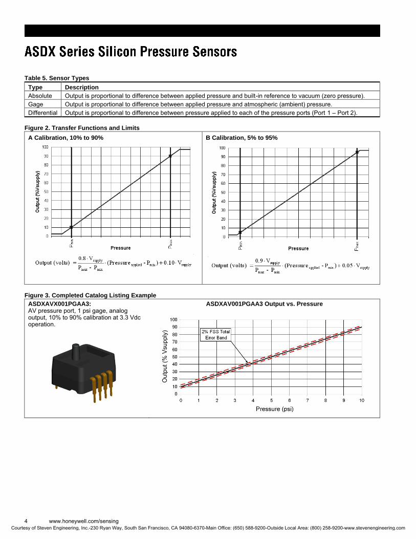
4 www.honeywell.com/sensing
Table 5. Sensor Types Type Description Absolute Output is proportional to difference between applied pressure and built-in reference to vacuum (zero pressure). Gage Output is proportional to difference between applied pressure and atmospheric (ambient) pressure. Differential Output is proportional to difference between pressure applied to each of the pressure ports (Port 1 – Port 2).
Figure 2. Transfer Functions and Limits
A Calibration, 10% to 90% B Calibration, 5% to 95%
Figure 3. Completed Catalog Listing Example
ASDXAVX001PGAA3: AV pressure port, 1 psi gage, analog output, 10% to 90% calibration at 3.3 Vdc operation.
ASDXAV001PGAA3 Output vs. Pressure
Courtesy of Steven Engineering, Inc.-230 Ryan Way, South San Francisco, CA 94080-6370-Main Office: (650) 588-9200-Outside Local Area: (800) 258-9200-www.stevenengineering.com

Honeywell Sensing and Control 5
Figure 4. Dimensional Drawings (For reference only: mm [in].) AV Package (Legacy G2) RR Package (Legacy D4)
AC Package (Legacy A2) RV Package
Table 7. Pinout
Pin Definition Type Description 1 Vsupply supply power supply source 2 Vout analog output provides the analog output 3 GND supply power supply ground 4 N/C not used do not connect in the application 5 N/C not used do not connect in the application 6 N/C not used do not connect in the application 7 N/C not used do not connect in the application 8 N/C not used do not connect in the application
Courtesy of Steven Engineering, Inc.-230 Ryan Way, South San Francisco, CA 94080-6370-Main Office: (650) 588-9200-Outside Local Area: (800) 258-9200-www.stevenengineering.com

Sensing and Control Honeywell 1985 Douglas Drive North Golden Valley, MN 55422 www.honeywell.com/sensing
008090-10-EN IL50 GLO Printed in USA July 2010 Copyright © 2010 Honeywell International Inc. All rights reserved.
WARNING PERSONAL INJURY DO NOT USE these products as safety or emergency stop devices or in any other application where failure of the product could result in personal injury. Failure to comply with these instructions could result in death or serious injury.
WARRANTY/REMEDY Honeywell warrants goods of its manufacture as being free of defective materials and faulty workmanship. Honeywell’s
standard product warranty applies unless agreed to otherwise by Honeywell in writing; please refer to your order acknowledgement or consult your local sales office for specific warranty details. If warranted goods are returned to Honeywell during the period of coverage, Honeywell will repair or replace, at its option, without charge those items it finds defective. The foregoing is buyer’s sole remedy and is in lieu of all other
warranties, expressed or implied, including those of merchantability and fitness for a particular purpose. In no event shall Honeywell be liable for consequential, special, or indirect damages. While we provide application assistance personally, through our literature and the Honeywell web site, it is up to the customer to determine the suitability of the product in the application. Specifications may change without notice. The information we supply is believed to be accurate and reliable as of this printing. However, we assume no responsibility for its use.
WARNING MISUSE OF DOCUMENTATION The information presented in this product sheet is for
reference only. Do not use this document as a product installation guide.
Complete installation, operation, and maintenance information is provided in the instructions supplied with each product.
Failure to comply with these instructions could result in death or serious injury.
SALES AND SERVICE Honeywell serves its customers through a worldwide network of sales offices, representatives and distributors. For application assistance, current specifications, pricing or name of the nearest Authorized Distributor, contact your local sales office or: E-mail: [email protected] Internet: www.honeywell.com/sensing Phone and Fax: Asia Pacific +65 6355-2828; +65 6445-3033 Fax Europe +44 (0) 1698 481481; +44 (0) 1698 481676 Fax Latin America +1-305-805-8188; +1-305-883-8257 Fax USA/Canada +1-800-537-6945; +1-815-235-6847 +1-815-235-6545 Fax
Courtesy of Steven Engineering, Inc.-230 Ryan Way, South San Francisco, CA 94080-6370-Main Office: (650) 588-9200-Outside Local Area: (800) 258-9200-www.stevenengineering.com

±
DESCRIPTION The ASDX Series is a Silicon Pressure Sensor offering either an I2C or SPI digital interface for reading pressure over the specified full scale pressure span and temperature range. The ASDX is fully calibrated and temperature compensated for sensor offset, sensitivity, temperature effects and non-linearity using an on-board Application Specific Integrated Circuit (ASIC). Calibrated output values for pressure are updated at approximately 1 kHz. The standard ASDX is calibrated over the temperature range of 0 °C to 85 °C [32 °F to 185 °F]. The sensor is characterized for operation from a single power supply of either 3.3 Vdc or 5.0 Vdc.
These sensors are available to measure absolute, differential and gage pressures. The absolute versions have an internal vacuum reference and an output value proportional to absolute pressure. Differential versions allow application of pressure to either side of the sensing diaphragm. Gage versions are referenced to atmospheric pressure and provide an output proportional to pressure variations from atmosphere. The ASDX Series sensors are intended for use with non-corrosive, non-ionic working fluids such as air and dry gases. They are designed and manufactured according to standards in ISO 9001.
FEATURES Output options: I2C- or SPI-compatible 12-bit digital Precision ASIC conditioning and temperature
compensated over 0 °C to 85 °C [32 °F to 185 °F] temperature range
Low operating voltage Absolute, differential and gage types Pressure ranges from 10 inches H20 to 100 psi Standard calibrations in inches H20, cm H20, psi, mbar,
bar, kPa Total error band of ±2.0% of full scale span maximum RoHS compliant
POTENTIAL APPLICATIONS Flow calibrators Ventilation and air flow monitors Gas flow instrumentation Sleep apnea monitoring and therapy equipment Barometry Pneumatic controls HVAC
Courtesy of Steven Engineering, Inc.-230 Ryan Way, South San Francisco, CA 94080-6370-Main Office: (650) 588-9200-Outside Local Area: (800) 258-9200-www.stevenengineering.com

2 www.honeywell.com/sensing
Table 1. Absolute Maximum Ratings1 Parameter Min Max Unit Supply voltage (Vsupply) -0.3 6.0 Vdc Voltage to any pin -0.3 Vsupply + 0.3 Vdc Digital clock frequency: I2C SPI
100 50
400 800
kHz
ESD susceptibility (human body model) 3 kV Storage temperature -50 [-58] 125 [257] °C [°F] Lead temperature (2 s to 4 s) 250 [482] °C [°F] External capacitance between Vsupply and ground2 100 470 nF
Table 2. Operating Specifications
Parameter Min. Typ. Max. Unit Supply voltage: (Vsupply)3 3.3 Vdc 5.0 Vdc Sensors are either 3.3 Vdc or 5.0 Vdc per the Order Guide (see Figure 1).
3.0
4.75
3.34
5.04
3.6
5.25 Vdc
Supply current 2.0 3.5 5.0 mA Compensated temperature range5 0 [32] 85 [185] °C [°F] Operating temperature range6 -20 [-4] 105 [221] °C [°F] Overpressure7 2X operating pressure range minimum Burst pressure8 3X operating pressure range minimum Startup time (power up to data ready) 2.8 7.3 ms Response time 0.46 ms I2C or SPI voltage level low 0.2 Vsupply I2C or SPI voltage level high 0.8 Vsupply Pull-up on SDA and SCL (I2C output only) 1 kOhm Total error band9 2.0 %FSS10 Output resolution 12 bits
Table 3. Environmental Specifications
Parameter Characteristic Humidity 0% to 95% RH non-condensing Vibration 10 G at 20 Hz to 2000 Hz Shock 100 G for 11 ms Life 1 million cycles minimum
Table 4. Wetted Materials11
Parameter Port 1 (Pressure Port)12 Port 2 (Reference Port)12 Covers glass-filled PBT glass-filled PBT Adhesives silicone silicone and epoxy Electronic components silicon and glass silicon, glass, and gold
Notes: 1. Absolute maximum ratings are the extreme limits that the device will withstand without damage to the device. 2. An external bypass capacitor is required across the supply voltage (Pins 6 and 3 – see Figure 4) as close to the sensor supply pin as possible
for correct sensor operation. 3. Ratiometricity of the sensor (the ability of the output to scale to the input voltage) is achieved within the specified operating voltage for each
option. Other custom supply voltages are available, please contact Honeywell Customer Service. 4. The sensor is not reverse polarity protected. Incorrect application of excitation voltage or ground to the wrong pin may cause electrical failure. 5. The compensated temperature range is the temperature range (or ranges) over which the sensor will produce an output proportional to
pressure within the specified performance limits. 6. The operating temperature range is the temperature range over which the sensor will produce an output proportional to pressure but may not
remain within the specified performance limits. 7. Overpressure is the maximum pressure which may safely be applied to the product for it to remain in specification once pressure is returned to
the operating pressure range. Exposure to higher pressures may cause permanent damage to the product. 8. Burst pressure is the maximum pressure that may be applied to any port of the product without causing escape of pressure media. Product
should not be expected to function after exposure to any pressure beyond the burst pressure. 9. Total error band is the maximum deviation in output from ideal transfer function over the entire compensated temperature and pressure range.
Includes all errors due to offset, full scale span, pressure non-linearity, pressure hysteresis, repeatability, thermal effect on offset, thermal effect on span and thermal hysteresis. Specification units are in percent of full scale span (%FSS).
10. Full scale span (FSS) is the algebraic difference between the output signal measured at the maximum (Pmax.) and minimum (Pmin.) limits of the pressure range.
11. Consult Honeywell Customer Service for detailed material information. 12. For AC pressure port configuration, the “pressure” and “reference” ports are reversed.
Courtesy of Steven Engineering, Inc.-230 Ryan Way, South San Francisco, CA 94080-6370-Main Office: (650) 588-9200-Outside Local Area: (800) 258-9200-www.stevenengineering.com

Honeywell Sensing and Control 3
Figure 1. Nomenclature and Order Guide
ASDX _ _ _ _ _ _ _ _ _Power Supply Voltage3 = 3.3 Vdc5 = 5.0 Vdc
Package Selection13
Calibration Selection
Series
Gage
- 010NG = 10 in H2O
-025CG = 25 cm H2O
001PG = 1 psi005PG = 5 psi015PG = 15 psi030PG = 30 psi100PG = 100 psi
-025MG = 25 mbar050MG = 50 mbar100MG = 100 mbar200MG = 200 mbar500MG = 500 mbar
001BG = 1 bar002BG = 2 bar007BG = 7 bar
003KG = 3 kPa 004KG = 4 kPa005KG = 5 kPa010KG = 10 kPa020KG = 20 kPa050KG = 50 kPa100KG = 100 kPa200KG = 200 kPa700KG = 700 kPa
Differential
005ND = ±5 in H2O010ND = ±10 in H2O
015CD = ±15 cm H2O025CD = ±25 cm H2O
001PD = ±1 psi005PD = ±5 psi015PD = ±15 psi030PD = ±30 psi-
015MD = ±15 mbar025MD = ±25 mbar050MD = ±50 mbar100MD = ±100 mbar200MD = ±200 mbar500MD = ±500 mbar
001BD = ±1 bar002BD = ±2 bar-
003KD = ±3 kPa004KD = ±4 kPa005KD = ±5 kPa010KD = ±10 kPa020KD = ±20 kPa050KD = ±50 kPa100KD = ±100 kPa200KD = ±200 kPa-
Absolute
- -
- - --015PA = 15 psi030PA = 30 psi100PA = 100 psi
------
001BA = 1 bar002BA = 2 bar007BA = 7 bar
------100KA = 100 kPa200KA = 200 kPa700KA = 700 kPa
Pressure Range16, 17, 18
Transfer Function Limits14
A = 10% to 90% calibrationB = 5% to 95% calibration
Output Type15
S = SPI2 = I2C, Address 0x283 = I2C, Address 0x384 = I2C, Address 0x485 = I2C, Address 0x586 = I2C, Address 0x687 = I2C, Address 0x78
_
Pressure Port
AV = Axial port on top, vented cover on bottom
RR = Radial port on top, radial port on bottom
AC = Axial port, sealed cover (commonly used for absolute)
RV = Radial port, single
Future Option
X
Notes: 13. Other package combinations are possible, please contact Honeywell Customer Service. 14. The transfer function limits define the output of the sensor at a given pressure input. By specifying the output signal at the maximum (Pmax.)
and minimum (Pmin.) limits of the pressure range, the complete transfer curve for the sensor is defined. See Figure 2 for a graphical representation of each calibration. For the 12-bit digital output, Table 6 provides the output of the sensor at significant percentages. These outputs are valid at the rated input voltage of the sensor.
15. The output type defines which communication protocol the sensor uses to communicate. Available protocols are I2C or half duplex SPI (sensor acts only as a slave). This communication protocol is not field selectable, and must be defined when ordering the sensor.
16. Custom pressure ranges are available, please contact Honeywell Customer Service. 17. The pressure units (inches H20, cm H20, psi, mbar, bar, kPa) define the units used during calibration and in the application. 18. See Table 5 for an explanation of sensor types.
Courtesy of Steven Engineering, Inc.-230 Ryan Way, South San Francisco, CA 94080-6370-Main Office: (650) 588-9200-Outside Local Area: (800) 258-9200-www.stevenengineering.com
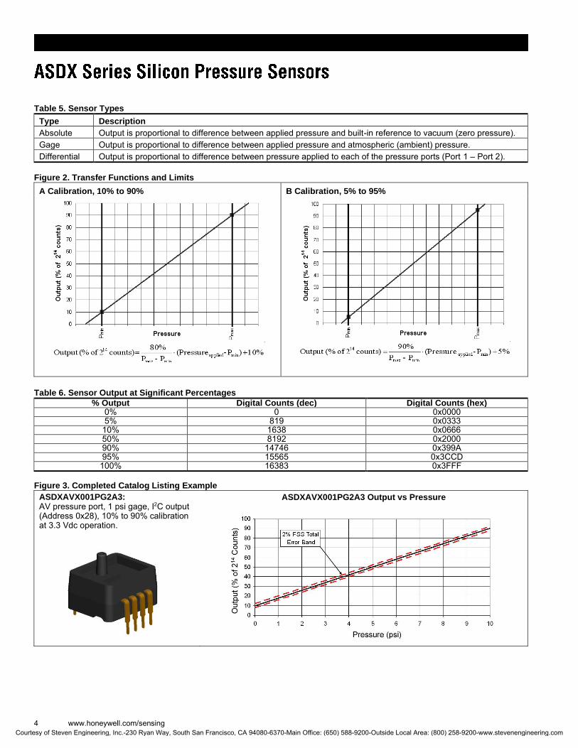
4 www.honeywell.com/sensing
Table 5. Sensor Types Type Description Absolute Output is proportional to difference between applied pressure and built-in reference to vacuum (zero pressure). Gage Output is proportional to difference between applied pressure and atmospheric (ambient) pressure. Differential Output is proportional to difference between pressure applied to each of the pressure ports (Port 1 – Port 2).
Figure 2. Transfer Functions and Limits
A Calibration, 10% to 90% B Calibration, 5% to 95%
Table 6. Sensor Output at Significant Percentages
% Output Digital Counts (dec) Digital Counts (hex) 0% 0 0x0000 5% 819 0x0333
10% 1638 0x0666 50% 8192 0x2000 90% 14746 0x399A 95% 15565 0x3CCD
100% 16383 0x3FFF Figure 3. Completed Catalog Listing Example
ASDXAVX001PG2A3: AV pressure port, 1 psi gage, I2C output (Address 0x28), 10% to 90% calibration at 3.3 Vdc operation.
ASDXAVX001PG2A3 Output vs Pressure
Courtesy of Steven Engineering, Inc.-230 Ryan Way, South San Francisco, CA 94080-6370-Main Office: (650) 588-9200-Outside Local Area: (800) 258-9200-www.stevenengineering.com

Honeywell Sensing and Control 5
Figure 4. Dimensional Drawings (For reference only: mm [in].) AV Package (Legacy G2) RR Package (Legacy D4)
AC Package (Legacy A2) RV Package
Table 7. Pinout
I2C SPI Pin Definition Type Description Pin Definition Type Description 1 SDA digital I/O serial bidirectional data;
data is clocked in or out on clock edge of SCL
1 MISO digital output “Master In Slave Out” - serial output data; data is clocked out on clock edge of SCK
2 SCL digital input serial clock input; used to clock data on SDA
2 SCK digital input serial clock input; used to clock data on MISO
3 GND supply power supply ground 3 GND supply power supply ground 4 N/C not used do not connect in the
application 4 N/C not used do not connect in the
application 5 SS digital output interrupt signal (conversion
complete output) 5 SS digital input slave select
6 Vsupply supply power supply source 6 Vsupply supply power supply source 7 N/C not used do not connect in the
application 7 N/C not used do not connect in the
application 8 N/C not used do not connect in the
application 8 N/C not used do not connect in the
application
Courtesy of Steven Engineering, Inc.-230 Ryan Way, South San Francisco, CA 94080-6370-Main Office: (650) 588-9200-Outside Local Area: (800) 258-9200-www.stevenengineering.com

Sensing and Control Honeywell 1985 Douglas Drive North Golden Valley, MN 55422 www.honeywell.com/sensing
008095-11-EN IL50 GLO Printed in USA July 2010 Copyright © 2010 Honeywell International Inc. All rights reserved.
WARNING PERSONAL INJURY DO NOT USE these products as safety or emergency stop devices or in any other application where failure of the product could result in personal injury. Failure to comply with these instructions could result in death or serious injury.
WARRANTY/REMEDY Honeywell warrants goods of its manufacture as being free of defective materials and faulty workmanship. Honeywell’s
standard product warranty applies unless agreed to otherwise by Honeywell in writing; please refer to your order acknowledgement or consult your local sales office for specific warranty details. If warranted goods are returned to Honeywell during the period of coverage, Honeywell will repair or replace, at its option, without charge those items it finds defective. The foregoing is buyer’s sole remedy and is in lieu of all other warranties, expressed or implied, including those of merchantability and fitness for a particular purpose. In no event shall Honeywell be liable for consequential, special, or indirect damages. While we provide application assistance personally, through our literature and the Honeywell web site, it is up to the customer to determine the suitability of the product in the application. Specifications may change without notice. The information we supply is believed to be accurate and reliable as of this printing. However, we assume no responsibility for its use.
WARNING MISUSE OF DOCUMENTATION The information presented in this product sheet is for
reference only. Do not use this document as a product installation guide.
Complete installation, operation, and maintenance information is provided in the instructions supplied with each product.
Failure to comply with these instructions could result in death or serious injury.
SALES AND SERVICE Honeywell serves its customers through a worldwide network of sales offices, representatives and distributors. For application assistance, current specifications, pricing or name of the nearest Authorized Distributor, contact your local sales office or: E-mail: [email protected] Internet: www.honeywell.com/sensing Phone and Fax: Asia Pacific +65 6355-2828; +65 6445-3033 Fax Europe +44 (0) 1698 481481; +44 (0) 1698 481676 Fax Latin America +1-305-805-8188; +1-305-883-8257 Fax USA/Canada +1-800-537-6945; +1-815-235-6847 +1-815-235-6545 Fax
Courtesy of Steven Engineering, Inc.-230 Ryan Way, South San Francisco, CA 94080-6370-Main Office: (650) 588-9200-Outside Local Area: (800) 258-9200-www.stevenengineering.com

ASDXL Series Microstructure Pressure
Sensors 0 in to ±5 in H2O, 0 in to 10 in H2O, 0 in to ±10 in H2O DESCRIPTION
The ASDXL Series pressure sensors are fully calibrated and
temperature compensated with on-board Application Specific
Integrated Circuitry (ASIC). This ASDXL sensor is in a DIP
format (Dual In-line Package) and provides digital correction of
sensor offset, sensitivity, temperature coefficients and non-
linearity. The ASDXL Series has an analog output that is
ratiometric with supply voltage over the compensated supply
range with 11-bit resolution.
All ASDXL sensors are accurate to within ±2.5 % Full Scale
Span (FSS) and are intended for use with non-corrosive, non-
ionic working fluids such as air and dry gases. (Contact factory
for media compatibility on G2/D4 packages).
This series is designed and manufactured in accordance with
ISO 9001 standards and is compliant with the WEEE and
RoHS directives.
FEATURES
• Available in differential and gage packages
• Calibrated and temperature compensated output
• Analog output with 11-bit resolution
• Pressure ranges from 0 in to ±5 in H2O, 10 in H2O,
±10 in H2O
• Response time of 8 ms
• DIP package
• ASIC-enhanced output
POTENTIAL APPLICATIONS
• Medical equipment
• HVAC controls
• Pneumatic controls
Courtesy of Steven Engineering, Inc.-230 Ryan Way, South San Francisco, CA 94080-6370-Main Office: (650) 588-9200-Outside Local Area: (800) 258-9200-www.stevenengineering.com
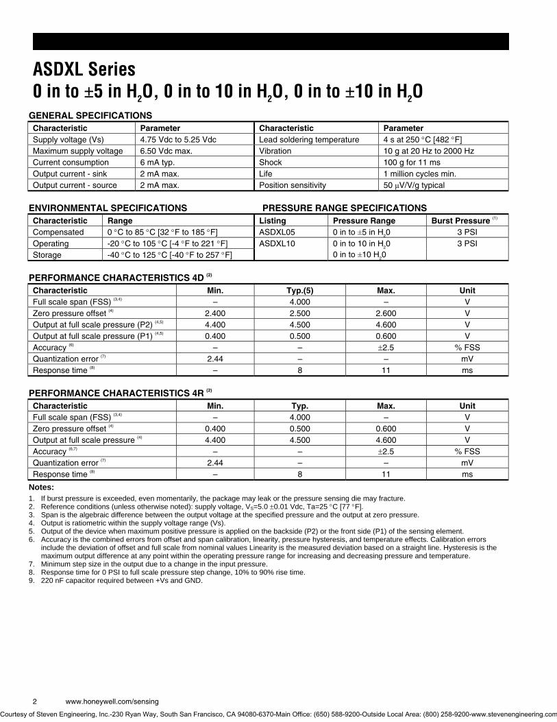
ASDXL Series 0 in to ±5 in H2O, 0 in to 10 in H2O, 0 in to ±10 in H2O
GENERAL SPECIFICATIONS Characteristic Parameter Characteristic Parameter Supply voltage (Vs) 4.75 Vdc to 5.25 Vdc Lead soldering temperature 4 s at 250 °C [482 °F] Maximum supply voltage 6.50 Vdc max. Vibration 10 g at 20 Hz to 2000 Hz Current consumption 6 mA typ. Shock 100 g for 11 ms Output current - sink 2 mA max. Life 1 million cycles min. Output current - source 2 mA max. Position sensitivity 50 μV/V/g typical
ENVIRONMENTAL SPECIFICATIONS PRESSURE RANGE SPECIFICATIONS Characteristic Range Listing Pressure Range Burst Pressure (1)
P
Compensated 0 °C to 85 °C [32 °F to 185 °F] ASDXL05 0 in to ±5 in H20 3 PSI Operating -20 °C to 105 °C [-4 °F to 221 °F] Storage -40 °C to 125 °C [-40 °F to 257 °F]
ASDXL10 0 in to 10 in H20 0 in to ±10 H20
3 PSI
PERFORMANCE CHARACTERISTICS 4D (2)
Characteristic Min. Typ.(5) Max. Unit Full scale span (FSS) (3,4) – 4.000 – V Zero pressure offset (4) 2.400 2.500 2.600 V Output at full scale pressure (P2) (4,5) 4.400 4.500 4.600 V Output at full scale pressure (P1) (4,5) 0.400 0.500 0.600 V Accuracy (6) – – ±2.5 % FSS Quantization error (7) 2.44 – – mV Response time (8) – 8 11 ms
PERFORMANCE CHARACTERISTICS 4R (2)
Characteristic Min. Typ. Max. Unit Full scale span (FSS) (3,4) – 4.000 – V Zero pressure offset (4) 0.400 0.500 0.600 V Output at full scale pressure (4) 4.400 4.500 4.600 V Accuracy (6,7) – – ±2.5 % FSS Quantization error (7) 2.44 – – mV Response time (8) – 8 11 ms
Notes: 1. If burst pressure is exceeded, even momentarily, the package may leak or the pressure sensing die may fracture. 2. Reference conditions (unless otherwise noted): supply voltage, VS=5.0 ±0.01 Vdc, Ta=25 °C [77 °F]. 3. Span is the algebraic difference between the output voltage at the specified pressure and the output at zero pressure. 4. Output is ratiometric within the supply voltage range (Vs). 5. Output of the device when maximum positive pressure is applied on the backside (P2) or the front side (P1) of the sensing element. 6. Accuracy is the combined errors from offset and span calibration, linearity, pressure hysteresis, and temperature effects. Calibration errors
include the deviation of offset and full scale from nominal values Linearity is the measured deviation based on a straight line. Hysteresis is the maximum output difference at any point within the operating pressure range for increasing and decreasing pressure and temperature.
7. Minimum step size in the output due to a change in the input pressure. 8. Response time for 0 PSI to full scale pressure step change, 10% to 90% rise time. 9. 220 nF capacitor required between +Vs and GND.
2 www.honeywell.com/sensing
Courtesy of Steven Engineering, Inc.-230 Ryan Way, South San Francisco, CA 94080-6370-Main Office: (650) 588-9200-Outside Local Area: (800) 258-9200-www.stevenengineering.com
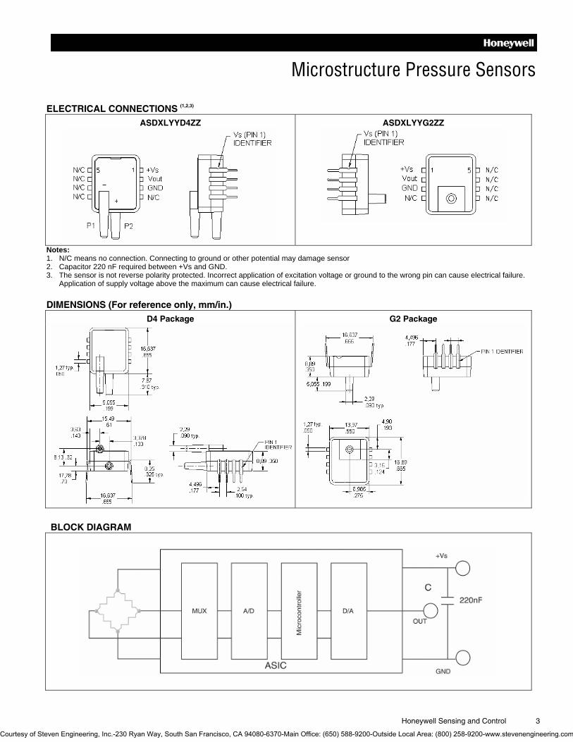
Microstructure Pressure Sensors
ELECTRICAL CONNECTIONS (1,2,3)
ASDXLYYD4ZZ ASDXLYYG2ZZ
Notes: 1. N/C means no connection. Connecting to ground or other potential may damage sensor 2. Capacitor 220 nF required between +Vs and GND. 3. The sensor is not reverse polarity protected. Incorrect application of excitation voltage or ground to the wrong pin can cause electrical failure.
Application of supply voltage above the maximum can cause electrical failure. DIMENSIONS (For reference only, mm/in.)
D4 Package G2 Package
BLOCK DIAGRAM
Honeywell Sensing and Control 3
Courtesy of Steven Engineering, Inc.-230 Ryan Way, South San Francisco, CA 94080-6370-Main Office: (650) 588-9200-Outside Local Area: (800) 258-9200-www.stevenengineering.com
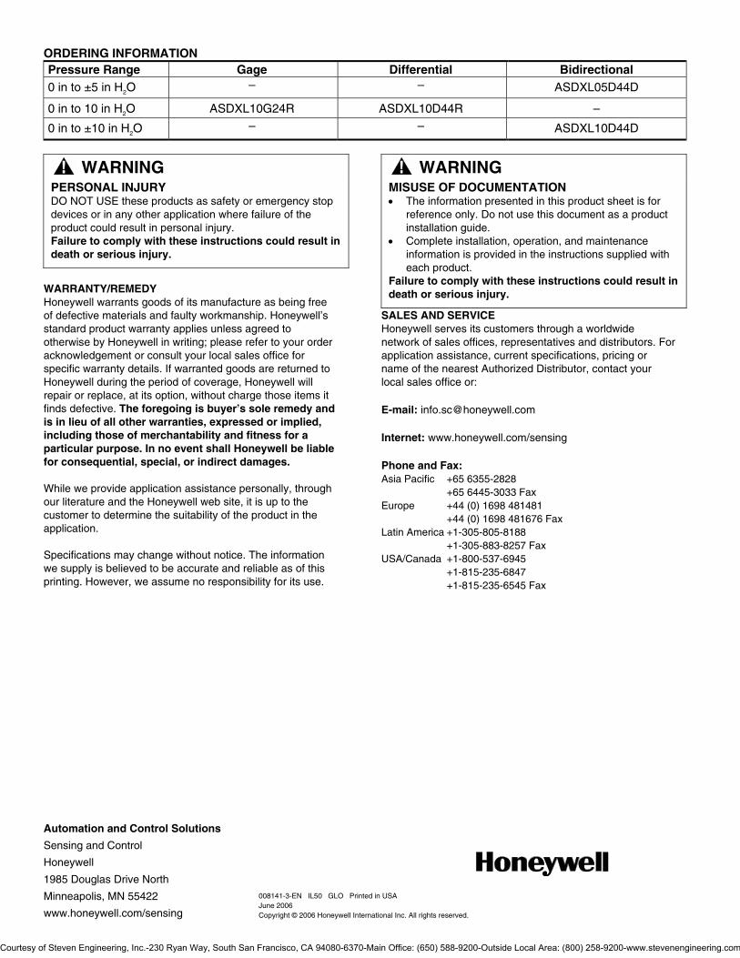
ORDERING INFORMATION Pressure Range Gage Differential Bidirectional 0 in to ±5 in H2O – – ASDXL05D44D
0 in to 10 in H2O ASDXL10G24R ASDXL10D44R –
0 in to ±10 in H2O – – ASDXL10D44D
WARNING PERSONAL INJURY DO NOT USE these products as safety or emergency stop devices or in any other application where failure of the product could result in personal injury. Failure to comply with these instructions could result in death or serious injury.
WARRANTY/REMEDY Honeywell warrants goods of its manufacture as being free of defective materials and faulty workmanship. Honeywell’s standard product warranty applies unless agreed to otherwise by Honeywell in writing; please refer to your order acknowledgement or consult your local sales office for specific warranty details. If warranted goods are returned to Honeywell during the period of coverage, Honeywell will repair or replace, at its option, without charge those items it finds defective. The foregoing is buyer’s sole remedy and is in lieu of all other warranties, expressed or implied, including those of merchantability and fitness for a particular purpose. In no event shall Honeywell be liable for consequential, special, or indirect damages. While we provide application assistance personally, through our literature and the Honeywell web site, it is up to the customer to determine the suitability of the product in the application. Specifications may change without notice. The information we supply is believed to be accurate and reliable as of this printing. However, we assume no responsibility for its use.
WARNING MISUSE OF DOCUMENTATION • The information presented in this product sheet is for
reference only. Do not use this document as a product installation guide.
• Complete installation, operation, and maintenance information is provided in the instructions supplied with each product.
Failure to comply with these instructions could result in death or serious injury.
SALES AND SERVICE Honeywell serves its customers through a worldwide network of sales offices, representatives and distributors. For application assistance, current specifications, pricing or name of the nearest Authorized Distributor, contact your local sales office or:
E-mail: [email protected]
Internet: www.honeywell.com/sensing
Phone and Fax: Asia Pacific +65 6355-2828 +65 6445-3033 Fax Europe +44 (0) 1698 481481 +44 (0) 1698 481676 Fax Latin America +1-305-805-8188 +1-305-883-8257 Fax USA/Canada +1-800-537-6945 +1-815-235-6847 +1-815-235-6545 Fax
Automation and Control Solutions
Sensing and Control
Honeywell
1985 Douglas Drive North
Minneapolis, MN 55422
www.honeywell.com/sensing
008141-3-EN IL50 GLO Printed in USA June 2006 Copyright © 2006 Honeywell International Inc. All rights reserved.
Courtesy of Steven Engineering, Inc.-230 Ryan Way, South San Francisco, CA 94080-6370-Main Office: (650) 588-9200-Outside Local Area: (800) 258-9200-www.stevenengineering.com

ASDXL DO Series Microstructure Pressure
Sensors 0 in to ±5 in H2O, 0 in to 10 in H2O, 0 in to ±10 in H2O DESCRIPTION
The ASDXL DO Series pressure sensors are fully calibrated
and temperature compensated with on-board Application
Specific Integrated Circuitry (ASIC). This ASDXL DO sensor is
in a DIP format (Dual In-line Package) and provides digital
correction of sensor offset, sensitivity, temperature coefficients
and non-linearity. The ASDXL DO Series has 12-bit I2C
compatible protocol interface which allows easy interfacing to
most commonly used microcontrollers and microprocessors.
The 2-wire I2C interface has a Serial Clock Line input (SCL)
and serial digital output data line. The output of the device is a
corrected pressure value in hexadecimal format with 12-bit
accuracy (unsigned) and not ratiometric to the supply voltage.
All ASDXL DO sensors are accurate to within ±2.5 % Full
Scale Span (FSS) and are intended for use with non-corrosive,
non-ionic working fluids such as air and dry gases. (Contact
factory for media compatibility on G2/D4 packages.)
This series is designed and manufactured in accordance with
ISO 9001 standards and is compliant with the WEEE and
RoHS directives.
FEATURES
• Available in differential and gage packages
• Calibrated and temperature compensated output
• 12-bit digital output (I2C compatible protocol)
• Pressure ranges from 0 in to ±5 in H2O, 10 in H2O,
±10 in H2O
• Response time of 8 ms
• DIP package
• ASIC-enhanced output
POTENTIAL APPLICATIONS
• Medical equipment
• HVAC controls
• Pneumatic controls
Courtesy of Steven Engineering, Inc.-230 Ryan Way, South San Francisco, CA 94080-6370-Main Office: (650) 588-9200-Outside Local Area: (800) 258-9200-www.stevenengineering.com

ASDXL DO Series 0 in to ±5 in H2O, 0 in to 10 in H2O, 0 in to ±10 in H2O
GENERAL SPECIFICATIONS Characteristic Parameter Characteristic Parameter Supply voltage (Vs) 4.75 Vdc to 5.25 Vdc Lead soldering temperature 4 s at 250 °C [482 °F] Maximum supply voltage 6.50 Vdc max. Vibration 10 g at 20 Hz to 2000 Hz Current consumption 6 mA typ. Shock 100 g for 11 ms Output current - sink 2 mA max. Life 1 million cycles min. Output current - source 2 mA max. Position sensitivity 50 μV/V/g typical
ENVIRONMENTAL SPECIFICATIONS PRESSURE RANGE SPECIFICATIONS Characteristic Range Listing Pressure Range Burst Pressure (1)
Compensated 0 °C to 85 °C [32 °F to 185 °F] ASDXL05 0 in to ±5 in H20 3 PSI Operating -20 °C to 105 °C [-4 °F to 221 °F] Storage -40 °C to 125 °C [-40 °F to 257 °F]
ASDXL10 0 in to 10 in H 0 2
0 in to ±10 H20 3 PSI
PERFORMANCE CHARACTERISTICS 4D DO (2,3)
Characteristic Min. Typ.(5) Max. Unit Full scale span (FSS) (4,5) – CCC – counts hex Zero pressure offset (5) 07AE 0800 0851 counts hex Output at full scale pressure (P2) (5,6) 0E14 0E66 0EB8 counts hex Output at full scale pressure (P1) (5,6) 0147 019A 01EB counts hex Accuracy (7) – – ±2.5 % FSS Output resolution – 12 – bit Response time (8) – 8 11 ms
PERFORMANCE CHARACTERISTICS 4R DO (2,3)
Characteristic Min. Typ. Max. Unit Full scale span (FSS) (4,5) – CCC – counts hex Zero pressure offset (5) 0147 019A 01EB counts hex Output at full scale pressure (5) 0E14 0E66 0EB8 counts hex Accuracy (7) – – ±2.5 % FSS Output resolution – 12 – bit Response time (8) – 8 11 ms
Notes: 1. If burst pressure is exceeded, even momentarily, the package may leak or the pressure sensing die may fracture. 2. Reference conditions (unless otherwise noted): supply voltage, V =5.0 ±0.01 Vdc, Ta=25 °C [77 °F]. S3. Read operation: Start, Slave Address, R/W =1, Data Byte 1 (MSB), Ackn Bit, Data Byte 2 (LSB). The output is corrected pressure as unsigned
12 bits. Slave Address is F0h. Acknowledge Bit - pull data line LOW, master generates an extra clock pulse for this purpose. 4. Span is the algebraic difference between the output voltage at the specified pressure and the output at zero pressure. 5. Output is non-ratiometric within the supply voltage range (Vs). 6. Output of the device when maximum positive pressure is applied on the backside (P2) or the front side (P1) of the sensing element. 7. Accuracy is the combined errors from offset and span calibration, linearity, pressure hysteresis, and temperature effects. Calibration errors
include the deviation of offset and full scale from nominal values Linearity is the measured deviation based on a straight line. Hysteresis is the maximum output difference at any point within the operating pressure range for increasing and decreasing pressure and temperature.
8. Response time for 0 PSI to full scale pressure step change, 10% to 90% rise time. 9. 220 nF capacitor required between +Vs and GND.
ELECTRICAL CONNECTIONS (1,2,3)
ASDXLYYD4ZZ-DO ASDXLYYG2ZZ-DO
Notes: 1. N/C means no connection. Connecting to ground or other potential may damage sensors. 2. Capacitor 220 nF required between +Vs and GND. 3. The sensor is not reverse polarity protected. Incorrect application of excitation voltage or ground to the wrong pin can cause electrical failure.
Application of supply voltage above the maximum can cause electrical failure.
2 www.honeywell.com/sensing
Courtesy of Steven Engineering, Inc.-230 Ryan Way, South San Francisco, CA 94080-6370-Main Office: (650) 588-9200-Outside Local Area: (800) 258-9200-www.stevenengineering.com

Microstructure Pressure Sensors
DIMENSIONS (For reference only, mm/in.) D4 Package G2 Package
SERIAL INTERFACE PARAMETERS Parameter Symbol Condition Min. Typ. Max. Unit Input high level VIH – 4.5 – 1 Vs Input low level VIL – 0 – 0.5 Vs Output low level VOL open drain IOL = -4 mA – – 0.1 Vs Pull up current VOH pin SCL and SDA 5 – 20 µA Load capacitance SDA CLSDA – – – 400 pF SCL clock frequency fSCL – – – 100 kHz Bus free time between STOP and START condition
tBUF – 4.7 – – µs
Hold time (repeated) START condition
tHD,STA to first clock pulse 4.0 – – µs
LOW period of SCL tLOW – 4.7 – – µs High period of SCL tHIGH – 4.0 – – µs Setup time repeated START condition
tSU, STA – 4.7 – – µs
Data hold time tHD, DAT – 0 – – ns Data setup time tSU, DAT – 250 – – ns Rise time of both SDA and SCL tR – – – 300 ns Fall time of both SDA and SCL – – – 300 ns Setup time for STOP condition tSU, STO – 4 – – µs
Input filter spike suppression tsp spikes on SDA or SCL of that
length are suppressed – – 50 µs
SERIAL INTERFACE TIMING CHARACTERISTICS BLOCK DIAGRAM
Honeywell Sensing and Control 3
Courtesy of Steven Engineering, Inc.-230 Ryan Way, South San Francisco, CA 94080-6370-Main Office: (650) 588-9200-Outside Local Area: (800) 258-9200-www.stevenengineering.com

ORDERING INFORMATION Pressure Range Gage Differential Bidirectional
0 in to ±5 in H2O – – ASDXL05D44D-DO
0 in to 10 in H2O ASDXL10G24R-DO ASDXL10D44R-DO –
0 in to ±10 in H2O – – ASDXL10D44D-DO
WARNING PERSONAL INJURY DO NOT USE these products as safety or emergency stop devices or in any other application where failure of the product could result in personal injury. Failure to comply with these instructions could result in death or serious injury.
WARRANTY/REMEDY Honeywell warrants goods of its manufacture as being free of defective materials and faulty workmanship. Honeywell’s standard product warranty applies unless agreed to otherwise by Honeywell in writing; please refer to your order acknowledgement or consult your local sales office for specific warranty details. If warranted goods are returned to Honeywell during the period of coverage, Honeywell will repair or replace, at its option, without charge those items it finds defective. The foregoing is buyer’s sole remedy and is in lieu of all other warranties, expressed or implied, including those of merchantability and fitness for a particular purpose. In no event shall Honeywell be liable for consequential, special, or indirect damages. While we provide application assistance personally, through our literature and the Honeywell web site, it is up to the customer to determine the suitability of the product in the application. Specifications may change without notice. The information we supply is believed to be accurate and reliable as of this printing. However, we assume no responsibility for its use.
WARNING MISUSE OF DOCUMENTATION • The information presented in this product sheet is for
reference only. Do not use this document as a product installation guide.
• Complete installation, operation, and maintenance information is provided in the instructions supplied with each product.
Failure to comply with these instructions could result in death or serious injury.
SALES AND SERVICE Honeywell serves its customers through a worldwide network of sales offices, representatives and distributors. For application assistance, current specifications, pricing or name of the nearest Authorized Distributor, contact your local sales office or:
E-mail: [email protected]
Internet: www.honeywell.com/sensing
Phone and Fax: Asia Pacific +65 6355-2828 +65 6445-3033 Fax Europe +44 (0) 1698 481481 +44 (0) 1698 481676 Fax Latin America +1-305-805-8188 +1-305-883-8257 Fax USA/Canada +1-800-537-6945 +1-815-235-6847 +1-815-235-6545 Fax
Automation and Control Solutions
Sensing and Control
Honeywell
1985 Douglas Drive North
Minneapolis, MN 55422
www.honeywell.com/sensing
008140-3-EN IL50 GLO Printed in USA June 2006 Copyright © 2006 Honeywell International Inc. All rights reserved.
Courtesy of Steven Engineering, Inc.-230 Ryan Way, South San Francisco, CA 94080-6370-Main Office: (650) 588-9200-Outside Local Area: (800) 258-9200-www.stevenengineering.com
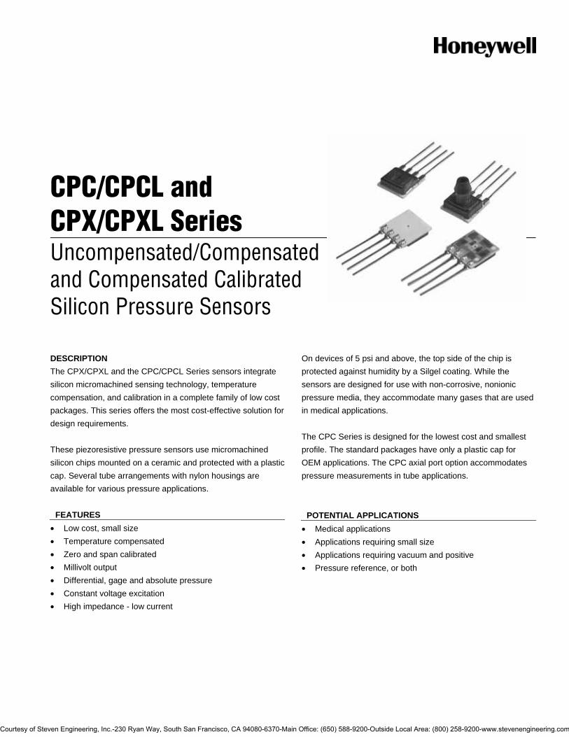
CPC/CPCL and CPX/CPXL Series
Uncompensated/Compensated and Compensated Calibrated Silicon Pressure Sensors
DESCRIPTION
The CPX/CPXL and the CPC/CPCL Series sensors integrate
silicon micromachined sensing technology, temperature
compensation, and calibration in a complete family of low cost
packages. This series offers the most cost-effective solution for
design requirements.
These piezoresistive pressure sensors use micromachined
silicon chips mounted on a ceramic and protected with a plastic
cap. Several tube arrangements with nylon housings are
available for various pressure applications.
On devices of 5 psi and above, the top side of the chip is
protected against humidity by a Silgel coating. While the
sensors are designed for use with non-corrosive, nonionic
pressure media, they accommodate many gases that are used
in medical applications.
The CPC Series is designed for the lowest cost and smallest
profile. The standard packages have only a plastic cap for
OEM applications. The CPC axial port option accommodates
pressure measurements in tube applications.
FEATURES
• Low cost, small size
• Temperature compensated
• Zero and span calibrated
• Millivolt output
• Differential, gage and absolute pressure
• Constant voltage excitation
• High impedance - low current
POTENTIAL APPLICATIONS
• Medical applications
• Applications requiring small size
• Applications requiring vacuum and positive
• Pressure reference, or both
Courtesy of Steven Engineering, Inc.-230 Ryan Way, South San Francisco, CA 94080-6370-Main Office: (650) 588-9200-Outside Local Area: (800) 258-9200-www.stevenengineering.com

CPC/CPCL and CPX/CPXL Series
2 www.honeywell.com/sensing
ELECTRICAL SPECIFICATIONS
CPC/CPCL at 12 Vdc, 25 °C [77 °F] CPX/CPXL at 5 Vdc, 25 °C [77 °F] Characteristic Min. Typ. Max. Unit Min. Typ. Max. Unit
Excitation voltage 3.0 12.0 16.0 Vdc 3.0 5.0 12.0 Vdc Null -1.0 0 1.0 mV -50 0 50 mV Offset temperature shift(1) 0 °C to 25 °C [32 °F to 77°F] 25 °C to 70 °C [77 °F to 158 °F](2)
– – ±1.0
mV – ±0.5 mV
Full scale temperature shift2 0 °C to 25 °C [32 °F to 158 °F] 25 °C to 70 °C [77 °F to 158 °F](2)
– – ±2
PPM/°C – -2200 – PPM/°C
Linearity, hysteresis error(3) – 0.25 1.0 % span 0.25 1.0 % span Input resistance 5.0 – – kOhm 5.0 – – kOhm Output resistance – 3.0 – kOhm – 3.0 – kOhm Operating temperature -25 [-13] – 85 [185] °C [°F] -25 [-13] – 85 [185] °C [°F] Storage temperature -40 [-40] – 125 [257] °C [°F] -40 [-40] – 125 [257] °C [°F] Common mode pressure – – 50 psi – – 50 psi Weight – 2 – g – 2 – g
Notes: 1. Pressure specs obtained with pressure applied to the front of the sensor. 2. Shift is relative to 25 °C [77 °F]. 3. Measured at ½ full scale rated pressure using BFSL. ABSOLUTE OUTPUT
CPC at 12 Vdc, 25 °C [77 °F] Output Full Scale Span (mV)
CPX at 5 Vdc, 25 °C [77 °F] Output Full Scale Span (mV)
Overpressure (psi)
FS Pressure
Min. Typ. Max. Min. Typ. Max. Max. 5 psi 57 60 63 112 168.5 225 15 15 psi 85 90 95 168 253 338 45 30 psi 85 90 95 168 253 338 90 60 psi 85 90 95 189 263.5 338 180 100 psi 95 100 105 210 295 380 250
GAGE/DIFFERENTIAL(1) OUTPUT
CPC/CPCL at 12 Vdc, 25 °C [77 °F] Output Full Scale Span (mV)
CPX/CPXL at 5 Vdc, 25 °C [77 °F] Output Full Scale Span (mV)
Overpressure (psi)
FS Pressure
Min. Typ. Max. Min. Typ. Max. Max. 4 in H2O 23 25 27 50 68 86 3 10 in H2O 19 20 21 40 78.5 112 3 1 psi 17 18 19 40 75 110 3 5 psi 57 60 63 112 168.5 225 15 15 psi 85 90 95 168 253 338 45 30 psi 85 90 95 168 253 338 90 60 psi 85 90 95 189 263.5 338 180 100 psi 95 100 105 210 295 380 250 150 psi 85 90 95 187 262.5 338 250
Note: 1. Differential common mode pressure should not exceed 50 psi.
Courtesy of Steven Engineering, Inc.-230 Ryan Way, South San Francisco, CA 94080-6370-Main Office: (650) 588-9200-Outside Local Area: (800) 258-9200-www.stevenengineering.com
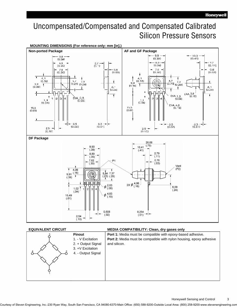
Uncompensated/Compensated and Compensated Calibrated Silicon Pressure Sensors
Honeywell Sensing and Control 3
MOUNTING DIMENSIONS (For reference only: mm [in].)
Non-ported Package AF and GF Package
DF Package
EQUIVALENT CIRCUIT MEDIA COMPATIBILITY: Clean, dry gases only
Pinout 1. - V Excitation 2. + Output Signal 3. +V Excitation 4. - Output Signal
Port 1: Media must be compatible with epoxy-based adhesive. Port 2: Media must be compatible with nylon housing, epoxy adhesive and silicon.
Courtesy of Steven Engineering, Inc.-230 Ryan Way, South San Francisco, CA 94080-6370-Main Office: (650) 588-9200-Outside Local Area: (800) 258-9200-www.stevenengineering.com

Sensing and Control
Honeywell
1985 Douglas Drive North
Minneapolis, MN 55422
www.honeywell.com/sensing
008054-3-EN IL50 GLO Printed in USA July 2007 © 2007 Honeywell International Inc. All rights reserved.
ORDER GUIDE
WARNING PERSONAL INJURY DO NOT USE these products as safety or emergency stop devices or in any other application where failure of the product could result in personal injury. Failure to comply with these instructions could result in death or serious injury.
WARRANTY/REMEDY Honeywell warrants goods of its manufacture as being free of defective materials and faulty workmanship. Honeywell’s standard product warranty applies unless agreed to otherwise by Honeywell in writing; please refer to your order acknowledgement or consult your local sales office for specific warranty details. If warranted goods are returned to Honeywell during the period of coverage, Honeywell will repair or replace, at its option, without charge those items it finds defective. The foregoing is buyer’s sole remedy and is in lieu of all other warranties, expressed or implied, including those of merchantability and fitness for a particular purpose. In no event shall Honeywell be liable for consequential, special, or indirect damages.
While we provide application assistance personally, through our literature and the Honeywell web site, it is up to the customer to determine the suitability of the product in the application.
Specifications may change without notice. The information we supply is believed to be accurate and reliable as of this printing. However, we assume no responsibility for its use.
WARNING MISUSE OF DOCUMENTATION • The information presented in this product sheet is for
reference only. Do not use this document as a product installation guide.
• Complete installation, operation, and maintenance information is provided in the instructions supplied with each product.
Failure to comply with these instructions could result in death or serious injury.
SALES AND SERVICE Honeywell serves its customers through a worldwide network of sales offices, representatives and distributors. For application assistance, current specifications, pricing or name of the nearest Authorized Distributor, contact your local sales office or:
E-mail: [email protected]
Internet: www.honeywell.com/sensing
Phone and Fax: Asia Pacific +65 6355-2828 +65 6445-3033 Fax Europe +44 (0) 1698 481481 +44 (0) 1698 481676 Fax Latin America +1-305-805-8188 +1-305-883-8257 Fax USA/Canada +1-800-537-6945 +1-815-235-6847 +1-815-235-6545 Fax
Courtesy of Steven Engineering, Inc.-230 Ryan Way, South San Francisco, CA 94080-6370-Main Office: (650) 588-9200-Outside Local Area: (800) 258-9200-www.stevenengineering.com

Silicon Pressure Sensors Ultra Low Pressure Sensing DC Series
FEATURES • Ultra Low Pressure
Sensing, down to 2.5 mBar
• ASIC Technology • Available in Gage and
Differential Pressure Ranges
• Available in Ratiometric and Regulated
• Temperature Compensated over 0 °C to 50°C [32 °F to 122 °F]
• Combined Linearity and Hysteresis error < ±0.25 % Span
TYPICAL APPLICATIONS • Medical Instrumentation • HVAC • Environmental Controls • Portable Monitors
WARNING PERSONAL INJURY DO NOT USE these products as safety or emergency stop devices or in any other application where failure of the product could result in personal injury. Failure to comply with these instructions could result in death or serious injury.
GENERAL DESCRIPTION The DC Series pressure sensors combine SURSENSE™ precision high sensitivity silicon sensing capabilities with the latest in Application Specific Integrated Circuitry ASIC technology to produce one of the most precise, reliable pressure sensors in the market. The SURSENSE technology provides Dynamic Self Compensation which substantially reduces offset errors due to changes in temperature, stability to warm up, long term instability and position sensitivity. When operated with an unregulated 7.0 Vdc to 16.0 Vdc supply the DC sensors provides a ratiometric 0.50 to 4.50 Vdc output (4.0 Vdc span).
WARNING MISUSE OF DOCUMENTATION
• The information presented in this product sheet is for reference only. Do not use this document as a product installation guide.
• Complete installation, operation, and maintenance information is provided in the instructions supplied with each product.
Failure to comply with these instructions could result in death or serious injury.
Courtesy of Steven Engineering, Inc.-230 Ryan Way, South San Francisco, CA 94080-6370-Main Office: (650) 588-9200-Outside Local Area: (800) 258-9200-www.stevenengineering.com
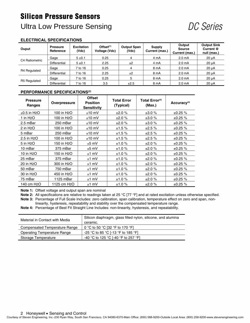
Silicon Pressure Sensors Ultra Low Pressure Sensing DC Series ELECTRICAL SPECIFICATIONS
Ouput Pressure Reference
Excitation (Vdc)
Offset(1) Voltage (Vdc)
Output Span (Vdc)
Supply Current (max.)
Output Source
Current (max.)
Output Sink Current @ null (max.)
Gage 5 ±0.1 0.25 4 4 mA 2.0 mA 20 μA C4 Ratiometric
Differential 5 ±0.1 2.25 ±2 4 mA 2.0 mA 20 μA
Gage 7 to 16 0.25 4 8 mA 2.0 mA 20 μA R4 Regulated
Differential 7 to 16 2.25 ±2 8 mA 2.0 mA 20 μA
Gage 7 to 16 0.25 5 8 mA 2.0 mA 20 μA R5 Regulated
Differential 7 to 16 3.5 ±2.5 8 mA 2.0 mA 20 μA PERFORMANCE SPECIFICATIONS(2)
Pressure Ranges
Overpressure Offset
Position Sensitivity
Total Error (Typical)
Total Error(3) (Max.)
Accuracy(4)
±0.5 in H2O 100 in H2O ±10 mV ±2.0 % ±3.0 % ±0.25 % 1 in H2O 100 in H2O ±10 mV ±2.0 % ±3.0 % ±0.25 % 2.5 mBar 250 mBar ±10 mV ±2.0 % ±3.0 % ±0.25 % 2 in H2O 100 in H2O ±10 mV ±1.5 % ±2.5 % ±0.25 % 5 mBar 250 mBar ±10 mV ±1.5 % ±2.5 % ±0.25 % 2.5 in H2O 100 in H2O ±10 mV ±1.5 % ±2.5 % ±0.25 % 5 in H2O 150 in H2O ±5 mV ±1.0 % ±2.0 % ±0.25 % 10 mBar 375 mBar ±5 mV ±1.0 % ±2.0 % ±0.25 % 10 in H2O 150 in H2O ±1 mV ±1.0 % ±2.0 % ±0.25 % 25 mBar 375 mBar ±1 mV ±1.0 % ±2.0 % ±0.25 % 20 in H2O 300 in H2O ±1 mV ±1.0 % ±2.0 % ±0.25 % 50 mBar 750 mBar ±1 mV ±1.0 % ±2.0 % ±0.25 % 30 in H2O 450 in H2O ±1 mV ±1.0 % ±2.0 % ±0.25 % 75 mBar 1125 mBar ±1 mV ±1.0 % ±2.0 % ±0.25 % 140 cm H2O 1125 cm H2O ±1 mV ±1.0 % ±2.0 % ±0.25 %
Note 1: Offset voltage and output span are nominal Note 2: All specifications are relative to readings taken at 25 °C [77 °F] and at rated excitation unless otherwise specified. Note 3: Percentage of Full Scale Includes: zero calibration, span calibration, temperature effect on zero and span, non-
linearity, hysteresis, repeatability and stability over the compensated temperature range. Note 4: Percentage of Best Fit Straight Line Includes: non-linearity, hysteresis, and repeatability.
Material in Contact with Media Silicon diaphragm, glass filled nylon, silicone, and alumina ceramic.
Compensated Temperature Range 0 °C to 50 °C [32 °F to 170 °F] Operating Temperature Range -25 °C to 85 °C [-13 °F to 185 °F] Storage Temperature -40 °C to 125 °C [-40 °F to 257 °F]
2 Honeywell • Sensing and Control Courtesy of Steven Engineering, Inc.-230 Ryan Way, South San Francisco, CA 94080-6370-Main Office: (650) 588-9200-Outside Local Area: (800) 258-9200-www.stevenengineering.com

Silicon Pressure Sensors Ultra Low Pressure Sensing DC Series PHYSICAL DIMENSIONS for reference only mm [In]
Note: For gage sensor apply pressure to port 2. DC Electrical Output Version
Pin Number
C4 0.25 Vdc to 4.25 Vdc Ratiometric
R4 0.25 Vdc to 4.25 Vdc
Regulated
R5 1.0 Vdc to 6.0 Vdc
Regulated 1 V Excitation V Excitation V Excitation 2 Common Common Common 3 V out V out V out
4 Not for Customer Use
Not for Customer Use
Not for Customer Use
Honeywell • Sensing and Control 3 Courtesy of Steven Engineering, Inc.-230 Ryan Way, South San Francisco, CA 94080-6370-Main Office: (650) 588-9200-Outside Local Area: (800) 258-9200-www.stevenengineering.com

Silicon Pressure Sensors Ultra Low Pressure Sensing DC Series
DC SERIES ORDER GUIDE
WARRANTY/REMEDY Honeywell warrants goods of its manufacture as being free of defective materials and faulty workmanship. Contact your local sales office for warranty information. If warranted goods are returned to Honeywell during the period of coverage, Honeywell will repair or replace without charge those items it finds defective. The foregoing is Buyer’s sole remedy and is in lieu of all other warranties, expressed or implied, including those of merchantability and fitness for a particular purpose. Specifications may change without notice. The information we supply is believed to be accurate and reliable as of this printing. However, we assume no responsibility for its use.
While we provide application assistance personally, through our literature and the Honeywell web site, it is up to the customer to determine the suitability of the product in the application. For application assistance, current specifications, or name of the nearest Authorized Distributor, contact a nearby sales office. Or call: 1-800-537-6945 USA/Canada 1-815-235-6847 International FAX 1-815-235-6545 USA INTERNET www.honeywell.com/sensing [email protected]
Sensing and Control
Honeywell
1985 Douglas Drive North
Golden Valley, MN 55422
www.honeywell.com
008134-2-EN IL50 GLO Printed in USA April 2009 © 2009 Honeywell International Inc.
Courtesy of Steven Engineering, Inc.-230 Ryan Way, South San Francisco, CA 94080-6370-Main Office: (650) 588-9200-Outside Local Area: (800) 258-9200-www.stevenengineering.com
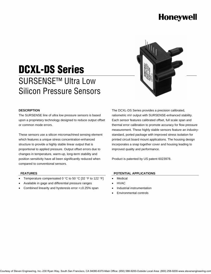
DCXL-DS Series
SURSENSE™ Ultra Low Silicon Pressure Sensors
DESCRIPTION
The SURSENSE line of ultra low pressure sensors is based
upon a proprietary technology designed to reduce output offset
or common mode errors.
These sensors use a silicon micromachined sensing element
which features a unique stress concentration-enhanced
structure to provide a highly stable linear output that is
proportional to applied pressure. Output offset errors due to
changes in temperature, warm-up, long-term stability and
position sensitivity have all been significantly reduced when
compared to conventional sensors.
The DCXL-DS Series provides a precision calibrated,
ratiometric mV output with SURSENSE-enhanced stability.
Each sensor features calibrated offset, full scale span and
thermal error calibration to promote accuracy for flow pressure
measurement. These highly stable sensors feature an industry-
standard, ported package with improved stress isolation for
printed circuit board mount applications. The housing design
incorporates a snap together cover and housing leading to
improved quality and performance.
Product is patented by US patent 6023978.
FEATURES
• Temperature compensated 0 °C to 50 °C [32 °F to 122 °F]
• Available in gage and differential pressure ranges
• Combined linearity and hysteresis error <±0.25% span
POTENTIAL APPLICATIONS
• Medical
• HVAC
• Industrial instrumentation
• Environmental controls
Courtesy of Steven Engineering, Inc.-230 Ryan Way, South San Francisco, CA 94080-6370-Main Office: (650) 588-9200-Outside Local Area: (800) 258-9200-www.stevenengineering.com

DCXL-DS Series
2 www.honeywell.com/sensing
ELECTRICAL SPECIFICATIONS (12 Vdc excitation at 25 °C [77 °F].)
Characteristic Min. Typ. Max. Unit Excitation voltage 3.0 12.0 16.0 Vdc Null offset -500 0 500 µV Span except DCXL01DS 19.0 20.0 21.0 mV Span DCXL01DS 9.0 10.0 11.0 mV Offset temperature shift 0 ºC to 50 ºC [32 ºF to 122 ºF]1 except DCXL01DS
-150 – 150 µV
Offset temperature shift 0 ºC to 50 ºC [32 ºF to 122 ºF]1 DCXL01DS
-250 0 250 µV
Span temperature shift 0 ºC to 50 ºC [32 ºF to 122 ºF]1
-200 0 200 µV
Linearity, hysteresis error2 – 0.05 0.25 % span Compensated temperature 0 [32] – 50 [122] °C [°F] Operating temperature -25 [-13] – 85 [185] °C [°F] Storage temperature -40 [-40] – 125 [257] °C [°F] Offset warm-up shift3 except DCXL01DS – ±50 – µV Offset warm-up shift3 DCXL01DS – ±100 – µV Offset position sensitivity (±1 g) DCXL01DS – ±50 – µV Offset position sensitivity (±1 g) DCXL05DS, DCXL10DS – ±10 – µV Offset position sensitivity (±1 g) DCXL20DS, DCXL30DS – ±5 – µV
Notes: 1. Shift is relative to 25 °C [77 °F]. 2. Measured at ½ full scale rated pressure using BFSL. 3. Shift is within the first hour of excitation applied to the device. PRESSURE RATINGS IN H2O (By Catalog Listing)
Parameter 01D 05D 10D 20D 30D Unit Operating pressure 1 5 10 20 30 in H2O Maximum overpressure 5 5 5 5 5 PSI Common mode 50 50 50 50 50 PSI
TYPICAL RESISTANCE VALUES (By Catalog Listing)
Parameter 01D 05D 10D 20D 30D Unit Input resistance 4.5 10 13 10 12 kΩ Output resistance 1.5 1.5 1.5 2 1.5 kΩ
Courtesy of Steven Engineering, Inc.-230 Ryan Way, South San Francisco, CA 94080-6370-Main Office: (650) 588-9200-Outside Local Area: (800) 258-9200-www.stevenengineering.com

SURSENSE™ Ultra Low Pressure Sensor Pressure Sensors
Honeywell Sensing and Control 3
MOUNTING DIMENSIONS (For reference only: mm/[in].)
654321
PORT 1
PORT 2
123456
20,32[0.80]
1,10[27,94]
16,67[0.42]
27,43[1.08] Ø 3,56
[0.14]
7,62[0.30]
0,25[0.01]
Ø 3,30[0.13]
12,19[0.48]
14,0[0.55]
21,6[0.85]
5,33[0.21]
Ø 4,83[0.19]
Ø 2,03[0.08]
2,54[0.10]
0,51[0.02]
EQUIVALENT CIRCUIT MEDIA COMPATIBILITY: Clean, dry gases only
Pinout 1. V Excitation 2. V Output 3. V Offset (Not to be used unless
adjusting null offset. 4. Common
Port 1: Media must be compatible with epoxy-based adhesive, silicon, silicone, gold, nylon and alumina. Port 2: Media must be compatible with epoxy-based adhesive, silicon, silicone, gold, nylon and alumina.
PRESSURE COMPATIBILITY Measures differential or gage pressure and vacuum. Pressure may be applied to either port. For pressure to the low pressure port, the output polarity is reversed. RATIOMETRIC OUTPUT The output voltage of the sensor is ratiometric (proportional) to the excitation voltage. All specifications will change proportionally to any changes in the excitation voltage, which may vary between 3 Vdc to 16 Vdc. All specifications will nominally be changed by a ratio of V Excitation/12.0 Vdc. For example: if the excitation voltage is 5.0 Vdc, then both the full scale output voltage and the offset voltage nominal would be 5/12th the specified value.
Courtesy of Steven Engineering, Inc.-230 Ryan Way, South San Francisco, CA 94080-6370-Main Office: (650) 588-9200-Outside Local Area: (800) 258-9200-www.stevenengineering.com
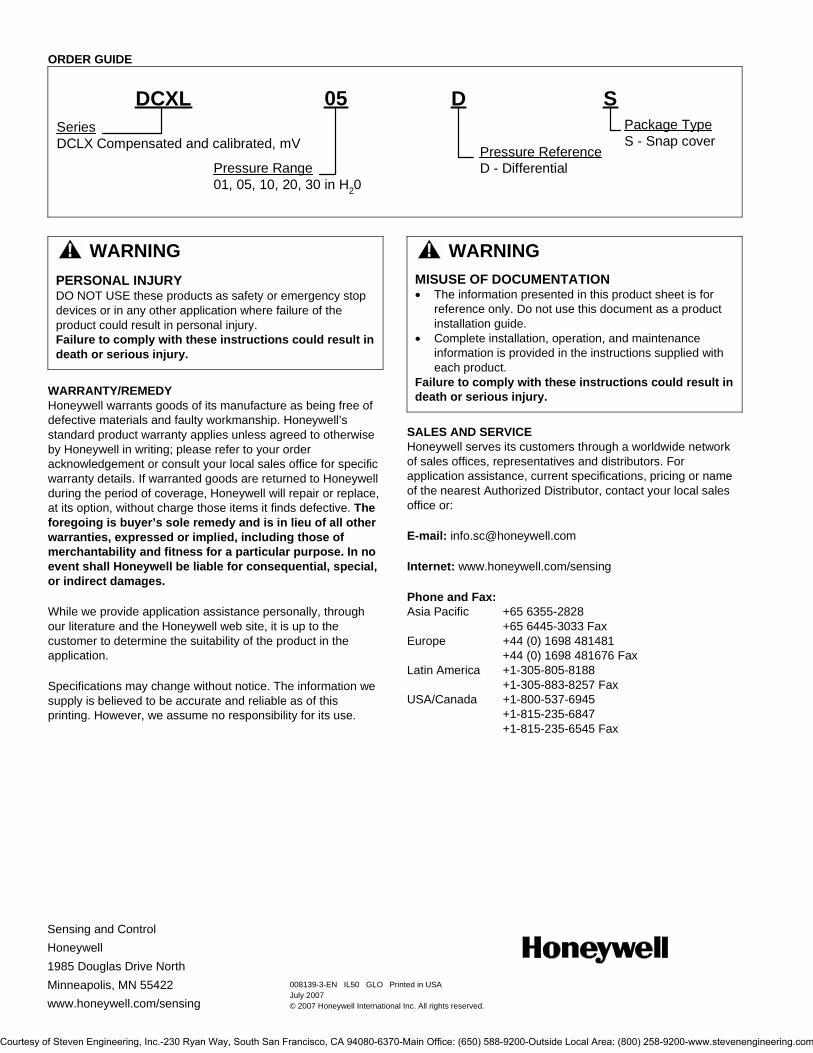
Sensing and Control
Honeywell
1985 Douglas Drive North
Minneapolis, MN 55422
www.honeywell.com/sensing
008139-3-EN IL50 GLO Printed in USA July 2007 © 2007 Honeywell International Inc. All rights reserved.
ORDER GUIDE
DCXL 05 D SSeriesDCLX Compensated and calibrated, mV
Pressure Range01, 05, 10, 20, 30 in H20
Pressure ReferenceD - Differential
Package TypeS - Snap cover
WARNING PERSONAL INJURY DO NOT USE these products as safety or emergency stop devices or in any other application where failure of the product could result in personal injury. Failure to comply with these instructions could result in death or serious injury.
WARRANTY/REMEDY Honeywell warrants goods of its manufacture as being free of defective materials and faulty workmanship. Honeywell’s standard product warranty applies unless agreed to otherwise by Honeywell in writing; please refer to your order acknowledgement or consult your local sales office for specific warranty details. If warranted goods are returned to Honeywell during the period of coverage, Honeywell will repair or replace, at its option, without charge those items it finds defective. The foregoing is buyer’s sole remedy and is in lieu of all other warranties, expressed or implied, including those of merchantability and fitness for a particular purpose. In no event shall Honeywell be liable for consequential, special, or indirect damages.
While we provide application assistance personally, through our literature and the Honeywell web site, it is up to the customer to determine the suitability of the product in the application.
Specifications may change without notice. The information we supply is believed to be accurate and reliable as of this printing. However, we assume no responsibility for its use.
WARNING MISUSE OF DOCUMENTATION • The information presented in this product sheet is for
reference only. Do not use this document as a product installation guide.
• Complete installation, operation, and maintenance information is provided in the instructions supplied with each product.
Failure to comply with these instructions could result in death or serious injury.
SALES AND SERVICE Honeywell serves its customers through a worldwide network of sales offices, representatives and distributors. For application assistance, current specifications, pricing or name of the nearest Authorized Distributor, contact your local sales office or:
E-mail: [email protected]
Internet: www.honeywell.com/sensing
Phone and Fax: Asia Pacific +65 6355-2828 +65 6445-3033 Fax Europe +44 (0) 1698 481481 +44 (0) 1698 481676 Fax Latin America +1-305-805-8188 +1-305-883-8257 Fax USA/Canada +1-800-537-6945 +1-815-235-6847 +1-815-235-6545 Fax
Courtesy of Steven Engineering, Inc.-230 Ryan Way, South San Francisco, CA 94080-6370-Main Office: (650) 588-9200-Outside Local Area: (800) 258-9200-www.stevenengineering.com

DUXL Series
Sursense™ Ultra Low Silicon Pressure Sensors
DESCRIPTION
The SURSENSE™ line of ultra low pressure sensors is based
upon a proprietary technology designed to reduce all output
offset or common mode errors.
These sensors use a silicon micromachined sensing element
which features a unique stress concentration enhanced
structure to provide a highly stable linear output that is
proportional to applied pressure. Output offset errors due to
changes in temperature, warm-up, long term stability and
position sensitivity have all been significantly reduced when
compared to conventional sensors.
The DUXL Series sensors provide a ratiometric millivolt output
and are housed in a low profile miniature ported package.
These sensors are intended for those applications where
customized external signal conditioning is required or available
from other sources. The low profile outline is ideal for portable
applications where small size is critical.
Product is patented by US patent 6023978
FEATURES
• Position sensitivity to ±5 mV/g, typical
• Operating temperature range -25 °C to 85 °C
[-13 °F to 185 °F]
• Available in gage and differential pressure ranges
POTENTIAL APPLICATIONS
• Hand held instrumentation
• Airflow controllers
• Medical monitors
• Smart microvalves and switches
• Level indicators
Courtesy of Steven Engineering, Inc.-230 Ryan Way, South San Francisco, CA 94080-6370-Main Office: (650) 588-9200-Outside Local Area: (800) 258-9200-www.stevenengineering.com

DUXL Series
2 www.honeywell.com/sensing
ELECTRICAL SPECIFICATIONS (At 4.5 Vdc Excitation 25 °C [77 °F].)
Characteristic Min. Typ. Max. Unit Excitation voltage 3.0 4.5 8.0 Vdc Span(1) except DUXL01D, DUXL05D 15 30 45 mV Span(1) DUXL01D 4.0 6.0 8.0 mV Span(1) DUXL05D 15 22.5 30 mV Null -10 0 10 mV Offset temperature shift 0 °C to 50 °C [32 °F to 122 °F](2) − 100 − µV Span temperature shift 0 °C to 50 °C [32 °F to 122 °F](2) − 100 − µV Linearity, hysteresis error(3) -0.5 0.1 0.5 % span Temperature coefficient of resistance − 2600 − ppm/°C Temperature cCoefficient of sensitivity − -2200 − ppm/°C Operating temperature -25 [-13] − 85 [185] °C [°F] Storage temperature -40 [-40] − 125 [257] °C [°F] Offset warm-up shift4 − 10 − µV Offset position sensitivity (±1 g) DUXL01D, DUXL05D − 15 − µV Offset position sensitivity (±1 g) DUXL10D − 10 − µV Offset position sensitivity (±1 g) DUXL20D, DUXL30D − 5 − µV Offset long term stability (1 year) − ±100 − µV Input resistance − 2.0 − kΩ
Notes: 1. The voltage added to the offset voltage at full scale pressure. Nominally the output voltage range is 1.0 Vdc to 6.0 Vdc. 2. Shift is relative to 25 °C [77 °F] 3. Measured at ½ full scale operating pressure using BFSL 4. Shift is within the first hour of excitation applied to the device.
PRESSURE RATINGS (In H2O by Catalog Listing)
Characteristic 01D 05D 10D 20D 30D Operating pressure range 1.0 5.0 10.0 20.0 30.0 Maximum overpressure 100 100 150 200 300 Common mode 50 50 50 50 50
Courtesy of Steven Engineering, Inc.-230 Ryan Way, South San Francisco, CA 94080-6370-Main Office: (650) 588-9200-Outside Local Area: (800) 258-9200-www.stevenengineering.com

Sursense™ Ultra Low Silicon Pressure Sensors
Honeywell Sensing and Control 3
MOUNTING DIMENSIONS (For reference only: mm (in).)
EQUIVALENT CIRCUIT MEDIA COMPATIBILITY: Clean, dry gases only
Pinout 1. –Vdc supply 2. +Vdc output 3. +Vdc supply 4. –Vdc output
Port A: Media must be compatible with nylon housing, epoxy adhesive and silicon. Port B: Media must be compatible with nylon housing, epoxy adhesive and silicon
PRESSURE COMPATIBILITY Measures differential or gage pressure and vacuum. Pressure may be applied to either port. For pressure to the low pressure port, the output polarity is reversed.
Courtesy of Steven Engineering, Inc.-230 Ryan Way, South San Francisco, CA 94080-6370-Main Office: (650) 588-9200-Outside Local Area: (800) 258-9200-www.stevenengineering.com

Sensing and Control
Honeywell
1985 Douglas Drive North
Minneapolis, MN 55422
www.honeywell.com/sensing
008052-3-EN IL50 GLO Printed in USA July 2007 © 2007 Honeywell International Inc. All rights reserved.
ORDER GUIDE
WARNING PERSONAL INJURY DO NOT USE these products as safety or emergency stop devices or in any other application where failure of the product could result in personal injury. Failure to comply with these instructions could result in death or serious injury.
WARRANTY/REMEDY Honeywell warrants goods of its manufacture as being free of defective materials and faulty workmanship. Honeywell’s standard product warranty applies unless agreed to otherwise by Honeywell in writing; please refer to your order acknowledgement or consult your local sales office for specific warranty details. If warranted goods are returned to Honeywell during the period of coverage, Honeywell will repair or replace, at its option, without charge those items it finds defective. The foregoing is buyer’s sole remedy and is in lieu of all other warranties, expressed or implied, including those of merchantability and fitness for a particular purpose. In no event shall Honeywell be liable for consequential, special, or indirect damages.
While we provide application assistance personally, through our literature and the Honeywell web site, it is up to the customer to determine the suitability of the product in the application.
Specifications may change without notice. The information we supply is believed to be accurate and reliable as of this printing. However, we assume no responsibility for its use.
WARNING MISUSE OF DOCUMENTATION • The information presented in this product sheet is for
reference only. Do not use this document as a product installation guide.
• Complete installation, operation, and maintenance information is provided in the instructions supplied with each product.
Failure to comply with these instructions could result in death or serious injury.
SALES AND SERVICE Honeywell serves its customers through a worldwide network of sales offices, representatives and distributors. For application assistance, current specifications, pricing or name of the nearest Authorized Distributor, contact your local sales office or:
E-mail: [email protected]
Internet: www.honeywell.com/sensing
Phone and Fax: Asia Pacific +65 6355-2828 +65 6445-3033 Fax Europe +44 (0) 1698 481481 +44 (0) 1698 481676 Fax Latin America +1-305-805-8188 +1-305-883-8257 Fax USA/Canada +1-800-537-6945 +1-815-235-6847 +1-815-235-6545 Fax
Courtesy of Steven Engineering, Inc.-230 Ryan Way, South San Francisco, CA 94080-6370-Main Office: (650) 588-9200-Outside Local Area: (800) 258-9200-www.stevenengineering.com

Microstructure Pressure Sensors 0 mm Hg to 300 mm Hg through 0 psi to 100 psi HPX Series
Sensing and Control
FEATURES • Miniature package size • Available in gage and
absolute sensing types • Non-compensated and non-
calibrated • Pressure ranges from
0 psi to 100 psi • Response time is 1 ms
typical • Two package styles, DIP
and SOIC • Wide operating temperature
range • Surface mount and through
hole mounting TYPICAL APPLICATIONS • Medical equipment • Altimeters and barometers • Pneumatic controls • Leak detection • Consumer goods
WARNING PERSONAL INJURY DO NOT USE these products as safety or emergency stop devices, or in any other application where failure of the product could result in personal injury. Failure to comply with these instructions could result in death or serious injury.
The HPX Series Pressure Sensors provide accurate, low cost sensing in
two different package configurations, DIP (Dual In-line Package) and SOIC (Small Outline Integrated Circuit).
The gage devices come in a 6-pin DIP and the absolute devices come in an 8 pin surface mount SOIC package. Both sensor styles are non-amplified and non-calibrated. The user may provide the HPX Series sensors with amplification and signal conditioning circuitry to meet specific application requirements.
These easy-to-use sensors feature Wheatstone bridge construction, silicon piezoresistive technology and ratiometric output for proven application flexibility, design simplicity and ease of end product manufacturing.
These devices are intended for use with non-corrosive, non-ionic working fluids such as air and dry gases.
WARNING MISUSE OF DOCUMENTATION • The information presented in this product sheet is for reference only. Do
not use this document as a product installation guide. • Complete installation, operation, and maintenance information is
provided in the instructions supplied with each product. Failure to comply with these instructions could result in death or serious injury.
Courtesy of Steven Engineering, Inc.-230 Ryan Way, South San Francisco, CA 94080-6370-Main Office: (650) 588-9200-Outside Local Area: (800) 258-9200-www.stevenengineering.com

Microstructure Pressure Sensors 0 mm Hg to 300 mm Hg through 0 psi to 100 psi HPX Series
2 Honeywell • Sensing and Control
GENERAL SPECIFICATIONS GAGE (DIP) Parameter Min. Typ. Max. Unit Excitation 3.0 10.0 Vdc Input impedance 4 k 5 k 6 k Ohm Output impedance 4 k 5 k 6 k Ohm ENVIRONMENTAL SPECIFICATIONS GAGE (DIP) Parameter Characteristic Operating temperature range -20 °C to 100 °C [-4 °F to 212 °F] Storage -40 °C to 125 °C [-40 °F to 257 °F] Vibration 1.5 mm at 10 Hz to 50 Hz Weight <1 g [<0.035 oz] Life 1 million cycles min. (5.8 psi is 100,000 cycles) Lead solder temperature DIP solder bath: max. 250 °C [482 °F] for 5 s PERFORMANCE CHARACTERISTICS GAGE (DIP)
Pressure Range
Linearity % Span
Hysteresis % Span
Null Offset (mV)
Span (mV)
Overpressure (psi) Max.
Response Time (ms)
Typ.
Temperature Coefficient of
Null Offset (% Span/ºC)
Typ.
Temperature Coefficient of
Span (% Span/ºC)
Typ. 5.8 psi (300 mm Hg) ±0.5 ±0.5 ±20 40 ±12 15 1.0 ±0.08 -0.1 to -0.3
15 psi ±0.3 ±0.3 ±30 42 ±12 45 1.0 ±0.08 -0.1 to -0.3 30 psi ±0.3 ±0.3 ±30 60 ±20 90 1.0 ±0.08 -0.1 to -0.3 50 psi ±0.3 ±0.3 ±30 60 ±20 150 1.0 ±0.08 -0.1 to -0.3
100 psi ±0.3 ±0.3 ±30 60 ±20 300 1.0 ±0.08 -0.1 to -0.3 Notes: 1. Reference conditions (unless otherwise noted): Supply voltage, VS=3.0 ± 0.01 Vdc; Ta=25 °C [77 °F]. Output is ratiometric within the
supply voltage range (Vs). 2. Temperature coefficients are typical values between -20 °C and 100 °C [-4 °F and 212 °F]. 3. Span is the algebraic difference between the output voltage at the specified pressure and the output at zero pressure. Span is ratiometric
to the supply voltage. 4. Response time for 0 psi to full-scale pressure step change, 10 % to 90 % rise time. GAGE (DIP) MOUNTING DIMENSIONS (for reference only mm[in])
Absolute Sensor Terminal
Connection Table
Terminal Number
Name
1 Power Supply (+) 2 Output (+) 3 Power Supply (-) 4 Power Supply (-) 5 Output (-)
3 2 1
4 5 6
7,19[0.283]
7,19[0.283]
Ø1,09[0.043]
(PRESSURE INLETHOLE)
Ø2,49[0.098]
Ø3,99[0.157]
3,99[0.157]
4,6[0.181]
2,54[0.100]
5[0.197]
8,2 MAX[0.323]
9,5[0.374]0,25
[0.010]
3,51[0.138]
6 No Connection
Wheatstone Bridge
5
1
2
34
Courtesy of Steven Engineering, Inc.-230 Ryan Way, South San Francisco, CA 94080-6370-Main Office: (650) 588-9200-Outside Local Area: (800) 258-9200-www.stevenengineering.com

Microstructure Pressure Sensors 0 mm Hg to 300 mm Hg through 0 psi to 100 psi HPX Series
Honeywell • Sensing and Control 3
GENERAL SPECIFICATIONS ABSOLUTE (SOIC) Parameter Min. Typ. Max. Unit Excitation 3.0 10.0 Vdc Input impedance 4 k 5 k 6 k Ohm Output impedance 4 k 5 k 6 k Ohm ENVIRONMENTAL SPECIFICATIONS ABSOLUTE (SOIC) Parameter Characteristic Operating temperature range -40 °C to 125 °C [-40 °F to 257 °F] Storage temperature range -40 °C to 125 °C [-40 °F to 257 °F] Vibration 1.5 mm at 10 Hz to 50 Hz Weight <1 g [<0.035 oz] Life 1 million cycles min. SMT solder Sn 96.5 Ag 3.5 No Clean Flux
Sn 63 Pb 37 No Clean Flux SMT reflow profile Max peak temperature of 250 °C [482 °F] for 10 s PERFORMANCE CHARACTERISTICS ABSOLUTE (SOIC)
Pressure Range
Linearity % Span
Hysteresis % Span
Null Offset (mV)
Span (mV) Overpressure (psi) Max.
Response Time (ms)
Typ.
Temperature Coefficient of
Null Offset (% Span/ºC)
Typ.
Temperature Coefficient of
Span (% Span/ºC)
Typ. 15 psi ±0.3 ±0.3 ±30 87 ±18 45 1.0 ±0.08 -0.1 to -0.3 30 psi ±0.3 ±0.3 ±30 60 ±20 90 1.0 ±0.08 -0.1 to -0.3 50 psi ±0.3 ±0.3 ±30 60 ±20 150 1.0 ±0.08 -0.1 to -0.3
100 psi ±0.3 ±0.3 ±30 60 ±20 300 1.0 ±0.08 -0.1 to -0.3 Notes: 1. Reference conditions (unless otherwise noted): Supply voltage, VS=3.0 ± 0.01 Vdc; Ta=25 °C [77 °F]. Output is ratiometric within the
supply voltage range (Vs). 2. Temperature coefficients are typical values between -20 °C and 100 °C [-4 °F and 212 °F]. 3. Span is the algebraic difference between the output voltage at the specified pressure and the output at zero pressure. Span is ratiometric
to the supply voltage. 4. Response time for 0 psi to full-scale pressure step change, 10 % to 90 % rise time. ABSOLUTE (SOIC) MOUNTING DIMENSIONS (for reference only mm[in])
Absolute Sensor Terminal
Connection Table
Terminal Number
Name
1 No Connection 2 Output (+) 3 No Connection 4 Power Supply (-) 5 Power Supply (-) 6 Output (-) 7 No Connection
4 3 2 1
5 6 7 8
5,08[0.200]
4,06[0.160]
Ø0,8[0.03]
(PRESSURE INLET HOLE)1,52
[0.060]
2,54[0.100]
2,79[0.110]
0,41[0.016]
1,27[0.050]
0,2[0.008]
0,71[0.028]5,99
[0.236]
1,78[0.070]
8 Power Supply (+)
Wheatstone Bridge
2
8
6
54
Courtesy of Steven Engineering, Inc.-230 Ryan Way, South San Francisco, CA 94080-6370-Main Office: (650) 588-9200-Outside Local Area: (800) 258-9200-www.stevenengineering.com
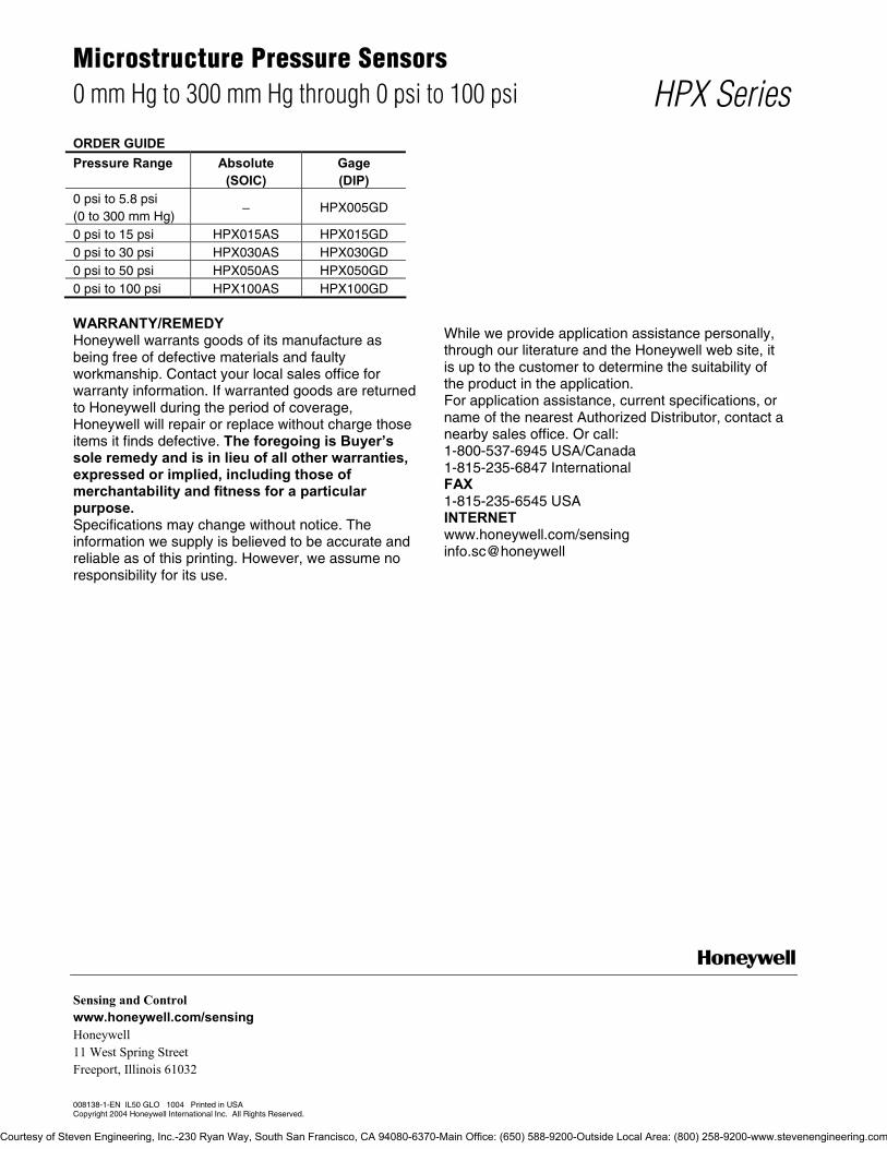
Microstructure Pressure Sensors 0 mm Hg to 300 mm Hg through 0 psi to 100 psi HPX Series
Sensing and Control www.honeywell.com/sensing Honeywell 11 West Spring Street Freeport, Illinois 61032 008138-1-EN IL50 GLO 1004 Printed in USA Copyright 2004 Honeywell International Inc. All Rights Reserved.
ORDER GUIDE Pressure Range Absolute
(SOIC) Gage (DIP)
0 psi to 5.8 psi (0 to 300 mm Hg)
HPX005GD
0 psi to 15 psi HPX015AS HPX015GD 0 psi to 30 psi HPX030AS HPX030GD 0 psi to 50 psi HPX050AS HPX050GD 0 psi to 100 psi HPX100AS HPX100GD WARRANTY/REMEDY Honeywell warrants goods of its manufacture as being free of defective materials and faulty workmanship. Contact your local sales office for warranty information. If warranted goods are returned to Honeywell during the period of coverage, Honeywell will repair or replace without charge those items it finds defective. The foregoing is Buyers sole remedy and is in lieu of all other warranties, expressed or implied, including those of merchantability and fitness for a particular purpose. Specifications may change without notice. The information we supply is believed to be accurate and reliable as of this printing. However, we assume no responsibility for its use.
While we provide application assistance personally, through our literature and the Honeywell web site, it is up to the customer to determine the suitability of the product in the application. For application assistance, current specifications, or name of the nearest Authorized Distributor, contact a nearby sales office. Or call: 1-800-537-6945 USA/Canada 1-815-235-6847 International FAX 1-815-235-6545 USA INTERNET www.honeywell.com/sensing info.sc@honeywell
Courtesy of Steven Engineering, Inc.-230 Ryan Way, South San Francisco, CA 94080-6370-Main Office: (650) 588-9200-Outside Local Area: (800) 258-9200-www.stevenengineering.com

DESCRIPTION The TruStability® Standard Accuracy Silicon Ceramic (SSC) Series is a piezoresistive silicon pressure sensor offering a ratiometric analog output for reading pressure over the specified full scale pressure span and temperature range. The SSC Series is fully calibrated and temperature compensated for sensor offset, sensitivity, temperature effects, and non-linearity using an on-board Application Specific Integrated Circuit (ASIC). Calibrated output values for pressure are updated at approximately 1 kHz. The SSC Series is calibrated over the temperature range of -20 C to 85 C [-4 F to 185 F]. The sensor is characterized for operation from a single power supply of either 3.3 Vdc or 5.0 Vdc.
These sensors measure absolute, differential, and gage pressures. The absolute versions have an internal vacuum reference and an output value proportional to absolute pressure. Differential versions allow application of pressure to either side of the sensing diaphragm. Gage versions are referenced to atmospheric pressure and provide an output proportional to pressure variations from atmosphere. The TruStability® pressure sensors are intended for use with non-corrosive, non-ionic gases, such as air and other dry gases. An available option extends the performance of these sensors to non-corrosive, non-ionic liquids. All products are designed and manufactured according to ISO 9001 standards.
FEATURES Industry-leading long-term stability Extremely tight accuracy of 0.25% FSS BFSL (Full Scale
Span Best Fit Straight Line) Total error band of 2% full scale span maximum Modular and flexible design offers customers a variety of
package styles and options, all with the same industry-leading performance specifications
Miniature 10 mm x 10 mm [0.39 in x 0.39 in] package Low operating voltage Extremely low power consumption Ratiometric analog output High resolution (min. 0.03 %FSS)
Precision ASIC conditioning and temperature compensated over -20 C to 85 C [-4 F to 185 F] temperature range
RoHS compliant Virtually insensitive to mounting orientation Internal diagnostic functions increase system reliability Also available with I2C or SPI digital output Absolute, differential and gage types Pressure ranges from 1 psi to 150 psi (60 mbar to 10 bar) Custom calibration available Various pressure port options Liquid media option
Courtesy of Steven Engineering, Inc.-230 Ryan Way, South San Francisco, CA 94080-6370-Main Office: (650) 588-9200-Outside Local Area: (800) 258-9200-www.stevenengineering.com

2 www.honeywell.com/sensing
POTENTIAL APPLICATIONS Medical:
- Airflow monitors - Anesthesia machines - Blood analysis machines - Gas chromatography - Gas flow instrumentation - Kidney dialysis machines - Oxygen concentrators - Pneumatic controls - Respiratory machines - Sleep apnea equipment - Ventilators
Industrial: - Barometry - Flow calibrators - Gas chromatography - Gas flow instrumentation - HVAC - Life sciences - Pneumatic controls
Table 1. Absolute Maximum Ratings1
Parameter Min. Max. Unit Supply voltage (Vsupply) -0.3 6.0 Vdc Voltage on any pin -0.3 Vsupply + 0.3 V ESD susceptibility (human body model) 3 kV Storage temperature -40 [-40] 85 [185] °C [°F] Soldering time and temperature:
Lead solder (SIP, DIP) Peak reflow (SMT)
4 s max. at 250 °C [482 °F]
15 s max. at 250 °C [482 °F] Table 2. Operating Specifications
Parameter Min. Typ. Max. Unit Supply voltage (Vsupply)2: 3.3 Vdc 5.0 Vdc Sensors are either 3.3 Vdc or 5.0 Vdc based on listing selected.
3.0
4.75
3.33 5.03
3.6
5.25 Vdc
Supply current: 3.3 Vdc supply 5.0 Vdc supply
-
1.6 2
2.1 3
mA
Compensated temperature range4 -20 [-4] 85 [185] °C [°F] Operating temperature range5 -40 [-40] 85 [185] °C [°F] Startup time (power up to data ready) 5 ms Response time 1 ms Upper output clipping limit 97.5 %Vsupply Lower output clipping limit 2.5 %Vsupply Accuracy6 ±0.25 %FSS BFSL Total error band7 ±2 %FSS8 Output resolution 0.03 %FSS8
Courtesy of Steven Engineering, Inc.-230 Ryan Way, South San Francisco, CA 94080-6370-Main Office: (650) 588-9200-Outside Local Area: (800) 258-9200-www.stevenengineering.com

Honeywell Sensing and Control 3
Table 3. Environmental Specifications Parameter Characteristic Humidity:
Dry gases only (See “Options N and D” in Figure 1.) Liquid media (See “Options T and V” in Figure 1.)
0% to 95% RH, non-condensing 100% condensing or direct liquid media on Port 1
Vibration MIL-STD-202F, Curve AK (20.7 g random) Shock MIL-STD-202F, Method 213B, Condition F Life9 1 million cycles minimum Solder reflow J-STD-020-C
Table 4. Wetted Materials10
Parameter Port 1 (Pressure Port) Port 2 (Reference Port) Covers high temperature polyamide high temperature polyamide Substrate alumina ceramic alumina ceramic Adhesives epoxy, silicone epoxy, silicone Electronic components ceramic, glass, solder, silicon silicon, glass, gold, solder
Notes: 1. Absolute maximum ratings are the extreme limits the device will withstand without damage. 2. Ratiometricity of the sensor (the ability of the device to scale to the supply voltage) is achieved within the specified operating voltage for each
option. 3. The sensor is not reverse polarity protected. Incorrect application of supply voltage or ground to the wrong pin may cause electrical failure. 4. The compensated temperature range is the temperature range over which the sensor will produce an output proportional to pressure within
the specified performance limits. 5. The operating temperature range is the temperature range over which the sensor will produce an output proportional to pressure but may not
remain within the specified performance limits. 6. Accuracy: The maximum deviation in output from a Best Fit Straight Line (BFSL) fitted to the output measured over the pressure range at
25 °C [77 °F]. Includes all errors due to pressure non-linearity, pressure hysteresis, and non-repeatability. 7. Total Error Band: The maximum deviation from the ideal transfer function over the entire compensated temperature and pressure range.
Includes all errors due to offset, full scale span, pressure non-linearity, pressure hysteresis, repeatability, thermal effect on offset, thermal effect on span, and thermal hysteresis.
8. Full Scale Span (FSS) is the algebraic difference between the output signal measured at the maximum (Pmax.) and minimum (Pmin.) limits of the pressure range. (See Figure 1 for ranges.)
9. Life may vary depending on specific application in which sensor is utilized. 10. Contact Honeywell Customer Service for detailed material information. CAUTION PRODUCT DAMAGE Ensure liquid media is applied to Port 1 only; Port 2 is not compatible with liquids. Ensure liquid media contains no particulates. All TruStability® sensors are dead-ended devices. Particulates can accumulate
inside the sensor, causing damage or affecting sensor output. Recommend that the sensor be positioned with Port 1 facing downwards; any particulates in the system are less likely to
enter and settle within the pressure sensor if it is in this position. Ensure liquid media does not create a residue when dried; build-up inside the sensor may affect sensor output. Rinsing of a
dead-ended sensor is difficult and has limited effectiveness for removing residue. Ensure liquid media are compatible with wetted materials. Non-compatible liquid media will degrade sensor performance and
may lead to sensor failure. Failure to comply with these instructions may result in product damage.
Courtesy of Steven Engineering, Inc.-230 Ryan Way, South San Francisco, CA 94080-6370-Main Office: (650) 588-9200-Outside Local Area: (800) 258-9200-www.stevenengineering.com

4 www.honeywell.com/sensing
Figure 1. Nomenclature and Order Guide
Series
PackageD = DIP (Dual Inline Pin)M = SMT (Surface Mount Technology)S = SIP (Single Inline Pin)
Transfer Function11
A = 10% to 90% of Vsupply
Output Type12
A = Analog voltage
SSC _ _ _ _ _ _ _ _ _ _ASupply Voltage3 = 3.3 Vdc5 = 5.0 Vdc
Pressure Range13, 14
1 psi to 150 psi
Absolute015PA = 0 psi to 15 psi030PA = 0 psi to 30 psi060PA = 0 psi to 60 psi100PA = 0 psi to 100 psi150PA = 0 psi to 150 psi
Differential001PD = ±1 psi005PD = ±5 psi015PD = ±15 psi030PD = ±30 psi060PD = ±60 psi
Gage001PG = 0 psi to 1 psi005PG = 0 psi to 5 psi015PG = 0 psi to 15 psi030PG = 0 psi to 30 psi060PG = 0 psi to 60 psi100PG = 0 psi to 100 psi150PG = 0 psi to 150 psi
60 mbar to 10 bar
Absolute001BA = 0 bar to 1 bar1.6BA = 0 bar to 1.6 bar2.5BA = 0 bar to 2.5 bar004BA = 0 bar to 4 bar006BA = 0 bar to 6 bar010BA = 0 bar to 10 bar
Differential060MD = ±60 mbar100MD = ±100 mbar160MD = ±160 mbar250MD = ±250 mbar400MD = ±400 mbar600MD = ±600 mbar001BD = ±1 bar1.6BD = ±1.6 bar2.5BD = ±2.5 bar004BD = ±4 bar
Gage060MG = 0 mbar to 60 mbar100MG = 0 mbar to 100 mbar160MG = 0 mbar to 160 mbar250MG = 0 mbar to 250 mbar400MG = 0 bar to 400 mbar600MG = 0 bar to 600 mbar001BG = 0 bar to 1 bar1.6BG = 0 bar to 1.6 bar2.5BG = 0 bar to 2.5 bar004BG = 0 bar to 4 bar006BG = 0 bar to 6 bar010BG = 0 bar to 10 bar
A
Options15
N = Dry gases only, no special optionsD = Dry gases only, diagnostics onT = Liquid media on Port 1, no diagnosticsV = Liquid media on Port 1, diagnostics on
AA = Dual axial barbed ports, opposite sides
DIP
AN = Single axial barbed port
DR = Dual radial barbed ports, opposite sides
FF = Fastener mount, dual axial barbed ports, opposite sides
FN = Fastener mount, single axial barbed port
HH = Fastener mount, dual radial barbed ports, same side
HN = Fastener mount, single radial barbed port
MN = Manifold mount, outer diameter seal
LN = Single axial barbless port
NB = Fastener mount, dual axial ports, same side
NN = No ports
RN = Single radial barbed port
RR = Dual radial barbed ports, same side
SN = Manifold mount, inner diameter seal
Pressure Port (* indicates not available)SMT SIP
AN = Single axial barbed port
AN = Single axial barbed port
DR = Dual radial barbed ports, opposite sides
DR =Dual radial barbed ports, opposite sides
LN = Single axial barbless port
RN = Single radial barbed port
RN = Single radial barbed port
RR = Dual radial barbed ports, same side
RR = Dual radial barbed ports, same side
NN = No ports NN = No ports
LN = Single axial barbless port
* *
* *
* *
* *
* *
* *
* *
* *
* *
GN = Ribbed fastener mount, single axial barbed port
Notes: 11. The transfer function limits define the output of the sensor at a given pressure input. By specifying Pmin. and Pmax., the output at Pmin. and
Pmax., the complete transfer function of the sensor is defined. See Figure 2 for a graphical representation of the transfer function. Other transfer functions are available. Contact Honeywell Customer Service for more information.
12. Digital outputs (SPI or I2C) are also available. Contact Honeywell Customer Service for more information. 13. Custom pressure ranges are available. Contact Honeywell Customer Service for more information. 14. See Table 5 for an explanation of sensor pressure types. 15. See CAUTION on previous page.
Courtesy of Steven Engineering, Inc.-230 Ryan Way, South San Francisco, CA 94080-6370-Main Office: (650) 588-9200-Outside Local Area: (800) 258-9200-www.stevenengineering.com
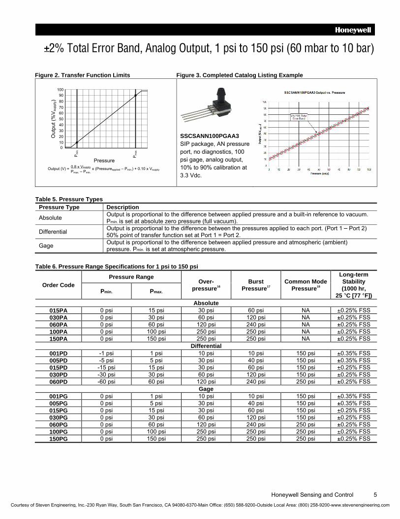
Honeywell Sensing and Control 5
Figure 2. Transfer Function Limits Figure 3. Completed Catalog Listing Example
Pressure
Out
put (
%V
supp
ly)
0102030405060708090
100
Pm
in.
Pm
ax.
Output (V) = 0.8 x Vsupply Pmax. – Pmin.
x (Pressureapplied – Pmin.) + 0.10 x Vsupply
SSCSANN100PGAA3 SIP package, AN pressure port, no diagnostics, 100 psi gage, analog output, 10% to 90% calibration at 3.3 Vdc.
Table 5. Pressure Types
Pressure Type Description
Absolute Output is proportional to the difference between applied pressure and a built-in reference to vacuum. Pmin. is set at absolute zero pressure (full vacuum).
Differential Output is proportional to the difference between the pressures applied to each port. (Port 1 Port 2) 50% point of transfer function set at Port 1 = Port 2.
Gage Output is proportional to the difference between applied pressure and atmospheric (ambient) pressure. Pmin. is set at atmospheric pressure.
Table 6. Pressure Range Specifications for 1 psi to 150 psi
Order Code Pressure Range
Over- pressure16
Burst Pressure17
Common Mode Pressure18
Long-term Stability (1000 hr,
25 C [77 F]) Pmin. Pmax.
Absolute 015PA 0 psi 15 psi 30 psi 60 psi NA 0.25% FSS 030PA 0 psi 30 psi 60 psi 120 psi NA 0.25% FSS 060PA 0 psi 60 psi 120 psi 240 psi NA 0.25% FSS 100PA 0 psi 100 psi 250 psi 250 psi NA 0.25% FSS 150PA 0 psi 150 psi 250 psi 250 psi NA 0.25% FSS
Differential 001PD -1 psi 1 psi 10 psi 10 psi 150 psi 0.35% FSS 005PD -5 psi 5 psi 30 psi 40 psi 150 psi 0.35% FSS 015PD -15 psi 15 psi 30 psi 60 psi 150 psi 0.25% FSS 030PD -30 psi 30 psi 60 psi 120 psi 150 psi 0.25% FSS 060PD -60 psi 60 psi 120 psi 240 psi 250 psi 0.25% FSS
Gage 001PG 0 psi 1 psi 10 psi 10 psi 150 psi 0.35% FSS 005PG 0 psi 5 psi 30 psi 40 psi 150 psi 0.35% FSS 015PG 0 psi 15 psi 30 psi 60 psi 150 psi 0.25% FSS 030PG 0 psi 30 psi 60 psi 120 psi 150 psi 0.25% FSS 060PG 0 psi 60 psi 120 psi 240 psi 250 psi 0.25% FSS 100PG 0 psi 100 psi 250 psi 250 psi 250 psi 0.25% FSS 150PG 0 psi 150 psi 250 psi 250 psi 250 psi 0.25% FSS
Courtesy of Steven Engineering, Inc.-230 Ryan Way, South San Francisco, CA 94080-6370-Main Office: (650) 588-9200-Outside Local Area: (800) 258-9200-www.stevenengineering.com
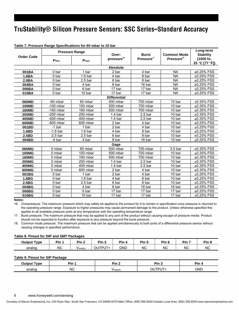
6 www.honeywell.com/sensing
Table 7. Pressure Range Specifications for 60 mbar to 10 bar
Order Code Pressure Range
Over- pressure16
Burst Pressure17
Common Mode Pressure18
Long-term Stability (1000 hr,
25 C [77 F]) Pmin. Pmax.
Absolute 001BA 0 bar 1 bar 2 bar 4 bar NA 0.25% FSS 1.6BA 0 bar 1.6 bar 4 bar 8 bar NA 0.25% FSS 2.5BA 0 bar 2.5 bar 6 bar 8 bar NA 0.25% FSS 004BA 0 bar 4 bar 8 bar 16 bar NA 0.25% FSS 006BA 0 bar 6 bar 17 bar 17 bar NA 0.25% FSS 010BA 0 bar 10 bar 17 bar 17 bar NA 0.25% FSS
Differential 060MD -60 mbar 60 mbar 500 mbar 700 mbar 10 bar 0.35% FSS 100MD -100 mbar 100 mbar 500 mbar 700 mbar 10 bar 0.35% FSS 160MD -160 mbar 160 mbar 500 mbar 700 mbar 10 bar 0.35% FSS 250MD -250 mbar 250 mbar 1.4 bar 2.5 bar 10 bar 0.35% FSS 400MD -400 mbar 400 mbar 1.4 bar 2.5 bar 10 bar 0.35% FSS 600MD -600 mbar 600 mbar 2 bar 4 bar 10 bar 0.25% FSS 001BD -1 bar 1 bar 2 bar 4 bar 10 bar 0.25% FSS 1.6BD -1.6 bar 1.6 bar 4 bar 8 bar 10 bar 0.25% FSS 2.5BD -2.5 bar 2.5 bar 6 bar 8 bar 10 bar 0.25% FSS 004BD -4 bar 4 bar 8 bar 16 bar 10 bar 0.25% FSS
Gage 060MG 0 mbar 60 mbar 500 mbar 700 mbar 3.5 bar 0.35% FSS 100MG 0 mbar 100 mbar 500 mbar 700 mbar 10 bar 0.35% FSS 160MG 0 mbar 160 mbar 500 mbar 700 mbar 10 bar 0.35% FSS 250MG 0 mbar 250 mbar 1.4 bar 2.5 bar 10 bar 0.35% FSS 400MG 0 mbar 400 mbar 1.4 bar 2.5 bar 10 bar 0.35% FSS 600MG 0 mbar 600 mbar 2 bar 4 bar 10 bar 0.35% FSS 001BG 0 bar 1 bar 2 bar 4 bar 10 bar 0.25% FSS 1.6BG 0 bar 1.6 bar 4 bar 8 bar 10 bar 0.25% FSS 2.5BG 0 bar 2.5 bar 6 bar 8 bar 10 bar 0.25% FSS 004BG 0 bar 4 bar 8 bar 16 bar 16 bar 0.25% FSS 006BG 0 bar 6 bar 17 bar 17 bar 17 bar 0.25% FSS 010BG 0 bar 10 bar 17 bar 17 bar 17 bar 0.25% FSS
Notes: 16. Overpressure: The maximum pressure which may safely be applied to the product for it to remain in specification once pressure is returned to
the operating pressure range. Exposure to higher pressures may cause permanent damage to the product. Unless otherwise specified this applies to all available pressure ports at any temperature with the operating temperature range.
17. Burst pressure: The maximum pressure that may be applied to any port of the product without causing escape of pressure media. Product should not be expected to function after exposure to any pressure beyond the burst pressure.
18. Common mode pressure: The maximum pressure that can be applied simultaneously to both ports of a differential pressure sensor without causing changes in specified performance.
Table 8. Pinout for DIP and SMT Packages
Output Type Pin 1 Pin 2 Pin 3 Pin 4 Pin 5 Pin 6 Pin 7 Pin 8 analog NC Vsupply OUTPUT+ GND NC NC NC NC
Table 9. Pinout for SIP Package
Output Type Pin 1 Pin 2 Pin 3 Pin 4 analog NC Vsupply OUTPUT+ GND
Courtesy of Steven Engineering, Inc.-230 Ryan Way, South San Francisco, CA 94080-6370-Main Office: (650) 588-9200-Outside Local Area: (800) 258-9200-www.stevenengineering.com

Honeywell Sensing and Control 7
Figure 4. DIP Pressure Port Dimensional Drawings (For reference only: mm [in]) DIP NN: No ports
13,35[0.525]
10,0[0.39]
6,99[0.275]
1 2 3 4
8 7 6 5
10,85[0.427]
9,24[0.364]
5,44[0.214]
2,54 TYP.[0.100]
8X 0,46 [0.018]
0,25[0.010]
PORT 1 PORT 2
DIP AN: Single axial barbed port
1 2 3 4
10,0[0.39]
13,35[0.525]
PORT 1
8 7 6 5
6,2[0.24]
2,54 TYP.[0.100]
9,24[0.364]
11,21[0.441]
7,95[0.313]
13,75[0.541]
4,93 DIA.[0.194] PORT 2 6,99
[0.275]
8X 0,46 [0.018]
0,25[0.010]
DIP LN: Single axial barbless port
PORT 1
PORT 2
10,0[0.39]
13,35[0.525]
6,99[0.275]
2,54 TYP.[0.100]
6,95[0.274]
1,00[0.039]
9,24[0.364]
11,21[0.441]
13,75[0.541]
5,80[0.228]
1 2 3 4
8 7 6 5
8X 0,46 [0.018]
0,25[0.010]
2,47 DIA.[0.097]
DIP RN: Single radial barbed port
PORT 1
13,35[0.525]
10,0[0.39]
6,99[0.275]
1 2 3 4
8 7 6 5
11,21[0.441]
9,24[0.364]
5,80[0.228]
2,54 TYP.[0.100]
8X 0,46 [0.018]
0,25[0.010]
1,93 DIA. [0.076]
4,2[0.17]
PORT 2
DIP RR: Dual radial barbed ports, same side
8X 0,46 [0.018]
13,35[0.525]
10,0[0.39]
6,99[0.275]
1 2 3 4
8 7 6 5
6,16[0.242]
2,54 TYP.[0.100] 11,21
[0.441]
9,24[0.364]
2X 1,93 DIA. [0.076]
4,65[0.183]
,25[0.010]
PORT 1 PORT 2
PORT 1
PORT 2
4,0[0.16]
3,78[0.149]
DIP DR: Dual radial barbed ports, opposite sides 10,0
[0.39]
13,35[0.525]
PORT 1PORT 2
1 2 3 4
8 7 6 5
6,16[0.242]
9,24[0.364]
2,54 TYP.[0.100]
15,76[0.620]
11,21[0.441]
2X 1,93 DIA.[0.076]
6,99[0.275]
8X 0,46 [0.018]
0,25[0.010]
PORT 1 PORT 2
3,78[0.149]
Courtesy of Steven Engineering, Inc.-230 Ryan Way, South San Francisco, CA 94080-6370-Main Office: (650) 588-9200-Outside Local Area: (800) 258-9200-www.stevenengineering.com

8 www.honeywell.com/sensing
Figure 5. SMT Pressure Port Dimensional Drawings (For reference only: mm [in]) SMT NN: No ports
13,4[0.53]
10,0[0.39]
6,99[0.275]
1 2 3 4
8 7 6 5
5,44[0.214]
2,54 TYP.[0.100] 6,41
[0.252]
4,80[0.189]
8X 0,46 [0.018]
PORT 1 PORT 2
SMT AN: Single axial barbed port
1 2 3 4
8 7 6 5
10,0[0.39]
13,4[0.53]
7,95[0.313]
13,75[0.541]
4,93 DIA.[0.194]
2,54 TYP.[0.100]
PORT 1
PORT 2
6,77[0.266]
4,80[0.189] 8X 0,46
[0.018]
6,99[0.275]
SMT LN: Single axial barbless port
10,0[0.394]
13,35[0.525]6,99
[0.275]
1 2 3 4
8 7 6 5
2,54 TYP.[0.100] 6,77
[0.266]
4,80[0.189]
5,80[0.228]
13,75[0.541]
8X 0,46 [0.018]
PORT 1
PORT 2
2,47 DIA.[0.097]
SMT RN: Single radial barbed port
13,3[0.53]
10,0[0.39]
6,99[0.275]
1 2 3 4
8 7 6 5
5,80[0.228]
2,54 TYP.[0.100] 6,77
[0.266]
4,80[0.189]
8X 0,46 [0.018]
PORT 1
1,93 DIA. [0.076]
4,2[0.17]
PORT 1 PORT 2
SMT RR: Dual radial barbed ports, same side
10,0[0.39]
6,99[0.275]
1 2 3 4
8 7 6 5
6,16[0.242]
2,54 TYP.[0.100] 6,77
[0.266]
4,80[0.189]
8X 0,46 [0.018]
13,35[0.525]
4,6[0.18]
PORT 1
PORT 2
2X 1,93 DIA. [0.076]
PORT 1 PORT 2
4,0[0.16]
3,78[0.149]
SMT DR: Dual radial barbed ports, opposite sides
1 2 3 4
8 7 6 5
13,4[0.53]
PORT 2PORT 1
10,0[0.39]
6,99[0.275]
2X 2,93 [0.115]
15,8[0.62]
2,54 TYP.[0.100]
2X 1,93 DIA.[0.076]
6,77[0.266]
4,80[0.189]
6,16[0.242]
3,78[0.149]
8X 0,46 [0.018]
Courtesy of Steven Engineering, Inc.-230 Ryan Way, South San Francisco, CA 94080-6370-Main Office: (650) 588-9200-Outside Local Area: (800) 258-9200-www.stevenengineering.com

Honeywell Sensing and Control 9
Figure 6. SIP Package Dimensional Drawings (For reference only: mm [in]) SIP NN: No ports
2,54 TYP.[0.100]
10,0[0.39]
15,2[0.60]
10,0[0.39]
1 2 3 4
4X 0,51 [0.020]
4,87[0.192]
PORT 1 PORT 2
0,25[0.010]
SIP AA: Dual axial barbed ports, opposite sides
PORT 1 PORT 2
0,25[0.010]
1 2 3 4
10,0[0.39]
10,0[0.39]
2,54 TYP.[0.100]
15,2[0.60]
22,06[0.869]
2X 4.93 DIA.[0.194]
4X 0,51 [0.020]
SIP AN: Single axial barbed port
0,25[0.010] 2,54 TYP.
[0.100]
PORT 1
1 2 3 4
10,0[0.39]
4.93 DIA.[0.194]
10,0[0.39]
13,75[0.541]
15,2[0.60]
PORT 2
4X 0,51 [0.020]
SIP LN: Single barbless port
10,0[0.39]
15,2[0.60]
10,0[0.39]
1 2 3 4
2,54 TYP.[0.100]
PORT 1
PORT 2
0,25[0.010]
13,75[0.541]
4X 0,51 [0.020]
2,47 DIA.[0.097]
SIP FF: Fastener mount, dual axial barbed ports, opposite sides
0,25[0.010] 2,54 TYP.
[0.100]
29,48[1.161]
1 2 3 4
27,20[1.071]
23,12[0.910]
10,44[0.411]
PORT 1PORT 2
17,78[0.700]
20,16[0.794]
2X 4,78 DIA.[0.188]
2X 3.94 DIA.[0.155]
4X 0,51 [.020]
SIP FN: Fastener mount, single axial barbed port
1 2 3 4
17,78[0.700]
20,16[0.794]
2,54 TYP.[0.100]
0,25[0.010]
29,48[1.161]
23,12[0.910]
PORT 1PORT 2
16,38[0.645]
2X 3.94 DIA.[0.155] 4.78 DIA.
[0.188]
4X 0,51 [0.020]
Courtesy of Steven Engineering, Inc.-230 Ryan Way, South San Francisco, CA 94080-6370-Main Office: (650) 588-9200-Outside Local Area: (800) 258-9200-www.stevenengineering.com

10 www.honeywell.com/sensing
Figure 6. SIP Package Dimensional Drawings (continued) SIP GN: Ribbed fastener mount, single axial barbed port
2,54 TYP.[0.100]
21,60[0.850]
PORT 1PORT 2
1 2 3 4
4.78 DIA.[0.188]
0,25[0.010]
2X 3,94 DIA.[0.155]
27,96[1.101]
16,51[0.650]
19,06[0.750]
10,63[0.418]
4X 0,51 [0.020]
SIP NB: Fastener mount, dual axial ports, same side
0,25[0.010] 2,54 TYP.
[0.100]
22,87[0.900]
13[0.52]
2X 3.50 DIA.[0.138]
21,60[0.850]
27,31[1.075] 25,3
[0.996]
PORT 1
PORT 2
4 3 2 1
4X 0,51 [0.020]
2X 4,80 DIA.[0.189]
SIP RN: Single radial barbed port
0,25[0.010] 2,54 TYP.
[0.100]
PORT 1
PORT 2
10,0[0.39]
15,2[0.60]
10,0[0.39]
1 2 3 4
5,80[0.228]
1,92 DIA.[0.076]
4X 0,51 [0.020]
SIP RR: Dual radial barbed ports, same side
0,25[0.010] 2,54 TYP.
[0.100]
PORT 1
PORT 2
1 2 3 4
10,0[0.39]
15,2[0.60]
10,0[0.39] 2X 1,92 DIA.
[0.076]
6,16[0.243]
4X 0,51 [0.020]
Courtesy of Steven Engineering, Inc.-230 Ryan Way, South San Francisco, CA 94080-6370-Main Office: (650) 588-9200-Outside Local Area: (800) 258-9200-www.stevenengineering.com

Honeywell Sensing and Control 11
Figure 6. SIP Package Dimensional Drawings (continued) SIP DR: Dual radial barbed ports, opposite side
0,25[0.010] 2,54 TYP.
[0.100]
PORT 1 PORT 2
1 2 3 4
10,0[0.39]
10,0[0.39]
15,2[0.60]
6,16[0.243]
2X 4.93 DIA.[0.194]
15,8[0.62]
4X 0,51 [0.020]
SIP HH: Fastener mount, dual radial barbed ports, same side
0,25[0.010]
1 2 3 4
28,96[1.140]
2,54 TYP.[0.100]
PORT 1PORT 2
29,62[1.166]
23,12[0.910]
11,27[0.444]
6,64[0.261]
10,58[0.416]
4X 0,51 [0.020]
PORT 1PORT 2
SIP HN: Fastener mount, single radial barbed port
28,96[1.140]
11,27[0.444]
23,12[0.910]
0,25[0.010] 2,54 TYP.
[0.100]
1 2 3 4
2X 3,94 DIA.[0.155]
7,97[0.314] 4,78 DIA.
[0.188]
4X 0,51 [0.020]
PORT 1
PORT 2
SIP MN: Manifold mount, outer diameter seal
2,54 TYP.[0.100]
0,25[0.010]
1 2 3 4
PORT 1PORT 2
15,24 DIA.[0.600]
12,5[0.49]
5,36[0.211]
4X 0,51 [0.020]
SIP SN: Manifold mount, inner diameter seal
2,54 TYP.[0.100]
1 2 3 4
13,11[0.516]
12,57[0.495]
15,6[0.61]
5,1[0.20]
4X 0,51 [0.020]
PORT 1
PORT 2
Courtesy of Steven Engineering, Inc.-230 Ryan Way, South San Francisco, CA 94080-6370-Main Office: (650) 588-9200-Outside Local Area: (800) 258-9200-www.stevenengineering.com

Sensing and Control Honeywell 1985 Douglas Drive North Golden Valley, MN 55422 www.honeywell.com
008215-2-EN IL50 GLO Printed in USA March 2011 © 2011 Honeywell International Inc.
WARNING PERSONAL INJURY DO NOT USE these products as safety or emergency stop devices or in any other application where failure of the product could result in personal injury. Failure to comply with these instructions could result in death or serious injury.
WARRANTY/REMEDY Honeywell warrants goods of its manufacture as being free of defective materials and faulty workmanship. Honeywell s standard product warranty applies unless agreed to otherwise by Honeywell in writing; please refer to your order acknowledgement or consult your local sales office for specific warranty details. If warranted goods are returned to Honeywell during the period of coverage, Honeywell will repair or replace, at its option, without charge those items it finds defective. The foregoing is buyer s sole remedy and is in lieu of all other warranties, expressed or implied, including those of merchantability and fitness for a particular purpose. In no event shall Honeywell be liable for consequential, special, or indirect damages. While we provide application assistance personally, through our literature and the Honeywell web site, it is up to the customer to determine the suitability of the product in the application. Specifications may change without notice. The information we supply is believed to be accurate and reliable as of this printing. However, we assume no responsibility for its use.
WARNING MISUSE OF DOCUMENTATION The information presented in this product sheet is for
reference only. DO NOT USE this document as a product installation guide.
Complete installation, operation, and maintenance information is provided in the instructions supplied with each product.
Failure to comply with these instructions could result in death or serious injury.
SALES AND SERVICE Honeywell serves its customers through a worldwide network of sales offices, representatives and distributors. For application assistance, current specifications, pricing or name of the nearest Authorized Distributor, contact your local sales office or: E-mail: [email protected] Internet: www.honeywell.com/sensing Phone and Fax: Asia Pacific +65 6355-2828; +65 6445-3033 Fax Europe +44 (0) 1698 481481; +44 (0) 1698 481676 Fax Latin America +1-305-805-8188; +1-305-883-8257 Fax USA/Canada +1-800-537-6945; +1-815-235-6847 +1-815-235-6545 Fax
Courtesy of Steven Engineering, Inc.-230 Ryan Way, South San Francisco, CA 94080-6370-Main Office: (650) 588-9200-Outside Local Area: (800) 258-9200-www.stevenengineering.com

DESCRIPTION The TruStability Standard Accuracy Silicon Ceramic (SSC) Series is a piezoresistive silicon pressure sensor offering a digital output for reading pressure over the specified full scale pressure span and temperature range. The SSC Series is fully calibrated and temperature compensated for sensor offset, sensitivity, temperature effects, and non-linearity using an on-board Application Specific Integrated Circuit (ASIC). Calibrated output values for pressure are updated at approximately 2 kHz. The SSC Series is calibrated over the temperature range of -20 C to 85 C [-4 F to 185 F]. The sensor is characterized for operation from a single power supply of either 3.3 Vdc or 5.0 Vdc.
These sensors measure absolute, differential, and gage pressures. The absolute versions have an internal vacuum reference and an output value proportional to absolute pressure. Differential versions allow application of pressure to either side of the sensing diaphragm. Gage versions are referenced to atmospheric pressure and provide an output proportional to pressure variations from atmosphere. The TruStability® pressure sensors are intended for use with non-corrosive, non-ionic gases, such as air and other dry gases. An available option extends the performance of these sensors to non-corrosive, non-ionic liquids. All products are designed and manufactured according to ISO 9001 standards.
FEATURES Industry-leading long-term stability Extremely tight accuracy of 0.25% FSS BFSL (Full Scale
Span Best Fit Straight Line) Total error band of 2% full scale span maximum Modular and flexible design offers customers a variety of
package styles and options, all with the same industry-leading performance specifications
Miniature 10 mm x 10 mm [0.39 in x 0.39 in] package Low operating voltage Extremely low power consumption I2C- or SPI- compatible 14-bit digital output (min. 12-bit
sensor resolution)
Precision ASIC conditioning and temperature compensated over -20 C to 85 C [-4 F to 185 F] temperature range
RoHS compliant Virtually insensitive to mounting orientation Internal diagnostic functions increase system reliability Also available with analog output Absolute, differential, and gage types Pressure ranges from 1 psi to 150 psi (60 mbar to 10 bar) Custom calibration available Various pressure port options Liquid media option
Courtesy of Steven Engineering, Inc.-230 Ryan Way, South San Francisco, CA 94080-6370-Main Office: (650) 588-9200-Outside Local Area: (800) 258-9200-www.stevenengineering.com

2 www.honeywell.com/sensing
POTENTIAL APPLICATIONS Medical:
- Airflow monitors - Anesthesia machines - Blood analysis machines - Gas chromatography - Gas flow instrumentation - Kidney dialysis machines - Oxygen concentrators - Pneumatic controls - Respiratory machines - Sleep apnea equipment - Ventilators
Industrial: - Barometry - Flow calibrators - Gas chromatography - Gas flow instrumentation - HVAC - Life sciences - Pneumatic controls
Table 1. Absolute Maximum Ratings1
Parameter Min. Max. Unit Supply voltage (Vsupply) -0.3 6.0 Vdc Voltage on any pin -0.3 Vsupply + 0.3 V Digital interface clock frequency:
I2C SPI
100 50
400 800
kHz
ESD susceptibility (human body model) 3 kV Storage temperature -40 [-40] 85 [185] C [ F] Soldering time and temperature:
Lead solder (SIP, DIP) Peak reflow (SMT)
4 s max. at 250 °C [482 °F]
15 s max. at 250 °C [482 °F] Table 2. Operating Specifications
Parameter Min. Typ. Max. Unit Supply voltage (Vsupply)2: 3.3 Vdc 5.0 Vdc Sensors are either 3.3 Vdc or 5.0 Vdc based on listing selected.
3.0
4.75
3.33 5.03
3.6
5.25 Vdc
Supply current: 3.3 Vdc supply 5.0 Vdc supply
-
1.6 2
2.1 3
mA
Compensated temperature range4 -20 [-4] 85 [185] C [ F] Operating temperature range5 -40 [-40] 85 [185] C [ F] Startup time (power up to data ready) 2.8 7.3 ms Response time 0.46 ms I2C voltage level low - - 0.2 Vsupply I2C voltage level high 0.8 - - Vsupply Pull up on SDA and SCL 1 - - kOhm Accuracy6 0.25 %FSS BFSL Total error band7 2 %FSS8 Output resolution 12 bits
Courtesy of Steven Engineering, Inc.-230 Ryan Way, South San Francisco, CA 94080-6370-Main Office: (650) 588-9200-Outside Local Area: (800) 258-9200-www.stevenengineering.com

Honeywell Sensing and Control 3
Table 3. Environmental Specifications Parameter Characteristic Humidity:
Dry gases only (See “Options N and D” in Figure 1.) Liquid media (See “Options T and V” in Figure 1.)
0% to 95% RH, non-condensing 100% condensing or direct liquid media on Port 1
Vibration MIL-STD-202F, Curve AK (20.7 g random) Shock MIL-STD-202F, Method 213B, Condition F Life9 1 million cycles minimum Solder reflow J-STD-020-C
Table 4. Wetted Materials10
Parameter Port 1 (Pressure Port) Port 2 (Reference Port) Covers high temperature polyamide high temperature polyamide Substrate alumina ceramic alumina ceramic Adhesives epoxy, silicone epoxy, silicone Electronic components ceramic, glass, solder, silicon silicon, glass, gold, solder
Notes: 1. Absolute maximum ratings are the extreme limits the device will withstand without damage. 2. Ratiometricity of the sensor (the ability of the digital device to maintain performance parameters independent of supply voltage) is achieved
within the specified operating voltage for each option. 3. The sensor is not reverse polarity protected. Incorrect application of supply voltage or ground to the wrong pin may cause electrical failure. 4. The compensated temperature range is the temperature range over which the sensor will produce an output proportional to pressure within
the specified performance limits. 5. The operating temperature range is the temperature range over which the sensor will produce an output proportional to pressure but may not
remain within the specified performance limits. 6. Accuracy: The maximum deviation in output from a Best Fit Straight Line (BFSL) fitted to the output measured over the pressure range at
25 °C [77 °F]. Includes all errors due to pressure non-linearity, pressure hysteresis, and non-repeatability. 7. Total Error Band: The maximum deviation from the ideal transfer function over the entire compensated temperature and pressure range.
Includes all errors due to offset, full scale span, pressure non-linearity, pressure hysteresis, repeatability, thermal effect on offset, thermal effect on span, and thermal hysteresis.
8. Full Scale Span (FSS) is the algebraic difference between the output signal measured at the maximum (Pmax.) and minimum (Pmin.) limits of the pressure range. (See Figure 1 for ranges.)
9. Life may vary depending on specific application in which sensor is utilized. 10. Contact Honeywell Customer Service for detailed material information. CAUTION PRODUCT DAMAGE Ensure liquid media is applied to Port 1 only; Port 2 is not compatible with liquids. Ensure liquid media contains no particulates. All TruStability® sensors are dead-ended devices. Particulates can accumulate
inside the sensor, causing damage or affecting sensor output. Recommend that the sensor be positioned with Port 1 facing downwards; any particulates in the system are less likely to
enter and settle within the pressure sensor if it is in this position. Ensure liquid media does not create a residue when dried; build-up inside the sensor may affect sensor output. Rinsing of a
dead-ended sensor is difficult and has limited effectiveness for removing residue. Ensure liquid media are compatible with wetted materials. Non-compatible liquid media will degrade sensor performance and
may lead to sensor failure. Failure to comply with these instructions may result in product damage.
Courtesy of Steven Engineering, Inc.-230 Ryan Way, South San Francisco, CA 94080-6370-Main Office: (650) 588-9200-Outside Local Area: (800) 258-9200-www.stevenengineering.com

4 www.honeywell.com/sensing
Figure 1. Nomenclature and Order Guide
Series
PackageD = DIP (Dual Inline Pin)M = SMT (Surface Mount Technology)S = SIP (Single Inline Pin)
Transfer Function11
A = 10% to 90% of Vsupply
Output Type12
S = SPI (not available in SIP package) 2 = I2C, Address 0x283 = I2C, Address 0x38 4 = I2C, Address 0x48 5 = I2C, Address 0x586 = I2C, Address 0x68 7 = I2C, Address 0x78
SSC _ _ _ _ _ _ _ _ _ _A_Supply Voltage3 = 3.3 Vdc5 = 5.0 Vdc
Pressure Range13, 14
1 psi to 150 psi
Absolute015PA = 0 psi to 15 psi030PA = 0 psi to 30 psi060PA = 0 psi to 60 psi100PA = 0 psi to 100 psi150PA = 0 psi to 150 psi
Differential001PD = ±1 psi005PD = ±5 psi015PD = ±15 psi030PD = ±30 psi060PD = ±60 psi
Gage001PG = 0 psi to 1 psi005PG = 0 psi to 5 psi015PG = 0 psi to 15 psi030PG = 0 psi to 30 psi060PG = 0 psi to 60 psi100PG = 0 psi to 100 psi150PG = 0 psi to 150 psi
60 mbar to 10 bar
Absolute001BA = 0 bar to 1 bar1.6BA = 0 bar to 1.6 bar2.5BA = 0 bar to 2.5 bar004BA = 0 bar to 4 bar006BA = 0 bar to 6 bar010BA = 0 bar to 10 bar
Differential060MD = ±60 mbar100MD = ±100 mbar160MD = ±160 mbar250MD = ±250 mbar400MD = ±400 mbar600MD = ±600 mbar001BD = ±1 bar1.6BD = ±1.6 bar2.5BD = ±2.5 bar004BD = ±4 bar
Gage060MG = 0 mbar to 60 mbar100MG = 0 mbar to 100 mbar160MG = 0 mbar to 160 mbar250MG = 0 mbar to 250 mbar400MG = 0 bar to 400 mbar600MG = 0 bar to 600 mbar001BG = 0 bar to 1 bar1.6BG = 0 bar to 1.6 bar2.5BG = 0 bar to 2.5 bar004BG = 0 bar to 4 bar006BG = 0 bar to 6 bar010BG = 0 bar to 10 bar
Options15
N = Dry gases only, no special optionsD = Dry gases only, diagnostics onT = Liquid media on port 1, no diagnosticsV = Liquid media on port 1, diagnostics on
AA = Dual axial barbed ports, opposite sides
DIP
AN = Single axial barbed port
DR = Dual radial barbed ports, opposite sides
FF = Fastener mount, dual axial barbed ports, opposite sides
FN = Fastener mount, single axial barbed port
HH = Fastener mount, dual radial barbed ports, same side
HN = Fastener mount, single radial barbed port
MN = Manifold mount, outer diameter seal
LN = Single axial barbless port
NB = Fastener mount, dual axial ports, same side
NN = No ports
RN = Single radial barbed port
RR = Dual radial barbed ports, same side
SN = Manifold mount, inner diameter seal
Pressure Port (* indicates not available)SMT SIP
AN = Single axial barbed port
AN = Single axial barbed port
DR = Dual radial barbed ports, opposite sides
DR =Dual radial barbed ports, opposite sides
LN = Single axial barbless port
RN = Single radial barbed port
RN = Single radial barbed port
RR = Dual radial barbed ports, same side
RR = Dual radial barbed ports, same side
NN = No ports NN = No ports
LN = Single axial barbless port
* *
* *
* *
* *
* *
* *
* *
* *
* *
GN = Ribbed fastener mount, single axial barbed port
Notes: 11. The transfer function limits define the output of the sensor at a given pressure input. By specifying Pmin. and Pmax., the output at Pmin. and
Pmax., the complete transfer function of the sensor is defined. See Figure 2 for a graphical representation of the transfer function. Other transfer functions are available. Contact Honeywell Customer Service for more information.
12. Analog output is also available. Contact Honeywell Customer Service for more information. 13. Custom pressure ranges are available. Contact Honeywell Customer Service for more information. 14. See Table 5 for an explanation of sensor pressure types. 15. See CAUTION on previous page.
Courtesy of Steven Engineering, Inc.-230 Ryan Way, South San Francisco, CA 94080-6370-Main Office: (650) 588-9200-Outside Local Area: (800) 258-9200-www.stevenengineering.com
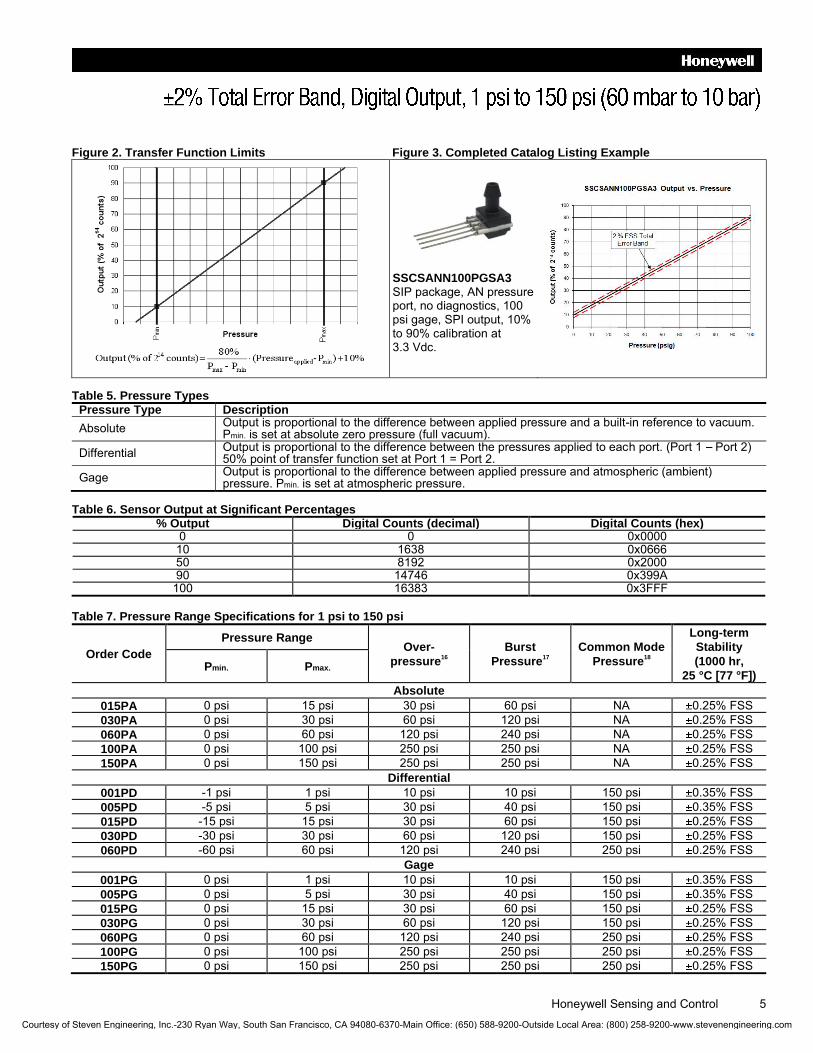
Honeywell Sensing and Control 5
Figure 2. Transfer Function Limits Figure 3. Completed Catalog Listing Example
SSCSANN100PGSA3 SIP package, AN pressure port, no diagnostics, 100 psi gage, SPI output, 10% to 90% calibration at 3.3 Vdc.
Table 5. Pressure Types
Pressure Type Description Absolute Output is proportional to the difference between applied pressure and a built-in reference to vacuum.
Pmin. is set at absolute zero pressure (full vacuum). Differential Output is proportional to the difference between the pressures applied to each port. (Port 1 Port 2)
50% point of transfer function set at Port 1 = Port 2. Gage Output is proportional to the difference between applied pressure and atmospheric (ambient)
pressure. Pmin. is set at atmospheric pressure. Table 6. Sensor Output at Significant Percentages
% Output Digital Counts (decimal) Digital Counts (hex) 0 0 0x0000 10 1638 0x0666 50 8192 0x2000 90 14746 0x399A
100 16383 0x3FFF Table 7. Pressure Range Specifications for 1 psi to 150 psi
Order Code Pressure Range
Over- pressure16
Burst Pressure17
Common Mode Pressure18
Long-term Stability (1000 hr,
25 °C [77 °F]) Pmin. Pmax.
Absolute 015PA 0 psi 15 psi 30 psi 60 psi NA 0.25% FSS 030PA 0 psi 30 psi 60 psi 120 psi NA 0.25% FSS 060PA 0 psi 60 psi 120 psi 240 psi NA 0.25% FSS 100PA 0 psi 100 psi 250 psi 250 psi NA 0.25% FSS 150PA 0 psi 150 psi 250 psi 250 psi NA 0.25% FSS
Differential 001PD -1 psi 1 psi 10 psi 10 psi 150 psi 0.35% FSS 005PD -5 psi 5 psi 30 psi 40 psi 150 psi 0.35% FSS 015PD -15 psi 15 psi 30 psi 60 psi 150 psi 0.25% FSS 030PD -30 psi 30 psi 60 psi 120 psi 150 psi 0.25% FSS 060PD -60 psi 60 psi 120 psi 240 psi 250 psi 0.25% FSS
Gage 001PG 0 psi 1 psi 10 psi 10 psi 150 psi 0.35% FSS 005PG 0 psi 5 psi 30 psi 40 psi 150 psi 0.35% FSS 015PG 0 psi 15 psi 30 psi 60 psi 150 psi 0.25% FSS 030PG 0 psi 30 psi 60 psi 120 psi 150 psi 0.25% FSS 060PG 0 psi 60 psi 120 psi 240 psi 250 psi 0.25% FSS 100PG 0 psi 100 psi 250 psi 250 psi 250 psi 0.25% FSS 150PG 0 psi 150 psi 250 psi 250 psi 250 psi 0.25% FSS
Courtesy of Steven Engineering, Inc.-230 Ryan Way, South San Francisco, CA 94080-6370-Main Office: (650) 588-9200-Outside Local Area: (800) 258-9200-www.stevenengineering.com

6 www.honeywell.com/sensing
Table 8. Pressure Range Specifications for 60 mbar to 10 bar
Order Code Pressure Range
Over- pressure16
Burst Pressure17
Common Mode Pressure18
Long-term Stability (1000 hr,
25 C [77 F]) Pmin. Pmax.
Absolute 001BA 0 bar 1 bar 2 bar 4 bar NA 0.25% FSS 1.6BA 0 bar 1.6 bar 4 bar 8 bar NA 0.25% FSS 2.5BA 0 bar 2.5 bar 6 bar 8 bar NA 0.25% FSS 004BA 0 bar 4 bar 8 bar 16 bar NA 0.25% FSS 006BA 0 bar 6 bar 17 bar 17 bar NA 0.25% FSS 010BA 0 bar 10 bar 17 bar 17 bar NA 0.25% FSS
Differential 060MD -60 mbar 60 mbar 500 mbar 700 mbar 10 bar 0.35% FSS 100MD -100 mbar 100 mbar 500 mbar 700 mbar 10 bar 0.35% FSS 160MD -160 mbar 160 mbar 500 mbar 700 mbar 10 bar 0.35% FSS 250MD -250 mbar 250 mbar 1.4 bar 2.5 bar 10 bar 0.35% FSS 400MD -400 mbar 400 mbar 1.4 bar 2.5 bar 10 bar 0.35% FSS 600MD -600 mbar 600 mbar 2 bar 4 bar 10 bar 0.25% FSS 001BD -1 bar 1 bar 2 bar 4 bar 10 bar 0.25% FSS 1.6BD -1.6 bar 1.6 bar 4 bar 8 bar 10 bar 0.25% FSS 2.5BD -2.5 bar 2.5 bar 6 bar 8 bar 10 bar 0.25% FSS 004BD -4 bar 4 bar 8 bar 16 bar 10 bar 0.25% FSS
Gage 060MG 0 mbar 60 mbar 500 mbar 700 mbar 3.5 bar 0.35% FSS 100MG 0 mbar 100 mbar 500 mbar 700 mbar 10 bar 0.35% FSS 160MG 0 mbar 160 mbar 500 mbar 700 mbar 10 bar 0.35% FSS 250MG 0 mbar 250 mbar 1.4 bar 2.5 bar 10 bar 0.35% FSS 400MG 0 mbar 400 mbar 1.4 bar 2.5 bar 10 bar 0.35% FSS 600MG 0 mbar 600 mbar 2 bar 4 bar 10 bar 0.35% FSS 001BG 0 bar 1 bar 2 bar 4 bar 10 bar 0.25% FSS 1.6BG 0 bar 1.6 bar 4 bar 8 bar 10 bar 0.25% FSS 2.5BG 0 bar 2.5 bar 6 bar 8 bar 10 bar 0.25% FSS 004BG 0 bar 4 bar 8 bar 16 bar 16 bar 0.25% FSS 006BG 0 bar 6 bar 17 bar 17 bar 17 bar 0.25% FSS 010BG 0 bar 10 bar 17 bar 17 bar 17 bar 0.25% FSS
Notes: 16. Overpressure: The maximum pressure which may safely be applied to the product for it to remain in specification once pressure is returned to
the operating pressure range. Exposure to higher pressures may cause permanent damage to the product. Unless otherwise specified this applies to all available pressure ports at any temperature with the operating temperature range.
17. Burst pressure: The maximum pressure that may be applied to any port of the product without causing escape of pressure media. Product should not be expected to function after exposure to any pressure beyond the burst pressure.
18. Common mode pressure: The maximum pressure that can be applied simultaneously to both ports of a differential pressure sensor without causing changes in specified performance.
Table 9. Pinout for SMT and DIP Packages
Output Type Pin 1 Pin 2 Pin 3 Pin 4 Pin 5 Pin 6 Pin 7 Pin 8 I2C GND Vsupply SDA SCL NC NC NC NC SPI GND Vsupply MISO SCLK SS NC NC NC
Table 10. Pinout for SIP Package
Output Type Pin 1 Pin 2 Pin 3 Pin 4 I2C GND Vsupply SDA SCL
Courtesy of Steven Engineering, Inc.-230 Ryan Way, South San Francisco, CA 94080-6370-Main Office: (650) 588-9200-Outside Local Area: (800) 258-9200-www.stevenengineering.com

Honeywell Sensing and Control 7
Figure 4. DIP Pressure Port Dimensional Drawings (For reference only: mm [in]) DIP NN: No ports
13,35[0.525]
10,0[0.39]
6,99[0.275]
1 2 3 4
8 7 6 5
10,85[0.427]
9,24[0.364]
5,44[0.214]
2,54 TYP.[0.100]
8X 0,46 [0.018]
0,25[0.010]
PORT 1 PORT 2
DIP AN: Single axial barbed port
1 2 3 4
10,0[0.39]
13,35[0.525]
PORT 1
8 7 6 5
6,2[0.24]
2,54 TYP.[0.100]
9,24[0.364]
11,21[0.441]
7,95[0.313]
13,75[0.541]
4,93 DIA.[0.194] PORT 2 6,99
[0.275]
8X 0,46 [0.018]
0,25[0.010]
DIP LN: Single axial barbless port
PORT 1
PORT 2
10,0[0.39]
13,35[0.525]
6,99[0.275]
2,54 TYP.[0.100]
6,95[0.274]
1,00[0.039]
9,24[0.364]
11,21[0.441]
13,75[0.541]
5,80[0.228]
1 2 3 4
8 7 6 5
8X 0,46 [0.018]
0,25[0.010]
2,47 DIA.[0.097]
DIP RN: Single radial barbed port
PORT 1
13,35[0.525]
10,0[0.39]
6,99[0.275]
1 2 3 4
8 7 6 5
11,21[0.441]
9,24[0.364]
5,80[0.228]
2,54 TYP.[0.100]
8X 0,46 [0.018]
0,25[0.010]
1,93 DIA. [0.076]
4,2[0.17]
PORT 2
DIP RR: Dual radial barbed ports, same side
8X 0,46 [0.018]
13,35[0.525]
10,0[0.39]
6,99[0.275]
1 2 3 4
8 7 6 5
6,16[0.242]
2,54 TYP.[0.100] 11,21
[0.441]
9,24[0.364]
2X 1,93 DIA. [0.076]
4,65[0.183]
,25[0.010]
PORT 1 PORT 2
PORT 1
PORT 2
4,0[0.16]
3,78[0.149]
DIP DR: Dual radial barbed ports, opposite sides 10,0[0.39]
13,35[0.525]
PORT 1PORT 2
1 2 3 4
8 7 6 5
6,16[0.242]
9,24[0.364]
2,54 TYP.[0.100]
15,76[0.620]
11,21[0.441]
2X 1,93 DIA.[0.076]
6,99[0.275]
8X 0,46 [0.018]
0,25[0.010]
PORT 1 PORT 2
3,78[0.149]
Courtesy of Steven Engineering, Inc.-230 Ryan Way, South San Francisco, CA 94080-6370-Main Office: (650) 588-9200-Outside Local Area: (800) 258-9200-www.stevenengineering.com

8 www.honeywell.com/sensing
Figure 5. SMT Pressure Port Dimensional Drawings (For reference only: mm [in]) SMT NN: No ports
13,4[0.53]
10,0[0.39]
6,99[0.275]
1 2 3 4
8 7 6 5
5,44[0.214]
2,54 TYP.[0.100] 6,41
[0.252]
4,80[0.189]
8X 0,46 [0.018]
PORT 1 PORT 2
SMT AN: Single axial barbed port
1 2 3 4
8 7 6 5
10,0[0.39]
13,4[0.53]
7,95[0.313]
13,75[0.541]
4,93 DIA.[0.194]
2,54 TYP.[0.100]
PORT 1
PORT 2
6,77[0.266]
4,80[0.189] 8X 0,46
[0.018]
6,99[0.275]
SMT LN: Single axial barbless port
10,0[0.394]
13,35[0.525]6,99
[0.275]
1 2 3 4
8 7 6 5
2,54 TYP.[0.100] 6,77
[0.266]
4,80[0.189]
5,80[0.228]
13,75[0.541]
8X 0,46 [0.018]
PORT 1
PORT 2
2,47 DIA.[0.097]
SMT RN: Single radial barbed port
13,3[0.53]
10,0[0.39]
6,99[0.275]
1 2 3 4
8 7 6 5
5,80[0.228]
2,54 TYP.[0.100] 6,77
[0.266]
4,80[0.189]
8X 0,46 [0.018]
PORT 1
1,93 DIA. [0.076]
4,2[0.17]
PORT 1 PORT 2
SMT RR: Dual radial barbed ports, same side
10,0[0.39]
6,99[0.275]
1 2 3 4
8 7 6 5
6,16[0.242]
2,54 TYP.[0.100] 6,77
[0.266]
4,80[0.189]
8X 0,46 [0.018]
13,35[0.525]
4,6[0.18]
PORT 1
PORT 2
2X 1,93 DIA. [0.076]
PORT 1 PORT 2
4,0[0.16]
3,78[0.149]
SMT DR: Dual radial barbed ports, opposite sides
1 2 3 4
8 7 6 5
13,4[0.53]
PORT 2PORT 1
10,0[0.39]
6,99[0.275]
2X 2,93 [0.115]
15,8[0.62]
2,54 TYP.[0.100]
2X 1,93 DIA.[0.076]
6,77[0.266]
4,80[0.189]
6,16[0.242]
3,78[0.149]
8X 0,46 [0.018]
Courtesy of Steven Engineering, Inc.-230 Ryan Way, South San Francisco, CA 94080-6370-Main Office: (650) 588-9200-Outside Local Area: (800) 258-9200-www.stevenengineering.com

Honeywell Sensing and Control 9
Figure 6. SIP Package Dimensional Drawings (For reference only: mm [in]) SIP NN: No ports
2,54 TYP.[0.100]
10,0[0.39]
15,2[0.60]
10,0[0.39]
1 2 3 4
4X 0,51 [0.020]
4,87[0.192]
PORT 1 PORT 2
0,25[0.010]
SIP AA: Dual axial barbed ports, opposite sides
PORT 1 PORT 2
0,25[0.010]
1 2 3 4
10,0[0.39]
10,0[0.39]
2,54 TYP.[0.100]
15,2[0.60]
22,06[0.869]
2X 4.93 DIA.[0.194]
4X 0,51 [0.020]
SIP AN: Single axial barbed port
0,25[0.010] 2,54 TYP.
[0.100]
PORT 1
1 2 3 4
10,0[0.39]
4.93 DIA.[0.194]
10,0[0.39]
13,75[0.541]
15,2[0.60]
PORT 2
4X 0,51 [0.020]
SIP LN: Single barbless port
10,0[0.39]
15,2[0.60]
10,0[0.39]
1 2 3 4
2,54 TYP.[0.100]
PORT 1
PORT 2
0,25[0.010]
13,75[0.541]
4X 0,51 [0.020]
2,47 DIA.[0.097]
SIP FF: Fastener mount, dual axial barbed ports, opposite sides
0,25[0.010] 2,54 TYP.
[0.100]
29,48[1.161]
1 2 3 4
27,20[1.071]
23,12[0.910]
10,44[0.411]
PORT 1PORT 2
17,78[0.700]
20,16[0.794]
2X 4,78 DIA.[0.188]
2X 3.94 DIA.[0.155]
4X 0,51 [.020]
SIP FN: Fastener mount, single axial barbed port
1 2 3 4
17,78[0.700]
20,16[0.794]
2,54 TYP.[0.100]
0,25[0.010]
29,48[1.161]
23,12[0.910]
PORT 1PORT 2
16,38[0.645]
2X 3.94 DIA.[0.155] 4.78 DIA.
[0.188]
4X 0,51 [0.020]
Courtesy of Steven Engineering, Inc.-230 Ryan Way, South San Francisco, CA 94080-6370-Main Office: (650) 588-9200-Outside Local Area: (800) 258-9200-www.stevenengineering.com

10 www.honeywell.com/sensing
Figure 6. SIP Package Dimensional Drawings (continued) SIP GN: Ribbed fastener mount, single axial barbed port
2,54 TYP.[0.100]
21,60[0.850]
PORT 1PORT 2
1 2 3 4
4.78 DIA.[0.188]
0,25[0.010]
2X 3,94 DIA.[0.155]
27,96[1.101]
16,51[0.650]
19,06[0.750]
10,63[0.418]
4X 0,51 [0.020]
SIP NB: Fastener mount, dual axial ports, same side
0,25[0.010] 2,54 TYP.
[0.100]
22,87[0.900]
13[0.52]
2X 3.50 DIA.[0.138]
21,60[0.850]
27,31[1.075] 25,3
[0.996]
PORT 1
PORT 2
4 3 2 1
4X 0,51 [0.020]
2X 4,80 DIA.[0.189]
SIP RN: Single radial barbed port
0,25[0.010] 2,54 TYP.
[0.100]
PORT 1
PORT 2
10,0[0.39]
15,2[0.60]
10,0[0.39]
1 2 3 4
5,80[0.228]
1,92 DIA.[0.076]
4X 0,51 [0.020]
SIP RR: Dual radial barbed ports, same side
0,25[0.010] 2,54 TYP.
[0.100]
PORT 1
PORT 2
1 2 3 4
10,0[0.39]
15,2[0.60]
10,0[0.39] 2X 1,92 DIA.
[0.076]
6,16[0.243]
4X 0,51 [0.020]
Courtesy of Steven Engineering, Inc.-230 Ryan Way, South San Francisco, CA 94080-6370-Main Office: (650) 588-9200-Outside Local Area: (800) 258-9200-www.stevenengineering.com

Honeywell Sensing and Control 11
Figure 6. SIP Package Dimensional Drawings (continued) SIP DR: Dual radial barbed ports, opposite side
0,25[0.010] 2,54 TYP.
[0.100]
PORT 1 PORT 2
1 2 3 4
10,0[0.39]
10,0[0.39]
15,2[0.60]
6,16[0.243]
2X 4.93 DIA.[0.194]
15,8[0.62]
4X 0,51 [0.020]
SIP HH: Fastener mount, dual radial barbed ports, same side
0,25[0.010]
1 2 3 4
28,96[1.140]
2,54 TYP.[0.100]
PORT 1PORT 2
29,62[1.166]
23,12[0.910]
11,27[0.444]
6,64[0.261]
10,58[0.416]
4X 0,51 [0.020]
PORT 1PORT 2
SIP HN: Fastener mount, single radial barbed port
28,96[1.140]
11,27[0.444]
23,12[0.910]
0,25[0.010] 2,54 TYP.
[0.100]
1 2 3 4
2X 3,94 DIA.[0.155]
7,97[0.314] 4,78 DIA.
[0.188]
4X 0,51 [0.020]
PORT 1
PORT 2
SIP MN: Manifold mount, outer diameter seal
2,54 TYP.[0.100]
0,25[0.010]
1 2 3 4
PORT 1PORT 2
15,24 DIA.[0.600]
12,5[0.49]
5,36[0.211]
4X 0,51 [0.020]
SIP SN: Manifold mount, inner diameter seal
2,54 TYP.[0.100]
1 2 3 4
13,11[0.516]
12,57[0.495]
15,6[0.61]
5,1[0.20]
4X 0,51 [0.020]
PORT 1
PORT 2
Courtesy of Steven Engineering, Inc.-230 Ryan Way, South San Francisco, CA 94080-6370-Main Office: (650) 588-9200-Outside Local Area: (800) 258-9200-www.stevenengineering.com

Sensing and Control Honeywell 1985 Douglas Drive North Golden Valley, MN 55422 www.honeywell.com
008213-2-EN IL50 GLO Printed in USA March 2011 © 2011 Honeywell International Inc.
WARNING PERSONAL INJURY DO NOT USE these products as safety or emergency stop devices or in any other application where failure of the product could result in personal injury. Failure to comply with these instructions could result in death or serious injury.
WARRANTY/REMEDY Honeywell warrants goods of its manufacture as being free of defective materials and faulty workmanship. Honeywell s standard product warranty applies unless agreed to otherwise by Honeywell in writing; please refer to your order acknowledgement or consult your local sales office for specific warranty details. If warranted goods are returned to Honeywell during the period of coverage, Honeywell will repair or replace, at its option, without charge those items it finds defective. The foregoing is buyer s sole remedy and is in lieu of all other warranties, expressed or implied, including those of merchantability and fitness for a particular purpose. In no event shall Honeywell be liable for consequential, special, or indirect damages. While we provide application assistance personally, through our literature and the Honeywell web site, it is up to the customer to determine the suitability of the product in the application. Specifications may change without notice. The information we supply is believed to be accurate and reliable as of this printing. However, we assume no responsibility for its use.
WARNING MISUSE OF DOCUMENTATION The information presented in this product sheet is for
reference only. DO NOT USE this document as a product installation guide.
Complete installation, operation, and maintenance information is provided in the instructions supplied with each product.
Failure to comply with these instructions could result in death or serious injury.
SALES AND SERVICE Honeywell serves its customers through a worldwide network of sales offices, representatives and distributors. For application assistance, current specifications, pricing or name of the nearest Authorized Distributor, contact your local sales office or: E-mail: [email protected] Internet: www.honeywell.com/sensing Phone and Fax: Asia Pacific +65 6355-2828; +65 6445-3033 Fax Europe +44 (0) 1698 481481; +44 (0) 1698 481676 Fax Latin America +1-305-805-8188; +1-305-883-8257 Fax USA/Canada +1-800-537-6945; +1-815-235-6847 +1-815-235-6545 Fax
Courtesy of Steven Engineering, Inc.-230 Ryan Way, South San Francisco, CA 94080-6370-Main Office: (650) 588-9200-Outside Local Area: (800) 258-9200-www.stevenengineering.com

DESCRIPTION The TruStability High Accuracy Silicon Ceramic (HSC) Series is a piezoresistive silicon pressure sensor offering a ratiometric analog output for reading pressure over the specified full scale pressure span and temperature range. The HSC Series is fully calibrated and temperature compensated for sensor offset, sensitivity, temperature effects, and non-linearity using an on-board Application Specific Integrated Circuit (ASIC). Calibrated output values for pressure are updated at approximately 1 kHz. The HSC Series is calibrated over the temperature range of 0 C to 50 C [32 F to 122 F]. The sensor is characterized for operation from a single power supply of either 3.3 Vdc or 5.0 Vdc.
These sensors measure absolute, differential, and gage pressures. The absolute versions have an internal vacuum reference and an output value proportional to absolute pressure. Differential versions allow application of pressure to either side of the sensing diaphragm. Gage versions are referenced to atmospheric pressure and provide an output proportional to pressure variations from atmosphere. The TruStability® pressure sensors are intended for use with non-corrosive, non-ionic gases, such as air and other dry gases. An available option extends the performance of these sensors to non-corrosive, non-ionic liquids. All products are designed and manufactured according to ISO 9001 standards.
FEATURES Industry-leading long-term stability Extremely tight accuracy of 0.25% FSS BFSL (Full Scale
Span Best Fit Straight Line) Total error band of 1% full scale span maximum Modular and flexible design offers customers a variety of
package styles and options, all with the same industry-leading performance specifications
Miniature 10 mm x 10 mm [0.39 in x 0.39 in] package Low operating voltage Extremely low power consumption Ratiometric analog output High resolution (min 0.03 %FSS)
Precision ASIC conditioning and temperature compensated over 0 C to 50 C [32 F to 122 F] temperature range
RoHS compliant Virtually insensitive to mounting orientation Internal diagnostic functions increase system reliability Also available with I2C or SPI digital output Absolute, differential and gage types Pressure ranges from 1 psi to 150 psi (60 mbar to 10 bar) Custom calibration available Various pressure port options Liquid media option
Courtesy of Steven Engineering, Inc.-230 Ryan Way, South San Francisco, CA 94080-6370-Main Office: (650) 588-9200-Outside Local Area: (800) 258-9200-www.stevenengineering.com

2 www.honeywell.com/sensing
POTENTIAL APPLICATIONS Medical:
- Airflow monitors - Anesthesia machines - Blood analysis machines - Gas chromatography - Gas flow instrumentation - Kidney dialysis machines - Oxygen concentrators - Pneumatic controls - Respiratory machines - Sleep apnea equipment - Ventilators
Industrial: - Barometry - Flow calibrators - Gas chromatography - Gas flow instrumentation - HVAC - Life sciences - Pneumatic controls
Table 1. Absolute Maximum Ratings1
Parameter Min. Max. Unit Supply voltage (Vsupply) -0.3 6.0 Vdc Voltage on any pin -0.3 Vsupply + 0.3 V ESD susceptibility (human body model) 3 kV Storage temperature -40 [-40] 85 [185] C [ F] Soldering time and temperature:
Lead solder temperature (SIP, DIP) Peak reflow temperature (SMT)
4 s max. at 250 °C [482 °F]
15 s max. at 250 °C [482 °F] Table 2. Operating Specifications
Parameter Min. Typ. Max. Unit Supply voltage (Vsupply)2: 3.3 Vdc 5.0 Vdc Sensors are either 3.3 Vdc or 5.0 Vdc based on listing selected.
3.0
4.75
3.33 5.03
3.6
5.25 Vdc
Supply current: 3.3 Vdc supply 5.0 Vdc supply
-
1.6 2
2.1 3
mA
Compensated temperature range4 0 [32] 50 [122] C [ F] Operating temperature range5 -20 [-4] 85 [185] C [ F] Startup time (power up to data ready) 5 ms Response time 1 ms Upper output clipping limit 97.5 %Vsupply Lower output clipping limit 2.5 %Vsupply Accuracy6 0.25 %FSS BFSL Total error band7 1 %FSS8 Output resolution 0.03 %FSS8
Courtesy of Steven Engineering, Inc.-230 Ryan Way, South San Francisco, CA 94080-6370-Main Office: (650) 588-9200-Outside Local Area: (800) 258-9200-www.stevenengineering.com

Honeywell Sensing and Control 3
Table 3. Environmental Specifications Parameter Characteristic Humidity:
Dry gases only (See “Options N and D” in Figure 1.) Liquid media (See “Options T and V” in Figure 1.)
0% to 95% RH, non-condensing 100% condensing or direct liquid media on Port 1
Vibration MIL-STD-202F, Curve AK (20.7 g random) Shock MIL-STD-202F, Method 213B, Condition F Life9 1 million cycles minimum Solder reflow J-STD-020-C
Table 4. Wetted Materials10
Parameter Port 1 (Pressure Port) Port 2 (Reference Port) Covers high temperature polyamide high temperature polyamide Substrate alumina ceramic alumina ceramic Adhesives epoxy, silicone epoxy, silicone Electronic components ceramic, glass, solder, silicon silicon, glass, gold, solder
Notes: 1. Absolute maximum ratings are the extreme limits the device will withstand without damage. 2. Ratiometricity of the sensor (the ability of the device to scale to the supply voltage) is achieved within the specified operating voltage for each
option. 3. The sensor is not reverse polarity protected. Incorrect application of supply voltage or ground to the wrong pin may cause electrical failure. 4. The compensated temperature range is the temperature range over which the sensor will produce an output proportional to pressure within
the specified performance limits. 5. The operating temperature range is the temperature range over which the sensor will produce an output proportional to pressure but may not
remain within the specified performance limits. 6. Accuracy: The maximum deviation in output from a Best Fit Straight Line (BFSL) fitted to the output measured over the pressure range at
25 °C [77 °F]. Includes all errors due to pressure non-linearity, pressure hysteresis, and non-repeatability. 7. Total Error Band: The maximum deviation from the ideal transfer function over the entire compensated temperature and pressure range.
Includes all errors due to offset, full scale span, pressure non-linearity, pressure hysteresis, repeatability, thermal effect on offset, thermal effect on span, and thermal hysteresis.
8. Full Scale Span (FSS) is the algebraic difference between the output signal measured at the maximum (Pmax.) and minimum (Pmin.) limits of the pressure range. (See Figure 1 for ranges.)
9. Life may vary depending on specific application in which sensor is utilized. 10. Contact Honeywell Customer Service for detailed material information.
CAUTION PRODUCT DAMAGE Ensure liquid media is applied to Port 1 only; Port 2 is not compatible with liquids. Ensure liquid media contains no particulates. All TruStability® sensors are dead-ended devices. Particulates can accumulate
inside the sensor, causing damage or affecting sensor output. Recommend that the sensor be positioned with Port 1 facing downwards; any particulates in the system are less likely to
enter and settle within the pressure sensor if it is in this position. Ensure liquid media does not create a residue when dried; build-up inside the sensor may affect sensor output. Rinsing of a
dead-ended sensor is difficult and has limited effectiveness for removing residue. Ensure liquid media are compatible with wetted materials. Non-compatible liquid media will degrade sensor performance and
may lead to sensor failure. Failure to comply with these instructions may result in product damage.
Courtesy of Steven Engineering, Inc.-230 Ryan Way, South San Francisco, CA 94080-6370-Main Office: (650) 588-9200-Outside Local Area: (800) 258-9200-www.stevenengineering.com
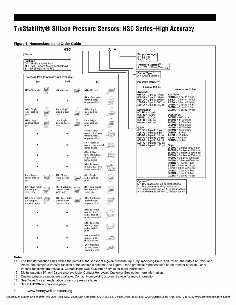
4 www.honeywell.com/sensing
Figure 1. Nomenclature and Order Guide
Series
PackageD = DIP (Dual Inline Pin)M = SMT (Surface Mount Technology)S = SIP (Single Inline Pin)
Transfer Function11
A = 10% to 90% of Vsupply
Output Type12
A = Analog voltage
HSC _ _ _ _ _ _ _ _ _ _ASupply Voltage3 = 3.3 Vdc5 = 5.0 Vdc
Pressure Range13, 14
1 psi to 150 psi
Absolute015PA = 0 psi to 15 psi030PA = 0 psi to 30 psi060PA = 0 psi to 60 psi100PA = 0 psi to 100 psi150PA = 0 psi to 150 psi
Differential001PD = ±1 psi005PD = ±5 psi015PD = ±15 psi030PD = ±30 psi060PD = ±60 psi
Gage001PG = 0 psi to 1 psi005PG = 0 psi to 5 psi015PG = 0 psi to 15 psi030PG = 0 psi to 30 psi060PG = 0 psi to 60 psi100PG = 0 psi to 100 psi150PG = 0 psi to 150 psi
60 mbar to 10 bar
Absolute001BA = 0 bar to 1 bar1.6BA = 0 bar to 1.6 bar2.5BA = 0 bar to 2.5 bar004BA = 0 bar to 4 bar006BA = 0 bar to 6 bar010BA = 0 bar to 10 bar
Differential060MD = ±60 mbar100MD = ±100 mbar160MD = ±160 mbar250MD = ±250 mbar400MD = ±400 mbar600MD = ±600 mbar001BD = ±1 bar1.6BD = ±1.6 bar2.5BD = ±2.5 bar004BD = ±4 bar
Gage060MG = 0 mbar to 60 mbar100MG = 0 mbar to 100 mbar160MG = 0 mbar to 160 mbar250MG = 0 mbar to 250 mbar400MG = 0 bar to 400 mbar600MG = 0 bar to 600 mbar001BG = 0 bar to 1 bar1.6BG = 0 bar to 1.6 bar2.5BG = 0 bar to 2.5 bar004BG = 0 bar to 4 bar006BG = 0 bar to 6 bar010BG = 0 bar to 10 bar
A
Options15
N = Dry gases only, no special optionsD = Dry gases only, diagnostics onT = Liquid media on Port 1, no diagnosticsV = Liquid media on Port 1, diagnostics on
AA = Dual axial barbed ports, opposite sides
DIP
AN = Single axial barbed port
DR = Dual radial barbed ports, opposite sides
FF = Fastener mount, dual axial barbed ports, opposite sides
FN = Fastener mount, single axial barbed port
HH = Fastener mount, dual radial barbed ports, same side
HN = Fastener mount, single radial barbed port
MN = Manifold mount, outer diameter seal
LN = Single axial barbless port
NB = Fastener mount, dual axial ports, same side
NN = No ports
RN = Single radial barbed port
RR = Dual radial barbed ports, same side
SN = Manifold mount, inner diameter seal
Pressure Port (* indicates not available)SMT SIP
AN = Single axial barbed port
AN = Single axial barbed port
DR = Dual radial barbed ports, opposite sides
DR =Dual radial barbed ports, opposite sides
LN = Single axial barbless port
RN = Single radial barbed port
RN = Single radial barbed port
RR = Dual radial barbed ports, same side
RR = Dual radial barbed ports, same side
NN = No ports NN = No ports
LN = Single axial barbless port
* *
* *
* *
* *
* *
* *
* *
* *
* *
GN = Ribbed fastener mount, single axial barbed port
Notes: 11. The transfer function limits define the output of the sensor at a given pressure input. By specifying Pmin. and Pmax., the output at Pmin. and
Pmax., the complete transfer function of the sensor is defined. See Figure 2 for a graphical representation of the transfer function. Other transfer functions are available. Contact Honeywell Customer Service for more information.
12. Digital outputs (SPI or I2C) are also available. Contact Honeywell Customer Service for more information. 13. Custom pressure ranges are available. Contact Honeywell Customer Service for more information. 14. See Table 5 for an explanation of sensor pressure types. 15. See CAUTION on previous page.
Courtesy of Steven Engineering, Inc.-230 Ryan Way, South San Francisco, CA 94080-6370-Main Office: (650) 588-9200-Outside Local Area: (800) 258-9200-www.stevenengineering.com

Honeywell Sensing and Control 5
Figure 2. Transfer Function Limits Figure 3. Completed Catalog Listing Example
Pressure
Out
put (
%V
supp
ly)
0102030405060708090
100
Pm
in.
Pm
ax.
Output (V) = 0.8 x Vsupply Pmax. – Pmin.
x (Pressureapplied – Pmin.) + 0.10 x Vsupply
HSCSANN100PGAA3 SIP package, AN pressure port, no diagnostics, 100 psi gage, analog output, 10% to 90% calibration at 3.3 Vdc.
Table 5. Pressure Types
Pressure Type Description
Absolute Output is proportional to the difference between applied pressure and a built-in reference to vacuum. Pmin. is set at absolute zero pressure (full vacuum).
Differential Output is proportional to the difference between the pressures applied to each port. (Port 1 Port 2) 50% point of transfer function set at Port 1 = Port 2.
Gage Output is proportional to the difference between applied pressure and atmospheric (ambient) pressure. Pmin.. is set at atmospheric pressure.
Table 6. Pressure Range Specifications for 1 psi to 150 psi
Order Code Pressure Range
Over- pressure16
Burst Pressure17
Common Mode Pressure18
Long-term Stability (1000 hr,
25 C [77 F]) Pmin. Pmax.
Absolute 015PA 0 psi 15 psi 30 psi 60 psi NA 0.25% FSS 030PA 0 psi 30 psi 60 psi 120 psi NA 0.25% FSS 060PA 0 psi 60 psi 120 psi 240 psi NA 0.25% FSS 100PA 0 psi 100 psi 250 psi 250 psi NA 0.25% FSS 150PA 0 psi 150 psi 250 psi 250 psi NA 0.25% FSS
Differential 001PD -1 psi 1 psi 10 psi 10 psi 150 psi 0.35% FSS 005PD -5 psi 5 psi 30 psi 40 psi 150 psi 0.35% FSS 015PD -15 psi 15 psi 30 psi 60 psi 150 psi 0.25% FSS 030PD -30 psi 30 psi 60 psi 120 psi 150 psi 0.25% FSS 060PD -60 psi 60 psi 120 psi 240 psi 250 psi 0.25% FSS
Gage 001PG 0 psi 1 psi 10 psi 10 psi 150 psi 0.35% FSS 005PG 0 psi 5 psi 30 psi 40 psi 150 psi 0.35% FSS 015PG 0 psi 15 psi 30 psi 60 psi 150 psi 0.25% FSS 030PG 0 psi 30 psi 60 psi 120 psi 150 psi 0.25% FSS 060PG 0 psi 60 psi 120 psi 240 psi 250 psi 0.25% FSS 100PG 0 psi 100 psi 250 psi 250 psi 250 psi 0.25% FSS 150PG 0 psi 150 psi 250 psi 250 psi 250 psi 0.25% FSS
Courtesy of Steven Engineering, Inc.-230 Ryan Way, South San Francisco, CA 94080-6370-Main Office: (650) 588-9200-Outside Local Area: (800) 258-9200-www.stevenengineering.com

6 www.honeywell.com/sensing
Table 7. Pressure Range Specifications for 60 mbar to 10 bar
Order Code Pressure Range
Over- pressure16
Burst Pressure17
Common Mode Pressure18
Long-term Stability (1000 hr,
25 C [77 F]) Pmin. Pmax.
Absolute 001BA 0 bar 1 bar 2 bar 4 bar NA 0.25% FSS 1.6BA 0 bar 1.6 bar 4 bar 8 bar NA 0.25% FSS 2.5BA 0 bar 2.5 bar 6 bar 8 bar NA 0.25% FSS 004BA 0 bar 4 bar 8 bar 16 bar NA 0.25% FSS 006BA 0 bar 6 bar 17 bar 17 bar NA 0.25% FSS 010BA 0 bar 10 bar 17 bar 17 bar NA 0.25% FSS
Differential 060MD -60 mbar 60 mbar 500 mbar 700 mbar 10 bar 0.35% FSS 100MD -100 mbar 100 mbar 500 mbar 700 mbar 10 bar 0.35% FSS 160MD -160 mbar 160 mbar 500 mbar 700 mbar 10 bar 0.35% FSS 250MD -250 mbar 250 mbar 1.4 bar 2.5 bar 10 bar 0.35% FSS 400MD -400 mbar 400 mbar 1.4 bar 2.5 bar 10 bar 0.35% FSS 600MD -600 mbar 600 mbar 2 bar 4 bar 10 bar 0.25% FSS 001BD -1 bar 1 bar 2 bar 4 bar 10 bar 0.25% FSS 1.6BD -1.6 bar 1.6 bar 4 bar 8 bar 10 bar 0.25% FSS 2.5BD -2.5 bar 2.5 bar 6 bar 8 bar 10 bar 0.25% FSS 004BD -4 bar 4 bar 8 bar 16 bar 10 bar 0.25% FSS
Gage 060MG 0 mbar 60 mbar 500 mbar 700 mbar 3.5 bar 0.35% FSS 100MG 0 mbar 100 mbar 500 mbar 700 mbar 10 bar 0.35% FSS 160MG 0 mbar 160 mbar 500 mbar 700 mbar 10 bar 0.35% FSS 250MG 0 mbar 250 mbar 1.4 bar 2.5 bar 10 bar 0.35% FSS 400MG 0 mbar 400 mbar 1.4 bar 2.5 bar 10 bar 0.35% FSS 600MG 0 mbar 600 mbar 2 bar 4 bar 10 bar 0.35% FSS 001BG 0 bar 1 bar 2 bar 4 bar 10 bar 0.25% FSS 1.6BG 0 bar 1.6 bar 4 bar 8 bar 10 bar 0.25% FSS 2.5BG 0 bar 2.5 bar 6 bar 8 bar 10 bar 0.25% FSS 004BG 0 bar 4 bar 8 bar 16 bar 16 bar 0.25% FSS 006BG 0 bar 6 bar 17 bar 17 bar 17 bar 0.25% FSS 010BG 0 bar 10 bar 17 bar 17 bar 17 bar 0.25% FSS
Notes: 16. Overpressure: The maximum pressure which may safely be applied to the product for it to remain in specification once pressure is returned to
the operating pressure range. Exposure to higher pressures may cause permanent damage to the product. Unless otherwise specified this applies to all available pressure ports at any temperature with the operating temperature range.
17. Burst pressure: The maximum pressure that may be applied to any port of the product without causing escape of pressure media. Product should not be expected to function after exposure to any pressure beyond the burst pressure.
18. Common mode pressure: The maximum pressure that can be applied simultaneously to both ports of a differential pressure sensor without causing changes in specified performance.
Table 8. Pinout for DIP and SMT Packages
Output Type Pin 1 Pin 2 Pin 3 Pin 4 Pin 5 Pin 6 Pin 7 Pin 8 analog NC Vsupply OUTPUT+ GND NC NC NC NC
Table 9. Pinout for SIP Packages
Output Type Pin 1 Pin 2 Pin 3 Pin 4 analog NC Vsupply OUTPUT+ GND
Courtesy of Steven Engineering, Inc.-230 Ryan Way, South San Francisco, CA 94080-6370-Main Office: (650) 588-9200-Outside Local Area: (800) 258-9200-www.stevenengineering.com

Honeywell Sensing and Control 7
Figure 4. DIP Pressure Port Dimensional Drawings (For reference only: mm [in]) DIP NN: No ports
13,35[0.525]
10,0[0.39]
6,99[0.275]
1 2 3 4
8 7 6 5
10,85[0.427]
9,24[0.364]
5,44[0.214]
2,54 TYP.[0.100]
8X 0,46 [0.018]
0,25[0.010]
PORT 1 PORT 2
DIP AN: Single axial barbed port
1 2 3 4
10,0[0.39]
13,35[0.525]
PORT 1
8 7 6 5
6,2[0.24]
2,54 TYP.[0.100]
9,24[0.364]
11,21[0.441]
7,95[0.313]
13,75[0.541]
4,93 DIA.[0.194] PORT 2 6,99
[0.275]
8X 0,46 [0.018]
0,25[0.010]
DIP LN: Single axial barbless port
PORT 1
PORT 2
10,0[0.39]
13,35[0.525]
6,99[0.275]
2,54 TYP.[0.100]
6,95[0.274]
1,00[0.039]
9,24[0.364]
11,21[0.441]
13,75[0.541]
5,80[0.228]
1 2 3 4
8 7 6 5
8X 0,46 [0.018]
0,25[0.010]
2,47 DIA.[0.097]
DIP RN: Single radial barbed port
PORT 1
13,35[0.525]
10,0[0.39]
6,99[0.275]
1 2 3 4
8 7 6 5
11,21[0.441]
9,24[0.364]
5,80[0.228]
2,54 TYP.[0.100]
8X 0,46 [0.018]
0,25[0.010]
1,93 DIA. [0.076]
4,2[0.17]
PORT 2
DIP RR: Dual radial barbed ports, same side
8X 0,46 [0.018]
13,35[0.525]
10,0[0.39]
6,99[0.275]
1 2 3 4
8 7 6 5
6,16[0.242]
2,54 TYP.[0.100] 11,21
[0.441]
9,24[0.364]
2X 1,93 DIA. [0.076]
4,65[0.183]
,25[0.010]
PORT 1 PORT 2
PORT 1
PORT 2
4,0[0.16]
3,78[0.149]
DIP DR: Dual radial barbed ports, opposite sides 10,0
[0.39]
13,35[0.525]
PORT 1PORT 2
1 2 3 4
8 7 6 5
6,16[0.242]
9,24[0.364]
2,54 TYP.[0.100]
15,76[0.620]
11,21[0.441]
2X 1,93 DIA.[0.076]
6,99[0.275]
8X 0,46 [0.018]
0,25[0.010]
PORT 1 PORT 2
3,78[0.149]
Courtesy of Steven Engineering, Inc.-230 Ryan Way, South San Francisco, CA 94080-6370-Main Office: (650) 588-9200-Outside Local Area: (800) 258-9200-www.stevenengineering.com

8 www.honeywell.com/sensing
Figure 5. SMT Pressure Port Dimensional Drawings (For reference only: mm [in]) SMT NN: No ports
13,4[0.53]
10,0[0.39]
6,99[0.275]
1 2 3 4
8 7 6 5
5,44[0.214]
2,54 TYP.[0.100] 6,41
[0.252]
4,80[0.189]
8X 0,46 [0.018]
PORT 1 PORT 2
SMT AN: Single axial barbed port
1 2 3 4
8 7 6 5
10,0[0.39]
13,4[0.53]
7,95[0.313]
13,75[0.541]
4,93 DIA.[0.194]
2,54 TYP.[0.100]
PORT 1
PORT 2
6,77[0.266]
4,80[0.189] 8X 0,46
[0.018]
6,99[0.275]
SMT LN: Single axial barbless port
10,0[0.394]
13,35[0.525]6,99
[0.275]
1 2 3 4
8 7 6 5
2,54 TYP.[0.100] 6,77
[0.266]
4,80[0.189]
5,80[0.228]
13,75[0.541]
8X 0,46 [0.018]
PORT 1
PORT 2
2,47 DIA.[0.097]
SMT RN: Single radial barbed port
13,3[0.53]
10,0[0.39]
6,99[0.275]
1 2 3 4
8 7 6 5
5,80[0.228]
2,54 TYP.[0.100] 6,77
[0.266]
4,80[0.189]
8X 0,46 [0.018]
PORT 1
1,93 DIA. [0.076]
4,2[0.17]
PORT 1 PORT 2
SMT RR: Dual radial barbed ports, same side
10,0[0.39]
6,99[0.275]
1 2 3 4
8 7 6 5
6,16[0.242]
2,54 TYP.[0.100] 6,77
[0.266]
4,80[0.189]
8X 0,46 [0.018]
13,35[0.525]
4,6[0.18]
PORT 1
PORT 2
2X 1,93 DIA. [0.076]
PORT 1 PORT 2
4,0[0.16]
3,78[0.149]
SMT DR: Dual radial barbed ports, opposite sides
1 2 3 4
8 7 6 5
13,4[0.53]
PORT 2PORT 1
10,0[0.39]
6,99[0.275]
2X 2,93 [0.115]
15,8[0.62]
2,54 TYP.[0.100]
2X 1,93 DIA.[0.076]
6,77[0.266]
4,80[0.189]
6,16[0.242]
3,78[0.149]
8X 0,46 [0.018]
Courtesy of Steven Engineering, Inc.-230 Ryan Way, South San Francisco, CA 94080-6370-Main Office: (650) 588-9200-Outside Local Area: (800) 258-9200-www.stevenengineering.com
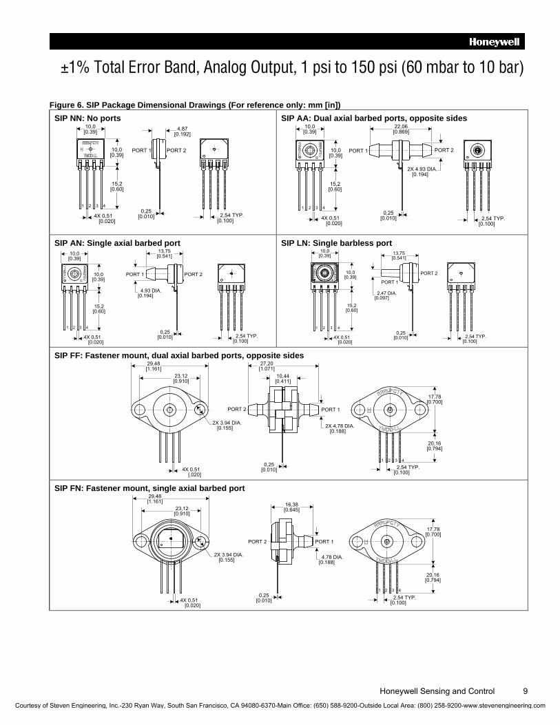
Honeywell Sensing and Control 9
Figure 6. SIP Package Dimensional Drawings (For reference only: mm [in]) SIP NN: No ports
2,54 TYP.[0.100]
10,0[0.39]
15,2[0.60]
10,0[0.39]
1 2 3 4
4X 0,51 [0.020]
4,87[0.192]
PORT 1 PORT 2
0,25[0.010]
SIP AA: Dual axial barbed ports, opposite sides
PORT 1 PORT 2
0,25[0.010]
1 2 3 4
10,0[0.39]
10,0[0.39]
2,54 TYP.[0.100]
15,2[0.60]
22,06[0.869]
2X 4.93 DIA.[0.194]
4X 0,51 [0.020]
SIP AN: Single axial barbed port
0,25[0.010] 2,54 TYP.
[0.100]
PORT 1
1 2 3 4
10,0[0.39]
4.93 DIA.[0.194]
10,0[0.39]
13,75[0.541]
15,2[0.60]
PORT 2
4X 0,51 [0.020]
SIP LN: Single barbless port
10,0[0.39]
15,2[0.60]
10,0[0.39]
1 2 3 4
2,54 TYP.[0.100]
PORT 1
PORT 2
0,25[0.010]
13,75[0.541]
4X 0,51 [0.020]
2,47 DIA.[0.097]
SIP FF: Fastener mount, dual axial barbed ports, opposite sides
0,25[0.010] 2,54 TYP.
[0.100]
29,48[1.161]
1 2 3 4
27,20[1.071]
23,12[0.910]
10,44[0.411]
PORT 1PORT 2
17,78[0.700]
20,16[0.794]
2X 4,78 DIA.[0.188]
2X 3.94 DIA.[0.155]
4X 0,51 [.020]
SIP FN: Fastener mount, single axial barbed port
1 2 3 4
17,78[0.700]
20,16[0.794]
2,54 TYP.[0.100]
0,25[0.010]
29,48[1.161]
23,12[0.910]
PORT 1PORT 2
16,38[0.645]
2X 3.94 DIA.[0.155] 4.78 DIA.
[0.188]
4X 0,51 [0.020]
Courtesy of Steven Engineering, Inc.-230 Ryan Way, South San Francisco, CA 94080-6370-Main Office: (650) 588-9200-Outside Local Area: (800) 258-9200-www.stevenengineering.com
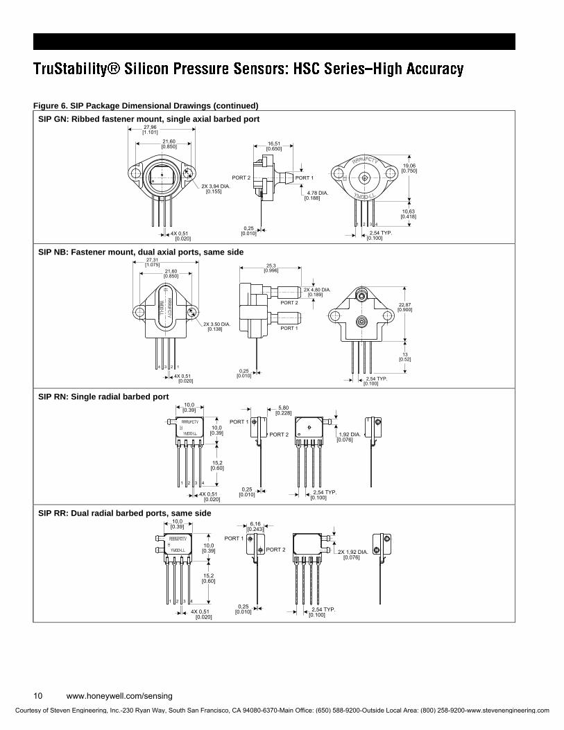
10 www.honeywell.com/sensing
Figure 6. SIP Package Dimensional Drawings (continued) SIP GN: Ribbed fastener mount, single axial barbed port
2,54 TYP.[0.100]
21,60[0.850]
PORT 1PORT 2
1 2 3 4
4.78 DIA.[0.188]
0,25[0.010]
2X 3,94 DIA.[0.155]
27,96[1.101]
16,51[0.650]
19,06[0.750]
10,63[0.418]
4X 0,51 [0.020]
SIP NB: Fastener mount, dual axial ports, same side
0,25[0.010] 2,54 TYP.
[0.100]
22,87[0.900]
13[0.52]
2X 3.50 DIA.[0.138]
21,60[0.850]
27,31[1.075] 25,3
[0.996]
PORT 1
PORT 2
4 3 2 1
4X 0,51 [0.020]
2X 4,80 DIA.[0.189]
SIP RN: Single radial barbed port
0,25[0.010] 2,54 TYP.
[0.100]
PORT 1
PORT 2
10,0[0.39]
15,2[0.60]
10,0[0.39]
1 2 3 4
5,80[0.228]
1,92 DIA.[0.076]
4X 0,51 [0.020]
SIP RR: Dual radial barbed ports, same side
0,25[0.010] 2,54 TYP.
[0.100]
PORT 1
PORT 2
1 2 3 4
10,0[0.39]
15,2[0.60]
10,0[0.39] 2X 1,92 DIA.
[0.076]
6,16[0.243]
4X 0,51 [0.020]
Courtesy of Steven Engineering, Inc.-230 Ryan Way, South San Francisco, CA 94080-6370-Main Office: (650) 588-9200-Outside Local Area: (800) 258-9200-www.stevenengineering.com
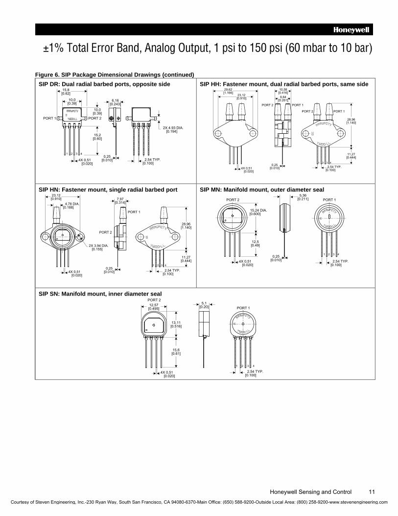
Honeywell Sensing and Control 11
Figure 6. SIP Package Dimensional Drawings (continued) SIP DR: Dual radial barbed ports, opposite side
0,25[0.010] 2,54 TYP.
[0.100]
PORT 1 PORT 2
1 2 3 4
10,0[0.39]
10,0[0.39]
15,2[0.60]
6,16[0.243]
2X 4.93 DIA.[0.194]
15,8[0.62]
4X 0,51 [0.020]
SIP HH: Fastener mount, dual radial barbed ports, same side
0,25[0.010]
1 2 3 4
28,96[1.140]
2,54 TYP.[0.100]
PORT 1PORT 2
29,62[1.166]
23,12[0.910]
11,27[0.444]
6,64[0.261]
10,58[0.416]
4X 0,51 [0.020]
PORT 1PORT 2
SIP HN: Fastener mount, single radial barbed port
28,96[1.140]
11,27[0.444]
23,12[0.910]
0,25[0.010] 2,54 TYP.
[0.100]
1 2 3 4
2X 3,94 DIA.[0.155]
7,97[0.314] 4,78 DIA.
[0.188]
4X 0,51 [0.020]
PORT 1
PORT 2
SIP MN: Manifold mount, outer diameter seal
2,54 TYP.[0.100]
0,25[0.010]
1 2 3 4
PORT 1PORT 2
15,24 DIA.[0.600]
12,5[0.49]
5,36[0.211]
4X 0,51 [0.020]
SIP SN: Manifold mount, inner diameter seal
2,54 TYP.[0.100]
1 2 3 4
13,11[0.516]
12,57[0.495]
15,6[0.61]
5,1[0.20]
4X 0,51 [0.020]
PORT 1
PORT 2
Courtesy of Steven Engineering, Inc.-230 Ryan Way, South San Francisco, CA 94080-6370-Main Office: (650) 588-9200-Outside Local Area: (800) 258-9200-www.stevenengineering.com

Sensing and Control Honeywell 1985 Douglas Drive North Golden Valley, MN 55422 www.honeywell.com
008216-2-EN IL50 GLO Printed in USA March 2011 © 2011 Honeywell International Inc.
WARNING PERSONAL INJURY DO NOT USE these products as safety or emergency stop devices or in any other application where failure of the product could result in personal injury. Failure to comply with these instructions could result in death or serious injury.
WARRANTY/REMEDY Honeywell warrants goods of its manufacture as being free of defective materials and faulty workmanship. Honeywell s standard product warranty applies unless agreed to otherwise by Honeywell in writing; please refer to your order acknowledgement or consult your local sales office for specific warranty details. If warranted goods are returned to Honeywell during the period of coverage, Honeywell will repair or replace, at its option, without charge those items it finds defective. The foregoing is buyer s sole remedy and is in lieu of all other warranties, expressed or implied, including those of merchantability and fitness for a particular purpose. In no event shall Honeywell be liable for consequential, special, or indirect damages. While we provide application assistance personally, through our literature and the Honeywell web site, it is up to the customer to determine the suitability of the product in the application. Specifications may change without notice. The information we supply is believed to be accurate and reliable as of this printing. However, we assume no responsibility for its use.
WARNING MISUSE OF DOCUMENTATION The information presented in this product sheet is for
reference only. DO NOT USE this document as a product installation guide.
Complete installation, operation, and maintenance information is provided in the instructions supplied with each product.
Failure to comply with these instructions could result in death or serious injury.
SALES AND SERVICE Honeywell serves its customers through a worldwide network of sales offices, representatives and distributors. For application assistance, current specifications, pricing or name of the nearest Authorized Distributor, contact your local sales office or: E-mail: [email protected] Internet: www.honeywell.com/sensing Phone and Fax: Asia Pacific +65 6355-2828; +65 6445-3033 Fax Europe +44 (0) 1698 481481; +44 (0) 1698 481676 Fax Latin America +1-305-805-8188; +1-305-883-8257 Fax USA/Canada +1-800-537-6945; +1-815-235-6847 +1-815-235-6545 Fax
Courtesy of Steven Engineering, Inc.-230 Ryan Way, South San Francisco, CA 94080-6370-Main Office: (650) 588-9200-Outside Local Area: (800) 258-9200-www.stevenengineering.com

DESCRIPTION The TruStability® High Accuracy Silicon Ceramic (HSC) Series is a piezoresistive silicon pressure sensor offering a digital output for reading pressure over the specified full scale pressure span and temperature range. The HSC Series is fully calibrated and temperature compensated for sensor offset, sensitivity, temperature effects, and non-linearity using an on-board Application Specific Integrated Circuit (ASIC). Calibrated output values for pressure are updated at approximately 2 kHz. The HSC Series is calibrated over the temperature range of 0 °C to 50 °C [32 °F to 122 °F]. The sensor is characterized for operation from a single power supply of either 3.3 Vdc or 5.0 Vdc.
These sensors measure absolute, differential, and gage pressures. The absolute versions have an internal vacuum reference and an output value proportional to absolute pressure. Differential versions allow application of pressure to either side of the sensing diaphragm. Gage versions are referenced to atmospheric pressure and provide an output proportional to pressure variations from atmosphere. The TruStability® pressure sensors are intended for use with non-corrosive, non-ionic gases, such as air and other dry gases. An available option extends the performance of these sensors to non-corrosive, non-ionic liquids. All products are designed and manufactured according to ISO 9001 standards.
FEATURES Industry-leading long-term stability Extremely tight accuracy of 0.25% FSS BFSL (Full Scale
Span Best Fit Straight Line) Total error band of 1% full scale span maximum Modular and flexible design offers customers a variety of
package styles and options, all with the same industry-leading performance specifications
Miniature 10 mm x 10 mm [0.39 in x 0.39 in] package Low operating voltage Extremely low power consumption I2C- or SPI-compatible 14-bit digital output (min. 12-bit
sensor resolution)
Precision ASIC conditioning and temperature compensated over 0 C to 50 C [32 F to 122 F] temperature range
RoHS compliant Virtually insensitive to mounting orientation Internal diagnostic functions increase system reliability Also available with analog output Absolute, differential and gage types Pressure ranges from 1 psi to 150 psi (60 mbar to 10 bar) Custom calibration available Various pressure port options Liquid media option
Courtesy of Steven Engineering, Inc.-230 Ryan Way, South San Francisco, CA 94080-6370-Main Office: (650) 588-9200-Outside Local Area: (800) 258-9200-www.stevenengineering.com

2 www.honeywell.com/sensing
POTENTIAL APPLICATIONS Medical:
- Airflow monitors - Anesthesia machines - Blood analysis machines - Gas chromatography - Gas flow instrumentation - Kidney dialysis machines - Oxygen concentrators - Pneumatic controls - Respiratory machines - Sleep apnea equipment - Ventilators
Industrial: - Barometry - Flow calibrators - Gas chromatography - Gas flow instrumentation - HVAC - Life sciences - Pneumatic controls
Table 1. Absolute Maximum Ratings1
Parameter Min. Max. Unit Supply voltage (Vsupply) -0.3 6.0 Vdc Voltage on any pin -0.3 Vsupply + 0.3 V Digital interface clock frequency:
I2C SPI
100 50
400 800
kHz
ESD susceptibility (human body model) 3 kV Storage temperature -40 [-40] 85 [185] C [ F] Soldering time and temperature:
Lead solder temperature (SIP, DIP) Peak reflow temperature (SMT)
4 s max. at 250 °C [482 °F]
15 s max. at 250 °C [482 °F] Table 2. Operating Specifications
Parameter Min. Typ. Max. Unit Supply voltage (Vsupply)2: 3.3 Vdc 5.0 Vdc Sensors are either 3.3 Vdc or 5.0 Vdc based on listing selected.
3.0
4.75
3.33 5.03
3.6
5.25 Vdc
Supply current: 3.3 Vdc supply 5.0 Vdc supply
-
1.6 2
2.1 3
mA
Compensated temperature range4 0 [32] 50 [122] C [ F] Operating temperature range5 -20 [-4] 85 [185] C [ F] Startup time (power up to data ready) 2.8 7.3 ms Response time 0.46 ms I2C voltage level low - - 0.2 Vsupply I2C voltage level high 0.8 - - Vsupply Pull up on SDA and SCL 1 - - kOhm Accuracy6 0.25 %FSS BFSL Total error band7 1 %FSS8 Output resolution 12 bits
Courtesy of Steven Engineering, Inc.-230 Ryan Way, South San Francisco, CA 94080-6370-Main Office: (650) 588-9200-Outside Local Area: (800) 258-9200-www.stevenengineering.com

Honeywell Sensing and Control 3
Table 3. Environmental Specifications Parameter Characteristic Humidity:
Dry gases only (See “Options N and D” in Figure 1.) Liquid media (See “Options T and V” in Figure 1.)
0% to 95% RH, non-condensing 100% condensing or direct liquid media on Port 1
Vibration MIL-STD-202F, Curve AK (20.7 g random) Shock MIL-STD-202F, Method 213B, Condition F Life9 1 million cycles minimum Solder reflow J-STD-020-C
Table 4. Wetted Materials10
Parameter Port 1 (Pressure Port) Port 2 (Reference Port) Covers high temperature polyamide high temperature polyamide Substrate alumina ceramic alumina ceramic Adhesives epoxy, silicone epoxy, silicone Electronic components ceramic, glass, solder, silicon silicon, glass, gold, solder
Notes: 1. Absolute maximum ratings are the extreme limits the device will withstand without damage. 2. Ratiometricity of the sensor (the ability of the digital device to maintain performance parameters independent of supply voltage) is achieved
within the specified operating voltage for each option. 3. The sensor is not reverse polarity protected. Incorrect application of supply voltage or ground to the wrong pin may cause electrical failure. 4. The compensated temperature range is the temperature range over which the sensor will produce an output proportional to pressure within
the specified performance limits. 5. The operating temperature range is the temperature range over which the sensor will produce an output proportional to pressure but may not
remain within the specified performance limits. 6. Accuracy: The maximum deviation in output from a Best Fit Straight Line (BFSL) fitted to the output measured over the pressure range at
25 °C [77 °F]. Includes all errors due to pressure non-linearity, pressure hysteresis, and non-repeatability. 7. Total Error Band: The maximum deviation from the ideal transfer function over the entire compensated temperature and pressure range.
Includes all errors due to offset, full scale span, pressure non-linearity, pressure hysteresis, repeatability, thermal effect on offset, thermal effect on span, and thermal hysteresis.
8. Full Scale Span (FSS) is the algebraic difference between the output signal measured at the maximum (Pmax.) and minimum (Pmin.) limits of the pressure range. (See Figure 1 for ranges.)
9. Life may vary depending on specific application in which sensor is utilized. 10. Contact Honeywell Customer Service for detailed material information. CAUTION PRODUCT DAMAGE Ensure liquid media is applied to Port 1 only; Port 2 is not compatible with liquids. Ensure liquid media contains no particulates. All TruStability® sensors are dead-ended devices. Particulates can accumulate
inside the sensor, causing damage or affecting sensor output. Recommend that the sensor be positioned with Port 1 facing downwards; any particulates in the system are less likely to
enter and settle within the pressure sensor if it is in this position. Ensure liquid media does not create a residue when dried; build-up inside the sensor may affect sensor output. Rinsing of a
dead-ended sensor is difficult and has limited effectiveness for removing residue. Ensure liquid media are compatible with wetted materials. Non-compatible liquid media will degrade sensor performance and
may lead to sensor failure. Failure to comply with these instructions may result in product damage.
Courtesy of Steven Engineering, Inc.-230 Ryan Way, South San Francisco, CA 94080-6370-Main Office: (650) 588-9200-Outside Local Area: (800) 258-9200-www.stevenengineering.com
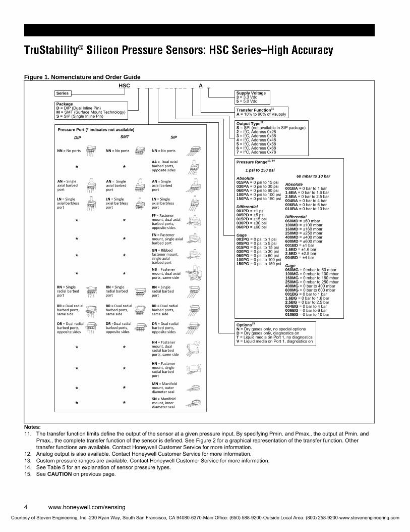
4 www.honeywell.com/sensing
Figure 1. Nomenclature and Order Guide
AA = Dual axial barbed ports, opposite sides
DIP
Series
PackageD = DIP (Dual Inline Pin)M = SMT (Surface Mount Technology)S = SIP (Single Inline Pin)
Options15
N = Dry gases only, no special optionsD = Dry gases only, diagnostics onT = Liquid media on Port 1, no diagnosticsV = Liquid media on Port 1, diagnostics on
Transfer Function11
A = 10% to 90% of Vsupply
Output Type12
S = SPI (not available in SIP package) 2 = I2C, Address 0x283 = I2C, Address 0x38 4 = I2C, Address 0x48 5 = I2C, Address 0x586 = I2C, Address 0x68 7 = I2C, Address 0x78
AN = Single axial barbed port
DR = Dual radial barbed ports, opposite sides
FF = Fastener mount, dual axial barbed ports, opposite sides
FN = Fastener mount, single axial barbed port
HH = Fastener mount, dual radial barbed ports, same side
HN = Fastener mount, single radial barbed port
MN = Manifold mount, outer diameter seal
LN = Single axial barbless port
NB = Fastener mount, dual axial ports, same side
NN = No ports
RN = Single radial barbed port
RR = Dual radial barbed ports, same side
SN = Manifold mount, inner diameter seal
Pressure Port (* indicates not available)SMT SIP
AN = Single axial barbed port
AN = Single axial barbed port
DR = Dual radial barbed ports, opposite sides
DR =Dual radial barbed ports, opposite sides
LN = Single axial barbless port
RN = Single radial barbed port
RN = Single radial barbed port
RR = Dual radial barbed ports, same side
RR = Dual radial barbed ports, same side
NN = No ports NN = No ports
HSC _ _ _ _ _ _ _ _ _ _A
LN = Single axial barbless port
* *
* *
* *
* *
* *
* *
* *
* *
* *
_Supply Voltage3 = 3.3 Vdc5 = 5.0 Vdc
GN = Ribbed fastener mount, single axial barbed port
Pressure Range13, 14
1 psi to 150 psi
Absolute015PA = 0 psi to 15 psi030PA = 0 psi to 30 psi060PA = 0 psi to 60 psi100PA = 0 psi to 100 psi150PA = 0 psi to 150 psi
Differential001PD = ±1 psi005PD = ±5 psi015PD = ±15 psi030PD = ±30 psi060PD = ±60 psi
Gage001PG = 0 psi to 1 psi005PG = 0 psi to 5 psi015PG = 0 psi to 15 psi030PG = 0 psi to 30 psi060PG = 0 psi to 60 psi100PG = 0 psi to 100 psi150PG = 0 psi to 150 psi
60 mbar to 10 bar
Absolute001BA = 0 bar to 1 bar1.6BA = 0 bar to 1.6 bar2.5BA = 0 bar to 2.5 bar004BA = 0 bar to 4 bar006BA = 0 bar to 6 bar010BA = 0 bar to 10 bar
Differential060MD = ±60 mbar100MD = ±100 mbar160MD = ±160 mbar250MD = ±250 mbar400MD = ±400 mbar600MD = ±600 mbar001BD = ±1 bar1.6BD = ±1.6 bar2.5BD = ±2.5 bar004BD = ±4 bar
Gage060MG = 0 mbar to 60 mbar100MG = 0 mbar to 100 mbar160MG = 0 mbar to 160 mbar250MG = 0 mbar to 250 mbar400MG = 0 bar to 400 mbar600MG = 0 bar to 600 mbar001BG = 0 bar to 1 bar1.6BG = 0 bar to 1.6 bar2.5BG = 0 bar to 2.5 bar004BG = 0 bar to 4 bar006BG = 0 bar to 6 bar010BG = 0 bar to 10 bar
Notes: 11. The transfer function limits define the output of the sensor at a given pressure input. By specifying Pmin. and Pmax., the output at Pmin. and
Pmax., the complete transfer function of the sensor is defined. See Figure 2 for a graphical representation of the transfer function. Other transfer functions are available. Contact Honeywell Customer Service for more information.
12. Analog output is also available. Contact Honeywell Customer Service for more information. 13. Custom pressure ranges are available. Contact Honeywell Customer Service for more information. 14. See Table 5 for an explanation of sensor pressure types. 15. See CAUTION on previous page.
Courtesy of Steven Engineering, Inc.-230 Ryan Way, South San Francisco, CA 94080-6370-Main Office: (650) 588-9200-Outside Local Area: (800) 258-9200-www.stevenengineering.com

Honeywell Sensing and Control 5
Figure 2. Transfer Function Limits Figure 3. Completed Catalog Listing Example
HSCSANN100PGSA3 SIP package, AN pressure port, no diagnostics, 100 psi gage, SPI output, 10% to 90% calibration at 3.3 Vdc.
Table 5. Pressure Types
Pressure Type Description Absolute Output is proportional to the difference between applied pressure and a built-in reference to vacuum.
Pmin. is set at absolute zero pressure (full vacuum). Differential Output is proportional to the difference between the pressures applied to each port. (Port 1 Port 2)
50% point of transfer function set at Port 1 = Port 2. Gage Output is proportional to the difference between applied pressure and atmospheric (ambient)
pressure. Pmin. is set at atmospheric pressure. Table 6. Sensor Output at Significant Percentages
% Output Digital Counts (decimal) Digital Counts (hex) 0 0 0x0000 10 1638 0x0666 50 8192 0x2000 90 14746 0x399A
100 16383 0x3FFF Table 7. Pressure Range Specifications for 1 psi to 150 psi
Order Code Pressure Range
Over- pressure16
Burst Pressure17
Common Mode Pressure18
Long-term Stability (1000 hr,
25 °C [77 °F]) Pmin. Pmax.
Absolute 015PA 0 psi 15 psi 30 psi 60 psi NA 0.25% FSS 030PA 0 psi 30 psi 60 psi 120 psi NA 0.25% FSS 060PA 0 psi 60 psi 120 psi 240 psi NA 0.25% FSS 100PA 0 psi 100 psi 250 psi 250 psi NA 0.25% FSS 150PA 0 psi 150 psi 250 psi 250 psi NA 0.25% FSS
Differential 001PD -1 psi 1 psi 10 psi 10 psi 150 psi 0.35% FSS 005PD -5 psi 5 psi 30 psi 40 psi 150 psi 0.35% FSS 015PD -15 psi 15 psi 30 psi 60 psi 150 psi 0.25% FSS 030PD -30 psi 30 psi 60 psi 120 psi 150 psi 0.25% FSS 060PD -60 psi 60 psi 120 psi 240 psi 250 psi 0.25% FSS
Gage 001PG 0 psi 1 psi 10 psi 10 psi 150 psi 0.35% FSS 005PG 0 psi 5 psi 30 psi 40 psi 150 psi 0.35% FSS 015PG 0 psi 15 psi 30 psi 60 psi 150 psi 0.25% FSS 030PG 0 psi 30 psi 60 psi 120 psi 150 psi 0.25% FSS 060PG 0 psi 60 psi 120 psi 240 psi 250 psi 0.25% FSS 100PG 0 psi 100 psi 250 psi 250 psi 250 psi 0.25% FSS 150PG 0 psi 150 psi 250 psi 250 psi 250 psi 0.25% FSS
Courtesy of Steven Engineering, Inc.-230 Ryan Way, South San Francisco, CA 94080-6370-Main Office: (650) 588-9200-Outside Local Area: (800) 258-9200-www.stevenengineering.com
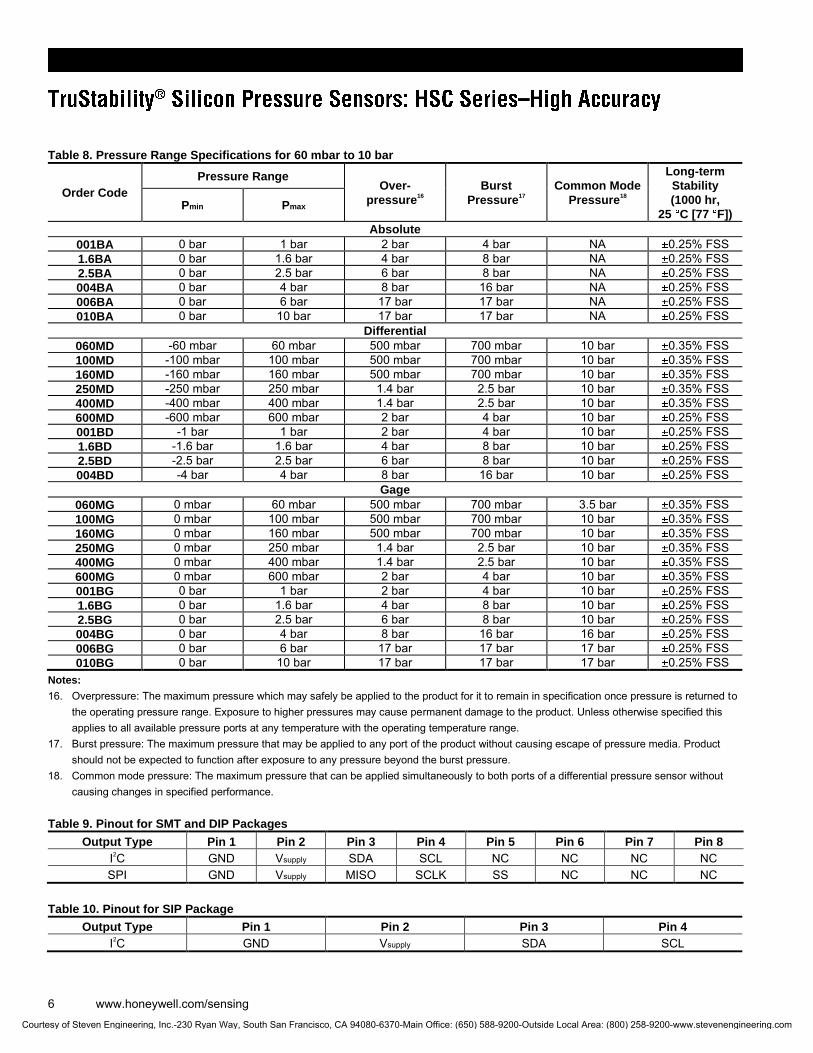
6 www.honeywell.com/sensing
Table 8. Pressure Range Specifications for 60 mbar to 10 bar
Order Code Pressure Range
Over- pressure16
Burst Pressure17
Common Mode Pressure18
Long-term Stability (1000 hr,
25 C [77 F]) Pmin Pmax
Absolute 001BA 0 bar 1 bar 2 bar 4 bar NA 0.25% FSS 1.6BA 0 bar 1.6 bar 4 bar 8 bar NA 0.25% FSS 2.5BA 0 bar 2.5 bar 6 bar 8 bar NA 0.25% FSS 004BA 0 bar 4 bar 8 bar 16 bar NA 0.25% FSS 006BA 0 bar 6 bar 17 bar 17 bar NA 0.25% FSS 010BA 0 bar 10 bar 17 bar 17 bar NA 0.25% FSS
Differential 060MD -60 mbar 60 mbar 500 mbar 700 mbar 10 bar 0.35% FSS 100MD -100 mbar 100 mbar 500 mbar 700 mbar 10 bar 0.35% FSS 160MD -160 mbar 160 mbar 500 mbar 700 mbar 10 bar 0.35% FSS 250MD -250 mbar 250 mbar 1.4 bar 2.5 bar 10 bar 0.35% FSS 400MD -400 mbar 400 mbar 1.4 bar 2.5 bar 10 bar 0.35% FSS 600MD -600 mbar 600 mbar 2 bar 4 bar 10 bar 0.25% FSS 001BD -1 bar 1 bar 2 bar 4 bar 10 bar 0.25% FSS 1.6BD -1.6 bar 1.6 bar 4 bar 8 bar 10 bar 0.25% FSS 2.5BD -2.5 bar 2.5 bar 6 bar 8 bar 10 bar 0.25% FSS 004BD -4 bar 4 bar 8 bar 16 bar 10 bar 0.25% FSS
Gage 060MG 0 mbar 60 mbar 500 mbar 700 mbar 3.5 bar 0.35% FSS 100MG 0 mbar 100 mbar 500 mbar 700 mbar 10 bar 0.35% FSS 160MG 0 mbar 160 mbar 500 mbar 700 mbar 10 bar 0.35% FSS 250MG 0 mbar 250 mbar 1.4 bar 2.5 bar 10 bar 0.35% FSS 400MG 0 mbar 400 mbar 1.4 bar 2.5 bar 10 bar 0.35% FSS 600MG 0 mbar 600 mbar 2 bar 4 bar 10 bar 0.35% FSS 001BG 0 bar 1 bar 2 bar 4 bar 10 bar 0.25% FSS 1.6BG 0 bar 1.6 bar 4 bar 8 bar 10 bar 0.25% FSS 2.5BG 0 bar 2.5 bar 6 bar 8 bar 10 bar 0.25% FSS 004BG 0 bar 4 bar 8 bar 16 bar 16 bar 0.25% FSS 006BG 0 bar 6 bar 17 bar 17 bar 17 bar 0.25% FSS 010BG 0 bar 10 bar 17 bar 17 bar 17 bar 0.25% FSS
Notes: 16. Overpressure: The maximum pressure which may safely be applied to the product for it to remain in specification once pressure is returned to
the operating pressure range. Exposure to higher pressures may cause permanent damage to the product. Unless otherwise specified this applies to all available pressure ports at any temperature with the operating temperature range.
17. Burst pressure: The maximum pressure that may be applied to any port of the product without causing escape of pressure media. Product should not be expected to function after exposure to any pressure beyond the burst pressure.
18. Common mode pressure: The maximum pressure that can be applied simultaneously to both ports of a differential pressure sensor without causing changes in specified performance.
Table 9. Pinout for SMT and DIP Packages
Output Type Pin 1 Pin 2 Pin 3 Pin 4 Pin 5 Pin 6 Pin 7 Pin 8 I2C GND Vsupply SDA SCL NC NC NC NC SPI GND Vsupply MISO SCLK SS NC NC NC
Table 10. Pinout for SIP Package
Output Type Pin 1 Pin 2 Pin 3 Pin 4 I2C GND Vsupply SDA SCL
Courtesy of Steven Engineering, Inc.-230 Ryan Way, South San Francisco, CA 94080-6370-Main Office: (650) 588-9200-Outside Local Area: (800) 258-9200-www.stevenengineering.com

Honeywell Sensing and Control 7
Figure 4. DIP Pressure Port Dimensional Drawings (For reference only: mm [in]) DIP NN: No ports
13,35[0.525]
10,0[0.39]
6,99[0.275]
1 2 3 4
8 7 6 5
10,85[0.427]
9,24[0.364]
5,44[0.214]
2,54 TYP.[0.100]
8X 0,46 [0.018]
0,25[0.010]
PORT 1 PORT 2
DIP AN: Single axial barbed port
1 2 3 4
10,0[0.39]
13,35[0.525]
PORT 1
8 7 6 5
6,2[0.24]
2,54 TYP.[0.100]
9,24[0.364]
11,21[0.441]
7,95[0.313]
13,75[0.541]
4,93 DIA.[0.194] PORT 2 6,99
[0.275]
8X 0,46 [0.018]
0,25[0.010]
DIP LN: Single axial barbless port
PORT 1
PORT 2
10,0[0.39]
13,35[0.525]
6,99[0.275]
2,54 TYP.[0.100]
6,95[0.274]
1,00[0.039]
9,24[0.364]
11,21[0.441]
13,75[0.541]
5,80[0.228]
1 2 3 4
8 7 6 5
8X 0,46 [0.018]
0,25[0.010]
2,47 DIA.[0.097]
DIP RN: Single radial barbed port
PORT 1
13,35[0.525]
10,0[0.39]
6,99[0.275]
1 2 3 4
8 7 6 5
11,21[0.441]
9,24[0.364]
5,80[0.228]
2,54 TYP.[0.100]
8X 0,46 [0.018]
0,25[0.010]
1,93 DIA. [0.076]
4,2[0.17]
PORT 2
DIP RR: Dual radial barbed ports, same side
8X 0,46 [0.018]
13,35[0.525]
10,0[0.39]
6,99[0.275]
1 2 3 4
8 7 6 5
6,16[0.242]
2,54 TYP.[0.100] 11,21
[0.441]
9,24[0.364]
2X 1,93 DIA. [0.076]
4,65[0.183]
,25[0.010]
PORT 1 PORT 2
PORT 1
PORT 2
4,0[0.16]
3,78[0.149]
DIP DR: Dual radial barbed ports, opposite sides 10,0[0.39]
13,35[0.525]
PORT 1PORT 2
1 2 3 4
8 7 6 5
6,16[0.242]
9,24[0.364]
2,54 TYP.[0.100]
15,76[0.620]
11,21[0.441]
2X 1,93 DIA.[0.076]
6,99[0.275]
8X 0,46 [0.018]
0,25[0.010]
PORT 1 PORT 2
3,78[0.149]
Courtesy of Steven Engineering, Inc.-230 Ryan Way, South San Francisco, CA 94080-6370-Main Office: (650) 588-9200-Outside Local Area: (800) 258-9200-www.stevenengineering.com

8 www.honeywell.com/sensing
Figure 5. SMT Pressure Port Dimensional Drawings (For reference only: mm [in]) SMT NN: No ports
13,4[0.53]
10,0[0.39]
6,99[0.275]
1 2 3 4
8 7 6 5
5,44[0.214]
2,54 TYP.[0.100] 6,41
[0.252]
4,80[0.189]
8X 0,46 [0.018]
PORT 1 PORT 2
SMT AN: Single axial barbed port
1 2 3 4
8 7 6 5
10,0[0.39]
13,4[0.53]
7,95[0.313]
13,75[0.541]
4,93 DIA.[0.194]
2,54 TYP.[0.100]
PORT 1
PORT 2
6,77[0.266]
4,80[0.189] 8X 0,46
[0.018]
6,99[0.275]
SMT LN: Single axial barbless port
10,0[0.394]
13,35[0.525]6,99
[0.275]
1 2 3 4
8 7 6 5
2,54 TYP.[0.100] 6,77
[0.266]
4,80[0.189]
5,80[0.228]
13,75[0.541]
8X 0,46 [0.018]
PORT 1
PORT 2
2,47 DIA.[0.097]
SMT RN: Single radial barbed port
13,3[0.53]
10,0[0.39]
6,99[0.275]
1 2 3 4
8 7 6 5
5,80[0.228]
2,54 TYP.[0.100] 6,77
[0.266]
4,80[0.189]
8X 0,46 [0.018]
PORT 1
1,93 DIA. [0.076]
4,2[0.17]
PORT 1 PORT 2
SMT RR: Dual radial barbed ports, same side
10,0[0.39]
6,99[0.275]
1 2 3 4
8 7 6 5
6,16[0.242]
2,54 TYP.[0.100] 6,77
[0.266]
4,80[0.189]
8X 0,46 [0.018]
13,35[0.525]
4,6[0.18]
PORT 1
PORT 2
2X 1,93 DIA. [0.076]
PORT 1 PORT 2
4,0[0.16]
3,78[0.149]
SMT DR: Dual radial barbed ports, opposite sides
1 2 3 4
8 7 6 5
13,4[0.53]
PORT 2PORT 1
10,0[0.39]
6,99[0.275]
2X 2,93 [0.115]
15,8[0.62]
2,54 TYP.[0.100]
2X 1,93 DIA.[0.076]
6,77[0.266]
4,80[0.189]
6,16[0.242]
3,78[0.149]
8X 0,46 [0.018]
Courtesy of Steven Engineering, Inc.-230 Ryan Way, South San Francisco, CA 94080-6370-Main Office: (650) 588-9200-Outside Local Area: (800) 258-9200-www.stevenengineering.com

Honeywell Sensing and Control 9
Figure 6. SIP Package Dimensional Drawings (For reference only: mm [in]) SIP NN: No ports
2,54 TYP.[0.100]
10,0[0.39]
15,2[0.60]
10,0[0.39]
1 2 3 4
4X 0,51 [0.020]
4,87[0.192]
PORT 1 PORT 2
0,25[0.010]
SIP AA: Dual axial barbed ports, opposite sides
PORT 1 PORT 2
0,25[0.010]
1 2 3 4
10,0[0.39]
10,0[0.39]
2,54 TYP.[0.100]
15,2[0.60]
22,06[0.869]
2X 4.93 DIA.[0.194]
4X 0,51 [0.020]
SIP AN: Single axial barbed port
0,25[0.010] 2,54 TYP.
[0.100]
PORT 1
1 2 3 4
10,0[0.39]
4.93 DIA.[0.194]
10,0[0.39]
13,75[0.541]
15,2[0.60]
PORT 2
4X 0,51 [0.020]
SIP LN: Single barbless port
10,0[0.39]
15,2[0.60]
10,0[0.39]
1 2 3 4
2,54 TYP.[0.100]
PORT 1
PORT 2
0,25[0.010]
13,75[0.541]
4X 0,51 [0.020]
2,47 DIA.[0.097]
SIP FF: Fastener mount, dual axial barbed ports, opposite sides
0,25[0.010] 2,54 TYP.
[0.100]
29,48[1.161]
1 2 3 4
27,20[1.071]
23,12[.910]
10,44[0.411]
PORT 1PORT 2
17,78[0.700]
20,16[0.794]
2X 4,78 DIA.[0.188]
2X 3.94 DIA.[0.155]
4X ,51 [.020]
SIP FN: Fastener mount, single axial barbed port
1 2 3 4
17,78[0.700]
20,16[0.794]
2,54 TYP.[0.100]
0,25[0.010]
29,48[1.161]
23,12[.910]
PORT 1PORT 2
16,38[0.645]
2X 3.94 DIA.[0.155] 4.78 DIA.
[0.188]
4X 0,51 [0.020]
Courtesy of Steven Engineering, Inc.-230 Ryan Way, South San Francisco, CA 94080-6370-Main Office: (650) 588-9200-Outside Local Area: (800) 258-9200-www.stevenengineering.com
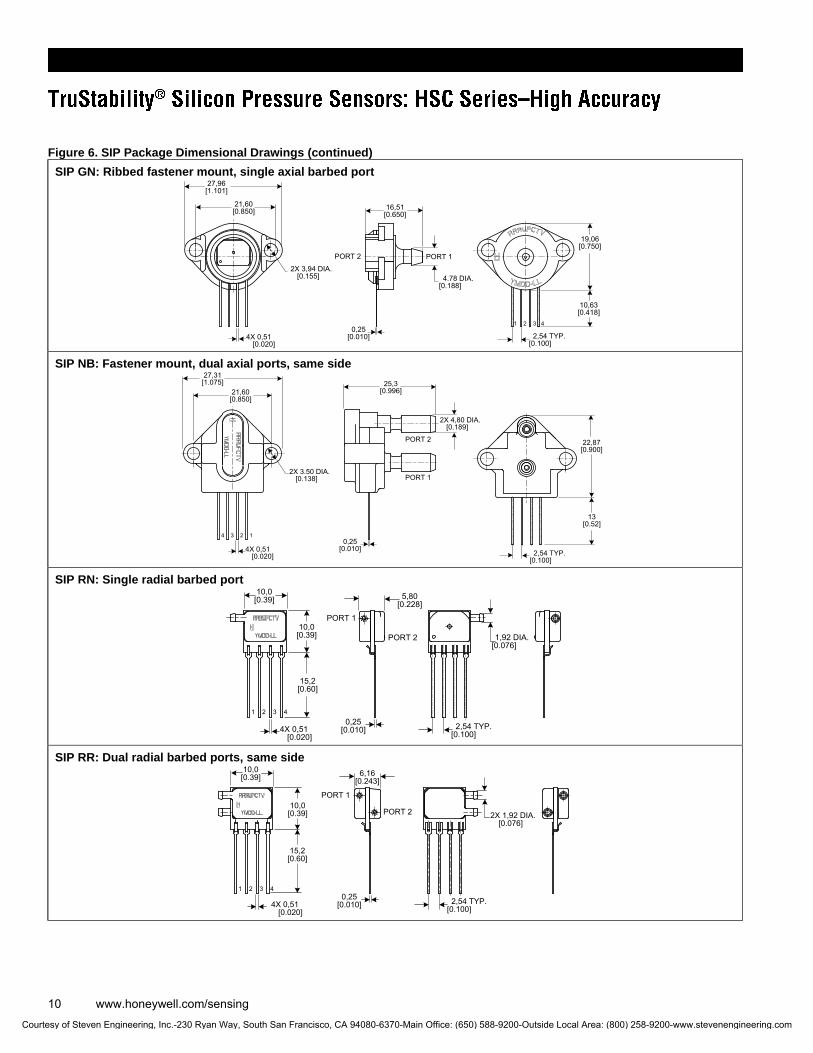
10 www.honeywell.com/sensing
Figure 6. SIP Package Dimensional Drawings (continued) SIP GN: Ribbed fastener mount, single axial barbed port
2,54 TYP.[0.100]
21,60[0.850]
PORT 1PORT 2
1 2 3 4
4.78 DIA.[0.188]
0,25[0.010]
2X 3,94 DIA.[0.155]
27,96[1.101]
16,51[0.650]
19,06[0.750]
10,63[0.418]
4X 0,51 [0.020]
SIP NB: Fastener mount, dual axial ports, same side
0,25[0.010] 2,54 TYP.
[0.100]
22,87[0.900]
13[0.52]
2X 3.50 DIA.[0.138]
21,60[0.850]
27,31[1.075] 25,3
[0.996]
PORT 1
PORT 2
4 3 2 1
4X 0,51 [0.020]
2X 4,80 DIA.[0.189]
SIP RN: Single radial barbed port
0,25[0.010] 2,54 TYP.
[0.100]
PORT 1
PORT 2
10,0[0.39]
15,2[0.60]
10,0[0.39]
1 2 3 4
5,80[0.228]
1,92 DIA.[0.076]
4X 0,51 [0.020]
SIP RR: Dual radial barbed ports, same side
0,25[0.010] 2,54 TYP.
[0.100]
PORT 1
PORT 2
1 2 3 4
10,0[0.39]
15,2[0.60]
10,0[0.39] 2X 1,92 DIA.
[0.076]
6,16[0.243]
4X 0,51 [0.020]
Courtesy of Steven Engineering, Inc.-230 Ryan Way, South San Francisco, CA 94080-6370-Main Office: (650) 588-9200-Outside Local Area: (800) 258-9200-www.stevenengineering.com

Honeywell Sensing and Control 11
Figure 6. SIP Package Dimensional Drawings (continued) SIP DR: Dual radial barbed ports, opposite side
0,25[0.010] 2,54 TYP.
[0.100]
PORT 1 PORT 2
1 2 3 4
10,0[0.39]
10,0[0.39]
15,2[0.60]
6,16[0.243]
2X 4.93 DIA.[0.194]
15,8[0.62]
4X 0,51 [0.020]
SIP HH: Fastener mount, dual radial barbed ports, same side
0,25[0.010]
1 2 3 4
28,96[1.140]
2,54 TYP.[0.100]
PORT 1PORT 2
29,62[1.166]
23,12[0.910]
11,27[0.444]
6,64[0.261]
10,58[0.416]
4X 0,51 [0.020]
PORT 1PORT 2
SIP HN: Fastener mount, single radial barbed port
28,96[1.140]
11,27[0.444]
23,12[0.910]
0,25[0.010] 2,54 TYP.
[0.100]
1 2 3 4
2X 3,94 DIA.[0.155]
7,97[0.314] 4,78 DIA.
[0.188]
4X 0,51 [0.020]
PORT 1
PORT 2
SIP MN: Manifold mount, outer diameter seal
2,54 TYP.[0.100]
0,25[0.010]
1 2 3 4
PORT 1PORT 2
15,24 DIA.[0.600]
12,5[0.49]
5,36[0.211]
4X 0,51 [0.020]
SIP SN: Manifold mount, inner diameter seal
2,54 TYP.[0.100]
1 2 3 4
13,11[0.516]
12,57[0.495]
15,6[0.61]
5,1[0.20]
4X 0,51 [0.020]
PORT 1
PORT 2
Courtesy of Steven Engineering, Inc.-230 Ryan Way, South San Francisco, CA 94080-6370-Main Office: (650) 588-9200-Outside Local Area: (800) 258-9200-www.stevenengineering.com
Sensing and Control Honeywell 1985 Douglas Drive North Golden Valley, MN 55422 www.honeywell.com
008214-2-EN IL50 GLO Printed in USA March 2011 © 2011 Honeywell International Inc.
WARNING PERSONAL INJURY DO NOT USE these products as safety or emergency stop devices or in any other application where failure of the product could result in personal injury. Failure to comply with these instructions could result in death or serious injury.
WARRANTY/REMEDY Honeywell warrants goods of its manufacture as being free of defective materials and faulty workmanship. Honeywell s standard product warranty applies unless agreed to otherwise by Honeywell in writing; please refer to your order acknowledgement or consult your local sales office for specific warranty details. If warranted goods are returned to Honeywell during the period of coverage, Honeywell will repair or replace, at its option, without charge those items it finds defective. The foregoing is buyer s sole remedy and is in lieu of all other warranties, expressed or implied, including those of merchantability and fitness for a particular purpose. In no event shall Honeywell be liable for consequential, special, or indirect damages. While we provide application assistance personally, through our literature and the Honeywell web site, it is up to the customer to determine the suitability of the product in the application. Specifications may change without notice. The information we supply is believed to be accurate and reliable as of this printing. However, we assume no responsibility for its use.
WARNING MISUSE OF DOCUMENTATION The information presented in this product sheet is for
reference only. DO NOT USE this document as a product installation guide.
Complete installation, operation, and maintenance information is provided in the instructions supplied with each product.
Failure to comply with these instructions could result in death or serious injury.
SALES AND SERVICE Honeywell serves its customers through a worldwide network of sales offices, representatives and distributors. For application assistance, current specifications, pricing or name of the nearest Authorized Distributor, contact your local sales office or: E-mail: [email protected] Internet: www.honeywell.com/sensing Phone and Fax: Asia Pacific +65 6355-2828; +65 6445-3033 Fax Europe +44 (0) 1698 481481; +44 (0) 1698 481676 Fax Latin America +1-305-805-8188; +1-305-883-8257 Fax USA/Canada +1-800-537-6945; +1-815-235-6847 +1-815-235-6545 Fax
Courtesy of Steven Engineering, Inc.-230 Ryan Way, South San Francisco, CA 94080-6370-Main Office: (650) 588-9200-Outside Local Area: (800) 258-9200-www.stevenengineering.com

SCC Series
DESCRIPTION
The SCC Series sensors offer an extremely low cost sensor
element with a temperature stable output when driven with a
constant current source. These integrated circuit sensors
were designed for extremely cost sensitive applications where
precise accuracy over a wide temperature range is not
required. This series is intended for use with non-corrosive,
non-ionic working fluids such as air, and dry gases.
Absolute devices have an internal vacuum reference and an
output voltage proportional to applied pressure. The
differential devices allow application of pressure to either side
of the diaphragm and devices are thereby available to
measure both differential and gage pressures.
This product is packaged either in standard low cost chip
carrier “button” package or a DIP package. Both packages
are designed for applications where the sensing element is to
be integral to the OEM equipment. These packages can be o-
ring sealed, epoxied, and/or clamped onto a pressure fitting.
A closed bridge four pin SIP configuration is provided for
electrical connection to the button package. The DIP package
offers a 5-pin open bridge configuration.
FEATURES
• Low cost sensor element
• Internal temperature compensation
• Differential or gage pressures
TYPICAL APPLICATIONS
• Pneumatic controls
• Automotive diagnostics
• Medical equipment
• Dental equipment
• Environmental controls
Silicon pressure sensors0 psi to 5 psi and 0 psi to 300 psi
ORDERING INFORMATION
ParParParParPart Number for Ort Number for Ort Number for Ort Number for Ort Number for Orderingderingderingderingdering
PrPrPrPrPressuressuressuressuressure Rangee Rangee Rangee Rangee Range Sensor inSensor inSensor inSensor inSensor in Sensor inSensor inSensor inSensor inSensor in Sensor inSensor inSensor inSensor inSensor in Sensor inSensor inSensor inSensor inSensor in
Button PackageButton PackageButton PackageButton PackageButton Package “N” Package“N” Package“N” Package“N” Package“N” Package Nipple PackageNipple PackageNipple PackageNipple PackageNipple Package DIP PackageDIP PackageDIP PackageDIP PackageDIP Package
0 psid to 5 psid or psig SCC05D SCC05DN SCC05DP1 SCC05GD2, SCC05DD4
0 psid to 15 psid or psig SCC015D SCC015DN SCC015DP1 SCC15GD2, SCC15DD4
0 psid to 30 psid or psig SCC30D SCC30DN SCC30DP1 SCC30GD2, SCC30DD4
0 psig to 100 psig SCC100D SCC100DN – SCC100GD2, SCC100DD4
0 psia to 15 psia SCC15A SCC15AN SCC15AP1 SCC15AD2
0 psia to 30 psia SCC30A SCC30AN SCC30AP1 SCC30AD2
0 psia to 100 psia SCC100A SCC100AN – SCC100AD2
0 psia to 300 psi – – – –
WARNINGPERSONAL INJURYDO NOT USE these products as safety or emergency stopdevices or in any other application where failure of theproduct could result in personal injury.FailurFailurFailurFailurFailure to comply with these instre to comply with these instre to comply with these instre to comply with these instre to comply with these instructions could ructions could ructions could ructions could ructions could result inesult inesult inesult inesult indeath or serious injurdeath or serious injurdeath or serious injurdeath or serious injurdeath or serious injuryyyyy.....
WARNINGMISUSE OF DOCUMENTATION• The information presented in this product sheet is for
reference only. Do not use this document as a productinstallation guide.
• Complete installation, operation, and maintenanceinformation is provided in the instructions supplied witheach product.
Failure to comply with these instructions could result indeath or serious injury.
Courtesy of Steven Engineering, Inc.-230 Ryan Way, South San Francisco, CA 94080-6370-Main Office: (650) 588-9200-Outside Local Area: (800) 258-9200-www.stevenengineering.com

SCC Series
2 www.honeywell.com/sensing
SPECIFICATION CHARACTERISTICS (Maximum Ratings for All Devices)
Supply current, IS 1.5 mA
Compensated temperature range 0 °C to 50 °C [32 °F to 122 °F]
Operating temperature range -40 °C to 85 °C [-40 °F to 185 °F]
Storage temperature range -55 °C to 125 °C [-67 °F to 257 °F]
Humidity 0 % to 100 % RH
Lead temperature 250 °C [482 °F] Soldering 2 sec to 4 sec
Common-mode pressure 150 psi
PERFORMANCE CHARACTERISTICS (Individual Models) Is=1.0 mA, TA=25 °C [77 °F](1)
Effect (3, 4) Effect(5, 4) Full-Scale
Part Operating Maximum on Span on Offset Span(6)
Number Pressure Range Over Pressure Accuracy(2) 0 °C to 50 °C 0 °C to 50 °C mV
SCC05(D,G) 0 psid to 5 psid (g) 20 psi 0.50 % 1.50 % 30 µV/°C 25-65
SCC15A 0 psia to 15 psia 30 psia 0.50 % 1.50 % 40 µV/°C 40-95
SCC15(D,G) 0 psid to 15 psid (g) 30 psi 0.50 % 1.50 % 40 µV/°C 40-95
SCC30(D,G) 0 psid to 30 psid (g) 60 psi 0.50 % 1.50 % 60 µV/°C 60-150
SCC100A 0 psia to 100 psia 150 psia 0.50 % 1.50 % 30 µV/°C 85-225
SCC100(D,G)(7) 0 psig to 100 psig 150 psig 0.50 % 1.50 % 90 µV/°C 85-225
SCC300A 0 psia to 300 psia 450 psia 0.50 % 1.50 % 50 µV/°C 50-120
PERFORMANCE SPECIFICATIONS (All Models) Is=10.0 Ma, Ta=25 °C [77 °F]
Min. Typ. Max. Unit
Zero Pressure Offset(8) -30.0 -10.0 20.0 mV
Combined Linearity, Hysteresis and Repeatability(2) – 0.25 0.50 % FSO
Long Term Stability of Offset and Span(9) – 0.10 – mV
Response Time (10 % to 90 %)(10) – 0.10 – ms
Input Impedance 4.00 5.00 6.50 kOhm
Output Impedance 4.00 5.00 6.50 kOhm
Specification Notes:
Note 1: Reference Conditions; Supply Current = 1.0 mA; TA = 25 °C [77 °F], Common-mode Line Pressure = 0 psig, Pressure Applied to P1, unless otherwise noted.
Note 2: Accuracy is the sum of Hysteresis and Linearity. Hysteresis is the maximum output difference at any point within the operating pressure range for increasing and
decreasing pressure. Linearity refers to the best straight line fit as measured for the offset, full-scale and ½ full-scale pressure at 25 °C [77 °F].
Note 3: This is the maximum temperature shift for span when measured between 0 °C and 50 °C [32 °F to 122 °F] relative to the 25 °C [77 °F] reading. Typical
temperature coefficients for span and resistance are -2200 ppm/°C and 2200 ppm/°C respectively.
Note 4: Temperature effect on span and offset are guaranteed by design. Therefore these parameters are not 100 % tested.
Note 5: This is the maximum temperature shift for offset when measured at 0 °C and 50 °C [32 °F to 122 °F] divided by the temperature difference.
Note 6: Span is the algebraic difference between the output voltage at full-scale pressure and the ouput at zero pressure.
Note 7: The SCC100D devices can only be used in a forward gauge mode. Application of more than 30 psig to the back side of any of the SCC Series devices can result
in device failure. On the SCC100GD2 pressure can only be applied to the back side of the die. No pressure I accessible from the front/top side of die.
Note 8: The zero pressure offset is 30 to -20 mV max. form parts SCCxxxGD2 and SCCxxDD4 devices.
Note 9: Maximum difference in output at any pressure with the operating pressure range and temperature within 0 °C and 50 °C [32 °F to 122 °F].
a) 100 temperature cycles, 0 °C and 50 °C [32 °F to 122 °F]
b) 1.0 million pressure cycles, 0 psi to full-scale span.
Note 10: Response time for a 0 psi to full-scale span pressure step change. 10 % to 90 % rise time.
Courtesy of Steven Engineering, Inc.-230 Ryan Way, South San Francisco, CA 94080-6370-Main Office: (650) 588-9200-Outside Local Area: (800) 258-9200-www.stevenengineering.com

Silicon pressure sensors
Honeywell Sensing and Control 3
ELECTRICAL CONNECTIONS
(Vs)(+Vo)
N Housing package
MOUNTING DIMENSIONS IN MM (INCHES), FOR REFERENCE ONLYButton package
Vs3
2
4
1GND
Button, Nipple and “N” Packages
DIP Packages
OUTPUT
OUTPUT
Vs
3
2
1
GND
4 5
-
+
-
+
EQUIVALENT CIRCUITS
Nipple package
Courtesy of Steven Engineering, Inc.-230 Ryan Way, South San Francisco, CA 94080-6370-Main Office: (650) 588-9200-Outside Local Area: (800) 258-9200-www.stevenengineering.com

Automation and Control Solutions
Sensing and Control
Honeywell
11 West Spring Street
Freeport, Illinois 61032, USA
www.honeywell.com
008135-2-EN IL50 GLOMay 2005Copyright 2004-2005 Honeywell International Inc.
SALES AND SERVICEHoneywell serves its customers througha worldwide network of sales offices,representatives and distributors. Forapplication assistance, currentspecifications, pricing or name of thenearest Authorized Distributor, contactyour local sales office or:
E-mail: E-mail: E-mail: E-mail: E-mail: [email protected]
InterInterInterInterInternet:net:net:net:net: www.honeywell.com/sensing
Phone and Fax:Phone and Fax:Phone and Fax:Phone and Fax:Phone and Fax:Asia Pacific +65 6355-2828
+65 6445-3033 FaxEurope +44 (0) 1698 481481
+44 (0) 1698 481676 FaxLatin America +1-305-805-8188
+1-305-883-8257 FaxUSA/Canada +1-800-537-6945
+1-815-235-6847+1-815-235-6545 Fax
WARRANTY/REMEDYHoneywell warrants goods of itsmanufacture as being free of defectivematerials and faulty workmanship.Honeywell’s standard product warrantyapplies unless agreed to otherwise byHoneywell in writing; please refer toyour order acknowledgement or consultyour local sales office for specificwarranty details. If warranted goods arereturned to Honeywell during the periodof coverage, Honeywell will repair orreplace, at its option, without chargethose items it finds defective. TheTheTheTheTheforforforforforegoing is buyeregoing is buyeregoing is buyeregoing is buyeregoing is buyer’’’’’s sole rs sole rs sole rs sole rs sole remedy andemedy andemedy andemedy andemedy andis in lieu of all waris in lieu of all waris in lieu of all waris in lieu of all waris in lieu of all warranties, exprranties, exprranties, exprranties, exprranties, expressedessedessedessedessedor implied, including those ofor implied, including those ofor implied, including those ofor implied, including those ofor implied, including those of
mermermermermerchantability and fitness for achantability and fitness for achantability and fitness for achantability and fitness for achantability and fitness for aparparparparparticular purpose. In no event shallticular purpose. In no event shallticular purpose. In no event shallticular purpose. In no event shallticular purpose. In no event shallHoneywell be liable forHoneywell be liable forHoneywell be liable forHoneywell be liable forHoneywell be liable forconsequential, special, or indirconsequential, special, or indirconsequential, special, or indirconsequential, special, or indirconsequential, special, or indirectectectectectdamages.damages.damages.damages.damages. While we provide applicationassistance personally, through ourliterature and the Honeywell web site, itis up to the customer to determine thesuitability of the product in theapplication. Specifications may change withoutnotice. The information we supply isbelieved to be accurate and reliable asof this printing. However, we assume no
responsibility for its use.
D2 DIP package
DD4 DIP package
AD4 DIP package
Courtesy of Steven Engineering, Inc.-230 Ryan Way, South San Francisco, CA 94080-6370-Main Office: (650) 588-9200-Outside Local Area: (800) 258-9200-www.stevenengineering.com

SCC SMT Series
Microstructure Pressure Sensors 0 psi to 5 psi through 0 psi to 100 psi The SCC SMT Series offers an extremely low-cost sensor
element with a temperature-stable output when driven with a
constant current source. These integrated circuit sensors were
designed for extremely cost-sensitive applications where
precise accuracy over a wide temperature range is not
required.
The standard surface mount package includes an optional
ported lid to fit in a variety of applications.
The absolute devices have an internal vacuum reference and
an output voltage proportional to absolute pressure. The
differential devices allow application of pressure to either side
of the sensing diaphragm and can be used for gage or
differential measurements.
The 4-pin closed bridge configuration allows electrical
connection with additional pads provided for mechanical
support. Pulsed power is recommended to achieve maximum
accuracy and conserve battery power in portable applications.
FEATURES
• Low cost
• Small size
• Internal temperature compensation
• Absolute or gage pressures
• High-impedance bridge
• Low power consumption
POTENTIAL APPLICATIONS
• Pneumatic controls
• Automotive diagnostics
• Medical equipment/instrumentation
• Dental equipment
• Environmental controls
• Barometric pressure measurement
• Altimeters
• Pneumatic controls
• Battery powered equipment
Courtesy of Steven Engineering, Inc.-230 Ryan Way, South San Francisco, CA 94080-6370-Main Office: (650) 588-9200-Outside Local Area: (800) 258-9200-www.stevenengineering.com
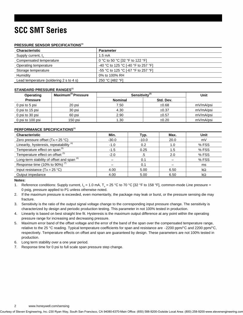
SCC SMT Series
2 www.honeywell.com/sensing
PRESSURE SENSOR SPECIFICATIONS(1)
Characteristic Parameter Supply current, IS 1.5 mA Compensated temperature 0 °C to 50 °C [32 °F to 122 °F] Operating temperature -40 °C to 125 °C [-40 °F to 257 °F] Storage temperature -55 °C to 125 °C [-67 °F to 257 °F] Humidity 0% to 100% RH Lead temperature (soldering 2 s to 4 s) 250 °C [482 °F]
STANDARD PRESSURE RANGES(1)
Sensitivity(3) Operating Pressure
Maximum(2) Pressure Nominal Std. Dev.
Unit
0 psi to 5 psi 20 psi 7.50 ±0.68 mV/mA/psi 0 psi to 15 psi 30 psi 4.30 ±0.37 mV/mA/psi 0 psi to 30 psi 60 psi 2.90 ±0.57 mV/mA/psi 0 psi to 100 psi 150 psi 1.30 ±0.20 mV/mA/psi
PERFORMANCE SPECIFICATIONS(1)
Characteristic Min. Typ. Max. Unit Zero pressure offset (TA = 25 °C) -30.0 -10.0 20.0 mV Linearity, hysteresis, repeatability (4) -1.0 0.2 1.0 % FSS Temperature effect on span (5) -1.5 0.25 1.5 % FSS Temperature effect on offset (5) -2.0 .5 2.0 % FSS Long-term stability of offset and span (6) – 0.1 – % FSS Response time (10% to 90%) (7) – 0.1 – ms Input resistance (TA = 25 °C) 4.00 5.00 6.50 kΩ Output impedance 4.00 5.00 6.50 kΩ
Notes: 1. Reference conditions: Supply current, IS = 1.0 mA, TA = 25 °C to 70 °C [32 °F to 158 °F], common-mode Line pressure =
0 psig, pressure applied to P1 unless otherwise noted. 2. If the maximum pressure is exceeded, even momentarily, the package may leak or burst, or the pressure sensing die may
fracture. 3. Sensitivity is the ratio of the output signal voltage change to the corresponding input pressure change. The sensitivity is
characterized by design and periodic production testing. This parameter in not 100% tested in production. 4. Linearity is based on best straight line fit. Hysteresis is the maximum output difference at any point within the operating
pressure range for increasing and decreasing pressure. 5. Maximum error band of the offset voltage and the error of the band of the span over the compensated temperature range,
relative to the 25 °C reading. Typical temperature coefficients for span and resistance are -2200 ppm/°C and 2200 ppm/°C, respectively. Temperature effects on offset and span are guaranteed by design. These parameters are not 100% tested in production.
6. Long term stability over a one year period. 7. Response time for 0 psi to full scale span pressure step change.
Courtesy of Steven Engineering, Inc.-230 Ryan Way, South San Francisco, CA 94080-6370-Main Office: (650) 588-9200-Outside Local Area: (800) 258-9200-www.stevenengineering.com

Microstructure Pressure Sensors
Honeywell Sensing and Control 3
MOUNTING DIMENSIONS (For reference only: mm [in].)
LOW PROFILE SMT
1,10[.05]O
8X 1,27 [.05]
7,60[.30]
6,60[.26] 7,60
[.30]
3,30[.13]
3,30[.13]
6,60[.26]
3,70[.14]
2,00[.08] 3,30
[.13]
+ OUT
- OUT
+ EX- EX
3,80[.15]
8X 0,76 [.03]7X 0,76 [.03]
0,5 [.02]FOR GAGE PORT (P2)
ON CENTERPADS
O0,70[.03]
PORTED “P” SMT
0,76[.03]7X
6,6[.26]
1,01[.04]
3,3[.13]
3,3[.13]
R0,3[.01]
R0,3[.01]
8,7[.34]
7,6[.30]
6,6[.26]
7,61[.30]
ON CENTERPADS
+ OUT
- OUT- EX+ EX
FOR GAGE PORT (P2)
1,27[.05]
8X
3,3[.13]
3,8[.15]
2,0[.08]
8X 0,76[.03]
0,5 [.02]0,70[.03]
2,05±0.76[0.081±0.003]
PORTED “LP” SMT
0,76[.03]7X
6,6[.26]
1,01[.04]
3,3[.13]
3,3[.13]
2,3[.09]
R0,3[.01]
R0,3[.01]
8,7[.34]
7,6[.30]
6,6[.26]
7,61[.30]
ON CENTERPADS
+ OUT
- OUT- EX+ EX
FOR GAGE PORT (P2)
1,27[.05]
8X
3,3[.13]
3,8[.15]
2,0[.08]
8X 0,76[.03]
0,5 [.02]0,70[.03]
EQUIVALENT CIRCUITS
- Out
+Out
Vs
Courtesy of Steven Engineering, Inc.-230 Ryan Way, South San Francisco, CA 94080-6370-Main Office: (650) 588-9200-Outside Local Area: (800) 258-9200-www.stevenengineering.com

Sensing and Control
Honeywell
1985 Douglas Drive North
Minneapolis, MN 55422
www.honeywell.com/sensing
008091-3-EN IL50 GLO Printed in USA July 2007 © 2007 Honeywell International Inc. All rights reserved.
ORDER GUIDE
WARNING MISUSE OF DOCUMENTATION • The information presented in this product sheet is for
reference only. Do not use this document as a product installation guide.
• Complete installation, operation, and maintenance information is provided in the instructions supplied with each product.
Failure to comply with these instructions could result in death or serious injury.
WARRANTY/REMEDY Honeywell warrants goods of its manufacture as being free of defective materials and faulty workmanship. Honeywell’s standard product warranty applies unless agreed to otherwise by Honeywell in writing; please refer to your order acknowledgement or consult your local sales office for specific warranty details. If warranted goods are returned to Honeywell during the period of coverage, Honeywell will repair or replace, at its option, without charge those items it finds defective. The foregoing is buyer’s sole remedy and is in lieu of all other warranties, expressed or implied, including those of merchantability and fitness for a particular purpose. In no event shall Honeywell be liable for consequential, special, or indirect damages.
While we provide application assistance personally, through our literature and the Honeywell web site, it is up to the customer to determine the suitability of the product in the application.
Specifications may change without notice. The information we supply is believed to be accurate and reliable as of this printing. However, we assume no responsibility for its use.
WARNING PERSONAL INJURY DO NOT USE these products as safety or emergency stop devices or in any other application where failure of the product could result in personal injury. Failure to comply with these instructions could result in death or serious injury.
SALES AND SERVICE Honeywell serves its customers through a worldwide network of sales offices, representatives and distributors. For application assistance, current specifications, pricing or name of the nearest Authorized Distributor, contact your local sales office or:
E-mail: [email protected]
Internet: www.honeywell.com/sensing
Phone and Fax: Asia Pacific +65 6355-2828 +65 6445-3033 Fax Europe +44 (0) 1698 481481 +44 (0) 1698 481676 Fax Latin America +1-305-805-8188 +1-305-883-8257 Fax USA/Canada +1-800-537-6945 +1-815-235-6847 +1-815-235-6545 Fax
Courtesy of Steven Engineering, Inc.-230 Ryan Way, South San Francisco, CA 94080-6370-Main Office: (650) 588-9200-Outside Local Area: (800) 258-9200-www.stevenengineering.com
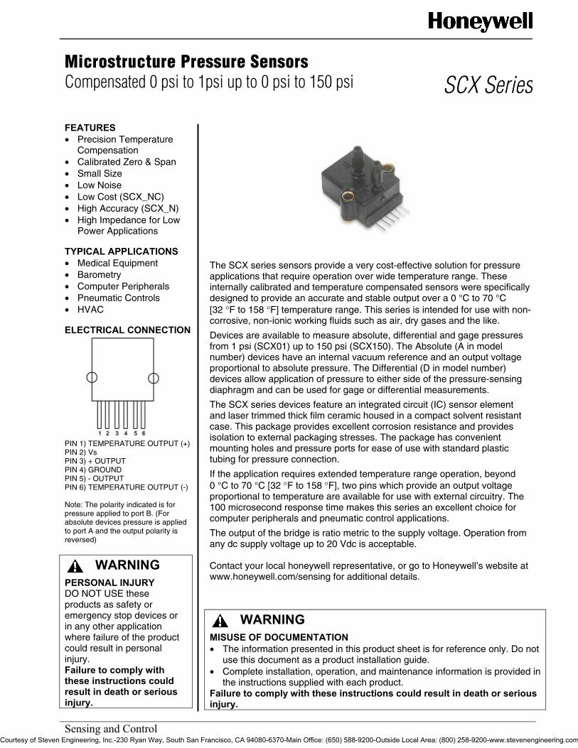
Microstructure Pressure Sensors Compensated 0 psi to 1psi up to 0 psi to 150 psi SCX Series
FEATURES • Precision Temperature
Compensation
• Calibrated Zero & Span • Small Size • Low Noise • Low Cost (SCX_NC) • High Accuracy (SCX_N) • High Impedance for Low
Power Applications TYPICAL APPLICATIONS • Medical Equipment The SCX series sensors provide a very cost-effective solution for pressure
applications that require operation over wide temperature range. These internally calibrated and temperature compensated sensors were specifically designed to provide an accurate and stable output over a 0 °C to 70 °C [32 °F to 158 °F] temperature range. This series is intended for use with non-corrosive, non-ionic working fluids such as air, dry gases and the like.
• Barometry • Computer Peripherals • Pneumatic Controls • HVAC ELECTRICAL CONNECTION Devices are available to measure absolute, differential and gage pressures
from 1 psi (SCX01) up to 150 psi (SCX150). The Absolute (A in model number) devices have an internal vacuum reference and an output voltage proportional to absolute pressure. The Differential (D in model number) devices allow application of pressure to either side of the pressure-sensing diaphragm and can be used for gage or differential measurements.
The SCX series devices feature an integrated circuit (IC) sensor element and laser trimmed thick film ceramic housed in a compact solvent resistant case. This package provides excellent corrosion resistance and provides isolation to external packaging stresses. The package has convenient mounting holes and pressure ports for ease of use with standard plastic tubing for pressure connection.
PIN 1) TEMPERATURE OUTPUT (+) PIN 2) Vs PIN 3) + OUTPUT PIN 4) GROUND If the application requires extended temperature range operation, beyond
0 °C to 70 °C [32 °F to 158 °F], two pins which provide an output voltage proportional to temperature are available for use with external circuitry. The 100 microsecond response time makes this series an excellent choice for computer peripherals and pneumatic control applications.
PIN 5) - OUTPUT PIN 6) TEMPERATURE OUTPUT (-) Note: The polarity indicated is for pressure applied to port B. (For absolute devices pressure is applied to port A and the output polarity is reversed)
The output of the bridge is ratio metric to the supply voltage. Operation from any dc supply voltage up to 20 Vdc is acceptable.
WARNING PERSONAL INJURY DO NOT USE these products as safety or emergency stop devices or in any other application where failure of the product could result in personal injury. Failure to comply with these instructions could result in death or serious injury.
Contact your local honeywell representative, or go to Honeywell’s website at www.honeywell.com/sensing for additional details.
WARNING MISUSE OF DOCUMENTATION • The information presented in this product sheet is for reference only. Do not
use this document as a product installation guide. • Complete installation, operation, and maintenance information is provided in
the instructions supplied with each product. Failure to comply with these instructions could result in death or serious injury.
Sensing and Control Courtesy of Steven Engineering, Inc.-230 Ryan Way, South San Francisco, CA 94080-6370-Main Office: (650) 588-9200-Outside Local Area: (800) 258-9200-www.stevenengineering.com

Microstructure Pressure Sensors
Compensated 0 psi to 1psi up to 0 psi to 150 psi SCX Series PRESSURE RANGE SPECIFICATIONS
Full-Scale Span (1)
Model * Operating Pressure
Proof Pressure (2) Sensitivity Min. Typ. Max.
SCX01DN 17.82 mV 18.00 mV 18.18 mV SCX01DNC
0 psid to 1 psid 20 psid 18 mV/psi 17.00 mV 18.00 mV 19.00 mV
SCX05DN 59.40 mV 60.00 mV 60.60 mV SCX05DNC
0 psid to 5 psid 20 psid 12 mV/psi 57.50 mV 60.00 mV 62.50 mV
SCX15AN 89.10 mV 90.00 mV 90.90 mV SCX15ANC
0 psid to 15 psia 30 psia 6.0 mV/psi 85.00 mV 90.00 mV 95.00 mV
SCX15DN 89.10 mV 90.00 mV 90.90 mV SCX15DNC
0 psid to 15 psid 30 psid 6.0 mV/psi 85.00 mV 90.00 mV 95.00 mV
SCX30AN 89.10 mV 90.00 mV 90.90 mV SCX30ANC
0 psid to 30 psia 60 psia 3.0 mV/psi 85.00 mV 90.00 mV 95.00 mV
SCX30DN 89.10 mV 90.00 mV 90.90 mV SCX30DNC
0 psid to 30 psid 60 psid 3.0 mV/psi 85.00 mV 90.00 mV 95.00 mV
SCX100AN 99.00 mV 100.0 mV 101.0 mV SCX100ANC
0 psid to 100 psia 150 psia 1.0 mV/psi 95.00 mV 100.0 mV 105.0 mV
SCX100DN 99.00 mV 100.0 mV 101.0 mV SCX100DNC
0 psid to 100 psid 150 psid 1.0 mV/psi 95.00 mV 100.0 mV 105.0 mV
SCX150AN 89.00 mV 90.00 mV 91.00 mV SCX150ANC
0 psid to 150 psia 150 psia 0.6 mV/psi 85.00 mV 90.00 mV 95.00 mV
SCX150DN 89.00 mV 90.00 mV 91.00 mV SCX150DNC
0 psid to 150 psid 150 psid 0.6 mV/psi 85.00 mV 90.00 mV 95.00 mV
* Ordering information: Order model number.
GENERAL SPECIFICATIONS Characteristic Description (Maximum Ratings) All Devices Supply Voltage (VS) 20 Vdc Common Mode Pressure 50 psig Lead Soldering Temperature (2 seconds to 4 seconds)
250 °C [482 °F]
ENVIRONMENTAL SPECIFICATIONS Characteristic Description (Maximum Ratings) All Devices Compensated Operating Temperature 0 °C to 70 °C [32 °F to 158 °F] Operating Temperature -40 °C to 85 °C [-40 °F to 185 °F] Storage Temperature -55 °C to 125 °C [-67 °F to 257 °F] Humidity Limits 0 % RH to 100 % RH ACCURACY Model Accuracy SCX01 through SCX150 Calibrated for span to within ±1 % (Highest accuracy) SCX01_C through SCX150_C Calibrated for span to within ±5 % (Fine adjustments of zero
and span can be provided in external circuitry)
2 Honeywell • Sensing and Control Courtesy of Steven Engineering, Inc.-230 Ryan Way, South San Francisco, CA 94080-6370-Main Office: (650) 588-9200-Outside Local Area: (800) 258-9200-www.stevenengineering.com

Microstructure Pressure Sensors
Compensated 0 psi to 1psi up to 0 psi to 150 psi SCX Series SCX PERFORMANCE CHARACTERISTICS (3) Characteristic Min. Typ. Max. Unit Zero Pressure Offset (4) -300 0.0 300 Microvolt
Combined Pressure Non-Linearity and Pressure Hysteresis (5) – ±0.1 ±0.5 % FSO Temperature Effect on Span 0 °C to 70 °C [32 °F to 158 °F] (6) – ±0.2 ±0.1 % FSO Temperature Effect on Offset 0 °C to 70 °C [32 °F to 158 °F] (6) – ±100 ±500 Microvolt Repeatability (7) – ±0.2 ±0.5 % FSO Input Resistance (8) – 4.0 – kOhm Output Resistance (9) – 4.0 – kOhm Common Mode Voltage (10) 5.8 6.0 6.2 Vdc Response Time (11) – 100 – Microsec. Long Term Stability of Offset and Span (12) – ±0.1 – mV
SCX_C SERIES PERFORMANCE CHARACTERISTICS (3) Characteristic Min. Typ. Max Unit Zero Pressure Offset -1.0 0.0 ±1.0 mV
Combined Pressure Non-Linearity and Pressure Hysteresis (5)
Models: SCX05DNC, SCX15ANC, and SCX15DNC,
Models: SCX01DNC, SCX30ANC, SCX30DNC, SCX100ANC, SCX100DNC,
SCX150ANC, and SCX150DNC
– –
±0.1
±0.2
±1.0
±1.0
% FSO % FSO
Temperature Effect on Span 0 °C to 70 °C [32 °F to 158 °F] (6) – ±0.4 ±2.0 % FSO Temperature Effect on Offset 0 °C to 70 °C [32 °F to 158 °F] (6) – ±0.2 ±1.0 mV Repeatability (7) – ±0.2 ±0.5 % FSO Input Resistance (8) – 4.0 – kOhm Output Resistance (9) – 4.0 – kOhm Common Mode Voltage (10) 5.7 6.0 6.3 Vdc Response Time (11) – 100 – Microsec. Long Term Stability of Offset and Span (12) – ±0.1 – mV
SPECIFICATION NOTES Note 1: Full-Scale Span is the algebraic difference between the output voltage at full-scale pressure and the output at zero pressure.
Full-Scale Span is ratiometric to the supply voltage. Note 2: Maximum pressure above which causes permanent sensor failure. Note 3: Reference Conditions: (Unless otherwise noted) T
A = 25°C, Supply VS = 12 Vdc, Common Mode Line pressure = 0 psig, Pressure applied to Port B. For absolute devices only, pressure is applied to Port A, and the output polarity is reversed.
Note 4: For models SCX15AN, SCX30AN, SCX100AN, and SCX150AN, the Maximum zero pressure offset for absolute devices is 0 to ±500 Microvolt.
Note 5: Pressure Hysteresis – the maximum output difference at any point within the operating pressure range for increasing and decreasing pressure.
Note 6: Maximum error band of the offset voltage and the error band of the span, relative to the 25 °C [77 °F] reading. Note 7: Maximum difference in output at any pressure within the operating pressure range and the temperature within 0 °C to 70 °C
[32 °F to 158 °F] after: a) 1,000 temperature cycles, 0 °C to 70 °C [32 °F to 158 °F] b) 1.5 million pressure cycles, 0 psi to Full-Scale Span. Note 8: Input resistance is the resistance between pins 2 and 4. Note 9: Output resistance is the resistance between pins 3 and 5. Note 10: Common Mode voltage of the output arms (Pins 3 and 5) for VS=12 Vdc. Note 11: Response time for a 0 psi to Full-Scale Span pressure step change, 10 % to 90 % rise time. Note 12: Long term stability over a one-year period.
Honeywell • Sensing and Control 3 Courtesy of Steven Engineering, Inc.-230 Ryan Way, South San Francisco, CA 94080-6370-Main Office: (650) 588-9200-Outside Local Area: (800) 258-9200-www.stevenengineering.com
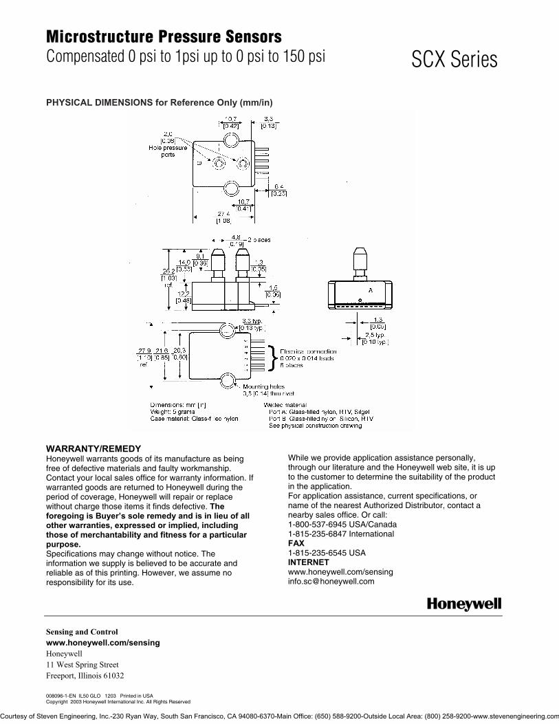
Microstructure Pressure Sensors Compensated 0 psi to 1psi up to 0 psi to 150 psi SCX Series
Sensing and Control www.honeywell.com/sensing
PHYSICAL DIMENSIONS for Reference Only (mm/in)
WARRANTY/REMEDY Honeywell warrants goods of its manufacture as being free of defective materials and faulty workmanship. Contact your local sales office for warranty information. If warranted goods are returned to Honeywell during the period of coverage, Honeywell will repair or replace without charge those items it finds defective. The foregoing is Buyer’s sole remedy and is in lieu of all other warranties, expressed or implied, including those of merchantability and fitness for a particular purpose. Specifications may change without notice. The information we supply is believed to be accurate and reliable as of this printing. However, we assume no responsibility for its use.
While we provide application assistance personally, through our literature and the Honeywell web site, it is up to the customer to determine the suitability of the product in the application. For application assistance, current specifications, or name of the nearest Authorized Distributor, contact a nearby sales office. Or call: 1-800-537-6945 USA/Canada 1-815-235-6847 International FAX 1-815-235-6545 USA INTERNET www.honeywell.com/sensing [email protected]
Honeywell 11 West Spring Street Freeport, Illinois 61032 008096-1-EN IL50 GLO 1203 Printed in USA Copyright 2003 Honeywell International Inc. All Rights Reserved
Courtesy of Steven Engineering, Inc.-230 Ryan Way, South San Francisco, CA 94080-6370-Main Office: (650) 588-9200-Outside Local Area: (800) 258-9200-www.stevenengineering.com

Microstructure Pressure Sensors Precision Compensated 0 in H2O to 4 in H2O and 0 in H2O to 10 in H2O SCXL Series
Sensing and Control
FEATURES • Very Low Pressure
Resolution • Precision Temperature
Compensation • Small Size • Low Noise • Calibrated Zero & Span • High Impedance for Low
Power Applications
TYPICAL APPLICATIONS • Air Flow • Respirators • HVAC • Medical Equipment • Computer Peripherals • Pneumatic Controls
WARNING PERSONAL INJURY DO NOT USE these products as safety or emergency stop devices or in any other application where failure of the product could result in personal injury. Failure to comply with these instructions could result in death or serious injury.
The SCXL series sensors provide a very cost-effective solution for pressure applications that require high accuracy over very low operating pressure ranges. These internally calibrated and temperature compensated sensors were specifically designed to provide an accurate and stable output over a 0 °C to 50 °C [32 °F to 122 °F] temperature range. This series is intended for use with non-corrosive, non-ionic working fluids such as air, dry gases and the like. The output of the bridge is ratiometric to the supply voltage. Operation from any dc supply voltage up to 18 Vdc [Model SCXL004DN] or 20 Vdc [SCXL010DN] is acceptable. Contact your local honeywell representative or go to Honeywell’s website at www.honeywell.com/sensing for additional details.
WARNING MISUSE OF DOCUMENTATION • The information presented in this product sheet is for reference only. Do
not use this document as a product installation guide. • Complete installation, operation, and maintenance information is provided
in the instructions supplied with each product. Failure to comply with these instructions could result in death or serious injury.
Courtesy of Steven Engineering, Inc.-230 Ryan Way, South San Francisco, CA 94080-6370-Main Office: (650) 588-9200-Outside Local Area: (800) 258-9200-www.stevenengineering.com

Microstructure Pressure Sensors Precision Compensated 0 in H2O to 4 in H2O and 0 in H2O to 10 in H2O SCXL Series
2 Honeywell • Sensing and Control
GENERAL SPECIFICATIONS Characteristic
Description (Maximum Ratings) SCXL004DN
Description (Maximum Ratings) SCXL010DN
Supply Voltage (VS) 18 Vdc 20 Vdc Common Mode Pressure 150 in H2O 50 psig Lead Soldering Temperature (2 seconds to 4 seconds)
250 °C [482 °F] 250 °C [482 °F]
Proof Pressure (12) 10 in H2O 10 psi Burst Pressure 5 psi 200 in H2O
ENVIRONMENTAL SPECIFICATIONS Characteristic
Description (Maximum Ratings) SCXL004DN
Description (Maximum Ratings) SCXL010DN
Compensated Operating Temperature 0 °C to 50 °C [32 °F to 122 °F] 0 °C to 50 °C [32 °F to 122 °F] Operating Temperature 0 °C to 70 °C [32 °F to 158 °F] -40 °C to 85 °C [-40 °F to 185 °F] Storage Temperature 0 °C to 70 °C [32 °F to 158 °F] -40 °C to 125 °C [-40 °F to 257 °F] Humidity Limits 0 % to 100 % RH 0 % to 100 % RH PRESSURE RANGE SPECIFICATIONS Full-Scale Span (1) Listing Operating Pressure Proof Pressure (2) Min. Typ. Max. SCXL004DN 0 in H2O to 4 in H2O 10 in H2O 38.0 mV 40.0 mV 42.0 mV SCXL010DN 0 in H2O to10 in H2O 10 psi 19.5 mV 20.0 mV 20.5 mV
SCXL004DN PERFORMANCE CHARACTERISTICS (3) Characteristic Min. Typ. Max. Unit Zero Pressure Offset (4) -1.5 0 1.5 mV Sensitivity – 10 – mV/in H2O Combined Pressure Non-Linearity and Pressure Hysteresis (5) – ±0.5 ±1.0 % FSS Temperature Effect on Span 0 °C to 50 °C [32 °F to 122 °F] (6) – ±0.2 ±1.0 % FSS Temperature Effect on Offset 0 °C to 50 °C [32 °F to 122 °F] (6) – ±0.5 ±2.0 mV Repeatability (7) – ±0.2 – % FSS Input Resistance (8) – 4.0 – kOhm Output Resistance (9) – 4.0 – kOhm Common Mode Voltage (10) 5.7 6.0 6.3 Vdc Response Time (11) – 500 – Microsec. Long Term Stability of Offset and Span (12) – ±0.5 – % FSS Position Sensitivity – 0.25 – mV/g
Courtesy of Steven Engineering, Inc.-230 Ryan Way, South San Francisco, CA 94080-6370-Main Office: (650) 588-9200-Outside Local Area: (800) 258-9200-www.stevenengineering.com

Microstructure Pressure Sensors Precision Compensated 0 in H2O to 4 in H2O and 0 in H2O to 10 in H2O SCXL Series
Honeywell • Sensing and Control 3
SCXL010DN PERFORMANCE CHARACTERISTICS (3) Characteristic Min. Typ. Max. Unit Zero Pressure Offset (4) -0.3 0.0 0.3 mV
Sensitivity – 2 – mV/in H2O Combined Pressure Non-Linearity and Pressure Hysteresis (5) – ±0.2 ±0.5 % FSS Temperature Effect on Span 0 °C to 50 °C [32 °F to 122 °F] (6) – ±0.2 ±1.0 % FSS Temperature Effect on Offset 0 °C to 50 °C [32 °F to 122 °F] (6) – ±300 ±500 Microvolts Repeatability (7) – ±0.2 ±0.5 % FSS Input Resistance (8) – 4.0 – kOhm Output Resistance (9) – 4.0 – kOhm Common Mode Voltage (10) 5.8 6.0 6.2 Vdc Response Time (11) – 100 – Microsec. Long Term Stability of Offset and Span (12) – 100 – Microvolts
SPECIFICATION NOTES Note 1: Full-Scale Span is the algebraic difference between the output voltage at full-scale pressure and the output at zero pressure.
Full-Scale Span is ratiometric to the supply voltage. Note 2: Proof pressure is the pressure above which devices will not return to guaranteed specifications. Note 3: Reference Conditions: (Unless otherwise noted) T
A = 25 °C, Supply VS = 12 Vdc, Common Mode Line pressure = 0 psig, Pressure applied to Port B. For absolute devices only, pressure is applied to Port A, and the output polarity is reversed.
Note 4: Zero pressure effect is measured with pins pointed towards the ground. Offset can be position sensitive. Note 5: Pressure Hysteresis – the maximum output difference at any point within the operating pressure range for increasing and
decreasing pressure. Note 6: Maximum error band of the offset voltage and the error band of the span, relative to the 25 °C [77 °F] reading. Note 7: Maximum difference in output at any pressure within the operating pressure range and the temperature within 0 °C to 50 °C
[32 °F to 122 °F] after: 004DN: a) 100 temperature cycles, 0 °C to 50 °C [32 °F to 122 °F] b) 1 million pressure cycles, 0 psi to Full-Scale Span. 010DN: a) 1,000 temperature cycles, 0 °C to 50 °C [32 °F to 122 °F] b) 1.5 million pressure cycles, 0 psi to Full-Scale Span. Note 8: Input resistance is the resistance between pins 2 and 4. Note 9: Output resistance is the resistance between pins 3 and 5. Note 10: Common Mode voltage of the output arms (Pins 3 and 5) for VS=12 Vdc. Note 11: Response time for a 0 psi to Full-Scale Span pressure step change, 10 % to 90 % rise time. Note 12: Long term stability over a one-year period. ORDERING INFORMATION Description Part Number 0 in H2O to 4 in H2O SCXL 004DN 0 in H2O to 10 in H2O SCXL 010DN
Special Options: Pins with N-90 = 90° Lead Bend ELECTRICAL CONNECTION
Pinout SCXL004DN [0 in H2O to 4 in H2O] SCXL004DN [0 in H2O to 10 in H2O]
PIN 1) Temperature output (+) PIN 2) Vs PIN 3) + Output PIN 4) Ground PIN 5) - Output PIN 6) Temperature output (-)
PIN 1) No Connection PIN 2) Vs PIN 3) + Output PIN 4) Ground PIN 5) - Output PIN 6) No Connection
Courtesy of Steven Engineering, Inc.-230 Ryan Way, South San Francisco, CA 94080-6370-Main Office: (650) 588-9200-Outside Local Area: (800) 258-9200-www.stevenengineering.com

Microstructure Pressure Sensors Precision Compensated 0 in H2O to 4 in H2O and 0 in H2O to 10 in H2O SCXL Series
Sensing and Control www.honeywell.com/sensing Honeywell 11 West Spring Street Freeport, Illinois 61032
008102-3-EN IL50 GLO 504 Printed in USA Copyright 2004 Honeywell International Inc. All Rights Reserved
PHYSICAL DIMENSIONS for Reference Only-(mm/in)
WARRANTY/REMEDY Honeywell warrants goods of its manufacture as being free of defective materials and faulty workmanship. Contact your local sales office for warranty information. If warranted goods are returned to Honeywell during the period of coverage, Honeywell will repair or replace without charge those items it finds defective. The foregoing is Buyer’s sole remedy and is in lieu of all other warranties, expressed or implied, including those of merchantability and fitness for a particular purpose. Specifications may change without notice. The information we supply is believed to be accurate and reliable as of this printing. However, we assume no responsibility for its use.
While we provide application assistance personally, through our literature and the Honeywell web site, it is up to the customer to determine the suitability of the product in the application. For application assistance, current specifications, or name of the nearest Authorized Distributor, contact a nearby sales office. Or call: 1-800-537-6945 USA/Canada 1-815-235-6847 International FAX 1-815-235-6545 USA INTERNET www.honeywell.com/sensing [email protected]
Courtesy of Steven Engineering, Inc.-230 Ryan Way, South San Francisco, CA 94080-6370-Main Office: (650) 588-9200-Outside Local Area: (800) 258-9200-www.stevenengineering.com

SDX Series
Plastic Silicon Pressure Sensors
Low Cost, Temperature Compensated, DIP, 0 psi to 1 psi, 0 psi to 100 psi DESCRIPTION The SDX Series sensors provide a very cost-effective solution for pressure applications that require small size plus performance. These calibrated and temperature-compensated sensors give an accurate and stable output over a 0 °C to 50 °C [32 °F to 122 °F] temperature range. This series is intended for use with non-corrosive, non-ionic working fluids such as air and dry gases. Devices are available to measure absolute and gage pressures from 1 psi (SDX01) up to 100 psi (SDX100). The absolute devices have an internal vacuum reference and an output voltage proportional to absolute pressure. The SDX devices are available in standard commercial and prime grades (SDCXXXXX-A) to allow optimization of accuracy and cost in any given application.
The SDX devices feature an integrated circuit (IC) sensor element and laser trimmed thick film ceramic housed in a compact solvent resistant case. The package is a double-wide, dual-inline package (DIP). This is the same familiar package used by IC manufacturers except it is only 11,94 mm [0.470 in] long and has a pressure port(s). The PC board area used by each DIP is approximately 0.26 in2. This extremely small size enables the use of multiple sensors in limited available space. The DIP provides excellent corrosion resistance and isolation to external package stress. The DIP mounts on a PC board like a standard IC with through-hole pins. The pins anchor the pressure sensor to the PC board and provide a more secure and stable unit than other types of packages. The output of the bridge is ratiometric to the supply voltage and operation from any dc supply voltage up to 20 Vdc is acceptable.
FEATURES • Low cost DIP • Precision temperature compensation • Calibrated zero and span • Small size • Low noise • High impedance for low power applications
POTENTIAL APPLICATIONS • Medical equipment • Computer peripherals • Pneumatic controls • HVAC
• Prime grade available (SDXxxxyy-A)
Courtesy of Steven Engineering, Inc.-230 Ryan Way, South San Francisco, CA 94080-6370-Main Office: (650) 588-9200-Outside Local Area: (800) 258-9200-www.stevenengineering.com

SDX Series
2 www.honeywell.com/sensing
Table 1. Pressure Range Specifications and Ordering Information
Catalog Listing, Pressure Connection, Pressure Type
Full-Scale Span (1)
Gage Differential/Gage Absolute
Operating Pressure
Proof Pressure (2)
Min. Typ. Max.
SDX01G2 SDX01D4 - 17.37 mV 18.00 mV 18.18 mV SDX01G2-A SDX01D4-A -
0 psid to 1 psid 20 psid 17.82 mV 18.00 mV 18.80 mV
SDX05G2 SDX05D4 - 57.90 mV 60.00 mV 62.10 mV SDX05G2-A SDX05D4-A -
0 psid to 5 psid 20 psid 59.40 mV 60.00 mV 60.60 mV
SDX15G2 SDX15D4 - 86.85 mV 90.00 mV 93.15 mV SDX15G2-A SDX15D4-A -
0 psid to 15 psid 30 psid 89.10 mV 90.00 mV 90.90 mV
- - SDX15A2 86.85 mV 90.00 mV 93.15 mV - - SDX15A4 86.85 mV 90.00 mV 93.15 mV - - SDX15A2-A 89.10 mV 90.00 mV 90.90 mV - - SDX15A4-A
0 psia to 15 psia 30 psia
89.10 mV 90.00 mV 90.90 mV SDX30G2 SDX30D4 - 86.85 mV 90.00 mV 93.15 mV
SDX30G2-A SDX30D4-A - 0 psid to 30 psid 60 psid
89.10 mV 90.00 mV 90.90 mV - - SDX30A2 86.85 mV 90.00 mV 93.15 mV - - SDX30A4 86.85 mV 90.00 mV 93.15 mV - - SDX30A2-A 89.10 mV 90.00 mV 90.90 mV - - SDX30A4-A
0 psia to 30 psia 60 psia
89.10 mV 90.00 mV 90.90 mV SDX100G2 SDX100D4 - 96.50 mV 100.00 mV 103.5 mV
SDX100G2-A SDX100D4-A - 0 psid to 100
psid 150 psid
99.00 mV 100.00 mV 101.0 mV - - SDX100A2 96.50 mV 100.00 mV 103.5 mV - - SDX100A4 96.50 mV 100.00 mV 103.5 mV - - SDX100A2-A 99.00 mV 100.00 mV 101.0 mV - - SDX100A4-A
0 psia to 100 psia
150 psia
99.00 mV 100.00 mV 101.0 mVNomenclature Pressure Connection
(See Fig. 2) Pressure Type Grade
G2 A2/G2 gage standard commercial G2-A A2/G2 gage prime D4 OK differential standard commercial
D4-A OK differential prime A2 A2/G2 absolute standard commercial
A2-A A2/G2 absolute prime A4 A4 absolute standard commercial
A4-A A4 absolute prime Table 2. General Specifications (Maximum)
Characteristic Parameter Supply voltage (VS) 20 Vdc Common mode pressure 150 psig Lead soldering temperature (2 s to 4 s) 250 °C [482 °F]
Table 3. Environmental Specifications (Maximum)
Characteristic Parameter Compensated operating temperature 0 °C to 50 °C [32 °F to 122 °F] Operating temperature -40 °C to 85 °C [-40 °F to 185 °F] Storage temperature -55 °C to 125 °C [-67 °F to 257 °F] Humidity limits 0% RH to 100% RH
Courtesy of Steven Engineering, Inc.-230 Ryan Way, South San Francisco, CA 94080-6370-Main Office: (650) 588-9200-Outside Local Area: (800) 258-9200-www.stevenengineering.com

Plastic Silicon Pressure Sensors, Low Cost, Temperature
Compensated, DIP, 0 psi to 1 psi, 0 psi to 100 psi
Honeywell Sensing and Control 3
Table 4. Performance Characteristics(3)
Characteristic Min. Typ. Max. Unit Zero pressure offset Zero pressure offset (prime grade) (4)
-1.0 -0.3
0.0 0.0
+1.0 0.3
mV mV
Combined linearity and hysteresis (5)
Combined linearity and hysteresis (prime grade) (5) (13)
– –
±0.2 ±0.1
±1.0 ±0.25
% FSO % FSO
Temperature effect on span, 0 °C to 50 °C [32 °F to 122 °F] (6)
Temperature effect on span, 0 °C to 50 °C [32 °F to 122 °F] (6) (prime grade) – –
±0.4 ±0.4
±2.0 ±1.0
% FSO % FSO
Temperature effect on offset 0, °C to 50 °C [32 °F to 122 °F] (6)
Temperature effect on offset 0, °C to 50 °C [32 °F to 122 °F] (6) (prime grade)
– –
±0.2 ±0.2
±1.0 ±0.5
mV mV
Repeatability (7) – ±0.2 ±0.5 % FSO Input resistance (8) – 4.0 – kOhm Output resistance (9) – 4.0 – kOhm Common mode voltage (10) 1.5 3.0 5.0 Vdc Response time (11) – 100 – µs Long term stability of offset and span (12) – ±0.1 – mV
Notes: 1. Full-Scale Span is the algebraic difference between the output voltage at full-scale pressure and the output at zero pressure.
Full-Scale Span is ratiometric to the supply voltage. 2. Maximum pressure above which causes permanent sensor failure. 3. Reference conditions:
• T
A = 25 °C (unless otherwise noted). • Supply VS = 12 Vdc, Common Mode Line pressure = 0 psig. • Pressure applied to Port B. For absolute devices only, pressure is applied to Port A and the output polarity is reversed.
4. Maximum zero pressure offset for absolute devices is ±500 mV. 5. Hysteresis is the maximum output difference at any point within the operating pressure range for increasing and decreasing
pressure. 6. Maximum error band of the offset voltage and the error band of the span, relative to the 25 °C [77 °F] reading. 7. Maximum difference in output at any pressure within the operating pressure range and the temperature within 0 °C to 50 °C
[32 °F to 122 °F] after: • 100 temperature cycles, 0 °C to 50 °C [32 °F to 122 °F]. • 1.0 million pressure cycles, 0 psi to full-scale span.
8. Input resistance is the resistance between VS and ground. 9. Output resistance is the resistance between the + and - outputs. 10. Common Mode voltage of the output arms for VS=12 Vdc. 11. Response time for a 0 psi to Full-Scale Span pressure step change, 10% to 90% rise time. 12. Long term stability over a one-year period. 13. Maximum combined linearity and hysteresis for the SDX05 prime grade is ±0.5%. Figure 1. Electrical Connections
Courtesy of Steven Engineering, Inc.-230 Ryan Way, South San Francisco, CA 94080-6370-Main Office: (650) 588-9200-Outside Local Area: (800) 258-9200-www.stevenengineering.com

Figure 2. Mounting Dimensions (For Reference Only. mm/[in]) A2/G2 Package
A4 Package D4 Package
WARNING PERSONAL INJURY DO NOT USE these products as safety or emergency stop devices or in any other application where failure of the product could result in personal injury. Failure to comply with these instructions could result in death or serious injury.
WARNING MISUSE OF DOCUMENTATION • The information presented in this product sheet is for
reference only. Do not use this document as a product installation guide.
• Complete installation, operation, and maintenance information is provided in the instructions supplied with each product.
Failure to comply with these instructions could result in death or serious injury.
WARRANTY/REMEDY Honeywell warrants goods of its manufacture as being free of defective materials and faulty workmanship. Honeywell’s standard product warranty applies unless agreed to otherwise by Honeywell in writing; please refer to your order acknowledgement or consult your local sales office for specific warranty details. If warranted goods are returned to Honeywell during the period of coverage, Honeywell will repair or replace, at its option, without charge those items it finds defective. The foregoing is buyer’s sole remedy and is in lieu of all other warranties, expressed or implied, including those of merchantability and fitness for a particular purpose. In no event shall Honeywell be liable for consequential, special, or indirect damages.
SALES AND SERVICE Honeywell serves its customers through a worldwide network of sales offices, representatives and distributors. For application assistance, current specifications, pricing or name of the nearest Authorized Distributor, contact your local sales office or: E-mail: [email protected] Internet: www.honeywell.com/sensing Phone and Fax:
While we provide application assistance personally, through our literature and the Honeywell web site, it is up to the customer to determine the suitability of the product in the application.
Asia Pacific +65 6355-2828; +65 6445-3033 Fax Europe +44 (0) 1698 481481; +44 (0) 1698 481676 Fax Latin America +1-305-805-8188; +1-305-883-8257 Fax USA/Canada +1-800-537-6945; +1-815-235-6847
+1-815-235-6545 Fax Specifications may change without notice. The information we
supply is believed to be accurate and reliable as of this printing. However, we assume no responsibility for its use.
Sensing and Control
Honeywell
1985 Douglas Drive North
Golden Valley, Minnesota 55422
www.honeywell.com/sensing
008103-3-EN IL50 GLO Printed in USA November 2008 Copyright © 2008 Honeywell International Inc. All rights reserved.
Courtesy of Steven Engineering, Inc.-230 Ryan Way, South San Francisco, CA 94080-6370-Main Office: (650) 588-9200-Outside Local Area: (800) 258-9200-www.stevenengineering.com

Microstructure Pressure Sensors Compensated 0 in H2O to 5 H2O in H2O
and 0 in H2O to 10 in H2O SDX IND Series
Sensing and Control
FEATURES • Low Cost Dual Inline
Package • Temperature Compensated • Calibrated Zero and Span • Small Size • Low Noise • High Impendance for Low
Power Applications TYPICAL APPLICATIONS • Medical Equipment • Computer Peripherals • Pneumatic Controls • HVAC
The SDX series sensors provide a very cost effective solution for pressure applications that require small size plus performance. These calibrated and temperature compensated sensors give an accurate and stable output over a 0 °C to 50 °C [32 °F to 122 °F] range. This series is intended for use with non-corrosive, non-ionic working fluids, such as, air and other dry gases.
The SDX series devices are specifically designed to measure low pressures with a 0 in H2O to 10.0 in H2O full scale range. The output of the bridge is ratiometric to the supply voltage up to 20.0 Vdc is acceptable.
The SDX series devices feature an integrated circuit sensor element and laser trimmed thick film ceramic housed in a compact solvent resistant case. The package is a double wide (i.e. 15,24 mm [0.600 in] lead spacing) dual inline package. This is the same familiar package used by IC manufactures except it has integral pressure port(s). The PC board area used by each DIP is approximately 6,60 mm² [0.26 in²]. This extremely small size enables the use of multiple sensors in limited available space. The DIP provides excellent isolation to external package stress.
The DIP mounts on a PC board like a standard IC with through-hole pins. The pins anchor the pressure sensor to the PC board which provides a more secure and stable unit than other types of packages.
WARNING MISUSE OF DOCUMENTATION
• The information presented in this product sheet is for reference only. Do not use this document as a product installation guide.
• Complete installation, operation, and maintenance information is provided in the instructions supplied with each product.
Failure to comply with these instructions could result in death or serious injury.
WARNING PERSONAL INJURY DO NOT USE these products as safety or emergency stop devices or in any other application where failure of the product could result in personal injury. Failure to comply with these instructions could result in death or serious injury.
Courtesy of Steven Engineering, Inc.-230 Ryan Way, South San Francisco, CA 94080-6370-Main Office: (650) 588-9200-Outside Local Area: (800) 258-9200-www.stevenengineering.com

Microstructure Pressure Sensors Compensated 0 in H2O to 5 in H2O
and 0 in H2O to 10 in H2O SDX IND Series
Honeywell • Sensing and Control 2
PRESSURE RANGE SPECIFICATIONS Full-Scale Span (1) Listing Operating Pressure Proof Pressure Min. Typ. Max. SDX005IND4 0 in H2O to 5 in H2O 193 in H2O 19.5 mV 20.0 mV 20.5 mV SDX010IND4 0 in H2O to 10 in H2O 193 in H2O 24.5 mV 25.0 mV 25.5 mV
GENERAL SPECIFICATIONS (all devices) Characteristic Description (Maximum Ratings) Supply Voltage (VS) 20.0 Vdc Maximum Pressure on any Port 50 psig Lead Temperature (Soldering 10 Sec.) 250 °C [482 °F] Burst Pressure 193 H2O [7 psi]
ENVIRONMENTAL SPECIFICATIONS (all devices) Compensated Operating Temperature 0 °C to 50 °C [32 °F to 122 °F] Operating Temperature -40 °C to 85 °C [-40 °F to 185 °F] Storage Temperature -55 °C to 125 °C [-67°F to 257 °F] Humidity Limits 0 % RH to 100 % RH PERFORMANCE SPECIFICATIONS (all devices) (2)
Characteristic Min. Typ. Max. Unit Zero Pressure Offset -1.0 0 + 1.0 mV Combined Linearity and Hysteresis (3) – ± 0.2 ± 1.0 % FSS Temperature Effect on Span 0 °C to 50 °C [32 °F to 122 °F] (4) – ± 0.4 ± 2.0 % FSS Temperature Effect on Offset 0 °C to 50 °C [32 °F to 122 °F] (4) – ± 0.2 ± 0.6 mV Repeatability (5) – ± 0.5 – % FSS Input Resistance (6) – 4.0 – KΩ Output Resistance (7) – 4.0 – KΩ Common-Mode Voltage(8) 1.5 3.0 5.0 Vdc Response Time(9) – 100 – µsec Long Term Stability of Offset and Span (10) – ± 0.1 – % FSS
SPECIFICATION NOTES Note 1: Span is the algebraic difference between the output voltage at full-scale pressure and the output at zero pressure. Span is
ratiometric to the supply voltage. Note 2: Reference conditions (unless otherwise noted): Supply voltage, VS = 12 Vdc, TA = 25 °C [77 °F], Common Mode Line Pressure =
0 psig, pressure applied to port 2 Note 3: Hysteresis is the maximum output difference at any point within the operating pressure range fro increasing and decreasing
pressure. Note 4: Maximum error band of the offset voltage and the error band of the span, relative to the 25 °C [77 °F] reading. Note 5: Maximum difference in output at any pressure with the operating pressure range and temperature within 0 °C to 50 °C [32 °F to
122 °F] after: a) 100 temperature cycles, °C to 50 °C [32 °F to 122 °F] b) 1.0 million pressure cycles, 0 in H2O to full-scale span
Note 6: Input impedance is the impedance between VS and ground Note 7: Output impedance is the impedance between the + and – outputs. Note 8: This is the common-mode voltage of the output arms for VS = 12 Vdc Note 9: Response time for a 0 psi to full-scale span pressure step change, 10 % to 90 % rise time. Note 10: Long term stability over a one year period.
Courtesy of Steven Engineering, Inc.-230 Ryan Way, South San Francisco, CA 94080-6370-Main Office: (650) 588-9200-Outside Local Area: (800) 258-9200-www.stevenengineering.com

Microstructure Pressure Sensors Compensated 0 in H2O to 5 in H2O
and 0 in H2O to 10 inH2O SDX IND Series
Honeywell • Sensing and Control 3
PHYSICAL DIMENSIONS for reference only mm [in]
10,9[.43] TYP.
14,0[.55]
11,9[.47]
4
1
3,4[.135]
COMPENSATION CERAMIC
6,4[.250]
0,3[.01] TYP.
15,2[.60] TYP. 2,5
[.10] TYP.
0,5[.02] TYP.
3,2[.12] TYP.
6,6[.30] TYP. 2,3 [.09] TYP.
2O DRAFTO
2,8[.11] TYP.
8,6[.34] TYP.
PORT CONFIGURATION
P1
P2
Courtesy of Steven Engineering, Inc.-230 Ryan Way, South San Francisco, CA 94080-6370-Main Office: (650) 588-9200-Outside Local Area: (800) 258-9200-www.stevenengineering.com

Microstructure Pressure Sensors Compensated 0 in H2O to 5 in H2O
and 0 in H2O to 10 in H2O SDX IND Series
Sensing and Control www.honeywell.com/sensing Honeywell 11 West Spring Street Freeport, Illinois 61032
008093-2-EN IL50 GLO 504 Printed in USA Copyright 2004 Honeywell International Inc. All Rights Reserved.
EQUIVALENT CIRCUIT
- OUT
+ OUT
VS
ELECTRICAL CONNECTIONS
OUTPUT +
OUTPUT -
GROUND VS +
ORDER INFORMATION Listings Operating Pressure Range SDX005IND4 0 in H2O to 5 in H2O SDX010IND4 0 in H2O to 10 in H2O
WARRANTY/REMEDY Honeywell warrants goods of its manufacture as being free of defective materials and faulty workmanship. Contact your local sales office for warranty information. If warranted goods are returned to Honeywell during the period of coverage, Honeywell will repair or replace without charge those items it finds defective. The foregoing is Buyer’s sole remedy and is in lieu of all other warranties, expressed or implied, including those of merchantability and fitness for a particular purpose. Specifications may change without notice. The information we supply is believed to be accurate and reliable as of this printing. However, we assume no responsibility for its use.
While we provide application assistance personally, through our literature and the Honeywell web site, it is up to the customer to determine the suitability of the product in the application. For application assistance, current specifications, or name of the nearest Authorized Distributor, contact a nearby sales office. Or call: 1-800-537-6945 USA/Canada 1-815-235-6847 International FAX 1-815-235-6545 USA INTERNET www.honeywell.com/sensing [email protected]
Courtesy of Steven Engineering, Inc.-230 Ryan Way, South San Francisco, CA 94080-6370-Main Office: (650) 588-9200-Outside Local Area: (800) 258-9200-www.stevenengineering.com

Pressure Sensor Low Pressure Sensor SLP Series
FEATURES • Accurate low pressure
readings • Low cost • High impedance bridge • Low noise • Low power consumption
for battery operation
TYPICAL APPLICATIONS • Medical instrumentation • Portable and battery-
operated equipment • Air-flow monitoring • HVAC • Industrial controls
WARNING PERSONAL INJURY DO NOT USE these products as safety or emergency stop devices or in any other application where failure of the product could result in personal injury. Failure to comply with these instructions could result in death or serious injury.
Sensing and Control
The SLP series of pressure sensors provides the lowest cost components for measuring very low pressures. These low pressure range devices were specifically designed to accurately measure differential and gage pressures of 0 inches to four inches of H2O.
They are meant for use with non-corrosive and non-ionic media, such as air, dry gases, and the like. These differential devices allow application of pressure to either side of the diaphragm and can be used for gage or differential pressure measurements.
WARNING MISUSE OF DOCUMENTATION • The information presented in this product sheet is for reference only. Do
not use this document as a product installation guide. • Complete installation, operation, and maintenance information is provided
in the instructions supplied with each product. Failure to comply with these instructions could result in death or serious injury.
Courtesy of Steven Engineering, Inc.-230 Ryan Way, South San Francisco, CA 94080-6370-Main Office: (650) 588-9200-Outside Local Area: (800) 258-9200-www.stevenengineering.com
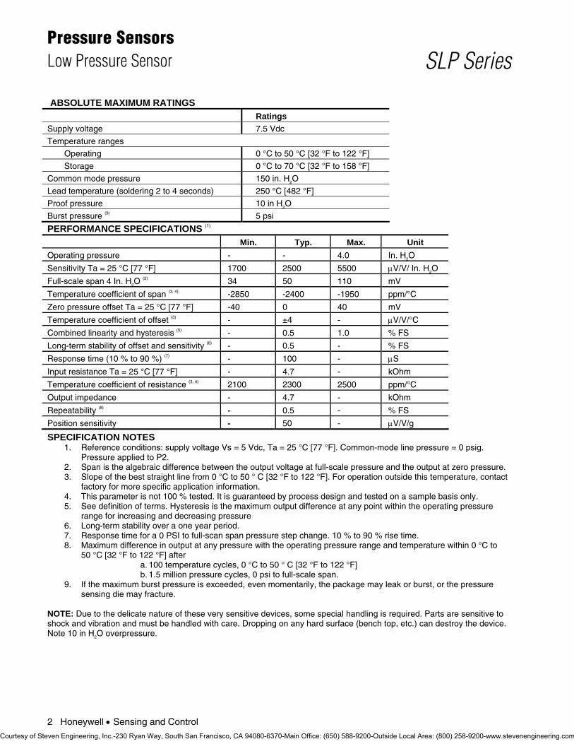
Pressure Sensors Low Pressure Sensor SLP Series
ABSOLUTE MAXIMUM RATINGS Ratings Supply voltage 7.5 Vdc
Temperature ranges
Operating 0 °C to 50 °C [32 °F to 122 °F]
Storage 0 °C to 70 °C [32 °F to 158 °F]
Common mode pressure 150 in. H2O
Lead temperature (soldering 2 to 4 seconds) 250 °C [482 °F]
Proof pressure 10 in H2O
Burst pressure (9) 5 psi
PERFORMANCE SPECIFICATIONS (1)
Min. Typ. Max. Unit Operating pressure - - 4.0 In. H2O
Sensitivity Ta = 25 °C [77 °F] 1700 2500 5500 µV/V/ In. H2O
Full-scale span 4 In. H2O (2) 34 50 110 mV
Temperature coefficient of span (3, 4) -2850 -2400 -1950 ppm/°C
Zero pressure offset Ta = 25 °C [77 °F] -40 0 40 mV
Temperature coefficient of offset (3) - ±4 - µV/V/°C
Combined linearity and hysteresis (5) - 0.5 1.0 % FS
Long-term stability of offset and sensitivity (6) - 0.5 - % FS
Response time (10 % to 90 %) (7) - 100 - µS
Input resistance Ta = 25 °C [77 °F] - 4.7 - kOhm
Temperature coefficient of resistance (3, 4) 2100 2300 2500 ppm/°C
Output impedance - 4.7 - kOhm
Repeatability (8) - 0.5 - % FS
Position sensitivity - 50 - µV/V/g
SPECIFICATION NOTES 1. Reference conditions: supply voltage Vs = 5 Vdc, Ta = 25 °C [77 °F]. Common-mode line pressure = 0 psig.
Pressure applied to P2. 2. Span is the algebraic difference between the output voltage at full-scale pressure and the output at zero pressure. 3. Slope of the best straight line from 0 °C to 50 ° C [32 °F to 122 °F]. For operation outside this temperature, contact
factory for more specific application information. 4. This parameter is not 100 % tested. It is guaranteed by process design and tested on a sample basis only. 5. See definition of terms. Hysteresis is the maximum output difference at any point within the operating pressure
range for increasing and decreasing pressure 6. Long-term stability over a one year period. 7. Response time for a 0 PSI to full-scan span pressure step change. 10 % to 90 % rise time. 8. Maximum difference in output at any pressure with the operating pressure range and temperature within 0 °C to
50 °C [32 °F to 122 °F] after a. 100 temperature cycles, 0 °C to 50 ° C [32 °F to 122 °F] b. 1.5 million pressure cycles, 0 psi to full-scale span.
9. If the maximum burst pressure is exceeded, even momentarily, the package may leak or burst, or the pressure sensing die may fracture.
NOTE: Due to the delicate nature of these very sensitive devices, some special handling is required. Parts are sensitive to shock and vibration and must be handled with care. Dropping on any hard surface (bench top, etc.) can destroy the device. Note 10 in H2O overpressure.
2 Honeywell • Sensing and Control Courtesy of Steven Engineering, Inc.-230 Ryan Way, South San Francisco, CA 94080-6370-Main Office: (650) 588-9200-Outside Local Area: (800) 258-9200-www.stevenengineering.com

Pressure Sensors Low Pressure Sensor SLP Series TYPICAL PERFORMANCE CHARACTERISTICS
DIMENSIONAL DRAWING – BUTTON SENSOR (for reference only mm/in)
DIMENSIONAL DRAWING –D4 SENSOR (for reference only mm/in) ELECTRICAL CONNECTIONS
Honeywell • Sensing and Control 3 Courtesy of Steven Engineering, Inc.-230 Ryan Way, South San Francisco, CA 94080-6370-Main Office: (650) 588-9200-Outside Local Area: (800) 258-9200-www.stevenengineering.com
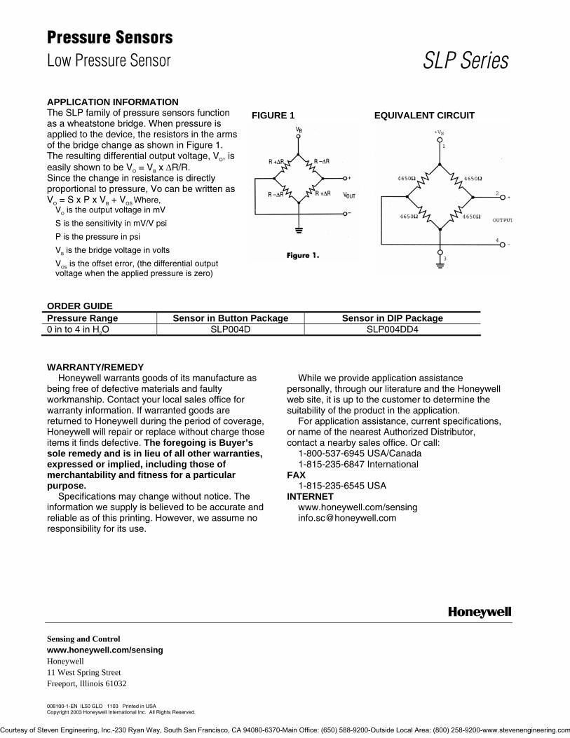
Pressure Sensors Low Pressure Sensor SLP Series
Sensing and Control www.honeywell.com/sensing Honeywell 11 West Spring Street Freeport, Illinois 61032 008100-1-EN IL50 GLO 1103 Printed in USA
APPLICATION INFORMATION The SLP family of pressure sensors function as a wheatstone bridge. When pressure is applied to the device, the resistors in the arms of the bridge change as shown in Figure 1. The resulting differential output voltage, VO, is easily shown to be VO = VB x ∆R/R. Since the change in resistance is directly proportional to pressure, Vo can be written as VO = S x P x VB + VOS Where,
VO is the output voltage in mV
S is the sensitivity in mV/V psi
P is the pressure in psi
VB is the bridge voltage in volts
VOS is the offset error, (the differential output voltage when the applied pressure is zero)
FIGURE 1 EQUIVALENT CIRCUIT
ORDER GUIDE Pressure Range Sensor in Button Package Sensor in DIP Package 0 in to 4 in H2O SLP004D SLP004DD4
WARRANTY/REMEDY
Honeywell warrants goods of its manufacture as being free of defective materials and faulty workmanship. Contact your local sales office for warranty information. If warranted goods are returned to Honeywell during the period of coverage, Honeywell will repair or replace without charge those items it finds defective. The foregoing is Buyer’s sole remedy and is in lieu of all other warranties, expressed or implied, including those of merchantability and fitness for a particular purpose.
Specifications may change without notice. The information we supply is believed to be accurate and reliable as of this printing. However, we assume no responsibility for its use.
While we provide application assistance
personally, through our literature and the Honeywell web site, it is up to the customer to determine the suitability of the product in the application.
For application assistance, current specifications, or name of the nearest Authorized Distributor, contact a nearby sales office. Or call:
1-800-537-6945 USA/Canada 1-815-235-6847 International
FAX 1-815-235-6545 USA INTERNET
www.honeywell.com/sensing [email protected]
Copyright 2003 Honeywell International Inc. All Rights Reserved.
Courtesy of Steven Engineering, Inc.-230 Ryan Way, South San Francisco, CA 94080-6370-Main Office: (650) 588-9200-Outside Local Area: (800) 258-9200-www.stevenengineering.com

SX Series
Silicon Pressure Sensors 0 psi to 1 psi to 0 psi to 150 psi
DESCRIPTION
The SX Series pressure sensors provide the lowest cost
components for measuring pressures up to 150 psi. These
sensors are designed for use with non-corrosive, non-ionic
media, such as air and dry gases. Convenient pressure ranges
are available to measure differential, gauge, and absolute
pressures from 0 psi to 1 psi (SX01) up to 0 psi to 150 psi
(SX150).
The Absolute (A) devices have an internal vacuum reference
and an output voltage proportional to absolute pressure. The
differential (D) devices allow application of pressure to either
side of the diaphragm and can be used for gauge or differential
pressure measurements.
This product is packaged in either the standard low cost chip
carrier “button” package, a plastic ported “N” package, or a DIP
package. All packages are designed for applications where the
sensing element is integral to the OEM equipment. These
packages can be o-ring sealed, epoxied, and/or clamped onto
a pressure fitting. A closed-bridge four pin SIP configuration is
provided for electrical connection to the “Button” or “N”
Package. The DIP Package mounts on a PC board like a
standard IC with through-hole pins. This extremely small size
package enables the use of multiple sensors in applications
with limited space.
FEATURES
• Low cost
• High-impedance bridge
• Absolute
• Differential (gage)
• Low noise
• Low power consumption for battery power
POTENTIAL APPLICATIONS
• Medical
• Instrumentation
• Barometric
• Measurement
• Pneumatic controls
• Battery powered equipment
Courtesy of Steven Engineering, Inc.-230 Ryan Way, South San Francisco, CA 94080-6370-Main Office: (650) 588-9200-Outside Local Area: (800) 258-9200-www.stevenengineering.com

SX Series
CHARACTERISTICS (Maximum ratings for all devices) Supply voltage, VS 12 Vdc
Operating temperature range -40 °C to 85 °C [-40 °F to 185 °F]
Storage temperature range -55 °C to 125 °C [-67 °F to 257 °F]
Humidity 0 % to 100 % RH Common-mode pressure 150 psig Lead soldering temperature 250 °C [482 °F] 2 sec to 4 sec
PERFORMANCE CHARACTERISTICS(1) Characteristic description Min. Typ. Max. Unit Zero pressure offset(2) -35.0 -20.0 0.0 mV
Temperature coefficient of offset(3,4) – 4 – μV/V/°C
Combined pressure non-linearity, and hysteresis(5) – 0.2 ±0.5 %FSS
Long term stability of offset and span(6) – 0.1 – %FSS Response time(7) – 100 – μs Input resistance – 4.1 – kΩ Temperature coefficient of resistance(3,4) 690 750 810 ppm/°C Temperature coefficient of span(3,4) -2550 -2150 -1900 ppm/°C Output resistance – 4.1 – kΩ Repeatability(8) – 0.5 – %FSS
SX PERFORMANCE CHARACTERISTICS(1)
Sensitivity (mV/V/psi) Full-scale span(9) (mV)
Burst pressure Part
number Operating pressure range Typ Min. Typ. Max.(10)
SX01 0 psi to 1 psi 4.0 15 20 25 20 psi
SX05 0 psi to 5 psi 3.0 50 75 100 20 psi
SX15 0 psi to 15 psi 1.5 75 110 150 45 psi
SX30 0 psi to 30 psi 0.75 75 110 150 90 psi
SX100 0 psi to 100 psi 0.3 100 150 200 150 psi
SX150 0 psi to 150 psi 0.15 75 110 150 200 psi Specification Notes: Note 1: Reference Conditions; TA = 25 °C [77 °F], Supply VS = 5 Vdc; Common Line Pressure = 0 psig, Pressure Applied to P1 Note 2: The zero pressure offset is 0 mV minimum to -20 mV typical and 35 mV maximum for part numbers SXxxxGD2 and SXxxxDD4. Note 3: Slope of best straight line fit from 0°C to 70°C. For operation outside this temperature range, contact factory for more information. Note 4: This parameter is not 100% tested. It is guaranteed by process design. Note 5: Pressure Hysteresis - the maximum output difference at any point within the operating pressure range for increasing and decreasing pressure. Pressure Non-linearity the maximum deviation of measure output, at constant temperature (25 °C [77 °F]), from “best straight line” through three points (offset pressure, full-scale pressure, one-half full scale pressure). Note 6: Long term stability over a one year period. Note 7: Response time for a 0 psi to Full-Scale Span pressure step change, 10% to 90% rise time. Note 8: Maximum difference in output at any pressure within the operating pressure range and the temperature range within 0 °C to 70 °C [32 °F to 158 °F] after: a) 100 temperature cycles, 0 °C and 70 °C [32 °F to 158 °F] b) 1 million pressure cycles, 0 psi to full-scale span. Note 9: Full-scale span is the algebraic difference between the output voltage at full-scale pressure and the output at zero pressure. Full-scale span is ratiometric to the supply voltage. Note 10: Exceeding maximum pressure can cause permanent sensor failure
2 www.honeywell.com/sensing
Courtesy of Steven Engineering, Inc.-230 Ryan Way, South San Francisco, CA 94080-6370-Main Office: (650) 588-9200-Outside Local Area: (800) 258-9200-www.stevenengineering.com

Silicon Pressure Sensors, 0 psi to 1 psi to 0 psi to 150 psi
EQUIVALENT CIRCUITS
Button, Nipple and N Packages DIP Packages
(Absolute Version Only)
ELECTRICAL CONNECTIONS
ORDERING INFORMATION
Order Part Number
Pressure Range Button Package Nipple Package “N” Package DIP Package
0 to 1 psid or psig SX01D SX01DP1 SX01DN SX01GD2, SX01DD4
0 to 5 psid or psig SX05D SX05DP1 SX05DN SX05GD2, SX05DD4
0 psia to 15 psia SX15A SX15AP1 SX15AN SX15AD2, SX15AD4
0 psia to 30 psia SX30A SX30AP1 SX30AN SX30AD2, SX30AD4
0 psia to 100 psia SX100A – SX100AN SX100AD2, SX100AD4
0 psia to 150 psia SX150A – SX150AN –
0 to 15 psid or psig SX15D SX25DP1 SX15DN SX15GD2, SX15DD4
0 to 30 psid or psig SX30D SX30DP1 SX30DN SX30GD2, SX30DD4
0 to 100 psid or psig SX100D – SX100DN SX100GD2, SX100DD4 0 to 150 psid or psig SX150D – – –
Honeywell Sensing and Control 3
Courtesy of Steven Engineering, Inc.-230 Ryan Way, South San Francisco, CA 94080-6370-Main Office: (650) 588-9200-Outside Local Area: (800) 258-9200-www.stevenengineering.com
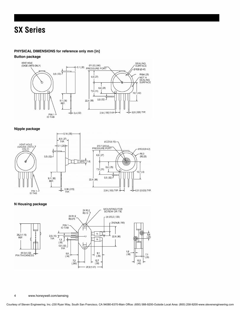
SX Series
PHYSICAL DIMENSIONS for reference only mm [in]
Button package
Nipple package
N Housing package
4 www.honeywell.com/sensing
Courtesy of Steven Engineering, Inc.-230 Ryan Way, South San Francisco, CA 94080-6370-Main Office: (650) 588-9200-Outside Local Area: (800) 258-9200-www.stevenengineering.com

Silicon Pressure Sensors, 0 psi to 1 psi to 0 psi to 150 psi
Honeywell Sensing and Control 5
D2 DIP package
DD4 DIP package
AD4 DIP package
Courtesy of Steven Engineering, Inc.-230 Ryan Way, South San Francisco, CA 94080-6370-Main Office: (650) 588-9200-Outside Local Area: (800) 258-9200-www.stevenengineering.com

WARNING PERSONAL INJURY DO NOT USE these products as safety or emergency stop
devices or in any other application where failure of the
product could result in personal injury.
Failure to comply with these instructions could result in
death or serious injury.
WARRANTY/REMEDY
Honeywell warrants goods of its manufacture as being free of
defective materials and faulty workmanship. Honeywell’s
standard product warranty applies unless agreed to otherwise
by Honeywell in writing; please refer to your order
acknowledgement or consult your local sales office for specific
warranty details. If warranted goods are returned to Honeywell
during the period of coverage, Honeywell will repair or replace,
at its option, without charge those items it finds defective. The
foregoing is buyer’s sole remedy and is in lieu of all other
warranties, expressed or implied, including those of
merchantability and fitness for a particular purpose. In no
event shall Honeywell be liable for consequential, special,
or indirect damages.
While we provide application assistance personally, through
our literature and the Honeywell web site, it is up to the
customer to determine the suitability of the product in the
application.
Specifications may change without notice. The information we
supply is believed to be accurate and reliable as of this
printing. However, we assume no responsibility for its use.
WARNING MISUSE OF DOCUMENTATION • The information presented in this product sheet is for
reference only. Do not use this document as a product
installation guide.
• Complete installation, operation, and maintenance
information is provided in the instructions supplied with
each product.
Failure to comply with these instructions could result in
death or serious injury.
SALES AND SERVICE
Honeywell serves its customers through a worldwide network
of sales offices, representatives and distributors. For
application assistance, current specifications, pricing or name
of the nearest Authorized Distributor, contact your local sales
office or:
E-mail: [email protected]
Internet: www.honeywell.com/sensing
Phone and Fax:
Asia Pacific +65 6355-2828
+65 6445-3033 Fax
Europe +44 (0) 1698 481481
+44 (0) 1698 481676 Fax
Latin America +1-305-805-8188
+1-305-883-8257 Fax
USA/Canada +1-800-537-6945
+1-815-235-6847
+1-815-235-6545 Fax
Sensing and Control
Honeywell
1985 Douglas Drive North
Golden Valley, MN 55422
www.honeywell.com
008136-2-EN IL50 GLO Printed in USA April 2009 © 2009 Honeywell International Inc.
Courtesy of Steven Engineering, Inc.-230 Ryan Way, South San Francisco, CA 94080-6370-Main Office: (650) 588-9200-Outside Local Area: (800) 258-9200-www.stevenengineering.com

SX7 Series
1 psig to 300 psig Button Package
Plastic Silicon Pressure Sensors DESCRIPTION The SX7 Series sensors offer a high pressure sensor in a very
small “button” style package.
These special devices use an RTV 730 for die attach to allow
measurement of gauge pressures of 1 psi (SX7001D) to 300
psi (SX7300D) with pressure applied to the backside of the sensor chip (Port P2) only. The output voltage is proportional
to pressure.
The output of the bridge is ratiometric to the supply voltage and
operation from any dc supply voltage up to +12V is acceptable.
This series is intended for use with non-corrosive, non-ionic working fluids such as air, dry gases, and the like.
FEATURES • Button package
• High pressure
• Small size • Low noise
• RTV 730 Die Attach
POTENTIAL APPLICATIONS • Medical equipment
• Computer peripherals
• Pneumatic controls • HVAC
Courtesy of Steven Engineering, Inc.-230 Ryan Way, South San Francisco, CA 94080-6370-Main Office: (650) 588-9200-Outside Local Area: (800) 258-9200-www.stevenengineering.com

SX7 Series Plastic Silicon Pressure Sensors
2 www.honeywell.com/sensing
Table 1. Maximum Ratings for All Devices Characteristic Parameter Unit Supply voltage, VS +12 Vdc Maximum pressure on any port 200 psig Temperature ranges: Operating Storage
-40 to 85 -55 to 125
°C [°F]
Humidity limits 0% to 100% RH Lead temperature 250 °C [°F] Soldering duration 3 s
Table 2. Standard Pressure Ranges
Full Scale Span* Catalog Listing
Operating Pressure
Proof Pressure
Maximum Pressure Min. Typ. Max.
SX7001D 1 psi – 20 psid 15 mV 20 mV 25 mV SX7005D 5 psi – 20 psid 50 mV 75 mV 100 mV SX7015D 15 psi – 30 psid 75 mV 110 mV 150 mV SX7030D 30 psi – 60 psid 75 mV 110 mV 150 mV SX7100D 100 psi – 150 psid 100 mV 150 mV 200 mV SX7150D 150 psi – 200 psid 75 mV 110 mV 150 mV SX7300D 0 psi to 300 psi 350 psi 300 psid 100 mV 150 mV 200 mV
*Full-Scale Span is the algebraic difference between the output voltage at full-scale pressure and the output at zero pressure. Full-Scale Span is ratiometric to the supply voltage. Table 3. Performance Characteristics
SX7001D Characteristic Min. Typ. Max. Unit Note Sensitivity 3.0 4.0 5.0 mV/V/psi – Temperature coefficient of span -2550 -2300 -2050 ppm/°C 4 Zero pressure offset -35 -20 0 mV – Temperature coefficient of offset – +4 – μV/V/°C 4 Combined pressure non-linearity and pressure hysteresis – 0.2 ±0.5 %FS 3 Long-term stability of offset and sensitivity – 0.1 – %FS 9 Response time (10% to 90%) – 100 – μs 8 Input resistance – 4.1 – kOhm 6 Temperature coefficient of resistance +690 +750 +810 ppm/°C – Output resistance – 4.1 – kOhm 7 Repeatability – 0.5 – %FS 5 SX7005D Characteristic Min. Typ. Max. Unit Note Sensitivity 2.0 3.0 4.0 mV/V/psi – Temperature coefficient of span -2550 -2300 -2050 ppm/°C 4 Zero pressure offset -35 -20 0 mV – Temperature coefficient of offset – +4 – μV/V/°C 4 Combined pressure Non-linearity and pressure hysteresis – 0.2 ±0.5 %FS 3 Long-term stability of offset and sensitivity – 0.1 – %FS 9 Response time (10% to 90%) – 100 – μs 8 Input resistance – 4.1 – kOhm 6 Temperature coefficient of resistance +690 +750 +810 ppm/°C – Output resistance – 4.1 – kOhm 7 Repeatability – 0.5 – %FS 5 SX7015D Characteristic Min. Typ. Max. Unit Note Sensitivity 1.0 1.5 2.0 mV/V/psi – Temperature coefficient of span -2400 -2150 -1900 ppm/°C 4 Zero pressure offset -35 -20 0 mV – Temperature coefficient of offset – +4 – μV/V/°C 4 Combined pressure Non-linearity and pressure hysteresis – 0.2 ±0.5 %FS 3 Long-term stability of offset and sensitivity – 0.1 – %FS 9 Response time (10% to 90%) – 100 – μs 8 Input resistance – 4.1 – kOhm 6 Temperature coefficient of resistance +690 +750 +810 ppm/°C – Output resistance – 4.1 – kOhm 7 Repeatability – 0.5 – %FS 5
Courtesy of Steven Engineering, Inc.-230 Ryan Way, South San Francisco, CA 94080-6370-Main Office: (650) 588-9200-Outside Local Area: (800) 258-9200-www.stevenengineering.com

1 psi to 300 psi, Button Package
Honeywell Sensing and Control 3
Table 3. Performance Characteristics (continued) SX7030D Characteristic Min. Typ. Max. Unit Note Sensitivity 0.5 0.75 1.0 mV/V/psi – Temperature coefficient of span -2400 -2150 -1900 ppm/°C 4 Zero pressure offset -35 -20 0 mV – Temperature coefficient of offset – +4 – μV/V/°C 4 Combined pressure Non-linearity and pressure hysteresis – 0.2 ±0.5 %FS 3 Long-term stability of offset and sensitivity – 0.1 – %FS 9 Response time (10% to 90%) – 100 – μs 8 Input resistance – 4.1 – kOhm 6 Temperature coefficient of resistance +690 +750 +810 ppm/°C – Output resistance – 4.1 – kOhm 7 Repeatability – 0.5 – %FS 5 SX7100D Characteristic Min. Typ. Max. Unit Note Sensitivity 0.2 0.3 0.4 mV/V/psi – Temperature coefficient of span -2400 -2150 -1900 ppm/°C 4 Zero pressure offset -35 -20 0 mV – Temperature coefficient of offset – +4 – μV/V/°C 4 Combined pressure Non-linearity and pressure hysteresis – 0.2 ±0.5 %FS 3 Long-term stability of offset and sensitivity – 0.1 – %FS 9 Response time (10% to 90%) – 100 – μs 8 Input resistance – 4.1 – kOhm 6 Temperature coefficient of resistance +690 +750 +810 ppm/°C – Output resistance – 4.1 – kOhm 7 Repeatability – 0.5 – %FS 5 SX7150D Characteristic Min. Typ. Max. Unit Note Sensitivity 0.1 0.15 0.2 mV/V/psi – Temperature coefficient of span -2400 -2150 -1900 ppm/°C 4 Zero pressure offset -35 -20 0 mV – Temperature coefficient of offset – +4 – μV/V/°C 4 Combined pressure Non-linearity and pressure hysteresis – 0.2 ±0.5 %FS 3 Long-term stability of offset and sensitivity – 0.1 – %FS 9 Response time (10% to 90%) – 100 – μs 8 Input resistance – 4.1 – kOhm 6 Temperature coefficient of resistance +690 +750 +810 ppm/°C – Output resistance – 4.1 – kOhm 7 Repeatability – 0.5 – %FS 5 SX7300D Characteristic Min. Typ. Max. Unit Note Sensitivity 0.033 0.04 0.06 mV/V/psi – Temperature coefficient of span -2400 -2150 -1900 ppm/°C 4 Zero pressure offset -16 0 16 mV – Temperature coefficient of offset – +4 – μV/V/°C 4 Combined pressure Non-linearity and pressure hysteresis – 0.2 ±0.5 %FS 3 Long-term stability of offset and sensitivity – 0.1 – %FS 9 Response time (10% to 90%) – 100 – μs 8 Input resistance – 4.1 – kOhm 6 Temperature coefficient of resistance +690 +750 +810 ppm/°C – Output resistance – 4.1 – kOhm 7 Repeatability – 0.5 – %FS 5
Notes: 1. Reference Conditions: TA = 25°C Supply VS = 5 Vdc Common Mode Line Pressure = 0 psig Pressure applied to Port 2 only. 3: Pressure Hysteresis is the maximum output difference at any point within the operating pressure range for increasing and decreasing pressure. 4: Slope of the best straight line from 0 °C to 70 °C. 5: Maximum difference in output at any pressure with the operating pressure range and the temperature range within 0 °C to 70 °C after:
a) 100 temperature cycles, 0 °C to 70 °C b) 1.0 million pressure cycles, 0 psi to Full-Scale Span
6: Input resistance is the impedance between Vs and ground. 7: Output resistance is the impedance between + and - outputs. 8: Response time for a 0 psi to Full-Scale Span pressure step change, 10% to 90% rise time. 9: Long-term stability over a one year period.
Courtesy of Steven Engineering, Inc.-230 Ryan Way, South San Francisco, CA 94080-6370-Main Office: (650) 588-9200-Outside Local Area: (800) 258-9200-www.stevenengineering.com

Figure 1. Equivalent circuit Figure 2. Pinout Figure 3. Drawing
WARNING PERSONAL INJURY DO NOT USE these products as safety or emergency stop devices or in any other application where failure of the product could result in personal injury. Failure to comply with these instructions could result in death or serious injury.
WARRANTY/REMEDY Honeywell warrants goods of its manufacture as being free of defective materials and faulty workmanship. Honeywell’s standard product warranty applies unless agreed to otherwise by Honeywell in writing; please refer to your order acknowledgement or consult your local sales office for specific warranty details. If warranted goods are returned to Honeywell during the period of coverage, Honeywell will repair or replace, at its option, without charge those items it finds defective. The foregoing is buyer’s sole remedy and is in lieu of all other warranties, expressed or implied, including those of merchantability and fitness for a particular purpose. In no event shall Honeywell be liable for consequential, special, or indirect damages.
While we provide application assistance personally, through our literature and the Honeywell web site, it is up to the customer to determine the suitability of the product in the application.
Specifications may change without notice. The information we supply is believed to be accurate and reliable as of this printing. However, we assume no responsibility for its use.
WARNING MISUSE OF DOCUMENTATION • The information presented in this product sheet is for
reference only. Do not use this document as a product installation guide.
• Complete installation, operation, and maintenance information is provided in the instructions supplied with each product.
Failure to comply with these instructions could result in death or serious injury.
SALES AND SERVICE Honeywell serves its customers through a worldwide network of sales offices, representatives and distributors. For application assistance, current specifications, pricing or name of the nearest Authorized Distributor, contact your local sales office or: E-mail: [email protected] Internet: www.honeywell.com/sensing Phone and Fax: Asia Pacific +65 6355-2828; +65 6445-3033 Fax Europe +44 (0) 1698 481481; +44 (0) 1698 481676 Fax Latin America +1-305-805-8188; +1-305-883-8257 Fax USA/Canada +1-800-537-6945; +1-815-235-6847 +1-815-235-6545 Fax
Sensing and Control
Honeywell
1985 Douglas Drive North
Golden Valley, MN 55422
www.honeywell.com/sensing
008180-2-EN IL50 GLO Printed in USA April 2009 Copyright © 2009 Honeywell International Inc. All rights reserved.
Courtesy of Steven Engineering, Inc.-230 Ryan Way, South San Francisco, CA 94080-6370-Main Office: (650) 588-9200-Outside Local Area: (800) 258-9200-www.stevenengineering.com

Pressure Sensor Low Pressure Sensor SXL Series
FEATURES • Accurate low pressure
readings • Low cost • High impedance bridge • Low noise • Low power consumption
for battery operation
TYPICAL APPLICATIONS • Medical instrumentation • Portable and battery-
operated equipment • Air-flow monitoring • HVAC • Industrial controls
WARNING PERSONAL INJURY DO NOT USE these products as safety or emergency stop devices or in any other application where failure of the product could result in personal injury. Failure to comply with these instructions could result in death or serious injury.
The SXL series of pressure sensors provides the lowest cost components for measuring very low pressures. These low pressure range devices were specifically designed to accurately measure differential and gage pressures of 1 inch to ten inches of H2O.
They are meant for use with non-corrosive and non-ionic media, such as air, dry gases, and the like. These differential devices allow application of pressure to either side of the diaphragm and can be used for gage or differential pressure measurements.
Sensing and Control
WARNING MISUSE OF DOCUMENTATION • The information presented in this product sheet is for reference only. Do
not use this document as a product installation guide. • Complete installation, operation, and maintenance information is provided
in the instructions supplied with each product. Failure to comply with these instructions could result in death or serious injury.
Courtesy of Steven Engineering, Inc.-230 Ryan Way, South San Francisco, CA 94080-6370-Main Office: (650) 588-9200-Outside Local Area: (800) 258-9200-www.stevenengineering.com

Pressure Sensors Low Pressure Sensor SXL Series
ABSOLUTE MAXIMUM RATINGS Ratings Supply voltage 5 Vdc
Temperature ranges
Operating 0 °C to 50 °C [32 °F to 122 °F]
Storage 0 °C to 70 °C [32 °F to 158 °F]
Common mode pressure 150 in. H2O
Lead temperature (soldering 2 to 4 seconds) 250 °C [482 °F]
Burst pressure 7 psi = 194 in H2O
PERFORMANCE SPECIFICATIONS (1)
Min. Typ. Max. Unit Operating pressure - 10.0 - In. H2O
Sensitivity Ta = 25 °C [77 °F] 0.4 0.9 1.6 mV/V/ In. H2O
Full-scale span 10 In. H2O (2) 20 45 80 mV
Temperature coefficient of span (3, 4) - -2300 - ppm/°C
Zero pressure offset Ta = 25 °C [77 °F] -35 -20 0 mV/V
Temperature coefficient of offset (3) - ± 4 - µV/V/°C
Combined linearity and hysteresis (5) ± 0.2 ± 1.0 % FS
Long-term stability of offset and sensitivity (6) - ± 0.1 - mV
Response time (10% to 90%) (7) - 100 - µS
Input resistance Ta = 25 °C [77 °F] - 4 - kOhm
Temperature coefficient of resistance (3, 4) - 750 - ppm/°C
Output impedance - 4 - kOhm
Repeatability (8) - 0.5 - % FSS
SPECIFICATION NOTES 1. Reference conditions: supply voltage Vs = 5 Vdc, Ta = 25 °C [77 °F]. Common-mode line pressure = 0 psig.
Pressure applied to P2. 2. Span is the algebraic difference between the output voltage at full-scale pressure and the output at zero pressure. 3. Slope of the best straight line from 0 °C to 50 ° C [32 °F to 122 °F]. For operation outside this temperature, contact
factory for more specific application information. 4. This parameter is not 100% tested. It is guaranteed by process design and tested on a sample basis only. 5. See definition of terms. Hysteresis is the maximum output difference at any point within the operating pressure
range for increasing and decreasing pressure 6. Long-term stability over a one year period. 7. Response time for a 0 PSI to full-scan span pressure step change. 10 % to 90 % rise time. 8. Maximum difference in output at any pressure with the operating pressure range and temperature within 0 °C to
50 °C [32 °F to 122 °F] after a. 100 temperature cycles, 0 °C to 50 ° C [32 °F to 122 °F] b. 1.5 million pressure cycles, 0 PSI to full-scale span.
9. If the maximum burst pressure is exceeded, even momentarily, the package may leak or burst, or the pressure sensing die may fracture.
2 Honeywell • Sensing and Control Courtesy of Steven Engineering, Inc.-230 Ryan Way, South San Francisco, CA 94080-6370-Main Office: (650) 588-9200-Outside Local Area: (800) 258-9200-www.stevenengineering.com
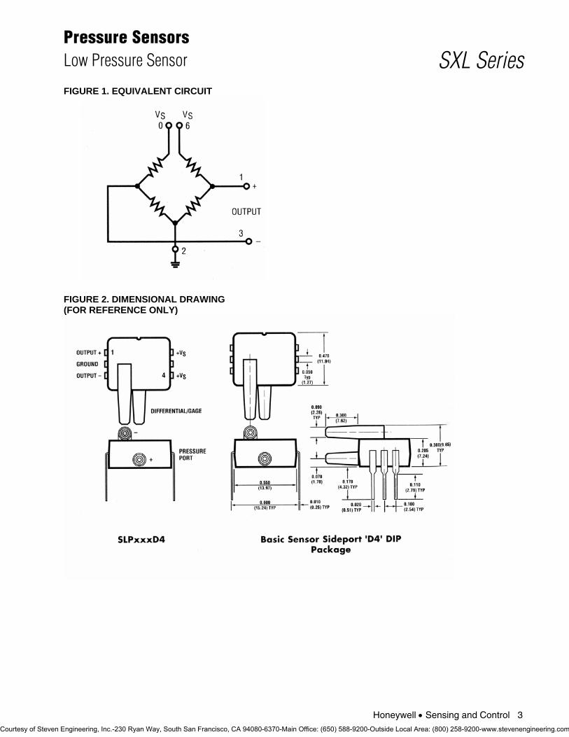
Pressure Sensors Low Pressure Sensor SXL Series FIGURE 1. EQUIVALENT CIRCUIT
FIGURE 2. DIMENSIONAL DRAWING (FOR REFERENCE ONLY)
Honeywell • Sensing and Control 3 Courtesy of Steven Engineering, Inc.-230 Ryan Way, South San Francisco, CA 94080-6370-Main Office: (650) 588-9200-Outside Local Area: (800) 258-9200-www.stevenengineering.com

Pressure Sensors Low Pressure Sensor SXL Series
Sensing and Control www.honeywell.com/sensing Honeywell 11 West Spring Street Freeport, Illinois 61032 008097-1-EN IL50 GLO 1103 Printed in USA
FIGURE 3. DIMENSIONAL DRAWING – D4 SENSOR - (FOR REFERENCE ONLY)
ORDER GUIDE Pressure Range SXL010D 0 to 10 in H2O/Standard Package SXL010DD4 0 to 10 in H2O/Sideport D4 DIP Package WARRANTY/REMEDY
Honeywell warrants goods of its manufacture as being free of defective materials and faulty workmanship. Contact your local sales office for warranty information. If warranted goods are returned to Honeywell during the period of coverage, Honeywell will repair or replace without charge those items it finds defective. The foregoing is Buyer’s sole remedy and is in lieu of all other warranties, expressed or implied, including those of merchantability and fitness for a particular purpose.
Specifications may change without notice. The information we supply is believed to be accurate and reliable as of this printing. However, we assume no responsibility for its use.
While we provide application assistance
personally, through our literature and the Honeywell web site, it is up to the customer to determine the suitability of the product in the application.
For application assistance, current specifications, or name of the nearest Authorized Distributor, contact a nearby sales office. Or call:
1-800-537-6945 USA/Canada 1-815-235-6847 International
FAX 1-815-235-6545 USA
INTERNET www.honeywell.com/sensing [email protected]
Copyright 2003 Honeywell International Inc. All Rights Reserved.
Courtesy of Steven Engineering, Inc.-230 Ryan Way, South San Francisco, CA 94080-6370-Main Office: (650) 588-9200-Outside Local Area: (800) 258-9200-www.stevenengineering.com

SX SMT Series
Microstructure Pressure Sensors 0 psi to 1 psi through 0 psi to 150 psi The SX SMT Series provides a most cost-effective method of
measuring absolute and gage pressures in a fully packaged
sensor. These sensors are designed primarily for use with
clean, dry gases such as air and nitrogen.
This series features the standard SX chip in a ceramic, surface
mount package. The standard version features a low profile
plastic lid to better withstand high temperatures. The optional
ported device offers a tube attachment port that is particularly
useful in gage applications.
The 4-pin closed bridge configuration allows electrical
connection with additional pads provided for mechanical
support. Pulsed power is recommended to achieve maximum
accuracy and conserve battery power in portable applications.
FEATURES
• Low cost
• Small size
• Absolute or gage pressures
• High-impedance bridge
• Low power consumption
POTENTIAL APPLICATIONS
• Pneumatic controls
• Automotive diagnostics
• Medical equipment/ instrumentation
• Dental equipment
• Environmental controls
• Barometric pressure measurement
• Altimeters
• Pneumatic controls
• Battery powered equipment
Courtesy of Steven Engineering, Inc.-230 Ryan Way, South San Francisco, CA 94080-6370-Main Office: (650) 588-9200-Outside Local Area: (800) 258-9200-www.stevenengineering.com
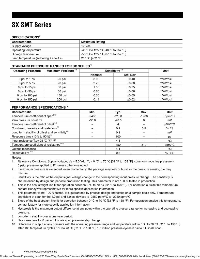
SX SMT Series
2 www.honeywell.com/sensing
SPECIFICATIONS(1) Characteristic Maximum Rating Supply voltage 12 Vdc Operating temperature -40 °C to 125 °C [-40 °F to 257 °F] Storage temperature -55 °C to 125 °C [-67 °F to 257 °F] Lead temperature (soldering 2 s to 4 s) 250 °C [482 °F] STANDARD PRESSURE RANGES FOR SX SERIES(1)
Sensitivity (3) Unit Operating Pressure Maximum Pressure (2)
Nominal Std. Dev. 0 psi to 1 psi 20 psi 3.90 ±0.40 mV/V/psi 0 psi to 5 psi 20 psi 2.70 ±0.38 mV/V/psi
0 psi to 15 psi 30 psi 1.50 ±0.25 mV/V/psi 0 psi to 30 psi 60 psi 0.66 ±0.06 mV/V/psi
0 psi to 100 psi 150 psi 0.30 ±0.05 mV/V/psi 0 psi to 150 psi 200 psi 0.14 ±0.02 mV/V/psi
PERFORMANCE SPECIFICATIONS(1) Characteristic Min. Typ. Max. Unit Temperature coefficient of span(4,5) -2400 -2150 -1900 ppm/°C Zero pressure offset TA -35.0 -20.0 0 mV Temperature coefficient of offset(6,5) – 4 – µV/V/°C Combined, linearity and hysteresis(7) – 0.2 0.5 % FS Long term stability of offset and sensitivity(8) – 0.1 – mV Response time (10% to 90%)(9) – 100 – µs Input resistance TA = 25 °C [77 °F] – 4.1 – kΩ Temperature coefficient of resistance(4,5) – 750 810 ppm/°C Output impedance – 4.1 – kΩ Repeatability (10) – 0.5 – % FSS
Notes: 1. Reference Conditions: Supply voltage, Vs = 5.0 Vdc, TA = 0 °C to 70 °C [32 °F to 158 °F], common-mode line pressure =
0 psig, pressure applied to P1 unless otherwise noted. 2. If maximum pressure is exceeded, even momentarily, the package may leak or burst, or the pressure sensing die may
fracture. 3. Sensitivity is the ratio of the output signal voltage change to the corresponding input pressure change. The sensitivity is
characterized by design and periodic production testing. This parameter in not 100 % tested in production. 4. This is the best straight line fit for operation between 0 °C to 70 °C [32 °F to 158 °F]. For operation outside this temperature,
contact Honeywell representative for more specific application information. 5. This parameter is not 100 % tested. It is guaranteed by process design and tested on a sample basis only. Temperature
coefficient of span for the 1.0 psi and 5.0 psi devices is -2550 ppm/°C to -2050 ppm/°C. 6. Slope of the best straight line fit for operation between 0 °C to 70 °C [32 °F to 158 °F]. For operation outside this temperature,
contact factory for more specific application information. 7. Hysteresis is the maximum output difference at any point within the operating pressure range for increasing and decreasing
pressure. 8. Long-term stability over a one year period. 9. Response time for 0 psi to full scale span pressure step change. 10. Difference in output at any pressure with the operating pressure range and temperature within 0 °C to 70 °C [32 °F to 158 °F]
after 100 temperature cycles 0 °C to 70 °C [32 °F to 158 °F], 1.0 million pressure cycles 0 psi to full-scale span.
Courtesy of Steven Engineering, Inc.-230 Ryan Way, South San Francisco, CA 94080-6370-Main Office: (650) 588-9200-Outside Local Area: (800) 258-9200-www.stevenengineering.com
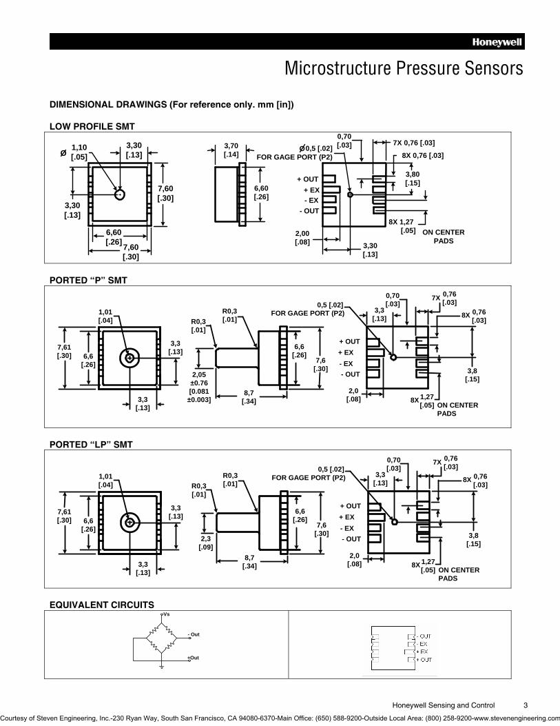
Microstructure Pressure Sensors
Honeywell Sensing and Control 3
DIMENSIONAL DRAWINGS (For reference only. mm [in]) LOW PROFILE SMT
1,10[.05]O
8X 1,27 [.05]
7,60[.30]
6,60[.26]7,60
[.30]
3,30[.13]
3,30[.13]
6,60[.26]
3,70[.14]
2,00[.08] 3,30
[.13]
+ OUT
- OUT
+ EX- EX
3,80[.15]
8X 0,76 [.03]7X 0,76 [.03]
0,5 [.02]FOR GAGE PORT (P2)
ON CENTERPADS
O0,70[.03]
PORTED “P” SMT
0,76[.03]7X
6,6[.26]
1,01[.04]
3,3[.13]
3,3[.13]
R0,3[.01]
R0,3[.01]
8,7[.34]
7,6[.30]
6,6[.26]
7,61[.30]
ON CENTERPADS
+ OUT
- OUT- EX+ EX
FOR GAGE PORT (P2)
1,27[.05]
8X
3,3[.13]
3,8[.15]
2,0[.08]
8X 0,76[.03]
0,5 [.02]0,70[.03]
2,05±0.76[0.081
±0.003]
PORTED “LP” SMT
0,76[.03]7X
6,6[.26]
1,01[.04]
3,3[.13]
3,3[.13]
2,3[.09]
R0,3[.01]
R0,3[.01]
8,7[.34]
7,6[.30]
6,6[.26]
7,61[.30]
ON CENTERPADS
+ OUT
- OUT- EX+ EX
FOR GAGE PORT (P2)
1,27[.05]
8X
3,3[.13]
3,8[.15]
2,0[.08]
8X 0,76[.03]
0,5 [.02]0,70[.03]
EQUIVALENT CIRCUITS
- Out
+Out
Vs
Courtesy of Steven Engineering, Inc.-230 Ryan Way, South San Francisco, CA 94080-6370-Main Office: (650) 588-9200-Outside Local Area: (800) 258-9200-www.stevenengineering.com

Sensing and Control
Honeywell
1985 Douglas Drive North
Minneapolis, MN 55422
www.honeywell.com/sensing
008098-5-EN IL50 GLO Printed in USA April 2008 © 2008 Honeywell International Inc.
SX SMT ORDER GUIDE
Cover TypeCeramic = SXPlastic Cover = SXP
Pressure Range0-1 = 01*0-5 = 05*0-15 = 150-30 = 300-100 = 1000-300 = 150
Pressure TypeGage = GAbsolute = A
Housing StyleLow profile cover = SMTPorted "P" = SMPTPorted "LP" = SMTLP
XXX XXX X XXXXX
*Not available in absolute pressure types.
WARNING MISUSE OF DOCUMENTATION • The information presented in this product sheet is for
reference only. Do not use this document as a product installation guide.
• Complete installation, operation, and maintenance information is provided in the instructions supplied with each product.
Failure to comply with these instructions could result in death or serious injury.
WARRANTY/REMEDY Honeywell warrants goods of its manufacture as being free of defective materials and faulty workmanship. Honeywell’s standard product warranty applies unless agreed to otherwise by Honeywell in writing; please refer to your order acknowledgement or consult your local sales office for specific warranty details. If warranted goods are returned to Honeywell during the period of coverage, Honeywell will repair or replace, at its option, without charge those items it finds defective. The foregoing is buyer’s sole remedy and is in lieu of all other warranties, expressed or implied, including those of merchantability and fitness for a particular purpose. In no event shall Honeywell be liable for consequential, special, or indirect damages.
While we provide application assistance personally, through our literature and the Honeywell web site, it is up to the customer to determine the suitability of the product in the application.
Specifications may change without notice. The information we supply is believed to be accurate and reliable as of this printing. However, we assume no responsibility for its use.
WARNING PERSONAL INJURY DO NOT USE these products as safety or emergency stop devices or in any other application where failure of the product could result in personal injury. Failure to comply with these instructions could result in death or serious injury.
SALES AND SERVICE Honeywell serves its customers through a worldwide network of sales offices, representatives and distributors. For application assistance, current specifications, pricing or name of the nearest Authorized Distributor, contact your local sales office or:
E-mail: [email protected]
Internet: www.honeywell.com/sensing
Phone and Fax: Asia Pacific +65 6355-2828 +65 6445-3033 Fax Europe +44 (0) 1698 481481 +44 (0) 1698 481676 Fax Latin America +1-305-805-8188 +1-305-883-8257 Fax USA/Canada +1-800-537-6945 +1-815-235-6847 +1-815-235-6545 Fax
Courtesy of Steven Engineering, Inc.-230 Ryan Way, South San Francisco, CA 94080-6370-Main Office: (650) 588-9200-Outside Local Area: (800) 258-9200-www.stevenengineering.com

XCA Series
Fixed Output, Amplified Calibrated with Ratiometric Output Voltage Pressure Sensors
DESCRIPTION
The XCA Series of pressure sensors use state-of-the-art
silicon micromachined pressure sensors in conjunction with
stress free packaging techniques to provide highly accurate,
amplified, calibrated and temperature compensated pressure
sensors for the most demanding applications.
When operated from a fixed 5.0 Vdc supply, the XCA4 gage
and absolute sensors provide a 0.25 Vdc to 4.25 Vdc output
(4.0 Vdc span).
The XCA5 Series offers an industry standard 1 Vdc to 6 Vdc
output (5 Vdc span) when operated from a fixed 8.0 Vdc
supply.
All other features are the same for both the XCA4 and the
XCA5, incorporating stress isolation and factory calibration to
achieve optimum accuracy in this industry standard package.
FEATURES
• Precise temperature compensation
• Low cost
• High performance
• Gage, absolute and differential versions
• Constant voltage excitation
• Calibrated output
• Ratiometric output voltage
POTENTIAL APPLICATIONS
• Ventilators
• Continuous positive airway pressure (CPAP) systems
• Audiometers
• Air compressors
• Chemical analyzers
• Variable air volume (VAV) controllers
• Airflow
Courtesy of Steven Engineering, Inc.-230 Ryan Way, South San Francisco, CA 94080-6370-Main Office: (650) 588-9200-Outside Local Area: (800) 258-9200-www.stevenengineering.com

XCA Series
2 www.honeywell.com/sensing
XCA4 ELECTRICAL SPECIFICATIONS (At 5 Vdc Excitation, 25 °C [77 °F].)
Characteristic Min. Typ. Max. Unit Excitation voltage 3.0 5.0 16.0 Vdc Null XCA4 (except differential) 0.15 0.25 0.35 Vdc Null XCA4 (differential) 2.20 2.25 2.30 Vdc Span XCA4 (except differential) 3.90 4.00 4.10 Vdc Span XCA4 (differential, changes with ± pressure applied ±1.95 ±2.00 ±2.05 Vdc Temperature change span 0 °C to 50 °C [32 °F to 122 °F](1) − ±0.6 ±1.0 % span Temperature change offset 0 °C to 50 °C [32 °F to 122 °F](1) − ±0.6 ±1.0 % span Linearity, hysteresis error(3) − ±0.30 ±0.50 % span Repeatability − ±0.1 − % span Input resistance − 15.0 − kΩ Output resistance − 3.0 − kΩ Operating temperature -25 [-13] − 85 [185] °C [°F] Storage temperature -40 [-40] − 125 [257] °C [°F] Common mode pressure − − 50 psi
Notes: 1. Shift is relative to 25 °C [77 °F]. 2. Measured at ½ full scale rated pressure using BFSL. XCA5 ELECTRICAL SPECIFICATIONS (At 8 Vdc Excitation, 25 °C [77 °F].)
Characteristic Min. Typ. Max. Unit Excitation voltage 3.0 8.0 16.0 Vdc Null XCA5 (except differential) 0.95 1.00 1.05 Vdc Null XCA5 (differential) 2.45 3.50 3.55 Vdc Span XCA5 (except differential) 4.90 5.00 5.10 Vdc Span XCA5 (differential, changes with ± pressure applied ±2.45 ±2.50 ±2.55 Vdc Temperature change span 0 °C to 50 °C [32 °F to 122 °F](1) − ±0.6 ±1.0 % span Temperature change offset 0 °C to 50 °C [32 °F to 122 °F](1) − ±0.6 ±1.0 % span Linearity, hysteresis error(2) − ±0.30 ±0.50 % span Repeatability − ±0.1 − % span Input resistance − 15.0 − kΩ Output resistance − 3.0 − kΩ Operating temperature -25 [-13] − 85 [185] °C [°F] Storage temperature -40 [-40] − 125 [257] °C [°F] Common mode pressure − − 50 psi
Notes: 1. Shift is relative to 25 °C [77 °F]. 2. Measured at ½ full scale rated pressure using BFSL. OVERPRESSURE RATING
Full Scale Pressure Overpressure (max.) 4 in H2O 3 psi 10 in H2O 3 psi 1 psi 3 psi 5 psi 15 psi 15 psi 45 psi 30 psi 90 psi 60 psi 180 psi 100 psi 250 psi 150 psi 250 psi
Courtesy of Steven Engineering, Inc.-230 Ryan Way, South San Francisco, CA 94080-6370-Main Office: (650) 588-9200-Outside Local Area: (800) 258-9200-www.stevenengineering.com

Calibrated with Ratiometric Output
Honeywell Sensing and Control 3
MOUNTING DIMENSIONS (For reference only: mm/[in].)
EQUIVALENT CIRCUIT MEDIA COMPATIBILITY: Clean, dry gases only
Pinout 1. V Excitation 2. V Output 3. V Offset (Not to be
used unless adjusting null offset.
4. Common
Port 1: Media must be compatible with epoxy-based adhesive. Port 2: Media must be compatible with nylon housing, epoxy adhesive and silicon. (Port not used for absolute devices.)
PRESSURE COMPATIBILITY • XCA4 Gage and Absolute: Measures gage pressure only with positive pressure to Port 2. There will be a small output voltage
between the actual offset voltage and ground proportional to vacuum if applied to Port 2. • XCA4 Differential: Measures differential pressure with positive pressure to Port 2 and negative pressure (vacuum) to Port 1.
The offset is set to 2.25 Vdc at 0 psid. It will change slightly with changes in common mode (line) pressure. • XCA5 Gage and Absolute: Measures gage pressure only with positive pressure to Port 2. There will be a small output voltage
between the actual offset voltage and ground proportional to vacuum if applied to Port 2.
Courtesy of Steven Engineering, Inc.-230 Ryan Way, South San Francisco, CA 94080-6370-Main Office: (650) 588-9200-Outside Local Area: (800) 258-9200-www.stevenengineering.com

Sensing and Control
Honeywell
1985 Douglas Drive North
Minneapolis, MN 55422
www.honeywell.com/sensing
008051-3-EN IL50 GLO Printed in USA July 2007 © 2007 Honeywell International Inc. All rights reserved.
ORDER GUIDE
WARNING PERSONAL INJURY DO NOT USE these products as safety or emergency stop devices or in any other application where failure of the product could result in personal injury. Failure to comply with these instructions could result in death or serious injury.
WARRANTY/REMEDY Honeywell warrants goods of its manufacture as being free of defective materials and faulty workmanship. Honeywell’s standard product warranty applies unless agreed to otherwise by Honeywell in writing; please refer to your order acknowledgement or consult your local sales office for specific warranty details. If warranted goods are returned to Honeywell during the period of coverage, Honeywell will repair or replace, at its option, without charge those items it finds defective. The foregoing is buyer’s sole remedy and is in lieu of all other warranties, expressed or implied, including those of merchantability and fitness for a particular purpose. In no event shall Honeywell be liable for consequential, special, or indirect damages.
While we provide application assistance personally, through our literature and the Honeywell web site, it is up to the customer to determine the suitability of the product in the application.
Specifications may change without notice. The information we supply is believed to be accurate and reliable as of this printing. However, we assume no responsibility for its use.
WARNING MISUSE OF DOCUMENTATION • The information presented in this product sheet is for
reference only. Do not use this document as a product installation guide.
• Complete installation, operation, and maintenance information is provided in the instructions supplied with each product.
Failure to comply with these instructions could result in death or serious injury.
SALES AND SERVICE Honeywell serves its customers through a worldwide network of sales offices, representatives and distributors. For application assistance, current specifications, pricing or name of the nearest Authorized Distributor, contact your local sales office or:
E-mail: [email protected]
Internet: www.honeywell.com/sensing
Phone and Fax: Asia Pacific +65 6355-2828 +65 6445-3033 Fax Europe +44 (0) 1698 481481 +44 (0) 1698 481676 Fax Latin America +1-305-805-8188 +1-305-883-8257 Fax USA/Canada +1-800-537-6945 +1-815-235-6847 +1-815-235-6545 Fax
Courtesy of Steven Engineering, Inc.-230 Ryan Way, South San Francisco, CA 94080-6370-Main Office: (650) 588-9200-Outside Local Area: (800) 258-9200-www.stevenengineering.com

XCX/XCXL Series
Compensated Silicon PressureSensors
DESCRIPTION
The XCX/XCXL Series integrates silicon micromachined
sensing technology, temperature compensation, and
calibration in an improved performance industry standard
package.
A unique stress isolating design protects against torque
induced.
Additional stability and long term accuracy improvements are
gained through simplified compensation techniques, which
eliminate temperature dependent thermal compensation
These products are available in High Grade (H) which are
calibrated for full scale span to ±1.0% over compensated
temperature range or in Commercial Grade (C) which are
calibrated for full scale span to ±2% over compensated
temperature range.
FEATURES
• Pressure ranges from 4 in H2O, 10 in H2O and 1 psi through
240 psi
• Calibrated offset
• High Grade (H) listings for high performance sensing
solutions or Commercial Grade (C) listings for lower
performance sensing solutions
• Temperature Compensated over 0 °C to 70 °C
[32 °F to 158 °F]
• Gage, differential, and absolute pressure
• Ratiometric mV output
POTENTIAL APPLICATIONS
• Medical
• Applications requiring small size
• Applications requiring vacuum, positive pressure or both
Courtesy of Steven Engineering, Inc.-230 Ryan Way, South San Francisco, CA 94080-6370-Main Office: (650) 588-9200-Outside Local Area: (800) 258-9200-www.stevenengineering.com

XCX/XCXL Series
2 www.honeywell.com/sensing
ELECTRICAL SPECIFICATIONS (At 12 Vdc Excitation at 25 °C(1) [77 °F].)
XCX/XCXL C Grade XCX/XCXL H Grade Characteristic Min. Typ. Max. Min. Typ. Max.
Unit
Excitation voltage 3.0 12.0 16.0 3.0 12.0 16.0 Vdc Null − − 1.0 − ±0.5 ±1.0 mV Temperature error on offset 0 °C to 50 °C [32 °F to 122 °F](2)
(4 in H2O) − − 1.0 − − 0.5 mV
Temperature error on offset 0 °C to 70 °C [32 °F to 158 °F](2)
(all except 4 in H2O) − − 1.0 − − 0.5 mV
Temperature error on span 0 °C to 50 °C [32 °F to 122 °F](2)
(4 in H2O) − − 2.0 − − 1.0 % span
Temperature error on span 0 °C to 70 °C [32 °F to 158 °F](2)
(all except 4 in H2O) − − 2.0 − − 1.0 % span
Linearity, hysteresis error(3) − 0.5 1.0 − 0.3 0.5 % span Repeatability − 0.1 − − 0.1 − % span Input resistance − 15 − − 15 − kΩ Output resistance − 3.0 − − 3.0 − kΩ Compensated temperature range 0 [32] 25 [77] 70 [158] 0 [32] 25 [77] 70 [158] °C [°F] Storage temperature range -40 [-40] − 125 [257] -40 [-40] − 125 [257] °C [°F] Relative humidity (non-condensing) 0 95 0 − 95 % RH Common mode pressure − − 50 − − 50 psig Shock (duration 11 ms any axis) − − 10 − − 10 g
Weight − 2 − − 2 − g
Notes: 1. All parameters are measured at 12 Vdc excitation, pressure specs obtained with pressure applied to the front of the sensor. 2. Shift is relative to 25 °C [77 °F]. 3. Measured at ½ full scale rated pressure using BFSL. DIFFERENTIAL AND GAGE OUTPUT (At 12 Vdc Excitation at 25 °C [77 °F].)
XCX C Grade Output Full Scale Span (mV)
XCX H Grade Output Full Scale Span (mV)
Full Scale Pressure
Min. Typ. Max. Min. Typ. Max.
Max. Overpressure (psi)
4 in H2O 38 40 42 − − − 5 10 in H2O 19 20 21 19.8 20.0 20.2 5 0.3 psi 19 20 21 19.8 20.0 20.2 5 1 psi 17 18 19 17.8 18.0 18.2 5 5 psi 57 60 63 59 60 61 15 15 psi 85 90 95 89 90 91 45 30 psi 85 90 95 89 90 91 90 60 psi 85 90 95 89 90 91 180 100 psi 95 100 105 99 100 101 200 150 psi 85 90 95 89 90 91 300 240 psi 95 100 105 99 100 101 300
Courtesy of Steven Engineering, Inc.-230 Ryan Way, South San Francisco, CA 94080-6370-Main Office: (650) 588-9200-Outside Local Area: (800) 258-9200-www.stevenengineering.com

Compensated Silicon Pressure Sensors
Honeywell Sensing and Control 3
ABSOLUTE OUTPUT (At 12 Vdc Excitation at 25 °C [77 °F].)
XCX Output, Full Scale Span (mV) FS Pressure Min. Typ. Max.
Max. Overpressure (psi)
5 psi 57 60 63 15 15 psi 85 90 95 45 30 psi 85 90 95 90 60 psi 85 90 95 180 100 psi 95 100 105 200 MOUNTING DIMENSIONS (For reference only: mm (in).)
EQUIVALENT CIRCUIT MEDIA COMPATIBILITY: Clean, dry gases only.
Pinout 1. N/C 2. +V Excitation 3. - Output signal 4. _V Excitation 5. - Output signal 6. N/C
P1 Port: Front side of silicon diaphragm, silicone gel passivation, glass-filled nylon alumina. P2 Port: Silicon diaphragm, glass-filled nylon and alumina ceramic.
Courtesy of Steven Engineering, Inc.-230 Ryan Way, South San Francisco, CA 94080-6370-Main Office: (650) 588-9200-Outside Local Area: (800) 258-9200-www.stevenengineering.com

Sensing and Control
Honeywell
1985 Douglas Drive North
Minneapolis, MN 55422
www.honeywell.com/sensing
008047-3-EN IL50 GLO Printed in USA July 2007 © 2007 Honeywell International Inc. All rights reserved.
ORDER GUIDE
Note 1. Gage and Differential use “D” suffix. Product is the same. Not all combinations are available.
WARNING PERSONAL INJURY DO NOT USE these products as safety or emergency stop devices or in any other application where failure of the product could result in personal injury. Failure to comply with these instructions could result in death or serious injury.
WARRANTY/REMEDY Honeywell warrants goods of its manufacture as being free of defective materials and faulty workmanship. Honeywell’s standard product warranty applies unless agreed to otherwise by Honeywell in writing; please refer to your order acknowledgement or consult your local sales office for specific warranty details. If warranted goods are returned to Honeywell during the period of coverage, Honeywell will repair or replace, at its option, without charge those items it finds defective. The foregoing is buyer’s sole remedy and is in lieu of all other warranties, expressed or implied, including those of merchantability and fitness for a particular purpose. In no event shall Honeywell be liable for consequential, special, or indirect damages.
While we provide application assistance personally, through our literature and the Honeywell web site, it is up to the customer to determine the suitability of the product in the application.
Specifications may change without notice. The information we supply is believed to be accurate and reliable as of this printing. However, we assume no responsibility for its use.
WARNING MISUSE OF DOCUMENTATION • The information presented in this product sheet is for
reference only. Do not use this document as a product installation guide.
• Complete installation, operation, and maintenance information is provided in the instructions supplied with each product.
Failure to comply with these instructions could result in death or serious injury.
SALES AND SERVICE Honeywell serves its customers through a worldwide network of sales offices, representatives and distributors. For application assistance, current specifications, pricing or name of the nearest Authorized Distributor, contact your local sales office or:
E-mail: [email protected]
Internet: www.honeywell.com/sensing
Phone and Fax: Asia Pacific +65 6355-2828 +65 6445-3033 Fax Europe +44 (0) 1698 481481 +44 (0) 1698 481676 Fax Latin America +1-305-805-8188 +1-305-883-8257 Fax USA/Canada +1-800-537-6945 +1-815-235-6847 +1-815-235-6545 Fax
Courtesy of Steven Engineering, Inc.-230 Ryan Way, South San Francisco, CA 94080-6370-Main Office: (650) 588-9200-Outside Local Area: (800) 258-9200-www.stevenengineering.com

XPC/XPCL and XPX/XPXL Series
Uncompensated/Compensated and Compensated Calibrated Silicon Pressure Sensors
DESCRIPTION
The XPC/XPCL and XPX/XPXL Series sensors integrate
silicon micromachined sensing technology, temperature
compensation, and calibration in a complete family of low-cost
packages. This series offers a cost-effective solution for design
requirements.
These piezoresistive pressure sensors use micromachined
silicon chips mounted on ceramic and protected with a plastic
cap. Several tube arrangements with nylon housings are
available for various pressure applications.
On devices of 5 psi and above, the top side of the chip is
protected against humidity by a Silgel® coating.
Although the sensors are designed for use with noncorrosive,
nonionic pressure media, they accommodate many gases that
are used in medical applications.
FEATURES
• Low cost, small size
• Temperature compensated
• Zero and span calibrated
• Millivolt output
• Differential, gage and absolute pressure
• Constant voltage excitation
• High impedance - low current
POTENTIAL APPLICATIONS
• Medical applications
• Applications requiring small size
• Applications requiring vacuum and positive pressure
reference or both
Courtesy of Steven Engineering, Inc.-230 Ryan Way, South San Francisco, CA 94080-6370-Main Office: (650) 588-9200-Outside Local Area: (800) 258-9200-www.stevenengineering.com

XPC/XPCL and XPX/XPXL Series
2 www.honeywell.com/sensing
ELECTRICAL SPECIFICATIONS XPC/XPCL at 12 Vdc, 25 °C [77 °F] XPX/XPXL at 5 Vdc, 25 °C [77 °F] Characteristic
Min. Typ. Max. Unit Min. Typ. Max. Unit Excitation voltage 3.0 12.0 16.0 Vdc 3.0 5.0 12.0 Vdc Null -1.0 0 1.0 mV -50 0 50 mV Offset temperature shift(1) 0 °C to 25 °C [32 °F to 77°F] 25 °C to 70 °C [77 °F to 158 °F]
– – ±1.0 mV
– ±0.5 mV
Full scale temperature shift(1) 0 °C to 25 °C [32 °F to 158 °F] 25 °C to 70 °C [77 °F to 158 °F]
– – ±2 PPM/°C – -2200 – PPM/°C
Linearity, hysteresis error(2) – 0.25 1.0 % span 0.25 1.0 % span Input resistance 5.0 – – kOhm 5.0 – – kOhm Output resistance – 3.0 – kOhm – 3.0 – kOhm Operating temperature -25 [-13] – 85 [185] °C [°F] -25 [-13] – 85 [185] °C [°F] Storage temperature -40 [-40] – 125 [257] °C [°F] -40 [-40] – 125 [257] °C [°F] Common mode pressure – – 50 psi – – 50 psi Weight – 2 – g – 2 – g
Notes: 1. Shift is relative to 25 °C [77 °F]. 2. Measured at 1/2 full scale rated pressure using BFSL. ABSOLUTE OUTPUT
XPC at 12 Vdc, 25 °C [77 °F] Output Full Scale Span (mV)
XPX at 5 Vdc, 25 °C [77 °F] Output Full Scale Span (mV)
Overpressure (psi)
FS Pressure
Min. Typ. Max. Min. Typ. Max. Max. 5 psi 57 60 63 112 168.5 225 15 15 psi 85 90 95 168 253 338 45 30 psi 85 90 95 168 253 338 90 60 psi 85 90 95 189 263.5 338 180 100 psi 95 100 105 210 295 380 250
GAGE/DIFFERENTIAL(1) OUTPUT
XPC/XPCL at 12 Vdc, 25 °C [77 °F] Output Full Scale Span (mV)
XPX/XPXL at 5 Vdc, 25 °C [77 °F] Output Full Scale Span (mV)
Overpressure (psi)
FS Pressure
Min. Typ. Max. Min. Typ. Max. Max. 4 in H2O 23 25 27 50 68 86 3 10 in H2O 19 20 21 40 78.5 112 3 1 psi 17 18 19 40 75 110 3 5 psi 57 60 63 112 168.5 225 15 15 psi 85 90 95 168 253 338 45 30 psi 85 90 95 168 253 338 90 60 psi 85 90 95 189 263.5 338 180 100 psi 95 100 105 210 295 380 250 150 psi 85 90 95 187 262.5 338 250
Note: 1. Differential common mode pressure should not exceed 50 psi.
MOUNTING DIMENSIONS (For reference only: mm (in).) D/A Housing (Differential/Absolute)
GFS/AFS Housing (Gage/Absolute Offset Axial)
GBFS Housing (Gage Backside Offset Axial)
Courtesy of Steven Engineering, Inc.-230 Ryan Way, South San Francisco, CA 94080-6370-Main Office: (650) 588-9200-Outside Local Area: (800) 258-9200-www.stevenengineering.com

Uncompensated/Compensated and Compensated Calibrated Silicon Pressure Sensors
Honeywell Sensing and Control 3
MOUNTING DIMENSIONS (For reference only: mm (in).) GF/AF Housing (Gage/Absolute Axial)
DF Housing (Differential Axial)
GBF Housing (Gage Backside Axial)
GT/AT Housing (Gage/Absolute Radial)
GBT Housing (Gage Backside Radial)
DT Housing (Differential Radial)
Courtesy of Steven Engineering, Inc.-230 Ryan Way, South San Francisco, CA 94080-6370-Main Office: (650) 588-9200-Outside Local Area: (800) 258-9200-www.stevenengineering.com

Sensing and Control
Honeywell
1985 Douglas Drive North
Minneapolis, MN 55422
www.honeywell.com/sensing
008046-5-EN IL50 GLO Printed in USA July 2007 © 2007 Honeywell International Inc. All rights reserved.
EQUIVALENT CIRCUIT
Pinout 1. -V Excitation 2. + Output Signal 3. +V Excitation 4. - Output Signal
Media compatibility: Clean, dry gases only.
P1 Port: Media must be compatible with epoxy-based adhesive and silicon gel. P2 Port: Media must be compatible with nylon housing, epoxy-based adhesive and silicon.
ORDER GUIDE(1)
Notes: 1. Not all combinations may be available. Contact Honeywell representative for details. 2. Option available in ported gage version only.
WARNING PERSONAL INJURY DO NOT USE these products as safety or emergency stop devices or in any other application where failure of the product could result in personal injury. Failure to comply with these instructions could result in death or serious injury.
WARRANTY/REMEDY Honeywell warrants goods of its manufacture as being free of defective materials and faulty workmanship. Honeywell’s standard product warranty applies unless agreed to otherwise by Honeywell in writing; please refer to your order acknowledgement or consult your local sales office for specific warranty details. If warranted goods are returned to Honeywell during the period of coverage, Honeywell will repair or replace, at its option, without charge those items it finds defective. The foregoing is buyer’s sole remedy and is in lieu of all other warranties, expressed or implied, including those of merchantability and fitness for a particular purpose. In no event shall Honeywell be liable for consequential, special, or indirect damages.
While we provide application assistance personally, through our literature and the Honeywell web site, it is up to the customer to determine the suitability of the product in the application.
Specifications may change without notice. The information we supply is believed to be accurate and reliable as of this printing. However, we assume no responsibility for its use.
WARNING MISUSE OF DOCUMENTATION • The information presented in this product sheet is for
reference only. Do not use this document as a product installation guide.
• Complete installation, operation, and maintenance information is provided in the instructions supplied with each product.
Failure to comply with these instructions could result in death or serious injury.
SALES AND SERVICE Honeywell serves its customers through a worldwide network of sales offices, representatives and distributors. For application assistance, current specifications, pricing or name of the nearest Authorized Distributor, contact your local sales office or:
E-mail: [email protected]
Internet: www.honeywell.com/sensing
Phone and Fax: Asia Pacific +65 6355-2828 +65 6445-3033 Fax Europe +44 (0) 1698 481481 +44 (0) 1698 481676 Fax Latin America +1-305-805-8188 +1-305-883-8257 Fax USA/Canada +1-800-537-6945 +1-815-235-6847 +1-815-235-6545 Fax
Courtesy of Steven Engineering, Inc.-230 Ryan Way, South San Francisco, CA 94080-6370-Main Office: (650) 588-9200-Outside Local Area: (800) 258-9200-www.stevenengineering.com

XSCL/XSC Series
Compensated and Calibrated Pressure Sensors
DESCRIPTION The XSCL/XSC Series sensors integrate silicon
micromachined sensing technology, temperature
compensation and calibration in a wide variety of low-cost
packages. This series offers a cost-effective solution for design
requirements.
These piezoresistive pressure sensors use micromachined
silicon chips mounted on ceramic and protected with a plastic
cap. Several tube arrangements with nylon housings are
available for various pressure applications.
On devices of 5 psi and above, the topside of the chip is
protected against humidity by a Silgel® coating. While the
sensors are designed for use with non-corrosive, non-ionic
pressure media, they accommodate many gases that are used
in medical applications.
FEATURES • Low cost, small size, temperature compensated
• Zero and span calibrated
• Millivolt output
• Differential, gage and absolute pressure
• Constant voltage excitation
• High impedence – low current
POTENTIAL APPLICATIONS
• Medical equipment
• Applications requiring small size
• Applications requiring vacuum and positive pressure
reference, or both
Courtesy of Steven Engineering, Inc.-230 Ryan Way, South San Francisco, CA 94080-6370-Main Office: (650) 588-9200-Outside Local Area: (800) 258-9200-www.stevenengineering.com

XSCL/XSC Series Compensated and Calibrated
2 www.honeywell.com/sensing
ELECTRICAL SPECIFICATIONS AT 12 ±0.01 VDC EXCITATION AT 25 °C [77 °F] (1) Characteristic Min. Typ. Max. Unit Excitation voltage 3.0 12.0 16.0 Vdc Null -1.0 0 +1.0 mV Offset temperature shift 0 °C to 70 °C [32 °F to 158 °F] (2)
– – ±1.0 mV
Full scale temperature shift 0 °C to 70 °C [32 °F to 158 °F] (2)
– – ±2 % span
Linearity, hysteresis error (3) – 0.25 1.0 % span Input resistance 5.0 – – kΩ Output resistance – 3.0 – kΩ Operating temperature -25 – +85 °C Storage temperature -40 – +125 °C Common mode pressure – – 50 psi Weight – 2 – g
Notes: 1. All parameters are measured at 12 Vdc excitation. Pressure specs obtained with pressure applied to the front of the sensor. 2. Shift is relative to 25 ºC [77 ºF]. 3. Measured at ½ full scale rated pressure using BFSL.
XSC ABSOLUTE OUTPUT AT 12 VDC ±0.01 EXCITATION AT 25 °C [77 °F] XSC Output Full Scale Span (mV) Overpressure (psi) FS Pressure (psi)
Min. Typ. Max. Max. 5 57 60 63 15 15 85 90 95 45 30 85 90 95 90 60 85 90 95 180
XSCL/XSC GAGE AND DIFFERENTIAL(1) OUTPUT AT 12 VDC ±0.01 EXCITATION AT 25 °C [77 °F] XSC Output Full Scale Span (mV) Overpressure (psi) FS Pressure (psi)
Min. Typ. Max. Max. 4 in H20 23 25 27 3 10 in H20 19 20 21 3 1 17 18 19 3 5 57 60 63 15 15 85 90 95 45 30 85 90 95 90 60 85 90 95 180 100 95 100 105 250
Note: 1. Differential common mode pressure should not exceed 50 psi.
Courtesy of Steven Engineering, Inc.-230 Ryan Way, South San Francisco, CA 94080-6370-Main Office: (650) 588-9200-Outside Local Area: (800) 258-9200-www.stevenengineering.com

Pressure Sensors
Honeywell Sensing and Control 3
MOUNTING DIMENSIONS (For reference only, mm/in.) XCS A/D/G/Style
XCS/XCSL WITH PORT, AF/GF STYLE
EQUIVALENT CIRCUIT
PIN DESIGNATIONS 1. –V Excitation 2. +Output Signal 3. +V Excitation 4. –Output Signal
MEDIA COMPATIBILITY Dry gasses only. Media must be compatible with nylon housing, epoxy adhesive and silicon.
1
2
3
4
Courtesy of Steven Engineering, Inc.-230 Ryan Way, South San Francisco, CA 94080-6370-Main Office: (650) 588-9200-Outside Local Area: (800) 258-9200-www.stevenengineering.com

Automation and Control Solutions Sensing and Control
Honeywell
11 West Spring Street
Freeport, Illinois 61032
www.honeywell.com/sensing
008056-2-EN IL50 GLO Printed in USA October 2005 © 2005 Honeywell International Inc.
ORDER GUIDE
SeriesXSC: Motorola, compensated and calibrated, mV
Pressure MeasurementL: Low pressure (in H2O)No character: Indicates pressure (psi)
Pressure Range04 in H2O, 10 in H2O01, 05, 15, 30, 60, 100 psi Pressure Reference
G: GageD: DifferentialA: Absolute > 5 psi
Port Operation (1)
B: Backside
Port OptionF: AxialT: RadialFS: Offset Axial (1)
Accuracy GradeC: CommercialH: High
XSC L 04 G B F C
Note: 1. Option available in ported gage version only.
WARNING PERSONAL INJURY DO NOT USE these products as safety or emergency stop devices or in any other application where failure of the product could result in personal injury. Failure to comply with these instructions could result in death or serious injury.
WARRANTY/REMEDY Honeywell warrants goods of its manufacture as being free of defective materials and faulty workmanship. Honeywell’s standard product warranty applies unless agreed to otherwise by Honeywell in writing; please refer to your order acknowledgement or consult your local sales office for specific warranty details. If warranted goods are returned to Honeywell during the period of coverage, Honeywell will repair or replace, at its option, without charge those items it finds defective. The foregoing is buyers sole remedy and is in lieu of all other warranties, expressed or implied, including those of merchantability and fitness for a particular purpose. In no event shall Honeywell be liable for consequential, special, or indirect damages. While we provide application assistance personally, through our literature and the Honeywell web site, it is up to the customer to determine the suitability of the product in the application. Specifications may change without notice. The information we supply is believed to be accurate and reliable as of this printing. However, we assume no responsibility for its use.
WARNING MISUSE OF DOCUMENTATION • The information presented in this product sheet is for
reference only. Do not use this document as a product installation guide.
• Complete installation, operation, and maintenance information is provided in the instructions supplied with each product.
Failure to comply with these instructions could result in death or serious injury.
SALES AND SERVICE Honeywell serves its customers through a worldwide network of sales offices, representatives and distributors. For application assistance, current specifications, pricing or name of the nearest Authorized Distributor, contact your local sales office or:
E-mail: [email protected]
Internet: www.honeywell.com/sensing
Phone and Fax: Asia Pacific +65 6355-2828 +65 6445-3033 Fax Europe +44 (0) 1698 481481 +44 (0) 1698 481676 Fax Latin America +1-305-805-8188 +1-305-883-8257 Fax USA/Canada +1-800-537-6945 +1-815-235-6847 +1-815-235-6545 Fax
Courtesy of Steven Engineering, Inc.-230 Ryan Way, South San Francisco, CA 94080-6370-Main Office: (650) 588-9200-Outside Local Area: (800) 258-9200-www.stevenengineering.com