DC INVERTER VRF SYSTEM SERVICE MANUAL(R410A)
173
DC INVERTER VRF SYSTEM SERVICE MANUAL(R410A)
-
Upload
khangminh22 -
Category
Documents
-
view
0 -
download
0
Transcript of DC INVERTER VRF SYSTEM SERVICE MANUAL(R410A)
DC INVERTER VRF SYSTEM SERVICE MANUAL(R410A)

CONTENTS PRODUCT ........................................................................................................................................ 1
1 PRODUCT LIST ......................................................................................................................................... 1 2 NOMENCLATURE ...................................................................................................................................... 3
2.1 Nomenclature of outdoor units ................................................................................................................... 3 3 PRODUCT FEATURES .............................................................................................................................. 3
3.1 General introduction ...................................................................................................................................... 3 3.2 Features............................................................................................................................................................. 3
4 SPECIFICATIONS ...................................................................................................................................... 4 4.1 Specifications .................................................................................................................................................. 4 4.2 Operation range .............................................................................................................................................. 8
5 PRODUCT CAPACITY CORRECTION ...................................................................................................... 8 5.1Correction factor of indoor and outdoor temperature ........................................................................... 8 5.2 Correction factor of pipe length and height difference ......................................................................... 9
6 PRINCIPAL OF OPERATION ................................................................................................................... 10 CONTROL ...................................................................................................................................... 15
1 UNITS’ CONTROL ................................................................................................................................... 15 1.1 Schematic diagram of units’ control ........................................................................................................ 15 1.2 Interpretation on the schematic diagram ................................................................................................ 15
2 REMOTE MONITORING SYSTEM ......................................................................................................... 15 2.1 General introduction .................................................................................................................................... 15
3 MONITORING SOFTWARE .................................................................................................................... 16 3.1 Function introduction .................................................................................................................................. 16 3.2 Connection of computer and units ........................................................................................................... 16 3.3 Parts introduction ......................................................................................................................................... 17
INSTALLATION .............................................................................................................................. 61 1 ENGINEERING INSTALLATION PREPARATION AND NOTICE ........................................................... 61
1.1 Installation notice ......................................................................................................................................... 61 1.2 Installation key points and importance ................................................................................................... 61
2 INSTALLATION MATERIALS SELECTION............................................................................................. 62 2.1 Refrigerant piping ......................................................................................................................................... 62 2.2 Condensate water pipe ................................................................................................................................ 63 2.3 Insulation material ........................................................................................................................................ 63 2.4 Communication cable and control cable ................................................................................................ 63 2.5 Power cable .................................................................................................................................................... 64 2.6 Hanger rod and support .............................................................................................................................. 64
3 INSTALLATION OF OUTDOOR UNIT ..................................................................................................... 64 3.1 Check before installation ............................................................................................................................ 64 3.2 Selection of installation site ....................................................................................................................... 64 3.3 Carrying and installing outdoor unit ........................................................................................................ 64 3.4 Installation notices ....................................................................................................................................... 65 3.5 Fixing and damping of unit ........................................................................................................................ 65 3.6 Outline dimension and position of installation hole ............................................................................ 65 3.7 Installation space requirement .................................................................................................................. 67
DEBUGGING &MAINTENANCE .................................................................................................... 68 1 DEBUGGING OF UNIT ............................................................................................................................ 69
1.1 Preparation for debugging ......................................................................................................................... 69 1.2 Debugging of unit ......................................................................................................................................... 70 1.3 Parameters reference value for the normal operation of unit ........................................................... 73
2 MALFUNCTION LIST ............................................................................................................................... 77 2.1 Malfunction list for the wired controller .................................................................................................. 77 2.2 Status display table for indicators on main board of outdoor unit .................................................. 78
3 TROUBLESHOOTING ............................................................................................................................. 88 4 POWER DISTRIBUTION OF UNIT .......................................................................................................... 98
4.1 Power distribution of unit ........................................................................................................................... 98 4.2 Main electric parts ........................................................................................................................................ 98 4.3 Circuit diagram .............................................................................................................................................. 99

5 REMOVAL OF PARTS ............................................................................................................... 104 5.1 Key parts ....................................................................................................................................................... 104 5.2 Removal of key parts ................................................................................................................................. 106
6 COMMON MAINTENANCE ................................................................................................................... 140 6.1 Vacuum drying for the system ................................................................................................................ 140 6.2 Fill and charge refrigerant ........................................................................................................................ 141 6.3 Airtightness test .......................................................................................................................................... 145
7 EXPLODED VIEW OF UNIT AND PARTS’ LIST ................................................................................... 146 7.1 Exploed view for outdoor unit and parts’ list ....................................................................................... 146

DC INVERTER VRF SYSTEM II SERVICE MANUAL(R410A)
PRODUCT

GREE DC Inverter Multi VRF System II Service Manual
1
PRODUCT 1 Product List
Model Product Code Cooling Capacity
(kW)
Heating Capacity
(kW)
Power Supply Refrigerant Appearance
GMV-80WL/A-T CN850W0530 8 9
220-240V 50Hz
208-230V 60Hz
R410A
GMV-100WL/A-T CN850W0430 10 11
GMV-121WL/A-T CN850W0420 12.1 13.0
GMV-80WL/C-T CN850W0590 8 9
GMV-100WL/ C -T CN850W0600 10 11
GMV-121WL/C-T CN850W0640 12.1 13.0
GMV-141WL/C-T CN850W0880 14.1 16.0
220V 240V
50Hz or 208V 230V
60Hz
R410A
GMV-120WL/A-T CN850W0180 12.1 14 220-240V
50Hz 208-230V
60Hz
R410A
GMV-140WL/A-T CN850W0170 14 16.5
GMV-160WL/A-T CN850W0160 16 18.5
GMV-120WL/A-X CN850W0260 12.1 14 380-415V 3N~50Hz 380-415V 3N~60Hz
R410A GMV-140WL/A-X CN850W0250 14 16.5
GMV-160WL/A-X CN850W0240 16 18.5
GMV-120WL/C-T CN850W0440 12.1 14.0 220-240V
50Hz 208-230V
60Hz
R410A GMV-140WL/C-T CN850W0450 14.0 16.5
GMV-160WL/C-T CN850W0460 16.0 18.0

GREE DC Inverter Multi VRF System II Service Manual
2
Model Product Code Cooling Capacity
(kW)
Heating Capacity
(kW)
Power Supply
Refrigerant Appearance
GMV-120WL/C-X CN850W0470 12.1 14.0
380-415V 3N~50Hz 380-415V 3N~60Hz
R410A
GMV-140WL/C-X CN850W0480 14.0 16.5
GMV-160WL/C-X CN850W0490 16.0 18.5
GMV-H224WL/A-X CN850W0330 22.2 24
380-415V 3N~50Hz 380-415V 3N~60Hz
R410A GMV-H280WL/A-X CN850W0340 27.9 30
GMV-H335WL/A-X CN850W0350 33.3 35.1
GMV-H224WL/A-X CN850W0331 22.4 24
380-415V 3N~50Hz 380-415V 3N~60Hz
R410A GMV-H280WL/A-X CN850W0341 28 30
GMV-H335WL/A-X CN850W0351 33.5 35
GMV-224WL/C-X CN850W0510 22.4 24
380-415V 3N~50Hz 380-415V 3N~60Hz
R410A GMV-280WL/C-X CN850W0520 28 30
GMV-335WL/C-X CN850W0500 33.5 35

GREE DC Inverter Multi VRF System II Service Manual
3
2 Nomenclature 2.1 Nomenclature of outdoor units
GMV □ - □ □ H □ W □ / □ □ □ □
1 2 3 4 5 6 7 8 9 10 11 12
No. Description Options 1 Product code GMV-Gree Multi VRF Units
2 Suitable climate Blank-T1 condition; T2-low temperature climate; T3-high temperature climate
3 Unit type DC Inverter —omit
4 Function code Q—Heat Recovery; S—Water Heater; W—Water-cooled Unit; X—Fresh Air
Unit Leave blank if above functions are unavailable.
5 Code H – Only for GMV-H224WL/A-X, GMV-H280WL/A-X, GMV-H335WL/A-X 6 Code of cooling capacity Nominal capacity/100(W) 7 Code of outdoor unit W
8 Unit structure M—Modular (top discharge); L—Non-modular (side discharge); blank—Non-modular (top discharge)
9 Refrigerant R410A —omit 10 Design No. Named in order of A, B, C, or combined with 1, 2, 3… 11 Power supply 7000~18000W, 1 phase—omit
12 Export T – 220-240V 50Hz or 208-230V 60Hz X – 380-415V 3N~50Hz or 380-415V 3N~60Hz
3 Product Features 3.1 General introduction
Gree DC Inverter Multi VRF System II is the latest generation of DC inverter units. One set of
air-cooled outdoor unit can be connected with multiple direct evaporation indoor units that are of the
same or different forms and capacity. This refrigerating system can directly provide air conditioning for
one or more areas, and is applicable for residential and light commercial uses. It features high energy
efficiency, strong anti-interference capability, long connectable pipe, wide operation range, good sound
quality, intelligent capacity regulation, complete protection, etc.
3.2 Features (1) Super high energy efficiency
The 2nd generation of DC Inverter Multi VRF System adopts DC motor to realize complete direct current and upgrade the energy efficiency. EER is up to 3.97 and COP can reach 4.28.
(2) New generation CAN bus communication Due to the latest communication method—CAN Bus Communication, system’s anti-interference capability is stronger and the control on indoor units is more accurate, with higher reliability. Specialized shield wire is no more needed and ordinary communication wire can be applied in the construction, which has increased the installation flexibility.
(3) Long connection pipe The maximum length of connection pipe is 300m (in total) and the farthest connection pipe between indoor and outdoor units can be 120m’s long, which has extended the installation condition and reduced the limit of installation distance.
(4) Wide operation range Units can operate reliably in a wide temperature range (cooling: -5~52 , heating: -20~27 ).
(5) Fine sound quality

GREE DC Inverter Multi VRF System II Service Manual
4
Through a series of optimized measures, system has reduced the throttle noise and oil return noise of indoor units, gas bypass noise, etc. so that units are more comfortable regarding sound quality.
(6) Intelligent PID capacity regulation With the independently developed PID capacity regulation technology, units are able to control the indoor ambient temperature more quickly and reduce the fluctuation of room temperature.
(7) Complete protection Units are equipped with a series of protection to accurately identify errors and protect the units, which has ensured reliable and safe operation.
4 Specifications 4.1 Specifications
Model GMV-120WL/A-T
GMV-140WL/A-T
GMV-160WL/A-T
GMV-120WL/A-X
GMV-140WL/A-X
GMV-160WL/A-X
Cooling capacity kW 12.1 14 16 12.1 14 16
Heating capacity kW 14 16.5 18.5 14 16.5 18.5 Circulating air
volume m3/h 6000 6300 6600 6000 6300 6600
Noise dB(A) 55 56 58 55 56 58 Refrigerant
charge volume kg 5 5 5 5 5 5
Energy efficiency level Level 1 1 1 1 1 1
Power supply 220-240V 50Hz 208-230V 60Hz 380-415V 3N~50Hz 380-415V 3N~60Hz
Rated power input
Cooling kW 3.05 3.98 4.85 3.05 3.98 4.85
Heating kW 3.27 3.99 4.67 3.27 3.99 4.67
Unit Dimensions (mm)(WxDxH) 900×340×1345
Package Dimensions (mm)(WxDxH) 998×458×1515
Compressor QXAS-F428zX050A QXAS-F428zX050C
Water-proof level IPX4 IPX4 IPX4 IPX4 IPX4 IPX4
Suitable climite T1 T1 T1 T1 T1 T1
Connection pipe
Gas mm Ф15.9 Ф15.9 Ф19.05 Ф15.9 Ф15.9 Ф19.05 Liqui
d mm Ф9.52 Ф9.52 Ф9.52 Ф9.52 Ф9.52 Ф9.52
Connection Method
Bell mouth connection
Bell mouth connection
Bell mouth connection
Bell mouth connection
Bell mouth connection
Bell mouth connection
Net weight kg 110 110 110 120 120 120

GREE DC Inverter Multi VRF System II Service Manual
5
Model GMV-120 WL/C-T
GMV-140 WL/C-T
GMV-160 WL/C-T
GMV-120 WL/C-X
GMV-140 WL/C-X
GMV-160 WL/C-X
Cooling capacity kW 12.1 14.0 16.0 12.1 14.0 16.0
Heating capacity kW 14.0 16.5 18.0 14.0 16.5 18.0 Circulating air
volume m3/h 6000 6300 6600 6000 6300 6600
Noise (Sound Power
Lever) dB(A) 68 69 69 68 69 69
Refrigerant charge volume kg 3.3 3.3 3.3 3.3 3.3 3.3
Energy efficiency level Level 1 1 1 1 1 1
Power supply 220-240V 50Hz 208-230V 60Hz 380-415V 3N~50Hz 380-415V 3N~60Hz
Rated power input
Cooling kW 3.03 3.59 4.75 3.03 3.59 4.75
Heating kW 3.27 3.95 4.65 3.27 3.95 4.65 Unit Dimensions (mm)(WxDxH) 900×340×1345
Package Dimensions (mm)(WxDxH) 998×458×1500
Compressor QXAS-F428zX050A QXAS-F428zX050C
Water-proof level IPX4 IPX4 IPX4 IPX4 IPX4 IPX4
Suitable climite T1 T1 T1 T1 T1 T1
Connection pipe
Gas mm Φ15.9 Φ15.9 Φ19.05 Φ15.9 Φ15.9 Φ19.05
Liquid mm Φ9.52 Φ9.52 Φ9.52 Φ9.52 Φ9.52 Φ9.52 Connection
Method Flare Flare Flare Flare Flare Flare
Net weight kg 112 112 112 122 122 122
Model GMV-H224WL/A-X
GMV-H280WL/A-X
GMV-H335WL/A-X
GMV-224WL/C-X
GMV-280WL/C-X
GMV-335WL/C-X
Cooling capacity kW 22.2 27.9 22.4 28 33.5 33.3
Heating capacity kW 24 30 24 30 35 35.1 Circulating air
volume m3/h 8000 11000 8000 11000 11000 11000
Noise dB(A) 60 62 74 74 76 63 Refrigerant charge
volume kg 5.5 7.1 5.5 7.1 8 8
Energy efficiency level Level 1 1 1 1 1 1
Power supply 380-415V 3N~50Hz 380-415V 3N~60Hz
Rated power input
Cooling kW 5.8 6.12 7.78 9.57 7.2 9.1
Heating kW 5.4 4.90 6.12 7.14 6.9 8.2 Unit Dimensions (mm)(WxDxH)
940×320×1430
940×460×1615
940×460×1615
940×320×1430
940×460×1615
940×460×1615
Package Dimensions (mm)(WxDxH)
1038×438×1580
1038×578×1765
1038×578×1765
1088×438×1580
1038×578×1765
1038×578×1765
Compressor LNB53FCAMC
E656DHD-65D2G
E706DHD-72D2G
LNB53FCAMC
E656DHD-65D2G
E706DHD-72D2G
Water-proof level IPX4 IPX4 IPX4 IPX4 IPX4 IPX4
Suitable climite T3 T3 T3 T1 T1 T1
Connect Gas mm Ф19.05 Ф19.05 Ф22.2 Ф25.4 Ф22.0 Ф25.4

GREE DC Inverter Multi VRF System II Service Manual
6
Model GMV-H224WL/A-X
GMV-H280WL/A-X
GMV-H335WL/A-X
GMV-224WL/C-X
GMV-280WL/C-X
GMV-335WL/C-X
ion pipe Liquid mm Ф9.52 Ф9.52 Ф9.52 Ф12.7 Ф9.52 Ф12.7 Connection
Method Brazing Connection
Brazing Connection
Brazing Connection
Brazing Connection
Brazing Connection
Brazing Connection
Net weight kg 133 166 133 166 177 177
Model GMV-80WL/A-T GMV-100WL/A-T GMV-121WL/A-T GMV-80WL/C-T
Cooling capacity kW 8 10 12.1 8
Heating capacity kW 9 11 13.0 9
Circulating air volume m3/h 3900 4000 4400 3900 Noise
(Sound Power Lever) dB(A) 67 67 68 68
Refrigerant charge volume kg 1.8 1.8 2.0 1.8
Energy efficiency level Level 1 1 1 1
Power supply 220 240V 50Hz 208 230V 60Hz
220 240V 50Hz 208 230V 60Hz
220 240V 50Hz 208 230V 60Hz
220 240V 50Hz 208 230V 60Hz
Rated power input
Cooling kW 2.00 2.70 3.20 2.05
Heating kW 1.90 2.40 3.00 1.90 Unit Dimensions (mm)(WxDxH) 980×360×790
Package Dimensions (mm)(WxDxH) 1097x477x937
Compressor QXAS-D32zX090A
Water-proof level IPX4 IPX4 IPX4 IPX4
Suitable climite T1 T1 T1 T1
Connection pipe
Gas mm Φ15.9 Φ15.9 Φ15.9 Φ15.9
Liquid mm Φ9.52 Φ9.52 Φ9.52 Φ9.52 Connection
Method Flare Flare Flare Flare
Net weight kg 80 80 85 80
Model GMV-100WL/C-T GMV-121WL/C-T GMV-141WL/C-T
Cooling capacity kW 10 12.1 14.1
Heating capacity kW 11 13.0 16.0
Circulating air volume m3/h 4000 4400 5200 Noise
(Sound Power Lever) dB(A) 69 70 70
Refrigerant charge volume kg 1.8 2.0 3.3
Energy efficiency level Level 1 1 1
Power supply 220 240V 50Hz 208 230V 60Hz
220 240V 50Hz 208 230V 60Hz
220 240V 50Hz 208 230V 60Hz
Rated power input
Cooling kW 3.45 3.45 3.92
Heating kW 2.70 2.70 4.16 Unit Dimensions (mm)(WxDxH) 980×360×790 940×460×820
Package Dimensions (mm)(WxDxH) 1097x477x937 1023 x563 x973

GREE DC Inverter Multi VRF System II Service Manual
7
Model GMV-100WL/C-T GMV-121WL/C-T GMV-141WL/C-T
Compressor QXAS-D32zX090A QXFS-F428zX450E
Water-proof level IPX4 IPX4 IPX4
Suitable climite T1 T1 T1
Connection pipe
Gas mm Φ15.9 Φ15.9 Φ15.9
Liquid mm Φ9.52 Φ9.52 Φ9.52 Connection
Method Flare Flare Flare
Net weight kg 80 85 98
Note: Units conform to design standard: EN 14511. Specifications may be changed due to product improvement. Please refer to nameplates of the units. Noise data are collected from a semi-anechoic room. Decibels may be slightly higher in actual
operation due to environmental change. Refrigerant charge volume listed in the table is based on the condition where indoor and outdoor
units are at a same level and with no connection pipe. Supplementary refrigerant needs to be charged according to actual circumstance. The sectional area of conducting wire is only applicable when the length is within 15m. If it’s over 15m’s long, sectional area must be increased accordingly, otherwise, over-current may burn the wires.

GREE DC Inverter Multi VRF System II Service Manual
8
4.2 Operation range Cooling Outdoor temperature: -5 52
Heating Outdoor temperature: -20 27
5 Product Capacity Correction 5.1Correction factor of indoor and outdoor temperature 1 Correction factor of cooling capacity
2 Correction factor of heating capacity

GREE DC Inverter Multi VRF System II Service Manual
9
5.2 Correction factor of pipe length and height difference � Symbol description:
Hp: Height difference in case indoor unit is below outdoor unit (m);
Hm: Height difference in case indoor unit is above outdoor unit (m);
L: Length of one-way equivalent pipe
� Below table shows the capacity variance ratio for 100% full load in standard working condition
(thermostat setting is 16 for cooling and 30 for heating).
GMV-80WL/A-T GMV-100WL/A-T GMV-121WL/A-T GMV-80WL/C-T GMV-100WL/C-T
GMV-121WL/C-T
GMV-141WL/C-T GMV-120WL/A-T GMV-140WL/A-T GMV-160WL/A-T GMV-120WL/A-X
GMV-140WL/A-X GMV-160WL/A-X GMV-H224WL/A-X GMV-H280WL/A-X GMV-H335WL/A-X
GMV-120WL/C-T GMV-140WL/C-T GMV-160WL/C-T GMV-120WL/C-X GMV-140WL/C-X GMV-160WL/C-X GMV-224WL/C-X GMV-280WL/C-X GMV-335WL/C-X

GREE DC Inverter Multi VRF System II Service Manual
10
6 Principal of Operation Components in flowcharts are presented according to the following table:
GMV-80WL/A-T GMV-100WL/A-T GMV-121WL/A-T GMV-120WL/C-T GMV-140WL/C-T GMV-160WL/C-T GMV-120WL/C-X GMV-140WL/C-X GMV-160WL/C-X GMV-H280WL/A-X GMV-H335WL/A-X GMV-280WL/C-X GMV-335WL/C-X
Name Compressor 4-way valve Cut-off valve One-way valve Capillary tube
Symbol
Name Gas-liquid separator
Pressure switch
Pressure sensor
Axial-flow finned heat exchanger
Electronic expansion valve
Symbol

GREE DC Inverter Multi VRF System II Service Manual
11
GMV-80WL/C-T GMV-100WL/C-T GMV-121WL/C-T

GREE DC Inverter Multi VRF System II Service Manual
12
GMV-141WL/C-T

GREE DC Inverter Multi VRF System II Service Manual
13
GMV-224WL/C-X GMV-H224WL/A-X
In cooling, the low-temperature and low-pressure refrigerant gas from each indoor heat exchanger
will be merged and inhaled by the compressor and then become high-temperature and high-pressure
gas, which will later be discharged into outdoor heat exchangers. By exchanging heat with outdoor air,
refrigerant will turn to liquid and flow to each indoor unit via Y-type branch or manifold. Pressure and
temperature of the refrigerant will then be lowered by throttle elements before it flows into indoor heat
exchangers. After exchanging heat with indoor air, refrigerant wil become low-temperature and
low-pressure gas again and repeat the circulation so as to realize the cooling effect. In heating, 4-way
valve will be energized to make refrigerant circulate in a reverse direction of cooling. Refrigerant will
release heat in indoor heat exchangers (electric heating elements will also work under certain
circumstance and release heat) and absorb heat in outdoor heat exchangers circularly so as to realize
the heating effect.

GREE DC Inverter Multi VRF System II Service Manual
14
CONTROL

GREE DC Inverter Multi VRF System II Service Manual
15
CONTROL 1 Units’ Control 1.1 Schematic diagram of units’ control
1.2 Interpretation on the schematic diagram
High pressure switch is used to identify system’s high and low pressure. When pressure is too high, the switch will break off and send a signal to main board. Main board will pass this signal to controller, where the error will be displayed, and stop unit from working. High/low pressure sensor is used to test unit’s high/low pressure and send real-time data to controller, which will control each unit’s output according to the control logic. Temperature sensors are used to test the tube temperature of the unit and send data to the controller, which will control each unit’s output according to the control logic.
2 Remote Monitoring System 2.1 General introduction
Gree CAC Remote Monitoring System is an automatic central management system as well as an
intelligent power management system based on internet or local area network. It can provide a complete
set of air conditioning solutions, including remote monitor, malfunction alarms and visual management,
for the real-time, safe and efficient management of air conditioners.
Gree CAC Remote Monitoring System can save your cost on human resources and equipment
management. User can check the running status of air conditioners, turn units on or off, set temperature
or other functions just by means of a browser (e.g. IE, Firefox, Chrome) in every corner of the world.

GREE DC Inverter Multi VRF System II Service Manual
16
3 Monitoring Software 3.1 Function introduction
With the rapid development of building complex, more and more central air conditioners in various
models are used in different places, resulting in inconvenience for the management of air conditioners.
Integrating with telecommunication technology and computing software, Gree Commissioning Tool Kits
can realize the comprehensive monitor, control and commissioning on central air conditioners. It is an
efficient solution for the management of central air conditioners that are separated in different parts of a
building. Administrator doesn’t need to control every unit on site, but rather controls the units by just
sitting in front of a computer. This will not only improve the productivity, but also reduce cost on human
resources, property and management.
Gree Commissioning Tool Kits can monitor and control the 2nd generation of Gree Multi VRF. User
can monitor and control units by monitoring the computer. This software is an efficient tool for the
intelligent air conditioning management as well as installation and after-sales service and commissioning.
It can debug units and control units’ operation status quickly and conveniently. It will not only improve the
productivity but also reduce the difficulty and cost of commissioning and maintenance, providing better
and faster service to customers.
3.2 Connection of computer and units
It can be connected with single-system network or multi-system network. In the single-system network,
indoor units or outdoor units are connectable, while in the multi-system network, only the master outdoor
unit can be connected.
Seen from the diagram, Gree commissioing network is made up of 3 parts:
The 1st part is the monitoring computer, including Gree debugger and Gree USB converter driver that
are installed in the computer.
The 2nd part is Gree USB converter, which is to convert the air conditioning communication into
computing communication. This part is made up of Gree USB data converter and USB data wire.
The 3rd part is air conditioners, including outdoor units, indoor units and the connection wires. If
connection wire is not long enough, it’s OK to connect via the patching board of the commissioning tool

GREE DC Inverter Multi VRF System II Service Manual
17
kits. In a single-system network, both indoor units and outdoor units can be connected, while in a
multi-system network, only the master outdoor unit can be connected.
3.3 Parts introduction 3.3.1 List of parts
Name Model Material no. Remark
Gree USB data converter MC40-00/B 30118027 Convert the air conditioning communication into computing communication
Gree Commissioning Tool Kits (CD-ROM) DG40-33/A(C) 36400000003
Include Gree debugger, monitoring software, USB driver and USB converter configuring
software.
USB wire \ 40020082 Wire connecting computer’s USB interface and converter
Communicaiton board \ 30118015 This board can be used when units are far from the computer.
Board connection wire (1m) \ 4001023229 4-core wire connecting units and converter Board connection wire (5.5m) \ 4001023214 4-core wire connecting units and converter
Instruction manual \ 66174100018 Instruction manual
3.3.2 Gree USB data converter 3.3.2.1 Functions introduction
Gree USB data converter will convert the RS485, HBS and CAN commucation within the air
conditioners into the communication that is recognizable by computer’s USB interface.
3.3.2.2 Appearance

GREE DC Inverter Multi VRF System II Service Manual
18
3.3.2.3 Operation instruction
� Power LED: a red light. If the red light is on, it indicates normal power supply. If the red light is off,
it indicates the power supply of converter is not normal.
� Communication LEDs: yellow lights. When converter is working and the computer is transmitting
data, the TX data transmitting light will be flickering. When units are uploading data to the
computer, the RX data receiving light will be flickering.
� When converter is under RS485 data transferring mode, the function LED of RS485 to USB will
be on.
� When converter is under CAN data transferring mode, the function LED of CAN to USB will be
on.
� When converter is under HBS data transferring mode, the function LED of HBS to USB will be
on.
� USB interface: connect USB data wire.
� CAN interface: When converter is under CAN communication mode, connect air conditioner’s
CAN data interface. CAN interface exhibits no polarity (A and B are equal).

GREE DC Inverter Multi VRF System II Service Manual
19
� HBS interface: When HBS converter is under HBS communication mode, connect air
conditioner’s HBS data interface. HBS interface exhibits no polarity (This interface is not yet
available for Gree debugger and the monitoring software).
� RS485 interface: When RS485 converter is under RS485 communication mode, connect air
conditioner’s RS485 data interface. RS485 interface exhibits polarity and terminal A and B are
different.
3.3.2.4 Installation notice
� Install indoors. To avoid collision, it is suggested to place it in the monitoring room together with
the computer.
� No need of power supply. Power is supplied through computer’s USB interface. 3.3.3 Communication board
Communication board is mainly used for transferring data. It functions similar with a patching board.
Provided that units are far away from the monitoring computer, communication board can be used for
connection.
3.3.4 Communication cord 3.3.4.1 USB wire
� Connect USB wire with computer’s USB interface at one end and with the USB interface of USB
data converter at the other end, as indicated below:
3.3.4.2 Board Connection Wire
� There are 2 board connection wires supplied for the commissioning tool kits. One is 1 meter’s
long and the other is 5.5 meters’ long. They are only different in length. One end of the wire shall
connect with air conditioner’s communication interface and the other end shall connect with CAN
interface of Gree USB converter. As shown below, the wire can be connected to the
communication interface of outdoor unit or the communication interface of indoor unit:
USB Wire

GREE DC Inverter Multi VRF System II Service Manual
20
3.4 Software introduction
1 One-button commissioning
Personnel responsible for the commissioning of air conditioners can start commissioning by
pressing one button according to the commissioning logic of software, which will give the
commissioning order to units. Then commissioning will be started up automatically step by step.
During the commissioning, the corresponding process will be ticked in green on the software
interface. If any commissioning process is not normal, it will be displayed in red. 2 Comprehensive monitoring
The software can monitor every part of the air conditioning system, including functions, equipment
and components operating status. The monitoring results will be displayed in text or curve so that
user can acquire the operating status of the entire system conveniently and straightforwardly. 3 Real-time control
Air conditioner’s operating time and requirements may be different based on areas and functions.
User can set units’ parameters on computer according to actual needs, such as the on/off,
temperature, fan speed, mode, etc. Meanwhile, the software can also set or view the function
parameters of outdoor units, gateway and other equipment. In this way, the mangement of central
air conditioners is realized. 4 Replay history
Software can replay and save the historical monitoring information in the data base. The replay
speed can be selected and the information will be shown in text or curve. This function has greatly
saved the time to track problem cause and resolved the difficulty of problem reproduction. 5 Applicable to multiple series, models and users
Gree Commissioning Tool Kits is applicable to air conditioning system that comsists of multiple
series and models. Later, it will be developed to cover all series of Gree central air conditioners,
such as multi VRF, centrifugal chiller, screw type chiller, ground source heat pump units, modular
units, fan coiled units, close control units, etc. It can be used by system and controller designers to
develop and monitor units, or used for maintenance and commissioning. 6 Other functions
For the convenience of users, the software has added functions like connection guide, printing
screen, opening database folder, rebuilding database, changing database saving path, etc.
Board Connection Wire

GREE DC Inverter Multi VRF System II Service Manual
21
3.4.1 Software installation 3.4.1.1 Installation requirements
1 Computer Configuration Memory 1 GB at least
2 GB or above is preferred Hard Disc 10 GB available
CPU Core 2 or higher 1 GHz at least
2 GHz or above is preferred
Operation System
Windows Server 2003 SP3 or higher Windows XP SP3 or higher
Windows Vista Windows 7
(2) CD Playing Make sure you have administrator access to the computer and there is a CD-ROM in the computer.
Put the CD into the CD-ROM. If it’s automically running, then the following display will be shown. Or
double-click the file “Launcher.exe”.
For the first time to use Gree Commissioning Tool Kits, install these programmes: .Net Framework
4.0, USB Data Converter, Access Driver (necessary for versions below OFFICE 2007), Gree Debugger.

GREE DC Inverter Multi VRF System II Service Manual
22
3.4.1.2 Installation flowchart Button Graphics
This flowchart describes basically the software installation process. See below for details.
3.4.1.3 Installation process (1) Install .Net Framework 4.0 � If your computer has installed .Net Framework 4.0 or versions above, there’s no need to install
again. Otherwise, click “Install .Net Framework 4.0”.

GREE DC Inverter Multi VRF System II Service Manual
23
� Extracting files
� Click and select “I have read and accept the license terms”. Then click “Install”.

GREE DC Inverter Multi VRF System II Service Manual
24
� Installation is in progress.
� Click “Finish” to complete the installation.

GREE DC Inverter Multi VRF System II Service Manual
25
(2) Install Access Driver � Before operating Gree commissioning software, please first install Access Driver (necessary for
versions below OFFICE 2007). Click “Install Access Driver”.
� Click ”Next”.

GREE DC Inverter Multi VRF System II Service Manual
26
� Tick “I accept the terms in the License Agreement” and then click “Next”
� Click “Browse” to change the default folder to the expected one, or click “Install” to continue the
installation.

GREE DC Inverter Multi VRF System II Service Manual
27
� Installation is in progress.
� Click “Ok” to complete the installation.
(3) Install Gree Debugger � Before installing Gree debugger, make sure that your computer is installed with .Net Framework 4.0
or versions above. Then click “Install Gree Debugger”.

GREE DC Inverter Multi VRF System II Service Manual
28
� Click “Next”.
� Click “Browse” to select installation folder. If no change is needed for the folder, click “Next” to
continue the installation.

GREE DC Inverter Multi VRF System II Service Manual
29
� Click “Next”.
� Installation is in progress.

GREE DC Inverter Multi VRF System II Service Manual
30
� Click “Close” to complete the installation.
(4) Install USB Converter Driver � If USB converter driver is already installed in your computer, this part can be skipped. Otherwise,
click “Install USB Converter Driver”.

GREE DC Inverter Multi VRF System II Service Manual
31
� Then the following installation window will be shown.
� This window will exit after installation is finished.

GREE DC Inverter Multi VRF System II Service Manual
32
(5) Install Gree USB Data Converter � If converter baud rate is needed to be set, then converter configuring software must be installed.
Click “Install Gree USB Data Converter”.
� Then select the setup language. You can choose Chinese ”simplified”, Chinese “traditional” or
English. Then click “OK”.
� Click “Next”.

GREE DC Inverter Multi VRF System II Service Manual
33
� ick “I accept the agreement”. Then click “Next” to continue installation.
� Click “Browse” to select your expected installation folder. Click “Next” to continue.

GREE DC Inverter Multi VRF System II Service Manual
34
� Click “Browse” to change folder. Click “Next” to continue.
� If you want to create s desktop shortcut, tick “Creat a desktop icon”. Then click “Next” to continue.

GREE DC Inverter Multi VRF System II Service Manual
35
� Destiniation location, folder and additional task will be shown in the next step. If you need to change
any of it, please click “Back”. If not, click “Install” to start installation.
� Installaiton is in progress.

GREE DC Inverter Multi VRF System II Service Manual
36
� Click “Finish” to complete the installation.
3.4.2 Data monitoring � Start up Gree Debugger.
� On the original interface, user can select language and units system. Click “OK” to confirm the
defaulted language and units system and start up the software.

GREE DC Inverter Multi VRF System II Service Manual
37
� Select language.
� Select system of units.
� If units you want to monitor are already connected, and able to communicate normally, with correct
COM and protocal, then you may click “Connect” to enter the interface of numbers. Otherwise,
connect in accordance with the connection diagram shown below.

GREE DC Inverter Multi VRF System II Service Manual
38
� COM selection: the serial port in your computer can be detected automatically. You just need to
select your desired serial port.

GREE DC Inverter Multi VRF System II Service Manual
39
� Protocal selection: This is to select the communication method of your units. Currently, CAN is
applicable to the units.

GREE DC Inverter Multi VRF System II Service Manual
40
� After the selection, click “Connnect”. If units can communicate normally with computer, then the
interface of numbers will be shown soon. Otherwise, “Connecting” will be shown.

GREE DC Inverter Multi VRF System II Service Manual
41
� There are several display zones on this interface. You can hide devices information and system
information by clicking devices information icon and system icon . Display zones of indoor
unit information and errors can be dragged up and down at the dividing lines. As to the display zone
of outdoor modules information, it can show information of only one module and hide information of
others (two modules are defaulted to be shown). Menu bar can be hidden by clicking icon .
Status bar shows the current time and period for data collection.
� On the display zone of devices information, you may click to select and view units that need
monitoring.
Devices info
Menu bar
Error display
System info
Outdoor modules info
IDU info
Status bar
Title bar

GREE DC Inverter Multi VRF System II Service Manual
42
3.4.3 Project debugging � Click icon of “Debug” on the menu bar and the interface will be switched to project debugging,
where auto debugging will be started from up to down and from left to right. Note: Debugging
function is only applicable to a single-system network.
� Click “Start” to enable the debugging function. Then debugging will be started up automatically.
indicates that debugging is in progress while indicates debugging is completed.

GREE DC Inverter Multi VRF System II Service Manual
43
� If “OK” button is displayed, it means user needs to judge whether to continue debugging or not.
Click icon and relevant information will be shown for your reference. Click “Close” to close the
pop-up (For No.3 Confirm ODU Basic Module NO. and No.4 Confirm IDU NO., the current number
of units under debugging will be displayed. See the following marked with circle. For No.8 Compr.
Preheat Confirmation, the preheat time will be displayed. See the following marked with circle).
� Icon indicates that there is problem found during debugging. Debugging will not be completed
unless problem is solved (after problem is solved, step without “OK” button will switch to the next
step automatically, otherwise user needs to click “OK” to continue). Click icon and relevant
information detected in this step will be displayed for your reference in order to solve problems.
Click “Close” to close the pop-up.

GREE DC Inverter Multi VRF System II Service Manual
44
� During debugging, a click on “Break” can stop debugging. Click “Start” to resume debugging and
then debugging will be finished step by step. For No.10 ODU Valves Check Before Startup, there
are “Back” and “Skip” buttons. If there is error in this step, you can back to step No.9 and click “OK”
to restart debugging on step No.10. If the error in step No.10 is U6 error (valve error alarm), you can
click “Skip”. In other cases, “Skip” button is null.
� Step 11, 13 and 14 are reserved steps. And step 13, 14, 15 and 16 are steps in parallel (only one of
the four will be selected according to actual needs).

GREE DC Inverter Multi VRF System II Service Manual
45
3.4.4 Control units � Click icon of “Setting” on menu bar and select parameter settings, which include “Gateway Settings”,
“IDU Settings”, “System Settings”, “Project Number Conflict (In case there is project number conflict in indoor units, other functions will be shielded. Then this parameter needs to be set in order to eliminate the conflict)” and “System Historical Info”. Click the corresponding set and adjust the parameters.
� Take indoor unit as an example. Click “IDU Settings” and a dialog box will pop up.

GREE DC Inverter Multi VRF System II Service Manual
46
� Tick the indoor units that need setting in the IDU selection zone or you may click “Select All” to
select all of them or “Select Inverted” to select none of them. After selection, the current values of
the corresponding parameters will be displayed in the zone of settings. Click “Set” and then click
in the pop-up dialog box to select values. Click “Set” and then the corresponding order will be
sent to units. If setting is successful, it will be displayed at the current values.

GREE DC Inverter Multi VRF System II Service Manual
47
3.4.5 Other functions Capture screen
� Click icon of “Capture Screen” to print the interface. If you want to open the interface, click “Open”.

GREE DC Inverter Multi VRF System II Service Manual
48
Search for database folder
� Click icon of “Open Data Folder” on the menu bar to open database folder.
Conversion of pressure value
� Click icon of “Others” on the menu bar and then click “Display Settings” to select “High Low
Pressure Value” and “Refrigerant Type”. Select “Temperature” and the pressure parameter

GREE DC Inverter Multi VRF System II Service Manual
49
displayed on the interface will be temperature. Select “Pressure” and the pressure parameter
displayed on the pressure interface will be pressure. Refrigerant type will affect the pressure
parameter displayed on the interface.
Database saving of multiple systems
� Click icon of “Others” on the menu bar and click “Database Save Settings” to select which system
that needs to save database. Because there is a large quantity of data in a network that contains
multiple systems, data of only one system can be saved.

GREE DC Inverter Multi VRF System II Service Manual
50
Change database saving path and rebuild database
� Change of database saving path and rebuilding of database should be set before the software starts
monitoring (see below interface). Click “Change database saving path” and click “Browse” to
change the saving path. Click “Rebuild Database” to rebuild the database folder. You can also stop
monitoring and turn back to the connection interface to change saving path or rebuild database
during monitoring.

GREE DC Inverter Multi VRF System II Service Manual
51
3.4.6 Usage of USB Converter Usage of converter
� Gree commissioning software should be connected with CAN interface when converter is used. For
air conditioners with a single system, connect D1 and D2 interfaces of the wiring board. For air
conditioners with multiple systems, connect G1 and G2 interfaces of the wiring board.

GREE DC Inverter Multi VRF System II Service Manual
52
� Gree monitoring software should be connected with RS485 interface when converter is used.
Connect outdoor or indoor units or the mainboard of wired controller according to actual needs.
� HBS, CAN and RS485 of the converter can be switched by buttons. Press the button “SET” on the
converter to realize the conversion among HBS, CAN and RS485 interfaces. You can check the
setting through the function LEDs.
Notice: If it’s the first time your PC uses Gree USB data converter, in order to prevent Gree USB
data converter from being mistaken by your computer as other devices and make sure your mouse
can work well, it is necessary to turn off the Serail Enumerator of computer after Gree USB data
converter is connected. Below are the steps:
Step 1: Right-click ”My Computer” on the desktop and click ”Manage”.
Step 2: In the pop-up window, select “Device Manager” in the left column and then find “Port
(COM and LPT)” in the right column. Click its .

GREE DC Inverter Multi VRF System II Service Manual
53
Step 3: Right-click ”USB Serial Port (COM6) and then click ”Properties”. The dialog box of
properties will then pop up.

GREE DC Inverter Multi VRF System II Service Manual
54
Step 4: Then click ”Port Settings” in the dialog box.

GREE DC Inverter Multi VRF System II Service Manual
55
Step 5: Click ”Advanced” and then a new dialog box will pop up. Find the ”Serial Enumerator” in
the miscellaneous options and cancel the tick. Click ”OK” to exit.

GREE DC Inverter Multi VRF System II Service Manual
56
Usage of converter configuring software:
� When the converter is working, hold the button ”SET” for 5 sec. Function LED will be flickering,
indicating that the converter has enter the baud rate setting mode. Then you can use the converter
configuring software to set the baud rate of converter. Baud rate supported by the converter (baud
rate of air conditioner’s communication interface matches with the baud rate of USB interface
automatically): Ex-factory defaulted baud rate: (unit: bps)
AC is connected with Baud rate of air conditioner interface Baud rate of USB interface
CAN 20000/50000 self-adaptive 115200
HBS 57600 38400
RS485 9600 9600
Baud rate look-up table for RS485 interface (unit: bps)
RS485 interface 4800 9600 19200 38400 57600 115200
USB interface 4800 9600 19200 38400 57600 115200

GREE DC Inverter Multi VRF System II Service Manual
57
Baud rate look-up table for HBS interface (unit: bps)
HBS interface 9600 19200 38400 57600
USB interface 4800 9600 19200 38400
Baud rate look-up table of CAN interface (unit: bps)
� Double-click the desktop shortcut.
� Select the needed communication serial port and language in the “System Settings”.
CAN interface 20000 50000 100000 125000
USB interface 115200 115200 256000 256000

GREE DC Inverter Multi VRF System II Service Manual
58
� Select the function that is to be set and the corresponding baud rate (refer to the look-up table) in
the “Converter Setup”.Then click “Set”.
� If you want to restore ex-factory settings, click “Default” to restore the default settings.

GREE DC Inverter Multi VRF System II Service Manual
59
� Click “Get” to get the current setting details of converter.
� Switchover of Software Languages

GREE DC Inverter Multi VRF System II Service Manual
60
INSTALLATION

GREE DC Inverter Multi VRF System II Service Manual
61
INSTALLATION 1 Engineering Installation Preparation and Notice 1.1 Installation notice
Personnel and property safety are highly concerned during the entire installation process.
Installation implementation must abide by relevant national safety regulations to ensure personnel and
property safety.
All personnel involved in the installation must attend safety education courses and pass
corresponding safety examinations before installation. Only qualified personnel can attend the
installation. Relevant personnel must be held responsible for any violation of the regulation.
1.2 Installation key points and importance VRF air conditioning systems use refrigerant, instead of other agent, to directly evaporate to carry
out the system heat. High level of pipe cleanness and dryness is required in the system. Since various
pipes need to be prepared and laid out onsite, carelessness or maloperation during installation may
leave impurities, water, or dust inside refrigerant pipes. If the design fails to meet the requirement,
various problems may occur in the system or even lead to system breakdown.
Problems that usually occur during installation are as follows: No. Installation Problem Possible Consequence
1 Dust or impurities enter into the refrigeration system.
Pipes are more likely to be blocked; air conditioning performance is reduced; compressor wear is increased or even hinder the normal operation of the system
and burn the compressor.
2 Nitrogen is not filled into the
refrigerant pipe or insufficient Nitrogen is filled before welding.
Pipes are more likely to be blocked; air conditioning performance is reduced; compressor wear is increased or even hinder the normal operation of the system
and burn the compressor.
3 The vacuum degree in the refrigerant pipe is insufficient.
The refrigeration performance is reduced. The system fails to keep normal operation due to frequent protection measures. When the problem getting serious,
compressor and other major components can be damaged.
4 Water enters into the refrigeration system.
Copper plating may appear on the compressor and reduce the compressor efficiency with abnormal noise generated; failures may occur in the system due to
ice plug.
5 The refrigerant pipe
specifications do not meet the configuration requirements.
Smaller configuration specifications can increase the system pipe resistance and affect the cooling performance; larger configuration specifications are waste of
materials and can also reduce the cooling performance.
6 Refrigerant pipe is blocked.
The cooling performance is reduced; in certain cases, it may cause long-term compressor operating under overheat conditions; the lubricating effect can be affected and the compressor may be burnt if impurities were mixed with the
lubricating oil.
7 Refrigerant pipe exceeds the limit.
The loss in pipe is considerable and the unit energy efficiency decreases, which are harmful for long-term running of the system.
8 Incorrect amount of refrigerant is filled.
The system cannot correctly control the flow allocation; the compressor may be operating under over-heating environment or running when the refrigerant flows
back to the compressor.
9 The refrigerant pipe leaks. Insufficient refrigerant circulating in the system decreases the cooling performance of the air conditioner. Long-term operation under such circumstance may cause an
overheating compressor or even damage the compressor.
10 Water drainage from the
condensate water pipe is not smooth.
Residual water in IDUs can affect the normal operation of the system. The possible water leakage can damage the IDU's decoration.

GREE DC Inverter Multi VRF System II Service Manual
62
No. Installation Problem Possible Consequence
11
The ratio of slop for condensate water pipe is insufficient or the
condensate water pipe is incorrectly connected.
Reverse slop or inconsistent connection of condensate water pipe can hinder the smooth drainage and cause leakage of the IDU.
12 The air channel is improperly fixed. The air channel will deform; vibration and noise occur during unit operating.
13 The guide vane of air channel is not reasonably manufactured.
Uneven air quantity allocation reduces the overall performance of the air conditioner.
14 The refrigerant pipe or
condensate water pipe does not meet the insulation requirement.
Water can easily condensate and drip to damage the indoor decoration, or even trigger the protection mode of system due to overheating operation.
15 The installation space for IDU is insufficient.
Since there is a lack of space for maintenance and checking, indoor decoration might need to be damaged during such operation.
16 The IDU or the location of the air
outlet or return air inlet is not designed reasonably.
The air outlet or return air inlet may be short-circuited, thus affecting the air conditioning performance.
17 The ODU is improperly installed.
The ODU is difficult to be maintained; unit exhaust is not smooth, which reduces the heat exchanging performance or even prevent the system from normal
operation; in addition, the cold and hot air for heat exchange and the noise may annoy people in surrounding areas.
18 Power cables are incorrectly provided. Unit components may be damaged and potential safety hazard may occur.
19 Control communication cables
are incorrectly provided or improperly connected.
The normal communication in the system fails or the control over IDUs and ODUs turn in a mess.
20 Control communication cables are not properly protected.
The communication cables are short-circuited or disconnected, and the unit cannot be started up due to communication failure.
Understand the special requirement (if any) for unit installation before implementation to ensure
installation quality. Relevant installers must have corresponding engineering construction qualifications.
Special type operators involved in the engineering implementation, such as welders, electricians,
and refrigeration mechanics must have relevant operating licenses and are accredited with vocational
qualification certification.
2 Installation Materials Selection The materials, equipment and instruments used during air conditioning engineering construction
must have certifications and test reports. Products with fireproof requirements must be provided with
fireproof inspection certificates and must meet national and relevant compulsory standards. If
environmentally-friendly materials are to be used as required by customers, all such materials must meet
national environmental protection requirement and be provided with relevant certificates.
2.1 Refrigerant piping a. Material requirement: Dephosphorization drawing copper pipe for air conditioners;
b.Appearance requirement: The inner and outer surface of pipe should be smooth without pinhole,
crack, peeling, blister, inclusion, copper powder, carbon deposition, rust, dirt or severe oxide film,
and without obvious scratch, pit, spot and other defects.
c.Test report: Certifications and quality test reports must be provided.
d.The tensile strength must be at least 240 kgf/mm².
GREE DC Inverter Multi VRF System II Service Manual
63
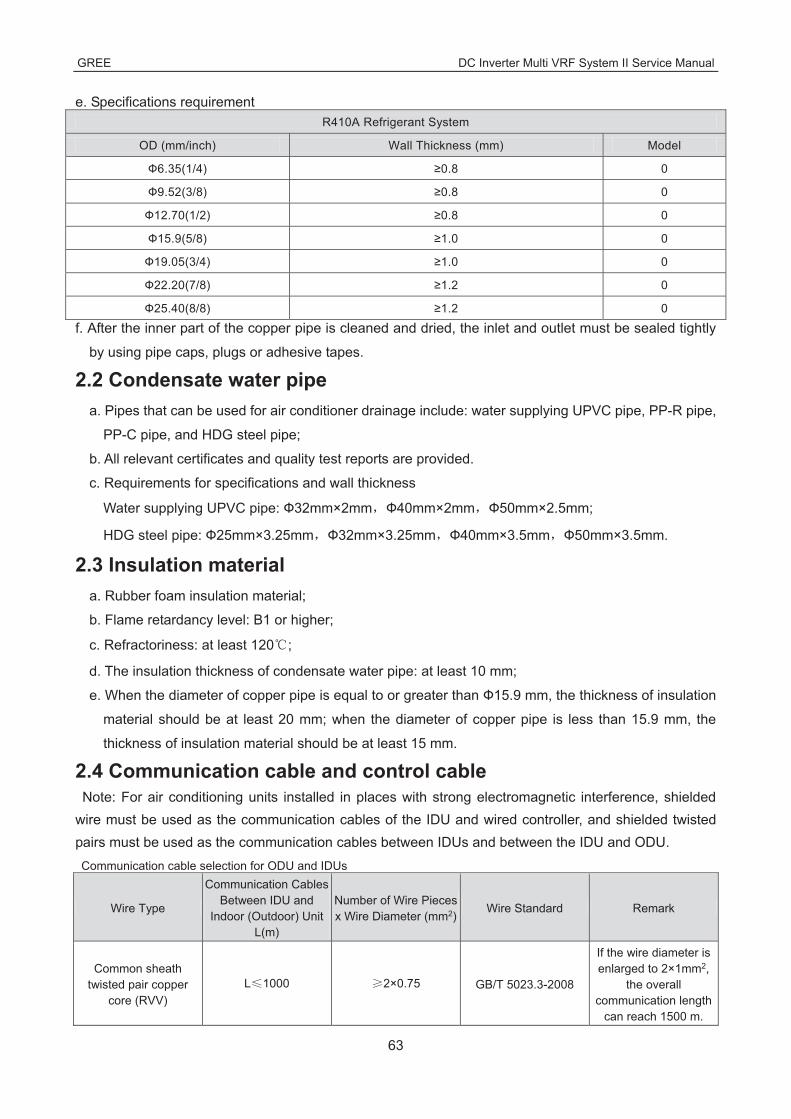
e. Specifications requirement R410A Refrigerant System
OD (mm/inch) Wall Thickness (mm) Model
Ф6.35(1/4) ≥0.8 0
Ф9.52(3/8) ≥0.8 0
Ф12.70(1/2) ≥0.8 0
Ф15.9(5/8) ≥1.0 0
Ф19.05(3/4) ≥1.0 0
Ф22.20(7/8) ≥1.2 0
Ф25.40(8/8) ≥1.2 0
f. After the inner part of the copper pipe is cleaned and dried, the inlet and outlet must be sealed tightly
by using pipe caps, plugs or adhesive tapes.
2.2 Condensate water pipe a. Pipes that can be used for air conditioner drainage include: water supplying UPVC pipe, PP-R pipe,
PP-C pipe, and HDG steel pipe;
b. All relevant certificates and quality test reports are provided.
c. Requirements for specifications and wall thickness
Water supplying UPVC pipe: Ф32mm×2mm Ф40mm×2mm Ф50mm×2.5mm;
HDG steel pipe: Ф25mm×3.25mm Ф32mm×3.25mm Ф40mm×3.5mm Ф50mm×3.5mm.
2.3 Insulation material a. Rubber foam insulation material;
b. Flame retardancy level: B1 or higher;
c. Refractoriness: at least 120 ;
d. The insulation thickness of condensate water pipe: at least 10 mm;
e. When the diameter of copper pipe is equal to or greater than Ф15.9 mm, the thickness of insulation
material should be at least 20 mm; when the diameter of copper pipe is less than 15.9 mm, the
thickness of insulation material should be at least 15 mm.
2.4 Communication cable and control cable Note: For air conditioning units installed in places with strong electromagnetic interference, shielded
wire must be used as the communication cables of the IDU and wired controller, and shielded twisted pairs must be used as the communication cables between IDUs and between the IDU and ODU. Communication cable selection for ODU and IDUs
Wire Type
Communication Cables Between IDU and
Indoor (Outdoor) Unit L(m)
Number of Wire Pieces x Wire Diameter (mm2)
Wire Standard Remark
Common sheath twisted pair copper
core (RVV) L 1000 2×0.75 GB/T 5023.3-2008
If the wire diameter is enlarged to 2×1mm2,
the overall communication length
can reach 1500 m.

GREE DC Inverter Multi VRF System II Service Manual
64
Communication cable selection for IDU and wired controller
Wire Type
Total Length of Communication Cables of the IDU and Wired
Controller L(m)
Number of Wire Pieces x Wire Diameter (mm2)
Wire Standard Remark
Common sheath twisted pair copper
core (RVV) L 250 2×0.75 GB/T 5023.3-2008
The overall communication length cannot exceed 250 m.
2.5 Power cable Only copper conductors can be used as power cables. The copper conductors must meet relevant
national standard and satisfy the carrying capacity of unit.
2.6 Hanger rod and support a. Hanger rod: M8 or M10;
b. U-steel: 14# or above;
c. Angle steel: 30mm×30mm×3mm or above;
d. Round steel: Ф10mm or above
3 Installation of outdoor unit 3.1 Check before installation
a. Before installation, please check the power cord if it complies with the power supply requirement on
the nameplate. Make sure the power supply is safe.
b. This air conditioner must be properly grounded through the receptacle to avoid electric shock. The
ground wire shouldn’t be connected with gas pipe, water pipe, lightning arrester or telephone line.
c. Maintain good air circulation to avoid lacking oxygen.
d. Read this manual carefully before installation.
3.2 Selection of installation site
a. Select a location which is strong enough to hold unit’s weight so that unit can stand still and erect.
b. Make sure the unit is not exposed to sun and rain. And the location can resist dust, typhoon and
earthquake.
c. Please keep the unit away from inflammable, explosive and corrosive gas or waste gas.
d. Make sure the location has space for heat exchange and maintenance so that unit can operate
reliably with good ventilation.
e. ODU and IDU should stay as close as possible to shorten the length of refrigerant pipe and reduce
bend angles.
f. Select a location which is out of children’s reach. Keep the unit away from children.
3.3 Carrying and installing outdoor unit When carrying the outdoor unit, hang the unit in four directions with two sufficient ropes. In order to
avoid excursion from the center, the angel of ropes must be smaller than 40º during hanging and
moving.

GREE DC Inverter Multi VRF System II Service Manual
65
3.4 Installation notices In order to ensure proper operation, the selection of installation site must conform to the following
principle: ●The discharged air of outdoor unit will not flow back and there is sufficient space around the unit for
maintenance;
●The installation site must be well ventilated to ensure sufficient air intake and discharge. Make sure
there is no obstacle at the air inlet and air outlet. If there is any obstacle, please remove it;
●The installation site shall be able to withstand the weight of outdoor unit and capable for soundproof
and vibration. The air outlet and noise of unit will not affect neighbors;
●The hanging of outdoor unit must use appointed hanging hole. Pay attention to protect the unit during
hanging and installation. Prohibit hitting the sheet metal to avoid rust in the future.
● Avoid direct sunlight;
● The rain and condensation water can be drained out smoothly;
● The outdoor unit will not be embedded by the snow and not affected by garbage and oil smog;
● The installation of outdoor unit shall adopt rubber damping pad or spring damper to reduce noise
and vibration;
● The installation dimension shall accord with the installation requirement of this manual and the
outdoor unit must be fixed at the installation site;
●The installation shall be done by professional technicians.
3.5 Fixing and damping of unit The outdoor unit shall be fixed with 4 M12 bolts and closely contacted with the foundation. Otherwise,
big vibration and noise will be caused.
The outdoor unit shall be fixed firmly. The rubber board with thickness over 20mm or corrugated
rubber damping pad shall be applied between the unit and foundation.
3.6 Outline dimension and position of installation hole When carrying the outdoor unit, hang the unit in four directions with two sufficient ropes. In order to
avoid excursion from the center, the angel of ropes must be smaller than 40º during hanging and
moving.

GREE DC Inverter Multi VRF System II Service Manual
66
Model A B C D E
GMV-120WL/A-T GMV-140WL/A-T GMV-160WL/A-T GMV-120WL/A-X GMV-140WL/A-X GMV-160WL/A-X GMV-120WL/C-T GMV-140WL/C-T GMV-160WL/C-T GMV-120WL/C-X GMV-140WL/C-X GMV-160WL/C-X
900 340 1345 572 378
GMV-H224WL/A-X GMV-224WL/C-X 940 320 1430 632 350
GMV-H280WL/A-X GMV-H335WL/A-X GMV-280WL/C-X GMV-335WL/C-X
940 460 1615 610 486

GREE DC Inverter Multi VRF System II Service Manual
67
Unit: mm Model A B C D E
GMV-80WL/A-T GMV-100WL/A-T GMV-121WL/A-T GMV-80WL/C-T
GMV-100WL/C-T GMV-121WL/C-T
980 360 790 650 395
GMV-141WL/C-T 940 460 820 610 486
3.7 Installation space requirement
If all sides of the ODU (including the top) are surrounded by walls, process according to the following
requirements for installation space:

GREE DC Inverter Multi VRF System II Service Manual
68
DEBUGGING &MAINTENANCE

DC INVERTER VRF SYSTEM II SERVICE MANUAL(R410A)
DEBUGGING &MAINTENANCE 1 Debugging of Unit Caution:
1. After the initial installation is finished and the main board of outdoor unit is replaced, it must perform
debugging. Otherwise, the unit can’t operate.
2. The debugging must be performed by professional person or under the the guide of professional
person.
1.1 Preparation for debugging (1) Do not disconnect the power before the installation is finished,
(2) All wires for controller and electric wires must be connected correctly and reliably.
(3) Check the the fixing ring of the foot of compressor for transportaion is removed.
(4) Remove all sundries from the unit, such as metal chips, joint, forceps holder, and so on.
(5) Check whether the appearance and pipeline system are damaged during carry or transportation
process.
(6) Calculate the required added refrigerant-charging volume according to the length of pipe of system
and pre-charge the refrigerant. If refrigerant can’t be added any more when the required
refrigerant-charging volume hasn’t been reached, record to refrigerant volume which still needs to
be added and continue to add refrigerant during run test operation process. Please refer to below
run test for the refrigerant-adding stage during run test process.
(7) After adding refrigerant, please make sure the valve for outdoor is opened completely.
(8) For the convenient of troubleshooting, the unit can’t be connected to the PC which installed with
related debugging software and make sure that the the datas in real time of this unit can be
inspected by this computer. Please refer to Service Manual for the installation and connection of the
bebugging software.
(9) Before turn test, please do make sure that the preheat time for compressor is 8h above and touch
the compressor to see whether preheat is normal. You can perform run test only after normal
preheat. Otherwise, it may damage the compressor.

GREE DC Inverter Multi VRF System II Service Manual
70
1.2 Debugging of unit Debugging procedure for test run, display instruction for indicator on main board of outdoor unit and
operation method are as below: GMV-80WL/A-T GMV-100WL/A-T GMV-121WL/A-T GMV-80WL/C-T GMV-100WL/C-T
GMV-121WL/C-T GMV-120WL/C-T GMV-140WL/C-T GMV-160WL/C-T GMV-120WL/C-X GMV-140WL/C-X GMV-160WL/C-X
GMV-H224WL/A-X GMV-H280WL/A-X GMV-H335WL/A-X GMV-H224WL/A-X GMV-H280WL/A-X GMV-H335WL/A-X
GMV-224WL/C-X GMV-280WL/C-X GMV-335WL/C-X Stage process instruction for debugging
—— Debugging code Process code Status code
Code instruction and operation method Process
LED1 LED2 LED3
Code Display status Code Display
status Code Display status
01_
Mai
n co
ntro
l un
it se
tting
00 ON OF/AC/AH ON A0 ON No debugging status for system
db ON 01 ON OC ON
Press SW7 button on main board for 5s to start system debugging. The indicator on main board is displayed as shown in the left. 2s later, it will enter into next step determination.
02_
Add
ress
dis
tribu
tion
db ON 02 ON Ad Flash Address distribution for the system. 10s later, the display is as below:
db ON 02 ON L7 Flash
No main indoor unit. Display will be kept for 1min. Within 1min, set the main indoor unit through debugging software. If notset the main indoor unit by hand within 1min, the system will automatically set the minimum IP address as the main indoor unit.
db ON 02 ON OC ON The distribution for the system address is finished. 2s later, it will enter into the next step determination automatically.
03_Q
uant
ity
conf
irmat
ion
of
outd
oor u
nit db ON 03 ON 01 Flash Cofirmation process of system. 1s later, it will
enter into the next step automatically.
db ON 03 ON OC ON Cofirmation process of system. 2s later, it will enter into the next step automatically.
04_Q
uant
ity c
onfir
mat
ion
of in
door
un
it db ON 04 ON 01~80 Flash
LED3 displays quantity of indoor unit. The quanity of indoor unit shall be confirmed by perform. If the actural quantity of indoor unit is different from the displayed quantity, cut off the power for indoor unit and outdoor unit. Check whether the communication wire for indoor unit is normal. After that, put through the power and start debugging from step 01. If the quantity of indoor unit is correct, press SW7 button on main board to confirm it. The display is as below after confirmation:

GREE DC Inverter Multi VRF System II Service Manual
71
Stage process instruction for debugging
—— Debugging code Process code Status code
Code instruction and operation method Process
LED1 LED2 LED3
Code Display status Code Display
status Code Display status
db ON 04 ON OC ON Confiration for the quantity of indoor unit of finished. 2s later, it will enter into the next step automatically.
05_I
nter
nal c
omm
unic
atio
n an
d ca
paci
ty ra
tio in
spec
tion
for
betw
een
indo
or u
nit a
nd o
utdo
or u
nit
db ON 05 ON C2 ON
Communication between main board of outdoor unit and drive is abnormal. Please check whether the communication wire connecting main board of outdoor unit and drive board is normal? It will enter into the next operation after troubleshooting. If it needs to cut off the power during troubleshooting process, start the debugging from step 01 after energization.
db ON 05 ON OC ON
Normal communication between main board of outdoor unit and drive. It will displays for 2s by the left method. With this 2s, the capacity ratio for indoor unit and outdoor unit will be detected automatically. If it hasn’t exceeded the capacity ratio range, it will enter into next step determination after 2s; if it has exceed the capactiry ration, display is as below:
db ON 05 ON CH ON
The rated capacity ratio for indoor unit is high. Change the combination for indoor unit and outdoor unit to let their capacity ration is within the reasonable range. Perfrom the debugging again from step 01.
db ON 05 ON CL ON
The rated capacity ratio for indoor unit is low. Change the combination for indoor unit and outdoor unit to let their capacity ration is within the reasonable range. Perfrom the debugging again from step 01.
06_P
arts
det
ectio
n fo
r ou
tdoo
r uni
t
db ON 06 ON
Correspond
ing error code
ON
Malfunction of parts for outdoor unit. LED3 displays corresponding malfunction code. After troubleshooting, it will enter into the next step determination automatically. If it needs to cut off the power for the outdoor unit during troubleshooting process, perform the debugging again from step 01 after energization.
db ON 06 ON OC ON When there’s no malfunction of parts for outdoor unit, it will enter into the next step determination automatically after 10s.
07_P
arts
det
ectio
n fo
r ind
oor u
nit
db ON 07 ON
XXXX/correspond
ing error code
ON
The system detected that there’s malfunction for the parts of indoor unit. XXXX indicates the engineering series code for the indoor unit with malfunction. 3s later, corresponding malfunction code will be displayed. Eg: When there is malfunction d5 and d6 for no. 1 indoor unit, and malfunction d6 and d7 for no. 792 indoor unit, LED3 nixie tube will display 00, 01, d5, d6, 07, 92, d6, d7 cyclely evey 2s. After troubleshooting, it will enter into the next step determination automatically. If it needs to cut off power for outdoor unit during troubleshooting process, perform the debugging again from step 01 after energization.
db ON 07 ON OC ON No parts malfunction for indoor unit. 2s later, it will enter into the next determination automatically.
Pre
hea
t co
nfirm
atio
n fo
r db ON 08 ON UO ON
Preheat time for compressor is not reached to 8h. Indicator will display as shown by the left method until the reheat time for compressor is reached to 8h. or short press SW7 button on main board to

GREE DC Inverter Multi VRF System II Service Manual
72
Stage process instruction for debugging
—— Debugging code Process code Status code
Code instruction and operation method Process
LED1 LED2 LED3
Code Display status Code Display
status Code Display status
confirm that the preheat time is reached to 8h and then enter into the next determination. (Note: If compressor isn’t started up when the preheat time is not reached to 8h, the compressor may be damaged. Please be careful.)
db ON 08 ON OC ON Preheat time for compressor is reached to 8h. 2s later, it will enter into the next step.
09_
Ref
riger
ant c
onfir
mat
ion
befo
re s
tartu
p
db ON 09 ON U4 ON
Refrigerant in system is not sufficient. The indicator will display by the left method. Please disconnect the power for indoor unit and outdoor unit, and check whether the pipeline is leaking. After leakage problem is solved, recharge the refrigerant according to requirement. After that, energize the unit and perform the debugging from step 01. (Note: Cut off the power for the unit before recharging the refrigerant to prevent the unit entering into step 10 during refrigerant-charging process)
db ON 09 ON OC ON The refrigerant volume for the system is normal. After it displayes as the left method for 2s, it will enter into the next determination automatically.
10_
Sta
tus
dete
rmin
atio
n fo
r out
door
un
it’s
valv
e be
fore
sta
rtup
db ON 10 ON ON ON
Dermination status for valve of outdoor unit; After compressor operating for about 2min, it will stop operation. It will judge the ON status of gas valve and liquid valve for outdoor unit. The judement result is displayed as below:
db ON 10 ON U6 ON
Valve for outdoor unit hasn’t been opened completely. Short press SW6 button on main board and the indicator will display “db 09 OC” and then check whether gas valve and liquid valve for outdoor unit are opened completely. After that, short press SW6 button on main board again. After compressor is started up and operated for about 2min, it will judge the status of valve again.
db ON 10 ON OC ON Normal status for valve. After it displays as the left method for 2s, it will enter into the next determination automatically.
12_
Deb
uggi
ng c
onfir
mat
ion
for
the
unit
db ON 12 ON AP Flash
Wait for confirming the debugging order for the unit. Short press SW7 button on main bard to confirm the debugging of unit. 2s later, the indicator on main board will display as below:
db ON 12 ON AE ON
Confirmation of startup of the unit. After displaying for 2s, the system will select “15_cooling ddebugging operation” or “16_heating debugging operation”automatically according ambient temperature to start up operation. If it needs to add refrigerant because of engineering requirement while the refrigerant hasn’t been added finished before debugging, refrigerant can be added through low-pressure detection valve during operation process.
15_D
ebug
ging
op
erat
ion
for
cool
ing
db ON 15 ON AC ON
Debugging under cooling mode. If there’s no malfunction after the compressor operates for 20min, it will enter into process 17 to finish debugging; If there’s malfunction during operation process, the display is as below:

GREE DC Inverter Multi VRF System II Service Manual
73
Stage process instruction for debugging
—— Debugging code Process code Status code
Code instruction and operation method Process
LED1 LED2 LED3
Code Display status Code Display
status Code Display status
db ON 15 ON
Correspodi
ng error code
ON
There’s malfunction during debugging process under cooling mode. After removing all malfunctions, it will enter into the next step determination.
16_D
ebug
ging
op
erat
ion
for h
eatin
g
db ON 16 ON AH ON
Debugging under heating mode. If there’s no malfunction after the compressor operates for 20min, it will enter into process 17 to finish debugging; If there’s malfunction during operation process, the display is as below:
db ON 16 ON
Correspodi
ng error code
ON
There’s malfunction during debugging operation under heating mode. The unit will enter into the next step determination after elimanted all malfunctions.
17_
Fini
shed
st
atus
of
debu
ggin
g
00 ON AC/AH ON OF ON Debugging is finished for the complete unit. The
system is at standby status.
GMV-141WL/C-T
Description of each stage of debugging progress —— Debugging code
Code meaning and operation method Progress
LED Code Display status
01_Set master unit
A0 ON System is not debugged, hold main board’s SW3 button for 5s to start debugging.
01 ON 2s later, next step starts.
02_ Allocate addresses
02/Ad Display circularly
System is allocating addresses. 10s later, display as below:
02/L7 Display circularly
No master indoor unit. Display will be on for 1min, during which master IDU can be set manually. If not, system will set the unit with minimum IP address as the master IDU.
02/oC Display circularly
Allocation is finished. 2s later, next step starts.
03_ Confirm the quantity of ODU 03/01 Display
circularly System is confirming. 1s later, next step starts.
04_ Confirm the quantity of IDU
04/00 16 Display circularly
“00 16” displays the quantity of indoor unit. Confirm the number manually. If the number is not consistent the display one, cut off power of IDU and ODU and check whether communication wire of IDU is correctly connected. After the check, connect power and start debugging from progress 01. If the number is then correct, press main board’s SW3 button to confirm. Then the display is as below:
04/oC Display circularly
System has confirmed the quantity. 2s later, next step starts.
00 16/CL Display circularly
“00 16” displays the quantity of indoor unit identified by the system. “CL” means the amount of indoor unit is very little (amount of indoor unit 2), at this moment, all buttons are invalid, the system cannot enter into the next judgment.
05_ Detect ODU’s internal
communication 05/C2 Display
circularly
Communication between master ODU and driver has error. Check the communication connection of ODU’s main board and drive board. When the error is eliminated, start next step. If

GREE DC Inverter Multi VRF System II Service Manual
74
Description of each stage of debugging progress —— Debugging code
Code meaning and operation method Progress
LED Code Display status
and capacity ratio power is off during troubleshooting, then restart debugging from progress 01 after power is on.
05/oC Display circularly
Communication of master ODU and driver is normal. Unit will display as in the left for 2s and detect the capacity ratio of IDU and ODU. If the ratio is within range, than next step will start 2s later. If the ratio is out of range, unit will display as below:
05/CH Display circularly
Rated capacity ratio of IDU is too high. Change the combination way of IDU and ODU to make the ratio within range. And restart debugging from progress 01.
05/CL Display circularly
Rated capacity ratio of IDU is too low. Change the combination way of IDU and ODU to make the ratio within range. And restart debugging from progress 01.
06_ Detect outdoor
components
06/error code Display circularly
Outdoor component’s error. Besides “06”, the other blinking will display the related error code. After errors are eliminated, system will start next step automatically. If power is off during troubleshooting, then restart debugging from progress 01 after power is on.
06/oC Display circularly
System detects no error on outdoor component. 10s later, next step starts.
07_ Detect indoor components
07/XX/error code
Display circularly
System detects error on indoor components. XX means the project code of IDU with error, e.g. no.1 IDU has d5 and d6 errors, meanwhile no.3 IDU displays error d6 and d7, then the nixie tube will display “07”, “01”, “d5”, “d6”and “03” circularly. After errors are eliminated, system will start next step automatically. If power is off during troubleshooting, then restart debugging from progress 01 after power is on.
07/XXXX/error code
Display circularly
If errors occur in IDU which the project code is 3-digit number, then it will display the 2 big digits of project code first, then the 2 small digits, finally the error code, e.g: L1 error occurs in no.101 IDU, then the nixie tube will display “01”,“01” and “L1” circularly. Display method is the same for several IDUs with multiple errors.
07/oC Display circularly
No error on components of IDU. 5s later, next step starts.
08_ Confirm preheated
compressor
08/U0 Display circularly
Preheat time for compressor is less than 8 hours. Display will be as in the left until the preheat time reaches 8 hours. Press main board’s SW3 button to confirm manually that the preheat time has reached 8 hours. Then start next step. (Note: Compressor may get damaged if it is started without 8 hours of preheat time)
08/oC Display circularly
Compressor has been preheated for 8 hours. 2s later, next step starts.
09_ Refrigerant judgments before
startup
09/U4 Display circularly
System is lack of refrigerant and display will be as in the left. Please cut off power of IDU and ODU and check if there is leakage on pipeline. Solve the leakage problem and complement refrigerant into the unit. Then connect power and restart debugging from progress 01. (Note: Before re-charging refrigerant, unit must be power off in case system starts progress 10 automatically.)
09/oC Display circularly
Refrigerant is normal and unit will display as in the left for 2s.Then next step starts.
10_ Status judgments of
outdoor valves before startup
10/on Display circularly
Valves of ODU are being inspected. Compressor will start operation for 2min or so and then stop. The opening and closing status of outdoor valves are as below:
10/U6 Display circularly
Outdoor valves are not fully turned on. Press main board’s SW4 button and display shows “09/OC”. Then check if the gas and liquid valves of ODU are completely open. After confirmation, press the SW4 button again. Then compressor will start running for about 2min to inspect the status of valves.

GREE DC Inverter Multi VRF System II Service Manual
75
Description of each stage of debugging progress —— Debugging code
Code meaning and operation method Progress
LED Code Display status
10/oC Display circularly
Valves status is normal. Unit will display as in the left for 2s and then start next step.
12_ Confirm debugging startup
12/AP Display circularly
Ready for units to start debugging. Press main board’s SW3 button to confirm startup of debugging. 2s later, main board will display as below:
12/AE Display circularly
Startup is confirmed. After displaying for 2s, system will choose “15_Cooling debugging” or “16_Heating debugging” according to ambient temperature. If the project requests to add refrigerant but it is not complemented before debugging, then refrigerant can be added in this process through the L-VALVE.
15_ Cooling debugging
15/AC Display circularly
Debugging for cooling mode. If no malfunction occurs for 50min when compressor is running, then the system is certified as normal. After shutting down the unit for 5s, the system will enter normal standby status.
15/error code Display circularly
Malfunction occurs when debugging for cooling mode.
16_ Heating debugging(For
heat pump units only)
16/AH Display circularly
Debugging for heating mode. If no malfunction occurs for 50min when compressor is running, then the system is certified as normal. After shutting down the unit for 5s, the system will enter normal standby status.
16/error code Display circularly
Malfunction occurs when debugging for heating mode.
17_ Debugging finished oF ON
The entire unit has finished debugging and under standby-by condition.
1.3 Parameters reference value for the normal operation of unit No. Debugging project Parameters name Unit Reference value
1
Paramers of system
Parameters of outdoor
unit
Outdoor ambient temperature ——
2 Discharge
temperature of compressor
●After compressor is started up, normal discharge temperature for cooling is 70~105 , which is 10 above more than the high pressure saturation temperature. ●The normal temperature for heating is 65 ~90 , which is 10 above more than the high pressure saturation temperature.
3 Defrosting temperature
●During cooling operation, defrosting temperature is 4~10 lower than the high pressure value of system; ●During heating operation, defrosting temperature is almost equal to the low pressure value of system (the disffrence is withing 2 ).
4 High pressure of system
●Under cooling mode, the normal high pressure value is 20 55 . According to the change of ambine temperature and operation capacity of system, the high pressure value of system is 10 30 higher than the ambient temperature. The higher the ambient temperature, the temperature difference is small; Under cooling operation at the ambient temperature of 25~35 , the high pressure value for the system is 44~53 ; ●The unit will operate at heating mode when the ambient temperature is above -5 . The high pressure value for the system is 40~52 . When the ambient temperature is low and the indoor unit is started up frequently, the high pressure value will be a little lower.
5 Low pressure of system
●The unit will operate under cooling mode when the ambient temperature is 25~35 , the low pressure value for the system is 0~8 . ●The unit will operate under heating mode when the ambient temperature is above -5 , the low pressure value

GREE DC Inverter Multi VRF System II Service Manual
76
No. Debugging project Parameters name Unit Reference value for the system is -15~8 .
6
Opening angle of electrocnic
expansion valve for heating
PLS
●During cooling operation, the electronica expansion valve for heating will always be kept at 480PLS; ●During heating operation, the opening angle for the adjusted electronic expansion valve is 55~480PLS.
7 Operation
frequency for compressor
HZ Change among 10HZ~95HZ
8 Operation current of compressor A Current should be no more than 25.0A during normal
operation for compressor
9 IPM module
temperature for compressor
When ambient temperature is lower than 35 , temperature for IPM module is lower than 80 . The maximum temperature won’t exceed 95 .
10 Operation frequenc for fan HZ It will adjust the frequency among 0~49HZ for operation
according to the system pressure
11
Parameters of indoor
unit
Ambient temperature for
indoor unit ——
12
Entry tube temperature for
indoor heat exchanger
●According to the difference of ambient temperature, the entry tube temperature is 1 ~7 lower than the exit tube temperature for the same indoor unit under cooling mode; 4~9 higher than low pressure. ●Under heating mode, entry temperature is 10 ~20 lower than exit tube temperature for the sae indoor unit.
13
Entry tube temperature for
indoor heat exchange
14 Opening angle of indoor electrocnic expansion valve
PLS
Under cooling mode, the opening angle for indoor electronic expansion valve is adjusted among 70~480PLS. Under heating mode, the opening angle for indoor unit is adjusted among 40~480PLS.
15 Communication paraters
Communication data —
Through debugging software, it detected that the quantity of indoor unit is same with the enginerring actural quantity. There’s no communication malfunction.
16 Drainage syste —— — Water can be drained smoothly for indoor unit; Outdoor unit can drain water fromo drainage pipe completely.
17 Other ——

GREE DC Inverter Multi VRF System II Service Manual
77
2 Malfunction List 2.1 Malfunction list for the wired controller
Display code Content Display
code Content Display code Content
L0 Malfunction of indoor unit L9
Wrong number of indoor unit for one-to-more indoor
unit d8 Malfunction of water
temperature sensor
L1 Indoor fan protection LA Wrong series for
one-to-more indoor unit d9 Malfunction of jumper cap
L2 E-heater protection LH Alarming due to bad air quality dA Abnormal address for
indoor unit
L3 Water overflow protection LC
The indoor unit model can’t match with outdoor unit
model dH Abnormal PCB for wired
controller
L4 Power supply
of wired controller is faulted
d1 Poor indoor PCB dC Abnormal code-dialing setting of capacity
L5 Freeze prevention protection d3 Malfunction of ambient
temperature sensor dL Malfunction of air exhause temperature sensor
L6 Mode shock d4 Malfunction of entry tube temperature sensor dE Malfunction of indoor C02
sensor
L7 No main indoor unit d6 Malfunction of exit tube temperature sensor C0 Communication malfunction
L8 Insufficient power supply d7 Malfunction of humidity
sensor AJ Clean alarming for filter
db Special code: engineering debugging code

GREE DC Inverter Multi VRF System II Service Manual
78
2.2 Status display table for indicators on main board of outdoor unit Definition: � LED1: It displays “00” for hot water mode as for DC Inverter Side Discharge VRF
� LED2: It displays “AC” for AC mode, cooling and cooling OFF mode for indoor unit, and displays
“AH” for heating and heating OFF mode for indoor unit
� LED3: It displays on or off status of compressor and malfunction code. It displays “ON” when the
compressor is operating and “OFF” when the compressor stops operation. When there’s
malfunction for the unit, it will display corresponding malfunction code; when there’re multiple
malfunctions, the malfunction codes will be displayed in turn.
Display code table of outdoor unit is as below: Display code Content Display
code Content Display code Content
E0 Malfunction of outdoor unit E1 High pressure protection E2 Low-temperature
protection for dicharge
E3 Low pressure protection E4 Discharge high temperature protection for compressor EC
Loose protection for discharge temperature
sensor for compressor 1
F0 Poor main board of outdoor unit F1 Malfunction of high
pressure sensor F3 Malfunction of low pressure sensor
F5 Malfunction of discharge temperature sensor for
compressor 1 FP Malfunction of DC motor J0 Other module protection
J1 Overcurrent protection for compressor 1 J7 Air-mixing protection for
4-way valve J8 High pressure ration protection of system
J9 Low pressure ratio protection of system JL High pressure is too low b1
Malfunction for outdoor ambient temperature
sensor
b2 Maflunction of defrosting temperature sensor 1 b3 Maflunction of defrosting
temperature sensor 2 b4 Malfunction of liquid
temperature sensor for subcooler
b5 Malfunction of gas
temperature sensor for subcooler
b6 Malfunction for temperature sensor of inlet tube of gas
and liquid separator b7
Malfunction for temperature sensor of exit
tube of gas and liquid separator (exit tube A)
b9 Malfunction of gas exit temperature sensor for
heat exchanger bH Abnormal clock of system P0 Malfunction driven board
for compressor
P1 Driven board of
compressor works abnormally
P2 Power voltage protection for
the driven board of compressor
P3 Reset protection for the
driven module of compressor
P4 Driven PFC protection of compressor P5 Overcurent protection for
inverter compressor P6 Driven IPM module protection for compressor
P7 Malfunction of driven
temperature sensor for compressor
P8 Overheating protection for driven IPM of compressor P9
Desynchronizing protection for inverter
compressor
PH High voltage protection for driven DC bus bar of
compressor PC
Circuit malfunction of driven current detection for
compressor PL
Low voltage protection for driven DC bus bar of
compressor
PE Phase-losing of inverter compressor PF
Malfunction of driven charging loop for
compressor PJ Failure start up for inverter
compressor
PP AC current protection for inverter compressor U0 Preheat time is not enough
for compressor U2 Capacity code of outdoor
unit/wrong setting of jumper cap
U4 Insufficient refrigerant protection U5 Wrong address for the
driven board of compressor U6 Alarm due to abnormal valve
U8 Malfunction of pipeline for indoor unit U9 Malfunction of pipeline for
outdoor unit UC Setting for indoor unit and oudoor unit is succeeded
UL Wrong code-dialing during emergency UE Refrigerant-charging is
invalid C0 Communication malfunction for indoor unit,

GREE DC Inverter Multi VRF System II Service Manual
79
Display code Content Display
code Content Display code Content
operation outdoor unit and wired controller of indoor unit
C2
Driven communication malfunction between
main board and inverter compressor
C3
Driven communication malfunction between main
board and inverter compressor
C4 Malfunction of indoor unit-lacking
C5
Alarming due to engineering series
number shock of indoor unit
C6 Alarming due to wrong quanity of outdoor unit C8 Emergency status of
compressor
C9 Emergency status of fan CH High rated capacity CC No malfunction of main control unit
CA Energycy status of module CF Malfunction of main control
unit CJ Address shock of syste
CL Low rated capacity CU Communication malfunction
between indoor unit receiving lamp board
Cb Distribution overflow of Ip address
A0 Debugging for unit A1 Operational parameter inquiry of compressor A2 Refrigerant recovery
A3 Defrosting A4 Oil return A5 On-line test
A6 Heat pump function setting A7 Quit mode setting A8 Vacuum pump
mode
A9 IPLV test AU Long-distance emergency stop Ab Emergency stop
AA EU AA class energy efficiency test mode AH Heating AL Charge refrigerant
automatically
AE Charge refrigerant by hand AF Fan blow AJ Cleaning alarm for filter
AP Startup debugging confirmation of unit Ad Limit opereation n0 SE setting for the
operation
n1 Defrosting period K 1 setting n2
Upper limit setting for the collocation matching ratio for indoor unit and outdoor
unit
n4 Limit setting for the maximum ouput capacity
n6 Engineering series
number inqury for indoor unit
n7 Malfunction inquiry n8 Parameters inquiry
nH Heating only model nC Cooling only model nA Heat pump unit
nF Fan model nE Negative code Ed Low temperature protection for drive module
2.3 Function Setting of Outdoor Unit GMV-80WL/A-T GMV-100WL/A-T GMV-121WL/A-T GMV-80WL/C-T GMV-100WL/C-T
GMV-121WL/C-T GMV-120WL/C-T GMV-140WL/C-T GMV-160WL/C-T GMV-120WL/C-X GMV-140WL/C-X GMV-160WL/C-X
GMV-H224WL/A-X GMV-H280WL/A-X GMV-H335WL/A-X GMV-H224WL/A-X GMV-H280WL/A-X GMV-H335WL/A-X
GMV-224WL/C-X GMV-280WL/C-X GMV-335WL/C-X
When debugging is finished, press SW3 on the master unit and unit will be ready for function setting.
Default display of outdoor unit’s main board is as below:
LED1 LED2 LED3 Function code Display Current progress Display Current status Display
A7 Blink 00 Blink 00 Blink Then press SW1 button(▲) and SW2 button(▼) on the master unit to switch function codes of LED1
to select relevant functions.
Function setting includes: outdoor silent mode setting (A7), heating and cooling function setting (A6),

GREE DC Inverter Multi VRF System II Service Manual
80
compulsory defrosting (n3)
After selecting relevant functions, press SW7 to confirm and start setting this function. Main board of
outdoor unit will display as below:
LED1 LED2 LED3
Function code Display Current progress Display Current status Display
A7 On 00 Blink oC Blink
A6 On nA Blink nA Blink
n3 On 35 Blink oC Blink
2.3.1 ODU Quiet Function This function is suitable for projects that have strict requirements for noise. It includes two modes:
smart night silent mode, compulsory silent mode.
When unit enters function setting, main board of outdoor unit will display as below:
LED1 LED2 LED3
Function code Display Current progress Display Current status Display
A7 On 00 Blink oC Blink
Press SW1 button (▲) and SW2 button (▼) to select the following silent modes.
LED1 LED2 LED3
Function code Silent mode Display Current status Display
A7 00~12 Blink oC Blink
When applicable mode is selected, press SW7 to confirm. Main board of outdoor unit will display as
below:
LED1 LED2 LED3
Function code Silent mode Display Current status Display
A7 00~12 On oC On
Notice: code 00 of LED2 refers to normal mode. Codes 01~09 refer to smart night silent mode.
Codes 10~12 refer to compulsory silent mode. When setting is finished, master unit will memorize it so
that it can’t be cancelled even when power is on or off.
Then press SW6 on the master unit to return to the previous step. (If this button is pressed when
function is being set, system will return to the previous step. If SW6 is pressed when setting is finished,
system will resume displaying the current operation status.)
If then no motion is taken to the master unit for 5min, unit will exit and resume displaying the current
status.

GREE DC Inverter Multi VRF System II Service Manual
81
2.3.2 Cool & Heat Function This function can set operation modes and prevent mode collision that is caused by setting different
modes for different indoor units. It is especially suitable for hotels and other small business areas. There
are 3 levels for this setting:
Level A—Mode Lock Control
Upon entering this function setting, main board of outdoor unit will display as below:
LED1 LED2 LED3
Function code Current progress Display Current status Display
A6 nC Blink nC Blink
Press SW1 button (▲) and SW2 button (▼) to select the following functions:
LED1 LED2 LED3
Function code Display Current progress/mode Display Current status Display
A6 On nC Blink nC Blink
A6 On nH Blink nH Blink
A6 On nA Blink nA Blink
A6 On nF Blink nF Blink
When applicable mode is selected, press SW7 to confirm. The related display is as below:
LED1 LED2 LED3
Function code Display Current progress/mode Display Current status Display
A6 On nC On nC On
A6 On nH On nH On
A6 On nA On nA On
A6 On nF On nF On
This setting will be memorized by master unit and can’t be cancelled even when power is on or off.
Then press SW6 on the master unit to return to the previous step.
If then no motion is taken to the master unit for 5min, unit will exit and resume displaying the current
status.
(If this button is pressed when function is being set, system will return to the previous step. If SW6
is pressed when setting is finished, system will resume displaying the current operation status.)
Default setting is “nA” cooling and heating type.
Level B—IDU Mode Auto Control
When Level A is disabled or outdoor unit is set to be cooling and heating type, the operation mode
within one system depends on the master-salve setting of indoor units.

GREE DC Inverter Multi VRF System II Service Manual
82
2.3.3 Forced Defrosting This function can only be set when outdoor compressor is running.
Upon entering this function, main board of outdoor unit will display as below:
LED1 LED2 LED3
Function code Display Current progress/mode Display Current status Display
n3 On 00 Blink 00 Blink
Press SW7 to confirm. When system enters this function, main board of outdoor unit will display as
below:
LED1 LED2 LED3
Function code Display Current progress/mode Display Current status Display
n3 On 00 On 00 On
Then unit will be in compulsory defrosting mode. Once unit is under compulsory defrosting, this
mode can only be stopped when requirements for exit are met.
2.3.4 Restore Factory Defaults i.If you want to restore factory defaults, hold SW8 button on the main board of ODU for more than
10s, then all LEDs will blink for 3s. Main board will cancel all setting, including the IP addresses and
project codes of IDU and ODU. The mark for finished debugging is “0”.
ii.If you want to restore factory defaults and don’t need project debugging, then hold SW3 and SW8
on the main board of ODU for more than 10s, then all LEDs will blink for 5s. All settings are cleared out,
including the IP addresses and project codes of IDU and ODU. The mark for finished debugging remains
the same.
iii.When you only want to restore the default functions, hold SW5 and SW8 button for more than 10s,
then all LED will blink for 7s. All function settings are cleared out, but IDU and ODU’s project codes and
the mark for finished debugging remain the same.
2.3.5 Static Pressure Function If ODU’s installation area is not convenient for releasing air and users do not have strict
requirements for ODU noise, this function can be set to satisfy the heat exchange of ODU.
Before power on, set codes of SA6 of main board. The relevant static pressure is:
Code setting SA6 Static pressure (Pa) DIP1 DIP2
0 0 0
1 0 20
Note: code of number side is “1”; default code of SA6 is “00”.

GREE DC Inverter Multi VRF System II Service Manual
83
GMV-141WL/C-T
When debugging is finished, press SW1 on the master unit for 5s and unit will be ready for function
setting. Default display of outdoor unit’s main board is as below, then press SW1 button( ) and SW2
button( ) on the master unit to switch function codes of LED to select relevant functions.
LED
Function Function code Display
A7 Blink Quiet mode setting
A6 Blink Heat pump function setting
qd Blink ODU target of subcooling
n1 Blink Defrosting period K 1 setting
n2 Blink Setting of upper limit of IDU/ODU capacity distribution ratio
n3 Blink Compulsory defrosting
n4 Blink Limit setting for max. capacity/output capacity
n5 Blink IDU number offset setting
nH Blink Adjusting target of high pressure
nL Blink Adjusting target of low pressure
nU Blink Clearing IDU remote shield
q7 Blink Temperature in Fahrenheit
q8 Blink Corrective value b for low discharge temperature
A2 Blink Refrigerant recovery
A8 Blink Vacuum pump mode
q9 Blink Defrosting mode setting
qF Blink compulsory cooling
qL Blink Static Pressure Function
qn Blink Solar on-grid setting
qU Blink Grid voltage configuration
Note A6 Heat pump function setting n1 Defrosting period K 1 setting n3 compulsory
defrosting nH Adjusting target of high pressure q9 Defrosting mode setting etc are unavailable
for Cooling only units.
Default display is “A7”, then press SW1 button(▲) and SW2 button(▼) on the master unit to switch
function codes of LED to select relevant functions. After selecting relevant functions, press SW3 to
confirm and start setting this function. Main board of outdoor unit will display as below:

GREE DC Inverter Multi VRF System II Service Manual
84
LED Function
Function code Display
Current status Blink Quiet mode setting
Current status Blink Heat pump function setting
Current status Blink Defrosting period K 1 setting
Current status Blink Setting of upper limit of IDU/ODU capacity distribution ratio
n3 ON Compulsory defrosting
Current status Blink Limit setting for max. capacity/output capacity
n5 ON IDU number offset setting
Current status Blink Adjusting target of high pressure
Current status Blink Adjusting target of low pressure
nU ON Clearing IDU remote shield
Current status Blink Temperature in Fahrenheit
Current status Blink Corrective value b for low discharge temperature
Current status Blink Refrigerant recovery
A8 ON Vacuum pump mode
Current status Blink Defrosting mode setting
Low pressure ON Compulsory cooling
Current status Blink Static Pressure Function
Press SW1 button (▲) and SW2 button (▼) to select the corresponding functions to adjust the
number press SW4 to quit Function setting mode
2.3.6 ODU Quiet Function This function is suitable for projects that have strict requirements for noise. It includes two modes:
smart night silent mode, compulsory silent mode.
When unit enters function setting, main board of outdoor unit will display as below:
LED
Function code Display
00~12 Blink
Codes 00~12 refer to the corresponding functions. Press SW1 button ( ) and SW2 button ( ) to
select the following silent modes.When applicable mode is selected, press SW3 to confirm. Main board
of outdoor unit will display as below:

GREE DC Inverter Multi VRF System II Service Manual
85
LED
Function code Display
00~12 ON
Notice: code 00 of LED refers to normal mode. Codes 01~09 refer to smart night silent mode.
Codes 10~12 refer to compulsory silent mode. When setting is finished, master unit will memorize it so
that it can’t be cancelled even when power is on or off.
Then press SW4 on the master unit to return to the previous step. (If this button is pressed when
function is being set, system will return to the previous step. If SW4 is pressed when setting is finished,
system will resume displaying the current operation status.)
If then no motion is taken to the master unit for 5min, unit will exit and resume displaying the current
status.
2.3.7 Cool & Heat Function Note:
Cool & Heat Function is not available for Cooling only units
Cool & Heat Function only work for air conditioning mode it doesn’t affect the living warm water and
floor heating functions.
This function can set operation modes and prevent mode collision that is caused by setting different
modes for different indoor units. It is especially suitable for hotels and other small business areas. There
are 3 levels for this setting:
Level A—Mode Lock Control
Upon entering this function setting, main board of outdoor unit will display as below:
LED
Function code Display
Current status Blink
Press SW1 button (▲) and SW2 button (▼) to select the following functions:
LED
Function code Display
nC Blink
nH Blink
nA Blink
nF Blink
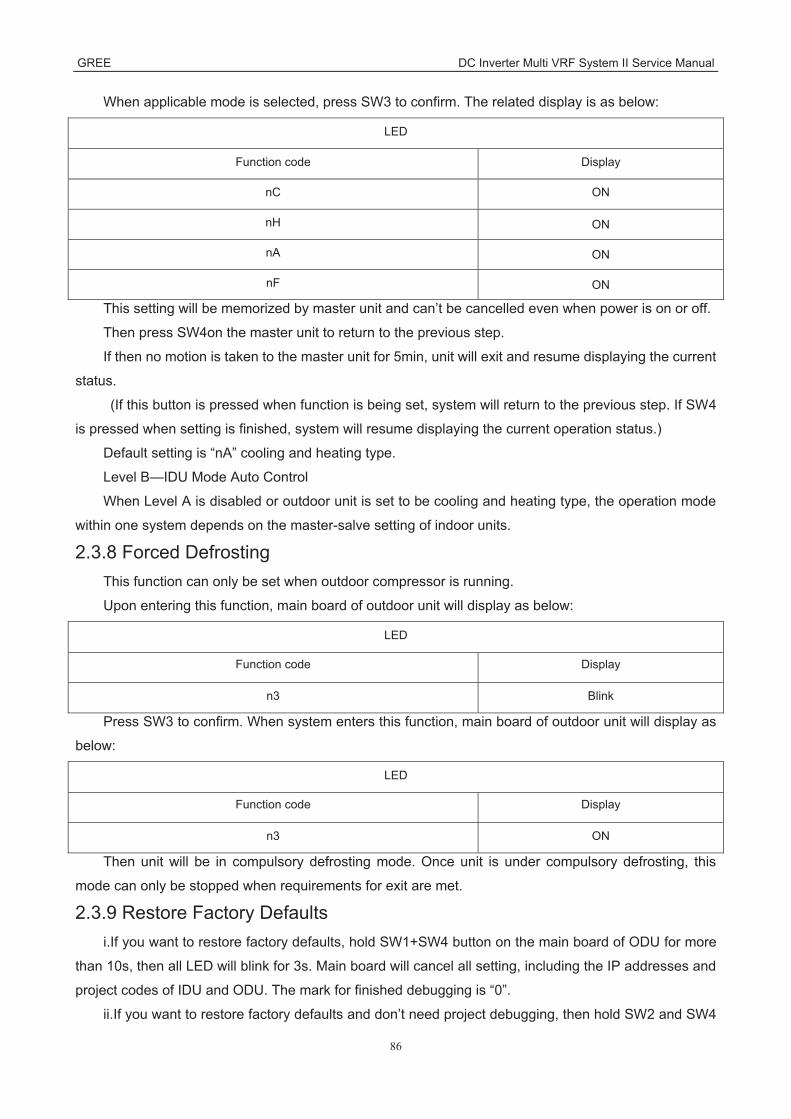
GREE DC Inverter Multi VRF System II Service Manual
86
When applicable mode is selected, press SW3 to confirm. The related display is as below:
LED
Function code Display
nC ON
nH ON
nA ON
nF ON
This setting will be memorized by master unit and can’t be cancelled even when power is on or off.
Then press SW4on the master unit to return to the previous step.
If then no motion is taken to the master unit for 5min, unit will exit and resume displaying the current
status.
(If this button is pressed when function is being set, system will return to the previous step. If SW4
is pressed when setting is finished, system will resume displaying the current operation status.)
Default setting is “nA” cooling and heating type.
Level B—IDU Mode Auto Control
When Level A is disabled or outdoor unit is set to be cooling and heating type, the operation mode
within one system depends on the master-salve setting of indoor units.
2.3.8 Forced Defrosting This function can only be set when outdoor compressor is running.
Upon entering this function, main board of outdoor unit will display as below:
LED
Function code Display
n3 Blink
Press SW3 to confirm. When system enters this function, main board of outdoor unit will display as
below:
LED
Function code Display
n3 ON
Then unit will be in compulsory defrosting mode. Once unit is under compulsory defrosting, this
mode can only be stopped when requirements for exit are met.
2.3.9 Restore Factory Defaults i.If you want to restore factory defaults, hold SW1+SW4 button on the main board of ODU for more
than 10s, then all LED will blink for 3s. Main board will cancel all setting, including the IP addresses and
project codes of IDU and ODU. The mark for finished debugging is “0”.
ii.If you want to restore factory defaults and don’t need project debugging, then hold SW2 and SW4

GREE DC Inverter Multi VRF System II Service Manual
87
on the main board of ODU for more than 10s, then all LEDs will blink for 5s. All settings are cleared out,
including the IP addresses and project codes of IDU and ODU. The mark for finished debugging remains
the same.
iii.When you only want to restore the default functions, hold SW3 and SW4 button for more than 10s,
then all LED will blink for 7s. All function settings are cleared out, but IDU and ODU’s project codes and
the mark for finished debugging remain the same.
2.3.10 Static Pressure Function If ODU’s installation area is not convenient for releasing air and users do not have strict
requirements for ODU noise, this function can be set to satisfy the heat exchange of ODU.
Before power on, set codes of SA6 of main board. The relevant static pressure is:
Code setting SA6 Static pressure (Pa) DIP1 DIP2
0 0 0
1 0 20
Note: code of number side is “1”; default code of SA6 is “00”.

GREE DC Inverter Multi VRF System II Service Manual
88
3 Troubleshooting Troubleshooting principle 1) Communication malfunction
Communicationmalfunction
Check whether indoor unit andoutdoor unit is power supplied
Energize indoor unit andoutdoor unit
Measure whether thecommunication wire is in
normal
Replace communicationwire
NO
NO
Check whether thecommunication wire betweenindoor unit and outdoor unit is
correct
Connect the communicationwire for indoor unit andoutdoor unit correctly
NO
YES
YES

GREE DC Inverter Multi VRF System II Service Manual
89
2) High pressure protection High pressure
protection
Measure whether the high pressureis too high with manometer
Measure whetherthe pressure
switch is normal
Replace mainboard of outdoor
unit
Replacepressure switch
Check whether gas valve and liquidvalve are open completely
Open the valvecompletely
Check whether the panel ofoutdoor unit is covered and sealed
well
Check whether the air can blowsmoothly at the heat exchanger of
indoor unit and outdoor unit
Check whether the indoor fan andoutdoor fan can operate
Cover the panel ofoutdoor unit well
E liminate obstaclesand sundries
Measure thecircumstances of fan
motor and signal input
Check whether the indoor swingblade is open completely
Measure thecircumstances of swingmotor and signal input
Check whether the electronic expansive value forindoor unit and outdoor unit can operate normally
Engage valve andcoil
Blockage forsystem pipeline
Mainly check the air inlet and air outlet connectingindoor unit and main pipe, and the expansive valvefor indoor unit and outdoor unit. Replace electronic
expansion valve, dry strainer,ect.
YES
YES
YES
YES
YES
YES
YES
YES
NO
NO
NO
NO
NO
NO
NO
NO
NO
Check whether the refrigerant-charging volume is superfluous
Charge refrigerant according to the volume onnameplate; check whether there is leakage for the
system
YES
YES

GREE DC Inverter Multi VRF System II Service Manual
90
3) Low-pressure protection Low pressure
protection
Measure whether the low pressureis too low with manometer
Measurewhether the
pressure switchis normal
Replace mainboard of outdoor
unit
Replacepressure switch
Check whether gas valve and liquidvalve are open completely
Open the valvecompletely
Check whether the panel ofoutdoor unit is covered and sealed
well
Check whether the air can blowsmoothly at the heat exchanger of
indoor unit and outdoor unit
Check whether the indoor fanand outdoor fan can operate
Cover the panelof outdoor unit
well
Eliminate obstacles andsundries
Measure thecircumstances of fan
motor and signal input
Check whether the indoor swingblade is open completely
Measure thecircumstances of swingmotor and signal input
Check whether the electronicexpansive value for indoor unit andoutdoor unit can operate normally
Engage valve andcoil
Blockage forsystem pipeline
Mainly check the air inlet and air outletconnecting indoor unit and main pipe, and the
expansive valve for indoor unit and outdoor unit.Replace electronic expansion valve, dry
strainer,ect.
YES
yes
YES
YES
YES
YES
YES
YES
NO
NO
NO
NO
NO
NO
NO
NO
Check whether the refrigerant-charging volume is insufficient
Charge refrigerant according to the volumeon nameplate; check whether there is
leakage for the system
YES
NO
NO

GREE DC Inverter Multi VRF System II Service Manual
91
4) Discharge temperature protection Discharge temperature
protection
Check whether the dischargetemperature for compressor is
reached to 113
Measure whether theresistance valve for
temperature sensor isnormal
Replace main board ofoutdoor unit
Replace dischargetemperature sensor
Check whether the gas valveand liquid valve are open
completely
Open the valvecompletely
Check whether the panel ofoutdoor unit is covered and
sealed well
Check whether the air can blowsmoothly at the heat exchangerof indoor unit and outdoor unit
Check whether the indoor fanand outdoor fan can operate
Cover the panel foroutdoor unit well
Eliminate obstacles andsundries
Measure the circumstancesof fan motor and signal input
Check whether the indoor swingblade is open completely
Measure the circumstancesof swing motor and signal
input
Check whether the electronicexpansion valve for indoor unitand outdoor unit can operate
normally
Engage valve and coil
Blockage for systempipeline
Mainly check the air inlet and air outlet connecting indoorunit and main pipe, and the expansive valve for indoor unitand outdoor unit. Replace electronic expansion valve, dry
strainer,ect.
YES
YES
YES
YES
YES
YES
YES
YES
NO
NO
NO
NO
NO
NO
NO
NO
NO
Check whether the refrigerant-charging volume is insufficient
Charge refrigerant according to the volume on nameplate; checkwhether there is leakage for the system
YES
NO

GREE DC Inverter Multi VRF System II Service Manual
92
5) Mafunction of temperature sensor Malfunction oftemperature
sensor
Whether the plug of temperature isconnected with the plug of main board
correctly
Conform whether theplug is connected
correctly
Replace mainboard
YES
NO
Measure whether resistance value oftemperature sensor is in the normal range
Replace temperaturesensor
YES
NO
6) Malfunction of sensor
Malfunction ofsensor
Check whether plug of sensor isconnected with socket correctly
Confirm whether theplug is connected
correctly
Replace main boardof outdoor unit
YES
NO
Measure whether the output value (DCvoltage) for socket of main board of outdoor
unit is normal
Replacepressuresensor
YES
NO
7) Unit and main board can’t be energized
Unit and main board can’t be energized
Measure whether voltage between pole Land pole N of wiring board is 220V
Check whether it sthe malfunction ofpower supply for
wiring board
Replace main boardof outdoor unit
YES
NO
Check whether there s powersupply for filter board
Replace filterboard
YES
NO

GREE DC Inverter Multi VRF System II Service Manual
93
8) Failure start-up Failure start-up for
consecutive 6times
Work normally afterreplacing main board?
Replace compressor andliquid gas separator
YES NO
Work normally
9) Reset protection for drive module of compressor, drive PFC protection for compressor, malfunction of drive temperature sensor for compressor, circuit malfunction of drive current detection for compressor
Wiredcontroller
displays P0
LED3 dual-8 nixietube displays P3, P4,P7 or PC
Replace mainboard
Work normally
10) Drive IPM overtemperature protection for compressor
Wiredcontroller
displays P0
LED3 dual-8nixie tube
displays P8
Whether two IPMmodule is tightened?
no
Work normally
Replace mainboard
yes
Tightenmodule

GREE DC Inverter Multi VRF System II Service Manual
94
11) Desynchronizing protection for inverter compressor
LED3 dual-8nixie tube
displays P9
Whether thesequence of wirefor compressor is
correct?
yes
Replace the mainboard. Worknormally?
no
Replacecompressor Work normally
yes
Adjust thesequence of wirefor compressor
Whetherthe wiring terminalfor compressor is
loose?
Connect the wiresof compressor
tightly
yes
no
no
Wiredcontroller
displays P0
12) Failure startup for inverter compressor
Wiredcontroller
displays P0
LED3 dual-8nixie tube
displays PJ
Replace mainboard. Worknormally?
Replacecompressor
Work normally
yes
no

GREE DC Inverter Multi VRF System II Service Manual
95
13) Loop malfunction of driven charging for compressor Wired
controllerdisplays P0
LED3 dual-8nixie tube
displays PF
Check whether thewires for PFC
induction is correct/
Reinsert thewires for PFC
Replace mainboard
yes no
Work normally
14) Malfunction of memory chip for inverter compressor
LED3 dual-8 nixietube displays PA
Whether thememory chip is
inserted inversely
yes
Work normally
Adjust the memorychip
Whether thememory chip is
loose
Insert the memorychip tightly
yes
no
no
Wire controllerdisplays P0
Replace mainboard

GREE DC Inverter Multi VRF System II Service Manual
96
15) Overcurrent protection for inverter compressor, IPM module protection, phase-lacking of inverter compressor
LED3 dual-8 nixie tubedisplays P5 P6 or PE
Whether thesequence of wirefor compressor is
correct?
yes
Replace mainboard. Worknormally?
no
Replacecompressor Work normally
yes
Adjust the sequence ofwire for compressor
Whether thewiring terminal of
compressor isloose?
Connect the wires ofcompressor tightly
yes
no
no
Wired controllerdisplays P1
16) High pressure protection for driven DC bus bar of compressor, low pressure protection for driven DC
bus bar of compressor
Wired controllerdisplays P2
LED3 nixie tubedisplays PH or PL
Whether the powervoltage is
185V~264V
yes
Replace mainboard. Worknormally?
no
Replace compressor Work normally
yes
Close Upon power offand ask authorized
personnel
no

GREE DC Inverter Multi VRF System II Service Manual
97
17) AC current protection for inverter compressor
Wiredcontroller
displays E0
LED3 dual-8nixie tube
displays PP
Replace mainboard
Work normally
18) Communication malfunction between main contoller and driver of inverter compressor
Wired controlleddisplays C2
LED3 dual-8 nixietube displays C2
Check whether themain control CPUboard is inserted
well?
no
Work normally
Replace mainboard
yes
Insert the CPUboard well

GREE DC Inverter Multi VRF System II Service Manual
98
4 Power Distribution of Unit 4.1 Power distribution of unit
The control logical relationship among parts inside the electric box of unit is showed by the mongline
diagram (CAD source file).
The main loop is showed by bold line (line width: 1mm); the control loop is showed by slim line (line
width: 0.2mm).
Bold line is the power line and the slim line is the control line
4.2 Main electric parts Name Photo Function introduction
Filter plate
It main effect is to eliminate the interference of power for protecting unit’s anti-interference
capability and prevent the interference to other electric appliances.
IPM Module
There are three complemental IGBT tube inside the IPM module. They are controlled by PWM wave and then bring the pressure of DC bus bar to different stator windings of compressor at different stage, and then generate current on the stator. Meanwhile, magnetic field will be generated on the stator winding, and push the operation of rotor and then drive compressor to operate.

GREE DC Inverter Multi VRF System II Service Manual
99
Name Photo Function introduction
PFC module
Four diodes and two MOS pipe are intergrated inside the PFC module. It will transform AC
input power into DC power. Meanwhile, MOS pipe is controlled by PWM wave. Pressure will
be increased by induction.
4.3 Circuit diagram Circuit diagram of outdoor unit
(The following are for reference only, the circuit diagram can be found on the unit)
GMV-80WL/A-T, GMV-100WL/A-T GMV-121WL/A-T GMV-80WL/C-T, GMV-100WL/C-T
GMV-121WL/C-T

GREE DC Inverter Multi VRF System II Service Manual
100
GMV-141WL/C-T
GMV-120WL/A-T, GMV-140WL/A-T, GMV-160WL/A-T

GREE DC Inverter Multi VRF System II Service Manual
101
MV-120WL/A-X, GMV-140WL/A-X, GMV-160WL/A-X
GMV-120WL/C-T,GMV-140WL/C-T,GMV-160WL/C-T

GREE DC Inverter Multi VRF System II Service Manual
102
GMV-120WL/C-X,GMV-140WL/C-X,GMV-160WL/C-X
GMV-H224WL/A-X,GMV-224WL/C-X:

GREE DC Inverter Multi VRF System II Service Manual
103
GMV-H280WL/A-X, GMV-280WL/C-X:
GMV-H335WL/A-X,GMV-335WL/C-X:

GREE DC Inverter Multi VRF System II Service Manual
104
5 Removal of Parts
5.1 Key parts Photo Name Function
compressor
Core part of air conditioning system. It sucks low temperature and low pressure gas, compress it to high temperature and high pressure gas, and then discharge
it.
Electronic expansion
valve
Throttling device. It transforms high pressure refrigerant liquid into low pressure steam.
4-way valve It changes the flow direction of refrigerant for switching between cooling and heating.
Oil separator
It stays between discharge outlet of compressor and inlet of condenser. It used for separating the lubricant oil
of compressor when the high temperature and high pressure refrigerant gas is discharged from the
compressor.

GREE DC Inverter Multi VRF System II Service Manual
105
Photo Name Function
Vapour liquid separator
It stays between outlet of evaporator and suction ouitlet of compressor. It used for separating low temperature
and low pressure refrigerant.
High pressure
liquid storage tank
It used for storing the superfluous high pressure refrigerant liquid during cooling process.
Solenoid valve
Cut-off valve It used for connecting indoor unit and outdoor unit, and used for maintenance and installation.

GREE DC Inverter Multi VRF System II Service Manual
106
5.2 Removal of key parts 5.2.1 GMV-120WL/A-T, GMV-140WL/A-T, GMV-160WL/A-T GMV-120WL/A-X,GMV-140WL/A-X,GMV-160WL/A-X,GMV-120WL/C-T,GMV-140WL/C-T,GMV-160WL/C-TGMV-120WL/C-X,GMV-140WL/C-X,GMV-160WL/C-X GMV-H224WL/A-X, GMV-H280WL/A-X, GMV-H335WL/A-X , GMV-224WL/C-X,GMV-280WL/C-X,GMV-335WL/C-Xseries unit Removal operation for panel Remark: Before removing the panel, please make sure that the unit is disconected with the power
Process Photo Operation Instruction
1)Remove top cover
● Loose the screws fixing the top cover with screwdriver ● Hold the top cover upwards and then put it on the floor flatly
2)Remove front side plate sub-assy
● Loose the screw fixing the front side plate with screwdriver ● Hold the front side plate upwards and then put it on the floor flatly

GREE DC Inverter Multi VRF System II Service Manual
107
Removal operation for panel Remark: Before removing the panel, please make sure that the unit is disconected with the power
Process Photo Operation Instruction
3)Remove front panel and grille
● Loose the screws fixing the front panel and grille with screwdriver ● Put the front panel and grille on the floor flatly
4)Remove left side plate and rear side plate
● Loose screws fixing left side plate and rear side plate with screwdriver ● remove the rear side plate
Removal operation for blade Remark: Before removing the motor, please make sure that the unit is disconnected with the power.
Process Photo Operation Instruction
1) Remove grille
● Loose screws fixing the panel with screwdriver
● Then remove the grille

GREE DC Inverter Multi VRF System II Service Manual
108
Removal operation for blade Remark: Before removing the motor, please make sure that the unit is disconnected with the power.
Process Photo Operation Instruction
2) Remove blade
● Loosen nuts fixing the blade with wrench
● Then remove the blade and put it on the
floor flatly
3) Remove motor
● Loose screws fixing the motor with
screwdriver ● then remove the
power cord of motor ● Take out the
damaged motor
4)Install motor
● Replace the motor, tighten screws with
screwdriver and then connect teh power
cord of motor

GREE DC Inverter Multi VRF System II Service Manual
109
Removal operation for blade Remark: Before removing the motor, please make sure that the unit is disconnected with the power.
Process Photo Operation Instruction
5) Assemble unit
● Assemble the unit in the the converse
sequence
Removal operation of compressor Remark: Before removing the compressor, please make sure that there’s no refrigerant inside the pipeline and the power is disconnected.
Process Photo Operation Instruction
1) Remove wiring cover of
compressor
● Loose screws fiixng the compressor with
screwdriver ● Then pull out the
power cord
Note: When removing the power cord, make
marks for different color power cords and corresponding wiring terminals for wrong
terminal.
2)Disconnect compressor and
connected pipeline
● Weld suction pipe and discharge pipe of
compressor ● then pull out the
connection pipe from the compressor
Note: During welding process, do not let the flame burn out other
parts.

GREE DC Inverter Multi VRF System II Service Manual
110
Removal operation of compressor Remark: Before removing the compressor, please make sure that there’s no refrigerant inside the pipeline and the power is disconnected.
Process Photo Operation Instruction
3) Loose nuts fixing the foot of
compressor
Twist off the nuts for compressor with
wrench
4)Remove the chassis from compressor
● Take out the compressor and
replace it Note: When replacing the compressor, do not damage nearby pipelines and other
parts
5)Fix the new compressor at the
chassis
After replacing the compresor, fix the
nuts at the bottom of compressor

GREE DC Inverter Multi VRF System II Service Manual
111
Removal operation of compressor Remark: Before removing the compressor, please make sure that there’s no refrigerant inside the pipeline and the power is disconnected.
Process Photo Operation Instruction
6) Connect suction pipe and discharge pipe of copressor
and pipeline of system again
Weld the connection pipe of compressor, connect the pipeline
and compressor Note: During welding process, do not let
flame burn out other parts
7) Connect the power cord of
compressor well
● Loose screws fixing the power cord with
screwdriver ● conenct the power
cord well again Note: When
connecting the power cord, make marks for different color power
cords and corresponding wiring
terminals.
8) Check and open the upper cover
plate
●Check whether the pipeline is connected
well ●Check whetehr all
parts and connection wires are connected
well ●If there’s no problem after checking, install front and rear cover
plates.

GREE DC Inverter Multi VRF System II Service Manual
112
Removal operation for 4-way valve Remark: Before removing the 4-way valve, please make sure that there’s no refrigerant inside the pipeline of system and then power is disconnected.
Process Photo Operation Instruction
1)Disconnect the coil of 4-way valve from the 4-way valve
●Remove the coil of 4-way valve at first
2)Disconnect the 4-way valve and connection
pipeline
● Weld those 4 connection spots on
4-way valve, and then pull out the
connection pipe Note: During welding
process, do not let the flae burn out other
parts
3) Replace 4-way valve
● Replace 4-way valve
Note: During welding process, do not let the flame burn out other
parts

GREE DC Inverter Multi VRF System II Service Manual
113
Removal operation for 4-way valve Remark: Before removing the 4-way valve, please make sure that there’s no refrigerant inside the pipeline of system and then power is disconnected.
Process Photo Operation Instruction
4)Replace 4-way valve
● Weld the connection position
between 4-way valve and pipeline
Note: During welding process, do not let
flame burn out other parts
Remival operation for eletronic expansion valve Remark: Before removing the electronic expansion valve, please make sure that there’s no refrigerant in th pipeline of system and the power is disconnected
Process Photo Operation Instruction
1)Disconnec the electronic
expansion valve from the pipeline
● Remove the coil of electroc expansion
valve at first ● Weld the
connection pipe for expansion valve, and
then pull out the connection pipe
Note During welding process, do not let
flame burn out other parts
2)Take out the electronic
expansion valve and replace it
●Take out the electronic expansion valve and replace it

GREE DC Inverter Multi VRF System II Service Manual
114
Remival operation for eletronic expansion valve Remark: Before removing the electronic expansion valve, please make sure that there’s no refrigerant in th pipeline of system and the power is disconnected
Process Photo Operation Instruction
3) Replace electronic
expansion valve
● Weld the connection pipe of
electronic expansion valve
● Inistall the coil of electronic expansion
valve
Note During welding process, do not let the flame burn out other
parts
Removal operation of gas liquid separator Remark: Before removing the gas liquid separator, please make sure that there’s no refrigerant inside the pipeline of system and disconnect the power
Process Photo Operation Instruction
1)Disconnect inlet pipe and
exit pipe of gas liquid separator
● Weld those two connection spots on
the gas liquid separator and then
pull out the connection pipe
Note: During welding process, do not let
flame burn out other parts
2) Replace gas liquid separator
● Loose 4 screws with screwdriver
● Replace gas lliquid separator

GREE DC Inverter Multi VRF System II Service Manual
115
Removal operation of gas liquid separator Remark: Before removing the gas liquid separator, please make sure that there’s no refrigerant inside the pipeline of system and disconnect the power
Process Photo Operation Instruction
3)Replace gas liquid separator
● Weld the pipe connected with gas
liquid separator ● Fix the screws at
the base of gas liquid separator well again Note: During welding process, do not let
flame burn out other parts
Removal operation for plate heat exchanger Remark: Before removing the plate heat exchanger, please make sure that there’s no refrigerant inside the pipeline of system and disconnect the power
Process Photo Operation Instruction
1)Twist off two nuts fixing the
plate heat exchanger with
wrench
●Twist off two nuts fixing the plate heat
exchanger with wrench

GREE DC Inverter Multi VRF System II Service Manual
116
Removal operation for plate heat exchanger Remark: Before removing the plate heat exchanger, please make sure that there’s no refrigerant inside the pipeline of system and disconnect the power
Process Photo Operation Instruction
2)Disconnect inlet pipe and outlet pipe of
plate heat exchanger
● Weld those 4 connection spots on
the plate heat exchanger, and then
pull out the connection pipe.
Note: During welding process, do not let
flame burn out other parts
3)Replace plate heat exchanger
●Replace plate heat exchanger
4) Replace gas liquid separator
● Weld the pipe connected with plate
heat exchanger Note: During welding process, do not let
flame burn out other parts

GREE DC Inverter Multi VRF System II Service Manual
117
5.2.2 GMV-80WL/A-T GMV-100WL/A-T GMV-121WL/A-T GMV-80WL/C-T GMV-100WL/C-T GMV-121WL/C-T series unit Removal operation for panel Remark: Before removing the panel, please make sure that the unit is disconected with the power
Process Photo Operation Instruction
1.Remove top cover
● Loose the screws fixing the top cover with screwdriver ● Hold the top cover upwards and then put it on the floor flatly
2. Remove front side plate sub-assy
● Loose the screw fixing the front side plate with screwdriver ● Hold the front side plate upwards and then put it on the floor flatly
3. Remove front panel and grille
● Loose the screws fixing the front panel and grille with screwdriver ● Put the front panel and grille on the floor flatly

GREE DC Inverter Multi VRF System II Service Manual
118
Removal operation for panel Remark: Before removing the panel, please make sure that the unit is disconected with the power
Process Photo Operation Instruction
4. Remove left side plate and rear side plate
● Loose screws fixing left side plate and rear side plate with screwdriver ● remove the rear side plate
Removal operation for blade Remark: Before removing the motor, please make sure that the unit is disconnected with the power.
Process Photo Operation Instruction
1. Remove grille
● Loose screws fixing the panel with screwdriver
● Then remove the grille
2. Remove blade
● Loosen nuts fixing the blade with wrench
● Then remove the blade and put it on the floor flatly

GREE DC Inverter Multi VRF System II Service Manual
119
Removal operation for blade Remark: Before removing the motor, please make sure that the unit is disconnected with the power.
Process Photo Operation Instruction
3. Remove motor
● Loose screws fixing the motor with screwdriver
● then remove the power cord of motor
● Take out the damaged motor
4. Install motor
● Replace the motor, tighten screws with screwdriver and then connect the power cord of motor
5. Assemble unit
● Assemble the unit in the the converse sequence

GREE DC Inverter Multi VRF System II Service Manual
120
Removal operation of compressor Remark: Before removing the compressor, please make sure that there’s no refrigerant inside the pipeline and the power is disconnected.
Process Photo Operation Instruction
1. Remove wiring cover of
compressor
● Loose screws fiixng the compressor with
screwdriver ● Then pull out the
power cord
Note: When removing the power cord, make
marks for different color power cords and corresponding wiring terminals for wrong
terminal.
2. Disconnect compressor and
connected pipeline
● Weld suction pipe and discharge pipe of
compressor ● then pull out the
connection pipe from the compressor
Note: During welding process, do not let the flame burn out other
parts.
3. Loose nuts fixing the foot of
compressor
Twist off the nuts for compressor with
wrench
4. Remove the compressor
from the chassis
● Take out the compressor and
replace it Note: When replacing the compressor, do not damage nearby pipelines and other
parts

GREE DC Inverter Multi VRF System II Service Manual
121
Removal operation of compressor Remark: Before removing the compressor, please make sure that there’s no refrigerant inside the pipeline and the power is disconnected.
Process Photo Operation Instruction
5. Fix the new compressor at the
chassis
After replacing the compresor, fix the
nuts at the bottom of compressor
6. Connect suction pipe and discharge pipe of copressor
and pipeline of system again
Weld the connection pipe of compressor, connect the pipeline
and compressor Note: During welding process, do not let
flame burn out other parts
7. Connect the power cord of
compressor well
● Loose screws fixing the power cord with
screwdriver ● conenct the power
cord well again Note: When
connecting the power cord, make marks for different color power
cords and corresponding wiring
terminals.
8. Check and open the upper cover
plate
●Check whether the pipeline is connected
well ●Check whetehr all
parts and connection wires are connected
well ●If there’s no problem after checking, install front and rear cover
plates.

GREE DC Inverter Multi VRF System II Service Manual
122
Removal operation for 4-way valve Remark: Before removing the 4-way valve, please make sure that there’s no refrigerant inside the pipeline of system and then power is disconnected.
Process Photo Operation Instruction
1.Disconnect the coil of 4-way valve from the 4-way valve
●Remove the coil of 4-way valve at first
2.Disconnect the 4-way valve and connection
pipeline
● Weld those 4 connection spots on
4-way valve, and then pull out the
connection pipe Note: During welding
process, do not let the flae burn out other
parts
3. Replace 4-way valve
● Replace 4-way valve
Note: During welding process, do not let the flame burn out other
parts

GREE DC Inverter Multi VRF System II Service Manual
123
Removal operation for 4-way valve Remark: Before removing the 4-way valve, please make sure that there’s no refrigerant inside the pipeline of system and then power is disconnected.
Process Photo Operation Instruction
4. Replace 4-way valve
● Weld the connection position
between 4-way valve and pipeline
Note: During welding process, do not let
flame burn out other parts
Remival operation for eletronic expansion valve Remark: Before removing the electronic expansion valve, please make sure that there’s no refrigerant in th pipeline of system and the power is disconnected
Process Photo Operation Instruction
1. Disconnec the electronic
expansion valve from the pipeline
● Remove the coil of electroc expansion
valve at first ● Weld the
connection pipe for expansion valve, and
then pull out the connection pipe
Note During welding process, do not let
flame burn out other parts
2. Take out the electronic
expansion valve and replace it
●Take out the electronic expansion valve and replace it

GREE DC Inverter Multi VRF System II Service Manual
124
Removal operation for 4-way valve Remark: Before removing the 4-way valve, please make sure that there’s no refrigerant inside the pipeline of system and then power is disconnected.
Process Photo Operation Instruction
3. Replace electronic
expansion valve
● Weld the connection pipe of
electronic expansion valve
● Inistall the coil of electronic expansion
valve
Note During welding process, do not let the flame burn out other
parts
Removal operation of gas liquid separator Remark: Before removing the gas liquid separator, please make sure that there’s no refrigerant inside the pipeline of system and disconnect the power
Process Photo Operation Instruction
1.Disconnect inlet pipe and
exit pipe of gas liquid separator
● Weld those two connection spots on
the gas liquid separator and then
pull out the connection pipe
Note: During welding process, do not let
flame burn out other parts
2. Replace gas liquid separator
● Loose 4 screws with screwdriver
● Replace gas lliquid separator

GREE DC Inverter Multi VRF System II Service Manual
125
Removal operation of gas liquid separator Remark: Before removing the gas liquid separator, please make sure that there’s no refrigerant inside the pipeline of system and disconnect the power
Process Photo Operation Instruction
3. Replace gas liquid separator
● Weld the pipe connected with gas
liquid separator ● Fix the screws at
the base of gas liquid separator well again Note: During welding process, do not let
flame burn out other parts
Removal operation for plate heat exchanger Remark: Before removing the plate heat exchanger, please make sure that there’s no refrigerant inside the pipeline of system and disconnect the power
Process Photo Operation Instruction
1. Remove top cover, back
plate and right plate
●Twist off the nuts fixing the plate,
remove front plate firstly, then remove
right plate, and remove back plate
finally
2.Remove the bracket of plate heat exchanger
● Twist off the nuts fixing the bracket of
plate heat exchanger

GREE DC Inverter Multi VRF System II Service Manual
126
Removal operation for plate heat exchanger Remark: Before removing the plate heat exchanger, please make sure that there’s no refrigerant inside the pipeline of system and disconnect the power
Process Photo Operation Instruction
3. Weld those 4 connection
spots on the plate heat
exchanger, and then pull out plate heat exchanger
●Weld those 4 connection spots on
the plate heat exchanger, and then
pull out the connection pipe.
Note: During welding process, do not let
flame burn out other parts
4. Replace new plate heat exchanger
● Weld the pipe connected with plate
heat exchanger Note: During welding process, do not let
flame burn out other parts
5.2.3 GMV-141WL/C-T series unit Removal operation for panel Remark: Before removing the panel, please make sure that the unit is disconected with the power
Process Photo Operation Instruction
1.Remove top cover
● Loose the screws fixing the top cover with screwdriver ● Hold the top cover upwards and then put it on the floor flatly

GREE DC Inverter Multi VRF System II Service Manual
127
Removal operation for panel Remark: Before removing the panel, please make sure that the unit is disconected with the power
Process Photo Operation Instruction
2. Remove front side plate
● Loose the screw fixing the front side plate with screwdriver ● Hold the front side plate upwards and then put it on the floor flatly
3. Remove rear side plate
● Loose the screws fixing the front panel and grille with screwdriver ● Put the front panel and grille on the floor flatly
Removal operation for blade Remark: Before removing the motor, please make sure that the unit is disconnected with the power.
Process Photo Operation Instruction
1. Remove grille ● Loose screws fixing the panel
with screwdriver ● Then remove the grille

GREE DC Inverter Multi VRF System II Service Manual
128
Removal operation for blade Remark: Before removing the motor, please make sure that the unit is disconnected with the power.
Process Photo Operation Instruction
2. Remove blade
● Loosen nuts fixing the blade with wrench
● Then remove the blade and put it on the floor flatly
3. Remove motor
● Loose screws fixing the motor with screwdriver
● then remove the power cord of motor
● Take out the damaged motor
4. Install motor
● Replace the motor, tighten screws with screwdriver and then connect the power cord of motor

GREE DC Inverter Multi VRF System II Service Manual
129
Removal operation for blade Remark: Before removing the motor, please make sure that the unit is disconnected with the power.
Process Photo Operation Instruction
5. Assemble unit
● Assemble the unit in the the converse sequence
Removal operation of compressor Remark: Before removing the compressor, please make sure that there’s no refrigerant inside the pipeline and the power is disconnected.
Process Photo Operation Instruction
1. Remove wiring cover of
compressor
● Loose screws fiixng the
compressor with screwdriver
● Then pull out the power cord
Note: When
removing the power cord, make marks for different color power cords and corresponding
wiring terminals for wrong terminal.

GREE DC Inverter Multi VRF System II Service Manual
130
Removal operation of compressor Remark: Before removing the compressor, please make sure that there’s no refrigerant inside the pipeline and the power is disconnected.
Process Photo Operation Instruction
2. Disconnect compressor and
connected pipeline
● Weld suction pipe and discharge pipe
of compressor ● then pull out the connection pipe
from the compressor Note: During
welding process, do not let the flame
burn out other parts.
3. Loose nuts fixing the foot of
compressor
Twist off the nuts for compressor with
wrench

GREE DC Inverter Multi VRF System II Service Manual
131
Removal operation of compressor Remark: Before removing the compressor, please make sure that there’s no refrigerant inside the pipeline and the power is disconnected.
Process Photo Operation Instruction
4. Remove the compressor
from the chassis
● Take out the compressor and
replace it Note: When replacing the
compressor, do not damage nearby
pipelines and other parts
5. Fix the new compressor at
the chassis
After replacing the compresor, fix the nuts at the bottom
of compressor

GREE DC Inverter Multi VRF System II Service Manual
132
Removal operation of compressor Remark: Before removing the compressor, please make sure that there’s no refrigerant inside the pipeline and the power is disconnected.
Process Photo Operation Instruction
6. Connect suction pipe and discharge pipe of
copressor and pipeline of
system again
Weld the connection pipe of
compressor, connect the pipeline
and compressor Note: During
welding process, do not let flame burn
out other parts
7. Connect the power cord of
compressor well
● Loose screws fixing the power
cord with screwdriver
● conenct the power cord well
again Note: When
connecting the power cord, make marks for different color power cords and corresponding wiring terminals.

GREE DC Inverter Multi VRF System II Service Manual
133
Removal operation of compressor Remark: Before removing the compressor, please make sure that there’s no refrigerant inside the pipeline and the power is disconnected.
Process Photo Operation Instruction
8. Check and open the upper
cover plate
●Check whether the pipeline is
connected well ●Check whetehr all
parts and connection wires
are connected well ●If there’s no problem after
checking, install front and rear cover
plates.
Removal operation for 4-way valve Remark: Before removing the 4-way valve, please make sure that there’s no refrigerant inside the pipeline of system and then power is disconnected.
Process Photo Operation Instruction
1.Disconnect the coil of 4-way valve from the 4-way valve
●Remove the coil of 4-way valve at first
2.Disconnect the 4-way valve and connection
pipeline
● Weld those 4 connection spots on
4-way valve, and then pull out the
connection pipe Note: During welding
process, do not let the flae burn out other
parts

GREE DC Inverter Multi VRF System II Service Manual
134
Removal operation for 4-way valve Remark: Before removing the 4-way valve, please make sure that there’s no refrigerant inside the pipeline of system and then power is disconnected.
Process Photo Operation Instruction
3. Replace 4-way valve
● Replace 4-way valve
Note: During welding process, do not let the flame burn out other
parts
4. Replace 4-way valve
● Weld the connection position
between 4-way valve and pipeline
Note: During welding process, do not let
flame burn out other parts
Remival operation for eletronic expansion valve Remark: Before removing the electronic expansion valve, please make sure that there’s no refrigerant in th pipeline of system and the power is disconnected
Process Photo Operation Instruction

GREE DC Inverter Multi VRF System II Service Manual
135
Removal operation for 4-way valve Remark: Before removing the 4-way valve, please make sure that there’s no refrigerant inside the pipeline of system and then power is disconnected.
Process Photo Operation Instruction
1. Disconnec the electronic
expansion valve from the pipeline
● Remove the coil of electroc expansion
valve at first ● Weld the
connection pipe for expansion valve, and
then pull out the connection pipe
Note During welding process, do not let
flame burn out other parts
2. Take out the electronic
expansion valve and replace it
●Take out the electronic expansion valve and replace it
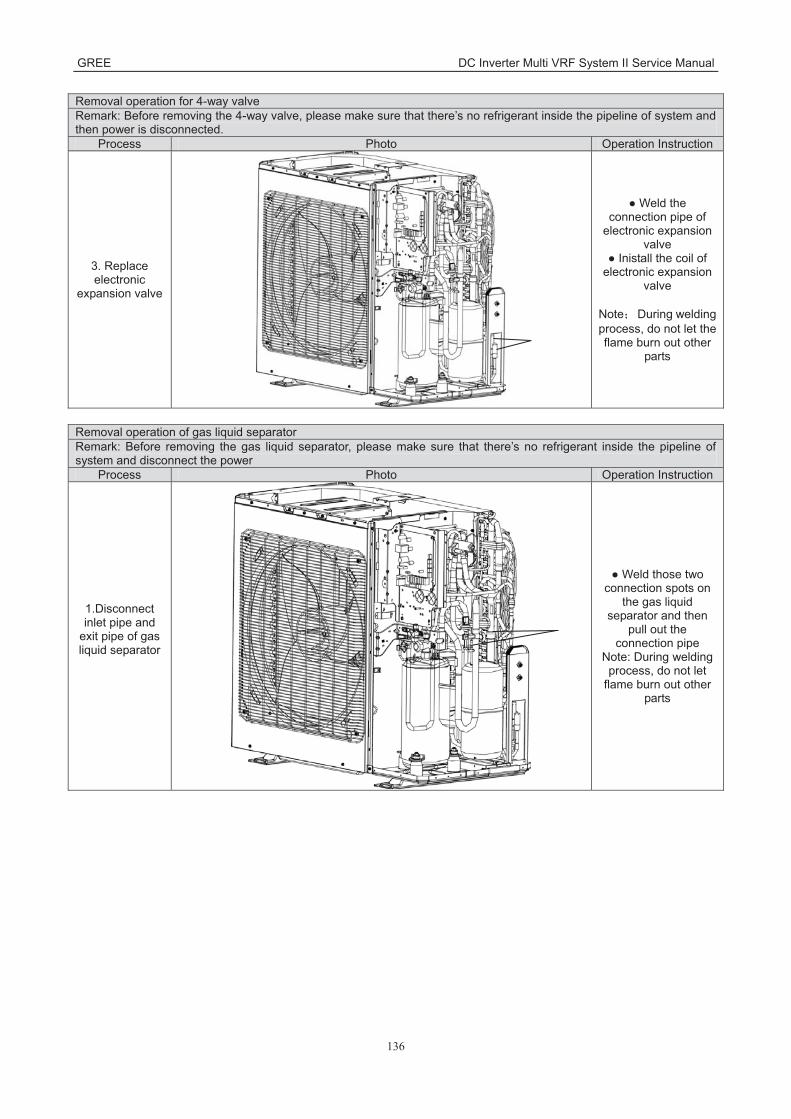
GREE DC Inverter Multi VRF System II Service Manual
136
Removal operation for 4-way valve Remark: Before removing the 4-way valve, please make sure that there’s no refrigerant inside the pipeline of system and then power is disconnected.
Process Photo Operation Instruction
3. Replace electronic
expansion valve
● Weld the connection pipe of
electronic expansion valve
● Inistall the coil of electronic expansion
valve
Note During welding process, do not let the flame burn out other
parts
Removal operation of gas liquid separator Remark: Before removing the gas liquid separator, please make sure that there’s no refrigerant inside the pipeline of system and disconnect the power
Process Photo Operation Instruction
1.Disconnect inlet pipe and
exit pipe of gas liquid separator
● Weld those two connection spots on
the gas liquid separator and then
pull out the connection pipe
Note: During welding process, do not let
flame burn out other parts

GREE DC Inverter Multi VRF System II Service Manual
137
Removal operation of gas liquid separator Remark: Before removing the gas liquid separator, please make sure that there’s no refrigerant inside the pipeline of system and disconnect the power
Process Photo Operation Instruction
2. Replace gas liquid separator
● Loose 4 screws with screwdriver
● Replace gas lliquid separator
3. Replace gas liquid separator
● Weld the pipe connected with gas
liquid separator ● Fix the screws at
the base of gas liquid separator well again Note: During welding process, do not let
flame burn out other parts
Removal operation for plate heat exchanger Remark: Before removing the plate heat exchanger, please make sure that there’s no refrigerant inside the pipeline of system and disconnect the power
Process Photo Operation Instruction
1. Remove top cover, back
plate and right plate
●Twist off the nuts fixing the plate,
remove front plate firstly, then remove
right plate, and remove back plate
finally

GREE DC Inverter Multi VRF System II Service Manual
138
Removal operation for plate heat exchanger Remark: Before removing the plate heat exchanger, please make sure that there’s no refrigerant inside the pipeline of system and disconnect the power
Process Photo Operation Instruction
2.Remove the bracket of plate heat exchanger
● Twist off the nuts fixing the bracket of
plate heat exchanger
3. Weld those 4 connection
spots on the plate heat
exchanger, and then pull out plate heat exchanger
●Weld those 4 connection spots on
the plate heat exchanger, and then
pull out the connection pipe.
Note: During welding process, do not let
flame burn out other parts

GREE DC Inverter Multi VRF System II Service Manual
139
Removal operation for plate heat exchanger Remark: Before removing the plate heat exchanger, please make sure that there’s no refrigerant inside the pipeline of system and disconnect the power
Process Photo Operation Instruction
4. Replace new plate heat exchanger
● Weld the pipe connected with plate
heat exchanger Note: During welding process, do not let
flame burn out other parts

GREE DC Inverter Multi VRF System II Service Manual
140
6 Common Maintenance 6.1 Vacuum drying for the system 6.1.1 Selection requirement for the vaccum pump
Do not use different vacuum pump for vaccum-pumping for different refrigerant system
The final vacuum for the vacuum pump should reach -0.1Mpa;
The air discharge volume for the vacuum pump should reach 4L/S above;
The precision of vacuum pup should reach 0.02mmHg above;
The system vacuum pump for R410A must be with check valve.
6.1.2 Operation procedure and notices for Vacuum drying 1 Operation procedure
a Before vacuum-pumping, please confirm that the cut-off valve for gas pipe and liquid pipe is at off
status; b Use charging conduct pipe to connect the governing value and vacuum heat pump to the detection
joint of gas valve and liquid valve; c After vacuum-pumping for 4h, check whether the vacuum degree is reached to -0.1MPa or above; If
not, there may be gas leakage. Please perform the leakage inspection again. If there’s no gas
leakage, please vacuum pump for another 2h.
d. If the required vaccum degree can’t be satisfied after vacuum-pumping for two times, there are water
inside the pipeline. Please drain out the water by the method of vaccum damage. The detailed
method: charge 0.05MPa nitrogen into the pipeline, vacuum pump for 2h and then keep the cacuum
for 1h. If -0.1 MPa vaccum degree still can’t be reached, repeat this operation unitl the water is
drained out completely. 2 After the vacuum pump is finished, turn off the valve of governing valve and stop vacuum pump and
keep it for 1h. Please confirm that the pressure of governing valve hasn’t been increased. a Vacuum pump for the gas pipe and liquid valve at the same time;
b When turn off the vacuum pump to stop vacuum-pumping, please turn off the valve at first and then
de-energize the vacuum pump; c Keep the vacuum pump for 2h and confirm that the pressure of vacuum meter hasn’t been increased.

GREE DC Inverter Multi VRF System II Service Manual
141
6.2 Fill and charge refrigerant 6.2.1 Filling procedure of regrigerant
1 Calculate the additional volume of refrigerant (GMV-120WL/A-T GMV-140WL/A-TGMV-160WL/A-T GMV-120WL/A-X GMV-140WL/A-X GMV-160WL/A-X)
1) Refrigerant quantity of outdoor unit before delivery:
Model GMV-120WL/A-T
GMV-140WL/A-T
GMV-160WL/A-T
GMV-120WL/A- X
GMV-140WL/A- X
GMV-160WL/A-X
Refrigerant Qty (kg) 5.0 5.0 5.0 5.0 5.0 5.0
Note: The refrigerant amount charged before delivery doesn’t include the amount that needs to be added
to indoor units and the connection pipeline. Length of connection pipe is decided on site. Therefore the amount of additional refrigerant shall be
decided on site according to the dimension and length of field-installed liquid pipe. Record the amount of additional refrigerant for convenience of after-sales service. 2) Calculation of the amount of additional refrigerant Calculation method of the quantity of additional refrigerant (based on liquid pipe)
Quantity of additional refrigerant = ∑length of liquid pipe × quantity of additional refrigerant per meter
Quantity of additional refrigerant per meter for liquid pipe kg/mΦ22.2 Φ19.05 Φ15.9 Φ12.7 Φ9.52 Φ6.35 0.35 0.25 0.17 0.11 0.054 0.022
Note: Liquid pipe that is within 20m doesn’t need to be added with refrigerant.
First confirm that there is no leakage from the system. When compressor is not working, charge
additional R410a with specific amount to the unit through the filling opening of the liquid pipe valve of the
outdoor unit. If required amount cannot be quickly filled due to pressure increase of the pipe, then set the
unit in cooling startup and fill refrigerant from the low pressure check valve of the outdoor unit.
3) Calculation example

GREE DC Inverter Multi VRF System II Service Manual
142
IDU No. IDU IDU IDU IDU
Model Duct type GMV-ND72PL/B-T
Duct type GMV-ND50PL/B-T
Duct type GMV-ND36PL/B-T
Duct type GMV-ND25PL/B-T
Liquid pipe: No. A B C D
Pipe size Φ9.52 Φ9.52 Φ9.52 Φ6.35 Length 10m 5m 5m 5m
No. a b c d Pipe size Φ9.52 Φ6.35 Φ6.35 Φ6.35 Length 3m 3m 2m 1m
Total length of each liquid pipe
Φ9.52 A+B+C+a=10+105+5+3=23m
Φ6.35: D+b+c+d=5+3+2+1=11m
Note: Liquid pipe that is within 20m doesn’t need to be added with refrigerant.
Therefore, the minimum quantity of additional refrigerant = (23-20)×0.054+11×0.022 0.404kg
2 Calculate the additional volume of refrigera GMV-80WL/C-T GMV-100WL/C-TGMV-121WL/C-T GMV-80WL/A-T GMV-100WL/A-T GMV-121WL/A-T GMV-120WL/C-TGMV-140WL/C-T GMV-160WL/C-T GMV-120WL/C-X GMV-140WL/C-X,GMV-160WL/C-X
1) Refrigerant quantity of outdoor unit before delivery:
Mod
el GMV-
80WL/A-T
GMV-100WL/A-T
GMV-121WL/A-T
GMV-80WL/C-T
GMV-100WL/C-T
GMV-121WL/C-T
GMV-141WL/C-T
GMV-120WL/C-T
GMV-140WL/C-T
GMV-160WL/C-T
GMV-120WL/C-X
GMV-140WL/C-X
GMV-160WL/C-X
Ref
riger
ant
Qty
(kg)
1.8 1.8 2.0 1.8 1.8 2.0 3.3 3.3 3.3 3.3 3.3 3.3 3.3
Note: The refrigerant amount charged before delivery doesn’t include the amount that needs to be added to indoor units and the connection pipeline.
Length of connection pipe is decided on site. Therefore the amount of additional refrigerant shall be decided on site according to the dimension and length of field-installed liquid pipe.
Record the amount of additional refrigerant for convenience of after-sales service. 2) Calculation of the amount of additional refrigerant
Calculation method of the quantity of additional refrigerant (based on liquid pipe) Quantity of additional refrigerant = ∑length of liquid pipe ×quantity of additional refrigerant per meter+ quantity of indoor unit -2 ×0.3
Quantity of additional refrigerant per meter for liquid pipe kg/mΦ22.2 Φ19.05 Φ15.9 Φ12.7 Φ9.52 Φ6.35 0.35 0.25 0.17 0.11 0.054 0.022
First confirm that there is no leakage from the system. When compressor is not working, charge additional R410a with specific amount to the unit through the filling opening of the liquid pipe valve of the outdoor unit. If required amount cannot be quickly filled due to pressure increase of the pipe, then set the unit in cooling startup and fill refrigerant from the low pressure check valve of the outdoor unit.

GREE DC Inverter Multi VRF System II Service Manual
143
3) Calculation example
IDU
No. IDU IDU IDU IDU
Model Duct type GMV-ND72PL/B-T
Duct type GMV-ND50PL/B-T
Duct type GMV-ND36PL/B-T
Duct type GMV-ND25PL/B-T
Liquid pipe: No. A B C D
Pipe size Φ9.52 Φ9.52 Φ9.52 Φ6.35 Length 10m 5m 5m 5m
No. a b c d Pipe size Φ9.52 Φ6.35 Φ6.35 Φ6.35 Length 3m 3m 2m 1m
Total length of each liquid pipe
Φ9.52 A+B+C+a=10+105+5+3=23m
Φ6.35: D+b+c+d=5+3+2+1=11m
Quantity of indoor unit: 4 sets
Therefore, the minimum quantity of additional refrigerant = (23×0.054+11×0.022)+(4-2) ×0.32.084kg
3 Calculate the additional volume of refrigerant (GMV-H224WL/A-X GMV-H280WL/A-XGMV-H335WL/A-X GMV-224WL/C-X GMV-280WL/C-X GMV-335WL/C-X)
1) Refrigerant quantity of outdoor unit before delivery:
Model GMV-H224WL/A-X GMV-224WL/C-X
GMV-H280WL/A-X GMV-280WL/C-X
GMV-H335WL/A-X GMV-335WL/C-X
Refrigerant Qty (kg) 5.5 7.1 8.0

GREE DC Inverter Multi VRF System II Service Manual
144
The refrigerant amount charged before delivery doesn’t include the amount that needs to be added
to indoor units and the connection pipeline. Length of connection pipe is decided on site. Therefore the amount of additional refrigerant shall be
decided on site according to the dimension and length of field-installed liquid pipe. Record the amount of additional refrigerant for convenience of after-sales service. 2) Calculation of the amount of additional refrigerant
Calculation method of the quantity of additional refrigerant (based on liquid pipe) Quantity of additional refrigerant = ∑length of liquid pipe X quantity of additional refrigerant per meter
Quantity of additional refrigerant per meter for liquid pipe kg/mΦ22.2 Φ19.05 Φ15.9 Φ12.7 Φ9.52 Φ6.35 0.35 0.25 0.17 0.11 0.054 0.022
Note:First confirm that there is no leakage from the system. When compressor is not working, charge additional R410a with specific amount to the unit through the filling opening of the liquid pipe valve of the outdoor unit. If required amount cannot be quickly filled due to pressure increase of the pipe, then set the unit in cooling startup and fill refrigerant from the low pressure check valve of the outdoor unit.
3) Calculation example
IDU
No. IDU IDU IDU IDU
Model Duct type GMV-ND72PL/B-T
Duct type GMV-ND50PL/B-T
Duct type GMV-ND36PL/B-T
Duct type GMV-ND25PL/B-T
Liquid pipe: No. A B C D
Pipe size Φ9.52 Φ9.52 Φ9.52 Φ6.35 Length 10m 5m 5m 5m
No. a b c d Pipe size Φ9.52 Φ6.35 Φ6.35 Φ6.35 Length 3m 3m 2m 1m
Total length of each liquid pipe
Φ9.52 A+B+C+a=10+105+5+3=23m
Φ6.35: D+b+c+d=5+3+2+1=11m
The minimum quantity of additional refrigerant = 23×0.054+11×0.022 1.484kg

GREE DC Inverter Multi VRF System II Service Manual
145
6.3 Airtightness test 6.3.1 Importance of airtightness test
The airtightness of VRF system is the leak tightness of the pipeline for refrigerant, which the
guarantee for safe and reliable operation. The leakage of refrigerant may affect the operation of air
conditioner seriously, or even damage compressor and then lead to breakdown of system. Therefore, it
needs to perform the airtightness test. If the there’s gas leakage after the system is installed completely,
because the indoor ceiling decoration are all finished, it’s will be very difficult to find out the leakage point.
Thus, the airtightness test of the system must be finished before finishing indoor decoration.
6.3.2 Operation procedure for the airtightness test Before ex-factory, cut-off valve for gas pipe and liquid pipe of outdoor unit is turned off. Please
confirm that before operation.
Before testm please smear a little corresponding lubricant oil at and pipe terminal, and use two
wrenches for fixing
Do not allow to connect the pipeline of outdoor unit for test during airtightness test.
The system test pressure for R410A is 4.15MPa (3.0MPa for R22 refrigerant system). Nitrogen must
be used as the medium for the airtightness test and the nitrogen should be dry. Increase pressure slowly
for three steps:
Step 1:Increase pressure slowly to 0.5MPa, stop for 5min and then check the gas leakage. Big
leakage may be found out;
Step 2:Increase pressure slowly to 1.5MPa, stop for 5min to check the airtightness. Small leakage
may be found out;
Step 3:Increase pressure slowly to 4.15MPa for R410A slowly (3.0MPa for R22 refrigerant system),
stop for 5min and perform the strength test. Minor leakage or sand hole may be found. Increase
pressure to test pressurem, keep it for 24h and observe whether the pressure is decreasing. If not, the
pressure is qualified.
6.3.3 Cautions 1 The test manometer range for R410A should be 4.5MPa above (3.5MPa above for R22 refrigerant
system); 2 Record the data on manometerk, ambient temperature and test time at the same time; 3 Pressure modification: when temperature changes 1 , the temperature will change 0.01MPa
correspondingly. 4 Pressure should be kept the same. 5 If it needs to keep pressure for a long time, decrease the pressire lower than 0.55MPa pr below.
Long-time high pressure can lead to leakage at the welding position, which may cause riskl. 6 Before the airtightness for the pipeline of refrigerant is finished, do not allow to insulate and bundle
the welding positions and connection position of bellmouth of indoor unit.

GREE DC Inverter Multi VRF System II Service Manual
146
Add pressure from gas pipe and liquid pipeat the same time
Note: Before airtightness test, all welding lines can’t be insulated and bundled.
7 Exploded View of Unit and Parts’ List 7.1 Exploed view for outdoor unit and parts’ list
1) Model: GMV-80WL/A-T GMV-100WL/A-T GMV-80WL/C-T GMV-100WL/C-T Exploded view
NO. Name of Part
GMV-80WL/A-T GMV-100WL/A-T GMV-80WL/C-T GMV-100WL/C-T
Product Code
CN850W0530 CN850W0430 CN850W0600 CN850W0590
Part Code Quantity
1 Coping '01264100027P 1
2 Electric Box Cover '01424100064 1 3 Electric Box Assy '100002000960 1 4 PFC Inductance '43120011 1 5 Main Board '30221000024 1
6 Filter Board '300020000004 1
7 Main Board '30226000045 1

GREE DC Inverter Multi VRF System II Service Manual
147
NO. Name of Part
GMV-80WL/A-T GMV-100WL/A-T GMV-80WL/C-T GMV-100WL/C-T
Product Code
CN850W0530 CN850W0430 CN850W0600 CN850W0590
Part Code Quantity
8 Radiator '4901800007501 1
9 Terminal Board '42011242 1
10 Terminal Board '42018000026 1
11 Left Side Plate '01314100043P 1
12 Drainage Connecter '06123401 1
13 Compressor Overload Protector(External) '00180030 1
14 Compressor Overload Protector(External) '00183032 1
15 Compressor Overload Protector(External) '00183051 1
16 Electric Heater(Compressor) '7651873215 1
17 Brushless DC Motor '1570280000401 1
18 Axial Flow Fan '10434100005 1
19 Diversion Circle '10474100003 1
20 Cabinet '01514100007P 1
21 Front Side Plate '01314100044P 1
22 Handle '26235253 1
23 Front Grill '01572800003 1
24 Drainage hole Cap '06813401 1
25 Chassis Sub-Assy '017000000148P 1
26 Motor Support Sub-Assy '01804100309 1
27 Clapboard Sub-Assy '01244100020 1
28 Sensing Device '322101002 1
29 Gas-liquid Separator '07422809 1
30 Magnet Coil (electromagnetic valve) '4304410018903 1
31 4-way Valve '4300008201 1
32 Magnet Coil '4304410018902 1
33 Compressor '00205200003 1
34 Compressor Gasket '76713066 1
35 Sensing Device '322101032 1
36 Nozzle for Adding Freon '06120014 1
37 Cut off Valve '07334100016 1
38 Cut off Valve '07130209 1
39 Strainer '07212001 1
40 Bidirection Strainer '07210044 1
41 Valve Support Assy '01804100306 1
42 Nozzle for Adding Freon 6120012 1
43 Capillary Sub-Assy '030006000255 1
44 Electromagnetic Valve '43000054 1
45 Right Side Plate '01314100046P 1
46 Rear Side Plate '01314100045P 1
47 Silencer '07444105 1

GREE DC Inverter Multi VRF System II Service Manual
148
NO. Name of Part
GMV-80WL/A-T GMV-100WL/A-T GMV-80WL/C-T GMV-100WL/C-T
Product Code
CN850W0530 CN850W0430 CN850W0600 CN850W0590
Part Code Quantity
48 Pressure Protect Switch '4602000913 1
49 Plate-type Heat Exchanger '00904100003 1
50 Electric Expand Valve Fitting '4304413205 1
51 Electric Expand Valve Fitting '4304413220 1
52 Strainer '07212121 1
53 Silencer '07245012 1
54 Condenser Sub-Assy '01000200003302 1
55 Rear Grill '01574100010 1
56 Inhalation Tube Sub-Assy '04574100067 1
57 Oil Separator '07228302 1
58 Strainer '07415200002 1
59 Discharge Tube Sub-Assy '030013000499 1
60 Discharge Charge Valve '07133771 1
61 Electronic Expansion Valve '07334390 1
62 Electronic Expansion Valve '07334447 1
63 Plate-type Heat Exchanger Assy '00904100035 1
64 Sensor Sub-assy '39008000060G 1
65 Electrical Heater '765100047 1
66 Corrugated Pipe '05015408 1

GREE DC Inverter Multi VRF System II Service Manual
149
2) Model: GMV-121WL/A-T GMV-121WL/C-T Exploded view
NO. Name of Part
GMV-121WL/A-T GMV-121WL/C-T
Product Code CN850W0420 CN850W0640
Part Code Quantity
1 Coping '01264100027P 1
2 Electric Box Cover '01424100064 1 3 Electric Box Assy '100002000960 1 4 PFC Inductance '43120011 1 5 Main Board '30221000024 1
6 Filter Board '300020000004 1
7 Main Board '30226000045 1
8 Radiator '4901800007501 1
9 Terminal Board '42011242 1
10 Terminal Board '42018000026 1
11 Left Side Plate '01314100043P 1
12 Drainage Connecter '06123401 1
13 Compressor Overload Protector(External) '00180030 1
14 Compressor Overload Protector(External) '00183032 1

GREE DC Inverter Multi VRF System II Service Manual
150
NO. Name of Part
GMV-121WL/A-T GMV-121WL/C-T
Product Code CN850W0420 CN850W0640
Part Code Quantity
15 Compressor Overload Protector(External) '00183051 1
16 Electric Heater(Compressor) '7651873215 1
17 Brushless DC Motor '1570280000401 1
18 Axial Flow Fan '10434100005 1
19 Diversion Circle '10474100003 1
20 Cabinet '01514100007P 1
21 Front Side Plate '01314100044P 1
22 Handle '26235253 1
23 Front Grill '01572800003 1
24 Drainage hole Cap '06813401 1
25 Chassis Sub-Assy '017000000148P 1
26 Motor Support Sub-Assy '01804100309 1
27 Clapboard Sub-Assy '01244100020 1
28 Sensing Device '322101002 1
29 Gas-liquid Separator '07422809 1
30 Magnet Coil (electromagnetic valve) '4304410018903 1
31 4-way Valve '4300008201 1
32 Magnet Coil '4304410018902 1
33 Compressor '00205200003 1
34 Compressor Gasket '76713066 1
35 Sensing Device '322101032 1
36 Nozzle for Adding Freon '06120014 1
37 Cut off Valve '07334100016 1
38 Cut off Valve '07130209 1
39 Strainer '07212001 1
40 Bidirection Strainer '07210044 1
41 Valve Support Assy '01804100306 1
42 Nozzle for Adding Freon 6120012 1
43 Capillary Sub-Assy '030006000255 1
44 Electromagnetic Valve '43000054 1
45 Right Side Plate '01314100046P 1
46 Rear Side Plate '01314100045P 1
47 Silencer '07444105 1
48 Pressure Protect Switch '4602000913 1
49 Plate-type Heat Exchanger '00904100003 1
50 Electric Expand Valve Fitting '4304413205 1
51 Electric Expand Valve Fitting '4304413220 1
52 Strainer '07212121 1
53 Silencer '07245012 1
54 Condenser Sub-Assy '0115410001901 1
55 Rear Grill '01574100010 1

GREE DC Inverter Multi VRF System II Service Manual
151
NO. Name of Part
GMV-121WL/A-T GMV-121WL/C-T
Product Code CN850W0420 CN850W0640
Part Code Quantity
56 Inhalation Tube Sub-Assy '04574100067 1
57 Oil Separator '07228302 1
58 Strainer '07415200002 1
59 Discharge Tube Sub-Assy '030013000499 1
60 Discharge Charge Valve '07133771 1
61 Electronic Expansion Valve '07334390 1
62 Electronic Expansion Valve '07334447 1
63 Plate-type Heat Exchanger Assy '00904100035 1
64 Sensor Sub-assy '39008000060G 1
65 Electrical Heater '765100047 1
66 Corrugated Pipe '05015408 1 3) Model: GMV-141WL/C-T Exploded view

GREE DC Inverter Multi VRF System II Service Manual
152
Parts list
NO. Name of Part
GMV-141WL/C-T
Product Code CN850W0880
Part Code Quantity
1 Chassis Assy 209058060095 1
2 Electrical Heater 765100049 1
3 Condenser Assy 100060114 1
4 Silencer 7245012 1
5 Strainer 721212101 1
6 Temp Sensor Sleeving 5212423 1
7 Sensor Insert 42020063 1
8 Motor Support Sub-Assy 17012060039 1
9 Brushless DC Motor 150104060013 1
10 Axial Flow Fan 1043410000801 1
11 Left Side Plate 012055000007P 1
12 Left Side Plate 12055000007 1
13 Cabinet 012022000003P 1
14 Cabinet 12022000003 1
15 Diversion Circle 10474100003 1
16 Front Grill 1572800003 1
17 Gas-liquid Separator 7424145 1
18 Compressor and Fittings 9001060150 1
19 Nut with Washer 70310014 3
20 Electrical Heater(Compressor) 7651521238 1
21 4-Way Valve Assy 30152060195 1
22 4-way Valve 4300008201 1
23 Filter 7224803 1
24 Cut off Valve 7334100016 1
25 Temp Sensor Sleeving 5212423 3
26 Magnet Coil (electromagnetic valve) 4304410018903 1
27 Sensor Insert 42020063 3
28 Strainer 721650101 1
29 Electromagnetic Valve 43000054 1
30 Magnet Coil (electromagnetic valve) 4304410018902 1
31 Electronic Expansion Valve 43044100173 1
32 Electric Expand Valve Fitting 4304413252 1
33 Pressure Protect Switch 46020006 1
34 Oil Separator 7424105 1
35 Temp Sensor Sleeving 5212423 1
36 Sensor Insert 42020063 1

GREE DC Inverter Multi VRF System II Service Manual
153
NO. Name of Part
GMV-141WL/C-T
Product Code CN850W0880
Part Code Quantity
37 Plate-type Heat Exchanger 10007060010 1
38 Temp Sensor Sleeving 5212423 1
39 Electronic Expansion Valve 72009000001 1
40 Current Divider 7223431 1
41 Nut with Washer 70310012 4
42 Cut off Valve 71302391 1
43 Strainer 721200102 1
44 Sensor Insert 42020063 1
45 Valve Support Sub-Assy 17104000008 1
46 Insulation Gasket 70410006 1
47 Insulation Gasket 70410503 1
48 Wire Clamp 71010103 1
49 Electric Box Assy 100002062969 1
50 Fixed Mount 200115000011 1
51 Radiator Cushion Block 1 430059000004 1
52 Main Board 300027000118 1
53 Wiring Terminal 42010264 1
54 Radiator Cushion Block 2 430059000005 1
55 Inductance 43128000014 1
56 Cable Cross Loop 76515202 2
57 Main Board 300027060511 1
58 XY capacitor 33020201 2
59 Bolt 70210051 1
60 Terminal Board 42200000001501 1
61 Terminal Board 422000060004 1
62 Magnetic Ring 49010118 1
63 Magnetic Ring 49010109 2
64 Magnetic Ring 49010104 1
65 Heat Insulator 12128748 15
66 Connection Board 01344100070P 1
67 Wire conduit 26904100132 2
68 Gland Bush 26904100134 2
69 Rear Side Plate 12076000021 1
70 Front Side Plate 012050000007P 1
71 Handle 26904100016 2
72 Coping 01264100052P 1
73 Coping 1264100052 1

GREE DC Inverter Multi VRF System II Service Manual
154
NO. Name of Part
GMV-141WL/C-T
Product Code CN850W0880
Part Code Quantity
74 Rear Grill 1574100014 1
75 Temperature Sensor Support 26905202 1
76 Corrugated Pipe 5015408 1
77 Drainage hole Cap 76715005 3
78 Drainage Joint 26113009 1
4) Model: GMV-120WL/A-T GMV-140WL/A-T GMV-160WL/A-T Exploded view

GREE DC Inverter Multi VRF System II Service Manual
155
Parts list
NO. Name of Part
GMV-120WL/A-T,GMV-140WL/A-T,GMV-160WL/A-T
Product Code CN850W0180 /CN850W0170/CN850W0160
Part Code Quantity
1 Coping 01264100008P 1
2 Inductance Assy 01394100050 1
3 Inductance 43120122 1
4 Electric Box Assy 01394100124 1
5 Main Board 30228000005 1
6 Radiator 49018000013 1
7 Filter Board 30228000006 1
8 Main Board 30226000045 1
9 Terminal Board 42018000026 1
10 Terminal Board 42011242 1
11 Left Side Plate 01314100013P 1
12 Clapboard Sub-Assy 01244100006 1
13 Fan Motor 15704115 1
14 Sensor Sub-Assy 39008000061G 1
15 Fan Motor 1570411501 1
16 Front Grill 26904100026 1
17 Cabinet 01514100002P 1
18 Front Side Plate 01314100012P 1
19 Handle 26235253 1
20 Front Connection Board 01344100002P 1
21 Diversion Circle 10474100001 1
22 Axial Flow Fan 10434100003 1
23 Chassis Sub-Assy 0119410000301P 1
24 Motor Support Assy 01804100293 1
25 Pressure Protect Switch 4602000902 1
26 Discharge Tube Sub-Assy 04534100057 1
27 Silencer 07444105 1
28 Oil Separator 07424105 1
29 Compressor 00204100001 1
30 Electrical Heater(Compressor) 765152128 1
31 Compressor Gasket 76710247 1
32 Cut off Valve 07330000002 1
33 Strainer 07212001 1
34 Gas-liquid Separator 07424100014 1
35 Capillary Sub-Assy 04004100013 1
36 Strainer 07415200002 1

GREE DC Inverter Multi VRF System II Service Manual
156
NO. Name of Part
GMV-120WL/A-T,GMV-140WL/A-T,GMV-160WL/A-T
Product Code CN850W0180 /CN850W0170/CN850W0160
Part Code Quantity
37 Electromagnetic Valve 43000054 1
38 Magnet Coil 4304000417 1
39 Right Connection Board 01344100003P 1
40 Rear Side Plate Sub-Assy 01314100011P 1
41 Sensing Device 322101001 1
42 Sensor (High Pressure) 322101032 2
43 Gas By-pass Sub- Assy 04534100056 2
44 Magnet Coil 4304000406 1
45 Plate-type Heat Exchanger Assy 00904100013 1
46 Discharge Charge Valve 07133771 1
47 Electronic Expansion Valve 07334447 1
48 Electric Expand Valve Fitting 4304413205 1
49 Electronic Expansion Valve 07334390 1
50 Electric Expand Valve Fitting 4304413220 1
51 Low Pressure Survey Valve Sub-Assy 07334100040 1
52 Cut off Valve 07130239 1
53 Strainer 07212121 1
54 Silencer 07245012 1
55 4-Way Valve Assy 04044100022 1
56 Cut off Valve 07330000001 1
57 Strainer 07210037 1
58 One way Valve 07130118 1
59 4-way Valve 43000338 1
60 Magnet Coil 4300040045 1
61 Nozzle for Adding Freon 06120012 1
62 Condenser Assy 01124100108 1
63 Rear Grill 01574100004 1
Above data is subject to change without notice, pls reference the SP in global service website.

GREE DC Inverter Multi VRF System II Service Manual
157
5) Model: GMV-120WL/A-X GMV-140WL/A-X GMV-160WL/A-X Exploded view
Parts list
NO. Name of Part
GMV-120WL/A-X GMV-140WL/A-X GMV-160WL/A-X
Product Code CN850W0260 / CN850W0250 / CN850W0240 Part Code Quantity
1 Front Grill 26904100026 2 2 Cabinet 01514100005 1 3 Front Side Plate 01314100012P 1 4 Handle 26235253 2 5 Front Connection Board 01344100002P 1 6 Diversion Circle 10474100001 2 7 Axial Flow Fan 1043410000301 1
8 Fan Motor 15704100013 1570410001301 2
9 Chassis Assy 0119410000301P 1 10 ompressor and Fittings 00204100018 1 11 Gas-liquid Separator 07424100014 1 12 Plate-type Heat Exchanger Assy 00904100013 1 13 Supporter 01804100312 1

GREE DC Inverter Multi VRF System II Service Manual
158
NO. Name of Part GMV-120WL/A-X GMV-140WL/A-X GMV-160WL/A-X
Product Code CN850W0260 / CN850W0250 / CN850W0240 Part Code Quantity
14 Rear Side Plate Sub-Assy 01314100011P 1 15 Right Connection Board 01344100003P 1 16 Current Divider 04414153 1 17 Strainer 07212121 1 18 Silencer 07245012 1 19 Condenser Sub-Assy 01154100008 1 20 Atmolysis Pipe Sub-Assy 04534100062 1 21 Cut off Valve 07330000001 1 22 Strainer 07212121 1 23 4-way Valve 43000338 1 24 Nozzle for Adding Freon 06120012 1 25 Rear Grill 01574100004 1 26 Strainer 07212121 1 27 Cut off Valve 07130239 1 28 Low Pressure Survey Valve Sub-Assy 07334100067 1 29 Inhalation Tube Sub-assy 04574100107 1 30 Strainer 07212121 1 31 Electromagnetic Valve 43000054 1 32 Discharge Tube Sub-Assy 04534100092 1 33 Coping 01264100008P 1 34 Reactor 43130192 1 35 Main Board 30226000046 1 36 Filter Board 30223000044 1 37 Electric Box Assy 26905200088 1 38 Radiator 49018000087 1 39 Terminal Board 42011221 1 40 Terminal Board 42018000026 1 41 Left Side Plate 01314100013P 1 42 Motor Support Sub-Assy 01805200244 1 43 Sensor (High Pressure) 322101032 1 44 Sensing Device 322101002 1 45 Sensor Sub-Assy 39008000061G 1 46 Magnet Coil 4304000417 1 47 Magnet Coil 4304000417 1 48 Magnet Coil 4304000417 1
Above data is subject to change without notice, pls reference the SP in global service website.

GREE DC Inverter Multi VRF System II Service Manual
159
6) Model: GMV-120WL/C-T GMV-140WL/C-T GMV-160WL/C-T Exploded view
NO. Name of Part
GMV-120WL/C-T GMV-140WL/C-T GMV-160WL/C-T CN850W0440 CN850W0450 CN850W0460
Quantity 1 Front Grill 2 2 Cabinet 1 3 Handle 2 4 Front Side Plate 1 5 Diversion Circle 2 6 Axial Flow Fan 1 7 Brushless DC Motor 1 8 Brushless DC Motor 1 9 Chassis Sub-assy 1
10 Motor Support Sub-assy 1 11 Oil Separator 1 12 One way Valve 1 13 Strainer 1 14 Cut off Valve 1

GREE DC Inverter Multi VRF System II Service Manual
160
NO. Name of Part
GMV-120WL/C-T GMV-140WL/C-T GMV-160WL/C-T CN850W0440 CN850W0450 CN850W0460
Quantity 15 Compressor and Fittings 1 16 Strainer 1 17 4-way Valve 1 18 Strainer 1 19 Electromagnetic Valve 1 20 Nozzle for Adding Freon 1 21 Electronic Expansion Valve 1 22 Discharge Charge Valve 1 23 Plate-type Heat Exchanger 1 24 Electronic Expansion Valve 1 25 Discharge Charge Valve 1 26 Front Connection Board 1 27 Right Connection Board 1 28 Rear Side Plate Sub-Assy 1 29 Sensor 1 30 Gas-liquid Separator 1 31 Strainer 1 32 Condenser Assy 1 33 Sensor(High Pressure) 1 34 Nozzle for Adding Freon 1 35 Pressure Protect Switch 1 36 Rear Grill 1 37 Electric Box Assy 1 38 Terminal Board 1 39 Terminal Board 1 40 Filter Boad 1 41 Main Board 1 42 Main Board 1 43 Inductance Assy 1 44 Inductance 1 45 Coping 1 46 Left Side Plate 1 47 Electric Expand Valve Fitting 1 48 Electric Expand Valve Fitting 1 49 Communication Interface Board 1 50 Drainage Connecter 1 51 Magnet Coil 1 52 Magnet Coil 1 53 Magnet Coil 1 54 Electrical Heater(Compressor) 1 55 Sensor Sub-Assy 1 56 Chassis Heater 1

GREE DC Inverter Multi VRF System II Service Manual
161
7) Model: GMV-120WL/C-X GMV-140WL/C-X GMV-160WL/C-X Exploded view
NO. Name of Part
GMV-120WL/C-X GMV-140WL/C-X GMV-160WL/C-X CN850W0470 CN850W0480 CN850W0490
Quantity 1 Front Grill 2 2 Handle 1 3 Diversion Circle 1 4 Cover 2 5 Front Side Plate 1 6 Axial Flow Fan 2 7 4-way Valve 1 8 Small Valve 2 9 Strainer 1
10 Electric Expand Valve Fitting 1 11 Discharge Charge Valve 1 12 Oil Separator 1 13 Nozzle for Adding Freon 1 14 High Pressure Circuit Breaker 1 15 Pressure Sensor(High) 1 16 Strainer 1 17 Large valve 1 18 Plate-type Heat Exchanger 1 19 Supporter 1 20 Compressor and Fittings 1

GREE DC Inverter Multi VRF System II Service Manual
162
NO. Name of Part
GMV-120WL/C-X GMV-140WL/C-X GMV-160WL/C-X CN850W0470 CN850W0480 CN850W0490
Quantity 21 Strainer 1 22 Strainer 1 23 Magnet Coil 1 24 Rear Side Plate Sub-Assy 1 25 Pressure Sensor(Low) 1 26 Strainer 1 27 Rear Grill 1 28 Condenser 1 29 Electric Box Assy 1 30 Terminal Board 1 31 Terminal Board 1 32 Main Board 1 33 Inductance 1 34 Brushless DC Motor 1 35 Electric Box Assy 1 36 Main Board 1 37 Radiator 1 38 Inductance 1 39 Top Cover 1 40 Magnet Coil 1 41 Magnet Coil 1 42 Sensor Sub-Assy 1 43 Drainage Connecter 1 44 Chassis Heater 1

GREE DC Inverter Multi VRF System II Service Manual
163
8) Model: GMV-H224WL/A-X,GMV-224WL/C-X Exploded view
Parts list
NO. Name of Part
GMV-H224WL/A-X,GMV-224WL/C-X
Product Code CN850W0330 CN850W0510
Part Code Quantity 1 Coping 01264100047P 1 2 Electric Box Assy 01394100349 1 3 Radiator 49018000083 2 4 Rectifier 46010604 1 5 Reactor 4313017401 1 6 Main Board 30223000045 1 7 Phase Reverse Protector 32218018 1 8 Filter Board 30228000015 1 9 Main Board 30226000045 1
10 Terminal Board 42011043 4 11 Terminal Board 42018000026 1 12 Left Side Plate 01314100084P 1 13 Fan Motor 1570280206 2 14 Axial Flow Fan 10434100006 215 Sensor Sub-assy 39008000061G 1 16 Front Grill 01574100008 2

GREE DC Inverter Multi VRF System II Service Manual
164
NO. Name of Part
GMV-H224WL/A-X,GMV-224WL/C-X
Product Code CN850W0330 CN850W0510
Part Code Quantity 17 Diversion Circle 10474100003 2 18 Cabinet Assy 01514100015 1 19 Handle 26235253 1 20 Front Side Plate 01314100082P 1 21 Nozzle for Adding Freon 06120012 1 22 Gas-liquid Separator 07424140 1 23 Pressure Protect Switch 4602000902 1 24 Cut off Valve 07334100011 1 25 Compressor and Fittings 00204100013 1 26 Electrical Heater(Compressor) 765152128 1 27 Oil Separator Sub-Assy 07424100045 1 28 Oil Separator 07424105 1 29 One way Valve 07130118 1 30 Strainer 07415200002 1 31 Capillary Sub-assy 04004100020 1 32 Electromagnetic Valve 43000054 1 33 Magnet Coil 4304000417 1 34 Electric Expansion Valve Sub-Assy 43044100160 1 35 One Way Valve 07133618 1 36 Electronic Expansion Valve 43044100173 1 37 Electric Expand Valve Fitting 4304413219 1 38 Sensor (High Pressure) 322101032 1 39 Sensing Device 322101002 1 40 Drainage Joint 26113009 1 41 Plate-type Heat Exchanger Assy 00904100025 1 42 Strainer 07212001 1 43 Electronic Expansion Valve 3044100172 1 44 Electric Expand Valve Fitting 4304413220 1 45 4-Way Valve Sub-Assy 04044100059 1 46 Gas By-pass sub- assy 04534100101 1 47 Magnet Coil 4304000416 1 48 Strainer 07212403 1 49 Condenser Assy 01124100138 1 50 Rear Grill 01574100011 1 51 Discharge Charge Valve 07133771 1 52 Discharge Charge Valve Sub-Assy 07334100062 1 53 4-Way Valve 43044100164 1 54 Magnet Coil 4300040032 1 55 Cut off Valve 07130239 1 56 Cut off Valve 07334100054 1
Above data is subject to change without notice, pls reference the SP in global service website.

GREE DC Inverter Multi VRF System II Service Manual
165
6) Model: GMV-H280WL/A-X,GMV-280WL/C-X Exploded view
Parts list
NO. Name of Part
GMV-H280WL/A-X,GMV-280WL/C-X
Product Code CN850W0340 CN850W0520
Part Code Quantity 1 Coping 01264100052P 1 2 Electric Box Assy 01394100496 1 3 Radiator 49018000083 2 4 Reactor 4313017401 1 5 Main Board 30223000072 1 6 Rectifier 46010604 1 7 Phase Reverse Protector 32214101 1 8 Filter Board 30223000025 1 9 Main Board 30226000066 1
10 Terminal Board 42011043 1 11 Terminal Board 42018000026 1 12 Brushless DC Motor 15704100010 2 13 Left Side Plate 01314100090P 114 Axial Flow Fan 10434100008 2 15 Sensor Sub-Assy 39008000121G 1 16 Front Side Plate 01314100091P 1

GREE DC Inverter Multi VRF System II Service Manual
166
NO. Name of Part
GMV-H280WL/A-X,GMV-280WL/C-X
Product Code CN850W0340 CN850W0520
Part Code Quantity 17 Front Grill 01574100008 2 18 Diversion Circle 10474100003 2 19 Handle 26235253 2 20 Chassis Assy 01194100112 1 21 Oil Separator 07424100050 1 22 Cut off Valve 07130208 1 23 Cut off Valve 07334100011 1 24 Compressor Gasket 76715019 4 25 Cut off Valve 07334100012 1 26 Compressor and Fittings 00204100023 1 27 Electric Heater(Compressor) 7651540714 1 28 Gas-liquid Separator 07424100048 1 29 Pressure Protect Switch 4602000902 1 30 Bidirection Strainer 07220016 1 31 Strainer 07415200002 1 32 Discharge Charge Valve Sub-Assy 07334100066 1 33 Discharge Charge Valve 07133771 1 34 Plate-type Heat Exchanger Assy 00904100029 1 35 Electronic Expansion Valve 43044100172 1 36 Electric Expand Valve Fitting 4304413204 1 37 Rear Side Plate 01314100092P 1 38 Inhalation tube Assy 04574100168 1 39 Electromagnetic Valve 43003091 1 40 Magnet Coil 4304000413 1 41 Electric Expansion Valve Sub-Assy 43044100237 1 42 Electronic Expansion Valve 43044100173 1 43 Electric Expand Valve Fitting 4304413205 1 44 4-Way Valve Assy 04044100081 1 45 Strainer 07414100026 1 46 4-way Valve 43000339 1 47 Strainer 07212121 1 48 Magnet Coil 4300040032 1 49 One way Valve 07335210 1 50 Nozzle for Adding Freon 06120012 1 51 Condenser Assy 01124100160 1 52 Rear Grill 01574100014 2 53 Gas By-pass sub- assy 04534100108 1 54 Magnet Coil 4304000416 1 55 Electromagnetic Valve 43000054 1 56 Sensor (High Pressure) 322101032 1 57 Sensor 322101002 1 58 One way Valve 04324001 1
Above data is subject to change without notice, pls reference the SP in global service website.

GREE DC Inverter Multi VRF System II Service Manual
167
7) Model: GMV-H335WL/A-X,GMV-335WL/C-X Exploded view
Parts list
NO. Name of Part
GMV-H335WL/A-X,GMV-335WL/C-X
Product Code CN850W0350 CN850W0500
Part Code Quantity 1 Coping 01264100052P 1 2 Electric Box Assy 01394100496 1 3 Radiator 49018000083 2 4 Reactor 4313017401 1 5 Rectifier 46010604 1 6 Main Board 30223000072 1 7 Phase Reverse Protector 32214101 1 8 Filter Board 30223000025 1 9 Main Board 30226000066 1
10 Terminal Board 42011043 1 11 Terminal Board 42018000026 112 Left Side Plate 01314100090P 1 13 Gas-liquid Separator 07424100048 1 14 Brushless DC Motor 15704100010 2 15 Axial Flow Fan 10434100008 216 Front Grill 01574100008 2 17 Cabinet 01514100016P 1 18 Diversion Circle 10474100003 2

GREE DC Inverter Multi VRF System II Service Manual
168
NO. Name of Part
GMV-H335WL/A-X,GMV-335WL/C-X
Product Code CN850W0350 CN850W0500
Part Code Quantity 19 Front Side Plate 01314100091P 1 20 Sensor Sub-assy 39008000121G 1 21 Chassis Sub-assy 01194100081P 1 22 Oil Separator 07424100050 1 23 Low Pressure Survey Valve Sub-assy 07334100065 1 24 Strainer 07414100024 1 25 Cut off Valve 07130208 1 26 Compressor and Fittings 00204100015 1 27 Electric Heater(Compressor) 7651540714 1 28 Cut off Valve 07334100014 1 29 Connecting Pipe Sub-assy(Big Vavle) 05024100925 1 30 Nozzle for Adding Freon 06120012 1 31 Pressure Protect Switch 4602000902 1 32 Connection Pipe Sub-assy 05024100948 1 33 Cut off Valve 07334100013 1 34 Strainer 07210032 1 35 Capillary Sub-assy 04004100022 1 36 Electromagnetic Valve 43003091 1 37 Magnet Coil 4304000413 1 38 Rear Side Plate 01314100092P 1 39 Handle 26235253 2 40 Sensor (High Pressure) 322101032 1 41 Sensing Device 322101002 1 42 Plate-type Heat Exchanger 00904100004 1 43 Electronic Expansion Valve 43044100172 1 44 Electric Expand Valve Fitting 4304413204 1 45 Plate-type Heat Exchanger Assy 00904100029 1 46 4-Way Valve Assy 04044100061 1 47 Strainer 07414100024 1 48 4-way Valve 43000339 1 49 One way Valve 07335210 1 50 Magnet Coil 4300040032 1 51 Discharge Charge Valve Sub-Assy 07334100066 1 52 Discharge Charge Valve 07133771 1 53 Condenser Assy 01124100151 1 54 Filter 0341010701 1 55 One way Valve 04324001 1 56 Electronic Expansion Valve 43044100190 1 57 Electric Expand Valve Fitting 4304413205 1 58 Rear Grill 01574100014 2 59 Electric Expansion Valve Sub-Assy 43044100211 1 60 Magnet Coil 4304000416 1 61 Electromagnetic Valve 43000054 1 62 Gas By-pass sub- assy 04534100108 1
Above data is subject to change without notice, pls reference the SP in global service website.

JF00302323