Heat Pump R410A(50Hz) 5CSL0-03B (Replaces ... - lg-b2b.ru
120
Heat Pump R410A(50Hz) 5CSL0-03B (Replaces 5CSL0-03A) CAC P/No. : MFL68221125
-
Upload
khangminh22 -
Category
Documents
-
view
1 -
download
0
Transcript of Heat Pump R410A(50Hz) 5CSL0-03B (Replaces ... - lg-b2b.ru

Heat Pump R410A(50Hz)5CSL0-03B (Replaces 5CSL0-03A)
CAC
P/No. : MFL68221125

Introduction
PrefaceNew era brings the more sophisticated and advanced buildings which in turn demands for specialized and optimized direct
expansion air conditioning systems. Also energy efficiency, environment friendly, low noise and low maintenance cost are
the features which are essential for these systems.
As a part of vertical integration LG makes all the key components in house, which gives an edge to LG to make better and
latest technology products with best quality in optimized time.
systems with are equipped with DC inverter technology and R410A refrigerant which is perfect solution to various
installation locations.
LG System consists of a single common outdoor unit for single indoor unit, such as ceiling cassette, ceiling sus-
pended, ceiling concealed duct.
This Engineering product data book incorporates information about the product itself, its installation and designing for
system.
The comprehensive study of this book will improve your knowledge about the system and its application in details.
SINGLE
SINGLE
SINGLE
LG Electronics Inc.Air Conditioning & Energy Solution Company
SINGLE CAC

SINGLE CAC
Part 1 General information
1. Model line up
2. Nomenclature

General Information _ 1
Gen
eral Info
rmatio
n
1.1 Indoor units
Category Type ChassisCapacity class [kW]
5.0 7.0 8.0 10.0 14.0 15.0
CeilingCassette
4-way
TP ATNW18GPLS1 ATNW24GPLS1 ATNW30GPLS1 - - -
TM - - - ATNW36GMLS1ATNW48GMLS1ATNW48LMLS1
ATNW54GMLS1ATNW54LMLS1
Ceiling Concealed
Duct
M1 ABNW18GM1S1 ABNW24GM1S1 ABNW30GM1S1 - - -
M2 - - - ABNW36GM2S1 - -
M3 - - - -ABNW48GM3S1ABNW48LM3S1
ABNW54GM3S1ABNW54LM3S1ABNW60LM3S1
FloorStanding
PS1 - - APNW24GS1S1 - - -
PT3 - - - APNW36GT3S1APNW48GT3S1APNW48LT3S1
-
SINGLE CAC1. Model line up

1. Model line up
2 _ General Information
Gen
eral
Info
rmat
ion
1.2 Outdoor units
Model NamesATUW18GPLS1ABUW18GM1S1
AUUW18GS1
ATUW24GPLS1ABUW24GM1S1APUW24GS1S1
AUUW24GS1
ATUW30GPLS1ABUW30GM1S1
AUUW30GS1
ATUW36GMLS1ABUW36GM2S1APUW36GT3S1AUUW36GS1
No. of connectable indoor units 1
Capacity class kW 5.0 7.0 8.0 10.0
Connectable indoor unit model namesATNW18GPLS1ABNW18GM1S1
ATNW24GPLS1ABNW24GM1S1APUW24GS1S1
ATUW30GPLS1ABUW30GM1S1
ATNW36GMLS1ABNW36GM2S1APNW36GT3S1
Power supply 1Ø, 220 - 240V, 50Hz
Chassis
Model NamesATUW48GMLS1ABUW48GM3S1APUW48GT3S1
ATUW54GMLS1ABUW54GM3S1
No. of connectable indoor units 1
Capacity class kW 14.0 15.0
Connectable indoor unit model namesATNW48GMLS1ABNW48GM3S1APNW48GT3S1
ATNW54GMLS1ABNW54GM3S1
Power supply 1Ø, 220 - 240V, 50Hz
Chassis
SINGLE CAC

General Information _ 3
Gen
eral Info
rmatio
n
1. Model line up
Model NamesATUW48LMLS1 ABUW48LM3S1 APUW48LT3S1
AUUW48LS1
ATUW54LMLS1 ABUW54LM3S1
AUUW54LS1ABUW60LM3S1
No. of connectable indoor units 1
Capacity class kW 14.0 15.0
Connectable indoor unit model namesATNW48LMLS1ABNW48LM3S1APNW48LT3S1
ATNW48LMLS1ABNW48LM3S1APNW48LT3S1
ATNW54LMLS1ABNW54LM3S1ABNW60LM3S1
Power supply 3Ø, 380 – 415V, 50Hz
Chassis
SINGLE CAC

SINGLE CAC
4 _ General Information
Gen
eral
Info
rmat
ion
2. Nomenclature
2.1 Ceiling Cassette Type
10. Function S : Standard
11. Serial Number
A T U W 2 4 G P L S 1
1 2 3 4 5 6 7 8 9 10 11
9. Look L : Basic * Exclude Universal type
* Exclude Universal type8. Chassis Name of Indoor Unit
7. Electric Ratings G : 220-240 V, 1 Ø , 50 Hz L : 380-415 V, 3 Ø , 50 Hz
5-6. Nominal Capacity Ex) ‘24’ : 24,000 Btu/h Class
4. Model type Q : DC Inverter C/O W : DC Inverter H/P
3. Supply typeN : Indoor UnitU : Outdoor Unit
2. Indoor Unit typeT : Ceiling CassetteU : Universal
1. Refrigerant typeA : R410A

SINGLE CAC
General Information _ 5
Gen
eral Info
rmatio
n
2. Nomenclature
A B U W 2 4 G M 1 S 1
1 2 3 4 5 6 7 8 9 10 11
10. Function S : Standard
11. Serial Number
8-9. Chassis Name of Indoor Unit
7. Electric Ratings G : 220-240 V, 1 Ø , 50 Hz L : 380-415 V, 3 Ø , 50 Hz
* Exclude Universal type
5-6. Nominal Capacity Ex) ‘24’ : 24,000 Btu/h Class
4. Model type Q : DC Inverter C/O W : DC Inverter H/P
3. Supply typeN : Indoor UnitU : Outdoor Unit
2. Indoor Unit typeB : Ceiling Concealed DuctP : Floor StandingU : Universal
1. Refrigerant type A : R410A
2.2 Ceiling Concealed Duct & Floor Standing Type

SINGLE CAC
Part 2 Product data
n Indoor units1. Ceiling Cassette 4-way2. Ceiling Concealed Duct3. Floor standing
n Outdoor units

SINGLE CAC
Ceiling Cassette 4-way
1. List of functions
2. Specifications
3. Dimensions
4. Piping diagrams
5. Wiring Diagrams
6. Air flow and temperature distributions (reference data)
7. Sound levels
8. Installation of Indoor units

Ceiling Cassette 4-way _ 1
SINGLE CAC1. List of functions
Indoor units
Note :1. O : Applied, X : Not applied
Accessory model name : Installed at field, ordered and purchased separatelyby the corresponding model name, supplied with separate package.
2. Some functions can be limited by remote controller.
3. In case of cassette type indoor units, Plasma kit and Auto ElevationGrille functions are not applicable at the same time.
4. * : These functions need to connect the wired remote controller.5. ** : It is included by default when the product is manufactured.
Category FunctionsATNW18GPLS1 / ATNW24GPLS1 / ATNW30GPLS1 / ATNW36GMLS1 / ATNW48GMLS1 / ATNW48LMLS1 /
ATNW54GMLS1 / ATNW54LMLS1
Air flow
Air purifying
Installation
Reliability
Convenience
Individual control
Network function
Special function kit
Air supply outlet 4Airflow direction control (left & right) XAirflow direction control (up & down) AutoAuto swing (left & right) XAuto swing (up & down) OAirflow steps (fan/cool/heat) 4 / 5 / 4Chaos wind(auto wind) XJet cool/heat O / XSwirl wind OTriple filter (Deodorizing) XPlasma air purifier PTPKM0Allergy Safe filter XLong-life prefilter (washable / anti-fungus) ODrain pump OE.S.P. control* XElectric heater XHigh ceiling operation OHot start OSelf diagnosis OAuto changeover OAuto cleaning XAuto operation(artificial intelligence) XAuto Restart OChild lock* OForced operation OGroup control* OSleep mode OTimer(on/off) OTimer(weekly)* OTwo thermistor control* OAuto Elevation Grille PTEGM0Wired remote controller (RS2) PQRCVSL0 / PQRCVSL0QWWired remote controller (RS2 Plus) PREMTB001 / PREMTBB01Premium Wired remote controller PREMTA000/PREMTA000A/PREMTA000BSimple wired remote controller PQRCVCL0Q / PQRCVCL0QWSimple Wired remote controller(for hotel use) PQRCHCA0Q / PQRCHCA0QWWireless remote controller** PQWRHQ0FDBGeneral central controller (Non LGAP) XNetwork Solution(LGAP) OSimple Dry contact PQDSA/PDRYCB000Dry contact for Thermostat XPI 485(for Indoor Unit) XZone controller XCTI(Communication transfer interface) XWi-Fi Controller XElectronic thermostat XTelecom shelter controller XIndependent Power Module XCO2 Sensor XRemote temperature sensor PQRSTA0Group control wire PZCWRCG3

2 _ Ceiling Cassette 4-way
2. Specifications
Indo
or u
nits
Notes : 1. Wiring cable size must comply with the applicable local and national code.2. Due to our policy of innovation some specifications may be changed without notification.3. Sound Level Values are measured at Anechoic chamber.
Therefore, these values can be increased owing to ambient conditions during operation.
Model Name Unit ATNW18GPLS1 ATNW24GPLS1
Power Supply V , Ø , Hz
Power Input Min. / Nom. / Max. W
Running Current A
Exterior Color -
Dimensions W x H x Dmm
inch
Net Weight kg (lbs)
Shipping Weight kg (lbs)
Heat Exchanger
#1_(Row x Column x Fins per inch) x No.
#2_(Row x Column x Fins per inch) x No.
Face Area m² (ft²)
FanFan Type -
Air Flow Rate H / M / L m³/min
Fan MotorType
Output W x No.
Dehumidification Rate l / h (pts/h)
Sound PressureLevel
Cooling H / M / L dB(A)
Heating H / M / L dB(A)
Sound Power Level Cooling Max. dB(A)
PipingConnections
Liquid Side mm (inch)
Gas Side mm (inch)
Drain Pipe O.D. / I.D. mm
Safety Device
Power and Communication Cable (included Earth) No. x mm² (AWG)
Decoration Panel
Model Name
Exterior Color
Dimensions W x H x Dmm
inch
Net Weight kg (lbs)
Shipping Weight kg (lbs)
220-240 , 1 , 50 220-240 , 1 , 50
220 , 1 , 60 220 , 1 , 60
20 / 50 / 60 20 / 50 / 60
0.60 0.60
- -
840 × 204 × 840 840 × 204 × 840
33-1/16 x 8-1/32 x 33-1/16 33-1/16 x 8-1/32 x 33-1/16
21 (46.3) 21 (46.3)
27 (59.5) 27 (59.5)
(2 x 8 x 19) x 1 (2 x 8 x 19) x 1
- -
0.35 (3.77) 0.35 (3.77)
Turbo Fan Turbo Fan
16.5 / 14.5 / 13.0 17.0 / 15.0 / 13.0
BLDC BLDC
60 x 1 60 x 1
1.3 (2.7) 2.4 (5.1)
38 / 36 / 34 40 / 38 / 36
38 / 36 / 34 40 / 38 / 36
- -
Ø 6.35(1/4) Ø 9.52 (3/8)
Ø 12.7(1/2) Ø 15.88 (5/8)
Ø 32 / 25 Ø 32 / 25
Fuse Fuse
4C x 0.75 (18) 4C x 0.75 (18)
PT-UMC1 PT-UMC1
Morning fog Morning fog
950 × 25 × 950 950 × 25 × 950
37-13/32 x 31/32 x 37-13/32 37-13/32 x 31/32 x 37-13/32
5.0 (11.0) 5.0 (11.0)
8.8 (19.4) 8.8 (19.4)
SINGLE CAC

Ceiling Cassette 4-way _ 3
2. Specifications
Indoor units
SINGLE CAC
Notes : 1. Wiring cable size must comply with the applicable local and national code.2. Due to our policy of innovation some specifications may be changed without notification.3. Sound Level Values are measured at Anechoic chamber.
Therefore, these values can be increased owing to ambient conditions during operation.
Model Name Unit ATNW30GPLS1 ATNW36GMLS1
Power Supply V , Ø , Hz
Power Input Min. / Nom. / Max. W
Running Current A
Exterior Color -
Dimensions W x H x Dmm
inch
Net Weight kg (lbs)
Shipping Weight kg (lbs)
Heat Exchanger
#1_(Row x Column x Fins per inch) x No.
#2_(Row x Column x Fins per inch) x No.
Face Area m² (ft²)
FanFan Type -
Air Flow Rate H / M / L m³/min
Fan MotorType
Output W x No.
Dehumidification Rate l / h (pts/h)
Sound PressureLevel
Cooling H / M / L dB(A)
Heating H / M / L dB(A)
Sound Power Level Cooling Max. dB(A)
PipingConnections
Liquid Side mm (inch)
Gas Side mm (inch)
Drain Pipe O.D. / I.D. mm
Safety Device
Power and Communication Cable (included Earth) No. x mm² (AWG)
Decoration Panel
Model Name
Exterior Color
Dimensions W x H x Dmm
inch
Net Weight kg (lbs)
Shipping Weight kg (lbs)
220-240 , 1 , 50 220-240 , 1 , 50
220 , 1 , 60 220 , 1 , 60
30 / 70 / 80 70 / 190 / 210
0.60 1.00
- -
840 × 204 × 840 840 × 288 × 840
33-1/16 x 8-1/32 x 33-1/16 33-1/16 x 11-11/32 x 33-1/16
21 (46.3) 28 (61.7)
27 (59.5) 34 (80.0)
(2 x 8 x 19) x 1 (2 x 12 x 19) x 1
- (1 x 10 x 19) x 1
0.35 (3.77) 0.53 (5.65)
Turbo Fan Turbo Fan
19.0 / 17.0 / 15.0 28.5 / 24.5 / 21.0
BLDC BLDC
60 x 1 124 x 1
2.5 (5.3) 2.5 (5.3)
42 / 39 / 37 48 / 46 /44
42 / 39 / 37 48 / 46 /44
- -
Ø 9.52 (3/8) Ø 9.52 (3/8)
Ø 15.88 (5/8) Ø 15.88 (5/8)
Ø 32 / 25 Ø 32 / 25
Fuse Fuse
4C x 0.75 (18) 4C x 0.75 (18)
PT-UMC1 PT-UMC1
Morning fog Morning fog
950 × 25 × 950 950 × 25 × 950
37-13/32 x 31/32 x 37-13/32 37-13/32 x 31/32 x 37-13/32
5.0 (11.0) 5.0 (11.0)
8.8 (19.4) 8.8 (19.4)

4 _ Ceiling Cassette 4-way
2. Specifications
Indo
or u
nits
Notes : 1. Wiring cable size must comply with the applicable local and national code.2. Due to our policy of innovation some specifications may be changed without notification.3. Sound Level Values are measured at Anechoic chamber.
Therefore, these values can be increased owing to ambient conditions during operation.
Model Name UnitATNW48GMLS1ATNW48LMLS1
ATNW54GMLS1ATNW54LMLS1
Power Supply V , Ø , Hz
Power Input Min. / Nom. / Max. W
Running Current A
Exterior Color -
Dimensions W x H x Dmm
inch
Net Weight kg (lbs)
Shipping Weight kg (lbs)
Heat Exchanger
#1_(Row x Column x Fins per inch) x No.
#2_(Row x Column x Fins per inch) x No.
Face Area m² (ft²)
FanFan Type -
Air Flow Rate H / M / L m³/min
Fan MotorType
Output W x No.
Dehumidification Rate l / h (pts/h)
Sound PressureLevel
Cooling H / M / L dB(A)
Heating H / M / L dB(A)
Sound Power Level Cooling Max. dB(A)
PipingConnections
Liquid Side mm (inch)
Gas Side mm (inch)
Drain Pipe O.D. / I.D. mm
Safety Device
Power and Communication Cable (included Earth) No. x mm² (AWG)
Decoration Panel
Model Name
Exterior Color
Dimensions W x H x Dmm
inch
Net Weight kg (lbs)
Shipping Weight kg (lbs)
220-240 , 1 , 50 220-240 , 1 , 50
220 , 1 , 60 220 , 1 , 60
80 / 190 / 210 80 / 190 / 210
1.00 1.00
- -
840 × 288 × 840 840 × 288 × 840
33-1/16 x 11-11/32 x 33-1/16 33-1/16 x 11-11/32 x 33-1/16
28 (61.7) 28 (61.7)
34 (80.0) 34 (80.0)
(2 x 12 x 19) x 1 (2 x 12 x 19) x 1
(1 x 10 x 19) x 1 (1 x 10 x 19) x 1
0.53 (5.65) 0.53 (5.65)
Turbo Fan Turbo Fan
32.0 / 30.0 / 27.5 32.0 / 30.0 / 27.5
BLDC BLDC
124 x 1 124 x 1
5.2 (11.0) 6.3 (13.3)
52 / 51 / 48 52 / 51 / 48
52 / 51 / 48 52 / 51 / 48
- -
Ø 9.52 (3/8) Ø 9.52 (3/8)
Ø 19.05 (3/4) Ø 19.05 (3/4)
Ø 32 / 25 Ø 32 / 25
Fuse Fuse
4C x 0.75 (18) 4C x 0.75 (18)
PT-UMC1 PT-UMC1
Morning fog Morning fog
950 × 25 × 950 950 × 25 × 950
37-13/32 x 31/32 x 37-13/32 37-13/32 x 31/32 x 37-13/32
5.0 (11.0) 5.0 (11.0)
8.8 (19.4) 8.8 (19.4)
SINGLE CAC

Ceiling Cassette 4-way _ 5
Indoor units
SINGLE CAC3. Dimensions
AT
NW
18G
PLS
1 A
TN
W24
GP
LS1
AT
NW
30G
PLS
1
TP
Cha
ssis

6 _ Ceiling Cassette 4-way
Indo
or u
nits
3. DimensionsSINGLE CAC
AT
NW
36G
MLS
1A
TN
W48
GM
LS1
AT
NW
54G
MLS
1A
TN
W48
LMLS
1A
TN
W54
LMLS
1
TM
Cha
ssis

Ceiling Cassette 4-way _ 7
Indoor units
SINGLE CAC4. Piping diagrams
Indoor Unit
: Cooling: Heating
Evaporator OutTemperatureThermistor
Evaporator InTemperatureThermistorM
(Fan)
Inlet AirTemperatureThermistor
Description PCB Connector
Inlet Air Temperature Thermistor CN-ROOM
Evaporator In Temperature Thermistor CN-PIPE/IN
Evaporator Out Temperature Thermistor CN-PIPE/OUT
Models : ATNW18GPLS1 / ATNW24GPLS1 / ATNW30GPLS1 / ATNW36GMLS1 /ATNW48GMLS1ATNW48LMLS1 / ATNW54GMLS1 / ATNW54LMLS1

8 _ Ceiling Cassette 4-way
Indo
or u
nits
5. Wiring diagramsSINGLE CAC
MEZ67128601
SW01
124 357 68
Models : ATNW18GPLS1 / ATNW36GMLS1 /ATNW48GMLS1 / ATNW48LMLS1 ATNW54GMLS1 / ATNW54LMLS1
SW01
8 67 5 34 2 1
Models : ATNW24GPLS1 / ATNW30GPLS1

Ceiling Cassette 4-way _ 9
Indoor units
SINGLE CAC6. Air flow and temperature distributions (reference data)
Model : ATNW18GPLS1 / ATNW24GPLS1
Cooling Heating
0.50.51.0 1.0
1.51.5
52522424
23 23
2222
0.50.5
1.0 1.0
1.51.5
2020
2222
2222
2424
26262828
Discharge angle: 40°
Air velocity [m/s]
Temperature [°C]
2.7m
2m
1m
0m1m 3m4m 4m2m1m0m2m3m
2.7m
2m
1m
0m1m 3m4m 4m2m1m0m2m3m
2.7m
2m
1m
0m1m 3m4m 4m2m1m0m2m3m
2.7m
2m
1m
0m1m 3m4m 4m2m1m0m2m3m
Discharge angle: 60°
Air velocity [m/s]
Temperature [°C]
Model : ATNW30GPLS1
Cooling Heating
2.02.52.5
3.0 3.0
2.0
1.51.5
1.01.0
30 30
27 27
24242222
2323
18
2020
2222
3.53.03.0
3.5
2.52.5
2.02.0
1.01.0
18 33 33
Discharge angle: 40°
Air velocity [m/s]
Temperature [°C]
2.7m
2m
1m
0m4m3m3m4m 2m2m 1m1m 0m
2.7m
2m
1m
0m4m3m3m4m 2m2m 1m1m 0m
Discharge angle: 50°
Air velocity [m/s]
Temperature [°C]
2.7m
2m
1m
0m4m3m3m4m 2m2m 1m1m 0m
2.7m
2m
1m
0m4m3m3m4m 2m2m 1m1m 0m

10 _ Ceiling Cassette 4-way
6. Air flow and temperature distributions (reference data)
Indo
or u
nits
SINGLE CAC
Model : ATNW36GMLS1
Cooling Heating
0.5 0.51.0 1.0
1.5 1.5
2.0 2.0
2.5 2.5
24 24
23 23
22 22
21 21
0.5 0.5
1.0 1.0
1.5 1.5
2.0 2.0
2.5 2.5
24 26 26
28 2832
30 30
34 34
32
24
22 22
Discharge angle: 40°
Air velocity [m/s]
Temperature [°C]
3.2m
2m
1m
0m1m 3m4m 4m2m
3m 3m
3m 3m
1m0m2m3m
3.2m
2m
1m
0m1m 3m4m 4m2m1m0m2m3m
3.2m
2m
1m
0m1m 3m4m 4m2m1m0m2m3m
3.2m
2m
1m
0m1m 3m4m 4m2m1m0m2m3m
Discharge angle: 50°
Air velocity [m/s]
Temperature [°C]
Model : ATNW48GMLS1 / ATNW54GMLS1 / ATNW48LMLS1 / ATNW54LMLS1
Cooling Heating
0.5 1.0
1.5
2.0
2.5
0.51.0
1.5
2.0
2.5
2424
23 23
22 22
21 21
0.5
1.0
0.5
1.0
1.5 1.5
2.0 2.0
2.5 2.5
24 24
26 2628 28
32 32
34 34
30 3022 22
Discharge angle: 40°
Air velocity [m/s]
Temperature [°C]
3.2m
0m1m 3m4m 4m2m1m0m2m3m
3.2m
0m1m 3m4m 4m2m1m0m2m3m
3.2m
0m1m 3m4m 4m2m1m0m2m3m
3.2m
0m1m 3m4m 4m2m1m0m2m3m
Discharge angle: 50°
Air velocity [m/s]
Temperature [°C]
2m
1m
3m 3m
3m 3m
2m
1m
2m
1m
2m
1m

Ceiling Cassette 4-way _ 11
7. Sound levels
Indoor units
SINGLE CAC
Octave Band Center Frequency (Hz)
Sou
nd P
ress
ure
Leve
l (dB
re
20uP
a)
10
20
30
40
50
60
70
80
63 125 250 500 1000 2000 4000 8000NC-15
NC-20
NC-25
NC-30
NC-35
NC-40
NC-45
NC-50
NC-55
NC-60
NC-65
ApproximateHearingThreshold
Octave Band Center Frequency (Hz)
Oct
ave
Ban
d S
ound
Pre
ssur
e Le
vel (
dB r
e 20
Pa
)
10
20
30
40
50
60
70
80
63 125 250 500 1000 2000 4000 8000NC-15
NC-20
NC-25
NC-30
NC-35
NC-40
NC-45
NC-50
NC-55
NC-60
NC-65
ApproximateHearingThreshold
Octave Band Center Frequency (Hz)
Oct
ave
Ban
d S
ound
Pre
ssur
e Le
vel (
0dB
= 2
0μP
a)
10
20
30
40
50
60
70
80
63 125 250 500 1000 2000 4000 8000NC-15
NC-20
NC-25
NC-30
NC-35
NC-40
NC-45
NC-50
NC-55
NC-60
NC-65
ApproximateHearingThreshold
ATNW18GPLS1 ATNW24GPLS1 ATNW30GPLS1
Overall
1.5m
Ceiling
Notes:- Sound measured at 1.5m away from the center of the unit.- Data is valid at free field condition.- Data is valid at nominal operation condition.- Reference accoustic pressure 0dB=20μPa.- Sound level will vary depending on a range of factors such as the construction(acoustic absorption coefficient) of particularroom in which the equipment is installed.
- The operating conditions are assumed to be standard.
Model
50Hz, 220-240V
Sound pressure Levels [dB(A)]
H M L
ATNW18GPLS1 38 36 34
ATNW24GPLS1 40 38 36
ATNW30GPLS1 42 39 37
ATNW36GMLS1 48 46 44
ATNW48GMLS1ATNW54GMLS1ATNW48LMLS1ATNW54LMLS1
52 51 48

12 _ Ceiling Cassette 4-way
Indo
or u
nits Octave Band Center Frequency (Hz)
So
un
d P
ress
ure
Le
vel (
dB
re
20
Pa
)
10
20
30
40
50
60
70
80
63 125 250 500 1000 2000 4000 8000
NC-15
NC-20
NC-25
NC-30
NC-35
NC-40
NC-45
NC-50
NC-55
NC-60
NC-65
ApproximateHearingThreshold
Octave Band Center Frequency (Hz)
So
un
d P
ress
ure
Le
vel (
dB
re
20
Pa
)
10
20
30
40
50
60
70
80
63 125 250 500 1000 2000 4000 8000
NC-15
NC-20
NC-25
NC-30
NC-35
NC-40
NC-45
NC-50
NC-55
NC-60
NC-65
ApproximateHearingThreshold
ATNW36GMLS1ATNW48GMLS1 / ATNW54GMLS1ATNW48LMLS1 / ATNW54LMLS1
7. Sound levelsSINGLE CAC

Ceiling Cassette 4-way _ 13
Indoor units
8. Installation of Indoor unitsSINGLE CACSINGLE CAC
Level gauge
Ceiling
Ceiling board
Unit:mm
875(Ceiling opening)
787(Hanging bolt)
68
4(H
angi
ng b
olt)
67
1
875
(Ceilin
g o
penin
g)
840 Unit size
84
0 U
nit
size
TP/TN/TM Series
CAUTION
• This air-conditioner uses a drain pump.
• Install the unit horizontally using a levelgauge.
• During the installation, care should be takennot to damage electric wires.
!
- Select and mark the position for fixing bolts andpiping hole.
- Decide the position for fixing bolts slightly tilted tothe drain direction after considering the direction ofdrain hose.
- Drill the hole for anchor bolt on the wall.
NOTE!Avoid the following installation location.
1 Such places as restaurants and kitchen whereconsiderable amount of oil steam and flour isgenerated. These may cause heat exchangeefficiency reduction, or water drops, drain pumpmal-function. In these cases, take the followingactions;
- Make sure that ventilation fan is enough tocover all noxious gases from this place.
- Ensure enough distance from the cooking roomto install the air conditioner in such a placewhere it may not suck oily steam.
2 Avoid installng air conditioner in such placeswhere cooking oil or iron powder is generated.
3 Avoid places where inflammable gas isgenerated.
4 Avoid place where noxious gas is generated.
5 Avoid places near high frequency generators.
Use the ventilation fan
for smoke-collecting
hood with sufficient
capacity.
Cooking table
Air conditioner
Take enoughdistance
8.1 The indoor unit installation

14 _ Ceiling Cassette 4-way
Indo
or u
nits
SINGLE CAC8. Installation of Indoor units
Set screw ofpaper model (4 pieces)
Paper modelfor installation
Ceilingboard
150
mm
Ceiling board
Ceiling
Flat washer for M10
(accessory)
Keep the length of the bolt
from the bracket to 40mm
Open the ceiling boardalong the outer edge of the paper model
Flat washer for M10(accessory)
Hanging bolt(W3/8 or M10)
Nut(W3/8 or M10)
Nut(W3/8 or M10)
Spring washer(M10)
Air Conditioner body
Keep the length of 15~18mm between the air conditioner bottom surface and the ceiling surface
Adjust thesame height
The following parts is option.
① Hanging Bolt - W 3/8 or M10
② Nut - W 3/8 or M10
③ Spring Washer - M10
④ Plate Washer - M10
Drill the piping hole on the wall slightly tilted to the outdoor side using a Ø 70 hole-core drill.
Wall
Indoor Outdoor
5~7m
m
CAUTION
Tighten the nut and bolt to prevent unitfalling.
!
Maintenancedrain port
Upwardroutingnot allowed
Pipe clamp
Indoor unit
300mm or less
8.2 Indoor Unit Drain Piping- Drain piping must have down-slope (1/50 to 1/100):
be sure not to provide up-and-down slope toprevent reversal flow.
- During drain piping connection, be careful not toexert extra force on the drain port on the indoorunit.
- The outside diameter of the drain connection on theindoor unit is 32mm.
- Be sure to execute heat insulation on the drainpiping.
- Install the drain raising pipes at a right angle to the indoor unit and no more than 300mm from the unit.
Piping material: Polyvinyl chloride pipe VP-25and pipe fittings

Ceiling Cassette 4-way _ 15
Indoor units
8. Installation of Indoor unitsSINGLE CAC
700
or
less
1 -1.5m
Clamp metal(attached) Drain hose(attached)
Drain raising pipe
300mm or less300mm or less300mm or less
Heat insulation material: Polyethylene foamwith thickness more than 8 mm.
Drain testThe air conditioner uses a drain pump to drain water.Use the following procedure to test the drain pumpoperation:- Connect the main drain pipe to the exterior and
leave it provisionally until the test comes to an end.- Feed water to the flexible drain hose and check the
piping for leakage.- Be sure to check the drain pump for normal
operating and noise when electrical wiring iscomplete.
- When the test is complete, connect the flexibledrain hose to the drain port on the indoor unit.
Feed water
Drain Pump
Drain pan
Flexible drain hose(accessory)
Main drain pipe
Glue the jointDrainportDrain hose connectionUse the clip (accessory)
HEAT INSULATION- Use the heat insulation material for the refrigerant
piping which has an excellent heat-resistance (over120°C).
- Precautions in high humidity circumstance:This air conditioner has been tested according tothe "KS Standard Conditions with Mist" andconfirmed that there is not any default. However, ifit is operated for a long time in high humidatmosphere (dew point temperature: more than23°C), water drops are liable to fall. In this case,add heat insulation material according to thefollowing procedure:
- Heat insulation material to be prepared... AdiabaticEPDM or NBR with thickness 10 to 20mm.
- Stick glass wool on all air conditioners that arelocated in ceiling atmosphere.
Indoor
unit
Thermal insulator (accessory)
Fastening band (accessory)
Refrigerant
piping
8.3 Wiring Connection- Open the control box cover and connect the
Remote controller cable and Indoor power wires.
- Remove the control box cover for electricalconnection between the indoor and outdoor unit.(Remove screws ¿)
- Use the cord clamper to fix the cable.
Remote controllercable
1
1
Connection cablebetween the indoor unit and the outdoor unit
Control box cover(On which the Electric Wiring Connection is put)
CAUTIONThe supplied flexible drain hose should notbe curved, neither screwed. The curved orscrewed hose may cause a leakage ofwater.
!
1/50~1/100 slope
Hanger
distance Hanger Bracket
Max
70
0m
m
Flexible drain hose
Insulation
Metalclamp
Max 300mm1~15m

SINGLE CAC8. Installation of Indoor units
8.4 Precautions when laying powerwiring
Use round pressure terminals for connections to thepower terminal block.
When none are available, follow the instructionsbelow.- Do not connect wiring of different thicknesses to
the power terminal block. (Slack in the power wiringmay cause abnormal heat.)
- When connecting wiring which is the samethickness, do as shown in the figure below.
CAUTION
The connecting cable connected to the indoorand outdoor unit should be complied with thefollowing specifications (This equipment shall beprovided with a cable set complying with thenational regulation). (Rubber insulation, typeH05RN-F approved by HAR or SAA).
!
CAUTION
The Power cable connected to the unit shouldbe selected according to the followingspecifications.
!
If the supply cable is damaged, it must bereplaced by a special cable or assemblyavailable from the manufacturer of its serviceagent.
NORMAL
CROSS-SECTIONAL
AREA 0.75 mm2
20 mm
35±5 mm
GN/YL
10±3 mm
Power wirer
Round pressure terminal
Connect same thickness
wiring to both sides.
It is forbidden to
connect two to one
side.
It is forbidden to
connect wiring of
different thicknesses.
- For wiring, use the designated power wire andconnect firmly, then secure to prevent outsidepressure being exerted on the terminal block.
- Use an appropriate screwdriver for tightening theterinal screws. A screwdriver with a small head willstrip the head and make proper tighterningimpossible.
- Over-tightening the terminal screws may breakthem.
Indo
or u
nits
16 _ Ceiling Cassette 4-way

SINGLE CAC
Ceiling Concealed Duct
1. List of functions
2. Specifications
3. Dimensions
4. Piping diagrams
5. Wiring Diagrams
6. External pressure setting for
7. Sound levels
8. Installation of Indoor units

Ceiling Concealed Duct _ 1
SINGLE CAC1. List of functions
Indoor units
Note :1. O : Applied, X : Not applied
Accessory model name : Installed at field, ordered and purchased separatelyby the corresponding model name, supplied with separate package.
2. Some functions can be limited by remote controller.
3. In case of cassette type indoor units, Plasma kit and Auto ElevationGrille functions are not applicable at the same time.
4. * : These functions need to connect the wired remote controller.5. ** : It is included by default when the product is manufactured.
Category FunctionsABNW18GM1S1 / ABNW24GM1S1 / ABNW30GM2S1ABNW36GM2S1 / ABNW48GM3S1 / ABNW48LM3S1ABNW54GM3S1 / ABNW54LM3S1/ ABNW60LM3S1
Air flow
Air purifying
Installation
Reliability
Convenience
Individual control
Network function
Special function kit
Air supply outlet 1Airflow direction control (left & right) XAirflow direction control (up & down) XAuto swing (left & right) XAuto swing (up & down) XAirflow steps (fan/cool/heat) 3 / 3 / 3Chaos wind(auto wind) XJet cool/heat X / XSwirl wind XTriple filter (Deodorizing) XPlasma air purifier XAllergy Safe filter XLong-life prefilter (washable / anti-fungus) ODrain pump ABDPGE.S.P. control* OElectric heater XHigh ceiling operation XHot start OSelf diagnosis OAuto changeover OAuto cleaning XAuto operation(artificial intelligence) XAuto Restart OChild lock* OForced operation XGroup control* OSleep mode XTimer(on/off)* OTimer(weekly)* OTwo thermistor control* OAuto Elevation Grille XWired remote controller (RS2) PQRCVSL0 / PQRCVSL0QWWired remote controller (RS2 Plus) PREMTB001 / PREMTBB01Premium Wired remote controller PREMTA000/PREMTA000A/PREMTA000BSimple wired remote controller** PQRCVCL0Q / PQRCVCL0QWSimple Wired remote controller(for hotel use) PQRCHCA0Q / PQRCHCA0QWWireless remote controller PQWRHQ0FDBGeneral central controller (Non LGAP) XNetwork Solution(LGAP) OSimple Dry contact PQDSA/PDRYCB000Dry contact for Thermostat XPI 485(for Indoor Unit) XZone controller ABZCACTI(Communication transfer interface) XWi-Fi Controller XElectronic thermostat XTelecom shelter controller XIndependent Power Module XCO2 Sensor XRemote temperature sensor PQRSTA0Group control wire PZCWRCG3

2 _ Ceiling Concealed Duct
2. Specifications
Indo
or u
nits
Notes : 1. Wiring cable size must comply with the applicable local and national code.2. Due to our policy of innovation some specifications may be changed without notification.3. Sound Level Values are measured at Anechoic chamber.
Therefore, these values can be increased owing to ambient conditions during operation.4. Sound pressure levels are measured at External Static Pressure condition like below.
- ABNW18GM1S1 / ABNW24GM1S1 : 25Pa
Model Name Unit ABNW18GM1S1 ABNW24GM1S1
Power Supply V , Ø , Hz
Power Input W
Running Current A
Dimensions W x H x Dmm
inch
Net Weight kg (lbs)
Shipping Weight kg (lbs)
Heat Exchanger (Rows x Columns x Fins per inch) x No.
Face Area m² (ft²)
FanFan Type -
Air Flow Rate H / M / L m³/min
Fan MotorType
Output W x No.
External static pressure High Mode_Factory Set Pa (mmAq)
Dehumidification Rate l / h (pts/h)
Sound PressureLevel
Cooling H / M / L dB(A)
Heating H / M / L dB(A)
Sound Power Level Cooling Max. dB(A)
PipingConnections
Liquid Side mm (inch)
Gas Side mm (inch)
Drain Pipe O.D. / I.D. mm
Safety Device
Power and Communication Cable (included Earth) No. x mm² (AWG)
220-240 , 1 , 50 220-240 , 1 , 50
220 , 1 , 60 220 , 1 , 60
80 90
0.40 0.50
900 × 270 × 700 900 × 270 × 700
35-7/16 x10-5/8 x 27-9/16 35-7/16 x10-5/8 x 27-9/16
23.8 (52.5) 24.2 (53.4)
28.9 (63.7) 29.5 (65.0)
(2 x 13 x 18) x 1 (2 x 13 x 18) x 1
0.21 (2.26) 0.21 (2.26)
Sirocco Fan Sirocco Fan
16.5 / 14.5 / 13.0 18.0 / 16.5 / 14.5
BLDC BLDC
136.5 x 1 136.5 x 1
58.8 (6) 58.8 (6)
1.3 (2.7) 2.6 (5.5)
36 / 34 / 32 37 / 36 / 34
36 / 34 / 32 37 / 36 / 34
- -
Ø 6.35(1/4) Ø 9.52 (3/8)
Ø 12.7(1/2) Ø 15.88 (5/8)
Ø 32 / 25 Ø 32 / 25
Fuse Fuse
4C x 0.75 (18) 4C x 0.75 (18)
SINGLE CAC

Ceiling Concealed Duct _ 3
2. Specifications
Indoor units
SINGLE CAC
Notes : 1. Wiring cable size must comply with the applicable local and national code.2. Due to our policy of innovation some specifications may be changed without notification.3. Sound Level Values are measured at Anechoic chamber.
Therefore, these values can be increased owing to ambient conditions during operation.4. Sound pressure levels are measured at External Static Pressure condition like below.
- ABNW30GM1S1 : 25Pa- ABNW36GM2S1 : 39Pa
Model Name Unit ABNW30GM1S1 ABNW36GM2S1
Power Supply V , Ø , Hz
Power Input W
Running Current A
Dimensions W x H x Dmm
inch
Net Weight kg (lbs)
Shipping Weight kg (lbs)
Heat Exchanger (Rows x Columns x Fins per inch) x No.
Face Area m² (ft²)
FanFan Type -
Air Flow Rate H / M / L m³/min
Fan MotorType
Output W x No.
External static pressure High Mode_Factory Set Pa (mmAq)
Dehumidification Rate l / h (pts/h)
Sound PressureLevel
Cooling H / M / L dB(A)
Heating H / M / L dB(A)
Sound Power Level Cooling Max. dB(A)
PipingConnections
Liquid Side mm (inch)
Gas Side mm (inch)
Drain Pipe O.D. / I.D. mm
Safety Device
Power and Communication Cable (included Earth) No. x mm² (AWG)
220-240 , 1 , 50 220-240 , 1 , 50
220 , 1 , 60 220 , 1 , 60
150 210
0.80 1.30
900 × 270 × 700 1,250 × 270 × 700
35-7/16 x10-5/8 x 27-9/16 49-7/32 x 10-5/8 x 27-9/16
25.3 (55.8) 36.0 (79.4)
30.4 (67.0) 43.0 (94.8)
(3 x 13 x 18) x 1 (2 x 13 x 18) x 1
0.21 (2.26) 0.30 (3.27)
Sirocco Fan Sirocco Fan
22.0 / 20.0 / 18.0 32.0 / 28.0 / 24.0
BLDC BLDC
136.5 x 1 350 x 1
58.8 (6) 58.8 (6)
2.6 (5.5) 2.6 (5.5)
39 / 37 / 36 38 / 36 / 35
39 / 37 / 36 38 / 36 / 35
- -
Ø 9.52 (3/8) Ø 9.52 (3/8)
Ø 15.88 (5/8) Ø 15.88 (5/8)
Ø 32 / 25 Ø 32 / 25
Fuse Fuse
4C x 0.75 (18) 4C x 0.75 (18)

4 _ Ceiling Concealed Duct
2. Specifications
Indo
or u
nits
Notes : 1. Wiring cable size must comply with the applicable local and national code.2. Due to our policy of innovation some specifications may be changed without notification.3. Sound Level Values are measured at Anechoic chamber.
Therefore, these values can be increased owing to ambient conditions during operation.4. Sound pressure levels are measured at External Static Pressure condition like below.
- ABNW48GM3S1 / ABNW48LM3S1 / ABNW54GM3S1 / ABNW54LM3S1 / ABNW60LM3S1 : 49Pa
Model Name UnitABNW48GM3S1ABNW48LM3S1
ABNW54GM3S1ABNW54LM3S1ABNW60LM3S1
Power Supply V , Ø , Hz
Power Input W
Running Current A
Dimensions W x H x Dmm
inch
Net Weight kg (lbs)
Shipping Weight kg (lbs)
Heat Exchanger (Rows x Columns x Fins per inch) x No.
Face Area m² (ft²)
FanFan Type -
Air Flow Rate H / M / L m³/min
Fan MotorType
Output W x No.
External static pressure High Mode_Factory Set Pa (mmAq)
Dehumidification Rate l / h (pts/h)
Sound PressureLevel
Cooling H / M / L dB(A)
Heating H / M / L dB(A)
Sound Power Level Cooling Max. dB(A)
PipingConnections
Liquid Side mm (inch)
Gas Side mm (inch)
Drain Pipe O.D. / I.D. mm
Safety Device
Power and Communication Cable (included Earth) No. x mm² (AWG)
220-240 , 1 , 50 220-240 , 1 , 50
220 , 1 , 60 220 , 1 , 60
180 290
1.10 1.65
1,250 x 360 x 700 1,250 x 360 x 700
49-7/32 x14-3/16 x 27-9/16 49-7/32 x14-3/16 x 27-9/16
42.3 (93.3) 42.3 (93.3)
50.1 (110.5) 50.1 (110.5)
(3 x 16 x 18) x 1 (3 x 16 x 18) x 1
0.36 (3.88) 0.36 (3.88)
Sirocco Fan Sirocco Fan
40.0 / 34.0 / 28.0 50.0 / 45.0 / 40.0
BLDC BLDC
400 x 1 400 x 1
58.8 (6) 58.8 (6)
3.9(8.1) 3.9(8.1)
41 / 39 / 37 44 / 42 / 41
41 / 39 / 37 44 / 42 / 41
- -
Ø 9.52 (3/8) Ø 9.52 (3/8)
Ø 19.05 (3/4) Ø 19.05 (3/4)
Ø 32 / 25 Ø 32 / 25
Fuse Fuse
4C x 0.75 (18) 4C x 0.75 (18)
SINGLE CAC

Ceiling Concealed Duct _ 5
Indoor units
3. Dimensions
M1
Cha
ssis
AB
NW
18G
M1S
1A
BN
W24
GM
1S1
AB
NW
30G
M1S
1
Supp
lied
with
pro
duct
SINGLE CAC

6 _ Ceiling Concealed Duct
Indo
or u
nits
SINGLE CAC3. Dimensions
M2
Cha
ssis
AB
NW
36G
M2S
1

Ceiling Concealed Duct _ 7
Indoor units
3. DimensionsSINGLE CAC
M3
Cha
ssis
AB
NW
48G
M3S
1A
BN
W54
GM
3S1
AB
NW
48LM
3S1
AB
NW
54LM
3S1
AB
NW
60LM
3S1

8 _ Ceiling Concealed Duct
Indo
or u
nits
SINGLE CAC4. Piping diagrams
Models : ABNW18GM1S1 / ABNW24GM1S1 / ABNW30GM1S1
Heat Exchanger OutThermistor
Heating
Cooling
Heat Exchanger InThermistor
Inlet Air Thermistor
M (Sirocco Fan)
Cooling
Heating
Description PCB Connector
Inlet Air Thermistor CN-ROOM
Heat Exchanger In Thermistor CN-PIPE/IN
Heat Exchanger Out Thermistor CN-PIPE/OUT

Ceiling Concealed Duct _ 9
Indoor units
4. Piping diagramsSINGLE CAC
Heat Exchanger OutThermistor
Heat Exchanger InThermistor
Inlet Air Thermistor
M (Sirocco Fan)
Cooling
Heating
Cooling
Heating
Description PCB Connector
Inlet Air Thermistor CN-ROOM
Heat Exchanger In Thermistor CN-PIPE/IN
Heat Exchanger Out Thermistor CN-PIPE/OUT
Models : ABNW36GM2S1 / ABNW48GM3S1 / ABNW54GM3S1 / ABNW48LM3S1ABNW54LM3S1 / ABNW60LM3S1

10 _ Ceiling Concealed Duct
Indo
or u
nits
SINGLE CAC5. Wiring diagrams
Models : ABNW18GM1S1

Ceiling Concealed Duct _ 11
5. Wiring diagrams
Indoor units
Models : ABNW24GM1S1 / ABNW30GM1S1
SINGLE CAC

12 _ Ceiling Concealed Duct
Indo
or u
nits
5. Wiring diagramsSINGLE CAC
Models : ABNW36GM2S1

Ceiling Concealed Duct _ 13
5. Wiring diagrams
Indoor units
SINGLE CAC
Models : ABNW48GM3S1 / ABNW54GM3S1 / ABNW48LM3S1 / ABNW54LM3S1 / ABNW60LM3S1

14 _ Ceiling Concealed Duct
Indo
or u
nits
SINGLE CAC6. External pressure setting for
Installer Setting -E.S.P.This is the function that decides the strength of the wind for each wind level and because this function is tomake the installation easier.
- If you set ESP incorrectly, the air conditioner may malfunction. - This setting must be carried out by a certificated-technician.
TEMP
FANSPEED
OPERMODE
When pressing the button and button simultaneously for more than 3 seconds, the system will be entered into the installer setting mode. - After entering into the installer setting
mode, select the E.S.P code value by pressing the button.
* E.S.P code value : 03
1
Select the desired air flow rate with the button. Whenever pressing the button, [Lo→Med→Hi] will be indicated.
2
Select the desired air flow rate value with the temperature up(▲), down(▼) button.* E.S.P value range : 0~255- E.S.P value will be indicated at the upper
right section of the display window.
3
When pressing the button, currently established E.S.P value will be set up.4When pressing the button and button simultaneously for more than 3 seconds after the setting has been completed, the setting mode will be released.- If there isn’t any button input for more than
25 seconds, the installer setting mode will also be released.
5
OPERMODE
OPERMODE
FANSPEED
FANSPEED
OPERMODE
- Precaution shall be taken not to alter the E.S.P value corresponded to each air flow section.
- E.S.P value can be varied according to the products.
- In the case of going to the next air flow rate stage by pressing the fan-speed button during the setup of theE.S.P value, the E.S.P value of previous air flow rate will be maintained by remembering the E.S.P value priorto the shift.

Ceiling Concealed Duct _ 15
Indoor units
6. External pressure setting forSINGLE CAC
- Static Pressure (Code 06) setting will not be used if Static Pressure Step (Code 32) setting is being used.
- For the static pressure value for each step, refer to the next page Table. 1
TEMP
FANSPEED
OPERMODE
When pressing the button and button simultaneously for more than 3 seconds, the system will be entered into the installer setting mode.
- After entering into the installer setting mode, select the static pressure step setting code value by pressing the button.
* Static pressure step setting code value : 32
1
Select the desired setting value with the temperature up(▲), down(▼) button.2
When pressing button, currently established static pressure value will be set up.
3
When pressing the button and button simultaneously for more than 3 seconds after the setting has been completed, the setting mode will be released.- If there isn’t any button input for more than
25 seconds, the installer setting mode will also be released.
4
OPERMODE
OPERMODE
Code value
OPERMODE
Value
00: use static pressure (code 06) set value01~ 11: static pressure step (code 32) set value
Installer Setting - Static Pressure Step SettingThis function is applied to only duct type. Setting this in other cases will cause malfunction.
This function is only available on some products.
This is the function that static pressure of the product is divided in 11 steps for setting.

16 _ Ceiling Concealed Duct
Indo
or u
nits
SINGLE CAC6. External pressure setting for
[Table. 1]
Model Step CMM
Static Pressure[mmAq(Pa)]2(20) 2.5(25) 3(29) 4(39) 6(59) 8(78) 10(98) 12(118) 13(127) 14(137) 15(147)
Setting Value32:01 32:02 32:03 32:04 32:05 32:06 32:07 32:08 32:09 32:10 32:11
ABNW24GM1S1LOW 14.5 76 77 85 89 97 107 114 121 125 128 131MID 16.5 85 87 90 94 103 110 118 125 128 131 134
HIGH 18 90 92 95 99 108 115 122 129 132 135 138
Model Step CMM
Static Pressure[mmAq(Pa)]4(39) 5(49) 6(59) 7(69) 8(78) 9(88) 10(98) 11(108) 12(118) 13(127) 15(147)
Setting Value32:01 32:02 32:03 32:04 32:05 32:06 32:07 32:08 32:09 32:10 32:11
ABNW48GM3S1ABNW48LM3S1
LOWMID
HIGH
Model Step CMM
Static Pressure[mmAq(Pa)]4(39) 5(49) 6(59) 7(69) 8(78) 9(88) 10(98) 11(108) 12(118) 13(127) 15(147)
Setting Value32:01 32:02 32:03 32:04 32:05 32:06 32:07 32:08 32:09 32:10 32:11
ABNW36GM2S1LOW 24 88 91 95 100 101 108 113 115 118 121 128MID 28 93 97 101 105 108 115 118 120 124 127 134
HIGH 32 101 105 109 112 115 119 123 126 128 133 137
Model Step CMM
Static Pressure[mmAq(Pa)]2.5(25) 4(39) 5(49) 6(59) 7(69) 8(78) 9(88) 10(98) 11(108) 13(127) 15(147)
Setting Value32:01 32:02 32:03 32:04 32:05 32:06 32:07 32:08 32:09 32:10 32:11
ABNW30GM1S1LOW 18 96 102 107 110 114 118 122 125 127 132 134MID 20 102 110 114 118 121 125 127 130 133 135 137
HIGH 22 110 117 121 124 127 130 133 136 137 138 140
28 74 76 79 82 89 92 94 96 99 102 10734 78 82 84 89 94 96 98 101 104 106 11240 83 89 92 94 98 100 102 105 108 110 116
Model Step CMM
Static Pressure[mmAq(Pa)]4(39) 5(49) 6(59) 7(69) 8(78) 9(88) 10(98) 11(108) 12(118) 13(127) 15(147)
Setting Value32:01 32:02 32:03 32:04 32:05 32:06 32:07 32:08 32:09 32:10 32:11
ABNW54GM3S1ABNW54LM3S1ABNW60LM3S1
LOWMID
HIGH
40 82 89 92 94 98 100 102 105 108 110 11345 90 92 96 98 102 104 106 109 112 114 11750 94 97 100 104 107 109 112 115 117 119 121
Model Step CMM
Static Pressure[mmAq(Pa)]2(20) 2.5(25) 3(29) 4(39) 6(59) 8(78) 10(98) 12(118) 13(127) 14(137) 15(147)
Setting Value32:01 32:02 32:03 32:04 32:05 32:06 32:07 32:08 32:09 32:10 32:11
ABNW18GM1S1LOW 13 73 74 77 88 93 103 111 117 120 125 128MID 14.5 76 77 85 91 97 107 114 121 125 128 131
HIGH 16.5 85 87 90 94 103 110 118 125 128 131 134

Ceiling Concealed Duct _ 17
Indoor units
6. External pressure setting forSINGLE CAC
NOTE!1. Be sure to set the value refering table 1. Unexpected set value will cause mal-function.
2. Table 1 is based at 230V. According to the fluctuation of voltage, air flow rate varies.
3. Factory Set(External Static Pressure) each Model
* If it is zero static pressure, please set value below Maximum value.
Model Factory set (E.S.P.)mmAq(Pa)
ABNW18GM1S1
6(59)
ABNW24GM1S1ABNW30GM1S1ABNW36GM2S1ABNW48GM3S1ABNW48LM3S1ABNW54GM3S1ABNW54LM3S1ABNW60LM3S1
Model Maximum Value
ABNW18GM1S1115
ABNW24GM1S1ABNW30GM1S1
120ABNW36GM2S1ABNW48GM3S1
98ABNW48LM3S1ABNW54GM3S1ABNW54LM3S1ABNW60LM3S1

18 _ Ceiling Concealed Duct
Indo
or u
nits
7. Sound levelsSINGLE CAC
External Static Pressure 2.5(25) [mmAq(Pa)]
Octave Band Center Frequency (Hz)
Oct
ave
Ban
d S
ound
Pre
ssur
e Le
vel (
0 dB
= 2
0 μP
a)
10
20
30
40
50
60
70
80
63 125 250 500 1 000 2 000 4 000 8 000
NC-15
NC-20
NC-25
NC-30
NC-35
NC-40
NC-45
NC-50
NC-55
NC-60
NC-65
ApproximateHearingThreshold
ABNW18GM1S1 ABNW24GM1S1 ABNW30GM1S1
n High▲ Midl Low
Overall
1.5m2m 2m
DUCT
DISCHARGE SUCTION
DUCT
Notes:1. Sound measured at 1.5m away from the center of the unit.2. Operating condition
- Power source : 220-240V 50Hz / 220V 60Hz- Cooling : Indoor temperature (27°C DB, 19°C WB),
Outdoor temperature (35°C DB, 24°C WB)- Heating : Indoor temperature (20°C DB, 15°C WB),
Outdoor temperature (7°C DB, 6°C WB) 3. Reference acoustic intensity 0dB = 10E-6μW/m2
4. Sound level will vary depending on a range of factors such as theconstruction (acoustic absorption coefficient) of particular room inwhich the equipment in installed.
h indicates values at ‘Standard Mode’.
Model
Sound Pressure Levels (dB(A),H-M-L)
External Static Pressure [mmAq(Pa)]
2.5(25) 5(49) 7(69) 10(98) 15(147)
ABNW18GM1S1
ABNW24GM1S136-34-32 37-35-34 38-37-36 40-39-38 42-41-4037-36-34 38-37-36 39-38-37 41-40-39 43-42-41
ModelSound Pressure Levels (dB(A),H-M-L)External Static Pressure [mmAq(Pa)]
2.5(25) 4(39) 5(49) 7(69) 10(98) 15(147)ABNW30GM1S1ABNW36GM2S1
ABNW48GM3S1 / ABNW48LM3S1ABNW54GM3S1 / ABNW54LM3S1 / ABNW60LM3S1
39-37-36 41-39-37 42-40-38 43-41-40 44-43-41 45-44-43- 38-36-35 39-38-36 40-39-37 41-40-39 44-42-41- - 41-39-37 42-40-38 43-41-39 45-44-43- - 44-42-41 45-43-42 46-44-42 47-46-45
Octave Band Center Frequency (Hz)
Oct
ave
Ban
d S
ound
Pre
ssur
e Le
vel (
0 dB
= 2
0 μP
a)
10
20
30
40
50
60
70
80
63 125 250 500 1 000 2 000 4 000 8 000
NC-15
NC-20
NC-25
NC-30
NC-35
NC-40
NC-45
NC-50
NC-55
NC-60
NC-65
ApproximateHearingThreshold
Octave Band Center Frequency (Hz)
Oct
ave
Ban
d S
ound
Pre
ssur
e Le
vel (
0 dB
= 2
0 μP
a)
10
20
30
40
50
60
70
80
63 125 250 500 1 000 2 000 4 000 8 000
NC-15
NC-20
NC-25
NC-30
NC-35
NC-40
NC-45
NC-50
NC-55
NC-60
NC-65
ApproximateHearingThreshold
n High▲ Midl Low
n High▲ Midl Low

Ceiling Concealed Duct _ 19
Indoor units
SINGLE CAC7. Sound levels
External Static Pressure 4(39) [mmAq(Pa)]
Octave Band Center Frequency (Hz)
Oct
ave
Ban
d S
ound
Pre
ssur
e Le
vel (
0 dB
= 2
0 μP
a)
10
20
30
40
50
60
70
80
63 125 250 500 1 000 2 000 4 000 8 000
NC-15
NC-20
NC-25
NC-30
NC-35
NC-40
NC-45
NC-50
NC-55
NC-60
NC-65
ApproximateHearingThreshold
ABNW30GM1S1
n High▲ Midl Low
Octave Band Center Frequency (Hz)
Oct
ave
Ban
d S
ound
Pre
ssur
e Le
vel (
0 dB
= 2
0 μP
a)
10
20
30
40
50
60
70
80
63 125 250 500 1 000 2 000 4 000 8 000
NC-15
NC-20
NC-25
NC-30
NC-35
NC-40
NC-45
NC-50
NC-55
NC-60
NC-65
ApproximateHearingThreshold
ABNW36GM2S1
n High▲ Midl Low
External Static Pressure 5(49) [mmAq(Pa)]
Octave Band Center Frequency (Hz)
Oct
ave
Ban
d S
ound
Pre
ssur
e Le
vel (
0 dB
= 2
0 μP
a)
10
20
30
40
50
60
70
80
63 125 250 500 1 000 2 000 4 000 8 000
NC-15
NC-20
NC-25
NC-30
NC-35
NC-40
NC-45
NC-50
NC-55
NC-60
NC-65
ApproximateHearingThreshold
Oct
ave
Ban
d S
ound
Pre
ssur
e Le
vel (
0 dB
= 2
0 μP
a)
Octave Band Center Frequency (Hz)
10
20
30
40
50
60
70
80
63 125 250 500 1 000 2 000 4 000 8 000
NC-15
NC-20
NC-25
NC-30
NC-35
NC-40
NC-45
NC-50
NC-55
NC-60
NC-65
ApproximateHearingThreshold
ABNW18GM1S1 ABNW24GM1S1 ABNW30GM1S1
ABNW48GM3S1 ABNW48LM3S1 ABNW54GM3S1 ABNW54LM3S1ABNW60LM3S1
n High▲ Midl Low
n High▲ Midl Low
Octave Band Center Frequency (Hz)
Oct
ave
Ban
d S
ound
Pre
ssur
e Le
vel (
0 dB
= 2
0 μP
a)
10
20
30
40
50
60
70
80
63 125 250 500 1 000 2 000 4 000 8 000
NC-15
NC-20
NC-25
NC-30
NC-35
NC-40
NC-45
NC-50
NC-55
NC-60
NC-65
ApproximateHearingThreshold
n High▲ Midl Low
Octave Band Center Frequency (Hz)
Oct
ave
Ban
d S
ound
Pre
ssur
e Le
vel (
0 dB
= 2
0 μP
a)
10
20
30
40
50
60
70
80
63 125 250 500 1 000 2 000 4 000 8 000
NC-15
NC-20
NC-25
NC-30
NC-35
NC-40
NC-45
NC-50
NC-55
NC-60
NC-65
ApproximateHearingThreshold
ABNW36GM2S1
n High▲ Midl Low
Octave Band Center Frequency (Hz)
Oct
ave
Ban
d S
ound
Pre
ssur
e Le
vel (
0 dB
= 2
0 μP
a)
10
20
30
40
50
60
70
80
63 125 250 500 1 000 2 000 4 000 8 000
NC-15
NC-20
NC-25
NC-30
NC-35
NC-40
NC-45
NC-50
NC-55
NC-60
NC-65
ApproximateHearingThreshold
Octave Band Center Frequency (Hz)
Oct
ave
Ban
d S
ound
Pre
ssur
e Le
vel (
0 dB
= 2
0 μP
a)
10
20
30
40
50
60
70
80
63 125 250 500 1 000 2 000 4 000 8 000
NC-15
NC-20
NC-25
NC-30
NC-35
NC-40
NC-45
NC-50
NC-55
NC-60
NC-65
ApproximateHearingThreshold
n High▲ Midl Low
n High▲ Midl Low

20 _ Ceiling Concealed Duct
Indo
or u
nits
7. Sound levels
External Static Pressure 7(69) [mmAq(Pa)]
Octave Band Center Frequency (Hz)
Oct
ave
Ban
d S
ound
Pre
ssur
e Le
vel (
0 dB
= 2
0 μP
a)
10
20
30
40
50
60
70
80
63 125 250 500 1 000 2 000 4 000 8 000
NC-15
NC-20
NC-25
NC-30
NC-35
NC-40
NC-45
NC-50
NC-55
NC-60
NC-65
ApproximateHearingThreshold
Oct
ave
Ban
d S
ound
Pre
ssur
e Le
vel (
0 dB
= 2
0 μP
a)
Octave Band Center Frequency (Hz)
10
20
30
40
50
60
70
80
63 125 250 500 1 000 2 000 4 000 8 000
NC-15
NC-20
NC-25
NC-30
NC-35
NC-40
NC-45
NC-50
NC-55
NC-60
NC-65
ApproximateHearingThreshold
ABNW18GM1S1
ABNW48GM3S1 ABNW48LM3S1 ABNW54GM3S1 ABNW54LM3S1ABNW60LM3S1
n High▲ Midl Low
n High▲ Midl Low
Octave Band Center Frequency (Hz)
Oct
ave
Ban
d S
ound
Pre
ssur
e Le
vel (
0 dB
= 2
0 μP
a)
10
20
30
40
50
60
70
80
63 125 250 500 1 000 2 000 4 000 8 000
NC-15
NC-20
NC-25
NC-30
NC-35
NC-40
NC-45
NC-50
NC-55
NC-60
NC-65
ApproximateHearingThreshold
n High▲ Midl Low
Octave Band Center Frequency (Hz)
Oct
ave
Ban
d S
ound
Pre
ssur
e Le
vel (
0 dB
= 2
0 μP
a)
10
20
30
40
50
60
70
80
63 125 250 500 1 000 2 000 4 000 8 000
NC-15
NC-20
NC-25
NC-30
NC-35
NC-40
NC-45
NC-50
NC-55
NC-60
NC-65
ApproximateHearingThreshold
ABNW36GM2S1
n High▲ Midl Low
Octave Band Center Frequency (Hz)
Oct
ave
Ban
d S
ound
Pre
ssur
e Le
vel (
0 dB
= 2
0 μP
a)
10
20
30
40
50
60
70
80
63 125 250 500 1 000 2 000 4 000 8 000
NC-15
NC-20
NC-25
NC-30
NC-35
NC-40
NC-45
NC-50
NC-55
NC-60
NC-65
ApproximateHearingThreshold
Octave Band Center Frequency (Hz)
Oct
ave
Ban
d S
ound
Pre
ssur
e Le
vel (
0 dB
= 2
0 μP
a)
10
20
30
40
50
60
70
80
63 125 250 500 1 000 2 000 4 000 8 000
NC-15
NC-20
NC-25
NC-30
NC-35
NC-40
NC-45
NC-50
NC-55
NC-60
NC-65
ApproximateHearingThreshold
ABNW24GM1S1 ABNW30GM1S1
n High▲ Midl Low
n High▲ Midl Low
SINGLE CAC

Ceiling Concealed Duct _ 21
Indoor units
7. Sound levels
External Static Pressure 10(98) [mmAq(Pa)]
Octave Band Center Frequency (Hz)
Oct
ave
Ban
d S
ound
Pre
ssur
e Le
vel (
0 dB
= 2
0 μP
a)
10
20
30
40
50
60
70
80
63 125 250 500 1 000 2 000 4 000 8 000
NC-15
NC-20
NC-25
NC-30
NC-35
NC-40
NC-45
NC-50
NC-55
NC-60
NC-65
ApproximateHearingThreshold
Oct
ave
Ban
d S
ound
Pre
ssur
e Le
vel (
0 dB
= 2
0 μP
a)
Octave Band Center Frequency (Hz)
10
20
30
40
50
60
70
80
63 125 250 500 1 000 2 000 4 000 8 000
NC-15
NC-20
NC-25
NC-30
NC-35
NC-40
NC-45
NC-50
NC-55
NC-60
NC-65
ApproximateHearingThreshold
ABNW18GM1S1
ABNW48GM3S1 ABNW48LM3S1 ABNW54GM3S1 ABNW54LM3S1ABNW60LM3S1
n High▲ Midl Low
n High▲ Midl Low
Octave Band Center Frequency (Hz)
Oct
ave
Ban
d S
ound
Pre
ssur
e Le
vel (
0 dB
= 2
0 μP
a)
10
20
30
40
50
60
70
80
63 125 250 500 1 000 2 000 4 000 8 000
NC-15
NC-20
NC-25
NC-30
NC-35
NC-40
NC-45
NC-50
NC-55
NC-60
NC-65
ApproximateHearingThreshold
n High▲ Midl Low
Octave Band Center Frequency (Hz)
Oct
ave
Ban
d S
ound
Pre
ssur
e Le
vel (
0 dB
= 2
0 μP
a)
10
20
30
40
50
60
70
80
63 125 250 500 1 000 2 000 4 000 8 000
NC-15
NC-20
NC-25
NC-30
NC-35
NC-40
NC-45
NC-50
NC-55
NC-60
NC-65
ApproximateHearingThreshold
ABNW36GM2S1
n High▲ Midl Low
Octave Band Center Frequency (Hz)
Oct
ave
Ban
d S
ound
Pre
ssur
e Le
vel (
0 dB
= 2
0 μP
a)
10
20
30
40
50
60
70
80
63 125 250 500 1 000 2 000 4 000 8 000
NC-15
NC-20
NC-25
NC-30
NC-35
NC-40
NC-45
NC-50
NC-55
NC-60
NC-65
ApproximateHearingThreshold
Octave Band Center Frequency (Hz)
Oct
ave
Ban
d S
ound
Pre
ssur
e Le
vel (
0 dB
= 2
0 μP
a)
10
20
30
40
50
60
70
80
63 125 250 500 1 000 2 000 4 000 8 000
NC-15
NC-20
NC-25
NC-30
NC-35
NC-40
NC-45
NC-50
NC-55
NC-60
NC-65
ApproximateHearingThreshold
ABNW24GM1S1 ABNW30GM1S1
n High▲ Midl Low
n High▲ Midl Low
SINGLE CAC

22 _ Ceiling Concealed Duct
Indo
or u
nits
7. Sound levels
External Static Pressure 15(147) [mmAq(Pa)]
Octave Band Center Frequency (Hz)
Oct
ave
Ban
d S
ound
Pre
ssur
e Le
vel (
0 dB
= 2
0 μP
a)
10
20
30
40
50
60
70
80
63 125 250 500 1 000 2 000 4 000 8 000
NC-15
NC-20
NC-25
NC-30
NC-35
NC-40
NC-45
NC-50
NC-55
NC-60
NC-65
ApproximateHearingThreshold
Oct
ave
Ban
d S
ound
Pre
ssur
e Le
vel (
0 dB
= 2
0 μP
a)
Octave Band Center Frequency (Hz)
10
20
30
40
50
60
70
80
63 125 250 500 1 000 2 000 4 000 8 000
NC-15
NC-20
NC-25
NC-30
NC-35
NC-40
NC-45
NC-50
NC-55
NC-60
NC-65
ApproximateHearingThreshold
ABNW18GM1S1
ABNW48GM3S1 ABNW48LM3S1ABNW54GM3S1 ABNW54LM3S1ABNW60LM3S1
n High▲ Midl Low
n High▲ Midl Low
Octave Band Center Frequency (Hz)
Oct
ave
Ban
d S
ound
Pre
ssur
e Le
vel (
0 dB
= 2
0 μP
a)
10
20
30
40
50
60
70
80
63 125 250 500 1 000 2 000 4 000 8 000
NC-15
NC-20
NC-25
NC-30
NC-35
NC-40
NC-45
NC-50
NC-55
NC-60
NC-65
ApproximateHearingThreshold
n High▲ Midl Low
Octave Band Center Frequency (Hz)
Oct
ave
Ban
d S
ound
Pre
ssur
e Le
vel (
0 dB
= 2
0 μP
a)
10
20
30
40
50
60
70
80
63 125 250 500 1 000 2 000 4 000 8 000
NC-15
NC-20
NC-25
NC-30
NC-35
NC-40
NC-45
NC-50
NC-55
NC-60
NC-65
ApproximateHearingThreshold
ABNW36GM2S1
n High▲ Midl Low
Octave Band Center Frequency (Hz)
Oct
ave
Ban
d S
ound
Pre
ssur
e Le
vel (
0 dB
= 2
0 μP
a)
10
20
30
40
50
60
70
80
63 125 250 500 1 000 2 000 4 000 8 000
NC-15
NC-20
NC-25
NC-30
NC-35
NC-40
NC-45
NC-50
NC-55
NC-60
NC-65
ApproximateHearingThreshold
Octave Band Center Frequency (Hz)
Oct
ave
Ban
d S
ound
Pre
ssur
e Le
vel (
0 dB
= 2
0 μP
a)
10
20
30
40
50
60
70
80
63 125 250 500 1 000 2 000 4 000 8 000
NC-15
NC-20
NC-25
NC-30
NC-35
NC-40
NC-45
NC-50
NC-55
NC-60
NC-65
ApproximateHearingThreshold
ABNW24GM1S1 ABNW30GM1S1
n High▲ Midl Low
n High▲ Midl Low
SINGLE CAC

Ceiling Concealed Duct _ 23
Indoor units
8. Installation of Indoor units
8.1 Selection of the best location
- The place shall easily bear a load exceeding fourtimes the indoor unit’s weight.
- The place shall be able to inspect the unit as thefigure.
- The place where the unit shall be leveled.
- The place shall allow easy water drainage.(Suitabledimension “H” is necessary to get a slope to drainas figure.)
- The place shall easily connect with the outdoor unit.
- The place where the unit is not affected by anelectrical noise.
- The place where air circulation in the room will begood .
- There should not be any heat source or steam nearthe unit
- Confirm the positional relationship between the unitand suspension bolts.
- Thermal insulator the ceiling opening to clean thefilter or service under the product.
8.2 Installation of Unit
Install the unit above the ceiling correctly.
Position of suspension Bolt
- Apply a joint-canvas between the unit and duct toabsorb unnecessary vibration.
- Apply a filter Accessory at air return hole.
CASE 1
Top viewUnit: mm
Front viewUnit: mm
Front
Inspection hole
600 x 600
Control box
1000
20 or more
Air outlet vents
Air inlet vents
600 600
(Unit:mm)
A B C D E F G H I J
5 / 7 / 8 933.4 971.6 619.2 679 35 270 4.5 857 200 900
10 1283.4 1321.6 619.2 679 35 270 4.5 1206 200 1250
14 / 16 1283.4 1321.6 619.2 679 35 360 4.5 1206 291 1250
Dimension
Capacity(kw)
Drain hole
C
E
G
D
F IAJ
B
H
SINGLE CAC

24 _ Ceiling Concealed Duct
Indo
or u
nits
- Install the unit leaning to a drainage hole side as afigure for easy water drainage.
Position of console Bolt - A place where the unit will be leveled and that can
support the weight of the unit.
- A place where the unit can withstand its vibration.
- A place where service can be easily performed.
- Select and mark the position for fixing bolts.
- Drill the hole for set anchor on the face of ceiling.
- Insert the set anchor and washer onto thesuspension bolts for locking the suspension bolts onthe ceiling.
- Mount the suspension bolts to the set anchor firmly.
- Secure the installation plates onto the suspensionbolts (adjust level roughly) using nuts, washers andspring washers.
CASE 2
M10 Nut
M10 SP. washer
M10 washer
X 4
X 4(Localsupply)
X 4
M10 Nut
M10 SP. washer
M10 washer X 4
X 4(Localsupply)
X 4
1 Set anchor
Old building New building
2 Plate washer
3 Spring washer
4 Nut
5 Suspension bolts
CAUTION
Tighten the nut and bolt to prevent unitfalling.
!
8. Installation of Indoor unitsSINGLE CAC

Ceiling Concealed Duct _ 25
Indoor units
SINGLE CAC8. Installation of Indoor units
CAUTION
• Install declination of the indoor unit is very important for the drain of the duct type air conditioner.• Minimum thickness of the insulation for the connecting pipe shall be 5mm.
Front of view• The unit must be declined to the drain hose connected when finished installation.
!
Drainage hole Drainage hole
CORRECT INCORRECT
1/100~1/50
Ceiling
Drainage hole
U-Trap
BC
A ≥ 70 mmB ≥ 2CC ≥ 2 x SPSP = External Pressure
(mmAq)Ex) External Pressure
= 10 mmAqA ≥ 70 mmB ≥ 40 mmC ≥ 20 mm
A
Make sure to be closed.
Unit
Drainage pipe(Local supply)
Thermal insulator(Local supply)•Always lay the drain withdownward
inclination (1/100 to 1/50).Prevent any upward flow or reverse flowin any part.
•10 mm or thicker formed thermal insulatorshall always be provided for the drainpipe.
• Install the P-Trap (or U-Trap) to preventa water leakage caused by the blockingof intake air filter.
Applied U-Trap Dimension
CORRECT INCORRECT
•Upward routing notallowed
Caution for gradient of unit and drain pipingLay the drain hose with a downward inclination so water will drain out.

26 _ Ceiling Concealed Duct
Indo
or u
nits
8.3 Indoor Unit Drain Piping
- Drain piping must have down-slope (1/50 to1/100): be sure not to provide up-and-downslope to prevent reversal flow.
- During drain piping connection, be careful not toexert extra force on the drain port on the indoorunit.
- The outside diameter of the drain connection onthe indoor unit is 32 mm.
Piping material: Polyvinyl chloride pipe VP-25and pipe fittings
- Be sure to execute thermal insulator on thedrain piping.
- Install the drain raising pipes at a right angle to the indoor unit and no more than 300 mm from the unit.
Thermal insulator material: Polyethylene foamwith thickness more than 8 mm.
8.4 Drain test
- Connect the main drain pipe to the exterior andleave it provisionally until the test comes to anend.
- Feed water to the flexible drain hose and checkthe piping for leakage.
- When the test is complete, connect the flexibledrain hose to the drain port on the indoor unit.
1 Remove the air filter.
2 Check the drain.
- Spray one or two glasses of water upon theevaporator.
- Ensure that water flows drain hose of indoorunit without any leakage.
Feed water
Flexible drain hose(accessory)
Main drain pipe
Glue the joint
Air filters
Maintenancedrain port
Upwardroutingnot allowed
Pipe clamp
Indoor unit
8. Installation of Indoor unitsSINGLE CAC

Ceiling Concealed Duct _ 27
Indoor units
SINGLE CAC8. Installation of Indoor units
8.5 Thermal insulator
1 Use the thermal insulator material for therefrigerant piping which has an excellent heat-resistance (over 120 °C).
2 If this air conditioner is operated for a longtime in high humid atmosphere (dew pointtemperature: more than 23 °C), water dropsare liable to fall. In this case, add thermalinsulator material according to the followingprocedure:
- Thermal insulation material to be prepared...Adiabatic glass wool with thickness 10 to 20mm.
- Stick glass wool on all air conditioners thatare located in ceiling atmosphere.
8.6 Wiring Connection
- Open the control box cover and connect theRemote controller cable and Indoor powerwires.
- Remove the control box cover for electricalconnection between the indoor and outdoorunit. (Remove screws ①.)
- Use the cord clamper to fix the cable.
Indoor unit
Thermal insulator (accessory)
Fastening band (accessory)
Refrigerant piping
Control box
Control terminal board
Remote controler cable
Connection cable between the indoor unit and the outdoor unit
Control box cover (On which the ElectricWiring Connection is put)
1
1
CAUTION
• The connecting cable connected to theindoor and outdoor unit should be compliedwith the following specifications (Rubberinsulation, type H05RN-F approved byHAR or SAA).
• If the supply cable is damaged, it must bereplaced by a special cable or assemblyavailable from the manufacturer of itsservice agent. When the connection linebetween the indoor unit and outdooor unitand outdoor unit is over 40 m, connect thetelecommunication line and power lineseparately.
!
20 mm
GN/YL
NORMAL
CROSS-SECTIONAL
AREA 0.75 mm2

28 _ Ceiling Concealed Duct
Indo
or u
nits
CAUTION
Precautions when laying power wiringUse round pressure terminals forconnections to the power terminal block.
When none are available, follow theinstructions below.
• Do not connect wiring of differentthicknesses to the power terminal block.(Slack in the power wiring may causeabnormal heat.)
• When connecting wiring which is the samethickness, do as shown in the figure below.
• For wiring, use the designated power wireand connect firmly, then secure to preventoutside pressure being exerted on theterminal block.
• Use an appropriate screwdriver fortightening the terinal screws. A screwdriverwith a small head will strip the head andmake proper tighterning impossible.
• Over-tightening the terminal screws maybreak them.
!
Round pressure terminal Power wiring
8. Installation of Indoor unitsSINGLE CAC

SINGLE CAC
Floor standing
1. List of functions
2. Specifications
3. Dimensions
4. Piping diagrams
5. Wiring Diagrams
6. Air flow and temperature distributions (reference data)
7. Sound levels
8. Installation of Indoor units

Floor standing _ 1
SINGLE CAC1. List of functions
Indoor units
Note :1. O : Applied, X : Not applied
Accessory model name : Installed at field, ordered and purchasedseparately by the corresponding model name, supplied with separatepackage.
2. Some functions can be limited by remote controller.3. * : These functions need to connect the wired remote controller.4. ** : It is included by default when the product is manufactured.
Category Functions APNW24GS1S1APNW36GT3S1APNW48GT3S1APNW48LT3S1
Air flow
Air purifying
Installation
Reliability
Convenience
Individual control
Network function
Special function kit
Air supply outlet 1 1Airflow direction control (left & right) Auto AutoAirflow direction control (up & down) Auto AutoAuto swing (left & right) O OAuto swing (up & down) O OAirflow steps (fan/cool/heat) 3 / 3 / 3 4 / 4 / 4Chaos wind(auto wind) X XJet cool/heat O / O O / OSwirl wind X XTriple filter (Deodorizing) X XPlasma air purifier X XAllergy Safe filter X XLong-life prefilter (washable / anti-fungus) O ODrain pump X XE.S.P. control* X XElectric heater X XHigh ceiling operation X XHot start O OSelf diagnosis O OAuto changeover X XAuto cleaning X XAuto operation(artificial intelligence) X XAuto Restart O OChild lock O OForced operation X XGroup control X XSleep mode X XTimer(on/off) O OTimer(weekly) X XTwo thermistor control X XAuto Elevation Grille X XWired remote controller (RS2) X XWired remote controller (RS2 Plus) X XPremium Wired remote controller X XSimple wired remote controller X XSimple Wired remote controller(for hotel use) X XWireless remote controller** O OGeneral central controller (Non LGAP) X XNetwork Solution(LGAP) O OSimple Dry contact PDRYCB000 PDRYCB000Dry contact for Thermostat X XPI 485(for Indoor Unit) X XZone controller X XCTI(Communication transfer interface) X XWi-Fi Controller X XElectronic thermostat X XTelecom shelter controller X XIndependent Power Module X XCO2 Sensor X XRemote temperature sensor X XGroup control wire X X

2 _ Floor standing
2. SpecificationsSINGLE CAC
Indo
or u
nits
Notes : 1. Wiring cable size must comply with the applicable local and national code.2. Due to our policy of innovation some specifications may be changed without notification.3. Sound Level Values are measured at Anechoic chamber.
Therefore, these values can be increased owing to ambient conditions during operation.
Model Name Unit APNW24GS1S1
Power Supply V , Ø , Hz
Power Input W
Running Current A
Exterior Color
Dimensions W x H x Dmm
inch
Net Weight kg (lbs)
Shipping Weight kg (lbs)
Heat Exchanger (Rows x Columns x Fins per inch) x No.
Face Area m² (ft²)
FanFan Type -
Air Flow Rate SH / H / M / L m³/min
Fan MotorType
Output W x No.
Dehumidification Rate l / h (pts/h)
Sound PressureLevel
Cooling SH / H / M / L dB(A)
Heating SH / H / M / L dB(A)
Sound Power Level Cooling Max. dB(A)
PipingConnections
Liquid Side mm (inch)
Gas Side mm (inch)
Drain Pipe O.D. / I.D. mm
Safety Device
Power and Communication Cable (included Earth) No. x mm² (AWG)
220-240 , 1 , 50
220 , 1 , 60
120
0.50
Noble White
530 x 1,800 x 295
20-7/8 x 70-7/8 x 11-5/8
26 (57.3)
31 (68.3)
(2 x 30 x 19) x 1
0.24 (2.58)
Turbo
17.5 / 16.5 / - / 15.0
BLDC
104 x 1
2.6 (5.5)
47 / 45 / - / 43
47 / 45 / - / 43
-
Ø 9.52 (3/8)
Ø 15.88 (5/8)
Ø 32 / 25
Fuse
4C x 0.75 (18)

Floor standing _ 3
SINGLE CAC2. Specifications
Indoor units
Model Name Unit APNW36GT3S1APNW48GT3S1APNW48LT3S1
Power Supply V , Ø , Hz
Power Input W
Running Current A
Exterior Color
Dimensions W x H x Dmm
inch
Net Weight kg (lbs)
Shipping Weight kg (lbs)
Heat Exchanger (Rows x Columns x Fins per inch) x No.
Face Area m² (ft²)
FanFan Type -
Air Flow Rate SH / H / M / L m³/min
Fan MotorType
Output W x No.
Dehumidification Rate l / h (pts/h)
Sound PressureLevel
Cooling SH / H / M / L dB(A)
Heating SH / H / M / L dB(A)
Sound Power Level Cooling Max. dB(A)
PipingConnections
Liquid Side mm (inch)
Gas Side mm (inch)
Drain Pipe O.D. / I.D. mm
Safety Device
Power and Communication Cable (included Earth) No. x mm² (AWG)
220-240 , 1 , 50 220-240 , 1 , 50
220 , 1 , 60 220 , 1 , 60
200 200
0.80 0.80
White White
590 × 1,840 × 440 590 × 1,840 × 440
23-7/32 x 72-7/16 x 18-1/8 23-7/32 x 72-7/16 x 18-1/8
47 (103.6) 47 (103.6)
55 (121.3) 55 (121.3)
(2 x 53 x 67) x 1 (2 x 53 x 67) x 1
0.44 (4.74) 0.44 (4.74)
Sirocco Sirocco
37.0 / 33.0 / 30.0 / 26.0 38.0 / 33.0 / 28.0 / 24.0
BLDC BLDC
120.7 x 1 120.7 x 1
2.6 (5.5) 5.2 (11.0)
55 / 52 / 49 / 47 55 / 52 / 49 / 47
55 / 52 / 49 / 47 55 / 52 / 49 / 47
- -
Ø 9.52 (3/8) Ø 9.52 (3/8)
Ø 15.88 (5/8) Ø 19.05 (3/4)
Ø 32 / 25 Ø 32 / 25
Fuse Fuse
4C x 0.75 (18) 4C x 0.75 (18)
Notes : 1. Wiring cable size must comply with the applicable local and national code.2. Due to our policy of innovation some specifications may be changed without notification.3. Sound Level Values are measured at Anechoic chamber.
Therefore, these values can be increased owing to ambient conditions during operation.

4 _ Floor standing
SINGLE CACIn
door
uni
ts
3. Dimensions
PS
1 C
hass
is
AP
NW
24G
S1S
1

Floor standing _ 5
SINGLE CACIndoor units
3. Dimensions
PT
3 C
hass
is
AP
NW
36G
T3S
1A
PN
W48
GT3
S1
AP
NW
48LT
3S1

6 _ Floor standing
4. Piping diagramsSINGLE CAC
Indo
or u
nits
Cooling
Heating
Cooling
Heating
Th1
Th3
Th2
Location Description PCB Connector
Th1 Thermistor for indoor room temperature CN-ROOM/TH
Th2 Thermistor for evaporator inlet temperature CN-EVA/TH
Th3 Thermistor for evaporator outlet temperature CN-EVA/TH2
Models : APNW24GS1S1

Floor standing _ 7
SINGLE CAC4. Piping diagrams
Indoor units
Cooling
Heating
Cooling
Heating
Th3
Th2
Sirocco fan
Th1
M
Location Description PCB Connector
Th1 Thermistor for indoor room temperature CN-ROOM/TH
Th2 Thermistor for evaporator inlet temperature CN-EVA/TH
Th3 Thermistor for evaporator outlet temperature CN-EVA/TH2
Models : APNW36GT3S1 / APNW48GT3S1 / APNW48LT3S1

8 _ Floor standing
SINGLE CACIn
door
uni
ts
SINGLE CAC5. Wiring diagrams
Models : APNW36GT3S1 / APNW48GT3S1 / APNW48LT3S1
Models : APNW24GS1S1

Floor standing _ 9
SINGLE CACIndoor units
Models : APNW24GS1S1
6. Air flow and temperature distributions (reference data)SINGLE CAC
Models : APNW36GT3S1 / APNW48GT3S1 / APNW48LT3S1
0.2 0.5
1.0 1.0
0.5
0.21.5
18
1617
1920
2122
23
1534
38 4028
26
3032
36
Air velocity [m/s] Air velocity [m/s]2.7m
2m
1m
0m0m
2.7m
2m
1m
0m10m 6m 4m 2m 0m8m
Temperature [°C] Temperature [°C]2.7m
2m
1m
0m0m
2.7m
2m
1m
0m0m
10m 6m 4m 2m8m
10m 6m 4m 2m8m 10m 6m 4m 2m8m
CoolingDischarge angle: 90°
HeatingDischarge angle: 95°
0.50.2
1.01.5
2.02.5 3.0
1618
20
1517
19
14
21
2.7m
2m
1m
0m10m 6m 4m 2m 0m8m
2.7m
2m
1m
0m0m10m 6m8m 4m 2m
Air velocity [m/s]
Temperature [°C]
CoolingDischarge angle:90°
2.52.0 3.01.5
0.5
1.0
0.2
3234
36 38 40 42
30
2.7m
2m
1m
0m10m 6m 4m 2m 0m8m
2.7m
2m
1m
0m0m10m 6m8m 4m 2m
Air velocity [m/s]
Temperature [°C]
HeatingDischarge angle:90°

10 _ Floor standing
SINGLE CACIn
door
uni
ts
SINGLE CACSINGLE CACSINGLE CAC7. Sound levels
Overall
Mircrophone
Notes :1. Sound measured at each 1.0m away from the front and bottom of the
unit2. Reference accoustic pressure 0dB = 20μPa3. Sound level will vary depending on a range of factors such as
the construction(acoustic absorption coefficient) of particularroom in which the equipment in installed.
Sound Pressure Level
ModelSound Pressure Level [dB(A)]
SH H M L
APNW24GS1S1 47 45 - 43
APNW36GT3S1APNW48GT3S1APNW48LT3S1
55 52 49 47
Octave Band Center Frequency (Hz)
Oct
ave
Ban
d S
ound
Pre
ssur
e Le
vel (
0dB
= 2
0μP
a)
10
20
30
40
50
60
70
80
63 125 250 500 1000 2000 4000 8000
NC-15
NC-20
NC-25
NC-30
NC-35
NC-40
NC-45
NC-50
NC-55
NC-60
NC-65
ApproximateHearingThreshold
Octave Band Center Frequency (Hz)
Oct
ave
Ban
d S
ound
Pre
ssur
e Le
vel (
0dB
= 2
0μP
a)
10
20
30
40
50
60
70
80
63 125 250 500 1000 2000 4000 8000
NC-15
NC-20
NC-25
NC-30
NC-35
NC-40
NC-45
NC-50
NC-55
NC-60
NC-65
ApproximateHearingThreshold
APNW36GT3S1 APNW48GT3S1APNW48LT3S1
n S-High▲ Highl Mid◆Low
APNW24GS1S1
◆S-Highn Highl Low

Floor standing _ 11
SINGLE CACIndoor units
SINGLE CACSINGLE CAC8. Installation of Indoor unitsSINGLE CAC
8.1 Indoor unit installation
1 The mounting floor should be strong and solidenough to prevent it from vibration.
2 Drill the piping hole with 70 mm diameter hole-core drill at either the right or the left of indoor unit.The hole should be sightly slant to the outdoorside.
3 Insert the plastic tube through the hole.
4 Cut the extruded outside part of the plastic tube, ifnecessary.
- When using knock-out hole to route the piping,insert the plastic cover in knock-out hole in order toprevent the piping from damaged by sharp edge ofthe hole.
200 mm
70 mm70 mm
90
mm
Wall
Core Drill
INSIDE OUTSIDE
Tilt
Cut if
necessary
More
than 15 mm
Wall
Plastic tube
(Bushing)
INSIDE OUTSIDE
Knock-out hole

12 _ Floor standing
SINGLE CACIn
door
uni
ts
SINGLE CACSINGLE CACSINGLE CAC8. Installation of Indoor units
8.2 Precautions in bending1 If it is necessary to bend or stretch the tubing, use the spring which is attached to the tubing instead
of pipe bender.
- Please make a careful notice to make a smooth line.
- Hold the tubing with your two hands closely and then bend or stretch it slowly not to make anycrack.
- Remember that the radius (R) should exceed 70 mm (Refer to Fig. 1)
2 Do not repeat the bending process to prevent the tubing from cracking or crushing.
3 Keep in mind that the bending part should not be cracked and make the radius (R) as long aspossible (Refer to Fig. 2)
Spring
more than R 70 mm
(Fig. 1)
(Fig. 2)
R

Floor standing _ 13
SINGLE CACIndoor units
SINGLE CACSINGLE CAC8. Installation of Indoor unitsSINGLE CAC
Connecting the cable
Indoor unit
* The inside and outside connecting cable can be connected after opening the inlet grille.
1 Open the inlet grille manually.
2 Open the control cover with screwdriver(⊕).
3 Connect the cables to the terminal block(①) in the control box.And fix the cable to cord clamp(②). Close the plastic cover of terminal block(①).
4 Secure the control cover to the original position with the screw(③).
5 Close the inlet grille.
Connectingcable
Ground
8.3 WIRING CONNECTION
<Outdoor Unit Power Supply : 1Ø>
Indoor unit
Outdoor unit
POWER SUPPLY
1(L) 2(N) 3
1(L) 2(N)1(L) 2(N) 3
<Outdoor Unit Power Supply : 3Ø>
Indoor unit
Outdoor unit
POWER SUPPLY
1(L) 2(N) 3
1(L) 2(N) 3

14 _ Floor standing
SINGLE CACIn
door
uni
ts
SINGLE CACSINGLE CACSINGLE CAC8. Installation of Indoor units
Vacuum drying of the connecting pipes and the indoor unit
The air which contains moisture remaining in the refrigeration cycle may cause a malfunction on thecompressor.
1 Confirm that both the liquid side valve and the gas side valve are set to the closed position.
2 After connecting the piping, check the joints for gas leakage with gas leak detector.
3 Remove the service port nut, and connect the gauge manifold and the vacuum pump to the serviceport by the charge hose.
4 Vacuum the indoor unit and the connecting pipes until the pressure in them lowers to below -0.8 Torrby the vacuum pump.
5 Remove the valve stem nuts, and fully open the stems of the 2-way and 3-way valves with a hexagonwrench.
6 Tighten the valve stem nuts of the 2-way valve and 3-way valve.
7 Disconnect the charge hose and fit the nut to the service port.(Tightening torque: 1.8 kgf·m)
Indoor unit
Outdoor unit
Liquid side
CLOSEOPEN
Vacuum pump
Gas side
Closed
Closed
2-way valve/3-way valve
3-wayvalve
8.4 LEAKAGE TEST AND EVACUATION

Floor standing _ 15
SINGLE CACIndoor units
SINGLE CACSINGLE CAC8. Installation of Indoor unitsSINGLE CAC
8.5 FINAL CHECK AND TEST RUN
A test run allows you to check if the product has beenproperly installed before operating the product.
Hold down the Power button and Temp. down buttonon the indoor unit simultaneously for 3 seconds. “Lo”appears on the display screen, and the productperforms a test run for 18 minutes.
Final check points during Test Run
1 Is the unit securely mounted?
2 Is the installation location adequate?
3 Does the water piping work adequately andwithout leakage?
4 Are trapped drain lines installed at condensateddrain connections?
5 Has the refrigeration cooling cycle been keptsealed?
6 Is the electrical wiring adequate and are thescrews tightened on terminals?
7 Does the remote control work properly?
8 Does the display on the indoor unit work properly?
9 Do you hear any abnormal noises?
10 Does the heating/cooling work properly?
11 Does the water drain properly?
MODE

SINGLE CAC
n Outdoor units
1. List of functions
2. Specifications
3. Dimensions
4. Capacity tables
5. Capacity Correction Factor
6. Electric characteristics
7. Operation range
8. Piping diagrams
9. Wiring diagrams
10. Sound levels

Heat Pump R410A(50Hz) _ 1
SINGLE CAC1. List of functions
Outdoor U
nits
Note :O: Applied, • X: Not applied• Accessory model name : Installed at field, ordered and purchased separately by the corresponding model name, supplied with separate package.
Category FunctionsATUW18GPLS1ABUW18GM1S1
AUUW18GS1
ATUW24GPLS1ABUW24GM1S1APUW24GS1S1
AUUW24GS1ATUW30GPLS1ABUW30GM1S1
AUUW30GS1
ATUW36GMLS1ABUW36GM2S1APUW36GT3S1AUUW36GS1
ATUW48GMLS1ABUW48GM3S1APUW48GT3S1ATUW54GMLS1ABUW54GM3S1
ATUW48LMLS1ABUW48LM3S1APUW48LT3S1AUUW48LS1
ATUW54LMLS1ABUW54LM3S1
AUUW54LS1ABUW60LM3S1
Reliability
Convenience
Network function
ODU Dry Contact
Defrost / Deicing O O O O
High pressure switch X X X X
Low pressure switch X X X X
Phase protection X X X O
Restart delay (3-minutes) O O O O
Self diagnosis O O O O
Soft start O X O O
Test function O O O O
Night Silent Operation X X X X
Wiring Error Check X X X X
Peak Control X X X X
Mode Lock X X X X
Forced Cooling Operation (Outdoor Unit) O O O O
SLC(Smart Load Control) X X X X
Network solution(LGAP) X O O O
X X X X
Category FunctionsATUW18GPLS1ABUW18GM1S1
AUUW18GS1
ATUW24GPLS1ABUW24GM1S1APUW24GS1S1
AUUW24GS1ATUW30GPLS1ABUW30GM1S1
AUUW30GS1
ATUW36GMLS1ABUW36GM2S1APUW36GT3S1AUUW36GS1
ATUW48GMLS1ABUW48GM3S1APUW48GT3S1ATUW54GMLS1ABUW54GM3S1
ATUW48LMLS1ABUW48LM3S1APUW48LT3S1AUUW48LS1
ATUW54LMLS1ABUW54LM3S1
AUUW54LS1ABUW60LM3S1
CentralController
BNU (BuildingNetwork Unit)
Low Ambient Kit
AC Ez (Simple Controller) X PQCSZ250S0 PQCSZ250S0 PQCSZ250S0
AC Ez Touch X PACEZA000 PACEZA000 PACEZA000
AC Smart lV X PACS4B000 PACS4B000 PACS4B000
ACP IV X PACP4B000 PACP4B000 PACP4B000
AC Manager IV X X PACM4B000 PACM4B000
PI485 X PMNFP14A1 PMNFP14A1 PMNFP14A1
LONWORKS Gateway X X PLNWKB000 PLNWKB000
BACnet Gateway X X PQNFB17C0 PQNFB17C0
O (Logical operation) O (Logical operation) O (Logical operation) O (Logical operation)

2 _ Heat Pump R410A(50Hz)
2. SpecificationsSINGLE CAC
Out
door
Uni
ts
Note :1. All data are based on the following conditions:
- Cooling¹ : Indoor Temperature 27°C(80.6°F) DB/19°C(66.2°F) WBOutdoor Temperature 35°C(95°F) DB/24°C(75.2°F) WB
- Cooling² : Indoor Temperature 29°C(84.2°F) DB/19°C(66.2°F) WBOutdoor Temperature 46°C(114.8°F) DB/24°C(75.2°F) WB
- Heating Temperature : Indoor 20°C(68°F) DB / 15°C(59°F) WBOutdoor 7°C(44.6°F) DB / 6°C(42.8°F) WB
- Piping Length : Interconnected Pipe Length = 7.5m- Difference Limit of Elevation (Outdoor ~ Indoor Unit) is Zero.
2. Wiring cable size must comply with the applicable local and national codes.3. Due to our policy of innovation some specifications may be changed
without notifications.4. Sound Level Values are measured at Anechoic chamber.
Therefore, these values can be increased owing to ambient conditionsduring operation.
5. The Cooling/Heating Capacity and Power Input is based on standardtests. The rating will vary slightly with different nation and in differentstandard.
2.1 Ceiling Cassette 4-way
CombinationOutdoor unit
UnitATUW18GPLS1
AUUW18GS1ATUW24GPLS1
AUUW24GS1ATUW30GPLS1
AUUW30GS1Indoor unit ATNW18GPLS1 ATNW24GPLS1 ATNW30GPLS1
Capacity
Cooling¹Min. ~ Rated ~ Max. kW 1.8 ~ 5.2 ~ 5.5 2.8 ~ 7.0 ~ 8.1 3.0 ~ 7.8 ~ 8.4
Min. ~ Rated ~ Max. Btu/h 6,100 ~ 17,700 ~ 18,800 9,600 ~ 23,900 ~ 27,600 10,200 ~ 26,600 ~ 28,700
Cooling² Rated kW 4.20 5.75 6.40
Rated Btu/h 14,300 19,600 21,800
HeatingMin. ~ Rated ~ Max. kW 1.9 ~ 5.3 ~ 5.8 3.0 ~ 7.6 ~ 8.6 3.2 ~ 8.4 ~ 8.8
Min. ~ Rated ~ Max. Btu/h 6,500 ~ 18,100 ~ 19,800 10,200 ~ 25,900 ~ 29,300 10,900 ~ 28,700 ~ 30,000
Power Input
Cooling¹ Rated W 1,620 2,325 2,590
Cooling² Rated W 1,750 2,600 3,150
Heating Rated W 1,560 2,235 2,770
Running CurrentCooling Rated A 6.7 10.0 11.1
Heating Rated A 6.5 9.5 12.0
EER / COP Cooling¹ / Heating W/W 3.21 / 3.41 3.01 / 3.40 3.01 / 3.01
CombinationOutdoor unit
UnitATUW36GMLS1
AUUW36GS1 ATUW48GMLS1 ATUW54GMLS1
Indoor unit ATNW36GMLS1 ATNW48GMLS1 ATNW54GMLS1
Capacity
Cooling¹Min. ~ Rated ~ Max. kW
Min. ~ Rated ~ Max. Btu/h
Cooling² Rated kW
Rated Btu/h
HeatingMin. ~ Rated ~ Max. kW
Min. ~ Rated ~ Max. Btu/h
Power Input
Cooling¹ Rated W
Cooling² Rated W
Heating Rated W
Running CurrentCooling Rated A
Heating Rated A
EER / COP Cooling¹ / Heating W/W
4.0 ~ 10.5 ~ 11.0 5.6 ~ 14.0 ~ 15.0 6.0 ~ 15.0 ~ 16.0
13,600 ~ 35,800 ~ 37,500 19,100 ~ 47,800 ~ 51,200 20,500 ~ 51,200 ~ 54,600
8.70 12.10 12.40
29,700 41,300 42,300
4.3 ~ 11.2 ~ 11.7 6.1 ~ 15.3 ~ 16.5 6.8 ~ 16.9 ~ 18.2
14,700 ~ 38,200 ~ 39,900 20,800 ~ 52,200 ~ 56,300 23,200 ~ 57,700 ~ 62,100
3,490 4,380 4,950
3,500 5,140 5,250
3,190 4,490 5,450
15.0 18.6 21.0
13.6 19.1 23.2
3.00 / 3.51 3.20 / 3.41 3.03 / 3.10

Heat Pump R410A(50Hz) _ 3
SINGLE CAC2. Specifications
Outdoor U
nits
Note :1. All data are based on the following conditions:
- Cooling¹ : Indoor Temperature 27°C(80.6°F) DB/19°C(66.2°F) WBOutdoor Temperature 35°C(95°F) DB/24°C(75.2°F) WB
- Cooling² : Indoor Temperature 29°C(84.2°F) DB/19°C(66.2°F) WBOutdoor Temperature 46°C(114.8°F) DB/24°C(75.2°F) WB
- Heating Temperature : Indoor 20°C(68°F) DB / 15°C(59°F) WBOutdoor 7°C(44.6°F) DB / 6°C(42.8°F) WB
- Piping Length : Interconnected Pipe Length = 7.5m- Difference Limit of Elevation (Outdoor ~ Indoor Unit) is Zero.
2. Wiring cable size must comply with the applicable local and national codes.3. Due to our policy of innovation some specifications may be changed
without notifications.4. Sound Level Values are measured at Anechoic chamber.
Therefore, these values can be increased owing to ambient conditionsduring operation.
5. The Cooling/Heating Capacity and Power Input is based on standardtests. The rating will vary slightly with different nation and in differentstandard.
CombinationOutdoor unit
Unit
ATUW48LMLS1AUUW48LS1
ATUW54LMLS1AUUW54LS1
ABUW60LM3S1
Indoor unit ATNW48LMLS1 ATNW54LMLS1ABNW60LM3S1
Capacity
Cooling¹Min. ~ Rated ~ Max. kW
Min. ~ Rated ~ Max. Btu/h
Cooling² Rated kW
Rated Btu/h
HeatingMin. ~ Rated ~ Max. kW
Min. ~ Rated ~ Max. Btu/h
Power Input
Cooling¹ Rated W
Cooling² Rated W
Heating Rated W
Running CurrentCooling Rated A
Heating Rated A
EER / COP Cooling¹ / Heating W/W
5.6 ~ 14.0 ~ 15.0 6.0 ~ 15.0 ~ 16.0
19,100 ~ 47,800 ~ 51,200 20,500 ~ 51,200 ~ 54,600
12.10 12.40
41,300 42,300
6.1 ~ 15.3 ~ 16.5 6.8 ~ 16.9 ~ 18.2
20,800 ~ 52,200 ~ 56,300 23,200 ~ 57,700 ~ 62,100
4,380 4,950
5,140 5,250
4,490 5,450
6.7 7.6
6.9 8.3
3.20 / 3.41 3.03 / 3.10

4 _ Heat Pump R410A(50Hz)
2. Specifications
Out
door
Uni
ts
CombinationOutdoor unit
UnitABUW36GM2S1
AUUW36GS1 ABUW48GM3S1 ABUW54GM3S1
Indoor unit ABNW36GM2S1 ABNW48GM3S1 ABNW54GM3S1
Capacity
Cooling¹Min. ~ Rated ~ Max. kW
Min. ~ Rated ~ Max. Btu/h
Cooling² Rated kW
Rated Btu/h
HeatingMin. ~ Rated ~ Max. kW
Min. ~ Rated ~ Max. Btu/h
Power Input
Cooling¹ Rated W
Cooling² Rated W
Heating Rated W
Running CurrentCooling Rated A
Heating Rated A
EER / COP Cooling¹ / Heating W/W
3.6 ~ 9.5 ~ 10.5 5.6 ~ 14.1 ~ 15.1 6.3 ~ 15.6 ~ 16.8
12,300 ~ 32,400 ~ 35,800 19,100 ~ 48,100 ~ 51,500 21,500 ~ 53,200 ~ 57,300
7.80 12.00 13.40
26,600 40,900 45,700
4.0 ~ 10.5 ~ 11.5 6.3 ~ 15.8 ~ 16.8 6.8 ~ 17 ~ 18.2
13,600 ~ 35,800 ~ 39,200 21,500 ~ 53,900 ~ 57,300 23,200 ~ 58,000 ~ 62,100
3,155 4,390 5,190
3,160 4,850 5,690
3,080 4,630 4,860
14.0 19.5 23.1
13.0 19.7 20.6
3.01 / 3.41 3.21 / 3.41 3.01 / 3.50
SINGLE CAC
2.2 Ceiling Concealed Duct
Note :1. All data are based on the following conditions:
- Cooling¹ : Indoor Temperature 27°C(80.6°F) DB/19°C(66.2°F) WBOutdoor Temperature 35°C(95°F) DB/24°C(75.2°F) WB
- Cooling² : Indoor Temperature 29°C(84.2°F) DB/19°C(66.2°F) WBOutdoor Temperature 46°C(114.8°F) DB/24°C(75.2°F) WB
- Heating Temperature : Indoor 20°C(68°F) DB / 15°C(59°F) WBOutdoor 7°C(44.6°F) DB / 6°C(42.8°F) WB
- Piping Length : Interconnected Pipe Length = 7.5m- Difference Limit of Elevation (Outdoor ~ Indoor Unit) is Zero.
2. Wiring cable size must comply with the applicable local and national codes.3. Due to our policy of innovation some specifications may be changed
without notifications.4. Sound Level Values are measured at Anechoic chamber.
Therefore, these values can be increased owing to ambient conditionsduring operation.
5. The Cooling/Heating Capacity and Power Input is based on standardtests. The rating will vary slightly with different nation and in differentstandard.
CombinationOutdoor unit
UnitABUW18GM1S1
AUUW18GS1ABUW24GM1S1
AUUW24GS1ABUW30GM1S1
AUUW30GS1
Indoor unit ABNW18GM1S1 ABNW24GM1S1 ABNW30GM1S1
Capacity
Cooling¹Min. ~ Rated ~ Max. kW
Min. ~ Rated ~ Max. Btu/h
Cooling² Rated kW
Rated Btu/h
HeatingMin. ~ Rated ~ Max. kW
Min. ~ Rated ~ Max. Btu/h
Power Input
Cooling¹ Rated W
Cooling² Rated W
Heating Rated W
Running CurrentCooling Rated A
Heating Rated A
EER / COP Cooling¹ / Heating W/W
1.8 ~ 5.2 ~ 5.5 2.8 ~ 7.0 ~ 8.1 3.0 ~ 7.8 ~ 8.5
6,100 ~ 17,700 ~ 18,800 9,600 ~ 23,900 ~ 27,600 10,200 ~ 26,600 ~ 29,000
4.20 5.75 6.50
14,300 19,600 22,200
1.9 ~ 5.3 ~ 6.1 3.0 ~ 7.6 ~ 8.7 3.2 ~ 8.0 ~ 9.0
6,500 ~ 18,100 ~ 20,800 10,200 ~ 25,900 ~ 29,700 10,900 ~ 28,700 ~ 30,700
1,700 2,325 2,590
1,750 2,650 3,150
1,650 2,300 2,650
8.0 10.5 11.5
7.1 10.0 10.5
3.06 / 3.21 3.01 / 3.30 3.01 / 3.01

Heat Pump R410A(50Hz) _ 5
2. Specifications
Outdoor U
nits
Note :1. All data are based on the following conditions:
- Cooling¹ : Indoor Temperature 27°C(80.6°F) DB/19°C(66.2°F) WBOutdoor Temperature 35°C(95°F) DB/24°C(75.2°F) WB
- Cooling² : Indoor Temperature 29°C(84.2°F) DB/19°C(66.2°F) WBOutdoor Temperature 46°C(114.8°F) DB/24°C(75.2°F) WB
- Heating Temperature : Indoor 20°C(68°F) DB / 15°C(59°F) WBOutdoor 7°C(44.6°F) DB / 6°C(42.8°F) WB
- Piping Length : Interconnected Pipe Length = 7.5m- Difference Limit of Elevation (Outdoor ~ Indoor Unit) is Zero.
2. Wiring cable size must comply with the applicable local and national codes.3. Due to our policy of innovation some specifications may be changed
without notifications.4. Sound Level Values are measured at Anechoic chamber.
Therefore, these values can be increased owing to ambient conditionsduring operation.
5. The Cooling/Heating Capacity and Power Input is based on standardtests. The rating will vary slightly with different nation and in differentstandard.
CombinationOutdoor unit
Unit
ABUW48LM3S1AUUW48LS1
ABUW54LM3S1AUUW54LS1
ABUW60LM3S1
Indoor unit ABNW48LM3S1 ABNW54LM3S1ABNW60LM3S1
Capacity
Cooling¹Min. ~ Rated ~ Max. kW
Min. ~ Rated ~ Max. Btu/h
Cooling² Rated kW
Rated Btu/h
HeatingMin. ~ Rated ~ Max. kW
Min. ~ Rated ~ Max. Btu/h
Power Input
Cooling¹ Rated W
Cooling² Rated W
Heating Rated W
Running CurrentCooling Rated A
Heating Rated A
EER / COP Cooling¹ / Heating W/W
5.6 ~ 14.1 ~ 15.1 6.3 ~ 15.8 ~ 16.8
19,100 ~ 48,100 ~ 51,500 21,500 ~ 53,900 ~ 57,300
12.00 13.40
40,900 45,700
6.3 ~ 15.8 ~ 16.8 6.8 ~ 17 ~ 18.2
21,500 ~ 53,900 ~ 57,300 23,200 ~ 58,000 ~ 62,100
4,390 5,210
4,850 5,690
4,630 4,860
6.8 7.8
6.7 6.7
3.21 / 3.41 3.03 / 3.50
SINGLE CAC

6 _ Heat Pump R410A(50Hz)
2. Specifications
Out
door
Uni
ts
SINGLE CAC
2.3 Floor standing
Note :1. All data are based on the following conditions:
- Cooling¹ : Indoor Temperature 27°C(80.6°F) DB/19°C(66.2°F) WBOutdoor Temperature 35°C(95°F) DB/24°C(75.2°F) WB
- Cooling² : Indoor Temperature 29°C(84.2°F) DB/19°C(66.2°F) WBOutdoor Temperature 46°C(114.8°F) DB/24°C(75.2°F) WB
- Heating Temperature : Indoor 20°C(68°F) DB / 15°C(59°F) WBOutdoor 7°C(44.6°F) DB / 6°C(42.8°F) WB
- Piping Length : Interconnected Pipe Length = 7.5m- Difference Limit of Elevation (Outdoor ~ Indoor Unit) is Zero.
2. Wiring cable size must comply with the applicable local and national codes.3. Due to our policy of innovation some specifications may be changed
without notifications.4. Sound Level Values are measured at Anechoic chamber.
Therefore, these values can be increased owing to ambient conditionsduring operation.
5. The Cooling/Heating Capacity and Power Input is based on standardtests. The rating will vary slightly with different nation and in differentstandard.
CombinationOutdoor unit
UnitAPUW24GS1S1 APUW36GT3S1
AUUW36GS1
Indoor unit APNW24GS1S1 APNW36GT3S1
Capacity
Cooling¹Min. ~ Rated ~ Max. kW
Min. ~ Rated ~ Max. Btu/h
Cooling² Rated kW
Rated Btu/h
HeatingMin. ~ Rated ~ Max. kW
Min. ~ Rated ~ Max. Btu/h
Power Input
Cooling¹ Rated W
Cooling² Rated W
Heating Rated W
Running CurrentCooling Rated A
Heating Rated A
EER / COP Cooling¹ / Heating W/W
2.8 ~ 7.0 ~ 7.7 3.8 ~ 10.0 ~ 10.6
9,600 ~ 23,900 ~ 26,300 13,000 ~ 34,100 ~ 36,200
5.80 8.10
19,800 27,600
3.0 ~ 7.6 ~ 8.5 4.1 ~ 10.8 ~ 11.5
10,200 ~ 25,900 ~ 29,000 14,000 ~ 36,800 ~ 39,200
2,325 3,320
2,750 3,270
2,525 3,170
10.0 14.4
10.9 13.5
3.01 / 3.01 3.01 / 3.41
CombinationOutdoor unit
UnitAPUW48GT3S1 APUW48LT3S1 AUUW48LS1
Indoor unit APNW48GT3S1 APNW48LT3S1 APNW48GT3S1
Capacity
Cooling¹Min. ~ Rated ~ Max. kW
Min. ~ Rated ~ Max. Btu/h
Cooling² Rated kW
Rated Btu/h
HeatingMin. ~ Rated ~ Max. kW
Min. ~ Rated ~ Max. Btu/h
Power Input
Cooling¹ Rated W
Cooling² Rated W
Heating Rated W
Running CurrentCooling Rated A
Heating Rated A
EER / COP Cooling¹ / Heating W/W
5.6 ~ 14.1 ~ 15.5 5.6 ~ 14.1 ~ 15.5
19,100 ~ 48,100 ~ 52,900 19,100 ~ 48,100 ~ 52,900
12.20 12.20
41,600 41,600
6.2 ~ 15.5 ~ 16.5 6.2 ~ 15.5 ~ 16.5
21,200 ~ 52,900 ~ 56,300 21,200 ~ 52,900 ~ 56,300
4,650 4,650
5,100 5,100
4,550 4,550
19.8 7.1
19.4 7.0
3.03 / 3.41 3.03 / 3.41

Heat Pump R410A(50Hz) _ 7
2. Specifications
Outdoor U
nits
Note :1. All data are based on the following conditions:
- Cooling Temperature : Indoor 27°C(80.6°F) DB/19°C(66.2°F) WBOutdoor 35°C(95°F) DB/24°C(75.2°F) WB
- Heating Temperature : Indoor 20°C(68°F) DB / 15°C(59°F) WBOutdoor 7°C(44.6°F) DB / 6°C(42.8°F) WB
- Piping Length : Interconnected Pipe Length = 7.5m- Difference Limit of Elevation (Outdoor ~ Indoor Unit) is Zero.
2. Wiring cable size must comply with the applicable local and national codes.
3. Due to our policy of innovation some specifications may be changedwithout notifications.
4. Sound Level Values are measured at Anechoic chamber.Therefore, these values can be increased owing to ambient conditionsduring operation.
5. The Cooling/Heating Capacity and Power Input is based on standardtests. The rating will vary slightly with different nation and in differentstandard.
Model Name UnitATUW18GPLS1ABUW18GM1S1
AUUW18GS1
ATUW24GPLS1ABUW24GM1S1APUW24GS1S1
AUUW24GS1
Power Supply V , Ø , Hz
Power Factor Rated -
Power Supply Cable (included Earth) No. x mm² (AWG)
Casing Color -
DimensionsW x H x D mm
W x H x D inch
WeightBody kg (lbs)
Shipping kg (lbs)
Compressor
Type -
Model Model x No.
Motor type -
Motor Output W x No.
Refrigerant
Type -
Precharged Amount g (oz)
Chargeless-Pipe Length m (ft)
Additional Charging Volume g/m (oz/ft)
Control -
Refrigerant OilType -
Charged volume cc x No.
Heat Exchanger (Row x Column x FPI) x No. -
FanType -
Air Flow Rate Rated m³/min x No.
Fan MotorType -
Output W x No.
Sound PressureLevel
Cooling Rated dB(A)
Heating Rated dB(A)
Sound Power Level Max. dB(A)
Piping ConnectionsLiquid Outer Dia. mm (inch)
Gas Outer Dia. mm (inch)
Piping Length Max. m (ft)
Maximum Height Difference (ODU ~ IDU) Max. m (ft)
220-240 , 1 , 50 220-240 , 1 , 50
0.94 0.98
3C x 2.5 (12) 3C x 2.5 (12)
Warm Gray Warm Gray
770 × 545 × 288 870 × 650 × 330
30-5/16 x 21-15/32 x 11-11/32 34-1/4 x 25-19/32 x 13
35.5 (78.3) 44.8 (98.8)
38.5 (84.9) 49.1 (108.2)
Twin Rotary Twin Rotary
GJT156MAD x 1 GKT208MAB x 1
BLDC BLDC
1,500 x 1 1,500 x 1
R410A R410A
1,300 (45.9) 1,600 (56.4)
7.5 (24.6) 7.5 (24.6)
20 (0.22) 30 (0.32)
Electronic Expansion Valve Electronic Expansion Valve
RB68A FVC68D
400 x 1 670 x 1
(2 x 24 x 14) x 1 (2 x 28 x 14) x 1
Propeller Propeller
28 x 1 50 x 1
BLDC BLDC
43 x 1 85 x 1
53 55
54 56
- -
Ø 6.35 (1/4) Ø 9.52 (3/8)
Ø 12.7 (1/2) Ø 15.88 (5/8)
25 (82.0) 30 (98.4)
15 (49.2) 30 (98.4)
SINGLE CAC

8 _ Heat Pump R410A(50Hz)
2. SpecificationsSINGLE CAC
Out
door
Uni
ts
Note :1. All data are based on the following conditions:
- Cooling Temperature : Indoor 27°C(80.6°F) DB/19°C(66.2°F) WBOutdoor 35°C(95°F) DB/24°C(75.2°F) WB
- Heating Temperature : Indoor 20°C(68°F) DB / 15°C(59°F) WBOutdoor 7°C(44.6°F) DB / 6°C(42.8°F) WB
- Piping Length : Interconnected Pipe Length = 7.5m- Difference Limit of Elevation (Outdoor ~ Indoor Unit) is Zero.
2. Wiring cable size must comply with the applicable local and national codes.
3. Due to our policy of innovation some specifications may be changedwithout notifications.
4. Sound Level Values are measured at Anechoic chamber.Therefore, these values can be increased owing to ambient conditionsduring operation.
5. The Cooling/Heating Capacity and Power Input is based on standardtests. The rating will vary slightly with different nation and in differentstandard.
Model Name UnitATUW30GPLS1ABUW30GM1S1
AUUW30GS1
ATUW36GMLS1ABUW36GM2S1APUW36GT3S1AUUW36GS1
Power Supply V , Ø , Hz
Power Factor Rated -
Power Supply Cable (included Earth) No. x mm² (AWG)
Casing Color -
DimensionsW x H x D mm
W x H x D inch
WeightBody kg (lbs)
Shipping kg (lbs)
Compressor
Type -
Model Model x No.
Motor type -
Motor Output W x No.
Refrigerant
Type -
Precharged Amount g (oz)
Chargeless-Pipe Length m (ft)
Additional Charging Volume g/m (oz/ft)
Control -
Refrigerant OilType -
Charged volume cc x No.
Heat Exchanger (Row x Column x FPI) x No. -
FanType -
Air Flow Rate Rated m³/min x No.
Fan MotorType -
Output W x No.
Sound PressureLevel
Cooling Rated dB(A)
Heating Rated dB(A)
Sound Power Level Max. dB(A)
Piping ConnectionsLiquid Outer Dia. mm (inch)
Gas Outer Dia. mm (inch)
Piping Length Max. m (ft)
Maximum Height Difference (ODU ~ IDU) Max. m (ft)
220-240 , 1 , 50 220-240 , 1 , 50
0.98 0.98
3C x 2.5 (12) 3C x 2.5 (12)
Warm Gray Warm Gray
870 × 650 × 330 950 × 834 × 330
34-1/4 x 25-19/32 x 13 37-13/32 x 32-27/32 x 13
44.8 (98.8) 58.0 (127.9)
49.1 (108.2) 66.0 (145.5)
Twin Rotary Twin Rotary
GKT208MAB x 1 GJT240MAA x 1
BLDC BLDC
1,500 x 1 2,137 x 1
R410A R410A
1,600 (56.4) 2,200 (77.6)
7.5 (24.6) 7.5 (24.6)
30 (0.32) 40 (0.43)
Electronic Expansion Valve Electronic Expansion Valve
FVC68D FVC68D
670 x 1 900 x 1
(2 x 28 x 14) x 1 (2 x 38 x 14) x 1
Propeller Propeller
50 x 1 58 x 1
BLDC BLDC
85 x 1 124.2 x 1
55 56
56 58
- -
Ø 9.52 (3/8) Ø 9.52 (3/8)
Ø 15.88 (5/8) Ø 15.88 (5/8)
30 (98.4) 40 (131.2)
30 (98.4) 30 (98.4)

Heat Pump R410A(50Hz) _ 9
2. Specifications
Outdoor U
nits
SINGLE CAC
Note :1. All data are based on the following conditions:
- Cooling Temperature : Indoor 27°C(80.6°F) DB/19°C(66.2°F) WBOutdoor 35°C(95°F) DB/24°C(75.2°F) WB
- Heating Temperature : Indoor 20°C(68°F) DB / 15°C(59°F) WBOutdoor 7°C(44.6°F) DB / 6°C(42.8°F) WB
- Piping Length : Interconnected Pipe Length = 7.5m- Difference Limit of Elevation (Outdoor ~ Indoor Unit) is Zero.
2. Wiring cable size must comply with the applicable local and national codes.
3. Due to our policy of innovation some specifications may be changedwithout notifications.
4. Sound Level Values are measured at Anechoic chamber.Therefore, these values can be increased owing to ambient conditionsduring operation.
5. The Cooling/Heating Capacity and Power Input is based on standardtests. The rating will vary slightly with different nation and in differentstandard.
Model Name UnitATUW48GMLS1ABUW48GM3S1APUW48GT3S1
ATUW54GMLS1ABUW54GM3S1
Power Supply V , Ø , Hz
Power Factor Rated -
Power Supply Cable (included Earth) No. x mm² (AWG)
Casing Color -
DimensionsW x H x D mm
W x H x D inch
WeightBody kg (lbs)
Shipping kg (lbs)
Compressor
Type -
Model Model x No.
Motor type -
Motor Output W x No.
Refrigerant
Type -
Precharged Amount g (oz)
Chargeless-Pipe Length m (ft)
Additional Charging Volume g/m (oz/ft)
Control -
Refrigerant OilType -
Charged volume cc x No.
Heat Exchanger (Row x Column x FPI) x No. -
FanType -
Air Flow Rate Rated m³/min x No.
Fan MotorType -
Output W x No.
Sound PressureLevel
Cooling Rated dB(A)
Heating Rated dB(A)
Sound Power Level Max. dB(A)
Piping ConnectionsLiquid Outer Dia. mm (inch)
Gas Outer Dia. mm (inch)
Piping Length Max. m (ft)
Maximum Height Difference (ODU ~ IDU) Max. m (ft)
220-240 , 1 , 50 220-240, 1, 50
0.98 0.98
3C x 6.0 (10) 3C x 6.0 (10)
Warm Gray Warm Gray
950 × 1,380 × 330 950 × 1,380 × 330
37-13/32 x 54-11/32 x 13 37-13/32 x 54-11/32 x 13
90.0 (198.4) 90.0 (198.4)
101 (222.7) 101 (222.7)
Twin Rotary Twin Rotary
GPT442MAB x 1 GPT442MAB x 1
BLDC BLDC
4,000 x 1 4,000 x 1
R410A R410A
3,400 (119.9) 3,400 (119.9)
7.5 (24.6) 7.5 (24.6)
40 (0.43) 40 (0.43)
Electronic Expansion Valve Electronic Expansion Valve
FVC68D FVC68D
1,300 x 1 1,300 x 1
(2 x 32 x 14) x 2 (2 x 32 x 14) x 2
Propeller Propeller
58 x 2 58 x 2
BLDC BLDC
124.2 x 2 124.2 x 2
55 55
57 57
- -
Ø 9.52 (3/8) Ø 9.52 (3/8)
Ø 19.05 (3/4) Ø 19.05 (3/4)
50 (164.0) 50 (164.0)
30 (98.4) 30 (98.4)

10 _ Heat Pump R410A(50Hz)
2. Specifications
Out
door
Uni
ts
SINGLE CAC
Note :1. All data are based on the following conditions:
- Cooling Temperature : Indoor 27°C(80.6°F) DB/19°C(66.2°F) WBOutdoor 35°C(95°F) DB/24°C(75.2°F) WB
- Heating Temperature : Indoor 20°C(68°F) DB / 15°C(59°F) WBOutdoor 7°C(44.6°F) DB / 6°C(42.8°F) WB
- Piping Length : Interconnected Pipe Length = 7.5m- Difference Limit of Elevation (Outdoor ~ Indoor Unit) is Zero.
2. Wiring cable size must comply with the applicable local and national codes.
3. Due to our policy of innovation some specifications may be changedwithout notifications.
4. Sound Level Values are measured at Anechoic chamber.Therefore, these values can be increased owing to ambient conditionsduring operation.
5. The Cooling/Heating Capacity and Power Input is based on standardtests. The rating will vary slightly with different nation and in differentstandard.
Model Name Unit
ATUW48LMLS1ABUW48LM3S1APUW48LT3S1AUUW48LS1
ATUW54LMLS1ABUW54LM3S1
AUUW54LS1ABUW60LM3S1
Power Supply V , Ø , Hz
Power Factor Rated -
Power Supply Cable (included Earth) No. x mm² (AWG)
Casing Color -
DimensionsW x H x D mm
W x H x D inch
WeightBody kg (lbs)
Shipping kg (lbs)
Compressor
Type -
Model Model x No.
Motor type -
Motor Output W x No.
Refrigerant
Type -
Precharged Amount g (oz)
Chargeless-Pipe Length m (ft)
Additional Charging Volume g/m (oz/ft)
Control -
Refrigerant OilType -
Charged volume cc x No.
Heat Exchanger (Row x Column x FPI) x No. -
FanType -
Air Flow Rate Rated m³/min x No.
Fan MotorType -
Output W x No.
Sound PressureLevel
Cooling Rated dB(A)
Heating Rated dB(A)
Sound Power Level Max. dB(A)
Piping ConnectionsLiquid Outer Dia. mm (inch)
Gas Outer Dia. mm (inch)
Piping Length Max. m (ft)
Maximum Height Difference (ODU ~ IDU) Max. m (ft)
380-415, 3, 50 380-415 , 3 , 50
0.94 0.94
5C x 2.5 (12) 5C x 2.5 (12)
Warm Gray Warm Gray
950 × 1,380 × 330 950 × 1,380 × 330
37-13/32 x 54-11/32 x 13 37-13/32 x 54-11/32 x 13
90.0 (198.4) 90.0 (198.4)
101 (222.7) 101 (222.7)
Twin Rotary Twin Rotary
GPT442MAB x 1 GPT442MAB x 1
BLDC BLDC
4,000 x 1 4,000 x 1
R410A R410A
3,400 (119.9) 3,400 (119.9)
7.5 (24.6) 7.5 (24.6)
40 (0.43) 40 (0.43)
Electronic Expansion Valve Electronic Expansion Valve
FVC68D FVC68D
1,300 x 1 1,300 x 1
(2 x 32 x 14) x 2 (2 x 32 x 14) x 2
Propeller Propeller
58 x 2 58 x 2
BLDC BLDC
124.2 x 2 124.2 x 2
55 55
57 57
- -
Ø 9.52 (3/8) Ø 9.52 (3/8)
Ø 19.05 (3/4) Ø 19.05 (3/4)
50 (164.0) 50 (164.0)
30 (98.4) 30 (98.4)

Heat Pump R410A(50Hz) _ 11
3. Dimensions
Outdoor U
nits
SINGLE CAC
UL2
Cha
ssis
AT
UW
18G
PLS
1A
BU
W18
GM
1S1
AU
UW
18G
S1

12 _ Heat Pump R410A(50Hz)
Out
door
Uni
ts
SINGLE CAC3. Dimensions
U24
A C
hass
is
AT
UW
24G
PLS
1A
BU
W24
GM
1S1
AP
UW
24G
S1S
1A
UU
W24
GS
1A
TU
W30
GP
LS1
AB
UW
30G
M1S
1A
UU
W30
GS
1

Heat Pump R410A(50Hz) _ 13
Outdoor U
nits
3. DimensionsSINGLE CAC
U4
Cha
ssis
ATU
W36
GM
LS1
AB
UW
36G
M2S
1A
PU
W36
GT3
S1
AU
UW
36G
S1

14 _ Heat Pump R410A(50Hz)
Out
door
Uni
ts
SINGLE CAC3. Dimensions
U3
Cha
ssis
ATU
W48
GM
LS1
/ ATU
W48
LMLS
1A
BU
W48
GM
3S1
/ AB
UW
48LM
3S1
AP
UW
48G
T3S
1 / A
PU
W48
LT3S
1A
UU
W48
LS1
/ ATU
W54
GM
LS1
ATU
W54
LMLS
1 / A
BU
W54
GM
3S1
AB
UW
54LM
3S1
/ AU
UW
54LS
1A
BU
W60
LM3S
1

Heat Pump R410A(50Hz) _ 15
Outdoor U
nits
4. Capacity tables
Model : ATUW24GPLS1/AUUW24GS1 + ATNW24GPLS1
• SymbolDB : Dry bulb temperature [°C]WB : Wet bulb temperature [°C]TC : Total capacity [kW]SHC : Sensible Heating Capacity [kW]PI : Power Input [kW]
(Comp.+ indoor fan motor+outdoor fan motor)
• Notes1. All capacites are net, evaporator fan motor heat is deducted. 2. Indicates Rated capacity at standard condition.3. Direct interpolation is permissible. Do not extrapolate4. Capacities are based on the following conditions:
- Interconnecting Piping Length 7.5m- Level Difference of Zero.
5. The Cooling/Heating Capacity and Power Input is based on standard tests.The rating will vary slightly with different nation and in different standard.
Model : ATUW18GPLS1/AUUW18GS1 +ATNW18GPLS1
4.1 Cooling Capacity
4.1.1 Ceiling cassette 4-way
Outdoor AirTemperature
Indoor Air Temperature : °CDB / °CWB20.0 / 14.0 22.0 / 16.0 25.0 / 18.0 27.0 / 19.0 30.0 / 22.0 32.0 / 24.0
°CDB TC SHC PI TC SHC PI TC SHC PI TC SHC PI TC SHC PI TC SHC PI
Model : ATUW30GPLS1/AUUW30GS1 + ATNW30GPLS1
Outdoor AirTemperature
Indoor Air Temperature : °CDB / °CWB20.0 / 14.0 22.0 / 16.0 25.0 / 18.0 27.0 / 19.0 30.0 / 22.0 32.0 / 24.0
°CDB TC SHC PI TC SHC PI TC SHC PI TC SHC PI TC SHC PI TC SHC PI
Outdoor AirTemperature
Indoor Air Temperature : °CDB / °CWB20.0 / 14.0 22.0 / 16.0 25.0 / 18.0 27.0 / 19.0 30.0 / 22.0 32.0 / 24.0
°CDB TC SHC PI TC SHC PI TC SHC PI TC SHC PI TC SHC PI TC SHC PI20.0 5.10 4.15 0.90 5.41 4.21 1.18 5.73 4.24 1.28 5.88 4.28 1.29 6.35 4.37 1.29 6.67 4.45 1.3225.0 4.88 4.02 1.10 5.19 4.08 1.25 5.50 4.13 1.29 5.66 4.17 1.30 6.13 4.26 1.33 6.44 4.35 1.3432.0 4.58 3.86 1.26 4.89 3.93 1.44 5.20 3.99 1.51 5.36 4.03 1.53 5.82 4.14 1.57 6.13 4.23 1.6035.0 4.44 3.73 1.37 4.75 3.80 1.55 5.06 3.86 1.61 5.20 3.90 1.62 5.68 4.02 1.66 5.99 4.12 1.6940.0 4.24 3.61 1.50 4.55 3.70 1.62 4.86 3.77 1.64 5.02 3.82 1.64 5.48 3.94 1.67 5.79 4.04 1.7043.0 3.89 3.28 1.49 4.17 3.36 1.64 4.44 3.41 1.69 4.58 3.45 1.70 5.00 3.56 1.73 5.28 3.65 1.7646.0 3.53 2.97 1.47 3.78 3.04 1.67 4.02 3.08 1.74 4.14 3.11 1.75 4.52 3.21 1.79 4.76 3.28 1.8248.0 3.29 2.80 1.31 3.52 2.86 1.50 3.74 2.90 1.55 3.84 2.92 1.56 4.19 3.01 1.58 4.42 3.08 1.60
20.0 6.86 5.74 1.30 7.29 5.82 1.70 7.71 5.87 1.84 7.92 5.92 1.86 8.55 6.04 1.86 8.98 6.15 1.9025.0 6.57 5.56 1.58 6.99 5.64 1.80 7.41 5.70 1.85 7.62 5.76 1.88 8.25 5.89 1.91 8.67 6.01 1.9332.0 6.16 5.33 1.81 6.58 5.43 2.08 7.00 5.51 2.18 7.21 5.57 2.20 7.84 5.72 2.25 8.26 5.85 2.3035.0 5.98 5.15 1.96 6.39 5.26 2.23 6.81 5.34 2.31 7.00 5.39 2.33 7.64 5.56 2.38 8.06 5.69 2.4340.0 5.71 4.99 2.16 6.13 5.11 2.32 6.55 5.21 2.36 6.76 5.27 2.36 7.38 5.44 2.40 7.80 5.58 2.4543.0 5.27 4.57 2.17 5.65 4.68 2.41 6.03 4.75 2.47 6.21 4.81 2.48 6.78 4.96 2.53 7.16 5.08 2.5846.0 4.83 4.18 2.19 5.17 4.27 2.49 5.51 4.33 2.58 5.66 4.37 2.60 6.18 4.51 2.66 6.52 4.61 2.7148.0 4.54 3.97 1.98 4.85 4.04 2.27 5.16 4.10 2.34 5.29 4.13 2.36 5.78 4.26 2.39 6.09 4.36 2.43
20.0 7.65 6.48 1.44 8.12 6.56 1.89 8.59 6.62 2.04 8.83 6.68 2.07 9.53 6.81 2.07 10.00 6.94 2.1125.0 7.32 6.27 1.75 7.78 6.36 2.00 8.25 6.43 2.06 8.49 6.49 2.09 9.19 6.64 2.12 9.66 6.77 2.1432.0 6.87 6.01 2.01 7.33 6.13 2.31 7.80 6.21 2.42 8.03 6.28 2.45 8.73 6.45 2.51 9.20 6.60 2.5535.0 6.66 5.81 2.18 7.12 5.93 2.48 7.59 6.02 2.57 7.80 6.08 2.59 8.52 6.27 2.65 8.98 6.42 2.7040.0 6.37 5.63 2.40 6.83 5.77 2.58 7.30 5.87 2.62 7.53 5.95 2.63 8.22 6.14 2.67 8.69 6.29 2.7243.0 5.87 5.16 2.53 6.29 5.27 2.80 6.71 5.36 2.87 6.92 5.42 2.89 7.55 5.59 2.94 7.97 5.73 3.0046.0 5.38 4.71 2.65 5.76 4.81 3.01 6.13 4.88 3.12 6.30 4.93 3.15 6.88 5.08 3.22 7.26 5.20 3.2848.0 5.05 4.47 2.42 5.40 4.56 2.77 5.74 4.62 2.86 5.90 4.66 2.88 6.43 4.80 2.92 6.78 4.91 2.97
SINGLE CAC

16 _ Heat Pump R410A(50Hz)
Out
door
Uni
ts
4. Capacity tables
• SymbolDB : Dry bulb temperature [°C]WB : Wet bulb temperature [°C]TC : Total capacity [kW]SHC : Sensible Heating Capacity [kW]PI : Power Input [kW]
(Comp.+ indoor fan motor+outdoor fan motor)
• Notes1. All capacites are net, evaporator fan motor heat is deducted. 2. Indicates Rated capacity at standard condition.3. Direct interpolation is permissible. Do not extrapolate4. Capacities are based on the following conditions:
- Interconnecting Piping Length 7.5m- Level Difference of Zero.
5. The Cooling/Heating Capacity and Power Input is based on standard tests.The rating will vary slightly with different nation and in different standard.
Model : ATUW54GMLS1+ATNW54GMLS1, ATUW54LMLS1/ AUUW54LS1+ATNW54LMLS1
Outdoor AirTemperature
Indoor Air Temperature : °CDB / °CWB20.0 / 14.0 22.0 / 16.0 25.0 / 18.0 27.0 / 19.0 30.0 / 22.0 32.0 / 24.0
°CDB TC SHC PI TC SHC PI TC SHC PI TC SHC PI TC SHC PI TC SHC PI20.0 14.71 11.98 2.76 15.61 12.14 3.61 16.52 12.24 3.91 16.97 12.35 3.95 18.33 12.60 3.95 19.24 12.83 4.0325.0 14.07 11.59 3.35 14.97 11.77 3.83 15.87 11.90 3.93 16.32 12.02 3.99 17.67 12.29 4.06 18.57 12.54 4.0932.0 13.21 11.13 3.84 14.11 11.34 4.41 15.00 11.50 4.63 15.45 11.63 4.68 16.80 11.94 4.79 17.69 12.20 4.8835.0 12.81 10.75 4.17 13.70 10.98 4.74 14.59 11.15 4.91 15.00 11.25 4.95 16.38 11.60 5.06 17.27 11.87 5.1640.0 12.25 10.42 4.58 13.14 10.67 4.94 14.03 10.87 5.01 14.48 11.01 5.02 15.81 11.36 5.10 16.71 11.65 5.2143.0 11.33 9.57 4.50 12.14 9.79 4.98 12.95 9.95 5.11 13.34 10.07 5.13 14.57 10.38 5.23 15.38 10.64 5.3446.0 10.42 8.78 4.42 11.15 8.96 5.02 11.88 9.10 5.21 12.21 9.19 5.25 13.33 9.47 5.36 14.06 9.69 5.4748.0 9.82 8.36 3.99 10.49 8.52 4.56 11.16 8.64 4.71 11.45 8.71 4.74 12.50 8.98 4.81 13.17 9.18 4.89
SINGLE CAC
Model : ATUW36GMLS1/AUUW36GS1+ATNW36GMLS1
Outdoor AirTemperature
Indoor Air Temperature : °CDB / °CWB20.0 / 14.0 22.0 / 16.0 25.0 / 18.0 27.0 / 19.0 30.0 / 22.0 32.0 / 24.0
°CDB TC SHC PI TC SHC PI TC SHC PI TC SHC PI TC SHC PI TC SHC PI
Model : ATUW48GMLS1+ATNW48GMLS1, ATUW48LMLS1/ AUUW48LS1+ATNW48LMLS1
Outdoor AirTemperature
Indoor Air Temperature : °CDB / °CWB20.0 / 14.0 22.0 / 16.0 25.0 / 18.0 27.0 / 19.0 30.0 / 22.0 32.0 / 24.0
°CDB TC SHC PI TC SHC PI TC SHC PI TC SHC PI TC SHC PI TC SHC PI
20.0 10.30 8.39 1.94 10.93 8.50 2.55 11.56 8.58 2.75 11.88 8.65 2.79 12.83 8.82 2.79 13.46 8.99 2.8425.0 9.85 8.12 2.36 10.48 8.25 2.70 11.11 8.34 2.77 11.42 8.42 2.81 12.37 8.61 2.86 13.00 8.78 2.8832.0 9.25 7.79 2.70 9.87 7.94 3.11 10.50 8.05 3.26 10.82 8.14 3.30 11.76 8.36 3.38 12.38 8.55 3.4435.0 8.96 7.53 2.94 9.59 7.69 3.34 10.21 7.81 3.46 10.50 7.88 3.49 11.46 8.12 3.57 12.09 8.31 3.6440.0 8.57 7.30 3.23 9.20 7.48 3.48 9.82 7.61 3.53 10.13 7.71 3.54 11.07 7.95 3.59 11.69 8.16 3.6743.0 7.94 6.71 3.09 8.51 6.86 3.41 9.08 6.98 3.50 9.35 7.06 3.52 10.21 7.28 3.59 10.78 7.46 3.6646.0 7.32 6.17 2.95 7.83 6.29 3.35 8.34 6.39 3.47 8.57 6.45 3.50 9.36 6.65 3.58 9.87 6.81 3.6548.0 6.90 5.88 2.65 7.37 5.99 3.03 7.84 6.08 3.13 8.05 6.12 3.15 8.78 6.31 3.19 9.26 6.46 3.24
20.0 13.73 11.18 2.44 14.57 11.33 3.20 15.42 11.43 3.46 15.84 11.53 3.50 17.11 11.76 3.50 17.95 11.98 3.5725.0 13.13 10.82 2.97 13.97 10.99 3.39 14.81 11.11 3.48 15.23 11.22 3.53 16.49 11.47 3.59 17.34 11.70 3.6232.0 12.33 10.39 3.39 13.17 10.58 3.90 14.00 10.73 4.10 14.42 10.85 4.14 15.68 11.14 4.24 16.51 11.39 4.3235.0 11.95 10.03 3.69 12.79 10.24 4.19 13.62 10.40 4.34 14.00 10.50 4.38 15.28 10.82 4.48 16.12 11.08 4.5740.0 11.43 9.73 4.05 12.26 9.96 4.37 13.09 10.14 4.43 13.51 10.27 4.44 14.76 10.60 4.51 15.59 10.87 4.6143.0 10.80 9.12 4.19 11.57 9.33 4.64 12.34 9.49 4.76 12.72 9.59 4.79 13.89 9.89 4.88 14.66 10.14 4.9846.0 10.18 8.57 4.33 10.89 8.75 4.92 11.59 8.88 5.10 11.92 8.97 5.14 13.01 9.25 5.25 13.72 9.46 5.3648.0 9.76 8.31 4.01 10.43 8.47 4.57 11.09 8.59 4.73 11.39 8.66 4.76 12.43 8.93 4.84 13.10 9.13 4.92

Heat Pump R410A(50Hz) _ 17
Outdoor U
nits
4. Capacity tables
Model : ABUW24GM1S1/AUUW24GS1+ ABNW24GM1S1
• SymbolDB : Dry bulb temperature [°C]WB : Wet bulb temperature [°C]TC : Total capacity [kW]SHC : Sensible Heating Capacity [kW]PI : Power Input [kW]
(Comp.+ indoor fan motor+outdoor fan motor)
• Notes1. All capacites are net, evaporator fan motor heat is deducted. 2. Indicates Rated capacity at standard condition.3. Direct interpolation is permissible. Do not extrapolate4. Capacities are based on the following conditions:
- Interconnecting Piping Length 7.5m- Level Difference of Zero.
5. The Cooling/Heating Capacity and Power Input is based on standard tests.The rating will vary slightly with different nation and in different standard.
Model : ABUW18GM1S1/AUUW18GS1+ABNW18GM1S1
4.1.2 Ceiling Concealed Duct
Outdoor AirTemperature
Indoor Air Temperature : °CDB / °CWB20.0 / 14.0 22.0 / 16.0 25.0 / 18.0 27.0 / 19.0 30.0 / 22.0 32.0 / 24.0
°CDB TC SHC PI TC SHC PI TC SHC PI TC SHC PI TC SHC PI TC SHC PI
Model : ABUW30GM1S1/AUUW30GS1+ ABNW30GM1S1
Outdoor AirTemperature
Indoor Air Temperature : °CDB / °CWB20.0 / 14.0 22.0 / 16.0 25.0 / 18.0 27.0 / 19.0 30.0 / 22.0 32.0 / 24.0
°CDB TC SHC PI TC SHC PI TC SHC PI TC SHC PI TC SHC PI TC SHC PI
Outdoor AirTemperature
Indoor Air Temperature : °CDB / °CWB20.0 / 14.0 22.0 / 16.0 25.0 / 18.0 27.0 / 19.0 30.0 / 22.0 32.0 / 24.0
°CDB TC SHC PI TC SHC PI TC SHC PI TC SHC PI TC SHC PI TC SHC PI20.0 5.10 4.15 0.95 5.41 4.21 1.24 5.73 4.24 1.34 5.88 4.28 1.36 6.35 4.37 1.36 6.67 4.45 1.3825.0 4.88 4.02 1.15 5.19 4.08 1.31 5.50 4.13 1.35 5.66 4.17 1.37 6.13 4.26 1.39 6.44 4.35 1.4032.0 4.58 3.86 1.32 4.89 3.93 1.51 5.20 3.99 1.59 5.36 4.03 1.61 5.82 4.14 1.65 6.13 4.23 1.6835.0 4.44 3.73 1.43 4.75 3.80 1.63 5.06 3.86 1.69 5.20 3.90 1.70 5.68 4.02 1.74 5.99 4.12 1.7740.0 4.24 3.61 1.57 4.55 3.70 1.70 4.86 3.77 1.72 5.02 3.82 1.72 5.48 3.94 1.75 5.79 4.04 1.7943.0 3.89 3.29 1.52 4.17 3.36 1.68 4.45 3.42 1.73 4.58 3.45 1.74 5.00 3.56 1.77 5.28 3.65 1.8146.0 3.53 2.98 1.47 3.78 3.04 1.67 4.03 3.09 1.74 4.14 3.11 1.75 4.52 3.21 1.79 4.77 3.29 1.8248.0 3.30 2.81 1.31 3.52 2.86 1.50 3.75 2.90 1.55 3.85 2.93 1.56 4.20 3.01 1.58 4.42 3.08 1.60
20.0 6.86 5.52 1.30 7.29 5.59 1.70 7.71 5.64 1.84 7.92 5.69 1.86 8.55 5.80 1.86 8.98 5.91 1.9025.0 6.57 5.34 1.58 6.99 5.42 1.80 7.41 5.48 1.85 7.62 5.53 1.88 8.25 5.66 1.91 8.67 5.77 1.9332.0 6.16 5.12 1.81 6.58 5.22 2.08 7.00 5.29 2.18 7.21 5.35 2.20 7.84 5.50 2.25 8.26 5.62 2.3035.0 5.98 4.95 1.96 6.39 5.05 2.23 6.81 5.13 2.31 7.00 5.18 2.33 7.64 5.34 2.38 8.06 5.47 2.4340.0 5.71 4.80 2.16 6.13 4.91 2.32 6.55 5.00 2.36 6.76 5.07 2.36 7.38 5.23 2.40 7.80 5.36 2.4543.0 5.27 4.39 2.19 5.65 4.49 2.43 6.03 4.57 2.49 6.21 4.62 2.51 6.78 4.77 2.55 7.16 4.88 2.6146.0 4.83 4.02 2.23 5.17 4.10 2.54 5.51 4.16 2.63 5.66 4.20 2.65 6.18 4.33 2.71 6.52 4.43 2.7648.0 4.54 3.81 2.03 4.85 3.89 2.31 5.16 3.94 2.39 5.29 3.97 2.41 5.78 4.09 2.44 6.09 4.19 2.48
20.0 7.65 6.48 1.44 8.12 6.56 1.89 8.59 6.62 2.04 8.83 6.68 2.07 9.53 6.81 2.07 10.00 6.94 2.1125.0 7.32 6.27 1.75 7.78 6.36 2.00 8.25 6.43 2.06 8.49 6.49 2.09 9.19 6.64 2.12 9.66 6.77 2.1432.0 6.87 6.01 2.01 7.33 6.13 2.31 7.80 6.21 2.42 8.03 6.28 2.45 8.73 6.45 2.51 9.20 6.60 2.5535.0 6.66 5.81 2.18 7.12 5.93 2.48 7.59 6.02 2.57 7.80 6.08 2.59 8.52 6.27 2.65 8.98 6.42 2.7040.0 6.37 5.63 2.40 6.83 5.77 2.58 7.30 5.87 2.62 7.53 5.95 2.63 8.22 6.14 2.67 8.69 6.29 2.7243.0 5.92 5.19 2.53 6.34 5.31 2.80 6.76 5.40 2.87 6.96 5.46 2.89 7.60 5.63 2.94 8.03 5.77 3.0046.0 5.46 4.78 2.65 5.84 4.88 3.01 6.23 4.96 3.12 6.40 5.00 3.15 6.99 5.16 3.22 7.37 5.28 3.2848.0 5.16 4.57 2.44 5.52 4.66 2.78 5.87 4.72 2.88 6.02 4.76 2.90 6.57 4.91 2.94 6.93 5.02 2.99
SINGLE CAC

18 _ Heat Pump R410A(50Hz)
Out
door
Uni
ts
4. Capacity tables
• SymbolDB : Dry bulb temperature [°C]WB : Wet bulb temperature [°C]TC : Total capacity [kW]SHC : Sensible Heating Capacity [kW]PI : Power Input [kW]
(Comp.+ indoor fan motor+outdoor fan motor)
• Notes1. All capacites are net, evaporator fan motor heat is deducted. 2. Indicates Rated capacity at standard condition.3. Direct interpolation is permissible. Do not extrapolate4. Capacities are based on the following conditions:
- Interconnecting Piping Length 7.5m- Level Difference of Zero.
5. The Cooling/Heating Capacity and Power Input is based on standard tests.The rating will vary slightly with different nation and in different standard.
Model : ABUW54GM3S1+ABNW54GM3S1, ABUW54LM3S1/AUUW54LS1+ABNW54LM3S1 / ABUW60LM3S1+ABNW60LM3S1
Outdoor AirTemperature
Indoor Air Temperature : °CDB / °CWB20.0 / 14.0 22.0 / 16.0 25.0 / 18.0 27.0 / 19.0 30.0 / 22.0 32.0 / 24.0
°CDB TC SHC PI TC SHC PI TC SHC PI TC SHC PI TC SHC PI TC SHC PI20.0 15.49 12.62 2.90 16.45 12.79 3.80 17.40 12.90 4.11 17.88 13.01 4.16 19.31 13.27 4.16 20.26 13.52 4.2425.0 14.82 12.21 3.53 15.77 12.40 4.03 16.72 12.54 4.14 17.19 12.66 4.20 18.62 12.94 4.27 19.56 13.20 4.3132.0 13.91 11.72 4.04 14.86 11.95 4.64 15.80 12.11 4.87 16.27 12.25 4.93 17.69 12.57 5.04 18.64 12.85 5.1435.0 13.49 11.32 4.39 14.43 11.56 4.98 15.37 11.74 5.17 15.80 11.85 5.21 17.25 12.22 5.32 18.19 12.50 5.4340.0 12.90 10.98 4.82 13.84 11.24 5.19 14.78 11.45 5.27 15.25 11.60 5.28 16.66 11.96 5.37 17.60 12.27 5.4843.0 12.08 10.21 4.81 12.95 10.44 5.32 13.81 10.61 5.46 14.22 10.73 5.49 15.53 11.07 5.59 16.40 11.34 5.7146.0 11.27 9.49 4.80 12.05 9.69 5.44 12.84 9.84 5.64 13.20 9.93 5.69 14.41 10.24 5.81 15.20 10.48 5.9348.0 10.73 9.13 4.39 11.46 9.31 5.01 12.19 9.44 5.18 12.52 9.52 5.22 13.66 9.81 5.30 14.39 10.03 5.39
SINGLE CAC
Model : ABUW36GM2S1/AUUW36GS1+ABNW36GM2S1
Outdoor AirTemperature
Indoor Air Temperature : °CDB / °CWB20.0 / 14.0 22.0 / 16.0 25.0 / 18.0 27.0 / 19.0 30.0 / 22.0 32.0 / 24.0
°CDB TC SHC PI TC SHC PI TC SHC PI TC SHC PI TC SHC PI TC SHC PI
Model : ABUW48GM3S1+ABNW48GM3S1, ABUW48LM3S1/AUUW48LS1+ABNW48LM3S1
Outdoor AirTemperature
Indoor Air Temperature : °CDB / °CWB20.0 / 14.0 22.0 / 16.0 25.0 / 18.0 27.0 / 19.0 30.0 / 22.0 32.0 / 24.0
°CDB TC SHC PI TC SHC PI TC SHC PI TC SHC PI TC SHC PI TC SHC PI
20.0 9.31 7.59 1.77 9.89 7.69 2.31 10.46 7.76 2.50 10.75 7.83 2.53 11.61 7.98 2.53 12.18 8.13 2.5825.0 8.91 7.35 2.15 9.48 7.46 2.45 10.05 7.54 2.52 10.34 7.62 2.55 11.19 7.79 2.60 11.76 7.94 2.6232.0 8.37 7.05 2.46 8.93 7.19 2.82 9.50 7.29 2.96 9.79 7.37 3.00 10.64 7.56 3.07 11.20 7.73 3.1235.0 8.11 6.81 2.67 8.68 6.96 3.03 9.24 7.06 3.14 9.50 7.13 3.17 10.37 7.35 3.24 10.94 7.52 3.3040.0 7.76 6.61 2.93 8.32 6.76 3.16 8.89 6.89 3.21 9.17 6.98 3.21 10.02 7.20 3.26 10.58 7.38 3.3343.0 7.16 6.05 2.80 7.67 6.19 3.09 8.18 6.29 3.17 8.43 6.36 3.19 9.20 6.56 3.25 9.71 6.72 3.3146.0 6.56 5.53 2.66 7.02 5.64 3.02 7.47 5.73 3.13 7.68 5.78 3.16 8.39 5.96 3.23 8.84 6.10 3.2948.0 6.16 5.25 2.38 6.58 5.35 2.72 7.00 5.43 2.81 7.19 5.47 2.83 7.84 5.64 2.87 8.27 5.77 2.91
20.0 13.83 11.27 2.45 14.68 11.42 3.21 15.53 11.52 3.47 15.95 11.62 3.50 17.23 11.85 3.50 18.08 12.07 3.5725.0 13.22 10.90 2.97 14.07 11.07 3.39 14.92 11.19 3.49 15.34 11.30 3.54 16.61 11.56 3.60 17.46 11.79 3.6332.0 12.42 10.46 3.40 13.26 10.66 3.91 14.10 10.81 4.11 14.52 10.93 4.15 15.79 11.23 4.25 16.63 11.48 4.3335.0 12.04 10.11 3.70 12.88 10.32 4.20 13.72 10.48 4.35 14.10 10.58 4.39 15.39 10.91 4.49 16.23 11.16 4.5840.0 11.51 9.80 4.06 12.35 10.04 4.38 13.19 10.22 4.44 13.61 10.35 4.45 14.86 10.68 4.52 15.70 10.95 4.6243.0 10.80 9.13 4.08 11.57 9.33 4.51 12.34 9.49 4.62 12.71 9.60 4.65 13.88 9.90 4.74 14.66 10.14 4.8446.0 10.09 8.50 4.09 10.79 8.68 4.64 11.50 8.81 4.81 11.82 8.90 4.85 12.90 9.17 4.96 13.61 9.39 5.0648.0 9.62 8.19 3.73 10.28 8.35 4.26 10.93 8.47 4.41 11.22 8.54 4.44 12.25 8.80 4.50 12.91 9.00 4.58

Heat Pump R410A(50Hz) _ 19
Outdoor U
nits
4. Capacity tables
Model : APUW48GT3S1/AUUW48LS1+APNW48GT3S1, APUW48LT3S1+APNW48LT3S1
• SymbolDB : Dry bulb temperature [°C]WB : Wet bulb temperature [°C]TC : Total capacity [kW]SHC : Sensible Heating Capacity [kW]PI : Power Input [kW]
(Comp.+ indoor fan motor+outdoor fan motor)
• Notes1. All capacites are net, evaporator fan motor heat is deducted. 2. Indicates Rated capacity at standard condition.3. Direct interpolation is permissible. Do not extrapolate4. Capacities are based on the following conditions:
- Interconnecting Piping Length 7.5m- Level Difference of Zero.
5. The Cooling/Heating Capacity and Power Input is based on standard tests.The rating will vary slightly with different nation and in different standard.
Model : APUW36GT3S1/AUUW36GS1+APNW36GT3S1
4.1.3 Floor Standing
Outdoor AirTemperature
Indoor Air Temperature : °CDB / °CWB20.0 / 14.0 22.0 / 16.0 25.0 / 18.0 27.0 / 19.0 30.0 / 22.0 32.0 / 24.0
°CDB TC SHC PI TC SHC PI TC SHC PI TC SHC PI TC SHC PI TC SHC PI
Outdoor AirTemperature
Indoor Air Temperature : °CDB / °CWB20.0 / 14.0 22.0 / 16.0 25.0 / 18.0 27.0 / 19.0 30.0 / 22.0 32.0 / 24.0
°CDB TC SHC PI TC SHC PI TC SHC PI TC SHC PI TC SHC PI TC SHC PI20.0 9.81 7.99 1.85 10.41 8.09 2.42 11.01 8.16 2.62 11.31 8.24 2.65 12.22 8.40 2.65 12.82 8.56 2.7025.0 9.38 7.73 2.25 9.98 7.85 2.57 10.58 7.93 2.64 10.88 8.01 2.67 11.78 8.19 2.72 12.38 8.36 2.7432.0 8.81 7.42 2.57 9.40 7.56 2.96 10.00 7.67 3.10 10.30 7.75 3.14 11.20 7.96 3.21 11.79 8.14 3.2735.0 8.54 7.17 2.80 9.13 7.32 3.18 9.73 7.43 3.29 10.00 7.50 3.32 10.92 7.73 3.39 11.51 7.91 3.4640.0 8.16 6.95 3.07 8.76 7.12 3.31 9.35 7.24 3.36 9.65 7.34 3.37 10.54 7.57 3.42 11.14 7.76 3.4943.0 7.49 6.32 2.91 8.02 6.47 3.22 8.56 6.58 3.30 8.82 6.65 3.32 9.63 6.86 3.38 10.16 7.03 3.4546.0 6.81 5.74 2.76 7.29 5.86 3.13 7.76 5.95 3.24 7.98 6.00 3.27 8.71 6.19 3.34 9.19 6.33 3.4148.0 6.36 5.42 2.44 6.80 5.52 2.79 7.23 5.60 2.89 7.42 5.64 2.90 8.10 5.82 2.94 8.54 5.95 2.99
Model : APUW24GS1S1 + APNW24GS1S1
Outdoor AirTemperature
Indoor Air Temperature : °CDB / °CWB20.0 / 14.0 22.0 / 16.0 25.0 / 18.0 27.0 / 19.0 30.0 / 22.0 32.0 / 24.0
°CDB TC SHC PI TC SHC PI TC SHC PI TC SHC PI TC SHC PI TC SHC PI20.0 6.86 5.14 1.30 7.29 5.21 1.70 7.71 5.26 1.84 7.92 5.30 1.86 8.55 5.41 1.86 8.98 5.51 1.9025.0 6.57 4.98 1.58 6.99 5.06 1.80 7.41 5.11 1.85 7.62 5.16 1.88 8.25 5.28 1.91 8.67 5.38 1.9332.0 6.16 4.78 1.81 6.58 4.87 2.08 7.00 4.94 2.18 7.21 4.99 2.20 7.84 5.12 2.25 8.26 5.24 2.3035.0 5.98 4.62 1.96 6.39 4.71 2.23 6.81 4.78 2.31 7.00 4.83 2.33 7.64 4.98 2.38 8.06 5.10 2.4340.0 5.71 4.48 2.16 6.13 4.58 2.32 6.55 4.67 2.36 6.76 4.73 2.36 7.38 4.88 2.40 7.80 5.00 2.4543.0 5.29 4.11 2.24 5.67 4.21 2.48 6.05 4.28 2.54 6.23 4.33 2.56 6.81 4.46 2.60 7.18 4.57 2.6646.0 4.87 3.78 2.32 5.21 3.86 2.63 5.55 3.92 2.73 5.71 3.95 2.75 6.23 4.07 2.81 6.57 4.17 2.8748.0 4.60 3.60 2.12 4.91 3.67 2.42 5.22 3.72 2.50 5.36 3.75 2.52 5.85 3.87 2.55 6.17 3.95 2.60
20.0 13.83 11.27 2.59 14.68 11.42 3.39 15.53 11.52 3.67 15.95 11.62 3.71 17.23 11.85 3.71 18.08 12.07 3.7925.0 13.22 10.90 3.15 14.07 11.07 3.60 14.92 11.19 3.69 15.34 11.30 3.75 16.61 11.56 3.81 17.46 11.79 3.8432.0 12.42 10.46 3.60 13.26 10.66 4.14 14.10 10.81 4.35 14.52 10.93 4.40 15.79 11.23 4.50 16.63 11.48 4.5835.0 12.04 10.11 3.92 12.88 10.32 4.45 13.72 10.48 4.61 14.10 10.58 4.65 15.39 10.91 4.75 16.23 11.16 4.8540.0 11.51 9.80 4.30 12.35 10.04 4.64 13.19 10.22 4.70 13.61 10.35 4.71 14.86 10.68 4.79 15.70 10.95 4.8943.0 10.89 9.20 4.30 11.66 9.41 4.76 12.44 9.56 4.88 12.81 9.67 4.91 13.99 9.98 5.00 14.77 10.22 5.1046.0 10.26 8.65 4.30 10.98 8.83 4.88 11.69 8.96 5.06 12.02 9.05 5.10 13.12 9.33 5.21 13.84 9.55 5.3248.0 9.85 8.38 3.98 10.52 8.55 4.53 11.19 8.67 4.69 11.49 8.74 4.72 12.54 9.01 4.80 13.21 9.21 4.88
SINGLE CAC

20 _ Heat Pump R410A(50Hz)
Out
door
Uni
ts
4. Capacity tables
Model : ATUW24GPLS1/AUUW24GS1+ ATUNW24GPLS1
• SymbolDB : Dry bulb temperature [°C]WB : Wet bulb temperature [°C]TC : Total capacity [kW]SHC : Sensible Heating Capacity [kW]PI : Power Input [kW]
(Comp.+ indoor fan motor+outdoor fan motor)
• Notes1. All capacites are net, evaporator fan motor heat is deducted. 2. Indicates Rated capacity at standard condition.3. Direct interpolation is permissible. Do not extrapolate4. Capacities are based on the following conditions:
- Interconnecting Piping Length 7.5m- Level Difference of Zero.
5. The Cooling/Heating Capacity and Power Input is based on standard tests.The rating will vary slightly with different nation and in different standard.
Model : ATUW18GPLS1/AUUW18GS1+ATNW18GPLS1
4.2 Heating Capacity
4.2.1 Ceiling cassette 4-way
Model : ATUW30GPLS1/AUUW30GS1+ ATNW30GPLS1
Outdoor AirTemperature
Indoor Air Temperature : °CDB 16.0 18.0 20.0 21.0 22.0 24.0
°CWB TC PI TC PI TC PI TC PI TC PI TC PI-10.0 4.19 1.24 4.19 1.27 4.18 1.30 4.19 1.32 4.19 1.34 4.15 1.37-5.0 4.54 1.29 4.55 1.33 4.55 1.37 4.55 1.39 4.55 1.41 4.49 1.450.0 4.85 1.39 4.85 1.43 4.84 1.47 4.83 1.49 4.81 1.51 4.78 1.546.0 5.39 1.49 5.35 1.52 5.30 1.56 5.27 1.57 5.23 1.58 5.19 1.61
10.0 5.69 1.55 5.62 1.58 5.58 1.60 5.58 1.61 5.58 1.62 5.48 1.6415.0 6.18 1.65 6.16 1.67 6.17 1.68 6.13 1.68 6.08 1.68 6.01 1.6918.0 6.47 1.70 6.38 1.71 6.32 1.71 6.24 1.70 6.15 1.70 5.98 1.69
Outdoor AirTemperature
Indoor Air Temperature : °CDB 16.0 18.0 20.0 21.0 22.0 24.0
°CWB TC PI TC PI TC PI TC PI TC PI TC PI-10.0 6.01 1.78 6.00 1.82 6.00 1.87 6.00 1.89 6.00 1.92 5.94 1.98-5.0 6.52 1.86 6.52 1.91 6.53 1.97 6.53 2.00 6.52 2.02 6.45 2.080.0 6.96 2.00 6.96 2.06 6.94 2.11 6.92 2.14 6.90 2.16 6.85 2.226.0 7.73 2.14 7.68 2.19 7.60 2.24 7.55 2.26 7.50 2.28 7.44 2.31
10.0 8.16 2.23 8.06 2.27 8.01 2.30 8.01 2.32 8.00 2.33 7.86 2.3515.0 8.86 2.37 8.83 2.40 8.85 2.41 8.79 2.42 8.72 2.42 8.62 2.4318.0 9.27 2.45 9.16 2.46 9.07 2.46 8.95 2.45 8.82 2.44 8.58 2.43
Outdoor AirTemperature
Indoor Air Temperature : °CDB 16.0 18.0 20.0 21.0 22.0 24.0
°CWB TC PI TC PI TC PI TC PI TC PI TC PI-10.0 6.64 2.20 6.63 2.26 6.63 2.32 6.63 2.35 6.63 2.38 6.57 2.45-5.0 7.20 2.31 7.21 2.37 7.22 2.44 7.21 2.47 7.21 2.51 7.12 2.580.0 7.69 2.48 7.69 2.55 7.67 2.62 7.65 2.65 7.63 2.68 7.57 2.756.0 8.54 2.65 8.48 2.71 8.40 2.77 8.35 2.80 8.29 2.82 8.22 2.87
10.0 9.02 2.76 8.91 2.81 8.85 2.85 8.85 2.87 8.84 2.89 8.69 2.9215.0 9.79 2.94 9.76 2.97 9.78 2.99 9.71 2.99 9.63 2.99 9.52 3.0218.0 10.25 3.04 10.12 3.05 10.02 3.04 9.89 3.03 9.74 3.02 9.48 3.01
SINGLE CAC

Heat Pump R410A(50Hz) _ 21
Outdoor U
nits
4. Capacity tables
• SymbolDB : Dry bulb temperature [°C]WB : Wet bulb temperature [°C]TC : Total capacity [kW]SHC : Sensible Heating Capacity [kW]PI : Power Input [kW]
(Comp.+ indoor fan motor+outdoor fan motor)
• Notes1. All capacites are net, evaporator fan motor heat is deducted. 2. Indicates Rated capacity at standard condition.3. Direct interpolation is permissible. Do not extrapolate4. Capacities are based on the following conditions:
- Interconnecting Piping Length 7.5m- Level Difference of Zero.
5. The Cooling/Heating Capacity and Power Input is based on standard tests.The rating will vary slightly with different nation and in different standard.
Model : ATUW54GMLS1+ATNW54GMLS1, ATUW54LMLS1/AUUW54LS1+ATNW54LMLS1
Outdoor AirTemperature
Indoor Air Temperature : °CDB 16.0 18.0 20.0 21.0 22.0 24.0
°CWB TC PI TC PI TC PI TC PI TC PI TC PI-10.0 13.37 4.34 13.35 4.44 13.34 4.56 13.35 4.62 13.35 4.68 13.22 4.82-5.0 14.49 4.54 14.51 4.67 14.52 4.80 14.52 4.87 14.51 4.94 14.33 5.080.0 15.48 4.87 15.47 5.01 15.43 5.15 15.40 5.21 15.35 5.28 15.23 5.406.0 17.18 5.22 17.07 5.34 16.90 5.45 16.79 5.50 16.67 5.55 16.54 5.64
10.0 18.15 5.43 17.93 5.53 17.81 5.62 17.81 5.65 17.78 5.68 17.49 5.7415.0 19.70 5.78 19.64 5.85 19.67 5.88 19.54 5.89 19.38 5.89 19.16 5.9318.0 20.62 5.97 20.36 6.00 20.17 5.99 19.91 5.97 19.60 5.94 19.07 5.92
Model : ATUW36GMLS1 /AUUW36GS1 +ATNW36GMLS1
Model : ATUW48GMLS1+ATNW48GMLS1, ATUW48LMLS1/AUUW48LS1+ATNW48LMLS1
Outdoor AirTemperature
Indoor Air Temperature : °CDB 16.0 18.0 20.0 21.0 22.0 24.0
°CWB TC PI TC PI TC PI TC PI TC PI TC PI-10.0 8.86 2.54 8.85 2.60 8.84 2.67 8.84 2.70 8.85 2.74 8.76 2.82-5.0 9.60 2.66 9.61 2.73 9.62 2.81 9.62 2.85 9.62 2.89 9.50 2.970.0 10.26 2.85 10.25 2.93 10.23 3.01 10.20 3.05 10.17 3.09 10.09 3.166.0 11.38 3.05 11.31 3.12 11.20 3.19 11.13 3.22 11.05 3.25 10.96 3.30
10.0 12.03 3.18 11.88 3.24 11.80 3.29 11.80 3.31 11.79 3.33 11.59 3.3615.0 13.06 3.38 13.01 3.42 13.04 3.44 12.95 3.45 12.84 3.45 12.70 3.4718.0 13.66 3.50 13.49 3.51 13.37 3.51 13.19 3.49 12.99 3.48 12.64 3.47
Outdoor AirTemperature
Indoor Air Temperature : °CDB 16.0 18.0 20.0 21.0 22.0 24.0
°CWB TC PI TC PI TC PI TC PI TC PI TC PI-10.0 12.10 3.57 12.08 3.66 12.08 3.76 12.08 3.81 12.08 3.86 11.97 3.97-5.0 13.12 3.74 13.13 3.85 13.14 3.96 13.14 4.01 13.14 4.07 12.98 4.180.0 14.01 4.02 14.00 4.13 13.97 4.24 13.94 4.29 13.90 4.35 13.79 4.456.0 15.55 4.30 15.45 4.40 15.30 4.49 15.20 4.53 15.09 4.57 14.97 4.65
10.0 16.43 4.47 16.23 4.56 16.12 4.63 16.12 4.66 16.10 4.68 15.83 4.7315.0 17.83 4.76 17.78 4.82 17.81 4.85 17.69 4.85 17.55 4.85 17.35 4.8918.0 18.66 4.92 18.43 4.94 18.26 4.93 18.02 4.92 17.75 4.90 17.27 4.88
SINGLE CAC

22 _ Heat Pump R410A(50Hz)
Out
door
Uni
ts
4. Capacity tables
Model : ABUW24GM1S1/AUUW24GS1+ ABNW24GM1S1
• SymbolDB : Dry bulb temperature [°C]WB : Wet bulb temperature [°C]TC : Total capacity [kW]SHC : Sensible Heating Capacity [kW]PI : Power Input [kW]
(Comp.+ indoor fan motor+outdoor fan motor)
• Notes1. All capacites are net, evaporator fan motor heat is deducted. 2. Indicates Rated capacity at standard condition.3. Direct interpolation is permissible. Do not extrapolate4. Capacities are based on the following conditions:
- Interconnecting Piping Length 7.5m- Level Difference of Zero.
5. The Cooling/Heating Capacity and Power Input is based on standard tests.The rating will vary slightly with different nation and in different standard.
Model : ABUW18GM1S1/AUUW18GS1+ABNW18GM1S1
4.2.2 Ceiling Concealed Duct
Model : ABUW30GM1S1/AUUW30GS1+ ABNW30GM1S1
Outdoor AirTemperature
Indoor Air Temperature : °CDB 16.0 18.0 20.0 21.0 22.0 24.0
°CWB TC PI TC PI TC PI TC PI TC PI TC PI-10.0 4.19 1.31 4.19 1.35 4.18 1.38 4.19 1.40 4.19 1.42 4.15 1.46-5.0 4.54 1.37 4.55 1.41 4.55 1.45 4.55 1.47 4.55 1.49 4.49 1.540.0 4.85 1.48 4.85 1.52 4.84 1.56 4.83 1.58 4.81 1.60 4.78 1.646.0 5.39 1.58 5.35 1.62 5.30 1.65 5.27 1.67 5.23 1.68 5.19 1.71
10.0 5.69 1.64 5.62 1.67 5.58 1.70 5.58 1.71 5.58 1.72 5.48 1.7415.0 6.18 1.75 6.16 1.77 6.17 1.78 6.13 1.78 6.08 1.78 6.01 1.8018.0 6.47 1.81 6.38 1.82 6.32 1.81 6.24 1.81 6.15 1.80 5.98 1.79
Outdoor AirTemperature
Indoor Air Temperature : °CDB 16.0 18.0 20.0 21.0 22.0 24.0
°CWB TC PI TC PI TC PI TC PI TC PI TC PI-10.0 6.01 1.83 6.00 1.87 6.00 1.92 6.00 1.95 6.00 1.98 5.94 2.03-5.0 6.52 1.91 6.52 1.97 6.53 2.03 6.53 2.05 6.52 2.08 6.45 2.140.0 6.96 2.06 6.96 2.12 6.94 2.17 6.92 2.20 6.90 2.23 6.85 2.286.0 7.73 2.20 7.68 2.25 7.60 2.30 7.55 2.32 7.50 2.34 7.44 2.38
10.0 8.16 2.29 8.06 2.33 8.01 2.37 8.01 2.39 8.00 2.40 7.86 2.4215.0 8.86 2.44 8.83 2.47 8.85 2.48 8.79 2.49 8.72 2.49 8.62 2.5018.0 9.27 2.52 9.16 2.53 9.07 2.53 8.95 2.52 8.82 2.51 8.58 2.50
Outdoor AirTemperature
Indoor Air Temperature : °CDB 16.0 18.0 20.0 21.0 22.0 24.0
°CWB TC PI TC PI TC PI TC PI TC PI TC PI-10.0 6.33 2.11 6.32 2.16 6.32 2.22 6.32 2.25 6.32 2.28 6.26 2.34-5.0 6.86 2.21 6.87 2.27 6.87 2.33 6.87 2.37 6.87 2.40 6.78 2.470.0 7.33 2.37 7.32 2.44 7.30 2.50 7.29 2.53 7.27 2.57 7.21 2.636.0 8.13 2.54 8.08 2.60 8.00 2.65 7.95 2.67 7.89 2.70 7.83 2.74
10.0 8.59 2.64 8.49 2.69 8.43 2.73 8.43 2.75 8.42 2.76 8.28 2.7915.0 9.33 2.81 9.30 2.84 9.31 2.86 9.25 2.86 9.17 2.86 9.07 2.8918.0 9.76 2.90 9.64 2.92 9.55 2.91 9.42 2.90 9.28 2.89 9.03 2.88
SINGLE CAC

Heat Pump R410A(50Hz) _ 23
Outdoor U
nits
4. Capacity tables
• SymbolDB : Dry bulb temperature [°C]WB : Wet bulb temperature [°C]TC : Total capacity [kW]SHC : Sensible Heating Capacity [kW]PI : Power Input [kW]
(Comp.+ indoor fan motor+outdoor fan motor)
• Notes1. All capacites are net, evaporator fan motor heat is deducted. 2. Indicates Rated capacity at standard condition.3. Direct interpolation is permissible. Do not extrapolate4. Capacities are based on the following conditions:
- Interconnecting Piping Length 7.5m- Level Difference of Zero.
5. The Cooling/Heating Capacity and Power Input is based on standard tests.The rating will vary slightly with different nation and in different standard.
Model : ABUW54GM3S1+ABNW54GM3S1, ABUW54LM3S1/AUUW54LS1+ABNW54LM3S1 / ABUW60LM3S1+ABNW60LM3S1
Outdoor AirTemperature
Indoor Air Temperature : °CDB 16.0 18.0 20.0 21.0 22.0 24.0
°CWB TC PI TC PI TC PI TC PI TC PI TC PI-10.0 13.45 3.87 13.43 3.96 13.42 4.06 13.42 4.12 13.43 4.18 13.30 4.30-5.0 14.58 4.05 14.59 4.16 14.60 4.28 14.60 4.34 14.59 4.40 14.42 4.530.0 15.57 4.35 15.56 4.47 15.52 4.59 15.49 4.65 15.44 4.70 15.32 4.826.0 17.28 4.65 17.17 4.76 17.00 4.86 16.89 4.91 16.77 4.95 16.64 5.03
10.0 18.26 4.84 18.03 4.93 17.91 5.01 17.91 5.04 17.89 5.07 17.59 5.1115.0 19.82 5.16 19.75 5.21 19.79 5.24 19.66 5.25 19.50 5.25 19.27 5.2918.0 20.74 5.33 20.48 5.35 20.29 5.34 20.03 5.32 19.72 5.30 19.18 5.28
Model : ABUW36GM2S1/AUUW36GS1+ABNW36GM2S1
Model : ABUW48GM3S1+ABNW48GM3S1, ABUW48LM3S1/AUUW48LS1+ABNW48LM3S1
Outdoor AirTemperature
Indoor Air Temperature : °CDB 16.0 18.0 20.0 21.0 22.0 24.0
°CWB TC PI TC PI TC PI TC PI TC PI TC PI-10.0 8.31 2.45 8.29 2.51 8.29 2.58 8.29 2.61 8.29 2.65 8.21 2.72-5.0 9.00 2.56 9.01 2.64 9.02 2.71 9.02 2.75 9.01 2.79 8.90 2.870.0 9.62 2.75 9.61 2.83 9.59 2.91 9.57 2.95 9.54 2.98 9.46 3.056.0 10.67 2.95 10.60 3.02 10.50 3.08 10.43 3.11 10.36 3.14 10.28 3.19
10.0 11.28 3.07 11.14 3.13 11.06 3.17 11.06 3.19 11.05 3.21 10.86 3.2415.0 12.24 3.27 12.20 3.30 12.22 3.32 12.14 3.33 12.04 3.33 11.90 3.3518.0 12.81 3.38 12.65 3.39 12.53 3.38 12.37 3.37 12.18 3.36 11.85 3.35
Outdoor AirTemperature
Indoor Air Temperature : °CDB 16.0 18.0 20.0 21.0 22.0 24.0
°CWB TC PI TC PI TC PI TC PI TC PI TC PI-10.0 12.50 3.68 12.48 3.77 12.48 3.87 12.48 3.92 12.48 3.98 12.36 4.09-5.0 13.55 3.85 13.56 3.97 13.57 4.08 13.57 4.14 13.56 4.19 13.40 4.310.0 14.47 4.14 14.46 4.26 14.43 4.37 14.39 4.43 14.35 4.48 14.24 4.596.0 16.06 4.43 15.96 4.54 15.80 4.63 15.70 4.67 15.59 4.71 15.46 4.79
10.0 16.97 4.61 16.76 4.70 16.65 4.77 16.65 4.80 16.63 4.83 16.35 4.8715.0 18.42 4.91 18.36 4.97 18.39 5.00 18.27 5.00 18.12 5.00 17.91 5.0418.0 19.27 5.07 19.03 5.10 18.85 5.09 18.61 5.07 18.33 5.05 17.83 5.03
SINGLE CAC

24 _ Heat Pump R410A(50Hz)
Out
door
Uni
ts
4. Capacity tables
Model : APUW48GT3S1/AUUW48LS1+APNW48GT3S1, APUW48LT3S1+APNW48LT3S1
• SymbolDB : Dry bulb temperature [°C]WB : Wet bulb temperature [°C]TC : Total capacity [kW]SHC : Sensible Heating Capacity [kW]PI : Power Input [kW]
(Comp.+ indoor fan motor+outdoor fan motor)
• Notes1. All capacites are net, evaporator fan motor heat is deducted. 2. Indicates Rated capacity at standard condition.3. Direct interpolation is permissible. Do not extrapolate4. Capacities are based on the following conditions:
- Interconnecting Piping Length 7.5m- Level Difference of Zero.
5. The Cooling/Heating Capacity and Power Input is based on standard tests.The rating will vary slightly with different nation and in different standard.
Model : APUW36GT3S1/AUUW36GS1+APNW36GT3S1
4.1.3 Floor Standing
Outdoor AirTemperature
Indoor Air Temperature : °CDB 16.0 18.0 20.0 21.0 22.0 24.0
°CWB TC PI TC PI TC PI TC PI TC PI TC PI-10.0 8.54 2.52 8.53 2.58 8.53 2.65 8.53 2.69 8.53 2.72 8.45 2.80-5.0 9.26 2.64 9.27 2.72 9.28 2.79 9.28 2.83 9.27 2.87 9.16 2.950.0 9.89 2.84 9.89 2.92 9.86 2.99 9.84 3.03 9.81 3.07 9.73 3.146.0 10.98 3.03 10.91 3.11 10.80 3.17 10.73 3.20 10.65 3.23 10.57 3.28
10.0 11.60 3.16 11.46 3.22 11.38 3.27 11.38 3.29 11.37 3.31 11.17 3.3415.0 12.59 3.36 12.55 3.40 12.57 3.42 12.49 3.43 12.39 3.43 12.24 3.4518.0 13.17 3.47 13.01 3.49 12.89 3.48 12.72 3.47 12.53 3.46 12.19 3.44
Model : APUW24GS1S1 + APNW24GS1S1
Outdoor AirTemperature
Indoor Air Temperature : °CDB 16.0 18.0 20.0 21.0 22.0 24.0
°CWB TC PI TC PI TC PI TC PI TC PI TC PI-10.0 6.01 2.01 6.00 2.06 6.00 2.12 6.00 2.14 6.00 2.17 5.94 2.24-5.0 6.52 2.11 6.52 2.17 6.53 2.23 6.53 2.26 6.52 2.29 6.45 2.360.0 6.96 2.26 6.96 2.33 6.94 2.39 6.92 2.42 6.90 2.45 6.85 2.516.0 7.73 2.42 7.68 2.48 7.60 2.53 7.55 2.55 7.50 2.58 7.44 2.62
10.0 8.16 2.52 8.06 2.57 8.01 2.61 8.01 2.62 8.00 2.64 7.86 2.6615.0 8.86 2.68 8.83 2.71 8.85 2.73 8.79 2.73 8.72 2.73 8.62 2.7518.0 9.27 2.77 9.16 2.79 9.07 2.78 8.95 2.77 8.82 2.76 8.58 2.75
Outdoor AirTemperature
Indoor Air Temperature : °CDB 16.0 18.0 20.0 21.0 22.0 24.0
°CWB TC PI TC PI TC PI TC PI TC PI TC PI-10.0 12.26 3.62 12.24 3.71 12.24 3.81 12.24 3.86 12.24 3.91 12.12 4.02-5.0 13.29 3.79 13.31 3.90 13.31 4.01 13.31 4.06 13.31 4.12 13.15 4.240.0 14.20 4.07 14.19 4.18 14.15 4.30 14.12 4.35 14.08 4.40 13.97 4.516.0 15.76 4.35 15.65 4.46 15.50 4.55 15.40 4.59 15.29 4.63 15.17 4.71
10.0 16.65 4.53 16.44 4.62 16.33 4.69 16.33 4.72 16.31 4.75 16.04 4.7915.0 18.07 4.83 18.01 4.88 18.04 4.91 17.93 4.92 17.78 4.92 17.57 4.9518.0 18.91 4.99 18.67 5.01 18.50 5.00 18.26 4.98 17.98 4.96 17.49 4.94
SINGLE CAC

Heat Pump R410A(50Hz) _ 25
Outdoor U
nits
5. Capacity Correction FactorSINGLE CAC
Rate of change in cooling capacity
Rate of change in heating capacity
Piping length(m) 5 10 15 20 25 30 35 40 50
Rate of change incapacity(%)
5kW 100 99.3 97.9 96.6 95.2 - - - -
7/8kW 100 99.3 97.9 96.6 95.2 93.8 - - -
10kW 100 99.3 97.9 96.6 95.2 93.8 92.4 91.1 -
14/16kW 100 99.3 97.9 96.6 95.2 93.8 92.4 91.1 88.4
Piping length(m) 5 10 15 20 25 30 35 40 50
Rate of change incapacity(%)
5kW 100 99.3 97.9 96.6 95.2 - - - -
7/8kW 100 99.3 97.9 96.6 95.2 93.8 - - -
10kW 100 99.3 97.9 96.6 95.2 93.8 92.4 91.1 -
14/16kW 100 99.7 99.2 98.7 98.2 97.7 97.1 96.6 95.6
1) Rate of change in capacity due to the main piping length
2) Calculation of actual system capacity① Outdoor unit rated capacity
Qodu(rated) [from specification table]
② Outdoor unit capacity at Ti, To temperature.Qodu(Ti, To) [from capacity table]
③ Outdoor unit capacity coefficient factorF(Ti, To) = Qodu(Ti, To) / Qodu(rated)
④ Piping correction factorFpiping for piping length [from capacity coefficient factor table]
⑤ Indoor Unit actual capacityQactual = Qodu(Ti,To) x Fpiping

26 _ Heat Pump R410A(50Hz)
Out
door
Uni
ts
SINGLE CAC6. Electric characteristics
Circuit breaker
Earth
Power supply
Field wiring - 1 Phase:
Field wiring - 3 Phase:
Outdoor unit
Earth
Earth
External wiring procedure- The power supply work is needed only to the outdoor unit. The power supply to the indoor unit is conducted through the
communication wiring. Therefore, the power supply work can be carried out at just one place of the outdoor unit. It will simplify the work procedure and save cost.
- Wiring cable size must comply with the applicable local and national code.
Circuit breaker
Earth
Power supply
Outdoor unit

Heat Pump R410A(50Hz) _ 27
Outdoor U
nits
6. Electric characteristicsSINGLE CAC
Notes :1. Voltage range
Voltage supplied to the unit terminals should be within theminimum and maximum range.
2. Maximum allowable voltage unbalance between phase is 2%.3. RLA is based on following conditions
- Cooling operation at indoor temp. 27ºCDB, 19ºCWB / outdoortemp. 35ºCDB.
4. FLA is measured as running current of fan motor(s) at rated testcondition.
5. Select the wire spec. based on MCA. The MCA could be substituted for the maximum running current.
6. MSC means the Max. current during the starting of compressor.
7. Recommended circuit breaker is ELCB (Earth Leakage CircuitBreaker).
8. MFA is used to select the circuit breaker and ground fault circuitinterrupter (earth leakage circuit breaker)
MCA : Minimum Circuit Amperes (A)MSC : Maximum Starting Current(A)RLA : Rated Load Amperes (A)OFM : Outdoor Fan MotorIFM : Indoor Fan MotorkW : Fan Motor rated output (kW) FLA : Full Load Amperes (A)MFA : Maximum Fuse Amperes(A)
Model names Unit Power Supply Compressor OFM IFM
Outdoor Unit Indoor Unit Phase Hz Volts Voltage range MCA MFA MSC RLA kW FLA kW FLAATUW18GPLS1AUUW18GS1
ATNW18GPLS1
1
50
220-240Min. : 198Max. : 264
12.7 15 - 9.5 0.043 0.25 0.06 0.60
ABUW18GM1S1AUUW18GS1
ABNW18GM1S1 12.5 15 - 9.5 0.043 0.25 0.08 0.40
ATUW24GPLS1AUUW24GS1
ATNW24GPLS1 20.3 25 - 15.5 0.085 0.33 0.06 0.60
ABUW24GM1S1AUUW24GS1
ABNW24GM1S1 20.2 25 - 15.5 0.085 0.33 0.09 0.50
APUW24GS1S1AUUW24GS1
APNW24GS1S1 20.2 25 - 15.5 0.085 0.33 0.12 0.50
ATUW30GPLS1AUUW30GS1
ATNW30GPLS1 20.3 25 - 15.5 0.085 0.33 0.08 0.60
ABUW30GM1S1AUUW30GS1
ABNW30GM1S1 20.5 25 - 15.5 0.085 0.33 0.15 0.80
ATUW36GMLS1AUUW36GS1
ATNW36GMLS1 22.7 25 - 17.0 0.124 0.48 0.21 1.00
ABUW36GM2S1AUUW36GS1
ABNW36GM2S1 23.0 25 - 17.0 0.124 0.48 0.35 1.30
APUW36GT3S1AUUW36GS1
APNW36GT3S1 22.6 25 - 17.0 0.124 0.48 0.20 0.91
ATUW48GMLS1 ATNW48GMLS1 33.2 40 - 25.0 0.124 x 2 0.48 x 2 0.21 1.00
ABUW48GM3S1 ABNW48GM3S1 33.3 40 - 25.0 0.124 x 2 0.48 x 2 0.26 1.10
APUW48GT3S1 APNW48GT3S1 33.1 40 - 25.0 0.124 x 2 0.48 x 2 0.20 0.91
ATUW54GMLS1 ATNW54GMLS1 34.5 40 - 26.0 0.124 x 2 0.48 x 2 0.21 1.00
ABUW54GM3S1 ABNW54GM3S1 35.1 40 - 26.0 0.124 x 2 0.48 x 2 0.29 1.65
ATUW48LMLS1AUUW48LS1
ATNW48LMLS1
3 380-415Min. : 342Max. : 456
14.5 20 - 10.0 0.124 x 2 0.48 x 2 0.21 1.00
ABUW48LM3S1AUUW48LS1
ABNW48LM3S1 14.6 20 - 10.0 0.124 x 2 0.48 x 2 0.26 1.10
APUW48LT3S1 APNW48LT3S1 14.4 20 - 10.0 0.124 x 2 0.48 x 2 0.20 0.91
ATUW54LMLS1AUUW54LS1
ATNW54LMLS1 14.5 20 - 10.0 0.124 x 2 0.48 x 2 0.21 1.00
ABUW54LM3S1AUUW54LS1
ABNW54LM3S1 15.1 20 - 10.0 0.124 x 2 0.48 x 2 0.29 1.65
ABUW60LM3S1 ABNW60LM3S1 15.1 20 - 10.0 0.124 x 2 0.48 x 2 0.29 1.65

28 _ Heat Pump R410A(50Hz)
Out
door
Uni
ts
SINGLE CAC7. Operation range
Cooling
-5
-10
-15
0
5
10
15
20
25
30
35
40
45
10 15 20 25 5
50
Out
door
Tem
pera
ture
(℃
DB
)
Indoor Temperature (℃ WB)28
55 54
12 23
Continuousoperation
Indoor Temp. [°C DB]
Out
door
Tem
p. [°
C W
B]
ContinuousOperation
War
min
g up
Ope
ratio
n10 16 30 33
25
1815
10
5
0
-5
-10
-15
Heating

Heat Pump R410A(50Hz) _ 29
Outdoor U
nits
8. Piping diagramsSINGLE CAC
Refrigerant Flow
CoolingHeating
M
PressureSensor
4 wayValve
DischargeTemperatureThermistor
Suction
Accu
mulat
or
TemperatureThermistor
InverterCompressor
Electronic Expansion ValveStrainer
Condenser OutTemperatureThermistor
Inlet AirTemperatureThermistor
Outdoor Unit
Flare Connection
Flare Connection
CondensingTemperatureThermistor
Models : ATUW18GPLS1 / ABUW18GM1S1 / AUUW18GS1
Description PCB Connector
Suction Temperature ThermistorCN_TH2
Discharge Temperature Thermistor
Condenser Out Temperature ThermistorCN_TH1
Inlet Air Temperature Thermistor
Condensing Temperature Thermistor CN_TH3
Pressure Sensor CN_PRESS
◆ Refrigerant pipe connection port diameters Unit : mm
Model Gas Liquid
ATUW18GPLS1 / ABUW18GM1S1 Ø12.7 Ø6.35

30 _ Heat Pump R410A(50Hz)
Out
door
Uni
ts
SINGLE CAC8. Piping diagrams
Refrigerant Flow
CoolingHeating
M
PressureSensor
4 wayValve
TemperatureDischarge
Thermistor
TemperatureThermistor
Suction
Inverter
Strainer
Compressor
Strainer
TemperatureCondenser Out
Thermistor
TemperatureThermistor
Inlet AirOutdoor Unit
Flare Connection
Temperature
Flare Connection
Thermistor
Condensing
Electronic Expansion Valve
Accu
mulat
or
Models : ATUW24GPLS1 / ABUW24GM1S1 / APUW24GS1S1 / AUUW24GS1 / ATUW30GPLS1 / ABUW30GM1S1 /AUUW30GS1 / ATUW36GMLS1 / ABUW36GM2S1 / APUW36GT3S1 / AUUW36GS1
Description PCB Connector
Suction Temperature Thermistor CN_SUCTION
Discharge Temperature Thermistor CN_DISCHARGE
Condenser Out Temperature Thermistor CN_C/PIPE
Inlet Air Temperature Thermistor CN_AIR
Condensing Temperature Thermistor CN_MID
Pressure Sensor CN_H_PRESS
◆ Refrigerant pipe connection port diameters Unit : mm
Model Gas Liquid
ATUW24GPLS1 / ABUW24GM1S1 / APUW24GS1S1 /AUUW24GS1 / ATUW30GPLS1 / ABUW30GM1S1 /AUUW30GS1 / ATUW36GMLS1 / ABUW36GM2S1 /
APUW36GT3S1 / AUUW36GS1
Ø15.88 Ø9.52

Heat Pump R410A(50Hz) _ 31
Outdoor U
nits
8. Piping diagramsSINGLE CAC
Refrigerant Flow
CoolingHeating
M
PressureSensor
4 wayValve
TemperatureDischarge
Thermistor
TemperatureThermistor
Accumulator
Suction
Inverter
Strainer
Compressor
Strainer
TemperatureCondenser Out
Thermistor
TemperatureThermistor
Inlet AirOutdoor Unit
Flare Connection
Temperature
Flare Connection
Thermistor
Condensing
Electronic Expansion Valve
Models : ATUW48GMLS1 / ABUW48GM3S1 / APUW48GT3S1 / ATUW48LMLS1 / ABUW48LM3S1 /APUW48LT3S1 / AUUW48LS1 / ATUW54GMLS1 / ABUW54GM3S1 / ATUW54LMLS1 /ABUW54LM3S1 / AUUW54LS1 / ABUW60LM3S1
Description PCB Connector
Suction Temperature Thermistor CN_SUCTION
Discharge Temperature Thermistor CN_DISCHA
Condenser Out Temperature Thermistor CN_C_PIPE
Inlet Air Temperature Thermistor CN_AIR
Condensing Temperature Thermistor CN_MID
Pressure Sensor CN_H_PRESS
◆ Refrigerant pipe connection port diameters Unit : mm
Model Gas Liquid
ATUW48GMLS1 / ABUW48GM3S1 / APUW48GT3S1 /ATUW48LMLS1 / ABUW48LM3S1 / APUW48LT3S1 /AUUW48LS1 / ATUW54GMLS1 / ABUW54GM3S1 /ATUW54LMLS1 / ABUW54LM3S1 / AUUW54LS1 /
ABUW60LM3S1
Ø19.05 Ø9.52

32 _ Heat Pump R410A(50Hz)
Out
door
Uni
ts
SINGLE CAC9. Wiring diagrams
MEZ66178918
Model : ATUW18GPLS1 / ABUW18GM1S1 / AUUW18GS1

Heat Pump R410A(50Hz) _ 33
Outdoor U
nits
9. Wiring diagramsSINGLE CAC
FANMOTOR
FUS
E
RD
RD
BL
BL
RD
RD
BL
YL
BK
WH
WHGR
ON
CN_H_PRESS
CN
-CO
M1
BR
1 2 3 4 5
YL BL
VI
BL
BR
BL
BK
BR
220-240 V~ 50 Hz
CO
MP
RE
SS
OR
MV JigPressure
Thermistor(Discharge)
Sensor
MEZ67351904
_BL
T
Models : ATUW24GPLS1 / ABUW24GM1S1 / APUW24GS1S1 / AUUW24GS1 / ATUW30GPLS1 /ABUW30GM1S1 / AUUW30GS1

34 _ Heat Pump R410A(50Hz)
9. Wiring diagrams
Out
door
Uni
ts
SINGLE CAC
MEZ67636505
CN_LGMV_BL
F01Q
FUSE1K
FUS
E01
M
F01Q FUSE01M
250V,T3.15A 250V,T3.15A
FUSE1K 250V, T25A
ON
OFF
T
12 34 5
Models : ATUW36GMLS1 / ABUW36GM2S1 / APUW36GT3S1 / AUUW36GS1

Heat Pump R410A(50Hz) _ 35
9. Wiring diagrams
Outdoor U
nits
SINGLE CAC
DIP_SW01D
1 2 3 4 5 6 7 8 9 10
-
-
MEZ66178916
ON
OFF
Models : ATUW48GMLS1 / ABUW48GM3S1 / APUW48GT3S1 / ATUW54GMLS1 / ABUW54GM3S1

36 _ Heat Pump R410A(50Hz)
9. Wiring diagrams
Out
door
Uni
ts
MEZ66178924
1 2 3 4 5 6 7 8 9 1010 9 8 7 6 5 4 3 2 1
1 2
VI
1 2 3 4 5 6
GR VIGR
YLOR
OR
YLBR BRBL BLRD
RD
BK WH
W BKH
50Hz
CN_LGMV_WH
FUSE1 FUSE
F3
F6
F4
F5
ON
DIP_SW01D
OFF
FUSEFUSE1,F1,F2 250
FH3 250V,T
V3.15A
, T12AFUSE 600FUSE 250
VV
, T, T
20A10A
GN
Models : ATUW48LMLS1 / ABUW48LM3S1 / APUW48LT3S1 / AUUW48LS1 / ATUW54LMLS1 /ABUW54LM3S1 / AUUW54LS1 / ABUW60LM3S1
SINGLE CAC
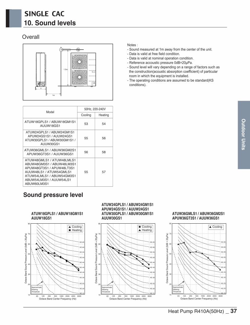
Heat Pump R410A(50Hz) _ 37
10. Sound levels
Outdoor U
nits
SINGLE CAC
1m
1.5m
D
OverallNotes :- Sound measured at 1m away from the center of the unit.- Data is valid at free field condition.- Data is valid at nominal operation condition.
- Sound level will vary depending on a range of factors such as the construction(acoustic absorption coefficient) of particularroom in which the equipment is installed.
- The operating conditions are assumed to be standard(KSconditions).
Model50Hz, 220-240V
Cooling Heating
ATUW18GPLS1 / ABUW18GM1S1AUUW18GS1
53 54
ATUW24GPLS1 / ABUW24GM1S1APUW24GS1S1 / AUUW24GS1
ATUW30GPLS1 / ABUW30GM1S1 /AUUW30GS1
55 56
ATUW36GMLS1 / ABUW36GM2S1APUW36GT3S1 / AUUW36GS1
56 58
ATUW48GMLS1 / ATUW48LMLS1ABUW48GM3S1 / ABUW48LM3S1APUW48GT3S1 / APUW48LT3S1 AUUW48LS1 / ATUW54GMLS1ATUW54LMLS1 / ABUW54GM3S1ABUW54LM3S1 / AUUW54LS1ABUW60LM3S1
55 57
Octave Band Center Frequency (Hz)
Oct
ave
Ban
d S
ound
Pre
ssur
e Le
vel (
0dB
= 2
0μP
a)
10
20
30
40
50
60
70
80
63 125 250 500 1000 2000 4000 8000
NC-15
NC-20
NC-25
NC-30
NC-35
NC-40
NC-45
NC-50
NC-55
NC-60
NC-65
ApproximateHearingThreshold
Octave Band Center Frequency (Hz)
Oct
ave
Ban
d S
ound
Pre
ssur
e Le
vel (
0dB
= 2
0μP
a)
10
20
30
40
50
60
70
80
63 125 250 500 1000 2000 4000 8000
NC-15
NC-20
NC-25
NC-30
NC-35
NC-40
NC-45
NC-50
NC-55
NC-60
NC-65
ApproximateHearingThreshold
Octave Band Center Frequency (Hz)
Oct
ave
Band
Sou
nd P
ress
ure
Leve
l (0d
B =
20μP
a)
10
20
30
40
50
60
70
80
63 125 250 500 1000 2000 4000 8000 NC-15
NC-20
NC-25
NC-30
NC-35
NC-40
NC-45
NC-50
NC-55
NC-60
NC-65
ApproximateHearingThreshold
▲ Coolingn Heating
n Cooling▲ Heating
▲ Cooling
Sound pressure level
ATUW18GPLS1 / ABUW18GM1S1AUUW18GS1
ATUW24GPLS1 / ABUW24GM1S1APUW24GS1S1 / AUUW24GS1ATUW30GPLS1 / ABUW30GM1S1AUUW30GS1
ATUW36GMLS1 / ABUW36GM2S1APUW36GT3S1 / AUUW36GS1

38 _ Heat Pump R410A(50Hz)
10. Sound levels
Out
door
Uni
ts
Octave Band Center Frequency (Hz)
Oct
ave
Band
Sou
nd P
ress
ure
Leve
l (0d
B =
20μP
a)
10
20
30
40
50
60
70
80
63 125 250 500 1000 2000 4000 8000 NC-15
NC-20
NC-25
NC-30
NC-35
NC-40
NC-45
NC-50
NC-55
NC-60
NC-65
ApproximateHearingThreshold
▲ Cooling
ATUW48GMLS1 / ATUW48LMLS1ABUW48GM3S1 / ABUW48LM3S1APUW48GT3S1 / APUW48LT3S1AUUW48LS1 / AUUW54LS1ATUW54GMLS1 / ATUW54LMLS1ABUW54GM3S1 / ABUW54LM3S1ABUW60LM3S1
SINGLE CAC

SINGLE CAC
Installation of Outdoor Units
1. Select the Best Location
2. Installation Space
3. Installation of Outdoor Unit
4. Refrigerant piping system
5. Installation guide at the seaside
6. Seasonal wind and cautions in winter

SINGLE CAC
Heat Pump R410A(50Hz) _ 1
1. Select the Best Location
Installation of O
utdoor Units
Select space for installing outdoor unit, which will meet the following conditions:
• No direct thermal radiation from other heat sources
• No possibility of annoying neighbors by noise from unit
• No exposition to strong wind
• With strength which bears weight of unit
• Note that drain flows out of unit when heating (Heat pump model)
• With space for air passage and service work shown next
• Because of the possibility of fire, do not install unit to the space where generation, inflow, stagnation, and leakage of combustible gas is expected.
• Avoid unit installation in a place where acidic solution and spray (sulfur) are often used.
• Do not use unit under any special environment where oil, steam and sulfuric gas exist.
• It is recommended to fence round the outdoor unit in order to prevent any person or animal from accessing theoutdoor unit.
• If installation site is area of heavy snowfall, then the following directions should be observed.
- Make the foundation as high as possible.
- Fit a snow protection hood.
• Select installation location considering following conditions to avoid bad condition when additionally performingdefrost operation. (Heat pump model)
1. Install the outdoor unit at a place well ventilated and having a lot of sunshine in case of installing the product ata place with a high humidity in winter (near beach, coast, lake, etc).(Ex) Rooftop where sunshine always shines.
2. Performance of heating will be reduced and pre-heat time of the indoor unit may be lengthened in case ofinstalling the outdoor unit in winter at following location:(1) Shade position with a narrow space(2) Location with much moisture in neighboring floor.(3) Location with much humidity around.(4) Location where liquid gathers since the floor is not even.

2 _ Heat Pump R410A(50Hz)
2. Installation Space
Inst
alla
tion
of
Out
door
Uni
tsSINGLE CAC
2.1 Clearance around outdoor units
300 mm or more300 mm or more
Air inlet grille
500
Blownair
Strong wind
Strong wind
300 mmor more
Sunroof
Fence orobstacles 600 mm or more
(Service space)
100 mm100 mmor moreor more300 mmor more• Ensure that the space around the back is
more than 300 mm on the opposite to thePCB side and secure 600 mm space nearthe compressor and PCB side of the airconditioner for service.
h Outdoor unit is representative. Actual appearance of outdoor unitmay be different but clearances will stay the same.
• Install the unit so that its discharge port facesto the wall of the building. Keep a distance500mm or more between the unit and the wallsurface.
• Supposing the wind direction during the oper-ation season of the air conditioner, install theunit so that the discharge port is set at rightangle to the wind direction.
Turn the air outlet side toward the build-ing's wall, fence or windbreak screen.
Set the outlet side at a right angle to the direction of the wind.
h Outdoor unit is representative. Actual appearance of outdoor unit may bedifferent but clearances will stay the same.

Heat Pump R410A(50Hz) _ 3
2. Installation Space
Installation of O
utdoor Units
SINGLE CAC
Clearance of side discharge unit [Unit:mm(inch)]
300(11 13/16) or more
300(11-13/16)or more
300(11 13/16) or more
600(23-19/32) or more
500(19-11/16) or more
500(19-11/16) or more
500(19-11/16) or less
300(11 13/16) or more
500(19-11/16) or less
1000
(39-
3/8)
or m
ore
300(11-13/16) or more
500(19-11/16) or less
300(11 13/16) or more
1000
(39-
3/8)
or m
ore
600(23-19/32) or more
1000
(39-
3/8)
or m
ore
300(11 13/16) or more
500(19-11/16) or more
300(11 13/16) or more
A
500(19-11/16) or less
L
H
1000
(39-
3/8)
or m
ore
1) Where there is an obstacle on the air intake side:
n No obstacle above• Obstacle on the suction side only • Obstacle on the both sides
n Obstacle above, too• Obstacle on the air intake side, too • Obstacle on the air intake side, and both sides
2) Where there is an obstacle on the discharge side:n No obstacle above n Obstacle above, too
3) Where there are obstacles on both suction and discharge sides:n Where the obstacles on the discharge side is higher than the unit:• No obstacle above
• Obstacle above, tooThe relations between H, A and L are as follows:
Close the bottom of the installation frame to preventthe discharged air from being bypassed.
L A[mm(inch)]
0 < L ≤ 1/2H 750(29 1/32)
1/2H < L 1 000(39 3/8)
H < L Set the stand as: L ≤ H
L ≤ H

4 _ Heat Pump R410A(50Hz)
2. Installation Space
Inst
alla
tion
of
Out
door
Uni
tsSINGLE CAC
2.1.1 Air guide workIn case of out door unit is located outdoor cabin of apart-ment or flats, then the efficiency can drop and systempressure increases thus finally damaging the compressoror other components in the system by heat short circuit.
<Without air guide>Safety device activation
<With air guide>Normal operation
[Example]
2.1.2 Lightning safety zone1) To protect outdoor unit from lightning, it should be placed
within lightning safety zone.
Safety zone
2) Power cable and communication cable should be 1.5m away from lightning rod.
3) High resistance grounded system should be performedagainst induced lightning or indirect stroke.
4) If the building has no lightning protection, outdoor may bedamage from lightning. This should be informed to cus-tomer or building owner in advance.
Building Height [m] 20 30 45 60
Protection Angle [˚] 55 45 35 25
Ground
Safe zone
Lightning rod
Protection Angle (25˚~55˚)
1.5m1.5m1.5m
Lightning rod
h Regarding the safetyfrom atmosphereelectricity, follow thelocal or national reg-ulations
300(11 13/16)
or more
500(19-11/16)
or more
L
H10
00(3
9-3/
8) o
r mor
e
1000(39-3/8)
or more
500(19-11/16) or less
300(11 13/16)
or more
n Where the obstacles on the discharge side is lower than the unit:• No obstacle above
• Obstacle above, too‘L’ should be lower than ‘H’.Close the bottom of the installation frame to prevent thedischarged air from being bypassed.
4) Series installationn One row of stand alone installation n Rows of collective installation (2 or more)
L
H
1500(59-1/16)
or more
600(23-19/32)
or more
3000(118 -1/8)
or more
300(11-13/16)
or more
300(11 13/16)
or more
2000(78-3/4)
or more
600(23-19/32)
or more
1000(39-3/8)
or more

Heat Pump R410A(50Hz) _ 5
3. Installation of Outdoor Unit
Installation of O
utdoor Units
SINGLE CAC
3.1 Foundation for Installation• Fix the unit tightly with bolts as shown below so that unit will not fall down due to earthquake or gust.• Use the H-beam support as a base support • Noise and vibration may occur from the floor or wall since vibration is transferred through the installation part
depending on installation status. Thus, use anti-vibration materials (cushion pad) fully (The base pad shall bemore than 200mm).
Unit : mm
20
0
75
75
20
0
100
Ⓐ The corner part must be fixed firmly. Otherwise, thesupport for the installation may be bent.
Ⓑ Get and use M10 Anchor bolt.Ⓒ Put Cushion Pad between the outdoor unit and ground
support for the vibration protection in wide area.Ⓓ Space for pipes and wiring (Pipes and wirings for bot-
tom side)Ⓔ H-beam supportⒻ Concrete supporth Outdoor unit is representative. Actual appearance of
outdoor unit may be different but clearances will stay thesame.
WARNING• Install where it can sufficiently support the weight of the outdoor unit.
If the support strength is not enough, the outdoor unit may drop and hurt people.• Install where the outdoor unit may not fall in strong wind or earthquake.
If there is a fault in the supporting conditions, the outdoor unit may fall and hurt people.• Please take extra cautions on the supporting strength of the ground, water outlet treatment(treat-
ment of the water flowing out of the outdoor unit in operation) of heat pump unit, and the passagesof the pipe and wiring, when making the ground support.
• Do not use tube or pipe for water outlet in the Base pan. Use drainage instead for water outlet. The tube or pipe may freeze and the water may not be drained. (Heat pump model)
WARNING• Be sure to remove the Pallet(Wood Support) of the bottom
side of the outdoor unit Base Pan before fixing the bolt. Itmay cause the unstable state of the outdoor settlement,and may cause freezing of the heat exchanger resulting inabnormal operations.
• Be sure to remove the Pallet(Wood Support) of the bottomside of the outdoor unit before welding. Not removingPallet(Wood Support) causes hazard of fire during welding.
Pallet(Wood Support)- Remove before Installation

6 _ Heat Pump R410A(50Hz)
3. Installation of Outdoor Unit
Inst
alla
tion
of
Out
door
Uni
tsSINGLE CAC
3.2 Settlement of the outdoor unit• Anchor the outdoor unit with a bolt and nut tightly and horizontally on a concrete or rigid mount.•When installing on the wall, roof or rooftop, anchor the mounting base securely with a nail or wire assuming the influence
of wind and earthquake.• In the case when the vibration of the unit is conveyed to the house, secure the unit with an anti-vibration rubber.
Bolt construction work
BoltTubing connection
M10Mechanical anchor bolt
20
Diagram of lower surface
Settlement draw of outdoor units
• The ingredients of foundation : Cement : Sand : Gravel for the concrete should 1 : 2 : 4 ratio• The foundation surface should be finished with mortar.• The edges of foundation should be rounded.• A drain passage should be made around the foundation to thoroughly drain water away from the equipment installation
area. (Heat pump model)• If installing the outdoor units on the roof, the roof's strength have to be checked.• Care should be taken for weather - proofing• Blocking all gaps of outdoor unit, for passing piping and wiring, using sealing material (Field supply)
(Animals and bugs might enter in the machine.)
CAUTION
[Unit : mm]

Heat Pump R410A(50Hz) _ 7
4. Refrigerant piping system
Installation of O
utdoor Units
SINGLE CAC
4.1 Piping System between outdoor unit / indoor unit
Single type
n Refrigerant additional charge calculation method
Additional Refrigerant = (L - A) x aL (m) : Installed Piping Length (Outdoor Unit ~ Indoor Unit)A (m) : Charge-less piping lengtha (g/m) : Additional charging volume
h Refer to the specifications for detail information of A, a.h If total additional charge value after calculation comes out to be negative, then do not consider additional charge.
• Capacity is based on standard length and maximum allowance length is on the basis of reliability.• Improper refrigerant charge may result in abnormal cycle.
CAUTION
• Please check the product type. Piping installation and refrigerant charge varies depending on the type of product. For more information, please refer to the installation manual.
CAUTION
Indoor Unit
Indoor Unit
L
H
L
H
NotesL (m) : Piping Length (Outdoor Unit ~ Indoor Unit) H (m) : Height Difference (Outdoor Unit ~ Indoor Unit)
h Refer to the specifications of Outdoor Unit for Maximum limit.

1. Air conditioners should not be installed in areas where corrosive gases, such as acid or alkaline gas, are produced.2. Do not install the product where it could be exposed to sea wind (salty wind) directly. It can result corrosion
on the product. Corrosion, particularly on the condenser and evaporator fins, could cause product malfunc-tion or inefficient performance.
3. If outdoor unit is installed close to the seaside, it should avoid direct exposure to the sea wind. Otherwise itneeds additional anticorrosion treatment on the heat exchanger.
Periodic ( more than once/year ) cleaning of the dust or salt particles stuck on the heat exchanger by using water
Selecting the location(Outdoor Unit)1) If the outdoor unit is to be installed close to the seaside, direct exposure to the sea wind should be avoided.
Install the outdoor unit on the opposite side of the sea wind direction.
2) In case, to install the outdoor unit on the seaside, set up a windbreak not to be exposed to the sea wind.
3) Select a well-drained place.
• It should be strong enough like concrete to preventthe sea wind from the sea.
• The height and width should be more than 150% ofthe outdoor unit.
• It should be kept more than 70 cm of spacebetween outdoor unit and the windbreak for easyair flow.
Sea wind
Windbreak
CAUTION
Sea wind Sea wind
• Sufficient measures are required in a snow area or severe cold area in winter so that product can be operated well.• Get ready for seasonal wind or snow in winter even in other areas.• Install a suction and discharge duct not to let in snow or rain.• Install the outdoor unit not to come in contact with snow directly. If snow piles up and freezes on the air suction hole,
the system may malfunction. If it is installed at snowy area, attach the hood to the system.• Install the outdoor unit at the higher installation console by 50cm than the average snowfall (annual average snowfall) if it is installed at
the area with much snowfall.• Where snow accumulated on the upper part of the Outdoor Unit by more than 10cm, always remove snow for operation.
1. The height of H frame must be more than 2 times the snowfall and its width shall not exceed the width of the product. (If width of the frame is wider than that of the product, snow may accumulate)
2. Don't install the suction hole and discharge hole of the Outdoor Unit facing the seasonal wind.
6. Seasonal wind and cautions in winter
8 _ Heat Pump R410A(50Hz)
5. Installation guide at the seaside
Inst
alla
tion
of
Out
door
Uni
tsSINGLE CAC

Copyright © 2017-2018 LG Electronics Inc. All Rights Reserved.Printed in Korea October / 2018
P/No.: MFL68221125
Air SolutionLG Electronics Inc, 128, Yeoui-daero,Yeongdeungpo-gu, Seoul, Korea(07336)http://partner.lge.com
The air conditioners manufactured by LG have received ISO9001 certificate for quality assurance and ISO14001 certificate for environmental management system.The specifications, designs, and information in this brochure are subject to change without notice.