POWER INVERTER - Photonic Universe
11
P series CAR series Modified Sine Wave Inverter Pure Sine Wave Inverter User Manual POWER INVERTER ISO9001: 2008
-
Upload
khangminh22 -
Category
Documents
-
view
0 -
download
0
Transcript of POWER INVERTER - Photonic Universe

P series
CAR series Modified Sine Wave Inverter
Pure Sine Wave Inverter
User Manual
POWER INVERTER
ISO9001: 2008

POWER INVERTER 01▲ ▲
1. IntroductionThank you for purchasing our CAR and P series power inverter.
Our power inverters are compact and high efficient inverters, and are leaders in the field of high frequency inverters.
Our power inverter converts low voltage, direct current (DC) to 110V/220 volt modified sine wave (MSW)or pure sine wave(PSW) alternating current( AC).
By connecting the power inverter directly to the 12/24/48V battery, you can turn your vehicle into a mobile office, or have power to run entertainment electronics.
Read this guide before installing and using the power inverter, and please reserve it for future reference.
2. Important Safety Instructions
Important:
This chapter contains important safety and installation instructions for our CAR and P series power inverters. Each time, before using the power inverter, read all instructions and cautionary marking on or provided with inverter and all appropriate sections of this guide.
Read and save this owner's guide for future reference.
CONTENT
1
1 - 2
3
3 - 4
4
4 - 7
7 - 8
8 - 11
14
14-15
16 -17
18
18
18 -19
11-13
13-14
Do not expose the inverter to rain, snow, spray, or bilge water. This inverter is designed for indoor use only.
Do not operate the inverter if it has received a sharp blow, been dropped, has cracks.
Do not disassemble the inverter. Internal capacitors remain charged after all power is disconnected.
Disconnect both AC and DC power from the inverter before attempting any maintenance or cleaning or working on any circuits connected to the inverter. See note below.
Do not operate the inverter with damaged or substandard wiring.
Make sure that all wiring is in good condition and is not undersized.
◆
! DANGER ELECTRICAL SHOCK HAZARD
◆
◆
◆
◆
◆
Failure to follow these instructions will result in death or serious injury.
Note: Turning off the inverter using the ON/OFF switch on the front panel will not reduce an electrical shock hazard.
1.Introduction
2.Important Safety Instructions
3.Protection Features
4.Location
5.Principle of Operation
6. Inverter Components and Diagrams
7. Inverter Output Waveform
8.Choose the Battery
9.Connections and Installation
10.Operating the AC Applicances
11.Fuse Replacement
12.Troubleshooting
13. Specification
14. Maintaining the inverter
15. Dispose Instruction
16. Warranty
Important Safety Instructions

POWER INVERTER 03▲ ▲POWER INVERTER 02▲ ▲
3. Protection Features
Our power inverters are equipped with numerous protection features to guarantee safe and trouble-free operation:
Note:
1. Follow these instructions and those published by the battery manufacturer and the manufacturer of any equipment you intend to use in the vicinity of the battery. Review cautionary markings on these products and on the engine.
2. The inverter contains components which tend to produce arcs or sparks.
3. Do not install and / or operate the inverter in compartments containing flammable materials or in locations that require ignition-protected equipment. Prohibited locations for the installation and use of the inverter include, but are not limited to, space containing petrol-powered machinery, fuel tanks, as well as joints, fittings or other connections between the components of the fuel system.
Alerts you if the battery has become discharged to 10.5V or lower.
Shuts the inverter down automatically if the battery voltage drops below 9.5 volts. This feature protects
the battery from being completely discharged.
Shuts the inverter down automatically if the input voltage rises to 15.5 volts or more.
Shuts the inverter down automatically if the loads connected to the inverter exceed the inverter's operating limits.
Shuts the inverter down automatically if its internal temperature rises above an unacceptable level.
Shuts the inverter down automatically if a short circuit is detected in the circuitry connected to the inverter's output.
Note:restarted after lower voltage protection, the voltage of DC input factory setting: modified sine wave inverter is 11.8V; pure sine wave inverter is 12.6V
All protection is automatically recovered. To protect the battery, if the unit needs to be
4. Location
The power inverter must only be installed in a location that is:
Dry The inverter must be installed in a dry location not subject to moisture especially rain, spray, or splashing bilge water.
Cool The inverter should not be exposed to metal fillings or any other form of contamination.
Ventilated The ambient air temperature should be between 0-40℃ (32-104℉) for best performance.
Safe Ventilation openings on the inverter must not be obstructed. If the inverter is mounted in a tight fitting compartment, the compartment must be ventilated with cut-outs to prevent the inverter from overheating.
Do not cover or obstruct the air intake vent openings and /or install in a zero-clearance compartment.
◆
! DANGER FIRE AND BURN HAZARD
Failure to follow these instructions will result in death or serious injury.
Charge only properly rated (such as 12V) lead-acid (GEL, AGM, Flooded, or lead-calcium) rechargeable batteries because other battery types may explode and burst.
Do not work in the vicinity of lead-acid batteries. Batteries generate explosive gases during normal operation.
Do not install and /or operate in compartments containing flammable materials or in locations that require ignition-protected equipment.
◆
! DANGER EXPLOSION HAZARD
◆
◆
Failure to follow these instructions will result in death or serious injury.
Never allow the inverter to come in to contact with any chemicals or substances such as battery acid.
Never place the inverter unit directly above batteries, gases from a battery will corrode and damage the inverter.
Do not place a battery on top of the inverter.
The inverter will not operate high wattage appliances over the output power limit or surge power limit.
This is not a toy-keep away from children.
◆
CAUTIONRISK OF DAMAGE TO THE INVERTER
◆
◆
Failure to follow these instructions can damage the unit and/or damage other equipment.
◆
◆
Low battery alarm
Low battery voltage shutdown
High battery voltage shutdown
Over load shutdown
Over thermal shutdown
Output short circuit shutdown
Reverse polarity protection
Earth Fault Protection
If polarity connection is incorrect, the internal fuse will blow.
The inverter complies with the standard current leakage allowance. When large current leakage to earth terminal occurs. The protection
circuit will be activated and shut down the inverter, to prevent electric shock. The only way to restart the inverter is to turn it off, unplug the faulty AC appliances and then turn the inverter ON.

5. Principle of Operation
There are two working stages in the power inverter:
The first stage: A DC to DC conversion process that raises the lower voltage DC at the inverter input to 300volts DC.
The second stages: An inversion stage that converts the high voltage DC into 110volts or 230volts AC (rms). DC to DC conversion stage uses modern high frequency power conversion techniques that have replaced the bulky transformers found in less technologically advanced models. The inverter stage uses advanced power MOSFET transistors in a full bridge configuration.
6. Inverter Components and Diagrams
The package includes a power inverter unit, user manual, DC cables and spare fuse(s).
Figure 1 (6.1, 6.2, 6.3, 6.4, 6.5, 6.6)
6.1 Modified sine wave inverter 800W
Close to battery The inverter is not ignition-protected equipment, so it cannot be installed in areas containing gasoline tanks or fittings which require ignition –protected equipment. We recommend that it is safest not to install any kind of electrical equipment including the inverter in these areas.
Protected form battery gases The inverter should be installed as close as possible to the batteries, but not in the same compartment to prevent corrosion. Avoid excessive cable lengths and use the recommended wire sizes. We recommend that installing with battery cables sized to achieve less that 3% voltage drop on battery cables under full load. This will maximize the performance of the inverter.
POWER INVERTER 05▲ ▲POWER INVERTER 04▲ ▲
6.3 Modified sine wave inverter 2000W~5000W
DC Cable with ring
Fuse
1 3 4 5
2
8
76
9
10
12
6.4 Pure sine wave inverter 300W~600W
OFF
NO
AC
OU
TPU
T: A
C22
0-24
0V~
50H
z FAULT POWER
1 5 2
3 4
6 7 89
DC Cable with clip
Fuse
11
12
OFF
NO
FAULT POWER
AC
OU
TPU
T: A
C22
0-24
0V~
50H
z
1 2
3 4
5 8
6 7
9 Fuse
DC Cable with ring
10
12
◆ Materials List
6.2 Modified sine wave inverter 1000W~1600W
Fuse
DC Cables with ring
7 6
9 8
10
OFF
NO
FAULT POWER
AC OUTPUT: AC220-240V~ 50Hz
3 4
5 2 1
12
6.5 Pure sine wave inverter 1000W
DC Cable with ring
Fuse
OFF
NO
FAULT POWER
AC OUTPUT: AC220V-AC240V~ 50Hz
1 2
3 4
INPUT: 24V
7
6
89
10
12
◆
◆

7. Inverter Output Waveform
The AC output waveform of the CAR series inverter is known as “modified sine wave”, P series inverter output waveform is “pure sine wave”.
always connect to the positive terminal of the battery via a positive DC input cable (red battery cable). The positive DC input terminal is coloured red.
Do not reverse the polarity of battery connection. The wrong connection will result in a blown fuse(s) inside the unit and may cause a permanent damage to the inverter.
Chassis ground screw: Earthing of the inverter.
High- speed cooling fan must not be obstructed for the proper operation of the inverter. When the inverter is mounted, the ventilation opening on the DC panel must not point up or down.
DC cable with ring: Connect the ring on one end of the red cable to the red terminal on the inverter, and connect the ring on the other end to the battery. Do the same with the black cable.
DC cable with clip: Can also be used to connect the battery and inverter. Connect the clip on one end of the cable to the battery, and the ring on the opposite end of the cable to the inverter.
Warning Symptoms of low battery power can result from cables that are either excessively long or an insufficient gauge. Substantial power loss and reduced battery operating time results from inverters installed with cables that are not able to supply full power.
Notes: The installer/operator should be especially aware of the requirements to maintain secure, tight, water-resistant electrical connections and to provide for strain relief for DC cables and appliance wiring. Cable insulation must be the appropriate type for the environment.
There is an internal fuse(s) inside the inverter, and spare fuse(s) inside the packaging.
Note: For added polarity protection, the fuse(s) will blow when an incorrect connection is made. Once replaced with correct polarity, the inverter will start working again. If the inverter does not work after replacing the fuse, please contact an engineer as the inverter may be damaged.
Positive DC input terminal
Warning:
:
◆
Please see the pictures as follows, the AC outlet socket types may vary.
ON/OFF Switch turns the inverter's control circuit on and off. This switch is not a power disconnect switch.
Fault light (red) indicates that the inverter has shutdown due to inverter overload, over temperature, short circuit, leakage or a fault.
Power light (green) indicates the inverter is operating.
The USB port has a 5V 2.1A output. Connect the external USB-compatible appliance to the USB port to charge it or provide power to it (such as a mobile phone, tablet, camera, light, fan, radio etc).
The USB output is permanently on when the power inverter is connected to a 12V input voltage.
◆ Do not connect memory sticks, MP3 player or similar data storage external appliances.
◆ Do not connect any data transfer cables to the USB port!
Negative DC input terminal always connect to the negative terminal of the battery via a negative DC input cable (black battery cable). The negative DC input terminal is coloured black.
Indication:
AC outlets are used to power loads
Warning: The USB port on the power inverter is not designed for transferring data. !
Figure 3
-360 -270 -180 -90 0 90 180 270 360
MODIFIEDSINE WAVE
PURE SINE WAVE
Phase(degrees)
POWER INVERTER 07▲ ▲POWER INVERTER 06▲ ▲
6.6 Pure sine wave inverter 1500W~4000W
DC Cables with ring
Fuse
1 53 48
2 6
7 9
10
12
④
⑤
⑥
⑦
⑧
⑨
⑩
③
②
①
Modified sine wave and pure sine wave comparison
!
!

8. Choose the Battery
Battery type and battery size strongly affect the performance of the power inverter. Therefore, you need to identify the type of loads your inverter will be powering and how much you will be using them between charges. To determine the minimum battery size that you need to operate appliances, please follow these steps:
1. Determine the wattage of each appliance and/or tool you will need to simultaneously operate from the inverter. To do this, read the labels on the equipment to be operated. Usually, power consumption is shown in watts. If it is shown in amps, multiply by 110V/230V to determine the
◆ Battery Requirements
When possible, recharge your batteries when they are approximately 50% discharged, or sooner. This gives the batteries a much longer life cycle than recharging when they are more deeply discharged.
POWER INVERTER 09▲ ▲POWER INVERTER 08▲ ▲
INTERFERENCE WITH SOME EQUIPMENT◆ Buzz in Audio Equipment
Some inexpensive stereo systems may emit a buzzing noise from their loudspeakers when operated from the inverter. This occurs because the power supply in the audio System does not adequately filter the modified sine wave produced by the inverter.
The only solution is to use a sound system that has a high quality power supply.
◆ Television Reception
When the inverter is operating, it can interfere with television reception on some channels.
If interference occurs, try the following:
1. Make sure that the chassis ground screw on the rear of the inverter is solidly connected to the ground system of your vehicle or home.
2. Make sure that the television antenna provides an adequate (“snow-free”) signal and that you are using good quality cable between the antenna and the television.
3. Keep the cables between the battery and the inverter as short as possible, and twist them together with two to three twists per foot.( this minimizes radiated interference from the cables.)
4. Move the television as far away from the inverter as possible.
5. Do not operate high power loads with the inverter which the television is on.
The modified sine wave has an RMS (Root mean square) voltage of 110/230volts, which is the same as standard household power. Most AC voltmeters (both digital and analog) are sensitive to the average value of the waveform rather than the RMS value. They are calibrated for RMS voltage under the assumption that the waveform measured will be a pure sine wave. These meters will not read the RMS voltage of a modified sine wave correctly. They will read about 20 to 30 volts low when measuring the output of the inverter. For accurate measurement of the output voltage of this unit, use a true RMS reading voltmeter such as Fluke 87III, Fluke 8060A, Fluke 77/99 series or Beckman 4410.
wattage.
2. Estimate the number of hours the equipment will be in use between battery recharges.
3. Determine the total watt-hours of energy by multiplying the wattage of your appliance by the time it will be working (in hours). For example, 60W laptop working for 5 hours will require 60W*5h = 300Wh (watt-hours) of energy. 250W TV working for 30 min will require 250W*0.5h = 125Wh.
4. Calculate the approximate amp-hours (Ah) which the battery bank will have to supply to your appliance to enable it to work for a certain amount of watt-hours, by dividing watt-hours by 10 (for 12V battery bank), or 20 (for 24V battery bank) or 40 (48V battery bank). E.g. 300Wh for laptop from a 12V inverter will require 300Wh / 10 = 30Ah of battery energy.
5. Add all the amp-hours (Ah) for each appliance to get the total battery capacity required for your system.
Note: Some appliances required high surge power to start, then consume less power. And some appliances are not operating for long periods of time. For example, a typical home-use coffee maker draws 500watts during its brew time of 5minutes, but it maintains the temperature of the pot at about 100watts. Typical use of a microwave is only a few minutes, sometimes at lower power. Some exceptions to brief operating times are lamps, TVs and computers.
Important: The power inverter must be connected only to batteries with a normal output voltage of 12 volts when you use a 12V inverter. The unit will not operate from a 6 volt battery, and will sustain permanent damage if connected to a 24 volt battery.
Caution: Loose connectors may cause overheated wires and melted insulation. Check to make sure you have not reversed the polarity. Reverse polarity connection will result in a blown fuse and may cause permanent damage to the inverter.
◆ Recharging Batteries
The battery's back up depends on the battery capacity (Ah) and your appliances power (Watt)The method to calculate the backup time:Battery capacity (Ah) * Input voltage (Volt)/Loads power (Watt)For example: Battery capacity = 150Ah Input voltage = 12Volt Loading power = 600WattSo: (150Ah*12V)/600Watt=3 Hours
Note: this calculation of back-up time produces a theoretical value, and doesn't take into account the self-consumption of the inverter. The actual back-up time may be significantly shorter than this value, particularly for larger loads, old and partially discharged batteries.
◆ The Calculation of the Battery’s Back Up Time
POWER INVERTER 11▲ ▲POWER INVERTER 10▲ ▲
- + -
Our inverter has a battery low voltage shutdown around 10Vdc. With moderate to heavy loads, this will protect against over-discharging the battery. If the inverter is running only light loads it is advisable to recharge before the inverter low voltage shutdown point is reached.
For more information on maintaining batteries, consult your battery’s manufacturer.
For information about our battery chargers, please contact us.
+
Over-current protection
6 volts (200 AHrs)
To 12 VDC Inverter
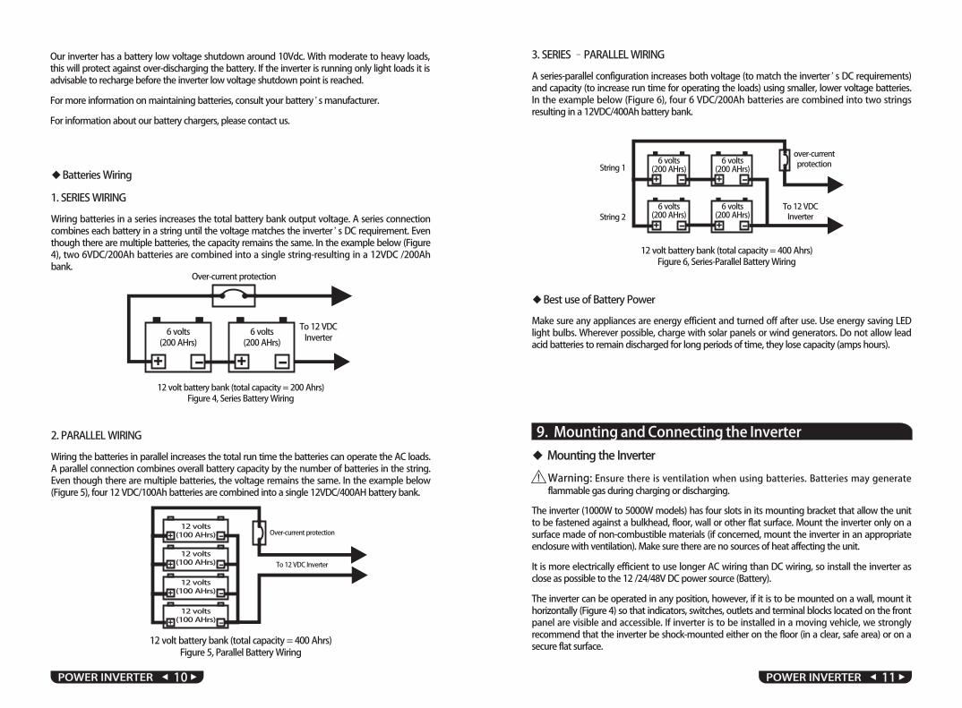
12 volt battery bank (total capacity = 200 Ahrs)Figure 4, Series Battery Wiring
6 volts (200 AHrs)
+ - Over-current protection
To 12 VDC Inverter
12 volts (100 AHrs)
+ -
+ -
+ -
12 volts (100 AHrs)
12 volts (100 AHrs)
12 volts (100 AHrs)
12 volt battery bank (total capacity = 400 Ahrs)Figure 5, Parallel Battery Wiring
A series-parallel configuration increases both voltage (to match the inverter’s DC requirements) and capacity (to increase run time for operating the loads) using smaller, lower voltage batteries. In the example below (Figure 6), four 6 VDC/200Ah batteries are combined into two strings resulting in a 12VDC/400Ah battery bank.
3. SERIES –PARALLEL WIRING
12 volt battery bank (total capacity = 400 Ahrs)Figure 6, Series-Parallel Battery Wiring
- + -+
6 volts (200 AHrs)
- + -+
6 volts (200 AHrs)
6 volts (200 AHrs)
6 volts (200 AHrs)
To 12 VDC Inverter
String 1
String 2
over-current protection
Warning: flammable gas during charging or discharging.
Ensure there is ventilation when using batteries. Batteries may generate
The inverter (1000W to 5000W models) has four slots in its mounting bracket that allow the unit to be fastened against a bulkhead, floor, wall or other flat surface. Mount the inverter only on a surface made of non-combustible materials (if concerned, mount the inverter in an appropriate enclosure with ventilation). Make sure there are no sources of heat affecting the unit.
It is more electrically efficient to use longer AC wiring than DC wiring, so install the inverter as close as possible to the 12 /24/48V DC power source (Battery).
The inverter can be operated in any position, however, if it is to be mounted on a wall, mount it horizontally (Figure 4) so that indicators, switches, outlets and terminal blocks located on the front panel are visible and accessible. If inverter is to be installed in a moving vehicle, we strongly recommend that the inverter be shock-mounted either on the floor (in a clear, safe area) or on a secure flat surface.
◆ Mounting the Inverter
!
2. PARALLEL WIRING
Wiring the batteries in parallel increases the total run time the batteries can operate the AC loads. A parallel connection combines overall battery capacity by the number of batteries in the string. Even though there are multiple batteries, the voltage remains the same. In the example below (Figure 5), four 12 VDC/100Ah batteries are combined into a single 12VDC/400AH battery bank.
◆ Batteries Wiring
1. SERIES WIRING
Wiring batteries in a series increases the total battery bank output voltage. A series connection combines each battery in a string until the voltage matches the inverter’s DC requirement. Even though there are multiple batteries, the capacity remains the same. In the example below (Figure 4), two 6VDC/200Ah batteries are combined into a single string-resulting in a 12VDC /200Ah bank.
◆ Best use of Battery Power
Make sure any appliances are energy efficient and turned off after use. Use energy saving LED light bulbs. Wherever possible, charge with solar panels or wind generators. Do not allow lead acid batteries to remain discharged for long periods of time, they lose capacity (amps hours).
9. Mounting and Connecting the Inverter
POWER INVERTER 13▲ ▲POWER INVERTER 12▲ ▲
. For safety purposes, you can connect a DC-rated fuse or DC-rated circuit breakers on the positive cable line in your power system, following recommendations below.
Select a fuse or circuit breaker with a proper rating (e.g. 100A DC for 1000W 12V inverter, 150A DC for 1500W 12V inverter etc.). You can roughly estimate the maximum current that the inverter will be taking at full power by dividing the nominal power rating of the inverter by the battery voltage. E.g. 2000W 12V inverter will have the maximum continuous current 2000W / 12V = 167A that can theoretically be drawn by the inverter from the battery. In reality it might be a bit higher current at full power due to energy losses and inverter self-consumption. So the current rating of the fuse or circuit breaker should be taken marginally higher than the result of this formula.
Note:
◆ Connection and Installation Steps:
1. Check to be sure the inverter’s power switch is turned off and that no flammable fumes are present.
2. Identify the positive (+) and negative (-) battery terminals.
3. Install a fuse holder or breaker close to the positive (+) terminal of the battery.
4. Connect a length of wire on one side of the fuse holder or circuit breaker. Connect the other
end of the wire to the positive (+) terminal of the inverter.
5. Connect a length of wire between the inverter’s negative (-) terminal and the battery’s negative (-) terminal.
6. Connect a short length of wire to the other terminal of the fuse holder or circuit breaker. Mark it “positive” or “+”.
7. Connect the free end of the fuse or breaker wire to the positive terminal of the battery.
8. Insert a suitable fuse in the fuse holder.
9. Check to be sure that all connections between battery clips, terminals and fuses are secure and tight.
Note: Sparking is normal for the first connection.
Make sure you have good secure connections- Do not over-tighten.
1.When you have confirmed that the AC appliances to be operated are turned off, plug an appliance cord into the AC outlet on the front panel of the inverter.
2.Turn ON the inverter.
3.Turn the appliance on.
4.Plug in additional appliances and turn them on.
Note: 1.Plug the cord from the AC appliances you wish to operate into the AC receptacle. When the inverter turns ON, the red and green LEDs will both light up for 3-5seconds. The red LED will then turn off, and the green LED will remain on, to indicate that the inverter is functioning. Make sure the combined load requirement of your equipment does not exceed inverter's output rating.
2.Turn OFF the inverter. The over load LED may briefly“ blink ” and the audible alarm may also sound a short“ chirp. ”This is normal. This same alarm may also sound when the inverter is being connected to or disconnected from.
3.When using an extension cord from the inverter to an appliance the extension cord should not be longer than 50 feet.
4.When connecting further appliances, please ensure that the highest power appliance is plugged in and switched on first, followed by any smaller appliances.
Caution: The inverter is engineered to be connected directly to standard electrical and electronic equipment. Do not connect the power inverter to household or RV AC distribution wiring. Do not connect the power inverter to any AC load circuit in which the neutral conductor is connected to ground (earth) or to the negative of the battery source.
Warning: Do not connect to AC distribution wiring.
10. Operating the AC Appliances
!
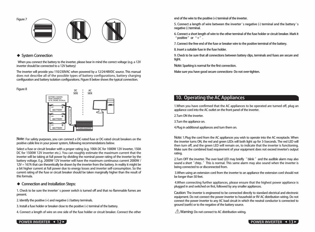
When you connect the battery to the inverter, please bear in mind the correct voltage (e.g. a 12V inverter should be connected to a 12V battery)
The inverter will provide you 110/230VAC when powered by a 12/24/48VDC source. This manual does not describe all of the possible types of battery configurations, battery charging configuration and battery isolation configurations. Figure 8 below shows the typical connection.
Figure 8 DCSIDE
ACSIDE
BATTERY
BATTERIES CHARGINGFROM COMMERCIALAC-DC, ENGINE, SOLAR,etc...
Fuse
or C
ircui
t bre
aker
BATTERY
BATTERY POWER INVERTER
◆ System Connection
Figure 7

◆ Operating TipsRated versus actual current draw of equipment
Most electrical tools, appliances and audio/video equipment have labels that indicate the power consumption in amps or watts.
Be sure that the power consumption of the item you wish to operate is less than inverter’s rating power. ( If the power consumption is rated in amps, simply multiply by the AC volts (110V or 230V) to determine the wattage). The inverter will shutdown if it is overloaded. The overload must be removed before the inverter will restart.
Resistive loads are the easiest for the inverter to run. However, larger resistive loads, such as electric stoves or heaters, usually require more wattage than the inverter can deliver. Inductive loads, such as TV’s and stereos, require more current to operate than do resistive loads of the same wattage rating. Induction motors, as well as some televisions, may require 2 to 6 times their wattage rating to start up. The most demanding in this category are those that start under load, such as compressors and pumps. To restart the unit after a shutdown due to overloading, remove the overload if necessary, then turn the power switch OFF and then ON.
11. Fuse Replacement
The inverter is protected by an integral electronic unit and will automatically reset. In addition, this inverter is equipped with a fuse(s), located inside the inverter. If reverse polarity connection is detected, the fuse(s) will blow. A qualified person can open the unit to replace the fuse(s), making sure the inverter is fully disconnected and briefly switched on and off to discharge internal capacitors. There are spare fuses inside the inverter packaging. Please ensure that the same size fuse(s) are used as a replacement.
Caution: High voltage and high temperature inside!
Possible Cause Suggested Solution
Non-continuous AC output; red LED lit on & off, green LED lit
Inverter output power limited by overload/short circuit protection circuit
Reduce load or remove short circuit
Possible Cause Suggested Solution
Reduce load or remove short circuit
Possible Cause Suggested Solution
No AC output (latch up); red & green LED lit
Earth fault protection is activated by excessive current leakage from the load Unplug the faulted load.
12. Trouble Shooting
Possible Cause DC input below 10volts(battery low voltage)
Inverter overheat thermal shutdown
Suggested Solution
Recharge or replace battery.
Remove or reduce load, wait for inverter to cool.
No AC output; red LED lit, green LED not lit
Possible Cause Suggested Solution
No AC output; red & green LED not lit
Inverter fuses openOpen the inverter case, change the fuse.
Or contact technical support.
Possible Cause Suggested Solution
Recharge or replace battery.
Remove or reduce load, wait for inverter to cool.
The battery backup time shorter than expect
The inverter chosen is too small
Battery poor quality or damaged
Battery empty or lower voltageRecharge for the battery, or use good quality charger to
charge the battery.
Possible Cause Suggested Solution
No AC output; red LED lit, green LED not lit
Current dissipation in DC cables is too high Use heavy cables and shorten the cables.
Possible Cause Suggested Solution
Low battery alarm sounds abnormal
Bad connection or wiring Tighten all DC connections.
Possible Cause Suggested Solution
Low battery alarm sounds
Low battery voltage Recharge or replace battery.
Possible Cause Suggested Solution
Low battery alarm sounds
Low battery voltage If appliance does not start, then appliance is drawing
excessive wattage and will not work with inverter
Possible Cause Suggested Solution
Low battery alarm sounds
Appliance too close to inverterKeep inverter and antenna distant from each other.
Use shielded antenna cable. Connect antenna with amplifier.
POWER INVERTER 15▲ ▲POWER INVERTER 14▲ ▲
The voltmeter used is not a true RMS meterChange to use a true “RMS” voltmeter when you
measure the AC voltage output from “modified sine wave inverter”.

1.5
8.2
8.6
Not
e: T
he sp
ecifi
catio
ns a
re su
bjec
t to
chan
ge w
ithou
t prio
r not
ice.
Spec
ifica
tions
for P
Ser
ies I
nver
ter:
P300
300W
600W
P400
400W
800W
53.8
*23*
10.8
48.8
*23*
10.8
37.2
*23*
10.8
31.6
*15*
9.75
(CM
)26
*15*
7.77
21.5
*15*
5.8
1.4
2.0
34.
74.
97.
79.
0
POWER INVERTER 17▲ ▲POWER INVERTER 16▲ ▲
13. Specification

14. Maintaining the Inverter
Minimal maintenance is required to keep your inverter operating properly, periodically you should:
Clean the exterior of the unit with a dry cloth to prevent the accumulation of dust and dirt (make sure the unit is unplugged and fully disconnected when doing this).
Ensure that DC cables are secure and fasteners are tight.
Make sure the ventilation openings on the DC panel and bottom of the inverter are not clogged.
◆
◆
◆
15. Disposal Instructions
Home electronic equipment:applicable collection point or deliver it to a public recycling location for old electronic equipment. Electronic equipment shall under no circumstances be disposed of in the same manner as normal household waste (see the crossed-out garbage can symbol below).
Further disposal instructions:recycling and disposal. Remove all batteries from the appliance in advance and prevent any liquid containers from being damaged. Electronic equipment may contain harmful substances. Improper use or malfunction caused by damage may adversely affect human health and harm the environment during recycling.
Hand over the appliance in a condition that will allow for safe
If you no longer wish to use this appliance, please take it to the
16. Warranty
This inverter is covered by a one year warranty. During this period, any breakdown under normal usage guidelines or owing to the quality of the product will be eligible for a free repair or replacement (at the discretion of the manufacturer or distributor). When claiming a service under warranty, the customer will be required to present details of their order to verity the purchase and establish the order date (such details could include the order number, full name, address, postcode etc). The customer might also be asked to fill in a warranty support form to provide further details about the problem.
Many problems can be resolved over the phone, email and remotely so the service engineers will always attempt to do this first. If the problem remains, the customer will be asked to send the inverter (at their cost) to a service centre address for further testing, and a repair or replacement if required. The repaired or replaced unit will be delivered to the customer free of charge within the
POWER INVERTER 19▲ ▲POWER INVERTER 18▲ ▲
country of the service centre.
The following damages and conditions are excluded from the warranty:
1) Wrong battery polarity connection
2) Connection of the AC inverter output to another power source (generator, mains power, another inverter etc) or AC distribution wiring in a vehicle, boat or a house.
3) Damage occurred during shipment
4) Contact with water, chemicals or any other reactive materials
5) Incorrect usage, abuse, negligence or conditions that do not follow the guidance provided in this manual
6) Unauthorised opening, modifications or attempted repair of the inverter
7) Breakdown or damage caused by mechanical impact or excessive vibration
8) Lightning, natural disasters and force majeure