EN500/EN600 series inverter
278
-
Upload
khangminh22 -
Category
Documents
-
view
0 -
download
0
Transcript of EN500/EN600 series inverter


Print version: V5.0-A3
Foreword Thank you for purchasing EN500/EN600 series inverter developed and produced by Shenzhen
Encom Electric Technologies CO., LTD.
EN500/EN600 series general vector inverter adopt advanced control mode to achieve high torque,
high precision and wide-range speed regulation drive, and it also support speed sensorless torque
control and PG control torque. It can meet customer all kinds of requirement to universal inverter.
EN500/EN600 inverter is a organic combination for customer’s universal and industrial control
purpose and provide practical main-auxiliary frequency provision, run channel frequency binding,
PID regulator, simple PLC, spinning traverse, programmable input&output terminal control, pulse
frequency provision and inbuilt Modbus, Can bus, Profibus, 485 freedom protocol and other
function and platform. It provide high integration solution for most manufacturing and automation
customer and EN500/EN600 inbuilt input phase loss function, output phase loss function, short
circuit to earth grounding function and many other protective function to improve effectively the
system reliability and safety.
This brochure provide the installation and wiring, settings, fault check and methods, maintenance
and other relative issues to customer. To make inverter assemble and operate rightly, and use its
high performance to best, please read this brochure carefully before installation usage and keep
them well to the final users of inverter.
Please contact our office or dealer anywhere at any moment when you have any doubts or special
demands in using these inverters, and you can also contact our after service center in our
Headquarters directly. We will serve you with all our heart.
We reserve our right to notice you if we change contents of this manual.
ENC

Content
1 Safety information and use notice points ...................................................................................... 1 1.1 Safety precautions .................................................................................................................... 1 1.2 Application range ..................................................................................................................... 3 1.3 Use notice points ...................................................................................................................... 3 1.4 Scraping handling notice ......................................................................................................... 4
2 Inverter type and specification ...................................................................................................... 5 2.1 Incoming inverter inspect ........................................................................................................ 5 2.2 Type explanation...................................................................................................................... 5 2.3 Nameplate explanation ............................................................................................................ 5 2.4 Inverter type explanation ......................................................................................................... 6 2.5 Appearance and parts name explanation ................................................................................. 8 2.6 Outer size ................................................................................................................................. 9 2.7 EN500/600 optional base ....................................................................................................... 12 2.8 Outer size of keypad and its fixing box ................................................................................. 14 2.9 Product technic index and spec ............................................................................................. 15
3 Installation and wiring ................................................................................................................. 18 3.1 Installation ambient ............................................................................................................... 18
3.1.1 The demands for installation ambient .......................................................................... 18 3.1.2 Installation direction and space .................................................................................... 18
3.2 Parts disassembly and installation ......................................................................................... 19
3.2.1 Keyboard disassembly and installation ........................................................................ 19 3.2.2 Cover disassembly and installation .............................................................................. 19
3.3 Wiring notice points .............................................................................................................. 20 3.4 Main loop terminal wiring ..................................................................................................... 21
3.4.1 Connection between inverter and fitting parts ............................................................. 23 3.4.2 Main loop terminal wiring ............................................................................................ 24
3.5 Basic running wiring diagram ............................................................................................... 27 3.6 Control loop collocation and wiring ...................................................................................... 27
3.6.1 Relative location and function for control board terminal and slide switch ................ 27 3.6.2 Descriptions for control board terminal ....................................................................... 29 3.6.3 Analog input&output terminal wiring .......................................................................... 31 3.6.4 Digital input terminal wiring ........................................................................................ 33 3.6.5 Communication terminal wiring .................................................................................. 34
4 EMC(Electromagnetic compatibility)explanation ................................................................. 36 4.1 Noise interference restraining ................................................................................................ 36
4.1.1 Interference noise type ................................................................................................. 36 4.1.2 Basic countermeasure for restrain interference ............................................................ 37
4.2 Field wiring and earth grounding .......................................................................................... 38 4.3 Leak current and countermeasure .......................................................................................... 38 4.4 Installation demand for electromagnetic on-off electronic device ........................................ 39 4.5 Noise filter installation instructions ....................................................................................... 39
5 Run and operation explanation for inverter ................................................................................. 40 5.1 Run of inverter ....................................................................................................................... 40
5.1.1 Running order channels ................................................................................................ 40
ENC

5.1.2 Frequency-provision channel ....................................................................................... 40 5.1.3 Work state ..................................................................................................................... 41 5.1.4 Run mode ...................................................................................................................... 41
5.2 Operation and use of key board ............................................................................................. 43
5.2.1 Keypad layout ............................................................................................................... 43 5.2.2 Keypad function description ........................................................................................ 43 5.2.3 LED and indicator light ................................................................................................ 44 5.2.4 Key board display status ............................................................................................... 45 5.2.5 User Management Parameters ...................................................................................... 46 5.2.6 Method for operating keypad ....................................................................................... 47
5.3 Inverter electrification ........................................................................................................... 49
5.3.1 Check before electrification ......................................................................................... 49 5.3.2 First electrification ........................................................................................................ 49
6 Function parameter schedule graph ............................................................................................. 51 6.1 Symbol description ................................................................................................................ 51 6.2 Function parameter schedule graph ....................................................................................... 51
7 Detailed function specification .................................................................................................... 94 7.1 System Parameter Group: F00 ............................................................................................... 94 7.2 Basic Run Function Parameter Group:F01 ......................................................................... 101 7.3 Start, stop, forward/reverse, brake function parameter group: F02 .................................... 108 7.4 V/F control parameter group: F03 ....................................................................................... 113 7.5 Auxiliary running parameter group: F04 ............................................................................. 115 7.6 Communication control parameter group: F05 ................................................................... 120 7.7 Setting curve parameter group: F06 .................................................................................... 124 7.8 Analog quantity, Pulse input function parameter group: F07 ............................................. 127 7.9 On-off input function parameter group: F08 ....................................................................... 130 7.10 Switch output function parameter group: F09 ................................................................... 143 7.11 Simple PLC/Multi-speed function parameters Group:F10 ............................................... 153 7.12 Closed-Loop PID operation Parameters Group:F11 ......................................................... 158 7.13 Constant pressure water supply function parameters Group: F12 ..................................... 164 7.14 Traverse, Fixed-length control Function Parameters Group: F13 .................................... 166 7.15 Vector Control parameters Group: F14 ............................................................................. 170 7.16 Motor parameters Group: F15 ........................................................................................... 175 7.17 Closed-loop encoder parameters Group: F16 .................................................................... 177 7.18 Reserved parameters Group1:F17 ..................................................................................... 179 7.19 Enhanced Control Functions Parameters Group: F18 ....................................................... 180 7.20 Protective Relevant Function Parameters Group:F19 ....................................................... 184 7.21 Internal Virtual Input Output Node Parameter Group: F20 .............................................. 193 7.22 Extended AI Parameter Group: F21 .................................................................................. 195 7.23 Extended AOI Parameter Group : F22 .............................................................................. 196 7.24 Reserved parameter group 4:F23 ....................................................................................... 196 7.25 Reserved parameter group 5:F24 ....................................................................................... 196 7.26 User Definition Display Parameter Group: F25 ................................................................ 197 7.27 Fault Record Function Parameter Group: F26 .................................................................. 199 7.28 Password and Manufacturer Function Parameter Group: F27 .......................................... 200
8 Troubleshooting ......................................................................................................................... 201
ENC

8.1 Failure and countermeasure ................................................................................................. 201 8.2 Failure record lookup ........................................................................................................... 206 8.3 Failure reset .......................................................................................................................... 206 8.4 Alarm reset ........................................................................................................................... 207
9 Maintenance ............................................................................................................................... 208 9.1 Routine maintenance ........................................................................................................... 208 9.2 Inspection and replacement of damageable parts ................................................................ 208 9.3 Repair guarantee .................................................................................................................. 209 9.4 Storage ................................................................................................................................. 209
Appendix A Modbus communication protocol ............................................................................ 210 Appendix B Free-port communication protocol .......................................................................... 223 Appendix C Keyboard .................................................................................................................. 235 Appendix D Communication extension card ............................................................................... 243 Appendix E Universal encoder expansion card ........................................................................... 250 Appendix F Integration expansion card ....................................................................................... 255 Appendix G Analog input output extension card ......................................................................... 257 Appendix H PLC Expansion card ................................................................................................ 259 Appendix I Isolated type 485 communication expansion card… ................................................ 262 Appendix J Application Macros ................................................................................................... 264 Appendix K Braking unit and braking resistance ........................................................................ 272
ENC

1 Safety information and use notice points
1
1 Safety information and use notice points To make ensure personal & equipment safety, this chapter must be read carefully before the
inverter come into use.
1.1 Safety precautions There are three kinds of safety warnings in this manual as below:
Symbol Symbol description
It may cause human death, serious injury or heavy property loss with wrong operation.
It may result body or device damage with wrong and timeless precautions under operation.
Should pay extra cautions when inverter in use under this symbol
!
Note
!
ENC

1 Safety information and use notice points
2
Forbid to cut off the power source directly when inverter under running, acceleration or deceleration status. Power source could cut off when inverter completely in halt and standby status. Otherwise user should be responsible for inverter and device damage and human injury.
!
(1) Forbid to connect AC power source to output terminal U, V, W, otherwise it could cause inverter completely damage. (2) Not allow for short circuit between (-) and (+), Otherwise it could cause inverter damage and power source short circuit. (3) Forbid to install inverter on flammable objects, otherwise it may cause fire. (4) Do not install inverter in a environment with explosive gas, it may cause explosion. (5) Bare connection terminal should be insulation treatment after main loop connection, otherwise it may cause electric shock. (6) Do not operate inverter with wet hands when inverter power on, otherwise it may cause electric shock. (7) Inverter earth terminal should be well grounding connection. (8) Do not open the front cover for wiring when inverter power on. Inverter wiring and check must handle after 10 minutes of inverter power off. (9) Wiring connection should handle by qualified person and not allow to slip any conductive objects inside inverter, otherwise it may cause a electric shock or inverter damage. (10) when inverter stocked for more than 6 months, using voltage regulator to boost voltage up and keep inverter in standy status for 1 hour, otherwise it may cause electric shock and explosion.
!
(1) Forbid to connect control terminals except TA, TB, TC to AC 220V/380V signal, otherwise it may cause inverter completely damage. (2) Do not install and run inverter when inverter damage or spare part less, otherwise it may cause fire or human injury. (3) Inverter should install in a place where can accept itself weight, otherwise it may cause inverter drop down or belongings damage.
! ENC

1 Safety information and use notice points
3
1.2 Application range (1) This kind of inverter apply to 3 phase ac asynchronous motor only for general industry. (2) It should handle cautiously and consult with manufacturer when inverter apply to high
reliability required equipment which relevant to life, properties and safety device. (3) This kind of inverter is the general motor control device in industry. When inverter apply
to dangerous equipment, safeguard should be considerable in case of inverter failure.
1.3 Use notice points (1) EN500/EN600 series inverter belong to voltage type inverter, and it is normal with up
temperature, noise and vibration of motor increasing over power frequency run slightly. (2) It is required to match inverter with variable frequency motor running at low speed with
constant torque for long time. When match inverter with general asynchronous motor running at low speed, it should take measures to make motor heat dissipation or monitoring motor temperature in avoid of motor flash.
(3) It is necessary to take measures in advance for the damage caused for the bad lubrication of the reduction box and wheel gear mechanical devices running at low speed for long time.
(4) It is necessary to assure at first that the use speed range of motor bearings and mechanical devices, also the increasing of motor vibration and noise should be considered, when motor run over rated frequency.
(5) It is necessary to select the suitable brake assembly for hoisting device and big inertia load to make sure the normal work when inverter stripping from power grid for the overcurrent or overvoltage failure.
(6) Inverter start and stop control through terminal or other normal command channel, otherwise it may cause inverter damage via connecting inverter input terminal to big current switch just like contactor direct to start and stop inverter frequently.
(7) It is necessary to make sure inverter cut off from operation without output, when inverter and motor connect through switch components just like contactor etc. Otherwise it will cause inverter damage.
(8) When inverter output frequency within some range, it may meet mechanical resonance point of load device, through setting jump frequency to avoid it.
(9) Checking power supply voltage within allowed working range before usage, otherwise, it need to change voltage or custom special voltage inverter.
(10) When inverter usage site altitude over1000 meters,inverter should derate current to use, output current decrease about 10% of rated current per 1000 meters increase.
(11) Motor should do insulation check before first usage or reusage after lay aside for long time. Checking method show as graph 1-1 below with 500V voltage type megohm meter , insulation resistance should not smaller than 5 MΩ,otherwise inverter maybe damaged.
(12) Forbid inverter output side to assemble capacitor to improve power factor or anti-thunder dependent resistor etc, otherwise it may cause inverter fault trip or component damage show as graph 1-2.
ENC

1 Safety information and use notice points
4
Fig.1-1 Motor insulation check Fig.1-2 Capacitor at output side forbidden
1.4 Scraping handling notice: Notices when handling with scrapped inverter and components: (1) The unit: dispose the inverter as industrial waste. (2) Electrolytic capacitor: It may cause explosion when electrolytic capacitor under burning. (3) Plastic: it may result in harmful and poisonous gas when plastic and rubber of inverter
burning, and safeguard preparations should be taken before burning.
EDS1000U
V
W
M EN500/EN600
Motor
Ground
Megohmmeter
After wiring finish, short-circuit U,V,W to measure insulation resistance
EN500/EN600
U V W
ENC

2 Inverter type and specification
5
2 Inverter type and specification
2.1 Incoming inverter inspect (1) Check if there is damage during transportation and inverter itself has damage or fall-off
parts. (2) Check if parts presented in packing list are all ready. (3) Please confirm nameplate data of the inverter is in line with your order requirement. Our product is guaranteed by strict quality system during manufacturing, Packing,
transportation etc., please contact our company or local agent rapidly if some careless omission or mistake arise, we’ll deal with it as soon as possible.
2.2 Type explanation
EN600 – 4T 0015G / 0022P B
Fig.2-1 Type description
2.3 Nameplate explanation Nameplate presented as figure 2-2 with type and rating data at the bottom of inverter right
side.
Fig.2-2 Nameplate
Series No.
Serial No.
Rated input vol. And freq.
Motor power and output current
Type
Manufacturer and origin
Code Name
EN500 Series No.
EN600 Series No.
Code Volt. grade
2S 1 phase 220V
4T 3 phase 380V
7T 3 phase 690V
Code
Constant torque general type motor power
(KW)
0004 0.4
0007 0.75
… …
5600G 560
6300G 630
Code accessories
B Inbuilt brake unit
Code
Dedicated fan &pump
motor power (KW)
0015P 1.5
0022P 2.2
… …
7100P 710
ENC

2 Inverter type and specification
6
2.4 Inverter type explanation
Input
Voltage Inverter type
Rated output
Current (A)
Adaptable motor
(KW)
1 phase
220V
EN600-2S0004 2.5 0.4
EN600-2S0007 4 0.75
EN600-2S0015 7 1.5
EN600-2S0022 10 2.2
EN600-2S0037 15 3.7
3 phase
380V
EN600-4T0007G/0015P 2.3/3.7 0.75/1.5
EN600-4T0015G/0022P 3.7/5 1.5/2.2
EN600-4T0022G/0037P 5/8.5 2.2/3.7
EN600-4T0037G/0055P 8.5/13 3.7/5.5
EN600-4T0055G/0075P 13/17 5.5/7.5
EN600-4T0075G/0110P 17/25 7.5/11
EN600-4T0110G/0150P 25/33 11/15
EN600-4T0150G/0185P 33/39 15/18.5
EN600-4T0185G/0220P 39/45 18.5/22
EN600-4T0220G/0300P 45/60 22/30
EN600-4T0300G/0370P 60/75 30/37
EN600-4T0370G/0450P 75/91 37/45
EN600-4T0450G/0550P 91/112 45/55
EN600-4T0550G/0750P 112/150 55/75
EN500-4T0750G/0900P 150/176 75/90
EN500-4T0900G/1100P 176/210 90/110
EN500-4T1100G/1320P 210/253 110/132
EN500-4T1320G/1600P 253/304 132/160
EN500-4T1600G/2000P 304/380 160/200
EN500-4T2000G/2200P 380/426 200/220
EN500-4T2200G/2500P 426/474 220/250
EN500-4T2500G/2800P 474/520 250/280
EN500-4T2800G/3150P 520/600 280/315
EN500-4T3150G/3550P 600/650 315/355
EN500-4T3550G/3750P 650/680 355/375
EN500-4T3750G/4000P 680/750 375/400
EN500-4T4000G/4500P 750/800 400/450
EN500-4T4500G/5000P 800/870 450/500
ENC

2 Inverter type and specification
7
EN500-4T5000G/5600P 870/940 500/560
EN500-4T5600G/6300P 940/1100 560/630
EN500-4T6300G/7100P 1100/1250 630/710
3 phase
690V
EN600-7T0110G/0150P 15/18 11/15
EN600-7T0150G/0185P 18/22 15/18.5
EN600-7T0185G/0220P 22/28 18.5/22
EN600-7T0220G/0300P 28/35 22/30
EN600-7T0300G/0370P 35/45 30/37
EN600-7T0370G/0450P 45/52 37/45
EN600-7T0450G/0550P 52/63 45/55
EN600-7T0550G/0750P 63/86 55/75
EN600-7T0750G/0900P 86/98 75/90
EN600-7T0900G/1100P 98/121 90/110
EN600-7T1100G/1320P 121/150 110/132
EN600-7T1320G/1600P 150/175 132/160
EN600-7T1600G/2000P 175/215 160/200
EN600-7T2000G/2200P 215/245 200/220
EN600-7T2200G/2500P 245/270 220/250
EN600-7T2500G/2800P 270/299 250/280
EN600-7T2800G/3150P 299/350 280/315
EN600-7T3150G/3550P 350/380 315/355
EN600-7T3550G/4000P 380/430 355/400
EN600-7T4000G/4500P 430/480 400/450
EN600-7T4500G/5000P 480/540 450/500
EN600-7T5000G/5600P 540/600 500/560
EN600-7T5600G/6300P 600/680 560/630
EN600-7T6300G 680 630
ENC

2 Inverter type and specification
8
2.5 Appearance and parts name explanation
Fig.2-3 Parts name sketch
2.6 Outer size
Fig.a Fig.b
Up cover plateOperation keyboard
Operation keyboardCover door
Control cable inlet
Control cable inlet Bottom installation hole
Input & output power cable inlet Input & output
power cable inlet
Bottom installation hole
LED数码管
操作键盘
变频器铭牌
输入、输出电
源电缆线入口
上面盖
下面盖
控制电缆入口
通风孔
LED数码管
操作键盘
变频器铭牌
上面盖
下面盖
控制电缆入口
风扇孔输入、输出电
源电缆线入口
Up cover plateUp cover plate
Down cover plateDown cover plate
Control cable inlet Control cable inlet
Fan hole Fan hole
digital tube digital tube
Operation keyboard Operation keyboard
Nameplate Nameplate
Input & output power cable inlet Input & output
power cable inlet
BH
AW D
D2
Mounting holes
H
WA
B
DD2
Mounting holesENC

2 Inverter type and specification
9
Fig.c Fig.d
Fig.e
Fig.2-4 Outer dimension
H
A1W
B
Mounting holes DD2
A1/2 A1/2A1W
B H
DD2
A1/2 A1/2
A
Mounting holes
H
WD
W1
D1
D2
Mounting holes
ENC

2 Inverter type and specification
10
Table 2-1 Mounting size
Input Voltage W
(mm)H
(mm)D
(mm)D2
(mm)A
(mm)A1
(mm) B
(mm)W1
(mm)D1
(mm)
Fix Hole(mm)
Fig.
No.
EN600-2S0004
115 200 151 164 104 - 186 - - 5 Fig.a
EN600-2S0007
EN600-2S0015
EN600-2S0022
EN600-2S0037
EN600-4T0007G/0015P
EN600-4T0015G/0022P
EN600-4T0022G/0037P
EN600-4T0037G/0055P
EN600-4T0055G/0075P 140 240 175 188 129 - 227 - - 5 Fig.a
EN600-4T0075G/0110P
EN600-4T0110G/0150P 180 304 189 202 165 - 281 - - 6 Fig.a
EN600-4T0150G/0185P
EN600-4T0185G/0220P 250 398 210 223 180 - 382 - - 9 Fig.b
EN600-4T0220G/0300P
EN600-4T0300G/0370P 280 450 240 253 180 - 434 - - 9 Fig.b
EN600-4T0370G/0450P
EN600-4T0450G/0550P 290 530 250 263 190 - 504.5 - - 9 Fig.b
EN600-4T0550G/0750P
EN500-4T0750G/0900P 340 570 320 333 237 - 546 - - 12 Fig.b
EN500-4T0900G/1100P
EN500-4T1100G/1320P 400 650 340 353 297 - 628 - - 12 Fig.b
EN500-4T1320G/1600P 420 650 340 353 297 - 628 - - 12 Fig.b
EN500-4T1600G/2000P 480 980 400 413 - 370 953 - - 9 Fig.c
EN500-4T2000G/2200P 500 1030 400 413 - 370 1003 - - 9 Fig.c
EN500-4T2200G/2500P
EN500-4T2500G/2800P
700 1368 430 443 440 500 1322 - - 12 Fig.dEN500-4T2800G/3150P
EN500-4T3150G/3550P
EN500-4T3550G/3750P
700 1518 430 443 440 500 1483 - - 12 Fig.dEN500-4T3750G/4000P
EN500-4T4000G/4500P
EN500-4T4500G/5000P 850 1650 550 563 - - - 700 490 13 Fig.e
EN500-4T5000G/5600P
EN500-4T5600G/6300P 900 1700 550 563 - - - 750 490 13 Fig.e
EN500-4T6300G/7100P
EN600-7T0110G/0150P
280 450 240 253 180 - 434 - - 9 Fig.bEN600-7T0150G/0185P
EN600-7T0185G/0220P
EN600-7T0220G/0300P
ENC

2 Inverter type and specification
11
EN600-7T0300G/0370P
290 530 270 283 190 - 504.5 - - 9 Fig.bEN600-7T0370G/0450P
EN600-7T0450G/0550P
EN600-7T0550G/0750P
EN600-7T0750G/0900P
400 650 340 353 297 - 628 - - 12 Fig.bEN600-7T0900G/1100P
EN600-7T1100G/1320P
EN600-7T1320G/1600P
EN600-7T1600G/2000P
500 1000 400 413 - 370 973 - - 9 Fig.cEN600-7T2000G/2200P
EN600-7T2200G/2500P
EN600-7T2500G/2800P
EN600-7T2800G/3150P
700 1368 430 443 440 500 1322 - - 12 Fig.dEN600-7T3150G/3550P
EN600-7T3550G/4000P
EN600-7T4000G/4500P
EN600-7T4500G/5000P
850 1650 550 563 - - - 700 490 13 Fig.eEN600-7T5000G/5600P
EN600-7T5600G/6300P
EN600-7T6300G
2.7 EN500/600 optional base
2.7.1 EN500/600 inverter and base selection table
Type Base model
Standard basebase with Input
reactor Base with
output reactorbase with DC
reactor
EN500-4T0750G/0900P SP-BS-0900
SP-BS-0750-LI SP-BS-0900-LO SP-BS-0750-LD
EN500-4T0900G/1100P SP-BS-0900-LI SP-BS-0900-LO -
EN500-4T1100G/1320P SP-BS-1100 SP-BS-1100-LI SP-BS-1100-LO -
EN500-4T1320G/1600P SP-BS-1320 SP-BS-1320-LI SP-BS-1320-LO -
EN500-4T1600G/2000P SP-BS-1600 SP-BS-1600-LI SP-BS-1600-LO -
EN500-4T2000G/2200P SP-BS-2200
SP-BS-2000-LI SP-BS-2000-LO -
EN500-4T2200G/2500P SP-BS-2200-LI SP-BS-2200-LO -
EN500-4T2500G/2800P
SP-BS-4000
SP-BS-2500-LI SP-BS-2500-LO -
EN500-4T2800G/3150P SP-BS-2800-LI SP-BS-2800-LO -
EN500-4T3150G/3550P SP-BS-3150-LI SP-BS-3150-LO -
EN500-4T3550G/3750P SP-BS-4000-LI SP-BS-4000-LO -
EN500-4T3750G/4000P SP-BS-4000-LI SP-BS-4000-LO -
EN500-4T4000G/4500P SP-BS-4000-LI SP-BS-4000-LO -
EN600-7T0750G/0900P SP-BS-1100 - - -
ENC

2 Inverter type and specification
12
EN600-7T0900G/1100P - - -
EN600-7T1100G/1320P - - -
EN600-7T1320G/1600P - - -
EN600-7T1600G/2000P
SP-BS-2200
- - -
EN600-7T2000G/2200P - - -
EN600-7T2200G/2500P - - -
EN600-7T2500G/2800P - - -
EN600-7T2800G/3150P
SP-BS-4000
- - -
EN600-7T3150G/3550P - - -
EN600-7T3550G/4000P - - -
EN600-7T4000G/4500P - - -
2.7.2 Base outer dimension
Fig.a Fig.b
Fig.2-5 Base dimension
Table 2-2 Base size
Base model W
(mm)
D1
(mm)
Ho
(mm) Fig.
SP-BS-0900 340 300 180
Fig.a
SP-BS-0750-LI
340 300 350 SP-BS-0750-LD
SP-BS-0900-LI
SP-BS-0900-LO
W D1
Ho
W
Ho
D1ENC

2 Inverter type and specification
13
SP-BS-1100 400 320 180
SP-BS-1100-LI 400 320 380
SP-BS-1100-LO
SP-BS-1320 420 320 180
SP-BS-1320-LI 420 320 380
SP-BS-1320-LO
SP-BS-1600 480 380 180
SP-BS-1600-LI 480 380 400
SP-BS-1600-LO
SP-BS-2200 500 380 200
SP-BS-2000-LI
500 380 400 SP-BS-2000-LO
SP-BS-2200-LI
SP-BS-2200-LO
SP-BS-4000 700 430 204
Fig.b
SP-BS-2500-LI
700 430 400
SP-BS-2500-LO
SP-BS-2800-LI
SP-BS-2800-LO
SP-BS-3150-LI
SP-BS-3150-LO
SP-BS-4000-LI 700 430 450
SP-BS-4000-LO
2.8 Outer size of keypad and its fixing box(unit:mm)
Fig.2-6 Mounting size of keypad Fig.2-7 Hole size of keypad
88
140
82.8
134.
5
67
109.
5
107.
5
64.516
17.9
7.1
ENC

2 Inverter type and specification
14
2.9 Product technic index and spec
Item Item description
Inpu
t
Rating volt., frequency1 phase 220V Grade:1 phase 220V, 50Hz/60Hz 3 phase 380V Grade:3 phase 380V, 50Hz/60Hz 3 phase 690V Grade:3 phase 690V, 50Hz/60Hz
Allowed volt. range 1 phase 220V Grade:200~260V 3 phase 380V Grade:320~460V 3 phase 690V Grade:586~760V
Ou
tpu
t
Voltage 0~690V
Frequency 0~600Hz
Over loading capacityG type:150% of rated current for 1 minute; P type:120% of rated current for 1 minute.
Con
trol Perform
ance
Control mode vector control, PG vector control, open-loop V/F control, torque control, PG torque control
Velocity control precision
±0.5% rated synchronous speed(Vector control); ±0.1% rated synchronous speed(PG vector control); ±1% rated synchronous speed(V/F control);
Speed regulation range1:2000(PG vector control) 1:100(Vector control); 1:50(V/F control);
Start-up torque 1.0Hz:150% rated torque(V/F control); 0.5Hz:150% rated torque (Vector control); 0Hz:180% rated torque(PG vector control);
Speed fluctuation ±0.3% rated synchronous speed(Vector control); ±0.1% rated synchronous speed(PG vector control);
Torque control precision
±10% rated torque(Vector control,torque control); ±5% rated torque(PG vector control,PG torque control).
Torque response ≤20ms(Vector control); ≤10ms(PG vector control);
Frequency precisionDigital setting:max. frequency×±0.01%;Analog setting:max. frequency×±0.5%
Freq. resolution
Analog setting
0.1% of max. frequency
Digital setting
precision 0.01Hz
(1) EN-LCD2 long-distance keypad outer lead, do not support keypad holder installed, only keypad installed support, mounting size refer to Fig.2-6. (2) Except EN-LCD2 long-distance keypad, when other keypad outer lead, user can adjust the hole size under actual situation on keypad or keypad holder; thickness of install board between 1.0~1.5mm is suggested. (3) When installed with keypad holder, it need to buy extra.
Note
ENC

2 Inverter type and specification
15
Exterior impulse
0.1% of max. frequency
Torque boost Automatic torque boost;manual torque boost 0.1~12.0%
V/F curve (Volt. Frequency
characteristic)
Setting rated frequency at the range of 5~600Hz,by choosing constant torque, degressive torque 1, degressive torque 2, degressive torque 3, self-defined V/F total 5 kinds of curve.
Acceleration Deceleration curve
Two modes:straight line acceleration and deceleration; S curve acceleration and deceleration; 15 kinds of acceleration and deceleration time,time unit (0.01s, 0.1s, 1s) for option ,max. time for 1000 minutes.
brake
Power consumption
brake
EN600 series 380V 15KW and below power range has built-in brake unit, only need to add brake resistance between (+) and PB;Built-in braking unit is optional for power range of 18.5kw or above, only add brake resistance between (+) and PB, or externally connect braking unit between (+) and (-); EN500 series can connect externally brake units between (+) and (-).
DC brake Start, stop action for option, action frequency 0~15Hz,action current 0~100% of rated current,action time 0~30.0s
jog Jog frequency range:0Hz~up limit frequency;jog acceleration and deceleration time 0.1~6000.0 seconds for setting.
Multi-section speed run
Realized by inbuilt PLC or control terminal; with 15 section speed, each section speed with separately acceleration and deceleration time; with inbuilt PLC can achieve reserve when power down.
Inbuilt PID controller Convenient to make closed-loop control system
Automatic energy saving run
Optimize V/F curve automatically to achieve power saving run according to the load status.
Automatic voltage regulate(AVR)
Automatically keep output voltage constant, when the power grid voltage fluctuation
Automatic current limiting
Current limited automatically under run mode in avoid of inverter over-current frequently to trip.
carrier modulation Modulate carrier wave automatically according to the load characteristic.
Speed tracking restart Make rotating motor smoothly start without shocking
Running function
running command specified channel
Keypad specified, control terminal specified, communication specified can switch through various means.
Running frequency specified channel
Main & auxiliary specified to a realize one main adjusting and one fine control. Digital specified, analog specified, pulse specified, pulse width specified, communication specified and others, which can be switched by many means at any time.
Binding function Run command channel and frequency specified channel can bind together randomly and switch synchronously
ENC

2 Inverter type and specification
16
Inpu
t outp
ut characteristic
Digital input channelChannel 8 for universal digital input, max. Frequency 1KHz, channel 1 can be used as pulse input channel, max. Input 50KHz,which can be expanded to channel 14 .
Analog input channel
Channel 2 for analog input channel, AI1 can choose 4~20mA or 0~10V output, AI2 is differential input channel,4~20mA or -10~10V for option, which can be expanded to channel 4 analog input.
Pulse output channel0.1 ~ 20KHz pulse square signal output to achieve setting frequency, output frequency and other physical quantity output.
Analog output channel
Channel 2 for analog signal output, AO1 can choose 4~20mA or 0~10V,AO2 can choose 4~20mA or 0~10Vto achieve setting frequency, output frequency and other physical quantity output, which can be expanded to channel 4 analog output.
Un
ique fu
nction
Rapid current limit Limit inverter over current to the greatest point, and make it run more stably
Monopulse control Suitable for working site where need one button to control inverter start and stop, first press to start, then press to stop, and that cycle repeats. Its very simple and reliable.
Fixed length control Realize fixed length control
Timing control Timing control function: setting time range 0.1Min ~ 6500.0Min
Virtual terminal Five group virtual input & output IO can realize simply logical control
Keypad
Keypad display The parameters as setting frequency, output frequency, output voltage, output current can be displayed
Button Locked Lock all or part of the buttons
Protection function
Motor power on Shot circuit test, input & output phase loss protection, over-current protection, over voltage protection, under voltage protection, over heat protection, overload protection, under load protection, relay absorption protection, terminal protection and no stop protection under power off.
En
vironm
ent
Application site Indoor, not bare to sunlight, no dust, no corrosive gas, no flammable gas, no vapor, no water drop or salt etc.
Altitude Under 1000 meter.(above 1000 meter require to reduce volume to use, output current reduce about 10% of rated currenvolt per 1000 meter high)
Environment temperature
-10~+40 ( environment temperature between 40 ~50, need to reduce volume or strengthen heat sink )
Environment humidity Smaller than 95%RH,no drop condenses
Vibration Smaller than 5.9 M/S²(0.6g)
Storage temperature -40~+70
structure
Protection grade IP20
Cooling mode Forced air cooling and natural
Installation mode Wall hanging and cabinet installation
ENC

2 Inverter type and specification
17
To get a perfect usage performance of the inverter, Please check and select right type according to this chapter before wiring.
Note
It is necessary to select right type, otherwise it may cause motor abnormal run or inverter damage. !
ENC

3 Installation and wiring
18
3 Installation and wiring
3.1 Installation ambient
3.1.1 The demands for installation ambient
(1) Installed in drafty indoor place,the ambient temperature should be within -10ºC~40ºC,it needs external compulsory heat sink or reduce the volume if temperature is over than 40ºC; when temperature under -10 , please preheat inverter first.
(2) Avoid installing in places with direct sunlight, much dust, floating fiber and metal powder. (3) Don’t install in place with corrosive, explosive gas. (4) The humidity should be smaller than 95%RH,without condensation water. (5) Installed in place of plane fixing vibration smaller than 5.9m/s²(0.6g). (6) Keep away from electromagnetic disturbance source and other electronic apparatus
sensible to electromagnetic disturbance.
3.1.2 Installation direction and space
(1) Normally the inverter should be mounted vertically, horizontal mounting will seriously affect heat dissipation and the inverter must be used in lower volume.
(2) Demand for minimum mounting space and distance,please see Fig.3-1. (3) When installing multiple inverters up and down, leading divider must be applied between
them, see Fig.3-2.
a:15KW & down power b:18.5KW & up power
Fig.3-1 Mounting space
50mm以上
110mm以上
110mm以上
风扇
排气
50mm以上
100mm以上
200mm以上
200mm以上
风扇
排气
100mm以上
Fan exhaust 110mm above
Fan exhaust 200mm above
100mm above 50mm
above
100mm above 50mm
above
110mm above 200mm above
ENC

3 Installation and wiring
19
Fig.3-2 Mounting of multiple inverters
3.2 Parts disassembly and installation
3.2.1 Keyboard disassembly and installation
(1) Disassembly
Let the forefinger press finger inlet on the keypad, Depress fixing flexible plate on the top lightly, draw it outward, then you can disassemble the keypad.
(2) Assembly
First interface the fixed hook of on the bottom of keyboard with the keyboard installation claw of inverter, then press the fixed shrapnel on the top of keyboard to push it assemble well properly (keyboard assemble well when sounding of crisp),show as Fig.3-3.
3.2.2 Cover disassembly and installation
3.2.2.1 Cover disassembly and installation
(1) Disassembly
Located the thumbs to the side bayonet, the ring fingers on the joint of the up and down cover, with thumbs press inside and pull upside at the same time until the bayonet open between cover and whole case, then pull back cover to make it off the inverter. (2) Assembly
1> Tilt cover at 5~10 degree; 2> Interface installation claw with hook on the top
of inverter, press down heavily till cover bayonet enter into the holes of two side completely, show as Fig.3-4.
钩口
安装爪
安装爪
Assemble hook Assemble hook
Assemble hook
hook mouth
卡扣snap joint
Leading divider
Fig.3-3 Keypad assembly
Fig.3-4 Metal cover disassemble and assembly
ENC

3 Installation and wiring
20
3.2.2.2 Metal cover disassembly and installation:
(1) Disassembly First take off 2 screws at the side of the cover and
move it a bit outward horizontally, then tilt it at 15 degree and draw it outward at the direction shown in right figure, now you can take the cover off. (2) Assembly
First put down the cover in parallel with unit body and make it just locked at two sides of the inverter, secondly force it ahead and make fixing part on its top inserted into fixing slot of unit body, at last screw the cover and finish assembly for the cover. Fig.3-5 metal cover disassemble As shown in Fig.3-5.
3.3 Wiring notice points
Fig.3-5 Metal cover disassemble and assembly
(1) Assure power be cut off completely for above 10 minutes before wiring, otherwise there is danger of getting electric shock. (2) Forbid connecting power wire to output U, V, W of the inverter. (3) If there is current leakage inside inverter, inverter and motor must be earth grounding for safety assurance, please refer to clause 8 in Chapter 3.4.1 for grounding wiring. (4) Before shipment compression resistance test of the inverter is Passed, so users should not conduct compression resistance test again. (5) Do not add absorbing capacitor or other resistance-capacitor absorbing device between inverter and motor; also do not add electromagnetic contact. If contactor and other switch component needed to add, please make sure inverter suspended without output, show as Fig.3-6 (6) To provide inverter over-current protection in output side and convenient maintenance under power off, it should be connected to power source through air switch and contactor. (7) Control signal wire should select multicore stranded wire or shielding wire. One end of the shielding layer hang in the air, and the other end connect to inverter earth grounding terminal, connection wire shorter than 20m.
!
(1) Make sure the inverter power supply is completely cut off.Operation keypad LED or LCD display off, Wait more then 10~20 minutes according to the model of inverter, then wiring can be done. (2) Before inverter internal wiring, confirm that DC volt. Between main loop end P+ and P- fall down to below DC36V. (3) Wiring can only be done by professional person trained and qualified. (4) Before power on, check if voltage grade of the inverter is in line with that of power supply volt., otherwise will cause personnel injured and device damaged.
!
ENC

3 Installation and wiring
21
Fig.3-6 Forbid to use contactor and absorbing capacitor
3.4 Main loop terminal wiring
Fig.3-7 Main loop simple wiring
To keep user power grid safety, please choose proper air switch, breaker, wiring at power input side,parameter recommended show as Table 3-1(Remark:wire must choose PVC insulation copper conductor).
Table 3-1 Parameter recommended for air switch(Breaker), contactor and wire selection
Type Air switch or breaker(A)
Contactor (A)
Input power wire mm2
Output motor cable
mm2
Control signal wire
mm2
EN600-2S0004 6 9 0.75 0.75 0.5
EN600-2S0007 10 12 0.75 0.75 0.5
EN600-2S0015 16 18 1.5 1.5 0.5
EN600-2S0022 16 18 1.5 1.5 0.5
EN600-2S0037 20 25 2.5 2.5 0.75
EN600-4T0007G/0015P 6 9 0.75 0.75 0.5
EN600-4T0015G/0022P 10 12 0.75 0.75 0.5
EN600-4T0022G/0037P 16 18 1.5 1.5 0.5
EN600-4T0037G/0055P 16 18 1.5 1.5 0.5
EN600-4T0055G/0075P 20 25 2.5 2.5 0.75
EN600-4T0075G/0110P 25 25 4.0 4.0 0.75
EN600-4T0110G/0150P 32 32 6.0 6.0 0.75
EN600-4T0150G/0185P 40 40 6.0 6.0 0.75
EN600-4T0185G/0220P 50 50 10 10 1.0
EN600-4T0220G/0300P 50 50 10 10 1.0
空气开关
WVU
M
接触器
R
S
T
三相
交流
电源
(断路器)EN500/ EN600
UInverter V
W
M
3 phase AC power
Air switch
breaker contactor
ENC

3 Installation and wiring
22
EN600-4T0300G/0370P 63 63 16 16 1.0
EN600-4T0370G/0450P 80 80 25 25 1.0
EN600-4T0450G/0550P 100 115 35 35 1.0
EN600-4T0550G/0750P 125 125 50 50 1.0
EN500-4T0750G/0900P 250 160 70 70 1.5
EN500-4T0900G/1100P 250 160 75 75 1.5
EN500-4T1100G/1320P 350 350 120 120 1.5
EN500-4T1320G/1600P 400 400 120 120 1.5
EN500-4T1600G/2000P 500 500 150 150 1.5
EN500-4T2000G/2200P 630 630 185 185 1.5
EN500-4T2200G/2500P 700 700 240 240 1.5
EN500-4T2500G/2800P 800 800 120*2 120*2 1.5
EN500-4T2800G/3150P 800 800 120*2 120*2 1.5
EN500-4T3150G/3550P 1000 1000 150*2 150*2 1.5
EN500-4T3550G/3750P 1000 1000 185*2 185*2 1.5
EN500-4T3750G/4000P 1250 1250 240*2 240*2 1.5
EN500-4T4000G/4500P 1250 1250 240*2 240*2 1.5
EN500-4T4500G/5000P 1250 1250 270*2 270*2 1.5
EN500-4T5000G/5600P 1600 1600 270*2 270*2 1.5
EN500-4T5600G/6300P 1600 1600 300*2 300*2 1.5
EN500-4T6300G/7100P 2000 2000 300*2 300*2 1.5
EN600-7T0110G/0150P 25 25 4.0 4.0 1.0
EN600-7T0150G/0185P 32 32 6.0 6.0 1.0
EN600-7T0185G/0220P 32 32 6.0 6.0 1.0
EN600-7T0220G/0300P 50 50 10 10 1.0
EN600-7T0300G/0370P 50 50 10 10 1.0
EN600-7T0370G/0450P 63 63 16 16 1.0
EN600-7T0450G/0550P 63 63 16 16 1.5
EN600-7T0550G/0750P 100 80 16 16 1.5
EN600-7T0750G/0900P 125 115 25 25 1.5
EN600-7T0900G/1100P 160 125 35 35 1.5
EN600-7T1100G/1320P 250 160 50 50 1.5
EN600-7T1320G/1600P 250 160 70 70 1.5
EN600-7T1600G/2000P 315 225 75 75 1.5
EN600-7T2000G/2200P 350 350 120 120 1.5
EN600-7T2200G/2500P 400 400 120 120 1.5
EN600-7T2500G/2800P 400 400 150 150 1.5
EN600-7T2800G/3150P 500 500 150 150 1.5
EN600-7T3150G/3550P 500 500 150 150 1.5
EN600-7T3550G/4000P 630 630 185 185 1.5
EN600-7T4000G/4500P 700 700 240 240 1.5
EN600-7T4500G/5000P 800 800 120*2 120*2 1.5
EN600-7T5000G/5600P 800 800 120*2 120*2 1.5
EN600-7T5600G/6300P 1000 1000 185*2 185*2 1.5
EN600-7T6300G 1000 1000 185*2 185*2 1.5
ENC

3 Installation and wiring
23
3.4.1 Connection between inverter and fitting parts (1) Breaking device like isolation Switch must assemble between power source and inverter to keep persona safety under repairing and inverter requirement for compulsory power off. (2) There must be over-current Protection breaker or fuse in inverter power supply circuit to avoid failure expanding because of the second device failure. (3) AC input reactor When high harmonics between inverter and power supply is strong which cannot meet system requirement or input side power factor need to improve, ac input reactor can be added. (4) Contactor is used to power supply only, Do not use it to control inverter start and stop. (5) Input side EMI filter Hoosing optionally EMI filter to restrain high frequency transduction interference and radio-frequency interference from inverter power line. (6) Output side EMI filter Choosing optionally EMI filter to restrain radio-frequency Interference and wire leakage current from inverter output side. (7) AC output reactor Installing AC output reactor is suggested to avoid motor insulation damage, oversize current leakage and inverter frequent protection when connecting wire between inverter and motor exceeds 50m. (8) Safety earth ground wire Inverter and motor must be earth ground connection, connection wire should select as shorter and thicker as above 3.5mm² multicore copper wire, and earth grounding resistance smaller than10Ω.
Fig.3-8 Connection of inverter and fitting parts
NTSR
U V W
TSR
空气开关
断路器或熔断器
接触器
交流输入电抗器(可选)
输入EMI滤波器(可选)
制动单元(可选)
输出EMI滤波器(可选)
交流输出电抗器(可选)
M
(-)(+)
EN500/EN600
Isolation switch
Breaker or fuse
Ac input reactor (In option)
Contactor
Input EMI filter (In option)
Brake unit( In option)
Output EMI filter( In option)
Ac output reactor( In option)
ENC

3 Installation and wiring
24
3.4.2 Main loop terminal wiring
(1) Main loop input output terminal show as table 3-2, 3-3.
Table 3-2 EN600 main loop input output terminal description
Adapted type Main loop terminal Terminal
name Function description
EN600-2S0004
~
EN600-2S0022
L1、L2 1 phase AC input terminal, connect power source
(+) DC volt. Positive terminal
PB External connect to brake resistor reverse terminal
(-) DC volt. Negative terminal
U、V、W3 phase AC output terminal,connect to motor
Grounding terminal
EN600-2S0037
L1、L2 1 phase AC input terminal, connect power source
(+) DC volt. Positive terminal
PB External connect to brake resistor reverse terminal
(-) DC volt. Negative terminal
U、V、W3 phase AC output terminal,connect to motor
Grounding terminal
EN600-4T0007G/0015P
~
EN600-4T0150G/0185P
R、S、T 3 phase AC input terminal, connect power source
(+) DC volt. Positive terminal
PB External connect to brake resistor reverse terminal
(-) DC volt. Negative terminal
U、V、W3 phase AC output terminal,connect to motor
Grounding terminal
EN600-4T0185G/0220P
EN600-4T0220G/0300P
R、S、T 3 phase AC input terminal, connect power source
P、(+) External connect to DC reactor
(+) DC volt. Positive terminal
PB External connect to brake resistor reverse terminal
(-) DC volt. Negative terminal
(+)、(-)External connect brake unit
U、V、W3 phase AC output terminal,connect to motor
Grounding terminal
EN600-4T0300G/0370P
EN600-4T0370G/0450P
R、S、T 3 phase AC input terminal, connect power source
P、(+) External connect to DC reactor
PB External connect to brake resistor reverse terminal
(+) DC volt. Positive terminal
R S T U(-) PB V W(+)
R S T U(-) PB V W(+)
R S T U(-) PB V W(+)
ENC

3 Installation and wiring
25
(-) DC volt. Negative terminal
(+)、(-)External connect brake unit
U、V、W3 phase AC output terminal,connect to motor
Grounding terminal
EN600-4T0450G/0550P
EN600-4T0550G/0750P
R、S、T 3 phase AC input terminal, connect power source
P、(+) External connect to DC reactor
PB External connect to brake resistor reverse terminal
(+) DC volt. Positive terminal
(-) DC volt. Negative terminal
(+)、(-)External connect brake unit
U、V、W3 phase AC output terminal,connect to motor
Grounding terminal
EN600-7T0110G/0150P
~
EN600-7T0220G/0300P
R、S、T3 phase AC input terminal, connect power source
P、(+) External connect to DC reactor(+) DC volt. Positive terminal (-) DC volt. Negative terminal (+)、(-)External connect brake unit
U、V、W3 phase AC output terminal,connect to motor
Grounding terminal
EN600-7T0300G/0370P
~
EN600-7T0550G/0750P
R、S、T3 phase AC input terminal, connect power source
P、(+) External connect to DC reactor
(+) DC volt. Positive terminal
(-) DC volt. Negative terminal
(+)、(-)External connect brake unit
U、V、W3 phase AC output terminal,connect to motor
Grounding terminal
EN600-7T0750G/0900P
~
EN600-7T1320G/1600P
R、S、T3 phase AC input terminal, connect power source
(+) DC volt. Positive terminal
(-) DC volt. Negative terminal
P、(+) External connect to DC reactor
(+)、(-)External connect brake unit
U、V、W3 phase AC output terminal,connect to motor
Grounding terminal
EN600-7T1600G/2000P
~
EN600-7T2500G/2800P
R、S、T3 phase AC input terminal, connect power source
(+) DC volt. Positive terminal
(-) DC volt. Negative terminal
P、(+) External connect to DC reactor
(+)、(-)External connect brake unit
U、V、W3 phase AC output terminal,connect to motor
R S T U(-) PB V W(+)
R S T U(-) P V W(+)
PR S T U(-)(+) V W
R S T P (+) (-)
U V WMOTOR
POWER
ENC

3 Installation and wiring
26
Grounding terminal
EN600-7T2850G/3150P ~
EN600-7T6300G
R、S、T 3 phase AC input terminal, connect power source
(+) DC volt. Positive terminal
(-) DC volt. Negative terminal
(+)、(-)External connect brake unit
U、V、W3 phase AC output terminal, connect to motor
Grounding terminal
Table 3-3 EN500 main loop input output terminal description
Adapted type Main loop terminal Terminal
name Function description
EN500-4T0750G/0900P
R、S、T
3 phase AC input terminal, connect power source
(+) DC volt. Positive terminal
(-) DC volt. Negative terminal P、(+) External connect to DC reactor
(+)、(-)External connect brake unit
U、V、W3 phase AC output terminal,connect to motor
Grounding terminal
EN500-4T0900G/1100P ~
EN500-4T1320G/1600P
R、S、T
3 phase AC input terminal, connect power source
(+) DC volt. Positive terminal
(-) DC volt. Negative terminal
(+)、(-)External connect brake unit
U、V、W3 phase AC output terminal,connect to motor
Grounding terminal
EN500-4T1600G/2000P ~
EN500-4T2200G/2500P
R、S、T
3 phase AC input terminal, connect power source
(+) DC volt. Positive terminal
(-) DC volt. Negative terminal
(+)、(-)External connect brake unit
U、V、W3 phase AC output terminal,connect to motor
Grounding terminal
EN500-4T2500G/2800P ~
EN500-4T6300G/7100P
R、S、T
3 phase AC input terminal, connect power source
(+) DC volt. Positive terminal
(-) DC volt. Negative terminal
(+)、(-)External connect brake unit
U、V、W3 phase AC output terminal,connect to motor
Grounding terminal
R S T U(-)(+) V W
R S T (+) U V W
(-)
PR S T U(-)(+) V W
R S T
U V W
(+) (-)
The wiring of main loop must connect right according to the description above. Wrong wiring will cause device damage and personal injury. !
R S T
U V W
(+) (-)
ENC

3 Installation and wiring
27
3.5 Basic running wiring diagram
Fig.3-9 Basic wiring diagram
3.6 Control loop collocation and wiring
3.6.1 Relative location and function for control board terminal and slide switch:
Control board terminal and slide switch location show as Fig 3-10. The terminal CN1 and CN7 are used by the manufacturers,CN2 is extended interface,CN5 is
for keypad,The CN3,CN4 and CN6 for users can be seen in table 3-4,The setting description and function of slide switch check table3-5. Please read the following descriptions carefully before using inverter.
1
2
3
4
5
6
X1
X2
X3
X4
X5
X6
X8/DI
COM
+10V0~10V
AI14~20mA
-10V~+10V AI2GND
Short circuit slice
M
DO:frequency meter
24V pulse
Internal optocoupler isolation input
A02
Analog output typeAO1 switch SW3
GND
TCTB-TC close
TA-TC openTB
485+
485-
485 communication port
Twisted-pair cable
Analog input type SW1 switch(AI1 valid)
Brake unit(external connect fitting part)
U
V
W
Y3
Y4/DO
Multi-function
RST
Ampere meter4~20mA
Voltmeter0~10V
V:0~10VA:4~20mA
Open
Close
Com-mon
TA
Relay load
X77
8
PW
+24V
X terminal active,electric level support high level and low level
COM
Y1
Y2
24V+
A01AO2 switch SW4
V
A
A
V
Must set parameter F00.20 when SW2 switch
(+) PB (-)
Brake resistance(external connect fitting part)
L1 220VAC
L2 220VAC EN500/EN600
Lower level valid---short circuit slice connect PW and +24V,external wiring show as solid line
High level valid---short circuit slice connect PW and COM,external wiring show as dotted line
Used as hi-speed pulse input terminal DI)
When external power source used,remove the short circuit slice
Analog input type SW2 switch(AI2 valid)
V:-10V~+10V voltage input
A:4~20mA current inputAI2
V:0~10V voltage input
A:4~20mA current inputAI1ENC

3 Installation and wiring
28
Fig.3-10 Sketch map of CPU board
Table 3-4 Function description of terminal provided for user
No. Function Description
CN3 Input and output control of
external terminal
To use when inverter run under external terminal control , refer to
3.6.2
CN4 Signal output of RLY1 TA-TC is normal open contact;TB-TC is normal closed contact,refer
to 3.6.2
CN6 CrystalRS485communication
interface
To use when inverter through 485 communication can achieve cascade
connection and other control, refer to 3.6.2
ENC

3 Installation and wiring
29
Table 3-5 Slide switch function description for users
No. Function Setting Default value
SW1 AI1 Analog input signal selection
V:F00.20 be XXX0
0~+10V voltage signal input
I:F00.20 be XXX1
4~20mA current signal input
F00.20 be 0000
0~+10V
SW2 AI2 Analog input signal selection
V: F00.20 be XX0X,
-10V~+10V voltage signal input
I:F00.20 be XX1X, 4~20mA current signal input
F00.20 be 0000
-10V~+10V
SW3 AO1 Analog output signal
selection V:F00.21 be XX00
0~+10V voltage signal output
I:F00.21 be XX11
4~20mA current signal output
F00.21 be 0000
0~+10V SW4
AO2 Analog output signal
selection
SW5 EMI inhibition for selection
terminal
:Earth grounding
:Suspending
suspending
SW6 Terminal resistor selection
:Connect to terminal resistor
:Suspending
suspending
3.6.2 Descriptions for control board terminal
(1) CN3 and CN4 terminal layout as following
CN3
CN4
(1) In the graphic of slide switch, black square means switch slidable location. (2) Only when heavy interfering exist on working site, it’s suggested to put EMI dial switch to earth grounding location, and should connect to the earth. Note ENC

3 Installation and wiring
30
(2) CN3 and CN4 terminal function description show as Table 3-6
Table 3-6 Function table for control board terminal
Type Symbol Description Terminal Function and specification
Multfunctio
n input
terminal
X1 Multifunction input 1
Input voltage range:15~30V; Opto coupler isolation, Compatible with bipolar input;
Input impedance:4.7KΩ
max input frequency:1KHz
X2 Multifunction input 2
X3 Multifunction input 3
X4 Multifunction input 4
X5 Multifunction input 5
X6 Multifunction input 6
X7 Multifunction input 7
X8/DI Multifunction input 8/
high-speed pulse input
Except for X1~X7 function,it can be used as hi-speed
pulse input.
Input impedance:2.2KΩ
max input frequency:50KHz
Power
source
+24V +24V power source Provide +24V power to external device(24±4V)
Max output current:200mA
PW External power source
input
factory default connect to +24V;when use external signal
to drive X terminal,it need to connect to external power
source and cut off with +24V power terminal.
+10V +10V power source Provide +10Vpower to external device(10±0.5V)
Max output current:50mA
COM Common interface Reference ground for digital signal and +24V power
GND Common interface Reference ground for analog signal and +10V power
Analog
input
AI1 Analog input 1
Input range:DC 0V~10V/4~20mA,selected by SW1
dial switch on control board.
Input impedance:voltage input at 20KΩ; current input at
250Ω.
resolution:1/4000
AI2 Analog input 2
Input range:DC-10V~10V/4~20mA,selected by the
second figure of F00.20 and SW2 dial switch on control
board.
Input impedance:voltage input at 20KΩ;current input at
250Ω.
resolution:1/2000
Analog
output
AO1 Analog output 1 Voltage or current output is selected by SW3(AO1)and
SW4(AO2) dial switch on control board.
Output voltage range:0~10V
Output current range:4~20mA AO2 Analog output 2
Multi-
function
output
terminal
Y1 Open circuit collector
output 1 Opto coupler isolation output, unipolar Open circuit
collector output
Max voltage output:30V
Max current output:50mA
Y2 Open circuit collector
output 2
Y3 Open circuit collector
output 3
Y4/DO
Open circuit collector
output 4/
High-speed impulse
Function code F00.22 to select terminal output mode
When Open circuit collector output, with the same spec as
terminal Y.
ENC

3 Installation and wiring
31
output When High-speed impulse
output,the max frequency is 20KHz.
RLY1
output
TB—TC Normal closed terminal Contact capacity:AC250V/2A(cosφ=1)
AC250V/1A(cosφ=0.4)
DC30V/1A TA—TC Normal open terminal
Communica
tion
interface
485+ 485 differential
signal interface
485 differential signal positive terminal
485- 485 differential signal negative terminal
Auxiliary
interface
CN2 retain
CN6 StandardRS485
communication interfaceTwisted-pair cable or shield wire to connect
(3) RS485 crystal outlet CN6 layout as following
3.6.3 Analog input&output terminal wiring
(1) AI1 receive analog voltage or current signal single-ended input, switch through SW1, wire as below:
Fig.3-11 AI1 terminal wiring diagram
1 2 3 4 5 6 7 8
RS485 terminal CN6 layout
No. 1 2 3 4 5 6 7 8
Name 485+ 485- - - - - - -
AI1 voltage input
AI1 current input
SW1
0~10V
4~20mA
SW1
屏蔽线近端接地
+10V
AI1
GND或4~20mA
0~+10V
-
+EN500/ EN600
Shield cable near-end earth grounding
or ENC

3 Installation and wiring
32
(2) AI2 receive analog voltage or current signal single-ended input, switch through SW2, and should match it with exact second figure of F00.20 setting, wire as below:
Fig.3-12 AI2 terminal wiring diagram
(3) AO1,AO2 terminal can connect to external analog meter, which can indicate several physical quantity,it can select analog voltage or current signal output,and switch through SW3 and SW4,wire as below:
Fig.3-13 AO1,AO2 terminal wiring diagram
AI2 voltage input
AI2 current input
SW2
-10~10V
4~20mA
SW2
屏蔽线近端接地
+10V
AI2
GND或4~20mA
-10V~+10V
-
+EN500/ EN600
Shield cable near-end earth grounding
or
EN600
GND
AO2
AO1模拟表
模拟表
AO1,AO2 voltage output
AO1,AO2 current output
SW3,SW4
0~10V
4~20mA
SW3,SW4
Analog meter
Analog meter
EN500/EN600
(1) Under analog input mode, filter capacitor or common mode choke can be installed between AI1 and GND or AI2 and GND. (2) Analog input and output signal can be interfered easily by ambient environment, it need use shield cable for connection and earth grounding well as short as possible. Note
ENC

3 Installation and wiring
33
3.6.4 Digital input terminal wiring
(1) To use inverter inbuilt +24V power supply, and NPN source type external controller connection mode.
Fig.3-14 Inbuilt 24V source type connection mode
(2) To use inverter inbuilt +24V power supply, and PNP drain type external controller connection mode.
Fig.3-15 Inbuilt 24V drain type connection mode
(3) To use external DC 15~30V power supply,and NPN source type external controller connection mode.(Remove the short circuit slice between PW and +24V).
Fig.3-16 External power supply source type connection mode
COM
+24V
PW
X1信号线
COM
R
外
部
控
制器
EN500/EN600
Signal wire
External controller
外
部
控
制器 RCOM
VCC
X1
PW
+24V
COM EN500/EN600 External controller
-+
信号线
COM
+24V
PW
X1
COM
R
外
部
控
制器
EN500/EN600
Signal wire
External controller
ENC

3 Installation and wiring
34
(4) To use external DC 15~30V power supply,and PNP drain type external controller connection mode.(Remove the short circuit slice between PW and +24V)
Fig.3-17 External power supply drain type connection mode
3.6.5 Communication terminal wiring
EN500/EN600 inverter provide RS485 serial communication interface to user. The following wire connection can make up of single-main single-sub control system or
single-main multi-sub control system. To use host computer softwar (PC or PLC controller) can realize real time monitoring and operation to inverter,and to achieve complicated run control like long-distance control, high degree automation. It can also use a host inverter and the other slave inverter to make up of the cascade or synchronous control inverter network.
(1) Inverter RS485 interface and other device with RS485 interface wire connection show as following
Fig.3-18 Communication terminal wiring
+-
COM
+24V
PW
X1
VCC
COM R
外
部
控
制器
EN500/EN600 External controller
Device with RS485 or EN500/EN600
EN500/ EN600 RS485
A(485+)
B(485-)
A(485+)
B(485-)
ENC

3 Installation and wiring
35
(2) Inverter RS485 interface and host computer (Device with RS232 interface) connection:
Fig.3-19 RS485 communication wiring
signal Pin No.
shell
RXD 2
TXD 3
GND 5
DTR 4
DSR 6
RI 9
CD 1
RTS 7
CTS 8
name description
B +5V
TXD
A RXD
GND
description name
Signal negative B
Signal positive A
RS232/RS485 transverter
Shield cable
Host computer
EN500/EN600 inverter
ENC

4 EMC(Electromagnetic Compatibility)Explanation
36
4 EMC(Electromagnetic compatibility)explanation Because of inverter working principal resulting in electromagnetic noise, and to avoid or
reduce inverter interference to ambient environment, this chapter introduce installation means to restrain interference from aspect of interference restrain, field wiring, system earth grounding, leakage current and power filter usage. Inverter will have good electromagnetic compatibility under general industrial environment, when user install the inverter according to this chapter.
4.1 Noise interference restraining Inverter interference generating for run may have effect to nearby electronic device and the
effect depend on the inverter installation surrounding electromagnetic environment and the restrain interference ability of the device.
4.1.1 Interference noise type
Becuase of inverter working principle, There are mainly 3 kinds of noise interference source: (1) Circuit conduction interference; (2) Space emission interference; (3) Electromagnetic induction interference;
Fig.4-1 Interference noise type
电机线 U、V、W 的射频干扰
电源线 R、S、T 的射频干扰
变频器的主回路 开关与开关电源 的射频干扰
漏电流接 地线回路 干扰
电源线高次 谐波电流传 导干扰
路径⑦
路径③
路径② 路径①
路径④ 路径⑤
路径⑥
输入线
感应 变频器功率
部件感应
输出线
感应
路径⑧
Interference Type
Circuit conduction interference
Space emission interference
Electromagnetic induction interference
Leak current earth grounding wire loop interference
Power wire high harmonic current conduction interference
Input wire induction
Inverter power component induction
Output wire induction
Inverter main circuit switch and switch power radio interference
Motor wire U,V,W radio inteference
Power wire R,S,T radio interference
route route
route route route
route route route
ENC

4 EMC(Electromagnetic Compatibility)Explanation
37
4.1.2 Basic countermeasure for restrain interference
Table 4-1 Interference restrain countermeasure
Noise spread road
Countermeasure of weakening effect
①
Earth grounding cable of peripheral device and inverter wiring make up of the closed-loop and leakage current of inverter earth grounding cable will make device perform wrong action. It will decrease wrong action when device not connect to earth grounding.
②
When the power of peripheral device and inverter power belong to the same power source, high harmonic gererating from inverter will transmit the voltage and current along with the power line which will interfere other devices within the same power source system. Take some restraining measures as below:install electromagnetic noise filter at inverter input end; use isolation transformer to isolate other devices; connect power end of peripheral device to remote power grid;add power ferrite filter magnetic ring to inverter R、S、T three phase wire to restrain high harmonic current conduction
③④⑤
Keep other sensitive devices and signal wire installed away from inverterr. it should use shield wire and make the shield layer single end earth grounding. Besides keep distance from inverter and its input & output wire as possible as. When signal wire need to intersect with strong current cable, it should make them orthogonal crossing not parallel. Install high frequency noise filter (ferrite common code choke, also called magnetic ring) at the bottom end of the inverter input & output to restrain radio frequency interference of dynamic wire effectively. Motor cable should be placed in protective object with large thickness, such as placed in larger thickness(over 2mm) pipeline or buried in cemented tank. Putting dynamic wire in metal tube and connect to earth grounding with shield wire (motor cable use 4-core cable, one side is earthed through the inverter, the other side connected to motor casing).
⑥⑦⑧
To prevent wire parallel or bundled of strong and weak current, it should keep away from inverter assemble device, and wiring should away from inverter R,S,T,U,V,W equipower line. Devices with highfield and high magnetic field should notice the corresponding installation position of inverter and keep distance and orthogonal crossing.
ENC

4 EMC(Electromagnetic Compatibility)Explanation
38
4.2 Field wiring and earth grounding (1) Inverter terminal motor connection wire (U,V,W terminal output wire) and inverter
terminal power connection wire (R,S,T terminal input wire) should keep distance enough as possible as can.
(2) U,V,W terminal 3 motor wires should be placed in metal tube or metal wiring tank as possible as.
(3) Generally control signal wire should use shield cable, when shield layer connect to inverter terminal, it should be the single end earth grounding which closed to inverter side.
(4) Inverter terminal earth grounding cable must directly connect to floor, it cannot connect to earth grounding through other device, and the location of earth grounding should close to inverter as possible as.
(5) Strong current cable (R,S,T,U,V,W) cannot parallel wiring closely with control signal wire, and bundled together is prohibited. It should keep distance from over 20~60 cm (Relative to strong current size). When it’s necessary to intersect, it should be orthogonal crossing, show as Fig.4-2.
Fig.4-2 System wiring demand
(6) Earth grounding wire for strong current should separately connect to earth grounding with control signal and sensor earth grounding wire for weak current.
(7) Forbid to connect inverter input terminal(R,S,T) to other devices.
4.3 Leak current and countermeasure The leak current flows through inverter input and output terminal for wire capacitance and
motor capacitance, and its size decided by the distributed capacitance and carrier frequency. There are two kinds of leak current: leak current to earth and wire-to-wire. Restraining methods as below:
(1) Diminish the cable length between inverter and motor. (2) Install ferrite magnetic ring or output reactor at the inverter output terminal.
(3) As carrier frequency low, the motor noise would increase accordingly.
电源线或电动机线
控制信号线
Power wire or motor cable
Control signal wire
When reactor installed with rated voltage drop more 5% and long wiring to U, V, W terminal,it would reduce motor’s voltage apparently. When motor run at full load, it is possible to flash motor, and it should be used by derating or boosting input and output voltage.
!
ENC

4 EMC(Electromagnetic Compatibility)Explanation
39
4.4 Installation demand for electromagnetic on-off electronic device It should pay attention that surge absorber must be installed when electromagnetic on-off
electronic device like relay, electromagnetic contactor and electromagnetic iron generating noise easily and largely installed near to inverter or in the same control cabinet, show as Fig. 4-3.
Fig.4-3 Install demand for electromagnetic on-off device
4.5 Noise filter installation instructions (1) To use strictly as per the rated value;filter metal casing grounding must connect reliably
to assemble cabinet metal grounding in large scale and it required good conductive continuity. Otherwise, it may cause electric shock and influence the EMC effect seriously.
(2) Filter grounding terminal and inverter terminal must connect to the same common earth grounding, otherwise it will influence the EMC effect seriously.
(3) Filter installed as close as possible to inverter power input terminal.
变频器或其
它电气设备
压敏电阻器
二极管
RC-滤波器
220VAC
220VAC
24VDC
+
_
~
~
~
~
diode
filter
varistor
Inverter or other devices
ENC

5 Run and operation explanation for inverter
40
5 Run and operation explanation for inverter
5.1 Run of inverter
5.1.1 Running order channels
There are 3 kinds of order channel for controlling run action of the inverter such as run, stop,
jog etc.
0: Keypad Control by key , , on keypad (Factory default). 1: Control terminal Use control terminal FWD, REV, COM to make of double-line control, or use one terminal of
X1~X8 and FWD or REV to make of three-line control. 2: Communication port Control run and stop of the inverter through upper machine or other device which can
communicate with the inverter. Choose order channel by setting function code F01.15;and also can choose by multi-function
input terminal (F08.18~F08.25 choose function 49,50,51,52,53). Also can reach switch the command channel through multi-function key (Only parts of
optional keyboards are equipped with multi-functional key).
5.1.2 Frequency-provision channel
EN500/EN600 includes main frequency provision and assist frequency provision:
:Main frequency provision 0: Keypad analog potentiometer provision; 1: AI1 analog setting; 2: AI2 analog setting; 3: Terminal UP/DOWN adjustment provision; 4: Communication provision (Modbus and external bus share a main frequency memory); 5: EAI1 analog setting(extend effective); 6: EAI2 analog setting(extend effective); 7: High speed pulse provision(X8 terminal need select the corresponding function); 8: Terminal pulse width provision(X8 terminal need select the corresponding function); 9: Terminal encoder provision(X1,X2 terminal connect to the encoder orthogonal input) 10~14: Reserved
:Assist frequency provision 0: Keypad analog potentiometer provision; 1: AI1 analog setting; 2: AI2 analog setting; 3: Terminal UP/DOWN adjustment provision; 4: Communication provision(Modbus and external bus share a main frequency memory);
Please make switching debugging in advance when switch the order channel to check if it can fulfill system requirement, otherwise have danger of damaging device and injuring personal.
!
ENC

5 Run and operation explanation for inverter
41
5: EAI1 analog setting(extend effective); 6: EAI2 analog setting(extend effective); 7: High speed pulse provision(X8 terminal need select the corresponding function); 8: Terminal pulse width provision(X8 terminal need select the corresponding function); 9: Terminal encoder provision(X1,X2 terminal connect to the encoder orthogonal input) 10~20: Reserved
5.1.3 Work state
Work state of EN500/EN600 includes of Waiting state, Running state and Parameter setting state.
Waiting state : If there is no running command after the inverter electrified or after stop command during
running state, the inverter enters into waiting state. Running state: The inverter enters into running state after receiving run command. Parameter setting state: After receiving the parameter identification command, enter the parameter setting state, after
turning into the shutdown state.
5.1.4 Run mode
EN500/EN600 inverter have 6 kinds of run mode, Following is in turn according to their priority, jog run →closed-loop run →PLC run → multi-section speed run →swing frequency run →common run. Shown as Fig.5-1.
ENC

5 Run and operation explanation for inverter
42
Fig.5-1 Run mode
0: Jog run Upon receiving jog run command (for instance, press the key on keypad) during waiting
state, the inverter run at jog frequency (see function code F01.25~F01.29). 1: Closed-loop run The inverter will come into closed-loop run mode when closed –loop run control effective
parameter is set (F11.00=1or F12.00≥1). Namely carry on PID adjustment to specified value and feedback value (proportion integral differential calculation, see F11 group function code) and PID adjuster output is inverter output frequency. Can make closed-loop run mode ineffective and switch to lower level run mode by multi-function terminal (function 31).
2: PLC run The inverter will enter into PLC run mode and run according to run mode preset(see F10 group
function code description) through setting PLC function effective parameter(F10.00 last bit≠0). Can make PLC run mode ineffective and switch to lower level run mode by multi-function terminal (function 36).
3: Multi-section speed run
Jog run
PLC run
Closed-loop run
Common run
Multi-sectionrun
Traverserun
Electrification
Waiting state
Any jog command?
Run command effective?
Closed-loop effective?
PLC effective?
Multi-section terminal effective?
PLC invalidation terminal closed?
Closed-loop invalidation terminal closed?
High priority
low priority
N
Traverse run? Y
Y
Y
Y
Y
Y
Y
Y
N
N
N
N
N
N
N
Common run?
N
Y
ENC

5 Run and operation explanation for inverter
43
By nonzero combination of multi-function terminal(5,6,7,8,function),choose multi-section frequency 1~15(F10.31~F10.45) to run at multi-section speed.
4: Swing frequency run The inverter will enter into swing frequency run mode when swing frequency function effective
parameter(F13.00=1)is set. Set relevant swing frequency run special parameter according to textile swing frequency craft to realize swing frequency run.
5: Common run Common open loop run mode of general inverter. In above 6 kinds of run mode except “jog run” the inverter can run according to kinds of
frequency setting method.
5.2 Operation and use of key board
5.2.1 Keypad layout
The operating keyboard is the main unit of frequency inverter to accept commands, display parameters. Keyboard outline diagram shown in Figure 5-2.
Fig.5-2 Keypad layout sketch
5.2.2 Keypad function description
There are 9 key-presses on inverter keypad, And function definition of each key is as shown in table 5-1.
Table 5-1 Keypad function table
Key Name Function description
Program/Exit key Enter into or exit programming state
模式指示灯
变频器故障报警指示灯
显示电流指示单位(A) 显示频率指示单位(Hz)
显示电压指示单位(V)
变频器正转指示灯
变频器反转指示灯
编程/退出键
移位/监控键
反转/点动键
递增键
数字电位器
确认/数据键递减键停止/复位键
正转运行键
Current indicator light
Failure alarm indicator light
Mode indicator light
Voltage indicator light
Frequency indicator light
Forward run indicator light
Reverse run indicator light
Digital potentiometer
Confirm/Data key Decrease key Stop/Reset key Forward run key
Increase key
Exit/Program key
Shift/Supervision key
Reverse/Jog key ENC

5 Run and operation explanation for inverter
44
Shift/Supervision
key
Can choose modification digit of set data under editor state;
can switch display status supervision parameter under other state
Function/Data key Enter into or exit programming state
Rev/Jog key
Under keypad mode: to press this key can set reverse run or Jog run
according to the 1st bit of parameter F00.15
Run key Enter into forward run under keypad mode
Stop/reset key
In common run status the inverter will be stopped according to set mode
after pressing this key if run command channel is set as keypad stop
effective mode. The inverter will be reset and resume normal stop status
after pressing this key when the inverter is in malfunction status.
Digital
potentiometer
It is the same as the function of increase and decrease key,rotate to the left
means decrease, rotate to the right means increase.
Increasing button
To increase data or function code (to press it continuously can improve
increasing speed)
Decreasing buttonTo decrease data or function code (to press it continuously can improve
decreasing speed)
5.2.3 LED and indicator light
4 status indicator light: they are MOD(mode):ALM(alarm):FWD(forward run): REV (Reverse run)from left to right on the LED: Their respective indicating meaning is as shown in table 5-2.
Table 5-2 Status indicator light description
Item Function description
Disp
lay function
Digital display Display current run status parameter and set parameter
Status indicator ligh
t
A, Hz, V Unit for relevant current digital displayed physical parameter(for current is A:for voltage is V:for frequency is Hz)
MOD This indicator light is lit in non-supervision status and extinguished if no key pressed for a minute: then come back to supervision status
ALM Alarm indicator light: indicate that the inverter is in over current or over voltage suppressing status or failure alarm status currently
FWD
Forward run indicator light, indicate that the inverter output forward phase order and the connected motor rotate in forward direction
The inverter work in DC brake status if FWD,REV indicator light is lit at the same time
REV
Reverse run indicator light: indicate that the inverter output reverse phase order and the connected motor rotate in reverse direction
ENC

5 Run and operation explanation for inverter
45
5.2.4 Key board display status
EN500/EN600 keypad display status is classified as Waiting status parameter display; Function code parameter editing status display; Malfunction alarm status display; Run status parameter display; Alarm state display in total 5 kinds of status. LED indicator light will all be lit after the inverter electrified. Then enter into set frequency display. As shown in Fig.5-3 a.
(1) Waiting parameter display status
The inverter is in waiting status and waiting status supervision parameter is displayed on keyboard: normally parameter F00.13 decide which status supervision parameter to be displayed. As shown in Fig.5-3 b, The indicator light shows the unit of the parameter.
To press key, it can display different waiting status supervision parameter circularly: for detail please see C-00 to C-05 group supervision parameter details decide by F00.07~F00.12.
(2) Run parameter display status
The inverter enters into run status when receiving effective run command and normally parameter F00.13 decide which status supervision parameter to be displayed on the keypad. As shown in Fig.5-3 c, The indicator light shows the unit of the parameter.
To press key can display run status supervision parameter circularly. For detail please see C-00 To C-05 group supervision parameter details decide by F00.01~F00.06 .
Fig.5-3 Inverter electrification: waiting: run status display
(3) Failure alarm display status
The inverter enters into failure alarm display status upon detecting failure signal and display failure code sparklingly (as shown in Fig.5-4); To press key can look over relative parameter after stopping running; Can press key to enter into program status to see about F26 group parameter if want to search failure information. Can carry on failure restoration by key: control terminal or communication command on the keypad after troubleshooting. Keep displaying failure code if failure exist continuously.
Fig.a Electrification, display 8.8.8.8.8.
Fig.b waiting status, display waiting status parameter
Fig.c run status: display run status parameter
Set frequency Output frequency
Fig.5-4
over current in accelerating
ENC

5 Run and operation explanation for inverter
46
(4) Function code editing status
Under waiting, run or failure alarm status, press key, can enter into editing status(If user password is set, can enter into editing status after inputting the password, see also F27.00 description and Fig.5-10), and editing status is displayed according to three classes menu mode, as shown in Fig. 5-5. To press key can enter into one class by one class. Under function parameter display status, to press key to carry on parameter storage operation; To press key can only come back to upper class menu without storing modified parameter.
Fig.5-5 Keypad display status switching
(5) Alarm state display
When under running and standby situation: It means enter failure alarm display status upon detecting failure signal and display failure code sparklingly (Fig5-6) Inverter keeping running state But this alarm display can not be reset button eliminated: After only find the cause of the alarm: in order to eliminate this factor Normal.
5.2.5 User Management Parameters
In order to facilitate the user parameter management: EN500/EN600 component model parameter menu for display management. The parameters do not need to be displayed can be shielded.
(1) Method parameter setting mode display. By setting F00.00 = 0,1,2,3 respectively parameter mode is set: Basic menu mode、 Menu
mode Intermediate、 Advanced menu mode 、 User menu mode and Parameter check.
Basic menu F00,F01,F02,F03,F26
For some serious failure, such as The earthing short circuit, Inverter modules protect, over current, over voltage etc., must not carry on failure reset forcibly to make the inverter run again without failure elimination confirmed. Otherwise have danger of damaging the inverter!
!
electrificati
ENTER/DATA ESC/MENU Second-class menu First class menu
ESC/MENUWaiting status parameter Display or run status parameter display or failure alarm display
Output freq.switch display
ESC/MENU
Para. group Display control
Fig.5-6
Same main/assist frequency channel
ENC

5 Run and operation explanation for inverter
47
Middle menu F00,F01,F02,F03,F04,F05,F06,F07,F08,F09,F10,F11,F12,F13,F14,
F15,F16,F18,F19,F26
Advance menu F00,F01,F02,F03,F04,F05,F06,F07,F08,F09,F10,F11,F12,F13,F14,
F15,F16,F17,F18,F19,F20,F21,F22,F23,F24,F25,F26,F27
User custom F00.00 and F25 parameters group
Parameter check Groups F00 to F25 (only display parameters that are inconsistent with the default values.)
5.2.6 Method for operating keypad
Can carry on various operation to the inverter through keypad, for example: :(1) Status parameter display switching
After pressing key ,display C group status supervision parameter; after displaying one supervision parameter code for 1 second will display this parameter value automatically. Press key
will go back to supervision interface.
Fig.5-7 Waiting status parameter display operating example
(2) Function code parameter setting
Take function code F01.01 modified from 5.00Hz to 6.00Hz as example. Boldface in Fig.5-8 shows flickering digit.
Fig.5-8 Example for parameter setting and modification
Description: under second -class menu: if the parameter has no blinking digit, this function
LED displayed content1s 1s
0.00 C-01
Key-press operation
order
Para. C-02 Para.
C-031s
Para. C-051s
Para.
∫…∫
C-00
0.00 F00.00 F01.00 F01.00 F01.01
005.00
Key-press peration order
Enter into editing Status display first-class menu
Choose F01 group function code
Move to the position to be adjusted
Choose function code F01.01
Exit editing status
Store modified value: back to first -class menu Display next function code
LED displayed content
005.00F01.02 006.00
Function code confirmation, Enter into second-class
Parameter modification, Choose parameter digit
Parameter
modification,
5→6
…
… ENC

5 Run and operation explanation for inverter
48
code can’t be modified, possible reasons are as follows:
1> This function code shouldn’t be modified: for example actual detected status
parameter: run record parameter etc.;
2> This function code can’t be modified under run status and can be changed after stopping running;
3> Parameter protected. All the function code can’t be modified when function Code F00.14=1 or 2, In order to avoid wrong operation. Need to set the function code F00.14 to
0 if you want to edit function code parameter.
(3) Specified frequency adjustment for common run
Take example modifying specified frequency from 50.00Hz to 40.00Hz at F01.06=1,F01.03=0 during running for explanation.
Fig.5-9 Set frequency adjustment operation example
(4) Jog run operation
For example: keypad as current run command channel: jog run frequency 5Hz: waiting status.
Fig.5-10 Jog run operating example
(5) Operation for entering to function code editing status after setting user password
For example :“User password” F27 is set to“12345”. Boldfaced digit in Fig.5-11 shows blinking bit.
LED displayed content
5.00 0.000.010.00 Release
Waiting Waiting
Display run output frequency
Output frequency
Increased by 5Hz
… Key-press
operation order Display set frequency
PressKeep
Output frequency Fall down to 0Hz Stop running
0.01
50.00 45.00 40.00
Press decreasing button for one time
Adjust frequency based on requirement
49.99
Stop pressing after set value reached: go back to normal display status after 1s
…
LED displayed content
Key-press operation order
ENC

5 Run and operation explanation for inverter
49
Fig.5-11 Inputting password to go into function code operation
(6) See about failure parameter under failure status:
If press key under failure status the user can quickly locate to the F26 group function code parameter. Press can quickly switch value between F26.04 ~ F26.10 parameters and fault alarm, easy to view the fault records.
(7) Keypad key-press locking operation
Under monitoring situation, To press for 5s,the keyboard will display ‘LOCH1’,now the buttons on the keyboard are under locked. The detailed locked situation is decided by the value of hundred unit of F00.14.
(8) Keypad key-press unlocking operation
Under keypad-locked situation, press key for more than 5s to unlock the keypad.
5.3 Inverter electrification
5.3.1 Check before electrification
Please carry on wiring based on operation requirement provided in “inverter wiring” of this Service manual.
5.3.2 First electrification
Close input side AC power supply switch after correct wiring and power supply confirmed: electrify the inverter and keypad LED display “8.8.8.8.8”,
contactor closed normally: LED displayed set frequency shows that electrification is finished. First electrification operation process is shown as Fig.5-12:
Press confirmation Key: pass validation, Go into editing status
10000 12000000000.00 10000
12300 120001234012340 12300
None-editing status
User password effective: go into password validation status
At first last Digit flash, Increase to“1”
Move cursor position to forth digit
Increase to“2”
Increase to“4”
Increase to“3” Move to third
Move to the unit
Move to second digit
LED displayed
content
Key-press
operation order
12345
Increase to“5”
F27.00
ENC

5 Run and operation explanation for inverter
50
Fig.5-12 First electrification operation flow
Start
Wiring based on 3.5 section
Wiring correct?
Input voltage correct?
Display 8.8.8.8.8.?
Hear contactor closed sound?
Display 0.00Hz?
Electrify
Cut off power
Success
check reason
Failure
Y
Y
Y
Y
Y
Y
N
N
N
N
N
ENC

6 Function parameter schedule graph
51
6 Function parameter schedule graph
6.1 Symbol description
× ---- Parameter can’t be changed in process of running
---- Parameter can be changed in process of running
* ---- Read-only parameter, unmodifiable
6.2 Function parameter schedule graph
F00-System Parameter Group
Function code
Name Set range Min.unit
FactoryDefault
Modifi-cation
F00.00 Parameter group display control
0: Basic list mode(only display F00~F03 basic control parameter group and F26 fault record parameter group.) 1: Middle list mode. Display all parameter except for extension: virtual and reserve parameter group. 2: Senior list mode. All parameter display. 3: User list mode. Display parameter defined by user: and monitor parameter: F00.00 display all the time. 4: Parameter check mode: (Groups F00 to F25,only display parameters that are inconsistent with the default values.)
1 2
F00.01 C-00 display parameter selection when operation
0: Main setup frequency (0.01Hz) 1: Auxiliary setup frequency (0.01Hz) 2: Setup frequency (0.01Hz) 3: Output frequency (0.01Hz) 4: Output current (0.1A) 5: Output voltage (1V) 6: DC busbar voltage (0.1V) 7: Motor speed (1 circle/min) 8: Motor line velocity (1 circle/min) 9: Inverter temperature (1 ) 10: Run time already this time (0.1min) 11: Current accumulate run time (1h) 12: Current accumulate power-on time (1h) 13: Inverter status 14: Input terminal status 15: Output terminal status 16: Extension output terminal status 17: Extension input terminal status 18: Communication virtual input terminal status 19: Internal virtual input node status 20: Analog input AI1 (after checkout) (0.01V/0.01mA) 21: Analog input AI2 (after checkout) (0.01V/0.01mA) 22: Extension analog input EAI1 (after checkout) (0.01V/0.01mA) 23: Extension analog input EAI2 (after checkout) (0.01V/0.01mA) 24: Analog AO1 output (after checkout) (0.01V/0.01mA)
1 51
ENC

6 Function parameter schedule graph
52
25: Analog AO2 output (after checkout) (0.01V/0.01mA) 26: Extension analog EAO1 output (0.01V/0.01mA) 27: Extension analog EAO2 output (0.01V/0.01mA)28: External pulse input frequency (before correction) (1Hz), when F07.09 is set bigger than 50Khz, display unit is 0.01Khz format 29: Reserved 30: Process PID provide (0.01V) 31: Process PID feedback (0.01V) 32: Process PID deviation (0.01V) 33: Process PID output (0.01Hz) 34: Simple PLC current segment No. 35: External multi-speed current segment No. 36: Constant pressure water supply provide pressure (0.001Mpa) 37: Constant pressure water supply feedback pressure(0.001Mpa) 38: Constant pressure water supply relay status 39: Current length (m/cm/mm) 40: Accumulate length (m/cm/mm) 41: Current internal count value 42: Current internal time value (0.1s) 43: Run command setup channel (0: Keyboard 1: Terminal 2: Communication) 44: Main frequency provide channel 45: Auxiliary frequency provide channel 46: Rated current (0.1A) 47: Rated voltage (1V) 48: Rated power (0.1KW) 49:Electric torque limit (0.1% Rated torque of motor)50: Brake torque limit (0.1% motor rated torque) 51: Frequency after Acce/Dece (0.01Hz) 52: Motor rotor frequency (0.01Hz) 53: Current given torque (Percentage relative to rated torque, with direction) 54: Current output torque (Percentage relative to rated torque, with direction) 55: Torque current at present (0.1A) 56: Glux current at present (0.1A) 57: Setting motor rotate speed (r/min) 58: Output power (active power)(0.1KW) 59: The low digit of Total power consumption (1kwh)60: The high digit of Total power consumption (1 represents 10000 kwh) 61~65: Reserved
F00.02 C-01 display Parameter selection when operation
Same as above 1 2
F00.03 C-02 display parameter selection when operation
Same as above 1 4
F00.04 C-03 display parameter selection when operation
Same as above 1 5
F00.05 C-04 display parameter selection
Same as above 1 6
ENC

6 Function parameter schedule graph
53
when operation F00.06 C-05 display
parameter selection when operation
Same as above 1 9
F00.07 C-00 display parameter selection when stop
Same as above 1 2
F00.08 C-01 display parameter selection when stop
Same as above 1 6
F00.09 C-02 display parameter selection when stop
Same as above 1 48
F00.10 C-03 display parameter selection when stop
Same as above 1 14
F00.11 C-04 display parameter selection when stop
Same as above 1 20
F00.12 C-05 display parameter selection when stop
Same as above 1 9
F00.13 Power-on fault monitor parameter selection
0~5 1 0
F00.14 Parameter operation control
Units digit: Parameter modification operations 0: All parameters are allowed to be modified 1: Except current parameter, all other parameters are not allowed to modify the 2: Except F01.01, F01.04 and current parameter, all other parameters are not allowed to be modified Tens digit: Reset to factory defaults 0: No action. 1: All parameters return to default.(Not include fault record parameter group(F26 Group) parameter). 2: Except for motor parameter: all parameters return to default.(not include F15 and F26 group parameter).3: Extension parameter return to default.(only F21~F24 group parameter return to default). 4: Virtual parameter return to default.(only F20 group parameter return to default). 5: Fault record return to default.(only fault record parameter group (F26 group) parameter return to default) Hundreds digit: Key operation 0: All locked 1: Except button: the others locked
2: Except , button: the others locked
3: Except , button: the others locked
4: Except , button: the others locked
1 000 ×
ENC

6 Function parameter schedule graph
54
F00.15 Button function selection
Units digit: panel button selection
0: Reversal command action button 1: Jog action button Tens digit: multi-function button function selection 0: Invalid. 1: Jog run. 2: For/rev switching. 3: Free stop. 4: Switching to run command provide mode as the setup order of F00.16. 5: Forward/Reverse Torque Switching 6~9: Reserved Hundreds digit: terminal run command control
0: Keyboard button invalid
1: Keyboard button valid
Thousands digit: communication run command control0: Keyboard button invalid
1: Keyboard button valid
1 0001
F00.16 Multi-function key run command channel switching order selection
0: Keyboard control→ terminal control→ communication control 1: Keyboard control←→terminal control 2: Keyboard control←→communication control 3: Terminal control←→communication control
1 0
F00.17 Motor speed display coefficient
0.1~999.9% 0.1% 100.0%
F00.18 Line velocity display coefficient
0.1~999.9% 0.1% 1.0%
F00.19 Extended Port Parts set
0: Invalid 1: Reserved 2: Multi pump water supply card 3: Incremental PG encoder 4:Analog input output extension card 5:Isolated type TX485 communication expansion card6~10: Reserved
1 0 ×
F00.20 Analog input terminal configuration
Units digit:AI1 configuration 0: 0~10V input 1: 4~20mA input Tens digit: AI2 configuration 0: -10~10V input 1: 4~20mA input Hundreds digit: EAI1 configuration 0: 0~10V input 1: -10~10V input 2: 4~20mA input Thousands digit: EAI2 configuration 0: 0~10V input 1: -10~10V input 2: 4~20mA input
1 1100 ×
F00.21 Analog output terminal configuration
Units digit: AO1 configuration 0: 0~10V output 1: 4~20mA output Tens digit: AO2 configuration 0: 0~10V output 1: 4~20mA output Hundreds digit: EAO1 configuration
1 0000 ×
ENC

6 Function parameter schedule graph
55
0: 0~10V output 1: 4~20mA output Thousands digit: EAO2 configuration 0: 0~10V output 1: 4~20mA output 2: 0~20mA output
F00.22 Y output terminal configuration
Units digit~Hundreds digit: reserved Thousands digit: Y4 output configuration 0: Open collector output 1: DO output
1 0000 ×
F00.23 G/P type setup 0: G type. 1: P type. Note: P type is only for V/F control
1 0 ×
F00.24 Motor control mode 0: V/F control (Object to torque control) 1: Speed less sensor vector control 1(compare to speed less sensor vector control 2, This control mode is more suitable for asynchronous motor ≤ 160KW, support speed and vector control) 2: Speed sensor vector control(support asynchronous motor speed and torque control) 3: Speed less sensor vector control 2 (only support asynchronous motor speed control, This control mode is more suitable for motor ≥185KW)
1 0 ×
F00.25 Monitor parameter 2 selection
The same as parameter F00.01 1 4
F00.26 Busbar voltage adjustment coefficient
0.900~1.100 1 1.000
F00.27 Parameters copying and Language selection
Units digit: Language (Only valid for LCD keypad) 0: Chinese 1: English 2: Reserved Tens digit: parameter upload and download 0: Inaction 1: Parameter upload 2: Parameter download 1(Without motor parameter) 3: Parameter download 2(With motor parameter)
1 00 ×
F01-Basic Run Function Parameter Group
Function Code
Name Set Range Min.Unit
FactoryDefault
Modifi-cation
F01.00 Main frequency input channel selection
0: Operation keyboard digital setup 1: AI1 analog setup 2: AI2 analog setup 3:Terminal UP/DOWN adjusting setup 4:Communication provide (Communication address:1E01). 5:EAI1 analog setup. 6:EAI2 analog setup 7:High speed pulse setup X8 terminal need choose the suitable function) 8:Terminal pulse setup (X8 terminal need choose the suitable function) 9:Terminal encoder setup (X1:X2 connect the encoder punctuation input) 10~14: Reserved
1 0
ENC

6 Function parameter schedule graph
56
F01.01 Main frequency digital setup
0.00Hz~Upper limit frequency 0.01Hz 50.00Hz
F01.02 Main frequency digital control
Only when parameter F01.00=0:3:4 valid. Units digit: power down reserve setup 0: Main frequency power down reserve. 1: Main frequency power down no reserve. Tens digit: Halt reserve setup 0:Halt main frequency hold 1:Halt main frequency recovery F01.01 Hundreds digit: Set of communication presetting frequency dimension 0: Preset of absolute frequency mode (preset 5000 represent 50.00Hz). 1: Preset 10000 represent upper limit frequency (F01.11).
1 00
F01.03 Auxiliary frequency input channel select
0: Operation keyboard digital setup 1: AI1 analog setup 2: AI2 analog setup 3:Terminal UP/DOWN adjusting setup 4:Communication provide (Communication address:1E01). 5:EAI1 analog setup. 6:EAI2 analog setup 7:High speed pulse setup X8 terminal need choose the suitable function) 8:Terminal pulse setup(X8 terminal need choose the suitable function) 9:Terminal encoder setup(X1:X2 connect the encoder punctuation input) 10: Reserved 11: Process PID Setting 12~20: Reserved
1 20
F01.04 Auxiliary frequency digital setup
0.00Hz~upper limit frequency 0.01Hz 0.00Hz
F01.05 Auxiliary frequency digital control
Units digit: Power down reserve setup 0: Auxiliary frequency power down reserve. 1: Auxiliary frequency power down no reserve. Tens digit: Halt reserve setup 0: Halt auxiliary frequency hold. 1:Halt auxiliary frequency recovery parameter F01.04
1 11
F01.06 Main and auxiliary provide calculating setup
0:Main frequency (Complex frequency of current is main frequency). 1: Auxiliary frequency (Complex frequency of current is auxiliary frequency.) 2: Plus (Polarity oppose of complex and main Frequency, Complex frequency is zero). 3: Minus (Polarity oppose of complex and auxiliary Frequency, Complex frequency is zero). 4: Multiplication (Polarity opposed of main and auxiliary frequency: Complex frequency is zero). 5: Max (The max frequency of main and auxiliary absolute value). 6:Min (The min frequency of main and auxiliary absolute value). 7:Selection no-zero value (Auxiliary is not negative, main frequency prior; Auxiliary is negative, Complex frequency is zero).
1 0 ENC

6 Function parameter schedule graph
57
8:Main frequency×Auxiliary frequency×2/F01.11 (Polarity opposed of main and auxiliary frequency ,complex frequency is zero)
F01.07 Auxiliary frequency provide coefficient
0.00~10.00 0.01 1.00
F01.08 Coefficient after complex of main and auxiliary frequency
0.00~10.00 0.01 1.00
F01.09 Auxiliary frequency range selection
0: Relative upper limit frequency. 1: Relative main frequency.
1 0
F01.10 Auxiliary frequency source scope
0.00~1.00 0.01 1.00
F01.11 upper limit frequency
Low limit frequency~600.00Hz 0.01Hz 50.00Hz ×
F01.12 Low limit frequency
0.00Hz~upper limit frequency 0.01Hz 0.40Hz ×
F01.13 Low limit frequency run mode
0: As low limit frequency run. 1: As setting frequency run. 2: As zero frequency run. 3: Sleep: PWM clocked at sleep mode.
1 2 ×
F01.14 Sleep run hysteresis frequency
0.01Hz~upper limit frequency(This function can be used to finish the sleep mode function, realizing energy-saving operation process, and the hysteresis width can avoid inverter starting frequently in threshold)
0.01Hz 0.01Hz
F01.15 Run command channel selection
0: Operation keyboard run control. 1: Terminal run command control 2: Communication run command control.
1 0
F01.16 Run direction setup
Units digit: Keyboard command For/Rev setup(Only valid to keyboard inching command) 0:Forward 1:Reverse Tens digit: For/Rev forbid(Suitable for all command channel, Not include inching function) 0: For/Rev available. 1: Reverse not available (Imposing on reverse, stop as the halt mode). 2: Forward not available (Imposing on forward, stop as the halt mode) Hundreds digit: Reverse running direction (Only valid for keyboard and communication channel) 0: Invalid 1: Valid Thousands digit: Terminal multi-section speed acceleration and deceleration time control 0: Respectively, corresponding to acceleration and deceleration 1~15 1: Determined by F01.17 and F01.18
1 1000
F01.17 Acceleration time 1 1~60000 (Acceleration time is interval accelerate from zero frequency to upper limit frequency) 1
Base on motor type
F01.18 Deceleration time 1 1~60000 (Deceleration time is the interval decelerate from upper limit frequency to zero frequency.)
1 Base on motor
ENC

6 Function parameter schedule graph
58
type F01.19 Acc/Dece time unit 0: 0.01s
1: 0.1s 2: 1s
1 1 ×
F01.20 Acc/Dece mode selection
0: Line acc/Dece mode. 1: S curve acc/Dece mode.
1 0 ×
F01.21 S curve acceleration initiation segment time
10.0%~50.0% (Acceleration/deceleration time) S curve deceleration start time+ S curve deceleration raise time ≤90% )
0.1% 20.0%
F01.22 S curve acceleration up segment time
10.0%~70.0%(Acceleration/deceleration time) S curve acceleration start time+ S curve acceleration raise time ≤90% )
0.1% 60.0%
F01.23 S curve deceleration initiation segment time
10.0%~50.0%(Acceleration/deceleration time) S curve acceleration start time+ S curve acceleration raise time ≤90% )
0.1% 20.0%
F01.24 S curve deceleration up segment time
10.0% ~70.0% (Acceleration/deceleration time) S curve acceleration start time+ S curve acceleration raise time ≤ 90% )
0.1% 60.0%
F01.25 Keyboard jog run frequency
0.00Hz~upper limit frequency 0.01Hz 5.00Hz
F01.26 Terminal jog run frequency
0.00Hz~upper limit frequency 0.01Hz 5.00Hz
F01.27 Jog interval time 0.0~100.0s 0.1s 0.0s F01.28 Jog acceleration
time 0.1~6000.0s 0.1s 20.0s
F01.29 Jog deceleration time
0.1~6000.0s 0.1s 20.0s
F02-Start, stop, forward/reverse, brake function parameter group
Function Code
Name Set Range Min.Unit
FactoryDefault
Modifi-cation
F02.00 Start running mode
0: Start from starting frequency 1: First brake and then start from starting frequency 2: Start by revolving speed tracking
1 0 ×
F02.01 Starting delay time
0.0 ~ 60.0s 0.1s 0.0s ×
F02.02 Starting frequency 0.0 ~10.00Hz 0.01Hz 0.00Hz × F02.03 Starting frequency
duration time 0.0 ~ 60.0s 0.1s 0.0s ×
F02.04 DC braking current when starting
0.0 ~100.0% (G type inverter rated current) 0.1% 30.0% ×
F02.05 DC braking time when starting
0.0~30.0s 0.1s 0.0s ×
F02.06 Speed track starting frequency selection
0: Current setting frequency. 1: Running frequency before power down. 2: Speed track auxiliary starting frequency.
1 2 ×
F02.07 Speed track auxiliary starting frequency
0.00Hz ~ upper limit frequency 0.01Hz 30.00Hz ×
F02.08 Speed track starting waiting time
0.00~10.00s 0.01s 0.10s ×
F02.09 Speed track current control coefficient
1~20 1 2 ×
ENC

6 Function parameter schedule graph
59
F02.10 Speed track searching speed time
0.1~30.0 (V/F control unit is 1 second; SVC control unit is 0.1 second)
0.1 4.0 ×
F02.11 Stop mode 0: Deceleration stop. 1: Free stop 2: Deceleration + DC braking stop.
1 0
F02.12 Deceleration stop holding frequency
0.00~upper limit frequency (This parameter is only valid for stop mode 0.)
0.01Hz 0.00Hz ×
F02.13 Deceleration stop holding time
0.00~10.00s 0.01s 0.00s ×
F02.14 Stop DC braking starting frequency
0.00~15.00Hz 0.01Hz 0.50Hz ×
F02.15 Stop DC braking waiting time
0.00~30.00s 0.01s 0.00s ×
F02.16 Stop DC braking current 0.0~100.0% (G type inverter rated current) 0.1% 0.0% × F02.17 Stop DC braking time 0.0~30.0s 0.1s 0.0s × F02.18 Stop auxiliary braking
current 0.0~100.0% (G type inverter rated current) 0.1% 0.0% ×
F02.19 Stop auxiliary braking time
0.0~100.0s 0.1s 0.0s ×
F02.20 Forward/Reverse dead zone time
0.0~3600.0s 0.1s 0.0s ×
F02.21 Forward/Reverse switching mode
0: Over zero switchover 1: Over starting frequency switchover
1 0 ×
F02.22 Energy consumption braking selection
0: No energy consumption braking 1: Energy consumption braking 1(No braking while halting). 2: Energy consumption braking 2(Braking while halting).
1 0
F02.23 Energy consumption braking voltage
100.0~145.0% (Rated busbar voltage) 0.1% 125.0%
F02.24 Energy consumption braking use rate
0.0~100.0% 0.1% 100.0%
F02.25 Encryption time 0~65535h 1 0 F02.26 Over debugging
coefficient 95%~115% (only when F00.24=1 valid) 1% 100%
F03-V/F control parameter group
Function Code
Name Set Range Min.Unit
FactoryDefault
Modifi-cation
F03.00 V/F curve set 0: Constant torque curve 1: Degression torque curve 1 (2.0 power) 2: Degression torque curve 1 (1.7 power) 3: Degression torque curve 3 (1.2 power) 4: User self-defined setting V/F curve (Confirmed by F03.04~F03.11) 5:V/F Separation control (voltage channel is
determined by F18.22)
1 0 ×
F03.01 Torque boost mode 0: Manual boost. 1: Auto torque boost
1 0
F03.02 Torque boost 0.0~12.0% 0.1% Base on motor type
F03.03 Torque boost cut-off frequency
0.0~100.0%(motor rated frequency) 0.1% 100.0%
F03.04 V/F frequency value 0 0.00~V/F frequency value 1 0.01Hz 10.00Hz × F03.05 V/F voltage value 0 0.00~V/F voltage value 1 0.01% 20.00% ×
ENC

6 Function parameter schedule graph
60
F03.06 V/F frequency value 1 V/F frequency value 0~V/F frequency value 2 0.01Hz 20.00Hz × F03.07 V/F voltage value 1 V/F voltage value 0~V/F voltage value 2 0.01% 40.00% × F03.08 V/F frequency value 2 V/F frequency value 1~V/F frequency value 3 0.01Hz 25.00Hz × F03.09 V/F voltage value 2 V/F voltage value 1~V/F voltage value 3 0.01% 50.00% × F03.10 V/F frequency value 3 V/F frequency value 2~upper limit frequency 0.01Hz 40.00Hz × F03.11 V/F voltage value 3 V/F voltage value 2~100.00%( motor rated
voltage) 0.01% 80.00% ×
F03.12 V/F oscillation suppression factor
0~255 1 10
F04-Auxiliary running parameter group
Function Code
Name Set Range Min. Unit
FactoryDefault
Modifi-cation
F04.00 Jump freq. 1 0.00Hz~upper limit frequency 0.01Hz 0.00Hz × F04.01 Jump freq. 1 range 0.00Hz~upper limit frequency 0.01Hz 0.00Hz × F04.02 Jump freq. 2 0.00Hz~upper limit frequency 0.01Hz 0.00Hz × F04.03 Jump freq. 2 range 0.00Hz~upper limit frequency 0.01Hz 0.00Hz × F04.04 Jump freq. 3 0.00Hz~upper limit frequency 0.01Hz 0.00Hz × F04.05 Jump freq. 3 range 0.00Hz~upper limit frequency 0.01Hz 0.00Hz × F04.06 Slip freq. gain 0.0~300.0% 0.1% 0.0% × F04.07 Slip compensation limit 0.0~250.0% 0.1% 100.0% × F04.08 Slip compensation
time constant 0.1~25.0s 0.1s 2.0s ×
F04.09 Carrier freq. 0.5~16.0K 0.1K Based on motor
type
F04.10 PWM optimized adjustment
Units digit: Carrier freq. is adjusted automatically according to temperature 0: Banned. 1: Allowed. Tens digit: low speed carrier freq. limit mode 0: No limit. 1: Limit. Hundreds digit: carrier wave modulation system0: 3 phase modulation. 1: 2 phase and 3 phase modulation. Thousands digit: Asynchronous modulation: synchronization mode (valid under V/F control)0:Asynchronous modulation. 1:Synchronous modulation (under 85Hz: Asynchronous modulation).
1 0010 ×
F04.11 AVR function 0: No action 1: Action all the time 2: No action only during deceleration
1 2 ×
F04.12 Reserved F04.13 Automatic energy-saving
operation 0: No action 1: Action
1 0 ×
F04.14 Acceleration time 2 and 1 switchover frequency
0.00Hz~upper limit frequency 0.01Hz 0.00Hz ×
F04.15 Deceleration time 2 and 1 switchover frequency
0.00Hz~upper limit frequency 0.01Hz 0.00Hz ×
F04.16 Acceleration time 2 1~60000 1 200 F04.17 Deceleration time 2 1~60000 1 200 F04.18 Acceleration time 3 1~60000 1 200 F04.19 Deceleration time 3 1~60000 1 200
ENC

6 Function parameter schedule graph
61
F04.20 Acceleration time 4 1~60000 1 200 F04.21 Deceleration time 4 1~60000 1 200 F04.22 Acceleration time 5 1~60000 1 200 F04.23 Deceleration time 5 1~60000 1 200 F04.24 Acceleration time 6 1~60000 1 200 F04.25 Deceleration time 6 1~60000 1 200 F04.26 Acceleration time 7 1~60000 1 200 F04.27 Deceleration time 7 1~60000 1 200 F04.28 Acceleration time 8 1~60000 1 200 F04.29 Deceleration time 8 1~60000 1 200 F04.30 Acceleration time 9 1~60000 1 200 F04.31 Deceleration time 9 1~60000 1 200 F04.32 Acceleration time 10 1~60000 1 200 F04.33 Deceleration time 10 1~60000 1 200 F04.34 Acceleration time 11 1~60000 1 200 F04.35 Deceleration time 11 1~60000 1 200 F04.36 Acceleration time 12 1~60000 1 200 F04.37 Deceleration time 12 1~60000 1 200 F04.38 Acceleration time 13 1~60000 1 200 F04.39 Deceleration time 13 1~60000 1 200 F04.40 Acceleration time 14 1~60000 1 200 F04.41 Deceleration time 14 1~60000 1 200 F04.42 Acceleration time 15 1~60000 1 200 F04.43 Deceleration time 15 1~60000 1 200
F05-Terminal correlative function parameter group
Function Code
Name Set Range Min. Unit
FactoryDefault
Modifi-cation
F05.00 protocol selection 0: Modbus protocol . 1: Reserved 2: Profibus protocol .(Extend effective) 3: CANlink protocol .(Extend effective) 4: CANopen protocol .(Extend effective) 5: Free protocol 1.(Can realize all the function parameter modification of EN500/EN600) 6: Free protocol 2.(Can realize part of the function parameter modification of EN500/EN600)
1 0 ×
F05.01 Baud rate configuration Units digit: Free protocol and Modbus Baud rate selection 0: 300BPS 1: 600BPS 2: 1200BPS 3: 2400BPS 4: 4800BPS 5: 9600BPS 6: 19200BPS 7: 38400BPS 8: 57600BPS 9: 115200BPS Tens digit: Reserved Hundreds digit: CanLink and CANopen Baud rate selection 0: 20K 1: 50K
1 005 × ENC

6 Function parameter schedule graph
62
2: 100K 3: 125K 4: 250K 5: 500K 6: 1M
F05.02 Data format Units digit: Free protocol and Modbus protocol data format 0:1-8-1 format, no parity, RTU 1: 1-8-1 format, even parity, RTU 2: 1-8-1 format, odd parity, RTU 3: 1-7-1 format, no parity, ASCII 4: 1-7-1 format, even parity, ASCII 5: 1-7-1 format, odd parity, ASCII Tens digit: Profibus_DP protocol data format 0: PPO1 communication format 1: PPO2 communication format 2: PPO3 communication format 3: PPO5 communication format Hundreds digit: Modbus agreement or free protocol response selection 0: Respond mainframe demand, and respond data package 1: Respond mainframe demand without response(Response when write parameter) 2: Respond mainframe demand without response (without response when write parameter) Thousands digit: Communication Sets power down reserve setup 0: No reserve 1: Reserve
1 0000 ×
F05.03 Local address 0~247, This function code is used to identify inverter’s address: among which 0 is broadcast address. When setting broadcast address: it can only receive and execute upper computer broadcast command: while cannot respond to upper computer.
1 1 ×
F05.04 Communication overtime checkout time
0.0~1000.0s 0.1s 0.0s
F05.05 Communication error checkout time
0.0~1000.0s 0.1s 0.0s
F05.06 Local response delay time 0~200ms (Modbus effective) 1ms 2ms F05.07 Main & sub inverter
communication frequency setting percentage
0~500% 1% 100%
F05.08 communication virtual input terminal enabled
00~FFH Bit0:CX1 virtual input terminal enabled 0: Forbidden 1 : Enabled Bit1: CX2 virtual input terminal enabled 0: Forbidden 1: Enabled Bit2: CX3 virtual input terminal enabled 0: Forbidden 1: Enabled Bit3: CX4 virtual input terminal enabled 0: Forbidden
1 00H
ENC

6 Function parameter schedule graph
63
1: Enabled Bit4: CX5 virtual input terminal enabled 0: Forbidden 1: Enabled Bit5: CX6 virtual input terminal enabled 0: Forbidden 1: Enabled Bit6: CX7 virtual input terminal enabled 0: Forbidden 1: Enabled Bit7: CX8 virtual input terminal enabled 0: Forbidden 1: Enabled
F05.09 Communication virtual input terminal joining node
0: Independent node. 1: Terminal node.
1 0
F05.10 Communication virtual terminal CX1 function
0~90 1 0
F05.11 Communication virtual terminal CX2 function
0~90 1 0
F05.12 Communication virtual terminal CX3 function
0~90 1 0
F05.13 Communication virtual terminal CX4 function
0~90 1 0
F05.14 Communication virtual terminal CX5 function
0~90 1 0
F05.15 Communication virtual terminal CX6 function
0~90 1 0
F05.16 Communication virtual terminal CX7 function
0~90 1 0
F05.17 Communication virtual terminal CX8 function
0~90 1 0
F05.18 Input mapping application parameter 1
F00.00~F26.xx 0.01 25.00
F05.19 Input mapping application parameter 2
F00.00~F26.xx 0.01 25.00
F05.20 Input mapping application parameter 3
F00.00~F26.xx 0.01 25.00
F05.21 Input mapping application parameter 4
F00.00~F26.xx 0.01 25.00
F05.22 Input mapping application parameter 5
F00.00~F26.xx 0.01 25.00
F05.23 Input mapping application parameter 6
F00.00~F26.xx 0.01 25.00
F05.24 Input mapping application parameter 7
F00.00~F26.xx 0.01 25.00
F05.25 Input mapping application parameter 8
F00.00~F26.xx 0.01 25.00
F05.26 Input mapping application parameter 9
F00.00~F26.xx 0.01 25.00
F05.27 Input mapping application parameter 10
F00.00~F26.xx 0.01 25.00
F05.28 Setting frequency Display current setting frequency 0.01Hz
F05.29 Frequency after current Acceleration/Deceleration
Display the frequency after current acceleration / deceleration
0.01Hz
F05.30 Synchronous frequency Display the current synchronous frequency 0.01Hz
ENC

6 Function parameter schedule graph
64
F05.31 Output current Display the current output current 0.1A
F05.32 Output voltage Display the current output voltage 1V
F05.33 DC busbar voltage Displays the current DC busbar voltage 0.1V
F05.34 Load motor speed Display the current load motor speed 1 r/min
F05.35 Set torque Display the current set torque(>37367, It is negative)
0.1%
F05.36 Output torque Display the current output torque (>32767, It is negative)
0.1%
F05.37 Torque current Display the current torque current 0.1A
F05.38 Accumulated power-on time
Display the accumulated power-on time of the inverter
1Hour
F05.39 Accumulated running time
Display the accumulated running time of the inverter
1 Hour
F06-Setting curve parameter group
Function Code
Name Set Range Min. Unit
FactoryDefault
Modifi-cation
F06.00 Setting curve selection
Units digit: AI1 curve selection 0: Curve 1 1: Curve 2 2: Curve 3 Tens digit: AI2 curve selection: The same as Units digit Hundred digit: Rapid pulse curve selection: The same as Units digit Thousands digit: Pulse width setting curve selection: The same as Units digit
1 0000
F06.01 Curve 1 min. setting 0.0%~Curve 1 inflexion setting 0.1% 0.0%
F06.02 Corresponding physical quantity of curve 1 min. setting
0.0~100.0% 0.1% 0.0%
F06.03 Curve 1 inflexion setting Curve 1 min. setting ~ Curve 1 Max. setting 0.1% 50.0%
F06.04 Corresponding physical quantity of curve 1 inflexion setting
0.0~100.0% 0.1% 50.0%
F06.05 Curve 1 Max. setting Curve 1 inflexion setting ~ 100.0%, 100.0% is corresponding to 5V Input AD terminal
0.1% 100.0%
F06.06 Corresponding physical quantity of curve 1 Max. setting
0.0~100.0% 0.1% 100.0%
F06.07 Curve 2 min. setting 0.0%~Curve 2 inflexion setting 0.1% 0.0%
F06.08 Corresponding physical quantity of curve 2 min. setting
0.0~100.0% 0.1% 0.0%
F06.09 Curve 2 inflexion setting Curve 2 min. setting ~ curve 2 Max. setting 0.1% 50.0%
F06.10 Corresponding physical quantity of curve 2 inflexion setting
0.0~100.0% 0.1% 50.0%
F06.11 Curve 2 Max. setting Curve 2 inflexion setting~100.0% 0.1% 100.0%
F06.12 Corresponding physical quantity of curve 2 Max. setting
0.0~100.0% 0.1% 100.0%
F06.13 Curve 3 min. setting 0.0%~Curve 3 inflexion 1 setting 0.1% 0.0%
F06.14 Corresponding physical 0.0~100.0% 0.1% 0.0%
ENC

6 Function parameter schedule graph
65
quantity of curve 3 min. setting
F06.15 Curve 3 inflexion 1 setting Curve 3 min. setting ~ Curve 3 inflexion 2 setting
0.1% 30.0%
F06.16 Corresponding physical quantity of curve 3 inflexion 1 setting
0.0~100.0% 0.1% 30.0%
F06.17 Curve 3 inflexion 2 setting Curve 3 inflexion 1 setting ~ curve 3 Max. setting
0.1% 60.0%
F06.18 Corresponding physical quantity of curve 3 inflexion 2 setting
0.0~100.0% 0.1% 60.0%
F06.19 Curve 3 Max. setting Curve 3 inflexion 1 setting~100.0% 0.1% 100.0%
F06.20 Corresponding physical quantity of curve 3 Max. setting
0.0~100.0% 0.1% 100.0%
F06.21 Curve lower than min. input corresponding selection
Units digit: Curve 1 setting 0: Corresponds to min. setting corresponding physical quantity. 1: 0.0% of the corresponding physical quantity. Tens digit: Curve 2 setting Same as units digit. Hundreds digit: Curve 3 setting Same as units digit. Thousands digit: Extended curve 1 Same as units digit. Ten thousands digit: Extended curve 2 Same as units digit.
1 11111
F07-Analog , Pulse input function parameter group
Function Code
Name Set Range Min.Unit
FactoryDefault
Modifi-cation
F07.00 AI1 input filter time 0.000~9.999s 0.001s 0.050s × F07.01 AI1 setting gain 0.000~9.999 0.001 1.006 F07.02 AI1 setting bias 0.0~100.0% 0.1% 0.5% F07.03 AI2 input filter time 0.000~9.999s 0.001 0.050s × F07.04 AI2 setting gain 0.000~9.999 0.001 1.003 F07.05 AI2 setting bias 0.0~100.0% 0.1% 0.1% F07.06 Analog setting bias
polarity Units digit: AI1 setting bias polarity 0: Positive polarity. 1: Negative polarity. Tens digit: AI2 setting bias polarity 0: Positive polarity. 1: Negative polarity.
1 01
F07.07 Pulse input filter time 0.000~9.999s 0.001 0.000s × F07.08 Pulse input gain 0.000~9.999 0.001 1.000 F07.09 Pulse input Max.
frequency 0.01~100.00KHz 0.01KHz 10.00KHz
F07.10 Pulse width input filter time
0.000~9.999s 0.001s 0.000s ×
F07.11 Pulse width input gain 0.000~9.999 0.001 1.000 F07.12 Pulse width input logic
setting. 0: Positive logic 1: Negative logic
1 0
F07.13 Max pulse input width 0.1~999.9ms 0.1ms 100.0ms
ENC

6 Function parameter schedule graph
66
F07.14 Analog input disconnection detection threshold
0.0%~100.0% 0.1% 10.0%
F07.15 Analog input disconnection detection time
0.0~500.0s 0.1s 3.0s
F07.16 Analog disconnection protection option
units digit: Disconnection detection channel choice 0: Invalid 1: AI1 2: AI2 Tens digit: Disconnection protection way 0: Stop according to stop mode 1: Fault, free stop 2: Continue operation
1 10
F07.17 Reserved
F08-On-off input function parameter group
Function Code
Name Set Range Min. Unit
FactoryDefault
Modifi-cation
F08.00 Input terminal positive and negative logic setting
0000~FFFF (Include extend input terminal) 1 0000
F08.01 Input terminal filter time
0.000~1.000s (Suitable for extend input terminal) 0.001s 0.010s
F08.02 X1 Input terminal closed time
0.00~99.99s 0.01s 0.00s
F08.03 X1 Input terminal opened time
0.00~99.99s 0.01s 0.00s
F08.04 X2 Input terminal closed time
0.00~99.99s 0.01s 0.00s
F08.05 X2 Input terminal opened time
0.00~99.99s 0.01s 0.00s
F08.06 X3 Input terminal closed time
0.00~99.99s 0.01s 0.00s
F08.07 X3 Input terminal opened time
0.00~99.99s 0.01s 0.00s
F08.08 X4 Input terminal closed time
0.00~99.99s 0.01s 0.00s
F08.09 X4 Input terminal opened time
0.00~99.99s 0.01s 0.00s
F08.10 X5 Input terminal closed time
0.00~99.99s 0.01s 0.00s
F08.11 X5 Input terminal opened time
0.00~99.99s 0.01s 0.00s
F08.12 X6 Input terminal closed time
0.00~99.99s 0.01s 0.00s
F08.13 X6 Input terminal opened time
0.00~99.99s 0.01s 0.00s
F08.14 X7 Input terminal closed time
0.00~99.99s 0.01s 0.00s
F08.15 X7 Input terminal opened time
0.00~99.99s 0.01s 0.00s
F08.16 X8 Input terminal closed time
0.00~99.99s 0.01s 0.00s
ENC

6 Function parameter schedule graph
67
F08.17 X8 Input terminal opened time
0.00~99.99s 0.01s 0.00s
F08.18 Input terminal X1 function selection
0: Leave control terminal unused 1: Forward running FWD terminal 2: Reverse running REV terminal 3: External forward jogging control 4: External reverse jogging control 5: Multi-step speed control terminal 1 6: Multi-step speed control terminal 2 7: Multi-step speed control terminal 3 8: Multi-step speed control terminal 4 9: Acceleration/Deceleration time selection terminal 1 10: Acceleration/Deceleration time selection terminal 2 11: Acceleration/Deceleration time selection terminal 3 12: Acceleration/Deceleration time selection terminal 4 13: Main and auxiliary frequency operational rule selection terminal 1 14: Main and auxiliary frequency operational rule selection terminal 2 15: Main and auxiliary frequency operational rule selection terminal 3 16: Frequency ascending command (UP) 17: Frequency descending command (DOWN) 18: Frequency ascending/Descending frequency resetting 19: Multi-step closed loop terminal 1 20: Multi-step closed loop terminal 2 21: Multi-step closed loop terminal 3 22: External equipment failure input 23: External interruption input 24:External resetting input 25: Free stop input 26: External stop instruction-Stop according to the stop mode 27: Stop DC braking input command DB 28: Inverter running prohibited-Stop according to the stop mode 29:Acceleration/deceleration prohibited command 30: Three-wire running control 31: Process PID invalid 32: Process PID stop 33: Process PID integral holding 34: Process PID integral resetting 35: Process PID function negation(Closed loop adjustment feature negation) 36: Simple PLC invalid 37: Simple PLC halted 38: Simple PLC stop state resetting 39: Main frequency switchover to digit (keypad)40: Main frequency switchover to AI1 41: Main frequency switchover to AI2 42: Main frequency switchover to EAI1 43: Main frequency switchover to EAI2
1 1 ×
ENC

6 Function parameter schedule graph
68
44: Main frequency setting channel selection terminal 1 45: Main frequency setting channel selection terminal 2 46: Main frequency setting channel selection terminal 3 47: Main frequency setting channel selection terminal 4 48: Auxiliary frequency reset 49: Command switchover to panel 50: Command switchover to terminal 51: Command switchover to communication 52:Running command Channel selection terminal 1 53:Running command Channel selection terminal 2 54:Forward prohibited command(Stop according to the stop mode: invalid for jogging command)55:Reverse prohibited command (Stop according to the stop mode: invalid for jogging command)56:Swinging frequency input 57:Resetting state of swinging frequency 58:Interior counter reset end 59:Interior counter input end 60:Internal timer resetting 61:Internal timer triggering 62:Length count input 63:Length reset 64:Reset this operation time 65: Speed/torque control switching 66: Point positioning enabled terminal (F00.24=2 valid). 67: Zero-speed servo enabled terminal (F00.24=2 valid). 68: Motor position reset terminal (F00.24=2 valid). 69: Recovery point positioning terminal (F00.24=2 valid). 70: Water shortage signal input (Closed means water shortage) 71: Water signal input (closed means have water)72~90: Reserved 91: Pulse frequency input (X8 VALID) 92: Pulse width PWM INPUT (X8 VALID) 93~96: Reserved
F08.19 Input terminal X2 function selection
Same as above 1 2 ×
F08.20 Input terminal X3 function selection
Same as above 1 0 ×
F08.21 Input terminal X4 function selection
Same as above 1 0 ×
F08.22 Input terminal X5 function selection
Same as above 1 0 ×
F08.23 Input terminal X6 function selection
Same as above 1 0 ×
F08.24 Input terminal X7 function selection
Same as above 1 0 ×
ENC

6 Function parameter schedule graph
69
F08.25 Input terminal X8 function selection
Same as above 1 0 ×
F08.26 FWD/REV operating mode selection
0: Two-wire control mode 1 1: Two-wire control mode 2 2: Two-wire control mode 3(monopulse control mode) 3: Three-wire control mode 1 4: Three-wire control mode 2
1 0 ×
F08.27 Set internal count value to setting
0~65535 1 0
F08.28 Specify internal count to setting
0~65535 1 0
F08.29 Internal timer timing setting
0.1~6000.0s 0.1s 60.0s
F08.30 Terminal pulse encoder frequency rate
0.01~10.00Hz (Only be effective by given X1:X2 encoder)
0.01Hz 1.00Hz
F08.31 Special function selection
Units digit: Jogging priority level selection 0: The highest priority level 1: The lowest priority level Tens digit: Keypad adjustment of display setting (under speed control mode) 0: Display setting frequency 1: Display setting rotation speed
1 00
F09-On-off ,analog output function parameter group
Function Code
Name Set Range Min. Unit
FactoryDefault
Modifi-cation
F09.00 Open collector output terminal Y1 output setup
0:Terminal unused 1:Operation(RUN) 2:CW run 3:CCW run 4:DC brake 5:Run prepare finish (Busbar voltage normal, fault free, no run forbid, Receival of run command’s status) 6:Stop command indication 7:No current arrived 8:Overcurrent arrived 9:Current1 arrived 10:Current2 arrived 11:No frequency output 12:Frequency arrival signal(FAR) 13:Frequency level detect signal 1(FDT1) 14:Frequency level detect signal 2(FDT2) 15:Output frequency arrival upper limit (FHL) 16:Output frequency arrival low limit(FLL) 17:Frequency 1 arrival output 18:Frequency 2 arrival output 19:Overload pre-alarm signal(OL) 20:Undervoltage lockout stop (LU) 21:External fault stop(EXT) 22:Fault 23:Alarm 24:Simple PLC operation 25:Simple PLC section operation finish 26:Simple PLC circle operation finish
1 0 ×
ENC

6 Function parameter schedule graph
70
27:Simple PLC operation stop 28:Traverse frequency high and low limit 29:Setup length arrival 30:Internal counter final value arrival 31:Internal counter designated value arrival 32:Internal timer arrival---output 0.5s valid signal on arrival 33:Operation stop time finish 34:Operation arrival time finish 35:Setup run time arrival 36:Setup power on time arrival 37:1st pump variable frequency 38:1st pump power frequency 39:2nd pump variable frequency 40:2nd pump power frequency 41:Communication provision 42: Torque control speed limiting 43: Torque arriving output 44: Positioning completion 45: The brake logic 1(Brake in the process of switching forward and reverse ) 46: The brake logic 2(Not brake in the process of switching Forward and reverse ) 47: Frequency inverter running 1(not jog running) 48: Analog input disconnection signal output 49: X1 Terminal closed valid 50: X2 Terminal closed valid 51: Water shortage fault output 52~60: Reserved
F09.01 Open collector output terminal Y2 output setup
Same as above 1 0 ×
F09.02 Open collector output terminal Y3 output setup
Same as above 1 0 ×
F09.03 Open collector output terminal Y4 output setup
Same as above 1 0 ×
F09.04 Programmable relay output setting
Same as above 1 22 ×
F09.05 Detection amplitude of Frequency arrival(FAR)
0.00~50.00Hz 0.01Hz 5.00Hz
F09.06 FDT1(Frequency level) level
0.00Hz~upper limit frequency 0.01Hz 10.00Hz
F09.07 FDT1 lag 0.00~50.00Hz 0.01Hz 1.00Hz F09.08 FDT2(Frequency level)
level 0.00Hz~upper limit frequency 0.01Hz 10.00Hz
F09.09 FDT2 lag 0.00~50.00Hz 0.01Hz 1.00Hz F09.10 Zero frequency signal
detection value 0.00Hz~upper limit frequency
0.01Hz 0.40Hz
F09.11 Zero frequency backlash
0.00Hz~upper limit frequency 0.01Hz 0.10Hz
F09.12 Zero-current detection amplitude
0.0~50.0% 0.1% 0.0%
F09.13 Zero-current detection time
0.00~60.00s 0.01s 0.1s
ENC

6 Function parameter schedule graph
71
F09.14 Over-current detection value
0.0~250.0% 0.1% 160.0%
F09.15 Over-current detection time
0.00~60.00s 0.01s 0.00s
F09.16 Current 1 arrival detection value
0.0~250.0% 0.1% 100.0%
F09.17 Current 1 width 0.0~100.0% 0.1% 0.0% F09.18 Current 2 arriving the
detection value 0.0~250.0% 0.1% 100.0%
F09.19 Current 2 width 0.0~100.0% 0.1% 0.0% F09.20 Frequency 1 arriving
the detection value 0.00Hz~upper limit frequency 0.01Hz 50.00Hz
F09.21 Frequency 1 arriving the detection width
0.00Hz~upper limit frequency 0.01Hz 0.00Hz
F09.22 Frequency 2 arriving the detection value
0.00Hz~upper limit frequency 0.01Hz 50.00Hz
F09.23 Frequency 2 arriving the detection width
0.00Hz~upper limit frequency 0.01Hz 0.00Hz
F09.24 Positive and negative logic setup of Output terminal
0000~FFFF(Extension valid) 1 0000
F09.25 Y1 output closed delay time
0.000~50.000s 0.001s 0.000s
F09.26 Y1 output disconnected delay time
0.000~50.000s 0.001s 0.000s
F09.27 Y2 output closed delay time
0.000~50.000s 0.001s 0.000s
F09.28 Y2 output disconnected delay time
0.000~50.000s 0.001s 0.000s
F09.29 Y3 output closed delay time
0.000~50.000s 0.001s 0.000s
F09.30 Y3 output disconnected delay time
0.000~50.000s 0.001s 0.000s
F09.31 Y4 output closed delay time
0.000~50.000s 0.001s 0.000s
F09.32 Y4 output disconnected delay time
0.000~50.000s 0.001s 0.000s
F09.33 Relay output closed delay time
0.000~50.000s 0.001s 0.000s
F09.34 Relay output disconnected delay time
0.000~50.000s 0.001s 0.000s
F09.35 Analog output (AO1) selection
0:Output frequency before slip compensation (0.00Hz~upper limit frequency) 1:Output frequency after slip Compensation (0.00Hz~upper limit frequency) 2:Setup frequency (0.00Hz~upper limit frequency) 3:Main setting frequency (0.00Hz~upper limit frequency) 4:Auxiliary setting frequency(0.00Hz~upper limit frequency) 5:Output current 1(0~2×inverter rated current) 6:Output current 2 (0~3×motor rated current) 7:Output voltage (0~1.2×load motor rated voltage) 8:Busbar voltage(0~1.5×rated busbar voltage)
1 0
ENC

6 Function parameter schedule graph
72
9:Motor speed(0~3 rated speed) 10:PID provision(0.00~10.00V) 11:PID feedback(0.00~10.00V) 12:AI1(0.00~10.00V or 4~20mA) 13:AI2(-10.00~10.00V or 4~20mA) 14:Communication provision 15: Motor rotor revolving speed(0.00Hz~upper limit frequency) 16: Present setting torque(0~2 times rated torque)17: Present output torque(0~2 times rated torque)18: Present torque current(0~2 times motor rated current) 19: Present flux current(0~1 times motor rated flux current) 20~25: Reserved
F09.36 Analog output (AO2) selection
Same as above 1 0
F09.37 DO function selection (with Y4 reuse)
Same as above 1 0
F09.38 Reserved F09.39 Analog output (AO1)
filter time 0.0~20.0s 0.1s 0.0s
F09.40 Analog output (AO1) gain
0.00~2.00 0.01 1.00
F09.41 Analog output (AO1) bias
0.0~100.0% 0.1% 0.0%
F09.42 Analog output (AO2) filter time
0.0~20.0s 0.1s 0.0s
F09.43 Analog output (AO2) gain
0.00~2.00 0.01 1.00
F09.44 Analog output (AO2) bias
0.0~100.0%(AO2 output terminal with Y3 reuse) 0.1% 0.0%
F09.45 DO filter time 0.0~20.0s 0.1s 0.0s F09.46 DO output gain 0.00~2.00 0.01 1.00 F09.47 DO maximum pulse
output frequency 0.1~20.0KHz 0.1KHz 10.0KHz
F09.48 Torque reaches to the detection time
0.02~200.00s 0.01s 1.00s
F09.49 Application macro selection
0: General model 1: Compressor application 2: Extruder Application 3: Water pump application 4: Fan application
1 0 ×
F09.50 Reserved
F10-Simple PLC/Multi-speed Function Parameter Group
Function Code
Name Set Range Min. Unit
FactoryDefault
Modifi-cation
F10.00 Simple PLC operate setting
Units digit: Run mode selection 0:Inaction 1:Stop after single cycle 2:Final value keep after single cycle 3:Continuous cycle Tens digit: Interrupt run restart mode selection 0:Restart from first phase
1 0000 ×
ENC

6 Function parameter schedule graph
73
1:Continuous run from phase frequency at interruption 2:Continuous run from run frequency at interruption Hundreds digit: PLC run time unit 0:Second 1:Minute Thousands digit: Power-down memory selection0:No memory 1:Phase of reserve power down, frequency power down recording PLC run status: contain power down phase, run frequency, time have run.
F10.01 Step 1 setting 000H~E22H Units digit: frequency setup 0: Multi-section frequency i (i=1~15) 1:Frequency determined by complex frequency of main and auxiliary 2: Reserved Tens digit: The selection of running direction for PLC and multi-speed. 0:Forward 1:Reversal 2:Determine by run command Hundreds digit: ACC/DEC time selection 0: ACC/DEC time 1 1: ACC/DEC time 2 2: ACC/DEC time 3 3: ACC/DEC time 4 4: ACC/DEC time 5 5: ACC/DEC time 6 6: ACC/DEC time 7 7: ACC/DEC time 8 8: ACC/DEC time 9 9: ACC/DEC time 10 A: ACC/DEC time 11 B: ACC/DEC time 12 C: ACC/DEC time 13 D: ACC/DEC time 14 E: ACC/DEC time 15
1 020
F10.02 Step 2 setting 000H~E22H 1 020 F10.03 Step 3 setting 000H~E22H 1 020 F10.04 Step 4 setting 000H~E22H 1 020 F10.05 Step 5 setting 000H~E22H 1 020 F10.06 Step 6 setting 000H~E22H 1 020 F10.07 Step 7 setting 000H~E22H 1 020 F10.08 Step 8 setting 000H~E22H 1 020 F10.09 Step 9 setting 000H~E22H 1 020 F10.10 Step 10 setting 000H~E22H 1 020 F10.11 Step 11 setting 000H~E22H 1 020 F10.12 Step 12 setting 000H~E22H 1 020 F10.13 Step 13 setting 000H~E22H 1 020 F10.14 Step 14 setting 000H~E22H 1 020 F10.15 Step 15 setting 000H~E22H 1 020 F10.16 Step 1 running time 0~6000.0 0.1 10.0 F10.17 Step 2 running time 0~6000.0 0.1 10.0 F10.18 Step 3 running time 0~6000.0 0.1 10.0 F10.19 Step 4 running time 0~6000.0 0.1 10.0
ENC

6 Function parameter schedule graph
74
F10.20 Step 5 running time 0~6000.0 0.1 10.0 F10.21 Step 6 running time 0~6000.0 0.1 10.0 F10.22 Step 7 running time 0~6000.0 0.1 10.0 F10.23 Step 8 running time 0~6000.0 0.1 10.0 F10.24 Step 9 running time 0~6000.0 0.1 10.0 F10.25 Step 10 running time 0~6000.0 0.1 10.0 F10.26 Step 11 running time 0~6000.0 0.1 10.0 F10.27 Step 12 running time 0~6000.0 0.1 10.0 F10.28 Step 13 running time 0~6000.0 0.1 10.0 F10.29 Step 14 running time 0~6000.0 0.1 10.0 F10.30 Step 15 running time 0~6000.0 0.1 10.0 F10.31 Multi-frequency 1 0.00Hz~upper limit frequency 0.01Hz 5.00Hz F10.32 Multi-frequency 2 0.00Hz~upper limit frequency 0.01Hz 10.00Hz F10.33 Multi-frequency 3 0.00Hz~upper limit frequency 0.01Hz 20.00Hz F10.34 Multi-frequency 4 0.00Hz~upper limit frequency 0.01Hz 30.00Hz F10.35 Multi-frequency 5 0.00Hz~upper limit frequency 0.01Hz 40.00Hz F10.36 Multi-frequency 6 0.00Hz~upper limit frequency 0.01Hz 45.00Hz F10.37 Multi-frequency 7 0.00Hz~upper limit frequency 0.01Hz 50.00Hz F10.38 Multi-frequency 8 0.00Hz~upper limit frequency 0.01Hz 5.00Hz F10.39 Multi-frequency 9 0.00Hz~upper limit frequency 0.01Hz 10.00Hz F10.40 Multi-frequency 10 0.00Hz~upper limit frequency 0.01Hz 20.00Hz F10.41 Multi-frequency 11 0.00Hz~upper limit frequency 0.01Hz 30.00Hz F10.42 Multi-frequency 12 0.00Hz~upper limit frequency 0.01Hz 40.00Hz F10.43 Multi-frequency 13 0.00Hz~upper limit frequency 0.01Hz 45.00Hz F10.44 Multi-frequency 14 0.00Hz~upper limit frequency 0.01Hz 50.00Hz F10.45 Multi-frequency 15 0.00Hz~upper limit frequency 0.01Hz 50.00Hz
F11-Close loop PID run function parameter group
Function Code
Name Set Range Min. Unit
FactoryDefault
Modifi-cation
F11.00 Closed-loop running control selection
0:PID close loop run control invalid 1:PID close loop run control valid
1 0 ×
F11.01 Provision channel selection 0:Digital provision 1:AI1 analog provision 2:AI2 analog provision 3:EAI1 analog provision 4:EAI2 analog provision 5: Pulse provision 6: Communication provision(Communication address: 1D00). 7: Reserved
1 0
F11.02 Feedback channel selection
0: AI1 analog input 1: AI2 analog input 2: EAI1 analog input (Extend effective) 3: EAI2 analog input (Extend effective) 4: AI1+AI2 5: AI1-AI2 6: Min{AI1, AI2} 7: Max{AI1, AI2} 8: Pulse input 9:Communication feedback ( address is 1DOC, 4000 stands for 10.00V)
1 0
F11.03 Provision channel filtering time
0.00~50.00s 0.01s 0.20s ×
F11.04 Feedback channel filtering time
0.00~50.00s 0.01s 0.10s ×
ENC

6 Function parameter schedule graph
75
F11.05 PID output filtering time
0.00~50.00s 0.01s 0.10s
F11.06 Provision digital setting 0.00~10.00V 0.01V 1.00V F11.07 Proportion gain Kp 0.000~6.5535 0.0001 0.0500
F11.08 Integral gain Ki 0.000~6.5535 0.0001 0.0500
F11.09 Differential gain Kd 0.000~9.999 0.001 0.000
F11.10 Sample cycle T 0.01~1.00s 0.01s 0.10s
F11.11 Deviation limit 0.0~20.0% correspond to provide value percentage
0.1% 2.0%
F11.12 PID differential amplitude limit
0.00~100.00% 0.01% 0.10%
F11.13 Closed-loop regulation characteristic
0: Action 1:reaction
1 0
F11.14 Feedback channel Positive-Negative characteristic
0:Positive characteristic 1:Negative characteristic
1 0
F11.15 PID regulation upper limit frequency
0.00Hz~upper limit frequency 0.01Hz 50.00Hz
F11.16 PID regulation lower limit frequency
0.00Hz~upper limit frequency 0.01Hz 0.00Hz
F11.17 Integral regulation selection
0:When integral arrival separate PID threshold value, stop integral adjusting 1:When integral arrival separate PID threshold value, continue threshold value adjusting
1 0
F11.18 PID threshold of the integral separation
0.0~100.0% 0.1% 100.0%
F11.19 Preset closed-loop frequency
0.00Hz~upper limit frequency 0.01Hz 0.00Hz
F11.20 Holding time of preset closed-loop frequency
0.0~6000.0s 0.1s 0.0s
F11.21 Closed-loop output reversion selection
0: Close-loop output minus, low limit frequency run. 1: Close-loop output minus, reverse run (Effect by run direction setting ) 2: Determined by running demand
1 2
F11.22 Closed-loop output Reversion frequency upper limit
0.00Hz~upper limit frequency 0.01Hz 50.00Hz
F11.23 Multiple closed-loop provision 1
0.00~10.00V 0.01V 0.00V
F11.24 Multiple closed-loop provision 2
0.00~10.00V 0.01V 0.00V
F11.25 Multiple closed-loop provision 3
0.00~10.00V 0.01V 0.00V
F11.26 Multiple closed-loop provision 4
0.00~10.00V 0.01V 0.00V
F11.27 Multiple closed-loop provision 5
0.00~10.00V 0.01V 0.00V
F11.28 Multiple closed-loop provision 6
0.00~10.00V 0.01V 0.00V
F11.29 Multiple closed-loop provision 7
0.00~10.00V 0.01V 0.00V
F12-Constant Pressure Water Supply Function Parameter Group
Function Name Set range Min. Factory Modifi
ENC

6 Function parameter schedule graph
76
code unit Default -cationF12.00 Constant pressure water
supply mode selection 0: No constant pressure water supply 1: Select inverter to achieve one drive two mode 2: Select extend board to achieve one drive two mode 3: Select extend board to achieve one drive three mode 4: Select extend board to achieve one drive four mode 5: Select inverterY1,Y2 as the double pump timing alternate constant pressure water supply mode
1 0 ×
F12.01 Target pressure setting 0.000~long-distance pressure gage range
0.001Mpa
0.200Mpa
F12.02 Sleep frequency threshold
0.00Hz~upper limit frequency 0.01Hz 30.00Hz
F12.03 Awake pressure threshold
0.000~long-distance pressure gage range 0.001Mpa
0.150Mpa
F12.04 Sleep delay time 0.0~6000.0s 0.1s 0.0s F12.05 Revival delay time 0.0~6000.0s 0.1s 0.0s F12.06 The range of long-distance
manometer 0.001~9.999Mpa 0.001
Mpa 1.000Mpa
F12.07 allowed deviation of upper limit frequency and lower limit frequency when add or reduce pump
0.1~100.0% 0.1% 1.0%
F12.08 Pump switch judging time 0.2~999.9s 0.1s 5.0s F12.09 Electromagnetism
contactor switching delay time
0.1~10.0s 0.1s 0.5s
F12.10 Automatic switching time interval
0000~65535 minute 1 0 ×
F12.11 Revival mode selection 0: Awake by the value of F12.03 1: Awake by the value of F12.12*F12.01
1 0
F12.12 Revival pressure coefficient
0.01~0.99 0.01 0.75
F12.13 Reduce pump switching estimate time
0.2~999.9s 0.1s 5.0
F12.14 Reserved
F13-Traverse/ Fixed Length Control Function Parameter Group
Function Code
Name Set Range Min. Unit
FactoryDefault
Modifi-cation
F13.00 Traverse function selection
0:Traverse invalid 1:Traverse valid
1 0 ×
F13.01 Traverse operating mode
Units digit: Enter mode 0:Automatically enter 1:Terminal enter manually Tens digit: 0:Variable swing 1:Fixed swing Hundreds digit: traverse halt start mode selection0:Restart 1:Start as previous halt record Thousands digit: Traverse status reserve selection
1 0000 ×
ENC

6 Function parameter schedule graph
77
0:No reserve 1:Reserve
F13.02 Traverse frequency swing value
0.0~50.0% 0.1% 10.0%
F13.03 Sudden-Jump frequency
0.0~50.0% 0.1% 2.0%
F13.04 Traverse cycle 0.1~999.9s 0.1s 10.0s F13.05 Triangular wave rising
time 0.0~98.0% (Traverse cycle) 0.1% 50.0%
F13.06 preset frequency of Traverse
0.00~400.00Hz 0.01Hz 0.00Hz
F13.07 Traverse preset frequency waiting time
0.0~6000.0s 0.1s 0.0s
F13.08 Setting length 0~65535(m\cm\mm) 1 0
F13.09 Number of pulses for axis per circle
1~10000 1 1
F13.10 Axis perimeter 0.01~655.35cm 0.01cm 10.00cm
F13.11 Percentage of remaining length
0.00%~100.00% 0.01% 0.00%
F13.12 Length correction coefficient
0.001~10.000 0.001 1.000
F13.13 After length arrival: record length manage
Units digit: Reserved Tens digit: Sets the unit of length 0: Meter(m) 1: Centimeter(cm) 2: Millimeter(mm) Hundreds digit: Actions when the length is reached 0: Continue running 1: Shut down according to stopping mode 2: Loop length control Thousands digit: Software reset length (could be cleared by communication) 0: No operation 1: The current length is cleared 2: The current length and total length both cleared
1 0000
F13.14 Record length manage Units digit: Stops the current length 0: Automatically cleared 1: Length is maintained Tens digit: Power-down length memory setting 0: Not stored 1: Stored Hundreds digit: length calculation at shutdown 0: The length is not calculated 1: Calculate the length
0 011
F14-Vector Control Parameter Group
Function code
Name Set Range Min. Unit
FactoryDefault
Modifi-cation
F14.00 Speed/torque control selection
0: Speed control 1: Torque control (This parameter is valid when F00.24=1 or 2)
1 0
F14.01 Speed loop high speed proportional gain
0.1~40.0 (This parameter is valid when F00.24=1 or 2)
0.1 20.0
F14.02 Speed loop high speed 0.001~10.000s (This parameter is valid when 0.001s 0.040s
ENC

6 Function parameter schedule graph
78
integral time F00.24=1 or 2) F14.03 Speed loop low speed
proportional gain 0.1~80.0 (This parameter is valid when F00.24=1 or 2)
0.1 20.0
F14.04 Speed loop low speed integral time
0.001~10.000s (This parameter is valid when F00.24=1 or 2)
0.001s 0.020s
F14.05 Speed loop parameter switching frequency
0.00Hz~20.00Hz (This parameter is valid when F00.24=1 or 2)
0.01Hz 5.00Hz
F14.06 Low frequency power generation stability coefficient
0~50 (This parameter is valid when F00.24=1 ) 1 25
F14.07 Current loop proportional gain
1~500 (This parameter is valid when F00.24=1 or 2)
1 70
F14.08 Current loop integral time
0.1~100.0ms (This parameter is valid when F00.24=1 or 2)
0.1ms 4.0ms
F14.09 Motor-driven torque current limit value
0.0~250.0% (This parameter is valid when F00.24=1 or 2 or 3)
0.1% 160.0%
F14.10 Braking torque current limit value
0.0~250.0% (This parameter is valid when F00.24=1 or 2)
0.1% 160.0%
F14.11 Asynchronous motor flux-weakening control coefficient
20.0~100.0% (This parameter is valid when F00.24=1 or 2)
0.1% 80.0%
F14.12 Asynchronous motor Min. flux coefficient
10.0~80.0% (This parameter is valid when F00.24= 2)
0.1% 10.0%
F14.13 Torque reference and limit channel selection
Units digit: Torque provision channel selection 0: Digital setting 1: AI1 Analog setting 2: AI2 Analog setting 3: Terminal UP/DOWN adjustment setting 4: communication provision(Communication address: 1D01) 5: EAI1 Analog setting (Expansion effective) 6: EAI2 Analog setting (Expansion effective) 7:rapid pulse setting (X8 terminal needs to choose the corresponding function) 8:Terminal pulse width setting(X8 terminal needs to choose the corresponding function) Note: This parameter is valid when F00.24=1 or 2. Tens digit: Electric torque limit channel selection 0: Digital setting (Determined by F14.09) 1: AI1 analog setting 2: AI2 analog setting 3: Terminal UP/DOWN adjustment setting 4: Reserved 5: EAI1 analog Setting (Extended Valid) 6: EAI2 analog setting (Extended Valid) 7: High-speed pulse setting (X8 terminals need to select the appropriate function) 8: Terminal pulse width setting (X8 terminals need to select the appropriate function) Note: The maximum value of 1 ~ 8 channels corresponds to F14.09 Hundreds digit: Braking torque limit channel selection
1 000
ENC

6 Function parameter schedule graph
79
0: Digital setting (Determined by F14.10) 1: AI1 analog setting 2: AI2 analog setting 3: Terminal UP/DOWN adjustment setting 4: Reserved 5: EAI1 analog Setting (Extended Valid) 6: EAI2 analog setting (Extended Valid) 7: High-speed pulse setting (X8 terminals need to select the appropriate function) 8: Terminal pulse width setting (X8 terminals need to select the appropriate function) Note: The maximum value of 1 ~ 8 channels corresponds to F14.10
F14.14 Torque polarity setting 0000~2112 Units digit: Torque setting polarity 0: Positive 1: Negative 2:Defined by running command Tens digit: Torque compensation polarity 0: The same as setting direction of torque 1: Opposite the setting direction of torque Note: This parameter is valid when F00.24=1 or 2. Hundreds digit: F14.21 compensation weakened when the motor locked rotor 0: Invalid 1: Enable. This function prevents belt slippage caused by low frequency compensation F14.21 set too large or torque set too large and motor locked rotor. Thousands digit: Torque control anti-reverse function 0: Invalid 1: Anti-reverse function is active continuously 2: Anti-reversal function enabled at startup.
1 2000
F14.15 Torque digital setting value
0.0~200.0% (This parameter is valid when F00.24=1 or 2)
0.1% 0.0%
F14.16 Forward speed limit channel selection in Torque control mode
0: Digital setting 1: AI1 Analog setting 2: AI2 Analog setting 3: Terminal UP/DOWN adjustment setting 4: Communication provision (Communication address: 1D0A). 5: EAI1 Analog setting (Expansion effective) 6: EAI2 Analog setting (Expansion effective) 7: Rapid pulse setting (X8 terminal needs to choose the corresponding function) 8: Terminal pulse width setting (X8 terminal needs to choose the corresponding function) Note: This parameter is valid when F00.24=1 or 2.
1 0 ×
F14.17 Reverse speed limit channel selection in Torque control mode
0: Digital setting 1: AI1 Analog setting 2: AI2 Analog setting 3: Terminal UP/DOWN adjustment setting 4: Communication provision (Communication address: 1D0B). 5: EAI1 Analog setting (Expansion effective)
1 0 ×
ENC

6 Function parameter schedule graph
80
6: EAI2 Analog setting (Expansion effective) 7:Rapid pulse setting (X8 terminal needs to choose the corresponding function) 8: Terminal pulse width setting(X8 terminal needs to choose the corresponding function) Note: This parameter is valid when F00.24=1 or 2.
F14.18 Forward speed limit value in Torque control mode
0.00Hz~upper limit frequency (This parameter is valid when F00.24=1 or 2.)
0.01Hz 50.00Hz
F14.19 Reverse speed limit value in Torque control mode
0.00Hz~upper limit frequency (This parameter is valid when F00.24=1 or 2.)
0.01Hz 50.00Hz
F14.20 Torque Accelerate/ Decelerate time setting
0.000~60.000s (This parameter is valid when F00.24=1 or 2.)
0.001s 0.100s
F14.21 Torque compensation 0.0~100.0%(This parameter is valid when F00.24=1 or 2.)
0.1% 0.0%
F14.22 Positive torque gain regulation coefficient
50.0~150.0% (This parameter is valid when F00.24=1 or 2.)
0.1% 100.0%
F14.23 Negative torque gain regulation coefficient
50.0~150.0% (This parameter is valid when F00.24=1 or 2.)
0.1% 100.0%
F14.24 Flux braking coefficient 0.0~300.0% (This parameter is valid when F00.24=1 or 2.)
0.1% 0.0%
F14.25 Pre-Excitation start-up time constant
0.1~3.0 (This parameter is valid when F00.24=1)
0.1 0.5 ×
F14.26 Speed loop proportional gain
0.010~6.000 (This parameter is valid when F00.24=3)
0.001 0.500
F14.27 Speed loop integral time constant
0.010~9.999 (This parameter is valid when F00.24=3)
0.001 0.360
F14.28 Motor stabilization coefficient
10~300(This parameter is valid when F00.24=3) 1 100
F14.29 Compensation gain of vibration restrain
100.0~130.0%(This parameter is valid when F00.24=3)
0.1% 100.0%
F14.30 Torque compensation limit frequency
0.00Hz~upper limit frequency(This parameter is valid when F00.24=1 or 2.)
0.01Hz 20.00Hz
F15-Asynchronous Motor Parameter Group
Function code
Name Set Range Min. Unit
Factory Default
Modifi-cation
F15.00 Reserved F15.01 Asynchronous motor
rated power 0.1~6553.5KW 0.1KW Base on
motor type×
F15.02 Asynchronous motor rated voltage
1~690V 1V Base on motor type
×
F15.03 Asynchronous motor rated current
0.1~6553.5A 0.1A Base on motor type
×
F15.04 Asynchronous motor rated frequency
0.00~600.00Hz 0.01Hz Base on motor type
×
F15.05 Asynchronous motor rated rotational speed
0~60000r/min 1r/min Base on motor type
×
F15.06 Asynchronous motor pole pairs No.
1~7 1 2 ×
F15.07 Asynchronous motor stator resistance
0.001~65.535Ω (Inverter power<7.5KW) 0.001Ω Base on motor type
× 0.0001~6.5535Ω (Inverter power≥7.5KW) 0.0001Ω
F15.08 Asynchronous motor 0.001~65.535Ω (Inverter power<7.5KW) 0.001Ω Base on ×
ENC

6 Function parameter schedule graph
81
rotor resistance 0.0001~6.5535Ω (Inverter power≥7.5KW) 0.0001Ω motor typeF15.09 Asynchronous motor
leakage inductance 0.01~655.35mH (Inverter power<7.5KW) 0.01mH Base on
motor type×
0.001~65.535mH (Inverter power≥7.5KW) 0.001mHF15.10 Asynchronous motor
mutual inductance 0.1~6553.5mH (Inverter power<7.5KW) 0.1mH Base on
motor type×
0.01~655.35mH (Inverter power≥7.5KW) 0.01mHF15.11 Asynchronous motor no
load current 0.01~655.35A 0.01A Base on
motor type×
F15.12 ~
F15.18
Reserved
F15.19 Motor parameter self-tuning selection
0: Inaction 1: Asynchronous motor stop to self-adjusting 2: Asynchronous motor rotate no-load to self-adjusting 3: Reserved Note:
Before adjustment① , The nameplate data should be setting directly.
Motor parameter group can have special ②default values, or can be modified by users, or can be self-adjusted. ③ When parameter F15.01 is modified, the other parameters of the motor will turn into default values automatically.
1 0 ×
F15.20 ~
F15.22
Reserved
F16-Closed loop encoder parameter group
Function code
Name Set Range Min. Unit
FactoryDefault
Modifi-cation
F16.00 Zero-speed servo enabled
0: Zero-speed servo is invalid. 1: Zero-speed servo is valid.
1 0
F16.01 Encoder line number 1~10000 1 1024 F16.02 Direction of encoder Units digit: AB phase sequence
0: Forward direction 1:Reverse direction Tens digit: Set of point positioning and seeking position direction. 0: Seeking position according to command direction. 1: Seeking position according to forward direction. 2: Seeking position according to reverse direction. 3: Seeking position according to random direction.
1 00 ×
F16.03 Encoder fractional frequency coefficient
0.001~60.000 0.001 1.000
F16.04 Encoder filtering coefficient
5~100 1 15
F16.05 Position control mode 0:Position control is invalid。 1:Point positioning mode。 2:Recovery point positioning mode 3~4:Reserved Remarks:
1 0 ×
ENC

6 Function parameter schedule graph
82
1, This parameter is valid while F00.24=2 2, While F16.05=1, need to cooperate with multi-function input terminal function of No.66.3, While F16.05=2, need to cooperate with multi-function input terminal function of No.69.
F16.06 Position control maximum frequency
0.01~100.00Hz 0.01Hz 30.00Hz ×
F16.07 Position control minimum frequency
0.01~5.00Hz 0.01Hz 0.01Hz ×
F16.08 Creeping after pulse count before finishing the position
0~60000 1 30
F16.09 Positioning reaches to the pulse range
1~255 1 2
F16.10 Position control gain 1~5000 1 200 F16.11 PSG alteration point 0.01~30.00Hz 0.01Hz 5.00Hz F16.12 Point positioning
relative to Z-axis angle0.00~360.00 degree 0.01 0.00
F16.13 Positioning control acceleration-deceleration time
1~60000 1 200
F17-Reserved Parameter Group 1
Function code
Name Set Range Min. Unit
FactoryDefault
Modifi-cation
F17.00 Profibus version - - - F17.01 PZD2 write frequency scaling
factor 0.1%~6553.5%
0.1% 100.0%
F17.02 PZD2 read frequency scaling factor
0.1%~6553.5% 0.1% 100.0%
F17.03 Write the symbols of PZD1~PZD10
0~1023 1 0
F17.04 Read the symbols of PZD1~PZD10
0~1023 1 0
F17.05 Water shortage protection mode 0~2 1 0 F17.06 Water shortage protection current 10%~150% 1% 80% F17.07 Wake up time after water shortage
protection 0~3000min 1min 60min
F17.08 Water shortage judgment time 1.0~100.0s 0.1s 5.0s F17.09 Output power display calibration
parameters 20~300% 1% 100%
F17.10 ~
F17.24
Reserved
F18-Enhance Control Parameter Group
Function code
Name Set Range Min. Unit
FactoryDefault
Modifi-cation
F18.00 Operation panel control frequency binding
0:No binding 1:Operation keyboard digital setup 2:AI1 analog setup 3:AI2 analog setup 4:Terminal UP/DOWN adjusting setup 5:Communication provide(Modbus and
1 0
ENC

6 Function parameter schedule graph
83
external bus use the same main frequency storage) 6:EAI1 analog setup(extension valid) 7:EAI2 analog setup(extension valid) 8:High speed pulse setup( X8 terminal need choose the relative function) 9:Terminal pulse width setup(X8 terminal need choose the relative function) 10:Terminal encoder provide(decide by X1, X2) 11~15: Reserved
F18.01 Terminal control frequency binding
Same as above 1 0
F18.02 Communication control frequency binding
Same as above 1 0
F18.03 Digital frequency integral function selection
Units digit: Keyboard UP/DW integral control 0:Integral function 1:No integral function Tens digit: terminal UP/DW integral control 0:Integral function 1:No integral function Hundreds digit: Keyboard shuttle knob enable (shuttle keyboard effective) 0:The shuttle knob is valid in the monitoring interface 1: The shuttle knob is invalid in the monitoring interface 2: In the monitoring interface, the UP DW and jog dial adjustments are invalid. Thousands digit: Keypad adjustment of frequency classic mode selection 0: Invalid 1: Valid, adjustment range decided by F18.05
1 0000
F18.04 Keyboard UP/DOWN integral rate
0.01~50.00Hz 0.01Hz 0.10Hz
F18.05 Keyboard no integral single step’s size setup
0.01~10.00Hz 0.01Hz 0.01Hz
F18.06 Terminal UP/DOWN integral rate
0.01~50.00Hz 0.01Hz 0.20Hz
F18.07 Terminal no integral single step’s size setup
0.01~10.00Hz 0.01Hz 0.10Hz
F18.08 Droop control decline frequency
0.00~10.00Hz 0.01Hz 0.00Hz
F18.09 Setup accumulate power on time
0~65535 hours 1 0
F18.10 Setup accumulate run time
0~65535 hours 1 0
F18.11 Timing run function enable
0: Invalid 1: Valid
1 0
F18.12 Timing run stop time 0.1~6500.0Min 0.1Min 2.0Min F18.13 Currently run arrival
time 0.0~6500.0Min
0.1Min 1.0Min
F18.14 Keyboard UP/DOWN selection under monitor mode
0:Keyboard frequency provide value adjusting 1:PID digital provide value adjusting 2~6: Reserved
1 0
F18.15 V/F vibration restrain 0.00Hz~upper limit frequency 0.01Hz 50.00Hz
ENC

6 Function parameter schedule graph
84
end frequency F18.16 Advanced control
functions Units digit : The function of torque closed-loop control 0: Torque open-loop control 1: Torque closed-loop control Tens digit: Torque limit mode 0: Torque limit according to rated current of frequency converter 1: Torque limit according to rated torque current Hundreds digit:fast through function when less than the lower limit frequency 0: Invalid 1: Valid Thousands digit: In torque control mode, Low torque given PWM blocking function (Thousands digit is valid when F00.24=1) 0: Invalid 1: Valid
1 0001
F18.17 cooling fan control selection
Units digit: Fan control mode 0:Smart fan 1:Inverter is running all the time after power on2: No running for fan, but it starts automatically when the temperature is higher than 75 degree. Tens digit: Speed regulation fan control mode. 0: Smart PWM Speed regulation 1: Running at highest speed.
1 00
F18.18 No speed vector slip gain
50%~200% (When F00.24=1,this function is valid)
1% 100%
F18.19 Low-order of total power consumption
0~9999 1kwh 0
F18.20 High-order of total power consumption
0~65535(1represent 10000kwh) 10000kwh
0
F18.21 Correction factor of power consumption calculation
50.0%~200.0% 0.1% 100.0%
F18.22 V/F separate control voltage reference channel
0: Digital setting (determined by 18.23) 1: AI1 analog setting 2: AI2 analog setting 3: Terminal UP/DOWN adjustment setting 4: Reserved 5: EAI1 analog Setting (Extended Valid) 6: EAI2 analog setting (Extended Valid) 7: High-speed pulse setting (X8 terminals need to select the appropriate function) 8: Terminal pulse width setting (X8 terminals need to select the appropriate function) Note: The maximum value of 0 ~ 8 channels correspond to the motor rated voltage
1 1
F18.23 V/F separate control voltage digital reference
0.0%~100.0% 0.1% 0.0%
F18.24 Low frequency slip gain 30~300% 1% 100%
F19-Protective Relevant Function Parameter Group
Function code
Name Set Range Min. Unit
FactoryDefault
Modifi-cation
F19.00 Power off restart waiting 0.0~20.0s (0 means no start function) 0.1s 0.0s ×
ENC

6 Function parameter schedule graph
85
time F19.01 Fault self-recovery times 0~10 (0 means no automatic reset function) 1 0 × F19.02 Fault self-recovery
interval time 0.5~20.0s 0.1s 5.0s ×
F19.03 Motor overload protection action selection
0:Alarm, Continuous run 1:Alarm, Stop run as halt mode 2:Fault, free halt
1 2
F19.04 Motor overload protection coefficient
10.0~2000.0%(Motor rated current) 0.1% 100.0%
F19.05 Inverter overload pre-alarm detection selection
0:Detection all the time 1:Detection as constant velocity
1 0
F19.06
Inverter overload pre-alarm detection level
20~180% (Inverter rated current) 1% 130%
F19.07 Inverter overload pre-alarm delay time
0.0~20.0s 0.1s 5.0s
F19.08 Motor under load alarm detection level
0.0~120.0% (Motor rated current) 0.1% 50.0%
F19.09 Motor under load alarm detection time
0.1~60.0s 0.1s 2.0s
F19.10 Motor under load alarm detection action
Units digit: detection selection 0:No detection 1:Detection all the time when run 2:Detection only when constant velocity Tens digit: Action selection 0:Alarm, continuous run 1:Alarm, stop run as halt mode 2:Fault, free halt
1 00
F19.11 Input& output phase loss, short circuit detection action
Units digit: Input phase loss 0:No detection 1:Fault, free halt Tens digit: Output phase loss 0:No detection 1:Fault, free halt Hundreds digit: power-on on earth short circuit protect detection enable 0:No detection 1:Fault, free halt Thousands digit: Operation on earth short circuit protect detection enable 0:No detection 1:Fault, free halt
1 1111
F19.12 Over voltage stall selection
0: Forbid 1: Allowed
1 1 ×
F19.13 Over voltage stall protection voltage
100~150% (rated busbar voltage) 1% 125% ×
F19.14 Automatic current limit level
50~230%(G type rated current) 1% 170% ×
F19.15 Frequency decline rate of automatic current limit
0.00~99.99Hz/s 0.01Hz/s 10.00Hz/s ×
F19.16 Automatic current limit action selection
0:Constant velocity invalid 1:Constant velocity valid
1 0 ×
F19.17 Rapid current-limiting coefficient
150%~250%(G type rated current) 1% 230% ×
F19.18 Motor run section 0:forbid 1 0 ×
ENC

6 Function parameter schedule graph
86
selection when instant power off
1:allowed
F19.19 Frequency droop rate when instant power off
0.00~99.99Hz/s 0.01Hz/s 10.00Hz/s ×
F19.20 Voltage rebound estimate time when instant power off
0.00~10.00s 0.01s 0.10s ×
F19.21 Action estimate voltage when instant power off
60~100%(rated busbar voltage) 1% 80% ×
F19.22 Allowed the longest off time when instant power off
0.30~5.00s 0.01s 2.00s ×
F19.23 Terminal external device fault action selection
0:Alarm, Continuous run 1:Alarm, Stop run as halt mode 2:Fault, Free halt
1 2 ×
F19.24 Power on terminal protection selection
0:Invalid 1:Valid
1 0 ×
F19.25 Provide lost detection value
0~100% 1% 0%
F19.26 Provide lost detection time
0.0~500.0s 0.1s 0.5s
F19.27 Feedback lost detection value
0~100% 1% 12%
F19.28 Feedback lost detection time
0.0~500.0s 0.1s 0.5s
F19.29 Deviation magnitude abnormal detection value
0~100% 1% 50%
F19.30 Deviation magnitude abnormal detection time
0.0~500.0s 0.1s 0.5s
F19.31 Protection action selection 1
Units digit: PID provide loss detection act 0:No detection 1:Alarm, continue run 2:Alarm, stop run as halt mode 3:Fault, free halt Tens digit: PID feedback loss detection act 0:No detection 1:Alarm, continue run 2:Alarm, stop run as halt mode 3:Fault, free halt Hundreds digit: PID error value abnormal detect action 0:No detection 1:Alarm, continue run 2:Alarm, stop run as halt mode 3:Fault, free halt
1 000
F19.32 Protection action selection 2
Units digit: Communication abnormal action: include communication time out and error 0:Alarm, continue run 1:Alarm, stop run as halt mode 2:Fault, free halt Tens digit: E2PROM abnormal action selection 0:Alarm, continue run 1:Alarm, stop run as halt mode 2:Fault, free halt Hundreds digit: Contactor abnormal action
1 1200 ×
ENC

6 Function parameter schedule graph
87
0:Alarm, continue run 1:Alarm, stop run as halt mode 2:Fault, free halt Thousands digit: Running lack-Voltage fault display action selection. 0:No detection 1:Fault, free halt
F19.33 Reserved F19.34 Reserved F19.35 Fault indication and
clock during the period of recovery
Units digit: Fault indication selection during the period of fault reset automatically 0:Action 1:No action Tens digit: Fault clock function selection: to achieve fault display before power down: etc. 0:Forbid 1:Open
1 00 ×
F19.36 Continuous run frequency selection when alarm
Match up with protect action 0:Run at the frequency setup by now 1:Run at the frequency of upper limit 2:Run at the frequency of low limit 3:Run at the frequency of abnormal for standby
1 0 ×
F19.37 Abnormal standby frequency
0.00Hz~upper limit frequency 0.01Hz 10.00Hz ×
F19.38 Encoder disconnection detection time
0.0~8.0s(No detection when value is 0) 0.1s 0.0s
F19.39 Over speed (OS) detection time
0.0~120.0%(Equals upper limit frequency) 0.1% 120.0%
F19.40 Over speed (OS) detection time
0.00~20.00s(No detection when value is 0) 0.01s 0.00s
F19.41 Detection value when speed deviation is too large
0.0~50.0%(Equals upper limit frequency) 0.1% 10.0%
F19.42 Detection time when speed deviation is too large
0.00~20.00s(No detection when value is 0) 0.01s 0.00s
F19.43 Overvoltage suppression coefficient
0.0~100.0% 0.1% 90.0%
F19.44 Fans start temperature 0~100 1 45
F20-Internal Virtual Input Output Node Parameter Group
Function code
Name Set Range Min. Unit
FactoryDefault
Modifi-cation
F20.00 Virtual input VDI1 function selection
0~90 1 0
F20.01 Virtual input VDI2 function selection
0~90 1 0
F20.02 Virtual input VDI3 function selection
0~90 1 0
F20.03 Virtual input VDI4 function selection
0~90 1 0
F20.04 Virtual input VDI5 function selection
0~90 1 0
F20.05 Virtual output VDO1 function selection
0~60 1 0
ENC

6 Function parameter schedule graph
88
F20.06 Virtual output VDO2 function selection
0~60 1 0
F20.07 Virtual output VDO3 function selection
0~60 1 0
F20.08 Virtual output VDO4 function selection
0~60 1 0
F20.09 Virtual output VDO5 function selection
0~60 1 0
F20.10 Virtual output VDO1 open delay time
0.00~600.00s 0.01s 0.00s
F20.11 Virtual output VDO2 open delay time
0.00~600.00s 0.01s 0.00s
F20.12 Virtual output VDO3 open delay time
0.00~600.00s 0.01s 0.00s
F20.13 Virtual output VDO4 open delay time
0.00~600.00s 0.01s 0.00s
F20.14 Virtual output VDO4 open delay time
0.00~600.00s 0.01s 0.00s
F20.15 Virtual output VDO1 close delay time
0.00~600.00s 0.01s 0.00s
F20.16 Virtual output VDO2 close delay time
0.00~600.00s 0.01s 0.00s
F20.17 Virtual output VDO3 close delay time
0.00~600.00s 0.01s 0.00s
F20.18 Virtual output VDO4 close delay time
0.00~600.00s 0.01s 0.00s
F20.19 Virtual output VDO5 close delay time
0.00~600.00s 0.01s 0.00s
F20.20 Virtual input VDI enable control 00~FF 1 00 F20.21 Virtual input VDI status digital
setup 00~FF 1 00
F20.22 Virtual Input / Output connection 00~FF Bit0:VDI1 and VDO1 connection 0:Positive logic 1:Negative logic Bit1:VDI2 and VDO2 connection 0:Positive logic 1:Negative logic Bit2:VDI3 and VDO3 connection 0:Positive logic 1:Negative logic Bit3:VDI4 and VDO4 connection 0:Positive logic 1:Negative logic Bit4:VDI5 and VDO5 connection 0:Positive logic 1:Negative logic
1 00
F21-Extended AI parameter group
Function code
Name Set Range Min. Unit
FactoryDefault
Modifi-cation
F21.00 EAI1 filter time 0~9.999s 0.001s 0.050s
F21.01 EAI1 gain 0~9.999 0.001s 1.003
F21.02 EAI1 bias 0.0~100.0% 0.10% 0.00%
F21.03 EAI2 filter time 0~9.999s 0.001s 0.050s
ENC

6 Function parameter schedule graph
89
F21.04 EAI2 gain 0~9.999 0.001 1.003
F21.05 EAI2 bias 0.0~100.0% 0.10% 0.00%
F21.06 Extension analog reference bias polarity
Units digit:EAI1 reference bias polarity 0: Positive 1: Negative Tens digit:EAI2 reference bias polarity 0: Positive 1: Negative
1 00
F21.07~ F21.21
Reserved
F22-Reserved Parameter Group 3
Function code
Name Set Range Min. Unit
FactoryDefault
Modifi-cation
F22.00~ F22.17
Reserved
F23-Reserved Parameter Group 4
Function code
Name Set Range Min. Unit
FactoryDefault
Modifi-cation
F23.00~ F23.17
Reserved
F24-Extended AO parameter group
Function code
Name Set Range Min. Unit
FactoryDefault
Modifi-cation
F24.00 EAO2 function selection 0~25 1 0
F24.01 EAO1 function selection 0~25 1 0
F24.02 EDO1 function selection 0~25 1 0
F24.03 EAO2 Filter time 0~20.0s 0.1s 0.0s
F24.04 EAO2 gain 0~2.00 0.01 1.00
F24.05 EAO2 bias 0~100.0% 0.10% 0.00%
F24.06 EAO1 Filter time 0~20.0s 0.1s 0.0s
F24.07 EAO1 gain 0~2.00 0.01 1.00
F24.08 EAO1 bias 0~100.0% 0.10% 0.00%
F24.09~ F24.13
Reserved
F25-User Definition Display Parameter Group
Function code
Name Set Range Min. Unit
FactoryDefault
Modifi-cation
F25.00 User Function Code 1 F00.00~F25.xx 0.01 25.00 F25.01 User Function Code 2 F00.00~F25.xx 0.01 25.00
F25.02 User Function Code 3 F00.00~F25.xx 0.01 25.00
F25.03 User Function Code 4 F00.00~F25.xx 0.01 25.00
F25.04 User Function Code 5 F00.00~F25.xx 0.01 25.00
F25.05 User Function Code 6 F00.00~F25.xx 0.01 25.00
F25.06 User Function Code 7 F00.00~F25.xx 0.01 25.00
F25.07 User Function Code 8 F00.00~F25.xx 0.01 25.00
F25.08 User Function Code 9 F00.00~F25.xx 0.01 25.00
ENC

6 Function parameter schedule graph
90
F25.09 User Function Code 10 F00.00~F25.xx 0.01 25.00
F25.10 User Function Code 11 F00.00~F25.xx 0.01 25.00
F25.11 User Function Code 12 F00.00~F25.xx 0.01 25.00
F25.12 User Function Code 13 F00.00~F25.xx 0.01 25.00
F25.13 User Function Code 14 F00.00~F25.xx 0.01 25.00
F25.14 User Function Code 15 F00.00~F25.xx 0.01 25.00
F25.15 User Function Code 16 F00.00~F25.xx 0.01 25.00
F25.16 User Function Code 17 F00.00~F25.xx 0.01 25.00
F25.17 User Function Code 18 F00.00~F25.xx 0.01 25.00
F25.18 User Function Code 19 F00.00~F25.xx 0.01 25.00
F25.19 User Function Code 20 F00.00~F25.xx 0.01 25.00
F25.20 User Function Code 21 F00.00~F25.xx 0.01 25.00
F25.21 User Function Code 22 F00.00~F25.xx 0.01 25.00
F25.22 User Function Code 23 F00.00~F25.xx 0.01 25.00
F25.23 User Function Code 24 F00.00~F25.xx 0.01 25.00
F25.24 User Function Code 25 F00.00~F25.xx 0.01 25.00
F25.25 User Function Code 26 F00.00~F25.xx 0.01 25.00
F25.26 User Function Code 27 F00.00~F25.xx 0.01 25.00
F25.27 User Function Code 28 F00.00~F25.xx 0.01 25.00
F25.28 User Function Code 29 F00.00~F25.xx 0.01 25.00
F25.29 User Function Code 30 F00.00~F25.xx 0.01 25.00
F26-Fault Record Function Parameter Group
Function Code
Name Set Range Min. Unit
FactoryDefault
Modifi-cation
F26.00 The last fault record 0:No fault 1:Overcurrent at acceleration 2:Overcurrent at deceleration 3:Overcurrent at constant speed 4:Overvoltage at acceleration 5:Overvoltage at deceleration 6:Overvoltage at constant speed 7:Overvoltage at motor halt 8:Undervoltage at run 9:Drive overload protection 10:Motor overload protection 11:Motor underload protection 12:Input phase loss 13:Output phase loss 14:Inverter module protection 15:Short circuit to earth at run 16:Short circuit to earth when power on 17:Drive overheat 18:External device fault 19:Current detect circuit fault 20:External interference 21:Internal interference-main clock etc 22:PID provide lost 23:PID feedback lost 24:PID error value abnormal 25:Terminal protection activate 26:Communication fault 27~29:Reserve 30:E2ROM read-write error
1 0 *
ENC

6 Function parameter schedule graph
91
31:Temperature detection disconnection 32:Auto-tunning fault 33:Contactor abnormal 34:Factory fault 1 35:Factory fault 2 36:Capacitor overheat(fFew mode with overheat protection) 37:Encoder disconnection 38:Over-speed protection 39:Protection when speed deviation is too large40:Fault of Z pulse loses 41:Analog channel disconnected protection 42~50: Reserved
F26.01 The last two fault records
Same as above 1 0 *
F26.02 The last three fault records
Same as above 1 0 *
F26.03 The last four fault records
Same as above 1 0 *
F26.04 Setup frequency at the last one fault
0.00Hz~upper limit frequency 0.01Hz 0.00Hz *
F26.05 Output frequency at the last one fault
0.00Hz~upper limit frequency 0.01Hz 0.00Hz *
F26.06 Output current at the last one fault
0.0~6553.5A 0.1A 0.0A *
F26.07 DC busbar voltage at the last one fault
0.0~6553.5V 0.1V 0.0V *
F26.08 Module temperature at the last one fault
0~125 1 0 *
F26.09 Input terminal status at the last one fault
0 *
F26.10 Accumulated run time at the last one fault
0~65535min 1min 0min *
F26.11 Setup frequency at the last two fault
0.00Hz~upper limit frequency 0.01Hz 0.00Hz *
F26.12 Output frequency at the last two fault
0.00Hz~upper limit frequency 0.01Hz 0.00Hz *
F26.13 Output current at the last two fault
0.0~6553.5A 0.1A 0.0A *
F26.14 DC busbar voltage at the last two fault
0.0~6553.5V 0.1V 0.0V *
F26.15 Module temperature at the last two fault
0~125 1 0 *
F26.16 Input terminal status at the last two fault
0 *
F26.17 Accumulated run time at the last two fault
0~65535min 1min 0min *
F27-Password and Manufacturer Function Parameter Group
Function Code
Name Set Range Min. Unit
FactoryDefault
Modifi-cation
F27.00 User password 00000~65535 1 00000 F27.01 Manufacturer password 00000~65535 1 00000
ENC

6 Function parameter schedule graph
92
C-Monitor Function Parameter Group
Function Code
Name Set Range Min. Unit
FactoryDefault
Modifi-cation
C-00 Display the parameter of F00.01, F00.07 definition
C-01 Display the parameter of F00.02, F00.08 definition
C-02 Display the parameter of F00.03, F00.09 definition
C-03 Display the parameter of F00.04, F00.10 definition
C-04 Display the parameter of F00.05, F00.11 definition
C-05 Display the parameter of F00.06, F00.12 definition
⑴ Corresponding relationship of input terminal status as below:
⑵ Corresponding relationship of standard output terminal status as below:
RLY terminal status
Y1 terminal status
Y2 terminal status
Y4 terminal status
Y3 terminal status
:terminal input invalid
:terminal input valid Reserved Reserved Reserved Reserved Reserved
X5 terminal status X6 terminal status
X1 terminal status
X2 terminal status X8 terminal status X7 terminal status
X4 terminal status
X3 terminal status
:Terminal input invalid
:Terminal input valid Reserved Reserved
ENC

6 Function parameter schedule graph
93
⑶ Corresponding relationship of communication virtual input terminal status as below:
⑷ Drive status:
BIT0:1=Busbar voltage setup
BIT1:1=Common run command valid
BIT2:1=Jog run command valid
BIT3:1=Drive run period
BIT4:1=Current run direction to reverse
BIT5:1=Run command direction to reverse
BIT6:1=Deceleration brake period
BIT7:1=Motor acceleration period
BIT8:1=Motor deceleration period
BIT9:1= Drive alarm
BIT10:1= Drive fault
BIT11:1= Current limited period
BIT12:1= Fault self-recovery period
BIT13:1= Self-adjusting period
BIT14:1= Free halt status
BIT15:1= Speed tracking start
CX1 terminal status
CX2 terminal status
CX4 terminal status
CX3 terminal status
:Terminal input invalid
:Terminal input valid
Reserved Reserved
CX8 terminal status
CX7 terminal status
CX6 terminal status
CX5 terminal status
ENC

7 Detailed function specification
94
7 Detailed function specification The parameter function code of this chapter listed content as below:
Code No. Description Setup Range/Explanation Factory Default
7.1 System Parameter Group: F00
F00.00 Parameter group display control Range: 0~4 2
0: Basic list mode. Display only F00, F01, F02, F03 basic control parameter group and F26 fault record parameter group.
1: Middle list mode. Display all parameter except for extension: virtual and reserve parameter group.
2: Senior list mode. All parameter groups can be displayed. 3: User list mode. Display parameter defined by user: and monitor parameter: F00.00 display
all the time. 4: Parameter verification mode. In this mode, only the parameter items that are inconsistent
with the default values are displayed (the parameter calibration range is F00 to F25. After entering the calibration mode, you can use the UP DW key to view the modified parameters, and you can also enter the specified parameters. If you modify the parameter value again, the SHIFT key is invalid during the parameter review. Note that F00.00 and F03.02 are special parameters in the calibration mode and will always be displayed.
F00.01 C-00 display parameter selection when operation
Range: 0~65 51
F00.02 C-01 display parameter selection when operation
Range: 0~65 2
F00.03 C-02 display parameter selection when operation
Range: 0~65 4
F00.04 C-03 display parameter selection when operation
Range: 0~65 5
F00.05 C-04 display parameter selection when operation
Range: 0~65 6
F00.06 C-05 display parameter selection when operation
Range: 0~65 9
The above parameter display when inverter run by C-00~C-05 parameter groups, pressing
to switch between these parameters. Pressing and then return to C-00 parameter monitor. For example: pressing parameter switch from C-00 to C-01: continuous pressing the same button: parameter switch from C-01 to C-02: then pressing return to C-00 parameter monitor.
0: Main setup frequency (0.01Hz) 1: Auxiliary setup frequency (0.01Hz) 2: Setup frequency (0.01Hz)
Note
F00.00 display all the time. Under intermediate menu mode: irrelevant parameter group can be covered according to different control mode.
ENC

7 Detailed function specification
95
3: Output frequency (0.01Hz) 4: Output current (0.1A) (display 0.01A below 11KW) 5: Output voltage (1V) 6: DC busbar voltage (0.1V) 7: Motor speed (1 circle/min) 8: Motor line velocity (1 circle/min) 9: Inverter temperature (1 ) 10: Run time already this time (0.1min) 11: Current accumulate run time (1h) 12: Current accumulate power-on time (1h) 13: Inverter status (Displays the working state of inverter, show it with decimalism, after
change it into binary, The definition is on the parameter details.) 14: Input terminal status 15: Output terminal status 16: Extension output terminal status 17: Extension input terminal status 18: Communication virtual input terminal status 19: Internal virtual input node status 20: Analog input AI1 (after checkout)(0.01V/0.01mA) 21: Analog input AI2 (after checkout)(0.01V/0.01mA) 22: Extension analog input EAI1 (after checkout)(0.01V/0.01mA) 23: Extension analog input EAI2 (after checkout)(0.01V/0.01mA) 24: Analog AO1 output (After checkout) (0.01V/0.01mA) 25: Analog AO2 output(After checkout)(0.01V or 0.01mA) 26: Extension analog EAO1 output (0.01V/0.01mA) 27: Extension analog EAO2 output (0.01V/0.01mA) 28: External pulse input frequency (before calibration) (1Hz). When F07.09 is set bigger
than 50Khz, the display of this monitoring item is 0.01Khz format 29: Reserved 30: Process PID provide (0.01V) 31: Process PID feedback (0.01V) 32: Process PID deviation (0.01V) 33: Process PID output (0.01Hz) 34: Simple PLC current segment No. 35: External multi-speed current segment No. 36: Constant pressure water supply provide pressure (0.001Mpa) 37: Constant pressure water supply feedback pressure (0.001Mpa) 38: Constant pressure water supplies relay status 39: Current length (1M) 40: Accumulate length (1M) 41: Current internal count value 42: Current internal time value (0.1s) 43: Run command setup channel (0: Keyboard 1: Terminal 2: Communication) 44: Main frequency provide channel 45: Auxiliary frequency provide channel 46: Rated current (0.1A)
ENC

7 Detailed function specification
96
47: Rated voltage (1V) 48: Rated power (0.1KW) 49, 50: Reserved 51: The frequency after deceleration (0.01Hz) 52: Motor rotator frequency (0.01Hz) (The frequency estimate on the open-loop ,actual
measurement for close-loop) 53 : Present provide torque (Relative to rated torque, it has direction) 54: Present output torque (Relative to rated torque, it has direction) 55: Present torque current (0.1A) 56: The present flux current (0.1A) 57: Setting motor rotate speed (R/Min) 58: Output power (Active power) (0.1KW) 59~65: Reserved
F00.07 C-00 display parameter selection when stop Range: 0~65 2
F00.08 C-01 display parameter selection when stop Range: 0~65 6
F00.09 C-02 display parameter selection when stop Range: 0~65 48
F00.10 C-03 display parameter selection when stop Range: 0~65 14
F00.11 C-04 display parameter selection when stop Range: 0~65 20
F00.12 C-05 display parameter selection when stop Range: 0~65 9
The above parameter display when inverter stop by C-00~C-05 parameter group, pressing
to switch between these parameters. Pressing and then return to C-00 parameter monitor. For example: pressing parameter switch from C-00 to C-01, continuous pressing the same button: parameter switch from C-01 to C-02: then pressing return to C-00 parameter monitor. Monitor contents various as different monitor parameter: refer to parameter F00.01.
F00.13 Power-on fault monitor parameter selection
Range: 0~5 0
When the parameter power on first time: C monitor parameter group display under drive run or stop status, For example F00.13=1, power on or stop to monitor, display parameter setup by C-01;when F00.02=3, F00.08=6, power on, inverter stops, busbar voltage display; inverter runs, output frequency and keypad display. Pressing monitor C-00 for the setting motor value.
F00.14 Parameter operation control Range: Units digit: 0~2
Tens digit: 0~5 Hundreds digit: 0~4
000
Units digit: To define which parameters will be allowed to modify. 0: All parameters are allowed to modification. 1: Excerpt this parameter, The other parameter is not allowed to modification. 2: Except F01.01, F01.04 and this parameter, The others parameter are not allowed to
modification.
Note
Monitor parameter group C-00~C-05 have run and stop modes. For example C-00 display different physical value under run and stop two modes. ENC

7 Detailed function specification
97
Tens digit: To define which parameters will be resumed factory default value 0: No action. 1: All parameters return to default. (Not include fault record parameter group (F26 Group)
parameter). 2: Except for motor parameter: all parameters return to default. (Not include F15 and
F26 group parameter). 3: Extension parameter return to default. (Only F21~F24 group parameter return to
default). 4: Virtual parameter return to default. (Only F20 group parameter return to default). 5: Fault record return to default. (Only fault record parameter group (F26 group) restores
factory default). Hundreds digit: Locked key that definite the keypad when locking function is valid. 0: All locked.
1: Except button: The others locked.
2: Except , button: The others locked
3: Except , button: The others locked
4: Except , button: The others locked
F00.15 Button function selection
Range: Units digit: 0,1 Tens digit: 0~9 Hundreds digit: 0,1
Thousands digit: 0,1
0001
Units digit: Panel button selection 0: Reversal command action button 1: Jog action button Tens digit: Multi-function button function selection 0: Invalid. 1: Jog run. Multi-function button as jog run button: run direction decided by unit bit of
F01.16. After setting function, The jog run function on the keypad is invalid. 2: For/Rev switching. Press this button to change the run direction when run: then press the
same button change to another direction. This function key is not used as start key, only for signal switch
(1) In factory status, the unit of this function code parameter is 0, and it is default and allowed to change all the other function code parameters: when user finish: and want to change the function code setup: this function code parameter should set up 0 first. When all changes finish and need to do parameter protect: this function code setup into the IP grade you need. (2) The decade recovers to 0 automatically after record remove or factory default operation. (3) When the third of parameter F00.14 finish setup: button pressing lasting for 2 seconds to lock keyboard and relevant keyboard key: when need to unlock the keyboard: press the button for 2 seconds.
Note
ENC

7 Detailed function specification
98
3: Free stop. Setup free stop function and stop mode F02.11 the same function with 1 Jog run.
4: Switching to run command provide mode as the setup order of F00.16. 5: For/rev torque switching. After this function is valid, it can realize the direction
switching after torque model. 6~9: Reserved Hundredth: Terminal run command control
0: Keypad is invalid.
1: Keypad is valid.
Thousandth: Communication run command control
0: Keypad is invalid.
1: Keypad is valid.
F00.16 Multi-function key run command channel switching order selection
Range: 0~3 0
0: Keyboard control → Terminal control → communication control 1: Keyboard control←→terminal control 2: Keyboard control←→communication control 3: Terminal control←→communication control These parameters cooperate with multi-function key to run command channel switching
function: with special switch to command channel switching order.
F00.17 Motor speed display coefficient Range: 0.1~999.9% 100.0%
This function code is used to check speed scale display error, There is no effect to motor actual speed.
F00.18 Line velocity display coefficient Range: 0.1~999.9% 1.0%
This function code is used to check speed scale display error, There is no effect to motor actual speed.
F00.19 Extended Port parts set Range: 0~10 0
0: Expansion card invalid 1: Reserved 2: Multi pump water supply card 3: Incremental PG encoder 4: Analog input output extension card 5: Isolated type TX485 communication expansion card 6~10: Reserved
Note
(1) Command channel priority terminal switch to(terminal function code 49, 50, 51) → terminal run command channel selection(terminal function code 52, 53) → multi-function key switch→F01.15,when switching to terminal control, be sure the terminal command invalid. Terminal switch to and terminal run command channel selection refer to F08 group parameter about the detailed description of terminal function. (2) We suggest alter the mode at the stop state. ENC

7 Detailed function specification
99
This function is for extended port expansion card parameter, after setting expansion card, F00.19 will choose the expansion card number accordingly, then we can use the expansion card normally. For example, when Extended Port add PG expansion card, F00.19 should be set to 3.
F00.20 Analog input terminal configuration
Range: Units digit: 0,1 Tens digit: 0,1 Hundreds digit: 0~2 Thousands digit: 0~2
1100
This parameter can configurate analog input AI1, AI2, EAI1, EAI2 to be current input type or voltage input type.
Units digit: AI1 configuration 0:0~10V input 1:4~20mA input Tens digit: AI2 configuration 0:-10~10V input 1:4~20mA input Hundreds digit: EAI1 configuration 0:0~10V input 1:-10~10V input 2:4~20mA input Thousands digit: EAI2 configuration 0:0~10V input 1:-10~10V input 2:4~20mA input
F00.21 Analog output terminal configuration
Range: Units digit: 0,1 Tens digit: 0,1 Hundreds digit: 0,1
Thousands digit: 0~2
0000
This parameter can configurate AO1, AO2, EAO1, EAO2 analog signal output to be voltage type or current type.
Units digit: AO1 configuration 0:0~10V output 1:4~20mA output Tens digit: AO2 configuration 0:0~10V output 1:4~20mA output Hundreds digit: EAO1 configuration 0:0~10V output 1:4~20mA output Thousands digit: EAO2 configuration 0:0~10V output 1:4~20mA output 2:0~20mA output
Note
Dial switching (SW1,SW2) under the left corner of CPU to the corresponding position: when AI1,AI2 configuration.
ENC

7 Detailed function specification
100
F00.22 Y output terminal configuration
Range: Units digit: Reserved Tens digit: Reserved Hundreds digit: Reserved Thousands digit: 0,1
0000
Units digit ~ Hundreds digit: Reserved Thousands digit: Y4 output configuration 0: Open collector output 1: DO output The thousands digit decide the Y4 output terminal type, when 0 means open collector output,
when 1 means high speed pulse DO output.
F00.23 G/P type setup Range: 0, 1 0
0: G type. Adapt to constant torque load type. 1: P type. Adapt to fan & pump load type.
EN500/EN600 integrates G/P type design in full power range. F15 group motor relative parameter will change automatically according to the G or P type.
F00.24 Motor control model Range: 0~2 0
0: V/F control If we need to start the fan and water pump application , or the inverter should drive one more
AC motors, please choose the V/F control mode, when drive parts of the synchronous machines, we also can choose V/F control.
1: Speedless Vector Control 1 (Comparing with the speed vector control 2, the mode is more suitable to control the induction motor below 160KW, supporting the speed and torque control)
Speedless sensor vector control run mode, mainly used to velocity control, torque control in the application site which require high control performance. To get better control performance, we need to set up motor parameter group F15 according to the motor nameplate details, and doing the self-learning to motor parameter. One VFD can only drive one motor in vector control mode, and VFD power need match up with motor, normally one class less or more of the VFD power than motor is allowed.
2: With speed sensor vector control (support the speed and torque control) When choose the closed-loop vector control mode, the AC motor should be installed with an
encoder, and the inverter should be installed with the same type of the encoder. It can be used on the high-accuracy speed control & torque control application. One inverter only can drive one AC motor, like Paper-make machine, cranes, and elevator.
When using the closed-loop control, including setting motor parameter (F15 group), we should also set the encoder parameter group (F16), and the Extended Port (F00.19) parameter.
F00.25 Monitor parameter 2 selection Range : 0~65 4
When user choose EN-LED4-D keypad, under monitoring mode we can use F00.25 parameter
Note
Dial switching(SW1,SW2)under the left corner of CPU to the corresponding position: when AI1,AI2 configuration.
Note
P type machine only can support V/F control .
ENC

7 Detailed function specification
101
to modify monitoring content of keypad digital display (LED2). When user choose EN-LCD1 or EN-LCD2 keypad, under monitoring mode we can use F00.25
parameter to change monitoring content of below LED. For monitoring content of F00.25 parameter, please refer to description of F00.01
F00.26 Busbar voltage adjustment Range : 0.900~1.100 1.000
We can use this parameter to adjust the busbar voltage; to make the inverter bus voltage is accordingly to the exact figures.
F00.27 Parameter copying and language selection
Range: Units digit: 0~2 Tens digit: 0~3
00
Units digit: language selection. (Only valid for LCD keypad) 0: Chinese 1: English 2: Reserve Tens digit: parameter upload and download (valid for LCD and digital potentiometer keypad) 0: No action 1: Parameter upload 2: Parameter upload 1 (Without motor parameter) 3: Parameter upload 2 (With motor parameter) When all motors carried by inverters are the same type in one system, we can use parameters
download 1. Otherwise, use the parameters download 2.
7.2 Basic Run Function Parameter Group: F01
F01.00 Main frequency input channel selection Range: 0~14 0
Total 15 types input channel for selection to chose inverter input channel of the main provide frequency,among 11~14 are reserve channel,currently there is no corresponding function.
0:Operation keyboard digital setup. When main frequency setup initial value to F01.01: modify F01.01 parameter to change main setting frequency with operation keyboard: or with ,
button to modify the value of F01.01 1:AI1 analog setup. Main frequency setup confirmed by AI1 analog voltage/ current, input
range: 0~10V (AI1 jumper wire selection V side)or 4~20mA(AI1 jumper wire selection A side). 2:AI2 analog setup. Main frequency setup confirmed by AI2 analog voltage/current, input
range: -10~10V (AI2 jumper wire selection V side)or 4~20mA(AI2 jumper wire selection A side). 3:Terminal UP/DOWN adjusting setup. When main frequency initial value is parameter
F01.01, through terminal UP/DOWN function to adjust the main setting frequency. Terminal function setup into 16(frequency increase progressively (UP))or 17(frequency decrease progressively control(DOWN)).
4:Communication provide(Communication address:1E01). Main frequency provide by selection communication mode.
5:EAI1 analog setup. When extension analog input EAI1 is valid,main frequency confirmed by EAI1 analog voltage/current,input range:-10~10V(EAI1 jumper wire selection V side)or 4~ 20mA(EAI1 jumper wire selection Aside).Relevant extension card selection needed to use this setup function.
6:EAI2 analog setup. when extension analog input EAI2 valid,main frequency setup by EAI2 analog voltage/current,input range:-10~10V(EAI2 jumper wire selection V side) or 4~ 20mA(EAI2 jumper wire selection A side). Relevant extension card selection needed to use this
ENC

7 Detailed function specification
102
setup function. 7:High speed pulse setup. main frequency setup by frequency signal of terminal pulse(only
X8 input),input pulse specification:voltage range 15~30V; Frequency range 0.00~50.00KHz. 8:Terminal pulse setup. main frequency setup by pulse width signal of terminal pulse(only
X8 input), input pulse specification:voltage range 15~30V; pulse width range 0.1~999.9ms. 9:Terminal encoder setup.main frequency setup by terminal encoder pulse(only
combination input by X1 and X2) and frequency velocity set by parameter F08.30. 10~14: Reserved
F01.01 Main frequency digital setup Range: 0.00Hz~upper limit frequency
50.00Hz
When F01.00=0,3 or 4,F01.01 is the initial value of main frequency.
F01.02 Main frequency digital control Range: 00~11 00
Units digit: power down reserve setup 0:Main frequency power down reserve. When main frequency channel provide is valid,
power down in run status, current main frequency of run frequency is recorded in parameter F01.01.
1: Main frequency power down no reserve. Tens digit: halt reserve setup 0:Halt main frequency hold. When main frequency channel provide is valid, current run
frequency only recorded after halt. 1:Halt main frequency recovery F01.01. main setting frequency recorded in software is
recovery to value of parameter F01.01 after halt. Hundreds digit: Set of communication presetting frequency dimension.( It is valid for both
main and salve frequency communication presetting) 0:Preset of absolute frequency mode(preset 5000 represent 50.00Hz). 1:Preset 10000 represent upper limit frequency (F01.11).
F01.03 Auxiliary frequency input channel select Range : 0~20 20
VFD auxiliary provides frequency input channel has 21 input channels for selection, for them 11~20 are Reserved channels, and currently there is no relevant function:
Note
Analog provide is positive and negative polarity control,its prior to command direction control: when main frequency provide is AI2,EAI1,EAI2: and setup provide to be -10~10V,run direction confirmed by analog provide signal polarity completely,when PID run is valid, run direction confirmed by PID error polarity and parameter F11.21 completely.
Excerpt terminal encoder provide (F01.00=9), main and auxiliary provide channel cannot be set into the same frequency source: if they are the same: then panel would be light (ALM) and display A-51.
!
Note
Only when parameter F01.00=0, 3, 4, it can be valid, after power-fail or Stop storage
function both are valid,stop the machine first, it also can serve.
ENC

7 Detailed function specification
103
0:Keyboard operation digital setup. When auxiliary frequency setup initial value is parameter F01.04, modify parameter F01.04 to change auxiliary setting frequency: or with , button modify the value of parameter F01.04
1:AI1 analog setup. Auxiliary frequency setup confirmed by AI1 analog voltage /current, input range: 0~10V (AI1 jumper wire selection V side)or 4~20mA(AI1 jumper wire A side).
2:AI2 analog setup. Auxiliary frequency setup confirmed by AI2 analog voltage/current, input range: -10~10V (AI2 jumper wire selection V side) or 4~20mA (AI2 jumper wire selection A side).
3:Terminal UP/DOWN adjusting setup. Auxiliary frequency initial value is parameter F01.04, through terminal UP/DOWN function to adjust auxiliary setting frequency.
4:communication setting(Communication address:1E01). The initial value of auxiliary frequency is for F01.04, it will determine by F05.00 of the communication setting.
5:EAI1 analog setup. When extension analog input EAI1 is valid, auxiliary frequency setup confirmed by EAI1 analog voltage/current, input range: -10~10V (EAI1 jumper wire selection V side)or 4~20mA(EAI1 jumper wire selection A side).
6:EAI2 analog setup. When extension analog input EAI2 is valid, auxiliary frequency setup confirmed by EAI2 analog voltage/current, input range: -10~10V (EAI2 jumper wire selection V side) or 4~20mA (EAI2 jumper wire selection A side).
7:High speed pulse setup. Auxiliary frequency setup by frequency signal of terminal pulse (only X8 input), input pulse specification: voltage range 5~30V; frequency range 0.00~50.00 KHz.
8:Terminal pulse width setup. Auxiliary frequency setup by pulse width signal of terminal pulse (only X8 input), input pulse specification: voltage range 15~30V; pulse width range 0.1~999.9ms.
9:Terminal encoder provide. Auxiliary frequency setup by terminal encoder pulse (only X3 or X4 input), 0.01Hz is a fixed adjusting precision.
10: Reserved. 11: Process PID Setting. Through the main frequency setting and the auxiliary frequency
setting, can realize PID with feed forward control, which can make the system be into a steady state quickly. Generally, it is used in the scene of the process closed loop control, such as constant pressure closed loop control, constant tension closed-loop control, etc.
12~20: Reserved.
F01.04 Auxiliary frequency digital setup Range: 0.00Hz~upper limit frequency
0.00Hz
When F01.03=0, 3 or 4, F01.04 is the initial frequency value of auxiliary frequency.
Note
Analog provide is positive and negative polarity control, Its prior to command direction control: when auxiliary frequency provide is AI2, EAI1, EAI2, and setup provide is to be -10~10V, run direction confirmed by analog provide signal polarity completely.
Except terminal encoder provide (F01.03=9), main and auxiliary provide channel cannot setup to the same frequency source, when they are the same,then panel light(ALM),and A-51 display.
!
ENC

7 Detailed function specification
104
F01.05 Auxiliary frequency digital control Range: 00~11 11
Units digit: Power down reserve setup 0:Auxiliary frequency power down reserve. When auxiliary frequency channel provide is
valid and power down at run mode, the current auxiliary setting frequency reserve in parameter F01.04.
1:Auxiliary frequency power down no reserve. Tens digit: Halt reserve setup 0:Halt auxiliary frequency hold. When auxiliary frequency channel provide is valid,
recording current run frequency only after halt. 1:Halt auxiliary frequency recovery parameter F01.04. auxiliary setting frequency in
software recording is recovered the value of parameter F01.04 after halt.
F01.06 Main and auxiliary provide calculating setup
Range: 0~8 0
This parameter is to select frequency provide channel: and through the complex of main frequency source and auxiliary frequency source to achieve frequency provide.
0:Main frequency. Complex frequency of current is main frequency. 1: Auxiliary frequency. Complex frequency of current is auxiliary frequency. 2: Plus (Polarity oppose of complex and main frequency,complex frequency is zero). 3:Minus (Polarity oppose of complex and auxiliary frequency,complex frequency is zero). 4:Multiplication (Polarity opposed of main and auxiliary frequency: complex frequency is
zero). 5:Max (The max frequency of main and auxiliary absolute value). 6:Min (The min frequency of main and auxiliary absolute value). 7:Selection no-zero value (Auxiliary is not negative,main frequency prior; auxiliary is
negative,complex frequency is zero) 8:Main frequency × Auxiliary frequency×2/F01.11. (Polarity opposed of main and
auxiliary frequency complex frequency is zero, can realize the fine tuning based on the main frequency ).
F01.07 Auxiliary frequency provide coefficient
Range : 0.00~10.00 1.00
Parameter F01.07 can adjust auxiliary provide frequency gain.
F01.08 Coefficient after complex of main and auxiliary frequency
Range: 0.00~10.00 1.00
This parameter is to setup frequency flexibly and calculates the gain of complex setting
Note Only when F01.03=0,3,4 is valid.
Note
(1) The initial polarity of main and auxiliary frequency cannot change after main and auxiliary operation. (2) When main and auxiliary frequency channel are complex value,and both setup into power down reserve: parameter F01.01 and F01.04 reserve separately the changed part of main frequency and auxiliary frequency in the complex frequency when power down.
ENC

7 Detailed function specification
105
frequency by main and auxiliary frequency.
F01.09 Auxiliary frequency range selection Range: 0, 1 0
0:Relative high limit frequency. Auxiliary frequency setup range: 0.00Hz~high limit frequency×F01.10.
1:Relative main frequency. Auxiliary frequency setup range: 0.00Hz~main frequency×F01.10.
F01.10 Auxiliary frequency source scope Range: 0.00~1.00 1.00
This parameter cooperate with F01.09 define the scope of auxiliary provide frequency. Auxiliary provide frequency high limit value is restrained by the frequency selected by parameter F01.09 through parameter F01.10 gain calculation.
F01.11 Upper limit frequency Range: Lower limit
Frequency~600.00Hz 50.00Hz
This parameter’s max setting frequency of all run modes should be modification carefully according to the motor nameplate details.
F01.12 Low limit frequency Range: 0.00Hz~upper limit frequency 0.40Hz
F01.13 Low limit frequency run mode
Range : 0~3 2
F01.14 Sleep run hysteresis frequency
Range: 0.01Hz~upper limit frequency 0.01Hz
0: As low limit frequency run. 1: As setting frequency run. 2: As zero frequency run. 3: Sleep: PWM clocked at sleep mode. When actual setting frequency lower than low limit frequency, low limit frequency run mode
selection 0, Then drive run at low limit frequency; low limit frequency run mode selection 1,drive continuously run according to setting frequency; low limit frequency run mode selection 2,drive continuously low output frequency and run at zero frequency; low limit frequency run mode selection 3,immediately clock the output and display frequency decline slowly to zero, when provide value over low limit frequency, drive restart to accelerate run from 0Hz to provide value after through F01.14 stagnant loop.
F01.15 Run command channel selection Range: 0~2 0
0: Operation keyboard run control. Start and stop with 1: Terminal run command control. Terminal X1 is forward (FWD),X2 is reverse (REV)
during the function code X1~X8 setup. Other terminal can also be regarded as for/rev input terminal.
2: Communication runs command control. Start and stop with communication mode.
Note
When F01.13=3: this parameter can finish sleep function to achieve energy saving run
and avoid drive to start frequently at threshold value through width of return difference. ENC

7 Detailed function specification
106
F01.16 Run direction setup
Range: Units digit: 0,1 Tens digit: 0~2
Hundreds digit: 0、1 Thousands digit: 0、1
1000
Units digit: Keyboard command for/rev setup (only valid to keyboard inching command) 0: Forward. 1: Reverse. Tens digit: For/Rev forbid (Suitable for all command channel, not include inching function) 0: For/Rev available. 1: Reverse not available (Imposing on reverse, stop as the halt mode). 2: Forward not available (Imposing on forward, stop as the halt mode). Hundreds digit: Reverse running direction (only valid for keyboard and communication
channel) 0: Invalid 1: Valid. It can achieve the adjustment of the motor running direction without adjusting the
UVW wiring sequence. Note:Under the condition that realize multi-section speed control by the PLC or terminal, if
the tens of F10.01 to F10.15 is equal to 0 or 1, the direction of motor running is not affected by this parameter.
Thousands digit: Terminal multi-section speed acceleration and deceleration time control 0: Respectively, corresponding to acceleration and deceleration 1 to 15 1: Determined by F01.17 and F01.18
F01.17 Acceleration time 1 Range: 1~60000 Depend on type
F01.18 Deceleration time 1 Range:1~60000 Depend on type
Acceleration time is interval accelerate from zero frequency to high limit frequency, deceleration time is the interval decelerate from high limit frequency to zero frequency. The unit defined by F01.19. Example: F01.17=100, F01.19=1, acceleration time 1 is 10.0 seconds.
(1) Drive can change run command channel through switch of multi-function key,terminal command channel in halt and run,carefully modify command channel after confirm in site the permission to run command channel modification. After the command channel modification: keyboard button setup valid or not by parameter F00.15. (2) After run command channel modification,frequency channel can be defined by parameter F18.00,F18.01,F18.02 .or defined by parameter F01.00,F01.03,F01.06 and multi-function terminal.
!
Note
(1) EN500/EN600 series drive defines 15 acceleration and deceleration time, only acceleration and deceleration time 1 defined here, acceleration and deceleration 2~15 defined in parameter F04.16~F04.43. (2) Acceleration and deceleration 1~15 select time unit through parameter F01.19, factory default unit is 0.1 second.
ENC

7 Detailed function specification
107
F01.19 Accelerate/decelerate time unit Range: 0~2 1
This function can define acceleration and deceleration time unit. 0:0.01s 1:0.1s 2:1s
F01.20 Accelerate/decelerate mode selection Range: 0, 1 0
0: Line acc/dece mode. Output frequency raises or decline as the constant slope, as fig.7-1. 1: S curve acc/dece mode. Output frequency raise or decline as the S curve: as fig.7-2.
Fig. 7-1 Line acc/dece Fig. 7-2 S curve acc/dece
F01.21 S curve acceleration initiation segment time
Range: 10.0%~50.0% 20.0%
F01.22 S curve acceleration up segment time
Range: 10.0%~70.0% 60.0%
F01.23 S curve deceleration initiation segment time
Range: 10.0%~50.0% 20.0%
F01.24 S curve deceleration up segment time
Range: 10.0%~70.0% 60.0%
F01.21~F01.24 select S curve acceleration and deceleration mode(F01.20=1)valid only under acceleration and deceleration, and F01.21+F01.22≤90% , F01.23 + F01.24 ≤ 90%.
S curve starts interval time as fig.7-2 ③, output frequency changed slope increase slowly from zero. S curve up interval time as fig.7-2 ②, output frequency changed slope is constant. S curve ends interval time as fig.7-2 ①, output frequency changed slope decrease slowly to zero.
F01.25 Keyboard jog run frequency Range:0.00Hz~upper limit frequency
5.00Hz
F01.26 Terminal jog run frequency Range:0.00Hz~upper limit frequency
5.00Hz
t1 t2
time
50.00Hz 50.00Hz
t1 t2
③
②
① ③
②
① time
Freq. Freq.
Note
(1) The function is valid to all acceleration and deceleration excerpt for inching run. (2) Advise to select 0.1s as the time unit.
Note
S curve acc/dece mode is suitable for the start and stop of elevator, conveyor belt, transport and transfer load so on.
ENC

7 Detailed function specification
108
F01.27 Jog interval time Range: 0.0~100.0s 0.0s
F01.28 Jog acceleration time Range: 0.1~6000.0s 20.0s
F01.29 Jog deceleration time Range: 0.1~6000.0s 20.0s
F01.25, F1.26 defines keyboard jog and terminal jog run frequency, when jog run: accelerate as the zero frequency, and not effect by the start mode defined by parameter F02.00. When jog command revocation, stop as setting halt mode, when input another command during the deceleration, accelerate or decelerate according to the current frequency.
F01.27 defies valid command interval time at continuously jog. When jog command invalid, the time restart jog command is short than jog interval time, jog command ignore here.
F01.28, F01.29 defines jog run acceleration and deceleration time, fixed unit is 1s.
7.3 Start, Stop, Forward/Reverse, Brake function parameter group: F02
F02.00 Start running mode Range: 0~2 0
0: Start from starting frequency. After receiving start command by setting F02.01 delay time, the inverter starts after setting F02.02 starting frequency and F02.03 starting frequency duration.
1: First brake, and then start from starting frequency. First brake the current from DC and then from time (F02.04, F02.05), and then start after setting starting frequency and starting frequency duration set by F02.03.
2: Speed tracking start. This mode can be supported by the entire motor control model at the present.
F02.01 Starting delay time Range: 0.0~60.0s 0.0s
Starting delay time refers to the waiting time before the inverter is started after receiving running command.
F02.02 Starting frequency Range: 0.0~10.00Hz 0.00Hz
F02.03 Starting frequency duration time Range: 0.0~60.0s 0.0s
Starting frequency refers to the initial frequency when the inverter is started, as shown in Fig. 7-3 fs; starting frequency holding time refers to consecutive running time during which the
Note
(1) Start-up mode 0: It is suggested to use Start-up mode 0 for general purpose applications and for general drive synchronous motor. (2) Start-up mode 1: Suitable for small inertia load, for example, forward and reverse occurs when the motor is not driven. (3) Start-up mode 2: Suitable for the starting of large inertia load before stopping stably. Generally this mode is used when restarting after power failure, fault self-recovery and other functions. The following points need to be noticed when this Start-up mode is used:
① When the inverter stops freely, restart the inverter after a few seconds. If over-current fault occurs when starting, please extend the F02.08 time.
② Do not modify the set frequency when the inverter starts in slow down process. (4) When torque model is valid, we suggest use the start mode 2.
ENC

7 Detailed function specification
109
inverter runs at the starting frequency, as shown in Fig. 7-3 t1.
Fig. 7-3 Starting frequency and starting time
F02.04 DC braking current when starting
Range: 0.0 ~ 100.0% (G type inverter rated current)
30.0%
F02.05 DC braking time when starting Range: 0.0~30.0s 0.0s
When F02.00=1, F02.04, F02.05 valid, and stop mode is deceleration stop, as shown in Fig. 7-4. The setting of starting DC braking current is with respect to the percentage of inverter rated
output current. When starting DC braking time is 0.0 second, no DC braking process.
Fig. 7-4 Starting mode 1 description
F02.06 Speed track starting frequency selection Range: 0~2 2
0: Current setting frequency. 1: Running frequency before power down. 2: Speed track auxiliary starting frequency.
time
t1
fs
fmax
Starting
time
Start
Freq.
Running command
DC brake quantity
Output Freq.
(Valid value)Output volt.
Time
Time
DC brake time
Note
Starting frequency is not limited by lower limit frequency.
ENC

7 Detailed function specification
110
Select frequency closed to the current running frequency of the motor so as to track the current running revolving speed of the motor. For example, when current running frequency is closed to current setting frequency, then select 0 and start to search from current setting frequency.
F02.07 Speed track auxiliary starting frequency
Range:0.00Hz~upper limit frequency
30.00Hz
This parameter defines when 2 is selected in F02.06 parameter, the starting searching frequency when revolving track is started.
F02.08 Speed track starting waiting time Range: 0.00~10.00s 0.10s
When 2 is selected in F02.00, if the inverter checks that the running command is valid, the revolving speed is searched after the time defined by F2.08.
F02.09 Speed track current control coefficient Range: 1~20 2
This parameter define the speed search process tracking current, the bigger of the value , the faster it can track.
F02.10 Speed track searching speed time Range: 0.1~30.0 4.00
This parameter can be modified to improve speed track time. On SVC control, the minimum unit of speed tracking for search speed time is 0.1s; On V/F control, the minimum unit of speed tracking for search speed time is 1s;
F02.11 Stop mode Range: 0~2 0
0: Deceleration stop. After receiving stop command, the inverter reduces output frequency gradually according to the set deceleration time, the inverter stops when frequency is 0.
1: Free stop. After receiving stop command, the inverter stops output immediately, and the load stops freely according to mechanical inertia.
2: Deceleration + DC braking stop. After receiving stop command, the inverter reduces output frequency gradually according to the set deceleration time. When reaching F02.14 starting frequency of stop braking, After F02.15 defines DC braking waiting time, the inverter starts DC braking, as shown in Fig. 7-5.
F02.12 Deceleration stop holding frequency
Range: 0.00Hz~upper limiting frequency
0.00Hz
F02.13 Deceleration stop holding time Range: 0.00~10.00s 0.00s
The parameters F02.12 and F02.13 define inverter’s deceleration stop holding function. When the frequency reaches set value of F02.12 in deceleration, it stops deceleration, and maintains the set time of F02.13, and enters deceleration state. This parameter is only valid for stop mode 0.
F02.14 Stop DC braking starting frequency
Range: 0.00~15.00Hz 0.50Hz
F02.15 Sop DC braking waiting time Range:0.00~30.00s 0.00s
F02.16 Stop DC braking current Range: 0.0~100.0% (G type machine rated current)
0.0%
Note
(1) F02.06~F02.09 parameter only can be started on the speed variator, The start is valid. (2) F02.10 parameter can be used for both V/F model and SVC model .
ENC

7 Detailed function specification
111
F02.17 Stop DC braking time Range: 0.0~30.0s 0.0s
F02.18 Stop auxiliary braking current Range: 0.0~100.0% (G type machine rated current)
0.0%
F02.19 Stop auxiliary braking time Range: 0.0~100.0s 0.0s
F02.14 ~ F02.19 parameter defines the current and duration inputting to the motor in the stop DC braking state. If F02.17, F02.19 or F02.14 parameter is 0.0s, then no DC braking process.
Auxiliary DC brake means when the inverter stops DC brake is finished give the second stage DC braking. Role in some special circumstances require rapid braking, and stop long time in the state of DC braking, but to prevent motor heat circumstances.
Fig. 7-5 Deceleration stop + DC braking
F02.20 Forward/reverse dead zone time Range:0.0~3600.0s 0.0s
F02.21 Forward/reverse switching mode Range: 0, 1 0
0: Over zero switchover 1: Over starting frequency switchover Forward/Reverse dead zone time refers to the process in which the inverter operates from
forward to reverse or from reverse to forward. After output frequency reaches the defined frequency in switchover mode, entering in to the transition time, as shown in Fig. 7-6 t1, within transition time t1, output frequency is 0Hz.
Fig. 7-6 Forward/Reverse dead zone time
time
t1
Output
Auxiliary brake quantity
Running command
Auxiliary brake time
Stop DC brake time
Stop brake
Starting freq. Time
Time
Output volt.
(Valid value)
Output freq.
DC brake quantity
ENC

7 Detailed function specification
112
F02.22 Energy consumption braking selection
Range: 0~2 0
0: No energy consumption braking. 1: Energy consumption braking 1 (No braking while halting). 2: Energy consumption braking 2 (Braking while halting). This option can prevent
over-voltage fault caused by high busbar voltage during the halting process.
F02.23 Energy consumption braking voltage
Range:100.0~145.0% (Rated busbar voltage )
125.0%
F02.24 Energy consumption braking use rate
Range:0.0~100.0% 100.0%
Energy consumption braking function is only valid for built-in brake unit. F02.23 defines energy consumption braking busbar voltage threshold value, F02.24 parameter adjusts duty ratio brake unit. The higher the brake use rate is, the greater the brake unit duty ratio is, and the more apparent the brake effect is, but when fluctuation of the brake process busbar voltage is more apparent, user needs to select proper parameter based on brake resistor and brake power.
F02.25 Encryption time Range:0~65535h 0
When F02.25>1,the encryption time is valid .When the running time (F05.38) exceed the time defined by F02.25, the inverter will stop and the keyboard display A-53, the inverter can only start again after decode.
F02.26 Over debugging coefficient Range:95%~115% (only when F00.24=1 valid)
1%
Under field-weaken (only when F00.24=1 valid), properly to boost this parameter to decrease the output current, while the parameter value too big will increase the harmonic wave of output current.
Note
Please set the function parameter correctly according to the actual use condition. Otherwise, control feature will be affected. Before starting this function, make sure the inverter has built-in brake unit and brake resistor.
ENC

7 Detailed function specification
113
7.4 V/F control parameter group: F03
F03.00 V/F curve set Range: 0~5 0
0: Constant torque curve. 1: Degression torque curve 1. 2: Degression torque curve 2. 3: Degression torque curve 3. 4: V/F curve setting (V/F frequency and voltage cannot be 0 or Max. value). 5:V/F Separation control (voltage channel is determined by F18.22). Torque motor, inverter
power supply, induction heating can use this control method. This function code defines EN500/EN600 flexible V/F setting mode to satisfy different load
characteristics. 4 kinds of fixed curves and one customized curve can be selected according to definition of F03.00.
When F3.00=0, V/F curve is Constant torque curve feature, as shown in Fig. 7-7a curve 0. When F03.00=1, V/F curve is 2.0 order power degressive torque characteristic, as shown in
Fig. 7-7a curve 3. When F03.00=2, V/F curve is 1.7 order power degressive torque characteristic, as shown in
Fig. 7-7a curve 2. When F03.00=3, V/F curve is 1.2 order power degressive torque characteristic, as shown in
Fig. 7-7a curve 1. User can choose 1, 2, 3 V/F curve running mode according to load characteristic to reach
better energy-saving effect when the inverter drives degressive torque load such as blower and water pump etc.
When F03.00=4, user can set V/F curve by setting F03.04 ~ F03.11 parameter. As shown in Fig. 7-7b, V/F curve can be defined freely by setting (V1, F1), (V2, F2), (V3,
F3), (V4, F4) to meet special load environment.
a :V/F curve b: User-setting V/F curve
Fig. 7-7
F03.01 Torque boost mode Range: 0, 1 0
0: Manual boost. Torque boost voltage is totally decided by parameter F03.02, whose feature is that the boost voltage is fixed, but magnetic saturation of the motor is occurs often to the light-load.
Rated freq.
Rated voltage
0
0123
Output freq.
Output voltage
Voltage %
Freq. Hz
F0 F1 F3 Fb
V0V1
V2
100%
V0~V3: The 1st-4th voltage percentage of multi section V/F
F0~F3: The 1st-4th frequency points of multi section V/F
Fb: Rated frequency
V3
F2 ENC

7 Detailed function specification
114
03.02
100
FBoost voltage motor rated voltage
1: Auto torque boost. Torque boost voltage changes when the stator current of the motor changes, the greater the stator current is, magnetic saturation boost voltage is.
03.02
100 2
F Inverter output currentBoost voltage motor rated voltage
Inverter rated current
F03.02 Torque boost Range: 0.0~12.0% Depend on type
F03.03 Torque boost cut-off frequency
Range:0.0~100.0% (Motor rated frequency )
100.0%
Improving inverter low torque characteristic, the output voltage can be compensated
Fig. 7-8 Torque boost
F03.04 V/F frequency value 0 Range: 0.00~V/F frequency value1 10.00Hz
F03.05 V/F voltage value 0 Range:0.00~V/F voltage value1 20.00%
F03.06 V/F frequency value1 Range: V/F frequency value 0~V/F frequency value2
20.00Hz
F03.07 V/F voltage value1 Range: V/F voltage value0~V/F voltage value2
40.00%
F03.08 V/F frequency value2 Range: V/F frequency value1~V/F frequency value3
25.00Hz
F03.09 V/F voltage value2 Range: V/F voltage value1~V/F voltage value3
50.00%
F03.10 V/F frequency value3 Range: V/F frequency value2~upper limiting frequency
40.00Hz
Motor rated volt.
a: Degression torque curve Torque boost
Boost volt.
Motor rated freq.
b: Constant torque curve Torque boost
Cut-off Freq.
Motor rated volt.
Boost Volt.
Motor rated freq.
Cut-off Freq.
Note
(1) F03.02 for increasing torque setting to this parameter can cause motor heating or over current protection. (2) When driving synchronous machine ,User is advised to adopt manual torque boost and adjust V/F curve according to motor parameter and usage occasion when driving synchronous motor. ENC

7 Detailed function specification
115
F03.11 V/F voltage value3 Range: V/F voltage value2~100.00%(Motor rated voltage)
80.00%
F03.04 ~ F03.11 defines multi-step V/F curve. Note that 4 voltage points and frequency points relationship shall be satisfied: V0<V1<V2<V3, F0<F1<F2<F3, for details, please refer to Fig. 7-8b.
If the voltage at low frequency is set too high, motor overheat or even over burning may cause, over current protection may occur to the inverter.
F03.12 V/F oscillation suppression factor Range: 0~255 10
Under V/F control, this parameter can be set properly to prevent motor vibration of the motor. When the inverter operates at low frequency without load, the greater the motor power is, the greater the vibration of motor will be. This parameter can be increased to restrain the vibration of motor. When carrier freq. is smaller, this parameter can be adjusted lower to reduce vibration.
7.5 Auxiliary running parameter group: F04
F04.00 Jump freq. 1 Range: 0.00Hz~upper limiting frequency 0.00Hz
F04.01 Jump freq. 1 range Range: 0.00Hz~upper limiting frequency 0.00Hz
F04.02 Jump freq. 2 Range: 0.00Hz~upper limiting frequency 0.00Hz
F04.03 Jump freq. 2 range Range: 0.00Hz~upper limiting frequency 0.00Hz
F04.04 Jump freq. 3 Range: 0.00Hz~upper limiting frequency 0.00Hz
F04.05 Jump freq. 3 range Range: 0.00Hz~upper limiting frequency 0.00Hz
F04.00 ~ F04.05 is set to keep inverter’s output frequency away from resonance frequency of mechanical load. Inverter setting frequency can jump around some frequency point according to mode as shown in Fig. 7-9, 3 jumping ranges can be defined at most.
.
Fig. 7-9 Jump freq. and range
F04.06 Slip freq. gain Range: 0.0~300.0% 0.0%
F04.07 Slip compensation limit Range: 0.0~250.0% 100.0%
F04.08 Slip compensation time constant Range: 0.1~25.0s 2.0s
This function can adjust output frequency properly as the load varies to compensate slip
Set freq. after adjustment
Jump range3
Jump range2
Jump range1
Output freq.
Jump freq. 1
Jump freq. 2
Jump freq. 3 ENC

7 Detailed function specification
116
frequency of the asynchronous motor dynamically, so that control motor speed is in constant value. If acting with automatic torque boost function, better low speed moment characteristic can be obtained. As shown in Fig.7-10.
Slip compensation range = Slip compensation limit (F04.06)× Rated slip . Rated slip = F15.03 ×60/Np - F15.04. Np is motor polarity.
Fig. 7-10 Slip freq. Compensation
F04.09 Carrier frequency Range: 0.5~16.0K Depend on type
Carrier freq. mainly affects motor noise and heat loss when running. Relationship among carrier freq, motor noise, and leak current is as follows:
When carrier freq. goes up (↑), the motor noise is reduced (↓), leakage current of the motor is increased (↑), and the interference is increased (↑);
When carrier freq. goes down (↓), the motor noise is increased (↑), leakage current of the motor is decreased (↓), and the interference is decreased (↓).
When the ambient temperature is high, and the motor load is heavy, reduce the carrier freq. properly to reduce thermal loss to the inverter.
Table7-1 Model and Carrier freq. relationship
Model Max. Carrier freq. Factory Default
0.4KW~1.5KW 16KHz 6KHz
2.2KW~11KW 16KHz 5KHz
15KW~55KW 8KHz 4KHz
75~200KW 6KHz 2KHz
220KW above 4KHz 2KHz
Output current
Slip compensation is 100%
After slip compensation
Motor revolving speed
Before slip compensation
150%
100%
50%
Note
(1) To get better control characteristic, it is suggested that the ratio of max. running frequency between carrier frequency and inverter be not smaller than 36. (2) Error exists in current displayed value when carrier frequency is small.
ENC

7 Detailed function specification
117
F04.10 PWM optimized adjustment
Range: Units digit: 0,1 Tens digit: 0,1 Hundreds digit: 0,1 Thousands digit: 0,1
0010
Units digit: Carrier freq. is adjusted automatically according to temperature 0: Banned. 1: Allowed. Carrier frequency changes based on temperature, which refers to inverter check that the
radiator temperature is relatively high, it automatically reduces carrier freq., so as to reduce inverter temperature rise. When radiator temperature is relatively low, carrier freq. gradually restores to set value. This function can reduce inverter overheat alarm.
Digit: low speed carrier freq. limit mode 0: No limit. 1: Limit. Limit carrier wave at low speed, improve stability performance of revolving speed
at low speed. Hundreds digit: carrier wave modulation system 0: 3 phase modulation. 1: 2 phase and 3 phase modulation. Thousands digit: Asynchronous modulation, synchronization mode (valid under V/F control) 0: Asynchronous modulation. 1: Synchronous modulation (Under 85Hz: Asynchronous modulation).
F04.11 AVR function Range : 0~2 2
AVR namely automatic voltage regulation function, It indicates that the inverter can output constant voltage by AVR function when the inverter inputs voltage fluctuates.
0: No action 1: Action all the time 2: No action only during deceleration
Note
(1) When units digit is set as 1, after reaching overheat warning alarm point, carrier wave will decrease to 1.5KHz; when the temperature decrease to 5 lower than overheat warning alarm point, carrier freq. will automatically rise to the set carrier freq. (2) Synchronous modulation, it means that carrier freq. changes when output frequency changes, it guarantees that the ratio (carrier ratio) between the two does not change, generally used when output frequency is high, conducive to input voltage quality. When output frequency is low(85Hz or below, generally no need of synchronous modulation , so at this time carrier freq. and output frequency ratio is relatively high, advantages of asynchronous modulation are more apparent. When operating frequency is higher than 85Hz , Synchronous modulation is valid, frequency lower than this is fixed with asynchronous modulation mode ENC

7 Detailed function specification
118
F04.12 Reserved
F04.13 Automatic energy saving operation Range: 0, 1 0
0: No action 1: Action To reach better energy-saving effect, automatic energy-saving purpose can be obtained by
checking load current. When motor runs with no-load or light-load, energy-saving can be realized by checking load
current, and properly adjusting input voltage. Auto energy-saving operation is mainly used in applications like stable load and revolving speed.
F04.14 Acceleration time 2 and 1 switchover frequency
Range: 0.00Hz~upper limit frequency
0.00Hz
F04.15 Deceleration time 2 and 1 switchover frequency
Range: 0.00Hz~upper limit frequency
0.00Hz
This function is used in the process of the inverter running, and we should adopted the acceleration time and deceleration for different applications.
During the acceleration process, if the frequency is lower than F04.14, we choose acceleration time 2, if the running frequency is bigger than F04.14, we choose acceleration time 1, during the deceleration process, if the running frequency is bigger than F04.15, then we choose deceleration time 1 , if the running frequency is lower than F14.05, then we choose deceleration time 2.
F04.16 Acceleration time 2 Range: 1~60000 200
F04.17 Deceleration time 2 Range: 1~60000 200
F04.18 Acceleration time 3 Range: 1~60000 200
F04.19 Deceleration time 3 Range: 1~60000 200
Note
(1) When input voltage is higher than rated value, under normal situation, F04.11=1 shall be set. F02.11= 0 namely inverter is in deceleration stop, motor deceleration time short time running current will be greater. But the motor decrease speed placidly with small run current and long Dec time if choose AVR action all the time. (2) When motor system vibration occurs due to AVR function, set F04.11= 0, namely AVR function is invalid.3.This function is valid in V/F control mode.
Note
(1) This function is generally used in load like blower and water pump. (2) This function is valid only in V/F mode.
Note
When using terminal for choose the deceleration time,F04.14, F04.15 function is invalid.
ENC

7 Detailed function specification
119
F04.20 Acceleration time 4 Range: 1~60000 200
F04.21 Deceleration time 4 Range: 1~60000 200
F04.22 Acceleration time 5 Range: 1~60000 200
F04.23 Deceleration time 5 Range: 1~60000 200
F04.24 Acceleration time 6 Range: 1~60000 200
F04.25 Deceleration time 6 Range: 1~60000 200
F04.26 Acceleration time 7 Range: 1~60000 200
F04.27 Deceleration time 7 Range: 1~60000 200
F04.28 Acceleration time 8 Range: 1~60000 200
F04.29 Deceleration time 8 Range: 1~60000 200
F04.30 Acceleration time 9 Range: 1~60000 200
F04.31 Deceleration time 9 Range: 1~60000 200
F04.32 Acceleration time 10 Range: 1~60000 200
F04.33 Deceleration time 10 Range: 1~60000 200
F04.34 Acceleration time 11 Range: 1~60000 200
F04.35 Deceleration time 11 Range: 1~60000 200
F04.36 Acceleration time 12 Range: 1~60000 200
F04.37 Deceleration time 12 Range: 1~60000 200
F04.38 Acceleration time 13 Range: 1~60000 200
F04.39 Deceleration time 13 Range: 1~60000 200
F04.40 Acceleration time 14 Range: 1~60000 200
F04.41 Deceleration time 14 Range: 1~60000 200
F04.42 Acceleration time 15 Range: 1~60000 200
F04.43 Deceleration time 15 Range: 1~60000 200
EN500/EN600 defines 15 kinds of acceleration/deceleration time, select acceleration/ deceleration time 1 ~ 15 during the inverter running by different combinations of control terminal. Please refer to the definitions of acceleration/deceleration time terminal function in F08.18 ~ F08.25. Cooperating with simple PLC function can also realize each step of PLC adopting different acceleration/deceleration time to complete specific requirements.
The time unit of acceleration/deceleration time 2~15 above is the same as that of acceleration /deceleration time 1, all are decided by F01.19 parameter of acceleration/deceleration time unit.
Note Acceleration/Deceleration time 1 is defined in F01.17 and F01.18.
ENC

7 Detailed function specification
120
7.6 Communication control parameter group: F05
F05.00 Protocol selection Range: 0~6 0
0: Modbus protocol . 1: Reserved. 2: Profibus protocol, External expansion card needs to be purchased if needed. 3: CANlink protocol, External expansion card needs to be purchased if needed. 4: CANopen protocol, External expansion card needs to be purchased if needed. 5: Free protocol 1. Can realize the revision of all EN500/EN600 function parameters 6: Free protocol 2. Can only realize the revision of part EN500/EN600 function parameters
F05.01 Baud rate configurationRange: Units digit: 0~9 Tens digit: Reserved Hundreds digit: 0~6
005
F05.01 is for choosing communication baud rate when using different communication modules.
Units digit: Free protocol and Modbus Baud rate selection 0:300BPS 1:600BPS 2:1200BPS 3:2400BPS 4:4800BPS 5:9600BPS 6:19200BPS 7:38400BPS 8:57600BPS 9:115200BPS Tens digit: Reserved Hundreds digit: CanLink and CANopen Baud rate selection 0:20K 1:50K 2:100K 3:125K 4:250K 5:500K 6:1M
F05.02 Data format
Range: Units digit:0~5 Tens digit :0~3
Hundreds digit: 0~2 Thousands digit: 0、1
0000
Units digit: Free protocol and Modbus protocol data format 0: 1-8-1 format, no parity, RTU. 1 for start bit, 8 for data bits, 1 for stop bit, no parity’s RTU
communication mode. 1: 1-8-1 format, even parity, RTU. 1 for start bit, 8 for data bits, 1 for stop bit, even parity’s
RTU communication mode. 2: 1-8-1 format, odd parity, RTU. 1 for start bit, 8 for data bits, 1 for stop bit, odd parity’s
RTU communication mode.
ENC

7 Detailed function specification
121
3: 1-7-1 format, no parity, ASCII. 1 for start bit, 7 data bits, 1 for stop bit, no parity’s ASCII communication mode.
4: 1-7-1 format, even parity, ASCII. 1 for start bit, 7 data bits, 1 for stop bit, even parity’s ASCII communication mode.
5: 1-7-1 format, odd parity, ASCII. 1 for start bit, 7 data bits, 1 for stop bit, odd parity’s ASCII communication mode.
Tens digit: Profibus_DP protocol data format 0: PPO1communication format 1: PPO2communication format 2: PPO3communication format 3: PPO5communication format Hundreds digit: Modbus agreement or free protocol response selection Under the condition that Modbus or protocol agreement and the hundreds of F05.02 is 1,
when slave sends mainframe the demand of running, frequency revise and hide parameter inside, the slave is without response to increase the slave response speed. But when mainframe reads inverter parameter, status or revises inverter any parameter, the hundreds of F05.02 would not influence the slave response. The read-only instruction will respond only when the hundreds of F05.02 is 2.
Thousands digit: Communication Sets power down reserve setup. If this bit = 1, the communication address like 1D00H, 1D01H, 1D02H, 1D03H, 1D06H, 1D0AH, 1D0BH will reserve when power-off , otherwise not reserved when power-off.
F05.03 Local address Range: 0~247 1
During serial port communication, this function code is used to identify inverter’s address. Under free protocol communication, 00 is set and the inverter is master station, can be the
Master-slave communication. Under Modbus communication, 00 is broadcast address. When setting broadcast address, it
can only receive and execute upper computer broadcast command, while cannot respond to upper computer.
F05.04 Communication overtime checkout time
Range:0.0~1000.0s 0.0s
When serial port communication fails and its continuous time exceed set value of this function code, the inverter judges it as communication failure.
The inverter would not detect serial port communication signal, namely this function ineffective when set value is 0.
F05.05 Communication error checkout time
Range: 0.0~1000.0s 0.0s
When serial port communication fails and its continuous time exceed set value of this function code, the inverter judges it as communication failure.
The inverter would not detect serial port communication signal, namely this function ineffective when set value is 0.
F05.06 Local response delay time Range: 0~200ms (Modbus is valid) 2ms
Local response delay time represents the time within which the inverter serial port receives and executes command from upper device and then responds to upper device.
ENC

7 Detailed function specification
122
F05.07 Main & sub inverter communication frequency setting percentage
Range: 0~500% 100%
After setting this parameter proportion when frequency sent from main inverter, as the input source of communication frequency of sub inverter, one inverter can control multiple devices with different proportional frequency.
F05.08 Communication virtual input terminal enabled
Range: 00~FFH 00H
Bit0: CX1 virtual input terminal enabled Bit1: CX2 virtual input terminal enabled Bit2: CX3 virtual input terminal enabled Bit3: CX4 virtual input terminal enabled Bit4: CX5 virtual input terminal enabled Bit5: CX6 virtual input terminal enabled Bit6: CX7 virtual input terminal enabled Bit7: CX8 virtual input terminal enabled
F05.09 Communication virtual input terminal joining node
Range: 0,1 0
0: Independent node. Communication virtual terminal function is only set in F05.10 ~ F05.17. 1: Terminal node. Communication virtual terminal function is only set in F08.18 ~ F08.25,
regardless of X1 ~ X8 valid, or CX1 ~ CX8 valid all execute this setting function , X1 ~ X8 corresponds to CX1 ~ CX8.
F05.10 Communication virtual terminal CX1 function
Range: 0~90 0
F05.11 Communication virtual terminal CX2 function
Range: 0~90 0
F05.12 Communication virtual terminal CX3 function
Range: 0~90 0
F05.13 Communication virtual terminal CX4 function
Range: 0~90 0
F05.14 Communication virtual terminal CX5 function
Range: 0~90 0
F05.15 Communication virtual terminal CX6 function
Range: 0~90 0
F05.16 Communication virtual terminal CX7 function
Range: 0~90 0
F05.17 Communication virtual terminal CX8 function
Range: 0~90 0
Communication virtual terminal CX1 ~ CX8 function and terminal X1 ~ X8 function is different.
Note
This parameter is valid only when inverter is master slave station and the frequency
given channel is communication given.
ENC

7 Detailed function specification
123
F05.18 Input mapping application parameter 1
Range: F00.00~F26.xx 25.00
F05.19 Input mapping application parameter 2
Range: F00.00~F26.xx 25.00
F05.20 Input mapping application parameter 3
Range: F00.00~F26.xx 25.00
F05.21 Input mapping application parameter 4
Range: F00.00~F26.xx 25.00
F05.22 Input mapping application parameter 5
Range: F00.00~F26.xx 25.00
F05.23 Input mapping application parameter 6
Range: F00.00~F26.xx 25.00
F05.24 Input mapping application parameter 7
Range: F00.00~F26.xx 25.00
F05.25 Input mapping application parameter 8
Range: F00.00~F26.xx 25.00
F05.26 Input mapping application parameter 9
Range: F00.00~F26.xx 25.00
F05.27 Input mapping application parameter 10
Range: F00.00~F26.xx 25.00
Input parameter address mapping. This parameter is used for mapping waiting for input. Integral part corresponds with group no.
of the parameter, while decimal part corresponds with intra-class reference (parameter series no. within group parameter). For example: Setting F05.18=00.00 indicates that mapping F05.18=00.00 as input parameter1.
F05.28 Setting frequency Display current setting frequency
F05.29 Frequency after current acceleration/deceleration
Display the frequency after current acceleration/deceleration
F05.30 Synchronous frequency Display the current synchronous frequency
Note
The communication virtual terminal function is realized by setting the Modbus address and 1D09
Note
(1) xx represents function code. (2) F25.xx represents not mapping. (3) By this way, some incontinuity parameter can be together to read the data, and using the input mapping application parameter to increase the communication efficiency. For example, if reading F00.00, F01.10, F02.02 and F03.04, you can map the above-mentioned parameters to F05.18, F05.19, F05.20, F05.21 and F05.22. Under RTU communication mode, only 1 continuous reading 5 groups of parameter commands (01 03 05 12 00 05 24 D1) can read 5 groups of parameter values, thus improving communication efficiency.
ENC

7 Detailed function specification
124
F05.31 Output current Display the current output current
F05.32 Output voltage Display the current output voltage
F05.33 DC busbar voltage Displays the current DC busbar voltage
F05.34 Load motor speed Display the current load motor speed
F05.35 Set torque Display the current set torque(>37367, it is negative)
F05.36 Output torque Display the current output torque (>32767, it is negative)
F05.37 Torque current Display the current torque current
F05.38 Accumulated power-on time
Display the accumulated power-on time of the inverter
F05.39 Accumulated running timeDisplay the accumulated running time of the inverter
By reading the above parameters, it can realize the function of continuously reading a plurality of process parameters by communication. When the read value (F05.35 or F05.36) are greater than 32767, the actual value = the current value -65536, for example read value of F05.35 equals 65307, because 65307>32767, the actual value = 65307-65536 = -299, and the given torque is -29.9%.
7.7 Setting curve parameter group: F06
F06.00 Setting curve selection
Range: Units digit: 0~2 Tens digit: 0~2 Hundreds digit: 0~2 Thousands digit: 0~2
0000
Units digit: AI1 curve selection 0: Curve 1. 1: Curve 2. 2: Curve 3. Tens digit: AI2 curve selection Same as units digit. Hundreds digit: rapid pulse curve selection Same as units digit. Thousands digit: Pulse width setting curve selection Same as units digit. This function code tens digit, hundreds digit and thousands digit are used to select analog
quantity input AI1, AI2, rapid pulse input and pulse width input signal setting curve. Curve 1 and 2 are 3 point curve, curve 3 is 4 point curve. User can select different curves for adjustment based on characteristic requirement of the input signal so as to realize specific input.
F06.01 Curve 1 min. setting Range: 0.0% ~ curve 1 Inflexion setting
0.0%
F06.02 Corresponding physical quantity of curve 1 min. setting
Range: 0.0 ~ 100.0% 0.0%
ENC

7 Detailed function specification
125
F06.03 Curve 1 inflexion setting
Range: curve 1 min. setting ~ curve 1 Max. setting
50.0%
F06.04 Corresponding physical quantity of curve 1 inflexion setting
Range: 0.0 ~ 100.0% 50.0%
F06.05 Curve 1 Max. setting Range: curve 1 inflexion setting ~100.0%
100.0%
F06.06 Corresponding physical quantity of curve 1 Max. setting
Range: 0.0 ~ 100.0% 100.0%
F06.07 Curve 2 min. setting Range: 0.0% ~ curve 2 inflexion setting
0.0%
F06.08 Corresponding physical quantity of curve 2 min. setting
Range: 0.0 ~ 100.0% 0.0%
F06.09 Curve 2 inflexion setting
Range: curve 2 min. setting ~ curve 2 Max. setting
50.0%
F06.10 Corresponding physical quantity of curve 2 inflexion setting
Range: 0.0 ~ 100.0% 50.0%
F06.11 Curve 2 Max. setting Range: curve 2 inflexion setting ~ 100.0%
100.0%
F06.12 Corresponding physical quantity of curve 2 Max. setting
Range: 0.0 ~ 100.0% 100.0%
F06.13 Curve 3 min. setting Range: 0.0% ~ curve 3 inflexion 1 setting
0.0%
F06.14 Corresponding physical quantity of curve 3 min. setting
Range: 0.0 ~ 100.0% 0.0%
F06.15 Curve 3 inflexion 1 setting Range: curve 3 min. setting ~ curve 3 inflexion 2 setting
30.0%
F06.16 Corresponding physical quantity of curve 3 inflexion 1 setting
Range: 0.0 ~ 100.0% 30.0%
F06.17 Curve 3 inflexion 2 setting Range: curve 3 inflexion 1 setting ~ curve 3 Max. setting
60.0%
F06.18 Corresponding physical quantity of curve 3 inflexion 2 setting
Range: 0.0 ~ 100.0% 60.0%
F06.19 Curve 3 Max. setting Range: curve 3 inflexion 1 setting ~100.0%
100.0%
F06.20 Corresponding physical quantity of curve 3 Max. setting
Range: 0.0 ~ 100.0% 100.0%
ENC

7 Detailed function specification
126
Take curve 1 as an example: Parameter F06.01 ~ F06.06 is used to set analog quantity input voltage and its representative
set value relationship. When analog quantity input voltage is greater than the set “Max. input”(F06.05), analog quantity voltage is calculated based on “Max. input”; similarly, When analog input voltage is smaller than the set “min. input ”(F06.01), Set based on “ curve lower than min. input setting selection”(F06.21), calculated by min. input or 0.0%.
F06.21 Curve lower than min. input corresponding selection
Range: Units digit: 0,1 Tens digit: 0,1 Hundreds digit: 0,1 Thousands digit: 0,1 Ten thousands digit: 0,1
11111
Units digit: curve 1 setting 0: Corresponds to min. setting corresponding physical quantity. 1: 0.0% of the corresponding physical quantity. Tens digit: curve 2 setting Same as units digit. Hundreds digit: curve 3 setting Same as units digit. Thousands digit: extended curve 1 Same as units digit. Ten thousands digit: extended curve 2 Same as units digit. This parameter is used to set, when curve’s corresponding analog quantity input voltage is
smaller than the min. setting, how to decide corresponding setting analog quantity. For example, F06.21 units=0, when analog quantity input is lower than F06.01, this curve
output F06.02 corresponding physical quantity value. If F06.21 units=1, when analog quantity input is lower than F06.01, this curve output is 0.
Take 0 ~ 10V AI1 for setting frequency as an example: AI1 selects curve 1, setting frequency and AI1 relationship as shown in Fig. 7-11.
Note
(1) For function and usage of curve 2, please refer to curve 1 instruction. (2) Curve 3 function is similar to curve 1 and curve 2, but curve 1 and 2 are three-point straight line, while curve 3 is four-point curve, which can realize more flexible corresponding relationship. (3) The output positive/negative polarity of curve 1, 2, 3 is decided by the features of input analog signal. Curve will not change output positive/negative polarity. (4) As frequency setting, 100.0% setting corresponding physical quantity is upper limit frequency F01.11.
ENC

7 Detailed function specification
127
Fig. 7-11 AI1 selects curve 1 frequency setting
7.8 Analog quantity, Pulse input function parameter group: F07
F07.00 AI1 input filter time Range: 0.000~9.999s 0.050s
F07.01 AI1 setting gain Range: 0.000~9.999 1.006
F07.02 AI1 setting bias Range: 0.0~100.0% 0.5%
AI1 input filter time, is used to set AI1 software filter time. When field analog quantity is easily interrupted, increase filter time to make the analog quantity check stable, but when filter time is greater, the response time of analog quantity check is slower. Please set according to the actual situation.
AI1 setting bias is indicated with Max. input (10V or 20mA) percentage, which is used to set up and down translation quantity of AI1 analog input. Take voltage input, bias positive as an example, the adjustment relationship of setting bias and gain adjustment before and after adjustment is as follows:
Analog input AI1 (After revise) = input gain (F07.01) × Analog input AI1 (Before revise)+setting bias (F07.02) ×10V
Taking current input and bias positive as an example, the adjustment relationship between gain adjustment and setting bias is as follows:
Analog input AI1 (after revise) = input gain (F07.01) × Analog input AI1 (before revise) +setting bias (F07.02) ×20mA
F07.03 AI2 input filter time Range: 0.000~9.999s 0.050s
F07.04 AI2 setting gain Range: 0.000~9.999 1.003
F07.05 AI2 setting bias Range: 0.0~100.0% 0.1%
Parameter F07.03 ~ F7.05 is used to set analog quantity input AI2 filter time, gain and setting bias, For detail using method, please refer to analog quantity input AI1. Take voltage input, bias positive as an example, the adjustment relationship between gain adjustment and setting bias is as
AI1 10V
Freq.
5V 2V 7.5V
50.00Hz
45.00Hz
30.00Hz
2.50Hz
F06.01=20.0% F06.02=5.0% F06.03=50.0% F06.04=60.0% F6.05=75.0% F06.06=90.0% F06.21=0
ENC

7 Detailed function specification
128
follows: Analog input AI2(after revise) = input gain(F07.04)× Analog input AI2(before revise)
+setting bias(F07.05)×10V Taking current input and bias positive as an example, the adjustment relationship between
gain adjustment and setting bias is as follows: Analog input AI2(after revise) = input gain(F07.04)× Analog input AI2(before revise)
+setting bias(F07.05)×20mA
F07.06 Analog setting bias polarity Range: Units digit: 0,1 Tens digit: 0,1
01
Units digit: AI1 setting bias polarity 0: Positive polarity. 1: Negative polarity. Tens digit: AI2 setting bias polarity 0: Positive polarity. 1: Negative polarity. Parameter F07.06 is used to set analog quantity AI1 and when AI2 counts the polarity of bias.
Take voltage input as an example, when F07.06 units are set as 0: Analog input AI1(after revise) = input gain(F07.01)×Analog input AI1(before revise)+
Setting bias (F07.02) ×10V When F7.06 units are set as 1: Analog input AI1(after revise) = input gain(F07.01)×Analog input AI1(before revise)-
Setting bias(F07.02)×10V
Fig.7-12 AI1 adjustment
F07.07 Pulse input filter time Range: 0.000~9.999s 0.000s
F07.08 Pulse input gain Range: 0.000~9.999 1.000
F07.09 Pulse input Max. frequency Range: 0.01~100.00KHz 10.00KHz
F07.07, F07.08 parameter defines filter time and gain when frequency channel selection terminal pulse is set. When setting filter time, Please be noted that the longer the filter time is, the slower the change rate of output frequency is. So set filter time properly according to the actual situation. Pulse width gain is for impulse quantity of current input impulse terminal.
F7.09 parameter defines frequency input range when frequency setting channel selection terminal pulse is set. When actual input frequency is greater than the set Max. frequency, deal with it according to Max. frequency. When the external input pulse is less than 2Hz, disposed as 0Hz.
Set voltage after AI1 filter
Output Volt. after AI1 adjustment
10V
Bias voltage
10V 0
input gain =2
input gain =1
5V ENC

7 Detailed function specification
129
When the setting of F07.09 is bigger than 50KHz, the monitor item No. 28 on the keyboard is displayed in 0.01KHz format.
F07.10 Pulse width input filter time Range: 0.000~9.999s 0.000s
F07.11 Pulse width input gain Range: 0.000~9.999 1.000
F07.12 Pulse width input logic setting Range: 0,1 0
F07.13 Pulse width Max. input width Range: 0.1~999.9ms 100.0ms
F07.10, F07.11 parameter defines filter time and gain when frequency channel selection terminal pulse width is set. When setting filter time, Please be noted that when the Max. pulse width set in F07.13 is smaller, the filter time is not suggested to be set too long, otherwise the response time of output frequency will be very slow. Pulse width gain is for impulse width duty cycle of current impulse width input terminal
0: Positive logic. 1: Negative logic. F07.12 defines valid level of digital quantity input X8 channel input pulse when frequency
channel selection terminal pulse width is set. The applications shall go with double polarity working state of X input terminal.
F07.13 parameter defines the width range of input valid pulse when frequency setting channel selection terminal pulse width is set.
F07.14 Analog input disconnection detection threshold
Range: 0.0%~100.0% 10.0%
F07.15 Analog input disconnection detection time
Range: 0.0~500.0s 3.0s
F07.16 Analog disconnection protection option
Range: Units digit: 0、1、2 Tens digit: 0、1、2
10
Units digit: disconnection detection channel choice 0: Invalid 1: AI1 2: AI2 Tens digit: Disconnection protection way 0: Stop according to stop mode 1: Fault, free stop 2: continue operation When channel(AI1 or AI2)selected by the units of F07.16 input a value less than the
threshold defined by F07.14 and it is sustained exceed the time defined by F07.15 , the program will generate a analog channel disconnection signal output ,which can output signal for external by multifunctional output terminals (function 48) and the inverter will action according the command defined by tens of F07.16 : when the tens of F07.16 = 1, the inverter will be submitted to the E - 41 fault (analog channel disconnection protection; when tens of F07.16 = 0, inverter Stops according to stop mode.
By this function, AI1 and AI2 can be used to test position signal and motor temperature signal of the system and take corresponding protective measures. When don't need this function, set the units of F07.16 to 0.
F07.17 Reserved
ENC

7 Detailed function specification
130
7.9 On-off input function parameter group: F08
F08.00 Input terminal positive and negative logic setting
Range: 0000~FFFF 0000
The setting of this parameter is finally converted to binary setting, relationship between
binary setting and hexadecimal is as shown in table 7-2.
Table 7-2 Relationship between binary setting and bit displayed value
Binary setting Hexadecimal (bit displayed value) BI3 BIT2 BIT1 BIT0
0 0 0 0 0 0 0 0 1 1 0 0 1 0 2 0 0 1 1 3 0 1 0 0 4 0 1 0 1 5 0 1 1 0 6 0 1 1 1 7 1 0 0 0 8 1 0 0 1 9 1 0 1 0 A 1 0 1 1 B 1 1 0 0 C 1 1 0 1 D 1 1 1 0 E 1 1 1 1 F
BIT0: X1 positive and negative logic definition BIT1: X2 positive and negative logic definition BIT2:X3 positive and negative logic definition BIT3:X4 positive and negative logic definition
thousands hundreds tens units
BIT: X5 positive and negative logic definition BIT1: X6 positive and negative logic definition BIT2:X7 positive and negative logic definition BIT3:X8 positive and negative logic definition
BIT0: EX1 positive and negative logic definition BIT1: EX2 positive and negative logic definition BIT2: EX3 positive and negative logic definition BIT3:EX4 positive and negative logic definition
BIT0: EX5 positive and negative logic definition BIT1:EX6 positive and negative logic definition
ENC

7 Detailed function specification
131
Bit refers to units, tens, hundreds or thousands displayed in operation panel. F08.00 parameter defines valid logic state of Xi input terminal: Positive logic: Xi terminal and corresponding common port closed valid, opened invalid; Negative logic: Xi terminal and corresponding common port closed invalid, opened valid; When BIT selects 0, it indicates positive logic; 1 indicates negative logic. Proper setting of
this parameter can realize correct logic input without changing terminal wiring.
F08.01 Input terminal filter time Range: 0.000~1.000s 0.010s
F08.01 parameter sets filter time of input terminal check. When input terminal state is changed, the terminal state change is valid only when the set filter time is unchanged. Otherwise, it will remain the last state, thus effectively reduce malfunction caused by interruption. The group C monitor state is for the state of the disposed parameter. When demand terminal as the high speed function, low down the value of this parameter is needed in case losing the signal.
F08.02 X1 Input terminal closed time Range: 0.00~99.99s 0.00s
F08.03 X1 Input terminal opened time Range: 0.00~99.99s 0.00s
F08.04 X2 Input terminal closed time Range: 0.00~99.99s 0.00s
F08.05 X2 Input terminal opened time Range: 0.00~99.99s 0.00s
F08.06 X3 Input terminal closed time Range: 0.00~99.99s 0.00s
F08.07 X3 Input terminal opened time Range: 0.00~99.99s 0.00s
F08.08 X4 Input terminal closed time Range: 0.00~99.99s 0.00s
F08.09 X4 Input terminal opened time Range: 0.00~99.99s 0.00s
F08.10 X5 Input terminal closed time Range: 0.00~99.99s 0.00s
F08.11 X5 Input terminal opened time Range: 0.00~99.99s 0.00s
F08.12 X6 Input terminal closed time Range: 0.00~99.99s 0.00s
F08.13 X6 Input terminal opened time Range: 0.00~99.99s 0.00s
F08.14 X7 Input terminal closed time Range: 0.00~99.99s 0.00s
F08.15 X7 Input terminal opened time Range: 0.00~99.99s 0.00s
F08.16 X8 Input terminal closed time Range: 0.00~99.99s 0.00s
F08.17 X8 Input terminal opened time Range: 0.00~99.99s 0.00s
F08.02 ~ F08.17 parameter defines the corresponding delay time of Xi input terminal from closed to opened or opened to closed so as to meet user’s multiple requirements. This parameter does not affect the monitor value of input terminal state. You can revise the parameter to control the filtering when the interruption is strong.
ENC

7 Detailed function specification
132
Fig. 7-13 Closed and opened delay
F08.18 Input terminal X1 function selection Range: 0~96 1
F08.19 Input terminal X2 function selection Range: 0~96 2
F08.20 Input terminal X3 function selection Range: 0~96 0
F08.21 Input terminal X4 function selection Range: 0~96 0
F08.22 Input terminal X5 function selection Range: 0~96 0
F08.23 Input terminal X6 function selection Range: 0~96 0
F08.24 Input terminal X7 function selection Range: 0~96 0
F08.25 Input terminal X8 function selection Range: 0~96 0
Multi-functional input terminal X1 ~ X8 provides users with up to 95 selections, which can be selected based on actual applications. For details, please refer to parameter function Table 7-3.
Table 7-3 Multi-functional input selection function table
Content Function Content Function
0 Leave control terminal unused 49 Command switchover to panel
1 Forward running FWD terminal 50 Command switchover to terminal
2 Reverse running REV terminal 51 Command switchover to communication
3 External forward jogging control 52 Running command Channel selection
terminal 1
4 External reverse jogging control 53 Running command Channel selection
terminal 2
5 Multi-step speed control terminal 1 54
Forward prohibited command
(Stop according to the stop mode, invalid for
jogging command)
6 Multi-step speed control terminal 2 55
Reverse prohibited command
(Stop according to the stop mode, invalid for
jogging command)
7 Multi-step speed control terminal 3 56 Swinging frequency input
8 Multi-step speed control terminal 4 57 Resetting state of swinging frequency
9 Acceleration/deceleration time selection
terminal 1 58 Interior counter reset end
10 Acceleration/deceleration time selection
terminal 2 59 Interior counter input end
11 Acceleration/deceleration time selection
terminal 3 60 Internal timer resetting
Invalid
Xi Valid
Xi Level
Invalid
Off-delay
Valid
On-delay
ENC

7 Detailed function specification
133
12 Acceleration/deceleration time selection
terminal 4 61 Internal timer triggering
13 Main and auxiliary frequency operational
rule selection terminal 1 62 Length count input
14 Main and auxiliary frequency operational
rule selection terminal 2 63 Length reset
15 Main and auxiliary frequency operational
rule selection terminal 3 64 Reset this operation time
16 Frequency ascending command (UP) 65 Speed/torque control switching
17 Frequency descending command (DOWN) 66 Point positioning enabled terminal(F00.24=2
valid).
18 Frequency ascending/descending frequency
resetting 67
Zero-speed servo enabled terminal(F00.24=2
valid).
19 Multi-step closed loop terminal 1 68 Motor position reset terminal(F00.24=2
valid).
20 Multi-step closed loop terminal 2 69 Recovery point positioning terminal
(F00.24=2 valid).
21 Multi-step closed loop terminal 3 70 Water shortage signal input (closed means
water shortage)
22 External equipment failure input 71 Water signal input (closed means there is
water)
23 External interruption input 72 Reserved
24 External resetting input 73 Reserved
25 Free stop input 74 Reserved
26 External stop instruction—Stop according
to the stop mode 75 Reserved
27 stop DC braking input command DB 76 Reserved
28 inverter running prohibited—Stop
according to the stop mode 77 Reserved
29 Acceleration/deceleration prohibited
command 78 Reserved
30 Three-wire running control 79 Reserved
31 Process PID invalid 80 Reserved
32 Process PID stop 81 Reserved
33 Process PID integral holding 82 Reserved
34 Process PID integral resetting 83 Reserved
35 Process PID function negation
(Closed loop adjustment feature negation) 84 Reserved
36 Simple PLC invalid 85 Reserved
37 Simple PLC halted 86 Reserved
38 Simple PLC stop state resetting 87 Reserved
39 Main frequency switchover to digit
(keypad) 88 Reserved
40 Main frequency switchover to AI1 89 Reserved
41 Main frequency switchover to AI2 90 Reserved
42 Main frequency switchover to EAI1 91 Pulse frequency input (X8 VALID)
43 Main frequency switchover to EAI2 92 Pulse width PWM INPUT (X8 VALID)
44 Main frequency setting channel selection 93 Reserved
ENC

7 Detailed function specification
134
terminal 1
45 Main frequency setting channel selection
terminal 2 94 Reserved
46 Main frequency setting channel selection
terminal 3 95 Reserved
47 Main frequency setting channel selection
terminal 4 96 Reserved
48 Auxiliary frequency reset - -
Function introduction in Table 7-3 is as shown below: 1, 2: External command terminal. When running command channel is terminal running
command, control inverter’s forward and reverse by external terminal. 3, 4: External jogging command terminal. Set as any running command channel setting
running command, control inverter’s jogging forward and jogging reverse by external terminal. 5 ~ 8: Multi-step running terminal. By setting these functions’ terminal ON/OFF
combination, up to 15 multi-step running frequencies can be set. The increase and decrease time of each step corresponds to the each step time. The corresponding motor running direction of each phase in multi-speed is determined by the ten’s place of F10.01~F10.15.
Table 7-4 Multi-step running selection table
K4 K3 K2 K1 Frequency setting
OFF OFF OFF OFF Other running frequencies
OFF OFF OFF ON Multi-step frequency 1
OFF OFF ON OFF Multi-step frequency 2
OFF OFF ON ON Multi-step frequency 3
OFF ON OFF OFF Multi-step frequency 4
OFF ON OFF ON Multi-step frequency 5
OFF ON ON OFF Multi-step frequency 6
OFF ON ON ON Multi-step frequency 7
ON OFF OFF OFF Multi-step frequency 8
ON OFF OFF ON Multi-step frequency 9
ON OFF ON OFF Multi-step frequency 10
ON OFF ON ON Multi-step frequency 11
ON ON OFF OFF Multi-step frequency 12
ON ON OFF ON Multi-step frequency 13
ON ON ON OFF Multi-step frequency 14
ON ON ON ON Multi-step frequency 15
When using multi-step speed to run and simple PLC to run, use multi-step speed frequency (F10.31 ~ F10.45) above, take multi-step speed running as an example:
Define control terminal X1, X2, X3, X4: When F08.18=5, F08.19=6, F08.20=7, F08.21= 8, X1, X2, X3, X4 are used to define
multi-step speed running, as shown in Fig. 7-14. In fig7-14. Take the example of terminal running command channel, the ten’s place of
F10.01~F10.15 are both 2, and X5 is set as forward running terminal, X6 is reverse running terminal, for the running control of forward direction and reverse direction.
ENC

7 Detailed function specification
135
Fig. 7-14 Multi-step speed running wiring Fig. 7-15 Peripheral equipment fault Normally Open
9 ~ 12:Acceleration/deceleration time terminal selection. By ON/OFF of acceleration /deceleration time terminal, acceleration/deceleration time 1 ~ 15 can be selected. For details, see Table 7-5:
Table 7-5 Acceleration/deceleration time terminal selection
Acceleration/
deceleration
time selection
terminal 4
Acceleration/
deceleration
time selection
terminal 3
Acceleration/
deceleration
time selection
terminal 2
Acceleration/
deceleration
time selection
terminal 1
Acceleration/deceleration time
selection
OFF OFF OFF ON Acceleration/deceleration time 1
OFF OFF ON OFF Acceleration/deceleration time 2
OFF OFF ON ON Acceleration/deceleration time 3
OFF ON OFF OFF Acceleration/deceleration time 4
OFF ON OFF ON Acceleration/deceleration time 5
OFF ON ON OFF Acceleration/deceleration time 6
OFF ON ON ON Acceleration/deceleration time 7
ON OFF OFF OFF Acceleration/deceleration time 8
ON OFF OFF ON Acceleration/deceleration time 9
ON OFF ON OFF Acceleration/deceleration time 10
ON OFF ON ON Acceleration/deceleration time 11
ON ON OFF OFF Acceleration/deceleration time 12
ON ON OFF ON Acceleration/deceleration time 13
ON ON ON OFF Acceleration/deceleration time 14
ON ON ON ON Acceleration/deceleration time 15
13 ~ 15: Main and auxiliary frequency operational rule selection terminal. By ON/OFF of frequency setting channel selection terminal 13, 14, and 15, 7 kinds of main and auxiliary frequency operational rules defined in F01.06 parameter can be realized. Switchover between main and auxiliary operational rule terminal is prior to function code F01.06 setting. For details, please see table 7-6:
Table 7-6 Selection table of terminal main and auxiliary frequency operational rule
Main and auxiliary
operational rule
selection terminal 3
Main and auxiliary
operational rule
selection terminal 2
Main and auxiliary
operational rule
selection terminal 1
Main and auxiliary operational
rule selection
OFF OFF OFF Decided by F01.06
X5
COM
KM 三相
交流
电源
K4K3K2K1
K6K5
M
COM
TSR
UVW
X5X6
COM
三相断路器
X1X2X3X4
EN500/EN600
3 phase breaker
3 phase
AC
Power
ENC

7 Detailed function specification
136
OFF OFF ON Synthesized frequency is sub-frequency
OFF ON OFF Operation rule: addition
OFF ON ON Operation rule: subtraction
ON OFF OFF Operation rule: multiplication
ON OFF ON Synthesized frequency is Max. value
ON ON OFF Synthesized frequency is min. value
ON ON ON Synthesized frequency is nonzero value
16,17: Frequency ascending command UP/descending command DOWN. Realize frequency ascending or descending by control terminal, substitute operation keypad for remote control. Normal running F01.00 or F01.03 set as 3 is valid. Ascending/descending rate is set in F18.06 and F18.07.
18: Frequency ascending/descending frequency resetting. When frequency setting is set as terminal UP/DOWM, this terminal can eliminate the set
frequency value by terminal UP/DOWN. 19 ~ 21: Multi-step closed loop setting terminal. By ON/OFF of multi-step closed loop
setting terminal, Table 7-7 Multi-step closed loop setting selection can be realized.
Table 7-7 Multi-step closed loop setting selection table
Multi-step closed loop
setting
selection terminal 3
Multi-step closed loop
setting
selection terminal 2
Multi-step closed loop
setting
selection terminal 1
Multi-step closed loop setting
selection
OFF OFF OFF Closed loop setting decided by F11.01
OFF OFF ON Multi-step closed loop setting 1 OFF ON OFF Multi-step closed loop setting 2 OFF ON ON Multi-step closed loop setting 3 ON OFF OFF Multi-step closed loop setting 4 ON OFF ON Multi-step closed loop setting 5 ON ON OFF Multi-step closed loop setting 6 ON ON ON Multi-step closed loop setting 7
22: External equipment failure jump-in. with this terminal, peripheral equipment fault signal can be input, which is convenient for inverter to perform fault monitoring for peripheral equipment, as shown in Fig. 7-15.
23: External interruption input. When the inverter is running, after receiving external interruption signal, it blocks output, and runs with zero frequency. Once external interruption signal is released, and inverter running command is still valid, inverter auto revolving speed tracking starts, the inverter restarts.
24: External resetting input. When fault alarm occurs to the inverter, you can reset fault by this terminal. Its function and operation keypad key function are in accordance.
25: Free stop input. The purpose of this function and free stop set in F02.11 is the same, but here it uses control terminal to realize, which is convenient for remote control.
26: External stop instruction. This command is effective for all running command channel, when this function terminal is effective, the inverter stops running according to mode set by F2.11.
27: Stop DC braking input command DB. Implement DC braking to the motor during stop by control terminal so as to realize emergency stop and accurate position of the motor. During deceleration stop, if this function terminal closed, when frequency is lower than the brake starting
ENC

7 Detailed function specification
137
frequency F02.14, it will brake according to brake current defined in F02.16. It will not stop until terminal is opened.
28: Inverter running prohibited. The running inverter stops freely when this terminal is effective, and forbidden to start in waiting status. It is mainly applied to occasion needing safe linkage.
29: Acceleration/deceleration prohibited command. When this function is valid, keep the motor away from any external signal (except stop command), maintain current revolving speed running.
30: Three-wire running control. Refer to F08.26 operating mode (Three-wire operating mode) function introduction.
31: Process PID invalid. Realize flexible switchover in low-level running mode under closed-loop running status.
32: Process PID stop. Invalid when PID stops, when inverter maintains current output frequency, PID regulation of frequency source is no more performed.
33: Process PID integral holding. PID integral impact maintains, and will not regulate according to the output quantity.
34: Process PID integral resetting. When the terminal is valid, PID integral regulation function halts, but PID proportional control and differential control function are still valid.
35: Process PID function negation. When the terminal is valid, direction of PID effect and setting direction of F11.13 is opposite.
36: simple PLC invalid. Realize flexible switchover in low-level running mode under PLC running status.
37: Simple PLC halted. It is to control the stop of running PLC, when the terminal is valid, the inverter runs at zero frequency, PLC running does not time; after invalid implementation, auto revolving speed tracking starts and keep on running PLC.
38: Simple PLC stop state resetting. Under stop status of PLC running mode, will clear PLC run step, runtime, run frequency etc. recorded when PLC running stops if this terminal is effective, please see F10 group function description.
39: Main frequency switchover to digital setting (keypad). The main frequency provision channel is switched to keypad digital provision when this terminal is valid (setting frequency by keypad up and down key).
Note This function is invalid in normal deceleration stop process.
Note
(1) Switchover between PLC and low level running mode can be available only when the inverter runs in PLC mode (F10.00 unit’s digit is not 0). (2) When switching to low-level running mode, start-stop control, direction and acceleration/deceleration time comply with relevant setting of running mode.
Note
(1) Switchover between closed-loop and low level running mode can be available only when the inverter runs in closed-loop mode (F11.00=1 or F12.00=1). (2) When switching to low-level running mode, start-stop control, direction and acceleration/deceleration time comply with relevant setting of running mode.
ENC

7 Detailed function specification
138
40: Main frequency switchover to AI1. The main frequency provision channel is switched to analog quantity AI1 provision when this terminal is valid
41: Main frequency switchover to AI2. The main frequency provision channel is switched to analog quantity AI2 provision when this terminal is valid
42: Main frequency switchover to EAI1. When extended analog quantity is valid, the main frequency provision channel is switched to extended analog quantity EAI1 provision when this terminal is valid,
43: Main frequency switchover to EAI2. When extended analog quantity is valid, , the main frequency provision channel switchover to extended analog quantity EAI2 provision when this terminal is valid.
44 ~ 47: Main frequency setting channel selection terminal. By ON/OFF of selection terminal 1 ~ 4, Free selection of main frequency setting channel can be realized by terminal. The priority of main frequency setting channel selection terminal (terminal function 44 ~ 47) is higher than the main frequency switchover to (terminal function 41, 42, 43). For details, see table 7-8.
Table 7-8 Main frequency setting channel selection terminal
Channel
selection
terminal 4
Channel
selection
terminal 3
Channel
selection
terminal 2
Channel
selection
terminal 1
Main frequency setting channel
selection terminal
OFF OFF OFF ON Operation keypad digital setting
OFF OFF ON OFF AI1 analog setting
OFF OFF ON ON AI2 analog setting
OFF ON OFF OFF Terminal UP/DOWN setting
OFF ON OFF ON Communication setting
OFF ON ON OFF EAI1 analog setting (extended)
OFF ON ON ON EAI2 analog setting (extended)
ON OFF OFF OFF rapid pulse setting (X8)
ON OFF OFF ON Pulse width setting (X8)
ON OFF ON OFF Terminal encoder setting (X1, X2)
ON OFF ON ON Keypad analog potentiometer
setting (optional)
ON ON OFF OFF Reserved
ON ON OFF ON Reserved
ON ON ON OFF Reserved
48: Auxiliary frequency reset. Only valid for digit auxiliary frequency, when this function terminal is valid, reset auxiliary frequency setting quantity, setting frequency is completely decided by main frequency setting channel.
49: Command switchover to panel. When current command source is reset by terminal or communication, switchover between current command source and keypad command setting can be realized by this terminal.
50: Command switchover to terminal. When current command source is reset by keypad or communication, switchover between current command source and terminal command setting can be realized by this terminal.
51: Command switchover to communication. When current command source is reset by keypad or terminal, switchover between current command source and communication command setting can be realized by this terminal.
52, 53: Running command Channel selection terminal. For details, please refer to Table 7-9.
ENC

7 Detailed function specification
139
Table 7-9 Running command channel logic mode
Running command channel
selection terminal 2
Running command channel
selection terminal 1 Running command channel
OFF OFF Invalid
OFF ON Operation keypad running
command channel
ON OFF Terminal running command channel
ON ON Communication running command
channel
54: Forward prohibited command. Enable this terminal during the forward running process, and the inverter stops according to the stop mode. First enable this terminal, and then forward running enters zero frequency running status. Jogging running is not affected by this.
55: Reverse prohibited command. Function and “Forward prohibited command” are opposite.
56: Swinging frequency input. When the starting mode of swinging frequency is manual input, this terminal is valid, and swinging frequency function is valid. See F13 group function parameter instruction. When swinging frequency is set as manual input, this terminal is invalid, run with preset frequency of swinging frequency.
57: Resetting state of swinging frequency. When selecting swinging frequency function, no matter auto or manual input mode, closing this terminal will clear state information of swinging frequency memorized in the inverter. When opening this terminal, swinging frequency restarts. For details, please see F13 group function.
58: Interior counter reset end. Reset inverter built-in counter, and go with counter triggering signal input. For details, please see parameter F08.27, F08.28.
59: Interior counter input end. Interior counter’s counting pulse input port, pulse max. frequency: 50.0KHz.
60: Interior timer reset end. Reset inverter built-in timer, goes with timer triggering-end signal input.
61: Interior timer triggering end. See parameter F08.29 function. 62: Length count input. Length counting input terminal, see fixed length function of F13
group parameter. 63: Length reset. When the terminal is valid, reset internal length value, see F13 fixed length
function of parameter group. 64: Reset this operation time. When the terminal is valid, the running counting time of this
inverter is reset, see timing running defined in F18 group. 65: speed/torque control switching. The function of this terminal is only effective under the
mode of Speed Mode, this terminal can realize the dynamic switching between torque Mode and Speed Mode.
66: Point positioning enabled terminal(F00.24=2 valid). See the parameter description at group 16.
67: Zero-speed servo enabled terminal(F00.24=2 valid). See the parameter description at group 16.
68: Motor position reset terminal(F00.24=2 valid). See the parameter description at group 16.
69: Recovery point positioning terminal(F00.24=2 valid). See the parameter description at group 16.
ENC

7 Detailed function specification
140
70: Water shortage signal input. Closed means water shortage. For details, please refer to F17 water shortage protection function parameter description.
71: Water signal input. Closed means there is water. For details, refer to the description of the function parameter of the water shortage protection in group F17.
72~ 90: Reserved 91: Pulse frequency input (X8 valid). Only valid for multi-functional input terminal X8, this
function terminal accepts pulse signal as frequency setting, relationship between the input signal pulse frequency and setting frequency is as shown in F06 and F07 group parameter.
92: Pulse width PWM input (X8 valid). Only valid for multi-functional input terminal X8, this function terminal accepts PWM signal, check pulse width as frequency setting, relationship between input PWM Pulse width and setting frequency is as shown in F06 and F07 group parameter.
93~96:Reserved
F08.26 FWD/REV operating mode selection Range: 0~4 0
This parameter defines five different modes by controlling external terminal inverter running. 0: Two-wire control mode 1
Fig. 7-16 Two-wire operating mode 1
1: Two-wire control mode 2
Fig. 7-17 Two-wire operating mode 2
2: Two-wire control mode 3 (monopulse control mode) Monopulse control is triggered-type control. After triggering SB1 once, it forwards runs.
Retriggering SB1 once, it stops. Triggering SB1 once, it reversely runs. Retriggering SB2 once, it stops. If it is forward running, the inverter stops when triggering SB2 once. Retriggering SB1 once, it stops. If it is reverse running, the inverter stops when triggering SB1 once.
K2 K1 Operating command
0 0 Stop
1 0 REV
0 1 FWD
1 1 Stop
EN500/EN600
FWD
REV
COM
K1
K2
K2 K1 Operating command
0 0 Stop
1 0 Stop
0 1 FWD
1 1 REV
EN500/EN600
FWD
REV
COM
K1
K2 ENC

7 Detailed function specification
141
Fig. 7-18 Two-wire control mode 3
3: Three-wire control mode 1
Defines are as follows:
SB1: stop button
SB2: forward button
SB3: reverse button
Fig. 7-19 Three-wire operating mode 1 Xi is X1 ~ X8’s Multi-functional Input terminal, at this moment, define its corresponding
terminal function as “Three-wire running control” function of No.30.
4: Three-wire control mode 2
SB1: stop button
SB2: run button
Fig. 7-20 Three-wire operating mode 2 Xi is X1 ~ X8’s Multi-functional input terminal, At this moment, define its corresponding
terminal function as “Three-wire running control” function of No. 30.
F08.27 Set internal count value to setting Range: 0~65535 0
F08.28 Specify internal count to setting Range: 0~65535 0
F08.27 and F08.28 are to additionally define functions of 30 and 31 in 7-10. When Xi (Counting trigger signal input function terminal) output pulse reaches F08.27
EN500/EN600
FWD
REV
COM
SB1
SB2
SB2
SB1
SB3
EN500/EN600
FWD
REV
COM
Xi
FWD
REV
COM
Xi
EN500/EN600 SB2
SB1
K2
K2Running direction
selection
0 Forward
1 Reverse ENC

7 Detailed function specification
142
defined value, Y1 (Y1 is set as internal count value final value to) outputs one indicating signal, as shown in Fig. 7-21, When Xi inputs the eighth pulse, Y1outputs one indicating signal. At this moment, F8.27=8.
When Xi (Counting trigger signal input function terminal) output pulse reaches F08.28 defined value, Y2 (Y2 is set as internal counter specified value to) outputs one indicating signal, until set count value arrives.
As shown in Fig. 7-21, when Xi inputs the fifth pulse, Y2 starts outputting one indicating signal. Until set count value 8 arrives, F08.28=5. When specified count value is greater than set count value, specified count value Invalid.
Fig. 7-21 Set count value setting and specified count value setting
F08.29 Internal timer timing setting Range: 0.1~6000.0s 60.0s
This parameter sets timing time of inverter internal timer, timer is triggered by external triggering terminal (Xi terminal function no. is 61), the timer starts timing upon receiving external triggering signal. After reaching timing time, Yi terminal outputs a breadth of 0.5s valid pulse signal. When internal timer clearing terminal is valid (Xi terminal function is set as 60), internal timer is reset.
F08.30 Terminal pulse encoder frequency rate
Range: 0.01~10.00Hz 1.00Hz
This parameter defines main frequency regulation speed during terminal pulse encoder setting frequency (F01.00=9). Main frequency terminal encoder pulse input can only choose channel X1 and X2 combination; auxiliary frequency terminal encoder pulse input can only choose channel X3 and X4 combination, and the rate of the auxiliary frequency encoder frequency is the fixed rate.
Units digit: jogging priority level selection 0: The highest priority level 1: The lowest priority level Tens digit: keypad adjustment of display setting (under speed control mode) 0: Display setting frequency 1: Display setting rotation speed
F08.31 Special function selection Range: Units digit:0~1
Tens digit :0~1 00
1 2 3 4 5 6 7 8 9Xi input
Y1
Y2
Note
When 9 is selected in F01.00 and F01.03, X1~X4 can only be used as encoder frequency setting. Other terminal functions defined by F08.18~F08.21 are invalid. ENC

7 Detailed function specification
143
7.10 Switch output function parameter group: F09
F09.00 Open-collector output terminal Y1 output setting Range: 0~60 0
F09.01 Open-collector output terminal Y2 output setting Range: 0~60 0
F09.02 Open-collector output terminal Y3 output setting Range: 0~60 0
F09.03 Open-collector output terminal Y4 output setting Range: 0~60 0
F09.04 Programmable relay output setting Range: 0~60 22
Functions of the above parameters are used to select Y1 ~ Y4 and relay output terminals. Table 7-10 shows the functions of the above 4 terminals. One function can be selected repeatedly.
Open-collector (Yi) and high-speed pulse (DO) output share terminal Y4. Y4 terminal as the high-speed pulse function to be modified F00.22 thousands place to 1.
Table7-10 Output terminals function selection diagram
Setting Function Setting Function
0 No output 31 Set count value reached
1 Frequency inverter running(RUN) 32 Designated count value reached
2 Frequency inverter Forward running 33 Shutdown time arrival of the running
3 Frequency inverter Reverse running 34 Time arrival of the running
4 Frequency inverter DC brake 35 Setup running time arrived
5 Frequency inverter Ready for
operation(RDY) 36 Setup power-on time arrived
6 Shutdown command indicator 37 1st pump variable frequency
7 Zero current state 38 1st pump frequency
8 Over current state 39 2nd pump variable frequency
9 Current 1 arrived 40 2nd pump frequency
10 Current 2 arrived 41 Communication given
11 Frequency inverter Zero-frequency output 42 Torque control speed limiting
12 Frequency arriving signal (FAR) 43 Torque arriving output
13 Frequency level detection signal 1 FDT1 44 Positioning completion
14 Frequency level detection signal 2(FDT2) 45 The brake logic 1
15 Output frequency arriving upper limit(FHL) 46 The brake logic 2
16 Output frequency arriving lower limit(FLL) 47 Frequency inverter running 1
17 Frequency 1 arrived 48 Analog input disconnection signal output
18 Frequency 2 arrived 49 X1 terminal closed valid
19 Frequency inverter overload pre- alarm
signal(OL) 50 X2 terminal closed valid
20 Frequency inverter Low voltage
lock-up signal(LU) 51 Water shortage fault output
21 External stopping command(EXT) 52 Reserved
22 Frequency inverter fault 53 Reserved
23 Frequency inverter warning 54 Reserved
24 Simple PLC operation running 55 Reserved
25 Completion of simple PLC operation 56 Reserved
26 Simple PLC cycle-running completed 57 Reserved
27 Simple PLC suspended 58 Reserved
ENC

7 Detailed function specification
144
28 Upper and lower limit of Wobble 59 Reserved
29 Setup length arrived 60 Reserved
30 Internal counter final value arrived - -
The instructions of the function output terminals listed in table 7-10 are as below: 0: The terminal function is idle. 1:Frequency inverter is running(RUN).The Drive is in the running state, output the
indicator signal. 2. Frequency inverter is forward running. The Drive is in the forward running state, output
the indicator signal. 3: Frequency inverter is reversed running. The Drive is in reversed running state, output
the indicator signal. 4: Frequency inverter is DC braking. The Drive is in DC braking state, output the indicator
signal. 5: Frequency inverter is ready to run. This signal being valid means that the Drive bus
voltage is normal, the Drive is running and forbidding the terminal is invalid, it can accept a start command.
6: Shutdown command indicator. When the shutdown command is valid, output the indictor signal.
7: Zero current is arrived. When detected the output meet the zero current state, output the indicator signal. Please refer to the instruction of F09.12and F09.13parameters for details.
8: Over current is arrived. When the output current meet the over current detection conditions, output the indicator signal. Please refer to the instruction of F09.14and F09.15 parameters for details.
9: Current 1 arrived. When the output current reaches the detection conditions to meet the current 1, output the indicator signal. Please refer to the instruction of F09.16and F09.17 parameters for details.
10: Current 2 arrived. When the output current reaches the detection conditions to meet the current 2, output the indicator signal. Please refer to the instruction of F09.18and F09.19 parameters for details.
11: Frequency inverter Zero frequency output. Please refer to the function instruction of F09.10and F09.11.
12: Frequency arriving signal(FAR). Please refer to the function instruction of F09.05. 13: Frequency level detection signal 1(FTD1). Please refer to the function instruction of
F09.06, F09.07. 14: Frequency level detection signal 2(FTD2). Please refer to the function instruction of
F09.08, F09.09. 15: Output frequency reaches upper limit (FHL). When the running frequency reaches
upper limit, the output is indicator signal. 16: Output frequency reaches lower limit (FHL). When the running frequency reaches
lower limit, the output is indicator signal. 17: Frequency 1 arriving output. Please refer to the function instruction of F09.20, F09.21. 18: Frequency 2 arriving output. Please refer to the function instruction of F09.22, F09.23. 19: Frequency inverter overload pre-alarm signal. Frequency inverter output current
exceeds F19.06 overload pre-alarm detection levels, and time is greater than F19.07 overload pre-alarm delay time, output the indicator signal.
20: Frequency inverter Low voltage lock-up signal (LU).When the frequency inverter is
ENC

7 Detailed function specification
145
running, the DC bus voltage below the limit level, output indication signal. 21: External fault shutdown (EXT).When the frequency inverter appears external fault trip
alarm (E-18), output indication signal. 22: Frequency inverter fault. When the frequency inverter detects fault, the output is
indication signal. 23: Frequency inverter warning. When the frequency inverter detects alarm, the output is
indication signal. 24: Simple PLC during operating. The simple PLC is enabled, and enter into operation
state, output indication signal 25: Simple PLC stage operation completed. When the simple PLC stage operation is
completed, output indication signal (single pulse signal, the width is 500ms). 26: Simple PLC ends after running a cycle. After the completion of a cycle of simple PLC,
output indication signal (single pulse signal, the width is 500ms) 27: Simple PLC pause. When the simple PLC is running into the pause state, output is
indication signal. 28: Wobble upper and lower limit. If the frequency fluctuation range calculated by center
frequency exceeds the upper limit F01.11 or belows lower limit F01.12 after selecting the wobble function, it will output indication signal, as shown in
Figure 7-22.
Fig.7-22 Wobble amplitude limit Fig.7-23 Freq. arrival signal output diagram
29: Setup length arrived. When detected the actual length exceeds a set value F13.08, output indication signal.
30: Internal counter final value arrived. Please refer to the function instruction of F08.27. 31: Internal counter specified value arrived. Please refer to the function instruction of
F08.28. 32: Internal counter timing meter arrival. Please refer to the function instruction of
F08.29. 33: Shutdown time arrival of the running. Frequency inverter runs longer than the setting
time of F18.12, output indication signal. 34: Time arrival of the running. Frequency inverter runs longer than the setting time of
F18.13, output indication signal. 35: Setup time arrived. Accumulated running time of the frequency inverter reaches the set
accumulated running time (F18.10), output indication signal. 36: Setup power-on time arrived. Accumulated power on time of the frequency inverter
reaches the set accumulated running time (F18.09), the output indication signal.
Y1:Wobble upper and lower
Lower limit
Upper limit
Output
Setting freq.
Time
Time
Y
Detection range
ENC
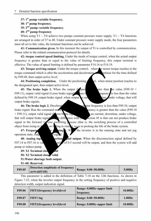
7 Detailed function specification
146
37: 1st pump variable frequency. 38: 1st pump frequency. 39: 2nd pump variable frequency. 40: 2nd pump frequency When using Y1 ~ Y4 achieve two pumps constant pressure water supply, Y1 ~ Y4 functions
are arranged in order of 37 to 40. Under constant pressure water supply mode, the four parameters must all set to this value, the terminal functions can be achieved
41: Communication given. In this moment the output of Yi is controlled by communication, Please refer to the related communication protocol for details.
42: torque control speed limiting. Under the mode of torque control, when the actual output frequency is greater than or equal to the value of limiting frequency, this output terminal is effective. The value of speed limiting is defined by parameter F14.16 to F14.19.
43: Torque arriving output. Under the torque control,when the motor torque reaches to the torque command which is after the acceleration and deceleration, and continue for the time defined by F09.48, then output active level.
44: Positioning completion. Under the positioning control,when motor position reaches to the designated spot, then output active level.
45: The brake logic 1. When the output frequency is greater than the value (F09.10 + F09.11), output valid signal (Loose brake signal) , when the output frequency is less than the value defined by F09.10 ,output brake signal .when output no current, downtime, under voltage, that will output brake signals.
46: The brake logic 2. Deceleration stop and the output frequency is less than F09.10, output brake signal. Run the command starts, when the output frequency is greater than the value (F09.10 + F09.11), output valid signal (Loose brake signal). If output no current, downtime, under voltage, that will output brake signals. What difference with the function 45 is that can not produce brake signal in the forward /reverse switching process (that is, the switching process of a controlled object from rising to falling or falling to rising), so as to prolong the life of the brake system.
47: Frequency inverter running 1. When the inverter is in the running state and not jog operation state, output the valid signal.
48: Analog input disconnection signal output. When the disconnection signal defined by F07.14 to F07.16 is valid, a valid pulse of 0.5 second will be output, and then the system will add pump or reduce pump.
49: X1 Terminal closed valid 50: X2 Terminal closed valid 51:Water shortage fault output. 51~60: Reserved.
F09.05 Detection amplitude of frequency arrival(FAR)
Range: 0.00~50.00Hz 5.00Hz
This parameter is added in the definition of Table 7-10 on the 12th functions. As shown in Figure 7-23, when the inverter output frequency in the setting frequency of positive and negative detection width, output indication signal.
F09.06 FDT1(frequency level)level Range: 0.00Hz~upper limit frequency
10.00Hz
F09.07 FDT1 lag Range: 0.00~50.00Hz 1.00Hz
F09.08 FDT2(frequency level)level Range: 0.00Hz~upper limit 10.00Hz
ENC

7 Detailed function specification
147
frequency
F09.09 FDT2 lag Range: 0.00~50.00Hz 1.00Hz
F09.06, F09.07 is in the definition of Table 7-10 on the 13th Functions, F09.08, F09.08 is in the definition of Table 7-10 on the 14th functions, take an example of 13th functions: When the output frequency exceeds a certain setting frequency (FDT1 level), output indicator Signal, until the output frequency drops below the certain frequency FDT1 frequency level (FDT1 level -FDT1 lag). As shown in Figure 7-24.
F09.10 Zero-frequency signal detection value
Range: 0.00Hz~upper limit frequency
0.40Hz
F09.11 Zero-frequency backlash Range: 0.00Hz~upper limit frequency
0.10Hz
Fig.7-25 Zero-frequency signal detection
Parameter F09.10, F09.11 defines the zero frequency output control function. When the output frequency is within the zero-frequency signal detection range, if Yi output function selects 11, then the output of Yi is indication signal.
F09.12 Zero current detection amplitude
Range: 0.0~50.0% 0.0%
F09.13 Zero current detection time Range: 0.00~60.00s 0.1s
Output freq.
FDT1 level
Time
Time
Y
FDT1 lag
Fig.7-24 Freq. level detection diagram
F09.10
运行频率
时间
F09.11
零频运行
输出
时间
Operating freq.
Time
Time
Zero freq. operating output ENC

7 Detailed function specification
148
Fig.7-26 Zero current detection diagram
When the output current of the inverter is less than or equal to zero current detection level, and lasts longer than the zero current detection time, then the output of frequency inverter multifunction Yi is indication signal. Figure 7-26 is the schematic of zero current detection.
F09.14 Over-current detection value Range: 0.0~250.0% 160.0%
F09.15 Over-current detection time Range: 0.00~60.00s 0.00s
Fig.7-27 Output over-current detection diagram
When the output current of the inverter is greater than the over-current detection points, and lasted longer than the over-current detection time, frequency inverter multifunction Yi output indication signal, Figure 7-27 is the schematic of output over-current detection.
F09.16 Current 1 arriving the detection value
Range: 0.0~250.0% 100.0%
F09.17 Current 1 width Range: 0.0~100.0% 0.0%
F09.18 Current 2 arriving the detection value
Range: 0.0~250.0% 100.0%
输出电流
F09.12零电流检出幅值
零电流检出
信号
F09.13
零电流检出时间
时间
时间Time
Time
Output current
Zero current detection amplitude (F09.12)
Zero current detection signal
Zero current detection time (F09.13)
输出过电流检出时间
F09.15
ON
时间
时间
输出过电流检出值F09.14
输出电流
输出过电流
指示信号
Time
Time
Output current Output over current detection value(F09.14)
Output over current induction signal
Output over current detection time(F09.15)
ENC

7 Detailed function specification
149
F09.19 Current 2 width Range: 0.0~100.0% 0.0%
When the output current of frequency inverter is within the positive and negative detection width of setting current arrival, then the output of frequency inverter multifunction Yi is indication signal.
EN500/EN600 provides two current arrival and detection width parameters, table 7-28 is the function schematic diagram.
Fig.7-28 Current arriving detection diagram
F09.20 Frequency 1 arriving detection value
Range:0.00Hz~upper limit frequency
50.00Hz
F09.21 Frequency 1 arriving detection width
Range:0.00Hz~upper limit frequency
0.00Hz
F09.22 Frequency 2 arriving detection value
Range:0.00Hz~upper limit frequency
50.00Hz
F09.23 Frequency 2 arriving detection width
Range:0.00Hz~upper limit frequency
0.00Hz
When the output frequency of frequency inverter reaches detecting value of the positive and negative detecting width range, then the output of multifunctional Yi is indication signal.
EN500/EN600 provides two sets of frequency arrival detecting parameters, which have set frequency value and frequency detecting width respectively. Table 7-29 is the diagram of this function.
Fig.7-29 Frequency arriving detection diagram
电流I到达检出值
电流I到达指示信号
电流I到达检出宽度
OFFOFF
ONONON
OFF
输出电流
时间
电流I到达检出宽度
Time
Output current
Current I arriving detection value
Current I arriving induction signal
Current I arriving detection width
Current I arriving detection width
频率I到达检出值频率I到达检出宽度
频率I到达检出宽度
运行频率
时间ON
OFFOFF
ON
OFF频率I到达指示信号
Time
Operating freq.
Frequency I arriving detection value
Frequency I arriving induction signal
Frequency I arriving detection width Frequency I arriving detection width
ENC

7 Detailed function specification
150
F09.24 Positive and negative logic setting of output terminal
Range: 0000~FFFF 0000
This parameter defines the output logic of the standard output terminal Yi, relay RLY and expand output terminal EYi, relays ERIY1, ERLY2.
0: Positive logic, output terminal and the common terminal close to the valid state, disconnect invalid state
1: Reverse logic, output terminal and the common terminal close to the invalid state, disconnect valid state
Parameter F09.25 ~ F09.34 defines the corresponding delay time from connect or disconnect
thousands hundreds The tens the units
F09.25 Y1 output closed delay time Range: 0.000~50.000s 0.000s
F09.26 Y1 output disconnected delay time
Range: 0.000~50.000s 0.000s
F09.27 Y2 output closed delay time Range: 0.000~50.000s 0.000s
F09.28 Y2 output disconnected delay time
Range: 0.000~50.000s 0.000s
F09.29 Y3 output closed delay time Range: 0.000~50.000s 0.000s
F09.30 Y3 output disconnected delay time
Range: 0.000~50.000s 0.000s
F09.31 Y4 output closed delay time Range: 0.000~50.000s 0.000s
F09.32 Y4 output disconnected delay time
Range: 0.000~50.000s 0.000s
F09.33 Relay output closed delay time
Range: 0.000~50.000s 0.000s
F09.34 Relay output disconnected delay time
Range: 0.000~50.000s 0.000s
BIT0:Y1 positive and negative logic definition BIT1:Y2 positive and negative logic definition BIT2:Y3 positive and negative logic definitionBIT3:Y4 positive and negative logic definition
BIT0: fault relay 1 positive and negative logic definition BIT1:expand OC1 positive and negative logic definitionBIT2:expand OC2 positive and negative logic definition BIT3:expand OC3 positive and negative logic definition
BIT0:expand OC4 positive and negative logic definition BIT1:expand fault relay1 positive and negative logic definitionBIT2:expand fault relay2 positive and negative logic definitionBIT3: reserved
BIT0~BIT3: reserved
ENC

7 Detailed function specification
151
to frequency level of the multifunction output terminals. Table 7-30 is the schematic of multi-function output terminal operation.
Fig.7-30 Multifunction output terminal action diagram
F09.35 Analog output (AO1) selecting Range: 0~25 0
F09.36 Analog output (AO2) selecting Range: 0~25 0
F09.37 DO function selecting(reuse with Y4) Range: 0~25 0
0: Output frequency before slip compensation(0.00Hz~ upper limit frequency) 1: Output frequency after slip compensation(0.00Hz~ upper limit frequency) 2: Setup frequency(0.00Hz~ upper limit frequency) 3: Master setup frequency(0.00Hz~ upper limit frequency) 4: Auxiliary setup frequency(0.00Hz~ upper limit frequency) 5: Current output 1(0~2×rated current of frequency inverter) 6: Current output 1(0~3×rated current of frequency inverter) 7: Output voltage(0~1.2×rated voltage of load motor) 8: Bus voltage (0~1.5×Rated bus voltage) 9: Motor speed(0~3 ×rated speed) 10: PID given(0.00~10.00V) 11: PID feedback(0.00~10.00V) 12: AI1(0.00~10.00V or 4~20mA) 13: AI2(-10.00~10.00V or 4~20mA) 14: Communication given(AO output is controlled by communication, please refer to
the related communication protocol for details.) 15: Motor rotate speed (0.00Hz~upper limit frequency) 16: Current given torque (0~2 times of rated torque) 17: Current output torque(0~2 times of rated torque) 18: Current torque current(0~2 times of rated motor current) 19: Current flux current(0~1 times of rated motor flux current) 20~25: Reserved
Valid Invalid
close delay Disconnect delay
Yi level
Yi Valid
Setting rang:0.000~50.000s
Invalid
Note
(1) Terminal AO1 and AO2 are optional output terminal of 0~10V or 4~20mA which can satisfy the variety needs of customer. (2) By disposing F00.21 analog output,output of terminal AO1 and AO2 can be 0~10V or 4~20mA to satisfy the variety needs of customer. (3) The unit’s place of F00.22 is set to 1 when DO output pulse signal. (4) Rated flux current=current value of F15.11 parameter. Rated torque current=sqrt (rated motor current×rated motor Current-rated flux current×rated flux current)
ENC

7 Detailed function specification
152
F09.38 Reserved
F09.39 Analog output (AO1) filter time Range: 0.0~20.0s 0.0s
F09.40 Analog output (AO1) gain Range: 0.00~2.00 1.00
F09.41 Analog output (AO1) bias Range: 0.0~100.0% 0.0%
Parameter F09.39 defines the filter time of A01 output, its reasonable setting can improve stability of analog output. But a higher setting will influence the rate of change, which can not reflect the instantaneous value of corresponding physical quantity.
If users want to change the display range or error correction table headers, you can achieve it by adjusting the output gain and bias of AO1.
When AO1 output voltage, the adjustment is as follows: Analog output AO1(after revise)=output gain (F09.40) ×analog output AO1 (before
revise)+output bias(F09.41)×10V When AO1 output current, the adjustment is as follows: Analog output AO1(after revise)=output gain (F09.40) × analog output AO1 (before
revise)+output bias(F09.41)×20mA
F09.42 Analog output (AO2) filter time Range: 0.0~20.0s 0.0s
F09.43 Analog output (AO2) gain Range: 0.00~2.00 1.00
F09.44 Analog output (AO2) bias Range: 0.0~100.0% 0.0%
Please refer to the function introduce of parameters F09.39~F09.41
F09.45 DO filter time Range: 0.0~20.0s 0.0s
F09.46 DO output gain Range: 0.00~2.00 1.00
F09.47 DO maximum pulse output frequency Range: 0.1~20.0KHz 10.0KHz
Please refer to the function introduce of parameters F09.39~F09.41. Maximum pulse output frequency of terminal DO corresponds to maximum select value of
F09.37. For example, F09.31=0, terminal DO’s function is: output frequency before slip compensation, which means Maximum pulse output frequency corresponds to upper frequency.
Note:When the output frequency of DO port is less than 1.5Hz, disposed as 0Hz.
F09.48 Torque reaches to the detection time Range: 0.02~200.00s 1.00s
F09.49 Application macro selection Range: 0~4 0
For details on application of macros, please refer to Appendix J. Application of Macros
F09.49 Reserved
F09.50 Reserved
Note This function code will influence analog output during modify processes.
ENC

7 Detailed function specification
153
7.11 Simple PLC/Multi-speed function parameters Group:F10
F10.00 Simple PLC operate setting
Range: Unit digit: 0~3 Tens digit: 0~2 Hundreds digit: 0,1 Thousands digit: 0,1
0000
The simple PLC operation mode, re-start mode after interruption, unit of running time and the storage mode when power off can be set in different bit of parameter F10.00, details as follows:
Unit digit: simple PLC operation mode. 0: No action.PLC operation mode is disabled. 1: Stop after single cycle. as show in Fig.7-31, the drive stops automatically after one cycle
of operation and will not start only when receiving RUN command again. 2: Maintain final value after one cycle, as show in Fig.7-32, the drive will keep running with
the final value and the direction after complete one cycle operation, the drive won’t stop according to the set stop mode until the stop command is available.
3: Continuous operation, as show in Fig.7-33, the drive will start next cycle of operation automatically after completing one cycle of operation until receiving STOP command then stop according the set stop mode.
Fig.7-31 PLC stop operating after one cycle mode
Fig.7-32 PLC holds the final value after one cycle mode
STOP Command
RUN Command
T15
4 5
33
4
T1 T5T4T3T2
fa
afd
f
2
1 1
2
3
5
5
15
a
a f
f
da
f
d 15
T15T4
1 1
2
2
d3
a3 f3
af4
5
a5
5
T5T3T2T1
afa
f
4
d
f
f15
RUN Command
STOP Command
d15
Hold final value
ENC

7 Detailed function specification
154
Fig7-33 PLC continuous operation mode
a1~a15:The Acc time of different steps d1~d15:The Dec time of different steps f1~f15:The frequency of different steps There are 15 steps can set in Fig.7-31,7-32,7-33. Tens digit: Restart mode after interruption. 0: Restart from the first step. If the drive stops during PLC operation due to receiving STOP commands, fault alarm or
power failure, it will run from the first step after restarting. 1: Restart from the interruption step; If the drive stops during PLC operation due to receiving STOP command or fault alarm, the
drive will record the operating time of the current step and will continue from the step where the drive stops after restart at the frequency defined for this step with the remained time, as show in Fig.7-34.If the drive stops due to power off, it will not record the state and from the first step operate when restart.
2: Restart from the interrupted Frequency If the drive stops during PLC operation due to receiving STOP command or fault alarm, the
drive will record the operating time and the current frequency of the interrupt step, it will operating with the record time and record frequency when restart, as show in Fig7-35
第二次循环第一次循环
f1
d1
f15
f5
f4
f3
f2
f1
f15
f5
f4
f3
f2
f1
T1 T2 T3 T4 T5 T15T15T5T4T3T2T1
a1
a2d2
a4
a3
d4
a5
d15
d1 a2
a3
d3
a4d4
a5
d15
STOP命令
RUN命令
PLC运行PLC Operation
RUN Command
STOP Command
The first cycle The second cycle
ENC

7 Detailed function specification
155
a1:Acc time of the 1st step a2:Acc time of the 2nd step a3:Acc time of the 3rd step d2:Dec time of the 1st step f1:Frequency of the 1st step f2:Frequency of the 2nd step f3:Frequency of the 3rd step
Fig.7-34 Simple PLC restart mode 1
a1:Acc time of the 1st stepa2:Acc time of the 2nd step a3:Acc time of the 3rd step d2:Dec time of the 1st step f1:Frequency of the 1st step f2:Frequency of the 2nd step f3:Frequency of the 3rd step
Fig.7-35 PLC Restart mode 2 Hundreds digit: PLC unit of running time. 0: Seconds; 1: Minutes; The unit is effective for the running time of different steps only, during the operation of PLC, the
unit of Acc time and Dec time is defined by parameter F01.19.
Time t
f 3 a 3 f2
a2
d2
f1
a 1
Pause signal
Operated time Step2 remain time
Step2Step1
Output Freq. Hz
f2
f3a3
d 2a2
d2
f1
a1
Pause signal
Step2Step1
Output Freq Hz Same freq.
Step 2 remain time
Operated time
Time t
Note
(1) The step is ineffective if the time of this step of PLC operation is set as 0 thereafter operate the next step. (2) Control the PLC process a pause ,ineffective, operate via terminal ,for details please refer to parameters in F8 Group that relative with terminal function.
ENC

7 Detailed function specification
156
Thousands digit: the storage mode when power off. 0: No storage. No record the running state when power off, it will restart from the first step
when power on again. 1: Storage. Records the running status which include the step, running frequency and running
time when power off, it restart with the mode that set in hundreds digit after power on again.
F10.01 Step 1 setting Range: 000H~E22H 020
F10.02 Step 2 setting Range: 000H~E22H 020
F10.03 Step 3 setting Range: 000H~E22H 020
F10.04 Step 4 setting Range: 000H~E22H 020
F10.05 Step 5 setting Range: 000H~E22H 020
F10.06 Step 6 setting Range: 000H~E22H 020
F10.07 Step 7 setting Range: 000H~E22H 020
F10.08 Step 8 setting Range: 000H~E22H 020
F10.09 Step 9 setting Range: 000H~E22H 020
F10.10 Step 10 setting Range: 000H~E22H 020
F10.11 Step 11 setting Range: 000H~E22H 020
F10.12 Step 12 setting Range: 000H~E22H 020
F10.13 Step 13 setting Range: 000H~E22H 020
F10.14 Step 14 setting Range: 000H~E22H 020
F10.15 Step 15 setting Range: 000H~E22H 020
F10.01~F10.15 are used to configure the operating frequency, direction and Acc/Dec time of each PLC operating step. These functions are all selected by digits on different place of parameters. Details as below:
Unit digit: Frequency setting 0: Select multi-frequency i. i=1~15, please refer to F10.31~F10.45 for definitions of
multi-frequency. 1: The frequency is determined by the combination of the main frequency and the
auxiliary frequency. 2: Reserved. Tens digit: The selection of running direction for PLC and multi-speed. 0: Forward. 1: Reversed. 2: Determined by operating commands (FWD, REV) Hundreds digit: Acc/Dec time choose
Note
No matter power-off storage in stop status or running status, you should set thousands digit as 1 thereafter set tens digit as 1 or 2,otherwise power-off storage function is ineffective.
ENC

7 Detailed function specification
157
0: Acc/Dec time 1 1: Acc/Dec time 2 2: Acc/Dec time 3 3: Acc/Dec time 4 4: Acc/Dec time 5 5: Acc/Dec time 6 6: Acc/Dec time 7 7: Acc/Dec time 8 8: Acc/Dec time 9 9: Acc/Dec time 10 A: Acc/Dec time 11 B: Acc/Dec time 12 C: Acc/Dec time 13 D: Acc/Dec time 14 E: Acc/Dec time 15 Accelerate time1~15 defined by F01.17,F01.18,F04.16~F04.43. The running direction of
PLC and multi-speed is determined by the ten’s place of F10.01~F10.15.
F10.16 Step 1 running time Range: 0~6000.0 10.0
F10.17 Step 2 running time Range: 0~6000.0 10.0
F10.18 Step 3 running time Range: 0~6000.0 10.0
F10.19 Step 4 running time Range: 0~6000.0 10.0
F10.20 Step 5 running time Range: 0~6000.0 10.0
F10.21 Step 6 running time Range: 0~6000.0 10.0
F10.22 Step 7 running time Range: 0~6000.0 10.0
F10.23 Step 8 running time Range: 0~6000.0 10.0
F10.24 Step 9 running time Range: 0~6000.0 10.0
F10.25 Step 10 running time Range: 0~6000.0 10.0
F10.26 Step 11 running time Range: 0~6000.0 10.0
F10.27 Step 12 running time Range: 0~6000.0 10.0
F10.28 Step 13 running time Range: 0~6000.0 10.0
F10.29 Step 14 running time Range: 0~6000.0 10.0
F10.30 Step 15 running time Range: 0~6000.0 10.0
Parameters F10.16~F10.30 defined Running time of each PLC Step from Step 1 to Step 15.
Note Each step running time include Acc time and Dec time.
ENC

7 Detailed function specification
158
F10.31 Multi-Frequency 1 Range:0.00Hz~upper limit Freq. 5.00Hz
F10.32 Multi-Frequency 2 Range:0.00Hz~upper limit Freq. 10.00Hz
F10.33 Multi-Frequency 3 Range:0.00Hz~upper limit Freq. 20.00Hz
F10.34 Multi-Frequency 4 Range:0.00Hz~upper limit Freq. 30.00Hz
F10.35 Multi-Frequency 5 Range:0.00Hz~upper limit Freq. 40.00Hz
F10.36 Multi-Frequency 6 Range:0.00Hz~upper limit Freq. 45.00Hz
F10.37 Multi-Frequency 7 Range:0.00Hz~upper limit Freq. 50.00Hz
F10.38 Multi-Frequency 8 Range:0.00Hz~upper limit Freq. 5.00Hz
F10.39 Multi-Frequency 9 Range:0.00Hz~upper limit Freq. 10.00Hz
F10.40 Multi-Frequency 10 Range:0.00Hz~upper limit Freq. 20.00Hz
F10.41 Multi-Frequency 11 Range:0.00Hz~upper limit Freq. 30.00Hz
F10.42 Multi-Frequency 12 Range:0.00Hz~upper limit Freq. 40.00Hz
F10.43 Multi-Frequency 13 Range:0.00Hz~upper limit Freq. 45.00Hz
F10.44 Multi-Frequency 14 Range:0.00Hz~upper limit Freq. 50.00Hz
F10.45 Multi-Frequency 15 Range:0.00Hz~upper limit Freq. 50.00Hz
Frequency will be used in Multi-speed operation mode and Simple PLC operation mode. More details please refer to the Multi-speed terminal operation function in Parameters Group F08 and Simple PLC operation function in Parameters Group F10.
7.12 Closed-Loop PID operation Parameters Group:F11 Analog feedback control system: Pressure reference is input through the terminal AI1,and water pressure sensor send a
4-20mA to the terminal AI2 of inverter as a feedback signal, all of them make up of analog closed-loop control system via build-in PID adjuster ,as shown in Fig.7-36
Fig.7-36 Build-in PID adjuster control system diagram
Xi (Defined as FWD)
COM
GND
AI1
+10V GND
AI2
Provision
1~3K
P
Three phase 380V
QF EN500/EN600 Output
Pressure sen
sor
4~20mA
UM
W
R
TV S
ENC

7 Detailed function specification
159
Operating principle of built-in PID function of EN500/EN600 is shown in Fig.7-37 as below:
Fig.7-37 PID block control principle diagram
In above diagram ,the definition of closed-loop reference ,feedback error limit and PI parameters are similar with the general PID adjuster,the relationship between reference and expected feedback is shown in Fig.7-38.The reference and feedback are converted and based on 10.00V.
In Fig.7-37, the real values of closed-loop reference and feedback can be regulated in Group F06 and F07, so that can reach a good performance.
Fig.7-38 Reference and expected feedback value
After the system control mode is confirmed, follow the procedures below to set the closed-loop parameters:
(1) Determine the closed-loop reference and feedback channel (F11.01F11.02). (2) The relationship between the closed-loop reference and feedback should be defined for
closed-loop control (the Group F6). (3) Set up the closed-loop frequency presetting function (F11.19,F11.20). (4) Adjust the proportion gain, integral gain, differential gain, sampling cycle and error
limit(F11.07~F11.11).
F11.00 Closed-loop control function Range: 0,1 0
0: PID closed-loop function disabled 1: PID closed-loop function enabled
Closed-loop
reference
Offset limit
(F11.11) Reference regulation (F11.03)
Closed-loop feedback
e +
Feedback regulation
(F11.04,F11.14)
Integral gain (F11.08)
Proportion gain
(F11.07)
Closed-loop output +
+
Differential gain
(F11.09)
Closed-loop output
regulation _
0
Pressure reference
Expected Value eedback
20mA
4mA
10V
Note Setting the value of F11.01 can choose the channel of pressure reference.
ENC

7 Detailed function specification
160
F11.01 Reference channel choose Range: 0~7 0
0: Digital provision 1:AI1 analog 0-10V or 4-20mA provision 2:AI2 analog provision 3:EAI1 analog provision (Extensible) 4:EAI2 analog provision (Extensible) 5: Pulse provision 6: Communication provision(Communication address:1D00). Please refer to the chapter
of Modbus communication. 7: Reserved
F11.02 Feedback channel selection Range: 0~9 0
0:AI1 analog input 1:AI2 analog input 2:EAI1 analog input (Extensible) 3:EAI2 analog input (Extensible) 4:AI1+AI2 5:AI1-AI2 6:Min{AI1,AI2} 7:Max{AI1,AI2} 8: Pulse input 9:Communication feedback ( address is 1DOC, 4000 stands for 10.00V)
F11.03 Provision channel filtering time Range: 0.00~50.00s 0.20s
F11.04 Feedback channel filtering time Range: 0.00~50.00s 0.10s
F11.05 PID output filtering time Range: 0.00~50.00s 0.10s
The external reference signal and feedback signal usually carry some noise. those noise signal can be filtered by setting the time constant of filter in F11.03 and F11.04.The bigger the time constant is, the better the immunity capability, but with a slow response. The shorter the time constant is, the faster the response, but the immunity capability became weak.
The PID output filter time is the time of the filter for output frequency or torque, the bigger time, the slower the response output.
F11.06 Provision digital setting Range: 0.00~10.00V 1.00V
This function can realize digital setting of reference via keypad.
Note
Except the above provision channels, Multi-Closed-loop provision is available. Connecting different terminal to choose different provision value which with a highest priority.
Note
When the PID function is enabled, Setting F18.14 as 1 can adjust pressure reference by press , otherwise the keys are invalid for adjusting reference in monitoring mode.
ENC

7 Detailed function specification
161
F11.07 Proportion Gain Kp Range: 0.000~6.5535 0.0500
F11.08 Integral Gain Ki Range: 0.000~6.5535 0.0500
F11.09 Differential Gain Kd Range: 0.000~9.999 0.000
F11.10 Sampling cycle T Range: 0.01~1.00s 0.10s
The bigger of the proportion gain of Kp, the faster the response, but oscillation may easily occur.
If only proportion gain Kp is used in regulation, the offset cannot be eliminated completely. To eliminate the offset, please use the integral gain Ki to form a PI control system. The bigger Ki is, the faster the response, but oscillation may easily occur if Ki is big enough.
The sampling cycle T refers to the sampling cycle of feedback value. The PI D regulator calculates once in each sampling cycle. The bigger the sampling cycle is, the slower the response.
F11.11 Deviation limit Range: 0.0~20.0% 2.0%
If defines the max. Deviation of the output from the reference, as shown in Fig.7-39, the PID adjuster stops operation when the feedback value within this range. Setting this parameter correctly will improve the moderation of the accuracy and stability of the system
Fig.7-39 Offset limit
F11.12 PID differential amplitude limit Range: 0.00~100.00% 0.10%
In the PID regulator, the effect of differential is too sensitive too easy to cause system oscillation, therefore limit the effect of differential PID in a smaller range, F11.12 the parameter that used to set the output range of PID differential.
F11.13 Closed-loop regulation characteristic Range: 0,1 0
0: Positive effect. When the provision increases, select while requiring speed of motor increase.
1: Negative effect. When the provision increases, select while requiring speed of motor decrease.
Offset limit
Time
Time
Output Freq.
Feedback
Reference
Note Offset limit is the percentage refer to the value of reference. ENC

7 Detailed function specification
162
Fig.7-40 Closed-loop characteristic Fig.7-41 Feedback characteristic
F11.14 Feedback channel positive-negative characteristic
Range: 0,1 0
0: Positive characteristic. The relationship between reference and feedback is positive 1: Negative characteristic. The relationship between reference and feedback is negative This parameter is used to change the feedback characteristic of the feedback signal. After
input into inverter through the feedback channel, the feedback pressure will compare with the reference after regulated by the positive and negative characteristic regulation, as shown in Fig.7-41
F11.15 PID regulation upper limit frequency
Range: 0.00Hz~upper limit Frequency
50.00Hz
F11.16 PID regulation lower limit frequency
Range: 0.00Hz~upper limit Frequency
0.00Hz
User can set up the parameters F11.15 and F11.16 to define the output lower limit and upper limit frequency of the PID regulator.
F11.17 Integral regulation selection Range: 0,1 0
0: Stop integral regulating when the comparison value of the reference and feedback reaches the range of threshold for integral separation
1: Keep integral regulating even thought the comparison value of the reference and feedback reach the range of threshold integral separation
Adjusting this parameter can avoid integral saturation and improve the response of the system.
F11.18 PID threshold of the integral separation
Range: 0.0~100.0% 100.0%
PID integral separated function: there is no integral regulating just proportion regulating during closed-loop control when the comparison value that between reference and feedback is bigger than this threshold. When the comparison is smaller than this threshold, the integral regulating will be active, and can adjust the response speed of system by adjusting this parameter.
F11.19 Preset Closed-loop frequency Range: 0.00Hz~upper limit frequency
0.00Hz
F11.20 Holding time of preset Closed-loop frequency
Range: 0.0~6000.0s 0.0s
This function can make the closed-loop adjuster into the stable status quickly. When the closed-loop function start,the output frequency will ramp up to the preset
closed-loop frequency(F11.19) within the Acc time, and keep running the time that set in F11.20
Positive Effect
Value after converted
10V 0 Feedback
Negative Effect
10V Positive Effect
Speed
10V 0 Reference
Negative Effect
ENC

7 Detailed function specification
163
then start the closed-loop operation as shown is Fig.7-42
Fig.7-42 Preset closed-loop operating
F11.21 Closed-loop output reversion selection Range: 0~2 2
0: The inverter will runs with the low limit frequency when the closed-loop output value is negative
1: The inverter will reverse running when the value of the closed-loop output is negative(be opposite of the initial direction )
2: Determined by running demand. The motor running direction is determined by demand direction.
F11.22 Closed-loop output reversion frequency upper limit
Range: 0.00Hz~upper limit Frequency
50.00Hz
The PID regulator is a kind of bipolar adjustment. By setting F11.21 and F11.22, can choose whether the inverter reverse run in some degree frequency or not.
F11.23 Multiple closed-loop provision 1 Range: 0.00~10.00V 0.00V
F11.24 Multiple closed-loop provision 2 Range: 0.00~10.00V 0.00V
F11.25 Multiple closed-loop provision 3 Range: 0.00~10.00V 0.00V
F11.26 Multiple closed-loop provision 4 Range: 0.00~10.00V 0.00V
F11.27 Multiple closed-loop provision 5 Range: 0.00~10.00V 0.00V
F11.28 Multiple closed-loop provision 6 Range: 0.00~10.00V 0.00V
F11.29 Multiple closed-loop provision 7 Range: 0.00~10.00V 0.00V
Among the closed-loop reference channel, besides the 7 channels defined by F11.01,the closed-loop reference can also be defined in F11.23~F11.29. The priority of multi-closed-loop
Preset Freq.
Time
Hold time of Preset Freq.
Output Freq.
Note Preset closed-loop Function is ineffective when set F11.19 and F11.20 as 0.
Note
The comparison value can be display in the PID monitor parameters, it’s positive when the reference bigger than the feedback value, and negative when reference smaller than feedback value. ENC

7 Detailed function specification
164
reference control is higher than the reference channels that defined by F11.01. Multi-closed-loop reference 1~7 can be selected by external terminals. Please refer to the
terminal function 19~21 of introductions to F08.18~F08.25.When the function of Constant water supply is enable, the reference of constant water pressure is decided by the multi-closed-loop reference which selected by external terminals.
Computational formula: constant pressure reference = F12.06 × Multi-closed-loop reference/10.00V.By using this functions can realize different times with a different constant water pressure.
7.13 Constant pressure water supply function parameters Group: F12
F12.00 Constant pressure water supply mode selection Range: 0~5 0
0: disabled. 1: Inverter works in one-drive-two-pump mode. 2: Choose extensible constant pressure board acts in one-drive-two-pump mode. 3: Choose extensible constant pressure board acts in one-drive-three-pump mode. 4: Choose extensible constant pressure board acts in one-drive-four-pump mode. 5: Select inverterY1,Y2 as the double pump timing alternate constant pressure water supply
mode. While F12.00=5,F09.00=37,F09.01=38,realize the timing alternate constant pressure water supply control between two pumps, only one motor is running at most at any time, the time of timing alternate is defined by F12.10. While F12.10=0, no alternate control, While F12.10=1,switch a running pump while starting.
This function can be used to choose different kinds of constant pressure water supply mode, and you should choose an extensible constant pressure board to realize one-drive-three mode and one-drive-four mode and F00.19 should be set to 2.
When modify F12.00 from 0 to water supply mode is valid,C-04,C-05 automatically relate constant pressure water supply setting pressure and feedback pressure (including the display of halting and running).
F12.01 Target pressure setting Range: 0.000~the range of long-distance manometer
0.200Mpa
This parameter defined the target pressure of the constant pressure supply system. The channels of the pressure reference and feedback are defined by F11.01 and F11.02.
F12.02 Sleep frequency threshold Range: 0.00Hz~upper limit frequency
30.00Hz
Note
(1) The function of Group F11 will be effective automatically when the constant pressure supply function is enabled. (2) Except for the related parameters in Group F11 and F12 for Closed-loop, the function of Yi should be enabled in F9 for the inverter works in one-drive-two-pump mode without an extend board. (3) Output terminal Y4/DO should be set to Y4. (4) When one inverter drive one pump with constant pressure water supply, the parameter F09.00~F09.03 (Y1~Y4) can not be set 37~38.
ENC

7 Detailed function specification
165
F12.03 Revival pressure threshold Range: 0.000~F12.06 Mpa 0.150Mpa
The function of Sleep frequency threshold: To save energy and protect the motor, when the water feedback pressure within the offset limit (F11.11), and the operating frequency is under in the sleep frequency threshold (F12.02), after a sleep delay time (F12.04), the system will enter a sleep mode and the operating frequency will drop to 0.00Hz
Revival function: When the system is in the sleep mode, if the feedback water pressure keep less than F12.03 (the revival pressure) a delay time (F12.05), the system will revival from the sleep mode.
F12.04 Sleep delay time Range: 0.0~6000.0s 0.0s
This parameter is the delay time that from the feedback pressure meets the sleep conditions to the system enter in sleep mode.
Within the sleep delay time, if the feedback pressure does not meet the sleep conditions, the system will not enter into sleep mode
Sleep function is disabled when F12.04=0.
F12.05 Revival delay time Range: 0.0~6000.0s 0.0s
When the constant pressure supply system in the sleep state, if the feedback pressure of system less than F12.11 which defined the revival pressure threshold ,the system will revival and get out of sleep mode after the revival delay time.
F12.06 The range of long-distance manometer
Range: 0.001~9.999Mpa 1.000Mpa
This parameter defines the range of long-distance manometer. Setting this parameter can correspond to the maximum feedback pressure with the analog feedback signal 10V or 20mA
F12.07 Allowed deviation of upper limit frequency or lower limit frequency when add or reduce pump
Range: 0.1~100.0% 1.0%
When output frequency reaches the deviation range of upper limited frequency and the feedback is less than given value, adding pumps judge is available. When output frequency reaches the deviation range of lower limited frequency and the feedback is more than given value, decreasing pumps judge is available.
When F12.07=0.0%, output frequency reach upper or lower limitation frequency and the pressure meets the requirement, then decrease pumps is available.
F12.08 Add pump switching estimate time
Range: 0.2~999.9s 5.0s
When the output frequency up to the upper limit frequency (F11.15) but the pressure still not meeting the requirement, the system will add pump after the judging time.
When the output frequency down to the lower limit frequency (F11.16) but the pressure still not meeting the requirement, the system will reduce pump after the judging time.
F12.09 Electromagnetic contactor switching delay time
Range: 0.1~10.0s 0.5s
This parameter defines the action delay time of magnetic control conductor when it’s switch from power source supply to variable or from variable frequency control to power source supply.
F12.10 Automatic switching time interval
Range: 0000~65535 minute 0
By setting this parameter can avoid the rust of motor when it’s not work long time. The
ENC

7 Detailed function specification
166
inverter will switch the work status of the working pump and static pump automatically and smartly under the switch interval.
The automatic switch function is disabled when set the parameter as 0000. The system will switch one time when each restart of system as this parameter is 0001. If the value of this parameter is bigger than 0002, the system will switch automatically according the switch interval.
F12.11 Revival mode selection Range: 0,1 0
F12.12 Revival pressure coefficient Range: 0.01~0.99 0.75
When F12.11=0, the revival pressure of the constant pressure supply is the value of F12.03. WhenF12.11=1, the revival pressure is the calculating value of F12.12*F12.01
F12.13 Reduce pump switching estimate time
Range: 0.2~999.9s 5.0s
When the output frequency up to the upper limit frequency (F11.15)but the pressure still not meeting the requirement, the system will add pump after the judging time defined by F12.08.
When the output frequency down to the lower limit frequency (F11.15) but the pressure still not meeting the requirement, the system will reduce pump after the judging time defined by F12.13.
F12.14 Reserved
7.14 Traverse, Fixed-length control Function Parameters Group: F13
F13.00 Traverse function selection Range: 0,1 0
0: Disabled 1: Enabled
F13.01 Traverse operating mode
Range: Unit digit: 0,1 Tens digit: 0,1 Hundreds digit: 0,1 Thousands digit: 0,1
0000
Unit digit: Start mode 1st 0: Auto start. The drive operates at the preset frequency of traverse for a certain time
thereafter enter traverse mode automatically. 1: Terminal manual mode. Choosing multi-function terminal(Xi= X1~X8)as 56 function,
when the terminal is enabled, the drive will enter traverse mode. The drive will exit traverse operation and operate at the pre-set traverse frequency when it’s disabled.
Tens digit: Traverse amplitude AW mode choosing 0: Variable swing. Amplitude AW changes with the central frequency and the change rate
relate to the definition of F13.02. 1: Fixed swing. Traverse operating amplitude AW is determined by Upper limit Frequency
and F13.02. Note: The traverse central frequency is set by the main frequency. Hundreds digit: Restart mode 0: Restart at the initial state. 1: Restart at the memorized state before stopping Thousands digit: Traverse state saving when power off. This function is effective when the start mode is Restarting from the reserved memory state,
ENC

7 Detailed function specification
167
and saving operating state when power off. 0: Not save 1: Save
F13.02 Traverse frequency swing value Range: 0.0~50.0% 10.0%
Variable amplitude: AW= the central frequency ×F13.02 Fixed amplitude: AW=Upper limit frequency ×F13.02
F13.03 Sudden-jump frequency Range:0.0~50.0% 2.0%
As shown in Fig.7-43, there is not a jitter frequency when F13.03=0.
F13.04 Traverse cycle Range:0.1~999.9s 10.0s
F13.04 defines a complete cycle of traverse operation which including rising and falling processed.
F13.05 Triangular wave rising time Range:0.0~98.0%(Traverse cycle) 50.0%
Definition traverse rising time=F13.04×F13.05 (s), the traverse falling time= F13.04×(1-F13.05)(s).
Please refer to Fig.7-43
F13.06 Preset frequency of Traverse Range:0.00~400.00Hz 0.00Hz
F13.06 defines the operating frequency of the Drive before entering traverse operation.
F13.07 Traverse preset frequency waiting time
Range:0.0~6000.0s 0.0s
F13.07 defines the operating time of Preset frequency before entering Traverse operation when auto-start mode is enabled.
If manual start mode is available, F13.07 is disabled. Please refer to Fig.7-43 as below.
Note
When in variable amplitude mode, the channel of central frequency is confirmed by
F01.06.During the traverse frequency operation, the Acc and Dec time are controlled
only by traverse frequency circle F13.04 when adjusting the central frequency.
Note
The traverse operating frequency is restricted by the upper and lower limit of frequency. Incorrectly setting the frequency will lead to abnormal of traverse operation.
ENC

7 Detailed function specification
168
Fig.7-43 Traverse operation
F13.08 Setup length Range:0~65535(m\cm\mm) 0
F13.09 Pulse No. of axis per circle Range:1~10000 1
F13.10 Axis perimeter Range:0.01~655.35cm 10.00cm
F13.11 Percentage of remaining length Range:0.00%~100.00% 0.00%
F13.12 Length correction coefficient
Range:0.001~10.000 1.000
Set length, actual length and Numbers of pulses per cycle are used for fixed length control. The Actual length is calculated by the number of pulses collected by terminal Xi (i=1--8), set the Xi function code to 62 and length signal output.
actual length=(Actual number of pulses×F13.10×F13.12)/ F13.09, When the actual record length(F00.02 = 39)>set length(F13.08), after the time defined by F13.07, The "reach length" signal can be output via Yi and the relay output terminal for 0.5 seconds.
When remaining length ratio< F13.11, The drive will run at the frequency defined by F13.06 until the length is reached. With this function, the overshoot of the stop can be prevented to increase the accuracy of the fixed length control. When this parameter equals 0.00%, this function is invalid. (This function is valid only when the current frequency is the primary auxiliary).
Preset Freq
Lower limit Freq
Central Freq
Upper Limit Freq
Run
Decelerate
according the Dec time
Accelerate Traverse waiting time=F13.07 Traverse Cycle
Hz Operating Fre.
a1
-AW
+AW
Traverse amplitude AW=Fset*F13.02
Jitter Freq
=AW*F13.03
Stop
Rising time
Time t
a1
Note
(1) When F00.02=39, Actual length can be monitored by C-01in running state. Count length function is available both V/F control mode and Vector Control mode. (2) Using X8 port as a fixed length count input, the maximum input value is 4K .Using X1~X7 port as a fixed length count input, the maximum input value is 50Hz .
ENC

7 Detailed function specification
169
F13.13 Record length when the length is reached
Range:Units digit: Reserved Tens digit: 0、1、2 Hundreds digit: 0、1、2 Thousands digit: 0、1、2
0000
Units digit: Reserved Tens digit: Sets the unit of length 0: Meter (m) 1: Centimeter (cm) 2: Millimeter (mm) Hundreds digit: Actions when the length is reached 0: Continue running 1: Shut down according to stopping mode 2: Loop length control Thousands digit: Software reset length (could be cleared by communication) 0: No operation 1: The current length is cleared 2: The current length and total length both cleared F13.13 tens digit determines the unit of length in F13.08, 0=m, 1=cm, 2=mm. According to
the process requirements to select different units can increase the accuracy of fixed-length control. F13.13 Hundreds digit determine the action of the drive when reach the length. 0 = Continue
running, 1 = Shut down according to stopping mode, 2 = Loop length control. When 2 is selected, the frequency will run for 0 frequency and continue for the next fixed time after the time defined by F13.04. This function is effective only when the frequency is the main auxiliary reference, for example jogging, PLC, process PID. This function is only available when the reference of a higher priority is invalid.
F13.13 Thousands digit: The upper computer can change the current length and the cumulative length by changing thousands digit of F13.13. Note that F13.13 can not be wrongly modify the other bits, such as F13.13 units, tens, hundreds were 1,1,0, then F13.13 should be set to 0x1110 or 0x2110.When the multi-function input terminal No. 63 is valid, both the current length and the accumulated length are cleared.
F13.14 Record length at shutdown
Range:Units digit: 0、1 Tens digit: 0、1 Hundreds digit: 0、1
011
Units digit: Stops the current length 0: Automatically cleared The current record length is automatically cleared at shutdown. 1: Length is maintained The current record length remains unchanged during shutdown. Tens digit: Power-down length memory setting 0: Not stored 1: Stored This digit controls the current length of the power-down storage feature, but the cumulative
length of the power-down will be stored. Hundreds digit: length calculation at shutdown 0: The length is not calculated 1: Calculate the length
ENC

7 Detailed function specification
170
When this digit is 1, the length calculation module will automatically calculate the length according to the external pulse when the inverter is shutdown.
7.15 Vector Control parameters Group: F14
F14.00 Speed/Torque control selection Range: 0,1 0
0: Speed control mode 1: Torque control mode (this parameter is effective when set F00.24 as 1 or 2). When the control mode is vector control with PG or without PG, the user can select torque
control or speed control by setting the parameter of F14.00 or through control multi-function terminal which selected as No.65 function.
F14.01 Speed loop high speed proportional Gain
Range:0.1~40.0(Valid when F00.24=1 or 2)
20.0
F14.02 Speed loop high speed integral time
Range:0.001~10.000s(Valid when F00.24=1 or 2)
0.040s
F14.03 Speed loop low speed proportional Gain
Range:0.1~80.0(Valid when F00.24=1 or 2)
20.0
F14.04 Speed loop low speed integral time
Range:0.001~10.000s(Valid when F00.24=1 or 2)
0.020s
F14.05 Speed loop parameter switching frequency
Range:0.00Hz~20.00Hz(Valid when F00.24=1 or 2)
5.00Hz
Through F14.01 to F14.05, you can set the proportional gain and integral time of Speed loop regulator, so as to change the speed response characteristic under vector control mode.
The system dynamic response of speed loop can be faster if the proportional gain is increased or the integral time is decreased. However, if the proportional gain is too large or the integral time is too small, the system tends to oscillate.
The suggested adjusting way as below: When the default parameter is not suitable, please fine adjust the parameters based on the
default value. Proportional gain is usually adjusted first. Under the condition that the system is immune from oscillation, proportional gain can be increased as big as possible. Then adjust integral time so that the system responds fast and will not be over adjusted.
The above parameters are valid for Closed-loop or Open-loop speed control mode, invalid for V/F control and torque control mode.
F14.06 Stable coefficient of low frequency generating
Range: 0~50(Valid when F00.24=1 or 2)
25
When the motor connected to frequency inverter under a low frequency generating status, Please adjusting this parameter appropriately.
For example, the frequency inverter will be unstable when drives a potential load which is declining gradually. Increasing F14.06 will improve the stability of the system.
F14.07 Current loop proportional gain Range: 1~500(Valid when F00.24=1 or 2)
70
F14.08 Current loop integral time Range: 0.1~100.0ms(Valid when F00.24=1 or 2)
4.0ms
F14.07 and F14.08 are the PI regulator parameters of Current loop. The system torque dynamic response can be faster if the Current loop proportional gain P is
increased or Current loop integral time constant Ti is decreased.
ENC

7 Detailed function specification
171
The system stability can be improved if the Current loop proportional gain P is decreased or integral time constant Ti is increased.
In general, the above parameters don’t need change.
F14.09 Motor-driven torque current limit value
Range: 0~250.0%(Valid when F00.24=1 ,2 and 3)
160.0%
F14.10 Braking torque current limit value
Range: 0~250.0%(Valid when F00.24=1 or 2)
160.0%
It is the range of output torque of speed loop defined by the positive torque and negative torque limit. When the application needs quick acceleration and deceleration, this parameter can be appropriately increased to meet the specific requirements. However, if it’s too large, the drive tends to over-current.
In torque control mode, the range of actual torque output is restricted to the above limit too.
F14.11 Asynchronous motor flux-weakening control coefficient
Range: 20.0~100.0%(Valid when F00.24=1 or 2)
80.0%
F14.12 Asynchronous motor Min. flux coefficient
Range: 10.0~80.0%(Valid when F00.24=1 or 2)
10.0%
Parameters of F14.11, F14.12 Used to correcting the weakening curve in weakening field. The correction of the curve will improve the precision of speed control during weakening field. The minimum field reference is the minimum value of weakening field. And F14.12 is just available for Closed-loop vector control mode.
F14.13 Torque reference and limit channel selection
Range: Unit digit: 0~8 Tens digit :0~8 Hundreds digit: 0~8
000
Units digit: Torque provision channel selection 0: Digital setting 1:AI1 analog provision(0-10V or 4-20mA corresponds to 0~200.0% Rated torque current
of the motor) 2:AI2 analog provision 3: Terminal UP/DOWN adjusting 4:Communication provision(Communication address:1D01) . (0~10000 corresponds to
0~200.0% Rated torque current of the motor ) 5:EAI1 analog provision (Extensible) 6:EAI2 analog provision (Extensible) 7: High speed Pulse provision (Please choose the related function of X8) 8: Terminal width provision (Please choose the related function of X8) The range of the above channels which from the Min value to the Max value corresponds to
0.0~200% Rated torque current of motor. Tens digit: Electric torque limit channel selection 0: Digital setting (determined by F14.09) 1: AI1 analog setting 2: AI2 analog setting 3: Terminal UP / DOWN adjustment setting 4: Reserved 5: EAI1 analog Setting (Extended Valid) 6: EAI2 analog setting (Extended Valid)
ENC

7 Detailed function specification
172
7: High-speed pulse setting (X8 terminals need to select the appropriate function) 8: Terminal pulse width setting (X8 terminals need to select the appropriate function) Note: The maximum value of 1~ 8 channels corresponds to F14.09 Hundreds digit: Braking torque limit channel selection 0: Digital setting (Determined by F14.10) 1: AI1 analog setting 2: AI2 analog setting 3: Terminal UP / DOWN adjustment setting 4: Reserved 5: EAI1 analog Setting (Extended Valid) 6: EAI2 analog setting (Extended Valid) 7: High-speed pulse setting (X8 terminals need to select the appropriate function) 8: Terminal pulse width setting (X8 terminals need to select the appropriate function) Note: The maximum value of 1 ~ 8 channels corresponds to F14.10 When the torque limit value is modified by communication, the torque channel must be set to
digital setting (Tens or hundreds digit are 0). Torque limitation can be performed by directly modifying F14.09 or F14.10 by communication. The shutdown and power-down storage function are affected by F01.03 and F01.05 when terminal UP / DOWN is adjusted. If stop is not restored and power-down is saved, F01.03 = 3 and F01.05 = 00 need to be set.
F14.14 Torque polarity setting Range: 0000~2112 00
Unit digit: Polarity of Torque reference 0: Positive 1: Negative 2: Defined by running command. While F14.13=2,and the ten's place of F00.20 equals 0,
the torque direction is determined by the polarity of AI2. Tens digit: Polarity of Torque compensation 0: Same direction with torque reference 1: Opposite direction with torque reference Hundreds digit: F14.21 compensation weakened when the motor locked rotor 0: Invalid 1: Enable. This function prevents belt slippage caused by low frequency compensation
F14.21 set too large or torque set too large and motor locked rotor. Thousands digit: Torque control anti-reverse function 0: Invalid 1: Anti-reverse function is active continuously 2: Anti-reversal function enabled at startup. Only the start-up moment has anti-reverse
function. The units digit and the tens digit of F14.14 determine the polarity of the given and
compensated torque. When AI2, EAI1, and EAI2 are selected, AI2, EAI1, and EAI2 are set to bipolar control. The given polarity of the torque is determined by the corresponding analog polarity, but not by unit digit of F14.14. The torque given direction can be dynamically switched by multi-function keys at the same time. It’s available changing the direction of torque provision through multi-function key.
F14.15 Torque digital setting value Range:0.0~200.0%(Valid when F00.24=1 or 2)
0.0%
ENC

7 Detailed function specification
173
When F14.13=0,the value of torque provision is set by F14.15. A 100.0% value of F14.15 corresponds to the rated current of motor. The actual output torque will be decreased when the motor under a weaken field status. When choosing digital setting, press up and down keypad can revise the torque value.
F14.16 Forward speed limit channel selection in torque control mode
Range: 0~8 0
0: Digital setting 1:AI1 analog provision 2:AI2 analog provision 3: Terminal UP/DOWN adjusting 4: Communication provision (Communication address: 1D0A). 5:EAI1 analog provision (Extensible) 6:EAI2 analog provision (Extensible) 7: High speed Pulse provision (Please choose the related function of X8) 8: Terminal width provision (Please choose the related function of X8) When positive torque provided, if the load torque is smaller than the output torque, the
motor’s rotational speed will rise forward continuously to the forward frequency limit defined by limit channel (F14.16),so as to avoiding runaway of the motor.
F14.17 Reverse frequency limit channel selection in torque control mode
Range: 0~8 0
0: Digital setting 1:AI1 analog provision 2:AI2 analog provision 3: Terminal UP/DOWN adjusting 4: Communication provision(Communication address: 1D0B). 5:EAI1 analog provision (Extensible) 6:EAI2 analog provision (Extensible) 7: High speed Pulse provision (Please choose the related function of X8) 8: Terminal width provision (Please choose the related function of X8) When negative torque provided, if the load torque is smaller than the output torque, the
motor’s rotational speed will rise reverse continuously to the reverse frequency limit defined by limit channel (F14.17),so as to avoiding runaway of the motor.
F14.18 Forward Speed limit in Torque control mode
Range: 0.00Hz~Upper limit freq.(Valid when F00.24=1 or 2)
50.00Hz
F14.19 Reverse Speed limit in Torque control mode
Range: 0.00Hz~Upper limit freq.(Valid when F00.24=1 or 2)
50.00Hz
When F14.16=0,F14.17=0,the related limit frequency of the positive torque or negative torque are confirmed by F14.18 and F14.19.
F14.20 Acc and Dec time of torque provision
Range: 0.000~60.000s Valid when F00.24=1 or 2)
0.100s
The torque provision from the provision channel will form the final torque provision after the Acc and Dec time of F14.20.Suitable value of F14.20 can avoid vibration of the motor which caused by saltation of torque provision.
F14.21 Torque compensation Range: 0.0~100.0% Valid when F00.24=1 or 2)
0.0%
ENC

7 Detailed function specification
174
Tens digit of F14.14 and F14.21 determine the torque compensation polarity and offset. Normally, it is not necessary to set the torque compensation when the torque loss due to the mechanical loss of the motor is large. When the set value is 100%, it corresponds to the rated torque current of the motor. When the reference torque is less than 1.1% of rated torque, the torque compensation value defined in F14.21 is invalid.
F14.22 Positive torque gain regulation coefficient
Range: 50.0~150.0% Valid when F00.24=1 or 2)
100.0%
F14.23 Negative torque gain regulation coefficient
Range: 50.0~150.0% Valid when F00.24=1 or 2)
100.0%
When choosing positive torque provision, adjusting F14.22 will correct the matching of the actual output torque and the torque provision if they are unmatched.
When choosing negative torque provision, adjusting F14.23 will correct the matching of the actual output torque and the torque provision if they are unmatched.
F14.24 Flux braking coefficient Range: 0.0~300.0% (Valid when F00.24=1 or 2)
0.0%
Under open-loop and closed-loop speed control mode, increasing the strength of the field can realize fast decreasing of the motor when stop. The energy generated during the field braking process will be consumed in a form of heat inside of the motor. As a result, the temperature of motor inside will increase when field braking frequently. Please care about the temperature of the motor not over the allowed maximum value. If an operation command be given during the process of field braking, the field braking function will be canceled and the frequency inverter will operate to the set frequency again. Please disable the field braking function when using braking resistor.
F14.25 Pre-excitation start-up time constant
Range: 0.1~3.0 (Valid when F00.24=1)
0.5
In SVC control mode, decrease the value of F14.25 appropriately will decrease the start time of the motor, realizing fast start performance.
F14.26 Speed loop proportional gainRange: 0.010~6.000(Valid when F00.24=3)
0.500
F14.27 Speed loop integral time constant
Range: 0.010~9.999(Valid when F00.24=3)
0.360
Adjusting F14.26 and F14.27 will change the responsive characteristic of Vector control.
F14.28 Motor stabilization coefficient
Range: 10~300(Valid when F00.24=3)
100
When the motor which connected to the drive is vibration and not stable, increasing F14.28 will get rid of the vibration.
F14.29 Compensation gain of vibration restrain
Range: 100.0~130.0%(Valid when F00.24=3)
100.0%
The compensation is 0 when F14.29=100%.Large enough of this value will lead to over-current when start operation.
F14.30 Torque compensation limit frequency
Range: 0.00Hz~Upper limit Freq(Valid when F00.24=1,2)
20.00Hz
When the output frequency is bigger than the value of F14.30, the torque compensation defined by F14.21 is 0.And the actual torque compensation will linear decrease from 0Hz to the frequency of F14.30.
ENC

7 Detailed function specification
175
7.16 Motor parameters Group: F15
F15.00 Reserved
F15.01 Asynchronous motor rated power
Range: 0.1~6553.5KW Depend on
type
F15.02 Asynchronous motor rated voltage
Range: 1~690V Depend on
type
F15.03 Asynchronous motor rated current
Range: 0.1~6553.5A Depend on
type
F15.04 Asynchronous motor rated frequency
Range: 0.00~600.00Hz Depend on
type
F15.05 Asynchronous motor rated rotational speed
Range: 0~60000r/min Depend on
type
F15.06 Asynchronous motor Pole pairs No.
Range: 1~7 2
Set the parameters according to the motor nameplate no matter whether V/F control mode or vector control mode is adopted, otherwise it may be abnormal.
To achieve better V/F or vector control performance, motor auto-tuning is required. The motor auto-tuning accuracy depends on the correct setting of motor nameplate
parameters.
F15.07 Asynchronous motor Stator resistance
Range: 0.001~65.535Ω(AC drive power<7.5KW) Depend on
type Range: 0.0001~6.5535Ω(Ac drive power≥7.5KW)
F15.08 Asynchronous motor Rotor resistance
Range: 0.001~65.535Ω(AC drive power<7.5KW) Depend on
type Range: 0.0001~6.5535Ω(Ac drive power≥7.5KW)
F15.09 Asynchronous motor leakage inductance
Range: 0.01~655.35mH(AC drive power<7.5KW) Depend on
type Range: 0.001~65.535mH (AC drive power≥7.5KW)
F15.10 Asynchronous motor mutual inductance
Range: 0.1~6553.5mH (AC drive power<7.5KW) Depend on
type Range: 0.01~655.35mH (AC drive power≥7.5KW)
F15.11 Asynchronous motor no-load current
Range: 0.01~655.35A Depend on
type F15.07~F15.11 is the characteristic parameters of asynchronous motor, not display on the
nameplate, which need detected by auto-tuning. To achieved a good control performance, please let the motor unload before start rotating auto-tuning. For the asynchronous motor that cannot be disconnected from the load, you can choose static auto-tuning or input the motor parameters manually. Another way is just set F15.01 and used the default parameters in F15.01~F15.11.Meantime,Choosing different type of G and P will also change the default parameters in F15.01~F15.11.
ENC

7 Detailed function specification
176
F15.12 ~
F15.18 Reserved
F15.19 Motor parameter auto-tuning selection Range: 0~3 0
0: No action 1: Static auto-tuning It is applied to applications where the motor cannot be disconnected from the load or the
process is complicated. Values on the motor’s nameplate should be input correctly before staring auto-tuning (F15.01-F15.06), Set F15.11 as 1 and press ,back to monitoring mode, then press to start auto-tuning which with a “tune” symbol on the keyboard.
After auto-tuning, the Drive will exit process automatically and the detected values of the stator’s resistance, rotor’s resistance and the leakage inductance will be saved in F15.07-F15.09.
In static auto-tuning mode, the value of No-load current and mutual inductive reactance will not be detected. The user can input the related values with the reference of the Motor factory data or the data on the motor test report. Without related value, please adopt the Default value. Otherwise it may cause negative influence on the performance of motor.
During the process of auto-tuning, any abnormal please press to stop auto-tuning. 2: Rotating auto-tuning of Asynchronous motor Rotating auto-tuning function is suitable for the applications which the load of motor is
lighter than 30% of the rated load or some kind of small inertia load. Please try your best to disconnect the load of your motor and make the motor in static or unload state so that auto-tuning the value of motor exactly.
Values on the motor’s nameplate should be input correctly before staring auto-tuning (F15.01-F15.06),Set F15.19 as 2 and press ,back to monitoring mode, then press to start auto-tuning which with a “tune” symbol on the keyboard. When rotation setting after the motor line is connected, the motor runs in the wrong direction (Negative for the device or the load is larger in the current direction). You can set F01.16 hundreds digit to 1running reverse direction rotation tuning. The F01.16 settings need to be manually restored after setting.
After auto-tuning, the Drive will exit process automatically and the detected values of the stator’s resistance, rotor’s resistance, the leakage inductance, No-load current and mutual inductive reactance will be saved in F15.07-F15.11.
During the process of auto-tuning, any abnormal please press to stop auto-tuning. 3: Reserved
F15.20 ~
F15.22 Reserved
ENC

7 Detailed function specification
177
7.17 Closed-loop encoder parameters Group: F16
F16.00 Zero-speed servo enabled Range:0,1 0
Zero-speed servo enabled 0:Zero-speed servo is invalid 1:Zero-speed servo is valid While F16.00=1 or the terminal function 67 is valid, under the circumstance that there is no
run command and the motor speed is less than the lower limit F01.12, the inverter is on the zero-speed control .
F16.01 Encoder line number Range: 0~10000 1024
This parameter should be set as same as the value of encoder installed on the axis of motor, or it will lead to an offset between the monitor speed and the actual speed of the motor.
F16.02 Direction of encoder Range: Units digit:0,1 Tens digit:0~3
00
Units digit: Phase sequence of AB phase 0: Forward 1: Reverse Tens digit: Set of point positioning and seeking position direction 0: Seeking position according to command direction. 1: Seeking position according to forward direction. 2: Seeking position according to reverse direction. 3: Seeking position according to random direction. The above parameters define the Encoder pulses per revolution and AB phase sequence of
encoder, wrong phase sequence will lead to over-current alarm of the drive.
F16.03 Encoder fractional frequency coefficient Range: 0.001~60.000 1.000
This parameter can correct the actual speed of the motor when the encoder not installed on the axis of motor.
For example, when the encoder installed on a reduction gears with a 10:1 ratio, you should set F16.02 as 10.000 so that get a correct feedback of actual motor speed.
Because of encoder usually install on the axis of motor in closed-loop vector control mode, so there is no need setting this parameters in this mode.
F16.04 Encoder filtering coefficient Range: 5~100 15
In some occasion with strong interference, increasing the value of F16.04 properly will weaken the vibration of the motor which because of the interference of the encoder signal. Meantime, a too big and too small value of F16.04 will lead to the vibration of the system.
F16.05 Position control mode Range: 0~4 0
0: Position control is invalid。 1: Point positioning mode。 2: Recovery point positioning mode 3~4:Reserved
Note
Except for correct setting of F16 parameters Group, Correct setting of F00.19 is also needed for a normal Closed-loop vector control.
ENC

7 Detailed function specification
178
While F16.05=1,No.66 multi-function input terminal is valid, inverter is positioned on the angle defined by F16.12 according to the position seeking mode defined by the ten's place of F16.02. Under the mode of point positioning, if losing the Z pulse, the inverter will alarm fault of E-40 (Z pulse losing)
While F16.05=2,No.69 multi-function input terminal is valid, under the non-jog running command, the motor will run to the original location recorded by system, the original location can be determined by the terminal function 68 or the first power on.
F16.06 Position control maximum frequency
Range: 0.01~100.00Hz 30.00Hz
F16.07 Position control minimum frequency
Range: 0.01~5.00Hz 0.01Hz
Parameter of F16.06, F16.07 are not limited by F01.11, F01.12, F01.13.
F16.08 Creeping afterpulse count before finishing the position
Range:0~60000 30
Under the set of positioning control for the parameter, it is the pulse count that the motor creeps at frequency of F16.07.
The parameter setting should be reasonable, if the setting value is too low, the final positioning may overshoot, sequentially affect the ultimate positioning precision; if the setting value is too high, the final positioning may switch from the higher output frequency to the creeping frequency, sequentially cause the vibration for motor and machine system. When the inertia is high but friction is low, the setting value should be increased.
Fig. 7-44 Afterpulse when deceleration is over at positioning
F16.09 Positioning reaches to the pulse range
Range:1~255 2
The parameter is set as the positioning control, the positioning reaches within the permissible error range of position to target setting value. If set F16.09=2,within the ±2 pulses range of target position, it defaults the position has reached, see the Fig. 7-45 Then terminal Y can output position reaching signal.
t
f
目标值点
减速终了前脉冲数Pulse count before deceleration end
Target value point ENC

7 Detailed function specification
179
Fig.7-45 Positioning reaches to the setting range
F16.10 Position control gain Range:1~5000 200
The bigger this parameter,the faster the location responds, but too higher setting value may cause the system oscillation.
F16.11 PSG alteration point Range:0.01~30.00Hz 5.00Hz
The smaller this parameter, the faster the location responds, but too lower setting value may cause the system oscillation.
F16.12 Point positioning relative to Z-axis angle
Range:0.00~360.00 degree 0.00
F16.13 Positioning control acceleration-deceleration time
Range:1~60000 200
The bigger this parameter,the faster the location responds, but too higher setting value may cause the system oscillation. The unit of time is determined by the F01.19, the factory default of F16.13 is 20.0s.
7.18 Reserved parameters Group1:F17
F17.00 Profibus version - -
F17.01 PZD2 write frequency scaling factor
Range:0.1%~6553.5% 100.0%
This parameter is valid only when non-EN500/EN600 Format is selected in the hardware configuration. PZD2 issued by PLC to inverter and F17.01 scaled value according to the corresponding scale factor are stored in the inverter.F17.03 is used to set the sign bit sent by the PLC to the inverter PZD2. When the value is set to 2, the value is negative, otherwise it is a positive value. (According to the principle of computer, The signed numbers in the PLC are stored in two's complement form. For example, the 16-bit signed number ‘-10’ is stored internally as 65526. The sign of 65526 in PZD is determined by F17.03, F17. 03 = 2, then PZD = -10, otherwise PZD = 65526).
F17.02 PZD2 read frequency scaling factor Range:0.1%~6553.5% 100.0%
This parameter is valid only when non-EN500/EN600 Format is selected in the hardware configuration. The inverter return the PZD2 which would back to PLC and F17.01 scaled value
t
f
在此范围内,认为定位到达
-A +APOS到达
时间点
PSG
Deem positioning reaches under this range
POS reaching time point
ENC

7 Detailed function specification
180
according to the corresponding scale factor back to the PLC. The sign bit of F17.04 which used to set the PZD2 of the inverter would return to the PLC. When F17.04 = 2, the value is negative, otherwise it is positive.(According to the principle of computer, The signed numbers in the PLC are stored in two's complement form. For example, the 16-bit signed number ‘-10’ is stored internally as 65526. The sign of 65526 in PZD is determined by F17.03, F17. 03 = 2, then PZD = -10, otherwise PZD = 65526).
F17.03 Write the symbols of PZD1~PZD10
Range:0~65535 0
When F17.03 = 2, the value sent to the inverter by the PLC is a signed number, otherwise it is an unsigned number. This parameter is valid only when ABB Format is selected in the PLC hardware configuration.
F17.04 Read the symbols of PZD1~PZD10
Range:0~65535 0
When F17.04 = 2, the value uploaded to the PLC by the inverter is a signed number.otherwise it is an unsigned number. This parameter is valid only when ABB Format is selected in the PLC hardware configuration.
F17.05 Water shortage protection mode Range: 0~15 0
F17.06 Water shortage protection current Range: 10%~150% 80%
F17.07 Wake up time after water shortage protection
Range: 0~3000min 60min
F17.08 Water shortage judgment time Range: 1.0~100.0s 5.0s
When F17.05 = 1, the lack of water is determined by the multi-function terminal X signal. Function 70: Water shortage signal input, Function 71: Water signal input. When a water shortage fault is detected, it is If the water input is detected (function No. 71), the time will automatically reset and run again.
When F17.05 = 2, whether there is water shortage is judged by the PID output frequency whether reach upper limit of the F11.15 after the inverter runs, and after F17.08 time judgment, if the inverter output current is less than F17 .06 *current value which defined by motor rated current (F15.03), the inverter reports E-42 water shortage fault, and then delays F17.07 time, the automatic reset will run again, if the fault reset is pressed during the fault, the inverter will Need to give the run command again. When E-42 fault occurs, F19.01 and F19.02, fault automatic reset is invalid.
F17.09 Output power display calibration parameters
Range: 20%~300% 100.0%
F17.10 ~
F17.20 Reserved
7.19 Enhanced Control Functions Parameters Group: F18
F18.00 Operation panel control frequency binding
Range: 0~15 0
F18.00 can bundle operation panel with frequency reference channels, to achieve synchronous switching.
0: No bundling
ENC

7 Detailed function specification
181
1: Keyboard digital provision 2:AI1 analog provision 3:AI2 analog provision 4: Terminal UP/DOWN adjust setting 5: Communication provision (MODBUS and FieldBus used a same storage registers) 6:EAI1 analog provision (Extensible) 7:EAI2 analog provision (Extensible) 8: High speed Pulse provision (Please choose the corresponding functions of X8) 9: Terminal pulse-width provision (Please choose the corresponding functions of X8) 10: Terminal encoder provision (Defined by X1 and X2) 11~15:Reserved Different control command channels can be bundled to the same frequency reference channel.
After success bundled, the bundled frequency reference channel have a highest priority and just available for Main frequency bundling.
F18.01 Terminal control frequency binding
Range: 0~15 0
Please refer to the description of F18.00
F18.02 Communication control frequency binding
Range: 0~15 0
Please refer to the description of F18.00
F18.03 Digital frequency integral function selection
Range: Units digit: 0,1 Tens digit: 0,1
Hundreds digit: 0,1,2 Thousands digit: 0,1
0000
Units digit: Keyboard UP/DOWN Integration control 0: Integral function enabled 1: Integral function disabled Tens digit: Terminal UP/DOWN Integration control 0: Integral function enabled 1: Integral function disabled Hundreds digit: Keyboard shuttle knob enable (shuttle keyboard effective) 0: The shuttle knob is valid in the monitoring interface 1: The shuttle knob is invalid in the monitoring interface 2: In the monitoring interface, the UP DW and jog dial adjustments are invalid. Thousands digit: keypad adjustment of frequency classic mode selection 0: invalid 1: valid, adjustment range decided by F18.05 This function should cooperate with 16 and 17 functions of multi-function terminal.
F18.04 Keyboard UP/DOWN integral rate Range: 0.01~50.00Hz 0.10Hz
When the keyboard UP/DOWN Integration is enabled, if keep adjusting the frequency in the same direction, the Integration effect will be effective, and the Integration rate is determined by F18.04.
This function is suitable for the applications that need adjusting frequency quickly.
F18.05 Keyboard no integral single step’s size setup
Range: 0.01~10.00Hz 0.01Hz
ENC

7 Detailed function specification
182
When the keyboard UP/DOWN integral function disabled, the rate of adjusting frequency fixed by the value of F18.05.
F18.06 Terminal UP/DOWN Integral rate Range: 0.01~50.00Hz 0.20Hz
F18.07 Terminal no integral single step’s size setup
Range: 0.01~10.00Hz 0.10Hz
Please refer to the functions of F18.04 and F18.05 for the functions of F18.06 and F18.07.
F18.08 Droop control decline frequency Range: 0.00~10.00Hz 0.00Hz
When several drivers drive one load, the function can make the drives share the load equally. When the load of one drive is heavier, the drive will reduce its output frequency to shed part of the load.
This function is suitable for the share of several motors which with a common load. The value of F18.08 is the maximum reduced frequency when the drive reaches the rated power.
F18.09 Setup accumulate power on time Range: 0~65535h 0
F18.10 Setup accumulate run time Range: 0~65535h 0
When the actual accumulate operation time reach to the set accumulated operation time (F18.10), the drive will output an indication signal. Please refer to the description of F09.00~F09.03.
F18.09 defined the expected accumulated time of power on from Ex factory.
F18.11 Timing run function enable Range: 0,1 0
0: Disabled 1: Enabled
F18.12 Timing run stop time Range: 0.1~6500.0Min 2.0Min
When F18.11 Timing operation function enabled, the driver will start the timer with inverter start.
The drive will stop automatically and the multi-function Yi (Set Yi as the 33 function) will output an indicator signal when reach to the set stop time.
F18.13 Currently run arrival time Range: 0.0~6500.0Min 1.0Min
When the actual operation time reach to this time, the multi-function Yi (choose Yi as 34 function) will output an indicator signal of “Currently operation time reached”.
F18.14 Keyboard UP/DOWN selection under monitor mode
Range: 0~6 0
0: Keyboard frequency provision frequency adjusting 1: PID digital reference value adjusting 2~6:Reserved When F18.14 =1, UP/DOWN is used to adjust the PID digital reference value in Monitor
Note
Power-on time and accumulated run time can be checked by monitoring parameters group C.
Note
The timer of inverter start form 0 every times, the user can monitor the current
operation time through the F0 Group.
ENC

7 Detailed function specification
183
Mode merely. When F18.14 =0, UP/DOWN is used to adjust the frequency value not only in Monitor Mode
when choose frequency digital reference channel.
F18.15 V/F vibration restrain end frequency
Range: 0.00Hz~upper limit frequency
50.00Hz
In V/F Control mode, when the output frequency of inverter is bigger than the limit frequency,the suppression of F03.12 will be disabled. Adjusting F18.15 can restrain the shake phenomenon of motor in a large range.
F18.16 Advanced control functions
Range: Unit digit: 0、1 Tens digit: 0、1 Hundreds digit: 0、1 Thousands digit: 0、1 (This parameter is valid when F00.24 = 1 or 2)
0001
When F18.16 tens digit is 0, the torque limit is set according to the rated current of the inverter. When this bit is 1, it is limited according to the rated torque current of the motor. Take the electric torque as an example: F14.13 tens digit = 1 (AI1 given), F14.09 = 150.0%, inverter rated current In = 100A, motor rated current Im (F15.01) = 90, motor no-load current Io (F15.11) = 30A. When unit digit of F18.16=0, AI1 maximum, the maximum output current of the inverter = In * F14.09 = 150A.When unit digit of F18.16=1, AI1 maximum, the maximum output current of the inverter=Sqrt ((F14.09 × Sqrt (Im ×Im-Io × Io)) 2 + Io2) = 130A.
When hundreds digit of F18.16 is 1, enable below the lower limit frequency fast traverse function. When a hoist load occurs when the hook phenomenon, you can open this function, and appropriately improve the F01.12 parameters, can effectively solve this problem.
When thousands digit of F18.16 is 1, the PWM will be blocked when the torque is less than 1.1% and the motor speed is less than 2Hz in no speed torque control mode, and the motor is in the free state. This function is valid when F00.24 = 1.
F18.17 Cooling fan control selection Range: Units digit: 0~2
Tens digit: 0,1 00
Units digit: Fan control mode 0: Smart fan 1: Inverter is running all the time after power on 2: No running for fan, but it starts automatically when the temperature is higher than
75 degree. Tens digit: Speed regulation fan control mode. 0: Smart PWM Speed regulation 1: Running at highest speed. Under the smart control, after stopping the inverter, if the detection temperature is lower than
35 degree, the fan stop running automatically in 20s.
F18.18 No speed vector slip gain Range: 50%~200% 100%
For speed sensorless vector control (F00.24 = 1), this parameter is used to adjust the speed accuracy of the motor: when the speed of the motor is low, the parameter is increased and vice versa.
F18.19 Low-order of total power consumption
Range: 0~9999 0
F18.20 High-order of total power Range: 0~65535 0
ENC

7 Detailed function specification
184
consumption
F18.21 Correction factor of power consumption calculation
Range: 50.0%~200.0% 100.0%
F18.19 and F18.20 show the total amount of power consumed by the load and the inverter. Similarly, C-x can be set to 59 and 60 to monitor the amount of power consumption by the keyboard. Where F18.20 parameter minimum unit represents 10000KWH, for example F18.19 = 1000, F18.20 = 4, the total power consumption = 4 × 10000 + 1000 = 41000KWH.
Users can also set F18.19 and F18.20 to 0 to restart the calculation of the power consumption; if the calculated power consumption are not correct, the F18.21 parameter can be adjusted, so that the calculated power consumption correspond to actual consumption.
F18.22 V/F separate control voltage reference channel.
Range:0~8 1
0: Digital setting (determined by 18.23) 1: AI1 analog setting 2: AI2 analog setting 3: Terminal UP / DOWN adjustment setting 4: Reserved 5: EAI1 analog Setting (Extended Valid) 6: EAI2 analog setting (Extended Valid) 7: High-speed pulse setting (X8 terminals need to select the appropriate function) 8: Terminal pulse width setting (X8 terminals need to select the appropriate function) Note: The maximum value of 0 ~ 8 channels correspond to the motor rated voltage When F03.00 = 5, and F00.24 = 0, then running VF separation control. The frequency is
given by the original way, the voltage is determined by the F18.22, you can choose digital set, analog set, the terminal UP / DOWN set, etc., can also be directly modified by communication F18.23 to achieve communication set. General induction heating, inverter power, torque motor could be controlled by this way.
F18.23 V/F separate control voltage digital reference
Range: 0.0%~100.0% 0.0%
V/F separate control voltage digital reference. 100.0% corresponds to the rated voltage of the motor.
F18.24 Low frequency slip gain Range: 30~300% 1%
This parameter when F00.24=1 valid, properly to adjust the parameter to improve the precision of low frequency rotation speed.
7.20 Protective Relevant Function Parameters Group:F19
F19.00 Power off restart waiting time
Range: 0.0~20.0s (0 indicates disabled this function)
0.0s
When the power is off, then power-on, whether this inverter will start automatically after a waiting time.
When F19.00=0.0s, after the power off then power-on, inverter will not start automatic. F19.00≠0.0s, after the power off then power-on again, if all is ready, inverter will run automatically with the start method defined by F02.00 after waiting the time defined by F19.00.
ENC

7 Detailed function specification
185
F19.01 Fault self-recovery times Range: 0~10 (0 indicates no self-recovery function)
0
F19.02 Fault self-recovery interval time
Range: 0.5~20.0s 5.0s
When the inverter is running, because of fluctuation of load, faults may happen in some case and it will top to output. In order not to stop the operation of equipment, choosing the recovery functions No alarm, stop in stopping mode. Inverter will recovery to run with speed-checking restart style, within the setting time, if inverter cannot run, then fault protection will begin, stop running. No alarm, when the self recovery times of fault are set to 0, self recovery function stops.
F19.03 Motor overload protection action selection Range: 0~2 2
When the AC motors is overloaded , this mode of Protection will happen. 0: Alarm, continue operation; It happens with only warning, no motor overload
Protection characteristic (used cautiously, at this time, inverter has nothing to do with load motor for overload protection;
1: Alarm, Stop according to the stop mode; 2: Fault, Free stop. When it is overloaded , the output of inverter is block , this AC motor
free stop .
F19.04 Motor overload protection coefficient
Range: 10.0~2000.0% (Motor rated current)
100.0%
To protect the loading motors with different types from overloading effectively, make sure that the parameter F15.03 (motor rated current) is set according to the motor nameplate.
The motor overloading time can be adjusted by adjusting F19.04, As shown in Fig.7-46, when the output current of motor equals 150% of motor's rated current, and continues for the time determined by 4min*F19.04, then alarm for motor overloading protection. If F19.04=120.0%,then the overloading time is 4min*120.0%=4.8min. The minimum overloading time of motor is 5s.
Note
Conditions for repower-on after power-off: it should be in the running status before power-off; there’s no fault and running signal maintained when power-on again; there’s no other factors which affect normal starting.
(1) When using fault self recovery function, and make sure the equipment is permitted and inverter do not enter fault. (2) Self recovery function is not effective on fault Protection caused by power-on terminal protection, clock fault, overload and over-heated, output short-circuit, short circuit to ground ,and lack-voltage during running. (3) When F19.00≠0,open stop and restart function. We can start this equipment without operators, so be careful to use this function.
!
ENC

7 Detailed function specification
186
Fig.7-46 Electronic thermal relay protection
This adjustable value can base on the user’s setting. In the same condition, if the AC motor is overloaded and need the fast protection, then decrease F19.04, or else increase.
F19.05 Inverter overload pre-alarm detection selection
Range: 0,1 0
0: Detection all the time. during the working process of inverter , it still work after detecting overload situation.
1: Enable only constant speed detection. Only the inverter work in a constant speed mode, it still works after detecting overload situation.
F19.06 Inverter overload pre-alarm detection level
Range: 20~180% (Inverter rated current)
130%
F19.07 Inverter overload pre-alarm delay time
Range: 0.0~20.0s 5.0s
If output current higher parameter F19.06,the set electrical level will go though delay time of F19.07,open collector will output enabled signal (please refer to fig7-47 and parameter list F09.00~F09.03).
Fig.7-47 Overload alarm
F19.08 Motor underload alarm detection levelRange: 0.0~120.0% (Motor rated current)
50.0%
F19.09 Motor underload alarm detection time Range:0.1~60.0s 2.0s
Time
Warning level
(F19.06) Output current
valid valid
Yi
F19.07 F19.07
125%115% 135% 145% 155% 165% 175% 185% 195% 230%
20s60s
90s2min
2.5min4min
15min
40min
80min
6min
过载时间
电机额定
电流百分比
Rated current percentage of motor
Overloading time
ENC

7 Detailed function specification
187
The output current Inverter will lower than Underload alarm detection level F19.08 (definite the value, comparing to motor rating current ) , and the last time will over motor underload alarm detection level time F19.09,then Yi will output underload alarm Signal .
F19.10 Motor underload alarm detection action
Range: Units digit: 0~2 Tens digit: 0~2
00
Units digit: detection selection. 0: No detection. 1: The operation has been detected all the time. This detection is enabled during the
running process of inverter. 2: Detect in constant speed mode only. This detection is enabled during the constant speed
mode only. Tens digit: action selection. 0: when it’s in alarm, continue operation. inverter will only warn when detecting motor is
underload alarm 1: Alarm, Stop according to the stop mode 2: Fault, Free stop .The inverter will detect motor is in underload alarm, and it will lock
PWM output, the motor will stop with free rotation.
F19.11 Input & output phase loss, short circuit detection action
Range: Units digit: 0,1 Tens digit: 0,1 Hundreds digit: 0,1 Thousands digit: 0,1
1111
Units digit: input phase failure protect 0: No detection. 1: Fault, Free stop .When inverter detect that the input is lacked one phase, alarm in input
lacked, alarm, and free stop. Tens digit: output phase failure protection 0 : No detection. 1:Fault, Free stop .When inverter detect that the output is lacked one phase, alarm in input
lacked, then Free stop. Hundreds digit: power-on will detect Short circuit protection. 0: No detection. 1: Fault, Free stop. When inverter is power-on, the output to earth is short-circuiting. At this
time, the fault of short-circuiting to earth while power on is alarmed, the inverter freely stops. Thousands digit: The detection to earth Short circuit protection in the running mode. 0: No detection. 1: Fault, Free stop. When inverter is power-on, the output to earth is short-circuiting during
the running process. At this time, the fault of short-circuiting to earth while running is alarmed, the inverter freely stops.
F19.12 Overvoltage stall selection Range: 0,1 1
0: Disabled. 1: Enabled
F19.13 Overvoltage stall protection voltage Range: 100~150% 125%
During deceleration, the motor’s decelerate rate may be lower than that of drive’s output frequency due to the load inertia. At this time, the motor will feed the energy back to the drive, resulting in the voltage rise on the drive's DC bus. If no measures taken, the drive will trip due to over voltage.
ENC

7 Detailed function specification
188
During the deceleration, the drive detects the bus voltage and compares it with the over voltage point at stall defined by F19.13. If the bus voltage exceeds the stall over-voltage point, the output frequency of the inverter will stop decreasing. When the bus voltage become lower than the point, then run slowly, as shown in Fig. 7-48.
Fig. 7-48 Over-voltage at stall
F19.14 Automatic current limit level Range: 50~230% 170%
F19.15 Frequency decline rate of automatic current limit
Range: 0.00~99.99Hz/s 10.00Hz/s
F19.16 Automatic current limit action selection
Range: 0,1 0
0: Constant speed disabled. 1: Constant speed enabled. Auto current limiting function is used to limit the load current smaller than the value defined
by F19.14 in real time. Therefore the drive will not trip due to surge over-current. This function is especially useful for the applications with big load inertia or big change of load.
F19.14 defines the threshold of auto current limiting. It is a percentage of the drive’s rated current.
F19.15 defines the decrease rate of output frequency when the drive is in auto current limiting status.
If F19.15 is set too small, overload fault may occur. If it is set too big, the frequency will change too sharply and therefore, the drive may be in generating status for longtime, which may result in overvoltage protection.
Auto current limiting function is always active in Acc or Dec process. Whether the function is active in constant speed operating process is decided by F19.16.
F19.16=0 Auto current limiting function is disabled inconstant speed operating process; F19.16=1 Auto current limiting function is enabled inconstant speed operating process; In auto current limiting process, the drive’s output frequency may change; therefore, it is
recommended not to enable the function when the drive’s output frequency is required stable.
F19.17 Rapid current-limiting coefficient Range: 150%~250% 230%
The rapid current limit function can reduce the AC drive's over-current faults at maximum, guaranteeing uninterrupted running of the AC drive. If the AC drive is in a rapid current limit state for a long time, the AC drive may be overheated or overloaded for further protection.
The lower the setting of the F19.17, the more sensitive the rapid current limit is. When the F19.17 equals 250%, the rapid current limit function is invalid.
F19.18 Motor run section selection when instant power off
Range: 0,1 0
Time
Time
Overvoltage point at stall
Output freq.
ENC

7 Detailed function specification
189
0: Disabled 1: Enabled
F19.19 Frequency droop rate when instant power off
Range: 0.00~99.99Hz/s 10.00Hz/s
F19.20 Voltage rebound estimate time when instant power off
Range: 0.00~10.00s 0.10s
F19.21 Action estimate voltage when instant power off
Range: 60~100% 80%
F19.22 Allowed the longest off time when instant power off
Range: 0.30~5.00s 2.00s
Fig 7-49 AC drive action diagram upon instantaneous power failure Upon instantaneous power failure or sudden voltage dip, the DC bus voltage of the AC drive
reduces. This function enables the AC drive to compensate the DC bus voltage reduction with the load feedback energy by reducing the output frequency so as to keep the AC drive running continuously.
If F19.18 = 1, upon instantaneous power failure or sudden voltage dip, the AC drive decelerates. Once the bus voltage resumes to normal, the AC drive accelerates to the set frequency. If the bus voltage remains normal for the time exceeding the value set inF19.20, it is considered that the bus voltage resumes to normal.
When instantaneous power failure happens, if the time is exceed the time of F19.22 definite, inverter No alarm, stop in stopping mode Free stop.
F19.23 Terminal external device fault action selection
Range: 0~2 2
0: Alarm, continue operation .When inverter checked that Terminal of the external is no alarm, stop in stopping mode enabled, it will alarm, then run continue. Under this mode, the inverter will do nothing with Terminal of the external in No alarm, stop in stopping mode, so please cautiously use.
F19.22
F19.20
F19.21
Time
Time
Time
Bus voltage
Run freq.
Run freq
Decelerationtime
Accelerationtime
ENC

7 Detailed function specification
190
1: Alarm, Stop according to the stop mode. When Inverter detect terminal outside fault is enabled, alarm, and then press Stop in stopping mode.
2: Fault, Free stop .When inverter detect terminal external fault is enabled, alarm for external equipment fault, and free stop.
F19.24 Power on terminal protection selection
Range: 0,1 0
0: Disabled. 1: Enabled. When setting power down and then restart function is enabled, this function is disabled.
When the running command channel is terminal command, and when power-on and detection run the command is enabled, it will get terminal protection with faults, this function only is enabled for terminal FWD/REV function.
F19.25 Provide lost detection value Range: 0~100% 0%
F19.26 Provide lost detection time Range: 0.0~500.0s 0.5s
When setting PID is lower than F19.25 definition continuous(setting the Max. as base), and the constant time is over than the time that F19.26 definition detected, then PID setting will lost, inverter will run base on F19.31 Units place set.PID loss detection show on fig 7-50.
F19.27 Feedback lost detection value Range: 0~100% 12%
F19.28 Feedback lost detection time Range: 0.0~500.0s 0.5s
When the feedback value of PID is lower than F19.27 definite(setting the input as base, and the constant time is over than the time that F19.28 definition detected, then PID setting will lost.
Inverter will run base on F19.31 Tens place set.PID loss detection show on Fig 7-50.
F19.29 Deviation magnitude abnormal detection value
Range: 0~100% 50%
F19.30 Deviation magnitude abnormal detection time
Range: 0.0~500.0s 0.5s
When the Error amount of PID is higher than F19.29 definite(setting the input as base, and the constant time is over than the time that F19.30 definition detected, then PID setting will lost. inverter will run base on F19.31 hundred’s place set.PID loss detection show on Fig 7-50.
Fig. 7-50 Closed loop detection timing diagram
Less than detection time
No alarm when detection
more than detection time
Failure alarm when detection
The detection value
No detection
Time
Close loop value (setting, feedback, error value) ENC

7 Detailed function specification
191
F19.31 Protection action selection 1
Range: Units digit: 0~3
Tens digit: 0~3
Hundreds digit: 0~3
000
This parameter definite the Internal PID controls the action selection of the setting loss and the fault Error amount. When it’s set as 0 OR 1, inverter will have no response. And with no protection selection, users should set this parameter basing on the actual applications.
Units digit: setting PID lost motion detection. 0: No detection. 1: Alarm, continue operation 2: Alarm, Stop according to the stop mode 3: Fault, Free stop. Tens digit: PID feedback for lost motion detection. 0: no detection. 1: Alarm, continue operation. 2: Alarm, Stop according to the stop mode. 3: Fault, Free stop. Hundreds digit: The amount of error fault for PID detection operation 0: no detection. 1: Alarm, continue operation 2: Alarm, Stop according to the stop mode 3: Fault, Free stop.
F19.32 Protection action selection 2
Range: Units digit: 0~2
Tens digit: 0~2
Hundreds digit: 0~2
Thousands digit: 0,1
1200
This parameter definite the communication fault, E2PROM fault, Contactor fault and lack-voltage when it’s in No alarm, stop in stopping mode for the action selection of inverter. When it’s set as 0, during the fault situation, inverter will only alarm. And with no protection selection, users should set this parameter basing on the actual applications.
Units digit: communication fault action, including communication replay and fault. 0: Alarm, continue operation 1: Alarm, Stop according to the stop mode 2: Fault, free stop . Tens digit: E2PROM fault action selection. 0: Alarm, continue operation 1: Alarm, stop according to the stop mode 2: Fault, free stop. Hundreds digit: Contactor fault action selection. 0: Alarm, continue operation 1: Alarm, stop according to the stop mode 2: Fault, free stop. Thousands digit: running lack-Voltage fault display action selection.
0: no detection. 1: Fault, free stop.
F19.33 Reserved
ENC

7 Detailed function specification
192
F19.34 Reserved
F19.35 Fault indication and clock during the period of recovery
Range: Units digit: 0,1
Tens digit: 0,1 00
Units digit: During automatic reset of fault display selection. 0: Action. During automatic reset, Yi and Relay of will update display the Signal based on
the internal state. 1: No action. During automatic reset, Yi and Relay display Signal No action. Tens digit: Lock function selection, to realize display before power-off. 0: Disabled. 1: Enabled. When this function is enabled, if the inverter shows the fault before the last time
power down, then the inverter will display the fault last time fault state, make sure that users will know about the inverter’s potential faults.
F19.36 Continuous run frequency selection when alarm
Range: 0~3 0
This parameter defines the run frequency when users choose “Alarm, continues to run” for the inverter’s failure.
0: Running at the current setting frequency. 1: Running at the upper limiting frequency. 2: Running at the lower limit frequency. 3: Running at the fault Alternate frequency.
F19.37 Abnormal standby frequency
Range: 0.00Hz~upper limit frequency
10.00Hz
This parameter definite the alternative running frequency when inverter fault , user can use it along with parameterF19.36.
F19.38 Disconnection testing time of encoder
Range: 0.0~8.0s (No detection while at 0)
0.0s
When the inverter runs with the closed-loop vector mode,the detection starts while the run frequency is higher than 1Hz, when the A,B-phase signal of the encoder continues for the time set in F19.38, and no feedback has been received, then the inverter alarms the fault of E-37 and freely stop.
F19.39 Overspeed detection valueRange: 0.0~120.0% (Equals upper limit frequency)
120.0%
F19.40 Overspeed detection time Range: 0.00~20.00s (No detection while at 0)
0.00s
Under the open-loop or the closed-loop vector mode, when it was detected that the motor rotational speed is higher than the setting value of F19.39, and after the continue time of F19.40’s setting value, the inverter alarms fault of E-38 and freely stop. No detection when F19.40 equals 0, but detection is still available when F19.39 equals 0.
F19.41 Detection value of too large speed deviation
Range: 0.0~50.0% (equals upper limit frequency)
10.0%
F19.42 Detection time of too large speed deviation
Range: 0.00~20.00s (no detection while at 0)
0.00s
Under the open-loop or the closed-loop vector running mode, when it was detected that the
ENC

7 Detailed function specification
193
difference of motor rotational speed and setting rotational speed equals the setting value of F19.41, and after the continue time of F19.42’s setting value, the inverter alarms fault of E-39 and freely stop. No detection when F19.42 equals 0, but detection is still available when F19.41 equals 0.
F19.43 Overvoltage suppression coefficient
Range: 0.0~100.0% 90.0%
The bigger value of F19.43, the more obvious the suppression will be, but the load response will be slow, the parameter is available when F00.24=1 or 2.
When the load fluctuation is strong, the devices like crusher, punch, pipe file machine and the equipment with clutch will be over-voltage easily, so increasing the parameter is needed.
F19.44 Fans start temperature Range: 0.0~100.0 45
When inverter temperature higher than the temperature which setup in F19.44,the fans start。When inverter temperature lower than 35,it will turn off the fans.
7.21 Internal Virtual Input Output Node Parameter Group: F20
F20.00 Virtual input VDI1 function selection Range: 0~90 0
F20.01 Virtual input VDI2 function selection Range: 0~90 0
F20.02 Virtual input VDI3 function selection Range: 0~90 0
F20.03 Virtual input VDI4 function selection Range: 0~90 0
F20.04 Virtual input VDI5 function selection Range: 0~90 0
VDI1 to VDI5 have the same functions as Xi terminals on the control board and can be used for digital input. For more details, see description of F08.18 to F08.25. The realization of the function set by internal virtual terminal must be based on the available terminal function.
F20.05 Virtual output VDO1 function selection Range: 0~60 0
F20.06 Virtual output VDO2 function selection Range: 0~60 0
F20.07 Virtual output VDO3 function selection Range: 0~60 0
F20.08 Virtual output VDO4 function selection Range: 0~60 0
F20.09 Virtual output VDO5 function selection Range: 0~60 0
VDO functions are similar to the Yi functions on the control board. The VDO can be used together with VDIx to implement some simple logic control.
If VDO function is set to non-0, the function setting and use of VDOx are the same as the output of parameter of Yi. Please refer to descriptions in group F09.
F20.10 Virtual output VDO1 open delay time Range: 0.00~600.00s 0.00s
F20.11 Virtual output VDO2 open delay time Range: 0.00~600.00s 0.00s
F20.12 Virtual output VDO3 open delay time Range: 0.00~600.00s 0.00s
F20.13 Virtual output VDO4 open delay time Range: 0.00~600.00s 0.00s
F20.14 Virtual output VDO5 open delay time Range: 0.00~600.00s 0.00s
F20.15 Virtual output VDO1 close delay time Range: 0.00~600.00s 0.00s
ENC

7 Detailed function specification
194
F20.16 Virtual output VDO2 close delay time Range: 0.00~600.00s 0.00s
F20.17 Virtual output VDO3 close delay time Range: 0.00~600.00s 0.00s
F20.18 Virtual output VDO4 close delay time Range: 0.00~600.00s 0.00s
F20.19 Virtual output VDO5 close delay time Range: 0.00~600.00s 0.00s
F20.10~ F20.19 definite the time of open up and shut down terminal VDO1~VDO5 definite is the delay time of internal level from open up to shut down.
F20.20 Virtual input VDI enable control Range: 00~FF 00
Parameter F20.20 is to control VDI1~VDI5 is enable. F20.20(BIT0-BIT4) is according to the enable unit VDI1~VDI5,0 stands for disabled , 1 stands for enable. The relations are below:
F20.21 Virtual input VDI status digital setup Range: 00~FF 00
Virtual input terminal VDI state is determined by the VDI F20.21 definite virtual input VDI state Digital and virtual output terminal VDO state, the relation between them is logical OR.
Parameter F20.21 BIT0-BIT4 is according to VDI1-VDI5 state, 0 stands for disabled state, 1 stands for enabled state.
F20.22 Virtual input: output connection Range: 00~FF 00
Bit0 : The connection of VDI1 and VDO1 0 : Positive logic. 1 : Negative logic. Bit1 : The connection of VDI2 and VDO2 0 : Positive logic. 1 : Negative logic. Bit2 : The connection of VDI3 and VDO3 0 : Positive logic. 1 : Negative logic. Bit3 : The connection of VDI4 and VDO4 0 : Positive logic. 1 : Negative logic. Bit4 : The connection of VDI5 and VDO5 0 : Positive logic. 1 : Negative logic. Parameter F20.22 definite logical relation if the virtual output terminal, Bit0~Bit4 is
according to logical relation setting of VDI1~VDI5 and VDO1~VDO5 , 0 stands for positive logic , 1 stands for negative logic.
BIT0: VDI1 enable control unit BIT1: VDI2 enable control unit BIT2: VDI3 enable control unit BIT3: VDI4 enable control unit
tens units
BIT0:VDI5 enable control unit
ENC

7 Detailed function specification
195
7.22 Extended AI parameter group:F21
F21.00 EAI1 filter time Range: 0~9.999s 0.050s
F21.01 EAI1 gain Range: 0~9.999 1.003
F21.02 EAI1 bias Range: 0.0~100.0% 0.00%
EAI1 input filter time, is used to set the software filter time of EAI1. When the on-site analog is easily disturbed, the filter time can be increased, so that the analog detection value tends to be stable. But the larger the filter time is, the slower the speed of response to analog detection. How to set up the time needs to be considered according to the actual application situation.
The EAI1 reference bias is expressed as a percentage of the maximum input (10V or 20mA) and is used to set the up and down translation of the EAI1 analog input. Taking the voltage input and bias as positive as an example, the before and after adjustment relationship between the reference biases and gain is as follows:
Analog input EAI1 (after correction) = input gain (F21.01)×analog input AI1 (before correction)+reference bias (F21.02)×10V
Taking the current input and bias as positive as an example, the before and after adjustment relationship between reference biases and gain is as follows:
Analog input EAI1 (after correction) = input gain (F21.01)×analog input AI1 (before correction)+reference bias (F21.02)×20mA
F21.03 EAI2 filter time Range: 0~9.999s 0.050s
F21.04 EAI2 gain Range: 0~9.999 1.003
F21.05 EAI2 bias Range: 0.0~100.0% 0.00%
Parameters F21.03~F21.05 are used to set the filtering time, gain and reference bias of analog input EAI2. For the specific method of application, please refer to analog input EAI1. Taking the voltage input and bias as positive as an example, the before and after adjustment relationship between reference biases and gain is as follows:
Analog input EAI2 (after correction) = input gain (F21.04)×analog input AI2 (before correction)+reference bias (F21.05)×10V
Taking the current input and bias as positive as an example, the before and after adjustment relationship between reference biases and gain is as follows:
Analog input EAI2 (after correction) = input gain (F21.04)×analog input AI2 (before correction)+reference bias (F21.05)×20mA
F21.06 Extension analog reference bias polarity
Range: units digit: 0,1 tens digit: 0,1
01
Units digit: EAI1 reference bias polarity 0: Positive 1: Negative Units digit: EAI2 reference bias polarity 0: Positive
Note
Parameter F20.21 definition VDI state , the Digital setting will not influence by F20.22.
ENC

7 Detailed function specification
196
1: Negative Parameters F21.06 is used to set the polarity during analog EAI1 and EAI2 calculate the bias.
Taking the input voltage as en example, when set F21.06 units digit to 0 : Analog input EAI1 (after correction) = input gain (F21.01)×analog input AI1 (before
correction)+reference bias (F21.02)×10V When set the units digit of F21.06 to 1 : Analog input EAI1 (after correction) = input gain (F21.01)×analog input AI1 (before
correction)-reference bias (F21.02)×10V
F21.07 ~
F21.21 Reserved
7.23 Reserved parameter group 3:F22
F22.00 ~
F22.17 Reserved
7.24 Reserved parameter group 4:F23
F23.00 ~
F23.17 Reserved
7.25 Extended AO parameter group:F24
F24.00 EAO2 function selection Range:0~25 0
F24.01 EAO1 function selection Range:0~25 0
F24.02 EDO1 function selection Range:0~25 0
0: Output frequency before slip compensation (0.00Hz~ upper limit frequency) 1: Output frequency after slip compensation (0.00Hz~ upper limit frequency) 2: Setup frequency (0.00Hz~ upper limit frequency) 3: Master setup frequency (0.00Hz~ upper limit frequency) 4: Auxiliary setup frequency (0.00Hz~ upper limit frequency) 5: Current output 1(0~2×rated current of frequency inverter) 6: Current output 1(0~3×rated current of frequency inverter) 7: Output voltage (0~1.2×rated voltage of load motor) 8: Bus voltage (0~1.5×Rated bus voltage) 9: Motor speed (0~3 ×rated speed) 10: PID given (0.00~10.00V) 11: PID feedback (0.00~10.00V) 12: AI1 (0.00~10.00V or 4~20mA) 13: AI2 (-10.00~10.00V or 4~20mA) 14: Communication given (AO output is controlled by communication, please refer to
the related communication protocol for details.) 15: Motor rotate speed (0.00Hz~upper limit frequency)
ENC

7 Detailed function specification
197
16: Current given torque (0~2 times of rated torque) 17: Current output torque(0~2 times of rated torque) 18: Current torque current(0~2 times of rated motor current) 19: Current flux current(0~1 times of rated motor flux current) 20~25: Reserved
F24.03 EAO2 filter time Range:0~20.0s 0.0s
F24.04 EAO2 gain Range:0~2.00 1.00
F24.05 EAO2 bias Range:0~100.0% 0%
Parameters F24.03 definition EAO2 output filter time, rational set that can improve the stability of the analog output. However, if the value was set too big that will influence the rate of change. It cannot quickly reflect the instantaneous value of the corresponding physical quantity.
If users want to change display range or head error, can adjust the output gain and bias of EAO2.
When EAO2 output voltage, the relationship after adjusts is like below: Analog output EAO2 (after correction) = output gain (F24.04)×analog output EAO2 (before
correction)+output bias (F24.05)×10V When EAO2 output current, the relationship after adjusts is like below: Analog output EAO2 (after correction) = output gain (F24.04)×analog output AO1 (before
correction)+output bias (F24.05)×20mA
F24.06 EAO1 filter time Range:0~20.0s 0.0s
F24.07 EAO1 gain Range:0~2.00 1.00
F24.08 EAO1 bias Range:0~100.0% 0%
Please refer to the function introduce of parameters F24.03~F24.05
F24.09~ F24.13
Reserved
7.26 User Definition Display Parameter Group: F25
F25.00 User function code 1 Range: F00.00~F25.xx 25.00
F25.01 User function code 2 Range: F00.00~F25.xx 25.00
F25.02 User function code 3 Range: F00.00~F25.xx 25.00
F25.03 User function code 4 Range: F00.00~F25.xx 25.00
F25.04 User function code 5 Range: F00.00~F25.xx 25.00
F25.05 User function code 6 Range: F00.00~F25.xx 25.00
F25.06 User function code 7 Range: F00.00~F25.xx 25.00
F25.07 User function code 8 Range: F00.00~F25.xx 25.00
F25.08 User function code 9 Range: F00.00~F25.xx 25.00
F25.09 User function code 10 Range: F00.00~F25.xx 25.00
F25.10 User function code 11 Range: F00.00~F25.xx 25.00
F25.11 User function code 12 Range: F00.00~F25.xx 25.00
ENC

7 Detailed function specification
198
F25.12 User function code 13 Range: F00.00~F25.xx 25.00
F25.13 User function code 14 Range: F00.00~F25.xx 25.00
F25.14 User function code 15 Range: F00.00~F25.xx 25.00
F25.15 User function code 16 Range: F00.00~F25.xx 25.00
F25.16 User function code 17 Range: F00.00~F25.xx 25.00
F25.17 User function code 18 Range: F00.00~F25.xx 25.00
F25.18 User function code 19 Range: F00.00~F25.xx 25.00
F25.19 User function code 20 Range: F00.00~F25.xx 25.00
F25.20 User function code21 Range: F00.00~F25.xx 25.00
F25.21 User function code 22 Range: F00.00~F25.xx 25.00
F25.22 User function code 23 Range: F00.00~F25.xx 25.00
F25.23 User function code 24 Range: F00.00~F25.xx 25.00
F25.24 User function code 25 Range: F00.00~F25.xx 25.00
F25.25 User function code 26 Range: F00.00~F25.xx 25.00
F25.26 User function code 27 Range: F00.00~F25.xx 25.00
F25.27 User function code 28 Range: F00.00~F25.xx 25.00
F25.28 User function code 29 Range: F00.00~F25.xx 25.00
F25.29 User function code 30 Range: F00.00~F25.xx 25.00
This parameter is the User-defined parameter, user can choose the at most 30 from F0 to F30 that are reflect into F25, in order to check and alter more convenient.
Use F25.00 setting the first function code parameter that users plan to. then use F25.01 setting the second function code parameter that users plan to, so after the maximum 30 User-defined parameter that can define is finished, then setting F00.00=3(user list view, press .If users want to drop out user-defined parameter mode, setting F00.00≠3,then press.
For example: user plan to set three User-defined parameter :F02.01,F03.02 和F04.00 , following the steps below :
Use F25.00 to set the first function code parameter02.01, press ;⑴
Use F25.01 to set the second function code parameter03⑵ .02, press ;
Use F25.02 to set the third function code parameter04.00, press .⑶
Set F00.00=3(user list view, press ⑷ ).
After the setting is finished , if users do not change F00.00 function code, when enter function code display state, the operation panel will display F00.00,F02.01,F03.02 and F04.00 only, if the user do not want to display User-defined parameter, setting F00.00 to the display expected mode.
Note
(1) xx represent function code. (2) F25.xx represent no reflection.
Note
When the setting function parameter is not available into the range of EN500/EN600 permit, setting the User-defined parameter will not make effective.
ENC

7 Detailed function specification
199
7.27 Fault Record Function Parameter Group: F26
F26.00 The last fault record Range: 0~50 0
F26.01 The last two fault records Range: 0~50 0
F26.02 The last three fault records Range: 0~50 0
F26.03 The last four fault records Range: 0~50 0
0:No fault. 1~26: E-01~E-26 fault. 27~29: Reserved. 30~40: E-30~E-40 fault. 41~50: Reserved. F26.00~F26.03 definite the four times previous four code of faults and the two times previous
fault for the voltage, current terminal and etc of inverter , users base on fault code and refer to fault function& fault handle process, then getting the results for different types of fault and reasons.
F26.04 Setup frequency at the last one fault
Range:0.00Hz~upper limit frequency
0.00Hz
F26.05 Output frequency at the last one fault
Range:0.00Hz~upper limit frequency
0.00Hz
F26.06 Output current at the last one fault
Range: 0.0~6553.5A 0.0A
F26.07 DC bus voltage at the last one fault
Range: 0.0~6553.5V 0.0V
F26.08 Module temperature at the last one fault
Range: 0~125 0
F26.09 Input terminal status at the last one fault
0
F26.10 Accumulated run time at the last one fault
Range: 0~65535min 0min
F26.11 Setup frequency at the last two fault
Range:0.00Hz~upper limit frequency
0.00Hz
F26.12 Output frequency at the last two fault
Range:0.00Hz~upper limit frequency
0.00Hz
F26.13 Output current at the last two fault
Range: 0.0~6553.5A 0.0A
F26.14 DC busbar voltage at the last two fault
Range: 0.0~6553.5V 0.0V
F26.15 Module temperature at the last two fault
Range: 0~125 0
F26.16 Input terminal status at the last two fault
0
F26.17 Accumulated run time at the last two fault
Range: 0~65535min 0min
F26.04~F26.17 record the running state of fault for the first and second time before, when Input terminal state at the fault, the terminal state is the whole terminal state after the time delay,
ENC

7 Detailed function specification
200
including the standard input terminal state and expanded input terminal state .When Virtual terminal communication is set as the terminal panel point , the standard Input terminal state is determined by the actual physical input terminal and Virtual terminal communication .please refer to the details of the Input terminal state :
Bit0:X1(Standard input terminal 1). 1: valid;0: invalid Bit1:X2(Standard input terminal 2). 1: valid;0: invalid Bit2:X3(Standard input terminal 3). 1: valid;0: invalid Bit3:X4(Standard input terminal 4). 1: valid;0: invalid Bit4:X5(Standard input terminal 5). 1: valid;0: invalid Bit5:X6(Standard input terminal 6). 1: valid;0: invalid Bit6:X7(Standard input terminal 7). 1: valid;0: invalid Bit7:X8(Standard input terminal 8). 1: valid;0: invalid Bit8:EX1(Extended input terminal 1). 1: valid;0: invalid Bit9:EX2(Extended input terminal 2). 1: valid;0: invalid Bit10:EX3(Extended input terminal 3). 1: valid;0: invalid Bit11:EX4(Extended input terminal 4). 1: valid;0: invalid Bit12:EX5(Extended input terminal 5). 1: valid;0: invalid BIT13:EX6(Extended input terminal 6). 1: valid;0: invalid
7.28 Password and Manufacturer Function Parameter Group: F27
F27.00 User password Range: 00000~65535 00000
User password setting function is used for preventing unauthorized persons from checking and modifying the functional parameters.
Set F27.00 to 00000 if the user password function is unnecessary. If user password function is necessary, input a 5-digitnone-zero figure, and press to
confirm. The password is effective at once. To change the password: Press and input the primary password, selectF27.00 (F27.00=00000 at the moment),
then input new password and press to confirm. The password is effective at once. To cancel the password: Press into the state of verification, and enter the original correct 5-digit password into
the state of parameter editing, then select F27.00 (F27.00=00000 at the moment), and directly press to confirm, the password can be canceled
F27.01 Manufacturer password Range: 00000~65535 00000
Factory setting function, the user can't modify.
Note Please memorize the password. Seeking advice from manufacturer in case it is lost.
ENC

8 Troubleshooting
201
8 Troubleshooting
8.1 Failure and countermeasure
Possible failure types in EN500/EN600 are shown in Table 8-1, the fault types including fault and alarm two kinds. Such as if inverter fault display E-XX, while the corresponding alarm is displayed in A-XX. Once the inverter failure , fault types are stored in the F26 fault recording parameter group, and if alarm, alarm status has been revealed, until the alarm source release, alarm status are not logged to the F26 parameter group. Some failure code is reserved for intelligent automatic diagnosis function which will be executed continuously in future. When failure takes place in the inverter, the user should check according to note of these table first and record failure phenomena detailedly. Please contact our after-sale service and technical support Department or agent in your local place when technical service is needed.
Table 8-1 Failure type and the countermeasure Failure
code Failure type Possible reason Countermeasure
E-01 Overcurrent during accelerating process
Accelerating time is too short
Prolong accelerating time
Improper V/F curve Adjust V/F curve setting,adjust manual torque boost or change to automatic torque boost
Restart rotating motor Set speed checking restart function
Low power source voltage Check input power supply
Too small power of the inverter Choose inverter with high-power
Output phase lose under vector control
Check whether the motor wiring is in good condition
E-02 Overcurrent during decelerating process
Decelerating time is too short Prolong decelerating time
Have potential energy load or big Inertia load
Increase braking power of external energy consumption braking subassembly
Power of inverter is a bit small Choose inverter with high-power
E-03 Overcurrent during constant speed process
Load change suddenly or have unwonted phenomena
Check or reduce saltation of the load
Acc./Dec. time is set to too short
Prolong accelerating /deceleratingtime properly
low power source voltage Check input power supply Power of inverter is a bit small Choose inverter with high-power
E-04 Overvoltage during accelerating process
Unwonted input voltage Check input power supply
Acc. time is set to too short Prolong accelerating time properly
Restart rotating motor Set speed checking restart function
E-05 Overvoltage during decelerating process
Decelerating time is too short Prolong decelerating time
Have potential energy load or big inertia load
Increase braking power of external energy consumption braking subassembly
ENC

8 Troubleshooting
202
E-06 Overvoltage during constant speed process
Unwonted input voltage Check input power supply Acc/Dec time is set to too short
Prolong accelerating deceleratingtime properly
Input voltage change abnormally Assemble reactor
Load inertia is a bit big Use energy consumption subassembly
E-07 Inverter control power supply overvoltage
Unwonted input voltage Check input power supply or look for service
E-08 Low-voltage when running Input voltage is too low Check the input voltage
E-09 Inverter overload protection
Acc time is set to too short Prolong accelerating time
DC injection braking is too big
Reduce DC injection braking current,prolong braking time
Improper V/F curve Adjust V/F curve and torque boost
Restart rotating motor Set speed checking restart functionpower source voltage is too low check power source voltage
Load is too big Choose inverter with high-power
E-10 (A-10)
Motor overload protection
Improper V/F curve Adjust V/F curve and torque boostPower source voltage is too low check power source voltage
General motor run at low speed with big load
Can choose frequency conversion motor for long time low speed run
Motor overload protection factor set incorrectly
to set motor overload protection factor correctly
Motor blocked up or load change too suddenly and quickly
Check the load
E-11 (A-11)
Motor underload protection
The operating current of inverter less than underload threshold
Confirm whether the parameters F19.08, F19.09 setting are reasonable
load divorced from motor Checking whether the load divorced from motor
E-12 The input phase lose
The three-phase input power supply is abnormal
Check the three-phase input power line is off or poor contact
Power supply board anomaly
Look for service from manufacturer or agent
The control board anomaly Look for service from manufacturer or agent
E-13 The output phase lose
Anomaly wire between motor and inverter Check the motor wire
When the motor runs inverter three-phase output unbalanced
Check whether the motor three-phase winding is balance
Power supply board anomaly
Look for service from manufacturer or agent
The control board anomaly Look for service from manufacturer or agent
ENC

8 Troubleshooting
203
E-14 Inverting module protection
Transient over current of the inverter
Refer to countermeasure forOver current
phase to phase short circuit or earthing short circuit of output 3 phase
wiring again
Air-path blocked or fan damaged To clear air-path or replace the fan
Ambient temperature is too high Lower ambient temperature
Connecting wire or insert on control board loose Check and connect the wire again
Unwonted current wave caused by missing output phase etc.
Check wiring
Assistant power supply damaged and drive voltage lacking
Look for service from manufacturer or agent
Unwonted control board Look for service from manufacturer or agent
E-15 Short circuit to ground when operation
Motor short circuit to ground The replacement of cable or motor
Hall component is damaged or the hall wiring is poor or the current detection circuit is abnormal
Look for service from manufacturer or agent
E-16 Short circuit to ground when power on
Motor short circuit to ground Change the cable or motor
The power supplier of the inverter and the motor wiring are reversed
Change the cable or motor wiring
Hall component is damaged or the hall wiring is poor
Look for service from manufacturer or agent
E-17 (A-17) Inverter overheat
Continuous alarm on A-17 for more than 30 minutes
Cleaning or to improve the ventilation duct
Duct blockage Cleaning or to improve the ventilation duct
The ambient temperature is too high
To improve the ventilation conditions, decreasing the carrier frequency
Fan damage Change new one
E-18 (A-18)
External device failure
Sudden stop terminal for external failure closed
Open external failure terminal after external failure is settled
E-19 Current detecting circuit failure
Connecting wire or insert on control board loose Check and connect the wire again
Assistant power supply damaged
Look for service from manufacturer or agent
Hall component damaged Look for service from manufacturer or agent
Unwonted amplifying circuit
Look for service from manufacturer or agent
ENC

8 Troubleshooting
204
E-20 External interference failure
The interruption protection of CPU is triggered, but none of the actual over current, overvoltage and short circuit signals have been detected
Press "STOP/RESET" button to reset or add external power supply filter from power input side
E-21 Internal interference failure Internal disturbance serious
Power off and restart, if the failure persists, seek the manufacturer or dealer service
E-22(A-22) PID given loss
PID given loss threshold setting is not reasonable To reset the relevant parameters
External given disconnection Check external given wiring
The control board anomaly Look for service from manufacturer or agent
E-23 (A-23) PID feedback loss
PID feedback loss threshold setting is not reasonable To reset the relevant parameters
Feedback signal disconnection
Check external feedback signal wiring
The control board anomaly Look for service from manufacturer or agent
E-24 (A-24)
PID error amount abnormal
PID error abnormal detection threshold setting is not reasonable
To reset the relevant parameters
The control board anomaly Look for service from manufacturer or agent
E-25 Start terminal protection
Terminal command effective when power on .
Check the external input terminal state
E-26 (A-26)
Communication failure
Baud rate set improperly set Baud rate properly
Serial port communication error
Press “STOP/RESET” key to reset,look for service
Failure warning parameter set improperly Modify F05.04, F05.05
Upper device doesn’t work Check if upper device work and wiring is correct
E-27 Reserved
E-28 Reserved
E-29 Reserved
E-30 (A-30)
E2PROM read and write wrongly
Mistake take place when read or write control parameter
Reset by pressing “STOP/RESET”Look for service from manufacturer or agent
E-31 Temperature detecting disconnection
Temperature sensor fault Look for service from manufacturer or agent
The temperature detection circuit anomaly
Look for service from manufacturer or agent
E-32 Self tuning failure
Parameter setting not according to the motor nameplate
set parameter correctly according to the motor nameplate
current anomaly when tuning Select inverter match the motor
Motor wiring error Check the motor three-phase wiring
ENC

8 Troubleshooting
205
E-33 (A-33) Contactor anomaly
Power board anomaly Look for service from manufacturer or agent
Contactor anomaly Replace contactorE-34 The factory fault 1 Debugging use in factory
E-35 The factory fault 2 Debugging use in factory
E-36 (A-36)
The bus capacitor overheating
Poor cooling environment Improve the inverter heat dissipation environment
The inverter capacity is too small Select inverter match motor
Bus capacitance cooling fan is damaged
Replace the bus capacitor cooling fan
E-37 Encoder disconnection
Damaged encoder or poor wiring Check the wiring or the encoder
E-38 Overspeed protection
Short acceleration time Prolong the acceleration time
Low inverter power Select high-power inverter
Overspeed detect parameter F19.39 and F19.40 is set improperly
Set the parameter properly according to the situation
E-39 Large speed deviation protection
Short Acceleration/ deceleration time Prolong the acceleration time
Low inverter power Select high-power inverter
Over velocity misalignment. Parameter F19.41 and F19.42 is set improperly
Set the parameter properly according to the situation
E-40 Fault of Z pulse loses
Z signal wire of motor coder is unconnected or loose.
Check the Z signal wire of motor coder.
E-41
Analog channel disconnected
AI1 or AI2 detection of the physical quantity is not within a reasonable range, or AI1 or AI2 circuit contact bad
Control the AI1 or AI2 measurement of physical quantities reasonably, check AI1 or AI2 wiring
E-42 ~
E-50 Reserved
A-51
The main and auxiliary given frequency channel exclusiveness alarm
Parameter setting error F01.00 and F01.03 cannot be set to the same channel (9: terminal encoder given except)
A-52
Terminal function exclusiveness alarm
Terminal function parameters setting repeatedly
Check the terminal function settings
A-53 Operation limit alarm Limit run time Please contact supplier
LOCH1. Keypad lock Keypad lock Press key for more than 2s
to unlock the keypad.
ENC

8 Troubleshooting
206
8.2 Failure record lookup This series inverter can record latest 4 failure code and inverter run parameter of the last 2 times
failure, refer to these information can redound to finding out reason of the failure. Failure information is all stored in F26 group parameter,please enter into F26 group parameter
to see about information by referring to keypad operation method.
Code Content Code Content
F26.00 Previous one failure record F26.09 Input terminal state at previous failure
F26.01 Previous two failure record F26.10 Running time at previous failure
F26.02 Previous three failure record F26.11 Set freq. at previous 2 failure
F26.03 Previous four failure record F26.12 Output freq. at previous 2 failure
F26.04 Set freq. at previous failure F26.13 Output current at previous 2 failure
F26.05 Output freq. at previous failure F26.14 DC bus volt. at previous 2 failure
F26.06 Output current at previous failure F26.15 Module temp. at previous 2 failure
F26.07 DC bus volt. at previous failure F26.16Input terminal state of previous 2 failure
F26.08 Module temp. at previous failure F26.17 Running time of previous 2 failure
8.3 Failure reset
(1) Alarm fault of E-16, the inverter must be power off for reset. (2) For the faults of over-current, short-circuit to ground while running, inverter can reset after 2s’s delay (3) When alarm fault of E-09, the reset time of inverter types over 75kw (Including 75kw) is 10s; for 55kw (including 55kw), the time is 4s.
Note
(1) Before reset you must find out reason of failure downright and eliminate it, otherwise may cause permanent damage to the inverter. (2) If can’t reset or failure takes place again after resetting, should look for reason and continuous resetting will damage the inverter. (3) Reset should take place 5 minutes later after overload, overheat protection action. (4) For the fault of E-14, the reset is invalid, the motor wiring should be checked after power off, and restart the inverter. (5) When there is a fault of E-16 after power on, do not directly run the inverter after reset, and need to check whether the input, out wiring are reversed.
!
ENC

8 Troubleshooting
207
To resume normal running when failure takes place in the inverter, you can choose following any kind of operation:
(1) After you set any terminal of X1~X8 to be inputted by external RESET, it will be reset after connected to COM. (2) When failure code is displayed,press key after confirmed that it can be restoration. (3) Communication reset. Please refer to annex description. (4) Cut off power supply.
8.4 Alarm reset When an alarm occurs, must eliminate alarm source which cause alarm, otherwise the alarm
cannot be eliminated, also cannot be reset by reset button.
ENC

9 Maintenance
208
9 Maintenance
9.1 Routine maintenance When you use this series you must assemble and operate it according to demand listed in this
“service manual” strictly. During run state, temperature, humidity, vibration and aging parts will affect it, which may cause failure of the inverter. To avoid this, it is recommended to perform routine inspections and maintenance.
Table 9-1 Daily inspection and maintenance items
Period Inspection item
Daily Periodic
√
Daily cleaning: (1) Inverter should be maintained in a clean state (2) Clean up the dust on the surface of inverter, prevent the dust into the inverter internal (especially metal dust). (3) Clean up the oil stain of cooling fan
√ Check the air duct, and regularly clean.
√ Check whether the screws is loose
√ Check whether the inverter is corrode
√ Whether inverter installation environment changes
√ Whether the inverter cooling fan is working properly
√ Whether the inverter is overheating
√ When running whether voice of motor abnormal change.
√ Whether occur abnormal vibration when motor running
√ Check wiring terminals have arc trace
√ The main circuit insulation test
Recommend to inspect with following instrument: Input voltage: electric voltmeter;output voltage: rectifying voltmeter;input output current:
pincers ammeter.
9.2 Inspection and replacement of damageable parts Some component parts in the inverter will be abraded or bear descending performance for
long-term usage,to assure that the inverter can run stably and reliably, it is recommended to perform defending maintenance and replace corresponding parts if necessary.
(1) Cooling fan Abnormal noise, even oscillation may take place if the fan have wearing bearing, aging blade,
here replacement of the fan should be considered. (2) Filter electrolyte capacitance When frequent-changing load causes increasing pulsant current and aging electrolyte under
high ambient temperature, the electrolyte capacitance may be damaged and here should replace it.
ENC

9 Maintenance
209
9.3 Repair guarantee (1) We provide the free maintenance within warranty time if any failure or damage under
normal usage, the warranty time can be seen in the warranty card, we will charge some when exceed warranty time.
(2) We will take some upkeep if one of following situations takes place within period of repair guarantee.
a. If did not use the inverter according to service manual strictly or did not use it under ambient demanded in service manual, which cause failure.
b. Failure caused by applying the inverter to non-normal function; c. Failure caused by self-repair, refit which is not already allowed; d. Damage caused by bad keeping, falling down from high place or other extrinsic factor
after purchasing the inverter; e. Failure caused by natural disaster or its reason such as unwonted voltage, thunderbolt,
water fog, fire, salt corroding, gas corroding, earthquake and storm etc.; f. Make bold to tear up product logo (such as: nameplate etc.); Body serial number don’t
accord with that in repair guarantee card. (3) We calculate service fee based on actual cost, which is subject to contract if any. (4) You can contact the agent and also our company directly if you have questions. After
repair guarantee period, we shall also provide lifetime charged repair service for our products.
9.4 Storage
The user must pay attention to following points for temporary storage and long-term storage after purchasing the inverter:
(1) Avoid storing the inverter in high temperature, moist place and place of dust, metal powder and assure good ventilation.
(2) Longtime storage will cause low quality of electrolyte capacitance, so must assure that it’s electrified for one time within 1 year and electrification time is not shorter than 1 hour and input voltage must be increased to rated value gradually by voltage regulator of 250w, meanwhile the inverter should be cut off from the motor.
Our company will also provide lifetime repair service with fee for inverter which is not within period of repair guarantee.
Note
ENC

Appendix A Modbus communication protocol
210
Appendix A Modbus communication protocol
A.1 Summary We provide general RS485 communication interface in our inverters for the user. Through
this communication interface upper device (Such as HMI, PC, PLC controller and etc.) can perform centralized monitor to the inverter (Such as to set inverter parameter, control run of inverter, read work state of the inverter).
This communication protocol is interface criterion file designed for realizing above-mentioned function, please read it earnestly and program according to it so that realize long-distance and network control to the inverter.
A.2 Communication net buildup mode
Fig.A-1 Net buildup graph
A.3 Communication mode At present, EN500/EN600 inverter can be used only as Slave device in RS485 net. Can
realize communication between inverters through PC, PLC or HMI if it’s needed. Specific communication mode is as mentioned below:
(1) PC or PLC as mainframe,inverter as Slave device, point-to-point communication between mainframe and Slave device.
(2) Slave device don’t response when mainframe send out command by broadcast address. (3) User can set local address, baud rate and data format of the inverter through Slave device keypad or serial communication mode. (4) EN500/EN600 provides the RS485 interface. (5) Default mode: Asynchronous serial,semiduplex transport mode. There are RTU and ASII
two mode . Default format and transport rate: 8-N-1, 9600bps.
A.4 Transmission mode Asynchronous serial, semiduplex transport mode. Default format and transport rate: 8-N-1,
9600bps. The detail setting parameter, please refer to the F05 group function mode. (Remark: The parameter is valid under the Modbus communication, the other parameter
mainframe is PC mainframe is PLC
232-485 conversionmodule
EN600 EN600 EN500 EN500
or
RS232
RS485
ENC

Appendix A Modbus communication protocol
211
comply with the original service manual) F05.00 Protocol
selection 0:Modbus protocol 1:Reserved 2:Profibus protocol(Expansion is valid) 3:CanLink protocol(Expansion is valid) 4:CANopen protocol(Expansion is valid) 5:free protocol 1(revision all the parameter of EN500/EN600 is valid) 6: free protocol 2(Only revising part parameter of EN500/EN600 is valid) Remark: expansion card is needed when select 2,3,4 communication
1 0 ×
F05.01 Baud rate setting
Units digit: free protocol and Modbus Baud rate selection 0:300BPS 1:600BPS 2:1200BPS 3:2400BPS 4:4800BPS 5:9600BPS 6:19200BPS 7:38400BPS 8:57600BPS
1 005 ×
F05.02 Data format Units digit: free protocol and Modbus protocol Data format 0:1-8-1 format,no checkout,RTU 1:1-8-1 format,Even Parity,RTU 2:1-8-1 format,Odd Parity,RTU 3:1-7-1 format,no checkout,ASCII 4:1-7-1 format,Even Parity,ASCII 5:1-7-1 format,Odd Parity,ASCII
00 ×
F05.03 Local address 0~247,00 is broadcast address 1 1 ×
A.5 Data communication structure
A.5.1 Data frame format
Using RTU mode, messages are sent at least 3.5 character time interval pause. The first transmitted field is device address, the character you can transfer is hexadecimal 0x00 ~ 0xFF. Network equipment Continuously monitor the bus, including pauses. When the address field is received, all equipment determine whether it is sent to their own. when the last character of the packet transfer is complete, at least a 3.5 character times pause mean the end of the message. A new message can begin after this pause.
The entire message frame must be transmitted as a continuous flow. If a new message start transmitting in less than 3.5 character times after a message and then receiving device will consider it a continuation of the previous message. This will cause an error, because in the final CRC field value can not be right. RTU frame format as the table below:
ENC

Appendix A Modbus communication protocol
212
Regarding generation method of CRC check value, please refer to Section A.9. ASCII frame format as the table below:
A.5.2 Host read slave parameter
Command code 03H. Host can read one or more parameter( up to ten) by initiating a communication transaction .
E.g., read 2 contiguous inverter parameter values from the address 0000H of inverter whose address is 01, the contents of host command :
ADR 01H
CMD 03H
Parameters initial address high byte 00H
Parameters initial address low byte 00H
Number of parameter high byte 00H
Number of parameter low byte 02H
Frame Header 3.5 characters time pause
Slave address Slave address:0~247
Communication command code 03H:read slave parameter 06H:write slave parameter
Data content DATA The contents of packet: Parameter address(16bit); Number of parameter or bytes of parameter value; Parameter value(16bit)
Data content DATA
……
……
CRC check value low byte 16bit Unsigned check value
CRC check value high byte
Closing Flag 3.5 characters time pause
Frame Header ‘:’(0x3A)
Slave address Hi Slave address: Combined by 2 ASCII code
Slave address Lo 8 bit slave address 0~247
Command code Hi Command code: 8 bit command code combined by 2 ASCII code
Command code Lo 03H: Read slave parameter 06H: Write slave parameter
Data content DATA The contents of data packet:
Data content DATA N pieces of 8bit data content combined by 2*N pieces of ASCII code
……
……
LRC CHK Hi LRC check value includes 2 pieces of ASCII code LRC CHK Lo
Closing Flag Hi Closing Flag Hi = CR(0x0D)
Closing Flag Lo Closing Flag Lo = LF(0x0A) ENC

Appendix A Modbus communication protocol
213
CRC check value low byte C4
CRC check value high byte OB
The contents of slave reply: ADR 01H CMD 03H
Parameter value bytes 04H Address 0000H content high byte 00H Address 0000H content low byte 00H Address 0001H content high byte 00H Address 0001H content low byte 03H
CRC check value low byte BA CRC check value high byte F2
A.5.3 Host write slave parameter
Command code 06H. Host can write an parameter by initiating a communication transaction . E.g.,The decimal system 5000 (1388H) written to the inverter 0101H address whose slave
address is 02,host command including: ADR 02H CMD 06H
Parameter address high byte 01H Parameter address low byte 01H Parameter value high byte 13H Parameter value low byte 88H
CRC check value low byte D4 CRC check value high byte 93
The contents of slave reply:
ADR 02H
CMD 06H
Parameter address high byte 01H
Parameter address low byte 01H
Address 0101H content high byte 13H
Address 0101H content low byte 88H
CRC check value low byte D4
CRC check value high byte 93
A. 6 Data communication address allocation
A.6.1 Function code F00-F26 group communication address
Inverter function parameter’s MODBUS communication address addressing process follows PPnn way: PP means high byte of the address, corresponding to function parameter’s group number; nn means low byte of the address, corresponding to function code parameter’s group internal code. For example: F3.21 function code’s communication address is 0315H, 03H is the hex form of group number 3, 15H is the hex form of group internal code 21.
F00.00~F26.17 communication address is 0000H~1A11H, F26 group fault record parameter start address is 1A00H.
ENC

Appendix A Modbus communication protocol
214
A.6.2 Control command and status word communication address
Variable Name
Communication address
Reading-writing attribute
Command data or response value meaning
Run command
word 1 E 00H
Reading and writing
1: Reserved
2: Jog stop command
3: Forward JOG run
4: Reversal JOG run
5: Run
6: Stop
7: Forward run
8: Reversal run
9: Fault reset
10: Reserved
Serial port value setting
1E 01H Reading and
writing
F01.02 while hundreds place=0: 5000 represents 50.00Hz F01.02 while hundreds place=1: 10000 represents F01.11
Inverter status
1E 02H Reading only
BIT0: Bus voltage set BIT1: The ordinary run command effectively BIT2: JOG command effectively BIT3: Running BIT4: The current running direction is reverse BIT5: The operating instructions is reverse direction BIT6: Deceleration braking BIT7: Acceleration BIT8: Deceleration BIT9: Alarm BIT10: Fault BIT11: Current limit BIT12: Fault self recovery BIT13: Self tuning BIT14: Free stop State BIT15: Speed tracking start
Alarm code
1E 03H Reading only 0: no alarm 1 ~ 50: the current alarm code
Modbus communication address: 1E01 is the given address of Frequency- Communication mode; 1D01 is the given address of Torque-Communication mode; 1D00 is the given address of PID-Communication mode.
Note
ENC

Appendix A Modbus communication protocol
215
A.6.3 Monitor parameter communication address
Variable name Communication
address read-write attribute
Command data or response value
C-00 1C00H Reading Monitoring parameters 1
C-01 1C01H Reading Monitoring parameters 2
C-02 1C02H Reading Monitoring parameters 3
C-03 1C03H Reading Monitoring parameters 4
C-04 1C04H Reading Monitoring parameters 5
C-05 1C05H Reading Monitoring parameters 6
A.6.4 Inside hidden parameters
Variable name Communication
address Read-write
attribute means of command data or
response value PID Communication
presetting value 1D00H Read-write
Range: 0~1000(1000 represents 10.00V)
Torque communication presetting value
1D01H Read-write Range:0~2000(2000 represents 200.0% rated motor torque)
Communication AO1 given value
1D02H Read-write Range: 0~4000(4000 represents 10.00V or 20.00mA)
Communication AO2 given value
1D03H Read-write Range: 0~4000(4000 represents 10.00V or 20.00mA)
Communication EAO1 given value
1D04H Read-write Range: 0~4000(4000 represents 10.00V or 20.00mA)
Communication EAO2 given value
1D05H Read-write Range: 0~4000(4000 represents 10.00V or 20.00mA)
Communication DO given value
1D06H Read-write Range: 0~4000(4000 represents 10.00V or 20.00mA)
Communication EDO given value
1D07H Read-write Range: 0~4000(4000 represents 10.00V or 20.00mA)
The communication output terminal given
value 1D08H Read-write
BIT0:Y1 BIT1:Y2 BIT2:Y3 BIT3: Y4 BIT4: RLY1 BIT5: EY1 BIT6: EY2 BIT7: EY3 BIT8: EY4 BIT9: ERLY1 BIT10: ERLY2
Communication virtual input terminal
given value 1D09H Read-write
BIT0:CX1 … BIT7: CX8
Positive toque limited frequency
1D0AH Read-write
Range: 0~60000(60000 represents 600.00Hz)
Negative torque 1D0BH Read-write Range: 0~60000(60000
ENC

Appendix A Modbus communication protocol
216
limited frequency represents 600.00Hz)
PID feedback voltage 1D0CH Read-write Range: 0~4000(4000 represents 10.00V)
Reserved 1D0DH /
A.7 Communication error processing Inverter receiving data packet detection error, it finds reading&writing parameter address or
parameter value invalid, so reply to the host with communication error response packet. Communication error response packet (host command code +80H) as command code, with 1 byte error code.
Format for communication error response packet as follows:
ADR 01H
CMD 83H/86H
Communication error code 01H~06H (for details, please check below table)
Low byte of CRC checksum Obtain by calculating
High byte of CRC checksum Obtain by calculating
Meaning for each communication error code value as follows:
Communication error code value
Communication error type Priority
0x01 CRC checksum error 1
0x02 Command code illegal 2
0x03 Register address visited illegal 3
0x04 Value to register illegal 4
0x05 Not allow to modify parameters 5
0x06 Register number read illegal 6
ENC

Appendix A Modbus communication protocol
217
A.8 Data frames examples
A.8.1 RTU Mode
1. Start #1 inverter running
Data
Field
Slave
Ad
dress
Ord
er cod
e
Register
address
High
b
yte
Register
address
Low
byte
Data
High
b
yte
Data
Low
byte
CR
C
low b
it
CR
C
high
bit
host command
frames 01 06 1E 00 00 05 4F E1
Slave respond frames 01 06 1E 00 00 05 4F E1
2. Stop #1 inverter running
Data
Field
Slave
Inverter
Ad
dress
Ord
er cod
e
Register
address
High
b
yte
Register
address
Low
byte
Data
High
b
yte
Data
Low
byte
CR
C
Low
bit
CR
C
High
bit
host command
frames 01 06 1E 00 00 06 0F E0
Slave respond frames 01 06 1E 00 00 06 0F E0
3. Set #1 inverter given value to 50.00Hz
Data
Field
Slave
Inverter
Ad
dress
Ord
er cod
e
Register
address
High
b
yte
Register
address
Low
byte
Data
High
b
yte
Data low
b
yte
CR
C
low b
it
CR
C
high
bit
host command
frames 01 06 1E 01 13 88 D3 74
Slave respond frames 01 06 1E 01 13 88 D3 74
4. Read #1 inverter running state
Data
Field
Slave
Inverter
Ad
dress
Ord
er cod
e
Register
address
High
b
yte
Register
address
Low
byte
Data
High
b
yte
Data low
b
yte
CR
C
low b
it
CR
C
high
bit
host command
frames 01 03 1E 02 00 01 23 E2
Slave respond frames 01 03
(Respond value byte quantity)
02 00 01 79 84
ENC

Appendix A Modbus communication protocol
218
A.8.2 ACSII Mode
Host read Slave,command code: 03
The host frame
The host frame format
Fram
e begin sym
bol
Slave address
Slave address
Com
mand
code
Com
mand
code
Register
address
Register
address
Register
address
Register
address
Register
number
Register
number
Register
number
Register
number
Checkout
checkout
Ending
symbol
Send
byte 1 2 2 4 4 2 2
Remark: Begin symbol:
The lower computer judge the frame header of ASCII based on this. It is:’:’ Slave address:
Single inverter ID code,range:0~247. Thereinto, 0 is broadcast address. Broadcast address can control all the lined Slave simultaneously,and the Slave will not send back any Data to the host. That means the Slave only accept and do not send.
Modbus protocol without host address. Command code:
Reading the command of parameter or data from inverter ,the value is:’0’’3’. Register address:
The internal memory address of inverter function parameter is of 4 byte, which is ASCII mode transformed from Hexadecimal. Corresponding relation between specific parameters and memory address can be seen in the later table.
Register number: The number of parameters read by a frame, it is 4 byte. It is ASCII mode transformed from Hexadecimal.
Checksum: From “slave address” to the character before checksum, the LRC checksum of the character string. Function terminal can be seen on the end of the text.
Ending code: enter,line break. is:0x0D,0x0A
ENC
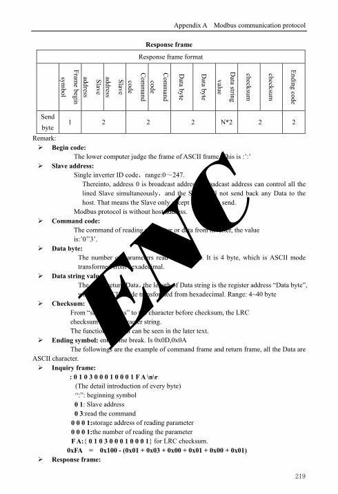
Appendix A Modbus communication protocol
219
Response frame
Response frame format
Fram
e begin
symbol
Slave
address
Slave
address
Com
mand
code
Com
mand
code
Data byte
Data byte
Data string
value
checksum
checksum
Ending code
Send
byte 1 2 2 2 N*2 2 2
Remark: Begin code:
The lower computer judge the frame of ASCII frame. This is :’:’ Slave address:
Single inverter ID code,range:0~247. Thereinto, address 0 is broadcast address. Broadcast address can control all the lined Slave simultaneously,and the Slave will not send back any Data to the host. That means the Slave only accept and do not send.
Modbus protocol is without host address. Command code:
The command of reading parameter or data from inverter, the value is:’0’’3’.
Data byte: The number of parameters read by a frame. It is 4 byte, which is ASCII mode transformed from hexadecimal.
Data string value: The detail return Data,the length of Data string is the register address “Data byte”, which is ASCII mode transformed from hexadecimal. Range: 4~40 byte
Checksum: From “slave address” to the character before checksum, the LRC checksum of the character string.
The function terminal can be seen in the later text. Ending symbol: enter, line break. Is 0x0D,0x0A
The followings are the example of command frame and return frame, all the Data are ASCII character. Inquiry frame:
: 0 1 0 3 0 0 0 1 0 0 0 1 F A \n\r (The detail introduction of every byte) “:”: beginning symbol
0 1: Slave address 0 3:read the command
0 0 0 1:storage address of reading parameter 0 0 0 1:the number of reading the parameter F A: 0 1 0 3 0 0 0 1 0 0 0 1 for LRC checksum.
0xFA = 0x100 - (0x01 + 0x03 + 0x00 + 0x01 + 0x00 + 0x01) Response frame:
ENC

Appendix A Modbus communication protocol
220
: 0 1 0 3 0 2 0 0 3 3 C 7 \n\r (The detail introduction of every byte) “:”: beginning symbol
0 1: Slave address 0 3:read the command 0 2:The byte length of return parameter Data. 0 0 3 3:return parameter,current storage value
C 7: 0 1 0 3 0 2 0 0 3 3 for LRC checksum. 0xC7 = 0x100 – (0x01 + 0x03 + 0x02 + 0x00 + 0x33)
The main frame writes slave address single register, command code: 06
The host frame
The host frame format
Fram
e begin
symbol
Slave add
ress
Slave add
ress
Slave add
ress
Com
man
d
code
Register
address
Register
address
Register
address
Register
address
Data
Data
Data
Data
Ch
eckou
t
checkou
t
En
ding
symbol
Send byte
1 2 2 4 4 2 2
Remark: Slave address:
Single inverter ID code,range:0~247. Thereinto, address 00 is broadcast address.
Command code: Read parameter from inverter or command of Data, the value is:06
Register address: The storage address of inverter function parameter, is double byte. The high byte is in the front and the low byte is in the back.
The detail relation between parameter and storage address can be seen in the later excel. Data:
The new value of revised parameter. Checksum:
From “slave address” to the character before checksum, the LRC checksum of the character string.
Response frame
Response frame format
Fram
e begin
symbol
Slave add
ress
Slave add
ress
Com
man
d
code
Com
man
d
code
Register
address
Register
address
Register
address
Register
address
Data
Data
Data
Data
Ch
eckou
t
Ch
eckout
En
ding
symbol
Send byte
1 2 21 4 4 2 2
ENC

Appendix A Modbus communication protocol
221
Remark: Slave address:
Single inverter ID code,range:0~247. Thereinto, address 00 is broadcast address.
Command code: Read parameter from inverter or command of Data, the value is:06
Register address: The storage address of inverter function parameter, is double byte. The high byte is in the front and the low byte is in the back.
The detail relation between parameter and storage address can be seen in the later excel.
Data: The new value of revised parameter.
Checksum: From “slave address” to the character before checksum, the LRC checksum of the character string.
The followings are the example of command frame and return frame, all the Data are ASCII character.
Inquiry frame: : 0 1 0 6 0 1 0 1 1 3 8 8 5 C \n\r
(The detail introduction of every byte) “:”: beginning symbol
0 1: Slave address 0 6:write command
0 1 0 1:storage address of writing parameter 1 3 8 8:the value of writing parameter 5 C: 0 1 0 6 0 1 0 1 1 3 8 8 for LRC checksum.
0x5C = 0x100 - (0x01 + 0x06 + 0x01 + 0x01 + 0x13 + 0x88) Response frame:
: 0 1 0 6 0 1 0 1 1 3 8 8 5 C \n\r (Detail introduction of every byte) “:”: beginning symbol
0 1: Slave address 0 6:write command
0 1 0 1:storage address of writing parameter 1 3 8 8:the value of writing parameter 5 C: 0 1 0 6 0 1 0 1 1 3 8 8 for LRC checksum.
0x5C = 0x100 - (0x01 + 0x06 + 0x01 + 0x01 + 0x13 + 0x88)
ENC

Appendix A Modbus communication protocol
222
A.9 CRC checkout mode CRC checkout value calculating function written by C language is as follows:
unsigned int cal_crc_value (unsigned char *pval, unsigned char len) unsigned int crc_value=0xFFFF; unsigned int i; while(len--) crc_value ^= *pval++; for(i=0; i<8; i++) if(crc_value & 0x0001) crc_value >>= 1; crc_value ^= 0xA001; else crc_value >>= 1; return(crc_value);
Note
(1) ASCII frame realizes transform by that 8Bit hexadecimal is divided as different 2 character of 4, and then grouped ashexadecimal of one 8Bit when reaching the destination. (2) Frame header, add“:”, frame footer adds“\n\r” the enter line break character. (3) The valid character in the protocol is: :, 0,1,2,3,4,5,6,7,8,9,A,B,C,D,E,F and hexadecimal 0DH, lower case ASCII letter a, b, c, d, e, f is invalid (4) The subject data volume is the 2 times as RTU, checksum adopt LRC check. (5) For the other information, please refer to the official standard protocol when need.
ENC

Appendix B Free-port communication protocol
223
Appendix B Free-port communication protocol
B. 1 Summarization We provide the customer with general RS485/RS232 communication interface in our
EN500/EN600 series frequency inverter. For the users, through the communication interface upper device (such as PC, PLC controller etc.) can perform centralized monitor to the inverter (such as setting inverter parameter, controlling run of inverter, reading work state of the inverter) and also long-distance control keypad can be connected to realize diverse operating requirement of the user.
This communication protocol is interface criterion file designed for realizing above-mentioned function, please read it earnestly and program according to it so that realize long-distance and network control to the inverter.
B. 2 Protocol content and description
B.2.1 Communication net buildup mode
Fig.B-1 Net buildup graph
B.2.2 Communication mode
At present, EN500/EN600 inverter can be used as not only auxiliary device but also mainframe device in RS485, If the inverter is used as auxiliary device, master device can be completed by PC, PLC or human interface, and if used as mainframe device, the main- auxiliary control of the inverter can be complement by it, Specific communication mode is as mentioned below:
(1) PC or PLC as mainframe, inverter as auxiliary device, point-to-point communication between mainframe and auxiliary device.
(2) Auxiliary device don’t response when mainframe send out command by broadcast address.
(3) User can set local address, baud rate and data format of the inverter through auxiliary device keypad.
(4) Auxiliary device report current failure information to mainframe in the last response frame.
(5) EN500/EN600 provides RS485 interface.
Mainframe is PC Mainframe is PC
232-485 conversion module
EN600 EN600 EN500 EN500
or
RS232
RS485
EN500/EN600 mainframeor
ENC

Appendix B Free-port communication protocol
224
B.2.3 Transport mode
Asynchronous serial, semiduplex transport mode. Default format and transport rate: 8-N-1, 9600bps.For specific parameter setting please see description for F05 group function code.
(Remark: The definition for this parameter is only effective under free –port communication mode, and definition for other parameters are the same as original)
F05.00 Protocol selection
0:Modbus protocol 1:Reserved 2:Profibus protocol(Extension effective) 3:CanLink protocol(Extension effective) 4:CANopen protocol(Extension effective) 5:Freedom protocol 1(Can modify all function parameters of EN500/EN600) 6:freedom protocol 2 (Can only modify part of function parameter of EN500/EN600) Remark: Expansion card is needed if select protocol 2, 3, 4
1 0 ×
F05.01 Baud rate configuration
Units digit: freedom protocol and Modbus baud rate selection 0:300BPS 1:600BPS 2:1200BPS 3:2400BPS 4:4800BPS 5:9600BPS 6:19200BPS 7:38400BPS 8:57600BPS
1 005 ×
F05.02 Data format Units digit: freedom protocol and Modbus protocol data format 0:1-8-1 format, no checkout, RTU 1:1-8-1 format, even checkout, RTU 2:1-8-1 format, odd checkout, RTU 3:1-7-1 format, no checkout, ASCII 4:1-7-1 format, even checkout, ASCII 5:1-7-1 format, odd checkout, ASCII
00 ×
F05.03 Local address 0~247, 00 is master station address 1 1 ×
ENC

Appendix B Free-port communication protocol
225
B.2.4 Data command frame format
Main device command frame format
Sending order
1 2 3 4 5 6 7 8 9 10 11 12 13 14 15 16 17 18
Fram
e head
Au
xiliary device address
Au
xiliary device address
Main
device com
man
d
Main
device com
man
d
Assistant ind
ex
Assistant ind
ex
Com
man
d in
dex
Com
man
d in
dex
Set d
ata
Set d
ata
Set d
ata
Set d
ata
Ch
eckou
t sum
Ch
eckou
t sum
Ch
eckou
t sum
Ch
eckou
t sum
Fram
e end
Definition
Head
Ad
dress
Com
man
darea
Index
area
Settin
g d
ata area
Ch
eckou
t area
En
d
Sending byte
1 2 2 4 4 4 1
Auxiliary device response frame format
Sending order
1 2 3 4 5 6 7 8 9 10 11 12 13 14 15 16 17 18
Fram
e head
Au
xiliary device address
Au
xiliary device address
Au
xiliary device respon
se
Au
xiliary device respon
se
Failure in
dex
Failure in
dex
Com
man
d in
dex
Com
man
d in
dex
Ru
n d
ata
Ru
n d
ata
Ru
n d
ata
Ru
n d
ata
Ch
eckou
t sum
Ch
eckou
t sum
Ch
eckou
t sum
Ch
eckou
t sum
Fram
e end
Definition
head
address
response
area
Index
area
Ru
n d
ata area
Ch
eckou
t area
end
Sending byte
1 2 2 4 4 4 1
Fig.B-2 Command/Response frame format
Remark: (1) “Setting data area” and “run data area” may not be existent in some command/data frame
format, So in protocol command list it’s marked with “nothing”. (2) In protocol effective character set is: ~, 1, 2, 3, 4, 5, 6, 7, 8, 9, A, B, C, D, E, F and hex
data 0DH, ASCII lowercase a, b, c, d, e, f are invalid. (3) Effective command frame length is 14 or 18 byte.
ENC

Appendix B Free-port communication protocol
226
B.2.5 Explanation and description for format
(1) Frame head It’s character“~” (namely hex 7E), single byte.
(2) Auxiliary device address Data meanings: local address of auxiliary device, double byte. ASCII format. Inverter factory
default is 01. (3) Mainframe command/auxiliary device respond
Data meanings: mainframe send out command and auxiliary device respond to the command. Double byte, ASCII format.
Response code function classification: Species 1>: Command code=“10”, mainframe ask auxiliary device to report current
preparation state and control situation.
Table B-1 Command code meanings for response frame response area
Response code
ASCII
Meanings
Preparation state of auxiliary device
Control from mainframe is allowed
To set frequency is allowed
10 Haven’t get ready No meaning
11 Get ready Allow Allow
12 Get ready Allow Allow
13 Get ready Don’t allow Don’t allow
14 Get ready Don’t allow Don’t allow
20 Frame error
Species 2>: Command code=“11”~“15”, 5 kinds of function command which mainframe send to auxiliary device, For detail please see protocol command list.
Table B-2 Response code meanings for response frame command index area
Response code
ASCII Meanings of response code Description
00
Auxiliary device communication and control is normal; function code modification is effective; password is correct.
20
(1) frame checkout error; (2)“command area” data overrun; (3)“index area” data overrun; (4)frame length error/non ASCII byte exist in area except frame head, frame end.
When this response code is reported, data of “command area”, “index area” and “running data area” are not reported.
30
(1) control to auxiliary device is ineffective; (2) ineffective function code parameter modification; (3)“setting/running data” area data overrun. (4) password error.
Whether report this response code relate to current set state of auxiliary device. When report data of area”, “index area” and “run data area” are reported according to protocol requirement.
ENC

Appendix B Free-port communication protocol
227
(4) Auxiliary index/command index/failure index Data meanings: include auxiliary index byte and command index byte. For mainframe, auxiliary index, command index are used for cooperating mainframe
command in realizing specific function. For auxiliary device, auxiliary index, command index are used for reporting failure state code,
command index are reported without modification Data type: hex, 4 byte, ASCII format. Command index occupy 2 low byte, data range: “00”~“FF”. Auxiliary index occupy 2 high byte, data range: “00”~“FF”. Auxiliary device failure state occupy “auxiliary index’’ byte, see table B-3.
Table B-3 Free-port1 failure type description
Failure code(decimal)
Description Failure
code(decimal) Description
1 Overcurrent during accelerating process
19 Current detecting circuit failure
2 Overcurrent during decelerating process
20 External interference failure
3 Overcurrent during constant speed process
21 Internal interference failure
4 Overvoltage during accelerating process
22 PID provision loss
5 Overvoltage during decelerating process
23 PID feedback loss
6 Overvoltage during constant speed process
24 PID error amount exception
7 Overvoltage while halting 25 Startup terminal protection
8 Under voltage during running process
26 RS485 communication failure
9 Inverter overload protection 27 Reserved
10 Motor overload protection 28 Reserved
11 Motor underload protection 29 Reserved
12 Input phase missing 30 E2PROM read and write wrongly
13 Output phase missing 31 Temperature detection breakage
14 Inverting module protection 32 Self-tuning failure
15 Short circuit to earth during running process
33 Contactor exception
16 Short circuit to earth during electrifying process
34 Interior failure 1
17 Inverter over heating
18 External device failure
ENC

Appendix B Free-port communication protocol
228
Free-port 2 Failure type description
Failure code(decimal)
Description Failure
code(decimal) Description
1 Overcurrent during accelerating process
13 Inverting module protection
2 Overcurrent during decelerating process
14 External device failure
3 Overcurrent during constant speed process
15 Current detecting circuit failure
4 Overvoltage during accelerating process
16 RS485 communication failure
5 Overvoltage during decelerating process
17 Reserved
6 Overvoltage during constant speed process
18 Reserved
7 Control power supply overvoltage
19 Under voltage
8 Inverter overload 20 System interference
9 Motor overload 21 Reserved
10 Inverter over heating 22 Reserved
11 Reserved 23 E2PROM read and write wrongly
12 Reserved
(5) Checkout sum Data meanings: frame checkout, 4 byte, ASCII. Calculation method: accumulative sum of ASCII code value of all byte from “auxiliary
device address ”to“ run data”. (6) Frame end
Hex 0D, single byte.
B.2.6 Protocol command list
Frame 7E and frame end 0D, address, checkout sum, ASCII character format are omitted in following description.
Table B-4 Free-port 1 protocol command table
Nam
e
Main
frame ord
er Decim
al
Au
xiliary ind
ex Hex
Ord
er ind
ex Hex
Ru
n d
ata setting ran
ge
Hex
Main
frame sen
din
g examp
le,
such
as PC
control op
eration
of inverter
(C lan
guage clu
ster format ,
auxiliary d
evice is set to 01)
Ru
n d
ata precision
Descrip
tion
ENC

Appendix B Free-port communication protocol
229
Look up auxiliary motor state 10 00 00 no ~010A00000192\r 1
Read
param
eter of auxiliary m
otor
Main setting frequency 11 00 00 no ~010B00000193\r 0.01Hz
Auxiliary setting
frequency 11 00 01 no ~010B00010194\r 0.01Hz
Setting frequency 11 00 02 no ~010B00020195\r 0.01Hz
Output frequency 11 00 03 no ~010B00030196\r 0.01Hz
Output current 11 00 04 no ~010B00040197\r 0.1A
Output voltage 11 00 05 no ~010B00050198\r 1V
DC bus-bar voltage 11 00 06 no ~010B00060199\r 0.1V
Load motor revolving speed 11 00 07 no ~010B0007019A\r 1RPM
Load motor linear speed 11 00 08 no ~010B0008019B\r no
Inverter temperature 11 00 09 no ~010B0009019C\r 1
Runtime 11 00 0A no ~010B000A01A4\r 0.1min
Current accumulative
runtime 11 00 0B no ~010B000B01A5\r 1h
Current accumulative
power-on time 11 00 0C no ~010B000C01A6\r 1h
Inverter state 11 00 0D no ~010B000D01A7\r no
Input terminal state 11 00 0E no ~010B000E01A8\r no
Output terminal state 11 00 0F no ~010B000F01A9\r no
Expand output terminal
state 11 00 10 no ~010B00100194\r no
Expanding input terminal
state 11 00 11 no ~010B00110195\r no
Communicational virtual
input terminal state 11 00 12 no ~010B00120196\r no
Internal virtual input node
state 11 00 13 no ~010B00130197\r no
Analog input AI1 11 00 14 no ~010B00140198\r no
Analog input AI2 11 00 15 no ~010B00150199\r no
Expanding analog input
EAI1 11 00 16 no ~010B0016019A\r no
Expanding analog input
EAI2 11 00 17 no ~010B0017019B\r no
Analog AO1
output 11 00 18 no ~010B0018019C\r no
Analog AO2 output 11 00 19 no ~010B0019019D\r no
Expanding analog EAO1
output 11 00 1A no ~010B001A01A5\r no
Expanding analog EAO2
output 11 00 1B no ~010B001B01A6\r no
External pulse input
frequency 11 00 1C no ~010B001C01A7\r 1Hz
Reserved
Process PID provision 11 00 1E no ~010B001E01A9\r 0.01V
Process PID feedback 11 00 1F no ~010B001F02AA\r 0.01V
Process PID error 11 00 20 no ~010B00200195\r 0.01V
Process PID output 11 00 21 no ~010B00210196\r 0.01Hz
Simple PLC current 11 00 22 no ~010B00220197\r no
ENC

Appendix B Free-port communication protocol
230
segments
External multi-section
speed current segments 11 00 23 no ~010B00230198\r no
Provision pressure for
constant pressure water 11 00 24 no ~010B00240199\r
0.001
Mpa
Feedback pressure for
constant pressure water 11 00 25 no ~010B0025019A\r
0.001
Mpa
Relay state for constant
pressure water 11 00 26 no ~010B0026019B\r no
Current length 11 00 27 no ~010B0027019C\r no
Accumulative length 11 00 28 no ~010B0028019D\r no
Current internal count 11 00 29 no ~010B0029019E\r no
Current internal time 11 00 2A no ~010B002A01A6\r no
Setting channel for run
command 11 00 2B no ~010B002B01A7\r no
Main frequency provision
channel 11 00 2C no ~010B002C01A8\r no
Auxiliary frequency
provision channel 11 00 2D no ~010B002D01A9\r no
Inverter rated current 11 00 2E no ~010B002E01AA\r 0.1A
Inverter rated voltage 11 00 2F no ~010B002F01AB\r 1V
Inverter rated power 11 00 30 no ~010B00300196\r 0.1KW
Reserved
Reserved
Frequency after
acceleration and
deceleration
11 00 33 no ~010B00330199\r 0.01Hz
Motor rotor frequency 11 00 34 no ~010B0034019A\r 0.01Hz
Current provision torque 11 00 35 no ~010B0035019B\r 0.1%
Current output torque 11 00 36 no ~010B0036019C\r 0.1%
Current torque current 11 00 37 no ~010B0037019D\r 0.1A
Current flux current 11 00 38 no ~010B0038019E\r 0.1A
Run control and adjusting function
Auxiliary device run
command 12 00 00 no ~010C00000194\r no
Set current run frequency
provision of auxiliary
device
12 00 010Hz~high
limit freq~010C00010FA0027C\r 0.01Hz
Set freq.
=40.00Hz
Auxiliary device run with
run frequency provision 12 00 02
0Hz~high
limit freq~010C00020FA0027D\r 0.01Hz
Auxiliary
device run
Set freq.
=40.00Hz
Auxiliary device forward
run 12 00 03 no ~010C00030197\r no
Auxiliary device reverse
run 12 00 04 no ~010C00040198\r no
Auxiliary device forward
run with run frequency
provision
12 00 050Hz~ high
limit freq~010C00050FA00280\r 0.01Hz
Forward run
boot-strap
Set freq.
=40.00Hz
Auxiliary device reverse 12 00 06 0Hz~ high ~010C00060FA00281\r 0.01Hz Reverse run
ENC

Appendix B Free-port communication protocol
231
run with run frequency
provision
limit freq boot-strap
Set freq.
=40.00Hz
Auxiliary device stop 12 00 07 no ~010C0007019B\r no
Auxiliary device jog run 12 00 08 no ~010C0008019C\r no
Auxiliary device forward
jog run 12 00 09 no ~010C0009019D\r no
Auxiliary device reverse
jog run 12 00 0A no ~010C000A01A5\r no
Auxiliary device stop run 12 00 0B no ~010C000B01A6\r no
Auxiliary device failure
restoration 12 00 0C no ~010C000C01A7\r no
Softw
are version
qu
ery order
Query auxiliary device
software version 15 00 00 no ~010F00000197\r 1
Free-Port 2 Protocol command table
Nam
e
Main
frame ord
er decim
al
Au
xiliary ind
ex hex
Ord
er ind
ex Hex
Ru
n d
ata setting ran
ge hex
Main
frame sen
din
g
examp
le, such
as PC
control op
eration of
inverter (C
langu
age cluster
format , au
xiliary device is
set to 01)
Ru
n d
ata precision
Descrip
tion
look up auxiliary motor state 10 00 00 no ~010A00000192\r 1 R
un control and adjusting function
Auxiliary device run
command 12 00 00 no ~010C00000194\r no
Set current run freq. of
auxiliary device 12 00 01
0Hz~ high
limit freq~010C00010FA0027C\r 0.01Hz
Auxiliary device run with
run frequency provision 12 00 02
0Hz~ high
limit freq~010C00020FA0027D\r 0.01Hz
Auxiliary device forward
run 12 00 03 no ~010C00030197\r no
Auxiliary device reverse
run 12 00 04 no ~010C00040198\r no
Auxiliary device forward
run with run frequency
provision
12 00 050Hz~ high
limit freq~010C00050FA00280\r 0.01Hz
Auxiliary device reverse
run with run frequency
provision
12 00 060Hz~ high
limit freq~010C00060FA00281\r 0.01Hz
Auxiliary device stop 12 00 07 no ~010C0007019B\r no
Auxiliary device jog run 12 00 08 no ~010C0008019C\r no
ENC

Appendix B Free-port communication protocol
232
Auxiliary device forward
jog run 12 00 09 no ~010C0009019D\r no
Auxiliary device reverse
jog run 12 00 0A no ~010C000A01A5\r no
Auxiliary device stop run 12 00 0B no ~010C000B01A6\r no
Auxiliary device failure
restoration 12 00 0C no ~010C000C01A7\r no
Softw
are version
qu
ery order
Query auxiliary device
software version 15 00 00 no ~010F00000197\r 1
Table B-5 Read auxiliary device function code parameter
Function
definition
Read auxiliary device function code parameter: all function code parameter except user
password and manufacturer password
except user password and manufacturer password
Meanings Frame
head Address Order
Order
index Run data
Checkout
sum
Frame
end
Mainframe
order 7EH ADDR 13 See remark 4 BCC 0DH
Byte quantity 1 2 2 4 0 4 1
Auxiliary
device respond 7EH ADDR 06 See remark
Function
code
parameter
BCC 0DH
Byte quantity 1 2 2 4 4 4 1
Remark
Command index=combination of function code group number and hex code of function
code number. For instance:
If want to read parameter of F0.05 function code, order index=0005;
If want to read parameter of F2.11 function code, order index =020B;
If want to read parameter of F2.15 function code, order index =020F;
If want to read parameter of F2.13 function code, order index =020D;
Corresponding relation between decimal and hex value of function code group No.
Function code
group No Decimal Hex
Function code
group No Decimal Hex
F00 0 00H F0E 14 0EH
F01 1 01H F0F 15 0FH
F02 2 02H F10 16 10H
F03 3 03H F11 17 11H
F04 4 04H F12 18 12H
F05 5 05H F13 19 13H
F06 6 06H F14 20 14H
ENC

Appendix B Free-port communication protocol
233
F07 7 07H F15 21 15H
F08 8 08H F16 22 16H
F09 9 09H F17 23 17H
F0A 10 0AH F18 24 18H
F0B 11 0BH F19 25 19H
F0C 12 0CH F1A 26 1AH
F0D 13 0DH F1B 27 1BH
Virtual data 0~FFFF (namely 0~65535)
Please input correct “user password” before you set user function code parameter.
Table B-6 Set auxiliary device function code parameter
Function
definition
Set auxiliary device function code parameter: all function code parameter except user password
and manufacturer password
Meanings Frame
head Address Order
Order
index Run data
Checkout
sum Frame end
Mainframe
order 7EH ADDR 14 See remark 4 BCC 0DH
Byte quantity 1 2 2 4 4 4 1
Auxiliary
device
respond
7EH ADDR 06 See remark
Function
code
parameter
BCC 0DH
Byte quantity 1 2 2 4 4 4 1
Remark
Command index=combination of function code group number and hex code of function code
number. For instance:
If want to read parameter of F00.05 function code, order index=0005;
If want to read parameter of F02.11 function code, order index =020B;
If want to read parameter of F02.15 function code, order index =020F;
If want to read parameter of F02.13 function code, order index =020D;
Corresponding relation between decimal and hex value of function code group No.
Function code
group No Decimal Hex
Function code
group No Decimal Hex
F00 0 00H F0E 14 0EH
F01 1 01H F0F 15 0FH
F02 2 02H F10 16 10H
F03 3 03H F11 17 11H
F04 4 04H F12 18 12H
F05 5 05H F13 19 13H
F06 6 06H F14 20 14H
F07 7 07H F15 21 15H
F08 8 08H F16 22 16H
ENC

Appendix B Free-port communication protocol
234
F09 9 09H F17 23 17H
F0A 10 0AH F18 24 18H
F0B 11 0BH F19 25 19H
F0C 12 0CH F1A 26 1AH
F0D 13 0DH F1B 27 1BH
Virtual data 0~FFFF(namely 0~65535)
ENC

Appendix C Keyboard
235
Appendix C Keyboard
C.1 Keyboard selection:
NO. Type Details Remark
1 EN-LED3-D Local LED single-display digital potentiometer keyboard(With
the function of parameter copy) Standard
2 EN-LED4-D Local LED double-display digital potentiometer keyboard(With
the function of parameter copy) Optional
3 EN-LCD1 Local LCD Keyboard(with the function of parameter copy) Optional
4 EN-LCD2 Remote Control LCD Keyboard(with the function of parameter
copy) Optional
5 EN-LED1 Local LED single-display keyboard Optional
At present, Our has 4 kinds of optional keyboards for our customers’ selection, they are EN-LED4-D, EN-LCD1, EN-LCD2 and EN-LED1. Their outer dimension and installation size are the same as the standard keyboard EN-LED3-D. For more detailed dimension, please refer to “Keyboard Operation and Outer Size of Keyboard installing box” in Chapter 2.
C.2 LED double-display digital potentiometer keyboard Local LED double-display digital potentiometer keyboard type: EN-LED4-D
C.2.1 Keyboard Layout
Fig.C-1 EN-LED4-D Operating Keyboard Layout
模式指示灯
变频器故障报警指示灯
LED1显示电流指示单位(A) LED1显示频率指示单位(Hz)
LED1显示电压指示单位(V)
变频器正转指示灯
变频器反转指示灯
编程/退出键
反转/点动键
递增键
数字电位器
递减键停止/复位键
正转运行键
LED2显示电流指示单位(A)LED2显示电压指示单位(V)
LED2显示每分钟转速指示单位(r/min)
(LED2显示频率指示单位(Hz))
参数百分比(%)数码显示(LED2)
数码显示(LED1)
移位/监控键 确认/数据键
Digital display(LED1)
Parameter percent(%) Speed(r/min)/Freq(Hz)indicator light LED2
Digital display(LED2)
Reverse run indicator light
Forward run indicator light
Voltage indicator light(LED1)
Frequency indicator light(LED1)
Mode indicator lightFailure alarm indicator light
Voltage indicator light(LED2) Current indicator light(LED2)
Current indicator light(LED1)
Digital potentiometer
Confirm/Data key Decrease key Stop/Reset keyForward run key
Increase key
Exit/Program key
Shift/Supervision key
Reverse/Jog key
(1) EN-LED3-D, EN-LED4-D,EN-LCD1,EN-LCD2 are four kinds of keyboard that with the function of parameter copy. (2) Using the function of parameter copy could through operating parameter F00.27. Note
ENC

Appendix C Keyboard
236
C.2.2 Description for keyboard functions, LED digital tubes and indicator lights
LED double -display digital potentiometer keyboard consists of two 5-digit digital tube screens,8 buttons, a digital potentiometer and 10 indicator lights.
If need more details about function definition of the 8 buttons, LED digital tubes, digital potentiometer and specification of the indicator lights, then please refer to “Keyboard Function Specifications” in Chapter 5.
C.3 LCD keyboard
C.3.1 LCD keyboard series:
(1) Local LCD keyboard type: EN-LCD1 (2) Remote control LCD keyboard type: EN-LCD2
C.3.2 Keyboard Layout
Fig.C-2 Keyboard Layout Sketch (EN-LCD1, EN-LCD2)
C.3.3 Keyboard Function, LCD Display and Spec. of Indicator Lights
LCD keyboard consists of a LCD screen, 9 buttons and 4 indicator lights LCD screen: To display Function Setting, Running Supervision, Failure Supervision Code
and Parameter. Multi-function key: The specific function keys decided by tens digit of F00.15 see F00.15
parameter descriptions. For more details about function definition of the 8 buttons and specification of the indicator
lights, please refer to “Keyboard Function Specifications” in Chapter 5.
模式指示灯
变频器故障报警指示灯 变频器正转指示灯
变频器反转指示灯
编程/退出键
多功能键
反转/点动键
递增键
确认/数据键
移位/监控键递减键停止/复位键正转运行键
LCD显示屏
Failure alarm indicator light
Mode indicator light
Exit/Program key
Multiple function key
Reverse/Jog key
Confirm/Data key
Stop/Reset key
Reverse run indicator light Forward run indicator light
LCD screen
Increase key
Decrease key
Forward run key
Shift/Supervision key
LED2 digital tube supervision is set by parameter F00.25.
Note
ENC

Appendix C Keyboard
237
C.3.4 Operating Spec. of LCD Display Keyboard
(1) Initialization status of LCD keyboard when power on
When the keyboard is power on, “Key Board” is displayed in the form of animation:
Fig.C-3 Initialization Display when Power On
(2) Operation of switching to firstly menu (Fig. C-4):
Fig.C-4 Power on initialized display
When set F00.00=2, Senior Menu parameters F00~F27 can be displayed, 28 groups in total. Operation methods are shown as Fig. C-4.
Keyboard
F00:System Parameter Group
F01:Basic Running Group
F02:Start Stop Brake Group
F03: V/F Control Group
F00:System Parameter Group
F01:Basic Running Group
F02: Start Stop Brake Group
F03: V/F Control Group
F00:System Parameter Group
F01:Basic Running Group
F02:Start Stop Brake Group
F03: V/F Control Group
F00:System Parameter Group
F01:Basic Running Group
F02: Start Stop Brake Group
F03: V/F Control Group
F26:Fault Record Group
F00:System Parameter Group
F01:Basic Running Group
F02: Start Stop Brake Group
F03: V/F Control Group
Press Press
Press
Press Press ENC

Appendix C Keyboard
238
(3) Display and operation of secondary menu:
When you are in the Firstly Menu, choose a parameter group, then press “ENTER/DATA” key and you will enter into the Secondary Menu. Take Parameter F00.00 for example:
Fig.C-5 Example of Secondary Menu Operation
Parameter Group Display
F0000=0
0:Basic List Mode
Range 0~4
Parameter Group Display
F0000=2
2:Senior List Mode
Range 0~4
Press increase button
F00:System Parameter Group
F01:Basic Running Group
F02:Start Stop Brake Group
F03: V/F Control Group
F00:System Parameter Group
00: Parameter Group Display
01:C00 display when operation
02: C01 display when operation
ENTER/DATA
ENTER/DATA
ENC

Appendix C Keyboard
239
(4) Function Parameter Operation
Function parameter operation includes the parameter checking, revise and storage of parameters. Before the operating the inverter, parameters should be set correctly. Operation methods are shown as Fig. C-6:
Fig.C-6 Example of function parameter editing
Motor Control Mode
F0024= 0
0:V/F Control
Range: 0~2
Motor Control Mode
F0024=1
1:Speedless Vector Control
Range: 0~2
Press increase button
ENTER/DATA
Frequency Setting
C00 050.00 Hz
Frequency Setting
050.00 Hz
F00:System Parameter Group
F01:Basic Running Group
F02:Start Stop Brake Group
F03: V/F Control Group
F00:System Parameter Group
00: Parameter Group Display
01:C00 display when operation
02:C01 display when operation
F00:System Parameter Group
24: Motor Control Mode
25:Supervision 2 selection
26:Busbar voltage coefficient
ESC/MENU
ENTER/DATA
Press
ENC

Appendix C Keyboard
240
(5) Fault query status
When fault alarm occurs, customers can enter the fault query status:
Fig.C-7 Fault query status
Fault Alarm!
E13
Output Phase Loss
F26:Fault Record Parameter
00:The Last Fault Record
01:The Last Two Fault Record
02: The Last Three Fault Record
The Last Fault Record
F2600=13
13:Output Phase Loss
Range 00~50
ESC/MENU
ENTER/DATA
ENC

Appendix C Keyboard
241
C.4 LED single-display keyboard The type of local single-display keyboard:EN-LED1.
C.4.1 Keyboard Layout
Fig.C-8 EN-LED1 Operation keyboard layout
C.4.2 Keyboard function, LED Nixie tube and indicator light description
LED single-display keyboard is composed of a 5-digit nixie tube display、9 keys and 6 indicator lights.
Multi-function key: The specific function keys decided by tens digit of F00.15 see F00.15 parameter descriptions.
For more details about function definition of the 8 buttons and specification of the indicator lights, please refer to “Keyboard Function Specifications” in Chapter 5.
模式指示灯
变频器故障报警指示灯
显示电流指示单位(A) 显示频率指示单位(Hz)
显示电压指示单位(V)
变频器正转指示灯
变频器反转指示灯
编程/退出键
多功能键
反转/点动键
递增键
确认/数据键
移位/监控键递减键停止/复位键
正转运行键
Failure alarm indicator light
Mode indicator light
Current indicator light
Voltage indicator light
Frequency indicator light
Forward run indicator light
Reverse run indicator light
Confirm/Data key
Shift/Supervision key
Decrease key Stop/Reset key
Forward run keyReverse/Jog key
Multiple function key
Exit/Program key
Increase key
Note
(1) Key position of EN-LED1, EL-LCD1, EN-LCD2 is different from those standard
keyboard, please note the key position of these three keyboards.
(2) For EN-LED1, EN-LCD1, EN-LCD2 these keyboards, the deblocking way is
different from the standard keyboards, the deblocking way is to press or press
for more than 2 seconds.
ENC

Appendix C Keyboard
242
C.5 Communication Component
The maximum electric distance between keyboard EN-LED3-D, EN-LED4-D, EN-LCD1, EN-LED1 and local inverter is 2m.
RS485 communication mode is adopted between inverter and remote keyboard EN-LCD2, only an ordinary cable is needed to connect each other, and their maximum electric distance can be 1000m. When the communication with each other is main-auxiliary mode, namely take remote keyboard as main device and inverter as auxiliary device. The terminals of the connection cable are made by crystal ends, so it is easy to maintain. Power needs customers’ outer leading,the voltage range is from 10V to 24V,the demand current is 150mA,1mm2 of PVC insulate copper wire is suggested to connect.
Following function can be realized by remote keyboard: (1) Can control run, stop, jog, failure reset, change setting frequency, modify function
parameter and run direction of auxiliary device. (2) Can identify the type of auxiliary device. Can monitor the running frequency, setting
frequency, output voltage, output current, analog closed loop feedback, analog closed loop setting and exterior counting value of auxiliary device.
ENC

Appendix D Communication extension card
243
Appendix D Communication extension card
D.1 Communication card selection: At the present, there are four kinds of communication card can be selected for.
Serial No. Type Description Remark
1 EN-PR01 PROFIBUS-DP communication card (Use in 15KW and the
below ) Optional
2 EN-PR02 PROFIBUS-DP communication card (Use in 15KW the
above) Optional
3 EN-CAN1 CANopen communication card Optional
4 EN-CAN2 CANlink communication card Optional
D.2 PROFIBUS-DP communication card
D.2.1 PROFIBUS introduction (1) PROFIBUS (Short for Process Field Bus), PROFIBUS is an international and open field
bus standard independent with manufacturer. It can be support for many equipment manufacturers, with good compatibility. It’s widely used in Manufacturing Automation, automation of process industry, and other buildings, transportation, electric power automation field.
(2) PROFIBUS can realize exchanging the data between all kinds of element of automation, all of this equipment can exchange the information though the same port. But the transmission rate is different .all the automatic equipment can exchange the information though the same port, but with the different rates, so PROFIBUS should offer different types for the speed rates selection. it is made up with PROFIBUS-DP(Distributed peripheral ), PROFIBUS-PA, PROFIBUS-FMS.
(3) PROFIBUS (RS485), the first layer realize the balanced data transmission, wire a bus segment one Bus segment is shielded twisted pair cable, both ends of the segments have a terminating resistor. Transmission mode to half duplex, asynchronous, synchronous gap-free data exchange basis, the physical layer supports fibre, the data frame 11, and the transfer rate: 9.6Kbit / sec-12Mbit / sec. Bus length range from 100 to 1200 meters
(4) Between same-level controller and PC communications (token passing procedure), to ensure adequate opportunity to deal with their communication tasks in a determined time. Complex PLC and PC with a simple division formula I / O communications, you must quickly and with minimal protocol overhead (master - slave program)
ENC

Appendix D Communication extension card
244
D.2.2 The external form of PROFIBUS-DP and terminal definition description
Fig D-1 PROFIBUS-DP outline dimensional drawing
Table D-1 Terminal function description
Terminal
date Name Description Remark
J2 USB form adapter
plugs
USB connection factory and distribution to DB9
adapter cable
Use it on 15KW
frequency inverter or
below
J3 DB9 communication
port
communication signal connection interface,
9-pin DB9 female.
Use it on 15KW
frequency inverter or
the above
JP2 Board-level docking
connector
When you install this plug docking with the
main control board CN2
J3
J2
JP2JP3
ENC

Appendix D Communication extension card
245
(1) J3 Plug pin definition:
PIN
data Definition
PIN
data Definition
1 Bit bare 6 VCC
2 Bit bare 7 Bit bare
3 Communication signal A 8 Communication signal B
4 Bit bare 9 bit bare
5 GND - -
(2) J2 Plug pin definition:
PIN
data Definition
PIN
data Definition
1 Communication signal A 3 GND
2 Communication signal B 4 VCC
(3) J2 switch wiring
Table D-2 The left end plug and The right end plug PIN data
The left end plug
PIN data
The right end plug
PIN data
The left end plug
PIN data
The right end plug
PIN data
- 1 4 6
- 2 - 7
1 3 2 8
- 4 - 9
3 5 - -
1 3
2 4
15
69
1
5
6
9
A向A向
B向 B向
1 23 4
左端插头
右端插头Right plug Direction B
Direction B
Left plug Direction A
Direction A ENC

Appendix D Communication extension card
246
D.3 CANopen communication card
D.3.1 CANopen introduction CANopen is an architecture in the control area network (Controller Area Network, CAN) on
the high-level communication agreements, including communication equipment sub-sub-agreements and agreements, often used in embedded systems, industrial control is a commonly used fieldbus. CANopen implements the network layer and above the agreement OSI model. CANopen standard includes addressing scheme, several small communication sub-agreements
D.3.2 Equipment model Communication agreement on other modules communication processing and network
communication unit needed to start and reset the device has a state machine control. State machine include: Initialization, Pre-operational, Operational, Stopped.
D.3.3 Object Dictionary
Object Dictionary (OD: Object Dictionary) is an ordered group of objects; each object using an index value of 16 is addressed, in order to allow access to the data structure of a single element, while the definition of an eight sub-indexes.
D.3.4 Communication
(1) Communication objects: Management packets, Service Data Objects (SDO), process data objects (PDO), the pre-definition packet or special function object
(2) Communication model: master/slave model, client/server model, producer/consumer model
D.3.5 Agreement
(1) NMT Agreement (network management, network management): Status Agreement definition of the state machine change commands (such as starting or stopping the equipment), to detect remote device bootup and failure scenarios.
(2) Heartbeat Agreement: nodes in the network to monitor and confirm it is working properly. (3) SDO agreement: between devices used to transfer large low-priority data, typically used
to configure devices on the CANopen network. (4) PDO Agreement: 8 bytes or less used to transmit data, no other agreement preset (which
means data has been pre-definition).
ENC

Appendix D Communication extension card
247
D.3.6 CANopen form and terminal definition description
Fig D-2 CANopen outline dimensional drawing
Table D-3 Terminal function description Terminal
number Name Description Remark
CN1 Communication wiring
terminal
By the client device connected to the CAN bus
communication
J1 Signal port When you install this plug docking with the
main control board CN2
J2 Terminal resistor access
entry Connect J2, then terminal resistor connect to bus
(1) CN1 pin definition
PIN data Definition PIN data Definition
1 Signal CANL 3 COM
2 Signal CANH - -
ENC

Appendix D Communication extension card
248
D.4 CANlink communication card
D.4.1 CANlink introduction
The physical layer CANlink card is CAN bus, only supports CAN2.0B extended frame. Since the control signal CANlink card connected directly to the main board, compared with CANOPEN card, with high transmission efficiency, real-time, stability and other characteristics, the maximum transfer rate of 1Mbps. CAN bus data transmission using a differential signal, with strong anti-interference, transmission distance and other characteristics, the communication rate 5Kbps below, the farthest reach 10Km, at 1Mbps baud rate up to 30m.
CANlink protocol is self-definition protocols, support for modifications and inverter terminal parameters monitoring.
D.4.2 CANlink card figure and terminal definition description
Fig D-3 CANlink Dimensions Table D-4 Terminal function description
Terminal
Number Name Description Remark
CN1 Communication wiring
terminal
By the client device connected to the CAN
bus communication
ENC

Appendix D Communication extension card
249
J1 Signal port When you install this plug docking with the
main control board CN2
J2 Terminal resistor access entry Connect J2, then terminal resistor connect to
bus
(1) The definition of CN1 pin.
PIN data Definition PIN data Definition
1 Signal CANL 3 COM
2 Signal CANH - -
ENC

Appendix E Universal encoder expansion card
250
Appendix E Universal encoder expansion card
E.1 The selection of encoder expansion card: Universal encoder expansion card (PG card), As an option to use, it is the necessary option
for closed loop vector control inverter.
No. Model Description Remark
1 EN-PG01 Differentiator input PG card, encoder input signal not isolated
(Suitable for all series machine) Optional
2 EN-PG02
Differentiator input PG card, encoder input signal through the
optocoupler isolation, stronger anti-interference ability (suitable
for all series machine)
Optional
3 EN-PG03 OC input PG card, encoder input signal through the optocoupler
isolation Optional
4 EN-PG04 Resolver(Rotary transformer) PG card, Available for 18.5KW
and above power inverter Optional
E.2 EN-PG01,EN-PG02 shape and terminal definitions
Fig.E-1 EN-PG01, EN-PG02 Outline dimension drawing
975
10864
3
2
1
CN1
CN2
ENC

Appendix E Universal encoder expansion card
251
Table E-1 Terminal function description
Terminal
number Name Description Remark
CN1 Board and board Butt
socket
When installing the plug and the main control board CN2
docking
CN2 The user interface The encoder uses
(1) CN2 Terminal definitions
PIN Data Terminal
labeling Description
1 PE Shielding terminal
2 PE Shielding terminal
3 GND Power supply (GND of EN-PG01 and GND of control panel is connect. GND of
EN-PG02 and GND of control panel isolation)
4 VCC Provide 5V/300mA current toward outside
5 A- Encoder output signal A negative
6 A+ Encoder output signal A positive
7 B- Encoder output signal B negative
8 B+ Encoder output signal B positive
9 Z- Encoder output signal Z negative
10 Z+ Encoder output signal Z positive
(2) PG card specification:
The user interface Terminal table
Spacing 3.81mm
The maximum rate 500kHz
Differentiator input signal amplitude ≤7V
ENC

Appendix E Universal encoder expansion card
252
E.3 EN-PG03 shape and terminal definitions
Fig.E-2 EN-PG03 Outline dimension drawing
Table E-2 Terminal function description
Terminal
number Name Description Remark
CN1 Board and board Butt
socket
When installing the plug and the main control board CN2
docking
CN2 The user interface The encoder uses
(1) CN2 Terminal definitions
PIN data Terminal labeling
Description
1 PE Shielding terminal
2 PE Shielding terminal
3 A Encoder output signal A
4 12V Provide voltage of 12V externally(Only supply power for 12V encoder)
5 B Encoder output signal B
6 24V Provide 24V/100mA current
7 Z Encoder output signal Z
8 COM Power ground
ENC

Appendix E Universal encoder expansion card
253
E.4 EN-PG04 sharp and terminal definitions
Fig.E-3 EN-PG04 Outline dimension drawing
Table E-3 Terminal function description
Terminal
number Name Description Remark
CN1 Board and board butt
socket
When installing the plug and the main control board CN2
docking
J2 User interface(DB9
terminal) Used for encoder connecting
(1) J2 Terminal definitions
Pin No. Definition Pin No. Definition
1 Rotary transformer exciting voltage - 5 Rotary transformer feedback COS +
2 Rotary transformer exciting voltage + 6~8 Vacancy
3 Rotary transformer feedback SIN + 9 Rotary transformer feedback COS -
4 Rotary transformer feedback SIN - - -
J2
15
69
ENC

Appendix E Universal encoder expansion card
254
(2) PG card specification instruction:
User interface Female DB9
Wire gauge >22AWG
Resolution 12 bit
Exciting frequency 10kHz
VRMS 7V
VP-P 3.15±25%
ENC

Appendix F Integration expansion card
255
Appendix F Integration expansion card
F.1 Expansion card model selection:
No. Model Introductions Note
1 EN-PRPGO1 PROFIBUS-DP and OC output PG integration expansion card
(apply to 5.5KW Inverter and above power) Optional
F.2 EN-PRPG01 expansion card
F.2.1 PROFIBUS Info
Please refer to appendix D about the details of communication expansion card.
F.2.2 Outside view and terminal definition introduction
Fig. F-1 Outline drawing
ENC

Appendix F Integration expansion card
256
Table F-1 Terminal function description
No. Name Description
J3 DP9 D type joint Communication signal connecting interface,9-pin DP9 female
JP2 Board level docking port Connect this plug with CN2 on the control board
JP3 Program download interface Used by manufacturer
CN1 User interface To connect encoder
(1) J3 plug pin definition:
Pin No. Definition Pin No. Definition
1 Vacancy 6 Power VCC
2 Vacancy 7 Vacancy
3 Communication signal A 8 Communication signal B
4 Vacancy 9 Vacancy
5 Power ground (GND) - -
(2) CN1 terminal definition
Pin No. Terminal mark Description
1 PE Shielding terminal
2 12V Provide 12V voltage(only supply for 12V encoder)
3 24V Provide 24V/100mA current
4 COM Power ground (GND)
5 A Encoder output A signal
6 B Encoder output B signal
7 Z Encoder output Z signal
15
69
ENC

Appendix G Analog input output extension card
257
Appendix G Analog input output extension card
G .1 Analog input output extension card Controlling output frequency of VFD by inputing external voltage or current analog signal.
No. Model Introductions Note
1 EN-AI1 Analog input output extension card, two line input, two lines
output Optional
G .2 EN-AI1 Outside view and terminal definition introduction
Fig.G-1 EN-AI1 Outline drawing
Table G-1 Terminal function description
No. Name Description Note
CN1 Board-grad connection port
Connect with CN2 of the main board when assembling
J1 Users interface Supply analog output or input connection port for users
12
2930
CN1
EAO1 EAO2 GNDEAI1 EAI2 GND
J11 2 3
5 64ENC

Appendix G Analog input output extension card
258
(1) J1 terminal definition
Pin No. Terminal mark Description
1 EAO1 Analog output channel 1, DIP switch can be used to achieve 0V to +10V
voltage signal output and 4mA to 20mA current signal output.
2 EAO2 Analog output channel 2, DIP switch can be used to achieve 0V to +10V
voltage signal output and 0mA to 20mA current signal output.
3 GND Power to ground electrode port
4 EAI1 Analog input channel 1, to achieve -10V to +10V voltage signal input and
4mA to 20mA current signal input, can control output frequency.
5 EAI2 Analog input channel 1, to achieve -10V to +10V voltage signal input and
4mA to 20mA current signal input, can control output frequency.
6 GND Power to ground electrode port.
ENC

Appendix H PLC Expansion card
259
Appendix H PLC Expansion card
H.1 PLC Expansion card: PLC expansion card supports 12-channel DI input, 8-channel DO output, 3-channel analog
input, 3-channel analog output, 1-channel RS485 and 1-channel serial port 232.
No. Model Specification Remark
1 EN-PLC1
PLC card adopt ladder diagram programming, can completely read
and write the parameters of the inverter and monitoring, but also
convenient for the digital IO and analog data interface set and
monitoring.
Optional
H.2 EN-PLC1 Description of outline and terminal
Diagram H-1 EN-PLC1outside drawing
J1
J9
J4
GN
DR
XT
X
J5
J2
PG
ND
EA
I1E
AO
1G
ND
B1
-A
1+
J6PA
4P
A3
PA
2P
A1
PC
CN1
12
2930
J3
J10
OP
CO
MX
12
X1
1X
10
X9
U2
U4
J7 J8
ENC

Appendix H PLC Expansion card
260
Table H-1 Resource type description
Resource
type Qty. No. Features & Specs
Read and
write
attribute
DI 12
X1~X7
The terminal is located in the inverter control board
Access digital input through the CAN_MSET directive
Input voltage range:15~30V
read only
X8
The terminal is located in the main control board of the inverter
and accessed by CAN_MSET instruction
Input voltage range:15~30V
In addition to the functions of X1~X7, it can also be used as
high-speed pulse input with a maximum input frequency of
50KHz.
read only
X9
~
X12
This terminal is located on the PLC expansion card
PLC address :10001~10004 digital input
Input voltage range :15~30V
read only
DO 8
Y1~Y3
The terminal is located in the control board of the frequency
converter, accessed by CAN_MSET instruction, and output
digital output
Output voltage: 24V
can read and
write Y4
The terminal is located in the inverter control board and
accessed by CAN_MSET instruction.
In addition to y1-y3 function, can be used as high speed pulse
output, the highest frequency is 20KHz.
PA1
~
PA4
The terminal is located in the PLC expansion card,PLC
address :00001~00004, relay output.
Output capacity: 7A 250VAC/7A 30VDC
AI 3
AI1
The terminal is located in the inverter control board, accessed
by CAN_MSET instruction, and analog input.
Input range :DC0~10V/5~20mA
Resolution: 1/4000
read only AI2
The terminal is located in the inverter control board, accessed
by CAN_MSET instruction, and analog input.
Input range :DC0~10V/5~20mA
Resolution: 1/2000
EAI1
The terminal is located in the PLC expansion card,
PLC address: 30001
Analog Input, input range :DC0~10V/5~20mA
Resolution: 1/4000
AO 3
AO1
The terminal is located in the inverter control board and
accessed by CAN_MSET instruction.
analog output;
Output voltage range: 0 ~ 10V
Output current range: 4 ~ 20mA can read and
write
AO2
The terminal is located in the inverter control board and
accessed by CAN_MSET instruction.
analog output;
Output voltage range: 0 ~ 10V
Output current range: 4 ~ 20mA
EAO1 The terminal is located in the inverter control board
ENC

Appendix H PLC Expansion card
261
PLC address: 40001
analog output;
Output voltage range: 0 ~ 10V
Output current range: 4 ~ 20mA
RS485 1 A1+B1- 485 differential signal, used forcommunication between PLC
and external devices; PLC program download Null
Serial port 1 TX RX
GND
-12V~12V TTL level, used forcommunication between PLC
card and PC ,PLC program download Null
H.3 EN-AI1 Extension card support function description The PLC extension card supports the following functions (1) IO Input/Output logic function (2) AI and AO functions (3) High speed pulse input (maximum frequency up to 50KHz) and high speed pulse output
(maximum frequency up to 20KHz) (4) Real-time monitoring of inverter operation (inverter start-stop, frequency, current, bus
voltage , torque, etc.) (5) Support Modbus RTU, which can be used as master station or slave station to realize
network control. In addition to common PLC instructions, two communication instructions are designed for
PLC card to access inverter, CAN_MSET and CAN_PSET. CAN_MSET is used to monitor inverter, and CAN_PSET is used to access inverter parameters.CAN communication parameters must be initialized before using CAN_MSET or CAN_PSET instructions, which are CAN_INIT.
ENC

Appendix I Isolated type 485 communication expansion card
262
Appendix I Isolated type 485 communication expansion card En-TX485 is specially developed to provide 485 communication function for frequency
converter, adopting isolation scheme, electrical parameters meet international standards, users can choose according to needs, to achieve remote serial port mode control inverter operation and parameter setting and other functions.
I.1 Communication expansion card model
No. Model Specification
1 EN-TX485 Isolated type 485 communication expansion card, 485 communication signal
isolated by optical coupler, stronger anti-interference ability.
I.2 Description of outline and terminal
Fig.I-1 Outside drawing
(1) Function description of J2 terminals
Terminal position Name Description
485+/485- Communication interface
terminal 485 communication input terminal, isolation input
RGND 485communication
power source earth The communication power source is isolated power source
U6
SW5
J2
CN112
2930
1 2 3
ENC

Appendix I Isolated type 485 communication expansion card
263
(2) DIP switch description
Terminal position Setting Description
SW5
Interrupt resistance is not applicable (factory default is in this
state)
Terminal resistance access (white dot is pin 1)
ENC

Application Macros
264
Appendix J Application Macros
J.1 Industry Application Macro Introduction The following industry applications have been configured with functional parameters according to the habits of some customers. As long as wiring according to the provided wiring diagram and select the corresponding application macro, Then it can be easily used and reducing the workload of parameter setting.
Function
code
Function code
name Function code parameter description Unit
Factory
default
Attribu
tes
F09.49 Application
macro selection
0: Universal model
1: Application of air compressor
2: Application of Extruder
3: Water pump application
4: Fan application
- 0
J.2 Applicable occasions of application Macros Application
Macros Applicable occasions
Universal model General-purpose inverter with keyboard control operation. For the terminal factory
configuration, see Chapter 3 Standard Wiring Diagram of Control Circuit.
Air compressor
application
The frequency converter is used as a speed regulating actuator, and the air compressor
control logic is completed by the controller.
4~20mA current signal is used as frequency reference, and factory parameters are
configured.
Extruder
application
Analog given frequency, terminal control start and stop. Can be used for host and feed
motor control
Water pump
application
Constant pressure water supply applications that include sleep and wake functions to control
variable frequency pumps and sleep pumps.
Set target pressure digitally, 4~20mA pressure transmitter as pressure feedback, configure
factory parameters
Fan application
Including Light load applications of manual / automatic switching, speed tracking start,
instantaneous stop and stop function.
When X2 terminal is valid, switch to manual state
ENC

Application Macros
265
J.3 Wiring diagram and parameter table for application macro
J.3.1 Wiring diagram corresponding to air compressor application macro
Parameter table corresponding to air compressor application macro F09.49 = 1: Air compressor application. After restoring factory values, the parameters are
shown in the following table: Function
code Function code name Function code parameter description Unit
Factory
defaultF00.24 Motor control mode 0: V / F control (Torque control is not supported) 1 0 F01.15 Run command channel
selection 0: Keyboard operation control 1 0
F01.00 Main frequency input channel selection
2: AI2 simulation setting 1 2
F01.17 Acceleration time 1 1 to 60000 (Acceleration time refers to the time required to accelerate from zero frequency to the upper limit frequency)
1 25.0
F01.18 Deceleration time 1 1~60000 (deceleration time refers to the time required to decelerate from the upper limit frequency to zero frequency)
1 30.0
F01.11 Upper frequency Lower limit frequency ~ 600.00Hz 0.01Hz 50.00HzF01.12 Lower limit frequency 0.00Hz ~ upper limit frequency 0.01Hz 30.00HzF01.13 Lower limit frequency
operation mode 0: Run at the lower limit frequency 1 0
F01.16 Setting of running direction
Units digit: keyboard command forward and reverse setting (only valid for jog) 0:Forward 1:Reverse Tens Digit: forward and reverse prohibition (applicable to all command channels, excluding jog) 0:Both Forward or Reverse are permitted 1:Reverse running is prohibited (When reverse running is applied, the machine will be stopped according to the stop mode) 2: Prohibition of forward running (when forward running is applied, the machine will stop according to the stop mode). Hundreds digit: Running direction choose
1 0X1010
AI2 Analog input: 0~10V Or 4~20mA
GND Analog input common terminals
24V Auxiliary power: 24VDC, max. 200mA
X1 Digital input terminals
X2 Digital input terminals
X4 Digital input terminals
COM Digital input common terminal
TC
TB
TA
485+ RS485 communication port
485- Get the inverter running status
Relay output
Frequency given signal
Inverter fault output
Free stop
Start/Stop
Fault reset
Connect the controller communication port
ENC

Application Macros
266
reverse(only valid for keyboard and communication channel) 0:Invalid 1:Valid Thousands digit: Terminal multi-step speed Acceleration/deceleration time control 0:Corresponds to acceleration and deceleration 1 to 15 1: Determined by F01.17, F01.18
F08.18 Function selection of input terminal X1
1: Forward running FWD terminal 1 1
F08.19 Function selection of input terminal X2
25: Free stop input 1 25
F06.00 Given curve selection Units digit: AI1 curve selection 0: Curve 1 1: Curve 2 2: Curve 3 Tens digit: AI2 curve selection: same as units digit Hundreds digit: high-speed pulse curve selection: same as units digit Thousands digit: Pulse width given curve selection: same as units digit
1 0x0010
F06.07 Curve 2 minimum given 0.0% ~ given the inflection point of curve 2 0.1% 21.0% F06.08 Curve 2 minimum given
corresponding physical quantity
0.0~100.0% 0.1% 0.0%
F06.09 Curve 2 inflection point given
Minimum setting of curve 2 ~ maximum setting of curve 2
0.1% 21.0%
F06.10 The inflection point of curve 2 gives the corresponding physical quantity
0.0~100.0% 0.1% 0%
F06.11 Curve 2 max given Curve 2 inflection point setting ~ 100.0% 0.1% 99.0% F06.12 Maximum physical
quantity corresponding to curve 2
0.0~100.0% 0.1% 100.0%
F09.00 Open collector output terminal Y1 output setting
1: Inverter running (RUN) 1 1
F09.04 RLY1 output setting 22: Inverter fault 1 22 F02.00 Start operation mode 0: Start from start frequency 1 0 F02.11 Stop mode 0~2 1 0 F03.00 V / F curve setting 0: Constant torque curve 1 0 F19.04 Motor overload
protection factor 10.0~2000.0% 0.1% 105.0
ENC

Application Macros
267
J.3.2 Wiring diagram of extruder application macro
Parameter table of extruder application macro. F09.49 = 2: Extruder application. After restoring factory values, the parameters are shown in
the following table: Function
code Function code name Function code parameter description Unit
Factory
defaultF01.15 Run command channel
selection 1: terminal running command control 1 1
F01.00 Main frequency input channel selection
1: AI1 analog setting 1 1
F01.17 Acceleration time 1 1 to 60000 (acceleration time refers to the time required to accelerate from zero frequency to the upper limit frequency)
1 25.0
F01.18 Deceleration time 1 1 ~ 60000 (deceleration time refers to the time required to decelerate from the upper limit frequency to zero frequency)
1 30.0
F01.11 Upper limit frequency Lower limit frequency ~ 600.00Hz 0.01Hz 50.00HzF01.12 Lower limit frequency 0.00Hz ~ upper limit frequency 0.01Hz 0.00HzF08.18 Function selection of
input terminal X1 1: Forward running FWD terminal 1 1
F08.19 Function selection of input terminal X2
2: reverse operation REV terminal 1 2
F08.20 Input terminal X3 function selection
22: External device fault input 1 22
F09.00 Open collector output terminal Y1 output setting
1: Inverter running (RUN) 1 1
F09.04 RLY1 output setting 22: Inverter fault 1 22 F02.00 Start operation mode 0: start from start frequency 1 0 F02.11 Stop mode 0: deceleration stop 1 0 F03.00 V / F curve setting 4: User-set V / F curve (determined by F03.04 ~
F03.11 function code) 1 4
10V 10V power supply, maximum 50mA
AI1 Analog input: 0-10V
GND Analog common terminals
Y1
24V Auxiliary power: 24VDC, max. 200mA
X1 Digital input terminal
X2
X3
X4
COM
Y1
Relay output
Inverter running
Analog input: 0-10V maximum 20mA
Digital input terminal
Digital input terminal
Digital input terminal
Digital common terminal
Digital output terminal
TC
TB
TA
485+
485-
RS485 communication port, can getthe running status of the inverter
Fault output
Communication port
Running speed output
Forward
Reverse
External fault
Fault reset
Frequencygiven
ENC

Application Macros
268
F03.04 V / F frequency value 0 0.00 ~ V / F frequency value 1 0.01Hz 0.50HzF03.05 V / F voltage value 0 0.00 ~ V / F voltage value 1 0.01% 2.00% F03.06 V / F frequency value 1 V / F frequency value 0 ~ V / F frequency
value 2 0.01Hz 2.00Hz
F03.07 V / F voltage value 1 V / F voltage value 0 ~ V / F voltage value 2 0.01% 5.50% F03.08 V / F frequency value 2 V / F frequency value 1 ~ V / F frequency
value 3 0.01Hz 5.00Hz
F03.09 V / F voltage value 2 V / F voltage value 1 ~ V / F voltage value 3 0.01% 10.00%F03.10 V / F frequency value 3 V / F frequency value 2 ~ upper limit
frequency 0.01Hz 40.00Hz
F03.11 V / F voltage value 3 V / F voltage value 2 ~ 100.00% (rated motor voltage)
0.01% 80.00%
F03.02 Torque boost 0.0~12.0% 0.1% 0.0%
J.3.3 Wiring diagram of pump application macro
Parameter table corresponding to water pump application macro F09.49=3; For pump applications, The parameters are shown in the following table after
restore the factory value. Functions: Process PID, instantaneous stop, common failure retry, sleep wake function Water
pressure conversion relationship: 1bar = 0.1Mpa =100kPa ≈ 1kg/cm²
Function
code Function code name Function code parameter description Unit
Factory
defaultF01.15 Run command channel
selection 0: Operation keyboard operation control 1 0
F11.00 Closed-loop operation control selection
1: PID closed-loop operation control is effective
1 1
F12.00 Constant pressure water supply mode selection
1: single pump water supply mode 1 1
F01.17 Acceleration time 1 1 to 60000 (acceleration time refers to the time required to accelerate from zero frequency to the upper limit frequency)
0.1% 25.0%
F01.18 Deceleration time 1 1~60000 (deceleration time refers to the time 0.1% 30.0%
24V Auxiliary power: 24VDC, max. 200mA
AI2 Analog input: 0-10V or 4-20mA
GND Analog common terminals
COM
X1 Digital input terminal
X2
X4
COM
Y1
Relay output
Sleep indication
Start/Stop
Digital input common terminal,Low power is GND
Digital input terminal
Digital input terminal
Digital common terminal.
Digital output terminal
TC
TB
TA
485+
485-
RS485 communication port Can get theinverter running status
Fault output
Pressurechanger
Power supply
GND
External fault
ENC

Application Macros
269
required to decelerate from the upper limit frequency to zero frequency)
F01.11 Upper limit frequency Lower limit frequency ~ 600.00Hz 0.01Hz 50.00HzF11.15 PID adjustment upper limit
frequency 0.00Hz~upper limit frequency 0.01Hz 50.00Hz
F01.13 Lower limit frequency operation mode
3: Sleep, PWM blocking during sleep 1 3
F01.16 Setting of running direction Units digit: keyboard command forward and reverse setting (only valid for jog) 0:Forward 1:Reverse Tens Digit: Forward and reverse prohibition (applicable to all command channels, excluding jog) 0:Both Forward or Reverse are permitted 1: Reverse running is prohibited (When reverse running is applied, the machine will be stopped according to the stop mode) 2: Prohibition of forward running (when forward running is applied, the machine will stop according to the stop mode). Hundreds digit: Running direction choose reverse(only valid for keyboard and communication channel) 0: invalid 1: valid Thousands digit: Terminal multi-step speed acceleration / deceleration time control 0: Corresponds to acceleration and deceleration 1 to 15 1: determined by F01.17, F01.18
1 0x1010
F08.18 Function selection of input terminal X1
0: Control terminal is idle 1 0
F08.19 Function selection of input terminal X2
22: External device fault input 1 22
F09.00 Open collector output terminal Y1 output setting
1: Inverter running (RUN) 1 1
F09.04 RLY1 output setting 22: Inverter fault 1 22 F02.00 Start operation mode 0: start from start frequency 1 0 F02.11 Stop mode 0: deceleration stop 1 0 F03.00 V / F curve setting 1: Decreasing torque curve 1 (power of 2.0) 1 1 F19.01 Failure self-recovery times
0 to 10 (0 means no automatic reset function) 1 5
F19.02 Failure self-recovery interval
0.5~50.0s 0.1s 30.0s
F11.01 Given channel selection 0: number given 1 0 F12.01 Target pressure setting 0.000 ~ Remote pressure gauge range 0.001M
pa 0.200Mp
a F11.02 Feedback channel selection 1: AI2 analog input 1 1 F12.06 Remote pressure gauge
range 0.001~9.999Mpa 0.001M
pa 1.000Mp
a F12.02 Sleep frequency threshold 0.00Hz~Upper limit frequency 0.01Hz 30.00HzF12.03 Wake pressure threshold 0.000~Remote pressure gauge range 0.001M
pa 0.150Mp
a F12.04 Sleep delay time 0.0~6000.0s 0.1s 5.0s F12.05 Wakeup delay time 0.0~6000.0s 0.1s 5.0s
ENC

Application Macros
270
F12.11 Wake mode selection 0: wake up according to the pressure defined by F12.03
1 0
F00.05 C-04 display parameter selection when running
36: Constant pressure water supply given pressure (0.001Mpa)
1 36
F00.06 C-05 display parameter selection when running
37: Constant pressure water supply feedback pressure (0.001Mpa)
1 37
F00.11 C-04 display parameter selection during stop
36: Constant pressure water supply given pressure (0.001Mpa)
1 36
F00.12 C-05 display parameter selection when stop
37: Constant pressure water supply feedback pressure (0.001Mpa)
1 37
J.3.4 Wiring diagram for fan application macro
Parameter table corresponding to fan application macro. F09.49 = 4: Fan application. After restoring factory values, the parameters are shown in the
following table: Functions: Including manual/automatic switching function, speed tracking start, instantaneous
stop non-stop, common failure retry function. Manual: F0.07 sets the running frequency, keyboard control starts and stops; when automatic:
AI1 voltage given frequency, terminal controls start and stop. Function
code Function code name Function code parameter description Unit
Factory
defaultF01.15 Run command channel
selection 1: terminal running command control 1 1
F01.00 Main frequency input channel selection
1: AI1 analog setting 1 1
F01.01 Digital setting of main frequency
0.00Hz~Upper limit frequency 0.01Hz 35.00Hz
F01.17 Acceleration time 1 1~60000 (acceleration time refers to the time required to accelerate from zero frequency to the upper limit frequency)
1 25.0
10V Analog terminals power, max. 50mA
AI1 Analog input: 0~10V
GND Analog common terminals
Y1
24V Auxiliary power: 24VDC, max. 200mA
X1 Digital input terminal
X2
X3
X4
COM
Y1
Relay output
Inverter running
Start/Stop
Analog input: 0-10V maximum 50mA
Digital input terminal
Digital input terminal
Digital input terminal
Digital common terminal.
Digital output terminal
TC
TB
TA
485+
485-
RS485 communication port, can get therunning status of the inverter
Fault output
Communication port
Running frequency output
Frequencygiven
Manual/Auto
Free stop
Fault reset
ENC

Application Macros
271
F01.18 Deceleration time 1 1 ~ 60000 (deceleration time refers to the time required to decelerate from the upper limit frequency to zero frequency)
1 30.0
F01.11 Upper limit frequency Lower limit frequency ~ 600.00Hz 0.01Hz 50.00HzF01.12 Lower limit frequency 0.00Hz ~ upper limit frequency 0.01Hz 0.00HzF01.16 Setting of running direction Units digit: keyboard command forward and
reverse setting (only valid for jog) 0:Forward 1:Reverse Tens Digit: Forward and reverse prohibition (applicable to all command channels, excluding jog) 0:Both Forward or Reverse are permitted 1: Reverse running is prohibited (When reverse running is applied, the machine will be stopped according to the stop mode) 2: Prohibition of forward running (when forward running is applied, the machine will stop according to the stop mode). Hundreds digit: Running direction choose reverse(only valid for keyboard and communication channel) 0: invalid 1: valid Thousands digit: Terminal multi-step speed acceleration / deceleration time control 0: Corresponds to acceleration and deceleration 1 to 15 1: determined by F01.17, F01.18
1 0X1010
F08.18 Function selection of input terminal X1
1: Forward running FWD terminal 1 1
F08.19 Function selection of input terminal X2
49: command switch to the panel 1 49
F08.20 Function selection of input terminal X3
25: Free stop input 1 25
F09.00 Open collector output terminal Y1 output setting
1: Inverter running (RUN) 1 1
F02.00 Start operation mode 2: Speed tracking start 1 2 F02.11 Stop mode 1:free stop 1 1 F03.00 V / F curve setting 1: Decreasing torque curve 1 (power of 2.0) 1 1 F19.01 Failure self-recovery times 0 to 10 (0 means no automatic reset function) 1 5 F19.02 Failure self-recovery
interval 0.5~50.0s 0.1s 30.0s
(1) When the AI2 current signal is selected as the reference/feedback, the AI2 switch on the control board is set to the current position to correctly receive the current signal. (2) When it is convenient to debug, except for the fan application macro, the factory command source is keyboard control. After debugging, please change to the required command source. (3) Industry application macros cannot guarantee the application needs of all users. Therefore, after selecting application macros, you may need to fine-tune related parameters.
Note
ENC

Appendix J Braking unit and braking resistance
272
Appendix K Braking unit and braking resistance
K .1 Braking unit and braking resistance The motor’s electric potential energy will charge inverter’s capacitance up reversely if speed
of the motor descends too quickly or load of the motor wobbles too quickly while the inverter is running, which will increase the voltage upon power modules suddenly and is easy to make the inverter damaged. The inverter will control it according to load size and performance. You only need to connect external braking resistance to realize timely energy discharge when the braking function is needed. To connect external resistance is a kind of energy consumption braking mode, as all the energy is consumed by the braking resistance.
EN600-2S0037, EN600-4T0007G/0015P~EN600-4T0150G/0185P has been configured the built-in braking unit for EN600-2S0004 ~ EN600-2S0022, EN600-4T0185G/0220P ~
EN600-4T0550G/0750P, the built-in braking unit is optional. When braking function needed, please connect external braking resistance according to below
table. Configuration table of braking unit and braking resistor configuration as well as
circumscribed braking resistor
Frequency inverter type
Built-in
braking
unit
Built-in
braking
resistor
Add
braking
resistor
Quantity
Power of braking
resistor (50%
braking rate)
Power of braking
resistor (10%
braking rate)
EN600-2S0004 Optional No ≥150Ω 1PCS ≥1KW ≥200W
EN600-2S0007 Optional No ≥100Ω 1PCS ≥1.5KW ≥250W
EN600-2S0015 Optional No ≥70Ω 1PCS ≥2KW ≥400W
EN600-2S0022 Optional No ≥50Ω 1PCS ≥3KW ≥600W
EN600-2S0037 Built-in No ≥30Ω 1PCS ≥5KW ≥1KW
EN600-4T0007G/0015P Built-in No ≥300Ω 1PCS ≥1KW ≥250W
EN600-4T0015G/0022P Built-in No ≥300Ω 1PCS ≥1KW ≥250W
EN600-4T0022G/0037P Built-in No ≥300Ω 1PCS ≥1KW ≥250W
EN600-4T0037G/0055P Built-in No ≥125Ω 1PCS ≥2KW ≥400W
EN600-4T0055G/0075P Built-in No ≥80Ω 1PCS ≥3.8KW ≥750W
EN600-4T0075G/0110P Built-in No ≥80Ω 1PCS ≥3.8KW ≥750W
EN600-4T0110G/0150P Built-in No ≥50Ω 1PCS ≥5KW ≥1KW
EN600-4T0150G/0185P Built-in No ≥40Ω 1PCS ≥7.5KW ≥1.5KW
EN600-4T0185G/0220P Optional No ≥27Ω 1PCS ≥9KW ≥1.8KW
EN600-4T0220G/0300P Optional No ≥22Ω 1PCS ≥11KW ≥2.2KW
EN600-4T0300G/0370P Optional No ≥19Ω 1PCS ≥15KW ≥3KW
EN600-4T0370G/0450P Optional No ≥16.8Ω 1PCS ≥18.5KW ≥3.7KW
EN600-4T0450G/0550P Optional No ≥13Ω 1PCS ≥22KW ≥4.5KW
EN600-4T0550G/0750P Optional No ≥11Ω 1PCS ≥28KW ≥5.5KW
ENC