Series Mining Explosion-proof and Intrinsic Safety AC Inverter
25
INVT ELECTRIC SYSTEM (SUZHOU) CO.,LTD. Series Mining Explosion-proof and Intrinsic Safety AC Inverter
-
Upload
khangminh22 -
Category
Documents
-
view
1 -
download
0
Transcript of Series Mining Explosion-proof and Intrinsic Safety AC Inverter

INVT ELECTRIC SYSTEM (SUZHOU) CO.,LTD.
Series
Mining Explosion-proof and
Intrinsic Safety AC Inverter

BPJ1 series mining explosion-proof and intrinsic safety AC inverters Content
-1-
Content Content ................................................................................................................................................ 1
1 Safety precautions ............................................................................................................................ 2
1.1 Warning symbols ................................................................................................................. 2
1.2 Installation and maintenance ............................................................................................... 2
2 Product overview .............................................................................................................................. 4
2.1 Product introduction............................................................................................................. 4
2.2 Environment conditions ....................................................................................................... 4
2.3 Application ........................................................................................................................... 4
2.4 Explosion-proof type ............................................................................................................ 4
2.5 Design standards ................................................................................................................. 4
2.6 Type designation key and selection ..................................................................................... 5
3 Technical features ............................................................................................................................. 6
3.1 Main features ....................................................................................................................... 6
3.2 Main parameters .................................................................................................................. 6
3.3 Intrinsically safe terminals ................................................................................................... 7
4 Dimension and weight ...................................................................................................................... 9
5 Structure features ........................................................................................................................... 10
6 Keypad ........................................................................................................................................... 12
6.1 Matrix keypad .................................................................................................................... 12
6.2 Function instruction of buttons ........................................................................................... 12
6.3 Operation procedure and parameter setting ...................................................................... 13
7 Typical electrical diagram ............................................................................................................... 14
7.1 BPJ1 two-quadrant explosion-proof inverter ...................................................................... 14
7.2 BPJ1 four-quadrant explosion-proof inverter ..................................................................... 15
8 Wiring diagram ............................................................................................................................... 16
8.1 Wiring diagram of two-quadrant inverter ............................................................................ 16
8.2 Wiring diagram of four-quadrant inverter ........................................................................... 21

BPJ1 series mining explosion-proof and intrinsic safety AC inverters Safety precautions
-2-
1 Safety precautions 1.1 Warning symbols Please read this manual carefully before installing, operating, maintaining or inspecting the inverter.
The safety precautions are classified into cautions and notes. Cautions refer to the conditions which
may result in injury or death and damage to the devices, and advice on how to avoid the danger, while
notes are mainly used for the instructions of special points. The following is three levels of cautions.
Symbols Name Instruction
Danger Dangerous voltage which may cause physical
injury or damage to the devices
Warning Except dangerous voltage, other cases which may
cause physical injury or damage to the devices
Electrostatic discharge
Electrostatic discharge which may cause damage
to the devices
1.2 Installation and maintenance
Do not carry out any operation on the inverter, motor and motor cable
when the power supply is applied.
Only qualified electricians are allowed to install and maintain the
inverter.
Do not operate until waiting for 15 minutes after power off and ensure
the bus capacitor inside the inverter completes discharge when the
inverter, motor and motor cable need maintenance.
Do not touch the live control part of the inverter or the live external
circuit connected to the control part because the control circuit may
cause dangerous voltage inside the inverter even at power loss.
Do not carry out any isolation or withstand voltage test at inverter side
directly.
Ensure whether the phase sequence of the motor cable is correct when
the motor needs to be connected again.
As long as the inverter powers on, dangerous voltage will be present at
the terminal of the motor cable regardless of whether the motor runs.
Dangerous high voltage may exist on P+ and P- terminals of DC bus.
Dangerous voltage may exist on the relay output terminals and the
specific degree is decided by the external circuit.
BPJ1 series mining explosion-proof and intrinsic safety AC inverters Safety precautions
-3-
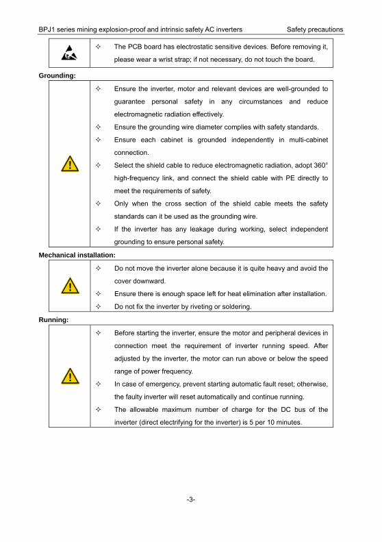
The PCB board has electrostatic sensitive devices. Before removing it,
please wear a wrist strap; if not necessary, do not touch the board.
Grounding:
Ensure the inverter, motor and relevant devices are well-grounded to
guarantee personal safety in any circumstances and reduce
electromagnetic radiation effectively.
Ensure the grounding wire diameter complies with safety standards.
Ensure each cabinet is grounded independently in multi-cabinet
connection.
Select the shield cable to reduce electromagnetic radiation, adopt 360°
high-frequency link, and connect the shield cable with PE directly to
meet the requirements of safety.
Only when the cross section of the shield cable meets the safety
standards can it be used as the grounding wire.
If the inverter has any leakage during working, select independent
grounding to ensure personal safety.
Mechanical installation:
Do not move the inverter alone because it is quite heavy and avoid the
cover downward.
Ensure there is enough space left for heat elimination after installation.
Do not fix the inverter by riveting or soldering.
Running:
Before starting the inverter, ensure the motor and peripheral devices in
connection meet the requirement of inverter running speed. After
adjusted by the inverter, the motor can run above or below the speed
range of power frequency.
In case of emergency, prevent starting automatic fault reset; otherwise,
the faulty inverter will reset automatically and continue running.
The allowable maximum number of charge for the DC bus of the
inverter (direct electrifying for the inverter) is 5 per 10 minutes.
BPJ1 series mining explosion-proof and intrinsic safety AC inverters Product overview
-4-
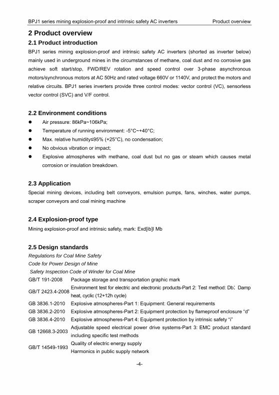
2 Product overview 2.1 Product introduction BPJ1 series mining explosion-proof and intrinsic safety AC inverters (shorted as inverter below)
mainly used in underground mines in the circumstances of methane, coal dust and no corrosive gas
achieve soft start/stop, FWD/REV rotation and speed control over 3-phase asynchronous
motors/synchronous motors at AC 50Hz and rated voltage 660V or 1140V, and protect the motors and
relative circuits. BPJ1 series inverters provide three control modes: vector control (VC), sensorless
vector control (SVC) and V/F control.
2.2 Environment conditions Air pressure: 86kPa~106kPa;
Temperature of running environment: -5°C~+40°C;
Max. relative humidity≤95% (+25°C), no condensation;
No obvious vibration or impact;
Explosive atmospheres with methane, coal dust but no gas or steam which causes metal
corrosion or insulation breakdown.
2.3 Application Special mining devices, including belt conveyors, emulsion pumps, fans, winches, water pumps,
scraper conveyors and coal mining machine
2.4 Explosion-proof type Mining explosion-proof and intrinsic safety, mark: Exd[ib]I Mb
2.5 Design standards Regulations for Coal Mine Safety Code for Power Design of Mine Safety Inspection Code of Winder for Coal Mine GB/T 191-2008 Package storage and transportation graphic mark
GB/T 2423.4-2008 Environment test for electric and electronic products-Part 2: Test method: Db: Damp heat, cyclic (12+12h cycle)
GB 3836.1-2010 Explosive atmospheres-Part 1: Equipment: General requirements GB 3836.2-2010 Explosive atmospheres-Part 2: Equipment protection by flameproof enclosure “d” GB 3836.4-2010 Explosive atmospheres-Part 4: Equipment protection by intrinsic safety “i”
GB 12668.3-2003 Adjustable speed electrical power drive systems-Part 3: EMC product standard including specific test methods
GB/T 14549-1993 Quality of electric energy supply Harmonics in public supply network
BPJ1 series mining explosion-proof and intrinsic safety AC inverters Product overview
-5-
GB 14048.1-2006 Low-voltage switchgear and controlgear-Part 1: General rules MT 1099-2009 Frequency conversion equipment for coal mine
MT/T 154.2-1996 Model designation method and management approach of electric appliances forcoal mine
MT/T 412-1995 Low-voltage terminals of explosion-proof electrical apparatus MT/T 661-2011 General technical conditions for electrical apparatus used underground mine AQ 1043-2007 Mining products safety label
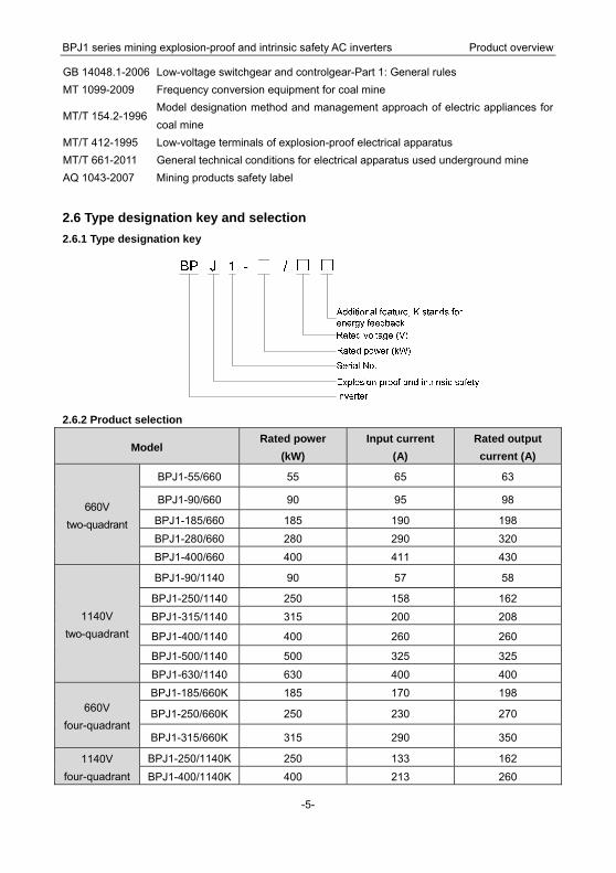
2.6 Type designation key and selection 2.6.1 Type designation key
2.6.2 Product selection
Model Rated power
(kW) Input current
(A) Rated output current (A)
660V two-quadrant
BPJ1-55/660 55 65 63
BPJ1-90/660 90 95 98
BPJ1-185/660 185 190 198
BPJ1-280/660 280 290 320
BPJ1-400/660 400 411 430
1140V two-quadrant
BPJ1-90/1140 90 57 58
BPJ1-250/1140 250 158 162
BPJ1-315/1140 315 200 208
BPJ1-400/1140 400 260 260
BPJ1-500/1140 500 325 325
BPJ1-630/1140 630 400 400
660V four-quadrant
BPJ1-185/660K 185 170 198
BPJ1-250/660K 250 230 270
BPJ1-315/660K 315 290 350
1140V four-quadrant
BPJ1-250/1140K 250 133 162
BPJ1-400/1140K 400 213 260

BPJ1 series mining explosion-proof and intrinsic safety AC inverters Technical features
-6-
3 Technical features BPJ1 mining explosion-proof inverter is applicable to underground mines in bad conditions and it can
adopt either local or remote control manner. Under the control of the inverter, AC asynchronous
motors and permanent magnet synchronous motors can realize soft start, VVVF, improvement of
rotating accuracy, change of power factor and protection of overcurrent, overvoltage and overload.
The inverter is fitted with LCD keypad for running parameters display.
Due to large starting torque and stable start-up, AC asynchronous motors and permanent magnet
synchronous motors can achieve smooth start-up, speed regulation and stop at any loads, reducing
mechanical and electrical impact and prolonging service life. Master-slave control can be applied to
belt conveyors for power balance in multi-motor drive.
When the inverter is applied to emulsion pumps, under PID control, the hydraulic system can obtain
constant pressure, cut down on power consumption and reduce impact on pipes.
3.1 Main features 1. Grid voltage: 660V±15%, 1140V±10%;
2. Brand-new dual-CUP (DSP+MCU) hardware control improving control performance greatly;
3. Three control modes: Vector control (VC), sensorless vector control (SVC) and V/F control;
4. Master-slave control for synchronous torque or speed and power balance among motors;
5. Soft start and stop for heavy loads with low starting current, stable starting speed and small impact
on the grid;
6. Rich communication control functions, Modbus, Profibus-DP and Ethernet communication modes,
communication protocols conforming to the international standards, compatible with the requirements
of various control systems;
7. Overvoltage, overcurrent, overload, phase loss, short circuit and overheat protection;
8. Excellent electromagnetic compatibility.
3.2 Main parameters Model 660V series 1140V series
Input voltage 660V±15% 1140V±10%
Input frequency 47~63Hz
Output frequency 0~50Hz
Explosion-proof
type Explosion-proof and intrinsic safety
Mark Exd[ib]I
Running Temperature: 0°C~40°C; humidity: 5%~95%; gas and dust

BPJ1 series mining explosion-proof and intrinsic safety AC inverters Technical features
-7-
Model 660V series 1140V series
environment explosive atmospheres
Control mode Vector control (VC), sensorless vector control (SVC) and V/F
control
Display LED display
Running Continuous
Heat elimination Heat pipe conduction by natural or air cooling
Control manner Local or remote control
Max. intrinsically
safe open-loop
voltage
25V
Intrinsically safe
parameters U0: 25VDC I0: 160mA
3.3 Intrinsically safe terminals
Type Code Name Function instruction
Power
supply
10V 10V reference
power supply
Provide 10V reference power supply for the external
with the maximum output current 20mA
Serve as the power supply of external potentiometer
above 5kΩ resistance
-10V
-10V
reference
power supply
Provide -10V reference power supply for the external
with the maximum output current 10mA
Serve as the power supply of external potentiometer
above 5kΩ resistance
24V 24V power
supply
Max. output voltage:25V, Max. output current:160mA
Serve as the power supply of digital input and output
or external sensor
Common
terminal
COM Common
terminal Common terminal of +24V or external power supply
GND Grounding
terminal
±10V reference null potential
(Note: GND and COM are isolated.)
Analog
input AI1 Analog input 1
1. Input range: 0~10V or 0~20mA
2. Input impedance: voltage input: 20kΩ, current
input: 500Ω
3. Voltage or current input depends on jumper J3

BPJ1 series mining explosion-proof and intrinsic safety AC inverters Technical features
-8-
Type Code Name Function instruction
AI2 Analog input 2
1. Input range: 0~10V or 0~20mA
2. Input impedance: voltage input: 20kΩ, current
input: 500Ω
3. Voltage or current input depends on jumper J4
Analog
output
AO1 Analog output
1
1. Output range: -10~10V or -20~20mA
2. Voltage or current output depends on jumper J1
AO2 Analog output
2
1. Output range: -10~10V or -20~20mA
2. Voltage or current output depends on jumper J2
Digital
input
S1 Switch input 1
Switch input terminals:
1. Internal impedance: 3.3kΩ
2. 12~30V voltage input is available
S2 Switch input 2
S3 Switch input 3
S4 Switch input 4
S5 Switch input 5
S6 Switch input 6
S7 Switch input 7
S8 Switch input 8
BPJ1 series mining explosion-proof and intrinsic safety AC inverters Dimension and weight
-9-
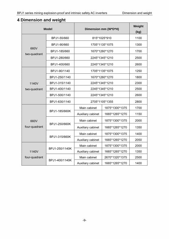
4 Dimension and weight
Model Dimension mm (W*D*H) Weight
(kg)
660V
two-quadrant
BPJ1-55/660 815*1025*910 1100
BPJ1-90/660 1705*1135*1075 1300
BPJ1-185/660 1670*1260*1270 1700
BPJ1-280/660 2245*1345*1210 2500
BPJ1-400/660 2245*1345*1210 2600
1140V
two-quadrant
BPJ1-90/1140 1705*1135*1075 1250
BPJ1-250/1140 1670*1260*1270 1800
BPJ1-315/1140 2245*1345*1210 2300
BPJ1-400/1140 2245*1345*1210 2500
BPJ1-500/1140 2245*1345*1210 2600
BPJ1-630/1140 2705*1105*1355 2800
660V
four-quadrant
BPJ1-185/660K Main cabinet 1875*1300*1375 1700
Auxiliary cabinet 1665*1265*1270 1150
BPJ1-250/660K Main cabinet 1875*1300*1375 2000
Auxiliary cabinet 1665*1265*1270 1350
BPJ1-315/660K Main cabinet 1875*1300*1375 1400
Auxiliary cabinet 1665*1265*1270 2050
1140V
four-quadrant
BPJ1-250/1140KMain cabinet 1875*1300*1375 2000
Auxiliary cabinet 1665*1265*1270 1350
BPJ1-400/1140KMain cabinet 2670*1320*1375 2500
Auxiliary cabinet 1665*1265*1270 1400
BPJ1 series mining explosion-proof and intrinsic safety AC inverters Structure features
-10-
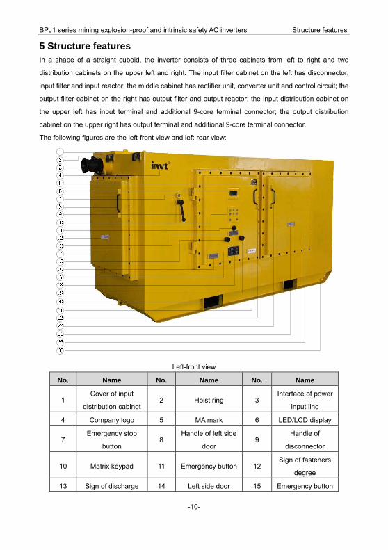
5 Structure features
In a shape of a straight cuboid, the inverter consists of three cabinets from left to right and two
distribution cabinets on the upper left and right. The input filter cabinet on the left has disconnector,
input filter and input reactor; the middle cabinet has rectifier unit, converter unit and control circuit; the
output filter cabinet on the right has output filter and output reactor; the input distribution cabinet on
the upper left has input terminal and additional 9-core terminal connector; the output distribution
cabinet on the upper right has output terminal and additional 9-core terminal connector.
The following figures are the left-front view and left-rear view:
Left-front view
No. Name No. Name No. Name
1 Cover of input
distribution cabinet2 Hoist ring 3
Interface of power
input line
4 Company logo 5 MA mark 6 LED/LCD display
7 Emergency stop
button 8
Handle of left side
door 9
Handle of
disconnector
10 Matrix keypad 11 Emergency button 12 Sign of fasteners
degree
13 Sign of discharge 14 Left side door 15 Emergency button

BPJ1 series mining explosion-proof and intrinsic safety AC inverters Structure features
-11-
button
16 Explosion-proof mark 17 Left front door 18 BPJ1 name plate
19 Emergency button 20 Forklift hole 21 Warning sign
22 Handle of left front
door 23
Handle of right front
door 24 Warning sign
25 Right front door 26 Chassis
Left-rear view
No. Name No. Name No. Name
1 Hoist ring 2 Interface of control
line 3
Sign of fasteners
degree
4 Radiator guard 5 Cooling fan 6
BPJ1 series mining explosion-proof and intrinsic safety AC inverters Keypad
-12-
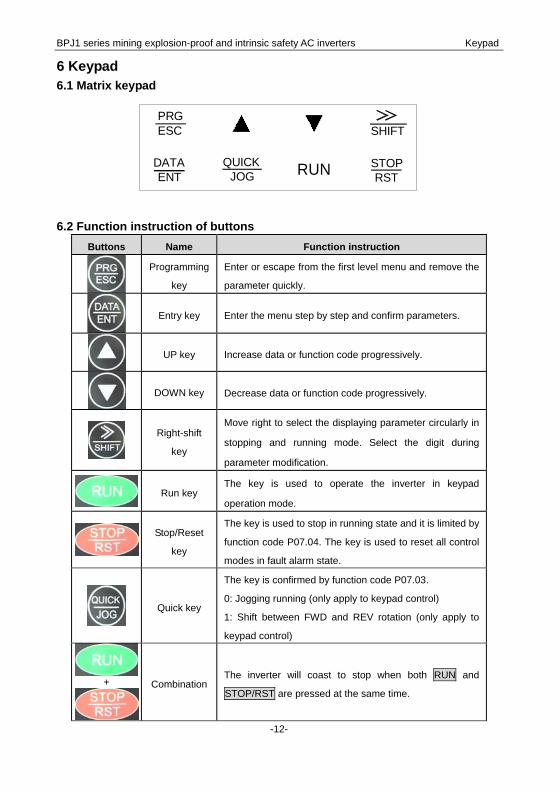
6 Keypad 6.1 Matrix keypad
RUN
PRGESC SHIFT
STOP RST
QUICK JOG
DATA ENT
6.2 Function instruction of buttons
Buttons Name Function instruction
Programming
key
Enter or escape from the first level menu and remove the
parameter quickly.
Entry key Enter the menu step by step and confirm parameters.
UP key Increase data or function code progressively.
DOWN key Decrease data or function code progressively.
Right-shift
key
Move right to select the displaying parameter circularly in
stopping and running mode. Select the digit during
parameter modification.
Run key
The key is used to operate the inverter in keypad
operation mode.
Stop/Reset
key
The key is used to stop in running state and it is limited by
function code P07.04. The key is used to reset all control
modes in fault alarm state.
Quick key
The key is confirmed by function code P07.03.
0: Jogging running (only apply to keypad control)
1: Shift between FWD and REV rotation (only apply to
keypad control)
+
CombinationThe inverter will coast to stop when both RUN and
STOP/RST are pressed at the same time.

BPJ1 series mining explosion-proof and intrinsic safety AC inverters Keypad
-13-
6.3 Operation procedure and parameter setting The inverter has three-level menu:
1. Group number of function code (first level menu)
2. Tab of function code (second level menu)
3. Set value of function code (third level menu)
Remarks: Press PRG/ESC or DATA/ENT to return to the second level menu from the third level
menu. The difference: pressing DATA/ENT will save the set parameters into the control board and
then return to the second level menu with shifting to the next function code automatically while
pressing PRG/ESC will directly return to the second level menu without saving the parameters and
keep staying at the current function code.
Example: Set function code P1.01 from 0.0% to 1.0%.
Fig 3-3 Sketch map of three-level menu
Under the third level menu, if the parameter has no flicker bit, it means the function code cannot be
modified. The possible reasons could be:
1) This function code is unmodifiable parameter, such as actual detected parameter and operation
records;
2) This function code is unmodifiable in run state but modifiable in stop state.
Stop/Run
BPJ1 series mining explosion-proof and intrinsic safety AC inverters Typical electrical diagram
-14-
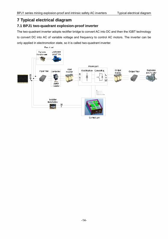
7 Typical electrical diagram 7.1 BPJ1 two-quadrant explosion-proof inverter The two-quadrant inverter adopts rectifier bridge to convert AC into DC and then the IGBT technology
to convert DC into AC of variable voltage and frequency to control AC motors. The inverter can be
only applied in electromotion state, so it is called two-quadrant inverter.

BPJ1 series mining explosion-proof and intrinsic safety AC inverters Typical electrical diagram
-15-
7.2 BPJ1 four-quadrant explosion-proof inverter IGBT power module can realize bidirectional energy flow. If IGBT works as rectifier bridge and DSP
featuring high speed and strong computing power generates PWM pulse, for one thing, the power
factor can be adjusted to eliminate harmonic pollution on the grid and change the inverters into green
products; for another, the energy generated by motors can be fed back to the grid to save energy.
Rectification Converting
Control part
Power part
RST
RST
NL
Input filter Input reactor
3-phase transformer
Explosion-proof fan
Isolation transformer
UVW
Explosion-proof motorOutput reactor Output filterContactor
Buffer resistor
PWM reactor
RC absorption circuit
LCL filter
Power supply
Filter cabinet Inverter cabinet
BPJ1 series mining explosion-proof and intrinsic safety AC inverters Wiring diagram
-16-
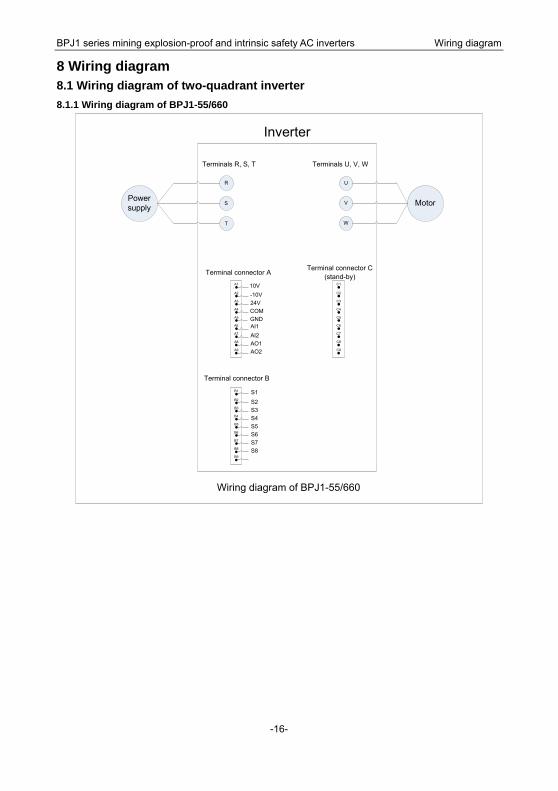
8 Wiring diagram 8.1 Wiring diagram of two-quadrant inverter 8.1.1 Wiring diagram of BPJ1-55/660
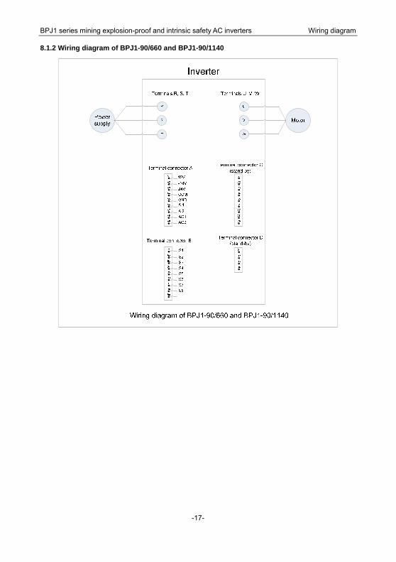
B1
B2
B3
B4
B5
B6
B7
B8
B9
U
V
W
Terminals U, V, W
R
S
T
Terminals R, S, T
Terminal connector B
Power supply Motor
Inverter
Wiring diagram of BPJ1-55/660
A1
A2
A3
A4
A5
A6
A7
A8
A9
Terminal connector AC1
C2
C3
C4
C5
C6
C7
C8
C9
Terminal connector C(stand-by)
10V-10V24VCOMGNDAI1AI2AO1AO2
S1
S2S3S4S5S6S7S8
BPJ1 series mining explosion-proof and intrinsic safety AC inverters Wiring diagram
-17-
8.1.2 Wiring diagram of BPJ1-90/660 and BPJ1-90/1140

BPJ1 series mining explosion-proof and intrinsic safety AC inverters Wiring diagram
-18-
8.1.3 Wiring diagram of BPJ1-185/660 and BPJ1-250/1140

BPJ1 series mining explosion-proof and intrinsic safety AC inverters Wiring diagram
-19-
8.1.4 Wiring diagram of BPJ1-280/660, BPJ1-400/660, BPJ1-315/1140, BPJ1-400/1140 and
BPJ1-500/1140
B1
B2
B3
B4
B5
B6
B7
B8
B9
U1
V1
W1
Terminals U1, V1, W1
R
S
T
Terminals R, S, T
Terminal connector B
Power supply
Motor
Inverter
Wiring diagram of BPJ1-280/660, BPJ1-400/660,BPJ1-315/1140, BPJ1-400/1140 and BPJ1-500/1140
A1
A2
A3
A4
A5
A6
A7
A8
A9
Terminal connector AC1
C2
C3
C4
C5
C6
C7
C8
C9
Terminal connector C(stand-by)
10V-10V24VCOMGNDAI1AI2AO1AO2
S1
S2S3S4S5S6S7S8
E1
E2
E3
E4
Terminal connector E(stand-by)
U2
V2
W2
Terminals U2, V2, W2 (stand-by)
D1
D2
D3
D4
Terminal connector D (to explosion-proof fan)
r1s1t1

BPJ1 series mining explosion-proof and intrinsic safety AC inverters Wiring diagram
-20-
8.1.5 Wiring diagram of BPJ1-630/1140

BPJ1 series mining explosion-proof and intrinsic safety AC inverters Wiring diagram
-21-
8.2 Wiring diagram of four-quadrant inverter 8.2.1 Wiring diagram of BPJ1-185/660K, BPJ1-250/660K and BPJ1-315/660K
R
S
T
R1
S1
T1
Terminals R, S, T Terminals R1, S1, T1
r
s
t
Terminals r, s, t
A1
A2
A3
A4
A5
A6
A7
A8
A9
Terminal connector A
Terminal connector B
B1
B2
B3
B4
D1
D2
D3
D4
D5
D6
D7
D8
D9
U
V
W
Terminals U, V, W
R1
S1
T1
Terminals R1, S1, T1
r
s
t
Terminals r, s, t
Terminal connector D
Power supply Motor
Filter cabinet Inverter cabinet
Wiring diagram of BPJ1-185/660K, BPJ1-250/660K and BPJ1-315/660K
C1
C2
C3
C4
C5
C6
C7
C8
C9
Terminal connector C (stand-by)
Terminal connector D (stand-by)
D1
D2
D3
D4
B1
B2
B3
B4
B5
B6
B7
B8
B9
Terminalconnector B
A1
A2
A3
A4
A5
A6
A7
A8
A9
Terminalconnector A
C1
C2
C3
C4
C5
C6
C7
C8
C9
Terminal connector C (stand-by)
10V-10V24VCOMGNDAI1AI2AO1AO2
S1
S2S3S4S5S6S7S8
G1
G2
G3
G4
G5
G6
G7
G8
G9
Terminal connector G(stand-by)
Terminal connector E (to explosion-proof fan)
E1
E2
E3
E4
r1s1t1
Terminal connector F(to explosion-proof fan)
F1
F2
F3
F4
r1s1t1

BPJ1 series mining explosion-proof and intrinsic safety AC inverters Wiring diagram
-22-
8.2.2 Wiring diagram of BPJ1-250/1140K
R
S
T
R1
S1
T1
Terminals R, S, T Terminals R1, S1, T1
r
s
t
Terminals r, s, t
A1
A2
A3
A4
A5
A6
A7
A8
A9
Terminal connector A
Terminal connector B
B1
B2
B3
B4
D1
D2
D3
D4
D5
D6
D7
D8
D9
U
V
W
Terminals U, V, W
R1
S1
T1
Terminals R1, S1, T1
r
s
t
Terminals r, s, t
Terminal connector D
Power supply Motor
Filter cabinet Inverter cabinet
Wiring diagram of BPJ1-250/1140K
C1
C2
C3
C4
C5
C6
C7
C8
C9
Terminal connector C(stand-by)
Terminal connector D(stand-by)
D1
D2
D3
D4
B1
B2
B3
B4
B5
B6
B7
B8
B9
Terminal connector B
A1
A2
A3
A4
A5
A6
A7
A8
A9
Terminal connector A
C1
C2
C3
C4
C5
C6
C7
C8
C9
Terminalconnector C
10V-10V24VCOMGNDAI1AI2AO1AO2
S1
S2S3S4S5S6S7S8
G1
G2
G3
G4
G5
G6
G7
G8
G9
Terminal connector G(stand-by)
Terminal connector E(to explosion-proof fan)
E1
E2
E3
E4
r1s1t1
Terminal connector F(to explosion-proof fan)
F1
F2
F3
F4
r1s1t1
BPJ1 series mining explosion-proof and intrinsic safety AC inverters Wiring diagram
-23-
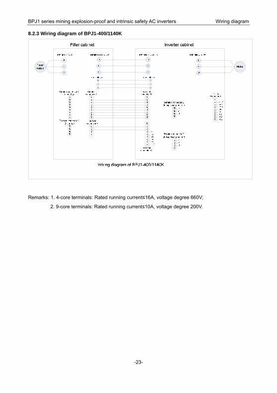
8.2.3 Wiring diagram of BPJ1-400/1140K
Remarks: 1. 4-core terminals: Rated running current≤16A, voltage degree 660V;
2. 9-core terminals: Rated running current≤10A, voltage degree 200V.

201306(V1.0)
0512-6691 6509 www.invt-equipment.com
No.189 Kunlun Shan Road, Science&Technology Town,New District,Suzhou,Jiangsu,China
Electric Drive: Explosion-proof Inverter