Hydrocarbon aerosol explosion: towards hazardous area ...
13
HAL Id: ineris-03319939 https://hal-ineris.archives-ouvertes.fr/ineris-03319939 Submitted on 13 Aug 2021 HAL is a multi-disciplinary open access archive for the deposit and dissemination of sci- entific research documents, whether they are pub- lished or not. The documents may come from teaching and research institutions in France or abroad, or from public or private research centers. L’archive ouverte pluridisciplinaire HAL, est destinée au dépôt et à la diffusion de documents scientifiques de niveau recherche, publiés ou non, émanant des établissements d’enseignement et de recherche français ou étrangers, des laboratoires publics ou privés. Hydrocarbon aerosol explosion : towards hazardous area classification Stéphanie El-Zahlanieh, Augustin Charvet, Alexis Vignes, Benoît Tribouilloy, Olivier Dufaud To cite this version: Stéphanie El-Zahlanieh, Augustin Charvet, Alexis Vignes, Benoît Tribouilloy, Olivier Dufaud. Hy- drocarbon aerosol explosion : towards hazardous area classification. 13th International symposium on hazards, prevention, and mitigation of industrial explosions (ISHPMIE 2020), Jul 2020, Braunschweig, Germany. pp.572-583, 10.7795/810.20200724. ineris-03319939
-
Upload
khangminh22 -
Category
Documents
-
view
0 -
download
0
Transcript of Hydrocarbon aerosol explosion: towards hazardous area ...
HAL Id: ineris-03319939https://hal-ineris.archives-ouvertes.fr/ineris-03319939
Submitted on 13 Aug 2021
HAL is a multi-disciplinary open accessarchive for the deposit and dissemination of sci-entific research documents, whether they are pub-lished or not. The documents may come fromteaching and research institutions in France orabroad, or from public or private research centers.
L’archive ouverte pluridisciplinaire HAL, estdestinée au dépôt et à la diffusion de documentsscientifiques de niveau recherche, publiés ou non,émanant des établissements d’enseignement et derecherche français ou étrangers, des laboratoirespublics ou privés.
Hydrocarbon aerosol explosion : towards hazardous areaclassification
Stéphanie El-Zahlanieh, Augustin Charvet, Alexis Vignes, Benoît Tribouilloy,Olivier Dufaud
To cite this version:Stéphanie El-Zahlanieh, Augustin Charvet, Alexis Vignes, Benoît Tribouilloy, Olivier Dufaud. Hy-drocarbon aerosol explosion : towards hazardous area classification. 13th International symposium onhazards, prevention, and mitigation of industrial explosions (ISHPMIE 2020), Jul 2020, Braunschweig,Germany. pp.572-583, �10.7795/810.20200724�. �ineris-03319939�
Hydrocarbon aerosol explosion: towards hazardous
area classification
Stephanie El - Zahlanieh a, Augustin Charveta , Alexis Vignes b , Benoit Tribouilloy b & Olivier
Dufaud a
a Université de Lorraine, CNRS, LRGP, F-54000 Nancy, France
b INERIS, Accidental Risks Division, Parc Technologique ALATA, Verneuil-en-Halatte, France
E-mail: [email protected]
Abstract
Assessing the risk of formation and ignition of explosive atmosphere (ATEX) associated with the
generation of a flammable aerosol is required by European ATEX regulation. However, such risk
analysis sometimes proves difficult because of the lack of tools correlating the dispersion conditions
of a mist cloud with its flammability and explosivity. This work aims to define objective criteria for
assessing the risk related to the hydrocarbon mists explosion within the framework of hazardous area
classification. Different fluids were selected according to their industrial interest and their
physicochemical characteristics; here, a volatile solvent (ethanol), a lubricating oil and kerosene.
Existing experimental set-ups as the 20L sphere and the modified Hartmann tube were adapted to
determine the flammability and explosion severity of sprays and mists. A sensitivity study was
performed as a function of influential parameters such as the fluid composition, the generation mode,
the pressure and the turbulence. The time evolution of droplet size distributions was determined by
in situ laser diffraction and APS spectrometry (aerodynamic diameter measurement). The
flammability study was focused on the determination of the Lower Explosive Limit and the Minimum
Ignition Energy. In parallel, the study of the flame propagation in a semi-open tube was used to
qualify the effects of the turbulence/combustion interactions. Some tests were also performed in a
standard 20L explosion sphere to determine the maximum explosion pressure and maximum rate of
pressure rise of specific mists. Finally, these experimental results could serve as an input for reactive
CFD simulations aiming at predicting the consequences of aerosol explosions. From a practical point
of view, this study should provide decision support tools for hazardous area classification, especially
for the definition of the flammable cloud extent on the basis of a percentage of the lower explosive
limit.
Keywords: aerosol, spray, explosion, flame propagation, hazardous area classification
1. Introduction
In 2009, an incident survey of the Health and Safety Laboratory, reported 37 mist incidents, among
which 9 explosions lead to 29 fatalities (Santon, 2009). In most of the cases, the incidents arose from
the ignition of mist or spray at a temperature near or below the liquids’ flash point. Similar to what is
proposed by Eckhoff (2016), the terms “spray” or “mist” are used arbitrarily in this text as they are
both relevant terms in explosion incidents. Sprays are usually produced mechanically from a spray
nozzle or an accidental leak whereas mists are clouds of liquid droplets of smaller size, usually
generated by condensation of a supersaturated liquid.
Ten years later, Lees et al. (2019) showed that 10% of reported releases on offshore oil and gas
installations in the UK involved sprays or mists. Such cases demonstrate the need to acquire full
knowledge and ability in order to classify hazardous mist explosive areas. This classification is
currently well established for gas and dust explosions (Gant, 2013). Several regulations (Directives
2014/34/EU and 1999/92 CE), standards (e.g. EN 14034 series), and industry codes of practice are
already available for use in industries in order to study the conditions of dispersion and explosions of
flammable gas or dust releases; however, such standards for mists have not been completely set yet.
In fact, some guides such as EI15 underline this lack of knowledge. It is noted in the guide’s model
code of safe practice on area classification (Energy Institute, 2015) that “there is little knowledge on
the formation of flammable mists and the appropriate extents of associated hazardous areas”. Also,
two pages of qualitative guidance on flammable mists are embodied in the latest version of the
relevant IEC standard (IEC 60079-10-1; IEC 2015) (Gant el al., 2016).
Identifying factors and criteria of liquid handling, as well as determining fluids’ safety parameters
will be helpful to assess the flammability and explosion severity of hydrocarbon mists. The ability to
determine the latter, is a stepping stone to the classification of hazardous areas (HAC) and to the
improvement of current ATEX standards and regulatory provisions concerning liquid aerosols.
However, the subject of mist ignition/explosion has been under study and investigation for over
seventy years. Eichhorn (1955) has notably published an article in the Petroleum Refiner entitled
“Careful! Mist can explode”. He has introduced the concept that aerosols of flammable liquids at
temperatures well below their flash points can explode. Eckhoff (1995) has also written a review of
spray and mist explosions, and has defined some conditions under which any combustible liquid
aerosol can be explosive. The possibility of a mist ignition/explosion has been studied in an HSE
report by Gant (2013). Such a report provides a large background on the physics of spark ignition and
flame propagation, the fundamentals of droplet dynamics and pressurized liquid releases, as well as
mitigation measures.
Scientifically studying mist formation, ignition and explosion is an object of study that can also be
presented as an intermediate case between gases and dusts. The behaviour of liquid sprays or mists
differs from that of gases as several phenomena, such as light diffraction, fuel evaporation (Ballal et
Lefebvre, 1981) or flame stretching by impacting droplets, occur for mists but not for gases. For
instance, Eckhoff (2016) describes explosive mist clouds as less stable than explosive dust clouds due
to the collisions between droplets, which gives rise to coalescence and the transformation to fewer
and larger droplets. The increase of size leads to a greater sedimentation velocity and perhaps more
turbulence and flame disturbance.
By addressing the unknowns and studying the differences between mist, gas and dust explosions,
guidelines can be provided to industrialists as well as standardised methods for HAC of liquid mists.
In order to illustrate this approach, this paper will be focused on common liquid fuels of different
physical properties (ethanol, kerosene, and a lubricating oil). Their dispersion, using spray nozzles,
ignition and explosion will be studied to highlight their different behaviours and stress their
specificities, notably with regard to gas explosion.
2. Materials and Methods
At first, the fuels selected will be presented according to their industrial interest and their physical
properties. The second step encompasses the description of the generation mode and the
characterisation of mist properties such as the droplet size distribution and concentration. The third
step focuses mainly on the determination of the explosion severity parameters of such mists, i.e. the
maximum deflagration pressure Pmax, the maximum rate of pressure rise dP/dtmax and the laminar
flame velocity.
2.1 Fuel Selection
A fluid classification system was developed by the Health and Safety Executive (Burrell and Gant,
2017), which divided fluids of industrial interest into four release classes based on their flashpoint
and their ease of atomisation represented by the Ohnesorge number Oh. This paper deals with three
fuels representing three releases classes.
Ethanol was chosen due to its growing use in our daily lives as an engine fuel, fuel additive for
automobiles or marine sector. With the increase of the demand for ethanol-fuel blends, its production
and transport increases, which requires to manage the fire and explosion risks. Beside to its physical
properties, ethanol was also selected as a calibration fluid as numerous studies were already
performed to characterised the ignition sensitivity and explosion severity of its vapours and mists
(Timothée, 2017).
Tests were performed on Kerosene, which represents the HSE Release Class I. Kerosene is a
combustible hydrocarbon liquid derived from petroleum. It is widely used as a jet fuel and also has a
range of household applications. Kerosene mist explosions have been frequently reported throughout
the years; for example: an explosion in 1886, UK due to a leak of Russian kerosene as a form of mist
ignited by a naked light (Santon, 2009). Various studies, on different types of kerosene, can be found
in literature; HSE, for instance, have performed ignition tests on spray releases of Jet A1 kerosene
with an ignition source of 1 Joule electric spark and a release pressure ranging from 5 to 20 bars.
(Bettis et al. 2017; Vukadinovic et al. 2013; Wu, 2016)
Another fluid tested is the Mobil DTE Heavy Medium VG68, which exemplifies HSE Release Class
III. This fluid is a hydraulic oil also tested by HSE at various release pressures. It is a lubricant
designed for applications where long lubricant service life is required; such as in gas turbines (Dufaud
et al. 2015) and hydraulic pumps.
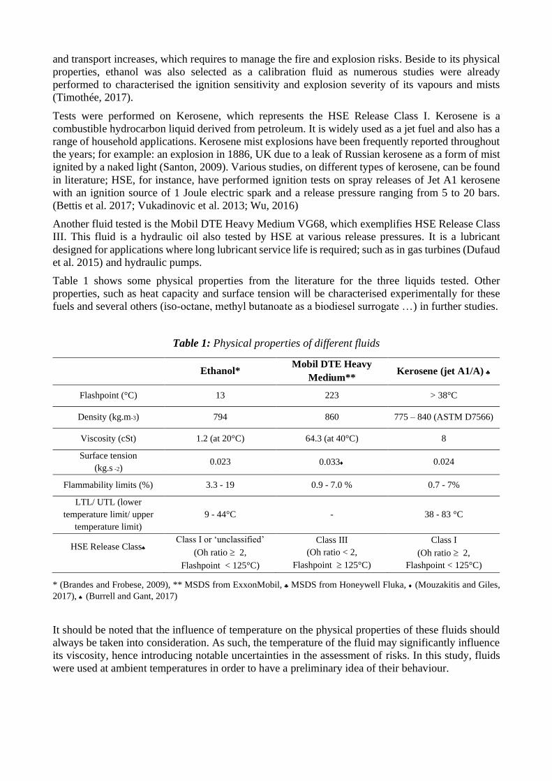
Table 1 shows some physical properties from the literature for the three liquids tested. Other
properties, such as heat capacity and surface tension will be characterised experimentally for these
fuels and several others (iso-octane, methyl butanoate as a biodiesel surrogate …) in further studies.
Table 1: Physical properties of different fluids
Ethanol* Mobil DTE Heavy
Medium** Kerosene (jet A1/A)
Flashpoint (°C) 13 223 > 38°C
Density (kg.m-3) 794 860 775 – 840 (ASTM D7566)
Viscosity (cSt) 1.2 (at 20°C) 64.3 (at 40°C) 8
Surface tension
(kg.s -2) 0.023 0.033 0.024
Flammability limits (%) 3.3 - 19 0.9 - 7.0 % 0.7 - 7%
LTL/ UTL (lower
temperature limit/ upper
temperature limit)
9 - 44°C - 38 - 83 °C
HSE Release Class
Class I or ‘unclassified’
(Oh ratio 2,
Flashpoint < 125°C)
Class III
(Oh ratio < 2,
Flashpoint 125°C)
Class I
(Oh ratio 2,
Flashpoint < 125°C)
* (Brandes and Frobese, 2009), ** MSDS from ExxonMobil, MSDS from Honeywell Fluka, (Mouzakitis and Giles,
2017), (Burrell and Gant, 2017)
It should be noted that the influence of temperature on the physical properties of these fluids should
always be taken into consideration. As such, the temperature of the fluid may significantly influence
its viscosity, hence introducing notable uncertainties in the assessment of risks. In this study, fluids
were used at ambient temperatures in order to have a preliminary idea of their behaviour.
2.2 Mist properties
Characterising and predicting the behaviour of mist is a challenge. For instance, a rupture or leak in
a vessel, due to damage or corrosion, has a very uneven shape and occurs in different conditions. To
better predict the behaviour of mist, tests should be performed in the closest conditions possible to
that of industrial accidents. Nevertheless, the experimental procedure proposed to characterise the
ignition sensitivity and explosion severity of such mists should also be standardized, so that the results
can be compared and that generic safety measures can be proposed. It should be noted that
characterising properly the mist before its ignition is of great importance since the safety parameters
of mists are highly affected by their droplet size distribution, concentration and turbulence (Gant et
al., 2013).
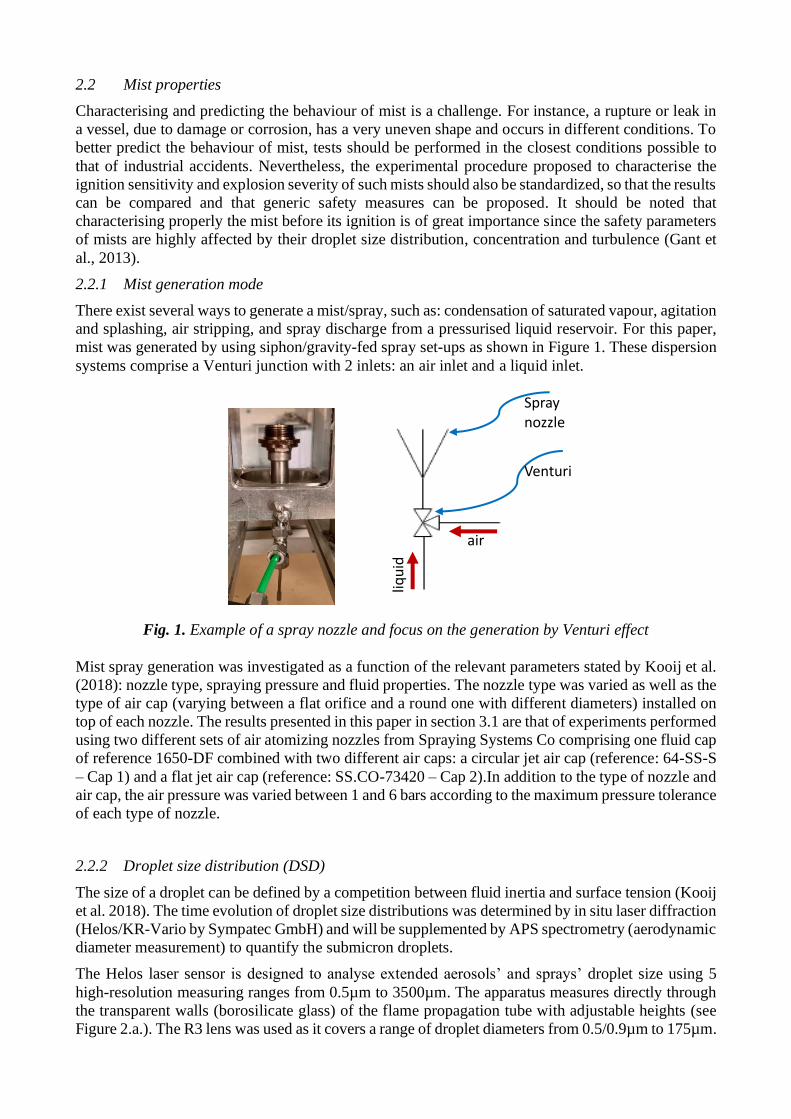
2.2.1 Mist generation mode
There exist several ways to generate a mist/spray, such as: condensation of saturated vapour, agitation
and splashing, air stripping, and spray discharge from a pressurised liquid reservoir. For this paper,
mist was generated by using siphon/gravity-fed spray set-ups as shown in Figure 1. These dispersion
systems comprise a Venturi junction with 2 inlets: an air inlet and a liquid inlet.
Fig. 1. Example of a spray nozzle and focus on the generation by Venturi effect
Mist spray generation was investigated as a function of the relevant parameters stated by Kooij et al.
(2018): nozzle type, spraying pressure and fluid properties. The nozzle type was varied as well as the
type of air cap (varying between a flat orifice and a round one with different diameters) installed on
top of each nozzle. The results presented in this paper in section 3.1 are that of experiments performed
using two different sets of air atomizing nozzles from Spraying Systems Co comprising one fluid cap
of reference 1650-DF combined with two different air caps: a circular jet air cap (reference: 64-SS-S
– Cap 1) and a flat jet air cap (reference: SS.CO-73420 – Cap 2).In addition to the type of nozzle and
air cap, the air pressure was varied between 1 and 6 bars according to the maximum pressure tolerance
of each type of nozzle.
2.2.2 Droplet size distribution (DSD)
The size of a droplet can be defined by a competition between fluid inertia and surface tension (Kooij
et al. 2018). The time evolution of droplet size distributions was determined by in situ laser diffraction
(Helos/KR-Vario by Sympatec GmbH) and will be supplemented by APS spectrometry (aerodynamic
diameter measurement) to quantify the submicron droplets.
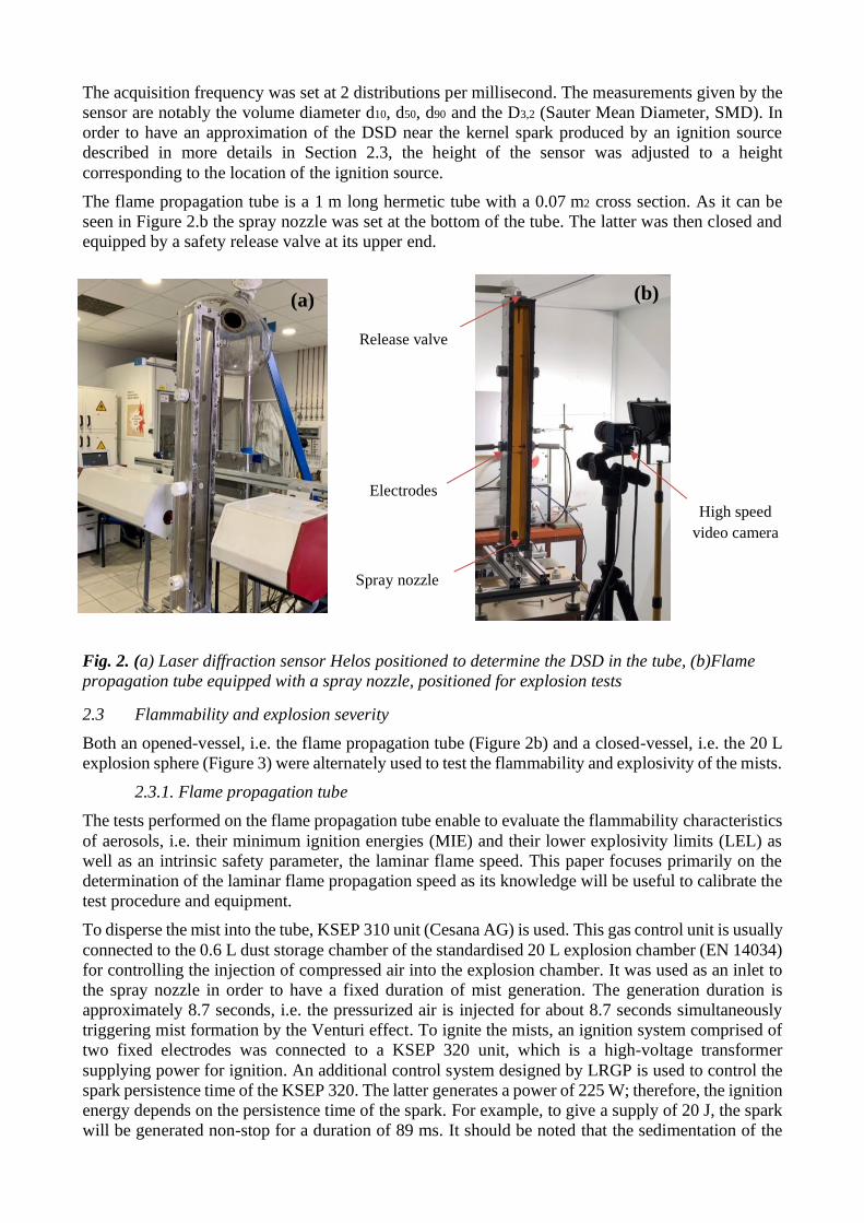
The Helos laser sensor is designed to analyse extended aerosols’ and sprays’ droplet size using 5
high-resolution measuring ranges from 0.5µm to 3500µm. The apparatus measures directly through
the transparent walls (borosilicate glass) of the flame propagation tube with adjustable heights (see
Figure 2.a.). The R3 lens was used as it covers a range of droplet diameters from 0.5/0.9µm to 175µm.
Spray nozzle
Venturi
air
liqu
id
The acquisition frequency was set at 2 distributions per millisecond. The measurements given by the
sensor are notably the volume diameter d10, d50, d90 and the D3,2 (Sauter Mean Diameter, SMD). In
order to have an approximation of the DSD near the kernel spark produced by an ignition source
described in more details in Section 2.3, the height of the sensor was adjusted to a height
corresponding to the location of the ignition source.
The flame propagation tube is a 1 m long hermetic tube with a 0.07 m2 cross section. As it can be
seen in Figure 2.b the spray nozzle was set at the bottom of the tube. The latter was then closed and
equipped by a safety release valve at its upper end.
Fig. 2. (a) Laser diffraction sensor Helos positioned to determine the DSD in the tube, (b)Flame
propagation tube equipped with a spray nozzle, positioned for explosion tests
2.3 Flammability and explosion severity
Both an opened-vessel, i.e. the flame propagation tube (Figure 2b) and a closed-vessel, i.e. the 20 L
explosion sphere (Figure 3) were alternately used to test the flammability and explosivity of the mists.
2.3.1. Flame propagation tube
The tests performed on the flame propagation tube enable to evaluate the flammability characteristics
of aerosols, i.e. their minimum ignition energies (MIE) and their lower explosivity limits (LEL) as
well as an intrinsic safety parameter, the laminar flame speed. This paper focuses primarily on the
determination of the laminar flame propagation speed as its knowledge will be useful to calibrate the
test procedure and equipment.
To disperse the mist into the tube, KSEP 310 unit (Cesana AG) is used. This gas control unit is usually
connected to the 0.6 L dust storage chamber of the standardised 20 L explosion chamber (EN 14034)
for controlling the injection of compressed air into the explosion chamber. It was used as an inlet to
the spray nozzle in order to have a fixed duration of mist generation. The generation duration is
approximately 8.7 seconds, i.e. the pressurized air is injected for about 8.7 seconds simultaneously
triggering mist formation by the Venturi effect. To ignite the mists, an ignition system comprised of
two fixed electrodes was connected to a KSEP 320 unit, which is a high-voltage transformer
supplying power for ignition. An additional control system designed by LRGP is used to control the
spark persistence time of the KSEP 320. The latter generates a power of 225 W; therefore, the ignition
energy depends on the persistence time of the spark. For example, to give a supply of 20 J, the spark
will be generated non-stop for a duration of 89 ms. It should be noted that the sedimentation of the
Release valve
Electrodes
Spray nozzle
High speed
video camera
(a) (b)
droplets should be taken into consideration, hence, using Stokes law for flows of Re < 1, the ignition
duration must be chosen according to the terminal velocity.
Several measurements were carried out for the three tested fluids with an ignition energy of 20 J and
an ignition delay time tv ranging from 100 ms to 1000 ms, i.e. the time between the mist generation
and ignition. A new generation unit is currently designed to adjust the various generation and ignition
parameters as requested.
After ignition, flame propagations were recorded using a high-speed video camera (the MotionBlitz
EoSens mini2 camera which has a resolution of 1,696 x 1,710 pixels and is equipped with an AF
NIKKOR 35mm f/2D lens from Nikon). The recorded videos were treated and analysed in order to
calculate the laminar flame speed. The procedure used to analyse the flame kernel growth and extract
the flame front position and surface area as a function of time is described by Cuervo et al. (2017).
Then, assuming a linear relationship between the flame spatial velocity and the Karlovitz factor
(stretching factor), the laminar burning velocity Su0 can be estimated (Cuervo et al., 2017).
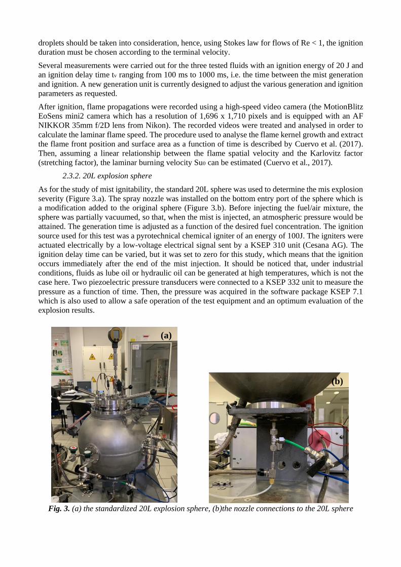
2.3.2. 20L explosion sphere
As for the study of mist ignitability, the standard 20L sphere was used to determine the mis explosion
severity (Figure 3.a). The spray nozzle was installed on the bottom entry port of the sphere which is
a modification added to the original sphere (Figure 3.b). Before injecting the fuel/air mixture, the
sphere was partially vacuumed, so that, when the mist is injected, an atmospheric pressure would be
attained. The generation time is adjusted as a function of the desired fuel concentration. The ignition
source used for this test was a pyrotechnical chemical igniter of an energy of 100J. The igniters were
actuated electrically by a low-voltage electrical signal sent by a KSEP 310 unit (Cesana AG). The
ignition delay time can be varied, but it was set to zero for this study, which means that the ignition
occurs immediately after the end of the mist injection. It should be noticed that, under industrial
conditions, fluids as lube oil or hydraulic oil can be generated at high temperatures, which is not the
case here. Two piezoelectric pressure transducers were connected to a KSEP 332 unit to measure the
pressure as a function of time. Then, the pressure was acquired in the software package KSEP 7.1
which is also used to allow a safe operation of the test equipment and an optimum evaluation of the
explosion results.
Fig. 3. (a) the standardized 20L explosion sphere, (b)the nozzle connections to the 20L sphere
(a)
(b)
Moreover, in order to visualise the flame propagation and the droplet size distribution of mists in the
20L sphere, several modifications were applied to a similar vessel (Santandrea et al., 2020). Four
windows were added to another sphere, as well as a vent. Further studies will show results of tests
performed on the open sphere.
3. Results and discussion
3.1 Droplet size distribution and flow rate
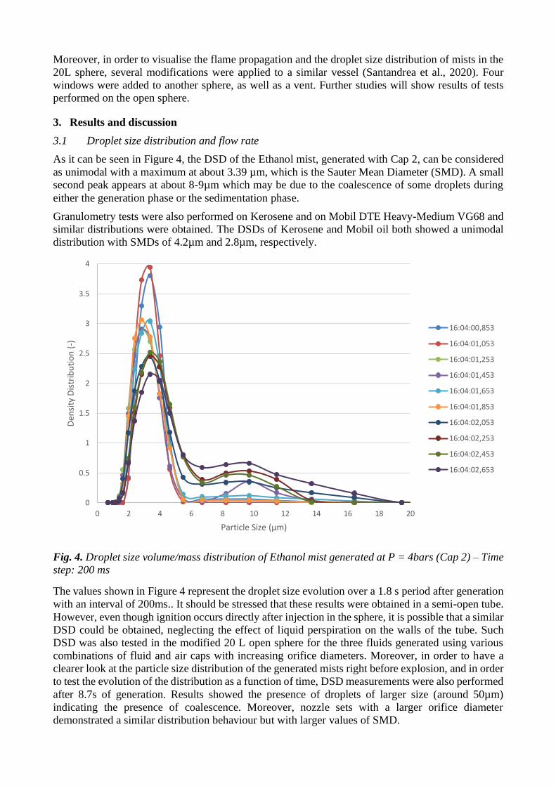
As it can be seen in Figure 4, the DSD of the Ethanol mist, generated with Cap 2, can be considered
as unimodal with a maximum at about 3.39 µm, which is the Sauter Mean Diameter (SMD). A small
second peak appears at about 8-9µm which may be due to the coalescence of some droplets during
either the generation phase or the sedimentation phase.
Granulometry tests were also performed on Kerosene and on Mobil DTE Heavy-Medium VG68 and
similar distributions were obtained. The DSDs of Kerosene and Mobil oil both showed a unimodal
distribution with SMDs of 4.2µm and 2.8µm, respectively.
Fig. 4. Droplet size volume/mass distribution of Ethanol mist generated at P = 4bars (Cap 2) – Time
step: 200 ms
The values shown in Figure 4 represent the droplet size evolution over a 1.8 s period after generation
with an interval of 200ms.. It should be stressed that these results were obtained in a semi-open tube.
However, even though ignition occurs directly after injection in the sphere, it is possible that a similar
DSD could be obtained, neglecting the effect of liquid perspiration on the walls of the tube. Such
DSD was also tested in the modified 20 L open sphere for the three fluids generated using various
combinations of fluid and air caps with increasing orifice diameters. Moreover, in order to have a
clearer look at the particle size distribution of the generated mists right before explosion, and in order
to test the evolution of the distribution as a function of time, DSD measurements were also performed
after 8.7s of generation. Results showed the presence of droplets of larger size (around 50µm)
indicating the presence of coalescence. Moreover, nozzle sets with a larger orifice diameter
demonstrated a similar distribution behaviour but with larger values of SMD.
0
0.5
1
1.5
2
2.5
3
3.5
4
0 2 4 6 8 10 12 14 16 18 20
Den
sity
Dis
trib
uti
on
(-)
Particle Size (µm)
16:04:00,853
16:04:01,053
16:04:01,253
16:04:01,453
16:04:01,653
16:04:01,853
16:04:02,053
16:04:02,253
16:04:02,453
16:04:02,653
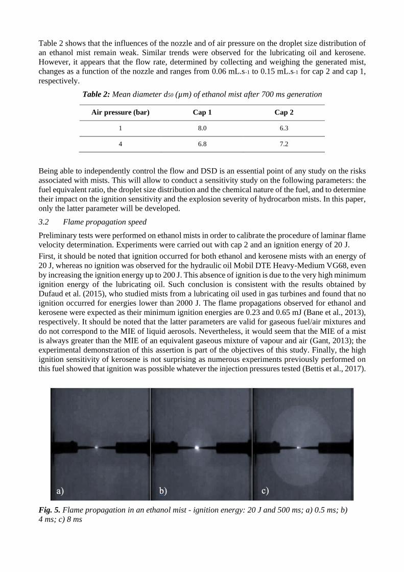
Table 2 shows that the influences of the nozzle and of air pressure on the droplet size distribution of
an ethanol mist remain weak. Similar trends were observed for the lubricating oil and kerosene.
However, it appears that the flow rate, determined by collecting and weighing the generated mist,
changes as a function of the nozzle and ranges from 0.06 mL.s-1 to 0.15 mL.s-1 for cap 2 and cap 1,
respectively.
Table 2: Mean diameter d50 (µm) of ethanol mist after 700 ms generation
Air pressure (bar) Cap 1 Cap 2
1 8.0 6.3
4 6.8 7.2
Being able to independently control the flow and DSD is an essential point of any study on the risks
associated with mists. This will allow to conduct a sensitivity study on the following parameters: the
fuel equivalent ratio, the droplet size distribution and the chemical nature of the fuel, and to determine
their impact on the ignition sensitivity and the explosion severity of hydrocarbon mists. In this paper,
only the latter parameter will be developed.
3.2 Flame propagation speed
Preliminary tests were performed on ethanol mists in order to calibrate the procedure of laminar flame
velocity determination. Experiments were carried out with cap 2 and an ignition energy of 20 J.
First, it should be noted that ignition occurred for both ethanol and kerosene mists with an energy of
20 J, whereas no ignition was observed for the hydraulic oil Mobil DTE Heavy-Medium VG68, even
by increasing the ignition energy up to 200 J. This absence of ignition is due to the very high minimum
ignition energy of the lubricating oil. Such conclusion is consistent with the results obtained by
Dufaud et al. (2015), who studied mists from a lubricating oil used in gas turbines and found that no
ignition occurred for energies lower than 2000 J. The flame propagations observed for ethanol and
kerosene were expected as their minimum ignition energies are 0.23 and 0.65 mJ (Bane et al., 2013),
respectively. It should be noted that the latter parameters are valid for gaseous fuel/air mixtures and
do not correspond to the MIE of liquid aerosols. Nevertheless, it would seem that the MIE of a mist
is always greater than the MIE of an equivalent gaseous mixture of vapour and air (Gant, 2013); the
experimental demonstration of this assertion is part of the objectives of this study. Finally, the high
ignition sensitivity of kerosene is not surprising as numerous experiments previously performed on
this fuel showed that ignition was possible whatever the injection pressures tested (Bettis et al., 2017).
Fig. 5. Flame propagation in an ethanol mist - ignition energy: 20 J and 500 ms; a) 0.5 ms; b)
4 ms; c) 8 ms
The videos recorded by the high-speed video camera were analysed for both ethanol and kerosene at
various ignition delay time. The tests carried out at low turbulence levels, i.e. at high tv, lead to the
more stable flame kernels and to ellipsoidal flame surfaces, which makes it easier to determine the
normalized increase of flame surface area or flame stretch K. Figure 5 shows the flame propagation
in an ethanol mist for a tv of 500 ms, which corresponds to a root-mean-square velocity urms lower
than 0.1 m.s-1 (Cuervo, 2015). In this case, spatial flame speeds up to 5 m.s-1 were recorded.
Considering the ellipsoidal flame deformation and assuming a linear relationship between the burning
velocity and the Karlovitz factor K (Clavin, 1985; Markstein, 1964), laminar burning velocities of
57 cm.s-1 and 31 cm.s-1 were obtained at tv 500 ms for ethanol and kerosene mists, respectively. It
should be underlined that the using such linear relationship requires validating numerous
assumptions, such as an unwrinkled, infinitesimally thin and weakly stretched flame, which is
impossible in practice, especially when dealing with biphasic combustion.
The results found for the ethanol mist are consistent with literature values, i.e. Liao et al. (2007) found
a laminar burning velocity between 54 and 58 cm.s-1 for mixtures of gaseous ethanol and air at
elevated temperatures. Bradley et al. (2014) found a laminar speed between 28 and 35 cm.s-1 for
ethanol aerosols, with DSD ranging from 5 to 30 µm.
As for ethanol, tests were mainly performed on kerosene vapours, i.e. at least at a temperature of
400K in gas phase. Vukadinovic et al. (2013) found an approximate of 82 cm.s-1 for the laminar flame
velocity of kerosene, whereas Wu (2016) obtained velocities ranging between 57 and 78 cm.s-1 for
temperatures ranging from 400 to 473K. The experimental value determined for kerosene mist is then
much lower than the literature values. Obviously, this difference can be due to the nature of the fuel
(liquid droplets or vapour), but before validating this assertion, tests should be performed at various
fuel equivalent ratio.
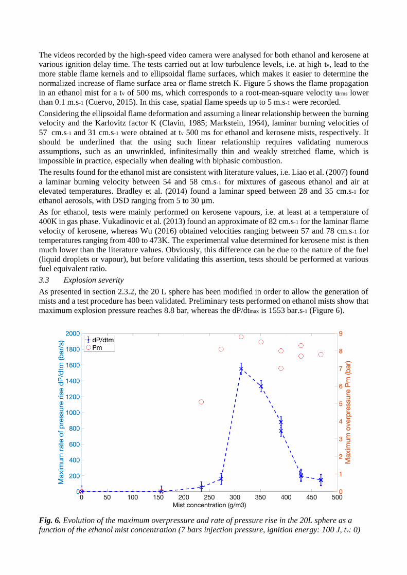
3.3 Explosion severity
As presented in section 2.3.2, the 20 L sphere has been modified in order to allow the generation of
mists and a test procedure has been validated. Preliminary tests performed on ethanol mists show that
maximum explosion pressure reaches 8.8 bar, whereas the dP/dtmax is 1553 bar.s-1 (Figure 6).
Fig. 6. Evolution of the maximum overpressure and rate of pressure rise in the 20L sphere as a
function of the ethanol mist concentration (7 bars injection pressure, ignition energy: 100 J, tv: 0)
If the evolution of the maximum overpressure as a function of the mist concentration is consistent
with the explosive behavior of a combustible gas or a dust, showing a lower explosive limit around
160 g.m-3 followed by an increase and then a decrease of Pm, the evolution of the dP/dtm parameter is
apparently unusual with a sharp peak around 300 g.m-3. A direct visualization of the flame
propagation in the open tube (3.2) at different fuel equivalence ratio will help to better interpret the
previous evolutions.
In addition, it should be kept in mind that the maximum adiabatic pressure for ethanol vapour is 9.5
bar and that a maximum pressure of 7.7 bar was reached in a 5 L explosion sphere for fuel equivalent
ratio of 1 at 293K (Cammarota et al., 2012), which is in rather good agreement with the preliminary
tests. Following the first validation tests, it is now necessary to conduct a sensitivity study including
the droplet size distribution, the initial turbulence of the mist and the chemical nature of the fuel.
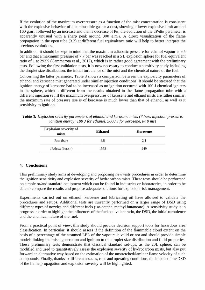
Concerning the latter parameter, Table 3 shows a comparison between the explosivity parameters of
ethanol and kerosene mist generated under similar injection conditions. It should be stressed that the
ignition energy of kerosene had to be increased as no ignition occurred with 100 J chemical igniters
in the sphere, which is different from the results obtained in the flame propagation tube with a
different injection set. If the maximum overpressures of kerosene and ethanol mists are rather similar,
the maximum rate of pressure rise is of kerosene is much lower than that of ethanol, as well as it
sensitivity to ignition.
Table 3: Explosion severity parameters of ethanol and kerosene mists (7 bars injection pressure,
ignition energy: 100 J for ethanol, 5000 J for kerosene, tv: 0 ms)
Explosion severity of
mists Ethanol Kerosene
Pmax (bar) 8.8 2.1
dP/dtmax (bar.s-1) 1553 249
4. Conclusions
This preliminary study aims at developing and proposing new tests procedures in order to determine
the ignition sensitivity and explosion severity of hydrocarbon mists. These tests should be performed
on simple or/and standard equipment which can be found in industries or laboratories, in order to be
able to compare the results and propose adequate solutions for explosion risk management.
Experiments carried out on ethanol, kerosene and lubricating oil have allowed to validate the
procedures and setups. Additional tests are currently performed on a larger range of DSD using
different types of nozzles and different fuels (iso-octane, methyl butanoate). A sensitivity study is in
progress in order to highlight the influences of the fuel equivalent ratio, the DSD, the initial turbulence
and the chemical nature of the fuel.
From a practical point of view, this study should provide decision support tools for hazardous area
classification. In particular, it should assess if the definition of the flammable cloud extent on the
basis of a percentage of the assumed LEL of the vapours is valid or not and should provide simple
models linking the mists generation and ignition to the droplet size distribution and fluid properties.
These preliminary tests demonstrate that classical standard set-ups, as the 20L sphere, can be
modified and used to quantitatively assess the explosion severity of hydrocarbon mists, but also put
forward an alternative way based on the estimation of the unstretched/laminar flame velocity of such
compounds. Finally, thanks to different nozzles, caps and operating conditions, the impact of the DSD
of the flame propagation and explosion severity will be highlighted.
Acknowledgements
The authors gratefully acknowledge the financial support of the French Ministry for the Ecological
and Solidary Transition and The French Ministry for Higher Education and Research.
References
Ballal, D.R. & Lefebvre, A.H. (1981). A general model of spark ignition for gaseous and liquid fuel-
air mixtures. Symposium (International) on Combustion, Eighteenth Symposium on Combustion
18, 1737–1746.
Bane, S.P.M., Ziegler, J.L., Boettcher, P.A., Coronel, S.A. & Shepherd, J.E. (2013). Experimental
investigation of spark ignition energy in kerosene, hexane, and hydrogen. Journal of Loss
Prevention in the Process Industries, 26(2): 290-294.
Bettis, R., Burrell, G., Gant, S. & Coldrick, S. (2017). Area classification for oil mists - final report
of a Joint Industry Project. RR1107 HSL report, Buxton, UK.
Bradley, D., Lawes, M., Liao, S. & Saat, A. (2014). Laminar mass burning and entrainment velocities
and flame instabilities of i-octane, ethanol and hydrous ethanol/air aerosols. Combustion and
Flame, 161: 1620–1632.
Brandes, E. & Frobese, D.H. (2009). Ethanol-containing automotive fuels - A safety concept for
petrol stations in Germany, Forschung auf dem Gebiete des Ingenieurwesens, 73(1): 25-32.
Burrell, G. & Gant, S. (2017). Liquid classification for flammable mists. RR1108 HSL report, Buxton,
UK.
Cammarota, F., Di Benedetto, A., Di Sarli, V. & Salzano, E. (2012). The effect of hydrogen addition
on the explosion of ethanol/air mixtures, Chemical Engineering Transactions, 26: 405-410.
Clavin, P. (1985). Dynamic behavior of premixed flame fronts in laminar and turbulent flows.
Progress in Energy and Combustion Science, 11: 1–59.
Cuervo, N. (2015). Influences of turbulence and combustion regimes on explosions of gas-dust hydrid
mixtures (PhD Thesis). The University of Lorraine, France (in English).
Cuervo, N., Dufaud, O. & Perrin, L. (2017). Determination of the burning velocity of gas/dust hybrid
mixtures. Process Safety and Environmental Protection, 109: 704–715.
Dufaud, O., Charvet, A., Mougel, G., Molière, M., Luthun, S., Brunello, D., Perrin, L., Delimoges,
S. & Couchot, M. (2015). Generation, Characterization and Ignition of Lube Oil Mists, ASME
Turbo Expo 2015, Combustion, Fuels and Emissions. ASME, Montreal, Canada, Paper No.
GT2015-43524, p. V04BT04A039.
Eckhoff, R.K. (2016). Explosion Hazards in the Process Industries. Gulf Professional Publishing.
Eckhoff, R.K. (1995). Generation, ignition, combustion and explosion of sprays and mists of
flammable liquids in air: a literature survey, Offshore Technology Report OTN 95 260, Health and
Safety Executive, Bootle, UK.
Eichhorn, J. (1955). Careful! Mist can explode. Petroleum Refiner, 34 (11): 194-196.
Gant, S. (2013). Generation of flammable mists from high flashpoint fluids: Literature review.
Research Report RR980, HSL report, Buxton, UK.
Gant, S., Bettis, R., Coldrick, S., Burrell, G., Santon, R., Fullam, B., Hill, H., Mouzakitis, K., Giles,
A. & Bowen, P. (2016). Area classification of flammable mists: summary of joint-industry project
findings, Symposium series n°161, IChemE Hazards 26, 24-26 May, Edinburgh, UK.
Kooij, S., Sijs, R., Denn, M.M., Villermaux, E. &Bonn, D. (2018). What determines the drop size in
sprays?, Phys. Rev. X 8, 031019.
Lees, P., Gant, S., Bettis, R., Vignes, A., Lacome, J.L. & Dufaud, O. (2019). Review of recent
incidents involving flammable mists. Symposium series n°166, IChemE Hazards 29 Conference,
Birmingham, UK.
Liao, S.Y., Jiang, D.M., Huang, Z.H., Zeng, K. & Cheng, Q. (2007). Determination of the laminar
burning velocities for mixtures of ethanol and air at elevated temperatures. Applied Thermal
Engineering, 27, 374–380.
Markstein, G.H., (1964). Non-Steady Flame Propagation. Pergamon, New York.
Mouzakitis, K. & Giles, A. (2017). Experimental investigation of oil mist explosion hazards, Research
Report RR1109, HSL report, Buxton, UK.
Santandrea, A., Gavard, M., Pacault, S., Vignes, A., Perrin, L. & Dufaud, O. (2020). ‘Knock on
nanocellulose’: Approaching the laminar burning velocity of powder-air flames. Process Safety
and Environmental Protection, 134: 247–259.
Santon, R.C. (2009). Mist fires and explosions - an incident survey. Symposium series, IChemE
Hazards XXI Symposium & Workshop, Manchester, UK.
Thimothée, R. (2017) Experimental characterization of a laminar flame propagation in a two-phase
medium (aerosol) in microgravity conditions, PhD thesis, Université d’Orléans, France (in
French).
Vukadinovic, V., Habisreuther, P. & Zarzalis, N. (2013). Influence of pressure and temperature on
laminar burning velocity and Markstein number of kerosene Jet A-1: Experimental and numerical
study. Fuel, 111: 401–410.
Wu, Y. (2016). Experimental investigation of laminar flame speeds of kerosene fuel and second
generation biofuels in elevated conditions of pressure and preheat temperature, PhD thesis, INSA
de Rouen, France (in English).