The Explosion Proof Limit Switch Box - Kinetrol
6
The Explosion Proof Limit Switch Box ®
-
Upload
khangminh22 -
Category
Documents
-
view
0 -
download
0
Transcript of The Explosion Proof Limit Switch Box - Kinetrol

The Explosion ProofLimit Switch Box
®
Explosion Proof Limit Switch Box
STANDARD INDICATORVisual indication of valve position (standard supply).
CLEAR CONE MONITOR OPTIONHigh visibility position indicator showsopen-closed status and/or angular positionviewed from any angle above the lid. Made ofrobust transparent antistatic polymer fullysealed onto the metal lid.
LIDMade of robust epoxy-coated anodisedaluminium alloy, threaded to give rapidremoval with external features for easy use.
ENCLOSURERobust epoxy-coated anodised aluminium alloy with oring sealing. 2 or 4 conduit entryoptions are available.
COUPLINGMade from strong plated steel with easily adjusted striker clamps in reinforced polymer.Special strikers with metal inserts are used with inductive proximity sensor options.
STANDARD TERMINAL BLOCKS2 x 3-way blocks accommodating up to a 2.5mm2 cable fitted directly adjacent toconduit entries, plus optional third and fourth 3-way blocks for single pointtermination of external solenoid valve or extra limit switches. Internal and externalearth terminals are also provided.
MULTI TERMINAL OPTIONPCB mounted option which gives 4 x 3 - wayterminals, plus 3-way termination for externalsolenoid and 2-way termination for 4-20mAangle retransmit wiring immediately adjacentto conduit entries (up to 17 connectionsprovided).
OPTIONAL AS INTERFACE CIRCUITThe AS interface circuit fits inside the standard box to give control and monitoringby serial communication of up to 31 actuators, (61 for certain applications).All power and communications for circuits and actuator solenoid valves can be carriedvia one 2-wire cable. Refer to Kinetrol for details.
The Explosion Proof Limit Switch Box offers a wide range of signalling options in a compactcorrosion resistant aluminium alloy housing available for close mounting onto Kinetrolactuators or discrete mounting via a Kinetrol 05 square or industry standard VDI/VDEinterface onto any make of rotary actuator. Easy to wire and set up with true industrialrobustness.Internally fitted options include AS interface digital communication and a 420mA, 2-wire,modulating angle retransmit circuit. The range of switches and terminal arrangementsincludes 2 or 4 switches and extra connections allowing single pointtermination of wiring for limit switches and solenoid valves. This product is available tomount on Kinetrol models 03 - 60.
POSITIONER OPTIONS AVAILABLEPlease refer to Kinetrol for details
OPTIONAL ANGLE RETRANSMITAn optional angle retransmit circuit fits inside the standard explosion proof limit switchbox. Powered by a 14 - 30v DC supply, the 2 wire, loop powered circuit generates a4-20mA current to feedback the position of the actuator. The circuit has zero and spanadjustments for easy setup and with the use of a high quality servo pot and anti backlashspring, gives a long life and high precision.
POTENTIOMETERFeedback from 0 to 20K ohms at 20v maximum.
05 or 03 REDUCERReducing square adapter from Kinetrol 07 size to 05 or 03.
CLOSE MOUNT PLATEStandard plate allows close fitting to Kinetrol actuator models 03-15.
KINETROL 05 SQUARE DRIVEInterfaces with Kinetrol 05 vane slot without backlash.
NAMUR ADAPTORConverts standard coupling to NAMUR standard.
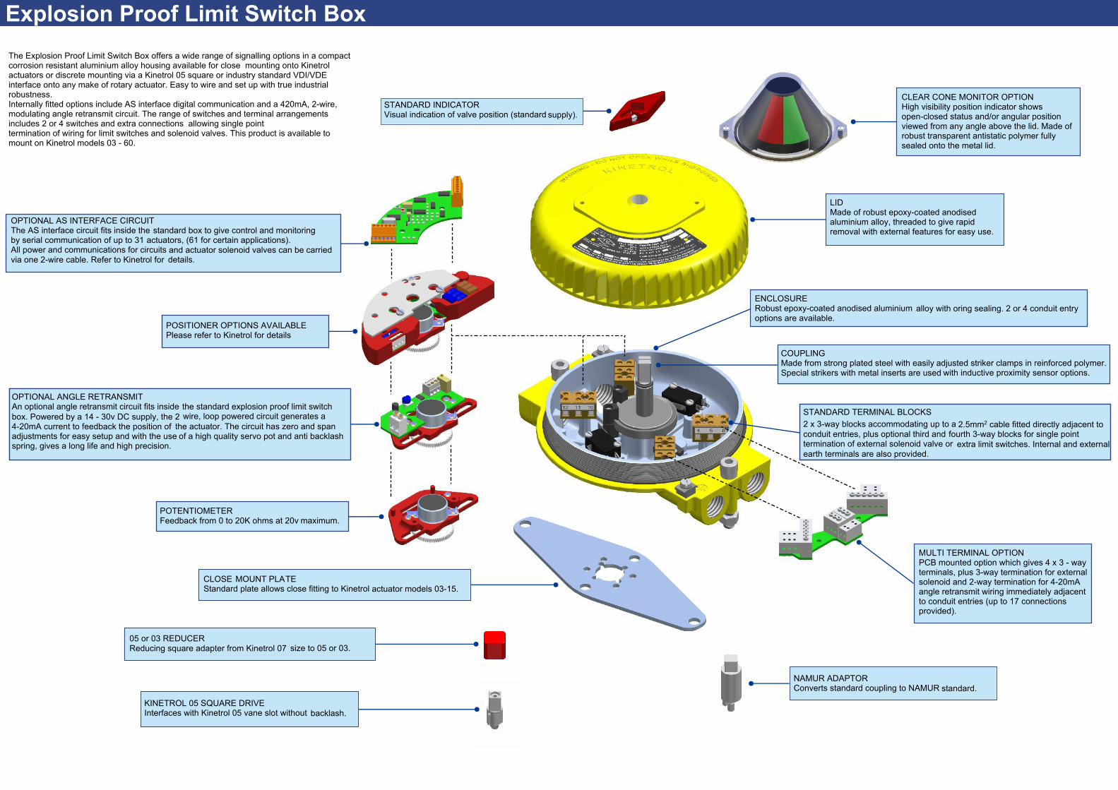
KEY FEATURES
● Wide range of worldwide explosion proof approvals including IECEX, ATEX & FM (for USA & Canada). FM option also comes IECand ATEX approved.
● All units protected to IP66 / NEMA 4X / TYPE 4X.
● Attractive, functional and partspherical profile. Robust corrosion resistant, anodised & epoxy painted diecast aluminium alloy housing.
● Close mount to Kinetrol actuator models 03 - 15 for low profile.
● Discrete Kinetrol 05 square drive insert for use with Kinetrol actuator models 16 - 60.
● Discrete NAMUR drive for use with VDI/VDE 3845 drive actuators.
● 2 or 4 cable entries available to allow back wiring of solenoid valves.
● Up to 4 switches available for SPDT, DPDT or multiple circuit operation.
● Easy and accurate setting of switching position.
● Optional antistatic Clear Cone Monitor available.
● Integral angle retransmit circuit options are available.
● Integral AS interface bus circuit option reads up to 4 switch inputs and drives up to 2 bus powered solenoids.
● -40°C to +80°C ambient operating temperatures (dependent on switch options).
SPECIFICATION
CABLE ENTRY OPTIONS - M20 x 1.5 Conduit thread- 1/2” 14 NPT Conduit thread
WEIGHT - 1.5Kg
CASING - Precision diecast aluminium alloy, anodised & epoxy stove enamel finish.
COUPLING - Zinc Plated Steel.
SEALS - Fluoropolymer dynamic seals and NBR static seals..
SWITCH OPERATINGCONDITIONS
Switch Option AC DC Current Ambient Temperature Range001/00A – 8 6 mA -20°C to +80°C004/007 250 48 2.4A ac / 1.8 A dc -40°C to +80°C005/00B 250 300 100 mA -25°C to +70°C006/00C – 60 100 mA -20°C to +80°C009/00D – 30 100 mA -40°C to +80°C00E/00F 140 140 200 mA -25°C to +80°C00M/00N – 30 100 mA -25°C to +70°C
Voltage
NORTH AMERICAN APPROVAL
Type of Explosion Proof protection
US: Class I, Division 1, Gas groups B,C,D. Class II, Division 1, Dust groups E,F,G. T5 NEMA 4X.For Gas group A use order code “P”.
CANADA: Class I, Division 1, Gas groups B,C,D. Class II, Division 1, Dust groups E,F,G. T5 TYPE 4X.
EUROPE/GLOBAL - ATEX / IECEx APPROVALProtection concept, Flame Proof ‘d’ Group II C/A21, Category 2, Gas & Dust, T5, IP66
IECEx & ATEX Approval type E FMC/U, IECEx & ATEX Approval type F & P
APPROVAL OPTIONS
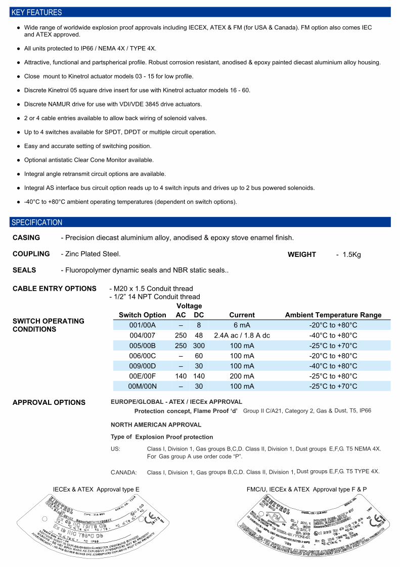
Switch Type 00A4 intrinsically safe 2 wire inductive proximity sensors for7.5-30V dc, normally closed.
Switch Type 00B4 x 2 wire proximity sensors 20-250 volts AC, normally open.
Switch Type 00C4 x 2 wire proximity sensors 5-60 volts DC, normally open,with Led switch status indicators.
Switch Type 00D4 x 3 wire gold plated contacts intrinsically safemicroswitches for SPDT.
Switch Type 00E2 x 2 wire inductive proximity sensors 20-140 volts AC /10-40V dc.
Switch Type 00M4 x 3 wire inductive proximity sensors 10-30 volts DC,normally open.
Switch Type 00N2 x 3 wire inductive proximity sensors 10-30 volts DC,normally open.
Switch Type 0012 intrinsically safe 2 wire inductive proximity sensors for7.5-30V dc, normally closed.
Switch Type 0042 x 3 wire microswitches for SPDT.
Switch Type 0052 x 2 wire proximity sensors 20-250 volts AC, normally open.
Switch Type 0062 x 2 wire proximity sensors 5-60 volts DC, normally open,with Led switch status indicators.
Switch Type 0074 x 3 wire microswitches for DPDT.
Switch Type 0092 x 3 wire gold plated contacts intrinsically safemicroswitches for SPDT.
ORDERING CODES
0 = STANDARD INDICATORA = ANTI-STATIC MONITOR
0 = 2 x 3 TERMINALS4 = 3 x 3 TERMINALS5 = 4 x 3 TERMINALS6 = MULTI-TERMINAL PCB (2x6 + 1x3 + 1x2)
P = POTENTIOMETER
F = ANGLE RETRANSMIT CLOCKWISEG = ANGLE RETRANSMIT ANTI-CLOCKWISE
–
0 = WITHOUT ACT1 = WITH ACT
0 = NO SR2 = SR CW3 = SR CCW
APPROVAL TYPEE = IEC / ATEX IIC, IIB, IIAF = FM / FMC GRPS B,C,DP = FM GRP A
D = ASi EXTENDED ADDRESSING OUTPUTS ENABLEDE = ASi EXTENDED ADDRESSING OUTPUTS ENABLED, SEPARATE POWER SUPPLY
B = ASi BUSC = ASi EXTENDED ADDESSING OUTPUTS DISABLED
0 = NO OPTIONS
0 = CLOSE-MOUNT (03-14 MODEL-SPECIFIC)1 = DISCRETE KINETROL 05 SQUARE DRIVE (16-30 MODEL-SPECIFIC)2 = DISCRETE NAMUR3 = NO MOUNTING PARTS (NON MODEL-SPECIFIC)
NOTE: ACTUATORS 16 - 60 REQUIRE DISCRETE MOUNTING
SWITCH OPTIONS(SUPPLIED WITH 2 STRIKERS AS STANDARD)1 = 2 x V3 7.5-30Vdc, NC, 2 WIRE INDUCTIVE SENSORS4 = 2 x V3 SPDT, 0-250Vac, MECHANICAL MICROSWITCHES5 = 2 x V3 20-250Vac / 10-300Vdc NO, 2 WIRE, INDUCTIVE SENSORS6 = 2 x V3 5-60Vdc, NO, 2 WIRE, INDUCTIVE SENSORS7 = 4 x CODE 4 MICROSWITCHES9 = 2 x V3 SPDT, GOLD PLATED CONTACTS MECHANICAL MICROSWITCHESA = 4 x CODE 1 SENSORSB = 4 x CODE 5 SENSORSC = 4 x CODE 6 SENSORSD = 4 x CODE 9 MICROSWITCHESE = 2 x V3 20-140Vac / 10-140Vdc, NO, 2 WIRE, INDUCTIVE SENSORSF = 4 x CODE E SENSORSM = 4 x 10-30Vdc, PNP, 3 WIRE, PROXIMITY SENSORSN = 2 x 10-30Vdc, PNP, 3 WIRE, PROXIMITY SENSORS
X
ACTUATORMODEL03 - 60
3 = DIN FLANGE STANDARD (FEMALE DRIVE)4 = ISO (M20) THREADA = DIN FLANGE STANDARD WITH NAMUR ADAPTORB = ISO (M20) THREAD STANDARD WITH NAMUR ADAPTORC = ANSI (1/2" NPT) THREAD STANDARD WITH NAMUR ADAPTOR7 = ANSI THREAD (1/2" NPT)
— = MALEF = FEMALES = SERRATED
B = 2 ENTRYD = 4 ENTRY
MOUNTING PARTS AVAILABLE: SP1601 - 05 SQUARE DRIVE SP1602 - 07/05 SQUARE REDUCER SP1603 - NAMUR DRIVE SP1604 - 07/03 SQUARE REDUCER SP/ASP1607 - CLOSE MOUNTING KIT SP/ASP1608 - 12/14/15 ACCESSORY MOUNTING ADAPTOR (UNDRILLED) SP/ASP389 - MODEL 16 MOUNT KIT SP/ASP329 - MODEL 18 MOUNT KIT SP/ASP400 - MODEL 21 - 60 MOUNT KIT
NOT AVAILABLE WITHAPPROVAL TYPES
F & P
ASI + 2 OR 4 SWITCHES = 2x3 (0)A/R + 2 SWITCHES = 2x3 (0)A/R + 4 SWITCHES = PCB (6)POT + 2 OR 4 SWITCHES = PCB (6)2 SWITCHES = 2x3 (0)4 SWITCHES = 4x3 (5)
A/R + 2 SWITCHES = PCB (6)A/R + 4 SWITCHES = PCB (6)POT + 2 SWITCHES = PCB (6)POT + 4 SWITCHES = PCB (6) SEE NOTE2 SWITCHES = 3x3 (4)4 SWITCHES = PCB (6)
TERMINALS NEEDED FOR OPTIONS
0
WITH BACKWIRING
NO BACKWIRING
NOTE - POT + 4 SWITCHES WITH BACKWIRINGWILL NOT HAVE ENOUGH TERMINALCONNECTORS TO WIRE ALL NORMALLYOPEN / NORMALLY CLOSED SWITCHCONNECTIONS WITH 3 POT CONNECTIONS.
ELECTRONICS OPTIONS
Electronics Option B - EAS interface options are available with both the two and fourentry Kinetrol Explosion Proof Switch Box. Options B to Eallow for different extended addressing options. For moreinformation on the Kinetrol AS interface card see Kinetrolleaflet KF-496.
Electronics Option F - GTwo or four entry Switch Box fitted with angle retransmit circuitpowered by 14-30v DC supply, the 2 wire loop poweredcircuit generates a 4-20mA current to feedback position.
Electronics Option PTwo or four way Switch Box fitted with potentiometer(20K ohms conductive plastic type).
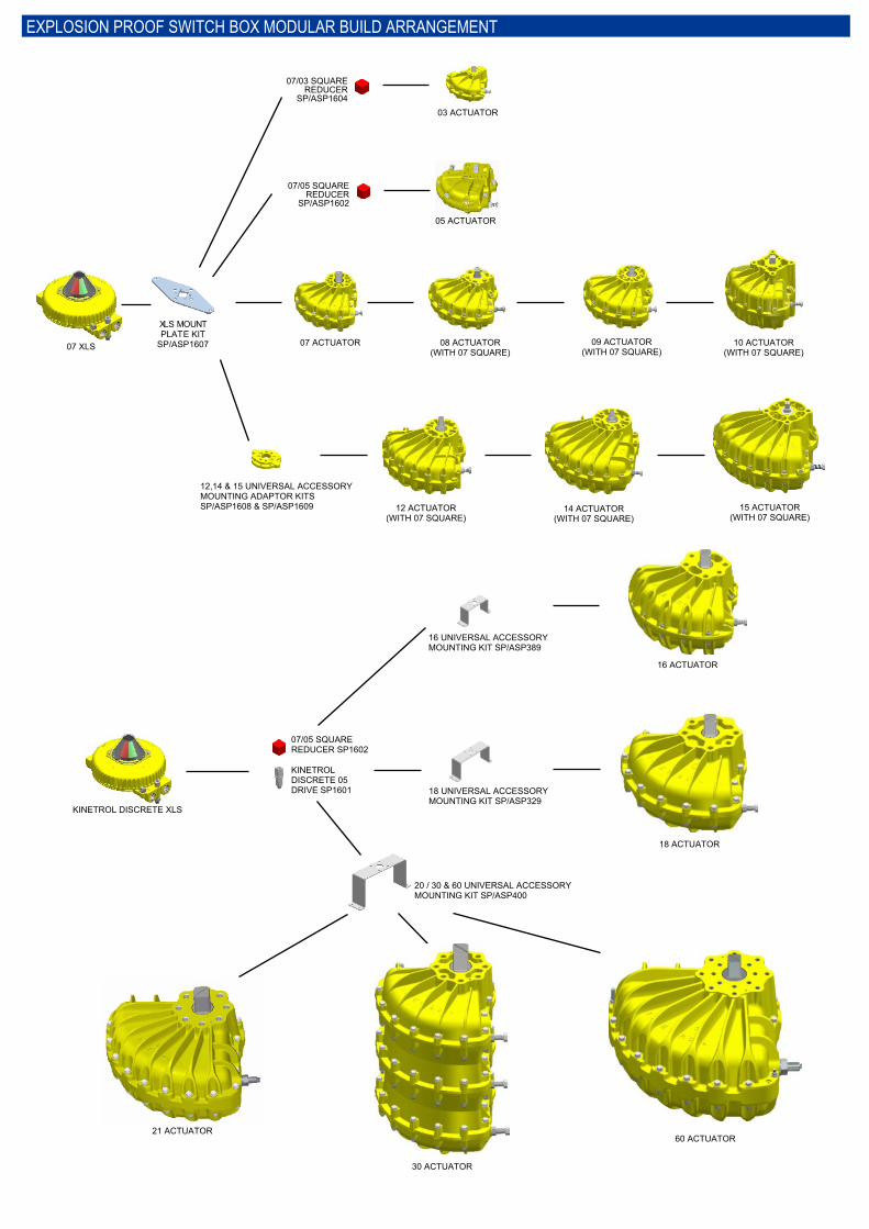
EXPLOSION PROOF SWITCH BOX MODULAR BUILD ARRANGEMENT
12,14 & 15 UNIVERSAL ACCESSORYMOUNTING ADAPTOR KITSSP/ASP1608 & SP/ASP1609 12 ACTUATOR
(WITH 07 SQUARE)14 ACTUATOR
(WITH 07 SQUARE)15 ACTUATOR
(WITH 07 SQUARE)
07 ACTUATOR 08 ACTUATOR(WITH 07 SQUARE)
09 ACTUATOR(WITH 07 SQUARE)
10 ACTUATOR(WITH 07 SQUARE)
03 ACTUATOR
07/03 SQUAREREDUCER
SP/ASP1604
07/05 SQUAREREDUCER
SP/ASP1602
07 XLS
XLS MOUNTPLATE KIT
SP/ASP1607
05 ACTUATOR
16 UNIVERSAL ACCESSORYMOUNTING KIT SP/ASP389
16 ACTUATOR
20 / 30 & 60 UNIVERSAL ACCESSORYMOUNTING KIT SP/ASP400
KINETROLDISCRETE 05DRIVE SP1601 18 UNIVERSAL ACCESSORY
MOUNTING KIT SP/ASP329
18 ACTUATOR
07/05 SQUAREREDUCER SP1602
KINETROL DISCRETE XLS
60 ACTUATOR
30 ACTUATOR
21 ACTUATOR
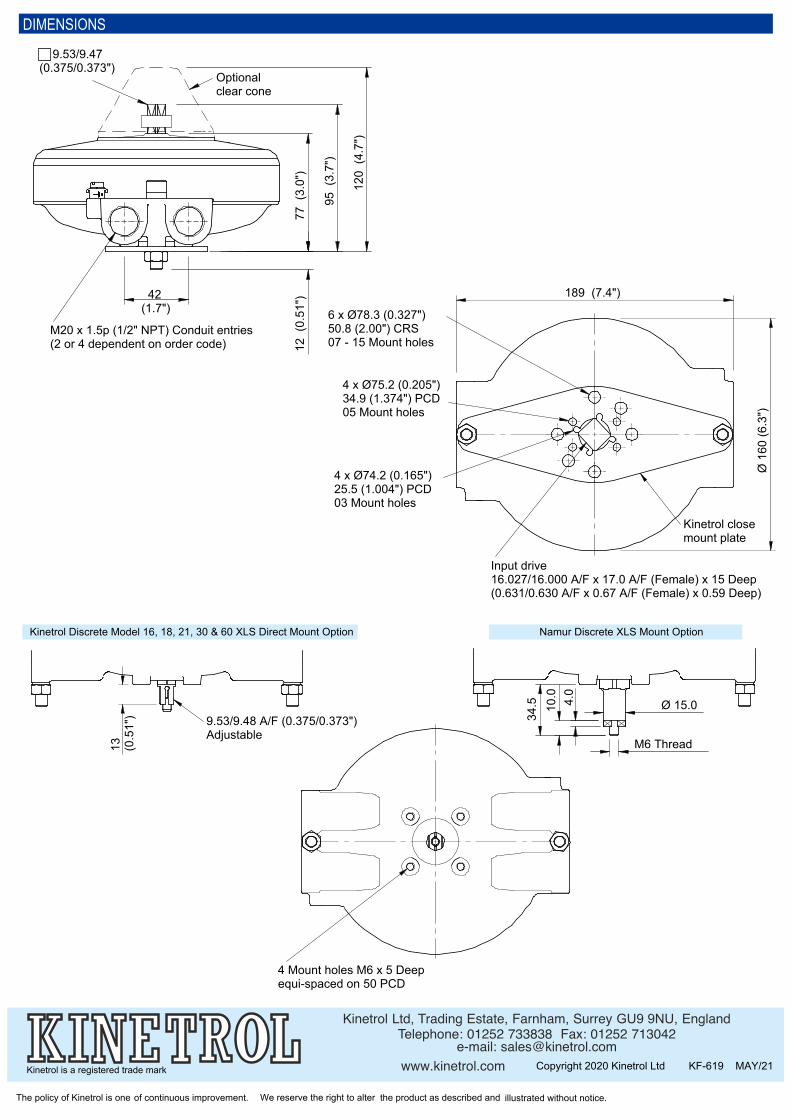
DIMENSIONS
Kinetrol Discrete Model 16, 18, 21, 30 & 60 XLS Direct Mount Option Namur Discrete XLS Mount Option
K in e tro l L td, Tradin g E s tate , F arn h am , Su rre y GU9 9NU, E n g lan dTe le p h o n e : 0 1 2 5 2 7 3 3 8 3 8 F ax : 0 1 2 5 2 7 1 3 0 4 2
e -m ail: s ale s @k in e tro l.co mw w w .k in e tro l.co m Copyright 2020 Kinetrol Ltd KF-619 MAY/21
The policy of Kinetrol is one of continuous improvement. We reserve the right to alter the product as described and illustrated without notice.
Kinetrol is a registered trade mark
95 (
3.7"
)
77 (
3.0"
)12
(0.
51")
M20 x 1.5p (1/2" NPT) Conduit entries(2 or 4 dependent on order code)
42(1.7")
9.53/9.47(0.375/0.373")
Optionalclear cone
120
(4.7
")
189 (7.4")
Input drive16.027/16.000 A/F x 17.0 A/F (Female) x 15 Deep(0.631/0.630 A/F x 0.67 A/F (Female) x 0.59 Deep)
4 x Ø75.2 (0.205")34.9 (1.374") PCD05 Mount holes
6 x Ø78.3 (0.327")50.8 (2.00") CRS07 - 15 Mount holes
Kinetrol closemount plate
4 x Ø74.2 (0.165")25.5 (1.004") PCD03 Mount holes
Ø 1
60 (6
.3")
34.5
M6 Thread
Ø 15.04.0
10.0
13 (0.5
1") 9.53/9.48 A/F (0.375/0.373")
Adjustable
4 Mount holes M6 x 5 Deepequi-spaced on 50 PCD