G2122 Explosion Protection - Rotor Technical Services
92
G2122 Explosion Protection EN Intelligent Drivesystems, Worldwide Services
-
Upload
khangminh22 -
Category
Documents
-
view
1 -
download
0
Transcript of G2122 Explosion Protection - Rotor Technical Services

Intelligent Drivesystems, Worldwide Services
G2122
G21
22 M
at.-N
r. 60
0350
2 / 4
619
Explosion Protection
EN
Intelligent Drivesystems, Worldwide ServicesIntelligent Drivesystems, Worldwide Services
Headquarters:Getriebebau NORD GmbH & Co. KGGetriebebau-Nord-Straße 122941 Bargteheide, GermanyFon +49 (0) 4532 / 289 - 0 Fax +49 (0) 4532 / 289 - [email protected], www.nord.com
Member of the NORD DRIVESYSTEMS Group
NORD DRIVESYSTEMS ® GroupHeadquarters and Technology centerin Bargteheide, Germany, close to Hamburg
Innovative drive solutionsfor more than 100 branches of industry
Mechanical productsparalell shaft, helical gear, bevel gear and worm gear units
Electrical productsIE2/IE3/IE4 motors
Electronic productscentralised and decentralised frequency inverters,motor starters and fi eld distribution systems
Seven state-of-the-art production plantsfor all drive components
Subsidiaries and distributorsin 98 countries on 5 continentsprovide local stocks, assembly, production,technical support and customer service
More than 4,000 employees throughout the worldcreate customer oriented solutions
www.nord.com/locator

www.nord.com
G1050 MAXXDRIVE ® Industrial gear unitsUNICASE housing 50 / 60 Hz Parallel-Axis Right-Angle
G1035 UNIVERSAL Worm gear units SI and SMI
ELECTRONICVARIABLE SPEED DRIVES
Headquarters:Getriebebau NORD GmbH & Co. KGGetriebebau-Nord-Straße 122941 Bargteheide, GermanyFon +49 (0) 4532 / 289 - 0 Fax +49 (0) 4532 / 289 - [email protected], www.nord.comMember of the NORD DRIVESYSTEMS Group
Intelligent Drivesystems, Worldwide Services
G401
4EL
ECTR
ONIC
VARI
ABLE
SPEE
D DR
IVES
NORD DRIVESYSTEMS GROUPHeadquarters and Technology Centerin Bargteheide near Hamburg, GermanyInnovative drive solutionsfor more than 100 industriesMechanic ProductsHelical, Parallel Shaft, Helical Bevel and Helical Worm Gear UnitsElectrical ProductsElectric motors in all efficiency classesElectronic ProductsCentralized and decentralized frequency inverters, Motor starters7 state-of-the-art production plantsfor all drive components36 subsidiaries on 5 continentsprovide on-site storage, assembly centers, technical support and customer serviceMore than 3.100 employees around the worldcreate customized solutions
www.nord.com/locator
DRIVESYSTEMS
G401
4 Mat.
-Nr. 6
0040
02 /
4214
NORDBLOC.1 Helical Gear Units, Helical Gear Units, Parallel Gear Units, Helical-Bevel Gear Units, Helical-Worm Gear Units
PRODUCT OVERVIEWG4014
EN
EN
www.nord.com/locator
G103
5 W
ORM
GEAR
UNITS
Mat
.-Nr. 6
0015
02/4
813
Intelligent Drivesystems, Worldwide Services
G1035UNIVERSAL Worm gear unitsSI und SMI
EN
EN
NORD Drivesystems | Global, always close to you
Headquarters:Getriebebau NORD GmbH & Co. KGGetriebebau-Nord-Straße 122941 Bargteheide, GermanyFon +49 (0) 4532 / 289 - 0 Fax +49 (0) 4532 / 289 - [email protected], www.nord.com
Member of the NORD DRIVESYSTEMS Group
DE
Intelligent Drivesystems, Worldwide Services
SK 180EDezentrale Antriebstechnik Frequenzumrichter
50 H
z • m
m F
ESTE
DRE
HZAH
LEN
DRIVESYSTEMS
Intelligent Drivesystems, Worldwide Services
G100
0 M
at.-N
r. 60
0180
2 / 4
815
G100
0EN
50 Hz • mm
CONSTANT SPEEDS G1000
ENHeadquarters:Getriebebau NORD GmbH & Co. KGGetriebebau-Nord-Straße 122941 Bargteheide, GermanyFon +49 (0) 4532 / 289 - 0 Fax +49 (0) 4532 / 289 - [email protected], www.nord.comMember of the NORD DRIVESYSTEMS Group
NORD DRIVESYSTEMS GROUPHeadquarters and Technology Centerin Bargteheide near Hamburg, GermanyInnovative drive solutions for more than 100 industriesMechanic ProductsHelical, Parallel Shaft, Helical Bevel and Helical Worm Gear UnitsElectrical ProductsElectric motors in all effi ciency classesElectronic ProductsCentralized and decentralized frequency inverters, Motor starters7 state-of-the-art production plantsfor all drive components36 subsidiaries on 5 continentsprovide on-site storage, assembly centers, technical support and customer serviceMore than 3.200 employees around the worldcreate customized solutions
www.nord.com/locator 50 H
z • m
m C
ONST
ANT
SPEE
DS
PRODUCT OVERVIEWG1050 • 50/60 Hz • mm
G105
0 M
at.-N
r. 60
0110
2 / 1
516
SK 7207 - SK 15507 Gear Units
50/6
0 Hz
•m
m
NORD
GEA
R - L
ARGE
INDU
STRI
AL G
EAR
UNIT
SG1
050
Large Industrial Gear UnitsParallel-Axis and Right-AngleHigh Precision, Long Life, Low Maintenance
Headquarters:Getriebebau NORD GmbH & Co. KGGetriebebau-Nord-Straße 122941 Bargteheide, GermanyFon +49 (0) 4532 / 289 - 0 Fax +49 (0) 4532 / 289 - [email protected], www.nord.comMember of the NORD DRIVESYSTEMS Group
NORD DRIVESYSTEMS GROUPHeadquarters and Technology Centerin Bargteheide near Hamburg, GermanyInnovative drive solutions for more than 100 industriesMechanic ProductsHelical, Parallel Shaft, Helical Bevel and Helical Worm Gear UnitsElectrical ProductsElectric motors in all efficiency classesElectronic ProductsCentralized and decentralized frequency inverters, Motor starters7 state-of-the-art production plantsfor all drive components36 subsidiaries on 5 continentsprovide on-site storage, assembly centers, technical support and customer serviceMore than 3.200 employees around the worldcreate customized solutions
www.nord.com/locator
Intelligent Drivesystems, Worldwide Services
EN
Intelligent Drivesystems, Worldwide Services
F 3020 DE
SK 200E
Contents
G1000 Fixed speedsUNICASE housing 50 Hz, 60 Hz Helical geared motors Parallel geared motors Bevel geared motors Helical worm geared motors
G4014 Electronic variable speed drives NORDBLOC.1 Helical geared motors Helical geared motors Parallel geared motors Bevel geared motors Helical worm geared motors
An overview ofNORD range
F3018_E3000 Frequency inverter SK180EF3020_E3000 Frequency inverter SK200E
F3060_E3000 NORDAC PRO Frequency inverter SK500P
Introduction
Country-specifi c explanations . . . . . . . . . . . . . . . . A 2 - 12
General Dust Explosion Protection . . . . . . . . . . . . B 1 - 8
Motors for Dust Explosion Protection . . . . . . . . . . C 1 - 24
General Gas Explosion Protection . . . . . . . . . . . . . D 1 - 8
Motors for Gas Explosion Protection . . . . . . . . . . . C 1 - 8
General Explosion Protected Gear Units . . . . . . . . F 1 - 10
Hybrid Mixtures . . . . . . . . . . . . . . . . . . . . . . . . . . . . G 1 - 2
Cooling systems for gear units. . . . . . . . . . . . . . . . H 1 - 2
Decentralised inverters and starters . . . . . . . . . . . I 1 - 4
Documentation . . . . . . . . . . . . . . . . . . . . . . . . . . . . . J 1 - 8
Intelligent Drivesystems, Worldwide Services
NORDAC PRO FREQUENCY INVERTER SK 500P
EN
VERSATILE FREQUENCY INVERTER FOR CONTROL CABINET APPLICATIONS
Intelligent Drivesystems, Worldwide Services

Headquarters and Technology Centre in Bargteheide,
near Hamburg
Innovative drive solutions for more than 100 branches
of industry
7 production locations withcutting edge technology Produce gear units, motors,
inverters, etc. for complete drive solutions from a single source
Subsidiaries and sales partners in 98 countries on 5 continents Provide local supplies Assembly centres Technical support and customer service
More than 4,000 employeesworldwide Create customised solutions
Industrial gear units Electronic productsGear unit motorsFrequency inverters, motor starters
and fi eld distributors
Gear unit production Motor production Inverter production
The map shown above is for information only and does not claim to be created for or applicable to any legal purpose. For this reason, we do not assume any liability for legality, correctness and completeness.
NORD DRIVESYSTEMS GROUP
www.nord.com ATEX EN

Intro
duct
ion
Introduction
For many decades, NORD DRIVESYSTEMS has supplied drive units for use in potentially explosive environments. Since 2003 this range has also included specially designed gear units which comply with EU Ex directives (ATEX).
Over the past years a great deal of work has been invested in order to comply with other international regulations such as IEC Ex, EAC Ex as well as the specifications for the North American market.
This catalogue contains information about gear units, motors and inverters for use in gas or dust explosion protection.
The catalogue has a modular structure and if necessary can be compiled separately for gas or dust areas.
In addition, this catalogue provides a large amount of additional technical information and supplements catalogues
catalogues G1000 (Geared Motors) and M7000 (Motors) the operating instructions B2000 for gear units and B1091 or B1091-1 for motors.
This catalogue provides assistance for use of software tools such as myNORD and NORDcad.The myNORD tool enables quick and simple verification of whether a particular drive is Ex compliant.
Certificates and declarations of conformity can be found on our homepage www.NORD.com - see chapter Documentation Page J 6-7
The nameplates shown in this catalog are examples only.NORD Drivesystems assumes no responsibility for the up-to-dateness of the data contained on the nameplates.
A2 ATEX www.nord.com

Specific national specifications
Intro
duct
ionThroughout the world; states, confederations of states or organisations define the technical
requirements and the necessary standards for explosion protected devices.
The resulting variety is a barrier to trade and places great demands on globally active manufacturers. As a result, harmonized technical standards have been used to define uniform, supraregional standards. These are also used by countries which themselves have no individual legal regulation regarding explosion-protected drives.
NORD DRIVESYSTEMS is a globally active company which is able to produce motors, gear units and frequency inverters according to various Ex standards. To enable this, it cooperates closely with the DEKRA EXAM GmbH as well as with the Physikalisch-Technischen Bundesanstalt PTB and other international institutions.
Conformity of the products as well as production and quality control are ensured by regular audits, which are performed by the PTB as well as the company NANIO CCVE. This is completed by a wide range of examination of motors and gear units by the responsible bodies worldwide.
In addition to fulfilling purely technical specifications, the corresponding labelling of drive units as well as provisions of the required specific documentation is of great importance. This enables NORD DRIVESYSTEMS not only to ensure the safe operation of plant and machinery with its specific products, but also the simple and smooth import of products into designated countries.
In the following sections of this Ex catalogue, products are differentiated according to the type of their certification. Four major acceptance systems are described in greater detail below.
Due to the complexity of this topic and for reasons of clarity, the following overview describes the facts which relate to selected products from NORD DRIVESYSTEMS. It does not claim to be complete or fully up-to-date.
www.nord.com ATEX A3

Specific national specifications
Intro
duct
ion European Union "ATEX"
For many decades, the EU has been using the ATEX technical standards to ensure the safe operation of machinery and equipment.
With its Ex specifications for mechanical devices regarding the former Directive 94/9/EG the EU acted as a pioneer at that time.
EU member states + others such as Norway and SwitzerlandTechnical standards based on IEC standards(IEC - International Electrotechnical Commission)
Directive 2014/34/EU relates to mechanical and electrical devices for use in explosion hazard areas.(In addition to this directive, which directly relates to explosion protection, the Ecodesign, EMC and RoHS directives must also be complied with).
DIN EN 60079-0, DIN EN 60079-7, DIN EN 60079-31
DIN EN 60079-0:2012, DIN EN 60079-31:2019, DIN EN ISO 80079-36, DIN EN ISO 80079-37
DIN EN ISO 80079-36:2016, DIN EN ISO 80079-37:2016
The suitability of the device for explosion protection is documented by: Type Test Certificate and Declaration of Conformity for Category 2 motors Declaration of Conformity for Category 3 motors Declaration of Conformity for gear units Official bodies involved:
- Physikalisch-Technischen Bundesanstalt PTB - DEKRA EXAM
Audits: The production and quality control of NORD DRIVESYSTEMS is audited at regular intervals by a Notified Body according to the regulations of EU 2014/34.
Energy efficiency requirements for motors:
According to Regulation 640/2009 motors for explosion protection (gas and dust) constitute an exception and are therefore not subject to requirements with regard to this. However, customers are increasingly specifying the use of IE2 and IE3 motors.
Scope of ApplicationBasis
Based on ...
Ex standards- for motors
- for inverters + starters
- or gear units
Documents
Energy efficient motors
A4 ATEX www.nord.com

Specific national specifications
Intro
duct
ionIECEx
IECEx approval can be helpful for the approval of explosion protected electrical equipment according to national standards.
Australia and New Zealand
Technical standards based on IEC standards(International Electrotechnical Commission)
IECEx 01 IEC Scheme for the Certification to Standards for Electrical Equipment for "Explosive Atmospheres (IECEx Scheme) - Basic Rules" and IECEx 02 IEC Scheme for the Certification to Standards for Electrical Equipment for "Explosive Atmospheres (IECEx Scheme) - Rules of Procedure"
IEC 60079-0 Explosive atmospheres - Part 0: Equipment - General requirements
IEC 60079-31 Explosive atmospheres - Part 31: Equipment dust ignition protection by enclosure "t"
ISO 80079-36 Non-electrical equipment for explosive - Part 36: atmospheres - Basic method and requirements
ISO 80079-37 Non-electrical equipment for explosive - Part 37: atmospheres - Non electrical type of protection constructional safety "c", control of ignition source "b", liquid immersion "k"
Official bodies involved: - DEKRA EXAM and PTB
Audits: IECEx audits by Ex- testing laboratories and (Ex-certification bodies) are mandatory. Performed by the PTB as the notified body.
Energy efficiency requirements for motors:From the point of view of the IECEx there are neither requirements nor restrictions with regard to energy efficiency classes. NORD supplies motors with efficiency classes IE1 and IE2 with IECx approval.
Currently, Getriebebau NORD does not offer EX gear units according to IECEx. A combination of an IECEx motor and a gear unit, complying with EU standard, is possible, see page 4.
Scope of ApplicationBasis
Based on ...
Ex standards- for motors
Documents
Energy efficient motors
- for gear units
Notice
www.nord.com ATEX A5

Specifi c national specifi cations
Intro
duct
ion EAC EX
EAC (abbreviation for EurAsian Conformity) is a label which states that a product complies with the specifi cations of the Eurasian Economic Union regarding to technical specifi cation, labelling and documentation.
EAC Ex indicated conformity with the standard TR CU 012/2011 1) "On safety of equipment intended for use in explosive atmospheres". This contains technical specifi cations which are largely based on the IEC Ex as well as standards which are used in the EU.
The conformity certifi cation is completed in the form of a declaration and certifi cation. NORD products, their production and quality management have been accepted and approved by the certifying body NANIO CCVE. The corresponding certifi cates can be found under www.nord.com Documentation / Certifi cates.
1) TRCU means "The technical regulation of the customs union“" in Cyrillic script "TP C"
Russia, Belarus, Armenia, Kazakhstan and KyrgyzstanTR CU 012/2011 "On safety of equipment intended for use in explosive atmospheres". Technical standards based on IEC (International Electrotechnical Commission) standards. In particular IEC 60079 and IEC 80079.
Products from NORD DRIVESYSTEMS compliant with EAC Ex are tested and produced in a similar manner to products according to Directive 2014/34/EU ATEX.
The technical data of the motors correspond to that of ATEX motors used in Europe - see page C1-2 and C5 as well as E1-2.
Applied standards for NORD EX motors
ГОСТ Standard IEC Standard
ГОСТ 31610.0-2014 IEC 60079-0:2011
ГОСТ P MЭЌ 60079-31-2013 IEC 60079-31:2013
ГОСТ P MЭЌ 60079-7-2012 IEC 60079-7:2006
ГОСТ 31610.15-2014 IEC 60079-15:2010
Scope of ApplicationBasis
Certifi ed NORD products
Standards forNORD EX motors
A6 ATEX www.nord.com

Specifi c national specifi cations
Intro
duct
ion
Energy effi cient motors
Type plate on the gear unit
Motor
Inverter
This results in comprehensive product labelling which is illustrated with the following example for a drive which is to be operated in a dust Ex atmosphere corresponding to Zone 22.
085
225
50
No.
Typ SK 72 - IEC 160 /3Di
M
Bj
T
xR2
u
MI
S
h
mm
°C
min-1
ges
kW
kN
kg
min
Nm
kN
kN
-1n 2
M2
FR2
FA2
Oil
51,25
2049
CLP 220 / 10,00I
II 3D Ex h IIIC T125°C Dc
1465
11
28,63
M1
-10/+40
Getriebebau NORD GmbH & Co. KG22939 Bargteheide / GERMANY
n 1
P1
FR1
160 MH/4 3D TFNo. 201408582-300 112345678
4400/690
20,5/11,8 A 11,0 0,85 1465
IE2-91,2 %II 3D Ex tc IIIB T125°C DcX
1 E
SK 1
80 ..
. 235
E Ex tc IIIB Dc U
TC RU C-DE.AA87.B.0108
Οткрывать, отключив от сети
Energy effi ciency requirements for motors:
From the point of view of the EAC Ex there are neither requirements nor restrictions with regard to energy effi ciency classes. NORD supplies motors with effi ciency classes IE1 and IE2 with EAC Ex approval.
Packaging
ПРЕДУПРЕЖДЕНИЕ ! ОТКРЫВАТЪ, ОТКЛЮЧИВ Т СЕТИ
II 3D Ex tc IIIB T125°C Dc Xεх
www.nord.com ATEX A7

Specific national specifications
Intro
duct
ion
CEC Canadian Electrical Code
The zone system according to IEC Ex protection is mandatory for all new installations as of 2015!
Hazloc - Explosion protection in North AmericaUnlike in many other parts of the world, the explosion protection in the US is not based on IEC specifications.With a similarly high safety level, this results in specific technical solutions as well as a separate categorisation of technical devices with regard to the corresponding explosive environment and the explosive mixture. The specifications for electrical equipment originate from the NEC The National Electrical Code (NEC) is a safety standard of the United States of America.This formulates the specifications for the design of electrical installations. Unlike e.g. in Europe, devices are not categorised according to their use, but rather into "Classes" and "Divisions". In the USA the term "Hazloc" is used in a similar manner to "ATEX" in Europe.
USA (and Canada for existing plants)USA: NEC National Electrical Code(Canada: CEC Canadian Electrical Code)
In 1996, the IEC classification system (categorisation according to zones) was also introduced for Class I. This change was made by Article 505 of the NEC, which gives the user the opportunity to choose the system that is technically and economically optimal for their purposes.In 2005 Zones 20, 21 and 22 for areas with flammable dust (Article 506) were introduced.
NEC in the USAArticle Contents
500 General requirements for Class I, II and III Divisions501 Requirements for Class I Divisions 502 Requirements for Class II Divisions 503 Requirements for Class III Divisions 504 Requirements for Class I, II and III Divisions with regard to intrinsic safety (IS)505 General and specific requirements for Zone 0, 1 and 2506 General and specific requirements for Zone 20, 21 and 22
HazLoc
Scope of ApplicationBasis
NECNational Electrical Code
Canada CEC With the 2015 version of the Canadian Electrical Code (CEC) the IEC concept based on
zones was adopted: A5, IEC Ex- Repairs and extensions of existing systems may continue to be carried out in accordance
with the requirements of the division system. A8, HazLoc• Article 18-000, Annex J (see also NEC 500)
CEC in Canada – with CEC 2015 several articles have been completely revised or deleted entirely!
Article Contents18-000 Description of scope of application 18-002 Definition of hazard areas 18-004 Classification of gases and dusts18-006 Classification of gases – Zone 0, 1 and 218-008 Classification of dusts – Zone 20, 21 and 22 18 -Annex J Classification according to the division system for existing plants
Safety standard NEC
A8 ATEX www.nord.com

Specific national specifications
Intro
duct
ionClass I - Gas groups A, B, C and D
Gases, vapours or aerosols NEC 500 / (CEC 18-000J for Canada up to 2015) Division 1
Areas in which hazardous concentrations of flammable gases or vapours– Can be present under normal operating conditions,– Can frequently occur during repair and maintenance work,– Can occur throughout malfunctions concerning operation. During which, errors
occurring in electrical equipment may result in a source of ignition.
Division 2– Areas in which hazardous concentration of flammable gases or vapours are kept in
closed containers or systems and can only be released under fault conditions.
Class II - Dust groups E, F and G Dusts NEC 500 / (CEC 18-000J for Canada up to 2015) Division 1
Areas in which hazardous concentration of explosive dust atmospheres– Can be present under normal operating conditions,– Can occur throughout malfunctions concerning operation. During which, errors
occurring in electrical equipment may result in a source of ignition.– Areas with hazardous quantities of conductive dust (Group E).
Division 2– Areas in which hazardous concentrations of explosive dust atmospheres can only be
released under fault conditions.
Class III Ignitable fibers and flyings NEC 500 / (CEC 18-000J for Canada up to 2015) Division 1
- Areas in which flammable fibres and lint are caused or are processed. Division 2
- Areas in which flammable fibres are stored or handled in a different manner to that in the production process.
Class I
Class II
Class III
www.nord.com ATEX A9

Specific national specifications
Intro
duct
ion Comparison of IEC and US explosion protection
Zone 20 Zone 21 Zone 22is an area in which hazardous explosive atmospheres in the form of a cloud of flammable dust is present in the air constantly, for long periods or frequently.
is an area where it is likely that an explosive atmosphere in the form of a cloud of flammable dust will occasionally occur during normal operation.
is an area where it is likely that an explosive atmosphere in the form of a cloud of flammable dust only occurs in the air for a short period during normal operation.
Division 1 Division 2is an area in which hazardous concentrations of explosive dust atmospheres- Can be present under normal operating conditions,- Can occur throughout malfunctions concerning operation. During which, errors
occurring in electrical equipment may result in a source of ignition.
is an area in which hazardous concentration of explosive dust atmospheres can only be released under fault conditions.
Zone 0 Zone 1 Zone 2
is an area in which the hazardous explosive atmosphere consisting of a mixture of air and flammable gases, vapours or aerosols is present constantly, over long periods or frequently.
is an area in which during normal operation a hazardous atmosphere consisting of an explosive mixture of air and flammable gases, vapours or aerosols can form occasionally.
is an area in which during normal operation a hazardous atmosphere consisting of a mixture or air, flammable gases, vapours or aerosols cannot normally occur, or only occur for short periods.
Division 1 Division 2is an area in which flammable concentrations or flammable gases aerosols or liquids- Probably occur during normal operating conditions- Regularly occur as a result of maintenance or repair work or due to frequent
faults.
is an area in which flammable concentrations of flammable gases, aerosols or liquids- Probably do not occur during normal
operating conditions- Normally occur in closed containers
and which can only be released in case of accidents, faults or abnormal operation.
A10 ATEX www.nord.com

Specific national specifications
Intro
duct
ion
In spite of the same wording, the US temperature classes differ from those which are used in the IEC:
Gas temperature categoryMax. surface temperature IEC / NEC 505 NEC 500
450°C T1 T1300°C
T2
T2280°C T2A260°C T2B230°C T2C215°C T2D200°C
T3
T3180°C T3A165°C T3B160°C T3C135°C
T4T4
120°C T4A100°C T5 T585°C T6 T6
For motors, the following specifications apply with regard to energy efficiency classes: USA Regulation: Epact 2007 EISA (NEMA MG-1) Canada Regulation: CSA C390 (NEMA MG-1)
Official body involved: - UL and CSA
Note
Energy efficient motors
Documents
www.nord.com ATEX A11

Notes
A12 ATEX www.nord.com

„ATEX" Dust explosion protection
Dust
explo
sion
prot
ectio
n
Basic information regarding European dust explosion protectionExplosive dust atmospheres occur in various areas of industry and crafts.They are usually caused by mixtures of oxygen in combination with circulating or deposited amounts of ignitable dust. Electrical and mechanical equipment for use in explosion hazard areas is subject to special national and international standards and directives.
Explosion protection prescribes rules which have the objective of protecting people and objects from possible explosion hazards.Integrated explosion protection specifies that the measures for explosion protection must be carried out in a defined sequence:
Rules of conduct to prevent the occurrence of explosive atmospheres Avoiding ignition of explosive atmospheres Limiting the effect of an explosion to a safe level
In the design of mechanical and electrical equipment the objective is to prevent ignition or to restrict its effects. For this, the explosion protection regulations come into effect The term ATEX, which is often used for explosion protection comes from the initial letters of an older French directive "Atmosphères Explosives". Current European explosion protection regulations are based on Directive 2014/34/EU as the successor of the previously valid EU Directive 94/9/EC. This Directive serves for the harmonisation of statutory regulations of member states for devices and protective systems for proper use in explosion hazard areas.This Directive is also know as the "Manufacturer Directive" in order to differentiate it from Directive 1999/92 EC which provides information regarding health and safety requirements for workers as well as details of categorisation according to zones.
Harmonised standards are used to meet basic safety and health requirements, some of which are exemplified belowStandards for electrical devices:
DIN EN 60 079 - 0 General Regulations DIN EN 60 079 - 31 Dust explosion protection with housing "t"
Standards for mechanical devices: DIN EN ISO 80079-36:2016 Basics and requirements DIN EN ISO 80079-37:2016 Protection by constructional Safety
Device groupsDirective 2014/34 EU differentiates between two groups of devices:
Group I devices - indicate equipment which is particularly suitable for mining with device categories M1 and M2
Group II devices - are suitable for use in other areas which may be endangered by an explosive atmosphere
For most applications the Ex protection data on the gear unit type plate begins with II, so that the special features of Group I systems are not considered further here.
General
EU Directive
Standards
- for electrical devices
- for mechanical devices
Device groups
www.nord.com ATEX B1

„ATEX"Dust explosion protection
Dust
explo
sion
prot
ectio
n
While Directive 2014/34 EU diff erentiates between two groups of devices I and II, it is further sorted into Groups I, II and III on the basis of DIN EN 60079-0 and -31 standards applicable to motors.
Group II - indicates devices for mining Group II . .- indicates devices for gas explosion protection Group III. .- indicates devices for dust explosion protection
ZoneThe categorisation into zones is dependent on specifi c conditions of the workplace – please refer to the stipulations in Directive 1999/92/EC with regard to the frequency of occurrence of dust.
Zone 21:The area in which an explosive atmosphere consisting of a mixture of air and infl amable dust can occasionally form during normal operation.
Zone 22:The area in which, during normal operation, an explosive atmosphere in the form of a cloud of combustible dust in the air normally does not occur, and if so, only rarely or for a short time.
gear unitsA gear unit ordinarily becomes an explosion-protected system due to a constructionally safe design, use of specifi c Ex special parts as well as extensive documentation. For technical requirements of components, please refer to the highly informative DIN EN ISO 80079-37:2016.
Temperature details, e,g.: "125°C"The Ex protection details on the type plate of Dust Ex drive units provide information about the maximum surface temperature of the device in degrees Celsius. This is the total of the ambient temperature, the heating as a result of operation as well as safety reserves.
Standard limit value 125°C [140°C]For most dust-air mixtures in the industry, this temperature is suffi cient and practicable. In spite of this, an individual examination must be made for each individual application.
Standards- for motors
Zone
- Zone 21
- Zone 22
Zone 22:Rare occurrence of explosive atmospheres
Zone 21:Occasional occurrence of explosive atmospheres
Zone 20:Constant or frequent occurrence of explosive atmospheres
B2 ATEX www.nord.com

„ATEX" Dust explosion protection
Dust
explo
sion
prot
ectio
n
Dust explosion protection device labelling
Wor
kpla
ce
Presence of an explosive dust atmosphere
occasionally rarely or for short periods
Zone 21 22
Dust type all types Electrically conducting Electrically non-conducting
Dev
ice
labe
lling
Device group according to 2014/34/EU II
Group according to DIN EN 60079-0 IIIC IIIC IIIB
Device category 2D 3D 3D
Equipment Protection Level EPL according to DIN EN 60079
Db Dc, Dc Dc, Dc
Protection class IP 65 IP65 IP55
Max. permissible housing temperature 125°C or 140°C
Certificate EC Type Test Certificate, EC Declaration of Conformity on the basis of an EC Type Test Certificate
EC Declaration of Conformity
Labelling according to 2014/34 EU εх II 2D εх II 3D εх II 3D
Labelling according toDIN EN 60079-0DIN EN 60079-31
e. g.:
II 2D Ex tb IIIC T125°C Db
e. g.:
II 3D Ex tc IIIC T125°C Dc
e. g.:
II 3D Ex tc IIIB T125°C Dc
Labelling according to 2014/34/EU for gear units II 2D Ex h IIIC T125°C Db II 3D Ex h IIIC T125°C Dc II 3D Ex h IIIB T125°C Dc
Drive dimensioningThe applications of our customers place a wide variety of demands on ATEX compliant operation. We are happy to consider these requirements in the drive design and thus contribute to the safe and reliable operation of systems and machinery. Documentation of special requirements is made on the type plate of the gear unit Section "Explosion Protected Gear Units in General" or in the special documentation enclosed with the standard documentation.
www.nord.com ATEX B3

Dust
explo
sion
prot
ectio
n
ATEX LABELLINGDUST FOR MOTORS
Labelling and categorisation of explosive environment
Type of material
Frequency of occurrence of
fl ammable materialCategorisation of
explosive environment Labelling of equipmentEPL -
Equipment protection level
Device group
Device category
Dusts
Constantly or frequently present Zone 20 II
1D DaOccasionally present Zone 21 II
2D DbRarely present (short periods) Zone 22 II 3D Dc
Type of ignition protection for electrical devices
Protection principle Type of ignition protection Identifi cation Use in
zone Standard
Protection with housing Dust explosion protection
tatbtc
202122
EN60079-31
II 3D Extc IIIB T125°C Dc X
B4 ATEX www.nord.com

Dust
explo
sion
prot
ectio
nExplosion group
Explosion group Dust Examples
IIIAIIIB
IIIC
Flammable lint
Non-conductive dust
Conductive dust
Additional information
X Note any special conditions or restrictions –refer to the operating and installation instructions
Surface temperature
Maximum surface temperature of equipment in degrees Celsius
www.nord.com ATEX B5

Dust
explo
sion
prot
ectio
n
ATEX LABELLINGDUST FOR GEAR UNITS
Labeling and categorisation of explosive environmentType of material
Frequency of occurrence of
fl ammable material
Categorisation of explosive environment
Labelling of equipment EPL - Equipment protection level
Device group
Device category
Dusts
Constantly or frequently present Zone 20 II
1D DaOccasionally present Zone 21 II
2D DbRarely present (short periods) Zone 22 II 3D Dc
II 3D Exh IIIC T125°C Dc
Exh Labelling of mechanical devices according to DIN EN ISO 80079-36
B6 ATEX www.nord.com

Dust
explo
sion
prot
ectio
nExplosion group
Explosion group Dust Examples
IIIAIIIB
IIIC
suitable for flammable suspended matter
suitable for flammable suspended matter and non-conductive dustsuitable for flammable suspended matter, non-conductive dust and conductive dust
Surface temperature
Maximum surface temperature of equipment in degrees Celsius
www.nord.com ATEX B7

Notes
B8 ATEX www.nord.com

Dust
explo
sion
prot
ectio
n
Dust Explosion protection „ATEX“
Motors for dust explosion protection according to Directive 2014/34/EUThe motors listed in the following are explosion protected motors from our own production, which can be fi tted NORD gear units either directly or by means of an IEC or NEMA cylinder.There are two versions which are suitable for mains or inverter operation, which are available as follows:
Version 2D for Zone 21 Version 3D for Zone 22 non-conducting dust
The maximum surface temperature is normally 125°C, but may also be 140°C in specially marked exceptions.
Motor energy effi ciency standard: ATEX 2D (conducting and non-conducting dust) ATEX 3D (non-conducting dust)
1500 rpm 230/400 V & 400/690 V50 Hz 4-pole
S1PN nN MN IN cos η MA/MN MK/MN IA/IN J
Type 230/400 V 400/690 V φ 4/4xPN * [kW] [rpm] [Nm] [A] [A] [%] [kgm²] [kg]
63 S/4 0,12 1385 0,83 0,88/0,51 0,62 50,5 2,8 2,8 3,26 0,00021 3,663 L/4 0,18 1368 1,26 1,13/0,65 0,66 58,1 2,5 2,6 3,38 0,00028 4,271 S/4 0,25 1365 1,75 1,28/0,74 0,80 61,5 1,8 1,9 3,97 0,00072 5,471 L/4 0,37 1385 2,55 1,82/1,05 0,76 65,8 2,2 2,4 4,50 0,00086 6,380 S/4 0,55 1385 3,79 2,62/1,51 0,75 75,1 1,9 2,0 4,11 0,00109 8,080 L/4 0,75 1395 5,13 3,52/2,03 0,75 75,5 2,0 2,1 4,17 0,00145 9,090 S/4 1,1 1410 7,45 4,78/2,76 0,76 77,6 2,3 2,6 5,26 0,00235 1290 L/4 1,5 1390 10,30 6,11/3,53 0,78 77,5 2,3 2,6 5,84 0,00313 14
100 L/4 2,2 1415 14,85 8,65/5,00 5,0/2,89 0,78 80,8 2,3 3,0 5,76 0,0045 18100 LA/4 1) 3,0 1415 20,25 11,76/6,80 6,80/3,93 0,78 83,3 2,5 2,9 6,32 0,006 21
* Version B5, without options 1) Deviating surface temperature T 140°C
εх II 2D IP 66 T 125°Cεх II 3D IP 55 T 125°C
ATEX 2D ATEX 3D Name plates
Mains or inverter operation
0 22939 Bargteheide/ GERMANY U1 G "( € Getriebebau NORD GmbH & Co. KG
;0102 EN 60034 / EN 60079 1
Type SK 80S/ 4 2D TF 3- Mot. 1 No. 201408582-300 20174276 Th.c1. 1ss (F)lIP 66 Is1 1 Baujahr : 2014 (H) S0Hzl 230/ 400 VA/Y
,. r"\ '-1/
2,62/1,51 Al 0,55 kW COSf'0.751 1385 min-
Hzl V A l k ,. "'
cos, 1 min_, '- ,/
@II 2D Ex tb IIIC T125°C Db BVS 04 A TEX E037 X altleiter fuer alleinigen Schutz PT( thermistors as sole protection
w www.nord.co1
G'""C € 22939 Bargteheide / GERMANY 1 Getriebebau NORD GmbH & Co. KG o
EN 60034 / EN 60079 ! Type SK BOL/ 4 3D TF 3- Mot. 1 No. 201408882-100 20186303 Th.Cl. 155 (F) IIP 55 1 S1 1 Baujahr : 2014 (H) 50 Hzl 230/ 400 V A/Y Hzl V
/ "' 3,52/2,03 Al 0,75 kW A l k ,. r"\ " ,/ COSf'0,75I 1395 min- cos, 1 min- '-1/
@II 3D Ex tc 111B T125°C De X l<al tle1ter f uer alleinigen Schutz PT( thermistors as sole protection
wwww.nord.co
1 E 1 E
www.nord.com EXPLOSION PROTECTION C1

Dust Explosion protection „ATEX“
Dust
explo
sion
prot
ectio
n
Motor energy effi ciency: High IE2 / Premium IE3
ATEX IE2 2D (conducting and non-conducting dust)ATEX IE2 3D (non-conducting dust)1500 1/min 230/400 V & 400/690 V50 Hz 4-pole
IE2 / S1PN nN MN IN cos η MA/MN MK/MN IA/IN J
Type 230/400 V 400/690 V φ 1/2xPN 3/4xPN 4/4xPN * [kW] [rpm] [Nm] [A] [A] [%] [%] [%] [kgm²] [kg]
80 SH/4 0,55 1415 3,71 2,39/1,38 0,73 77,7 80,7 80,8 3,1 3,2 5,5 0,0014 9,080 LH/4 0,75 1410 5,08 3,12/1,80 0,74 81,6 83,0 82,4 3,0 3,1 5,7 0,0019 10,290 SH/4 1,10 1430 7,35 4,26/2,46 0,79 80,9 82,0 81,8 3,1 3,5 6,5 0,0034 15,190 LH/4 1,50 1420 10,09 5,85/3,38 0,78 81,3 82,4 82,2 3,3 3,5 6,7 0,0039 16,8
100 LH/4 2,20 1445 14,54 4,79/2,76 0,77 85,2 86,7 86,6 3,7 4,3 8,2 0,0075 25,2100 AH/4 3,00 1420 20,18 6,40/3,69 0,80 86,4 86,7 85,6 3,1 3,5 6,9 0,0075 25,2112 MH/4 4,00 1440 26,53 8,12/4,69 0,83 87,4 87,6 86,7 3,1 3,6 8,0 0,014 35,5132 SH/4 5,50 1455 36,10 10,82/6,24 0,83 87,6 88,5 88,2 3,1 3,5 8,1 0,032 55,0132 MH/4 7,50 1460 49,23 15,19/8,77 0,80 88,5 89,5 89,3 3,3 3,9 8,2 0,035 62,0132 LH/4 1) 9,20 1450 60,59 19,70/11,39 0,77 87,6 89,7 89,3 3,44 3,84 7,7 0,035 62,0160 MH/4 11,0 1465 71,70 20,5/11,8 0,85 90,8 91,3 91,2 2,9 3,4 9,1 0,067 93,0160 LH/4 15,0 1465 97,75 27,5/15,9 0,87 91,7 92,4 92,0 3,0 3,5 9,6 0,092 122180 MH/4 18,5 1475 120 34,9/20,2 0,84 92,2 92,6 92,2 2,9 3,2 8,3 0,13 137180 LH/4 22,0 1475 142 40,8/23,6 0,86 92,7 92,9 92,2 2,8 3,1 8,4 0,16 155
IE3 / S1225 SP/4 2) 37 1485 238 68,9 39,8 0,83 94,1 2,9 3,2 8,43 0,54 330225 MP/4 2) 45 1485 289 82,2 47,5 0,84 94,6 3,0 3,4 8,77 0,67 365250 WP/4 2) 55 1480 355 96,8 55,9 0,88 94,6 2,6 2,8 7,65 0,82 400
* Version B5, without options 1) Deviating surface temperature T 140°C 2) only available in 3D
ATEX IE2 3DATEX IE2 2D
2D according to Directive 2014/34 EU 3D according to Directive 2014/34 EU TF Temperature sensor (Standard) TF Temperature sensor (Standard) RD Rain shield RD Rain shield WE 2nd shaft end WE 2nd shaft end KB Condensation hole KB Condensation hole B3 Foot-mounted version B3 Foot-mounted version RLS Back stop BRE Brake
F External fan for sizes 63 to 132: RLS Back stop for sizes 80 to 132:
Motor options
Name plates
The motors, which comply with the European Directive 2014/34 EU, can be operated in the corresponding design with inverters with frequencies between 3 and 100 Hz. The 50, 87 and 100 Hz characteristic curves can be used. 2D motors for Zone 21 for operation with inverters are always designed for 230/400V in order to enable maximum fl exibility.
80201400655-100 20180323
66 2019
3,12/1,80 0,750,75 1410
X
1 E
BVS 04 ATEX E 037
9
1 E 1 E
1 E 1 E
C2 EXPLOSION PROTECTION www.nord.com
Dust
explo
sion
prot
ectio
n
Dust Explosion protection „ATEX“
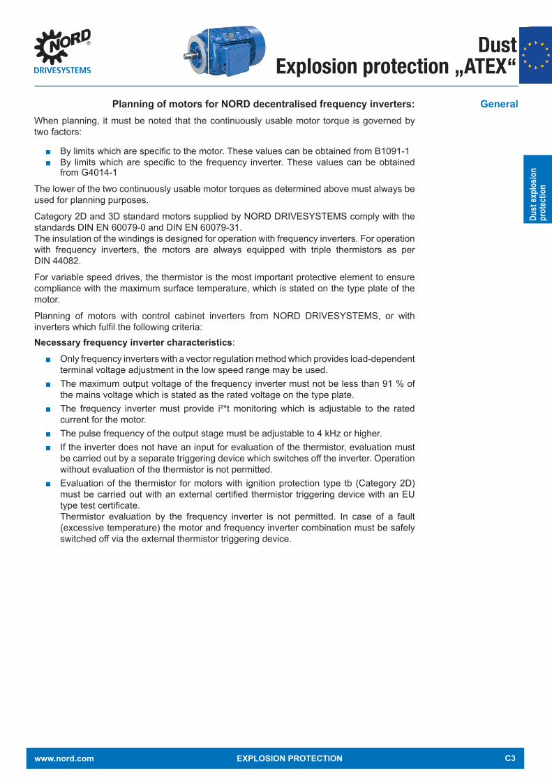
Planning of motors for NORD decentralised frequency inverters:When planning, it must be noted that the continuously usable motor torque is governed by two factors:
By limits which are specifi c to the motor. These values can be obtained from B1091-1 By limits which are specifi c to the frequency inverter. These values can be obtained
from G4014-1
The lower of the two continuously usable motor torques as determined above must always be used for planning purposes.
Category 2D and 3D standard motors supplied by NORD DRIVESYSTEMS comply with the standards DIN EN 60079-0 and DIN EN 60079-31. The insulation of the windings is designed for operation with frequency inverters. For operation with frequency inverters, the motors are always equipped with triple thermistors as per DIN 44082.
For variable speed drives, the thermistor is the most important protective element to ensure compliance with the maximum surface temperature, which is stated on the type plate of the motor.
Planning of motors with control cabinet inverters from NORD DRIVESYSTEMS, or with inverters which fulfi l the following criteria: Necessary frequency inverter characteristics:
Only frequency inverters with a vector regulation method which provides load-dependent terminal voltage adjustment in the low speed range may be used.
The maximum output voltage of the frequency inverter must not be less than 91 % of the mains voltage which is stated as the rated voltage on the type plate.
The frequency inverter must provide i²*t monitoring which is adjustable to the rated current for the motor.
The pulse frequency of the output stage must be adjustable to 4 kHz or higher. If the inverter does not have an input for evaluation of the thermistor, evaluation must
be carried out by a separate triggering device which switches off the inverter. Operation without evaluation of the thermistor is not permitted.
Evaluation of the thermistor for motors with ignition protection type tb (Category 2D) must be carried out with an external certifi ed thermistor triggering device with an EU type test certifi cate. Thermistor evaluation by the frequency inverter is not permitted. In case of a fault (excessive temperature) the motor and frequency inverter combination must be safely switched off via the external thermistor triggering device.
General
www.nord.com EXPLOSION PROTECTION C3

Dust Explosion protection „ATEX“
Dust
explo
sion
prot
ectio
n
Torques with use of the 50 Hz characteristic curve for 2D and 3D motors without external fan
Motor type / Circuit type
Category 3 20 40 60 100 fs[Hz]
63S/4 230/400V, 50 HzY circuit
2D/3D 0,65 0,86 0,86 0,86 0,54 M [Nm]2D/3D 0 450 1073 1484 1805 n [rpm]2D/3D 0 0,04 0,10 0,13 0,10 P [kW]2D/3D 80 187 347 363 361 Us [V]2D/3D 0,45 0,48 0,52 0,48 0,65 Is [A]
63L/4 230/400V, 50 HzY circuit
2D/3D 0,71 1,26 1,26 1,26 0,74 M [Nm]2D/3D 0 438 1060 1428 1886 n [rpm]2D/3D 0 0,06 0,14 0,19 0,15 P [kW]2D/3D 65 185 352 361 360 Us [V]2D/3D 0,50 0,61 0,66 0,71 0,80 Is [A]
71S/4 230/400V, 50 HzY circuit
2D/3D 1,15 1,76 1,76 1,56 0,72 M [Nm]2D/3D 0 441 1059 1448 2469 n [rpm]2D/3D 0 0,08 0,20 0,24 0,19 P [kW]2D/3D 62 187 342 356 357 Us [V]2D/3D 0,54 0,72 0,72 0,88 0,79 Is [A]
71L/4 230/400V, 50 HzY circuit
2D/3D 1,81 2,55 2,57 2,38 1,22 M Nm]2D/3D 0 461 1069 1481 2312 n [rpm]2D/3D 0 0,12 0,29 0,37 0,30 P [kW]2D/3D 57 181 329 344 343 Us [V]2D/3D 0,83 1,02 1,04 1,24 1,30 Is [A]
Legend
fS Stator frequency M Torque M Torque n Speed
[Hz] in Hertz [Nm] in Newton metres [%] in % of rated torque [rpm] Speed in rpm
Increased ambient temperatures for 3D motorsOperation is possible up to an ambient temperature of 60°C. The stated torques must then be reduced to 72 %.
Linear interpolation between adjacent frequencies is permissible.
Continuously usable torques for operation with control cabinet inverters e.g. SK 500E
C4 EXPLOSION PROTECTION www.nord.com

Dust
explo
sion
prot
ectio
n
Dust Explosion protection „ATEX“
Motors with 50 Hz nominal point, Size 80S/4 to 132M/4 for Category 3D
Motor type LegendSee below
Frequency inverter power and rated current
Motor power in [kW] at 50 Hz (upper value) and 100 Hz (lower value)
3 10 20 30 40 50 60 70 80 90 100 fs [Hz]
80S/40,55 kW 0,48 1,6 2,0 2,9 3,4 3,8 3,5 3,2 2,7 2,3 2,0 1,6 M [Nm]
1,6 A 42 52 76 89 99 91 82 71 59 52 42 M [%]0,43 30 150 463 765 1,061 1,314 1,604 1,837 2,073 2,296 2,529 n [rpm]
80L/40,75 kW 0,67 2,1 3,1 4,0 4,7 5,2 4,7 4,4 3,8 3,2 2,8 2,3 M [Nm]
2,2 A 40 60 77 90 100 90 85 73 62 54 45 M [%]0,63 26 166 471 769 1,091 1377 1,614 1,864 2,108 2,348 2,564 n [rpm]
90S/41,1 kW 1,01 3,5 5,4 6,6 7,3 7,6 7,0 6,4 5,6 5,1 4,3 3,9 M [Nm]
3,0 A 46 71 87 96 100 92 84 73 68 57 51 M [%]1,06 10 207 503 800 1,032 1,379 1,626 1,875 2,096 2,372 2,606 n [rpm]
90L/41,5 kW 1,31 4,3 5,8 7,8 9,0 9,5 9,0 8,3 7,2 6,5 5,6 4,9 M [Nm]
3,7 A 42 56 76 87 92 87 80 70 63 54 47 M [%]1,37 0 196 495 790 1,091 1,388 1,654 1,909 2,173 2,437 2,695 n [rpm]
100L/42,2 kW 1,92 5,5 9,5 12,1 13,6 14,3 13,1 12,2 10,8 9,9 8,3 7,4 M [Nm]
5,5 A 38 66 84 95 99 91 84 75 69 58 51 M [%]2,17 0 207 488 805 1,106 1,408 1,715 2,010 2,234 2,523 2,807 n [rpm]
100LA/4T140°C
3 kW 2,61 10,7 13,6 16,4 18,0 18,9 17,7 15,6 13,2 11,4 10,0 8,3 M [Nm]7,0 A 53 67 81 89 93 87 77 65 56 49 41 M [%]
2,39 12 256 541 833 1,140 1,410 1,681 1,940 2,233 2,490 2,760 n [rpm]
112M/44 kW 3,52 13,2 18,1 21,9 24,0 25,5 23,8 21,1 18,0 15,9 14,0 12,1 M [Nm]9,5 A 50 69 83 91 97 90 80 68 60 53 46 M [%]
3,51 17 237 529 824 1,120 1,414 1,689 1,963 2,236 2,506 2,775 n [rpm]
132S/45,5 kW 5,04 22,0 25,8 30,0 34,0 36,2 33,7 29,6 25,5 21,9 18,4 16,1 M [Nm]12,5 A 61 71 83 94 100 93 82 71 60 51 45 M [%]
4,78 44 240 536 832 1,130 1,428 1,714 1,995 2,276 2,556 2,834 n [rpm]
132M/47,5 kW 6,66 30,0 35,0 41,0 47,1 49,5 44,5 39,3 32,2 27,7 23,8 20,5 M [Nm]16,0 A 60 70 82 94 99 89 79 64 55 48 41 M [%]
6,06 62 241 538 837 1,133 431 1,713 1,967 2,268 2,551 2,828 n [rpm]
Legend
fS Stator frequency M Torque M Torque n Speed
[Hz] in Hertz [Nm] in Newton metres [%] in % of rated torque [rpm] Speed in rpm
www.nord.com EXPLOSION PROTECTION C5

Dust Explosion protection „ATEX“
Dust
explo
sion
prot
ectio
n
Motors with 50 Hz nominal point, Size 80SH/4 to 180LH/4 for Category 2D and 3D
Motor type /Circuit type
Category 3 20 40 60 100 fs[Hz]
80SH/4 230/400V, 50 HzY circuit
2D/3D 2,64 3,74 3,73 3,71 1,83 M [Nm]2D/3D 14,8 516 1118 1628 2551 n [rpm]2D/3D 0 0,2 0,44 0,63 0,49 P [kW]2D/3D 38 174 328 368 352 Us [V]2D/3D 1,11 1,4 1,41 1,61 1,75 Is [A]
80LH/4 230/400V, 50 HzY circuit
2D/3D 3,33 4,92 5,08 4,84 2,51 M [Nm]2D/3D 10 508 1105 1596 2549 n [rpm]2D/3D 0 0,26 0,59 0,81 0,67 P [kW]2D/3D 36 172 333 363 363 Us [V]2D/3D 1,38 1,77 1,81 2,13 2,22 Is [A]
90SH/4 230/400V, 50 HzY circuit
2D/3D 0,97 5,52 6,83 5,72 3,11 M [Nm]2D/3D 76 540 1127 1676 2763 n [rpm]2D/3D 0,01 0,31 0,81 1 0,9 P [kW]2D/3D 29 168 332 361 362 Us [V]2D/3D 1,29 2,06 2,36 2,43 2,49 Is [A]
90LH/4 230/400V, 50 HzY circuit
2D/3D 5,99 9,75 10,22 10,07 5,43 M Nm]2D/3D 33 521 1115 1605 2603 n [rpm]2D/3D 0,02 0,53 1,19 1,69 1,48 P [kW]2D/3D 35 173 338 361 361 Us [V]2D/3D 2,38 3,28 3,33 4,19 4,31 Is [A]
100LH/4 230/400V, 50 HzY circuit
2D/3D 2,38 14,6 14,79 12,08 6,96 M [Nm]2D/3D 80 545 1143 1704 2818 n [rpm]2D/3D 0,02 0,83 1,77 2,16 2,05 P [kW]2D/3D 27 171 334 360 361 Us [V]2D/3D 2,8 4,84 4,82 4,89 4,9 Is [A]
100AH/4 230/400V, 50 HzY circuit
2D/3D 9,8 19,31 20,19 18,21 10,14 M [Nm]2D/3D 49 528 1122 1646 2690 n [rpm]2D/3D 0,05 1,07 2,37 3,14 2,86 P [kW]2D/3D 32 172 336 363 363 Us [V]2D/3D 4,17 6,15 6,41 7,08 7,36 Is [A]
112MH/4 230/400V, 50 HzY circuit
2D/3D 16,56 24,27 26,49 21,76 11,92 M Nm]2D/3D 47,4 543 1139 1683 2774 n [rpm]2D/3D 0,08 1,38 3,16 3,83 3,46 P [kW]2D/3D 33 170 338 349 349 Us [V]2D/3D 5,78 7,63 8,31 9 9,2 Is [A]
C6 EXPLOSION PROTECTION www.nord.com
Dust
explo
sion
prot
ectio
n
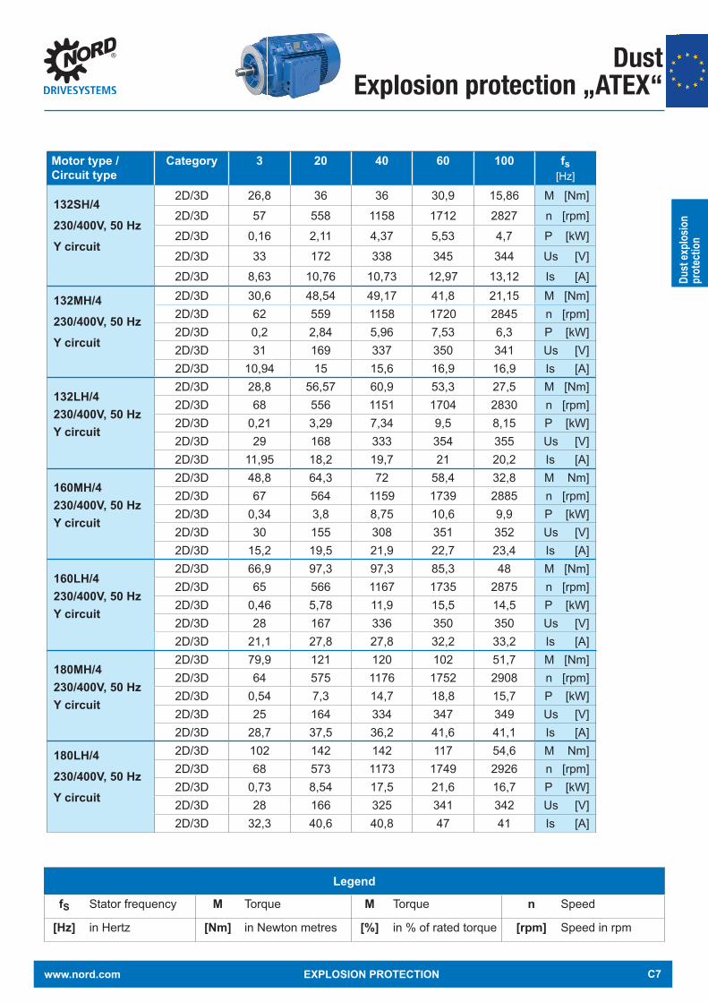
Dust Explosion protection „ATEX“
Motor type /Circuit type
Category 3 20 40 60 100 fs[Hz]
132SH/4 230/400V, 50 HzY circuit
2D/3D 26,8 36 36 30,9 15,86 M [Nm]2D/3D 57 558 1158 1712 2827 n [rpm]2D/3D 0,16 2,11 4,37 5,53 4,7 P [kW]2D/3D 33 172 338 345 344 Us [V]2D/3D 8,63 10,76 10,73 12,97 13,12 Is [A]
132MH/4 230/400V, 50 HzY circuit
2D/3D 30,6 48,54 49,17 41,8 21,15 M [Nm]2D/3D 62 559 1158 1720 2845 n [rpm]2D/3D 0,2 2,84 5,96 7,53 6,3 P [kW]2D/3D 31 169 337 350 341 Us [V]2D/3D 10,94 15 15,6 16,9 16,9 Is [A]
132LH/4 230/400V, 50 HzY circuit
2D/3D 28,8 56,57 60,9 53,3 27,5 M [Nm]2D/3D 68 556 1151 1704 2830 n [rpm]2D/3D 0,21 3,29 7,34 9,5 8,15 P [kW]2D/3D 29 168 333 354 355 Us [V]2D/3D 11,95 18,2 19,7 21 20,2 Is [A]
160MH/4 230/400V, 50 HzY circuit
2D/3D 48,8 64,3 72 58,4 32,8 M Nm]2D/3D 67 564 1159 1739 2885 n [rpm]2D/3D 0,34 3,8 8,75 10,6 9,9 P [kW]2D/3D 30 155 308 351 352 Us [V]2D/3D 15,2 19,5 21,9 22,7 23,4 Is [A]
160LH/4 230/400V, 50 HzY circuit
2D/3D 66,9 97,3 97,3 85,3 48 M [Nm]2D/3D 65 566 1167 1735 2875 n [rpm]2D/3D 0,46 5,78 11,9 15,5 14,5 P [kW]2D/3D 28 167 336 350 350 Us [V]2D/3D 21,1 27,8 27,8 32,2 33,2 Is [A]
180MH/4 230/400V, 50 HzY circuit
2D/3D 79,9 121 120 102 51,7 M [Nm]2D/3D 64 575 1176 1752 2908 n [rpm]2D/3D 0,54 7,3 14,7 18,8 15,7 P [kW]2D/3D 25 164 334 347 349 Us [V]2D/3D 28,7 37,5 36,2 41,6 41,1 Is [A]
180LH/4 230/400V, 50 HzY circuit
2D/3D 102 142 142 117 54,6 M Nm]2D/3D 68 573 1173 1749 2926 n [rpm]2D/3D 0,73 8,54 17,5 21,6 16,7 P [kW]2D/3D 28 166 325 341 342 Us [V]2D/3D 32,3 40,6 40,8 47 41 Is [A]
Legend
fS Stator frequency M Torque M Torque n Speed
[Hz] in Hertz [Nm] in Newton metres [%] in % of rated torque [rpm] Speed in rpm
www.nord.com EXPLOSION PROTECTION C7
Dust Explosion protection „ATEX“
Dust
explo
sion
prot
ectio
n
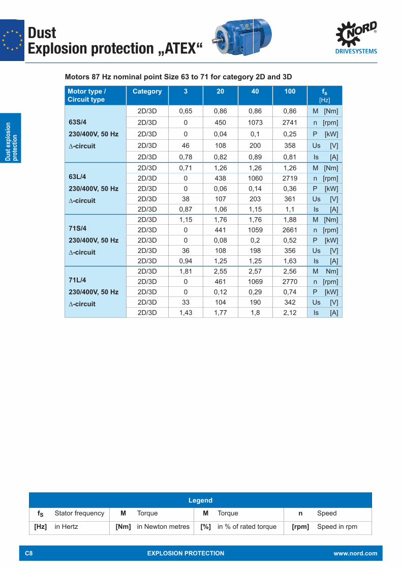
Motors 87 Hz nominal point Size 63 to 71 for category 2D and 3D
Motor type /Circuit type
Category 3 20 40 100 fs[Hz]
63S/4 230/400V, 50 Hz∆-circuit
2D/3D 0,65 0,86 0,86 0,86 M [Nm]2D/3D 0 450 1073 2741 n [rpm]2D/3D 0 0,04 0,1 0,25 P [kW]2D/3D 46 108 200 358 Us [V]2D/3D 0,78 0,82 0,89 0,81 Is [A]
63L/4 230/400V, 50 Hz∆-circuit
2D/3D 0,71 1,26 1,26 1,26 M [Nm]2D/3D 0 438 1060 2719 n [rpm]2D/3D 0 0,06 0,14 0,36 P [kW]2D/3D 38 107 203 361 Us [V]2D/3D 0,87 1,06 1,15 1,1 Is [A]
71S/4 230/400V, 50 Hz∆-circuit
2D/3D 1,15 1,76 1,76 1,88 M [Nm]2D/3D 0 441 1059 2661 n [rpm]2D/3D 0 0,08 0,2 0,52 P [kW]2D/3D 36 108 198 356 Us [V]2D/3D 0,94 1,25 1,25 1,63 Is [A]
71L/4 230/400V, 50 Hz∆-circuit
2D/3D 1,81 2,55 2,57 2,56 M Nm]2D/3D 0 461 1069 2770 n [rpm]2D/3D 0 0,12 0,29 0,74 P [kW]2D/3D 33 104 190 342 Us [V]2D/3D 1,43 1,77 1,8 2,12 Is [A]
Legend
fS Stator frequency M Torque M Torque n Speed
[Hz] in Hertz [Nm] in Newton metres [%] in % of rated torque [rpm] Speed in rpm
C8 EXPLOSION PROTECTION www.nord.com
Dust
explo
sion
prot
ectio
n
Dust Explosion protection „ATEX“
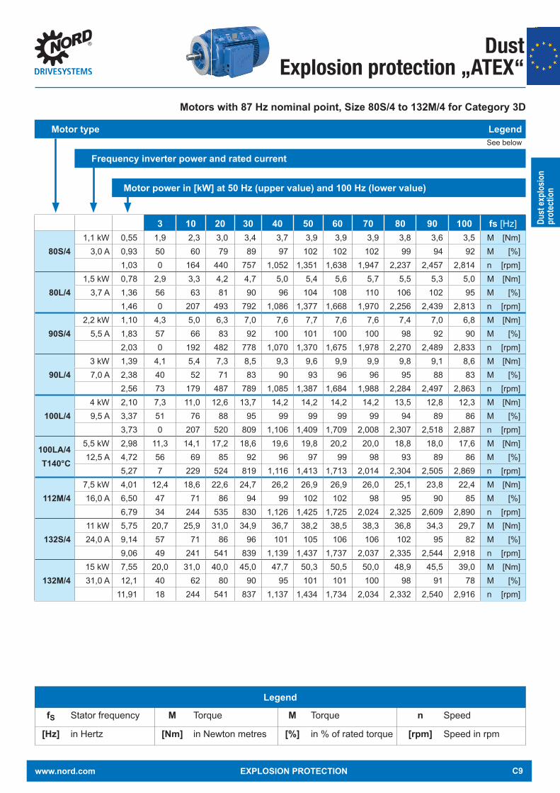
Motors with 87 Hz nominal point, Size 80S/4 to 132M/4 for Category 3D
Motor type LegendSee below
Frequency inverter power and rated current
Motor power in [kW] at 50 Hz (upper value) and 100 Hz (lower value)
3 10 20 30 40 50 60 70 80 90 100 fs [Hz]
80S/41,1 kW 0,55 1,9 2,3 3,0 3,4 3,7 3,9 3,9 3,9 3,8 3,6 3,5 M [Nm]
3,0 A 0,93 50 60 79 89 97 102 102 102 99 94 92 M [%]1,03 0 164 440 757 1,052 1,351 1,638 1,947 2,237 2,457 2,814 n [rpm]
80L/41,5 kW 0,78 2,9 3,3 4,2 4,7 5,0 5,4 5,6 5,7 5,5 5,3 5,0 M [Nm]
3,7 A 1,36 56 63 81 90 96 104 108 110 106 102 95 M [%]1,46 0 207 493 792 1,086 1,377 1,668 1,970 2,256 2,439 2,813 n [rpm]
90S/42,2 kW 1,10 4,3 5,0 6,3 7,0 7,6 7,7 7,6 7,6 7,4 7,0 6,8 M [Nm]
5,5 A 1,83 57 66 83 92 100 101 100 100 98 92 90 M [%]2,03 0 192 482 778 1,070 1,370 1,675 1,978 2,270 2,489 2,833 n [rpm]
90L/43 kW 1,39 4,1 5,4 7,3 8,5 9,3 9,6 9,9 9,9 9,8 9,1 8,6 M [Nm]7,0 A 2,38 40 52 71 83 90 93 96 96 95 88 83 M [%]
2,56 73 179 487 789 1,085 1,387 1,684 1,988 2,284 2,497 2,863 n [rpm]
100L/44 kW 2,10 7,3 11,0 12,6 13,7 14,2 14,2 14,2 14,2 13,5 12,8 12,3 M [Nm]9,5 A 3,37 51 76 88 95 99 99 99 99 94 89 86 M [%]
3,73 0 207 520 809 1,106 1,409 1,709 2,008 2,307 2,518 2,887 n [rpm]
100LA/4T140°C
5,5 kW 2,98 11,3 14,1 17,2 18,6 19,6 19,8 20,2 20,0 18,8 18,0 17,6 M [Nm]12,5 A 4,72 56 69 85 92 96 97 99 98 93 89 86 M [%]
5,27 7 229 524 819 1,116 1,413 1,713 2,014 2,304 2,505 2,869 n [rpm]
112M/47,5 kW 4,01 12,4 18,6 22,6 24,7 26,2 26,9 26,9 26,0 25,1 23,8 22,4 M [Nm]16,0 A 6,50 47 71 86 94 99 102 102 98 95 90 85 M [%]
6,79 34 244 535 830 1,126 1,425 1,725 2,024 2,325 2,609 2,890 n [rpm]
132S/411 kW 5,75 20,7 25,9 31,0 34,9 36,7 38,2 38,5 38,3 36,8 34,3 29,7 M [Nm]24,0 A 9,14 57 71 86 96 101 105 106 106 102 95 82 M [%]
9,06 49 241 541 839 1,139 1,437 1,737 2,037 2,335 2,544 2,918 n [rpm]
132M/415 kW 7,55 20,0 31,0 40,0 45,0 47,7 50,3 50,5 50,0 48,9 45,5 39,0 M [Nm]31,0 A 12,1 40 62 80 90 95 101 101 100 98 91 78 M [%]
11,91 18 244 541 837 1,137 1,434 1,734 2,034 2,332 2,540 2,916 n [rpm]
Legend
fS Stator frequency M Torque M Torque n Speed
[Hz] in Hertz [Nm] in Newton metres [%] in % of rated torque [rpm] Speed in rpm
www.nord.com EXPLOSION PROTECTION C9

Dust Explosion protection „ATEX“
Dust
explo
sion
prot
ectio
n
Motors with 87 Hz nominal point, Size 80SH/4 to 180LH/4 for Category 2D and 3D
Motor type /Circuit type
Category 3 20 40 100 fs[Hz]
80SH/4 230/400V, 50 Hz∆-circuit
2D/3D 2,64 3,74 3,73 3,74 M [Nm]2D/3D 15 516 1118 2840 n [rpm]2D/3D 0 0,2 0,44 1,11 P [kW]2D/3D 22 100 190 355 Us [V]2D/3D 1,92 2,42 2,44 2,77 Is [A]
80LH/4 230/400V, 50 Hz∆-circuit
2D/3D 3,33 4,92 5,08 5,1 M [Nm]2D/3D 10 508 1105 2803 n [rpm]2D/3D 0 0,26 0,59 1,5 P [kW]2D/3D 21 99 192 357 Us [V]2D/3D 2,38 3,06 3,14 3,69 Is [A]
90SH/4 230/400V, 50 Hz∆-circuit
2D/3D 0,97 5,52 6,83 5,96 M [Nm]2D/3D 76 540 1127 2882 n [rpm]2D/3D 0,01 0,31 0,81 1,8 P [kW]2D/3D 17 97 192 358 Us [V]2D/3D 2,24 3,57 4,08 4,25 Is [A]
90LH/4 230/400V, 50 Hz∆-circuit
2D/3D 6 9,75 10,2 10,1 M Nm]2D/3D 33 521 1115 2822 n [rpm]2D/3D 0,02 0,53 1,19 2,98 P [kW]2D/3D 20 100 195 357 Us [V]2D/3D 4,13 5,68 5,77 7,08 Is [A]
100LH/4 230/400V, 50 Hz∆-circuit
2D/3D 2,38 14,6 14,8 12,56 M [Nm]2D/3D 80 545 1143 2905 n [rpm]2D/3D 0,02 0,83 1,77 3,82 P [kW]2D/3D 16 99 193 359 Us [V]2D/3D 4,85 8,39 8,35 8,5 Is [A]
100AH/4 230/400V, 50 Hz∆-circuit
2D/3D 9,8 19,3 20,2 20,2 M [Nm]2D/3D 49 528 1122 2840 n [rpm]2D/3D 0,05 1,07 2,37 6 P [kW]2D/3D 18 99 194 357 Us [V]2D/3D 7,22 10,6 11,1 13 Is [A]
112MH/4 230/400V, 50 Hz∆-circuit
2D/3D 16,5 24,3 26,5 22,5 M Nm]2D/3D 47 543 1139 2884 n [rpm]2D/3D 0,08 1,38 3,16 6,8 P [kW]2D/3D 19 98 195 341 Us [V]2D/3D 10 13,2 14,4 15,8 Is [A]
C10 EXPLOSION PROTECTION www.nord.com

Dust
explo
sion
prot
ectio
n
Dust Explosion protection „ATEX“
Motor type /Circuit type
Category 3 20 40 100 fs[Hz]
132SH/4 230/400V, 50 Hz∆-circuit
2D/3D 26,8 36,1 36,1 31 M [Nm]2D/3D 57 558 1158 2915 n [rpm]2D/3D 0,16 2,11 4,37 9,46 P [kW]2D/3D 19 99 195 338 Us [V]2D/3D 14,9 18,65 18,6 22,15 Is [A]
132MH/4 230/400V, 50 Hz∆-circuit
2D/3D 30,6 48,5 49,17 39,5 M [Nm]2D/3D 62 559 1158 2921 n [rpm]2D/3D 0,2 2,84 5,96 12,1 P [kW]2D/3D 18 98 195 332 Us [V]2D/3D 18,95 26 27 28,4 Is [A]
132LH/4 230/400V, 50 Hz∆-circuit
2D/3D 28,8 56,6 60,9 48 M [Nm]2D/3D 68 556 1151 2927 n [rpm]2D/3D 0,21 3,29 7,34 14,7 P [kW]2D/3D 17 97 192 353 Us [V]2D/3D 20,7 31,5 34,1 31,5 Is [A]
160MH/4 230/400V, 50 Hz∆-circuit
2D/3D 48,8 64,3 72,1 56,9 M Nm]2D/3D 67 564 1159 2944 n [rpm]2D/3D 0,34 3,8 8,75 17,5 P [kW]2D/3D 17 89 178 348 Us [V]2D/3D 26,4 33,9 37,9 37,2 Is [A]
160LH/4 230/400V, 50 Hz∆-circuit
2D/3D 66,9 97,4 97,4 82,4 M [Nm]2D/3D 65 566 1167 2939 n [rpm]2D/3D 0,46 5,78 11,9 25,4 P [kW]2D/3D 16 96 194 344 Us [V]2D/3D 36,5 48,1 48,2 53,4 Is [A]
180MH/4 230/400V, 50 Hz∆-circuit
2D/3D 79,9 121 120 93,6 M [Nm]2D/3D 64 575 1176 2957 n [rpm]2D/3D 0,54 7,3 14,8 29 P [kW]2D/3D 14 95 193 343 Us [V]2D/3D 49,8 65,1 62,7 65,8 Is [A]
180LH/4 230/400V, 50 Hz∆-circuit
2D/3D 102 14 142,8 96,8 M Nm]2D/3D 68 573 1173 2963 n [rpm]2D/3D 0,73 8,54 17,5 30 P [kW]2D/3D 16 96 188 335 Us [V]2D/3D 56 70,4 70,7 65,4 Is [A]
Legend
fS Stator frequency M Torque M Torque n Speed
[Hz] in Hertz [Nm] in Newton metres [%] in % of rated torque [rpm] Speed in rpm
www.nord.com EXPLOSION PROTECTION C11

Dust Explosion protection „ATEX“
Dust
explo
sion
prot
ectio
n
Motors 100 Hz nominal point Size 63 to 71 for category 2D and 3D
Motor type /Circuit type
Category 3 20 40 100 fs[Hz]
63S/4 230/400V, 50 Hz∆-circuit
2D/3D 0,55 0,61 0,61 0,6 M [Nm]2D/3D 0 500 1097 2835 n [rpm]2D/3D 0 0,03 0,07 0,18 P [kW]2D/3D 42 100 178 349 Us [V]2D/3D 0,7 0,74 0,76 0,68 Is [A]
63L/4 230/400V, 50 Hz∆-circuit
2D/3D 0,56 0,83 0,83 0,83 M [Nm]2D/3D 0 488 1088 2844 n [rpm]2D/3D 0 0,04 0,09 0,25 P [kW]2D/3D 32 94 170 349 Us [V]2D/3D 0,73 0,89 0,91 0,88 Is [A]
71S/4 230/400V, 50 Hz∆-circuit
2D/3D 0,92 1,22 1,22 1,22 M [Nm]2D/3D 0 474 1081 2832 n [rpm]2D/3D 0 0,06 0,14 0,36 P [kW]2D/3D 32 94 172 357 Us [V]2D/3D 0,83 0,97 1,01 1,1 Is [A]
71L/4 230/400V, 50 Hz∆-circuit
2D/3D 1,53 1,82 1,81 1,81 M Nm]2D/3D 0 479 1087 2830 n [rpm]2D/3D 0 0,09 0,21 0,54 P [kW]2D/3D 30 91 168 342 Us [V]2D/3D 1,3 1,44 1,46 1,51 Is [A]
Legend
fS Stator frequency M Torque M Torque n Speed
[Hz] in Hertz [Nm] in Newton metres [%] in % of rated torque [rpm] Speed in rpm
C12 EXPLOSION PROTECTION www.nord.com

Dust
explo
sion
prot
ectio
n
Dust Explosion protection „ATEX“
Motors with 100 Hz nominal point, Size 80S/4 to 132M/4 for Category 3D
Motor type LegendSee below
Frequency inverter power and rated current
Motor power in [kW] at 50 Hz (upper value) and 100 Hz (lower value)
3 10 20 30 40 50 60 70 80 90 100 fs [Hz]
80S/40,75 kW 0,39 1,8 2,3 2,5 2,6 2,6 2,6 2,6 2,5 2,5 2,4 2,2 M [Nm]
2,2 A 48 61 64 68 68 68 67 66 66 62 57 M [%]0,67 0 163 410 810 1,108 1,416 1,712 2,028 2,344 2,627 2,910 n [rpm]
80L/41,1 kW 0,53 3,0 3,3 3,6 3,6 3,6 3,6 3,6 3,6 3,5 3,4 3,2 M [Nm]
3,0 A 58 63 69 69 69 69 69 69 67 66 62 M [%]0,99 0 196 505 812 1,116 1,414 1,715 2,015 2,313 2,611 2,908 n [rpm]
90S/41,5 kW 0,75 4,2 4,9 4,9 4,9 5,0 5,0 5,0 5,0 5,0 4,9 4,6 M [Nm]
3,7 A 55 64 64 64 66 66 66 66 66 65 60 M [%]1,40 0 183 516 822 1,120 1,425 1,725 2,025 2,321 2,620 2,911 n [rpm]
90L/42,2 kW 1,06 4,0 5,6 7,2 7,2 7,2 7,2 7,2 7,2 7,1 6,9 6,6 M [Nm]
5,5 A 39 54 70 70 70 70 70 70 69 67 64 M [%]2,00 20 192 484 799 1,098 1,406 1,707 2,008 2,309 2,606 2,905 n [rpm]
100L/43 kW 1,51 8,4 9,1 9,9 10,1 10,1 10,1 9,9 9,7 9,7 9,2 8,7 M [Nm]7,0 A 58 63 69 70 70 70 69 67 67 64 61 M [%]
2,68 25 205 524 829 1,132 1,429 1,736 2,036 2,335 2,631 2,927 n [rpm]
100LA/4T140°C
4 kW 1,99 6,6 11,3 13,1 13,2 13,2 13,2 13,2 13,3 13,3 12,6 12,0 M [Nm]9,5 A 32 56 64 65 65 65 65 65 66 62 59 M [%]
3,69 20 200 530 834 1,130 1,442 1,734 2,028 2,332 2,639 2,944 n [rpm]
112M/45,5 kW 2,72 14,4 17,0 18,0 18,0 18,0 18,0 18,0 18,0 18,0 17,3 16,3 M [Nm]12,5 A 54 64 68 68 68 68 68 68 68 65 62 M [%]
5,02 36 233 539 840 1,142 1,442 1,742 2,042 2,341 2,640 2,933 n [rpm]
132S/47,5 kW 3,63 20,6 22,0 24,3 24,3 24,3 24,3 24,3 24,3 24,3 24,3 24,3 M [Nm]16,0 A 57 61 67 67 67 67 67 67 67 67 67 M [%]
7,42 36 227 530 828 1,124 1,425 1,724 2,023 2,324 2,623 2,918 n [rpm]
132M/411 kW 5,32 17,2 28,9 35,7 35,7 35,7 35,7 35,7 35,7 35,7 35,7 35,7 M [Nm]24,0 A 34 58 71 71 71 71 71 71 71 71 71 M [%]
10,9 16 233 530 826 1,125 1,423 1,723 2,022 2,321 2,625 2,916 n [rpm]
Legend
fS Stator frequency M Torque M Torque n Speed
[Hz] in Hertz [Nm] in Newton metres [%] in % of rated torque [rpm] Speed in rpm
www.nord.com EXPLOSION PROTECTION C13

Dust Explosion protection „ATEX“
Dust
explo
sion
prot
ectio
n
Motors with 100 Hz nominal point, Size 80SH/4 to 180LH/4 for Category 2D and 3D
Motor type /Circuit type
Category 3 20 40 100 fs[Hz]
80SH/4 230/400V, 50 Hz∆-circuit
2D/3D 1,99 2,45 2,45 2,46 M [Nm]2D/3D 29 534 1134 2913 n [rpm]2D/3D 0,01 0,14 0,29 0,75 P [kW]2D/3D 19 87 167 362 Us [V]2D/3D 1,63 1,89 1,91 1,95 Is [A]
80LH/4 230/400V, 50 Hz∆-circuit
2D/3D 2,17 3,59 3,6 3,6 M [Nm]2D/3D 0 511 1115 2886 n [rpm]2D/3D 0 0,19 0,42 1,09 P [kW]2D/3D 16 84 163 350 Us [V]2D/3D 1,91 2,54 2,55 2,73 Is [A]
90SH/4 230/400V, 50 Hz∆-circuit
2D/3D 0,97 4,92 4,89 4,9 M [Nm]2D/3D 76 529 1131 2902 n [rpm]2D/3D 0,01 0,27 0,58 1,49 P [kW]2D/3D 17 85 164 343 Us [V]2D/3D 2,24 3,39 3,39 3,78 Is [A]
90LH/4 230/400V, 50 Hz∆-circuit
2D/3D 4,3 7,21 7,17 7,14 M Nm]2D/3D 0 518 1120 2913 n [rpm]2D/3D 0 0,39 0,84 2,18 P [kW]2D/3D 16 84 164 347 Us [V]2D/3D 3,7 4,74 4,94 5,25 Is [A]
100LH/4 230/400V, 50 Hz∆-circuit
2D/3D 2,38 9,71 9,65 9,67 M [Nm]2D/3D 80 551 1152 2934 n [rpm]2D/3D 0,02 0,56 1,16 2,97 P [kW]2D/3D 16 83 164 348 Us [V]2D/3D 4,85 6,46 6,62 6,98 Is [A]
100AH/4 230/400V, 50 Hz∆-circuit
2D/3D 9,29 12,96 13,11 13 M [Nm]2D/3D 0 535 1136 2932 n [rpm]2D/3D 0 0,73 1,56 4 P [kW]2D/3D 20 84 164 347 Us [V]2D/3D 7,54 8,47 8,7 9,37 Is [A]
112MH/4 230/400V, 50 Hz∆-circuit
2D/3D 16,56 17,85 17,85 17,8 M Nm]2D/3D 47 548 1147 2915 n [rpm]2D/3D 0,08 1,02 2,14 5,44 P [kW]2D/3D 19 89 173 345 Us [V]2D/3D 10,01 9,53 9,46 12,35 Is [A]
C14 EXPLOSION PROTECTION www.nord.com

Dust
explo
sion
prot
ectio
n
Dust Explosion protection „ATEX“
Legend
fS Stator frequency M Torque M Torque n Speed
[Hz] in Hertz [Nm] in Newton metres [%] in % of rated torque [rpm] Speed in rpm
Motor type /Circuit type
Category 3 20 40 100 fs[Hz]
132SH/4 230/400V, 50 Hz∆-circuit
2D/3D 24,3 24,2 24,2 24,2 M [Nm]2D/3D 51 563 1163 2939 n [rpm]2D/3D 0,13 1,43 2,95 7,45 P [kW]2D/3D 18 88 167 342 Us [V]2D/3D 13,8 14,6 14,6 17,2 Is [A]
132MH/4 230/400V, 50 Hz∆-circuit
2D/3D 29,7 29,6 29,6 29,7 M [Nm]2D/3D 50 568 1167 2946 n [rpm]2D/3D 0,16 1,76 3,62 9,15 P [kW]2D/3D 16 84 166 335 Us [V]2D/3D 18,2 17,4 16,95 20,1 Is [A]
132LH/4 230/400V, 50 Hz∆-circuit
2D/3D 28,81 35,4 35,5 35,3 M [Nm]2D/3D 68 564 1163 2947 n [rpm]2D/3D 0,21 2,09 4,32 10,9 P [kW]2D/3D 17 84 164 340 Us [V]2D/3D 20,7 22,1 21,6 21,4 Is [A]
160MH/4 230/400V, 50 Hz∆-circuit
2D/3D 48,4 48,4 48,3 48,2 M Nm]2D/3D 58 564 1164 2954 n [rpm]2D/3D 0,29 2,86 5,88 14,9 P [kW]2D/3D 15 77 151 347 Us [V]2D/3D 27,1 29,2 25,1 32,1 Is [A]
160LH/4 230/400V, 50 Hz∆-circuit
2D/3D 59,5 59,7 59,4 59 M [Nm]2D/3D 55 574 1173 2959 n [rpm]2D/3D 0,34 3,59 7,3 18,3 P [kW]2D/3D 14 82 163 346 Us [V]2D/3D 35,5 32,9 31,9 37,3 Is [A]
180MH/4 230/400V, 50 Hz∆-circuit
2D/3D 70,7 70,5 69,8 70,8 M [Nm]2D/3D 69 582 1181 2969 n [rpm]2D/3D 0,51 4,29 8,63 22 P [kW]2D/3D 14 85 163 344 Us [V]2D/3D 42,2 41,2 38,6 36 Is [A]
180LH/4 230/400V, 50 Hz∆-circuit
2D/3D 95,9 94,5 96,3 96,4 M Nm]2D/3D 54 576 1176 2965 n [rpm]2D/3D 0,54 5,7 11,9 29,9 P [kW]2D/3D 15 82 162 337 Us [V]2D/3D 65,5 53,6 54,6 65,7 Is [A]
www.nord.com EXPLOSION PROTECTION C15

Dust Explosion protection „ATEX“
Dust
explo
sion
prot
ectio
n
Motors with external fan, 50 Hz nominal point, Category 3D
Motor type Frequency inverter power and rated current
Motor power in [kW] at 50 Hz (upper value) and 100 Hz (lower value)
3 10 20 30 40 50 60 70 80 90 100 fs [Hz]
63S/40,55 kW 0,11 0,8 0,8 0,8 0,8 0,8 0,8 0,8 0,8 0,7 0,6 0,4 M [Nm]
1,6 A 94 94 94 94 94 94 92 90 82 66 50 M [%] 0,09 10 150 375 690 1,010 1,320 1,381 1,441 1,641 1,840 1,932 n [rpm]
63L/40,55 KW 0,17 1,3 1,3 1,3 1,3 1,3 1,3 1,2 1,2 1,1 0,9 0,8 M [Nm]
1,6 A 96 96 96 96 96 96 93 91 83 73 61 M [%] 0,18 0 142 419 696 990 1,282 1,458 1,633 1,787 1,941 2,151 n [rpm]
71S/40,55 kW 0,23 1,7 1,7 1,7 1,7 1,7 1,6 1,5 1,4 1,2 1,1 0,9 M [Nm]
1,6 A 100 100 100 100 100 92 87 81 72 61 53 M [%] 0,23 10 150 437 733 1,032 1,364 1,537 1,710 1,939 2,168 2,388 n [rpm]
71L/40,55 kW 0,33 2,4 2,4 2,4 2,4 2,4 2,4 2,2 1,9 1,6 1,4 1,3 M [Nm]
1,6 A 92 92 92 92 92 92 83 73 62 55 48 M [%] 0,33 0 128 427 734 1,042 1,339 1,594 1,843 2,092 2,326 2,490 n [rpm]
80S/40,55 kW 0,48 3,5 3,5 3,5 3,5 3,5 3,5 3,2 2,7 2,3 2,0 1,6 M [Nm]
1,6 A 91 91 91 91 91 91 82 71 59 52 42 M [%] 0,43 30 150 463 765 1,061 1,314 1,604 1,837 2,073 2,296 2,529 n [rpm]
80L/40,75 kW 0,67 4,7 4,7 4,7 4,7 4,7 4,7 4,4 3,8 3,2 2,8 2,3 M [Nm]
2,2 A 90 90 90 90 90 90 85 73 62 54 45 M [%] 0,63 26 166 471 769 1,091 1,377 1,614 1,864 2,108 2,348 2,564 n [rpm]
90S/41,1 kW 1,01 7,0 7,0 7,0 7,0 7,0 7,0 6,4 5,6 5,1 4,3 3,9 M [Nm]
3,0 A 92 92 92 92 92 92 84 73 68 57 51 M [%] 1,06 10 207 503 800 1,032 1,379 1,626 1,875 2,096 2,372 2,606 n [rpm]
90L/41,5 kW 1,31 9,0 9,0 9,0 9,0 9,0 9,0 8,3 7,2 6,5 5,6 4,9 M [Nm]
3,7 A 87 87 87 87 87 87 80 70 63 54 47 M [%] 1,37 0 196 495 790 1,091 1,388 1,654 1,909 2,173 2,437 2,695 n [rpm]
100L/42,2 kW 1,92 13,1 13,1 13,1 13,1 13,1 13,1 12,2 10,8 9,9 8,3 7,4 M [Nm]
5,5 A 91 91 91 91 91 91 84 75 69 58 51 M [%] 2,17 0 207 488 805 1,106 1,408 1,715 2,010 2,234 2,523 2,807 n [rpm]
100LA/4T140°C
3 kW 2,68 20,3 20,3 20,3 20,3 20,3 18,2 16,1 13,9 12,1 10,1 9,0 M [Nm]7,0 A 100 100 100 100 100 90 79 69 59 50 44 M [%]
2,59 11 172 488 804 1,105 1,406 1,673 1,940 2,214 2,488 2,753 n [rpm]
112M/44 kW 3,57 26,4 26,4 26,4 26,4 26,4 24,0 21,2 18,6 16,0 13,8 12,1 M [Nm]9,5 A 100 100 100 100 100 91 80 70 61 52 46 M [%]
3,53 2 224 402 827 1,123 1,418 1,691 1,967 2,242 2,519 2,793 n [rpm]
132S/45,5 kW 4,88 35,2 36,4 36,4 36,4 35,8 32,3 28,3 23,4 19,5 17,3 14.2 M [Nm]12,5 A 97 100 100 100 98 89 78 64 54 47 39 M [%]
4,28 26 250 551 851 1,153 1,444 1,725 2,010 2,299 2,585 2,876 n [rpm]
132M/47,5 kW 6,83 47,0 49,6 49.6 49,6 49,6 45,2 38,6 31,3 27,1 23,1 20,0 M [Nm]16,0 A 95 100 100 100 100 91 78 63 55 47 40 M [%]
6,03 27 249 551 851 1,151 1,442 1,727 2,011 2,302 2,585 2,875 n [rpm]
132MA/4T140°C
11 kW 8,19 57,2 60,8 60,8 60,8 60,8 54,5 46,8 38,8 32,9 28,9 25,1 M [Nm]24,0 A 94 100 100 100 100 90 77 64 54 48 41 M [%]
7,52 18 238 539 840 1,140 1,435 1,720 2,008 2,298 2,580 2,866 n [rpm]
C16 EXPLOSION PROTECTION www.nord.com

Dust
explo
sion
prot
ectio
n
Dust Explosion protection „ATEX“
Motors with external fan, 87 Hz nominal point, Category 3D
Motor type Frequency inverter power and rated current
Motor power in [kW] at 50 Hz (upper value) and 100 Hz (lower value) and 100 Hz (lower value)
3 10 20 30 40 50 60 70 80 90 100 fs [Hz]
63S/40,55 kW 0,12 0,9 0,9 0,9 0,9 0,9 0,9 0,9 0,9 0,8 0,8 0,8 M [Nm]
1,6 A 0,20 100 100 100 100 100 100 100 100 96 92 90 M [%] 0,22 20 152 369 688 1,007 1,310 1,612 1,914 2,213 2,419 2,763 n [rpm]
63L/40,55 KW 0,18 1,3 1,3 1,3 1,3 1,3 1,3 1,3 1,3 1,3 1,2 1,2 M [Nm]
1,6 A 0,30 100 100 100 100 100 100 100 100 96 92 90 M [%] 0,33 20 175 407 715 1,002 1,306 1,610 1,909 2,207 2,415 2,713 n [rpm]
71S/40,55 kW 0,25 1,7 1,7 1,7 1,7 1,7 1,7 1,7 1,7 1,7 1,6 1,6 M [Nm]
1,6 A 0,41 100 100 100 100 100 100 100 100 97 92 92 M [%] 0,47 100 146 442 734 1,031 1,364 1,663 1,962 2,260 2,460 2,818 n [rpm]
71L/40,75 kW 0,35 2,5 2,5 2,5 2,5 2,5 2,5 2,5 2,5 2,5 2,4 2,3 M [Nm]
2,2 A 0,61 95 95 95 95 95 95 95 95 95 92 90 M [%] 0,69 0 188 488 782 1,077 1,350 1,633 1,941 2,245 2,457 2,797 n [rpm]
80S/41,1 kW 0,54 3,8 3,8 3,8 3,8 3,8 3,8 3,8 3,8 3,8 3,6 3,5 M [Nm]
3,0 A 0,93 99 99 99 99 99 99 99 99 99 94 92 M [%] 1,03 0 164 440 757 1,052 1,351 1,638 1,947 2,237 2,457 2,814 n [rpm]
80L/41,5 kW 0,79 5,5 5,5 5,5 5,5 5,5 5,5 5,5 5,5 5,5 5,3 5,0 M [Nm]
3,7 A 1,36 106 106 106 106 106 106 106 106 106 102 95 M [%] 1,46 0 207 493 792 1,086 1,377 1,668 1,970 2,256 2,439 2,813 n [rpm]
90S/42,2 kW 1,07 7,4 7,4 7,4 7,4 7,4 7,4 7,4 7,4 7,4 7,0 6,8 M [Nm]
5,5 A 1,83 98 98 98 98 98 98 98 98 98 92 90 M [%] 2,03 0 192 482 778 1,070 1,370 1,675 1,978 2,270 2,489 2,833 n [rpm]
90L/43 kW 1,42 9,8 9,8 9,8 9,8 9,8 9,8 9,8 9,8 9,8 9,1 8,6 M [Nm]7,0 A 2,38 95 95 95 95 95 95 95 95 95 88 83 M [%]
2,56 73 179 487 789 1,085 1,387 1,684 1,988 2,284 2,497 2,863 n [rpm]
100L/44 kW 1,99 13,5 13,5 13,5 13,5 13,5 13,5 13,5 13,5 13,5 12,8 12,3 M [Nm]9,5 A 3,37 94 94 94 94 94 94 94 94 94 89 86 M [%]
3,73 0 207 520 809 1,106 1,409 1,709 2,008 2,307 2,518 2,887 n [rpm]
100LA/4T140°C
5,5 kW 3,02 20,3 20,3 20,3 20,3 20,3 20,3 20,3 20,3 19,3 18,5 17,3 M [Nm]12,5 A 4,87 100 100 100 100 100 100 100 100 95 91 85 M [%]
5,21 51 211 516 820 1,120 1,419 1,718 2,016 2,263 2,510 2,877 n [rpm]
112M/47,5 kW 3,92 21,1 26,4 26,4 26,4 26,4 26,4 26,4 26,4 26,3 26,1 21,6 M [Nm]16,0 A 6,87 80 100 100 100 100 100 100 100 100 99 82 M [%]
6,54 15 213 518 820 1,119 1,419 1,719 2,016 2,312 2,517 2,896 n [rpm]
132S/411 kW 5,52 33,5 36,4 36,4 36,4 36,4 36,4 33,8 31,7 28,7 25,3 20,5 M [Nm]24,0 A 6,79 92 100 100 100 100 100 93 87 79 70 56 M [%]
6,27 15 240 545 848 1,150 1,450 1,755 2,057 2,357 2,566 2,921 n [rpm]
132M/415 kW 7,40 46,9 49,6 49,6 49,6 49,6 48,7 47,0 45,3 41,6 39,0 33,8 M [Nm]31,0 A 10,47 95 100 100 100 100 98 95 91 84 79 68 M [%]
10,43 19 244 547 849 1,151 1,452 1,757 2,054 2,356 2,562 2,944 n [rpm]
132MA/4T140°C
18 kW 9,01 51,9 60,8 60,8 60,8 59,7 59,6 56,4 53,9 50,4 45,6 42,6 M [Nm]38,0 A 12,20 85 100 100 100 98 98 93 89 83 75 70 M [%]
13,09 17 234 540 840 1,143 1,443 1,746 2,049 2,349 2,556 2,934 n [rpm]
www.nord.com EXPLOSION PROTECTION C17
Dust Explosion protection „ATEX“
Dust
explo
sion
prot
ectio
n
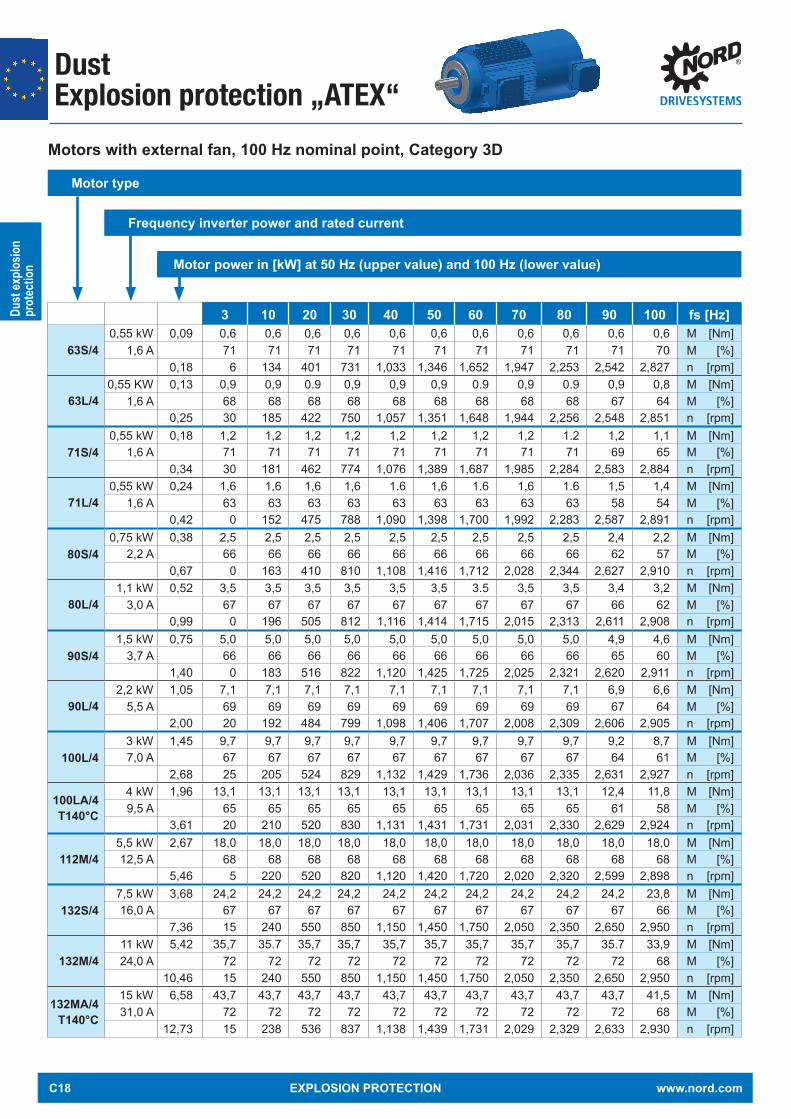
Motors with external fan, 100 Hz nominal point, Category 3D
Motor type Frequency inverter power and rated current
Motor power in [kW] at 50 Hz (upper value) and 100 Hz (lower value)
3 10 20 30 40 50 60 70 80 90 100 fs [Hz]
63S/40,55 kW 0,09 0,6 0,6 0,6 0,6 0,6 0,6 0,6 0,6 0,6 0,6 0,6 M [Nm]
1,6 A 71 71 71 71 71 71 71 71 71 71 70 M [%]0,18 6 134 401 731 1,033 1,346 1,652 1,947 2,253 2,542 2,827 n [rpm]
63L/40,55 KW 0,13 0,9 0,9 0.9 0,9 0,9 0,9 0.9 0,9 0.9 0,9 0,8 M [Nm]
1,6 A 68 68 68 68 68 68 68 68 68 67 64 M [%]0,25 30 185 422 750 1,057 1,351 1,648 1,944 2,256 2,548 2,851 n [rpm]
71S/40,55 kW 0,18 1,2 1,2 1,2 1,2 1,2 1,2 1,2 1,2 1.2 1,2 1,1 M [Nm]
1,6 A 71 71 71 71 71 71 71 71 71 69 65 M [%]0,34 30 181 462 774 1,076 1,389 1,687 1,985 2,284 2,583 2,884 n [rpm]
71L/40,55 kW 0,24 1,6 1,6 1,6 1,6 1.6 1,6 1.6 1,6 1.6 1,5 1,4 M [Nm]
1,6 A 63 63 63 63 63 63 63 63 63 58 54 M [%]0,42 0 152 475 788 1,090 1,398 1,700 1,992 2,283 2,587 2,891 n [rpm]
80S/40,75 kW 0,38 2,5 2,5 2,5 2,5 2,5 2,5 2,5 2,5 2,5 2,4 2,2 M [Nm]
2,2 A 66 66 66 66 66 66 66 66 66 62 57 M [%]0,67 0 163 410 810 1,108 1,416 1,712 2,028 2,344 2,627 2,910 n [rpm]
80L/41,1 kW 0,52 3,5 3,5 3,5 3,5 3,5 3,5 3.5 3,5 3,5 3,4 3,2 M [Nm]
3,0 A 67 67 67 67 67 67 67 67 67 66 62 M [%]0,99 0 196 505 812 1,116 1,414 1,715 2,015 2,313 2,611 2,908 n [rpm]
90S/41,5 kW 0,75 5,0 5,0 5,0 5,0 5,0 5,0 5,0 5,0 5,0 4,9 4,6 M [Nm]
3,7 A 66 66 66 66 66 66 66 66 66 65 60 M [%]1,40 0 183 516 822 1,120 1,425 1,725 2,025 2,321 2,620 2,911 n [rpm]
90L/42,2 kW 1,05 7,1 7,1 7,1 7,1 7,1 7,1 7,1 7,1 7,1 6,9 6,6 M [Nm]
5,5 A 69 69 69 69 69 69 69 69 69 67 64 M [%]2,00 20 192 484 799 1,098 1,406 1,707 2,008 2,309 2,606 2,905 n [rpm]
100L/43 kW 1,45 9,7 9,7 9,7 9,7 9,7 9,7 9,7 9,7 9,7 9,2 8,7 M [Nm]7,0 A 67 67 67 67 67 67 67 67 67 64 61 M [%]
2,68 25 205 524 829 1,132 1,429 1,736 2,036 2,335 2,631 2,927 n [rpm]
100LA/4T140°C
4 kW 1,96 13,1 13,1 13,1 13,1 13,1 13,1 13,1 13,1 13,1 12,4 11,8 M [Nm]9,5 A 65 65 65 65 65 65 65 65 65 61 58 M [%]
3,61 20 210 520 830 1,131 1,431 1,731 2,031 2,330 2,629 2,924 n [rpm]
112M/45,5 kW 2,67 18,0 18,0 18,0 18,0 18,0 18,0 18,0 18,0 18,0 18,0 18,0 M [Nm]12,5 A 68 68 68 68 68 68 68 68 68 68 68 M [%]
5,46 5 220 520 820 1,120 1,420 1,720 2,020 2,320 2,599 2,898 n [rpm]
132S/47,5 kW 3,68 24,2 24,2 24,2 24,2 24,2 24,2 24,2 24,2 24,2 24,2 23,8 M [Nm]16,0 A 67 67 67 67 67 67 67 67 67 67 66 M [%]
7,36 15 240 550 850 1,150 1,450 1,750 2,050 2,350 2,650 2,950 n [rpm]
132M/411 kW 5,42 35,7 35.7 35,7 35,7 35,7 35,7 35,7 35,7 35,7 35.7 33,9 M [Nm]24,0 A 72 72 72 72 72 72 72 72 72 72 68 M [%]
10,46 15 240 550 850 1,150 1,450 1,750 2,050 2,350 2,650 2,950 n [rpm]
132MA/4T140°C
15 kW 6,58 43,7 43,7 43,7 43,7 43,7 43,7 43,7 43,7 43,7 43,7 41,5 M [Nm]31,0 A 72 72 72 72 72 72 72 72 72 72 68 M [%]
12,73 15 238 536 837 1,138 1,439 1,731 2,029 2,329 2,633 2,930 n [rpm]
C18 EXPLOSION PROTECTION www.nord.com

Dust
explo
sion
prot
ectio
n
Dust Explosion protection „ATEX“
Motor name plate at inverter operation
Motor of category 2D and effi ciency IE2
Name plates of other categories and effi ciency classes may diff er.
Example
Attention
Name plates
90200788472-100 12345678
66
I E
2018
EN 60034 (H), (A) / EN 60079BVS 04 ATEX E 037II 2D Ex tb IIIC T125°C Db
INVERTER
DUTY
HzNmminkWV YA
L INE
OPERAT ION
3 20 50 706,00 9,80 10,1 9,0033 521 1390 1950
0,02 0,53 1,47 1,8335 174 361 361
2,38 3,28 3,30 4,0016,8 kg
minkWV HzA
IE2
Versorgung durch Umrichter fmax 100 Hz fp min 4 kHz PWM
0,79
230/400 ∆/Y1,51415
505,8/3,35
82,8 %
50 Hz - characteristic curve
90200788472-100 12345678
66
I E
2018
EN 60034 (H), (A) / EN 60079BVS 04 ATEX E 037II 2D Ex tb IIIC T125°C Db
INVERTER
DUTY
HzNmminkWV ∆A
L INE
OPERAT ION
3 20 87 1006,00 9,80 10,2 10,133 521 2425 2822
0,02 0,53 2,60 2,9820 100 361 361
4,12 5,68 7,1 7,0816,8 kgVersorgung durch Umrichter fmax 100 Hz fp min 4 kHz PWM
minkWV HzA
IE20,79
230/400 ∆/Y1,51415
505,8/3,35
82,8 %
87 Hz - characteristic curve
www.nord.com EXPLOSION PROTECTION C19

DustExplosion protection according IEC Ex
Dust
explo
sion
prot
ectio
n
1500 rpm 230/400 V & 400/690 V50 Hz 4-pole
S1PN nN MN IN cos η MA/MN MK/MN IA/IN J
Type 230/400 V 400/690 V φ 4/4xPN * [kW] [rpm] [Nm] [A] [A] [%] [kgm²] [kg]
63 S/4 0,12 1385 0,83 0,88/0,51 0,62 50,5 2,80 2,80 3,26 0,00021 3,663 L/4 0,18 1368 1,26 1,13/0,65 0,66 58,1 2,50 2,60 3,38 0,00028 4,271 S/4 0,25 1365 1,75 1,28/0,74 0,80 61,5 1,80 1,90 3,97 0,00072 5,471 L/4 0,37 1385 2,55 1,82/1,05 0,76 65,8 2,20 2,40 4,50 0,00086 6,380 SH/4 0,55 1415 3,71 2,39/1,38 0,73 80,8 3,10 3,20 5,50 0,0014 9,080 LH/4 0,75 1410 5,08 3,12/1,80 0,74 82,4 3,00 3,10 5,70 0,0019 10,290 SH/4 1,10 1430 7,35 4,26/2,46 0,79 81,8 3,10 3,50 6,50 0,0034 15,190 LH/4 1,50 1420 10,09 5,85/3,38 0,78 82,2 3,30 3,50 6,70 0,0039 16,8
100 LH/4 2,20 1445 14,54 4,79/2,76 0,77 86,6 3,70 4,30 8,20 0,0075 25,2100 AH/4 3,00 1420 20,18 6,40/3,69 0,80 85,6 3,10 3,50 6,90 0,0075 25,2112 MH/4 4,00 1440 26,53 8,12/4,69 0,83 86,7 3,10 3,60 8,00 0,014 35,5132 SH/4 5,50 1455 36,10 10,82/6,24 0,83 88,2 3,10 3,50 8,10 0,032 55,0132 MH/4 7,50 1460 49,23 15,19/8,77 0,80 89,3 3,30 3,90 8,20 0,035 62,0132 LH/4 1) 9,20 1450 60,59 19,7/11,39 0,77 89,3 3,44 3,84 7,70 0,035 62,0160 MH/4 11 1465 71,70 20,5/11,8 0,85 91,2 2,90 3,40 9,10 0,067 93,0160 LH/4 15 1465 97,75 27,5/15,9 0,87 92,0 3,00 3,50 9,60 0,092 122180 MH/4 18,5 1475 120 34,9/20,2 0,84 92,2 2,90 3,20 8,30 0,13 137180 LH/4 22 1475 142 40,8/23,6 0,86 92,2 2,80 3,10 8,40 0,16 155
* Version B5, without options 1) Deviating surface temperature T 140°C
Motors for dust explosion protection according to IEC ExThe motors listed in the following are explosion protected motors from our own production, which can be fi tted NORD gear units either directly or by means of an IEC cylinder. They are only suitable for mains operation.The motors have two versions which are exclusively suitable for mains operation and are available as follows:
Version IDB IP66 conducting and non-conducting dust Version IDC IP55 non-conducting dust
The maximum surface temperature is normally 125°C, but this may be 140°C in specially labelled exceptional cases.Technically, these motors are similar to NORD Ex motors for dust application such as those on Page C1 with acceptance according to Directive 2014/34 EU. However, they have a smaller number of options and are also not suitable for inverter operation.
Only for mains operation
εхεх
Not for inverter operation
IEC Ex tb IIIC T*** °C Db (conducting and non-conducting dust)IEC Ex tc IIIB T*** °C Dc (non-conducting dust)
C20 EXPLOSION PROTECTION www.nord.com

DustExplosion protection according IEC Ex
Dust
explo
sion
prot
ectio
n
Type plates
Permissible motor options for motors as per IEC Ex TF Temperature sensor (Standard) RD Rain shield WE 2nd shaft end KB Condensation hole B3 Foot-mounted version
Motor options
IEC Ex 2D IEC Ex 3D
www.nord.com EXPLOSION PROTECTION C21

Dust Explosion protection „HazLoc“
Dust
explo
sion
prot
ectio
n
Motors for the North American marketClass II, Division 2 Group, Groups F and G temperature code 156°C, operating mode S1, IP 55, IP 66, -20°C to +40°CThese are motors which are used in areas in which fl ammable mixtures of dust and oxygen do not occur under normal conditions, but in exceptional cases can not be ruled out.
These motors are available in effi ciency classes High "IE2" and Premium "IE3". The motor data is listed for the voltages 230 / 460 V and 332 / 575 V which are especially important for the USA and Canada.
All motors are suitable for mains operation.Mains operation
and Inverter operation
1800 rpm 332/575 V 60 Hz 4 - pole
US motor data - dust
P P n U f M I cos IA/IN JTyp φ
[kW] [hp] [rpm] [V] [Hz] [Nm] [A] [°] [kgm²]
63 S/4 TF IID2 0,12 0.16 1702 332/575 60 0,67 0,65/0,37 0,58 3,34 0,0002163 L/4 TF IID2 0,18 0.25 1711 332/575 60 1,00 0,92/0,53 0,55 3,70 0,0002871 S/4 TF IID2 0,25 0.33 1690 332/575 60 1,41 0,90/0,52 0,73 4,33 0,0007271 L/4 TF IID2 0,37 0.50 1710 332/575 60 2,07 1,26/0,73 0,71 4,84 0,0008680 S/4 TF IID2 0,55 0.75 1710 332/575 60 3,07 1,84/1,06 0,71 4,47 0,00109
80 LP/4 TF IID2 0,75 1.00 1730 332/575 60 4,14 2,16/1,25 0,70 6,50 0,001990 SP/4 TF IID2 1,10 1.50 1740 332/575 60 6,04 2,91/1,68 0,76 8,50 0,003490 LP/4 TF IID2 1,50 2.00 1730 332/575 60 8,28 3,88/2,24 0,78 7,70 0,0039
100 LP/4 TF IID2 2,20 3.00 1770 332/575 60 11,87 5,32/3,07 0,79 9,20 0,0081112 MP/4 TF IID2 3,70 5.00 1755 332/575 60 20,13 9,00/5,20 0,80 9,60 0,014132 SP/4 TF IID2 5,50 7.50 1770 332/575 60 29,68 13,5/7,81 0,77 10,20 0,032132 MP/4 TF IID2 7,50 10.0 1765 332/575 60 40,58 18,6/10,7 0,77 9,60 0,035160 MP/4 TF IID2 11,0 15.0 1770 332/575 60 59,35 24,7/14,2 0,84 8,80 0,067160 LP/4 TF IID2 15,0 20.0 1775 332/575 60 80,70 33,0/19,0 0,85 10,80 0,092180 MP/4 TF IID2 18,5 25.0 1780 332/575 60 99,00 24,2/14,0 0,82 10,10 0,160180 LP/4 TF IID2 22,0 30.0 1780 332/575 60 118,00 27,8/16,0 0,85 8,80 0,160
these motors are also suitable for inverter operation
C22 EXPLOSION PROTECTION www.nord.com

Dust
explo
sion
prot
ectio
n
Dust Explosion protection „HazLoc“
Permissible motor options for North American motors
TF Temperature sensor (Standard) TW Temperature sensor (bi-metal) RD Rain shield RDD Double fan cowl WE 2nd shaft end KB Condensation hole B3 Foot-mounted version BRE Brake
Motor options
Type plates
and Inverter operation
Mains operation
1800 rpm 230/460 V 60 Hz 4 - pole
, c@us
<D· ® c<Ds Di LISTED Energy Verified CC 092 B 189340
E 191510
Type SK 90 LP / 4 CUS 1102 TF 2016 3,...,Mot. INo.34714712 FIN 12345678 INS F INEMA l1P 1 55 S1 1 AMB 40 'CI TEFC DP 60Hzl 230/ 460 VYY /Y EFF 84,0% CODE K /" '\ 5,60/ 2,80A 1 2 hp 1,5 kWISF 1,15 /"
./ PF0,781 1730 rpm [lass I DIV2 Group A, B, C, D \.. ./ --
[lass II DIV2 Group F&G T3B-165 ° C Hz rpm Nm lb-in hp A
eOver Temp Prot-2 [lass F nord.com
16,7 kg
II
1 E
, c@us
<D· ® c<Ds Di LISTED Energy Verified CC 092 B 189340
E 191510
2016 Type SK 90 LP / 4 CUS 1102 BRE20 TF 3,...,Mot. INo.34714712 FIN 12345678 INS F INEMA l1P 1 55 S1 1 AMB 40 'CI TEFC DP 60Hzl 230/ 460 VYY /Y EFF 84,0% CODE K /" '\ 5,60/ 2,80A 1 2 hp 1,5 kWISF 1,15 /"
./ PF0,781 1730 rpm \.. ./ --
[lass II DIV2 Group F&G T3B-165 ° C Hz rpm Nm lb-in hp A
eOver Temp Prot-2 [lass F nord.com
16,7 kg
II
INVERTER DUTY VPWM CT
4 83
110 2400
6,0 6,0
53,1 53,1
0,092
5/2,55/2,5
MB 20 Nm 230 VAC 205 VDC
1 E
US motor data - dust
P P n U f M I cos IA/IN JTyp φ
[kW] [hp] [rpm] [V] [Hz] [Nm] [A] [°] [kgm²]
63 S/4 TF IID2 0,12 0.16 1687 230/460 60 0,68 0,94/0,47 0,54 3,21 0,0002163 L/4 TF IID2 0,18 0.25 1706 230/460 60 1,01 1,18/0,59 0,57 3,58 0,0002871 S/4 TF IID2 0,25 0.33 1710 230/460 60 1,40 1,56/0,78 0,64 0,0007271 L/4 TF IID2 0,37 0.50 1715 230/460 60 2,06 1,89/0,94 0,69 4,84 0,0008680 S/4 TF IID2 0,55 0.75 1710 230/460 60 3,07 2,70/1,35 0,71 0,00109
80 LP/4 TF IID2 0,75 1.00 1730 230/460 60 4,14 3,14/1,57 0,70 6,50 0,001990 SP/4 TF IID2 1,10 1.50 1740 230/460 60 6,04 4,20/2,10 0,76 8,40 0,003490 LP/4 TF IID2 1,50 2.00 1730 230/460 60 8,28 5,60/2,80 0,78 7,60 0,0039
100 LP/4 TF IID2 2,20 3.00 1770 230/460 60 11,87 7,68/3,07 0,79 9,20 0,0081112 MP/4 TF IID2 3,70 5.00 1755 230/460 60 20,13 13,0/6,50 0,80 9,50 0,014132 SP/4 TF IID2 5,50 7.50 1770 230/460 60 29,68 19,5/9,75 0,77 10,20 0,032132 MP/4 TF IID2 7,50 10.0 1765 230/460 60 40,58 26,7/13,4 0,77 9,60 0,035160 MP/4 TF IID2 11,0 15.0 1770 230/460 60 59,35 35,6/17,8 0,84 8,80 0,067160 LP/4 TF IID2 15,0 20.0 1775 230/460 60 80,70 47,6/23,8 0,85 10,80 0,092180 MP/4 TF IID2 18,5 25.0 1780 230/460 60 99,00 60,6/30,3 0,82 10,10 0,160180 LP/4 TF IID2 22,0 30.0 1780 230/460 60 118,00 69,6/34,8 0,85 8,80 0,160
these motors are also suitable for inverter operation
www.nord.com EXPLOSION PROTECTION C23

Notes
C24 EXPLOSION PROTECTION www.nord.com

GasExplosion Protection „ATEX“
Gas e
xplos
ion
prot
ectio
n
Basic information regarding European gas explosion protectionExplosive gas atmospheres occur in various areas of industry and crafts.They are usually caused by mixtures of oxygen in combination with explosive gases. Electrical and mechanical equipment for use in explosion hazard areas are subject to special national and international standards and guidelines.
Explosion protection prescribes rules which have the objective of protecting people and objects from possible explosion hazards.Integrated explosion protection specifies that the measures for explosion protection must be carried out in a defined sequence:
Rules of conduct to prevent the occurrence of explosive atmospheres Avoidance of ignition of explosive atmospheres Limiting the effect of an explosion to a manageable level
In the design of mechanical and electrical equipment the objective is to prevent ignition or to restrict its effects. For this, the explosion protection regulations come into effect. The term ATEX, which is often used for explosion protection comes from the initial letters of an older French directive "Atmosphères Explosives". Current European explosion protection regulations are based on Directive 2014/34/EU as the successor of the previously valid EU Directive 94/9/EC. This Directive serves for the harmonisation of statutory regulations of member states for devices and protective systems for proper use in explosion hazard areas.This Directive is also referred to as the “Manufacturer’s Directive” to distinguish it from the “1999/92 EC” directive, which also provides information on improvements to employee health and safety requirements in categories and zones.
Harmonised standards apply in order to meet basic safety and health requirements, some of which are exemplified below:Standards for electrical devices:
DIN EN 60079 - 0 General Regulations DIN EN 60079 - 1 Pressure-resistant Encapsulation "d" DIN EN 60079 - 7 Increased Safety "eb, ec" DIN EN 60079 - 15 Non Sparking "n"
Standards for mechanical devices: DIN EN ISO 80079-36:2016 Basics and requirements DIN EN ISO 80079-37:2016 Protection by Constructional Safety
Equipment groupDirective 2014/34 EU differentiates between two groups of devices:
Group I devices - indicate equipment which is especially suitable for mining with device categories M1 and M2
Group II devices - are suitable for use in other areas which may be endangered by an explosive atmosphere
For the majority of applications, the explosion protection data on the type plate begins with "II", therefore the special features of Group I systems will not be described in further detail here.
General
EU Directive
Standards
- for electrical devices
- for mechanical devices
Device groups
www.nord.com EXPLOSION PROTECTION D1

GasExplosion Protection „ATEX“
Gas e
xplos
ion
prot
ectio
n
While Directive 2014/34 EU distinguishes between two categories of devices I and II, it is diff erentiated into Groups I, II and III based on EN 60079-0 standards for motors.
Group I - features devices mining Group II . .- features devices for gas explosion protection Group III. .- features devices for dust explosion protection
ZoneThe categorisation into zones is made according to the conditions of the workplace – please refer to the statements in Directive 1999/92/EC with regard to the frequency of occurrence of the gas.
Zone 0:The area in which an explosive atmosphere consisting of a mixture of air and infl ammable gases, vapours or aerosols is present permanently, for long periods, or frequently.
Zone 1:The area in which an explosive atmosphere consisting of air and infl ammable gases, vapours or aerosols can occasionally form during normal operation.
Zone 2:The area in which an explosive atmosphere of air and combustible gases, vapours or aerosols normally does not occur, or only occurs for a short time during normal operation.
Flammable atmospheres are divided into temperature classes, which provide information of how high the temperatures of surfaces may be that can come into contact with these gases.
For motors, this typically applies to externally accessible housing and shafts as well as for surfaces inside the motor and the terminal box.
The temperature classes are divided into T1-T6, whereby in practice the temperature classes T3 and T4 deserve special attention because they are particularly often implemented by motors. The higher the temperature class, the lower the maximum permissible surface temperature. For example, motors of temperature class T4 have temperatures of up to 135 °C as a result of heating during operation, whereas motors in class T3 do not exceed 200 °C.
Standards- for motors
Zone
- Zone 0
- Zone 1
- Zone 2
Zone 2:Rare occurrence of explosive atmospheres
Zone 1:Occasional occurrence of explosive atmospheres
Zone 0:Constant or frequent occurrence of explosive atmospheres
Source: ATEX Poster
Temperature classes
T1 - T6
This means:
D2 EXPLOSION PROTECTION www.nord.com

GasExplosion Protection „ATEX“
Gas e
xplos
ion
prot
ectio
n
Type of ignition protectionDepending on the device category and type of risk, small letters in the explosion protection data identify the precise ignition protection type for a device. Encapsulations and constructional measures mainly come into question as methods of protection. Different solutions are permissible and possible according to the hazard zone.
Gear unitsAs a rule, a gear unit becomes an Ex-protected system through a safe design, the use of Ex-specific special parts and detailed documentation. The very informative EN 80079-37 indicates which requirements the technical components must meet.
Motors with pressure-resistant encapsulation "d" or pressure-resistant encapsulation with terminal boxes with Increased Safety "de"
The idea for protection with "Pressurised encapsulation - Ex d" consists of housing potential source of ignition in a pressure-resistant casing. The sealing surfaces are bounded by gaps which are resistant to ignition penetration. This safely prevents any explosion inside the housing from spreading to the environment. For ignition protection class "Ex de" a terminal box with ignition protection type "Ex e" is used. The motor itself has ignition protection type "Ex d".
Pressurised encapsulation motors are assigned to Device Category 2G (Zone 1) and also meet the requirements for Device Category 3G (Zone 2). The rated power does not differ from that of the standard motor. These motors are often used in cases where inverter operation, brakes, encoders and/or a very high level of safety are required. Typically, pressure resistant encapsulated motors supplied by NORD DRIVESYSTEMS fulfil the requirements for Explosion Group IIC and Temperature Class T4.
Motors versions Increased Safety, type "eb"
For motors of device categories 2G and 3G, i.e. Ex-Zones 1 and 2, sparking and imper-missible temperatures are prevented as per ignition protection type "e" (Increased Safety). This is achieved by the design of the fans and fan cowls, bearings and terminal boxes. Characteristic for this is e.g. the low surface resistance of plastic fans (depending on the circumferential speed of the fan). There are large air gaps between the rotating parts and large air gaps and leakage tracks in terminal boxes. For the selection of the model it should be noted that drives units with ignigiton protection type “e” often have a reduced output power when compared to the corresponding standard motor.
These motors have different windings and have a larger air gap between the rotor and the stator in comparison with motors for non-explosive areas. This results in a genuine reduction in power. Ex e motors from NORD DRIVESYSTEMS comply with energy efficiency class IE2. "Ex e" motors are usually used up to Temperature Class T3.
Motor versions Non Sparking "Ex n"For use in Zone 2, i.e. for category 3G devices, in addition to the motors described above with ignition protection classes "e" and "d" or "de", in particular motors with protection class "n" or with ignition protection class "E" with protection class Ex ec are suitable.
These simple, non-sparking motors are structurally similar to those with ignition protection class "eb" but do not achieve this level of protection. Non-sparking motors are usually used up to Temperature Class T3.
Explosion group IIC Temperature class T4
Areas of application
Temperature class T3
Temperature class T3
www.nord.com EXPLOSION PROTECTION D3

Gas e
xplos
ion
prot
ectio
n
ATEX LABELLINGGAS FOR MOTORS
Labelling and categorisation of explosive environment
Type of material
Frequency of occurrence of
fl ammable material
Categorisation of explosive environment
Labelling of equipment EPL - Equipment
protection level
Device group
Device category
Gas(vapours, aerosols,
etc.)
Constantly or frequently present Zone 0 II
1G GaOccasionally present Zone 1 II
2G GbRarely present (short periods) Zone 2 II 3G Gc
Type of ignition protection for electrical devices
Protection principle Type of ignition protection Identifi cation Use in
zone Standard
Pressure-resistant
encapsulationContains any explosion within
the motor housing de or d 1 and 2 EN60079-1
Increased safety(EPL Gb)
Avoidance of high temperatures and sparks
eb 1 and 2 EN60079-7
Increased safety(EPL Gc)
Avoidance of high temperatures and sparks ec 2 EN60079-7
II 2G Exeb IIC T3 Gb
D4 EXPLOSION PROTECTION www.nord.com

Gas e
xplos
ion
prot
ectio
n
Explosion groups and temperature classes
Explosion group Gas
Examples (not complete) for gases, depending on explosion group and temperature class
IIAIIB
IIC
Acetone, ethane,
benzene, methane, propane
Ethyl alcohol, n-butane
Heating oil, petrol and
diesel fuels
AcetaldehydeEthyl ether
Town gas (natural gas)
Ethylene Hydrogen sulphide
Hydrogen Acetylene
T1 <450 °C
T2 <300 °C
T3 <200 °C
T4 <135 °C
www.nord.com EXPLOSION PROTECTION D5

Gas e
xplos
ion
prot
ectio
n
Exh Labelling of mechanical devices comply with DIN EN ISO 80079-36
ATEX LABELLINGGAS FOR GEAR UNITS
Drive dimensioningOur customers' applications present a wide variety of requirements for ATEX-compliant operation. We are pleased to consider this in the design of the drive unit in order to contribute to the safe and reliable operation of plant and machinery.
Documentation of special requirements is made on the type plate of the gear unit - see Section "Explosion Protected Gear Units in General" or in the special documentation enclosed.
Labelling and categorisation of explosive environment
Type of material
Frequency of occurrence of
fl ammable material
Categorisation of explosive environment
Labelling of equipment EPL - Equipment
protection level
Device group
Device category
Gas(vapours, aerosols,
etc.)
Constantly or frequently present Zone 0 II
1G GaOccasionally present Zone 1 II
2G GbRarely present (short periods) Zone 2 II 3G Gc
II 2GExh IIC T3 Gb
D6 EXPLOSION PROTECTION www.nord.com

Gas e
xplos
ion
prot
ectio
n
Explosion groups and temperature classes
Explosion group Gas
Examples (not complete) for gases, depending on explosion group and temperature class
IIAIIB
IIC
Acetone, ethane,
benzene, methane, propane
Ethyl alcohol, n-butane
Heating oil, petrol and
diesel fuelsAcetaldehyde,
ethyl ether
Town gas (natural gas) Ethylene Hydrogen
sulphide
Hydrogen Acetylene
T1 <450 °C
T2 <300 °C
T3 <200 °C
T4 <135 °C
www.nord.com EXPLOSION PROTECTION D7
Notes
D8 EXPLOSION PROTECTION www.nord.com

GasExplosion protection „ATEX“
Gas e
xplos
ion
prot
ectio
n
Exeb Motors Successor of the Exe Motors
Exec Motors Successor of the Exn Motors „Non Sparking“
NORD supplies modern Exeb and Exec motors from its own production, which comply with energy effi ciency class IE2.
In many cases, due to their high effi ciency and modern design, the commonly used reduction of the rated power is not necessary. These motors have type test certifi cation from the PTB (Physikalisch-Technische Bundesanstalt).
NORD DRIVESYSTEMS explosion protected motors have the following type codes:
PTB Certifi cates
Type code
Size: 63 – 200
Power code: S, M, L, A, X
Number of poles
ATEX category 2G, 3G
Effi ciency class H = High (IE2)
Options
80 L H /4 2G ...
The Exe and Exn motors listed comply with temperature classes T1, T2 and T2.
These motors may not be operated with frequency inverters.
Use of a suitable soft starter is permissible. The permissible ambient temperature or cooling air temperature for NORD Exe and Exn motors is between -20°C and +40°C.
These motors have the following features: Housing material: Aluminium Protection class: IP55 Insulation class: F Fan cowl material: Metal Fan material: Plastic;
above Size 132 metal Type plate material: Stainless steel (V2A) Cable gland: 63, 71: 1 x M25x1.25 II brass
80, 90: 1 x M25x1.5 II brass100,112: 1 x M32x1.5 II brass132: 1 x M32x1.5 II brass160,180: 1 x M40x1.5 II brass
Blind plugs: 63, 71: 3 x M25x1.25 & 2 x M12x1.5 II brass80, 90: 3 x M25x1.5 & 2 x M12x1.5 II brass100,112: 3 x M32x1.5 & 2 x M12x1.5 II brass132: 3 x M32x1.5 & 2 x M12x1.5 & 2 x M16x1.5 II brass160,180: 1 x M40x1.5 & 2 x M12x1.5 & 2 x M16x1.5 II brass
Features
Temperature classes
NoticeNot permitted for use with
frequency inverters
www.nord.com EXPLOSION PROTECTION E1

GasExplosion protection „ATEX“
Gas e
xplos
ion
prot
ectio
n
Exec MotorsII 3G Ex ec IIC T3 Gc
Type
PN nN MN IN cos φ η MA/MN MK/MN IA/IN J Time tE Time tE230/400 V 400/690 V 4/4xPN * T1/T2 T3
[kW] [rpm] [Nm] [%] [kgm²] [kg] [s] [s]
63 S /4 3G 0.12 1355 0.85 0.99/0.57 0.63 49.7 2.7 2.7 2.7 0.00021 3.6 60/60 5063 L /4 3G 0.18 1370 1.25 1.49/0.86 0.54 55.4 2.5 2.6 3.0 0.00028 4.2 60/60 1971 S /4 3G 0.25 1389 1.72 1.52/0.88 0.68 65.0 2.2 2.2 3.8 0.00072 5.4 29/29 2571 L /4 3G 0.37 1397 2.53 2.25/1.30 0.63 67.5 2.0 2.4 4.3 0.00086 6.3 23/23 20
80SH/4 3G 0.55 1415 3.71 2.86/1.65 0.66 77.1 3.2 3.2 4.8 0.0014 8.0 45/45 4080LH/4 3G 0.75 1400 5.12 3.55/2.05 0.68 79.6 3.0 3.1 4.9 0.0019 9.0 45/45 3190SH/4 3G 1.10 1425 7.37 5.00/2.90 0.70 81.4 3.1 3.5 5.8 0.0034 12.0 24/24 2190LH/4 3G 1.50 1425 10.0 7.53/4.35 0.65 83.6 3.3 3.5 5.6 0.0039 15.0 17/17 9
100LH/4 3G 2.20 1445 14.5 10.0/5.80 5.80/3.35 0.71 84.3 3.7 4.3 7.1 0.0075 21.0 18/18 13100AH/4 3G 3.00 1450 19.8 12.6/7.30 7.30/4.21 0.76 85.5 2.4 3.6 6.5 0.0081 25.0 10/10 9112MH/4 3G* 3.60 1445 23.8 13.9/8.00 8.00/4.64 0.77 86.2 3.4 4.0 8.3 0.014 28.0 14/14 6132SH/4 3G 5.50 1460 36.0 20.8/12.0 12.0/6.93 0.77 87.7 3.1 3.5 7.7 0.032 42.0 14/14 9132MH/4 3G* 7.50 1460 49.0 29.1/16.8 16.8/9.70 0.74 88.7 3.3 3.9 8.1 0.035 55.0 10/10 5160MH/4 3G* 11.0 1470 71.5 39.0/22.5 22.5/13.0 0.82 89.8 2.9 3.4 8.6 0.067 93.0 12/12 5160LH/4 3G 13.5 1470 87.7 45.9/26.5 26.5/15.3 0.85 90.4 3.32 3.85 9.53 0.092 122 14/14 6180MH/4 3G* 15.0 1480 96.8 30.3/17.5 0.82 90.6 2.9 3.2 8.2 0.13 137 24/24 8180LH/4 3G* 17.5 1478 113.1 34.5/19.9 0.84 91.0 2.9 3.2 8.2 0.16 155 23/23 7
* 112MH/4 2G, 132MH/4 2G, 160MH/4 2G, 180MH/4 2G and 180LH/4 2G cannot be operated with the integrated temperature sensor (TF) as the sole protection of the motor.
II 2G Ex eb IIC T3 Gb
Type
PN nN MN IN cos φ η MA/MN MK/MN IA/IN J Time tE Time tE230/400 V 400/690 V 4/4xPN * T1/T2 T3
[kW] [rpm] [Nm] [%] [kgm²] [kg] [s] [s]
63 S /4 2G 0.12 1355 0.85 0.99/0.57 0.63 49.7 2.7 2.7 2.7 0.00021 3.6 60/60 5063 L /4 2G 0.18 1370 1.25 1.49/0.86 0.54 55.4 2.5 2.6 3.0 0.00028 4.2 60/60 1971 S /4 2G 0.25 1389 1.72 1.52/0.88 0.68 65.0 2.2 2.2 3.8 0.00072 5.4 29/29 2571 L /4 2G 0.37 1397 2.53 2.25/1.30 0.63 67.5 2.0 2.4 4.3 0.00086 6.3 23/23 20
80SH/4 2G 0.55 1415 3.71 2.86/1.65 0.66 77.1 3.2 3.2 4.8 0.0014 8.0 45/45 4080LH/4 2G 0.75 1400 5.12 3.55/2.05 0.68 79.6 3.0 3.1 4.9 0.0019 9.0 45/45 3190SH/4 2G 1.10 1425 7.37 5.00/2.90 0.70 81.4 3.1 3.5 5.8 0.0034 12.0 24/24 2190LH/4 2G 1.50 1425 10.0 7.53/4.35 0.65 83.6 3.3 3.5 5.6 0.0039 15.0 17/17 9
100LH/4 2G 2.20 1445 14.5 10.0/5.80 5.80/3.35 0.71 84.3 3.7 4.3 7.1 0.0075 21.0 18/18 13100AH/4 2G 3.00 1450 19.8 12.6/7.30 7.30/4.21 0.76 85.5 2.4 3.6 6.5 0.0081 25.0 10/10 9112MH/4 2G* 3.60 1445 23.8 13.9/8.00 8.00/4.64 0.77 86.2 3.4 4.0 8.3 0.014 28.0 14/14 6132SH/4 2G 5.50 1460 36.0 20.8/12.0 12.0/6.93 0.77 87.7 3.1 3.5 7.7 0.032 42.0 14/14 9132MH/4 2G* 7.50 1460 49.0 29.1/16.8 16.8/9.70 0.74 88.7 3.3 3.9 8.1 0.035 55.0 10/10 5160MH/4 2G* 11.0 1470 71.5 39.0/22.5 22.5/13.0 0.82 89.8 2.9 3.4 8.6 0.067 93.0 12/12 5160LH/4 2G 13.5 1470 87.7 45.9/26.5 26.5/15.3 0.85 90.4 3.32 3.85 9.53 0.092 122 14/14 6180MH/4 2G* 15.0 1480 96.8 30.3/17.5 0.82 90.6 2.9 3.2 8.2 0.13 137 24/24 8180LH/4 2G* 17.5 1478 113.1 34.5/19.9 0.84 91.0 2.9 3.2 8.2 0.16 155 23/23 7
* 112MH/4 2G, 132MH/4 2G, 160MH/4 2G, 180MH/4 2G and 180LH/4 2G cannot be operated with the integrated temperature sensor (TF) as the sole protection of the motor.
Exeb Motors
E2 EXPLOSION PROTECTION www.nord.com

GasExplosion protection „ATEX“
Gas e
xplos
ion
prot
ectio
n
Thermal protection of the machine by means of direct temperature monitoring of the windings with a thermistor temperature sensor is permitted, if this is certifi ed and stated on the rating plate.
Notice- if tA is not stated
on the type plate
No sole protectionvia temperature sensor
Sole protectionvia temperature sensor
Notice!If the time tA is not indicated on the type plate, the thermistor is not permissible as the sole means of protection.It is essential that the motor is protected with a motor protection relay which has been approved by a testing facility.The motor protection relay must be approved for the ignition protection class which is stated on the motor.
Thermistor permissible as the sole protection
Type SK 112MH/4 2G TFNo. 200900815.200 12345678
2019
EN 60034 (H), (A)/EN 60079S1IP55TH.Cl. 155(F)3 ~ Mot.
50 Hz 230/400 V Δ/Y 220-242/380-420 V Δ/Y13,9/8,0 A 3,60 kWcos φ 0,77 1445 min -1
II 2G Ex eb II C T3 Gb
PTB 14
ATEX 3038/01T1 T2 T3 T4
IA/IN: 8,3 t E [s] : 14 14 6IE2=86,2%230/400 V Δ/Y
PTC nur als zusätzlicher Schuz zulässig
0102
Getriebebau NORD GmbH & Co. KG22939 Bargteheide / GERMANY
0851
3450
Type SK 80SH/4 2G TFNo. 200900815.100 12345678
2019
EN 60034 (H), (A)/EN 60079S1IP55TH.Cl. 155(F)3 ~ Mot.
50 Hz 230/400 V Δ/Y 220-242/380-420 V Δ/Y2,86/1,65 A 0,55 kWcos φ 0,66 1415 min -1
II 2G Ex eb II C T3 Gb
PTB 08
ATEX 3024/19T1 T2 T3 T4
IA/IN: 4,3 t E [s] : 45 45 40IE2=77,1%230/400 V Δ/Y
TMS bei Angabe der tA-Zeit nur mit PTC-Auslösegerät nach
0102
Getriebebau NORD GmbH & Co. KG22939 Bargteheide / GERMANY
0851
3450
II (2)G PTC DIN 44082 M90 - tA : 31 s
www.nord.com EXPLOSION PROTECTION E3

GasExplosion protection „ATEX“
Gas e
xplos
ion
prot
ectio
n
NORD DRIVESYSTEMS high effi ciency explosion protected motors are available with the following options:
Motor Option DesignationKB Condensation hole (closed)RD Protective shieldTF Thermistor (Standard)WE Second shaft endIP66 Protection class IP66SOSP Special voltages between 104 - 725 V60Hz Motor for 60 Hz mains operation
DocumentationThe correct operating and installation instructions B1091 are included in every delivery and can be viewed in advance at www.nord.com. They are available in the following languages:German, English, French, Spanish, Italian, Serbian, Chinese, Arabic, Brazilian/Portuguese, Dutch, Bulgarian Slovenian, Danish, Greek, Lithuanian, Turkish, Latvian, Romanian, Polish, Russian Slovakian, Czech, Finnish, Swedish, Hungarian, Croatian and Norwegian.
Exe and Exn motor, which are not stated in the above ranges, are taken from the Siemens product range. This is typical for powers > 17.5 kW, other pole numbers or motor speeds, as well as for Exn motors for inverter operation.
Options
Documentation
- Available languages
- Siemens range
E4 EXPLOSION PROTECTION www.nord.com

GasExplosion protection „ATEX“
Gas e
xplos
ion
prot
ectio
n
Exd and Exde motors No other explosion protected motors are off ered on the market in a greater variety than pressure resistant encapsulated motors.
To make the advantages of this variety accessible to our customers, NORD DRIVESYSTEMS cooperates closely with various manufacturers. This enables us to provide our customers with an attractively priced and technically engaging drive, which realises the customer demand in the best possible way.
The standard version of these motors is as follows: II 2G T4 de IIC T4 Gb as 4-pole version - suitable for mains and inverter operation.
The majority overview of motors does not indicate individual motor features in this catalogue. The following overview presents the range of product and draws attention to special features.
Power range: 0.12 - 200 kW (in combination with industrial gear units up to 1000 kW) Number of poles: 2,4,6 and 8 pole as well as switchable poles for 4-2, 6-4, 8-4 and 8-6 pole Cast iron motors in the entire power range and die cast aluminium motors up to 4 kW are possible Energy effi ciency class IE1 as standard. IE2 and IE3 are possible at extra charge
Motor mounting on the gear unit is typically by means of IEC cylinders in use with IEC B5 standard motors for fast delivery.In many cases, the motor can also be mounted directly on the gear unit. This has advantages in thermally critical cases or to achieve high output speeds and larger adjustment ranges with inverter operation. This version also has advantages for confi ned installation spaces.
Pressure resistant encapsulated motors are suitable for gas and dust applications in combination with very low ambient temperatures of < -20°C to -40°C.
High ambient temperatures of >40°C < 60°C are also possible. In some cases, this results in a reduction in motor power and / or ISO H insulation.
Further motor options which can be supplied on request:
Standard version
Motor mounting- IEC cylinder
Direct motor mounting- Advantages
Pressure resistant encapsulated motors
<-20°C to -40°C
>40°C < 60°C
Options on request
Effi ciency class IE2 or IE3 Exd version with pressure resistant terminal box encapsulation Protective or rain cover "RD" Foot-mounted version Temperature sensor for shut down in case of excess temperature "TF" Additional temperature sensors which switch at lower temperatures and are used as a
warning. "2TF" PT100 for direct measurement of the winding temperature "PT100" ISO H Tropicalised installation External fan Special voltage "SOSP" IP66 Standstill heating to prevent condensation "SH" Additional explosion protection for Zone 21 or Zone 22 "2D" / "3D" Brakes (various versions for combination with other options) as holding or working
brakes "BRE" Incremental encoder "IG" Second shaft end, optionally with hand wheel "WE" Insulated bearings for inverter operation for motor sizes above Size 160
These special motors are marked accordingly with temperature specifi cations and are equipped with powerful standstill heaters.
www.nord.com EXPLOSION PROTECTION E5

GasExplosion protection „HazLoc“
Gas e
xplos
ion
prot
ectio
n
Motors for the North American market Class I Division 2 Groups A, B, C, D Temperature Code 165°C Operating mode S1 IP 55, IP 66, -20°C to +40°C
These are motors which are used in areas in which fl ammable mixtures of gases or vapours do not occur under normal conditions, but in exceptional cases cannot be ruled out.
These motors are available in effi ciency classes High "IE2" and Premium "IE3". The motor data is listed for the voltages 230 / 460 V and 332 / 575 V which are particularly important for the USA and Canada See type plate.
NORD DRIVESYSTEMS motors are suitable for mains operation. Inverter operation is in preparation.
Special voltages between 200 and 600 V Temperature sensor "TF" Temperature monitor "TW" bi-metal switch Protective cover "RD" Double fan cowl "RDD" Second shaft end "WE"
In addition to NORD’s listed motors for the North American market, various motors from suppliers can be off ered in addition.Please contact us.
Options
, c@us
<D· ® c<Ds Di LISTED Energy Verified CC 092 B 189340
E 191510
Type SK 90 LP / 4 CUS 1102 TF 2016 3,...,Mot. INo.34714712 FIN 12345678 INS F INEMA l1P 1 55 S1 1 AMB 40 'CI TEFC DP 60Hzl 230/ 460 VYY /Y EFF 84,0% CODE K /" '\ 5,60/ 2,80A 1 2 hp 1,5 kWISF 1,15 /"
./ PF0,781 1730 rpm [lass I DIV2 Group A, B, C, D \.. ./ --
[lass II DIV2 Group F&G T3B-165 ° C Hz rpm Nm lb-in hp A
eOver Temp Prot-2 [lass F nord.com
16,7 kg
II
1 E
E6 ATEX www.nord.com

GasExplosion protection „HazLoc“
Gas e
xplos
ion
prot
ectio
n
Standard + High Effi ciency 230/460 V 4-pole Class I Division 2
TypePN PN nN Voltage Frequency M cos φ IA/IN J
[kW] [hp] [rpm] [V] [Hz] [Nm] [A] [kgm²]
63 S /4 TF ID2 0.12 0.16 1687 230/460 60 0.68 0.94/0.47 0.54 3.21 0.0002163 L /4 TF ID2 0.18 0.25 1706 230/460 60 1.01 1.18/0.59 0.57 3.58 0.0002871 S /4 TF ID2 0.25 0.33 1710 230/460 60 1.40 1.56/0.78 0.64 0.0007271 L /4 TF ID2 0.37 0.50 1715 230/460 60 2.06 1.89/0.94 0.69 4.84 0.0008680 S/4 TF ID2 0.55 0.75 1710 230/460 60 3.07 2.70/1.35 0.71 0.0010980 L/4 TF ID2 0.75 1.00 1750 230/460 60 4.09 3.88/1.94 0.59 6.00 0.0019
90SH/4 TF ID2 1.10 1.50 1740 230/460 60 6.04 4.30/2.15 0.76 6.30 0.003490LH/4 TF ID2 1.50 2.00 1745 230/460 60 8.21 6.30/3.15 0.71 6.70 0.0039
100LH/4 TF ID2 2.20 3.00 1765 230/460 60 11.9 8.60/4.30 0.73 7.90 0.0075112MH/4 TF ID2 3.60 5.00 1770 230/460 60 19.4 14.1/7.20 0.74 8.10 0.014132SH/4 TF ID2 5.50 7.50 1770 230/460 60 29.7 20.9/10.5 0.78 8.20 0.032132MH/4 TF ID2 7.50 10.0 1770 230/460 60 40.5 27.0/13.5 0.78 7.40 0.035
Premium Effi ciency 80 LP/4 TF ID2 0.75 1.00 1730 230/460 60 4.14 3.14/1.57 0.70 6.50 0.001990SP/4 TF ID2 1.10 1.50 1740 230/460 60 6.04 4.20/2.10 0.76 8.40 0.003490LP/4 TF ID2 1.50 2.00 1730 230/460 60 8.28 5.60/2.80 0.78 7.60 0.0039100LP/4 TF ID2 2.20 3.00 1770 230/460 60 11.9 7.68/3.07 0.79 9.20 0.0081112MP/4 TF ID2 3.70 5.00 1755 230/460 60 20.1 13.0/6.50 0.80 9.50 0.014132SP/4 TF ID2 5.50 7.50 1770 230/460 60 29.7 19.5/9.75 0.77 10.2 0.032132MP/4 TF ID2 7.50 10.0 1765 230/460 60 40.6 26.7/13.4 0.77 9.60 0.035160MP/4 TF ID2 11.0 15.0 1770 230/460 60 59.4 35.6/17.8 0.84 8.80 0.067160LP/4 TF ID2 15.0 20.0 1775 230/460 60 80.7 47.6/23.8 0.85 10.8 0.092
Standard + High Effi ciency 332/575 V 4-pole Class I Division 2
TypePN PN nN Voltage Frequency M cos φ IA/IN J
[kW] [hp] [rpm] [V] [Hz] [Nm] [A] [kgm²]
63 S /4 TF ID2 0.12 0.16 1702 332/575 60 0.67 0.65/0.37 0.58 3.34 0.0002863 L /4 TF ID2 0.18 0.25 1711 332/575 60 1.01 0.92/0.53 0.55 3.70 0.0002871 S /4 TF ID2 0.25 0.33 1690 332/575 60 1.41 0.90/0.52 0.73 4.33 0.0007271 L /4 TF ID2 0.37 0.50 1710 332/575 60 2.07 1.26/0.73 0.71 4.84 0.0008680 S/4 TF ID2 0.55 0.75 1710 332/575 60 3.07 1.84/1.06 0.71 4.47 0.0010980 L/4 TF ID2 0.75 1.00 1750 332/575 60 4.09 2.60/1.50 0.61 6.20 0.0019
90SH/4 TF ID2 1.10 1.50 1740 332/575 60 6.04 3.03/1.75 0.75 6.30 0.003490LH/4 TF ID2 1.50 2.00 1740 332/575 60 8.23 4.24/2.45 0.73 6.90 0.0039
100LH/4 TF ID2 2.20 3.00 1765 332/575 60 11.9 5.89/3.40 0.74 7.90 0.0075112MH/4 TF ID2 3.60 5.00 332/575 60132SH/4 TF ID2 5.50 7.50 1780 332/575 60 29.5 14.4/8.30 0.74 8.20 0.032132MH/4 TF ID2 7.50 10.0 1770 332/575 60 40.5 18.7/10.8 0.78 7.40 0.035
Premium Effi ciency80 LP/4 TF ID2 0.75 1.00 1730 332/575 60 4.14 2.16/1.25 0.70 6.50 0.001990SP/4 TF ID2 1.10 1.50 1740 332/575 60 6.04 2.91/1.68 0.76 8.50 0.003490LP/4 TF ID2 1.50 2.00 1730 332/575 60 8.28 3.88/2.24 0.78 7.70 0.0039100LP/4 TF ID2 2.20 3.00 1770 332/575 60 11.9 5.32/3.07 0.79 9.20 0.0081112MP/4 TF ID2 3.70 5.00 1755 332/575 60 20.1 9.00/5.20 0.80 9.60 0.014132SP/4 TF ID2 5.50 7.50 1770 332/575 60 29.7 13.5/7.81 0.77 10.2 0.032132MP/4 TF ID2 7.50 10.0 1765 332/575 60 40.6 18./10.7 0.77 9.60 0.035160MP/4 TF ID2 11.0 15.0 1770 332/575 60 59.4 24.7/14.2 0.84 8.80 0.067160LP/4 TF ID2 15.0 20.0 1775 332/575 60 80.7 33.0/19.0 0.85 10.8 0.092
www.nord.com ATEX E7

Notes
E8 EXPLOSION PROTECTION www.nord.com

„ATEX“ Explosionprotected gear units
Explo
sion p
rotec
tedge
ar u
nits
Unlike in much of the world, European strict requirements apply to non-electrical equipment such as e.g. Pumps or gearboxes to be used in potentially explosive atmospheres.
The basic requirements for these are defi ned in Directive 94/9/EC and its successor 2014/34/EU. To facilitate the demonstration that a device meets these requirements, uniform standards have been adopted at the European level, such as DIN EN ISO 80079-36:2016 and DIN EN ISO 80079-37:2016 were created, which apply in particular to the non-electrical area of explosion protection. These standards infl uence the conception, construction, testing, labelling and documentation of the devices and equipment. Compliance with these standards ensures that a product can be expected to comply with the essential conditions needed for the Declaration of Conformity.
The level of safety in each Member State is determined by these mandatory regulations for equipment and protective devices intended for use in explosion hazard areas. This facilitates free trade within the EU.
The safe operation of gearboxes and gearmotors depends on the standards-compliant design and two other aspects. Firstly, selection of a gearbox corresponding to the application, taking into account all the factors acting on the gearbox, and secondly proper assembly, operation and maintenance of a drive.
Selection of the gear unit should be made according to the technical explanations in the relevant product catalogues G1000, G1012, G1035 and G2000.
The gear unit selections described there must be complied with in order to avoid overloading the gear unit. This must be performed particularly conscientiously.
The selection of a suitable gear unit for the application, especially the necessary operating factor fB for drive units to be operated in explosion hazard areas also has an infl uence on safety.
Special technical features of gear units
Pressure venting to reduce the pressure inside the gear unit and to protect against dirt
In case of a calculated oil temperature > 84°C, automatic use of synthetic oil and Viton shaft sealing rings
The strength of the housings, shafts and gears correspond to or exceed the minimum values required by the standards
In some cases a special housing material may be required. This depends on the method of attachment and the weight of the motor
In some cases, special coupling materials (electrically conducting)
Largely closed covers for shrink disk versions
Possibility of checking the oil level, even for small gear units
General
www.nord.com EXPLOSION PROTECTION F1

„ATEX“ Explosionprotected gear units
Explo
sion p
rotec
tedge
ar u
nits
Available gear unit types
Helical gear units (Catalogue G1000)
Foot or fl ange mounted
UNICASE housing
Sizes 11kW 0.12 – 160Nm 10 – 26,000i 1.35:1 – 14,340.31:1
Parallel shaft gear units (Catalogue G1000)
Push-on, foot or fl ange mounted versions
Hollow or solid shaft
Compact design
UNICASE housing
Sizes 15kW 0.12 – 200Nm 65 – 90,000i 4.03:1 – 6,616.79:1
NORDBLOC.1 helical gear units(Catalogue G1000, G1012)
Foot or fl ange mounted
Die-cast aluminium housing (5 sizes)
UNICASE housing
Dimensions according to industrial standards
Sizes 13kW 0.12 – 37Nm 55 – 3,300i 2.10:1 – 456.77:1
Helical worm gear units (Catalogue G1000)
Push-on, foot or fl ange mounted versions
Hollow or solid shaft
UNICASE housing
Sizes 6kW 0.12 – 15Nm 46 – 3,090i 4.40:1 – 7,095.12:1
SI worm gear units (Catalogue G1035)
Modular
Universal fastening facilities
IEC versions
Sizes 5kW 0.12 – 4.0Nm 21 – 427i 5.00:1 – 3,000.00:1
2-stage bevel gear units (Catalogue G1000, G1014)
Up to 97% effi ciency
Push-on, foot or fl ange mounted versions
Hollow or solid shaft
UNICASE housing
Die-cast aluminium housing
Sizes 5kW 0.12 – 9.2Nm 90 – 660i 3.55:1 – 70:1
3-stage bevel gear units (Catalogue G1000)
Up to 95% effi ciency
Push-on, foot or fl ange mounted versions
Hollow or solid shaft
UNICASE housing
Sizes 11kW 0.12 – 200Nm 180 – 50,000i 8.04:1 – 13,432.68:1
SMI worm gear units (Catalogue G1035)
Smooth surface
Lifetime oil fi lling
Sizes 4kW 0.12 – 1.5Nm 21 – 246i 5.00:1 – 540.0:1
F2 EXPLOSION PROTECTION www.nord.com

„ATEX“ Explosionprotected gear units
Explo
sion p
rotec
tedge
ar u
nits
To enable selection according to the application, NORD recommends that the following enquiry form is used.
General enquiry form––––––––––––––––––––––––––––––––––––––––––––––––––––––––––––––––––––––––––––––––––––––––––––––––––––––––––––––––––––––––––––––––––––––-
Please send the enquiry directly to your local NORD contact.See homepage:www.nord.com(NORD Sales)
Company:
Reference:
Date:
Helical gear units*G1000/G2000
Parallel shaft gear units*G1000
Bevel gear units*G1000
Worm gear unitsG1000/G1035
Type according to catalogue: Pcs.:
Parameters specific to the gear unit Frequency inverter operationOutput speed n2 at mains frequency: Control cabinet inverters Motor-mounted inverterOutput torque M2:Speed ratio i: Speed from n1:
Installation position (M1 – M6) : Constant torque within adjustment range:Flange: B14 B5 Ø Characteristic curve: 50 Hz 70 Hz 87 Hz 100 Hz
Hollow shaft Solid shaft Ø Rotary encoder*: Incremental AbsoluteOperating factor fB: Generating mode: Recovered PowerRequired min. bearing life according to L10h: Outline conditions
Ambient temperature: min.Max. relative humidity RH:
Bearings: normal VL VL2 VL3 AL Max. installation altitude (if > 1,000 m):
Bevel gear and worm gear units: A/B side for flange/shaft* Internal External Contact with water* Exposure to direct sunlight
Oil type: Mineral Synth. Food grade Bio-degradable Other (dust/dirt/aggressive media; mech./chem.)*Special oil: ____________________________________ ATEXParameters specific to the motor Gas explosion protection Dust explosion protectionRated power P1 : Zone 1 Ex II 2G Zone 21 Ex II 2D
Rated speed n1: Zone 2 Ex II 3G Zone 22 Ex II 3DTemperature sensor (TF) Bi-metal temperature monitor (TW) Ex e II T3 Non-conducting dust
Mains voltage: EEx de IIC T4 Conducting dustEfficiency class: IE1 IE2 IE3 IE4 Painting/ Surface treatmentProtection class: IP55 (Standard) IP Without 1.0 2.0 (Standard) 3.0 3.Operating mode: S1 (Standard) nsd tupH (only for aluminium housings)
Switching frequency: Colour (RAL): Blue (5010) Grey (7031)
Rel. switch-on time: Back stop (RLS) Special colour (RAL No. / Colour):Ventilation: Standard External (F) Without (OL) RemarksTerminal box position:Parameters specific to brakeBraking torque MB: Manual release (HL)
Brake/coil voltage:
Documentation operation and maintenance instruction (language abbreviation according to ISO 639-1):DE BG ZH CS DA ES FI FR EN EL HU IT NL NO PL PT RU SV SK LV RO
*Please add details in the remarks - Getriebebau NORD GmbH & Co. KG | Getriebebau-Nord-Str. 1 | D-22941 Bargteheide - DE-0818
Please send the enquiry directly to Customer number:
Town/Postcode/Country:
Contact:
E-mail address:
Phone:
Adapter for IEC/NEMA motor/servo*Geared motorsW - Type (free drive shaft): External force: Axial FA1: [N] | Radial FR1:
Stand-alone motor (M7000)[mm]
[Nm][rpm]
[h]
Holding/emergency brake Service brake
Adjustment range from: [Hz][rpm] to
[Hz] to[rpm]
[Nm]
[kW]
to max. [°C][%]
[m]
[mm][mm]x
[N][mm]
Forces on output: Axial FA2:Radial FR2: [N] | Leverage on shaft collar:
[kW][rpm]
[Hz][V] | Mains frequency:
*S[cyles/h]
[%]
Cable entry:
[Nm][V]
[N]; Leverage on shaft collar:
Delete section Delete section
Delete section
Delete section
Delete section
Delete section
Delete section
www.nord.com EXPLOSION PROTECTION F3
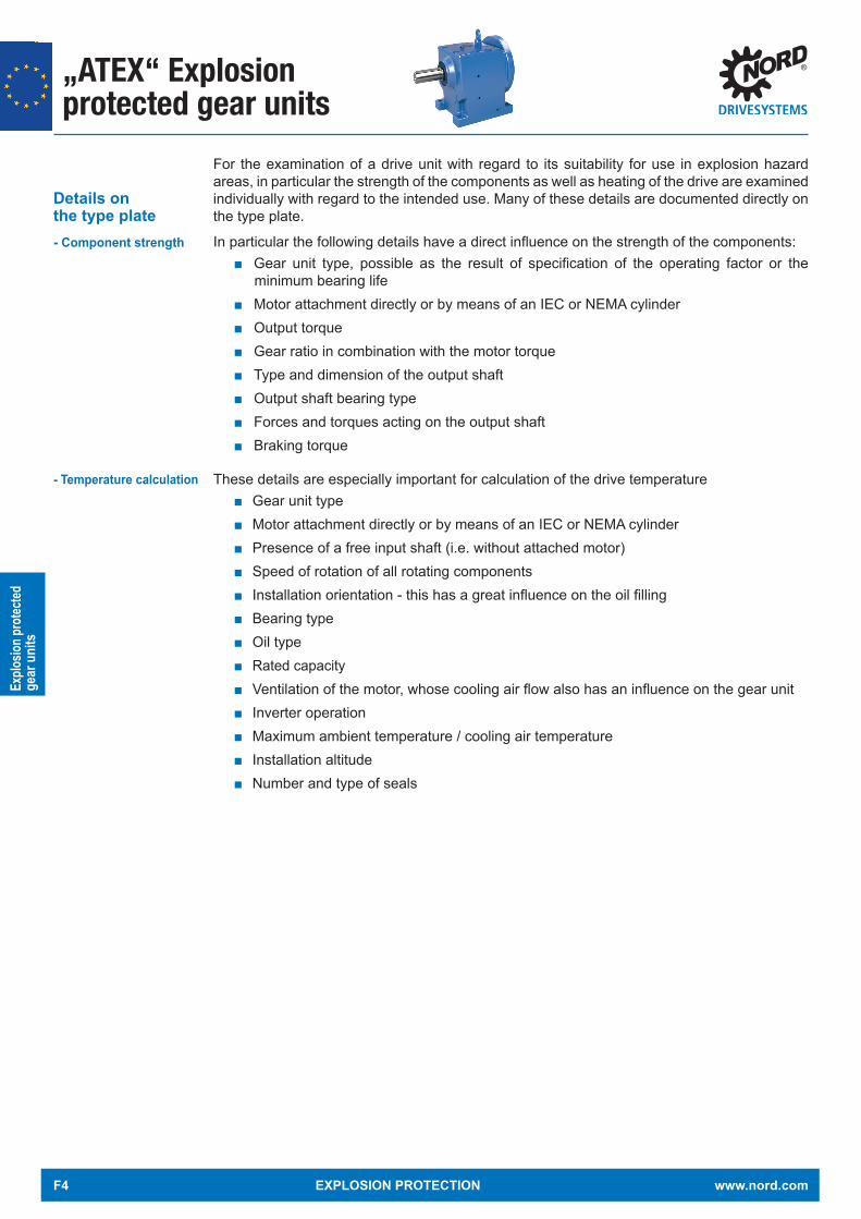
„ATEX“ Explosionprotected gear units
Explo
sion p
rotec
tedge
ar u
nits
For the examination of a drive unit with regard to its suitability for use in explosion hazard areas, in particular the strength of the components as well as heating of the drive are examined individually with regard to the intended use. Many of these details are documented directly on the type plate.
In particular the following details have a direct infl uence on the strength of the components: Gear unit type, possible as the result of specifi cation of the operating factor or the
minimum bearing life Motor attachment directly or by means of an IEC or NEMA cylinder Output torque Gear ratio in combination with the motor torque Type and dimension of the output shaft Output shaft bearing type Forces and torques acting on the output shaft Braking torque
These details are especially important for calculation of the drive temperature Gear unit type Motor attachment directly or by means of an IEC or NEMA cylinder Presence of a free input shaft (i.e. without attached motor) Speed of rotation of all rotating components Installation orientation - this has a great infl uence on the oil fi lling Bearing type Oil type Rated capacity Ventilation of the motor, whose cooling air fl ow also has an infl uence on the gear unit Inverter operation Maximum ambient temperature / cooling air temperature Installation altitude Number and type of seals
Details on the type plate- Component strength
- Temperature calculation
F4 EXPLOSION PROTECTION www.nord.com

„ATEX“ Explosionprotected gear units
Explo
sion p
rotec
tedge
ar u
nits
Many of the customer's details are documented directly on the type plate. Ex Gear unit type plate
Explanation of the type plate
Abbreviations Unit Designation B2000Section
Type - NORD gear unit typeNo. - Serial numberiges - Overall gear unit ration2 rpm Rated speed of gear unit output shaft*n1 rpm Rated speed of the gear unit drive shaft or the drive motor*IM - Version (installation orientation) 6.1M2 Nm Max. permissible gear unit output shaft torqueP1 kW Max. permissible drive power or motor powerBj - Year of manufactureFR2 kN Max. permissible transverse force on the gear unit output shaft 3.9FR1 kN Max. permissible transverse force on the gear unit drive shaft for option W 3.9Tu °C Permissible ambient temperature for the gear unitFA2 kN Max. permissible axial force on the gear unit output shaft 3.9
kg Total weight 3.8MI h Interval for general overhaul of the gear unit in operating hours or
according to the specifi cation of the dimensionless maintenance class CM5.2
xR2 mm Max. dimension for the point of application of the transverse force FR2 3.9Oil - Gear unit oil type (standard designation) 6.2
Last line ATEX labelling, as per (DIN EN 13463-1): 4.31. Group (always II, not for mines)2. Category (2G, 3G for gas or 2D, 3D for dust)3. Ignition protection type if fi tted (c)4. Explosion group if applicable (IIC, IIB)5. Temperature class (T1-T3 or T4 for gas) or max. surface temperature
(e.g. 125 °C for dust) or special max. surface temperature see special documentation (TX)
6. Temperature measurement on commissioning (X)S - Number of the special documentation, consisting of serial no. / year
The maximum permissible speeds are 10 % above the rated speed, if the maximum permissible drive power P1 is not exceeded.If the fi elds FR1, FR2, FA1 and FA2 are empty, the forces are zero. If the fi eld xR2 is empty, the point of application of force FR2 is central on the output shaft journal ( Section 3.9")
εх
www.nord.com EXPLOSION PROTECTION F5

„ATEX“ Explosionprotected gear units
Explo
sion p
rotec
tedge
ar u
nits
Details from the enquiry form
Examples
Forces on output: Axial FA2: 500 [N]
Radial FR2: 1000 [N] Leverage on shaft collar: 120 [mm]
Motor-specifi c parameters Delete section
Rated power P1 : 4.6 [kW]
Rated speed n1 : 1800 [rpm]
Temperature sensor (TF) Bi-metal temperature monitor (TW)
Mains voltage [V] Mains frequency: 60 [Hz]
Frequency inverter operation Delete section
Control cabinet inverter Motor-mounted inverter
Adjustment range from : 10 [Hz] to 80 [Hz]Speed from n1 [rpm] to [rpm]
Constant torque within adjustment range: 100 [Nm]
Characteristic curve : 50 Hz 70 Hz 87 Hz 100 Hz
Framework conditions Delete section
Ambient temperature: min. -10 to max. +50 [°C]
085
0150
0
No.
Typ SK 12 VL /2D - 90 L/4 /2Di
M
Bj
T
xR2
u
MI
S
h
mm
°C
min-1
ges
kW
kN
kN
min
Nm
kN
kN
-1n 2
M2
FR2
FA2
Oil
162,7
88,1
1
0,5
CLP 220
II 2D Ex h IIIC T125°C Db
1390
1,5
8,56
M1
-10/+40
120
7442
085
0150
0
No.
Typ SK 32 - IEC112 /2Di
M
Bj
T
xR2
u
MI
S
h
mm
°C
min-1
ges
kW
kN
kN
min
Nm
kN
kN
-1n 2
M2
FR2
FA2
Oil
183,8
239
CLP 220
II 2D Ex h IIIC T125°C Db
1800
4,6
9,80
M1
-10/+40
9555
085
0150
0
No.
Typ SK 32 - IEC112 /2Di
M
Bj
T
xR2
u
MI
S
h
mm
°C
min-1
ges
kW
kN
kN
min
Nm
kN
kN
-1n 2
M2
FR2
FA2
Oil
233,7
262
CLP 220
II 2D Ex h IIIC T125°C Db
2288
4
9,80
M1
-10/+40
9172
085
0150
0
No.
Typ SK 32 - IEC112 /2Di
M
Bj
T
xR2
u
MI
S
h
mm
°C
min-1
ges
kW
kN
kN
min
Nm
kN
kN
-1n 2
M2
FR2
FA2
Oil
146
262
CLP 220
II 2D Ex h IIIC T125°C Db
1430
4
9,80
M1
-10/+50
9172
Getriebebau NORD GmbH & Co. KG22939 Bargteheide / GERMANY
Getriebebau NORD GmbH & Co. KG22939 Bargteheide / GERMANY
Getriebebau NORD GmbH & Co. KG22939 Bargteheide / GERMANY
Getriebebau NORD GmbH & Co. KG22939 Bargteheide / GERMANY
n 1
P1
FR1
FA1
n 1
P1
FR1
FA1
n 1
P1
FR1
FA1
n 1
P1
FR1
FA1
1 E
1 E
1 E
1 E
F6 EXPLOSION PROTECTION www.nord.com

„ATEX“ Explosionprotected gear units
Explo
sion p
rotec
tedge
ar u
nits
Preventative maintenanceScheduled and proper maintenance of gear units is especially important for explosion protection as it has a direct impact on safe operation. In particular, operators of Category 2 (2D or 2G) drives for use in Zone 1 or 21 must take expected errors into account.This includes scheduled replacement of the gear oil as well as regular checks on the oil level – refer to the details in the operating and maintenance manual B2000.
In addition, the bearings and shaft sealing rings must be replaced as a preventative measure depending on the requirements of drive selection and application. Maintenance in case of damage or signs of imminent bearing damage results in a potentially dangerous situation and must be avoided at all costs!
To enable this preventative maintenance, according to a draft version of DIN EN ISO 80079-37:2016,NORD labels its Category 2 gear units with a maintenance interval "MI". This interval indicates the number of operating hours after which replacement of the bearings and seals is advisable. In association with this, other components of the gear unit are subjected to a visual inspection and are replaced in rare cases. The maintenance interval assumes use of the gear unit with the rated power / rated torque. Lower powers have a positive eff ect on the maintenance interval.
Example for a gear unit with a maintenance interval of 24497 hours.08
5 01
500
No.
Typ SK 22 /2G - 80 LH/4 /2Gi
M
Bj
T
xR2
u
MI
S
h
mm
°C
min-1
ges
kW
kN
kN
min
Nm
kN
kN
-1n 2
M2
FR2
FA2
Oil
56,71
126
1
0,5
CLP 220
II 2G Ex h IIC T3 Gb
1400
0,75
24,73
M1
-10/+40
24497
Getriebebau NORD GmbH & Co. KG22939 Bargteheide / GERMANY
n 1
P1
FR1
FA1
085
0150
0
No.
Typ SK 22 /2G - 80 LH/4 /2Gi
M
Bj
T
xR2
u
MI
S
h
mm
°C
min-1
ges
kW
kN
kN
min
Nm
kN
kN
-1n 2
M2
FR2
FA2
Oil
56,71
126
CLP 220
II 2G Ex h IIC T3 Gb
1400
0,75
24,73
M1
-10/+40
CM=3
Getriebebau NORD GmbH & Co. KG22939 Bargteheide / GERMANY
n 1
P1
FR1
FA1
1 E
1 E
On customer’s request, it is also possible to specify a maintenance class, which enables the customer to calculate the maintenance interval depending in the period of use per day and the actual average output power. Further details can be found in the operation and maintenance manual B2000.
085
0150
0
No.
Typ SK 22 /2G - 80 LH/4 /2Gi
M
Bj
T
xR2
u
MI
S
h
mm
°C
min-1
ges
kW
kN
kN
min
Nm
kN
kN
-1n 2
M2
FR2
FA2
Oil
56,71
126
1
0,5
CLP 220
II 2G Ex h IIC T3 Gb
1400
0,75
24,73
M1
-10/+40
24497
Getriebebau NORD GmbH & Co. KG22939 Bargteheide / GERMANY
n 1
P1
FR1
FA1
085
0150
0
No.
Typ SK 22 /2G - 80 LH/4 /2Gi
M
Bj
T
xR2
u
MI
S
h
mm
°C
min-1
ges
kW
kN
kN
min
Nm
kN
kN
-1n 2
M2
FR2
FA2
Oil
56,71
126
CLP 220
II 2G Ex h IIC T3 Gb
1400
0,75
24,73
M1
-10/+40
CM=3
Getriebebau NORD GmbH & Co. KG22939 Bargteheide / GERMANY
n 1
P1
FR1
FA1
1 E
1 E
Maintenance interval
Oil level check
Maintenance class
Examples
www.nord.com EXPLOSION PROTECTION F7

„ATEX“ Explosionprotected gear units
Explo
sion p
rotec
tedge
ar u
nits
DECLARATION OF CONFORMITYYou can fi nd certifi cates on the NORD homepage under www.nord.com - Heading DOCUMENTATION / CERTIFICATES
F8 EXPLOSION PROTECTION www.nord.com

„ATEX“ Explosionprotected gear units
Explo
sion p
rotec
tedge
ar u
nits
Documentation
Standard Special Documentation
B2000 Inclined installation orientations
Documentation
- Available languages:
Documentation:
The appropriate operating and installation instructions B2000 are included in every delivery and can be viewed in advance at www.nord.com.
They are available in the following languages:German, English, French, Spanish, Italian, Serbian, Chinese, Arabic, Brazilian/Portuguese, Dutch, Bulgarian Slovenian, Danish, Greek, Lithuanian, Turkish, Latvian, Romanian, Polish, Russian Slovakian, Czech, Finnish, Swedish, Hungarian, Croatian and Norwegian.
www.nord.com EXPLOSION PROTECTION F9

Notes
F10 EXPLOSION PROTECTION www.nord.com

Hybrid mixtures
Hybr
id m
ixtur
es
Hybrid mixturesBoth the gear units and motors, which are used in the context of explosion protection, take into account the specifi c requirements of the respective explosive substance.
For example, gases may penetrate into cavities in the motor or terminal box, which must be taken into account during construction.Dust, on the other hand, is prevented by IP55 or higher protection from accumulating in the motor in an ignitable concentration, which facilitates the motor design on this point and saves costs.
In contrast, in the case of motors in a dust environment, electrostatic charging may occur more easily, which may result in hazardous corona discharge. In summary, it can be said that the ignition hazards in dust and gas atmospheres diff er and result in specifi c technical solutions.
In rare cases, e.g. in mining, a mixture of fl ammable dust and fl ammable gas may occur - so-called hybrid mixtures. In the case of mining, this would typically be a mixture of methane, coal dust and air. In view of the large number of fl ammable gases, dust and their resulting mixtures, the potential hazards are extremely numerous and complex.
The selection of a suitable drive can therefore not be made without the precise analysis of the situation on site. It must be acknowledged that a drive which can be used safely in a pure gas or dust atmosphere cannot provide an adequate level of safety in an environment with a hybrid mixture. In this case, the operator or plant constructor has to endeavour to avoid danger in the context of tertiary explosion protection - ie to reduce the eff ect of a possible explosion.
Currently no standard exists which provides specifi cations for the technical design of motors or gear units in environments with hybrid mixtures. NORD DRIVESYSTEMS therefore does not off er motors or gear units for this purpose.
For logistical reasons it may be advisable to use a drive unit which can be used in either an explosive gas or dust atmosphere. Here it should be weighed whether the higher price of the drive is outweighed by the fl exibility gained. Such drives are off ered by NORD DRIVESYSTEMS in the following combinations: 2G/2D, 2G/3D and 3G/3D.
The type plates of the gear unit and the motor indicate suitability for both gas and dust.
Hybrid mixtures
NORD drives- 2G/2D, 2G/3D, 3G/3D
Example- 2G/2D drive,
PTC Ta
V Hz kW A r/mincos I / IA N
I.Cl. IP kg
No.D-32008 Herford
3~Mot.
IM
t
55 60F
www.nord.com EXPLOSION PROTECTION G1

Notes
G2 EXPLOSION PROTECTION www.nord.com
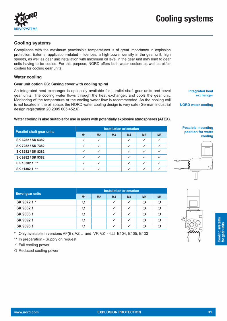
Cooling systems
Cool
ing
syst
ems
for g
ear u
nits
Cooling systemsCompliance with the maximum permissible temperatures is of great importance in explosion protection. External application-related influences, a high power density in the gear unit, high speeds, as well as gear unit installation with maximum oil level in the gear unit may lead to gear units having to be cooled. For this purpose, NORD offers both water coolers as well as oil/air coolers for cooling gear units.
Water coolingGear unit option CC: Casing cover with cooling spiralAn integrated heat exchanger is optionally available for parallel shaft gear units and bevel gear units. The cooling water flows through the heat exchanger, and cools the gear unit. Monitoring of the temperature or the cooling water flow is recommended. As the cooling coil is not located in the oil space, the NORD water cooling design is very safe (German industrial design registration 20 2005 005 452.6).
Water cooling is also suitable for use in areas with potentially explosive atmospheres (ATEX).
Integrated heat exchanger
NORD water cooling
Possible mounting position for water
coolingParallel shaft gear units
Installation orientationM1 M2 M3 M4 M5 M6
SK 6282 / SK 6382
SK 7282 / SK 7382
SK 8282 / SK 8382
SK 9282 / SK 9382
SK 10382.1 **
SK 11382.1 **
Bevel gear unitsInstallation orientation
M1 M2 M3 M4 M5 M6SK 9072.1 *
SK 9082.1
SK 9086.1
SK 9092.1
SK 9096.1
* Only available in versions AF(B), AZ... and VF, VZ ð& E104, E105, E133** In preparation - Supply on requestFull cooling powerReduced cooling power
www.nord.com EXPLOSION PROTECTION H1

Cooling systems
Cool
ing
syst
ems
for g
ear u
nits
Oil coolerGear unit option CS2An oil/air cooler is a separate system which is connected to the gear unit with hoses which cools the oil in the gear unit and therefore directly reduces the surface temperature of the gear unit.
For this, the gear unit is drawn in by a pump and flows through a heat exchanger. The oil is cooled by an air stream which is generated by a fan. The oil is then returned to the housing from the heat exchanger. The temperature is controlled by a thermostat.
Temperature monitoring is necessary and is enabled by an Ex-compliant PT100 which is supplied with the system. Depending on the ambient temperature, the cooling power is approx. 5 kW.
Can be used for the following gear units Helical gear units SK62 – SK103 Parallel shaft gear units SK6282 – SK11382.1 Bevel gear units SK9072.1 – SK9096.1
The cooling system is suitable for II 2G Ex h IIB + H2 T4 GB II 3D Ex h IIIC T130°C Dc Ambient temperatures (hoses and cooler) in operation
- Minimum +5°C with 2 m hose length- For ≥+20°C 2 or 4 m hoses can be used
Max. ambient temperature +40°C- Higher temperatures on request
Planning of this cooling system is always carried out by experienced engineers, who modify the system to the special features of the application and the gear unit which is to be cooled.
Separate special documentation exists, which provides detailed information about the commissioning, operation and maintenance of the system.
Oil cooler, gear unit with special type plate, hose pack, PT100
Temperature- monitoring - EX-compliant PT100
Commissioning, maintenance
ThermostatThermostat
Cooler
FanPump
Drain = Intake line Oil level = Pressure line
Oil cooler
Delivery
H2 EXPLOSION PROTECTION www.nord.com

Decentralised frequency inverters for „ATEX“ dust explosion protection
Freq
uenc
y inv
erte
rs
and
star
ters
Decentralised Product GroupNORD DRIVESYSTEMS understands decentralised inverters and starters to be devices which are mounted on the motor or mounted in the vicinity of the drive with the aid of wall mounting kits. This means that the devices must provide the same level of explosion protection as the drives with which they are associated. A 1:1 connection is required for this.
It is not permissible for an inverter to operate two motors simultaneously. NORD DRIVESYSTEMS is the manufacturer of all inverters and starters sold by NORD and can take all of the necessary measures from development and production up to quality control to ensure that the combination and electrics are ideally matched.
NORD has the following decentralised product groups which may all be installed in Ex Zone 22.
Decentralised product groups
NORDAC Start motor starter SK 135EThe motor starter NORDAC START is a decentralised wear-free electronic motor starter for soft starting of all kinds. It is equipped with a reversing function and internal motor protectionandcanthereforebeflexiblyintegratedintoanysystem.
NORDAC BASE – Frequency inverter SK 180EThe NORDAC BASE is NORD's economical drive solution for the decentralised frequency inverter technology sector. With the NORDAC BASE, you purchase technology with a robust design that has been specially developed for simple drive solutions for installation outside the control cabinet at low cost.
NORDAC FLEX – Frequency inverter SK 200EFlexibletoinstall,easytoservice.TheNORDACFLEXisourmostflexibleinverterthatcan be tailored to any customer application by means of scalable functions. Installing and servicing the SK 200E can be carried out quickly and reliably due to its extensive plug-in capability and easy parameter transfer via EEPROM memory.
Device Within ATEX-Zone 22 Outside of a zoneNORDAC START 0.25 ... 7.5 kW 0.25 ... 7.5 kWNORDAC BASE 0.25 ... 2.2 kW 0.25 ... 2.2 kW
NORDAC FLEX 0.55 ... 7.5 kW 0.55 ... 22 kW
Extensions for devices which are used within the ATEX zone: Internal CU4 modules / internal braking resistors ATEX Potentiometer Wall mounting kit without fan
Protection class IP55 IP66Non-conducting dust II3D Ex tc IIIB T125°C Dc X Yes
Conducting dust II3D Ex tc IIIC T125°C Dc X - Yes
Sealing of the devices is essential for safe and reliable operation. For this, special IP66 cable glands and exceptionally reliable housing seals are used. Conversions may only be made by NORDorbypersonscertifiedbyNORD!
Notice
www.nord.com EXPLOSION PROTECTION I1

Decentralised frequency inverters for „ATEX“ dust explosion protection
Freq
uenc
y inv
erte
rs
and
star
ters
To ensure smooth commissioning, documentation is available in the following languages:
Documentation EN EN FR ES P RU PL CN US CZE IT NLBU 0135E X X X X X X X
BU 0180 / 0185 X X X X Y X Y X Y Y Y
BU 0200 / 0240 X X X X Y X X X X Y YX Main instructionY Brief instruction
The frequency inverters can be operated with variously set characteristic curves. The settings for this are stated in B1096. The following are possible:
50 Hz characteristic curve (only for ASM asynchronous motors) 60 Hz characteristic curve (only for ASM asynchronous motors) 87 Hz characteristic curve (only for ASM asynchronous motors) 100 Hz characteristic curve (for ASM)
It is essential that the following settings are complied with for operation: Pulse frequency 4 – 6 kHz Vector regulation Setting of the I²t trigger curve Maximum frequency 100 Hz Temperature sensor triggering must be used and tested
The otherwise extensive range of options is reduced to just a few for starters and inverters which are operated in the Ex zone.
Available languages
Options
Usable characteristic curves
Settings
Customer units
Internal brake resistors
Wall mounting kit
Frequency inverter
ATEX potentiometer
I2 EXPLOSION PROTECTION www.nord.com

Decentralised frequency inverters for „ATEX“ dust explosion protection
Freq
uenc
y inv
erte
rs
and
star
ters
Frequency inverters and starters for installation outside of the Ex zoneFor safe operation of motors within the Ex zone, motor manufacturers specify requirements for the technical design and settings of inverters and starters.Details of these can be found in the relevant operating and maintenance instructions.
If the motors and inverters from the same manufacturer are used, it is very likely the devices will be in sync.For explosion protection a 1:1 connection between the motor and the inverter is necessary. It is not permissible for an inverter to operate two motors simultaneously. NORD DRIVESYSTEMS is the manufacturer of all inverters and starters which are sold by NORD and can take all of the necessary measures from development and production up to quality control to ensure that the combination and electrics are ideally matched.
NORDAC LINK Motor starter SK155EOne product, many advantages. The NORDAC LINK motor starter impresses with its highplug-incapabilityand itseasy installation. Itcanbefreelyconfiguredandeasilyinstalled. Commissioning and servicing of the motor starter is performed easily with the integrated maintenance switch and the local manual control facility. It can also be integratedintovariousfieldbussystems.Inshort:TheSK155Eissimplyconvenient.
NORDDAC LINK Frequency inverter SK250ETheNORDACLINKistheconvenientNORDdrivesolutionforflexibledecentralisedinstallation. Depending on the application and the requirements, NORDAC LINK can befreelyconfigured,whichresultsinalargenumberofdifferentpotentialapplicationsfor this inverter. The high level of plug-in capability enables fast and easy installation of the units. Commissioning and servicing of the system is performed quickly with the integrated maintenance switch and the local manual control facility. The NORDAC LINK can be integrated into all common bus systems.
NORDAC PRO Frequency inverter SK500ETheNORDACPROisthe inverter foralldriveapplications. Itoffersawidepowerrange, and its functionality can be extended with plug-in option modules. For this inverter, variable cooling concepts are used to remove heat, which can enable the removal of heat outside of the control cabinet and can be simply adapted to the requirements of the application with various option modules.
Device Within ATEX-Zone 22 Outside of ATEXNORDAC LINK (Starter) -- 0.25 … 3 kWNORDAC LINK (Inverter) - - 0.55 … 7.5 kWNORDAC PRO - - 0.25 … 160 kW
Documentation EN EN FR ES P RU PL CN US CZE IT NLBU 0155 X X X X
BU 0250 X X X X
BU 0500 / 0540 X X X X Y X X X X Y Y
X Main instruction Y Brief instruction
Available languages
www.nord.com EXPLOSION PROTECTION I3

Notes
I4 EXPLOSION PROTECTION www.nord.com

Documentation
Docu
men
tatio
n
NORD DRIVESYSTEMS provides extensive documentation. It ranges from the description of the product groups gearboxes, motors and inverters in catalogues, to the provision of drawings and data sheets, to operating and maintenance instructions.
This section is intended to provide a brief overview.
CataloguesThis Ex-catalogue is a supplement to motor and gear unit catalogues M7000, G1000, G2000, G1012 and G1035. These can provide important information for the selection of the gear unit as well as descriptions of the various kinds and types of gear units and their options. Possible speeds and gear ratios as well as the associated output torques are shown.
Use of Ex motors may result in slightly changed data,which can be obtained from the off er in case of an enquiry.
Motor catalogue M7000 contains information for motor selection and technical explanations.
50 H
z • m
m F
ESTE
DRE
HZAH
LEN
DRIVESYSTEMS Intelligent Drivesystems, Worldwide Services
G100
0 M
at.-
Nr. 6
0018
02 /
481
5
G10
00EN
50 Hz • mm
CONSTANT SPEEDS G1000
ENHeadquarters:Getriebebau NORD GmbH & Co. KGGetriebebau-Nord-Straße 122941 Bargteheide, GermanyFon +49 (0) 4532 / 289 - 0 Fax +49 (0) 4532 / 289 - [email protected], www.nord.comMember of the NORD DRIVESYSTEMS Group
NORD DRIVESYSTEMS GROUPHeadquarters and Technology Centerin Bargteheide near Hamburg, GermanyInnovative drive solutions for more than 100 industriesMechanic ProductsHelical, Parallel Shaft, Helical Bevel and Helical Worm Gear UnitsElectrical ProductsElectric motors in all effi ciency classesElectronic ProductsCentralized and decentralized frequency inverters, Motor starters7 state-of-the-art production plantsfor all drive components36 subsidiaries on 5 continentsprovide on-site storage, assembly centers, technical support and customer serviceMore than 3.200 employees around the worldcreate customized solutions
www.nord.com/locator 50 H
z • m
m C
ONST
ANT
SPEE
DS
Intelligent Drivesystems, Worldwide Services
G2122
G212
2 M
at.-N
r. 60
0350
1 / 5
118
ATEX - Explosionsschutz
DEGetriebebau NORD GmbH & Co. KG, Getriebebau-Nord-Str. 1, D-22941 BargteheideFon +49 (0) 4532 / 289 - 0 , Fax +49 (0) 4532 / 289 - 2253, [email protected]
Getriebebau NORD GmbH, A-4030 Linz, Deggendorfstrasse 8Fon +43 (0) 732 / 31 89 20, Fax +43 (0) 732 / 31 89 20 – 85, [email protected]
Getriebebau NORD AG, Bächigenstrasse 18, CH-9212 ArneggFon +41-71-388 99 11, Fax +41-71-388 99 15, [email protected]
DE
AT
CH
Members of the NORD DRIVESYSTEMS Group
NORD DRIVESYSTEMS GroupStammsitz und Technologiezentrumin Bargteheide bei Hamburg
Innovative Antriebslösungen für mehr als 100 Industriezweige
Mechanische ProdukteFlach-, Stirn-, Kegelrad- und Schneckengetriebe
Elektrische ProdukteIE 2/IE3/IE4-Motoren
Elektronische Produktezentrale und dezentrale Frequenzumrichter, Motorstarter, Feldverteiler
7 technologisch führende Fertigungsstandortefür alle Antriebskomponenten
Tochtergesellschaften und Vertriebspartner in 89 Ländern auf 5 Kontinentenbieten Vor-Ort-Bevorratung, Montagezentren, technische Unterstützung und Kundendienst.
Mehr als 4.000 Mitarbeiter weltweitschaffen kundenspezifische Lösungen.
www.nord.com/locator
NORD Drivesystems | Global vor Ort
ATEX
- Exp
losion
ssch
utz
G212
2DE
G10
35
Mat
.-Nr.
6001
502
/ 371
7
G1035UNIVERSAL Worm gear units SI and SMI
NORD Drivesystems
EN
G103
5 W
ORM
GEAR
UNITS
EN
Intelligent Drivesystems, Worldwide Services
NORD DRIVESYSTEMS GroupHeadquarters and Technology centerin Bargteheide close to Hamburg
Innovative drive solutionsfor more than 100 branches of industry
Mechanical productsparalell shaft, helical gear, bevel gear and worm gear units
Electrical productsIE2/IE3/IE4 motors
Electronic productscentralised and decentralised frequency inverters,motor starters and fi eld distribution systems
7 state-of-the-art production plantsfor all drive components
Subsidiaries and distributorsin 89 countries on 5 continentsprovide local stocks, assembly, production,technical support and customer service
More than 3.600 employees throughout the worldcreate customer oriented solutions
www.nord.com/locator
Headquarters:Getriebebau NORD GmbH & Co. KGGetriebebau-Nord-Straße 122941 Bargteheide, GermanyT: +49 (0) 4532 / 289 - 0 F: +49 (0) 4532 / 289 - [email protected], www.nord.com
Member of the NORD DRIVESYSTEMS Group
NORD
BLOC
.1 S
K 07
2.1
- SK
973
.1
Intelligent Drivesystems, Worldwide Services
G101
2 M
at.-
Nr. 6
0016
01 /
2217
SK 072.1 - SK 973.1
NORDBLOC.1G1012
DEGetriebebau NORD GmbH & Co. KG, Getriebebau-Nord-Str. 1, D-22941 BargteheideFon +49 (0) 4532 / 289 - 0 , Fax +49 (0) 4532 / 289 - 2253, [email protected]
Getriebebau NORD GmbH, A-4030 Linz, Deggendorfstrasse 8Fon +43 (0) 732 / 31 89 20, Fax +43 (0) 732 / 31 89 20 – 85, [email protected]
Getriebebau NORD AG, Bächigenstraße 18, CH-9212 ArneggFon +41-71-38899 11, Fax +41-71-38899 15, [email protected]
DE
AT
CH
Member of the NORD DRIVESYSTEMS Group
NORD DRIVESYSTEMS GroupStammsitz und Technologiezentrum in Bargteheide bei Hamburg
Innovative Antriebslösungenfür mehr als 100 Industriezweige
Mechanische Produkte Flach-, Stirn-, Kegelrad- und Schneckengetriebe
Elektrische Produkte IE2/IE3/IE4-Motoren
Elektronische Produkte Zentrale und dezentrale Frequenzumrichter, Motorenstarter
7 technologisch führende Fertigungsstandorte für alle Antriebskomponenten
Tochtergesellschaften in 36 Ländern auf 5 Kontinenten bieten Vor-Ort-Bevorratung, Montagezentren, technische Unterstützung und Kundendienst
Mehr als 3.200 Mitarbeiter weltweit schaffen kundenspezifische Lösungen.
www.nord.com/locator
M70
00MO
TORE
N
Intelligent Drivesystems, Worldwide Services
M70
00 M
at.-N
r. 600
0601
/ 38
17
DE MOTORENM7000
DE
Getriebebau NORD GmbH & Co. KG, Getriebebau-Nord-Str. 1, D-22941 BargteheideFon +49 (0) 4532 / 289 - 0 , Fax +49 (0) 4532 / 289 - 2253, [email protected]
Getriebebau NORD GmbH, A-4030 Linz, Deggendorfstrasse 8Fon +43 (0) 732 / 31 89 20, Fax +43 (0) 732 / 31 89 20 – 85, [email protected]
Getriebebau NORD AG, Bächigenstrasse 18, CH-9212 ArneggFon +41-71-388 99 11, Fax +41-71-388 99 15, [email protected]
DE
AT
CH
NORD DRIVESYSTEMS GroupStammsitz und Technologiezentrumin Bargteheide bei Hamburg
Innovative Antriebslösungen für mehr als 100 Industriezweige
Mechanische ProdukteFlach-, Stirn-, Kegelrad- und Schneckengetriebe
Elektrische ProdukteIE 2/IE3/IE4-Motoren
Elektronische Produktezentrale und dezentrale Frequenzumrichter, Motorstarter, Feldverteiler
7 technologisch führende Fertigungsstandortefür alle Antriebskomponenten
Tochtergesellschaften und Vertriebspartner in 89 Ländern auf 5 Kontinentenbieten Vor-Ort-Bevorratung, Montagezentren, technische Unterstützung und Kundendienst.
Mehr als 3.600 Mitarbeiter weltweitschaffen kundenspezifische Lösungen.
www.nord.com/locator
Member of the NORD DRIVESYSTEMS Group
GBN M7000_DE_3817 Umschlag_5mm.indd 1 15.12.17 10:45
StandardHelical Gearboxes
Réducteurs à engrenagescylindriques standards
VerstellgetriebeVariable Speed DrivesVariateurs mécaniques à courroie
G 2000 DE GB FR
GmbH & Co. KG
D-22934 Bargteheide/Hamburg · P.O.Box 1262 · Rudolf-Diesel-Str. 1Telefon 0 45 32 / 4 01-0 · Telefax 0 45 32 / 40 15 55 NORD Internet: http://www.nord.com
Getriebebau NORD
STANDARD-STIRNRADGETRIEBE
Mat
.-Nr.:
600
0599
28.
05
J1www.nord.com EXPLOSION PROTECTION J1

Documentation
Docu
men
tatio
n
Drive Expert / MYNORDThe product configurator in the myNORD customer portal (www.mynord.com) is also available as an alternative to catalogues. In this, all drive units, including Ex drive units and their options can be selected for
Precise configuration. Direct generation of CAD- data (3D models, dimensioned drawings, outline drawings). Create offers online
It must be emphasised that the configurator indicates whether or not a selected drive unit is ATEX compliant. Price information as well as an enquiry/order form are also included. Here are some impressions from this program:
HOME I MYNORD I PRODUCT SELECTION
MYNORD PRODUCT SELECTIONOrdering process
Create new product / CAD
J2 EXPLOSION PROTECTION www.nord.com

Documentation
Docu
men
tatio
n
Preview of possible partial results as a result of using this software. Please contact your NORD Sales contact partner for more detailed information.
NORDBLOC.1 GEARMOTORType name: SK 172.1F /3D - 63S/4 3D TF
J3www.nord.com EXPLOSION PROTECTION J3

Documentation
Docu
men
tatio
n
J4 EXPLOSION PROTECTION www.nord.com

Documentation
Docu
men
tatio
n
J5www.nord.com EXPLOSION PROTECTION J5

DocumentationDo
cum
enta
tion
Documentation accompanying the orderAll deliveries of Ex drives to destination countries in the EU contain complete printed documentation in German, as well as in a language which can easily be understood by the operator. Customers are requested to state the required language in their request for an off er.
For Ex gear units, B2000 is supplied, which specifi cally deals with explosion protection,
B1091 is intended for main operating motors,
B1091 and B1091-1 are intended for motors operated with inverters,
For use of motor mounted inverters for Zone 22 documents B1091, B1091-1 and G4014-1 are supplied.
NORD homepageAll operating and maintenance instructions, spare parts lists and certifi cates can be found under www.nord.com.
B 2000 – de
Explosionsgeschützte GetriebeBetriebs- und Montageanleitung
B 1091 – de
MotorenBetriebs- und Montageanleitung
B 1091 – de
MotorenBetriebs- und Montageanleitung
B 1091 – de
MotorenBetriebs- und Montageanleitung
B 1091-1 – de
Motoren im FU-Betrieb für Kategorie 2D/3D Projektierungsleitfaden zur B 1091
B 1091-1 – de
Motoren im FU-Betrieb für Kategorie 2D/3D Projektierungsleitfaden zur B 1091
DE
ELEKTRONISCHE VERSTELLGETRIEBE
Intelligent Drivesystems, Worldwide Services
PRODUKTINFORMATIONG4014-1NORDBLOC.1 Stirnradgetriebe, Stirnradgetriebe, Flachgetriebe, Kegelradgetriebe, Stirnrad-Schneckengetriebe
J6 EXPLOSION PROTECTION www.nord.com

Documentation
Docu
men
tatio
n
Rapid access enables a targeted search for documents:
If the name of the document is known, the "search" will be successful.
J7www.nord.com EXPLOSION PROTECTION J7
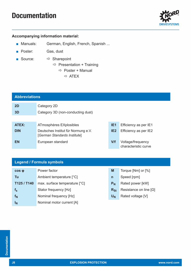
Documentation
Docu
men
tatio
n
Abbreviations
2D Category 2D
3D Category 3D (non-conducting dust)
ATEX: ATmosphères EXplosibles IE1 Efficiency as per IE1DIN Deutsches Institut für Normung e.V.
[German Standards Institute]IE2 Efficiency as per IE2
EN European standard V/f Voltage/frequency characteristic curve
Legend / Formula symbols
cos φ Power factor M Torque [Nm] or [%]
Tu Ambient temperature [°C] n Speed [rpm]
T125 / T140 max. surface temperature [°C] PN Rated power [kW]
fs Stator frequency [Hz] RSt Resistance on line [Ω]
fN Nominal frequency [Hz] UN Rated voltage [V]
IN Nominal motor current [A]
Accompanying information material:
Manuals: German, English, French, Spanish ...
Poster: Gas, dust
Source: Sharepoint Presentation + Training Poster + Manual ATEX
J8 EXPLOSION PROTECTION www.nord.com

Notes
www.nord.com EXPLOSION PROTECTION J9
Notes
J10 EXPLOSION PROTECTION www.nord.com

www.nord.com
G1050 MAXXDRIVE ® Industrial gear unitsUNICASE housing 50 / 60 Hz Parallel-Axis Right-Angle
G1035 UNIVERSAL Worm gear units SI and SMI
ELECTRONICVARIABLE SPEED DRIVES
Headquarters:Getriebebau NORD GmbH & Co. KGGetriebebau-Nord-Straße 122941 Bargteheide, GermanyFon +49 (0) 4532 / 289 - 0 Fax +49 (0) 4532 / 289 - [email protected], www.nord.comMember of the NORD DRIVESYSTEMS Group
Intelligent Drivesystems, Worldwide Services
G401
4EL
ECTR
ONIC
VARI
ABLE
SPEE
D DR
IVES
NORD DRIVESYSTEMS GROUPHeadquarters and Technology Centerin Bargteheide near Hamburg, GermanyInnovative drive solutionsfor more than 100 industriesMechanic ProductsHelical, Parallel Shaft, Helical Bevel and Helical Worm Gear UnitsElectrical ProductsElectric motors in all efficiency classesElectronic ProductsCentralized and decentralized frequency inverters, Motor starters7 state-of-the-art production plantsfor all drive components36 subsidiaries on 5 continentsprovide on-site storage, assembly centers, technical support and customer serviceMore than 3.100 employees around the worldcreate customized solutions
www.nord.com/locator
DRIVESYSTEMS
G401
4 Mat.
-Nr. 6
0040
02 /
4214
NORDBLOC.1 Helical Gear Units, Helical Gear Units, Parallel Gear Units, Helical-Bevel Gear Units, Helical-Worm Gear Units
PRODUCT OVERVIEWG4014
EN
EN
www.nord.com/locator
G103
5 W
ORM
GEAR
UNITS
Mat
.-Nr. 6
0015
02/4
813
Intelligent Drivesystems, Worldwide Services
G1035UNIVERSAL Worm gear unitsSI und SMI
EN
EN
NORD Drivesystems | Global, always close to you
Headquarters:Getriebebau NORD GmbH & Co. KGGetriebebau-Nord-Straße 122941 Bargteheide, GermanyFon +49 (0) 4532 / 289 - 0 Fax +49 (0) 4532 / 289 - [email protected], www.nord.com
Member of the NORD DRIVESYSTEMS Group
DE
Intelligent Drivesystems, Worldwide Services
SK 180EDezentrale Antriebstechnik Frequenzumrichter
50 H
z • m
m F
ESTE
DRE
HZAH
LEN
DRIVESYSTEMS Intelligent Drivesystems, Worldwide Services
G100
0 M
at.-N
r. 60
0180
2 / 4
815
G100
0EN
50 Hz • mm
CONSTANT SPEEDS G1000
ENHeadquarters:Getriebebau NORD GmbH & Co. KGGetriebebau-Nord-Straße 122941 Bargteheide, GermanyFon +49 (0) 4532 / 289 - 0 Fax +49 (0) 4532 / 289 - [email protected], www.nord.comMember of the NORD DRIVESYSTEMS Group
NORD DRIVESYSTEMS GROUPHeadquarters and Technology Centerin Bargteheide near Hamburg, GermanyInnovative drive solutionsfor more than 100 industriesMechanic ProductsHelical, Parallel Shaft, Helical Bevel and Helical Worm Gear UnitsElectrical ProductsElectric motors in all efficiency classesElectronic ProductsCentralized and decentralized frequency inverters, Motor starters7 state-of-the-art production plantsfor all drive components36 subsidiaries on 5 continentsprovide on-site storage, assembly centers, technical support and customer serviceMore than 3.200 employees around the worldcreate customized solutions
www.nord.com/locator 50 H
z • m
m C
ONST
ANT
SPEE
DS
PRODUCT OVERVIEWG1050 • 50/60 Hz • mm
G105
0 M
at.-N
r. 60
0110
2 / 1
516
SK 7207 - SK 15507 Gear Units
50/6
0 Hz
•m
m
NORD
GEA
R - L
ARGE
INDU
STRI
AL G
EAR
UNIT
SG1
050
Large Industrial Gear UnitsParallel-Axis and Right-AngleHigh Precision, Long Life, Low Maintenance
Headquarters:Getriebebau NORD GmbH & Co. KGGetriebebau-Nord-Straße 122941 Bargteheide, GermanyFon +49 (0) 4532 / 289 - 0 Fax +49 (0) 4532 / 289 - [email protected], www.nord.comMember of the NORD DRIVESYSTEMS Group
NORD DRIVESYSTEMS GROUPHeadquarters and Technology Centerin Bargteheide near Hamburg, GermanyInnovative drive solutions for more than 100 industriesMechanic ProductsHelical, Parallel Shaft, Helical Bevel and Helical Worm Gear UnitsElectrical ProductsElectric motors in all efficiency classesElectronic ProductsCentralized and decentralized frequency inverters, Motor starters7 state-of-the-art production plantsfor all drive components36 subsidiaries on 5 continentsprovide on-site storage, assembly centers, technical support and customer serviceMore than 3.200 employees around the worldcreate customized solutions
www.nord.com/locator
Intelligent Drivesystems, Worldwide Services
EN
Intelligent Drivesystems, Worldwide Services
F 3020 DE
SK 200E
Contents
G1000 Fixed speedsUNICASE housing 50 Hz, 60 Hz Helical geared motors Parallel geared motors Bevel geared motors Helical worm geared motors
G4014 Electronic variable speed drives NORDBLOC.1 Helical geared motors Helical geared motors Parallel geared motors Bevel geared motors Helical worm geared motors
An overview ofNORD range
F3018_E3000 Frequency inverter SK180EF3020_E3000 Frequency inverter SK200E
F3060_E3000 NORDAC PROFrequency inverter SK500P
Introduction
Country-specifi c explanations . . . . . . . . . . . . . . . . A 2 - 12
General Dust Explosion Protection . . . . . . . . . . . . B 1 - 8
Motors for Dust Explosion Protection . . . . . . . . . . C 1 - 24
General Gas Explosion Protection . . . . . . . . . . . . . D 1 - 8
Motors for Gas Explosion Protection . . . . . . . . . . . C 1 - 8
General Explosion Protected Gear Units . . . . . . . . F 1 - 10
Hybrid Mixtures . . . . . . . . . . . . . . . . . . . . . . . . . . . . G 1 - 2
Cooling systems for gear units. . . . . . . . . . . . . . . . H 1 - 2
Decentralised inverters and starters . . . . . . . . . . . I 1 - 4
Documentation . . . . . . . . . . . . . . . . . . . . . . . . . . . . . J 1 - 8
Intelligent Drivesystems, Worldwide Services
NORDAC PRO FREQUENCY INVERTER SK 500P
EN
VERSATILE FREQUENCY INVERTER FOR CONTROL CABINET APPLICATIONS
Intelligent Drivesystems, Worldwide Services

Intelligent Drivesystems, Worldwide Services
G2122
G21
22 M
at.-N
r. 60
0350
2 / 0420
Explosion Protection
EN
Intelligent Drivesystems, Worldwide ServicesIntelligent Drivesystems, Worldwide Services
Headquarters:Getriebebau NORD GmbH & Co. KGGetriebebau-Nord-Straße 122941 Bargteheide, GermanyFon +49 (0) 4532 / 289 - 0 Fax +49 (0) 4532 / 289 - [email protected], www.nord.com
Member of the NORD DRIVESYSTEMS Group
NORD DRIVESYSTEMS ® GroupHeadquarters and Technology centerin Bargteheide, Germany, close to Hamburg
Innovative drive solutionsfor more than 100 branches of industry
Mechanical productsparalell shaft, helical gear, bevel gear and worm gear units
Electrical productsIE2/IE3/IE4 motors
Electronic productscentralised and decentralised frequency inverters,motor starters and fi eld distribution systems
Seven state-of-the-art production plantsfor all drive components
Subsidiaries and distributorsin 98 countries on 5 continentsprovide local stocks, assembly, production,technical support and customer service
More than 4,000 employees throughout the worldcreate customer oriented solutions
www.nord.com/locator