363 Rotor Design Report - Connor McDowall
41
2018 S EMESTER 2 363 Rotor Design Report Connor McDowall 530913386 cmcd398 September 30, 2018
-
Upload
khangminh22 -
Category
Documents
-
view
0 -
download
0
Transcript of 363 Rotor Design Report - Connor McDowall

2018
SEMESTER 2
363 Rotor Design Report
Connor McDowall530913386cmcd398
September 30, 2018

Contents1 Summary 3
1.1 Rotor Purpose . . . . . . . . . . . . . . . . . . . . . . . . . . . . . . . . . . . . . . . . . . . 31.2 Achievement of Purpose . . . . . . . . . . . . . . . . . . . . . . . . . . . . . . . . . . . . . 31.3 Design Criteria . . . . . . . . . . . . . . . . . . . . . . . . . . . . . . . . . . . . . . . . . . 31.4 Analysis . . . . . . . . . . . . . . . . . . . . . . . . . . . . . . . . . . . . . . . . . . . . . . 31.5 Conclusion . . . . . . . . . . . . . . . . . . . . . . . . . . . . . . . . . . . . . . . . . . . . 31.6 Cost . . . . . . . . . . . . . . . . . . . . . . . . . . . . . . . . . . . . . . . . . . . . . . . . 41.7 Performance . . . . . . . . . . . . . . . . . . . . . . . . . . . . . . . . . . . . . . . . . . . . 4
2 Development of Design 42.1 Assumptions . . . . . . . . . . . . . . . . . . . . . . . . . . . . . . . . . . . . . . . . . . . . 42.2 Drawings . . . . . . . . . . . . . . . . . . . . . . . . . . . . . . . . . . . . . . . . . . . . . 42.3 Method of Analysis . . . . . . . . . . . . . . . . . . . . . . . . . . . . . . . . . . . . . . . . 4
3 Design Calculations 53.1 Final Input Parameters . . . . . . . . . . . . . . . . . . . . . . . . . . . . . . . . . . . . . . 53.2 Blade Chords and Angles . . . . . . . . . . . . . . . . . . . . . . . . . . . . . . . . . . . . . 63.3 Rotor Torque and Co-efficient of Power . . . . . . . . . . . . . . . . . . . . . . . . . . . . . 6
4 Appendices 74.1 Background and Product Requirements . . . . . . . . . . . . . . . . . . . . . . . . . . . . . . 74.2 Final Design Dimensions . . . . . . . . . . . . . . . . . . . . . . . . . . . . . . . . . . . . . 84.3 Costs . . . . . . . . . . . . . . . . . . . . . . . . . . . . . . . . . . . . . . . . . . . . . . . . 94.4 Models and Drawings : Parts, Rigs and Assemblies . . . . . . . . . . . . . . . . . . . . . . . 94.5 Analysis: A Nine-Step Process . . . . . . . . . . . . . . . . . . . . . . . . . . . . . . . . . . 21
5 Fundamental Rotor Theory 215.1 Iterative Scheme . . . . . . . . . . . . . . . . . . . . . . . . . . . . . . . . . . . . . . . . . . 215.2 Complete Enumeration . . . . . . . . . . . . . . . . . . . . . . . . . . . . . . . . . . . . . . 355.3 Stage One Selection . . . . . . . . . . . . . . . . . . . . . . . . . . . . . . . . . . . . . . . . 375.4 Blade and Section Iteration . . . . . . . . . . . . . . . . . . . . . . . . . . . . . . . . . . . . 385.5 Manufacturing Considerations . . . . . . . . . . . . . . . . . . . . . . . . . . . . . . . . . . 395.6 Final Selection . . . . . . . . . . . . . . . . . . . . . . . . . . . . . . . . . . . . . . . . . . . 40
Listings1 XfoilIteration . . . . . . . . . . . . . . . . . . . . . . . . . . . . . . . . . . . . . . . . . . . 212 evaluateTurbine . . . . . . . . . . . . . . . . . . . . . . . . . . . . . . . . . . . . . . . . . . 223 evaluatePlot . . . . . . . . . . . . . . . . . . . . . . . . . . . . . . . . . . . . . . . . . . . . 254 callXfoil . . . . . . . . . . . . . . . . . . . . . . . . . . . . . . . . . . . . . . . . . . . . . . 275 xfoil.m . . . . . . . . . . . . . . . . . . . . . . . . . . . . . . . . . . . . . . . . . . . . . . . 29
List of Figures1 Background and Product Reqiurements in the Project Brief . . . . . . . . . . . . . . . . . . . 72 Exact Dimensions for the Final Design . . . . . . . . . . . . . . . . . . . . . . . . . . . . . . 83 Costs for the Final Design including Two Blade Setting rigs and One Spare Blade . . . . . . . 94 Method of Analysis: A Nine Step Process . . . . . . . . . . . . . . . . . . . . . . . . . . . . 215 A Small Subset of the Plots generated during Complete Enumeration . . . . . . . . . . . . . . 366 37 Selected Aerofoils . . . . . . . . . . . . . . . . . . . . . . . . . . . . . . . . . . . . . . . 37
1

7 One third of all iterations . . . . . . . . . . . . . . . . . . . . . . . . . . . . . . . . . . . . . 388 Evaluation of Manufacturing Considerations . . . . . . . . . . . . . . . . . . . . . . . . . . . 399 sd7003 Plot and Shape . . . . . . . . . . . . . . . . . . . . . . . . . . . . . . . . . . . . . . 40
2

1 Summary
1.1 Rotor Purpose
The rotor is a commercial product. The target market is rural communities in the higher windy latitudesaround the world. The product will consist of a kitset used to build a general assembly, a fixture on a locallyconstructed tower. See 1. for rotor application and kitset components. The kitset will include instructions forassembly.
1.2 Achievement of Purpose
Our chosen design of six blades with fifteen sd7003 aerofoils per blade will: meet the design criteria (below),be easy to both distribute to and assemble by rural communities using the compact kitset, and contain keycomponents and samples of easily assessible surfacing and adhesive materials. The surfacing materials areduct tape, sellotape and hot glue.
1.3 Design Criteria
The rotor must operate in wind conditions between eight to twelve knots, rotating at 140 rpm at the targetwindspeed of ten knots. The rotor must have between three to eight blades. The general assembly must beeasy to assemble from the kitset using the instruction manual. Blade surfacing and adhesives must be easyfor rural communities to source for repairs and maintenance. The rotors components and materials must havethe strength and durability to withstand the operating environment and are of low cost for maintenance andrepair.
1.4 Analysis
The analysis was broken up into a series of discrete steps: Understanding the fundamental rotor theory. Writingan Iterative scheme in MATLAB. Conducting complete enumeration with every aerofoil design. Ruling out aseries of aerofoil designs in a stage one selection process. Iterating on selected aerofoil designs, changing thenumber of blades and sections. Selecting the number of blades and aerofoils in a stage two selection process.Making manufacturing considerations in the design. Making the final selection based on the all major factors.Considering surfacing materials.
The main factors considered in the design are: The lift to drag (CL/CD) ratios for the aerofoil design acrossa range of angles of attack (alpha) and different windspeeds expressed by different Reynolds numbers. Themargin of error in CL/CD ratios with changes in the angle of attack and windspeed, assessed in the CL/CDvs alpha plots for every aerofoil. The thickness of the aerofoil. The camber of the aerofoil. The shapeof the aerofoil. The surface area of the aerofoils. The cost, manufacturability and durability of surfacingmaterials.
1000 different aerofoil designs were investigated in complete enumeration. After, 37 aerofoil designs wereconsidered for stage two. In stage two, 333 different combinations were considered, the 37 selected aerofoilsfrom stage one with 4,5 or 6 blades and 14,15 or 16 sections. 37 from stage two were considered to make thefinal selection. 1259 unique designs were considered in the process.
1.5 Conclusion
Our final design is a rotor with six blades with fifteen sections per blade. Each section is a sd7003 aerofoildesign with varying chord lengths between 28.3 and 19.5cm, and a total blade length of 69.0cm from the
3

centre of the hub. Each aerofoil has a camber of 1.2% of chord length. Each aerofoil has a different bladesetting angle in the range of 28.6 to 13.0 degrees. The aerofoils are equally spaced along the blades, startingat 26cm from the centre of the hub and ending at 69.0cm. The aerofoils are surfaced using sellotape, duct tapeand hot glue. See 2 for exact parameters and dimensions.
The design was the best of the last 37 in the final selection stage, maximising the Cl/CD ratios whilst having themost reasonable margin of error with changing angles of attack and windspeeds. The aerofoil had a smooth,continuous shape with slight camber, easy to laser cut and surface. Each aerofoil was thick enough to insert theblade rods. The weight per blade is low considering the number of sections, aerofoil surface area and thicknessof the acrylic. Six blades decreased the chord lengths and increased our margin of error for manufacturingfaults. Fifteen sections maximised the CL/CD ratios compared to other combinations. Sellotape and duct tapeare durable, easy to apply and inexpensive compared to other materials. The hot glue is easy to apply andinexpensive compared to other adhesives.
1.6 Cost
The total rotor, two blade setting rigs and one extra blade will cost $241.79. See 3 for a full cost break-down.
1.7 Performance
Our turbine will achieve 47.6W with a torque of 3.25m across all three windspeeds with 140rpm. The turbinewill generate a power coefficients of 0.3978, 0.3632 and 0.3064 at 8,10 and 12 knots respectively.
2 Development of Design
2.1 Assumptions
We made the following assumptions to conduct our analysis: Fundamental rotor theory is applicable and doesnot break down. Assume losses due to wake rotation, aerodynamic drag, tip losses and losses attributable tohaving a finite number of blades. The mechanic system the rotor spins on is 100% efficient. Wind direction isperpendicular to the rotor and flows in one dimension.
2.2 Drawings
See 4.4 for drawings on the aerofoil design and the blade distance setting tool used in construction.
2.3 Method of Analysis
See 4 for our nine-stage method of analysis.
(1) Fundamental Rotor Theory. We learnt extracting power from the wind using a rotor. We learnt the follow-ing concepts: Lift and drag around an aerofoil design and deriving their subsequent coefficients. Learning howto extract power from the wind considering the Betz Limit, Bernoulli Analysis, axial induction factors, pres-sures, velocities and forces. The limitations of rotor design. The blade element momentum method consideringboth axial and angular induction factors. Incorporating axial induction factors and taking into considerationwake rotation and Prandtl tip loss. See 5 for lectures slide three through to eight where the aforementionedtheory was covered.
4

(2) An iterative scheme. XfoilIteration.m was devised using the fundamental theory in MATLAB. The namesof the aerofoil designs were extracted from an aerofoil bank. The aerofoil names were passed into evalu-atePlot.m to generate CL/CD plots across a range of alphas and Reynolds numbers. The CL, CD and alphavalues were found by using the callXfoil.m and Xfoil.m scripts, written by Kevin Jia. The plots were saved ina directory. The fundamental theory calculations were written in evaluateTurbine.m, returning the followingparameters: Power coefficient of rotor power over system power, number of blades and sections, windspeed,angle of attack, Reynolds number, radii for aerofoil locations, chord lengths and the blade setting angles.These parameters were stored in an excel spreadsheet. See 5.1 for aforementioned MATLAB scripts.
(3) Complete Enumeration. The iterative scheme was applied to approximately 1000 aerofoil types, focusingon the CL/CD vs Alpha plots for a range of Reynolds numbers. These plots were stored in a directory. See 5for a subset of plots.
(4) Stage One Selection. Each plot was accessed on the CL/CD magnitude and margin of error for changingalphas and Reynolds numbers. An ideal plot was one with a high CL/CD ratio with flat curves and tight bands,a similar shape to a rainbow. This stage eliminated 963 designs, leaving 37 as listed in 6.
(5) Blade and Section Iteration. The number of blades and sections varied in another implementation of theiterative scheme. After investigating combinations of blades (four, five or six) and sections (fourteen, fifteenor sixteen). These results were stored in an excel spreadsheet. See 7 for one third of total iterations.
(6) Stage Two Selection. After reviewing the spreadsheet, six blades with fifteen sections gave the best CL/CDratios with adequate chord lengths for the 37 aerofoils considering manufacturing errors and blade redun-dancy.
(7) Manufacturing Considerations. The 37 aerofoil designs were assessed on four factors: their plot from stageone selection, their shape looking at the profile on airfoiltools.com, their camber, and their thickness calculatedfrom a percentage of chord length. The plots were ranked amongst themselves between 0 (low) to 3 (high).The shape had to be smooth and continuous for easy laser cutting. The foil design must have some camberand have a low surface area. The minimum thickness of the aerofoil must be as greater than 14mm to allow a10mm diameter rod insert with 2mm spacing to the edge either side. See 8 for the evaluation.
(8) Final Selection. After considering the aforementioned factors in the manufacturing considerations, sd7003with 6 blades and 15 aerofoils was the chosen design. See 9 for a profile and plot of this design.
(9) The materials used must be strong enough to withstand the applied operating loads to meet the target of 140rpm. The acrylic (PMMA) aerofoils and aluminium hubs/rods/hub-rod inserts are strong enough to withstandthose loads and easy to manufacture. The blade surfacing material must be lightweight, smooth and easy toapply to create a smooth surface on the aerofoil design. Achieving these criteria leads to maximising the liftto drag ratios, maximising the power extracted from the wind, and therefore meeting the objectives outlined inthe design criteria. After considering materials, sellotape on the blade surfaces with duct tape on the sides forstrength were chosen. These will minimise weight, be strong enough to withstand the operating environment,and are easy to apply and source. Other materials such as shrink wrap are difficult to apply and source, notsuitable for the repair and maintenance in rural communities. Hot glue is a suitable yet cost effective adhesivewith adequate strength to fix the aerofoils to the rods.
3 Design Calculations
3.1 Final Input Parameters
Vu(ms−1) 5.14 RPM ( rmin
) 140 Hub Radius (m) 0.26 Cp 0.3632 CL 0.7202ρ, air(kgm−3) 1.29 Torque (Nm) 3.25 # of Blades 6 Ps (W) 47.6475 CD 0.0218
ηsystem 1 # of sections 15 Re 60,000 α 0.0873
5

3.2 Blade Chords and Angles
Calculate the blade radius (R). R needs to be divided into the number of sections starting from the hub radius(0.26m) until the end (0.6896m). I will use one aerofoil section (The hub radius, r = 0.26m) to demonstrate.The calculations account for Prandtl tip loss and wake rotation. When starting the iterative scheme, begin withthe betz limit (Cp = 0.593). Cp will update on subsequent iterations until the tolerance criteria is met.
Rotor Radius: R =
√2Ps
CpηρπV 3u
=
√2 × 47.6475
0.3632 × 1 × 1.29π × 5.14443= 0.6896m
Tip speed ratio: λr =Ωr
Vu=
2 × 140 × π × 60−1 × 0.26
5.1444= 0.7410
Local wind angle: φ =2
3tan−1(
1
λr) =
2
3tan−1(
1
0.7410) = 0.6221rad
Chord length with Wake Rotation: c =8πr
BCL
(1 − cosΦ) =8π0.26
6 × 0.7202(1 − cos(0.6221) = 0.2833m
Blade Setting Angle: β =180
π× (0.6221 − 0.0873) = 30.6420 degrees
Repeating this process for all other radii in the final design, the blade chord and angles are as follows.
Radii (m) 0.26 0.2907 0.3214 0.3520 0.3827 0.4134 0.4441 0.4748Chord length (m) 0.2832 0.2821 0.2785 0.2732 0.2667 0.2598 0.2524 0.2449
Blade Setting Angle (Degrees) 30.64 28.57 26.68 24.94 23.34 21.88 20.54 19.31Radii (m) 0.5055 0.5361 0.5668 0.5975 0.6282 0.6589 0.6896
Chord length (m) 0.2373 0.2298 0.2226 0.2155 0.2088 0.2021 0.1959Blade Setting Angle (Degrees) 18.17 17.14 16.17 15.28 14.46 13.69 12.98
3.3 Rotor Torque and Co-efficient of Power
Coefficients (r=0.26m): Cn = CLcos(φ) + CDsin(φ) = 0.5980 and Ct = CLsin(φ) − CDcos(φ) = 0.4019
Factors: F =2
πcos−1(e−f ) where f =
B(R− r)
2rsin(φ)=
6 × (0.6896 − 0.26)
2 × 0.26sin(0.6221)= 8.5059
Factors: F =2
πcos−1(e−8.5059) = 0.9999
Blade Solidarity: σ′=
Bc
2πr=
6 × 0.2832
2π0.26= 1.0404
Axial Induction Factor: a =σ
′Cn
4Fsin2(φ) + σ′Cn
=1.0404 × 0.5980
4 × 0.9999sin2(0.6221) + 1.0404 × 0.5980= 0.3142
Tangential load :1
2ρV 2u (1 − a)2
sin2(φ)Ctc =
1
21.29
5.14442(1 − 0.3142)2
sin2(0.6221)× 0.4019 × 0.2832 = 2.6920N
Incremental Torque :∆Qi,i+1 =
∫ ri+1
ri
PT rdr =
∫ ri+1
ri
PT rdr =
∫ 0.2907
0.26
2.6920rdr = 0.0228Nm
Need the torque from all sections. Repeat with the remaining sections and sum to get Q = 3.250 as required.Power extracted: PE = Q× Ω = 3.250 × 2 × 140 × π × 60−1 = 47.6475
Power available: PT =1
2ρπR2V 3
u =1
21.29π0.689625.14443 = 131.1796
Power Coefficient: Cp =PE
PT
=47.6475
131.1796= 0.3632 as required.
6

4 Appendices
4.1 Background and Product Requirements
Figure 1: Background and Product Reqiurements in the Project Brief
7
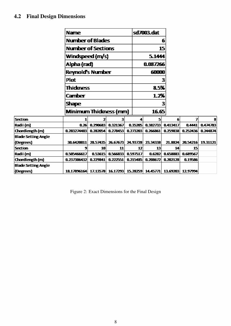
4.2 Final Design Dimensions
Figure 2: Exact Dimensions for the Final Design
8

4.3 Costs
Figure 3: Costs for the Final Design including Two Blade Setting rigs and One Spare Blade
4.4 Models and Drawings : Parts, Rigs and Assemblies
9

10
2
3.1
3
5
5 5
1
1
64.90 48.97
Section One. The remaining sections have then samedesign, only with changing chordlengths and thereforethicknessess.
283.25
3
24.
26
sd7003 AerofoilConnor McDowall
A A
B B
C C
D D
6
6
5
5
4
4
3
3
2
2
1
1
DRAWN
CHK'D
APPV'D
MFG
Q.A
UNLESS OTHERWISE SPECIFIED:DIMENSIONS ARE IN MILLIMETERSSURFACE FINISH:TOLERANCES: LINEAR: ANGULAR:
FINISH: DEBURR AND BREAK SHARP EDGES
NAME SIGNATURE DATE
MATERIAL:
DO NOT SCALE DRAWING REVISION
TITLE:
DWG NO.
SCALE:1:2 SHEET 1 OF 1
A4
WEIGHT:
sect_1
SOLIDWORKS Educational Product. For Instructional Use Only.

SOLIDWORKS Educational Product. For Instructional Use Only.

SOLIDWORKS Educational Product. For Instructional Use Only.

Rotor TurbineConnor McDowall
A A
B B
C C
D D
6
6
5
5
4
4
3
3
2
2
1
1
DRAWN
CHK'D
APPV'D
MFG
Q.A
UNLESS OTHERWISE SPECIFIED:DIMENSIONS ARE IN MILLIMETERSSURFACE FINISH:TOLERANCES: LINEAR: ANGULAR:
FINISH: DEBURR AND BREAK SHARP EDGES
NAME SIGNATURE DATE
MATERIAL:
DO NOT SCALE DRAWING REVISION
TITLE:
DWG NO.
SCALE:1:20 SHEET 1 OF 1
A4
WEIGHT:
turbine
SOLIDWORKS Educational Product. For Instructional Use Only.

Turbine on the rigConnor McDowall
A A
B B
C C
D D
6
6
5
5
4
4
3
3
2
2
1
1
DRAWN
CHK'D
APPV'D
MFG
Q.A
UNLESS OTHERWISE SPECIFIED:DIMENSIONS ARE IN MILLIMETERSSURFACE FINISH:TOLERANCES: LINEAR: ANGULAR:
FINISH: DEBURR AND BREAK SHARP EDGES
NAME SIGNATURE DATE
MATERIAL:
DO NOT SCALE DRAWING REVISION
TITLE:
DWG NO.
SCALE:1:50 SHEET 1 OF 1
A4
WEIGHT:
FinalAssembly
SOLIDWORKS Educational Product. For Instructional Use Only.

100
R110
90
10
Oliver WilsonKevin Jia
A A
B B
C C
D D
E E
F F
4
4
3
3
2
2
1
1
DRAWN
CHK'D
APPV'D
MFG
Q.A
UNLESS OTHERWISE SPECIFIED:DIMENSIONS ARE IN MILLIMETERSSURFACE FINISH:TOLERANCES: LINEAR: ANGULAR:
FINISH: DEBURR AND BREAK SHARP EDGES
NAME SIGNATURE DATE
MATERIAL:
DO NOT SCALE DRAWING REVISION
TITLE:
DWG NO.
SCALE:1:5 SHEET 1 OF 1
A4
WEIGHT:
Appendix A.1: Technical Drawing - Turbine Hub
Page 12 of 25

10
8
Blade Shaft
DRAWN
CHK'D
APPV'D
MFG
Q.A
UNLESS OTHERWISE SPECIFIED:DIMENSIONS ARE IN MILLIMETERSSURFACE FINISH:TOLERANCES: LINEAR: ANGULAR:
FINISH: DEBURR AND BREAK SHARP EDGES
NAME SIGNATURE DATE
MATERIAL:
DO NOT SCALE DRAWING REVISION
TITLE:
DWG NO.
SCALE:1:1 SHEET 1 OF 1
A4
WEIGHT:
A A
B B
C C
D D
E E
F F
4
4
3
3
2
2
1
1Appendix A.2: Technical Drawing - Blade Shaft / Connector
Oliver WilsonKevin Jia
Page 13 of 25

10 648
Blade AssemblyConnor McDowall
A A
B B
C C
D D
6
6
5
5
4
4
3
3
2
2
1
1
DRAWN
CHK'D
APPV'D
MFG
Q.A
UNLESS OTHERWISE SPECIFIED:DIMENSIONS ARE IN MILLIMETERSSURFACE FINISH:TOLERANCES: LINEAR: ANGULAR:
FINISH: DEBURR AND BREAK SHARP EDGES
NAME SIGNATURE DATE
MATERIAL:
DO NOT SCALE DRAWING REVISION
TITLE:
DWG NO.
SCALE:1:10 SHEET 1 OF 1
A4
WEIGHT:
blade_assem
SOLIDWORKS Educational Product. For Instructional Use Only.

3 15
3
13.39
27.68
550
50
Blade Distance Setting ToolConnor McDowall
A A
B B
C C
D D
6
6
5
5
4
4
3
3
2
2
1
1
DRAWN
CHK'D
APPV'D
MFG
Q.A
UNLESS OTHERWISE SPECIFIED:DIMENSIONS ARE IN MILLIMETERSSURFACE FINISH:TOLERANCES: LINEAR: ANGULAR:
FINISH: DEBURR AND BREAK SHARP EDGES
NAME SIGNATURE DATE
MATERIAL:
DO NOT SCALE DRAWING REVISION
TITLE:
DWG NO.
SCALE:1:5 SHEET 1 OF 1
A4
WEIGHT:
Guide
SOLIDWORKS Educational Product. For Instructional Use Only.

15 32
35
3
50
65
Stand for the Blade DistanceSetting Tool
Connor McDowall
A A
B B
C C
D D
6
6
5
5
4
4
3
3
2
2
1
1
DRAWN
CHK'D
APPV'D
MFG
Q.A
UNLESS OTHERWISE SPECIFIED:DIMENSIONS ARE IN MILLIMETERSSURFACE FINISH:TOLERANCES: LINEAR: ANGULAR:
FINISH: DEBURR AND BREAK SHARP EDGES
NAME SIGNATURE DATE
MATERIAL:
DO NOT SCALE DRAWING REVISION
TITLE:
DWG NO.
SCALE:1:1 SHEET 1 OF 1
A4
WEIGHT:
Stand
SOLIDWORKS Educational Product. For Instructional Use Only.

Blade Setting Tool AssemblyConnor McDowall
A A
B B
C C
D D
6
6
5
5
4
4
3
3
2
2
1
1
DRAWN
CHK'D
APPV'D
MFG
Q.A
UNLESS OTHERWISE SPECIFIED:DIMENSIONS ARE IN MILLIMETERSSURFACE FINISH:TOLERANCES: LINEAR: ANGULAR:
FINISH: DEBURR AND BREAK SHARP EDGES
NAME SIGNATURE DATE
MATERIAL:
DO NOT SCALE DRAWING REVISION
TITLE:
DWG NO.
SCALE:1:5 SHEET 1 OF 1
A4
WEIGHT:
GuideAssem
SOLIDWORKS Educational Product. For Instructional Use Only.

4.5 Analysis: A Nine-Step Process
Figure 4: Method of Analysis: A Nine Step Process
5 Fundamental Rotor Theory
See the pdf files on canvas for lectures three to eight covering the fundamental rotor theory. Follow the linkbelow.”https://canvas.auckland.ac.nz/courses/30227/files/folder/Lecture%20Slides?”
5.1 Iterative Scheme
Listing 1: XfoilIteration1 % This Script iterates through all aerofoil designs, trying to find the2 % best combination for one aerofoil type.34 % Convert Airfoil Bank (Toggle via commenting)5 bank = dir('airfoil bank');6 foilnames = bank.name;78 % Set up the good aerofoils (Toggle via commenting)9 good = dir('Good');
10 goodfoils = good.name;1112 % Read adjust names to get the data files13 for i = 1:length(goodfoils)14 temp = strsplit(goodfoilsi,'.');15 goodfoilsi = strcat(convertCharsToStrings(temp(1)),'.dat');16 end1718 % Chosen design (Toggle via Commenting)19 goodfoils = 'sd7003.dat','sd7003.dat','sd7003.dat';2021 % Set the global variables22 global Vu RPM rho torque eta nSections hubRadius B Re ReRange Storage23
21

24 Vu = 10* 0.51444; % Design speed, e.g. 10 knots an hour (Range: 8/10/12knots).
25 RPM = 140; % Target RPM26 rho = 1.29; % Density of air27 torque = 3.25; % Target torque, from datasheet28 eta = 1; % System efficiency29 nSections = 15;30 hubRadius = 0.26; % Radius of hub + any further radius with no blade
allowed31 B = 6; % Number of blades (Set the appropriate number of
blades).32 Re = 60000; % Approximate Reynolds number for design,33 ReRange = 40000:10000:80000;34 Storage = 'H:\ENGSCI 363 BEM\BEM\clcdfigures'; %Storage String Directory3536 % Saving variables37 SheetNum = 2;38 iteration =6;39 Count = 1;40 max = 40;4142 % Create a for loop for setp through evaluate (changed as the design43 % process, currently set up to text final design).44 for i = 3:length(goodfoils)45 disp(goodfoilsi)46 % Call evaluate turbine47 try48 % Create the figure for the aerofoil49 [savefile] = evaluatePlot(foilnamesi);50 % Get parameters fro the aerofoil.51 [˜, design1] = evaluateTurbine(goodfoilsi);52 % Create a Table53 name = goodfoilsi;54 T = table(name,design1.Cp, design1.blades ,design1.nSections,
design1.Windspeed,design1.alpha, design1.Re, design1.r,design1.chord, design1.beta);
55 T(1,:);56 % Save this table to an excel file57 filename = 'FinalIterations.xlsx';58 writetable(T,filename,'Sheet',SheetNum,'Range',strcat('A',
num2str(i+1+iteration*max)), 'WriteVariableNames', false)59 Count = Count + 1;60 catch61 end62 end
Listing 2: evaluateTurbine1 function [obj, design] = evaluateTurbine(varargin)2 % This function evaluates a turbine design, given a set of properties in
a3 % format suitable for optimisation using the metaheuristics code by Yang
.4 % 1 Input: x - either a string that contains the ONE aerofoil type to
22

be5 % used, or else a cell array that contains the aerofoil
type6 % at each cross-section.7 % -- OR --8 % 4 Inputs: for aerofoil information already found from elsewhere9 % Inputs must be in correct order.
10 % 1. x = 1 x n matrix containing the sequence number (1...k)of the
11 % aerofoil to be used at each section. n == nSections12 % 2. CL = 1 x k matrix containing lift coefficient for each of
k13 % aerofoils14 % 3. CD = 1 x k matrix containing drag coefficient at optimal
angle15 % of attack for each of k aerofoils.16 % 4. alpha = 1 x k matrix containing optimal angle of attack
for17 % each of k aerofoils18 % Outputs: obj = objective value of interest, to be defined for the
application.19 % design = structure with turbine design features,
specifically20 % r = cross-sectional radii21 % chord = chord length22 % Cp = power coefficient23 % alpha = angle of attack24 % beta = local twist angles2526 % Connor McDowall cmcd398 5309133862728 % Constants (to go into params)29 global Vu RPM rho torque eta nSections hubRadius B Re30 mach = 0;31 % Extract names if one cell input.32 if nargin == 133 x = varargin1;34 if isa(x, 'cell')35 assert(nSections == length(x))36 else37 x = cellstr(x);38 end3940 % Find the unique items in the cell array41 unique_xfoil = unique(x);42 % Use a loop to step through and the optimum ratios.43 % Initialise alpha values.44 alpha_loop = 0:0.5:15;45 for j = 1:length(unique_xfoil)46 % Call X foil to get alpha, CD and CL of that cell array.47 [pol,˜] = callXfoil(unique_xfoilj,alpha_loop , Re, mach);48 % Find index position of the max ratio49 [˜,i] = max((pol.CL./pol.CD));
23

50 % Save the CD, CL and alpha values of the max CL/CD ratioposition
51 Cdsave = pol.CD(i);52 Clsave = pol.CL(i);53 alphasave = deg2rad(alpha_loop(i));54 % Use a loop to step through the length array and place CD, CL
and55 % alpha values of unique_xfoil of the same type.56 for k = 1:length(x)57 if xk == unique_xfoilj58 Cd(k) = Cdsave;59 Cl(k) = Clsave;60 alpha(k) = alphasave;61 end62 end63 end6465 elseif nargin == 466 % Aerofoil info already pre-generated and is read in.67 x = varargin1;68 assert(nSections == length(x));69 LiftCoeffs = varargin2;70 DragCoeffs = varargin3;71 Alphas = varargin4;7273 Cl = LiftCoeffs(x); % Lift coeff for EACH cross-section74 Cd = DragCoeffs(x); % Drag coeff for EACH cross-section75 alpha = Alphas(x); % angle of attack for each aerofoil at EACH cross
-section76 else77 error("Incorrect number of inputs")78 end7980 % BEM Calculations81 % Establish Power requirement and estimate Cp.82 omega = (RPM.*2.*pi()./60);83 Ps = omega.*torque;84 iterate = true;85 Cp = 0.593; % Benz Limit86 % Create the loop to iterate until Cp converges.87 while iterate == true88 % Calculate the overall rotor radius89 R = sqrt((2.*Ps./(Cp.*eta.*rho.*pi().*Vu.ˆ3)));9091 % Individual Blade Radius, radia of all aerofoil locations.92 rind = linspace(hubRadius, R,nSections) ;9394 % Calculate the individual wind speed ratios, from the centre of the95 % blade96 lambda_ind = (omega.*(rind)./Vu);9798 % Calculate the local wind angle and chord length off each section.99 % This is with wake rotation.
24

100 phiw = (2./3)*atan(1./lambda_ind); % radians101 cwake =((8.*pi().*(rind))./(B.*Cl)).*(1 - cos(phiw));102103 % Calculate the blade setting angles in degrees104 beta = (180./pi).*(phiw- alpha) ;105106 % Calculate the axial induction factors107 % Get the constants108 Cn = Cl.*cos(phiw) + Cd.*sin(phiw);109 Ct = Cl.*sin(phiw) - Cd.*cos(phiw);110 f = ((B*(R - rind))./(2.*(rind).*sin(phiw))); % Check r = Rotor
Radius/ Number of sections111 F = (2./pi()).*acos(exp(-f));112113 % Calculate the blade solidarity114 sigmaprime = (B.*cwake./(2.*pi().*rind));115116 % Axial induction factor117 a = (sigmaprime.*Cn)./(4.*F.*(sin(phiw)).ˆ2 + sigmaprime.*Cn);118119 % Calculate the tangential load at each cross section120 pt = (0.5.*rho.*((Vu.ˆ2).*((1-a).ˆ2)./(sin(phiw).ˆ2))).*Ct.*cwake;121122 % Integrate between sections to find the total torque between the123 % cross sections.124 Q = B.*trapz(rind,pt.*rind);125126 % Find the power extracted and the power available to the wind,
therefore127 % finding the power co-efficient Cp128 Pe = Q.*omega;129 Pt = 0.5.*rho.*pi().*(R.ˆ2).*(Vu.ˆ3);130 Cp_iterate = Pe./Pt;131132 % Control the looping133 if abs(Cp_iterate - Cp)<=eps134 % Reset looping variable if it has converged.135 iterate = false;136 end137 Cp = Cp_iterate;138 end139140 % Store the things in a structure141 % Define the objective function142 obj = Cp;143 % Blade design parameters144 design = struct('r',rind,'chord',cwake,'Cp',Cp,'alpha',alpha,'beta',beta
,'blades',B,'Re',Re,'nSections',nSections,'Windspeed',Vu,'Torque',Q,'Power',Pe,'PowerSystem',Pt);
145 %performance = struct('Reynolds Number',Re,'Wind speed',Vu,'Torgue',Q, 'Power',Pe,'Power Coefficient',Cp);
146 return
25

Listing 3: evaluatePlot1 function [savefile] = evaluatePlot(varargin)2 % This function evaluates the Cl and Cd, given a set of properties in a3 % format suitable for optimisation using the metaheuristics code by Yang
.4 % 1 Input: x - either a string that contains the ONE aerofoil type to
be5 % used, or else a cell array that contains the aerofoil
type6 % at each cross-section.7 % -- OR --8 % 4 Inputs: for aerofoil information already found from elsewhere9 % Inputs must be in correct order.
10 % 1. x = 1 x n matrix containing the sequence number (1...k)of the
11 % aerofoil to be used at each section. n == nSections12 % 2. CL = 1 x k matrix containing lift coefficient for each of
k13 % aerofoils14 % 3. CD = 1 x k matrix containing drag coefficient at optimal
angle15 % of attack for each of k aerofoils.16 % 4. alpha = 1 x k matrix containing optimal angle of attack
for17 % each of k aerofoils18 % Outputs: Location of the saved image for the matlab19 % savefile = File Location of saved image2021 % Connor McDowall cmcd398 53091338622 % Clear Figure23 clf;2425 % Constants (to go into params)26 global nSections ReRange Storage27 mach = 0;28 % Extract names if one cell input.29 if nargin == 130 x = varargin1;31 if isa(x, 'cell')32 assert(nSections == length(x))33 else34 x = cellstr(x);35 end3637 % Find the unique items in the cell array38 unique_xfoil = unique(x);39 % Use a loop to step through and the optimum ratios.40 % Initialise alpha values and legend41 plotLegend = ;42 alpha_loop = 0:1:15;43 for p = 1:length(ReRange)44 for j = 1:length(unique_xfoil)45 % Call X foil to get alpha, CD and CL of that cell array.
26

46 [pol,˜] = callXfoil(unique_xfoilj,alpha_loop , ReRange(p),mach);
47 % Plot the Cl/CD Function in each iteration of the loop.48 plot(pol.alpha,(pol.CL./pol.CD))49 plotLegendp = num2str(ReRange(p));50 hold on51 end52 end5354 %Name and Label plot55 ylabel('Ratio: Cl/Cd')56 xlabel('Alpha (Degrees)')57 split = strsplit(unique_xfoil1,'.');58 foil = strcat(split1,'.png');59 title(split) % Assuming only one aerofoil is passed in.60 legend(plotLegend);61 % Show the figure62 figure(gcf);63 % Save the figure to the current directory.64 savefile = fullfile(Storage, foil);65 saveas(gcf,savefile);6667 else68 error("Incorrect number of inputs")69 end
Listing 4: callXfoil1 function [pol, foil] = callXfoil(coord, alpha, Re, Mach)2 % This function acts as a general interface to xfoil.m by Louis Edelmann
:3 % https://au.mathworks.com/matlabcentral/fileexchange/49706-xfoil-
interface-updated4 %5 % Inputs: coord = coordinates of aerofoil.6 % 3 cases: 1. 'NACAxxxxx' for NACA 4 or 5 digits7 % 2. 'xxxx.dat' for an aerofoil in the
airfoil8 % bank.9 % 3. an n by 2 array of x and y
10 % coordinates.11 % For non NACA cases, 300 panel points are
interpolated to12 % hopefully give convergence. In all cases, max 10013 % iterations are run.14 % alpha = angle(s) of attack to consider Re = Reynold's number
of15 % interest. Mach = Mach number of interest. Typically 0 for16 % non-turbulent flow.17 % Outputs: see xfoil.m18 %19 % This code is supplied with an adapted version of the UIUC Airfoil20 % Database (http://m-selig.ae.illinois.edu/ads/coord_database.html) by21 % Michael Selig. Divahar Jayaraman adapted these to a consistent format
27

in22 % her code for 2D Potential Flows, as found below...23 % http://au.mathworks.com/matlabcentral/fileexchange/12790-panel-method-
based-2-d-potential-flow-simulator24 % This is used by loading the 'airfoil bank' folder into the path when25 % needed.26 %27 % Kevin Jia, UoA EngSci, 2017.2829 if isa(coord, 'char') == true && strcmp(coord(1:4), 'NACA') == true30 % A built in NACA airfoil.31 [pol,foil] = xfoil(coord, alpha, Re, Mach,'PLOP G', 'pane ppar n
300/', 'oper/iter 200');32 elseif isa(coord, 'char') == true && strcmp(coord(length(coord)-3:length
(coord)), '.dat')33 % An aerofoil in the airfoil bank folder.34 addpath('airfoil bank')35 if exist(coord)36 % Import data, first remove heading.37 data = importdata(coord, ' ', 1);38 coordinates = data.data;39 [pol,foil] = xfoil(coordinates, alpha, Re, Mach, 'PLOP G', 'pane
n 300/', 'oper/iter 200');40 else41 error('.dat file does not exist')42 end4344 else45 % 2D array of coordinates46 [pol,foil] = xfoil(coord, alpha, Re, Mach,'PLOP G', 'pane n 200/', '
oper/iter 100');47 end4849 pol = checkPol(pol, alpha);5051 return5253 function polOut = checkPol(polIn, alpha)5455 if length(polIn.alpha) ˜= length(alpha)56 % Lengths do not match, need to do an interpolation for some angle(s
).5758 % Copy structure59 polOut = polIn;60 % Find missing angles61 existingInds = ismember(alpha', polIn.alpha);62 missingInds = ˜ismember(alpha', polIn.alpha);63 needToFind = alpha(missingInds);64 missingLifts = interp1(polIn.alpha, polIn.CL, needToFind);65 missingDrags = interp1(polIn.alpha, polIn.CD, needToFind);6667 allLifts(existingInds) = polIn.CL;
28

68 allLifts(missingInds) = missingLifts;6970 allDrags(existingInds) = polIn.CD;71 allDrags(missingInds) = missingDrags;7273 polOut.CL = allLifts';74 polOut.CD = allDrags';75 polOut.alpha = alpha';7677 else78 polOut = polIn;79 end8081 return
Listing 5: xfoil.m1 function [pol,foil] = xfoil(coord,alpha,Re,Mach,varargin)2 % Run XFoil and return the results.3 % [polar,foil] = xfoil(coord,alpha,Re,Mach,extra commands)4 %5 % Xfoil.exe needs to be in the same directory as this m function.6 % For more information on XFoil visit these websites;7 % http://web.mit.edu/drela/Public/web/xfoil8 %9 % Inputs:
10 % coord: Normalised foil co-ordinates (n by 2 array, of x & y11 % from the TE-top passed the LE to the TE bottom)12 % or a filename of the XFoil co-ordinate file13 % or a NACA 4 or 5 digit descriptor (e.g. 'NACA0012')14 % alpha: Angle-of-attack, can be a vector for an alpha polar15 % Re: Reynolds number (use Re=0 for inviscid mode)16 % Mach: Mach number17 % extra commands: Extra XFoil commands18 % The extra XFoil commands need to be proper xfoil commands19 % in a character array. e.g. 'oper/iter 150'20 %21 % The transition criterion Ncrit can be specified using the22 % 'extra commands' option as follows,23 % foil = xfoil('NACA0012',10,1e6,0.2,'oper/vpar n 12')24 %25 % Situation Ncrit26 % ----------------- -----27 % sailplane 12-1428 % motorglider 11-1329 % clean wind tunnel 10-1230 % average wind tunnel 9 <= standard "eˆ9 method"31 % dirty wind tunnel 4-832 %33 % A flap deflection can be added using the following command,34 % 'gdes flap xhinge yhinge flap_defelction exec'35 %36 % Outputs:37 % polar: structure with the polar coefficients (alpha,CL,CD,CDp,CM,
29

38 % Top_Xtr,Bot_Xtr)39 % foil: stucture with the specific aoa values (s,x,y,UeVinf,40 % Dstar,Theta,Cf,H,cpx,cp) each column corresponds to a
different41 % angle-of-attack.42 % If only one left hand operator is specified, only the polar
will be parsed and output43 %44 % If there are different sized output arrays for the different incidence45 % angles then they will be stored in a structured array, foil(1),foil(2)
...46 %47 % If the output array does not have all alphas in it, that indicates a
convergence failure in Xfoil.48 % In that event, increase the iteration count with 'oper iter ##;49 %50 % Examples:51 % % Single AoA with a different number of panels52 % [pol foil] = xfoil('NACA0012',10,1e6,0.0,'panels n 330')53 %54 % % Change the maximum number of iterations55 % [pol foil] = xfoil('NACA0012',5,1e6,0.2,'oper iter 50')56 %57 % % Deflect the trailing edge by 20deg at 60% chord and run multiple
incidence angles58 % [pol foil] = xfoil('NACA0012',[-5:15],1e6,0.2,'oper iter 150','gdes
flap 0.6 0 5 exec')59 % % Deflect the trailing edge by 20deg at 60% chord and run multiple
incidence angles and only60 % parse or output a polar.61 % pol = xfoil('NACA0012',[-5:15],1e6,0.2,'oper iter 150','gdes flap
0.6 0 5 exec')62 % % Plot the results63 % figure;64 % plot(pol.alpha,pol.CL); xlabel('alpha [\circ]'); ylabel('C_L');
title(pol.name);65 % figure; subplot(3,1,[1 2]);66 % plot(foil(1).xcp(:,end),foil(1).cp(:,end)); xlabel('x');67 % ylabel('C_p'); title(sprintf('%s @ %g\\circ',pol.name,foil(1).alpha
(end)));68 % set(gca,'ydir','reverse');69 % subplot(3,1,3);70 % I = (foil(1).x(:,end)<=1);71 % plot(foil(1).x(I,end),foil(1).y(I,end)); xlabel('x');72 % ylabel('y'); axis('equal');73 %7475 % Some default values76 if ˜exist('coord','var'), coord = 'NACA0012'; end;77 if ˜exist('alpha','var'), alpha = 0; end;78 if ˜exist('Re','var'), Re = 1e6; end;79 if ˜exist('Mach','var'), Mach = 0.2; end;80 Nalpha = length(alpha); % Number of alphas swept
30

81 % default foil name82 foil_name = mfilename;8384 % default filenames85 wd = fileparts(which(mfilename)); % working directory, where xfoil.exe
needs to be86 fname = mfilename;87 file_coord= [foil_name '.foil'];8889 % Save coordinates90 if ischar(coord), % Either a NACA string or a filename91 if isempty(regexpi(coord,'ˆNACA *[0-9]4,5$')) % Check if a NACA
string92 % foil_name = coord; % some redundant code removed to go green ( ˜
isempty if uncommented)93 % else % Filename supplied94 % set coord file95 file_coord = coord;96 end;97 else98 % Write foil ordinate file99 if exist(file_coord,'file'), delete(file_coord); end;
100 fid = fopen(file_coord,'w');101 if (fid<=0),102 error([mfilename ':io'],'Unable to create file %s',file_coord);103 else104 fprintf(fid,'%s\n',foil_name);105 fprintf(fid,'%9.5f %9.5f\n',coord');106 fclose(fid);107 end;108 end;109110 % Write xfoil command file111 fid = fopen([wd filesep fname '.inp'],'w');112 if (fid<=0),113 error([mfilename ':io'],'Unable to create xfoil.inp file');114 else115 if ischar(coord),116 if ˜isempty(regexpi(coord,'ˆNACA *[0-9]4,5$')), % NACA string
supplied117 fprintf(fid,'naca %s\n',coord(5:end));118 else % filename supplied119 fprintf(fid,'load %s\n',file_coord);120 end;121 else % Coordinates supplied, use the default filename122 fprintf(fid,'load %s\n',file_coord);123 end;124 % Extra Xfoil commands125 for ii = 1:length(varargin),126 txt = vararginii;127 txt = regexprep(txt,'[ \\\/]+','\n');128 fprintf(fid,'%s\n\n',txt);129 end;
31

130 fprintf(fid,'\n\noper\n');131 % set Reynolds and Mach132 fprintf(fid,'re %g\n',Re);133 fprintf(fid,'mach %g\n',Mach);134135 % Switch to viscous mode136 if (Re>0)137 fprintf(fid,'visc\n');138 end;139140 % Polar accumulation141 fprintf(fid,'pacc\n\n\n');142 % Xfoil alpha calculations143 [file_dump, file_cpwr] = deal(cell(1,Nalpha)); % Preallocate cell
arrays144145 for ii = 1:Nalpha146 % Individual output filenames147 file_dumpii = sprintf('%s_a%06.3f_dump.dat',fname,alpha(ii));148 file_cpwrii = sprintf('%s_a%06.3f_cpwr.dat',fname,alpha(ii));149 % Commands150 fprintf(fid,'alfa %g\n',alpha(ii));151 fprintf(fid,'dump %s\n',file_dumpii);152 fprintf(fid,'cpwr %s\n',file_cpwrii);153 end;154 % Polar output filename155 file_pwrt = sprintf('%s_pwrt.dat',fname);156 fprintf(fid,'pwrt\n%s\n',file_pwrt);157 fprintf(fid,'plis\n');158 fprintf(fid,'\nquit\n');159 fclose(fid);160161 % execute xfoil162 cmd = sprintf('cd %s && xfoil.exe < xfoil.inp > xfoil.out',wd);163 [status,result] = system(cmd);164 if (status˜=0),165 disp(result);166 error([mfilename ':system'],'Xfoil execution failed! %s',cmd);167 end;168169 % Read dump file170 % # s x y Ue/Vinf Dstar Theta Cf
H171 jj = 0;172 ind = 1;173 % Note that174 foil.alpha = zeros(1,Nalpha); % Preallocate alphas175 % Find the number of panels with an inital run176 only = nargout; % Number of outputs checked. If only one left hand
operator then only do polar177178 if only >1 % Only do the foil calculations if more than one left hand
operator is specificed
32

179 for ii = 1:Nalpha180 jj = jj + 1;181182 fid = fopen([wd filesep file_dumpii],'r');183 if (fid<=0),184 error([mfilename ':io'],'Unable to read xfoil output file %s',
file_dumpii);185 else186 D = textscan(fid,'%f%f%f%f%f%f%f%f','Delimiter',' ','
MultipleDelimsAsOne',true,'CollectOutput',1,'HeaderLines',1);187 fclose(fid);188 delete([wd filesep file_dumpii]);189190 if ii == 1 % Use first run to determine number of panels (so that
NACA airfoils work without vector input)191 Npanel = length(D1); % Number of airfoil panels pulled from
the first angle tested192 % Preallocate Outputs193 [foil.s, foil.x, foil.y, foil.UeVinf, foil.Dstar, foil.Theta,
foil.Cf, foil.H] = deal(zeros(Npanel,Nalpha));194 end195196 % store data197 if ((jj>1) && (size(D1,1)˜=length(foil(ind).x)) && sum(abs(foil(
ind).x(:,1)-size(D1,1)))>1e-6 ),198 ind = ind + 1;199 jj = 1;200 end;201 foil.s(:,jj) = D1(:,1);202 foil.x(:,jj) = D1(:,2);203 foil.y(:,jj) = D1(:,3);204 foil.UeVinf(:,jj) = D1(:,4);205 foil.Dstar(:,jj) = D1(:,5);206 foil.Theta(:,jj) = D1(:,6);207 foil.Cf(:,jj) = D1(:,7);208 foil.H (:,jj)= D1(:,8);209 end;210211 foil.alpha(1,jj) = alpha(jj);212213 % Read cp file214 fid = fopen([wd filesep file_cpwrii],'r');215 if (fid<=0),216 error([mfilename ':io'],'Unable to read xfoil output file %s',
file_cpwrii);217 else218 C = textscan(fid, '%10f%9f%f', 'Delimiter', '', 'WhiteSpace', '',
'HeaderLines' ,3, 'ReturnOnError', false);219 fclose(fid);220 delete([wd filesep file_cpwrii]);221 % store data222 if ii == 1 % Use first run to determine number of panels (so that
NACA airfoils work without vector input)
33

223 NCp = length(C1); % Number of points Cp is listed for pulledfrom the first angle tested
224 % Preallocate Outputs225 [foil.xcp, foil.cp] = deal(zeros(NCp,Nalpha));226 foil.xcp = C1(:,1);227 end228 foil.cp(:,jj) = C3(:,1);229 end;230 end;231 end232233 if only <= 1% clear files for default run234 for ii=1:Nalpha % Clear out the xfoil dump files not used235 delete([wd filesep file_dumpii]);236 delete([wd filesep file_cpwrii]);237 end238 end239240 % Read polar file241 %242 % XFOIL Version 6.96243 %244 % Calculated polar for: NACA 0012245 %246 % 1 1 Reynolds number fixed Mach number fixed247 %248 % xtrf = 1.000 (top) 1.000 (bottom)249 % Mach = 0.000 Re = 1.000 e 6 Ncrit = 12.000250 %251 % alpha CL CD CDp CM Top_Xtr Bot_Xtr252 % ------ -------- --------- --------- -------- -------- --------253 fid = fopen([wd filesep file_pwrt],'r');254 if (fid<=0),255 error([mfilename ':io'],'Unable to read xfoil polar file %s',
file_pwrt);256 else257 % Header258 % Calculated polar for: NACA 0012259 P = textscan(fid,' Calculated polar for: %[ˆ\n]','Delimiter',' ','
MultipleDelimsAsOne',true,'HeaderLines',3);260 pol.name = strtrim(P11);261 % xtrf = 1.000 (top) 1.000 (bottom)262 P = textscan(fid, '%*s%*s%f%*s%f%s%s%s%s%s%s', 1, 'Delimiter', ' ',
'MultipleDelimsAsOne', true, 'HeaderLines', 2, 'ReturnOnError',false);
263 pol.xtrf_top = P1(1);264 pol.xtrf_bot = P2(1);265 % Mach = 0.000 Re = 1.000 e 6 Ncrit = 12.000266 P = textscan(fid, '%*s%*s%f%*s%*s%f%*s%f%*s%*s%f', 1, 'Delimiter', '
', 'MultipleDelimsAsOne', true, 'HeaderLines', 0, 'ReturnOnError', false);
267 pol.Re = P2(1) * 10ˆP3(1);268 pol.Ncrit = P4(1);
34

269270 % data271 P = textscan(fid, '%f%f%f%f%f%f%f%*s%*s%*s%*s', 'Delimiter', ' ', '
MultipleDelimsAsOne', true, 'HeaderLines' , 4, 'ReturnOnError',false);
272 fclose(fid);273 delete([wd filesep file_pwrt]);274 % store data275 pol.alpha = P1(:,1);276 pol.CL = P2(:,1);277 pol.CD = P3(:,1);278 pol.CDp = P4(:,1);279 pol.Cm = P5(:,1);280 pol.Top_xtr = P6(:,1);281 pol.Bot_Xtr = P7(:,1);282 end283 if length(pol.alpha) ˜= Nalpha % Check if xfoil failed to converge284 warning('One or more alpha values failed to converge. Last
converged was alpha = %f. Rerun with ''oper iter ##'' command.\n', pol.alpha(end))
285 end286287 end
5.2 Complete Enumeration
Over 1000 plots were generated. Below is a very small subset to illustrate the concept.
35

(a) ag12 (b) mh200
(c) stcyr234 (d) vr11x
(e) fx83w108 (f) giiid
(g) rhodesg36 (h) tsagi12
Figure 5: A Small Subset of the Plots generated during Complete Enumeration
36

5.3 Stage One Selection
Figure 6: 37 Selected Aerofoils
37

5.4 Blade and Section Iteration
(a) One set of changing the Number of Blades with a Fixed Number of Sections
(b) One set of changing the Number of Sections with a Fixed Number of Blades
Figure 7: One third of all iterations
38

5.5 Manufacturing Considerations
Figure 8: Evaluation of Manufacturing Considerations
39

5.6 Final Selection
(a) sd7003 plot of CL/CD ratios with margins for changing alpha and Reynold’s numbers
(b) sd7003 Profile Design
Figure 9: sd7003 Plot and Shape
40