Landing Site Detection for Autonomous Rotor Wing UAVs ...
14
Vol.:(0123456789) 1 3 https://doi.org/10.1007/s10846-021-01544-6 REGULAR PAPER Landing Site Detection for Autonomous Rotor Wing UAVs Using Visual and Structural Information Evangelos Chatzikalymnios 1 · Konstantinos Moustakas 1 Received: 14 April 2021 / Accepted: 27 November 2021 © The Author(s) 2022 Abstract The technology of unmanned aerial vehicles (UAVs) has increasingly become part of many civil and research applications in recent years. UAVs offer high-quality aerial imaging and the ability to perform quick, flexible and in-depth data acquisi- tion over an area of interest. While navigating in remote environments, UAVs need to be capable of autonomously landing on complex terrains for security, safety and delivery reasons. This is extremely challenging as the structure of these terrains is often unknown, and no prior knowledge can be leveraged. In this study, we present a vision-based autonomous landing system for rotor wing UAVs equipped with a stereo camera and an inertial measurement unit (IMU). The landing site detec- tion algorithm introduces and evaluates several factors including terrain’s flatness, inclination and steepness. Considering these features we compute map metrics that are used to obtain a landing-score map, based on which we detect candidate landing sites. The 3D reconstruction of the scene is acquired by stereo processing and the pose of the UAV at any given time is estimated by fusing raw data from the inertial sensors with the pose obtained from stereo ORB-SLAM2. Real-world trials demonstrate successful landing in unknown and complex terrains such as suburban and forest areas. Keywords Unmanned aerial vehicles · Autonomous landing · Vision-based · Stereo processing 1 Introduction In the past decades the use of rotor wing UAVs has increased in the context of many modern civil applica- tions, including wireless coverage, delivery, precision agriculture, search and rescue. Lately, UAVs are designed to work cooperatively with Unmanned Ground Vehicles (UGVs) to improve safety in navigation, path planning, data delivery. Furthermore, UAVs equipped with sensors such as optical and thermal cameras, radars and IMUs are life- saving technologies that can provide medical aid to remote regions and support the identification of survivors in cases of emergency. Due to the many diverse applications of UAVs, the study of autonomous landing needs to consider multiple factors and constraints for the development of versatile, robust, and practical autonomous landing systems. Spe- cifically, landing research needs to acknowledge issues such as: Control without Global Positioning System (GPS) Signal UAVs often need to operate in GPS-denied or weak signal environments. If the on-board GPS signal receiver malfunc- tions, drones lose their navigation and positioning estimate, and thereby fail to land safely. Besides, GPS signal accuracy can be affected by various factors. In particular, weather con- ditions can quickly reduce signal power while electromag- netic interference such as radio and magnetic fields generate different levels of interference. Furthermore, GPS signals are weak under tunnels, vehicles, forests, metal components, and tall buildings with high density. Therefore, it is essential to study the autonomous landing strategies for drones without GPS signals. Landing in case of Emergency Drones navigate and per- form tasks in mostly unknown and variegated environments. When severe failures occur, UAVs probably lose contact with the ground. In such cases, they should be able to auton- omously detect landing sites for an emergency landing. It is crucial to forestall the drone from falling into densely popu- lated areas and protect it from significant damage. Hence, it * Konstantinos Moustakas [email protected] Evangelos Chatzikalymnios [email protected] 1 Department of Electrical and Computer Engineering, University of Patras, Patras, Greece / Published online: 22 January 2022 Journal of Intelligent & Robotic Systems (2022) 104: 27
-
Upload
khangminh22 -
Category
Documents
-
view
2 -
download
0
Transcript of Landing Site Detection for Autonomous Rotor Wing UAVs ...

Vol.:(0123456789)1 3
https://doi.org/10.1007/s10846-021-01544-6
REGULAR PAPER
Landing Site Detection for Autonomous Rotor Wing UAVs Using Visual and Structural Information
Evangelos Chatzikalymnios1 · Konstantinos Moustakas1
Received: 14 April 2021 / Accepted: 27 November 2021 © The Author(s) 2022
AbstractThe technology of unmanned aerial vehicles (UAVs) has increasingly become part of many civil and research applications in recent years. UAVs offer high-quality aerial imaging and the ability to perform quick, flexible and in-depth data acquisi-tion over an area of interest. While navigating in remote environments, UAVs need to be capable of autonomously landing on complex terrains for security, safety and delivery reasons. This is extremely challenging as the structure of these terrains is often unknown, and no prior knowledge can be leveraged. In this study, we present a vision-based autonomous landing system for rotor wing UAVs equipped with a stereo camera and an inertial measurement unit (IMU). The landing site detec-tion algorithm introduces and evaluates several factors including terrain’s flatness, inclination and steepness. Considering these features we compute map metrics that are used to obtain a landing-score map, based on which we detect candidate landing sites. The 3D reconstruction of the scene is acquired by stereo processing and the pose of the UAV at any given time is estimated by fusing raw data from the inertial sensors with the pose obtained from stereo ORB-SLAM2. Real-world trials demonstrate successful landing in unknown and complex terrains such as suburban and forest areas.
Keywords Unmanned aerial vehicles · Autonomous landing · Vision-based · Stereo processing
1 Introduction
In the past decades the use of rotor wing UAVs has increased in the context of many modern civil applica-tions, including wireless coverage, delivery, precision agriculture, search and rescue. Lately, UAVs are designed to work cooperatively with Unmanned Ground Vehicles (UGVs) to improve safety in navigation, path planning, data delivery. Furthermore, UAVs equipped with sensors such as optical and thermal cameras, radars and IMUs are life-saving technologies that can provide medical aid to remote regions and support the identification of survivors in cases of emergency.
Due to the many diverse applications of UAVs, the study of autonomous landing needs to consider multiple factors and constraints for the development of versatile,
robust, and practical autonomous landing systems. Spe-cifically, landing research needs to acknowledge issues such as:
Control without Global Positioning System (GPS) Signal UAVs often need to operate in GPS-denied or weak signal environments. If the on-board GPS signal receiver malfunc-tions, drones lose their navigation and positioning estimate, and thereby fail to land safely. Besides, GPS signal accuracy can be affected by various factors. In particular, weather con-ditions can quickly reduce signal power while electromag-netic interference such as radio and magnetic fields generate different levels of interference. Furthermore, GPS signals are weak under tunnels, vehicles, forests, metal components, and tall buildings with high density. Therefore, it is essential to study the autonomous landing strategies for drones without GPS signals.
Landing in case of Emergency Drones navigate and per-form tasks in mostly unknown and variegated environments. When severe failures occur, UAVs probably lose contact with the ground. In such cases, they should be able to auton-omously detect landing sites for an emergency landing. It is crucial to forestall the drone from falling into densely popu-lated areas and protect it from significant damage. Hence, it
* Konstantinos Moustakas [email protected]
Evangelos Chatzikalymnios [email protected]
1 Department of Electrical and Computer Engineering, University of Patras, Patras, Greece
/ Published online: 22 January 2022
Journal of Intelligent & Robotic Systems (2022) 104: 27

1 3
is necessary that they can choose safe landing sites following autonomous landing strategies [1, 2].
The rest of this paper is organized as follows: In Section 2 we present a background overview of previous studies in vision-based autonomous landing. In Section 3 we introduce the proposed system modules and in Section 4 we analyze our vision-based algorithm for detecting candidate landing sites in unknown, GPS-denied environments. In Section 5 we evaluate the performance of the algorithm experimentally in non-trivial outdoor landing scenarios. Finally, in Section 6 we summarize our results and discuss the conclusions.
2 Related Work
Autonomous landing has long been standing as an impor-tant challenge for UAVs. Inertial Navigation System (INS) and Global Navigation Satellite System (GNSS) are the traditional sensors of the navigation system. However, INS accumulates errors during the integration of the posi-tion and velocity of the vehicle, and the GNSS often fails when buildings occlude satellites. Vision-based landing has become attractive because it is passive and does not require any special equipment other than an optical camera (com-monly already mounted on the vehicle) and an on-board processing unit. The problem of safe and accurate landing using vision-based algorithms has been well studied. Over the last decade, a wide range of vision-based, landing site detection approaches for UAVs have been proposed. These techniques can be classified either as methods that employ markers for landing at known locations or as methods that evaluate multiple surface and terrain characteristics for land-ing in unknown environments.
2.1 Landing on a Known Area
In the first category of approaches, markers are detected based on their appearance or geometry using traditional image features, and then the relative pose of the UAV is computed from these extracted feature points. Over the years, several types of markers have been proposed for this purpose including point markers [3, 4], circle markers [5], H-shaped markers [6, 7], square markers [8] and ArUco markers [9, 13]. These approaches require the landing site to be predestined and are not employable in unstructured or unfamiliar environments.
Patruno et al. [10] presents a vision-based helipad detec-tion algorithm to estimate the altitude of a drone, on which the camera is mounted, with respect to the target. The method is based on curvatures to detect the helipad’s corners and compute the homography matrix containing the relative pose information.
Yang et al. [11] propose an onboard monocular vision system for autonomous take-off, hovering and landing. The solution to six Degrees of Freedom (DOF) pose estimation is based on a single image of a typical landing pad which consists of the letter “H” surrounded by a circle. A greater circle radius would lead to a larger working distance for the vision system, but would lead to a larger “blind” range, in which the camera cannot observe the circle. The authors treat this as a sign detection problem and solve it similarly as in [12] by binarization of the camera image, finding con-nected components, and then classifying connected compo-nents using an artificial neural network.
Lebedev et al. [13] presents a combination of two algo-rithms for on-image search and accurate landing on an ArUco marker. When the marker appears in the acquired image, it’s characteristics are revealed and the algorithm estimates the orientation and position of the marker and the distance from the observing vehicle.
Yu et al. [14] deal with the problem of landmark detec-tion utilizing deep learning. The authors present a modified SqueezeNet architecture into the Yolo scheme to develop a simplified CNN for detecting landmarks. Additionally, a sep-arative implementation strategy that leverages the complex CNN training and the instant CNN detection is presented.
2.2 Landing on Unstructured Area
Pluckter et al. [15] propose a method using a downward-facing fish-eye lens camera to accurately land a UAV from the position that took off. This approach aims to land on an unstructured surface using a position estimate relative to the take-off path of the drone to guide the drone back. The method is inspired by Visual Teach and Repeat [16], where the take-off is the teach pass and the landing is the repeat pass. Fraczek et al. [17] presents an embedded Vision sys-tem for automated drone landing site detection. The method comprises four modules. Initially, a Support-vector machine (SVM) classification method is used to identify the type of ground beneath the drone. Afterwards, binarization and thresholding are employed to extract shadowed areas. Such areas provide poor information about their type and indicate the presence of obstacles nearby. Finally, the output data from individual modules and information about the reach-ability of each site are fused to evaluate the most appropriate landing site.
Yang et al. [18] presents an autonomous monocular vision-based UAV landing system for use in emergencies and unstructured environments. The authors suggest a novel map representation approach that utilizes three-dimensional features extracted from Simultaneous Localization And Mapping (SLAM) to construct a grid-map with different heights. Therefore, a region segmentation algorithm is performed to divide the map according to the height. The
27 Page 2 of 14 Journal of Intelligent & Robotic Systems (2022) 104: 27

1 3
proposed system gains an understanding of the height dis-tribution of the ground and the obstacle information to a certain extent and subsequently collects the landing area suitable for the UAV. Similarly, Forster et al. [19] propose a system for mapping the local ground environment under-neath a UAV equipped with a single camera. The authors use semi-direct visual odometry (SVO) algorithm to estimate the current UAV’s pose given the image stream from the single downward-looking camera. However, with a single camera, the relative camera motion can be obtained only up to an unknown scale factor. Therefore, to align the pose cor-rectly with the gravity vector and to estimate the scale of the trajectory, the authors fuse the output of SVO with the data coming from the onboard IMU. Afterwards, they compute depth estimates with a modified version of the Regularized Modular Depth Estimation (REMODE) algorithm [20]. The generated depth maps are then used to incrementally update a 2D robot-centric elevation map [21].
Johnson et al. [22] propose a Lidar-based approach in which an elevation map is computed from Lidar measure-ments, followed by thresholding the regions based on local slope and roughness of the terrain. Hinzmann et al. [23] present a landing site detection algorithm for autonomous planes. Initially, the authors employ a binary random for-est classifier to identify grass areas. They extract the most promising landing regions on which hazardous factors such as terrain roughness, slope and the proximity to obstacles are computed to determine the safest landing point.
Mittal et al. [24] present a vision-based autonomous land-ing system for UAV mounted with an IMU and RGB-D cam-era. The method consists of a detection algorithm, a pose estimation by fusing IMU, GPS and SLAM data and two 3D map representations of the environment, an occupancy grid for its navigation and planning, and a textured 3D mesh for visualization. The detection algorithm considers several hazardous terrain factors to compute a weighted cost-map based on which dense candidate landing sites are detected. During the landing procedure, the UAV plans a trajectory to the selected site and initiates the landing manoeuvre. To compute the landing trajectory the authors use a minimum-jerk trajectory generator with non-linear optimization. The algorithm first discovers a collision-free path to the landing position using the Rapidly-exploring Random Tree (RRT*) algorithm, followed by generating way-points from the opti-mal route according to a line-of-sight technique.
2.3 Contribution
The techniques in [11, 19] employ SLAM mapping to detect such sites. The main drawback with these methods is that the acquired point cloud is sparse. Moreover, the constructed map corresponds to features extracted from the sequence of frames. Thus, the map consists of points that refer to edges, corners
and points with intensity discontinuities in general. These points illustrate the characteristics of the 3D structure of the scene, but they also provide poor information about uniform, low-contrast surfaces. Thus, a more dense 3D reconstruction of the scene would be highly informative. In [23] the method requires the existence of grass region to land on and in [22] the method is focused on detecting safe landing sites on collapsed buildings for search and rescue. In addition, the effectiveness of the method presented in [17] is highly dependent on the pixel classification module and the machine learning model training. Thus, when operating in a varying environment with unfamiliar terrain, its efficiency may be affected.
On contrast to the aforementioned techniques, the approach presented in this paper utilize only structural infor-mation to accurately detect safe landing sites in completely unknown and multiform environments.
In this work, we employ several terrain factors to deter-mine the safest landing site, using only a stereo camera and an IMU. The 3D reconstruction of the scene is acquired by stereo processing and the pose of the UAV is estimated by fusing raw data from the inertial sensors with the pose obtained from stereo ORB-SLAM2 [25]. We utilize the scene’s disparity map and point cloud representation to eval-uate the terrain factors and quantify them into map-metrics [26]. These metrics are used to produce a landing-score map of the scene, based on which we detect candidate landing sites.
More precisely the contribution of our method can be summarized in the following.
– Update of the flatness and steepness map-metrics pro-posed in [22] and introduction of two novel map-metrics, the inclination and depth-variance metrics. This com-bination leads to more well-rounded perception of the terrains characteristics.
– Introduction of a novel landing-score map based on a Bayesian method. We classify the points of the scene into three classes depending on their landing potential. The most promising landing regions are identified and grouped into clusters to later determine the safest landing site.
Finally, we evaluate the performance of our system in dif-ferent environments such as forest regions with dense veg-etation, steep cliffs, stairs and varying altitude, using both a versatile dataset and real-world experiments.
3 System Overview and Preliminaries
In this section we present the overview of the proposed system and we introduce the individual modules. The autonomous landing system overview is presented in
Page 3 of 14 27Journal of Intelligent & Robotic Systems (2022) 104: 27

1 3
Fig. 1. The UAV’s pose is continuously estimated by fusing the poses obtained from stereo ORB-SLAM2 with the raw data from the inertial measurement unit (IMU) using an Unscented Kalman Filter (UKF) as described in Section 3.1. When autonomous landing is required a stereo image pair captured from the stereo camera beneath the UAV is utilized to obtain a 173D reconstruc-tion of the current scene (Section 3.2). The computed reconstruction is used to evaluate some crucial terrain’s properties such as flatness, steepness and inclination. These properties are quantified into map-metrics that lead to a landing-score map based on a Bayesian method as explained in Section 4. The region in the image-frame with the higher landing-score is considered as the most appropriate site for landing. Finally, we combine the landing site’s position in the local camera frame with the pose of the UAV obtained by the sensor-fusion pro-cedure to calculate the position of the landing site in the global frame.
To make the paper self-contained, we briefly present the pose estimation method in Section 3.1 and the equations related to the point cloud 3D reconstruction in Section 3.2.
3.1 Pose Estimation
We estimate the current pose of the UAV using stereo ORB_SLAM2. Since we use a stereo configuration in our system, the pose estimated from ORB-SLAM2 is in absolute scale. However, to further improve the accu-racy of the estimated pose, we fuse the output from the ORB_SLAM2 system with data from the on-board IMU of the guidance system. No GPS information is used as we assume that the UAV can operate in completely GPS-denied environments. In our system configuration, the image focal plane of the down-looking stereo camera is considered to be parallel to the ground underneath. So, the landing trajectory is simplified by moving the UAV above the landing point and then landing it vertically
below. If an appropriate landing point cannot be identi-fied, the UAV will move to a neighbouring location, and repeat the procedure until a safe landing point is identified. Through the whole process, the UAV pose is published on the image frame and it is encoded in global/world coordinates.
State Model The simplest model that can be used to esti-mate and predict the motion of the UAV in the x,y-axis is a linear model of second-order translational dynamics.
Here, x[n]�Rn is the state vector and u[n]�Rk is the control vector in sample n. We assume that , � = �.
To improve the UAV state estimation for nonlinear motion, a different model is required.
Here, x0[n]
= (x, y)T[n]
is the x-y axis position of the UAV in the global coordinate system. �[n] is the UAV yaw, v[n] is its scalar velocity, and �t is the time difference which is estimated as 1/v, where v is the frequency of the IMU.
Extended Kalman Filter (EKF) is widely used in sensor-fusion applications [27, 28]. In our work we utilize a UKF instead of EKF. The UKF represents the derivative-free (no explicit Jacobian or Hessian calcu-lation are necessary) alternative to EKF and provides superior performance at an equivalent computational complexity. A central and vital operation performed in the Kalman Filter is the propagation of a Gaussian random variable (GRV) through the system dynamics. In the EKF, the state distribution is approximated by a GRV, which is then propagated analytically through the
(1)x[n+1] =Ax[n] + Bu[n]
y[n+1] =Cy[n] + Du[n]
(2)
x0[n+1]
=x0[n]
+ x0[n]�t
�[n+1] =�[n] + �[n]�t
x0[n+1]
=
(cos�[n+1]
sin�[n+1]
)V[n+1]
Fig. 1 System Overview: Stereo ORB_SLAM2 continuously estimates the pose of the camera and a map of the environment. Using a UKF we fuse the ORB_SLAM2 measurements with IMU data to further improve the accuracy of the estimated pose. When landing is needed, the stereo images of the current scene are captured, inserted as input in the landing algorithm, which outputs the most appro-priate site for landing on the image frame
27 Page 4 of 14 Journal of Intelligent & Robotic Systems (2022) 104: 27
1 3
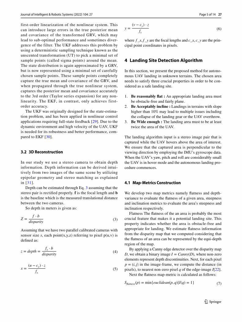
where f_x, f_y are the focal lengths and c_x, c_y are the prin-cipal point coordinates in pixels.
4 Landing Site Detection Algorithm
In this section, we present the proposed method for autono-mous UAV landing in unknown terrains. The chosen area needs to satisfy three crucial properties in order to be con-sidered as a safe landing site.
1. Be reasonably flat : An appropriate landing area must be obstacle-free and fairly plane.
2. Be Acceptably incline : Landings in terrains with slope higher than 10% may lead to multiple issues including the collapse of the landing gear or the UAV overthrow.
3. Be Wide enough : The landing area must to be at least twice the area of the UAV.
The landing algorithm input is a stereo image pair that is captured while the UAV hovers above the area of interest. We ensure that the captured area is perpendicular to the viewing direction by employing the IMU’s gyroscope data. When the UAV’s yaw, pitch and roll are considerably small the UAV is in hover mode and the autonomous landing pro-cedure commences.
4.1 Map‑Metrics Construction
We develop two map metrics namely flatness and depth-variance to evaluate the flatness of a given area, steepness and inclination metrics to evaluate the area’s steepness and inclination respectively.
Flatness The flatness of the an area is probably the most crucial feature that makes it a potential landing site. This property indicates whether the area is obstacle-free and appropriate for landing. We estimate flatness information from the disparity map that we computed considering that the flatness of an area can be represented by the equi-depth region of the map.
By applying a Canny edge detector over the disparity map D, we obtain a binary image I = Canny(D) , where non-zero elements represent depth discontinuities. Next, for each pixel p = (i, j) in the image-frame, we compute the distance (in pixels), to nearest non-zero pixel q of the edge-image I[22].
Next the flatness map-metric is calculated as follows:
(6)y =(v − cy) ⋅ z
fy
(7)Sflatness(p) = min{euclidean(p, q)|I(q) = 1}
first-order linearization of the nonlinear system. This can introduce large errors in the true posterior mean and covariance of the transformed GRV, which may lead to sub-optimal performance and sometimes diver-gence of the filter. The UKF addresses this problem by using a deterministic sampling technique known as the unscented transformation (UT) to pick a minimal set of sample points (called sigma points) around the mean. The state distribution is again approximated by a GRV, but is now represented using a minimal set of carefully chosen sample points. These sample points completely capture the true mean and covariance of the GRV, and when propagated through the true nonlinear system, captures the posterior mean and covariance accurately to the 3rd order (Taylor series expansion) for any non-linearity. The EKF, in contrast, only achieves first-order accuracy.
The UKF was originally designed for the state-estima-tion problem, and has been applied in nonlinear control applications requiring full-state feedback [29]. Due to the dynamic environment and high velocity of the UAV, UKF is needed for its robustness and better performance, com-pared to EKF [30].
3.2 3D Reconstruction
In our study we use a stereo camera to obtain depth information. Depth information can be derived intui-tively from two images of the same scene by utilizing epipolar geometry and stereo matching as explained in [31].
Depth can be estimated through Eq. 3 assuming that the stereo pair is rectified properly. f is the focal length and b is the baseline which is the measured translational distance between the two cameras.
So depth in meters is given as:
Assuming that we have two parallel calibrated cameras with sensor size s, each point(x,y,z) referring to pixel p(u,v) is defined as:
(3)Z =
f ⋅ b
disparity
(4)z = depth =
fx ⋅ b
disparity
(5)x =(u − cx) ⋅ z
fx
Page 5 of 14 27Journal of Intelligent & Robotic Systems (2022) 104: 27

1 3
Depth Variance The flatness map metric performance is reli-ant on the Canny filter parameters. Depending on the scene’s terrain this map metric may be sensitive to false-positive flatness identification. To smooth out this effect we com-bine the flatness map metric with a second flatness-oriented metric computed directly from the disparity map, without any pre-possessing step. We consider that flatness can be expressed by the variance of the disparity values in a por-tion of the disparity map. We have mentioned that dispar-ity is inversely proportional to depth. Thus, higher standard deviation indicates areas with depth discontinuities. The depth variance map-metric pixels correspond to the stand-ard deviation of a fixed window with centre the counterpart pixel in the disparity map.
Around each pixel p = (i, j) in the image plane, we apply a fixed window and compute the standard deviation of the included pixel values. The Depth Variance map-metric is calculated as follows:
Inclination Terrain’s flatness only, is not adequate to ensure a safe landing procedure. An area with a flat surface can also be so inclined, that landing on it may not be considered as stable or secure. We employ the principal curvatures to determine the inclination of a region under examination. Principal Component Analysis (PCA) is applied on a surface patch of normals to estimate these parameters. We use the same KdTree for the normal and curvature estimation and a curvature score is given to each pixel.
Around each pixel p = (i, j) in the image plane, princi-pal curvature in the z-axis (pc_z) and the corresponding max eigenvalue of curvature (max _c) is computed. Later, the inclination map-metric is calculated as follows:
Steepness Another feature of great importance is the steep-ness of the area around the candidate landing region. Steep-ness is a feature that can’t be derived directly from the disparity map. In that case, we need to convert the depth information into a point cloud using Eqs. 4, 5, 6. Next, we filter the point cloud from outliers and compute the point cloud normals. Point cloud normals are the most reliable sources of information about the steepness of the surface in a specific area.
For each pixel p in the calculated disparity map we find the corresponding point in the generated pointcloud and we compute the angle between the normalized surface nor-mal n and the z-axis vector in the global frame using the vector dot product as [22]:
(8)Sdvar = e−std2
(9)Sinclination = exp
�−
√�max _c�√�pc_z�
�
The steepness score for each pixel p is the calculated as:
4.2 Bayesian Classification of Landing Points
After evaluating the individual map-metrics, we perform min-max normalization over flatness, depth-variance, inclination and steepness map-metrics to scale their values to the same range and remove any biases. At this point the following ques-tion arise: Is there any site in the current scene where the UAV can safely land on? To answer this question we classify the scene points into possible and not possible landing sites. We start with the division of the set of scene points viewed in the left stereo image �o into the following two subsets.
1. 𝛺a ⊂ 𝛺o : The set of scene points appropriate for land-ing
2. 𝛺r ⊂ 𝛺o : The set of scene points which are potential but risky landing sites
3. 𝛺n ⊂ 𝛺o : The set of scene points not suitable for land-ing
For this task a Bayesian method is proposed based on the constructed map-metrics and the selection of the following hypothesis.
Where s in the point of the point cloud corresponding to pixel n = (i, j) . According to the Bayes decision test, hypoth-esis Ha will be selected if
where ra(s,�a) is the average cost of accepting hypothesis Ha and can be defined as follows :
where Gia is the cost of accepting Ha when is true, p(s,Hi) is the mutual probability of s and Hi , and N is the num-ber of the possible landing classes. It is very reasonable to assume that Gaa = Grr = Gnn = 0 (zero cost for proper classification) and Kn ∗ Gna = Kr ∗ Grn = Gan (with con-stants Kn > Kr > 1 ), since erroneous classifications for non-appropriate landing sites is more noxious than erroneous
(10)𝜃 = cos(n, z)−1
(11)Ssteepness = e−�2
Ha ∶ point s is an appropriate landing site
Hr ∶ point s is a potential yet risky landing site
Hn ∶ point s is not an appropriate landing site
(12)ra(s,𝛺a) < rr(s,𝛺r) < rn(s,𝛺n)
(13)ra(s,�a) =
N∑
i=1
Giap(s,Hi) =
N∑
i=1
Giap(s|Hi)p(Hi)
27 Page 6 of 14 Journal of Intelligent & Robotic Systems (2022) 104: 27
1 3
classification for the risky and appropriate sites. Adopting the Maximum-likelihood (ML) criterion and assuming that p(Hi) = 1∕N = 1∕3 , Eq. 13 is trivially seen to be minimized if the hypothesis Ha is selected when
Therefore, all the information regarding the hypothe-sis selection is inserted in the formula of the probability p(n|Hi) . To model this probability we exploit the map-metrics (m) values, calculated in the previous step. Those metrics are considered as the features that we will use to determine the conditional probabilities. Assuming that the features are independent the probabilities can be written as :
Where, Nm is the number of map-metrics and f (x;�) is the probability density function (pdf) of an exponential distribution.
As already mentioned the map-metrics values x are post-normalized to be in the same range [0-1]. Thus, when we evaluate the p(n|Hn) probability we use the x as input. On the other hand, when we evaluate the p(n|Ha) and p(n|Hr) , the value 1-x is used.
4.3 Landing Sites Decision
To determine the best landing site, we define a set of candi-date landing point 𝛺c ⊂ 𝛺a . A landing-score map is con-structed based on the previous Bayesian method. For every potential landing point in image-frame that occurs in Eq. 14, we assign a landing score using the formula presented in Eq. 15. Next the map’s values are scaled to the same range using min-max normalization. The points of the normalized map with values higher than 0.5 constitute the candidate landing point �c.
Consequently a k-means clustering algorithm is applied over the candidate point set to extract the dense landing sites among the scene. The clustering algorithm takes into consideration both candidate’s position (X,Y,Z) and normal vector. The points are initially organized into a KdTree for finding the nearest neighbors and the points with normals in approximately the same direction may be joined into the cluster [32]. The centroid of the biggest cluster is considered as the safest landing site and the corresponding point in the pointcloud is identified. It’s coordinates in the image-frame and the UAV’s current pose are combined to determine the
(14)p(s|Ha) > Kr ∗ p(s|Hr) > Kn ∗ p(s|Hn)
(15)p(n|Hi) =
Nm∏
i=1
f (mi(n);�)
(16)f (x;𝜆) =
{𝜆e−(𝜆x) x ≥ 0,
0 x < 0.
landing sites word-coordinates which are finally forwarded to the flight-controller.
Before starting landing procedure, we check the size of the landing area. We compute the convex hull of the domi-nant cluster and calculate the convex hull area. If the space is larger than twice the area of the UAV, it is considered acceptably wide and landing is allowed.
The aforementioned procedure is demonstrated in Algorithm 1.
5 Experimental Evaluation
We evaluate the utility of our system using a multifaceted dataset and extensive experiments in real-world environ-ments. We use DJI Matrice 100 with mounted DJI guidance system. Guidance’s IMU scalar velocity and orientation data are fused with ORB_SLAM’s measurements for the UAV pose estimation. Additionally, Guidance’s bottom ste-reo camera is utilized for the disparity map generation and the scene 3D Reconstruction. The stereo camera produces grayscale images with a resolution of 320 x 240 pixels at 20Hz. Furthermore we use Raspberry Pi 4 as the embed-ded computational unit. We use Robotic Operating System
Page 7 of 14 27Journal of Intelligent & Robotic Systems (2022) 104: 27

1 3
(ROS) as the middleware on the Raspberry Pi 4 which runs all the processes for sensor processing, state estimation, sen-sor fusion and landing site detection.
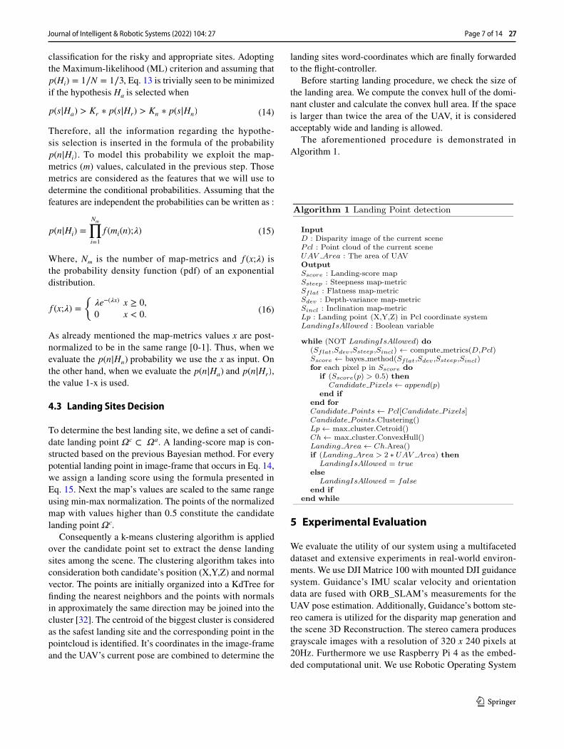
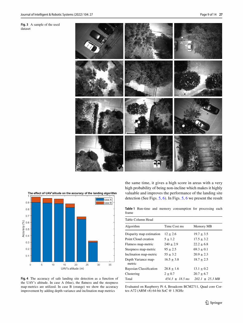
A versatile dataset acquisition is significant for the evalu-ation of our method. Specifically, our dataset is comprised of 120 grayscale stereo-image pairs taken from the down-looking stereo camera. The captured terrains include scenes of road sections,vehicles, trees, dense vegetation, bushes and building. Moreover, the dataset was organised in different classes depending on the UAV’s altitude (0-30m). In the Fig. 3, a sample of our dataset is presented.
5.1 Map‑Metrics Evaluation
In Fig. 4 we demonstrate the performance of the landing site detection algorithm as a function of the UAV’s altitude, in two cases. In the first case, we utilize only the flatness and the steepness map-metrics. In the second case the novel metrics are added to the previous ones.
As expected, the performance decreases as altitude increases however, the algorithm performs well for an alti-tude of less or equal to 15 meters (accuracy over 96.5%). The performance is evaluated through accuracy. For every image in the dataset the algorithm detects a landing site. The accu-racy is defined as the proportion of the safe sites detected by the algorithm across all images in the dataset. Including all four metrics improves accuracy of landing site detection across all altitudes, particularly for altitudes 0-20m.
Table 1 illustrates the time and memory consumption of every single metric and process in the system. The results indicate that the flatness map-metric is the most time-demand-ing procedure. The time consumed is highly affected by the distance transform operation, which varies with the image content of the binary map obtained from the Canny edge oper-ation. However, the flatness map-metric is highly informative and performs very efficiently in terrains with uniform and wide flat areas, as the scene illustrated in Fig. 2. One crucial parameter is the Canny edge detector sensitivity. Depending on the scene’s terrain this map metric may be sensitive to false-positive flatness identification. We counterbalance this effect by utilizing the the depth-variance map metric.
The depth-variance map metric performs pixel-wise cal-culations and thus it runs a lot faster. It can be considered as less informative than the flatness map-metric however, it is less sensitive to false-positive identifications. It is a fast calculation that gives a big penalty to pixels that are part of regions with high non-flat probability.
The Steepness map metric utilizes the point cloud normal vectors to locally compute the steepness of the scene. It is a time efficient map-metric and performs great in identifying true-positive, non-steep sites. Steepness information is valu-able but doesn’t ensure us the identification of a safe landing site. Non-steep areas, like the top a big round bush (Fig. 6)
should be excluded, thus information about the inclination of the scene is also needed.
The inclination map-metric computes the inclination in a broader area than the Steepness metric and demonstrates great results in identifying true-positive, incline sites. At
Fig. 2 Landing Point Detection Overview: The constructed map-metrics lead to a landing-score map using a Bayes method. Landing candidate points are extracted from the landing-score map and are grouped into clusters. The centroid of the biggest cluster (blue clus-ter) is the selected landing site.
27 Page 8 of 14 Journal of Intelligent & Robotic Systems (2022) 104: 27
1 3
the same time, it gives a high score in areas with a very high probability of being non-incline which makes it highly valuable and improves the performance of the landing site detection (See Figs. 5, 6). In Figs. 5, 6 we present the result
Fig. 3 A sample of the used dataset
Fig. 4 The accuracy of safe landing site detection as a function of the UAV’s altitude. In case A (blue), the flatness and the steepness map-metrics are utilized. In case B (orange) we show the accuracy improvement by adding depth-variance and inclination map metrics
Table 1 Run-time and memory consumption for processing each frame
Evaluated on Raspberry Pi 4, Broadcom BCM2711, Quad core Cor-tex-A72 (ARM v8) 64-bit SoC @ 1.5GHz
Table Column Head
Algorithm Time Cost ms Memory MB
Disparity map estimation 12 ± 2.6 19.7 ± 3.5Point Cloud creation 5 ± 1.2 17.5 ± 3.2Flatness map-metric 240 ± 2.9 22.2 ± 6.8Steepness map-metric 95 ± 2.5 69.3 ± 0.1Inclination map-metric 55 ± 3.2 20.9 ± 2.3Depth Variance map-
metric16.5 ± 3.8 18.7 ± 2.5
Bayesian Classification 28.8 ± 1.6 13.1 ± 0.2Clustering 2 ± 0.7 20.7 ± 6.7Total 454.3 ± 18.5 ms 202.1 ± 25.3 MB
Page 9 of 14 27Journal of Intelligent & Robotic Systems (2022) 104: 27
1 3
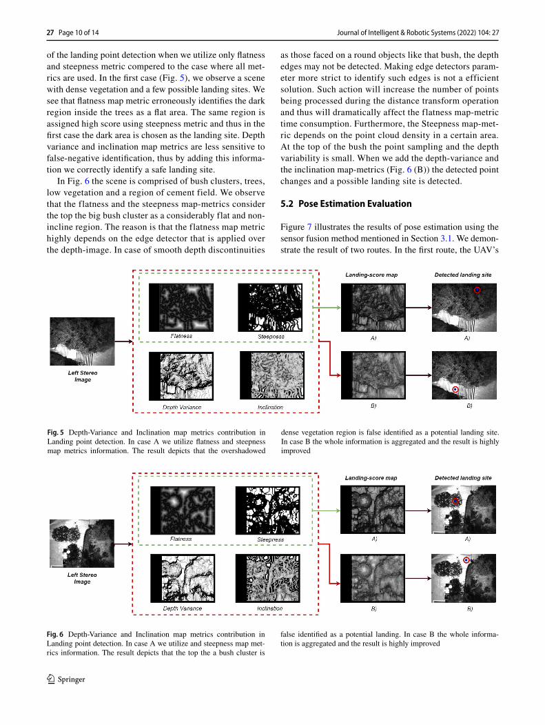
of the landing point detection when we utilize only flatness and steepness metric compered to the case where all met-rics are used. In the first case (Fig. 5), we observe a scene with dense vegetation and a few possible landing sites. We see that flatness map metric erroneously identifies the dark region inside the trees as a flat area. The same region is assigned high score using steepness metric and thus in the first case the dark area is chosen as the landing site. Depth variance and inclination map metrics are less sensitive to false-negative identification, thus by adding this informa-tion we correctly identify a safe landing site.
In Fig. 6 the scene is comprised of bush clusters, trees, low vegetation and a region of cement field. We observe that the flatness and the steepness map-metrics consider the top the big bush cluster as a considerably flat and non-incline region. The reason is that the flatness map metric highly depends on the edge detector that is applied over the depth-image. In case of smooth depth discontinuities
as those faced on a round objects like that bush, the depth edges may not be detected. Making edge detectors param-eter more strict to identify such edges is not a efficient solution. Such action will increase the number of points being processed during the distance transform operation and thus will dramatically affect the flatness map-metric time consumption. Furthermore, the Steepness map-met-ric depends on the point cloud density in a certain area. At the top of the bush the point sampling and the depth variability is small. When we add the depth-variance and the inclination map-metrics (Fig. 6 (B)) the detected point changes and a possible landing site is detected.
5.2 Pose Estimation Evaluation
Figure 7 illustrates the results of pose estimation using the sensor fusion method mentioned in Section 3.1. We demon-strate the result of two routes. In the first route, the UAV’s
Fig. 5 Depth-Variance and Inclination map metrics contribution in Landing point detection. In case A we utilize flatness and steepness map metrics information. The result depicts that the overshadowed
dense vegetation region is false identified as a potential landing site. In case B the whole information is aggregated and the result is highly improved
Fig. 6 Depth-Variance and Inclination map metrics contribution in Landing point detection. In case A we utilize and steepness map met-rics information. The result depicts that the top the a bush cluster is
false identified as a potential landing. In case B the whole informa-tion is aggregated and the result is highly improved
27 Page 10 of 14 Journal of Intelligent & Robotic Systems (2022) 104: 27

1 3
changes of course are partially abrupt while in the following one the route is orbicular and smoother. The blue line refers position as of the UAV estimated by the IMU’s gyroscope and accelerometer analysis. The green line illustrates the position as estimates by the SLAM algorithm and finally the red line depicts the UAV’s position estimation by the UKF sensor fusion method.
5.3 Real‑World Outdoor Experiments
In this section, we evaluate the utility of our system by performing extensive experiments in the real world. The proposed landing method is described next. When emer-gency landing command is given from the ground-station,
the following method is designed. The UAV is set to hover mode, and stereo images from the scene underneath the UAV are captured. The Navigation node continuously checks if the UAV hovers and updates the Boolean mes-sage of the hover ROS topic. The Landing algorithm node subscribes to the ROS images topics, and the hover topic and begins the process when hover mode is set on. Sub-sequently, the best landing site is published along with the Boolean message that indicates if the landing on the detected site is allowed. If so, the landing area world coor-dinates are calculated taking into account the UAV’s pose in world coordinates (X,Y,Z) given from IMU-SLAM fusion and the detected landing point’s Image coordinates
Fig. 7 Sensor fusion results in x,y position. IMU estimation (blue), SLAM estimation (green), UKF sensor fusion estimation (red)
Fig. 8 Illustrations of real world experiment in dense wooded area. We demonstrate the resulting total score-image of the scene, the detected landing point on the image frame and the landing position of the UAV on the world frame
Page 11 of 14 27Journal of Intelligent & Robotic Systems (2022) 104: 27
1 3
(x,y,z). Afterwards, landing is taking place, and the pro-cedure comes to an end.
Conversely, if the landing is not allowed the UAV moves randomly to a neighbour point in a given radius. The motion is implemented to be random within a radius of six meters. For each new transition, the UAV altitude increases by two meters to expand the field of view. Still, the maximum height maintained is twenty five meters. When hover mode is detected, the new stereo image pair is forwarded to the landing algorithm. The procedure is repeated until a safe landing point is detected.
Our landing site algorithm safely detects landing sites in various scenarios, while the outdoor trials follow the predic-tions of our algorithm (Figs. 4). In Figs. 8, 9 we demonstrate the outcome of two outdoor trials.
In Fig. 8 the UAV operates above a forest area. When landing signal is received the landing procedure com-mences. After a few steps the UAV’s stereo camera cap-tures the depicted scene where a possible landing area among the trees is detected. Afterwards the width and the steepness of the site is successfully checked and the UAV lands on.
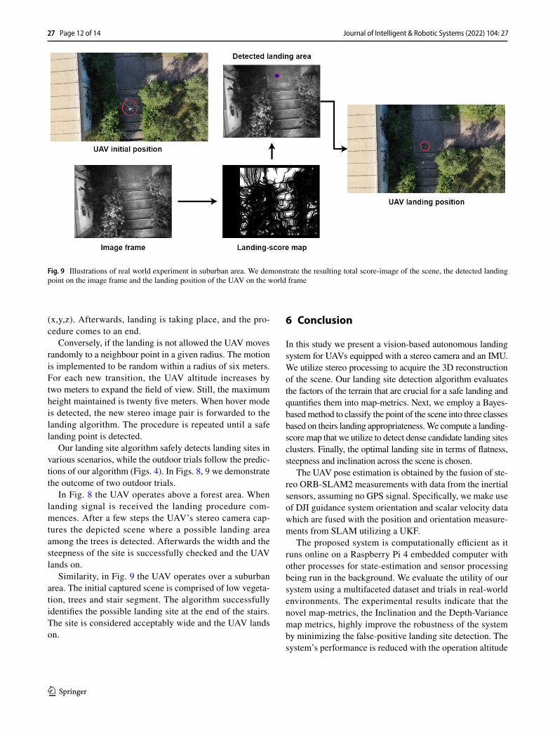
Similarity, in Fig. 9 the UAV operates over a suburban area. The initial captured scene is comprised of low vegeta-tion, trees and stair segment. The algorithm successfully identifies the possible landing site at the end of the stairs. The site is considered acceptably wide and the UAV lands on.
6 Conclusion
In this study we present a vision-based autonomous landing system for UAVs equipped with a stereo camera and an IMU. We utilize stereo processing to acquire the 3D reconstruction of the scene. Our landing site detection algorithm evaluates the factors of the terrain that are crucial for a safe landing and quantifies them into map-metrics. Next, we employ a Bayes-based method to classify the point of the scene into three classes based on theirs landing appropriateness. We compute a landing-score map that we utilize to detect dense candidate landing sites clusters. Finally, the optimal landing site in terms of flatness, steepness and inclination across the scene is chosen.
The UAV pose estimation is obtained by the fusion of ste-reo ORB-SLAM2 measurements with data from the inertial sensors, assuming no GPS signal. Specifically, we make use of DJI guidance system orientation and scalar velocity data which are fused with the position and orientation measure-ments from SLAM utilizing a UKF.
The proposed system is computationally efficient as it runs online on a Raspberry Pi 4 embedded computer with other processes for state-estimation and sensor processing being run in the background. We evaluate the utility of our system using a multifaceted dataset and trials in real-world environments. The experimental results indicate that the novel map-metrics, the Inclination and the Depth-Variance map metrics, highly improve the robustness of the system by minimizing the false-positive landing site detection. The system’s performance is reduced with the operation altitude
Fig. 9 Illustrations of real world experiment in suburban area. We demonstrate the resulting total score-image of the scene, the detected landing point on the image frame and the landing position of the UAV on the world frame
27 Page 12 of 14 Journal of Intelligent & Robotic Systems (2022) 104: 27

1 3
however, the accuracy of the algorithm is over 96.5% for an altitude less or equal to 15 meters.
As future work, it is planned to consider the potential effect of water surface more carefully. For instance, lakes and sea are uniform, low-contrast terrains that the algorithm may false identify as potential landing sites. This can be done by adjusting a semantic segmentation into the scene and identify the regions filled with water. Besides, using a stereo camera with a higher resolution and sensor size may improve the system performance. Finally, the algorithm can be further optimized to decrease the landing time even further.
Author Contributions All authors contributed to the study concep-tion and design. Embedded/Hardware preparation, data collection by Evangelos Chatzikalymnios, analysis were performed by Evangelos Chatzikalymnios and Konstantinos Moustakas. The first draft of the manuscript was written by Evangelos Chatzikalymnios and all authors commented on previous versions of the manuscript. All authors read and approved the final manuscript.
Declarations
Conflicts of interest All authors certify that they have no affiliations with or involvement in any organization or entity with any financial interest or non-financial interest in the subject matter or materials dis-cussed in this manuscript.
Open Access This article is licensed under a Creative Commons Attri-bution 4.0 International License, which permits use, sharing, adapta-tion, distribution and reproduction in any medium or format, as long as you give appropriate credit to the original author(s) and the source, provide a link to the Creative Commons licence, and indicate if changes were made. The images or other third party material in this article are included in the article’s Creative Commons licence, unless indicated otherwise in a credit line to the material. If material is not included in the article’s Creative Commons licence and your intended use is not permitted by statutory regulation or exceeds the permitted use, you will need to obtain permission directly from the copyright holder. To view a copy of this licence, visit http:// creat iveco mmons. org/ licen ses/ by/4. 0/.
References
1. Yubo, L., et al: Survey of UAV autonomous landing based on vision processing. In: Advances in Intelligent Networking and Collaborative Systems, pp 300–311, Springer International Pub-lishing (2021)
2. Kanellakis, C., Nikolakopoulos, G.: Survey on computer vision for UAVs: Current developments and trends. Journal of Intel-ligent & Robotic Systems 87(1), 141–168 (2017)
3. Masselli, A., Zell, A.: A novel marker based tracking method for position and attitude control of mavs. In: Proceedings of Inter-national Micro Air Vehicle Conference and Flight Competition (IMAV) (2012)
4. Mebarki, R., Lippiello, V., Siciliano, B.: Autonomous landing of rotary-wing aerial vehicles by image-based visual servoing in gps-denied environments. In: 2015 IEEE International Sym-posium on Safety, Security, and Rescue Robotics (SSRR), pp. 1–6, IEEE (2015)
5. Lange, S., Sunderhauf, N., Protzel, P.: A vision based onboard approach for landing and position control of an autonomous multirotor uav in gps-denied environments. In: 2009 Inter-national Conference on Advanced Robotics. pp. 1–6, IEEE (2009)
6. Patruno, C., Nitti, M., Petitti, A., et al.: A Vision-Based Approach for Unmanned Aerial Vehicle Landing. Journal of Intelligent & Robotic Systems 95, 645–664 (2019). https:// doi. org/ 10. 1007/ s10846- 018- 0933-2
7. Hu, B., Lu, L., Mishra, S.: Fast, safe and precise landing of a quadrotor on an oscillating platform, In: 2015 American Control Conference (ACC), pp. 3836–3841, IEEE (2015)
8. Chaves, S.M., Wolcott, R.W., Eustice, R.M.: Neec research: Toward gps-denied landing of unmanned aerial vehicles on ships at sea. Naval Engineers Journal 127(1), 23–35 (2015)
9. Araar, O., Aouf, N., Vitanov, I.: Vision based autonomous land-ing of multirotor uav on moving platform. Journal of Intelligent & Robotic Systems 85(2), 369–384 (2017)
10. Patruno, C., et al.: Helipad detection for accurate UAV pose estimation by means of a visual sensor. International Jour-nal of Advanced Robotic Systems 14(5), 1729881417731083 (2017)
11. Yang, S., Scherer, S. A., Zell, A.: An onboard monocular vision system for & Robotic Systems. 69, (1-4), 499–515 (2013)
12. Scherer, S.A., Dube, D., Komma, P., Masselli, A., Zell, A.: Robust, real-time number sign detection on a mobile outdoor robot. In: ECMR, pp. 145–152 (2011)
13. Lebedev, I., Erashov, A., Shabanova, A.: Accurate autonomous uav landing using vision-based detection of aruco-marker. In: International Conference on Interactive Collaborative Robotics, pp. 179–188, Springer (2020)
14. Yu, L., et al.: Deep learning for vision-based micro aerial vehi-cle autonomous landing. International Journal of Micro Air Vehicles 10(2), 171–185 (2018)
15. Pluckter, K., Scherer, S.: Precision UAV landing in unstruc-tured environments. International Symposium on Experimental Robotics. Springer, Cham (2018)
16. Clement, L., Kelly, J., Barfoot, T.D.: Monocular visual teach and repeat aided by local ground planarity. In: Field and Service Robotics, pp. 547–561. Springer, Cham (2016)
17. Fraczek, P., Mora, A., Kryjak T.: Embedded vision system for automated drone landing site detection. International Confer-ence on Computer Vision and Graphics. Springer, Cham (2018)
18. Yang, T., Li, P., Zhang, H., Li, J., Li, Z.: Monocular vision slam-based uav autonomous landing in emergencies and unknown environments. Electronics 7(5), 73 (2018)
19. Forster, C., Faessler, M., Fontana, F., Werlberger, M., Scara-muzza, D.: Continuous on-board monocular-vision-based eleva-tion mapping applied to autonomous landing of micro aerial vehicles, In: 2015 IEEE International Conference on Robotics and Automation (ICRA), pp. 111–118, IEEE (2015)
20. Pizzoli, M., Forster, C., Scaramuzza, D.: Remode: Probabilistic, monocular dense reconstruction in real time. In: 2014 IEEE International Conference on Robotics and Automation (ICRA), pp. 2609–2616, IEEE (2014)
21. Fankhauser, P., Bloesch, M., Gehring, C., Hutter, M., Siegwart, R.: Robot-centric elevation mapping with uncertainty estimates. In: Mobile Service Robotics. World Scientific, pp. 433–440 (2014)
22. Johnson, A.E., et al.: Lidar-based hazard avoidance for safe landing on mars. JGCD 25(6), 1091–1099 (2002)
23. Hinzmann, T., Stastny, T., Cadena, C., Siegwart, R., Gilitschen-ski, I.: Free LSD: Prior-free visual landing site detection for autonomous planes. IEEE Robotics and Automation Letters 3(3), 2545–2552 (2018). https:// doi. org/ 10. 1109/ LRA. 2018. 28099 62
Page 13 of 14 27Journal of Intelligent & Robotic Systems (2022) 104: 27

1 3
24. Mittal, M., Valada, A., Burgard, W.: Vision-based autonomous landing in catastrophe-struck environments. arXiv: 1809. 05700 (2018)
25. Mur-Artal, R., Tardós, J.D.: ORB-SLAM2: An open-source SLAM system for monocular, stereo, and RGB-D cameras. IEEE Transactions on Robotics 33(5), 1255–1262 (2017). https:// doi. org/ 10. 1109/ TRO. 2017. 27051 03
26. Bonin-Font, F., Ortiz, A., Oliver, G.: Visual Navigation for Mobile Robots: A Survey. Journal of Intelligent & Robotic Systems 53, 263 (2008)
27. Haddadi, S.J., Castelan, E.B.: Visual-inertial fusion for indoor autonomous navigation of a quadrotor using ORB-SLAM. In: 2018 Latin American Robotic Symposium, 2018 Brazilian Sym-posium on Robotics (SBR) and 2018 Workshop on Robotics in Education (WRE), pp. 106–111, IEEE Xplore (2018)
28. Lynen, S., et al.: A robust and modular multi-sensor fusion approach applied to MAV navigation. In: 2013 IEEE/RSJ International Conference on Intelligent Robots and Systems, pp 3923–3929, IEEE Xplore (2013)
29. Julier, S.J., Uhlmann, J.K.: New extension of the Kalman filter to nonlinear systems. In: Proc. SPIE 3068, Signal Processing, Sensor Fusion, and Target Recognition VI, (28 July 1997), https:// doi. org/ 10. 1117/ 12. 280797 (1997)
30. Wan, E.E.A., Van Der Merwe, R.: The unscented Kalman fil-ter for nonlinear estimation. In: Proceedings of the IEEE 2000 Adaptive Systems for Signal Processing, Communications, and Control Symposium (Cat. No.00EX373), Lake Louise, AB, Canada, pp. 153–158 (2000). https:// doi. org/ 10. 1109/ ASSPCC. 2000. 882463
31. Wöhler, C.: 3D computer vision: efficient methods and applica-tions. Springer Science & Business Media (2012)
32. Point Cloud Library (1.11.1-dev), Conditional Euclidean Cluster-ing [source code]. https:// point clouds. org/ docum entat ion/ tutor ials/ clust er_ extra ction. html
Evangelos Chatzikalymnios received the Diploma degree in electrical and computer engineering and MSc in information processing sys-tems and machine intelligence from the University of Patras (UPAT), Greece, in 2018 and 2020 respectively. During 2019-2021 he served as a Computer Vision research assistant in the Virtual Reality and Visualization group (VVR) in the UPAT. His main research interests include 3D geometry processing, point cloud registration, computa-tional geometry, computer vision, visual odometry, and stereoscopic image processing. He is currently a Computer Vision engineer in embedded vision systems.
Konstantinos Moustakas received the Diploma degree and the PhD in electrical and computer engineering from the Aristotle University of Thessaloniki, Greece, in 2003 and 2007 respectively. During 2007-2011 he served as a post-doctoral research fellow in the Information Technologies Institute, Centre for Research and Technology Hellas. He is currently a Professor at the Electrical and Computer Engineer-ing Department of the University of Patras, Head of the Visualization and Virtual Reality Group, Director of the Wire Communications and Information Technology Laboratory and Director of the MSc Program on Biomedical Engineering of the University of Patras. He serves as an Academic Research Fellow for ISI/Athena research center. His main research interests include virtual, augmented and mixed reality, 3D geometry processing, haptics, virtual physiological human mod-eling, information visualization, physics-based simulations, computa-tional geometry, computer vision, and stereoscopic image processing. During the latest years, he has been the (co)author of more than 250 papers in refereed journals, edited books, and international confer-ences. His research work has received several awards. He serves as a regular reviewer for several technical journals and has participated in more than 23 research and development projects funded by the EC and the Greek Secretariat of Research and Technology, while he has served as the coordinator or scientific coordinator in 4 of them. He has also been a member of the organizing committee of several inter-national conferences. He is a Senior Member of the IEEE, the IEEE Computer Society and member of Eurographics.
27 Page 14 of 14 Journal of Intelligent & Robotic Systems (2022) 104: 27