
High-Altitude, Long-Endurance UAVs vs. Satellites - CiteSeerX
Upload
independentCategory
view
0download
0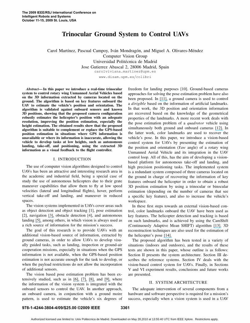
Trinocular Ground System to Control UAVs
Carol Martınez, Pascual Campoy, Ivan Mondragon, and Miguel A. Olivares-MendezComputer Vision Group
Universidad Politecnica de MadridJose Gutierrez Abascal 2, 28006 Madrid, Spain
www.disam.upm.es/colibri
Abstract— In this paper we introduce a real-time trinocularsystem to control rotary wing Unmanned Aerial Vehicles basedon the 3D information extracted by cameras located on theground. The algorithm is based on key features onboard theUAV to estimate the vehicle’s position and orientation. Thealgorithm is validated against onboard sensors and known3D positions, showing that the proposed camera configurationrobustly estimates the helicopter’s position with an adequateresolution, improving the position estimation, especially theheight estimation. The obtained results show that the proposedalgorithm is suitable to complement or replace the GPS-basedposition estimation in situations where GPS information isunavailable or where its information is inaccurate, allowing thevehicle to develop tasks at low heights, such as autonomouslanding, take-off, and positioning, using the extracted 3Dinformation as a visual feedback to the flight controller.
I. INTRODUCTION
The use of computer vision algorithms designed to controlUAVs has been an attractive and interesting research area inthe academic and industrial field, being a special case ofstudy the use of autonomous helicopters due to their gratemaneuver capabilities that allow them to fly at low speedvelocities (lateral and longitudinal flights), hover, performvertical take-off and landing, and maneuver in reducedspaces.
The vision systems implemented in UAVs cover areas suchas object detection and object tracking [1], pose estimation[2], navigation [3], obstacle detection [4], and autonomouslanding [5], among others, in which vision is always used asa rich source of information for the mission’s success.
The goal of this research is to provide UAVs with anadditional vision-based source of information, extracted byground cameras, in order to allow UAVs to develop visu-ally guided tasks, such as landing, inspection or ground-aircooperation missions, especially in situations when the GPSinformation is not available, when the GPS-based positionestimation is not accurate enough for the task to develop, orwhen the payload restrictions do not allow the incorporationof additional sensors.
The vision based pose estimation problem has been ex-tensively studied, such as in [6], [7], [8], and [9], wherethe information of the vision system is integrated with theonboard sensors to control the UAV. In another approach,an onboard camera, in conjunction with a ground moirepattern, is used to estimate the vehicle’s six degrees of
freedom for landing purposes [10]. Ground-based camerasapproaches for solving the pose estimation problem have alsobeen proposed. In [11], a ground camera is used to controla dirigible based on the information of artificial landmarks.In that work, the 3D position and orientation informationare recovered based on the knowledge of the geometricalproperties of the landmarks. A more recent work deals withthe pose estimation problem of a quadrotor vehicle usingsimultaneously both ground and onboard cameras [12]. Inthe latter work, color landmarks are used to recover thevehicle’s pose. In this paper, we introduce a vision-basedcontrol system for UAVs by presenting the estimation ofthe position and orientation (Yaw angle) of a rotary wingUnmanned Aerial Vehicle and its integration in the UAVcontrol loop. All of this, has the aim of developing a vision-based platform for autonomous take-off and landing, andhigh precision positioning tasks. The implemented systemis a redundant system composed of three cameras located onthe ground in charge of recovering the information of keyfeatures onboard the helicopter in order to obtain a robust3D position estimation by using a trinocular or binocularestimation (depending on the number of cameras that seea specific key feature), and also to increase the vehicle’sworkspace.
In these first steps towards an external vision-based con-trol, color landmarks onboard the UAV have been used askey features. The helicopter detection and tracking is basedon such landmarks, and is achieved by using the CamShift(Continuously Adaptive Mean SHIFT) algorithm [13]. 3Dreconstruction techniques are also used for the estimation ofthe helicopter’s pose [14].
The proposed algorithm has been tested in a variety ofsituations (indoors and outdoors), and the results of thesetests are shown in this paper, whose outline is as follows:Section II presents the system architecture. Section III de-scribes the reference systems. Section IV deals with thevision-based control system for UAVs. Finally, in SectionsV and VI experiment results, conclusions and future worksare presented.
II. SYSTEM ARCHITECTURE
The adequate intervention of several components from ahardware and software perspective is required for a mission’ssuccess, especially when a vision system is used in a UAV
The 2009 IEEE/RSJ International Conference onIntelligent Robots and SystemsOctober 11-15, 2009 St. Louis, USA
978-1-4244-3804-4/09/$25.00 ©2009 IEEE 3361
Authorized licensed use limited to: Univ Politecnica de Madrid. Downloaded on May 28,2010 at 13:55:40 UTC from IEEE Xplore. Restrictions apply.
control loop. The following section presents a description ofthe different components of the proposed system.
Fig. 1. Helicopter tesbed Colibri III, during a flight. Color landmarksonboard the UAV are used as key features for the position estimationalgorithm.
A. Helicopter Testbed
The Computer Vision Group at the UPM (UniversidadPolitcnica de Madrid) counts with three fully operationalUAV systems to develop indoors and outdoors applications.Such systems form part of the COLIBRI Project, whosepurpose is to develop algorithms for vision based controlof UAVs [15]. The experiments were carried out with theColibri III system (see Fig. 1). It is a Rotomotion SR20helicopter with an electric motor of 1.300 W, 8A. It isequipped with an xscale-based flight computer, a GPS,an IMU (Inertial Measurement Unit), an onboard pan andtilt camera, and an onboard Nano Itx computer for imageprocessing algorithms. The flight computer runs Linux OSand uses an 802.11g wireless Ethernet protocol for sendingand receiving information to/from the ground station.
B. Trinocular System
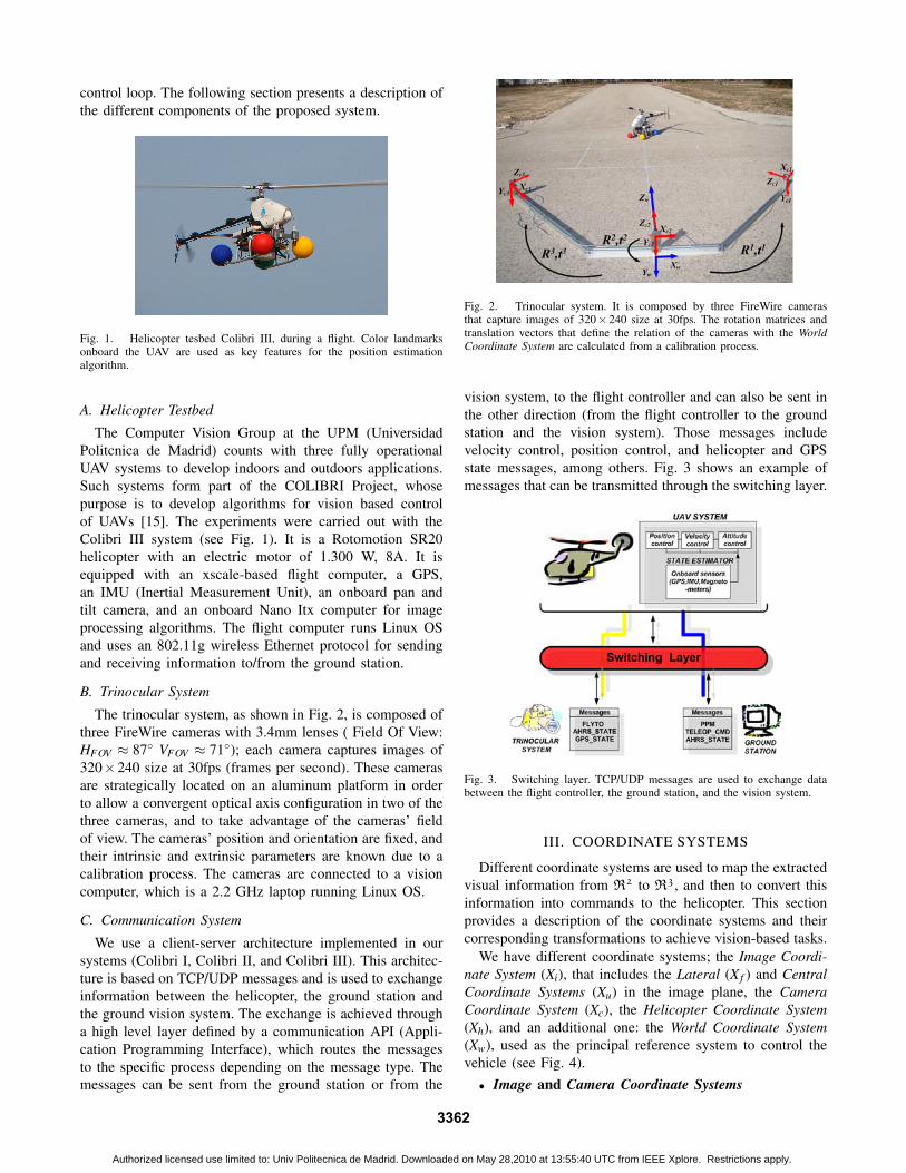
The trinocular system, as shown in Fig. 2, is composed ofthree FireWire cameras with 3.4mm lenses ( Field Of View:HFOV ≈ 87◦ VFOV ≈ 71◦); each camera captures images of320×240 size at 30fps (frames per second). These camerasare strategically located on an aluminum platform in orderto allow a convergent optical axis configuration in two of thethree cameras, and to take advantage of the cameras’ fieldof view. The cameras’ position and orientation are fixed, andtheir intrinsic and extrinsic parameters are known due to acalibration process. The cameras are connected to a visioncomputer, which is a 2.2 GHz laptop running Linux OS.
C. Communication System
We use a client-server architecture implemented in oursystems (Colibri I, Colibri II, and Colibri III). This architec-ture is based on TCP/UDP messages and is used to exchangeinformation between the helicopter, the ground station andthe ground vision system. The exchange is achieved througha high level layer defined by a communication API (Appli-cation Programming Interface), which routes the messagesto the specific process depending on the message type. Themessages can be sent from the ground station or from the
Fig. 2. Trinocular system. It is composed by three FireWire camerasthat capture images of 320× 240 size at 30fps. The rotation matrices andtranslation vectors that define the relation of the cameras with the WorldCoordinate System are calculated from a calibration process.
vision system, to the flight controller and can also be sent inthe other direction (from the flight controller to the groundstation and the vision system). Those messages includevelocity control, position control, and helicopter and GPSstate messages, among others. Fig. 3 shows an example ofmessages that can be transmitted through the switching layer.
Fig. 3. Switching layer. TCP/UDP messages are used to exchange databetween the flight controller, the ground station, and the vision system.
III. COORDINATE SYSTEMS
Different coordinate systems are used to map the extractedvisual information from R2 to R3, and then to convert thisinformation into commands to the helicopter. This sectionprovides a description of the coordinate systems and theircorresponding transformations to achieve vision-based tasks.
We have different coordinate systems; the Image Coordi-nate System (Xi), that includes the Lateral (X f ) and CentralCoordinate Systems (Xu) in the image plane, the CameraCoordinate System (Xc), the Helicopter Coordinate System(Xh), and an additional one: the World Coordinate System(Xw), used as the principal reference system to control thevehicle (see Fig. 4).• Image and Camera Coordinate Systems
3362
Authorized licensed use limited to: Univ Politecnica de Madrid. Downloaded on May 28,2010 at 13:55:40 UTC from IEEE Xplore. Restrictions apply.
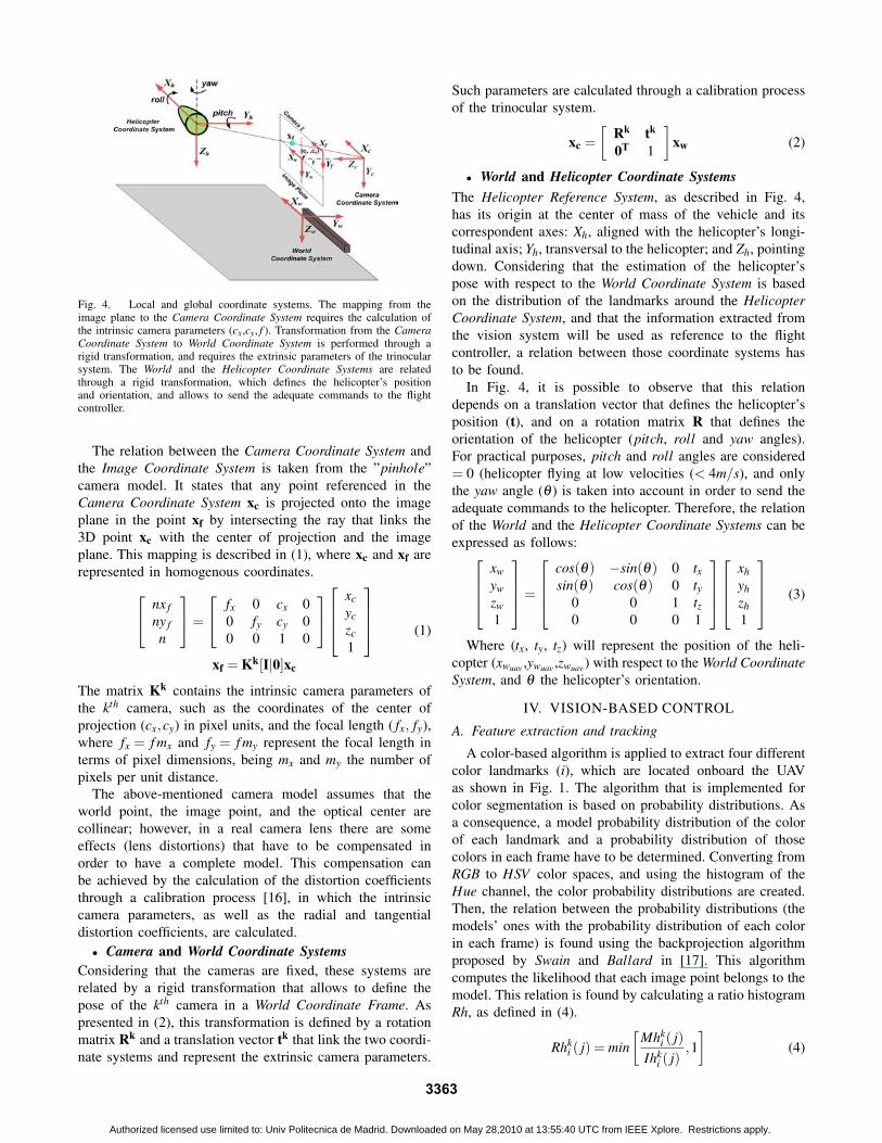
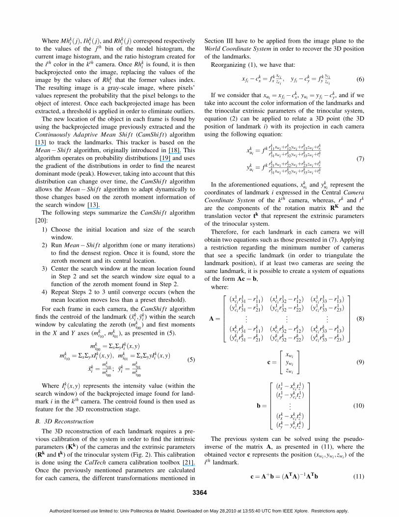
Fig. 4. Local and global coordinate systems. The mapping from theimage plane to the Camera Coordinate System requires the calculation ofthe intrinsic camera parameters (cx,cy, f ). Transformation from the CameraCoordinate System to World Coordinate System is performed through arigid transformation, and requires the extrinsic parameters of the trinocularsystem. The World and the Helicopter Coordinate Systems are relatedthrough a rigid transformation, which defines the helicopter’s positionand orientation, and allows to send the adequate commands to the flightcontroller.
The relation between the Camera Coordinate System andthe Image Coordinate System is taken from the ”pinhole”camera model. It states that any point referenced in theCamera Coordinate System xc is projected onto the imageplane in the point xf by intersecting the ray that links the3D point xc with the center of projection and the imageplane. This mapping is described in (1), where xc and xf arerepresented in homogenous coordinates. nx f
ny fn
=
fx 0 cx 00 fy cy 00 0 1 0
xcyczc1
xf = Kk[I|0]xc
(1)
The matrix Kk contains the intrinsic camera parameters ofthe kth camera, such as the coordinates of the center ofprojection (cx,cy) in pixel units, and the focal length ( fx, fy),where fx = f mx and fy = f my represent the focal length interms of pixel dimensions, being mx and my the number ofpixels per unit distance.
The above-mentioned camera model assumes that theworld point, the image point, and the optical center arecollinear; however, in a real camera lens there are someeffects (lens distortions) that have to be compensated inorder to have a complete model. This compensation canbe achieved by the calculation of the distortion coefficientsthrough a calibration process [16], in which the intrinsiccamera parameters, as well as the radial and tangentialdistortion coefficients, are calculated.• Camera and World Coordinate Systems
Considering that the cameras are fixed, these systems arerelated by a rigid transformation that allows to define thepose of the kth camera in a World Coordinate Frame. Aspresented in (2), this transformation is defined by a rotationmatrix Rk and a translation vector tk that link the two coordi-nate systems and represent the extrinsic camera parameters.
Such parameters are calculated through a calibration processof the trinocular system.
xc =[
Rk tk
0T 1
]xw (2)
• World and Helicopter Coordinate SystemsThe Helicopter Reference System, as described in Fig. 4,has its origin at the center of mass of the vehicle and itscorrespondent axes: Xh, aligned with the helicopter’s longi-tudinal axis; Yh, transversal to the helicopter; and Zh, pointingdown. Considering that the estimation of the helicopter’spose with respect to the World Coordinate System is basedon the distribution of the landmarks around the HelicopterCoordinate System, and that the information extracted fromthe vision system will be used as reference to the flightcontroller, a relation between those coordinate systems hasto be found.
In Fig. 4, it is possible to observe that this relationdepends on a translation vector that defines the helicopter’sposition (t), and on a rotation matrix R that defines theorientation of the helicopter (pitch, roll and yaw angles).For practical purposes, pitch and roll angles are considered= 0 (helicopter flying at low velocities (< 4m/s), and onlythe yaw angle (θ ) is taken into account in order to send theadequate commands to the helicopter. Therefore, the relationof the World and the Helicopter Coordinate Systems can beexpressed as follows:
xwywzw1
=
cos(θ) −sin(θ) 0 txsin(θ) cos(θ) 0 ty
0 0 1 tz0 0 0 1
xhyhzh1
(3)
Where (tx, ty, tz) will represent the position of the heli-copter (xwuav ,ywuav ,zwuav ) with respect to the World CoordinateSystem, and θ the helicopter’s orientation.
IV. VISION-BASED CONTROL
A. Feature extraction and tracking
A color-based algorithm is applied to extract four differentcolor landmarks (i), which are located onboard the UAVas shown in Fig. 1. The algorithm that is implemented forcolor segmentation is based on probability distributions. Asa consequence, a model probability distribution of the colorof each landmark and a probability distribution of thosecolors in each frame have to be determined. Converting fromRGB to HSV color spaces, and using the histogram of theHue channel, the color probability distributions are created.Then, the relation between the probability distributions (themodels’ ones with the probability distribution of each colorin each frame) is found using the backprojection algorithmproposed by Swain and Ballard in [17]. This algorithmcomputes the likelihood that each image point belongs to themodel. This relation is found by calculating a ratio histogramRh, as defined in (4).
Rhki ( j) = min
[Mhk
i ( j)Ihk
i ( j),1]
(4)
3363
Authorized licensed use limited to: Univ Politecnica de Madrid. Downloaded on May 28,2010 at 13:55:40 UTC from IEEE Xplore. Restrictions apply.
Where Mhki ( j), Ihk
i ( j), and Rhki ( j) correspond respectively
to the values of the jth bin of the model histogram, thecurrent image histogram, and the ratio histogram created forthe ith color in the kth camera. Once Rhk
i is found, it is thenbackprojected onto the image, replacing the values of theimage by the values of Rhk
i that the former values index.The resulting image is a gray-scale image, where pixels’values represent the probability that the pixel belongs to theobject of interest. Once each backprojected image has beenextracted, a threshold is applied in order to eliminate outliers.
The new location of the object in each frame is found byusing the backprojected image previously extracted and theContinuously Adaptive Mean Shi f t (CamShi f t) algorithm[13] to track the landmarks. This tracker is based on theMean−Shi f t algorithm, originally introduced in [18]. Thisalgorithm operates on probability distributions [19] and usesthe gradient of the distributions in order to find the nearestdominant mode (peak). However, taking into account that thisdistribution can change over time, the CamShi f t algorithmallows the Mean−Shi f t algorithm to adapt dynamically tothose changes based on the zeroth moment information ofthe search window [13].
The following steps summarize the CamShi f t algorithm[20]:
1) Choose the initial location and size of the searchwindow.
2) Run Mean−Shi f t algorithm (one or many iterations)to find the densest region. Once it is found, store thezeroth moment and its central location.
3) Center the search window at the mean location foundin Step 2 and set the search window size equal to afunction of the zeroth moment found in Step 2.
4) Repeat Steps 2 to 3 until converge occurs (when themean location moves less than a preset threshold).
For each frame in each camera, the CamShi f t algorithmfinds the centroid of the landmark (xk
i , yki ) within the search
window by calculating the zeroth (mki00
) and first momentsin the X and Y axes (mk
i10, mk
i01), as presented in (5).
mki00
= ΣxΣyIki (x,y)
mki10
= ΣxΣyxIki (x,y), mk
i01= ΣxΣyyIk
i (x,y)
xki =
mki10
mki00
; yki =
mki01
mki00
(5)
Where Iki (x,y) represents the intensity value (within the
search window) of the backprojected image found for land-mark i in the kth camera. The centroid found is then used asfeature for the 3D reconstruction stage.
B. 3D Reconstruction
The 3D reconstruction of each landmark requires a pre-vious calibration of the system in order to find the intrinsicparameters (Kk) of the cameras and the extrinsic parameters(Rk and tk) of the trinocular system (Fig. 2). This calibrationis done using the CalTech camera calibration toolbox [21].Once the previously mentioned parameters are calculatedfor each camera, the different transformations mentioned in
Section III have to be applied from the image plane to theWorld Coordinate System in order to recover the 3D positionof the landmarks.
Reorganizing (1), we have that:
x fi − ckx = f k
xxcizci
, y fi − cky = f k
yycizci
(6)
If we consider that xui = x fi−ckx, yui = y fi−ck
y, and if wetake into account the color information of the landmarks andthe trinocular extrinsic parameters of the trinocular system,equation (2) can be applied to relate a 3D point (the 3Dposition of landmark i) with its projection in each camerausing the following equation:
xkui
= f k rk11xwi +rk
12ywi +rk13zwi +tk
x
rk31xwi +rk
32ywi +rk33zwi +tk
z
ykui
= f k rk21xwi +rk
22ywi +rk23zwi +tk
y
rk31xwi +rk
32ywi +rk33zwi +tk
z
(7)
In the aforementioned equations, xkui
and ykui
represent thecoordinates of landmark i expressed in the Central CameraCoordinate System of the kth camera, whereas, rk and tk
are the components of the rotation matrix RK and thetranslation vector tk that represent the extrinsic parametersof the trinocular system.
Therefore, for each landmark in each camera we willobtain two equations such as those presented in (7). Applyinga restriction regarding the minimum number of camerasthat see a specific landmark (in order to triangulate thelandmark position), if at least two cameras are seeing thesame landmark, it is possible to create a system of equationsof the form Ac = b,
where:
A =
(x1
cir1
31− r111) (x1
cir1
32− r112) (x1
cir1
33− r113)
(y1ci
r131− r1
21) (y1ci
r132− r1
22) (y1ci
r133− r1
23)...
......
(xkci
rk31− rk
11) (xkci
rk32− rk
12) (xkci
rk33− rk
13)(yk
cirk
31− rk21) (yk
cirk
32− rk22) (yk
cirk
33− rk23)
(8)
c =
xwi
ywi
zwi
(9)
b =
(t1
x − xkci
t1z )
(t1y − yk
cit1z )
...(tk
x − xkci
tkz )
(tky − yk
citkz )
(10)
The previous system can be solved using the pseudo-inverse of the matrix A, as presented in (11), where theobtained vector c represents the position (xwi ,ywi ,zwi ) of theith landmark.
c = A+b = (ATA)−1ATb (11)
3364
Authorized licensed use limited to: Univ Politecnica de Madrid. Downloaded on May 28,2010 at 13:55:40 UTC from IEEE Xplore. Restrictions apply.

C. Pose estimation
In this case, the estimation of the helicopter’s pose willbe related exclusively with the estimation of the 3D positionof the helicopter (xwuav ) and the orientation of the helicopterboth expressed with respect to the World Coordinate System.The helicopter’s orientation is defined only with respect tothe Zh axis (θ ), while the angles, with respect to the otheraxes, are considered = 0. Therefore, taking into account the3D positions of the landmarks extracted in the previous stage,and taking into account the landmarks’ distribution aroundthe Helicopter Coordinate System, it is possible to formulateequation (12) for each landmark, considering only the yawangle θ (as explained in section III):
xwi
ywi
zwi
1
=
cos(θ) −sin(θ) 0 txsin(θ) cos(θ) 0 ty
0 0 1 tz0 0 0 1
xhi
yhi
zhi
1
(12)
Reorganizing (12) for all the landmarks that have beendetected, and considering that cθ = cos(θ), sθ = sin(θ),xwuav = tx, ywuav = ty, zwuav = tz, equation (12) can be rewrittenin the form:
Ac = b (13)
xh1 yh1 1 0 0yh1 −xh1 0 1 00 0 0 0 1...
......
......
xhi yhi 1 0 0yhi −xhi 0 1 00 0 0 0 1
cθ
sθ
xwuav
ywuav
zwuav
=
xw1yw1
zw1 − zh1...
xwi
ywi
zwi − zhi
Where our unknown parameters cθ ,sθ ,xwuav ,ywuav ,zwuav
correspond to the values that define the orientation (yawangle) and the position of the helicopter with respect to theWorld Coordinate System. The previous system of equationscan be solved as in (11), with the restriction that thereconstruction of at least two landmarks is required to findboth xwuav and the yaw angle (θ ). However, this restrictioncan vary depending on the task to develop: in the case ofautonomous landing, if we assume that the helicopter is inthe adequate landing position and the trinocular system willactuate only on the helicopter’s height, the control task canbe achieved with only one detected landmark.
D. Vision system and flight control system integration
The integration of the visual system into the UAV controlsystem is presented in Fig. 5. It follows the architectureof a ”dynamic look and move system” [22], which is ahierarchical control architecture composed of a fast internalcontrol loop -flight control system- (±120Hz), which is incharge of the helicopter’s stability, and an external loop (thevision system), which operates at low frequencies and givesreferences to the helicopter’s control loop.
The helicopter’s control loop is composed of: a StateEstimator, which fuses the information from different sensors(GPS, Magnetometers, IMU -Inertial Measurement Unit-)
using a Kalman f ilter to determine the position and ori-entation of the vehicle, and the Flight Controller which iscomposed of different control loops based on PID controllers(for attitude control, velocity control, position control) thatallow different modes of operation, as presented in [23], [15],and [24].
Fig. 5. Vision-based control. In this scheme, a fast internal control loop(flight control system) is in charge of the helicopter’s stability, whereas theexternal loop (vision system) operates at low frequency and uses the visualinformation as a feedback to the helicopter’s flight controller.
Considering that the vision system will determine theposition of the UAV in the World Coordinate System, theadequate references will be given in terms of 3D positions,so that the position xwsetPoint and the position informationgiven by the trinocular system xwuav , both defined in theWorld Coordinate System, will be compared to generatereferences to the position controller, as shown in Fig. 5.These references are first transformed into commands to thehelicopter xhsetPoint by taking into account the helicopter’sorientation θ (see Fig. 5), and then those references are sentto the position controller in order to move the helicopter tothe desired position.
V. EXPERIMENTS AND RESULTS
Several experiments were developed with the aim of val-idating the proposed algorithm regarding feature extraction,tracking and position estimation. The program was developedin C + +, and the OpenCV libraries were used for imageprocessing. The UAV system and the trinocular platformdescribed in Section II were used for the tests.• Static testsThe first set of experiments consisted in positioning the
helicopter in different known 3D coordinates with respect tothe World Coordinate System. Real values of the UAV posi-tions are obtained measuring them. The Root Mean SquareError (RMSE) of the helicopter’s position is calculated bycomparing the algorithm results with the known position.Fig. 6 presents the RMSE for different situations. As ex-pected, the error in the Yw axis increases as the helicoptergets farther away from the trinocular platform. This is sobecause at those positions the parallax angle within the raysbecomes small. Errors in Zw and Xw axes are satisfactory andconstant within a small range, compared with those obtained
3365
Authorized licensed use limited to: Univ Politecnica de Madrid. Downloaded on May 28,2010 at 13:55:40 UTC from IEEE Xplore. Restrictions apply.
in the Yw direction. This happens because changes of Xw andYw can be better perceived in the image plane.
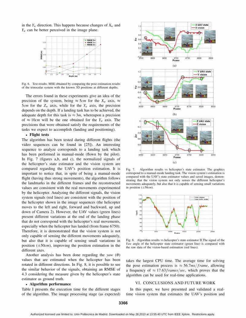
Fig. 6. Test results. MSE obtained by comparing the pose estimation resultsof the trinocular system with the known 3D positions at different depths.
The errors found in these experiments give an idea of theprecision of the system, being ≈ 5cm for the Xw axis, ≈5cm for the Zw axis, while for the Yw axis, the precisiondepends on the depth. If a landing task has to be achieved, theadequate depth for this task is ≈ 3m, whereupon a precisionof ≈ 10cm will be the one obtained for the Yw axis. Theprecisions that were obtained satisfy the requirements of thetasks we expect to accomplish (landing and positioning).• Flight tests
The algorithm has been tested during different flights (thevideo sequences can be found in [25]). An interestingsequence to analyze corresponds to a landing task whichhas been performed in manual-mode (flown by the pilot).In Fig. 7 (figures a,b, and c), the normalized signals ofthe helicopter’s state estimator and the vision system arecompared regarding the UAV’s position estimation. It isimportant to notice that, in spite of being a manual-modeflight (having thus strong movements), the algorithm followsthe landmarks in the different frames and the reconstructedvalues are consistent with the real movements experimentedby the helicopter. Analyzing the different signals, the visionsystem signals (red lines) are consistent with the position ofthe helicopter shown in the image sequences (the helicoptermoves to the left and right, forward and backward, up anddown of Camera 2). However, the UAV values (green lines)present different variations at the end of the landing phasethat do not correspond with the helicopter’s real movements,especially when the helicopter has landed (from frame 6750).Therefore, it is demonstrated that the vision system is notonly capable of sensing the different movements adequately,but also that it is capable of sensing small variations inposition (±50cm), improving the position estimation in thedifferent axes.
Another analysis has been done regarding the yaw (θ )values that are estimated when the helicopter has beenrotated in different directions. In Fig. 8, it is possible to seethe similar behavior of the signals, obtaining an RMSE of4.3 considering the measure given by the helicopter’s stateestimator as ground truth.• Algorithm performance
Table I presents the execution time for the different stagesof the algorithm. The image processing stage (as expected)
(a)
(b)
(c)
Fig. 7. Algorithm results vs helicopter’s state estimator. The graphicscorrespond to a manual-mode landing task. The vision system’s estimation iscompared with the UAV’s state estimator values and saved images, demon-strating that the vision system not only senses the different helicopter’smovements adequately, but also that it is capable of sensing small variationsin position (±50cm).
Fig. 8. Algorithm results vs helicopter’s state estimator II.The signal of theYaw angle of the helicopter state estimator (green line) is compared withthe raw data of the vision-based estimation (red lines).
takes the largest CPU time. The average time for solvingthe pose estimation process is ≈ 56.7ms/ f rame, allowinga frequency of ≈ 17.63 f rames/sec, which proves that thealgorithm can be used for real-time applications.
VI. CONCLUSIONS AND FUTURE WORK
In this paper, we have presented and validated a real-time vision system that estimates the UAV’s position and
3366
Authorized licensed use limited to: Univ Politecnica de Madrid. Downloaded on May 28,2010 at 13:55:40 UTC from IEEE Xplore. Restrictions apply.
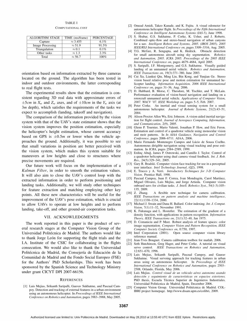
TABLE ICOMPUTATIONAL COST
ALGORITHM STAGE TIME (ms/frame) PERCENTAGECapture ≈ 3.455 6.1%
Image Processing ≈ 51.9 91.5%Triangulation ≈ 0.1 0.1%Other tasks ≈ 1.3 2.3%
Total ≈ 56.7 100%
orientation based on information extracted by three cameraslocated on the ground. The algorithm has been tested inindoor and outdoor environments, the latter correspondingto real flight tests.
The experimental results show that the estimation is con-sistent regarding 3D real data with approximate errors of±5cm in Xw and Zw axes, and of ±10cm in the Yw axis (at3m depth), which satisfies the requirements of the tasks weexpect to accomplish (landing, takeoff and navigation).
The comparison of the information provided by the visionsystem with that of the UAV’s state estimator shows that thevision system improves the position estimation, especiallythe helicopter’s height estimation, whose current accuracybased on GPS is ±0.5m or lower when the vehicle ap-proaches the ground. Additionally, it was possible to seethat small variations in position are better perceived withthe vision system, which makes this system suitable formaneuvers at low heights and close to structures whereprecise movements are required.
Our future work will focus on the implementation of aKalman Filter, in order to smooth the estimation values.It will also aim to close the UAV’s control loop with theextracted information in order to perform positioning andlanding tasks. Additionally, we will study other techniquesfor feature extraction and matching employing other keypoints. All these new characteristics will be useful for theimprovement of the UAV’s pose estimation, which is crucialto allow UAVs to operate at low heights and to performlanding, take-off, and other ground-air cooperation tasks.
VII. ACKNOWLEDGMENTS
The work reported in this paper is the product of sev-eral research stages at the Computer Vision Group of theUniversidad Politecnica de Madrid. The authors would liketo thank Jorge Leon for supporting the flight trials and theI.A. Institute of the CSIC for collaborating in the flightsconsecution. We would also like to thank the UniversidadPolitecnica de Madrid, the Consejerıa de Educacion de laComunidad de Madrid and the Fondo Social Europeo (FSE)for the Authors’ PhD Scholarships. This work has beensponsored by the Spanish Science and Technology Ministryunder grant CICYT DPI 2007-66156.
REFERENCES
[1] Luis Mejias, Srikanth Saripalli, Gauvav Sukhatme, and Pascual Cam-poy. Detection and tracking of external features in a urban environmentusing an autonomous helicopter. In Proceedings of IEEE InternationalConference on Robotics and Automation, pages 3983–3988, May 2005.
[2] Omead Amidi, Takeo Kanade, and K. Fujita. A visual odometer forautonomous helicopter flight. In Proceedings of the Fifth InternationalConference on Intelligent Autonomous Systems (IAS-5), June 1998.
[3] S. Hrabar, G.S. Sukhatme, P. Corke, K. Usher, and J. Roberts.Combined optic-flow and stereo-based navigation of urban canyonsfor a uav. Intelligent Robots and Systems, 2005. (IROS 2005). 2005IEEE/RSJ International Conference on, pages 3309–3316, Aug. 2005.
[4] T.G. McGee, R. Sengupta, and K. Hedrick. Obstacle detectionfor small autonomous aircraft using sky segmentation. Roboticsand Automation, 2005. ICRA 2005. Proceedings of the 2005 IEEEInternational Conference on, pages 4679–4684, April 2005.
[5] S. Saripalli, J.F. Montgomery, and G.S. Sukhatme. Visually guidedlanding of an unmanned aerial vehicle. Robotics and Automation,IEEE Transactions on, 19(3):371–380, June 2003.
[6] Cui Xu, Liankui Qiu, Ming Liu, Bin Kong, and Yunjian Ge. Stereovision based relative pose and motion estimation for unmanned he-licopter landing. Information Acquisition, 2006 IEEE InternationalConference on, pages 31–36, Aug. 2006.
[7] D. Hubbard, B. Morse, C. Theodore, M. Tischler, and T. McLain.Performance evaluation of vision-based navigation and landing on arotorcraft unmanned aerial vehicle. Applications of Computer Vision,2007. WACV ’07. IEEE Workshop on, pages 5–5, Feb. 2007.
[8] Peter Corke. An inertial and visual sensing system for a smallautonomous helicopter. Journal of Robotic Systems, 21(2):43–51,2004.
[9] Alison Proctor Allen Wu, Eric Johnson. A vision-aided inertial naviga-tion for flight control. Journal of Aerospace Computing, Information,and Communication, 2(9), 2005.
[10] Glenn P. Tournier, Mario Valenti, Jonathan P. How, and Eric Feron.Estimation and control of a quadrotor vehicle using monocular visionand moir patterns. In In AIAA Guidance, Navigation and ControlConference, pages 2006–6711. AIAA, 2006.
[11] Mario Fernando Montenegro Campos and Lucio de Souza Coelho.Autonomous dirigible navigation using visual tracking and pose esti-mation. In ICRA, pages 2584–2589, 1999.
[12] Erdinc Altug, James P. Ostrowski, and Camillo J. Taylor. Control ofa quadrotor helicopter using dual camera visual feedback. Int. J. Rob.Res., 24(5):329–341, 2005.
[13] Gary R. Bradski. Computer vision face tracking for use in a perceptualuser interface. Intel Technology Journal, (Q2), 1998.
[14] E. Trucco y A. Verri. Introductory Techniques for 3-D ComputerVision. Prentice Hall, 1998.
[15] Pascual Campoy, Juan F. Correa, Ivan Mondragon, Carol Martınez,Miguel Olivares, Luis Mejıas, and Jorge Artieda. Computer visiononboard uavs for civilian tasks. J. Intell. Robotics Syst., 54(1-3):105–135, 2009.
[16] Z. Zhang. A flexible new technique for camera calibration.IEEE Transactions on pattern analysis and machine intelligence,22(11):1330–1334, 2000.
[17] Michael J. Swain and Dana H. Ballard. Color indexing. Int. J. Comput.Vision, 7(1):11–32, November 1991.
[18] K. Fukunaga and L. Hostetler. The estimation of the gradient of adensity function, with applications in pattern recognition. InformationTheory, IEEE Transactions on, 21(1):32–40, Jan 1975.
[19] D. Comaniciu and P. Meer. Robust analysis of feature spaces: colorimage segmentation. Computer Vision and Pattern Recognition, IEEEComputer Society Conference on, 0:750, 1997.
[20] Intel Corporation (2001). Open source computer vision libraryreference manual.
[21] Jean-Yves Bouguet. Camera calibration toolbox for matlab, 2006.[22] Seth Hutchinson, Greg Hager, and Peter Corke. A tutorial on visual
servo control. IEEE Transactions on Robotics and Automation,12:651–670, 1996.
[23] Luis Mejias, Srikanth Saripalli, Pascual Campoy, and GauravSukhatme. Visual servoing approach for tracking features in urbanareas using an autonomous helicopter. In Proceedings of IEEEInternational Conference on Robotics and Automation, pages 2503–2508, Orlando, Florida, May 2006.
[24] Luis Mejias. Control visual de un vehiculo aereo autonomo usandodeteccion y seguimiento de caracterısticas en espacios exteriores.PhD thesis, Escuela Tecnica Superior de Ingenieros Industriales.Universidad Politecnica de Madrid, Spain, December 2006.
[25] Computer Vision Group. Universidad Politecnica de Madrid. COL-IBRI project homepage. http://www.disam.upm.es/colibri, 2009.
3367
Authorized licensed use limited to: Univ Politecnica de Madrid. Downloaded on May 28,2010 at 13:55:40 UTC from IEEE Xplore. Restrictions apply.
Copyright © 2022 FDOKUMEN