
Omnidirectional vision applied to Unmanned Aerial Vehicles (UAVs) attitude and heading estimation
26
Omnidirectional Vision applied to Unmanned Aerial Vehicles UAVs attitude and heading estimation Iv´ an F. Mondrag´ on *,a , Pascual Campoy a , Carol Martinez a , Miguel Olivares a a Computer Vision Group, Universidad Polit´ ecnica de Madrid, C. Jos´ e Guti´ errez Abascal 2. 28006 Madrid, Spain Abstract This paper presents an aircraft attitude and heading estimator using cata- dioptric images as a principal sensor for UAV or as a redundant system for IMU (Inertial Measure Unit) and gyros sensors. First, we explain how the unified theory for central catadioptric cameras is used for attitude and head- ing estimation, explaining how the skyline is projected on the catadioptric image and how it is segmented and used to calculate the UAV’s attitude. Then, we use appearance images to obtain a visual compass, and we calcu- late the relative rotation and heading of the aerial vehicle. Finally the tests and results using the UAV COLIBRI platform and the validation of them in real flights are presented, comparing the estimated data with the inertial values measured onboard. Key words: Omnidirectional Images, Catadioptric systems, Unmanned Aerial Vehicles (UAV), Sky segmentation. 1. Introduction Omnidirectional vision can be a useful sensor in estimating attitude in UAV. It can be used as the only sensor or as complementary sensor for in- ertial and GPS information. Its main advantage is that pitch and roll are estimated accordingly to the horizon line and therefore it regards the land level variations, as well as yaw is estimated accordingly to visual objects that * Corresponding author Email address: [email protected] (Iv´ an F. Mondrag´ on ) URL: www.disam.upm.es/colibri (Iv´ an F. Mondrag´ on ) Preprint submitted to Robotics and Autonomous Systems December 7, 2009
-
Upload
independent -
Category
Documents
-
view
5 -
download
0
Transcript of Omnidirectional vision applied to Unmanned Aerial Vehicles (UAVs) attitude and heading estimation

Omnidirectional Vision applied to Unmanned Aerial
Vehicles UAVs attitude and heading estimation
Ivan F. Mondragon∗,a, Pascual Campoya, Carol Martineza, Miguel Olivaresa
aComputer Vision Group, Universidad Politecnica de Madrid, C. Jose Gutierrez Abascal2. 28006 Madrid, Spain
Abstract
This paper presents an aircraft attitude and heading estimator using cata-dioptric images as a principal sensor for UAV or as a redundant system forIMU (Inertial Measure Unit) and gyros sensors. First, we explain how theunified theory for central catadioptric cameras is used for attitude and head-ing estimation, explaining how the skyline is projected on the catadioptricimage and how it is segmented and used to calculate the UAV’s attitude.Then, we use appearance images to obtain a visual compass, and we calcu-late the relative rotation and heading of the aerial vehicle. Finally the testsand results using the UAV COLIBRI platform and the validation of themin real flights are presented, comparing the estimated data with the inertialvalues measured onboard.
Key words: Omnidirectional Images, Catadioptric systems, UnmannedAerial Vehicles (UAV), Sky segmentation.
1. Introduction
Omnidirectional vision can be a useful sensor in estimating attitude inUAV. It can be used as the only sensor or as complementary sensor for in-ertial and GPS information. Its main advantage is that pitch and roll areestimated accordingly to the horizon line and therefore it regards the landlevel variations, as well as yaw is estimated accordingly to visual objects that
∗Corresponding authorEmail address: [email protected] (Ivan F. Mondragon )URL: www.disam.upm.es/colibri (Ivan F. Mondragon )
Preprint submitted to Robotics and Autonomous Systems December 7, 2009
can be used for trajectory planning and see & avoid strategies.
In general, there are twelve variables that define the UAV state [1], whichare inertial latitude, longitude and altitude of the UAV, body frame veloci-ties (rates); and roll, pitch and yaw angles and rates. In order to make a lowlevel controller for UAVs, it is necessary to have a direct measurement of theattitude angles (Roll, Pitch and Yaw) or their rates. Frequently, these vari-ables are measured using rate gyros as a part of a more complex sensor (theInertial Measurement Unit (IMU)) that involves gyroscopes and accelerom-eters to estimate the relative position, velocity and acceleration of a vehiclein motion. There has been an active improvement in precision, cost and sizeof this sensor in the last years from mechanical devices through optical sys-tems to MEMs sensors. Gyroscopes and IMU units are extremely sensitiveto measurements errors caused by drift, generating wrong estimation in ori-entation after a long operation period, making it necessary to reference themto an external measurement system like GPS framework [2]. Also, they stillcan be affected by structural and mechanical fatigue, vibrations, temperaturechanges, electric interferences and others [3], [4] causing a erroneous data ora sensor failure. In addition, small and micro UAV sometimes have restric-tions in cost and sensors payload capacity restricting the use of other sensors.
The idea of using visual information for UAV attitude estimation is notnew. The first experiments attempted to obtain the skyline from imagestaken by a single perspective camera looking forward on the aircraft, usingthis to estimate the roll angle with a horizontal reference [5], [6],[7],[8]. Theseworks differ in the way that they segment the sky and ground and in howthey estimate the horizon line.
Omnidirectional vision has also been used for UAV control and attitudeestimation. Hrabar [9] use an omnidirectional system for sideways-lookingsensing on an autonomous helicopter by applying image unwrapping. Demon-ceaux et al.[10], use a similar approach to the one presented in this paper,showing the advantages of using omnidirectional rather than perspective im-ages for attitude estimation. They detect the horizon line on the catadioptricimage using a Markov Random Fields segmentation and then project it onthe equivalent sphere projection model for a Catadioptric system, showinga good performance (without a ground true validation), on an off-line pro-cessed video sequence.
2

Catadioptric systems also have been used for robot odometry and rela-tive orientation on outdoor vehicles [11], [12] showing that it is possible toestimate relative orientation and position of a mobile robot using appearancepanoramic images.
In this work, we propose the use of an omnidirectional vision system asan attitude sensor for simultaneous Roll, Pitch and relative heading or Yawangle measurement. Section 2 shows the UAV platform employed for tests.Section 3 shows the catadioptric system employed and the equivalent projec-tion model. Then, in section 4 an image processing algorithm to isolate theskyline from the catadioptric image is implemented with the aim to estimatethe attitude of the bodyframe. Relative yaw or heading is also obtained us-ing the so called visual compass on appearance images. Finally, in section 5we present the feasibility and reliability of this approach when the obtainedresults are compared with the Inertial Measurement Unit (IMU) of the UAVtestbed employed.
2. UAV System Description
The Colibri project has three totally operational UAV platforms: Oneelectric helicopter with a 1400 W motor (Figure 1), and two gasoline pow-ered industrial twin helicopter with an 52 cc engine and 8 hp capable tocarry up to 12 kg payload. The COLIBRI testbeds [13], are equipped witha Xscale-based flight computer augmented with sensors (GPS, IMU, Magne-tometer, etc fused with a Kalman filter for state estimation). Additionallythey include a Pan and Tilt servo controlled platform for many differentcameras and sensors. In order to enable it to perform vision processing, italso has a VIA mini-ITX 1.5 GHz onboard computer with 2 GB RAM, awireless interface and support for many type of Firewire cameras includingMono (BW), RAW Bayer, color, and stereo heads for images acquisition. Itis possible to use IP cameras and analog cameras as well.
The system runs in a client-server architecture using TCP/UDP messages.The computers run Linux OS working in a multi-client wireless 802.11g ad-hoc network, allowing the integration of vision system and visual tasks withflight control. This architecture allows embedded applications to run on-board the autonomous helicopter while it interacts with external processes
3

Figure 1: UPM-COLIBRI III Electric Helicopter platform during an Omnidirectionalattitude and heading estimation tests using a catadioptric camera
through a high level switching layer. The visual control system and addi-tional external processes are integrated with the flight control through thislayer using TCP/UDP messages. The layer is based on a communicationsAPI where all the messages and data types are defined. The helicopter’slow-level controller is based on simple PID control loops to ensure its stabil-ity. The higher level controller uses various sensing mechanisms such as GPSand/or vision to perform tasks such as navigation, landing, visual tracking,etc.
3. Central Catadioptric Cameras
Catadioptric cameras are devices that combine reflective elements (catop-tric) and refractive systems (dioptric) to form a projection onto the imageplane of the camera. They can be classified as central and non-central cata-dioptric cameras according to the single effective viewpoint criteria. Bakerand Nayar [14], [15], define the configurations that satisfy the constraints ofa single viewpoint, finding that a central catadioptric system can be builtcombining a perspective camera with a hyperbolic, elliptical or planar mir-ror, or using an orthographic camera with a parabolic mirror.
Geyer and Daniilidis [16], [17] proposed an unified model for the projec-tive geometry induced by central catadioptric systems, showing that theseprojections are isomorphic to a projective mapping from a sphere (centered
4

on the effective viewpoint) to a plane with the projection center on the per-pendicular axis to the plane.
A modified version of this unified model is presented by Barreto andAraujo in [18], [19], where the mapping between points in the 3D world andpoints in the catadioptric image plane is split into three steps. First, a linearfunction maps the world into an oriented projective plane. Then a non-linearfunction transforms points between two oriented projective planes. Finallythere is a collineation function depending on the mirror parameters and thecamera calibration matrix (intrinsic parameters). Figure 2 shows the generalunit sphere projection for modeling catadioptric systems.
Figure 2: Catadioptric projection modelled by the unit sphere.
Consider a point in space (visible to the catadioptric system), with Carte-sian coordinates Xw = (xw, yw, zw)T in the catadioptric reference (focus).This point is mapped onto point Xs = (xs, ys, zs)
T on the unitary spherecentered on the effective view point by equation 1.
Xs =Xw√
x2w + y2
w + z2w
=Xw
‖Xw‖(1)
5
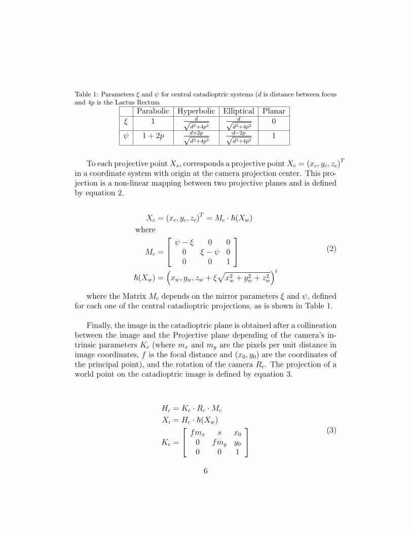
Table 1: Parameters ξ and ψ for central catadioptric systems (d is distance between focusand 4p is the Lactus Rectum
Parabolic Hyperbolic Elliptical Planar
ξ 1 d√d2+4p2
d√d2+4p2
0
ψ 1 + 2p d+2p√d2+4p2
d−2p√d2+4p2
1
To each projective pointXs, corresponds a projective pointXc = (xc, yc, zc)T
in a coordinate system with origin at the camera projection center. This pro-jection is a non-linear mapping between two projective planes and is definedby equation 2.
Xc = (xc, yc, zc)T = Mc · ~(Xw)
where
Mc =
ψ − ξ 0 00 ξ − ψ 00 0 1
~(Xw) =
(xw, yw, zw + ξ
√x2w + y2
w + z2w
)t(2)
where the Matrix Mc depends on the mirror parameters ξ and ψ, definedfor each one of the central catadioptric projections, as is shown in Table 1.
Finally, the image in the catadioptric plane is obtained after a collineationbetween the image and the Projective plane depending of the camera’s in-trinsic parameters Kc (where mx and my are the pixels per unit distance inimage coordinates, f is the focal distance and (x0, y0) are the coordinates ofthe principal point), and the rotation of the camera Rc. The projection of aworld point on the catadioptric image is defined by equation 3.
Hc = Kc ·Rc ·Mc
Xi = Hc · ~(Xw)
Kc =
fmx s x0
0 fmy y0
0 0 1
(3)
6

~(Xw) is a homogenous positive injective fucytion, with an inverse definedby ~−1(Xw). This function maps points in a projective plane onto the unitarysphere. The non-linear inverse function is defined by
(xs, ys, zs)t = ~−1(H−1
c Xi) = (λcxc, λcyc, λczc − ξ)t
where
λc =zcξ +
√z2c + (1− ξ2)(x2
c + y2c )
x2c + y2
c + z2c
(4)
3.1. Catadioptric system
Svoboda, Pajdla and Hlavac [20], [21], developed a projection model fora perspective camera with a hyperbolic mirror and gave a general approachto design and construct a useful catadioptric system for mobile robots. Theyalso explain the appropriated assembly and alignment of camera and mirrorin order to obtain the adequate images with central projection center. Thisapproach assumes a hyperbolic shaped mirror centered in one of its focalpoints F ′ which general function is defined by equation 5:(
z +√a2 + b2
a
)2
−(xb
)2
−(yb
)2
= 1 (5)
Where a,b are the mirror parameters. The mirror eccentricity is e =√a2 + b2 and the distance between focus is defined as d = 2e.
The maximum view angle taking into account the dimension of the mirror
and the distance to the camera is α = π2
+ arctan(h−2ertop
), where rtop is the
radius of any point on the mirror top rim (r2top = x2
top + y2top), and h is the
distance between the the top of the mirror and the camera center.
The employed catadioptric system is based on the hyperbolic shape pro-posed by Okamoto et. al [22], designed using the Svoboda method [20]. Ithas a height from the top mirror to camera center of h = 100mm and theradius of the mirror is set to rrim = 20mm. A standard firewire 30 fps,CCD camera with resolution of 640x480 pixels is selected and looking forthe maximum occupancy on the image, the projected radius is defined torpixrim
= 240 pixels. Assuming a pixel size of 0.01mm, a lens with focaldistance of f = 12mm has to be used. The mirror shape parameters areb = 100
√4 + 1 − 2
√1002 + 202 = 19.6461 and a = 2b = 39.2922, with a
7

maximum vertical angle of view of α = 121.3 degrees. Figure 3 shows thecamera mirror distribution. A transparent extruded thermoplastic acrylictube is used to make the final assembly. Finally, the catadioptric camerasystem is calibrated using the omnidirectional camera calibration toolboxdeveloped by Mei and Rives [23].
Figure 3: Catadioptric system design and assembly using a transparent extruded thermo-plastic acrylic tube.
4. Omnidirectional Image Processing
To be able to measure the body frame attitude based on the catadioptricimage, it is necessary to know, how the skyline is projected onto the unitarysphere and onto the catadioptric plane. Geyer and Daniilidis [17] demon-strate that a line on the space projects as a great circle on the unitary sphereand as a conic on the image plane. Later, Ying and Hu [24] demonstrate thatthe occluding contour of a sphere in space is projected onto a circle on theunit sphere or onto a conic in the catadioptric image plane. Considering theskyline the occluding contour on the earth sphere surface, finding it requiresto look for a small circle on the unitary sphere model or for a conic or ellipseon the image plane as proposed by Demonceaux et al. [10], (see figure 4 foran illustration).
Because the original datum obtained is the image projection, the skylinedetection focused on isolating the sky from the ground in this image and thenestimating the best adjusted ellipse to the skyline. To isolate the sky fromthe ground we use an approach based on the method employed by Cornallet al. [7] in which the RGB components of each pixel are weighted using thefunction f(RGB) = 3B2/(R + G + B). This function has shown very good
8
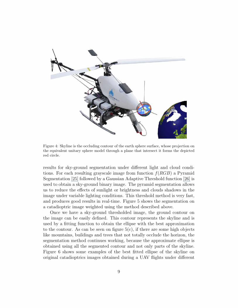
Figure 4: Skyline is the occluding contour of the earth sphere surface, whose projection onthe equivalent unitary sphere model through a plane that intersect it forms the depictedred circle.
results for sky-ground segmentation under different light and cloud condi-tions. For each resulting grayscale image from function f(RGB) a PyramidSegmentation [25] followed by a Gaussian Adaptive Threshold function [26] isused to obtain a sky-ground binary image. The pyramid segmentation allowsus to reduce the effects of sunlight or brightness and clouds shadows in theimage under variable lighting conditions. This threshold method is very fast,and produces good results in real-time. Figure 5 shows the segmentation ona catadioptric image weighted using the method described above.
Once we have a sky-ground thresholded image, the ground contour onthe image can be easily defined. This contour represents the skyline and isused by a fitting function to obtain the ellipse with the best approximationto the contour. As can be seen on figure 5(c), if there are some high objectslike mountains, buildings and trees that not totally occlude the horizon, thesegmentation method continues working, because the approximate ellipse isobtained using all the segmented contour and not only parts of the skyline.Figure 6 shows some examples of the best fitted ellipse of the skyline onoriginal catadioptrics images obtained during a UAV flights under different
9

(a) (b) (c)
Figure 5: Segmentation on a catadioptric image (5(a)), weighted using the functionf(RGB) = 3B2/(R+G+B) (5(b)), and the obtained sky ground binary image (5(c)).
sunlight and weather conditions.
4.1. Skyline backprojection on sphere.
The segmented skyline is defined by the points of the contour that repre-sent the ground border or by the adjusted ellipse points SKYimg = (xSKYimg
,ySKYimg
, 1). These points are backprojected onto the unitary sphere usingequation 4 obtaining SKYs = (xSKYs , ySKYs , zSKYs) as shown in figure 7.The circle formed by the skyline points on the sphere forms a plane thatintersects with the unitary sphere. To obtain the parameters of the skylinein the unitary sphere, it is sufficient to find the plane with normal equationNxxSKYs +NyySKYs +NzzSKYs +D = 0 that best adjusts the backprojectedpoints of the skyline contour or the adjusted ellipse on the image plane.
For each point of the backprojected skyline, the normal equation of theplane is obtained by ziSKYs
= NxxiSKYs
+ NyyiSKYs
+ D with i = 1, ..., n andan overdetermined linear system of the form (Ax = b) is solved using thepseudo-inverse method to obtain the plane πsky = (Nx, Ny, 1, D) (Equation6).
10

(a) (b)
(c) (d)
Figure 6: The best fitted ellipse (blue) to the skyline on original catadioptric imagesobtained during a UAV flight under different sunlight and weather conditions . Figure6(a) is a flight under a fall season clear sky, figure 6(b) is a winter cloudy day, figure 6(c)is on a winter partly cloudy sunset, and 6(d) is a takeoff and flight in a summer sunnyday.
[Nx, Ny, D]t = arg minx‖Ax− b‖
where
A =
xiSKYs
yiSKYs1
......
...xnSKYs
ynSKYs1
x =
Nx
Ny
D
b =
ziSKYs
...znSKYs
(6)
11
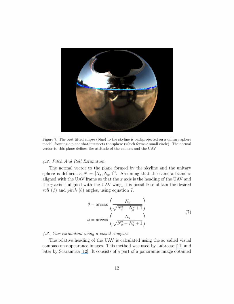
Figure 7: The best fitted ellipse (blue) to the skyline is backprojected on a unitary spheremodel, forming a plane that intersects the sphere (which forms a small circle). The normalvector to this plane defines the attitude of the camera and the UAV
4.2. Pitch And Roll Estimation
The normal vector to the plane formed by the skyline and the unitarysphere is defined as N = [Nx, Ny, 1]t. Assuming that the camera frame isaligned with the UAV frame so that the x axis is the heading of the UAV andthe y axis is aligned with the UAV wing, it is possible to obtain the desiredroll (φ) and pitch (θ) angles, using equation 7.
θ = arccos
(Nx√
N2x +N2
y + 1
)
φ = arccos
(Ny√
N2x +N2
y + 1
) (7)
4.3. Yaw estimation using a visual compass
The relative heading of the UAV is calculated using the so called visualcompass on appearance images. This method was used by Labrosse [11] andlater by Scaramuza [12]. It consists of a part of a panoramic image obtained
12

from a catadioptric image using a polar to Cartesian coordinates change orunwrapping process employing equation 8
I(α,R) = Ic(R cos(α) + u0, R sin(α) + v0) (8)
where (u0, v0) are the coordinates of the catadioptric image center, α is alinear function with maximum range [0, 2π] and R is a linear function thatscans along the image Radius. The steps and range for α and R are definedaccording to the desired panoramic image resolution and size. The unwrap-ping process excludes the parts of the catadioptric images that involves thecamera reflex and the outside of the mirror.
If the catadioptric image corresponds to a scene captured with an almostperfect vertical camera to the ground plane, then pure rotation will appear onthe appearance image as a pure pixel column-wise shift. The relative rotationbetween two consecutive images is obtained, by finding the best match basedon the images’ column shift using the Euclidean distance. Equation 9 showsthe Euclidean distance between two panoramic images Im and In with thesame size and space color, as a function of the column-wise shift on theImage In by α pixels (horizontal rotation). Figure 8 shows two consecutiveappearance images obtained by a unwrapping process with a small rotation.
d (Im, In, α) =
√√√√width∑i=1
height∑j=1
Nchan∑k=1
(Im(i, j, k)− In(i+ α, j, k))2 (9)
The best shift αmin that minimize the distance function d(Im, In, αmin) ≤d(Im, In, α)∀α ∈ R is the best pixel rotation between these two images. Fig-ure 9 shows the Euclidean distance between the two appearance images onfigure 8 as a function of a column-wise shift on the second image.
The rotation angle or yaw ψ between images is directly related to the ob-tained column shift between images, considering only the angular resolutionof the appearance images defined by the images field of view FOV and theimages width as shown in equation 10.
ψ(Im,In) = αminFOV
imgWidth(10)
To obtain the final rotation relative to the first image, it is necessary toadd the obtained value to a counter.
13

Figure 8: Two consecutive appearance images with a small rotation between them. Awhite grid is superimposed to reference and the red box shows clearly the column shiftbetween images
The method described above was developed under the assumption of apure camera rotation on its vertical axis which is perpendicular to the hor-izontal plane. In the general case, the UAV has translational componentsand roll and pitch variations, causing the camera vertical axis to not alwaysbe perpendicular to the horizon. However, as shown by Labrosse [11] and byScaramuza [12] the visual compass method based on appearance images isstill valid under translation and attitude variations if the camera has smalldisplacements or the distance to the objects is large compared with the dis-placement. Because images are captured at high frequency, small variationsof pitch and roll are present between consecutive images; therefore, the purerotation assumption is still valid. Finally, because the translational move-ments contribution to the optical flow is not homogeneous on the omnidirec-tional image, but the rotation movements contributes equally on all image, isenough to use the regions of the images on which the translation contributionto optical flow is reduced. Considering that a forward/backward translationhas more contribution to the optical flow on the image regions correspondingto the sides of the vehicles and little in from and back regions of the vehicle,working only with the from and/or back portion of the image is enough toreduce the effects of a translation on the image rotation estimation. In our
14

Figure 9: Euclidean Distance between the two appearance images on figure 8 as functionof the column-wise shift on the second image
implementation we only use a FOV of 120 degrees corresponding to the frontcentral part of the panoramic image.
5. Tests and Results
Several tests have been made using the Colibri testbeds [27] in differentseasons, weather and illumination conditions. Table 2 describes the flightand weather conditions in which these tests have been done. In these tests,a series of flights were performed in both autonomous and manual modes. Inautonomous mode, the helicopter can take both, a previously defined trajec-tory, or a hover (stationary) flight. In manual mode, a safety pilot takes afree flight with strong movements of the helicopter. The algorithm is testedduring these flights (including a takeoff process) and an image sequence isstored, associating to each of the processed images the UAV attitude infor-mation estimated by the omnidirectional system. Also, a flightlog is createdwith the GPS position, IMU data (heading, body frame angles and displace-ment velocities), and the helicopter position estimated by the Kalman Filterof the controller on the local plane with reference to the takeoff point. Thesevalues are used for later comparisons with the estimated data using the cata-dioptric system.
15
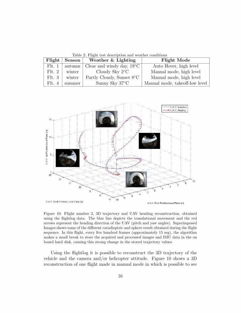
Table 2: Flight test description and weather conditionsFlight Season Weather & Lighting Flight ModeFlt. 1 autumn Clear and windy day, 19◦C Auto Hover, high levelFlt. 2 winter Cloudy Sky 2◦C Manual mode, high levelFlt. 3 winter Partly Cloudy, Sunset 8◦C Manual mode, high levelFlt. 4 summer Sunny Sky 37◦C Manual mode, takeoff-low level
Figure 10: Flight number 2, 3D trajectory and UAV heading reconstruction, obtainedusing the flightlog data. The blue line depicts the translational movement and the redarrows represent the heading direction of the UAV (pitch and yaw angles). SuperimposedImages shows some of the different catadioptric and sphere result obtained during the flightsequence. In this flight, every five hundred frames (approximately 15 seg), the algorithmmakes a small break to store the acquired and processed images and IMU data in the onboard hard disk, causing this strong change in the stored trajectory values
Using the flightlog it is possible to reconstruct the 3D trajectory of thevehicle and the camera and/or helicopter attitude. Figure 10 shows a 3Dreconstruction of one flight made in manual mode in which is possible to see
16

−2 −1.5 −1 −0.5 0 0.5−3
−2
−1
0
1
2
3
4
5
6
U.A.V. East Position Local Plane (m)
U.A
.V. N
orth
Pos
ition
Loc
al P
lane
(m
)
U.A.V. trajectoryU.A.V. Heading
(a)
−8 −6 −4 −2 0 2 4 6 8 10
0
5
10
15
20
25
U.A.V. East Position Local Plane (m)
U.A
.V. N
orth
Pos
ition
Loc
al P
lane
(m
)
U.A.V. trajectoryU.A.V. Heading
(b)
−15 −10 −5 0 5
16
18
20
22
24
26
28
30
32
U.A.V. East Position Local Plane (m)
U.A
.V. N
orth
Pos
ition
Loc
al P
lane
(m
)
U.A.V. trajectoryU.A.V. Heading
(c)
−6 −4 −2 0 2 4 6 8 10
0
5
10
15
20
U.A.V. East Position Local Plane (m)
U.A
.V. N
orth
Pos
ition
Loc
al P
lane
(m
)
U.A.V. trajectoryU.A.V. Heading
(d)
Figure 11: 2D trajectories and UAV heading reconstruction. Figure 11(a) is a high levelhover flight in autonomous mode, figure 11(b) is a manual high level flight, figure 11(c) ismanual high level during a sunset and 11(d) is a manual takeoff and low level flight.
big changes in the attitude and orientation of the UAV. Figure 11 shows thecorresponding 2D reconstructions of flight tests described on table 2, showingfor each one, the trajectory and helicopter heading.
The algorithm developed, estimates the absolute Roll and Pitch anglesof the Camera bodyframe on the UAV and the relative Yaw rotation to thefirst image. For these tests, the camera is located on the Pan and Tilt plat-form of the helicopter in such a way that the vertical axes of the camera
17

Table 3: RMSE for estimated roll (φ), pitch (θ) and Relative Yaw (ψ)roll (φ) pitch (θ) R. Yaw (ψ)
Flight 1 0.1807 4.3710 1.2533Flight 2 2.7528 2.8267 10.7844Flight 3 0.9363 4.0918 6.0413Flight 4 2.8647 1.9183 5.0086
and helicopter are parallel (by adjusting the camera platform tilt). In thisway, the hyperbolic mirror faces downward, and the camera looks up. Thispositioning ensures that all axes of the helicopter and camera are coincident,so that the obtained roll and pitch angles for the camera, are the same forthe helicopter frame, as shown in figure 4.
The estimated values of roll, pitch and yaw from test flights (Table 2, Fig.11) are compared with the corresponding stored IMU values. Figures 12, 13and 14 shows these results and table 3 has the Root Mean Squared Error(RMSE) of the estimated values compared with the IMU values as groundtruth. In flight 2 (Fig. 10), every five hundred frames (15 seg), the algorithmmade a small break to store the acquired and processed images and IMU datain the on board hard disk (other tests, the process is continuous), causingthis strong change in the measured values, because there are not processedimages during this saving time.
The estimated roll values have a very similar behavior to the one per-formed by the helicopter during the tests. The estimated values are veryclose to the IMU values and have a small RMSE against absolute valuesmeasured in the IMU.
Pitch values are also estimated accurately compared with the groundtruth IMU. However when the helicopter has a high nose-up angle, a por-tion of the ground is occluded on the catadioptric image by the platform’sstructure and the UAV’s reflections, causing a small error in the adjustmentof the skyline on the equivalent sphere projection, and the pitch estimation.Additionally, this causes that in general, the pitch RMSE has higher valuesthan the Roll, although these values are still a high-quality measurement.The error caused by the ground occlusion can be solved changing the cameraposition to be totally below the UAV bodyframe reducing the portion of the
18

0 2 4 6 8 10 12 14 160.5
1
1.5
2
2.5
3Roll
time (seg)
Rol
l Ang
le (
Deg
rees
)
RMSE = 0.1807
I.M.U dataCatadioptric estimation
(a)0 5 10 15 20 25 30
−15
−10
−5
0
5
10
15Roll
time (seg)
Rol
l Ang
le (
Deg
rees
)
RMSE = 2.753I.M.U dataCatadioptric estimation
(b)
0 5 10 15 20 25−4
−2
0
2
4
6
8
10Roll
time (seg)
Rol
l Ang
le (
Deg
rees
)
RMSE = 0.9363
I.M.U dataCatadioptric estimation
(c)0 20 40 60 80 100 120
−15
−10
−5
0
5
10
15Roll
time (seg)
Rol
l Ang
le (
Deg
rees
)
RMSE = 2.865
I.M.U dataCatadioptric estimation
(d)
Figure 12: Estimated Roll compared with the Roll Angle measured by IMU (Roll anglein degrees −180 < φ < 180. Zero is level with the horizon and increasing is right wingdown.). Figures 12(a) to 12(a) corresponds to the flights shown in figure 11.
camera platform reflected on the mirror.
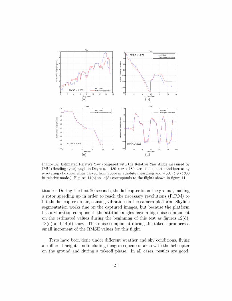
Yaw estimation uses the first image taken by the algorithm as a refer-ence, calculating rotation with respect to this reference image. Absolute Yawdata measured by the IMU is rotated according to the first image angle andchanged to a range between 0 < ψ < 360 for easy comparison with omnidi-rectional data. Results show that the rotation between frames, as well as thetotal rotation, are both a good approximation to real values, however thereare some cases in which the rotation direction is correctly estimated, but themagnitude is not correct, as can be seen on Fig. 14(b). This happens, becauseYaw estimation is obtained using a counter of rotations between consecutiveimages, causing an accumulative error along all the estimation process. In
19

0 2 4 6 8 10 12 14 16−5.5
−5
−4.5
−4
−3.5
−3
−2.5
−2
−1.5
−1Pitch
time (seg)
Pitc
h A
ngle
(D
egre
es)
RMSE = 4.371
I.M.U dataCatadioptric estimation
(a)0 5 10 15 20 25 30
−15
−10
−5
0
5Pitch
time (seg)
Pitc
h A
ngle
(D
egre
es)
RMSE = 2.827
I.M.U dataCatadioptric estimation
(b)
0 5 10 15 20 25−8
−6
−4
−2
0
2
4Pitch
time (seg)
Pitc
h A
ngle
(D
egre
es)
RMSE = 4.092
I.M.U dataCatadioptric estimation
(c)0 20 40 60 80 100 120
−10
−8
−6
−4
−2
0
2
4
6
8
10Pitch
time (seg)
Pitc
h A
ngle
(D
egre
es)
RMSE = 1.918 I.M.U dataCatadioptric estimation
(d)
Figure 13: Estimated Pitch compared with the Pitch Angle measured by IMU (Pitchangle in degrees −90 < θ < 90. Zero is level with the horizon and increasing is nose up.).Figures 13(a) to 13(d) corresponds to the flights shown in figure 11.
addition, the unwrapped panoramic image only has a resolution of 0.5 pixelsper degree, causing that small rotations between consecutive images cannotbe detected and not added to the counter. Roll and Pitch estimation donot have this accumulative error problem, because they are calculated usingonly the information available in the last catadioptric image. Currently, it isunder test a new method to reduce the Yaw estimation error, by increasingthe resolution of the unwrapped image and using a Kalman filter in orderto improve the estimation robustness, however there are not available resultsyet.
In Flight 4 ( Figure 11(d)) the algorithm was running from the helicopter’stakeoff phase in order to test the robustness of the skyline detection at low al-
20
0 2 4 6 8 10 12 14 16−2
0
2
4
6
8
10
12Yaw
time (seg)
Rel
ativ
e Y
aw A
ngle
(D
egre
es)
RMSE = 1.253I.M.U dataCatadioptric estimation
(a)0 5 10 15 20 25 30
−350
−300
−250
−200
−150
−100
−50
0Yaw
time (seg)
Rel
ativ
e Y
aw A
ngle
(D
egre
es)
RMSE = 10.78 I.M.U dataCatadioptric estimation
(b)
0 5 10 15 20 25−180
−160
−140
−120
−100
−80
−60
−40
−20
0
20Yaw
time (seg)
Rel
ativ
e Y
aw A
ngle
(D
egre
es)
RMSE = 6.041
I.M.U dataCatadioptric estimation
(c)0 20 40 60 80 100 120
−150
−100
−50
0
50
100
150Yaw
time (seg)
Rel
ativ
e Y
aw A
ngle
(D
egre
es)
RMSE = 5.008
I.M.U dataCatadioptric estimation
(d)
Figure 14: Estimated Relative Yaw compared with the Relative Yaw Angle measured byIMU (Heading (yaw) angle in Degrees. −180 < ψ < 180, zero is due north and increasingis rotating clockwise when viewed from above in absolute measuring and −360 < ψ < 360in relative mode.). Figures 14(a) to 14(d) corresponds to the flights shown in figure 11.
titudes. During the first 20 seconds, the helicopter is on the ground, makinga rotor speeding up in order to reach the necessary revolutions (R.P.M) tolift the helicopter on air, causing vibration on the camera platform. Skylinesegmentation works fine on the captured images, but because the platformhas a vibration component, the attitude angles have a big noise componenton the estimated values during the beginning of this test as figures 12(d),13(d) and 14(d) show. This noise component during the takeoff produces asmall increment of the RMSE values for this flight.
Tests have been done under different weather and sky conditions, flyingat different heights and including images sequences taken with the helicopteron the ground and during a takeoff phase. In all cases, results are good,
21

showing the feasibility of using a catadioptric system as a UAV attitude andheading estimator or as a redundant visual system. The total video sequencesfor these flights and additional tests in manual and autonomous mode areavailable on the Colibri Project Web Page [27].
6. Conclusions
This paper deals with the research and results of the use of omnidirec-tional computer vision techniques onboard a UAV. These techniques are notmerely used to acquire environmental visual information that can be used af-terward by off-line processing. Rather, this paper has shown that computervision can play an important role on-line during the flight itself in order toacquire the essential UAV state information in order to be used as flight con-troller’s sensor.
We have developed and tested a method for UAV attitude (roll and pitch)and heading estimation based totally on visual information taken by a cata-dioptric camera. This approach has been validated against inertial measuresusing a UAV testbed, showing that the estimated values are a very goodapproximation of the real state of the aircraft, demonstrating the feasibilityof using this kind of system as a main sensor on UAVs with reduced sensorpayloads or as a redundant system for IMU and gyroscopes in cases of failureor malfunction of these systems. The pitch and roll are calculated in relationto the horizon and they are thereafter referenced to the actual land inclina-tion, which can varies during the flight. Similarly the heading is calculatedin reference to external objects, so it can used with adventage in trajectoryplanning.
We have tested the algorithm under different weather conditions, showingthe adaptability of the proposed method to many sunlight and illuminationconditions and the robustness in extreme cases like a totally cloudy sky or asunset in which the skyline isolation is difficult to obtain.
Tests have shown a good performance at different fly levels, with a highrobustness at low altitudes in which high objects (trees, mountains and build-ings) often occlude parts of the contour of the earth sphere surface, makingdifficult the skyline detection and segmentation. At high altitudes, this ob-jects are under the horizon line level, allowing a excellent sky ground seg-
22

mentation and algorithm efficiency.
Estimated values using the omnidirectional system, have shown a goodresponse to strong changes on the aircraft flying state with a near real timecomputational cost. These visual based measurements have been proved tovary accordingly to the measurements of the classical sensors, showing dis-crepancies of only a few degrees. These discrepancies can be used for sensorfusion, as well as for obstacle avoidance and trajectory updating. Consid-ering these facts, the inertial data measured with the catadioptric systemare appropriate for a flight controller based on visual sensor with additionalfeatures like object tracking and servoing.
Based on the results of our work, we conclude that the UAV field hasreached an important stage of maturity, in which the possibility of usingvision as a main sensor for UAVs control can now be imagined and in somecases attained. We have experimentally demonstrated capabilities to measurethe attitude and the heading of an autonomous helicopter by using only visualinformation.
Acknowledgement
The work reported in this paper is the conclusion of several researchstages at the Computer Vision Group - Universidad Politecnica de Madrid.The authors would like to thank Jorge Leon for supporting the flight trials,the I.A. Institute - CSIC for collaborating in the flights, and the UniversidadPolitecnica de Madrid, and Consejerıa de Educacion de la Comunidad deMadrid and the Fondo Social Europeo (FSE) for the authors’s Ph.D. fund-ing. This work has been sponsored by the Spanish Science and TechnologyMinistry under the grant CICYT DPI 2007-66156.
References
[1] R. W. Beard, State estimation for micro air vehicles, in: Innovations inIntelligent Machines (1), 2007, pp. 173–199.
[2] B. Siciliano, O. Khatib (Eds.), Springer Handbook of Robotics, Springer,Berlin, Heidelberg, 2008. doi:http://dx.doi.org/10.1007/978-3-540-30301-5.
23

[3] J. A. Walraven, Failure mechanisms in M.E.M.S., Internantional TestConference (2003) 828.
[4] A. Dumai, A. Winkler, Reliability prediction model for gyroscopes,Annual Reliability and Maintainability Symposium, 1990. Proceedings.(1990) 5–9doi:10.1109/ARMS.1990.67921.
[5] S. M. Ettinger, M. C. Nechyba, P. G. Ifju, M. Waszak, Vision-guidedflight stability and control for micro air vehicles, in: IEEE InternationalConference on Intelligent Robots and Systems, IEEE, 2002.
[6] S. Todorovic, M. Nechyba, P. Ifju, Sky/ground modeling for au-tonomous MAV flight, Robotics and Automation, 2003. Proceedings.ICRA ’03. IEEE International Conference on 1 (2003) 1422–1427 vol.1.doi:10.1109/ROBOT.2003.1241791.
[7] T. Cornall, G. Egan, A. Price, Aircraft attitude estimationfrom horizon video, Electronics Letters 42 (13) (2006) 744–745.doi:10.1049/el:20060547.
[8] D. Dusha, W. Boles, R. Walker, Fixed-wing attitude estimation usingcomputer vision based horizon detection, in: In Proceedings 12th Aus-tralian International Aerospace Congress, Melbourne, Australia, 2007,pp. 1–19.
[9] S. Hrabar, G. Sukhatme, Omnidirectional vision for an autonomous he-licopter, in: In IEEE Internation Conference on Robotics and Automa-tion, 2003, pp. 558–563.
[10] C. Demonceaux, P. Vasseur, C. Pgard, Omnidirectional vision onUAV for attitude computation, in: IEEE International Conference onRobotics and Automation 2006 (ICRA’06), IEEE, Orlando, FL, US,2006, pp. 2842–2847.
[11] F. Labrosse, The visual compass: Performance and limitations of anappearance-based method, Journal Of Field Robotics 23 (10) (2006)913–941.
[12] D. Scaramuzza, R. Siegwart, Appearance guided monocular omnidirec-tional visual odometry for outdoor ground vehicles, IEEE Transactionson Robotics, Special Issue on Visual SLAM. In press. Guest editors:
24

Jose’ Neira, Andrew Davison, John J. Leonard, Publication date: Oc-tober 2008 (2008).
[13] P. Campoy, J. F. Correa, I. Mondragon, C. Martınez, M. Olivares,L. Mejıas, J. Artieda, Computer vision onboard UAVs for civilian tasks,Journal of Intelligent and Robotic Systems. 54 (1-3) (2009) 105–135.doi:http://dx.doi.org/10.1007/s10846-008-9256-z.
[14] S. Nayar, S. Baker, A theory of catadioptric image formation, tech reportCUCS-015-97, Department of Computer Science, Columbia University,1997.
[15] S. Baker, S. K. Nayar, A theory of single-viewpoint catadioptric imageformation, International Journal of Computer Vision 35 (2) (1999) 1 –22.
[16] C. Geyer, K. Daniilidis, A unifying theory for central panoramic systemsand practical applications, in: ECCV (2), 2000, pp. 445–461.
[17] C. Geyer, K. Daniilidis, Catadioptric projective geometry, Journal ofComputer Vision 43 (2001) 223–243.
[18] J. a. Barreto, H. Araujo, Issues on the geometry of central catadiop-tric image formation, Computer Vision and Pattern Recognition, 2001.CVPR 2001. Proceedings of the 2001 IEEE Computer Society Confer-ence on 2 (2001) II–422–II–427 vol.2. doi:10.1109/CVPR.2001.990992.
[19] J. a. Barreto, H. Araujo, Geometric properties of central catadioptricline images, in: ECCV ’02: Proceedings of the 7th European Conferenceon Computer Vision-Part IV, Springer-Verlag, London, UK, 2002, pp.237–251.
[20] T. Svoboda, T. Pajdla, V. Hlavac, Central panoramic cameras: Geom-etry and design, Research report K335/97/147, Czech Technical Uni-versity, Faculty of Electrical Engineering, Center for Machine Percep-tion, FEL CVUT, Karlovo namestı 13, Praha, Czech Republic, avail-able at ftp://cmp.felk.cvut.cz/pub/cmp/articles/svoboda/TR-K335-97-147.ps.gz (December 1997).
[21] T. Svoboda, T. Pajdla, Epipolar geometry for central catadioptric cam-eras, Int. J. Computer Vision. 49 (1) (2002) 23–37.
25

[22] J. Okamoto Jr, V. Grassi Jr., Visual servo control of a mobile robot usingomnidirectional vision, in: Proceedings of Mechatronics 2002, Universityof Twente, Netherlands, 2002, pp. 413–422.
[23] C. Mei, P. Rives, Single view point omnidirectional camera calibrationfrom planar grids, in: IEEE International Conference on Robotics andAutomation, 2007.
[24] X. Ying, Z. Hu, Catadioptric camera calibration using geometric invari-ants, Pattern Analysis and Machine Intelligence, IEEE Transactions on26 (10) (2004) 1260–1271. doi:10.1109/TPAMI.2004.79.
[25] H. J. Antonisse, Image segmentation in pyramids, j. Comput Graphicsand Image Process 19 (4) (1982) 367–383.
[26] G. Bradski, A. Kaehler, Learning OpenCV: Computer Vision with theOpenCV Library, O’Reilly, Cambridge, MA, 2008.
[27] COLIBRI, Universidad Politecnica de Madrid. Computer Vision Group.COLIBRI Project, http://www.disam.upm.es/colibri (2009).
26