
Endurance and Strength Training in Coronary Artery Disease ...
Upload
khangminh22Category
view
0download
0
High-Altitude, Long-Endurance UAVs vs. Satellites:Potential Benefits for U.S. Army Applications
by
William Everette Symolon ARCHIVESMajor, U.S. Army
B.S., Electrical EngineeringBucknell University, 1998
Submitted to the Department of Aeronautics and Astronautics in Partial Fulfillment of theRequirements for the Degree of
MASTER OF SCIENCEat the
MASSACHUSETTS INSTITUTE OF TECHNOLOGY A
CJ '. e I OFTECHNOLOGYMay 2009
@Charles Stark Draper Laboratory, 2009
All rights reserved LIBRARIES
Signature of the Author .............................. ............ ....... .Department of Aeronautics and Astronautics
May 12, 2009
Certified by .............. ...................... ...... ~ ... .;. .........ohn E. Keesee, Col., USAF (Ret.)
Thesis Advisor
C ertified by .......................................... ............ . . ..... ...rrentD. Appleby
Charles Stark Draper LaboratoryThesis Supervisor
Accepted by ......... ................ ...... .. ...... ..Profe or avid Darmofal
Chairman, Department (gkuate Committee

This page intentionally left blank.
High-Altitude, Long-Endurance UAVs vs. Satellites:Potential Benefits for U.S. Army Applications
by
William Everette Symolon, Major, U.S. Army
Submitted to the Department of Aeronautics and Astronautics on May 12, 2009 in PartialFulfillment of the Requirements for the Degree of Master of Science in Aeronautics and
Astronautics.
ABSTRACT
Satellites have become a critical component of nearly every aspect of modern life. In addi-tion to well-known civilian applications, military applications of space-based platforms includesupporting mission operations through communications; intelligence, surveillance and recon-naissance (ISR); and position, navigation and timing (PN&T). While satellite applications arenumerous and increasing technical achievements make satellites more capable, they do haveseveral drawbacks. Satellites are expensive, they require long development times and they aredifficult to replace. Since the successful Chinese anti-satellite (ASAT) missile test on January11, 2006, U.S. military leaders have become increasingly concerned over this new vulnerabilityto critical space assets. In addition to efforts designed to improve operationally responsive spacecapabilities, military leaders have begun researching alternatives to space-based platforms. InNovember, 2006, the U.S. Army released the Army Space Master Plan (ASMP). In the unclas-sified extract of that plan, the Army identifies a list of eight topics for further investigationincluding the question, "Where should the Army invest in near-space and high-altitude, long-endurance [HALE] platforms as a lower cost, more responsive alternative to space platformsif they prove technically feasible?" This thesis discusses technical challenges associated withmaking HALE platforms feasible and explores the potential benefits of using these platformsto augment or enhance the three primary military applications of communications, ISR andPN&T including a detailed examination of current satellite-based military payload capabilitiesand limitations. Finally, this thesis discusses potential methods to integrate HALE capabilitiesinto the current U.S. Army Space Operations doctrine and provides some suggestions for thepotential role of Army Space Operations in the design, development, implementation and useof HALE systems. By demonstrating how the Army can use HALE platforms to reduce thecapability gap and fulfill more of the users' requirements, this research will answer the questionposed in the Army Space Master Plan.
Thesis Advisor: John E. Keesee, Col., USAF (Ret.), Senior Lecturer, Department of Aeronauticsand Astronautics
Thesis Supervisor: Dr. Brent D. Appleby, C.S. Draper Laboratory

This page intentionally left blank.
Acknowledgments
First and foremost, I owe a huge thanks to my wonderful wife, Kimberly, and two beautiful
daughters, Ellie and Kate, without whose constant love and support through the long days and
late nights none of this would have been possible or even worthwhile. I can't thank you enough
or ever express how I feel but this thesis, meager though it may be, is for you.
Abraham Lincoln once said, "all that I am and all that I hope to be, I owe to my angel
mother." This is as true for me as it was for him but, if I may be so bold as to attempt to
improve upon Mr. Lincoln, I need to include my 'old man' as well. Mom and Dad, your love
and caring guidance through the years have gotten me where I am today. You showed me how
to be a good husband, father, officer and student - thank you from the bottom of my heart. To
my sisters and brother, Jennifer, Kerry and Kyle, thank you for everything.
To Dr. Brent Appleby and Col. John Keesee, thank you for your time, focus and mentorship
over the past two years. From reining me in when I need it and encouraging me otherwise to
reading all those last-minute chapter drafts, you managed to provide both the freedom and the
direction I needed to see this through. Brent, you make an excellent guardrail! Col. Keesee,you and your wife welcomed my family into yours as only a military family can; from all of us,thank you.
There are numerous folks at Draper Labs to whom I owe a great debt. Kevin Duda, Mike
Cleary, Yechezkal Gutfreund, Rich Kolacinski, Jim Donna, Don Gustafson, Marc McConley,Megan Mitchell, Richard Greenspan, Jim Zagami, Chris Yu, Joe Kochocki, Steve Kolitz, Phil
Hattis, John Scudiere and Mark Abramson, your keen insights and feedback were critical to
the military applications chapters. To the education department, Linda Fuhrman and Gail
DiDonato, you ladies are first rate. And last, but certainly not least, thanks to the hard-
working staff at the Draper Library. My heartfelt thanks to all of you.
To the brilliant minds at the Army Space and Missile Defense Command in Colorado Springs,Stuart Stout, Rob King, Scott Johnson, D.J. Bremser, Jeff Faunce, Bill Coffey and MAJ Tim
Tubergen, thank you for helping me see what Space Operations is all about. Your work on
high-altitude capabilities was invaluable to me.
If someone had told me, even four years ago, that I would be graduating from MIT with a
Master's degree, I would have said they were crazy. Thanks to everyone who helped make that
crazy idea a reality.
This thesis was prepared at the Charles Stark Draper Laboratory, Inc., under contract
number 22951-001.
Publication of this thesis does not constitute approval by Draper or the sponsoring agency
of the findings or conclusions contained herein. It is published for the exchange and stimulation
of ideas.
The views expressed in this thesis are those of the author and do not reflect the official
policy or position of the United States Army, the Department of Defense or the United States
Government.
William E. Symolon, Major, U.S. Army12 May 2009

This page intentionally left blank.
,liMASSACHUSETTS INSTITUTE OF TECHNOLOGY
MASTER OF SCIENCE IN AERONAUTICS AND ASTRONAUTICS
High-Altitude, Long-Endurance UAVs vs. Satellites:Potential Benefits for U.S. Army Applications
Author:William E. SymolonMajor, U.S. Army
Thesis Advisor:John E. Keesee
Col., USAF (Ret.)
Supervisor:Dr. Brent D. Appleby
C.S. Draper Laboratory
May 12, 2009

This page intentionally left blank.
Contents
Abstract
Acknowledgments
List of Figures
List of Tables
Nomenclature
1 Introduction1.1 Background & Motivation ................1.2 Lighter-than-Air Platforms ...............1.3 Heavier-than-Air Platforms ..............1.4 Research Context & Thesis Outline ...........
2 HALE Platform Overview2.1 Design Drivers and Engineering Challenges ......
2.1.1 Environmental Considerations ..........2.1.2 Power System Requirements ...........2.1.3 Thermal Management ..............2.1.4 Materials Selection ................2.1.5 Dynamic and Electronic Attacks ........
2.2 Projected HALE Capabilities ..............2.3 Platform Sizing Example .................
2.3.1 Platform Physical Sizing .............2.3.2 Power Sub-system Sizing .............
2.4 General CONOPS ..............2.5 Chapter Summary . ...................
3 Military Applications - Communications Payload3.1 Link Margin Governing Equations . . . . . . . . . ..3.2 Communications Satellite Performance Analysis . ...3.33.43.5
HALE Platform Performance Analysis - Communications Payload .Communications Mission Specific CONOPS .............Chapter Summary ..........................
5 L 3J
7 C61
11
13
15
: : : : : : : :.
4 Military Applications - ISR Payload4.1 ISR Payload Design and Sizing .............4.2 ISR Satellite Performance Analysis ......... . .4.3 HALE Platform Performance Analysis - ISR Payload .4.4 ISR Mission Specific CONOPS . . . . . . . . . . . . .4.5 Chapter Summary ....................
5 Military Applications - Navigation Payload5.1 Global Positioning System Overview ..........5.2 GPS Satellite Performance Analysis.............5.3 HALE Platform Performance Analysis - GPS Payload
5.3.1 HALE as GPS Augmentation ..........5.3.2 HALE as GPS Alternative ............
5.4 Navigation Mission Specific CONOPS . . . . . . . . .5.5 Chapter Summary ...................
6 HALE Integration with Current Operations6.1 Existing Military Space Doctrine ............6.2 HALE Operational Considerations ...........6.3 Assessment of HALE Operational Benefits .......
6.3.1 Communications Payload Operational Benefits6.3.2 ISR Payload Operational Benefits ........6.3.3 Navigation Payload Operational Benefits . . . .
6.4 Future Role of Army Space Operations .........
7 Summary7.1 Military Applications - Multi-modal Capabilities
7.1.1 HALE Platform Limitations & Candidate 17.1.2 Potential Mission Enhancements . . . . .
7.2 Known Limitations .................7.3 Future Work .......... .........7.4 Conclusions ......... ...........
87879192
100.... ... .... ... 101
103. . . . . . . . . . . . . . 104. . . . . . . . . . . . . . 108. . . . . . . . . . . . . . 110. . . . . . . . . . . . . . 110. . . . . . . . . . . ... 115. . . . . . . . . . . . . . 115. . . . . . . . . . . . . . 117
119119121126126128128129
131. . . . . . . . . . . . . . . . 13 1lyload Combinations . . . . 131. . . . . . . . . . . . . . . . 133. . . . . . . . . . . . . . . . 134. . . . . . . . . . . . . . . . 136. . . . . . . . . . . . . . . . 137
A Subsystem Governing EquationsA.1 Power Subsystem Sizing ...........................A.2 Thermal Control Subsystem Sizing . . . . . . . . . . . . . . . . . . . . .
Bibliography
139139141
145
I I I : I I II
Pa
List of Figures
. . . . . 29
. . . . . 30
. . . . . 31
HATBS Concept Diagram ..................Air Force RQ-4 Global Hawk UAV .............
Ven Diagram of Current Capability -Gaps .........
Annual Winds Aloft Near Baghdad .............Daily and Yearly Solar Power Distribution .........
Deployment Flight Routes to Forward Destinations . . . .
Diagram of a Regenerative Fuel Cell System ........
Advantage of Regenerative Fuel Cell Energy Storage . . .RFC Specific-Energy & Mass Relations . ..........
Near-Space Atmospheric Temperature and Density Profile
Altitude Density Effects on Near Space Carriers ......
Definition of Angular Relationships . ............
HALE Platform Sensor Coverage Profile . .........
Example HALE Footprint Coverage . . . . . . . . . . . .
LTA Radius for 1000 lb Payload . ..............
LTA Radii for Varying Payload Weights . .........
LTA Volume for Varying Payload Fractions . . . . . . . .
HTA Wingspan for Varying Payload Fractions .......
2.16 Charge/Discharge Profile and Battery Life Characteristics for Secondary Batteries
2.17 Expanded Ven Diagram of Current Capability Gaps . . . . . . . . . . . . . . .
Wideband Global SATCOM Diagram . ................Bit Error Probability as a Function of Eb/No . ...........
Rain Attenuation as a Function of Frequency . ...........
Simplified WGS Payload Block Diagram .......... . .....
Communications Payload Antenna Diameter to Mass RelationshipDSCA Structure and Radiation Pattern . . . . . . . . . . . . . . .
HALE Transmit Power versus Antenna Size Trade Study ......
Multiple Access Formats ........................
Optical Characteristics of a Refractive Imaging System .......
Point Spread Function .........................
Transmission Characteristics of the Earth's Atmosphere ......
Scanning Techniques for Electro-Optical Instruments ........
GeoEye-1 Satellite Configuration and Optics Functionality .....
. . . 34
. . . 36
. . . 36
. . . 38
. . . 39
. . . 40
. . . 43
. . . 44
. . . 48
. . . 49
. . . 50
. . . 51
. . . 52
. . . 52
. . . 535763
6669717578818384
1.11.21.3
2.12.22.32.42.52.62.72.82.92.102.112.122.132.14
2.15
3.13.23.33.43.53.63.7
3.8
4.14.2
4.34.4
4.5
S . . . . . .
HALE Platform Remote Sensor Ground Resolutions . . . . . . . . . .HALE Platform Remote Sensor Ground Resolutions at Nadir.....Angular Relationships for HALE Performance with an ISR Payload ..
GPS Orbit Schematic ...........................Illustration of UERE ............................Illustration of DOP ............. ................Diagram of Differential GPS Correction Signals . ............GPS Antenna Pattern ...........................Received Power vs. Elevation Angle . . . . . . . . . . . . . . . . . . .HALE Augmentation of Differential GPS Correction Signals ......HALE Relay of Standard GPS Signals ..................Configuration of the Navigation System Covering the South Korean Pe
4.64.74.8
5.15.25.35.45.55.65.75.85.9
6.16.26.3
7.17.2
OODA Loop Diagram ................................Regions of the Earth's Atmosphere and Orbital Space . . . . . . . . . . . . . .HALE Platform Operational View .........................
Intuitive Payload Pareto Frontiers .........................Expanded Ven Diagram of Current Capability Gaps . . . . . . . . . . . . . . .
939496
ninsula
104105106107108109111112116
120122123
138138
.
.
.
.
.
.
.
.
.
List of Tables
2.1 Examples of Typical Thermal Requirements for Spacecraft Components
2.22.32.42.52.62.7
3.13.23.3
4.14.24.34.44.54.6
5.15.25.35.4
Medium/Long-Range SAM Capabilities ...........HALE Platform Size Requirements ..... ........
Comparison of Common Spacecraft Power Sources.....
Characteristics of Common Secondary Batteries .......
Specific Energy of RFC Designs ................Summary of Power Subsystem Sizing Requirements .....
Limitations on Frequency Band Ranges & Uses .......
WGS Technical Specifications .................Typical System Noise Temperatures .............
Diffraction-Limited Resolution . ...............
Comparison of Spectral Types for Remote Sensing Systems
High-Resolution CCD Arrays .................
Compression Ratios ......................Link Equation Parameters ...................Characteristics of Typical Satellite Payloads .........
Military GPS Receiver Comparison . .............
Link Budget Analysis for Civil and DoD GPS Signals . . . .
Space Loss Values for HALE GPS Signals ..........Received Power Values for HALE GPS Signals .......
58. .... ..... . 59
. . . . . . . . . . . 66
. . . . . . . . . . . 67
. . . . . . . . . . . 72
107109112113
5.5 Received Power Values for HALE GPS Signals with Increased Transmitter Power 114
7.1 HALE Platform Payload Requirements ................... .. . . 132
7.2 HALE Platform Payload Requirements ....................... 132
A.1 Elements of Inherent Solar Array Degradation . .................. 140
A.2 Common Solar Cell Efficiencies ........................... 140

This page intentionally left blank.
Nomenclature
a Radiator Absorptivity
p Angle Between the Sun and the Vector Normal to the Platform Face
1s Angle of the Sun Above the Orbit Plane
er Radiator Emissivity
es Minimum Elevation Angle in degrees
77b Transmission Efficiency Between the Battery and the Load
T ant Antenna Efficiency
Thnadir Nadir Angle in degrees
77sa Solar Array Efficiency
2 Half Rotation Angle Corresponding to Eclipse Duration
Eb Ratio of Received Energy-per-Bit to Noise DensityNo
A Carrier Wavelength (f = C/A)
AE Earth Central Angle in degrees
Commwt Communications Payload Weight
p Angular Radius of the Earth in degrees
Palbedo Earth's Albedo
Patm Atmospheric Density in slugs per ft3
a Stefan-Boltzmann Constant (5.67051 x 10- s W/m 2 K4)
T Material Tensile Strength in psi
0 Antenna Half-Power Beamwidth
90 Angular Resolution of an Image
Or Rayleigh Limit of the Point Spread Function in radians
Ai Required Aperture Diameter of Imaging Payload
Ao Aperture Diameter of the Reference Imaging Payload
Ap Surface Area of the Platform Face
Ar Radiator Surface Area
Asa Solar Array Surface Area
C Received Power
c Velocity of Light in Free Space (; 3 x 10s m/s)
Cr Battery Capacity
D Aperture, Diameter of an Optical Instrument
d Imaging Pixel Size
d' Diameter of the First Minimum of the Point Spread Function
Dr Ground Receive Antenna Diameter in meters
Dant Diameter of a Parabolic Antenna in meters
DoD Depth of Discharge
e Antenna Pointing Error
f Carrier Wave Frequency in Hertz
fi Focal Length
Fr Sensor Footprint Radius in miles
Falbedo Geometrical Factor Accounting for the Direction of the Radiator Relative to the Sun
FEIR Geometrical Factor Accounting for the Direction of the Radiator Relative to the Earth
Gr Receive Antenna Gain
Gt Transmit Antenna Gain
Hp Platform Altitude
I Current in Amperes
Id Inherent Degradation of Solar Cell Efficiency (Due to Design and Assembly Inefficiencies)
IEIR Intensity of the Earth IR Flux
Isolar Intensity of the Solar Flux
IA Incidence Angle = 900 - ,s

k Boltzmann's constant (1.380658 x 10⁻²³ J/K)
Ksoar Solar Constant in the Vicinity of the Earth (1367 W/m 2 )
La Transmission Path Loss
Ld Life Degradation of the Solar Array
Li Scaled Payload Linear Dimension
L1 Transmitter to Antenna Line Loss
Lo Reference Payload Linear Dimension
L Space Loss
Lpr Antenna Pointing Loss
Mb Battery Mass in kg
Mi Scaled Payload Mass
Mo Reference Payload Mass
Msa Solar Array Mass in kg
NaS Sodium-Sulfur
Nb Number of Batteries in the Power Subsystem
NH Nickel-Hydrogen
P Orbit Period
p Atmospheric Pressure in lbs/ft2
P(a) Probability that Signal Attenuation, a is Exceeded
Pd Platform Power Requirements During Daylight
Pe Platform Power Requirements During Eclipse
Pi Scaled Payload Power
P, Reference Payload Power
Pt Transmitter Power
PBOL Beginning-of-Life Power Generated
PEOL End-of-Life Power Generated
Pideal Ideal Solar Cell Power Output
Psa Power Generation Requirement of the Solar Arrays During Daylight

Pwr Power Measured in Watts
Q Image Quality Factor
Qr Radiative Power
qalbedo Heat Input from the Earth's Albedo
qbackload Radiative Backload from Other Platform Surfaces
qEarthIR Absorbed Earth IR Heat Load per Unit Area
Qexternal Environmental Heat Absorbed
qexternal External Environmental Heat Load on the Radiator per Unit Area
Qinternal Power Dissipation of Onboard Electronic Components
QMLI Heat Loss Through Multi-layer Insulation on the Platform
Qradiator Heat Rejected from the Platform's Primary Radiator Surfaces
q,,olar Incident Solar Energy on the Face of a Platform
R Data Rate
RE Radius of the Earth (3963.16 miles)
R 8 Slant Range to Target
Rscale Payload Scaling Ratio
S Transmission Path Length (m)
S, Swath Width in degrees
T Ambient Atmospheric Temperature in 'F
Td Duration of Daylight Period (minutes)
Te Duration of Eclipse Period (minutes)
Tr Absolute Radiator Temperature in K
T, System Noise Temperature
V Potential Difference in Volts
X Ground Pixel Size
X' Ground Resolution
Xd Efficiency of the Path Directly from the Solar Arrays to the Loads
Xe Efficiency of the Paths from the Solar Arrays Through the Batteries to the Loads
Xmax Maximum Cross-Track Pixel Resolution
Ymax Maximum Along-Track Sampling Distance
Zc Number of Cross-Track Pixels
ABM Anti-Ballistic Missile
ACR Armored Cavalry Regiment
ACTD Advanced Concept Technology Demonstration
AFRL Air Force Research Laboratory
AFSPC Air Force Space Command
Amp-hr Ampere-hour
AMTI Air Moving Target Indicator
AO Area of Operations
APL Applied Physics Laboratory
ASAT Anti-Satellite Weapon
ASMP Army Space Master Plan
AU Astronomical Unit (1 AU = 149, 597, 870, 691 meters)
BDA Battle Damage Assessment
BER Bit Error Rate
BFT Blue Force Tracker
BLOS Beyond Line-of-Sight
BOL Beginning-of-Life
BOS Battlefield Operating Systems
bpp Bits per Pixel
C2 Command and Control
CBRN Chemical, Biological, Radiological and Nuclear
CCD Charge Coupled Device
CCP Concept Capability Plan
CDMA Code Division Multiple Access
CER Cost Estimating Relationship
CNO Computer Network Operations
CONOPS Concept of Operations
CONUS Continental United States
DAGR Defense Advanced GPS Receiver
DARPA Defense Advanced Research Projects Agency
DET Direct-Energy-Transfer System
DGPS Differential GPS
DOD Department of Defense
DOP Dilution of Precision
DOT Department of Transportation
DOTMLPF Doctrine, Organization, Training, Materiel, Leadership and Education, Personneland Facilities
DRMS Distance Root Mean Square
DSCA Dielectric-loaded Slotted-Cylinder Antenna
DSCS Defense Satellite Communications System
EC Electrochemical Cell
EIRP Effective Isotropic Radiated Power
EMPRS En-route Mission Planning and Rehearsal System
EOL End-of-Life
EPLRS Enhanced Position Location Reporting System
EPS Electrical Power Subsystem
ERP Effective Radiated Power
EW Electronic Warfare
FBCB2 Force XXI Battle Command, Brigade and Below
FDMA Frequency Division Multiple Access
FM Field Manual
FOR Field of Regard
fW femto-watt (10-15)
FY Fiscal Year
Gbps Gigabits per Second
GBS Global Broadcast System
GCS Ground Control Station
GEO Geosynchronous Earth Orbit (35,786km altitude)
GLONASS Global Navigation Satellite System (Russian)
GMTI Ground Moving Target Indicator
GNSS Global Navigation Satellite System
GPS Global Positioning System
GUI Graphical User Interface
HA-ECA High-Altitude Enabled Capabilities Assessment
HAA High Altitude Airship
HALE High-Altitude, Long-Endurance
HALL High-Altitude, Long-Loiter
HATBS High Altitude Tethered Balloon System
HPT High-Priority Target
HTA Heavier-than-Air
IED Improvised Explosive Device
IFOV Instantaneous Field of View
INS Inertial Navigation Systems
IO Information Operations
IR Infrared
ISR Intelligence, Surveillance and Reconnaissance
ITU International Telecommunications Union
JCTD Joint Concept Technology Demonstration
JP Joint Publication
JSTARS Joint Surveillance Target Attack Radar System
kW kilowatt
LEO Low Earth Orbit (200km to 2,000km altitude)
LIDAR Light Detection and Ranging
LTA Lighter-than-Air
MDA Missile Defense Agency
MEDEVAC Medical Evacuation
MEO Medium Earth Orbit (2,000km to 35,786km altitude)
MILDEC Military Deception
MUAR Military Utility Assessment Report
NASA National Aeronautics and Space Administration
NGA National Geospatial-Intelligence Agency
NOAA National Oceanic and Atmospheric Administration
NSA National Security Agency
OODA Observe, Orient, Decide and Act
OPSEC Operations Security
ORS Operationally Responsive Space
PA Power Amplifier
PLGR Precision Lightweight GPS Receiver
PN&T Position, Navigation and Timing
PPS Precise Positioning Service
PPS-SM Precise Positioning Service - Security Module
PPT Peak Power Tracker
psi Pounds per Square Inch
PSYOP Psychological Operations
PVNT Position, Velocity, Navigation and Timing
pW pico-watt (10-12)
QPSK Quadriphased Phase Shift Keying
RF Radio Frequency
RFC Regenerative Fuel Cells
RFI Radio Frequency Interference
RSTA Reconnaissance, Surveillance and Target Acquisition
RTK Real-Time Kinematic
Rx Receiver
SA Selective Availability
SAASM Selective Availability/Anti-Spoofing Module
SAM Surface-to-Air Missile
SAR Synthetic Aperture Radar
SATCOM Satellite Communications
SINCGARS Single Channel Ground and Airborne Radio System
SLEP Service Life Enhancement Package
SMAD Space Mission Analysis and Design, 3d Edition
SMDC Space and Missile Defense Command
SPS Standard Positioning Service
Tbps Terra-Bits per Second
TCDL Tactical Common Data Link
TCS Thermal Control System,
TDMA Time Division Multiple Access
TDOA Time Difference Of Arrival
TRADOC U.S. Army Training and Doctrine Command
TST Time-Sensitive Target
TTFF Time to First Fix
TTSF Time to Subsequent Fix
Tx Transmitter
UAS Unmanned Aircraft System
UAV Unmanned Aerial Vehicle
UERE User Equivalent Range Error
URFC Reversible (Unitized) Regenerative Fuel Cell
USAF SAB U.S. Air Force Scientific Advisory Board
USCM Unmanned Space Vehicle Cost Model
W-hr Watt-hour
WAAS Wide Area Augmentation System
WGS Wide-band Global SATCOM System
WTEM Weather, Terrain and Environmental Monitoring

Chapter 1
Introduction
1.1 Background & Motivation
Satellites have become a critical component of nearly every aspect of modern life. In addition to
well-known civilian applications, military applications of space-based platforms include support-
ing mission operations through communications; intelligence, surveillance and reconnaissance
(ISR); and position, navigation and timing (PN&T) or position, velocity, navigation and timing
(PVNT). While satellite applications are numerous and increasing technical achievements make
satellites more capable, they do have several drawbacks. Satellites are expensive, they require
long development times and they are difficult to replace.
Since the successful Chinese anti-satellite (ASAT) missile test on January 11, 2006, U.S. mil-
itary leaders have become increasingly concerned over this new vulnerability to critical space
assets. In addition to efforts designed to improve operationally responsive space (ORS) capa-
bilities, military leaders have begun researching alternatives to space-based platforms.
In November, 2006, the U.S. Army released the Army Space Master Plan (ASMP). In the
unclassified extract of that plan, the Army "identifies roles and capabilities to guide the devel-
opment of space capabilities as key enablers in support of ground maneuver force operations." l]
The ASMP extract concludes with a list of eight topics for further investigation and decision
making. Second in that list of eight topics is the question, "Where should the Army invest
in near-space and high-altitude, long-endurance platforms as a lower cost, more responsive
alternative to space platforms if they prove technically feasible?"[1]
Also in November, 2006 and accompanying the ASMP, the U.S. Army Training and Doc-
trine Command (TRADOC) released TRADOC Pamphlet 525-7-4: The United States Army's
Concept Capability Plan (CCP) Space Operations 2015-2024. The CCP "concentrates on the
growing importance and dependence of Army operations on space-based systems and space-
enabled functions, processes and information. The Army Space Operations CCP is intended to
focus the Army's efforts to exploit ... space and describe the required space-enabled capabilities
Chapter 1. Introduction
needed to realize the objectives of our joint and Army concepts."[2] The CCP is designed toachieve four imperatives:
* Facilitate the integration of space capabilities across the full spectrum of Army and jointoperations.
* Improve the Army's ability to exploit existing space capabilities.
* Deliver space capabilities that address Army needs (capability requirements) and prioritiesby influencing the design of space-based systems and payloads.
* Systematically and deliberately evolve Army space support operations over time to providededicated, responsive, theater-focused support to operational and tactical commanders.
This thesis will attempt to provide input into the third bullet item by answering the questionposed in the ASMP.
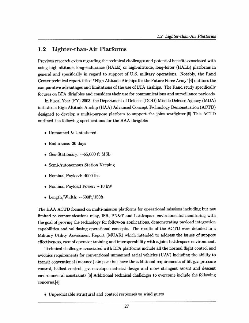
For the past several decades, military and commercial agencies have been capable of launch-ing short duration, high-altitude platforms into the lower stratosphere (36,000 feet to 82,000feet) for the purposes of atmospheric monitoring and beyond line-of-sight (BLOS) communica-tions relay. These platforms have traditionally been free flying, non-steerable lighter-than-air(LTA) balloons that are launched from a location which allows the prevailing winds to blow theplatform over the area of interest. Persistent coverage with these types of platforms can onlybe achieved by continually launching balloons for as long as coverage is required. Addition-ally, changes in wind direction necessitate changes in the launch locations which can be timeconsuming and cause service delays. New research in controllable airships will allow persistentcoverage with a single long-endurance platform.
With the renewed focus on the near-space region of the earth's atmosphere that lies between65,000 ft (20 km) and 325,000 ft (100 km) in altitude, the U.S. Air Force Scientific AdvisoryBoard (USAF SAB) conducted a study on the subject of persistence at near space altitudesfrom March 2005 to June 2005. In that study, the authors determined that
"in order to persist at high altitudes, a fixed wing aircraft requires an extremely
large wingspan, and a balloon or airship requires an extremely large volume ... thestudy found that a notional "near space" platform operating well above 100,000 feetaltitude is not technologically feasible in the foreseeable future. On the other hand,if one limits one's focus in "near space" to the regime between 65,000-100,000 feetin altitude, there are viable options for such operation, even in the near-term." [3]
1.2. Lighter-than-Air Platforms
1.2 Lighter-than-Air Platforms
Previous research exists regarding the technical challenges and potential benefits associated with
using high-altitude, long-endurance (HALE) or high-altitude, long-loiter (HALL) platforms in
general and specifically in regard to support of U.S. military operations. Notably, the Rand
Center technical report titled "High Altitude Airships for the Future Force Army" [4] outlines the
comparative advantages and limitations of the use of LTA airships. The Rand study specifically
focuses on LTA dirigibles and considers their use for communications and surveillance payloads.
In Fiscal Year (FY) 2003, the Department of Defense (DOD) Missile Defense Agency (MDA)
initiated a High Altitude Airship (HAA) Advanced Concept Technology Demonstration (ACTD)
designed to develop a multi-purpose platform to support the joint warfighter.[5] This ACTD
outlined the following specifications for the HAA dirigible:
* Unmanned & Untethered
* Endurance: 30 days
* Geo-Stationary: -65,000 ft MSL
* Semi-Autonomous Station Keeping
* Nominal Payload: 4000 lbs
* Nominal Payload Power: -10 kW
* Length/Width: '500ft/150ft
The HAA ACTD focused on multi-mission platforms for operational missions including but not
limited to communications relay, ISR, PN&T and battlespace environmental monitoring with
the goal of proving the technology for follow-on applications, demonstrating payload integration
capabilities and validating operational concepts. The results of the ACTD were detailed in a
Military Utility Assessment Report (MUAR) which intended to address the issues of support
effectiveness, ease of operator training and interoperability with a joint battlespace environment.
Technical challenges associated with LTA platforms include all the normal flight control and
avionics requirements for conventional unmanned aerial vehicles (UAV) including the ability to
transit conventional (manned) airspace but have the additional requirements of lift gas pressure
control, ballast control, gas envelope material design and more stringent ascent and descent
environmental constraints.[6] Additional technical challenges to overcome include the following
concerns. [4]
* Unpredictable structural and control responses to wind gusts
Chapter 1. Introduction
* No industrial base; limited institutional knowledge/memory
* Hull fabric degradation due to high altitude UV radiation (current UV barriers may be
inadequate)
* High altitude control system is less effective at lower altitudes due to stronger winds
* Maximum latitude limitations due to solar power availability (+ 450 north/south latitudes
(worst case)) limit global coverage capability
The additional subsystems necessarily increase the complexity of an LTA platform which in-
creases the likelihood of failure modes and reduces the overall reliability and thus availability
of the system.
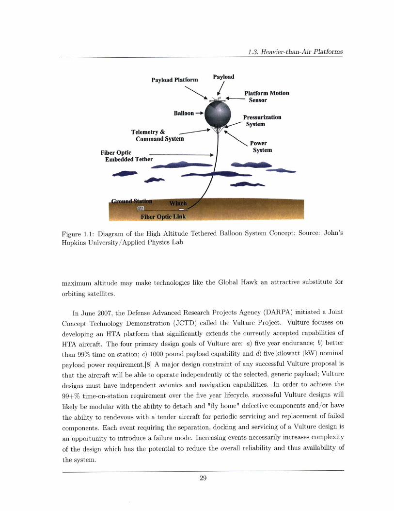
A further subset of the LTA class of HALE platforms are tethered high-altitude balloons.
Tethers offer the advantage of providing "hard line" communications connections to the ground
station via an embedded fiber optic cable to facilitate telemetry and command as well as pro-
viding a potential source of continuous power for the airship and the payload. Using a tether
for telemetry, command and power supply allows a weight reduction of the airship which allows
an increased payload mass margin. Disadvantages of the tether include: a) strength-to-weight
requirements of the tether material; b) tether drag in high winds; c) tether ice accretion at
altitude; d) conventional airspace clearance around the tether; e) tether insulation material
(thermal and electrical) and f) ground station survivability.
The Johns Hopkins University Applied Physics Laboratory (APL) conducted a study on the
High Altitude Tethered Balloon System (HATBS). In that study, which was conducted from
2003 to 2004, the APL determined that it is technically feasible to maintain a captive LTA
platform at an altitude of 65,000 feet for extended periods. The program ended before any
physical tests could be conducted. See figure 1.1 for an illustration of the HATBS concept.
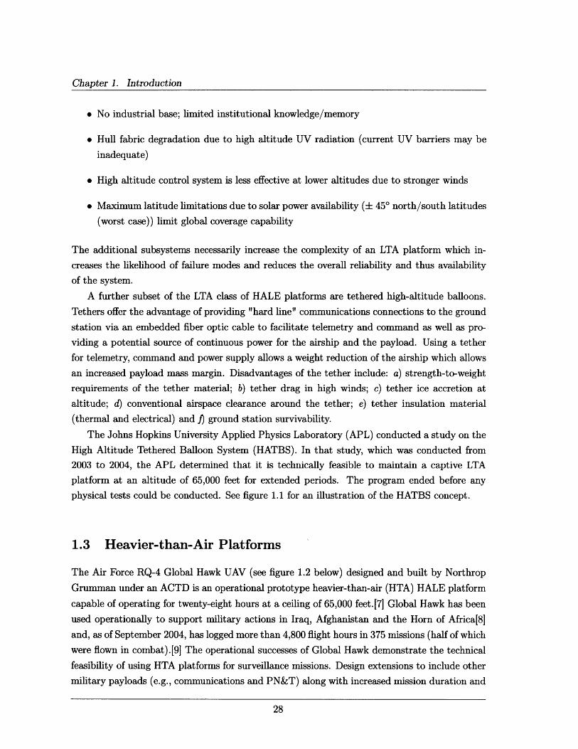
1.3 Heavier-than-Air Platforms
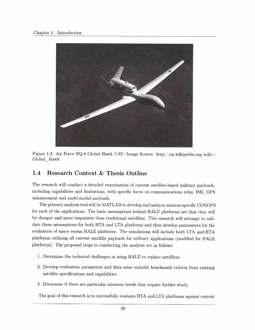
The Air Force RQ-4 Global Hawk UAV (see figure 1.2 below) designed and built by Northrop
Grumman under an ACTD is an operational prototype heavier-than-air (HTA) HALE platform
capable of operating for twenty-eight hours at a ceiling of 65,000 feet.[7 Global Hawk has been
used operationally to support military actions in Iraq, Afghanistan and the Horn of Africa[8]
and, as of September 2004, has logged more than 4,800 flight hours in 375 missions (half of which
were flown in combat).[9 The operational successes of Global Hawk demonstrate the technical
feasibility of using HTA platforms for surveillance missions. Design extensions to include other
military payloads (e.g., communications and PN&T) along with increased mission duration and
1.3. Heavier-than-Air Platforms
Payload Platform
Balloon
Telemetry &Command System
Fiber OpticEmbedded Tether
Payload
S Platform Motion-- Sensor
PressurizationSSystem
PowerSystem
Figure 1.1: Diagram of the High Altitude Tethered Balloon System Concept; Source: John's
Hopkins University/Applied Physics Lab
maximum altitude may make technologies like the Global Hawk an attractive substitute for
orbiting satellites.
In June 2007, the Defense Advanced Research Projects Agency (DARPA) initiated a Joint
Concept Technology Demonstration (JCTD) called the Vulture Project. Vulture focuses on
developing an HTA platform that significantly extends the currently accepted capabilities of
HTA aircraft. The four primary design goals of Vulture are: a) five year endurance; b) better
than 99% time-on-station; c) 1000 pound payload capability and d) five kilowatt (kW) nominal
payload power requirement.[81 A major design constraint of any successful Vulture proposal is
that the aircraft will be able to operate independently of the selected, generic payload; Vulture
designs must have independent avionics and navigation capabilities. In order to achieve the
99+% time-on-station requirement over the five year lifecycle, successful Vulture designs will
likely be modular with the ability to detach and "fly home" defective components and/or have
the ability to rendevous with a tender aircraft for periodic servicing and replacement of failed
components. Each event requiring the separation, docking and servicing of a Vulture design is
an opportunity to introduce a failure mode. Increasing events necessarily increases complexity
of the design which has the potential to reduce the overall reliability and thus availability of
the system.
Chapter 1. Introduction
Figure 1.2: Air Force RQ-4 Global Hawk UAV; Image Source: http://en.wikipedia.org/wiki/-Global Hawk
1.4 Research Context & Thesis Outline
The research will conduct a detailed examination of current satellite-based military payloads,including capabilities and limitations, with specific focus on communications relay, ISR, GPSenhancement and multi-modal payloads.
The primary analysis tool will be MATLAB to develop and analyze mission-specific CONOPSfor each of the applications. The basic assumptions behind HALE platforms are that they willbe cheaper and more responsive than traditional satellites. This research will attempt to vali-date these assumptions for both HTA and LTA platforms and then develop parameters for theevaluation of space versus HALE platforms. The simulations will include both LTA and HTAplatforms utilizing all current satellite payloads for military applications (modified for HALEplatforms). The proposed steps in conducting the analysis are as follows:
1. Determine the technical challenges in using HALE to replace satellites.
2. Develop evaluation parameters and data mine suitable benchmark criteria from existingsatellite specifications and capabilities.
3. Determine if there are particular missions/needs that require further study.
The goal of this research is to successfully evaluate HTA and LTA platforms against current
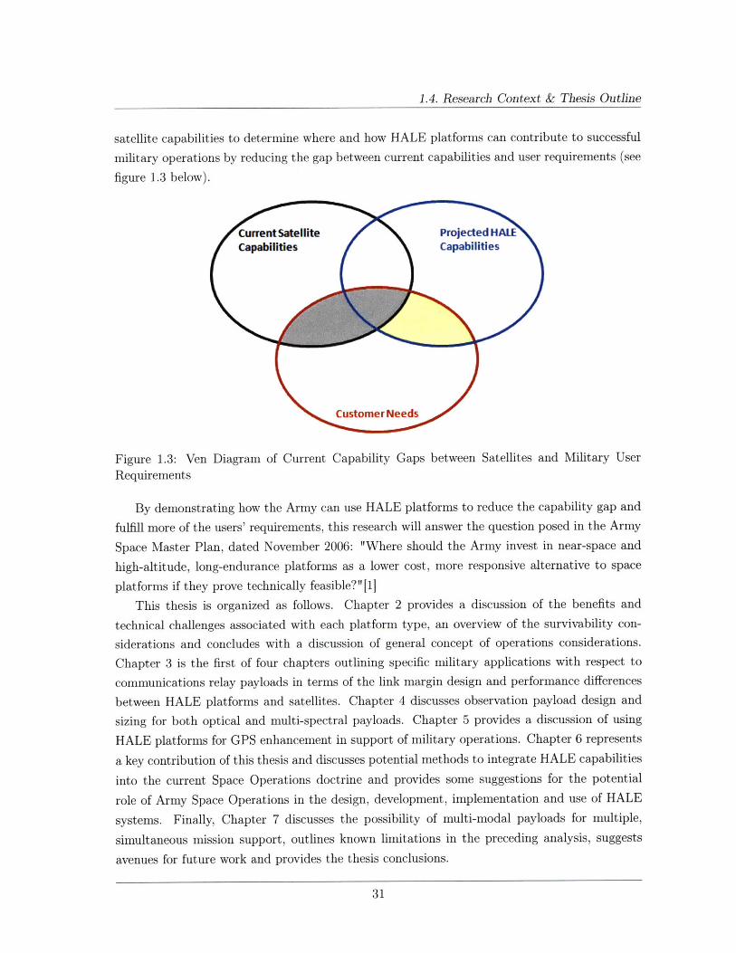
1.4. Research Context & Thesis Outline
satellite capabilities to determine where and how HALE platforms can contribute to successful
military operations by reducing the gap between current capabilities and user requirements (see
figure 1.3 below).
Current Satellite Projected HALECapabilities Capabilities
Customer Needs
Figure 1.3: Ven Diagram of Current Capability Gaps between Satellites and Military User
Requirements
By demonstrating how the Army can use HALE platforms to reduce the capability gap and
fulfill more of the users' requirements, this research will answer the question posed in the Army
Space Master Plan, dated November 2006: "Where should the Army invest in near-space and
high-altitude, long-endurance platforms as a lower cost, more responsive alternative to space
platforms if they prove technically feasible?"[1]
This thesis is organized as follows. Chapter 2 provides a discussion of the benefits and
technical challenges associated with each platform type, an overview of the survivability con-
siderations and concludes with a discussion of general concept of operations considerations.
Chapter 3 is the first of four chapters outlining specific military applications with respect to
communications relay payloads in terms of the link margin design and performance differences
between HALE platforms and satellites. Chapter 4 discusses observation payload design and
sizing for both optical and multi-spectral payloads. Chapter 5 provides a discussion of using
HALE platforms for GPS enhancement in support of military operations. Chapter 6 represents
a key contribution of this thesis and discusses potential methods to integrate HALE capabilities
into the current Space Operations doctrine and provides some suggestions for the potential
role of Army Space Operations in the design, development, implementation and use of HALE
systems. Finally, Chapter 7 discusses the possibility of multi-modal payloads for multiple,
simultaneous mission support, outlines known limitations in the preceding analysis, suggests
avenues for future work and provides the thesis conclusions.

This page intentionally left blank.
Chapter 2
HALE Platform Overview
This chapter provides a discussion of the design drivers and engineering challenges associated
with HALE platforms then moves to a discussion of the projected HALE platform capabilities,
provides a platform sizing example to help scope the problem and concludes with some general
concept of operations (CONOPS) considerations.
2.1 Design Drivers and Engineering Challenges
Successful long-duration airborne platforms, as with any complex system, must be designed
with the ability to survive within the operating environment. Considerations for generic HALE
platforms include climatology and winds aloft; power issues; thermal management issues; and
materials selection criteria. Additionally, for military applications, survivable designs must con-
sider the impact of dynamic and electronic attacks via ground-to-air and air-to-air engagements.
This section is not intended to be a detailed design analysis of each of the subsystems
listed above. Rather, it is intended to acquaint the reader with some of the major survivability
considerations for the implementation of HALE platforms. For the purposes of this thesis, it
is assumed that the technological feasibility of HALE platforms has already been determined,
citing the RQ-4 Global Hawk UAV[7] discussed in section 1.3 as an existence proof of the
concept.
2.1.1 Environmental Considerations
Figure 2.1 below, taken from the Rand Study "High Altitude Airships for the Future Force
Army" 4] details the average annual winds aloft over Baghdad and clearly shows that strato-
spheric winds are most favorable for extended operations between the altitudes of 60,000 feet
and 80,000 feet. This graph is intended for application to LTA platforms but one can draw
similar conclusions for HTA platforms as well. Additionally, system design and site selection
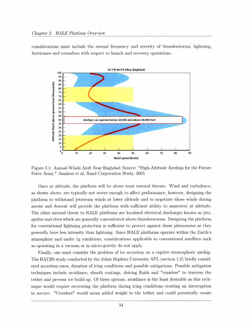
Chapter 2. HALE Platform Overview
considerations must include the annual frequency and severity of thunderstorms, lightning,
hurricanes and tornadoes with respect to launch and recovery operations.
33.1°N 44.50 E (Near Baghdad)100959085
I 80o 75
70> 65
60
55 -50 -
S45-40 Airships can operate below 20,000 and above 60,000 feet3530
. 25-3 20
1510-
0 10 20 30 40 50 60 70 80 90
Wind speed (knots)
Figure 2.1: Annual Winds Aloft Near Baghdad; Source: "High-Altitude Airships for the FutureForce Army," Jamison et al, Rand Corporation Study, 2005
Once at altitude, the platform will be above most natural threats. Wind and turbulence,
as shown above, are typically not severe enough to affect performance, however, designing the
platform to withstand jetstream winds at lower altitude and to negotiate those winds during
ascent and descent will provide the platform with sufficient ability to maneuver at altitude.
The other natural threat to HALE platforms are localized electrical discharges known as jets,sprites and elves which are generally concentrated above thunderstorms. Designing the platform
for conventional lightning protection is sufficient to protect against these phenomena as they
generally have less intensity than lightning. Since HALE platforms operate within the Earth's
atmosphere and under ig conditions, considerations applicable to conventional satellites such
as operating in a vacuum or in micro-gravity do not apply.
Finally, one must consider the problem of ice accretion on a captive stratospheric airship.
The HATBS study conducted by the Johns Hopkins University APL (section 1.2) briefly consid-
ered accretion rates, duration of icing conditions and possible mitigations. Possible mitigation
techniques include avoidance, sheath coatings, deicing fluids and "crawlers" to traverse the
tether and prevent ice build-up. Of these options, avoidance is the least desirable as this tech-
nique would require recovering the platform during icing conditions creating an interruption
in service. "Crawlers" would mean added weight to the tether and could potentially create
2.1. Design Drivers and Engineering Challenges
unnecessary design complications. Deicing fluids appear to be a viable solution assuming an
effective, lightweight delivery system. Given the two limiting factors of coverage requirements
and weight limitations, hydrophobic sheath coatings appear to be the most viable option.
2.1.2 Power System Requirements
Satellites and HALE platforms have similar power requirements in terms of the necessity for
renewable power sources. The extreme mission durations (months to years) being considered
for HALE platforms eliminate the possibility of conventional, expendable fuel sources. Three
possible long-duration power sources are nuclear reactors, fuel cells and solar arrays. Nuclear
reactors are widely considered to be too dangerous and too heavy for implementation in HALE
platforms operating within the Earth's atmosphere and existing fuel cells are not efficient enough
to provide sustained power for several years. As a result, the primary focus of this section is on
solar arrays. There are some emerging technologies involving regenerative fuel cells that may
yield a viable alternative to solar arrays and are discussed at the end of this section.
With respect to captive stratospheric airships, such as APL's HATBS concept, the tether
could potentially provide a continuous virtually unlimited power supply from the ground station.
This concept has the advantage of reducing the onboard power subsystem requirements to a
simple back-up battery supply in the event of a temporary power disruption from the ground
station.
Solar Arrays
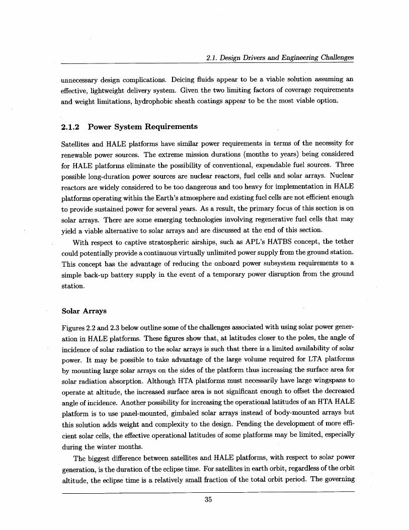
Figures 2.2 and 2.3 below outline some of the challenges associated with using solar power gener-
ation in HALE platforms. These figures show that, at latitudes closer to the poles, the angle of
incidence of solar radiation to the solar arrays is such that there is a limited availability of solar
power. It may be possible to take advantage of the large volume required for LTA platforms
by mounting large solar arrays on the sides of the platform thus increasing the surface area for
solar radiation absorption. Although HTA platforms must necessarily have large wingspans to
operate at altitude, the increased surface area is not significant enough to offset the decreased
angle of incidence. Another possibility for increasing the operational latitudes of an HTA HALE
platform is to use panel-mounted, gimbaled solar arrays instead of body-mounted arrays but
this solution adds weight and complexity to the design. Pending the development of more effi-
cient solar cells, the effective operational latitudes of some platforms may be limited, especially
during the winter months.
The biggest difference between satellites and HALE platforms, with respect to solar power
generation, is the duration of the eclipse time. For satellites in earth orbit, regardless of the orbit
altitude, the eclipse time is a relatively small fraction of the total orbit period. The governing
Chapter 2. HALE Platform Overview
z = 17 km 22 DecemberS 36"* N
1--x 40 N
8 12 16 20 24Time (hours)
1250
1000
750
500
250
0
z a 17 km
40 N
45 N
22 June36" N
0 4 8 12 16Time (hours)
= 4T 1I
1200 30 N1000 4WN
600400200
00.0 36.5 73.0 109.5 146.0 182.5 219.0 255.5 292.0 328.5 365.0
Time (day)
Figure 2.2: Daily and Yearly Solar Power Distributioncourtesy Giulio Romeo, Turin Polytechnic University
at Several Latitudes; Source: Illustration
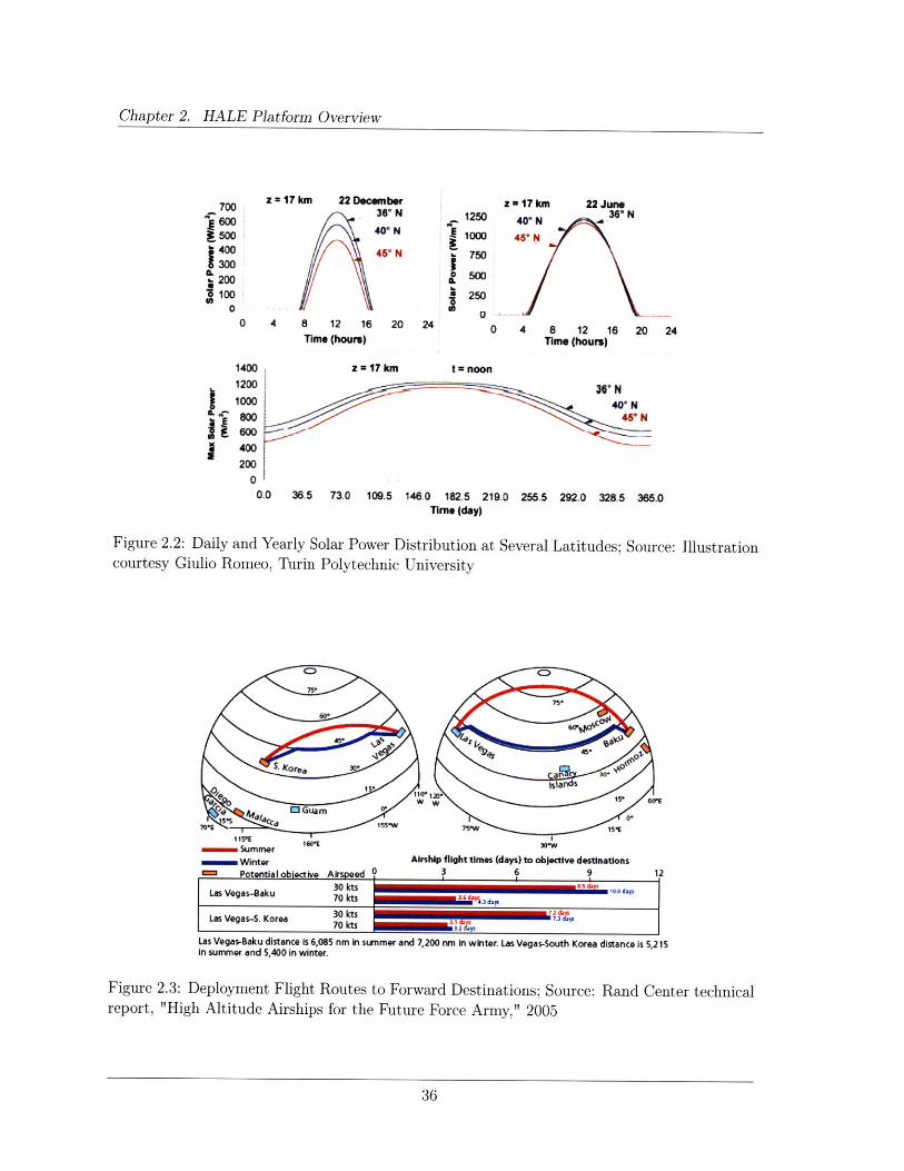
7OE imm 7W 15%115"E Is*E Irw1601 3WSummer
Winter Airship flight times (days) to objective destinationsm Potential objective Airspeed 0 3 6 9 12
Las VQegas-Baku 70 kts . ayds
3o0 ktsLas Vegas-S. Korea 70 kts W ,
Las Vegas-Baku distance is 6,085 nm in summer and 7,200 nm in winter. Las Vegas-South Korea distance is 5,215in summer and 5,400 in winter.
2.3: Deployment Flight Routes to Forward Destinations; Source: Rand Center technical"High Altitude Airships for the Future Force Army," 2005
700
,E 600
300
1000
20 24
iI
Figurereport,
4 J1kl 6 =
2.1. Design Drivers and Engineering Challenges
equations for computing the eclipse fraction for any given sun angle are:[10]
cos cosp (2.1)COS 2 cos sS
The duration of the eclipse in a circular orbit, TE, is then
TE = P (2.2)
Where p is the angular radius of the Earth, 3s is the angle of the sun above the orbit plane, 2
is half of the rotation angle corresponding to the eclipse duration and P is the orbit period.[10]
For satellites in Earth orbit, the eclipse time is measured in minutes and is usually on the order
of 30% of the total orbit period for LEO satellites.
For HALE platforms, which are nearly stationary with respect to the area of interest on
the ground and still operating within the Earth's atmosphere, the daily eclipse time has the
same duration as the local night. Accounting for seasonal variations and operational latitude,
the average annual eclipse duration is taken to be twelve hours. It is important to note, how-
ever, that the eclipse period approaches 24 hours or 100% of the duty cycle during the winter
months in operational latitudes approaching 220 north/south thus significantly limiting the op-
erational latitude ranges during certain months. This extended eclipse period translates to fewer
charge/discharge cycles than required for conventional satellites. Spacecraft in low earth orbit
(LEO) experience their maximum depth of discharge (DoD - percent of total battery capacity
removed during a discharge period) approximately fifteen times per day while HALE platforms
experience the maximum DoD only once per day. The reduced number of battery cycles af-
forded by HALE platforms allows for either lighter batteries or a deeper depth of discharge.
Additionally, the reduced cycles prolong battery life facilitating a longer operational lifetime.
The expectation for power system sizing is that the smaller, lighter payloads possible on
HALE platforms (discussed in the following Military Applications chapters) will require less
power and therefore allow a lighter power subsystem. Further research is necessary to optimize
HALE platform power systems in terms of size, mass and cost or to optimize the CONOPS
by limiting operations at higher latitudes. As stated at the beginning of this section, sub-
system optimization is beyond the scope of this thesis; however, the relevant governing equations
are provided in Appendix A for further examination. This chapter will provide a power sub-
system sizing example to outline the general requirements and feasibility of supporting a HALE
platform.
Regenerative Fuel Cells
As mentioned above, the efficiency of existing fuel cells is insufficient to provide sustained power
for the multi-year missions planned for HALE platforms. Fuel cell efficiency is determined by
Chapter 2. HALE Platform Overview
the amount of power drawn from the cell. The current drawn from a fuel cell is proportional to
the amount of power drawn through the equation:
Pwr = VI (2.3)
Where Pwr is the power in Watts, V is the potential difference in volts and I is the current in
Amperes.
Drawing more power means drawing more current, which increases the losses in the fuel
cell. As a general rule, the more power (current) drawn, the lower the efficiency. Most losses
manifest themselves as a voltage drop in the cell, so the efficiency of a cell is almost proportional
to its voltage. The affect of power draw on efficiency generally makes conventional fuel cells
undesirable for use as a long term power source.
Fuel cells operate by electrochemical conversion through the consumption of a fuel and an
oxidant which react in the presence of an electrolyte. The reactants consumed in the process
must be replenished in order to maintain power output. This replenishment requirement is
another major drawback to using fuel cells on HALE platforms.
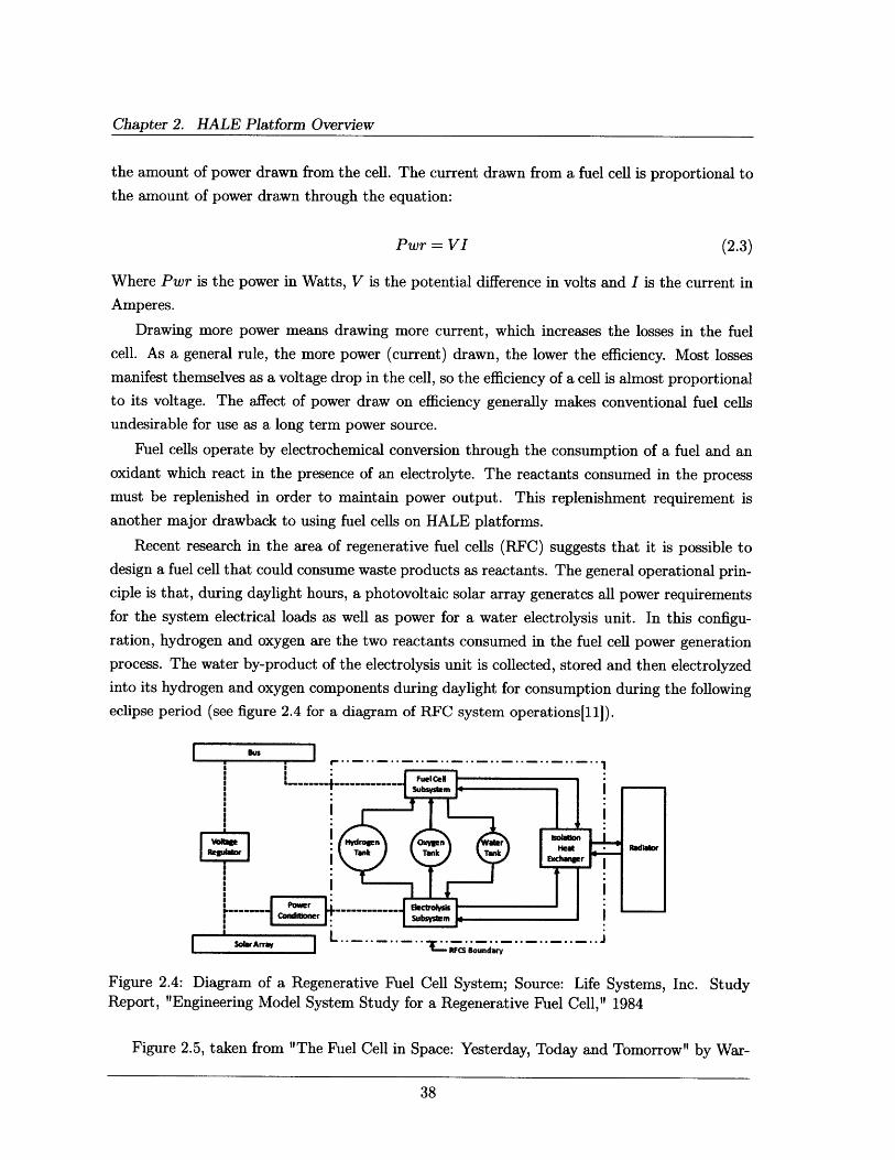
Recent research in the area of regenerative fuel cells (RFC) suggests that it is possible to
design a fuel cell that could consume waste products as reactants. The general operational prin-
ciple is that, during daylight hours, a photovoltaic solar array generates all power requirements
for the system electrical loads as well as power for a water electrolysis unit. In this configu-
ration, hydrogen and oxygen are the two reactants consumed in the fuel cell power generation
process. The water by-product of the electrolysis unit is collected, stored and then electrolyzed
into its hydrogen and oxygen components during daylight for consumption during the following
eclipse period (see figure 2.4 for a diagram of RFC system operations[i1]).
Subsytm
I Povl on io dron ox----- lectls
R lar Tank "CTan Tlundkar
Figure 2.4: Diagram of a Regenerative Fuel Cell System; Source: Life Systems, Inc. StudyReport, "Engineering Model System Study for a Regenerative Fuel Cell," 1984
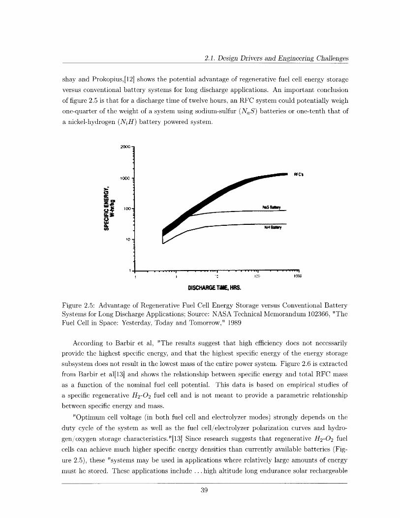
Figure 2.5, taken from "The Fuel Cell in Space: Yesterday, Today and Tomorrow" by War-
2.1. Design Drivers and Engineering Challenges
shay and Prokopius,[12] shows the potential advantage of regenerative fuel cell energy storage
versus conventional battery systems for long discharge applications. An important conclusion
of figure 2.5 is that for a discharge time of twelve hours, an RFC system could potentially weigh
one-quarter of the weight of a system using sodium-sulfur (NaS) batteries or one-tenth that of
a nickel-hydrogen (NiH) battery powered system.
1000WIC's1000
IItX
DISCHARGE TOE, HRS.
Figure 2.5: Advantage of Regenerative Fuel Cell Energy Storage versus Conventional BatterySystems for Long Discharge Applications; Source: NASA Technical Memorandum 102366, "TheFuel Cell in Space: Yesterday, Today and Tomorrow," 1989
According to Barbir et al, "The results suggest that high efficiency does not necessarily
provide the highest specific energy, and that the highest specific energy of the energy storage
subsystem does not result in the lowest mass of the entire power system. Figure 2.6 is extracted
from Barbir et al[13] and shows the relationship between specific energy and total RFC mass
as a function of the nominal fuel cell potential. This data is based on empirical studies of
a specific regenerative H 2-0 2 fuel cell and is not meant to provide a parametric relationship
between specific energy and mass.
"Optimum cell voltage (in both fuel cell and electrolyzer modes) strongly depends on the
duty cycle of the system as well as the fuel cell/electrolyzer polarization curves and hydro-
gen/oxygen storage characteristics."[13] Since research suggests that regenerative H 2-0 2 fuel
cells can achieve much higher specific energy densities than currently available batteries (Fig-
ure 2.5), these "systems may be used in applications where relatively large amounts of energy
must he stored. These applications include ... high altitude long endurance solar rechargeable

Chapter 2. HALE Platform Overview
0.6
0.55
0.5
0.45
3 0.4
f 0.35
0.3
0.25
0.2
0.15
250
230
210
190
170
150
130
110
90
70
50U ..L - I I I 1
0.4 0.5 0.6 0.7 0.8 0.9 1
Fuel Cell Nominal Potential (V)
-Specific Energy (kW-hr/kg) - Total Mass (kg/kW)
Figure 2.6: RFC Specific-Energy & Mass Relations as a Function of Fuel Cell Voltage; Source:
IEEE A&E SYSTEMS MAGAZINE, "Regenerative Fuel Cells for Energy Storage: Efficiency
and Weight Trade-offs," Barbir et al, 2005
aircraft."[13]
A further advantage of these hydrogen/oxygen RFCs is that they operate more efficiently
on pure oxygen rather than an air mixture of oxygen and nitrogen. This characteristic is
important in high altitude applications where atmospheric oxygen is limited (and critical in
the vacuum of space). The pure oxygen by-product of electrolysis allows the system to operate
more efficiently, be lighter as it would not require a device to pump air through the fuel cell
(resulting in additional efficiency losses) and be a closed system with fewer failure modes.
Another existence proof of this concept is "Helios", a solar cell/regenerative fuel cell system
powered unmanned air vehicle under development by AeroVironment. Helios is designed to "fly
at 50,000-70,000 feet for months without landing and serve as a substitute satellite, a platform
capable of supporting telecommunication, and military and civilian applications." [14] To date,
a HALE UAV named "Pathfinder," designed and built by AeroVironment "flew to 80,000 feet
setting a new world record for the highest flying propeller driven aircraft."[14]
Research to date indicates that H 2-0 2 RFCs are a viable option for HALE platforms how-
ever, further research must be done to optimize the system design for specific applications (e.g.,
duration of charge/discharge cycles and various load profiles).
- -- ---- ---- ---

2.1. Design Drivers and Engineering Challenges
2.1.3 Thermal Management
Since HALE platforms operate within the Earth's atmosphere, temperature variations are not
as extreme as those experienced by Earth orbiting satellites. However, temperatures in the
near-space regime of the atmosphere still vary widely between daylight and nighttime hours.
Thus successful HALE designs must include a thermal control system (TCS) to maintain all
platform and payload components within their required upper and lower operating tempera-
tures. Traditionally two temperature limits are defined: "operational limits that the component
must remain within while operating and survival limits that the components must remain within
at all times."[115] There are two broad categories of thermal control: passive, which uses ma-
terials, coatings, insulation and radiators; and active, which uses electrically powered heaters
and coolers. Table 2.1 below is taken from chapter 11.5 of Space Mission Analysis and Design,
3d Edition (SMAD) written by Gilmore et al and provides examples of typical thermal require-
ments for spacecraft and payload components. In general, if the spacecraft components shown
in the table can also be used on HALE platforms, the component will have similar operational
and survival temperatures and can be used as design guidelines for HALE systems. While the
difference in ambient temperatures between stratospheric and orbital altitudes will necessitate
different thermal system requirements, the governing equations and design principles are the
same and are discussed later.
Component
BatteriesPower Box BaseplatesReaction WheelsGyros/IMUsStar TrackersC&DH Box BaseplatesHydrazine Tanks and LinesAntenna GimbalsAntennasSolar Panels
Table 2.1: Examples of Typical ThermalSMAD Chapter 11.5
Typical Temperature Ranges (oC)
Operational Survival
0 to 15 -10 to 25
-10 to 50 -20 to 60
-10 to 40 -20 to 500 to 40 -10 to 500 to 30 -10 to 40
-20 to 60 -40 to 75
15 to 40 5 to 50-40 to 80 -50 to 90
-100 to 100 -120 to 120
-150 to 110 -200 to 130
Requirements for Spacecraft Component,s; Source:
In October 2007, while working under contract to the Missile Defense Agency, Charles La-
van gave a presentation entitled the High Altitude Long Endurance Primer[16] in which he
outlined the basic design considerations and issues surrounding HALE platforms. In that pre-
sentation, Dr. Lavan provided several simple equations to determine the ambient temperature
and atmospheric pressures at various altitudes. Those equations are summarized below:
Chapter 2. HALE Platform Overview
For altitudes in the upper stratosphere (Hp > 82345 feet):
T = -205.05 + 0.00164Hp
p = 51.97 T + 459.7 -11.388 (2.4)P= .97* [389.98 1
For altitudes in the lower stratosphere (36152 < Hp < 82345 feet):
T = -70
p = 473.1 * e (1. 7 3 -0 .000048Hp) (2.5)
For altitudes in the troposphere (Hp < 36152 feet):
T = 59 - 0.00356Hp
p = 2116 *[T + 459.7 5.526 (2.6)518.6 J
In all cases, atmospheric density (Patm) is a function of pressure as follows:
Patm = (2.7)1718 * (T + 459.7)
Where Hp is the platform altitude in feet, T is the ambient temperature in oF, p is the atmo-
spheric pressure in lbs/sq ft and Patm is measured in slugs/cu ft.
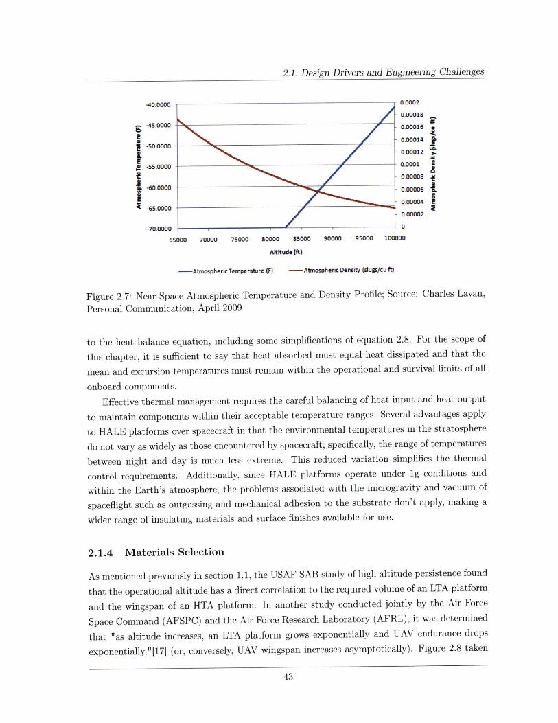
Based on the USAF SAB study discussed in section 1.1, we are primarily interested in HALE
uses in the near space regime between 65,000 ft (20 km) and 100,000 ft (30.5 km), therefore;
we will restrict our consideration to equations (2.4), (2.5) and (2.7). Applying those equations,we obtain the atmospheric temperature/density profile shown in figure 2.7.
Knowing the external temperatures at various altitudes allows us to calculate the required
heat balance for proper system operation. According to Gilmore et al,[15] "for most spacecraft,heat balance on radiators is the dominant factor in the thermal design." We will apply this
same consideration to HALE platforms in a generalized heat balance equation:
Qexternal + Qinternal = Qradiator + QMLI + Qconvective (2.8)
Where Qexternal is the environmental heat absorbed, Qinternal is the power dissipation of on-
board electronic components, Qradiator is the heat rejected from the platform's primary radiator
surfaces, QMLI is the heat lost through multi-layer insulation on the platform and Qconvectiveis the heat lost through convection. For the purposes of this section, it is assumed that the pri-
mary means of heat elimination is radiative since the low atmospheric density makes convective
heating and cooling impractical. Therefore, we will ignore the Qconvective term.
Appendix A contains the other governing equations relevant to determining the solutions
2.1. Design Drivers and Engineering Challenges
-40.0000 0.0002
0.00018
-45.0000 0.00016
_ 0.00014 4-50.0000
S-55.0000 0.0001
-. oooo oooo0.-6.000000002
-70.0000 . 0
65000 70000 75000 80000 85000 90000 95000 100000
Altitude (ft)
-Atmospheric Temperature (F) - Atmospheric Density (slugs/cu ft)
Figure 2.7: Near-Space Atmospheric Temperature and Density Profile; Source: Charles Lavan,
Personal Communication, April 2009
to the heat balance equation, including some simplifications of equation 2.8. For the scope of
this chapter, it is sufficient to say that heat absorbed must equal heat dissipated and that the
mean and excursion temperatures must remain within the operational and survival limits of all
onboard components.
Effective thermal management requires the careful balancing of heat input and heat output
to maintain components within their acceptable temperature ranges. Several advantages apply
to HALE platforms over spacecraft in that the environmental temperatures in the stratosphere
do not vary as widely as those encountered by spacecraft; specifically, the range of temperatures
between night and day is much less extreme. This reduced variation simplifies the thermal
control requirements. Additionally, since HALE platforms operate under ig conditions and
within the Earth's atmosphere, the problems associated with the microgravity and vacuum of
spaceflight such as outgassing and mechanical adhesion to the substrate don't apply, making a
wider range of insulating materials and surface finishes available for use.
2.1.4 Materials Selection
As mentioned previously in section 1.1, the USAF SAB study of high altitude persistence found
that the operational altitude has a direct correlation to the required volume of an LTA platform
and the wingspan of an HTA platform. In another study conducted jointly by the Air Force
Space Command (AFSPC) and the Air Force Research Laboratory (AFRL), it was determined
that "as altitude increases, an LTA platform grows exponentially and UAV endurance drops
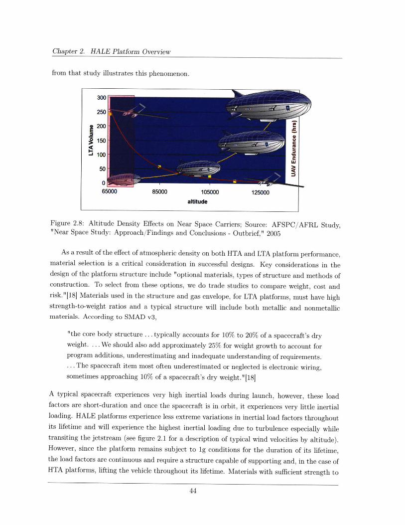
exponentially,"[171 (or, conversely, UAV wingspan increases asymptotically). Figure 2.8 taken
Chapter 2. HALE Platform Overview
from that study illustrates this phenomenon.
300
250
E 200=150 C
50
65000 85000 105000 125000altitude
Figure 2.8: Altitude Density Effects on Near Space Carriers; Source: AFSPC/AFRL Study,"Near Space Study: Approach/Findings and Conclusions - Outbrief," 2005
As a result of the effect of atmospheric density on both HTA and LTA platform performance,material selection is a critical consideration in successful designs. Key considerations in thedesign of the platform structure include "optional materials, types of structure and methods ofconstruction. To select from these options, we do trade studies to compare weight, cost andrisk."18] Materials used in the structure and gas envelope, for LTA platforms, must have highstrength-to-weight ratios and a typical structure will include both metallic and nonmetallicmaterials. According to SMAD v3,
"the core body structure ... typically accounts for 10% to 20% of a spacecraft's dryweight. ... We should also add approximately 25% for weight growth to account forprogram additions, underestimating and inadequate understanding of requirements.... The spacecraft item most often underestimated or neglected is electronic wiring,sometimes approaching 10% of a spacecraft's dry weight. "[181
A typical spacecraft experiences very high inertial loads during launch, however, these loadfactors are short-duration and once the spacecraft is in orbit, it experiences very little inertialloading. HALE platforms experience less extreme variations in inertial load factors throughoutits lifetime and will experience the highest inertial loading due to turbulence especially whiletransiting the jetstream (see figure 2.1 for a description of typical wind velocities by altitude).However, since the platform remains subject to ig conditions for the duration of its lifetime,the load factors are continuous and require a structure capable of supporting and, in the case ofHTA platforms, lifting the vehicle throughout its lifetime. Materials with sufficient strength to

2.1. Design Drivers and Engineering Challenges
withstand the inertial loads due to the jetstream will be strong enough to support the vehicle
through the range of inertial loads experienced during operation. Generally speaking, structural
materials for HALE platforms will account for a larger percentage of the platform dry weight,
on the order of 40% of the total weight.[19]
In a study conducted by the Naval Ordnance Laboratory in 1975, the authors discuss several
considerations germane to LTA platforms.
"Fabric selection will be determined by environmental conditions as well as by
weight, strength, and other basic parameters of the material. ... The ideal hull
fabric should be very strong, extremely light, insensitive to extremes of temper-
ature, impervious to ultraviolet radiation, ozone and bombardment with charged
particles, have limited elasticity and no creep, and be impenetrable to helium or
hydrogen. For ease of manufacture the material should be easy to cut, seam, and
seal, and be readily available and cheap. In addition it should be insensitive to
folding and creasing, and have a storage life of several years under the poorest of
conditions." 19]
The two most important considerations in this rather extensive list are arguably the material's
resistance to temperature fluctuations and ultraviolet radiation since exposure to sunlight is
magnified and thermal coupling to the atmosphere is reduced at higher altitudes thus increasing
exposure to ultraviolet radiation.[19]
While it is beyond the scope of this thesis to select actual candidate materials for HALE
platforms, it is important to identify some key parameters upon which material selection de-
pends most strongly. To this end, two parameters are offered for the reader's consideration:
material tensile strength, -, and resistance to inelastic deformation. Tensile strength is im-
portant in determining the material's strength-to-weight ratio and the material's resistance to
inelastic deformation is critical with respect to the material's ability to retain its shape and lift
properties through the cyclic and continuous stresses over the extreme mission durations being
considered for HALE applications.
In general, HALE platforms benefit from a wider range of available materials than does
a spacecraft. The materials available are not exotic and do not require space qualification.
Therefore, while material selection is a critical component of a successful design, it is not likely
to be the significant factor in the overall technical feasibility of the HALE concept.
2.1.5 Dynamic and Electronic Attacks
Predictability is undoubtedly the issue at the crux of a platform's ability to survive dynamic
and electronic attacks via both ground-to-air and air-to-air engagements. In the military ap-
plications discussed here: communications relay, ISR, and GPS enhancement, predictability is

Chapter 2. HALE Platform Overview
essential in order to maximize the performance of the platform. On the other hand, a platform's
predictability is the key factor that would enable engagement by an enemy force.
A study commissioned by the AFRL conducted an analysis of HALE platform survivability
and concluded that there are several advantages working in favor of a platform's ability to
survive an attack. First and foremost, HALE platforms, while operating at altitude, are out of
range for most conventional weapon systems. The exception to this rule is a radio frequency
(RF) terminally guided medium to long-range missile.[20] Table 2.2 outlines the capabilities of
currently available medium/long-range surface-to-air missiles (SAM). A further limiting factor
on platform vulnerability is the fact that medium/long-range SAMs are not highly proliferated
due to their inherent high cost.
Country Designation Range Flight Alt. Guidance
SA-2 28km 66 kft 3 GHz Track/Engage RadarRussia SA-5 >300km 130 kft Active RF Terminal Seeker
SA-10 (SA-10C) 200km 82 kft RF Terminal Seeker
China KS-1 40km 79 kft Phased Array RadarFrance MASURCA 23km 75 kft Semi-active Radar
Table 2.2: Medium/Long-Range SAM Capabilities; Source: www.wikipedia.com, accessedMarch 2009
The AFRL study also considered vulnerability to weapon systems operating in the infrared
(IR) and visible spectrums. In both cases, the study concluded that HALE platform does not
have any significant vulnerability to these types of attack.[16] The key contributing factor tolow IR vulnerability is the fact that the vehicle's IR signature is very large (spatially) and highly
distributed with no significant "hot spots" for terminal lock-on. Based on an unclassified reviewof threat literature, it is sufficient to say that IR terminally guided munitions are not capable
of detecting HALE platforms.
Vulnerability in the visible spectrum depends on the range, relative brightness and atmo-
spheric clarity. HALE platforms are beyond the range of visually targeted hand held weapons
and the low target contrast with the background sky means even high-altitude visually targeted
weapons will not be able to detect the platform. It is valid to argue that HALE platforms
are vulnerable to visually targeted weapon systems during ascent and descent. In this case,alternate means of protection must be considered and are discussed later.
Further contributing factors to HALE survivability include the fact that these platforms
are maneuverable and, given sufficient warning, can be moved out of range of SAM attacks. Anominal operating altitude of 85,000 feet places the platform out of range of all threat SAMs
except the SA-5. Additionally HALE platforms can be equipped with conventional counter-
measure devices that alter the electromagnetic, acoustic or radio frequency (RF) signature of
2.2. Projected HALE Capabilities
the platform and/or jettison decoys such as chaff and flares. It is important to note that al-
tering or modifying the platform's RF signature will not work for communications and GPS
payloads which depend on their RF signatures for mission accomplishment. Finally, the U.S.
Army's MIM-104 Patriot missile system, operating in its primary role as an anti-ballistic missile
(ABM) platform, could intercept and destroy any inbound missile threat.
Having safely achieved the operating altitude, one must now consider the platform's vul-
nerability during ascent and descent; several options exist to offset potential threats. First, the
U.S. Army always assumes air superiority in any confrontation. Assigning USAF fighter jets
to patrol the vicinity of the HALE platforms ascent and descent will afford the necessary pro-
tection against most conventional attacks. The Patriot missile system could also be employed
to protect the platform during this period of increased vulnerability. Deploying the platform
from within the United States and then moving the platform to the area of operations under
its own power and thus avoiding ascent and descent over hostile territory is another way to
mitigate platform vulnerability. Finally, the vulnerability during ascent and descent can be
mitigated by not operating the payload until the platform has reached its operational altitude
thus eliminating a large percentage of platform emissions during the most vulnerable times.
One admitted limitation to the AFRL study is that it does not consider the properties of the
payload in the survivability calculations. One key example is that, while the platform may have
a small radar cross-section, a communications relay payload would essentially act as a beacon
for RF terminally guided munitions. This limitation is offset by the fact that a communications
payload will only be operational once on station. The communications payload vulnerability
example requires significant design upgrades to ensure platform survivability.
2.2 Projected HALE Capabilities
HALE platforms have the capability to significantly improve many aspects of military oper-
ations. A commander's situational understanding on the battlefield relies on rapid, relevant
information. Space-based assets are currently able to satisfy these requirements to a limited ex-
tent but they are difficult to retask, require significant operational resources and usually cannot
be accessed below the National Command Authority level. Sufficient numbers of HALE plat-
forms have the potential to provide commanders with dedicated pseudo-satellite capabilities at
a fraction of the cost of conventional satellites. Dedicated support would allow the combatant
commander to specify the platform's tasks and retask the platform to higher priority missions
with virtually no time-lag.
A simple example can clearly demonstrate the potential effectiveness of HALE platforms.
Consider a HALE platform with a generic mission payload. Equation (2.9) shows the calculation
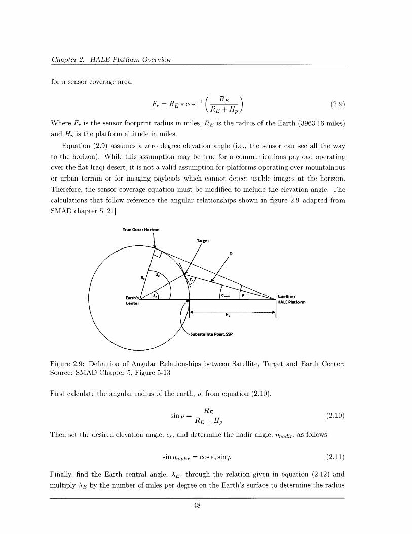
Chapter 2. HALE Platform Overview
for a sensor coverage area.
Fr = RE * Cs-1 (REpRE (2.9)
Where Fr is the sensor footprint radius in miles, RE is the radius of the Earth (3963.16 miles)
and Hp is the platform altitude in miles.
Equation (2.9) assumes a zero degree elevation angle (i.e., the sensor can see all the way
to the horizon). While this assumption may be true for a communications payload operating
over the flat Iraqi desert, it is not a valid assumption for platforms operating over mountainous
or urban terrain or for imaging payloads which cannot detect usable images at the horizon.
Therefore, the sensor coverage equation must be modified to include the elevation angle. The
calculations that follow reference the angular relationships shown in figure 2.9 adapted from
SMAD chapter 5.[21]
True Outer Horizon
Figure 2.9: Definition of Angular RelationshipsSource: SMAD Chapter 5, Figure 5-13
between Satellite, Target and Earth Center;
First calculate the angular radius of the earth, p, from equation (2.10).
REsin p
RE + Hp(2.10)
Then set the desired elevation angle, es, and determine the nadir angle, 'rnadir, as follows:
sin rinadzr = cos Es sin p (2.11)
Finally, find the Earth central angle, AE, through the relation given in equation (2.12) and
multiply AE by the number of miles per degree on the Earth's surface to determine the radius
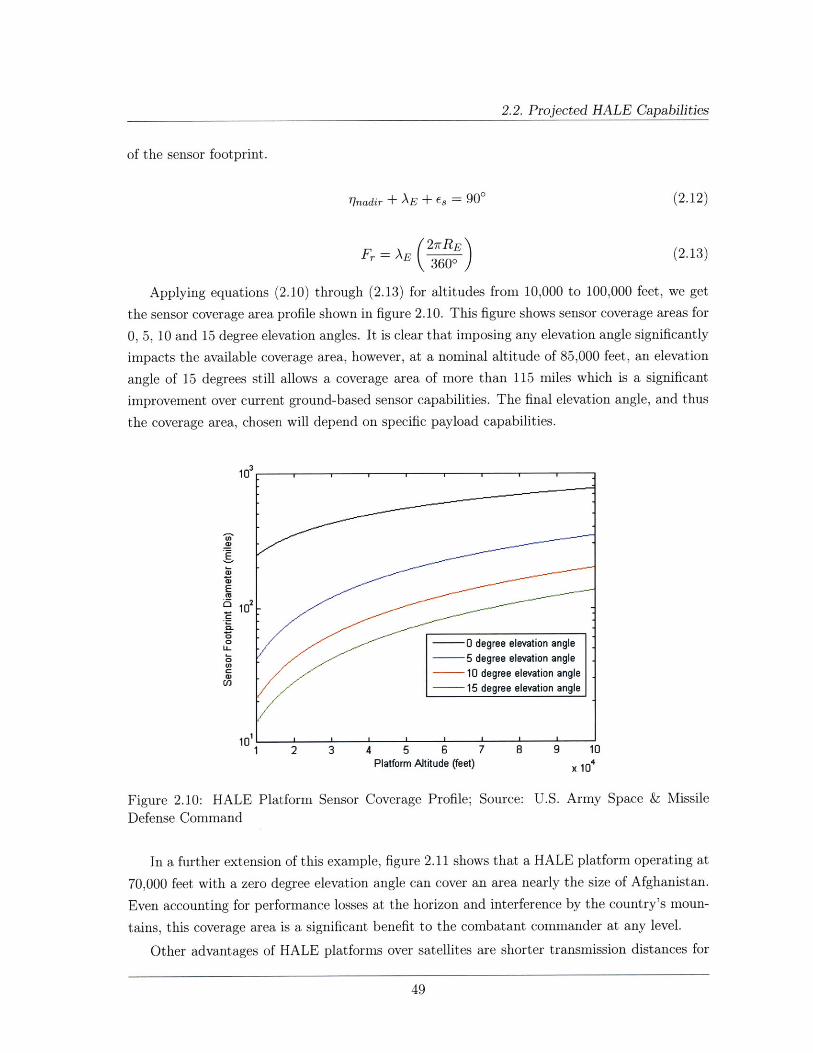
2.2. Projected HALE Capabilities
of the sensor footprint.
77nadir + AE + Es = 900 (2.12)
(2.13)Fr = AE (2rREFr = 3600
Applying equations (2.10) through (2.13) for altitudes from 10,000 to 100,000 feet, we get
the sensor coverage area profile shown in figure 2.10. This figure shows sensor coverage areas for
0, 5, 10 and 15 degree elevation angles. It is clear that imposing any elevation angle significantly
impacts the available coverage area, however, at a nominal altitude of 85,000 feet, an elevation
angle of 15 degrees still allows a coverage area of more than 115 miles which is a significant
improvement over current ground-based sensor capabilities. The final elevation angle, and thus
the coverage area, chosen will depend on specific payload capabilities.
a)
10
U_ 0 degree elevation angle
-- 5 degree elevation angle
a)- 10 degree elevation anglea--vI
10o- __15 degree elevation angle
1 2 3 4 5 6 7 8 9 1ePlatform Altitude (feet) x 10
Figure 2.10: HALE PlatformDefense Command
Sensor Coverage Profile; Source: U.S. Army Space & Missile
In a further extension of this example, figure 2.11 shows that a HALE platform operating at
70,000 feet with a zero degree elevation angle can cover an area nearly the size of Afghanistan.
Even accounting for performance losses at the horizon and interference by the country's moun-
tains, this coverage area is a significant benefit to the combatant commander at any level.
Other advantages of HALE platforms over satellites are shorter transmission distances for
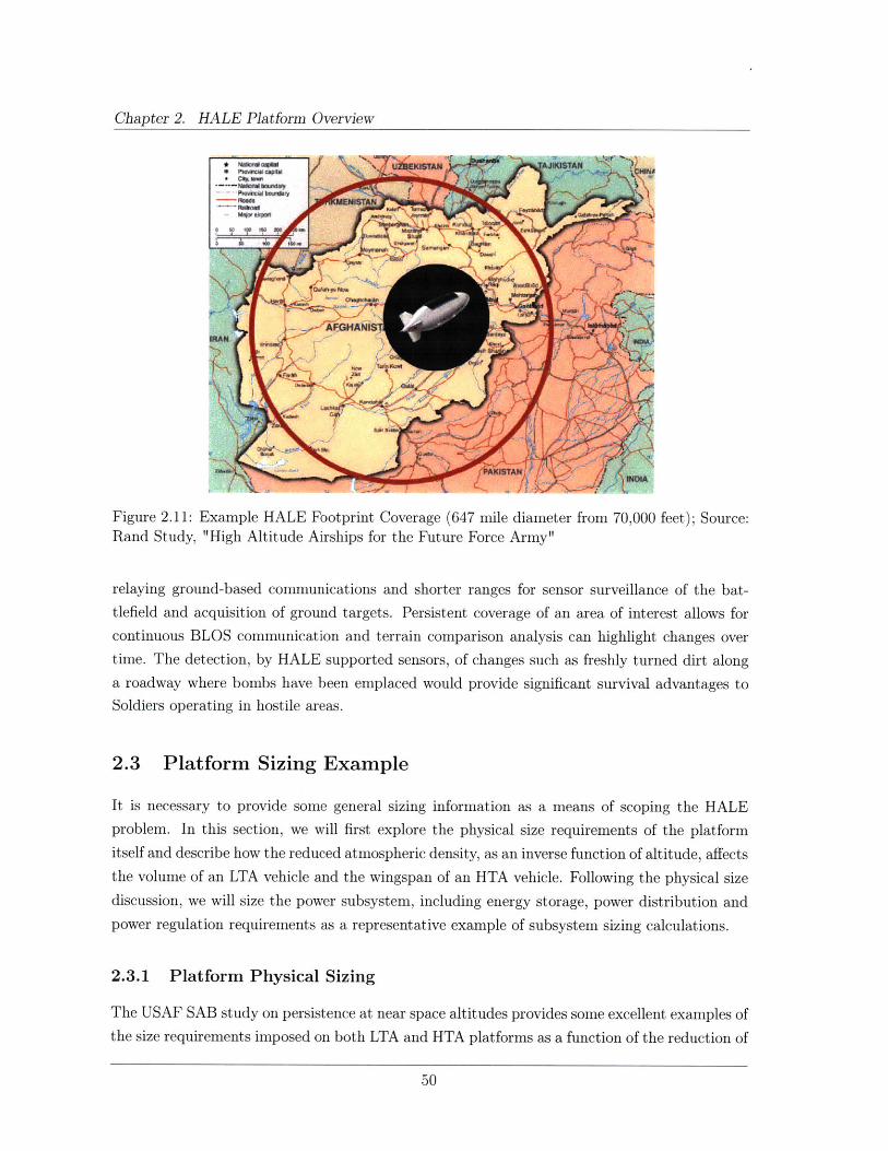
Chapter 2. HALE Platform Overview
Figure 2.11: Example HALE Footprint Coverage (647 mile diameter from 70,000 feet); Source:Rand Study, "High Altitude Airships for the Future Force Army"
relaying ground-based communications and shorter ranges for sensor surveillance of the bat-
tlefield and acquisition of ground targets. Persistent coverage of an area of interest allows for
continuous BLOS communication and terrain comparison analysis can highlight changes over
time. The detection, by HALE supported sensors, of changes such as freshly turned dirt along
a roadway where bombs have been emplaced would provide significant survival advantages to
Soldiers operating in hostile areas.
2.3 Platform Sizing Example
It is necessary to provide some general sizing information as a means of scoping the HALE
problem. In this section, we will first explore the physical size requirements of the platform
itself and describe how the reduced atmospheric density, as an inverse function of altitude, affects
the volume of an LTA vehicle and the wingspan of an HTA vehicle. Following the physical size
discussion, we will size the power subsystem, including energy storage, power distribution and
power regulation requirements as a representative example of subsystem sizing calculations.
2.3.1 Platform Physical Sizing
The USAF SAB study on persistence at near space altitudes provides some excellent examples of
the size requirements imposed on both LTA and HTA platforms as a function of the reduction of
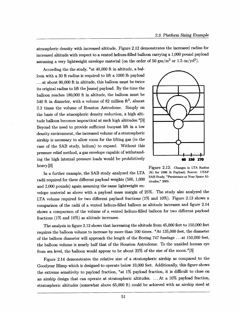
2.3. Platform Sizing Example
atmospheric density with increased altitude. Figure 2.12 demonstrates the increased radius for
increased altitude with respect to a vented helium-filled balloon carrying a 1,000 pound payload
assuming a very lightweight envelope material (on the order of 50 gm/m 2 or 1.5 oz/yd2).
According the the study, "at 40,000 ft in altitude, a bal-
loon with a 30 ft radius is required to lift a 1000 lb payload
... at about 90,000 ft in altitude, this balloon must be twice
its original radius to lift the [same] payload. By the time the
balloon reaches 180,000 ft in altitude, the balloon must be
540 ft in diameter, with a volume of 82 million ft3 , almost
2.3 times the volume of Houston Astrodome. Simply on
the basis of the atmospheric density reduction, a high alti-
tude balloon becomes impractical at such high altitudes." 13]
Beyond the need to provide sufficient buoyant lift in a low
density environment, the increased volume of a stratospheric
airship is necessary to allow room for the lifting gas (in the
case of the SAB study, helium) to expand. Without this
pressure relief method, a gas envelope capable of withstand-
ing the high internal pressure loads would be prohibitively
heavy. 3]
6i o Z70
Figure 2.12: Changes in LTA Radius
In a further example, the SAB study analyzed the LTA (ft) for 1000 lb Payload; Source: USAFSAB Study, "Persistence at Near Space Al-
radii required for three different payload weights (500, 1,000 titudes," 2005
and 2,000 pounds) again assuming the same lightweight en-
velope material as above with a payload mass margin of 25%. The study also analyzed the
LTA volume required for two different paylaod fractions (1% and 10%). Figure 2.13 shows a
comparison of the radii of a vented helium-filled balloon as altitude increases and figure 2.14
shows a comparison of the volume of a vented helium-filled balloon for two different payload
fractions (1% and 10%) as altitude increases.
The analysis in figure 2.13 shows that increasing the altitude from 45,000 feet to 150,000 feet
requires the balloon volume to increase by more than 100 times. "At 135,000 feet, the diameter
of the balloon diameter will approach the length of the Boeing 747 fuselage ... at 150,000 feet,
the balloon volume is nearly half that of the Houston Astrodome. To the unaided human eye
from sea level, the balloon would appear to be about 25% of the size of the moon." 3]
Figure 2.14 demonstrates the relative size of a stratospheric airship as compared to the
Goodyear Blimp which is designed to operate below 10,000 feet. Additionally, this figure shows
the extreme sensitivity to payload fraction, "at 1% payload fraction, it is difficult to close on
an airship design that can operate at stratospheric altitudes. ... At a 10% payload fraction,
stratospheric altitudes (somewhat above 65,000 ft) could be achieved with an airship sized at
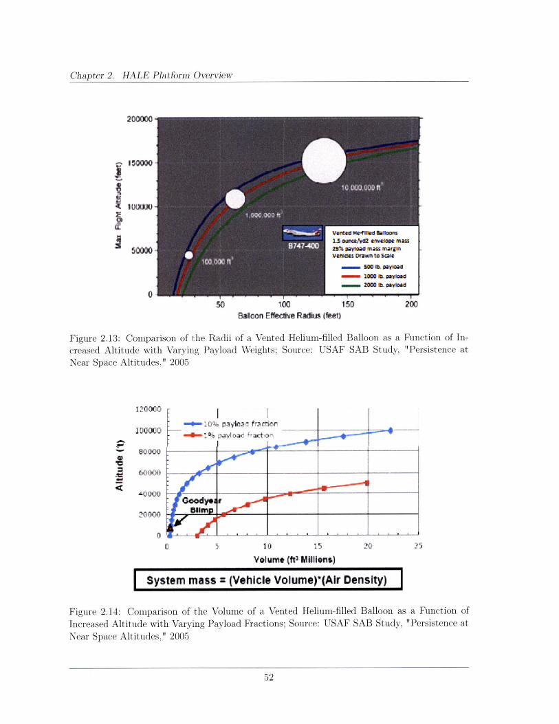
Chapter 2. HALE Platform Overview
200000
150000
mN om 1000 L uloa
O T T
50 100 150Baloon Effecdtive Radkn (feeD
Figure 2.13: Comparison of the Radii of a Vented Helium-filled Balloon as a
creased Altitude with Varying Payload Weights; Source: USAF SAB Study,Near Space Altitudes," 2005
Ioo -o1--% I yla a..ct n,
00000--
20000 -uWp< Q• . . . . . . .0_,_ ._._ _ t
Function of In-"Persistence at
0 5 10 15 20
Volume (ft3 Mllions)
System mass = (Vehicle Volume)'(Air Density)
Figure 2.14: Comparison of the Volume of a Vented Helium-filled Balloon as a Function ofIncreased Altitude with Varying Payload Fractions; Source: USAF SAB Study, "Persistence atNear Space Altitudes," 2005
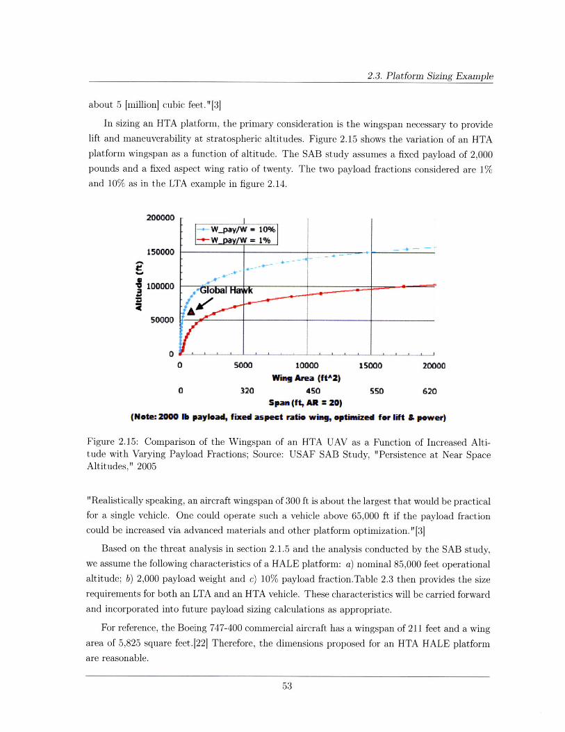
2.3. Platform Sizing Example
about 5 [million] cubic feet."[31
In sizing an HTA platform, the primary consideration is the wingspan necessary to provide
lift and maneuverability at stratospheric altitudes. Figure 2.15 shows the variation of an HTA
platform wingspan as a function of altitude. The SAB study assumes a fixed payload of 2,000
pounds and a fixed aspect wing ratio of twenty. The two payload fractions considered are 1%
and 10% as in the LTA example in figure 2.14.
200000
150000
0 5000 10000 15000 20000Wino Area (ftA2)
0 320 450 550 620pam (ft, AR = 20)
(Note: 2000 b payload, fixed aspect ratio w~n gptimized for lift & power)
Figure 2.15: Comparison of the Wingspan of an HTA UAV as a Function of Increased Alti-tude with Varying Payload Fractions; Source: USAF SAB Study, "Persistence at Near SpaceAltitudes," 2005
"Realistically speaking, an aircraft wingspan of 300 ft is about the largest that would be practical
for a single vehicle. One could operate such a vehicle above 65,000 ft if the payload fraction
could be increased via advanced materials and other platform optimization."[3]
Based on the threat analysis in section 2.1.5 and the analysis conducted by the SAB study,we assume the following characteristics of a HALE platform: a) nominal 85,000 feet operational
altitude; b) 2,000 payload weight and c) 10% payload fraction.Table 2.3 then provides the size
requirements for both an LTA and an HTA vehicle. These characteristics will be carried forward
and incorporated into future payload sizing calculations as appropriate.
For reference, the Boeing 747-400 commercial aircraft has a wingspan of 211 feet and a wing
area of 5,825 square feet.[22] Therefore, the dimensions proposed for an HTA HALE platform
are reasonable.

Chapter 2. HALE Platform Overview
Platform Type Diameter VolumeLTA 96 ft 5.5 million ft3
Platform Type Wingspan Wing AreaHTA 64 ft 1,000 ft 2
Table 2.3: HALE Platform Size Requirements for Given Operational Characteristics; Source:USAF SAB Study, "Persistence at Near Space Altitudes," 2005
2.3.2 Power Sub-system Sizing
Subsequent chapters will analyze HALE platform performance with respect the three primary
military applications identified in section 1.4: communications, ISR and navigation. As the
reader will see later, the maximum payload power requirement for the three discussed applica-
tions is 113 watts which is the requirement for an earth observation payload operating in both
the visible and infrared spectrums. We will use this power value to determine the required
subsystem size in terms of the hardware, software and interfaces for each.
The detailed governing equations for power sub-system design and sizing are outlined inappendix A.1 and are referenced here. As discussed in appendix A.1, it is necessary to size the
power subsystem based on the end-of-life (EOL) requirements in order to account for solar cell
degradation over time. Additionally, the 113 watt power requirement is the average payloadpower. It is necessary to multiply the average power by a factor of 2 or 3 to determine the peak
power requirements for attitude control, thermal management and electrical power subsystem
(EPS) while charging the batteries in addition to the payload requirements.[23] Generally, thesolar arrays are sized to provide the average power requirement and any additional powerrequirements, up to the peak power, are serviced by the batteries - even during daylight hours.
This method is possible because not all systems will require peak power at the same time and
peak requirements are short-duration.
Table 2.4[24] shows a comparison of the most common spacecraft power sources. This
analysis will focus on solar arrays as the more mature power generation technology available
and because solar arrays offer the highest specific power (W/kg) and lower specific cost ($/W)
than other power sources.
Having identified the average power requirements of the platform, the next step is to cal-
culate the amount of power, Pa, that the solar arrays must produce. The formula is provided
in equation (2.14). As discussed in section 2.1.2, the average eclipse time (discounting seasonal
variations and operational latitudes) is taken to be 12 hours (720 minutes). For this analysis,we will assume an array to battery to load efficiency, Xe, of 0.6 and an array to load efficiency,Xd, of 0.8, assuming a peak power tracking regulation scheme; daylight and eclipse power
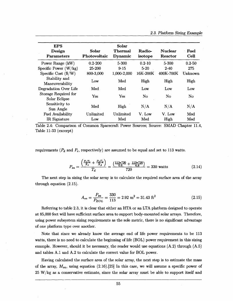
2.3. Platform Sizing Example
EPSDesign
Parameters
Power Range (kW)Specific Power (W/kg)
Specific Cost ($/W)Stability and
ManeuverabilityDegradation Over LifeStorage Required for
Solar EclipseSensitivity to
Sun AngleFuel Availability
IR Signature
SolarPhotovoltaic
0.2-20025-200
800-3,000
Low
Med
Yes
SolarThermalDynamic
5-3009-15
1,000-2,000
Med
Med
Yes
Med High
Unlimited UnlimitedLow Med
Table 2.4: ComparisonTable 11-33 (excerpt)
of Common Spacecraft Power Sources; Source: SMAD Chapter 11.4,
requirements (Pd and Pe, respectively) are assumed to be equal and set to 113 watts.
(2.14)=a , d + _ (113*720 113*720
Psa xd 0.6 + 0.8 330 wattsTd 720
The next step in sizing the solar array is to calculate the required surface area of the array
through equation (2.15).
Pa_ 330Asa - Ps 330 = 2.92 m 2 = 31.43 ft2
PEOL 113(2.15)
Referring to table 2.3, it is clear that either an HTA or an LTA platform designed to operate
at 85,000 feet will have sufficient surface area to support body-mounted solar arrays. Therefore,
using power subsystem sizing requirements as the sole metric, there is no significant advantage
of one platform type over another.
Note that since we already know the average end of life power requirements to be 113
watts, there is no need to calculate the beginning of life (BOL) power requirement in this sizing
example. However, should it be necessary, the reader would use equations (A.2) through (A.5)
and tables A.1 and A.2 to calculate the correct value for BOL power.
Having calculated the surface area of the solar array, the next step is to estimate the mass
of the array, Msa, using equation (2.16).[25] In this case, we will assume a specific power of
25 W/kg as a conservative estimate, since the solar array must be able to support itself and
Radio-isotope
0.2-105-20
16K-200K
High
Low
No
N/A
V. LowMed
NuclearReactor
5-3002-40
400K-700K
High
Low
No
N/A
V. LowHigh
FuelCell
0.2-50275
Unknown
High
Low
No
N/A
MedMed
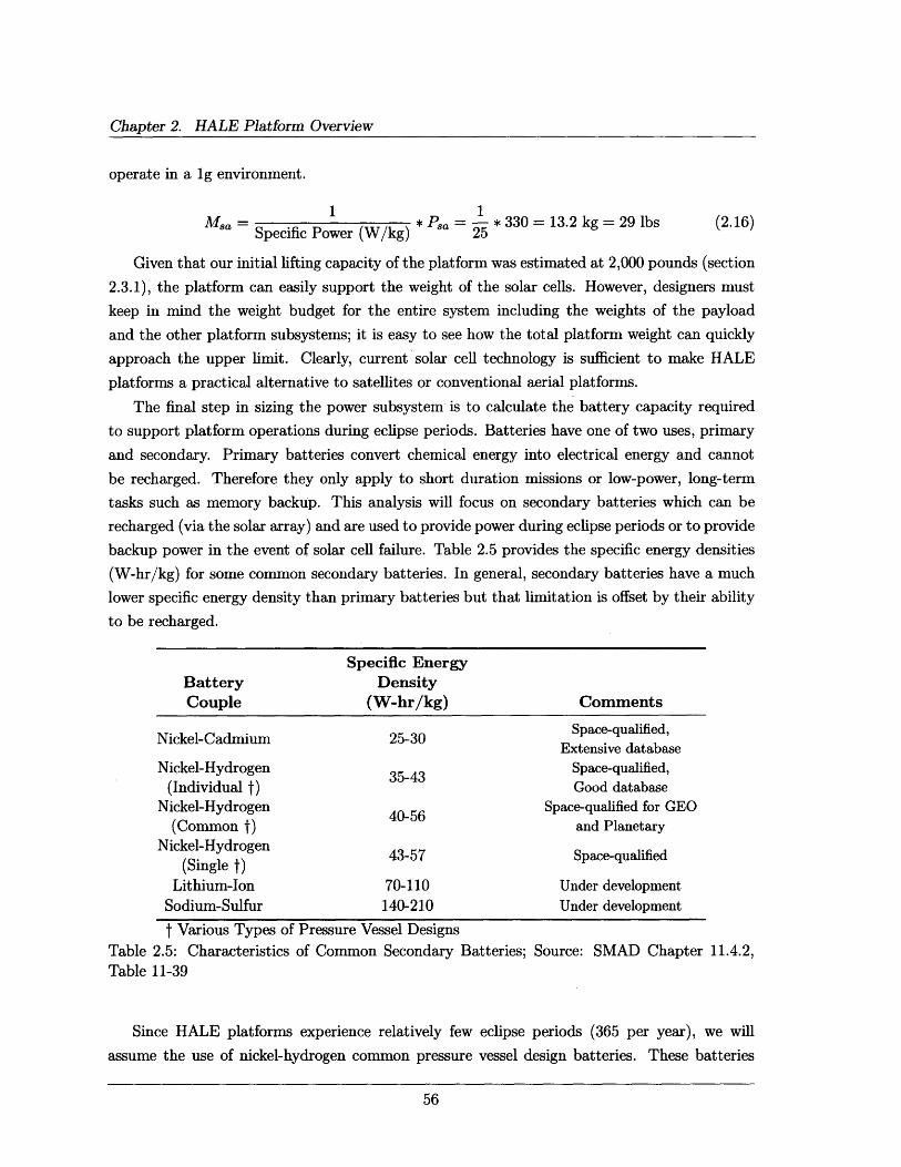
Chapter 2. HALE Platform Overview
operate in a ig environment.
1 1Msa = * Psa = * 330 = 13.2 kg = 29 lbs (2.16)
Specific Power (W/kg) 25
Given that our initial lifting capacity of the platform was estimated at 2,000 pounds (section
2.3.1), the platform can easily support the weight of the solar cells. However, designers must
keep in mind the weight budget for the entire system including the weights of the payload
and the other platform subsystems; it is easy to see how the total platform weight can quickly
approach the upper limit. Clearly, current solar cell technology is sufficient to make HALE
platforms a practical alternative to satellites or conventional aerial platforms.
The final step in sizing the power subsystem is to calculate the battery capacity required
to support platform operations during eclipse periods. Batteries have one of two uses, primary
and secondary. Primary batteries convert chemical energy into electrical energy and cannot
be recharged. Therefore they only apply to short duration missions or low-power, long-term
tasks such as memory backup. This analysis will focus on secondary batteries which can be
recharged (via the solar array) and are used to provide power during eclipse periods or to provide
backup power in the event of solar cell failure. Table 2.5 provides the specific energy densities
(W-hr/kg) for some common secondary batteries. In general, secondary batteries have a much
lower specific energy density than primary batteries but that limitation is offset by their ability
to be recharged.
TableTable
Specific EnergyBattery DensityCouple (W-hr/kg) Comments
Space-qualified,Nickel-Cadmium 25-30 Extensive database
Extensive databaseNickel-Hydrogen Space-qualified,
(Individual t) Good databaseNickel-Hydrogen Space-qualified for GEO
(Common t) and PlanetaryNickel-Hydrogen 43-57 Space-qualified
(Single t)Lithium-Ion 70-110 Under development
Sodium-Sulfur 140-210 Under development
t Various Types of Pressure Vessel Designs2.5: Characteristics of Common Secondary Batteries; Source: SMAD Chapter11-39
11.4.2,
Since HALE platforms experience relatively few eclipse periods (365 per year), we will
assume the use of nickel-hydrogen common pressure vessel design batteries. These batteries
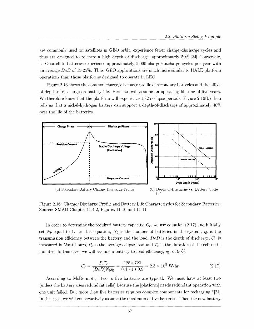
2.3. Platform Sizing Example
are commonly used on satellites in GEO orbit, experience fewer charge/discharge cycles and
thus are designed to tolerate a high depth of discharge, approximately 50%.[241 Conversely,
LEO satellite batteries experience approximately 5,000 charge/discharge cycles per year with
an average DoD of 15-25%. Thus, GEO applications are much more similar to HALE platform
operations than those platforms designed to operate in LEO.
Figure 2.16 shows the common charge/discharge profile of secondary batteries and the affect
of depth-of-discharge on battery life. Here, we will assume an operating lifetime of five years.
We therefore know that the platform will experience 1,825 eclipse periods. Figure 2.16(b) then
tells us that a nickel-hydrogen battery can support a depth-of-discharge of approximately 40%
over the life of the batteries.
--- Charge Phase - ------ Discharge Phase
----------------------- 9Positive Currert Stable Discharge Voltage
(Flat Curve) -
- - - - - - - -
lou
so
60
401"''
2O 0PM ~ Il I IIMaaknazc~
Negative Current 10 103 1We 10
Cycle Life {# Cycles)
(a) Secondary Battery Charge/Discharge Profile (b) Depth-of-Discharge vs. Battery CycleLife
Figure 2.16: Charge/Discharge Profile and Battery Life Characteristics for Secondary Batteries;Source: SMAD Chapter 11.4.2, Figures 11-10 and 11-11
In order to determine the required battery capacity, Cr, we use equation (2.17) and initially
set Nb equal to 1. In this equation, Nb is the number of batteries in the system, Tib is the
transmission efficiency between the battery and the load, DoD is the depth of discharge, Cr is
measured in Watt-hours, Pe is the average eclipse load and Te is the duration of the eclipse in
minutes. In this case, we will assume a battery to load efficiency, rib, of 90%.
Cr PeTe 125 * 720 2.3 x 10 5 W-hr (2.17)(DoD)Nbb 0.4 * 1 * 0.9
According to McDermott, "two to five batteries are typical. We must have at least two
(unless the battery uses redundant cells) because the [platform] needs redundant operation with
one unit failed. But more than five batteries requires complex components for recharging."[24]
In this case, we will conservatively assume the maximum of five batteries. Then the new battery
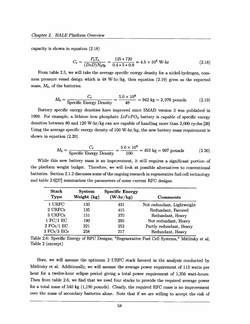
Chapter 2. HALE Platform Overview
capacity is shown in equation (2.18)
PeTe - 125 * 720 = 4.5 x 10⁴ W-hr(DoD)Nb?7b 0.4 * 5 * 0.9 (2.18)
From table 2.5, we will take the average specific energy density for a nickel-hydrogen, com-
mon pressure vessel design which is 48 W-hr/kg, then equation (2.19) gives us the expected
mass, Mb, of the batteries.
Mb =Specific Energy Density
5.0 x 104
= 942 kg = 2, 076 pounds48
Battery specific energy densities have improved since SMAD version 3 was published in
1999. For example, a lithium iron phosphate LiFeP04 battery is capable of specific energy
densities between 80 and 120 W-hr/kg can are capable of handling more than 2,000 cycles.J26]
Using the average specific energy density of 100 W-hr/kg, the new battery mass requirement is
shown in equation (2.20).
Mb =Specific Energy Density
5.0 x 10⁴
- 100 =452 kg = 997 pounds100
While this new battery mass is an improvement, it still requires a significant portion of
the platform weight budget. Therefore, we will look at possible alternatives to conventional
batteries. Section 2.1.2 discusses some of the ongoing research in regenerative fuel cell technology
and table 2.6[27] summarizes the parameters of some current RFC designs.
Stack S
Type We
1 URFC2 URFCs3 URFCs
1 FC/1 EC2 FCs/1 EC3 FCs/3 ECs
Table 2.6: Specific EnergyTable 2 (excerpt)
;ystem Specific Energyight (kg) (W-hr/kg)
130 431135 415151 370190 295221 253258 217
of RFC Designs; "Regenerative
Comments
Not redundant, LightweightRedundant, FavoredRedundant, Heavy
Not redundant, HeavyPartly redundant, Heavy
Redundant, Heavy
Fuel Cell Systems," Mitlitsky et al,
Here, we will assume the optimum 2 URFC stack favored in the analysis conducted byMitlitsky et al. Additionally, we will assume the average power requirement of 113 watts perhour for a twelve-hour eclipse period giving a total power requirement of 1,356 watt-hours.Then from table 2.6, we find that we need four stacks to provide the required average powerfor a total mass of 540 kg (1,190 pounds). Clearly, the required RFC mass is no improvementover the mass of secondary batteries alone. Note that if we are willing to accept the risk of
(2.19)
(2.20)
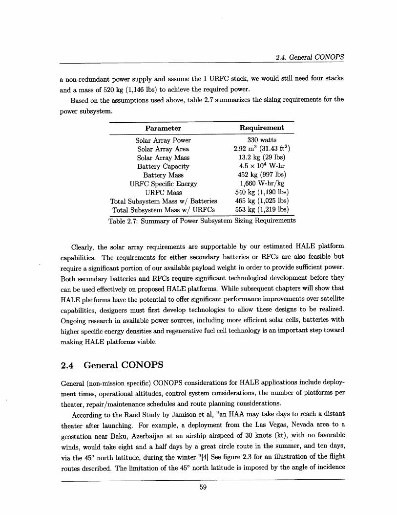
2.4. General CONOPS
a non-redundant power supply and assume the 1 URFC stack, we would still need four stacks
and a mass of 520 kg (1,146 lbs) to achieve the required power.
Based on the assumptions used above, table 2.7 summarizes the sizing requirements for the
power subsystem.
Parameter Requirement
Solar Array Power 330 watts
Solar Array Area 2.92 m2 (31.43 ft 2)
Solar Array Mass 13.2 kg (29 lbs)
Battery Capacity 4.5 x 10⁴ W-hr
Battery Mass 452 kg (997 lbs)
URFC Specific Energy 1,660 W-hr/kg
URFC Mass 540 kg (1,190 lbs)
Total Subsystem Mass w/ Batteries 465 kg (1,025 lbs)
Total Subsystem Mass w/ URFCs 553 kg (1,219 lbs)
Table 2.7: Summary of Power Subsystem Sizing Requirements
Clearly, the solar array requirements are supportable by our estimated HALE platform
capabilities. The requirements for either secondary batteries or RFCs are also feasible but
require a significant portion of our available payload weight in order to provide sufficient power.
Both secondary batteries and RFCs require significant technological development before they
can be used effectively on proposed HALE platforms. While subsequent chapters will show that
HALE platforms have the potential to offer significant performance improvements over satellite
capabilities, designers must first develop technologies to allow these designs to be realized.
Ongoing research in available power sources, including more efficient solar cells, batteries with
higher specific energy densities and regenerative fuel cell technology is an important step toward
making HALE platforms viable.
2.4 General CONOPS
General (non-mission specific) CONOPS considerations for HALE applications include deploy-
ment times, operational altitudes, control system considerations, the number of platforms per
theater, repair/maintenance schedules and route planning considerations.
According to the Rand Study by Jamison et al, "an HAA may take days to reach a distant
theater after launching. For example, a deployment from the Las Vegas, Nevada area to a
geostation near Baku, Azerbaijan at an airship airspeed of 30 knots (kt), with no favorable
winds, would take eight and a half days by a great circle route in the summer, and ten days,
via the 450 north latitude, during the winter."[4] See figure 2.3 for an illustration of the flight
routes described. The limitation of the 450 north latitude is imposed by the angle of incidence
Chapter 2. HALE Platform Overview
of solar radiation. This limitation could be avoided through the use of alternate power sources
discussed in section 2.1.2. Deployment times aside, once the asset was in place, it could loiter
almost indefinitely providing support as needed to the combatant commander.
Section 2.1.5 outlines survivability concerns against dynamic and electronic attacks; specif-
ically table 2.2 highlights the five conventional weapon systems that can threaten HALE plat-
forms. Setting a nominal operational altitude of 80,000 feet places the platform out of range
for all but two of the long-range SAMs listed in table 2.2 and an operational altitude of 85,000
feet would place the platform out of range of all but the SA-5 SAM.
Another general CONOPS consideration is the platform control system. The main deci-
sion is whether the platform should be fully autonomous or human-in-the-loop controlled via
a ground station. Fully autonomous flight control allows the platform to operate indefinitely
while significantly reducing the operational costs associated with platform performance. Two
key drawbacks to a fully autonomous system are the difficultly of responding to dynamic or
electronic attacks as detailed in section 2.1.5 and reduced operational flexibility to meet the
changing requirements of the combatant commander. It is likely that successful designs will
incorporate some measure of both autonomous and human-in-the-loop control, allowing the
platform to deploy itself to the required theater and monitor general flight control operations
while maintaining the flexibility to rapidly respond to changing ground conditions and contin-
gency operations.
Platform cost will likely have the most direct impact on the number of platforms operating
per theater. Subsequent chapters will demonstrate that HALE platforms can provide equivalent
performance as current satellite payloads but at a fraction of the cost. In order to take advantageof the projected HALE capabilities outlined in section 2.2, it is expected that at least one
platform will operate in each of the Army's major theaters of operation. Ideally, funding will
be available to provide dedicated HALE platforms to each of the brigade-level commanders
in theater. In the case of Iraq and Afghanistan, this means approximately twenty platforms
operating over Southwest Asia alone.
This thesis assumes that HALE platforms will operate as pseudo-satellite platforms for
operational lifetimes of up to five years. This being the case, HALE platforms should be
designed to be maintained as if they were satellites, relying on platform telemetry to diagnose
and repair all malfunctions. One significant advantage of HALE platforms over satellites is that
they can be recovered in the event of a catastrophic failure that cannot be repaired by any other
means. It is expected, however, that recovering the platform for repair will be the last resort
and will only occur to avoid total platform loss.
Route planning considerations are critical to the success of any HALE platform. Two areas
for consideration are flight plan deconfliction with other HALE platforms operating in theater
and overflight of sovereign airspace. As mentioned above, if each brigade-level commander in
2.5. Chapter Summary
Southwest Asia received a dedicated platform, there would be twenty platforms operating in
close proximity and careful flight planning would be required to avoid collisions. Figure 2.3
outlines two possible deployment flight routes to forward destinations. Observe that the route
from Las Vegas to Baku requires the platform to fly almost directly over Moscow. The key
consideration in this case is international law which currently recognizes sovereign airspace up
to an altitude of 65,000 feet and then is not regulated again until 330,000 feet which is the
legal definition of space.128] The area between 65,000 feet and 330,000 feet is currently in a
legal "gray area." Until this legal issue is resolved, deployment route planning will continue to
require the avoidance of hostile airspace.
2.5 Chapter Summary
At this point it is appropriate to revisit the question posed by the Army Space Master Plan,
"Where should the Army invest in near-space and high-altitude, long-endurance platforms as a
lower cost, more responsive alternative to space platforms if they prove technically feasible?"[1]
This chapter has demonstrated, in very general terms, the technical feasibility of designing
and operating a HALE platform in the "near space" regime between 65,000-100,000 feet in
altitude. It remains to be determined whether or not HALE payloads can provide the necessary
performance requirements when compared to currently existing satellite payloads.
In a conversation with personnel at the U.S. Army Space and Missile Defense Command
(SMDC), Mr. William Coffey and MAJ Timothy Tubergen identified some key user needs that
could potentially be filled by HALE platforms. These capability gaps include persistent BLOS
communications in all terrain and command and control on-the-move, the need for increased
bandwidth (network expansion) in operational theaters, persistent ISR capability and the need
to reduce the latency associated with Blue Force Tracking (BFT) and Force XXI Battle Com-
mand, Brigade and Below (FBCB2) transmissions. According to MAJ Tubergen, SMDC, there
are no current capability gaps in GPS navigation service, however, the U.S. Army is not cur-
rently engaged in a navigation war. MAJ Tubergen agreed that stronger GPS signals to allow
increased functionality in complex (i.e., urban and mountainous) terrain would be valuable
under any circumstances.
With respect to persistent BLOS communications, U.S. Army forces in Iraq are currently
using the RIPR network which is essentially communications over telephone lines. Additionally
the U.S. Air Force E-8 Joint Surveillance Target Attack Radar System (JSTARS) is capable of
providing short duration radio retransmission capability but it does not provide a very large
footprint, communications relay is not the platform's primary mission and use of the system
is prohibitively expensive for routine communications. The Army is also looking to improve
BLOS communications to small mobile antennas. Currently, the only spacecraft capable of
providing this service are communications satellites in geosynchronous orbit (GEO). In order
Chapter 2. HALE Platform Overview
for a small antenna to receive transmissions from a GEO orbiting satellite at an altitude of
35,786 km (22,236 mi), the satellite must be equipped with a powerful transmitter and a very
large transmitting antenna. A large antenna focuses the beamwidth into a small diameter on theEarth's surface. Thus persistent coverage of an area the size of Iraq requires many large antennas
on GEO satellites - a requirement severely limited both by cost and by space availability in the
GEO belt. HALE communications relay platforms could potentially provide the same service
but at a fraction of the power and antenna size requirements imposed by the extreme GEOaltitude. Additionally, the U.S. Army is continually fielding new technologies in Iraq (on theorder of thirty to forty new systems per week) [28] each of which requires bandwidth to operate.
HALE platforms equipped with communications relay payloads may be capable of providing
both large-footprint BLOS communications and network expansion for new technologies. HALE
communication payload capabilities will be outlined and analyzed in chapter 3.
Current ISR satellites must operate in low earth orbit (LEO) in order to achieve a useful tar-get resolution. The physics governing LEO orbits limit the coverage capability to approximately
six minutes every nine hours, an insufficient amount of time in a rapidly evolving battlefield
like Iraq. A constellation of LEO ISR satellites improves the percent coverage of the Earth'ssurface but, by definition, increases the number of satellites and thus the cost of the mission. AHALE platform, being nearly stationary with respect to the area of interest on the ground, is
capable of providing continuous coverage from a much lower altitude. The lower altitude also
has the advantage of providing better resolution as will be demonstrated in chapter 4.
Finally, while GPS navigation coverage is admittedly not a key capability gap for current
operations, experts do not question the advantages of stronger, more reliable GPS signals. TheArmy relies on GPS dependent automation for more than simple navigation. BFT and FBCB2both combine location (derived from GPS signals) and unit status (input by the user) infor-mation into a consolidated report for units to send to their higher headquarters. FBCB2 usestransponder frequencies in the L-band and transmits via the non-satellite based Enhanced Po-sition Location Reporting System (EPLRS), a line-of-sight secure radio system. BFT transpon-ders transmit information via a satellite network and frequently experience latency ranging
from eight minutes to eight hours. Even for routine operations in a combat zone, an eight
minute latency is too long and emergency situations require an immediate response. Potential
improvements to both line-of-sight EPLRS communications and BFT latency through the useof HALE platforms are discussed in chapter 5.
Having identified several key user needs not satisfied by current satellite service to themilitary, we return our attention to the ven diagram introduced in figure 1.3 and fill in someareas for further development. Figure 2.17 summarizes the focus of the rest of this thesis with
the goal of evaluating HALE payloads against current satellite capabilities for communicationsrelay, ISR and GPS to determine where and how HALE platforms can contribute to successful
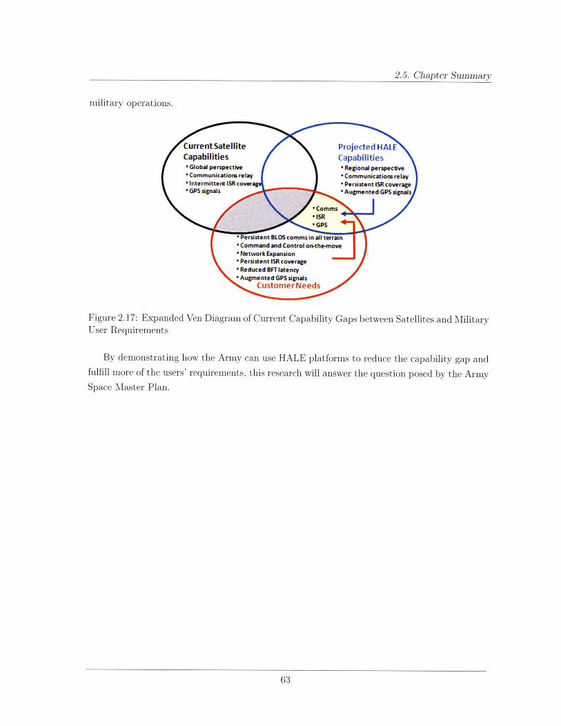
2.5. Chapter Summary
military operations.
Figure 2.17: Expanded Ven Diagram of Current Capability Gaps between Satellites and MilitaryUser Requirements
By demonstrating how the Army can use HALE platforms to reduce the capability gap andfulfill more of the users' requirements, this research will answer the question posed by the ArmySpace Master Plan.

This page intentionally left blank.
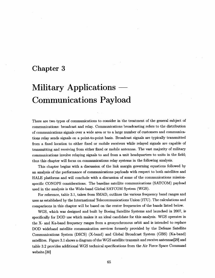
Chapter 3
Military Applications
Communications Payload
There are two types of communications to consider in the treatment of the general subject of
communications: broadcast and relay. Communications broadcasting refers to the distribution
of communications signals over a wide area or to a large number of customers and communica-
tions relay sends signals on a point-to-point basis. Broadcast signals are typically transmitted
from a fixed location to either fixed or mobile receivers while relayed signals are capable of
transmitting and receiving from either fixed or mobile antennas. The vast majority of military
communications involve relaying signals to and from a unit headquarters to units in the field;
thus this chapter will focus on communications relay systems in the following analysis.
This chapter begins with a discussion of the link margin governing equations followed by
an analysis of the performance of communications payloads with respect to both satellites and
HALE platforms and will conclude with a discussion of some of the communications mission-
specific CONOPS considerations. The baseline satellite communications (SATCOM) payload
used in the analysis is the Wide-band Global SATCOM System (WGS).
For reference, table 3.1, taken from SMAD, outlines the various frequency band ranges and
uses as established by the International Telecommunications Union, (ITU). The calculations and
comparisons in this chapter will be based on the center frequencies of the bands listed below.
WGS, which was designed and built by Boeing Satellite Systems and launched in 2007, is
specifically for DOD use which makes it an ideal candidate for this analysis. WGS operates in
the X- and Ka-band frequency ranges from a geosynchronous orbit and is intended to replace
DOD wideband satellite communication services formerly provided by the Defense Satellite
Communications System (DSCS) (X-band) and Global Broadcast System (dBS) (Ka-band)
satellites. Figure 3.1 shows a diagram of the WGS satellite transmit and receive antennas[29 and
table 3.2 provides additional WGS technical specifications from the Air Force Space Command
website. [30]
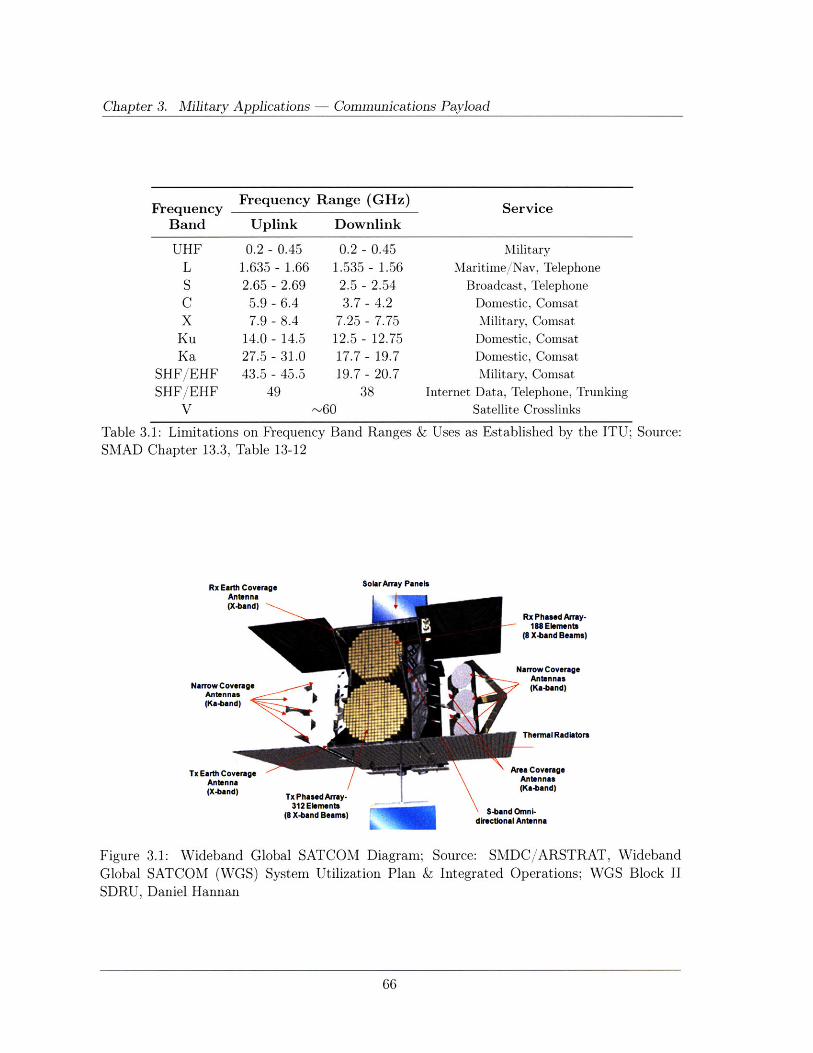
Chapter 3. Military Applications
Frequency Frequency Range (GHz) Service
Band Uplink Downlink
UHF 0.2 - 0.45 0.2 - 0.45 Military
L 1.635 - 1.66 1.535 - 1.56 Maritime/Nav, TelephoneS 2.65 - 2.69 2.5 - 2.54 Broadcast, TelephoneC 5.9 - 6.4 3.7 - 4.2 Domestic, ComsatX 7.9 - 8.4 7.25 - 7.75 Military, Comsat
Ku 14.0- 14.5 12.5- 12.75 Domestic, ComsatKa 27.5 - 31.0 17.7- 19.7 Domestic, Comsat
SHF/EHF 43.5 - 45.5 19.7- 20.7 Military, ComsatSHF/EHF 49 38 Internet Data, Telephone, Trunking
V -60 Satellite Crosslinks
Table 3.1: Limitations on Frequency Band Ranges & Uses as Established by the ITU; Source:SMAD Chapter 13.3, Table 13-12
Rx Earth CoverageAntenna(X-band)
Narrow CoverageAntennas(Ka-band)
Tx Earth CoverageAntnna(X-band)
SolarArray Panels
Rx Phased Array-188 Elements
(8 X-band Beams)
Narrow CoverageAntennas(Ka-band)
Thermal Radiators
Area CoverageAntennas(Ka-band)
S-band Omni-dectional Antenna
Tx Phased Array-312 Elements
(8 X-band Beams)
Figure 3.1: Wideband Global SATCOM Diagram; Source: SMDC/ARSTRAT, Wideband
Global SATCOM (WGS) System Utilization Plan & Integrated Operations; WGS Block II
SDRU, Daniel Hannan
Communications Payload
I
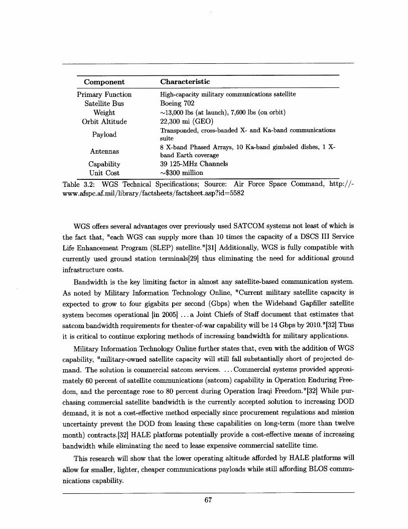
Component Characteristic
Primary Function High-capacity military communications satellite
Satellite Bus Boeing 702
Weight -13,000 lbs (at launch), 7,600 lbs (on orbit)
Orbit Altitude 22,300 mi (GEO)
Payload Transponded, cross-banded X- and Ka-band communicationssuite
8 X-band Phased Arrays, 10 Ka-band gimbaled dishes, 1 X-Antennasband Earth coverage
Capability 39 125-MHz ChannelsUnit Cost -$300 million
Table 3.2: WGS Technical Specifications; Source: Air Force Space Command, http://-
www.afspc.af.mil/library/factsheets/factsheet.asp?id=5582
WGS offers several advantages over previously used SATCOM systems not least of which is
the fact that, "each WGS can supply more than 10 times the capacity of a DSCS III Service
Life Enhancement Program (SLEP) satellite." [31] Additionally, WGS is fully compatible with
currently used ground station terminals[29 thus eliminating the need for additional ground
infrastructure costs.
Bandwidth is the key limiting factor in almost any satellite-based communication system.
As noted by Military Information Technology Online, "Current military satellite capacity is
expected to grow to four gigabits per second (Gbps) when the Wideband Gapfiller satellite
system becomes operational [in 2005] ... a Joint Chiefs of Staff document that estimates that
satcom bandwidth requirements for theater-of-war capability will be 14 Gbps by 2010." [32] Thus
it is critical to continue exploring methods of increasing bandwidth for military applications.
Military Information Technology Online further states that, even with the addition of WGS
capability, "military-owned satellite capacity will still fall substantially short of projected de-
mand. The solution is commercial satcom services. ... Commercial systems provided approxi-
mately 60 percent of satellite communications (satcom) capability in Operation Enduring Free-
dom, and the percentage rose to 80 percent during Operation Iraqi Freedom."[32] While pur-
chasing commercial satellite bandwidth is the currently accepted solution to increasing DOD
demand, it is not a cost-effective method especially since procurement regulations and mission
uncertainty prevent the DOD from leasing these capabilities on long-term (more than twelve
month) contracts.[32] HALE platforms potentially provide a cost-effective means of increasing
bandwidth while eliminating the need to lease expensive commercial satellite time.
This research will show that the lower operating altitude afforded by HALE platforms will
allow for smaller, lighter, cheaper communications payloads while still affording BLOS commu-
nications capability.
Chapter 3. Military Applications - Communications Payload
3.1 Link Margin Governing Equations
In beginning the analysis of the communications link equation, the primary sizing equation
used relates all of the link parameters to the signal-to-noise ratio and is given in equation (3.1)
below:[331
Eb PtLGtLLaGr (3.1)(3.1)
No kTsR
Where Eb/No is the ratio of received energy-per-bit to noise density, Pt is the transmitter power,Ll is the transmitter to antenna line loss, Gt is the transmit (Tx) antenna gain, L, is the free
space loss, La is the atmospheric transmission path loss, Gr is the receive (Rx) antenna gain, k
is Boltzmann's constant (1.380658 x 10⁻²³ J/K), T is the system noise temperature and R is
the data rate in bps.
Equation (3.1) can be rewritten in decibel notation as follows:
Eb/IN = Pt + L + Gt + Lpr + Ls + La + Gr + 228.6 - 10 logTs - 10log R (3.2)
Where EbIN, LI, Gt, Ls, La, Lpr and Gr are in dB, Pt is in dBW, T, is in K, R is in bps and
10 log k = -228.60 dBW/Hz - K. Note that equation (3.2) contains one additional term, Lp,that is not included in equation (3.1). This additional term is the receive antenna pointing loss,which accounts for imperfect antenna alignment, and will be discussed later.
For the purpose of this thesis, we want to solve equation (3.1) (or equation (3.2), depending
on preference) for Pt and then use parametric relations to determine payload mass and cost
from the transmitter power. Thus it is necessary first to determine all the remaining parameters
in the equation.
The energy-to-noise ratio, Eb/No, can be estimated from figure 3.2 (taken from SMAD,chapter 13) after selecting an appropriate bit error rate (BER) and modulation scheme.
A common bit error rate for communications payloads is between 10-5 and 10-6; in this
case, we will use the more stringent standard of 10-6. Modulation is the process of varying the
RF carrier wave characteristics of the input signal. Quadriphased phase shift keying (QPSK)
is the modulation technique used by WGS and "takes two bits at a time to define one of four
symbols. Each symbol corresponds to one of four carrier phases: 0 deg, 90 deg, 180 deg or
270 deg."[33] Thus using QPSK modulation and a BER of 10-6, figure 3.2 gives the required
energy-to-noise ratio of:
Eb = 10.5 dB (3.3)No
Note that we could improve the energy-to-noise ratio by employing coding techniques such
as Viterbi or Reed-Solomon (also shown in figure 3.2) thus gaining at least a 3dB reduction in
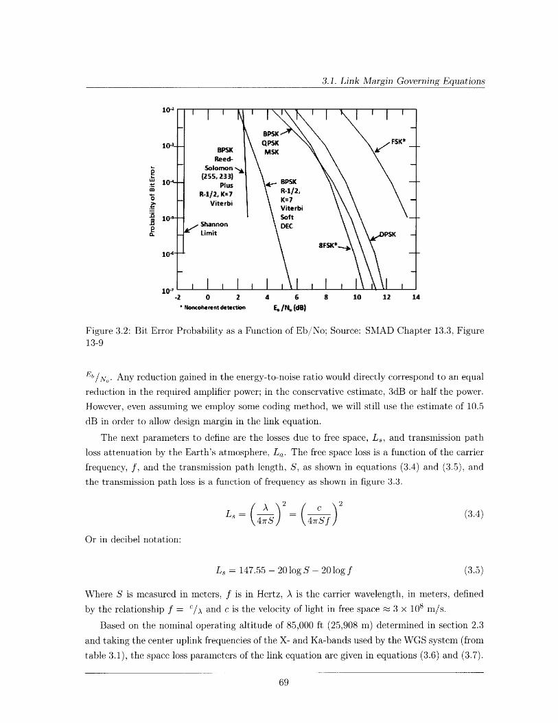
3.1. Link Margin Governing Equations
Solomon(255, 233)
10 - Plus BPSK
R-112, K=7 R-112,- Viterbi K= e
Viterbi
S10- - Soft - -Shannon DEC2
CL Limit PS K
8FSK*-10-
10-'-2 0 2 4 6 8 10 12 14
f oncohKet detection EjN, (dB)
Figure 3.2: Bit Error Probability as a Function of Eb/No; Source: SMAD Chapter 13.3, Figure13-9
Eb/N o . Any reduction gained in the energy-to-noise ratio would directly correspond to an equal
reduction in the required amplifier power; in the conservative estimate, 3dB or half the power.
However, even assuming we employ some coding method, we will still use the estimate of 10.5
dB in order to allow design margin in the link equation.
The next parameters to define are the losses due to free space, Ls, and transmission path
loss attenuation by the Earth's atmosphere, La. The free space loss is a function of the carrier
frequency, f, and the transmission path length, S, as shown in equations (3.4) and (3.5), and
the transmission path loss is a function of frequency as shown in figure 3.3.
L8 A ) 2 4Sf) (3.4)
Or in decibel notation:
Ls = 147.55 - 20 log S - 20 log f (3.5)
Where S is measured in meters, f is in Hertz, A is the carrier wavelength, in meters, defined
by the relationship f = c/x and c is the velocity of light in free space a 3 x 10s m/s.
Based on the nominal operating altitude of 85,000 ft (25,908 m) determined in section 2.3
and taking the center uplink frequencies of the X- and Ka-bands used by the WGS system (from
table 3.1), the space loss parameters of the link equation are given in equations (3.6) and (3.7).
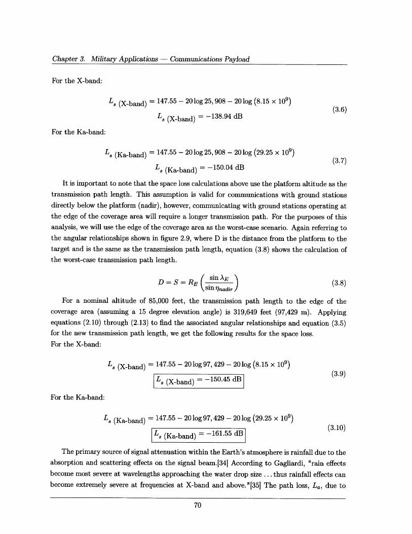
Chapter 3. Military Applications - Communications Payload
For the X-band:
Ls (X-band) = 147.55 - 20 log 25, 908 - 20 log (8.15 x 10⁹)(3.6)
Ls (X-band) = -138.94 dB
For the Ka-band:
L8 (Ka-band) = 147.55 - 20 log 25, 908 - 20 log (29.25 x 10⁹)
(3.7)Ls (Ka-band) = -150.04 dB
It is important to note that the space loss calculations above use the platform altitude as the
transmission path length. This assumption is valid for communications with ground stations
directly below the platform (nadir), however, communicating with ground stations operating at
the edge of the coverage area will require a longer transmission path. For the purposes of this
analysis, we will use the edge of the coverage area as the worst-case scenario. Again referring to
the angular relationships shown in figure 2.9, where D is the distance from the platform to the
target and is the same as the transmission path length, equation (3.8) shows the calculation of
the worst-case transmission path length.
D=S=RE ( sin AE N (3.8)Ssin 7 nadir
For a nominal altitude of 85,000 feet, the transmission path length to the edge of the
coverage area (assuming a 15 degree elevation angle) is 319,649 feet (97,429 m). Applying
equations (2.10) through (2.13) to find the associated angular relationships and equation (3.5)
for the new transmission path length, we get the following results for the space loss.
For the X-band:
Ls (X-band) = 147.55 - 20 log 97, 429 - 20 log (8.15 x 10⁹)
Ls (X-band) = -150.45 dB
For the Ka-band:
L (Ka-band) = 147.55 - 20 log 97,429 - 20 log (29.25 x 10⁹)
Ls (Ka-band) = -161.55 dB (3.10)
The primary source of signal attenuation within the Earth's atmosphere is rainfall due to the
absorption and scattering effects on the signal beam.[34] According to Gagliardi, "rain effects
become most severe at wavelengths approaching the water drop size ... thus rainfall effects can
become extremely severe at frequencies at X-band and above."[35] The path loss, La, due to
3.1. Link Margin Governing Equations
rain attenuation is a difficult parameter to quantify as one must account for the size and rate
of the rain drops as well as the frequency of storms and all of these factors vary according to
the climate of a given operational area. Due to the uncertainty associated with predicting rain
attenuation, it is common to consider the percentage of time a certain attenuation level will
be exceeded. If P(a) is the probability that all attenuation, a, is exceeded, then 1 - P(a)
is the percent availability of the link. Probability curves are much more useful in allowing
for sufficient design margin while preventing link overdesign.[35 ] According to the WGS System
Utilization Plan developed by the U.S. Army Space and Missile Defense command, "the X-band
is comparatively robust in the presence of weather [whereas] the Ka-band is less robust and will
result in outages - 3% of the time, depending on rain region."[29] Figure 3.3 shows predicted
rain attenuation for a climate typical of the northern United States.
so50 I I I I I I I I II I llElevationAngle 100
40 Availability99.5%
-------- 98.0%-oc 30 -130o 15
2020
20010 45 -
45
2 4 810 20 40Frequency (GHz)
Figure 3.3: Rain Attenuation as a Function of Frequency for Rain Climate Typical of theNorthern United States; Source: SMAD Chapter 13.3, Figure 13-11
Assuming that the rain climate of the northern United States is representative of the typical
climates of current operational areas, a conservative estimate for countries such as Iraq and
Afghanistan, figure 3.3 provides an estimate of the path loss. Assuming 99.5% link availability,
a 15 degree elevation angle and the mean uplink frequencies of the X and Ka-bands used above
then the atmospheric path losses, La, are shown below.
For the X-band: For the Ka-band:
La (X-band) 2 dB La (Ka-band) = 7 dB(3.11) (3.12)
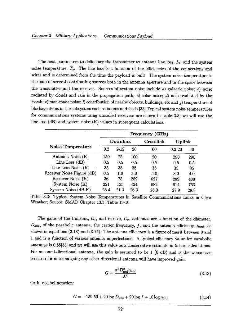
Chapter 3. Military Applications - Communications Payload
The next parameters to define are the transmitter to antenna line loss, LI, and the system
noise temperature, T,. The line loss is a function of the efficiencies of the connections and
wires and is determined from the time the payload is built. The system noise temperature is
the sum of several contributing sources both in the antenna aperture and in the space between
the transmitter and the receiver. Sources of system noise include a) galactic noise; b) noise
radiated by clouds and rain in the propagation path; c) solar noise; d) noise radiated by the
Earth; e) man-made noise; f) contribution of nearby objects, buildings, etc and g) temperature of
blockage items in the subsystem such as booms and feeds.[33j Typical system noise temperatures
for communications systems using uncooled receivers are shown in table 3.3; we will use the
line loss (dB) and system noise (K) values in subsequent calculations.
Frequency (GHz)
Downlink Crosslink UplinkNoise Temperature 0.2 2-12 20 60 0.2-20 40
Antenna Noise (K) 150 25 100 20 290 290Line Loss (dB) 0.5 0.5 0.5 0.5 0.5 0.5
Line Loss Noise (K) 35 35 35 35 35 35Receiver Noise Figure (dB) 0.5 1.0 3.0 5.0 3.0 4.0
Receiver Noise (K) 36 75 289 627 289 438System Noise (K) 221 135 424 682 614 763
System Noise (dB-K) 23.4 21.3 26.3 28.3 27.9 28.8
Table 3.3: Typical System Noise Temperatures in Satellite Communications Links in ClearWeather; Source: SMAD Chapter 13.3, Table 13-10
The gains of the transmit, Gt, and receive, Gr, antennas are a function of the diameter,Dant, of the parabolic antenna, the carrier frequency, f, and the antenna efficiency, rlant, as
shown in equations (3.13) and (3.14). The antenna efficiency is a figure of merit between 0 and
1 and is a function of various antenna imperfections. A typical efficiency value for parabolic
antennas is 0.55[33] and we will use this value as a conservative estimate in future calculations.
For an omni-directional antenna, the gain is assumed to be 1 (0 dB) and is the worse-case
scenario for antenna gain; any other directional antenna will have improved gain.
G = 2 (3.13)
Or in decibel notation:
G = -159.59 + 20 log Dant + 20 log f + 10 log r7 ant (3.14)
3.1. Link Margin Governing Equations
Where Dant is measured in meters and f is in Hertz.
Finally, we return to the antenna pointing loss which is a result of the receive antenna not
pointing at the center of the transmitted beam and manifests as a loss in gain of the receive
antenna (subtracted from Gr prior to the calculation of equation (3.1)). Small antenna pointing
errors, introduced by wind gusts on the ground or platform stabilization errors, become more
significant contributors as the beamwidth becomes more narrow.[33] The antenna pointing loss
is calculated through equation (3.15).
Lp = -12 2 (3.15)
Where e is the pointing error and 0 is the antenna half-power beamwidth (calculated below in
equation (3.17)).
For the purposes of this thesis, we will assume that the HALE platform is operating directly
overhead and the beamwidth covers the ground area of operations; thus there is no need to
point the platform antenna. Rather, all users within the coverage area will be able transmit to
and receive from the platform. In order to accomplish this coverage, we will assume that the
pointing error, e, is equal to half of 0. Substituting this pointing error into equation (3.15), we
get the following relationship for the antenna pointing loss:
L = -12 = -12 = -3 dB (3.16)
The typical methodology for determining the link budget requirements is first to determine
the required footprint size or beamwidth necessary to cover the area of operations. Once the
footprint radius is known, use the angular relationships shown in figure 2.9 and discussed in
equations (2.10) and (2.11) to determine the required nadir angle, lqnadir. The nadir angle is the
same as the half-power beamwidth, 0, or the angle at which the signal strength is half (3 dB) of
the transmitted signal strength. The beamwidth can then be used to find the required transmit
antenna diameter (through the relationship shown in equation (3.17)) and the transmit antenna
gain (equations (3.13) and (3.14)).
0 21 (3.17)fDant
Where f is the carrier frequency in GHz and Dant is the antenna diameter in meters.
The next step is to determine the ground receive antenna diameter, Dr, and efficiency, 7lant,
which then yield the receive antenna gain, Gr, through the relationships shown in equations
(3.13) and (3.14). Then substitute these factors into the link equation, (3.1) or (3.2), along
with the previously defined losses to determine the required transmitter power.
In defining the relationship between data rate and bandwidth, we refer to C.E. Shannon's

Chapter 3. Military Applications - Communications Payload
paper, A Mathematical Theory of Communication, published in 1948 in which he stated "The-
orem 22: The rate for a white noise source of power, Q, and band W1 relative to [a root mean
square] measure of fidelity is: R = W1 * log (Q/N)."[36] Where N is the allowed mean square
error between original and recovered messages and the log is base 2. Rewriting Shannon's
equation in terms of the variables used in this section, we get equation (3.18).
R = BW log 2 (BR (3.18)
Where R is the data rate in bps, BW is the bandwidth in hertz, Pt is the transmit power in
watts and BER is the bit error rate all as previously defined. Then solving for BW we find:
RBW - (3.19)
log2 (B R)
Section 3.4 will recommend frequency division multiple access as an appropriate interference
mitigation technique. In order to determine the number of independent channels the link is
able to support, we will use the bandwidth determined above and the operating ranges of the
frequencies. Therefore, the required transmitter power and the number of channels will be the
two primary metrics with which we evaluate performance.
Subsequent sections of this chapter will analyze the performance delta between a WGS
payload at GEO altitude and a WGS payload at the nominal HALE altitude of 85,000 feet.
Following that, we will size a communications payload, with equivalent WGS performance, for
a HALE platform and compare the resultant mass and cost.
3.2 Communications Satellite Performance Analysis
This section will use the analysis conducted in section 3.1 to develop the performance analysis
of a WGS satellite for communications relay. For reference, figure 3.4 shows a simple block
diagram of the WGS payload.[37
Since we are primarily concerned with the power requirements onboard the WGS platform,
we will restrict our analysis to the downlink (satellite to ground) portion of the link equation.
According to the WGS System Utilization Plan, the WGS downlink frequency ranges are "X-
band: 7250.135 to 7750.135 MHz [500 MHz range] and Ka-band: 20199.865 to 21199.865 MHz
[1 GHz range]."[291 We will use the center frequencies of these X-band and Ka-band ranges in
subsequent calculations.
Based on the WGS System Utilization Plan developed by the U.S. Army Space and Missile
Defense command, "the best-fit [ground] terminal antenna diameter is 2.4 meters and above
at X-band and 1 meter at Ka-band. WGS supports smaller terminal antennas by using a
disproportionate amount of power to "close" [the link]."[29] For the purposes of this analysis,
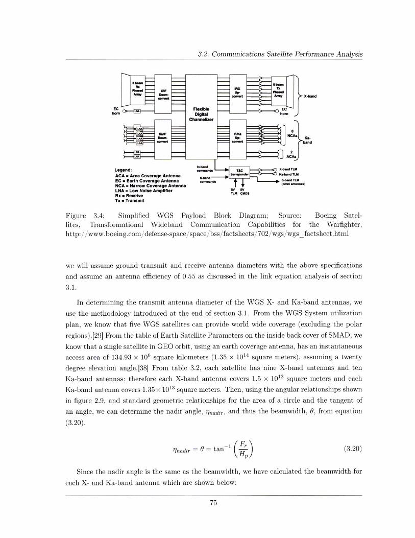
3.2. Communications Satellite Performance Analysis
X-band
ECFlexWble
Channeliwe
KW U CAs
Legend: onmsrc X-b.nd TLM
ACA = Area Coverage Antenna m M .LM
EC m Earth Coverage Antenna SmMnnd. Md T4mNCA = Narrow Coverage Antenna (ormannn.m)LNA = Low Noise Amplifier Ov sv
Rx = ReceiveTx = Transmit
Figure 3.4: Simplified WGS Payload Block Diagram; Source: Boeing Satel-lites, Transformational Wideband Communication Capabilities for the Warfighter,http://www.boeing.com/defense-space/space/bss/factsheets/702/wgs/wgsfactsheet.html
we will assume ground transmit and receive antenna diameters with the above specifications
and assume an antenna efficiency of 0.55 as discussed in the link equation analysis of section
3.1.
In determining the transmit antenna diameter of the WGS X- and Ka-band antennas, we
use the methodology introduced at the end of section 3.1. From the WGS System utilization
plan, we know that five WGS satellites can provide world wide coverage (excluding the polar
regions).[29] From the table of Earth Satellite Parameters on the inside back cover of SMAD, we
know that a single satellite in GEO orbit, using an earth coverage antenna, has an instantaneous
access area of 134.93 x 10⁶ square kilometers (1.35 x 10¹⁴ square meters), assuming a twenty
degree elevation angle.[38] From table 3.2, each satellite has nine X-band antennas and ten
Ka-band antennas; therefore each X-band antenna covers 1.5 x 10¹³ square meters and each
Ka-band antenna covers 1.35 x 10¹³ square meters. Then, using the angular relationships shown
in figure 2.9, and standard geometric relationships for the area of a circle and the tangent of
an angle, we can determine the nadir angle, 7lnadir, and thus the beamwidth, 0, from equation
(3.20).
lnadir= 0 = tan ( ) (3.20)
Since the nadir angle is the same as the beamwidth, we have calculated the beamwidth for
each X- and Ka-band antenna which are shown below:
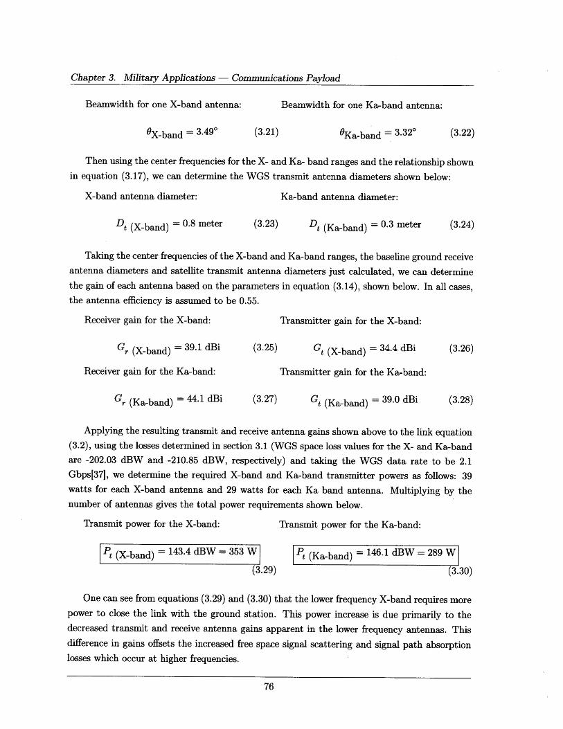
Chapter 3. Military Applications - Communications Payload
Beamwidth for one X-band antenna:
OX-band = 3.490
Beamwidth for one Ka-band antenna:
(3.21) OKa-band = 3.320 (3.22)
Then using the center frequencies for the X- and Ka- band ranges and the relationship shown
in equation (3.17), we can determine the WGS transmit antenna diameters shown below:
X-band antenna diameter:
Dt (X-band) = 0.8 meter
Ka-band antenna diameter:
(3.23) Dt (Ka-band) = 0.3 meter
Taking the center frequencies of the X-band and Ka-band ranges, the baseline ground receive
antenna diameters and satellite transmit antenna diameters just calculated, we can determine
the gain of each antenna based on the parameters in equation (3.14), shown below. In all cases,the antenna efficiency is assumed to be 0.55.
Receiver gain for the X-band:
Gr (X-band) = 39.1 dBi
Receiver gain for the Ka-band:
Gr (Ka-band) = 44.1 dBi
Transmitter gain for the X-band:
(3.25) Gt (X-band) = 34.4 dBi
Transmitter gain for the Ka-band:
(3.27) Gt (Ka-band) = 39.0 dBi
Applying the resulting transmit and receive antenna gains shown above to the link equation
(3.2), using the losses determined in section 3.1 (WGS space loss values for the X- and Ka-band
are -202.03 dBW and -210.85 dBW, respectively) and taking the WGS data rate to be 2.1
Gbps[37], we determine the required X-band and Ka-band transmitter powers as follows: 39
watts for each X-band antenna and 29 watts for each Ka band antenna. Multiplying by the
number of antennas gives the total power requirements shown below.
Transmit power for the X-band:
Pt (X-band) = 143.4 dBW = 353 W
(3.29)
Transmit power for the Ka-band:
P (Ka-band) = 146.1 dBW = 289 W
(3.30)
One can see from equations (3.29) and (3.30) that the lower frequency X-band requires morepower to close the link with the ground station. This power increase is due primarily to thedecreased transmit and receive antenna gains apparent in the lower frequency antennas. Thisdifference in gains offsets the increased free space signal scattering and signal path absorptionlosses which occur at higher frequencies.
(3.24)
(3.26)
(3.28)
3.2. Communications Satellite Performance Analysis
Referring to equation (3.19) we can estimate the available bandwidth for each of the fre-
quency bands as follows.
WGS X-band Bandwidth:
R 2.1e9BW lR 2.-e9= 8.8 x 10⁷ Hz = 88 MHz (3.31)P 1 144
log2 BER log2 T
WGS Ka-band Bandwidth:
R 2.1e9BW R - l2.e9- =9.1 x 10⁷ Hz = 91 MHz (3.32)
log 2 BP log2 89.78
Then, dividing the frequency range of each band by the associated bandwidth, we find that the
X-band is able to support five channels and the Ka-band can support eleven channels.
It is possible to parametrically estimate the cost of the communications payload from the
subsystem weight and power requirement using the cost estimating relationship (CER) shown
in equation (3.33) taken from the Unmanned Space Vehicle Cost Model (USCM).139]
Cost = (4574.25 + (0.19 * (Commwt * Pt))) + (2798.12 + 0.066 * Commwt * Pt) (3.33)
Where the first term is the non-recurring cost in $K, the second term is the recurring cost in
$K, Commwt is in pounds and Pt is in watts. Both the non-recurring and recurring costs are
in FY00 dollars; multiply the result by an inflation factor of 1.199 to get the cost in FY09
dollars.[38]
The weight of the subsystem can be found from the diameters of the Tx and Rx antennas
using the using the curve fit shown in figure 3.5, extrapolated from SMAD chapter 13.[33]
Applying the antenna diameter to payload weight relation in figure 3.5 and the CER in
equation (3.33), we get the following value for the total communications payload system cost.
Total WGS Communications P/L Cost = $2.5279 x 107 = $25, 279, 000 (FY09)
The next section will demonstrate that HALE platforms are capable of achieving comparable
WGS performance at significantly lower power and cost requirements.
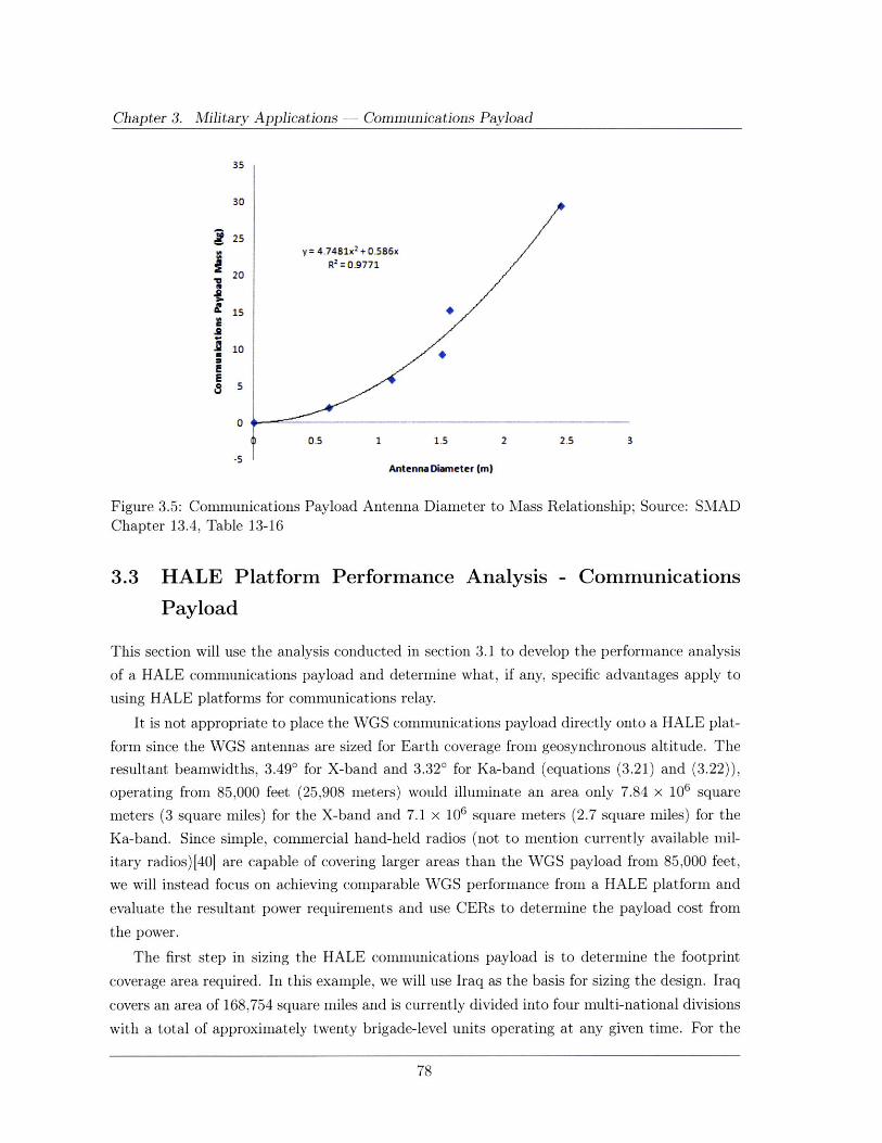
Chapter 3. Military Applications - Communications Payload
35
30
25y = 4.7481x 2 + 0.586x
Rz2 = 0.977120
E
10
0.5 1 1.5 2 2.5 3
-5Antenna Diameter (m)
Figure 3.5: Communications Payload Antenna Diameter to Mass Relationship; Source: SMADChapter 13.4, Table 13-16
3.3 HALE Platform Performance Analysis - Communications
Payload
This section will use the analysis conducted in section 3.1 to develop the performance analysis
of a HALE communications payload and determine what, if any, specific advantages apply to
using HALE platforms for communications relay.
It is not appropriate to place the WGS communications payload directly onto a HALE plat-
form since the WGS antennas are sized for Earth coverage from geosynchronous altitude. The
resultant beamwidths, 3.49' for X-band and 3.320 for Ka-band (equations (3.21) and (3.22)),
operating from 85,000 feet (25,908 meters) would illuminate an area only 7.84 x 10⁶ square
meters (3 square miles) for the X-band and 7.1 x 10⁶ square meters (2.7 square miles) for the
Ka-band. Since simple, commercial hand-held radios (not to mention currently available mil-
itary radios)[40] are capable of covering larger areas than the WGS payload from 85,000 feet,
we will instead focus on achieving comparable WGS performance from a HALE platform and
evaluate the resultant power requirements and use CERs to determine the payload cost from
the power.
The first step in sizing the HALE communications payload is to determine the footprint
coverage area required. In this example, we will use Iraq as the basis for sizing the design. Iraq
covers an area of 168,754 square miles and is currently divided into four multi-national divisions
with a total of approximately twenty brigade-level units operating at any given time. For the
3.3. HALE Platform Performance Analysis - Communications Payload
purposes of this analysis, we will use the area of operations (AO) assigned to the 3d Armored
Cavalry Regiment (ACR) (of which the author was a part) in Northwestern Iraq from May 2005
through February 2006. During this time, the 3d ACR's area of operations comprised an area of
3,861 square miles; assuming a circular area of operations, the diameter of the AO was seventy
miles. Figure 2.10 shows that a HALE platform operating at 85,000 feet with an elevation angle
of fifteen degrees is capable of achieving a footprint diameter of 116 miles. Therefore, the 3d
ACR's AO was well within the established capabilities of a HALE communications payload.
Taking the footprint radius of thirty-five miles and the nominal operating altitude of 85,000
feet, then equation (3.20) yields the required communications beamwidth to be 65.40. Next,
using the center frequencies for the X- and Ka- band ranges and the relationship shown in
equation (3.17), we can determine the HALE platform transmit antenna diameters as shown
below.
X-band transmit antenna diameter: Ka-band transmit antenna diameter:
Dt (X-band) = 0.04 meter (3.34) Dt (Ka-band) = 0.02 meter (3.35)
Taking the transmitting antenna efficiencies to be 0.55 as in previous calculations, the gains
of the transmitting antennas, for X- and Ka-band are 22 dBi and 27.5 dBi, respectively. Then,
assuming the same ground receive antenna diameters (2.4 meters for the X-band and 1 meter
for the Ka-band) and gains used in section 3.2 (and shown in equations (3.25) and (3.27)), along
with the associated link losses calculated in section 3.1 and a comparable WGS data rate of 2.1
Gbps, then the required transmitter power for a HALE communications payload operating at
85,000 feet are shown below.
Platform transmit power for the X-band: Platform transmit power for the Ka-band:
t (X-band) = -17.02 dBW = 0.019 W Pt (Ka-band) = -17.68 dBW = 0.017 W
(3.36) (3.37)
Clearly, the reduced altitude afforded by a HALE platform allows for significantly reduced
transmitter power and, again, the X-band requires slightly more power than the Ka-band. This
power advantage can be translated into subsystem cost, using figure 3.5 and equation (3.33),
as shown below.
Total HALE Communications P/L Cost = $1.7679 x 107 = $17, 679, 000 (FY09)
Again referring to equation (3.19) we estimate the available bandwidth for each of the
frequency bands as follows.
Chapter 3. Military Applications - Communications Payload
HALE X-band Bandwidth:
R 2.1e9BW - 2 9- =1.93 x 10⁸ Hz = 193 MHz (3.38)
log2 BE Og 0
HALE Ka-band Bandwidth:
BW R _ 2.1e9 = 1.96 x 10⁸ Hz = 196 MHz (3.39)log 2 BER log2 'o1
The above calculations show that the low operating altitude of a HALE platform allows for
significantly reduced power requirements. These reduced transmit powers result in increased
bandwidth and a corresponding decrease in the number of available channels (two channels for
the X-band and five for the Ka-band). Subsequent analysis will show that it is possible to
increase the number of channels to bring HALE platforms in-line with WGS capabilities.
While these reduced power requirements do translate to a lower system cost, the HALE cost
is not as low as expected (a savings of about $8 million). The primary reason for this discrepancy
is that the HALE cost was calculated using satellite CERs obtained from the USCM rather than
aircraft CERs which were not available to the author at the time of this analysis. Using the
appropriate cost model will undoubtedly result in even lower system costs.
There is one further step to take in this analysis. The above calculations use the best fit
ground receive antennas taken from the WGS System Utilization Plan. However, as noted in
section 2.5, one of the key capability gaps is BLOS communications on-the-move which is not
possible with antenna dishes of the size used above. Therefore, we must consider the use of an
omnidirectional ground receive antenna and determine the required platform transmit power to
enable mobile communications. Note that this next step will not change the established platform
antenna diameters or gains (equations (3.34) and (3.35)). Rather, it changes the ground receive
terminals from directional, parabolic antennas sized for the WGS link to an omnidirectional
ground receive antenna.
It is important to note that the ideal omnidirectional antenna is an isotropic antenna which
radiates equally in all directions. While an isotropic antenna is the simplest reference antenna
model, it cannot be built, "as isotropic radiation is incompatible with the transverse character of
electromagnetic waves. "[34] Due to this limitation most omnidirectional antennas are, in reality,
only capable of transmitting in two-dimensions rather than three. In spite of the directional
limitations, certain antenna configurations allow for wider beamwidths than others. Figure 3.6,
taken from a 2008 study conducted by Ando et al[41] shows an existence proof of one such
antenna.
The figure shows a dielectric-loaded slotted-cylinder antenna (DSCA) configuration that
allows wide beamwidth communications in the X-Y plane. While this antenna was mounted on
a rooftop for the purposes of the study, figure 3.6(a) shows that the antenna is small enough
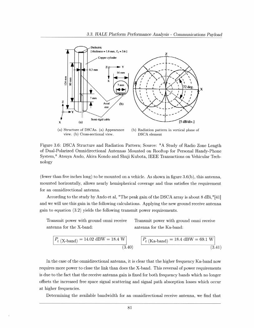
3.3. HALE Platform Performance Analysis - Communications Payload
7 mm
slot
X (a) rig cabic [5 dB/div.]
(a) Structure of DSCAs. (a) Appearance (b) Radiation pattern in vertical plane ofview. (b) Cross-sectional view. DSCA element
Figure 3.6: DSCA Structure and Radiation Pattern; Source: "A Study of Radio Zone Lengthof Dual-Polarized Omnidirectional Antennas Mounted on Rooftop for Personal Handy-PhoneSystem," Atsuya Ando, Akira Kondo and Shuji Kubota, IEEE Transactions on Vehicular Tech-nology
(fewer than five inches long) to be mounted on a vehicle. As shown in figure 3.6(b), this antenna,
mounted horizontally, allows nearly hemispherical coverage and thus satisfies the requirement
for an omnidirectional antenna.
According to the study by Ando et al, "The peak gain of the DSCA array is about 8 dBi," [411
and we will use this gain in the following calculations. Applying the new ground receive antenna
gain to equation (3.2) yields the following transmit power requirements.
Transmit power with ground omni receive Transmit power with ground omni receive
antenna for the X-band: antenna for the Ka-band:
Pt (X-band) = 14.02 dBW = 18.4 W Pt (Ka-band) = 18.4 dBW = 69.1 W
(3.40) (3.41)
In the case of the omnidirectional antenna, it is clear that the higher frequency Ka-band now
requires more power to close the link than does the X-band. This reversal of power requirements
is due to the fact that the receive antenna gain is fixed for both frequency bands which no longer
offsets the increased free space signal scattering and signal path absorption losses which occur
at higher frequencies.
Determining the available bandwidth for an omnidirectional receive antenna, we find that
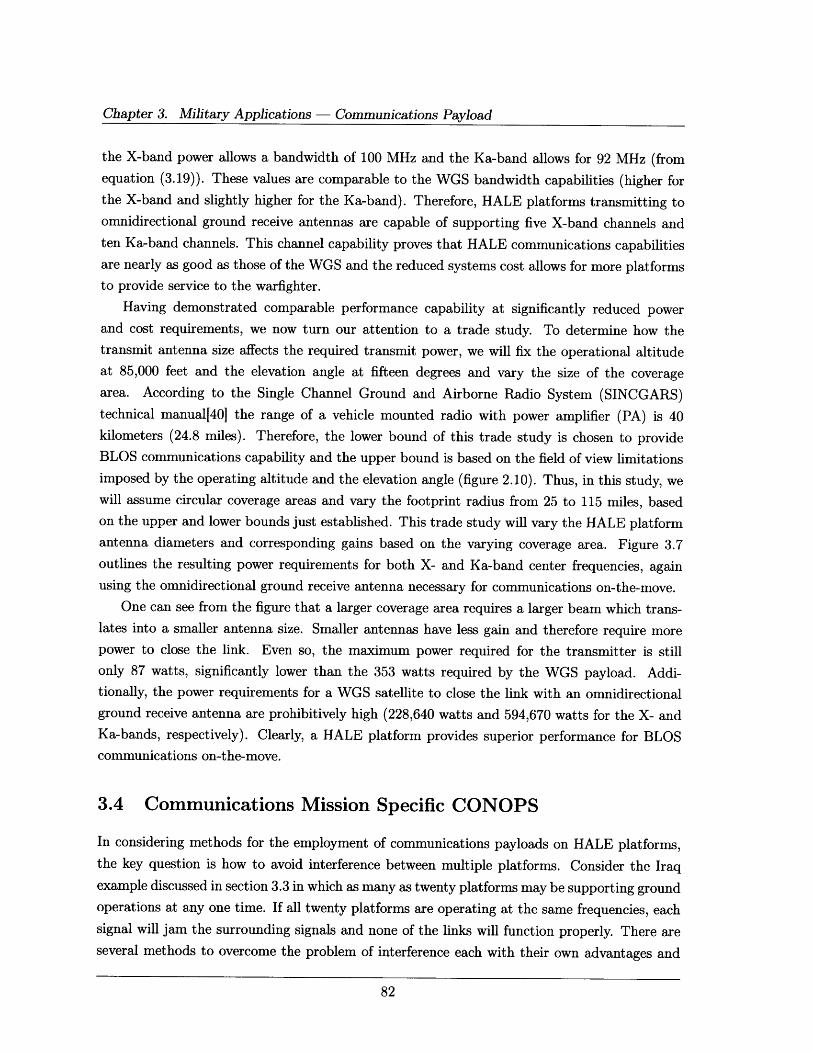
Chapter 3. Military Applications - Communications Payload
the X-band power allows a bandwidth of 100 MHz and the Ka-band allows for 92 MHz (from
equation (3.19)). These values are comparable to the WGS bandwidth capabilities (higher for
the X-band and slightly higher for the Ka-band). Therefore, HALE platforms transmitting toomnidirectional ground receive antennas are capable of supporting five X-band channels and
ten Ka-band channels. This channel capability proves that HALE communications capabilities
are nearly as good as those of the WGS and the reduced systems cost allows for more platforms
to provide service to the warfighter.
Having demonstrated comparable performance capability at significantly reduced power
and cost requirements, we now turn our attention to a trade study. To determine how the
transmit antenna size affects the required transmit power, we will fix the operational altitude
at 85,000 feet and the elevation angle at fifteen degrees and vary the size of the coverage
area. According to the Single Channel Ground and Airborne Radio System (SINCGARS)
technical manual[40] the range of a vehicle mounted radio with power amplifier (PA) is 40
kilometers (24.8 miles). Therefore, the lower bound of this trade study is chosen to provide
BLOS communications capability and the upper bound is based on the field of view limitations
imposed by the operating altitude and the elevation angle (figure 2.10). Thus, in this study, we
will assume circular coverage areas and vary the footprint radius from 25 to 115 miles, based
on the upper and lower bounds just established. This trade study will vary the HALE platform
antenna diameters and corresponding gains based on the varying coverage area. Figure 3.7
outlines the resulting power requirements for both X- and Ka-band center frequencies, again
using the omnidirectional ground receive antenna necessary for communications on-the-move.
One can see from the figure that a larger coverage area requires a larger beam which trans-
lates into a smaller antenna size. Smaller antennas have less gain and therefore require more
power to close the link. Even so, the maximum power required for the transmitter is still
only 87 watts, significantly lower than the 353 watts required by the WGS payload. Addi-tionally, the power requirements for a WGS satellite to close the link with an omnidirectional
ground receive antenna are prohibitively high (228,640 watts and 594,670 watts for the X- andKa-bands, respectively). Clearly, a HALE platform provides superior performance for BLOScommunications on-the-move.
3.4 Communications Mission Specific CONOPS
In considering methods for the employment of communications payloads on HALE platforms,the key question is how to avoid interference between multiple platforms. Consider the Iraq
example discussed in section 3.3 in which as many as twenty platforms may be supporting groundoperations at any one time. If all twenty platforms are operating at the same frequencies, each
signal will jam the surrounding signals and none of the links will function properly. There areseveral methods to overcome the problem of interference each with their own advantages and
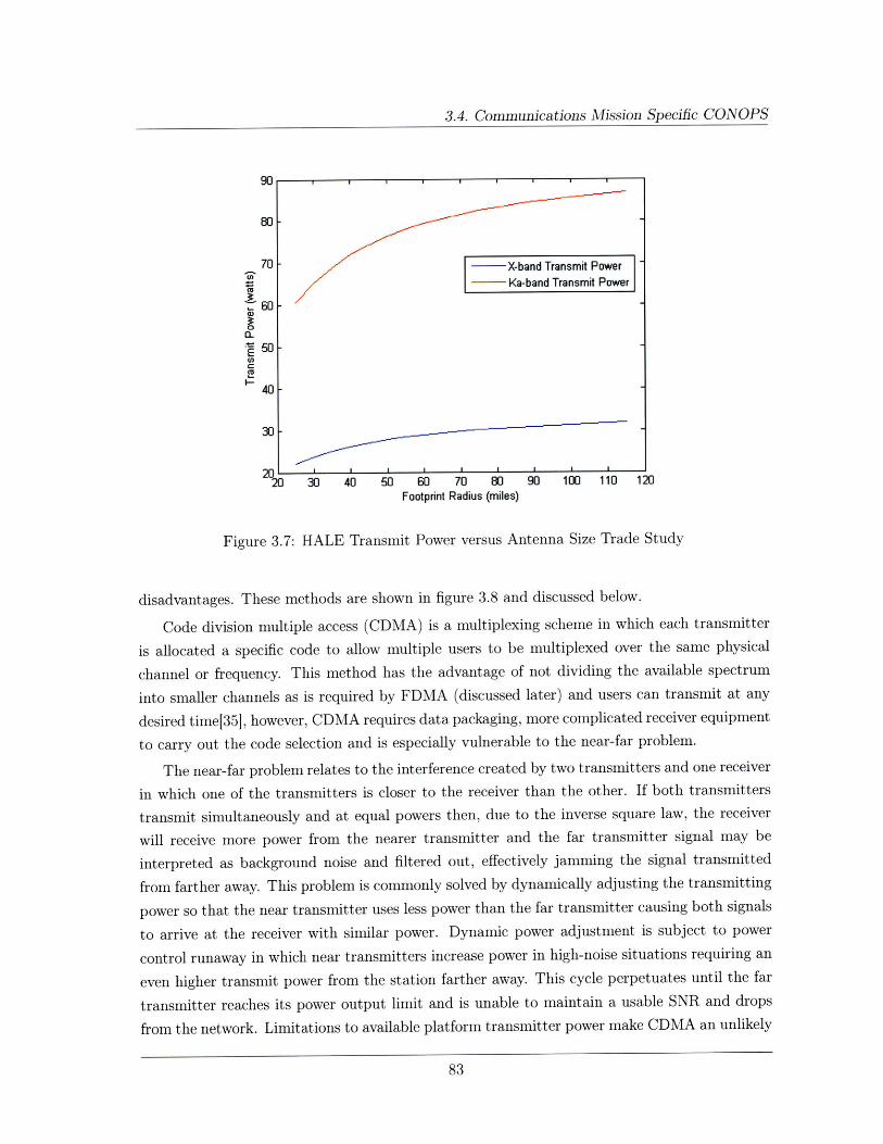
3.4. Communications Mission Specific CONOPS
90
80 -
70 ~ ( X-band Transmit Power
Sa-band Transmit Power
a 60
50 -
CO
40 -
30
20 30 40 50 60 70 80 90 100 110 120Footprint Radius (miles)
Figure 3.7: HALE Transmit Power versus Antenna Size Trade Study
disadvantages. These methods are shown in figure 3.8 and discussed below.
Code division multiple access (CDMA) is a multiplexing scheme in which each transmitter
is allocated a specific code to allow multiple users to be multiplexed over the same physical
channel or frequency. This method has the advantage of not dividing the available spectrum
into smaller channels as is required by FDMA (discussed later) and users can transmit at any
desired time[35], however, CDMA requires data packaging, more complicated receiver equipment
to carry out the code selection and is especially vulnerable to the near-far problem.
The near-far problem relates to the interference created by two transmitters and one receiver
in which one of the transmitters is closer to the receiver than the other. If both transmitters
transmit simultaneously and at equal powers then, due to the inverse square law, the receiver
will receive more power from the nearer transmitter and the far transmitter signal may be
interpreted as background noise and filtered out, effectively jamming the signal transmitted
from farther away. This problem is commonly solved by dynamically adjusting the transmitting
power so that the near transmitter uses less power than the far transmitter causing both signals
to arrive at the receiver with similar power. Dynamic power adjustment is subject to power
control runaway in which near transmitters increase power in high-noise situations requiring an
even higher transmit power from the station farther away. This cycle perpetuates until the far
transmitter reaches its power output limit and is unable to maintain a usable SNR and drops
from the network. Limitations to available platform transmitter power make CDMA an unlikely
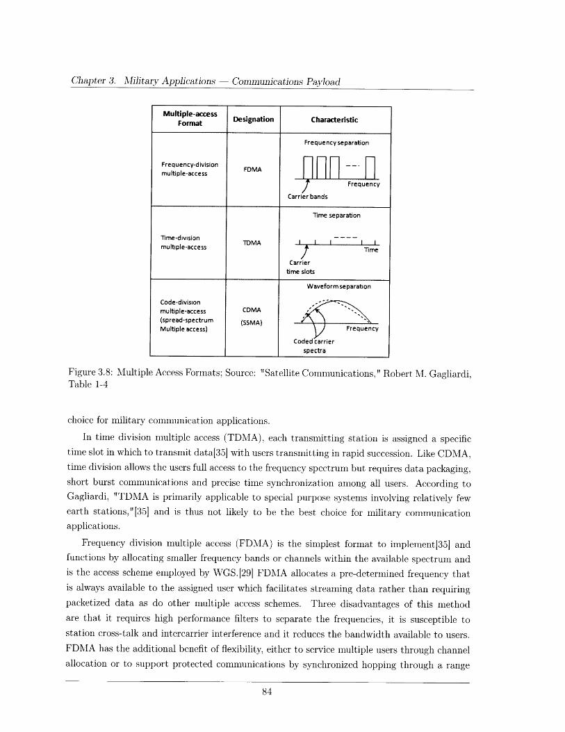
Chapter 3. Alilitary Applications Communications Payload
Figure 3.8: MultipleTable 1-4
Access Formats; Source: "Satellite Communications," Robert M. Gagliardi,
choice for military communication applications.
In time division multiple access (TDMA), each transmitting station is assigned a specific
time slot in which to transmit data[35] with users transmitting in rapid succession. Like CDMA,time division allows the users full access to the frequency spectrum but requires data packaging,short burst communications and precise time synchronization among all users. According toGagliardi, "TDMA is primarily applicable to special purpose systems involving relatively fewearth stations,"[35] and is thus not likely to be the best choice for military communicationapplications.
Frequency division multiple access (FDMA) is the simplest format to implement[35] andfunctions by allocating smaller frequency bands or channels within the available spectrum andis the access scheme employed by WGS.[29] FDMA allocates a pre-determined frequency that
is always available to the assigned user which facilitates streaming data rather than requiring
packetized data as do other multiple access schemes. Three disadvantages of this method
are that it requires high performance filters to separate the frequencies, it is susceptible to
station cross-talk and intercarrier interference and it reduces the bandwidth available to users.
FDMA has the additional benefit of flexibility, either to service multiple users through channel
allocation or to support protected communications by synchronized hopping through a range
Multiple-accessFormat Designation Characteristic
Frequency separation
Frequency-division FDMAmultiple-access
Frequency
Carrier bands
Time separation
Time-divisionTDMA I I I I I
multiple-access Time
Carriertime slots
Waveform separation
Code-divisionmultiple-access CDMA(spread-spectrum (SSMA)Multiple access) Frequency
Coded carrier
spectra
Chapter 3. Military Applications - Communications Payload
3.5. Chapter Summary
of frequencies. Therefore, FDMA is likely to be the best choice for military communication
applications.
As discussed in section 3.1 we are assuming that the HALE platform is operating directly
overhead with a beamwidth sufficient to cover the entire field of view and thus does not require
platform antenna pointing. Should it be necessary to point the antenna, "it is common to
have a pointing accuracy of 10% to 20% of the field of view diameter."[21] In the case of
communications payloads, the field of view radius is the half-power beamwidth, 0. If we assume
the mean pointing accuracy of 15%, then e =20 /15 and equation (3.42) shows the relationship
for the antenna pointing loss.
= -12 1 = -12 (3.42)( 0 (15
Note that pointing the platform antenna toward a specific ground terminal will change the
coverage area and prevent communications access to users located outside the antenna pattern.
Therefore, designers must give careful consideration to user impact when deciding to employ
antenna pointing.
3.5 Chapter Summary
This chapter has demonstrated that HALE platforms are capable of providing communications
performance comparable to that of the WGS satellites with significantly reduced power require-
ments due to the shortened path length. These power savings consequently result in a lower
system cost although the resultant cost savings were not as high as anticipated.
The main drawback of the HALE platform compared to the WGS is the reduced field of view
of the onboard communications system. However, since this thesis is attempting to develop the
feasibility of using HALE platforms to support operations at the brigade-level, the available
footprint is still more than sufficient to cover the size of the area of operations in question.

This page intentionally left blank.
Chapter 4
Military Applications ISR Payload
Resolution is the key performance metric in the design of observation payloads. Astronomical
observations define resolving power in terms of angular resolution, or the angular separation
between two objects of interest. In earth observation, the key is be able to resolve fine detail
on the surface, therefore, the resolution is expressed in terms of the size of an object that is
distinguishable from the background.[42 This chapter will focus on earth observation and thus
will use ground resolution as the primary evaluation metric.
This chapter will begin with an overview of the equations governing observation payload
design followed by an analysis of the performance of observation payloads with respect to both
satellites and HALE platforms and will conclude with a discussion of observation mission-specific
CONOPS considerations. This analysis will use the newly commissioned GeoEye commercial
imaging satellite as the baseline for ground resolution performance comparisons.
The GeoEye-1 satellite was designed and built by General Dynamics Advanced Information
Systems and launched in September 2008 aboard a Boeing Delta II rocket. While GeoEye is a
commercial satellite, it provides imaging services to government agencies as well including the
National Geospatial-Intelligence Agency (NGA) and the National Oceanic and Atmospheric
Administration (NOAA). Section 4.2 will discuss the GeoEye-1 satellite capabilities in more
detail.
4.1 ISR Payload Design and Sizing
As mentioned previously, ground resolution is the primary performance metric and is dependent
upon four factors: distance to the target (R,), focal length (ft), wavelength (A) and aperture
size (D). Figure 4.1 shows the optical characteristics of a refractive imaging system.
The fundamental resolution limitation is diffraction, the bending of light that occurs at the
edge of the optical system.[42] Diffraction causes a point source of light to appear as a series
of concentric circles getting successively dimmer away from the center; a pattern known as the
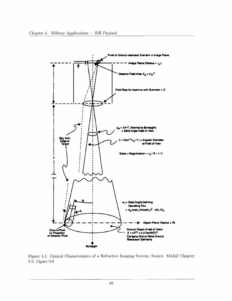
Chapter 4. Military Applications
TfII
I
I
IM; Of
Targo
i
1
4, r4
Prw ot Groun-re.ooen* EJWemW. Irege Plwe
- -- - -P (Rads . rt)
Doector Fgid Ar Ad Z, U2
Fekod St o Aprtue wth Mar clf . O0
a F* of Vew
$COO 2 MagurfI4Cn A'* '"l
*SOre~ghh
eS, old AIVlo W"einUpwgNV Fka
- Aecos,J(Itgne9 " 49,4AdOW,4bWbat)2 %Mel)2
- - -* OW PeW (Radis . FO
Grorud Oilc (Feed of VWw)- AanxR2(tan(tW2)9
Co.tmire One or Moe GwoundRo iton Eurwrat
Figure 4.1: Optical Characteristics of a Refractive Imaging System; Source: SMAD Chapter9.3, Figure 9-8
- ISR Payload

4.1. ISR Payload Design and Sizing
point spread function as shown in figure 4.2.
9.3, Figure 9-11
The angular distance, Or, from the maximum at the center of the image to the first dark
interference ring, called the Rayleigh limit is given in equation (4.1).142]
Or = 1.22A (4.1)D
Where A is the wavelength, D is the aperture diameter of the optical instrument and 0 r is
expressed in radians.
For a satellite, or HALE platform at altitude, Hp, the ground resolution is shown in equation
(4.2).
, 2.44HpA (4.2)D
Equation (4.2) is valid for objects located at nadir, however, Hp can be replaced by the slant
range, Rs, to determine the resolution away from nadir. Here Rs is the same as S in equation
(3.8) and refers to the angular relationships shown in figure 2.9. Table 4.1, taken from SMAD
chapter 9, provides some possible resolutions from various altitudes for common aperture sizes.
Ground Resolution = 2.44 h A/D
Aperture Visible IR MicrowaveAltitude Size, D [A 0.5 pm] [A = 3 pm] [A = 3 cm]
1 m 1.1 m 6.59 m 65.9 km900 km (LEO) 3 m 0.366 m 2.2 m 22 km
1 m 43.7 m 262 m 2,620 km35,800 km (GEO) 3m 14.6m 87.4 874 km
3 m 14.6 m 87.4 m 874 km
20 km (SR-71) 0.3 m 0.081 m 0.488 m 4.88 km
Table 4.1: Diffraction-Limited Resolution: Source: SMAD Chapter 9.3, Table 9-9
There is one additional design parameter to consider in the design of optical detector arrays:
the quality factor, Q. The quality factor is defined as the ratio of the pixel size (d) to the diameter
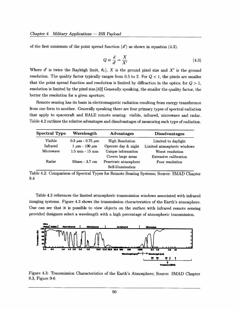
Chapter 4. Military Applications - ISR Payload
of the first minimum of the point spread function (d') as shown in equation (4.3).
d Xd' X' (4.3)
Where d' is twice the Rayleigh limit, Or), X is the ground pixel size and X' is the ground
resolution. The quality factor typically ranges from 0.5 to 2. For Q < 1, the pixels are smaller
that the point spread function and resolution is limited by diffraction in the optics; for Q > 1,resolution is limited by the pixel size.[42] Generally speaking, the smaller the quality factor, the
better the resolution for a given aperture.
Remote sensing has its basis in electromagnetic radiation resulting from energy transference
from one form to another. Generally speaking there are four primary types of spectral radiation
that apply to spacecraft and HALE remote sensing: visible, infrared, microwave and radar.
Table 4.2 outlines the relative advantages and disadvantages of measuring each type of radiation.
Spectral Type Wavelength Advantages Disadvantages
Visible 0.3 pm - 0.75 ,pm High Resolution Limited to daylightInfrared 1 pm - 100 Am Operate day & night Limited atmospheric windows
Microwave 1.5 mm - 15 mm Unique information Worst resolutionCovers large areas Extensive calibration
Radar 50mm - 3.7 cm Penetrate atmosphere Poor resolutionSelf-illumination
Table 4.2: Comparison of Spectral Types for Remote Sensing Systems; Source: SMAD Chapter9.4
Table 4.2 references the limited atmospheric transmission windows associated with infrared
imaging systems. Figure 4.3 shows the transmission characteristics of the Earth's atmosphere.
One can see that it is possible to view objects on the surface with infrared remote sensing
provided designers select a wavelength with a high percentage of atmospheric transmission.
W"I I MWrv I MI ,wd far I Mkm-
£wiEf2\~f~Jf A/fl
6020 10 6 3
ft-.wr w
Figure 4.3: Transmission Characteristics of the9.3, Figure 9-6
Earth's Atmosphere; Source: SMAD Chapter
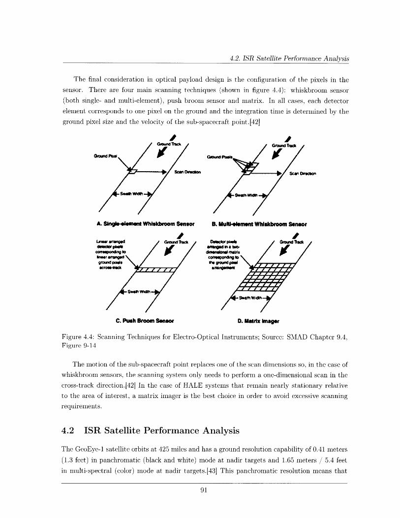
4.2. ISR Satellite Performance Analysis
The final consideration in optical payload design is the configuration of the pixels in the
sensor. There are four main scanning techniques (shown in figure 4.4): whiskbroom sensor
(both single- and multi-element), push broom sensor and matrix. In all cases, each detector
element corresponds to one pixel on the ground and the integration time is determined by the
ground pixel size and the velocity of the sub-spacecraft point.[42]
A. ~ngI.-mmt Whlkroom Sensor B. MulItemnt Whlskboom Sensor
ohe potion o e sra onel of t anwh b oo send Ctoh snesn tagrndlagle \/ the grod /hl
Figure 4.4: Scanning Techniques for Electro-Optical Instruments; Source: SMAD Chapter 9.4,Figure 9-14
The motion of the sub-spacecraft point replaces one of the scan dimensions so, in the case of
whiskbroom sensors, the scanning system only needs to perform a one-dimensional scan in the
cross-track direction.J42] In the case of HALE systems that remain nearly stationary relative
to the area of interest, a matrix imager is the best choice in order to avoid excessive scanning
requirements.
4.2 ISR Satellite Performance Analysis
The GeoEye-1 satellite orbits at 425 miles and has a ground resolution capability of 0.41 meters(1.3 feet) in panchromatic (black and white) mode at nadir targets and 1.65 meters / 5.4 feet
in multi-spectral (color) mode at nadir targets.(43] This panchromatic resolution means that
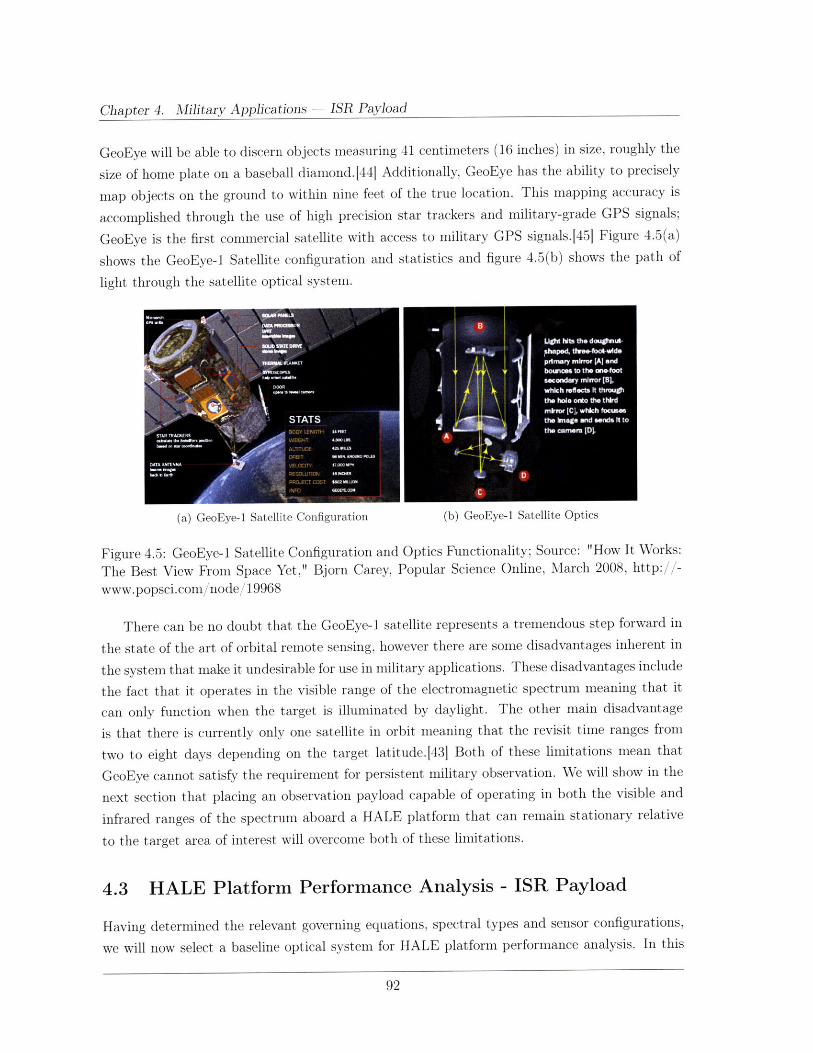
Chapter 4. Military Applications - ISR Payload
GeoEye will be able to discern objects measuring 41 centimeters (16 inches) in size, roughly the
size of home plate on a baseball diamond.[44] Additionally, GeoEye has the ability to precisely
map objects on the ground to within nine feet of the true location. This mapping accuracy is
accomplished through the use of high precision star trackers and military-grade GPS signals;
GeoEye is the first commercial satellite with access to military GPS signals.[45] Figure 4.5(a)
shows the GeoEye-1 Satellite configuration and statistics and figure 4.5(b) shows the path of
light through the satellite optical system.
(a) GeoEye-1 Satellite Configuration (b) GeoEye-1 Satellite Optics
Figure 4.5: GeoEye-1 Satellite Configuration and Optics Functionality; Source: "How It Works:
The Best View From Space Yet," Bjorn Carey, Popular Science Online, March 2008, http://-
www.popsci.com/node/19968
There can be no doubt that the GeoEye-1 satellite represents a tremendous step forward in
the state of the art of orbital remote sensing, however there are some disadvantages inherent in
the system that make it undesirable for use in military applications. These disadvantages include
the fact that it operates in the visible range of the electromagnetic spectrum meaning that it
can only function when the target is illuminated by daylight. The other main disadvantage
is that there is currently only one satellite in orbit meaning that the revisit time ranges from
two to eight days depending on the target latitude.43] Both of these limitations mean that
GeoEye cannot satisfy the requirement for persistent military observation. We will show in the
next section that placing an observation payload capable of operating in both the visible and
infrared ranges of the spectrum aboard a HALE platform that can remain stationary relative
to the target area of interest will overcome both of these limitations.
4.3 HALE Platform Performance Analysis - ISR Payload
Having determined the relevant governing equations, spectral types and sensor configurations,
we will now select a baseline optical system for HALE platform performance analysis. In this

4.3. HALE Platform Performance Analysis - ISR Payload
section, we will use a multi-spectral imaging system using both the visible and infrared ranges of
the electromagnetic spectrum with sensor pixels configured in a matrix imager. As in previous
analyses, we will assume a nominal operating altitude of 85,000 feet and an elevation angle of
fifteen degrees. Based on equation (3.8), the maximum slant range, Rs, then becomes 319,649
feet (97,429 meters). We will use this slant range to determine the worst case ground resolution
possible
In this analysis, we will vary the aperture diameter from 0.3 meters (equivalent to the
sensor on an SR-71 Blackbird) to one meter (approximately equivalent to the GeoEye-1 satellite
aperture). Figure 4.6 shows the resulting ground resolution for the given aperture range.
2.5 . . . . . . ._1_' _ -- _-Visible Spectrum
" -- Infrared Spectrum
nx GeoEye-1 Satellite (visible spectrum only)a 2-
_ 1s
- 0.5
W2 0.3 0.4 0.5 0.6 0.7 0.8 0.9 1Aperture Diameter (meters)
Figure 4.6: HALE Platform Remote Sensor Ground Resolutions at the Minimum Elevation
Angle (15 degrees) for the Visible and Infrared Spectrums
One can see from figure 4.6 that an aperture diameter of 0. 3 meters allows a ground resolution
of 0.39 meters; the HALE platform already outperforms the GeoEye-1 satellite. As the aperture
diameter approaches one meter, the ground resolution in the visible spectrum is 0.12 meters. For
perspective, a resolution of 0.01 meters is sufficient to distinguish a large newspaper headline.[42
Any resolution in this range of aperture diameters is sufficient to observe human activity on the
surface. Activities such as the emplacement of improvised explosive devices (IEDs) in Iraq or
Afghanistan are of particular concern for military operations. It is important to note that these
resolution values are for the maximum slant range for a 15 degree elevation angle. At nadir,
the resolution is even better as shown in figure 4.7. At an aperture diameter of one meter, the
nadir ground resolution is approximately 0.03 meters.
In order to calculate the design parameters of the optical system, we must begin with swath
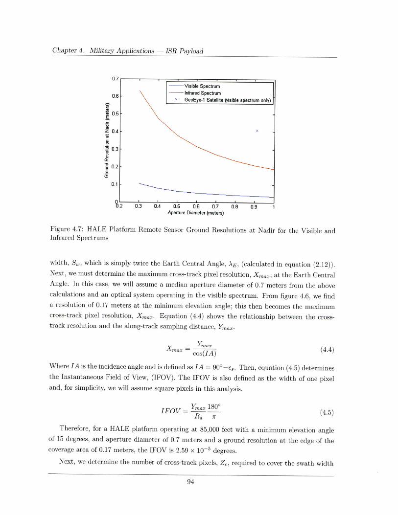
Chapter 4. Military Applications - ISR Payload
0.7-Visible Spectrum
0.6 Infrared Spectrumx GeoEye-1 Satellite (visible spectrum only)
S0.5
z 0.4 -
S0.3
0.20
0.1
.2 0.3 0.4 0.5 0.6 0.7 0.8 0.9 1Aperture Diameter (meters)
Figure 4.7: HALE Platform Remote Sensor Ground Resolutions at Nadir for the Visible andInfrared Spectrums
width, S,, which is simply twice the Earth Central Angle, AE, (calculated in equation (2.12)).Next, we must determine the maximum cross-track pixel resolution, Xmax, at the Earth CentralAngle. In this case, we will assume a median aperture diameter of 0.7 meters from the abovecalculations and an optical system operating in the visible spectrum. From figure 4.6, we finda resolution of 0.17 meters at the minimum elevation angle; this then becomes the maximumcross-track pixel resolution, Xmax. Equation (4.4) shows the relationship between the cross-track resolution and the along-track sampling distance, Ymax.
Yaxax = max (4.4)
cos(IA)
Where IA is the incidence angle and is defined as IA = 90'-Es. Then, equation (4.5) determinesthe Instantaneous Field of View, (IFOV). The IFOV is also defined as the width of one pixeland, for simplicity, we will assume square pixels in this analysis.
IFOV = Ymax 1800 (4.5)Rs, r
Therefore, for a HALE platform operating at 85,000 feet with a minimum elevation angleof 15 degrees, and aperture diameter of 0.7 meters and a ground resolution at the edge of thecoverage area of 0.17 meters, the IFOV is 2.59 x 10- 5 degrees.
Next, we determine the number of cross-track pixels, Z, required to cover the swath width
4.3. HALE Platform Performance Analysis - ISR Payload
as shown in equation (4.6).
Zc = 277nadir - 5.73 x 106 pixels (4.6)IFOV
Since HALE platforms remain relatively stationary with respect to the ground, we will
assume a matrix imager (from figure 4.4) and, for simplicity, we will assume a square matrix.
Therefore, the total number of pixels required is Z 2 = 3.29 x 1013 pixels.
Next, we must determine the number of bits used to encode each pixel. The number of bits
used is based on resolution and dynamic range requirements and can range from one to thirty-
two bits per pixel (bpp), 1 bpp being the minimum required for a binary (black-and-white)
image; 8 bpp allows for a 256 color image but tend to produce grainy pictures; 16 bpp provide
65,536 distinct colors and is often used in high quality computer graphics cards; 24 bpp allows
for 331,776 distinct colors; and 32 bpp provide a true-color image. In this case, we will assume
the median 16 bpp. Then the required data rate, R, is the total number of pixels imaged in one
second times the number of bits per pixel. Based on the above numbers, imaging such a large
detector array once per second will require a downlink capacity of 5.3 x 1014 bits per second or
530 terra-bits per second (Tbps) - an impossibly high number.
In order to make the data rate manageable, we need to trade it against lower resolution and
smaller coverage area. First, we will reduce the size of the coverage area to a more practical size.
Referring to the coverage area discussion in section 3.3, we will again assume a coverage area
equivalent to the area of operations assigned to the 3d ACR in Northwestern Iraq from May
2005 through February 2006: an area of 3,861 square miles (62 x 62 miles). Next, we will reduce
the resolution requirement to the minimum achievable with a 0.3 meter aperture diameter, 0.11
meters at nadir (0.39 meters at the edge). Then, applying equations (4.4) through (4.6), we find
we still need 6.85 x 1012 pixels and a data rate of 110 Tbps - a data rate still not supportable
with conventional data links.
Clearly, trying to image the entire field of regard (FOR) with a single array requires a
data rate that is unsupportable by current communications links and an array size that is not
commercially available. Table 4.3[461 shows some commercially available high-resolution charge
coupled device (CCD) arrays.
In the following analysis we will use the Lockheed Martin F-979F model CCD array, the
largest square array available - approximately 85 Mpixels. Figure 4.8 shows the angular rela-
tionships used in the analysis; note that we assume the HALE platform will be operating over
the center of the coverage area rather than over the edge. Using this array and again assuming
a 3,861 square mile field of regard, we must determine the total number of images required to
scan the entire coverage area. First, we take the required resolution at nadir, 0.11 meters, and
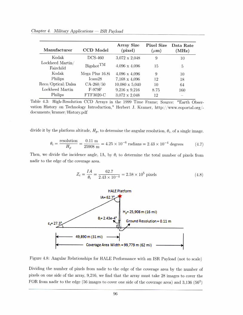
Chapter 4. Military Applications
Array Size Pixel Size Data RateManufacturer CCD Model (pixel) (pm) (MHz)
Kodak DCS-460 3,072 x 2,048 9 10Lockheed Martin BigshotTM 4,096 x 4,096 15 5Fairchild
Kodak Mega Plus 16.8i 4,096 x 4,096 9 10Philips Icam28 7,168 x 4,096 12 18
Reco/Optical/Dalsa CA-260/50 10,080 x 5,040 10 64Lockheed Martin F-979F 9,216 x 9,216 8.75 160
Philips FTF3020-C 3,072 x 2,048 12
Table 4.3: High-Resolution CCD Arrays in the 1999 Time Frame; Source: "Earth Obser-vation History on Technology Introduction," Herbert J. Kramer, http://www.eoportal.org/-documents/kramer/History.pdf
divide it by the platform altitude, Hp, to determine the angular resolution, Oi, of a single image.
resolutioni
HP0.11 m
= 4.25 x 10⁻⁶ radians = 2.43 x 10- 4 degrees25908 m
Then, we divide the incidence angle, IA, by Oi to determine the total number of pixels fromnadir to the edge of the coverage area.
IAZc = --
0j
62.72.43 104 = 2.58 x 105 pixels
2.43 x 10⁻⁴ (4.8)
HALE Platform
Es= 27.
H = 25,908 m (16 mi)
Ground Resolution= 0.11 m
49,890 m (31mi)
Coverage Area Width =9,779 m (62 mi)
Figure 4.8: Angular Relationships for HALE Performance with an ISR Payload (not to scale)
Dividing the number of pixels from nadir to the edge of the coverage area by the number ofpixels on one side of the array, 9,216, we find that the array must take 28 images to cover theFOR from nadir to the edge (56 images to cover one side of the coverage area) and 3,136 (562)
(4.7)
ISR Payload
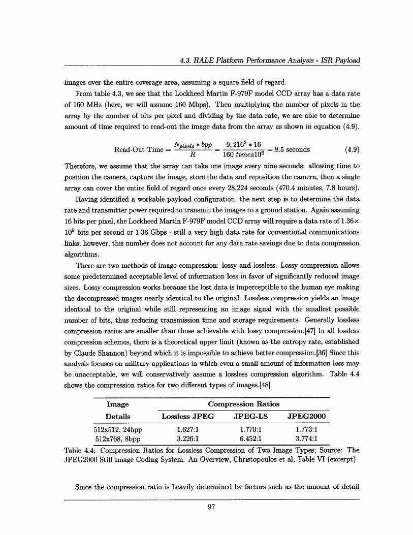
4.3. HALE Platform Performance Analysis - ISR Payload
images over the entire coverage area, assuming a square field of regard.
From table 4.3, we see that the Lockheed Martin F-979F model CCD array has a data rate
of 160 MHz (here, we will assume 160 Mbps). Then multiplying the number of pixels in the
array by the number of bits per pixel and dividing by the data rate, we are able to determine
amount of time required to read-out the image data from the array as shown in equation (4.9).
N - I, * bpp 9, 2162 * 16Read-Out Time = pxe * bpp _ 9,162 16 = 8.5 seconds (4.9)
R 160 timesl06
Therefore, we assume that the array can take one image every nine seconds: allowing time to
position the camera, capture the image, store the data and reposition the camera, then a single
array can cover the entire field of regard once every 28,224 seconds (470.4 minutes, 7.8 hours).
Having identified a workable payload configuration, the next step is to determine the data
rate and transmitter power required to transmit the images to a ground station. Again assuming
16 bits per pixel, the Lockheed Martin F-979F model CCD array will require a data rate of 1.36 x
109 bits per second or 1.36 Gbps - still a very high data rate for conventional communications
links; however, this number does not account for any data rate savings due to data compression
algorithms.
There are two methods of image compression: lossy and lossless. Lossy compression allows
some predetermined acceptable level of information loss in favor of significantly reduced image
sizes. Lossy compression works because the lost data is imperceptible to the human eye making
the decompressed images nearly identical to the original. Lossless compression yields an image
identical to the original while still representing an image signal with the smallest possible
number of bits, thus reducing transmission time and storage requirements. Generally lossless
compression ratios are smaller than those achievable with lossy compression.147 In all lossless
compression schemes, there is a theoretical upper limit (known as the entropy rate, established
by Claude Shannon) beyond which it is impossible to achieve better compression.[36] Since this
analysis focuses on military applications in which even a small amount of information loss may
be unacceptable, we will conservatively assume a lossless compression algorithm. Table 4.4
shows the compression ratios for two different types of images.[48]
Image Compression Ratios
Details Lossless JPEG JPEG-LS JPEG2000
512x512, 24bpp 1.627:1 1.770:1 1.773:1
512x768, 8bpp 3.226:1 6.452:1 3.774:1
Table 4.4: Compression Ratios for Lossless Compression of Two Image Types; Source: The
JPEG2000 Still Image Coding System: An Overview, Christopoulos et al, Table VI (excerpt)
Since the compression ratio is heavily determined by factors such as the amount of detail
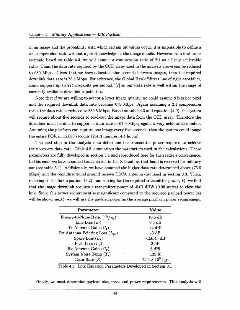
Chapter 4. Military Applications - ISR Payload
in an image and the probability with which certain bit values occur, it is impossible to define a
set compression ratio without a priori knowledge of the image details. However, as a first order
estimate based on table 4.4, we will assume a compression ratio of 2:1 as a likely achievable
ratio. Thus, the data rate required by the CCD array used in the analysis above can be reduced
to 680 Mbps. Given that we have allocated nine seconds between images, then the required
downlink data rate is 75.5 Mbps. For reference, the Global Hawk "direct line of sight capability,
could support up to 274 megabits per second,"[7] so our data rate is well within the range of
currently available downlink capabilities.
Note that if we are willing to accept a lower image quality, we could assume 8 bits per pixel
and the required downlink data rate becomes 679 Mbps. Again assuming a 2:1 compression
ratio, the data rate is reduced to 339.5 Mbps. Based on table 4.3 and equation (4.9), the system
will require about five seconds to read-out the image data from the CCD array. Therefore the
downlink must be able to support a data rate of 67.9 Mbps; again, a very achievable number.
Assuming the platform can capture one image every five seconds, then the system could image
the entire FOR in 15,680 seconds (261.3 minutes, 4.4 hours).
The next step in the analysis is to determine the transmitter power required to achieve
the necessary data rate. Table 4.5 summarizes the parameters used in the calculations. These
parameters are fully developed in section 3.1 and reproduced here for the reader's convenience.
In this case, we have assumed transmission in the X-band, as that band is reserved for military
use (see table 3.1). Additionally, we have assumed the higher data rate determined above (75.5
Mbps) and the omnidirectional ground receive DSCA antenna discussed in section 3.3. Then,
referring to the link equation, (3.2), and solving for the required transmitter power, Pt, we find
that the image downlink requires a transmitter power of -0.07 dBW (0.98 watts) to close the
link. Since this power requirement is insignificant compared to the required payload power (as
will be shown next), we will use the payload power as the average platform power requirement.
Parameter Value
Energy-to-Noise Ratio (Eb/N) 10.5 dBLine Loss (L1 ) 0.5 dB
Tx Antenna Gain (Gt) 22 dBiRx Antenna Pointing Loss (L,) -3 dB
Space Loss (Ls) -150.45 dBPath Loss (La) 2 dB
Rx Antenna Gain (Gr) 8 dBiSystem Noise Temp (T,) 135 K
Data Rate (R) 75.5 x 10⁶ bps
Table 4.5: Link Equation Parameters Developed in Section 3.1
Finally, we must determine payload size, mass and power requirements. This analysis will
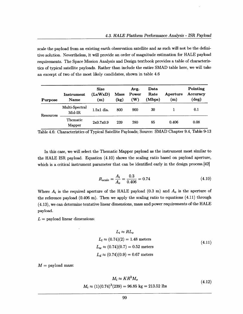
4.3. HALE Platform Performance Analysis - ISR Payload
scale the payload from an existing earth observation satellite and as such will not be the defini-
tive solution. Nevertheless, it will provide an order of magnitude estimation for HALE payload
requirements. The Space Mission Analysis and Design textbook provides a table of characteris-
tics of typical satellite payloads. Rather than include the entire SMAD table here, we will take
an excerpt of two of the most likely candidates, shown in table 4.6
Size Avg. Data Pointing
Instrument (LxWxD) Mass Power Rate Aperture Accuracy
Purpose Name (m) (kg) (W) (Mbps) (m) (deg)
Multi-Spectral 1.5x1 dia. 800 900 30 1 0.1Mid-IR
ResourcesThematic 2x0.7x0.9 239 280 85 0.406 0.08Mapper
Table 4.6: Characteristics of Typical Satellite Payloads; Source: SMAD Chapter 9.4, Table 9-13
In this case, we will select the Thematic Mapper payload as the instrument most similar to
the HALE ISR payload. Equation (4.10) shows the scaling ratio based on payload aperture,
which is a critical instrument parameter that can be identified early in the design process.[421
A _ 0.3Rscale 0.3 = 0.74 (4.10)
Ao 0.406
Where Ai is the required aperture of the HALE payload (0.3 m) and Ao is the aperture of
the reference payload (0.406 m). Then we apply the scaling ratio to equations (4.11) through
(4.13), we can determine tentative linear dimensions, mass and power requirements of the HALE
payload.
L = payload linear dimensions:
Li - RLo
L, ; (0.74)(2) = 1.48 meters(4.11)
L,, (0.74)(0.7) = 0.52 meters
Ld r (0.74)(0.9) = 0.67 meters
M = payload mass:
Ui - KR 3 Mo (4.12)
Mi r (1)(0.74)3(239) = 96.85 kg = 213.52 lbs
Chapter 4. Military Applications - ISR Payload
P = payload power:
Pi K R3 Po(4.13)
Pi z (1)(0.74)3(280) = 113.46 W = 20.55 dBW
Where K is an additional weighting factor that is set to 2 when R is less than 0.5 and 1
otherwise.
Therefore, for a HALE ISR platform, an order of magnitude estimation for the payload size
is 1.48 m x 0.52 m x 0.67 m (LxWxD) with a mass of about 97 kilograms (213.85 pounds) and
a required power of about 114 watts. Based on the analysis in chapter 2, these numbers are
feasible for a HALE platform operating at 85,000 feet.
This section shows that HALE platforms offer a clear improvement in resolution over their
orbiting counterparts. In the next section, we will offer some CONOPS considerations that
can offer an even faster performance time in order to make these platforms more attractive to
combatant commanders.
4.4 ISR Mission Specific CONOPS
There are three primary CONOPS to consider for the use of ISR payloads in HALE platforms.
First, we must determine the desired image quality (16 bpp or 8 bpp). This consideration
then drives the amount of time required to image the entire FOR and thus has a direct impact
on the number of systems employed by the Army.
Next, we can chose to increase the number of platforms available for earth observation. If it
takes one platform about eight hours to image a 3,861 square mile field of regard, then five similar
platforms can image the entire area in about an hour and a half. Referring to section 3.3, recall
that Iraq is divided into approximately twenty brigade-level units. If we assume that each unit
has the same size coverage area, then this course of action would require 100 platforms taking
images every nine seconds in order to cover all of Iraq in 1.6 hours. This large number of HALE
platforms may make this course of action impractical from the point of view of manufacture
and system maintenance. However, should the Army decide that the logistics problems are
outweighed by the need to provide valuable imagery information to ground soldiers, the ability
to provide current imagery data updated hourly would be a significant combat multiplier and
is well worth considering. This relatively rapid refresh rate would allow Soldiers to detect the
emplacement of IEDs in enough time to react to the threat before the IED is fully emplaced
thus providing a significant improvement to Soldier safety.
The third course of action to consider is to use the platforms to focus on a single area of
interest at at time. Again assuming the use of the Lockheed Martin F-979F model CCD array,one platform can stare at an area approximately 3.6 square kilometers at a resolution of 0.11
100
4.5. Chapter Summary
meters at nadir (0.39 meters at the edge). This area is large enough to cover small villages or
significant portions of the larger cities. In the current U.S. Army force structure, most combat
brigade-level units have three to four subordinate battalions. Providing each brigade with a
similar number of HALE platforms, equipped with earth observation systems, would allow the
brigade commander to prioritize the assignment of these platforms based on the historic threat
level of a given area or the level of importance of a subordinate unit mission. This option is
most likely to be the one preferred by combatant commanders.
Many aerial observation missions involve the use of airborne assets to track people or ve-
hicles of interest. Often, a situation arises in which assets (manned or unmanned) are either
unavailable due to competing tasks or are available but cannot reach the required area before
the target of interest leaves. Additionally, conventional air assets are only capable of tracking
a target forward in time, i.e., they identify a moving target and follow it until ground forces
are in position to interdict. Having a HALE platform permanently overhead and constantly
monitoring the area of interest may also provide commanders with the ability to track targets
backward in time to their point of origin, such as a safe house or a weapons cache. This ability
would give commanders another piece of critical information in determining when and where
to position ground forces.
4.5 Chapter Summary
This chapter has demonstrated that HALE platforms offer significantly improved image resolu-
tion when compared to surveillance satellite capabilities. While the analysis has shown that it
is not possible for a single platform - or multiple platforms - to provide continuous surveillance
over a brigade's entire area of operations, these platforms are nonetheless capable of allowing
sustained observation of critical areas of interest.
Though current conventional UAV assets, such as the Global Hawk, are capable of providing
similar image resolutions and coverage areas, the fundamental endurance limitation and limited
number of systems make truly continuous coverage impractical. HALE platforms offer the
potential to fulfill a much needed role in the search improved surveillance of hostile forces.
The ability to provide dedicated surveillance assets to combatant commanders makes HALE
platforms an attractive alternative to conventional UAV and satellite capabilities.
101

This page intentionally left blank.
Chapter 5
Military Applications Navigation
Payload
In considering global navigation satellite system (GNSS) signals, the primary limiting factor
is the signal strength. "At a receiver's antenna, in the open air, [the signal] strength is about
-160 dBW or 10-16 watts" approximately 10 billion times weaker than the average cell phone
signal. [49] This limited signal strength is the primary cause for poor GPS performance in urban
and mountainous terrain. Additionally, GPS signals are easy to jam with radio frequency
interference (RFI) either intentionally or unintentionally and incorrect or false position signals
can be sent to the receivers via a process known as spoofing.[50]
This chapter will provide an overview of the U.S. Global Positioning System (GPS) and a
general description of current military GPS systems including the Precision Lightweight GPS
Receiver (PLGR), Defense Advanced GPS Receiver (DAGR), BFT and FBCB2 including how
these systems work currently. Equations will form the basis for comparing satellite-based GPS
capability with the potential benefit of relaying/augmenting that signal through HALE plat-
forms; the primary metric used in this analysis is the power received by the user. This chapter
will demonstrate that a stronger GPS signal will offer marked performance improvement in ur-
ban and mountainous terrain and reduced susceptibility to jamming and spoofing. Additionally,
this section will explore the possibility of reducing the latency (minutes to hours) associated
with relaying BFT and FBCB2 signals through satellites. For non-satellite Enhanced Posi-
tion Location Reporting System (EPLRS) based FBCB2 systems, the section will include a
discussion of increasing the range to BLOS transmissions.
There are currently two primary space-based navigation systems in use: the U.S. op-
erated global positioning system (GPS) and the Russian global navigation satellite system
(GLONASS). Additionally, the European system, GALILEO, is under development and is ex-
pected to be operational in 2013 and the Chinese Compass system is currently expected to be
operational after 2020.[51] This chapter will focus on the U.S. operated GPS constellation.
103
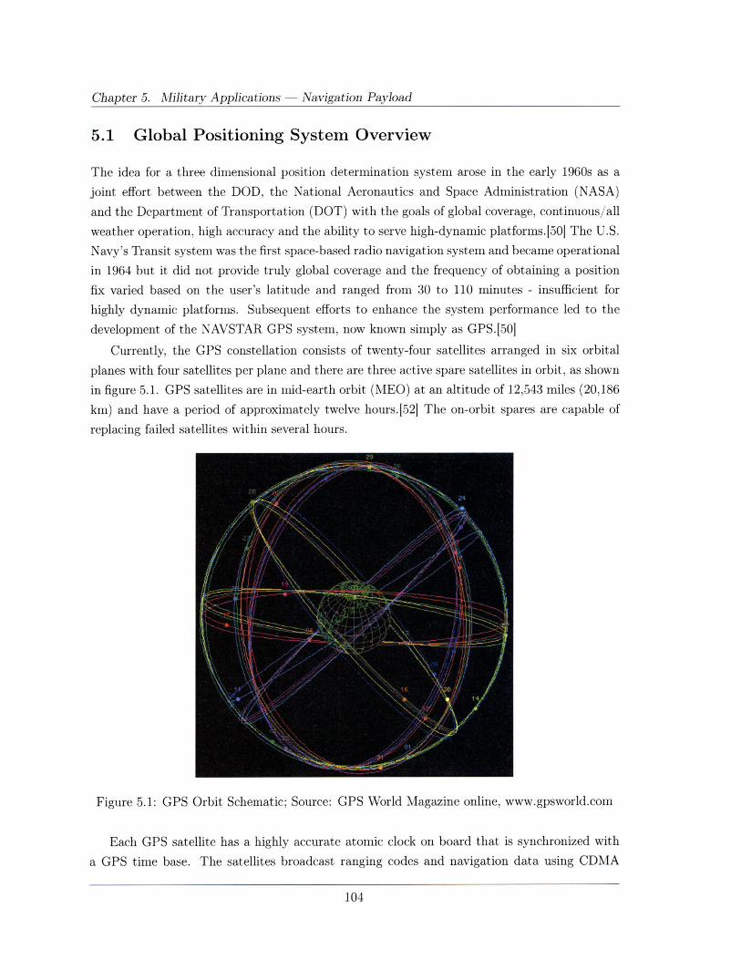
Chapter 5. Military Applications - Navigation Payload
5.1 Global Positioning System Overview
The idea for a three dimensional position determination system arose in the early 1960s as a
joint effort between the DOD, the National Aeronautics and Space Administration (NASA)
and the Department of Transportation (DOT) with the goals of global coverage, continuous/all
weather operation, high accuracy and the ability to serve high-dynamic platforms.[50] The U.S.
Navy's Transit system was the first space-based radio navigation system and became operational
in 1964 but it did not provide truly global coverage and the frequency of obtaining a position
fix varied based on the user's latitude and ranged from 30 to 110 minutes - insufficient for
highly dynamic platforms. Subsequent efforts to enhance the system performance led to the
development of the NAVSTAR GPS system, now known simply as GPS.[50]
Currently, the GPS constellation consists of twenty-four satellites arranged in six orbital
planes with four satellites per plane and there are three active spare satellites in orbit, as shown
in figure 5.1. GPS satellites are in mid-earth orbit (MEO) at an altitude of 12,543 miles (20,186
km) and have a period of approximately twelve hours.[52] The on-orbit spares are capable of
replacing failed satellites within several hours.
Figure 5.1: GPS Orbit Schematic; Source: GPS World Magazine online, www.gpsworld.com
Each GPS satellite has a highly accurate atomic clock on board that is synchronized with
a GPS time base. The satellites broadcast ranging codes and navigation data using CDMA
104
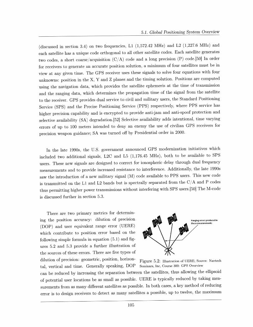
5.1. Global Positioning System Overview
(discussed in section 3.4) on two frequencies, L1 (1,572.42 MHz) and L2 (1,227.6 MHz) and
each satellite has a unique code orthogonal to all other satellite codes. Each satellite generates
two codes, a short coarse/acquisition (C/A) code and a long precision (P) code.[50] In order
for receivers to generate an accurate position solution, a minimum of four satellites must be in
view at any given time. The GPS receiver uses these signals to solve four equations with four
unknowns: position in the X, Y and Z planes and the timing solution. Positions are computed
using the navigation data, which provides the satellite ephemeris at the time of transmission
and the ranging data, which determines the propagation time of the signal from the satellite
to the receiver. GPS provides dual service to civil and military users, the Standard Positioning
Service (SPS) and the Precise Positioning Service (PPS) respectively, where PPS service has
higher precision capability and is encrypted to provide anti-jam and anti-spoof protection and
selective availability (SA) degradation. 52] Selective availability adds intentional, time varying
errors of up to 100 meters intended to deny an enemy the use of civilian GPS receivers for
precision weapon guidance; SA was turned off by Presidential order in 2000.
In the late 1990s, the U.S. government announced GPS modernization initiatives which
included two additional signals, L2C and L5 (1,176.45 MHz), both to be available to SPS
users. These new signals are designed to correct for ionospheric delay through dual frequency
measurements and to provide increased resistance to interference. Additionally, the late 1990s
saw the introduction of a new military signal (M) code available to PPS users. This new code
is transmitted on the L1 and L2 bands but is spectrally separated from the C/A and P codes
thus permitting higher power transmissions without interfering with SPS users.[50] The M-code
is discussed further in section 5.3.
There are two primary metrics for determin-
ing the position accuracy: dilution of precision Rangngerrorsproducedin
(DOP) and user equivalent range error (UERE) these measurements
which contribute to position error based on the
following simple formula in equation (5.1) and fig-
ures 5.2 and 5.3 provide a further illustration of
the sources of these errors. There are five types of
dilution of precision: geometric, position, horizon-Figure 5.2: Illustration of UERE; Source: Navtech
tal, vertical and time. Generally speaking, DOP Seminars, Inc, Course 300: GPS Overview
can be reduced by increasing the separation between the satellites, thus allowing the ellipsoid
of potential user locations be as small as possible. UERE is typically reduced by taking mea-
surements from as many different satellites as possible. In both cases, a key method of reducing
error is to design receivers to detect as many satellites a possible, up to twelve, the maximum
105
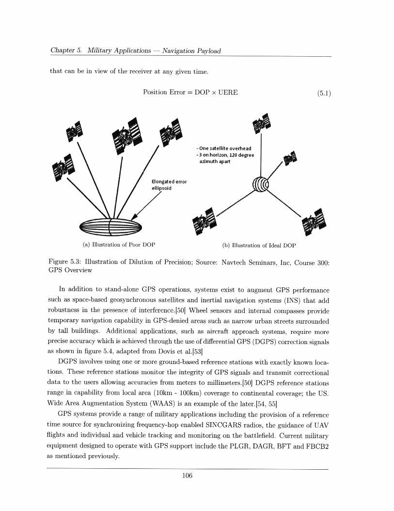
Chapter 5. Military Applications - Navigation Payload
that can be in view of the receiver at any given time.
Position Error = DOP x UERE
- One satellite overhead- 3 on horizon, 120 degree
azimuth apart
(a) Illustration of Poor DOP (b) Illustration of Ideal DOP
Figure 5.3: Illustration of Dilution of Precision;GPS Overview
Source: Navtech Seminars, Inc, Course 300:
In addition to stand-alone GPS operations, systems exist to augment GPS performancesuch as space-based geosynchronous satellites and inertial navigation systems (INS) that addrobustness in the presence of interference. [50] Wheel sensors and internal compasses providetemporary navigation capability in GPS-denied areas such as narrow urban streets surroundedby tall buildings. Additional applications, such as aircraft approach systems, require moreprecise accuracy which is achieved through the use of differential GPS (DGPS) correction signalsas shown in figure 5.4, adapted from Dovis et a1.[53]
DGPS involves using one or more ground-based reference stations with exactly known loca-tions. These reference stations monitor the integrity of GPS signals and transmit correctionaldata to the users allowing accuracies from meters to millimeters.[50 DGPS reference stationsrange in capability from local area (10km - 100km) coverage to continental coverage; the US.Wide Area Augmentation System (WAAS) is an example of the later.[54, 55]
GPS systems provide a range of military applications including the provision of a referencetime source for synchronizing frequency-hop enabled SINCGARS radios, the guidance of UAVflights and individual and vehicle tracking and monitoring on the battlefield. Current militaryequipment designed to operate with GPS support include the PLGR, DAGR, BFT and FBCB2as mentioned previously.
106
(5.1)

5.1. Global Positioning System Overview
GPS and Galileoconstellations
Differentialcorrection signal
Dedicateduplink channel
Figure 5.4: Diagram of Differential GPS Correction Signals; Adapted from: Dovis et al, SupportInfrastructures Based on High Altitude Platforms for Navigation Satellite Systems, October2005
PLGRs and DAGRs are simply GPS receivers with decryption software to enable access
to the PPS service. The PLGR is a hand-held, single frequency (L1 only) receiver that was
fielded in 1994 and used extensively until is was replaced by the DAGR in 2004. The DAGR is
a dual frequency (L1 and L2) receiver with communications security components controlled by
the National Security Agency (NSA). Table 5.1 outlines the performance enhancements of the
DAGR over the PLGR.
Parameter
Frequency bandsSecurityDisplayNumber of channels (satellites)Anti-Jam resistanceTime to first fix (TTFF)Time to subsequent fix (TTSF)WeightDimensions (LxWxD)Battery lifeReliability
Table 5.1: Military GPS ReceiverDefense Advanced GPS Receiver
PLGR
Single (Li only)PPS-SMText only
524 dB
6 minutes60 seconds
2.75 lb (1.25 kg)9.5" x 4.1" x 2.6"
13 hours (8 batteries)2000 hours
Comparison; Source:
DAGR
Dual (L1 & L2)SAASM
GUI with maps12 (all in view)
41 dB100 seconds
< 22 seconds0.94 lb (0.43 kg)
6.4" x 3.5" x 1.6"14 hours (4 batteries)
5000 hours
http://en.wikipedia.org/wiki/-
Blue Force Tracking (BFT) and Force XXI Battle Command Brigade and Below (FBCB2)
are GPS-enabled computer systems used to provide military commanders and forces with lo-
107
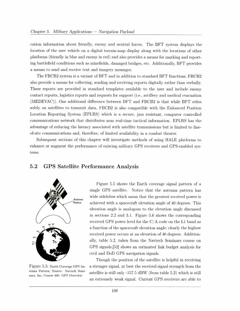
Chapter 5. Military Applications - Navigation Payload
cation information about friendly, enemy and neutral forces. The BFT system displays the
location of the user vehicle on a digital terrain-map display along with the locations of other
platforms (friendly in blue and enemy in red) and also provides a means for marking and report-
ing battlefield conditions such as minefields, damaged bridges, etc. Additionally, BFT provides
a means to send and receive text and imagery messages.
The FBCB2 system is a variant of BFT and in addition to standard BFT functions, FBCB2
also provide a means for collecting, sending and receiving reports digitally rather than verbally.
These reports are provided in standard templates available to the user and include enemy
contact reports, logistics reports and requests for support (i.e., artillery and medical evacuation
(MEDEVAC)). One additional difference between BFT and FBCB2 is that while BFT relies
solely on satellites to transmit data, FBCB2 is also compatible with the Enhanced Position
Location Reporting System (EPLRS) which is a secure, jam resistant, computer controlled
communications network that distributes near real-time tactical information. EPLRS has the
advantage of reducing the latency associated with satellite transmissions but is limited to line-
of-site communications and, therefore, of limited availability in a combat theater.
Subsequent sections of this chapter will investigate methods of using HALE platforms to
enhance or augment the performance of existing military GPS receivers and GPS-enabled sys-
tems.
5.2 GPS Satellite Performance Analysis
Figure 5.5 shows the Earth coverage signal pattern of a
single GPS satellite. Notice that the antenna pattern has
wide sidelobes which mean that the greatest received power is
Pattern achieved with a spacecraft elevation angle of 40 degrees. This
elevation angle is analogous to the elevation angle discussed
in sections 2.2 and 3.1. Figure 5.6 shows the corresponding
received GPS power level for the C/A code on the L1 band as
6o" a function of the spacecraft elevation angle; clearly the highest
received power occurs at an elevation of 40 degrees. Addition-20'
. t ally, table 5.2, taken from the Navtech Seminars course on
GPS signals,[52] shows an estimated link budget analysis for
civil and DoD GPS navigation signals.
Though the position of the satellite is helpful in receiving
Figure 5.5: Earth Coverage GPS An- a stronger signal, at best the received signal strength from thetenna Pattern; Source: Navtech Semi- satellite is still only -157.5 dBW (from table 5.2) which is stillnars, Inc, Course 300: GPS Overview
an extremely weak signal. Current GPS receivers are able to
108
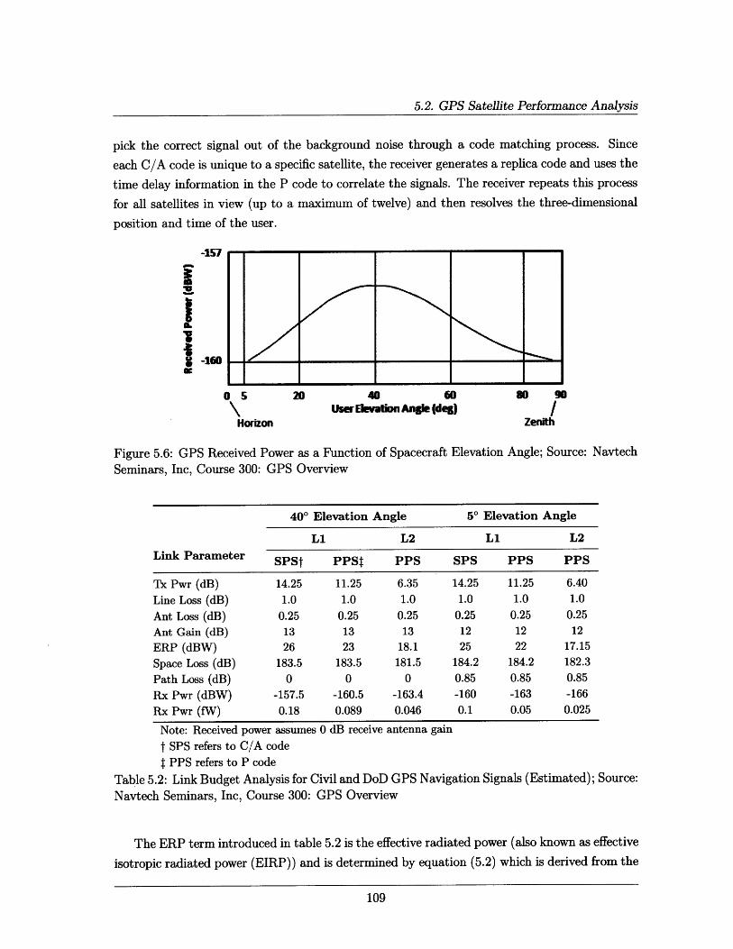
5.2. GPS Satellite Performance Analysis
pick the correct signal out of the background noise through a code matching process. Since
each C/A code is unique to a specific satellite, the receiver generates a replica code and uses the
time delay information in the P code to correlate the signals. The receiver repeats this process
for all satellites in view (up to a maximum of twelve) and then resolves the three-dimensional
position and time of the user.
-151
IVS-160="w
o 5 20
Horizon
40 60User Elvtion Angle (deg)
Figure 5.6: GPS Received Power as a Function of Spacecraft Elevation Angle; Source: Navtech
Seminars, Inc, Course 300: GPS Overview
400 Elevation Angle 50 Elevation Angle
L1 L2 L1 L2
Link Parameter SPSt PPSt PPS SPS PPS PPS
Tx Pwr (dB) 14.25 11.25 6.35 14.25 11.25 6.40
Line Loss (dB) 1.0 1.0 1.0 1.0 1.0 1.0
Ant Loss (dB) 0.25 0.25 0.25 0.25 0.25 0.25
Ant Gain (dB) 13 13 13 12 12 12
ERP (dBW) 26 23 18.1 25 22 17.15
Space Loss (dB) 183.5 183.5 181.5 184.2 184.2 182.3
Path Loss (dB) 0 0 0 0.85 0.85 0.85
Rx Pwr (dBW) -157.5 -160.5 -163.4 -160 -163 -166
Rx Pwr (fW) 0.18 0.089 0.046 0.1 0.05 0.025
Note: Received power assumes 0 dB receive antenna gain
t SPS refers to C/A codef PPS refers to P code
Table 5.2: Link Budget Analysis for Civil and DoD GPS Navigation Signals (Estimated); Source:
Navtech Seminars, Inc, Course 300: GPS Overview
The ERP term introduced in table 5.2 is the effective radiated power (also known as effective
isotropic radiated power (EIRP)) and is determined by equation (5.2) which is derived from the
109
so 90
/Zenith
~I
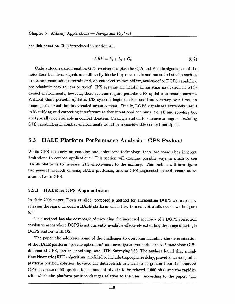
Chapter 5. Military Applications - Navigation Payload
the link equation (3.1) introduced in section 3.1.
ERP = Pt + L, + Gt (5.2)
Code autocorrelation enables GPS receivers to pick the C/A and P code signals out of the
noise floor but these signals are still easily blocked by man-made and natural obstacles such as
urban and mountainous terrain and, absent selective availability, anti-spoof or DGPS capability,are relatively easy to jam or spoof. INS systems are helpful in assisting navigation in GPS-
denied environments, however, these systems require periodic GPS updates to remain current.
Without these periodic updates, INS systems begin to drift and lose accuracy over time, an
unacceptable condition in extended urban combat. Finally, DGPS signals are extremely useful
in identifying and correcting interference (either intentional or unintentional) and spoofing but
are typically not available in combat theaters. Clearly, a system to enhance or augment existing
GPS capabilities in combat environments would be a considerable combat multiplier.
5.3 HALE Platform Performance Analysis - GPS Payload
While GPS is clearly an enabling and ubiquitous technology, there are some clear inherent
limitations to combat applications. This section will examine possible ways in which to use
HALE platforms to increase GPS effectiveness to the military. This section will investigate
two general methods of using HALE platforms, first as GPS augmentation and second as an
alternative to GPS.
5.3.1 HALE as GPS Augmentation
In their 2005 paper, Dovis et a11[531 proposed a method for augmenting DGPS correction by
relaying the signal through a HALE platform which they termed a Stratolite as shown in figure
5.7.
This method has the advantage of providing the increased accuracy of a DGPS correction
station to areas where DGPS is not currently available effectively extending the range of a single
DGPS station to BLOS.
The paper also addresses some of the challenges to overcome including the determination
of the HALE platform "pseudo-ephemeris" and investigates methods such as "standalone GPS,differential GPS, carrier smoothing, and RTK Surveying"[53] The authors found that a real-
time kinematic (RTK) algorithm, modified to include tropospheric delay, provided an acceptable
platform position solution, however the data refresh rate had to be greater than the standard
GPS data rate of 50 bps due to the amount of data to be relayed (1000 bits) and the rapidity
with which the platform position changes relative to the user. According to the paper, "the
110
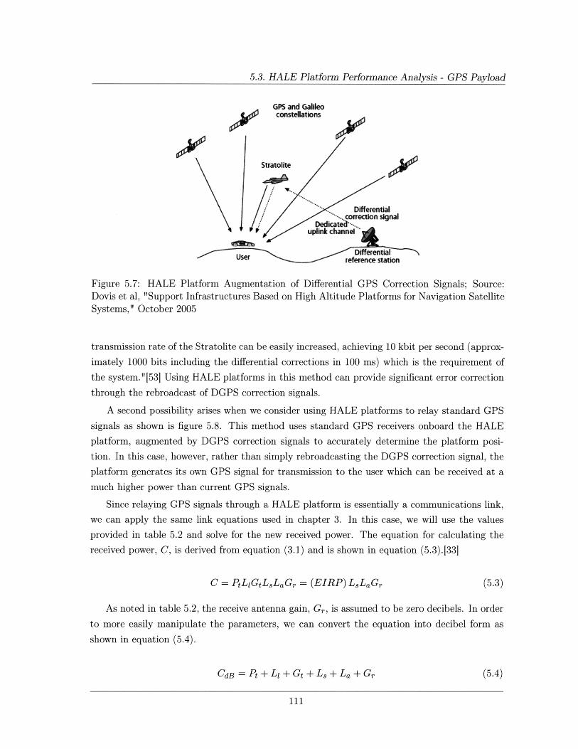
5.3. HALE Platform Performance Analysis - GPS Payload
GPS and Galileoconstellations
Stratolite
S.. Differentialp/ orrection signalJ i Dedicat'.-.
uplink channel
reference station
Figure 5.7: HALE Platform Augmentation of Differential GPS Correction Signals; Source:Dovis et al, "Support Infrastructures Based on High Altitude Platforms for Navigation SatelliteSystems," October 2005
transmission rate of the Stratolite can be easily increased, achieving 10 kbit per second (approx-
imately 1000 bits including the differential corrections in 100 ms) which is the requirement of
the system." [531 Using HALE platforms in this method can provide significant error correction
through the rebroadcast of DGPS correction signals.
A second possibility arises when we consider using HALE platforms to relay standard GPS
signals as shown is figure 5.8. This method uses standard GPS receivers onboard the HALE
platform, augmented by DGPS correction signals to accurately determine the platform posi-
tion. In this case, however, rather than simply rebroadcasting the DGPS correction signal, the
platform generates its own GPS signal for transmission to the user which can be received at a
much higher power than current GPS signals.
Since relaying GPS signals through a HALE platform is essentially a communications link,
we can apply the same link equations used in chapter 3. In this case, we will use the values
provided in table 5.2 and solve for the new received power. The equation for calculating the
received power, C, is derived from equation (3.1) and is shown in equation (5.3).[33]
C = PtLiGtLLaGr = (EIRP) LLaGr (5.3)
As noted in table 5.2, the receive antenna gain, Gr, is assumed to be zero decibels. In order
to more easily manipulate the parameters, we can convert the equation into decibel form as
shown in equation (5.4).
CdB = Pt + Ll + Gt + Ls + La + Gr (5.4)
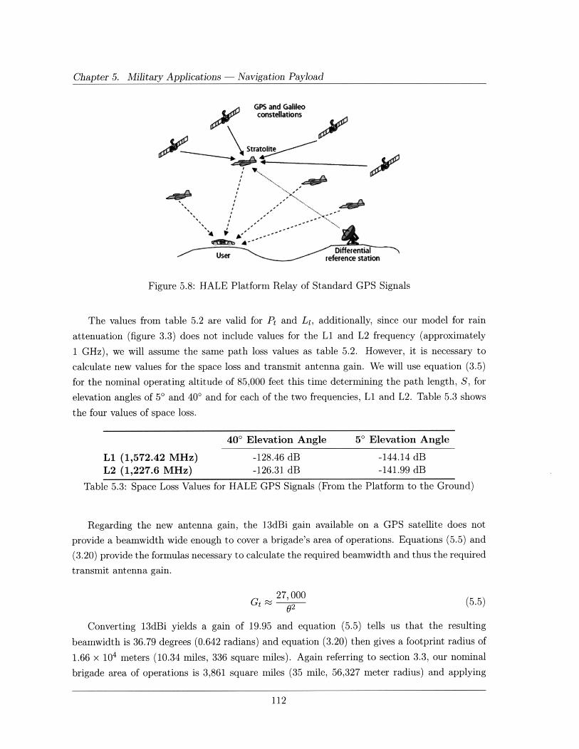
Chapter 5. Military Applications - Navigation Payload
GPS and Galileoconstellations
Stratolite
'N
sr "DiffentialUser reference station
Figure 5.8: HALE Platform Relay of Standard GPS Signals
The values from table 5.2 are valid for Pt and L1, additionally, since our model for rain
attenuation (figure 3.3) does not include values for the Li and L2 frequency (approximately
1 GHz), we will assume the same path loss values as table 5.2. However, it is necessary to
calculate new values for the space loss and transmit antenna gain. We will use equation (3.5)
for the nominal operating altitude of 85,000 feet this time determining the path length, S, for
elevation angles of 5' and 400 and for each of the two frequencies, L1 and L2. Table 5.3 shows
the four values of space loss.
40' Elevation Angle 5' Elevation Angle
L1 (1,572.42 MHz) -128.46 dB -144.14 dB
L2 (1,227.6 MHz) -126.31 dB -141.99 dB
Table 5.3: Space Loss Values for HALE GPS Signals (From the Platform to the Ground)
Regarding the new antenna gain, the 13dBi gain available on a GPS satellite does not
provide a beamwidth wide enough to cover a brigade's area of operations. Equations (5.5) and
(3.20) provide the formulas necessary to calculate the required beamwidth and thus the required
transmit antenna gain.
27, 000 (5.5)Gt
(5.5)02
Converting 13dBi yields a gain of 19.95 and equation (5.5) tells us that the resulting
beamwidth is 36.79 degrees (0.642 radians) and equation (3.20) then gives a footprint radius of
1.66 x 10⁴ meters (10.34 miles, 336 square miles). Again referring to section 3.3, our nominal
brigade area of operations is 3,861 square miles (35 mile, 56,327 meter radius) and applying
112
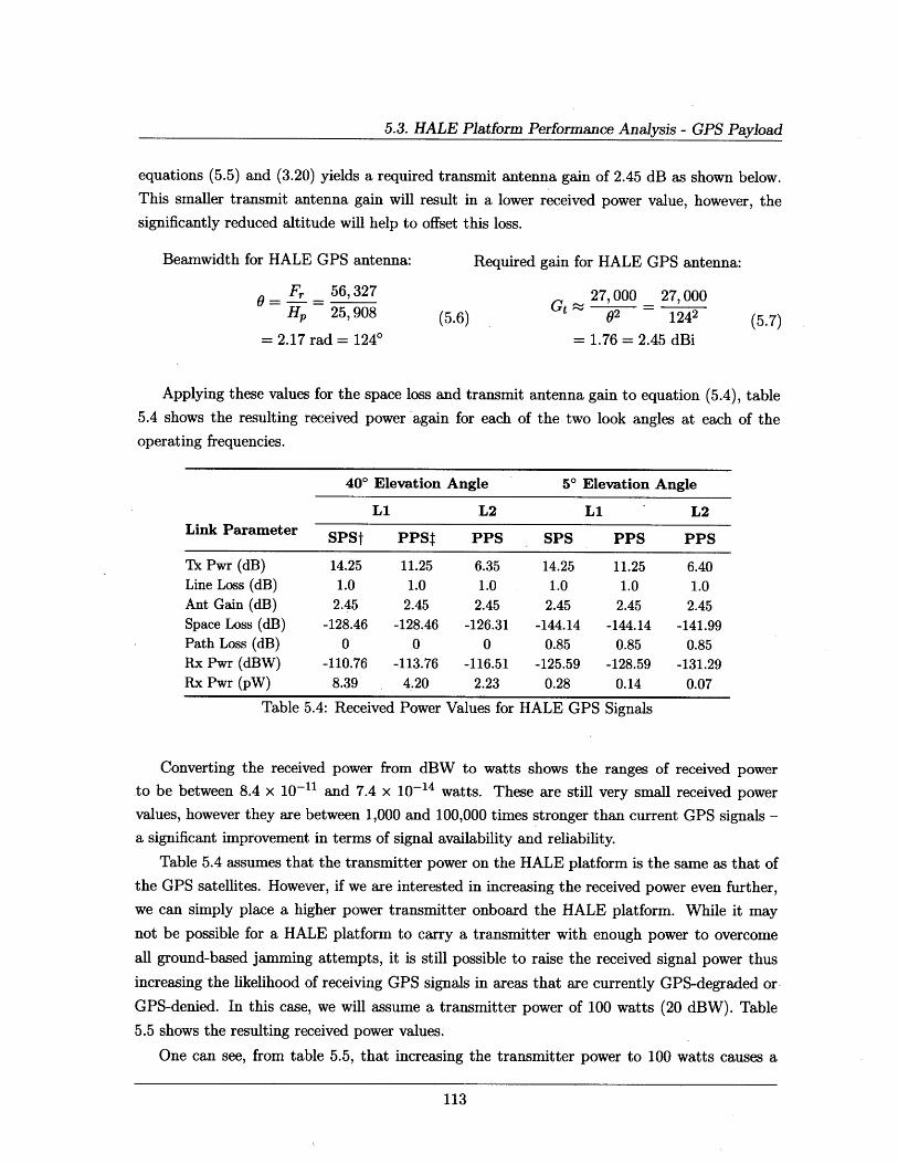
5.3. HALE Platform Performance Analysis - GPS Payload
equations (5.5) and (3.20) yields a required transmit antenna gain of 2.45 dB as shown below.
This smaller transmit antenna gain will result in a lower received power value, however, the
significantly reduced altitude will help to offset this loss.
Beamwidth for HALE GPS antenna:
Fr 56,327
Hp 25,908
= 2.17 rad = 1240
Required gain for HALE GPS antenna:
(5.6)27, 000 27, 000
82 1242
= 1.76 = 2.45 dBi
Applying these values for the space loss and transmit antenna gain to equation (5.4), table
5.4 shows the resulting received power again for each of the two look angles at each of the
operating frequencies.
400 Elevation Angle 50 Elevation Angle
L1 L2 L1 L2Link Parameter SPSt PPSt PPS SPS PPS PPS
Tx Pwr (dB) 14.25 11.25 6.35 14.25 11.25 6.40Line Loss (dB) 1.0 1.0 1.0 1.0 1.0 1.0Ant Gain (dB) 2.45 2.45 2.45 2.45 2.45 2.45Space Loss (dB) -128.46 -128.46 -126.31 -144.14 -144.14 -141.99Path Loss (dB) 0 0 0 0.85 0.85 0.85Rx Pwr (dBW) -110.76 -113.76 -116.51 -125.59 -128.59 -131.29Rx Pwr (pW) 8.39 4.20 2.23 0.28 0.14 0.07
Table 5.4: Received Power Values for HALE GPS Signals
Converting the received power from dBW to watts shows the ranges of received power
to be between 8.4 x 10- 11 and 7.4 x 10⁻¹⁴ watts. These are still very small received power
values, however they are between 1,000 and 100,000 times stronger than current GPS signals -
a significant improvement in terms of signal availability and reliability.
Table 5.4 assumes that the transmitter power on the HALE platform is the same as that of
the GPS satellites. However, if we are interested in increasing the received power even further,
we can simply place a higher power transmitter onboard the HALE platform. While it may
not be possible for a HALE platform to carry a transmitter with enough power to overcome
all ground-based jamming attempts, it is still possible to raise the received signal power thus
increasing the likelihood of receiving GPS signals in areas that are currently GPS-degraded or
GPS-denied. In this case, we will assume a transmitter power of 100 watts (20 dBW). Table
5.5 shows the resulting received power values.
One can see, from table 5.5, that increasing the transmitter power to 100 watts causes a
113
(5.7)
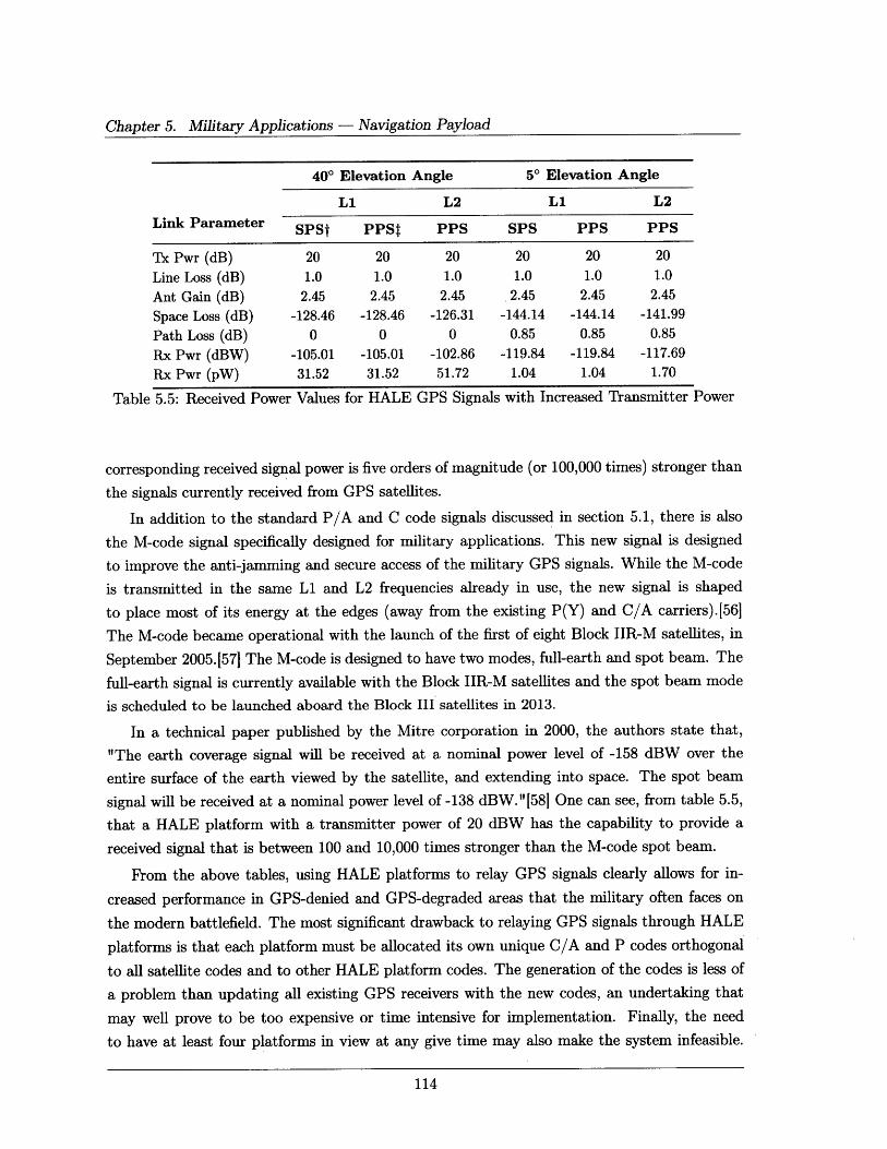
Chapter 5. Military Applications - Navigation Payload
400 Elevation Angle 5' Elevation Angle
L1 L2 L1 L2
Link Parameter SPSt PPSt PPS SPS PPS PPS
Tx Pwr (dB) 20 20 20 20 20 20
Line Loss (dB) 1.0 1.0 1.0 1.0 1.0 1.0
Ant Gain (dB) 2.45 2.45 2.45 2.45 2.45 2.45
Space Loss (dB) -128.46 -128.46 -126.31 -144.14 -144.14 -141.99
Path Loss (dB) 0 0 0 0.85 0.85 0.85
Rx Pwr (dBW) -105.01 -105.01 -102.86 -119.84 -119.84 -117.69
Rx Pwr (pW) 31.52 31.52 51.72 1.04 1.04 1.70
Table 5.5: Received Power Values for HALE GPS Signals with Increased Transmitter Power
corresponding received signal power is five orders of magnitude (or 100,000 times) stronger than
the signals currently received from GPS satellites.
In addition to the standard P/A and C code signals discussed in section 5.1, there is also
the M-code signal specifically designed for military applications. This new signal is designed
to improve the anti-jamming and secure access of the military GPS signals. While the M-code
is transmitted in the same L1 and L2 frequencies already in use, the new signal is shaped
to place most of its energy at the edges (away from the existing P(Y) and C/A carriers).[56
The M-code became operational with the launch of the first of eight Block IIR-M satellites, in
September 2005.[57] The M-code is designed to have two modes, full-earth and spot beam. The
full-earth signal is currently available with the Block IIR-M satellites and the spot beam mode
is scheduled to be launched aboard the Block III satellites in 2013.
In a technical paper published by the Mitre corporation in 2000, the authors state that,
"The earth coverage signal will be received at a nominal power level of -158 dBW over the
entire surface of the earth viewed by the satellite, and extending into space. The spot beam
signal will be received at a nominal power level of -138 dBW."[581 One can see, from table 5.5,
that a HALE platform with a transmitter power of 20 dBW has the capability to provide a
received signal that is between 100 and 10,000 times stronger than the M-code spot beam.
From the above tables, using HALE platforms to relay GPS signals clearly allows for in-
creased performance in GPS-denied and GPS-degraded areas that the military often faces on
the modern battlefield. The most significant drawback to relaying GPS signals through HALE
platforms is that each platform must be allocated its own unique C/A and P codes orthogonal
to all satellite codes and to other HALE platform codes. The generation of the codes is less of
a problem than updating all existing GPS receivers with the new codes, an undertaking that
may well prove to be too expensive or time intensive for implementation. Finally, the need
to have at least four platforms in view at any give time may also make the system infeasible.
114

5.4. Navigation Mission Specific CONOPS
Nevertheless, if the military is willing to invest in solving these logistics problems, augmenting
GPS signals with HALE platforms offers the potential for significant performance improvement
and is well worth considering.
5.3.2 HALE as GPS Alternative
There are two possible uses for HALE platforms as alternatives to GPS signals. The first
is to create synchronized beacons on three or more platforms to be used in multilateration,
or hyperbolic positioning, to locate the receiver by measuring the time difference of arrival
(TDOA) of the signals. This method has the advantage of not requiring unique, orthogonal
codes. However, it requires the development and fielding of an entirely new series of receivers
and transmitters, does not allow for the messaging and reporting functions of BFT and FBCB2
and still poses the problem of accurate platform position information (though this last problem
could be solved with GPS receivers onboard the HALE platforms).
In 2001, Myoung et al[59] proposed a constellation of stratospheric GPS airships designed
exclusively for civilian use and independent of any existing GPS architectures as shown in figure
5.9.
In their article, the authors demonstrate that it is possible to triangulate the position of the
airships from ground stations, transmit that position data to the airship which then retransmits
to the user. User position is then determined using conventional autocorrelation techniques
described in the literature.[50, 52] Their research shows that a constellation of stratospheric
airships is capable of achieving improved distance root mean square (DRMS) error and thus
improved GDOP over existing GPS satellites.
While a stand-alone stratospheric GPS constellation has attractive features for exclusive
civilian availability and improved performance, it is unlikely that an entirely new GPS constel-
lation is either feasible or desirable for U.S. military applications. First, because the proposed
system requires ground stations to determine the position of each HALE platform which must
be designed, built and then placed within a combat theater thus adding an increased element of
vulnerability. Second because a military system already exists with a proven performance record
and finally, achieving the required global coverage with a constellation of HALE platforms leads
to an impossibly large number of airships, both in terms of manufacture and maintenance of
the systems. Simply put, there are more feasible alternatives for improving GPS performance
that should be explored before deciding to invest in an entirely new system.
5.4 Navigation Mission Specific CONOPS
This chapter has proposed four potential uses for HALE platforms either in the augmentation
or replacement of the existing GPS system. Each option has unique merits but each also has
115

Chapter 5. Military Applications N- avigation Payload
Figure 5.9: Configuration of the Navigation System Covering the South Korean Peninsula;Source: Adapted from Myoung et al, "A System Design of Stratospheric Airships for the Navi-gation in Korea," August 2001
significant drawbacks to feasibility.
As discussed previously, any use of HALE platforms to replace the current GPS system isunlikely in the near future due to the time required for development, increased vulnerabilityto ground assets in combat areas, and the fact that the current system has a proven record ofgood performance for military applications.
Additionally, as with GPS satellites, there must be at least four HALE platforms in viewat all times in order to provide the navigation solution. Referring to figure 2.10 and the Iraqexample used in section 3.3, we again assume an altitude of 85,000 feet and a fifteen degreeelevation angle. Given that each HALE platform can cover a circular area of 3,861 square miles(70 mile diameter) and a total Iraqi land area of 168,754 square miles, continuous coverage ofIraq with at least four platforms in view at any given time will require a minimum of 176 HALEplatforms.
The most likely short term application of HALE platforms for GPS augmentation is therebroadcast of DGPS correction signals. This technique requires nothing more than a bent-pipecommunications relay to provide significantly improved position and timing accuracy. This
116
5.5. Chapter Summary
application echoes the analysis conducted in section 3.3 and would require the same number of
platforms as required to support communications relay in a given area of operations. Continuing
with Iraq as the reference combat theater, twenty HALE platforms are capable of providing
regional DGPS support over the country of Iraq.
It has been shown in previous research that it is possible to accurately determine the position
of a HALE platform. Extending this research to include the broadcast of GPS signals from a
HALE platform, the analysis shows that it is possible to attain significantly improved received
signal strength which would translate to improved performance in areas that are currently
GPS-denied or degraded such as urban and mountainous terrain and possibly including signal
acquisition within buildings. Another alternative to improving GPS performance is to design the
HALE platform to transmit the signals at higher frequencies to allow better indoor penetration.
Again, due to the requirements to update all existing GPS receivers with the new C/A and P
codes and add higher frequency receivers, this application is not likely to be used in the short
term. Nevertheless, it is an attractive method for improving GPS signal acquisition and should
be considered further.
5.5 Chapter Summary
This chapter has demonstrated that HALE platforms designed to augment the existing GPS
system are capable of providing improved performance either through relaying DGPS correction
signals or by relaying the actual GPS signal. Both applications are feasible but require significant
modifications/upgrades to existing GPS receivers.
The advantages and drawbacks to each of the proposed applications are outlined in the
various sections but, in general, any use of HALE platforms for navigation payloads will require
changes to the existing system. The degree of change required, the timeline for implementation
and the cost of the proposed changes will all play an important role in the decision to use HALE
platforms to enhance navigation capabilities.
The bottom line is that while HALE platforms do have the potential in improve GPS
system performance and there are elements that make HALE platforms attractive for navigation
applications, GPS service is not likely to provide the most effective use of HALE platforms for
military applications.
117

This page intentionally left blank.
Chapter 6
HALE Integration with Current
Operations
6.1 Existing Military Space Doctrine
According to Field Manual (FM) 3-14: Space Support to Army Operations:
"Space is the newest of the warfighting media, alongside air, land, and sea. The
harsh space environment, vast distances, and high speeds of orbiting satellites are
all very different from what the Armed Forces deal with in the air, on land, and on
or under the sea. Still, many of the principles that successfully guide operations in
those environments are applicable to the space medium. The Army is committed to
using space to its best advantage. Indeed the advantages are so great that it is clearly
worthwhile to overcome the characteristic difficulties of the space environment. Use
of space-based capabilities is not only common; it is critical, in Army operations." [60]
Clearly, the Army leadership recognizes the importance of space in supporting ground op-
erations and the applications discussed in the preceding chapters are areas of emphasis for the
Army leadership as well.[61] FM 3-14 also outlines several key elements of Army Space Opera-
tions including the control and exploitation of space to enhance land warfighting power. This
control and exploitation covers a spectrum of activities from deploying, operating and maintain-
ing U.S. satellites to denying space capabilities to an adversary.[60] Due to the vast expanse of
space, even orbital space, and the number of satellites in orbit - friendly, neutral and hostile -
it is not possible to control all of space all the time. Rather, the military focuses on "maximum
control of particular space assets at particular times; this requires the ability to exercise control
of any space asset at any time." [60] Just as situational understanding is critical to ground op-
erations, space situational understanding is a critical, continuous process that allows the Army
to exercise its will at decisive points in support of the joint and Army land campaign. Army
119
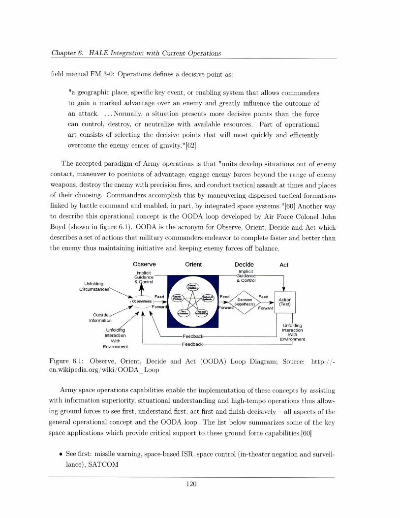
Chapter 6. HALE Integration with Current Operations
field manual FM 3-0: Operations defines a decisive point as:
"a geographic place, specific key event, or enabling system that allows commanders
to gain a marked advantage over an enemy and greatly influence the outcome of
an attack. ... Normally, a situation presents more decisive points than the force
can control, destroy, or neutralize with available resources. Part of operational
art consists of selecting the decisive points that will most quickly and efficiently
overcome the enemy center of gravity." [62]
The accepted paradigm of Army operations is that "units develop situations out of enemy
contact, maneuver to positions of advantage, engage enemy forces beyond the range of enemy
weapons, destroy the enemy with precision fires, and conduct tactical assault at times and places
of their choosing. Commanders accomplish this by maneuvering dispersed tactical formations
linked by battle command and enabled, in part, by integrated space systems. "[60] Another way
to describe this operational concept is the OODA loop developed by Air Force Colonel John
Boyd (shown in figure 6.1). OODA is the acronym for Observe, Orient, Decide and Act which
describes a set of actions that military commanders endeavor to complete faster and better than
the enemy thus maintaining initiative and keeping enemy forces off balance.
Observe Orient Decide ActImplicit Implicit
Guidance uidance
Unfolding & control & Control
Circumstances
Feed Feed FeediObsevations Decision Action
I (Hypotes Is) (Test)
InformationUnfolding
Unfolding InteractionInteraction Feedback With
With EnvironmentWith Feedback IEnvironment Feedback
Figure 6.1: Observe, Orient, Decide and Act (OODA) Loop Diagram; Source: http://-en.wikipedia.org/wiki/OODA_ Loop
Army space operations capabilities enable the implementation of these concepts by assisting
with information superiority, situational understanding and high-tempo operations thus allow-
ing ground forces to see first, understand first, act first and finish decisively - all aspects of the
general operational concept and the OODA loop. The list below summarizes some of the key
space applications which provide critical support to these ground force capabilities.[60]
* See first: missile warning, space-based ISR, space control (in-theater negation and surveil-
lance), SATCOM
120
6.2. HALE Operational Considerations
* Understand first: SATCOM, BFT, in-transit visibility, information operations (IO), space
control and PVT
* Act first: space control, in-transit visibility, PVT and SATCOM
* Finish decisively: space control, PVT, precision engagement, ISR, continuous battle dam-
age assessment (BDA) and SATCOM
The Army has developed a list of core competencies and FM 1-0: Human Resources Support
details the enduring capabilities necessary to achieving these competencies.[63] These enduring
capabilities include a) Shaping the Security Environment through the constant, conspicuous
presence of Soldiers in the field thus building confidence among allies and deterring adversaries;
b) Prompt Response by quickly limiting enemy achievement of objectives and reversing suc-
cesses; c) Mobilizing the Army through the mitigation of training, logistical, and operational
challenges; d) Forcible Entry Operations through the use of the en-route mission planning and
rehearsal system (EMPRS) allowing Soldiers to exploit optimum access points for enemy en-
gagement and e) Sustained Land Dominance by influencing the Army's ability to win and hold
territory which hinges not only on Soldiers and firepower, but also on comprehensive situational
understanding enabled by space assets.[60] The routine use of space-based capabilities such as
GPS, SATCOM and ISR enable ground forces to monitor force buildups, precisely fix the lo-
cations of force elements, provide targeting information, find optimum staging areas and lines
of communication, and track personnel and material movements throughout theater. Clearly,
space-based capabilities play a critical role in sustaining the Army's enduring capabilities.
While current Army doctrine focuses on the application of space-based assets, the Army is
also sponsoring studies on HALE platform development through the Army Space Master Plan
as mentioned in chapter 1. Army leadership recognizes the inherent importance of space-based
assets to ground operations and there is no attempt to replace the unique satellite capabilities
with HALE platforms. Rather, the studies focus on adding another layer of coverage and
support in the high altitude regime as shown in figure 6.2.[61] To that end, the Army SMDC
has been designated as the Army proponent for high-altitude studies as an enabling capability
for future operations support.
6.2 HALE Operational Considerations
The SMCD is currently involved in conducting a High-Altitude Enabled Capabilities Assess-
ment (HA-ECA). While the ECA has not yet been approved for public release, there are some
concepts in the study that we can discuss here based on previously released literature and
military doctrine. The ECA looks at ways in which the high-altitude domain can supplement
121
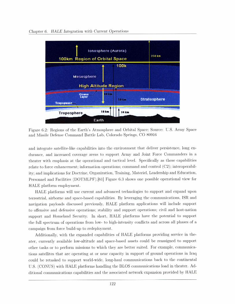
Chapter 6. HALE Integration with Current Operations
Figure 6.2: Regions of the Earth's Atmosphere and Orbital Space; Source: U.S. Army Space
and Missile Defense Command Battle Lab, Colorado Springs, CO 80916
and integrate satellite-like capabilities into the environment that deliver persistence, long en-
durance, and increased coverage areas to support Army and Joint Force Commanders in a
theater with emphasis at the operational and tactical level. Specifically as these capabilities
relate to force enhancement; information operations; command and control (C2); interoperabil-
ity; and implications for Doctrine, Organization, Training, Materiel, Leadership and Education,
Personnel and Facilities (DOTMLPF).611 Figure 6.3 shows one possible operational view for
HALE platform employment.
HALE platforms will use current and advanced technologies to support and expand upon
terrestrial, airborne and space-based capabilities. By leveraging the communications, ISR and
navigation payloads discussed previously, HALE platform applications will include support
to offensive and defensive operations; stability and support operations; civil and host-nation
support and Homeland Security. In short, HALE platforms have the potential to support
the full spectrum of operations from low- to high-intensity conflicts and across all phases of a
campaign from force build-up to redeployment.
Additionally, with the expanded capabilities of HALE platforms providing service in the-
ater, currently available low-altitude and space-based assets could be reassigned to support
other tasks or to perform missions to which they are better suited. For example, communica-
tions satellites that are operating at or near capacity in support of ground operations in Iraq
could be retasked to support world-wide, long-haul communications back to the continental
U.S. (CONUS) with HALE platforms handling the BLOS communications load in theater. Ad-
ditional communications capabilities and the associated network expansion provided by HALE
122
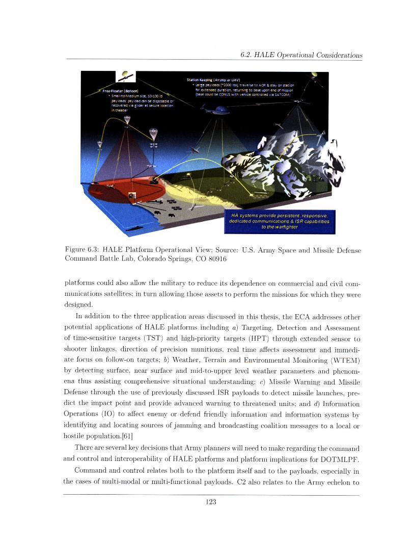
6.2. HALE Operational Considerations
Figure 6.3: HALE Platform Operational View; Source: U.S. Army Space and Missile DefenseCommand Battle Lab, Colorado Springs, CO 80916
platforms could also allow the military to reduce its dependence on commercial and civil com-munications satellites; in turn allowing those assets to perform the missions for which they weredesigned.
In addition to the three application areas discussed in this thesis, the ECA addresses otherpotential applications of HALE platforms including a) Targeting, Detection and Assessmentof time-sensitive targets (TST) and high-priority targets (HPT) through extended sensor toshooter linkages, direction of precision munitions, real time affects assessment and immedi-ate focus oil follow-on targets; b) Weather, Terrain and Environmental Monitoring (WTEM)by detecting surface, near surface and mid-to-upper level weather parameters and phenom-ena thus assisting comprehensive situational understanding; c) Missile Warning and MissileDefense through the use of previously discussed ISR payloads to detect missile launches, pre-dict the impact point and provide advanced warning to threatened units; and d) InformationOperations (IO) to affect enemy or defend friendly information and information systems byidentifying and locating sources of jamming and broadcasting coalition messages to a local orhostile population.[611
There are several key decisions that Army planners will need to make regarding the commandand control and interoperability of HALE platforms and platform implications for DOTMLPF.
Command and control relates both to the platform itself and to the payloads, especially inthe cases of multi-modal or multi-functional payloads. C2 also relates to the Army echelon to
123
Chapter 6. HALE Integration with Current Operations
which specific platforms should be assigned. In the CONOPS sections of previous chapters, we
assume that these platforms will be available to brigade-level commanders; however, there are
some significant employment considerations that must be overcome in order for that concept
to be possible. Not least among those concerns is the fact that brigades, as they are currently
organized, do not have the organic capability to control the platforms or payloads. If a com-
mander has a dedicated asset to position and task based on his priorities but no direct ability
to control that asset, then it is of limited utility to him. It is the opinion of the ECA authors
that these platforms would be best assigned to Division, Corps or even Army level units in
a theater.[61] However, these higher echelon units already have access to a large number of
space-based capabilities. If we accept that one of the primary capability gaps exists at echelons
below Division, then the Army must make some clear organizational changes to enable brigade
commanders to directly control these emerging HALE platforms. Organic control at the brigade
level has clear implications for the platforms to have a low burden on ground operators. Note
that even without these organizational changes to enable organic control, brigade-level units
should still have the ability to request support from HALE platforms operating over their areas
of operation.
Interoperability refers to a HALE platform's ability to operate seamlessly with many agen-
cies, forces and levels of command.1611 The level of interoperability among unmanned aircraft
systems (UAS) varies widely, from systems that can pass full control of the aircraft and/or pay-
load from one operator to another (such as commonly employed during Predator remote split
operations), to systems that can only transmit sensor data to specific recipients. Examples of
mission needs for interoperability are operating one UAS through another to extend the range
of control, or passing control from one ground control station (GCS) to another. Since mission
needs are not always predictable, technologies and employment options that facilitate interop-
eration provide enhanced flexibility.[61] HA systems will meet all levels of interoperability:
Level 1 Indirect receipt/transmission of UAS related payload data
Level 2 Direct receipt of ISR/other data where "direct" covers reception of the UAS payload
data by a remote video terminal when it has direct communication with the UAS
Level 3 Control and monitoring of the UAS payload in addition to direct receipt of ISR/other
data
Level 4 Control and monitoring of the UAS, less launch and recovery
Level 5 Level 4, plus launch and recovery functions
In general, HALE platform implications for Doctrine, Organization, Training, Materiel,
Leadership and Education, Personnel and Facilities (DOTMLPF) should be similar to the re-
quirements for existing and planned conventional UAVs.
124
6.2. HALE Operational Considerations
Doctrine: The overall doctrine will not change in terms of the requirement for commanders
to see first, understand first, act first and finish decisively. HALE platforms will provide addi-
tional capabilities to accomplish the same goals, therefore existing doctrine should only require
minor changes to support effective platform employment.
Organization: The preceding paragraphs discuss the potential organization changes re-
quired for brigade-level units to effectively employ HALE platforms. In addition to the unit-
level organization, HALE platforms will also require platform and payload operators, mechanics
and engineers for anomaly resolution.
Training: Current, high-altitude, short-duration platforms such as the Global Hawk (sec-
tion 1.3) require the operators to be licensed pilots to allow Global Hawk to transit conventional
airspace. Future HALE platforms will likely have similar requirements and the training pro-
grams should closely mirror existing programs.
Materiel: In addition to the platform material concerns address in section 2.1.4, future
HALE platforms will have specific equipment requirements, such as operator terminals and
interfaces, required to successfully operate the platforms. Wherever possible, these platforms
should be designed for seamless integration into existing ground control station equipment.
Leadership and Education: The unique capabilities afforded by HALE platforms will
provide ground commanders with direct access to assets with which they have no prior expe-
rience. Leaders who will be using these future HALE systems must clearly understand their
capabilities and limitations in order to most effectively employ them. Professional development
programs and service school curricula must be updated to train leaders at every echelon. The
CONOPS for these HALE platforms are far from set and leaders will discover additional capa-
bilities and uses after the platforms have been used operationally. Training programs should be
designed to incorporate these lessons learned from the field.
Personnel: Future HALE platforms will likely vary in size and scope with the larger, more
complex systems requiring operational and maintenance support from a combination of Soldiers,
civilians and contractors. HALE platforms should be designed along the lines of current military
systems with maintenance requirements ranging from simple user-level fixes to complex depot-
level repair and refurbishment at the end of the platform's programmed life cycle.
Facilities: In this case, consideration must be given to storage, transport, deployment
and recovery facilities. Due to the physical size requirements of the platforms (section 2.3.1)
necessary to operate at very high altitudes, conventional hangars will likely be insufficient for
HALE platform storage. Additionally, HTA platforms will require prepared surface runways
that may not be available in a combat theater. Section 2.4 discusses some of the CONOPS
considerations that may mitigate availability and security considerations for launch/recovery
facilities.
The current Army doctrine is designed around flexibility both in terms of leader capabilities
125
Chapter 6. HALE Integration with Current Operations
and force development. To that end, the Army should be able to integrate future HALE platform
capabilities with minimal changes to the existing doctrine and support infrastructure.
6.3 Assessment of HALE Operational Benefits
In order to provide robust performance in all three application areas, the ideal platform con-
stellation will make use of all three aerial sub-layers (low, medium, and high-altitude) as well
as space-based platforms. The low and medium-altitude layers (sea-level to 60,000 feet) and
orbital space are technologically mature regions and conventional systems are currently sup-
porting military operations. As shown in the literature and by this thesis, the high-altitude
layer has room for significant technological advancement.
In all three of the application areas discussed in this thesis, there is a great deal of inter-
dependence among the payload types. For example the increased bandwidth made available
through communications network expansion will also facilitate the transmission of ISR imagery
data. Navigation payloads operate via radio frequency signals transmitted through conventional
communications links and thus are very similar to communications payloads. Section 7.1 will
discuss the potential for multi-modal payloads in greater detail.
6.3.1 Communications Payload Operational Benefits
HALE platform enabled communications have the potential to augment multiple military com-
munications networks such as EPLRS radios, BFT, SINCGARS radios and the Tactical Com-
mon Data Link (TCDL), discussed previously. All of these systems have compatible military
ground terminals greatly simplifying the integration requirements. Army units at every echelon
have significant bandwidth requirements for the exchange of voice, imagery and full-motion
video data.
There is currently limited information available regarding the specific bandwidth require-
ments of units deployed to a combat theater. The limited data is due, in part, to the fact that
individual unit requirements vary greatly in the course of the mission with routine operations
requiring a fairly small amount of data transfer and emergency or high-tempo operations re-
quiring more. Therefore, as a first order estimate of the bandwidth requirements for a typical
brigade, we will refer to the Military Information Technology Online article referenced in the
introduction to chapter 3, "a Joint Chiefs of Staff document estimates that satcom bandwidth
requirements for theater-of-war capability will be 14 Gbps by 2010."[32]. If we assume, con-
servatively, that a typical "theater-of-war" will consist of one Corps with three Divisions each
comprised of three brigades, then the nine brigades and four higher headquarters elements will
each require approximately 1.1 Gbps by 2010.
Military SATCOM capabilities will be unable to satisfy the projected demand thus causing
126
6.3. Assessment of HALE Operational Benefits
the military to rely on commercial and civil systems to fill the gap. While these commercial and
civil systems are able to satisfy the required bandwidth capacity, they are not designed with
military security and survivability considerations in mind. HALE assets have the potential
to provide the required network expansion while still providing the necessary communications
security and survivability for military operations. HALE platforms will be persistent; less vul-
nerable to low-altitude threats; simplify airspace C2 requirements by operating above controlled
airspace; and be mobile, responsive and consistently available to ground commanders.[61]
Operations at and below the brigade level currently require low-capacity, short-duration
communications consisting mostly of voice and data and can usually be satisfied by line-of-sight
communications links. However, as the Army continues to field new battlefield sensors, units will
have an increasing requirement to send large volumes of raw image and video data to their higher
headquarters. These sensors will require high-capacity links that are not currently supported
by brigade and below communications systems. Additionally, line-of-sight links are limited by
operations in complex terrain such as mountainous and urban areas. HALE platforms will
provide high-capacity links while extending the range of communications beyond line-of-sight,
thus freeing organic communications assets for the critical function of command and control.
A further change in the Army warfighting paradigm in Iraq is the increasing dispersion of
small units throughout the local population in order to provide increased security and to develop
better relations with the populace. These small patrol bases are often isolated from their higher
headquarters for extended periods of time and out of range of LOS communications. Dedicated,
persistent HALE platforms will allow these dispersed and isolated units to remain in constant
contact without the need for vulnerable ground relay sites.
Chapter 3 demonstrated that HALE platforms are capable of providing communications
performance comparable to that of the WGS satellites with power requirements reduced by an
order of magnitude due to the shortened transmission path length. This order of magnitude
power reduction comes with the added benefit of closing the link with an omnidirectional ground
receive antenna. Thus, a HALE communications platform can provide beyond line-of-site com-
munications on-the-move capability at a tenth of the power required by WGS - one of the most
advanced communications satellites.
The most significant limitation to HALE communications payloads is their reduced fields of
view compared to satellites in geosynchronous orbit. Applications at the tactical level of combat
(division and below) mitigate this limitation and help to reduce the bandwidth load currently
imposed on orbital communications links. HALE platforms have the potential to provide in-
creased high-capacity links, limit the Army's reliance on unsecure commercial communications
and allow units to use their organic communications systems for mission critical command and
control.
127
Chapter 6. HALE Integration with Current Operations
6.3.2 ISR Payload Operational Benefits
Ground commanders at all levels require timely, current intelligence of their areas of operations
throughout all phases of an operations. Commanders use this imagery to assist in planning
deployments, troop movements, combat operations and redeployments including finding the best
locations for patrol bases, planning secure routes for convoy operations and monitoring enemy
activities. The persistent ISR and reconnaissance, surveillance and target acquisition (RSTA)
performance afforded by HALE platforms will greatly increase situational understanding in
highly fluid combat environment and will support the rapid identification and engagement of
high-priority targets such as weapons caches, insurgent leaders, IED emplacements.
Chapter 4 focuses primarily on visual and infrared surveillance capabilities; however, as
sensor technologies become more advanced, it will be possible for HALE platforms to carry
a wide array of payloads such as a) laser designators for precision munition guidance; b) light
detection and ranging (LIDAR); c) Synthetic Aperture Radar (SAR); d) ground and air moving
target indicators (GMTI/AMTI); e) mine detection; and f) Chemical, Biological, Radiological
and Nuclear (CBRN) detection.[61]
There are many Battlefield Operating Systems (BOS) that can directly benefit from ded-
icated, persistent ISR capabilities including maneuver; indirect fires (artillery); air support;
engineering support for mobility, countermobility and survivability; and intelligence collection.
HALE enabled ISR will also help the commander observe the battlespace over extended dis-
tances in real-time thus greatly increasing the ability to command and control subordinate
units.
As demonstrated by chapter 4, HALE platforms offer significantly improved image resolution
when compared to their surveillance satellite counterparts. Additionally, the reference earth
observation satellite, GeoEye-1, does not have the capability to provide imagery in the infrared
spectrum while the proposed HALE platform does provide IR imagery with nadir resolution
improved by an order of magnitude over a satellite in LEO (compare figure 4.7 and table 4.1).
While the analysis has shown that it is not possible for a single platform - or multiple platforms
- to provide continuous surveillance over a brigade's entire area of operations, these platforms
are nonetheless capable of allowing sustained observation of critical areas of interest without
the endurance limitation imposed by current high-altitude UAV assets like the Global Hawk.
As with communications payloads, HALE ISR payloads will provide additional capability to
supply detailed imagery over a wide area thus allowing units to use their organic surveillance
assets on targets affecting the immediate, or close, fight.
6.3.3 Navigation Payload Operational Benefits
The HA-ECA conducted by the SMDC focuses on the benefits of using HALE platforms for
differential GPS correction signals as DGPS is the most practical and realizable application of
128
6.4. Future Role of Army Space Operations
HALE platforms for GPS augmentation.61] The benefits discussed in the ECA largely mirror
the conclusions reached in chapter 5 and are summarized below.
* Resistance to GPS jamming
* Accurate blue/red force tracking and reporting
* Precise air navigation, including precision approaches to airports
* Enhanced GPS correction message broadcast
In addition to these similarities, the ECA also proposes three additional benefits of HALE
enabled PN&T. Frequency hopping radios and communications networks require a precisely
controlled time standard in order to function. The highly accurate atomic clocks onboard GPS
satellites combined with their ubiquitous presence make GPS the military time standard. HALE
platforms can aid in precision time transfer for improved network synchronization throughout
the area of responsibility thus ensuring remote units are able to maintain communications.
GPS payloads combined with the laser designator discussed above can provide additional
support to target designation and precision weapon employment. This capability allows for
remote target designation without requiring ground personnel to be in direct visual contact with
the target thus reducing exposure both to hostile engagement and friendly weapons affects.
Combined GPS and ISR payloads are capable of providing precise and current maps of
a given area. Frequently, units plan operations based on outdated maps and imprecise or
low resolution imagery. While this limitation does not significantly impact operations in open
desert areas, it often results in plan changes for operations in urban areas. The ability to receive
current (minutes to hours old) maps and imagery will significantly improve the level of fidelity
with which commanders are able to plan their operations and provide a common reference for
subordinate units to coordinate their actions.
Of the three applications, navigation payloads offered the lowest potential utility based
on the scope of required changes to the existing ground infrastructure. While chapter 5 has
demonstrated that HALE platforms designed to augment the existing GPS system are capa-
ble of providing received power values that are five orders of magnitude stronger than current
GPS satellite signals. Although, these platforms can improve performance either through relay-
ing DGPS correction signals or by relaying the actual GPS signal, both applications required
significant modifications or upgrades to existing GPS receivers; thus limiting their utility.
6.4 Future Role of Army Space Operations
Current and emerging military satellite capabilities, with respect to the applications discussed
previously, are largely derived from Army requirements.[641 However, aside from dictating re-
129
Chapter 6. HALE Integration with Current Operations
quirements, Army Space Operations has very little involvement with the actual design, devel-
opment and acquisition of space-based military assets. Rather, the Army leverages existing
technology and capabilities to support the warfighter. While this arrangement works and space
operators are able to provide critical space capabilities to enable and enhance land warfare,there is little argument among Army space professionals that increased involvement in the
initial stages of capability development will provide a marked improvement in the ability to
support ground operations.
The Army is currently leading the military development of HALE platform capabilities with
little Air Force involvement in the programs.[61] If the Army is able to maintain this level of in-
volvement, it will be able to gain entry at the ground-level of platform design and development.
Current Army doctrine describes "an essential component of the Army's efforts to maximize
the contributions that space capabilities bring to land warfare."[60] Further, the Army's "de-
pendence on space will increase in the future as space-based capabilities enable the future force
concepts of information superiority, enhanced situational awareness, and high-tempo, noncon-
tiguous operations." [60] There is no doubt among Army leaders and space professionals that
space-based capabilities will only increase in importance for future generations of Soldiers. To
that end, the Army must increase its influence over space capabilities from the earliest design
efforts.
All the work to date suggests that the general mindset is that HALE platforms are an
extension of airborne assets. If we instead view HALE platforms as an extension of space
assets, then the Army is perfectly positioned to take advantage of this emerging capability.
130
Chapter 7
Summary
7.1 Military Applications - Multi-modal Capabilities
Based on the preceding findings for smaller, lighter payloads, this section will discuss options
for placing multiple payload types (i.e., Communication/ISR or ISR/GPS) on a single HALE
platform. Adding multi-modal capabilities will reduce the number of required platforms and
allow for increased mission flexibility without requiring the retasking of additional assets.
7.1.1 HALE Platform Limitations & Candidate Payload Combinations
Referring to section 2.3, recall that the operational altitude is inversely proportional to the
atmospheric density which in turn directly affects the size of the platform and the mass of the
payload. For the purposes of this thesis, we have assumed an operating altitude of 85,000 feet
and a maximum payload weight of 2,000 pounds (907 kilograms). Further, referring to section
2.3.2, the extended eclipse duration has a negative impact on the amount of power that the
system is able to supply to the payload and other subsystems. In this case, we will assume an
upper limit to the average power requirement of 130 watts (21.1 dBW).
Drawing on the payload sizing results from chapters 3 through 5, table 7.1 summarizes the
payload weight and power requirements for each of the three application areas. The weight of
the communications payload is taken from the Space Mission Analysis and Design textbook,
table 11-26 which states that the total mass for a typical X-band communications subsystem
is 20.2 kg (45 lbs) and for a typical Ku-band subsystem is 13.3 kg (29 lbs).[65]. In this case,
we will assume that the requirements for a Ku-band subsystem are equivalent to a Ka-band
subsystem since the frequencies are similar and the services they provide are identical (table
3.1). Therefore, the total mass of a communications payload with X- and Ka-band capabilities
is 33.5 kg (74 lbs).
Since, at the time of this writing direct data for the weight of a GPS payload was not
131
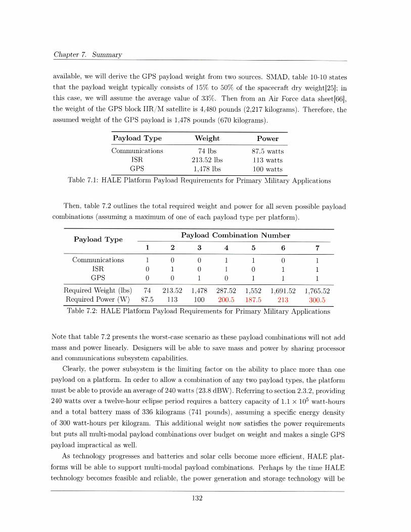
Chapter 7. Summary
available, we will derive the GPS payload weight from two sources. SMAD, table 10-10 states
that the payload weight typically consists of 15% to 50% of the spacecraft dry weight[25]; in
this case, we will assume the average value of 33%. Then from an Air Force data sheet[66],the weight of the GPS block IIR/M satellite is 4,480 pounds (2,217 kilograms). Therefore, the
assumed weight of the GPS payload is 1,478 pounds (670 kilograms).
Payload Type Weight Power
Communications 74 lbs 87.5 wattsISR 213.52 lbs 113 wattsGPS 1,478 lbs 100 watts
Table 7.1: HALE Platform Payload Requirements for Primary Military Applications
Then, table 7.2 outlines the total required weight and power for all seven possible payload
combinations (assuming a maximum of one of each payload type per platform).
Payload Type Payload Combination Number
1 2 3 4 5 6 7
Communications 1 0 0 1 1 0 1ISR 0 1 0 1 0 1 1GPS 0 0 1 0 1 1 1
Required Weight (lbs) 74 213.52 1,478 287.52 1,552 1,691.52 1,765.52Required Power (W) 87.5 113 100 200.5 187.5 213 300.5
Table 7.2: HALE Platform Payload Requirements for Primary Military Applications
Note that table 7.2 presents the worst-case scenario as these payload combinations will not add
mass and power linearly. Designers will be able to save mass and power by sharing processor
and communications subsystem capabilities.
Clearly, the power subsystem is the limiting factor on the ability to place more than one
payload on a platform. In order to allow a combination of any two payload types, the platform
must be able to provide an average of 240 watts (23.8 dBW). Referring to section 2.3.2, providing
240 watts over a twelve-hour eclipse period requires a battery capacity of 1.1 x 10⁵ watt-hours
and a total battery mass of 336 kilograms (741 pounds), assuming a specific energy density
of 300 watt-hours per kilogram. This additional weight now satisfies the power requirements
but puts all multi-modal payload combinations over budget on weight and makes a single GPS
payload impractical as well.
As technology progresses and batteries and solar cells become more efficient, HALE plat-
forms will be able to support multi-modal payload combinations. Perhaps by the time HALE
technology becomes feasible and reliable, the power generation and storage technology will be
132
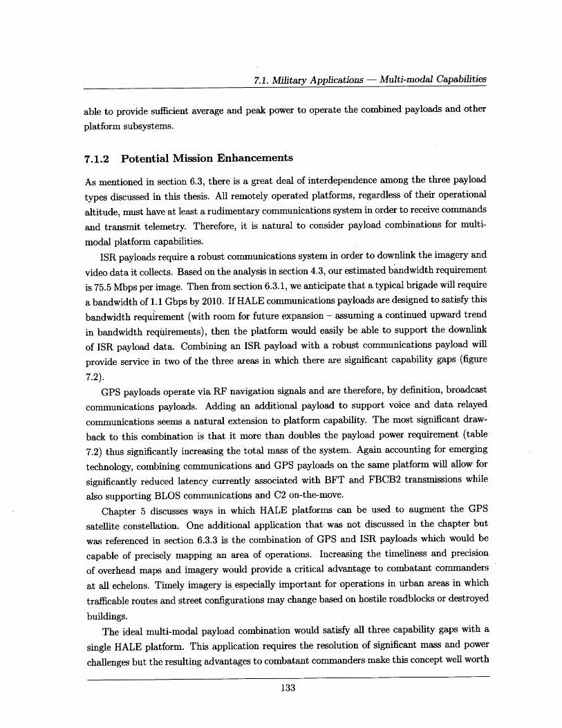
7.1. Military Applications - Multi-modal Capabilities
able to provide sufficient average and peak power to operate the combined payloads and other
platform subsystems.
7.1.2 Potential Mission Enhancements
As mentioned in section 6.3, there is a great deal of interdependence among the three payload
types discussed in this thesis. All remotely operated platforms, regardless of their operational
altitude, must have at least a rudimentary communications system in order to receive commands
and transmit telemetry. Therefore, it is natural to consider payload combinations for multi-
modal platform capabilities.
ISR payloads require a robust communications system in order to downlink the imagery and
video data it collects. Based on the analysis in section 4.3, our estimated bandwidth requirement
is 75.5 Mbps per image. Then from section 6.3.1, we anticipate that a typical brigade will require
a bandwidth of 1.1 Gbps by 2010. If HALE communications payloads are designed to satisfy this
bandwidth requirement (with room for future expansion - assuming a continued upward trend
in bandwidth requirements), then the platform would easily be able to support the downlink
of ISR payload data. Combining an ISR payload with a robust communications payload will
provide service in two of the three areas in which there are significant capability gaps (figure
7.2).
GPS payloads operate via RF navigation signals and are therefore, by definition, broadcast
communications payloads. Adding an additional payload to support voice and data relayed
communications seems a natural extension to platform capability. The most significant draw-
back to this combination is that it more than doubles the payload power requirement (table
7.2) thus significantly increasing the total mass of the system. Again accounting for emerging
technology, combining communications and GPS payloads on the same platform will allow for
significantly reduced latency currently associated with BFT and FBCB2 transmissions while
also supporting BLOS communications and C2 on-the-move.
Chapter 5 discusses ways in which HALE platforms can be used ,to augment the GPS
satellite constellation. One additional application that was not discussed in the chapter but
was referenced in section 6.3.3 is the combination of GPS and ISR payloads which would be
capable of precisely mapping an area of operations. Increasing the timeliness and precision
of overhead maps and imagery would provide a critical advantage to combatant commanders
at all echelons. Timely imagery is especially important for operations in urban areas in which
trafficable routes and street configurations may change based on hostile roadblocks or destroyed
buildings.
The ideal multi-modal payload combination would satisfy all three capability gaps with a
single HALE platform. This application requires the resolution of significant mass and power
challenges but the resulting advantages to combatant commanders make this concept well worth
133
Chapter 7. Summary
pursuing. This concept has one other significant drawback in terms of the level of risk that senior
Army leaders are willing to accept. Should the platform be lost - either due to malfunction,accident or hostile act - ground commanders will lose all of their network expansion, persistent
surveillance and augmented GPS capabilities. Application of the risk mitigation techniques
discussed in section 2.1.5 will help reduce platform vulnerability, nevertheless leaders mustgive strong consideration to the inherent benefits of HALE platforms versus their survivabilitylimitations.
7.2 Known Limitations
This section outlines the known limitations of the preceding research.
Chapter 2: HALE Platform Overview
1. Section 2.1.1, figure 2.1 clearly shows that the most favorable operational altitude forHALE platforms is between 65,000 feet and 80,000 feet. In this analysis, we chose tofocus on an operational altitude of 85,000 feet for survivability reasons, however, even thisrelatively small altitude increase has significant ramifications in terms of the platform'sability for station keeping, the power and propulsion subsystems and the platform physicalsize. It is almost universally accepted among HALE designers that future systems willoperate between 65,000 feet and 75,000 feet.[61]
2. In section 2.1.2, we assume that nuclear reactors are too heavy and too dangerous forapplications within the Earth's atmosphere. However, a paper by Gary Bennett discussesthe uses of nuclear power to enable space exploration missions.(67] This research suggeststhat nuclear power sources may soon be a viable alternative to solar arrays or fuel cellsfor operations near the Earth's surface.
3. Section 2.1.2 assumes an average 12-hour eclipse period corresponding to the local nightbut a true requirements analysis will include a more accurate model to account for seasonal
and latitude variations. The 12-hour assumption generally accounts for the average casescenario.
4. The threat analysis conducted in section 2.1.5 is limited to an unclassified, open sourcereview of threat capabilities and is therefore incomplete.
5. The AFRL study of system survivability referenced in 2.1.5 focuses primarily on theplatform properties, not those of the payload. Further detailed study of payload affectsis required to ensure platform survivability.
134
7.2. Known Limitations
6. In section 2.4, we assume that future HALE platforms will be available to brigade level
commanders. The SMDC proponent for high-altitude studies anticipates that HALE
platforms will only be available at echelons above brigade.[61]
7. The assumed five-year operational life (section 2.4) of future HALE platforms is prob-
ably too long to be realistic with respect to system cost and reliability; additionally,
the assumption of satellite-like operations not requiring the platform to land for periodic
maintenance is likely not feasible. It is more likely that operational HALE platforms will
be designed for two to three year life cycles with periodic scheduled maintenance between
missions lasting on the order of weeks to months. The maintenance conducted at the end
of the life cycle can replace worn-out components and refurbish the platform for further
use while re-using components that are capable of longer lifetimes - such as solar arrays,
which can be designed for a fifteen year operational life.
Chapter 3: Military Applications - Communications Payload
1. Chapter 3 focuses primarily on the relay of mission critical command and control and
imagery data, however, there are also military applications for broadcast communications.
Information operations (IO) encompasses efforts to attack enemy C2 systems and protect
friendly systems that are equally important in the conduct of ground operations. The
core capabilities within IO are electronic warfare (EW), computer network operations
(CNO), psychological operations (PSYOP), military deception (MILDEC), and operations
security (OPSEC). FM 3-13 Information Operations: Doctrine, Tactics, Techniques, and
Procedures[68] discusses these broadcast applications in detail.
2. Section 3.1 makes assumptions of several link margin equations in order to provide a
generic link budget analysis. In order to develop a truly accurate link margin, designers
will need to know exact values for the line loss, transmission path loss and system noise
temperature which are system-dependent parameters.
3. At the time of this writing, exact specifications for WGS antenna size and antenna gain
were not available. Therefore, section 3.2 antenna values are derived from coverage area
assumptions which may not result in accurate transmit power requirements. The values
presented in this section provide an order of magnitude estimate only.
4. The parametric relationships of antenna size to payload weight and weight to system cost
are only sufficient to provide order of magnitude estimates. As with the link margin,
designers will need to know specific system parameters in order to develop an accurate
weight budget and system cost.
135
Chapter 7. Summary
5. Since HALE platform technology is still in its infancy, there are no established cost es-
timating relationships for these platforms. The cost estimate in section 3.3 is based on
satellite CERs and is therefore less accurate than a cost comparison based on current
high-altitude platforms such as Global Hawk.
Chapter 4: Military Applications - ISR Payload
1. Sections 4.1 and 4.3 do not discuss any platform or camera stabilization requirements. The
theoretical ground resolution achievable from a HALE platform depends on the stability
of the payload and station keeping capabilities of the platform. Without stabilization, the
images will have significantly reduced resolution and thus reduced utility.
2. While figure 4.3 describes the atmospheric transmission characteristics of the Earth's
atmosphere, there is no specific discussion of the affects of atmospheric distortion, such
as scintillation, on image resolution. Truly accurate resolution modeling must go beyond
the theoretical capabilities and account for these distortions.
Chapter 5: Military Applications - Navigation Payload
1. Section 5.3.1 assumes that using HALE platforms to relay GPS signals at a higher power
would require assigning independent C/A and P(Y) codes to each HALE platform in
order to avoid corruption of the satellite timing and ephemeris data. It may be possible
to allow the HALE platform to modify the received satellite codes with new data for the
platform and rebroadcast the modified codes. This course of action may allow currently
fielded GPS receivers to recognize HALE codes as if they were original satellite codes thus
avoiding the need to field new receivers with HALE specific codes.
2. The M-code spot beam, scheduled for launch on the BPS Block III satellites (section 5.3.1)
is designed to assist the receiver to establish initial synchronization with the satellite.
Once the receiver has identified the signal, it is easier to maintain synchronization even
with a lower power, earth coverage signal through the use of code correlation. This
chapter does not discuss the feasibility of using HALE platforms to assist in satellite-
receiver synchronization; an additional GPS augmentation technique that may be worth
exploring.
7.3 Future Work
Potential avenues of future research are based largely on the known limitations outlined in the
previous section. These areas include a) a more detailed analysis of technical requirements to
ensure HALE platform feasibility; b) an examination of the affects of payload properties on
136
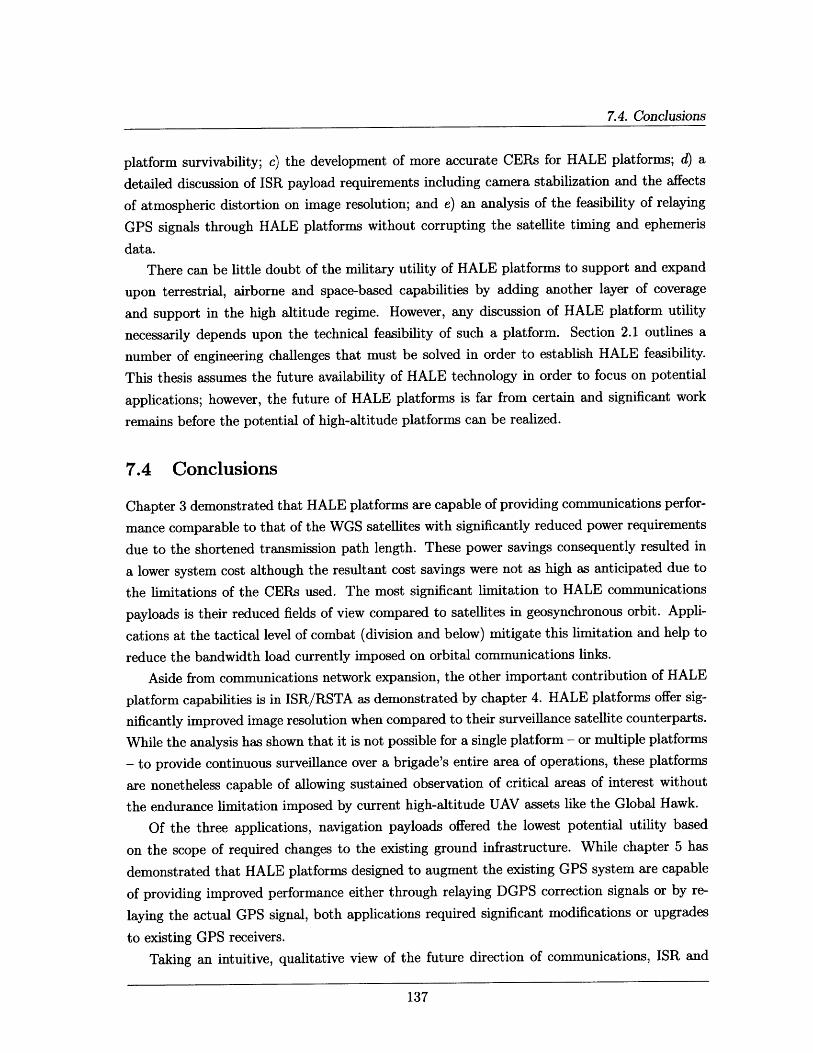
7.4. Conclusions
platform survivability; c) the development of more accurate CERs for HALE platforms; d) a
detailed discussion of ISR payload requirements including camera stabilization and the affects
of atmospheric distortion on image resolution; and e) an analysis of the feasibility of relaying
GPS signals through HALE platforms without corrupting the satellite timing and ephemeris
data.
There can be little doubt of the military utility of HALE platforms to support and expand
upon terrestrial, airborne and space-based capabilities by adding another layer of coverage
and support in the high altitude regime. However, any discussion of HALE platform utility
necessarily depends upon the technical feasibility of such a platform. Section 2.1 outlines a
number of engineering challenges that must be solved in order to establish HALE feasibility.
This thesis assumes the future availability of HALE technology in order to focus on potential
applications; however, the future of HALE platforms is far from certain and significant work
remains before the potential of high-altitude platforms can be realized.
7.4 Conclusions
Chapter 3 demonstrated that HALE platforms are capable of providing communications perfor-
mance comparable to that of the WGS satellites with significantly reduced power requirements
due to the shortened transmission path length. These power savings consequently resulted in
a lower system cost although the resultant cost savings were not as high as anticipated due to
the limitations of the CERs used. The most significant limitation to HALE communications
payloads is their reduced fields of view compared to satellites in geosynchronous orbit. Appli-
cations at the tactical level of combat (division and below) mitigate this limitation and help to
reduce the bandwidth load currently imposed on orbital communications links.
Aside from communications network expansion, the other important contribution of HALE
platform capabilities is in ISR/RSTA as demonstrated by chapter 4. HALE platforms offer sig-
nificantly improved image resolution when compared to their surveillance satellite counterparts.
While the analysis has shown that it is not possible for a single platform - or multiple platforms
- to provide continuous surveillance over a brigade's entire area of operations, these platforms
are nonetheless capable of allowing sustained observation of critical areas of interest without
the endurance limitation imposed by current high-altitude UAV assets like the Global Hawk.
Of the three applications, navigation payloads offered the lowest potential utility based
on the scope of required changes to the existing ground infrastructure. While chapter 5 has
demonstrated that HALE platforms designed to augment the existing GPS system are capable
of providing improved performance either through relaying DGPS correction signals or by re-
laying the actual GPS signal, both applications required significant modifications or upgrades
to existing GPS receivers.
Taking an intuitive, qualitative view of the future direction of communications, ISR and
137
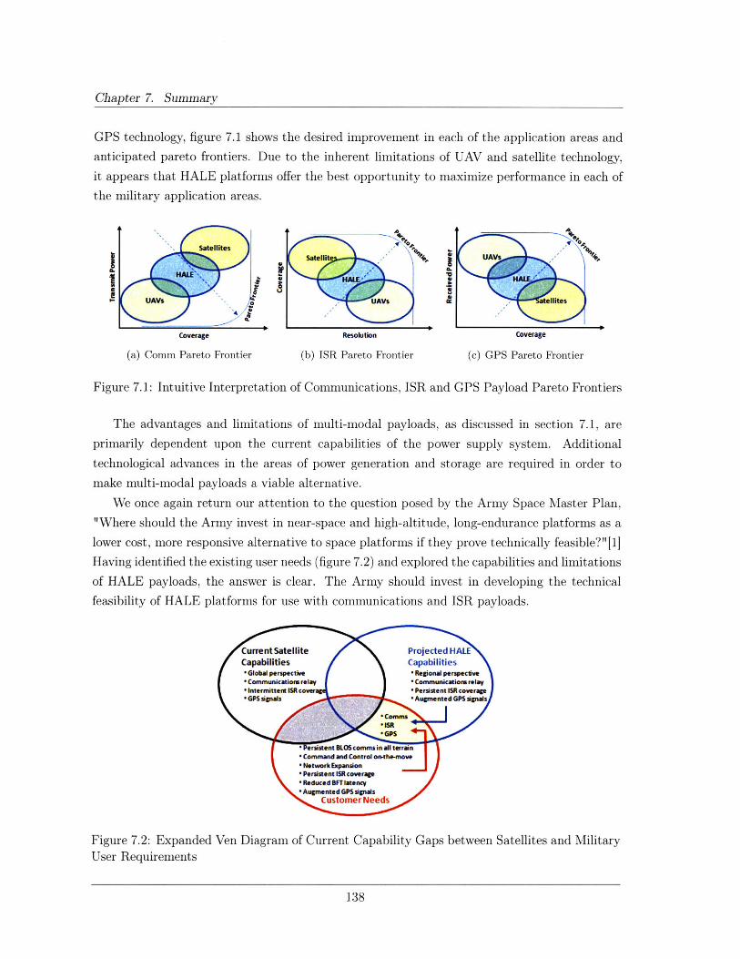
Chapter 7. Summary
GPS technology, figure 7.1 shows the desired improvement in each of the application areas and
anticipated pareto frontiers. Due to the inherent limitations of UAV and satellite technology,
it appears that HALE platforms offer the best opportunity to maximize performance in each of
the military application areas.
Coverage Resolution
(a) Comm Pareto Frontier (b) ISR Pareto Frontier
Coverage
(c) GPS Pareto Frontier
Figure 7.1: Intuitive Interpretation of Communications, ISR and GPS Payload Pareto Frontiers
The advantages and limitations of multi-modal payloads, as discussed in section 7.1, are
primarily dependent upon the current capabilities of the power supply system. Additional
technological advances in the areas of power generation and storage are required in order to
make multi-modal payloads a viable alternative.
We once again return our attention to the question posed by the Army Space Master Plan,
"Where should the Army invest in near-space and high-altitude, long-endurance platforms as a
lower cost, more responsive alternative to space platforms if they prove technically feasible?" [1]
Having identified the existing user needs (figure 7.2) and explored the capabilities and limitations
of HALE payloads, the answer is clear. The Army should invest in developing the technical
feasibility of HALE platforms for use with communications and ISR payloads.
Figure 7.2: Expanded Ven Diagram of Current Capability Gaps between Satellites and MilitaryUser Requirements
138
Appendix A
Subsystem Governing Equations
This Appendix details some of the key governing equations required for sizing the various
platform subsystems discussed in Section 2.1 (Design Drivers and Engineering Challenges).
A.1 Power Subsystem Sizing
To begin sizing the power system for the HALE platform, one must first determine the mission
life and average power requirements of the platform by considering the end-of-life (EOL) power
requirements of the system rather than the beginning-of-life (BOL) requirements. Sizing for
EOL power requirements allows designers to account for solar array degradation over the life
of the system, however EOL designs will cause excess power generation during BOL operations
and the system must be designed to account for and dissipate the excess power to avoid thermal
problems.[24] Initial power budgets are achieved by estimating the power requirements for the
payload and the platform bus, sizing the batteries and estimating the power system degradation
over the mission life.[25]
Next, one must determine the total power generation requirements of the solar arrays, based
on the initial design budget, as follows:[24]
Psa - (x xTd (A.1)Td
Where Psa is the power generation requirement of the solar arrays during daylight, Pe and Pd
are the platform's power requirements during eclipse and daylight, respectively, Te and Td are
the lengths of the eclipse and daylight periods, Xe is the efficiency of the paths from the solar
arrays through the batteries to the loads and Xd is the efficiency of the path directly from the
solar arrays to the loads. Efficiency values during eclipse and daylight hours depend on the
type of power regulation used.
Once we have determined the power generation requirements, we can select the type of
139
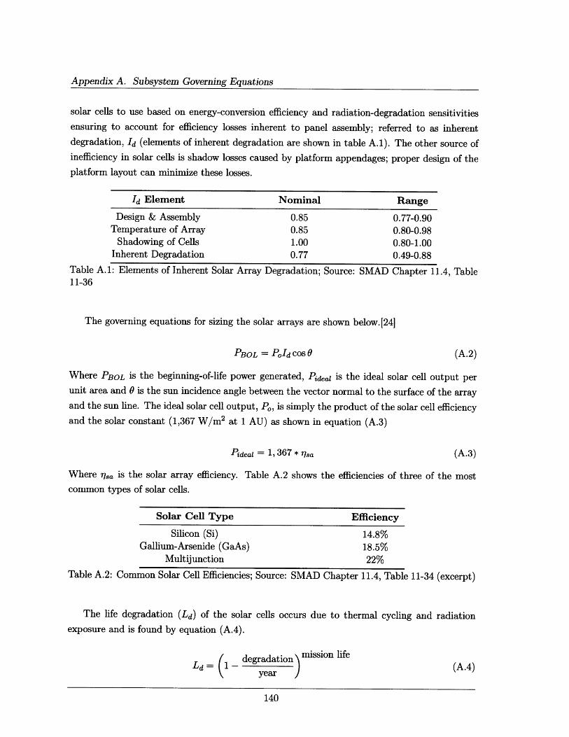
Appendix A. Subsystem Governing Equations
solar cells to use based on energy-conversion efficiency and radiation-degradation sensitivities
ensuring to account for efficiency losses inherent to panel assembly; referred to as inherent
degradation, Id (elements of inherent degradation are shown in table A.1). The other source of
inefficiency in solar cells is shadow losses caused by platform appendages; proper design of the
platform layout can minimize these losses.
Id Element Nominal Range
Design & Assembly 0.85 0.77-0.90Temperature of Array 0.85 0.80-0.98
Shadowing of Cells 1.00 0.80-1.00Inherent Degradation 0.77 0.49-0.88
Table A.1: Elements of Inherent Solar Array Degradation; Source: SMAD11-36
Chapter 1]1.4, Table
The governing equations for sizing the solar arrays are shown below.[24]
PBOL = PoId cos 0 (A.2)
Where PBOL is the beginning-of-life power generated, Pideal is the ideal solar cell output per
unit area and 0 is the sun incidence angle between the vector normal to the surface of the array
and the sun line. The ideal solar cell output, Po, is simply the product of the solar cell efficiency
and the solar constant (1,367 W/m 2 at 1 AU) as shown in equation (A.3)
Pideal = 1, 367 * rlsa (A.3)
Where lsa is the solar array efficiency. Table A.2 shows the efficiencies of three of the most
common types of solar cells.
Solar Cell Type
Silicon (Si)Gallium-Arsenide (GaAs)
Multijunction
Table A.2: Common Solar Cell Efficiencies;
The life degradation (Ld) of the solar
exposure and is found by equation (A.4).
Efficiency
14.8%18.5%22%
Source: SMAD Chapter 11.4, Table 11-34 (excerpt)
cells occurs due to thermal cycling and radiation
Ld= (1- degradation mission life
year
140
(A.4)

A.2. Thermal Control Subsystem Sizing
And the array's performance per unit area at the end-of-life is shown in equation (A.5):
PEOL = PBOLLd (A.5)
Finally, the solar array area required to support the platform's power requirement can be found
using equation (A.6):
Asa Psa (A.6)PEOL
Once the solar array requirements are determined, we must also size the energy storage
system (typically batteries) to provide power during peak power demands and eclipse peri-
ods. Elements that factor into the determination of the system energy storage requirements
are a) mission length; b) eclipse frequency and duration; c) voltage and current requirements
d) depth of discharge e) duty cycle and f) charge/discharge cycle limits. Next we select the type
of battery to be used based on specific-energy density and efficiency and determine the size
of the batteries (battery capacity).[24] The battery capacity (Cr)is determined with equation
(A.7).
C = PeTe (A.7)(DoD)Nblb
Where Nb is the number of batteries in the system, 7b is the transmission efficiency between
the battery and the load, DoD is the depth of discharge and Cr is measured in Watt-hours (for
battery capacity in Amp-hours, divide by the bus voltage).
The final step in designing the power system is to design the power distribution, control
and regulation system by considering the electrical load profile, centralized versus decentralized
control and the fault protection subsystem. Critical to this process is managing excess power
from the solar arrays during BOL operations through a peak-power tracker (PPT) or a direct-
energy-transfer (DET) system. PPT systems extract the exact amount of power required to
operate the system and charge the batteries while DET systems dissipate excess power through
external shunt resistors.[24]
A.2 Thermal Control Subsystem Sizing
The Stefan-Boltzmann equation determines the radiating power of a radiator which is given by
equation (A.8).
Qr = E rcArT4 (A.8)
Where 6r is the radiator emissivity, Ar is the surface area of the radiator, Tr is the absolute ra-
141
Appendix A. Subsystem Governing Equations
diator temperature in (K) and a is the Stefan-Boltzmann constant (5.67051 x 10- s W/m 2 K4 ).
To simplify equation (2.8), we assume that the net QMLI is negligible. This simplification
is conservative for spacecraft and particularly valid for HALE platforms operating in the more
benign temperature environment of the Earth's stratosphere. Substituting equation (A.8) for
Qradiator and qexternalA for Qexternal, the simplified radiator heat balance is shown in equation
(A.9).
Qinternal + qexternalA = EcAT 4 (A.9)
Where qexternal is the external environmental heat load on the radiator per unit area and all
other quantities are as described above.
The external environmental load, qexternal, is composed of the following individual compo-
nents (equation (A.10)).
qexternal = qsolar + qalbedo + qEarthlR ± qbackload (A. 10)
Subsequently, the incident solar energy on the face of a platform (qsolar), the heat input from
the Earth's albedo (qalbedo) and the absorbed Earth IR heat load per unit area (qEarthlR) can
be calculated using equations (A.11) through (A.13).
qsolar = ApKsolar cos / (A.11)
Where Ap is the surface area of the platform face, Ksolar is the solar constant in the vicinity
of the Earth (1367 W/m 2 ) and 3 is the angle between the Sun and the vector normal to theplatform face.
qalbedo = QasolarPalbedoFalbedo (A. 12)
Where a is the absorptivity of the radiator, Isolar is the intensity of the solar flux, Palbedo is theEarth's albedo and Falbedo is a geometrical factor that accounts for the direction of the radiatorrelative to the Sun.
qEarthIR = EIEIRFEIR (A.13)
Where E is the emissivity of the radiator, IEIR is the intensity of the Earth IR flux, and FEIRis a geometrical factor that accounts for the direction of the radiator relative to the Earth.
The geometrical factors Falbedo and FEIR for common altitudes and attitudes can be found
in look-up tables in various spherical geometry texts (including SMAD Appendix D) and are
not calculated here.
Additionally, it is beyond the scope of this thesis to calculate the radiative backload from
142
A.2. Thermal Control Subsystem Sizing
other platform surfaces (i.e., the qbackload component of qexternal) as that calculation requires
geometric modeling of the individual platform configuration in question. In general, effective
heat radiation requires that the surface upon which a radiator is mounted must not be blocked
by other platform surfaces. Therefore, radiators are usually located on surfaces that have a
clear view to space.
143

This page intentionally left blank.

Bibliography
[1] U.S. Army Space & Missile Defense Command/U.S. Army Forces Strategic Command,"United States Army Space Master Plan," November 2006, U.S. Army Space and MissileDefense Command/Army Forces Strategic Command.
[2] U.S. Army Space Training & Doctrine Command, The United States Army's ConceptCapability Plan (CCP), Space Operations, 2015-2024, U.S. Army Training and DoctrineCommand, November 2006, TRADOC Pamphlet 525-7-4.
[3] Prof. Karagozian, A., Dr. Brown, A., Prof. Gallimore, A., Glasgow, E., Prof. Kroo, I.,Shyu, H., and Dr. Whelan, D., "Persistence at Near Space Altitudes - Executive Summaryand Annotated Brief," Tech. rep., United States Air Force Scientific Advisory Board,August 2005, SAB-TR-05-06.
[41 Jamison, L., Sommer, G. S., and Porche, I. R., "High-Altitude Airships for the FutureForce Army," Tech. Rep. ADA440454, Rand Arroyo Center, Santa Monica, CA, 2005.
[5] Spencer, C. W., "High Altitude Airship (HAA) ACTD," March 2003, DoD Missile DefenseAgency update briefing.
[6] Khoury, G. A. and Gillet, J. D., editors,' Airship Technology, Vol. 10 of CambridgeAerospace Series, Cambridge University Press, 1999.
[7] GlobalSecurity.org, "RQ-4A Global Hawk (Tier II+ HAE UAV)," http://www.global-security.org/intell/systems/globalhawk.htm, accessed on April 18, 2008.
[8] Pulliam, W., van Laak, J., Nickol, C., Lt Col McCormick, J., and Davis, S., "DARPAIndustry Day Consolidated Briefings," June 2007, http://www.darpa.mil/tto/solicit/-BAA07-51/VULTURE_Industry_Day_ Consolidated _Briefs.pdf.
[9] Ramirez, A., "Global Hawk: Successful Transition from an ACTD to a Formal AcquisitionEMD and Production Program," AIAA 3rd "Unmanned Unlimited" Technical Conference,Workshop and Exhibit, September 2004, AIAA 2004-6322.
[10] Wertz, J. R., Space Mission Analysis and Design, chap. 3, Microcosm Press, 3rd ed., 2006,pp. 47-72.
[11] Chang, B. J., Schubert, F. H., Kovach, A. J., and Wynveen, P. A., "Engineering ModelSystem Study for a Regenerative Fuel Cell," Tech. rep., Life Systems, Inc., Cleveland, OH44122, September 1984, TR-376-30.
145

Bibliography
[12] Warshay, M. and Prokopius, P. R., "The Fuel Cell in Space: Yesterday, Today and To-morrow," September 1989, NASA Technical Memorandum 102366.
[13] Barbir, F., Molter, T., and Dalton, L., "Regenerative Fuel Cells for Energy Storage:Efficiency and Weight Trade-offs," IEEE A&E SYSTEMS MAGAZINE, March 2005,pp. 35-40.
[14] Velev, O. A., "Regenerative Fuel Cell System for an Unmanned Solar Powered Aircraft,"35th Intersociety Energy Conversion Engineering Conference, AIAA 2000-2873, July2000.
[15] Gilmore, D. G., Grob, E. W., Hardt, B. E., Ousley, W., and Prager, R. C., Space MissionAnalysis and Design, chap. 11, Microcosm Press, 3rd ed., 2006, pp. 428-458.
[16] Lavan, C., Lockheed Martin/Missile Defense Agency Contractor, Personal Communica-tion, 2 April 2009.
[17] Dr Hardy, D. and Maj Steves, M., "Near Space Study: Approach/Findings and Conclu-sions - Outbrief," June 2005.
[18] Britton, W. R., Doukas, P. G., McCandless, J. R., and Sarafin, T. P., Space MissionAnalysis and Design, chap. 11, Microcosm Press, 3rd ed., 2006, pp. 459-497.
[19] Wessel, P. and Petrone, F., "Special Problems and Capabilities of High Altitude LighterThan Air Vehicles," Tech. rep., Naval Ordnance Laboratory, Interagency Workshop onLighter Than Air Vehicles, Monterey, CA, January 1975, Access Number BT-2548.31.
[20] "List of Surface-to-Air Missiles," http://en.wikipedia.org/wiki/List_of_surface-to-air_missiles; Accessed March, 2009.
[211 Wertz, J. R., Space Mission Analysis and Design, chap. 5, Microcosm Press, 3rd ed., 2006,pp. 95-130.
[22] Aircraft-Info.net, "Boeing 747-400," http://portal.aircraftinfo.net/article3.html; AccessedMay 2009.
[23] Berget, R. T., Space Mission Analysis and Design, chap. 11, Microcosm Press, 3rd ed.,2006, pp. 395-407.
[24] McDermott, J. K., Space Mission Analysis and Design, chap. 11, Microcosm Press, 3rded., 2006, pp. 407-427.
125] Reeves, E. I., Space Mission Analysis and Design, chap. 10, Microcosm Press, 3rd ed.,2006, pp. 301-352.
[26] "Table of Rechargeable Battery Technologies," http://en.wikipedia.org/wiki/-Rechargeable_battery#Table ofrechargeable batterytechnologies; Accessed April,2009.
[27] Mitlitsky, F., Myers, B., and Weisberg, A. H., "Regenerative Fuel Cell Systems," Energy& Fuels, Vol. 20, 1998, pp. 56-71, Published by American Chemical Society.
146
Bibliography
[281 Coffey, W. and MAJ Tubergen, T., U.S. Army Space and Missile Defense Command,Peterson AFB, Colorado Springs, CO 80914, Personal Communication, July 1, 2008.
[29] Hannan, D., "Wideband Global SATCOM (WGS) System Utilization Plan & Integrated
Operations; WGS Block II SDRU," July 2007.
[301 Air Force Space Command, "U.S. Air Force Fact Sheet: Wideband Global SATCOM
Satellite," October 2007.
[31] GlobalSecurity.org, "Wideband Gapfiller System," http://www.globalsecurity.org/space/-systems/wgs.htm, accessed on October 23, 2008.
[32] Chisholm, P., "Buying Time: Disconnects in Satcom Procurement," http://www.military-
information-technology.com/article.cfm?DocID= 285.
[33] Davies, R. S. and Dietrich, F. J., Space Mission Analysis and Design, chap. 13, Microcosm
Press, 3rd ed., 2006, pp. 533-586.
134] Boithias, L., Radio Wave Propagation, McGraw-Hill Inc., 1984, Revised and updated
1987.
[351 Gagliardi, R. M., Satellite Communications, Van Nostrand Reinhold Company Inc., 1984.
[36] Shannon, C. E., "A Mathematical Theory of Communication," The Bell System Technical
Journal, Vol. XXVII, No. 3, July 1948, pp. 379-423, 623-656.
[371 Satellites, B., 'Transformational Wideband Communication Capabilities for the
Warfighter," http://www.boeing.com/defense-space/space/bss/factsheets/7 02 /wgs/-
wgs_factsheet.html, accessed on October 21, 2008.
[38] Larson, W. J. and Wertz, J. R., editors, Space Mission Analysis and Design, Microcosm
Press, 3rd ed., 2006.
[39] "Unmanned Space Vehicle Cost Model," https://www.uscm8.com/.
[40] Headquarters, Department of the Army, SINCGARS Ground Combat Radio Technical
Manual, December 1998, TM 11-5820-890-10-8.
[41] Ando, A., Kondo, A., and Kubota, S., "A Study of Radio Zone Length of Dual-Polarized
Omnidirectional Antennas Mounted on Rooftop for Personal Handy-Phone System,"
IEEE Transactions on Vehicular Technology, Vol. 57, No. 1, January 2008.
[42] Brodsky, R. F., Chesley, B., and Lutz, R., Space Mission Analysis and Design, chap. 9,
Microcosm Press, 3rd ed., 2006, pp. 241-300.
[43] Satellite Imaging Corporation, "GeoEye-1 Satellite Imagery/Sensor Specifications,"
http://www.satimagingcorp.com/satellite-sensors/geoeye- .html.
[44] Boeing Integrated Defense Systems and Boeing Launch Services, "Boeing Launches
GeoEye-1 Earth-Imaging Satellite," http://www.boeing.com/defense-space/space/bls/-
missions/335/.
147

Bibliography
145] Carey, B., "How It Works: The Best View From Space Yet," Popular Science, March2008, http://www.popsci.com/node/19968.
[46] Kramer, H. J., "Earth Observation History on Technology Introduction," http://-www.eoportal.org/documents/kramer/History.pdf.
[47] Bovik, A. C., editor, Handbook of Image and Video Processing, Academic Press, 2005,http://common.books24x7.com/book/id_25360/book.asp (accessed March 20, 2009).
[48] Christopoulos, C., Skodras, A., and Ebrahimi, T., "The JPEG2000 Still Image CodingSystem: An Overview," IEEE Transactions on Consumer Electronics, Vol. 46, No. 4,November 2000, pp. 1103-1127.
[49] Langley, R., "Innovation Insights," GPS World, Vol. 19, No. 6, June 2008.
[501 Kaplan, E. D. and Hegarty, C. J., editors, Understanding GPS: Principles and Applica-tions, Artech House, Inc., 2nd ed., 2006.
[51] Dinerman, T., "Will China Compel the Development of GPS 4?" The Space Review, June2006, http://www.thespacereview.com/article/643/1.
[52] Navtech Seminars, Inc, "Course 300: GPS Overview," March 1995.
[53] Dovis, F., Lo Presti, L., and Mulassano, P., "Support Infrastructures Based on HighAltitude Platforms for Navigation Satellite Systems," Tech. rep., IEEE Wireless Com-munications, October 2005, The Synergy of Spatial and Terrestrial Communications inNext-Generation Hybrid Wireless Systems.
[541 Federal Aviation Administration, "Navigation Services: Wide Area Augmentation Sys-tem," http://www.faa.gov/about/office_org/headquarters_offices/ato/service_units/-techops/navservices/gnss/waas/.
[55] Yeazel, J., "WAAS and its Relation to Enabled Hand-Held GPS Receivers," http://-gpsinformation.net/exe/waas.html.
[56] "GPS Modernization," Accessed January 2, 2009, http://en.wikipedia.org/wiki/-GPS modernization.
[57] GlobalSecurity.org, "GPS Block II R-M," http://www.globalsecurity.org/space/systems/-gps_2r.htm, accessed on February 9, 2009.
[58] Capt. Barker, B. C., Betz, J. W., Clark, J. E., Correia, J. T., Gillis, J. T., Lazar, S.,Lt. Rehborn, K. A., and Straton, III, J. R., "Overview of the GPS M Code Signal," Tech.rep., The MITRE Corporation, May 2000, http://www.mitre.org/work/tech_papers/-tech_papers_00/betz_overview/index.html.
[591 Shin, M. J., Lee, E. S., Lee, Y. J., and Hur, J., "A System Design of StratosphericAirships for the Navigation in Korea," Tech. rep., American Institute of Aeronautics andAstronautics, August 2001, AIAA 2001-4171.
148
Bibliography
[60] Headquarters, Department of the Army, FM 3-14: Space Support to Army Operations,Department of the Army, May 2005, Distribution Restriction: Approved for public release;distribution is unlimited.
[61] Stout, S., Bremser, D. J., Johnson, S., and King, R., U.S. Army Space and Missile DefenseCommand, Colorado Springs, CO 80916, Personal Communication, 7 April 2008.
[621 Headquarters, Department of the Army, FM 3-0: Operations, Department of the Army,June 2001, Distribution Restriction: Approved for public release; distribution is unlimited.
[63] Headquarters, Department of the Army, FM 1-0: Human Resources Support, Depart-ment of the Army, February 2007, Distribution Restriction: Approved for public release;distribution is unlimited.
[64] Col. John Keesee (USAF, Ret.), MIT Lincoln Laboratory, Lexington, MA 02420, PersonalCommunication, 29 October 2008.
[651 Kirkpatrick, D., Space Mission Analysis and Design, chap. 11, Microcosm Press, 3rd ed.,2006, pp. 381-394.
[66] Air Force Space Command, Public Affairs Office, "U.S. Air Force Fact Sheet: Global Po-sitioning System," http://www.af.mil/factsheets/factsheet.asp?id=119, accessed on April23, 2009.
[67] Bennett, G. L., "Space Nuclear Power: Opening the Final Frontier," 4th InternationalEnergy Conversion Engineering Converence and Exhibit (IECEC), June 2006, pp. 1-17,AIAA 2006-4191.
[68] Headquarters, Department of the Army, FM 3-13: Information Operations - Doctrine,Tactics, Techniques, and Procedures, Department of the Army, November 2003, Distribu-tion Restriction: Approved for public release; distribution is unlimited.
[69] Analytic Decisions Incorporated Staff, "Infrared Satellite Technology Study, Final Re-port," Tech. rep., Analytic Decisions Incorporated, 5155 Rosecrans Ave., Hawthorne, CA,December 1982, Report Number OGU-B2-011.
[701 Army Science Board, "Prioritizing Army Space Needs," Tech. rep., Army Science Board,2511 Jefferson Davis Highway, Arlington, VA 22202, July 1999, Summer Study, FinalReport.
[71] Bajaj, R., Ranaweera, S. L., and Agrawal, D. P., "GPS: Location-Tracking Technology,"Computer Magazine, Vol. 35, No. 4, March 2002, pp. 92-94.
[72] Bauer, F. H., Hartman, K., and Lightsey, E. G., "Spaceborne GPS Current Status andFuture Visions," Aerospace Conference, 1998. Proceedings., IEEE, Vol. 3, March 1998,pp. 195-208, DOI: 10.1109/AERO.1998.685798.
[73] Bearden, D. A., "When is a Satellite Mission Too Fast and Too Cheap?" September 2001,2001 MAPLD International Conference.
149
Bibliography
[74] Bearden, D. A., "A complexity-based Risk Assessment of Low-cost Planetary Missions:When is a Mission Too Fast and Too Cheap?" Acta Astronautica, Vol. 52, January 2003,pp. 371-379(9).
[75] Bennett, B., Hannan, D., Marshall, J., and Gibbons, Ph.D., R., "Link Analysis of Com-mercial and Wideband Gapfiller Satellite (WGS) Satellites Using DVB-S2 with VariableCoding and Modulation (VCM)," Military Communications Conference, 2006, October2006, pp. 1-7, DOI: 10.1109/MILCOM.2006.302474.
[76] Bennett, B., Greeves, J., Hemmings, P., and Skowrunski, M., '"Tactical Services Providers:Wireless and SATCOM Integration for Tactical Services," Military Communications Con-ference, 2007, October 2007, pp. 1-7, DOI: 10.1109/MILCOM.2007.4455305.
[77] Besse, J., Gonzalez, L., and Condello, R., "On the Performance of Small Aperture Ka-Band Terminals for Use Over the Wideband Gapfiller Satellite," MILCOM 2002 Proceed-ings, Vol. 2, October 2002, pp. 1388-1391, IEEE 0-7803-7625-0/02.
[78] Bhaskar, P. and Zhao, J., "Design Considerations for Next Generation Satellite Terminal,"Military Communications Conference, 2007, October 2007, pp. 1-5, DOI: 10.1109/MIL-COM.2007.4454963.
[79] Biber, K. and Tilmann, C. P., "Supercritical Airfoil Design for Future High-AltitudeLong-Endurance Concepts," Journal of Aircraft, Vol. 41, No. 1, January-February 2004,AIAA-1049-356.
[80] Bolkcom, C., "Potential Military Use of Airships and Aerostats," November 2004, Con-gressional Research Service, Report for Congress.
[81] Bowes, W. C., Engelland, J., Fernandez, F. L., Fratarangelo, P., Kohn Jr., E. R., Lister,M. J., Neal, W. A., Polmar, N., Rumpf, R. L., Smith, T. B., Williamson Jr., W. E., andWinston, P. H., "Lighter-Than-Air Systems for Future Naval Missions," Tech. rep., NavalResearch Advisory Committee, 875 N. Randolph St., Arlington, VA 22203, 2006.
[82] Boyle, A., "Airship Groomed for Flight to Edge of Space," May 2004,http://www.msnbc.msn.com/id/5025388/from/ET/.
[83] Brand, J. C., "On the Use of Commercial X-, Ku- and Ka-Band Satellites for Military On-the-Move-Communications," 22nd AIAA International Communications Satellite SystemsConference & Exhibit, May 2004, pp. 1-7, AIAA 2004-3115.
[84] Brand, J. C., "Practical On-the-Move Satellite Communications for Present and FutureMobile Warfighters," Military Communications Conference, 2005, Vol. 1, October 2005,pp. 625-629, DOI: 10.1109/MILCOM.2005.1605752.
[85] Bretz, E. A., "X Marks the Spot, Maybe," IEEE Spectrum, Vol. 37, No. 4, April 2000,pp. 26-36, DOI: 10.1109/6.833025.
[86] Buiten, H. J. and Clevers, J. G. P. W., editors, Land Observation by Remote Sensing:Theory and Applications, Gordon and Breach Science, 1993, Volume 3 of Current Topicsin Remote Sensing Series, Senior Editor: C. Voilte.
150

Bibliography
[871 Bulter, A., "Private Eyes: Secret Satellite Program Raises Concerns for the Future of
Commercial Remote Sensing," Aviation Week & Space Technology, May 2008, pp. 30-32.
[88] Butsch, F., "Radio Frequency Interference and GPS," GPS World, October 2002, pp. 40-
46.
[89] Carr, J. J., "Directional or Omnidirectional Antenna?" http://www.dxing.com/tnotes/-tnote0l.pdf.
[901 Cazaux, Y., Subiela, D., and Boucharlat, G., "12,000 Pixel Monolithic Linear Sensor
for High Resolution Pushbroom Earth Observation Satellites," SPIE, Vol. 2583, 1995,pp. 430-439, 0-8194-1947-8.
[91] Chen, H. S., Space Remote Sensing Systems: An Introduction, Harcourt Brace Jovanovich,1985, Academic Press, Inc.
[921 Clark, J. E., Wu, C. A., and Goldstein, D. B., "The Role of Technology Development in
the Global Positioning System," 2002 IEEE International Frequency Control Symposium
and PDA Exhibition, May 2002, pp. 488-492, 0-7803-7082-1/02.
[93] Clemons, R. R., "Next-Generation High-Resolution Commercial Imaging Satellite," SpaceImaging, Japan, 2005, IAC-05-B1.2.02.
[94] Cobb, H. S., GPS Pseudolites: Theory, Design and Applications, Ph.D. thesis, Stanford
University, September 1997, UMI Number 9810101.
[95] Collett, J., "INMARSAT Solutions to Global Military Communications Challenges,"
lEE Colloquium on Military Satellite Communication (Ref. No. 2000/024), June 2000,
pp. 5/1-5/5.
[96] Colwell, R. N. (Editor-in-Chief), Simonett, D. S., and Ulaby, F. T., editors, Manual
of Remote Sensing, Vol. I: Theory, Instruments and Techniques, American Society of
Photogrammetry, 2nd ed., 1983.
[97] Colwell, R. N. (Editor-in-Chief), Estes, J. E., and Thorley, G. A., editors, Manual of Re-
mote Sensing, Vol. II: Interpretation and Applications, American Society of Photogram-
metry, 2nd ed., 1983.
[98] Cross, P., "Some Very High Precision Applications of Global Navigation Satellite Sys-
tems," Printed and published by the IEE, Michael Faraday House, UK, March 2005,
University College London, Department of Geomatic Engineering.
[99] Curtis, W. J., Gray, P., Harrison, M., Holdaway, R., Waltham, N. R., Jasani, B., and
Rathmell, A., "A System for High-Resolution Imaging from Space," Proceedings of the
Euro-Asia Space Week on Cooperation in Space - "Where East and West Finally Meet",
November 1998, pp. 605-614, ESA SP-430, February 1999.
[100] Davies, J. K., Astronomy from Space: The Design and Operation of Orbiting Observato-
ries, John Wiley & Sons, Inc. in accociation with Praxis Publishing, 1997, Wiley-Praxis
Series in Astronomy and Astrophysics.
Bibliography
[101] Detoma, E. and Lisi, M., "Interoperability and Compatibility Issues for Global Navi-gation Satellite Systems," 18th AIAA International Communications Satellite SystemsConference and Exhibit, April 2000, pp. 663-669, Collection of Technical Papers. Vol. 2(A00-25001 06-32).
[102] Drezner, J. A. and Leonard, R. S., "Innovative Development. Global Hawk and Dark-star: Their Advanced Concept Technology Demonstrator Program Experience, ExecutiveSummary," Tech. rep., Rand Corporation, Santa Monica, CA, August 2002.
(103] Drezner, J. A. and Leonard, R. S., "Innovative Development. Global Hawk and Darkstar,Volume 1: HAE UAV ACTD Program Description and Compartive Analysis," Tech. rep.,Rand Corporation, Santa Monica, CA, August 2002.
[104] Drezner, J. A. and Leonard, R. S., "Innovative Development. Global Hawk and Darkstar,Volume 2: Flight Test in the HAE UAV ACTD Program," Tech. rep., Rand Corporation,Santa Monica, CA, August 2002.
[105] Drezner, J. A. and Leonard, R. S., "Innovative Development. Global Hawk and Darkstar,Volume 3: Transitions within and out of the HAE UAV ACTD Program," Tech. rep.,Rand Corporation, Santa Monica, CA, August 2002.
[106] Elachi, C. and van Zyl, J., Introduction to the Physics and Techniques of Remote Sensing,John Wiley & Sons, Inc., 2006, Wiley Series in Remote Sensing.
[107] Enge, P., Walter, T., Pullen, S., Kee, C., Chao, Y.-C., and Tsai, Y.-J., "Wide AreaAugmentation of the Global Positioning System," Proceedings of the IEEE, Vol. 84, No. 8,August 1996, pp. 1063-1088, DOI: 10.1109/5.533954.
[108] Ganz, A., Gong, Y., and Li, B., "Performance Study of Low Earth-Orbit Satel-lite Systems," IEEE Transactions on Communications, Vol. 42, No. 2/3/4, Febru-ary/March/April 1994, pp. 1866-1871, IEEE Log Number 9401588.
[109] Gerten, G., "Protecting the Global Positioning System," IEEE A&E Systems Magazine,Vol. 20, No. 11, November 2005, pp. 3-8, DOI: 10.1109/MAES.2005.1576067.
[110] Giggenbach, D., Horwath, J., and Epple, B., "Optical Satellite Downlinks to OpticalGround Stations and High-Altitude Platforms," IST Mobile & Wireless CommunicationSummit, July 2007.
[111] LTC Ginter, K., Space Technology and Network Centric Warfare: A Strategic Paradox,Master's thesis, U.S. Army War College, February 2007.
[112] Hitchman, M. H., Kudeki, E., Fritts, D. C., Kugi, J. M., Fawcett, C., Postel, G. A., Yao,C.-Y., Ortland, D., Riggin, D., and Harvey, V. L., "Mean Winds in the Tropical Strato-sphere and Mesosphere During January 1993, March 1994 and August 1994," Journal ofGeophysical Research, Vol. 122, No. D22, November 1997, pp. 26,033-26,052.
[113] Hoberecht, M. A. and Green, R. D., "Use of Excess Solar Array Power by Regenerative FuelCell Energy Storage Systems in Low Earth Orbit," Proceedings of the 32nd IntersocietyEnergy Conversion Engineering Conference, July-August 1997, pp. 224-227.
152
Bibliography
[1141 Hoder, D. and Zakrajsek, R., Airborne Satcom Terminal Research at NASA Glenn, Na-
tional Aeronautics and Space Administration, Glenn Research Center, Cleveland, Ohio,
December 2002, NASA/TM-2002-212006.
[1151 Hogan, H., "Getting a Better View from Above: Commercial Satellite Technology Means
More Accurate Object Location and Expanded Spectral Bands for Color Imaging," Pho-
tonics Spectra, Vol. 41, No. 10, October 2007, pp. 48-57.
[1161 Hong, S., Chun, H.-H., Kwon, S.-H., and Lee, M. H., "Observability Measures and Their
Application to GPS/INS," IEEE Transaction on Vehicular Technology, Vol. 57, No. 1,
January 2008, pp. 97-106, 0018-9545.
[117] Inamiya, K. and Sakata, K., "A Study on Navigation and Communication Satellite System
for the Next Generation," 17th AIAA International Communications Satellite Systems
Conference and Exhibit, February 1998, pp. 382-391, AIAA-98-1296.
[118] Isakowitz, S. J., Hopkins, J. B., and Hopkins, Jr., J. P., International Reference Guide
to Space Launch Systems, American Institude of Aeronautics and Astronautics, 4th ed.,
2004.
[119] Iwata, T., Ishida, H., and Osawa, Y., "Advanced Land Observing Satellite (ALOS): En-
abling Technologies and Platform Performance," Proceedings of SPIE, Vol. 7106, 2008,
pp. 1-13.
[1201 Jasani, B., "Civil Radar Observation Satellites for IAEA Safeguards," Journal of the
Institude of Nuclear Materials Management, Vol. 27, No. 2, Winter 1999, pp. 29-34.
[121] Joint Chiefs of Staff, JP 3-14: Space Operations, Department of Defense, January 2009,
Distribution Restriction: Approved for public release; distribution is unlimited.
[1221 MAJ Kennedy, M. W., A Moderate Course for USAF UAV Development, Master's thesis,
Air Command and Staff College, Air University, April 1998.
[123] Kleusberg, A. and Langley, R. B., "The Limitations of GPS," GPS World, March/April
1990.
1124] Khan, M. S., "Political and Economic Dimensions of Global Navigation Satellite System
(GNSS)," 2001 IEEE Aerospace Conference Proceedings, March 2001, pp. 3/1271-3/1276,
DOI: 10.1109/AERO.2001.931356.
[125] Maj. Knight, A. G. and MAJ Luck, A. B., Tactical Space - Beyond Line of Sight Alterna-
tives for the Army and Marine Corps Ground Tactical Warfighter, Master's thesis, Naval
Postgraduate School, September 2007.
[126] Maj. Knoedler, A. J., Lowering the High Ground: Using Near-Space Vehicles for Per-
sistent ISR, Master's thesis, Center for Strategy and Technology, Air War College, Air
University, November 2005.
[1271 Krischke, M., Niemeyer, W., and Scherer, S., "RapidEye Satellite Based Geo-Information
System," Acta Astronautica, Vol. 46, No. 2-6, 2000, pp. 307-312.
153

Bibliography
[128] Kumar, R., Taggart, D., Monzingo, R., and Goo, G., "Wideband Gapfiller Satellite
(WGS) System," 2005 IEEE Aerospace Conference, March 2005, pp. 1410-1417, DOI:10.1109/AERO.2005.1559431.
[129] Lamard, J.-L., Gaudin-Delrieu, C., Valentini, D., Renard, C., Tournier, T., and Laherrere,J.-M., "Design of the High Resolution Optical Instrument for the Pleiades HR Earth
Observation Satellites," Proceedings of the 5th International Conference on Space Optics,March-April 2004, pp. 149-156, ESA SP-554, June 2004.
[1301 Langley, R. B., '"The GPS Receiver: An Introduction," GPS World, January 1991.
[131] Langley, R. B., '"The Mathematics of GPS," GPS World, July/August 1991.
[132] Langley, R. B., "Why is the GPS Signal So Complex?" GPS World, May/June 1990.
[133] Martin, L., "High Altitude Airship (HAA)," http://www.lockheedmartin.com/products/-HighAltitudeAirship/.
[134] Martin, L., "High Altitude Airship (HAA): Global Persistence for the JointWarfighter," Brochure; http://www.lockheedmartin.com/data/assets/corporate/press-kit/HAA-Brochure.pdf.
[135] Martin, L., "Lighter-Than-Air Surveillance Systems Persistent C4ISR," Brochure;http://www.lockheedmartin.com/data/assets/corporate/press-kit/LTA-surveillance-Brochure.pdf.
[136] Long, C. and Fisher, M., "Near Space Payload and Vehicle Concepts," Tech. rep., GeneralDynamics C4 Systems, April 2006.
[1371 LtCol Martel, J. H., "NAVSTAR Global Positioning System," Space Tracking and DataSystems; Proceedings of the Symposium, June 1981, AIAA-1981-3013.
[138] Marx, H. F., "NAVSAT to GPS: The Rocky Path to Success," 46th AIAA AerospaceSciences Meeting and Exhibit, January 2008, AIAA 2008-865.
[139] Mathur, A., Nguyen, T. M., and Goo, G., "Rain Attenuation Model Assessment for Wide-band Gapfiller Satellite Communications Link," Military Communications Conference,2001, Vol. 1, October 2001, pp. 681-686, DOI: 10.1109/MILCOM.2001.985922.
[140] Matosevic, M., Salcic, Z., and Berber, S., "A Comparison of Accuracy Using a GPS anda Low-Cost DGPS," IEEE Transactions on Instrumentation and Measurement, Vol. 55,No. 5, October 2006, pp. 1677-1683, IEEE, 0018-9456.
[141] Mayer, N., "Lighter-than-Air Systems," Aerospace America, Vol. 41.12, December 2003,IRN 1034522X.
[142] McNeff, J. G., "The Global Positioning System," IEEE Transactions on Microwave Theoryand Techniques, Vol. 50, No. 3, March 2002, pp. 645-652, 0018-9480/02.
[143] Mensing, C. and Sand, S., "Performance Enhancement of GNSS Positioning in Criti-cal Scenarios by Wireless Communications Systems," Position, Location and NavigationSymposium, May 2008, pp. 334-340, IEEE, 1-4244-1537-3/08.
154
Bibliography
[144] CPT Moomey, E. R., Technical Feasibility of Loitering Lighter-than-Air Near-Space Ma-neuvering Vehicles, Master's thesis, Air Force Institute of Technology, March 2005.
1145] Moore, T., "An Introduction to the Global Positioning System and its Applications,"Developments in the Use of Global Positioning Systems, February 1994, pp. 1/1-1/6,Institute of Engineering Surveying and Space Geodesy, University of Nottingham.
1146] Mueller, J., "Guidance, Navigation and Control of High-Altitude Airships," Tech. rep.,Princeton Satellite Systems, Inc., 33 Witherspoon Street, Princeton, NJ 08542, 2006.
[147] Mukhopadhyay, M., Sarkar, B. K., and Chakraborty, A., "Augmentation of Anti-Jam GPSSystem Using Smart Antenna with a Simple DOA Estimation Algorithm," Progress InElectromagnetics Research, 2007, pp. 231-249, PIER 67, 2007.
[1481 National Aeronautics and Space Administration, 2008 NASA Cost Estimating Handbook.
[149] Neufeld, D. and Chung, J., "Development of Aircraft Conceptual Design OptimizationSoftware," Fifth International Conference on Computational Science and Applications,2007, IEEE, 0-7695-2945-3/07.
[150] Nickol, C. L., Guynn, M. D., Kohout, L. L., and Ozoroski, T. A., "High Altitude LongEndurance Air Vehicle Analysis of Alternatives and Technology Requirements Develop-ment," 45th AIAA Aerospace Sciences Meeting and Exhibit, January 2007, Reno, NV.
[151] North American Aerospace Defense Command/U.S. Army Space & Missile Defense Com-mand, "High Altitude Airship (HAA): FY03 ACTD Briefing," 2003.
[152] Norris, G. and Brown, T., "Global Reborn," Flight International, Vol. 170.5043, July2006, pp. 26-31, IRN 10328385.
[153] MAJ O'Brien, P., "Army Space and Missile Defense Command's Position on Space," TheArmy Space Journal, Vol. 6, No. 3, Summer 2007.
[154] "OODA Loop," http://en.wikipedia.org/wiki/OODA_Loop; Accessed April 20, 2009.
[155] Oshman, Y. and Koifman, M., "Robust Navigation Using the Global Positioning Systemin the Presence of Spoofing," Journal of Guidance, Control and Dynamics, Vol. 29, No. 1,January-February 2006, pp. 95-104.
[1561 Palestini, C., Pedone, R., Villanti, M., and Corazza, G. E., "Integrated NAV-COM Sys-tems: Assisted Code Acquisition and Interference Mitigation," IEEE Systems Journal,
Vol. 2, No. 1, March 2008, IEEE, 1932-8184.
[157] Parkinson, B. W., "Origins, Evolution and Future of Satellite Navigation," Journal of
Guidance, Control and Dynamics, Vol. 20, No. 1, January-February 1997, pp. 11-25.
[158] Peczalski, A., Kriz, J., Carlson, S. G., and Sampson, S. J., "Military/Civilian Mixed-ModeGlobal Positioning System (GPS) Receiver (MMGR)," 2004 IEEE Aerospace ConferenceProceedings, 2004, pp. 2697-2703, 0-7803-8155-6/04.
155
Bibliography
[1591 Quinlan, M., "Galileo - A European Global Satellite Navigation System," Printed andpublished by the IEE, Michael Faraday House, UK, March 2005, The IEE Seminar onNew Developments and Opportunities in GNSS.
11601 Ramirez, A., "Global Hawk: Persistent, Long Range, High Altitude, Multi-IntelligenceCapability for the US Air Force and the Battlefield Commander," AIAA/ICAS Interna-tional Air and Space Symposium and Exposition: The Next 100 Years, July 2003, AIAA2003-2615.
[161] Romeo, G., "Design Proposal of High Altitude Very-Long Endurance Solar Powered Plat-form for Earth Observation and Telecommunications Applications," 48th InternationalAstronautical Congress, October 1997, paper no. IAF-97-M.2.05.
[1621 Romeo, G., Frulla, G., Cestino, E., and Corsino, G., "HELIPLAT: Design, Aerodynamic,Structural Analysis of Long-Endurance Solar-Powered Stratospheric Platform," Journalof Aircraft, Vol. 41, No. 6, November-December 2004, pp. 1505-1520, AIAA 2723-589.
[163] Romeo, G. and Frulla, G., "Heliplat: High Altitude Very-Long Endurance Solar Pow-ered UAV for Telecommunication and Earth Observation Applications," The AeronauticalJournal, Vol. 108.1084, 2004, pp. 277-293, IRN 10020524.
[164] Rosetti, C., "Problems Related to Global Navigation . Satellite Systems(GPS;GLONAS;GALILEO)," Member, International Academy of Astronautics; Fel-low, Royal Institute of Navigation (UK).
[165] Saint-P6, O., Tulet, M., Davancens, R., Larnaudie, F., Magnan, P., Martin-Gonthier,P., Corbiare, F., and Estribeau, M., "Space Optical Instruments Optimisation Thanks toCMOS Image Sensor Technology," Proceedings of SPIE - Sensors, Systems, and Next-Generation Satellites IX, Vol. 5978, 2005.
[166] Samudraiah, D. R. M. and Raghava Murthy, D. V. A., "Small Satellites Planned ByISRO for Earth Obervation," 58th International Astronautical Conference, Vol. 6, 2007,pp. 3690-3700.
[1671 Dr. Schmidt, G. T., "GPS/INS Technology Trends for Military Systems," AIAA Guidance,Navigation and Control Conference, August 1997, pp. 1018-1034, Collection of TechnicalPapers. Pt. 2, AIAA-97-3826.
[168] Schreier, G. and Dech, S., "High Resolution Earth Observation Satellites and Services inthe Next Decade - A European Perspective," Acta Astronautica, Vol. 57, 2005, pp. 520-533.
[169] Various Contributing Authors, "Space-Based Observation Technology," Research andTechnology Organization Sensors and Electronics Technology Panel (SET) Symposium,October 2000, RTO-MP-61, AC/323(SET)TP/14.
[170] Shaw, M., Levin, P., and Martel, J., '"The DoD: Stewards of a Global Information Re-source, the Navstar Global Positioning System," Proceedings of the IEEE, Vol. 87, No. 1,January 1999, pp. 16-23, 0018-9219/99.
156
Bibliography
1171] Silk, R., Cole, L., and Roberts, F., "The Role for Commercial Geostationary Satellites in
Delivering Military Services," IEE Colloquium on Military Satellite Communication (Ref.
No. 2000/024), June 2000, pp. 2/1-2/16.
[172] Simon, D. and El-Sherief, H., "Real-Time Navigation Using the Global Positioning Sys-
tem," IEEE A&E Systems Magazine, Vol. 10, No. 1, January 1995, pp. 31-37, DOI:
10.1109/62.370460.
[173] Singer, J., "U.S. Army Developing Radar Sensor for High-Altitude Battle-
field Surveillance," November 2004, http://www.space.com/spacenews/archive04/-radararch 111704.html.
[174] U.S. Army Space & Missile Defense Command, "50 Future Army Space Capabilities," U.S.
Army Space and Missile Defense Command Battle Lab, Frontiers Division.
[175] Snowball, A., "An Update on GNSS Vulnerability Threats and Solutions," 2007 IET
Seminar on Global Navigation Satellite Systems, March 2007, pp. 87-104.
[176] Stewart, M. A., Lt. Col. Frisbie, K., and Trinkle, G., "High-Altitude Surveillance," July
2004, Geo Intelligence, http://www.geointelmag.com/geointelligence/content/.
[177] Sweetman, B., "Boeing Working on New Large UAV," Jane's Defense Weekly, Vol. 43,No. 27, June 2006.
[178] Thompson, J., "Phased Array Antenna for Satellite Communications to Small Tactical
Platforms," IEE Colloquium on Military Satellite Communication (Ref. No. 2000/024),
June 2000, pp. 6/1-6/6.
[179] Tomazi6, S., Vugrinec, A., and Skraba, P., "Wireless Communication Employing High
Altitude, Long Endurance Aeronautical Platforms," 10th Mediterranean Electrotechnical
Conference, MEleCon, Vol. I, 2000, IEEE, 0-7803-6290-X/00.
[180] Tozer, T., Grace, D., Thompson, J., and Baynham, P., "UAVs and HAPs - PotentialConvergence for Military Communications," Journal of Electrical Engineers, November2000.
[181] Tozer, T. C. and Grace, D., "High-Altitude Platforms for Wireless Communications,"
Electronics and Communications Engineering Journal, June 2001, pp. 127-137.
[182] Tuzcu, I., Marzocca, P., Cestino, E., Romeo, G., and Frulla, G., "Sta-
bility, Control, and Simulation of High-Altitude-Long-Endurance UAVs," 47th
AIAA/ASME/ASCE/AHS/ASC Structures, Structural Dynamics, and Materials Con-
ference, May 2006, Newport, RI.
[183] Unwin, M., "A Spaceborne View of GNSS," Printed and published by the IEE, Michael
Faraday House, UK, March 2005, IEE Seminar on GNSS.
[184] Unwin, M., "Spaceborne GNSS and the GIOVE - A Satellite," 2007 IET Seminar on
Global Navigation Satellite Systems, March 2007, pp. 65-85.
157
Bibliography
1185] Valdez, T. I., Miley, G. H., Luo, N., Burton, R., Mather, J., Hawkins, G., Byrd, E., Gu,L., and Shrestha, P. J., "Regenerative Fuel Cells for Space Power and Energy Conversion(NaBH4/H202 Fuel Cell Development)," April 2006.
[186] Viandier, N., Nahimana, D. F., Marais, J., and Duflos, E., "GNSS Performance En-hancement in Urban Environment Based on Pseudo-range Error Model," Tech. rep., TheInstitute of Electrical and Electronics Engineers, 2008, IEEE, 1-4244-1537-3/08.
[187] Ward, C., Strittmatter, R., and McGuire, M., "Unmanned Aerial Vehicles: Progress ofthe Global Hawk Advanced Concept Technology Demonstration," April 2000, GeneralAccounting Office, National Security and International Affairs Div.
[188] Warwick, G., "Years Aloft: Teams Studying 'Infinite Endurance', Vulture will ID Candi-date Missions," Aviation Week & Space Technology, April 28, 2008, pp. 26-28.
[189] Wells, D. and Kleusberg, A., "GPS: A Multi-Purpose System," GPS World, Jan-uary/February 1990.
[190] Wells, P., "Military Use of Global Mobile Personal Communications Systems," IEE Col-loquium on Military Satellite Communication (Ref. No. 2000/024), June 2000, pp. 3/1-3/12.
[191] Werner, M., Jahn, A., Lutz, E., and B6ttcher, A., "Analysis of System Parameters forLEO/ICO - Satellite Communication Networks," IEEE Journal on Selected Areas in Com-munications, Vol. 13, No. 2, February 1995, pp. 371-381, IEEE Log Number 9407509.
[192] Wexler, R. S., Ho, D., and Jones, D. N., "Medium Data Rate (MDR) Satellite Communica-tions (SATCOM) On The Move (SOTM) Prototype Terminal for the Army Warfighters,"Military Communications Conference, 2005, Vol. 3, October 2005, pp. 1734-1739, DOI:10.1109/MILCOM.2005.1605924.
1193] Lt.Cdr. Wickline, J. O., Teledesic's Capabilities to Meet Future Department of DefenseWideband Communications Requirements, Master's thesis, Naval Postgraduate School,Montery, CA, September 1998.
[194] Williams, R. A. and Paul, H. I., "Military X and Ka - Bands Media Mix Analysis for theWideband Gapfiller Satellite System," 21st Century Military Communications ConferenceProceedings, Vol. 2, October 2000, pp. 1214-1218, DOI: 10.1109/MILCOM.2000.904119.
[195] Williams, R. A. and Paul, H. I., "Wideband Gapfiller System Support for the GlobalHawk Mission," FC DISA - MILCOM 2002 Proceedings, 2002, pp. 1383-1387.
[196] Wilson, J. R., "A New Era for Airships," Aerospace America, Vol. 42.5, May 2004, pp. 27-31, IRN 1034522X.
[197] Wilson, J. R., "Global Hawk Spawns New Applications," Aerospace America, Vol. 36.9,September 1998, pp. 30-36, IRN 1034522X.
[198] Wright, M., Stallings, D., and Derrek, D., "The Effectiveness of Global Positioning SystemElectronic Navigation," Tech. rep., The Institute of Electrical and Electronics Engineers,2003, Proceedings IEEE SoutheastCon 2003, ISBN 0-7803-7856-3/03.
158
Bibliography
[199] Wu, M., kim, J., Ahn, K., and Kim, C., "An Accuracy Improving Method for Three Di-
mensional Location Systems," Fourth International Conference on Networked Computing
and Advanced Information Management, 2008, pp. 172-177, IEEE, 978-0-7695-3322-3/08.
[200] Yamashita, T., Ishizaka, K., and Uchiyama, T., "Space Technology," Fujitsu Scientific,Vol. 25, No. 1, 1989, pp. 1-25.
[201] Zaidi, A. and Suddle, M., "Global Navigation Satellite Systems: A Survey," Tech. rep.,The Institute of Electrical and Electronics Engineers, 2006, IEEE, 1-4244-0514-9/06.
[202] Zeitouni, P., Lane, D., and Trippett, M., "Protected Wideband Military Satellite Com-
munications," Space 2004 Conference and Exhibit, September 2004, pp. 1-7, AIAA 2004-
5849.
159
Copyright © 2022 FDOKUMEN