Multi-purpose satellites constellations propagator toolkit
9
1 Multi-Purpose Satellites Constellations Propagator Toolkit V. Nicolai 2 , M. Lucente 1 , G. Piantieri 1 , T. Rossi 1 , M. De Sanctis 1 , M. Ruggieri 1 , P. Salvini 2 1 University of Rome “Tor Vergata”, Dept. of Electronic Engineering, Via del Politecnico 1, 00133 Rome-Italy Tel. +39 06 7259 7283; Fax. +39 06 7259 7455, e-mail: [email protected], [email protected] 2 University of Rome “Tor Vergata”, Dept. of Mechanical Engineering, Via del Politecnico 1, 00133 Rome-Italy Tel. +39 06 ; Fax. +39 06 , e-mail: [email protected], [email protected] Abstract—Since ancient times explaining the motion of celestial bodies has been a must and a challenge for scientists. Many people in history, from Ptolomaeus to Copernicus, from Brahe to Kepler, from Galileo to Newton up to Lagrange and Einstein, have investigated the motion of planets, giving birth to celestial mechanics. [1][2] Orbital mechanics is based on the same laws applied to artificial satellites and is pervasively employed in space missions to design orbits according to specific requirements and to predict the movement of satellites over long periods. This has a significant importance in satellite constellations design where the presence of many satellites results in a growing complexity in terms of deployment, dynamics, reconfigurability and control, up to the disposal at the end of life. Today the theory on orbit dynamics is developed, but the problem is to predict the movement of many satellites, choosing the suitable propagator, considering all the perturbations, taking into account the station keeping manoeuvres, tracking and observability. In this paper, an overview of a new kind of orbit propagator is presented, together with an analysis of perturbation corrections using both impulsive and low-thrust manoeuvres (electric engine); some application examples will be presented as well. The paper will deal with the following issues: satellite constellation propagator (from 2 to n satellites), orbital perturbations, Sun visibility, Earth coverage, inter satellites links, station keeping (impulsive and continuous firing). TABLE OF CONTENTS 1. INTRODUCTION.................................................. 1 2. ORBITAL PERTURBATIONS ............................... 1 3. CONSTELLATION PROPAGATOR ....................... 2 4. TOOLKIT FUNCTIONALITIES............................. 2 5. SIMULATION RESULTS....................................... 5 6. CONCLUSION ..................................................... 6 1 1 1-4244-0525-4/07/$20.00 ©2007 IEEE. 2 IEEEAC paper #1001, Version 6, Updated July 1, 2006 REFERENCES............................................................. 7 BIOGRAPHY............................................................... 8 1. INTRODUCTION The design of satellite missions is a complex branch in which the capability of succeeding is strictly related to the capacity of properly evaluating and facing the possible problems encountered during the overall life. This happens for each element which constitutes the mission chain, from the launch to the deployment, from the in-orbit operations to the disposal at end of life. In this context, one of the main subjects is the ability to conceive orbits and related ground tracks which fit as best as possible to the mission requirements. Orbital mechanics helps us to face these problems. It permits us to design the orbits according to the need of the specific application. This point is not so easy to develop as it can seem. Actually, orbits can be derived easily through the use of Kepler’s laws, which apply for the gravitational field generated by a spherically symmetrical body. Unfortunately, such a model is true only at a very first approximation. When we must foresee the motion of one or more satellites in Earth orbit, we have to take into account other effects, otherwise significant discrepancies would be obtained with regard to the observed behavior. Furthermore, if a constellation of satellites composed by more than one satellite rather than a single satellite has to be designed, the perturbations also affect the structure and the shape of the initial constellation. Consequently, more detailed propagators have to be considered in order to predict the movement of satellites. The paper is organized as follows. In section 2, an overview of the main orbital perturbations will be introduced. Sections 3 and 4 describe the main features of the constellation toolkit and the methodology of implementation. Section 5 shows some simulation results and the constellation visualization tool. 2. ORBITAL PERTURBATIONS If satellites were subjected only to the gravitational field
Transcript of Multi-purpose satellites constellations propagator toolkit
1
Multi-Purpose Satellites Constellations Propagator Toolkit
V. Nicolai2, M. Lucente1, G. Piantieri1, T. Rossi1, M. De Sanctis1, M. Ruggieri1, P. Salvini2
1 University of Rome “Tor Vergata”, Dept. of Electronic Engineering, Via del Politecnico 1, 00133 Rome-Italy Tel. +39 06 7259 7283; Fax. +39 06 7259 7455, e-mail: [email protected], [email protected]
2 University of Rome “Tor Vergata”, Dept. of Mechanical Engineering, Via del Politecnico 1, 00133 Rome-Italy
Tel. +39 06 ; Fax. +39 06 , e-mail: [email protected], [email protected] Abstract—Since ancient times explaining the motion of celestial bodies has been a must and a challenge for scientists. Many people in history, from Ptolomaeus to Copernicus, from Brahe to Kepler, from Galileo to Newton up to Lagrange and Einstein, have investigated the motion of planets, giving birth to celestial mechanics.[1][2]
Orbital mechanics is based on the same laws applied to artificial satellites and is pervasively employed in space missions to design orbits according to specific requirements and to predict the movement of satellites over long periods. This has a significant importance in satellite constellations design where the presence of many satellites results in a growing complexity in terms of deployment, dynamics, reconfigurability and control, up to the disposal at the end of life. Today the theory on orbit dynamics is developed, but the problem is to predict the movement of many satellites, choosing the suitable propagator, considering all the perturbations, taking into account the station keeping manoeuvres, tracking and observability.
In this paper, an overview of a new kind of orbit propagator is presented, together with an analysis of perturbation corrections using both impulsive and low-thrust manoeuvres (electric engine); some application examples will be presented as well. The paper will deal with the following issues: satellite constellation propagator (from 2 to n satellites), orbital perturbations, Sun visibility, Earth coverage, inter satellites links, station keeping (impulsive and continuous firing).
TABLE OF CONTENTS
1. INTRODUCTION..................................................1 2. ORBITAL PERTURBATIONS ...............................1 3. CONSTELLATION PROPAGATOR .......................2 4. TOOLKIT FUNCTIONALITIES.............................2 5. SIMULATION RESULTS.......................................5 6. CONCLUSION .....................................................6
1 1 1-4244-0525-4/07/$20.00 ©2007 IEEE. 2 IEEEAC paper #1001, Version 6, Updated July 1, 2006
REFERENCES............................................................. 7 BIOGRAPHY............................................................... 8
1. INTRODUCTION
The design of satellite missions is a complex branch in which the capability of succeeding is strictly related to the capacity of properly evaluating and facing the possible problems encountered during the overall life. This happens for each element which constitutes the mission chain, from the launch to the deployment, from the in-orbit operations to the disposal at end of life.
In this context, one of the main subjects is the ability to conceive orbits and related ground tracks which fit as best as possible to the mission requirements. Orbital mechanics helps us to face these problems. It permits us to design the orbits according to the need of the specific application. This point is not so easy to develop as it can seem. Actually, orbits can be derived easily through the use of Kepler’s laws, which apply for the gravitational field generated by a spherically symmetrical body. Unfortunately, such a model is true only at a very first approximation. When we must foresee the motion of one or more satellites in Earth orbit, we have to take into account other effects, otherwise significant discrepancies would be obtained with regard to the observed behavior. Furthermore, if a constellation of satellites composed by more than one satellite rather than a single satellite has to be designed, the perturbations also affect the structure and the shape of the initial constellation. Consequently, more detailed propagators have to be considered in order to predict the movement of satellites.
The paper is organized as follows. In section 2, an overview of the main orbital perturbations will be introduced. Sections 3 and 4 describe the main features of the constellation toolkit and the methodology of implementation. Section 5 shows some simulation results and the constellation visualization tool.
2. ORBITAL PERTURBATIONS
If satellites were subjected only to the gravitational field
2
generated by a spherically symmetrical Earth, a satellite or a constellation would keep their pattern for all the lifespan without the need of intervention from the ground station. Unfortunately, our planet, although it is near spherical, presents various drifts as a flattening of poles and equator and a non-uniform distribution of mass, which cause variations of orbital parameters. In addition, the Earth is influenced by the gravitational field of other bodies, especially Sun and Moon; the first one due to the huge mass and the second one due to the relatively low distance. Other effects can be considered, mainly for some low altitude orbits, as the presence of atmosphere, which causes a slowing of the satellite with orbital decaying; the solar radiation pressure, which modifies the orbital eccentricity, can be also considered for higher orbits. All this effects imply that the use of Kepler’s laws is not accurate enough in obtaining the motion of satellites compatible with the observations. Actually, Kepler’s laws allow to determine the orbit by means of six orbital elements time-fixed (osculating elements). The presence of the additive effects, previously mentioned, adds perturbations to the orbital elements, causing time variations. These perturbations appear as short/long period variations (with respect to the orbital period) and secular variations (which increase or decrease with time, the most damaging perturbations to be corrected) in the orbital elements. A good propagator requires to take into account all these perturbations in order to determine satellite orbital elements within the necessary accuracy. Many types of propagators have been developed to determine satellite orbits. Next sections will illustrate the developed constellation toolkit.
3. CONSTELLATION PROPAGATOR
The developed Constellation Propagator considers the perturbation field resulting from parameters chosen by user, calculating, per each time step changes of position the satellite. When a constellation cycle is completed, results are presented for understanding constellation maintenance costs, inter satellite links quality, Earth coverage time and quality. The propagator allows to take into account different orbit perturbations with respect to the mission requirements. Next to the simple two bodies dynamics ruled by Kepler’s laws, it is possible to implement effects such as the Earth flatness (J2 effect), the third body perturbations (Sun and Moon), the atmospheric drag. Moreover, as previously introduced, the software foresees the possibility of taking into account station keeping manoeuvres and compensating selected perturbations, through continuous firing (very low-thrust) or through the classical impulsive method. The low-thrust orbit maintenance should become the most viable technique in the future applications.
Concerning the station keeping through continuous firing,
propagator routines finds the right mean anomaly position for controlling position: differently from the impulse station keeping, through the continuous firing it is possible to in a range of mean anomaly values (arcs of orbit).
A graphical user interface will permit to settle the parameters related to the propagator and satellites (mass, engine type, antennas position, etc.), orbit perturbations, station keeping, inter-satellite links constraints (such as related speed, max distance), the choose of the propagator.
4. TOOLKIT FUNCTIONALITIES
The toolkit has been developed by using Matlab software due to its easy way of showing results in 3D graphics and to manage matrices, but this is surely not the fastest way to get simulation completed. As mentioned in the previous paragraph, the software implements many functions to help the users on the research activities, providing the possibility to study constellation behavior during an entire or many propagation periods. Before developing this software, a survey has been conducted in order to find other instruments on the freeware market, such as SGDPx, or on the licensed market, such as Satellite Tool Kit (STK). The first one has some useful characteristics as the possibility of adding further functionalities in addition to the basic ones; this is due to the availability of the source code (ansi C). However, STK is the present standard used in many space contexts in order to develop and analyze scenarios with one or more satellites. It is a licensed software which implements different propagators and several utilities, some of which require additional licenses.
The developed toolkit has a rudimentary GUI but furthermore, for next releases, it will be developed ad hoc. Once the user has defined all the parameters, the simulation starts, showing some information about simulation time and satellite status. The toolkit implements different type of propagators:
(1) Kepler’s second law propagator (2) Very fast propagator (3) Lagrange Planetary Equations (LPEs) propagator
Kepler’s Second Law Propagator
The first propagator uses the second law of Kepler to estimate the satellite position in orbit per each time step. It is well known that the satellite orbital speed depends on the distance from Earth so that, if the orbit is circular, speed is constant and the swept orbital area within the same time interval keeps constant too. But, if orbit is not circular, the area can not be solved in a trivial way due to the necessity to solve an elliptic integral [1].
The propagator solves this problem through an approximation.
3
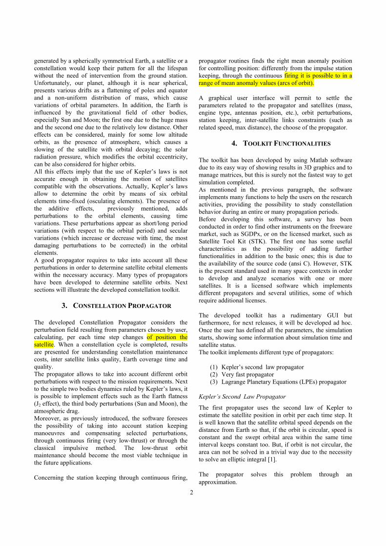
Figure 1: Ellipse area approximation.
Referring to Figure 1, supposing that
0W is the true anomaly at the time t and 1W is the true anomaly at the time t+dt, the spanning angle can be divided as:
1 0W Wdanglen−
= (1)
where n is a positive integer indicating how many slices divide the arc of ellipse. So, dangle expresses the angle step of increment and, beginning from
0W and summing contributions until 1W is reached, each slice, depending on actual true anomaly, is calculated through:
( ) ( )212 satdA R dangleθ θ= (2)
where:
(1) ( ) ( )( )
211 cossat
a eR
eθ
θ
−=
+ is the satellite distance from
the Earth centre (2) a is the semimajor axis (3) e is the eccentricity (4) θ is the true anomaly The simplest area to calculate is the area at the first dt ( 00 =W ,
1 t dtW θ == ), where t dtθ =
represents the true anomaly after just one time step. Once obtained the
t dtθ =, the area
covered by the satellite in the first dt should be calculated; let us assume ( )0,t dt t dtA A θ= == .
For a generic non circular orbit, we assume that 1 0 t dtW W θ =− ≠ ; this value is found with the following
condition satisfied: ( )0 1, t dtA W W A == . On the opposite, if the
orbit is circular it simply implies 1 0 ,t dtW W dtθ =− = ∀ .
Very Fast Propagator
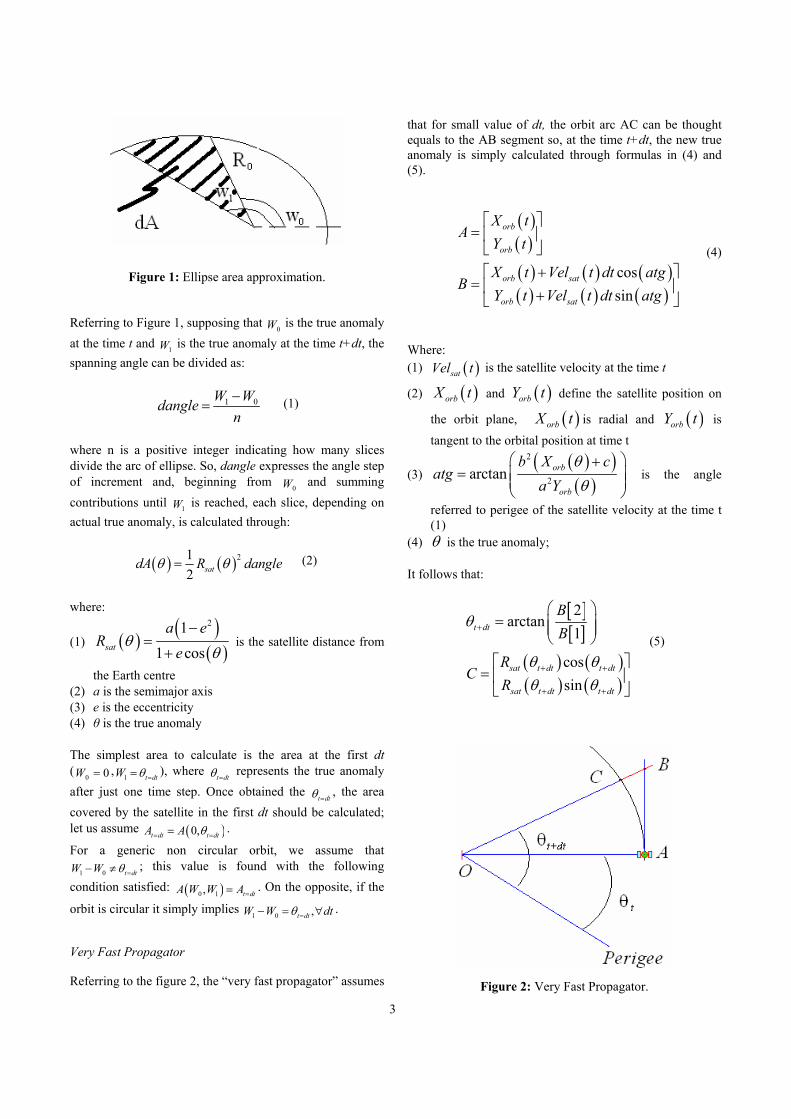
Referring to the figure 2, the “very fast propagator” assumes
that for small value of dt, the orbit arc AC can be thought equals to the AB segment so, at the time t+dt, the new true anomaly is simply calculated through formulas in (4) and (5).
( )( )( ) ( ) ( )( ) ( ) ( )
cossin
orb
orb
orb sat
orb sat
X tA
Y t
X t Vel t dt atgB
Y t Vel t dt atg
=
+ = +
(4)
Where: (1) ( )satVel t is the satellite velocity at the time t
(2) ( )orbX t and ( )orbY t define the satellite position on
the orbit plane, ( )orbX t is radial and ( )orbY t is tangent to the orbital position at time t
(3) ( )( )( )
2
2arctan orb
orb
b X catg
a Yθθ
+=
is the angle
referred to perigee of the satellite velocity at the time t (1)
(4) θ is the true anomaly; It follows that:
[ ][ ]
( ) ( )( ) ( )
2arctan
1
cossin
t dt
sat t dt t dt
sat t dt t dt
BB
RC
R
θ
θ θθ θ
+
+ +
+ +
=
=
(5)
Figure 2: Very Fast Propagator.
4
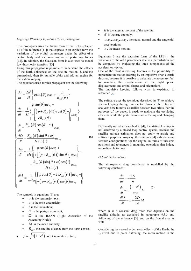
Lagrange Planetary Equations (LPEs)Propagator
This propagator uses the Gauss form of the LPEs (chapter 11 of the reference [11]) that express in an explicit form the variations of the orbital parameters under the effect of a central body and its non-conservative perturbing forces [12]. In addition, the Gaussian form is also used to model low thrust orbit transfers [13]. Using this propagator is possible to understand the effects of the Earth oblateness on the satellite motion: J2 and the atmospheric drag for suitable orbits and add an engine for the station keeping. The equations used for this propagator are the following.
( ) ( )( )
( )( ) ( )( )
( ) ( )
( ) ( )( )( )
( )( ) ( )( )
22 sin
sin1 cos
cos
sinsin
cos1sin
rsat
r
satt
sat
satt
satn
r
sat t
sat
da a pe accdt H R
p accde p Rdt H acc
eR
Rdi accdt H
Rd accdt H i
p accddt eH p R acc
R
θθ
θ
θ θ
θ
θ θ ω
θ θ ω
θωθ θ
θ
= +
+ = + + +
+ +
=
+Ω=
− + = − + +
−( ) ( )
( )( ) ( )
( )( ) ( )2
sin cossin
cos 21sin
t
sat r
sat t
iacc
H i
p eR accdMdt na e p R acc
θ ω
θ θ
θ θ
+
− − = − −
(6)
The symbols in equations (6) are:
• a is the semimajor axis; • e is the orbit eccentricity; • i is the inclination; • ω is the perigee argument; • Ω is the RAAN (Right Ascension of the
Ascending Node); • M is the mean anomaly; • satR , the satellite distance from the Earth centre;
• ( )21p a e= − , orbit semilatus rectum;
• H is the angular moment of the satellite; • θ is the true anomaly; • , ,r n tacc acc acc , the radial, normal and the tangential
accelerations; • n , the mean motion; Equations 6 are the gaussian form of the LPEs: the variations of the orbit parameters due to a perturbation can be computed by evaluating the three components of the acceleration vector. One of the most interesting features is the possibility to implement the station keeping by an impulsive or an electric thruster, because it is possible to calculate the necessary fuel to maintain the constellation in the right phase displacements and orbital shapes and orientations. The impulsive keeping follows what is explained in reference [2].
The software uses the technique described in [3] to achieve station keeping through an electric thruster: the reference analyzes how to move a satellite between two orbits. For the purposes of the paper, it needs to maintain the osculating elements while the perturbations are affecting and changing them.
Differently on what described in [4], the station keeping is not achieved by a closed loop control system, because the satellite attitude estimation does not apply to article and software purposes. Anyway, the reference [4] indicate some feasible configurations for the engine, in terms of thrusters positions and tolerances in mounting operations that induce unpredictable torques.
Orbital Perturbations
The atmospheric drag considered is modelled by the following equations:
( )2
2
1
2
da Ddt n
ede Ddt naedM Dn Mdt na
= −
−= −
= +
(7)
where D is a constant drag force that depends on the satellite altitude, as explained in paragraphs 9.3.3 and following of the reference [5], and on the frontal area as well.
Considering the second order zonal effects of the Earth, the J2 effect due to poles flattening, the mean motion in the
5
equations 6 must be corrected by the time rate variations of the mean anomaly M, as reported in references [6] and [7].
The mean motion becomes perturbed mean motion by applying the following correction:
( )22
2 2 2
31 sin3 2n=n 1+2 1
Earth
iRJ
p e
− −
(8)
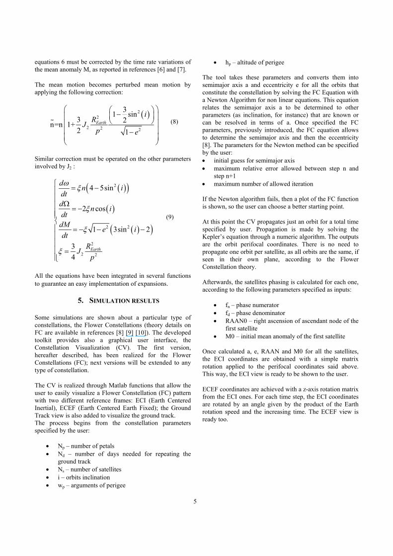
Similar correction must be operated on the other parameters involved by J2 :
( )( )
( )
( )( )
2
2 2
2
2 2
4 5sin
2 cos
1 3sin 2
34
Earth
d n idtd n idt
dM e idt
RJp
ω ξ
ξ
ξ
ξ
= −
Ω = − = − − − =
(9)
All the equations have been integrated in several functions to guarantee an easy implementation of expansions.
5. SIMULATION RESULTS
Some simulations are shown about a particular type of constellations, the Flower Constellations (theory details on FC are available in references [8] [9] [10]). The developed toolkit provides also a graphical user interface, the Constellation Visualization (CV). The first version, hereafter described, has been realized for the Flower Constellations (FC); next versions will be extended to any type of constellation.
The CV is realized through Matlab functions that allow the user to easily visualize a Flower Constellation (FC) pattern with two different reference frames: ECI (Earth Centered Inertial), ECEF (Earth Centered Earth Fixed); the Ground Track view is also added to visualize the ground track. The process begins from the constellation parameters specified by the user:
• Np – number of petals • Nd – number of days needed for repeating the
ground track • Ns – number of satellites • i – orbits inclination • wp – arguments of perigee
• hp – altitude of perigee The tool takes these parameters and converts them into semimajor axis a and eccentricity e for all the orbits that constitute the constellation by solving the FC Equation with a Newton Algorithm for non linear equations. This equation relates the semimajor axis a to be determined to other parameters (as inclination, for instance) that are known or can be resolved in terms of a. Once specified the FC parameters, previously introduced, the FC equation allows to determine the semimajor axis and then the eccentricity [8]. The parameters for the Newton method can be specified by the user: • initial guess for semimajor axis • maximum relative error allowed between step n and
step n+1 • maximum number of allowed iteration If the Newton algorithm fails, then a plot of the FC function is shown, so the user can choose a better starting point.
At this point the CV propagates just an orbit for a total time specified by user. Propagation is made by solving the Kepler’s equation through a numeric algorithm. The outputs are the orbit perifocal coordinates. There is no need to propagate one orbit per satellite, as all orbits are the same, if seen in their own plane, according to the Flower Constellation theory.
Afterwards, the satellites phasing is calculated for each one, according to the following parameters specified as inputs:
• fn – phase numerator • fd – phase denominator • RAAN0 – right ascension of ascendant node of the
first satellite • M0 – initial mean anomaly of the first satellite
Once calculated a, e, RAAN and M0 for all the satellites, the ECI coordinates are obtained with a simple matrix rotation applied to the perifocal coordinates said above. This way, the ECI view is ready to be shown to the user.
ECEF coordinates are achieved with a z-axis rotation matrix from the ECI ones. For each time step, the ECI coordinates are rotated by an angle given by the product of the Earth rotation speed and the increasing time. The ECEF view is ready too.
6
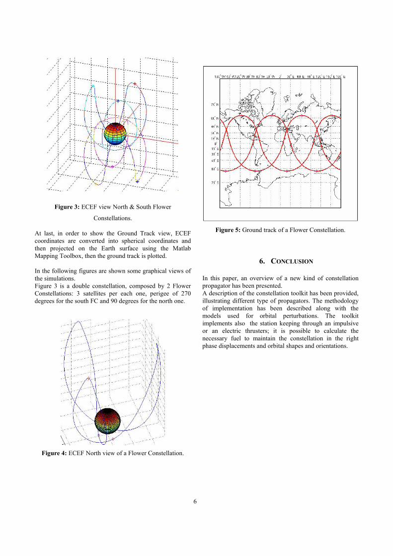
Figure 3: ECEF view North & South Flower
Constellations.
At last, in order to show the Ground Track view, ECEF coordinates are converted into spherical coordinates and then projected on the Earth surface using the Matlab Mapping Toolbox, then the ground track is plotted. In the following figures are shown some graphical views of the simulations. Figure 3 is a double constellation, composed by 2 Flower Constellations: 3 satellites per each one, perigee of 270 degrees for the south FC and 90 degrees for the north one.
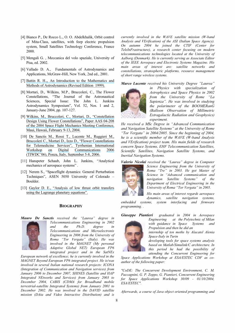
Figure 4: ECEF North view of a Flower Constellation.
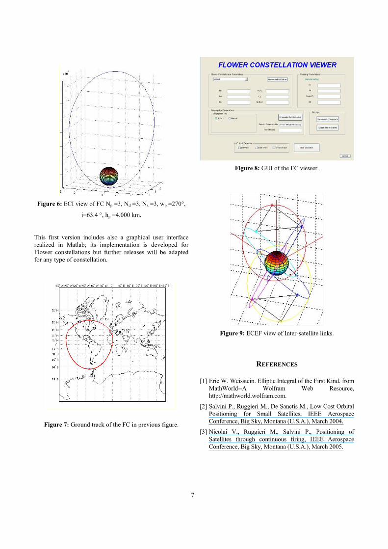
Figure 5: Ground track of a Flower Constellation.
6. CONCLUSION
In this paper, an overview of a new kind of constellation propagator has been presented. A description of the constellation toolkit has been provided, illustrating different type of propagators. The methodology of implementation has been described along with the models used for orbital perturbations. The toolkit implements also the station keeping through an impulsive or an electric thrusters; it is possible to calculate the necessary fuel to maintain the constellation in the right phase displacements and orbital shapes and orientations.
7
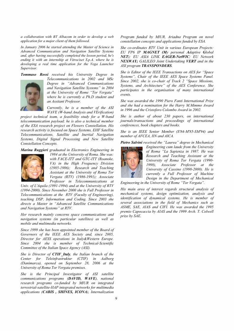
Figure 6: ECI view of FC Np =3, Nd =3, Ns =3, wp =270°,
i=63.4 °, hp =4.000 km.
This first version includes also a graphical user interface realized in Matlab; its implementation is developed for Flower constellations but further releases will be adapted for any type of constellation.
Figure 7: Ground track of the FC in previous figure.
Figure 8: GUI of the FC viewer.
Figure 9: ECEF view of Inter-satellite links.
REFERENCES
[1] Eric W. Weisstein. Elliptic Integral of the First Kind. from MathWorld--A Wolfram Web Resource, http://mathworld.wolfram.com.
[2] Salvini P., Ruggieri M., De Sanctis M., Low Cost Orbital Positioning for Small Satellites, IEEE Aerospace Conference, Big Sky, Montana (U.S.A.), March 2004.
[3] Nicolai V., Ruggieri M., Salvini P., Positioning of Satellites through continuous firing, IEEE Aerospace Conference, Big Sky, Montana (U.S.A.), March 2005.
8
[4] Bianco P., De Rocco L., O. O. Abdelkhalik, Orbit control of Mita-Class, satellites, with feep electric propulsion system, Small Satellites Technology Conference, France 2000.
[5] Mengali G. , Meccanica del volo spaziale, University of Pisa, ed. 2002.
[6] Vallado D. A., Fundamentals of Astrodynamics and Applications, McGraw-Hill, New York, 2nd ed., 2001.
[7] Battin R. H.,, An Introduction to the Mathematics and Methods of Astrodynamics (Revised Edition 1999).
[8] Mortari, D., Wilkins, M.P., Bruccoleri, C., The Flower Constellations, “The Journal of the Astronautical Sciences, Special Issue: The John L. Junkins Astrodynamics Symposium”, Vol. 52, Nos. 1 and 2, January-June 2004, pp. 107-127.
[9] Wilkins, M., Bruccoleri, C., Mortari, D., “Constellation Design Using Flower Constellations”, Paper AAS 04-208 of the 2004 Space Flight Mechanics Meeting Conference, Maui, Hawaii, February 9-13, 2004.
[10] De Sanctis M., Rossi T., Lucente M., Ruggieri M., Bruccoleri C., Mortari D., Izzo D., “Flower Constellations for Telemedicine Services”, Tyrrhenian International Workshop on Digital Communications 2006 (TIWDC’06), Ponza, Italy, September 5-8, 2006.
[11] Hanspeter Schaub, John L. Junkins, “Analytical mechanics of aerospace systems” .
[12] Nerem S., “Spaceflight dynamics: General Perturbation Techniques”, ASEN 5050 University of Colorado – Boulder.
[13] Gaylor D. E., “Analysis of low thrust orbit transfers using the Lagrange planetary equations”.
BIOGRAPHY
Mauro De Sanctis received the “Laurea” degree in Telecommunications Engineering in 2002 and the Ph.D. degree in Telecommunications and Microelectronis Engineering in 2006 from the University of Roma “Tor Vergata” (Italy). He was involved in the MAGNET (My personal Adaptive Global NET) European FP6 integrated project and in the SatNEx
European network of excellence; he is currently involved in the MAGNET Beyond European FP6 integrated project. He is/was involved in several Italian national research projects: ICONA (Integration of Communication and Navigation services) from January 2006 to December 2007, SHINES (Satellite and HAP Integrated NEtworks and Services) from January 2003 to December 2004, CABIS (CDMA for Broadband mobile terrestrial-satellite Integrated Systems) from January 2001 to December 2002. He was involved in the DAVID satellite mission (DAta and Video Interactive Distribution) and is
currently involved in the WAVE satellite mission (W-band Analysis and VErification) of the ASI (Italian Space Agency). On autumn 2004 he joined the CTIF (Center for TeleInFrastructure), a research center focusing on modern telecommunications technologies located at the University of Aalborg (Denmark). He is currently serving as Associate Editor of the IEEE Aerospace and Electronic Systems Magazine. His main areas of interest are: satellite networks and constellations, stratospheric platforms, resource management of short range wireless systems.
Marco Lucente received his University Degree ”Laurea” in Physics with specialization of Astrophysics and Space Physics in 2002 from the University of Rome “La Sapienza”. He was involved in studying the polarimeter of the BOOMERanG (Balloon Observation of Millimetric Extragalactic Radiation and Geophysics) experiment.
He received a MSc Degree in “Advanced Communication and Navigation Satellite Systems” at the University of Rome “Tor Vergata” in 2004/2005. Since the beginning of 2004, he is a scientific member of the WAVE (W-band Analysis and VErification) project team. His main fields of research concern Space Systems, EHF Telecommunication Satellites, Scientific Satellites, Navigation Satellite Systems, and Inertial Navigation Systems.
Valerio Nicolai received the “Laurea” degree in Computer Science Engineering from the University of Roma “Tre” in 2003. He got Master of Science in “Advanced communication and navigation Satellite Systems” of the Department of Electrical Engineering in the University of Roma “Tor Vergata” in 2005.
His main areas of interest regards aerospace dynamics, satellite navigation systems,
embedded systems, system interfacing and firmware programming. . Giuseppe Piantieri graduated in 2004 in Aerospace
Engineering at the Polytechnic of Milan with guidance in Space Systems and Propulsion and then he did an internship of ten moths by Alacatel Alenia Space-Italy in Turin developing tools for space systems analysis based on Matlab/Simulink/C architecture. In this period he had the possibility of attending the Concurrent Engineering for
Space Applications Workshop at ESA/ESTEC CDF as co-author of the following paper: "CoDE: The Concurrent Development Environment, C. M. Paccagnini, G. P. Zoppo, G. Piantieri, Concurrent Engineering for Space Applications Workshop 30/09 - 01/10/2004, ESA/ESTEC". Afterwards, a course of Java object oriented programming and
9
a collaboration with BT Albacom in order to develop a web application for a major client of them followed.
In January 2006 he started attending the Master of Science in Advanced Communication and Navigation Satellite Systems and, after having successfully completed the lesson period, he's ending it with an internship at Vitrociset S.p.A. where he is developing a real time application for the Vega Launcher Supervisor.
Tommaso Rossi received his University Degree in Telecommunications in 2002 and MSc Degree in “Advanced Communications and Navigation Satellite Systems” in 2004 at the University of Rome “Tor Vergata” where he is currently a Ph.D student and an Assitant Professor.
Currently, he is a member of the ASI WAVE (W-band Analysis and VErification)
project technical team, a feasibility study for a W-band telecommunication payload; he is also a technical member of the ESA research project on Flowers Constellation. His research activity is focused on Space Systems, EHF Satellite Telecommunications, Satellite and Inertial Navigation Systems, Digital Signal Processing and New Satellite Constellation Concepts.
Marina Ruggieri graduated in Electronics Engineering in 1984 at the University of Roma. She was: with FACE-ITT and GTC-ITT (Roanoke, VA) in the High Frequency Division (1985-1986); Research and Teaching Assistant at the University of Roma Tor Vergata (RTV) (1986-1991); Associate Professor in Telecommunications at
Univ. of L'Aquila (1991-1994) and at the University of RTV (1994-2000). Since November 2000 she is Full Professor in Telecommunications at the RTV (Faculty of Engineering), teaching DSP, Information and Coding. Since 2003 she directs a Master in “Advanced Satellite Communications and Navigation Systems” at RTV.
Her research mainly concerns space communications and navigation systems (in particular satellites) as well as mobile and multimedia networks.
Since 1999 she has been appointed member of the Board of Governors of the IEEE AES Society and, since 2005, Director for AESS operations in Italy&Western Europe. Since 2004 she is member of Technical-Scientific Committee of the Italian Space Agency (ASI).
She is Director of CTIF_Italy, the Italian branch of the Center for Teleinfrastruktur (CTIF) in Aalborg (Danimarca), opened on September 28, 2006 at the University of Roma Tor Vergata premises.
She is the Principal Investigator of ASI satellite communications programs (DAVID, WAVE), national research programs co-funded by MIUR on integrated terrestrial-satellite-HAP integrated networks for multimedia applications (CABIS , SHINES, ICONA), Internalization
Program funded by MIUR, Ariadna Program on novel constellation concepts and applications funded by ESA.
She co-ordinates RTV Unit in various European Projects: EU FP6 IP MAGNET (My personal Adaptive Global NET); EU ASIA LINK EAGER-NetWIC; EU Network NEXWAY; GALILEO Joint Undertaking VERT and in the ASI program TRANSPONDERS.
She is Editor of the IEEE Transactions on AES for “Space Systems”, Chair of the IEEE AES Space Systems Panel. Since 2002, she is co-chair of Track 2 “Space Missions, Systems, and Architecture” of the AES Conference. She participates in the organisation of many international events.
She was awarded the 1990 Piero Fanti International Prize and she had a nomination for the Harry M.Mimmo Award in 1996 and the Cristoforo Colombo Award in 2002.
She is author of about 230 papers, on international journals/transactions and proceedings of international conferences, book chapters and books.
She is an IEEE Senior Member (S'84-M'85-SM'94) and member of AFCEA, IIN and AICA.
Pietro Salvini received the “Laurea” degree in Mechanical Engineering cum laude from the University of Roma “La Sapienza in 1987. He was Research and Teaching Assistant at the University of Roma Tor Vergata (1990-1998), Associate Professor at the University of Cassino (1998-2000). He is currently a Full Professor of Machine Design in the Department of Mechanical
Engineering in the University of Rome “Tor Vergata”.
His main area of interest regards structural analysis of mechanical systems, design optimization, analysis and identification of dynamical systems. He is member of several associations in the field of Mechanics such as ASME, SAE, AIAS and CIFI. He was awarded the 1995 premio Capocaccia by AIAS and the 1999 Arch. T. Colwell prize by SAE.