High-Altitude, Long-Endurance UAVs vs. Satellites - CiteSeerX
Upload
khangminh22Category
view
2download
0
Chapter 5ALTERNATIVE SYSTEMS FOR SPS

ContentsPage
Microwave Transmission . . . . . . . . . . . . . . 65The Reference System.. . . . . . . . . . . . . 65
Laser Transmission.. . . . . . . . . . . . . . . . . 78Laser Generators . . . . . . . . . . . . . . . . . . . 79Laser Transmission . . . . . . . . . . . . . . . . 81Laser-Power Conversion at Earth . . . . . . 82The Laser-Based System . . . . . . . . . . . . . 82
Mirror Reflection . . . . . . . . . . . . . . . . . 86The Mirror System. . . . . . . . . . . . . . . . . . 88
Space Transportation and ConstructionAlternatives . . . . . . . . . . . . . . . . . . . 89
Transportation . . . . . . . . . . . . . , . . . . 89Space Construction. . . . . . . . . . . . . . . . . 91
SPA Costs . . . . . . . . . . . . . . . . . . . . . . . . . . 92Reference System Costs . . . . . . . . . . . . 92
Alternative Systems . . . . . . . . . . . . . . . . 96The Solid-StateSystem . . . . . . . . . . . 96The Laser System . . . . . . . . . . . . . . . . . . 96The Mirror System. . . . . . . . . . . . . . . . . 97
LIST OF TABLES
Table No. Page
6.
7.8.9.
10.11.12.13.
Projections for Laser Energy Convertersin 1981-90 . . . . . . . . . . . . . . . . . . . . . . .500 MWe Space Laser Power System. . .Laser Power Station Specification. . . . .SOLARES Baseline Systerm . . . . . . . .Research— $370 Million . . . . . . . . . .Engineering– $8 Billion . . . . . . . . . . . .Demonstration– $23 Billion . . . . . . .SPS lnvestment– $57.9 Billion . . . . . . .
8385858893939394
LIST OF FIGURES
Figure No. Page
9
10
11
1213
14
1516
17
18
1 9
20.2122.23.2425
26
Solar Power Satellite ReferenceSystem. . . . . . . . . . . . . . . . . . . . . . . . . . 66Satellite Power System EfficiencyChain . . . . . . . . . . . . . . . . . . . . . . . . . . . 67Major Reference System ProgramElements. . . . . . . . . . . . . . . . . . . . . . . . 68The Retrodirective Concept . . . . . . . . . 69Power Density at Rectenna as aFunction of Distance From theBeam Centerline . . . . . . . . . . . . . . . . . . 70Peak Power Density Levels as aFunction of Range From Rectenna . . . . 70SPS Space Transportation Scenario . . . 73The Solid-State Variant of the ReferenceSystem. . . . . . . . . . . . . . . . . . . .lndirect Optically Pumped CO/CO2
Mixing Laser . . . . . . . . . . . . . . . . .The CATALAC Free Electron LaserConcepts. . . . . . . . . . . . . . . . . . . . .Optics and Beam Characteristics ofTwo Types of Laser Power Trans-mission System (LTPS) Concepts. . .The Laser Concept. . . . . . . , . . . . .Components of the Laser Concept .The Mirror Concept (SOLARES) . . .Reference System Costs . . . . . . . . .How Cost Could Be Allowed. . . . . .Elements and Costs, in 1977 Dollars,the Baseline SOLARES System . . . .Sensitivity of the SOLARES MirrorSystem to Variations in SystemParameters . . . . . . . . . . . . . . . . . . .
. . . 78
. . . 80
. . . 81
. . . 82
. . . 84
. . . 84
. . . 87
. . . 9293
for. . . 97
. . . 98

Chapter 5
ALTERNATIVE SYSTEMS FOR SPS
A variety of systems have been proposed forcollecting, transmitting, and converting solarpower from space. Each system has its advan-tages and disadvantages, its benefits and draw-backs. Each alternative system would use oneof three transmission modes — microwave,laser, or optical reflector–to transmit powerto Earth where it is collected and converted toelectricity or some other highly useful form ofenergy. Each system would use numerous sub-systems to collect and convert energy in spaceor on the ground. This chapter wiII character-ize the alternative systems and subsystems anddiscuss their potential for generating powerfrom space. It will also describe four repre-sentative systems that serve as the technicalbasis for discussion of the environmental, insti-
tutional, and public acceptance issues in thechapters that follow.
In order to estimate reliably and fully therange of costs and potential technical uncer-tainties for a given solar power satellite (SPS)option, it would be necessary to subject it tothe same detailed analysis that the referencesystem has undergone during the last 5 years.Unfortunately, this analysis has not been ac-complished for the alternative systems. Hence,detailed comparisons between systems will notbe possible. At this stage it is possible only tocompare the major features of each technol-ogy and note the uncertainties that should beaddressed as conceptual development of thevarious alternatives continues.
MICROWAVE TRANSMISSION
Because the atmosphere is highly transpar-ent to microwaves, they constitute an obviouscandidate for the SPS transmission mode. Inaddition, microwave technology also is well-known and is used today in a number of spaceand terrestrial communications and radar ap-plications. Microwave power transmission wasfirst demonstrated experimentally in 1964, ’and tested in 1974.2 3
The Reference System4 56
The reference system was selected by theDepartment of Energy/National Aeronautics
1). F Degenford, M D. Sirkis, and PV H Steir, “Ttle ReflectingBeam Waveguide, ” I E EE Transact ions 01 Microwave Theory
Technology MIT-72, July 1964, pp 445-453‘Richard M Dickinson, “Evaluation of a Microwave High-
Power Reception-Conversion Array for Wireless Power Transmis-sion, ” Jet Propulsion Laboratory Technical Memorandum No33-741, Sept 1, 1975
~R i chard M Dick InsOn, “Microwave Power TransmittingPhased Array Antenna Research Project Summary Report, ” JetPropulsion Laboratory publication No 78-28, Dec 15, 1978
‘Department of Energy, “Satellite Power System Concept De-velopment and Evaluation Program Reference System Report, ”report No. DOE/E R-0023, October 1978
‘C. C. Kraft, “The Solar Power Satellite Concept, ” NASA pub-lication No JSC-14898, July 1979
and Space Administrationbasis for study. It consists
(DOE/NASA) as aof a large planar
array of photovoltaic celIs located in the geo-synchronous orbit 35,800 km above the Earth’sEquator (fig. 9). The cells convert solar energyinto direct-current (de) electricity that isconducted at high voltage to a phased-arraymicrowave transmitting antenna mounted atone end of the photovoltaic array. Klystronamplifiers convert the dc electricity to high-voltage radio-frequency power that is thenradiated to Earth by slotted waveguides. Areceiving antenna (rectenna) on the groundreconverts the electromagnetic radiation intoelectric current and rectifies it into dc. Afterbeing converted to high-voltage, low alter-nating current (ac), the power can then beeither delivered directly to the conventional acgrid or converted back to dc at high voltageand delivered to a dc transmission network.
The amount of power delivered to the gridby each reference system rectenna has been
bR O Piiand, “SPS Cost Methodology and Sensitivities, ” TheF/na/ Proceedings of the Solar Power Sate l l i te Program Review,
DOE/NASA Conf-800491, July 1980.
65
66 ● Solar Power Satellites
Figure 9.—Solar Power Satellite Reference System
Transmitt
Solar power satellite reference system
Solar cell arr
ty
SOURCE: C. C. Kraft, “The Solar Power Satellite Concept,” NASA publication No. JSC-14898, July 1979
set at 5 gigawatts (GW)—or 5,000 megawatts(MW). The microwave transmission frequencywas chosen to be 2.45 gigahertz (GHz). Max-imum microwave power density at the centerof the rectenna (on Earth) was set at 23milliwatts per square centimeter (mW/cm 2),and the maximum power density at the edge ofthe rectenna was set at 1 mW/cm 2 (one-tenththe current U.S. recommended occupationallimit). The reference design assumes that allmaterials would be obtained from Earth, andthat the system lifetime would be 30 years withno residual salvage value.
The area of the satellite’s photovoltaic arraywould be approximately 55 square kilometers(km 2); the diameter of the transmitting antenna1 km. The total in-orbit mass of the completesystem, including a 25-percent contingencyfactor, would be either 51,000 or 34,000 metrictons (tonnes), depending on whether silicon orgallium arsenide photovoltaic cells would beused.
The system is designed to deliver baseload,i.e., continuous 24-hour power to the electricgrid. However, some variations in deliveredpower would occur. A seasonal fluctuation inoutput due to the variation of the Sun’s dis-tance from Earth would cause variations inboth incident insolation and photovoltaic celltemperature, the latter producing a conse-quent change in efficiency. In addition, aroundthe spring and fall equinoxes the Earth’sshadow would occult the SPS, resulting in ashort period each night for about 6 weeks atlocal midnight (about 75 minutes maximum, atthe equinoxes) where no solar radiation im-pinges on the satellite and therefore no powercould be delivered to the grid (see ch. 9 for adiscussion of this effect).
Subsystem Description
ENERGY COLLECTION AND CONVERSIONTwo photovoltaic concepts were considered
for the DOE/NASA reference system. One uses

Ch. 5—Alternative Systems for SPS . 67
Ga71.77 GW(Solar)
70.81 GWSi
Figure 10.
63.18 GW
62.34 GW
-Satellite Power System Efficiency Chain
57.81 GW 11.58 GW 10.50 GW 9.46 GW
Ga
10.79 GW 10.29 GW 9.79 GW
Si
Ga 9.08 GW8.50 GW 8.50 GW 8.18 GW 6.96 GW 6.72 GW
Si
9.08 GW
6.58 GW 5.79 GW 5.15 GW
overall efficiency = 6.970/. Ga MPTS efficiency = 63.00/.7.06% Si
Abbreviation: “Ga” indicates the gallium-alum aluminum-arsenide option, “Si” the silicon option.
SOURCE: Department of Energy, “Satellite Power System Concept Development and Evaluation Program: Reference System Report,” DOE report No.DOE/ER-0023, October 1978.
single crystal silicon converters that wouldreceive sunlight directly; the other usesgallium-arsenide (GaAs) photovoltaic cells il-luminated directly and by mirrors in a 2:1 con-centration ratio.
Silicon cells, currently used in all solarpowered spacecraft, have the advantages ofan extensive manufacturing base, abundant re-source materials, and lower cost per cell, aswell as an R&D program in DOE aimed at ma-jor cost reduction for terrestrial cells. How-ever, silicon cells in space suffer degradationfrom radiation effects and from high-operatingtemperatures, and hence would probably re-quire periodic annealing of the array surface(possibly by laser or electron beam techniques)or the development of silicon cells less af-fected by ionizing radiation.
Gallium-aluminum arsenide photovoltaiccells have several advantages over silicon
cells: low mass per unit area, resistance to ther-mal and radiation degradation, and higher effi-ciency. They have the disadvantages of rela-tively high cost, the limited production availa-bility of gallium, and a smaller technologybase than for silicon cells. Because of theselatter characteristics, these cells would beused in a 2:1 concentration ratio in the refer-ence system, trading the relatively expensivecells for less expensive Iightweight reflectorsto concentrate sunlight on the cells.
The structure that supports the solar cellswould be an open-truss framework made ofgraphite-fiber reinforced thermoplastic com-posite (fig. 9). Because the solar array must beoriented toward the Sun and the transmittingantenna toward the Earth, a massive rotaryjoint is essential in order to provide the nec-essary mechanical coupling. Sliprings about400 m in diameter would be used in conjunc-

68 ● Solar Power Satellites
Figure 11 .—Major Reference System Program Elements
constructiondepot
Spacefreighter
COTV
GEO
SOURCE: R. O. Piland, Cost Methodology and Sensitivities,” The Final Proceedings of the Solar Power Satellite ProgramReview, DOE/NASA 1980.
tion with the rotary joint in order to transferelectric power from the array to the antenna.
POWER TRANSMISSION AND DELlVERYThe power transmission and delivery system
for the reference system design is common toboth photovoltaic options. It is composed ofthree major elements: the transmitting anten-na, the rectenna, and the substation.
The selection of the microwave transmissionfrequency was based on tradeoffs between at-mospheric attenuation and interactions withthe ionosphere as well as the sizes of theantenna and rectenna. The optimal frequen-cies were found to be between 1.5 and 4 GHz.The reference frequency was selected to be2.45 GHz, which lies in the center of the inter-national Industrial, Scientific, and Medical(ISM) band of 2.4 to 2.5 GHz.
The size of the antenna is determined by thetransmission frequency, the amount of heat itis feasible to dissipate at the antenna, thetheoretical limits of ionospheric heating, andthe maximum power densities chosen atground level, i.e., at the rectenna. 7 For the
‘Raytheon Corp., “Microwave Power Transmission SystemStudies,” report No, ER75-4368, contract No NAS3-I 7835, De-cember 1975.
reference system, these design considerationsresulted in a l-km diameter antenna. It wouldbe constructed of 7,220 subarrays each con-taining from four to thirty-six 70-kW klystronpower amplifiers connected to slotted wave-guides for transmitting power to Earth. KIys-trons were chosen because their technologyand operating characteristics at low powerlevels are well-known. However, they require acooling system (probably heat pipes). Klystronsof 70-kW continuous power rating have notbeen built and tested at this frequency, so theircharacteristics are not known in detail.
Each of the more than 100,000 klystrons inthe antenna must be properly adjusted or“phased” to provide a uniform power beamand to point it. This adjustment is especiallycritical at the very high, gross power level ofthe SPS beam. Were the antenna a totally rigidarray of amplifiers precisely fixed in space, theadjustment could be accomplished once andfor all just after the antenna is fabricated inspace. However, because it would be desirablefor the antenna to be relatively flexible itwould be necessary to use an active system ofphase control, a so-called “adaptive electroniccontrol” in which a pilot beam, installed in thecenter of the rectenna and pointed toward the

Ch. 5—Alternative Systems for SPS ● 69
satellite, establishes a phase reference orstandard clock against which the individualklystrons compare and adjust their phases (fig.12).8
An important safety feature inherent in thissystem is that loss of the pilot beam from therectenna would eliminate all pointing andphase control. Without the pilot beam, theklystron subarrays would immediately losesynchronization with one another and al I focuswould be lost, resulting in the spreading of the
‘William C Brown, “Solar Power Satellites Microwaves Deliv-er the Power, ” Spectrum, June 1979, pp 36-42.
Figure 12.—The Retrodirective Concept
In the retrodirective-array concept, a pilot beam from thecenter of the rectenna establishes a phase front at thetransmitting antenna. Central logic elements in each of theantenna’s 7,220 subarrays compare the pilot beam’s phasefront with an internal reference, or clock phase. The phasedifference is conjugated and used as a reference to controlthe phase of the outgoing signal. This concept enables thetransmitted beam to be centered precisely on the rectennaand to have a high degree of phase uniformity. If this phase-control system fails, the beam would automatically bedefocused, dropping the power density to 0.003 mW/cm2,an intensity acceptable by current standards. This featurehas been referred to as the “fail-safe” aspect of themicrowave transmission system.
SOURCE: William C. Brown, “Solar Power Satellites: Microwaves Deliver thePower,” Spectrum, June 1979, pp. 36-42.
beam to very low power (0.003 mW/cm 2). Thetransmission system would therefore requirecontinual ground-based guidance to keep itoperating as a coherent beam. By incor-porating relatively well-known anti jammingtechniques in the pilot-beam generator, de-liberate or accidental diversion or misuse ofthe SPS beam could be prevented.
The parameters of the microwave beam areof critical importance in assessing the en-vironmental impacts of the SPS. The peakpower density at the transmitting antenna iscalculated to be 21 kW/m2. By the time thebeam reached the upper atmosphere it wouldhave spread considerably and the intensityreduced to 23 mW/cm 2, a power Iimit that wasset because theoretical studies suggested thatat higher power densities, nonlinear instabil-ities could appear in the F layer of the iono-sphere (200 to 300 km) as a result of the inter-actions between the beam and the electricallycharged particles in this region. Recent ex-perimental studies indicate that the limit in thelower ionosphere might be able to be set muchhigher, ’ thereby making it possible to decreasethe size of the antenna and/or rectenna signifi-cantIy.
With these design constraints, a theoreticalbeam power distribution was conceived result-ing in the radiation pattern at the rectennashown in figure 13, on which are noted thepresent U.S. recommendations for public ex-posure (10 mW/cm 2) and the current U.S.S.R.occupational guideline (0.01 mW/cm 2).
The off-center peaks in figure 13 are called“sidelobes;” the level of intensity shown is aconsequence of the 1-km antenna aperture(which is optimized to minimize orbital mass)and the projected cumulative antenna errors.The first sidelobe would have a peak intensityof 0.08 mW/cm 2, less than one-hundredth thecurrent U.S. occupational exposure recom-mendation, about 8 km from the beam center-line; the intensity at the edge of the referencesystem rectenna (5 km from the beam center-line) would be 1 mW/cm 2–one-tenth the U.S.occupational exposure guideline.
‘w Cordon, and L M Duncan, Impacts on the UpperAtmosphere,” Astronautics and Aeronautics, July/August 1 9 8 0

70 ● Solar Power Satellites
10
5
1.0
0.01
0.005
0.001
USA standard
0 5,000 10,000 15,000 20,000
Ground radius, m
SOURCE: Department of Energy, “Satellite Power System Concept Develop-ment and Evaluation Program: Reference System Report,” DOEreport No. DOE/ER-0023, October 1978.
In addition to the relatively strong sidelobes,the finite size of the antenna subarrays andtheir projected misalinements would producemuch weaker “grating lobes, ” which for thereference system would occur at 440-km inter-vals from the rectenna. The integrated intensi-ty of these grating lobes, even for hundreds ofoperational SPSs, would be well below eventhe U.S.S.R. public-exposure guideline, asshown in figure 14.
Figure 14.—Peak Power Density Levels as aFunction of Range From Rectenna
10
10
10
o 2,000 4,000 6,000 8,000
Radius from boresight (km)
I I I I I I 1 I I 1 I Io 1,000 2,000 3,000 4,000 5,000
Radius from boresight (miles)
Grating lobe spikes occur every 245 km for the 18-m sub-arrays used on simulations although only two grating lobesare shown. The SPS 10-m subarrays have grating lobesevery 440 km.
SOURCE: Department of Energy, “Satellite Power System Concept Develop-ment and Evaluation Program: Reference System Report,” DOEreport No. DOE/ER-0023, October 1978.
The rectenna design is quite insensitive bothto the angular incidence of the microwavebeam (within 100, and to variations in phase oramplitude caused by the atmosphere. Hence,rectennas would be interchangeable; the samesatellite could power different rectennas, aslong as they were equipped with the appropri-ate pilot beam needed for phase control of thetransmitting antenna. The reference rectennawould be composed of billions of dipole an-

Ch. 5—Alternative Systems for SPS Ž 71
tennas placed above a transparent wire grid.The microwave energy received by each dipolewould pass through a rectifier circuit thatwould convert it to dc power at high currentand low voltage. Several more conversionswould be necessary to condition the power forthe grid. The received power would first beconverted to ac and then transformed to high-voltage low-current 60-cycle ac power andthen either fed into ac transmission lines fordelivery to the users or reconverted to high-voltage dc for transmission, a relatively newtransmission technology.
Estimates of overall rectenna conversion ef-ficiency run from about 80 to 92 percent, andthe extreme simplicity and repetitive-elementconstruction of the electrical componentswould facilitate mass production at extremelylow unit cost. Reliability of the rectennashould be extremely high, because each com-ponent would be ultrareliable and could oper-ate redundantly. Hence replacement would benecessary only after a large number of individ-ual failures.
None of the substation equipment involvestechnological advances beyond those that areprojected through normal development by theelectric utility industry. The major concernthat has been expressed is the large scale ofthe minimum individual power unit. Currentgrid control systems are quite adequate to han-dle near-instantaneous switching of singlepower units as high as 1,300 MW. Single unitvariations of 5,000 MW could present majorcontrol difficulties to the utilities as they cur-rently operate10 11 (see ch. 9 for a detaileddescription of utilities interface problems).
SPACE CONSTRUCTIONThe mass and physical size of the space seg-
ment needed for an operational 5-GW satellitepower station are larger by several orders ofmagnitude than any space system heretoforelaunched and therefore require careful con-
‘“J. G. Bohn, J. W. Patmore, and H W Faininger, “SatellitePower Systems: Utility Impact Study,” EPRI AP-1 548 TPS 79-752,September 1980.
11 p j, Donalek, and J. L. WhYsong, “Utility Interface Require-ments for a Solar Power System, ” Harza Engineering Co ,DO E/E R-0032, September 1978
sideration of the transportation options. Thebasis for all projected Earth-to-low-orbittransportation concepts is the current U.S.space shuttle, scheduled to become the opera-tional mainstay of the U.S. (and much of theworld’s) space program.
Of the many possible shuttle derivatives andother new transportation prospects, 12 NASAselected four different types of vehicles to sup-ply the four basic transportation functions:
●
●
●
●
The
carrying cargo between Earth and low-Earth orbit (LEO),carrying personnel between Earth andLEO,transferring cargo between LEO and thegeosynchronous orbit (CEO), andtransferring personnel between LEO andCEO.
designs of these four vehicles, called re-spectively, the heavy-lift launch vehicle(HLLV), the personnel launch vehicle (PLV), thecargo orbital transfer vehicle (COTV), and thepersonnel orbital transfer vehicle (POTV), arebased on existing technology, although allwould require considerable development be-fore reaching operational status. 13 14 15 16
Both the HLLV and the PLV would utilizefully reusable flyback boosters similar to thoseoriginally considered by NASA in early shuttledesigns in the late 1960’s. Both boosters wouldemploy methane-oxygen rocket engines for(vertical) takeoff and airbreathing (turbofan)engines for flyback to base for horizontal land-ings. The HLLV orbiter would use oxygen-
“Robert Salkeld, Donald W Patterson, and Jerry Grey (eds ),‘Space Transportation Systems, 1980-2000, ” VOI 2, AlAA Aero-
ipace Assessment Series, A IAA, New York, 1978‘‘G Woodcock, “Solar Power Satellite System Definition
Study, ” Boeing Aerospace Co., Johnson Space Center contractNo NAS9-I 5196, pt 1, report No D180-20689, June 1977; pt 11,report No D180-22876, December 1977, pt I I 1, report NoD180-24071, March 1978
“C Hanley, “Satellite Power System (SPS) Concept Defini-tion, ” Rockwell International Corp., Marshall Space Flight Cen-ter, contract No NAS8-32475, report No SD78-AP-0023, April1 ’378
15 Gordon R Woodcock, “Future Space Transportation Sys-tems Analysis Study, ” Johnson Space Center contract No.NAS9-I 4323, Boeing Aerospace Co. report No DI 80-20242-1(three volumes), Dec. 31,1976
“Donald P, Hearth (Study Director), “A Forecast of SpaceTechnology 1980-2000,” NASA SP-387, January 1976.

72 . Solar Power Satellites
hydrogen rockets essentially identical to thoseof the current space shuttle, and then glideback to base much like the shuttle does. Un-like the shuttle, it would be fully reusable; itwould have no disposable external propellanttank.
The PLV orbiter would be very much like thecurrent space shuttle, but would employ a pas-senger-carrying module in the payload bay.Like the shuttle, it would also use a disposableexternal propellant tank, but a somewhatsmaller one. It couId carry 75 passengers, plusthe normal shuttle crew.
A fleet of COTV, all reusable, would makethe round trip from LEO to CEO, carrying thecargo payloads up to CEO and returningempty to LEO for reuse. They would be pro-pelled by efficient but slow electrostaticengines. Using low-thrust electric propulsionwould require very long trip times, of the orderof 4 to 6 months. The bases for selecting thispropulsion option were essentially minimumcost and ready availability of the argon pro-pellant and other materials. Such long triptimes, although suitable for cargo, are clearlynot acceptable for personnel, so a high-thrustpropulsion approach was chosen for thePOTV. The design utilizes a basic oxygen-hydrogen propulsion stage now undergoingresearch evaluation at NASA as part of its Ad-vanced Space Engine program. It employsessentially the same level of “technology asthat used in the current space shuttIe mainengine. It could carry up to 160 people fromLEO to CEO and back, or 98 tonnes (480 man-months) of consumables from LEO to CEO.
Because it would be impractical to launch afull-sized power satellite by single launch vehi-cle, a strategy for constructing the satellite inEarth orbit would be necessary. The basicspace construction strategy selected for thereference system is to launch all materials,components, and people to staging areas inLEO (fig. 15). The COTVs, because of theirlarge solar arrays, would be assembled in LEOas well. The main construction base would belocated in CEO, although not necessarily atthe eventual geostationary-orbit location ofthe operational SPS. Hence the LEO staging
area would serve as the transfer point for allmaterials and personnel both up to CEO andback down to Earth. Alternative strategieshave been considered, some of which will bediscussed later.
The principal factor that governs the costand effectiveness of in-space construction isgenerally accepted to be the productivity ofthe construction crew and cost, and require-ments for shielding. The replacement of somecrew by automated equipment is therefore amajor consideration in alI construction strate-gies or scenarios, e.g., effort has already beendevoted to automatic beam-building sys-tems. 17 The use of teleoperators and robot ma-nipulators for assembly of large structures hasalso been considered. The current growth oftechnology in these areas is extremely rapid, ’8and incorporation of such techniques wouldalmost certainly benefit all aspects of SPS con-struction. Despite the wide range of construc-tion options, estimated personnel require-ments for them are approximately the same:750 & 200. 19
GROUND-BASED CONSTRUCTION ,
Building the rectenna, although a very largeand relatively unique structure, neverthelesswould involve far fewer uncertainties thanconstructing the space segment. A detailedanalysis 20 of both the basic structure andconstruction aspects concluded that the pri-mary structural material should be galvanizedor weathering steel rather than aluminum(which is more scarce and requires a higherenergy cost to produce).
SYSTEM OPERATIONAn active control system would be needed
both to keep the satellite in the proper orbit
‘Denls j Powell and Lee Brewing, “Automated Fabrication ofLarge Space Structures, ” Astronautics and Aeronautics, October1978, pp 24-29
‘ 8 Antal K Bejczy, “Advanced Teleoperators,” Astronauticsand Aeronautics, May 1979, pp. 20-31
“W H Wales, “SPS Program Review Transportation Perspec-tive, ” I n The Final Proceedings of the Solar Power Satellite Pro-gram /?ev/ew, DOE/NASA Conf-800491, July 1980
‘O’’ Feaslbil ity Study for Various Approaches to the StructuralDesign and Arrangement of the Ground Rectenna for the Pro-posed Satellite, ” NASA contract No. NAS-I 5280, Bovay Engi-neers, In{ , M a y 1 9 7 7

Ch. 5—Alternative Systems for SPS ● 73
Figure 15.—SPS Space Transportation Scenario
SOURCE: W. H. Wales, “SPS Program Review Transportation Perspective,” in The Final Proceedings of the Solar Power Satellite Proqram Review, DOE/NASAConf-800491, July 1980. -
(stationed above the rectenna) and to maintainthe solar array’s orientation to the Sun. Themass of the necessary control system is esti-mated at 200 tonnes; its average electric powerconsumption would be 34 MW.
Because of its low coefficient of thermal ex-pansion and relative stiffness, a graphite com-posite structural material was selected for thereference system in preference to the alumi-num alloys so widely used in aerospace struc-tures. Although a complex engineering prob-lem and, furthermore, one not readily subjectto testing at an adequate scale prior to deploy-ment in space, it does not appear likely thatdynamic stability would cause any major unex-pected problems in either performance or
83-316 0 - 81 - 6
costs, partly because of the predictability ofthe space environment as compared, for exam-ple, with the uncertain environment in whichaircraft structures must be designed to oper-ate, and partly because of the extensive bodyof applicable design, testing, and operationalexperience with high-performance aerospacestructures. However, questions of dynamic in-stability resulting from Iow-probability occur-rences such as major meteor strikes or aggres-sive military action would have to be eval-uated.
Orientation of the transmitting antenna rela-tive to that of the solar array would be main-tained via the large rotary joint. Physical aim-ing of the antenna itself would be accom-

74 ● Solar Power Satellites
plished by gyroscopes, which would feed con-trol signals to the mechanical-joint turntableso that it could follow the antenna pointing re-quirements. However, mechanical pointing ofthe antenna would not have to be performedwith high accuracy, since the electronic phas-ing and pointing of the antenna subarrayswould be insensitive to angular deflections ofthe antenna of upto100.
In addition to the equipment for satellitestation keeping and attitude control, it wouldbe necessary to provide routine maintenanceof both the space and ground segments. Poten-tial maintenance problems in the space seg-ment, in addition to the expected routine re-placement of components, include the effectsof solar wind, cosmic rays, micrometeoroids,and impacts by station-generated debris. Asidefrom the solar wind and cosmic radiation ef-fects on solar cells, which would require activeannealing of the silicon cells, none of these ef-fects would appear to introduce significantmaintenance problems or costs, based on ex-tensive past and current experience with oper-ational satellites powered by photovoltaiccelIs.
Repair and replacement of the solar blan-kets and more than 100,000 70-kW klystrons inthe transmitting antenna are estimated to re-quire a crew of from 5 to 20 people at thegeostationary orbit construction base,21 alongwith the necessary transportation, support,and resupply (e. g., station-keeping propellant)services.
Maintenance requirements of the rectennaand substation are also primarily associatedwith repair and replacement of their biIIions ofcomponents. Although a certain degree of re-dundancy is built into the system, a mainte-nance crew would still be required to replacestorm-damaged rectenna sections and routinefailures of both rectenna and substation equip-ment.
Technical Uncertainties ofthe Reference System
Although most observers accept the basicscientific feasibility of the SPS system con-
2’ DOE, op cit
cept, there are many technical uncertaintiesassociated with the reference system. This sec-tion identifies specific issues or problems inthe reference system that would be of impor-tance in formulating decisions concerning theresearch, evaluation, development, demon-stration, and deployment of satellite powerstat ions.
●
●
●
●
Performance. A major issue in the referencesystem design is the tremendous scale of thesatellite. The level of 5 GW (net outputpower) is based on scaling assumptions thatcould be subject to considerable change(e.g., the transmission frequency, the an-tenna and rectenna power densities); multi-ple rectennas served by a single satellite alsoconstitute a potential variation.
The overall efficiency of the entire systemwould be subject to considerable variationeither up or down, and would be a key factorin all cost and technology tradeoffs. Al-though all system elements would involveknown technology, there is considerable un-certainty about how their efficiencies mightadd up when assembled together.
Powerplant lifetime, assumed to be 30 yearsfor the reference system, could actually begreater or less depending on a number ofeconomically interrelated factors (e. g., easeof replacement of damaged components,sudden technological advances in compo-nent efficiencies, etc.) This would affect alleconomic projections, even allowing forhigh-discount rates.
The total mass in orbit, one of the criticalparameters in assessing costs and launch-related environmental impacts, depends ona number of factors stilI subject to consider-able variation. The power CoIlection/conver-sion system is an obvious factor; the refer-ence system’s two photovoltaic options areindicative of the significance of that trade-off. The antenna mass is also important.Prospects for revising the reference-system’s100:1 ratio of rectenna-to-antenna areacould have major impact on the overall sys-tem cost and performance. The 25-percentcontingency factor is another major factorsubject to revision if R&D mature.

Ch. 5—Alternative Systems for SPS ● 75
SPS would require an extensive program ofresearch and testing of the numerous satelliteand terrestrial components of the systembefore planning for a demonstration satellitecould be completed. In addition, substantialimprovements in components and overall tech-nology would have to occur before the SPScould meet the performance specifications ofthe reference system. However, the currentreference system does not constitute a pre-ferred system. It is, perhaps, technically feasi-ble but certainly not an optimum design. It waschosen by NASA/DOE as a model and a refer-ence to be used in the assessment process. Assuch it has the inherent I imitation that as newinformation becomes available the design be-comes progressively obsolete.
The following items summarize the majortechnical uncertainties for the reference sys-tem and suggest possible ways to alleviatethem.
. Photovoltaic cells. The reference systemspecifies a silicon solar cell efficiency of17-percent and a mass of 2 grams per peakwatt (g/Wp). Current space-rated singlecrystal silicon cells operate at 12- to 16-percent efficiency. However, they areabout nine times as massive (18 g/Wp) ascalled for in the reference system andthey cost about $70/Wp (1980). The refer-ence system assumes a cell cost of about$0.17/Wp. Although the issue of costs willbe addressed in more detail in a separatesection, it is clear that meeting all threegoals for the silicon cell blanket wouldpresent manufacturers of current celltechnology with an extremely difficulttask. Normal advances in cell productiontechniques would readily result in thenecessary efficiency increase. However,the burden of achieving a nine timesreduction in weight along with a reduc-tion in costs of a factor of 400 makes ithighly unlikely that an SPS could be builtusing single crystal silicon cells.
If efficiency-mass-cost goals were met,there would still be the problem of celllifetime in space and the related problemof the feasibiIity of annealing the surface.
Silicon cells are subject to serious degra-dation by high energy electrons and pro-tons in the solar wind released by solarflares. One study” estimates that the ac-cumulated particle damage would de-grade the output from the cells by 30-percent during the 30-year nominal life ofthe satellite. The resulting damage couldbe repaired periodically by annealing thecells by either a laser or an electron beam.The beam would sweep across the surfaceof the cells and heat them briefly to sev-eral hundred degrees centigrade. Very lit-tle is known about either process in thelaboratory and nothing at ail about howthey would work in space or how muchenergy they would use to anneal the sur-face of the photovoltaic cells. However,experiments have shown that annealingby electron beam is much more efficientthan laser annealing.23 Because no long-term studies have been done, the suita-bility of silicon cells for extended dura-tion space applications is in question;however, they have demonstrated ex-cellent performance over a period ofabout 10 years in operating spacecraft.
GaAs cells appear to be a more realisticcandidate for a reference-type satellite,though they have received much less at-tention than the silicon cells. GaAs cellsreach higher efficiencies and can operateat higher ambient temperatures than sili-con cells. Laboratory models of GaAscells have reached efficiencies as high as18 percent. 24 Because of their currentlyhigher unit cost, the GaAs array wouldprobably require refIectors to concentratethe Sun’s rays on the cells and therebyreduce the required cell area. AluminizedKapton has been suggested as a reflectivematerial because of its low thermal coeffi-cient of expansion and low mass density.
2*C R Woodcock, “SPS Silicon Reference System,” The Fina/Proceedings of the Solar Power Sate//ite Program Review,DOE/NASA Conf-800491, July 1980,
“B E. Anspaugh, J. A Scott-Monck, R. G. Downing, D W.Moffett, and T. F Miyahira, “Effects of Electrons & Protons onUltra Thin Silicon Solar Cells, ” J PL contract No, NAS7-1OO.
“lbld

76 . Solar Power Satellites
●
●
●
Here, again, whether Kapton and GaAscells can maintain their integrity over the30-year design lifetime of the satellite isunknown. Considerably more study wouldbe needed to determine the feasibility ofthis option.Space charge and plasma effects. Becauseof the high voltages associated with oper-ation of the klystrons, electrical chargebuildup in the satellite components couldcause arcing and subsequent failure ofcertain components.Rotary joint/slip rings. Although the basictechnology of building a rotary joint andan associated slip ring (for electrical con-tinuity) is well-known, considerable uncer-tainty surrounds their construction andoperation on the scale of the referencesatellite in a space environment. Becauseit would operate in a gravity-free environ-ment, the design demands would be dif-ferent than they are for terrestrial designs.Klystrons. Current klystrons last about 10years, but these are tubes especially se-lected for their long life characteristicsand they operate at much lower powerlevels than the 70 kW required of refer-ence system klystrons. High-power klys-trons do exist, but they operate in a pulsedmode, not continuously as the referencesystem klystrons would have to. The an-tenna’s phased array control systemwould need considerable developmentand testing. Although pilot beams havebeen used in other applications, and thetechnology is therefore known, it isunclear whether the power beam wouldleave the ionosphere sufficiently unaf-fected to allow for undisturbed passage ofthe pilot control beam.
Although harmonics and other noiseproduced by the klystron or alternativetransmitting device would seem unlikelyto affect the natural environment adverse-ly, they could cause radio frequency inter-ference for communications systems (seethe discussion of ch. 8). This problemmight be severe and wouId need extensivestudy, but most experiments could be car-ried out in ground-based testing. Alter-
●
●
natives to the klystron may provide betternoise and harmonic control (see sectionon alternatives below).Space transportation. The problems inher-ent in developing the capability to trans-port SPS components to LEO and CEO arethose of extending a mature technology,i.e., there is sufficient understanding ofthe problems to be faced that there is lit-tle doubt that the appropriate vehiclecould be developed. The most importantquestion is whether the necessary massiveloads could be transported for sufficientlylow costs, i.e., would reusable vehiclesprove economic? In this area, much canbe learned from experience with the shut-tle
I n addition to economic concerns, thereare additional technical questions relatingto environmental effects that would re-quire study. For instance, can the launchvehicles fly trajectories that would keepthe effects of ionospheric contaminationto a minimum? Would it be possible tosubstitute other technologies for theargon ion engine proposed for the refer-ence system (see ch. 8).Construction, operations, and mainten-ance. There are unresolved questionsabout the productivity of humans and ma-chines in the space environment. Someautomated equipment has been built andtested on Earth, but considerable develop-ment would be needed to choose the bestratio between automated and humantasks.
Alternatives to the ReferenceSystem Subsystems
One of OTA’s goals is to explore the possiblealternatives to the reference system. Some op-tions improve specific components of the ref-erence system. Others would require signifi-cant redesign of the overall system. This isbecause the reference system is composed of anumber of interlocking components, some ofwhich depend heavily on the other elements ofthe system. Thus, a radical change in one com-ponent might require numerous other system
Ch. 5—Alternative Systems for SPS • 77
changes in order to create the most efficientoverall design.
A number of alternative subsystems and sys-tems were considered in the process of elect-ing the reference system design. Advanceshave been made in some components thatwere previously rejected. In addition, consid-eration of some of the above-mentioned tech-nical uncertainties has engendered new de-signs that could alleviate these uncertaintiesor resolve some of the technical problems en-countered in the reference system.
The following summary lists a number ofsubsystem options that could be considered asalternatives to the reference system. A moredetailed discussion of each can be found in ap-pendix A.
Solar thermal power conversion. Either aBrayton- or Rankine-cycle engine offershigher efficiency energy conversion thanphotovoltaics. However, they currentlysuffer from limitations on the means forheat rejection.
Thermionic, magnetohydrodynamicor wave energy exchanger technologiesmight eventually find use in combinationwith the Rankine or Brayton cycle.Photovoltaic alternatives. Materials otherthan silicon or gallium arsenide may even-tually prove more viable for use in theSPS. Currently none of the other obviousoptions meet the projected standards forefficiency, low mass, materials availabili-ty, etc., that would be needed for satelliteuse. Different sorts of concentrator sys-tems are also of interest, as is the possi-bility of using single cells or a combina-tion of cells that respond to a wide por-tion of the solar spectrum. A possible ap-proach would be to use a combination ofal I these variations.Alternative microwave power converters.Several devices other than the klystronhave been considered for converting elec-tricity to microwaves and transmittingthem to Earth including the magnetron,which offers the principal potential ad-vantage of cost and low noise, and thesolid-state amplifier whose reliabilitycould be very high and mass low.
● Photoklystron. This device, which is stilI inthe very early stages of study, both con-verts the sunlight directly to microwavepower, and transmits it. If successful, itcould replace both photovoltaic cell andamplifier.
● Offshore rectennas. For highly populatedEuropean and U.S. coastal areas, recten-nas mounted in the shallow offshore sea-beds offer some advantages over longtransmission lines from suitable land-based rectennas.
THE SOLID-STATE SYSTEM
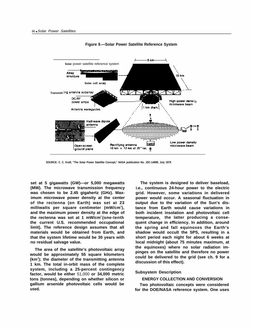
Two system approaches using solid-statedevices have been considered for the SPS. Themost direct of these simply replaces the kyls-trons and slotted waveguides in the referencesystem by solid-state amplifiers and dipoleantennas maintaining essentially the samebasic configuration as that of the referencesystem (fig. 9); the second approach complete-ly revises the satellite configuration by inte-grating the antenna and solar array in theEarth-facing “sandwich” configuration, using amovable Sun-facing mirror to illuminate thesolar array (fig. 16). A number of alternativesandwich configurations have been exploredbut at the moment the configuration of figure16 seems to be the best.25
Another related subsystem option uses themultibandgap photovoltaic cells discussedearlier, possibly in conjunction with selectivefiltering to reduce solar-cell temperatures.When such cells are utilized in the sandwichconfiguration of figure 16, they offer consid-erable potential mass reduction. A recent pre-liminary case study26 compared sandwich-typesystems such as that of figure 16 employingsingle-bandgap GaAs photocelIs similar tothose of the reference system but having high-er concentration ratios (CR) with optimizedmultibandgap photovoitaics. Such a configu-ration would result in an approximate W-per-cent increase in power delivered per kilogram.
“G M Hanley, et al , “Satellite Power Systems (SPS) ConceptDeflnitlon Study, ” First performance Review, Rockwell interna-tional report NO SSD79-01 63, NASA MSFC contract NoNAS8- )2475, Oct 10, 1979
~bl bld

78 ● Solar Power Satellites
Figure 16.—The Solid-State Variant of the Reference System
Reflected sunlight
Detail of solar cellblanket panel
Solid-stateamplifierpanel
Sunlight I
Microwave /p o w e r t oE a r t h
/ ’Solar array/microwave antennasandwich panels
SOURCE: G. M. Hanley, et al., “Satellite Power Systems (SPS) Concept Definition Study, “First Performance Review, Rockwell International reportNo. SSD-79-0163, NASA MSFC contract No. NAS-8-32475, Oct. 10, 1979.
LASER TRANSMISSION
Lasers constitute an alternative to micro- ●
wave transmitters for the transmission ofpower over long distance. 27 They offer the fun-damental advantage that at infrared wave-lengths, energy can be transmitted and re-ceived by apertures over a hundred timessmaller in diameter than the microwave beam.This obviously would reduce the size and massof the space transmitter and the land-area re-quirement of the ground receiver. But perhapseven more important, the great reduction inaperture area would permit consideration offundamentally different systems. For example:
W H p o w e r
Satellites: The Laser Option,” Ast ronaut ics a n d A e r o n a u t i c s ,
March 1979, pp. 59,67,
The use of low Sun-synchronous ratherthan high geostationary orbits for the mas-sive space power conversion subsystemmight be possible. (A Sun-synchronous or-bit is a near-polar low orbit around theEarth that keeps the satellite in fullsunlight all the time while the Earth ro-tates beneath it.) In this suggested system,the laser would beam its power up to low-mass laser mirror relays in geostationaryorbit for reflection down to the Earthreceiver, an arrangement that might con-siderably reduce the cost of transporta-tion, since the bulk of the system mass isin LEO rather than in GEO. However, sys-tem complexity would be increased dueto the need for relay satellites.

Ch. 5—Alternative Systems for SPS ● 7 9
●
●
Because the mass of the laser transmitterswould not dominate the satellite, as doesthe reference-system microwave transmit-ter, laser satellites would not benefit near-ly so much by large scale as the referencesystem satellites. The resulting smallersystems would improve the flexibility ofterrestrial power demand matching, pro-vide high degrees of redundancy, permit asmaller and therefore less costly systemdemonstration project, and might evenpreclude the need for ultimate develop-ment of an HLLV.The small size of the receiving stationwould make it possible to employ multi-ple locations close to the points of use,thereby simplifying the entire ground dis-tribution and transmission system. Itwould also open up the possibility ofrepowering existing powerplants, regard-less of their size, simply by replacing theirsteam generating units with laser-heatedboilers and/or superheaters.
The most important technical disadvantagesof laser-power transmission are the very lowefficiencies of present laser-generation andpower-conversion methods, low efficiency oflaser transmission through clouds and mois-ture, and the relatively undeveloped status oflaser power-system technology in general.
The laser system would consist of threedistinct elements: the laser-generation sub-system, the laser-to-electric power-conversionsubsystem, and the laser beam itself.
Laser Generators
Although the laser has become a well-knownand widely utilized device in industry, thehigh-power continuous-wave (CW) laser gen-erators needed for SPS are still in theadvanced-technology or, in many cases, theearly research phase.28 However, the technol-ogy is improving dramatically as exemplifiedby the growth of laboratory-demonstrated con-version efficiencies (input power to laser
beam) from about 1 to nearly 50 percent dur-ing the past decade.
Of all the currently operating CW lasers,only the electric discharge laser (EDL)29 seemsa feasible alternative for the SPS. The gas dy-namic laser (CDL) suffers from very low effi-ciency if used in the closed cycles necessaryfor space (i.e., the gas supply must be circu-lated, cooled, and reused). Chemical lasers re-quire a continuous propellant supply thatmakes them also unsuitable for long-term usein space.
High-power density at 50-percent conversionefficiency levels has been achieved for EDLs,but only in the open-cycle mode for short timeperiods. The closed-cycle systems needed forSPS have yet to be tested, even in the labora-tory. In theory, they should achieve high effi-ciencies in that mode as well, but considerableimprovement in the available technologywould be required to reach the necessarygoals.
In addition to using improved designs of cur-rently operating lasers, several advanced con-cepts have been suggested. Of these, the solar-pumped laser and the free electron laser (FEL)seem most promising for the long term.
● Solar-pumped lasers. Figure 17 illustratesthe concept of a solar-pumped laser. Theenergy contained in sunlight directly ex-cites a combination of gases confined be-tween two mirrors, which subsequently“lase” and transmit the captured energy.It suffers the drawback that because onlya part of the solar spectrum is useful in ex-citing any given Iasant gas, its conversionefficiency is likely to be fairly low. How-ever, elimination of the need for a sepa-rate electric power-generating system,and the consequent reduction in mass andcomplexity, could more than compensatefor this drawback. Further, in comparisonwith other laser systems, the solar-pumped laser’s efficiency need be only asgood as the combined power-generating
28j Frank Coney bear, “The Use of Lasers for the Transmissionof Power, ” in Progress in Astronautics, vol. 61, A IAA, N Y ,)ui~ 1978, pp. 279-310
“G W Kelch and W. E. Young, “Closed-Cycle GasdynamicLaser Design Investigation, ” Pratt & Whitney Aircraft, NASALewis Research Center report No CR-135530, Jan 1,1970.

80 • Solar Power Satellites
Figure 17. —Indirect Optically Pumped CO/CO2 Mixing Laser
Ps QSEP
solar n
SOURCE: R. Taussig, P. Cassady, and R. Klosterman, “Solar Driven Lasers for Power Satellite Applications,” in Firra/ Proceedings of SPS Program Review, Department of Energy, p. 267
system and laser generator of other lasersystems (about 7.5-percent for a photo-voltaic-powered carbon monoxide (CO)EDL30).
Although the information exists to deter-mine the applicabiIity of solar-pumped lasersto SPS, adequate studies have not been done.There is as yet little or no realistic basis for themass, efficiency, and cost projections pro-posed by several authors.31 32 33 34
‘“R. E. Beverly, “Satellite Power Systems (SPS) Laser StudiesTechnical Report, Vol. 1, Laser Environmental Impact Study,”Rockwell International SSD-80-0119-I, August 1980
“W. S. Jones, L. L. Morgan, J. B, Forsyth, and J Skratt, “LaserPower Conversion System Analysis: Final Report, Vol. I l,” Lock-heed Missiles and Space Co., report No LMSC-D673466, NASAreport No. CR-1 59523, contract No NAS3-21 137, Mar 15, 1979
32 Claud N Bain, “Potential of Laser for SPS Power Transmis-sion, ” report No R-1 861, PRC Energy Analysls Co , DOE contractNo. EG-77-C-01-4024, September 1978
3JJohn D. G. Rather, “New Candidate Lasers for Power Beam-ing and Discussion of Their Appl icatlons, ” I bid,, pp. 313-332.
34 Daryl J. Monson, “Systems Efficiency and Specific Mass Esti-mates for Direct and Indirect Solar-Pumped Closed-Cycle High-Energy Lasers in Space,” ref 105, pp 333-345
Free-Electron Lasers (FEL)
An FEL is powered by a beam of high-energyelectrons oscillating in a magnetic field in sucha way that they radiate in the forward direc-tion (fig. 18). A number of pulses reinforce thestored light between the mirrors, generating acoherent laser beam. The high-energy densityof the relativistic electron beam is theoreti-cally capable of producing very high-powerdensity lasers, and the emitted frequency istunable simply by changing the electronenergy.
Although efficiencies are theoretically pro-jected to be quite high (around 50 percent forthe combined FEL and storage ring35), it is notknown whether such efficiencies could bereached in practice. In addition, the systemmass per unit power output and the ability to
‘5John W Freeman, William B. Colson, and Sedgwick Simons,“New Methods for the Conversion of Solar Energy to R. F. andLaser Power, ” in Space Manufacturing ///, Jerry Grey andChrlstlne Krop (eds ) (New York AlAA, November 1979).

Ch. 5—Alternative Systems for SPS ● 81
Figure 18.—The CATALAC Free Electron Laser Concepts
SOURCE: R. Taussig, P. Cassady, and R. Klosterman, “Solar Driven Lasers for Power Satellite Applications,” in Final Pro-ceedings of SPS Program Review, Department of Energy. p. 267
scale to the size and power levels of a laserSPS are impossible to predict reliably at thistime. 36
Laser Transmission
As in the case of microwave transmission,the fundamental parameter that governs muchof laser transmission performance is the fre-quency (or wavelength). At ultraviolet or visi-ble wavelengths, absorption losses in the at-mosphere are higher than for infrared wave-lengths. The wavelength also affects the effi-ciency of the laser power absorption and con-version equipment.
At the wavelengths of CO or CO, EDLs, (5 to10 microns), the primary mechanism of beamattenuation is molecular absorption. Scatter-ing by molecuIes or by aerosols in clear air isrelatively unimportant. Attenuation of thebeam by aerosols under hazy or cloudy condi-tions is quite significant and can completelyblock the beam if the clouds are thick enough.Although it is apparently possible to burn ahole through thin clouds,37 the attenuation ofenergy is appreciable, and because clouds areseldom stationary, the laser would continuallyencounter new water droplets to vaporize.
‘s Beverly, op. cit.37E. W. Walbridge, “Laser Satellite Power Systems, ” Argonne
National Laboratory report No AN L/ES-92
Transmission of the laser beam through theatmosphere is also affected by a phenomenoncalled “thermal blooming;” i.e., heating of theatmosphere that causes it to act Iike a lens anddistort the laser beam. Scientists are currentlydivided on the significance of this issue andopinions range from assertions that it is a ma-jor factor38 to suggestions that it couldbe avoided altogether by selecting the trans-mitting wavelengths carefully.39 Considerableclassified research is now being carried out onthis effect in connection with laser-weaponsresearch. Some of this work might be applica-ble to SPS use, though in general the militarylasers are pulsed, not CW systems. The differ-ence could be critical and should be studiedcarefulIy.
With regard to laser optics, it is important todevelop components capable of low-loss, high-power-density transmission and reflection oflaser light.40 It appears that adequate tech-nology for SPS systems has a high probabilityof being available within the next 20 to 30years, due primarily to advances being made incurrent military laser research and technologyprograms.
“Jones, et al , op cit“Beverly, op. cit40 Baln, op cit

82 Ž Solar Power Satellites
Transmission options for SPS lasers areessentially of two types: a narrow, highly con-centrated beam or a wide, dispersed beam (fig.19). Advantages of the narrow beam are thereduced land area needed and the smalI size ofthe ground power-conversion system; prob-lems include potential environmental andsafety impacts of the high-intensity beam, con-cerns over military uses, and the need for so-phisticated high-temperature receivers andpower-conversion equipment. Advantages ofthe dispersed beam are its less severe environ-mental impact, the possible use of low-per-formance optics, and simplicity of low-power-density receiving systems. Disadvantages in-clude relatively high atmospheric dissipation,larger land area required and the large mass ofEarth receptors. It is probably too early tomake an informed selection between the twooptions, but the narrow-beam approach ap-pears to offer the principal benefit comparedto reference-system microwave transmission.
A final concern is the ability to point andcontrol the beam to make sure it would alwaysremain within the designated receiver area andto shut it off instantly should it stray. Theadaptive-optics approach to beam control(e.g., phased-array) such as would be used forthe microwave beam, appears adequate toprovide the necessary pointing accuracy andto ensure safety, since any loss of phasing con-trol would cause loss in coherence of the sev-
eral lasers making up the beam, and eachbeam by itself would transmit far too littlepower to cause any problems. Adaptive opticssystems are being studied for use in militarydirected energy weapons and look promising.”It should be emphasized that the overall sys-tem constraints might be quite different forthe large CW lasers needed for SPS than forpulsed military examples.
Laser-Power Conversion at Earth
Several approaches are possible for convert-ing high-energy-density laser radiation to use-ful electric power. The technology of laserenergy converters is relatively new, but prog-ress has been rapid. Laboratory models haveachieved conversion efficiencies of 30 to- 40percent and designers project eventual effi-ciencies of 75 percent for some versions. Table6 summarizes the available technology andprojects future potential efficiencies. 42
The Laser-Based System
Lockheed 43 has generated one possible lasersystem (fig. 20) that utilizes power satellites in
4’Claud N Bain, “Power From Space by Laser,” in “High-Pow-ered Lasers In Space, ” Ast ronaut ics a n d Aeronaut ics , vol. 17,March 1979, pp 28-40
“(;eorge Lee , “S ta tus and Summary o f Laser Energy Conver-sion, ‘ In Progress in As t ronaut i cs , VOI 61 Al AA, N Y , July1978 pp 549-565
4’Jones, et al , op clt
Figure 19.—Optics and Beam Characteristics of Two Types ofLaser Power Transmission System (LPTS) Concepts
Optics Optics
m
SOURCE: Claud N. Bain, “Potential of Laser for SPS Power Transmission,” report No. R-l WI,PRC Energy Analysis Co., DOE contract No. EG-77-C-01-4042, September 1978.

Ch. 5—Alternative Systems for SPS ● 8 3
Table 6.—Projections for Laser Energy Converters in 1981-90
Current 1981-90
Photovoltaics. . . . . . . . . . . .
Heat engines . . . . . . . . . . . .
Thermionics . . . . . . . . . . . . .
Photochemical cells . . . . . .
Optical diodes . . . . . . . . . . .
—30% efficiency—megawatt power levels—wavelengths below 1 micron
—Piston engine: Otto or diesel cycles—50% efficiency—1-10 k W—wavelengths near 10.6 microns
—40% ef f ic iency—1-10 kW—wavelengths near 10.6 microns
—Photoassisted dissociation of water—15Y0 efficiency—wavelengths near 0.4 microns
—Evaporated junction arrays—not ready to convert power
—45% efficiency—megawatt power levels—wavelengths below 1 micron
—Turbine—75% efficiency—megawatt power levels—wavelengths near 5 microns
—50% efficiency—megawatt power levels—wavelengths near 5 or 10 microns
—Photoassisted dissociation of water—30% efficiency—wavelengths near 0.6 microns
— Evaporated junction arrays—50% efficiency—megawatt power levels—respond to wavelengths from UV to
over 10 microns
SOURCE: George Lee, “Status and Summary of Laser Energy Conversion, “ in Progress in Astronautics, vol. 61, AlAA, N. Y., July 1978, pp. 549-565.
low Sun-synchronous orbit and relay satellites(laser mirrors) both in LEO and CEO. One geo-stationary relay serves each power satellite.Based on an analysis of five candidate systemsin three power ranges, Lockheed selected aCO, EDL powered by a wave energy exchanger(EE) binary cycle and a similar binary cycle forground power conversion.
The specific 500 MW system selected is dia-gramed in figure 21; hardware details of thepower satellite appear in table 7, and the Over- .
all system characteristics are summarized intable 8.
A major potential advantage of the lasersystem is that it could be demonstrated via asubscale 500-kW pilot program using the spaceshuttle to deliver the power and relay satellitesinto LEO orbits.
Other laser systems are possible. For exam-ple, Rockwell44 has investigated a geosyn-chronous laser SPS powered by photovoltaicceils and using 20 to 24 100-MW CO EDLlasers. The CO laser was chosen because it hasgreater overall efficiency and is lighter than aC 02 laser.
This study will use the LEO-based C02 lasersystem in its subsequent analysis because of
‘*Beverly, op. cit.
the significant difference in space basing (i. e.,LEO rather than CEO) which it presents com-pared to the reference system. Because of thesignificant uncertainties present in the lasersystems concepts and the relative lack of tech-nology base for laser devices, the optimumlaser system would undoubtedly look ratherdifferent from any system so far devised.
A laser system that used photovoltaic arraysto collect and convert the Sun’s energy wouldsuffer from the fundamental difficulty that theoveralI efficiency of the system wouId be quitelow compared to projected reference systemefficiency .45 The major limiting factors are theprojected efficiencies of the laser itself (50 per-cent for an EDL), the atmospheric transmis-sion (84 to 97 percent), and the conversion effi-ciency of the terrestrial receptor (40 to 75 per-cent). When multiplied together with thehigher efficiency of other system components,they result in an overall efficiency of 17 to 36percent after photovoltaic conversion of sun-light to electricity to power the laser. When theefficiency of the solar cells (17 percent) istaken into account, the overalI system efficien-cy falls to only 2.8 to 6 percent compared tothe projected reference system efficiency of 7percent. Although this decrease would con-
45D0E, op. cit.

Ground site
SOURCE: W. S. Jones, L. L. Morgan, J. B. and J. “Laser Power Conversion Analysis: Final Report, Vol. Lockheed Missiles and SpaceCo., report No. NASA report No. CR-159523, contract No. 137, Mar. 15, 1979.
Figure 21 .—Components of the Laser Concept
Synchronous relays
Occulted ,Power
SOURCE: W. S. Jones, L. L. Morgan, J. B. and J. “Laser Power Conversion System Analysis: Final Report, Vol. 11,” Lockheed Missiles and Space Co.,report No. NASA report No. CR-159523, contract No. 137, Mar. 15, 1979

Ch. 5—Alternative Systems for SPS • 85
Table 7.—500 MWe Space Laser Power System
Powergeneration Spacecraft,
EE/binary and structure, Transmitter apertureCollector Solar cavity cycle conditioning Laser radiators, etc. and optical train
Unit efficiency (%) . . . . . 85 86 73.5 93.1 23 98.7System efficiency (%) . .
—
85 73.1 53.7 50.0 11.5 — 11.4Power in (MW). . . . . . . . . 7,913 6,726 5,784 4,251 3,958 910Power out (MW). . . . . . . .
—6,726 5,784 4,251 3,958 910 899
Orbital weight (kg) . . . . . 242,850—
517,750 1,326,330 717,660 1,809,000 128,653 97,811Spacecraft 4,108 Telescope (2)
89,812Structure 94,433 Beam reduction
5,379Radiators 6,032 Phasing array
1,539Stabilization Optical train 1,181
24,080
Space Atmospheric Ground Thermal Binary Electricaltransmission Space relay transmission receiver cavity cycle generation
Unit efficiency (%) . . . . . 95 99 85 96 98 75.5 98System efficiency (%) . . 10.8 10.7 9.1 8.7 8.5 6.5 6.3Power in (MW). , . . . . . . . 899 854 845 718 690 676 510Power out (MW). . . . . . . . 854 845 718 690 676 510 500Orbital weight (kg) . . . . . – 105,438 — — — — —
Transmitter 44,703Receiver 46,729Optical train 945Spacecraft 5,900Radiators 5,762Structure 1,023
Miscellaneous 376
SOURCE: W. S. Jones, L. L., Morgan, J.B. Forsyth, and J. Skratt, “Laser Power Conversion System Analysis: Final Report, Vol. 11,” Lockheed Missiles and Space Co.,report No. LMSC-D673466, NASA report No CR-159523, contract No. NAS3-21 137, Mar 15, 1979.
Table 8.—Laser Power Station Specification
Solar power collected (MW). . . . . . . . . . . . . . . . . 7,913.0Collector diameter(m). . . . . . . . . . . . . . . . . . . . . 2,710.0Electrical power to laser(MW) . . . . . . . . . . . . . . 3,958.0Laser power output (MW) (20 lasersat 45.5 MW each). . . . . . . . . . . . . . . . . . . . . . . . . 910.0
Transmitter, aperture diameter (m). . . . . . . . . . . 31.5Secondary mirror diameter (o). . . . . . . . . . . . . . . 3.0Transfer mirror size (m) . . . . . . . . . . . . . . . . . . . . 3.0 x 4.2Mirror reflectivity (%). . . . . . . . . . . . . . . . . . . . . . 99.85Optics heat rejection (MW) . . . . . . . . . . . . . . . . . 11.8Radiator area (m2). . . . . . . . . . . . . . . . . . . . . . . . . 2,656.7Mirror operating temperature (“C) . . . . . . . . . . . 200.0
stitute a potential problem for the lasersystem, it must be emphasized that many othercomplex factors (e. g., the smaller terrestrialreceivers, or lower mass in GEO), might com-pensate in complex ways for lower efficiency.When added up, the combination might makethe laser system more acceptable overall thanthe microwave systems. ’b
“Abraham Hertzberg and Chan-Veng Lau, “A High-Tempera-
SOURCE: W. S. Jones, L. L., Morgan, J. B. Forsyth, and J. Skratt, “Laser Powerture Ranklne Binary Cycle for Ground and Space Solar AppIica-
Conversion System Analysis: Final Report, Vol. 11,” Lockheed tions, ” m “Radiation Energy Conversion in Space, ” K W,Missiles and Space Co., report No. LMSC-D673466, NASA report No. Billman (cd,), Progress in Astronautics and Aeronautics, vol. 61CR-159523, contract No. NAS3-21137, Mar 15, 1979. (New York, AlAA, July 1978), pp 172-185.

86 . Solar Power Satellites
MIRROR REFLECTION
Instead of placing the solar energy conver-sion system in orbit as in the reference SPS,several authors have suggested using large or-biting mirrors to reflect sunlight on a 24-hourbasis to ground-based solar-conversion sys-tems. 4 7 4 8 4 9 5 0
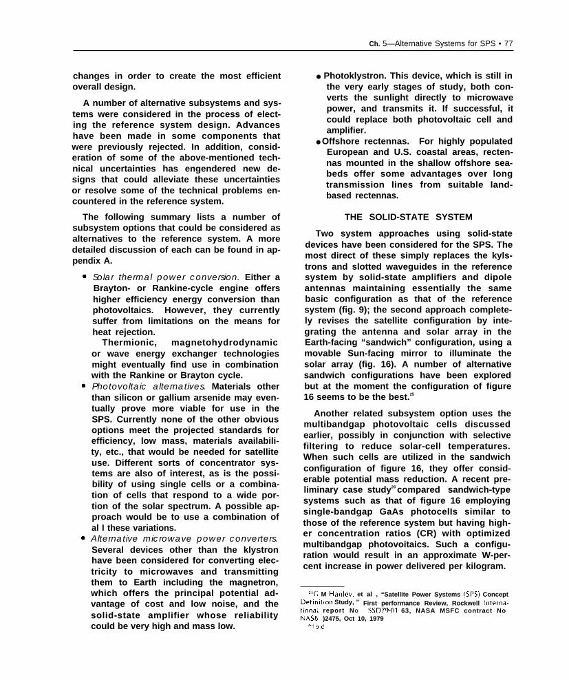
Typically, this option would use plane mir-rors (fig. 22) in various nonintersecting low-altitude Earth orbits, each of which directssunlight to the collectors of several ground-based solar-electric powerplants as it passesover them (the so-called “SOL ARE S“ concept).
Each mirror would be composed of a thinfilm reflecting material stretched across a sup-porting structure made up of graphite-rein-forced thermoplastic. As they pass withinrange of the terrestrial receiving station, themirrors would acquire the Sun and the groundstation nearly simultaneously. They wouldmaintain pointing accuracy by means of built-in reaction wheels.
Two typical “limiting cases” have been iden-tified from among several alternatives.51 onewouId use a 1,196-km circular equatorial orbit(O 0 latitude) serving 16 equatorial ground sta-tions each generating about 13 CW (baseload,with minimum storage) and another 6,384-km40 ‘-inclination circular orbit serving four 375GW ground stations at 300 latitude. Additionalground stations in each case (to accommodatedemand growth) could be achieved simply by
47 Hermann Oberth, “Wege zur Raumschiffahrt, ” Oldenburg-Verlag, Berlin, 1929; also see “Ways to Spaceflight, ” NASA tech-nical translation TT F-662
48 Krafft A Ehricke (for example), “Cost Reductions in EnergySupply Through Space Operations, ” paper IAF-A76-24, 27th lrr-ternationa/ Astrorraut;ca/ Congress, Anaheim, Calif , Oct. 10-16,1976.
“K, W. Billman, W, P Gilbreath, and S W Bowen, “introduc-tory Assessment of Orbiting Reflectors for Terrestrial Power Gen-eration,” NASA TMX-73,230, April 1977
‘“K, W. Billman, W. P. Cilbreath, and S W Bowen, “OrbitingMirrors for Terrestrial Energy Supply, ” in “Radiation Energy Con-version in Space,” K, W, Billman (ed ), Progress in Astronautics
and Aeronautics Series, VOI 61 (New York Al AA, July 1978), pp61-80
“K. W. Billman, W. P. Gil breath, and S W. Bowen, “SolarEnergy Economics Revisited: The Promise and Challenge of Or-biting Reflector for World Energy Supply,” DOE SPS ProgramReview, June 8,1979.
increasing the orbit altitude and mirror size,which increases the size of the illuminatedground circle and thereby permits the use oflarger ground stations.52 The orbiting mirrorsthemselves could probably be quite large (upto 50 km’ each) with very low mass density53
and still maintain their required optical sur-face flatness in the presence of disturbingforces.
A mirror system would offer the followingpotential advantages:
●
●
●
●
●
●
●
●
The space segment would be simple andof low mass. It would consist only ofplanar reflective thin-film mirrors.It would minimize the need for large-scalespace operations, since recent designsallow terrestrial fabrication and packag-ing with automatic deployment i n space.The system would be modular and highlyredundant, i.e., there would be many iden-tical mirrors capable of mass production.The mirrors would operate at low-orbit al-titudes, thus not requiring the CEO trans-portation system of some other alterna-tives.It would eliminate the need for develop-ing microwave- or laser-transmitting tech-nology.The mirrors would reflect ordinary sun-light, thus eliminating many of the poten-tial damaging environmental effects dueto laser or microwave transmission.It could be used for a variety of terrestrialuses where enhanced 24-hour sunlightwouId be useful. SOLARES couId increasethe solar product fivefold over the samesystem operating on ambient sunlight.Demonstration would be very inexpensivecompared to laser or microwave options.
‘2K W Billman, “Space Orbiting Light Augmentation Reflec-tor Energy System: A Look at Alternative Systems,” SPS ProgramReview, June 1979.
“John M Hedgepeth, “Ult[ ghtweight Structures for SpacePower, ” in “Radiation Energy Conversion in SpaceJ” K W, Bill-man (ed ), Progress in Astronautics and Aeronautics, vol. 61 (New
York Al AA, j uly 1978), pp. 126-135.

Ch. S—Alternative Systems for SPS ● 87
Figure 22.–The Mirror Concept (SOLARES)
Photo credit: National Aeronautics and Space Administration
SOURCE: W. Bill man, “Space Orbiting Light Augmentation Reflector System: A Look at Alternative Systems,” Review, June 1979.
-.
On the other hand, mirror systems would ●
possess the following potential disadvantages:
● They would require a large number of sat-ellites each with individual attitude con- ●
trol. Maintenance might be expensive anddifficult to accomplish.
The mechanisms needed to keeprors pointed accurately might becated.
the mir-compli-
The mirrors might cause unwanted weath-er modifications around the ground sta-tions (see below and ch. 8).

88 ● Solar Power Satellites
●
●
●
Scattered light from the mirrors and thelight beams in the atmosphere would in-terfere with astronomical research (seech. 8).The large power production per site (10 to135 GW) and necessary centralization ofthe electrical supply from them would notbe attractive to the utilities (see ch. 9).The large area of the receiving sites (100to 1,000 km2) would be likely to makeland-based siting extremely difficult if notimpossible from a sociopolitical stand-point (see ch. 9).
The Mirror System
The “baseline” Mark 1 SOLARES54 design(table 9) would require a total mirror area ofnearly 46,000 km2. If each mirror were 50 km2,about 916 of them would be necessary for aglobal power system that would produce atotal of 810 GW from six individual sites, orabout twice 1980 U.S. electric generation. Itwas chosen for comparative purposes becauseit demonstrates the potential for large scaleenergy output that might be achieved with mir-rors. It is by no means the optimum SOLARESsystem. A low-orbit version (altitude 2,000 km)with 15 smaller ground stations (10,000 to13,000 MW output) might be more feasible ordesirable. One of the principal features of theSOLARES concept is that it could be used forany energy use where enhanced sunlight wouldbe used to advantage. By using many moresmaller mirrors, the mass per unit area couldbe minimized, and the total mass in orbit forthe entire baseline system then becomes about4X105 tonnes. Thus, the entire SOLARESbaseline system would require only the samemass in space as eight 5,000 MW reference sys-tem satellites.
Several Earth-based energy productionmethods currently under development mightbe used in conjunction with orbital reflectorsystems: 1 ) photovoltaic arrays of varying sizesare projected for commercial deployment inthe late 1980’s, and 2) solar-thermal electric
54 Billman, et al., “Solar Energy Economics Revisited. ThePromise and Challenge of Orbiting Reflector for World EnergySupply, ” op. cit
Table 9.—SOLARES Baseline System
configuration:Space system
4,146km inclined orbit, 45,800km2 total mirror areaGround system
6 sites with DOE 1986 goal solar cells @ 15% efficiency11 0/0 overall system conversion efficiency, ~~-circlearea = 1.168km2 each, 135 GWe each
Impact:Total system would produce 3.24 times current U.S. con-
sumption, total area = 84 x 84km2 (52 x 52 mi2)
Baselined costs (in 1977 dollars)Implementation schedule
5-year development, design, test, and evaluation (DDTE)2-year manufacturing and transport fleet facilities
preparation6-year space and ground hardware construction
System complete about 1995Direct costs estimate (billions of dollars)
Facilities . . . . . . . . . . . . . . . . . . . . ... ... ... ... ..$ 47.30Hardware. . . . . . . . . . . . . . . . . . . . . . . . . . . . . . . . . . 885.65
Total direct . . . . . . . . . . . . . . . . . . . . ... ... ... .$932.95Indirect costs estimate (billions of dollars)
15% contingency on direct costs ... ... ... ... .. $139.94Design, development, test, and evaluation . . . . . . 43.80Interest a:
Facilities . . . . . . . . . . . . . . . . . . . . . . . . . . . . . . . . 23.58Hardware . . . . . . . . . . . . . . . . . . . . . . . . . . . . . . . . 101.26DDTE . . . . . . . . . . . . . . . . . . . . . . . . . . . . . . . . . . . 41.01
Total indirect. . . . . . . . . . . . . . . . . . . . . ... .. .$349.59Total cost . . . . . . . . . . . . . . . . . . . . ... .. . $1,282.54
Indirect cost factor. . . . . . . . . . . . . . . . . . . . . . . . . . .....1.38Installed cost per rated output ($/kWe)b. . ...........1,508Capacity factor(%) . . . . . . . . . . . . . . . . . . . . . . . . . .......951995 O&M costs:
Fixed ($/kW-y). . . . . . . . . . . . . . . . . . . . . . . . . . . . ........3Variable (mills/kWh). . . . . . . . . . . . . . . . . . . . . . . ........2
Levelized capital cost (mil ls/kWh)C . .................27.2Levelized O&M cost (mills/kWh)d . . . . . . . . . . . . . . . . . . . . 4.5Levelized busbar energy cost (mills/kWh)e. . ..........31.6
Comparison baseload power systems (CIRCA 1995):Conventional coal/nuclear mixf
Levelized busbar energy cost (mills/kWh)e . . .......45Ambient sunlight photovoltaicf g
Levelized busbar energy cost (mills/kWh). . .......115a4Y@ first year, 8% per annum until positive cash flow after Year 11.blncludes all direct costs, 157” contingency, interest during implementation at
8% per annum.c15% fixed charge rate 30 years at 60/0 annual inflatiOn.d30 years at 6% annual’ inflation,e15y& fixed charge rate.fsee text; these d. not include their historically eXtenSive R&D costs that are
Included, in SOLARES costing.91Jses same terrestrial costing algorithm as SOLARES that results in indirect
cost factor of 1.37.
SOURCE: K. W. Billman, W. P. Gilbreath, and S. W. Bowen, “Solar Energy -Economics Revisited: The Promise and Challenge of OrbitingReflector for World Energy Supply,” DOE SPS Program Review,June 8, 1979.
plants should become commercially feasiblein selected locations about the same time, pos-sibly also for “repowering” of existing coal- oroil-fired fossil-fuel plants with solar boilers.Much of the economic disadvantage of bothtypes of solar-electric powerplants is associ-

Ch. 5—Alternative Systems for SPS Ž 89
ated with the energy storage needed to allowthem to serve as intermediate or baseloadplants. Should these plants prove to be evenmarginally successful, relieving their storageneeds by keeping them I it for 24 hours a day bysunlight from orbiting reflectors would en-hance the attractiveness of these terrestrial op-tions.
The various benefits of a mirror system mustbe weighed against the percentage of time theground-based energy production facilitieswould be obscured by clouds, smog, fog, andother atmospheric obstruct ions. However,there is some evidence” that the concentratedsunlight provided by the orbiting mirrorswould tend to disperse water-based obscura-tions such as clouds and fog, as a consequence
“Ibid
of the accelerated evaporation produced bythe high-intensity solar radiation.
If the orbiting mirrors can disperse clouds ofmoisture around the SOLARES ground station,what effects may they have on the climatenearby? Large orbiting mirrors have been sug-gested for use in climate modification,56 buttheir possible detrimental side effects have notbeen studied (see ch. 8). However, even ifreflected sunlight could be shown to have asalutary effect on certain regions of the Earth,there is no reason to believe, without furtherstudy, that regions whose weather patternscould benefit from enhanced sunlight wouldnecesssariIy coincide with the SOLARESground stations.
—*’I Bekey and J E Nagle, “Just Over the Horizon in Space,”
Astronaut/es and Aeronautics, May 1980.
SPACE TRANSPORTATION AND CONSTRUCTION ALTERNATIVES
Space transportation and construction (withthe possible exception of SOLARES) are com-mon to all the options. NASA contractors whodeveloped the transportation, construction,and assembly plan for the reference systemdevoted considerable effort to the processof winnowing out a host of alternative ap-proaches. Nevertheless, several other construc-tion/assembly schemes have been proposed forvarious phases of SPS program development.If feasible, they would mostly serve the pur-pose of reducing costs by using technologydeveloped for other programs or by reconfigur-ing the reference system scenario. Becausetransportation costs are a significant percent-age of any systems cost (see section on costsbelow), it would be important to explore thesealternatives fulIy.
Transportation
Transportation strategy in the early develop-ment phase and engineering verification is touse the shuttle or an upgraded shuttIe to theirmaximum capacities. In these, as well as laterdemonstration and production phases, using
shuttle size vehicles at high launch rates couldbe cheaper than developing and using largerlaunch vehicles (see section on costs). Perhapsthe most obvious approach is to upgrade theshuttle-based space transportation system toperhaps five times the capability (i.e., totalmass to space in a given time as represented bypayload size, launch rate, and turn-around) ofthe present shuttle.57
The need to conduct relatively sizable ex-periments, and possibly prototype or demon-stration projects in geostationary orbits ratherthan in low-Earth orbits, would pose a serioustransportation problem. Current space-shuttleupper stages, or “orbital transfer vehicles, ” arenot capable of carrying large payloads to geo-stationary orbit and are not able to supportany servicing operations there, since theseunits are not reusable.
Several innovative approaches have beensuggested that circumvent the need for devel-oping new vehicles. One such approach em-ploy; an in-orbit propel
‘7 Salkeld, et al,, op. cit.
ant processing facility
83-316 0 - 81 - 7

90 ● Solar Power Satellites
built into one of the shuttle’s big “throwaway”propellant tanks to convert water into hydro-gen and oxygen –the best propellants for high-performance rocket engines. The water re-quired as the feedstock for this process wouldbe carried into LEO as an “offload” on everyspace shuttle flight whose payload is less thanthe maximum shuttle capability. The hydrogenand oxygen, after being liquefied and stored inthe propellant processing facility’s tank, arethen used as the propellants for a reusable low-thrust “space tug” whose principal componentis also a leftover shuttle propellant tank. Thetug, which replaces the cargo orbital transfervehicle of the reference system, would carrySPS prototype or demonstration hardware upto CEO. Although such a system is rather com-pletely defined,58 considerable technology ad-vancement and development would be re-quired, e.g., for the in-orbit electrolysis andliquefaction plants, the space-tug-develop-ment, and the system logistics and integration.Cost estimates have not yet been released.Nevertheless, this concept represents an in-teresting suggestion for eliminating the de-velopment of a major new (or upgraded)launch vehicle just for an SPS demonstration,thereby reducing the “up-front” costs of anysizable SPS prototype or demonstration proj-ect.
Another scheme would use an electro-magnetic propulsion device59 called a “massdriver” to provide orbital transfer thrust in-stead of the chemical-rocket-powered spacetug. The mass driver is simply a solar-poweredlinear electric motor, which derives its thrustby accelerating chunks of waste mass (e.g.,chopped-up or powdered shuttle propellanttanks) into space at high exhaust velocities. 60 61
Since it uses electricity, its energy could comedirectly from the Sun via photoelectric conver-
58 Central Dynamics Corp (Convair Dlvlslon), “Utilization ofShuttle External Tank in Space, ” unpublished presentation, j une1978.
5~F, Chiiton, B, H ibbs, H. Kolm, G K O’Neill, and J. phil lips,“Electromagnetic Mass Drivers,” in “Space-Based Manufactur-ing From Nonterrestrial Material s,” G K C)’Neil I (cd.), Progress inAstronautics and Aeronautics, vol. 57 (New York AlAA, August1977), pp. 37-61.
bochllton, et a]., “Mass-Driver Application s,” ibid , PP. 63-94.“Gerard K O’Neill, “The Low (Profile) Road to Space Manu-
facturing,” Astronautics & Aeronautics, March 1978, pp. 24-32.
sion. This concept is far more ambitious thanthe in-space propellant processing scheme; fur-thermore, it depends on a device that, al-though tested extensively on Earth in experi-mental high-speed trains and in the laboratory,has yet to be demonstrated at the scale and ac-celeration levels required by the orbital trans-fer application. A modest research effort onthis concept is currently being supported byNASA’s Office of Aeronautics and Space Tech-nology.
The production phase of the SPS programwould present a number of opportunities fortransportation alternatives that could not onlyreduce production costs, but could also miti-gate environmental and other impacts. Be-cause of the high proportion of total space seg-ment construction costs (both nonrecurringand recurring) taken up by transportation,many of the proposed innovations center onalternatives to the family of four transporta-tion vehicles selected for the reference system.
The most direct approach to transportationcost reduction would be to improve the HLLV,since it absorbs the bulk of transportationdevelopment and operations costs. The mostlikely technological alternative appears to bethe use of fully reusable single-stage-to-orbit(SSTO) vehicles. 62 Very advanced wingedSSTO vehicles that could reduce LEO payloaddelivery costs to the order of $1 5/km are pro-jected as becoming practical in the last decadeof this century, provided sufficient demandexists. 63
For orbital transfer the personnel and cargoorbital transfer vehicles selected for thereference system probably represent the bestavailable technology in the two principal op-tions: chemical and electric propulsion.
Alternatives for routine high-mass payloadhauling might include solar sails, laser propul-sion, and various forms of electric propulsionother than the ion (electrostatic) rocket de-scribed for the reference system, e.g., elec-
62 Beverly Z. Henry and Charles H Eldred, “Advanced Technol-ogy and Future Earth-Orbit Transportation System s,” in Space
Manu(actur;ng Facilities //, jerry Grey (ed ) (New York: Al AA,Sept 1, 1977), pp 43-51
“lbld

Ch. 5—Alternative Systems for SPS ● 91
tromagnetic (plasma) thrusters or the massdriver discussed above. None of these optionshas been studied in enough detail to makechoices about them at the present time.
Space Construction
As currently designed, the space componentof the reference system would be constructedin CEO. However, it may be more cost effec-tive to build the necessary facilities andsatellites in LEO and transport them to CEOfully constructed. Such a scenario would re-duce the number of personnel needed in CEOas well as lower the total mass that must betransported there.
Introducing one of the LEO scenarios (i. e.,laser or mirrors) would open up significantchanges in the construction and transportationoption for the SPS. Even a change in one majorcomponent of the reference system satellitecould alter the ways in which the transporta-tion and construction components are con-figured. For example, if the photovoltaic cellswere to be replaced by solar thermal conver-sion systems, it would be attractive to con-struct satellites in LEO and transport them toCEO on their own power because they wouldsuffer less from passage through the Van Allenradiation belts.
Of all the alternative options for SPS con-struction in the production phase, the prospec-tive use of nonterrestrial materials is perhapsthe most innovative and, ultimately, capableof the maximum potential return on invest-ment.
The basic premise of the nonterrestrial ma-terials option is that the cost, energy and mate-rials requirements, and environmental impactof lifting the enormous cumulative massesneeded to establish and operate a system ofmany satellite power stations off the Earth canbe markedly reduced by utilizing first lunarmaterials, and eventually materials obtainedfrom asteroids. The fundamental physical prin-ciple that supports this premise is that it takesover 20 times as much energy to launch an ob-ject to geostationary orbit from the Earth as itdoes from the Moon, and the situation for as-
teroidal materials could be even more favor-able. The primary drawback is the high “up-front” cost of establishing the necessary min-ing base on the Moon and the space-based fa-cility needed to construct and assemble theSPS. Hence, it is not likely that nonterrestrialmaterials would be used in the prototype,demonstration, or even the early phases of SPSproduction. However, if a commitment ismade to produce a large-scale SPS system inCEO, the lunar materials supply option couldwell be less expensive than the Earth-launchedoption (including payback of the initial invest-merit) . 64 It has been argued that by “bootstrap-ping” the operation (i. e., using nonterrestrialmaterial right from the beginning, not only tobuild the SPS but to build all the necessaryfacilities as well), there is no need for any newlaunch-vehicle development (a major elementin the “up-front” investment); i.e., the presentspace shuttle can provide all the Earth-launchspace transportation needed to implement anoperational multi-SPS network. 65
Decisions on the nonterrestrial materials op-tion clearly hinge on the results of current andprojected SPS technology studies and experi-ments. Sufficient research on the two techno-logical factors unique to nonterrestrial materi-als development—the mass driver (both forlunar materials transfer and for in-space pro-pulsion) and lunar materials mining and proc-essing capability —should be done so that adecision to proceed with either the Earth ornonterrestrial materials options could be prop-erly made. Other study and research require-ments for the nonterrestrial materials optioninclude system analyses (including design ofan SPS that maximizes the use of lunar materi-als), more intensive searches for appropriateEarth-approaching asteroids, and establishingcapabilities for the host of space operationalfunctions needed for other space programs.
As is clear from the preceding discussion, itis difficult to establish a priori alternatives toconstruction, assembly, and transportation,
“Davld L Akin, “Optimization of Space Manufacturing Sys-terns, ” in Space Manufacturing ///, Jerry Grey and Christine Krop(eds ) (New York. AlAA, November 1979)
b50’Nelll, op cit

92 . Solar Power Satellites
since each of the SPS alternative optionswould call for a different approach. Generalguidelines can be identified, minimizingtransportation and construction costs duringthe evaluation, development, prototype, anddemonstration phases by: 1) utilizing a phased,step-by-step approach (e. g., ground-based ex-periments, only then followed by dedicatedspace experiments); 2) maximizing use of the
essentially developed space shuttle; 3) max-imizing the common utilization of technologyand development efforts by other programshaving related requirements (e.g., large com-munications antennas and other large spacestructures, spacecraft power generation, con-trol and transmission, etc.); and 4) developingnew transportation vehicles and constructionhardware only when economically necessary.
SPS COSTS
Although knowledge of the overall costs ofan SPS program will be essential to making adecision about developing the SPS, currentcost estimates are inadequate. Today’s projec-tions are based on extrapolations from currenttechnology and in most cases assume majoradvances. Thus, the technical uncertainties ofthe concept are too great to provide a firmbasis for economic analyses. Here, as in mostother areas, it is only possible to develop thefoundation for future analysis that would seekto reduce the current uncertainties.
Reference System Costs
The most detailed cost estimates have beenmade by NASA66 for the reference system (fig.23). According to these estimates, which arebased on detailed hardware specifications andassociated transportation and industrial in-f restructure, achieving the first completereference system satellite will require an in-vestment of $102.4 billion over a 20-yearperiod. Figure 24 illustrates one estimate67 ofhow the costs could be allocated over time.Each additional copy of the satellite and asso-ciated terrestrial facilities would cost $11.3billion. Expenses are divided into the followingphases:
● Research — $370 million. This phase of SPSdevelopment (table 10) is by far the small-est, constituting less than 0.4 percent ofthe total SPS program. About half of these
bbPiland, op. cit.“Woodcock, “Solar Power Satellite System Definition Study,”
op. cit.
Figure 23.—Reference System Costs(dollars in billions)a
aNASA estimates—1977 dollars.
SOURCE: National Aeronautics and Space Administration

Ch. 5—Alternative Systems for SPS ● 93
Figure 24.— How Cost Could Be Allocated
o
Years
SOURCE: National Aeronautics and Space Administration.
Table 10.—Research—$37O Million
Millions Percentof dollars of total
Power generation . . . . . . . . . . . . . . $ 79 21Power transmission . . . . . . . . . . . . 40 11Structures and control. . . . . . . . . . 22 6Space construction . . . . . . . . . . . . 25 7Space transportation . . . . . . . . . . . 20 5System studies. . . . . . . . . . . . . . . . 19 5Research flight test . . . . . . . . . . . . 165 45
$370
SOURCE: National Aeronautics and Space Administration.
●
●
costs are chargeable to the developmentof the transportation system.Engineering–$8 billion. This part of theprogram (table 11) contributes the com-plex engineering knowledge necessary forcreating a useful space structure. Thework includes developing an engineeringtest article in LEO, capable of generating1 MW of power. It is the direct precursorto the demonstrator and provides the test-ing ground for constructing and using col-lector and transmitting subarrays, a rotaryjoint and satellite attitude control.Demonstration –$23 billion. This phase ofthe reference program (table 12) culmi-nates in a 300-MW satellite and the asso-
Table 11 .—Engineering—$8 Billion—
Millions Percentof dollars of total
SPS. . . . . . . . . . . . . . . . . . . . . . . . . .Test article hardware . . . . . . . . . . .LEO base (8 man) . . . . . . . . . . . . . .Manned orbital transfer vehicle. . .Shuttle flights. . . . . . . . . . . . . . . . .Shuttle booster. . . . . . . . . . . . . . . .Management and integration . . . .
Total. . . . . . . . . . . . . . . . . . . . . . .
$ 370 5210 3
2,400 301,200 15
870 112,900 36
61 1
$8,000
NOTE: Percentages do not total 100% due to rounding errors.
SOURCE: National Aeronautics and Space Administration.
Table 12.—Demonstration—$23 Billion
Millions Percentof dollars of total
Demonstrator:DDT&E . . . . . . . . . . . . . . . . . . . . . $2,700Hardware. . . . . . . . . . . . . . . . . . . 2,500
Pilot production facilities . . . . . . . 400Shuttle DDT&E and fleet . . . . . . . . 3,000Construction:
DDT&E . . . . . . . . . . . . . . . . . . . . . 3,100Hardware. . . . . . . . . . . . . . . . . . . 3,000
Space operations (4 yearsoperations, construct bases,and demonstrations) . . . . . . . . . 2,800
Personnel orbital transfer vehicle(DDT&E and hardware). . . . . . . . 1,700
Electric orbital transfer vehicle(DDT&E) . . . . . . . . . . . . . . . . . . . . 1,800
Demonstration rectenna . . . . . . . . 1,800Management and integration . . . . 200
1211
213
1313
12
7
881
Total. . . . . . . . . . . . . . . . . . . . . $23,000
SOURCE: National Aeronautics and Space Administration.
●
ciated rectenna and ground facilities tocollect and disperse electrical power tothe grid. The demonstrator requires a sec-ond generation shuttle and orbital trans-fer vehicle to provide the transportationcapabiIity to GEO.Investment—$57.9 billion. By far thelargest percentage (57 percent) of the non-recurring costs of the reference system aredevoted to this phase (table 13). In addi-tion to providing for the transportationand construction capabilities for thespace component, it also includes thecosts ($7.8 bill ion) for developing the ter-restrial factories needed to produce satel-lite components.

94 ● Solar Power Satellites
Table 13.—SPS lnvestment—$57.9 Billion
Millions of Percentdollars of total
Heavy lift launch vehicle . . . . . . . . $16,600 29Development. ... ... ... ... .. .$10,500 18%Fleet (6 boosters, 7 orbiters) ... $ 6,100 11 0/0
Electric orbital transferVehicle (21 x 284). . . . . . . . . . . . . 6,000
Construction bases . . . . . . . . . . . . 17,200 30Development. ... ... ... ... ... $ 4,300 8 %
Hardware and launch ... ... .. .$12,900 22%.SPS development . . . . . . . . . . . . . . 2,200 4Ground-based factories(klystrons, solar cells, etc.) . . . . . 7,800 13
Launch and recovery sites. . . . . . . 7,300 13Program management andintegration. . . . . . . . . . . . . . . . . . . 800 1Total. . . . . . . . . . . . . . . . . . . . . . . $57,900
SOURCE: National Aeronautics and Space Administration.
Though these are the best estimates currentlyavailable, they suffer from an unavoidablelack of specific engineering details, as well asfrom insufficient manufacturing experiencefor most of the system components. Moreover,in some areas, (e. g., klystrons, slip ring, phasecontrol) current technology is inadequate todefine solutions to engineering problems.Thus, the estimates could eventually turn outto be high or low. The DOE SPS Cost Review68
examined five different elements of the SPSreference design and concluded that the pro-jected costs are “based on optimistic assess-ments of future technological and manufac-turing capabilities. ”
●
●
Rectenna support construction. Projectedcosts were found to be low by a factor of3 to 5. Automated production mightreduce costs to a level more in keepingwith the reference system estimates, butsignificant advances over today’s meth-ods would be needed.Graphite fiber-reinforced thermoplastic.Currently used for golf clubs, fishing rods,and for any other use where low weightand high stiffness are required, this is therecommended material for the satellitetruss work. The proposed structures areinsufficiently defined to specify the costs.Estimates of future costs for the materials
‘*J. H. Crowley and E J. Ziegler, “Satellite Power Sy5tems (SPS)Cost Review,” DOE/TIC-11190, MaV 1980
●
●
●
alone vary by a factor of 30 ($40 to$1 ,250/kg).Photovoltaic cells. GaAs cell cost esti-mates are extremely optimistic given thecurrent state of technology. Break-throughs will be needed to reach thedesign goals for mass, efficiency, andcosts. Silicon cell cost estimates are lessoptimistic but will still require significantsimultaneous reductions in mass and costand an increase in efficiency to achievethe SPS goal (2 g/W, $0.17/Wp, and 17-percent efficiency).Slip ring. It is not well enough defined toappraise the slip ring components or theiroperational capabiIity.Satellite electrical systems. The degree ofdetail is insufficient to judge the credibili-ty of the cost estimates of the subsystem.
Thus, the $102.4 billion estimate of “frontend” costs and the $11.3 billion estimates foreach satellite may be an optimistic estimate ofSPS costs.
On the other hand, if unexpected break-throughs were to occur in space transporta-tion, rectenna or satellite technology, the costsof the reference system could be lower thannow estimated. Since NASA estimates alreadyassume some technological breakthroughs(e.g., in solar cell production, space construc-tion, rectenna construction), they are morelikely to be low than high. In either case, theestimates reflect a troublesome feature of thereference system —the high costs that are nec-essary to demonstrate the feasibility of the SPS(about $31 billion). A further $71 billion wouldbe needed to build and use a single referencesystem satellite (investment of $57.9 billionand a first satellite costing $13.1 billion).Because the initial costs have a direct bearingon financing the project, they are more fullydiscussed in chapter 9.
A number of opportunities exist for reducingSPS development expenses. Some involve pur-suing alternative concepts; others, revising thereference system. Because the reference sys-tem is by no means an optimal design, im-provements could lead to significant costreductions. Common to all potential systems

Ch. 5—Alternative Systems for SPS ● 95
would be the division of SPS development intothe phases outlined above: research, engineer-ing verification, demonstration, and invest-ment, with increasing commitment of re-sources in each successive phase. For micro-wave and laser systems, space transportationand construction would constitute a high per-centage of the system costs in all phases. It isin these areas that there would be a highpotential for reducing overall costs.
The precise costs of an SPS program wouldalso depend strongly on the nature and scopeof national and global interest in space. Ifcommercial ventures in space grow at a strongenough rate (e. g., for telecommunications sat-ellites, space manufacturing, etc.), the currentshuttle and its related technology would be in-adequate, and pressures would be strong fordeveloping expanded space capabilities. Theexplosive growth of the domestic airline in-dustry since the 1930’s has been suggested asthe appropriate model to use to investigatethis eventuality. 69
Much of the technology and experienceneeded for space construction (manned LEOand GEO bases, large-scale antennas, studiesof space productivity, etc. ) and space transpor-tation (manned and unmanned orbital-transfervehicles, shuttIe boosters, HLLVS, etc.) of SPSwould be developed for other programs aswell. Of these, the SPS program should bearonly its share. By charging only those coststhat are unique to SPS to the SPS program, itsfront end costs would be reduced by a signifi-cant amount. Seen in this light, the massivespace capability needed for mounting an SPSprogram would be less of an anomaly (giventhe future evolution of space technology), ’”and SPS would need to shoulder fewer of thedevelopment costs for this capability.
There is also the possibility that a percent-age of the investment phase could be shoul-dered by private investment, thereby reducingthe burden to taxpayers. This would be all themore likely to happen in a milieu in which
“C, R. Woodcock, “Solar Power Satellites and the Evolutionof Space Technology, “ AIAA Annual Meeting, May 1980.
701 bid.
private investment in space is strong for otherreasons. Under these combined circumstances,the total risk to the U.S. taxpayer would besubstantialIy reduced.
One interesting option for reducing trans-portation costs of a CEO SPS would be toassemble the satellite in LEO and send it toCEO under its own power. This might beparticularly applicable to the demonstrationphase of the reference program, since it wouldavoid the need for premature investment in anexpensive manned geosynchronous construc-tion/assembly facility.
Whatever their potential savings, all of thesepossibilities could only be evaluated after theproper scale of a demonstration satellite hadbeen determined. This decision, in turn, woulddepend on considerable terrestrial and space-based testing, some of which will take place inother space programs (see ch. 5).
Because the HLLV would be used later on inthe production phase of the reference SPS ab-sorbs the bulk of transportation costs, it is ofconsiderable interest to find less expensiveways of transporting mass to space. Some ofthe alternative high-capacity transportationvehicles have been discussed earlier in thischapter. The heavy Iift launch vehicles achievetheir cost reductions by economies of scale. Ithas been suggested that smaller vehicles,perhaps only slightly larger than the currentspace shuttle, could be used instead of themuch larger HLLV.71 The smaller vehicleswould use higher launch frequencies toachieve the same or better benefits. Accordingto this proposal, the minimum-cost individualpayload necessary to launch as many as fivereference SPS satellites to orbit is about 50tonnes (compared to the Shuttle’s 30 tonnes).The prospects for employing routine airline-Iike launch practices opens a whole new ap-proach to the logistics of major space manu-facturing enterprises as well as providingpotential cost reductions for SPS.
“R. H Miller and D. L. Akin, “Logistics Costs of Solar PowerSatellites,” Space So/ar Power Review, VOI 1, pp. 191-208,1980.

96 ● Solar Power Satellites
ALTERNATIVE SYSTEMS
Systems other than the reference systemmight be more or less costly, depending on fac-tors such as the achievable efficiency, themass in orbit, and the state of development ofthe alternative technologies that make upthese systems. At present, these alternativesare much less defined and their costs accord-ingly even more uncertain than the referencesystem costs. The following discussion summa-rizes available cost data and the greatest costuncertainties of the alternative systems.
●
●
●
The Solid-State System
The unit cost of the solid-state devices is un-known. However, the semiconductor indus-try has considerable experience in producinglarge numbers of reliable solid-state com-ponents at low cost, and the learning curvefor such production is well-known. In princi-ple, it should be possible to make a realisticprediction of costs when the appropriate de-vice or devices are well characterized.Solid-state efficiencies. Present efficienciesare much lower than for the klystron. Cur-rent research is aimed at increasing theiroperating efficiency (to reach at least 85 per-cent).Mass in space. Current estimates of the massper kilowatt of delivered power72 suggestthat the mass in space would be higher thanthat of the reference system making thetransportation costs higher as well.
Since many components of the solid-statesystem are shared with the reference system(e.g., the graphite fiber reinforced thermo-plastic support structures, the photovoltaic ar-rays, the rectenna design, etc.), it would bepossible to generate realistic relative costs ifthe above uncertainties are reduced.
7*G. Hanley, “Satellite Power Systems (SPS) Concept Defini-tion Study,” vol. 1, Rockwell International SSD-8O-O1O8-I, Oc-tober 1980.
The Laser System
The largest unknowns for the laser systemare the efficiency, specific mass and the costof the transmitting lasers themselves. This isbecause the technology of high-power CWlasers is in a relatively primitive state (currentCW lasers achieve outputs of 20 kw or greater,operated in a so-called loop move, i.e., theIasant is recirculated). Space lasers for SPSwould have to operate at much higher outputs(megawatts) and at higher efficiencies (i.e., 50v. 20 percent) for current lasers. Concepts suchas the solar pumped laser and the free electronlaser are completely untried in a form thatwould be appropriate to SPS. Therefore theircosts are even more difficult to ascertain. Ingeneral it can be said that the cost of thesystem would be tied to the overall efficiencyof the system and the amount of mass inspace, but considerable study and some devel-opment would be needed to make suitablyreliable projections.
●
●
●
Transportation. The laser systems that havebeen explored project higher mass in orbitthan for the reference system, which maydrive the cost of the laser system up. How-ever, if a substantial portion of this mass isin LEO rather than in CEO, the overall trans-portation costs might not exceed the trans-portation costs of the reference system andcould turn out to be lower.
Demonstration. Because the laser system isintrinsically smaller it should be possible tomount a demonstration project for consid-erably less than for the reference system.
Terrestrial component. The ground stationswould have to have a certain amount of re-dundancy in order to accommodate lasertransmission when cloudy weather obscuresone or more receivers. The precise amountof redundancy would depend on the particu-lar location and would include extra trans-mission lines as well as extra groundreceivers.

Ch. 5—Alternative Systems for SPS ● 9 7
The Mirror System
Figure 25 summarizes mirror system costestimates for the SOLARES baseline case 73
based on the DOE 1986 cost goals for photo-voltaic cells. These “up front” cost estimates,which include contingency and interest on theborrowed money, lead to an estimated level-ized busbar energy cost of 31 mills/kWehrcompared to 1990 estimated costs of nuclear/coal mix of 45 mills/kWehr. I n comparison, astrictly terrestrial system of photovoltaics pro-
7 3 et “Solar Energy Economics Revisited: ThePromise and Challenge of orbiting Reflector for World EnergySupply, ” cit.
ducing the same overall output computed onidentical assumptions would cost 115m i I Is/k Wehr.
Since electricity production from the mirrorsystem would depend heavily on the use of ter-restrial solar photovoltaic or solar thermalsystems, cost variations of either conversionsystem would have a strong effect on totalsystem costs. Figure 26 summarizes the effectof varying several system parameters on thecost of electricity delivered to the busbar inthe SOLARES system. The three most sensitiveparameters are solar cell efficiency, solar cellcost per peak kilowatt and total space cost
Figure 25.—Elements and Costs, in 1977 Dollars, for the Baseline (photovoltaicconversion, 4,146 km, inclined orbit) SOLARES System
Solar cells
NOTE: Total costs are proportional to the areas of the circles. Interest and contingency constitute 33 percent of the total SOLARES costs.SOURCE: K. W. Billman, W. P. Gilbreath, and S. W. Bowen, “Space Reflector Technology and Its System Implications” AlAA paper 79-0545,
AIAA 15th Annual Meeting and Technical Display, 1979.

98 ● Solar Power Satellites
Figure 26.—Sensitivity of the SOLARES MirrorSystem to Variations in System Parameters
% Variation of parameters
(transport, construction, mirrors in space). Acost over-run of about 2 times (to $1,000/pkkWe) could be tolerated before a busbar costof 45 milis/kWehr wouId be reached. Similarly,a space system total cost over-run of a factorof 4.25 could be tolerated. Finally, because ofthe projected high energy production per unitof mirror mass in space, a twenty-three-fold in-crease in space transport cost (or $1 ,380/kg)would still result in a production cost of 45mills/kWehr. For comparison, the charge fortransporting mass to space by means of thespace shuttle is estimated to be between $84and $154 (1975 dollars). ”
74 National Aeronautics and Space Administration, “SpaceTransportation Reimbursement Guide,” JSC-11-802, May 1980
SOURCE: Ken Billman, W. P. Gilbreath, and S. W. Bower, “Space ReflectorTechnology and Its System Implications” AlAA paper 79-0545 AlAA15th Annual Meeting and Technical Display, 1979,
Copyright © 2022 FDOKUMEN