Position Controller Design for Quad-rotor under Perturbed Condition
12
Vol 20, No. 7;Jul 2013 178 [email protected] Position Controller Design for Quad-rotor under Perturbed Condition M. Kamran Joyo, S. Faiz Ahmed, D. Hazry, M. Hassan Tanveer, Faizan. A. Warsi, Centre of Excellence for Unmanned Aerial System (COEUAS) Universiti Malaysia Perlis (UniMAP), Kangar, Perlis, Malaysia. Email: [email protected] , [email protected] , [email protected] , [email protected] , [email protected] Abstract: There are number of failures are recorded in UAV projects because of its non-linearity nature. In Quad-rotor type Unmanned Aerial Vehicles, position controlling is one of the most critical tasks and suitable Position stabilization controller is the essential part of these types of unmanned systems. In this paper a position stabilization (i.e. x and y axes) control with noise rejection system is presented for the quad-rotor type UAV under perturbation conditions. The proposed controller is based upon Auto-tuned PID controller with extended Kalman filter for Position stabilization controlling under noisy and external disturbance conditions. Extended Kalman filter is used to filter out the sensor noises and provide more accurate feedback signal to the PID controller. The proposed control technique is simulated on Quad-rotor’s nonlinear mathematical model under perturbed and unperturbed conditions for its position controlling using MATLAB environment. Simulation results shows that proposed controller performed well and quickly maintains quad-rotor position under perturbed conditions. Key Words: EKF, UAV, PID, stability, noise and disturbance rejection 1 Introduction: One leading rotorcraft, a quad-rotor has been the area of interest among researchers over the past years since they are inherently suitable for many applications such as surveillance, search and rescue, inspection of the structure, defense, etc., especially where human presence is difficult or dangerous. The quad-rotor helicopter is a (UAV) unmanned aerial vehicle with four propllers attached to four motors installed on a fixed body. A quad-rotor UAV have exceptional benefits such as small size, light weight and simple mechanical Assembly. UAVs are being used in several applications including search and rescue missions (Ryan. A.Hedrick, 2005), wild fire surveillance (Alexis.K, 2009), monitoring over nuclear reactors (Sarris.Z, 2001), power plants inspection (Caprari. G, 2012), agricultural services (Herwitz, S.R., 2004), mapping and photographing (Naval Studies Board, 2005), marine operations (Gray.S. 2003), battle damage assessment (Girard, A., Howell, 2004), border interdiction prevention and law enforcement (Murphy.D. Cycon, 1998). Due to their small size UAVs can be useful in hazardous conditions where human life is at risk and surroundings that are inaccessible to reach.
Transcript of Position Controller Design for Quad-rotor under Perturbed Condition
Vol 20, No. 7;Jul 2013
Position Controller Design for Quad-rotor under Perturbed
Condition
M. Kamran Joyo, S. Faiz Ahmed, D. Hazry, M. Hassan Tanveer, Faizan. A. Warsi,
Centre of Excellence for Unmanned Aerial System (COEUAS) Universiti Malaysia Perlis (UniMAP),
Kangar, Perlis, Malaysia.
Email: [email protected], [email protected], [email protected],
[email protected], [email protected]
Abstract:
There are number of failures are recorded in UAV projects because of its non-linearity nature. In
Quad-rotor type Unmanned Aerial Vehicles, position controlling is one of the most critical tasks and
suitable Position stabilization controller is the essential part of these types of unmanned systems. In
this paper a position stabilization (i.e. x and y axes) control with noise rejection system is presented
for the quad-rotor type UAV under perturbation conditions. The proposed controller is based upon
Auto-tuned PID controller with extended Kalman filter for Position stabilization controlling under
noisy and external disturbance conditions. Extended Kalman filter is used to filter out the sensor
noises and provide more accurate feedback signal to the PID controller. The proposed control
technique is simulated on Quad-rotor’s nonlinear mathematical model under perturbed and
unperturbed conditions for its position controlling using MATLAB environment. Simulation results
shows that proposed controller performed well and quickly maintains quad-rotor position under
perturbed conditions.
Key Words: EKF, UAV, PID, stability, noise and disturbance rejection
1 Introduction:
One leading rotorcraft, a quad-rotor has been the area of interest among researchers over the past
years since they are inherently suitable for many applications such as surveillance, search and rescue,
inspection of the structure, defense, etc., especially where human presence is difficult or dangerous.
The quad-rotor helicopter is a (UAV) unmanned aerial vehicle with four propllers attached to four
motors installed on a fixed body. A quad-rotor UAV have exceptional benefits such as small size,
light weight and simple mechanical Assembly.
UAVs are being used in several applications including search and rescue missions (Ryan. A.Hedrick,
2005), wild fire surveillance (Alexis.K, 2009), monitoring over nuclear reactors (Sarris.Z, 2001),
power plants inspection (Caprari. G, 2012), agricultural services (Herwitz, S.R., 2004), mapping and
photographing (Naval Studies Board, 2005), marine operations (Gray.S. 2003), battle damage
assessment (Girard, A., Howell, 2004), border interdiction prevention and law enforcement
(Murphy.D. Cycon, 1998). Due to their small size UAVs can be useful in hazardous conditions where
human life is at risk and surroundings that are inaccessible to reach.

Vol 20, No. 7;Jul 2013
The above mentioned applications influence the requirement of such systems which have ability of
operating in harsh environments and difficult & complex mission. In unmanned aviation, helicopters
and rotorcraft proved one of the best solutions because of their core capabilities such as hovering,
vertical takeoff & landing and accurate positioning which is our main concern in this article while
flying autonomously. So an efficient position controller is necessary requirement of these UAVs.
Besides that its embedded sensor systems are noisy which make its controls more complex. To
overcome these problems, EKF and PID controller are presented for removing sensor noise and the
position controlling with extended disturbance rejection respectively for quad-rotor UAV systems.
1.1 Related Work:
In the recent years, position controlling of quad-rotor has remained a problem due to the constraints
and unstable kinematics and dynamics. However, some of the techniques of control were developed in
this field. Adaptive neural controller for handling attitude control system of UAV (D.Hazry, 2011).
The X4-Flyer and STARMAC II uses LQR and PID control technique (Anil guclu, 2007). R. Xu
(2006) used sliding mode and PID control for the system. Backstepping method was used for altitude,
attitude and position control of a quad-rotor, the results of this technique showed a flexible control
structure. Moreover, showed that quad-rotor was able to perform autonomous hovering with altitude
control and autonomous take-off and landing (Samir Bouabdullah, 2007). Bouadi (2008) presented
stabilizing control laws by sliding mode and backstepping approach. Syed Ali Raza(2010) applied
fuzzy logic control on position, altitude and attitude. Keun Uk Lee (2011) used Dynamic Surface
Control (DSC) method for altitude control and position control. This paper presents the modeling of a
quad-rotor and a technique based on PID controller for position stabilization. The proposed algorithm
is simulated on (MATLAB). In a real-time system, sensors and measurement devices provide noisy
data. A filter is introduced into the system in order to reject noise. The proposed filter is a Kalman
filter which could be a decent filter for this system. Due to the non-linear nature of the quad-rotor
system a simple KF cannot be used. The extended version of the Kalman filter is EKF which is used
to linearize the system States.
The organization of the paper is structured as the section 1 that refers to the mathematical modeling,
which follows the discussion on Kinematics and Dynamics of quadrotor. Experimental results and
simulations have been provided in section 2. Section 3 is regarding the proposed Control and filter
technique for disturbance and noise rejection.
Mathematical Modeling of Quad-rotor:
2 Kinematics and Dynamics of Quad-rotor:
2.1 Quad-rotor Kinematics
The quad-rotor UAV has four fixed pitch rotors which are mounted on the four ends of a simple cross
frame. A pair of motors (Q1 and Q3) rotates clockwise while other pair of motors (Q2 and Q4) rotates
counter-clockwise direction as shown in figure 1 This combination of motor rotation counters the
opposite torques produced by motors. The rotation of these propellers generate a vertical lifting force
upwards which raises quad-rotor body in the air and it can moves in pitch, roll, yaw, hover, takeoff
and landing positions. For the vertical takeoff and landing, the rotation speed of all four rotors
gradually increased and decreased respectively. Pitch and roll movements can be achieved by the

Vol 20, No. 7;Jul 2013
altering the speed of any one pair of motors while other motor pair speed remain constant. Yaw
movement can be achieved by altering the speed of both motors pairs in quadrotor.
2.2 Quad-rotor Dynamics
As we have discussed quad-rotor consists of four motors that are used to control the 6 degrees of
freedom (DOF), so we need to understand the dynamics of the motor. Propeller motor dynamics is
identified and validated in (N. Guenard et al, 2006). A first-order transfer function is sufficient to
present the dynamics of rotor used in quad-rotor type unmanned system.
(2.0)
In modeling quadrotor dynamics, there are two frames that have to be defined as a reference which is
Earth Inertial frame (E frame) and quadrotor fixed-body frame (F frame). The frames are shown in
Figure2. The dynamics of quadrotor can be describe in many different ways such as quaternion, Euler
angle and direction matrix. The Quadrotor orientation can be defined by three Euler angles which are
roll angle ( ), pitch angle ( ) and yaw angle ( ). These three Euler angles form the vector = ( , ,
). Similarly the position of the vehicle in the inertial frame is define by the vector q = ( , y, z) and
the transformation of vectors of the fixed frame to the inertial frame is given by the resultant
transformation matrix of z, y and x axis, as below:
(2.1)
Where, c and s denotes the cos and sin function respectively.
The thrust force, F generated by each motor j is defined as following:
(2.2)
With j=1, 2, 3 & 4
Where b is the thrust factor and is the rotational speed of motor j. The total thrust force applied to
the airframe from the four motors is given by:
(2.3)
The differential equation for acceleration of the quadrotor can be described in equation 2.4 as:
(2.4)
Where g is gravity (9.81ms-1
) and m is the weight of the quadrotor.

Vol 20, No. 7;Jul 2013
Vector T describes the torque applied to the quadrotor’s body. Torque can be calculated by using
equation 2.5. So, the vector T can be defined as:
(2.5)
(2.6)
Where F and are the force produced from the propeller while L is the length of the quadrotor’s arm.
b and d are thrust factor and drag factor respectively.
Vector TG described as the gyroscopic torque. The gyroscopic torque is produced by the effect of
rotation of the motors. The vector TG defined as:
(2.7)
Where, IM is the motor inertia.
Using equation 1.6 and 1.7 with the inertia matrix (a diagonal matrix with the inertias , and
on the main diagonal), a second set of differential equations is obtained:
(2.8)
As discussed, the movements of quadrotor are achieved by varying the speeds of the motors. The
rotational speed of each motor denotes as the input variable for the transformation of the quadrotor
movements using the obtained mathematical model. Therefore, the input variables can be defined as
following:
(2.9)
Where is equal to F as in equation 1.3 which denotes to the thrust force applied to the quadrotor
body; denotes the force which leads to the roll torque; denotes the force which leads to the pitch
torque and denotes the force which leads to the yaw torque.
However, remember that the gyroscopic torque also produced from the rotational velocities of the
motors. Defined that vector = ( , , , ) is the input variables. The total gyroscopic torques
g(u) effected on quadrotor is:
(2.10)

Vol 20, No. 7;Jul 2013
Where, is the motor’s speed.
By combining equation 2.4 and equation 2.8, overall dynamic model yield in the form of equation
2.11.
(2.11)
For Position controlling only X & Y axis equations will be taken in account as shown in Equation
(2.12),
(2.12)
3. Proposed Controller Design for Perturbed and Unperturbed system
Technique of Auto-tune PID controller is proposed for good position controllability of quad-rotor
under the perturbed and unperturbed conditions. In addition Externded Kalman Filter (EKF) is also
proposed to filter the noise caused by the sensors and system.
Figure 3 shows the overall block diagram of Proposed Control Algorithm for Stabilizing quadrotor
position control.
The main aim of this research is to design controller which maintains the stability of a quad-rotor
under the circumstances of external disturbance. To handle this problem a suitable auto-tune PID
controller is proposed which stabilize the quadrotor under different disturbance condition during
flying.
The other common problem is quad-rotor is its sensor noises which cause to gave wrong feedback
information to the controller and make system unstable. To overcome this problem EKF is used in
feedback loop to filter out the noises and provide noise free signal to the controller.
3.1 Extended Kalman for noise Rejection
The kalman filter states the general problem of finding the estimates of the discrete time process of a
linear system while EKF is used if the dynamics of the system or output of the system is nonlinear. In

Vol 20, No. 7;Jul 2013
our case quad-rotor is nonlinear system so we must adapt EKF to filter out the noisy sensor data. EKF
lies on the principles of linearization of the current estimation error mean and covariance (Bishop,
2001).
Considering a standard state space model of a nonlinear system as shown in figure 4.
(3.1)
(3.2)
Where, ‘ ’ is a state vector, ‘ ’ is a measured process, ‘ and ‘ ’ are the process and
measurement noises respectively. and are generic nonlinear functions.
The extended Kalman filter is used to estimate unmeasured states and the actual process outputs. The
figure (5) shows the estimated state and estimated measured output.
Likewise the standard kalman filter, the EKF also uses two step prediction and correction algorithm.
The time update equations of EKF are
(3.3)
(3.4)
Where ‘ ’ is prior state estimate.
The time update equations uses the state and covariance estimate ‘ ’ from previous time step ‘k’
to the current time step ‘k+1’. The measurement update equations of EKF are
(3.5)
(3.6)
(3.7)
Where ‘K’ is the Kalman gain correction vector and ‘ ’ and ‘ ’ cannot be used directly. With this
type of limitation either Taylor series is applied or Jacobian is used. The Jacobians are defined as
(3.8)
(3.9)
Where can be evaluated as in the eq. (3.10).
(3.10)
Vol 20, No. 7;Jul 2013
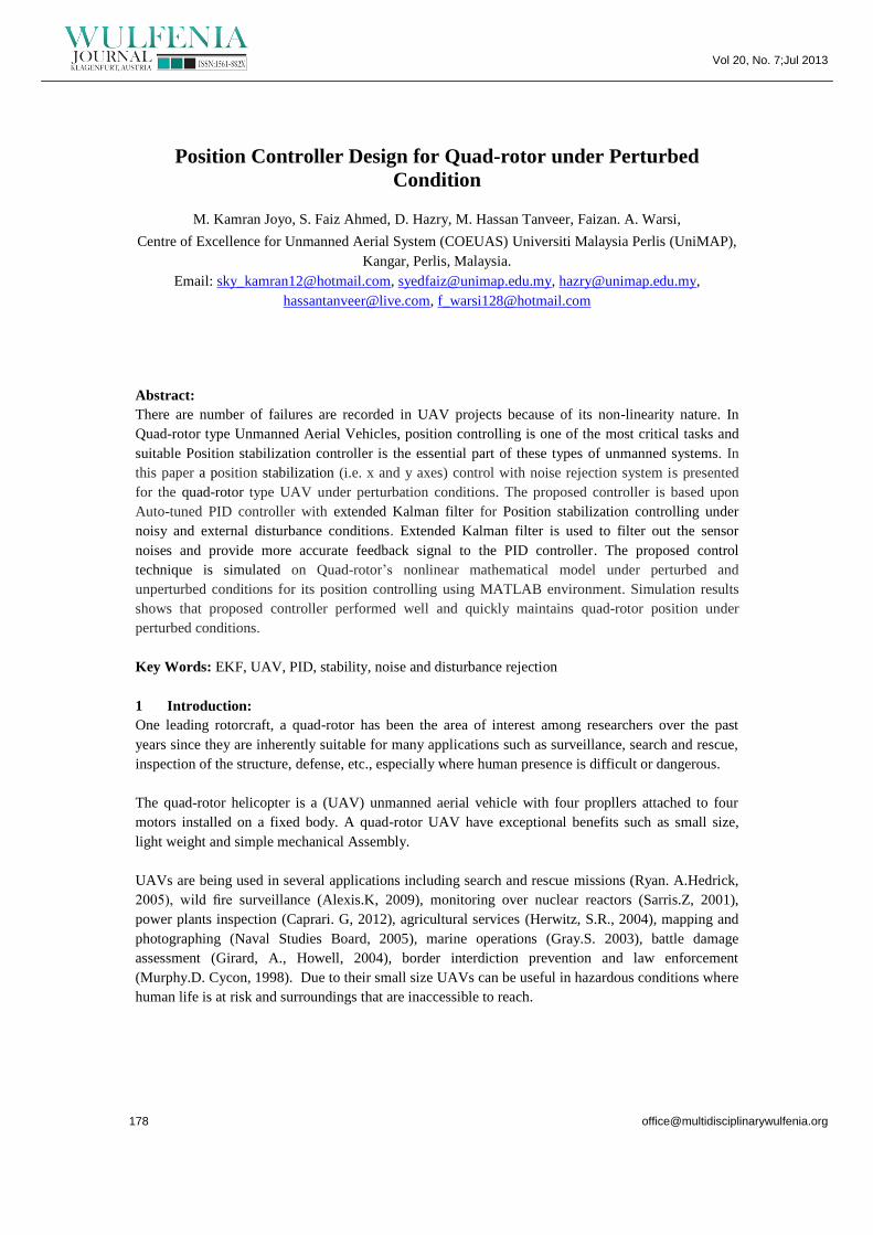
3.2 PID controller For Perturbed Conditions:
The output of EKF produces a noiseless signal in feedback loop which combine with the input
reference signal to produce the error signal for the controller as shown in Figure (3).
Here PID controller which is regulated by auto-tune method within range between 0 to 1 for its all
parameters which are Kp,Ki,Kd. For the realization of the desired task only the principal requirement
is to work on the position of quad-rotor. Only stipulation is the dynamics of axes X and Y, which
represents the positional checking of the quad-rotor.
(t)
(t) (3.11)
Where, (t) is the disturbance factor. Taking ideal condition supposing (t) = 0.
For Position controlling and by using small angle approximation to the eq. 3.11 yields:
(3.12)
In above equation and
are constant values, where with respect of time and change their
values and give a constant value at a particular time so above equation can be rewritten as:
(3.13)
For controller design, the tracking error signal for X and Y will be:
(3.14)
PID controller is proposed to control the position of quad-rotor. So the control law can be chosen as:
(3.15)
Therefore close loop transfer function for the complete system will become:
(3.16)
Where Kj can be K1 or K2 for X and Y axis position respectively. Equation (3.16) is the Position
controller equation for X and Y axis, which represents actual, linearized and controlled output.

Vol 20, No. 7;Jul 2013
4. Results & Simulations
4.1 Disturbance Rejection:
Figure 6 shows the disturbance applied on a system and the PID controlled System output. Figure 7
represents the overall Position Control system for disturbance rejection and satisfies the response of
control system tracking the actual path under perturbs and the system could track the actual path with
almost minimal tracking error. However, Controller responding time was found to be very quick in
stabilizing the system.
4.2 Noise Rejection:
This part shows the estimate of the trajectory of EKF, figure 8 shows the Gaussian noise added in the
way of real trajectory and to evaluate the performance of EKF figure 9 shows the real and measured
trajectory of the particular system with the rejection of the noise.
5. Conclusion:
This article presents the complete mathematical modeling and position control of quad-rotor. Design
of controller is based on PID with auto-tune method. Finally EKF is introduced by which the
estimates of parameters could converge successfully with their right value at the time of the desired
exit is deductible under the terms of the difficulties due to the noise. According to simulations, there is
evidence that the effectiveness of the control method is verified that the controller has offered to
return the entire system to stabilize the situation where there is any kind of disturbance and noise
imposed quad-rotor.
References:
Ryan, A., Hedrick, J., 2005 ‘A mode-switching path planner for UAVassisted search and
rescue’. 44th IEEE Conf. Decision and Control, European Control Conf., CDC-ECC ’05,
Seville, Spain, 2005, pp. 1471–1476
Alexis, K., Nikolakopoulos, G., Tzes, A. Dritsas, 2009 : ‘Coordination of helicopter UAVs
for aerial forest-fire surveillance’, in ‘Applications of intelligent control to engineering
systems’, pp. 169–193
Sarris, Z., 2001 ‘Survey of UAV applications in civil markets’. Mediterranean Conf. on
Control and Automation, Ancona, Italy,
Caprari, G., Breitenmoser, A., Fischer, W. et al., 2012: ‘Highly compact robots for inspection
of power plants’, J. Field Robot, pp. 47–68
Herwitz, S.R., Johnson, L.F., Dunagan, S.E. et al, 2004.: ‘Imaging from an unmanned aerial
vehicle: agricultural surveillance and decision support’, Comput. Electron. Agri, pp. 49–61
Committee on Autonomous Vehicles in Support of Naval Operations, National Research
Council: ‘Autonomous vehicles in support of naval operations’ (Naval Studies Board,
Washington DC, USA, 2005)
Gray, S., 2003 ‘Cooperation between UAVs in search and destroy mission’. American
Institute of Aeronautics and Astronautics (AIAA) Guidance, Navigation, and Control Conf.
and Exhibit, Austin, USA.

Vol 20, No. 7;Jul 2013
Girard, A., Howell, A., Hedrick, J.:, 2004 ‘Border patrol and surveillance missions using
multiple unmanned air vehicles’. 43rd IEEE Conf. on Decision and Control, Atlantis,
Paradise Island, Bahamas, December, vol. 1, pp. 620–625
Murphy, D., Cycon, J.:, 1998 ‘Applications for mini VTOL UAV for law enforcement’.
Information and Training Technologies for Law Enforcement, Boston, MA, USA.
D.Hazry, Shaiful Zairi1,”Adaptive Neural Controller Implementation In Autonomous Mini
Aircraft Quadrotor (AMAC-Q) For Attitude Control Stabilization”, IEEE 7th International
Colloquium on Signal Processing and its Applications, 2011
Anil guclu, 2007 “Attitude And Altitude Control Of An Outdoor Quad-Rotor”, Atilim
University,
R. Xu and U. Ozguner, 2006 “Sliding mode control of a quad-rotor helicopter,” Proc. of the
45th IEEE Conferenceon Decision and Control, pp. 4957-4962.
Samir Bouabdullah, 2007 “Full Control of a quad-rotor,” in proc (IEEE) International
conference on Intelligent Robots and Systems (IROS 2007).
H. Bouadi, M. Bouchoucha and M. Tadjine, 2008 “Sliding Mode Control based on
Backstepping Approach for an UAV Type-Quad-rotor,” International Journal of Applied
Mathematics and Computer Sciences, vol. 4, no. 1, pp. 12-17.
Syed Ali Raza, 2010, “ Intelligent Flight Control of an Autonomous quadrotor,”
www.intechopen.com
Keun Uk Lee , 2011 “Modeling and Altitude Control of Quad-rotor UAV, “ in proc (IEEE)
International conference on Control, Automation and Systems (ICCAS), Gyeonggi-do, South
Korea.
Tommaso Bresciani, 2008 “Modelling, Identification and Control of a Quad-rotor
Helicopter”,
Wetch, G.Bishop, 2001. “An introduction to the Kalman filter”, SIFFRAPH 2001 course 8.
In Computer Graphics, Annual conference on Computer Graphics & Interactive Techniques.
N. Guenard et al. 2006 “Control laws for the tele operation of an unmanned aerial vehicle
known as an x4-flyer,” in Proc. (IEEE) International Conference on Intelligent Robots
(IROS’06), Beijing, China,
Figures:
Figure 1: Quad-rotor UAV with its dimensions

Vol 20, No. 7;Jul 2013
Figure 2: Quad-rotor Body and Earth Inertial Frame
Figure 3 : Proposed Control System

Vol 20, No. 7;Jul 2013
Figure 4: Nonlinear system, with input and a measurement noise
Figure 5: EKF system
Figure 6: Disturbance and its effect
Figure 7: Overall Position system
0.2 0.233 0.267 0.3 0.333 0.367 0.4 0.433 0.467
0
0.2
0.4
0.6
0.8
1
Positio
n
Time (mins)
Disturbance
0.2 0.233 0.267 0.3 0.333 0.367 0.4 0.433 0.467
0
2
4
6
8
10
12
14
16
Am
plitu
de
Time (mins)
Effect
Offset=0.000 (mins)
0.167 0.333 0.5 0.667 0.833 1
0
2
4
6
8
10
12
14
16
18
20
Positio
n
Time (mins)
Actual Path
Measured Path
Offset=0.000 (mins)
Kp = 0.0328
Ki = 0.0025
Kd = 0.0379
X = 5X = 5
X = 15.4
Extended Kalman
Filter

Vol 20, No. 7;Jul 2013
Figure 8: Noise Traced
Figure 9: Noise Rejection by Using Extended Kalman Filter
0 0.5 1 1.5 2 2.5 3 3.5 4 4.5 5
-10
0
10
20
30
40
50
60
70
80
90
Positio
n
Time (secs)
Noisy signal
Offset=0 (secs)
0 0.5 1 1.5 2 2.5 3 3.5 4 4.5 5
-10
0
10
20
30
40
50
60
70
80
90
Positio
n
Time (secs)
Actual Path
Corrected Path
Offset=0 (secs)


![Quad 240[1737]](https://static.fdokumen.com/doc/165x107/633b2fc5c007a38db701fb49/quad-2401737.jpg)