CRC Reactivity Calculations for Quad Cities Unit 2. - NRC.gov
342
CRWMS/M&O I Calculation Cover Sheet Complete only applicable items. 1. QA: L Page:1 Of: 48 2. Calculation ritle CRC Reactivity Calculations for Quad Cities Unit 2 3. Document Identifier (including Revision Number) 4. Total Pages B00000000-01717-021 0-00010 REV 00 148 5. Total Attachments 6. Attachment Numbers - Number of pages in each MOL 19990322 0327 20 See Remarks" Block for Listing Print Name Signature Date 7. Originator M. J. Anderson IM 8. Checker D. P. Henderson/J. M. Scaglione * o 9. Lead Design Engineer D. A. Thomas 10. Remarks List of Attachments: 1-7,11-43, 11143, IV-16, V-12, VI141, VII-12,V111:37, IX-IS, X-16XI-,14, Xll-9, XII-59, XIV-.241, XV-51, XVI-IS, XVII-), XVIII-18, pXIX-21, Y-Y-180 'Thc number of pagesshown for Attachment I refers to the number of pages in thec listing of the contents of the tapes. FA n v ' Sa u q -S jv.4 1w Ux*& W045 Kizw e S ldh& Revision History 11. Revision No. 12. Date Approved 13. Description of Revision 00 Initial Release - ., ...... . _ .......... .1. Mr-3-21 1F.11ft-twe 0112619M -I -r-k- ,; , -, .A ., -,N 0635 IRM 1 120197 , L M
-
Upload
khangminh22 -
Category
Documents
-
view
7 -
download
0
Transcript of CRC Reactivity Calculations for Quad Cities Unit 2. - NRC.gov

CRWMS/M&O I Calculation Cover Sheet
Complete only applicable items.1. QA: L
Page:1 Of: 48
2. Calculation ritleCRC Reactivity Calculations for Quad Cities Unit 2
3. Document Identifier (including Revision Number) 4. Total PagesB00000000-01717-021 0-00010 REV 00 148
5. Total Attachments 6. Attachment Numbers - Number of pages in each MOL 19990322 032720 See Remarks" Block for Listing
Print Name Signature Date
7. Originator M. J. Anderson IM
8. Checker D. P. Henderson/J. M. Scaglione * o
9. Lead Design Engineer D. A. Thomas
10. RemarksList of Attachments: 1-7,11-43, 11143, IV-16, V-12, VI141, VII-12,V111:37, IX-IS, X-16XI-,14, Xll-9, XII-59, XIV-.241,XV-51, XVI-IS, XVII-), XVIII-18, pXIX-21, Y-Y-180
'Thc number of pagesshown for Attachment I refers to the number of pages in thec listing of the contents of the tapes.
FA n v ' Sa u q -S jv.4 1w
Ux*& W045 Kizw e S ldh&
Revision History
11. Revision No. 12. Date Approved 13. Description of Revision
00 Initial Release
-., ...... ._ .......... .1.Mr-3-21 1F.11ft-twe 0112619M
-I -r�-k- �,; , -,.A., -,�N
0635 IRM 1 120197
, L M

Waste Package Organization Engineering Calculation
Title: CRC Reactivity Calculations for Quad Cities Unit 2Document Identifier: BOOOOOOOO-01717-0210-00010 REV 00 Page 2 of 48
Table of Contents
Title Page
1. Purpose 6
2. Method 6
3. Assumptions 6
4. Use of Computer Software 7
4.1. Software Approved for QAWork 84.2. Software Routines 8
5. Calculation *
5.1. Automation of MCNP Input Deck Creation 95.2. Data Acquisition 125.3. Process Framework 255A. Automation Creation 285.5. Conventions for Surface, Cell and Material Numbering 385.6. Development of MCNP Input for Quad Cities Unit 1, BOL, Criticality Calculations 385.7. Development of MCNP Input for Quad Cities Unit 2, Cycle 13, Criticality Calculations 385.8. Development of MCNP Input for Quad Cities Unit 2, Cycle 14, Criticality Calculations 38
6. Results 40
6.1. Treatment of Gadolinia 416.2. Conclusions 46
7. References 47
S. Attachments 48

Waste Package Organization
Title: CRC Reactivity Calculations for Quad Cities Unit 2Document Identifier: B00000000-01717-021D-00010 REV 00
Engineering Calculation
Page 3 of 48
List of Tables
Table
Table 5-1.
Table 5-2.
Table 5-3.
Table 5-4.
Table 6-5.
Table 5-.
Table 5-7.
Table 5-8.
Table 5-9.
Table 5-10.
Table 5-1 1.
Table 6-12.
Table 6-1.
Table 6-2.
Table 6-3.
Table 8-1.
Title
Task List for Prototype Implementation
Task List for Production Software Routine Creation
Library Identifiers for Nuclides Used in Evaluations
Ust of Nuclides In OPrincipal Isotope' Set
List of Nuclides In 'Principal Actinilde Set
Ust of Nuclides in mActinide-only" Set
Input Requirements for IDSGEN
Input Requirements for BLINK
Location of Data for Core Structures
Order of Indices
Critical Experiments Performed In Cycle 13, in Quad Cities Unit 2
Critical Experiments Performed In Cycle 14, In Quad Cities Unit 2
Results for CRC Reactivity Calculations
Gadolinium Inventory for Node 3
Gadolinium Inventory for Node 8
List of Attachments
Page
10
11
21
24
25
25
26
27
33
38
38
39
40
43
43
48

Waste Package Organization E
Title: CRC Reactivity Calculations for Quad Cities Unit 2Document Identifier: B00000000-01717-021 0-0010 REV 00
List of Figures
ngineering Calculation
Page 4 of 48
Figure
Figure 5-1
Figure 5-2
Figure 5-3
Figure 5-4
Figure 5-5
Figure 5-6
Figure 5-7
Figure 5-8
Figure 5-9
Figure 5-10
Figure 5-11
Figure 6-1
Figure 6-2
Figure 6-3
Figure 6-4
Title
Components in MCNP Model for BWR Core (Planar Slice)
Components in MCNP Model for BWR Core (Axial Slice)
7x7 BWR Fuel Assembly (Planar Section)
BWR Fuel Assembly (Axial Section)
Control Blade Model
Origin for MCNP Model
Fuel Assembly Model
Control Blade Model
Control Cell Layout Illustration
Core Arrangement
Top Level Flowchart for Automation Code
Results for CRC Reactivity Calculations
Gadolinium Inventory for Node 3
Gadolinium Inventory for Node 8
Comparison of Loss In Gadolinla Effectiveness
Page
13
14
15
16
17
29
29
30
31
32
34
41
44
45
46

Waste Package Organization
Title: CRC Reactivity Calculations for Quad Cities Unit 2Document Identifier: B00000000-01717-0210-00010 REV 00
Engineering Calculation
Page 5 of 48
List of Worksheets
Worksheet Title
Worksheet 5-1 Core Data Requirements
Worksheet 5-2 Lattice Data Requirements
Worksheet 5-3 Control Blade Data Requirements
Page
18
20
20

Waste Package Organization Engineering Calculation
Title: CRC Reactivity Calculations for Quad Cities Unit 2Document Identifier: BOOOOOOOO-01717-0210-00010 REV 00 Page 6 of 48
1. Purpose
In the development of a methodology to account for exposure effects on the reactivity of spent BoilingWater Reactor (BWR) fuel In the proposed Monitored Geologic Repository (MGR) at Yucca Mountain, theaccuracy of the methods used to predict the inventories of fissile and fissionable nuclides as well asneutron poisons present in the spent fuel must be established. One aspect of this confirmatory effort isaccomplished by performing benchmark problems for known in-reactor critical configurations -Commercial Reactor Criticals (CRC's). These "experiments' are performed during each startup of a coreand provide a test of the ability of the Waste Package Operations (WPO) methods to properly predictneutron multiplication for a fuel mass that Includes actinides and fission products created during poweroperation.
2. Method
The analytical model employed in this analysis consisted of using the MCNP computer program(References 7.1 and 7.2, the MCNP 4A and 4B User's Manuals) to determine the effective neutronmultiplication factor (kff) for CRC's. The results reported for the MCNP calculations are the combinedaverage values of ki from the three estimates (collision, absorption and track length) listed in the finalgeneration summary In the MCNP output. The calculation of acceptable bias values and subcriticalmargins are based on the results of numerous evaluations performed using the MCNP code system. TheCRC's documented in this analysis may be used to help determine appropriate bias values for use insubsequent criticality evaluations performed with MCNP.
The Input Instructions to MCNP are constructed from two sources. For the definition of core andperipheral components and thermodynamic values, reference is made to applicable references. For theconstituents of exposed fuel, reference to values from companion calculations performed with the SAS2Hsequence of the SCALE computer code package (Reference 7.3) is made.
3. Assumptions
The following assumptions were made In preparing this calculation. Note that assumptions used In thegeneration of the nuclide inventories of the spent fuel are not included. For those assumptions, see theNLP-3-27 Engineering Calculation that documents their generation (Reference 7.4, hereafter cited as the*QC2 Depletion Calculations').
1) It Is assumed that quarter-core symmetry adequately approximates the fuel loading of the core.Since It Is the practice of nuclear fuel vendors and the operating utilities to use this assumption (or amore restrictive assumption of one-eighth symmetry) in developing fuel loading patterns and selectingcontrol blade positions, negligible error Is Introduced by performing calculations with this assumption.This assumption is used throughout this engineering calculation.
2) It Is assumed that the water density throughout the core is the same; however, this is not exact sincethe exposed fuel is thermally hot and creates local temperature - and hence density gradients - dueto convection. Further there Is a small increase In density from the top of the core to the bottom ofthe core due to the weight of water above the particular axial location. Since both the isothermal andisobaric compressibility for sub-cooled water and saturated liquid water are small, there is a smallvariation in density throughout the problem and this is a good assumption. This assumption is usedthroughout this engineering calculation.
3) The presence of stainless steel components between the core shroud and the inner surface of thepressure vessel, including the jet pumps, Is neglected. This is acceptable since the importance ofneutrons in this region of the problem is vanishingly small. The stainless steel liner on the Insidesurface of the pressure vessel is omitted for the same reason. This assumption is used in §5.1.3.

Waste Package Organization Engineering Calculation
Title: CRC Reactivity Calculations for Quad Cities Unit 2Document Identifier: BOOOOOOOO-01717-0210-00010 REV 00 Page 7 of 48
4) The structural components above and below the active fuel, including the upper and lower tie plates,core grid and core plate are homogenized with the moderator to represent the neutron transportcharacteristics of regions. This is acceptable since these regions of the problem affect the computedneutron multiplication through the reflection of neutrons that have escaped from the region of theactive core and the estimation of the hydrogen density is most important to determining this reflection.Since there is little variation In moderator density from startup test to startup test, the samehomogenized composition is used for all the exposed-core calculations. This assumption is used inAttachments l1l, XVIII and XIX.
5) For the exposed-core calculations, the fuel assembly grid spacers were omitted. For these cases thenodes were very large and the spacer grid volume fraction was very low. Further, the spacer gridsare composed of zlrcaloy, which is virtually transparent to neutrons. Therefore, there is little error inthis assumption. This assumption Is used In Attachments XVIII and XiX.
6) In the computation of the oxygen inventory for gadolinia-bearing fuel lattices, the computation of theoxygen Inventory of the U02 Is not decreased by the fraction of U02 displaced by the gadolinia;however, the lattice-averaged gadolinia concentration is generally less than 1% and the low atomicweight of oxygen makes the effect even less pronounced. Therefore, this assumption is acceptable.This assumption Is used in Attachment VIlI.
7) The isotopic inventories for exposed fuel are uniformly distributed through all the fuel rods In a givenlattice. This is necessary since the depletion calculations are performed on a lattice-averaged basisand no Information Is provided to re-distribute the fuel materials. This is also true for the gadolinia infuel lattices with Integral burnable absorber. The effect of this approximation Is studied for beginning-of-cycle (BOC) calculations where the effect should be the most pronounced. This is possible sincethe explicit loading of gadolinia in the fresh fuel is known. This assumption is used In Attachments VI,XVIII and XIX.
8) For exposed gadolinia-bearing fuel, the 15sGd due to fission is not processed from the depletioncalculations. This is acceptable since there Is already "sGd in the fuel in the form of Otails' from thegadolinia added as an integral burnable absorber and the incremental effect of the fission product'55Gd is probably small. Further, this Is a conservative assumption that increases the neutronmultiplication. This assumption Is used in Attachments Vi, XVII and XiX
9) For startup criticality tests that do not have quarter-core symmetricceitical control blade pattems, thesymmetry locations In the four quadrants are averaged together. This is acceptable since theincremental reactivity effect of the position of a small number of control blades is approximatelyrepresented by the depth of insertion Into the core. This Is particularly true If the blades arewithdrawn beyond the strong axial flux peak near the top of the core. This assumption is used inAttachments V1, XVII and XIX.
4. Use of Computer Software
Two types of software are used In the analyses documented herein. The first type is software that hasbeen approved for Quality Assurance (QA) work and is already qualified within the context of the CivilianRadioactive Waste Management System (CRWMS) QA system. The second typd is asoftware routines."Some of these are routines written to automate the process described in this document These are fullydocumented in this document Others are commercially available products which are merely referenced;nevertheless, the results of the use of such software, as well as the inputs, are described in sufficientdetail to permit an independent repetition of the calculations.
Waste Package Organization Engineering Calculation
Title: CRC Reactivity Calculations for Quad Cities Unit 2Document Identifier: B00000000-01717-0210-00010 REV 00 Page 8 of 48
4.1. Software Approved for QA Work
The versions of MCNP used for these calculations Is MCNP 4A HP 9000 Version, CSCI: 30006 VER. 4A(Reference 7.5, the MCNP Version 4A Software Qualification Report - SOR) and MCNP 4B2 HP9000Version, CSCI: 30033 VER 4B2LV (Reference 7.6, the MCNP Version 4B2 SQR), both installed on aHewlett Packard 9000 Workstation. The neutron interaction libraries used In this analysis are thosedocumented In the Software Qualification Report. Both the ENDF/B-V and ENDF/B-VI libraries werequalified for use In the MNCP 4A and 4B2 SQR's.
The Input fies used are reiterated in the output files and those output files are contained on a magnetictape. The contents of this tape are given in Attachment I.
a) The MCNP 4A and 4B2 computer codes are an appropriate tools to determine thecriticality potential, Ice, of fresh and spent lattices of light water reactor fuel assemblies.
b) This software has been validated over the range it was used.
c) Itwas previously obtained from the Software Control Management (SCM) in accordancewith appropriate procedures.
4.2. Software Routines
Two software routines were created to support the work documented In herein.
4Z1. BLINK
BLINK (BWR Linkage) is a software routine that creates an MCNP model of a BWR core as card imagerepresentations in an ASCII-formatfile.
4.2.2. IDSGEN
IDSGEN (Intermediate Dataset Generator) creates ASCII-format files containing information defining thefresh and exposed fuel materials for the fuel assemblies that populate a given BWR core.

Waste Package Organization Engineering Calculation
Title: CRC Reactivity Calculations for Quad Cities Unit 2Document Identifier: BOOOOOOOO-01717-0210-00010 REV 00 Page 9 of 48
S. Calculation
The subject calculations for this document are for Cycles 13 and 14 of the Quad Cities Unit 2 BWR.However, the software routines developed to support this work are substantial, so an Initial calculationwas performed to model the initial core criticality of the Quad Cities Unit I core. Specific testing of themodel produced by the automation Is demonstrated for the model of the Quad Cities Unit I initial core,while Integration testing of the linkage is obtained from the evaluation of that core. This calculationmimicked the previous analysis of that core with a specifically prepared ('hand crafted') MCNP model(Reference 7.7, hereafter cited as the *Previous Analysis') and good agreement between that analysisand an analysis with the software routine automation provides confidence in the models generated by thatautomation.
Subsequent to this reiteration of the Quad Cities Unit I CRC, the analysis of the CRC's from Quad CitiesUnit 2 are documented.
6.1. Automation of MCNP Input Deck Creation
This sub-section documents the creation of a process to create MNCP input representations suitable formodeling BWR CRC's and calculations that support the validity of that process. This process includes thefollowing components:
* reference ASCII-format datasets containing Information common to modeling for specifictypes of BWR's and the components thereof,
• Input Instructions for the specific analysis; and
• problem-specific datasets containing number densities for exposed fuel SAS2H.
5.1.1. Process Abstract
The analysis tools currently approved for use within MGR for performing such computations are theSAS2H sequence of the SCALE code system to generate fuel nuclide inventories with depletion anddecay, and the MCNP code to compute the steady state neutron transport and multiplication in thereactor core. Therefore, a process must be structured whereby isotopic inventories are transferred, withappropriate manipulation, from the output of the SAS2H sequence computations to the MCNP inputrepresentations.
In order to achieve an efficient and error-resistant process, suitable automation must be developed toperform this linkage. This linkage prepares the MCNP representation of the fuel assemblies, corestructure, and components and regions adjacent to the active fuel. Adequate testing must be performedto verify its performance.
5.1.2. Computational Platform and Software
The linkage that creates the MCNP input representations (i.e., BLINK) was created on an HP 9000Workstation and was written to be compliant with either FORTRAN-77 or C89 as appropriate. Theautomation to directly process SAS2H output files and create intermediate fuel datasets for use by BLINK(i.e., IDSGEN) was written to be compliant with FORTRAN-77.
5.1.3. Specific Data Requirements
The information necessary to create an MCNP model of a particular BWR core at a specific point in timeare:
core arrangement, including design of fuel assemblies at each location in the core andlocations of control blades and in-core instrumentation dry tubes;

Waste Package Organization Engineering Calculation
Title: CRC Reactivity Calculations for Quad Cities Unit 2Document Identifier: BOOOOOOOO-01717-0210 -00010 REV 00 Page 10 of 48
* geometrical design of fuel assemblies;
* location, dimensions and composition of fuel spacer grids;
• material composition of fuel In fuel assemblies;
* geometrical design and material compositions of control blades;
* location and thickness of core shroud;
* location and thickness of reactor pressure vessel; and
* configuration and composition of axial reactor internal components above and below theactive core.
The isotopic inventories from SAS2H are applicable to distinct lattices designs at specific combinations ofexposure and moderator density history (or the corollary void history). Thus for an exposed core, uniqueinventories must be provided for each distinct node in the core tracking supplied by the plant processcomputer in the portion of the core modeled (generally a quarter of the core). At a maximum, every fuelassembly must be modeled, and each assembly will be divided into multiple axial nodes. The coretracking data is generally performed In 24 or 25 axdal nodes, so this Is as fine of a division as may beused.
The execution of the SAS2H code set has been automated for the purposes of these analyses withCRAFT Version 4B and Its attendant executive, SPACE Version 00 (Attachments I and 11 of the QC2Depletion Calculations, respectively). The results from SAS2H are compiled in databases for each fuelassembly type in the particular CRC "experirnent"
Additional databases are created based on the BWR size and layout and the varieties of fuel assemblydesigns, as well as common materials used In the construction of the BWR internals and the fuelassemblies.
6.1A. -Tasks
In order to implement the automated process whereby an MCNP representationcreated, the tasks shown In Tables 5-1 and 5-2 must be accomplished.
of a BWR can be
Table 6-1. Task Ust for Prototype Implementation
Index | Task Sub-task Description Predecessors1.0 Data
Acquisition1.1 Determine Required Data to Describe Core and Fuel
Data Assemblies1.2 Data Sources Identify Sources of Data 1.12.0 Process
Framework2.1 Data Structures Define Data Structures within 1.1
Context of Automation (filecontents and directorystructure)
2.2 . ..________ Populate Structures Load Data into Data Structures 1.2, 2.13.0 Automation
Creation3.1 MNCP Model Layout Create Overall Framework for
BWR Core ModelLink to Data Correlate Data with Regions in 2.23.2

- - -
Waste Package Organization Engineering Calculation
Title: CRC Reactivity Calculations for Quad Cities Unit 2Document Identifier: BOOOOOOO-01717-0210-00010 REV 00 Page 11 of 48
Index Task Sub-task Description PredecessorsStructures Layout
3.3 Program Flow Top Level Program Flowchart 2.1, 3.13.4 Functional Description Create Functional Description 3.3
of Major Modules3.5 ____________ Encode Logic 3.2. 3.34.0 Testing 3.04.1 Dummy Datasets SAS2H Dataset Representing 2.1
Creation Initial Core4.2 MCNP Input 3.0
RepresentationCreation
4.3 Result Comparison Compare Results from 4.2Automation to Previous
_ _ _ _ _ _ _ _ _ _ _ _ _ _ _ _ _ _ _ _ _ _ _ _ _ _ _ A nalysis_ _ _ _ _ _ _ _
5.0 Depleted-core 4.0Analysis
5.1 Dataset Update Create Models for New Lattices 2.1Types
5.2 SAS2H Datasets Process SAS2H Datasets forDepleted Configuration
5.3 MCNP Input Input Representations for 5.1, 5.2Representation Depleted BWR CoreCreation
5.4 .__________ Generate Results 5.3
Table 5-2. Task List for Production Software Routine Creation
Index Task Sub-task Description Predecessors1.0 Upgrade to Full
Scope1.1 Core Models Introduce Datasets for other
Core Sizes and Layouts1.2 Lattices Models Introduce Datasets for other
.__ _ _ _ _ _ _________________ _______________________ L a ttic e s,
The balance of this document describes the fulfillment of these tasks.

Waste Package Organization Engineering Calculation
Title: CRC Reactivity Calculations for Quad Cities Unit 2Document Identifier: BOOOOOOOO-01717-0210-00o0I REV 00 Page 12 of 48
5.2. Data Acquisition
5.2.1. Required Data
The data requirements for automating the creation of MNCP Input representations for BWR cores isInformed by the analysis for the initial core of the Quad Cities-1 BWR (the Previous Analysis). The MCNPmodel represents a BWR core and adjacent core Internals and is either a full-core representation or asymmetrical subset of the full core (i.e., a quarter of the core). This representation contains the followingcomponents:
* fuel assemblies, including fuel rods, water rods (where applicable), channels and water amongchannels (inter-assembly bypass flow);
* control rods;
* Instrument dry tubes;
* core shroud and bypass region between fuel region and shroud (extra-assembly bypass flow);
* water in downcomer, outside of the shroud; and
* axial ends comprised of mixtures of light water and stainless steel to approximate the coreInternal below and above the fuel.
These components and their relative locations are Illustrated in Figure 5-1, which shows a planar sectionof the core model. An axial section of the reactor Is shown In Figure 5-2. A detailed planar sectionIllustration of a typical 7x7 off-set BWR fuel assembly design is shown in Figure 5-3 (N.B., this designdoes not Incorporate water rods) and an axial schematic Is shown In Figure 5-4. In the axial schematiccontemporary axial zoning of the lattices designs Is shown with General Electric (GE) terminology. Whilenot all fuel assemblies will have these specific zones, the schematic does Illustrate the range of differentlattice nuclear designs realizable with a single fuel assembly. An Illustration of a typical control blade forthe same lattice geometry Is shown in Figure 5-5.
Since BWR cores come in a variety of sizes, templates are developed to represent the particular coredesigns modeled. Further, BWR lattices designs and control blade designs vary and specific models areprovided as appropriate.
The data to describe the entire core may be correlated with the illustrations In this section. Thenecessary data for the core and core structure are shown in Worksheet 5-1. Information required formodeling of a 7x7 fuel assembly In shown In Worksheet 5-2, while data for modefling a control blade usedin this type core is provided In Worksheet 5-3.

Waste Package Organization Engineering CalculationTitle: CRC ReactMty Calculations for Quad Cities Unit 2Document Identifier: Booooo000-01717-0210-00010 REV 00 Page 13 of 48
Figure 5-1. Components In MCNP Model for BWR Core (Planar Slice)
Extra-AssemblyBypass Flow
Core
Downcomer 117o
11IQT F15 1:1E al 1 Ie11 nto Q0Ie l U310Q1 a
svg&h�, IInstrumentation Dry Tube
D L] Control Cell
\Box" for Fuel Assembly Model
\ Box" for Control Blade Model
Inter-assembly Bypass Water
k

Waste Package Organization Engineering Calculation
Title: CRC Reactivity Calculations for Quad Cities Unit 2Document Identifier: BOOOOOOOD-01717-0210-00010 REV 00 Page 14 of 48
Figure 5-2. Components In MCNP Model for BWR Core (Axial Slice)
..
Upper Plenum Region
Core Grid Region
Upper Tie Plate Region
Core Region
Bypass Region _
|Not to ScalS
Lower Fuel Tie Plate Region
Fuel Support/Core Plate Region P Vessel
Lower Plenum Region Jet Pump Region -
Core Shroud "'

Waste Package Organization Engineering CalculationTitle: CRC Reactivity Calculations for Quad Cities Unit 2Document Identifier: BOOODOOO-01717-0210-O001O REV 00 Pane IS of 48
Paa l-w- f4R .
Figure 6-3. 7x7 BWR Fuel Assembly (Planar Section)
@@@0@
N I N ~~Channel
n-hnnel Moderator
L Fuel
\ Cladding
..

Waste Package Organization Engineering CalculationTitle: CRC Reactivity Calculations for Quad Ctlies Unit 2Document Identifier: BOOOOOOO-01717-0210-00010 REV 00 Page 16 of 48
Figure 5-4. BWR Fuel Assembly (Axlia Section)
Top Natural End
w ,h'
:Wilighff'Zone
Top of ActiveFuel
Shutdown Zone
Dominant Zone
|Not to iq
Scale IX
he~~~%
Power Shaping Zode
Bottom Natural End
Bottom ofActive Fuel

Waste Package Organization Engineering CalculationWaste Package Organization Engineering CalculationTitle: CRC Reactivity Calculations for Quad Cities Unit 2Document Identifier: BOOOOOOOo-01717-0210-00010 REV 00 Page 17 of 48
Figure 5-5. Control Blade Model
't
| Not to Scale i

Waste Package Organization Engineering Calculation
Title: CRC Reactivity Cakculations for Quad Cities Unit 2Document Identifier: B00000000-01717-021 00010 REV 00 Page 18 of 48
Worksheet 6-1. Core Data Requirements
Component Parameter PurposeVessel Outer Diameter Define Outer Lateral Edge of Problem Domain
Thickness Define Inner Radius of Vessel Component and. helps to Define the Jet Pump Region
Material Composition Needed to Select Appropriate Nuclear DataConstants
Core Shroud Outer Diameter Define Outer Radius of Shroud Component andhelps to Define Jet Pump Region
Inner Diameter Define Inner Radius of Shroud Component andhelps to Define Region between Shroud andPeripheral Fuel Assemblies
Material Composition Needed to Select Appropriate Nuclear DataConstants
Core Number of Columns In Fuel Defines Size of ProblemAssembly Map
Number of Rows In Fuel Defines Size of ProblemAssembly MapValid Fuel Assembly Locations Gives Locations of Fuel Assemblies
Valid Control Blade Locations Gives Locations of Control Blades
Instrumentation Tube Layout Gives Location of In-core Instrumentation DryTubes
Guide Tube Outer Diameter Defines Size of Guide Tube
Guide Tube Inner Diameter Defines Size of Guide Tube
Material Composition of In- Needed to Select Appropriate Nuciear Datacore Guide Tube ConstantsFuel Assembly Pitch Provides Sizing for Problem and Separation
between Fuel Assemblies and Control BladesTop of Upper Tie Plate Region Helps Define Upper Tie Plate RegionTop of Core Grid Region Helps Define Core Grid RegionMaterial Composition of Top Needed to Select Appropriate Nuclear DataGrid Region Constants (N.B., Homogenized with the Moderator
in that Region)Axial Top of Problem Non-re-entrant Surface to Delimit Problem Domain
(fixed to be 30 cm above the Top of Core Grid_____ ____ ____ ____ ___ egion)
Bottom of Lower Tie Plate Helps Define Lower Tie Plate CellRegion
I

Waste Package Organization Engineering Calculation
Title: CRC Reactivity Calculations for Quad Cities Unit 2Document Identifier: B0000000-01717-0210-00010 REV 00 Page 19 of 48
Worksheet 6-1 (cont'd)
Component Parameter PurposeBottom of Fuel Support/Core Helps Define Fuel Support/Core Plate RegionPlate RegionMaterial Compositon of Fuel Needed to Select Appropriate Nuclear DataSupporl/Core Plate Region Constants (N.B., Homogenized with the Moderator
in that Region)Bottom of Lower Plenum Non-re-entrant Surface to Delimit Problem DomainRegion (fixed to be 30 cm below the Bottom of Fuel
______ _______ __ SupportCore Plate Region

Waste Package Organization Engineering Calculation
Title: CRC Reactivity Calculations for Quad Cities Unit 2Document Identifier: BOOOOOOOO-01717-0210-00010 REV 00 Page 20 of 48
Worksheet 6-2. Lattice Data Requirements
Component Parameter PurposeChannel Inner Span Provide Window" for Fuel Rod Array and helps to
.Define Channel Inner SurfaceWide Gap Thickness Give Offset from Control Blade and helps to Define
|Channel Outer Surface in Wide GapsNarrow Gap Thickness Give Offset from Instrument Tube and helps to. ______________________ Define Channel Thickness In Narrow GapsThickness Helps to Define Channel Inner SurfacesComer Inner Radius Define Inner and Outer Channel Surfaces at
. ~~ComersFuel Rods Clad to Clad Separation Helps to Situate Fuel Rods with respect to One
AnotherChannel to Clad Separation Situates Fuel Rods with respect to Channel Inner
SurfaceFuel Rod Pitch Helps to Situate Fuel Rods with respect to One
AnotherCladding Outer Diameter Defines Outer Surface of Fuel Rod Cladding CellCladding Thickness Define Inner Surface of Fuel Rod Cladding Cell and
help to Define Fuel-to-cladding GapPellet Diameter Defines Outer Surface of Fuel Pellet and helps to
Define Fuel-to-cladding GapInstrument Tube Dry Tube Outer Diameter Defines Outer Surface of Dry Tube
Dry Tube Inner Diameter Defines Inner Surface of Dry Tube and also DefinesDetector Location for In-core Instrumentation
Worksheet 6-3. Control Blade Data Requirements
Component Parameter PurposeAbsorber Tubes Inner Diameter Defines B4C Poison Cell and Helps to Define
Absorber Tube CellOuter Diameter Helps to Define Absorber Tube Cell and Internal
Flow AreaPlacement Locates Absorber Tubes within Internal Sheath
VolumeTie Rod Span Helps to Define Tie Rod Cell and Placement of
Sheath and Absorber TubesThickness Helps to Define Tie Rod Cell and Placement of
SheathLength Defines Length of Control Blade Model
Sheath Thickness Helps to Define Sheath Cell

Waste Package Organization Engineering CalculationTitle: CRC Reactivity Calculations for Quad Cities Unit 2Document Identifier: BOOOOOOOO-01717-021D-00010 REV 00 Page 21 of 48
e
I
5.2.2. Data Sources
For the prototype development, the data necessary to construct the MCNP model for the initial coremodel will come from the Quad Cities-1 analysis already noted. Additional supporting Information willcome from the EPRI report documenting the startup testing and cycle tracking (Reference 7.8). For thefirst exposed core CRC, data Is obtained from utility data and compiled in a QAP-3-5 document(Reference 7.9, hereafter cited as the OQuad Cities Unit 2 CRC Data Reporr).
For both the core structural materials and the exposed fuel materials, cross sections must be selectedfrom those available In the MCNP libraries to represent the nuclear properties of those materials. Thelibraries used for the Isotopes considered In the present analysis are shown in Table 5-3. For 'bestestimate evaluations, all of the nuclides shown in Table 5-3 are used. Three other nuclide sets areconsidered for evaluations, the "principal Isotope* set (Reference 7.10, page 3-26), the "principal actinideset" (which Is merely the "principal Isotope" set less the fission products) and the "actinlde-only" set usedin the transportation licensing effort (Reference 7.11). The Identities of the nuclides in the "principalisotope' set are shown In Table 5-4. The other Identifying characteristics for the libraries for thesenuclides are Identical to those shown In Table 5-3. Nuclides included in the mprincipal actinide set areprovided In Table 5-5 and those of the "actinide-only set are shown in Table 5-6.
Table 5-3. Library Identifiers for Nuclides Used In Evaluations
Element I MCNP Temperature Library Data SourceIsotope ZAID (K) Name
H-1 1001.50c 294.0 rmncs ENDFIB-V.0
H-3 1003.50c 294.0 rmccs ENDF/B-V.0
He-4 2004.50c 294.0 rmccs E NDFIB-V.0
U-S 3006.50c 294.0 rrmcs ENDF/B-V.0
11-7 3007.55c 294.0 rmccs ENDF/B-V.2
Be-9 4009.50c 294.0 rmccs ENDF/B-V.0
B-10 010.50c 294.0 IrIcs ENDF/B-V.0
5-11 5011.56c 294.0 newxs LANLrr-2
C-nat 6000.50c 294.0 rmccs ENDF/B-V.0
N-14 7014.50c 294.0 rmccs ENDF/B-V.0
0-16 *8016.S0c 294.0 rmccs ENDFIB-V.0
AI-27 13027.60c 294.0 rmccs ENDF/B-V.0
Si-nat 14000.50c 294.0 endf5p ENDF/B-V.0
P-31 15031 .50c 294.0 endf5u ENDFIB-V.0
S-32 16032.50c. 294.0 endf5u ENDFIB-V.0
Ti-nat 22000.50c 294.0 endf5u ENDF/B-V.0
Cr-SO 24050.60c 294.0 endf60 ENDF/B-VI.1
Cr-52 24052.60c 294.0 endf6a ENDF/B-VI.1
Cr-53 24053.60c 294.0 endf60 ENDF/B-VI.1
Cr-54 24054.60c 294.0 endf60 ENDF/B-VI.1
Mn-55 25055.50c 294.0 endf5u ENDFIB-V.0

Waste Package Organization Engineering Calculation
Title: CRC Reactivity Calculations for Quad Cities Unit 2Document Identifier: B00000000-01717-0210-00010 REV 00 Page 22 of 48
Element I MCNP Temperature LUbrary Data SourceIsotope ZAID (K) Name
Fe-54 26054.60c 294.0 endf60 ENDFIB-VI.
Fe-56 26056.60c 294.0 endf60 ENDFIB-VI.1
Fe-57 26057.60c 294.0 endf60 ENDFI)BVI.
Fe-58 26058.60c 294.0 endf60 ENDFIB-Vl.1
CO-69 27059.50c 294.0 endf5u ENDF1B-V.0
NI-58 28058.60c 294.0 endf60 ENDF/B-VI.1
NI-6Q 28060.60c 294.0 endf60 ENDF/B-VI.1
Ni-61 28061.60c 294.0 endf6O ENDFI-VI.1
Ni-62 28062.60c 294.0 endf60 ENDF/B-VI.1
Ni-64 28064.60c 294.0 endf60 ENDF/B-Vl.1
Cu-63 29063.60c 294.0 endf60 ENDF/B-VI.2
Cu-65 29065.60c 294.0 endf60 ENDF/B-VI.2
As-75 33075.35c 0.0 rmccsa ENDFIB-V.0
Kr-0 _36080.50c 294.0 rmccsa ENDFIB-V.0
Kr-82 36082.50c 294.0 nmccsa ENDFIB-V.0
Kr-83 36083.50c 294.0 rmccsa ENDFIS-V.0
Kr-84 36084.50c 294.0 rmrc'sa ENDF/B-V.0
Kr-86 36086.50c 294.0 rmccsa ENDFIB-V.0
Y-89 39089.50c 294.0 endf5u ENDF/B-V.0
Zr-nat 40000.60c 294.0 endf60 ENDFIB-VI.1
Zr-93 40093.50c 294.0 kidman ENDF/B-V.O
Nb-93 41093.50c 294.0 endf5p ENDFIB-V.0
Mo-nat 42000.50c 294.0 endf5u ENDF/B-V.0
Mo-95 42095.50c 294.0 kIdman ENDFlB-V.0
Tc-99 43099.50c 294.0 kidman ENDF/B-V.O
Ru-101 44101.50c 294.0 kidman ENDFIB-V.0
Ru-103 44103.50c 294.0 kidman ENDF/B-V.0
Rh-103 45103.50c 294.0 rmccsa ENDFIB-V.0
Rh-105 45105.50c 294.0 kidman ENDF/B-V.0
Pd-105 46105.50c 294.0 Wddman ENDF/B-V.0
Pd-108 46108.50c 294.0 kidman ENDFI-V.0
Ag-107 47107.60c 294.0 endf60 ENDF/B-VI.0
Ag- 109 471 09.60c 294:0 endf6O ENDFlB-VI.0
Cd-nat 48000.60c 294.0 endf5u ENDF/B-V.O
In-nat 49000.60c 294.0 endf60 ENDF/B-VI.0

Waste Package Organization Engineering Calculation
Title: CRC Reactivity Calculations for Quad Cities Unit 2Document Identifier: BOO00-01717-0210-00010 REV 00 Page 23 of 48
Element I MCNP Temperature Library Data SourceIsotope ZAID (K) Name
Sn-nat 50000.35c 0.0 endl85 LLNL
Xe-131 54131.50c 294.0 kidman ENDFIB-V.0
Xe-134 54134.35c 0.0 endl85 LLNL
Xe-135 54135.53c 587.0 eprixs ENDFIB-V
Cs-133 55133.50c 294.0 kidman ENDFIB-V.0
Cs-135 55135.50c 294.0 kidman ENDF/B-V.0
Ba-138 56138.50c 294.0 MIcXs ENDFIB-V.0
Pr-141 59141.50c 294.0 kidman ENDF/B-V.0
Nd-143 60143.50c 294.0 kidman ENDF/B-V.0
Nd-145 60145.50c 294.0 kidman ENDF/B-V.0
Nd-147 60147.50c 294.0 kidman ENDF/B-V.0
Nd-148 60148.50c 294.0 kidman ENDFIB-V.0
Pm-147 61147.50c 294.0 kWdman ENDF/B-V.0
Pm-148 61148.50c 294.0 kidman ENDF/B-V.0
Pm-149 61 149.50c 294.0 kidman ENDF/B-V.0
Sm-147 62147.50c 294.0 Iddman ENDF/B-V.0
Sm-149 62149.50c 294.0 endf5u ENDFIB-V.0
Sm-150 62150.50c 294.0 kidman ENDF/B-V.0
Sm-151 62151.50c 294.0 kidman ENDFIB-V.0
Sm-152 62152.50c 294.0 kidman ENDF/B-V.0
Eu-151 63151.55c 294.0 newxs LANLIT-2
Eu-152 63152.50c 294.0 endf5u ENDFJB-V.0
Eu-153 63153.55c 294.0 newxs LANLrr-2
Eu-154 63154.50c 294.0 endf5u ENDFIB-V.0
Eu-155 63155.50c 294.0 kidman ENDF/B-V.0
Gd-152 64152.50c 294.0 endf5u ENDF/B-V.0
Gd-154 64154.50c 294.0 endf5u ENDFIB-V.0
Gd-155 64155.50c 294.0 endf5u ENDFIB-V.0
Gd-156 64156.50c 294.0 endf5u ENDF/B-V.0
Gd-157 64157.50c 294.0 endf5u ENDFIB-V.0
Gd-158 64158.50c 294.0 endf5u ENDFIB-V.0
Gd-160 64160.50c 294.0 endf5u ENDFIB-V.0
Ho-165 67165.55c 294.0 newxs LANIT7-2
Ta-1B1 73181.50c 294.0 endf5u ENDF/B-V.0
Th-232 90232.50c 294.0 endf5u ENDFIB-V.0

Waste Package Organization Engineering Calculation
Title: CRC Reactivity Calculations for Quad Cities Unit 2Document Identifier: 800000000-01717-021-00010 REV 00 Page24of48
Element I MCNP Temperature Library Data SourceIsotope ZAID (K) Name Data______
Pa-233 91233.50c 294.0 endf5u ENDFIB-V.0
U-233 92233.50c 294.0 rmccs ENDF/B-V.0
U-234 92234.50c 294.0 endf5p ENDFIB-V.0
U-235 92235.50c 294.0 eprixs ENDFtB-V.0
U-236 92236.50c 294.0 endf5p ENDFIB-V.0
U-237 92237.50c 294.0 endf5p ENDFIB-V.0
U-238 92238.50c 294.0 eprixs ENDFIB-V.0
Np-235 93235.35c 0.0 endl85 LLNL
Np-236 93236.35c 0.0 endiBS LLNL
Np-237 93237.50c 294.0 endf5p ENDFIB-V.0
Np-238 93238.35c 0.0 endl85 LLNL
Pu-237 94237.35c 0.0 endl85 LLNL
Pu-238 94238.50c 294.0 endf5p ENDF/IB-V.0
Pu-239 94239.55c 294.0 rmccs ENDF/B-V.2
Pu-240 94240.50c 294.0 rmccs ENDFIS-V.0
Pu-241 94241.50c 294.0 endf5p ENDFtB-V.0
Pu-242 94242.50c 294.0 endf5p ENDF/I-V.0
Am-241 95241.50c 294.0 endf5u ENDF/B-V.0
Am-242m 95242.50c 294.0 endf5u ENDFtB-V.0
Am-243 95243.50c 294.0 endf5u ENDFIB-V.0
Cm-242 96242.50c 294.0 endf5u ENDF/B-V.0
Cm-243 96243.35c 0.0 endl85 LLNL
Cm-244 96244.50c 294.0 endf5u ENDF/B-V.0
Cm-245 96245.35c 0.0 endl85 LLNL
Cm-246 96246.35c 0.0 endl85 LLNL
Cm-247 96247.35c 0.0 endiBS LLNL
Cm-248 96248.35c 0.0 endl85 LLNL
Table 5-4. List of Nuclides In 'Principal Isotope" Set
Mo-95 I Nd-145 Eu-151 U-236 Pu-241TC-99 I Sm-147 EU-153 U-238 PU242
Ru-101 J Sm-149 Gd-155 NP-237 An-241Rh-103 Sm-n150 ( U-233 Pu-238 Am-242mAg-109 Sm-151 U-234 Pu-239 AM243.....3 Fu-240_ . A_..
Nd-143 bns152 U-235 Pu-240

- -
Waste Package Organization Engineering Calculation
Title: CRC Reactivity Calculations for Quad Clties Unit 2Document Identifier: BOOOOOOO-01717-0210-000IO REV 00 Page 25 of 48
Table 6-5. List of Nuclides In "Principal Actinide" Set
U-233 U-236 Pu-238 Pu-241 42mU-234 I U-238 Pu-239 Pu-242 lX Am-243U-235 | Np-23 7 Pu240 Am-241l
Table 6-6. List of Nuclides In "Actinide-only" Set
U-234 U-238 Pu240 Ai-241U-235 Pu-238 Pu-241U-236 Pu-239 Pu-242
5.3. Process Framework
The software routine for the MCNP input representations is only one part of the process whereby MNCPinput decks are created to model BWR CRC's. The process relies on reliable data flowing from multiplesources. These sources supply the data described In §5.2.
5.3.1. Data Structures
The data obtained from the various sources that are used by the automation to produce the MCNP inputdecks are loaded into reference datasets. These are ASCII-format files that contain defined sets of datathat are applicable to specific components. While these datasets are dependent on a particular coregeometrical arrangement or fuel geometrical design, they are not dependent on the particular CRC beingevaluated. Thus a set of such datasets will be created for a 724-bundle BWR (e.g., Quad Cles-1) whichwill be usable for all such cores. Further, geometrical datasets will be prepared for GE 7x7 fuel designswhich are present In the Quad Cities-1 initial core. These datasets will be valid for use in other coreswhich incorporated fuel assemblies with this geometric design.
Datasets were created for common structural materials used in these problems, e.g., Type 304 stainlesssteel, zircaloy-2 and zlrcaloy-4. This will provide a common source for material compositions and reducethe potential for error in the inclusion of such materials in the MNCP Input deck.
Additional datasets or depleted fuel compositions come from results of the SAS2H code. The 'cur filesfrom that code are processed Into compact ASCII-format datasets for accessing by the automationsoftware routine.
These datasets will be stored in a common locations (dataset classes) on the HP workstation used forrunning the automation. The filenames for these datasets are are:
* Core Geometry datasets: core databasel
* Control Blade Geometry datasets: blade-database/
* Lattice Geometry datasets: lattice-database/
* Structural Component Material datasets: material-databasel
The Fuel Intermediate Datasets representing fuel constituents from SAS2H depend on the specific CRCanalyzed.
Waste Package Organization Engineering CalculationWaste Pckage rganiztion Egineerng Calulatio
Title: CRC Reactivity Calculations for Quad Cities Unit 2Document Identifier: B0000000O-01717-0210-00010 REV 00 Page 26 of 48
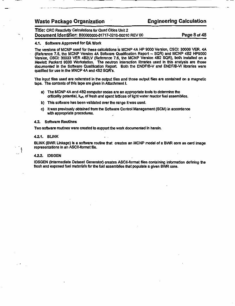
In addition to the file specification for the location of the SAS21H data, the information shown In Table 5-7is required by IDSGEN to create the Fuel Intermediate Datasets.
Table 6-7. Input Requirements for IDSGEN
Item PurposeLattice Dlmensionality Sizes the ProblemLattice Identification Identifies the Lattice DatasetPellet Stack Densities Needed to Compute Nodal MassPellet Outer Diameter Needed to Compute Nodal MassLattice Map Defines the Location of Fuel Rods Types within
Lattice to Properly Compute Average ValuesEnrichments Needed to Compute Proper Inventories for
Unexposed Fuel and Name Dataset for bothExposed and Unexposed Fuel
Gadolinia Needed to Compute Proper Inventories forUnexposed Fuel and Name Dataset for bothExposed and Unexposed Fuel
5.3.X Data Structure Population
The definition and filling of the core geometry dataset for a 724-bundle BWR is given In Attachment II.The contents and generation of the core materials datasets Is given in Attachment l1l. The creation oflattice geometry datasets applicable to the Quad Cities Unit 1 Initial core CRC as well as those applicableto all the exposed core CRC for Quad Cities Unit 2 is documented In Attachment IV. A description of theformat of that dataset Is also located in that attachment Attachment V provides the same information forthe control blade geometry datasets.
5.3.3. Case-specific Input to Process
With the exception of the Fuel Intermediate Datasets, the data structures are intended to be applicable tomore than a single CRC. The requirements for user Input to the linkage automation are shown In Table5-8.

Waste Package Organization Engineering CalculationWastePackae Oranizaion ngineringCalcuatio
Title: CRC Reactivity Calculations for Quad Cities Unit 2Document Identifier. B00000000-01717-0210-00010 REV 00 Page 27 of 48
Table 64. Input Requirements for BLINK
Item PurposeFile Specification for Core Necessary to Locate the DatabaseMaterials DatabaseFile Specification for Core Necessary to Locate the DatabaseGeometry DatabaseFile Specffication for Necessary to Locate the DatabaseBlade GeometryDatabaseFile Specification for Necessary to Locate the Fuel Geometry DatasetsLattice GeometryDatabaseThermodynamic Necessary to Specify Problem Temperatures andParameters Moderator DensityMaterial Compositions for Necessary to Properly Model these HomogenizedUpper and Lower Tie Regions of the CorePlate RegionsFuel Assembly Loading Placement of Lattice DesignMap by GeometryFuel Assembly Loading Placement of Lattice DesignMap by MaterialCompositionBlade Position Map Position of Control BladesLattice Assignments to Necessary to Build Fuel Assembly ModelsFuel AssembliesNames of Lattice Necessary to Locate Proper Geometrical DataGeometry DatasetsNames of Lattice Material Necessary to Locate Proper Material DataDatasetsNumber, Location and Necessary to Properly Model such SpacersMaterial Specification forGrid Spacers

Waste Package Organization Engineering Calculation
Title: CRC Reactivity Calculations for Quad Cities Unit 2Document Identifier: BOOOOOOOO-01717-0210-00010 REV 00 Page 28 of 48
5.4. Automation Creation
This section of the document describes the specification for and encoding of automation.
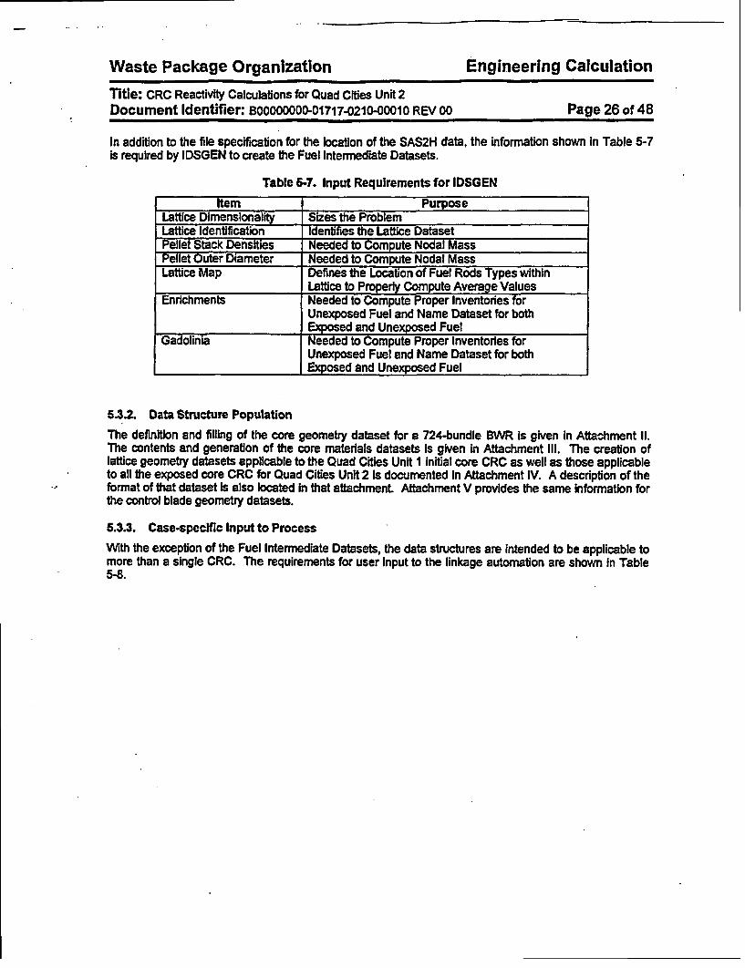
5A.1. MCNP Model Layout
The model of the MCNP core Is comprised of the vessel, core shroud and various repeating structures.The origin assumed for the model Is shown In Figure 5-6. The repeating structures In the core are thefuel assemblies and the control blades. The fuel assemblies are modeled as stacks of rectangularparallelepipeds as shown In Figure 5-7.
The control rods are modeled as a single structure as shown In Figure 54. This permits the blades toreadily be moved to new positions to perform sensitivity studies and to reduce unnecessary complexity inthe blade model. Further subdivison provides no calculational benefit since blade depletion Is generallynot provided with the CRC data. Further, since blade lifetime criteria are based on small effects onoverall core reactivity, the effect of blade depletion should be small and within the resolution of the MonteCarlo calculation. As shown In the Illustration, the blade handle and blade velocity limiter are omitted.The handle has a small effect on reactivity due to the displacement of moderator and Introduction ofstainless steel as an absorber. While these two considerations will offset one another somewhat, the neteffect should be small.
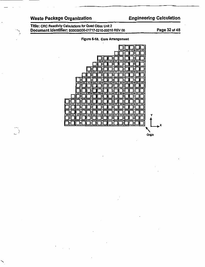
These repeating structures are situated In the core through the device of control cells.- A control cell isillustrated In Figure 5-9. Each control cell is constructed from four fuel assemblies and a control blade atthe center of the cell. Each fuel assembly may be different in its geometric details - and certainly in theirmaterial compositions. These control cells are placed in the larger framework of the core (see Figure5-10).
Waste Package Organization E
Title: CRC Reactivity Calculations for Quad Cities Unit 2*. Document Identifier: B00000000-01717-0210-00010 REV 00
Figure 56. Origin for MCNP Model
Iore Codin St
ngineering Calculation
Page 29 of 48
*l
Figure 6-7 Fuel Assembly Model
of S t ocked Unique L Fel ( Vs )
= / ( ~~~~Bottom of Active Fuel (8A19

- -=
Waste Package Organization Engineering CalculationWat Pakg OraiainEgnern acltoTitle: CRC Reactivity Calculations for Quad Cities Unft 2Document Identifier: B00000000-01717-0210-00010 REV 00 _______ Page 30 of 48
Figure 6-8. Control Blade Model
SLkv UnvrseX
_ l ~ Rod

Waste Package Organization Engineering Calculation
Title: CRC Reactivity Calculations for Quad Cities Unit 2Document Identifier: BOOOOOOOO-01717-0210-00010 REV 00 Page 31 of 48
Figure 5-9. Control Cell Layout Illustration
Control BladeModel
Unique Channel Models
Unique FuelRod Types
0
0
0
0o
0o
Waste Package Organization Engineering CalculationWaste Package Organization Engineering CalculationTitle: CRC Reactivity Calculations for Quad Cities Unit 2Document Identifier: B00000000-01717-0210-00010 REV 00 Page 32 of 48
Figure 5-10. Core Arrangement
BIB En_-Ar e - -- _4
I llLJFIM LrI 11HIM
:31:j7d, r1-7- E Z-- i ::::::: i;_-- ! -_ -- ,. -_ ---- ., --
LOr, I1UI 1 1-
US-Lnrr
[zzI ir 1LU
-2 -O-. M-1- a - UM-i -_
F-I LiLi7d, ri
1-1107711M
Li 0*H, Lj Li41 171
ULLi*17171
LJILJ~~~ 4 r- -1[3010101 11J.J11
Origin
..

Waste Package Organization Engineering Calculation
Title: CRC Reactivity Calculations for Quad Cities Unit 2Document Identifier: B00000000-01717-0210-00010 REV 00 Page 33 of 48
5.42. Link to Data Structures
The classes of datasets described in §5.3 are used by the automation process to create MCNP inputrepresentations for the structures described in §5.2. The dataset classes where information for eachcomponent is provided is delineated In Table 5-9. For all the components except the fuel pellets withinthe fuel rods, material definitions are provided in the Core Structural Material datasets.
Table 5-9. Location of Data for Core Structures
Structure Dataset ClassVessel Core GeometryCore Shroud Core GeometryAxial Ends Core GeometryControl Blades Control BladeInstrument Dry Tubes Core GeometryAxIal'Structure of Fuel Core Geometry/LatticeAssembly GeometryChannel Lattice GeometryFuel Assembly Spacer Lattice GeometryGridsFuel Rods Lattice GeometryWater Rods Lattice Geometry
5.4.3. Program Flow
The program flow to transform the Instructions from the user and the contents of the appropriate datasetsinto card Image input representations for MCNP is shown in Figure 5-11.

Waste Package Organization Engineering CalculationWaste Package Organization Engineering CalculationTitle: CRC Reactivity Calculations for Quad Cities Unit 2Document Identifier: BOOOOOOOO-01717-0210001O REV 00 Page 34 of 48
Figure 5-11. Top Level Flowchart for Automation Software Routine
g~a ser
. Screen Input
i Against V e BWR Core Component andPRaceestrictis Layout Database
i-N InpuVad
Yes
eoa Lattice P Lattice Geometrical DesignGeometrical Database
Load Control Control Blade GeometryBlade Data Dataset
A.~~~~~~~SIAdd LatficeDefinitilons forSpacer Grid.TreatmentLoad Contents
of Core . _ Structural MaterialMaterial < Composition Database
. kI

- -
Waste Package Organization Engineering Calculation
Title: CRC Reactivity Calculations for Quad Cities Unit 2Document Identifier: B0000000001717-0210-00010 REV 00 Page 35 of 48
Figure 5-11 (contd)
Temporary File forSurface Definitions
Temporary File forCell Definitions
Temporary Fiie forMaterial Definitions
Loop Over UnLattices in C
Temporary File forSurface Definitions
Temporary File forCell Definitions
Temporary File forMaterial Definitions
Temporary File forSurface Definitions
Temporary File forCell Definitions
iqueore
Fuel Intermediate Dataset
Temporary File forMaterial Definitions

Waste Package Organization Engineering CalculationTitle: CRC Reactivity Calculations for Quad Cities Unit 2Document Identifier: BOOOOOOOO-01717-0210-00010 REV 00 Page 36 of 48
Figure 5-11 (cont'd)
Temporary File forSurface Definitions
Temporary File forCell Definitions
Temporary File forMaterial Definitions
Temporary File forSurface Definitions
Temporary File forCell Definitions
Temporary File forMaterial Definitions

Waste Package Organization Engineering CalculationTitle: CRC Reactivity Calculations for Quad Cities Unit 2Document Identifier BOQOOOOO-01717-0210-00010 REV 00 Page 37 of 48
Figure 6-11 (contrd)
Temporary File forSurface Definitions
Temporary File forMaterial Definitions

Waste Package Organization Engineering Calculation
Title: CRC Reactivity Calculations for Quad Cities Unit 2Document Identifier: BOOOOOOOO-01717-0210-00010 REV 00 Page 38 of 48
5.5. Conventions for Surface, Cell and Material Numbering
In order to provide consistent generation of MCNP input decks for a variety of fuel and control rod designsand core sizes, the assignment of indices for cells, surfaces and materials Is performed sequentially byBLINK However, the order of the indices assigned follows the order shown in Table 5-10. Note thatwhile the cells will appear In this order In the Input deck, the indices for the components may not be soordered. This Is because MCNP generates special indices for translated cells; therefore, low numberedcell Indices are reserved for such cells. While this could be a consideration for surfaces, there are manyfewer surfaces than cells due to the elimination of redundant surfaces.
Table 6-10. Order of Indices
Relative ComponentsPosition
1 Vessel, Shroud and Axial RegionOutside Active Fuel
2 Control Blade3 Fuel Lattice4 Fuel Assembles5 Control Cells6 Active Core Region7 Control Cell Lattice
5.6. Development of MCNP Input for Quad Cities Unit 1, BOL, Criticality Calculations
To support the integration testing of the automation, the previously performed calculations for thebeginning-of-life (BOL) core of the Quad Cities Unit I unit were reiterated. The development of the inputfor the automation is provided In Attachment XII.
5.7. Development of MCNP Input for Quad Cities Unit 2, Cycle 13, Criticality Calculations
Four critical reactor startup tests performed during Cycle 13 of the Quad Cities Unit 2 core were modeledwith MCNP. These are identified in Table 5-11 (see the Quad Cities Unit 2 CRC Data Report, §4.3) andthe development of the Input for the previously described automation is provided in Attachment XVIII.
Table 5-11. Critical Experiments Performed In Cycle 13, In Quad Cities Unit 2
Cycle Exposure (MWdIt) Identifier0.0 QC2BOC13
201.61 I QC2C13CP102257.20 QC2C13CP116489.46 QC2C13CP13
5.8. Development of MCNP Input for Quad Cities Unit 2, Cycle 14, Criticality Calculations
Two critical reactor startup tests performed during Cycle 14 of the Quad Cities Unit 2 core were modeledwith MCNP. These are identified In Table 5-12 (as before, these are from the Quad Cities Unit 2 CRCData Report, §4.3) and the development of the input for the previously described automation Is providedin Attachment XIX

Waste Package Organization Engineering Calculation
Title: CRC Reactivity Calculations for Quad Cities Unit 2Document Identifier: BOOOOOOOO-01717-0210-00010 REV 00 Page 39 of 48
Table 5-12. Critical Experiments Performed in Cycle 14, In Quad Cities Unit 2
Cycle Exposure (MWdItt Identifier0.0 QC2BOC14
4238.45 QC2C14CPI6
.;

Waste Package Organization Engineering CalculationTitle: CRC Reactivity Calculations for Quad Cities Unit 2Document Identifier: BOOOOOOOO-01717-0210-00010 REV 00 Page 40 of 48
6. Results
The results for the CRC reactivity analysis cases for Quad Cities Unit 2, Cycles 13 and 14, are shown inTable 6-1 and Illustrated in Figure 6-1.
Table 6-1. Results for CRC Reactivity Calculations
Identifier EFPD I Exposure aff cI (~MWDtt)
Best EstimateQC2BOC131aJ 0.00 0.00 1.02122 0.00027QC2BOC131b] 0.00 0.00 0.98992 0.00026QC2C13CP10 10.00 201.61 0.99525 0.00024QC2C13CP11 123.00 2257.20 1.00254 0.00025QC2C13CP13 325.00 6489.46 1.03404 0.00026QC2BOC141a] 0.00 0.00 1.01929 0.00028QC2BOC14[b] 0.00 0.00 1.00293 0.00034QC2C14CP16 211.00 4238.45 1.00176 0.00036Principal IsotopeQC2BOC13[a] 0.00 0.00 1.03132 0.00027QC2C13CP10 10.00 201.61 1.00927 0.00027QC2C13CP11 123.00 2257.20 1.01553 0.00027QC2C13CP13 325.00 6489.46 1.05023 0.00027QC2BOC14[aJ 0.00 0.00 1.02855 0.00027QC2C14CP16 211.00 4238.45 1.01582 0.00031Principal ActinideQC2BOC13[a] 0.00 0.00 1.07578 0.00027QC2C13CP10 10.00 201.61 1.06023 0.00025QC2C13CPf1 123.00 2257.20 1.06666 0.00028QC2C13CP13 325.00 6489.46 1.05912 0.00026QC2BOC14[a] 0.00 0.00 1.06990 0.00030QC2C14CP16 211.00 4238.45 1.06440 0.00033Actinide OnlyQC2BOC1 3(a] 0.00 0.00 1.07690 0.00025QC2C13CP10 10.00 201.61 1.06113 0.00026QC2C13CP1 1 123.00 2257.20 1.06760 0.00027QC2C13CP13 325.00 6489.46 1.10745 0.00024QC2BOC14[a] 0.00 0.00 1.07065 0.00027QC2C14CP16 211.00 4238.45 1.06615 0.00032
[a]. Fresh Fuel Assemblies have Non-smeared Nodal Treatment[b). Fresh Fuel Assemblies have Smeared Nodal Treatment

Waste Package Organization Engineering Calculation
Title: CRC Reactivity Calculations for Quad Cities Unit 2Document Identifier: BOOOOOOOO-01717-21020010 REV 00 Page 41 of 48
Figure 6-1. Results for CRC Reactivity Calculations
0
I
1.11
1.09
1.07
1.05
1.03-
1.01
0.91 3,_f" ', -b% A
a Best-esumate !IOPuincipal kotopS I
IoPiincipal Actkides I
*Actirdde Orly is
Identifier
6.1. Treatment of Gadolinla
Gadolinia Incorporated as an integral burnable absorber markedly suppresses the power In the fuel rodsin which it is Incorporated. Since the SAS2H sequence lumps the fuel constituents into a single mass toperform depletion calculations, the significant spatial self-shielding Inherent in such fuel rods is lost. Thusthe gadolinia depletes uniformly rather than from the surface to the center of a gadolinia-laden fuel rod(the 'onion skin' effect). This results in premature burn-out of the gadolinia isotopes. An allied effect Isthe distribution of gadolinia in the fuel rods in a given lattice. When the gadolinia Is segregated in therelatively few rods In which It was originally placed, the effect on reactivity is less than If it is uniformlydistributed among all the fuel rods in the lattice. This is because most of the gadolinia Is spatially self-shielded and the reactivity contribution is suppressed in only the few fuel rods in which it is Incorporated.
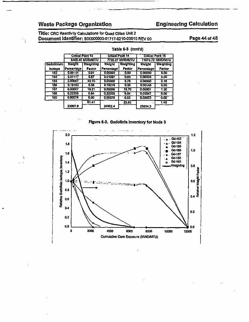
To illustrate the effect of the gadolinia depletion rates obtained from the SAS2H analysis, the gadoliniainventory was tabulated for two nodes in a GE Wx8 assembly with a large-central water rod loaded Intothe core In Cycle 13. The first selected node - designated as 'Node 3' - is In the power shaping sectionof the fuel assembly, where the reaction rates may be assumed to be high, particularly In the first half ofthe cycle. This particular lattice has an average enrichment of 3.32 wio (here and subsequently thesymbol wto represents the weight percentage) with two gadolinia-bearing fuel rods with a Gd2 %3concentration of 3.0 w/o and eight gadolinia-bearing fuel rods with a concentration of 4.0 wio. The node is12.0 Inches (30.48 cm) in length. These values are provided in Table 6-2 and illustrated In Figure 6-2.The second node selected In this assembly - designated as *Node B' - is near the top of core, in the'shutdown zone.' This lattice has an average enrichment of 3.48 wlo and the same gadolinla loading.This node is 18.0 inches (45.72 cm) long. Since this second node is near the top of the core, the powershould be less than that of the first node. The gadolinia inventory values for this node are shown In Table6-3 and illustrated in Figure 6-3.

-
Waste Package Organization Engineering Calculation
Title: CRC Reactivity Calculations for Quad Cities Unit 2Document Identifier: BOOOOOOOO-01717-0210-00010 REV 00 Page 42 of 48
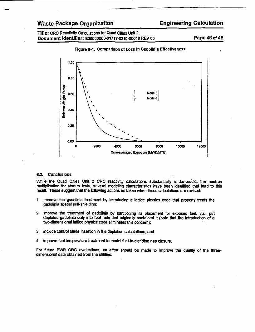
The 'weighting factor" Is the product of the weight percentage of the gadolinfum Isotope In the node andthe 2200 W/s absorption cross section (Reference 7.12, page 9, hereafter cited as the 'Chart of theNuclides) for that Isotope. Thus the change in the sum of these weighting factors over time Is a measureof capability of the gadolinia loading to reduce fuel assembly reactivity. As may be seen from Figure 6-2,the effective weighting factor In Node 3 drops rapidly over the first 2000 MWDIMTU, indicating the rapidburnout of the gadolinium Isotopes with high thermal absorption cross sections. For Node 8, Figure 6-3shows a less dramatic decrease. These two weighting factor curves are compared in Figure 6-4.
The results shown In Figure 6-1 may now be understood in light of the known behavior of the gadoliniaburnout. Two effects are present The first Is the effect of the uniform application of the exposed latticeisotopics to all the fuel rods, as seen in the change In neutron multiplication between QC2BOC13Ia] andQC2BOC13[b], and QC2BOC14[a] and QC2BOC14[b], while the second is the premature depletion of theneutronically important gadolinium isotopes. The first effect markedly decreases the spatial self-shieldingof the gadolinium and Increases Its negative reactivity contribution to the core. This effect is fairly uniformas long as there Is substantial gadolinia remaining In the newly Inserted fuel; however, when the gadoliniais effectively gone due to premature burnout, as In QC2C113CP13, the reactivity 'hold down' supplied bythe gadolinia also disappears and the inherent excess reactivity of the core is revealed. This samephenomenon is probably at work In Cycle 14, and the eigenvalue of QC2C14CP16 Is still reduced by theuniformly distributed gadolinia since the effective exhaustion of gadornia has not yet occurred.
As expected, the principal isotope results track the best-estimate results well, Indicating that no significanteffect is omitted by assuming the abbreviated nuclide set Further, it may be seen that the reactivityincrement accepted by omitting the less important fission products is about 1%, most of which is probablyfrom 49Sm.
The effect of eliminating all of the fission products in the principal actinide and actinide only casesproduces another Increase In reactivity; however, the differences among the results are somewhatsoftened, probably by the redistribution of power caused by the elimination of the fission products, but thisremained to be confirmed. (N.B., the results for QC2C13CP13PA appear to be too low based on theother results and clearly there should be better agreement between the principal actinide and actinide-only results.)

Waste Package Organization Engineering Calculation
Title: CRC Reactivity Calculations for Quad Cities Unit 2Document Identifier: B00000000-01717-0210-00010 REV 00 Page 43 of 48
Table 6-2. Gadolinium Inventory for Node 3
Description I Critical Point 9 i Critical Point 10 I Critical Point 11~~~~~~~ . _- _ __- . _ . _ . _ . - . -- -- -- - _ _ _ .
Cycle Exposure 0.00 MWD.MTU I 201.61 MWJOMTu I 2257.20 MW DMIUGadolinium _ Weight Weighting Weight Weighting Weight Weighting
Isotope (barns) lb) Percentage Factor Percentage Factor Percentage Fector152 900 0.00110 0.99 0.00109 0.98 0.00107 0.96154 60 0.01173 0.70 0.01191 0.71 0.01172 070155 61000 0.0013 4887.93 0.07815 4767.15 0.04267 2603.05156 2 0.1110 022 0.11475 0.23 0.15021 0.30157 255000 0.08580 21879.00 0.07629 19453.95 0.00745 1900.97158 2A 0.13710 0.33 0.14514 0.35 0.21466 0.52160 1 0.12220 0.12 0.11971 0.12 0.00004 0.00
Fuel Mass I 2[769.30(g) 16122.9
24223A9 4506.51 116216.1 16194.8 1
la]. Note that the core-averaged exposure Increment has been carried across the cyclebreak.
[b]. These values are from the Chart of the Nuclides.
Table 6-2 (confd)Critical Point 13 la)I Critical Point 14 [a] Critical Point 16 (a]
nasa .. *.nf-. - a^ . .. s...I I ^Iq=% jV4VVUIIVSu I 1fQaU.AI rAVIVVUJIU I U1VIO.ISC MVfVLANjI
Gadolinium Weight Weighting Weight Weighting Weight WeightingIsotope Percentage Factor Percentage Factor Percentage Factor
152 0.00101 0.91 0.00100 0.90 0.00000 0.00I5 0.01105 0.66 0.01087 0.65 0.00004 0.001SS- 0.00005 2.91 0.00005 321 0.00000 0.17156 0.19232 0.38 0.19196 0.38 0.00196 0.00157 0.00003 8.53 0.00003 838 0.00000 1.05158 0.22353 0.54 0.22359 0.54 0.00058 0.00160 0.00082 ~ 0.00072 0.00 0.00004 0.00
13.94 14.0416187.3 16186.8 16112.7
1.23
Table 6-3. Gadolinium Inventory for Node 8Descrption I Critical Point 9 Critical Point 10 Critical Point 11
_= ^.^.,7 A a .A^f .i .. m . .I an-
%IYWU GApwiU. U.W IWIM41JIW IU AUw .U I MVVLIIM I U I LS9ILU M WVVLJV I U
Gadoliniur n Weight Weighting Weight Weighting Weight WeightingIsotope (barns) Percentage Factor Percentage Factor Percentage Factor
152 900 0.00110 0.99 0.00109 0.98 0.00107 0.96154 60 0.01173 0.70 0.01191 0.71 0.01170 |0.70155 61000 0.08013 4887.93 0.07898 4817.54 0.05541 3379.9515D- 2 0.11150 0.22 0.11412 0.23 0.13777 0.28157- ~ 255000 0.08580 21879.00 0.07856 20033.82 0.02226 5676.30158 2A 0.13710 0.33 0.14265 0.34 0.19974 0.48160 1 0.12220 0.12 0.11950 0.12 0.11950 0.12
F Ftuel MassI O()
Z5769.3024184.4
1 24853.74
24309.Lj��9058.79
24217.1
[a]. Note that the core-averaged exposure Increment has been carried across the cyclebreak.
M - -
Waste Package Organization Engineering Calculation
Title: CRC Reactivity Calculations for Quad Cities Unit 2
Document Identifier: B00000000-01717-0210-00010 REV 00 Page 44 of 48
Table 6-3 (conrd)
Critical Point 13 Critial Point 14 _ Grit ical Point FS-.. Aff .. *a .al - - ~~f. 1 ..-- *.A" il,
0..40^ MVMM I w I 1102.41 My"Hwipw I M1113.11C WW"Mr~~~~~fflu
Gadolinkan Weight Weighting Weigiht Weighting Weight Weighting
isotope Percentage Factor Percentage Factor Percentage Factor-- 162 0.00101 0.91 0.0009 0.89 0.0000 0.00154 0.01117 0.67 0.01097 0.66 0.00004 0.00
155 0.00067 7 0.00009 5.7S 0.00000 0.18156 0.19193 80.1216 0.3 0 0.00
157 0.00007 1821 0.0OX6 16.70 0.00001 1.30
168 0.22305 0.54 0.22353 0.54 0.00047 0.00160 0.00078 0.00078 0.00 0.00003 0.00
51.4124002.4
23.S223804.3
1.49
Figure 6-2. Gadollnla Inventory for Node 3
2.0 1.2
I
IIaI
1.0
gil
- ISn.6 1
0.4 1
0.2
0 2000 4000 6000 8000
Cuublative Core iposure (MiVDJMTU
1 00 0.10010000 12000 ,

Waste Package Organization Engineering CalculationTitle: CRC Reactivity Calculations for Quad Cities Unit 2Document Identifier: BOOOOOOOO-01717-0210-00010 REV 00 Page 45 of 48
Figure 6-3. Gadolinla Inventory for Node 8
2o
1.8
1.6
1.2
1.0
0.81 1.4
14
* 1.2
; 1.OIMe
X 0.80
w 0.4
0.2.
0.0
0.6 2
£0.4
0.2
0.0
Cumulative Core Exposure (MW~DJMTtU)
-
Waste Package Organization Engineering Calculation
Title: CRC Reactivity Calculations for Quad Cities Unit 2Document Identifier: BOOOOOOOO-01717-0210-00010 REV 00 Page 46 of 48
Figure 6.4. Comparison of Loss In Gadollnla Effectiveness
1.00
0.80
t
U! 0.60.
0.40
0.20
0.000 2000 4000 6000 8000 10000
Core-averaged Exposure (MWDNM)12000
6.2. ConclusionsWhile the Quad Cities Unit 2 CRC reactivity calculations substantially under-predict the neutronmultiplication for startup tests, several modeling characteristics have been identified that lead to thisresult. These suggest that the following actions be taken when these calculations are revised:
1. improve the gadolinia treatment by Introducing a lattice physics code that properly treats thegadolinia spatial self-shielding;
2. Improve the treatment of gadolinia by partitioning its placement for exposed fuel, viz., putdepleted gadolinla only Into fuel rods that originally contained it (note that the introduction of atwo-dimensional lattice physics code eliminates this concern);
3. include control blade insertion in the depletion calculations; and
4. improve fuel temperature treatment to model fuel-to-cladding gap closure.
For future BWR CRC evaluations, an effort should be made to improve the quality of the three-dimensional data obtained from the utilities.

- -
Waste Package Organization Engineering Calculation
Title: CRC ReactivitY Calculations for Quad Cities Unit 2Document Identifier: BOOOOOOOO-01717-0210-00010 REV 00 Page 47 of 48
7. References
7.1 Briesmeister, J. F., Ed., MCNP"m - A General Monte Carlo N-Particle Transport Code, Version 4A,LA-12625-M, Los Alamos National Laboratory (LANL), November 1993. Technical InformationCenter Number (TIC #): 233782.
7.2 Briesmelster, J1. F., Ed., MCNPTh - A General Monte Catlo N-Particle Transport Code, Version 4B,LA-12625-M, LANL, March 1997. MOL.19980624.0328.
7.3 Software Qualification Report for the SCALE Modular Code System Version 4.3, SCALE Version4.3 Computer Software Configuration Item (CSCI): 30011 V4.3, DIl#: 30011-2002 REV 01, CRWMSM&O. MOL19970731.0884.
7.4 CRC Depletion Calculations fhr Quad Cities Unit 2, Document Identification Number (Dl#):B00000000-01717-0210-00009 REV 00, Chrilian Radioactive Waste Management System,Management and Operating Contractor (CRWMS M&O). MOL.19980730.0510.
7.5 Software Qualification Report for MNYCP 4A A General Monte Carlo N-Particle Transport Code,CSCI: 30006 V4A, DI# 30006-2003 REV 02, CRWMS M&O. MOL19961028.0272.
7.6 Software Qualification Report for MNCP 4B2, A General Monte Carlo N-Particle Transport Code,CSCI: 30006 V4B2LV, DIl#: 30033-2003 REV 01, CRWMS M&O. MOL.19980622.0637.
7.7 MCNP CRC Reactvity Calculatfon for Quad Cities BWR, DI#: BBAOOOOO-01717-0200-00146 REV00, CRWMS M&O. MOL19971229.0128.
7.8 Core Design and Operating Data for Cycles I and 2 of Quad Cities 1, EPRI NP-240, Electric PowerResearch Institute, Palo Alto, CA, November 1976. TIC #: 237267.
7.9 Summay Report of Commercial Reactor CHtrcaity Data for Quad Cities Unit 2, D#. B00000000-01717-5705-00096 REV 00, CRWMS M&O. MOL.19980730.0509.
7.10 Disposal Crfitcalty Anays Methodology Technical Report, DIl. B00000000-01717-5705-00020REV 01, CRWMS M&O. MOL. 19980127.0095.
7.11 Topical Report on Actinide-Only Bumup Credit for PWR Spent Nuclear Fuel Packages, DOEJRW-0472 Rev. 1, Department of Energy Office of Civilian Radioactive Waste Management, Washington,D.C., May 1997. MOV.19970416.0125.
7.12 Nuclides and Isotopes (Incorporating the Chart of the Nuclides), 14 h Edition, General ElectricCompany, San Jose, CA, 1989. TIC # 201637.
7.13 CRC Reactfity Calculation for Quad Cities Unit 2, DIl: B00000000-01717-0210-00010 REV 00,CRWMS M&O, Attachment I - Data Cartridges. MOL.19980810.0213.

Waste Package Organization Engineering Calculation
Title: CRC Reactivity Calculations for Quad Cities Unit 2Document Identifier: BOOOOOOO-01717-0210-00010 REV 00 Page 48 of 48
8. Attachments
The attachments that support the work in this document are listed In Table 8-1.
Table 8-1. List of Attachments
Attachment Contents Numberof
PagesI Index for Computer Output Files Supporting this Analysis (moved to 7 [a)
Attachment 7.13)II Development of Core Geometry Datasets 13Ill Development of Core Materials Dataset 43IV Development of Lattice Geometry Datasets 16V Development of Control Blade Geometry Dataset 12VI Development of Algorithms and Encoding for Linkage Automation 41
VHI Specification of Intermediate Datasets for Fuel Materials 12Vill Development of Automation to Create Intermediate Fuel Materials Datasets 37IX -Methodology for Building Control Blade Model 15X Methodology for Building GE 7x7 Fuel Lattice Model 16Xi Methodology for Building GE 8x8 with Small Water Rods Model 14XII Creation of MCNP Model for Quad Cities Unit 1, Beginning-of-Life Core 9XIII MCNP Input Deck Generated by BLINK, Version 0, for QC1, BOL 59XIV Listing of Routines and Functions for BLINK, Version 0 241XV Usting of Routines and Functions for IDSGEN, Version 0 51XVI Methodology for Building GE 8x8 with Large Central Water Rod Model 15XVII Algorithms and Encoding to Produce BLINK, Version 1 1$4XVIII Creation of MCNP Model for Quad Cities Unit 2 Exposed Core CRCs for
_____ _____ Cycle 13XIX Creation of MCNP Model for Quad Cities Unit 2 Exposed Core CRC's for 21
Cycle 14XX I Usting of Routines and Functions for BLINK, Version 1 180
la]. This Is the number of pages in the hard-copy listing of contents of the data cartridges.

Waste Package Operations Engineering Calculation (Attachment)
Title: Index for Computer Files Supporting this AnalysisDocument Identifier: 800000000-01717-o210-OOO1o REV 00 Attachment I Page 1 of 7
Table of Contents
Contents Page
1. Introduction 3
2. References 7
1

Waste Package Operations Engineering Calculation (Attachment)
Title: Index for Computer Files Supporting this AnalysisDocument Identifier: B00000000-01717-021"00010 REV 00 Attachment I Page 2 of 7
List of Tables
Table Contents Page
Table 1-1 Summary of Computer Output Supporting this Analysis 3

-
Waste Package Operations Engineering Calculation (Attachment)
Title: Index for Computer Files Supporting this AnalysisDocument Identifier: B000OOOO-01717-0210-00010 REV 00 Attachment I Page 3 of 7
1. Introduction
This attachment provides a description of the computer output produced In the course of this analysis.This output is provided on magnetic tapes (also known as data cartridges). An enumeration and asummary of the contents of the computer output files Is loWated in Table 1-1. The magnetic tapes werewritten using a Colorado Model T1000e External Parallel Port Backup System for personal computers.(These tapes have been moved to Reference 2.1). Note that the file sizes shown In the table are the MS-DOS file sizes. Sizes fmm Wndows-95
Table 141 Summary of Computer Output Supporting this Analysis
File Name I Size (tes) I Date I Time I DescriptionIDSGEN OLtpu - Tape ICPI4SIO.SUM 113,403 7/198 126p Consolidated IDSGEN Output for QC2BOC14 Critical Point with
Best Estimate Isotopics and Smeared" Fresh Fuel Loading
CP101O.SUM 19.760,450 7398 10:40a Consolidated IDSGEN Output for QC2C13CP10 Critical Point with__a_110_ Best-estimate Isotopics
CP10PAJO.SUM 9,553,097 7M98 11:17a ConsolIdated IDSGEN Output for OC2C13CPIO Critcal Point with_Principal Actnide Isotopics
CPtOPIIO.SUM 11.931,000 7/3U98 10:S0a Consolidated IDSGEN Output for QC2C13CP10 Critical Point wthPrincdpal Isotope isotopics
CP1IAOIO.SUM 9.224.751 7N98 1:21p Consoridated IDSGEN Output for QC2Ci3CPI Critical Point withA_____e-onily Isotopics
CPI1IO.SUM 20,128,638 713N98 10 42a Consolidated IDSGEN Output for QC2C13CP1t Critical Point withIBest-tiate lsotopics
CP11 PAO.8UM 9,623.647 7=3198 11:17a Consolidated IDSGEN Output for QC2C13CP1I1 Critical Point withPrncipalActinide Isotopics
CP11PIIO.SUM 12,034.169 MM 10.S1R Consolidated IDSGEN Output for QC2C13CP1I Critical Point with_______ _Principal Isotope Isotopics
CP13AOIO.SUM 9.122.495 M98 1:22p Consolidated IDSGEN Output for QC2CI3CP13 Critical Point with__________ ____ __ Actinide-only Isotopics
CP131O.SUM 20,202,176 7/98 1O:44a Consolidated IDSGEN Output for QC2C13CP1 3 CrItical Point withBest-estimate Isotopics
CP13PAIO.SUM 9,553,097 7/3/98 11:18a Consolidated IDSGEN Output for QC2C13CP13 Critical Point withPrincipal Actinide Isotopics
CP13PIIO.SUM 11.934.486 7N98 10:53a Consolidated IDSGEN Output for QC2C13CP13 Critical Point withPdncipal Isotope Isotopics
CPI4AOIO.SUM 7.643.633. 7N398 1.23p Consoldated IOSGEN Output for QC2BOC14 Critical Point with._________ Actinide-only Isotopics
CP1410.SUM 16.695.514 7/3/98 10:46a Consolidated IDSGEN Output for QC2BOC14 Critical Point withBest-estinate Isotopics
CP14PAIO.SUM 7.969,457 7/3/98 1:16p Consolidated IDSGEN Output for QC2BOC14 Critical Point withPrincipal Actinide Isotopics
CP14PIIO.SUM 9,937,595 7/98 11:10a Consolidated IDSGEN Output for QC2BOC14 Critical Point withPrincipal Isotope Isotopics
CP16AOIO.SUM 9,077,720 7398 1.24p Consolidated IDSGEN Output for QC2C14CP16 Critical Point withActinide-only Isotopics
CP1610.SUM 20.294.019 7398 10:47a Consolidated IDSGEN Output for QC2C14CP16 Critical Point withBest-estimate Isotopics
CP16PIIO.SUM 11,83.123 7N98 11:14a Consolidated IDSGEN Output for QC2C14CP16 Critical Point withPrincipal isotope Isotopics
CP9AOIO.SUM 7,509,033 7/98 1:17p Consolidated IDSGEN Output for QC2BOC13 Critical Point with___________ .________ Actinide-only Isotopics
CP8I0.SUM 16.184.373 7//98 tO.39a Consolidated IDSGEN Output for QC2BOC13 Critical Point withBest-estimate Isotopics
CP9PAiO.SUM 7,831,109 7/398 11:16a Consolidated IOSGEN Output for OC2BOC13 Critical Point withPrincipalActinide.lsotopics

Waste Package Operations Engineering Calculation (Attachment)
Title: Index for Computer Files Supporting this AnalysisDocument Identifier: BOOOOOOOO-01717-0210-00010 REV 00 Attachment I Page 4 of 7
File Name Size (bytes) Date Time DescriptionCP9PIIO.SUM 9,775,577 7 0ia Consolidaied IDSGEN Output for QC2BOC13 Critical Point with
Principal Isotope IsotopicsCP9SIO.SUM e3,339 7 tS t2p- Consolidated IDSGEN Output for QC2BOC13 Critical Point with
Best EsUimate Isotopics and *Smeared' Fresh Fuel Loading
CP10AOIO.SUM 0,193,377 7/98 t:19p Consolidated IDSGEN Output tor QC2C13CP10 Critical PointwithActnide-only Isotopics
BOLIO.SUM 189.933 7/398 3:52p Consolidated IDSGEN Output for Quad Cities Unit Beginning ofLie Case
BUNK Output Ta pe 2QC1C1.OUT 702,845 7t31198 3:09p BUNK Output for Quad Cities Unit Beginning of Life Cse
Prepared with Version 1:- of BUNK
epl0b.out 27,229.289 7/31/98 3:12p BLINK Output for QC2C13CP10 Critical Point with Best Estimatekotopics
cpl4b.out 23,068,452 7/31t98 3:17p BUNK Output for QC2BOC14 Critical Point with Best Estimate_ _______ Isoatopks
cpllb.out 27,347.162 7/31/98 3:13p BLINK Output for QC2C13CP11 Critical Point with Best Estimate
cp9sb.out 22,103,321 7131/98 320p BLINK Output for QC2BOCi3 Critical Podntwith Smeared BestEstimate Isotopics
cpl3b.out 27.371,002 7/31/98 3:15p LUNK Output for QC2C13CP13 Critical Point with Best Estimate_________________ _ ___________ _Isotopics
cpl6b.out 27,731,571 7/31t98 3:18p BUNK Output for QC2C14CP16 Critical Polntwith Best Estimate____________ ~~Isotopics
cp10pib.out 26,213.003 7/31/98 3.29p BUNK Output for QC2C13CP10 Critical Point with PrincipalIsotopic Set
cpl3pib.out 26,217.402 7/31/98 3:32p BLINK Output for QC2C13CP13 Critical Point with PrincipalI _ Isotopic Set
cpl4sb.out 23,045,527 7/31/98 326p BLINK Output for QC2BOC14 Critical Point with Smeared Best______________ ~~~~~~Estimrate isotopic.
cp1 1pib.out 26.249,261 7/31/98 3:30p BLINK Output for 0C2C13CP1 I Critical Point with PrincipalIsotopic Set
cp9plb.out 21,250,855 7/31/98 3 27p BLINK Output for QC2BOC13 Criteal Point with Principal IsotopicSet
cpl4pib.out 22,223,000 7131198 3:34p BLINK Output for QC2BOC14 Critical Point with Principal Isotopic_ _ _ _ _ _ _ _ _ _ _ _ _ _ _ _ _ _ _ _ _ _ _s et
cp16plb.out 25,S89.443 7131198 3:35p BUNK Output for QC2C14CP16 Critical Point wlth Pdncpal________ _______ _ Isotopic Set
cp9b.out 22,107,360 7/31/98 3:11p BLINK Output for QC2BOC1 3 Critical Point with Best Estimate______ ______ _ ____ ____ _ Isotopics
BUNK Output - Tipe 3 .
cp9pab.out 20,899.061 7131198 3 37p BLINK Output for QC2BOC13 Critical Point with Principal ActinideSet
cp1Opab.out 25,791,340 7131/98 3.38p BLINK Output for QC2C13CPIO Critical Point with Principal_ctinlde Set
cp 1pab.out 25.813.991 7/31198 3:40p BUNK Outputr QC2C13CP11 Critical Point with Principal________ _ Actinide Set
cpl3pab.out 25.791.328 7/31/98 3:41p BLINK Output for QC2C13CP13 Critical Point with PrincipalActhiriide Set
cpi4pab.out 21.866,987 7/31/98 3:43p BLINK Output for QC2BOC14 Critical Pointwith PrincipalAclinide_________ _ Setcpl6pab.out 26,161,434 7/31/98 3:45p BUNK-Output forQC2C14CP16 Critical Point with Principal
Actinide Setcpl3aob.out 25,729,775 7/31/98 3:S0p BUNK Output for OC2Ci3CP13 Critical Point with Actinide-only
setcpl6aob.out 26.105,850 M/31/98 3:53p BUINK Output for QC2C14CP16 Critical Point with Actinide-only
_____________ __________ S et
cp9acb.out 20,858,218 7131198 346p BLINK Output for QC2BOC13 Critical Point with Actinide-only Set

Waste Package Operations Engineering Calculation_(Attachment)
Title: Index for Computer Files Supporting this AnalysisDocument Identifier., BODOOOOODO.01717-021U010ol REV 00 Attachment I Page 5 of 7
File Name bSi (bytes) Date Time Descriptioncp10aob.out 25,753,191 /311/95 3.48p BUNK Output for QC2C13CPIO Crtical Point vth Actinide-only
_ _ _ _ _ _ _ _ _ ~~~~~~Setcpllaob.out 25,762,199 7/31198 3:49p BUNK Output for QC2C13CP11 Critical Point with Actinide-only
Setcpl4aob.out 21,e24,982 Tt31 19 3.51p BUNK Output for C2BOC14 Critical Point with Actinide-only Set
MCtfP Oulpu -Tape 4CP9M.OUT 18.217,792 811/9 10:53a MCNP Output for 0C2BOC13 Critical Point with Best Estimate
CP10M.OUT 21,686,771 81/U98 12S~ MCNP Output for QIC2C13CPIO Critcal Point with Best Estimate__________ _ ________ Isotopics
CP11M.OUT 20.212,516 8398 10:37a CNP Output for QC2C13CP1I1 Critical Point with Best Estimate__ _ _ _ __ _ _ _ _ _ _st pc
CP13NLOUT 22,219,49 10.38a MCNP Output for OC2CI3CPI3 Critical Point with Best Estimate
CP14M.OUT 19,328,304 8131S8 10:39a MCNP Output for QC2BOC14 Critical Point with Best Estimate
CP16M.OUT 23,097,085 8/3tsa 10:40a MCNP Output for QC2C14CP16 Critical Point with Best Estimate__________ Isotopics
CP9SM.OUT 16,383,450 898 10:40a MCNP Output forOC2BOC13Crtical Pointwith Smeared Best_Estimate Isotopics
CP14SM.OUT 19.038,100 8 S3/95 10:41a MCNP Output for QC2BOC14 Critical Point with Smeared BestI_ _Estimae Isotopics
CP9PLM.OUT 13,584.472 I79 10i15 a MCNP Output for QC2BOC13 Critical Point with Principal Isotopic
CP1OPIM.OUT 16,649,912 838 10.42a MCNP OutputforQC2CI3CP1OCritical Pointwith PdncipalIsotopic Set
CP11PIM.OUT 16,765.837 t S 1 0.T42a MCNP Output for QC2C13CP11 Critical Point with PrincipalIsotopic Set
CP13PtM.OUT 16.31B,737 8/3198 10.43a MCNP Output for OC2C13CP13 Critical Point with Principal__________ ____ _ __ Isotopic Set
CP14PIM.OUT 14,462,125 8NS 10.43a MCNP Output for QC2BOC14 Critical Point with Principal Isotopic
CP16PiM.OUT 16,902,918 8s3e98 10:44 t MCNP OutputorQC2C14CP1t Critical Point with Principal____________ 2326.481 - - Isotopic Set
QC1C1_M.OUT 2,326,461 83/ 5e 10:58a JMCNP Output for Quad Cities Unit 1 BOL CRC Calculation
MCNP Output - Tape 5CP9PAM.OUT 12,283.059 3J98 10 a MCNP Output for QC2BOC13 Critical Point with Principal Actinide
CP10PAM.OUT 15,202,838 U3198 10 a UCNP Output for QC2C3CP10 Critical Point with Principal__________ ________ ~~~Actinide Set
CP11PAM.OUT 15,185,595 8/3/98 10:54a MCNP Output for QC2C13CP1I Critical Point with PrincipalActinide Set
CP13PAM.OUT 14,584.690 813198 MS a MCNP Output for QC2C13CP13 Critical Point with PrincipalWAcinlde Set
CP14PAM.OUT 13,223.335 8 9 10:Sa MCNP Output for QC2BOC14 Critical Point with Principal Actinide__________ ~Set
CP16PAM.OUT 15267,605 8/3/98 10:55a MCNP Output for QC2C14CP16 Critical Point with Principal____c side St
CP9AOM.OUT 12.355,340 8N98 10:56a UCNP Output for OC2BOC13 Critical Point with Actiide-Only Set
CP1OAOU.OUT 14,922.179 8U3/98 10:S6a MCNP Output forQC2C13CP10 Critial Pointwith Acinide-Ordy_____________ ~~~~~Set
CP11AOM.OUT 14,805.739 i&m 2 1Sp MCNP Output for QC2C13CP1 Critical Point with Actinide-Only
CP13AOM.OUT 14,610,099 8138 219p CNP Output for C2C13CP13 Critical Point wih Acinide-Only
CP16AOM.OUT 15,102.800 85/98 3:1 p MCNP Output for QC2C14CP16 Critical Point wlh Acdinlde.Only_ _ _ _ _ _ _ _ _ _ _ _ S~~~~~~~et

Waste Package Operations Engineering Calculation (Attachment)Title: Index for Computer Files Supporting this AnalysisDocument Identifier: B00000000-01717-0210-00010 REV 00 Attachment I Page 6 of 71 File Name I Size (bytes) Date Time I Description IECp4AOM.UT 12,777.076 15198 3.17p MCNP Output fEr QC2BOC14 Critical Point with TWIde-Only Set
';
.,

Waste Package Operations Engineering Cafculation (Attachment)Wat Pakg Oprtin Enien Caclto (AtchetTitle: Index for Computer Files Supporting this AnalysisDocument Identifier: B0OOOOOO-01717-0210-0000 REV 00, Attachment I Page 7 of 7
2. References
2.1 CRC Reactvty Calculation for Quad Cies Unit Z DI#: BOOOOODO-01717-0210-00010 REV 00,CRWMS M&O, Attachment I - Data Cartrdges. MOL.19980810.0213.
7.
Waste Package Operations Engineering
Title: Development of Core Geometry DatasetsDocument Identifier. BOOOOOOOO-01717-0210-00010 REV 00
Calculation (Attachment)
Attachment 11 Page 1 of 13
Table of Contents
Contents
1. Introduction
2. Dataset Structure and Contents
3. Dataset Creation
3.1. Dataset Title Record3.2. Namelist Input3.3. Spame-delimited Fields3.4. Dataset Identification
4. References
Page
5
5
8
8888
13
Waste Package Operations Engineering Calculation (Attachment)
Title: Development of Core Geometry DatasetsDocument Identifier: BOOOOOOOO-01717-0210-00010 REV 00 Attachment II Page 2 of 13
List of Figures
Figure Contents Page
Figure 2-1 Location Indexing for Control Blades and Dry Tubes 7
Figure 3-1 Core Geometry Dataset for 724 Bundle BWR/3 9

Waste Package Operations Enfgineering Calculation (Attachment)
Title: Development of Core Geometry DatasetsDocument Identifier: BOOOOOOOO-01717-0210-oO010 REV 00 Attachment II Page 3 of 13
LUst of Tables
Table contents Page
Table 2-1 Contents of Dataset 6

Waste Package Operations Engineering Calculation (Attachment)
Title: Development of Core Geometry DatasetsDocument Identifier: BOOOOOOO-01717-0210-00010 REV 00 Attachment II Page 4 of 13
List of Worksheets
Worksheet Contents Page
Worksheet 3-1 Nameflst Input Development 11

Waste Package Operations Engineering Calculation (Attachment)
Title: Development of Core Geometry DatasetsDocument Identifier: BOOOOOOO-01717-0210-00010 REV 00 Attachment II Page 5 of 13
1. Introduction
This attachment describes the creation of the datasets defining the core layout and core supportstructures. It provides a detailed fist of contents for such datasets and documents the creation of thedatasets of this type used In the present analysis.
2. Dataset Structure and Contents
The dataset structure is an ASCII-format file that Incorporates both FORTRAN Namellst-type Input andfields of space-delimited data. The contents of this dataset are given In Table 2-1. In this table the formatof each datum Is given. The indexing for the locations of the control blades and the in-coreInstrumentation dry tube are depicted In Figure 2-1. In this figure, the control blade shown has an Index of(2,2) and the instrument location also has an Index of (2,2). This permits the location of the blades andthe instrument dry tubes to be referenced to the same scheme as for the fuel assembles.

Waste Package Operations Engineering Calculation (Attachment)
Title: Development of Core Geometry Datasets
Document Identifier: B00000000-01717-0210-00010 REVOO Attachment 11 Page 6 of 13
Table 2-1 Contents of Dataset
Mnemonic Definition Comments FormatTitle Dataset Title Character String - Describes Application for this Single LIne
Dataset (Class of BWR to which It Is Applicable)ncol Dimensionality of Core Integer - Maximum Number of Fuel Assemblies Namelist
.___________ in the Widest Rod of such Assemblies
nrow Dimensionality of Core Integer - Maximum Number of Fuel Assemblies Namelist.____ _ In the Longest Column of such Assemblies
apitch Assembly Pitch (cm) Real - Always Six Inches (15.34 cm) except for NamelistBWR/1 and Advanced Boiling Water Reactor(A__R)
vod Vessel Outer Diameter Defines Lateral Outer Surface for Problem Namelist(cm ) _ _ _ _ _ _ _ _ _ _
vthick Vessel Thickness (cm) Used to Compute Inner Surface of Vessel Cell Namelistsod Core Shroud Outer Defines Shroud and Jet Pump Region Namelist
Diameter (cm)
sthick Core Shroud Thickness Used to Compute Inner Surface of Core Shroud Namelist(CM) Cell
tutpr Top of Upper Tie Plate Defines the First Upper Reflector Region NamelistRegion (cm) [a] _
tcgr Top of Core Grid Region Defines the Second Upper Reflector Region Namelist_________(cm) [a]
bftpr Bottom of Lower Tie Plate Defines the First Lower Reflector Region NamelistRegion (cm) [a]
bcpr Bottom of Fuel Defines the Second Lower Reflector Region NamelistSupport/Core PlateRegIon (cm) [a]
dtod Instrument Dry Tube Used to Dimension Dry Tube NamelistOuter Diameter (cm)
dtid Instrument Dry Tube Used to Dimension Dry Tube NamelistInner Diameter (cm)
mvessel Material Identifier for Combined with Water to Create a Homogenized Namelist[Vessel Material
mshroud Material Identifier for Core Combined with Water to Create a Homogenized NamelistShroud Material
mtg Material Identifier for Core Combined with Water to Create a Homogenized NamelistTop Guide Material
mcp Material Identifier for Core Combined with Water to Create a Homogenized NamelistPlate Material
[a]. The axial datum Is the bottom of active fuel (BAF).

Waste Package Operations Engineering Calculation (Attachment)
Title: Development of Core Geometry DatasetsDocument Identifier: BOOOOOOOO-017i7-0210-00010 REV 00 Attachment II Page 7 of 13
Table 2-1 (cont'd)
Mnemonic Definition Comments Formatmigt Material Identifier for In- Narnelist
core Guide Tubevalid. Array.of.Valid Assembly . Integer.-r. Values.for.Entire Core are Provided. Space-delimited
Locations and then Partitioned for the Particular Problem Fieldbvalid Array of Valid Control Integer - Values are Provided for each Control Space-delimited
Blade Locations Cell (or Implied Control Cell for Peripheral and FIeldnon-fuel Locations)
ivalid Aay of Locations for In- Integer - Values are Provided for each Control Space-delimitedcore Instrumentation Dry Cell (or Implied Control Cell for Peripheral and FieldTubes non-fuel Locations)_
Figure 2-1 Location Indexing for Control Blades and Dry Tubes
(1.1)
Z-I Z
(2,1)
(1.2)
(2,2)
ID0

Waste Package operations Engineering Calculation (Attachment)
Title: Development of Core Geometry DatasetsDocument Identifier: BooooooOo-01717-0210-00010 REV 00 Attachment 11 Page 8 of 13
3. Dataset Creation
Each group of data In the dataset will now be discussed in greater detail and the creation of the dataset fora 724-bundle BWR/3 documented. The final dataset is shown In Figure 3-1.
3.1. Dataset Title Record
The first line of the dataset Is a title. While the contents of this line are arbitrary. It should contain thefollowing Information to ensure consistency with the file name:
number of bundles In the core (724 In this case); and
* the class of BWR (3 n this case).
32. Narnellst Input
The FORTRAN namelist-type Input variables must adhere to the restrictions Inherent In the format of suchInput. Care must be taken to ensure that the value provided is consistent with the data storage class Inthe automation (i.e., Integer Input for Integer variables and real Input for real variables) so that precision Isnot lost for real variables and Illusory precision Is Implied for Integer variables.
The development of the values appropriate for the 724-bundle BWR/3 Is shown in Worksheet 3-1. All ofthe material Identifiers for the dataset are consistent with Type 304 stainless steel (Reference 4.1, for thefirst two cycles of operation of the Quad CiUes-1 core, Table 12 and Figure 29 - hereafter cited as themEPRI Report@).
3.3. Space-delimited Fields
These fields are used for 'maps' Indicating the locations of fuel assembfles, control blades and In-coreInstrumentation dry tubes. While these are read In a "free-format," good practice Indicates that theyshould be arrayed In a regular fashion that maxdimzes legibility.
3A. Dataset Identification
This dataset file Is named: bwr3_724bundle.dat

Waste Package Operations Engineering Calculation (Attachment)
Title: Development of Core Geometry DatasetsDocument Identifier: BOOOOOOO-01717-0210.00010 REV 00- - Attachment II Page 9 of 13
Figure 3-1 Core Geometry Dataset for 724 Bundle BWRI3
Core Geometry for 724-bundle BWR/35corencol - 30nrow - 30apitch - 15.24vod - 668.654vthick - 15.557sod - 526.096sthick - 5.08tutpr - 399.0tcgr - 403.0bltpr - -13.49bcpr - -18.57mvessel - 'SS304rmshroud - 'SS304'mtg - '3TG1'mcp - '3CP1'migt - 'SS304'dtod - 1.78dtid - 1.63SendValid Assembly Locations
000 0 0 0 0000 1 1 1 1 1 1 1 1 1 1 0 0 00 00 00 0 0000 000000 1 1 1 1 1 1 1 1 1 1 1 1 0 0 00 00 0 0 00 0 0 0 O 0 1 1 1 1 1 1 1 1 1 1 1 1 1 1 1 1 1 0 0 0 0 0 0O O O O 0 1 1 1 1 1 1 1 1 1 1 1 1-1 1 1 1 1 1 1 1 0 0 0 0 0O O O 0 1 1 1 1 1 1 I I 1 1 1 1 1 1 1 1 1 1 1 1 1 1 0 0 0 00 0 0 1 1 1 1 1 1 1 1 1 1 1 1 1 1 1 1 1 1 1 1 1 1 1 1 0 0 0O 0 1 1 1 1 1 1 1 1 1 1 1 1 1 1 1 1 1 1 1 1 1 1 1 1 1 1 0 0000 1 1 1 1 1 1 1 1 1 1 1 1 1 1 1 1 1 1 1 11 1 1 1 1 00O 0 1 1 1 1 1 1 1 1 1 1 1 1 1 1 1 1 1 1 1 1 1 1 1 1 1 1 0 00 1 1 1 1 1 1 1 1 1 1 1 1 1 1 1 1 1 1 1 1 1 1 1 1 1 1 1 1 0
1 1 1 1 1 1 1 1 1 1 1 1 1 1 1 1 I 1 1 1 1 1 1 1 1 1 1 1 1 11 11 11 11 11 11 11 11 11 11 1 1 1 1 1 1 1 1 1 1 1
1 1 1 11 11 1 1 1 1 1 1 1 1 1 1 1 1 1 1 1 1 1 1 1 1 1 11 1 1 1 1 11 11 11 11 1 1 1 1 1 1 1 1 1 1 1 I 1 11 1 1 11 11 1 1 11 11 1 1 1 1 1 1 1 1 1 1 1 1 1 1
1 1 1 1 1 11 11 11 1 1 1 I 1 1 1 1 1 1 1 1 1 1 1 1
1 1 1 1 1 1 1 1 1 1 1 1 1 1 1 1 1 1 1 1 1 1 1 1 1 1 1 1 1 10 1 1 1 1 1 1 1 111111 1 1 1 1 1 1 1 1 1 1 1 1 101 1 1 1 1 1 1 1 1 1 1 1 1 1 1 1 1 1 1 1 1 1 1 1 1 1 1 1 1 1
0 1 1 1 1 1 1 1 1 1 1 1 1 1 1 1 1 1 1 1 1 1 1 1 1 1 1 1 1 0O 0 1 1 1 1 1 } 1 1 1 1 1 1 1 1 1 1 1 1 1 1 1 1 1 1 1 1 0 0O 0 1 1 1 1 1 1 1 1 1 1 1 1 1 1 1 1 1 1 1 1 1 1 1 1 1 1 0 0
O O O 0 1 1 ill 1 1 1 1 1 1 1 1 1 1 1 1 1 1 1 1 1 1 0 0 0 0O O O O 0 1 1 1 1 1 1 1 1 1 1 1 1 1 1 1 1 1 1 1 1 0 0 0 0 0
o 0 0 0 O 0 O O 0 1 1 1 1 1 1 1 1 1 1 1 1 0 0 0 0 0 0 0 0 00 O O O O O O O O 0 1 1 1 1 1 1 1 1 1 1 a a 0 0 0 0 0 0 0 °
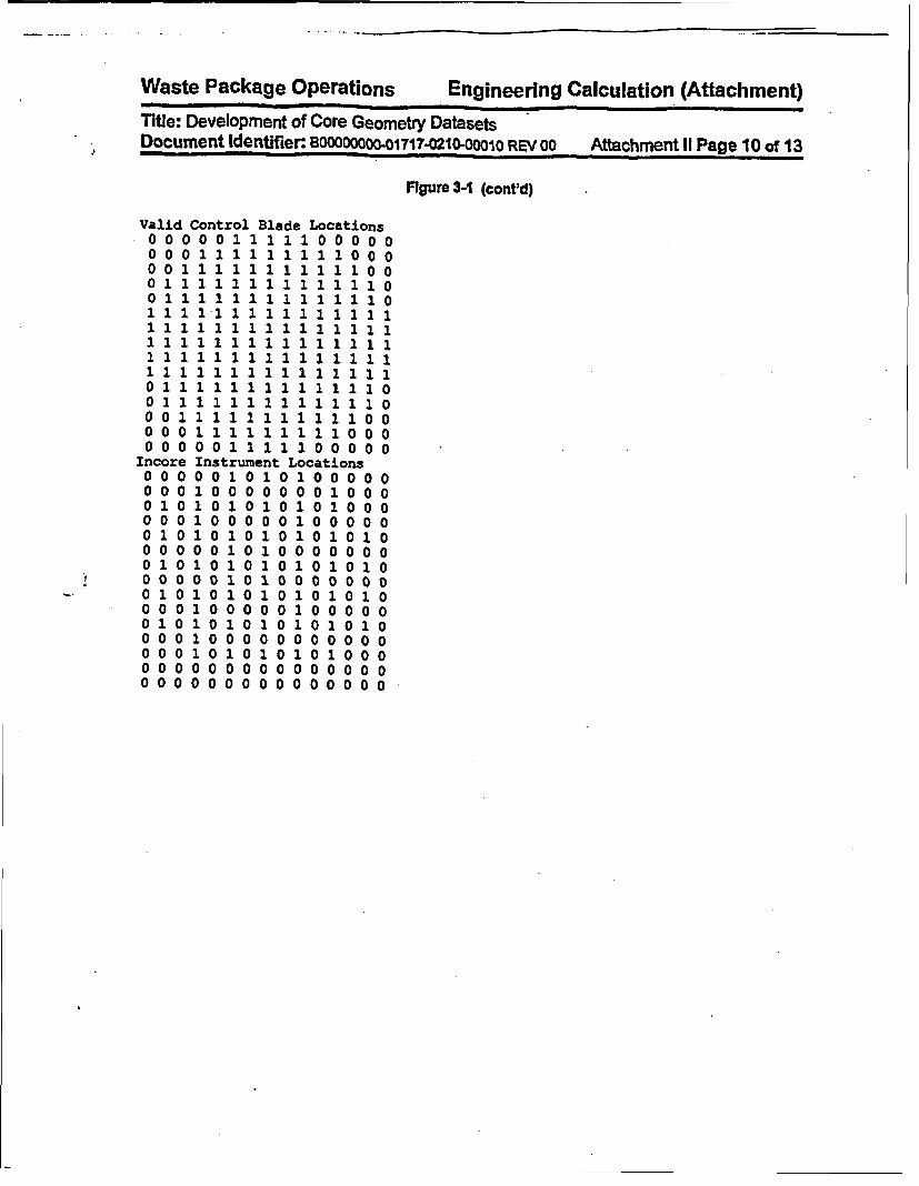
Waste Package Operations Engineering Calculation (Attachment)
Title: Development of Core Geometry Datasets-JI Document identifier: BOOOOOO01717.0210-00010 REV 00 Attachment II Page 10 of 13
Figure 3-1 (cont'd)
Valid Control Blade Locations0 0000 1 1 1 1 1 0 0 000O O 0 1 1 1 1 1 1 1 1 1 0 0 0001 1 1 1 1 1 1 1 1 1 1 0 00 1 1 1 1 1 1 1 1 1 1 1 1 1 00 1 1 2 1 1 1 1 1 1 1 1 1 1 0
1 1 1 1 1 1 1 1 1 1 1 1 1 1 11 1 1 1 1 1 1 1 2 1 1 1 1 1 11 111 1 11 1 11 1111 1
0 0 1 1 1 1 1 1 1 1 1 1 1 0 0O O 0 1 1 1 1 1 1 1 1 1 0 0 0O O O O 0 1 1 1 1 1 0 0 0 0 0
Incore00000 001 000 001 000 001 0! 0 001 000 001 0000000000000
Instrument Locations0 0 1 0 1 0 1 0o o C0 0 0 0 0 00 1 0 aol o 1 o 1 o 1 o C
1 0 00 00 100001 0 1 0 1010101001 01 0 00 0 0 01 0101 0 1 0 1 010 0 1 0 1 0 0 0 0 0 01 o 1 0 1 0 1 0 1 0 11 0 0000 1 0 0 001 o 1 0 1 0 1 0 1 0 11 00 0 0 0 00001 01 0 1 0 1 0 1000 0 0 0 0 0 0 0000000 00000000
I
I
I
000000000000000

Waste Package Operations Engineering Calculation (Attachment)
Title: Development of Core Geometry DatasetsDocument identifier: B100000Oo-01717-0210-00010 REV 00 Attachment 1i Page11 of 13
Worksheet 3-1 Namelist Input DevelopmentiReference -
Mnemonic DefinitIon Value Units Source Namencol Dimensionality of Core 30 n/a la] nlanrow Dlmensionality of Core 30 nla [a) n/aapitch Assembly Pitch 6 Inches [b] APITCHvod Vessel Outer Diameter 668.654 cm [cl I n/avthick Vessel Thickness 15.557 cmr [C] I rasod Core Shroud Outer Diameter 526.096 cm Ic] na
sthlck Core Shroud Thickness 5.08 cm [c] nlana Assembly Length (Handle to Noseplece) 171.27 Inches Id3 ATLEN
n/a Nosepiece Guide 1A5 Inches [dl LNPGn/a Nosepiece Cylinder 0.625 inches [dJ LNPCYL
n/a Lower Tie Plate 5.31 Inches [dl LLTPn/a Active Fuel Length 144 Inches [d) AFL
r/a Handle Length 6.65 Inches [dl LHANDLE
tutpr Top of Upper Tie Plate Region n/a n/a n/a TUTPR
tcgr Top of Core Grid Region 158.6875 inches (el TCGR
bitpr Bottom of Lower Tie Plate Region n/a n/a n/a n/an/a Core Support Plate Thickness 2 Inches lel CSPTHbepr Bottom of Fuel Support/Core Plate n/a n/a n/a nra
Regon I
dtod Instrument Dry Tube Outer Diameter 0.700 Inches It] DTDDry Tube Thickness 0.03 Inches IfJ DTD
dtld Instrument Dry Tube Inner Diameter 1.63 Inches n/a DTID
al-. This value Is from the EPRI Report Table 15.[b). Thts value Is from the EPRI Report Table 3.(c]. Reference 4.2, Table 4.1-1.[d]. This value is from the EPRI Report Figure 10.le]. This value Is from the EPRI Report, Figure 26.Mf. This value Is from the EPRI Report, Figure 29.
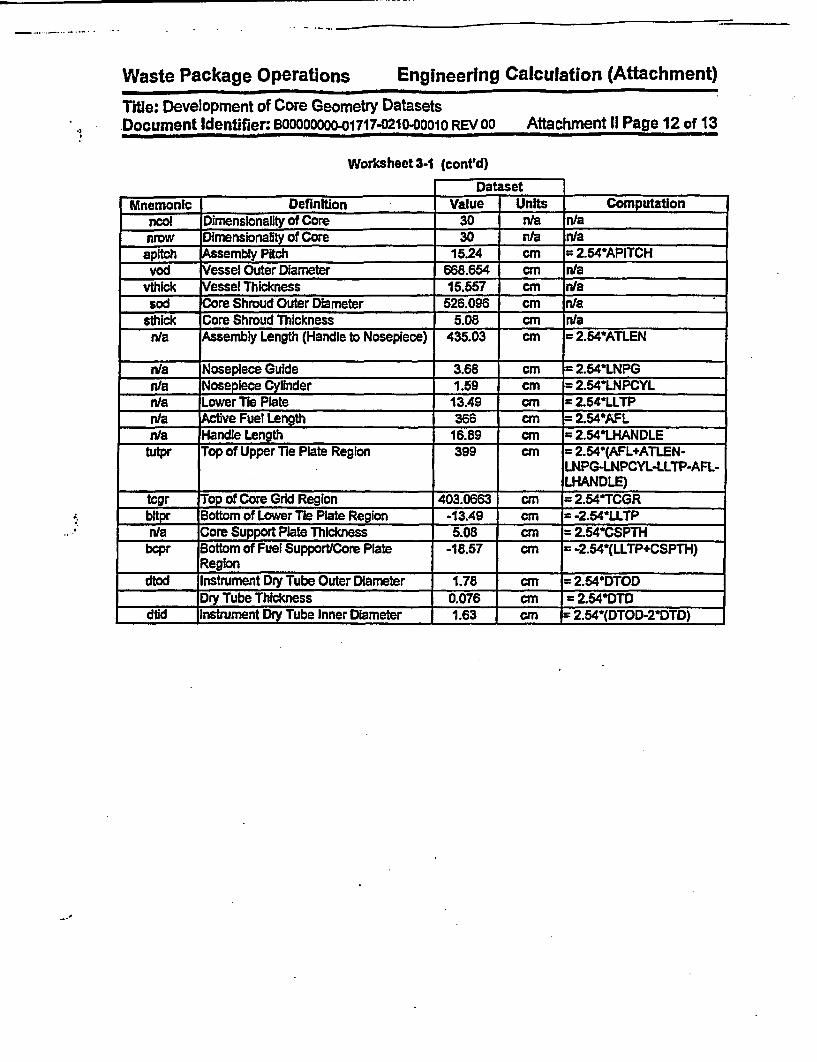
Waste Package Operations Engineering Calculation (Attachment)
I1
Title: Development of Core Geometry DatasetsDocument Identifier: BOOOOOOOO-01717-0210-00010 REV 00 Attachment II Page 12 of 13
Worksheet3-1 (cont'd)
DatasetMnemonic Definition Value Units Computation
ncol Dimenslonality of Core 30 n/a n/anrow Dimensionality of Core 30 n/a n/aapitch Assembly Pitch 15.24 cm = 2.54*APITCHvod Vessel Outer Diameter 668.654 cm n/a
vthkck Vessel Thickness 15.557 cmr n/asod Core Shroud Outer Diameter 526.096 cm nla
sthick Core Shroud Thickness 5.08 cm n/an/a Assembly Length (Handle to Nosepiece) 435.03 cm = 2.54ATLEN
n/a Nosepiece Guide 3.68 cm = 2.54^LNPGn/a Noseplece Cylinder 1.59 cm = 2.54*LNPCYLn/a Lower Tie Plate 13.49 cm = 2.54*LLTPn/a Active Fuel Length 366 cm = 2.54*AFLn/a Handle Length 16.89 cm = 2.54*LHANDLE
tutpr Top of Upper Tie Plate Region 399 cm = 2.54*(AFL+ATLEN-LNPG-LNPCYL-LLTP-AFL-LHANDLE)
tcgr Top of Core Grid Region 403.0663 cm = 2.54TCGRbitpr Bottom of Lower Tie Plate Region -13.49 cm = -2.54*LLTPn/a Core Support Plate Thickness 5.08 cm = 2.54CSPTHbipr Bottom of Fuel Support/Core Plate -18.57 cm = -2.54*(LLTP+CSPTH)
Regiondtod Instrument Dry Tube Outer Diameter 1.78 cm = 2.54*DTOD
Dry Tube Thickness 0.076 cm = 2.54*DTDdid Instrument Dry Tube Inner Diameter 1.63 cm = 2.54*(DTOD-2DTD)

Waste Package Operations Engineering Calculation (Attachment)
Title: Development of Core Geometry DatasetsDocument Identifier: BOOOOOOOO-01717-0210-O01o REV 00 Affachment II Page 13 of 13
4. References
4.1 Core Design and Operating Data for CyCles I and 2 of Quad Cites 1, EPRI NP-240, Electic PowerResearch Institute, Palo Alto, Carifomra, November 1976. TIC #: 237267.
4.2 MCNP CRC React~ffly Calculation for Quad Cities BAIR, DI: BBA000000-01717-0200-00146 REV00, CRWMS M&O. MOL.19971229.0128.

Waste Package Operations Engineering Calculation (Attachment)
Title: DeveloPment of Core Materials DatasetDocument Identifier: BOOOOOOOO-01717-0210-00010 REV oo Attachment IlIl Page 1 of 43
Table of Contents
Contents Page
1. Introductfon 5
2. Dataset Structure and Contents 5
3. Dataset Creation 73.1. DatasetTitle Record 732 Space-separated-variable Fields 73.3. Dataset Location 22
4. References 43
v~ )n
t An_/

Waste Package Operations Engineering Calculation (Attachment)
Title: Development of Core Materals DatasetDocument Identifier: BOOOOOOOO-01717-0210-001 0 REV 00 Attachment III Page 2 of 43
List of Tables
Table Contents Page
Table 2-1 Contents of Dataset
Table 3-1 Isotopic Constants
Table 3-2 End-zone Component Specifications
Table 3-3 Moderator Weight Percentages
Table 34 Moderator Density Values
Table 3-5 Upper Tie Plate Region Composition
Table 3-6 Lower Tie Plate Composition
Table 3-7 Core Grid and Core Plate Compositions
Table 3-8 Spacer Grid Composition
Table 3-9 Material Dataset - Elemental Portion
Table 3-10 Material Dataset- Isotopic Portion
6
8
11
11
13
15
15
16
20
22
29

Waste Package Operations Engineering Calculation (Attachment)
Titie: Development of Core Materials DatasetDocument Identifier: 800_0boOO-1717-0210-00010 REV 00 Attachment III Page 3 of 43
List of Figures
Figure Contents
Figure 3-1 Core Grid Geometry In Control Cefl
Figure 3-2 Moderator Density Values
Figure 3-3. Dataset for Core Materials
Page
12
14
36
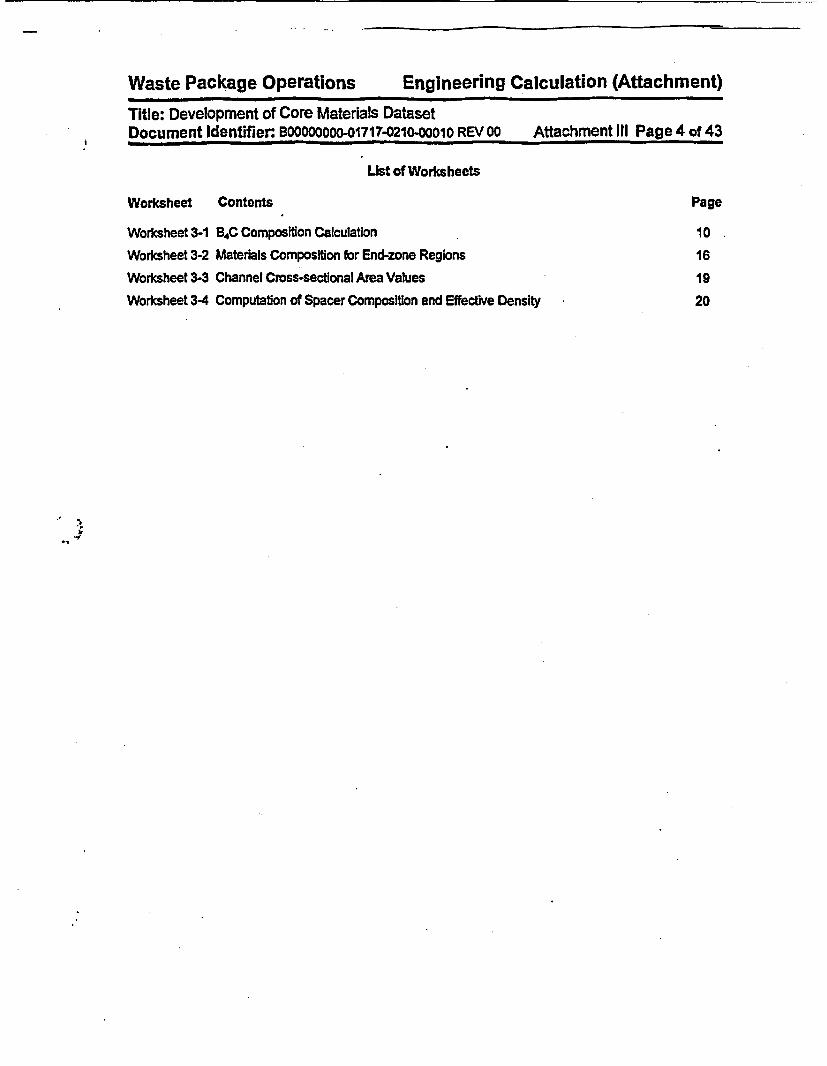
Waste Package Operations Engineering Calculation (Attachment)
Title: Development of Core Materials DatasetDocument Identiier. BOOOOQOOO-01717-0210-00010 REV 00 Attachment III Page 4 of 43
List of Worksheets
Worksheet Contents
Worksheet 3-1 B4C Composition Calculation
Worksheet 3-2 Materials Composition for End-zone Regions
Worksheet 3-3 Channel Cross-sectional Area Values
Worksheet 3-4 Computation of Spacer Composition and Effective Density
Page
10
1619
20
I
-
Waste Package Operations Engineering Calculation (Attachment)
Title: Development of Core Materals DatasetDocument Identifier._BOOOOODO01717-0210-0001o REV 00 Attachment IlI Page 5 of 43
1. Introduction
This attachment describes the creation of the datasets defining the core materials dataset, including thefuel channel materials, fuel rod cladding and spacer grids. It provides a detailed list of contents for suchdatasets and documents the creation of the datasets of this type used In the present analysis. Suchdatasets are not necessarily specific to the analysis at hand and may not be referenced and used insubsequent analyses documented In other engineering calculations.
2. Dataset Structure and Contents
The dataset structure is an ASCII-format file that Incorporates fields of space-separated-variable data.The contents of this dataset is given in Table 2-1.

Waste Package Operations Engineering Calculation (Attachment)
Title: Development of Core Materials DatasetDocument Identifier: B0000000-01717-0210-D0010 REV 00 Attachment IIl Page 6 of 43
Table 2-1 Contents of Dataset
Value Description NotesTitle Descriptive Tile of Fife ContentsMaterial Mnemonic Five Alphanumeric Character This is used as in the input directives
Identifier for Material to select materials from the datasetfor use in the representation of aparticular cell.
Density Material Density In Units of g/cm3 Density Is used on the Cell Card.Weight Percentage Weight Percentage of a Given
Element In the Composition
Atomic Number The atomic number Is used to Identifythe element and construct thereference to the library.
Ubrary (Elemental) [a) Suffix for Ubrary Entry This Is used to build the library entryIdentifier for a element
Mass Number Atomic Mass Number This Is used to identify the Isotopeand construct the reference to the
_____________________ library.Natural Abundance Frequency of Occurrence of this The natural abundance is used to
Isotope in Nature as an Atom modify the elemental weightPercentage percentage to properly reflect the
amount of the nuclide presentUbrary (Isotopic) [a] Suffix for Ubrary Entry This Is used to build the library entry
Identifier for an Isotope.
[a]. A value of zero for this entry Indicates that no values are available for this portion of the dataset.
i

Waste Package Operations Engineering Calculation (Attachment)
Title: Development of Core Materials DatasetDocument Identifier: B30000000-01717-0210-00010 REV 00 Attachment IIl Page 7 of 43
3. Dataset Creation
Each group of data In the dataset will now be discussed In greater detail and the creation of the datasetdocumented. The final dataset Is shown In Figure 3-3.
3.1. Dataset Title Record
The first line of the dataset Is a title. While the contents of this fine are arbitrary, it should contain thefollowing Information to ensure consistency with the file name:
3.2. Space-separated-varlable Fields
These fields form the bulk of the Information on the dataset. The values In the dataset is given in Tables3-9 and 3-10. Note that the dataset has been loaded with the library suffixes given In the main body of thisdocument
Note that the data Is grouped by element and isotopes within each element (see Figure 3-3). Thus thefirst line of a material definition contains, as Its last value, a numeral corresponding to the total number ofelements In the material. These elements then sequentially follow In the dataset The elements may alsobe further sub-divided Into data for each constituent Isotope. Again, the last value on the record definingthe element Is a numeral that represents the subsequent number of records of Isotopic Information.
3.2.1. Homogeneous Compositions
For structures that are composed of a single material rather than a mixture of two distinct (e.g., stainlesssteel and light water), the basic Isotopic constants from Table 3-1 are appropriately combined based onthe previously determined compositions (Reference 4.1, hereafter cited as the Materials Compilation").For boron carbide, the computation of the weight percentages Is given In Worksheet 3-1.

Waste Package Operations Engineering Calculation (Attachment)
Title: Development of Core Materials DatasetDocument Identifier: BOOOOOOOO-01717-0210-00010 REV 00 Attachment III Page 8 of 43
Table 3-1 'Isotopic Constants
Element Atomic Ubrary lmass Natural Ubraiy Atomic Weight WeightNurnber Ibl Number Abundance, [bl gig-atom Percentage
p]i [pl Atom percent la]
Hydrogen I na 1 1 00.00 .50c 1.00782503 100.000
Boron 5 nWa 10 19.9 .50c 10.0129371 18.426
11 80.1 .56c 11.0129371 81.574
Carbon 6 .500 12 100.00 n/a 12.00000000 100.000
N1troen 7 nla 14 100.00 .50c 14.00307401 100.000
Oxygen 8 nh 16 100.00 .50c 15.9994 100.000
Magnesium 12 .50c 24 78.99 n/a 23.985042 77.950
25 10.00 nfa 24.985837 10.280
26 11.01 n/a 25.982594 11.770
Aluminum 13 nWa 27 100 .50c 26.981538 100.000
Silcon 14 ,50c 28 92.23 nha 27.976927 91.873
29 4.67 nla 28.976494 4.818
30 3.1 n/a 29.973770 3.308
Phosphorus 15 n/a 31 100.0 .S0c 30.973762 100.000
Sulfur 16 n/s 32 100.0 .500 31.9720705 100.000
Titanulm 22 .50c 46 8.0 n/a 45.952630 7.920
47 7.3 nra 48.951764 7.298
48 73.8 n/a 47.947947 73.845
49 5. Wda 48.947871 5.532
50 5.4 nts 49.944792 5.405
Chromium 24 nTa 50 4.345 .60c 49.946047 4.179
52 83.79 .60c 51.940511 83.701
53 9.50 .60 52.940652 9.673
54 2.365 .60c 53.938884 2.448
Manganese 25 n/a 55 100.00 .50c 54.938048 100.000
Iron 26 W/a 54 5.9 .600 53.939613 5.65056 91.72 .600 55.934940 91.898
57 2.1 .60c 56.935398 2.161
S8 0.28 .60c 57.933278 0.290
Nickel 27 n/a 5S 68.27 .60c 57.935348 67.201
60 26.10 .6tc 59.930788 26.773
61 1.13 .60c 60.931058 1.183
62 3.59 .60c 61.928346 3.830
64 0.91 .60c 63.92796988 1.013
Copper 29 n/a 63 69.17 .60c 62.929699 68.499
65 30.83 .60c 64.927792 31.501
Zirconium 40 .60c 90 51.5 n/a 89.904702 50.706
91 11.22 n/a 90.905643 11.1B1
92 17.15 nla 91.905038 17.278
94 17.38 na 93.906314 17.891
96 2.80 Wea 95.908275 2.944
Molybdenum 42 .50c 14.84 nla 91.90607 14.217
84 9.25 n/a 93.9050t5 9.055
95 15.92 n/a 94.905841 15.750
96 16.68 nla 95.904678 16.675

Waste Package Operations Engineering Calculation (Attachment)
Title: Development of Core Materals DatasetDocument Identifier: B00000000-1717-0210-00010 REV oo Attachment III Page 9 of 43
Element Atomic Ubraly Mass Natural Ubrary Atomic Weight WeightNumber (bJ Number Abundance, b g"gatom Percentage
ali [a) Atom percent tol
97 9.55 n/a 96.906020 9.647
e8 24.13 n/a 97.905407 24.627
100 9.63 n/a 99.90748 10.029
rM 60 .35c 112 0.97 nla 111.90482 0.914
114 0.65 n/a 113.902761 0.624
115 0.38 n/* 114.903347 0.329
116 14.53 n/a 115.901745 14.196
117 7.68 n/a 116.902953 7.563
116 24.22 nla 117.901606 24.055
119 6.58 n/s 11L.903309 8.604
120 32.59 n/s 119.902197 32.017
122 4.63 n/a 121.903440 4.765
______ 124 5.79 n/a 123.905274 6.043
[a]. These values are from te Chart of the Nuclides (Reference 4.2, hereafter cited asthe *Chart of the Nuclidesj).
lb]. These values are from Reference 4.3, page 31.[cJ. In some cases the natura! abundances have been changed due to the absence of
libraries for some of the Isotopes.
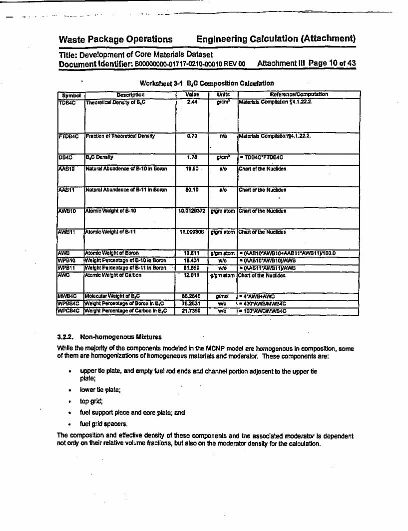
Waste Package Operations Engineering Calculation (Attachment)
Title: Development of Core Materials DatasetDocument Identifier: B0000000-01717-0210-00010 REV 00 Attachment III Page 10 of 43
Worksheet 3-1 B4C Composition CalculationSymbol Description Value Units ReferencefComputation
TD-B4C Theoretical Density of B4C 2.44 91cm3 Materials Compilation ¶4.1.22.2.
FTDB4C Fraction of Theoretical Density 0.73 nts Materials Compilation¶14.122.2.
DB4C B4C Density 1.78 * TDB4CFTDB4C
AAB10 Natural Abundence of B-10 hi Boron 19.90 alo Chart of the Nuclides
AAB11 Natural Abundence of B-11 hI Boron 80.10 alo Chart of the Nuckdes
AWBIO Atomic Weight of B-10 10.0129372 glgm atom Chart of the Nuclides
AWB11 Atomic Weight of B-11 11.009306 glgrn atomn Chart of the Nuclides
AWS omicWelghtof Boron 10.811 glgm atomi * (AAB1O'AWB10+AAB11VAWB11y1OO.0WPB10 Weight Percentage of B-10 In Boron 18.431 wlo * (PAB10AWB10yAWBWP811 Weiht Percentage of B-11 Boron 81.559 w/o *w(AB11'AWB11IyAWBAWC Aonic Weight of Carbon 12.011 g/gm atom Chart of the Nudides
MWB4C Molecular Weight of B4C 55.2548 glmol * 4AWB+AWCWPBB4C Weight Percentage of Boron In B.C 782631 Wo * 400^AWBIMW4CWPCB4C Weight Percentage of Carbon In BSC 21.7369 w/o a 1 001AWCJMWB4C
3.2.2. Non-homogenous Mixtures
While the majority of the components modeled In the MCNP model are homogenous In composition, someof them are homogenizations of homogeneous materials and moderator. These components are:
* upper tie plate, and empty fuel rod ends and channel portion adjacent to the upper tieplate;
lower tie plate;
• top grid;
* fuel support piece and core plate; and
* fuel grid spacers.
The composition and effective density of these components and the associated moderator Is dependentnot only on their relative volume fractions, but also on the moderator density for the calculation.

Waste Package Operations Engineering Calculation (Attachment)
Title: Development of Core Materals DatasetDocument Identifier: B00000000-01717-0210-00010 REV 00 Attachment III Page 11 of 43
3.2.2.1. Compositions for End-zone Region
The-specifications for the regions both above and below the active core are given in Table 3-2. Thesevalues are from the EPRI report on values for methods benchmarkIng from the Quad Cities Unit I core(Reference 4.4 - hereafter cited as the "EPRI Report").
Table 3-2 End-zone Component Specifications
Component (a] Material Quantity Weight (lb) Mass (kg)End Plugs Zircaloy-2 98 3.565 1.6171Lower Tie Plate Type 304 Stainless Steel 1 9.614 4.3608Upper Tie Plate Type 304 Stainless Steel 1 4.514 2.0475Hold-down Spring Type 304 Stainless Steel 49 3.402 1.5431Getter Type 304 Stainless Steel 49 0.972 0.4409Orificed Fuel Support lb] Type 304 Stainless Steel 1 62 28.1227
[a]. These values are from the EPRI Report Table 12. except as noted.lb]. This value is from the EPRI Report Figure 28.
For the moderator In all regions, the weight percentages for the Isotopic constituents are as shown inTable 3-3 and the density depends on the pressure and temperature of the moderator for the particularCRC. The proper densities are computed from the tables for saturated liquid by linear Interpolation asshown In Table 3-4 and Illustrated In Figure 3-2. The computation of the volume of the core grid In acontrol cell Is baied on the scheme shown in Figure 3-1. The density In this table and figure wereevaluated at 147eF which was the temperature of the Quad Cities Unit I Initial core critical as documentedin the EPRI Report Figure 35, Page C-35.
Table 3-3 Moderator Weight Percentages
Element Atomic Weight Atom Atomic Mass Weight(gig-atom) [a] Fractions (gig-atom) Percentage
Hydrogen 1.0079 0.6667 0.6720 11.1898Oxygen 15.9994 0.3333 5.3331 88.8102
Total 6.0051 100.0000
[a). These values are from the Chart of the Nuclides.

Waste Package Operations Engineering Calculation (Attachment)
Title: Development of Core Materials DatasetDocument Identifier: B00000000-01717-0210-D0010 REV 00 Attachment III Page 12 of 43
FIgure 3-1 Core Grid Geometry In Control Cell
I ieVew
Top of Core Grd Region
Top of Upper Tie Plate Region
373.4 Inches -
114.25 inches
- 175 inerhe
Core Grid- 360.75 inches360.3125 Inches t
Top of Active Fuel (TAF)
(N.B., BAF Is at 216.3125 Inches)
i Top View I
III IL_r ~-.r----
i iI IIII II II I
I ~~~~~~~~~~~~~~~~~~~~~~~~~~~~~~~~~~~IControl Cell
IIII I - - - - - -
..I
0.360 Inches
Not toI Scale I
M! I!lI
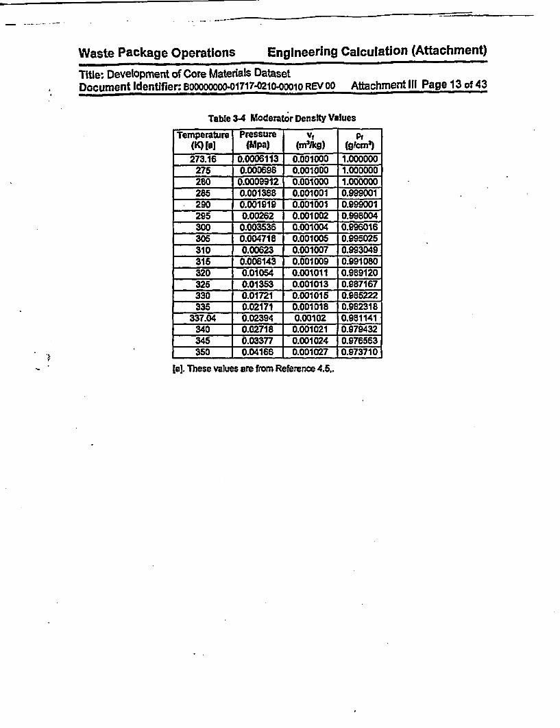
Waste Package Operations Engineering Calculation (Attachment)
Title: Development of Core Materials DatasetDocument Identifier: BOOOOOOOO-01717-021O-0001O REV 00 Attachment III Page 13 of 43
Table 3-4 Moderator Density Values
Temperature Pressure VfPt(K) [a) (Mpa) (mkg) (g9cnM)
273.16 0.0006113 0.001000 1.000000275 0.000698 0.001000 1.000000280 0.0009912 0.001000 1.000000285 0.001388 0.001001 0.999001290 0.001919 0.001001 0.999001295 0.00262 0.001002 0.998004300 0.003536 0.001004 0.996016305 0.004718 0.001005 0.995025310 0.00623 0.001007 0.993049315 0.008143 0.001009 0.991080320 0.01054 0.001011 0.989120325 0.01353 0.001013 0.987167330 0.01721 0.001015 0.985222335 0.02171 0.001018 0.982318
337.04 0.02394 0.00102 0.981141340 0.02718 0.001021 0.979432345 0.03377 0.001024 0.976563350 0.04166 0.001027 0.973710
[a]. These values are from Reference 4.5,.

Waste Package Operations Engineering Calculation (Attachment)Wat Pacag Oprtin Eniern Caclto(tahet
Title: Development of Core Materals DatasetDocument Identifier: Boooo0000-01717-0210-00010 REV 00 Attachment IlIl Page 14 of 43
Figure 3-2 Moderator Density Values
Interpolation of Moderator Density
1.01
1.00
E o.9g*1
1 0.98
0.97
0.96* L-250
;275 300 325 350
Temperature (Kelvin)
375
For the Quad Cities Unit I initial core CRC, the material weight percentages for the Upper Tie PlateRegion are shown In Table 3-5. Those for the Lower Tie Plate Region are given in Table 3-6; those for theCore Grid Region and Core Plate Region (Incorporating the Fuel Support Piece) are shown In Table 3-7.The computation of these material weight percentages Is shown In Worksheet 3-2 as well as thedetermination of the effective densities for the non-homogenous mixtures. This computation assumes thecomputation of channel cross-sectional area values shown in Worksheet 3-3.

Waste Package Operations Engineering Calculation (Attachment)
Title: Development of Core Materals DatasetDocument Identifier: B00000000-01717-0210-0001O REV 00 Attachment III Page 16 of 43
Table 3-6 Upper Tie Plate Region Composition
Upper Tie Plate Region Mass FractionsSS-304IZI oy-2lZircaloy-4 Water Total. . _ .
0.055 0.051 0.264 0.630 I 1.000
Hydrogen 7.053 7.053Carbon 0.004 0.004Nitrogen 0.006 0.006Oxygen 0.006 0.032 55.977 56.015Silicon 0.041 0.041Phosphorus 0.002 _ 0.002Sulfur 0.002 0.002Chromium 1.049 0.005 0.026 X ______ 1.081Manganese 0.110 0.110Iron 3.797 0.005 0.053 3.855Nickel 0.511 0.003 0.513Zirconium 4.964 25.912 30.876rin 0.071 0.369 _ _ 0.440
Total 5.524 5.054 26.392 63.030 100.000
Table 3-6 Lower Tie Plate Composition
Lower Tie Plate Regon Mass FractionsSS-304 Zlrcaloy-2 Zircaloy-4 Water Total
_ 0.550 0.102 0.079 0.270 1.000Hydrogen | 3.016 3.016Carbon 0.044 0.044Nitrogen 0.055 0.055Oxygen 0.012 0.009 23.935 23.957Silicon 0.412 0.412Phosphorus 0.025 0.025Sulfur 0.016 _ 0.016Chromium 10.445 0.010 0.008 10.463Manganese 1.099 1.099Iron 37.790 0.010 0.016 37.816Nickel 6.085 0.005 5.090ZIrconium _ _ 10.012 7.742 17.754Tin _______ 0.143 0.110 0.253
Total 54.9720 10.192 7.885 1 26.951 1 100-000
!

Waste Package Operations Engineering Calculation (Attachment)
Title: Development of Core Materals DatasetDocument Identifier: B00000000-01717-0210-00010 REV 00 Attachment III Page 16 of 43
Table 3-7 Core Grid and Core Plate Compositions
Core Grid Mass Fractions I Core Plate Mass FractionsSS-304 Water Total SS-304 Water Total0.069 0.931 1.000 0.701 0.299 1.000
Hydrogen 10.415 10.415 3.343 3.343Carbon 0.006 0.0055 0.056 0.056Nitrogen 0.007 0.0069 0.070 _ 0.070Oxygen 82.657 82.6571 26.533 26.533Silicon 0.052 0.0520 0.526 0.526Phosphorus 0.003 0.0031 0.032 0.032Sulfur 0.002 0.0021 0.021 0.021Chromilum 1.316 1.3164 13.324 13.324Manganese 0.139 0.1386 1.402 1A02Iron 4.763 4.7629 48.207 48.207Nickel 0.641 0.6409 6.486 6.486Zirconium . 0.0000 0.000
Tin _ _ 0.0000 _ = 0.0006.928 93.072 100.000 1 70.124 29.876 100.000
Worksheet 3-2 Materials Composition for End-zone Regions
Symbol Parameter Value Units ComputatlonlReferenceCL Cladding Length 156 Inches EPRI Report. Table 1. (39624 cm)AFL Active Fuel Length 144 Inches EPRI Report. Fgure 10 (365.76 cm).NIA Cladding Length Below Bottom of -0 Inches EPRI Report, Figure 10.
Active FuelCLUTAF Cladding Length Above Top of 30.480 cn ( (CL-AFL)2.54
Aive FuelCOD Cladding Outer Diameter 0.563 inches EPRI Report, Table 4. (1.43 cm)CWTH Cladding Wal Thickness 0.032 Inches EPRI Report. Table 4. (0.081 cm)CID Cladding Inner Diameter 1267 cm - (COD-2OCWTM2.54ZIRC2D ZMrcaloy-2 Density 6.560 glc W Table 3-1ZtRC4D ZDrcaloy-4 Density 6.560 glc? Table 3-1SS304D SS-304 Density 7.900 g/cm' Table 3-1RHOM Moderator Density for Quad 0.98114 tcrM3 From Table 3-3
Citles-' Initial Core Critial Point
CMATAF Cladding Mass Above Top of 3374246 g 49tCLATAF((Pl(y4) (((C0D254r2)-Ative Fuel (CIDA2)))ZIRC2D
CVATAF Cladding Volume Above Top of 514.367 ='3 - CMATAF1ZIRC2DAve Fuel
EPTM Endplug Mass (Zrcaoy-2) 1617.057 aEPVBBAF Endplug Volume Below Bottom of 123251 cr - (EPTM12yZIRC2
Active FuelEPVATAF Endplug Volume Above Top of 123.251 cTn 7 (EPTMI2)JZIRC2
Active FuelLTPM Lower Tie Plate Mass (SS304) 4360.837 g
LTPV Lower Tie Plate Volume 552.005 s LTPMISS304D

Waste Package Operations Engineering Calculation (Attachment)
Tite: Development of Core Materials DatasetDocument Identifier: Boooooooo-01717-0210-00010 REV 00 Attachment III Page 17 of 43
Symbol Parameter value Units ComputatlonlReferenceUTPM Upper Tie Plate Mass (SS.304) 2047.616 jUTPV Upper Tie Plate Volume 259.179 c - UTPM/SS304DMHDS Mass of Hold-down Springs ( 6- 43.121 g
304)HDSV Volume of Hold-down Springs 195.332 c U MHIDS/SS304DMG Mass of Getters (SS-304) 440.892 gVG Volume of Getters 65.809 c u MG/SS304DMVICATAF Free Volume Inside Fuel 1509.992 cm3 w 49 ((PIO/4r)CIDA2)ICLATAF)-EPVTAF.HDSV-
Cladding Above Top of Active VGFuel
APITCH Assemtly Pitch 6.000 Inches EPRI Report, Table 3. (1524 cm)BCG Bottom of Core Grid 144.4375 Inches EPRI Report, Figure 26 (zero axial location re-
adjusted to be at the Bottom ofActive Fuel). (366.87cm)
CGATH Core Grid Axial Thickness 14250 Inches EPRI ReportFigure 26. (361.95 cm)CGWTH Core Grid Web Thickness 0.380 Inches EPRI Report Figure 27. (0.914 cm)ODOFS Outer Diameter of Odficed Fuel 10.447 Inches EPRI Report, Figure 28. (26.535 cm)
Support at Core PlateCPTH Core Plate Thickness 2.00 Inches IEPRI Report Figure 26. (5.08 cm)HOFS HeIght of Orificed Fuel Support 10.270 Inches EPRI Report Figure 28. (26.09 cm)Upper Tle ahte Region above AssemblyTUTPR Top of Upper Tie Plate Region 399.000 cmCGVUTPR Core Grid Volume In Upper Tie 68.357 cm' * (CGWTHAPITCH.(CGWrH/2){(TUTPR-
Plate Region (BCG-2.54))
CGMUTPR Core Grid Mass In Upper Tie 540.021 9 * CGVUTPR^SS304DPlate Region
CVUTPR Channel Volume In Upper Tie 3329.814 a CCSA(TUTPR-AFL)Plate Region
CMUTPR Channel Mass in Upper Tie Plate 21843.581 a CVUTPR'ZIRC4DRegion
YUTPRMA Volume of Upper lie Plate 59225.688 c * ((APITCH2.54r2)*(TUTPR-AFL)Region above Assemblies
MVUTPRAA Moderator Volume In Upper rTe 53169.587 W E VUTPRM-CVATAF-EPVATAF-UTPV-HDSV-VG-Plate Region above Assemblies FVICATAF-CVUTPR-CGVUTPR
MMUTPRAA Moderator Mass In Upper Tie 62166.877 g - MVUTPRAA'RHOMPlate Region above Assemblies
MUTPRAA Mass In Upper Tie PlFate Region 82764.782 g - CMATAF+(EPTMI2)4UTPM+MHDS+MG+MMUITPRAA+ CGMUTPR
MFC Mass Fraction for Cladding 0.041 n/a a CMATAF/MUTPRAAMFUE Mass Fraction for Upper 0.010 . nra = (EPTMi2YMUTPRAA
Endplugs
MFUTP Mass Fraction for Upper Tie 0.025 n/a A UTPM/IMUTPRAAPlate
MFHDS Mass Fraction of Hold-down 0.019 n/a - MHDSIMUTPRAASprings
MFG Mass Fraction for Getters 0.005 n/a a MG/MUTPRAAMFUTPRMM Mass Fraction for Upper To 0.630 n/a a MMUTPRAA/MUTPRAA
Plate Region Moderator aboveAssembly
MFCUTPR Mass Fraction for Channel In 0.264 n/a a CMUTPR/MUTPRAM'Upper Tie Plate Region
MFCGUTPR IMass Fraction for Core Grid In 0.007 n/a a CGMUTPRIMUTPRAAiUpper Tie Plate Region

Waste Package Operations Engineering Calculation (Attachment)
Title: Development of Core Materials DatasetDocumAnt Identifier: 800000000-01717-0210-00010 REV 00 Attachment IlIl Page 18 of 43
Symbol Parameter 1 Value Units ComputatlonlReferenceEDUTPR Effective Density hn Upper Tie 1.397 g/cm UIUTPRAA VUTPRM
Piate iRegionLower re Plate Region below AssemblyBLTPR Bottom of Lower Tie Plate -12.7 cm
_Region
CLLTPR Channel Length in Lower Te 7.303 cm EPRI Report Figure 10.Plate Region
CVLTPR Channel Volume In Lower Tie 95.357 c - CCSACLLTPRPlate Region
CMLTPR Channel Mass in Lower Tie Plate 625.540 9 a CVLTPR ZIRC4DRegion
VLTPRBA VoiUme of Lower Tie Plte 2949.672 crrH a ((APlTCH2.54)A2r(-BLTPR)Region below Assembly
MVLTPRBA Moderator Volume in Lower Tie 2179.059 r - VLTPRBA-EPVBBAF-LTPVCVLTPRPlate Region below Assembly
MMLTPRBA Moderator Mass in Lower Tle 2137.905 8 -MVLTPRBAiRHOMPlace Region below Assembly
MLTPRBA Mass In Lower Tie Plate Region 7932.870 g a (EPT2)+LTPM+MMLTPRBA+CMLTPRMFLE Mass Fraction In Lower End 0.102 n/a * (EPTM12yMLTPRBA
PlugsMFLTP Mass Fraction in Lower Tie Plate 0.550 nha * LTPFMMLTPRBA
MFLTPRMBA mass Fraction for Lower Tie 0.270 nla * MMLTPRBAIMLTPRBAPlate Region Moderator below
embly
MFCLTPR Mass Fraction for Chanel In 0.079 Wna * CMLTPRtMLTPRBALower Tie Plate Region
EDLTPR Effective Density in Lower Tie 2.689 gC - MLTPRBANVLTPRBAPlate Region
Com Gdd RegonTCGR Top of Core Grid Region 403.000 cmCGVCGR Core Grid Volume In Core Grid 8510 an * (CGWTFiAPITCH-(CGWHl2)A2)r(TCGR-
Region TUTPR)CGMCGR Core Grid Mass h Core Grid 67232 C * CGVCGRISS304D
RegionVCGRM Volume of Core Grid Region 929.030 * ((APrrCHW254)A2)(TCGR-TUTPR)
above AssemblyMVCGRMA Moderator Volume In Core Grid 920.520 2 * VCGRAA-CGVCGR
Region above AssemblyMMCGRM Moderator Mass in Core Grid 903.160 O * MVCGRAARHOM
Region above Assembly_MCGR Mass in Core Grid Region 970.392 9 * CGMCGR+MMCGRAAMFCGCGR Mass Fraction of Core Grid In 0.069 n/a - CGMCGRIMCGR
Core Grid Region
MFMCGR Mass Fraction of Moderator In 0.931 n/a * MMCGRAIMCGRCore Grid Region
EDCGR Effective Density of the Core Grid 1.045 glcms UMCGR/MVCRGAARegion
Csre Plate RegionBCPR lBottorn of Core Plate Region .38.79 cm a BLTPR-(HOFS 2.54)
JMOFS IMass of Orificed Fuel Support 1 28122.73 g

Waste Package Operations Engineering Calculation (Attachment)
Title: Development of Core Materials DatasetDocument Identifier: Booooooo01717-0210-00=o REV 00 Attachment III Page 19 of 43
Symbol Parameter Value Units Computatlon/ReferflceMOFSBA Mass of Odficed Fuel Support 7030.68 E a MOFSJ4
below AssemblyVOFS Volume of Orificed Fuel Support 3559.84 _ r M D
VOFSBA Volume of Orfficed Fuel Support 889.96 w- Sbelow Assembly
CPVBA Core Plate Volume below 477.53 W (CPTHW2.54)(APITCH2.54)A2-Assembly (Pio/4)r(CPTH2.54)*(ODOFS2.54)A2
CPMBA Core Plate Mass below Assembly 3772.82 g CPVBASS3W4D
VCPRBA Volume of COre Plate Region 6058.63 a' u (BLTPR.8CPR)(APITCHW2.54)A2below Assembly_
VMCPRBA Volume of Water hi Cor Plate 4691.13 cm' - VCPRSA-VOFSBA-CPVBARegion below Assembly _
MMCPRBA Mass of Water In Core Plate 4602.66 g - VMCPRBAIRHOMRegion below Assembly
MCPRBA Mass of Core Plate Region below 15405.86 g a MOFSBA+CPMBA+MMCPRBAAssembly_
MFOFSCPR Mass Fraction of Oriiced Fuel 0.456 n/a a MOFSBA/MCPRBA_ Support hI Core Plate Region
MFCPCPR Mass Fraction of Core Plate In 0.245 n/a w CPMBANMCPRBACore Plate Region
MFMCPR Mass Fraction of Moderator hi 0299 nta - MMCPRBAIMCPRBACore Plate Region
EDCPR Effective Density of Core Plate 2.543 g/crnm - MCPRBA/VCPRBARegion _ I
Worksheet 3-3 Channel Cross-sectional Area Values
Symbol Parameter Value Units ComputationtReferenceCOS Outside Span of Channel 8.54 inches EPRI Reporti Figure 14 (Top of Channel Values).CIS inside Span of Channel .258 Inches EPRI Report, Figure 14 (Top of Channel Values).CICR 5 Channel Inside Comer Radius 0.4 inches EPRI Report Table 1.CSSL Length of Straight Side t1.3233 cm - (CIS.54)-2TCICR'2.54CTk Channel Thickness 0.2489 cm - ((COS-CIS)/2) 254CSSA Straight Side Aea 2.6186 crif - CTHCSSLCOCR Channel Outside Corner Radius 1.2649 cm = (CICR'2.54).CTHCCA Corer Area 0.4459 cR - ((PI014)(COCRA2-(CICR-2.54)r2)CCSA Channel Cross-sectional Area 13.0581 cm w 4-(CSSA*CCA)
.322.2 Compositions for Spacer Grids
The composition and effective density for'the spacer grids In the Quad Cities Unit-I core are shown InTable 34. The computation of these values Is shown in Worksheet 3-4.
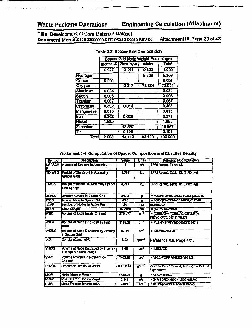
Waste Package Operations Engineering Calculation (Attachment)
Title: Development of Core Materials DatasetDocument Identifier: B00000000o01717-0210-00010 REV 00 Attachment Ill Page 20 of 43
Table 3-8 Spacer Grid Composition_ . . ....... . . _ ....... .
Spacer Grid Node Weight PercentagesInconei-X jZrcaloy-4 Water I Total
0.027 0.141 0.832 1.000Hydrogen - | 9.309 9.309Carbon 0.001 0.001
Oxygen 0.017 73.884 73.901Aluminum 0.024 0.024
Silicon 0.008 0.008
Titanium 0.067 0.067
Chromium 0.452 0.014 0.466Manganese 0.013 0.013
Iron 0.242 0.028 0.271Nickel 1.885 1.885
irconIum 13.857 13.857Tin 0.198 0.198
Total 2.693 14.113 83.193 100.000
Worksheet 3-4 Computation of Spacer Composition and Effective Density
Symbol Description Value Units ReferenceCornputatlonNSPACE Number of Spacers In Assembly 7 n/a EPRI Repow1 Table 12.R
TZ4WSG Weight of Zircaloy.4 In Assembly 3.757 lb, EPRI Report. Table 12. (1.704 kg)SpacerGrlds
TiWSG Weight of Inconel In Assembly Spacer 0.717 lb. EPRI Report. Table 12. (0.325 kg)Grid Springs
Z4MSG ZIrcaloy-4 Mass in Spacer Grid 243.6 9 a 10001(TZ4WSG/NSPACER)/2.2046IMSG Inconel Mass in Spacer Grid 46.5 g - 1 OD(TIWS;G/NSPACER)/2.2046NNAF Number of Nodes In Active Fuel 24 nla AssumptonNLEN Node Length 152400 cm - (AFL2.54YNNAFYNIC Volume of Node Inside Channel 2704.77 rr' * (CSSLA2+4'(CSSL'CICR2.54)+
P10-(CICR2.54r2)-NLENVNFR Volurne of Node Displaced by fuel 1199.38 rm * t41N49P10((COO/2)2.54)A2
RodsVNZSG Volume of Node Displaced by Zlrcaloy 37.11 -' * Z4)ASGZRC4D
in Spacer Grid
IXD Density of Inconel.X 8.22 gicrns Reference 4.6, Page 441.
VNISG Volume of Node Displaced by Inconel- 5.65 c * IMSGIIXDX In Spacer Grid Springs
VNW Volume of Water In Node Inside 1462.63 c * VNICY-NFR-VNZSG-VN1SGChannel
RH2OD Reference Density of Water 0.981141 g9rn9 Valid for Quad Cities-1i Initial Core Critical._________ __________ __________ _______Experim ent
UIMN Nodal Mass of Water 1435.05 C * VNWRH20DNMFZ Mass Fraction for Zircaloy-4 0.141 n/a * Z4MSG(Z4MSG+IMSG+MNW)NMFI Mass Fraction for hnconel-X 0.027 n/a * IMSG/(Z4MSG+IMSG+MNW

Waste Package Operations Engineering Calculation (Attachment)
Title: Development of Core Materials DatasetDocument Identifier: BOOOOOOOO-01717-0210-00010 REV 00 Attachment III Page 21 of 43
Symbol Description Value Units Referencer~omputatlonNMlFW 'Mass Fraction for Water 0.32 Wa - MNW(Z4MSG+IMSGMNW)NHD Homogenized Density 1.179 gjcm3 a (MNW4Z4MSG+IMSGyMMNwCSIE Center of First Spacer above Bottom 18.500 Inches EPRI Report, Table 12. Page A-9.
of Active FuelCS2E Center of Second Spacer above 3B.000 inches EPRI Report. Table 12, Page A-B.
Bottom of Active FuelCS3E Center of Third Spacer above Bottom 57.500 Inches EPRI Report Table 12. Page A-$.
of Active FuelCS4E Center of Fourth Spacer above Bottom 77.000 ches EPRI Report. Table 12. Page AB
of Active FuelCS5E Center of Fifth Spacer above Bottom 06.500 Inches EPRI Report, Table 12, Page A-8.
of Active FuelCS6E Center of Sxth Spacer above Bottom 116.000 Inches EPRI Report, Table 12. Page A.
of Active FuelCS7E Center of Seventh Spacer above 135500 hIches EPRI Report. Table 12, Page A-.
Bottom of Active FuelCSIM Center of First Spacer above Bottom 46.990 cm a CSIE12.54
of Active FuelCS2M Center of Second Spacer above 96.520 cm a CS2E2.54
Bottom of Active FuelCS3M Center of Third Sparer above Bottom 146.050 cm * CSSE2.64
of Active FuelCS4M Center of Fourth Spacer above Bottom 195.580 cm a CS4E 2.54
of Active FuelCS5M Centerof Fifth Spacerabove Bottom 245.110 cm - CS5E2.54
of Active FuelCS6M Center of Sbith Spacer above Bottom 294.640 cm * CS6E2.54
ofActive FuelCS7M Center of Seventh Spacer above 344.170 cm a CS7E2J4
Bottom of Active Fuel

Waste Package Operations Engineering Calculation (Attachment)
Title: Development of Core Materals DatasetDocument Identifier. B00000000-01717-0210-00010 REV 00 Attachment IlI Page 22 of 43
3.3. Dataset Location
This dataset file has the following name:
core_rnaterials.dat
The contents of the Individuat fields In the dataset are shown in Tables 3-9 and 3-10, while a copy of thedataset Itself Is provided in Figure 3-3.
Table 3-9 Material Dataset - Elemental Porton
Constituents ElementalMaterial Mnemonic Density Element Weight Atomic Library
(glen) Percentage Number
Type 304 Stainless Steel SS304 7.900 Carbon 0.080 6 .50cManganese 2.000 25 n/aPhosphorus 0.045 15 n/aSulfur 0.030 16 n/aSilicon 0.750 14 .50c
Chromium 19.00 24 n/a
Nickel 9.250 27 n/a
Nitrogen 0.100 7 n/aIron 68.745 26 n/a
zircaloy-Z ZIRCZ 6.55 Oxygen 0.12 8 n/aChromium 0.10 24 n/a
Iron 0.10 26 n/a
Nickel 0.05 27 n/a

Waste Package Operations Engineering Calculation (Attachment)
Title: Development of Core Materials DatasetDocument Identifier: BOOOOOOO-01717-0210-00010 REV 00 Attachment IIl Page 23 of 43
Constituents ElementalMaterial Mnemonic Density Element Weight Atomic Library
(glcm3) Percentage Number
Tin 1 .40 50 .35c
Zirconium 98.23 40 .60c
Zrcaloy-4 ZIRC4 6.56 Oxygen 0.12 8 n/aChromium 0.10 24 n/a
Iron 0.20 26 n/a
Tin 1.40 50 .35c
Zirconium 98.18 40 .60c
Boron Carbide 14C 1.76 Boron 78.26 5 n/a
Carbon 21.74 6 .50c.noe- .NC 8.2 .ro 9.0 26 .__InconeI-X INCX 8.22 Iron I 9.00 26 .550

Waste Package Operations Engineering Calculation (Attachment)
Title: Development of Core Materals DatasetDocument Identifier: Boo8oooooo01717-0210-00010 REV 00 Attachment III Page 24 of 43
Constituents ElementalMaterial Mnemonic Density Element Weight Atomic Ubrary
(g/cn 3) Percentage Number
Nickel 70.00 27 n/a
Chromium 16.77 24 nla
iltanium 2.50 22 .50c
Manganese 0.50 25 n/aCarbon 0.03 6 .50cSilicon 0.30 14 .50c
.__ ___ ___ ___ __ _uminum 0.90 13 n/aUpper Tie Plate Region JG7UTPI 1.397 IHydrogen 7.05 I n/a
Carbon 0.004 6 .50cNitrogen 0.006 7 ntaOxygen 56.015 8 n/aSilicon 0.04 14 .50c
Phosphorus 0.002 15 n/aSulfur 0.002 16 n/aChromium 1.081 24 n/a
Manganese 0.11 25 n/aIron 3.85 25 n/a
... ke 0.5 . 7 .n/a.._Nickel 0.51 27 nda

Waste Package Operations Engineering Calculation (Attachment)
Title: Development of Core Materals DatasetDocument Identifier: BOOOOOOO-01717.0210-00010 REV oo Attachment Ill Page 25 of 43
Constituents ElementalMaterial Mnemonic Density Element Weight Atomic Ubrary
(gfcm2) Percentage Number
rconium 30.88 40 .60c
mTn 0.44 50 .35c
LowerTie Plate Region 6G7LTP1. 1.397 Hydrogen 3.02 1 n/a
I
Carbon 0.044 6 .60cN~trogen 0.055 7 n/aOxyfgen 23.957 8 nfaSilicon OA1 14 .50c
Phosphorus 0.025 15 nfaSulfur 0.016 16 nfaChromium 10.463 24 n/a
Manganese 1.10 25 n/aIron 37.82 25 n/a
Nickel 5.09 27 n/a
Zirconium 17.75 40 .60c

Waste Package Operations Engineering Calculation (Attachment)
TitKle: Development of Core Materials DatasetDocument Identifier: B0000000001717-0210o00010 REV 00 Attachment lII Page 26 of 43
Constituents Elemental
Material Mnemonic Density Element Weight Atomic Library(.gIo) Percentage Number
Tin 0.25 s0 .35c
BWR/3 Core Grid 3TG1 1.045 Hydrogen 10A.1 1 n/aCarbon 0.006 6 .50cNftrogen 0.007 7 n/aOxygen 82.657 8 n/aSilicon 0.052 14 .50c
Phosphorus 0.003 15 nraSulfur 0.002 16 n/aChromium 1.316 24 n/a
Manganese 0.14 25 n/aIron 4.76 26 n/a
Nickel 0.64 27 n/a
,
BWR/3 Fuel SupportfCore Plate
3CP1 1.045 Hydrogen 3.34 I n/aCarbon 0.056 6 .50cNitrogen 0.070 7 n/aOxygen 26.533 8 n/aSilicon 0.526 14 .50c
Phosphorus 0.032 15 nlaSulfur 0.021 16 1nl
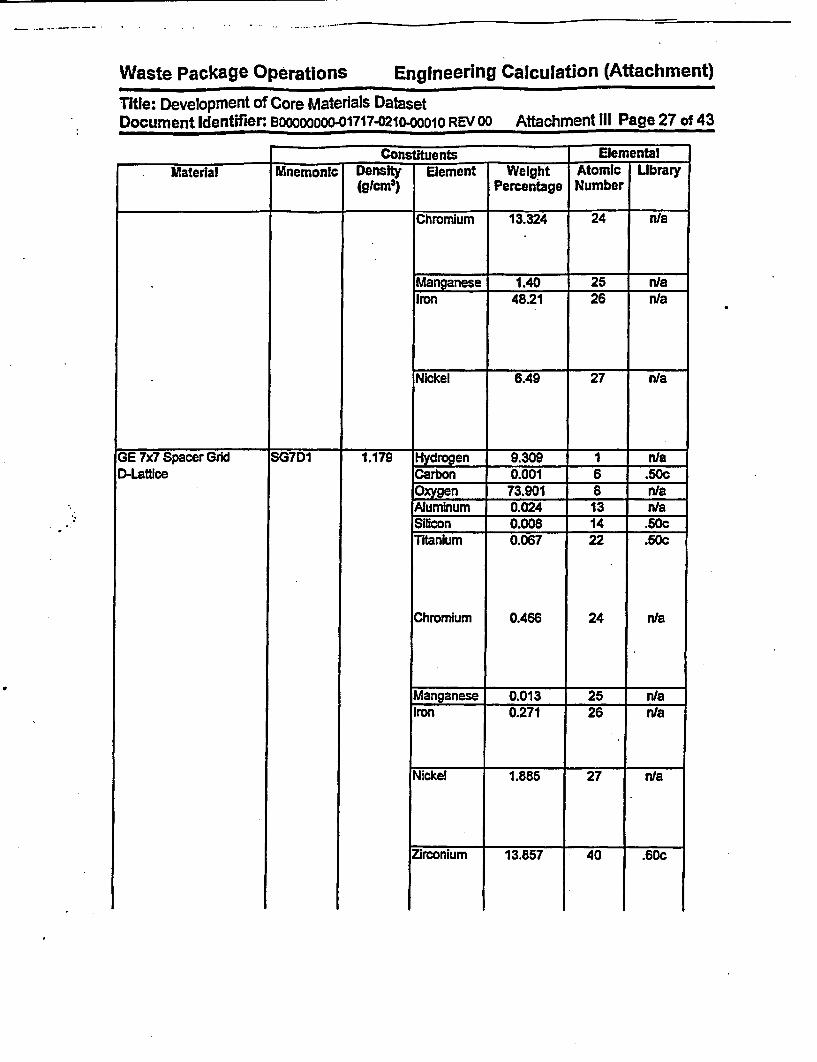
Waste Package OPerations Engineering Calculation (Affachment)Waste Package Operations Engineering Calculation (Attachment)Title: Development of Core Materials DatasetDocument Identifier. 1000000001717-0210-00010 REV 00 Attachment Ill Page 27 of 43
i -� - -
Constituents ElementalMaterial Mnemonic Density Element Weight Atomic Ubrary
(gtcm) Percentage Number
Chromium 13.324 24 n/a
Manganese 1.40 25 nlaIron 48.21 26 n/a
Nickel 6A9 27 n/a
GE 7x7 Spacer GridD-Lattice
1SG7D1 1.179 Hydrogen 9.309 1 niaCarbon 0.001 6 .50cOxygen 73.901 8 n/aAluminum 0.024 13 n/aSilicon 0.008 14 .50cTitanium 0.067 22 .50c
Chromium 0.466 24 n/a
Manganese 0.013 25 n/aIron 0.271 26 n/a
Nickel 1.885 27 n/a
_.coiu _381 40 .Zirconium 13.857 40 .60c

Waste Package Operations Engineering Calculation (Attachment)
Title: Development of Core Materals DatasetDocument Identifier: Bo0000000-01717-o210-00010 REV 00 Attachment IlIl Page 28 of 43
Material Mnemonic Density Element Weight Atomic LibraryCon~ftffurnts . _ ̂ .emeia
Vlemental-Material MnmncDensity Element weight Atomic Library
(glcm3) Percentage Number
Tin 0.198 60 .35c

Waste Package Operations Engineering Calculation (Attachment)
* Title: Development of Core Matenals DatasetDocument Identifier: B00000000-01717-0210-00010 REV 00 Attachment IlI Page 29 of 43
Table 3-10 Material Dataset - Isotopic Portion_
. .
Isotopic
material Element Mass isotopic LibraryNumber Weight
Percentage
Type 304 Stainless Steel Carbon 12 100 n/aManganese 55 100 .50cPhosphorus 31 100 .50cSulfur 32 100 .50cSillcon 28 91.873 n/a
29 4.818 nla________ 30 3.308 n/a
iChromium 50 4.179 .60c52 83.701 .60c53 9.673 .60c54 2.448 .60c
NIckel 58 67.201 .60c60 26.773 .60c61 1.183 .60062 3.830. .60c64 1.013 .60c
NiWogen 14 100.000 .50cIron 54 5.650 .60c
56 91.898 .60c57 2.161 .60c
_ _ _ _ _ _ _ _ _ _ _ _ _ _ _ _ _ _ _ _ 58 0.290 .60cZircaloy-2 Oxygen 16 100.000 .50c
Chromium 50 4.179 .60c52 83,701 .60c53 9.673 .60c54 2.448 .60c
Iron 54 5.650 .60c56 91.898 .60c57 2.161 .60c58 0.290 .60c
Nickel 58 67.201 .60c60 26.773 .60c61 1.183 .60c62 3.830 .60c
________ 64 1.013 .60c
Tin 112 0.914 n/a114 0.624 n/a115 0.329 n/a116 14.196 nla117 7.663 n/a I
118 24.055 , n/a
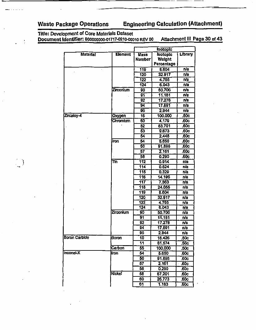
Waste Package Operations Engineering Calculation (Attachment)
Title: Development of Core Materials DatasetDocument Identifier: B00000000-01717-0210-00010 REV 00 Attachment III Page 30 of 43
._ .
IsotonicMaterial Element Mass Isotopic Ubrary
Number WeightPercentage
119 8.604 nl/a120 32.917 n/a122 4.755 n/a124 6.043 n/a
rconium 90 50.706 n/a91 11.181 n/a92 17.278 n/a94 17.891 n/a96 2.944 n/a
Zircaloy-4 Oxygen 16 100.000 .60cChromium 50 4.179 .60c
52 83.701 .60c53 9.673 .60c54 2A48 .60c
Iron 54 5.650 .60c56 91.898 .60c57 2.161 .60c58 0.290 .60c
Tin 112 0.914 nta114 0.624 n/a115 0.329 n/a116 14.196 n/a117 7.563 n/a118 24.055 n/a119 8.604 n/a120 32.917 n/a122 4.755 n/a124 6.043 n/a
Zirconium 90 50.706 n/a-91 11.161 n/a
92 17.278 n/a94 17.891 n/a96 2.944 n/a
Boron Carbide Boron 10 18.426 .50c11 81.574 .56c
.____________._____ Carbon 55 100.000 .50c
i
Inconei-X Iron 54 5.650 .60c56 _ 91.898 .60c57 j 2.161 - .60c58 0.290 .60c
... ~ ~ ~ - . _-
Nickel 5B 67.201 .60c60 I 26.773 .60c61 1.183 .60c

Waste Package Operations Engineering Calculation (Attachment)
Title: Development of Core Materials DatasetDocument Identifier. BOODOOOOO-01717-0210-00010 REV 00 Attachment IlIl Page 31 of 43
Isotovic
Material _X__ __
Element MassNumber
IsotopicWeight
Percentage
Library
. .I � T
62 3.830 .DUGi Z . -
64 1.013 .60cGChromium 50 4.179 .60c
52 83.701 .60053 9.673 .60c_____ 54 2.448 .60c
Titanium 46 7.920 nla47 7.298 n/a48 73.845 nla49 5.532 n/a60 5.405 nra
Manganese 55 100.000 .60cCarbon 12 100.000 n/a.Silicon 28 91.873 n/a
29 4.818 n/a30 3.308 n/a
Aluminum 27 100.000 .50c- I� - 1� -�
Upper Tie Plate Region Hydrogen I 100.000 .5OcCarbon 12 100.000 n/a
Nitrogen 14 100.000 .60c
Oxygen 16 100.000 .50c
Silicon 28 91.873 n/a29 4.818 n/a30 3.308 n/a
Phosphorus 31 100,000 .50c
Sulfur 32 100.000 .50cChromium 50 4.179 .60c
52 83.701 .60c53 9.673 .60c54 2.448 .60c
Manganese 55 5.405 n/a
Iron 55 100.000 .50c54 5.650 .60c56 91.898 .60c57 2.161 .60c58 0.290 .60c
Nickel 58 67.201 .60c
60 26.773 .60c61 1.183 .60c62 3.830 .60c
_. ____ _ .64 1.013 .60c
Zirconium s0 n/a91 11.181 t n/a

Waste Package Operations Engineering Calculation (Attachment)
Title: Development of Core Materials DatasetDocument Identifier: BOOOOoooo-01717-0210-o0010 REV 00 Attachment III Page 32 of 43
IsotopicMaterial Element M Isotoplc Ubrary
Number Weight___ _Percentage
92 17.278 n/a94 17.891 n/a96 2.944 n/a
112 0.914 nla114 0.624 n/a115 0.329 n/a116 14.196 n/a117 . 7.563 n/al18 24.055 n/a119 8.604 n/a120 32.917 n/a122 4.755 n/a124 6.043 n/a
Lower Tie Plate Region Hydrogen I 100.000 .50cCarbon 12 100.000 n/aNitrogen 14 100.000 .50cOxgen 16 100.000 .50cSilicon 28 91.873 n/a
29 4.818 n/a_ 30 3.308 n/a
Phosphorus 31 100.000 .50cSulfur 32 100.000 .50cChromium 50 4.179 .60c
52 83.701 .60c53 9.673 .60c54 2.448 .60c
Manganese 55 100.000 .50cIron 55 100.000 .50c
54 5.650 .60c56 91.898 .60c57 2.161 .60c
________ 58 0.290 i .60c
Nickel 58 67.201 .60c60 26.773 .60c61 1.183 .60c62 3.830 .60c
________ 64 1.013 .60c
Zirconium 90 50.706 n/a91 11.181 n/a92 17.278 n/a94 17.891 n/a
___ *__ ,96 2.944 n/a
~nn 112 0.914 1nla. _

Waste Package Operations Engineering Calculation (Attachment)
Title: Development of Core Materals DatasetDocument Identifier: BOOOOO-01717-0210-00010 REV 00 Attachment III Page 33 of 43
IsotopicMaterial Element Mass Isotopic Library
Number Weight_ _Percentage
114 0.624 _a
115 0.329 n/a116 14.196 n/a117 7.563 nla118 24.055 nia
_119 8.604 n/a120 32.917 n/a122 4.755 n/a
--124 6.043 n/aBWR13 Core Grid Hydrogen I 100.000 .50c
Carbon 12 100.000 n/aNitrogen 14 100.000 .50cOxygen 16 100.000 .50cSilicon 28 91.873 n/a
29 4.818 n/a_______ - 30 3.308 n/a
Phosphorus 31 100.000 .50cSulfur 32 100.000 .50cChromium 50 4.179 .60c
52 83.701 .60c53 9.673 .60c54 2.445 .60c
Manganese 55 100.000 .50cIron 54 5.650 .60c
56 91.898 .60c57 2.161 .60c58 0.290 .60c_58 67.201 .60c
Nickel 58 67.201 .60c.60 26.773 .60c
61 1.183 .60c62 3.830 .60c
_________. _____ _ . . . . .64 1.013 .60c
t
BWR/3 Fuel Support/Core Plate
Hydrogen I 100.000 .50cCarbon 12 100.000 n/aNitrogen 14 100.000 .50cOxygen 16 100.000 .50cSilicon 28 91.873 .60c
29 4.818 .60c30 3:308 n/a
Phosphorus 31 100.000 .50cSulfur 32 100.000 .50cChromnium -so 4.179 .60c

Waste Package Operations Engineering Calculation (Attachment)
Title: Development of Core Materials DatasetDocument Identifier. BooO000O-01717-0210O0M010 REV 00 Attachment III Page 34 of 43
IsotoolCMaterial Element Mass Isotopic Ubrary
Number WeightPercentage
5Z B3.I01 .MUG.� I. I
9.673 .bc_ _ _ _ _ _ _ _ _ _ _
54 2.448 .600Manganese 55 100.000 .I6c
rown 54 5.650 .60c56 j 91.898 _.6057 2.161 .60c58tI 0290 - .60c58 67.201 .60c
jj�iI.Nickel F 67.201 .60c
60 26.773 .60c61 1.183 .60c62 3.830 .60c64 1.013 .6c
GE 7x7 Spacer GridD-Latlice
-I . .. I -- t1 --Hvdrocen 1 I 1UUA.UU .Duc
Carbon 12 100.000 n/aOxygen 16 100.000 .50cAluminum 27 100.000 .50cSilicon 28 91.873 n/aTitanium 46 7.920 n/a
47 7.298 n/a48 73.845 n/a49 5.532 n/a50 5.405 n/a
Chromium 50 4.179 .60c52 83.701 .60c53 9.673 .60c54 2.448 .60c55 100.000 .60c
Manganese 55 100.000 .500Iron 54 5.650 .60c
56 91.898 .60c57 2.161 .60c58 0.290 .60c
Nickel 58 67.201 .60c60 26.773 .60c61 1.183 .60c62 3.830 .60c64 1.013 .60c
Zirconium 90 50.706 n/a91 11.181 n/a92 17.278 n/a94 17.891 n/a

Waste Package Operations Engineering Calculation (Attachment)Title: Development of Core Materials DatasetDocument Identifier: BooOOOOO-01717-021o-ooo0O REV 00 Attachment Ill Page 35 of 43
I ISotooICMaterial Element Mass Isotopic Ubrary
Number WeightPercentage
________ 96 2.944 nraE~n 112 0.914 n/a
114 0.624 n/a115 0.329 n/a116 14.196 n/a117 7.563 n/a118 24.055 n/a119 8.604 n/a120 32.917 n/a122 4.755 n/a
_ __124 6.043 n/a
.4
.1

-
Waste Package Operations Engineering Calculation (Aftachment)Title: Development of Core Materials DatasetDocument Identifier: BODOOOOOO-01717-021D0OOO1O REV oo Attachment III Page 36 of 43
Figure 3-3 Dataset for Core Materials
Core Materials for BWRType 304 Stainless SteelSS304 7.900 9Carbon 0.080 6 .50c 112 100.0 0Manganese 2.000 25 0 155 100 .50cPhosphorus 0.045 15 0 131 100 .50cSulfur 0.030 16 0 132 100.0 .50cSilicon 0.750 14 .50c 328 91.873 029 4.818 030 3.308 0Chromium 19.00 24 0 450 4.179 .60c52 83.701 .60c53 9.673 .60c54 2.448 .60cNickel 9.250 28 0 558 67.201 .60c60 26.773 .60c61 1.183 .60c62 3.83 .60c64 1.013 .60cNitrogen 0.100 7 0 114 100.0 .50cIron 68.745 26 0 454 5.65 .60c56 91.898 .60c57 2.161 .60c58 0.290 .60cZircaloy 2ZIRC2 6.56 6Oxygen 0.12 8 0 116.100 .50cChromium 0.10 24 0 450 4.179 .60c52 83.701 .60c53 9.673 .60c54 2.448 .60cIron 0.10 26 0 454 5.650 .60c56 91.898 .60c57 2.161 .60c58 0.290 .60cNickel 0.05 28 0 558 67.201 .60c60 26.773 .60c61 1.183 .60c62 3.83 .60c64 1.013 .60ec

Waste Package Operations Engineering Calculation (Attachment)
Title: Development of Core Materials DatasetDocument Identifier: Bo0000000-01717.0210-00010 REV 00 Attachment Ill Page 37 of 43
Flgure 3-3 (confd)
Tin 1.40 50 .35c 10112 0.914 0114 0.624 0115 0.329 0116 14.196 0117 7.563 0118 24.055 0119 8.604 0120 32.917 0122 4.755 0124 6.043 0Zirconium 98.23 40 .60c 590 50.706 091 11.181 092 17.278 094 17.891 096 2.944 0Zircaloy.4ZIRC4 6.56 5Oxygen 0.12 8 0 116 100 .50cChromium 0.10 24 0 450 4.179 .60c52 83.701 .60c53 9.673..60c54 2.448 .60cIron 0.20 26 0 454 5.650 .60c56 91.898 .60c57 2.161 .60cSB 0.290 .60cTin 1.40 50 .35c 10112 0.914 0114 0.624 0115 0.329 0116 14.196 0117 7.563 0118 24.055 0119 8.604 0120 32.917 0122 4.755 0124 6.043 0Zirconium 98.18 40 .60c 590 50.706 091 11.181 092 17.278 094 17.891 096 2.944 0Boron CarbideB4C 1.76 2Boron 78.26 5 0 210 18.426 .50c11 81.574 .56c

Waste Package Operations Engineering Calculation (Attachment)
Title: Development of Core Materals DatasetDocument Identifier: BOOOOOOOO-01717-0210-00010 REV oo Attachment III Page 38 of43
Figure 3-3 (cont'd)
Carbon 20.0 6 .50c 112 100.0 0Spacer GE 7x7 D LatticeSG7D1 1.179 12Hydrogen 9.309 1 0 11 100 .SOcCarbon 0.001 6 .50c 112 100 0Oxygen 73.901 8 0 116 100 .50cAluminum 0.024 13 0 127 100 .50cSilicon 0.008 14 .50c 328 91.873 029 4.818 030 3.308 0Titanium 0.067 22 .50c 546 7.920 047 7.298 048 73.845 049 5.532 050 5.405 0Chromium 0.466 24 0 450 4.179 .60c52 83.701 .60c53 9.673 .60c54 2.448 .60cManganese 0.013 25 0 155 100 .50cIron 0.271 26 0 454 5.650 .60c56 91.898 .60c57 2.161 .60c58 0.290 .60cNickel 1.B85 28 0 558 67.201 .60c60 26.773 .60c61 1.183 .60c62 3.83 .60c64 1.013 .60cZirconium 13.857 40 .60c90 50.706 091 11.181 092 17.278 094 17.891 096 2.944 0Tin 0.198 50 .35c 10112 0.914 0114 0.624 0115 0.329 0116 14.196 0117 7.563 0118 24.055 0119 8.604 0120 32.917 0122 4.755 0
(0.981141 Water Density)

c
Waste Package Operations Engineering Calculation (Attachment)Title: Development of Core Materials DatasetDocument Identifier: BOOC0000o-01717-021o-00010 REV oo Attachment Ill Page 39 of 43
Figure 3-3 (conrd)124 6.043 0Upper Tie Plate Region GE-7x7 Fuel, BWR/3 (0.981141 Water Density)7GUTP1 1.397 13Hydrogen 7.053 1 0 11 100 .5ScCarbon 0.004 6 .50c 112 100 0Nitrogen 0.006 7 0 114 100 .50cOxygen 56.015 8 0 116 100 .50cSilicon 0.041 14 .50c 328 91.873 029 4.818 030 3.308 0Phosphorus 0.002 15 0 131 100 .50cSulfur 0.002 16 0 132 100.0 .50cChromium 1.081 24 0 450 4.179 .60c52 83.701 .60c53 9.673 .60c54 2.448 .60cManganese 0.110 25 0 155 100 .5scIron 3.855 26 0 454 5.650 .60c56 91.898 .60c57 2.161 .60c58 0.290 .60cNickel 0.513 28 0 558 67.201 .60c60 26.773 .60c61 1.183 .60c62 3.83 .60c64 1.013 .60cZirconium 30.876 40 .60c 590 5Q.706 091 11.181 092 17.278 094 17.891 C96 2.944 0Tin 0.440 50 .35c 10112 0.914 0114 0.624 C115 0.329 0116 14.196 0117 7.563 0118 24.055 C119 8.604 0120 32.917 o122 4.755 0124 6.043 0Lower Tie Plate Region GE-7x7 Fuel, BWR/3 (0.981141 Water Density)7GLTP1 1.397 13

Waste Package Operations Engineering Calculation (Attachment)
Title: Development of Core Materials DatasetDocument Identifier: BOO00000O-01717-0210-00010 REV 00 Attachment III Page 40 of 43
Figure 3-3 (contd)Hydrogen 3.016 1 0 11 100 .5cCarbon 0.044 6 .50c 112 100 .0Nitrogen 0.055 7 0 114 100 .50cOxygen 23.957 8 0 116 100 .50cSilicon 0.412 14 .50c 328 91.873 029 4.818 030 3.308 0Phosphorus 0.025 15 0 131 100 .50cSulfur 0.016 16 0 132 100.0 .50cChromium 10.463 24 0 450 4.179 .60c52 83.701 .60c53 9.673 .60c54 2.448 .60cManganese 1.099 25 0 155 100 .50cIron 37.816 26 0 454 5.650 .60c56 91.898 .60c57 2.161 .60c58 0.290 .60cNickel 5.090 28 0 558 67.201 .60c60 26.773 .60c61 1.183 .60c62 3.83 .60c64 1.013 .60cZirconium 17.754 40 .60c90 50.706 091 11.181 092 17.278 094 17.891 096 2.944 0Tin 0.253 50 .35c 10112 0.914 0114 0.624 0115 0.329 0116 14.196 0117 7.563 0118 24.055 0119 8.604 0120 32.917 0122 4.755 0124 6.043 0Core Grid, BWR/3 (0.981143TG1 1.045 11Hydrogen 10.415 1 0 11 100 .50cCarbon 0.006 6 .50c 1
5
41 Water Density)

Waste Package Operations Engineering Calculation (Attachment)
Title: Development of Core Materials DatasetDocument Identifier: Bo0oo0000001717-021i 0001 REV 00 Attachment IlIl Page 41 of 43
Figure 3-3 (contd)
12 100 0Nitrogen 0.007 7 0 114 100 .50cOxygen 82.657 8 0 116 100 .50cSilicon 0.052 14 .50c 328 91.873 029 4.818 030 3.308 0Phosphorus 0.003 15 0 131 100 .50cSulfur 0.002 16 0 132 100.0 .50cChromium 1.316 24 0 450 4.179 .60c52 83.701 .60c53 9.673 .60c54 2.448 .60cManganese 0.139 25 0 155 100 .50cIron 4.763 26 0 454 5.650 .60c56 91.898 .60c57 2.161 .60c58 0.290 .60cNickel 0.641 28 0 558 67.201 .60c60 26.773 .60c61 1.183 .60c62 3.83 .60c64 1.013 .60cCore Plate, BWR/3 (0.981141 Water Density)3CPl 2.543 11Hydrogen 3.343 1 0 11 100 .50cCarbon 0.056 6 .50c 112 100 0Nitrogen 0.070 7 0 114 100 .50cOxygen 26.533 8 0 116 100 .50cSilicon 0.526 14 .50c 328 91.873 029 4.818 030 3.308 0Phosphorus 0.032 15 0 131 100 .50cSulfur 0.021 16 0 132 100.0 .50cChromium 13.324 24 0 450 4.179 .60c52 83.701 .60c53 9.673 .60c54 2.448 .60cManganese 1.402 25 0 155 100 .50c

Waste Package Operations Engineering Calculation (Attachment)
Title: Development of Core Materials DatasetDocument Identifier: BOOOOOOOO-01717.0210-0001O REV oo Attachment IlIl Page 42 of 43
Figure 3-3 (contd)Iron 48.207 26 0 454 5.650 .60c56 91.898 .60c57 2.161 .60c58 0.290 .60cNickel 6.486 28 0 558 67.201 .60c60 26.773 .60c61 1.183 .60c62 3.83 .60c64 1.013 .60c

Waste Package Operations Engineering Calculation (Attachment)Title: Development of Core Materials DatasetDocument Identifier: BOOOOOOO-01717.0210-00010 REV 00 Attachment ill Page 43 of 43
4. References
4.1 Material Compositions and Number Densies for Neutronjcs Calculations (SCPB: A/A), DI#:BBAOOOOOO-01717-0200-00002 REV 00, CRWMS M&O. MOL.19960624.0023.
4.2 Nuclides and Isotopes (Incorporating the Chadt of Mte Nuclides), 14" Edition, General ElecticCompany, San Jose, CA. 1989. TIC #: 201637.
4.3 CRC Statepoint ReactMty Calculations for Cycles 1A, 1S, 2, 3, and 4 of Cqst}a River Unit 3, DI#.BBAOOOOOO-01717-0200-00046 REV 00, CRWMS M&O. MOL19971218.1060.
4.4 Core Design and Operating Data for Cycles 1 and 2 of Quad Cities I, EPRI NP-240, Electric PowerResearch Institute, Palo Alto, CA, November 1976. TIC #: 237267. .
4.5 Keenan, J. H., Keyes, F. G., Hill. P. G., and Moore, J. G.. Steam Tables, John Wiley and Sons, Inc.,New York, 1969. NNA19900604.0041.
4.6 Metals Handbook, Volume 2, nProperties and Selection: Nonferrous Alloys and Pure Metals," 9hEdition, ASM, 1989. NNA.19900106.0326.

Waste Package Operations Efngineering Calculation (Attachment)Title: Development of Lattice Geometry DatasetsDocument Identifier: B00000000-1717-0210-00010 REV 00 Attachment IV Page 1 of 16
Table of Contents
Contents Page
1. Introduction 5
2. Dataset Structure and Contents 5
3. Dataset Creation g3.1. Dataset Title Record 93.2. Narnellst Input 93.3. Dataset Location 9
4. References 16

Waste Package Operations Engineering Calculation (Attachment)
Title: Development of Lattice Geometry DatasetsDocument Identifier: BO00000OO0-1717-021-000010 REV 00 Attachment IV Page 2 of 16
Ust of Figures
Figure Contents
Figure 2-1 Lattice Parameters for GE 7x7 Lattice
Figure 2-2 Illustration of GE 8x8 Lattice with Large Central Water Rod
Figure 3-1 Lattice Geometry Dataset for GE 7x7 Lattice
Figure 3-2 Lattice Geometry Dataset for GE 8x8 Lattice with Small Water Rods
Figure 3-3 Lattice Geometry Dataset for GE 8x8 Lattice with Large Central Water Rod
Page
78
10
10
11

Waste Package Operations Engineering Calculation (Attachment)
Title: Development of Lattice Geometry DatasetsDocument Identifier: sOODOOOO01717-0210-00010 REV 00 Attachment IV Page 3 of 16
Ust of Tables
Table Contents
Table 2-1 Contents of Dataset for Fuel Latfices
Page
6
I-

Waste Package Operations Engineering Calculation (Attachment)Title: Development of Lattice Geometry DatasetsDocument Identifier: B00000000-01717-0210-OO010 REV 00 Attachment IV Page 4 of 16
---Ust of Worksheets
Worksheet Contents
Worksheet 3-1 Namellst Input Development.for GE.7x7 Lattbce
Worksheet 3-2 Namellst Input Development for GE M8 Lattice with Small Water Rods
Worksheet 3-3 Namerist Input Development for GE 8x8 Lattice with Large Central Water Rod
Page
12
13
14

I
Waste Package Operations Engineering Calculation (Attachment)
Title: Development of Lattice Geometry DatasetsDocument Identifier: B00000000-01717-210-00010 REV 00 Attachment IV Page 5 of 16
1. IntroductIon
This attachment describes the creation of the datasets defining the fuel assembly lattices. It provides a
detailed list of contents for such datasets and documents the creation of the datasets of this type used in
the present analysis.
2. Dataset Structure and Contents
The dataset structure Is an ASCII-format file that Incorporates FORTRAN Namelist-type Input The
contents of this dataset for BWR fuel are given In Table 2-1. Note that all dimensional values in this
dataset are in units of centimeters. In this table the format of each datum is given. The locations of most
of the geometrical parameters shown In this table are shown In Figure 2-1 for a GE 7x7 lattice. The layout
of a GE 8x8 lattice which Incorporates a large central water rod Is shown in Figure 2-2.

Waste Package Opet~ions Engineering Calculatbon (Attachment)
Title: Development of Lattice Geometry DatasetsDocument Identifier. BOOOOOOO-01717.0210-O001O REV 00 Attachment IV Page 6 of 16
Table 2-1 Contents of Dataset for Fuel Lattices
Mnemonic Definition Comments FormatTitle iataset T1tie Character String - Describes Application for this Single Line
Dataset
ASIN Inner Span of Assembly Defines Active Flow Area of Lattice NAMELIST(cM)_
WGAP Wtde Gap Thickness (cm) Defines Placement of Channel within Control NAMELISTCell
NGAP Narrow Gap Thickness Defines Placement of Channel within Control NAMELIST(cm) Cell
CTHICK Channel Thickness (cm) Defines Channel Component NAMELISTCRADIUS Inner Radius of Channel Defines Channel Component NAMELIST
Corner (cm)FRSD Clad Surface to Clad Used for Relative Positioning of Fuel Rods NAMELIST
Surface Separation (cm) .CFRSD Clad Surface to Inner Situates Fuel Rods with respect to Channel NAMEUST
Channel SurfaceSeparation (cm)
RPITCH Fuel Rod Pitch (cm) Used for Relative Positioning of Fuel Rods NAMELIST
COD Cladding Outer Diameter Used to Dimension Fuel Rod Components NAMELIST(cm)
CLD Cladding Thickness (cm) Used to Dimension Fuel Rod Components NAMELISTPOD Pellet Outer Diameter Used to Dimension Fuel Rod Components NAMELIST
cm) .
FRCMAT Material Identifier for Fuel NAMELISTRod Cladding (cm) _
FCMAT Material Identifier for NAMELISTChannel
LATDIM Lattice Dimensionality NAMELISTNWR Number of Water Rods NAMELIST
WROD Outer Diameter for Water Only used If Water Rod(s) are Differently Sized NAMELISTRod(s) (cm) Fuel Rod Cladding
WRTH Thickness of Water Only used If Water Rod(s) are Differently Sized NAMELISTRod(s) (cm) n Fuel Rod Cladding

Waste Package Operations Engineering Palculation, (Attachment)Wat Pakg Oprtin Egnengalutin(tch n)Title: Development of Lattice Geometry DatasetsDocument Identifier: B00000O-01717-0210-00010 REV 00 Attachment IV Page 7 of 16
Figure 2-1 Lattice Parameters for GE 7x7 Lattice
.000Q(37EO0000000
000 Q00 00 CTHICKRPITCH -
0000 000000000
.. WC A OOOQ
NCLD
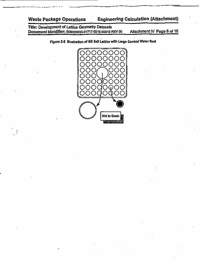
Waste Package Operations Engineering calculation (Attachment)Waste Package Operations Engineering Calculation (Attachment)Title: Development of Lattice Geometry DatasetsDocument Identifier: Bo0oooooo-01717-0210-00010 REV 00 Attachment IV Pagex of 16
Figure 2-2 Illustration of GE x8B Lattice with Large Central Water Rod
~0r000000000000000000000000000 0000000000
000 000L00 0 00oooo ooo
0,aNotto Scale

Waste Package Operations Engineering Calculation (Attachment)
Title: Development of Lattice Geometry DatasetsDocument Identifier: 83000000000o1717.0210-00010 REV 00 Attachment IV Page 9 of 16
3. Dataset Creation
Each group of data In the dataset will now be discussed In greater detail and the creation of the datasetsfor a GE 7x7 lattice, GE 8x8 lattice with small - Le., fuel rod-sized - water rods and a GE 8x8 lattice with alarge central water rod (displacing four fuel rods) documented. The final datasets are shown In Figures3-1, 3-2 and 3-3 (most of the values are from the EPRI report for the Quad Cities Unit-1 initial core design- Reference 4.1 - hereafter cited as the OEPRI Report").
3.1. Dataset Title Record
The first Oine of the dataset Is a tite. While the contents of this Une are arbitrary, it should contain the.foflowing information to ensure consistency with the file name:
* dimensionarity of the lattice;
* important characteristics of lattice (such as the number of water rods, if any);
* manufacturer, and
* BWR lattice (D-lattice in all these examples).
3.2. Namellst Input
The FORTRAN narnelist-type Input variables must adhere to the restrictions Inherent In the format of suchInput Care must be taken to ensure that the value provided Is consistent with the data storage class Inthe automation (i.e., Integer Input for integer variables and real Input for real variables) so that neitherprecision is lost for real variables and nor Is illusory precision Implied for Integer variables.
The development of the values appropriate for the 7x7 GE lattice Is shown In Worksheet 3-1. That for theGE Ux8 lattice with small water rods Is provided In Worksheet 3-2, while the same Information for the GE8x8 lattice with a large central water rod Is given In Worksheet 3-3.
3.3. Dataset Location
This datasets have the following file names:
. ge7x7.dat
. ge8x8_swr 2.dat
. ge8x8.jwr.dat

Waste Package Operations Engineering Calculation (Attachment)Title: Development of Lattice Geometry DatasetsDocument Identifier: BOOOOOO-01717-0210-00010 REV oo Attachment IV Page 10 of 16
FIgure 3-1 Lattice Geometry Dataset for GE 7x7 LatticeGE 7x7 D-lattice/No Water$FUELCTHiCK - 0.20ASIN - 13.406WGAP - 0.953NGAP - 0.478CRADIUS - 1.02FSRD - 0.445CFSRD - 0.3645RPITCH - 1.875COD - 1.430CLD - 0.081POD - 1.240FRCMAT - 'ZIRC2'FCMAT - 'ZIRC4'LATDIM - 7NWR 0 O$END
Rod/No Curtains/
Figure 3-2 Lattice Geometry Dataset for GE 8x8 Lattice with Small Water RodsGE 8x8 D-lattice/Two Water Rods/No Curtains/$FUELCTHICK - 0.20ASIN - 13.406WGAP - 0.953NGAP - 0.478CRADIUS - 1.02FSRD - 0.196CFSRD - 0.3874RPITCH - 1.626COD - 1.252CLD - 0.086POD - 1.057FRCMAT - 'ZIRC2'FCMAT - 'ZIRC4'LATDIM - 8NWR - 2
SEND

Waste Package Operations Engineering Calculation (Affachment)Title: Development of Latfice Geometry DatasetsDocument Identifier: B00000000-017o7.o210-00o0o REv 00 Attachment IV Page 11 of 16
Figure 3-3 Lattice Geometly Dataset for GE 8x8 Lattice with Large Central Water RodGE 8x8 D-lattice/Large Central Water Rod/No Curtains/$FUELCTHICK - 0.20ASIN - 13.406WGAP - 0.953NGAP - 0.478CRADIUS - 1.02FSRD - 0.196CFSRD - 0.3874RPITCH - 1.6256COD - 1.2268CLD - 0.0813POD - 1.0414FRCMAT - 'ZIRC2'FCMAT - 'ZIRC4'LATDIM - 8NWR - 1WROD - 2.6187WRTH - 0.0813
$END
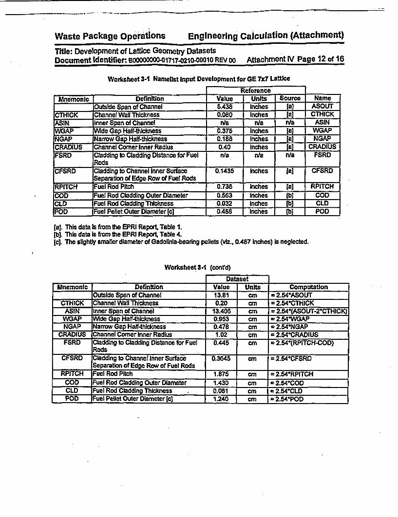
Waste Package Operations Engineering Calculation (Attachment)
Thie: Development of Lattice Geometry DatasetsDocument Identifier: B00000000-01717-0210-OO010 REV 00 Attachment IV Page 12 of 16
Worksheet 3-1 Namelist Input Development for GE 7x7 Lattice
ReferenceMnemonic Definition Value Units Source Name
Outside Span of Channel 5.438 Inches [a) ASOUTCTHICK Channel Wall Thickness 0.080 Inches [a] CThICKASIN Inner Span of Channel n/a n/a n/a ASINWGAP de Gap Haif-thickness 0.375 Inches [a] WGAPNGAP Narrow Gap Half-thickness 0.188 Inches [a) NGAPCRADIUS Channel Corner Inner Radius 0.40 Inches [a] CRADIUSFSRD Cladding to Cladding Distance for Fuel n/a n/a n/a FSRD
RodsCFSRD Cladding to Channel Inner Surface 0.1435 Inches [a] CFSRD
Separation of Edge Row of Fuel RodsRPITCH Fuel Rod Pitch 0.738 Inches [a) RPITCHCOD Fuel Rod Cladding Outer Diameter 0.563 Inches [b] CODCLD Fuel Rod Cadding Thickness 0.032 Inches lb] CLDPOD Fuel Pellet Outer Diameter (qc 0.488 Inches (b] POD
[a]. This data Is from the EPRI Report, Table 1.[b]. This data Is from the EPRI Report, Table 4.[c]. The slightly smaller diameter of Gadolinia-bearlng pellets (viz., 0.487 Inches) is neglected.
Worksheet 3- (conrd)
DatasetMnemonic Definition Value Units Computation
_Outside Span of Channel 13.81 cm = 2.54ASOUTCTHICK Channel Wall Thickness 0.20 cm = 2.54'CTHICK
ASIN Inner Span of Channel 13.406 cm = 2.54-(ASOUT-2*CTHICK)WGAP Wide Gap Half-thickness 0.953 cm = 2.54VWVAPNGAP Narrow Gap Half-thickness 0.478 cm = 2.54NGAP
CRADIUS Channel Corner Inner Radius 1.02 cm = 2.54CRADIUSFSRD Cladding to Cladding Distance for Fuel 0.445 cm = 2.54*(RPITCH-COD)
RodsCFSRD Cladding to Channel Inner Surface 0.3645 cm = 2.54'CFSRD
Separation of Edge Row of Fuel RodsRPITCH Fuel Rod Pitch 1.875 cm = 2.54'RPITCH
COD Fuel Rod Cladding Outer Diameter 1.430 cm = 2.54'CODCLD Fuel Rod Cladding Thickness . 0.081 cm = 2.54*CLDPOD Fuel Pellet Outer Diameter [c] 1.240 cm I 2.54POD
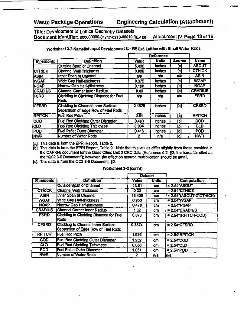
----.-. . ..... ----
Waste Package Operations Engineering Calculation (Attachment)
Title: Development of Lattice Geometry DatasetsDocument Identifier: 1300000000-01717-0210-0001o REV 00 Attachment IV Page 13 of 16
Worksheet 3-2 Namelist input Development for GE 8x8 Lattice with Small Water Rods
ReferenceMnemonic Definition Value Units Source Name
Outside Span of Channel 5.438 Inches la] ASOUTCTHICK Channel Wall Thickness 0.080 inches (a] CTHICKASIN Inner Span of Channel rye n/a n/a ASINWGAP. Wide Gap Half-thickness 0.375 inches 1[a WGAPNGAP Narrow Gap Half-thickness 0.188 inches [a] NGAPCRADIUS Channel Comer Inner Radius, 0.40 Inches [a) CRADIUSFSRD Cladding to Cladding Distance for Fuel n/a n/a n/a FSRD
RodsCFSRD Cladding to Channel Inner Surface 0.1525 inches [a) CFSRD
Separation of Edge Row of Fuel Rods .RPITCH Fuel Rod Pitch 0.64 Inches [a] RPITCHCOD Fuel Rod Cladding Outer Diameter 0.493 Inches lb] CODCLD Fuel Rod Cladding Thickness 0.034 inches lb] CLDPOD _ Fuel Pellet Outer Diameter 0.416 Inches [b] PODNWR Number of Water Rods 2 n/a [c] NWR
[a]. This data Is from the EPRI Report Table 2.[b]. This data is from the EPRI Report Table 9. Note that this values differ slightly from those provided In
the QAP-3-5 document for the Quad Cities Unit 2 CRC Data (Reference 4.2, §2, the hereafter cited asthe *QC2 3-5 Document"); however, the effect on neutron multiplication should be small.
tc]. This data Is from the QC2 3-5 Document §2.Worksheet 3-2 (contd)
DatasetMnemonic Definition Value Units Computation
Outside Span of Channel 13.81 cm * 2.54*ASOUTCTHICK Channel Wall Thickness 0.20 cm = 2.64*CTHICK
ASIN Inner Span of Channel 13.406 cm = 2.54*(ASOUT-2*CTHICK)WGAP Wide Gap Half-thickness 0.953 cm = 2.54* APNGAP Narrow Gap Half-thickness 0.478 cm = 2.54*NGAP
CRADIUS hannel Comer Inner Radius 1.02 cm = 2.64*CRADIUSFSRD Cladding to Cladding Distance for Fuel 0.373 cm = 2.54 (RPITCH-COD)
RodsCFSRD Cladding to Channel Inner Surface 0.3874 cm = 2.54*CFSRD
Separation of Edge Row of Fuel RodsRPITCH Fuel Rod Pitch 1.626 cm = 2.54*RPITCH
COD Fuel Rod Cladding Outer Diameter 1.252 cm = 2.54*CODCLD Fuel Rod Cladding Thickness 0.086 cm = 2.54*CLDPOD Fuel Pellet Outer Diameter 1.057 cm = 2.54*PODNWR Number of Water Rods 2 n/a n/a
I

Waste Package Operations Engineering Calculation (Attachment)
Title: Development of-Lattice Geometry DatasetsDocument Identifier: B00000000-01717-0210-1001 REV 00 Attachment lV Page 14 of 16
Worksheet 3-3 Namelist Input Development for GE 8x8 Lattice with Large Central Water Rod
ReferenceMnemonic Definition Value Units Source Name
Outside Span of Channel 5.438 Inches [a] ASOUTMTHICK Channel Wall Thickness 0.080 Inches [a] CTHICK
ASIN Inner Span of Channel nla nia n/a ASIN.GP Wide Gap Half-thickness 0.376 Inches [al WGAP
NGAP Narrow Gap Half-thickness 0.188 Inches la] NGAPCRADIUS Channel Comer Inner Radius 0.40 inches la] CRADIUSFSRD Cladding to Cladding Distance for Fuel n/a n/a n/a FSRD
Rods
CFSRD Cladding to Channel Inner Surface 0.1525 inches [a) CFSRDSeparation of Edge Row of Fuel Rods .
RPITCH Fuel Rod Pitch 0.64 Inches lb] RPITCHCOD Fuel Rod Cladding Outer Diameter 0.483 inches [bJ CODCLD Fuel Rod Cladding Thickness 0.032 Inches [b CLDPOD Fuel Pellet Outer Diameter 0A10 inches lb) PODNWR Number of Water Rods 1 n/a [b] NWR
[a]. This data Is from the EPRI Report, Table 2.lb]. This data Is from the QC2 3-5 Document
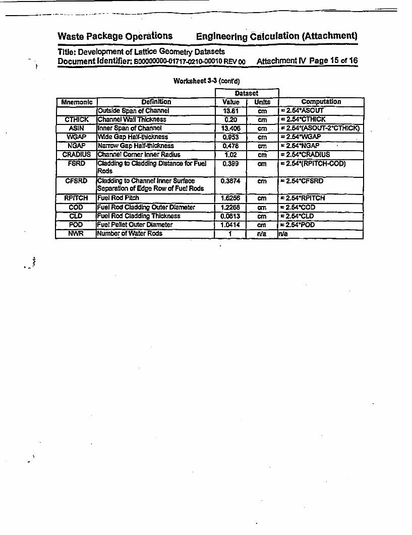
Waste Package Operations Engineering Calculation (Attachment)
Title: Development of Lattice Geometry DatasetsDocument Identifier: BOOO0 O-01717-0210-00010 REVOO Attachment IV Page 15 of 16
Worksheet 3$3 (confd)
DatasetMnemonic Definition Value Units Computation
Outside Span of Channel 13.81 cm = 2.54ASOUTCTHICK Channel Wall Thickness 0.20 cm = 2.54*CTHICK
ASIN Inner Span of Channel 13.406 cm 2.64-(ASOUT-2'CTHICK)WGAP Wide Gap Half-thickness 0.953 cm = 2.54WGAPNGAP Narrow Gap Half-thickness 0.478 cm = 2.54*NGAP
CRADIUS Channel Corner Inner Radius 1.02 cm = 2.64*CRADIUSFSRD Cladding to Cladding Distance for Fuel 0.399 cm = 2.654(RPITCH-COD)
RodsCFSRD Cladding to Channel Inner Surface 0.3874 cm = 2.54*CFSRD
Separation of Edge Row of Fuel RodsRPITCH Fuel Rod Pitch 1.6256 cm = 2.54WRPITCH
COD Fuel Rod Cladding Outer Diameter 1.2268 cm = 2.54*CODCLD Fuel Rod Cladding Thickness 0.0813 cm = 2.54*CLDPOD Fuel Pellet Outer Diameter 1.0414 cm = 2.54*PODNWR Number of Water Rods I n/a n/a
....

Waste Package Operations Engineering Calculation (Attachment)
Title: Development of Lattice Geometry DatasetsDocument ldentifier: B0000000001717.021000010 REVoo Attachment lV Page 16 of 16
4. References
4.1 Core Design and Operating Data for Cycles I and 2 of Quad CUies 1, EPRI NP-240, Eectric PowerResearch InstitMe, Pao Alto, CalffornIa, November 1976. TIC e 237267.
4.2 Summary Report of Commercial Reactor CINcality Data fhr Quad Cies Unft 2. DI#: BO000000-01717-5705-00096 REV 00, CRWMS M&O. MOL19980730.0509.

Waste Package Operations Engineering Calculation (Attachment)Title: Development of Control Blade Geometry DatasetDocument Identifier: BOOOOOOOO-01717.0210-OO010 REV 00 Attachment V Page 1 of 12
Table of Contents
Contents Page
1. intoduction . 5
2. Dataset Structure and Contents 5
3. Dataset Creation 8
3.1. Dataset Title Record 83.2. Namellst Input 83.3. Dataset Location 8
4. References 12
I

Waste Package Operations Engineering Calculation (Attachment)
Title: Development of Control Blade Geometry DatasetDocument Identifier: B00000000-01717-0210-00010 REV 00 Attachment V Page 2 of 12
List of Figures
Figure Contents Page
Figure 2-1 Geometry Parameters for GE DNlattoe Control Blade 7
Figure 3-1 Lattice Geometry Dataset for GE D-lattlce Control Blade 9
Waste Package Operations Engineering Calculation (Attachment)Title: Development of Control Blade Geometry DatasetDocument Identifier: BOOOOOOOO-01717-0210-OO1O REV 00 Attachment V Page 3 of 12
List of Tables
Table Contents Page
Table 2-1 Contents of Dataset for BWR Control Blade 6

- --1-1 ------
Waste Package Operations Engineering Calculation (Attachment)
Title: Development of Control Blade Geometry DatasetDocument Identifier: BOoooooo0001717-0210-00010 REV 00 AttachmentV Page 4 of 12
List of Worksheets
Worksheet Contents
Worksheet 3-1 Namerist Input Development
Page
10
It

Waste Package Operations Engineering calculation (Attachment)
Title: Development of Control Blade Geometry DatasetDocument Identifier. BOOOOOOoO-01717-0210-0001 REV oo Attachment V Page 5 of 12
1. Introduction
This attachment describes the creation of the datasets defining the control blades. It provides a detailedIst of contents for such datasets and documents the creation of the datasets of this type used In thepresent analysis.
2 Dataset Structure and Contents
The dataset structure Is an ASCII-format file that Incorporates FORTRAN Namelist-type Input Therelevance of each of these variables to the blade dimensions is shown In Figures 2-1. This Illustrationshows a GE D-Ilattice Original Equipment blade. The contents of this dataset for a D-iattlee control bladeare given in Table 2-1 (values are from the EPRI report for the initial core design, Reference 4.1, hereaftercited as the 0EPRi Report"). In this table the format of each datum Is given.
Ih
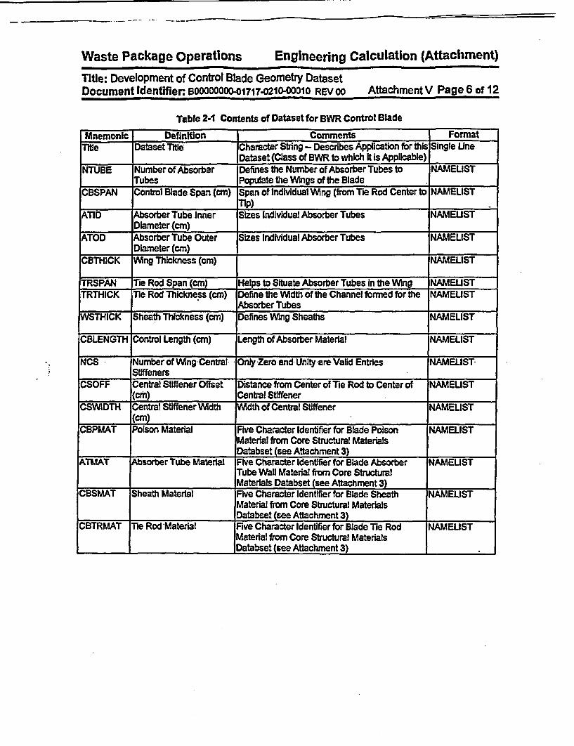
Waste Package Operations Engineering Calculation (Attachment)
Title: Development of Control Blade Geometry DatasetDocument Identifier: B00000000-01717-0210-00010 REV 00 Attachment V Page 6 of 12
Table 2-1 Contents of Dataset for BWR Control Blade
Mnemonic Definition Comments FormatTile Dataset Title Character String - Describes Application for this Single Line
Dataset (Class of BWR to which It is Applicable)NTUBE Number of Absorber Defines the Number of Absorber Tubes to NAMELIST
Tubes Populate the Wings of the Blade .CBSPAN Control Blade Span (cm) Span of Individual Wing (from Tie Rod Center to NAMELIST
Tp)ATID Absorber Tube Inner Sizes Individual Absorber Tubes NAMELIST
Diameter (cm)ATOD Absorber Tube Outer Sizes Individual Absorber Tubes NAMELIST
Diameter (cm)CBTHICK Wing Thickness (cm) NAMELIST
TRSPAN Tie Rod Span (CM) Helps to Situate Absorber Tubes In the Wing NAMELISTTRTHICK Tie Rod Thickness (cm) Define the Width of the Channel formed for the NAMELIST
.______ _ Absorber TubesWSTHICK Sheath Thickness (cm) Defines Wing Sheaths NAMELIST
CBLENGTH Control Length (cm) Length of Absorber Material NAMELIST
NCS Number of WingCentral Only Zero and Unity are Valid Entries NAMELISTl _______ Stiffeners .
CSOFF Central Stiffener Offset Distance from Center of Tie Rod to Center of NAMEUST(cm) Central Stiffener _
CSVVIDTH Central Stiffener Width Wdth of Central Stiffener NAMELIST(cM)
CBPMAT Poison Material Five Character Identifier for Blade Poison NAMELISTMaterial from Core Structural MaterialsDatabset (see Attachment 3)
ATMAT Absorber Tube Material Five Character Identifier for Blade Absorber NAMEUSTTube Wall Material from Core StructuralMaterials Databset (see Attachment 3)
CBSMAT Sheath Material Five Character Identifier for Blade Sheath NAMELISTMaterial from Core Structural MaterialsDatabset (see Attachment 3)
CBTRMAT Tie Rod 'Material Five Character Identifier for Blade Tie Rod NAMELISTMaterial from Core Structural MaterialsDatabset (see Attachment 3)

Waste Package Operations Engineering calculation (Attachment)
Title: Development of Control Blade Geometry DatasetDocument Identifier:, BD-000,_017170.210-000 1 REV 00 Attachment V Page 7 of 12
Figure 2-1 Geometry Parameters for GE D4attice Control Blade
CSThICK
C8SPAN
| Not to Scale12~~~~W

Waste Package Operations Engineening Calculation (Attachment)Title: Development of Control Blade Geometry DatasetDocument Identifier: BOOO 000 117'021000010 REV 00 Attachment V Page 8 of 12
3. Dataset Creation
Each group of data In the dataset will now be discussed In greater detail and the creation of the dataset fora D-lattice GE control blade documented. The final dataset Is shown in Figure 3-1.
3.1. Dataset Title Record
The first line of the dataset Is a title. While the contents of this line are arbitrary, It should contain thefollowing Information to ensure consistency with the file name:
* manufacturer, and
* BWR lattice (D-lattice In this case).
3.2. Namerist Input
The FORTRAN namelist-type Input variables must adhere to the restrictions Inherent In the format of suchInput Care must be taken to ensure that the value provided Is consistent with the data storage class Inthe automation (I.e., Integer Input for Integer variables and real input for real variables) so that neitherprecision Is not lost for real variables nor Is illusory precision Impiled for Integer variables.
The development of the values appropriate for the D-Iattice GE control blade Is shown In Worksheet 3-1.
3.3. Dataset Location
The dataset for the GE D-Iattice blade In named: ge_.dcLatlice.dat,

Waste Package Operations Engineering Calculation (Attachment)Title: Development of Control Blade Geometry DatasetDocument Identifier: B00000OO1717.0210-00010 REV 00 Attachment V Page 9 of 12
Figure 3-1 LattIce Geometry Dataset for GE D4attice Control BladeGE D-lattice Control Blade$BLADENTUDE 84CBSPAN - 12.38ATOD a 0.478ATID * 0.351CBTHICK - 0.7925WSTHICK * 0.14TRSPAN * 1.985TRTHICK - 0.508CBLENGTH - 363.2CBPMAT a 'B4C'ATHAT - 'SS304'CBSMAT - 'SS304'cETEMAT - 'SS304'
$END

Waste Package Operations Engineering calculation (Attachment)Wat Pakg prtos EgneigCluain(tahet
Title: Development of Control Blade Geometry DatasetDocument Identifier: B000000001717-0210-0001o REV 00 Attachment V Page 10 of 12
Worksheet 3-1 Namelist Input Development
ReferenceMnemonic Definition Value Units Source Name
NTUBE Number of Absorber Tubes In Blade 84 N/A [a] NIACBSPAN Span of Blade from Center of Tie Rod to 4.875 Inches [a] CBSPAN
pV~ng TpATOD Absorber Tube Outer Diameter 0.188 Inches [a) ATOD
Absorber Tube Thickness 0.025 inches [a] ATDATID Absorber Tube Inner Diameter N/A NJA NIA ATIDCBTHICK Control Blade Ving Thickness 0.3120 Inches la] CBTHICKWSTHrICK Blade Sheath Thickness, 0.056 Inches [a] WSTHICKTRSPAN Tie Rod Span (Half of Total) 0.7815 Inches la] TRSPANTRTHICK Tie Rod Thickness N/A NiA NIA N/A
CBLENGTH Control Length 143.0 inches [a] CBLENGTHCBPMAT Poison B4C N/A [a] N/AATMAT Absorber Tube Material Identifier SS304 N/A lb) N/ACBSMAT Sheath Material SS304 N/A lb) N/ACBTRMAT Tie Rod Material SS304 N/A [b] N/A
[a]. This data Is from the EPRI Report Table 13.*b]. This assumes that the stainless steel used In the blade components Is the same as that used In the
fuel assembly tie plate (see Table 12 of the EPRI Report).
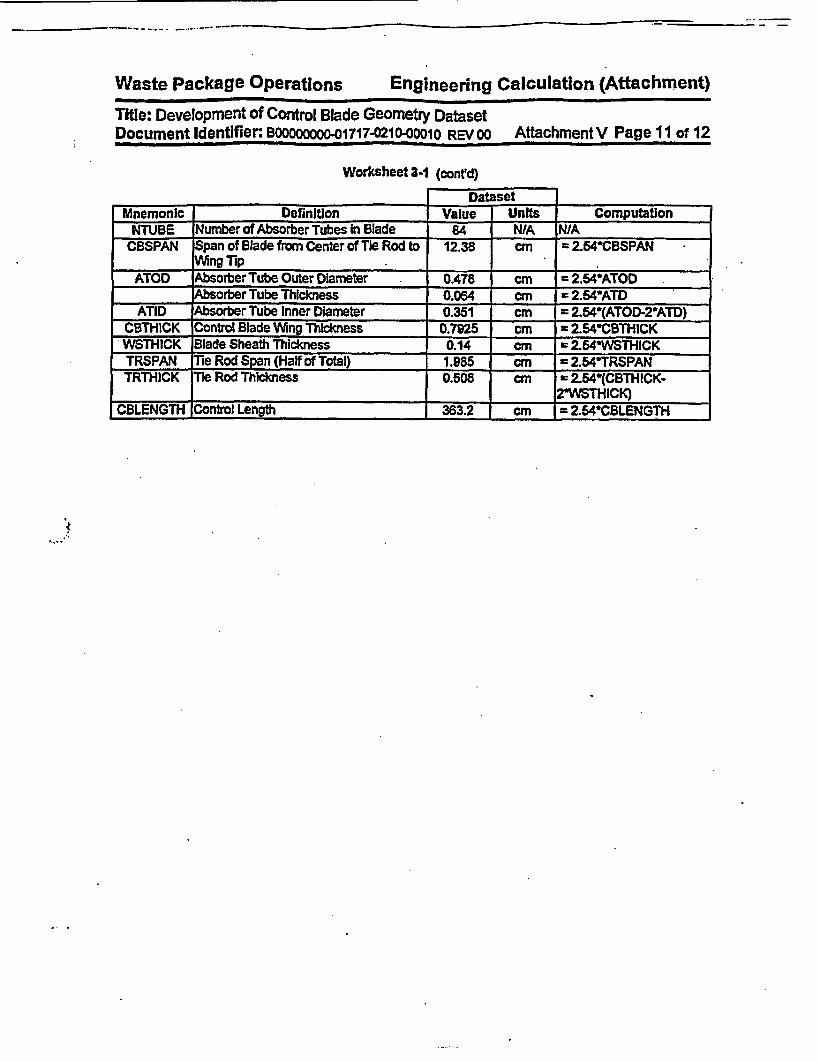
Waste Package Operations Engineering Calculation (Attachment)
Title: Development of Control Blade Geometry DatasetDocument Identifier: BOOOOOOOO-01717-0210-00010 REVOO Attachment V Page 11 of 12
Worksheet 3-1 (conrd)
Dataset __I
Mnemonic Definition Value Units ComputationNTUBE Number of Absorber Tubes In Blade 84 NA NIA
CBSPAN Span of Blade from Center of Tie Rod to 12.38 cm 2.54CBSPANVlfing Tip - ._ _
ATOD Absorber Tube Outer Diameter 0.478 cm = 2.54*ATODAbsorber Tube Thickness 0.064 cm = 2.54ATD
ATID Absorber Tube Inner Diameter 0.351 cM = 2.54(ATOD-2*ATD)CBTHICK Control Blade VVng Thickness 0.7925 cm = 2.54*CBTHICKWSTHICK Blade Sheath Thickness 0.14 cm = 2.54*WSTH1CKTRSPAN ie Rod Span (Half of Total) 1.985 cm = 2.54*TRSPANTRTHICK Tie Rod Thickness 0.508 = 2.54*(CBTHICK-
2-WSTHICK)CBLENGTH Control Length 363.2 cm = 2.64WCBLENGTH

Waste Package Operations Engineering calculation (Attachment)
Title: Development of Control Blade Geometry Dataset*. Document Identifier: BOOOOooOO.01717-0210-00010 REV oo Attachment V Page 12 of 12
4. References
4.1 Core Design and Operating Data for Cycles 1 and 2 of Quad Cities 1, EPRI NP-240, Electric PowerResearch Institute, Palo Alto, CA, November 1976. TIC #: 237267.
.,

Waste Packaae ODerations Engineering Calculation (Affachment)Tite: Development of Algorithms and Encoding of Linkage AutomationDocument Identifier BOoOcaO0 1717-o210OO1o REV 00 Attachment VI Page 1 of 41
Table of Contents
Title Page
1. Introduction 4
2. Specifications 4
3. Encoding of Process 43.1. Program Flow 43.2. Input Parameters to Process 93.3. Detailed Algorithms 12
4. Testing 34
6. Integration Testing 40
6. References 41

Waste Package Oierations Engineering Calculation (Attachment)Title: Development of Algorithms and Encoding of Linkage AutomationDocument Identifier BOOOooOO-01717-0210-001O REV 00 Attachment VI Page 2 of 41
List of Tables
Table Contents Page
Table 3-1 Input Variables 9
Table 3-2 Service Routine List 14
Table 3-3 Type Description for Structured Variables 16
Table 3-4 List of Input Routines 16
Table 3-5 Input Editing Routine List 21
Table 3-6 Deck Generation Routine Listing 29
Table 4-1 Input Values used to Create Vessel and Core Internals Models 35
Table 4-2 Surface Definitions for Vessel and Core Internals Models 36
Table 4-3 Cell Definitions for Vessel and Core Internals Models 38
Table 5-1 Results of Integration Testing Case 40
iI

Waste Package Operations En ineering Calculation (Attachment)Title: Development of Algorithms and Encoding of Linkage AutomationDocument Identifier BOOOOOOOO-017170210-0010 REV 00 Attachment VI Page 3 of 41
List of Figures
Figure Contents Page
Figure 3-1 Top Level Flowchart 5
Figure 3-2 BLINK Input Deck for Quad Cities Unit-1 Initial Core II
Figure 3-3 Illustration of Linked List Concept 13
Figure 3-4 Flowchart for Input Processing 17
Figure 3-5 Input Editing Flowchart 22
Figure 3-6 Building of Core Model from Unique Components 24
Figure 3-7 Windown for Fuel Assembly In Control Cell 26
Figure 3-8. Window In Control Cell Model for Control Blade 27
Figure 3-9 Assembly Loading Into Control Cell 28
Figure 3-10 Deck Generation Flowchart 30

WasfA Parkage Qnprsfinns Enalneering Calculation (Attachment)z--z- z -- ==-W il
Title: Development of Algorithms and Encoding of Linkage AutomationDocument Identifier BoooOOOOO-01717-0210-oo1o REV OO Attachment VI Page 4 of 41
1. IntroductionThis attachment contains the detailed specifications for and documents the development of a softwareroutine to create MCNP Input decks (References 6.1 and 6.2 - the Los Alamos National Laboratory(LANL) User's Manuals - and References 6.3 and 6.4 - the Software Qualification Reports) for analyzingCommercial Reactor Criticals (CRC's) using Isotopic Inventories from the SAS2H sequence of the SCALEcode (Reference 6.6-the Software Qualification Report).
2. SpecificationsThis process must Include the foliowing functions:
* accept Input from the user that controls the operation of the software routine and speci-fies the source of Information about the fuel assemblies geometry and material composi-tion. control blades and reactor statepoint
* generate a complete MCNP Input card Image representation that permits a CRC analysisto be performed without additional modification;
* create an output file that documents the processing performed.
3. Encoding of ProcessThe computational algorithms and the process described In Attachment VAI must be encoded In a soft-ware routine on an HP workstation. For this application, a mixture of C and FORTRAN coding Is used.The name for this software routine Is OBLINiC.
3.1. Program FlowA top-level flowchart for the software routine Is shown In Figure 3-1.
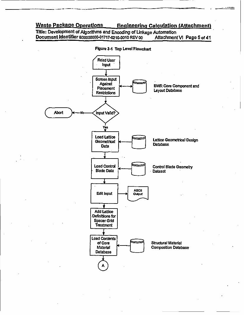
WastA Package Onnirnflans Enalneerina Calculation (AttachmentlWa-tc Packaa Onrtnl 2nlern Calculation -- w- f~tahetTitle: Development of Algorithms and Encoding of Unkage AutomationDocument identifier BODOOOOO-01717-0210-001O REV 00 Attachment VI Page 5 of 41
Figure 341 Top Level Flowchart
/edUser|
Screen InputAgainst BWR Core Component and
PaceRestnct L _ J Layout Database
yes
Load Latflce I q Lattice Geometrical Design
Data l J Database
Load Control Contol Blade GeometryBlade Data Dataset
ASCIIIEdit Input outpu
Add Latticelefinitiions forSpacer GridTreatment
oad Contentsof Core _ Structural MaterialMaterial Composition Database

Waste Par-kaae Onersntinng. Pinnsn aeri~nn Caln-viinfinn (Affaithmantl- ws-- - *-- …
Title: Development of Algorithms and Encoding of Linkage AutomationDocument Identifier B00000000.017`17-021-oo1Oo REV 00 AttachmentVI Page 6 of 41
Figure 3- (conrd)
Temporary File forSurface Definitions
Temporary File forCell Definitions
Temporary File forMaterial Defirsitions
Loop Over UnLattices In Co
Temporary File forSurface Definitions
Temporary File forCell Definitions
Temporary File forMaterial DefinItions
Temporary File forSurface Definitions
Temporary File forCell Definitions
iqueDre
Fuel Intermediate Dataset
Temporary File forMaterial Definitions

Waste Packa9.QoPeatlons Endineerina Calculation (AttachmentiTitle: Deeomn of Alotm and. Enodn ofLnaeAtmtoTitle: Development of Algorithms and Encoding of Linkage, AutomationDocument Identifier 800000000x1717x0210-0o10 REV 00 Attachment VI Page 7 of 41
Figure 3-1 (cont'd)
Temporary File forSurface Definitions Determine
Number ofTemporary FRe for Unique Control
Cell Definitions Cells
Temporary File forMaterial Definitions,
BAss~emnbliqe~s output
Temporary File forSurface Definitions
Temporary File for Build ControlASICell Defnitions Cell Models outpu
Temporary File forMaterial Definitions

Wa-,fg% Pankane Oniraftinnt. 9novi, io0grinn Peihiiufatirn lA44ae-hmanfO- - -. �.5.F. *W �u�Ma*s��s ,1 �it*t5* *flSC.* *��5*�f
Title: Development of Algorithms and Encoding of Linkage AutomationDocument Identifier BOOMOOO0117-M7021 001i REV 00 Attachment VI Page 8 of 41
Figure 3-1 (contd)
Temporary File forSurface Definifflons
Temporary File forMaterial Definirons
I

Wme4r% paelkana n*%rrftf1fnc =*%rilinaprinn r-air-oillsitinn tAffnr-hmentlI ~3D*Y 'I.~U." LEqS r
Title: Development of Algorithms and Encoding of Linkage AutomationDocument Identifier Boooooooo-01717-0210-oo 01 REV 00 Attachment VI Page 9 of 41
3.2. Input Parameters to Process
The Input to the linkage software routine Is all the information necessary to construct an MCNP geometri-cal representation of the core and populate it with the proper material representation. The input Is anASCII-format file that Incorporates both FORTRAN Namelist-type Input and fields of space-delimited data.The Input variables are described In Table 3-1. A copy of the Input deck for the Quad Cities Unit-1 Initialcore is shown In Figure 3-2.The automation also makes use of a large number of prepared datasets tominimize the size of the Input file.
3.2.1. Dataset Title Record
The first line of the dataset Is a title. While the contents of this line are arbitrary, good practice indicatesthat it should contain the following Information:
* name of plant modeled,
* cycle and exposure point,
* thermal-hydraulic conditions, and
* software routine execution options.
3.22. Namelist Input
The FORTRAN narnelist-type input variables must adhere to the restrictions inherent In the format of suchinput. Care must be taken to ensure that the value provided Is consistent with the data storage class Inthe automation (i.e., Integer Input for Integer variables and real input for real variables) so that neitherprecision Is not lost for real variables nor Is fllusory precision Implied for integer variables.
3.2.3. List Input Fields
These fields are used for vectors and arrays of data, such as Indices to fuel assembly axial nodes andmrnaps' Indicating the locations of fuel assembly geometrical types. While these are read In a *free-
format, good practice Indicates that they should be arrayed in a regular fashion that maximizes legibility.The list Input fields are preceded by a titfe Une In every Instance.
Table 3-1 Input VariablesVariable Definition Comments Format
Tite Case Title Character String - Describes Analysis Single Line
COREDB File Specification for Core NamelistGeometry Database
COREMTLS Fie Specification for Core Namelist.__________ Materials Database
BLADEDB File Specification for NamelistControl Blade GeometryDatabase
FPREFIX Directory Specification for NamelistLocation of Fuel MaterialIntermediate Database
LPREFIX Directory Specification for NamelistLocation of Lattice Ge-ometry Database
NAXIAL Number of Axial Nodes In Must be Consistent with SAS2H Analysis Namelist_Core Representation forming the Source of the Fuel Material

Waafp Ppt--kanft flnP-rafinne P-nninnarinq r-alt.-tilpfinn fAffachmp-ntlWa. ti. P.~ mufnl~in - r--- son" ----- 35*w--~*u* .- --.- -
Title: Development of Algorithms and Encoding of Linkage AutomationDocument Identifier BDODOOOOO-01717.0210-0010 REV 0o Attachment V\ Page 10 of 41
Variable DefinItion Comments FormatCompositions
AFL Active Fuel Length Value must be in centimeters NamelistNCOLP Maximum Number of May be Consistent with Quarter-core, Haff- Namelist
Columns of Fuel Assem- core or Full-core Representationsblies In the Problem
NROWP Maximum Number of May be Consistent with Quarter-core, Half- NamelistRows of Fuel Assemblies core or Full-core RepresentationsIn the Problem
RHO Density for In-channel Units are g/cmv NarnefstModerator
RHOBYP Density for Moderator In Units are g~cW NamelistBypass Region
TEMPK Problem Temperature for Units are Kelvin NamelistScattering Kernel
MUTP Material Identifier for Up- Maximum of Six Characters Namelist. per Tie Plate Region
MLTP Material Identifier for Maximum of Six Characters NamelistLower Tie Plate Region .
GMAPMap Pointing to Fuel As- List Formatsembly Geometrical Da-taset Vectors
MMAP Map Pointing to Fuel List FormatMaterial IntermediateDataset Vectors
B3LADEP Control Blade Position Map of Control Blade Positions (must be an List Formateven Integer between 0 and 48, Inclusive)
LGVECT Lattice Geometry Vectors Supplies Description of Datasets that Rep- List Formatresent the Geometry of the Lattices
LMVECT Lattice Material Vectors Supplies Description of Datasets that Rep- List-Formatresent the Material Composition of the Lat-tices
N_SPACER Number of Spacers for List Formateach Geometrical FuelType
SLOC Spacer Location for Each List FormatSpacer for a Given Geo-metrical Fuel Type
S_MTL Spacer Material Label for List FormatEach Geometrical Fuel
_____ ____ Type__ _ _ _ _ _ _ _ _ _ _ _ _ _

Waste Package-_5P-erations -Eualneerinct Calculation (Attachment)Title: Development of Algodthms and Encoding of Linkage AutomationDocument identifier BoooDoooo0o1717-0210-O010 REV 00 Attachment A Page 11 of 41
Figure 3-2 BLINK Input Deck for Quad Cities Unit-I Initial Core
Quad Cities-i, Beginning of Life$LINKINCORE DB - '/users/anderson/crc bwr/core database/bwr3 724bundle.dat'
CORE MTLS '/users/anderson/crc bwr/materials database/core materials.dat'BLADE DB - '/users/anderson/crc bwr/blade database/ge d lattice.dat'LPREFIX - '/users/anderson/crc bwr/qclic/lattice database/I
FPREFIX - '/users/anderson/crc bwr/qclic/fuel composition database/'
NAXIAL - 24AFL - 365.760NCOLP - 15NROWP - 15RHO - 0.981141RHOBYP - 0.981141TEMPK - 337.04MUTP - '7GUTP1'MLTP - '7GLTP1'$ENDFuel Geometry Loading Map
0 0 0 0 0 0 0 0 0 0 1 1 I I I0 0000 00001 1 1 1 1I0 0 0 0 0 0 1 1 1 1 I I I I 1O O O O 0 1 1 1 1 1 1 1 1 1 1O O O 0 1 1 1 1 1 1 1 1 1 1 10 0 0 1 1 1 1 1 1 1 1 1 1 1 10 0 1 1 1 1 1 1 1 11 I 1 1 1O 0 1 1 1 1 I 1 1 1 1 1 1 1 1O 0 1 1 1 1 1 1 1 1 1 1 1 1 10 1 1 1 1 1 1 1 1 1 1 1 1 1 2
00000 11 11 1 11 11 1100001 11 11 11 11 1 1 '
1 111 11 11 11 1 11 1*.1
I
Fuel Material IO 0 00 0 0 00 0 0 0 0 0 00000003000003300003310003313003313100313240033242033142433 1 42423132424331424231324243314242
Blade Positions-1 -1 -1-1-1-1 -1 -1 00 00-1 -1 00 48 00
.oading Map00033:00331:3331413141 432424 ;24241 4424 24;24241:424 1324 131.41313 313131313131131313313131
33
313242413131313
3314242313.132.31
480048
00 4800 0000 48

Waste Packaue Oneratinns Enaineerinq Calculation (Attachment)Title: Development of Algorithms and Encoding of Linkage AutomationDocument Identifier BOOOOOOOO01717-0210-0010 REV 00 Attachment VI Page 12 of 41
-1 00 00 00 00 00 00 00-1 48 00 48 00 48 00 4800 00 00 00 00 00 00 0000 48 00 48 00 48 00 4800 00 00 00 00 00 00 00
Lattice Geometry Indices1 24*1
Lattice Material Indicies1 1 7*2 10*3 5*2 12 4 7*5 10*6 5*5 43 7 22*8 74 9 22*10 9
Lattice Geometry Datasetsge7x7.datLattice Material DatasetsG7212G003DL1.datG7212G006DL2.datG7212G007DL3.datG7211G003DL4.datG7211G006DL5.datG7211G007DL6.datG7212G003DL7.datG7212G006DL8.datG7211G003DL9.datG7212G006DL10.datFuel Assembly Spacers for each Bundle Type7Locations of Spacer for Each Bundle Type46.99 96.52 146.05 195.58 245.11 294.64 344.17Spacer Material MnemonicsSG7D1
3.3. Detailed Algorithms
The coding that comprises the software routine Is described in this sub-section by functional block. List-ings of the FORTRAN coding are provided In Attachment XIV.
3.3.1. Driver Routine
The driver routine manages the overall processing performed by the software routine and Is well repre-sented by the flowchart in Figure 3-1. It Is comprised of the main function rmain").
3.3.2. Service Routines
These are routines that provide memory management, file management, control of overall output proc-essing, and miscellaneous services. These routines are listed in Table 3-2. Memory management in thissoftware routine is achieved by utilizing the dynamic memory allocation functions of the C libraries.Structured variables used in the software routine, and particularly in the construction of linked lists, areshown in Table 3-3.
In a linked list the memory address of the next structure is part of the existing structure; therefore, if thebase member of the linked list is known, then the list may be traversed in the forward direction. In thelinked lists in BLINK, the memory address of the previous member of the list is Included in the structure,permitted the list also to be traversed in the backward direction. This is Illustrated In Figure 3-3. The useof linked lists of structures permits the use of dynamic memory without a priori knowledge of the numberof entries In the list.

Waste Package Operations -Encineering Calculation (Attachment)Title: Development of Algorithms and Encoding of Linkage AutomationDocument Identifier Bo0000ooo-01717-0210-oo1o REV 00 Attachment VI Page 13 of 41
Figure 3-3 Illustration of LUnked List Concept
Positive Traverse of Ust
*ast Con 1
Structure Structure Structure Structure
' S;

WnQ+n Parle-ana Onp-raflnna Fnninnaring Calt--tils;f Ion (AftachmentlW--+ci as an-s- - -Org .- - C o atU - --- -
Title: Development of Algorithms and Encoding of Linkage AutomationDocument Identifier BOOOOOOO-01717-0210-O00o REV 00 Attachment VI Page 14 of 41
Table 3-2 Service Routine List
Name la) Functionabort (c) Common Location for Controlled Termination of Processing when
Error Detected by Codingbufferpad (c) Adds Blanks to a C Character Stringcopasciifile c copies the Contents of One ASCII File to Anotherdiscard scratchjfle (c) Creates Sub-process to Delete Scratch File used In Processingfortranjnessage (c) C Function to Print Message from FORTRAN Routines to the Out-
put StreamFTCLOSE (f_ Manages the Closing of FORTRAN Sequential Text FilesFTOPEN(f) Manages the Opening of FORTRAN Sequential Text Filesheader (c) Prints Header for New Output Page; also Obtains Process Infor-
rnation (i.e., Date, Time and Process Identification Number forCase Identification)
INVALI (f) Initializes an Integer Vector to a Given ValueINVALR (f) Initializes a Real Vector to a Given Valuelines (c) Tracks the Number of Output Lines on a Page and Requests a
New Page when Current Page Is Fullloadccore mtls (c) Loads the Contents of the Core Materials Dataset Into MemoryloadjueLmaterial (c) Loads the Contents of a Intermediate Fuel Material Dataset in
Memorylad surfaceusagejiist (c) Loads Entries Into 6surface .usegeList Structure In Linked Listload.Usge.Llest (c) Loads Entries Into usagejls Sucture in Linked ListMCHAR (f) Determines the Last Non-blank Character in a Character Stringmemory.asclLrecord (C) Manages Memory Requests for Variables of the *ascii records
___________________________ Type (see Table 3-3 for Definition)memory_psciistring (c) Manages Memory Requests for Variables of the *asciistring'
Type (viz., charl 331)memoryjfg-fist (c) Manages Memory Requests for Variables of the fgjisr Type (see
Table 3-3 for Definition)memory float (c) Manages Memory Requests for Single-precision Real VariablesmemryjInteger (c) Manages Memory Requests for Integer VariablesmnemoryjlatticqIist ()Manages Memory Requests for Variables of the aug-
mented latticejist Type (see Table 3-3 for Definition)memory_;.smaterial (c) Manages Memory Requests for Variables of the *11materiar Type
(see Table 3-3 for Definition)memory~surface~usagejlist (c) Manages Memory Requests for Variables of the 'sur-
face _usagejsr Type (see Table 3-3 for Definition)memorypusagejist (c) Manages Memory Requests for Variables of the usage~listf Type
(see Table 3-3 for Definition)mernsum (c) Summarizes Software Routine Dynamic Memory Usagerollup llm (c) Returns Memory Associated with a *11 material Unked Listsearchsurface_usagejist (c) Searches Linked Lists of the 'surface.usagejisr Type either by
____ ____ ____ ______ " Index or Labelsearch usagejlist (c) Searches Unked Lists of the musagejist Type either by Index or
Label
[a]. The character in parentheses represents the computer language in which the routine is created. Alower case *c' represents C source statements while a lower case ef represents FORTRAN sourcestatements. The name of FORTRAN source routines are also given In all uppercase letters.

Wnehci Ps~r-kann lnp-ratinnQ Fnaoinerinn Calculation (Attachment)Ad CI- A- s- - - Ac __ a- --
Title: Development of Algorithms and Encoding of Unkage AutomationDocument Identifier BOOOOOOOO-01717-0210-0010 REV 00 AttachmentVI Page 15 of 41
Table 34 Type Description for Structured Variables
Type Name Definition CommentsasciLstring char[1 33] character string variable used to
_________________________ process text from ASCII filesasclLirecord asci~record *last linked list structure used to load
asci string the contents of ASCII files Into_asci record *next memor
11rnatertal II material *last linked list structure used to loadInt atornic~number the material definitions Intoint mass~number memory for processingfloat weigh..percentagechar ffbraryspuffi45jI rmaterial next
usage-ist usagejist last linked list structure used to trackint Index the usage of material definitionsasciLstring labelusagejist rnext
surfacejusagejIst usage_list 'last linked fist structure used to trackint Index the usage of surface definitionsascilttring labelasicstring valuechar mnemonic[4]asciistrng equivalentjlabelusagejlist 'next
fgjist asciLstring gdsname structure used to hold the con-Int latdim stants defining a lattice geometryInt nwrfloat cthickfloat asinfloat wgapfloat ngapfloat cradiusfloat fsrdfloat cfsrdfloat rpitchfloat codfloat cldfloat podchar frcmat[6]char cmat[61
all all *last linked list structure used to ac-Int baslsjattlce materialindex cumulate list of lattices that mustInt lattice_materlaLindex be replicated due to the presenceall *next of a fuel grid spacer
.
3.3.3. Input Processing
These routines control the processing of Input data to the software routine. Thus, they process the Inputvariables shown in Table 3-1. This functions are listed In Table 3-4 and the flow of the Input process Isshown In Figure 3-4.

waste Psyr-wine operatinn-Q Enainpp'rina Calculation (Attachment)Title: Development of Algorithms and Encoding of Unkage AutomationDocument Identifier B00000o0o001717.O210-0010 REV 00 Attachment VI Page 16 of 41
Table 3.4 List of Input Routines
Name la] FunctionBPCHEK (t) Ensures that Control Blade Indices are in Valid Locations and all
Positions are in a Valid RangeCBUNDLE (f) Computes the Number of Unique Fuel Assembly TypesCLATTICE () Determines the Number of Unique Fuel Lattices In the Coreecho (c) Copies an Image of the Input File to the Output Stream__ _ __ _ (D Reads Vectors of Integers and an Associated Title Une
LDLVR (f) Reads Vectors of Real Values and an Associated Title UneLODCT (fl Creates Correspondence Table between Lattice Geometry Indices
and Lattice MaterIal IndicesMAPCHdEK (fl Ensures that Fuel Assembly Indices are in Valid Locations and all
.________ _ Valid Locations are FiledR2DMAP (f) Reads Rectangular Arrays of Integer VariablesRBLADE (f_ Reads the Contents of the Control Blade Geometry DatasetK _ __IN (_ _ _ Manages the Reading of Input FiesRLAT~iCE (f)Reads the Contents of the Lattice Geometry DatasetSTRNGR () Reads Character Stdrngs from FORTRAN Logical Unit
la]. The character in parentheses represents the computer language in which the routine Is coded. Alower case Sc' represents C source statements while a lower case f represents FORTRAN sourcestatements. The name of FORTRAN source routines are also given in all uppercase letters.

Waste Package Operations Engineering Calculation (Attachment)Title: Development of Algorithms and Encoding of Linkage AutomationDocument Identifier B00000000-l717.0210-0010 REV 00 Attachment VM Page 17 of 41
Figure 34 Flowchart for Input Processing
*1
Cats R2DMAP to Read the2-dimenslonal Core LayoutMaps and CBUNOLE toDetermine the Number of .Unique Fuel Asstmbly

Waste Package Operations En-lineernjq Calculation (Attachment)Title: Development of Algorithfms and Encoding of Linkage AutomationDocument Identifier BOOOOOOOO-01717.0210-O01O REV 00 Attachment VI Page 18 of 41
Figure 34 (conrd)
'. .

Waste Package OPerations Engineering Calculation (Attachment)Title: Development of Algorthms and Encoding of linkage AutomationDocument Identifier B00OO0OO-01717-0210-0010 REV 00 Attachment VI Page 19 of 41
Figure 3-4 (contd)

Waste Package Operations Engineering Calculation (Attachment)Title: Development of Algorithms and Encoding of Linkage AutomationDocument Identifier Bo0000000-01717-0210-0010 REV 00 Attachment VI Page 20 of 41
Figure 3-4 (contd)
Note Utat Input EdfitigRoutines Occur at this Pointli the Program Flow

Waste Packavie-Oner'ations Enalneerinci Calculation (Attachment)Title: Development of Algorithms and Encoding of Linkage AutomationDocument Identifier BOOOaaooO-01717-0210-0o1o REV 00 Attachment V Page 21 of 41
3.3A. Input Editing Routines
These routines edit the user input to the software routine and the contents of many of the datasets se-lected for the creation of the MCNP Input deck These routines are listed In Table 3-5 and the flow of theInput editing process Is shown In Figure 3-5.
Table 3-5 Input Editing Routine List
Name [al Functioneditin (c) Edits Input from User Input Directives from FORTRAN NAMELIST
Inputcoredb4edt (c) Edits Contents of Core Geometry Datasetbladedb edt (c) Edits Contents of Blade Geometry Datasetfgds._edt (c) - Edits Contents of Fuel Geometry Datasetseditct (c) Edits Correspondence Table which Relates Lattice Geometry Indi-
ces and Lattice Material Indicesedltspacer (c) Edits Input Variables Defining Fuel Assembly Spacers
la]. The character In parentheses represents the computer language In which the routine Is coded. Alower case 0c represents C source statements while a lower case mt represents FORTRAN sourcestatements. The name of FORTRAN source routines are also given in all uppercase letters.
i

Waste Package Operations Engineering Calculation (Attachment)Title: Development of Algorithms and Encoding of Linkage AutomationDocument Identifier BoO00oo00-01717-0210OO 0I REV 00 Attachment Vi Page 22 of 41
Figure 3-5 Input Editing Flowchart
Edit InutDiretives *om
User Inputle
Fase SdW

WasfL% Packaue Onp-rations Fnaineerinq ralculation fAttachment)Tise: Development of Algorithms and Encoding of Unkage AutomationDocument Identifier B00000000 01717-0210-O01O REV 00 Attachment NA Page 23 of 41
Flgure 3-5 (contd)
the Lattice Ust Is
with Spacers

Waste Pck~age OneratlOns Enagineering Calculation (Attachment)Title: Development of Algorthms and Encoding of Linkage AutomationDocument Identifier BOOOOOODD001717.0210-0010 REV ao AttachmentVI Page 24of 41
3.3.6. MCNP Input Deck Generation
The MCNP model for a BWR core Is created from the smallest set of unique components for which differ-entlated nuclear data Is available: lattices filling a Onode' of the core. Thus separate MCNP universes arebuilt for each unique lattice. These lattices are then built up into unique fuel assembly models that aremerely strings of such nodes. The next higher grouping of components in the core Is control cells,"which are groups of four fuel assemblies, the control blade location at the center, and, possibly, one ormore in-core Instrumentation guide tube at the corner of the control cell. These unique control cells arethen loaded Into the core region of the model to complete the fuel mass. This process Is Illustrated inFigure 3-6.
Figure 34 Building of Core Model from Unique Components
Unique UniqueLattices Assembly
Control CellLattice

. . -.. -- 11 - '.. -- -- -- -
Waste Package Oc erations Engineering Calculation (Attachment)Title: Development of Algorithms and Encoding of Linkage AutomationDocument Identifier B00000oO0001717-0210-0010 REV 00 Attachment VI Page 25 of 41
The details of the construction of the MCNP model for specific lattices are shown In other attachmentsand the building of the assemblies Is straightforward. Each assembly Is placed in a specially prepared'cells In each control cell as shown in Figure 3-7. While the fuel assembly Is roughly square In cross sec-tion, this Owindow has been adjusted to provide dearance for in-core instrumentation guide tubes whichmay be present in the comer of the control cell. The coordinate of the center of this curved surface andthe ambiguity planes are computed as:
4,T2- (DTODEq.3-1 °=°°+ 2
Here DTOD is the outer diameter of the guide tube and 6a is sum of the clearance between the guide tubeouter surface and the window for the fuel assembly model. The radius of the curved surface may becomputed as:
Eq. 3-2 R = '2 .* 5 tan(67.50)
The coordinates of the center of the curved surface may be written as:
Eq. 3-3 Xc = (APITCH - 6 0)- RYc = (APITCH - 60)+ R
Here APITCH is the lattice pitch.
There is also a 'window" constructed for the control blade as shown In Figure 3-8. The location of bladewindow is defined by a fixed offset from the center of the control cell that accommodates both the controlblade and the fuel assembly. The fuel assemblies are loaded Into the windows and distributed in thecontrol cell as shown In Figure 3-9. The reference location for the fuel assembly window Is In the south-east quadrant and assemblies at other locations are placed by rotating the defined cell-about the centerof the control cellto the proper location.

.
Waste Packasce ODerations Encineeingn Calculation (Attachment)Title: Development of Algorithms and Encoding of Linkage AutomationDocument Identifier Boo0oooo0o1717-o21o-oO1o REV 00 Attachment VI Page 26 of 41
Figure 3-7 "Window" for Fuel Assembly In Control Cell
max Y
min X
xP = APITCH-8.
_ AmbiguitySurface
I CurvedSurface
Not to Scale fAmbiguitySurface

Waste Package 1aerntinns 9nninaftriney Catri,.icfinn lAftgai'hme~nnI I&& Ion ON,.-No I, r
Title: Development of Algorithms and Encoding of Linkage AutomationDocument Identifier B00000000.01717-M21000o0 REV 00 Attachment VI Page 27 of 41
Figure 3-8 Window in Control Cell Model for Control Blade
BC8
BC3 IBC2
I EN_ _ .
BCI
, _
Not to Scale
BSc BCs
BC7

Waste Packane-O-P-Grations --En-alneering Calculation (Attachment)Title: Development of Algorithms and Encoding of Linkage AutomationDocument Identifier 1OO3ooooO-01717-210-001O REV 00 AttachmentV Page 28 of 41
Figure 349 Assembly Loading Into Control Cell
4 Not to Scale
These routines perform the primary function of the software routine, viz., governing the production of theMCNP Input deck These names and function of these routines are listed In Table 346 and the logic flowfor this portion of the software routine Is shown In Figure 3-10.

Waste Packasqq-O-P-G-ratllons -- mineerin Calculation (Attachment)Title: Development of Algorithms and Encoding of Linkage AutomationDocument Identifier BO0000000001717-0210O-Oo1 REV 00 Attachment VI Page 29 of 41
Table 3-6 Deck Generation Routine Listing
Name lal Functionaddcell (c) Acdds Cell Definition to MCNP Modeladd like but (c) Adds Cell of Form *Uke Bur to MCNP Modeladd material (c) Adds Material Definition to MCNP Modeladd surface (c) Adds Surface Definition to MCNP Modeladd symmetry surfaces (c) Adds Symmetry Surfaces to MCNP ModelaugmentjatticeJist (c) Adds Lattices Incorporating Spacer Grids Into Material Lattice
Loading Vectorsbuild assemblies (c) Combines Unique Lattices Type Into Unique Assembly TypesbuildcontroL~blade (c) Creates Cells, Surfaces and Material Definitions for Control Bladebuild.controLcells (c) Creates Control Cells and Loads Fuel Assembly Models as Ap-
propriateCCMGEN (f)Determines the Location and Number of Unique Control Cellscore-atticegeneration (c) Creates Control Cell Lattice within Core Shroudecho MCNPedeck (c) Copies the MCNP Input File to the Output Streamedit materials (c) Edits the Descriptions of Materials used in the Problemedit surfaces (c) Edits the Descriptions of Surfaces used in the Problemedit~unlverses (c) Edits the Universe Indices for the Control Cells and Fuel Assem-
bliesge7x7jattice (c) Creates Cells, Surfaces and Material Definitions for Model of GE
7x7 Lattice (No Water Rods)ge8x8j1attwceswr (c) Creates Cells, Surfaces and Material Definitions for Model of GE
8x8 Lattice with Small Water Rodsgeneratejdeck (c) Combines Scratch Files containing Segments of MCNP Input In-
structions Into a Single MCNP Input Filegeneratejatbce_model (c) Controls the Generation of the Appropriate Lattice Representation
for each Unique Lattice in the Core [b]materiaLmatch (c) Matches Material Identifiers with Materials In the Linked Ust for
Core Materialssearchjaujlist (c) Search List of Fuel Assembly Assignments to Control Cells and
Returns Fuel Assembly Indices at Desired Locationssourcespecification (c) Adds Source Specification and Other Problem Control to the
MCNP Inputspacer location (c) Determines the Nodal Locations of Each Fuel Spacer Gridvesselgeneration (c) Creates Cells, Surfaces and Material Definitions for Vessel, Vessel
Internals and Axial Reflector Regions
[a]. The character in parentheses represents the computer language in which the routine Is coded. Alower case *c represents C source statements while a lower case *f represents FORTRAN sourcestatements. The name of FORTRAN source routines are also given In all uppercase letters.
[b). This function calls other functions that create the appropriate cells, surfaces and material definitionsfor each lattice geometrical type. The models for tese various lattice types are documented in Indi-vidual attachments to the main document (see §8).
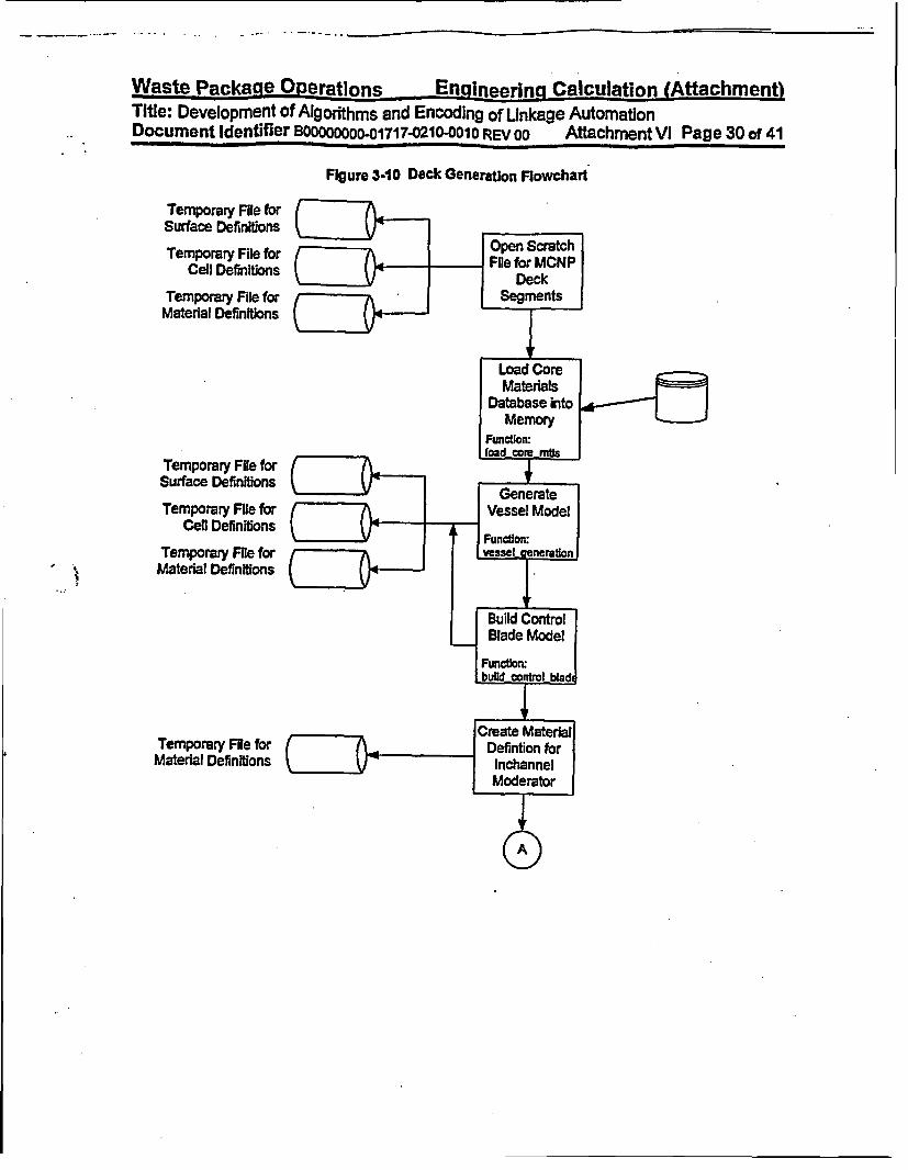
- | | > > �
Waste Packane OPerations Engineering Calculation (Attachment)Title: Development of Algorithms and Encoding of Linkage AutomationDocument Identifier B0000000O01717.0210-o0010 REV 00 Attachment Vi Page 30 of 41
Figure 3-10 Deck Generation Flowchart
Temporary File forSurface Definitions
Temporary File forCell Definitions
Temporary File forMaterial Definitions
Temporary File forSurface Definitions
Temporary File forCefl Definitions
Temporary File forMaterial Definitions
Temporary FRe forMaterial Definitions

Waste Package ODerations Engineerinq Calculation (Attachment)Title: Development of Algorithms and Encoding of Linkage AutomationDocument Identifier B8000O0OoU1717.0210-0o1o REV OO Attachment V Page 31 of 41
Figure 3-10 (conted)
Temporary File forSurface Definitions
Temporary File forCell Definitions
Temporary File forMaterial Definitions
Temporary File forSurface Definitions
Temporary File forCell Definitlons
Temporary File forMaterial Definitions
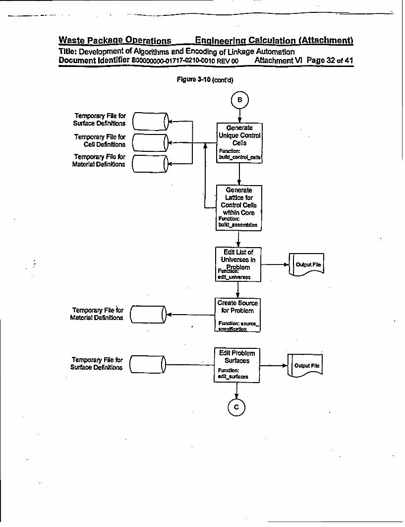
Wa-qfp Pqr-katie Onarmunnc -Enalnearing Calculation (Attachment)-w w-b * _B %4_F-
Title: Development of Algorithms and Encoding of Unkage AutomationDocument Identifier Bo0000roooo1717-021D-0010 REV 00 Attachment VI Page 32 of 41
Figure 3-10 (contd)
Temporary File forSurface Definitions
Temporary File forCell Definitions
Temporary File forMaterial Definitions
Temporary File forMaterial Definitions
Temporary File forSurface Definitions

Waste Package O-erations En-ineering Calculation (Attachment)Title: Development of Algorithms and Encoding of Linkage AutomationDocument Identifier 800000O00001717-0210-0010 REV 00 Attachment VI Page 33 of 41
Figure 3-10 (conrd)
Temporary File forMaterial Definitions
Temporary File forCell Definitions
Temporary File forMaterial Definitions
.. .
..,x

Waste Package OPerations Engineering- Calculation (Aftachment)Title: Development of Algorithms and Encoding of Linkage AutomationDocument Identifier BOOOOOO-01717-021 0-010 REV 00 Attachment VI Page 34 of 41
4. TestingThe MCNP model for a quarter core contains many components, the modeling of which Is verified In theattachments which document the specific components. The testing in this section of this attachmentseeks only to show that the vessel and core Internals models, including the control cells, are appropriatelyconstructed. For this testing, the MCNP input deck generated for the Quad Cities Unit I Beginning of LifeCRC calculation is used (see Attachment Xli).
The input parameters used to generated the model are shown In Table 4-1. These values are used tocreate the surfaces shown In Table 4-2 and the cell definitions given in Table 4-3 (note that the cell indi-ces merely provide the ordering of the cells and do not correspond to any particular input to BAFL).These may be compared with the input deck shown In Attachment XiI to confirm that the linkage automa-tion is creating the expected values.

Wmat h Da -leZnP nviCainna1 Engineering Calculation (Attachment)I %Aws.
Title: Development of Algorithms and Encoding of Linkage AutomationDocument Identifier B000OOOOO01717-0210-0010 REV 00 Attachment VI Page 35 of 41
Table 4-1 Input Values used to Create Vessel and Core Internals ModelsReference
Mnemonic Definition Value Units Source Namencol Dimensionality of Core 30 n/a la] n/anrow Dimensionality of Core 30 n/a (a] n/aapitch Assembly Pitch 6 inches Ibi APITCHvod Vessel Outer Diameter 688.654 cm IC] VODvthick Vessel Thickness 15.557 cm cl VTHICKsod Core Shroud Outer Diameter 526.096 cm [c] SODsthick Core Shroud Thickness 5.08 cm - C] STHICKn/a sembly Length (Handle to Nosepiece) 171.27 Inches [d] ATLEN
n/a Nosepiece Guide 1.45 Inches [dl LNPGn/a Nosepiece Cylinder 0.625 inches Id) LNPCYLn/a Lower Tie Plate 5.31 Inches Id] LLTPna Active Fuel Length 144 Inches [d) AFLn/a Handle Length 6.65 inches [di LHANDLEtutpr Top of Upper Tie Plate Region n/a n/a n/a TUTPR
tcgr Top of Core Grid Region 158.6875 inches le] TCGRbltpr Bottom of Lower Tie Plate Region n/a n/a n/a n/an/a Core Support Plate Thickness 2 Inches [e] CSPTHbcpr Bottom of Fuel Support/Core Plate Re- n/a n/a n/a n/a
giondtod Instrument Dry Tube Outer Diameter 0.700 Inches (fi DTOD
Dry Tube Thickness 0.03 inches nIq DTDdtid Instrument Dry Tube Inner Diameter 1.63 inches ri/a DTIDdo Offset between Instrument Tube and 0.1 cm g91 DO
Window for Fuel Assembly _ _
Comer Radius for Window for Fuel As- n/a n/a n/a CR.sembly -
Blade Window Offset 0.4 cm 191 BWOControl Blade Span 4.875 inches (h) CBSPAN
(a.1
fbl.
le].
(hJ.
This value Is from Reference 6.6 (hereafter cited as the REPRI Report), Table 15.This value is from the EPRI Report Table 3.This value Is from Reference 6.7 (hereafter cited as 6QC1 BOL Report"), Table 4.1-1.This value Is from Reference the EPRI Report, Figure 10.This value Is from Reference the EPRI Report Figure 26.This value Is from Reference the EPRI Report Figure 29.This Is an assumed value which provides adequate cell clearance in the MCNP model.This value is from Reference the EPRI Report, Figure 13.

Wa-qfr Ppr-kaae Orlerzatinn~a Efngingcrints Cakriusation (Attachmentl
Title: Development of Algorithms and Encoding of Linkage AutomationDocument Identifier 8O0000000001717-021-0010 REV 00 Attachment VI Page 36 of 41
Table 4-2 Surface DefinlitOns for Vessel and Core Internals Models
Index Symbol DWfinition Mlneiimonic p ameter Just.ficationtComputatlon
1 STP Top ofProblem P- 4.3307E+02 * 2.54'TCGR+30.0
2 -- SBP 9aBottor oProbtem - _z -4AW7E+01 = 2.54-LLTrP+CSPTH)-30.0
3 SMREP Maxinum Radial Extent of pioblem CZ 3.3433E+02 w VOO/2
4 SXP- X2Z Plane oy .oooOE+OO symmietry Uine.
SYZP Y-Z Plane px O.OOOOE+00 Symmetry Lne
6 SIRSV Eaner Radial Surface of Vessel cz 3.1 877E+02 - (VOD2-VTHICKY2
-SORSCS Outer Radial Surface of Core Shroud cz 2.6305E+02 - S0D12
8 SIRSCS Inner Radial Surface 0 Core Shrou-dC 2.6797E+02 - (SOD-2-STIC-ilIy-2
-T -ISF- Top of Active Fuel P_ 3.6576E+02 Fxmn Quad CLues Unit I Input Decr
10 STUTPR of Upper Tie Plate Region pa 3.9938E+02 - TUTPR
11 I TG rof Care Grid Region PZ 4.0307E+02 - 2.54 TCGR
W= 1 S BFttom of Active Fuel p .0000E+00 Datum for Model
1S SBLTPR Botom of Lower Tie Plate Region pz -1.3487Es01 -. 64-LLTP-
14 SBCPR 3oft oifuet Su~ppmUcore PER- e Reoon p -1.8567E+01 - -2.54(L~lTP+CSPTH)
15- STFN Top Fuel Nodes pz 1.5240E+01 - STAF/24 (Number of Axial Rodes1rom
p. 3.0480E+01 Quad Cities UnIt I Input Deck)
. ~~~~pz 4S.5720E+01pz 6.0960E.01pz 7.6200E+01
pz 1.0668EI02pz 1.2162RE02pz 1.3716E 02
pz 1.5240E+02pz 1.6764E+02pz 1. 4288E+02pz 1.9812E+02pz 2.1336E+02pz 2.2860E+02pz 2.4384E+02
pa 2.7432E+02pa 2.8956E802pz 3.0480E+02
_Z32004E+02pz 3.3528E+02pa 3.6052E+02
90 SF-AWMXX Wudow for Fuel Assembly (max X) PX 1 .S140E+01 u (24 APITCK)-0.1
S1 SPAhWMNX Ykxdow hor Fuel Assernbly (nin X) px 5 .0000E-01 hsm fseor BiadeWind3W,+ 0.10
92 SFAWMXY Window fr Fuel Assembly (max n) pa 1.5140E+01 - (2.54-APITC1)-0.1
93 SFAVOW WWdow tor Fuel Assembly (min Y) PY 5.0000-E01 Assumed Offset for Blade Windowe+0.10
94 SCSFAW Curved Surface for Fuel Assembly Window c'z 1.3094E+01 w 2.54,APITCH-OO-CR
-13094E+01 -(2.54APITCHDOO)CR
S5 SASFAWI Ambiguity Surface for Fuel Assernbly n- Py -1.3094E+01 *.(2.54ASITCH-DO).CRdow.
5b6 9- SF Ar92 knbigulty Surface br Fuel Assembl Wn- px 1.3094E+01 - 2.54APITCH-Do.CRdow
97 SBCi Surace for Blade Cutout *4.0000E-0t Assumed Offset for Blade Window
I98 SBC2 Iurlace 2 for Slade Cutout py 4.0000E-01 Assumed Offset for Biade Wmdow
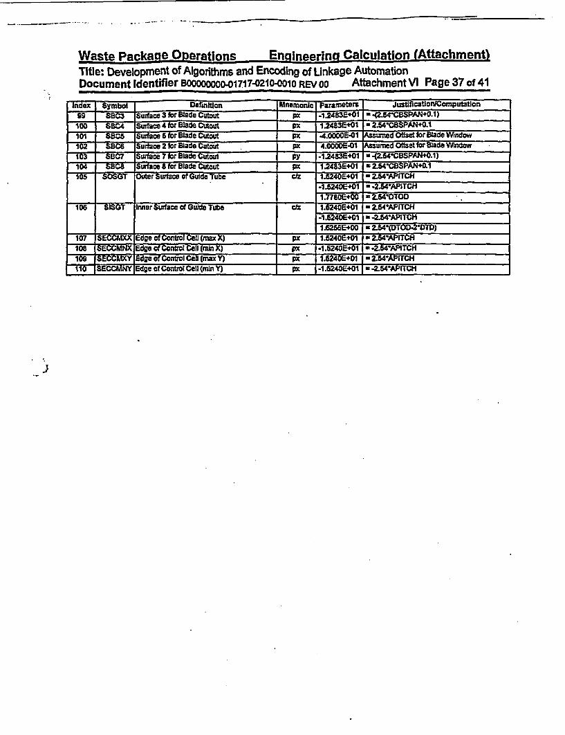
Wacqtcft Pnnkafle ODarafinvir Enninnaring Calculation (Attachment)Title: Development of Algorithms and Encoding of Linkage AutomationDocument Identifier BOOOOOOO-.01717-0210-0010 REVOO Attachment VI Page 37 of 41
Index Symbol Definftfon Unernoniz 0 Paameters JustificationiComputation99 BC3 Surface 3 for Blade Cutout P -1.2483E'01 (2.54-CBSPAN+0.1)
100 SBC4 Surface 4 fr Blade Cutout _ 1i2483+01 = 2.54-CBSPAN+0.1101 SBC5 Swrface 5 for Blade Cutout 4 .0s000E-0 V ed Offset for Blade Window
- - iS-C6 Surface 2 for Blade Cutout P 4 1 /ued Offset for B1ade WIndow103 SBC7 Suface 7 for Blade Cutout Py -1.2483E+01 * -(2.54CBSPAN+O.1)104 SSBC Surface E for Blade Cutout px 1.2483E+01 - 2.54-CSPANZ0.1M CSOSGT Outer Surface of Gude Tube 1z 240E+01 - 2.54-APiTCH
-1A240E+01 a -2.54-APITCH_ ______ t________________________ 1.7780E+00 * 2.54'OTOD
106 SISGT Inner Surface of Guide Tube c/z 1.6240E+01 a 2.54-APITCH-1.5240E+01 a -2.54APITCHt.6256E+00 - 2.54'(DTOD-2-DTD)
107 SECCUKX Edge of Control Cell (max X) p 1.5240E+01 - 2.54WAPITCH
108 SECCMNX Edge of Control Cell (rain X) p -1.5240E+01 * -Z54APITCH
109 -SECAY- Edge of Control Cell (rnax Y) p 1.5240E+01 w 2.54-APITCH110 SECCMNY Edge of Control Cell (min Y) p -1.5240E+01 - -2.54'APITCH
J

Waste ackage Operations En-iineering Calculation (Attachment)_l
Title: Development of Algorithms and Encoding of Linkage AutomationDocument Identifier B0000000001717-0210-0010 REV 00 Attachment VI Page 38 of 41
Table 4-3 Cell DefinItIons for Vessel and Core Internals Models
Surraces-Cell Definitlon UMateral Universe Sumtare Mnernonic Notes [reference as appro- Cell Definition
Index Index Index pratel
2000 Pressure Vessel 1 O 4 p Materlal Is SS304 -1 2 -3 4 5 6pa
py=6 PY-8 px6 CZ
2001 Outride World 0 0 3 (3:1:-2:-4:5)
-4 py6 px
| 2002 Jet Purnp Region 2 0 -6 Material 2 Is Bypass 6 74 -5 1 27 e- Moderator4 py
25 pa _ _ _ _-71 pZ2 pz
2003 Core Shroud I 0 = e -7 8-4 5-12
-4 py= px-1 p2 pz _
2004 Upper Tk Plate Region 3 0 .8 CZ Material 3 is a Mixture of -84-5 9-104 py SS304 and Moderator-6 pz
.16 pz2005 Core Gid Region 4 0 -8 CZ Matedal 4kaMixs W ex of .8 44610-11
4 py SS304 and Moderator-5 px10 pz
2006 Upper Pbnum Region 2 O11 =P 44-11-14 py-5 PX11 pz
. -~ ~~~~1 pz _ _ _ _ _ _ _ _ _ _
2007 Lower Tie Plate Reglon 5 0 -8 CZ material 5 saMixtu of -84 -5 -12 134 py SS304 and Moderator.5 px
-12 pz13 pz
MMu LueI OuppowuCore Support
S U I*5 i CZ4T py-6 px-13 FE
Matenai is a Mkture ofSS304 and Moderator
14 4-013 14

-- -------
Wanrfa PaIrnkfA 00arafirtne Enaineerina Calculation (Attachment)Title: Development of Algorithms and Encoding of Linkage AutomationDocument Identifier BOOOooooo-01717-0210-0010 REV 00 Attachment VI Page 39 of 41
SurfacesColl Definition Materil Unrerse Mnemonic WoIes [reference as appro Cell Definlton
Index Index Index priatel
14 ppz
20969 Lower Plenum Reglor ~ 2 O cz CZ -84-5 -14 2
5 pC.14 p_2 pz _ _ _ _
11 Fuel Assembly h 2 151 - px Flled with a Fuel Lattice (-9091 -92 93)Northwest Quadrant px Universe, the Reference (( -9093 94 95 96 ala))
-92 py Location s Rotated by l80-93 py To Obtain this Cell
93 py
py_ _ _ _ _ 66_ px _ _ _ _ _
12 FuelAssembly In 2 151 nh na Created by RotatingNortheast Quadrant Cenl 151 by _oo
13 Fuel Assembly hI 2 151 a n/a Cloned from Cell 151Southeast Quadrant wihout Rotation
14 Fuel Assembly In 151 n/a n/a Crested by RotatingSouthwest Quadrant C.! 151 by -_O_
15 Blade Window 2 161 97 Py Filed with a Control Blade (97-9899 -t00):48 Py Universe (4101-102.1034104)
*100 px.~~~~-0 px
-102 Pr-103 Py-104 px .
t6 Gulde Tube Segment 1 151 -105 __t -105106106 c_ _
17 Inside Guide Tube 0 151 -106 cz -106Segment~ Active Cae 2 0 _8 C Flled with Cone Lattice 4 -5 -912
4 py Universe
12 pz
2621 Core Lattice 2 235 7 px -107108109-110
109 px_ _ _ _ _ _ _ _ _ _ _ _ _ _ _ _ -110 p _ _ _ _ _ _ _ _ _ _ _ _ _ _ _ _ _ _ _ _ _ _ _ _ _ _ _ _ _ _ __x
I*

Waste Package OPeratlons Engineerina Calculation (Attachment)Title: Development of Algorithms and Encoding of Linkage AutomationDocument Identifier B000O000 01717-0210-0010 REV 00 Attachment VI Page 40 of 41
S. integration TestingIntegration testing of the linkage automaton is performed by repeating the analysis for the Quad CtluesUnit 1 initial core (see the QC1 BOL Report). The MNCP input deck generated by BLINK Version 0, Isgiven in Attachment XII based on the input values given In that attachment The results from the currentanalysis as well as the reference analysis are shown In Table 5-1. The excellent agreement with the ac-tual critical measurement, where the elgenvalue is unity, and the previous analysis provides confidencethat BUNK Is properly preparing the MCNP model.
Table 6-1 Results of Integration Testing CaseCase Ei envalue Uncertainty
Reference Analysis 1.00435 0.0004Present Evaluation a 0.99967 0.00035
[a]. The Input deck generated by BLINK for this case Is named, *qclclm.lnpo.

Waste Package Onerations Engineering Calculation (Affachment)Title: Development of Algorithms and Encoding of Linkage AutomationDocument Identifier BOOOOOOOO-01717-0210-0010 REV 00 Attachment VI Page 41 of 41
6. References
6.1 Briesmelster, J. F., Ed., MCNP= - A General Monte Carlo N-Particle Transport Code, Version 4A,LA-12625-M, Los Alamos National Laboratory (LANL), November 1993. TIC #: 233782.
6.2 Briesmelster, J. F., Ed., MCNPw - A General Monte Cado N-Pautidle Transport Code, Version 4B,LA-12625-M, Los Alamos National Laboratory (LANL), March 1997. MOL19980624.0328.
6.3 Software Qualification Report for MCNP 4A, A General Monte Carlo N-Partie Transport Code,Computer Software Configuration Item (CSCI): 30006-2003 REV 02, CRWMS M&O.MOL.19961028.0272.
6.4 Software Qualification Report for MNCP 4B2, A General Monte Carlo N-Particle Transport Code,CSCI: 30006 V4B2LV, DI#: 30033-2003 REV 01, CRWMS M&O. MOL.19980622.0637.
6.5 Software Qualification Report for the SCALE Modular Code System Version 4.3, SCALE Version 4.3CSCI: 30011 V4.3, Dht 30011-2002 REV 00, CRWMS M&O. MOL 1 970804.0240.
6.6 Core Design and Operating Data for Cycles I and 2 of Quad Cities 1, EPRI NP-240, Electric PowerResearch Institute, Palo Alto, CA, November 1976. nC # 237267.
6.7 MCNP CRC Reactvty Caculaton for Quad Cities BSLR, Dil BBAOOOOOO-01717-0200-0146 REV00, CRWMIS M&O. MOL.19971229.0128.

Waste Package Operations Engineering Calculation (Attachment)Title: Specification of Intermediate Dataset for Fuel MaterialsDocument Identifier: B00000000-01717-0210-00010 REV 00 AttachmentVII Page 1 of 12
Table of Contents
Contents Page
I. Introduction 4
2. Dataset Structure and Contents 4
3. Dataset Creation 63.1. Dataset Title Record 63.2. Comma-separated-variable Fields 63.3. Dataset Location 6
4. References 12

Waste Package Operations Engineering Calculation (Attachment)Title: Specification of Intermediate Dataset for Fuel MaterialsDocument identifier:00 BOOOOM-O1717-0210"0010o REVOO Attachment VII Page 2 of 12
Ust of Figures
Figure Contents PageFigure 3-1 Dataset for Unexposed Fuel 8Figure 3-2 Dataset for Exposed Fuel 10

Waste PackageOperations Engineering Calculation (Attachment)Waste Package Operations Engineering Calculation (Attachment)Title: Specification of Intermediate Dataset for Fuel MaterialsDocument Identifier: BOOooooo01717-0210-00010 REV oo Attachment VII Page 3 of 12
List of Tables
Table Contents
Table 2-1 Contents of Dataset
Page
5
a

Waste Package Operations Engineering Calculation (Attachment)Title: Specification of Intermediate Dataset for Fuel MaterialsDocument Identifier 800000000-01717-021-00010 REV oo Attachment VI I Page 4 of 12
1. Introduction
This attachment describes the creation of the datasets defining the fuel materials dataset These datasetsmust be provided for each unique node In the MCNP core model and are ether based processed filesfrom SAS2H (Referenoes 4.1 and especially 42), which provide isotopics for exposed fuel, or are createdfrom the specification of fresh fuel This attachment provides a detailed list of contents for such datasetsand documents the creation of the datasets of this type used In the present analysis.
2. Dataset Structure and Contents
A separate dataset is created for each unique fueled node partition In the core portion modeled. Here aUpartltion' may be either the entire lattice or some sub-set of the lattice (sub-lattice). Therefore, for a par-ticular Commercial Reactor Critical (CRC) calculation (i.e., a combination of core exposure, control bladepattern and moderator temperature), datasets are available for each fuel node.
The dataset structure Is an ASCII-format file that incorporates fields of comma-separated-variable (CS\0data. The contents of this dataset are given In Table 2-1.
I..

..
Waste Package Operations Engineering Calculation (Attachment)
Title: Specification of Intermediate Dataset for Fuel MatenalsDocument Identifier: Boooooooo-01717-0210-00010 REV 00 Attachment VIA Page 5 of 12
Table 2-1 Contents of DatasetValue Description Notes
Ttle ptive of File Contents For isotopics from SAS2H analysis,this should contain information aboutthat evaluation; for fresh fuel, Itshould Include the enrichment andIntegral burnable absorber Inventory,
___________________ If any.Header for Density Val- *Density Value(s)- This is an aid to users who may ex-ues _ arnine the file.Density Value(s) Material Density In Units of glcm This is a single value for data from
SAS2H and a vector of values foreach distinct fuel rod type for unex-posed fuel. If the unexposed fuelisotopics are smeared across the lat-tice, then this Is a single value.
Header for Fuel Rod OFuel Rod Type Map' This is an aid to users who may ex-Type Map amine the file.Fuel Rod Type Map Map of Indices for Placement of This Is used to properly assign unique
Unique Fuel Rod Types within the fuel rod types for unexposed fuel lat-Lattice or Sublattice tices; otherwise used for consistency
checidng for other treatments.Header for Fuel Material 'Fuel Material Compositions This Is an aid to users who may ex-Compositions amine the fme.Fuel Material Composi- The following entries are on a singletions line and are repeated for each mate-
rial In the fuel rod type.Fuel Rod Type This Is an Index corresponding to the
Indices In the Fuel Rod Type Map.For data from SAS21- or smearedvalues for unexposed fuel, the entryIs a blank, since there is a single fuelmaterial composition
Atomic Number This Is the atomic number of the Iso-tope on this line.
Ubrary Suffix This is the neutron Interaction librarysuffix for this Isotope.
Mass Number This Is the mass number of the iso-_______ ______ _____ _ ______ _______ ______ ______ tope on this line
Weight Fraction This is the weight fraction for the Iso-__ __ __ _ __ __ _ _ __ tope on this line.
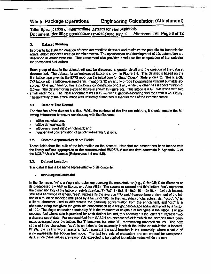
Waste Package Operations Engineering Calculation (Attachment)Title: Specification of intermediate Dataset for Fuel MaterialsDocument Identifier: B0000000001717.021000010 REV 00 Attachment VII Page 6 of 12
3. Dataset CreationIn order to facilitate the creation of these intermediate datasets and minimize the potential for transmissionerrors, automation was created for this process.. The specification and development of this automation aredescribed In Attachment Vill. That attachment also provides details on the computation of the isotopicsfor unexposed fuel lattices.
Each group of data In the dataset will now be discussed In greater detail and the creation of the datasetdocumented. The dataset for an unexposed lattice is shown In Figure 3-1. This dataset is based on thefirst lattice type given In the EPRI report on the initial core for Quad Cities-1 (Reference 4.3). This Is a GE7x7 lattice with a lattice-averaged enrichment of 2.12 wdo and two rods Incorporating Integral burnable ab-sorber. One such fuel rod has a gadorinia cohcentratlon of 0.5 who, while the other has a concentration of2.0 wlo. The dataset for an exposed lattie is shown in Figure 3-2. This lattice Is a GE 8x8 lattice with twosmall water rods. The initial enrichment was 3.19 wo with 6 gadolinia-bearing fuel rods with 3 wio Gd2O3.The Inventory of the entire lattice was uniformly distributed In the fuel rods of the exposed lattice.
3.1. Dataset Title RecordThe first line of the dataset is a title. While the contents of this fine are arbitrary, it should contain the fol-lowing information to ensure consistency with the file name:* lattice manufacturer;* lattice dimensionality;* lattice-averaged Initial enrichment and* number and concentration of gadolinia-bearing fuel rods.
32. Comma-separated-varlable FieldsThese fields form the bulk of the information on the dataset Note that the dataset has been loaded withthe library suffixes appropriate to the recommended ENDF/B-V nuclear data constants in Appendix G ofthe MCNP User's Manuals (References 4.4 and 4.5).
3.3. Dataset LocationThis dataset has a file name representative of its contents:
* mnneeegccctaaazz.dat
In the file name, wm is a single character representing the manufacturer (e.g., G for GE; S for Siemens orits predecessors - ANF or Exxon, and A for ABB). The second or second and third letters, Onnr, representthe dimensionarity of the lattice or sub-lattice (i.e., 7 - 7x7, 8 - Wx8. 9 - 9x9, 10 - 10x10, 4 - 4x4 sub-lattice).The next sequence of letters, Oeee, represents the average 25U weight-percentage enrichment of the lat-tice or sub-lattice modeled multiplied by a factor of 100. In the next string of characters, viz., Ogccc, g isa literal character used to differentiate the gadolinia concentration from the enrichment, and acdc Is acharacter string that gives the gadolinia concentration as a weight percentage again multiplied by a factorof 100. The single character denoted by T is the treatment of unique fuel rod types in the lattice. For un-exposed fuel where data is provided for each distinct fuel rod, this character is the letter OD, representinga discrete set of data. For exposed fuel from SAS2H or unexposed fuel for which the isotopics have beenmass-averaged over the lattice, the T becomes the letter OS, representing smeared values. The nextstring of three characters, *aaa, is an Index to the assembly in which the lattice or sub-lattice Is located.Finally, the trailing two characters, Ozz, represent the axial location In the assembly, where a value ofunity represents the bottom fuel node. The last two sets of characters are not present for unexposeddata, since these values are reasonably expected to be applied to multiple nodes within the core.

Waste Package Operations Engineering Calculation (Attachment)Title: Specification of Intermediate Dataset for Fuel MaterialsDocument Identifier: BOOOOCOOO-01717-0210-00010 REV 00 Attachment VII Page 7 of 12
Thus the file name 07303g02012304.dat represented a GE 7x7 lattioe wi than average mU enrichment of3.03 wio that incorporates gadorinla-bearing fuel rods with a lattice-averaged concentration of 0.2 wo ga-dolinla. This node Is contained In the Wel assembly with an index of "1230 and is located in the fourth axialnode.
I

Waste Package Operations Engineering Calculation (Attachment)
Title: Specification of Intermediate Dataset for Fuel MaterialsDocument Identifier: BOOOOOOO-01717-0210-00010 REV 00 Attachment VII Page 8 of 12
Figure 3-1 Dataset for Unexposed FuelGE 7x7/Avg Enrichment 2.12/Avg Gadolinia .070/DiscreteDensity Value(s)10.420,10.420,10.420,10.290,10.390Fuel Rod Type Map3 3 2 2 2 2 33 2 2 1 1 1 22 2 5 I 1 1 12 2 1 1 1 4 12 1 1 1 1 1 12 1 1 4 1 1 13 2 1 1 1 1 2
Fuel Material CompositionsIndex 1,92,.50c,234, .0001O,92,.SOc,235, .02177,92,.50c,236, .00010,92,.50c,238, .85942,8,.50c,16, .11853,64,.52c,152, .00000,64,.50c,154, .00000,64,.SOc,155, .00000,64,.50c,156, .00000,64,.50c,157, .00000,64,.50c,158, .00000,64,.SOc,160, .00000Index 2,92,.50c,234, .00012,92,.50c.235, .01499,92,.50c,236, .00007,92,.50c,238, .86631,8,.50c,16, .11852,64,.52c,152, .00000,64,.50c,154, .00000,64,.50c,155, .00000,64,.50c,156, .00000,64,.50c,157, .00000,64,.50c,1SS, .00000,64,.50c,160, .00000Index 3,92,.50c,234, .00008,92,.50c,235, .01059,.92,.50c,236, .00005,92,.50c,238, .87078,B,.50c,16, .11851.64,.52c,152, .00000,64,.50c,154, .00000,64,.50c,155, .00000,64,.50c,156, .00000,64,.SOc,157, .00000,64,.50c,15B, .00000,64,.50c,160, .00000
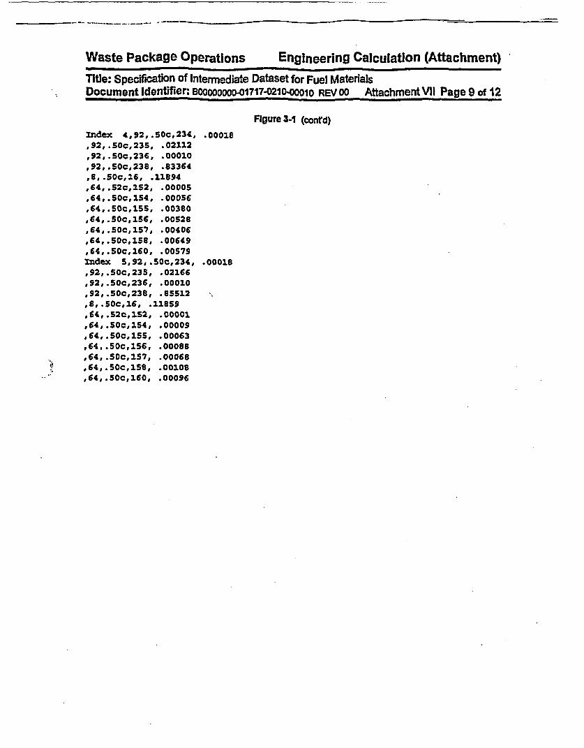
.
Waste Package Operations Engineering Calculation (Attachment)
Title: Specification of Intermediate Dataset for Fuel MaterialsDocument Identifier: BO0000000-01717-021"0OO1 REV 00 Attachment VII Page 9 of 12
Figure 3-1 (conrd)
index 4,92,.Soc,234, .00018,92,.50c,235, .02112,92, .soc,236, .00010,92, .SOc,236, .83364,8,.SOc,16, .11894,64,.52C,152, .00005,64,.50c,154, .00056,64, .50c,155, .00380,64, .50c,IS6, .00528,64, .50c,157, .00406,64,.SOc,158, .00649,64,.50c,160, .00579Index s,92,.SOc,234, .00016,92, .SOc,23S, .02166,92, .SOc,236, .00010,92,.50c,238, .85512,8,.soC,16, .11859,64, .52c,1S2, .00001,64,.50c,154, .00009,64,.SOc,ISS, .00063,64,.50c,156, .00088.64,.50c,ls7, .00068,64,.SOc,158, .00108,64,.50c,160, .00096

Waste Package Operations Engineering Calculation (Attachment)
Title: Specification of Intermediate Dataset for Fuel MaterialsDocument Identifier: Bo1000000 01717M0210i00010 REV 00 Attachment VII Page 10 of 12
Figure 3-2 Dataset for Exposed Fuel
GE Ox8/Avg Enrichment 3.19/Avg Gadolinia .290/Exposed Fuel
Generated by IDSGEN 0:- on 15-May-98 at 14:55:31 by Process 10020
Fuel Rod Type Map1 1 1 1 1 1 1 11 I 1 1 1 1 1 1
1 1 1 1 1 1 1 11 1 1.-1 1 1 11 1 1 -1 1 1 1 1
Density Value~s)-10.171Fuel Material Compositions691,.5c, 3,3.2052E-062,.50c, 4,7.5629E-068,.50c, 16,1.1972Ee01
33,.35c, 75,9.0034E-0636,.50c, 82,3.1212E-OS36,.50c, 83,3.2832E-0336,.50c, 84,9.1835E-0336,.50c, .86,1.5186E-0239,.50c, 89,3.7514E-0240,.50c, 93,3.7514E-0242,.50c, 95,5.9122E-0243,.50c, 99,6.2424E-0244,.50c,101,5.8342E-0244,.50c,103,1.6086E-0445,.50c,103,3.5834E-0246,.50c,105,2.5930E-0246,.50c,108,8.8233E-0347,.50c,109,5.7742E-0354,.50c,131,3.4993E-0254,.35c,134,1.1404E-0155,.50c,133,9.1835E-0255,.50c,135,3.2472E-0256,.50c,138,9.8437E-0259,.50c,141,8.5832E-0260,.50c,143,6.1823E-0260,.50c,145,5.3360E-0260,.50c,147,5.7322E-0760,.50c,148,2.7550E-0261,.50c,147,1.0564E-0261,.50c,148,6.9626E-0862,.50c,147,1.3085E-0262,.50c,149,1.1824E-0462,.50c,150,1.9867E-0262, .50c,151,7.9230E-0462,.50c,152,1.0684E-0263,.55c,151,4.9939E-0663,.50c,152,5.3480E-0663,.55c,153,7.6829E-0363,.50c,154,1.0144E-0363,.50c,155,3.1212E-0464,..5c,152,6.0023E-06

-
Waste Package Operations
Engineering Calculation
(Attachment)
Title: Specification Of Intermediate
Wataset for Fuel Materials
Document Identifier:
BOOO0O0.17i7.0210-0O
REV 00 Attachment Vil Page 11 of 12
64,.50c,154,2.2028E-0464,.50c,155,1.8127E-0564,.50c,156,4.1476E-0364,.50c,157,3.0792E-0664,.50c,158,9.2435E-0464,.50c,160,6.0623E-0567,.55c,165,3.0011E-0690,.50c,232,5.6541E-0992,.50c,233,8.2831E-0992,.50c,23411.5846E-0292,.50c,235,7.3228E-0192,.50c,236,3.4513E-0192, .50c,237,1.9747E-0892, . SOc, 238,8.
4032E+0193,.50c, 237,2q.3809E-0294,.50c,238,7.2027E-03
94,.55c,239,3.2772E-0194,.50c,240,1.6566E-0194,.50c,241,6.2424E-0294,.50c,242,2.8091E-0295,.50c,241,6.3624E-0395, .50c,242,8.1031E-0595,.50c,243,3.8354E-0396,.50c,242,3.4273E-0496,.35c,243,1.0924E-0596,.5Oc,244,6.6025E-0496,.35c,245,,1.4225E-0596,.35c,246,1.2005E-06

Waste Package Operations Engineering Calculation (Attachment)
Title: Specification of Intermediate Dataset for Fuel MaterialsDocument Identifier: BOoOOo O-01717021&90010 REV 00 Attachment Vll Page 12 of 12
4. References
4.1 SoftWare Qualification Report for the SCALE Modular Code System Versbon 4.3, SCALE Version 4.3Computer Software Configuration Item (CSCI): 30011 V4.3, DIX: 30011-2002 REV 00. CRWMSM&O. MOL.9970804.0240.
4.2 CRC Depletion Celculatons for Quad Wtes Unit 2, Di#: B00000000-01717-0210-00009 REV 00,CRWMS M&O. MOL.19980730.0510.
4.3 Core Design and Operating Data for Cycles I and 2 of Quad Cities I, EPRI NP-240, Electric PowerResearch Institute, Palo Alto, CA, November 1976. TIC t 237267.
4.4 Briesmeister, J. F., Ed., MCNP1U - A General Monte Carlo N-Particle Transport Code, Versioh 4A,LA-12625-M, Los Alamos National Laboratory, November 1993. TIC # 233782.
4.5 Briesmeister, J. F., Ed., MCNPPw - A General Monte Carlo N-Particle Transport Code, Version 4B,LA-12625-M, Los Alamos National Laboratory (LANL), March 1997. M0L19980624.0328.
I.
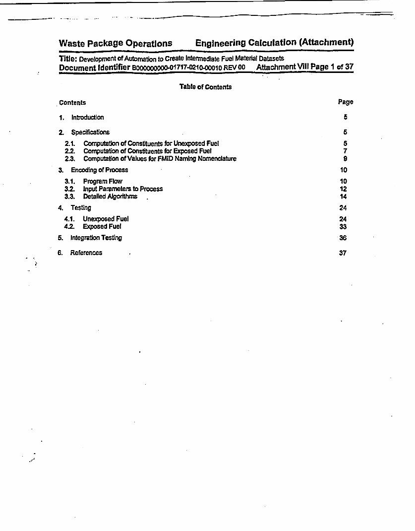
Waste Package Operations Engineering Calculation (Attachment)Title: Development of Automation to Create Intermediate Fuel Material DatasetsDocument Identifier BOOOOOOOOO-01717-0210-00010 REV 00 Attachment Vill Page 1 of 37
Table of Contents
Contents Page
1. Introduction 5
2. Specifications 52.1. Computation of Constituents for Unexposed Fuel 522 Computation of Constituents for Exposed Fuel 72.3. Computation of Values for FMID Naming Nomenclature 9
3. Encoding of Process 103.1. Program Flow 103.2. Input Parameters to Process 123.3. Detailed Algorithms 14
4. Testing 244.1. Unexposed Fuel 2442 Exposed Fuel 33
5. Integration Testing 36
6. References 37f

Waste Package Operations Engineering Calculation (Attachment)Title: Development of Automation to Create Intermediate Fuel Material DatasetsDocument Identifier BOOoooooOD-01717-0210-Ooo1o REV OO Attachment VIII Page 2 of 37
Ust of Figures
Figure Contents PageFigure 3-1 Flowchart for Intermediate Fuel Dataset Creation 11Figure 3-2 Flowchart for Input Process 16Figure 3-3 Flowchart for Processing of Unexposed Fuel Lattices 18Figure 3-4 Flowchart for Processing of Exposed Fuel Latfices 22Figure 4-1 Example Input Deck for Unexposed Fuel, Non-smeared 24Figure 4-2 Example Input Deck for Unexposed Fuel, Smeared 25Figure 4-3 Example Dataset for Unexposed Fuel, Non-smeared 26Figure 4-4 Example Dataset for Unexposed Fuel, Smeared 28Figure 4-5 Example Input Deck for Exposed Case 33Figure 4-6 Dataset for Exposed Fuel 34
.1

Waste Package Operations Engineering Calculation (Attachment)
Tite: Development of Automation to Create Internediate Fuel Material DatasetsDocument Identifier BOOOOOOOOo-01717-0210.00010 REV 00 Attachment MIII Page 3 of 37
List of Tables
Table Contents Page
Table 3-1 Input to Software Routine 13
Table 3-2 Ust of Service Routines 14
Table 3-3 List of Input Routines 15
Table 3-4 List of Routines for Processing Unexposed Fuel Lattices 17
Table 3-5 List of Routines for Processing Exposed Fuel Lattices 21

Waste Package Operations Engineering Calculation (Attachment)
Title: Development of Automation to Create Intermediate Fuel Material DatasetsDocument Identifier 10oooooooo0-0117-0210.00010 REV 00 Attachment Vill Page 4 of 37
Lid of Worksheets
Worksheet Contents Page
Worksheet 2-1 Solution for Uranium Isotopic Atom Fractions 8
Worksheet 4-1 Assumed Lattice Parameters 29
Worksheet 4-2 Assumed Atomic Weights and Natural Abundances 30
Worksheet 4-3 Computation of Isotopic Weight Fractions for Unexposed Fuel 31

Waste Package Operations Engineering Calculation (Attachment)
Title: Development of Automation to Create Intermediate Fuel Material DatasetsDocument Identifier BoOODOOOoo-01717-0210-00010 REV 00 Attachment Vill Page 5 of 37
1. Introduction
This attachment contains the specifications for and documents the development of a software routine tocreate Fuel Material Intermediate Datasets (FMID's) for Commercial Reactor Critical calculations.
The fuel pellet material compositions for exposed fuel must be obtained from the output of the CRAFTVersion 4B (Reference 6.1), which is an executive program for performing calculations with the SAS2Hsequence of the SCALE code (Reference 6.2, the Software Qualification Report). For unexposed fuelthese material compositions must be computed from the description of the fuel (I.e., enrichment and inte-gral burnable absorber loading-i any). The software routines which are specified and developed in thisattachment automate the creation of fuel intermediate material datasets. These datasets are intermediateIn the sense that they represent processed results from SAS2H analyses, but are not the card image inputrepresentations for MCNP (References 6.3 and 6.4 - the Los Aiamos National Laboratory (LANL) UsersManuals - and References 6.5 And 6.6 - the Software Qualification Reports).
2. Specifications
This process must include the following functions:
* accept Input from the user that controls the operation of the software routine and specifiesthe source of Information about the fuel composition;
* for unexposed fuel, compute the appropriate weight percentages for the constituent ele-ments and nuclides;
* for exposed fuel, process the Isotopics available from SAS2H analyses;
* for exposed fuel, accommodate a custom set of nucrides to process, excluding others thatare present in the processed SAS2H file;
* create a Fuel Material intermediate Dataset for this fuel composition; and
* create an output file that documents the processing performed.
2.1. Computation of Constituents for Unexposed Fuel
While the m35U enrichment Is provided on a fuel rod-by-fuel rod basis, the weight percentages of the re-maining uranium isotopes are not; therefore, the following equations (page 16 of Reference 6.7) are usedto compute the weight percentages of 234U. 23rU and MU for a given enrichment.
Eq. 2-1 w24 o.0077 31l(w2)
Eq. 2-2 w26= 0.0046 *- w2
Eq. 23 W23 =100.0-W 24 -W2S-W26
Here, the uranium isotopes have been identified with two-digit subscripts. The first digit is the last numberin the atomic number and the second digit Is the last digit in the mass number.
2.1.1. Urania Fuel
For fuel that does not contain gadolinla, the weight fractions of the constituent isotopes, assuming nominalstochiometry, may be calculated with the following expressions:

Waste Package Operations Engineering Calculation (Attachment)Title: Development of Automation to Create Intermediate Fuel Material DatasetsDocument Identifier B0000000-00117-0210-00010 REV 00 Attachment Vill Page 6 of 37
128S(WI -A WI)
Eq. 2.4 AWu 100.0 (glg-atom)
Note that strictly, the atom percentage should be used in this equation; however, It is shown in §2.2 thatthis approxirmaton makes a negligible difference In calculated uranium Isotopic Inventories.
A2AWuo AWu + AWo (g-atorn)
Eq. 2-6 Muo = AWu (g-atom)
Eq.2.7 MU = (g-atorn/cm)
Eq.2-8 MO 2 *o, (g-atomncm)
Eq.2-9 mu 5Mu AWu (gcm)
Eq. 2-10 MO MO * AWo (gfcm)
m -wEq. 2-11 Ml = u I (g/cm)
100.0
Eq. 2-12 Ml (dimensionless)
r'(D 2
In these equations, w represents the weight percentage of the uranium isotopes In uranium metal, AWrepresents the atomic weight (glg-atorn), p represents the mass density (glcrr), D represents the fuelpellet outer diameter (cm), M represents the linear atomic density (g9atorincm), m represents the linearmass loading (glm), and f represents the mass fraction of a given constituent in U0 2.
2.1.2. Urania Fuel Incorporating Gadolinla as an Integral Bumable AbsorberFor fel Incorporating gadolinfa as an Integral burnable absorber, the equations of §2.1.1 must be modifiedto accommodate the presence of the Gd2O3. The fuel pellet density for such fuel varies with the amount ofgadolinia Incorporated.
Eq. 2-13 mGdo = Wd o'PUOIGo (X )DJ (gcm)

Waste Package Operations Engineering Calculation (Attachment)
Title: Development of Automaton to Create Intermediate Fuel Material DatasetsDocument Identifier B1OOOooo-01717-021-o00010 REV OO Attachment VilI Page 7 of 37
Eq. 2-14 muoJ = muodA -mGdp, (g9cm)
Once the U02 density has been computed, the weight fractions of the uranium Isotopes In the fuel may becomputed from the relationships given In §2.1.1.
Eq. 2-5 MGd2O A= (g-atorrcm)AGdO,
Eq. 2-16 Md = 2 * M~d0 , (g-atornrcm)
Eq. 2-17 MO 2. Mw,2 +3. Mot (g-atomncm)
Eq. 2-168 MGd MGd * AWGd (gcr)
Eq. 2-19 m = (glm)
Eq. 2-20 fG = G4 (dimensionless)mGOA
2.2. Computation of Constituents for Exposed Fuel
For exposed fuel, nodal masses of the constituents are read from the SAS2H file. To reduce the numberof Isotopes treated In the fuel, the SAS2H calculatons do not Include oxygen In the fuel material definition;therefore, the oxygen must be added back Into the material composition for processing by MCNP. Thenodal mass (grams) for oxygen In the fresh fuel that corresponds to the exposed fuel composition pro-vided in the SAS2H file Is computed as:
of odal (mv02tn *al AW,.Y,~ - 200)Eq. 2-21 M = (25 * AW25 + (24 * AW24 + X *6 AW26 +s .2 *AW2O + 200 * AWO)
Here e is the Initial weight percentage for each of the uranium Isotopes and the AW values are the ele-mental and Isotopic atomic weights. The weight percentage value for 235U Is the reported Initial enrich-ment while the values for the other Isotopes are computed from Equations 2-1 through 2-3. Note thecomputation of the atomic weight for uranium in the denominator of Equation 2-21 Is an approximation.The proper computation of the atomic weight for uranium (glg-atom) is:
Eq. 2-22 AWu = f2s - AW23 + f24 * AW24 + f2s * AWn + f2s -AW28
Here, f, is the atom fractions for each of the uranium Isotopes; however, these atom fractions are notknown. Considering for the moment a mass of uranium with the given enrichment distribution, It may benoted that
Eq. 2-23 & = *1 00 = Mu W 100 Mu AWu _0Mu M.A MAW

Waste package Operations Engineering Calculation (Attachment)
Title: Development of Automation to Create Intermediate Fuel Material DatasetsDocument Identifier B00000000-01717-021000010 REV OO AttachmentVIII Page 8 of 37
The atom fractions for the same isotopes may be written as:
Eq. 2-24 f, = 2U- (dimensionless)
Combining the two previous equations and solving for tle atom fraction yields:
Eq. 2-25 f £ AWu100 AW1(dimensionless)
The exact form of Equation 2-21 Is thus:
Eq. 2-26 m, U0 2O0.AWxe)
[AWu AZ + 200- AW](glcm)
From Equation 2-25, the atom percentages and the atomic weight for the uranium are unknown; however,the atomic weight may readily be computed from the atom fractions:
Eq. 2-27 AWU = (f -AWI)l
(g/9-atom)
Thus for each of the four uranium Isotopes, there is a separate equation and the four may be used tosolve for the atom fractions.
Eq. 2-28 1 e fAW 1 f = 0) f 100I AW,
This system of equation was solved for fuel enriched to 5 wlo and the results are shown In Worksheet 2-1.This table Is divided Into two sections. The first section provides the known weight percentages for ura-nium enriched to 5 wo in 05U, the isotopic weights and the isotopic atom fractions computed from thesystem of equations. This section also Includes the uranium atomic weights computed both from the atomfractions and approximated with the weight percentages. The second section shows the solution of thesystem of linear equations. Since this system was solved with an iterative method, the column denoted asORow Sums and the entry labeled as Totar provide a measure of the convergence of the solution. Asmay be seen from the comparison of the two atomic weights for uranium, there is negligible error In usingthe weight percentages rather than the atom fractions.
Worksheet 2-1 Solution for Uranium Isotopic Atom Fractions
Enrfthnent I
wo 5.00000 0.04423 2300 4.93277AW 235.043922 234.040945 1236.045561 238.0507851 OO 0.020 0.00071 0.00036 0.94932
AW AW I: A238.036741 237.898211 -0.000582 I
I Isotope I Tents h Equation |ow Sums

Waste Package operations Engineering Calculation (Attachment)
Title: Development of Automation to Create Intermediate Fuel Material DatasetsDocument Identifier BOOOOOOOO-O01717-0210-00010 REV 00 Attachment Vill Page 9 of 37
25 0.047695285 -3.5499D-05 I1.80751E-O .0.04807308 .0.000436424 .2.22982-05 4.0007 2714. 1.6057E .07-O.00042707 0.0002632 126 -1.1497E-05 -1.626.E07 0.000359881 .0.0002202 0.00012828 -0.04705458 -0.0006655 0.048104061 4.514E-05
Total 3.792E-16
For constituent Isotopes other than uranium, the weight percentages are computed directly as:
Eq. 2-29 WI = no" (dimensionless)mU2
The nodal mass for U02 Is that of the fresh fuel and Is computed as:
Eq.2-30 rUO2=H D 2
Since MCNP re-normalizes the weight percentages of a particular composition, this treatment Is accept-able. Here N, Is the number of fuel rods for each fuel rod type in the lattice, A Is the pellet density for thisrod type, D) Is the fuel pellet diameter, and H is the height of node.
The density for the exposed fuel Is computed from the Isotopic inventories obtained from the SAS2H file,the oxygen Inventory from Equation 2-21, and the fuel nodal mass computed from the initial enrichment,pellet diameters and the node height This Is computed as:
Eq. 2-31 pen = IMU02
Here ml Is the nodal mass of each constituent from the SAS2H file. Since the mass from SAS2H Is lessthan the initial mass due to the failure of some Isotopes to meet the lower cutoff In that code, the density Isless than the Initial density.
2.3. Computation of Values for FMID Naming Nomenclature
As a part of the naming of the Fuel Material Intermediate Datasets, the lattice-averaged enrichment andlattice-averaged gadolinla concentration are used. The lattice-averaged enrichment Is directly computedfrom the Input values as:
E(Ni*E)Eq. 2-32 E=I
Here, N, Is the number of fuel rods associated with a given pellet enrichment, rj is the pellet enrichmentand No Is the total number of fuel rods in the lattice.
The lattice-averaged gadolinium concentration Is computed based on the U02 linear mass for the lattice.

Waste Package Operations Engineering Calculation (Attachment)
Title: Development Of Automation to Create Intermediate Fuel Material DatasetsDocument Identifier B000000000-01717-0210.OO1O REV00 AttachmentVII[ Page 10 of 37
Eq. 2-33 LU02 = E -I
Here DX,,fi Is the pellet diameter and pi Is the fuel pellet outer diameter.
The lattice-averaged gadorinia concentration Is then computed as:
Eq. 2-34 Gda L(U0Pi2No (4)-Dow )1U02
Here Gd, Is the gadolinla (Gd2O2) concentration associated with a given fuel rod type.
3. Encoding of Process
The computational algorithms and tse process described In Attachment VII must be encoded In a softwareroutine on an LIP workstation. For this application, FORTRAN is used exclusively. The name for thissoftware routine Is 'IDSGEN.'
3.1. Program Flow
A flowchart for the software routine Is shown In Figure 3-1.
I
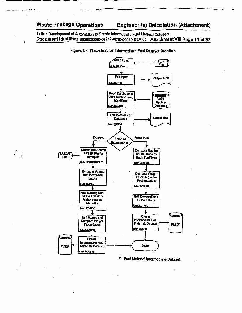
Waste Package Operations Engineering Calculation (Attachment)
Title: Development of Automation to Create Intermediate Fuel Material DatasetsDocument Identifier BOO0000000-01717-0210-0001 REV 00 Attachment VIII Page 11 of 37
Figure 3-1 Fowchart for Intermediate Fuel Dataset Creation
* - Fuel Material Intermediate Dataset

Waste Package Operations Engineering Calculation (Attachment)
Title: Development of Automation to Create Intermediate Fuel Material DatasetsDocumentIdentifier Boooooooo0-017l 7-0210-00010 REV00 AttachmentVIII Page 12 of 37
3.2. Input Parameters to Process
For exposed fuel isotopics from SAS2H analyses, the primary process input Is the file name of the acut'file which contains the masses of constituents present in the fuel. For unexposed fuel, information neces-sary properly to compute the fuel densities and weight fractions that will be uniformly allocated to all thefuel rods within the lattice or sub-lattice Is required. This information is also required for exposed latticecases to Identify the data In accordance with the process nomenclature. For both cases, a database ofvalid nuclides is required. This database contains the valid MCNP identifiers and the correspondingSAS2H abbreviations. By changing this database, restricted sets of nuclides (e.g., principal isotopics, ac-tinides only, etc.) may be written to FMlIYs.
The input Is an ASCII-format file that incorporates both FORTRAN Namelist-type Input and fields of space-delimited data. The Input variables are described In Table 3-1.
32.1. Dataset Title Record
The first line of the dataset Is a title. While the contents of this line are arbitrary, good practice Indicatesthat it should contain the following Information:
* name of fuel lattice manufacturer,
* lattice dimensionality,
* average enrichment,
* number of fuel rods containing integral burnable absorber and the concentration thereof,and
* software routine execution options.
32.2. Nramelist Input
The FORTRAN Namelist-type input variables must adhere to the restrictions Inherent In the format of suchInput Care must be taken to ensure that the value provided Is consistent with the data storage class Inthe automation (I.e., Integer Input for integer variables and real input for real variables) so that neither pre-cision Is not lost for real variables nor Is illusory precision Implied for integer variables.
3.2.3. Ust Input Fields
These fields are used for vectors of data, such as stack densities and "maps" Indicating the locations ofunique fuel rods types within the lattice. While these are read in a "free-format,* good practice Indicatesthat they should be arrayed In a regular fashion that maximizes legibility.
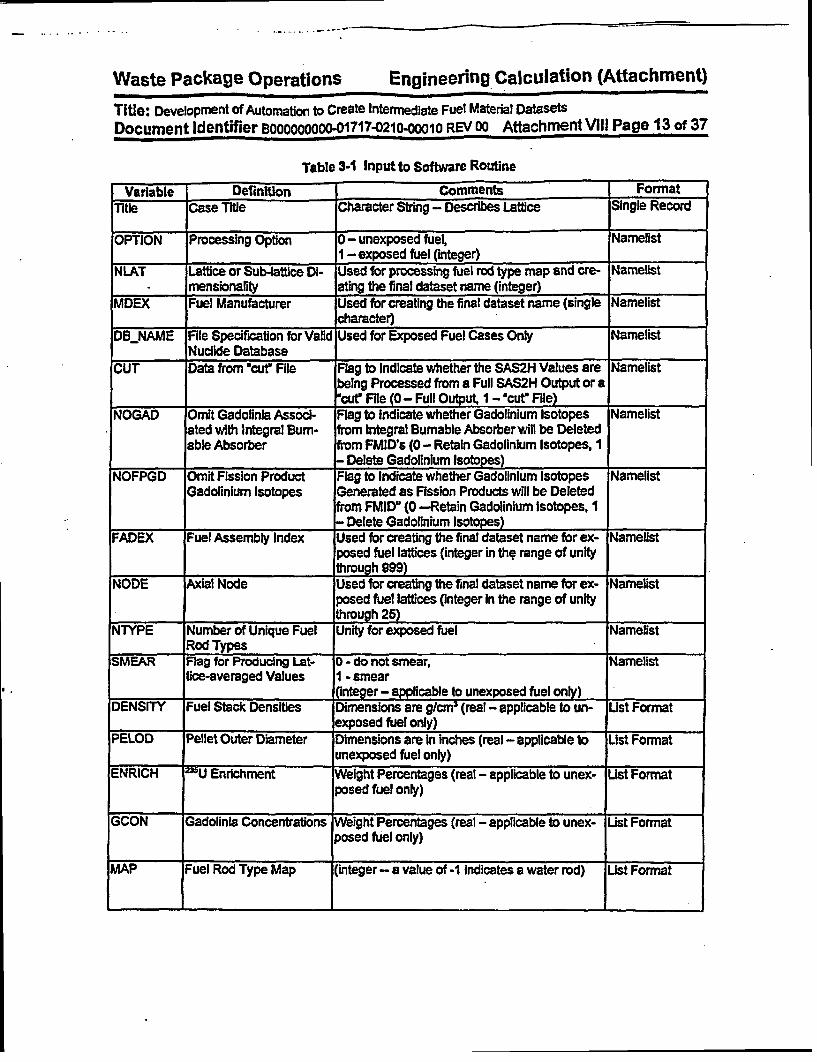
Waste Package Operations Engineering Calculation (Attachment)
Title: Development of Automation to Create Intermediate Fuel Material DatasetsDocument Identifier Booooooooo-01717 -0210-OOO1O REVD00 AttachmentVlI Page 13 of 37
Table 3-1 Input to Software Routine
Variable Definition comments FormatTitle Case Title Character String - Describes Lattice Single Record
OPTION Processing Option 0 - unexposed fuel, Namelist1 -exposed fuel (integer)
NLAT Lattice or Sub-lattice Di- Used for processing fuel rod type map and cre- Namelistmensionality ating the final dataset name (integer)
MDEX Fuel Manufacturer Used for creating the final dataset name (single Narnelistcharacter)
DBENAME File Specification for Valid Used for Exposed Fuel Cases Only NamelistNuclide Database
CUT Data from "cut File Flag to Indicate whether the SAS2H Values are arnelistbeing Processed from a Full SAS2H Output or a"cutr File (0- Full Output, I - "cutr File)
NOGAD Omit Gadolinla Associ- Flag to Indicate whether Gadolinium Isotopes Namelistated with Integral Bum- from Integral Burnable Absorberwill be Deletedable Absorber from FMID's (0 - Retain GadolInium Isotopes, 1
- Delete Gadolinium Isotopes)NOFPGD Omit Fission Product Flag to Indicate whether Gadolinium Isotopes Namelist
Gadolinium Isotopes Generated as Fission Products will be Deletedfrom FMID" (0 -Retain Gadolinium Isotopes, I- Delete Gadolinium Isotopes)
FADEX Fuel Assembly Index Used for creating the final dataset name for ex- Namelistposed fuel lattices (integer in the range of unitythrough 999)
NODE Axial Node Used for creating the final dataset name for ex- Namelistposed fuel lattices (integer In the range of unity
_ _ _ _ _ _ _ ________________ through 25)NTYPE Number of Unique Fuel Unity for exposed fuel Namelist
Rod TypesSMEAR Flag for Producing Lat- 0 - do not smear, Namelist
lice-averaged Values I - smear(Integer - applicable to unexposed fuel only)
DENSITY Fuel Stack Densities Dimensions are g/cM 3 (real - applicable to un- List Formatexposed fuel only)
PELOD Pellet Outer Diameter Dimensions are In Inches (real - applicable to Ust Formatunexposed fuel only)
ENRICH =U Enrichment Weight Percentages (real - applicable to unex- List Formatposed fuel only)
GCON Gadolinla Concentrations Weight Percentages (real - applicable to unex- Ust Formatposed fuel only)
MAP Fuel Rod Type Map (integer - a value of -1 indicates a water rod) List Format

Waste Package Ope'rations Engineering Calculation (Attachment)
Title: Development of Automation to Create Intermediate Fuel Material DatasetsDocument Identifier Boo0000000-01717-0210-oolo RiEV 0o Attachment VIII Page 14 of 37
3.3. Detailed Algorithms
The coding that comprises the software routine Is described in this sub-section by functional block. List-ings of the FORTRAN coding are provided In Attachment XV.
3.3.1. Driver Routine
The driver routine manages the overall processing performed by the software routine. and Is well repre-sented by the flowchart in Figure 3-1. It Is comprised of the main routine IDSGEN and the block data sec-ffon.
3.3.2. Service Routines
These are routines that provide memory management, file management, control of overall output proc-essing, and miscellaneous services. These routines are fisted In Table 3-2. Memory management In thissoftware routine Is not true memory management In the sense of requesting additional process spacefrom the UNIX operating system, but rather allocation of a fixed amount of memory from a pre-allocatedamount In BLANK COMMON. Thus Improved memory utilization is obtained by allocating regions of thefixed memory for specific processes and then returning it to this 'poor when finished.
Table 3-2 List of Service Routines
Name FunctionABORT Common Location for Controlled Abort of Proc-
essing when Error Detected by CodingFCLOSE Manages the Closure of Open FilesFOPEN Manages the Opening of Sequential Text FilesHEADER Prints Header for New Page; also Obtains Proc-
ess Information (i.e., Date, Time and ProcessIdentification Number for Case Identification)
INVALR Initialzes a Real Aray to a Given ValueLINES Tracks the Number of Output Lines on an Output
Page and Requests a New Page when CurrentPage Full
MCHAR Determines the Last Non-blank Character In aCharacter String
MEMORY Manages MemoryMEMSUM Edit Dynamic Memory Allocation Statistics
3.3.3. Input Processing
These routine control the processing of Input data to the software routine (not including the processing ofthe SAS2H 'cur file); thus, they process the Input variables shown In Table 3-1. These routines are listedin Table 3-3 and the flow of the input process Is shown In Figure 3-2.

Waste Package Operations Engineering Calculation (Attachment)
Title: Development of Automaton to Create Intermediate Fuel Material Datasets
Document Identifier 000000000-01717-021-OOO1O REVOO. Attachment\ AiPage 15 of 37
Table 3-3 Ust of Input Routines
Name Function
ECHO Echoes the Input Card Images to the output File
EDITIN Edits In the Input to the Software Routine
R2DMAP Reads Rectangular Arrays of Integer Values
RDBVAL Performs Reading of Valid Nuclide Database En-
tiesREADDB Manages the Reading of Database of Vafld Nu-
lcide, Including Memory ManagementREADIN Reads NAMELIST-type Input and Manages
Processing of Vector and ArTay Input In Ust-
________ directed Format
RRD Reads Vectors of Real Values

Waste Package Operations Engineering calculation (Attachment)
Title: Development of Automation to Create Intermediate Fuel Material Datasets
Document Identifier BOoooooQOO-1717-0210.O0O10 REV 00 Attachment VIl Page 16 of 37
Figure 3-2 Flowchart for input Process
A.4
EI I-.A.o.Cod OupA Unk
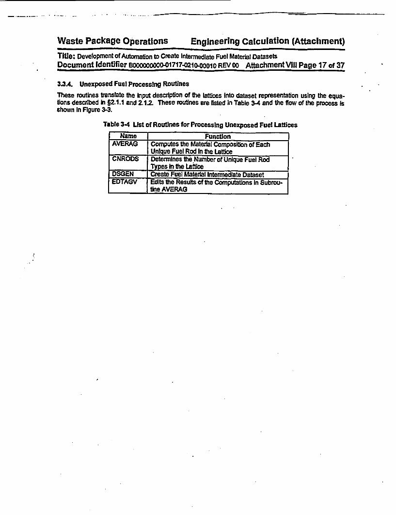
Waste Package Operations Engineering Calculation (Attachment)Title: Development of Automation to Create Intermediate Fuel Materal DatasetsDocument Identifier Booooooooo-01717-021.OOO1O REV 00 Attachment VIII Page 17 of 37
3.3A. Unexposed Fuel Processing Routines
These routines translate the Input description of the lattices Into dataset representation using the equa-tions described In §2.1.1 and 2.12. These routines are listed In Table 3-4 and the flow of the process isshown In Figure 3-3.
Table 3-4 List of Routines for Processing Unexposed Fuel Lattices
Name FunctionAVERAG Computes the Material Composition of Each
Unique Fuel Rod In the LatticeCNRODS Determines the Number of Unique Fuel Rod
Types in the LatticeDSGEN Create Fuel Material Intermediate DatasetEDTAGV Edits the Results of the Computations In Subrou-
tine AVERAG

Waste Package Operations Engineering Calculation (Attachment)
Tite: Development of Automation to Create Intermediate Fuel Material Datasets
Document Identifier sooooo0o00 -01717-0210.00io REVOO AttachmentVII Page 18 of 37
Figure 3-3 Flowchart for Processing of Unexposed Fuel Lattices
Determine Numberof Unique Fuel
Rod Types&.CNRODS
Aflocate MemoryforWorking Arrays
A MEMORY
Convert PeletDiameters to
Centimeters~- 4
Com~puteGadoliium Atomic
Weight
Cmpute AtomicWeight of Uranium
Metal
Compute UnearMasses of U102
and Gd23O
Compute UnearMolecular and
Atomic Masses of
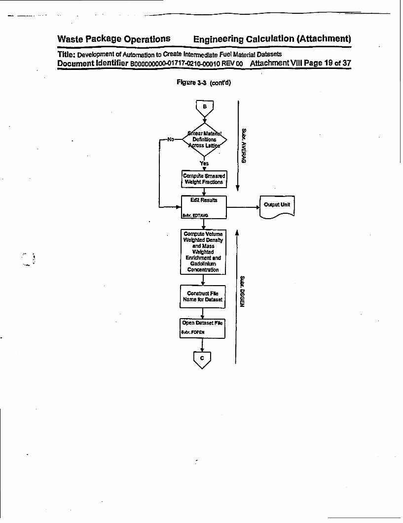
Waste Package operations Engineering Calculation (Attachment)
Title: Development of Automation to Create Intermediate Fuel Material DatasetsDocument Identifier Booooooooo-01717-0210OOOIo REVOo AttachmentVIII Page 19 of 37
Figure 3-3 (cont'd)
Co
II
L
FI

Waste Package Operations Engineering Calculation (Attachment)
Title: Development of Automation to Create Intermediate Fuel Material Datasets
Document Identifier Booooo0oo-01717-0210 0001O REVOO AttachmentV VIPage 20 of 37
Figure 3-3 (conrd)
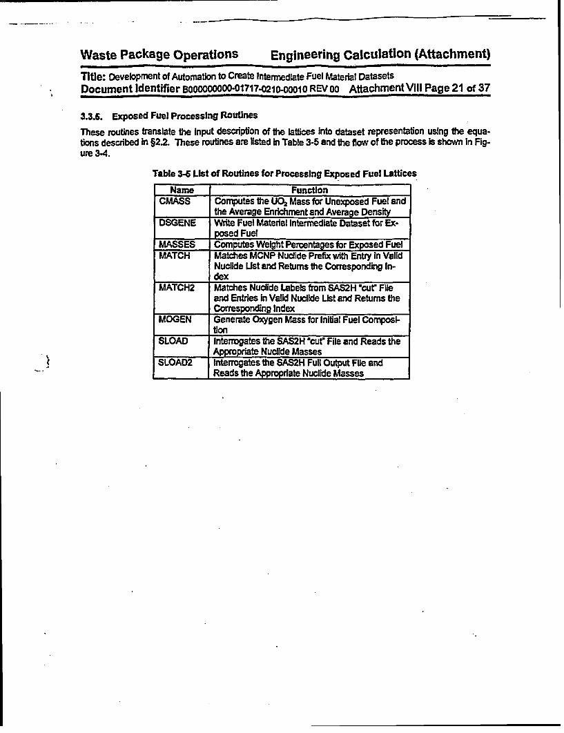
Waste Package Operations Engineering Calculation (Attachment)
Title: Development of Automation to Create Intermediate Fuel Material DatasetsDocument Identifier BOooC0OOO-01 7 17-021 0-0O1O REV 00 Attachment VIII Page 21 of 37
3.3.6. Exposed Fuel Processing Routines
These routines translate the Input description of the lattices into dataset representation using the equa-tions described In §2.2. These routines are listed In Table 3-5 and the flow of the process is shown In Fig-ure 3-4.
Table 3-6 List of Routines for Processing Exposed Fuel Lattices
Name FunctionCMASS Computes the UO2 Mass for Unexposed Fuel and
the Average Enrichment and Average DensityDSGENE Write Fuel Material Intermediate Dataset for Ex-
posed FuelMASSES Computes Weight Percentages for Exposed FuelMATCH Matches MCNP Nuclide Prefix with Entry In Valid
Nuclide List and Returns the Corresponding In-dex
MATCH2 Matches Nuclide Labels from SAS2H 'cur Fileand Entries In Valid Nuclide List and Returns theCorresponding Index
MOGEN Generate Oxygen Mass for Initial Fuel Composi-tion
SLOAD Interrogates the SAS2H 'cur File and Reads theAppropriate Nucilde Masses
SLOAD2 Interrogates the SAS2H Full Output File andReads the Appropriate Nuclide Masses
I

Waste Package Operations Engineering Calculation (Attachment)
Title: Development of Automation to Create Intermediate Fuel Material Datasets
Document Identifier Boooooooo0O1717-0210-oooio REVOO AttachmentVIII Page 22 of 37
Figure 3-4 Flowchart for Processing of Exposed Fuel Lattices

Waste Package Operations Engineering Calculation (Attachment)
Title: Development of Automation to Create Intermediate Fuel Material Datasets
Document Identifier BOOOOOOOOO-01717-0210Oo010 REV 0o Attachment Vill Page 23 of 37
Figure 3.4 (contd)

Waste Package Operations Engineering Calculation (Attachment)
Title: Development of Automation to Create Intermediate Fuel Material DatasetsDocument Identifier BOOOOOoooo-01717-0210-00010REVOO AttachmentVIII Page 24 of 37
4. Testing
This section contains examples of the computations performed by the software routine. Three examplesare included and verify the proper functioning of the coding; two for unexposed fuel, both with and withoutsmearing, and one for exposed fuel.
4.1. Unexposed Fuel
For both examples, viz., without and with smearing, the first lattice type from the EPRI Quad Cities-1 InitialCore report will be used (Reference 6.8. hereafter cited as the 9EPRI Report ). This is a GE 7x7 latticewith a lattice-averaged enrichment of 2.12 *do and which incorporates two fuel rods with Integral burnableabsorber. One such rod has a gadolinla concentration of 0.5 wlo, while the other has an Inventory of 2.0wro. The Input deck for the non-smeared case Is shown in Figure 4-1, while the input deck for the smearedcase Is shown In Figure 4-2. The resulting fuel material Intermediate datasets are shown In Figures 4-3and 4-4. respectively. Computations that demonstrate that the software routine Is properly performingthese calculations are shown In Worksheets 4-1, 4-2 and 4-3. Note that In Worksheet 4-3, the results forthe non-smeared case are entitled as, 'Isotopic Fractions by Rod Type," while those for the smeared caseand is entitled as, *Isotopic Fractions for Lattice."
Figure 4-1 Example Input Deck for Unexposed Fuel, Non-smeared
Test Case for Fuel Material Intermediate Dataset Creation$FUELOPTION = 0NLAT - 7MDEX - 'GIDB NAME - '/users/anderson/util/idsgen/complete nuclide list.db'NTYPE - 5FADEX - 1SMEAR - 0$ENDStack Densities3*10.42,10.29, 10.39Pellet Outer Diameters3*0.488, 2*0.487Enrichments2.47, 1.70, 1.20, 2*2.47Gadolinia Concentrations3*0.0, 3.0, 0.5Fuel Rod Type Map3 3 2 2 2 2 33 2 2 1 1 1 22 2 5 121 1 12 1 1 1 1 4 12 1 1 1 1 1 12 1 1 4 1 1 13 2 11 11 2

Waste Package Operations Engineering Calculation (Attachment)Tite: Development of Automation to Create Intermediate Fuel Material DatasetsDocument Identifier E000o00000-01717-0210-0OO10 REVOO AttachmentVIII Page 25 of 37
Figure 4.2 Example Input Deck for Unexposed Fuel, Smeared
Test Case for Fuel Material Intermediate Dataset Creation$FUELOPTION - 0NLAT - 7MDEX - 'G'DB NAME - '/users/anderson/util/idsgen/complete nuclide list.db'NTYPE - 5FADEX - 1SMEAR - 1
$ENDStack Densities3*10.42,10.29, 10.39Pellet Outer Diameters3*0.488, 2*0.487Enrichments2.47, 1.70, 1.20, 2*2.47Gadolinia Concentrations3*0.0, 3.0, 0.5Fuel Rod Type Map3 3 2 2 2 2 33 2 21 1 122 2 51 1 112 1 11 1 412 1 11 1 112 1 14 1 113 2 11 1 12

Waste Package Opbratlons Engineering Calculation (Attachment)
Title: Development of Automation to Create Intermediate Fuel Material DatasetsDocument Identfier 000000000-01717-0210-0010 REV 00 Attachment V1II Page 26 of 37
Figure 4-3 Example Dataset for Unexposed Fuel, Non-smeared
GE 7x7/Avg Enrichment 2.12/Avg Gadolinia .070/DiscreteGenerated by IDSGEN 0:- on 5-May-98 at 14:26:29 by Process 17385Fuel Rod Type Map
3 3 2 2 2 *2 33 2 2 1 1 1 22 2 5 1 1 1 12 1 1 1 1 4 12 1 1 1 1 1 12 1 1 4 1 1 1*3 2 1 1 1 1 2Density Value(s)10.420,10.420,10.420,10.290,10.390Fuel Material CompositionsIndex 1 1292,.50c,234, .0001892,.50c,235, .0217792,.SOc,236, .0001092,.50c,238, .859428,.50c,16, .1185364,.50c,152, .0000064,.50c,154, .0000064,.50c,155, .0000064,.50c,156, .0000064,.50c,157, .0000064,.50c,158, .0000064,.50c,160, .00000Index 2 1292,.50c,234, .0001292,.50c,235, .0149992,.50c,236, .0000792,.50c,238, .866318,.50c,16, .1185264,.50c,152, .0000064,.50c,154, .0000064,.50c,155, .0000064,.50c,156, .0000064,.50c,157, .0000064,.50c,158, .0000064,.50c,160, .00000Index 3 1292,.50c,234, .0000892,.50c,235, .0105892,.50c,236, .0000592, .50c,238, .870788,.50c,16, .1185164,.50c,152, .0000064,.50c,154, .0000064,.50c,155, .0000064,.50c,156, .0000064,.50c,157, .0000064,.50c,158, .0000064,.50c,160, .00000

Waste Package Operations Engineering Calculation (Attachment)
Title: Development of Automaton to Create Intermediate Fuel Material Datasets
Document Identifier BOO000000-01717-0210-0001 REVOO AttachmentVil Page 27 of 37
Figure 443 (coned)
Index 4 1292, .50c,234, .0001892, .50c,235, .0211292, .SOc,236, .0001092, .50c,238, .833648,.50c,16, .1189464, .50c,152, .0000564, .SOc,154, .0005664, .SOc,155, .0038064, .50c,156, .0052864,.50c,157, .0040664, .50c.158, .0064964,.50c,160, .00579Index 5 1292, .50c,234, .0001892, .50c,235, .0216692, .SOc,236, .0001092, .50c,238, .855128,.SOc,16, .1185964, .50c,152, .0000164,.50c,154, .0000964, .50c,155, .0006364, .50c,156, .0008864, .SOc,157, .0006864, .50c,158, .0010864, .50c,160, .00096
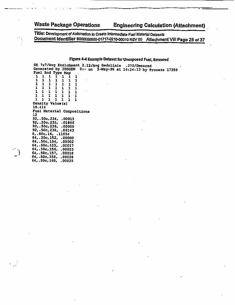
Waste Package Operations Engineering Calculation (Attachment)Title: Development of Automaton to Create Intermediate Fuel Material DatasetsDocument Identifier BOoooooooo01717-02104lOa0 REVOO AttachmentVIII Page 28of 37
Figure 44 Example Dataset for Unexposed Fuel, SmearedGE 7x7/Avg Enrichment 2.12/Avg Gadolinia .070/SmearedGenerated by IDSGEN 0:- on 5-May-98 at 14:24:13 by Process 17359Fuel Rod Type Map
1 1 1 1 1 1 1
1e Materil Comosiion
9150.414 ,.814
1el 1 M 11154
92,.50c,234, .0000292,.50c,235, .0017692,.50c,236, .00023
1,Sc11, 11114
64,.50c,155, .00017
64,.50c,158, .0002864,.50c,160, .00025
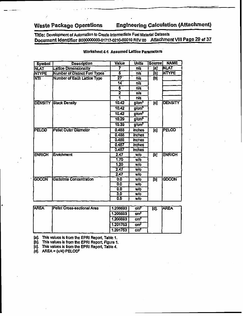
Waste Package Operations Engineering Calculation (Attachment)
Ttle: Development of Automation to Create Intermediate Fuel Material DatasetsDocument Identifier B0000000-01717-0210-00010 REVoo Attachment VIII Page 29 of 37
Woritsheet4-1 Assumed Lattice Parameters
Symbol Description Value Units Source NAMENLAT Lattice Dimensionality 7 n/a [a] NLATNTYPE Number of Distinct Fuel Types 5 nra lb) NTYPENIl Number of Each Lattice Type 27 n/a (bl
14 n/a5 nla2 n/a
DENSITY Stack Density 10.42 g/cm3 [le DENSITY
10.42 g/crn10.42 9/m10.29 g/crM
_______ 10.39 gtcm3
PELOD Pellet Outer Diameter 0.488 inches le] PELOD0.488 Inches0.488 inches0.487 Inches0.487 Inches
ENRICH Enrichment 2.47 wlo lb] ENRICH1.70 wlo1.20 wlo2.47 w/o2.47 wlo
GDCON Gadolinia Concentration 0.0 w/o lb] GDCON0.0 w/o0.0 W/o3.0 w/o
. 0.5 w/o
AREA Pellet Cross-sectional Area 1.206693 a2 | [dJ. AREA1.206693 cn2
1.206693 cre1.201753 crn
11.201753 Mi r
[a]. This values is from the EPRI Report, Table 1.[b]. This values Is from the EPRI Report Figure 1.lc]. This values is from the EPRI Report, Table 4.id]. AREA= (x/4)-PELOD2
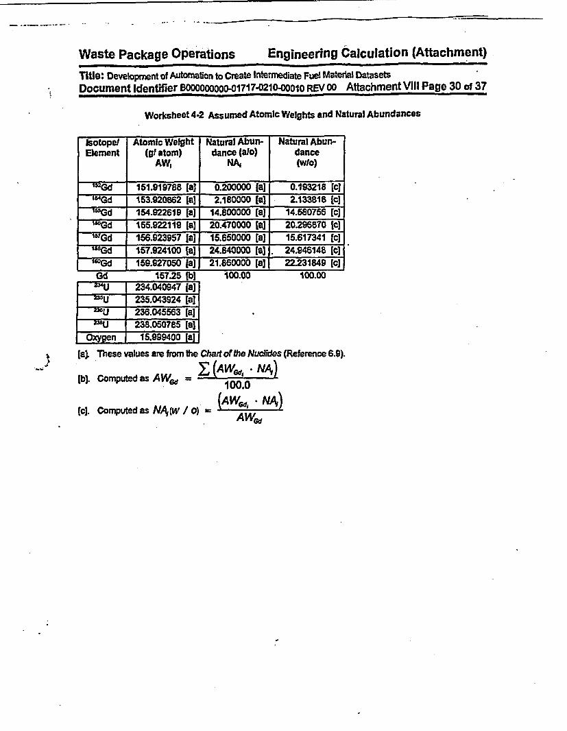
Waste Package Operations Engineering Calculation (Attachment)
Title: Development of Automation to Create InterMediate Fuel Material DatasetsDocument Identifier BOOOOOOOO-01717-0210-00010 REVOO Attachment VIII Page 30 of 37
Worksheet 4-2 Assumed Atomic Weights and Natural Abundances
Isotope/ Atomic Weight Natural Abun- Natural Abun-Element (gt atom) dance 0a1o) dance
AW, NA, (wlo)
=Gd 151.819788 [a] 0.200000 [a] 0.193218 [c'IGd 163.920862 [a] 2.180000 [a] 2.133818 [c]155Gd 154.922619 [a] 14.800000 [a] 14.580756 [c
155.922119 [a] 20.470000 [a] 20.296870 Ic]r6TGd 156.923957 [a] 15.650000 [a] 15.617341 [q]sssgd 157.924100 [a] 24.840000 [a] . 24.948148 [ci'Gd 159.927050 [a] 21.860000 [a] 22.231849 lc]Gd 157.25 fb] 100.00 100.00Z- zwU 234.040947 ia]a35U 235.043924 (a]E U 235u 236.045563 [a]
* U 238.050785 (a]Oxygen 15.999400 [a]I
* J
[a]. These values are from the Chart of the Nucildes (Reference 6.9).
lb). Computedas AW~ d = I ( . NA)100.0
[c]. Computed as NA (w /F0) =(AWed, NAT)
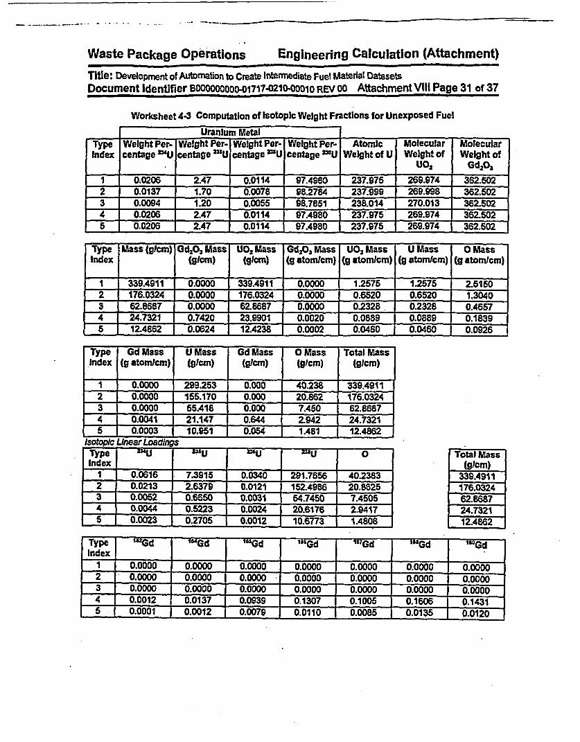
Waste Package Operations Engineering Calculation (Attachment)
Tie: Development of Automation to Create Intermediate Fuel Matefial Datasets
Document Identifier BDOODOOOO0o1717-0210-D0O1O REV00 AttachmentVIII Page 31 of 37
Worksheet 4-3 Computation of Isotopic Weight Fractions for Unexposed Fuel
________ Uranium MetalType Weight Per- Weight Per. Weight Per- Weight Per- Atomic Molecular MolecularIndex centage 4U centage 2"U centage N'U centage O"U Weight of U Weight of Weight of
U02 Gd 2 0,
1 0.0206 2.47 0.0114 97.4980 237.975 269.974 362.502
2 0.0137 1.70 0.8 98.2784 237.999 269.998 362.502
3 0.0094 1.20 0.0055 98.7851 238.014 270.013 362.602
4 0.0206 2.47 0.0114 97.4980 237.975 269.974 362.502
5 0.0206 2.47 0.0114 97.4980 _237.975 269.974 362.502
Type Mass (glcm) GdO,% Mass UO, Mass Gd,O, Mass UO, Mass U Mass 0 MassIndex (glkm) (gtcm) (g atomlcm) (g atomncm) (S atom/cm) (g atom/cm)
1 339.4911 0.0000 339A911 0.0000 1.2575 1.2575 2.5150
2 176.0324 0.0000 176.0324 0.0000 0.6520 0.6520 1.3040
3 62.8687 0.0000 62.8687 0.0000 0.2328 0.2328 0.4657
4 24.7321 0.7420 23.8901 0.0020 0.089 0.0889 Q0.18395 12A862 0.0624 12.4238 0.0002 0.0460 0.0460 0.0926
Type Gd Mass U Mass Gd Mass 0 Mass Total MassIndex (g atom/cm) (glcm) (gicm) (91cm) (glcm)
1 0.0000 299.253 0.000 40.238 339.49112 0.0000 155.170 0.000 20.862 176.03243 0.0000 65A18 0.000 7.450 62.86874 0.0041 21.147 0.644 2.942 24.73215 0.0003 10.951 0.054 1.481 12.4862
Isotopic Unear LoadingsType 1i 24UU =6U MU °0 Total MassIndex _ _ _ (gicm)
1 0.0616 7.3915 Q.0340 291.7656 40.2383 339.4911I
2 0.0213 2.6379 0.0121 152.4986 20.8825 176.03243 0.0052 0.6650 0.0031 54.7450 7.4505 62.6687
4 0.0044 0.5223 0.0024 20.6176 2.9417 24.73215 0.0023 0.2705 0.0012 10.6773 1A4808 12.4862
Type 1 15Gd ' 4Gd t Gd "Gd "GGd "Gd "'GdIndex |_________
I 0.0000 0.0000 0.0000 0.0000 0.0000 0.0°°° 0.0000
2 0.0000 0.0000 0.0000 0.0000 0.0000 0.0000 0.00003 0.0000 I0.0000 I 0.0000 I 0.°00 0.0000 0.0000 0.0000
4 0.0012 0.0137 0.0939 0.1307 0.1005 0.1606 0.1431
5 0.0001 0.0012 0.0079 0.0110 I 0.0085 1 0.0135 0.0120

Waste Package Operations Engineering Calculation (Attachment)
Title: Development of Automaion to Create Intermediate Fuel Material Datasets
Document Identifier B00Ooo00O1717-O210-ODo1O REV00 Attachment VIII Page 32 of 37
Table 4-3 (conrd)
Isotopic Fractions by Rod TypeType lU - 'UU - 'E '' MU °Index II
I 0.00018 0.02177 0.00010 0.85942 0.118532 0.00012 0.01499 0.00007 0.86631 0.118523 0.00008 0.01058 0.00005 0.87078 0.11851 14 0.00018 0.02112 0.00010. 0.83364 0.118945 0.00018 0.02166 0.00010 0.85512 0.11859
Total
.1.0000-1.000Q1.00001.00001.0000
Type ""Gd '"Gd '"Gd '"Gd "7 Gd '"Gd '"GdIndex
1 0.00000 0.00000 0.00000 0.00000 0.00000 O.OOQ00 0.000002 0.00000 0.00000 0.00000 0.00000 0.00000 0.00000 0.00000
3 0.00000 0.00000 - 0.00000 0.00000 0.00000 0.00000 0.000004 0.00005 0.00056 0.00380 0.00528 0.00406 0.00649 0.005795 0.00001 I 0.00009 I 0.00083 0.00088 0.00068 0.00108 0.00096
Isotopic Fractions for Lattice2"U I mu I 2 u I 'u I O
0.00015 | 0.01866 0.00009 r 0.86143 0.11854EI Tota
I 2Gd I '"Gd I '"Gd I '&Gd I "Gd I '"Gd I '"Gd0.00000 1 0.00002 T 0.00017 T 0.00023 1 0.00018 1 0.00028 1 0.00025 1
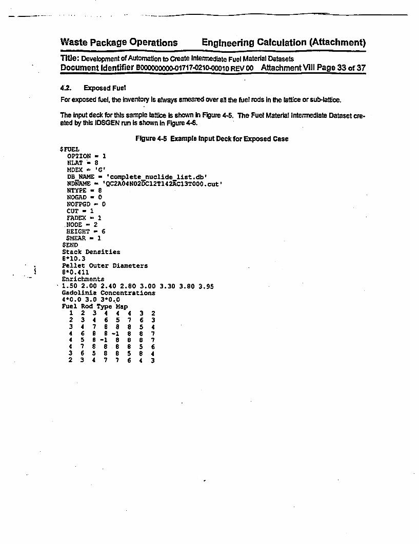
Waste Package Operations Engineering Calculation (Attachment)Title: Development of Automation to Create Intermediate Fuel Material DatasetsDocument dentifier BO000000OD-01717-0210-001O REV 00 Attachment VIII Page 33of37
4.2. Exposed Fuel
For exposed fuel, the inventory Is always smeared over all the fuel rods In the lattice or sub-lattice.
The Input deck for this sample lattice is shown In Figure 4-5. The Fuel Material Intermedlate Dataset cre-ated by this IDSGEN run Is shown in Figure 4-6.
Figure 4-5 Example Input Deck for Exposed Case$FUEL
OPTION - 1NLAT = 8MDEX - GDB NAME - 'complete nuclide list.db'NDNAME - 'QC2AO4NO2DC12T142AC13T000.cutINTYPE - 8NOGAD 0 0NOFPGD - 0CUT 1FADEX 1
,NODE - 2HEIGHT - 6SMEAR - 1
$ENDStack Densities8*10.3Pellet Outer Diameters8*0.411Enrichments1.50 2.00 2.40 2.80 3.00 3.30 3.80 3.95Gadolinia Concentrations4*0.0 3.0 3*0.0Fuel Rod Type Map1 2 3 4 4 4 3 22 3 4 6 5 7 6 33 4 7 8 8 8 5 44 6 8 8 -1 8 8 74 5 8 -1 8 8 8 74 7 8 8 8 8 5 63 6 5 8 8 5 8 42 3 4 7 7 6 4 3

Waste Package Operations Engineering Calculation (Attachment)
Tite: Development of Automatlort to Create Intermedlate Fuel Material DatasetsDocument Identifier BOO00000001717-021-OO1O REV 00 Attachment VIII Page 34 of 37
IA
Figure 4-6 Dataset for Exposed Fuel
GE 8x8/Avg Enrichment 3.19/Avg Gadolinia .290/Exposed FuelGenerated by IDSGEN 0:- on 4-May-98 at 10:27:42 by Process 7050
Fuel Rod Type Map
1 1 1 1 12 1 1 1
1 1 1 1 -1 1 1 11 1 1 -1 1 1 1 1
Density Value(s)19.098Fuel Material Compositions691,.50c, 3,6.4104E-062,.50c, 4,1.5126E-058,.50c, 16,1.1854E+0133,.35c, 75,1.8007E-0536,.50c, 82,6.2424E-0536,.50c, 83,6.5665E-0336,.50c, 84,1.8367E-0236,.50c, 86,3.0371E-0239,.50c, 89,7.5028E-0240,.50c, 93,7.5028E-0242,.50c, 95,1.1824E-0143,.50c, 99,1.2485E-0144,.50c,101,1.1668E-0144,.50c,103,3.2172E-0445,.50c,103,7.1667E-0246,.50c,105,5.1860E-0246,.50c,108,1.7647E-0247,.50c,109,1.1548E-0254,.50c,131,6.9986E-0254,.35c,134,2.2B09E-0155,.50c,133,1.8367E-0l55,.50c,135,6.4944E-0256,.50c,138,1.9687E-0159,.50c,141,1.7166E-0160,.50c,143,1.2365E-0160,.50c,145,1.0672E-0160,.50c,147,1.1464E-0660,.50c,148,5.5101E-0261,.50c,147,2.1128E-0261,.50c,148,1.3925E-0762,.50c,147,2.6170E-0262,.50c,149,2.3649E-0462,.50c,150,3.9735E-0262,,.5 0 c,151,1.5846E-0362,.50c,152,2.1368E-0263,.55c,151,9.987SE-0663,.50c,152,1.0696E-0563,.55c,153,1.5366E-0263,.50c,154,2.0288E-0363,.50c,155,6.2424E-0464,.50c,152,1.2005E-05

Waste Package Operations Engineering Calculation (Attachment)
Title: Development of Automation to Create Intermediate Fuel Materal DatasetsDocument Identifier BO00000000o01717-021-0001O REV00 AttachmentVIII Page 35 of 37
64, .50c,154,4.4057E-0464, .50c,155,3.6254E-0564, .50c,156,8.2951E-0364, .5Cc,157,6.1583E-0664, .50c,158,1.8487E-0364, .50c,160,1.2125E-0467, .55c,165,6.0023E-0690, .50c,232,1.1308E-0892, .50c,233,1.6566Z-0892, .50c,234,3.1692E-0292; .50c,235,1.4646E+0092, .50c,236,6.9026E-0192, .SOc,237,3.9495E-0892, .SOc,238,1.6906E+0293, .50c,237,4.7778E-0294, .50c,238,1.4405E-0294, .55c,239,6.5545E-0194, .50c,240,3.3132E-0194, .50c,241,1.2485E-0194, .50c,242,5.6181E-0295, .50c,241,1.2725E-0295, .50c,242,1.6206E-0495, .50c,243,7.6709E-0396, .50c,242,6.8546E-0496, .35c,243,2.1848E-0596, .50c,244,1.3205E-0396, .35c,245,2.8451E-0596, .35c,246,2.4009E-06

Waste Package Operations Engineering Calculation (Attachment)Title: Development of Automation to Create Intermediate Fuel Material DatasetsDocument Identifier BOO0000000-01717.0210-00010 REV 00 AttachimentV111 Page 36 of 37
5. Integration TestingIntegration testing of the proper operation of this software routine can only be performed In the context ofthe entire process whereby lattice depletion Is performed with SAS2H and a CRC model is built In MCNP.

Waste Package Opbations Engineering dalculation (Attachment)
TitVe: Development of Automation to Create Intermediate Fuel Material DatasetsDocument Identifier Booooooooo-01717-021000a1O REV00 AttachmentVll Page 37 o 37
6. References
6.1 CRC Depletion Calculations for Quad CXies Unt 2, DiB: B0000000-01717-0210-00009 REV 00,CRWMS M&O. MOL.19980730.0510.
.62 Software Qualification Report for the SCALE Modular Code System Version 4.3, SCALE Version 4.3Computer Software Configuration Item (CSCI): 30011 V4.3. DI#- 30011-2002 REV 00, CRWMSM&O. M0L1-9970804.0240.
6.3 Briesmelster, J. F., Ed., MCNVP m -A General Monte Carlo N-Parfide Transport Code, Version 4A,LA-12625-M, Los Alamos National Laboratory (LANL), November 1993. TIC #: 233782.
6.4 Briesmeister, J. F., Ed., MCNPm - A General Monte Carlo N-Particle Transport Code, Version 4B,LA-12625-M, Los Alamos National Laboratory (LANL), March 1997. MOL19980624.0328.
6.5 Software Qualffication Report for MCNP 4A, A General Monte Carlo N-ParUtce Transport Code,CSCI: 30006-2003 REV 02, CRWMS M&O. MOL19961028.0272.
6.6 Software Qualtcaton Report for MNCP 4B2, A General Monte Carlo N-Partf Transport Code,CSCI: 30006 V4B2LV, D: 30033-2003 REV 01, CRWMS M&O. MOL.9980622.0637.
6.7 SCALE-4 Analysis of Pressurized Water Reactor Crtial Configurations: Volume 4 - Three Mile Is-land Unit I Cycle 5, ORNUTM-12294N4, ORNL, March 1995. MOL.19960821.0245.
6.8 Core Design and Operating Data for Cycles I and 2 of Quad Cities 1, EPRI NP-240, Electric PowerResearch Institute, Palo Alto, CA, November 1976. TIC #: 237267.
6.9 Nucldes and Isotopes (Incorporating the Chart of the Nuclides), 14m Edition, General Electric Com-pany, San Jose, CA, 1989. TIC##: 201637.
Wamefra PanknsanA C~Onaflnn-q Pnrininnerincs r~ill-ulation (Attachment)aV S - e*s t* - .q. - ------L
Title: Methodology for Developing Control Blade ModelDocument-ldentifier BoooooooOo-01717-0210-00010 REV 00 Attachment X Page 1 of 15
Table of Contents
Contents
1. Introduction
2. Specifications
2.1. Definition of Control Blade Absorber Tubes2.2. Definition of Control Blade Tie Rod2.3. Definition of Control Blade Sheath2.4. Integration of Components
3. Encoding of Process
Page
4
66666
134. References
15

-
Waste Package Operations EnQineerinaTitle: Methodology for Developing Control Blade ModelDocument Identifier 8ooooooooo-01717-0210.00010 REV 00
Calculation (Aftachment)
Attachment IX Page 2 of 15
Ust of Figures
Figure
Figure 1-1
Figure 2-1
Figure 2-2
Figure 2-3
Figure 2-4
Figure 3-1
Contents Page
Cross-sectional Geometry for D-latlice BWR Control Blade
Components of Control Blade Absorber TubeTie Rod Surfaces
Sheath Pictures
Universe Definitions
Flowchart for Creating Control Blade Model
578
8
9
14
..
Waste Package ODerations Engineering Calculation {Attachment)Title: Methodology for Developing Control Blade ModelDocument Identifier Boooooo0 O-01717-021o-0ooO1 REV OO Attachment IX Page 3 of 15
List of Worksheets
Worksheet Contents Page
Worksheet 2-1 Computation of Internal Variables from Dataset Variables 10Worksheet 2-2 Computation of Surface Values IIWorksheet 2-3 Definition of Cells 12

WastA- Piat-kncue OnLMilnns Fnningerina CaltCaulation (Attachment)Title: Methodology for Developing Control Blade ModelDocument Identifier B000oooooo-01717-0210-00010 REV 00 Attachment IX Page 4 of 15
1. IntroductionThis attachment describes the methodology used to create control blade models for use in MCNP(References 4.1, 4.2, 4.3 and 4.4) representations of BWR cores. The methodology assumes theexistence of a dataset describing the blade geometry that has been generated according to therequirements of Attachment V.
The geometry of a typical BWR control blade is shown in Figure 1-1. The coding within the linkageautomation is intended to be sufficiently robust to readily model all the varieties of the GE 8OriginalEquipment" control blade (I.e., those blade in~itally deployed with the initial core of the reactor).

Waste Package Operations Enineerin - Calculation (Attachment)Title: Methodology for Developing Control Blade ModelDocument IdentifierBOO0oo0OOo-01717-0210.00010 REV 00 Attachment IX Page 5 of 15
Figure 14- CrodssecUonal GeometryforD-lattice BWR Control Blde
CBTHICK
CSSPAN NTUSE14
-IoXT__iXXXXXXXX~
I Not to SIMMM

Waste Package OPerations Engineeinng Calculation (Attachment)Title: Methodology for Developing Control Blade ModelDocument Identifier Boooooooo-01717-0210O00010 REV 00 Attachment IX Page 6 of 15
2 Specifications
This process must include the following functions:
* process data obtained from the blade geometry dataset (this processing Is described InAttachment VI of this document);
* algorithms to create the various components of control blade; and
* integrate the models for the various components Into a unified control blade model,
The Illustrative calculations shown In this attachment are consistent with a GE D-lattice OriginalEquipment control blade and the basis values are shown In Attachment V. Processing of these valuesinto variables used In the software routine are shown In Worksheet 2-1, while the cell and universedefinitions are shown In Worksheet 2-3. Note that this Is provided to illustrate the process whereby anMNCP model of the control blade is constructed and may not correspond to exactly any model used Insubsequent calculations; however, given the given the blade geometry definition, the same process isused to obtain the control blade model.
2.1. DefinItion of Control Blade Absorber Tubes
The absorber tubes of a BWR Control Blade are comprised of stainless steel absorber tubes filled withvibratory-compacted boron carbide (Reference 4.6) as shown In Figure 2-1. Computation of the valuesfor the absorber tubes defining surfaces Is shown In Worksheet 2-2, while the cell and universe definitionsare shown In Worksheet 2-3.
2.2. Definition of Control Blade Tie Rod
The stainless steel tie rod forms the central structural member of the control blade. A schematic depictionof a cross section of the tie rod Is shown In Figure 2-2. Computation of the.values for the tie rod surfacesIs shown In Worksheet 2-2, while the cell and universe definitions are shown In Worksheet 2-3.
2.3. Definition of Control Blade Sheath
The control blade sheath surrounds the absorber tubes and provides lateral support and containment forthem. A schematic depiction of a cross section of the sheath is shown In Figure 2-3. Computation of thevalues for the sheath surfaces is shown In Worksheet 2-2, while the cell and universe definitions areshown in Worksheet 2-3.
2A. Integration of Components
The combination of Me blade components into a complete model Is Illustrated In Figure 2-4. The universesymbolic names are from Worksheet 2-3.

Waste Package Oneration (Aftachment)Title: Methodology for Developing Control Blade ModelDocument Identifier BOO0O00o0o-01717-021 oo010 REV 00 Attachment IX Page 7 of 15
Figure 2-1 Components of Controt Blade Absorber Tube
SPOR
Poison
Absorber Tube
SRATYMINI
/ SRATMAX
Reference Absorber Tube Cell

Waste Package Operations Engineering Calculation (Affachment)Title: Methodology for Developing Control Blade ModelDocument Identifier 1Boooooooo-01717-0210-ooo0 O REV Go Attachment IX Page 8 of 15
Figure 2-2 Tie Rod Surfaces
m lie Rod Surface Indices
3 270
C4 1_
.,
Figure 2-3 Sheath Pictures
TRS7-SY-M-AKS
7TRS6SYMINS -
SCIj SCIR
XAMBIGSRATMIN

Waste Packane Orerations Encineerinc Calculation (Attachment)Title: Methodology for Developing control Blade ModelDocument Identifier B~oooooDo -01717-0210-000ol REV 00 Attachment IX Page 9 of 15
Figure 24 Universe Definitions
*DE4UAR
161610 P-- - - - i �-
. I --- 0
rI. ...... .. - ------
Al
_,.
us) u'wNG
.UBLADEl
L-j
ICloned to Other Three Locations

---
Wastf- Par~kaae Onpmririns~ Fnrnin APrina Calptulation (Aftachment)l
Title: MethodologY for Developing Control Blade ModelDocument Identifier B0ooo0Dooo-017174210-0001O REV 00 Attachment lX Page 10 of 15
Worksheet 2-1 Computation of Internal Variables from Dataset Variables
Definlton Symbol Value Units -- CoputaionPoison Tip when Fully Inserted -- TMI 365.76 a * 1442.54Poison Bottom when FUdly Inserted F U254 cm ZTMIICBLENGTHBoon Carbide Poson OuterRadlwu POR 0.1753 cm =ATIDI2
orber ube Outer Radius ATOR 02388 cm ATOD12inner Surface of Sheath Comer XCORN 11A745 cm CBSPAN-TRTHICKTube Field Span TFS 9.8895 - XOORN-TRSPAN
3MAK Surface of Reference Absorber A 2.4559 cm * (TFS/(NTUBE14))+TRSPANcellCenter fbr Referene Absorber Tube XO 22205 n * (ACMAX+TRSPANy2Ambguity Surface for Sheath CUorner XAM IG 7 cm R SPAN + ((NTU E14) 0.5r(A MAX- TRSPAN)

Waste Packa-ie Operations Enalneerina Calculation (Attachment)Title: Methodology for Developing Control Blade ModelDocument Identifier Booo0wooo0-01717-021o-ooo1O REV00 Attachment IX Page 11 of 15
Worksheet 22 Computation of Surface Values
Index Eymbol Definitions Mnemonic Parameters ComputationI -awl Top of Absorber Column pn 365.7600 * ZTMI
SZBMI Bottom of Absorber Column p 2.5400 m ZBMI3 SPOR Reference Boon CarbIde Outer elz 22205 * X0
Radius
0.0000 On Axis.______ ______ ______0.1753 -POR
4 F~SATOI Reference Absorber Tube Outer CI 2.220S * X0Radius
0.0000 On AxisM = ATOR
SRATlAX MAX for Reference Absorber px 2A.59 w ACMAXTube Cel
6 SRATMIN X1IN for Reference Absorber x 1.9850 - TRSPANTube Cel
7 SRTYMAX YMAX for Reference Absorber Py 0.5080 a TRTHICKTube
BSRATYMIN YMilN for Reference Absorber Py -0.5080 - -TRTHICKTube
T '!TRS2 Tie Rod Surface #2 0.6502 a TRTHLCK+WSTHICK
0 TRS3 Tie Rod Surface #3 px 0.6502 * (TRTHICK+WSTHICK)
11 0 T=S4 TeRodSurfacel4 px .1.9850 a-TRSPAN
12 TRS5 Tie Rod Surface 05 Py .1.9850 u -TRSPAN
13 TRS6 Tie Rod Surface 96 Py 40.6502 z .(TRTHICK+WSTHiCK)14 TRS7 Tie Rod Surface #7 py 0.6502 - TRTKiCK+WSTHICK
15 TRS8 Tle Rod Surface I8 Py 1.9850 = TRSPAN16 S I Ambigulty Surface for Sheath px 11.6390 = XAMBIG
Corner
17 SOUR Outer Surface of Sheath Corner ciz 11.6390 * XAMBIG
0.0000 On Axis
._______ ________ _________ 0.6502 * TRTHICK+WSTHICK
18 SCIR Inner Surface of Sheath Corner ck 11.6390 * XAMBIG
0.0000 On Axis._______ _________ 0.6080 = TRTHICK
19 SXMINBW WIN for Blade Window px 1.9950 - TRSPAN+0.01
20 S AMAX for Blade Window px 12.3925 * CBSPAN+0.01
21 SYMJNBW YMIN for Blade Wmidow Py .0.6602 * .(TRTHICK+WSTHICK+0.01)
22 SYMUtB Y or Blade W ow 0.6602 - TRTHICK+WSTHICK+0.01
23 SXMINSI XMIN for Sheath Interior px 6.0010 * SRAT(MIN+001
24 SYMASt YMAX for Sheath Interior Py 9990 SRATYWMAX-0.001
25 SYMINSI YMIN for Sheath Interior Py 7.9990 1 SRATYMIN-0.001
1.
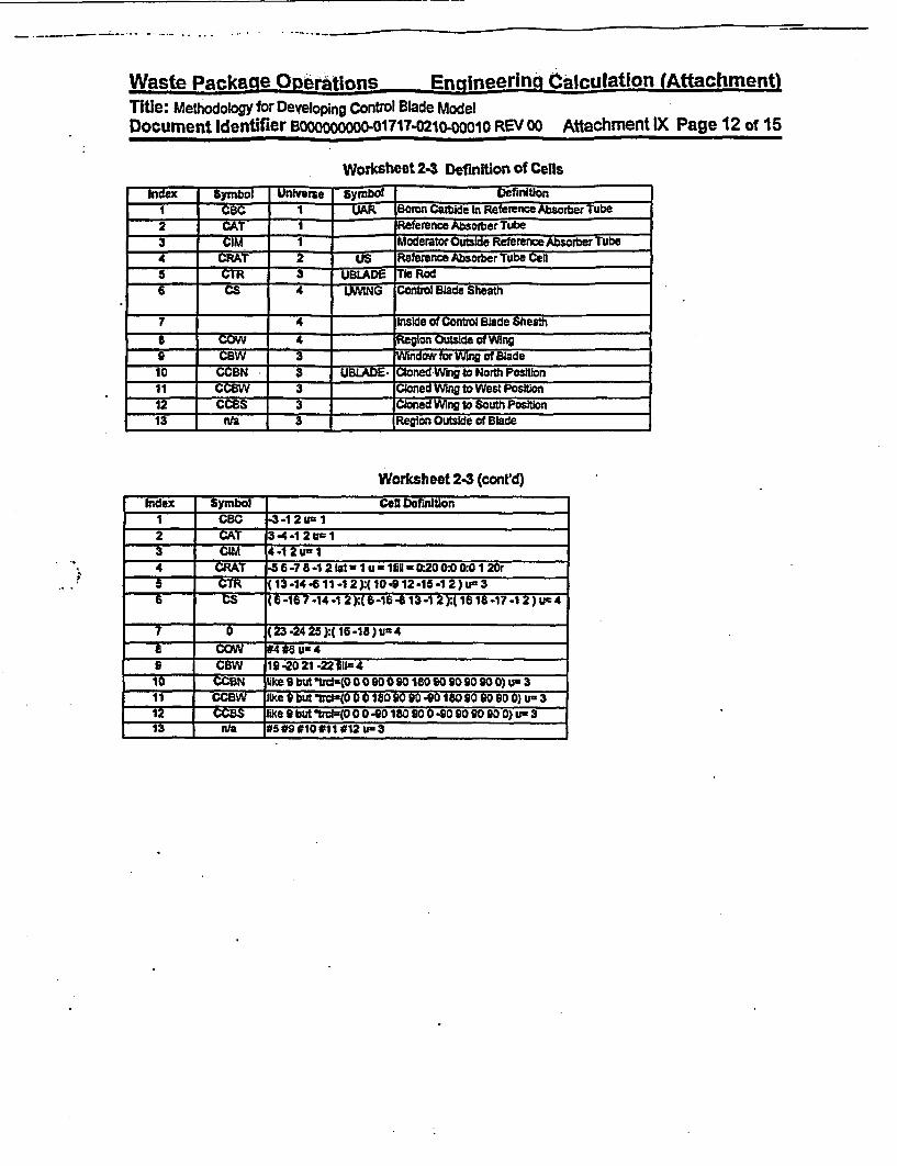
Wn~mto Dauletip-n Olngio~irlnc~ Ennineerind CAlculation (Attachment)l*-s- rabnM_ -vsa|ufa*7
Title: Methodology for Developing Control Blade ModelDocument Identifier Booooooo-O01717-021o0-00o1 REV 00 Attachment lX Page 12 of 15
Worksheet 24 Definition of CellsIndex SyMbol UIViie SymboD -efinition
I ~ ¶ UCBC Boron Carbide In Reference Absorber Tube2 R 1 i~eference Absorber Tube3 WCI M 1 Moderator Ousde Reference Absorber Tube4 ~CRAT US Reference Absorber Tube Cen5 ~3CTR UBLAD Tle Rod6 C4 UMNG Contol BMade Sheath
7 4 Inside of Control BMade Sheath8U -O A Region Outside of Wing9 eCW T - Window for Wng of Blade10 -CCEN 3 UMM§ Cloned Wing to North Position11 MWa 3 Cloned Wing toWest Position12 CCBS 3 Cloned Wing to South Position13 nla 3 _ Reglon Outside of lade
Worksheet 243 (cont'd)Index Symbol Wel Definition
I CBC - *1 2 u1
3 ~~~I~~I3* -4.12 U-
4 CRAF -5 6-7 & -2lot auul Ifig lOR0:O0100I20rB CTR ( 13 14-6 11 4 2):(10-912 .15.1 2 )u 3
7 0 (23-2425):(16-18)v=4T COW * 16 u-4
s CBW 19 .20 21.22 III=410 CCUBN Uke 9buttrci-(0090O890O00)
11 ~ ke~bu~rc 9(0 0 90 1O090 901 90 900) us 3
Y.- -- CY like 9 W -Ud-=(O 0-OD9ISO 00 0.90OD90 90 0) U=3F IWY n/a 1#5 #9 10#I 1#12 un3

Waste Packaae O2erations Engineering Calculation (Affachment)Tite: Methodology for Developing Control Blade ModelDocument Identifier BOOOOOOOOO-01717-0210-OOO1O REV oo Attachment IX Page 13 of 15
3. Encoding of Process
The flowchart for the coding to Implement the specification Is shown In Figure 3-1. This logic has beenImplemented as a C language function named bufldlcontrolblade.
h
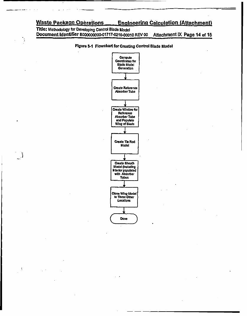
Waste Package O6erations _ Enfineering Calculation (Attachment)Title: Methodology for Developing Control Blade ModelDocument Identifier BOOOOOOO -01 717.0210-ooolO REV 00 Attachment IX Page 14 of 15
Figure 3.1 Flowchart for Creating Control Blade Model
ComputeCoordinates for
Blade ModelGeneration
Create ReferenceAbsorberTube
Create WIndow forReference
Absorber Tubeand PopulateWing of Blade
Create TIle RodModel
Create SheathModel Oncudkn
Wrterlor populatedwith Absorber
Tubes
Clone Wing Modelto Three Other
Locations
* V / .Don

Waste Package Operations EnrElneerina Calculation (Attachment)Title: Methodology for Developing Control Blade ModelDocument Identifier Bo0000000-01717-0210-ooo1o REV oo Attachment KX Page 15 of 15
4. References
4.1 Brlesmeister, J. F., Ed., MCNP1 ' - A General Monte Carlo N-Parile Transport code, Version 4A,LA-12625-M, Los Alamos National Laboratory (LANL), November 1993. TIC#: 233782.
4.2 Briesmelster, J. F., Ed., MCNPTm - A General Monte Carlo N-Particle Transport Code, Version 4B,LA-12625-M, Los Alamos National Laboratory (LANL), March 1997. MOL19980624.0328.
4.3 Software Qualfcation Report for MNCP 4BZ A General Monte Carlo N-Partcle Transport Code,Computer Software Configuration Identifier (CSCI): 30006 V4B2LV, DWI: 30033-2003 REV 01,CRWMS M&O. MOL.19980622.0637.
4.4 Softwar Qualification Report for MNCP 4A A General Monte Carlo N-Parcle Transport Code,CSCI: 30006 V4A, Dig: 30006-2003 REV 02, CRWMS M&O. MOL.19961028.0272.
4.5 Core Design and Operating Data for Cycles I and 2 of Quad Cities 1, EPRI NP-240, Electric PowerResearch Institute, Palo Alto, CA, November 1976. TIC #: 237267.
If

Waste Package Operations EngineeringTitle: MethodologY for GE 7x7 Fuel Laffice ModelDocument Identifier B00000000001717.020o-00010 REV 00
Calculation (Attachment)
AttachmentX Page 1 of 16
Table of Contents
Contents Page1. Introduction
42. Specifications
2.1. Definition of Fuel Rods2.2.- Definition of Fuel Lattice2.3. Definition of Fuel Channel2.4. Integration of Components
3. Encoding of Process
3.1. Driver Function3.2. Latie-preparation Function
4. References
S
5555
12
1212
16

Waste Package Operations EngineeringTitle: Methodology for GE 7x7 Fuel Lattie ModelDocument Identifier Boo00oO.ooo01717-0210o0o01o REV 00
Calculation (Attachment).
AttachmentX Page 2 of 16I
List of Figures
Figure Contents Page
Figure 2-1
Figure 2-2
Figure 2-3
Figure 2-4
Figure 3-1
Figure 3-2
Fuel Rod
Lattice Population
Channel
Integration of Components Into LatticeFlowchart for Lattice Model Generation Driver FunctionFlowchart for Creation of GE 7x7 Lattice
678
.913
14
._

Waste Package Operations EngineerIng Calculation (Affachment)Title: Methodology for GE 7x7 Fuel Lattice ModelDocument Identifier BOOOOOOOoo-01717 0210-00010 REV 0o Attachment X Page 3 of 16
List of WorksheetsWorksheet Contents PageWorksheet 2-1 Computation of Surface Coordinates 10Worksheet 2-2 Celt Definitions 11
I
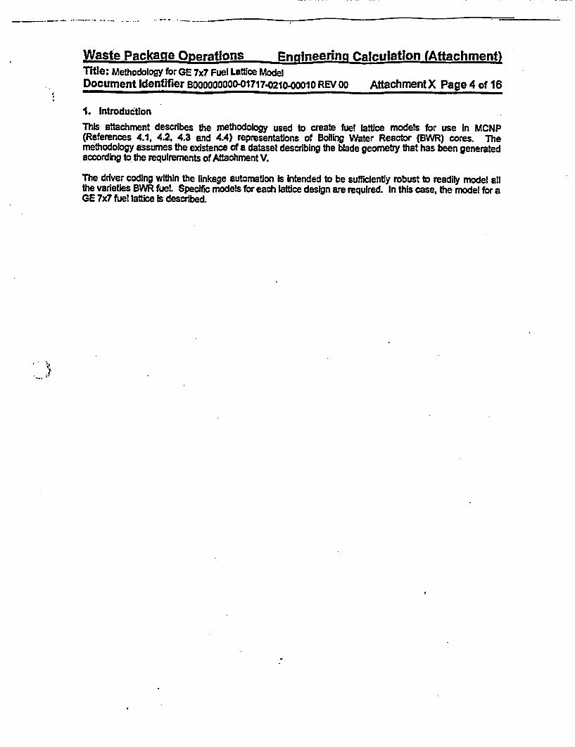
Wasfpc Park~ao nnamfifnns Irdnniaprinnf r-al'm illsitnn fAHfganihmrxnfl
Title: Methodology for GE 7x7 Fuel Lattice ModelDocument Identifier Bo0O0000 -01717-0210-0001o REV 00 AttachmentX Page 4 of 16
1. Introduction
This attachment describes the methodology used to create fuel lattice models for use In MCNP(References 4.1, 4.2, 4.3 and 4.4) representations of Boiling Water Reactor (BWR) cores. Themethodology assumes the existence of a dataset describing the blade geometry that has been generatedaccording to the requirements of Attachment V.
The driver coding within the linkage automaton Is Intended to be sufficiently robust to readily model allthe varieties BWR fuel. Specific models for each lattice design are required. In this case, the model for aGE 7x7 fuel lattice Is described.

Waste Package Orerations En-gineering Calculation (Attachment)Title: Methodology for GE 7x7 Fuel Lattice ModelDocument Identifier BOOOOOOOOO-01717-0210- O10 REV 00 AttachmentX Page 5 of 16
2. Specifications
This process must include the following functions:
• process data obtained from the lattice geometry dataset (this processing is described inAttachment VI of this document);
* govern the generation of lattice model fbr each unique lattice In the core (lattices aredifferentiated by geometry and material composition of the fuel rods within the lattice);
* algorithms to create the various components of the lattice; and
* integrate the various components into a unified model for the lattice.
The Illustrative calculations shown In this attachment are consistent with a GE 7x7 lattice and the basisvalues are shown in Attachment IV. Note that the values shown herein do not necessarily correspond toa particular lattice used in the analyses, but are shown to illustrate the process whereby such an MCNP Isconstructed.
2.1. Definiton of Fuel Rods
The fuel rods are comprised of zircaloy tubes filled with U02 ceramic pellets (Reference 4.5) as shown inFigure 2-1. Computation of the values for the absorber tubes defining surfaces Is shown In Worksheet2-1, while the cell and universe definitions are shown In Worksheet 2-2.
2.2. Definition of Fuel Lattice
The fuel rods fill a regular lattice. In the case of the GE 7x7 fuel design, there are no water rods whichdisplace fuel rods (see Figure 2-2). For the case of lattices with water rods, locations within the lattice willbe filled with water rods - or perhaps water rod segments.
2.3. Definition of Fuel Channel
The channel is assumed to be of uniform thickness with rounded corners as shown In Figure 2-3. Theassumption of constant thickness is also assumed for those channel designs that Incorporate variations inthe wall thickness to Increase the water mass In the bypass region (viz., GE's Interactive' channel). Forsuch channels, the thickness is selected to maintain the same areal density of zirconium. Computation ofthe values for the channel defining surfaces is shown in Worksheet 2-1, while the cell and universedefinifflons are shown In Worksheet 2-2.
2A. Integration of Components
The combination of the lattice components into a complete model Is illustrated In Figure 2-4.

Waste Package Operatlons Engineering Calculation (Aftachment)Title: Methodology for GE 7x7 Fuel Laftice ModelDocument Identifier BOOOOOOOOO-01717.021o-00010 REV oo Attachment X Page 6 of 16
Figure 2-1 Fuel Rod
Fuel Pellet
Cladding
I i f i 9II X R | II
1. 1 It
11*%*l
%
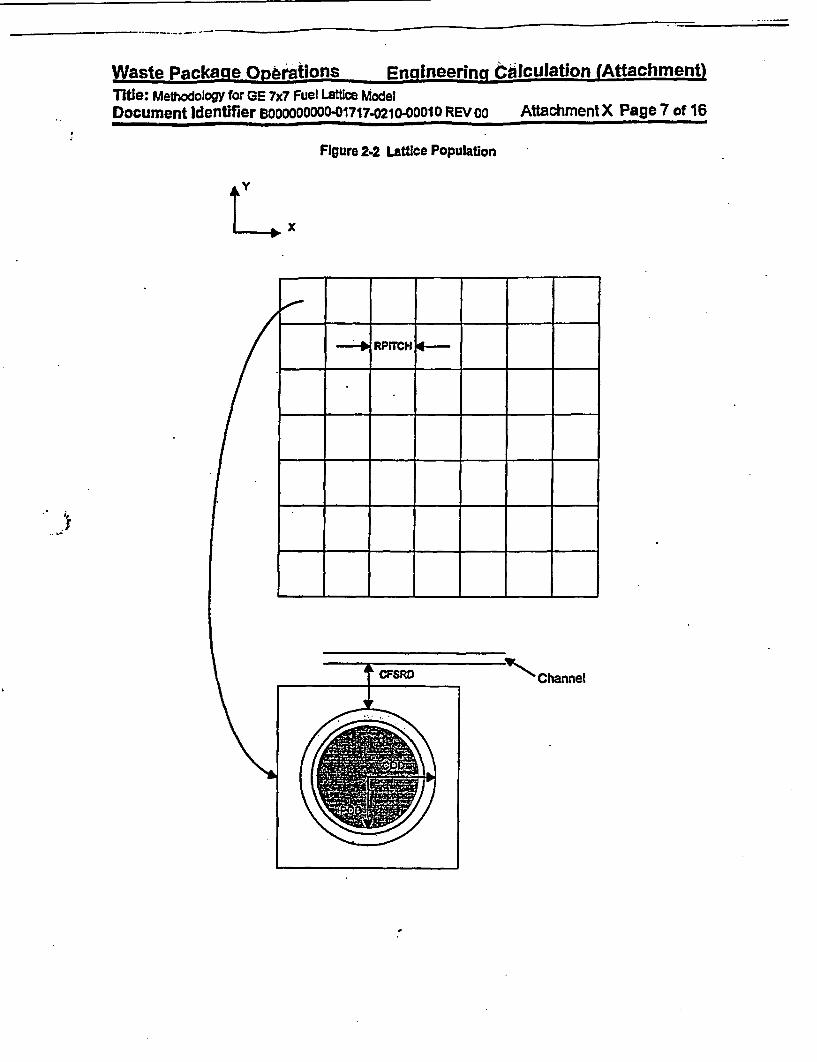
Waste Package Operations Engineering Clalculation (Attachment)Title: Methodology for GE 7x7 Fuel Lattce ModelDocument Identifier BOOOOOOOO-1717-2102OOO10 REV 00 Attachment X Page 7 of 16
Figure 2-2 Lattice Population
x
RPrTCH
4
a.} 1

Waste Packaqe One-rtions En_-lneerinn dalculation (Attachment)Title: Methodology for GE 7x7 Fuel Lattie ModelDocument Identifier BoooooOOO-01717-0210-o001o0 REV 00 AttachmentX Page 8 of 16
Figure 2-3 Channel
Y
WGCOWY
Index
CcnRO
. XAMBIGI NscnNY XAMBIG2.

Waste Package Operations Ennineerng Calculation (Attachment)Title: Methodology for GE 7x7 Fuel Lattice ModelDocument Identifier B000000000-01717.0210-00010 REV 00 Attachment X Page 9 of 16
Figure 24 Integration of Components Into Lattice
I. SACS .ws 0

Waste Packa-ge opera EnggineednO Calculation (Attachment)
Title: MethodologY for GE 7x7 Fuel Lattce ModelDocument Identifier B00000000O1?17.0210-00010 REV 00 Attachment X Page 10 of 16
Worksheet 2-1 Computation of Surface Coordinates
Index Symfol Defi n - M nenionlk Parameters CornputationI TSPOR Reference Fuel Pellet Outer Suirace cz 2.2352 3 WGAP+CTlHCK+CFSRD+(C001)
.-22352 = .+CTH ICK+CFSRD+(CODl2))
_______ .______________________ ________ 0.61sa .-PoD2
2 SCIR Reference Cladding Inner Surface Cz 2.2352 WGAP+CTCK+CFSRD+(CODl2)
2.2352 * (VGAPCTH ICK+CFSRD4(COD2))
_______ o0.63373 - (CO2).CD
3 S Reference Cbding Outer Surface clz 2.2352 = WGAP+MTHlCK+CFSR;T(C0D12)
_-_2___ - AF+CTHICK+CFSRD+(COD12))0.7150 C 012
4 XMINFRW KMW Surface or Fuel Rod Wdow px -0.9373 - (RPgTCHK2)
6 XMAXFRW XMAX Surface for Fuel Rod Window px 0.9373 * RPITCH/2
8 YMINFRW XMIN Surface for Fuel Rod Window Py -0.9373 - -(RPITCHI2)
7 AXFIRW XMAX Surface for Fuel Rod Window py 0.9373 a RPITCHK2
8 WGCOWX Wide Gap, Channel Outside WaU, px 0.9525 - WO_X Surface
9 WGCW Wide Gap, Channel Inskde W.U, pX px 1.1557 * WGAP*CTHICKSurface
10 NGCIWX Narrow Gap, Channel Inside Wall. PX 6.4337 a WGAP+CTHICK+AStNpX Surface
11 NGCOWX Narrow Gap, Channel Outside Wall, px 6.6369 a WGAP+(2CTHICK"ASINpX Surface
12 WGCOWY Wde Gap. Channel Outside Wail. py -0.9525 * -WGAPpY Surface
13Y Y Wide Gap, Channel Inide Wal, pY Py -1.1557 - GAP+CTHICK)Surface
T4 RGURY Narrow Gap, Channel Inside Watl. Py *44337 a -(WGAP4CTHECK+ASIN)pYSurface
15 NGCOWY Narrow Gap. Channel Outside Wal, py *6.6369 * (WHGAP4V(CTI4CK).ASIN)pY Surface
W16 XAMBIG1 Arbity Surface for Channel px 2.1717 -WGAP+CTHICK+CRADIUSCorners (Wde Gap)
17 XAMBIG2 Ambiguity Surface for Channel px 5.4177 a WGAP+CTHICK+ASIN-CRADIUSCorner (Narrow Gap)
18 YAMBIG1 ipgulty Surface for Channel py -21717 * P+WG CTHlCK+CRADIUS)Corners (WIde Gap)
19 YAMBIG2 Ambiguty Surface for Channel Py *5.4177 * -(WGAP+CTHICK+ASIN-CR4DIUS)Corners (Narrow Gap)
20 CC1RO Outer Radius for Corner I C 2.1717 - WGAP+CTHECKeCRADIUS*2.1717 -u 4WGAP+CTHICK+CRADIUS)1.2192 - CRADIUS+CTHICK
21 CC1RI Inner Radius for Corner I az 2.1717 * WGAP+CTHICK+CRADIUS-2.1717 a -(WGAP+CTHICK+CRADIUS)
T__ _ 1.016 *CRADIUS2 CC2RO Outer Radius for Corner 2 5.4177 * WGAP+CTHICK+ASIN-CRADIUS

Waste Pac.kae Orbtions Engineerinq Calculation (Attachment)Title: Methodology for GE 7x7 Fuel Lattice ModelDocument Identifier 8OOOOOOOOO-01717.0210-ooo1O REV oo Attachment X Page 11 of 16
Index Symbol Definition UMnnonic Parameters Computation-2.1717 * -(WGAP+CTHICK+CRAbIUS)1.2192 - CRADIUS+CTHICK
23 CC2RI Inner Radius for Comer 2 6cz 5.4177 WGAP+CTHICK+ASIN-CRADIUS-2.1717 -C IAP+CTHlCK.CRADIUS)1.016 CR4DIUS
24- CC3RO Outer Radius for Corner 3 S 5.4177 - WGAP+CTHICK+ASIN.CR4DIlUS. 4Z.4177 -(WAP+CThlCK+ASINCRADIUS)__1.2192 u CRAUUS+CTHICK
25 C RI Ine Radius for Comer3 c3 5.477 a WQAPhIC+KASIN-CRADlUS.6.4177 z .(WGAP+CTHICK+ASiN-CRADIUS)
10-16 a CRADIUS26 CC4RO Outer Radius for Corner 4 ckz 2.1717 a WGAP.CTHICK+CRADIUS
.4.-.4177 - -(WCGAPCTHJCK+ASIN-CRADIUS)1_1.2192 * CRADIUSNHICK
27 CC4RI Inner Radius for Corner 4 . z 2.1717 * WGAP+CTHICK+CRADIUS44177 a -VWGAP4CTHlCK+ASlN.CRADlus)
.___ _ _ __ _ __ _ __ __a 1.016 - CRADIUS
.,I
Worksheet.2-2 Cell Definitions
Index Synbol Univere Symbol DefnlUon Cell Definition1 P 1 UFR Fuel Pellet -lusi2 C G 1 Peilet-Cladding Clap -21 u I3 CFRC 1 Cladding 32 un 1
4 CMOFR I Moderator Outside Fuel Rod 3 u1-WRL UFRL ndowor Fuel Rod(Latgie) 44667u=2fin-1
6 CCHA 3 UGHAN Channel ( 8 -S 18 19):t(121316 17):(-141516-17):(104-11-1819):(-2021 18-16 )(-2223 18 17):(-24 25 17 19 ):(-26 27 -19 -16)u- a
CVIC W3 ater Inside Channel (16.17-1314 ):(9.16 -18 9):(17 .1O.1 19-):( -21 -1618):(2317 19):(-25 17-19):(27-16-1D)u=311=2
a CWOC 3 Vater Outside Channel 197 96 u=- 3

Waste Packaae Onerations Enilneering Calculation (Attachment)Title: Methodology for GE 7x7 Fuel Lattice ModelDocument Identifier Bsoooooooo-01717-0210-oo00010 REV 0o AttachmentX Page 12 of 16
3. Encoding of Process
There are two distinct parts of the process for creating latice models. The first is a driver function thatmanages the selection of the appropriate data for the lattice and second is a latice-geometry-specificfunction that creates the detailed lattice model.
3.1. Driver Function
The driver function ensures that the appropriate lattice geometry and lattice material composition datasetsare selected for the subject lattice. Once this information has been staged, the function selects thefunction corresponding to the lattice geometry design and calls that function to create the detailed latticemodel The logical flow of this function Is shown In Figure 3-1.
3.2. Lattice-preparation Function
This function is specific to a particular lattice design. For Instance, GE 7x7 and GE 8x8 lattices requiredifferent functions since they are different in geometrical layout Further, different varieties of GE 8x8lattices rnight require different functions since they can Incorporate different numbers and sizes of waterrods (I.e., fuel-rod-sized water rods, large water rods displacing two fuel rods, or a large-central water roddisplacing four fel rods). Fuel assemblies constructed by different manufacturers may also requiredifferent functions, even when the constituent lattices have the same lattice dimensionatity. This is mostlikely due to details In the number, placement or shape of water rods.
The flowchart of this process for GE 7x7 fuel assemblies is shown In Figure 3-2.

Waste Package Oeratlons Ensineering Calculation {Attachment)Ttlte: Methodology for GE 7x7 Fuel Lattice ModelDocument Identifier BOOOOOOOOO-01717.0210-0001O REV 00 Attachment X Page 13 of 16
Figure 3-1 Flowchart for Lattice Mode? Generation Driver Function
Fkid AppropriateLatioe GeometryDataset hi Linked
Ust
j ~~~~Load Prope Fuel|
Fuel MatedialDataset,
SeletProeFunction to
Generate Lattice
rGenerate Lattic|Representation|

Waste Package Omerations Enaineering Calculation (Attachment)Title: Methodology for GE 7x7 Fuel Lattice ModelDocument Identifier Booooooooo-01717.021o000010 REV oo AffachmentX Page 14 of 16
Figure 3-2 Flowchart for Creation of GE 7x7 Lattice
Corrpute Surfacesfor LatticeDefinition
Comnpute OfsetThis Structure Loops over for Reference Fuel
the Distinct Fuel Rods In RodFuel
|Create Pellet Cell|
Add AppropateMatedials for Fuel
* ~~~~~~~~~~~~~~~~~~Peflet
rCreat FueUl|.; | ~~~~~~~~~~~~~~~~~~~Cladding G:ap Cell|
Cteate Fuel ||Cladding
WakerOutside o|Cladding
-No+
Yes

Waste Package Operations Engineering Calculation (Attachment)Title: Methodology for GE 7x7 Fuel Lattice ModelDocument Identifier BooOO000-01717.0210-00010 REV oo Attachment X Page 15 of 16
Figure 3-2 (contd)

Waste Package Operations En ineer ng'CalculaQion (Attachment)Title: Methodology for GE 7x7 Fuel Lattice ModelDocument Identifier BOOOOOOOOo-01717-0210-0001o REV 00 Attachment X Page 16 of 16
4. References
4.1 Briesmeister, J. F., Ed., MCNP'm - A General Monte Carlo N-Particle Transport Code, Version 4A,LA-12625-M, Los Alamos National Laboratory (LANL), November 1993. TIC #: 233782.
4.2 Briesmelster, J. F., Ed., MCNPm - A General Monte Carlo N-Partcle Transport Code, Version 4B,LA-12625-M, Los Alamos National Laboratory (LANL), March 1997. MOL.19980624.0328.
4.3 Software Qualffication Report for MNCP 482, A General Monte Cbrfo N-Partcle Transport Code,Computer Software Configuration Identifier (CSCI): 30006 V4B2LV, DI#: 30033-2003 REV 01.CRWMS M&O. MOL.19980622.0637.
4.4 Software Qualification Report for MNCP 4A, A General Monte Carlo N-Particle Transport Code,CSCI: 30006 Y4A, Document Identifier 30006-2003 REV 02, CRWMS M&O. MOL19961028.0272.
4.5 Core Design and Operaffing Data for Cycles I and 2 of Quad Cties 1, EPRI NP-240, Electric PowerResearch Institute, Palo Alto, CA, November 1976. TIC #: 237267.

Waste Package operations Engineering Calculation (Attachment)Title: Methodology for GE 8x8 Fuel Latftce with Small Water Rods ModelDocument Identifier BOOOOOOOO-01717-0210-00010 REV 00 Attachment Xl Page 1 of 14
Table of Contents
Contents Page
1. Introduction 4
2. Specifications 6
2.1. Definition of Fuel Rods 52.2. DefinitIon of Fuel Latce 52.3. Definition of Fuel Channel 52.4. Integration of Components 5
3. Encoding of Process 113.1. Driver Function 113.2. Lattice-preparation Function 11
4. References 14

Waste Package Operations Engineering Calculation (Attachment)Title: Methodology for GE 8x8 Fuel Lattice with Small Water Rods ModelDocument Identifier BOOOOOOOOO-01717.0210-00010 REV 00 Aftachment XI Page 2 of 14
LUst of Figures
Figure Contents Page
Figure 2-1 Fuel Rod 6Figure 2-2 Lattice Population 7Figure 2-3 Integration of Components Into Lattice 8Figure 3-1 Flowchart for Creation of GE 8x78 Lattice with Small Water Rods 12

Waste Package Operations Engineering Calculation (Attachment)Title: Methodology for GE 8x8 Fuel Lattice with Sman Water Rods ModelDocument Identifier B00000000-01717.0210-00010 REV oo Attachment XI Page 3 of 14
List of Worksheets
Worksheet Contents Page
Worksheet 2-1 Computation of Surface Coordinates 9Worksheet 2-2 Cell Defintlgons 10
,.

Waste Package Operations Engineering Calculation (Attachment)Title: Methodology for GE 8x8 Fuel Lattice with Small Water Rods ModelDocument Identifier BOOOOODOOD-01717.0210-o001O REV 00 Attachment Xi Page 4 of 14
1. Introduction
This attachment describes the methodology used to create GE 8x8 (small water rods) fuel lattice modelsfor use In MCNP (References 4.1, 4.2, 4.3 and 4.4) representations of Boiling Water Reactor (BWR)cores. The methodology assumes the existence of a dataset describing the blade geometry that hasbeen generated according to the requirements of Attachment V.
The driver coding within the linkage automation Is Intended to be sufficiently robust to readily model allthe varieties BWR fuel and Is described in Attachment X. This attachment describes bhe modeling of aGE 8x8 fuel lattice with small water rods. Here gsmall" Indicates that the water rod dimensions, areIdentical to the fuel cladding dimensions.

Waste Package Operations Engineering Calculation (Attachment)Title: Methodology for GE 8x8 Fuel Lattice with Small Water Rods ModelDocument Identifier BOOOOOOOOO-01717.0210-00010 REV oo AttachmentXI Page 5 of 14
2. Specifications
This process Is a subset of the larger process described and illustrated In Attachment X and thisattachment describes the particular processing for a GE 8x8 fuel lattice with small water rods (and for fuelassemblies designed and manufactured by other vendors which are consistent with this geometricrepresentation). The basis values used In this attachment are shown In Attachment IV. Note that thevalues shown herein do not necessarily correspond to a particular lattice used In the analyses, but areshown to illustrate the process whereby such an MCNP is constructed.
2.1. Definition of Fuel Rods
The fuel rods are comprised of zircaloy tubes filed with U02 ceramic pellets (Reference 4.5) as shown InFigure 2-1. Computation of the values for the absorber tubes defining surfaces Is shown In Worksheet2-1, while the cell and universe definitions are shown in Worksheet 2-2.
2.2. Definition of Fuel Lattice
The fuel rods fill a regular lattice. In the case of the GE 8x8 fuel design with small water rods, one ormore of these fuel rods are displaced with cladding hulls through which non-voided water flows (seeFigure 2-2).
2.3. Deflnitlon of Fuel Channel
The channel Is assumed to be of uniform thickness with rounded corners and Is as described InAttachment X for a OD lattice geometry.
2A. Integration of Components
^ t The combination of the lattice components Into a complete model is Illustrated in Figure 2-3.

Waste Package Operations Engineering ialculation (Attachment)Title: Methodology for GE 8x8 Fuel Lattice with Small Water Rods ModelDocument Identifier BOOOOOOOO-01717.0210-00010 REV 00 A ttachment Xl Page 6 of 14
I
Figure 2-1 Fuel Rod
Fuel Pellet
Cladding
Ii III II1I IIII IIII ffII iiII II1I II
0*0I a- % I
I 4~%1
I
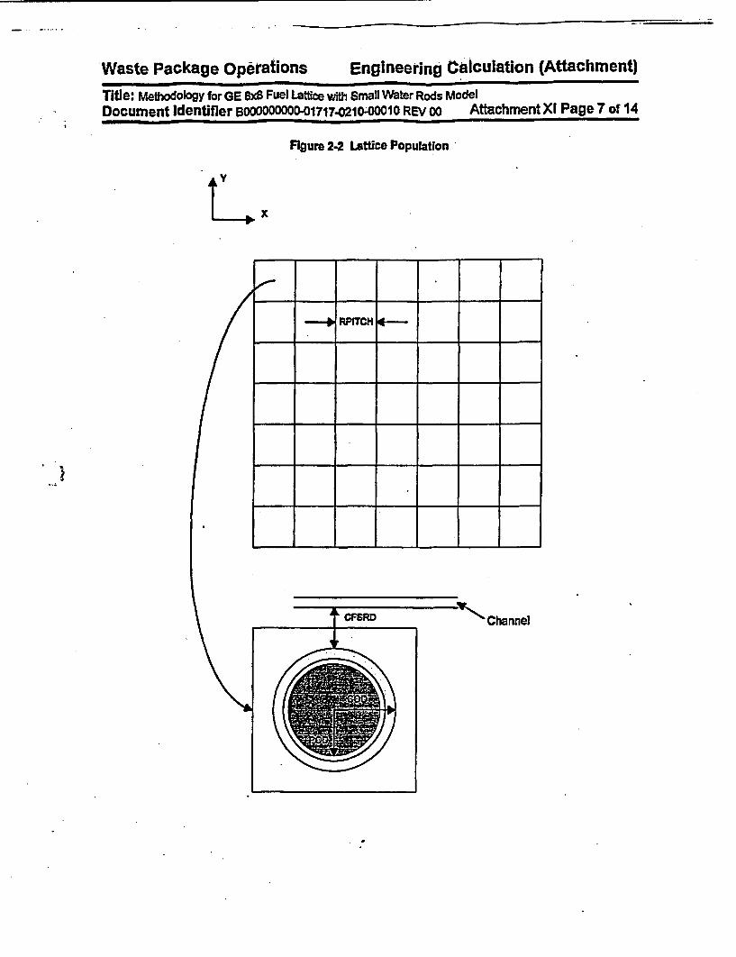
Waste Package Ope" rations Engineering Calculation (Attachment)
Title: Methodology for GE 8x8 Fuel Lattice with Small Water Rods ModelDocument identifier BOOOOOOOO-01717-0210-00010 REV 00 Attachment XI Page 7 of 14
;
Figure 2-2 Lattice Population
ty
%
(0
10RPITCHI ,
l
I I . I I I I
t CFSRD -11- Channel

Waste Package operations Engineering Calculation (Attachment)
Title: Methodology for GE 8x8 Fuel Latce with Small Water Rods ModelDocument Identifier BOOOOOOOO-01717.0210-00010 REV oo Attachment XI Page 8 of 14
Figure 243 Integration of Components Into Lattice
E I I4II I
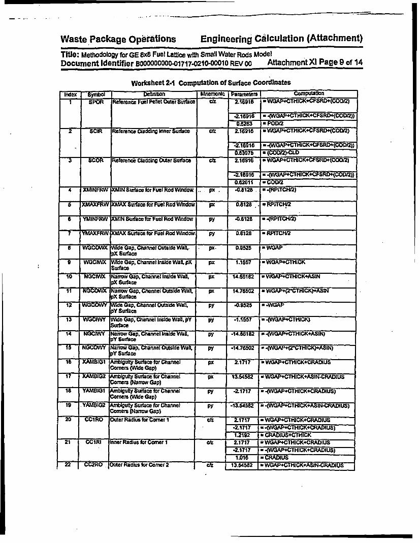
. .. .... . .. . - -
Waste Package Operations Engineering CAlculation (Attachment)-
Title: Methodology for GE 8x8 Fuel Lattice with Small Water Rods ModelDocument Identifier B000000000-01717.0210-00010 REV 00 Attachment Xl Page 9 of 14
Worksheet 2-1 ComputatiOn of Surface Coordinates
Index Symtbl Definition Mnemonic Parameters Computaon.
1 SPOR Rekrence Fuel Peet Outer Surfahce z 2.1691 WGAP+CTkICK+CFSRD+(WOD=2)
-216916 - .(WGAP+CTMICK+CFSRD+(COD2))Q5283 - POD/2
SCIR Refere Ce ladding Inner Surface 216916 WGAPCTHICK+CFSRD+(COD/2)
.2.-16916 * (WHGAP+CTHCK4CFSRD+rCODO2))
_______________________ _______ CL53975 - (COD 2)-CL0
3 SCOR Rdeence Claddcin Outer Surlacex di 2.16916 - WGAP+CTIUCK+CFSRD+(COO/2)
2.16916 a .(WGAP4CTMICKI'CFSRDI(COD12))
_62611 - CODM2
4 iFRW XMIN Surface br Fuel Rod Window . px. .0.8128. .(RPITCM/2)
5 XAXFrW Xl MX Surface hr Fuel Rod Window FX 0.8128 ..* PITCHk
6 YMINFRW iMIN Surface for Fuel Rod Window py -0.B128 -(RPITCM2)
7 YMAXFRM XMAX Surface for Fuel Rod Window py 0.8128 RPITCW2
E WGCOwX Wide Gap, Channel Outside Wall,- px. 0.9525 * WGAPpX Surface
9 WGGUI Wide Gap, Channel Inside Wall, pX px 1.1557 * WGAP+CTHICKSurfce
10 GCIWX Narrow Gap, Channel InsIde Wa, px 14.56182 w WGAP+CTHiCK4ASIN
pX Suace
1 NarNGCOV r Naow Gap. Channel Outside Wal, px 14.76502 - W(GAP+4(2CTHlCK)+ASlNpX Surface
12 WGCOWY Mde Gap, Channel Outside Wall, py 0.9525 p
pYSurface
13 WiwGON Wide Gap, Channel Indde Wall, pY py -1.1557 a (WGAP+CThlCK)Surface
14 NCIWY Narrow Gap, Channel Inside Wal. py -14.66182 * -WGAP+CTHICK+ASIN)pY Surface
1T5 FN 5W Narrow Gap, Channel Outside Wall, py .14.76502 a 4(WGAP4(2'CTPHCK)+ASIN)pY Surface
16 XAMBIG A4nbiguity Surtace for Channel I px 2.1717 WGAP CTHICK+CRADIUS
Corners (Wde Gap)
If XZMrBG2 Aftigulty Surface for Channel px 13.54582 - WGAP+CThCK+ASIN-CRADIUSCorners (Narrow Gap)
18 YAMBIGI Ambigulty Surface for Chann py -21717 -(WAP+CTCK+CRADIUS)
Corners (Wde Gap)
19 .YAMBIG2 rbtiguliy Surace for Channel py -13.54582 *-(WGAP+CTHICK+ASIN-CRADIUS)
Corners VNarow Gap) _ __
20 CC1RO Outer Radius for Corner 1 C 2.1717 * WGAP4CTHICK+CRADIUS
-2.1717 * -(WAP+CTHICK+CRADIUS)
1.2192 * CRADIUS+CTHICK
21 CCIRI inner Radiusbr Corner 1 2.1717 *WGAP+CTHiCK+CRADIUS
-2.1717 a 4WGAP+CTHICK+CRADIUS)
1_._1_6 - CRADIUS i W22 CC2RO Outer Rtadks for Corner 2 eta 13.54582 a WGAP+CTHiCK+AS1N-CRADlUS

Waste Package Operations Engineering Calculation (Attachment)
Title: Methodology for GE 8x8 Fuel Lattfce with Small Water Rods ModelDocument Identifier BOCIODOOCII01717.0210-00O10 REV 00 Attachment Xi Page 10 of 14
Index S~rbl Deftnion maemcnic ______te_ Comrputation
-2.1717 a -(WGAP+CTHCK+CRADIUS)1.2192 1 CRADIUS+CTHICK
2V -TCRI Inner Radlus fr Corner 2 13.6I4582 a WGAP+CTHlCK+ASIN-CRADIUS
-2.1717 - INGAP+CTHICK+CRADIUS)1.016 CRADiUS
24 CC3R0 Outer Radius for CoMer 3 - z 1354582 WGAP+CTHICK+ASIN-CRADIUS
-3%.545s82 w .(WCAPCTHICK+ASIN-CRADIUS)121 2 * CRADIUS+CTHICK
25 CCURI Inner Radius for ComerS 3z 13.54582 a WGAP+CTHCK4ASIN.CRADIUS
-13.54582 .-(WGAPCTICK+ASIN-CRADIUS)1.016 CARUUS
26-CC4RO Outer Radis for Corner 4 ctz 2.1717 WGAP+CTHICK+CRADIUS
.13.54582 * -(WWA THICK+ASIN-CRADIUS)
_ 12192 = CRADXUS+CTHICK
7 CC4RI Inner Radius for Comer 4 C& 2.1717 = WGAP+CTHICK+CRADIUS
13.54582 -(WAP+CTHICK+ASIN-CRADIUS)
_ _____ . __________________ ____ .016 *CRADN US
Worksheet 2-2 Cell Defintlions
Index Symbol Universe Symbol Definiuon Cell DefinitionI CFP I *UFPR FuelPellet -1 u 1-
2* CFCG 1 Pellet-ClacddIg Gap .21 ur I3 CR 1 Cladding -3 2 u- 1
4 CUOFR I Moderator Outside Fuel Rod 3 un 16 CIWR 2 . m Water Inside Water Rod -1 uw 26 CWR 2 ___RWater Rod -3 2 ul 2
CUIOWR 2 Moderator Outside Water Rod 3 u- 2
CWRL 3 UFRL W~ndow for Fuel Rod (Lattice) 4-5 6 -7 u- 3 1il= 1 or fiii 2
9 CCIAN 4 UCHAN Channel (a -9 .1 19 X(-12 1316-17):(-14 1516*17)(10-11 -18 19):(.2021 18.16):(22231817):(.2425 17-19 ):(42627-19-16)
10 CMi 4 Water Insie Channel (16 -17 -13 14 ):(9 -16 -18 19):( 17 -10 -18 19 ):( -21 -16 18):(.2317 19 i. -25 17 19 ):( 27 -16 -19)
11_ _ CWOC 4 Outside Channel #10 aun 4 f1= 31 11 CwOc 4 Water Outside Channel #10#9u 4

Waste Package Operations Engineering Calculation (Attachment)-~~~~~~~~~~~~~~0
Title: Methodology for GE 8x8 Fuel Lattice with Small Water Rods ModelDocument Identfier B00000DOO-01717.0210-00010 REV00 Attachment Xl Page 11 of 14
3. Encoding of ProcessThere are two distinct parts of the process for creating lattice models. The first Is a driver function thatmanages the selection of the appropriate data for the lattice and second Is a lattice-geometry-specificfunction that creates the detailed lattice modeL
3.1. Driver Function
A description of this function Is provided in Attachment X
3.2. Lattice-preparation FunctionA global description of this function Is provided In Attachment X The flowchart of this process fbr GE 8x8fuel assemblies with small water rods is shown In Figure 3-1.
.3

Waste Package Operations Engineering CAlculation (Attachment)
Title: Methodology for GE 8x8 Fuel Lattice with Small Water Rods Model
Document Identifier BOOOOOOOO-001717-0210-00010 REV 00 Attachment Xl Page 12 of 14
FIgure 3-1 Flowchart for Creation of GE 8x8 Lattice with Small Water Rods
Compute Surfacesfor LatticeDefinItIon
Compube offsetThis Structure Loops over for Reference Fuel
tge Distinct Fuel Rods hI RodFuetlce4
rCreate Pellet Cetli.I
Add AppropdlateMateriats for Fuel
Pellet
|CreateFuelf, | N~~~~~~~~~~~~~Caddin Gap Cell
Create FuelCladclng
|Water OutsWe oIC~ladcrin
Yes
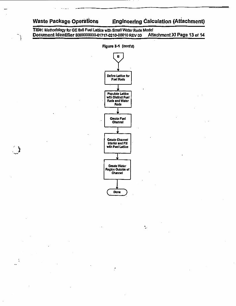
Waste Package Operations Engineering ailculation (Attachment)Title: Methodology for GE 8x8 Fuel Lattce with Small Water Rods Model
.- !A. Document Identifier BOOOOOOQO-01717-0210-0001O REV oo AttachmentXI Page 13 of 14
Figure 3-1 (cont'd)

Waste Package operaions Engineering Calculation (Attachment)Title: Methodology for GE 8x8 Fuel Lattice with SmaN Water Rods ModelDocument Identifier B00000000D-01717-0210-00010 REV oo Attachment Xl Page 14 of 14
4. References
4.1 Briesmelster, J. F., Ed., MCNPm - A General Monte Carlo N-Parftcle Transport Code, Version 4A,LA412625-M, Los Alamos National Laboratory (LANL), November 1993. TIC #: 233782.
4.2 Eriesmeister, J. F., Ed., MCNPIU - A General Monte Cario N-Particle Transport Code, Version 4B,LA-12625-M, Los Alamros National Laboratory (LANL), March 1997. MOL19980624.0328.4.3 Software Qualificafton Report for MNCP 4A, A General Monte Carlo N-Partide Transpot Code,
CSCI: 30006 V4A, Dl#; 30006-2003 REV 02, CRWMS M&O. M0L19961028.0272.4.4 Software Qualification Report for MNCP 4B2, A General Monte Carto N-Partcle Transport Code,
CSCI: 30006 .V4B2LV, DW#: 30033-2003 REV 01, CRWMS M&O. M0L19980622.0637.4.5 Core Design and Operating Data for Cycles I and 2 of Quad Cities 1, EPRI NP-240, Electic Power
Research Institute, Palo Alto, CA, November 1976. TIC #: 237267.

Waste Package Organization Engineering Calculation (Attachment)Title: Creation of MNCP Model for Quad Cities Unit I Beginning-of-Life CoreDocument Identifier: B00000ooo0o1717-0210-ooo1o REV 00 Attachment X11 Page 1 of 9
Table of Contents
Contents Page
1. Introduction 4
2. Construction of MCNP Input Streams 42.1. BLINK Input Specification 4
3. References 9
.1o)
..
�
Waste Package Organization Engineering Calculation (Attachment)
Title: Creation of MNCP Model for Quad Cites Unit 1 Beginning-of-Life CoreDocument Identifier. B00000000-1717-0210-00010 REV 00 Attachment XII Page 2 of 9
Ust of Figures
Figure Contents Page
Figure 2-1 BUNK Fuel Assembly Idenifiers for QCI Initial Core 5Figure 2-2 Quarter-core Control Blade Posit1on for QC1 BOL 8
Waste Package Organization Engineering Calculation (Attachment)Title: Creation of MNCP Model for Quad Cities Unk 1 Beginningof-Life CoreDocument Identifier: BOOOOOOOO-01717.0210-00010 REV 00 Attachment XiI Page 3 of 9
List of Tables
Table Contents Page
Table 2-1 BUNK NAMEUST Input fbr BOL CRC Reactivity Analysis 6Table 2-2 Spacer Locations 7
t

Waste Package Organization Engineering Calculation (Attachment)Title: Creation of MNCP Model for Quad Cities Unit 1 Beginning-of-ife CoreDocument Identifier. B00000000-01717-0210)-0010 REV 00 Attachment XII Page 4 of 9
1. Introduction
This attachment describes the creation of the MCNP Input streams to model the Initial core critical for theQuad Cities Unit 1 core. Thus it documents the processing of Fuel Material Intermediate Datasets(FMID's) from Watoce nuclear and geometric specifications and the preparation of input to BUNK, thelinkage software routine used to prepare the MCNP Input streams.
2. Construction of MCNP Input Streams
The documentation of this portion of the work consists of three parts:
1. identifying the relationship between BLINK fuel assemblies indices and the identifiers used forthe unexposed fuel Inventories;
2. specifying the various datasets used to construct the MCNP Input streams and geometricaland thermodynamic parameters; and
3. defining the control blade positioning.
2.1. BLINK Input Specification
This startup test was performed at the beginning of the first cycle for Quad Cities Unit 1. This evaluationwas performed to validate the linkage methodology described In Attachment VI. As such the results mustbe essentially the same as those obtained from a previous evaluation (Reference 3.1, hereafter cited asthe "previous evaluation") where a Ohand-crafted" MCNP model was used.
2.1.1. Correspondence of Fuel Assembly Identifiers
The BLINK fuel assembly Indices are shown In Figure 2-1. These Indices are the same as those used Inthe reference document for Quad Cities Unit I (Reference 3.2, hereafter cited to as the OEPRI Report).
The Fuel Material Intermediate Datasets (FMID's) are created with the IDSGEN software routine, which Isdocumented in Attachment VIII. The SAS2H "cutr files processed in this manner have the following filename nomenclature: AaNn.dat - where "a" Is the BUNK fuel assembly Index and Ono is the axial nodeIndex.

Waste Package Organization Engineering Calculation (Attachment)Title: Creation of MNCP Model for Quad Cites Unit I Beginning-of-Life CoreDocument Identifier: B0000000001717-021000010 REV 00 Attachment XII Page 5 of 9
Figure 2-1 BUNK Fuel Assembly Identifiers for QC1 Initial CoreII 2 13T14 5i16I1 7 [ISTi9 11111112113114F15
3 r 3 3 3
3 3 313213 I2 1 3 14ae 3 3 1 13 1 -4 1 14 2 4
6~~~6 3 3 3134 2 4 2 14 2 4 -26 3 -3 1 32 4 2 4 1 4 2 4
7 -3 3 1 -3 _ 42 _4 -2 -4 -2 4 -2
a 3 1 3 2 4 2 4 2 4 1 3 1 3
9 3 3 2 4 2 4_2 4 1 3 1 31
10 _ 3 3 1 4 2 4 2 4 1 3 1 3 1 3
11 3 3 1 4 2 4 2 4 1 3 1 3 1 3 112 3 1 3 2 4 2 4 1 3 1 3 1 3 T 3
13 -3 3 1 4 -2 4 -2 3 -1 -3 _ -3 -1 -3_
14 3 _--2 -4 2 4 1 3 I1 33 1 -3 _ 3
15 3 _ 7 -3 3 I 3 1 3 _

Waste Package Organization Engineering Calculation (Attachment)
Title: Creation of MNCP Model for Quad Cites Unit I Beginning-of-Life CoreDocument Identifier: B130000Oo-01717-0210-0010 REV 00 Attachment XII Page 6 of 9
2.1.2. Dataset, Geometrical and Thernodynamic Input Values
These values are those documented In Attachment VI, §3.2. The specific values selected for theFORTRAN NAMELIST portion of Input for this CRC are shown In Table 2-1. The values for theassignment of fuel assembly geometrical and material types and the underlying lattice geometric andmaterial types are consistent with the fuel assembly Indices. The axial node length was a constant valueof 15.24 cm (6 Inches). This value was expicitly used for the BLINK Version 1 testing, but was Implicit forthe Version 0 testing. The spacer centers are shown In Table 2-2. The material definition for the smearspacer composition is "SG7DI and Is defined In Attachment IlIl.
Table 2-1 BUNK NAMELIST Input for BOL CRC Reactivity Analysis
Variable Value JustificationfReferenceCORE DB bwr3 724bundle.dat a] See Attachment II for complete description of dataset
CORE _TLS core materials.dat la] See Attachment Ill for complete description of datasetBLADE DB ge.d lattice.dat [a) See Attachment V for complete description of datasetLPREFIX [b .FPREFIX [b_NAXIAL 24 This Is the number of axial nodes used In the SAS2H
depletion calculations.AFL 365.760 Fuel length Is fixed to be 14524 Inches
NCOLP 15 MaxImum dimensionality of the quarter core In units offuel assemblies.
NROWP 15 Maximum dimensionality of the quarter core in units of_fuel assemblies.
RHO 0.981 [d] For this value, see Table 7.3.3-3 of the previous__________________ evaluation.RHOBYP 0.981 [d] The moderator density throughout the problem Is
assumed uniform, which Is consistent with the startupconditions when the criticality test Is performed.
TEMPK 337.04 This value corresponds to 147F (see §7.1 of theprevious evaluation).
MUTP 7GUTP1 [c] A homogenized mixture of materials with an assumedmoderator density of 0.981 g/cfni3 Is used.
MLTP 7GLTP1 [cl A homogenized mixture of materials with an assumedmoderator density of 0.981 g/cms Is used.
[a.[bj.[c1.Id).
The prefix Is consistent with the location where the software routine Is executed.This Input Is consistent with location of FMID's processed for this analysis.See Attachment Ill for a complete description of this composition.The Input to BUNK Implies greater precision; however, the effect Is negligible.

Waste Package Organization Engineering Calculation (Aftachment)
Title: Creation of MNCP Model for Quad Cities Unlt I Beginning-of-Life CoreDocument Identifier. B00000000-01717-0210-o000o REV 00 Atta chment XII Pane 7 of 9
Table 2.2 Spacer Locations
Soacer Center LocationIndex (Inches) [a] (cm)
1 18.60 46.992 38.00 95.523 57.60 146.054 77.00 195.585 96.50 245.11
6 116.00 294.647 135.60 344.17
[a-. These values are from the EPRIReport page A-s.
3

Waste Package Orgafization Engineering Calculation (Attachment)
Title: Creation of MNCP Model fOr Quad Crites Unit I Beginning-of-Life CoreDocument Identifier: B00000000-01717-0210-0010 REV 00 Attachment XII Page 8 of 9
2.1.3. Control Blade Positions
The control blade positions at which the reactor attained criticaliy are shown in Figure 2-2. The core ismodeled In quarter-core symmetry, but since the critical control blade pattern Is quarter-core symmetric,no approximations were Involved In the control blade pattern used.
Figure 2-2 Quarter-core Control Blade Position for QCI BOL
2.1A. Input Deck Generated by BLINK
A copy of the Input deck generated by BUNK, Version 0, is given In Attachment XJII.
I
Waste Package Orgafilzation Engineering Calculation (Attachment)Title: Creation of MNCP Model for Quad Cities Unit I Beginning-of-Lfe CoreDocument Identifier: BOOOOOOD-01717-0210-00010 REV oo Attachment XII Page 9 of 9
3. References
3.1 MCNVP CRC ReacMvty Celculation for Quad Cies BWR, DIM BBAOOOOO-01717-0200-00146 REV00, CRWMS M&O. M0L19971229.0128.
3.2 Core Design and Operating Data for Cycles I and 2 of Quad Cities 1, EPRI NP-240, Electric PowerResearch Institute, Palo Afto, CA, November 1976. TIC t 237267.

Mar 23 16:26 1998 File Nam: qclcl.m irp BnoooOO-01717-021o-oogo1 REV 00 ATTACHMENT X1II - Page 1
Quad cities-1, Beginning of LifeCc Input Deck Generated by BLINK, Version 0:-c Generated on 03/23/98 at 16:26:43 by process 20234CC. Cell Cards
c Celts Defining Problem DomainCc Pressure Vessel
2001 1 -7.9000EO0 -1 2 -3 4 -5 6imp:nu 1.0
c Outside World2002 0 C 3: 1: -2: -4: 5)
Icp:n- 0.0c Jet Punp Region2003 2 -9.8114E-01 -6 7 4 -5 -1 2
irp:n=1.0c Core Shroud
2004 1 -7.9000E+00 -7 4 -5 *1 2irp:n=l 0
c Upper Tie Plate Region2005 3 -1.397E4+00 -8 4 -59 -10
imp:n=1.0c Core Grid Region2006 4 -1.0450E+00 -8 4 -5 10 -11
fmp:n-1.0c Upper Plenum Region2007 2 *9.8114E-01 -8 4 -5 11 -1
ifp:nr1.0c Lower Tie Plate Region2008 5 -1.3970E+00 -8.4 -5 -12 13
lmp:n=1.0c Fuel Support/Core Plate2009 6 -2.5430E+00 -8 4 -5 -13 14
Imp:n=1 .0c Lower Plenum Region2010 2 -9.814E-01 -8 4 -5 -14 2
imp:n 1.0c Boron Carbide In Reference Absorber Tube
2011 7 -1.7600E+00 -15imp:nu1.0 um 1
c Reference Absorber lube2012 1 -7.9000Eo00 -16 15
imp:nwl.0 u IC Water Outside Reference Absorber Tube2013 2 -9.8114E-01 16
imp:rwl.0 u Ia Window for Reference Absorber Tube Cell2014 2 -9.114E-01 -17 18 -19 20
imp:n=1.0 us 2 tat- I fill- 0:21 0:0 0:0 1 20r 2c Tie Rod2015 1 -7.9000E+00 C -21 22 -18 23 -24 25):( 26 -27 2B -29 -24 25)
iop:nz1.O u 3c Control Blade Sheath2016 1 -7.9000E.00 C 18 -30 19 -21 -24 25):C 18 -30 -20 22 -24 25):
C 30 31 -32 -24 25 )igp:rn1.0 u= 4
c Inside of Blade Wing2017 2 -9.8114E-01 C 33 34 -35 -30 -24 25 ):C -31 -24 25 )
u- 4 fills 2 Inp:n- 1.0c Region Outside of Blade Wing2018 2 -9.8114E-01 f2016 f2017
lop:n1.O um 4c Window for Wing of Blade
1 2 -9.8114E-01 36 -37 38 -39 fill- 4Iqp:na1.0 uc 3
c Wing Cloned to Korth Position2 like I but *trocl-C 0 0 0 90 0 90 180 90 90 90 90 0)
um 3
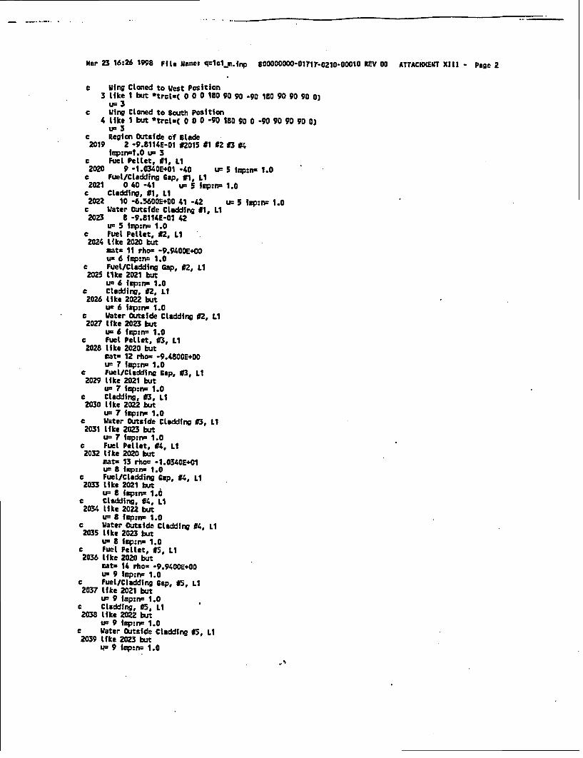
mar 23 16:26 1998 File Name: qc1c1-A.fnp *00000000-01717-0210-00010 RV 00 ATTACHXENT XlII - Page 2
c Wing Cloned to West Position3 like 1 but *trclt( 0 0 0 180 90 90 -90 ¶80 90 90 90 0)u= 3
c Wing Cloned to South Position4 like I but *trclt( 0 0 0 90 180 90 0 -90 90 90 90 0)
u= 3c Region Outside of Blade2019 2 -9.8114E-01 #2015 41 92 83 #4
ifp:n-l.O u- 3c Fuel Pellet, #1, Li2020 9 -1.0340E+01 -40 Um 5 Ifp:nr 1.0c Fuel/Cladding Gap, #1, Li2021 0 40 -41 u- 5 fap:nr 1.0e Cladding, #1, Li2022 10 -6.5600E+00 41 -42 u 5 fop:n- 1.0c Water Outside Cladding #1, LI2023 B -9.8114E-01 42
u- 5 Imp:n= 1.0c Fuel Pellet, 42, Li
2024 Like 2020 butmat. 11 rho: -9.9400E+OOu- 6 frp:n- 1.0
c Fuel/Cladding Gap, #2, Li2025 LIke 2021 but
un 6 irp:nc 1.0c Cladding, f2, LI2026 like 2022 but
us 6 irp:nz 1.0c Water Outside Cladding #2, Li2027 like 2023 but
u= 6 fmp:n 1.0c Fuel Pellet, 03, Li2028 lIf ke 2020 but
mat. 12 rho= -9.480OE+O0u= 7 lp:ma 1.0
c Fuel/Cladding Cap, 93, LI2029 like 2021 but
U3 7 Imp:n- 1.0c Cladding, 03, Li2030 like 2022 but
u- 7 iap:nu 1.0c Water Outside Cladding t3, Li
2031 lIke 2023 butn 7r mp:nu 1.0
c Fuel Pellet, 94, LI2032 like 2020 but
mat= 13 rho: -1.0340E+01uI B ip:nn 1.0
c Fuel/Cladding Cap, #4, Li2033 like 2021 but
un 8 frp:r- 1.0c Cladding, #4, Li
2034 like 2022 butu= 8 fmp:nu 1.0
c Water Outside Cladding #4, Li2035 like 2023 but
un a ip:rn 1.0c Fuel Pellet, f5, Li2036 like 2020 but
mata 14 rho. -9.9400E+00uI 9 fmp:n- 1.0
c Fuel/Claddfng Cap, J5, Li2037 Ifke 2021 but
uI 9 iap:nc 1.0c Cladding, C5, Li2038 like 2022 but
u. 9 imp:Iw 1.0c Water Outside Cladding #5, Li2039 like 2023 but
IF 9 Iap:n= 1.0

Mar 23 16:26 1998 rFle mame: qcIcl_.inp s00000000-01717-Oz20-00010 REV 00 ATTACHMENT XIII - Page 3
C Fuel PeLlet, t6, Li2040 like 2020 but
mats 15 rho= .9.9400E400u= 10 fnp:n= 1.0
c Fuel/Cladding Cap, 16, Li2041 like 2021 but
u5 10 imp:nu 1.0c Cladding, 16, Li2042 like 2022 but
us 10 fmp:ns 1.0c Uater outside Cladding 16, Li
2043 like 2023 butUr 10 fIp:nu 1.0
e Fuel Pellet, 17, Li2044 like 2020 but
mats 16 rhos -1.0300X+01u= 11 fmp:nx 1.0
c Fuel/Cladding Cap, 17, Li2045 like 2021 but
u= 11 imp:no 1.0c Cladding, 17, Li2046 like 2022 but
uw 11 lmp:ns 1.0c Water Outside Cladding #7, LI2047 like 2023 but
uin Ii Ip:ns 1.0c Fuel Pellet, 18, LI2048 like 2020 but
mat- 17 rhos -1.0340E+01us 12 i1p:rn3 1.0
c Fuel/Cladding Cap, 18, Li2049 like 2021 but
ua 12 fmp:nw 1.0c Cladding, #S, Li2050 like 2022 but
us 12 fap:rs 1.0c Water Outside Cladding 18, Li
2051 like 2023 butus 12 Imp:rw 1.0
c Reference Fuel Rod Cell, Li2052 8 -9.8114E-01 -43 44 45 -46 tats 1 u a 13 imp:nu 1.0
fill. -1:T -1:7 0:013 13 13 13 13 13 13 13 1313 10 10 9 9 9 9 10 1313 t0 9 8 5 5 6 9 1313 9 8 12 5 5 5 6 1313 9 5 5 7 5 t1 6 1313 9 5 5 5 5 5 6 1313 9 6 5 11 S 5 6 1313 10 9 6 6 6 6 9 1313 13 13 13 13 13 13 13 13
c Charnel, Li2053 18 -6.5600E400 C 47 -68 -49 SO):l -51 52 53 -54):
C -S5 56 53 -54):( 57 -58 50 -49):C -59 60 49 -53):t -61 62 49 54):C -63 64 54 -50):( -65 66 -50 -53)u= 14 imp:nu 1.0
c Active Fuel Area, Li2054 8 9.8114E-01 C 53 -54 -52 55):C 48 -53 -49 50 ):
C 54 -57 -49 50):( -60 -53 49):C -62 54 49):t -64 54 -50):C -66 -53 -50)fills 13 u= 14 Imp:no 1.0
c Water Outside of Channel, Li2055 2 -9.8114E-01 C -47 : 51 : 58 s -56 ):
C 59 -53 49 ):C 61 54 49 ):C 63 54 -50 3:C 65 -53 -50 )u= 14 fm:ir 1.0

mar 23 16:26 1998 File Name: qceclnm.inp BoooW0000-01717-021O-0.000 REV 00 ATTACHMENT XIII - Page 4
c Fuel Pellet, #1, L22056 19 -1.0340Ee01 -40 Ucn 15 frp:r- 1.0
c FuelfCladdirg Gap, #1, 1.22057 0 40 -41 um 15 fmp:nr 1.0
c Cladding, Y1, L22056 10 -6.5600E.OO 41 -42 un 15 izp:nw 1.0
c Water Outside CLadding #1, U22059 8 -9.8114E-01 42
um 15 ilmp:n= 1.0a Fuel Pellet, #2, L22060 Like 2056 but
wat. 20 rhct -9.9400E400um 16 imp:n. 1.0
c Fuel/Cladding Gap, #2, L22061 Iike 2057 but
um 16 fmp:n= 1.0c Cladding, #2, U22062 like 2058 but
uc 16 fup:n= 1.0c Water Outside Cladding #2, L22063 like 2059 but
UI 16 wp:nu 1.0c Fuel Pellet, #3, U22064 like 2056 but
mata 21 rho= -9.4800E+00us 17 fmp:rpf 1.0
c Fuel/Cladding Gap, #3, L22065 like 2057 but
u= 17 iqp:n 1.0c Cladding, #3, L22066 like 2058 but
un 17 lmp:nu 1.0c Water Outside Cladding #3, L22067 like 2059 but
Uc 17 iwp:n= 1.0c Fuel Pellet, #4, L22068 like 2056 but
mat. 22 rho- -1.034OE+OluI 18 Ixp:n= 1.0
c Fuel/Cladding Gap, #4, L22069 like 2057 but
IF 18 Iwp:nr 1.0c Cladding, 4, 1.2
2070 like 2058 butUF 18 isp:n3 1.0
c Water Outside Cladding 14, L22071 like 2059 but
u- 18 Iip:n= 1.0c Fuel Pellet, #5, L2
2072 like 2056 butmats 23 rhor -9.9400E+OouI 19 fap:nu 1.0
c Fuel/Cladding cap, #5, C22073 Like 2057 but
uI 19 imp:n 1.0c Cladding, #5, L22074 like 2058 but
U- 19 imp:n= 1.0c Water Outside Cladding #5, L22075 like 2059 but
uI 19 qp:n- 1.0c Fuel Pellet, #6, L22076 like 2056 but
mat- 24 rho= -9.9400E+00UF 20 imp:ll 1.0
c Fuel/Cladding Cap, #6, L22077 like 2057 but
uI 20 imp:re 1.0c Cladding, #6, L22078 like 2058 but
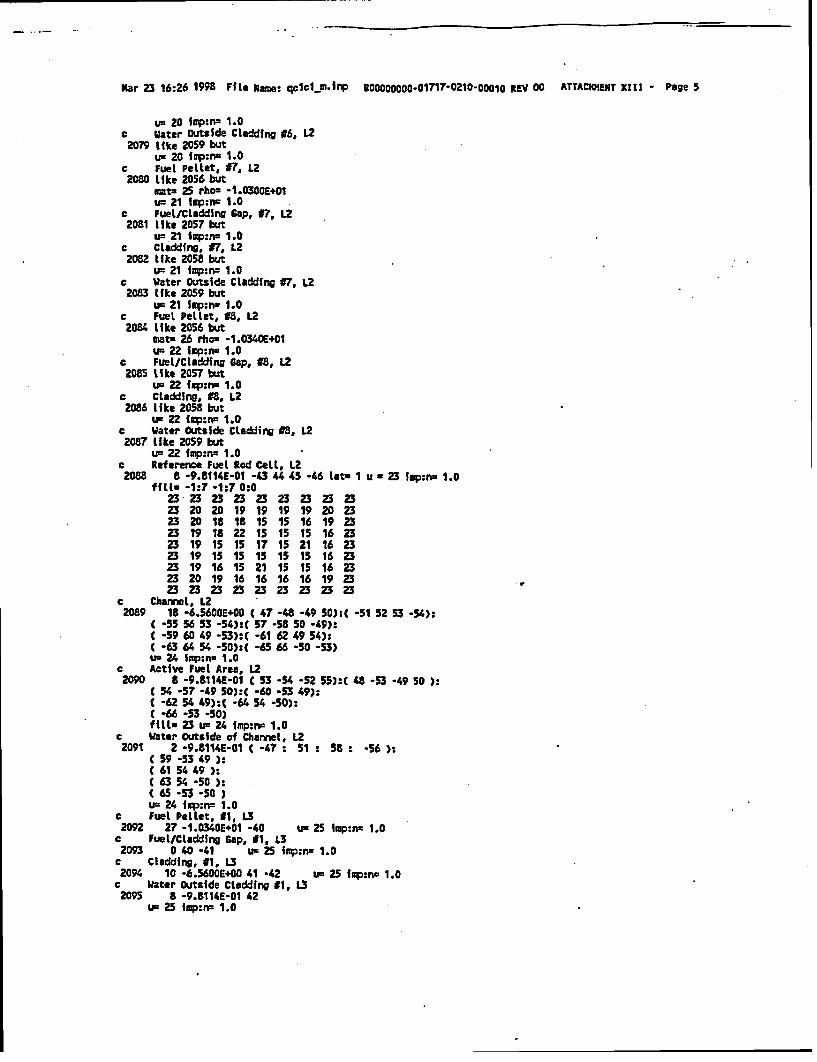
Mar 23 16:26 1998 Flle Uame: qc1c1p-lmrp B0OOOOOOO-01717-0210-ooo1o gEV 00 ATTACHMENT XtlI - Page 5
u= 20 ifrp:iw 1.0c Water outside Cladding 16, L22079 like 2059 but
um 20 Irp:ri 1.0c Fuel Pellet, t7, L22080 Like 2056 but
mat- 25 rho- -1.0300E+01u= 21 lnp:n= 1.0
c Fuelt/Cladding Cap, 97, U22081 Like 2057 but
u= 21 lmp:nc 1.0c Cladding, n, L22082 like 2058 but
u= 21 lmp:nz 1.0c Water Outside Cladding t7, L22083 like 2059 but
ui 21 frp:ri 1.0c Fuel Pellet, #8, L22084 like 2056 but
matP 26 rho- -1.0340E'01u- 22 fmp:n- 1.0
c Fuel/Cledding Gap, #8, L22085 l~ke 2057 but
u. 22 fmp:rn 1.0c Cladding, #8, L22086 like 2058 but
uL 22 tmp:rn 1.0c Water Outside Cladding #8, L22087 like 2059 but
u 22 mp:nu 1.0c Reference Fuel Rod Ceol, L22088 8 -9.8114E-01 -43 4 45 -46 let- I u a 23 lmp:rn 1.0
fill- -1:7 -1:7 0:023 23 23 23 23 23 23 23 2323 20 20 19 19 19 19 20 2323 20 18 18 15 15 16 19 2323 19 18 22 15 15 15 16 2323 19 15 15 17 15 21 16 2323 19 15 15 15 15 15 16 2323 19 16 15 21 15 15 16 2323 20 19 16 16 16 16 19 2323 23 23 23 23 23 23 23 23
c Channel, L22089 18 -6.5600E4O0 t 47 -48 -49 50):t -51 52 53 -54):
C -55 56 53 *54):( 57 -58 50 -49):C -59 60 49 -53):( -61 62 49 54)s( -63 64 54 -50):( -65 66 -50 -53)uu 24 lmp:n- 1.0
c Active Fuel Area, U22090 8 -9.8114E-01 C 53 -54 -52 55):t 48 -53 -49 50 ):
C 54 -57 -49 50):( -60 -53 49):C -62 54 49):C -64 54 -50):( -66 -53 -50)fitll 23 u- 24 fup:n= 1.0
c Water Outside of Chamnel, L22091 2 -9.114UE-01 < -47 : 51 : 58 : -56 ):
C 59 -53 49 ):C 61 54 49 ):C 63 54 -50 ):( 65 -53 -50 )um 24 Iqp:rn= 1.0
c Fuel Pellet, 41, L32092 27 -1.0340E.01 -40 u= 25 lmp:nu 1.0c Fuel/Cladding Gap, #1, L32093 0 40 -41 um 25 frp:n t1.0
c Cladding, #1, U2094 10 -6.5600E+00 41 -42 ue 25 imp:n. 1.0
c Water Outside Cladding #1, U2095 8 -9.8114E-01 42
um 25 imp:rp 1.0

Mar 23 16:26 1998 f1le Name: qclc1m.inp BaooOoOOOO1 717-0210-oooIO REV 00 ATTACHMENT XIII - Page 6
c Fuel Pellet, #2, L32096 Like 2092 but
mats 28 rho= -9.9400K 00u- 26 Imp:n 1.0
c Fuel/Cladding Cap, #2, U32097 like 2093 but
u- 26 qp:nw 1.0c Cladding, #2, U32098 like 2094 but
u- 26 imp:nc 1.0c Water Outside Cladding #2, U3
2099 like 2095 butu= 26 imp:wr 1.0
c Fuel Pellet, #3, L32100 like 2092 but
matz 29 rho= -9.4800E+00uc 27 mp:n- 1.0
c Fuel/Cladding Cap, #3, 132101 Like 2093 but
u- 27 imp:n 1.0c Cladding, 83, U32102 like 2094 but
u= 27 fmp:nu 1.0c Water Outside Cladding #3, U2103 like 2095 but
u' 27 11p:na 1.0c Fuel Pellet, #4, U2104 like 2092 but
mats 30 rho. -1.0340E+01up 28 iap:rn 1.0
c Fuel/Cladding Gap, t4, L32105 like 2093 but
&F 28 lnp:nc 1.0c Cladding, #4, L32106 like 2094 but
u= 28 imp:mw 1.0e Water Outside Cladding f4, U32107 like 2095 but
u' 28 iup:nu 1.0c Fuel Pellet, #5, U2108 like 2092 but
matu 31 rho= -9.9400E+00um 29 fop:nm 1.0
c Fuel/Cladding Gap, #5, U2109 like 2093 but
u' 29 iap:m 1.0e Cladding, 5, .3L2110 Like 2094 but
um 29 Ip:na 1.0c Water Outside Cladding #5, U32111 like 2095 but
u' 29 imp:n= 1.0e Fuel Pellet, #6, U2112 like 2092 but
mato 32 rhos -9.9400E+00un 30 imp:n- 1.0
c Fuel/Cladding Gap, #6, 32113 like 2093 but
UF 30 imp:n= 1.0c Cladding, #6, 132114 like 2094 but
us 30 lap:nu 1.0c Water Outside Cladding #6, 12115 like 2095 but
un 30 iip:m- 1.0c Fuel Pellet, n7, L32116 like 2092 but
mat= 33 rhon -1.0300E+01'P 31 imp:i 1.0
c Fuel/Cladding Gap, #7, U

Mar 23 16:26 IM File Name: qcjcj-w.fnp a00000000-01717.0210-00010 REV 00 ATTACHMENT XIII - Page 7
2117 lfke 2093 butUn 31 fimpmn 1.0
e Ctadding, 17, L32118 like 2094 but
un 31 iUp:n= 1.0c Water Outside Cladding 7, U2119 like 2095 but
u=31 ip:n, 1.0c Fuel Pellet, #8, L32120 like 2092 but
mat- 34 rhos -1.0340E+01u- 32 rm:nw 1.0
c Fuel/Cladding Cap, #8, 1.32121 Like 2093 but
u- 32ifqp:nr 1.0c Cladding, #8, L32122 like 2094 but
u= 32 imp:nz 1.0c Water Outside Cladding #8, L32123 like 2095 but
un 32 imp:n- 1;0c Reference Fuel Rod Cell, 132124 8 -9.8114E-01 -4 44 45 -46 Iat I urn 33 ifp:n- 1.0
fill. -1:7 -t:7 0:033 33 33 33 33 33 33 33 3333 30 30 29 29 29 29 30 3333 30 28 28 25 25 26 29 3333 29 28 32 25 25 25 26 3333 29 25 25 27 25 31 26 3333 29 25 25 25 25 26 3333 29 26 25 31 25 25 26 3333 30 29 26 26 26 26 29 3333 33 33 33 33 33 33 33 33
c Channel, U32125 18 -6.5600E+00 C 47 -48 -49 SO):t -51 52 53 -54):
C -55 56 53 -54):C 57 -58 50 -49):( -59 60 49 -53):C -61 6Z 49 54):C -63 64 54 -50):C -65 66 -50 -53)um 34 imp:- 1.0
c Active Fuel Area, 1.32126 B -9.8114E-01 C 53 -54 -52 55):t 48 -53 -49 50 ):
C 54 -57 -49 50):( -60 -53 49):C -62 54 49):C -64 54 -50):C -66 -53 -50)fill. 33 u= 34 imp:wn 1.0
c Water Outside of Channel, 132127 2 -9.t114E-01 t -47 : 51: 58 : -56 ):
C 59 -53 49 ):( 61 54 49 ):C 63 54 -50 ):( 65 -53 -50 )Um 34 imp:nm 1.0
c Fuel Pellet, #1, L42128 35 -1.0340E+01 -40 un 35 fmp:n- 1.0
c Fuel/Cladding Cap, #1, L42129 0 40 -41 u 35 Imp:nr 1.0
c Cladding, #1, L42130 10 -6.5600.E00 41 -42 us 35 imp:nw 1.0
c Water Outside Cladding #1, L42131 8 -9.8114E-01 42
u- 35 irp:n 1.0e Fuel Pellet, f2, L42132 like 2128 but
nmt. 36 rho= -9.4800E+00um 36 fup:yw 1.0
c Fuet/Cladding Gap, 52, LA2133 like 2129 but
us 36 finp:nz 1.0c Cladding, #2, L42134 like 2130 but

gar 23 16:26 1998 Fite Kane: qclclm.inp 500000000-01717.0210-00010 REV 00 ATTACHMENT XII - Page 8
Uz 36 lp:na 1.0c Water Outside Cladding #2, L4
2135 like 2131 butus 36 Iap:n= 1.0
c Fuel Pellet, #3, L42136 Like 2128 but
mat* 37 rho' -1.0340E+01%r 37 ivp:n- 1.0
e Fuel/CLadding cap, #3, L42137 Like 2129 but
us 37 im:mri 1.0c Cladding, #3, U2138 like 2130 but
um 37 Imp:n: 1.0c Water Outside Cladding #3, U.2139 like 2131 but
us 37 imp:n- 1.0c Fuel Pellet, #4, L42140 like 2128 but
matx 38 rho= -1.0340E+01us 38 impmw 1.0
c Fuel/Cladding Cap, 4, L42141 lkte 2129 but
u= 38 lmp:n- 1.0c Cladding, #4, L42142 like 2130 but
un 38 fop:nu 1.0c Water Outside Cladding #4, L42143 ike 2131 but
Us 38 iip:nm 1.0c Fuel Pellet, O5, L.42144 like 2128 but
mats 39 rho- -1.0300E+01u- 39 irp:rn 1.0
c Fuet/Ctadding Gap, #5, Li42145 like 2129 but
u- 39 fnp:n- 1.0e Cladding, *5, Li4
2146 Like 2130 butu= 39 lmp:n= 1.0
c Water Outside Cladding #5, Li42147 like 2131 but
us 39 fup:n 1.0c Fuel Pellet, #6, L42148 Like 2128 but
matr 40 rho= -1.0340E+01um 40 fmp:nu 1.0
c FUel/Ctadding Cap, #6, L42149 like 2129 but
us 40 fop:nu 1.0c Cladding, #6, L42150 like 2130 but
u' 40 fmp:nu 1.0c Water Outside Cladding t6, L42151 like 2131 but
uK 40 iap:nu 1.0c Reference Fuel Rod Cell, L42152 S -9.8114E-01 -43 44 45 -46 lat- 1 u u 41 imp:n 1.0
fills -1:7 -1:7 0:041 41 41 41 41 41 41 41 4141 38 38 37 37 37 37 38 4141 38 37 37 35 35 35 37 4141 37 37 40 35 35 35 35 4141 37 35 35 36 35 39 35 4141 37 35 35 35 35 35 35 4141 37 35 35 39 35 35 35 4141 38 37 35 35 35 35 37 4141 41 41 41 41 41 41 41 41
C Channel, L42153 18 -6.5600E+00 ( 47 -48 -49 5D):C -51 52 53 -54):

Mar 23 16:26 1998 File Name: cIclIfl rIp B00000 0oo -01717-0210-Ooo0 o REV 00 ATTACKMENT XIII - Page 9
c -55 56 53 -54):( 57 -58 50 -49):C -59 60 49 -53):C -61 62 49 54):C -63 64 54 -50):C -65 66 -50 -53)us 42 fop:rr- 1.0
c Active Fuel Area, U42154 8 -9.8114E-01 ( 53 -54 -52 55):t 48 -53 -49 50 ):
C 54 -57 -49 50):t -60 -53 49):-62 54 49):C -64 54 -50):
C -66 -53 -S0ffll* 41 u- 42 Imp:ru 1.0
c Water Outside of Charmel, L42155 2 -9.8114E-01 C -47 : 51 : 58: -56 ):
( 59 -53 49):C 61 54 49 ):
63 54 -50.):C 65 -53 -50 )um 42 igp:n= 1.0
c Fuel Pellet, #1, L52156 41 -1.0340E+01 -40 um 43 tap:u 1.0
c FuelICladding Gap, M1, L52157 0 40 -41 u 43 iSp:rr 1.0
c Cladding, #1, L52158 10 -6.56001+00 41 -42 u- 43 iupm- 1.0
c Water Outside Cladding t1, LS2159 8 -9.8114E-01 42
u- 43 Ifp:n- 1.0c fuel Pellet, 1Z, L52160 Like 2156 but
mt. 42 rho- -9.4800E+00um 44 Imp:n 1.0
c Fuel/Cladding Gap, #2, L52161 Like 2157 but
us 44 imp:rsa 1.0c Cladding, #2, L52162 like 2158 but
U=44 ump:nu 1.0c Water Outside Cladding #2, L52163 like 2159 but
44 iump:nx 1.0e Fuel Pellet, 13, L52164 like 2156 but
mats 43 rPha -1.0340E+01uc 45 fp:rp 1.0
e Fuel/Cladding Cap, t3, L52165 like 2157 but
ui 45 fmi:n: 1.0c Cladding, 13, LS2166 like 2158 but
U2 45 lmp:na 1.0c Vater Outside Cladding #3, U.2167 like 2159 but
us 45 Imp:r¢ 1.0c Fuel Pellet, #4, L52168 like 2156 but
mat 44 rhos -1.040E+01us 46 sp:nu 1.0
c Fuel/Cladding Gap, #4, LS2169 like 2157 but
UV 46 lapIe 1.0c Cladding, #4, L52170 LMke 2158 but
u= 46 iop:n- 1.0c Water Outside Cladding Ug, LS2171 like 2159 but
ui 46 Iwp:nu 1.0c Fuel Pel let, #5, L52172 like 2156 but
mat- 45 thou -1.0260E+01us 47 imp:n. 1.0
c Fuel/Claddino Gap, 45, L5

Mar 23 16:26 1998 File Uame: qc1cl m..np gDO000000-01717-0210-O00lO REV 00 ATTACHMENT XItI - Page 10
2173 Like 2157 butU3 4£7 lmp:n= 1.0
e Cladding, 15, L52174 like 2158 but
u= 47 imp:nr 1.0c Water Outside Cladding K5, U.2175 like 2159 but
tP 47 ixp:n= 1.0c Fuel Pellet, #6. 1.52176 Like 2156 but
mat= 46 rhos -1.034CE+01um 48 ihp:nw 1.0
c Fuel/Claddfng Gap, 16, LS2177 like 2157 but
Ye 48 lmp:ni 1.0c Cladding, 16, L52178 Like 2158 but
u- 48 iUp:r- 1.0c Mater Outside Cladding #6, LS2179 like 2159 but
um 48 iip:n- 1.0c Reference Fuel Rod Cell, LS2180 8 -9.8114E-01 *3 44 45 -46 late u a 49 lop:na 1.0
fill. -1:7 -1:7 0:049 49 49 49 49 49 49 49 4949 46 46 45 45 45 45 46 £949 4 45 45 43 43 43 45 4949 45 45 48 43 43 43 43 4949 45 43 43 4 43 47 43 4949 45 43 43 43 43 43 43 4949 45 43 £3 47 43 43 43 4949 46 45 43 43 43 43 45 4949 49 49 49 49 49 49 49 49
c Chamnel, L52181 18 -6.5600E+00 C 47 -48 -49 50):t -51 52 53 -54):
t -55 56 53 -54):C 57 -58 50 -49):C 59 60 49 -53):( -61 62 49 54):C -63 64 54 -50):t -65 66 -50 -53)uf 50 Imp:n. 1.0
c Active Fuel Area, LS2182 8 -9.8114E-01 C 53 -54 -52 55):t 48 -53 -49 50 ):
( 54 -57 -49 50):C -60 -53 49):C -62 54 49):C -64 54 -50):C -"6 -53 -50)fill. 49 us 50 imp:nz 1.0
c Water Outside of Channel, L52183 2 -9.8114E-01 C -47 : 51 : 58 : -56 )
C 59 -53 49 ):C 61 54 49 ):( 63 54 -50 ):C 65 -53 -50 )t 50 h p:n3 1.0
c Fuel Peltet, C1, 162184 47 -1.0340E.01 -40 us 51 fmp:nc 1.0
c Fuel/Cladding Cap, #1, L62185 0 40 -4t u= 51 imp:ne 1.0
c Cladding, 11, L62186 10 -6.5600E+00 41 -42 un 51 fup:nr 1.0
c Water Outside Cladding #1, L62187 8 -9.8114E-01 42
um 51 ixp:n. 1.0c Fuel Pellet, 12, L62188 like 2184 but
mat. £8 rho= *9.4800E*O0u= 52 lmp:n- 1.0
c Fuel/Cladding Gap, 02, 162189 like 2185 but
U3 52 fmp:n- 1.0c Cladding, #2, L6
2190 like 2186 but

Mar 23 16:26 1998 File Name: qclcim.inp EB00000000-01717-0210-00010 REV 00 ATTACHMENT XIII - Page 11
u= 52 fmp:rr 1.0c Water Outside Cladding #2, L6
2191 like 2187 butum 52 imp:rn= 1.0
e Fuel Pellet, #3, L62192 Like 2184 but
mat- 49 rho= -1.0340E+01uP 53 frp:rn 1.0
e Fuelt/Ctadding Gap, 13, L62193 like 2185 but
um 53 inp:rn 1.0c Cladding, £3, L6
2194 like 2186 butu- 53 inp:n= 1.0
c Water Outside Cladding £3, L62195 like 2187 but
u- 53 trup:n= 1.0c Fuel Pellet, #4, L62196 like 2184 but
mats 50 rho- -1.0340E+01u- 54 imp:nz 1.0
e Fuel/Cladding gap, t4, L62197 Like 2185 but
Uf 54 fap:rn 1.0c Cladding, #4, L62198 Like 2186 but
LF 54 lmp:rr 1.0c Water Outside Cladding #4, L62199 like 2187 but
um 54 fxrp:n 1.0c Fuel Pellet, #5, L62200 like 2184 but
matz 51 rho- -1.0260E401u- 55 inp:rw 1.0
e Fuelt/Cladding 6sp, #5, L62201 like 2185 but
IF 55 Icp:rn 1.0c Cladding, #5, L62202 like 2186 but
u= 55 imp:nu 1.0c Water Outside Claddfng #5, L62203 like 2187 but
u= 55 fop:nz 1.0c Fuel Pellet, #6, L62204 like 2184 but
mat- 52 rho- -1.0340E+O1Un 56 Imp:nn 1.0
e Fuet/Cladding 6ap, 16, U62205 like 2185 but
> 56 irp:n= 1.0c Cladding, #6, 1.62206 Like 2186 but
um 56 iupme 1.0c Water Outside Cladding #6, L62207 like 2187 but
w 56 Irp:rp 1.0c Refoeree Fuel Rod Cell, L62208 8 -9.8114E-01 -43 44 45 -46 lat. 1 u 57 imp:n. 1.0
fill. -1:7 -1s7 0:057 57 57 57 57 57 57 57 5757 54 54 53 53 53 53 54 5757 54 53 53 51 51 51 53 5757 53 53 56 51 51 51 51 5757 53 51 51 52 51 55 51 5757 53 51 S1 S1 51 51 51 5757 53 51 51 55 51 51 51 5757 54 53 51 51 51 51 53 5757 57 57 57 57 57 57 57 57
c Channel, L62209 18 -6.5600E.00 t 47 -48 -49 50):t -51 52 53 -54):

--
Mar 23 16:26 1998 Fie Name: qcicl.inp o0000000o-C1717 0210-0001O REv 00 ATTACWUT XIII - Page 12
C -55 56 53 -54):C 57 -58 So -49):C -59 60 49 -53):C -61 62 49 54):( -63 64 54 -50):( -65 66 -50 -53)u- 58 fup:ni 1.0
c Active Fuel Area, L62210 8 -i.8114E-01 C 53 -54 -52 55):t 48 -53 -49 50 ):
C 54 -57 -49 5O):C -60 -53 49):C -62 54 49):C -64 54 -50):C -66 -53 -50)fitll 57 u= 58 lmp:na 1.0
e Water Outside of ChanneL, L62211 2 -9.8114£-01 C -47 : 51 : 58 : -56 ):
C 59 -53 49 ):C 61 54 49 ):(63 54 -50)C 65 -53 -50Ou- 58 lmp:n.. 1.0
c Fuel Pellet, #1, LT2212 53 -1.0340E+01 -40 u- 59 lap:n- 1.0c Fuel/Cladding Cap, f1. LT2213 0 40 -41 ur 59 fmp:nr 1.0
c Cladding, 41t L72214 10 -6.5600E+00 41 -42 ur 59 irp:nm 1.0
c Water Outside Cladding #1, L72215 8 -9.8114E-01 42
uF 59 lmp:n 1.0C Fuel Pellet, 12, LT2216 like 2212 but
mat. 54 rho= -9.9400E+00u, 60 imp:n 1.0
c Fuel/Cladding cap, #2, L72217 like 2213 but
u- 60 rp:rn 1.0c Cladding, #2, L72218 Like 2214 but
um 60 iip:nr 1.0c Water Outside CLadding #2, LT2219 like 2215 but
U5 60 Imp:nr 1.0c Fuel Pellet, #3, U.2220 like 2212 but
mat- 55 rho= -9.4800E+00ur 61 Imp:nu 1.0
C Fuel/Cladding Cap, #3, L72221 like 2213 but
u= 61 imp:rn 1.0c Cladding, 03, L7
2222 like 2214 butun 61 lp:nr 1.0
c Water Outside Cladding 13, U72223 like 2215 but
uo 61 finp:nu 1.0c Fuel Pellet, #4, L72224 like 2212 but
mat. 56 rhou -1.0340E+01ur 62 iop:nn 1.0
c Fuel/Cladding Gap, 14, 172225 like 2213 but
Ui 62 fmp:n= 1.0c Cladding, #4, L7
2226 like 2214 butur 62 limp:n= 1.0
c Water Outside Cladding #44, U227 like 2215 but
ur 62 Imp:mr 1.0c Fuel Pellet, f5, L72228 like 2212 but
mat. 37 rhor -0.9400E+00ur 63 lmp:nr 1.0
c Fuel/Cladding Gap, K5, L7
mar 23 16:26 1998 Fi Le Name: qclcl-p.inp Ma000000o.01717-0210-00010 REV 00 ATTACHMENT XtIlI - Page 13
2229 like 2213 butus 63 iip:rn 1.0
c Cladding, #5, LT2230 like 2214 but
Um 63 pm:n 1.0c Water Outside Cladding #5, L72231 like 2215 but
un 63 imp:nrx 1.0c Fuel Pellet, #6, L72232 like 2212 but
mat= SB rhos -9.9400E+00u= 64 imp:nu 1.0
c Fuel/Cladding Gap, #6, L72233 like 2213 but
um 64 .ip:rr- 1.0c Cladding, 16, L72234 like 2214 but
us 64 isp:na 1.0c Water Outside Cladding #6, Li2235 Like 2215 but
UF 64 tip:uw 1.0c Fuel Pellet, #7, L72236 Lke 2212 but
mats 59 rhos -1.0300E+01us 65 fmp:na 1.0
c Fuel/CladdinG sap, #7, Li2237 like 2213 but
um 65 fgp:n= 1.0c Cladding, #7, L72238 Like 2214 but
uF 65 qnpna 1.0c Water Outside Cladding C7, L72239 like 2215 but
u- 65 imp:nw 1.0c Reference Fuel Rod Cell, L72240 8 -9.8114E-o1 -43 45 -46 lets I uw 66 fap:n= 1.0
fill. -1:7 -1:7 0:066 66 66 66 66 66 66 66 6666 64 64 63 63 63 63 64 6666 64 62 62 59 59 60 63 6666 63 62 59 59 59 59 60 6666 63 59 59 61 59 65 60 6666 63 59 59 59 59 59 60 6666 63 60 59 65 59 S9 60 6666 64 63 60 60 60 60 63 6666 66 66 66 66 66 66 66 66
c Channel, L72241 18 -6.5600E.00 C 47 -48 -49 50):( -51 52 53 -54):
C -55 56 53 -54):C 5T -58 50 -49):( -59 60 49 53):t -61 62 49 54):C -63 64 54 50):t -65 66 -50 -53)Um 67 iUp:m 1.0
c Active Fuel Area, L72242 B -9.8114E-01 C 53 -54 -52 55):( 48 -53 -49 50 ):
C 54 -5T -49 50):C -60 -53 49):C -62 54 49):t -64 54 -50):( -66 -53 -50)fills 66 u= 67 iq0:rw 1.0
c Water Outside of Channel, LT2243 2 -9.8114E-01 ( -47 : 51: 58 : -56 ):
C 59 -53 49 ):C 61 54 49 ):( 63 54 -50 ):C 65 -53 -50 )u- 67 imp:n 1.0
c Fuel Pellet, 11, LB2244 60 -1.0340E.01 -40 UF 68 imp:nm 1.0c Fuel/Cladding Cap, #1, La
2245 0 40 -41 u- 68 .p:ni 1.0c Cladding, #1, LB

-
Mar 23 16:26 1998 File arme: qclcj ImnP 1100000000.017¶7.0210O00010 REV 00 ATTACHMENT XIII - Page 14
2246 10 -6.5600E+D0 41 -42 u- 68 imp:rn 1.0c jWater Outside Cladding 01, La2247 a -9.8114E-01 42
u- 68 imp:nw 1.0c Fuel Pellet, #2, LB2248 like 224 but
mats 61 rhos .9.9400E+OOue 69 fip:nc 1.0
e Fuel/Cladding Cap, #2, LB2249 Like 2245 but
i= 69 imp:n2 1.0c Cladding, #2, LB2250 like 2246 but
us 69 imp:iw 1.0e Water Outside Cladding #2, LB
2251 like 2247 butu= 69 imp:n= 1.0
c Fuel Pellet, #3, LB2252 like 2244 but
mats 62 rhon -9.4800E'00u. 70 imp:w 1.0
c Fuel/Cladding Gap, #3, LB2253 Like 2245 but
ue 70 imp:nr 1.0c Cladding. #3, LB2254 Like 2246 but
ur 70 1fp:n- 1.0c Water Outside Cladding #3, LB2255 like 2247 but
us 70 lpm:ns 1.0c Fuel Pellet, 44, LB2256 like 2244 but
mat- 63 rho- -1.0340E+01u 71 iop:n 1.0
c Fuel/Cladding Gap, A4, LBk 2257 like 2245 but
uI 71 Imp:n- 1.0e Cladding, #4, LB2258 like 2246 but
us 71 imp:n= 1.0c Water Outside Cladding #4, LB2259 like 2247 but
ur 71 fIIp:n- 1.0c Fuel Pellet, #5, LB2260 like 2244 but
mat- 64 rhos -9.9400E.00um 72 irp:n- 1.0
c Fuel/Cladding Cap, #5, LB2261 like 2245 but
us 72 iop:n. 1.0c Cladding, #5, LB2262 like 2246 but
us 72 tp:rz 1.0c Water Outside Cladding tS, LB2263 like 2247 but
u- 72 lmp:ne 1.0c Fuel Pellet, #6, LB2264 like 2244 but
mat= 65 rho= *9.9400E+00us 73 imp:nz 1.0
c Fuel/Cladding Cap, 16, LB2265 like 2245 but
um 73 fqp:n= 1.0c Cladding, 06, LB2266 like 2246 but
us 73 fop:ns 1.0c Water Outside Cladding t6, LB2267 like 2247 but
um 73 irp:n- 1.0e Fuel Pellet, #7, LB

Mar 23 16:26 1998 Fle Netacel qcielM.ip 90OOO000-017¶7- 0210-000ib lEY 00 ATTACHMENT XIII - Page 15
2268. tIke 2244 butmnat. 66 rho= -1.0290E+01IF 74 Impuw 1.0
c FueLt/Cladding Gap, f7, La2269 like 2245 but
uN 74 imp:n. 1.0c Cladding, #7, L2270 like 2246 but
u- 74 Imp:n= 1.0c Water Outside Cladding $7, LB2271 like 2247 but
u= 74 fmp:n= 1.0c Reference Fuel Rod Cell, LB
2272 8 -9.8114E-01 -43 44 45 -46 Lats I u a 75 lip:n 1.0filLm -1:7 -l:7 0:0
75 75 75 75 775 7 75 7575 73 73 72 727272 73 7575 73 71 71 68 68 69 72 7575 72 71 68 68 68 68 69 7575 72 68 68 70 68 74 69 7575 72 68 68 68 68 68 69 7575 72 69 68 74 68 68 69 7575 73 72 69 69 69 69 72 7575 75 75 75 75 75 75 75 75
c ChanneL. LB2273 18 -6.5600E+00 C 47 -48 -49 S0)tC -51 52 53 -54):
C -55 56 53 -54):C 57 *58 50 -49):C -59 60 49 -53):t -61 62 49 54):C -6 64 54 -50):( -65 66 -50 -53)u= 76 ap:n= 1.0
c Active Fuel Area, LB2274 8 -9.8114E-01 C 53 -54 -52 55): 48 -53 -49 50 ):
( 54 -57 -49 S0):( *60 -53 49):( -62 54 49):( -64 54*-50):C -66 -53 -50)fItIl 75 um 76 fap:n= 1.0
c Water Outside of Channel, LB2275 2 -9.8114E-01 t -47 : 51 : 58 -56 ):
( 59 -53 49 ):C 61 54 49 ):C 63 54 -50 ):C 65 -53 -50 )um 76 iep:n= 1.0
c Fuel Pellet, #1, L92276 67 -1.0340E.01 -40 uc 77 iop:n= 1.0c Fuel/Cledding Cap, #1, L92277 0 40 -41 u- 77 Ip:nw 1.0c Cladding, #1, L9
2278 10 -6.56001+00 41 -42 um 77 fqp:n= 1.0c Water Outside Cladding #1, L92279 8 -9.8114E-01 42
um 77 Imp:nc 1.0c Fuel Pellet, *2, L92280 like 2276 but
mata 68 rho. -9.4800E+00us 78 fuip:nu 1.0
C Fuelt/Cladding Gap, #2. L92281 like 2277 but
uI 78 Inp:nu 1.0c Claddfng, #2, L9
2282 like 2278 butu 78 inp:nu 1.0
c Water Outside Cladding #2, L92283 like 2279 but
us 78 ipin- 1.0c Fuel Pellet, d3, L92284 like 2276 but
watz 69 rho= -1.0340E+1Ou- 79 imp:n= 1.0
c Fuel/Cladding cap, #3, L9

Mar 23 16:26 1998 Fite Name: qc1cl.m.inp g0oo00000-01717-0210-ooo10 REV 00 ATTACHMEnT Xlll - Page 16
2285 llke 2277 buttF. 79 lmp:rw 1.0
c cladding, 93, .92286 like 2278 but
us 79 lop:nu 1.0c Water Outside Cladding #3, L9
2287 like 2279 butum 79 fmp:sr 1.0
e Fuel Pellet, #4, L92288 like 276 but
mats 70 rho= -1.0340E+01um 80 lmp:ns 1.0
c FuetfCladding Gap, 94, L92289 Like 2277 but
UR 80 twp:n. 1.0c Cladding, #4, L92290 like 2278 but
um 80 imp:nn 1.0c Water Outside Cladding 94, L9
2291 like 2279 butun 80 imp:rr 1.0
c Fuel Pellet, f5, L92292 like 2276 but
mats 71 rho= -1.03008E01u. 81 mp:rn= 1.0
c Fuel/Cladding Gap, #5, L92293 lke 2277 but
us E1 fwp:na 1.0c Cladding, 95, L92294 like 2278 but
us 81 im:n= 1.0c Water outside Cladding #5, L92295 Like 2279 but
us 81 ifp:n- 1.0c Reference Fuel Rod Cell, L92296 8 -9.8114E-01 -43 44 45 -46 lat 1 u a 82 imp:nu 1.0
fills -1:7 -1:7 0:082 82 82 82 82 £2 82 82 8282 80 80 79 79 79 79 80 8282 80 79 79 77 77 77 79 8282 79 79 77 77 77 77 77 8282 79 77 77 78 77 81 77 8282 79 77 77 7777 77 77 8282 79 77 77 81 77 77 77 8282 80 79 77 77 77 77 79 8282 82 82 82 82 82 82 82 82
c Channel, L92297 18 -6.3600E+00 C 47 -48 -49 50):t -51 52 53 -54):
C -55 56 53 -54)t( 57 -58 50 -49):( *59 64 49 -53)( -61 62 49 54):C -63 64 54 -50):C -65 66 -50 -53)Us 83 imp:nz 1.0
c Active Fuel Area, L92295 8 -9.8114E-01 C 53 -54 -52 55):( 48 -53 -49 50 ):
C 54 -S7 -49 50):t -60 -53 49):C -62 54 49):C -64 54 -50):( -66 -53 -50)fill. 82 u= 83 frp:n. 1.0
c Water Outside of Channel, L92299 2 -9.8114E-01 C -47 : 51: 58: -56 ):
C 59 -53 49 )-C 61 54 49 :C 63 54 -50 ):C 65 -53 -50 )us E3 Iap:rr 1.0
c Fuel Pellet, #1, 102300 72 -1.0340E+01 -40 us 54 imp:n= 1.0
c Fuel/Claddfng Cap, 91, LI12301 0 40 -41 u= 84 imp:n 1.0
c Cladding, 91, LID

Mar 23 16:26 1998 file XNUe: qcclm.inp B00000000-01717.0210.o001O REV 00 ATTACHMENT Xill - Page 17
2302 10 -6.5600E+0O 41 -42 u= 84 Snp:nr 1.0c Water Outside cladding 11, LID
2303 8 -9.8114E-01 42u 84 lp:n= 1.0
c Fuel Pellet, #2, LID2304 Mfke 2300 but
mats 73 rho= -9.9400E+00uc 85 imp:n. 1.0
c Fuel/Cladding Gap, 12, LID2305 like 2301 but
UR 85 imp:ns 1.0c Cladding, #2, L102306 like 2302 but
ui 85 finp:m 1.0c Water Outside Cladding #2, LID2307 Like 2303 but
us 85 inp:nu 1.0c Fuel Pellet, I3, L1I2308 lMke 2300 but
mats 74 rho= -9.4800E+D0U= 86 imp:n- 1.0
c Fuel/Cladding Gap, 03, LID2309 like 2301 but
U= 86 fmp:nc 1.0c Cladding, 13, LI12310 like 2302 but
ui 86 imp:n- 1.0c Water Outside Cladding t3, L10
2311 like 2303 butus 86 ip:nm 1.0
c Fuel Pellet, #4, LID2312 lMke 2300 but
mats 75 rho- -1.0340E+01UF 87 nsp:ns 1.0
c Fuel/Cladding Cap, 4, LID2313 Like 2301 but
us E7 imp:n= 1.0c Cladding, #4, LID2314 like 2302 but
us 87 imp:n- 1.0c Water Outside Clsdding A4. L102315 like 2303 but
u= 87 lSp:n- 1.0c Fuel Pellet, #5, LID2316 Like 2300 but
mato 76 rho: -9.9400E+OOus 88 iwp:nc 1.0
c Fuel/Cladding cap, #5, LID2317 like 2301 but
us 88 Irp:n. 1.0c Cladding, #5, LID2318 like 2302 but
u= 88 imp:n 1.0c Water Outside Cladding #5, LID2319 like 2303 but
uc 88 fap:ni 1.0c Fuel Pellet, 16, L102320 like 2300 but
mat- 77 rhou *9.9400E.00us 89 fmp:nw 1.0
c Fuel/Cladding Gap, #6, LID2321 Like 2301 but
ue 89 fop:n- 1.0c Cladding, #6, LID
2322 like 2302 butus 89 irp:n- 1.0
c Water Outside CLadding 16, LID2323 like 2303 but
us 89 imp:na 1.0c Fuel Pellet, #7, LI0
Mar 23 16:26 19g8 File Name: qcjc1 .inp BO0000000o-1717-0210-00010 REV 00 ATTACKMENT X1II - Page 18
2324 like 2300 butmat. 78 rho= -1.0290E+01u= 90 inp:na 1.0
c Fuel/Ctadding Gap, *7, L102325 like 2301 but
um 90 Imp:nw 1.0c Cladding, 97. LID2326 1ike. 2302 but
u- 90 iip:nu 1.0c Water Outside Cladding #7, LI12327 like 2303 but
um 90 imp:ns 1.0c Reference Fuel Rod Celt, L102328 8 -9.8114E-01 -43 44 45 -46 Lats 1 u m 91 imp:nz 1.0
fill. -1:7 -1:7 C0:91 91 91 91 91 91 91 91 9191 89 89 88 88 88 88 89 9191 89 87 87 84 84 85 88 9191 88 87 84 84 84 84 85 9191 88 84 84 86 84 90 85 9191 88 84 84 84 84 84 85 9191 88 85 84 90 84 84 85 9191 89 88 85 85 85 85 88 9191 91 91 91 91 91 91 91 91
c Charnel, L102329 18 -6.5600E+00 C 47 -48 -49 50):C -51 52 53 -54):
( -55 56 53 -54):C 57 -58 50 -49):t -59 60 49 -53):C -61 62 49 54):C -63 64 54 50):C -65 66 -50 -53)um 92 ilsp:n- 1.0
c Active Fuel Area, L102330 8 -9.8114E-01 C 53 -54 -52 55):t 48 -53 -49 50 ):
C 54 -57 -49 50):t -60 -53 49):C -62 54 49):C -64 54 -50):C -66 -53 -50)filM 91 um 92 Inp:nx 1.0
c Water Outside of Channel, LI12331 2 -9.8114E-01 C -47 : 51: 58: -56 ):
C 59 -53 49 ):t 61 54 49 ):C 63 54 -50 ):
65 -53 -50 )us 92 fivp:n 1.0
c Fuel Pellet, #1, L22332 19 -1.0340E601 -40 u' 93 iop:n- 1.0
c Fuel/Cladding Cap, 91. L22333 0 40 -41 u1 93 Imp:a 1.0
c Cladding, #1, L22334 10 -6.56006E00 41 -42 u- 93 ixp:n= 1.0
c Water Outside Cladding 91, L2m33s 79 -1.1790E+00 42
u 93 imp:rr 1.0c Fuel Pellet, #2, L22336 like 2332 but
mats 20 rho- -9.9400E+00um 94 imp:n= 1.0
c Fuet/ClaWding Cap, #2, t22337 like 533 but
un 94 imp:n 1.0c Cladding, t2, L223 like 2334 but
um 94 iwp:n- 1.0c Water Outside Cladding 42, L22339 Like 2335 but
u- 94 iqp:n- 1.0c Fuel Petlet, #3, U22340 like 2332 but
mat. 21 rho= -9.48006E00ui 95 xip:n. 1.0
c Fuel/Cladding Gap, 93, 12

Mar 23 16:26 1M8 fiMe Name: qcIcl .lnp BOOO0000O01717-0210-00010 REV 00 ATTACHMENT XltJ - Page 19
2341 like 2333 butUn 95 Imp:m 1.0
c Cladding, #3, L22342 Mike 2334 but
um 95 irp:n 1.0c Water Outside Cladding 93, L22343 like 2335 but
u= 95 ifp-nn 1.0c Fuel Pellet, #4, L22344 lUke 2332 but -
mats 22 rhon -1.0340E+01un 96 ivp:nu 1.0
c FuetlCladding Cap, #4, L22345 like 2333 but
u- 96 lsp:rn 1.0c Cladding, #4, L22346 like 2334 but
u- 96 imp:nr 1.0c Water Outside Cladding #4, L22347 like 2335 but
us 96 fqp:nu 1.0c Fuel Pellet, #5, L22348 like 2332 but
mats 23 rhos -9.9400E+00UR 97 iup:n= 1.0
c Fuel/Cladding Cap, t5, L22349 Like 2333 but
us 97 Imp:rr 1.0c Cladding, #5, L22350 like 2334 but
un 97 imp:n- 1.0c Water Outside Cladding #5, L2
2351 like 2335 butus 97 tip:ro- 1.0
c Fuel Pellet, #6, L22352 like 2332 but
mats 24 rho- -9.9400E+00us 98 irp:n- 1.0
c Fuel/Cladding Gap, 96, L22353 like 2333 but
Us 98 imp:ni 1.0c Cladding, #6, L22354 like 2334 but
us 98 iqp:nz 1.0c Water Outside Cladding #6, L2
2355 Like 2335 but. us 98 fap:n= 1.0
c Fuel Pellet, #7, LZ2356 like 2332 but
mats 25 rho- *1.0300E+01um 99 Imp:n= 1.0
a FueL/Cladding Cap, 47, L22357 Like 2333 but
us 99 imp:nc 1.0c Cladding, #7, L22358 like 2334 but
us 99 fmp:rn 1.0c Water Outside Cladding #7, L2
2359 like 2335 butu= 99 fip:nw 1.0
c Fuel Pellet, #B, L22360 like 2332 but
mats 26 rhos -1.0340Es01un 100 iap:nn 1.0
c Fuel/Cladding Cap, t8, L22361 Like 2333 but
Un 100 imp:n- 1.0c Cladding, #8. L22362 like 2334 but
us 100 tap:n- 1.0

Mar 23 16:26 1998 File ame qc1cl n.np 900000000-01717-0210-00010 REV Oo ATTACHMENT X1ii - Page 20
c Water Outside Cladding #8, L22363 like 2335 but
u= 100 fiup:nI 1.0c Reference Fuel Rod Cell, L22364 79 -1.1790g+00 -43 44 45 -46 Iat- I u 101 1mp:n- 1.0
fill- -1:7 -1:7 0:0101 101 101 101 101 101 101 101 101101 98 98 97 97 97 97 98 101101 98 96 96 93 93 94 97 101101 97 96 100 93 93 93 94 101101 97 93 93 95 93 99 94 101101 97 93 93 93 93 93 94 101101 97 94 93 99 93 93 94 101101 98 97 94 94 94 94 97 101101 101 101 101 101 101 101 101 101
c Channel, 122365 18 -6.5600E+00 C 47 -48 -49 50):( -51 52 53 -54):
C -55 56 53 -54):C ST -58 50 -49):( -59 60 49 -53):( -61 62 49 54):-63 64 54 -50):( -65 66 -50 -53)
u= 102 imp:nz 1.0c Active Fuel Area, 1.22366 79 -1.1790E+00 t 53 -54 *52 55):( 48 -53 -49 50):
C 54 -57 -49 50):t -60 -53 49):t -62 54 49):( -64 54 -50):( -66 -53 -50)fill- 101 u= 102 fmp:n- 1.0
c Water Outside of Channel, L22367 2 -9.8114E-01 C -47 : 51 : 58 : -56 ):
C 59 -53 49 ):C 61 54 49 ):C 63 54 -50 ):C 65 -53 -50 )us 102 iup:n= 1.0
c Fuel Pellet, #1, 1.32368 27 -1.0340E+01 -40 ua 103 imp:nr 1.0c Fuel/Cladding Gap, #1, L32369 0 40 -41 uF 103 iupmw 1.0
c Cladding, #1, LI32370 10 -6.5600E+00 41 -42 Li 103 lp:nu 1.0c Water Outside Cladding #1, U2371 79 -1.1790E+00 42
ui 103 fmp:n- 1.0c Fuel Pellet, #2, 132372 like 2368 but
mats 28 rhox -9.9400E+00uL 104 lup:,w 1.0
a Fuel/Cladding Gap, 92, U2373 like 2369 but
u= 104 imp:n= 1.0C Cladding, #2, L32374 like 2370 but
u= 104 fmp:nn 1.0c Water Outside Cladding #2, U2375 like 2371 but
us 104 irp:nm 1.0c Fuel Pellet, 43, L32376 like 2368 but
mat. 29 rhom -9.4800E+00u= 105 fgp:n- 1.0
c Fuel/Cladding Cap, 43, U2377 like 2369 but
u= 105 iur:nz 1.0c Cladding, 93, L32378 like 2370 but
u- 105 fmp:nz 1.0c Water Outside Claddfng #3, 1.32379 like 2371 but
ui 105 f p:vw 1.0c Fuel Pellet, 4. L3

Mar 23 16:26 1998 File Names qclcll-.inp 0000ooooO-01717-0210-00oo1 REV O ATTACHMENT XSSS - Page 21
2380 like 2368 butmat= 30 rhos -1.0340E+olu=- 106 Irp:n3 1.0
C Fuel/Claddirn Cap, #4, LU2381 like 2369 but
uc= 106 impn- 1.0c Cladding, #4, S32382 like 2370 but
un 106 mp:nrs 1.0c Water Outside Cladding I4, L3
2383 like 2371 butum 106 fmp:nz t.0
c Fuel Pellet, t5, U2384 like 2368 but
mat- 31 rho= -9.9400E+00um 107 hxp:na 1.0
c Fuel/Cladding Cap, 1S, L32385 like 2369 but
um 107 impm: 1.0c Cladding, 5, U3
2386 like 2370 butu= 107 flp:nz 1.0
c Water Outside Cladding CS, U2387 like 2371 but
un 107 iop:n 1.0c Fuel Pellet, 16, U32388 like 2368 but
mat- 32 rheo -9.9400E+00um 108 imp:n= 1.0
c Fuel/Cladding Cap, f6, U2389 like 2369 but
uc 108 frp:n= 1.0c Cladding, 56, U2390 like 2370 but
u= 108 imp:n 1.0c Water Outside Cladding #6, U
2391 like 2371 butU= 108 fip:n= 1.0
c Fuel Pellet, 57, U2392 like 2368 but
mats 33 rho5 *1.0300E+O1
4= 109 imp:na 1.0c Fuel/Cladding Cap, C7. L32393 like 2369 but
un 109 fmp:n= 1.0c Cladding, #7, U
2394 like 2370 butuo 109 fip:ns 1.0
c Water Outside Cladding n7, u2395 like 2371 but
u- 109 iaip:n= 1.0c Fuel Pellet, 8, U32396 like 2368 but
mato 34 rho= -1.0340E+O1um 110 imp:n= 1.0
c Fuel/Cladding Cap, #8, L32397 like 2369 but
um 110 impmna 1.0
c Cladding, #8, U2398 like 2370 but
u1 110 fmp:n= 1.0c Water Outside Cladding C8, L32399 like 2371 but
um 110 lmp:sw 1.0c Reference Fuel Rod Cell, U2400 79 -1.1790E+00 -43 44 45 -46 Lata 1 u * 111 ip:n= 1.0
fills -1:7 -1:7 O:0111Il 111 Ill Ill III III III 1illt
111 108 108 107 107 107 107 108 1I1111 108 106 106 103 103 104 107 111

Mar 23 16:26 1998 File Name: qclclm.inp *00000000-01717-0210-00010 REV 00 ATTACHMENT XJII - Page 22
111 107 106 110 103 103 103 104 I11111 107 103 103 105 103 109 104 111111 107 103 103 103 103 103 104 111111 107 104 103 109 103 103 104 111111 108 107 104 104 104 104 107 111
c Channel, U32401 18 -6.5600E+00 ( 47 -48 -49 50):( -51 52 53 -54):
( -55 56 53 -54):( 57 -58 50 -49):( -59 60 49 -53):C -61 62 49 54):C -63 64 54 -50):( -65 66 -50 -53)ur 112 fmp:,w 1.0
c Active Fuel Area, U32402 79 -1.1790E0oo C 53 -54 -52 S5)st 48 -53 -49 50 ):
t 54 -57 -49 50):t -60 *53 49):C -62 54 49M:( -64 54 -50):C -66 -53 -50)fills 111 us 112 fwp:rn 1.0
c Water Outside of Channel, U32403 2 -9.8114E-01 C -47 : 51 : 58 : -56 ):
C 59 -53 49 ):C 61 54 49 ):C 63 54 -50):C 65 -53 -50 )us 112 iop:nr 1.0
c Fuel Pellet, 91, L52404 41 -1.0340E+01 -40 u- 113 imp:ma 1.0
c Fuel/Claddin9 Gap, t1, LS2405 0 40 -41 um 113 Iqp:n= 1.0
c Cladding, 91, 1.52406 10 -6.5600E+00 41 -42 uc 113 inp:r 1.0c Water Outside Cladding 91, LS2407 79 -1.1790E.00 42
um 113 iqp:nc 1.0c Fuel Pellet, #2, LS2408 like 2404 but
mats 42 rhos -9.480+EO0us 114 inp:nm 1.0
c Fuel/Cladding Gap, 92, L52409 like 2405 but
us 114 imp:nr 1.0c Cladding, 92, LS2410 like 2406 but
u- 114 fsp:ns 1.0c Water Outside Cladding 92, 1.
2411 like 2407 butun 114 lfp:nu 1.0
c Fuel Pellet, 93, L52412 like 2404 but
mats 43 rhom -1.0340Eo01us 115 imp:n- 1.0
c Fuel/Cladding Gap, 13, L52413 like 2405 but
us 115 lInp:nr 1.0c Cladding, 93, L52414 like 2406 but
us 115 imp:ns 1.0c Water Outside Cladding 93, L5
2415 like 2407 butus 115 lmp:ns 1.0
c Fuel Pellet, t4, L52416 like 2404 but
uats 44 rho= -1.0340E+01uc 116 uimp:n= 1.0
c Fuel/Cladding Gap, #4, L52417 like 2405 but
us 116 irp:an 1.0c Cladding, K4, 1.2418 like 2406 but
us 116 Ip:ns 1.0

Mar 23 16:26 1998 File Name: qc1clm.inp g00000000-01717-o21o-ooOiO REV 00 ATTACHMENT XIIJ - Paje 23
e Water Outside cladding #4, L52419 like 2407 but
ur 116 fmp:n= 1.0c Fuel Pellet, #5, L52420 lUke 2404 but
mats 45 rhom -1.0260E+01ur 117 imp:nm 1.0
c Fuet/Cladding Gap, #5, L52421 like 2405 but
u- 117 imp:m- 1.0e Cladding, *5, L5
2422 like 2406 butus 117 fmp:rw 1.0
c Water Outside CLadding #5, L52423 like 2407 but
ut 117 lmp:rr 1.0e Fuel Pellet, 16, L52424 like 2404 but
mat. 46 rhos -1.0340E401us lie iome~ 1.0
e Fuet/Cladding Gap, #6, L52425 like 2405 but
u= 118 Imp:m 1.0c Cladding, #6, LS2426 like 2406 but
u- 118 fmp:nc 1.0e Water Outside Cladding 16, L52427 like 2407 but
us 118 fip:n= 1.0c Reference Fuel Rod Cell, L52428. 79 -1.1790E+00 -43 44 45 -46 tat= I u 119 iop:rn 1.0
ftll. -1:7 -1:7 0:0119 119 119 119 119 119 119 119 119119 116 116 115 115 115 115 116 119119 116 115 115 113 113 113 115 119119 115 115 118 113 113 113 113 119119 11S 113 113 114 113 117 113 119119 115 113 113 113 113 113 113 119119 115 113 113 117 113 113 113 119119 116 115 113 113 113 113 115 119119 119 119 119 119 119 119 119 119
c Channel, 652429 18 -6.5600E+00 C 47 -48 -49 50):C -51 52 53 -54):
C -55 56 53 -54):C 57 -58 50 -49):C -59 60 49 -53):( -61 62 49 54):C 063 64 54 -50):t -65 66 -50 -53)Lm 120 imp:n. 1.0
e Active Fuel Area, LS2430 79 -1.1790E+00 C 53 -54 -52 55):C 48 -53 -49 50 ):
C 54 -57 -49 50):( -60 -53 49):C -62 54 49):C -64 54 -50):C -66 -53 -50)fill. 119 u= 120 imp:rn 1.0
c Water Outside of Channel, LS2431 2 -9.8114E-01 C -47 : 51: 58 : -56 ):
C 59 -53 49 ):( 61 54 49 ):C 63 54 -50 ):C 65 -53 -50 )um 120 fmp:rw 1.0
e Fuel Pellet, 11, L62432 47 -1.0340E+01 -40 us 121 imp:qn 1.0
c Fuel/Cleddirg Gap, 1. L62433 0 40 -41 u 121 lmp:n- 1.0e Cladding, #1, L62434 10 -6.5600E+00 41 -42 uc 121 inp:n=* 1.0
c later Outside Cladding #1, L62435 79 -1.1790E+00 42
us 121 mp:nr 1.0e Fuel Pellet, 42, L6

Mar 23 16:26 l99 File Name: qclclu.Inp 3 000 00000-01o 0o210-00010 REV 00 ATTACHMENT XIII - Page 24
2436 like 2432 butmats 48 rhom -9.4800M+00um 122 irpun 1.0
C Fuel/Cladding Cap, #2, L62437 like 2433 but
us 122 imp:nr 1.0c Cladding, #2, 162438 like 2434 but
uF 122 ivp:uw 1.0c Water Outside Cladding f2, L62439 Like 2435 but
us 122 Ip:nm 1.0C Fuel Pellet, 93, L62440 L1km 2432 but
.at= 49 rho= -1.0340E+01u- 123 imp:n= 1.0
c Fuel/Cladding Cap, B3, L62441 like 2433 but
u- 123 impunw 1.0c Cladding, Y3, L62442 like 2434 but
us 123 fip:ni 1.0c Water outside Cladding 93, L62443 like 2435 but
us 123 imp:rn 1.0e Fuel Pellet, A4, L62444 like 2432 but
mat= 50 rhos *1.0340E+01u 124 imp:rw 1.0
e FueL/CLadding Gap, #4, L62445 like 2433 but
u= 124 fmp:np 1.0c Cladding, #4, L62446 Like 2434 but
us 124 iup:rw 1.0c Water Outside Cladding 4, .L6244? like 2435 but
us 124 uimp:rw 1.0c Fuel Pellet, f5, L62448 like 2432 but
ntu 51 rhos -1.0260E+01us 125 imp:n= 1.0
c Fuel/Cladding Cap, f5, L62449 Like 2433 but
us 125 impnw 1.0c Cladding, #5, U62450 Like 2434 but
us 125 Imp:n' 1.0C Water Outside Cladding 95, L6
2451 like 2435 butu= 125 iap:ns 1.0
c Fuel PeLlet, f6, L62452 like 2432 but
matu 52 rhot -1.0340E+01us 126 Iqn=p 1.0
c Fuel/CLadding Cap, #6, L62453 like 2433 but
us 126 imp:ns 1.0C Cladding, t6, 1.62454 like 2434 but
uI 126 Imp:nw 1.0c Water Outside Cladding 96, L62455 Like 2435 but
us 126 imp:n= 1.0c Reference Fuel Rod Celt, L62456 79 -1.1790E+00 -43 44 45 -46 Lets 1 u a 127 imp:nx 1.0
fills -1:7 -1:7 0:0127 127 127 127 127 127 127 127 127127 124 124 123 123 123 123 124 127127 124 123 123 121 121 121 123 127

Mar 23 16:26 1998 File Name: qclcl.inp B0000000-017 1 7.0210l00010 REV 00 ATTACHMENT XtlI - Page 25
127 123 123 126 121 121 121 121 127127 123 121 121 122 121 125 121 127127 123 121 121 121 121 121 121 127127 123 121 121 125 121 121 121 127127 124 123 121 121 121 121 123 127127 127 127 127 127 127 127 127 127
c Channel, L62457 18 -6.5600E+00 ( 47 *48 -49 50):( -
( -55 56 53 -54):( 57 -58 50 -49):C -59 60 49 -53):( -61 62 49 54):C -63 64 54 -50( -65 66 -50 -53)us 128 iqp:nn 1.0
c Active Fuel Area, L62458 79 -1.1790E+O. C 53 -54 -52 55):t 4
C 54 -57 -49 50):C -60 -53 49):C -62 54 49):C -64 54 *50):C -66 -53 -50)fillU 127 us 128 iqnn" 1.0
c Water Outside of Channel, L62459 2 -9.8114E-01 ( -47 : 51 : 58
C 59 -53 49 ):C 61 54 49 ):C 63 54 -50 S:C 65 -53 -50 )us 128 1mp:n= 1.0
c Fuel Pellet, #1, LB2460 60 -1.0340E+01 -40 us 129 inp::c Fuel/Cladding Gap, #1, LB
2461 0 40 -41 us 129 iap:nw 1.0c Cladding, #1, LB2462 10 -6.5600E+00 41 -42 us 129 1i
c Water Outside Cladding #1, LB2463 79 -1.1790E+00 42
us 129 imp:ni 1.0c Fuel Pellet, #2, LB2464 like 2460 but
mats 61 rho- -9.9400E+00us 130 iap:n= 1.0
e Fuel/Cladding Cap, #2, LB2465 like 2461 but
us 130 imp:rn 1.0c Cladding, #2, LB2466 like 2462 but
us 130 frp:n= 1.0c Water Outside Cladding #2, LB2467 like 2463 but
us 130 irp:n5 1.0c Fuel Pellet, 03, LB2468 like 2460 but
mats 62 rho- -9.48W1+.00us 131 Imp:nz 1.0
e Fuel/Cladding Cap, #3, LB2469 like 2461 but
us 131 imp:n= 1.0c Cladding, #3, LB2470 like 2462 but
us 131 qpxn- 1.0c Water Outside Cladding #3, LB2471 lIke 2463 but
us 131 iep:nx 1.0c Fuel Pellet, #4, LB2472 like 2460 but
mats 63 rho- -1.0340E+01ur 132 imp:rw 1.0
e Fuel/Cladding Gap, #4, LB2473 like 2461 but
us 132 iap:n= 1.0c Cladding, #4, LB
2474 like 2462 butus 132 lp:n= 1.0
51 52 53 -54):
8 -53 -49 50 ):
-56 ):
1= 1.0
ipma 1.0
Mar 23 16:26 1998 Fie Name: qclcl m.fnp B00000000-01717.0210-O001° REV 00 ATTACHMENT XllJ - Page 26
c Water Outside Cladding 54, LB2475 like 2463 but
uP 132 lop:mu 1.0c Fuel Pellet, #5, LB2476 like 2460 but
mat- 64 rho- -9.9400E+00um 133 imp:nz 1.0
c Fuelt/cladding Cap, t5, LB2477 like 2461 but
u- 133 imp:nz 1.0c Cladding, 45, LB2478 like 2462 but
u 133 Iqp:rP 1.0c Water Outside Cladding #5, LS
2479 like 2463 butU3 133 fip:rv- 1.0
c Fuel Pellet, #6, LS2480 like 2460 but
mat- 65 rho- -9.9400E+00un 134 inp:m 1.0
c Fuel/Cladding Cap, #6, LB2481 like 261 but
u= 134 icip:nz 1.0c Cladding, #6, LB2482 Like 2462 but
o- 134 Iwp:nu 1.0c Water Outside Cladding 56, LB
2483 Like 2463 but'um 134 iorp:nz 1.0
c Fuel Pellet, 47, LB2484 like 2460 but
mat- 66 rho2 *1.0290E*01u- 135 fqp:n 1.0
c Fuel/Cladding Gap, 47, LB2485 like 2461 but
u- 135 irp:n- 1.0c Cladding, n, LS
2486 like 2462 butii 135 imp:n- 1.0
c Water Outside Cladding *7, LB2487 like 2463 but
ir 135 Inp:n 1.0c Reference Fuel Rod Cell, LB2488 79 -1.1790E+00 -U 44 45 -6 latz I u a 136 imp:rn
fill. -1:7 -1:7 0:0136 136 136 136 136 136 136 136 136136 134 134 133 133 133 133 134 136136 134 132 132 129 129 130 133 136136 133 132 129 129 129 129 130 136136 133 129 129 131 129 135 130 136136 133 129 129 129 129 129 130 136136 133 130 129 135 129 129 130 136136 134 133 130 130 130 130 133 136136 136 136 136 136 136 136 136 136
c Charnel, LB2489 18 -6.5600E+00 ( 47 -48 -49 50):( -51 52 53 -54):
C -55 56 53 -54):( 57 -58 50 -49):C -59 60 49 -53):C -61 62 49 54):C -63 64 54 -50):C -65 66 -50 -53)um 137 imp:nu 1.0
c Active fuel Area, LS2490 79 -1.1790E+00 t 53 -54 -52 55):C 48 -53 -49 SO ):
C 54 -57 -49 50):( -60 -53 49):--62 54 49):( -64 54 -50):-66 -53 -50)
fill. 136 u- 137 inp:n= 1.0c Water Outide of Channel, LB
2491 2 -9.8114E-01 t -47 : 51 : 58 : -56 ):C 59 -53 49 ):C 61 54 49 ):
a 1.0

Par 23 16:26 1998 File Name: qclC.m.iInp boooOo0O-01717-0210-00010 REV 00 ATTACKHEXT X1II - Page 27
C 63 54 -50 ):C 65 -53 -50 )um 137 imp:r- 1.0
c Fuel Pellet, 91, LID2492 72 -1.0340E201 *40 u 138 imp:n2 1.0c Fuel/Cladding Gap, #1, LI12493 0 40 -41 u- 138 icp:rn 1.0c Cladding, #1. LI12494 10 -6.5600E+00 41 -42 un 138 fmpm: 1.0
c Water Outside Cladding #1, L102495 79 -1.1790E+00 42
ur 138 inp:nu 1.0c Fuel Pellet, #2, LI12496 Like 2492 but
mat. 73 rho- -9.9400E200um 139 irap:n 1.0
c Fuel/Cladding Cap, #2, LI12497 like 2493 but
u 139' ip:nr 1.0e Cladding, #2, L102498 like 2494 but
un 139 irp:ns 1.0c Water Outside Cladding #2, LI02499 like 2495 but
u- 139 imp:n= 1.0c Fuel Pellet, 3, LIt2500 like 2492 but
mats 74 rhos -9.4800E+00u- 140 fmp:nn 1.0
c Fuet/Cladding Gap, #3, L102501 like 2493 but
u= 140 iwp:nu 1.0c Cladding, 43, LI°2502 like 2494 but
u= 140 imp:n- 1.0c Water Outside CladdIng #3, LID2503 like 2495 but
Li= 140 f mp:nu 1.0c Fuel Pellet, #4, LIb2504 like 2492 but
mat= 75 rhon -1.0340E+01u- 141 irp:nr 1.0
c Fuel/Cladding Gap, t4, LI12505 like 2493 but
u- 141 Ilp:ns 1.0c Cladding, #4, LI12506 like 2494 but
uw 141 irp:n. 1.0c Water Outside Cladding #4, LI02507 like 2495 but
un 141 imp:nz 1.0c Fuel Pellet, 45, LI0
2508 like 2492 butmat- 76 rho= -9.9400E+00uc 142 imp:nz 1.0
c Fuel/Cladding Gap, 45, LI02509 like 2493 but
un 142 igp:n= 1.0c Cladding, #5, LI12510 like 2494 but
u 142 ilfp:n. 1.0c Water Outside Cladding 45, LI02511 like 2495 but
ur 142 imp:n= 1.0c Fuel Pellet, #6, L102512 like 2492 but
mat. 77 rhos -9.9400E+00u- 143 lmp:nc 1.0
c Fuel/Cladding Gap, #6, L102513 like 2493 but

Mar 23 16:26 1998 File Nane: qcIcm.i5np *00000000-01717-0210-0001O REV 00 ATTACHMENT XIII - Page 28
u= 143 lmp:rr 1.0c Cladding, 6, L102514 like 2494 but
uI 143 iuq:: 1.0c Water outside Cladding #6, LI1
2515 Like 2495 butu= 143 iup:n 1.0
c Fuel Peltet, #7. L102516 like 2492 but
mate 78 rho= -¶.0290E+01u 144 iop:n 1.0
c Fuel/Cladding Gap, #7, LI12517 like 2493 but
um 144 imp:rr 1.0c -Cladding, #7, .102518 like 2494 but
u= 144 fmp:n= 1.0c Water Outside Cladding n7, LID2519 like 2495 but
u- 144 imp:n- t1.0c Reference Fuel Rod Cell, L102520 79 -1.1790E+DO -U 44 45 -46 lats I u 145 lep:rp 1.0
fill- -1:7 -1:7 0:0145 145 145 145 145 145 145 145 145145 143 143 142 142 142 142 143 145145 143 141 141 138 138 139 142 145145 142 141 138 138 138 138 139 145145 142 138 138 140 138 144 139 145145 142 138 138 138 138 138 139 145145 142 139 138 144 138 138 139 145145 143 142 139 139 139 139 142 145145 145 145 145 145 145 145 145 145
c CharneL, L102521 18 *6.5600Ee00 C 47 -48 -49 SO): -51 52 53 -54):
C -55 56 53 -54):( 57 -58 50 -49):C -59 60 49 -53):C -61 62 49 54):t -63 64 54 -50):( -65 66 -50 *53)u= 146 imp:rw 1.0
c Active Fuel Area, 102522 79 -1.1790E+00 C 53 -54 -52 55):5 48 -53 -49 50 ):
C 54 -57 -49 50):( -60 -53 49):C -62 54 49):( -64 54 -50):C -66 -53 -50)fills 145 u- 146 imp:r 1.0
c Water Outside of Channel, LI12523 2 -9.8114E-01 C -47 : 51 : 58 -56 ):
C 59 -53 49 ):C 61 54 49 ):C 63 54 -50 ):C 65 -53 -50 )us 146 inp:n. 1.0
c Axial Mode I for Fuel Assembly 12524 0 -67
fill- 14um 147 fop:na 1.0
c Axial Node 2 for Fuel Assembly 12525 0 67 -63
fill- 24um 147 fip:no 1.0
c Axial Node 3 for Fuel Asseably 12526 0 68 -69
fiLtL 24u- 147 Imp:n- 1.0
c AxiaL Mode 4 for Fuel Assembly 12527 0 69 -70
filL. 102us 147 fwp:n- 1.0
c Axial Mode 5 for Fuel Asseebly 12528 0 70 -71
fill. 24

gar 23 16:26 1998 File Name: qlcljn.ifnp 0C0000000-01717-0210-ooioo REV 00 ATTACHMENT Xill - Page 29
u= 147 imp:nz 1.0c Axial Node 6 for Fuel Assembly 12529 0 71 -72
fitll 24u= 147 imp:nr 1.0
c Axial Node 7 for Fuel Assembly 12530 0 72 -73
fill. 102un 147 mp:n- 1.0
c Axial Node 8 for Fuel Assembly 12531 0 73 -74
fillz 24u= 147 imp:nw 1.0
c Axial Node 9 for Fuel Assembly 12532 0 74 -75
f*lls 34u- 147 iUlp:nF 1.0
c Axial Mode 10 for Fuel Assembly 12533 0 75 -76
fillX 112un 147 Imp:nv 1.0
c Axial Node 11 for Fuel Assembly 12534 0 76 -77
fill. 34un 147 Imp:no 1.0
c Axial Node 12 for Fuel Assembly 12535 0 77 -78
fills 34un 147 imp:nr 1.0
c Axial Node 13 for Fuel Assembly 12536 0 78 -79
filtn 112ua 147 imp:n, 1.0
c Axial Node 14 for Fuel Assembly I2537 0 79 -80
fill= 34u= 147 fip:,w 1.0
c Axial Node 15 for Fuel Assembly I2538 0 O -81
fill* 34us 147 inp:n= 1.0
c Axial Node 16 for Fuel Assembly I2539 0 81 -82
fills 34us 147 Irp:rn 1.0
c Axial Node 17 for Fuel Assembly 12540 0 82 -83
fills 112um 147 lcp:n= 1.0
c Axial Node 18 for Fuel Assembly 12541 0 83 -4
fills 34us 147 fop:na 1.0
c Axial Node 19 for Fuel Assembly 12542 0 84 -85
fills 24us 147 inp:n= 1.0
c Axial Node 20 for Fuel Assembly 12543 0 85 -86
fills 102us 147 imp:nu 1.0
c Axial Node 21 for Fuel Assembly ¶2544 0 86 -87
fills 24um 147 Iup:rw 1.0
c Axial Node 22 for Fuel Assembly I2545 0 C7 -8a
fill. 24us 147 Imp:nu 1.0
c Axial Node 23 for Fuel Assembly I

Kar 23 16:26 1998 File Name: qclcl m.irp BOooooOoi717-o210-0001o REV 00 ATTACHMENT Xitt - Page 30
2546 0 88 -89fill- 102un 147 iqp:. 1.0
c Axial Node 24 for Fuel Assembly 12547 0 89
fill. 14un 147 Imp:n- 1.0
c Axial Node I for Fuel Assembly 22548 0 -67
fills 42um 148 imp:n- 1.0
c Axial Node 2 for Fuel Assembly 22549 0 67 -68
fill- 50un 148 fmp:nm 1.0
c Axial Node 3 for Fuel Assembly 22550 0 68 -69
ffl1. 50un 148 p:n= 1.0
c Axial Node 4 for Fuel Assembly 22551 0 69 -70
ffltl 120ust 148 imne: 1.0
c Axial Node S for Fuel Assembly 22552 0 70 -7
fill- 50uc 148 U wp:nu 1.0
c Axial Node 6 for Fuel Assembly 22553 0 71 -72
fIll. 50un 148 inp:nz 1.0
e Axial Node 7 for Fuel Assembly 22554 0 72 -73
fill- 120ust 148 imp:nm 1.0
c Axial Node E for Fuel Assembly 22555 0 73 -74
fIllX 50u- 148 irp:na 1.0
c Axial Node 9 for Fuel Assembly 22556 0 74 -75
fills 58un 148 irp:nm 1.0
c Axial Node 10 for Fuel Assembly 22557 0 75 -76
fill- 128un 148 top:nr 1.0
c Axial Node 11 for Fuel Assembly 22558 0 76 -77
fill- 58um 148 Imp:nc 1.0
c Axial Node 12 for Fuel Assembly 22559 0 77 -78
ffils 58us 148 imp:nn 1.0
c Axial Node 13 for Fuel Assembly 22560 0 78- 79
fill- 128um 148 tsp:na 1.0
c Axial Node 14 for Fuel Assembly 22561 0 79 -8D
fitll 58un 148 IUrp:n 1.0
c Axial Node 15 for Fuel Assembly 22562 0 80 -81
ffMIX S8n 14U8 imp:n 1.0
c Axial Node 16 for Fuel Assembly 22563 0 81 -82
fills 58

far 23 16:26 1998 Fite Name: qlc¶1 .jnp ,, 00000000.017¶7-0210-ooolO REV 00 ATTACHMENT XIII - Page 31
U 148 ip:ns 1.0c Axial Node 17 for Fuel Assembly 2
2564 0 82 -83fills 128uL 148 Ip:n- 1.0
e Axial Mode 18 for Fuel Assembly 22565 0 83 -84
filRs 58uG 148 fp:nz 1.0
c Axial Node 19 for Fuel Assembly 22566 0 84 -85
fills SOum 148 fmp:na 1.0
c Axial Node 20 for Fuel Assembly 22567 0 85 -86
fills 120us 148 inp:w 1.0
c Axial Node 21 for Fuel Assembly 22568 0 86 -87
fills Sou= 148 inp:na 1.0
c Axial Node 22 for Fuel Assembly 22569 0 87 -88
fills S0um 1U48 imp:n 1.0
c Axial Node 23 for Fuel Assembly 22570 0 88 -89
Mfils 120uS 118 Imp:nz 1.0
c Axial Node 24 for Fuel Assembly 22571 0 89
fills 42us 148 fmp:n- 1.0
c Axial Node I for Fuel Assembly 32572 0 -67
fills 67uS 149 imp:nn 1.0
c Axial Node 2 for Fuel Assembly 32573 0 67 -68
filLs 76uI 149 iup:ns 1.0
c Axial Node 3 for Fuel Assembly 32574 0 68 -69
fills 76uS 149 Irmp:nw 1.0
c Axial Node 4 for Fuel Assembly 32575 0 69 -70
fillc 137u 149 Imp:nr 1.0
c Axial Node 5 for Fuel Assembly 32576 0 70 -71
fills T6uS 149 iup:na 1.0
e Axial Node 6 for Fuel Assembly 32577 0 71 -72
fills 76Us 149 iqp:rn 1.0
c Axial Node 7 for Fuel Assembly 32578 0 72 -73
fills 137u- 149 igp:n- 1.0
e Axial Node 8 for Fuel Assembly 32579 0 73 -74
fills 76us 149 imp:nc 1.0
c Axial Node 9 for Fuel Assembly 32580 0 74 -75
fills 76us 149 Imp:rs 1.0
c Axial Node 10 for Fuel Assembly 3

gar 23 16:26 1998 File Name: qcjcl;M.inp B30000000-01717.O210-0000l REV 00 ATTACHMENT XIII - Page 32
2581 0 75 -76ftll. 137ui 149 lmp:'n 1.0
c Axial Node 11 for Fuel Assambly 32582 0 76 -77
fitlt 76uz 149 Imp:n- 1.0
C Axial Node 12 for Fuel Assembly 32583 0 77 -78
fiLlt 76uLn 149 imp:n=r1.0
c Axial Node 13 for Fuel Assembly 32584 0 78 -79
filL. 137uw 149 irp:nr 1.0
c Axial Node 14 for Fuel Assembly 32585 0 79 -80
fill. 76um 149 imp:nz 1.0
c Axial Node 15 for Fuel Assenbly 32586 0 80 -81
fills 76u- 149 imp:n= 1.0
c Axial Mode 16 for Fuel Assembly 32587 0 81 -82
fillx 76U5 149 tmp:n- 1.0
c Axial Node 17 for Fuel Assembly 32588 0 82 -83
fill= 137u5 149 imp:up 1.0
c Axial Mode 18 for Fuel Assembly 32589 0 83 -84
fill. 76Su 149 Imp:n 1.0
c Axial Node 19 for Fuel Assembly 32590 0 84 -85
fillt 76ur 149 imp:n- 1.0
c Axial Node 20 for Fuel Assembly 32591 0 85 -86
fill. 137us 149 imp:rn 1.0
c Axial Node 21 for Fuel Assembly 32592 0 86 -87
filla 76uu 149 imp:nu 1.0
c Axial Node 22 for Fuel Assembly 32593 0 87 -88
ftll. 76u= 149 imp-n- 1.0
c Axial Node 23 for Fuel Assembly 32594 0 -89
fillt 137us 149 Imp:nu 1.0
c Axial Node 24 for Fuel Assembly 32595 0 89
filtl 67Un 149 imp:-n 1.0
c Axial Node I for Fuel Assembly 42596 0 -67
fill. 83U- 150 iap:na 1.0
e Axial Node 2 for Fuel Assembly 42597 0 67 -68
fill. 92uS 150 Imp:nu 1.0
c Axial Mode 3 for Fuel Assembly 42598 0 68 -69
fillt 92 .

ar 23 16:26 1998 File Name: qclclm.flnp BOOOOO0o-01717-0210-000¶O REV 00 ATTACHMENT X111 - Page 33
u 150 fmp:n= 1.0C Axial Node 4 for Fuel Assembly 42599 0 69 -70
fitll 1U6Ur 150 iip;-na 1.0
c Axial Node 5 for Fuel Assembly 42600 0 70 -71
fill. 92u= 150 lmp:nr 1.0
c Axial Node 6 for Fuel Assembly 42601 0 71 -72
fills 92uc 150 fmp:nc 1.0
e Aximl Mode 7 for Fuel Assembly 42602 0 72 -73
fills 146U= 150 imp:w 1.0
c Axial Mode 8 for Fuel Assembly 42603 0 73 -74
fill. 92u- 150 lmp:rr 1.0
c Axial Mode 9 for Fuel Assembly 42604 0 74 -75
fillt 92u= 150 imp:nn 1.0
c Axial Node 10 for Fuel Assembly 42605 0 75 -76
fills 146U= 150 inpn 1.0
c Axial Node 11 for Fuel Asszebly 42606 0 76 -7
fills 92un 150 tqp:n= 1.0
c Axial Node 12 for Fuel Assembly 42607 0 77 -78
fillt 92u= 150 Uop:rp 1.0
e Axial Mode 13 for Fuel Assembly 42608 0 78 -79
fills 146Ui 150 lSp:nu 1.0
e Axial Node 14 for Fuel Assembly 42609 0 79 -80
fills 92us 150 ixp:n= 1.0
e Axial Node 15 for Fuel Assembly 42610 0 s0 -81
fill. 92us 150 iap:n- 1.0
e Axiat Node 16 for Fuel Assembly 42611 0 81 -82
fills 92UC SO iup:pu 1.0
e Axial Node 17 for Fuel Assembly 42612 0 82 -83
fill- 146ur 150 iap:mu 1.0
c Axial Node 18 for Fuel Assembly 42613 0 83 -84
fill. 92un 150 imp:nn 1.0
c Axial Node 19 for Fuel Assembly 42614 0 84 -8S
fills 92UP 150 imp:nw 1.0
c Axial Node 20 for Fuel Assembly 42615 0 85 -B6
fill. 146ue 150 lmp:nw 1.0
c Axial Node 21 for Fuel Assembly 4
Mar 23 16:26 1998 File Name: qclclju.irP o00000000.01717-0210-00010 REV 00 ATTACHMENT XIII - Page 34
2616 0 86 -87fill. 92un 150 ip:nx 1.0
c Axial Node 22 for Fuel Assembly 42617 0 87 -88
fill. 92ur 150 imp:ni 1.0
c Axial Mode 23 for Fuel Assembly 42618 0 8 -89
fill. 146*n 1 t0 tapnre1.0
e Axial Node 24 for Fuel Assembly 42619 0 89
fills 83u 150 imp:n 1.0
c Fuel Assembly in Northwest Quadrant, CC1515 2 -9.8114E-01 CC -90 91 -92 93 )
dC -90 93 94 -95 96 )u= 151 lrp:rp 1.0*trcl.C 0.0 0.0 0.0 180 90 90 -90 180 90 90 90 0 )fill. 0
c Fuel Assembly In Northeast Quadrant, CC1516 like 5 but fill. 0
*trcltC 0 0 0 90 0 90 180 90 90 90 90 0)uz 151 imp:nr 1.0
c Fuel Assembly in Southeast Quadrant, CC1517 Like 6 but ftll. 149
trclCt 0 0 0 ) un 151 iop:n- 1.0c Fuel Assembly in Southwest Quadrant, CC151
8 like 5 but fills 0*trcltc 0 0 0 -90 180 90 0 -90 90 90 90 0) u- 151 fmp:n= 1.0
c Blade Window, CC1519 2 -9.8114E-01 C 97 -98 99 -100 ):s 101 -102 103 -104)u= 151 iup:rr 1.0
c Balance of Control Cell, CC15t10 2 -9.8114E-01 #5 96 97 t8 19
u- 151 imp:n- 1.0c Fuel Assembly in Northwest Quadrant, CC152
11 2 -9.8114E-01 CC -90 91 -92 93 )tCO -90 93 94 -95 96 )un 152 Iwp:nc 1.0trcluC 0.0 0.0 0.0 180 90 90 -90 180 90 90 90 0 )
fitll 149c Fuel Assembly in Northeast Quadrant, CCI52
12 like 11 but fillu 149*trclt( 0 0 0 90 0 90 180 90 90 90 90 0)un 152 irp:nW 1.0
c Fuel Assembty In Southeast Quadrent, CC15213 like 12 but fill. 147
trclut 0 0 0 ) un 152 iup:nx 1.0c Fuel Assembly In Southwest Quadrant, CC152
14 like 11 but fill. 149*trcltC 0 0 0 -90 180 90 0 -90 90 90 90 0) ut 152 irp:nz 1.0
c S*ade Window, CC15215 2 -9.8114E-01 ( 97 -98 99 -100 ):C 101 -102 103 -104)
u= 152 fm:in 1.0fills 3 trcl( 0.0 0.0 -3.6576E.02 )
c Guide Tube Segment, CC15216 1 *7.9000E+CO -105 106 um 152 Imp:nrz 1.0
e Inside Guide Tube Segment, CC15217 0 -106 u3 152 fop:n- 1.0
c Balance of Control Cell, CC15218 2 -9.8114£-01 O11 #12 #13 #14 #15 #16 117
un 152 Iqp:nn 1.0e Fuel Assembly In Northwest Quadrant, CC153
19 2 -9.8114E-01 CC -90 91 -92 93 )t#t -90 93 94 -95 96 )))ur 153 inp:nr 1.0*trcl-( 0.0 0.0 0.0 180 90 90 -90 180 90 90 90 0 )fills 149

Mar 23 16:26 1998 File Name: qcIc1ln-frp B000000o0-01717-0210-00010 REV 00 ATTACOMENT'XI! - Page 35
C Fuel Assembly In Northeast Quadrant, CC15320 like 19 but fills 149
*trclC( 0 0 0 90 0 90 180 90 90 90 90 0)u= 153 ffp:n- 1.0
c Fuel Assembly in Southeast Quadrant, CC15321 like 20 but fills 147
trcl-t 0 0 0 ) um 153 Imp:uw 1.0c Fuel Assembly in Southwest Quadrant, CC153
22 like 19 but fitl. 149*trel-t O O 0 -90 180 90 0 -90 90 90 90 0) un 153 Imp:nx 1.0
c Blade Window. CC15323 2 -9.8114E-01 ( 97 -98 99 -100 ):C 101 -102 103 -104)
us 153 Imp:n- 1.0fills 3 trocla( 0.0 0.0 0.000Ee00 )
c Guide Tube Segment, CC15324 1 -7.9000E+00 -105 106
trclt( -3.0480E+01 0.0 0.0) us 153 Imp:nz 1.0c Inside Guide Tube Segment, CC153
25 0 -106 trcl-( -3.0480E.01 0.0 0.0) un 153 Iip:n- 1.0C Balance of Control Cell, CC153
26 2 -9.8114E-01 #19 420 #21 922 Om #24 #25un 153 imp:n= 1.0
c Fuel Assembly In Northwest Quadrant, CC15427 2 -9.8114E-01 (C -90 91 -92 93 )
(#C -90 93 94 -95 96 )))u- 154 imp:n- 1.0*trcl-t 0.0 0.0 0.0 180 90 90 -90 180 90 90 90 0 )fill. 149
a Fuel Assembly in Northeast Quadrant, CC15428 like 27 but fills 0
trcl.( 0 0 0 90 0 90 180 90 90 90 90 0)uW 154 fop:nf 1.0
c Fuel Assembly In Southeast Quadrant, CC15429 like 28 but fill- 0
trel-C 0 0 0 ) un 154 fup:nu 1.0c Fuel Assembly In Southwest Quadrant, CC154
30 like 27 but fill- 149trcl.t 0 0 0 -90 180 90 0 -90 90 90 90 0) un 154 lmp:n- 1.0
c Blade Window, CC15431 2 -9.8114E-01 C 97 -98 99 -100 ):t 101 -102 103 -104)
un 154 Imp:n= 1.0fittls 3 trclt( 0.0 0.0 -3.6576E+02 )
c Balance of Control Cell, CC15432 2 -9.8114E-01 #27 #28 #29 #30 131
ta. 154 Imp:no 1.0c fuel Assembly In Northwest Quadrant, CC155
33 2 -9.8114E-01 Cc -90 91 -92 93 )(Cc -90 93 94 -95 96 )))U. 155 iup:n. 1.0*trclt. 0.0 0.0 0.0 180 90 90 -90 180 90 90 90 0 )fill- 149
c Fuel Assembly in Kortheast Quadrant, CC15534 like 33 but fills 149
*trclt( 0 0 0 90 0 90 180 90 90 90 90 0)uz 155 Iup:nc 1.0
c Fuel Assembly in Southeast Quadrant, CC15535 like 34 but fitll 147
trcl.t 0 0 0 ) Us 155 Imp:n 1.0c Fuel Assembly in Southwest Quadrant, CCI5S
36 like 33 but fill. 149trclt( 0 0 0 -90 180 90 0 -90 90 90 90 0) u- 155 fmp:n 1.0
c Slade WIndow, CC15537 2 -9.8114E-01 ( 97 -98 99 -100 ):C 101 -102 103 -104)
U= 155 Imp:n= 1.0fft11 3 trclt( 0.0 0.0 0.00004E00 )
C Guide Tube Segment, CC15538 1 -7.9000E400 -105 106 U= 155 i~p:n= 1.0
c inside Guide Tube Segment, CC15539 0 -106 un 155 imp:n- 1.0
c Balance of Control Cell, CC155

Mar 23 16:26 1998 File Name: qc1cl p.ir'p BOO000000O00177-0210-00010 REV 00 ATTACHMENT XIJI - Page 36
40 2 -9.8114E-01 033 #34 035 g36 #37 138 139u 155 im:na 1.0
c Fuel Assembly in Northwest Quadrant, CC15641 2 -9.8114E-01 CC -90 91 -92 93 )
(#C -90 93 94 .95 96 )))un 156 imp:n 1.0*trclt( 0.0 0.0 0.0 180 90 90 -90 180 90 90 90 O )fills 147
c Fuel Assembly in Northeast Quadrant, CC15642 Like 41 but fIll= 150
*trct-( 0 0 0 90 0 90 18 90 90 90 90 0)ut 156 fmp:nu 1.0
c Fuel Assembly In Southeast Quadrant, cC15643 like 42 but fiLL 147
trcltC 0 0 0 ) un 156 fmp:nc 1.0c Fuel Assembly 1n Southwest Quadrant, CC156
44 like 41 but ff11. 150*trclC O O 0 -90 180 900 -90 990 90 0) Un 156 iip:n- 1.0
c Blade Window, CC15645 2 -9.t114E-01 C 97 -98 99 -100 ):t 101 -102 103 -104)
u= 156 i1p:n- 1.0filtm 3 trcl-t 0.0 0.0 0.0000E+00 )
c Guide Tube Segment, CC15646 1 -7.9000E+00 -105 106
trelt( 0.0 3.0480E+01 0.0) tF 156 lcp:n 1.0c Inside Gufde TUbe Segment, CC156
47 0 -106 trcltC 0.0 3.0480E+01 0.0) um 156 iwp:n= 1.0c Balance of Control Cell, CC156
48 2 -9.8114E-01 #41 #42 143 44 145 #46 147un 156 ihp:nz 1.0
c Fuel Assembly in Northwest Quadrant, CC15749 2 -9.8114E-01 CC -90 91 -92 93 )
(IC -90 93 94 -95 96 )))ut 157 imp:nn 1.0*trclt( 0.0 0.0 0.0 180 90 90 -90 180 90 90 90 0 )fIlls 147
c Fuel Assembly in Northeast Quadrant, CC15750 Like 49 but fitll 149
*trclu( 0 0 0 90 0 90 180 90 90 90 90 0)us 157 fqp:nw 1.0
c Fuel Assembly in Southeast Quadrant, CC15751 like 50 but filL. 148
trcLa( 0 0 0 ) u- 157 ip:n- 1.0o Fuel Assembly in Southwest Quadrant, CC157
52 like 49 but fills 150*trclt( 0 0 0 -90 180 90 0 -90 90 90 90 0) Ut 157 fmp:rn 1.0
c Elade Window, CCI5753 2 -9.8114E-01 C 97 -98 99 -100 ):C 101 -102 103 -104)
ut 157 1fp:n- 1.0fill= 3 trcltC 0.0 0.0 0.0000E+00 )
c Guide Tube Segment, CC15754 1 -7.9000E+00 -105 106
trcl-C -3.0480E+01 3.0480E+01 0.0) us 157 irp:nu 1.0c Inside Guide Tube Segment, CC157
55 0 -106 trcltC -3.0480E+01 3.0480E+01 0.0) tF 157 fqp:n= 1.0c Balance of Control Cell, CC157
56 2 -9.8114E-01 #49 #50 151 #52 #53 154 155ut 157 fgp:rn 1.0
c Fuel Assembly In Northwest Quadrant, CC15857 2 -9.8114E-01 CC -90 91 -92 93 )
(IC -90 93 94 -95 96 )))us 158 iap:nz 1.0*trclaC 0.0 0.0 0.0 180 90 90 -90 180 90 90 90 0 )fills 147
c Fuel Assembly In Northeast Quadrant, CC15858 like 57 but fill 0
*trclz( 0 0 0 90 0 90 180 90 90 90 90 0)us 158 imp:ne 1.0
*c Fuel Assembly in Southeast Quadrant, CC158.59 like 58 but fll 0

Mar 23 16126 1998 File Name: qc1c1jp.Inp E0000000-01717-0210-00010 PEV 00 ATTACHMENT XIII - Page 37
trclu( O O O ) us 158 Iop:nw 1.0c Fuel Assembly in Southwest Quadrant, CC158
60 like 57 but fftls 150*trcl-t 0 0 0 -90 180 90 0 -90 90 90 90 0) us 158 fsp:nf 1.0
C Blade Window, CC15861 2 -9.8114E-01 t 97 -98 99 -100 ):C 101 -102 103 -104)
un 158 fqp:n= 1.0fill- 3 trlcl 0.0 0.0 0O.OOOE00 )
c Balance of Control Cell, CCIS862 2 -9.8114E-01 #57 958 #59 #60 #61
um 158 fnp:no 1.0c Fuel Assenbly in Northwest Quadrant, cC159
63 2 -9.8114E-01 CC -90 91 -92 93 )(IC -90 93 94 -95 96 )))me 159 imp:nr 1.0trcl*C 0.0 0.0 0.0 180 90 90 -90 180 90 90 90 0 )tIlls 0
e Fuel Assembly In Northeast Quadrant, CC15964 t1ke 63 but fill- 0
*trclt( 0 0 0 90 0 90 180 90 90 90 90 0)u: 159 Iap:nn 1.0
c Fuel Assembly In Southeast Quadrant, CC15965 lIke 64 but fill. 149
trcltC 0 0 0 ) us 159 ihp:n= 1.0c Fuel Assembly In Southwest Quadrant, CC159.
66 like 63 but filts 0*trcltC 0 0 0 -90 180 90 0 -90 90 90 90 0) ue 159 Impun 1.0
c Blade WtIndow, CC15967 2 -9.8114E-01 C 97 -98 99 -100 ):C 101 -102 103 -104)
uV 159 Iip:nw 1.0c Guide Tube Segment, CC159
68 1 -7.9000E+00 -105 106 un 159 mp:nw 1.0c Inside Guide Tube Segment, CCI59
69 0 -106 u'r 159 lfp:tr 1.0c Balance of Control Cell, CCI59
70 2 -9.8114E-01 #63 #64 065 #66 #67 #68 #69um 159 cp:no 1.0
c Fuel Assembly In Northwest Quadrant, CC16071 2 -9.81145-01 CC -90 91 -92 93 )
(CC -90 93 94 -5 96 )))ui 160 Ifp:nr 1.0*trcl-C 0.0 0.0 0.0 180 90 90 -90 180 90 90 90 0 )fIlls 147
c Fuel Assembly In Northeast Quadrant, CC16072 Ike 71 but fills 149
*trcl-C 0 0 0 90 0 90 180 90 90 90 90 0)us 160 iup:lw 1.0
c Fuel Assembly in Southeast Quadrant, CC16073 lIke 72 but fills 148
trclu- 0 a 0 ) ur 160 iip:uw 1.0c Fuel Assembly In Southwest Qudrant, CC160
74 lIke TI but fIll* 149*trcl.t 0 0 0 -90 180 90 0 -90 90 90 90 0) um 160 Iip:iw 1.0
c Blade Window, CC16O75 2 -9.8114E-01 C 97 -98 99 -100 ):( 101 -102 103 -704)
us 160 fIOp:n= 1.0fill= 3 trctlC 0.0 0.0 -3.6576E+02 )
c Guide Tube Segment, CC16076 1 7.9000E+00 -105 106 u- 160 isp:n- 1.0
c Inside Guide Tube Segment, CC16077 0 -106 us 160 Iwp:nr 1.0
c Guide Tube Segment (2), CC16078 1 -7.9000E200 -105 106
trclut 0.0 3.0.0E+01 0.0) us 160 imp:n 1.0c Inside Guide Tube Segment (2), CC160
79 0 -106 troclm( 0.0 3.0480E+01 0.0) Un 160 ir4:n= 1.0c Balance of Control Cell. CC160
80 2 -9.t114E-01 #71 72 f73 #74 #75 76 #77 #78 f79Um 160 fmp:nr 1.0
c Fuel Assembly in Northwest Quadrant, CC161

Mar 23 16:26 1998 File Name: qclel...ItP 500000000-01717-0210-00010 REV 00 ATTACHYENT XIII - Page 38
81 2 -9.8114E-01 t( -90 91 -92 93 )C#C -90 93 94 -95 96 ))UF 161 iop:iw 1.0*trcltuC 0.0 0.0 0.0 180 90 90 -90 180 90 90 90 0 )fiLl 14J
c Fuel Assembly In Northeast Quadrant, CC16182 lIke 81 but fill 150
*trctf( 0 0 0 90 0 90 180 90 90 90 90 0)UJ 161 imp:nw 1.0
c Fuel Assembly in Southeast Quadrant, CC16183 like 82 but fillt 148
trctC 0 0 0 ) us 161 fmp:na 1.0c FueL Assembly In Southwest Quadrant, CC161
84 Uike 81 but fitlI 150*trclt( 0 0 0 -90 180 90 0 -90 90 90 90 0) un 161 imp:n= 1.0
e Blade WIindow, CC16185 2 -9.8114E-01 C 97 -98 99 -100 ):C 101 -102 103 -104)
uc 161 Iqp:tw 1.0fil1 3 trcl*C 0.0 0.0 O.OOOOE+00 )
c Guide Tube Segment, CC16186 1 -7.9000E+00 -105 106
trcl=C -3.0480E+01 0.0 0.0) um 161 frp:n- 1.0c Inside Gulde Tube Segment, CC161
87 0 -106 trcl-t -3.0480E+01 0.0 0.0) u- 161 Imp:nr 1.0c Guide Tube Segment (2), CC161
88 1 -7.9000E+00 -105 106trclCt -3.0480E+01 3.0480E+01 0.0) u- 161 frp:n- 1.0
c Inside Guide Tube Segment (2), CC16189 0 -106 trl*tC -3.0480E101 3.0480E+01 0.0) un 161 fmp:n- 1.0
c Balance of Control Cell, CC16190 2 -9.8114E-01 #81 J82 #83 #84 #85 #86 #7 488 #89
un 161 imp:nc 1.0c Fuel Assembly In Northwest Quadrant, CC162
91 2 -9.8114E-01 (( -90 91 -92 93 )(#I -90 93 94 -95 96 )un 162 im:pn 1.0*trcl=C 0.0 0.0 0.0 180 90 90 -90 180 90 90 90 0 )ff11- 148
c Fuel Assembly In Northeast Quadrant, CC16292 like 91 but fill 150
*trcl-( 0 0 0 90 0 90 180 90 90 90 90 0)u= 162 1rp:na 1.0
c Fuel Assembly In Southeast Quadrant, CC16293 like 92 but fflls 147
trcltC 0 0 0 ) um 162 imp:na 1.0c Fuel Assembly in Southwest Quadrant, CC162
94 like 91 but fills 150*trclu( 0 0 0 -90 180 90 0 -90 90 90 90 0) un 162 iup:ne 1.0
c Blade Window, CC16295 2 -9.8114E-01 ( 97 -98 99 -100 )st 101 -102 103 -104)
un 162 imp:nz 1.0fill 3 trcluC 0.0 0.0 -3.6576E+02 )
c Guide Tube Segment, CC16296 1 -7.90001E00 -105 106 us 162 iqp:na 1.0
c Inside Guide Tube Segment, CC16297 0 -106 u 162 fmp:n- 1.0
c Balance of Control Cell, CC16298 2 -9.8114E-01 #91 #92 C93 t94 #95 #96 #97
ua 162 Iap:nu 1.0c Fuel Assembly In Northwest Quadrant, CC163
99 2 -9.8114E-01 (C -90 91 -92 93 )C#( -90 93 94 -95 96 )))us 163 lep:nc 1.0*trclu( 0.0 0.0 0.0 1W 90 90 -90 180 90 90 90 0)ffi- 148
c Fuel Assembly In Northeast Quadrant, CC163100 like 99 but fill. 150
*trclt( 0 0 0 90 0 90 180 90 90 90 90 0)uF 163 S p:nm 1.0
t Fuel Assembly in Southeast Quadrant, CC163

Mar 23 16:26 1998 Fit* Mame: qccj.Inp 3D 0 D000000-01717-0210-00010 REV 00 ATTACHHENT XIII - Page 39
101 Like 100 but fill= 148trel-( 0 0 O ) u- 163 imp:n- 1.0
C Fuel Assembly in Southwest Quadrant, CC163102 like 99 but filLm 150
*trcltC 0 0 0 -90 180 90 0 -90 90 90 90 0) Un 163 inp:ns 1.0c Blade Window, CC163
103 2 -9.8114E-01 C 97 98 99 -100 ):C 101 -102 103 -104)um 163 fqp:nn 1.0fill. 3 trcltC 0.0 0.0 O.OOOOE+00 )
c Guide Tube Segment, CC163104 1 -7.9000E+00 -105 106
trcl=( -3.0480E+01 0.0 0.0) ur 163 imp:nr 1.0c Inside Guide Tube Segment, CC163
105 0 -106 trcl=C -3.0480E+01 0.0 0.0) u- 163 0 ap:nu 1.0c Balance of Control Cell, CC163
106 2 -9.8114E-01 #99 #100 #101 #102 #103 #104 #105un 163 Ifp:n- 1.0
c Fuel Assembly in Northwest Quadrant, CC164107 2 -9.8114E-01 CC -90 91 -92 93 )
(NC -90 93 94 -95 96))up 164 Imp:n= 1.0*trcl=C 0.0 0.0 0.0 180 90 90 -90 180 90 90 90 0 )fill. 148
c. Fuel Assembly in Northeast Quadrant, CC164108 like 1tl7 but fills O
*trcilC 0 0 0 90 0 90 180 90 90 90 90 0)us 164 Ippznu 1.0
c Fuel Assembly In Southeast Quadrant, CC164109 lIke 108 but fill. 0
trclt( 0 0 0 ) un 164 imp:nz 1.0C Fuel Assembly In Southwest Quadrant, CC164
110 like 107 but filL. 150*trct-C 0 0 0 -90 180 90 0 -90 90 90 90 0) us 164 inw:n. 1.0
c Slade Window, CC164111 2 -9.8114E-01 C 97 -98 99 -100 ):C 101 -102 103 -104)
uc 164 Imp:nr 1.0fill. 3 trolts 0.0 0.0 -3.6576E+02 )
c Balance of Control Cell, CC164112 2 -9.8114E-01 #107 #108 #109 #110 #111
un 164 Imp:nz 1.0c Fuel Assembly in Northwest Quadrant, CC165
113 2 -9.8114E-01 (C -90 91 -92 93(#(-90 93 94 -95 96 )))u- 165 imp:n= 1.0*trcl.t 0.0 0.0 0.0 180 90 90 -90 180 90 90 90 0 )ftll. 149
c Fuet Assembly in Northeast Quadrant, CC165114 like 113 but fill- 149
*trcl-( 0 0 0 90 0 90 180 90 90 90 90 0)un 165 Inp:nw 1.0
c Fuel Assembly In Southeast Quadrant, CC165115 like 114 but fill- 147
trcltC 0 0 0 ) u- 165 fop:nr 1.0C Fuel Assembly In Southwest Quadrant, CC165
116 like 113 but fills 149*trcltu 0 0 0 -90 180 90 0 -90 90 90 90 0) us 165 Imp:ns 1.0
c Blade Window, CC165117 2 -9.8114E-01 C 97 -98 99 -100 ):t 101 -102 103 -104)
uM 165 imp:n- 1.0fill. 3 trcl-C 0.0 0.0 0.0000E+00 )
C Guide Tube Segment, CC165118 1 -7.9040E+OO -105 106
trcla( 0.0 3.0480E+01 0.0) us 165 fqp:nz 1.0C Inside Guide Tube Segment, CC165
119 0 -106 tralt( 0.0 3.0480E+01 0.0) ur 165 fmp:n= 1.0c Balance of Control Cell, CCI65
120 2 -9.8114E-01 #113 #114 1115 #116 #117 #118 #119us 165 imp:nn 1.0
C Fuel Assembly in Northwest Quadrant, CC166121 2 -9.8114E-01 (C -90 91 -92 93 )

Mar 23 16:26 1998 File ame: qclc-mifnP BO30O0-0o1717-021O-00010 REV 00 ATTACHMENT X1I1 - Page 40
(9C -90 93 94 .95 96 )us 166 icp:n 1.0*trct( 0.0 0.0 0.0 180 90 90 -90 18t 90 90 90 0 )fill- 147
c Fuel Assembly in Northeast Quadrant, CC166122 like 121 but fill- 149
*trclt( 0 0 0 90 0 90 180 90 90 90 90 0)u= 166 fmp:nu 1.0
c Fuel Assembly in Southeast Quadrant, CC166123 like 122 but fills 148
trcltC 0 0 0 ) u- 166 imp:nn 1.0c Fuel Assembly In Southwest Quadrant, CC166
124 like 121 but fillf 149*trcL.( 0 0 0 -90 180 90 0 -90 90 90 90 0) u= 166 imp:na 1.0
c 'Blade Window, MC166125 2 -9.8114E-01 C 97 -98 99 -100 ):( 101 -102 103 -104)
un 166 inp:nz 1.0Mill= 3 trcltC 0.0 0.0 0.OO00 )
c Guide Tube Segment, CC166126 1 -7.9000E+00 -105 106
trclCs -3.0480E+01 3.0480E+01 0.0) u- 166 Imp:nz 1.0c Inside Guide Tube Segment, CC166
127 0 -106 treltC -3.0480E+O1 3.0480E.01 0.0) u- 166 iqp:ns 1.0c Balance of Control Cell, CC166
128 2 -9.8114E-01 #121 #122 #123 #124 #125 #126 #127uz 166 Imp:n 1.0
c Fuel Assembty In Northwest Quadrant, CC167129 2 -9.8114E-01 (C -90 91 -92 93 )
(IC -90 93 94 -95 96 )))un 167 imp:nU 1.0*trocl( 0.0 0.0 0.0 180 90 90 -90 IS0 90 90 90 0)ffi1 147
e Fuel Assexbly In Northeast Quadrant, CC167130 like 129 but fills 150
*trclt( 0 0 0 90 0 90 180 90 90 90 90 0)un 167 ifp:n- 1.0
c Fuel Assembly in Southeast Quadrant, CC167131 like 130 but ftIll 148
trcl( 0 0 0 ) un 167 imp:n= 1.0c Fuel Assembly In Southwest Quadrant, CC167
132 like 129 but fill. 150*trcl=C 0 0 0 -90 180 90 0 -90 90 90 90 0) um 167 imp:no 1.0
c Blade Uindow, CC167133 2 -9.8114E-01 C 97 -98 99 -100 ):C 101 -102 103 -104)
u= 167 fop:nz 1.0fillt 3 trcltC 0.0 0.0 O.OOOE+00 )
c guide Tube Segment, CC167134 1 -7.9000E.00 -105 106 un 167 Imp:n= 1.0
c insIde Guide Tube Segment, CC167135 0 -106 uz 167 fmp:ns 1.0
c Guide Tube Segment t2), CC167136 1 -7.9000E*00 -105 106
trcl*C 0.0 3.0480E.01 0.0) um 167 fmp:ns 1.0c Inside Guide Tube Segment (2), CC167
137 0 -106 trcltC 0.0 3.0480E+01 0.0) u 167 Imp:n= 1.0c Balance of Control Cell, CC167
138 2 -9.8114E-01 #129 #130 #131 #132 #133 #134 #135 #136 #137u= 167 lmp:n- 1.0
c Fuel Asserbly In Northwest Quadrant, CC168139 2 -9.8114E-01 CC -90 91 -92 93 )
(#C 90 93 94 -95 96 ))u- 168 imp:n- 1.0*trcL=C 0.0 0.0 0.0 180 90 90 -90 180 90 90 90 0 )fill- 148
c Fuel Assembly in Northeast Quadrant, CC168140 like 139 but fill. 150
*trclt( 0 0 0 90 0 90 180 90 90 90 90 0)u= 168 fvp:n- 1.0
c Fuel Assembly in Southeast Quadrant, CC168141 like 140 but fills 147

Nar 23 16:26 1998 Fite Name: qclclj.inp B00000000-0171-T0210-00O10 REV 00 ATTACKMENT XIII Page 41
trclC( 0 0 0 ) UP 168 imp:n= 1.0C Fuel AssemblY In Southwest Quadrant, CC168
142 like 139 but ftits 150*trcl-( 0 0 0 -90 180 90 0 -90 90 90 90 0) u- 168 iup:n- 1.0
c Blade Window, CC168143 2 -9.8114E-01 C 97 -98 99 -100 ):t 101 -102 103 -104)
us 168 imp:n= 1.0ff1L- 3 trclxC 0.0 0.0 0.OOOOE+0O )
c Guide Tube SegMent, CC168144 1 -7.9000E+00 -105 106
trclt( 0.0 3.0480E+01 0.0) un 168 frp:nr 1.0c Inside bulde Tube Segment, CC168
145 0 -106 trcl=C 0.0 3.0480E+01 0.0) u- 168 isp:nr 1.0c Balance of Control Cetll, CC168
146 2 -9.8114E-01 #139 #140 1141 #142 1143 #144 1145un 168 Imp:n= 1.0
c Fuel Assembly In Northwest Quadrant, CC169147 2 -9.8114E-01 (C -90 91 -92 93 )
(NC -90 93 94 -95 96 )Lp 169 Imp:nz 1.0*trcltuC 0.0 0.0 0.0 180 90 90 -90 180 90 90 90 0)ffll* 148
c Fuel Assembly in Northeast Quadrant, CC169148 like 147 but fills 150
*trctlu 0 0 0 90 0 90 180 90 90 90 90 0)u= 169 imp:na 1.0
c Fuel Assembly in Southeast Quadrant, CC169149 like 148 but fill 147
trclwC 0 0 0 ) un 169 Irp:n- 1.0c Fuel Assembly In Southwest Quadrant, CC169
150 like 147 but fills 149*trcl( 0 0 0 -90 180 90 0 .90 90 90 90 0) u- 169 imp:n- 1.0
c Blade Window, CC169151 2 -9.8114E-01 C 97 -98 99 -100 ):t 101 -102 103 -104)
us 169 Imp:nO 1.0fills 3 trcls( 0.0 0.0 O.OOOOE+0 )
c guide Tube Segment, CC169152 1 -7.9000E+00 -105 106
trcluC -3.0480E+01 3.0480E+01 0.0) ul 169 fmp:nn 1.0c Inside Guide Tube Segment, CC169
153 0 -106 trcla( -3.0480E401 3.0480E+01 0.0) us 169 Imp:nr 1.0e Balance of Control Cell, CC169
154 2 -9.8114E-01 #147 1148 t149 1150 #151 1152 1153us 169 Imp:ns 1.0
c Fuet Assembly in Northwest Quadrant, CC170155 2 -9.8114E-01 (t -90 91 -92 93 )
(#( -90 93 94 -95 96 )))u= 170 lip:nu 1.0*trclCt 0.0 0.0 0.0 180 90 90 -90 180 90 90 90 0 )ff11. 148
c Fuel Assembly in Northeast Quadrant, CC170156 like 155 but fill. 0
*trclu( 0 0 0 90 0 90 180 90 90 90 90 0)uL 170 imp:n- 1.0
c Fuel Assembly In Southeast Quadrant, CC170157 like 156 but fill. 0
trcltC 0 0 0 ) us 170 irp:iw 1.0c Fuel Assembly in Southwest Quadrant, CC170
158 like 155 but ftll 149*trclt( 0 0 0 -90 180 90 0 -90 90 90 90 0) us 170 irp:rr 1.0
c Blade Iindow, CC170159 2 9.t114E-01 C 97 -98 99 -100 ):C 101 -102 103 -104)
us 170 iap:rr 1.0fIlls 3 trcl=C 0.0 0.0 0.OOOOE+00 )
e Balance of Control Cell, CC170160 2 *9.8114E-01 1155 1156 1157 v158 #159
us 170 imp:n- 1.0c Fuel Assembly In Northwest Quadrant, CC171
161 2 -9.8114E-01 CC -90 91 -92 93 )(IC -90 93 94 -95 96 )))

Mar 23 16:26 1998 Fite Kae: qc1cju.inp 500000000-01717.0210-OOOlO REV 00 ATTACHMENT Xltl - Page 42
um 171 im:rF 1.0*trcla( 0.0 0.0 0.0 180 90 90 -90 180 90 90 90 0 )fIllu 148
C Fuel Assembly In Northeast Quadrant, CC171162 like 161 but fill- 150
*trcl-C 0 0 0 90 0 90 180 90 90 90 90 0)un 171 Imp:nz 1.0
c Fuel Assembly In Southeast Quadrant, CC17t163 like 162 but fills 148
trcl-t 0 0 0 ) u- 171 imp:no 1.0c Fuel Assembly in Southwest Quadrant, CCITI
164 like 161 but fill. 150*trc(-t 0 0 0 -90 180 90 0 -90 90 90 90 0) un 171 imp:na 1.0
c Blade Window, CC171165 2 -9.8t14E-01 ( 97 -98 99 -100 ):C 101 -102 103 -104)
u= 171 iep:n= 1.0fill 3 trct-C 0.0 0.0 -3.6576E+02 )
c Guide Tube Segment, CC171166 1 -7.9000E+00 -105 106 u- 171 Iap:nn 1.0
c Inside Guide Tube Segment, CCM71167 0 -106 L- 171 fwpin- 1.0
c Guide Tube Segment (2), CC171168 1 -7.9000E+00 -105 106
trcta( 0.0 3.0480E+01 0.0) u 171 lip:n- 1.0c Inside Guide Tube Segment C2), CCI?1
169 0 -106 trcls( 0.0 3.048tE+01 0.0) u- 171 fmp:nw 1.0c Balance of Control Cell. CC171
170 2 -9.E114E-01 9161 9162 0163 9164 *165 9166 #167 9168 #169u- 171 Imp:nz 1.0
c Fuel Assembly in Northwest Quadrant, CC172171 2 -9.8114E-01 CC -90 91 -92 93 )
COt -90 93 94 -95 96 )))L- 172 imp:nn 1.0*trclt( 0.0 0.0 0.0 180 90 90 -90 180 90 90 90 0 )fill. 148
c Fuel Assembly In Northeast Quadrant, CC172172 like 171 but fills 150
*trcl-t 0 0 0 90 0 90 180 90 90 90 90 0)un 172 imp:n 1.0
c Fuel Assembly in Southeast Quadrant, CC172173 like 17n but fill. 147
trel-t 0 0 0 ) un 172 isp:n 1.0c Fuel Assembly in Southwest Quadrant, CC172
174 like 171 but fill. 150*trcl-t 0 0 0 -90 180 90 0 -90 90 90 90 0) uF 172 imp:nn 1.0
c Blade Window, CC172175 2 -9.8114E-01 ( 97 -98 99 -100 ):C 101 -102 103 -104)
uz 172 Imp:n 1.0fills 3 trclsC 0.0 0.0 0.00001E00 >
c Guide Tube Segment, CC172176 1 -7.9000E+00 -105 106
trcl-tC -3.0480E.01 0.0 0.0) u' 172 Imp:rw 1.0c Inside Guide Tube Segment, CC1 n177 0 -106 trcl-t -3.0480E101 0.0 0.0) u- 172 Imp:rn 1.0
c Guide Tube Segment C2), CC172178 1 -7.9000E+00 -105 106
trclu( -3.0480E+01 3.0480E+01 0.0) un 172 imp:n 1.0c Inside Guide Tube Segment (2), CC172
179 0 -106 trclaC -3.0480E.01 3.0480E.01 0.0) un 172 imp:n- 1.0c Balance of Conttol Cell, CC172
180 2 -9.8114E-01 #171 9172 #173 #174 9175 #176 #177 #178 9179ux 172 imp:iw 1.0
e Fuel Assembly in Northwest Quadrant, CC173181 2 -9.8114E-01 C( -90 91 -92 93 )
COt -90 93 94 -95 96 ))u= 173 Imp:na 1.0'trc1M( 0.0 0.0 0.0 180 90 90 -90 180 90 90 90 0 )fills 147
c Fuel Assembly in Northeast Quadrant, CC173182 like 181 but fill. 149

Mar 23 16:26 1998 Fite %ame: qc1c1 .inp BOOO0000-01?17¶-02o1-00010 REV 00 ATTACHffENT XIII - Page 43
*trcltC 0 0 0 90 0 90 180 90 90 90 90 0)us 173 ip:n 1.0
c Fuel Assembly in southeast Quadrant, CC173183 like 182 but fill. 147
trclts 0 0 0 ) un 173 iup:nr 1.0c Fuel Assembly in Southwest Quadrant, CC173
184 like 181 but fitls 149trcl-t 0 0 0 -90 180 90 0 -90 90 90 90 0) us 173 Imp:nr 1.0
c Blade Wlndow, cc173185 2 -9.8114E-01 C 97 -98 99 *100 ):C 101 -102 103 -104)
u- 173 1mpi:rw 1.0fft1z 3 trcl-t 0.0 0.0 -3.6576E+02 )
c Guide Tube Segment, CC173186 1 -7.9000E+00 -105 106 uln 173 Ip:rn 1.0
e Inside Guide Tube Segment, CC173187 0 -106 u= 173 fop:nu 1.0
c Balance of Control Cell, cc173188 2 -9.8114E-01 1181 t182 4183 #184 #185 #186 #187
us 173 fup:rp 1.0c Fuel Assembly in Northwest Quadrant, CC174
189 2 -9.8114E-01 CC *90 91 -92 93 )(EC -90 93 94 -95 96 )))u= 174 imp:na 1.0trcltC 0.0 0.0 0.0 180 90 90 -90 180 90 90 90 0 )fills 147
c Fuel Assembly In Northeast Quadrant, CC174190 like 189 but fill. 149
*trclt( 0 0 0 90 0 90 180 90 90 90 90 0)Ur 174 imp:n- 1.0
c Fuel Assembly In Southeast Quadrant, CC174191 Like 190 but fIll 147
trolts 0 0 0 ) ui 174 lap:nn 1.0e Fuel Assembly In Southwest Quadrant, CC174
19Z Like 189 but fill- 149trclsC 0 0 0 -90 180 90 0 -90 90 90 90 0) ur 174 fwp:nc 1.0
c Blade WIndow, CC174193 2 -9.8114E-01 C 97 -98 99 -100 ):( 101 -102 103 -104)
um 174 lmp:rs 1.0fill. 3 trcltC 0.0 0.0 0.0000E+00
c Guide Tube Segment, CC174194 1 -7.9000E+00 -105 106
trolu( -3.0480E.01 0.0 0.0) us 174 fvp:n- 1.0c Inside Guide Tube Segment, CC174
195 0 -106 trolas -3.0480E+01 0.0 0.0) u= 174 imp:ns 1.0c Balance of Control Cell, CC174
196 2 -9.8114E-01 #189 #190 #191 #192 4193 #194 1195us 174 ixp:n= 1.0
c Fuel Assembly in Northwest Quadrant, CC175197 2 -9.8114E-01 CC -90 91 -92 93
dC -90 93 94 -95 96 )))us 175 irp:nz 1.0trolts 0.0 0.0 0.0 180 90 90 -90 180 90 90 90 0
fillz 147c Fuel Assembly in Northeast Quadrant, CC175
198 like 197 but fills 0trolms 0 0 0 90 0 90 180 90 90 90 90 0)
uF 175 llp:tF 1.0c Fuel Asseubly In Southeast Quadrant, CC175
199 like 198 but fills 0trolt( 0 0 0 ) ur 175 Imp:na 1.0
c Fuel Assembly in Southwest Quadrant, CC175200 like 197 but fills 149
trclaC 0 0 0 -90 180 90 0 -90 90 90 90 0) um 175 imp:na 1.0c glade Uindow, CC175
201 2 -9.8114E-01 C 97 -98 99 -100 ):( 101 -102 103 -104)uS 175 lp:iw 1.0fills 3 trclt( 0.0 0.0 -3.6576E402 )
a Salance of Control Cell. CC175202 2 -9.8114E-01 t197 #198 #199 1200 1201
u- 175 imp no 1.0
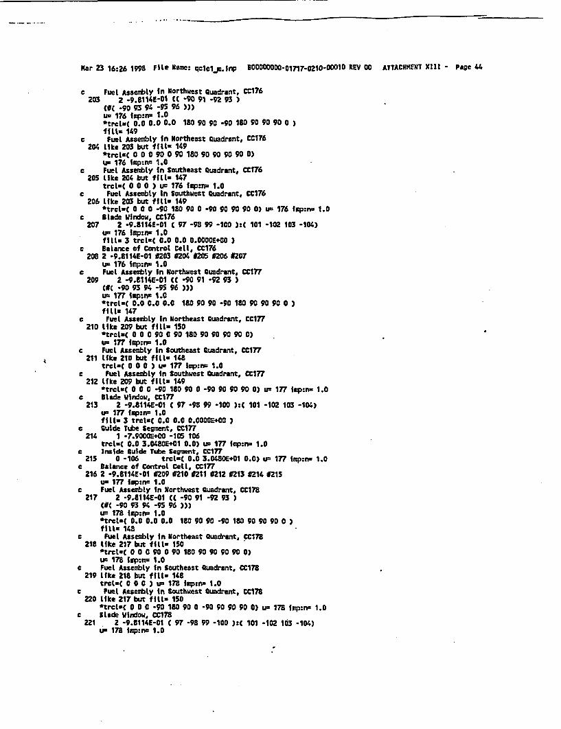
Mar 23 16:26 1998 File Name: qc1c1..l. 3 DB00000000.01717.0210-00010 REV 00 ATTACHMENT XIII - Page 44
c Fuel Assembly In Northwest Quadrant, CC176203 2 *9.8114E-01 CC -90 91 -92 93 )
(#( *90 93 94 -95 96 )))un 176 imp:n 1.0*trcl-C 0.0 0.0 0.0 180 90 90 -90 180 90 90 90 0 )fills 149
c Fuel Assembly in Northeast Quadrant, CC176204 like 203 but fills 149
*trcltC 0 0 0 90 0 90 180 90 90 90 90 0)ur 176 lkp:n= 1.0
c Fuel Assembly in Southeast Quadrant, CC176205 Like 2C4 but fill. 147
trcltC 0 0 0 ) U5 176 iq,:r, 1.0c Fuel Assembly In Southwest Quadrant, CC176
206 like 203 but filtz 149*trcL=C 0 0 0 -90 180 90 0 -90 90 90 90 0) un 176 tmp:nu 1.0
c Blade Window, CC176207 2 -9.8114E-01 C 97 -98 99 -100 ):t 101 -102 103 -104)
u-s 176 lmp:n- 1.0fill. 3 trclt( 0.0 0.0 0.OOOOE+00 )
c Balance of Control Cell, CC176208 2 -9.8114E-01 #3 #204 #205 #206 #207
u 176 isnp:n 1.0c Fuel Assembly In Northwest Quadrant, CC1?
209 2 -9.8114E-01 CC -90 91 -92 93 )C#C -90 93 94 -95 96 ))u 177 imp:mF 1.0*trcL=C 0.0 0.0 0.0 180 90 90 -90 10 90 90 90 0 )fill- 147
c Fuel Assembly in Northeast Quadrant, CC177210 like 209 but fill= 150
*trclt( 0 0 0 90 0 90 180 90 90 90 90 0)u- 177 imp:r= 1.0
c Fuel Assembly in Southeast Quadrant, CC177211 like 210 but fill= 148
trcltu 0 0 0 ) um 177 inp:n= 1.0c Fuel Assembly in Southwest Quadrant, Cc177
212 like 209 but fill 149*trcltC 0 0 0 -90 180 90 0 -90 90 90 90 0) u- 177 iqp:n- 1.0
c Blade Window, C177213 2 -9.8114E-01 C 97 -98 99 -100 ):C 101 -102 103 -104)
ua 177 iup:ns 1.0fill- 3 trcl.t 0.0 0.0 0.0000E+00 0
c guide Tube Segment, CC177214 1 -7.9000E+00 -105 106
trcltC 0.0 3.0480E+01 0.0) us 177 Icp:ns 1.0c Inside Guide Tube Segment, CC177215 0 -106 trcltC 0.0 3.0480E+01 0.0) ua 177 Ifp:n- 1.0
c Balance of Control Cell, CC177216 2 -9.8114E-01 N9 #210 #211 #212 #213 #214 #215
ua 177 Iap:n= 1.0c Fuel Assembly in Northwest Quadrant, CC178
217 2 -9.8114E-01 CC -90 91 -92 93 )C#( -90 93 94 -95 96 )))
u= 178 imp:nu 1.0*trol.( 0.0 0.0 0.0 180 90 90 -90 180 90 90 90 0 )fill- 148
c Fuel Assembly in Northeast Quadrant, CC178218 like 217 but fills 150
*trcluC 0 0 0 90 0 90 180 90 90 90 90 0)um 178 Ip:pn 1.0
e Fuel Assembly In Southeast Quadrant, CCI7B219 like 218 but fill. 148
trcl-t 0 0 0 ) us 178 fip:nu 1.0c Fuel Assembly in Southwest Quadrant, CC178
220 like 217 but fills 150*trct=C 0 0 0 -90 180 90 0 -90 90 90 90 0) u- 178 Imp:rr 1.0
c Iltde Window, CC178221 2 -9.8114E-01 C 97 -98 99 -100 ):t 101 -102 103 -104)
us 178 imp:nc 1.0

Mar 23 16:26 1998 File Namest qlcl.u-Inp BoOOOD-01717-0210o0001o REV 00 ATTACIDENT XIII Page 45
fMi1. 3 trclCt 0.0 0.0 O.0000E+00 )c Guide Tube Se ment, Ctl78
222 1 -7.9000E+00 -105 106trclt( -3.0480E+01 3.0480E+01 0.0) IF 178 IWM= 1.0
c Inside Guide Tube Segment, CC178223 0 -106 trclaC -3.0480E+01 3.0480E+01 0.0) lu 178 fqp:lw 1.0
c Balance of Cantrel Cell, Ct178224 2 -9.E114E-01 #217 #218 1219 O220 1221 1222 2
un 178 Imp:no 1.0c Fuel Assembly in Northwest Quadrant, CC179
225 2 -9.5114E-01 CC -90 91 -92 93 )(IC -90 93 94 -95 96 )))um 179 imp:nw 1.0*trcluC 0.0 0.0 0.0 180 90.90 -90 180 90 90 90 0 )MfilL 147
c Fuel Assembly in Northeast Quadrant, CC179226 like 225 but fMlix 149
*trclsC 0 0 0 90 0 90 180 90 90 90 90 0)un 179 fmp:n- 1.0
c Fuel Assembly in Southeast Quadrant, CC179227 Uike 226 but fitls 147
trcrC 0 0 0 o) ue 179 lrp n 1.0c Fuel Assembly in Southwest Quadrant, CC1?9
228 Like 225 but fillt 149*trcluC 0 0 0 -90 180 90 0 -90 90 90 90 0) uL 179 imp:nw 1.0
c Blade Ijndow, CC179229 2 -9.8114E-01 ( 97 -98 99 -100 ): 101 *102 103 *104)
u' 179 lqp:n= 1.0fill 3 trclu( 0.0 0.0 0.OOOE+00 )
c Guide Tube Segment, CC179230 1 -7.9000E+00 -105 106
trclt( -3.04UE+01 3.0480E+01 0.0) IF 179 ip:no 1.0c Inside Guide Tube Segment, CC179
231 0 -106 trcl-( -3.0480E+01 3.0480E.01 0.0) u- 179 imp:nr 1.0c Balance ef Control Cell, CC179
232 2 -9.8114E-01 #225 t226 #227 #228 #229 0230 #231u- 179 imp:n. 1.0
c Fuel Assembly in Northwest Quadrant, CC180233 2 -9.8114E-01 CC -90 91 -92 93 )
(NC -90 93 94 -95 96 ))uI 180 Imp:n= 1.0*trclaC 0.0 0.0 0.0 180 90 90 -90 180 90 90 90 0 )fills 147
c Fuel Assembly in Northeast Quadrant, CCtEO234 Like 233 but filLs 149
*trcl&C 0 0 0 90 0 90 180 90 90 90 90 0)UF 1J0 impr:n 1.0
c Fuel Assembly in Southeast Quadrant, CC180235 LIke 234 but fills 147
trcluC 0 0 0 ) un 180 imp:rn 1.0c Fuel Assembly In Southwest Quadrant, CC180236 like 233 but fill- 149
*trclt( 0 0 0 -90 180 90 0 -90 90 90 90 0) uz 150 iap:nz 1.0e Blade Window, CCISO237 2 -9.8114E-01 ( 97 -98 99 -100 ):C 101 -102 103 -104)
uF 180 ISp:n- 1.0fill- 3 ticL-C 0.0 0.0 0.0000E00 )
c Guide Tube Segment, CCI8O238 1 *7.9000E+00 -105 106 u- 1¶0 imp:n= 1.0
c Inside Guide Tube Segment, CC180239 0 -106 u- 180 imp:nu 1.0
c Guide Tube Segment (2), CC180240 1 -7.9000E100 -105 106
trcltuC 0.0 3.0480E+01 0.0) u- 180 ixp:n- 1.0e Inside Guide Tube Segment (2), CC180
241 0 -106 trct-C 0.0 3.0480E+01 0.0) uL 180 ip :n- 1.0• Balance of Control Cell, OC160
242 2 -9.8114E-01 t233#234 4235 4236 #237 #238 t239 t240 4241uV 180 imp:ns 1.0
c Fuel Assembly in Northwest Quadrant, CCI8I

Mar 23 16:26 1998 Flle Uame: qclcIs .r1np BX00000000.01717-0210-00010 REV 00 ATTACHKENT XIJ- Page 46
243 2 -9.8114UE-i tC -90 91 -92 93 )(g( -90 93 94 -95 96 )fluc- 18t imw:rp 1.0*trcltC 0.0 0.0 0.0 180 90 90 -90 180 90 90 90 0 )fiLl- 147
e Fuel Assembly In Northeast Quadrant, CCi81244 like 243 but fills 149
ftrcltC 0 0 0 90 0 90 180 90 90 90 90 0)u= 181 ip:nw 1.0
c Fuel Assembly in Southeast Quadrant, CC1t1245 like 244 but fills 147
trcls( 0 0 0 ) u= 181 Imp:rn 1.0c Fuel Assembly in Southwest Quadrant, CCI81
246 like 243 but fills 149-- trcl-t 0 0 0 -90 180 90 0 -90 90 90 90 0) UR 181 imp:nr 1.0
c Blade Window, CC161247 2 -9.8114E-01 C 97 -98 99 -100 ):C 101 -102 103 -104)
uL= 181 imp:nr 1.0fill. 3 trclt( 0.0 0.0 0.0000WE+00
c Guide Tube Segment, CCI81248 1 -7.9000E+00 -105 106
trclC -3.D480E+01 0.0 0.0) us 181 fmp:nr- 1.0c inside Guide Tube Segment, CCISI
249 0 -106 trclt-( -3.0480E+01 0.0 0.0) us 181 imp:r- 1.0c Guide Tube Segment C2), CC181
250 1 -7.9000E+00 *105 106trcl-t -3.0480E+01 3.0480E+01 0.0) u= 181 l p:rn 1.0
c Inside Guide Tube Seament (2), CC181251 0 -106 troct-( -3.0480E+01 3.0480+01 0.0) u- 181 iap:nn 1.0
a Balance of Control Celt, CC18I252 2 -9.8114E-01 #243 #244 #245 4246 #247 1248 #249 #250 #251
u- 181 frp:n= 1.0c Fuel Assembly in Northwest Quadrant, CCI8Z
253 2 -9.8114E-01 tC -90 91 -92 93 3(NC -90 93 94 -95 96)))u= 182 fmp:n- 1.0*trclt( 0.0 0.0 0.0 180 90 90 -90 180 90 90 90 0 3f1S11 147
c Fuel Assembly in Northeast Quadrant. CC182254 Like 253 but fill. 0
*trcl-t 0 0 0 90 0 90 180 90 90 90 90 0)us 182 imp:n- 1.0
c Fuel Assembly In Southeast Quadrant, CC182255 like 254 but fill. 0
trcl*t 0 0 0 ) iF 182 lup:n. 1.0c Fuel Assembly In Southwest Quadrant, CC182
256 like 253 but fills 149trcl*t 0 0 0 -90 180 90 0 -90 90 90 90 0) uw 182 ixp:n- 1.0
c Elude Window, CC182257 2 -9.8114E-01 t 97 -98 99 -100 ):C 101 -102 103 -104)
uL 182 Imp:na 1.0fills 3 trclCt 0.0 0.0 0.00004E00 )
c Balance of Control Cell, CC182258 2 -9.8114E-01 #253 #254 #255 #256 #257
un 182 Imp:n- 1.0c Fuel Assenbly In Northwest Quadrant, CC183
259 2 -9.8114£-01 Ct -90 91 -92 93 )C#( -90 93 94 -95 96 ))uw 183 Imp:n. 1.0*trcls( 0.0 0.0 0.0 180 90 90 -90 180 90 90 90 0 )fills 147
c Fuel Assembly In Northeast Quadrant, CC183260 like 259 but fill. 150
*trolt( 0 0 0 90 0 90 180 90 90 90 90 0)u= 183 np:n= 1.0
c Fuel Assembly in Southeast Quadrant, CC183261 like 260 but fills 148
trct.C 0 0 0 ) un 183 lapzn- 1.0c Fuel Assembly in Southwest Quadrant, CC183
262 like 259 but fill 149

Mar 23 16:26 1998 Ft I. Name: qclcl rm.inp BCOOMOOOO01717-0210-0001O REV 00 ATTACHMENT XIfi - Page 47
*trcl-C 0 0 O -90 180 90 0 -90 90 90 90 0) U= 183 lmp:nr 1.0c Blade Window, CC183
263 2 -9.8114E-01 ( 97 -98 99 -100 ):C 101 -102 103 -104)us 183 iq:nz 1.0fill 3 trcLtC 0.0 0.0 -3.6s76m+02 )
c Guide Tube Segment, CC183264 1 -7.9000E+00 -105 106 ip 183 ipp:Iw 1.0
c Inside Guide Tube Segment, CC183265 0 -106 u= 183 fmp:nn 1.0
e Balance of Control Cetl, CM183266 2 -9.8114E-01 9259 9260 9261 #262 #N 9264 C265
tF 183 isp:nz 1.0e Fuel Assebly in Northwest Quadrant, CC184-
267 2 -9.8114E-01 CC -90 91 -92 93 )(#( -90 93 94 -95 96 )Ou= 184 fop:n= 1.0*trclCt 0.0 0.0 0.0 180 90 90 -90 180 90 90 90 0)fills 148
c Fuel Assembly In Northeast Quadrant, CC184265 Like 267 but ff1i- 149
trctuC 0 0 0 90 0 90 180 90 90 90 90 0)u- 184 inp:n 1.0
c Fuel Assembly in Southeast Quadrant, CC184269 like 268 but fill 147
trcl-tC 0 0 0 ) um 184 Iep:rn 1.0c Fuel Assembly In Southwest Quadrant, CC184
270 like 267 but fft11 150*trcltC 0 0 0 -90 180 90 0 -90 90 90 90 0) u- 184 Irp:n- 1.0
c Blade Window, CC184271 2 -9.9114E-01 ( 97 -98 99 -100 ):C 101 -102 103 -104)
ut 184 tap:ns 1.0fILf- 3 trcl=C 0.0 0.0 -3.6576E+02 )
e Guide Tube Segment, CC184272 1 -7.9000E+00 -105 106 uL 184 fmo:pn 1.0
c Inside guide Tube Segment, CCI84273 0 -106 u 184 lap:n 1.0
c Balance of Contral Cell, CCI84274 2 -9.8114E-01 9267 4268 4269 #270 9271 #272 #273
un 184 iop:ri= 1.0c Fuel Assembly in Northwest Quadrant, CC185
275 2 -9.8114E-01 CC -90 91 -92 93 )#C -90 93 94 -95 96 )f
u- 185 imp:nw 1.0*trclut 0.0 0.0 0.0 180 90 90 -90 180 90 90 90 0 )ffl- 147
c Fuel Assembly in Northeast Quadrant, CC185276 like Z75 but fill. 149
*trct=C 0 0 0 90 0 90 180 90 90 90 90 0)u- 185 Imp:n 1.0
c Fuel Assembly in Southeast Quadrant, CC185277 like 276 but fill- 147
trcltuC 0 0 0 ) u 185 imp:nu 1.0c Fuel Assembly In Southwest Quadrant, CCI8S
278 like 275 but fill. 149*trcl-( 0 0 0 -90 180 90 0 -90 90 90 90 0) u- 185 ixp:rn 1.0
e Blade Window, CC1E5279 2 -9.8114E-01 C 97 -98 99 -100 ):C 101 -102 103 -104)
u. 185 Illp:nw 1.0fillf 3 trcltC 0.0 0.0 -3.6576E+02 )
c Guide Tube Segment, CC185280 1 -7.9000E+00 -105 106 Ua 185 imp:nr 1.0
c Inside Guide Tube Segment, CCI8S281 0 -106 u= 185 fm:pn 1.0
c Guide Tube Segment (2), CCI8S282 1 -7.9000E+00 -105 106
trcltC 0.0 3.04802.01 0.0) um 185 inp:n- 1.0c Inside Guide Tube Segment (2), CC185
283 0 -106 trcltC 0.0 3.04800E+1 0.0) u- 185 fmp:n- 1.0c Balance of Control Cell, CC185
284 2 -9.8114E-01 9275 9276 #277E 278 #279 928O #Z1 282 #283

lMar 23 16:26 1998 File Name: qc1cl .inp 90000000o-71¶7.o22o1o0O10 REV 00 ATTACHMIENT XIII - Page 48
u- 185 frp:n' 1.0C Fuel Assembly In Northwest Quadrant, CC186
285 2 -9.8114E-01 (C -90 91 -92 93 )(tC -90 93 94 -95 96 )))us 186 Jimp:n= 1.0*trcl-t 0.0 0.0 0.0 180 90 90 -90 180 90 90 90 0 )ffIlt 149
c Fuel Assembly In Northeast Quadrant, CCI16286 like 285 but fill. 149
*trcl-C 0 0 0 90 0 90 180 90 90 90 90 0)us 186 fip:n- 1.0
c Fuel Assembly In Southeast Quadrant, CC186287 like 286 but fill. 0
trcltC 0 0 0 ) us 186 imp:n= 1.0c Fuel Assembly in Southwest Quadrant, CC186
288 like 285 but fil.t 0*trcLaC 0 0 0 -90 180 90 0 -90 90 90 90 0) u= 186 frp:n 1.0
c Blade Window, CC186289 2 -9.8114E-01 t 97 -98 99 -100 ):C 101 -102 103 -104)
un186 inp:rp 1.0fill- 3 trcltu 0.0 0.0 O.COOE00 )
c Balance of Control Cell, CC186290 2 -9.8114E-01 #285 #286 #287 #288 #289
us 186 ip:n= 1.0c Fuel Assembly in Northwest Quadrant, CC187
291 2 -9.t114E-01 CC -90 91 -92 93 )(IC -90 93 94 -95 96 )))u- 187 Irp:nc 1.0*trctlC 0.0 0.0 0.0 180 90 90 -90 180 90 90 90 0)fil. 147
c Fuel Assembly In Northeast Quadrant, CC187292 like 291 but fill. 150
ttrcl-C 0 0 0 90 0 90 180 90 90 90 90 0)u- 187 fmp:nc 1.0
c Fuel Assembly In Southeast Quadrant, CC187293 lke 292 but fills 0
trcl-tC 0 0 0 ) uL 187 sp:nx 1.0c Fuel Assembly in Southwest Quadrant, CC187
294 like 291 but filf 0*tmcltC 0 0 0 -90 180 90 0 -90 90 90 90 0) uc 187 Imp:nn 1.0
c Slade Window, CC187295 2 -9.8114E-01 C 97 -98 99 -100 ):C 101 -102 103 -104)
us 187 imp:nc 1.0fill. 3 trcLmC 0.0 0.0 0.0000E400 )
c Guide Tube Segment, CC187296 1 -7.9000E+00 -105 106
trcl-C 0.0 3.0400E+01 0.0) us 187 iap:ns 1.0c Inside Guide Tube Segment, CC187
297 0 -106 trcLt. 0.0 3.0480E+01 0.0) um 187 iap:nu 1.0c Balance of Control Cell, CC187
298 2 -9.8114E-01 ¢291 #292 N293 #294 #295 1296 N297uR 187 iqp:nU 1.0
c Fuel Assembly in Northwest Quadrant, CCl88299 2 -9.8114E-01 CC -90 91 -92 93 )
(IC -90 93 94 -95 96 )))us 188 Imp:nc 1.0*trcl-C 0.0 0.0 0.0 180 90 90 90 180 90 90 90 0 )fill. 148
c Fuel Assembly in Northeast Quadrant, CCI1U300 like 299 but fill. 150
*trclz( 0 0 0 90 0 90 180 90 90 90 90 0)us 188 irp:rp 1.0
c Fuel Assembly in Southeast Quadrant, CCi88301 like 300 but fills 0
trcl-( 0 0 0 ) ux 188 ifp :n 1.0c Fuel Assembly in Southwest Quadrant, CC188302 like 299 but fills 0
trmcl-C 0 0 0 -90 180 90 0 -90 90 90 90 0) us 188 irp:nz 1.0c Btlde Window, CC188303 2 -9.8114E-01 C 97 -98 99 -100 ):C 101 -102 103 -104)

Mar 23 16:26 1998 Filt Naae: qctc1.Uifnlp B00000000_01717-0210-00010 REV 00 ATTACHMENT XIII - Page 49
un 188 irp:nW 1.0fill. 3 trcl(t 0.0 0.0 0.0O+O0 )
c Guide Tube Segment, CC188304 1 -7.9000E+00 -105 106
trclMC -3.0480E+01 3.0480Egci 0.0) uc 188 tp:qn 1.0e Inside Guide Tube Segment, cc188
305 0 -106 trcltC -3.04tOE+01 3.0480E+010.0) u- 188 Imp:nn 1.0C Balance of Control CelL, ccla8
306 2 -9.8114E-01 #299 #300 #301 #302 #303 n304 J305u' 188 lmp:V- 1.0
c Fuel Assembly in Northwest Quadrant, CC189307 2 -9.8114E-01 CC -90 91 -92 93 )
(IC -90 93 94 -95 96 )))u' 189 imp:na 1.0*trcluC 0.0 0.0 0.0 18UO90 90 -90 180 90 90 900)fill- 148
c Fuel Assembly In Northeast Quadrant, CC1S9308 like 307 but fills 149
*trclxC 0 0 0 90 0 90 180 90 90 90 90 0)u= 189 lap:n. 1.0
c Fuel Asserbly In Southeast Quadrant, CCl89309 like 308 but fill. 0
trcltC 0 0 0 ) um 189 imp:nu 1.0c Fuel Assembly In Southwest Quadrant, CC189310 like 307 but fIll. 0
*trcl-C 0 0 0 -90 180 90 0 -90 90 90 90 0) u- 189 fiprn 1.0c Blade Irindow, CC189
311 2 -9.8114E-01 C 97 -98 99 -100 ):C 101 -102 103 -104)un 189 imp:na 1.0fill. 3 trcl*t 0.0 0.0 0.OOOOE+00 )
c Guide Tube Segment, CC189312 1 -7.9000E+00 -105 106
trclt( 0.0 3.0480E+01 0.0) u- 189 inp:na 1.0c Inside Guide Tube Segment, CC189313 0 -106 trclt( 0.0 3.04802401 0.0) ux 189 imp:nz 1.0
c Balance of Control Cell, CC189314 2 -9.8114E-01 J307 d308 M309 #310 #311 #312 #313
us 189 fmp:nm 1.0c Fuel Assembly In Northwest Quadrant, CC190315 2 -9.8114E-01 CC -90 91 -92 93 )
dCO -90 93 94 -95 96 )))u- 190 1ip:n- 1.0*trcltC 0.0 0.0 0.0 180 90 90 -90 180 90 90 90 0 )fill. 147
c Fuel Assembly in Northeast Quadrant, CC190316 like 315 but fill. 149
*trctl( 0 0 0 90 0 90 180 90 90 90 90 0)u' 190 fsp:n. 1.0
c Fuel Assembly in Southeast Quadrant, CC190317 like 316 but fIllx 0
trcl-t 0 0 0 ) u- 190 imp:n= 1.0c Fuel Assembly in Southwest Quadrant, CC190318 like 315 but fills 0
*trcl.t 0 0 0 -90 180 90 0 -90 90 90 90 0) u- 190 Icp:ra= 1.0c Blade Window, CC190319 2 -9.8114E-01 C 97 -98 99 -100 ):C 101 -102 103 -104)
u- 190 fmp:n- 1.0ftitw 3 trctsC 0.0 0.0 0.0000E+00 )
c Guide Tube Segment, CC190320 1 -7.9000E+00 -105 106
trct-C -3.0480E+01 3.0480E+01 0.0) Lp 190 Imp:nr 1.0c Inside Guide Tube Segment, CC190
321 0 -106 trcl-( -3.0480E201 3.04SOE+01 0.0) UF 190 imp:n= 1.0c Balance of Control Cell, CC190
322 2 -9.8114E-01 1315 #316 #317 #318 #319 #320 #321u= 190 imp:iw 1.0
c Fuel Assembly in Northwest Quadrant, CC191323 2 -9.8114E-01 CC -90 91 -92 93 )
(IC -90 93 94 -9 9K )))u- 191 fmp:n- 1.0

Mar 23 16:26 1998 File Name: qcIbI-l.fnp *oOOOOoto-01717-0210-ooolo agV 00 ATTACKMENT X1II - Page 50
*trcltC 0.0 0-0 0.0 180 90 90 -90 180 90 90 90 0 )f f11z 147
C Fuel Assembly in Northeast Quadrant, CcI91324 like 323 but ff11- 149
*trclCt 0 0 0 90 0 90 180 90 90 90 90 0)us- 191 imp:Iw 1.0
C Fuel Assembly in Southeast Quadrant, CC191325 like 324 but fillf 0
trcltc 0 0 0 ) u- 191 Iap:n- 1.0c Fuel Assembly In Southwest Quadrant, CC191326 like 323 bu fitll- 0
*trcltC 0 0 0 -90 180 90 0 -90 90 90 90 0) L- 191 fmp:IW 1.0c BLade Window, CC191
327 2 -9.8114E-Q1 C 97 -98 99 -100 ):t 101 -102 103 -104)us 191 ixp:n. 1.0fill. 3 trcltC 0.0 0.0 0.00002.00 )
c Guide Tube Segment, CC191328 1 -7.9000E200 -105 106
trcltu( 0.0 3.0480E201 0.0) us 191 iup:na 1.0c inside Guide Tube Segment, CC191
329 0 -106 trcl=( 0.0 3.0480E.01 0.0) L- 191 Imp:nz 1.0c Balance of Control Cell, CC191
330 2 -9.8114E-01 B323 #324 #325 9326 ¢327 32 9329uL 191 isp:nx 1.0
e Fuel Assembly In Northwest Quadrant, CC192331 2 -9.8114E-01 (C -90 91 -92 93 )
C( -90 93 94 -95 96 )))um 192 10p:ri3 1.0*trclt( 0.0 0.0 0.0 180 90 90 -90 180 90 90 90 0 )ffil1 147
c Fuel Assembly in Northeast Quadrant, CC192332 Like 331 but fill- 0
*trcltc 0 0 0 90 0 90 180 90 90 90 90 0)un 192 inp:n- 1.0
c Fuel Assembly In Southeast Quadrant, CC192333 like 332 but fill- 0
trcltu 0 0 0 ) un 192 Iup:n. 1.0c Fuel Assembly In Southwest Quadrant, CC192334 tike 331 but ff.Lz 0
trcLtu 0 0 0 -90 180 90 0 -90 90 90 90 0) u- 192 Imp:ns 1.0c Blade Window, CC192
335 2 -9.8114E-01 C 97 -98 99 -100 ):C 101 -102 103 -104)u= 192 fmp:rn: 1.0fill. 3 trcl-t 0.0 0.0 0.00002.00 )
c Balance of Control Cell, .CC192336 2 -9.8114E-019331 C332 #333 0334 9335
un 192 fmp:ns 1.0c Active Core2620 2 -9.8114E-01 -8 4 -5 -9 12
ftfl.235i.p:nz 1.0
c Core Lattice2621 2 -9.8114E-01 -107 108 109 -110
latol u235 iqp:nw 1.0fills -8:0 -8sO 0:0235 235 235 235 235 235 235 235 235235 235 235 235 235 151 152 153 154235 235 235 151 155 153 156 157 158235 235 159 153 160 161 162 163 164235 235 165 166 167 161 168 169 170235 151 152 163 171 172 173 174 175235 176 177 178 168 179 180 181 182235 176 183 163 184 174 185 181 175235 186 187 188 189 190 191 190 192
c Surface CardsCc Surfaces for Problem Domainc Top of Problem
I pz 4.3300E.02

Mar 23 16:26 1998 Filt Name: qcicl.P-1.P B00000000-01717-0210-00010 WV 00 ATTACHMENT XIII - Page 51
c Bottom of Problem2 ps -4.8570E+01
C Maximum Radial Extent of Problem3 cz 3.3433E+02
C X-Z Plane*4 py 0.0
c Y-Z Plane*5 px 0.0
c Inner Radial Surface of Vessel6cz 3.1877Et02
c Outer Radial Surface of Core Shroud7 cz 2.6305E+02
c Inner Radial Surface of Core Shroud8 ez 2.5797E+02
c Top of Active Fuel9 pz 3. 6576E.02
c Top of Upper Tie Plate Region10 pz 3.9900E202
e Top of Core Grid Region11 pz 4.0300E+02
c Bottom of Active Fuel12 pz 0.0
c Bottom of Lower Tie Plate Region13 pz -1.3490E+01
c Bottom of Fuet Support/Core Plate Region14 pz -1.8570E+01
c Outer Radius of Absorber15 ecz 2.2292E+00 0.0000E+00 1.7550E-01
c Outer Radius of Absorber Tube16 cOx 2.2292E+00 0.0000E+00 2.3900E-01
c XMAX for Reference Absorber Tube Cell17 px 2.4733E+00
c XMIN for Reference Absorber Tube Cell18 px 1.9850E+00
c YHAX for Reference Absorber Tube Cell19 py 2.5400E-01
c THIN for Reference Absorber Tube Cell20 py -2.5400E-01
c Tie Rod Surface #621 py 3.2400E-01
c Tie Rod Surface #722 py -3.2400E-01
c Tie Rod Surface #423 px -1.9850E+00
c Top of Absorber Column24 pz 3.6512E+02
c Bottom of Absorber Column25 pz 1.9250E+00
c Tie Rod Surface t326 px -3.2400E-01
e Tie Rod Surface ¢227 px 3.2400E-01
c Tie Rod Surface #528 py -1.9850E+00
c Tie Rod Surface #829 py 1.9850E+00
c Ambiguity Surface for Sheath Corner30 px 1.1996E+01
c Inner Surface for Sheath Corner31 cOx 1.1996E+01 0.0000E+00 2.5400E-01
c Outer Surface for Sheath Corner32 c/z 1.1996E+01 0.0000E+00 3.240OE-01
c XMIN for Sheath Interior33 px 1.9860
c TKIN for Sheath Interior34 py -0.2530
c YMAX for Sheath Interior35 py 0.2530
C XMIN for Blade WIndow36 px 1.9950E+00

-
Mar 23 16:26 1998 File Name: qc1cln.Inp B00000000001717.o21o0-oOi0 RIV 00 ATTACHMENT XIII - Page 52
c XMAX for 8lade Window37 px i.2390E+01
e YmIN for Blade Vindow38 py -6.5800E-01
c YMAX for Blade Window39 py 6.5800E-01
c Fuel Pellet Outer Surface, 01, LI40 c/z 2.2325E+00 -2.2325E+00 6.2000E-01
c Fuel Cladding Inner Surface, #1, LI41 c/z 2.2325E+00 -2.2325E+00 6.3400E-01
c fuel Cladding Outer Surface, #1, LI42 c/z 2.2325E+0O -2.2325E+00 7.15CSE-01
c XMAX Surface for Fuel Rod Window, LI43 px 3.1700E+00
c XMIN Surface for Fuel Rod Window, LI44 px 1.2950E+00
c YMIM Surface for Fuel Rod Window, LI45 py -3.1700E.00
c YTAX Surface for Fuel Rod Window, LI46 py -1.2950E+00
c Wide Gap, Charnel Outside Wall, pX Surface, Li47 px 9.5300E-01
c Wide Cap, Channel Inside Wall, pX Surface, Li48 px 1.1530E+00
c Ambiguity Surface for ChanneL Corners (Wide Cap), pY, Li49 py -2.1730E600
c Ambiguity Surface for Channel Corners (Narrow Cap), pY, Li50 py -1.3539E+01
e Wide Gap, Channel Outside Wall, pY Surface, LiS1 py -9.5300E-01
c Wide Gap, Charnel Inside Watl, pY Surface, LI52 py -1.1530E+00
e Azbiguity Surface for Charnel Corners (Wide Gap), pX, Li53 px 2.1730E+00
e Ambiguity Surface for Channel Corners (Narrow Gap), pX, Li54 px 1.3539E+01
c Narrow Gap, Channel Inside Wall, pY Surface, Li55 py -1.4559E+01
e Narrow cap, Channel Outside Wall, pY Surface, Li56 py -1.4759E+01
e Narrow Gap, Channel Inside Wall, px Surface, LiI 57 px 1.4559E+01e Narrow Gap, Charnel Outside Wall, pX Surface, Li
58 px 1.4759E+01e Channel Corner Outer Radius (VW), LI
59 U/z 2.1730E+O0 -2.17306E00 1.2200E+00e Channel Corner Inner Radius (NW), Li
60 c/z 2.1730E+00 -2.17306E00 1 .0200E+00e Channel Corner Outer Radius (NE), Li
61 cez 1.3539E+01 -2.1Z30E+00 1.2200E+00e Channel Corner Inner Radius (NE), Li
62 C/x 1.3539E+01 -2.17306E.00 1.0200E+00e Channel Corner Outer Radius (SE), LI
63 c/z 1 .3539E+01 -1.3539E+01 1.2200E+00c Channel Corner Inner Radius (SE), LI
64 c/z 1.3539E+01 -1.3539E+01 1.020OE+OOc Channel Corner Outer Radius (SW), Li
65 c/z 2.1730E.00 -1.3539E+01 1.2200E+0Oc Chanrel Corner Inner Radius (SW), Li
66 c/z 2.1730+00 -1.3539E+01 1.0200E+00c Top of Mode t
67 pz 1.5240E+01o Top of Node 2
68 pz 3.0406E+01c Top of Node 3
69 pz 4.5720E+01c Top of Node 4
70 pz 6.O960E+01e Top of Mode S
7t pz 7.6200E.01

Mar 23 16:26 1998 File Name: qclcl -. Inp *00000000-01*17.0210-00010 REV 00 ATTACHMENT XIII - Page 53
C Top of Node 672 pz 9.1440E+01
C Top of Node 773 p2 1.O668E+02
C Top of Node 874 pz 1.2192E+02
C Top of Node 975 pz 1.3716E+02
C Top of Node 1076 pz 1.5240E+02
C Top of Node 1177 pz 1.6764E+02
c Top of Node 1278 pz 1.8288E+02
C Top of Node 1379 pz 1.9812E+02
c Top of Node 1480 pz 2.1336E+02
c Top of Node 1581 pz 2.2860E+02
C Top of Node 1682 pz 2.4384E+02
c Top of Node 1783 pz 2.5908E+02
c Top ofI Node 1884 pz 2.74U2E+02
c Top of Node 1985 pz 2.8956E+02
c Top of Node 2086 pz 3.04802E02
c Top of lode 2187 pz 3.2004E+02
c Top of lode 2288 pz 3.3528E+02
c Top of lode 2389 pz 3.5052E+02
c Window for Fuel Asseubly Cmax X), CC15190 px 1.5140E+01
c Wilndow for Fuel Assembly (Cin X), CC15191 pX 5.0000E-01
c Window for Fuel Assefbly Cmax Y), CC15192 py -5.OOOOE-01
c Window for Fuel Assembly (min Y), CC15193 py -1.5140E+01
c Curved Corner In Window for Fuel Assewbly, CC15194 e/z 1.3091E+01 *1.3091E+01 2.04U6E+00
c Y Awbicufty Surface for Fuel Assembly Window, CClSl95 py -1.3091E+01
c X Ambiguity Surface for Fuel Assembly Window, CC15196 px 1.3091E+01
-c Surface I for Control Blade Window97 py -4.00O0E-01
c Surface 2 for Control Blade Window98 py 4.0000E-01
c Surface 3 for Control Blade Window99 px -1.2480E+01
c Surface 4 for Control Blade Window100 px 1.2480E+01
c Surface 5 for Control Blade Window101 px -4.0000E-01
c Surface 6 for Control Blade Window102 px 4.0000E-O1
c Surface 7 for Control Blade Window103 py -1.2480+01
c Surface t for Control Blade Window104 py 1.2480E+01
e Outer Surface of Guide Tube105 clz 1.5240E+01 -1.5240E+01 8.9000E-01
c Inner Surface of Guide Tube106 cJz 1.5240E+01 -1.5240E+01 8.1500E-01
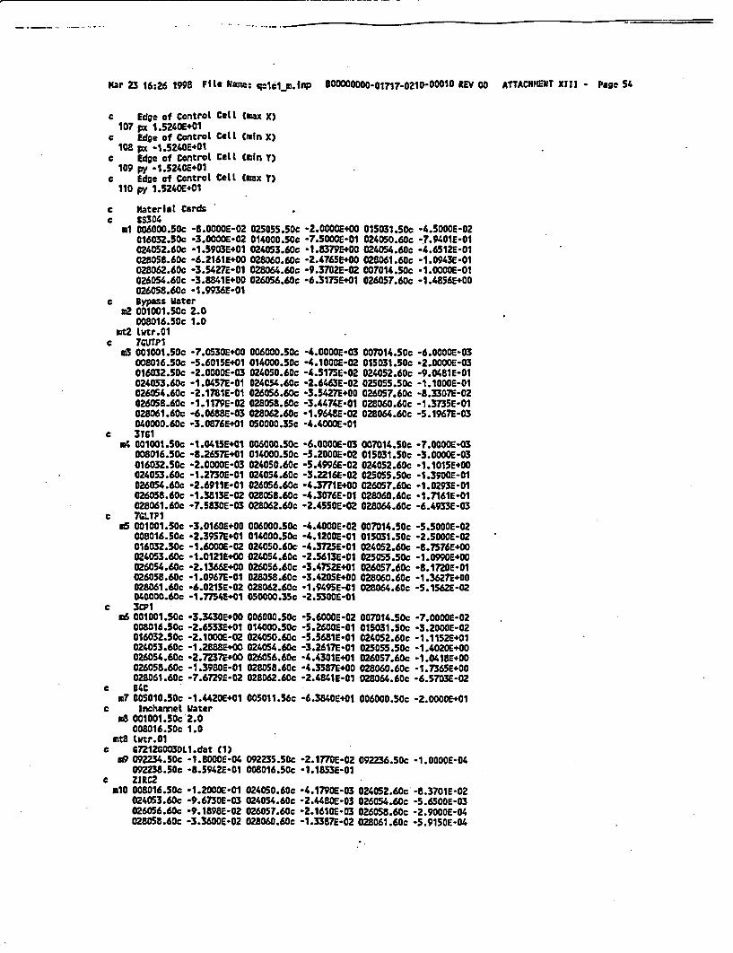
Mar 23 16:26 1998 FMe Rlame: qclcl m.fnp B00000000.717.0210-OOO10 REV 00 ATTACHMENT XIII - Page 54
c Edge of Control Cell (max X)107 px 1.5240E+01
c Edge of Control Cell (mln X)108 px -i.5240E+01
C Edge of Control Celt tmfn Y)109 py -1.5240E+01
C Edge of Control Cell (max y)110 py 1.5240E+01
c Material Cardsc 38304
m1 006000.50c -8.OOOOE-02 025055.50c -2.0000E+00 015031.50c -4.5000E-02016032.50c -3.0000E-02 014000.50c -7.5000E-01 024050.60c -7.9401E-01024052.60c -1.5903E+01 024053.60c -1.8379E+00 024054.60c -4.6512E-01028058.60c -6.2161E+00 028060.6oc -2.4765E+00 028061.60c -1.0943E-01028062.60c -3.5427E-01 028064.60C -9.3722E-02 007014.50c -1.0000E-01026054.60c -3.8341E+00 026056.60c -6.3175E+01 026057.6oc -l.4856E+O0026058.60c -1.9 36E-01
c Bypass Water.2 001001.50c 2.0
008016.50c 1.0Wt2 ltr.01
c ?&UTPI.3 001001.50c -7.0530E+00 006000.SOc -4.0000E-03 007014.50c -6.0000E-03
008016.50c -5.6015E+01 014000.50c -4.1000E-02 015031.50c -2.0000E-03016032.50c -2.0000E-03 024050.60c -4.517sE-02 024052.60c -9.0481E-01024053.60c -1.04572-01 024054.60c -2.6463E-02 025055.50c -1.1000E-01026054.60c -2.1781E-01 026056.60c -3.54271+00 026057.6Cc -8.3307E-02026058.60c -1.1179E-02 028058.60c -3.4474E-01 028060.6Cc -1.3735E-01028061.60c -6.0688E-03 028062.60c -1.964UE-02 028064.6oc -5.1967E-03040000.60c -3.0876E+01 050000.35c -4.400OE-01
c 3TG104 01001.5Cc -1.0415E+01 006000.50c -6.0000E-03 007014.50c -7.0000E-03
008016.50c -8.2657E+01 014000.50c -5.2000E-02 015031.50c -3.0000E-03016032.50c -2.0000E-03 024050.60c -5.4996E-02 024052.60c -1.1015E+00024053.60c -1.2730E-01 024054.60c -3.2216E-02 025055s5Cc -1.3900E-01026054.60c -2.6911E-01 026056.60c -4.3771E+00 026057.60c -1.0293E-01026058.60c -1.3813E-02 028058.60c -4.3076E-01 028060.60c -1.7161E-01028061.60c -7.5330E-03 028062.60c -2.4552E-02 028064.60c -6.4933E-03
c 7GLTPI.5 001001.50c -3.0160E+00 006000.50c -4.4000E-02 007014.50c -5.5000E-02
008016.50c -2.3957E+01 014000.50c -4.1200E-01 015031.50c -2.5000E-02016032.50c -1.60002-02 024050.60c -4.372SE-01 024052.60c -8.7576E+00024053.60c -1.0121E+OO 024054.60c -2.5613E-01 0250ss.50c -1.09E+00026054.60c -2.1366E+00 026056.60c -3.4752E+01 026057.60c -8.1720E-01026058.60c -1.0967E2-l 02805.60c -3.4205E+00 028060.60c -1.3627E+00028061.60c -6.021SE-02 028062.60c -1.949SE-01 028064.60c -5.1562E-02040000.60c -1.77524+01 050000.35c -2.530OE-01
c 3CP1m6 001001.50c -334302+00 006000.50c -5.60OOE0-2 007014.50c -7.OO0OE-02
008016.50c -2.6533E+01 014000.50c -5.2600E-01 015031.50c -3.200WE-02016032.SOc -2.1000E-02 024050.60c -5.56S1E-O1 024052.60c -1.1152E+01024053.60c -1.28802+00 024054.60c -3.2617E-01 025055.50c -1.4020E+00026054.60c -2.7237+00 026056.60c -4.4301E+01 026057.60c -1.0418E+00026058.60c -1.39aOE-01 028058.60c -4.3587+00 028060.60c -1.7365E+00028061.60c -7.6729E-02 028 6.60c -2.4841E-C1 028064.60c -6.5703E-02
c B4Cr7 005010.50c -1.4420E+01 005011.56c -6.3840E+01 006000.50c -2.0000E+01
c Incharmel Waterm8 001001.50c 2.0
0O8016.5Cc 1.0rt8 tutr.01
c 7Z12GCO03DLI.dat t1)gO 092234.50c -1.BWCOE-04 092235.50c -2.1770E-02 092236.50c -l.OOOOE-04
092238.50c -8.5942E-01 008016.50c -1.1853E-01c ZlIC2
mlO 008016.50c -1.2000E-01 024050.6Cc -4.1790E-03 024052.60c -8.3701E-02024053.60c -9.6730E-03 024054.60c -2.448OE-03 026054.60c -5.6500E-03026056.60c -9.198sE-02 026057.60c -2.1610E-03 026058.60c -2.9000E-04028058.60c -3.36D0E-02 028060.60c -1.3387E-02 028061.60c -5.91soE-04

Mar 23 16:26 1998 File Name: qccilp.frip B0000000-0171?7-021o-o001 REV 00 ATTACHNENT XIII - Page 55
028062.60c -1.9150E-03 028064 .60c -5.0650E-04 050000.35c -1.4000E+00040000.60c -9.8230E+O1
c G7212G003DLl.dat (2)nil 092234.50c -1.8000E-04 092235.50c -2.1770E-02 092236.50c -1.0000E-04
092238.50c -8.5942E-01 008016.50c -1.1853E-01C 072l2G003DL1.dat (3)
m12 092234.50c -1.8OOE-04 092235.50c -2.1770E-02 092236.50c -1.0000E-04092238.50c -8.5942E-01 008 016.50c -1.1853E-01
c Gn 12G003DL1.dat (4)m13 092234.50c -1.ZSOOE-04 092235.50c -1.4990E-02 092236.50c -7.0000E-05
092238.50c -8.6631E-01 008016.50c -1.1852E-01c C7212G003DLl.dat (5)
.14 092234.50c -1.2000E-04 092235.50c -1.4990E-02 092236.50c -7.0000E-05092238.50c -8.6631E-01 008016.50c -1.1852E-01
c 07212GO03DL1.dat (6)n1S 092234.50c -8.0000E-05 092235.50c -1.0580E-02 092236.50c -5.0000E-05
092238.50c -8.7078E-01 008016.50c -1.1851E-01c 67212G003DL1.dat CT)m16 092234.50c -1.8000E-04 092235.50c -2.1450E-02 092236.50c -1.0000E-04
092238.50c -8.4653E-01 008016.Sc -1.1873E-01 064152.50c -3.OOOOE-05064154.50c -2.tOOE-04 064155.50c -1.9000E-03 064156.50c -2.6400E-03064157.50c -2.0300E-03 064158.50c -3.2500E-03 064160.50c -2.8900E-03
c 67212GO03DL1.dat CZ).17 092234.50c -1.8000E-04 092235.50c -2.1770E-02 092236.50c -1.0000E-04
092238.Sc -8.5942E-01 008016.50c -1.1853E-01c ZIRC4c18 008016.Sc -1.200WE-01 024050.60c -4.1790E-03 024052.60c -8.3701E-02
024053.60c -9.6730E-03 024054.60c -2.4480E-03 026054.60c -1.1300E-02026056.60c -1.8380E-01 026057.60c -4.3220E-03 026058.60c -5.8000E-04050000.35c -1.4000E+00 040000.60c -9.8180E+01
c C7212G006DL2.dat (1)m19 092234.50c -1.8000E-04 092235.50c -2.1770E-02 092236.50c -1.0OOOE-04
092238.5Cc -8.5942E-01 008016.Sc -1.1E53E-01c Cn212G006DL2.dat (2)
.20 092234.50c -1.8000E-04 092235.50c -2.1770E-02 092236.50c -1.0000E-04092238.50c -8.5942E-01 008016.Sc -1.1853E-01
c G7212C0060L2.dat t3)r21 092234.50c -1.8000E-04 092235.Sc -2.1770E-02 092236.50c -1.0000E-04
092238.50c -8.5942E-01 008016.50c -1.1853E-01c Cn12G006DL2.dat (4)r22 092234.50c -1.2000E-04 092235.50c -1.4990E-02 092236.50c -7.0000E-05
092238.50c -8.6631E-01 008016.50c -1.1852E-Clc 67n12G006DL2.dat (5)
.23 092234.50c -1.2000E-04 092235.5Cc -1.4990E-02 092236.50c -7.0000E-05092238.50c -8.6631E-01 008016.50c -1.1852E-01
c *7212G006DL2.dat (6).24 092234.5Sc -8.00C01-05 092235.5Cc -1.0580-E02 092236.50c -5.0000E-05
C0922N8.50c -8.7078£-01 008016.50c -1.1851E-01C C7212G006DL2.dat (7)e25 092234.5Cc -1.8001E-04 092235.50c -2.1120E-02 092236.50c -1.0000E-04
092238.5Cc -8.3364E-01 008016.50c -1.1894E-01 064152.50c -5.0000E-05064154.50c -5.6000E-04 064155.50c -3.8000E-03 064156.50c -5.2800E-03064157.50c -4.0600E-03 064158.50c -6.4900E-03 064160.50c -5.7900E-03
c Gn12G006DL2.dat CB).26 092234.50c -1.8000E-04 092235.50c -2.177CE-02 092236.Sc -1.0000E-04
092238.50c -8.5942E-01 008016.50c -1.1853E-01c G7212G007DL3.dat t1)n27 092234.50c -1.8000E-04 092235.50c -2.1770E-02 092236.50c -1.0000E-04
0922358.5c -8.5942E-01 008016.50c -1.1853E-01c C7212G007DL3.dat (2)
.28 092234.50c -1.8000E-04 092235.50c -2.1770E-02 092236.5Cc -1.0000E-04092238.50c -8.5942E-01 008016.50c -1.1853E-01
c C7212G007DL3.dat (3).29 092234.50c -1.8000-E04 092235.50c -2.1770E-02 092236.50c -1.0000E-04
092238.50c -8.5942E-01 008016.50c -1.1853E-01c G7212GO070L3.dat (4)o3O 092234.50c -1.2000E-04.092235.50c -1.4990E-02 092236.Sc -7.0000E-05
092238.50c -8.6631E-01 008016.50c -1.1852E-01c G7212C007DL3.dat (5)
.31 092234.Sc -1.20O0E-04 092235.50c -1.4990E-02 092236.50c -7.0000E-05

Mar 23 16-26 1998 Fte Mane: qclclo.lrnp BOOODOCOO-O1717-0210-00010 REV 00 ATTACHMIKT XIII Page 56
092238.50c -8.6631E-01 008016.50c -1.1852E-01C G7212coO7DL3.dat (6)
.32 092234.50c -8.0000E-05 092235.50C -1.0501E-02 092236.50c -5.OOOOE-05092238.5Cc -8.707SE-01 008016.50c -1.1851-01
C 07212GO07DL3.dt C7)033 092234.50c -1.8000E-04 092235.5Cc -2.1120E-02 092236.50c -1.OODOE-04
092233.50c -8.3364E-Di 008016.50c -1.1894E-01 064152.50c -S.OODOE-05064154.50c -5.6000E-04 064155.50c -3.8O0OE-03 064156.50c -5.2800E-03064157.50c -4.0600E-03 064158.50c -6.4900E-03 064160.50c -5.790OE-03
c G7212G007DL3.dat (8)r34 092234.5sc -1s.80E-04 092235.50c -2.1660E-02 092236.50c -1.0000E-04
092238.50c -8.5512E-01 008016.50c -1.1859E-01 064152.50c -1.OOOOE-05064154.50c -9.0000E-05 064155.50c -6.3000E-04 064156.50c -8.8000E-04064157.50c -6.8000E-04 064158.50c -t.O80E-03 064160.50c -9.6000E-04
c 07211603DL4.dat (1).35 092234.5sc -1.8000E-04 092235.50c -2.1770E-02 092236.5Cc -1.0000E-04
09223.50c -8.5942E-01 008016.5Cc -1.1853E-01e G7211003DL4.dat (2)
.36 092234.5Cc -1.8001E-04 092235.50c -2.17701-02 092236.50c -1.000OE-04092238.50c -8.5942E-01 008016.50c -1.1853E-01
c C7211C003DL4.dat (3).37 092234.5Cc -1.2000E-04 092235.50c -1.49OE0-02 092236.50c -7.00WOE-05
092238.5sc -8.6631E-01 008016.50c -1.1852E-01c C7211003DL4.dat (4)
.38 092234.5Cc -S.OOOE-05 092235.50c -1.05801-02 092236.5Cc -5.OCOOE-05092238.50c -8.7078-Cl 008016.50c -1.18S1E-01
c C7211GO03DL4.dat (5).39 092234.5Cc -1.80O0E-04 092235.50c -2.1450E-02 092236.50c -1.00001-04
092238.50c -6.653E-O1 008016.50c -1.1873E-01 064152.50c -3.0000E-05064154.50c -2.8000E-04 064155.5Cc -1.9001E-03 064156.50c -2.6400E-03064157.50c -2.0300E-03 064158.SOc -3.25OOE-03 064160.50c -2.8900E-03
c C 7211C003DL4.dat (6).40 092234.50c -1.0S001-04 092235.50c -2.177nE-02 092236.5Cc -1.0000E-04
092238.50c -8.59421E-1 008016.50c -1.1s83E-01c G7211G006DL5.dat Cl)
m41 092234.50c -1.800OE-04 092235.50c -2.1770E-02 092236.50c -1.0000E-04092233.5Cc -8.5942E-01 008016.50cc 1.1853E-01
c C7211C006DLS.dat (2).42 092234.50c -1.8000E-04 092235.50c -2.17701-02 092236.50c -1.0000E-04
092m28.50c -8.5942E-01 008016.5Cc -1.1853E-01c e7211C0060L5.dat (3)
.43 092234.50c -1.2000E-04 092235.50c -1.4991E-02 092236.50c -7.0000-05092238.50c -8.6631E-01 t00316.50c -. 1a52E-01
c G72110060DLS.dat (4).44 092234.50c -8.0000E-05 092235.50c 1.0581-02 092236.50c -5.0001E-05
092238.50c -8.7078E-01 008016.50c -118s1E-Clc 6721110060Ls.dat (5)
45 092234.5Cc -1.80ooE-04 092235.5Cc -2.1120E-02 092236.50c -1.0000E-04092238.50c -8.3364E-01 o0016.50c -1.1894E-01 064152.50c -5.0000E-05064154.50c -5.6000E-04 064155.50c -3.80001-03 064156.50c -5.2OOEC03064157.5Cc -4.0600E-03 064158.50c -6.49OOE-03 064160.50c -5.79OOE-03
o e7211G006DLS.dat (6)"46 092234.50c -1.80O1E-04 092235.50c -2.1770E-02 092236.50c -1.0000E-04
092238.5Cc -8.5942E-C1 008016.50c -1.1853E-01c G721tG007DL6.dat (1)
M47 092234.50c -1.80001-04 092235.5¢C -2.1770E-02 092236.50c -1.0000E-04092238.5Cc -8.5942E-01 008016.50c -1.1853E-Cl
c G7211G007DL6.dat (2).4B 092234.50c -1.8000E-04 092235.50c -2.1770E-02 092236.50c -1.0000E-04
092238.50c -8.5942E1-C 008016.50c -1.1831-01c CnZ11C007DL6.dat (3)
.49 092234.50C -1.2000E-04 092235.50c -1.49901-02 092236.5Cc -7.0000E-05092238.5Cc -8.6631E1-l 008016.50c -1.1852E-01
c G72116007DL6.dat (4)aSO 092234.50c -8.0000E-05 092235.50c -1.0580E-02 092236.50c -5.0000E-05
092238.5C -8s.7078E-01 008016.5Cc -1.1851E01-C C7211GO7DL6.dat (5)
.51 092234.50c -1.8000E-04 092235.50c -2.1120E-02 092236.50c -1.00OE-04092238.50c -8.3364E-01 008016.5Cc -1.1894E-01 064152.5Cc -5.OOOOE-05064154.50c -5.6OOE-04 064155.50c -3.8000E-03 064156.50c -5.280OE-03

Mar 23 16:26 1998 FMle Nam: qclcl-iLn P *00000000-017170210-00010 REV 00 A"ACxmN2T XI I - Page 57
064157.50c -4.0600E-03 06415.5CC -6-4900E-t3 064160.50C -5.7900E-03c 67211GO07DL6.dat (6)
rd52 092234.50c -1.EOOOE-04 09225.50c -2.1661E-02 092236.50c *t.0000E-04092238.50c -8.5512E-01 008016.SCc -1.1959E201 064152.50c -1.00OOE-05064154.50c *9.OOCOE-05 064155.50c -6 .3000E-04 064156.50c *8.80E-04064157.SOc -6.8000E-04 064158.50C -1.O800E-03 064160.Sc -9.6000E-04
c G7212G003L7.dat (1)m53 092234.Sc -1.8DOE-04 092235.50c -2.1770&-02 092236.Sc -1.0000E-04
092238.Sc -8.5942E-01 008016.Sc 1.1853E-01c 67212G003DL7.dat C2)
m54 092234.Sc -1.8000E-04 092235.50c -2.1770E-02 092236.Sc -1.OOOOE-04092238.50c -8.5942E-01 008016.50c *1.1853E-01
c G7212C003DL7.dat (3)c55 092234.50c -1.8000E-04 092235.50c -2.1770E-02 092236.50c -1.0000E-04
092238.Sc -8.5942E-01 008016.50c-1.1853E-01c G7212C003DL7.dat (4)
m56 092234.50c -1.2000E-04 092235.50c -1.4990E-02 092236.50c -7.0000E-05092238.50c *8.6631E-01 008016.50c -1.1852E-01
c 07212G003DL7.dat (5)a57 092234.50c -1.2000E-04 092235.5Cc -1.4990E-02 092236.50c -7.0000E-05
092238.50c -8.631E-01 008016.50c -1.1852E-01c 67212G003DL7.dat (6)
m58 092234.50c -8.0000E-05 092235.50c -1.0580E-02 092236.50c -5.0000E-05092238.50c -8.707BE-01 008016.50c -1.18S1E-01
c 67212G003DL7.dat (7)m59 092234.50c -1.8000E-04 092235.50c -2.1450E-02 092236.50c -1.0000E-04
092238.50c -8.4653E-01 008016.50c -1.1873E-01 064152.50c -3.0000E-05064154.50c -2.8000E-04 064155.50c -1.9000E-03 064156.50c -2.6400E-03064157.50c -2.0300E-03 064158.50c -3.2500E-03 064160.50c -2.8900E-03
c 67212C006DL8.dat t1)o60 092234.5Cc -1.8000E-04 092235.50c -2.I770E-02 092236.50c -1.OOOE-04
092238.50c -8.5942E-01 008016.50c -1.1853E-01c C7Z12G006DL8.dat (2)
.61 092234.50c -1.80O0E-04 092235.50c -2.1770E-02 092236.50c -1.000CE-04092238.50c -8.5942E-01 008016.50c -1.1853E-01
c 67212G006DL8.dat (3)o62 092234.50c -1.8000E-04 092235.50c -2.1770E-02 092236.50c -1.000OE-04
092238.50c -8.5942E-01 008016.50c -1:1853E-01c C7212C006DL8.dat (4)
.63 092234.5Cc -1.2000E-04 092235.Sc -1.4990E-02 092236.5Cc -7.0000E-05092238.50c -8.6631E-01 O08016.50c -1.1852E-01
c 67212G006DLC.dat (5)n64 092234.50c -1.2000E-04 092235.SOc -1.4990E-02 092236.50c -7.0000E-05
092238.50c -8.6631E-01 008016.50c -1.1852E-01c G7212C006DL8.dat (6)
.65 092234.50c -8.0000E-05 092235.50c -1.0580E-02 092236.50c -5.0000E-05092238.50c -8.7072-l 008016.50c -1.1851E-01
c G7212G006DL8.dat C7)r66 092234.50c -1.8000E-04 092235.50c -2.1120E-02 092236.50c -1.OOOE-04
092238.50c -8.3364E-01 008016.50c -1.1894E-01 064152.50c -5.0000E-05064154.50c -5.6000E-04 064155.50c -3.8000E-03 064156.50c -5.2800E-03064157.50c -4.0600E-03 064158.50c -6.4900E-03 064160.50c -5.7900E-03
c C7211G003DL9.dat Cl).67 092234.50c -1.80002-04 092235.5Cc -2.1770E-02 092236.50c -1.0000E-04
092238.50c -8.5942E-01 008016.50c -1.1853E-01c C72116003DL9.dat C2)
o68 092234.50c -. 8000E-04 092235.50c -2.1770t-02 092236.50c -1.0000E-04092238.50c -8.5942E-01 008016.50c -1.1853E-01
c C7211O0030L9.dat C3).69 092234.50c -1.2000E-04 092235.5Cc -1.4990E-02 092236.50c -7.0000E-05
092238.50c -8.6631E-01 008016.50c -1.1852E-01c 072ll0030L9.dat (4)
m70 092234.5Sc -8.0000E-05 092235.50c -1.05802-02 092236.50c -5.0000E-05092238.50c -8.7078E-01 008016.50c -1.1851E-01
c G7Z11C003DL9.dat (5).71 092234.50c -1.8000E-04 092235.50c -2.1450E-02 092236.50c -1.0000E-04
092238.50c -8.4653E201 008016.50c -1.1873E-01 064152.50c -3.OOOOE-05064154.5Cc -2.8000E-04 064155.50c -1.9000E-03 064156.50c -2.6400E-03064157.5Cc -2.0300E-03 064158.50c -3.2500E-03 064160.50c -2.8900E-03
c G712GO06DLIO.dat (1)

Mar 23 16:26 1998 File Name: qclclp.l.nP. B00Ooo0oooo1717-:0210-00010 REV 00 ATTACHEWT XIII - Page 58
072 092234.50C -1.8000E-04 092235.50c *2.1770E-02 o92236.Sc -1.00OOE-04092238.50c -8.5942E-01 008016.50c -1.1853E-01
c G7212GO06OL1O-dat (2)to3 092234.50c -1.8DOOE-04 092235.50c -2A177E-02 092236.50c -1.OOOOE-04
092238.Sc -8.5942E-01 008016.50c -1.1853E-01c G7212GO06DL1O.dat (3)iT4 092234.50c -1.8000E-04 092235.50c -2.1OE-02 092236.50c -1.OOOOE-04
092238.50c -8.5942E-01 008016.50c -1.1853E-01c G7212G006DL10.dat (4)n75 092234.50c -1.2000E-04 092235.50c -1.4990E-02 W92236.50c -7.0000E-05
092238.50c 8.6631E-01 008016.5c -1.1852E-01c G7212GO06DL1O.dat CS)
m76 092234.5Cc -1.200CE-04 092235.50c -1.4990E-02 092236.50c -7.0000E-05092238.50c -8.6631E-01 C08016.50c -1.1852E-01
c C7212G006DLlO.dat C6)r77 092234.50c -8.0000E-05 092235.Sc -1.0580E-02 092236.50c *5.0O0OE-05
092238.50c -8.7078E-01 008016.50c -1.1851E-01c 67n12C2ObDL10.dat (7)
078 092234.50c -1.80002-04 C02235.50c -2.1120E-02 092236.Sc -1.000OE-04092238.Sc -8.3364E-01 008016.Sc -1.1894E-01 064152.50c -S.0OOOE-05064154.50c -5.6000E-04 064155.5Cc -3.8000E-03 064156.Sc *5.28tOE-03064157.Sc -4.0600E-03 064158.50c -6.4900E-03 064160.50c -5.79002-03
c WD701079 001001.Sc -9.3090E+00 006000.Sc -1.0000E-03 008016.5Cc -7.3901E+01
013027.Sc -2.4000E-02 014000.Sc -8.0000E-03 022000.Sc -6.7000E-02024050.60c -1.9474E-02 024052.60c -3.9005E-01 024053.60c -4.5076E-02024054.60c -1.14082-02 025055.Sc -1.300OE-02 026054.60c -1.5312E-02026056.60c -2.4904E-01 026057.60c -5.8563E-03 026058.60c -7.8590E-04028058.60c -1.2667E+00 028060.6Dc -5.0467E-01 028061.60c -2.2300E-02028062.60c -7.2196E-02 028064.60c -1.9095E-02 040000.60c -1.38571+O1050000.35c -1.9800E-01
mt79 Lwtr.01c Control Cardsctopi 2.9043E-08 956r
kcode 10000 1.000 10 310printprdmp 310 5 1 2adef erg--dl pos=d2 axsu 0 0 1 radsd3 ext-d4spi -3&f2 L -1.5240E+02 3.0480E+01 1.8288E+02
-1.2192E+02 3.0480E+01 1.82 GE+02-9.1440E+01 3.0480E+01 1.8288E+02-6.096DE+01 3.0480E+01 1.8288E+02-3.04802.01 3.0480E+01 1.8288E+02-1.82882+02 6.0960E+01 l.t288E402-1.5240E+02 6.0960E.01 1.6288E+02-1.2192E+02 6.0960E+01 1.8288 +02-9.1440E+01 6.0960E+01 1.8288E+02-6.0960E+01 6.0960E201 1.82F88E02-3.0480E+Ot .0960E+01 1.8288E+02-1.E288E+02 9.1440E+01 1.82882E02-1.5240E.02 9.1440E+01 1.8288E+02-1.2192E+02 9.1440E+01 1.8288E+02-9.1440E+01 9.1UOE+01 1.8288E+02-6.096DE+01 9.1 U0E+01 1.288E+02-3.0480E+01 9.1440E+01 1.8288E+02-2.1336E+02 1.2192E+02 1.8288E+02-1.E2882+02 1.2192E+02 1.8288E+02-1.5240E+02 1.2192E+02 1.8288E+02-1.2192E.02 1.2192E+02 1.8288WE02-9.1440E01 1.2192E+02 1.E2882+02-6.0960E+01 1.2192E+02 1.8288E+02-3.0480E+01 1.2192E+02 1.8288E+02-2.1336E+02 1.524OE402 1.8288E+02-1.8288E+02 1.5240E+02 1.82882.02-1.5240E202 1.5240E+02 t.E2882+02-1.2192E+02 1.5240E.02 1.E2882+02-9.1440E01 1.5240E+02 1.8288E+02-6.09602.01 1.5240E+02 1.8288E402

Mar 23 16:26 1998 FiLe gNe: qlc1l1. 1 "P BOOooo oo-01717-0210-00010 REV 00 ATTACHMENT XIII - Page 59
-3.0480E+01 1.5240E+02 1j8288E+02-2.1336E+02 1.8288E+.2 1.8288E+02-1.82882.02 1.2882E+02 1 .288E*02-1.5240E+02 1.8288E+02 1.82882.02-1.2192E+02 1.82882+02 1.8288E+02-9.1440E+01 1.8288M+02 1.828E*202-6.0960E+01 1.82882E02 1. 8288E+02-3.0480E+01 I.8288SE02 1.8288E+02-2.1336E+02 2.1336E+02 1.8288E202-1.82880E+2 2.1336E202 1.82882+02-1.5240E+02 2.1336E+02 1.8288E+02
.-1.2192E+02 2.1336E202 1.8288E+02-9.1440E+01 2.1336E+02 1.8288E+02-6.0960E+01 2.1336E+02 1.8288E+02-3.0480E+01 2.1336E+02 1.8288E+02
sp2 1 11 1 1 1 1 1 1
1 1111.13 3.0470E+01sf4 1.8288E+02


![NUREG-0383 Vol. 2, Rev. 27, [2:2], Page 299 - NRC.gov](https://static.fdokumen.com/doc/165x107/6313baf215106505030b10d2/nureg-0383-vol-2-rev-27-22-page-299-nrcgov.jpg)


![Quad 240[1737]](https://static.fdokumen.com/doc/165x107/633b2fc5c007a38db701fb49/quad-2401737.jpg)