Explosion-Proof Gas Catalytic Heaters - Fluid Technology
42
Explosion-Proof Gas Catalytic Heaters
-
Upload
khangminh22 -
Category
Documents
-
view
5 -
download
0
Transcript of Explosion-Proof Gas Catalytic Heaters - Fluid Technology

Explosion-Proof Gas Catalytic Heaters

2
Product IndexAccessories
Accessories .............................................................................................................................................. 36Cata-Dyne™ Heating Package
CHS ........................................................................................................................................................... 34Enclosure Heating
Enclosure Request For Quote Form ..................................................................................................... 25Instrument Gas Enclosure ...................................................................................................................... 24Motor Valve Enclosure ............................................................................................................................ 20Orifice Fitting Meter Enclosure .............................................................................................................. 21Pipe Preheater Enclosure ...................................................................................................................... 18Regulator Enclosures .............................................................................................................................. 16Rotary Meter Enclosure .......................................................................................................................... 19 Super Conductor ...................................................................................................................................... 23
Explosion-Proof Gas Catalytic HeatersGas Catalytic Heater Request For Quote Form .................................................................................. 15Infrared Technology ................................................................................................................................... 6MKII ........................................................................................................................................................... 10WX ............................................................................................................................................................... 9WXS ............................................................................................................................................................11
Gas Scrubbing SystemsFLO-DRI .................................................................................................................................................... 26NGS 1000 ................................................................................................................................................. 28
Industrial Catalytic HeaterG ................................................................................................................................................................ 12
Line HeatersLine Heater ............................................................................................................................................... 30Line Line Heater Request For Quote Form ......................................................................................... 33
ReferenceCatalogues at a Glance ............................................................................................................................ 4Fuel and Electrical Rating Data ............................................................................................................. 13How Our Cata-Dyne™ Operates ............................................................................................................. 7Locations ..................................................................................................................................................... 3Model Coding ............................................................................................................................................. 8Warranty .................................................................................................................................................... 41
Sure Seal™ Pipeline SystemSure Seal™ Pipeline System ................................................................................................................. 22

CCI Thermal Technologies Inc. 3
Edmonton, Alberta Houston, Texas
Orillia, Ontario Greensburg, Indiana
Oakville, Ontario Denver, Colorado
As a leader in heating and filtration solutions, CCI Thermal Technologies Inc. is committed to ongoing research, product development and above all, excellence in customer service. With facilities across North America, CCI Thermal manufactures seven of the top brands in industrial heating in addition to a comprehensive line of engineered industrial filtration products including:
Cata-Dyne™ Explosion-Proof Gas Catalytic HeatersRuffneck™ Heaters for the Harshest EnvironmentsCaloritech™ Engineered Electric Heat3L Filters™ Engineered Filtration Systems
Norseman™ Electric Explosion-Proof HeatersDriQuik™ Infrared OvensFastrax® Track and Switch Heaters
Cata-Dyne™ gas catalytic explosion-proof heaters are available in various models with Btu ratings ranging from 1,000 to 48,000 Btu/hr (0.3 kW to 14.0 kW). In addition, these heaters can be banked together to obtain any Btu (kW) rating desired. CCI Thermal's Cata-Dyne™ heaters are competitively priced, simple to install and operate, and require minimal maintenance under normal operating conditions. These heaters are economical to operate and highly efficient.
We invite you to visit www.ccithermal.com to view the broad range of innovative industrial heating products manufactured by CCI Thermal Technologies Inc.
Reference
Locations

4 Catalogues at a GlanceCCI Thermal Technologies Inc.
Air and Space HeatersSection C
Caloritech™ Catalog: Section CAir and Space Heaters
infrared radiant heaters, panel
heaters, convection heaters,
commercial and explosion-proof
duct heaters, unit heaters, gate
and gain heaters. Controls Section F
Caloritech™ Catalog: Section FControls
electronic controls, industrial
thermostats, explosion-proof
thermostats, thermoswitches,
thermocouples and thermowells,
x-Max® explosion-proof housings.
Putting Safety FirstCCI Thermal Technologies Inc. has always been committed to the safety and well being of our customers.We are familiar with the safety regulations of heating products in a wide variety of environments and ensure that our products meet or exceed the requirements for their applications. CCI Thermal Technologies Inc. takesgreatprideinitslinesofcertifiedproducts.
Visit us at www.ccithermal.comOur website offers on-line PDF catalogs, product specifications,installationmanuals,andtechnicaldocumentation24hoursaday.Additionally,youwillfindeasy access to anyone of our factory representatives, regional sales managers or customer service personnel.
QualityAll our business processes are steered by the principles of ISO 9001 and ASME, providing an operational framework that places emphasis on continual improvement and customer satisfaction.
Caloritech™ Catalog: Section AElements and Specialty Heaters
Elements and Specialty Heaters
Section A
Calvane™ heaters, tubular heaters,
bolt heaters, tubular band heaters,
mitosis heaters, finned tubular
heaters, cartridge heaters, strip and
finned strip heaters, hot plate/drum
heaters, cast-in heaters, transit heaters.
Engineered ProductsSection D
Caloritech™ Catalog: Section DEngineered Productscirculation heaters, heat transfer
systems, custom engineered
products, panel heaters, control
panels, technical data.
Cata-Dyne™ Catalog
explosion-proof infrared gas
catalytic heaters, high temperature
industrial infrared heaters,
infrared gas catalytic heating
systems, accessories.Explosion-Proof
Gas Catalytic Heaters
Ruffneck™ Catalog
explosion-proof electric air heaters,
heat-exchanger unit heaters,
corrosion-resistant washdown
unit heaters, convection
heaters, thermostats.Explosion-Proof Electric
Air Heaters
Immersion Heaters Section B
Caloritech™ Catalog: Section BImmersion Heatersscrewplug heaters, domestic
immersion heaters, urn heaters,
flange heaters, over-the-side
heaters, pipe insert heaters, gate
and gain heaters.Boilers Section E
Caloritech™ Catalog: Section EBoilershot water boilers, steam boilers,
condensate receiver packages,
blow off tanks, packaged
circulation heaters, calorifiers.
Norseman™ Catalog
natural convection explosion-proof
heaters, forced air explosion-proof
heaters, thermostats.
Electric Explosion-Proof
Heaters & Thermostats
DriQuik™ Catalog
long, medium and short
wavelength infrared ovens and
emitters, dusters, cooling tunnels,
control panels.
3L Filters™ Catalog
filters, strainers, separators,
dehydrators, fuel monitors, clay
treaters, head lifts, closures,
pressure vessels, engineered
products, nuclear, aviation
general industrial products.
®
C US
®
ISO 9001
®
C US
®
ISO 9001
Catalogues at a Glance

CCI Thermal Technologies Inc. 5Catalogues at a GlanceCCI Thermal Technologies Inc.
Air and Space HeatersSection C
Caloritech™ Catalog: Section CAir and Space Heaters
infrared radiant heaters, panel
heaters, convection heaters,
commercial and explosion-proof
duct heaters, unit heaters, gate
and gain heaters. Controls Section F
Caloritech™ Catalog: Section FControls
electronic controls, industrial
thermostats, explosion-proof
thermostats, thermoswitches,
thermocouples and thermowells,
x-Max® explosion-proof housings.
Putting Safety FirstCCI Thermal Technologies Inc. has always been committed to the safety and well being of our customers.We are familiar with the safety regulations of heating products in a wide variety of environments and ensure that our products meet or exceed the requirements for their applications. CCI Thermal Technologies Inc. takesgreatprideinitslinesofcertifiedproducts.
Visit us at www.ccithermal.comOur website offers on-line PDF catalogs, product specifications,installationmanuals,andtechnicaldocumentation24hoursaday.Additionally,youwillfindeasy access to anyone of our factory representatives, regional sales managers or customer service personnel.
QualityAll our business processes are steered by the principles of ISO 9001 and ASME, providing an operational framework that places emphasis on continual improvement and customer satisfaction.
Caloritech™ Catalog: Section AElements and Specialty Heaters
Elements and Specialty Heaters
Section A
Calvane™ heaters, tubular heaters,
bolt heaters, tubular band heaters,
mitosis heaters, finned tubular
heaters, cartridge heaters, strip and
finned strip heaters, hot plate/drum
heaters, cast-in heaters, transit heaters.
Engineered ProductsSection D
Caloritech™ Catalog: Section DEngineered Productscirculation heaters, heat transfer
systems, custom engineered
products, panel heaters, control
panels, technical data.
Cata-Dyne™ Catalog
explosion-proof infrared gas
catalytic heaters, high temperature
industrial infrared heaters,
infrared gas catalytic heating
systems, accessories.Explosion-Proof
Gas Catalytic Heaters
Ruffneck™ Catalog
explosion-proof electric air heaters,
heat-exchanger unit heaters,
corrosion-resistant washdown
unit heaters, convection
heaters, thermostats.Explosion-Proof Electric
Air Heaters
Immersion Heaters Section B
Caloritech™ Catalog: Section BImmersion Heatersscrewplug heaters, domestic
immersion heaters, urn heaters,
flange heaters, over-the-side
heaters, pipe insert heaters, gate
and gain heaters.Boilers Section E
Caloritech™ Catalog: Section EBoilershot water boilers, steam boilers,
condensate receiver packages,
blow off tanks, packaged
circulation heaters, calorifiers.
Norseman™ Catalog
natural convection explosion-proof
heaters, forced air explosion-proof
heaters, thermostats.
Electric Explosion-Proof
Heaters & Thermostats
DriQuik™ Catalog
long, medium and short
wavelength infrared ovens and
emitters, dusters, cooling tunnels,
control panels.
3L Filters™ Catalog
filters, strainers, separators,
dehydrators, fuel monitors, clay
treaters, head lifts, closures,
pressure vessels, engineered
products, nuclear, aviation
general industrial products.
®
C US
®
ISO 9001
®
C US
®
ISO 9001
Catalogues at a Glance

6 Infrared Technology
Cata-Dyne™ Explosion-Proof Gas Catalytic HeatersCata-Dyne™ Explosion-Proof Gas Catalytic HeatersThe Industry Standard
Cata-Dyne™ heaters boast the most efficient conversion of hydrocarbon fuels to infrared energy compared to any competitive brand on the market today, with over a quarter of a million units in service during our 40-year history and an exceptional safety record.
Designed for both hazardous and non-hazardous applications, Cata-Dyne™ is the benchmark in innovation for space or spot heating.
Customer Care
CCI Thermal’s state of the art, 105,000 square foot, Edmonton manufacturing facility is designed to ensure our worldwide customer base of the most efficient explosion-proof and general purpose infrared gas catalytic heaters and heating systems for use in industrial heating. We are the only fully integrated infrared gas catalytic manufacturing plant in the world, sharing our unique technology and manufacturing techniques with three other manufacturing facilities. This enables us to exert greater quality control over our product lines and allows us to respond quickly to our customer’s special heating application needs.
CCI Thermal has set the industry standard for total quality customer service by offering same or next day product delivery. We also refurbish “well used” heaters into “like new” condition in our repair service center.
Every heater manufactured or repaired by CCI Thermal undergoes stringent safety and performance testing in accordance with all applicable Safety Certification standards including CSA, FM and CE/ATEX. Our ongoing commitment to the safety and well being of our customers includes free product safety instruction sessions by our field sales professionals covering everything from an overview of basic infrared technology to detailed explanations on how our unique Cata-Dyne™ catalytic technology works.
Infrared Technology• infrared is smart. it heats only what needs to be
heated: personnel or equipment within a facility, not the surrounding air
• infrared is direct. it takes less time and energy to do the job
• infrared is versatile. it handles a large variety of process and space heating applications
• infrared is environmentally friendly. it helps surpass today’s ever-tightening standards
Infrared radiation is a form of electromagnetic energy that is generated by the vibration and rotation of atoms and molecules within all objects with temperatures above absolute zero (0°Kelvin; -273°C; or -459°F).
Electromagnetic energy, which travels at the speed of light, is comprised of waves that can be measured both electrically and magnetically.
Infrared (literally meaning below or beyond the red) is located between the visible and microwave portions of the electromagnetic spectrum and shares many of the same properties of visible light, except it has a longer wavelength. When infrared waves encounter a solid object they can be reflected (bounced off), diffracted (scattered), refracted (bent), transmitted (pass through), or absorbed by the object. Several of these effects can take place at the same time.
Infrared Technology

CCI Thermal Technologies Inc. 7
How Our Cata-Dyne™ Operates• power is applied to the electrical elements which
provide the required 120°C (250°F) preheat temperature for the catalyst pad
• fuel enters the rear of the heater through an orifice and a gas distribution system
• the baffle plate prevents the insulation from choking off the fuel entry points
• the first layer of insulation allows the fuel to build up enough pressure to provide even gas distribution throughout the heater
• the fuel passes through the heater insulation and comes in contact with the under side of the catalyst
• with the catalyst pad at the preheat temperature, the fuel is converted into infrared energy
How the Catalyst Works• once the catalyst pad has reached the activation
temperature of 120°C (250°F) the pad is ready to emit infrared energy
• natural gas or propane and atmospheric oxygen chemically react with the proprietary catalyst in the pad
• the reaction creates infrared energy with water and carbon dioxide as by-products
• the fuel should be clean dry gas; contaminants such as hydrogen sulphide, oil and moisture will affect the longevity of the pad
1. Bexel2. Wire Mesh3. Catalyst Pad4. Heating Elements5. Insulation6. Baffle Plate
7. Spud Nozzel8. Orifice Nut9. Heater Box10. Thermocouple11. Safety Shut Off Valve12. Junction Box
Heater Construction
Infrared Technology
How Our Cata-Dyne™ Operates
8
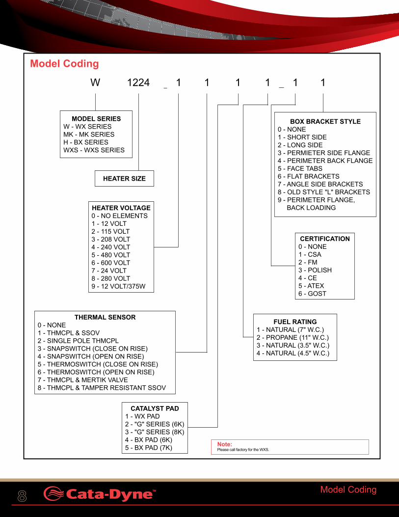
Model Coding
W 1224 1 1 1 1 1 1
Note: Please call factory for the WXS.
MODEL SERIESW - WX SERIESMK - MK SERIESH - BX SERIESWXS - WXS SERIES
HEATER SIZE
HEATER VOLTAGE0 - NO ELEMENTS1 - 12 VOLT2 - 115 VOLT3 - 208 VOLT4 - 240 VOLT5 - 480 VOLT6 - 600 VOLT7 - 24 VOLT8 - 280 VOLT9 - 12 VOLT/375W
CATALYST PAD1 - WX PAD2 - "G" SERIES (6K)3 - "G" SERIES (8K)4 - BX PAD (6K)5 - BX PAD (7K)
THERMAL SENSOR0 - NONE1 - THMCPL & SSOV2 - SINGLE POLE THMCPL3 - SNAPSWITCH (CLOSE ON RISE)4 - SNAPSWITCH (OPEN ON RISE)5 - THERMOSWITCH (CLOSE ON RISE)6 - THERMOSWITCH (OPEN ON RISE)7 - THMCPL & MERTIK VALVE8 - THMCPL & TAMPER RESISTANT SSOV
BOX BRACKET STYLE0 - NONE1 - SHORT SIDE2 - LONG SIDE3 - PERMIETER SIDE FLANGE4 - PERIMETER BACK FLANGE5 - FACE TABS6 - FLAT BRACKETS7 - ANGLE SIDE BRACKETS8 - OLD STYLE "L" BRACKETS9 - PERIMETER FLANGE, BACK LOADING
CERTIFICATION0 - NONE1 - CSA2 - FM3 - POLISH4 - CE5 - ATEX6 - GOST
FUEL RATING1 - NATURAL (7" W.C.)2 - PROPANE (11" W.C.)3 - NATURAL (3.5" W.C.)4 - NATURAL (4.5" W.C.)
Model Coding

CCI Thermal Technologies Inc. 9
WX Series Explosion-Proof Catalytic Heater
The Cata-Dyne™ WX Series infrared gas catalytic explosion-proof heaters are the industry standard for hazardous location heating needs. They are available in over twenty, three-inch depth cabinet sizes, with gas, electrical and accessory connections on the back side of the heater.These are the heaters of choice for many of our customers who have come to trust their reliability.
Applications
WX Series heaters are used in many different applications that involve spot or space heating where hazardous materials may be present.
These include:• comfort heating for industrial buildings and installations• freeze protection for equipment or components• drying or curing processes
Features• heater box constructed of 300 series stainless steel for
corrosion protection• Cata-Dyne™ proprietary explosion-proof catalyst pad.• standard 3/8” NPT gas connections• explosion-proof electrical junction box with standard
3/4” NPT connections• Cata-Dyne™ heaters are designed to operate on either
natural gas or propane• Cata-Dyne™ heaters do not require electrical power to
operate once they have been started• our explosion-proof catalytic technology is the most
efficient in the industrial heating market• heater contains no moving parts and is designed to
operate indefinitely when supplied with air and clean fuel• internal heater components such as our proprietary
catalyst pad and preheat Caloritech™ tubular element are manufactured in-house
Certifications
The WX Series Cata-Dyne™ explosion-proof catalytic heaters are approved for the following:• Canadian Standards Association (CSA) for use in Class
I, Division 1 & 2, Group D hazardous locations• Factory Mutual (FM) for use in Class I, Division 1,
Group D hazardous locations. Temperature code T2C at an ambient temperature of 40°C (104°F)
• CE marked and ATEX certified
See TABLE 1 on page 13 for fuel & electrical ratings.
Explosion-Proof Gas Catalytic Heaters
WX
WX Series Explosion-Proof Catalytic Heater

10 Explosion-Proof Gas Catalytic Heaters
Our Cata-Dyne™ MKII Series explosion-proof catalytic heater has sleek side mount controls ideal for customers seeking to reduce costs with easier and quicker heater installation.
Applications
The Cata-Dyne™ MKII Series heaters are used in many different applications that involve spot or space heating where hazardous materials may be present.
These include:• comfort heating for industrial buildings and installations• freeze protection for equipment or components• drying or curing processes
Features• heater box constructed of 300 series stainless steel for
corrosion protection• Cata-Dyne™ proprietary explosion-proof catalyst pad.• standard 3/8” NPT gas connections• Cata-Dyne™ heaters are designed to operate on either
natural gas or propane• Cata-Dyne™ heaters do not require electrical power to
operate once they have been started• our QuikSTART heater technology reaches the catalytic
threshold faster, bringing the heater to full operating temperature in half the time
• shorter thermocouple is nickel plated with an added polymer sleeve to enhance the corrosion protection for a stronger electromagnetic connection to the safety shut-off valve (SSOV)
• all gas control components as well as all electrical connections are side mounted for easy installation and access
• side mounted rating plate for easy visibility• single start up element with the same power and
wattage rating as used in the standard WX heaters dual elements
• heater contains no moving parts and is designed to operate indefinitely when supplied with air and clean fuel
• internal heater components such as our proprietary catalyst pad and preheat Caloritech™ tubular element are manufactured in-house
Certifications
The Cata-Dyne™ MKII Series explosion-proof catalytic heater is approved for the following:• Canadian Standards Association (CSA) for use in Class
I, Division 1 & 2, Group D hazardous locations• Factory Mutual (FM) for use in Class I, Division 1,Group
D hazardous locations. Temperature code T2C at an ambient temperature of 40°C (104°F)
See TABLE 2 on page 13 for fuel & electrical ratings
MKII Series Explosion-Proof Catalytic Heater
MKII
MKII Series Explosion-Proof Catalytic Heater

CCI Thermal Technologies Inc. 11
WXS
Explosion-Proof Gas Catalytic Heaters
WXS Series Explosion-Proof Catalytic HeaterThinner Space Saving Unit
The Cata-Dyne™ WXS Series "Slim Line" explosion-proof catalytic heater is everything our WX Series heater has become renowned for with the added feature of a more compact 1 ½” (38 mm) thick stainless steel cabinet. This design versatility allows it to be used in both traditional installations and in compact enclosures for valves, regulators and instrumentation.
Applications
Slim Line heaters are used in many different applications that involve spot or space heating where hazardous materials may be present.
These include:• comfort heating for industrial buildings and installations• freeze protection for equipment or components
Features• these units are designed to run on either clean natural
gas or propane• all standard Cata-Dyne™ accessories can be used
with the Slim Line models• 1 ½” (38 mm) thinner than the standard
Cata-Dyne™ heater• equipped with universal mounting brackets, the heater
can easily be mounted into existing facilities or enclosures
• heater boxes are constructed of 300 series stainless steel for maximum corrosion protection
• units are fitted with standard 3/8” NPT gas connections.• no power is needed to operate the heaters or their
controls once the heater has started and the catalytic reaction has been established
• our QuikSTART heater technology reaches the catalytic threshold faster bringing the heater to full operating temperature in half the time
• our explosion-proof catalytic technology is the most efficient in the industrial heating market
• heater contains no moving parts and is designed to operate indefinitely when supplied with air and clean fuel
• internal heater components such as our proprietary catalyst pad and preheat Caloritech™ tubular element are manufactured in-house
Certifications• FM, Class I, Division 1, Group D explosion-proof ratings
See TABLE 4 on page 14 for fuel & electrical ratings.
WXS Series Explosion-Proof Catalytic Heater

12 Industrial Catalytic Heater
G
G Series Industrial Catalytic HeaterG Series Industrial Catalytic Heater
The Cata-Dyne™ G Series infrared gas catalytic heater is designed for use in non-hazardous heating applications such as infrared drying and curing ovens. It is fitted with a patented high temperature catalyst pad, operates on either natural or propane fuel and is available in a wide variety of cabinet sizes.
Applications
The large surface area of the Cata-Dyne™ heater allows for efficient transfer of infrared heat that can be used in a variety of applications including:
- facility space heating - process heating - freeze protection - comfort heating for personnel - ovens (refer to the DriQuik™ catalog)
Features• all major components produced in our own facilities.• patented catalyst manufactured in our Edmonton,
Alberta facility• preheat tubular element manufactured in our Orillia,
Ontario facility• multiple Btu input ratings and a variety of standard
heater sizes available• offered in a variety of preheat voltages• natural gas (NG) or propane (LPG) configurations• choice of manual control or electronic control options
(refer to DriQuik™ catalog)• multiple heater mounting bracket configurations available• heater contains no moving parts and is designed to
operate indefinitely when supplied with air and clean fuel• internal heater components such as our proprietary
catalyst pad and preheat tubular element are manufactured in-house
Certifications• G Series (high performance hot catalytic heater)
certified by Canadian Standards Association (CSA) and Factory Mutual (FM) and (European standards) for non- hazardous area applications
See TABLE 3 on page 14 for fuel & electrical ratings.

CCI Thermal Technologies Inc. 13Fuel and Electrical Rating Data
TABLE 1 - Fuel and Electrical Rating DataWX Series - CSA and FM
Model No.
Maximum Gas Input Minimum Gas Input Maximum Gas Flow Start-Up AmerageBtu/hr (kW) Btu/hr (kW) CFH m3/hrNatural Gas &
Propane Natural Gas Propane Natural Gas Propane Natural
Gas Propane 12V 120V 208V 240V 380V 480V 600V
WX6x6 1,250 (0.366) 500 (0.147) 375 (0.110) 1.25 0.5 0.0354 0.0142 7.1 0.7 ~ 0.4 ~ ~ ~WX6x12 2,500 (0.733) 1,000 (0.293) 750 (0.220) 2.5 1.0 0.0708 0.0283 7.1 0.7 ~ 0.4 ~ ~ ~WX6x24 5,000 (1.465) 2,000 (0.586) 1,500 (0.440) 5.0 2.0 0.1416 0.0566 15.0 2.1 1.2 1.0 ~ ~ ~WX6x60 12,500 (3.663) 5,000 (1.465) 3,750 (1.099) 12.5 5.0 0.3540 0.1416 ~ ~ ~ ~ ~ 1.3 ~WX8x8 2,222 (0.651) 900 (0.264) 700 (0.205) 2.2 0.9 0.0629 0.0252 7.1 0.7 ~ 0.4 ~ ~ ~
WX10x12 4,167 (1.221) 1,700 (0.498) 1,250 (0.366) 4.2 1.7 0.1180 0.0472 15.0 2.1 1.2 1.0 ~ ~ ~WX12x12 5,000 (1.465) 2,000 (0.586) 1,500 (0.440) 5.0 2.0 0.1416 0.0566 15.0 2.1 1.2 1.0 ~ ~ ~WX12X24 10,000 (2.931) 4,000 (1.172) 3,000 (0.879) 10.0 4.0 0.2832 0.1133 30.0 4.2 2.4 2.1 ~ 1.5 0.9WX12x36 15,000 (4.396) 6,000 (1.758) 4,500 (1.319) 15.0 6.0 0.4248 0.1699 30.0 5.0 2.9 2.5 1.6 1.3 1.0WX12x48 20,000 (5.861) 8,000 (2.345) 6,000 (1.758) 20.0 8.0 0.5663 0.2265 30.0 6.7 3.9 3.3 2.1 1.7 1.3WX12x60 25,000 (7.327) 10,000 (2.931) 7,500 (2.198) 25.0 10.0 0.7079 0.2832 45.0 10.4 6.0 5.2 3.3 2.6 2.1WX12x72 30,000 (8.792) 12,000 (3.517) 9,000 (2.638) 30.0 12.0 0.8495 0.3398 ~ 12.1 7.0 6.0 3.8 3.0 2.4WX18x24 15,000 (4.396) 6,000 (1.758) 4,500 (1.319) 15.0 6.0 0.4248 0.1699 30.0 4.2 2.4 2.1 ~ 1.5 ~WX18x30 18,750 (5.495) 7,500 (2.198) 5,625 (1.649) 18.75 7.5 0.5309 0.2124 ~ ~ ~ ~ ~ 1.5 ~WX18x36 22,500 (6.594) 9,000 (2.638) 6,750 (1.978) 22.5 9.0 0.6371 0.2549 ~ 10.0 5.8 5.0 3.2 2.5 2.0WX18x48 30,000 (8.792) 12,000 (3.517) 9,000 (2.638) 30.0 12.0 0.8495 0.3398 ~ 13.3 7.7 6.7 4.2 3.3 2.7WX18x60 37,500 (10.990) 15,000 (4.396) 11,250 (3.297) 37.5 15.0 1.0619 0.4248 ~ 20.8 12.0 10.4 6.6 5.2 4.2WX18x72 45,000 (13.188) 18,000 (5.275) 13,500 (3.956) 45.0 18.0 1.2743 0.5097 ~ 24.2 14.0 12.1 7.6 6.0 4.8WX24x24 20,000 (5.861) 8,000 (2.345) 6,000 (1.758) 20.0 8.0 0.5663 0.2265 30.0 4.2 2.4 2.1 ~ 1.5 ~WX24x30 25,000 (7.327) 10,000 (2.931) 7,500 (2.198) 25.0 10.0 0.7079 0.2832 30.0 4.2 2.4 2.1 ~ 1.5 ~WX24x36 30,000 (8.792) 12,000 (3.517) 9,000 (2.638) 30.0 12.0 0.8495 0.3398 ~ 10.0 5.8 5.0 3.2 2.5 2.0WX24x48 40,000 (11.723) 16,000 (4.689) 12,000 (3.517) 40.0 16.0 1.1327 0.4531 ~ 13.3 7.7 6.7 4.2 3.3 2.7WX24x60 50,000 (14.654) 20,000 (5.861) 15,000 (4.396) 50.0 20.0 1.4159 0.5663 ~ 20.8 12.0 10.4 6.6 5.2 4.2WX24x72 60,000 (17.584) 24,000 (7.034) 18,000 (5.275) 60.0 24.0 1.6990 0.6796 ~ 24.2 14.0 12.1 7.6 6.0 4.8
TABLE 2 - MKII Series - CSA and FM
Model No.Maximum Gas Input Minimum Gas Input Maximum Gas Flow Start-Up
AmperageBtu/hr (kW) Btu/hr (kW) CFH m3/hrNatural Gas & Propane Natural Gas Propane Natural Gas Propane Natural Gas Propane 12V 120V
MKII12x12 5,000 (1.464) 2,000 (0.586) 1,500 (0.440) 5.0 2.0 0.1416 0.0566 15.0 2.1MKII12x24 10,000 (2.929) 4,000 (1.172) 3,000 (0.879) 10.0 4.0 0.2832 0.1133 30.0 4.2MKII18x24 15,000 (4.393) 6,000 (1.758) 4,500 (1.319) 15.0 6.0 0.4248 0.1699 30.0 4.2MKII18x48 30,000 (8.787) 12,000 (3.517) 9,000 (2.638) 30.0 12.0 0.8495 0.3398 ~ 13.3MKII24x24 20,000 (5.858) 8,000 (2.345) 6,000 (1.758) 20.0 8.0 0.5663 0.2265 30.0 4.2MKII24x48 40,000 (11.716) 16,000 (4.689) 12,000 (3.517) 40.0 16.0 1.1327 0.4531 ~ 13.3
Fuel and Electrical Rating Data

14 Fuel and Electrical Rating Data
TABLE 3 - Fuel and Electrical Rating DataG Series CSA and FM
MODEL NO.
Maximum Gas Input Minimum Gas Input Maximum Gas FlowStart-Up Amperage
BTU/hr (kW) BTU/hr (kW) CFH m3/hrNatural Gas &
Propane Natural Gas Propane Natural Gas Propane Natural
Gas Propane 12V 120V 208V 240V 380V 480V 600V
G6x6 1,500 (0.440) 500 (0.147) 375 (0.110) 1.5 0.6 0.0425 0.0170 7.1 0.7 ~ 0.4 ~ ~ ~G6x12 3,000 (0.879) 1,000 (0.293) 750 (0.220) 3.0 1.2 0.0850 0.0340 7.1 0.7 ~ 0.4 ~ ~ ~G6x24 6,000 (1.758) 2,000 (0.586) 1,500 (0.440) 6.0 2.4 0.1699 0.0680 15.0 2.1 1.2 1.0 ~ ~ ~G8x8 2,667 (0.782) 900 (0.264) 700 (0.205) 2.7 1.1 0.0755 0.0302 7.1 0.7 ~ 0.4 ~ ~ ~
G10x12 5,000 (1.465) 1,700 (0.498) 1,250 (0.366) 5.0 2.0 0.1416 0.0566 15.0 2.1 1.2 1.0 ~ ~ ~G12x12 6,000 (1.758) 2,000 (0.586) 1,500 (0.440) 6.0 2.4 0.1699 0.0680 15.0 2.1 1.2 1.0 ~ ~ ~G12X24 12,000 (3.517) 4,000 (1.172) 3,000 (0.879) 12.0 4.8 0.3398 0.1359 30.0 4.2 2.4 2.1 ~ 1.5 0.9G12x36 18,000 (5.275) 6,000 (1.758) 4,500 (1.319) 18.0 7.2 0.5097 0.2039 ~ 5.0 2.9 2.5 1.6 1.3 1.0G12x48 24,000 (7.034) 8,000 (2.345) 6,000 (1.758) 24.0 9.6 0.6796 0.2718 30.0 6.7 3.9 3.3 2.1 1.7 1.3G12x60 30,000 (8.792) 10,000 (2.931) 7,500 (2.198) 30.0 12.0 0.8495 0.3398 45.0 10.4 6.0 5.2 3.3 2.6 2.1G12x72 36,000 (10.551) 12,000 (3.517) 9,000 (2.638) 36.0 14.4 1.0194 0.4078 ~ 12.1 7.0 6.0 3.8 3.0 2.4G18x24 18,000 (5.275) 6,000 (1.758) 4,500 (1.319) 18.0 7.2 0.5097 0.2039 30.0 4.2 2.4 2.1 ~ 1.5 ~G18x30 22,500 (6.594) 7,500 (2.198) 5,625 (1.649) 22.5 9.0 0.6371 0.2549 ~ ~ ~ ~ ~ 1.5 ~G18x36 27,000 (7.913) 9,000 (2.638) 6,750 (1.978) 27.0 10.8 0.7646 0.3058 ~ 10.0 5.8 5.0 3.2 2.5 2.0G18x48 36,000 (10.551) 12,000 (3.517) 9,000 (2.638) 36.0 14.4 1.0194 0.4078 ~ 13.3 7.7 6.7 4.2 3.3 2.7G18x60 45,000 (13.188) 15,000 (4.396) 11,250 (3.297) 45.0 18.0 1.2743 0.5097 ~ 20.8 12.0 10.4 6.6 5.2 4.2G18x72 54,000 (15.826) 18,000 (5.275) 13,500 (3.956) 54.0 21.6 1.5291 0.6116 ~ 24.2 14.0 12.1 7.6 6.0 4.8G24x24 24,000 (7.034) 8,000 (2.345) 6,000 (1.758) 24.0 9.6 0.6796 0.2718 30.0 4.2 2.4 2.1 ~ 1.5 ~G24x30 30,000 (8.792) 10,000 (2.931) 7,500 (2.198) 30.0 12.0 0.8495 0.3398 30.0 4.2 2.4 2.1 ~ 1.5 ~G24x36 36,000 (10.551) 12,000 (3.517) 9,000 (2.638) 36.0 14.4 1.0194 0.4078 ~ 10.0 5.8 5.0 3.2 2.5 2.0G24x48 48,000 (14.067) 16,000 (4.689) 12,000 (3.517) 48.0 19.2 1.3592 0.5437 ~ 13.3 7.7 6.7 4.2 3.3 2.7G24x60 60,000 (17.584) 20,000 (5.861) 15,000 (4.396) 60.0 24.0 1.6990 0.6796 ~ 20.8 12.0 10.4 6.6 5.2 4.2G24x72 72,000 (21.101) 24,000 (7.034) 18,000 (5.275) 72.0 28.8 2.0388 0.8155 ~ 24.2 14.0 12.1 7.6 6.0 4.8
TABLE 4 - WXS Slim Line Series FM Only
MODEL NO.
Maximum Gas Input Minimum Gas Input Maximum Gas Flow Start-Up Amperage
BTU/hr (kW) BTU/hr (kW) CFH m3/hr
Natural Gas & Propane Natural Gas Propane Natural Gas Propane Natural
Gas Propane 12V 120V 240V
WXS6x6 1,750 (0.513) 583 (0.171) 438 (0.128) 1.8 0.7 0.0496 0.0198 7.1 0.7 0.4WXS6x12 3,500 (1.025) 1,167 (0.342) 875 (0.256) 3.5 1.4 0.0991 0.0396 7.1 0.7 0.4WXS6x24 7,000 (2.050) 2,333 (0.684) 1,750 (0.513) 7.0 2.8 0.1982 0.0793 15.0 2.1 1.0WXS8x8 3,111 (0.911) 1,037 (0.304) 778 (0.228) 3.1 1.2 0.0881 0.0352 7.1 0.7 0.4
WXS10x12 5,833 (1.709) 1,944 (0.570) 1,458 (0.427) 5.8 2.3 0.1652 0.0661 15.0 2.1 1.0WXS12x12 7,000 (2.050) 2,333 (0.684) 1,750 (0.513) 7.0 2.8 0.1982 0.0793 15.0 2.1 1.0WXS12x24 14,000 (4.101) 4,667 (1.368) 3,500 (1.026) 14.0 5.6 0.3964 0.1586 30.0 4.2 2.0
Fuel and Electrical Rating Data

CCI Thermal Technologies Inc. 15Gas Catalytic Heater Request For Quote Form
Gas Catalytic Heater Request For QuoteClient Information:Company Name: ____________________________
Address: __________________________________
City, State (Prov): ___________________________
Country, Zip (Postal Code): ____________________
Contact Name: _____________________________
Phone / Fax: _______________________________
E-mail: ____________________________________
Proposal Type Required:
o Budgetary o Formal Quote
Other: ____________________________________
Required Date for Proposal: ___________________
Anticipated Shipping Date for Project: ___________
Project Name: ______________________________
Application Summary: ________________________
__________________________________________
__________________________________________
__________________________________________
Services:
Natural Gas: o 3.5" w.c. o 4.5" w.c. o 7.0" w.c.
Propane: o 11" w.c.
Voltage:
o 12V o 120V o 208V o 240V o 380V o 480V o 600V
Note: Refer to TABLES 1 - 3 on page 10 & 11 for available voltages.
Heater Selection:
Please include quantity in space provided:
WX Series - Rear Mounted Controls: 6 x 6 _____
6 x 12 _____ 6 x 24 _____ 8 x 8 _____ 10 x 12 _____
12 x 12 _____ 12 x 24 _____ 12 x 14 _____ 12 x 60 _____
12 x 72 _____ 18 x 24 _____ 18 x 36 _____ 18 x 48 _____
18 x 60 _____ 18 x 72 _____ 24 x 24 _____ 24 x 30 _____
24 x 36 _____ 24 x 48 _____ 24 x 60 _____ 24 x 72 _____
MKII Series - Side Mounted Controls: 12 x 12 _____
12 x 24 _____ 18 x 24 _____ 18 x 48 _____ 24 x 24 _____
24 x 36* ____ 24 x 48° _____
Note:* Only Available in 12V.° Available in 12V and 24V.
WXS Slim Line Series - Thinner Design: 6 x 6 _____ 6 x 12 _____ 6 x 24 _____ 8 x 8 _____
10 x 12 _____ 12 x 12 _____ 12 x 24 _____
Note:For information on the G Series - Non-Hazardous Industrial Heater contact the factory for a quote.
Accessories:
Please include quantity in space provided:
Safety Controls: ASV375 ______ ASV375-NT _______ Mertik* ________
Scrubbers: NGS-4 ______ NGS-12 _______
Regulators: Low Pressure 912 _______ High Pressure 130 _______
12V Start-up Leads: 25' ______ 30' _______ 40' ________
Propane Hoses: 5' ______ 10' _______
Other: Battery Cable Cabinet ____ Vent Hood ______
Wall Mount Bracket ____ Floor Stand ______
45° Wall Mount Bracket ____ Thermostat ______
Manual Shut-Off Ball Valve ____ Protection Grill ______
Gas Pressure Test Kit ____ POL Adaptor ______
Note:* Includes Thermostat.
To receive your enclosure quote, fax these pages to: (780) 468-5904
Attention: Projects
Gas Catalytic Heater Request For Quote

16 Enclosure Heating
The Regulator Enclosure is specifically designed to provide freeze protection for a wide variety of natural gas pipeline regulators. Enclosures are designed for specific regulators and generic applications.
Features• Enclosure comes fully assembled• Stainless steel enclosures provide added longevity for
the harshest environments• Cata-DyneTM heaters are CSA or FM certified, available
in both natural gas or propane• Optional thermostats and regulators are available• Designed to clamp directly to the pipeline, spring
clamps make installation easy• Custom designed enclosure packages available upon
request
Regulator EnclosuresRegulator Enclosures
Regulator Enclosures
Model Coding
HEATER TYPEHEA 600D 1 1 2 A
MODEL SERIESHEA - HEATER ENCLOSURE ASSEMBLY
PIPE SIZE (IN) INLET X OUTLET
REGULATOR0100/0101 - 6 X 6 ENCLOSURE0102/0103 - 6 X 12 ENCLOSURE0104/0105 - 6 X 24 ENCLOSURE0106/0107 - 8 X 8 ENCLOSURE0108/0109 - 10 X 12 ENCLOSURE0110/0111 - 12 X 12 ENCLOSURE0600 - FISHER 630 BIG JOE1301 - FISHER 13010232 - DE 232 0461 - FISHER 461 6300 - FISHER 630 0627 - FISHER 627 627F - FISHER 627 FLANGED67CF - FISHER 67CF 600D - FISHER 600# D-BODY VALVE0EZR - EZR ENCLOSURE4413 - TESCOM 44-1300 TESC - TESCOM MOON -MOONEY FLOWGRID VALVE
OPTIONSA - APPLIANCE REGULATOR (factory matched
to heaters)B - SERVICE REGULATOR (low pressure,
250 psig - 11” w.c.)B1 - SERVICE REGULATOR (low pressure,
250 psig - 4” w.c.)C - SERVICE REGULATOR (high pressure,
6000 psig - 50 psi)T - THERMOSTAT [regular, 32°F - 104°F, factory
matched to heater(s)]T1 - THERMOSTATT2 - THERMOSTAT (high temperature, 60°F -
250°F)V - RELIEF VALVE (Fisher 289U 5” -
25” w.c.)V1 - RELIEF VALVE (Fisher H120, 120 psi)G - PRESSURE GAUGE
X
NUMBER OF HEATERS
REFERENCE MODEL CODING PAGE 5
UN
IVE
RS
AL
Regulator Enclosures

CCI Thermal Technologies Inc. 17Enclosure Heating
TABLE 5 - Regulator Enclosures
Model # * Description
Dimensions
L W H
in (mm) in (mm) in (mm)
HEA0100-1X1-1-___0606 Enclosure, Universal 1 and 2" inlet pipe 10.125 (257) 8.375 (213) 8.563 (218)
HEA0101-1X1-2-___0606 Enclosure, Universal 1 and 2" inlet pipe 10.125 (257) 8.375 (213) 8.563 (218)
HEA0102-1X1-1-___0612 Enclosure, Universal 1 and 2" inlet pipe 12.250 (311) 11.000 (279) 8.250 (210)
HEA0103-1X1-2-___0612 Enclosure, Universal 1 and 2" inlet pipe 12.250 (311) 11.000 (279) 8.250 (210)
HEA0104-1X1-1-___0624 Enclosure, Universal 1 and 2" inlet pipe 24.500 (622) 11.000 (279) 8.250 (210)
HEA0105-1X1-1-___0624 Enclosure, Universal 1 and 2" inlet pipe 24.500 (622) 11.000 (279) 8.250 (210)
HEA0106-1X1-2-___0808 Enclosure, Universal 1 and 2" inlet pipe 12.125 (308) 14.125 (359) 10.188 (259)
HEA0107-1X1-2-___0808 Enclosure, Universal 1 and 2" inlet pipe 12.125 (308) 14.125 (359) 10.188 (259)
HEA0108-1X1-1-___1012 Enclosure, Universal 1 and 2" inlet pipe 14.000 (356) 16.000 (406) 14.000 (356)
HEA0109-1X1-2-___1012 Enclosure, Universal 1 and 2" inlet pipe 14.000 (356) 16.000 (406) 14.000 (356)
HEA0110-1X1-1-___1212 Enclosure, Universal 1 and 2" inlet pipe 14.000 (356) 16.000 (406) 14.000 (356)
HEA0111-1X1-2-___1212 Enclosure, Universal 1 and 2" inlet pipe 14.000 (356) 16.000 (406) 14.000 (356)
HEA-1301-1X1-1-___0606 Enclosure, 1301 Regulator 6.375 (162) 9.000 (229) 8.375 (213)
HEA-0232-1X1-1-___0606 Enclosure, DE 232 Regulator, Basic 10.125 (257) 8.375 (213) 8.563 (218)
HEA-0461-1X1-2-___0808 Enclosure, Fisher 461-S Regulator Flanged 17.625 (448) 19.183 (487) 11.750 (298)
HEA-0461-3X3-1-___0808 Enclosure, Fisher 461-X57 Regulator, High Pressure 8.250 (210) 19.183 (487) 10.313 (262)
HEA-0600-1X1-2-___0808 Enclosure, 600 Series Reg, "BIG JOE" 12.125 (308) 14.125 (359) 10.188 (259)
HEA-0600-1X1-2-___0612 Enclosure, 600 Series Reg, "BIG JOE" 12.250 (311) 11.000 (279) 8.250 (210)
HEA-0600-1X1-2-___0612 Enclosure, 600 Series Reg, "BIG JOE", Flanged 12.250 (311) 11.000 (279) 8.250 (210)
HEA-0600-1X1-2-___1212 Enclosure, Fisher 630 Regulator 12.125 (308) 15.188 (386) 14.188 (360)
HEA-0627-1X1-2-___0808 Enclosure, Fisher 627 Regulator 12.125 (308) 12.500 (318) 7.500 (191)
HEA-627F-1X1-1-___1212 Enclosure, Fisher 627 Regulator Flanged 16.250 (413) 20.438 (519) 14.063 (357)
HEA-627F-1X1-1-___0808 Enclosure, Fisher 627 Regulator Flanged 16.250 (413) 20.438 (519) 14.063 (357)
HEA-0627-2X2-1-___0808 Enclosure, Fisher 627 Regulator 15.063 (383) 15.125 (384) 13.000 (330)
HEA-0627-1X1-1-___0808 Enclosure, Fisher 627 Regulator 15.063 (383) 15.125 (384) 13.000 (330)
HEA-0627-2X2-1-___1012 Enclosure, Fisher 627 Regulator 12.125 (308) 12.833 (326) 10.500 (267)
HEA-67CF-1X1-1-___0606 Enclosure, 67CF Regulator 6.438 (164) 9.000 (229) 8.375 (213)
HEA-600D-3X3-2-___1012 Enclosure, Similar to 600# Fisher D-Body Valve 21.625 (549) 15.625 (397) 12.500 (318)
HEA-0EZR-2X2-2-___1212 Enclosure, Fisher 2" EZR Regulator 20.625 (524) 28.125 (714) 23.125 (587)
HEA-0EZR-1X1-2-___1212 Enclosure, Fisher 1" EZR Regulator 20.625 (524) 28.125 (714) 23.125 (587)
HEA-0EZR-3X3-2-___1212 Enclosure, Fisher 3" EZR Regulator 20.625 (524) 28.125 (714) 23.125 (587)
HEA-0EZR-4X4-2-___1212 Enclosure, Fisher 4" EZR Regulator 20.625 (524) 28.125 (714) 23.125 (587)
HEA-0EZR-6X6-2-___1212 Enclosure, Fisher 6" EZR Valve, CL 600 20.625 (524) 28.125 (714) 23.125 (587)
HEA-0EZR-8X8-2-___1212 Enclosure, Fisher 6" EZR Valve 8" x 6" Pipe Size 20.625 (524) 28.125 (714) 23.125 (587)
HEA-MOON-2X2-2-___1212 Enclosure, Mooney Flowgrid Valve 14.750 (375) 14.125 (359) 14.125 (359)
HEA-TESC-2X2-1-___0612 Enclosure, Tescom Regulator 12.000 (305) 10.000 (254) 7.000 (178)
HEA-4413-1X1-1-___0606 Enclosure, Tescom 44-1300 Reg 11.125 (283) 10.313 (262) 8.750 (222)
Regulator Enclosures
*Note: __ = WX, BX or WXS.
18
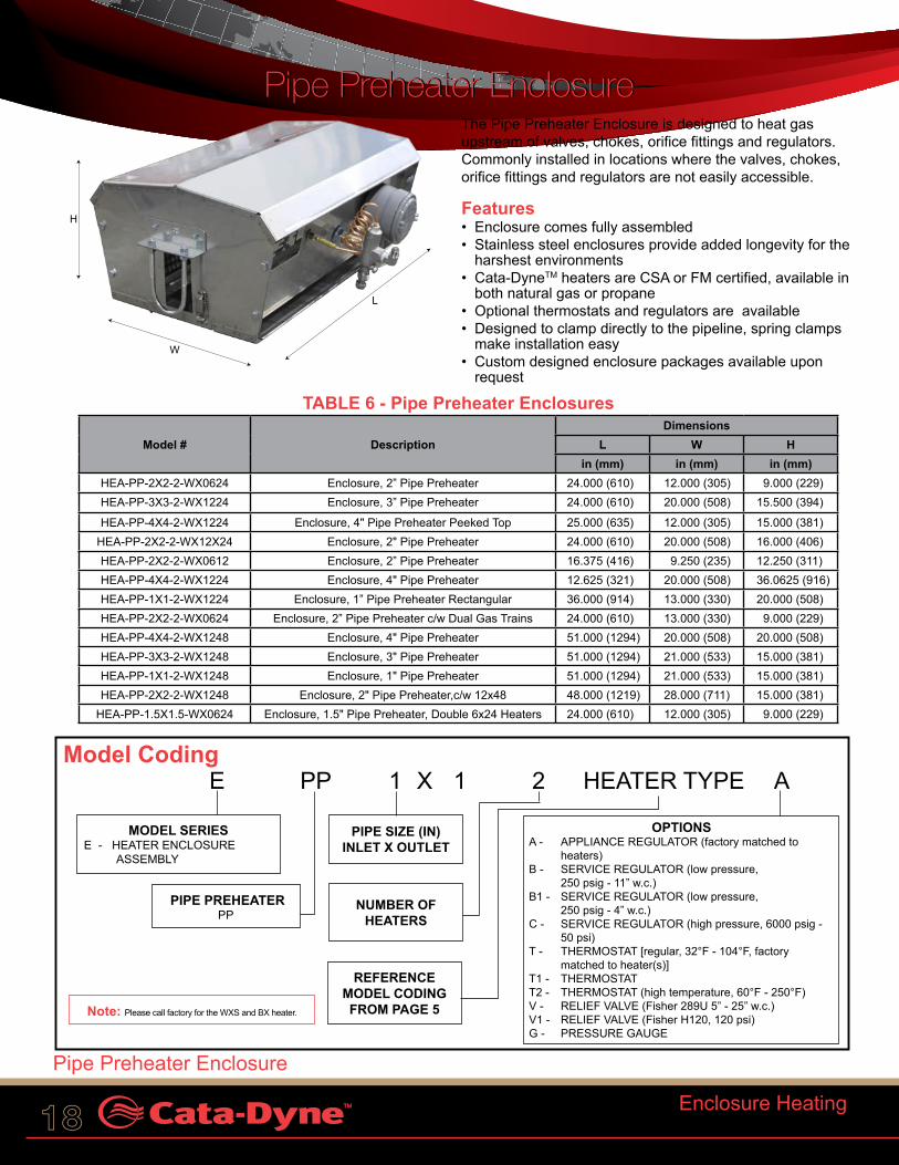
EModel Coding
Note: Please call factory for the WXS and BX heater.
PP 1 1 2 HEATER TYPE A
MODEL SERIESE - HEATER ENCLOSURE ASSEMBLY
PIPE SIZE (IN) INLET X OUTLET
PIPE PREHEATERPP
OPTIONSA - APPLIANCE REGULATOR (factory matched to
heaters)B - SERVICE REGULATOR (low pressure,
250 psig - 11” w.c.)B1 - SERVICE REGULATOR (low pressure,
250 psig - 4” w.c.)C - SERVICE REGULATOR (high pressure, 6000 psig -
50 psi)T - THERMOSTAT [regular, 32°F - 104°F, factory
matched to heater(s)]T1 - THERMOSTATT2 - THERMOSTAT (high temperature, 60°F - 250°F)V - RELIEF VALVE (Fisher 289U 5” - 25” w.c.)V1 - RELIEF VALVE (Fisher H120, 120 psi)G - PRESSURE GAUGE
X
NUMBER OF HEATERS
REFERENCE MODEL CODING FROM PAGE 5
The Pipe Preheater Enclosure is designed to heat gas upstream of valves, chokes, orifice fittings and regulators. Commonly installed in locations where the valves, chokes, orifice fittings and regulators are not easily accessible.
Features• Enclosure comes fully assembled• Stainless steel enclosures provide added longevity for the
harshest environments• Cata-DyneTM heaters are CSA or FM certified, available in
both natural gas or propane• Optional thermostats and regulators are available• Designed to clamp directly to the pipeline, spring clamps
make installation easy• Custom designed enclosure packages available upon
request
L
H
W
Pipe Preheater EnclosurePipe Preheater Enclosure
Enclosure Heating
Pipe Preheater Enclosure
TABLE 6 - Pipe Preheater Enclosures
Model # DescriptionDimensions
L W Hin (mm) in (mm) in (mm)
HEA-PP-2X2-2-WX0624 Enclosure, 2” Pipe Preheater 24.000 (610) 12.000 (305) 9.000 (229)HEA-PP-3X3-2-WX1224 Enclosure, 3” Pipe Preheater 24.000 (610) 20.000 (508) 15.500 (394)
HEA-PP-4X4-2-WX1224 Enclosure, 4" Pipe Preheater Peeked Top 25.000 (635) 12.000 (305) 15.000 (381)HEA-PP-2X2-2-WX12X24 Enclosure, 2" Pipe Preheater 24.000 (610) 20.000 (508) 16.000 (406)HEA-PP-2X2-2-WX0612 Enclosure, 2” Pipe Preheater 16.375 (416) 9.250 (235) 12.250 (311)HEA-PP-4X4-2-WX1224 Enclosure, 4" Pipe Preheater 12.625 (321) 20.000 (508) 36.0625 (916)HEA-PP-1X1-2-WX1224 Enclosure, 1” Pipe Preheater Rectangular 36.000 (914) 13.000 (330) 20.000 (508)HEA-PP-2X2-2-WX0624 Enclosure, 2” Pipe Preheater c/w Dual Gas Trains 24.000 (610) 13.000 (330) 9.000 (229)HEA-PP-4X4-2-WX1248 Enclosure, 4" Pipe Preheater 51.000 (1294) 20.000 (508) 20.000 (508)HEA-PP-3X3-2-WX1248 Enclosure, 3" Pipe Preheater 51.000 (1294) 21.000 (533) 15.000 (381)HEA-PP-1X1-2-WX1248 Enclosure, 1" Pipe Preheater 51.000 (1294) 21.000 (533) 15.000 (381)HEA-PP-2X2-2-WX1248 Enclosure, 2" Pipe Preheater,c/w 12x48 48.000 (1219) 28.000 (711) 15.000 (381)
HEA-PP-1.5X1.5-WX0624 Enclosure, 1.5" Pipe Preheater, Double 6x24 Heaters 24.000 (610) 12.000 (305) 9.000 (229)

CCI Thermal Technologies Inc. 19
Model Coding
Enclosure Heating
Rotary Meter Enclosure
The Rotary Meter Enclosure is designed to prevent freezing of wet gas and creation of hydrates that can cause meters to fail or provide inaccurate readings.
Features• Designed to suit many different rotary meter valves• Enclosure comes fully assembled• Stainless steel enclosures provide added longevity for
the harshest environments• Cata-DyneTM heaters are CSA or FM certified, available in
both natural gas or propane• Optional thermostats and regulators are available• Designed to clamp directly to the pipeline, spring clamps
make installation easy• Custom designed enclosure packages available upon
request
HEATER TYPEE RM2M175 1 1 2 A
MODEL SERIESE - HEATER ENCLOSURE ASSEMBLY
PIPE SIZE (IN) INLET X OUTLET
ROTARY METERRM1M600 - Roots Meter, 1M600 RM1.5M - Roots Meter, 1.5MRM1.5M125 - Roots Meter, 1.5M125RM2M175 - Roots Meter, 2M175RM3M125 - Roots Meter, 3M125RM3M600 - Roots Meter, 3M600RM3.6M600 - Roots Meter, 3.6M600RM5M - Roots Meter, 5MRM7M - Roots Meter, 7M
X
NUMBER OF HEATERS
REFERENCE MODEL CODING FROM PAGE 5
Note: Please call factory for the WXS and BX heaters.
OPTIONSA - APPLIANCE REGULATOR (factory matched to
heaters)B - SERVICE REGULATOR (low pressure,
250 psig - 11” w.c.)B1 - SERVICE REGULATOR (low pressure,
250 psig - 4” w.c.)C - SERVICE REGULATOR (high pressure, 6000 psig
- 50 psi)T - THERMOSTAT [regular, 32°F - 104°F, factory
matched to heater(s)]T1 - THERMOSTATT2 - THERMOSTAT (high temperature, 60°F - 250°F)V - RELIEF VALVE (Fisher 289U 5” - 25” w.c.)V1 - RELIEF VALVE (Fisher H120, 120 psi)G - PRESSURE GAUGE
Gas FlowL
H
W
Rotary Meter EnclosureRotary Meter Enclosure
TABLE 7 - Rotary Meter Enclosures
Model # DescriptionDimensions
L W Hin (mm) in (mm) in (mm)
HEA-RM1M600-2X2-1-WX0808 Enclosure, Roots 1M600 Meter 15.00 (381) 14.50 (368) 15.00 (381)
HEA-RM1.5M-2X2-1-WX0808 Enclosure, Roots 1.5M Meter 10.00 (254) 11.00 (279) 10.00 (254)
HEA-RM2M175-2X2-1-WX0808 Enclosure, 2M175 Meter 12.00 (305) 12.00 (305) 10.00 (254)
HEA-RM3M125-2X2-1-WX0808 Enclosure, 3M125 Meter 12.00 (305) 12.00 (305) 10.00 (254)
HEA-RM3.6M600-2X2-1-WX0808 Enclosure, Roots 3.6M600 Meter 15.00 (381) 16.00 (406) 14.00 (356)
HEA-RM1.5M-3X3-1-WX0612 Enclosure, Roots 1.5M Meter 14.00 (356) 10.00 (254) 10.00 (254)
HEA-RM1M600-3X3-1-WX0612 Enclosure, Roots 1M600 Meter 16.00 (406) 14.00 (356) 14.00 (356)
HEA-RM3M125-2X2-1-WX0612 Enclosure, Roots 3M125 Meter 11.00 (279) 16.00 (406) 15.00 (381)
HEA-RM3M600-3X3-1-WX0612 Enclosure, Roots 3M600 Meter 15.00 (381) 15.00 (381) 14.00 (356)
HEA-RM5M-3X3-1-WX0808 Enclosure, Roots 5M 11.00 (279) 16.00 (406) 11.00 (279)
HEA-RM5M-3X3-1-WX0612 Enclosure, Roots 5M 11.00 (279) 16.00 (406) 11.00 (279)
HEA-RM7M-3X3-1-WX1012 Enclosure, Roots 7M 15.00 (381) 15.00 (381) 16.00 (406)

20
The Motor Valve Enclosure heats the critical portions of the motor valve to prevent freezing.
Features• Designed to ensure that all the sensitive portions of the
valve are outside of the heated zone• Enclosure comes fully assembled• Stainless steel enclosures provide added longevity for the
harshest environments• Cata-DyneTM heaters are CSA or FM certified, available in
both natural gas or propane• Optional thermostats and
regulators are available• Designed to clamp directly to
the pipeline, spring clamps make installation easy
• Custom designed enclosure packages available upon request.
TABLE 8 - Motor Valve Enclosures
Model # Description
DimensionsL W H
in (mm) in (mm) in (mm)
HEA-MV1-1X1-1-WX10X12 Enclosure, 1” Motor Valve 9.625 (244) 12.000 (305) 14.125 (359)
HEA-MV2-2X2-2-WX10X12 Enclosure, 2” Motor Valve 14.000 (356) 9.500 (241) 12.000 (305)
HEA-MV1-1X1-2-WX0808 Enclosure, 1" Motor Valve 10.000 (254) 8.000 (203) 10.563 (268)
Model CodingE MV 1 1 2 HEATER TYPE A
MODEL SERIESE - HEATER ENCLOSURE ASSEMBLY
PIPE SIZE (IN) INLET X OUTLET
MOTOR VALVEMV
X
NUMBER OF HEATERS
REFERENCE MODEL CODING FROM PAGE 5
Note: Please call factory for the WXS and BX heaters.
OPTIONSA - APPLIANCE REGULATOR (factory matched
to heaters)B - SERVICE REGULATOR (low pressure,
250 psig - 11” w.c.)B1 - SERVICE REGULATOR (low pressure,
250 psig - 4” w.c.)C - SERVICE REGULATOR (high pressure,
6000 psig - 50 psi)T - THERMOSTAT [regular, 32°F - 104°F, factory
matched to heater(s)]T1 - THERMOSTATT2 - THERMOSTAT (high temperature, 60°F - 250°F)V - RELIEF VALVE (Fisher 289U 5” - 25” w.c.)V1 - RELIEF VALVE (Fisher H120, 120 psi)G - PRESSURE GAUGE
LH
W
Gas Flow
Motor Valve EnclosureMotor Valve Enclosure
Enclosure Heating
Motor Valve Enclosure

CCI Thermal Technologies Inc. 21
The Orifice Fitting Meter Enclosure heats an orifice fitting directly. The enclosure has an easily accessible entry for the orifice fitting adjustment. The assembly is designed to heat natural gas passing through the orifice to prevent icing and the dropout of liquids.
Features• Designed to heat the orifice fitting directly• Enclosure comes fully assembled• Stainless steel enclosures provide added longevity for the
harshest environments• Cata-DyneTM heaters are CSA or FM certified, available in
both natural gas or propane• Optional thermostats and regulators are available• Custom designed enclosure packages available upon
request• Designed to clamp directly to the pipeline, spring clamps
make installation easy• Custom designed enclosure packages available upon
request
TABLE 9 - Orifice Fitting Meter Enclosures
Model # DescriptionDimensions
L W Hin (mm) in (mm) in (mm)
HEA-OF-2X2-1-WX1012 Orifice Fitting 14 (356) 16 (406) 14 (356)
HEA-OF-3X3-1-WX1012 Orifice Fitting 14 (356) 16 (406) 14 (356)
HEA-OF-4X4-1-WX1012 Orifice Fitting 14 (356) 16 (406) 14 (356)
Model CodingE OF 1 1 2 HEATER TYPE A
MODEL SERIESE - HEATER ENCLOSURE ASSEMBLY
PIPE SIZE (IN) INLET X OUTLET
ORIFICE FITTINGSOF
X
NUMBER OF HEATERS
REFERENCE MODEL CODING FROM PAGE 5
OPTIONSA - APPLIANCE REGULATOR (factory matched
to heaters)B - SERVICE REGULATOR (low pressure,
250 psig - 11” w.c.)B1 - SERVICE REGULATOR (low pressure,
250 psig - 4” w.c.)C - SERVICE REGULATOR (high pressure,
6000 psig - 50 psi)T - THERMOSTAT [regular, 32°F - 104°F, factory
matched to heater(s)]T1 - THERMOSTATT2 - THERMOSTAT (high temperature, 60°F - 250°F)V - RELIEF VALVE (Fisher 289U 5” - 25” w.c.)V1 - RELIEF VALVE (Fisher H120, 120 psi)G - PRESSURE GAUGE
LH
W
Gas Flow
Note: Please call factory for the WXS and BX heaters.
Orifice Fitting Meter EnclosureOrifice Fitting Meter Enclosure
Enclosure Heating
Orifice Fitting Meter Enclosure

22 Sure Seal™ Pipeline System
The Cata-Dyne™ Sure Seal™ pipeline system is a unique infrared heating system consisting of a number of Cata-Dyne™ heaters mounted in a clamshell frame configuration to provide a safe and fast method of applying heat to the construction and maintenance of various sizes of pipeline systems.
Applications
Large surface area of the Cata-Dyne™ heater allows for efficient transfer of infrared heat that can be utilized in a variety of pipeline applications.
- suitable for preformed or wrap around sleeves - ideal for both preheat and shrink sleeve processes - can be used for baking to remove hydrogen
induced cracking - appropriate for a variety of manufacturers’ sleeves - can be used in windy or poor weather
Features• utilizes the Cata-Dyne™ heater for high
temperature applications• models available for 2” (51 mm) diameter or
greater pipelines• requires no water, electricity or compressed air
to operate• faster than tiger torch methods and uses less propane• portable and easily operated by one person, depending
on pipeline sizes• custom built equipment and other options are available
upon special request• utilizes the hottest catalytic gas heater on the market
TABLE 10 - Product Dimensions & Data
Part #
Pipe Dimensions Wt.
Approx. Propane
Consump.Diameter L W Hin
(mm)in
(mm)in
(mm)in
(mm)lbs (kg) (lb/hr)
SS2-4/24 2 - 4 (51 - 102)
40 (1016)
30 (762)
15 (381)
78 (35) 2.2
SS6-8/24 6 - 8 (152 - 203)
40 (1016)
32 (813)
19 (483)
85 (39) 2.2
SS10-12/24 10 - 12 (254 - 305)
40 (1016)
34 (864)
23 (584)
93 (42) 2.2
SS16-18/24 16 - 18 (406 - 457)
40 (1016)
40 (1016)
28 (711)
122 (55) 3.8
SS20-24/36 20 - 24 (508 - 610)
52 (1321)
52 (1321)
40 (1016)
205 (93 5.5
Sure Seal™ Pipeline System
Lifting Lugs
Adjustable Pipe Roller
High Pressure Gas Tubing
Main Zone Regulator
Locking Mechanism
Locking Support
Cata-Dyne™ Heaters
Sure Seal™ Pipeline System
Sure Seal™ Pipeline System
Sure Seal™ Pipeline System

CCI Thermal Technologies Inc. 23Enclosure Heating
Super ConductorSuper Conductor
Super Conductor
Super Conductor
The Super Conductor Enclosure‘s innovative design transfers heat using heat conducting rods, creating a moisture free heat source. The super conductor provides dry penetrating heat for small enclosures housing batteries, radio controls and other moisture sensitive equipment.
Features• Designed to keep instrumentation at an operable
temperature• Electrical power is not required to maintain operation
after start-up• Designed to operate for extended periods of time without
maintenance• Cata-DyneTM heaters are CSA and FM certified, available
in both natural gas and propane• Custom sizes and designs available
TABLE 11 - Super Conductor Enclosures
Part # Pipe Qty Pipe Length in (mm)
Heater Size in
Length in (mm)
Width in (mm)
Height in (mm)
Pipe Length in (mm)
SCH-4P-18-0808 4 18 (457) 8 x 8 17.30 (439) 17.20 (437) 10.40 (264) 8.50 (216)SCH-4P-24-0808 4 24 (610) 8 x 8 17.30 (439) 17.20 (437) 10.40 (264) 14.50 (368)SCH-4P-33-1212 4 33 (838) 12 x 12 17.30 (439) 19.00 (478) 14.75 (375) 19.50 (495)
Model Coding
SCH 4P 18 HEATER TYPE
MODEL SERIESSCH - SUPER CONDUCTOR HEATER ENCLOSURE ASSEMBLY
PIPE LENGTH
NUMBER OF HEAT PIPES
REFERENCE MODEL CODING FROM PAGE 5
L
H
W
Pipes

24 Enclosure Heating
Instrument Gas EnclosureThe Instrument Gas Enclosure is the preferred solution for the natural gas industry, providing freeze protection for instrument supply gas, pilot actuated regulators and related applications.
Features• Stainless steel enclosure with both single & dual coil models• Cata-DyneTM heaters are CSA and FM certified,
available in both natural gas and propane• Operates for extended periods, without maintenance• The compact unit helps eliminate the need for a
separate facility to keep gas temperatures optimal• Often used for gas chromatographs, valves, pilots and
other low flow instruments• Custom sizes and designs available
TABLE 12 - Instrument Gas EnclosuresPart # Coils Heater* Size
inLength in (mm)
Width in (mm)
Height in (mm)
IGP-SP-WX0808 Single Pass 8 x 8 6 (152) 14 (356) 14 (356)IGP-DP-WX0808 Double Pass 8 x 8 6 (152) 14 (356) 18 (457)IGP-SP-WX1212 Double Pass 12 x 12 5 (127) 18 (457) 18 (457)IGP-DP-WX1212 Single Pass 12 x 12 5 (127) 18 (457) 18 (457)
Instrument Gas Enclosure
Instrument Gas Enclosure
LH
W
Model CodingE-IGP 02 HEATER TYPE A
MODEL SERIESEIGP - INSTRUMENT GAS PREHEATER
01 - SINGLE PHASE02 - DOUBLE PHASE
OPTIONSA - APPLIANCE REGULATOR (factory matched to heaters)B - SERVICE REGULATOR (low pressure, 250 psig - 11” w.c.)B1 - SERVICE REGULATOR (low pressure, 250 psig - 4” w.c.)C - SERVICE REGULATOR (high pressure, 6000 psig - 50 psi)M - WALL MOUNT BRACKET (not applicable to HEA)M1 - PIPE MOUNT BRACKET (2” pipe size, U-Bolt mount)T - THERMOSTAT [regular, 32°F - 104°F, factory matched to
heater(s)]T1 - THERMOSTATT2 - THERMOSTAT (high temperature, 60°F - 250°F)V - RELIEF VALVE (Fisher 289U 5” - 25” w.c.)V1 - RELIEF VALVE (Fisher H120, 120 psi)
REFERENCE MODEL CODING FROM
PAGE 5 *Note: Only available with Cata-DyneTM WX series heater.

CCI Thermal Technologies Inc. 25Enclosure Request For Quote Form
Enclosure Request For Quote FormEnclosure Type:o Regulator
o Pipe Preheater
o Rotary Meter
o Motor Valve
o Orifice Fitting
o Super Conductor
o Instrument Gas Preheater
o Other With Description: ____________________
__________________________________________
Device To Be Enclosed:Type or Manufacturer/Size/Model: _______________
__________________________________________
Temperature: Gas Inlet Before Device: ______________ o°F/o°C
Temp. Limit of Enclosed Device: ________ o°F/o°C
Gas Outlet After Device: ______________ o°F/o°C
Piping: Diameter Inlet: ________________________ inches
Diameter Outlet: ______________________ inches
Design Temperature: _________________ o°F/o°C
Design Pressure: _______________________ psig
Pressure: Gas Inlet Before Regulator or Enclosure: __________ psig
Gas Outlet After Regulator or Enclosure: __________ psig
Gas Flow:Maximum: ________________________________ SCFM
Minimum: ________________________________ SCFM
Type of Fluid Being Heated:o Natural Gas o LPG o Other
_______________________________________________
Electrical/Controls:Supply Power: ________________________________ volt
Hazardous Area Classification:Class:____Div:____, Group:____
Outside Physical Dimensions Restrictions: Max Min
L: __________ ___________
W: __________ ___________
H: __________ ___________
Dimension Size:
A -
B -
C -
D -
E -
F -
G -
I -
J - Other Field Restrictions (please specify): _________
__________________________________________
__________________________________________
__________________________________________
__________________________________________
Available Drawings/Sketches: o Yes (please attach) o No
Available Photos: o Yes (please attach) o No
Options:o Manual Shut-off Ball Valve
o Filter
o H2S o Water o Oil o Particles
o Filter Bypass Line
Thermostat Control:o High Temperature Controller 60°F - 250°F (15°C - 121°C)
o Temperature Controller 32°F - 110°F (0°C - 43°C)
Enclosure Request For Quote Form
L
H
Gas
W
AD
E
B
C
F
G
IJ
26 Gas Scrubbing Systems
FLO-DRI
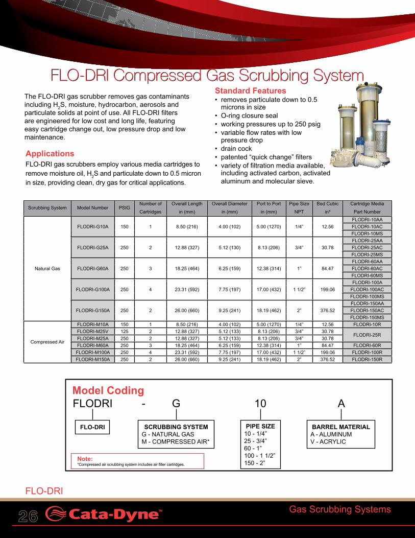
FLO-DRI Compressed Gas Scrubbing SystemFLO-DRI Compressed Gas Scrubbing SystemThe FLO-DRI gas scrubber removes gas contaminants including H2S, moisture, hydrocarbon, aerosols and particulate solids at point of use. All FLO-DRI filters are engineered for low cost and long life, featuring easy cartridge change out, low pressure drop and low maintenance.
ApplicationsFLO-DRI gas scrubbers employ various media cartridges to remove moisture oil, H2S and particulate down to 0.5 micron in size, providing clean, dry gas for critical applications.
Standard Features• removes particulate down to 0.5
microns in size• O-ring closure seal• working pressures up to 250 psig• variable flow rates with low
pressure drop• drain cock• patented “quick change” filters• variety of filtration media available,
including activated carbon, activated aluminum and molecular sieve.
Model Coding FLODRI - G 10 A
FLO-DRI PIPE SIZE10 - 1/4” 25 - 3/4”60 - 1”100 - 1 1/2”150 - 2”
SCRUBBING SYSTEMG - NATURAL GASM - COMPRESSED AIR*
BARREL MATERIALA - ALUMINUMV - ACRYLIC
Scrubbing System Model Number PSIGNumber of
Cartridges
Overall Length
in (mm)
Overall Diameter
in (mm)
Port to Port
in (mm)
Pipe Size
NPT
Bed Cubic
in³
Cartridge Media
Part Number
Natural Gas
FLODRI-G10A 150 1 8.50 (216) 4.00 (102) 5.00 (1270) 1/4” 12.56FLODRI-10AAFLODRI-10ACFLODRI-10MS
FLODRI-G25A 250 2 12.88 (327) 5.12 (130) 8.13 (206) 3/4” 30.78FLODRI-25AAFLODRI-25ACFLODRI-25MS
FLODRI-G60A 250 3 18.25 (464) 6.25 (159) 12.38 (314) 1” 84.47FLODRI-60AAFLODRI-60ACFLODRI-60MS
FLODRI-G100A 250 4 23.31 (592) 7.75 (197) 17.00 (432) 1 1/2” 199.06FLODRI-100A
FLODRI-100ACFLODRI-100MS
FLODRI-G150A 250 2 26.00 (660) 9.25 (241) 18.19 (462) 2” 376.52FLODRI-150AAFLODRI-150ACFLODRI-150MS
Compressed Air
FLODRI-M10A 150 1 8.50 (216) 4.00 (102) 5.00 (1270) 1/4” 12.56 FLODRI-10RFLODRI-M25V 125 2 12.88 (327) 5.12 (133) 8.13 (206) 3/4” 30.78
FLODRI-25RFLODRI-M25A 250 2 12.88 (327) 5.12 (133) 8.13 (206) 3/4” 30.78FLODRI-M60A 250 3 18.25 (464) 6.25 (159) 12.38 (314) 1” 84.47 FLODRI-60RFLODRI-M100A 250 4 23.31 (592) 7.75 (197) 17.00 (432) 1 1/2” 199.06 FLODRI-100RFLODRI-M150A 250 2 26.00 (660) 9.25 (241) 18.19 (462) 2” 376.52 FLODRI-150R
Note: *Compressed air scrubbing system includes air filter cartridges.
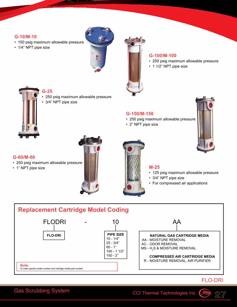
G-10/M-10• 150 psig maximum allowable pressure• 1/4” NPT pipe size
Replacement Cartridge Model Coding
FLODRI - 10 AA
FLO-DRI NATURAL GAS CARTRIDGE MEDIA AA - MOISTURE REMOVAL AC - ODOR REMOVAL MS - H2S & MOISTURE REMOVAL
COMPRESSED AIR CARTRIDGE MEDIA R - MOISTURE REMOVAL, AIR PURIFIER
Note: To order specify model number and cartridge media part number.
G-25• 250 psig maximum allowable pressure• 3/4” NPT pipe size
G-60/M-60• 250 psig maximum allowable pressure• 1” NPT pipe size
G-100/M-100• 250 psig maximum allowable pressure• 1 1/2” NPT pipe size
G-150/M-150• 250 psig maximum allowable pressure• 2” NPT pipe size
PIPE SIZE10 - 1/4” 25 - 3/4”60 - 1”100 - 1 1/2”150 - 2”
M-25• 125 psig maximum allowable pressure• 3/4” NPT pipe size• For compressed air applications
The FLO-DRI gas scrubber removes gas contaminants including H2S, moisture, hydrocarbon, aerosols and particulate solids at point of use. All FLO-DRI filters are engineered for low cost and long life, featuring easy cartridge change out, low pressure drop and low maintenance.
CCI Thermal Technologies Inc. 27
FLO-DRI
Gas Scrubbing System
FLO-DRI Compressed Gas Scrubbing SystemFLO-DRI Compressed Gas Scrubbing SystemThe FLO-DRI gas scrubber removes gas contaminants including H2S, moisture, hydrocarbon, aerosols and particulate solids at point of use. All FLO-DRI filters are engineered for low cost and long life, featuring easy cartridge change out, low pressure drop and low maintenance.
ApplicationsFLO-DRI gas scrubbers employ various media cartridges to remove moisture oil, H2S and particulate down to 0.5 micron in size, providing clean, dry gas for critical applications.
Standard Features• removes particulate down to 0.5
microns in size• O-ring closure seal• working pressures up to 250 psig• variable flow rates with low
pressure drop• drain cock• patented “quick change” filters• variety of filtration media available,
including activated carbon, activated aluminum and molecular sieve.
Model Coding FLODRI - G 10 A
FLO-DRI PIPE SIZE10 - 1/4” 25 - 3/4”60 - 1”100 - 1 1/2”150 - 2”
SCRUBBING SYSTEMG - NATURAL GASM - COMPRESSED AIR*
BARREL MATERIALA - ALUMINUMV - ACRYLIC
Scrubbing System Model Number PSIGNumber of
Cartridges
Overall Length
in (mm)
Overall Diameter
in (mm)
Port to Port
in (mm)
Pipe Size
NPT
Bed Cubic
in³
Cartridge Media
Part Number
Natural Gas
FLODRI-G10A 150 1 8.50 (216) 4.00 (102) 5.00 (1270) 1/4” 12.56FLODRI-10AAFLODRI-10ACFLODRI-10MS
FLODRI-G25A 250 2 12.88 (327) 5.12 (130) 8.13 (206) 3/4” 30.78FLODRI-25AAFLODRI-25ACFLODRI-25MS
FLODRI-G60A 250 3 18.25 (464) 6.25 (159) 12.38 (314) 1” 84.47FLODRI-60AAFLODRI-60ACFLODRI-60MS
FLODRI-G100A 250 4 23.31 (592) 7.75 (197) 17.00 (432) 1 1/2” 199.06FLODRI-100A
FLODRI-100ACFLODRI-100MS
FLODRI-G150A 250 2 26.00 (660) 9.25 (241) 18.19 (462) 2” 376.52FLODRI-150AAFLODRI-150ACFLODRI-150MS
Compressed Air
FLODRI-M10A 150 1 8.50 (216) 4.00 (102) 5.00 (1270) 1/4” 12.56 FLODRI-10RFLODRI-M25V 125 2 12.88 (327) 5.12 (133) 8.13 (206) 3/4” 30.78
FLODRI-25RFLODRI-M25A 250 2 12.88 (327) 5.12 (133) 8.13 (206) 3/4” 30.78FLODRI-M60A 250 3 18.25 (464) 6.25 (159) 12.38 (314) 1” 84.47 FLODRI-60RFLODRI-M100A 250 4 23.31 (592) 7.75 (197) 17.00 (432) 1 1/2” 199.06 FLODRI-100RFLODRI-M150A 250 2 26.00 (660) 9.25 (241) 18.19 (462) 2” 376.52 FLODRI-150R
Note: *Compressed air scrubbing system includes air filter cartridges.
G-10/M-10• 150 psig maximum allowable pressure• 1/4” NPT pipe size
Replacement Cartridge Model Coding
FLODRI - 10 AA
FLO-DRI NATURAL GAS CARTRIDGE MEDIA AA - MOISTURE REMOVAL AC - ODOR REMOVAL MS - H2S & MOISTURE REMOVAL
COMPRESSED AIR CARTRIDGE MEDIA R - MOISTURE REMOVAL, AIR PURIFIER
Note: To order specify model number and cartridge media part number.
G-25• 250 psig maximum allowable pressure• 3/4” NPT pipe size
G-60/M-60• 250 psig maximum allowable pressure• 1” NPT pipe size
G-100/M-100• 250 psig maximum allowable pressure• 1 1/2” NPT pipe size
G-150/M-150• 250 psig maximum allowable pressure• 2” NPT pipe size
PIPE SIZE10 - 1/4” 25 - 3/4”60 - 1”100 - 1 1/2”150 - 2”
M-25• 125 psig maximum allowable pressure• 3/4” NPT pipe size• For compressed air applications

28 Gas Scrubbing Systems
NGS 1000
Applications• engineered specifically for industrial
applications with gas supply lines to equipment such as Cata-Dyne™ WX, MKII & WXS heaters and gas appliances
• this natural gas scrubbing system is used to remove contaminants found in fuel gas from natural gas wells
• interchangeable with existing applications
Standard Features• housing and cover material - extruded, heat treated,
machined and anodized 6000 series aluminum• maximum operating pressure is 250 psi• operating temperature is -40°C to 93°C (-40°F to 200°F)• flow rate range from 10 SCFM to 25 SCFM• inlet and outlet ports available in 1/4” NPT or 3/4” NPT• drain cock• standard stainless steel universal mounting kit• filtration media is available for moisture, sour gas, odor
and oil contaminants• cartridge filter change-out indicator plugs available• removes particulate down to 0.5 micron in size• variety of filtration media available, including activated
carbon, activated aluminum and molecular sieve• SAE/ORB O-ring design
Certifications• certification for pressure vessels CRN #0H6573.213• designed to ASME Section VIII Div.1
Gas Flow Heater Recommendedcu. ft/hr Size (in) NGS 1000 Scrubber
1.8 8 x 8 NGS-44.0 12 x 12 NGS-48.0 12 x 24 NGS-4
12.0 18 x 24 NGS-416.0 24 x 24 NGS-1220.0 24 x 30 NGS-1224.0 24 x 36 NGS-12
Note: When ordering please specify the operating fuel, pressure and flow rate.
Sour Gas H2S (10 ppm) Moisture (50 ppm)
WX Series Heater
(in)
Rating (Btu/hr)
FLODRI-10MS Days
FLODRI-25MS Days
FLODRI-10MS Days
FLODRI-25MS Days
6 x 6 1,250 560 1,512 440 1,1846 x 12 2,500 280 756 220 5926 x 24 5,000 140 378 110 2968 x 8 2,916 240 648 189 50810 x 12 4,166 168 454 132 35512 x 12 5,000 140 378 110 29612 x 24 10,000 70 189 55 14812 x 36 15,000 47 126 37 9912 x 48 20,000 35 95 28 7412 x 60 25,000 28 73 22 5912 x 72 30,000 23 63 18 4918 x 24 15,000 47 126 37 9918 x 30 18,750 37 101 29 7918 x 36 22,500 31 84 24 6618 x 48 30,000 23 63 18 4918 x 60 37,500 19 50 15 3918 x 72 45,000 16 42 12 3324 x 24 20,000 35 95 27 7424 x 30 25,000 28 76 22 5924 x 36 30,000 23 63 18 4924 x 48 40,000 18 47 14 3724 x 60 50,000 14 38 11 3024 x 72 60,000 12 32 9 25
Note: The above table shows cartridge change-out frequencies in days for each model heater and gas scrubber for H2S and moisture. To determine the cartridge change-out frequency in days for other H2S or moisture concentrations, use the formulas provided in the examples as outlined in the Change-Out Frequency Calculation Examples.
NGS 1000 Natural Gas Scrubbing System
NGS 1000 Natural Gas Scrubbing System
G
A
B
F
3"
D
INLETPORT
OUTLETPORT
C
DR
AIN
2"
RIGHT SIDE
3/4"
OPTIONALMOUNTING KIT
3/4" x 5/16"4 SLOTS
E
5/8"
B
3"
FD
LEFT SIDE
OUTLETPORT
INLETPORT
G
AC 2"
E
DR
AIN
3/4"
3/4" x 5/16"4 SLOTS
OPTIONALMOUNTING KIT 5/8"
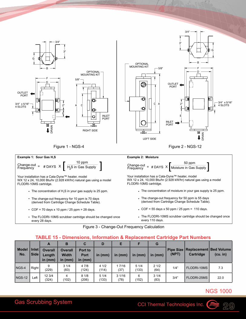
Figure 3 - Change-Out Frequency Calculation
Model No.
Inlet Side
A B C D E F GPipe Size
(NPT)Replacement
CartridgeBed Volume
(cu. in)Overall Lengthin (mm)
Overall Width
in (mm)
Port to Port
in (mm)in (mm) in (mm) in (mm) in (mm)
NGS-4 Right 9(229)
3 1/4(83)
4 7/8(124)
4 1/2(114)
1 7/16(37)
5 1/4(133)
2 1/2(64) 1/4” FLODRI-10MS 7.3
NGS-12 Left 12 3/4(324)
4(102)
8 1/8(206)
5 1/4(133)
3 1/16(78)
6(152)
3 1/4(83) 3/4” FLODRI-25MS 22.0
Example 1: Sour Gas H S2
Your installation has a Cata-Dyne™ heater, model
The concentration of H S in your gas supply is 25 ppm.2
The change-out frequency for 10 ppm is 70 days(derived from Cartrdige Change Schedule Table).
COF = 70 days x 10 ppm / 25 ppm = 28 days.
The FLODRI-10MS scrubber cartridge should be changed once every 28 days.
H S in Gas Supply[X# DAYSChange-out
Frequency = ]10 ppm
2
WX 12 x 24, 10,000 Btu/hr (2.928 kW/hr) natural gas using a model FLODRI-10MS cartridge.
•
•
•
•
Example 2: Moisture
Your installation has a Cata-Dyne™ heater, model
The concentration of moisture in your gas supply is 25 ppm.
The change-out frequency for 50 ppm is 55 days (derived from Cartrdige Change Schedule Table).
COF = 55 days x 50 ppm / 25 ppm = 110 days.
The FLODRI-10MS scrubber cartridge should be changed once every 110 days.
Change-out
Moisture in Gas Supply# DAYS X [ ]Frequency =50 ppm
WX 12 x 24, 10,000 Btu/hr (2.928 kW/hr) natural gas using a model FLODRI-10MS cartridge.
•
•
•
•
Figure 1 - NGS-4 Figure 2 - NGS-12
The Cata-Dyne™ NGS 1000 Natural Gas Scrubber is designed to remove contaminants and extend the life of your Cata-Dyne™ infrared heater. These infrared heaters, as with all other gas appliances, are designed to work on clean natural gas or propane. Fuel gas from natural gas wells may contain some form of contamination or particulates that can interfere with the operation of an infrared heater. Using an Cata-Dyne™ NGS 1000, reduces the risk of costly repairs and downtime.
TABLE 13 - Scrubber Selection for Cata-Dyne™ Heaters
TABLE 14 - Cartridge Change Schedule in Days
CCI Thermal Technologies Inc. 29
NGS 1000
Gas Scrubbing System
Applications• engineered specifically for industrial
applications with gas supply lines to equipment such as Cata-Dyne™ WX, MKII & WXS heaters and gas appliances
• this natural gas scrubbing system is used to remove contaminants found in fuel gas from natural gas wells
• interchangeable with existing applications
Standard Features• housing and cover material - extruded, heat treated,
machined and anodized 6000 series aluminum• maximum operating pressure is 250 psi• operating temperature is -40°C to 93°C (-40°F to 200°F)• flow rate range from 10 SCFM to 25 SCFM• inlet and outlet ports available in 1/4” NPT or 3/4” NPT• drain cock• standard stainless steel universal mounting kit• filtration media is available for moisture, sour gas, odor
and oil contaminants• cartridge filter change-out indicator plugs available• removes particulate down to 0.5 micron in size• variety of filtration media available, including activated
carbon, activated aluminum and molecular sieve• SAE/ORB O-ring design
Certifications• certification for pressure vessels CRN #0H6573.213• designed to ASME Section VIII Div.1
Gas Flow Heater Recommendedcu. ft/hr Size (in) NGS 1000 Scrubber
1.8 8 x 8 NGS-44.0 12 x 12 NGS-48.0 12 x 24 NGS-412.0 18 x 24 NGS-416.0 24 x 24 NGS-1220.0 24 x 30 NGS-1224.0 24 x 36 NGS-12
Note: When ordering please specify the operating fuel, pressure and flow rate.
Sour Gas H2S (10 ppm) Moisture (50 ppm)
WX Series Heater
(in)
Rating (Btu/hr)
FLODRI-10MS Days
FLODRI-25MS Days
FLODRI-10MS Days
FLODRI-25MS Days
6 x 6 1,250 560 1,512 440 1,1846 x 12 2,500 280 756 220 5926 x 24 5,000 140 378 110 2968 x 8 2,916 240 648 189 50810 x 12 4,166 168 454 132 35512 x 12 5,000 140 378 110 29612 x 24 10,000 70 189 55 14812 x 36 15,000 47 126 37 9912 x 48 20,000 35 95 28 7412 x 60 25,000 28 73 22 5912 x 72 30,000 23 63 18 4918 x 24 15,000 47 126 37 9918 x 30 18,750 37 101 29 7918 x 36 22,500 31 84 24 6618 x 48 30,000 23 63 18 4918 x 60 37,500 19 50 15 3918 x 72 45,000 16 42 12 3324 x 24 20,000 35 95 27 7424 x 30 25,000 28 76 22 5924 x 36 30,000 23 63 18 4924 x 48 40,000 18 47 14 3724 x 60 50,000 14 38 11 3024 x 72 60,000 12 32 9 25
Note: The above table shows cartridge change-out frequencies in days for each model heater and gas scrubber for H2S and moisture. To determine the cartridge change-out frequency in days for other H2S or moisture concentrations, use the formulas provided in the examples as outlined in the Change-Out Frequency Calculation Examples.
NGS 1000 Natural Gas Scrubbing System
NGS 1000 Natural Gas Scrubbing System
G
A
B
F
3"
D
INLETPORT
OUTLETPORT
C
DR
AIN
2"
RIGHT SIDE
3/4"
OPTIONALMOUNTING KIT
3/4" x 5/16"4 SLOTS
E
5/8"
B
3"
FD
LEFT SIDE
OUTLETPORT
INLETPORT
G
AC 2"
E
DR
AIN
3/4"
3/4" x 5/16"4 SLOTS
OPTIONALMOUNTING KIT 5/8"
Figure 3 - Change-Out Frequency Calculation
Model No.
Inlet Side
A B C D E F GPipe Size
(NPT)Replacement
CartridgeBed Volume
(cu. in)Overall Lengthin (mm)
Overall Width
in (mm)
Port to Port
in (mm)in (mm) in (mm) in (mm) in (mm)
NGS-4 Right 9(229)
3 1/4(83)
4 7/8(124)
4 1/2(114)
1 7/16(37)
5 1/4(133)
2 1/2(64) 1/4” FLODRI-10MS 7.3
NGS-12 Left 12 3/4(324)
4(102)
8 1/8(206)
5 1/4(133)
3 1/16(78)
6(152)
3 1/4(83) 3/4” FLODRI-25MS 22.0
Example 1: Sour Gas H S2
Your installation has a Cata-Dyne™ heater, model
The concentration of H S in your gas supply is 25 ppm.2
The change-out frequency for 10 ppm is 70 days(derived from Cartrdige Change Schedule Table).
COF = 70 days x 10 ppm / 25 ppm = 28 days.
The FLODRI-10MS scrubber cartridge should be changed once every 28 days.
H S in Gas Supply[X# DAYSChange-out
Frequency = ]10 ppm
2
WX 12 x 24, 10,000 Btu/hr (2.928 kW/hr) natural gas using a model FLODRI-10MS cartridge.
•
•
•
•
Example 2: Moisture
Your installation has a Cata-Dyne™ heater, model
The concentration of moisture in your gas supply is 25 ppm.
The change-out frequency for 50 ppm is 55 days (derived from Cartrdige Change Schedule Table).
COF = 55 days x 50 ppm / 25 ppm = 110 days.
The FLODRI-10MS scrubber cartridge should be changed once every 110 days.
Change-out
Moisture in Gas Supply# DAYS X [ ]Frequency =50 ppm
WX 12 x 24, 10,000 Btu/hr (2.928 kW/hr) natural gas using a model FLODRI-10MS cartridge.
•
•
•
•
Figure 1 - NGS-4 Figure 2 - NGS-12
TABLE 15 - Dimensions, Information & Replacement Cartridge Part Numbers

30 Line Heaters
The Cata-Dyne™ LH Line Heater prevents equipment freezing and possible hydrate formation during pressure reduction at natural gas regulating sites. The LH Line Heater heats the gas stream using infrared radiant heat transfer, eliminating the use of burners, glycol fluid and high maintenance heat exchange systems. It is also used to condition fuel gas for natural gas fired turbines or engines, and for heating gas and diluent streams in a variety of process applications. Custom engineered units for non-standard applications are available.
The Cata-Dyne™ LH Line Heater’s use of direct infrared heat transfer eliminates the need for traditional gas fired glycol bath systems. The elimination of glycol based heat transfer systems results in a more environmentally favorable installation. High field maintenance and operating costs are all eliminated by the Cata-Dyne™ LH Line Heater.
Applications Cata-Dyne™ Line Heaters are used for a variety of applications in the oil & gas, pipeline, midstream, gas distribution, and power generation industries. Common applications include:• Heating high pressure natural gas prior to pressure
reduction to prevent equipment freezing and the formation of hydrates.
• Conditioning fuel gas for natural gas fired turbines and engines.
• Heating of gas and diluent streams in a variety of process applications.
Features• Infrared radiant energy provided by the silent Cata-
Dyne™ WX Gas Catalytic Heater is NOx free providing the cleanest and quietest heating system available.
• The flanged multi-pass coil heat exchanger is designed and built to the ASME B31.3 Code for Process Piping.
• Enclosures feature galvanized steel structures with stainless-steel cladding, limiting corrosion and maintenance.
• Control options from manual stop/start with and without temperature control to remote start/stop and automated feedback pneumatic or electric temperature control.
• Automatic units feature engineered control panels with PLC control systems.
• Infrared heat is accurately controlled to meet process temperature requirements while economizing operating costs.
• Standard high temperature shutdowns, optional low flow shutdowns available.
• Fuel gas system designed and built in accordance with CSA/Can – B149.1 and NFPA 54.
• Electrical system designed and built in accordance with CSA/Can – C22.2 and NEC (NFPA 70).
• Catalytic heaters conform to ANSI Z83.20b-2011/ CSA 2.34b-2011 standard for Gas-Fired Low Intensity Heaters and are CSA and FM certified for use in Class 1, Division 1 or 2, Group D hazardous locations.
ModelHeater Input (Btu/hr) External Dimensions in (mm)Minimum Maximum Length x Width x Height
LH-40 10,000 40,00056 x 48 x 84
(1420 x 1219 x 2130)LH-60 15,000 60,000
LH-80 20,000 80,000
LH-100 25,000 100,000 78 x 68 x 90 (1980 x 1725 x 2286)LH-160 40,000 160,000
Hybrid Capabilities Only CCI Thermal offers the optional Catalytic/Electric Hybrid Line Heater. A secondary electric gas circulation heater is used to augment the capabilities of the base catalytic line heater. The hybrid design provides enhanced responsiveness to gas flow transients and deeper turn-down capabilities.
Cata-Dyne™ Natural Gas Line HeatersCata-Dyne™ Natural Gas Line Heaters
Line Heaters
TABLE 16 - Cata-DyneTM Line Heater Models
Custom Engineered Line Heater (above)
Standard LH Series Line Heater (right)
Note:1. Custom designs and Btu ratings are available upon request.2. Heater output between minimum and maximum values is manually selected on manual
and sequential models. 3. Automatic zone control is only available with the automatic model.

CCI Thermal Technologies Inc. 31
Line Heaters
Model Coding
Cata-DyneTM LH Line Heater
Prefix Model Start-up Type
Temp. Control
Start-upVoltage
Flange Size
Flange Rating
LH 40 M NT 12 1 600
12 VDC120 VAC208 VAC240 VAC480 VAC600 VAC
M ManualS SequencialA Automatic (engineered option)
600 ANSI900 ANSI
40 40,000 Btu/hr
60 60,000 Btu/hr80 80,000 Btu/hr100 100,000 Btu/hr 160 160,000 Btu/hrXXX Other
NT Fixed heat output, outlet temperature not controlled
T* Variable heat output, low/high, outlet temperature controlled
*Variable control from 60% to 100% of heater output.
1 1 in 2 2 in3 3 in4 4 in
Line Heaters

32
Offset Serpentine Tube Heat Exchanger
Exterior Stainless Steel Panels
Cata-Dyne™ Gas Catalytic Heaters
Gas Inlet
Gas Outlet
Manual or Automatic Gas Train Options
Stainless SteelTubing Frame
Cata-DyneTM Custom Engineered Line Heater
Line Heaters
Line Heaters

CCI Thermal Technologies Inc. 33
LH Line Heater Request For Quote FormLH Line Heater Request For Quote FormClient Information:
Company Name: ____________________________
Address: __________________________________
City, State (Prov): ___________________________
Country, Zip (Postal Code): ____________________
Contact Name: _____________________________
Phone / Fax: _______________________________
E-mail: ____________________________________
Proposal Type Required:
o Budgetary o Formal Quote
Other: ____________________________________
Required Date for Proposal: ___________________
Anticipated Shipping Date for Project: ___________
Project Name: ______________________________
Application Summary: ________________________
__________________________________________
__________________________________________
__________________________________________
Piping:
Diameter: ________________________ oin/omm
Flange Rating ANSI/ASME: ____________________
Design Temperature: _________________ o°F/o°C
Design Pressure: __________________ psig (kPag)
Temperature:
Heater Inlet: ________________________ o°F/o°C
Regulator Temp. Limit: ________________ o°F/o°C
Temp. After Regulation: ______________ o°F/o°C
Pressure: (Maximum 4500 psig /31,026 kPag)
Inlet Pressure: ____________________ psig (kPag)
Pressure Reduction:Stage One: _________________________ psi (kPa)
Stage Two: _________________________ psi (kPa)
Stage Three: ________________________ psi (kPa)
Gas Flow Rate:Maximum: ___________________________ SCFM
Minimum: ___________________________ SCFM
Electrical/Controls:Supply Power: ______________________volt/phase
o Automated System o Manual System
Area of Classification:
o Non-Hazardous oro Hazardous:
Class:____ Div:____ Group:____ “T” Code:____
o Indoor o Outdoor
To receive your quote, fax this page to: 905-829-4430
Attention: Projects
Line Line Heater Request For Quote Form
Line Heaters

34
The Cata-Dyne™ CHS Series Heating Package is the industry standard for space and spot heating applications where flammable gases, vapors or liquids may be present. Equipped with explosion-proof infrared heaters, this package comes standard or custom designed to meet any unique application.
The Cata-Dyne™ infrared heaters are controlled either manually or with an integrated hazardous locations control panel.
Applications
Comfort heating for industrial buildings, CNG, LNG or propane vehicle maintenance facilities and freeze protection for equipment and components.
Control Panel Features• single switch ON/OFF/STANDBY control• -18°C to 38°C (0°F to 100°F) thermostat• interlock terminals for integration with ancillary equipment• custom options available• CCSAUS certified for Class I, Division 2, Group D, or
optional ULC certification for Class I, Division 1, Group D, IEC Ex, ATEX
• expandable to 6 zones• touch screen option for CSA Class 1, Division 2• exhaust fan control
Control Panel Benefits• single point control of multiple heaters• floor level access to all control functions• interlock terminals for remote "Enable" & "Standby"• self diagnostic fault indication• optional remote thermostat for each zone
Heater Features• proprietary Cata-Dyne™ catalyst pad• corrosion resistant 300 series
stainless-steel construction• natural gas or propane operation• electric start available in 120V to 600V• individual heater models range from
8,000 - 48,000 Btu/hr• CSA certified for use in Class I, Division 1 & 2, Group D
hazardous locations• certified to ANSI Z83.20b-2011/CSA 2.34b-2011• NFPA30A Compliant
Heater Benefits• no moving parts and designed to operate indefinitely
when supplied with clean fuel and adequate ventilation• heaters can be strategically positioned to optimize
heat distribution
CHS Industrial Facility Hazardous Area Heating Package
CHS
Cata-Dyne™ Heating Package
CHS Industrial Facility Hazardous Area Heating Package
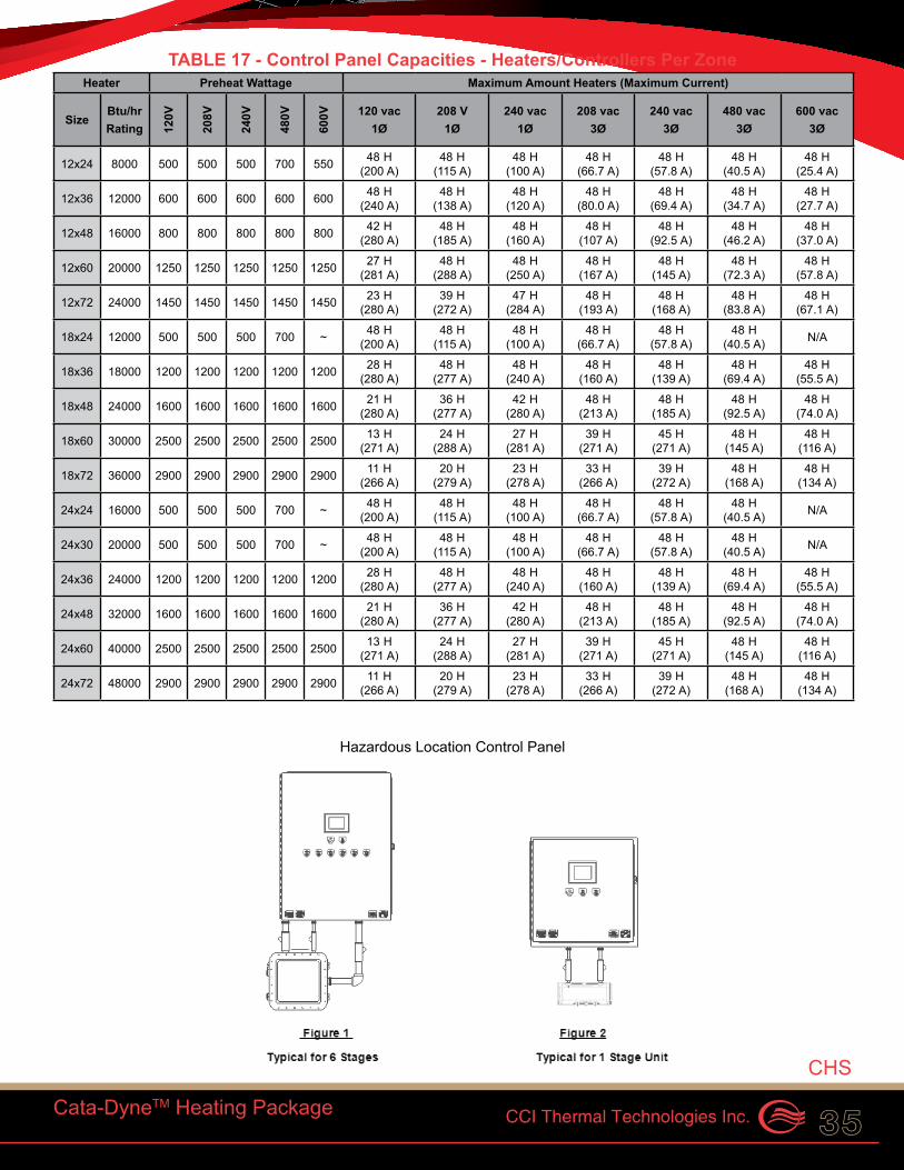
CCI Thermal Technologies Inc. 35
TABLE 17 - Control Panel Capacities - Heaters/Controllers Per ZoneHeater Preheat Wattage Maximum Amount Heaters (Maximum Current)
SizeBtu/hr Rating 12
0V
208V
240V
480V
600V 120 vac
1Ø208 V
1Ø240 vac
1Ø208 vac
3Ø240 vac
3Ø480 vac
3Ø600 vac
3Ø
12x24 8000 500 500 500 700 550 48 H (200 A)
48 H (115 A)
48 H (100 A)
48 H (66.7 A)
48 H (57.8 A)
48 H (40.5 A)
48 H (25.4 A)
12x36 12000 600 600 600 600 600 48 H (240 A)
48 H (138 A)
48 H (120 A)
48 H (80.0 A)
48 H (69.4 A)
48 H (34.7 A)
48 H (27.7 A)
12x48 16000 800 800 800 800 800 42 H (280 A)
48 H (185 A)
48 H (160 A)
48 H (107 A)
48 H (92.5 A)
48 H (46.2 A)
48 H (37.0 A)
12x60 20000 1250 1250 1250 1250 1250 27 H (281 A)
48 H (288 A)
48 H (250 A)
48 H (167 A)
48 H (145 A)
48 H (72.3 A)
48 H (57.8 A)
12x72 24000 1450 1450 1450 1450 1450 23 H (280 A)
39 H (272 A)
47 H (284 A)
48 H (193 A)
48 H (168 A)
48 H (83.8 A)
48 H (67.1 A)
18x24 12000 500 500 500 700 ~ 48 H (200 A)
48 H (115 A)
48 H (100 A)
48 H (66.7 A)
48 H (57.8 A)
48 H (40.5 A) N/A
18x36 18000 1200 1200 1200 1200 1200 28 H (280 A)
48 H (277 A)
48 H (240 A)
48 H (160 A)
48 H (139 A)
48 H (69.4 A)
48 H (55.5 A)
18x48 24000 1600 1600 1600 1600 1600 21 H (280 A)
36 H (277 A)
42 H (280 A)
48 H (213 A)
48 H (185 A)
48 H (92.5 A)
48 H (74.0 A)
18x60 30000 2500 2500 2500 2500 2500 13 H (271 A)
24 H (288 A)
27 H (281 A)
39 H (271 A)
45 H (271 A)
48 H (145 A)
48 H (116 A)
18x72 36000 2900 2900 2900 2900 2900 11 H (266 A)
20 H (279 A)
23 H (278 A)
33 H (266 A)
39 H (272 A)
48 H (168 A)
48 H (134 A)
24x24 16000 500 500 500 700 ~ 48 H (200 A)
48 H (115 A)
48 H (100 A)
48 H (66.7 A)
48 H (57.8 A)
48 H (40.5 A) N/A
24x30 20000 500 500 500 700 ~ 48 H (200 A)
48 H (115 A)
48 H (100 A)
48 H (66.7 A)
48 H (57.8 A)
48 H (40.5 A) N/A
24x36 24000 1200 1200 1200 1200 1200 28 H (280 A)
48 H (277 A)
48 H (240 A)
48 H (160 A)
48 H (139 A)
48 H (69.4 A)
48 H (55.5 A)
24x48 32000 1600 1600 1600 1600 1600 21 H (280 A)
36 H (277 A)
42 H (280 A)
48 H (213 A)
48 H (185 A)
48 H (92.5 A)
48 H (74.0 A)
24x60 40000 2500 2500 2500 2500 2500 13 H (271 A)
24 H (288 A)
27 H (281 A)
39 H (271 A)
45 H (271 A)
48 H (145 A)
48 H (116 A)
24x72 48000 2900 2900 2900 2900 2900 11 H (266 A)
20 H (279 A)
23 H (278 A)
33 H (266 A)
39 H (272 A)
48 H (168 A)
48 H (134 A)
Hazardous Location Control Panel
Cata-DyneTM Heating Package
CHS

36 Accessories
AccessoriesAccessories
In many typical oil & gas applications that are classified as Class I hazardous locations, the Cata-Dyne™ heater must be installed in accordance with CSA, FM and ATEX codes and regulations. As a result, the Cata-Dyne™ product line is supported with essential accessories required to ensure the safe and efficient operation of the units.
Safety Shut-Off Valves• the safety shut-off valve
works in conjunction with the thermocouple to monitor the catalytic reaction ensuring it is well established before fuel supply remains on unattended
• designed to automatically shut off the gas supply to the heater if the thermocouple senses that the catalyst pad has dropped below the activation temperature
• two styles are available to suit your heating application needs
ASV375 - Safety Shut-Off Valves• 3/8” NPT connections and a maximum inlet pressure
of 1/2 psi• designed with a pilot test port located at the base of the
valve that can be used to measure operating pressure
TABLE 18 - ASV375 Part # DescriptionValve - ASV375 Safety Shut-Off Valve & Thermostat
ASV375NT - Safety Shut-Off Valves• the ASV375NT valve includes an additional tamper-
resistant design discouraging mechanical attempts to fix the valve open and override it’s safety feature
• 3/8” NPT connections and a maximum inlet pressure of 1/2 psi
TABLE 19 - ASV375NT Part # DescriptionValve - ASV375NT Tamper-Proof Safety Shut-Off Valve
Mertik Combination Gas Controls/Valves• designed as a non-electric combination of the safety
shut-off valve and a thermostat control• includes a tamper-resistant thermocouple connection
that cannot be mechanically fixed open
TABLE 20 - Mertik Part # DescriptionAC-GV33 Combination Gas Control/Valve
Certifications• Mertik - CSA approved and CE certified• ASV375 and ASV375NT - CSA approved
Thermostatic Temperature Control Valve• this valve is designed with a bulb and capillary
assembly that automatically regulates fuel flow to a Cata-Dyne™ heater from 100% when heat is required to approximately 30% when the thermostat is satisfied
• this unit is used to control building temperature for spot and space heating applications
• the sensing bulb is filled with a temperature sensitive liquid. Changes in the temperature at the bulb expand and contract the liquid on temperature rise and fall causing the internal mechanism to modulate the flow of fuel
• temperature control range of 0°C to 44°C (32°F to 110°F)
• maximum inlet pressure of 1/2 psi• each unit has a connection size of 3/8” NPT female and
a capillary length of 5 ft (1.5 m)• no electrical power is required to operate this unit• controls are factory set to specific Btu and fuel ratings
Certifications• CSA approved
TABLE 21 - Temperature Control Valves
Part # DescriptionAC-TC 0°C to 44°C (32°F to 110°F)
Accessories
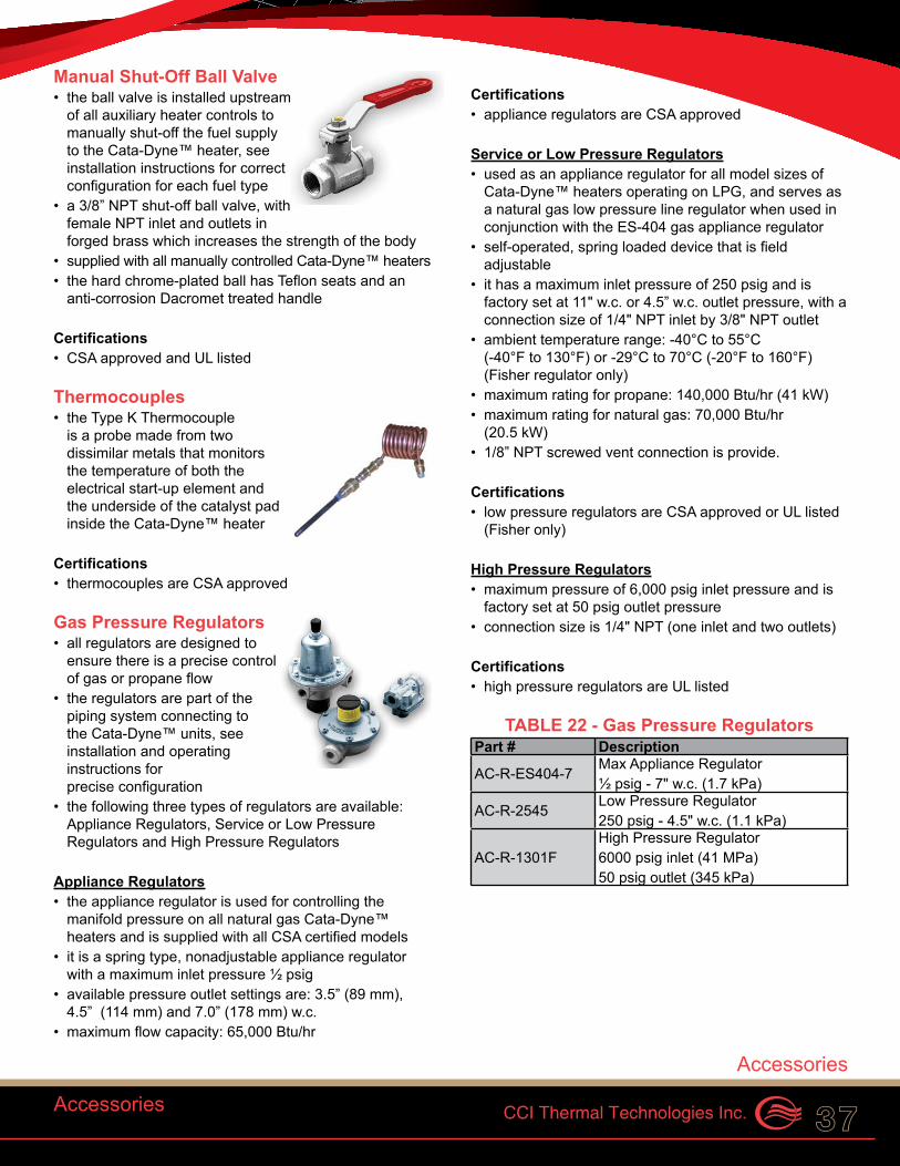
CCI Thermal Technologies Inc. 37Accessories
Manual Shut-Off Ball Valve• the ball valve is installed upstream
of all auxiliary heater controls to manually shut-off the fuel supply to the Cata-Dyne™ heater, see installation instructions for correct configuration for each fuel type
• a 3/8” NPT shut-off ball valve, with female NPT inlet and outlets in forged brass which increases the strength of the body
• supplied with all manually controlled Cata-Dyne™ heaters• the hard chrome-plated ball has Teflon seats and an
anti-corrosion Dacromet treated handle
Certifications• CSA approved and UL listed
Thermocouples• the Type K Thermocouple
is a probe made from two dissimilar metals that monitors the temperature of both the electrical start-up element and the underside of the catalyst pad inside the Cata-Dyne™ heater
Certifications• thermocouples are CSA approved
Gas Pressure Regulators• all regulators are designed to
ensure there is a precise control of gas or propane flow
• the regulators are part of the piping system connecting to the Cata-Dyne™ units, see installation and operating instructions for precise configuration
• the following three types of regulators are available: Appliance Regulators, Service or Low Pressure Regulators and High Pressure Regulators
Appliance Regulators• the appliance regulator is used for controlling the
manifold pressure on all natural gas Cata-Dyne™ heaters and is supplied with all CSA certified models
• it is a spring type, nonadjustable appliance regulator with a maximum inlet pressure ½ psig
• available pressure outlet settings are: 3.5” (89 mm), 4.5” (114 mm) and 7.0” (178 mm) w.c.
• maximum flow capacity: 65,000 Btu/hr
Certifications• appliance regulators are CSA approved
Service or Low Pressure Regulators• used as an appliance regulator for all model sizes of
Cata-Dyne™ heaters operating on LPG, and serves as a natural gas low pressure line regulator when used in conjunction with the ES-404 gas appliance regulator
• self-operated, spring loaded device that is field adjustable
• it has a maximum inlet pressure of 250 psig and is factory set at 11" w.c. or 4.5” w.c. outlet pressure, with a connection size of 1/4" NPT inlet by 3/8" NPT outlet
• ambient temperature range: -40°C to 55°C (-40°F to 130°F) or -29°C to 70°C (-20°F to 160°F)(Fisher regulator only)
• maximum rating for propane: 140,000 Btu/hr (41 kW)• maximum rating for natural gas: 70,000 Btu/hr
(20.5 kW)• 1/8” NPT screwed vent connection is provide.
Certifications• low pressure regulators are CSA approved or UL listed
(Fisher only)
High Pressure Regulators• maximum pressure of 6,000 psig inlet pressure and is
factory set at 50 psig outlet pressure• connection size is 1/4" NPT (one inlet and two outlets)
Certifications• high pressure regulators are UL listed
TABLE 22 - Gas Pressure Regulators Part # Description
AC-R-ES404-7Max Appliance Regulator ½ psig - 7" w.c. (1.7 kPa)
AC-R-2545Low Pressure Regulator250 psig - 4.5" w.c. (1.1 kPa)
AC-R-1301FHigh Pressure Regulator6000 psig inlet (41 MPa)50 psig outlet (345 kPa)
Accessories

38
Battery Cables/Electric Start Up Leads• are used for starting a 12V Cata-
Dyne™ heater from a battery or other power supply
• each set of cables comes with heavy duty spring loaded serrated jaw clamps at one end and closed loop terminal ends the other
• a strain relief connector is attached at the terminal end to enable the user to seal the connection between the cable and the junction box
• lengths are available in 25 ft (7.6 m), 30 ft (9.14 m), and 40 ft (12.19 m)
TABLE 23 - Start-Up Leads 12V Part # DescriptionAC-LEAD-25 25 ft. LeadAC-LEAD-30 30 ft. LeadAC-LEAD-40 40 ft. Lead
Battery Cable Cabinet• this mountable storage cabinet is a convenient solution
for storing battery start-up leads, offering protection from adverse weather conditions
• each cabinet is manufactured from heavy duty 20-gauge stainless steel, and can be used with all lengths of battery cables from 25 ft to 40 ft (7.6 m to 12.2 m)
• the units are lockable and easy to install
TABLE 24 - Battery Cable Cabinet Part # DescriptionIN-BATBOX Battery Cable Cabinet
Fuel Gas Hose• versatile braided rubber fuel hose• these hoses have a 350 psi maximum working
pressure, and are available in lengths of 5, 10, 15, 20 ft (7.6 m to12.2 m). Other custom sizes are available
• the connection size at each end is 3/8" NPT male
Certifications• CSA approved Type 1 natural and propane gas hose
TABLE 25 - Propane HosesPart # DescriptionIN-P-H-3/8 x 18 in. 18 in. HoseIN-P-H-3/8 x 5 ft. 5 ft. HoseIN-P-H-3/8 x 10 ft. 10 ft. HoseIN-P-H-3/8 x 15 ft. 15 ft. HoseIN-P-H-3/8 x 20 ft. 20 ft. HoseIN-P-H-3/8 x 25 ft. 25 ft. HoseIN-P-H-3/8 x 30 ft. 30 ft. Hose
Protection Grilles
Two types of protection grills are available to protect personnel and objects from coming into direct contact with the face of the Cata-Dyne™ heater.
Strap-On Grilles• comes with four straps on all corners so the grille can
be bolted to the heater box• can be bolted to a variety of standard Cata-Dyne™ heaters• the bolting hardware is included in the purchase
Note:Cannot be used with MKII units.
Snap-On Grilles• these snap on to the bezel of the Cata-Dyne™ heater• available in a variety of sizes• they do not require any additional hardware or tools
to install• MKII units accept this style only
Note:Can only be used with units manufactured after Sept 1, 2002.
Gas Pressure Test Kit• pressure gauge and PVC tube used to accurately test
and measure the gas pressure going into a Cata-Dyne™ heater by connecting the tube end to the gas test port of the Safety Shut-Off Valve
• portable kit, ideal for all heater sizes• eliminates the need to fit test ports on pipelines used for
heater operation• includes a 15” w.c. (3.7 kPa) pressure gauge, a 6 ft
(1.8 m) PVC tube and the connection to the SSOV• compatible with both natural gas and propane heaters
Accessories
Accessories

CCI Thermal Technologies Inc. 39
POL Adapters• propane fitting adapter used
as a straight adapter that reduces a propane cylinder adapter to 1/4” NPT
• full flow brass fitting with a 7/8” (22 mm) hex nut
Stratafan™
Stratafan™ produces up to 150 cfm of air flow promoting uniform distribution of heat within enclosed areas, reducing temperature stratification and ventilation dead spots. This thermoelectric fan is self powered by a thermoelectric generator and has a cast aluminum housing.
Certifications• CSA certified for Class I, Divisions 1 & 2, Group D
Hazardous locations; certified to temperature code T3C
Vent Hood Assembly• a light weight galvanized steel
construction venting system for use with the Cata-Dyne™ heater to vent the by-products of reaction (carbon dioxide and water vapour) outside the building
• each assembly consists of 1 exhaust hood, 1 length of vent pipe 30" (762 mm), 1 elbow, 1 flashing, and 1 snowcap
• assemblies available for both standard Cata-Dyne™ heaters and MKII models (12" and 24")
• the above parts can be ordered individually
TABLE 26 - Vent Hood Assemblies Part # WidthAC-VHASSY-6 6" (152 mm)AC-VHASSY-8 8" (203 mm)AC-VHASSY-12 12" (305 mm)AC-VHASSY-24 24" (610 mm)AC-VHASSY-36 36" (914 mm)AC-VHASSY-48 48" (1219 mm)AC-MKIIVHASSY-12 MKII - 12" (305 mm)AC-MKIIVHASSY-24 MKII - 24" (610 mm)
Wall Mounting Brackets• optional stainless steel or mild steel constructed
mounting brackets and hardware
• standard wall brackets can mount Cata-Dyne™ heaters 7.5" (190 mm) away from the wall to allow access to the back of the heater
• MKII model bracket sizes are half the length of our standard wall mounting brackets allowing the heater to be installed closer to the wall
• brackets for large units over 8,000 Btu/hr (2.3 kW) are manufactured from heavy gauge mild steel flat bar
TABLE 27 - Wall Mount Brackets Part # Heater Size (inches)AC-WBRK-08 8x8AC-WBRK-06 6x24AC-WBRK-12 12x12AC-WBRK-12 12x24AC-WBRK-12 12x36AC-WBRK-12 12x48AC-WBRK-12 12x60AC-WBRK-12 12x72AC-WBRK-1824 18x24AC-WBRK-1836 18x36AC-WBRK-1848 18x48AC-WBRK-1860 18x60AC-WBRK-1872 18x72AC-WBRK-2424 24x24AC-WBRK-2430 24x30AC-WBRK-2436 24x36AC-WBRK-2448 24x48AC-WBRK-2460 24x60AC-WBRK-2472 24x72AC-WBRK-MK12 12x12 and 12x24
Accessories
Accessories

40 Accessories
45˚ Wall Mount Brackets• specialized mounting angle brackets used to simplify
the installation of all 18" and 24" Cata-Dyne™ heaters• manufactured from mild rolled steel with a zinc
plated finish
TABLE 28 - Wall Mount Brackets - 45° Part # Description - Mounting Angle BracketAC-WBRK-1824-45 18 x 24, Short SideAC-WBRK-1836-45 18 x 36, Long SideAC-WBRK-1848-45 18 x 48, Long SideAC-WBRK-1860-45 18 x 60, Long SideAC-WBRK-872-45 18 x 72, Long SideAC-WBRK-2424-45 24 x 24, Long SideAC-WBRK-2436-45 24 x 36, Long SideAC-WBRK-2448-45 24 x 48, Long SideAC-WBRK-2460-45 24 x 60, Long SideAC-WBRK-2472-45 24 x 72, Long Side
Floor Stands• 12-gauge galvanized steel
construction and hardware• allows the heater to be placed
closer to an object than the wall mounting system
• floor stands are adjustable, allowing the unit to be moved to the optimum height for the required heating application
TABLE 29 - Floor Mount Brackets Part # DescriptionAC-FSS-8 8x8AC-FSS-12 6x24AC-FSS-24 12x12AC-FSS-12 12x24AC-FSL 12x36AC-FSL 12x48AC-FSL 12x60AC-FSL 12x72AC-FSL 18x24AC-FSL 18x36AC-FSL 18x48AC-FSL 18x60AC-FSL 18x72AC-FSL 24x24AC-FSL 24x30AC-FSL 24x36AC-FSL 24x48AC-FSL 24x60AC-FSL 24x72
Conversion Data
1000 Btu/hr = 0.2929 kW or 292.9 W 1000 Btu = 1.054 MJ 3,412 Btu/hr = 1.0 kW
1 psi = 27.91 inches w.c. 1 psi = 6.895 kPa 1 inch w.c. = 0.247 kPa
1 standard cubic foot NAT Gas = 1000 Btu 1 standard cubic foot LPG = 2,500 Btu
1 standard cubic meter NAT Gas = 37 MJ 1 standard cubic meter LPG = 88 MJ
1 pound LPG = 21,560 Btu 1 kilogram LPG = 50.1 MJ
3.5 inches w.c. = 8.7 mbar = 0.87 kPa = 0.126 psi 4 inches w.c. = 9.9 mbar = 0.99 kPa = 0.144 psi 7 inches w.c. = 17.3 mbar = 1.73 kPa = 0.251 psi 11 inches w.c. = 27.2 mbar = 2.72 kPa = 0.394 psi
°C = (°F - 32) x (5/9) °F = (9/5 x °C) + 32
1 ft = 0.3048 m 1 ft² = 0.09290304 m² 1 ft³ = 0.02831685 m³ 1 in = 2.54 cm 1 in² = 6.4516 cm² 1 in³ = 16.38706 cm³
1 psi = 27.91 in. w.c. 1 in. w.c. = 0.247 kPa
1 cfm = 0.028312 m³/hr
Inverse Square Law
Intensity of infrared energy is inversely proportional to the square of the distance from the source of energy.
For infrared energy, this translates to: I=P/4πr2
Where: I = intensity of infrared at the heated object
P = total power emitted from IR source
r = the distance from the source to the heated object
Accessories

CCI Thermal Technologies Inc. 41Reference
Warranty
PLEASE ADHERE TO INSTRUCTIONS PUBLISHED IN THIS MANUAL.Failure to do so may be dangerous and may void certain provisions of your warranty.
For further assistance, please call:
WARRANTY: Under normal use the Company warrants to the purchaser that defects in material or workmanship will be repaired or replaced without charge for a period of 18 months from date of shipment, or 12 months from the start date of
product was purchased for authorized repair or replacement within the terms of this warranty.
Subject to State or Provincial law to the contrary, the Company will not be responsible for any expense for installation, removal from service, transportation, or damages of any type whatsoever, including damages arising from lack of use, business interruptions, or incidental or consequential damages.
The Company cannot anticipate or control the conditions of product usage and therefore accepts no responsibility for the safe application and suitability of its products when used alone or in combination with other products. Tests for the safe application and suitability of the products are the sole responsibility of the user.
This warranty will be void if, in the judgment of the Company, the damage, failure or defect is the result of:• vibration, radiation, erosion, corrosion, process
contamination, abnormal process conditions, temperature and pressures, unusual surges or pulsation, fouling, ordinary wear and tear, lack of maintenance, incorrectly applied utilities such as voltage, air, gas, water, and others or any combination of the aforementioned causes not
• any act or omission by the Purchaser, its agents, servants or independent contractors which for greater certainty, but not so as to limit the generality of the foregoing, includes physical, chemical or mechanical abuse, accident, improper installation of the product, improper storage and handling of the product, improper application or the misalignment of parts.
manufacturing defects apparent within 30 days from the date of installation.
The Company neither assumes nor authorizes any person to assume for it any other obligation or liability in connection with the product(s).
The Purchaser agrees that all warranty work required after the initial commissioning of the product will be provided only if the Company has been paid by the Purchaser in full accordance with the terms and conditions of the contract.
The Purchaser agrees that the Company makes no warranty or guarantee, express, implied or statutory, (INCLUDING ANY WARRANTY OF MERCHANTABILITY OR WARRANTY OF FITNESS FOR A PARTICULAR PURPOSE) written or oral, of the Article or incidental labour, except as is expressed or contained in the agreement herein.
LIABILITY: Technical data contained in the catalog or on the website is subject to change without notice. The Company reserves the right to make dimensional and other design changes as required. The Purchaser acknowledges the Company shall not be obligated to modify those articles manufactured before the formulation of the changes in design or improvements of the products by the Company.
The Company shall not be liable to compensate or indemnify the Purchaser, end user or any other party against any actions, claims, liabilities, injury, loss, loss of use, loss of business, damages, indirect or conse-
-es (including legal expenses), costs, obligations and causes of action of any kind arising wholly or partly from negligence or omission of the user or the mis-use, incorrect application, unsafe application, incor-rect storage and handling, incorrect installation, lack of maintenance, improper maintenance or improper operation of products furnished by the Company.
5918 Roper Road, Edmonton, Alberta, Canada T6B 3E1Phone: (780) 466-3178 Fax: (780) 468-5904
24 Hr. Hotline: 1-800-661-8529(U.S.A. and Canada)
Please have model and serial numbers available before calling.
Edmonton
1-800-661-8529(780) 466-3178F 780-468-5904
Oakville1-800-410-3131(905) 829-4422F 905-829-4430
Orillia1-877-325-3473(705) 325-3473F 705-325-2106
Greensburg1-800-473-2402(812) 663-4141F 812-663-4202
Houston1-855-219-2101(281) 506-2310F 281-506-2316
Denver1-855-244-3128(303) 979-7339F 303-979-7350
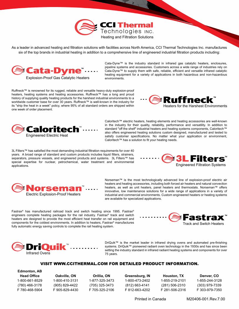
As a leader in advanced heating and filtration solutions with facilities across North America, CCI Thermal Technologies Inc. manufactures six of the top brands in industrial heating in addition to a comprehensive line of engineered industrial filtration products including:
VISIT WWW.CCITHERMAL.COM FOR DETAILED PRODUCT INFORMATION.
DriQuik™ is the market leader in infrared drying ovens and automated pre-finishing systems. DriQuik™ pioneered radiant oven technology in the 1930s and has since been setting the industry standard in infrared radiant heating systems and components for over 75 years.
Norseman™ is the most technologically advanced line of explosion-proof electric air heaters and heating accessories, including both forced air heaters and natural convection heaters, as well as unit heaters, panel heaters and thermostats. Norseman™ offers innovative, low maintenance solutions for a wide range of applications in a variety of industrial and commercial environments. Custom engineered heaters or heating systems are available for specialized applications.
3L Filters™ has satisfied the most demanding industrial filtration requirements for over 40 years. A broad range of standard and custom products includes liquid filters, strainers, separators, pressure vessels, and engineered products and systems. 3L Filters™ has special expertise for nuclear, petrochemical, water treatment and environmental applications.
Fastrax® has manufactured railroad track and switch heating since 1995. Fastrax® engineers complete heating packages for the rail industry. Fastrax® track and switch heaters are designed to provide the most efficient heat transfer on rail equipment and components for the coldest environments. In addition to heaters, Fastrax® manufactures fully automatic energy saving controls to complete the rail heating system.
Caloritech™ electric heaters, heating elements and heating accessories are well-known in the industry for their quality, reliability, performance and versatility. In addition to standard "off the shelf" industrial heaters and heating systems components, Caloritech™ also offers engineered heating solutions custom designed, manufactured and tested to satisfy customer specifications. No matter what your application or environment, Caloritech™ has a solution to fit your heating needs.
Ruffneck™ is renowned for its rugged, reliable and versatile heavy-duty explosion-proof heaters, heating systems and heating accessories. Ruffneck™ has a long and proud history of supplying quality heating products for the harshest industrial environments to a worldwide customer base for over 30 years. Ruffneck™ is well-known in the industry for its "ship the heat in a week" policy, where 95% of all standard orders are shipped within one week of order placement.
Cata-Dyne™ is the industry standard in infrared gas catalytic heaters, enclosures, pipeline systems and accessories. Customers across a wide range of industries rely on Cata-Dyne™ to supply them with safe, reliable, efficient and versatile infrared catalytic heating equipment for a variety of applications in both hazardous and non-hazardous environments.
Edmonton, AB Head Office
1-800-661-8529(780) 466-3178F 780-468-5904
Oakville, ON1-800-410-3131(905) 829-4422F 905-829-4430
Orillia, ON1-877-325-3473(705) 325-3473F 705-325-2106
Greensburg, IN1-800-473-2402(812) 663-4141F 812-663-4202
Houston, TX1-855-219-2101(281) 506-2310F 281-506-2316
Denver, CO1-855-244-3128(303) 979-7339F 303-979-7350
Printed in Canada M20406-001.Rev.7.00