1MB1 / 1MB5 explosion-proof motors
29
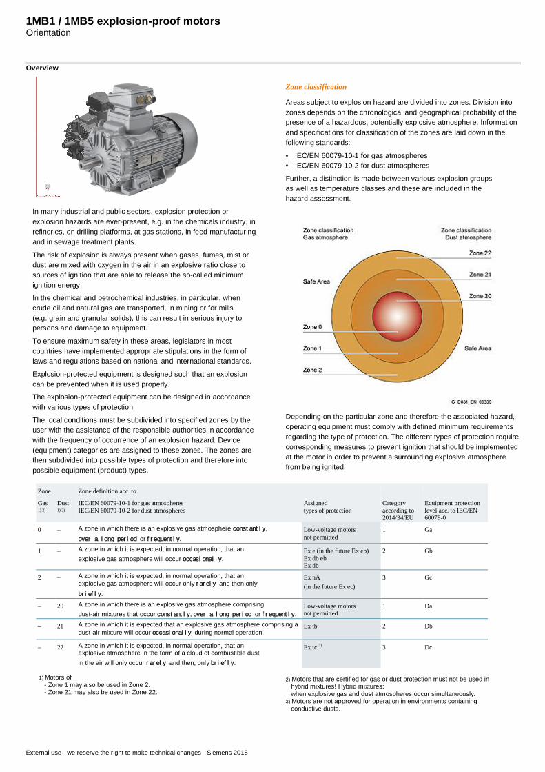
1MB1 / 1MB5 explosion-proof motors Orientation External use - we reserve the right to make technical changes - Siemens 2018 Overview In many industrial and public sectors, explosion protection or explosion hazards are ever-present, e.g. in the chemicals industry, in refineries, on drilling platforms, at gas stations, in feed manufacturing and in sewage treatment plants. The risk of explosion is always present when gases, fumes, mist or dust are mixed with oxygen in the air in an explosive ratio close to sources of ignition that are able to release the so-called minimum ignition energy. In the chemical and petrochemical industries, in particular, when crude oil and natural gas are transported, in mining or for mills (e.g. grain and granular solids), this can result in serious injury to persons and damage to equipment. To ensure maximum safety in these areas, legislators in most countries have implemented appropriate stipulations in the form of laws and regulations based on national and international standards. Explosion-protected equipment is designed such that an explosion can be prevented when it is used properly. The explosion-protected equipment can be designed in accordance with various types of protection. The local conditions must be subdivided into specified zones by the user with the assistance of the responsible authorities in accordance with the frequency of occurrence of an explosion hazard. Device (equipment) categories are assigned to these zones. The zones are then subdivided into possible types of protection and therefore into possible equipment (product) types. Zone classification Areas subject to explosion hazard are divided into zones. Division into zones depends on the chronological and geographical probability of the presence of a hazardous, potentially explosive atmosphere. Information and specifications for classification of the zones are laid down in the following standards: • IEC/EN 60079-10-1 for gas atmospheres • IEC/EN 60079-10-2 for dust atmospheres Further, a distinction is made between various explosion groups as well as temperature classes and these are included in the hazard assessment. Depending on the particular zone and therefore the associated hazard, operating equipment must comply with defined minimum requirements regarding the type of protection. The different types of protection require corresponding measures to prevent ignition that should be implemented at the motor in order to prevent a surrounding explosive atmosphere from being ignited. Zone Zone definition acc. to Gas 1) 2) Dust 1) 2) IEC/EN 60079-10-1 for gas atmospheres IEC/EN 60079-10-2 for dust atmospheres Assigned types of protection Category according to 2014/34/EU Equipment protection level acc. to IEC/EN 60079-0 0 – A zone in which there is an explosive gas atmosphere constantly, over a long period or frequently. Low-voltage motors not permitted 1 Ga 1 – A zone in which it is expected, in normal operation, that an explosive gas atmosphere will occur occasionally. Ex e (in the future Ex eb) Ex db eb Ex db 2 Gb 2 – A zone in which it is expected, in normal operation, that an explosive gas atmosphere will occur only rarely and then only briefly. Ex nA (in the future Ex ec) 3 Gc – 20 A zone in which there is an explosive gas atmosphere comprising dust-air mixtures that occur constantly, over a long period or frequently. Low-voltage motors not permitted 1 Da – 21 A zone in which it is expected that an explosive gas atmosphere comprising a dust-air mixture will occur occasionally during normal operation. Ex tb 2 Db – 22 A zone in which it is expected, in normal operation, that an explosive atmosphere in the form of a cloud of combustible dust in the air will only occur rarely and then, only briefly. Ex tc 3) 3 Dc 1) Motors of - Zone 1 may also be used in Zone 2. - Zone 21 may also be used in Zone 22. 2) Motors that are certified for gas or dust protection must not be used in hybrid mixtures! Hybrid mixtures: when explosive gas and dust atmospheres occur simultaneously. 3) Motors are not approved for operation in environments containing conductive dusts.
-
Upload
khangminh22 -
Category
Documents
-
view
3 -
download
0
Transcript of 1MB1 / 1MB5 explosion-proof motors
1MB1 / 1MB5 explosion-proof motorsOrientation
External use - we reserve the right to make technical changes - Siemens 2018
Overview
In many industrial and public sectors, explosion protection orexplosion hazards are ever-present, e.g. in the chemicals industry, inrefineries, on drilling platforms, at gas stations, in feed manufacturingand in sewage treatment plants.
The risk of explosion is always present when gases, fumes, mist ordust are mixed with oxygen in the air in an explosive ratio close tosources of ignition that are able to release the so-called minimumignition energy.In the chemical and petrochemical industries, in particular, whencrude oil and natural gas are transported, in mining or for mills(e.g. grain and granular solids), this can result in serious injury topersons and damage to equipment.
To ensure maximum safety in these areas, legislators in mostcountries have implemented appropriate stipulations in the form oflaws and regulations based on national and international standards.
Explosion-protected equipment is designed such that an explosioncan be prevented when it is used properly.The explosion-protected equipment can be designed in accordancewith various types of protection.
The local conditions must be subdivided into specified zones by theuser with the assistance of the responsible authorities in accordancewith the frequency of occurrence of an explosion hazard. Device(equipment) categories are assigned to these zones. The zones arethen subdivided into possible types of protection and therefore intopossible equipment (product) types.
Zone classification
Areas subject to explosion hazard are divided into zones. Division intozones depends on the chronological and geographical probability of thepresence of a hazardous, potentially explosive atmosphere. Informationand specifications for classification of the zones are laid down in thefollowing standards:
• IEC/EN 60079-10-1 for gas atmospheres• IEC/EN 60079-10-2 for dust atmospheres
Further, a distinction is made between various explosion groupsas well as temperature classes and these are included in thehazard assessment.
Depending on the particular zone and therefore the associated hazard,operating equipment must comply with defined minimum requirementsregarding the type of protection. The different types of protection requirecorresponding measures to prevent ignition that should be implementedat the motor in order to prevent a surrounding explosive atmospherefrom being ignited.
Zone Zone definition acc. to
Gas1) 2)
Dust1) 2)
IEC/EN 60079-10-1 for gas atmospheresIEC/EN 60079-10-2 for dust atmospheres
Assignedtypes of protection
Categoryaccording to2014/34/EU
Equipment protectionlevel acc. to IEC/EN60079-0
0 – A zone in which there is an explosive gas atmosphere constantly,over a long period or frequently.
Low-voltage motorsnot permitted
1 Ga
1 – A zone in which it is expected, in normal operation, that anexplosive gas atmosphere will occur occasionally.
Ex e (in the future Ex eb)Ex db ebEx db
2 Gb
2 – A zone in which it is expected, in normal operation, that anexplosive gas atmosphere will occur only rarely and then onlybriefly.
Ex nA(in the future Ex ec)
3 Gc
– 20 A zone in which there is an explosive gas atmosphere comprisingdust-air mixtures that occur constantly, over a long period or frequently.
Low-voltage motorsnot permitted
1 Da
– 21 A zone in which it is expected that an explosive gas atmosphere comprising adust-air mixture will occur occasionally during normal operation.
Ex tb 2 Db
– 22 A zone in which it is expected, in normal operation, that anexplosive atmosphere in the form of a cloud of combustible dustin the air will only occur rarely and then, only briefly.
Ex tc 3) 3 Dc
1) Motors of - Zone 1 may also be used in Zone 2. - Zone 21 may also be used in Zone 22.
2) Motors that are certified for gas or dust protection must not be used in hybrid mixtures! Hybrid mixtures: when explosive gas and dust atmospheres occur simultaneously.3) Motors are not approved for operation in environments containing conductive dusts.
ADMATH2
Rechteck
ADMATH2
Rechteck
ADMATH2
Stempel
1MB1 / 1MB5 explosion-proof motorsOrientation
External use - we reserve the right to make technical changes - Siemens 2018
Overview
Types of protection
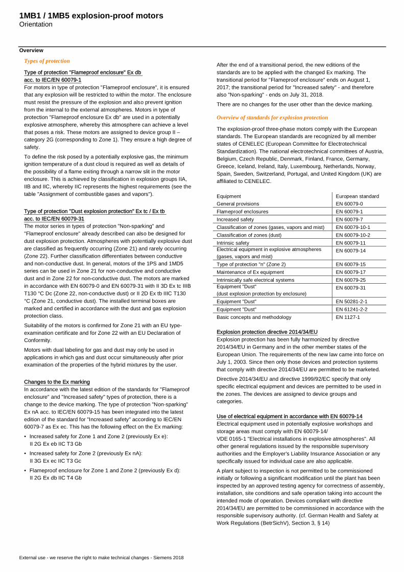
Type of protection "Flameproof enclosure" Ex dbacc. to IEC/EN 60079-1For motors in type of protection "Flameproof enclosure", it is ensuredthat any explosion will be restricted to within the motor. The enclosuremust resist the pressure of the explosion and also prevent ignitionfrom the internal to the external atmospheres. Motors in type ofprotection "Flameproof enclosure Ex db" are used in a potentiallyexplosive atmosphere, whereby this atmosphere can achieve a levelthat poses a risk. These motors are assigned to device group II –category 2G (corresponding to Zone 1). They ensure a high degree ofsafety.
To define the risk posed by a potentially explosive gas, the minimumignition temperature of a dust cloud is required as well as details ofthe possibility of a flame exiting through a narrow slit in the motorenclosure. This is achieved by classification in explosion groups IIA,IIB and IIC, whereby IIC represents the highest requirements (see thetable "Assignment of combustible gases and vapors").
Type of protection "Dust explosion protection" Ex tc / Ex tbacc. to IEC/EN 60079-31The motor series in types of protection "Non-sparking" and"Flameproof enclosure" already described can also be designed fordust explosion protection. Atmospheres with potentially explosive dustare classified as frequently occurring (Zone 21) and rarely occurring(Zone 22). Further classification differentiates between conductiveand non-conductive dust. In general, motors of the 1PS and 1MD5series can be used in Zone 21 for non-conductive and conductivedust and in Zone 22 for non-conductive dust. The motors are markedin accordance with EN 60079-0 and EN 60079-31 with II 3D Ex tc IIIBT130 °C Dc (Zone 22, non-conductive dust) or II 2D Ex tb IIIC T130°C (Zone 21, conductive dust). The installed terminal boxes aremarked and certified in accordance with the dust and gas explosionprotection class.
Suitability of the motors is confirmed for Zone 21 with an EU type-examination certificate and for Zone 22 with an EU Declaration ofConformity.
Motors with dual labeling for gas and dust may only be used inapplications in which gas and dust occur simultaneously after priorexamination of the properties of the hybrid mixtures by the user.
Changes to the Ex markingIn accordance with the latest edition of the standards for "Flameproofenclosure" and "Increased safety" types of protection, there is achange to the device marking. The type of protection "Non-sparking"Ex nA acc. to IEC/EN 60079-15 has been integrated into the latestedition of the standard for "Increased safety" according to IEC/EN60079-7 as Ex ec. This has the following effect on the Ex marking:
• Increased safety for Zone 1 and Zone 2 (previously Ex e):II 2G Ex eb IIC T3 Gb
• Increased safety for Zone 2 (previously Ex nA):II 3G Ex ec IIC T3 Gc
• Flameproof enclosure for Zone 1 and Zone 2 (previously Ex d):II 2G Ex db IIC T4 Gb
After the end of a transitional period, the new editions of thestandards are to be applied with the changed Ex marking. Thetransitional period for "Flameproof enclosure" ends on August 1,2017; the transitional period for "Increased safety" - and thereforealso "Non-sparking" - ends on July 31, 2018.
There are no changes for the user other than the device marking.
Overview of standards for explosion protection
The explosion-proof three-phase motors comply with the Europeanstandards. The European standards are recognized by all memberstates of CENELEC (European Committee for ElectrotechnicalStandardization). The national electrotechnical committees of Austria,Belgium, Czech Republic, Denmark, Finland, France, Germany,Greece, Iceland, Ireland, Italy, Luxembourg, Netherlands, Norway,Spain, Sweden, Switzerland, Portugal, and United Kingdom (UK) areaffiliated to CENELEC.
EquipmentGeneral provisions
European standardEN 60079-0
Flameproof enclosures EN 60079-1Increased safety EN 60079-7Classification of zones (gases, vapors and mist) EN 60079-10-1Classification of zones (dust) EN 60079-10-2Intrinsic safety EN 60079-11Electrical equipment in explosive atmospheres(gases, vapors and mist)
EN 60079-14
Type of protection "n" (Zone 2) EN 60079-15Maintenance of Ex equipment EN 60079-17Intrinsically safe electrical systems EN 60079-25Equipment "Dust"(dust explosion protection by enclosure)
EN 60079-31
Equipment "Dust" EN 50281-2-1Equipment "Dust" EN 61241-2-2Basic concepts and methodology EN 1127-1
Explosion protection directive 2014/34/EUExplosion protection has been fully harmonized by directive2014/34/EU in Germany and in the other member states of theEuropean Union. The requirements of the new law came into force onJuly 1, 2003. Since then only those devices and protection systemsthat comply with directive 2014/34/EU are permitted to be marketed.Directive 2014/34/EU and directive 1999/92/EC specify that onlyspecific electrical equipment and devices are permitted to be used inthe zones. The devices are assigned to device groups andcategories.
Use of electrical equipment in accordance with EN 60079-14Electrical equipment used in potentially explosive workshops andstorage areas must comply with EN 60079-14/VDE 0165-1 "Electrical installations in explosive atmospheres". Allother general regulations issued by the responsible supervisoryauthorities and the Employer's Liability Insurance Association or anyspecifically issued for individual case are also applicable.
A plant subject to inspection is not permitted to be commissionedinitially or following a significant modification until the plant has beeninspected by an approved testing agency for correctness of assembly,installation, site conditions and safe operation taking into account theintended mode of operation. Devices compliant with directive2014/34/EU are permitted to be commissioned in accordance with theresponsible supervisory authority. (cf. German Health and Safety atWork Regulations (BetrSichV), Section 3, § 14)
1MB1 / 1MB5 explosion-proof motorsOrientation
External use - we reserve the right to make technical changes - Siemens 2018
Overview
Device marking
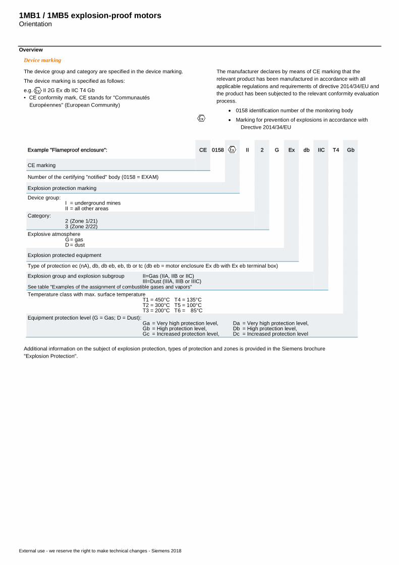
The device group and category are specified in the device marking.
The device marking is specified as follows:e.g. II 2G Ex db IIC T4 Gb• CE conformity mark, CE stands for "Communautés
Européennes" (European Community)
The manufacturer declares by means of CE marking that therelevant product has been manufactured in accordance with allapplicable regulations and requirements of directive 2014/34/EU andthe product has been subjected to the relevant conformity evaluationprocess.
· 0158 identification number of the monitoring body· Marking for prevention of explosions in accordance with
Directive 2014/34/EU
Example "Flameproof enclosure": CE 0158 II 2 G Ex db IIC T4 Gb
CE marking
Number of the certifying "notified" body (0158 = EXAM)
Explosion protection marking
Device group:I = underground minesII = all other areas
Category:2 (Zone 1/21)3 (Zone 2/22)
Explosive atmosphereG = gasD = dust
Explosion protected equipment
Type of protection ec (nA), db, db eb, eb, tb or tc (db eb = motor enclosure Ex db with Ex eb terminal box)
Explosion group and explosion subgroup II=Gas (IIA, IIB or IIC)III=Dust (IIIA, IIIB or IIIC)
See table "Examples of the assignment of combustible gases and vapors"Temperature class with max. surface temperature
T1 = 450°C T4 = 135°CT2 = 300°C T5 = 100°CT3 = 200°C T6 = 85°C
Equipment protection level (G = Gas; D = Dust):Ga = Very high protection level, Da = Very high protection level,Gb = High protection level, Db = High protection level,Gc = Increased protection level, Dc = Increased protection level
Additional information on the subject of explosion protection, types of protection and zones is provided in the Siemens brochure"Explosion Protection".
1MB1 / 1MB5 explosion-proof motorsOrientation
External use - we reserve the right to make technical changes - Siemens 2018
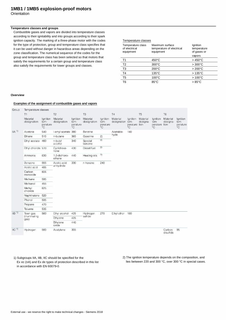
Temperature classes and groupsCombustible gases and vapors are divided into temperature classesaccording to their ignitability and into groups according to their sparkignition capacity. The marking of a three-phase motor with the codesfor the type of protection, group and temperature class specifies thatit can be used without danger in hazardous areas depending on thezone classification. The numerical sequence of the codes for thegroup and temperature class has been selected so that motors thatsatisfy the requirements for a certain group and temperature classalso satisfy the requirements for lower groups and classes.
Temperature classesTemperature classof electricalequipment
Maximum surfacetemperature of electricalequipment
Ignitiontemperatureof gases orvapors
T1 450°C > 450°CT2 300°C > 300°CT3 200°C > 200°CT4 135°C > 135°CT5 100°C > 100°CT6 85°C > 85°C
Overview
Examples of the assignment of combustible gases and vapors
1) Subgroups IIA, IIB, IIC should be specified for the Ex ec (nA) and Ex de types of protection described in this list in accordance with EN 60079-0.
2) The ignition temperature depends on the composition, and lies between 220 and 300 °C, over 300 °C in special cases.
1MB1 / 1MB5 explosion-proof motorsOrientation
External use - we reserve the right to make technical changes - Siemens 2018
Electrical design
The insulation system of SIMOTICS XP 1MB.55 motors is suitablefor line voltages up to 690 V. The connection system (terminal box,terminals) is also designed for this rated voltage.The explosion-proof motors are equipped with 6 terminals. They canthus be operated in star or delta. If a version with dual voltage e.g.400VΔ /690VY is selected, the rated data of both voltage levels isstamped on the rating plate.SIMOTICS XP 1MB.55 motors are manufactured with an insulationsystem having a thermal class of 155 °C. Utilization at ratedoperation corresponds to thermalClass 130 °C.
Operation with a converterThe general use of high-quality insulation systems enables converteroperation. When operated with a converter, the motor with explosionprotection must be fitted with PTC thermistors. These are installed inthe stator winding and, in combination with a certified trip unit (EUtype examination certificate), they perform sole motor protection inthe case of converter operation. Motor circuit breakers are notrequired.The permissible speed and torque range is stamped on an additionalrating plate.These rated operating points stamped on the additional plate applyfor both constant torque drives and fluid-flow machines with asquare-law load torque. For constant torque drives, the resultingthermal motor torques in the positioning range must be taken intoaccount.
Voltage tolerancesThe motors are suitable for operation with voltage and frequencytolerances according to EN 60034-1.In addition, tests are to be performed to ensure that the permissibletemperature limits for the outer surface of the explosion-proofenclosure according to EN 60079-1 are not exceeded duringcontinuous operations at the voltage limits (± 10%).The 1MB.55 motors in this catalog are certified for T4. The maximumpermitted surface temperature is 135 °C.
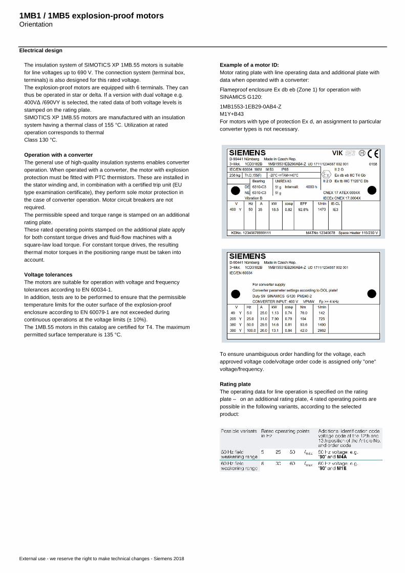
Example of a motor ID:Motor rating plate with line operating data and additional plate withdata when operated with a converter:
Flameproof enclosure Ex db eb (Zone 1) for operation withSINAMICS G120:
1MB1553-1EB29-0AB4-ZM1Y+B43For motors with type of protection Ex d, an assignment to particularconverter types is not necessary.
To ensure unambiguous order handling for the voltage, eachapproved voltage code/voltage order code is assigned only "one"voltage/frequency.
Rating plateThe operating data for line operation is specified on the ratingplate – on an additional rating plate, 4 rated operating points arepossible in the following variants, according to the selectedproduct:
SIMOTICS XP 1MB1 / 1MB5 explosion-proof motorsMotors with type of protection Ex db; Ex db eb
External use - we reserve the right to make technical changes - Siemens 2018
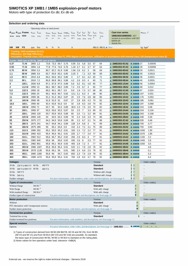
Selection and ordering data
Operating values at rated power
Prated,
50 Hz
Prated,
60 Hz
Framesize
nrated,
50 Hz
Trated,
50 Hz
hrated,
50 Hz,
4/4
hrated,
50 Hz,
3/4
hrated,
50 Hz,
2/4
cosjra-
ted,50 Hz,
4/4
Irated,
50 Hz,
400 V
TLR/Trated,
50 Hz
ILR/Irated,
50 Hz
TB/Trated,
50 Hz
LpfA,
50 Hz2)
LWA,
50 Hz2)
Cast-iron series1MB1553/1MB5553– IE3version in accordance with IEC60034-30Article No.
mIM B3 J
kW kW FS rpm Nm % % % A dB(A) dB(A)▲ New kg kgm2
* Cooling: Self-ventilated (IC411)* Efficiency: IE3 High Efficiency* Insulation: Thermal class 155 (temperature class F), IP55 degree of protection, utilization in accordance with thermal class 130 (temperature class B)
2-pole: 3000 rpm at 50 Hz, 3600 rpm at 60 Hz0,37 71 M 2850 1,2 73,8 73,3 69,7 0,76 0,95 3,5 5,8 3,5 57 64 ▲ 1MB1553-0CA2 n-nnnn 27 0,000450,55 71 M 2850 1,8 77,8 77,5 74,5 0,76 1,34 3,7 6,1 3,7 57 64 ▲ 1MB1553-0CA3 n-nnnn 28 0,000560,75 80 M 2850 2,5 80,7 82,2 81,9 0,86 1,56 2,6 6,2 3 58 69 ▲ 1MB1553-0DA2 n-nnnn 29 0,00111,1 80 M 2885 3,6 82,7 83,9 83,1 0,85 2,25 3 7,1 3,3 58 69 ▲ 1MB1553-0DA3 n-nnnn 30 0,00131,5 90 S 2910 4,9 84,2 84,6 83,2 0,86 3 2,7 8,1 4,2 60 71 ▲ 1MB1553-0EA0 n-nnnn 36 0,00212,2 90 L 2910 7,2 85,9 86,8 86,1 0,88 4,2 2,6 8,3 4 60 71 ▲ 1MB1553-0EA4 n-nnnn 40 0,00313 100 L 2920 9,8 87,1 87,9 87,5 0,88 5,6 3,2 8,1 4,6 65 77 ▲ 1MB1553-1AA4 n-nnnn 56 0,00544 112 M 2950 13 88,1 88,7 88,2 0,89 7,4 2,5 8,7 4 65 77 ▲ 1MB1553-1BA2 n-nnnn 68 0,0125,5 132 S 2950 18 89,2 90,1 89,7 0,9 9,9 1,9 7,3 3,7 68 80 ▲ 1MB1553-1CA0 n-nnnn 97 0,0247,5 132 S 2950 24 90,1 90,9 90,7 0,92 13,1 2,1 8,3 4 68 80 ▲ 1MB1553-1CA1 n-nnnn 107 0,03111 160 M 2955 36 91,2 91,3 90,2 0,87 20 2,5 7,6 3,8 68 80 ▲ 1MB1553-1DA2 n-nnnn 176 0,05315 160 M 2960 48 91,9 91,9 91 0,87 27 2,8 8,8 4,3 70 82 ▲ 1MB1553-1DA3 n-nnnn 186 0,06118,5 160 L 2955 60 92,4 92,8 92,3 0,9 32 2,8 8,3 3,9 70 82 ▲ 1MB1553-1DA4 n-nnnn 197 0,06822 180 M 2950 71 92,7 93 92,4 0,89 38,5 2,3 7,5 3,5 70 82 ▲ 1MB1553-1EA2 n-nnnn 243 0,0830 200 L 2955 97 93,3 93,6 93,3 0,87 53 2,5 7 3,3 69 81 ▲ 1MB1553-2AA4 n-nnnn 319 0,13437 200 L 2955 120 93,7 93,9 93,5 0,88 65 2,5 7,1 3,2 69 81 ▲ 1MB1553-2AA5 n-nnnn 343 0,15845 225 M 2960 145 94 94,5 94,4 0,89 78 2,4 6,9 3,3 74 88 ▲ 1MB1553-2BA2 n-nnnn 438 0,2655 250 M 2975 177 94,3 94,5 93,9 0,89 95 2,3 6,7 3,1 74 88 ▲ 1MB1553-2CA2 n-nnnn 535 0,4675 280 S 2975 241 94,7 94,8 94,1 0,89 128 2,4 6,8 3 75 89 ▲ 1MB1553-2DA0 n-nnnn 700 0,7790 280 M 2975 289 95 95,1 94,6 0,9 152 2,4 7,2 3,1 75 89 ▲ 1MB1553-2DA2 n-nnnn 755 0,94110 315 S 2980 352 95,2 95,5 95,3 0,91 183 2,3 7,2 3,2 77 91 ▲ 1MB5553-3AA0 n-nnnn 1000 1,55132 315 M 2982 423 95,4 95,6 95,1 0,91 220 2,7 7,7 3,4 77 91 ▲ 1MB5553-3AA2 n-nnnn 1070 1,85160 315 L 2982 512 95,6 95,7 95,2 0,92 265 2,6 8,3 3 77 91 ▲ 1MB5553-3AA4 n-nnnn 1150 2,2200 315 L 2982 640 95,8 96 95,6 0,92 330 2,6 8 3,3 77 91 ▲ 1MB5553-3AA5 n-nnnn 1400 2,8250 315 L 2982 801 95,8 96,1 95,9 0,93 405 2,8 7,2 3 77 91 ▲ 1MB5553-3AA6 n-nnnn 1550 3,5315 355 M 2986 1007 95,8 95,9 95,4 0,91 520 2,1 7,8 2,8 78 92 ▲ 1MB5553-3BA2 n-nnnn 4,8355 355 M 2978 1138 95,8 96,1 96 0,91 580 2,4 6,6 2,5 78 92 ▲ 1MB5553-3BA6 n-nnnn 5,1400 355 L 2985 1280 95,8 96 95,7 0,92 650 2,3 7,6 2,9 78 92 ▲ 1MB5553-3BA4 n-nnnn 5,3460 355 L 2988 1470 95,8 95,9 95,4 0,91 760 2,8 8,5 3,7 78 92 ▲ 1MB5553-3BA5 n-nnnn 6,4
Voltages Version Order code(s)50 Hz 230 VD/400 VY 60 Hz 460 VY Standard 2 2 –50 Hz 400 VD/690 VY 60 Hz 460 VD Standard 3 4 –50 Hz 500 VY Without add. charge 2 7 –50 Hz 500 VD Without add. charge 4 0 –Further voltages For price information, code numbers, order codes and descriptions, see from page 9 9 0 . . .
Types of construction Version Order code(s)Without flange IM B3 1) Standard A –With flange IM B5 1) With add. charge F –With standard flange IM B14 1) With add. charge K –Further types of construction For price information, code letters and descriptions, see from page 10 n . . .
Motor protection Version Order code(s)Without Standard A –PTC thermistor with 3 temperature sensors With add. charge B –Further motor protection For price information, code letters, and descriptions, see from page 11 n . . .
Terminal box position Version Order code(s)Terminal box at top Standard 4 –Further terminal box positions For price information, code numbers, and descriptions, see from page 12
Special versions Order code(s)Options For price information, order codes, and descriptions, see from page 13 1MB.553- . . . . n-nnnn -Z . . .+. . .+. . .+. . .
1) Types of construction derived from IM B3 (IM B6/7/8, IM V6 and IM V5), from IM B5 (IM V3 and IM V1) and from IM B14 (IM V19 and IM V18) are possible. As standard, the basic type of construction IM B3, IM B5 or IM B14 is stamped on the rating plate.2) Noise values for line operation under load, tolerance +3dB(A)

SIMOTICS XP 1MB1 / 1MB5 explosion-proof motorsMotors with type of protection Ex db; Ex db eb
External use - we reserve the right to make technical changes - Siemens 2018
Selection and ordering data
Operating values at rated power
Prated,
50 Hz
Prated,
60 Hz
Framesize
nrated,
50 Hz
Trated,
50 Hz
hrated,
50 Hz,
4/4
hrated,
50 Hz,
3/4
hrated,
50 Hz,
2/4
cosjra-
ted,50 Hz,
4/4
Irated,
50 Hz,
400 V
TLR/Trated,
50 Hz
ILR/Irated,
50 Hz
TB/Trated,
50 Hz
LpfA,
50 Hz2)
LWA,
50 Hz2)
Cast-iron series1MB1553/1MB5553– IE3version in accordance with IEC60034-30Article No.
mIM B3 J
kW kW FS rpm Nm % % % A dB(A) dB(A)▲ New kg kgm2
* Cooling: Self-ventilated (IC411)* Efficiency: IE3 High Efficiency* Insulation: Thermal class 155 (temperature class F), IP55 degree of protection, utilization in accordance with thermal class 130 (temperature class B)
4-pole: 1500 rpm at 50 Hz, 1800 rpm at 60 Hz0,25 71 M 1395 1,7 73,5 73,7 70,4 0,72 0,68 2,5 4,2 2,6 57 64 ▲ 1MB1553-0CB2 n-nnnn 27 0,000950,37 71 M 1410 2,5 77,3 76,8 73,2 0,70 0,99 3,1 4,8 3,1 57 64 ▲ 1MB1553-0CB3 n-nnnn 29 0,00140,55 80 M 1440 3,6 80,8 81,1 79,3 0,78 1,26 2,1 5,9 3,1 58 69 ▲ 1MB1553-0DB2 n-nnnn 29 0,00210,75 80 M 1450 4,9 82,5 82,3 79,9 0,75 1,75 2,7 7,1 3,9 58 69 ▲ 1MB1553-0DB3 n-nnnn 32 0,00291,1 90 S 1440 7,3 84,1 84,7 83,4 0,78 2,4 2,9 6,9 3,6 60 72 ▲ 1MB1553-0EB0 n-nnnn 35 0,00361,5 90 L 1445 10 85,3 85,9 84,9 0,80 3,15 2,7 7,2 3,6 60 72 ▲ 1MB1553-0EB4 n-nnnn 39 0,00492,2 100 L 1465 14 86,7 87,0 85,9 0,83 4,4 3,2 8,4 4,4 62 77 ▲ 1MB1553-1AB4 n-nnnn 61 0,0143 100 M 1460 20 87,7 88,5 87,9 0,83 5,9 2,5 8,3 3,9 62 77 ▲ 1MB1553-1AB5 n-nnnn 61 0,0144 112 S 1460 26 88,6 89,2 88,6 0,82 7,9 2,4 7,1 3,7 60 75 ▲ 1MB1553-1BB2 n-nnnn 69 0,0175,5 132 S 1470 36 89,6 90,0 89,4 0,82 10,8 2,9 8,6 3,7 65 80 ▲ 1MB1553-1CB0 n-nnnn 108 0,0347,5 132 M 1465 49 90,4 91,1 90,8 0,84 14,3 2,6 8,2 3,7 65 80 ▲ 1MB1553-1CB2 n-nnnn 113 0,04611 160 M 1475 71 91,4 91,8 91,2 0,84 20,5 2,6 7,6 3,4 67 81 ▲ 1MB1553-1DB2 n-nnnn 178 0,07115 160 L 1475 97 92,1 92,3 91,5 0,82 28,5 2,5 8,5 3,8 67 81 ▲ 1MB1553-1DB4 n-nnnn 197 0,08518,5 180 M 1470 120 92,6 93,1 93,0 0,82 35 2,5 7,2 3,3 68 82 ▲ 1MB1553-1EB2 n-nnnn 244 0,1322 180 L 1470 143 93,0 93,6 93,6 0,83 41 2,3 6,8 3,3 68 82 ▲ 1MB1553-1EB4 n-nnnn 254 0,1430 200 L 1470 195 93,6 94,2 94,2 0,84 55 2,6 7,3 3,1 67 81 ▲ 1MB1553-2AB5 n-nnnn 340 0,2437 225 S 1478 239 93,9 94,5 94,4 0,86 66 2,5 6,4 2,7 67 81 ▲ 1MB1553-2BB0 n-nnnn 421 0,4245 225 M 1478 291 94,2 94,9 95,1 0,86 80 2,6 6,4 2,7 67 81 ▲ 1MB1553-2BB2 n-nnnn 443 0,4755 250 M 1482 354 94,6 95,1 95,0 0,87 96 2,5 6,8 2,9 68 82 ▲ 1MB1553-2CB2 n-nnnn 570 0,8575 280 S 1485 482 95,0 95,3 95,0 0,86 133 2,5 6,9 3,0 72 86 ▲ 1MB1553-2DB0 n-nnnn 755 1,3990 280 M 1485 579 95,2 95,5 95,3 0,87 157 2,6 7,2 3,0 72 86 ▲ 1MB1553-2DB2 n-nnnn 820 1,7110 315 S 1490 705 95,4 95,6 95,3 0,87 191 2,5 7 2,5 74 88 ▲ 1MB5553-3AB0 n-nnnn 1010 2,2132 315 M 1491 845 95,6 95,8 95,4 0,87 230 2,4 7,4 2,9 74 88 ▲ 1MB5553-3AB2 n-nnnn 1090 2,8160 315 L 1491 1025 95,8 96 95,7 0,88 275 2,4 7,2 2,8 74 88 ▲ 1MB5553-3AB4 n-nnnn 1120 3,2200 315 L 1490 1282 96 96,2 95,9 0,88 340 2,6 7,2 2,7 74 88 ▲ 1MB5553-3AB5 n-nnnn 1340 3,9250 315 L 1490 1602 96 96,3 96,1 0,87 430 2,1 7,2 2,8 74 88 ▲ 1MB5553-3AB6 n-nnnn 1550 4,7315 355 M 1491 2017 96 96,2 95,8 0,87 550 2,3 8 2,9 75 89 ▲ 1MB5553-3BB2 n-nnnn 6,1355 355 M 1491 2274 96 96,2 95,9 0,89 610 2,2 7,5 3,1 75 89 ▲ 1MB5553-3BB3 n-nnnn 6,4400 355 L 1491 2562 96 96,2 96 0,89 680 2,1 7,3 3 75 89 ▲ 1MB5553-3BB4 n-nnnn 6,8460 355 L 1491 2946 96 96,2 96 0,88 790 3,1 8,4 3,3 75 89 ▲ 1MB5553-3BB4 n-nnnn 8,5
Voltages Version Order code(s)50 Hz 230 VD/400 VY 60 Hz 460 VY Standard 2 2 –50 Hz 400 VD/690 VY 60 Hz 460 VD Standard 3 4 –50 Hz 500 VY Without add. charge 2 7 –50 Hz 500 VD Without add. charge 4 0 –Further voltages For price information, code numbers, order codes and descriptions, see from page 9 9 0 . . .
Types of construction Version Order code(s)Without flange IM B3 1) Standard A –With flange IM B5 1) With add. charge F –With standard flange IM B14 1) With add. charge K –Further types of construction For price information, code letters and descriptions, see from page 10 n . . .
Motor protection Version Order code(s)Without Standard A –PTC thermistor with 3 temperature sensors With add. charge B –Further motor protection For price information, code letters, and descriptions, see from page 11 n . . .
Terminal box position Version Order code(s)Terminal box at top Standard 4 –Further terminal box positions For price information, code numbers, and descriptions, see from page 12
Special versions Order code(s)Options For price information, order codes, and descriptions, see from page 13 1MB.553- . . . . n-nnnn -Z . . .+. . .+. . .+. . .
1) Types of construction derived from IM B3 (IM B6/7/8, IM V6 and IM V5), from IM B5 (IM V3 and IM V1) and from IM B14 (IM V19 and IM V18) are possible. As standard, the basic type of construction IM B3, IM B5 or IM B14 is stamped on the rating plate.2) Noise values for line operation under load, tolerance +3dB(A)
SIMOTICS XP 1MB1 / 1MB5 explosion-proof motorsMotors with type of protection Ex db; Ex db eb
External use - we reserve the right to make technical changes - Siemens 2018
Selection and ordering data
Operating values at rated power
Prated,
50 Hz
Prated,
60 Hz
Framesize
nrated,
50 Hz
Trated,
50 Hz
hrated,
50 Hz,
4/4
hrated,
50 Hz,
3/4
hrated,
50 Hz,
2/4
cosjra-
ted,50 Hz,
4/4
Irated,
50 Hz,
400 V
TLR/Trated,
50 Hz
ILR/Irated,
50 Hz
TB/Trated,
50 Hz
LpfA,
50 Hz2)
LWA,
50 Hz2)
Cast-iron series1MB1553/1MB5553– IE3version in accordance with IEC60034-30Article No.
mIM B3 J
kW kW FS rpm Nm % % % A dB(A) dB(A)▲ New kg kgm2
* Cooling: Self-ventilated (IC411)* Efficiency: IE3 High Efficiency* Insulation: Thermal class 155 (temperature class F), IP55 degree of protection, utilization in accordance with thermal class 130 (temperature class B)
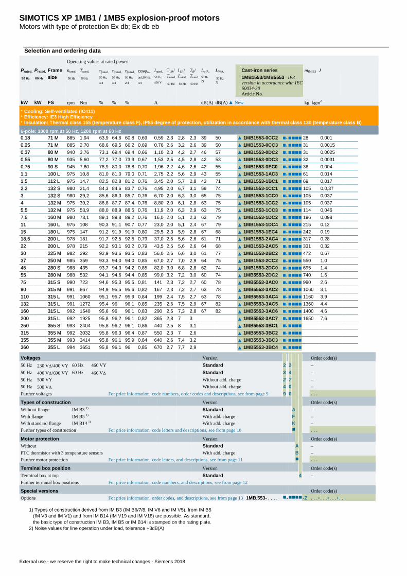
6-pole: 1000 rpm at 50 Hz, 1200 rpm at 60 Hz0,18 71 M 885 1,94 63,9 64,6 60,8 0,69 0,59 2,3 2,8 2,3 39 50 ▲ 1MB1553-0CC2 n-nnnn 28 0,0010,25 71 M 885 2,70 68,6 69,5 66,2 0,69 0,76 2,6 3,2 2,6 39 50 ▲ 1MB1553-0CC3 n-nnnn 31 0,00150,37 80 M 940 3,76 73,1 69,4 69,4 0,66 1,10 2,3 4,2 2,7 46 57 ▲ 1MB1553-0DC2 n-nnnn 31 0,00250,55 80 M 935 5,60 77,2 77,0 73,9 0,67 1,53 2,5 4,5 2,8 42 53 ▲ 1MB1553-0DC3 n-nnnn 32 0,00310,75 90 S 945 7,60 78,9 80,0 78,8 0,70 1,96 2,2 4,6 2,6 42 55 ▲ 1MB1553-0EC0 n-nnnn 36 0,0041,1 100 L 975 10,8 81,0 81,0 79,0 0,71 2,75 2,2 5,6 2,9 43 55 ▲ 1MB1553-1AC3 n-nnnn 61 0,0141,5 112 L 975 14,7 82,5 82,8 81,2 0,76 3,45 2,0 5,7 2,8 43 71 ▲ 1MB1553-1BC1 n-nnnn 69 0,0172,2 132 S 980 21,4 84,3 84,6 83,7 0,76 4,95 2,0 6,7 3,1 59 74 ▲ 1MB1553-1CC1 n-nnnn 105 0,0,373 132 S 980 29,2 85,6 86,3 85,7 0,76 6,70 2,0 6,3 3,0 65 75 ▲ 1MB1553-1CC0 n-nnnn 105 0,0374 132 M 975 39,2 86,8 87,7 87,4 0,76 8,80 2,0 6,1 2,8 63 75 ▲ 1MB1553-1CC2 n-nnnn 105 0,0375,5 132 M 975 53,9 88,0 88,9 88,5 0,76 11,9 2,0 6,3 2,9 63 75 ▲ 1MB1553-1CC3 n-nnnn 114 0,0467,5 160 M 980 73,1 89,1 89,8 89,2 0,76 16,0 2,0 5,1 2,3 63 79 ▲ 1MB1553-1DC2 n-nnnn 196 0,09811 160 L 975 108 90,3 91,1 90,7 0,77 23,0 2,0 5,1 2,4 67 79 ▲ 1MB1553-1DC4 n-nnnn 215 0,1215 180 L 975 147 91,2 91,9 91,9 0,80 29,5 2,3 5,9 2,8 67 68 ▲ 1MB1553-1EC4 n-nnnn 242 0,1918,5 200 L 978 181 91,7 92,5 92,5 0,79 37,0 2,5 5,6 2,6 61 71 ▲ 1MB1553-2AC4 n-nnnn 317 0,2822 200 L 978 215 92,2 93,1 93,2 0,79 43,5 2,5 5,6 2,6 64 68 ▲ 1MB1553-2AC5 n-nnnn 331 0,3230 225 M 982 292 92,9 93,6 93,5 0,83 56,0 2,6 6,6 3,0 61 77 ▲ 1MB1553-2BC2 n-nnnn 472 0,6737 250 M 985 359 93,3 94,0 94,0 0,85 67,0 2,7 7,0 2,9 64 75 ▲ 1MB1553-2CC2 n-nnnn 550 1,045 280 S 988 435 93,7 94,3 94,2 0,85 82,0 3,0 6,8 2,8 62 74 ▲ 1MB1553-2DC0 n-nnnn 695 1,455 280 M 988 532 94,1 94,6 94,4 0,85 99,0 3,2 7,2 3,0 60 74 ▲ 1MB5553-2DC2 n-nnnn 740 1,675 315 S 990 723 94,6 95,3 95,5 0,81 141 2,3 7,2 2,7 60 78 ▲ 1MB5553-3AC0 n-nnnn 990 2,690 315 M 991 867 94,9 95,5 95,6 0,82 167 2,3 7,2 2,7 63 78 ▲ 1MB5553-3AC2 n-nnnn 1060 3,1110 315 L 991 1060 95,1 95,7 95,9 0,84 199 2,4 7,5 2,7 63 78 ▲ 1MB5553-3AC4 n-nnnn 1160 3,9132 315 L 991 1272 95,4 96 96,1 0,85 235 2,6 7,5 2,9 67 82 ▲ 1MB5553-3AC5 n-nnnn 1360 4,4160 315 L 992 1540 95,6 96 96,1 0,83 290 2,5 7,3 2,8 67 82 ▲ 1MB5553-3AC6 n-nnnn 1400 4,6200 315 L 992 1925 95,8 96,2 96,1 0,82 365 2,8 7 3 ▲ 1MB5553-3AC7 n-nnnn 1650 7,6250 355 S 993 2404 95,8 96,2 96,1 0,86 440 2,5 8 3,1 ▲ 1MB5553-3BC1 n-nnnn315 355 M 992 3032 95,8 96,3 96,4 0,87 550 2,3 7 2,6 ▲ 1MB5553-3BC2 n-nnnn355 355 M 993 3414 95,8 96,1 95,9 0,84 640 2,6 7,4 3,2 ▲ 1MB5553-3BC3 n-nnnn360 355 L 994 3651 95,8 96,1 96 0,85 670 2,7 7,7 2,9 ▲ 1MB5553-3BC4 n-nnnn
Voltages Version Order code(s)50 Hz 230 VD/400 VY 60 Hz 460 VY Standard 2 2 –50 Hz 400 VD/690 VY 60 Hz 460 VD Standard 3 4 –50 Hz 500 VY Without add. charge 2 7 –50 Hz 500 VD Without add. charge 4 0 –Further voltages For price information, code numbers, order codes and descriptions, see from page 9 9 0 . . .
Types of construction Version Order code(s)Without flange IM B3 1) Standard A –With flange IM B5 1) With add. charge F –With standard flange IM B14 1) With add. charge K –Further types of construction For price information, code letters and descriptions, see from page 10 n . . .
Motor protection Version Order code(s)Without Standard A –PTC thermistor with 3 temperature sensors With add. charge B –Further motor protection For price information, code letters, and descriptions, see from page 11 n . . .
Terminal box position Version Order code(s)Terminal box at top Standard 4 –Further terminal box positions For price information, code numbers, and descriptions, see from page 12
Special versions Order code(s)Options For price information, order codes, and descriptions, see from page 13 1MB.553- . . . . n-nnnn -Z . . .+. . .+. . .+. . .
1) Types of construction derived from IM B3 (IM B6/7/8, IM V6 and IM V5), from IM B5 (IM V3 and IM V1) and from IM B14 (IM V19 and IM V18) are possible. As standard, the basic type of construction IM B3, IM B5 or IM B14 is stamped on the rating plate.2) Noise values for line operation under load, tolerance +3dB(A)
SIMOTICS XP 1MB1 / 1MB5 explosion-proof motorsMotors with type of protection Ex db; Ex db eb
External use - we reserve the right to make technical changes - Siemens 2018
Selection and ordering data
Operating values at rated power
Prated,
50 Hz
Prated,
60 Hz
Framesize
nrated,
50 Hz
Trated,
50 Hz
hrated,
50 Hz,
4/4
hrated,
50 Hz,
3/4
hrated,
50 Hz,
2/4
cosjra-
ted,50 Hz,
4/4
Irated,
50 Hz,
400 V
TLR/Trated,
50 Hz
ILR/Irated,
50 Hz
TB/Trated,
50 Hz
LpfA,
50 Hz2)
LWA,
50 Hz2)
Cast-iron series1MB1553/1MB5553– IE3version in accordance with IEC60034-30Article No.
mIM B3 J
kW kW FS rpm Nm % % % A dB(A) dB(A)▲ New kg kgm2
* Cooling: Self-ventilated (IC411)* Efficiency: IE3 High Efficiency* Insulation: Thermal class 155 (temperature class F), IP55 degree of protection, utilization in accordance with thermal class 130 (temperature class B)
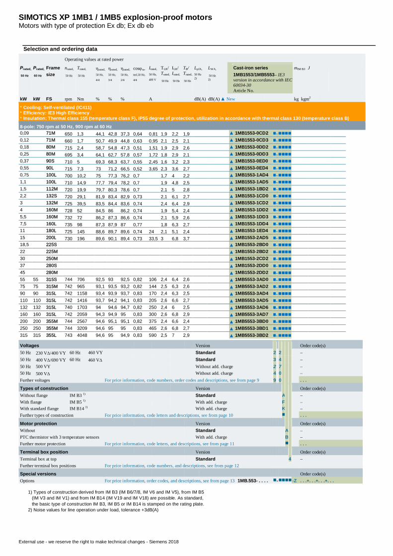
8-pole: 750 rpm at 50 Hz, 900 rpm at 60 Hz0,09 71M 650 1,3 44,1 42,8 37,3 0,64 0,81 1,9 2,2 1,9 ▲ 1MB1553-0CD2 n-nnnn0,12 71M 660 1,7 50,7 49,9 44,8 0,63 0,95 2,1 2,5 2,1 ▲ 1MB1553-0CD3 n-nnnn0,18 80M 715 2,4 58,7 54,8 47,3 0,51 1,51 1,9 2,9 2,6 ▲ 1MB1553-0DD2 n-nnnn0,25 80M 695 3,4 64,1 62,7 57,8 0,57 1,72 1,8 2,9 2,1 ▲ 1MB1553-0DD3 n-nnnn0,37 90S 710 5 69,3 68,3 63,7 0,55 2,45 1,6 3,2 2,3 ▲ 1MB1553-0ED0 n-nnnn0,55 90L 715 7,3 73 71,2 66,5 0,52 3,65 2,3 3,6 2,7 ▲ 1MB1553-0ED4 n-nnnn0,75 100L 700 10,2 75 77,3 76,2 0,7 1,7 4 2,2 ▲ 1MB1553-1AD4 n-nnnn1,1 100L 710 14,9 77,7 79,4 78,2 0,7 1,9 4,8 2,5 ▲ 1MB1553-1AD5 n-nnnn1,5 112M 720 19,9 79,7 80,3 78,6 0,7 2,1 5 2,8 ▲ 1MB1553-1BD2 n-nnnn2,2 132S 720 29,1 81,9 83,4 82,9 0,73 2,1 6,1 2,7 ▲ 1MB1553-1CD0 n-nnnn3 132M 725 39,5 83,5 84,4 83,6 0,74 2,4 6,4 2,9 ▲ 1MB1553-1CD2 n-nnnn4 160M 728 52 84,5 86 86,2 0,74 1,9 5,4 2,4 ▲ 1MB1553-1DD2 n-nnnn5,5 160M 732 72 86,2 87,3 86,6 0,74 2,1 5,9 2,6 ▲ 1MB1553-1DD3 n-nnnn7,5 160L 735 98 87,3 87,9 87 0,77 1,8 6,3 2,7 ▲ 1MB1553-1DD4 n-nnnn11 180L 725 145 88,6 89,7 89,6 0,74 24 2,1 5,1 2,4 ▲ 1MB1553-1ED4 n-nnnn15 200L 730 196 89,6 90,1 89,4 0,73 33,5 3 6,8 3,7 ▲ 1MB1553-2AD5 n-nnnn18,5 225S ▲ 1MB1553-2BD0 n-nnnn22 225M ▲ 1MB1553-2BD2 n-nnnn30 250M ▲ 1MB1553-2CD2 n-nnnn37 280S ▲ 1MB1553-2DD0 n-nnnn45 280M ▲ 1MB1553-2DD2 n-nnnn55 55 315S 744 706 92,5 93 92,5 0,82 106 2,4 6,4 2,6 ▲ 1MB5553-3AD0 n-nnnn75 75 315M 742 965 93,1 93,5 93,2 0,82 144 2,5 6,3 2,6 ▲ 1MB5553-3AD2 n-nnnn90 90 315L 742 1158 93,4 93,9 93,7 0,83 170 2,4 6,3 2,5 ▲ 1MB5553-3AD4 n-nnnn110 110 315L 742 1416 93,7 94,2 94,1 0,83 205 2,6 6,6 2,7 ▲ 1MB5553-3AD5 n-nnnn132 132 315L 740 1703 94 94,6 94,7 0,82 250 2,4 6 2,5 ▲ 1MB5553-3AD6 n-nnnn160 160 315L 742 2059 94,3 94,9 95 0,83 300 2,6 6,8 2,9 ▲ 1MB5553-3AD7 n-nnnn200 200 355M 744 2567 94,6 95,1 95,1 0,82 375 2,4 6,6 2,4 ▲ 1MB5553-3BD0 n-nnnn250 250 355M 744 3209 94,6 95 95 0,83 465 2,6 6,8 2,7 ▲ 1MB5553-3BD1 n-nnnn315 315 355L 743 4048 94,6 95 94,9 0,83 590 2,5 7 2,9 ▲ 1MB5553-3BD2 n-nnnn
Voltages Version Order code(s)50 Hz 230 VD/400 VY 60 Hz 460 VY Standard 2 2 –50 Hz 400 VD/690 VY 60 Hz 460 VD Standard 3 4 –50 Hz 500 VY Without add. charge 2 7 –50 Hz 500 VD Without add. charge 4 0 –Further voltages For price information, code numbers, order codes and descriptions, see from page 9 9 0 . . .
Types of construction Version Order code(s)Without flange IM B3 1) Standard A –With flange IM B5 1) With add. charge F –With standard flange IM B14 1) With add. charge K –Further types of construction For price information, code letters and descriptions, see from page 10 n . . .
Motor protection Version Order code(s)Without Standard A –PTC thermistor with 3 temperature sensors With add. charge B –Further motor protection For price information, code letters, and descriptions, see from page 11 n . . .
Terminal box position Version Order code(s)Terminal box at top Standard 4 –Further terminal box positions For price information, code numbers, and descriptions, see from page 12
Special versions Order code(s)Options For price information, order codes, and descriptions, see from page 13 1MB.553- . . . . n-nnnn -Z . . .+. . .+. . .+. . .
1) Types of construction derived from IM B3 (IM B6/7/8, IM V6 and IM V5), from IM B5 (IM V3 and IM V1) and from IM B14 (IM V19 and IM V18) are possible. As standard, the basic type of construction IM B3, IM B5 or IM B14 is stamped on the rating plate.2) Noise values for line operation under load, tolerance +3dB(A)
SIMOTICS XP 1MB1 / 1MB5 explosion-proof motorsMotors with type of protection Ex db; Ex db eb
External use - we reserve the right to make technical changes - Siemens 2018
Selection and ordering data
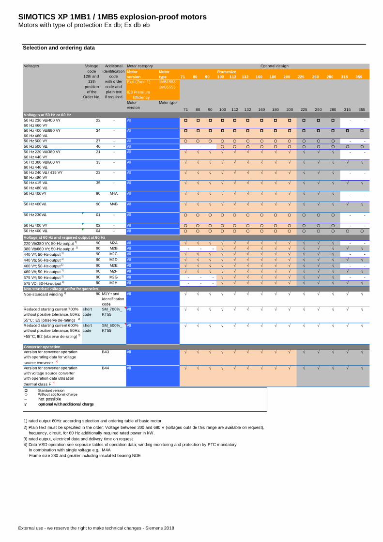
71 80 90 100 112 132 160 180 200 225 250 280 315 355Ex d (Zone 1)
IE3 Premium Efficiency
1MB15531MB5553
71 80 90 100 112 132 160 180 200 225 250 280 315 355
50 Hz 230 VΔ/400 VY60 Hz 460 VY
22 - All p p p p p p p p p p p p - -
50 Hz 400 VΔ/690 VY60 Hz 460 VΔ
34 - All p p p p p p p p p p p p p p
50 Hz 500 VY 27 - All ¡ ¡ ¡ ¡ ¡ ¡ ¡ ¡ ¡ ¡ ¡ ¡ - -50 Hz 500 VΔ 40 - All - - - ¡ ¡ ¡ ¡ ¡ ¡ ¡ ¡ ¡ ¡ ¡50 Hz 220 VΔ/380 VY60 Hz 440 VY
21 - All √ √ √ √ √ √ √ √ √ √ √ √ - -
50 Hz 380 VΔ/660 VY60 Hz 440 VΔ
33 - All √ √ √ √ √ √ √ √ √ √ √ √ √ √
50 Hz 240 VΔ / 415 VY60 Hz 480 VY
23 - All √ √ √ √ √ √ √ √ √ √ √ √ - -
50 Hz 415 VΔ60 Hz 480 VΔ
35 - All √ √ √ √ √ √ √ √ √ √ √ √ √ √
50 Hz 400VY 90 M4A All √ √ √ √ √ √ √ √ √ √ √ √ - -
50 Hz 400VΔ 90 M4B All √ √ √ √ √ √ √ √ √ √ √ √ √ √
50 Hz 230VΔ 01 - All ¡ ¡ ¡ ¡ ¡ ¡ ¡ ¡ ¡ ¡ ¡ ¡ - -
50 Hz 400 VY 02 - All ¡ ¡ ¡ ¡ ¡ ¡ ¡ ¡ ¡ ¡ ¡ ¡ - -50 Hz 400 VΔ 04 - All ¡ ¡ ¡ ¡ ¡ ¡ ¡ ¡ ¡ ¡ ¡ ¡ ¡ ¡
Voltage at 60 Hz and required output at 60 Hz220 VΔ/380 VY; 50-Hz-output 1) 90 M2A All √ √ √ √ √ √ √ √ √ √ √ √ - -380 VΔ/660 VY; 50-Hz-output 1) 90 M2B All - - - √ √ √ √ √ √ √ √ √ √ √440 VY; 50-Hz-output 1) 90 M2C All √ √ √ √ √ √ √ √ √ √ √ √ - -440 VΔ; 50-Hz-output 1) 90 M2D All √ √ √ √ √ √ √ √ √ √ √ √ √ √460 VY; 50-Hz-output 1) 90 M2E All √ √ √ √ √ √ √ √ √ √ √ √ - -460 VΔ; 50-Hz-output 1) 90 M2F All √ √ √ √ √ √ √ √ √ √ √ √ √ √575 VY; 50-Hz-output 1) 90 M2G All - - - √ √ √ √ √ √ √ √ √ - -575 VD; 50-Hz-output 1) 90 M2H All - - - √ √ √ √ √ √ √ √ √ √ √
Non-standard winding 2) 90 M1Y • andidentificationcode
All √ √ √ √ √ √ √ √ √ √ √ √ √ √
Reduced starting current 700%without positive tolerance, 50Hz;55°C; IE3 (observe de-rating) 3)
shortcode
SM_700%_KT55
All √ √ √ √ √ √ √ √ √ √ √ √ √ √
Reduced starting current 600%without positive tolerance; 50Hz;+55°C; IE2 (observe de-rating) 3)
shortcode
SM_600%_KT55
All √ √ √ √ √ √ √ √ √ √ √ √ √ √
Version for converter operationwith operating data for voltagesource converter. 4)
B43 All √ √ √ √ √ √ √ √ √ √ √ √ √ √
Version for converter operationwith voltage source converterwith operation data utilsationthermal class F 4)
B44 All √ √ √ √ √ √ √ √ √ √ √ √ √ √
1) rated output 60Hz according selection and ordering table of basic motor
3) rated output, electrical data and delivery time on request
2) Plain text must be specified in the order: Voltage between 200 and 690 V (voltages outside this range are available on request), frequency, circuit, for 60 Hz additionally required rated power in kW.
4) Data VSD operation see separate tables of operation data; winding monitoring and protection by PTC mandatory In combination with single voltage e.g.: M4A Frame size 280 and greater including insulated bearing NDE
Converter operation
Voltages Voltagecode
12th and13th
positionof the
Order No.
Additionalidentification
codewith ordercode andplain text
if required
Motor categoryMotorversion
Motortype
FramesizeOptional design
Motorversion
Motor type
Voltages at 50 Hz or 60 Hz
Non-standard voltage and/or frequencies
p Standard version¡ Without additional charge– Not possible√ op onal with addi onal charge
SIMOTICS XP 1MB1 / 1MB5 explosion-proof motorsMotors with type of protection Ex db; Ex db eb
External use - we reserve the right to make technical changes - Siemens 2018
Selection and ordering data
71 80 90 100 112 132 160 180 200 225 250 280 315 355
Ex d (Zone 1)IE2 High EfficiencyIE3 Premium Efficiency
1MB15531MB5553
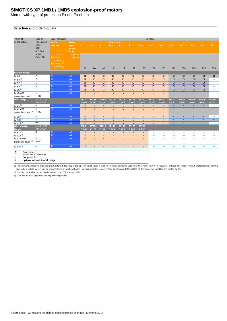
71 80 90 100 112 132 160 180 200 225 250 280 315 355
IM B3 A All All p p p p p p p p p p p p p p
IM B6 1) T All All p p p p p p p p p p p p p –
IM B7 1) U All All p p p p p p p p p p p p p –
IM B8 1) V All All p p p p p p p p p p p p p –IM V6 1) D All All p p p p p p p p p p p p p –IM V5 withprotective cover 1)
C+H00
All All √ √ √ √ √ √ √ √ √ √ √ √ √ –
With flange acc. to DINEN 50347
FF130A 160
FF165A 200
FF165A 200
FF215A 250
FF215A 250
FF265A 300
FF300A 350
FF300A 350
FF350A 400
FF400A 450
FF500A 550
FF500A 550
FF600A 660
FF740A 800
IM B5 5) F All All √ √ √ √ √ √ √ √ √ √ √ √ √ –IM V1 withprotective cover 1)3)
G+H00
All All √ √ √ √ √ √ √ √ √ √ √ √ √ √
IM V3 1) H All All √ √ √ √ √ √ √ √ √ √ √ √ √ –IM B35 1) J All All √ √ √ √ √ √ √ √ √ √ √ √ √ √IM V15 3) W All All √ √ √ √ √ √ √ √ √ √ √ √ √ –With standardflange
acc. to DINEN 50347
FT85C 105
FT100C 120
FT115C 140
FT130C 160
FT130C 160
FT165C 200
FT215C 250
IM B14 1) K All All √ √ √ √ √ √ √ – – – – – – –IM V19 1) L All All √ √ √ √ √ √ √ – – – – – – –IM V18 withprotective cover 1)3)
M+H00
All All √ √ √ √ √ √ √ – – – – – – –
IM B34 1) N All All √ √ √ √ √ √ √ – – – – – – –
1) The follow ing applies for explosion-proof motors: In the case of the types of construction w ith shaft extension dow n, the version "w ith protective cover" is required. For types of construction w ith shaft extension pointing upw ards, a suitable cover must be implemented to prevent small parts f rom falling into the fan cover (see the standard IEC/EN 60079-0). The cover must not block the cooling air flow .3) The "Second shaft extension" option (order code L05) is not possible.5) In FS 315 vertical f lange mounted only 315S/M possible.
Without flange
Types ofconstruction
Type ofconstructioncode14thpositionof theOrder No.
Motor categoryMotorversion
Motortype(cast-iron)
FramesizeOptions
p Standard version¡ Without additional charge– Not possible√ op onal with addi onal charge
SIMOTICS XP 1MB1 / 1MB5 explosion-proof motorsMotors with type of protection Ex db; Ex db eb
External use - we reserve the right to make technical changes - Siemens 2018
Selection and ordering data
71 80 90 100 112 132 160 180 200 225 250 280 315 355Ex d (Zone 1)IE3 Premium Efficiency
1MB15531MB5553
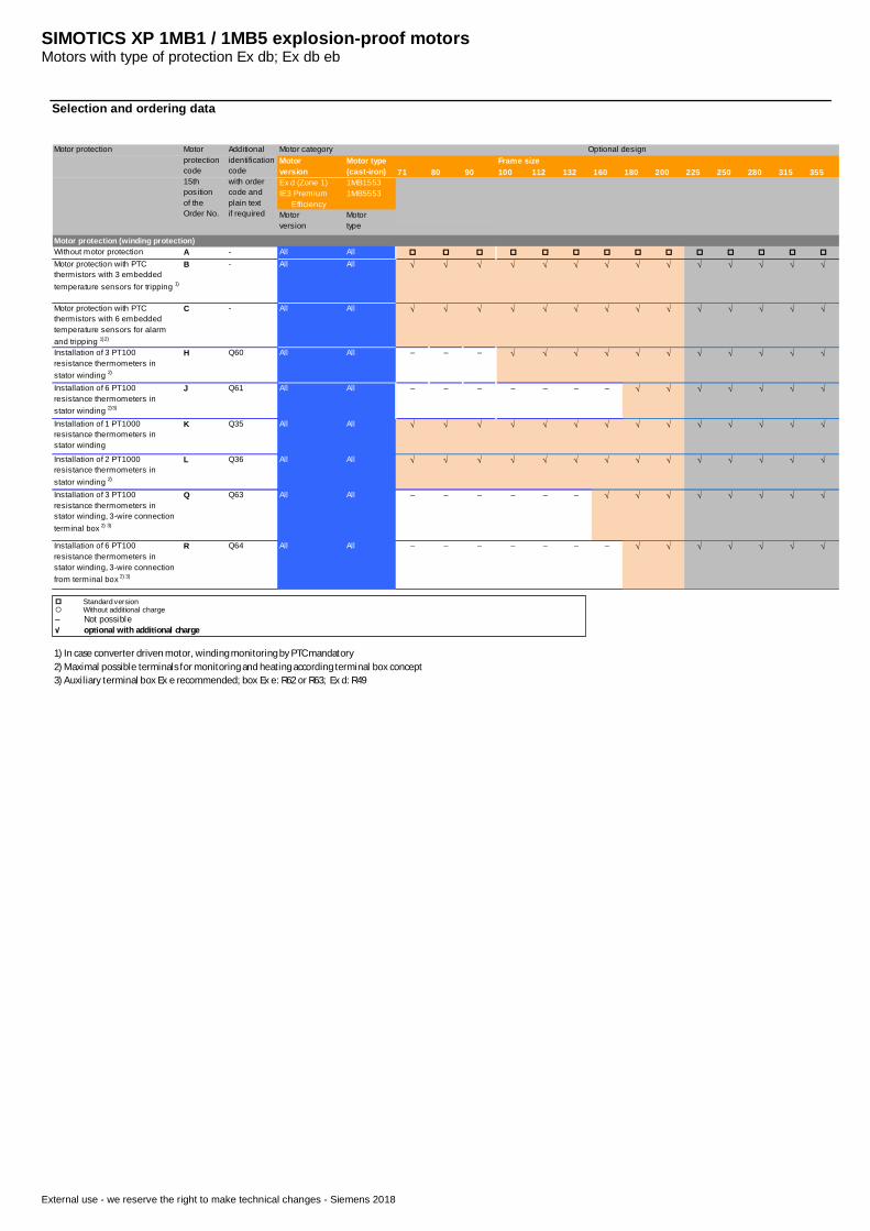
Motor protection (winding protection)Without motor protection A - All All p p p p p p p p p p p p p p
Motor protection with PTCthermistors with 3 embeddedtemperature sensors for tripping 1)
B - All All √ √ √ √ √ √ √ √ √ √ √ √ √ √
Motor protection with PTCthermistors with 6 embeddedtemperature sensors for alarmand tripping 1)2)
C - All All √ √ √ √ √ √ √ √ √ √ √ √ √ √
Installation of 3 PT100resistance thermometers instator winding 2)
H Q60 All All – – – √ √ √ √ √ √ √ √ √ √ √
Installation of 6 PT100resistance thermometers instator winding 2)3)
J Q61 All All – – – – – – – √ √ √ √ √ √ √
Installation of 1 PT1000resistance thermometers instator winding
K Q35 All All √ √ √ √ √ √ √ √ √ √ √ √ √ √
Installation of 2 PT1000resistance thermometers instator winding 2)
L Q36 All All √ √ √ √ √ √ √ √ √ √ √ √ √ √
Installation of 3 PT100resistance thermometers instator winding, 3-wire connectionterminal box 2) 3)
Q Q63 All All – – – – – – √ √ √ √ √ √ √ √
Installation of 6 PT100resistance thermometers instator winding, 3-wire connectionfrom terminal box 2) 3)
R Q64 All All – – – – – – – √ √ √ √ √ √ √
1) In case converter driven motor, winding monitoring by PTC mandatory2) Maximal possible terminals for monitoring and heating according terminal box concept3) Auxiliary terminal box Ex e recommended; box Ex e: R62 or R63; Ex d: R49
Motorversion
Motortype
Motor protection Motorprotectioncode15thpositionof theOrder No.
Additionalidentificationcodewith ordercode andplain textif required
Motor categoryMotorversion
Motor type(cast-iron)
Frame sizeOptional design
p Standard version¡ Without additional charge– Not possible√ op onal with addi onal charge
SIMOTICS XP 1MB1 / 1MB5 explosion-proof motorsMotors with type of protection Ex db; Ex db eb
External use - we reserve the right to make technical changes - Siemens 2018
Selection and ordering data
71 80 90 100 112 132 160 180 200 225 250 280 315 355Ex d (Zone 1)IE3 Premium Efficiency
1MB15531MB5553
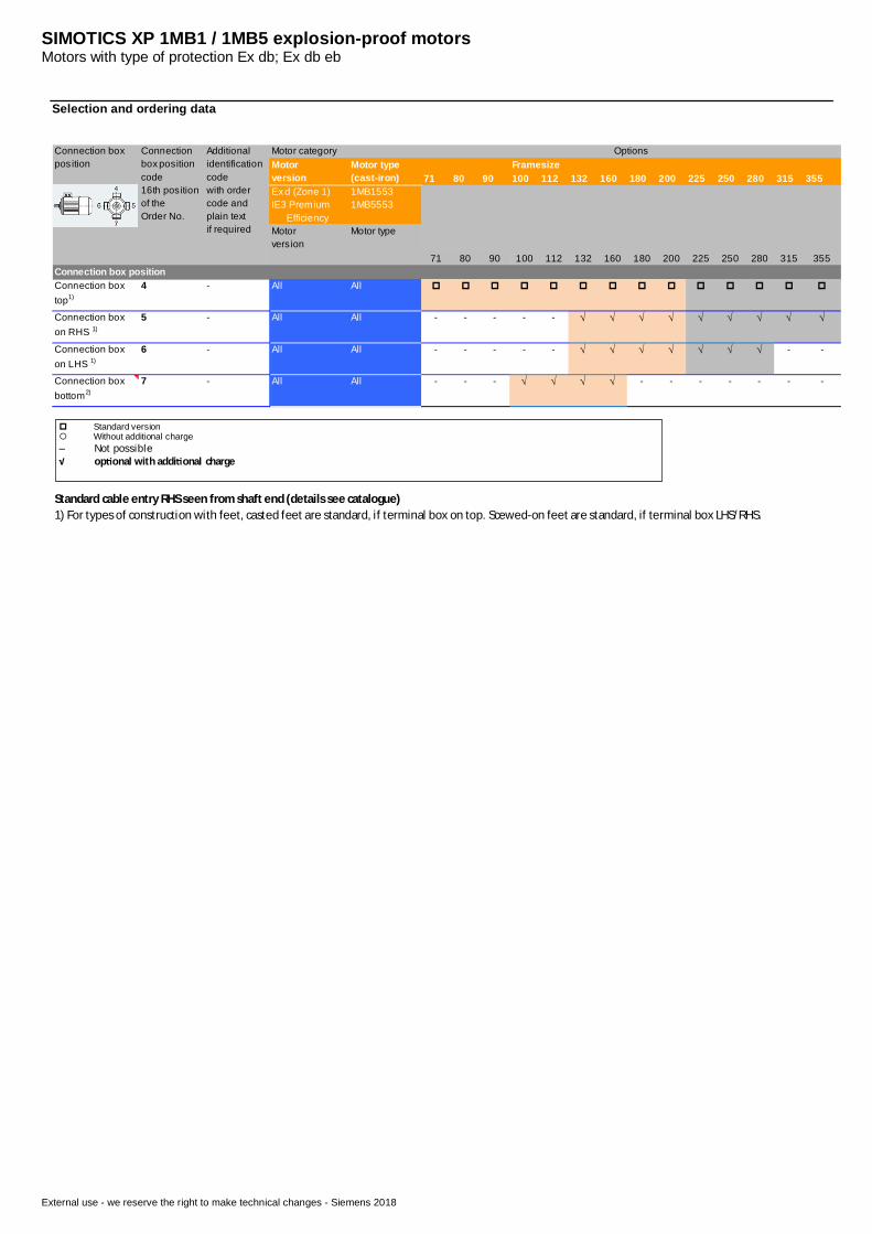
71 80 90 100 112 132 160 180 200 225 250 280 315 355Connection box positionConnection boxtop1)
4 - All All p p p p p p p p p p p p p p
Connection boxon RHS 1)
5 - All All - - - - - √ √ √ √ √ √ √ √ √
Connection boxon LHS 1)
6 - All All - - - - - √ √ √ √ √ √ √ - -
Connection boxbottom2)
7 - All All - - - √ √ √ √ - - - - - - -
Standard cable entry RHS seen from shaft end (details see catalogue)1) For types of construction with feet, casted feet are standard, if terminal box on top. Scewed-on feet are standard, if terminal box LHS/RHS.
Motorvers ion
Motor type
Connection boxposition
Connectionbox positioncode16th positionof theOrder No.
Additionalidentificationcodewith ordercode andplain textif required
Motor categoryMotorversion
Motor type(cast-iron)
FramesizeOptions
p Standard version¡ Without additional charge– Not possible√ op onal with addi onal charge
SIMOTICS XP 1MB1 / 1MB5 explosion-proof motorsMotors with type of protection Ex db; Ex db eb
External use - we reserve the right to make technical changes - Siemens 2018
Selection and ordering data
71 80 90 100 112 132 160 180 200 225 250 280 315 355Ex d (Zone 1)IE3 Premium Efficiency
1MB15531MB5553
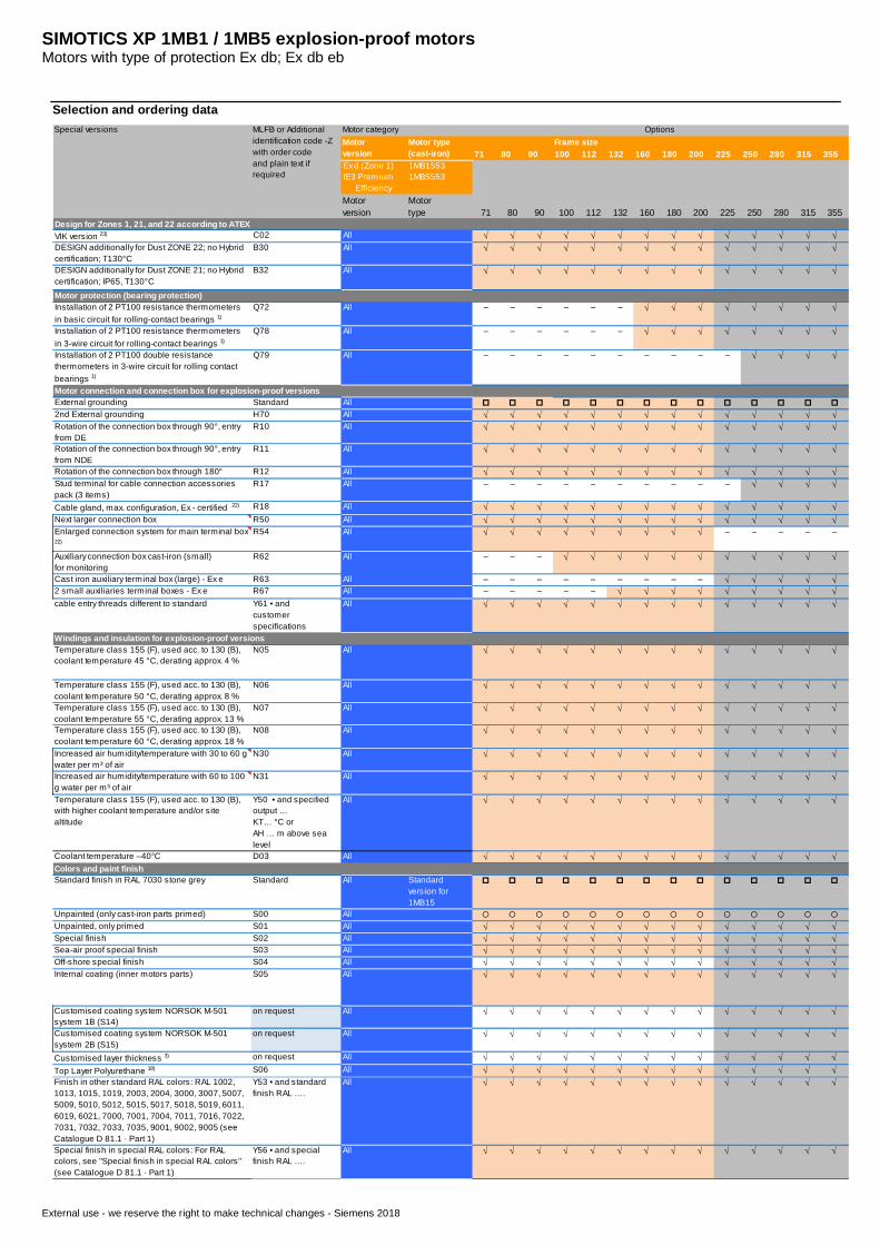
71 80 90 100 112 132 160 180 200 225 250 280 315 355Design for Zones 1, 21, and 22 according to ATEXVIK version 23) C02 All √ √ √ √ √ √ √ √ √ √ √ √ √ √DESIGN additionally for Dust ZONE 22; no Hybridcertification; T130°C
B30 All √ √ √ √ √ √ √ √ √ √ √ √ √ √
DESIGN additionally for Dust ZONE 21; no Hybridcertification; IP65, T130°C
B32 All √ √ √ √ √ √ √ √ √ √ √ √ √ √
Motor protection (bearing protection)Installation of 2 PT100 resistance thermometersin basic circuit for rolling-contact bearings 1)
Q72 All – – – – – – √ √ √ √ √ √ √ √
Installation of 2 PT100 resistance thermometersin 3-wire circuit for rolling-contact bearings 1)
Q78 All – – – – – – √ √ √ √ √ √ √ √
Installation of 2 PT100 double resistancethermometers in 3-wire circuit for rolling contactbearings 1)
Q79 All – – – – – – – – – – √ √ √ √
Motor connection and connection box for explosion-proof versionsExternal grounding Standard All p p p p p p p p p p p p p p2nd External grounding H70 All √ √ √ √ √ √ √ √ √ √ √ √ √ √Rotation of the connection box through 90°, entryfrom DE
R10 All √ √ √ √ √ √ √ √ √ √ √ √ √ √
Rotation of the connection box through 90°, entryfrom NDE
R11 All √ √ √ √ √ √ √ √ √ √ √ √ √ √
Rotation of the connection box through 180° R12 All √ √ √ √ √ √ √ √ √ √ √ √ √ √Stud terminal for cable connection accessoriespack (3 items)
R17 All – – – – – – – – – – √ √ √ √
Cable gland, max. configuration, Ex - certified 22) R18 All √ √ √ √ √ √ √ √ √ √ √ √ √ √Next larger connection box R50 All √ √ √ √ √ √ √ √ √ √ √ √ √ √Enlarged connection system for main terminal box22)
R54 All √ √ √ √ √ √ √ √ √ – – – – –
Auxiliary connection box cast-iron (small)for monitoring
R62 All – – – √ √ √ √ √ √ √ √ √ √ √
Cast iron auxiliary terminal box (large) - Ex e R63 All – – – – – – – – – √ √ √ √ √2 small auxiliaries terminal boxes - Ex e R67 All – – – – – √ √ √ √ √ √ √ √ √cable entry threads different to standard Y61 • and
customerspecifications
All √ √ √ √ √ √ √ √ √ √ √ √ √ √
Windings and insulation for explosion-proof versionsTemperature class 155 (F), used acc. to 130 (B),coolant temperature 45 °C, derating approx. 4 %
N05 All √ √ √ √ √ √ √ √ √ √ √ √ √ √
Temperature class 155 (F), used acc. to 130 (B),coolant temperature 50 °C, derating approx. 8 %
N06 All √ √ √ √ √ √ √ √ √ √ √ √ √ √
Temperature class 155 (F), used acc. to 130 (B),coolant temperature 55 °C, derating approx. 13 %
N07 All √ √ √ √ √ √ √ √ √ √ √ √ √ √
Temperature class 155 (F), used acc. to 130 (B),coolant temperature 60 °C, derating approx. 18 %
N08 All √ √ √ √ √ √ √ √ √ √ √ √ √ √
Increased air humidity/temperature with 30 to 60 gwater per m³ of air
N30 All √ √ √ √ √ √ √ √ √ √ √ √ √ √
Increased air humidity/temperature with 60 to 100g water per m³ of air
N31 All √ √ √ √ √ √ √ √ √ √ √ √ √ √
Temperature class 155 (F), used acc. to 130 (B),with higher coolant temperature and/or sitealtitude
Y50 • and specifiedoutput …KT… °C orAH … m above sealevel
All √ √ √ √ √ √ √ √ √ √ √ √ √ √
Coolant temperature –40°C D03 All √ √ √ √ √ √ √ √ √ √ √ √ √ √Colors and paint finishStandard finish in RAL 7030 stone grey Standard All Standard
version for1MB15
p p p p p p p p p p p p p p
Unpainted (only cast-iron parts primed) S00 All ¡ ¡ ¡ ¡ ¡ ¡ ¡ ¡ ¡ ¡ ¡ ¡ ¡ ¡Unpainted, only primed S01 All √ √ √ √ √ √ √ √ √ √ √ √ √ √Special finish S02 All √ √ √ √ √ √ √ √ √ √ √ √ √ √Sea-air proof special finish S03 All √ √ √ √ √ √ √ √ √ √ √ √ √ √Off-shore special finish S04 All √ √ √ √ √ √ √ √ √ √ √ √ √ √Internal coating (inner motors parts) S05 All √ √ √ √ √ √ √ √ √ √ √ √ √ √
Customised coating system NORSOK M-501system 1B (S14)
on request All √ √ √ √ √ √ √ √ √ √ √ √ √ √
Customised coating system NORSOK M-501system 2B (S15)
on request All √ √ √ √ √ √ √ √ √ √ √ √ √ √
Customised layer thickness 3) on request All √ √ √ √ √ √ √ √ √ √ √ √ √ √Top Layer Polyurethane 18) S06 All √ √ √ √ √ √ √ √ √ √ √ √ √ √Finish in other standard RAL colors: RAL 1002,1013, 1015, 1019, 2003, 2004, 3000, 3007, 5007,5009, 5010, 5012, 5015, 5017, 5018, 5019, 6011,6019, 6021, 7000, 7001, 7004, 7011, 7016, 7022,7031, 7032, 7033, 7035, 9001, 9002, 9005 (seeCatalogue D 81.1 · Part 1)
Y53 • and standardfinish RAL ….
All √ √ √ √ √ √ √ √ √ √ √ √ √ √
Special finish in special RAL colors: For RALcolors, see "Special finish in special RAL colors"(see Catalogue D 81.1 · Part 1)
Y56 • and specialfinish RAL ….
All √ √ √ √ √ √ √ √ √ √ √ √ √ √
Motortype
Motorversion
Special versions MLFB or Additionalidentification code -Zwith order codeand plain text ifrequired
Motor categoryMotorversion
Motor type(cast-iron)
Frame sizeOptions
SIMOTICS XP 1MB1 / 1MB5 explosion-proof motorsMotors with type of protection Ex db; Ex db eb
External use - we reserve the right to make technical changes - Siemens 2018
Selection and ordering data
71 80 90 100 112 132 160 180 200 225 250 280 315 355Ex d (Zone 1)IE3 Premium Efficiency
1MB15531MB5553
71 80 90 100 112 132 160 180 200 225 250 280 315 355Motortype
Motorversion
Special versions MLFB or Additionalidentification code -Zwith order codeand plain text ifrequired
Motor categoryMotorversion
Motor type(cast-iron)
Frame sizeOptions
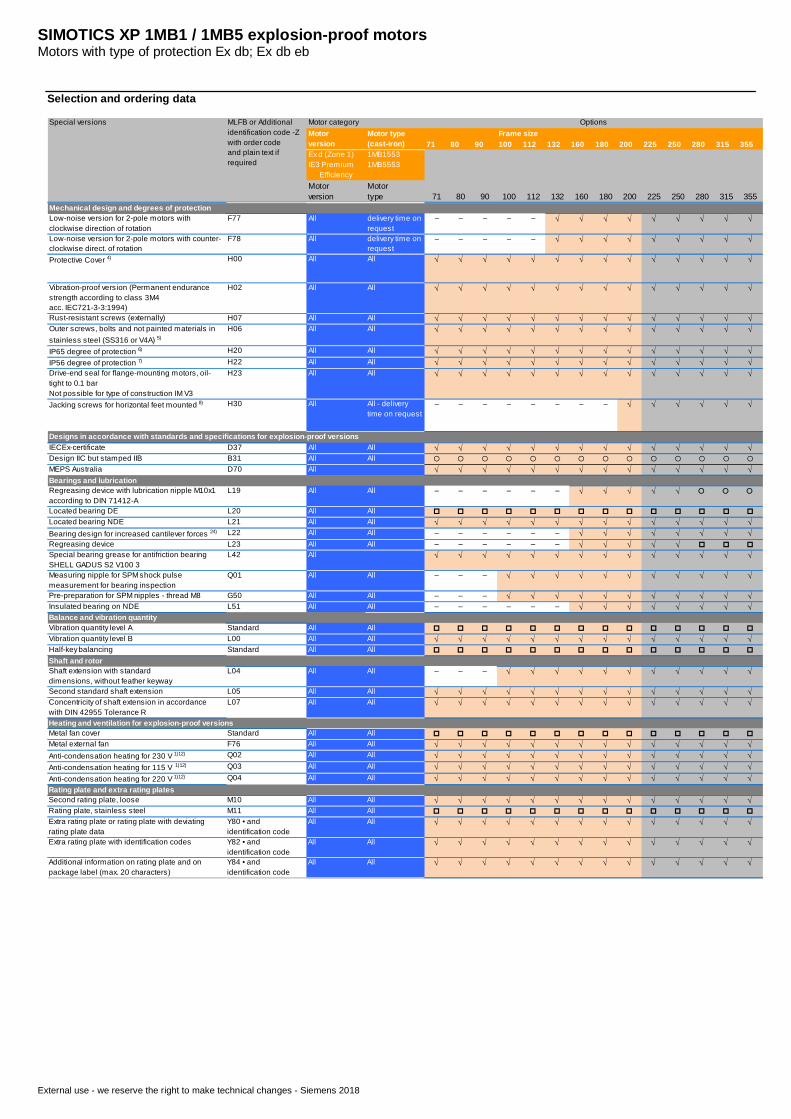
Mechanical design and degrees of protectionLow-noise version for 2-pole motors withclockwise direction of rotation
F77 All delivery time onrequest
– – – – – √ √ √ √ √ √ √ √ √
Low-noise version for 2-pole motors with counter-clockwise direct. of rotation
F78 All delivery time onrequest
– – – – – √ √ √ √ √ √ √ √ √
Protective Cover 4) H00 All All √ √ √ √ √ √ √ √ √ √ √ √ √ √
Vibration-proof version (Permanent endurancestrength according to class 3M4acc. IEC721-3-3:1994)
H02 All All √ √ √ √ √ √ √ √ √ √ √ √ √ √
Rust-resistant screws (externally) H07 All All √ √ √ √ √ √ √ √ √ √ √ √ √ √Outer screws, bolts and not painted materials instainless steel (SS316 or V4A) 5)
H06 All All √ √ √ √ √ √ √ √ √ √ √ √ √ √
IP65 degree of protection 6) H20 All All √ √ √ √ √ √ √ √ √ √ √ √ √ √IP56 degree of protection 7) H22 All All √ √ √ √ √ √ √ √ √ √ √ √ √ √Drive-end seal for flange-mounting motors, oil-tight to 0.1 barNot possible for type of construction IM V3
H23 All All √ √ √ √ √ √ √ √ √ √ √ √ √ √
Jacking screws for horizontal feet mounted 8) H30 All All - deliverytime on request
– – – – – – – – √ √ √ √ √ √
Designs in accordance with standards and specifications for explosion-proof versionsIECEx-certificate D37 All All √ √ √ √ √ √ √ √ √ √ √ √ √ √Design IIC but stamped IIB B31 All All ¡ ¡ ¡ ¡ ¡ ¡ ¡ ¡ ¡ ¡ ¡ ¡ ¡ ¡MEPS Australia D70 All √ √ √ √ √ √ √ √ √ √ √ √ √ √Bearings and lubricationRegreasing device with lubrication nipple M10x1according to DIN 71412-A
L19 All All – – – – – – √ √ √ √ √ ¡ ¡ ¡
Located bearing DE L20 All All p p p p p p p p p p p p p pLocated bearing NDE L21 All All √ √ √ √ √ √ √ √ √ √ √ √ √ √Bearing design for increased cantilever forces 24) L22 All All – – – – – – √ √ √ √ √ √ √ √Regreasing device L23 All All – – – – – – √ √ √ √ √ p p pSpecial bearing grease for antifriction bearingSHELL GADUS S2 V100 3
L42 All √ √ √ √ √ √ √ √ √ √ √ √ √ √
Measuring nipple for SPM shock pulsemeasurement for bearing inspection
Q01 All All – – – √ √ √ √ √ √ √ √ √ √ √
Pre-preparation for SPM nipples - thread M8 G50 All All – – – √ √ √ √ √ √ √ √ √ √ √Insulated bearing on NDE L51 All All – – – – – – √ √ √ √ √ √ √ √Balance and vibration quantityVibration quantity level A Standard All All p p p p p p p p p p p p p pVibration quantity level B L00 All All √ √ √ √ √ √ √ √ √ √ √ √ √ √Half-key balancing Standard All All p p p p p p p p p p p p p p
Shaft and rotorShaft extension with standarddimensions, without feather keyway
L04 All All – – – √ √ √ √ √ √ √ √ √ √ √
Second standard shaft extension L05 All All √ √ √ √ √ √ √ √ √ √ √ √ √ √Concentricity of shaft extension in accordancewith DIN 42955 Tolerance R
L07 All All √ √ √ √ √ √ √ √ √ √ √ √ √ √
Heating and ventilation for explosion-proof versionsMetal fan cover Standard All All p p p p p p p p p p p p p pMetal external fan F76 All All √ √ √ √ √ √ √ √ √ √ √ √ √ √Anti-condensation heating for 230 V 1)12) Q02 All All √ √ √ √ √ √ √ √ √ √ √ √ √ √Anti-condensation heating for 115 V 1)12) Q03 All All √ √ √ √ √ √ √ √ √ √ √ √ √ √Anti-condensation heating for 220 V 1)12) Q04 All All √ √ √ √ √ √ √ √ √ √ √ √ √ √Rating plate and extra rating platesSecond rating plate, loose M10 All All √ √ √ √ √ √ √ √ √ √ √ √ √ √Rating plate, stainless steel M11 All All p p p p p p p p p p p p p pExtra rating plate or rating plate with deviatingrating plate data
Y80 • andidentification code
All All √ √ √ √ √ √ √ √ √ √ √ √ √ √
Extra rating plate with identification codes Y82 • andidentification code
All All √ √ √ √ √ √ √ √ √ √ √ √ √ √
Additional information on rating plate and onpackage label (max. 20 characters)
Y84 • andidentification code
All All √ √ √ √ √ √ √ √ √ √ √ √ √ √
SIMOTICS XP 1MB1 / 1MB5 explosion-proof motorsMotors with type of protection Ex db; Ex db eb
External use - we reserve the right to make technical changes - Siemens 2018
Selection and ordering data
71 80 90 100 112 132 160 180 200 225 250 280 315 355Ex d (Zone 1)IE3 Premium Efficiency
1MB15531MB5553
71 80 90 100 112 132 160 180 200 225 250 280 315 355Motortype
Motorversion
Special versions MLFB or Additionalidentification code -Zwith order codeand plain text ifrequired
Motor categoryMotorversion
Motor type(cast-iron)
Frame sizeOptions
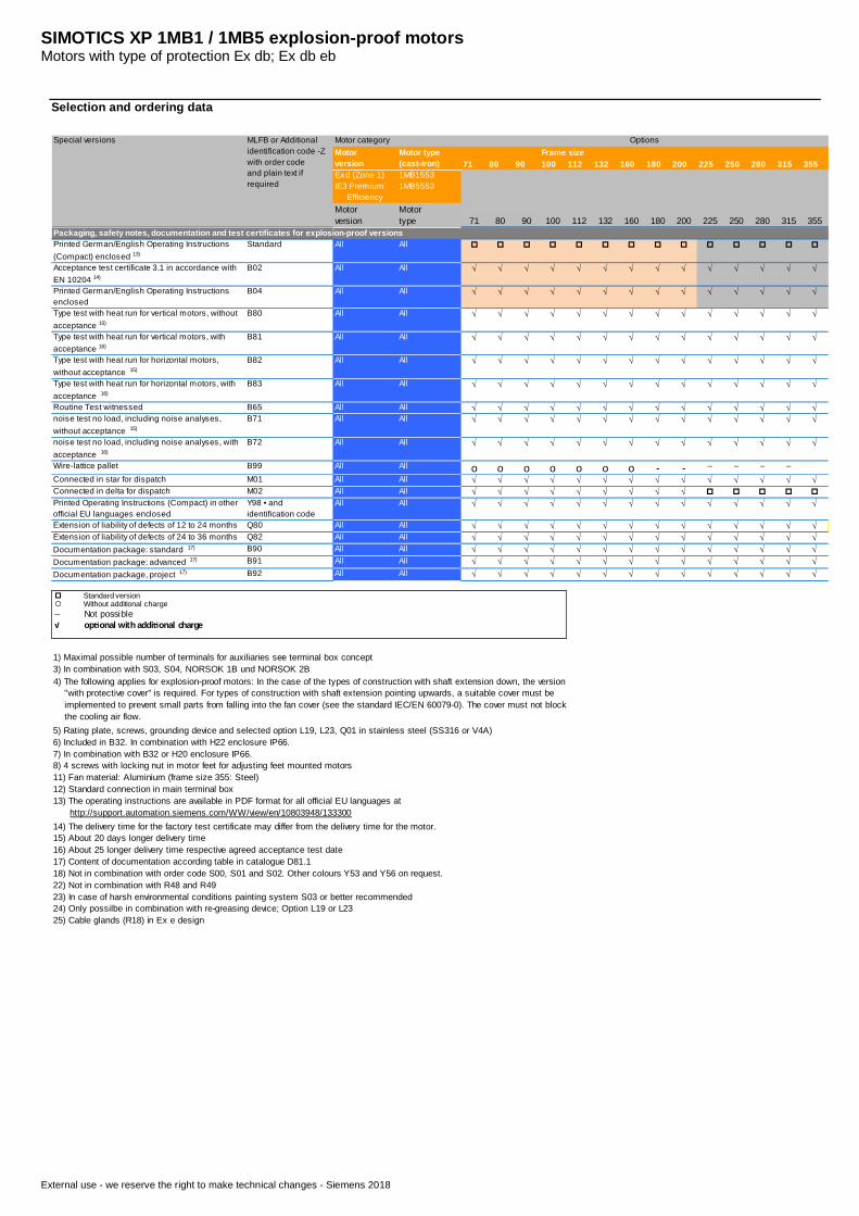
Packaging, safety notes, documentation and test certificates for explosion-proof versionsPrinted German/English Operating Instructions(Compact) enclosed 13)
Standard All All p p p p p p p p p p p p p p
Acceptance test certificate 3.1 in accordance withEN 10204 14)
B02 All All √ √ √ √ √ √ √ √ √ √ √ √ √ √
Printed German/English Operating Instructionsenclosed
B04 All All √ √ √ √ √ √ √ √ √ √ √ √ √ √
Type test with heat run for vertical motors, withoutacceptance 15)
B80 All All √ √ √ √ √ √ √ √ √ √ √ √ √ √
Type test with heat run for vertical motors, withacceptance 16)
B81 All All √ √ √ √ √ √ √ √ √ √ √ √ √ √
Type test with heat run for horizontal motors,without acceptance 15)
B82 All All √ √ √ √ √ √ √ √ √ √ √ √ √ √
Type test with heat run for horizontal motors, withacceptance 16)
B83 All All √ √ √ √ √ √ √ √ √ √ √ √ √ √
Routine Test witnessed B65 All All √ √ √ √ √ √ √ √ √ √ √ √ √ √noise test no load, including noise analyses,without acceptance 15)
B71 All All √ √ √ √ √ √ √ √ √ √ √ √ √ √
noise test no load, including noise analyses, withacceptance 16)
B72 All All √ √ √ √ √ √ √ √ √ √ √ √ √ √
Wire-lattice pallet B99 All All o o o o o o o - - – – – –Connected in star for dispatch M01 All All √ √ √ √ √ √ √ √ √ √ √ √ √ √Connected in delta for dispatch M02 All All √ √ √ √ √ √ √ √ √ p p p p pPrinted Operating Instructions (Compact) in otherofficial EU languages enclosed
Y98 • andidentification code
All All √ √ √ √ √ √ √ √ √ √ √ √ √ √
Extension of liability of defects of 12 to 24 months Q80 All All √ √ √ √ √ √ √ √ √ √ √ √ √ √Extension of liability of defects of 24 to 36 months Q82 All All √ √ √ √ √ √ √ √ √ √ √ √ √ √Documentation package: standard 17) B90 All All √ √ √ √ √ √ √ √ √ √ √ √ √ √Documentation package: advanced 17) B91 All All √ √ √ √ √ √ √ √ √ √ √ √ √ √Documentation package, project 17) B92 All All √ √ √ √ √ √ √ √ √ √ √ √ √ √
1) Maximal possible number of terminals for auxiliaries see terminal box concept3) In combination with S03, S04, NORSOK 1B und NORSOK 2B
5) Rating plate, screws, grounding device and selected option L19, L23, Q01 in stainless steel (SS316 or V4A)6) Included in B32. In combination with H22 enclosure IP66.7) In combination with B32 or H20 enclosure IP66.8) 4 screws with locking nut in motor feet for adjusting feet mounted motors11) Fan material: Aluminium (frame size 355: Steel)12) Standard connection in main terminal box
14) The delivery time for the factory test certificate may differ from the delivery time for the motor.15) About 20 days longer delivery time16) About 25 longer delivery time respective agreed acceptance test date17) Content of documentation according table in catalogue D81.118) Not in combination with order code S00, S01 and S02. Other colours Y53 and Y56 on request.22) Not in combination with R48 and R4923) In case of harsh environmental conditions painting system S03 or better recommended24) Only possilbe in combination with re-greasing device; Option L19 or L2325) Cable glands (R18) in Ex e design
13) The operating instructions are available in PDF format for all official EU languages at http://support.automation.siemens.com/WW/view/en/10803948/133300
4) The following applies for explosion-proof motors: In the case of the types of construction with shaft extension down, the version "with protective cover" is required. For types of construction with shaft extension pointing upwards, a suitable cover must be implemented to prevent small parts from falling into the fan cover (see the standard IEC/EN 60079-0). The cover must not block the cooling air flow.
p Standard version¡ Without additional charge– Not possible√ op onal with addi onal charge
SIMOTICS XP 1MB1 / 1MB5 explosion-proof motorsMotors with type of protection Ex db; Ex db ebOperation on PWM converter
External use - we reserve the right to make technical changes - Siemens 2018
Overview
Typical voltage stress of motors forconverter operation
General information
All the data listed in the catalog is applicable for a 50 Hz line supply.During converter operation, the reduced torques for constant torqueand drives for fans, pumps and compressors must be observed dueto the harmonic content of the supply. Higher noise levels must beexpected than for 50 Hz line operation for motors operating withconverters due to the harmonic content of the supply.Maximum voltage load on the motor winding in converter operation:• Ûphase-phase: ≤ 1500 V (3000 V peak-peak values (Vpk/pk))• Ûphase-ground: ≤ 1100 V (2200 V peak-peak values (Vpk/pk))The following generally applies to Siemens converters (SINAMICS):• Uline: = 500 V ± 10 % (BLM = Basic Line Module; DFE = DirectFront End)• Uline: ≤ 460 V ± 10 % (ALM = Active Line Module; AFE = ActiveFront End); Udc <720 V• Uline: = 690 V ± 10 % (only permissible with SINAMICS G180,that has a reinforced dv/dt filter (standard option G180: L10).
Engineering information for converter operationPermissible voltage stressMore stress is placed on the insulation of the motor winding withconverter operation than with line operation. The voltage stress alsodepends on the type of inverter used.
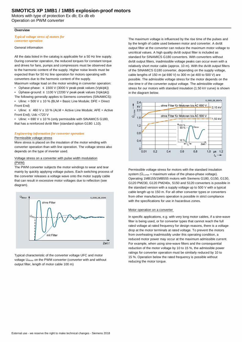
Voltage stress on a converter with pulse width modulation(PWM)The PWM converter subjects the motor windings to wear and tearmainly by quickly applying voltage pulses. Each switching process ofthe converter releases a voltage wave onto the motor supply cablethat can result in excessive motor voltages due to reflection (seediagram).
Typical characteristic of the converter voltage UFC and motorvoltage UMotor on the PWM converter (converter with and withoutoutput filter, length of motor cable 100 m)
The maximum voltage is influenced by the rise time of the pulses andby the length of cable used between motor and converter. A dv/dtoutput filter at the converter can reduce the maximum motor voltage touncritical values. A high quality dv/dt output filter is included asstandard for SINAMICS G180 converters. With converters withoutdv/dt output filters, inadmissible voltage peaks can occur even with arelatively short motor cable (approx. 10 m). With the dv/dt output filtersof the SINAMICS G180 converter, depending on the supply voltage,cable lengths of 150 m (at 690 V) to 300 m (at 400 to 500 V) arepossible. The admissible voltage stress for the motor depends on therise time tr of the converter output voltage. The admissible voltagestress for our motors with standard insulation (1.50 kV curve) is shownin the diagram below.
Permissible voltage stress for motors with the standard insulationsystem (ÛLLmax = maximum value of the phase-phase voltage).Operating 1MB155/1MB555 motors with Siemens G180, G150, G130,G120 PM230, G120 PM240x, S150 and S120 converters is possible inthe standard version with a supply voltage up to 500 V with a typicalcable length up to 150 m. For all other converter types or convertersfrom other manufacturers operation is possible in strict compliancewith the specifications for use in hazardous zones.
Motor operation on a converter
In specific applications, e.g. with very long motor cables, if a sine-wavefilter is being used, or for converter types that cannot reach the fullrated voltage at rated frequency for design reasons, there is a voltagedrop at the motor terminals at rated voltage. To prevent the motorsfrom overheating inadmissibly under this operating condition, areduced motor power may occur at the maximum admissible current.For example, when using sine-wave filters and the consequentialreduction of the motor voltage by 10 to 15 %, the admissible powerratings for converter operation must be similarly reduced by 10 to15 %. Operation below the rated frequency is possible withoutreducing the motor torque.
SIMOTICS XP 1MB1 / 1MB5 explosion-proof motorsMotors with type of protection Ex db; Ex db ebOperation on PWM converter
External use - we reserve the right to make technical changes - Siemens 2018
Overview
Individually checking a variable speed drive (VSD)Systems (IC411 self-ventilated motors) with configurationcharacteristics for converter operation - 1MB155/1MB555 motors
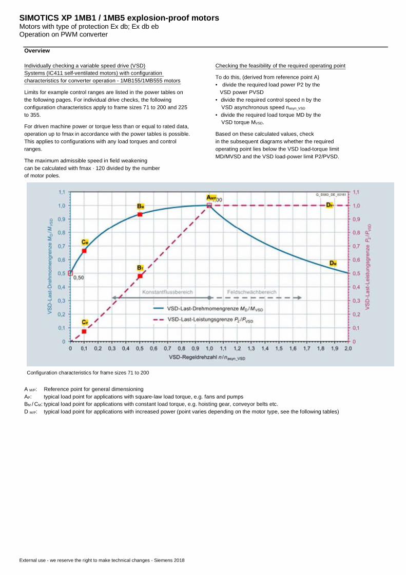
Limits for example control ranges are listed in the power tables onthe following pages. For individual drive checks, the followingconfiguration characteristics apply to frame sizes 71 to 200 and 225to 355.
For driven machine power or torque less than or equal to rated data,operation up to fmax in accordance with the power tables is possible.This applies to configurations with any load torques and controlranges.
The maximum admissible speed in field weakeningcan be calculated with fmax · 120 divided by the numberof motor poles.
Checking the feasibility of the required operating point
To do this, (derived from reference point A)• divide the required load power P2 by the VSD power PVSD• divide the required control speed n by the VSD asynchronous speed nasyn_VSD
• divide the required load torque MD by the VSD torque MVSD.
Based on these calculated values, checkin the subsequent diagrams whether the requiredoperating point lies below the VSD load-torque limitMD/MVSD and the VSD load-power limit P2/PVSD.
Configuration characteristics for frame sizes 71 to 200
A M/P: Reference point for general dimensioningAP: typical load point for applications with square-law load torque, e.g. fans and pumpsBM / CM: typical load point for applications with constant load torque, e.g. hoisting gear, conveyor belts etc.D M/P: typical load point for applications with increased power (point varies depending on the motor type, see the following tables)
SIMOTICS XP 1MB1 / 1MB5 explosion-proof motorsMotors with type of protection Ex db; Ex db ebOperation on PWM converter
External use - we reserve the right to make technical changes - Siemens 2018
Overview
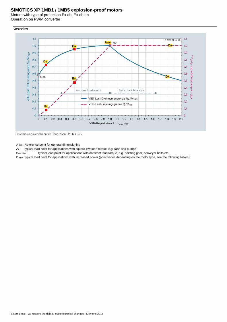
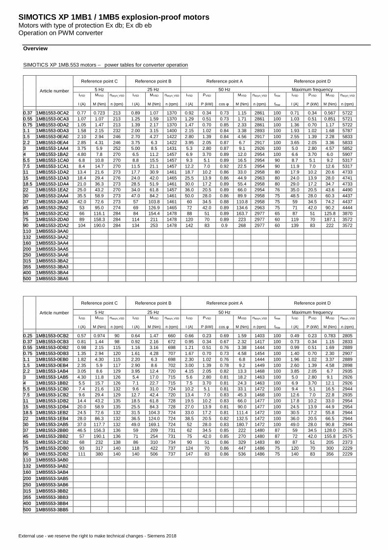
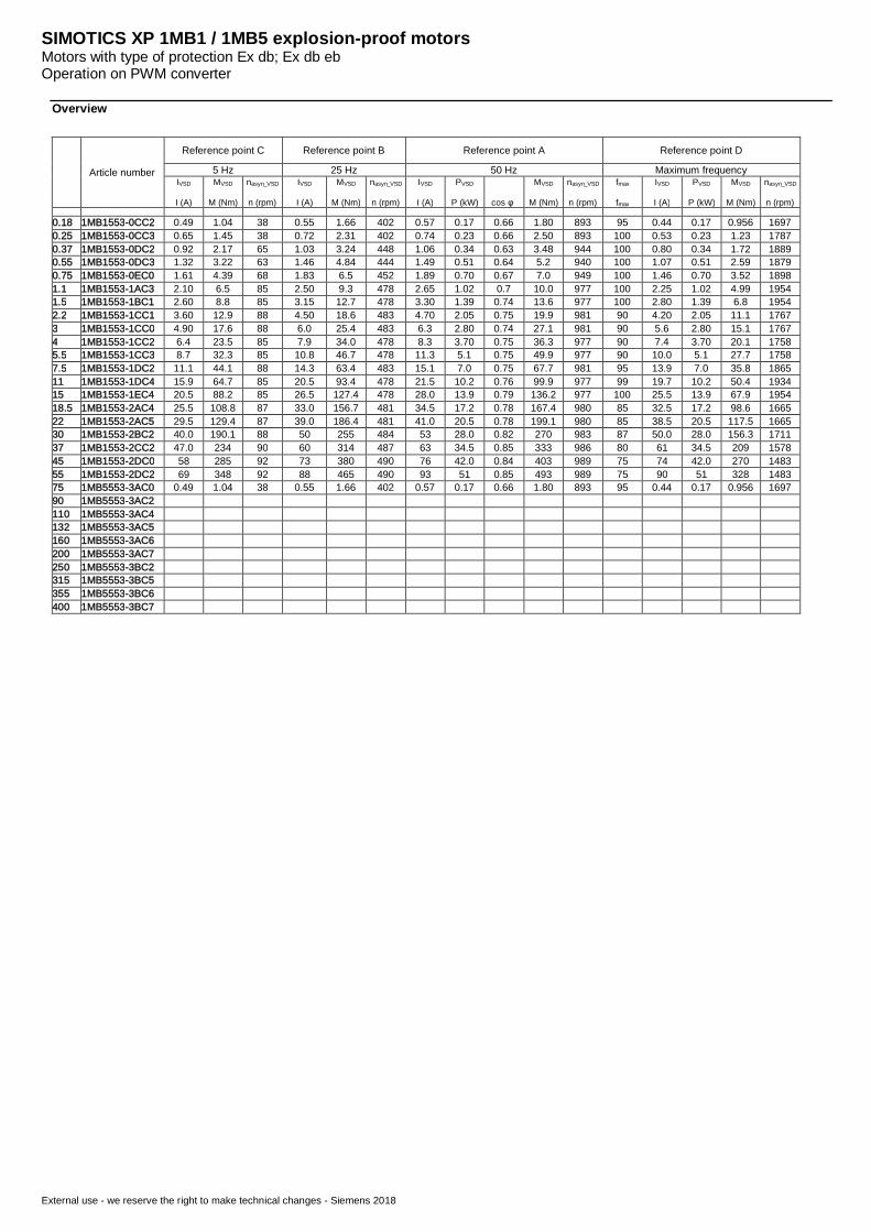
SIMOTICS XP 1MB.553 motors – power tables for converter operation
Article number
Reference point C Reference point B Reference point A Reference point D
5 Hz 25 Hz 50 Hz Maximum frequencyIVSD
I (A)
MVSD
M (Nm)
nasyn_VSD
n (rpm)
IVSD
I (A)
MVSD
M (Nm)
nasyn_VSD
n (rpm)
IVSD
I (A)
PVSD
P (kW) cos φ
MVSD
M (Nm)
nasyn_VSD
n (rpm)
fmax
fmax
IVSD
I (A)
PVSD
P (kW)
MVSD
M (Nm)
nasyn_VSD
n (rpm)
0.37 1MB1553-0CA2 0.77 0.723 213 0.89 1.07 1370 0.92 0.34 0.73 1.15 2861 100 0.71 0.34 0.567 57220.55 1MB1553-0CA3 1.07 1.07 213 1.25 1.59 1370 1.29 0.51 0.73 1.71 2861 100 1.03 0.51 0.851 57210.75 1MB1553-0DA2 1.05 1.47 213 1.39 2.17 1370 1.47 0.70 0.85 2.33 2861 100 1.36 0.70 1.17 57221.1 1MB1553-0DA3 1.58 2.15 232 2.00 3.15 1400 2.15 1.02 0.84 3.38 2893 100 1.93 1.02 1.68 57871.5 1MB1553-0EA0 2.10 2.94 246 2.70 4.27 1422 2.80 1.39 0.84 4.56 2917 100 2.55 1.39 2.28 58332.2 1MB1553-0EA4 2.85 4.31 246 3.75 6.3 1422 3.95 2.05 0.87 6.7 2917 100 3.65 2.05 3.36 58333 1MB1553-1AA4 3.75 5.9 252 5.00 8.5 1431 5.3 2.80 0.87 9.1 2926 100 5.0 2.80 4.57 58524 1MB1553-1BA2 4.80 7.8 270 6.5 11.2 1457 6.9 3.70 0.89 12.0 2954 100 6.6 3.70 6.0 59075.5 1MB1553-1CA0 6.8 10.8 270 8.8 15.5 1457 9.3 5.1 0.89 16.5 2954 90 8.7 5.1 9.2 53177.5 1MB1553-1CA1 8.4 14.7 270 11.5 21.1 1457 12.2 7.0 0.92 22.5 2954 90 11.9 7.0 12.6 531711 1MB1553-1DA2 13.4 21.6 273 17.7 30.9 1461 18.7 10.2 0.86 33.0 2958 80 17.9 10.2 20.6 473315 1MB1553-1DA3 18.4 29.4 276 24.0 42.0 1465 25.5 13.9 0.86 44.9 2963 80 24.0 13.9 28.0 474118.5 1MB1553-1DA4 21.0 36.3 273 28.5 51.9 1461 30.0 17.2 0.89 55.4 2958 80 29.0 17.2 34.7 473322 1MB1553-1EA2 25.0 43.2 270 34.0 61.8 1457 36.0 20.5 0.89 66.0 2954 76 35.0 20.5 43.6 449030 1MB1553-2AA4 35.5 58.9 273 47.0 84.2 1461 50.0 28.0 0.86 89.9 2958 75 48.5 28.0 60.3 443737 1MB1553-2AA5 42.0 72.6 273 57 103.8 1461 60 34.5 0.88 110.8 2958 75 59 34.5 74.2 443745 1MB1553-2BA2 53 95.0 274 69 126.9 1465 72 42.0 0.89 134.6 2963 75 71 42.0 90.2 444455 1MB1553-2CA2 66 116.1 284 84 154.4 1478 88 51 0.89 163.7 2977 65 87 51 125.8 387075 1MB1553-2DA0 89 158.3 284 114 211 1478 120 70 0.89 223 2977 60 119 70 187.1 357290 1MB1553-2DA2 104 190.0 284 134 253 1478 142 83 0.9 268 2977 60 139 83 222 3572110 1MB5553-3AA0132 1MB5553-3AA2160 1MB5553-3AA4200 1MB5553-3AA5250 1MB5553-3AA6315 1MB5553-3BA2355 1MB5553-3BA3400 1MB5553-3BA4500 1MB5553-3BA5
Article number
Reference point C Reference point B Reference point A Reference point D
5 Hz 25 Hz 50 Hz Maximum frequencyIVSD
I (A)
MVSD
M (Nm)
nasyn_VSD
n (rpm)
IVSD
I (A)
MVSD
M (Nm)
nasyn_VSD
n (rpm)
IVSD
I (A)
PVSD
P (kW) cos φ
MVSD
M (Nm)
nasyn_VSD
n (rpm)
fmax
fmax
IVSD
I (A)
PVSD
P (kW)
MVSD
M (Nm)
nasyn_VSD
n (rpm)
0.25 1MB1553-0CB2 0.57 0.974 90 0.64 1.47 660 0.66 0.23 0.69 1.59 1403 100 0.49 0.23 0.783 28050.37 1MB1553-0CB3 0.81 1.44 98 0.92 2.16 672 0.95 0.34 0.67 2.32 1417 100 0.73 0.34 1.15 28330.55 1MB1553-0DB2 0.98 2.15 115 1.16 3.16 698 1.21 0.51 0.76 3.38 1444 100 0.99 0.51 1.69 28890.75 1MB1553-0DB3 1.35 2.94 120 1.61 4.28 707 1.67 0.70 0.73 4.58 1454 100 1.40 0.70 2.30 29071.1 1MB1553-0EB0 1.82 4.30 115 2.20 6.3 698 2.30 1.02 0.76 6.8 1444 100 1.96 1.02 3.37 28891.5 1MB1553-0EB4 2.35 5.9 117 2.90 8.6 702 3.00 1.39 0.78 9.2 1449 100 2.60 1.39 4.58 28982.2 1MB1553-1AB4 3.05 8.6 129 3.95 12.4 720 4.15 2.05 0.82 13.3 1468 100 3.85 2.05 6.7 29353 1MB1553-1AB5 4.30 11.8 126 5.4 17.0 715 5.6 2.80 0.81 18.2 1463 100 5.0 2.80 9.1 29264 1MB1553-1BB2 5.5 15.7 126 7.1 22.7 715 7.5 3.70 0.81 24.3 1463 100 6.9 3.70 12.1 29265.5 1MB1553-1CB0 7.4 21.6 132 9.6 31.0 724 10.2 5.1 0.81 33.1 1472 100 9.4 5.1 16.5 29447.5 1MB1553-1CB2 9.6 29.4 129 12.7 42.4 720 13.4 7.0 0.83 45.3 1468 100 12.6 7.0 22.8 293511 1MB1553-1DB2 14.4 43.2 135 18.5 61.8 728 19.5 10.2 0.83 66.0 1477 100 17.8 10.2 33.0 295415 1MB1553-1DB4 20.0 58.9 135 25.5 84.3 728 27.0 13.9 0.81 90.0 1477 100 24.5 13.9 44.9 295418.5 1MB1553-1EB2 24.5 72.6 132 31.5 104.3 724 33.0 17.2 0.81 111.4 1472 100 30.5 17.2 55.8 294422 1MB1553-1EB4 28.0 86.3 132 36.5 124.0 724 38.5 20.5 0.82 132.5 1472 100 36.0 20.5 66.5 294430 1MB1553-2AB5 37.0 117.7 132 49.0 169.1 724 52 28.0 0.83 180.7 1472 100 49.0 28.0 90.8 294437 1MB1553-2BB0 46.5 156.3 136 59 209 731 62 34.5 0.85 222 1480 87 59 34.5 128.0 257545 1MB1553-2BB2 57 190.1 136 71 254 731 75 42.0 0.85 270 1480 87 72 42.0 155.8 257555 1MB1553-2CB2 68 232 138 86 310 734 90 51 0.86 329 1483 80 87 51 205 237375 1MB1553-2DB0 93 317 140 118 422 737 124 70 0.86 447 1486 75 120 70 300 222990 1MB1553-2DB2 111 380 140 140 506 737 147 83 0.86 536 1486 75 140 83 356 2229110 1MB5553-3AB0132 1MB5553-3AB2160 1MB5553-3AB4200 1MB5553-3AB5250 1MB5553-3AB6315 1MB5553-3BB2355 1MB5553-3BB3400 1MB5553-3BB4500 1MB5553-3BB5
SIMOTICS XP 1MB1 / 1MB5 explosion-proof motorsMotors with type of protection Ex db; Ex db ebOperation on PWM converter
External use - we reserve the right to make technical changes - Siemens 2018
Overview
Article number
Reference point C Reference point B Reference point A Reference point D
5 Hz 25 Hz 50 Hz Maximum frequencyIVSD
I (A)
MVSD
M (Nm)
nasyn_VSD
n (rpm)
IVSD
I (A)
MVSD
M (Nm)
nasyn_VSD
n (rpm)
IVSD
I (A)
PVSD
P (kW) cos φ
MVSD
M (Nm)
nasyn_VSD
n (rpm)
fmax
fmax
IVSD
I (A)
PVSD
P (kW)
MVSD
M (Nm)
nasyn_VSD
n (rpm)
0.18 1MB1553-0CC2 0.49 1.04 38 0.55 1.66 402 0.57 0.17 0.66 1.80 893 95 0.44 0.17 0.956 16970.25 1MB1553-0CC3 0.65 1.45 38 0.72 2.31 402 0.74 0.23 0.66 2.50 893 100 0.53 0.23 1.23 17870.37 1MB1553-0DC2 0.92 2.17 65 1.03 3.24 448 1.06 0.34 0.63 3.48 944 100 0.80 0.34 1.72 18890.55 1MB1553-0DC3 1.32 3.22 63 1.46 4.84 444 1.49 0.51 0.64 5.2 940 100 1.07 0.51 2.59 18790.75 1MB1553-0EC0 1.61 4.39 68 1.83 6.5 452 1.89 0.70 0.67 7.0 949 100 1.46 0.70 3.52 18981.1 1MB1553-1AC3 2.10 6.5 85 2.50 9.3 478 2.65 1.02 0.7 10.0 977 100 2.25 1.02 4.99 19541.5 1MB1553-1BC1 2.60 8.8 85 3.15 12.7 478 3.30 1.39 0.74 13.6 977 100 2.80 1.39 6.8 19542.2 1MB1553-1CC1 3.60 12.9 88 4.50 18.6 483 4.70 2.05 0.75 19.9 981 90 4.20 2.05 11.1 17673 1MB1553-1CC0 4.90 17.6 88 6.0 25.4 483 6.3 2.80 0.74 27.1 981 90 5.6 2.80 15.1 17674 1MB1553-1CC2 6.4 23.5 85 7.9 34.0 478 8.3 3.70 0.75 36.3 977 90 7.4 3.70 20.1 17585.5 1MB1553-1CC3 8.7 32.3 85 10.8 46.7 478 11.3 5.1 0.75 49.9 977 90 10.0 5.1 27.7 17587.5 1MB1553-1DC2 11.1 44.1 88 14.3 63.4 483 15.1 7.0 0.75 67.7 981 95 13.9 7.0 35.8 186511 1MB1553-1DC4 15.9 64.7 85 20.5 93.4 478 21.5 10.2 0.76 99.9 977 99 19.7 10.2 50.4 193415 1MB1553-1EC4 20.5 88.2 85 26.5 127.4 478 28.0 13.9 0.79 136.2 977 100 25.5 13.9 67.9 195418.5 1MB1553-2AC4 25.5 108.8 87 33.0 156.7 481 34.5 17.2 0.78 167.4 980 85 32.5 17.2 98.6 166522 1MB1553-2AC5 29.5 129.4 87 39.0 186.4 481 41.0 20.5 0.78 199.1 980 85 38.5 20.5 117.5 166530 1MB1553-2BC2 40.0 190.1 88 50 255 484 53 28.0 0.82 270 983 87 50.0 28.0 156.3 171137 1MB1553-2CC2 47.0 234 90 60 314 487 63 34.5 0.85 333 986 80 61 34.5 209 157845 1MB1553-2DC0 58 285 92 73 380 490 76 42.0 0.84 403 989 75 74 42.0 270 148355 1MB1553-2DC2 69 348 92 88 465 490 93 51 0.85 493 989 75 90 51 328 148375 1MB5553-3AC0 0.49 1.04 38 0.55 1.66 402 0.57 0.17 0.66 1.80 893 95 0.44 0.17 0.956 169790 1MB5553-3AC2110 1MB5553-3AC4132 1MB5553-3AC5160 1MB5553-3AC6200 1MB5553-3AC7250 1MB5553-3BC2315 1MB5553-3BC5355 1MB5553-3BC6400 1MB5553-3BC7
SIMOTICS XP 1MB1 / 1MB5 explosion-proof motorsMotors with type of protection Ex db; Ex db ebDimensions and mechanical data
External use - we reserve the right to make technical changes - Siemens 2018
Dimensional drawings
Type of construction IM B3 / IM B35
Baugröße Polzahl Maßbezeichnung nach IECA AA AB AC AD AG AS B BA BB BC C H HA HH K L
SIMOTICS XP71 M 2 … 8 112 25 140 139 215 126 62 90 30 125 76 45 71 10 121 7 34980 M 2 … 8 125 35 160 157 224 126 62 100 34 130 75,5 50 80 13 125,5 10 37590 L 2 … 8 140 40 179 174 236 126 62 125 40 155 80 56 90 13 136 10 450100 L 2 … 8 160 40 205 199 259 163 81 140 50 170 92 63 100 18 155 12 544112 M 2 … 8 190 45 240 223 279 163 81 140 50 170 92 70 112 18 162 12 516132 S 2 … 8 216 50 260 262 295 163 81 140 57 235 101 89 132 18 190 12 571132 M 4 (1CB2) 626
6 (1CC2) 5716 (1CC3) 626
160 M 2 … 8 254 60 310 318 351 190 92 210 60 307 162,5 108 160 20 270 15 786160 L 2 … 8 254180 M 2 … 8 279 70 349 353 388 190 92 241 100 359 184 121 180 19 305 15 838180 L 4 … 8 279200 L 2 … 8 318 80 400 393 447 266 112 305 120 425 217 133 200 25 350 19 899225 S 2 356 90 446 439 467 266 112 286 115 438 221 149 225 26 370 19 974
4 … 8 1004225 M 2 311 974
4 … 8 1004250 M 2 406 100 505 487 502 319 145 349 120 420 189 168 250 35 357 24 1013
4 … 8280 S 2 457 108 567 535 524 319 145 368 171 520 252,5 190 280 40 442,5 24 1119
4 … 8280 M 2 419 1124,5
4 … 8315 S/M 2 508 120 610 622 610 448 167 406 140 677 216 315 50 28 1219
4 … 8 1249315 L 2 508 1219
4 … 8 1249355 S 2 610 150 780 622 610 550 175 191 1078 254 355 50 33 1630
4 … 8 1660355 M 2 1630
4 … 8 1660
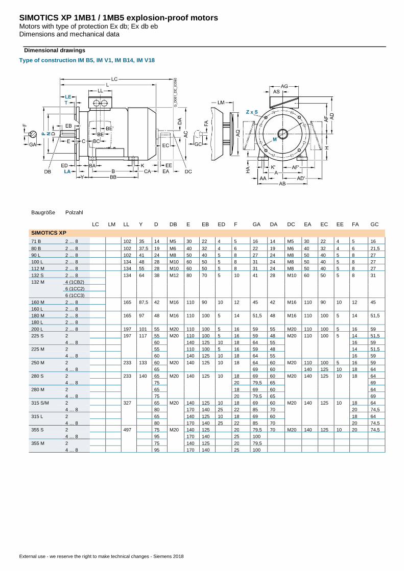
SIMOTICS XP 1MB1 / 1MB5 explosion-proof motorsMotors with type of protection Ex db; Ex db ebDimensions and mechanical data
External use - we reserve the right to make technical changes - Siemens 2018
Dimensional drawings
Type of construction IM B5, IM V1, IM B14, IM V18
Baugröße Polzahl
LC LM LL Y D DB E EB ED F GA DA DC EA EC EE FA GCSIMOTICS XP71 B 2 … 8 102 35 14 M5 30 22 4 5 16 14 M5 30 22 4 5 1680 B 2 … 8 102 37,5 19 M6 40 32 4 6 22 19 M6 40 32 4 6 21,590 L 2 … 8 102 41 24 M8 50 40 5 8 27 24 M8 50 40 5 8 27100 L 2 … 8 134 48 28 M10 60 50 5 8 31 24 M8 50 40 5 8 27112 M 2 … 8 134 55 28 M10 60 50 5 8 31 24 M8 50 40 5 8 27132 S 2 … 8 134 64 38 M12 80 70 5 10 41 28 M10 60 50 5 8 31132 M 4 (1CB2)
6 (1CC2)6 (1CC3)
160 M 2 … 8 165 87,5 42 M16 110 90 10 12 45 42 M16 110 90 10 12 45160 L 2 … 8180 M 2 … 8 165 97 48 M16 110 100 5 14 51,5 48 M16 110 100 5 14 51,5180 L 2 … 8200 L 2 … 8 197 101 55 M20 110 100 5 16 59 55 M20 110 100 5 16 59225 S 2 197 117 55 M20 110 100 5 16 59 48 M20 110 100 5 14 51,5
4 … 8 60 140 125 10 18 64 55 16 59225 M 2 55 110 100 5 16 59 48 14 51,5
4 … 8 60 140 125 10 18 64 55 16 59250 M 2 233 133 60 M20 140 125 10 18 64 60 M20 110 100 5 16 59
4 … 8 65 69 60 140 125 10 18 64280 S 2 233 140 65 M20 140 125 10 18 69 60 M20 140 125 10 18 64
4 … 8 75 20 79,5 65 69280 M 2 65 18 69 60 64
4 … 8 75 20 79,5 65 69315 S/M 2 327 65 M20 140 125 10 18 69 60 M20 140 125 10 18 64
4 … 8 80 170 140 25 22 85 70 20 74,5315 L 2 65 140 125 10 18 69 60 18 64
4 … 8 80 170 140 25 22 85 70 20 74,5355 S 2 497 75 M20 140 125 20 79,5 70 M20 140 125 10 20 74,5
4 … 8 95 170 140 25 100355 M 2 75 140 125 20 79,5
4 … 8 95 170 140 25 100
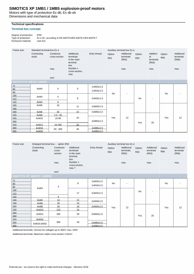
SIMOTICS XP 1MB1 / 1MB5 explosion-proof motorsMotors with type of protection Ex db; Ex db ebDimensions and mechanical data
External use - we reserve the right to make technical changes - Siemens 2018
Technical specifications
Terminal box concept:
Degree of protection: IP55Type of protection: Ex e IIC, according to EN 60079-0/EN 60079-1/EN 60079-7Enclosure material: cast iron
Frame size Standard terminal box Ex e Auxiliary terminal box Ex eConnectingstuds
Conductorcross-section
Additionalterminalsin the mainterminalbox
Entry thread OptionR62
Additionalterminals(R62)
OptionR63
Additionalterminals(R63)
OptionR66
Additionalterminals(R66)
max. Number xcross-section,max.
max. max. max.
mm2
SIMOTICS XP 1MB155 / 1MB555
716xM4 4 0
1xM25x1.51xM16x1.5
No -
No -
No -
8090100 6xM4 4
8 2xM32x1.5112132 6xM4 6160 6xM5 16 11 2xM40x1.5
Yes 12 Yes 12
180200 6xM6 35 22 2xM50x1.5225 6xM8 2.5 - 50
24
Yes 25
250 6xM10 10-952xM63x1.5280
315 6xM12 16-185 30355 6xM16 50 - 300 40 2xM80x2.0355 6xM20 4xM80x2.0
Frame size Enlarged terminal box – option R50 Auxiliary terminal box Ex eConnectingstuds
Conductorcross-section
Additionalterminalsin the mainterminalbox
Entry thread OptionR62
Additionalterminals(R62)
OptionR63
Additionalterminals(R63)
OptionR66
Additionalterminals(R66)
max. Number xcross-section,max.1)
max. max. max.
mm2
SIMOTICS XP 1MB155 / 1MB55571
6xM44
81xM25x1.51xM16x1.5
No -
No -
No -8090100
17 2xM32x1.5
Yes 12 Yes 12
112132 6160 6xM5 16 22 2xM40x1.5180 6xM6 35 20200 6xM8 50 18 2xM50x1.5
Yes 25
225 6xM10 120 24
2xM63x1.5250 6xM12 185 30280315 6xM16
300 40355 6xM16 (M20) 2xM80x2,0355 4xM80x2.0
Additional terminals: Version for voltages up to 400V; max. 440V
Additional terminals: Maximum cable cross-section 2.5mm²
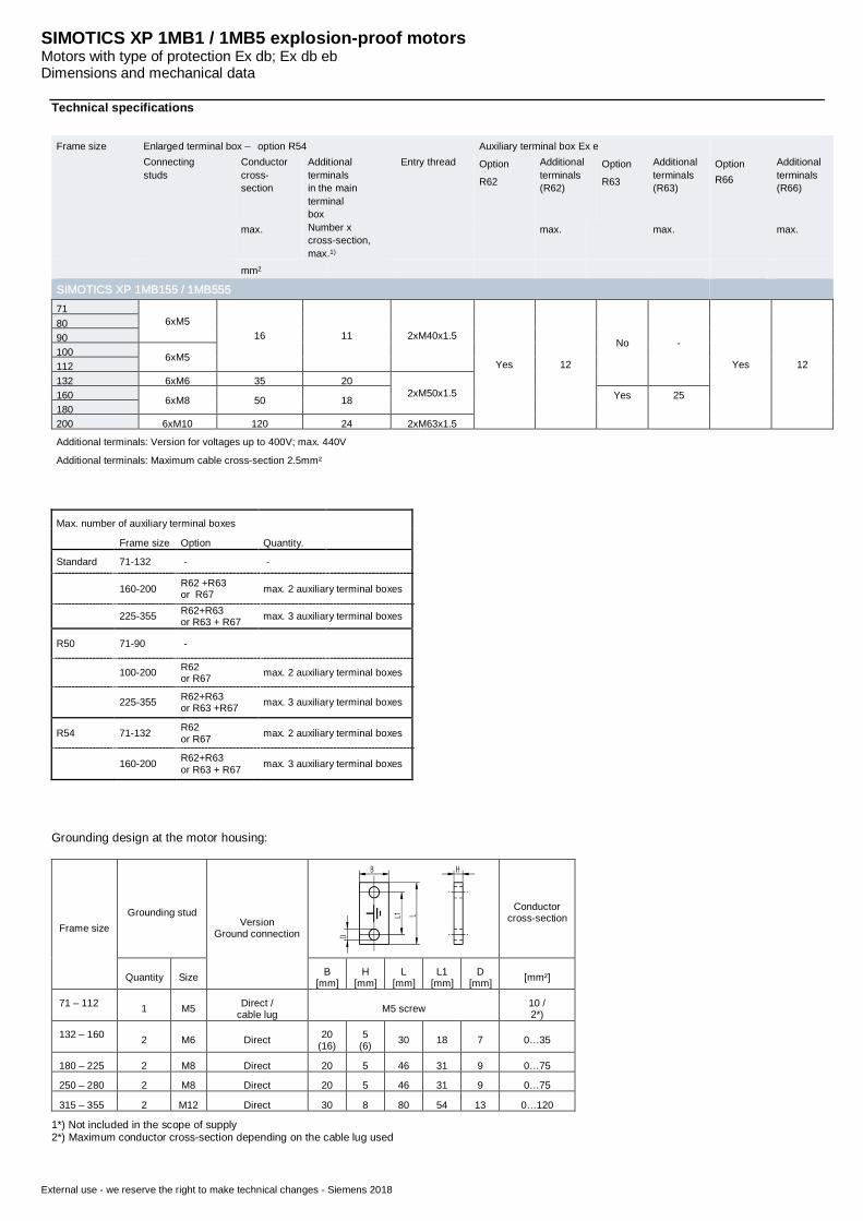
SIMOTICS XP 1MB1 / 1MB5 explosion-proof motorsMotors with type of protection Ex db; Ex db ebDimensions and mechanical data
External use - we reserve the right to make technical changes - Siemens 2018
Technical specifications
Frame size Enlarged terminal box – option R54 Auxiliary terminal box Ex eConnectingstuds
Conductorcross-section
Additionalterminalsin the mainterminalbox
Entry thread OptionR62
Additionalterminals(R62)
OptionR63
Additionalterminals(R63)
OptionR66
Additionalterminals(R66)
max. Number xcross-section,max.1)
max. max. max.
mm2
SIMOTICS XP 1MB155 / 1MB55571
6xM516 11 2xM40x1.5
Yes 12
No -
Yes 12
8090100 6xM5112132 6xM6 35 20
2xM50x1.5160 6xM8 50 18 Yes 25180200 6xM10 120 24 2xM63x1.5
Additional terminals: Version for voltages up to 400V; max. 440V
Additional terminals: Maximum cable cross-section 2.5mm²
Max. number of auxiliary terminal boxes
Frame size Option Quantity.
Standard 71-132 - -
160-200 R62 +R63or R67 max. 2 auxiliary terminal boxes
225-355 R62+R63or R63 + R67 max. 3 auxiliary terminal boxes
R50 71-90 -
100-200 R62or R67 max. 2 auxiliary terminal boxes
225-355 R62+R63or R63 +R67 max. 3 auxiliary terminal boxes
R54 71-132 R62or R67 max. 2 auxiliary terminal boxes
160-200 R62+R63or R63 + R67 max. 3 auxiliary terminal boxes
Grounding design at the motor housing:
Frame sizeGrounding stud
VersionGround connection
Conductorcross-section
Quantity Size B[mm]
H[mm]
L[mm]
L1[mm]
D[mm] [mm²]
71 – 112 1 M5 Direct /cable lug M5 screw 10 /
2*)
132 – 160 2 M6 Direct 20(16)
5(6) 30 18 7 0…35
180 – 225 2 M8 Direct 20 5 46 31 9 0…75
250 – 280 2 M8 Direct 20 5 46 31 9 0…75
315 – 355 2 M12 Direct 30 8 80 54 13 0…120
1*) Not included in the scope of supply2*) Maximum conductor cross-section depending on the cable lug used
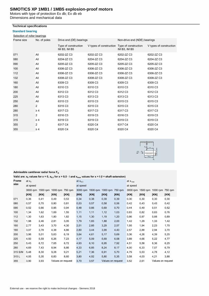
SIMOTICS XP 1MB1 / 1MB5 explosion-proof motorsMotors with type of protection Ex db; Ex db ebDimensions and mechanical data
External use - we reserve the right to make technical changes - Siemens 2018
Technical specifications
Standard bearing
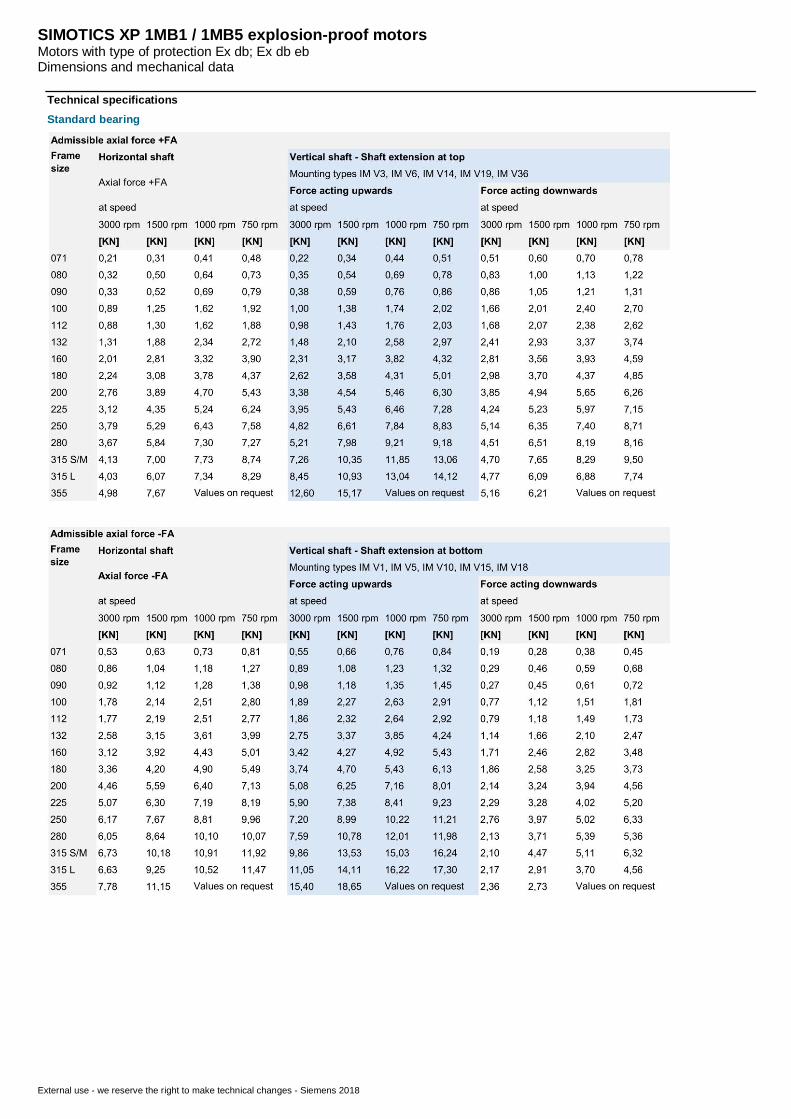
SIMOTICS XP 1MB1 / 1MB5 explosion-proof motorsMotors with type of protection Ex db; Ex db ebDimensions and mechanical data
External use - we reserve the right to make technical changes - Siemens 2018
Technical specifications
Standard bearing
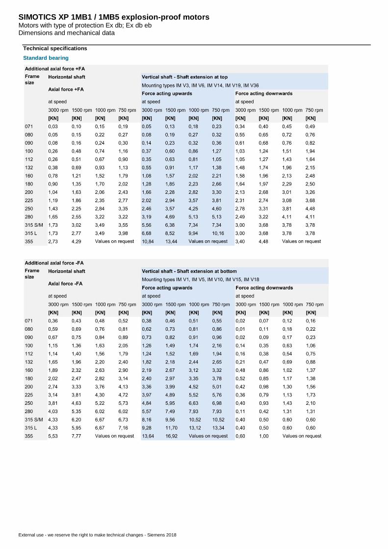
SIMOTICS XP 1MB1 / 1MB5 explosion-proof motorsMotors with type of protection Ex db; Ex db ebDimensions and mechanical data
External use - we reserve the right to make technical changes - Siemens 2018
Technical specifications
Standard bearing
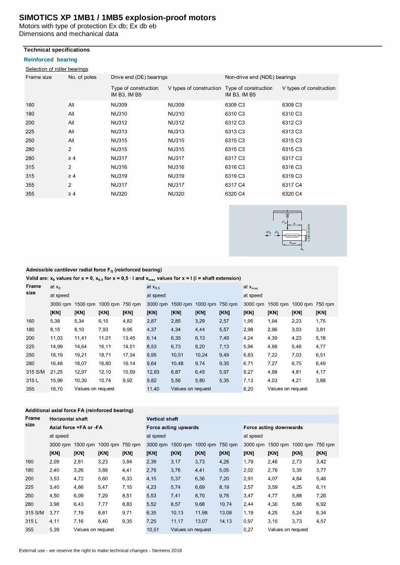
SIMOTICS XP 1MB1 / 1MB5 explosion-proof motorsMotors with type of protection Ex db; Ex db ebDimensions and mechanical data
External use - we reserve the right to make technical changes - Siemens 2018
Technical specifications
Reinforced bearing