
Rotary protein motors
9
-
Upload
independent -
Category
Documents
-
view
5 -
download
0
Transcript of Rotary protein motors
Rotary protein motorsGeorge Oster1 and Hongyun Wang2
1Depts Molecular and Cellular Biology and ESPM, College of Natural Resources, University of California, Berkeley, CA 94720, USA2Dept Applied Mathematics and Statistics, University of California, Santa Cruz, CA 95064, USA
Three protein motors have been unambiguously iden-
tified as rotary engines: the bacterial flagellar motor
and the two motors that constitute ATP synthase (F0F1
ATPase). Of these, the bacterial flagellar motor and F0
motors derive their energy from a transmembrane ion-
motive force, whereas the F1 motor is driven by ATP
hydrolysis. Here, we review the current understanding
of how these protein motors convert their energy supply
into a rotary torque.
Rotary protein motors accomplish their primary functionsby rotating one group of subunits with respect to the rest.Although they constitute but a small entry in the growingcatalog of cellular molecular motors, they have beenstudied so intensively that more is known about themthan any other. The best characterized protein in terms ofits atomic structure and biochemistry is ATP synthase(also called F0F1 ATPase), which actually consists of tworotary motors connected to a common shaft or axle. Thelargest, most powerful protein motor is the bacterialflagellar motor (BFM), which is found in many species buthas been most studied in Escherichia coli. In this article,we focus on these three motors. There are other proteinmotors that are thought to be rotary: certain members ofthe AAA protein family, including the helicases, and theportal protein in certain viruses that package their DNAinto their viral capsid. However, there is currently nounequivocal evidence that they operate in a rotaryfashion. We here restrict our attention mostly to ATPsynthase because its basic operating principles arethe best understood. By this, we mean that our under-standing has progressed beyond the ‘cartoon’ stage todetailed calculations that demonstrate that the ideasembodied in cartoon proposals can actually work andexplain experimental data.
The basic physical principle that governs the operationof all protein motors is quite simple but far removed fromour everyday intuition. Stated simply, it is this: molecularmotors generate mechanical forces by using intermolecu-lar binding energy to capture ‘favorable’ Brownian motions.They do this in two ways: (1) they may bias againstunfavorable Brownian motions by a sequence of smallfree-energy drops, making backward steps slightly lessunlikely than forward ones; or (2) they may rectify a long‘run’ of favorable thermal fluctuations by a large free-energy drop, making backward steps extremely unlikelyin comparison with forward ones. The former is generallycalled a ‘power stroke’ and the latter a ‘Brownian ratchet’.
Of course, these two mechanisms for exploiting Brownianmotion represent the extreme cases of the same processand any intermediate situation is possible. The distinctionbetween them is illustrated by the cartoon motors in Box 1.The nomenclature should not obscure their common fea-ture: the use of short-range intermolecular attractions,generally hydrogen bonds and/or electrostatic forces, toeither bias or rectify favorable diffusive motions.
ATP synthase
ATP synthase consists of two opposing rotary motors con-nected in series (Fig. 1a), which we describe separatelybelow. The soluble F1 motor is fueled by nucleotidehydrolysis and drives the connecting g shaft clockwise(viewed from F1 toward the membrane), whereas thetransmembrane F0 motor is fueled by the ion-motive forceand drives the g shaft counterclockwise [1]. Under normalcircumstances, the F0 motor generates the larger torqueand drives the F1 motor in the synthesis direction.However, in bacteria under anaerobic conditions, whenthe proton-motive force is low, the F1 motor hydrolyzesATP, driving the F0 motor in reverse, whereupon itfunctions as a proton pump. The two motors illustratetwo of the principal mechanisms cells use to convertchemical energy into mechanical force.
F1 motor
Hydrolyzing nucleotides to produce mechanical forces isone of the most common energy transduction processes incells. There is a great deal of homology between most ATPbinding sites, suggesting that the underlying mechanismmight be common to them all. The catalytic site of theF1 motor is the best characterized because there arecrystal structures for several chemical states along thereaction pathway.
The F1 ATPase is composed of a hexameric headpieceassembled from alternating a and b subunits, denoted(a3b3), much like the sections of an orange (Fig. 1a). Thenucleotide-binding sites lie in the interface clefts betweenthe subunits but they are not all the same. Three catalyticsites lie mostly in the b subunits, and alternate with threenoncatalytic sites that lie mostly in the a subunits. The(a3b3) hexamer surrounds an eccentric coiled coil ‘shaft’,the g subunit, whose rotation is driven by the sequentialATP hydrolysis at the three catalytic sites. The rotation ofF1 motor has been directly observed in the laboratories ofYoshida and Kinosita (movies of this remarkable experi-ment can be viewed at http://www.res.titech.ac.jp/~seibutu/)[2]. To understand how the hydrolysis cycle produces aCorresponding author: George Oster ([email protected]).
Review TRENDS in Cell Biology Vol.13 No.3 March 2003114
http://ticb.trends.com 0962-8924/03/$ - see front matter q 2003 Elsevier Science Ltd. All rights reserved. doi:10.1016/S0962-8924(03)00004-7
rotational torque, we must examine events taking place atthe catalytic site at the atomic level.
Power stroke
The overall hydrolysis cycle is conventionally written asfour steps, indicating the change of occupancy of thecatalytic site – binding of ATP, hydrolysis and sequentialrelease of products,
CS þ ATP $ CS·ATP $ CS·ADP·Pi $ CS·ADP
þ Pi $ CS þ ADP
where CS is the catalytic site. This obscures the fact thatthe ATP-binding step actually comprises many substeps.
Only the first substep of ATP binding, an ATP fromsolution diffusing into and binding weakly to the bindingcleft, depends on the external ATP concentration. Thesubsequent annealing of 15–20 hydrogen bonds duringthe transition from weak to strong binding is the processthat generates the power stroke. This is illustrated inFig. 1, which shows a stereoscopic view of the catalytic sitealong with a cartoon escapement showing how the powerstroke is generated.
The sequence of events that take place during thebinding transition can be inferred from molecular-dynamics simulations of the reverse process of unbindingfrom the tightly bound state [3]. At the end of the bindingtransition, in the tight binding state, the nucleotide is
Box 1. Power strokes and Brownian ratchets
The terms ‘power stroke’ and ‘Brownian ratchet’ represent two extreme
mechanisms for using random thermal fluctuations to drive a load. An
illustration of how a power stroke can be generated is shown in Fig. Ia;
this is typical of motors that derive their free energy from the binding of a
ligand. Generally, a nucleotide (ATP or GTP) binds to a catalytic site by
gradually annealing an array of hydrogen bonds. The ligand progresses
from its initial weak binding state to its final tight binding state by
biasing relatively small Brownian fluctuations of the two binding
surfaces. This gradual ‘zipping’ of intermolecular bonds is used to
perform mechanical work on an external load.
Of course, one power stroke is not sufficient to make a motor, which
must operate in a cycle. For this, the catalytic site must release the tightly
bound nucleotide and reset the catalytic site so that a new power stroke
can be initiated. Power-stroke enzymes accomplish this by enzymati-
cally cleaving the nucleotide into two products [e.g. ADP and inorganic
phosphate (Pi)]. These products are negatively charged and repel one
another in the confines of the binding cleft. Because hydrogen bonds
are strongly directional, the consequent reorientation of the products
weakens their binding sufficiently for phosphate to be released. In most
motors, the ADP remains fairly tightly bound and requires additional
strain energy to be released. This release energy can be derived by
binding a second ligand (e.g. actin for myosin, tubulin for kinesin) or
from another elastically linked nucleotide-binding site (e.g. the F1 motor
has three elastically linked catalytic sites, dimeric kinesin can pass strain
energy between the catalytic sites via the neck coiled coil).
A Brownian ratchet mechanism (Fig. Ib) [47] involves a filament
that polymerizes against an object whose diffusion coefficient is D. The
load force FL pushes the object to the left. If the object succeeds in
diffusing to the right against the load by further than the size of a
monomer, an additional monomer may polymerize onto the end of the
filament. This will ‘rectify’ the object’s diffusive motion, blocking it from
being pushed by the load force back to the left. The free-energy drop
when a monomer binds to the end of the filament supplies the energy to
rectify the object’s run of fluctuations to the right. Each monomer-
binding event entails a large free-energy drop (DGbinding Ç»>> kBT ) that
would require a large fluctuation to surmount. Thus, the free-energy
landscape resembles a tilted staircase (Fig. Ib). Operation in a cycle is
built into the mechanism because the binding of each new monomer
reinitiates the cycle. The Brownian-ratchet mechanism has been
invoked to explain a range of cellular processes including protein
translocation [48,49], lamellipodial protrusion [50] and the propulsion
of intracellular pathogens [51].
Fig. I. (a) The power stroke. A flexible binding site on the enzyme slides over the binding surface of a fixed ligand. Its stochastic motion is driven by biased Brownian
fluctuations that progressively anneal the short-range attractive forces between the enzyme and substrate ‘induced fit’ [52]. Thus, the binding energy is converted
directly into mechanical work. The red curve is the free-energy landscape seen by the system as the enzyme gradually binds to the substrate. During the binding
process, the free-energy decrease encounters only small energy barriers of order kBT. (b) The Brownian ratchet. A polymer drives an object with diffusion coefficient D
by rectifying its diffusive motion. When the object diffuses against the load FL by more than the size of a monomer, another monomer can bind to the end of the
growing polymer. If binding is successful, the lengthened polymer prevents the object from being driven back to the left by the load force [47]. The free-energy
landscape seen by the object is a tilted staircase: uphill against the load force until a new monomer binds, whereupon the free energy drops suddenly; the free energy
in each step is much greater than kBT.
TRENDS in Cell Biology
(a)
D FL
(b)
Brownianmotion
FL
Brownianmotion
Enzymecatalytic site
Substratebinding site
∆G∆G
DisplacementDisplacement
>> kBT~ kBT
Review TRENDS in Cell Biology Vol.13 No.3 March 2003 115
http://ticb.trends.com
grasped by two loops in the b subunit and a crucialarginine residue from the adjacent a subunit (a-Arg373).These two loops emanate from two ends of the b sheet.They are the P loop, which connects helix B to one end ofthe b sheet, and the loop connecting helix C to the otherend of the b sheet. At the beginning of the bindingtransition, the nucleotide has settled into position in thebinding cleft and the P loop starts its slide down overthe nucleotide surface from the proximal (adenine) endtowards the distal (g-phosphate) end. The decrease in freeenergy that accompanies the progressive annealing of15–20 hydrogen bonds is converted into the bendingmotion of the b subunit and into elastic strain energy thatis stored in the b sheet.
The b sheet is the locus of the ‘hinge’ that allows theupper (C-terminus) portion of the b subunit to rotate withrespect to the lower (N-terminus) portion. Deformation of
the b sheet is used to drive the helix–turn–helix motifat the tip of the b subunit into the ‘bulge’ on the coiled-coilg subunit. This converts the hinge-bending motion of theb subunit into rotary motion of the g shaft. Thus, duringthe binding transition, the binding energy is transmittedfrom the nucleotide–P-loop interface through the P loop tothe b sheet. The b sheet acts as a spring that tends torestore the b subunit to its unbent ‘open’ configuration inthe absence of nucleotide (the empty state) [4]. Accordingto biochemical measurements, ,10 kBT (where kB isBoltzmann’s constant and T the absolute temperature) ofthe 24 kBTof binding energy is stored in the b sheet springduring the power stroke (driven by the binding transition).This stored elastic energy is used later on to aid the powerstroke of the next catalytic site that comes into play [5,6].
It is worth emphasizing that hydrogen bonds, beinglargely electrostatic, are not either ‘on’ or ‘off ’: a bond
Fig. 1. (a) The complete ATP synthase consists of two parts: a soluble region (F1) and a membrane-bound region (F0). Functionally, it can be divided into two counter-
rotating parts: the rotor (white) consists of subunits g, e and the cylindrical c10 –14 subunit, whose stoichiometry varies with the species. The stator (shaded) consists of
the remainder: the (a3b3) hexamer with alternating a and b subunits is connected via the d and b2 subunits to the a subunit. The three catalytic sites lie in the clefts between
every other b–a subunit. Ions in the periplasm enter the inlet channel in the a subunit of the stator, where they bind onto the rotor site that is exposed to the inlet channel.
Riding on the rotor sites, the bound ions pass out of the hydrophobic rotor–stator interface, where they can dissociate into the cytoplasm through outlet channels. The
cartoon shows the presumed structure of the sodium-powered F0 motor of P. modestum [13,17]. The proton-powered F0 motor in mitochondria is thought to be based on a
two-channel model in which a single outlet channel is in the stator [14,44]. Both motors work with the same mechanochemical principle [17,18]. Movies of the motions of
both F1 and F0 can be downloaded from the authors’ websites (http://nature.berkeley.edu/~goster/home.html and http://www.cse.ucsc.edu/~hongwang). The inset shows a
stereo view of the ATP-binding site in the tightly bound state (from Ref. [8]). The nucleotide is held by two a-helix/loops emanating from the b sheet that forms the
floor of the catalytic site, and a crucial arginine residue from the neighboring a subunit. The P loop connecting the B helix with the b sheet is the force-generating
element. During the transition from weak to tight binding, the P loop slides over the nucleotide from the a phosphate to the g phosphate. Its motion is transmitted
through the b sheet to the rest of the b subunit, driving the b subunit through a hinge-bending motion of ,308. The elastic energy stored in the b sheet enables it
to recoil to its open configuration at the end of the hydrolysis cycle. A complete description of the ATP binding/unbinding process, including movies, is given in
Refs [3,4]. (b) A mechanical cartoon illustrating how the weak to strong binding transition of ATP drives the rotary power stroke. The surface of the P loop slides over
the surface of ATP from the proximal (adenine) end towards the distal (g-phosphate) end. This converts the chemical free energy of the bonds into mechanical force
that flows through the P loop to the b sheet, and thence outwards, driving the b subunit to bend. The C-terminal end of the b subunit bends ,308 with respect to the
N-terminal end. The helix–turn–helix motif at the tip pushes on the bulge in the coiled coil g subunit generating the rotational torque.
TRENDS in Cell Biology
P-Loop
B-Helix
C-Helix
Mg2+
β-Sheet
ATPγ-Phosphate
P-Loop
β-sheet
ATP
Brownianmotion
γ-shaft
Rotation
Open state: ATP weakly bound Closed state: ATP tightly bound
∆G
Displacement
~ kBT
β-Subunit
C-te
rmin
al
F1
F0
Na+
a
ε
c
δ10 nm
b
Periplasm
Cytoplasm
γ
Catalyticsite
(a)
(b)
ααβ β
Review TRENDS in Cell Biology Vol.13 No.3 March 2003116
http://ticb.trends.com
fluctuates rapidly because of thermal motion, and increasesits average strength from zero to its maximum, whichmight range from 4 kBT to 6 kBT depending on the localdielectric geometry. Because bonds can form between morethan two loci, the hydrogen bonds ‘walk’ the P loop overthe nucleotide surface fairly smoothly with a continuousand nearly linear free-energy drop, with ‘bumps’ of orderonly kBT. This produces an almost constant force, whichis reflected in the nearly constant torque applied to theg shaft. Also, the Mg2þ ion associated with the nucleotideplays an essential role in steering the nucleotide betweenthe weakly and tightly bound states [3,7]. Without it,the binding transition cannot complete and little torqueis generated.
Releasing the products
At the end of the power stroke, the nucleotide is boundtightly in the catalytic site. To complete the hydrolysiscycle, the binding site must return to its empty state.Several effects conspire to bring this about. First, at thetransition state, an in-line hydrolysis of the g-phosphatebond takes place [8]. This breaks the ATP into twohydrolysis products, inorganic phosphate (Pi) and ADP,and distributes the ATP binding over these two products.The disappearance of the g-phosphate bond also exposesthe electrostatic repulsion between Pi and ADP. Thisrepulsion weakens the binding of the two products. This is
generally sufficient to allow release of the phosphate.However, Mg–ADP remains tightly bound to the catalyticsite [9]. To release it, ATP must bind at an adjacent site,which transmits stress to the catalytic site via the rotationof the g shaft and through the intervening a subunit.Together, these stresses allow Mg–ADP release from thecatalytic site so that the cycle can repeat. Indeed, thehydrolysis rate of multisite hydrolysis is five orders ofmagnitude higher than that of one-site hydrolysis, inwhich only one site is allowed to participate in the reaction.
To summarize, the binding transition of ATP with eachcatalytic site converts the binding free energy into a hinge-bending motion of the b subunit. This is converted intorotary motion by pushing on the eccentric g shaft. Thethree catalytic sites are synchronized by the rotation of theg shaft so that they hydrolyze sequentially to produce anearly constant torque [10].
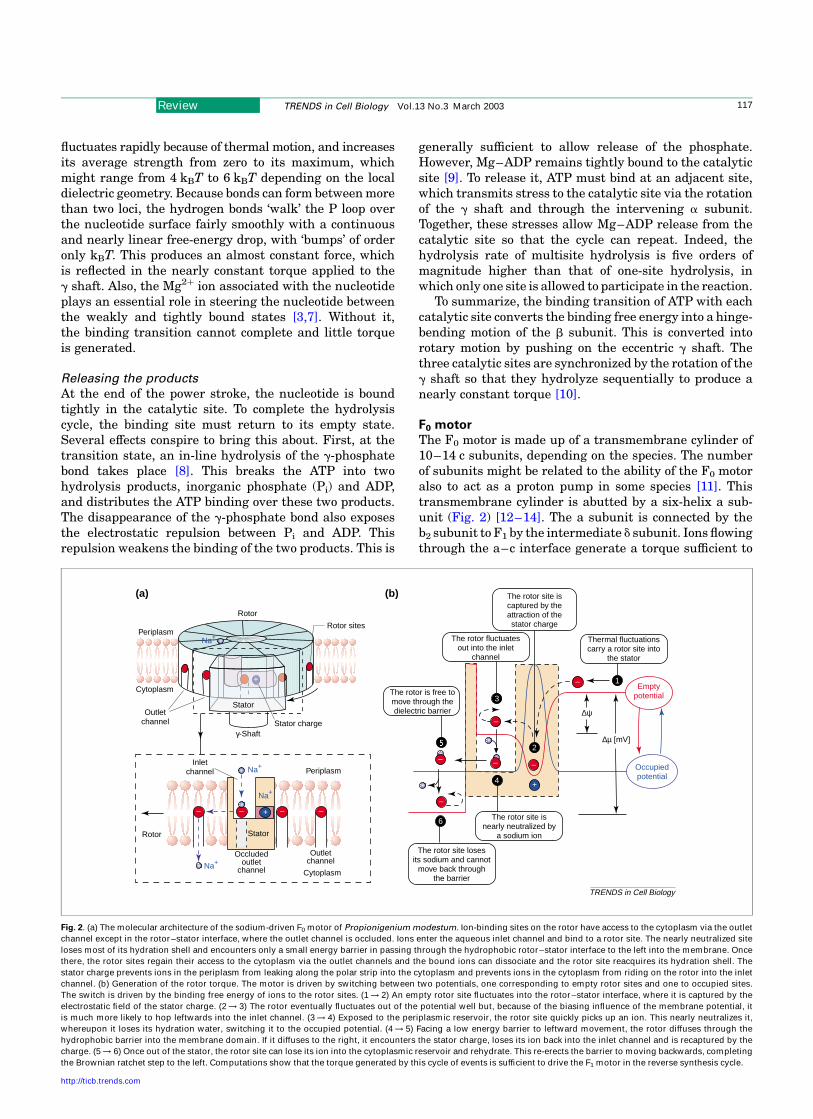
F0 motor
The F0 motor is made up of a transmembrane cylinder of10–14 c subunits, depending on the species. The numberof subunits might be related to the ability of the F0 motoralso to act as a proton pump in some species [11]. Thistransmembrane cylinder is abutted by a six-helix a sub-unit (Fig. 2) [12–14]. The a subunit is connected by theb2 subunit to F1 by the intermediate d subunit. Ions flowingthrough the a–c interface generate a torque sufficient to
Fig. 2. (a) The molecular architecture of the sodium-driven F0 motor of Propionigenium modestum. Ion-binding sites on the rotor have access to the cytoplasm via the outlet
channel except in the rotor–stator interface, where the outlet channel is occluded. Ions enter the aqueous inlet channel and bind to a rotor site. The nearly neutralized site
loses most of its hydration shell and encounters only a small energy barrier in passing through the hydrophobic rotor–stator interface to the left into the membrane. Once
there, the rotor sites regain their access to the cytoplasm via the outlet channels and the bound ions can dissociate and the rotor site reacquires its hydration shell. The
stator charge prevents ions in the periplasm from leaking along the polar strip into the cytoplasm and prevents ions in the cytoplasm from riding on the rotor into the inlet
channel. (b) Generation of the rotor torque. The motor is driven by switching between two potentials, one corresponding to empty rotor sites and one to occupied sites.
The switch is driven by the binding free energy of ions to the rotor sites. (1 ! 2) An empty rotor site fluctuates into the rotor–stator interface, where it is captured by the
electrostatic field of the stator charge. (2 ! 3) The rotor eventually fluctuates out of the potential well but, because of the biasing influence of the membrane potential, it
is much more likely to hop leftwards into the inlet channel. (3 ! 4) Exposed to the periplasmic reservoir, the rotor site quickly picks up an ion. This nearly neutralizes it,
whereupon it loses its hydration water, switching it to the occupied potential. (4 ! 5) Facing a low energy barrier to leftward movement, the rotor diffuses through the
hydrophobic barrier into the membrane domain. If it diffuses to the right, it encounters the stator charge, loses its ion back into the inlet channel and is recaptured by the
charge. (5 ! 6) Once out of the stator, the rotor site can lose its ion into the cytoplasmic reservoir and rehydrate. This re-erects the barrier to moving backwards, completing
the Brownian ratchet step to the left. Computations show that the torque generated by this cycle of events is sufficient to drive the F1 motor in the reverse synthesis cycle.
TRENDS in Cell Biology
(a)
Periplasm
Cytoplasm
Inletchannel Periplasm
Cytoplasm
Outletchannel
Outletchannel
(b)
∆ψ
∆µ [mV]
Rotor sites
Rotor
Rotor Stator
Stator
Stator charge
Na+
Na+
Na+
Na+
γ-Shaft
Thermal fluctuationscarry a rotor site into
the stator
The rotor site iscaptured by theattraction of thestator charge
The rotor fluctuatesout into the inlet
channel
The rotor site isnearly neutralized by
a sodium ion
The rotor is free tomove through thedielectric barrier
The rotor site losesits sodium and cannot
move back throughthe barrier
Emptypotential
Occupiedpotential
Occludedoutlet
channel
+
+
+
– – – ––
– – –
–
– 1
2
3
4
6
Review TRENDS in Cell Biology Vol.13 No.3 March 2003 117
http://ticb.trends.com
GO
5
turn the g shaft and to drive ATP release during thesynthesis cycle in F1. The F0 motor of ATP synthase andthe bacterial flagellar motor are the two known rotaryprotein motors that use this energy source. The toy modeldescribed in Box 2 illustrates the general principle used bythe F0 motor; the bacterial flagellar motor might operatedifferently (see below). Because it is a membrane protein,crystal structures for the F0 motor are not yet available.However, extensive mutational, nuclear magnetic reson-ance and molecular modeling studies have provided a goodpicture of its general structure for both the proton-drivenF0 motor of mitochondria and E. coli [14], and the sodium-driven F0 motor of the anaerobic bacterium Propionigeniummodestum [13].
Applying the general principle to specific proteinsdepends, as always, on molecular architecture. Althoughboth types of motors operate on the same principle, there isstill disagreement about certain aspects of the moleculargeometry. Figure 2 gives a schematic account of thecurrent structure of the P. modestum sodium-driven motor.By convention, the F0 motor consists of a stator and a rotor,although they in fact rotate about one another in themembrane. The stator consists of subunits a, b2 and d; therotor is composed of a ring of 11 c subunits. Each c subunitis a pair of transmembrane a helices with an ion-bindingsite in the core of membrane [15]. In E. coli, the ion-bindingsite is a negatively charged residue (Asp61); in P. modestum,it consists of a trio of one negatively charged and two polarresidues (Gln32, Glu65 and Ser66). [13] The stator containsan essential positive charge: Arg210 in E. coli [14] andArg227 in P. modestum [16].
Based on mutation and molecular modeling studies, theion path for the sodium motor is as shown in Fig. 2a [12].When outside the rotor–stator interface, a rotor site hasaccess to the cytoplasm via the outlet channel that extendsfrom the rotor site to the cytoplasm. Diffusion of the rotorbrings a rotor site into the rotor–stator interface through apolar strip that compensates for the energy penalty ofthe rotor site shedding its hydration waters. In the polarstrip, the rotor site encounters the positive stator charge(Arg227). If the rotor site carries an ion then the ion isdislodged into the cytoplasm by the positive stator charge.Ions from the periplasm can only access the rotor sites viathe aqueous inlet channel in the a subunit. A sodium ion inthe inlet channel can bind to a rotor site and the nearlyneutralized rotor site can move through the hydrophobicrotor–stator interface into the membrane where the sodiumion can dissociate through the outlet channel. The statorcharge also prevents ions in the inlet channel from leakingthrough the stator to the cytoplasm. The sequence of eventis chronicled in Fig. 2.
The torque generated by the F0 motor comes from theenergy of binding and dissociation of ions to the rotor sites.The binding and dissociation of ions switches the rotorback and forth between two driving potentials (Fig. 2b). Anempty rotor site diffuses subject to the ‘empty potential’into the rotor–stator interface, where it is captured by theelectrostatic attraction of the stator charge. Because of themembrane potential, the rotor is much more likely tofluctuate out to the left, into the inlet channel. Once there,the rotor site binds an ion, which reduces its net charge
and thus its hydration. This lowers the barrier for diffusionto the left through the hydrophobic rotor–stator interface.We represent this by switching to the ‘occupied potential’,which is almost flat unless the rotor site fluctuates veryclose to the stator charge. When an occupied rotor sitefluctuates from the inlet channel towards the statorcharge, it loses the bound ion through the inlet channelto the periplasm and is recaptured by the electrostaticattraction of the stator charge. While the rotor site is in therotor–stator interface, the outlet channel is occluded andthe ion cannot escape to the cytoplasm. Once the occupiedrotor site diffuses through the hydrophobic barrier, theoutlet channel reopens and the bound ion can exit to thecytoplasm. The bare rotor site immediately hydrates,creating a large barrier against fluctuating backwards intothe rotor–stator interface; that is, its motion is ratchetedby switching back to the empty potential. This sequence ofevents drives the rotor stochastically to the left in stepsequal to the distance between rotor sites. Calculationsshow that the torque generated by this cycle is quitesufficient to drive the F1 motor in the synthesis direction atthe observed rate [17].
The difference between the models for sodium- andproton-driven motors lies in the presumed path of the ionas it passes through the motor assembly. In the sodium-motor model, the rotor ion-binding sites are accessiblefrom the cytoplasm when outside the rotor–stator inter-face; this allows bound sodium ions to dissociate into thelow concentration reservoir. In the proton F0-motor model,these outlet channels are not present. Instead, the statorhas a single outlet channel through which protons mustexit. It is still unresolved whether or not the sodium F0 andproton F0 have the same ion path. The mechanochemicalprinciple is the same in both models [17,18].
Because the two stalks (g and b2) coupling F0 to F1
are elastic, F1 does not directly see the steps of F0. Insteadthis flexible coupling transmits only the F0 torque to F1
Therefore, there is not a fixed ‘stoichiometry’ relating thenumber of c subunits in F0 to the number of subunits in F1.This elastic coupling also passes energy more efficientlybetween F1 and F0 [5].
Bacterial flagellar motor
The BFM is the powerhouse of protein motors, generatingtorques of ,4000 pN nm near stall. The radius of the rotoris ,20 nm, so the motor generates at its rim a force of,200 pN, far greater than any other molecular motor.(The current runner-up is the ATP-driven PilT AAAprotein, which can retract a bacterial pilus with a forceof ,120 pN [19,20].) Like F0, the BFM draws its energyfrom a transmembrane ion-motive force, and it can bedriven by either protons or sodium ions. For each revo-lution of the motor, ,1200 protons pass through it, eachcontributing ,6 kBT. The proton-driven motor rotates at,300 Hz, whereas the sodium-driven motor rotates at upto ,1700 Hz! Despite intensive investigation, the energytransduction mechanism of the BFM remains elusive; forcurrent reviews, see Refs [21,22].
Like the F0 motor, the BFM has a transmembrane rotorand approximately eight peripheral stators (Fig. 3). How-ever, the operating principle might not be the same as F0,
Review TRENDS in Cell Biology Vol.13 No.3 March 2003118
http://ticb.trends.com
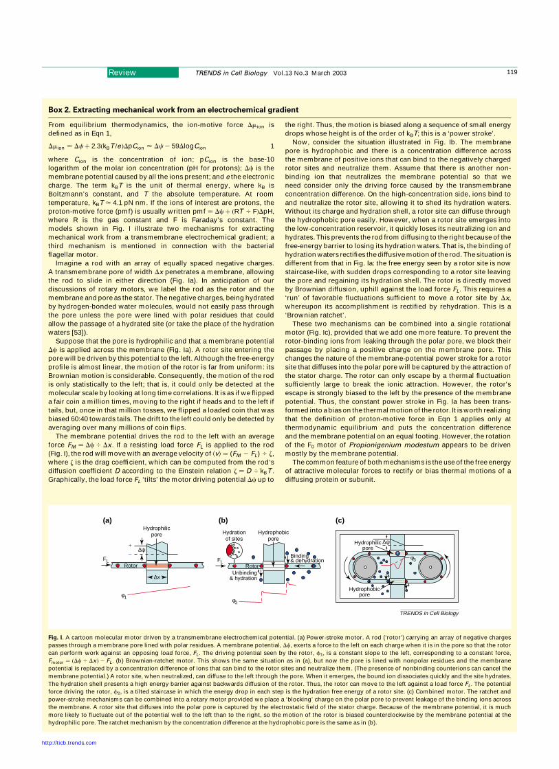
Box 2. Extracting mechanical work from an electrochemical gradient
From equilibrium thermodynamics, the ion-motive force Dmion is
defined as in Eqn 1,
Dmion ¼ Dcþ 2:3ðkBT =eÞDpCion < Dc2 59DlogCion 1
where Cion is the concentration of ion; pCion is the base-10
logarithm of the molar ion concentration (pH for protons); Dc is the
membrane potential caused by all the ions present; and e the electronic
charge. The term kBT is the unit of thermal energy, where kB is
Boltzmann’s constant, and T the absolute temperature. At room
temperature, kBT < 4.1 pN nm. If the ions of interest are protons, the
proton-motive force (pmf) is usually written pmf ¼ Dcþ ðRT 4 FÞDpH;
where R is the gas constant and F is Faraday’s constant. The
models shown in Fig. I illustrate two mechanisms for extracting
mechanical work from a transmembrane electrochemical gradient; a
third mechanism is mentioned in connection with the bacterial
flagellar motor.
Imagine a rod with an array of equally spaced negative charges.
A transmembrane pore of width Dx penetrates a membrane, allowing
the rod to slide in either direction (Fig. Ia). In anticipation of our
discussions of rotary motors, we label the rod as the rotor and the
membrane and pore as the stator. The negative charges, being hydrated
by hydrogen-bonded water molecules, would not easily pass through
the pore unless the pore were lined with polar residues that could
allow the passage of a hydrated site (or take the place of the hydration
waters [53]).
Suppose that the pore is hydrophilic and that a membrane potential
Dc is applied across the membrane (Fig. Ia). A rotor site entering the
pore will be driven by this potential to the left. Although the free-energy
profile is almost linear, the motion of the rotor is far from uniform: its
Brownian motion is considerable. Consequently, the motion of the rod
is only statistically to the left; that is, it could only be detected at the
molecular scale by looking at long time correlations. It is as if we flipped
a fair coin a million times, moving to the right if heads and to the left if
tails, but, once in that million tosses, we flipped a loaded coin that was
biased 60:40 towards tails. The drift to the left could only be detected by
averaging over many millions of coin flips.
The membrane potential drives the rod to the left with an average
force FM ¼ Dc4 Dx : If a resisting load force FL is applied to the rod
(Fig. I), the rod will move with an average velocity of kvl ¼ (FM 2 FL) 4 z,
where z is the drag coefficient, which can be computed from the rod’s
diffusion coefficient D according to the Einstein relation z ¼ D 4 kBT :
Graphically, the load force FL ‘tilts’ the motor driving potential Dc up to
the right. Thus, the motion is biased along a sequence of small energy
drops whose height is of the order of kBT; this is a ‘power stroke’.
Now, consider the situation illustrated in Fig. Ib. The membrane
pore is hydrophobic and there is a concentration difference across
the membrane of positive ions that can bind to the negatively charged
rotor sites and neutralize them. Assume that there is another non-
binding ion that neutralizes the membrane potential so that we
need consider only the driving force caused by the transmembrane
concentration difference. On the high-concentration side, ions bind to
and neutralize the rotor site, allowing it to shed its hydration waters.
Without its charge and hydration shell, a rotor site can diffuse through
the hydrophobic pore easily. However, when a rotor site emerges into
the low-concentration reservoir, it quickly loses its neutralizing ion and
hydrates. This prevents the rod from diffusing to the right because of the
free-energy barrier to losing its hydration waters. That is, the binding of
hydration waters rectifies the diffusive motion of the rod. The situation is
different from that in Fig. Ia: the free energy seen by a rotor site is now
staircase-like, with sudden drops corresponding to a rotor site leaving
the pore and regaining its hydration shell. The rotor is directly moved
by Brownian diffusion, uphill against the load force FL: This requires a
‘run’ of favorable fluctuations sufficient to move a rotor site by Dx,
whereupon its accomplishment is rectified by rehydration. This is a
‘Brownian ratchet’.
These two mechanisms can be combined into a single rotational
motor (Fig. Ic), provided that we add one more feature. To prevent the
rotor-binding ions from leaking through the polar pore, we block their
passage by placing a positive charge on the membrane pore. This
changes the nature of the membrane-potential power stroke for a rotor
site that diffuses into the polar pore will be captured by the attraction of
the stator charge. The rotor can only escape by a thermal fluctuation
sufficiently large to break the ionic attraction. However, the rotor’s
escape is strongly biased to the left by the presence of the membrane
potential. Thus, the constant power stroke in Fig. Ia has been trans-
formed into a bias on the thermal motion of the rotor. It is worth realizing
that the definition of proton-motive force in Eqn 1 applies only at
thermodynamic equilibrium and puts the concentration difference
and the membrane potential on an equal footing. However, the rotation
of the F0 motor of Propionigenium modestum appears to be driven
mostly by the membrane potential.
The common feature of both mechanisms is the use of the free energy
of attractive molecular forces to rectify or bias thermal motions of a
diffusing protein or subunit.
Fig. I. A cartoon molecular motor driven by a transmembrane electrochemical potential. (a) Power-stroke motor. A rod (‘rotor’) carrying an array of negative charges
passes through a membrane pore lined with polar residues. A membrane potential, Dc, exerts a force to the left on each charge when it is in the pore so that the rotor
can perform work against an opposing load force, FL : The driving potential seen by the rotor, f1, is a constant slope to the left, corresponding to a constant force,
Fmotor ¼ ðDc4 DxÞ2 FL: (b) Brownian-ratchet motor. This shows the same situation as in (a), but now the pore is lined with nonpolar residues and the membrane
potential is replaced by a concentration difference of ions that can bind to the rotor sites and neutralize them. (The presence of nonbinding counterions can cancel the
membrane potential.) A rotor site, when neutralized, can diffuse to the left through the pore. When it emerges, the bound ion dissociates quickly and the site hydrates.
The hydration shell presents a high energy barrier against backwards diffusion of the rotor. Thus, the rotor can move to the left against a load force FL: The potential
force driving the rotor, f2, is a tilted staircase in which the energy drop in each step is the hydration free energy of a rotor site. (c) Combined motor. The ratchet and
power-stroke mechanisms can be combined into a rotary motor provided we place a ‘blocking’ charge on the polar pore to prevent leakage of the binding ions across
the membrane. A rotor site that diffuses into the polar pore is captured by the electrostatic field of the stator charge. Because of the membrane potential, it is much
more likely to fluctuate out of the potential well to the left than to the right, so the motion of the rotor is biased counterclockwise by the membrane potential at the
hydrophilic pore. The ratchet mechanism by the concentration difference at the hydrophobic pore is the same as in (b).
TRENDS in Cell Biology
∆ψ
Rotor
∆ψ
FL
φ1
(a) (b) (c)
φ2
φ3
+
–
RotorFL
Hydrationof sites
Binding& dehydration
Unbinding& hydration∆x
Hydrophilicpore Hydrophobic
poreHydrophilic
pore
Hydrophobicpore
+
Review TRENDS in Cell Biology Vol.13 No.3 March 2003 119
http://ticb.trends.com
because scaling up the F0 motor does not produce enoughtorque to account for the BFM’s amazing performance [23].There have been many proposals and several sophisticatedquantitative models [18,24,25] but none has managed tocapture all of the important experimental properties. Theonly models that have been investigated in quantitativedetail use the ‘proton turbine’ mechanism [25–27]. This isan electrostatic mechanism based on the idea that thereare inclined helical arrays of proton-binding sites on therotor that interact with vertical rows of stator chargesalong which protons ‘hop’ from periplasm to cytoplasm.Although these models can reproduce many of the measure-ments, recent work on the structure and charge distri-butions on the stator and rotor are hard to reconcile withthis mechanism (Fig. 3 inset) [28,29]. Although the rotor–stator interaction appears to be electrostatic, current think-ing centers around some sort of ‘power-stroke’ mechanismwith ,50 steps per revolution [21,30]. Just how thisworks awaits more detailed structures of the rotor andstator elements.
Other possible rotary motors
There are several other protein motors that are thought tobe rotary but none has been unequivocally shown to rotate.Examples include the portal protein that packages DNAinto the viral capsid, a multimeric ATPase that can gene-rate a force of nearly 60 pN [31]. The hexameric helicasesthat can translocate single- or double-stranded DNA arealso thought (but have not yet been proved) to be rotarymotors [32–35]. The helicases are members of the AAAfamily proteins, a large class of ATPases, many of whichare (like F1) hexameric and whose catalytic sites arehomologous to that of F1 [36–39]. However, simply being ahexameric ATPase does not guarantee a rotary escape-ment. The PilT motor in bacteria retracts type-4 pilus with
forces that exceed 100 pN but the pilus does not rotateduring retraction [19].
Concluding remarks
The second law of thermodynamics dictates that a motorwithout an external free-energy supply cannot extractheat from an isothermal environment to do work. Althoughthe notion that molecular motors run on Brownian motionappears at first glance to run afoul of the second law,we must remember that the second law is a statementabout the averaged behavior of systems (e.g. macroscopicbehavior). Occasionally, and for short times, an individualmolecular motor can ‘violate’ the second law [40,41]. Forexample, a protein-sized object can fluctuate to stretch aspring but, without a free energy supply, such individualviolations are not sustainable. When averaged over manyobjects or over long times for one object, these violationsdisappear. However, proteins can capture these temporaryviolations by using an energy supply, such as binding freeenergy; such behavior does not violate the second law. So,protein motors can ‘extract’ heat from their surroundingsto do work by using a free-energy supply to bias or rectifythermal fluctuations. This cools down the motor’s localenvironment by taking kinetic energy from the surround-ing solvent molecules. An example is the motor shown inBox 2 Fig. Ib, which is driven by a transmembrane ion-concentration difference. By rectifying the leftward fluc-tuations of the rod, the motor performs work against theload force and cools down the fluid. Without the ion-concentration difference, the leftward fluctuations are notsustainable. In cells, such heat extractions are eventuallypaid back so that the temperature remains constant.Notice that the heat is generally not paid back by themotor itself but by other metabolic processes, such as themanufacture of ATP or the pumping up of the ion gradient.
The F1 motor has provided the deepest insights intothe mechanochemistry of protein motors. This is becausescientists have compiled the most exhaustive catalog ofits properties and behavior. Having atomic structures inseveral energetic states [8] has enabled predictions of theglobal conformational transitions accompanying the cata-lytic cycle [5]. Biochemical studies provided the energytransactions and kinetic rates [42]. Mutation studiesisolated the key amino acids. The final necessary infor-mation was single-molecule mechanical measurementsthat measured the forces the motor could generate underdifferent loading and fuel conditions [2,43]. With all this inhand, a comprehensive model could be constructed, sewingtogether this information to create a reasonably completepicture of the operation of this motor enzyme [5]. The samepath must be traveled for a similar level of understandingof other molecular motors.
AcknowledgementsG.O. was supported by NIH Grant GM59875-02. H.W. was supported byNSF grant DMS-0077971.
References
1 Capaldi, R. and Aggeler, R. (2002) Mechanism of the F1F0-type ATPsynthase, a biological rotary motor. Trends Biochem. Sci. 27, 154–200
2 Noji, H. et al. (1997) Direct observation of the rotation of F1-ATPase.Nature 386, 299–302
Fig. 3. Structure of the bacterial flagellar motor [21,45]. Ions (protons or sodium)
flow through eight stators, each of which consists of four MotA and two MotB
subunits. Each MotA comprises four transmembrane a-helices with a large
cytoplasmic domain, whereas each MotB is a single transmembrane helix that is
anchored to the cell body via the peptidoglycan layer. The torque-generating
surfaces are the cytoplasmic domains of the MotA stator units and the FliG
proteins on the M ring. Mutation studies have determined the conserved amino
acids that participate in torque generation, which are shown in the inset [28,29,46].
Of these, only the negative charge on MotB (Asp32) is essential.
TRENDS in Cell Biology
FliN
FliM
MS-Ring
P-Ring
M-Ring
C-Ring
Cytoplasm
Outer membrane
Innermembrane
Peptidoglycan layer
Periplasm
Flagellar hook
L-Ring
Asp289 Asp288 Arg281
Arg90 Glu98
Asp32MotB (stator)
FliG (rotor)
MotA (stator)
+
+––
–
–
Review TRENDS in Cell Biology Vol.13 No.3 March 2003120
http://ticb.trends.com
GO
GO
3 Antes, I. et al. The unbinding of ATP from the catalytic site ofF1-ATPase. Biophys. J. (in press)
4 Sun, S. et al. Elastic energy storage in F1-ATPase. Nat. Struct. Biol.(submitted)
5 Oster, G. and Wang, H. (2000) Reverse engineering a protein: themechanochemistry of ATP synthase. Biochim. Biophys. Acta 1458,482–510
6 Wang, H. and Oster, G. (1998) Energy transduction in the F1 motor ofATP synthase. Nature 396, 279–282
7 Weber, J. et al. (1998) Mg2þ coordination in catalytic sites ofF-1-ATPase. Biochemistry 37, 608–614
8 Abrahams, J. et al. (1994) Structure at 2.8 A resolution of F1-ATPasefrom bovine heart mitochondria. Nature 370, 621–628
9 Boyer, P. (2002) Catalytic site occupancy during ATP synthasecatalysis. FEBS Lett. 512, 29–32
10 Kinosita, K. et al. (2000) A rotary molecular motor that can workat near 100% efficiency. Philos. Trans. R. Soc. London Ser. B 355,473–490
11 Grabe, M. et al. (2000) The mechanochemistry of the V-ATPase protonpumps. Biophys. J. 78, 2798–2813
12 Dimroth, P. et al. (2000) Osmomechanics of the Propionigeniummodestum F0 motor. J. Bioenerg. Biomembr. 32, 449–458
13 Vonck, J. et al. (2002) Molecular architecture of the undecameric rotorof a bacterial Naþ-ATP synthase. J. Mol. Biol. 321, 307–316
14 Fillingame, R. et al. (2002) Coupling movements to c-ring F1F0 ATPsynthase: aqueous access channels and helix rotations at the a–cinterface. Biochim. Biophys. Acta 1555, 29–36
15 Ballmoos, C. et al. (2002) Membrane topography of the coupling ionbinding site in Naþ translocating F1F0 ATP synthase. J. Biol. Chem.277, 3504–3510
16 Wehrle, F. et al. (2002) Molecular mechanism of the ATP synthase’s F0
motor probed by mutational analyses of subunit a. J. Mol. Biol. 322,369–381
17 Dimroth, P. et al. (1999) Energy transduction in the sodium F-ATPaseof Propionigenium modestum. Proc. Natl. Acad. Sci. U. S. A. 96,4924–4929
18 Elston, T. et al. (1998) Energy transduction in ATP synthase. Nature391, 510–514
19 Maier, B. et al. (2002) Single pilus forces exceed 100pN. Proc. Natl.Acad. Sci. U. S. A. 99, 16012–16017
20 Kaiser, D. (2000) Bacterial motility: how do pili pull? Curr. Biol. 10,R777–R780
21 Berg, H. (2002) The bacterial rotary motor. The Enzymes: EnergyCoupling and Molecular Motors, pp. 1–84
22 Berry, R. and Armitage, J. (1999) The bacterial flagella motor.Advances in Microbial Physiology (41), pp. 291–337, Academic Press
23 Caplan, S. and Walz, D. (2002) Bacterial flagellar motor and Hþ/ATPsynthase: two proton-driven rotary molecular devices with differentfunctions. Bioelectrochemistry 55, 89–92
24 Berry, R.M. (1993) Torque and switching in the bacterial flagellarmotor. An electrostatic model. Biophys. J. 64, 961–973
25 Walz, D. and Caplan, S.R. (2000) An electrostatic mechanism closelyreproducing observed behavior in the bacterial flagellar motor.Biophys. J. 78, 626–651
26 Elston, T. and Oster, G. (1997) Protein turbines I: the bacterialflagellar motor. Biophys. J. 73, 703–721
27 Berry, R. et al. (1995) Mechanical limits of bacterial flagellar motorsprobed by electrorotation. Biophys. J. 69, 280–286
28 Brown, P. et al. (2002) Crystal structure of the middle and C-terminaldomains of the flagellar rotor protein FliG. EMBO J. 21, 3225–3234
29 Zhou, J. et al. (1998) Electrostatic interactions between rotor andstator in the bacterial flagellar motor. Proc. Natl. Acad. Sci. U. S. A. 95,6436–6441
30 Kojima, S. and Blair, D. (2001) Conformational change in the stator ofthe bacterial flagellar motor. Biochemistry 40, 13041–13050
31 Smith, D. et al. (2001) The bacteriophage f29 portal motor can packageDNA against a large internal force. Nature 413, 748–752
32 Hingorani, M. and O’Donnell, M. (2000) A tale of toroids in DNAmetabolism. Nat. Rev. Mol. Cell Biol. 1, 22–30
33 Singleton, M. et al. (2000) Crystal structure of T7 gene 4 ring helicaseindicates a mechanism for sequential hydrolysis of nucleotides. Cell101, 589–600
34 Soultanas, P. and Wigley, D.B. (2001) Unwinding the ‘Gordian knot’ ofhelicase action. Trends Biochem. Sci. 26, 47–54
35 Patel, S. and Picha, K. (2000) Structure and function of hexamerichelicases 1. Annu. Rev. Biochem. 69, 651–697
36 Zhang, X. et al. (2000) Structure of the AAA ATPase p97. Mol. Cell 6,1473–1484
37 Dalal, S. and Hanson, P.L. (2001) Membrane traffic: what drives theAAA motor? Cell 104, 5–8
38 Wall, D. and Kaiser, D. (1999) Type IV pili and cell motility. Mol.Microbiol. 32, 1–10
39 Vale, R. (2000) AAA proteins: Lords of the Ring. J. Cell Biol. 150,F13–F19
40 Wang, G. et al. (2002) Experimental demonstration of violations of thesecond law of thermodynamics for small system and short time scales.Phys. Rev. Lett. 89 050601-050601–105061-050604
41 Liphardt, J. et al. (2002) Equilibrium information from nonequilibriummeasurements in an experimental test of Jarzynski’s equality. Science296, 1832–1835
42 Weber, J. and Senior, A. (1997) Catalytic mechanism of F1-ATPase.Biochim. Biophys. Acta 1319, 19–58
43 Panke, O. et al. (2001) Viscoelastic dynamics of actin filaments coupledto rotary F-ATPase: angular torque profile of the enzyme. Biophys. J.81, 1220–1233
44 Fillingame, R. et al. (2000) The oligomeric subunit c rotor in the F0
sector of ATP synthase: unresolved questions in our understanding offunction. J. Bioenerg. Biomembr. 32, 433–439
45 Francis, N. et al. (1994) Isolation, characterization and structure ofbacterial flagellar motors containing the switch complex. J. Mol. Biol.235, 1261–1270
46 Zhou, J. and Blair, D. (1997) Residues of the cytoplasmic domain ofMotA essential for torque generation in the bacterial flagellar motor.J. Mol. Biol. 273, 428–439
47 Peskin, C.S. et al. (1993) Cellular motions and thermal fluctuations:the Brownian ratchet. Biophys. J. 65, 316–324
48 Simon, S. et al. (1992) What drives the translocation of proteins? Proc.Natl. Acad. Sci. U. S. A. 89, 3770–3774
49 Matlack, K. et al. (1999) BiP acts as a molecular ratchet duringposttranslational transport of prepro-a factor across the ERmembrane. Cell 97, 553–564
50 Mogilner, A. and Oster, G. (1996) The physics of lamellipodialprotrusion. Eur. Biophys. J. 25, 47–53
51 Mogilner, A. and Oster, G. (1996) Cell motility driven by actinpolymerization. Biophys. J. 71, 3030–3045
52 Koshland, D.E. (1958) Application of a theory of enzyme specificity toprotein synthesis. Proc. Natl. Acad. Sci. U. S. A. 44, 98–104
53 Doyle, D.A. et al. (1998) The structure of the potassium channel:molecular basis of Kþ conduction and selectivity. Science 280, 69–77
Managing your references and BioMedNet ReviewsDid you know that you can now download selected search results from BioMedNet Reviews directly into your chosen reference-managing software? After performing a search, simply click to select the articles you are interested in, choose the format required(e.g. EndNote 3.1) and the bibliographic details, abstract and link to the full-text will download into your desktop reference managerdatabase.BioMedNet Reviews is available on institute-wide subscription. If you do not have access to the full-text articles in BioMedNetReviews, ask your librarian to contact [email protected]
Review TRENDS in Cell Biology Vol.13 No.3 March 2003 121
http://ticb.trends.com