Alternating Current Motors
39
Alternating Current Motors
-
Upload
khangminh22 -
Category
Documents
-
view
0 -
download
0
Transcript of Alternating Current Motors

Alternating Current Motors

• AC induction motor is the most widely used type of electric motor in the modern world.
• AC motors are primarily used as a source of constant-speed mechanical power but are increasingly being used in variable speed-control applications.
• Advantages: They are popular because they can provide rotary power with high efficiency, low maintenance, and exceptional reliability—all at relatively low cost.
• These desirable qualities are the result of two factors: (1) AC motors can use the AC power “right off the lines.”—DC
motors require the added expense of a rectifier circuit; (2) most AC motors do not need brushes as DC motors do. In
most cases, the AC power is connected only to the motor’s stationary field windings. The rotor gets its power by electromagnetic induction, a process that does not require physical electrical contact. Maintenance is reduced because brushes do not have to be periodically replaced. Also, the motor tends to be more reliable and last longer because there are fewer parts to go wrong and there is no “brush dust” to contaminate the bearings or windings.

Disadvantages:
• there is a problem with using AC motors in control systems: These high-efficiency AC motors are by nature constant speed, and control systems usually require the motor speed to be controllable.
• the speed of a DC motor can be controlled by simply adjusting the applied voltage. For complete speed control of an AC motor, both voltage and frequency must be adjusted, which requires using special electronic speed-control circuitry, such as the volts-per-hertz (V/Hz) drive or the vector drive

INDUCTION MOTORS

Induction Motor Operation
Rotor windings built into Iron Rotor
Air Gap
Stator windings in outer fixed Iron Core
The Three phase ac voltage in the stator windings
sets up a rotating magnetic field which crosses the
air gap and induces current in the rotor winding.
The resultant current acts with the field to produce
a rotational force

Theory of Operation
How 2-phase AC causes a rotating field:

• Synchronous speed: The speed of the rotating field. For a line frequency of 60 Hz, the field would rotate at 3600 rpm—(60 cycle/s) × (60 s/min) =3600 rpm.
• For an induction motor, the rotor speed does not exactly match the
synchronous speed, it’s slightly lower.
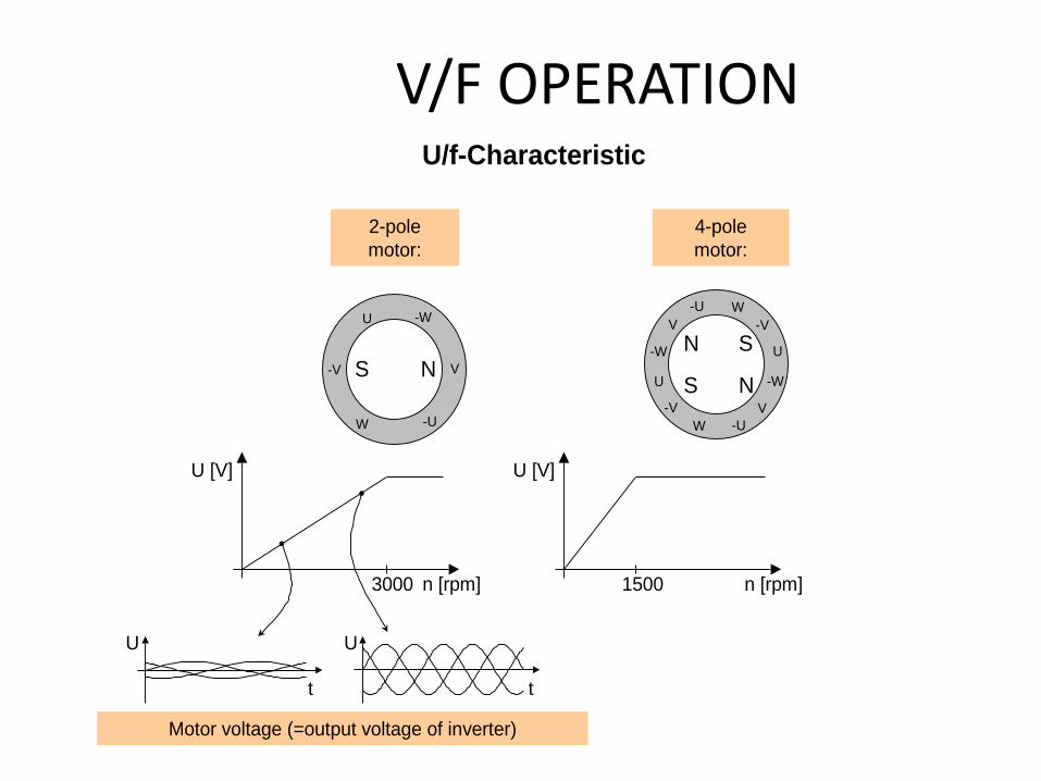
V/F OPERATION U/f-Characteristic
n [rpm]
U [V]
1500
4-pole
motor:
S N
N S
-W
W -U
-V V
U
-W
W-U
-VV
U
2-pole
motor:
n [rpm]
U [V]
3000
S N
-W
W -U
-V V
U
Motor voltage (=output voltage of inverter)
t t
U U

Single-Phase Motors

Start Winding (Split Phase)

Three-Phase Motors • The three-phase motor is simpler and smaller than its single-phase counterpart, but it can
be used only where three-phase power is available.
• The natural timing sequence of the three individual phase voltages produces the rotating stator field that pulls the rotor around. The rotor is the squirrel cage type. The reason this motor is so simple (and hence reliable) is that it is self-starting—just apply the power, and it starts.
• A three-phase motor, once started, will continue to run even when one of the phases is disconnected, because two-thirds of the rotating field is still working and the mechanical inertia of the spinning rotor will carry it over the “dead spot” caused by the missing wire. However, vibration and noise will increase, torque will decrease, and the motor may overheat due to greater current in the active field windings.

Torque - Speed Chart of Induction Motor
1.0
2.0
2.5
0 0.2 0.4 0.6 0.8
Constant Flux Range
1.2 1.4 1.6 1.8 2.0
Field Weakening Range
Maximum Torque
Nominal Torque

Practical meaning of this graph
If overloaded too
much, the motor
will stall ‘pull out’
but continue to
draw high
current.
The motor will
continue to run
in overload, and
may overheat
At frequencies
above ‘normal’,
Maximum torque
is greatly
reduced
At lower
frequencies full
torque is
available

Voltage and Frequency Requirements
A Linear Voltage to Frequency Curve is
suitable for most Applications.
A Quadratic curve can be used with
pumps and fans to save energy by
reduction of magnetising losses.
Special curves can be programmed for
special motors and applications.
At higher frequencies higher voltage
would be desirable, but is not usually
possible.
Vector and Flux Current control
systems control the flux levels
independently.
0
20
40
60
80
100
120
Ou
tpu
t Vo
lta
ge
%
Output Frequency
Because an induction motor works like a transformer, the voltage must be reduced if the frequency is reduced.

MN Rated-load torque
MM Motor torque
ML Load torque
MB Accelerating torque
MA Locked-rotor torque
MK Breakdown torque
MS Pull-up torque
nN Rated speed
nS Synchronous speed
Motor and Load Torque Characteristics

AC Servomotors • A special case of the two-phase motor is the AC servomotor. This is a high-slip, high
torque motor, designed specifically for control systems, and it has a relatively linear torque-speed curve). the lighter the load, the faster the motor runs. This is very similar to the way a DC motor behaves.
• The two windings are called the main winding and the control winding. The main winding is connected to an AC source, usually 120 Vac. The control winding is driven by an electronic circuit that (1) causes the phase to be either leading or lagging the main winding (thereby controlling the motor direction) and (2) sets the magnitude of the control-winding voltage, which determines the speed. Typically, the maximum control winding voltage is about 35 Vac. If the control winding has 0 V, the motor will coast to a stop, even though the main winding is still connected to the line voltage. This is different from a normal induction motor that will continue to run on a single phase.

SYNCHRONOUS MOTORS • The synchronous motor is similar to the induction
motor with one important difference: The rotor in the synchronous motor rotates at exactly
the speed of the rotating field—there is no slip. i.e, the speed of the synchronous motor is always an exact multiple of the line frequency.
This feature is extremely desirable in industrial applications, for example, when several motors along a conveyer belt must all be going exactly the same speed.
• Although many synchronous motors are large, the concept is also used extensively in small clock or timing motors where an exact relationship must exist between frequency and speed.

Operation • To make a synchronous motor work, the power to form a magnetic field in
the rotor must come from another source. Traditionally, this is done by supplying DC power into the rotor via slip rings and brushes.
• Slip rings and brushes on the synchronous motor are similar to the commutator assembly used in DC motors, with one important difference; here the electrical contact from stator to rotor is made through a smooth
• ring, not the multiple contacts of the DC motor’s commutator. The action is smoother, the components last far longer, and less electrical noise is generated.
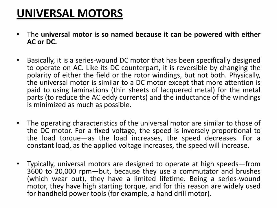
UNIVERSAL MOTORS
• The universal motor is so named because it can be powered with either AC or DC.
• Basically, it is a series-wound DC motor that has been specifically designed to operate on AC. Like its DC counterpart, it is reversible by changing the polarity of either the field or the rotor windings, but not both. Physically, the universal motor is similar to a DC motor except that more attention is paid to using laminations (thin sheets of lacquered metal) for the metal parts (to reduce the AC eddy currents) and the inductance of the windings is minimized as much as possible.
• The operating characteristics of the universal motor are similar to those of the DC motor. For a fixed voltage, the speed is inversely proportional to the load torque—as the load increases, the speed decreases. For a constant load, as the applied voltage increases, the speed will increase.
• Typically, universal motors are designed to operate at high speeds—from 3600 to 20,000 rpm—but, because they use a commutator and brushes (which wear out), they have a limited lifetime. Being a series-wound motor, they have high starting torque, and for this reason are widely used for handheld power tools (for example, a hand drill motor).

AC MOTOR CONTROL Start–Stop Control

Reduced-Voltage Starting
Variable-Speed Control of AC Motors
• In order to fully control the speed of an AC motor, you must be able to change the frequency.
• This can be done with off-the-shelf power-conversion units that are capable of converting the line voltage at 60 Hz into a wide range of voltages and frequencies.
• A motor-control unit (or the control unit plus the motor) is called a drive. There are four choices of AC-motor variable-speed drives:
1- the older variable-frequency drive (also known as a V/Hz drive) and
2-4 the newer vector drives (sensorless, flux vector, and field oriented control

Variable-Frequency (V/Hz) Drives
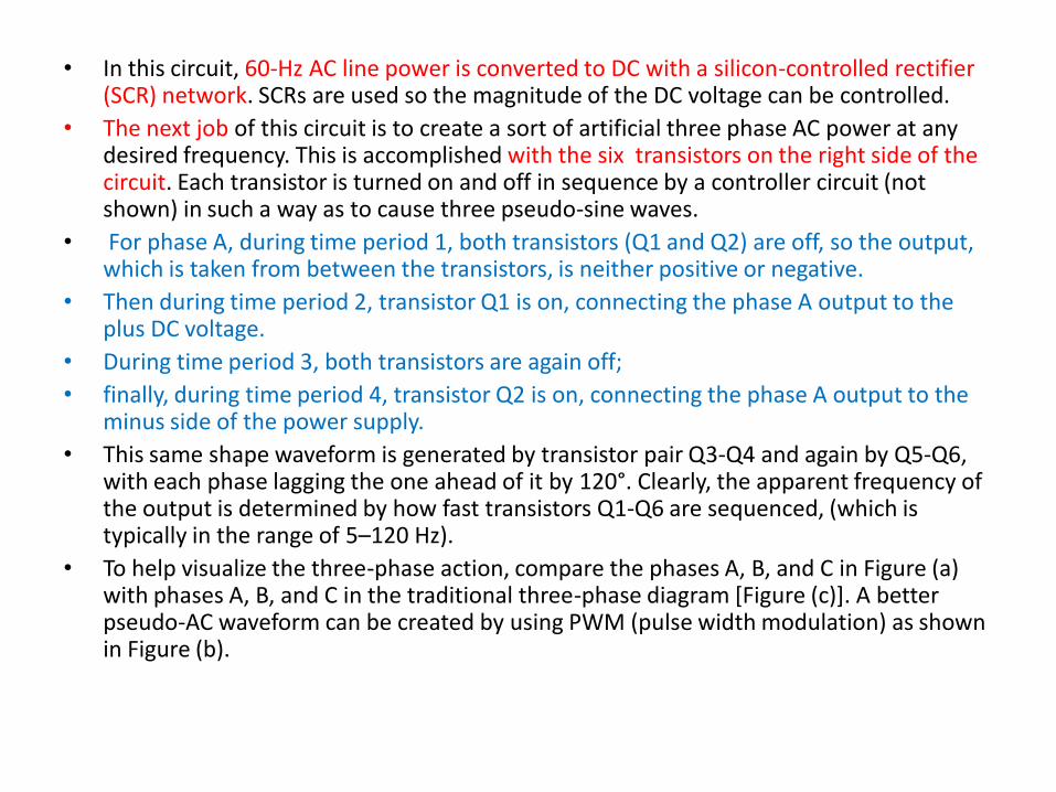
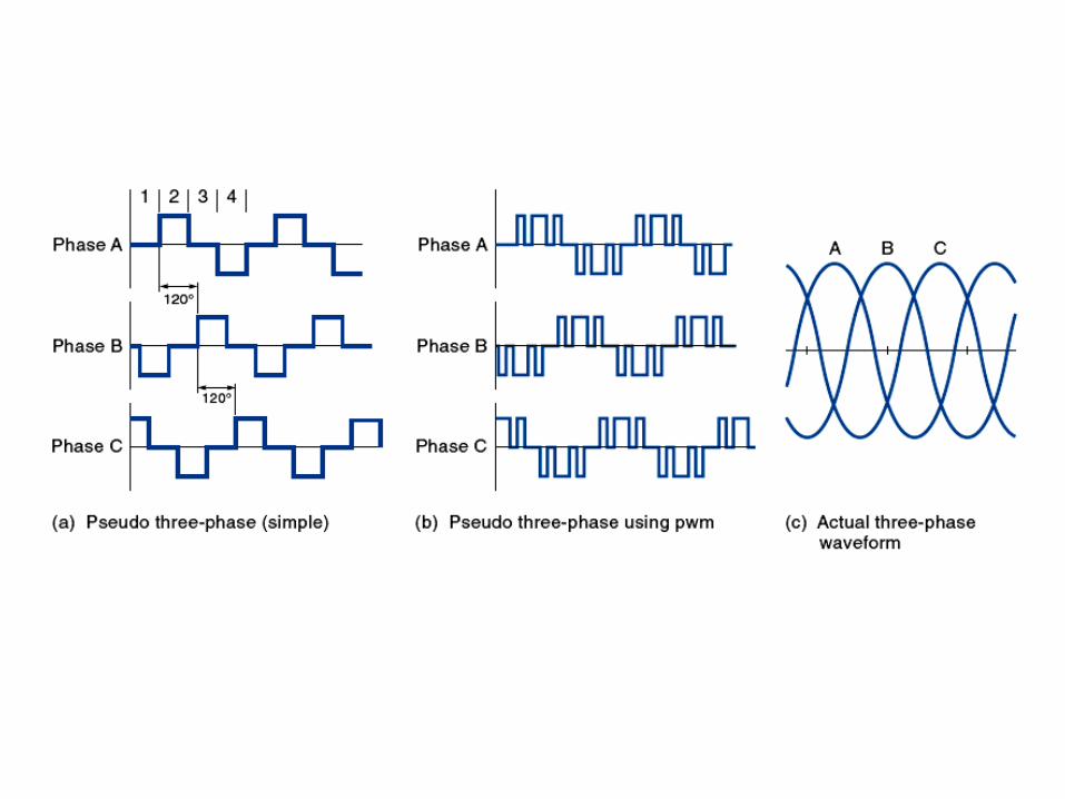
• In this circuit, 60-Hz AC line power is converted to DC with a silicon-controlled rectifier (SCR) network. SCRs are used so the magnitude of the DC voltage can be controlled.
• The next job of this circuit is to create a sort of artificial three phase AC power at any desired frequency. This is accomplished with the six transistors on the right side of the circuit. Each transistor is turned on and off in sequence by a controller circuit (not shown) in such a way as to cause three pseudo-sine waves.
• For phase A, during time period 1, both transistors (Q1 and Q2) are off, so the output, which is taken from between the transistors, is neither positive or negative.
• Then during time period 2, transistor Q1 is on, connecting the phase A output to the plus DC voltage.
• During time period 3, both transistors are again off;
• finally, during time period 4, transistor Q2 is on, connecting the phase A output to the minus side of the power supply.
• This same shape waveform is generated by transistor pair Q3-Q4 and again by Q5-Q6, with each phase lagging the one ahead of it by 120°. Clearly, the apparent frequency of the output is determined by how fast transistors Q1-Q6 are sequenced, (which is typically in the range of 5–120 Hz).
• To help visualize the three-phase action, compare the phases A, B, and C in Figure (a) with phases A, B, and C in the traditional three-phase diagram [Figure (c)]. A better pseudo-AC waveform can be created by using PWM (pulse width modulation) as shown in Figure (b).

• For the motor to work well at various speeds, the voltage to the motor must be modified each time the frequency is changed. Specifically, the voltage and frequency should be held proportional—that is, when the frequency is increased, the voltage should be increased, and vice versa.
• The reason for this requirement is that the current in the stator windings must be maintained at a certain design value for the magnetic induction process (to the rotor) to work.
• Most motors are designed to operate at 60 Hz and 120 V (or 240 V), so the stator is wound to create the proper magnetic field with those conditions. If the frequency drops below 60 Hz, the inductive impedance of the windings also drops, which would allow in more current. Consequently, the voltage must be lowered as the frequency is lowered in order to maintain the proper stator current. Figure (a) shows how the voltage should increase linearly with frequency in the range 0–60 Hz and explains why this type of drive is called a volts-per-hertz or V/Hz type. The voltage is usually not allowed to increase beyond the motor’s rated voltage (for its own health).
• in practice, there are really two distinct operating ranges. The first range (5-60 Hz) is called the constant-torque region because the motor produces a constant torque in this speed range, as shown in Figure (b). This is the same torque that the motor has at normal (60 Hz) operating speed. The region above 60 Hz is known as the constant-power region because, even though the torque is falling off, the speed is increasing, so the actual mechanical power stays the same (power is the product of speed times torque). Commercial motor-control circuits are capable of meeting these qualifications.

CONVERTER PRINCIPLE Principle of a Converter
M
Converter
Rectifier Inverter
Motor
DC link:
Capacitors with rectified mains voltage
Approx. 1.35 x 400V = 540V
Mains connection:
e.g.
3 AC, 400V
Variable frequency and
voltage

CONVERTER PRINCIPLE Pulse Width Modulation - Drives
VDC MM
Motor
MM
Motor
1. Both transistors are switched on. The
full DC link voltage is applied to 2
phases of the motor. The current
increases.
2. One of the two transistors is switched
off. The inductance of the motor
causes the current to find a path via
the recovery diode. The current drops
slightly.
VAVAVDC
VDC
DC link voltage: Output voltage:
IA
Mean output voltage: Output current:
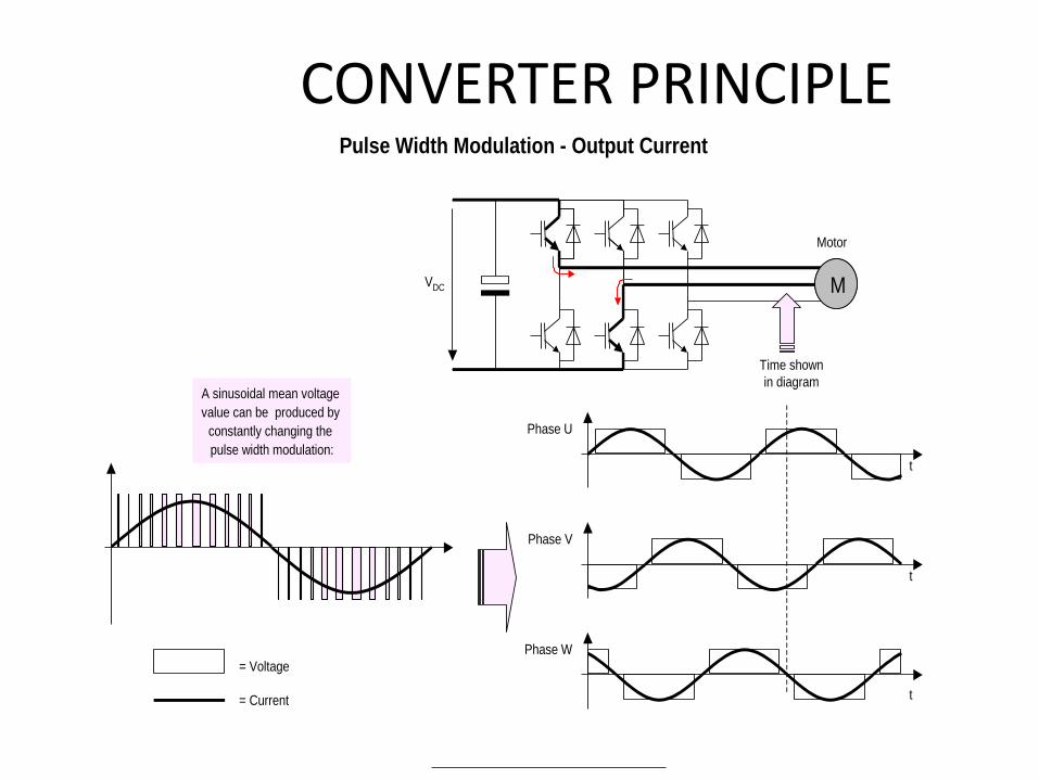
CONVERTER PRINCIPLE Pulse Width Modulation - Output Current
VDC MM
Motor
= Voltage
= Current
Phase U
Phase V
Phase W
Time shown
in diagramA sinusoidal mean voltage
value can be produced by
constantly changing the
pulse width modulation:t
t
t
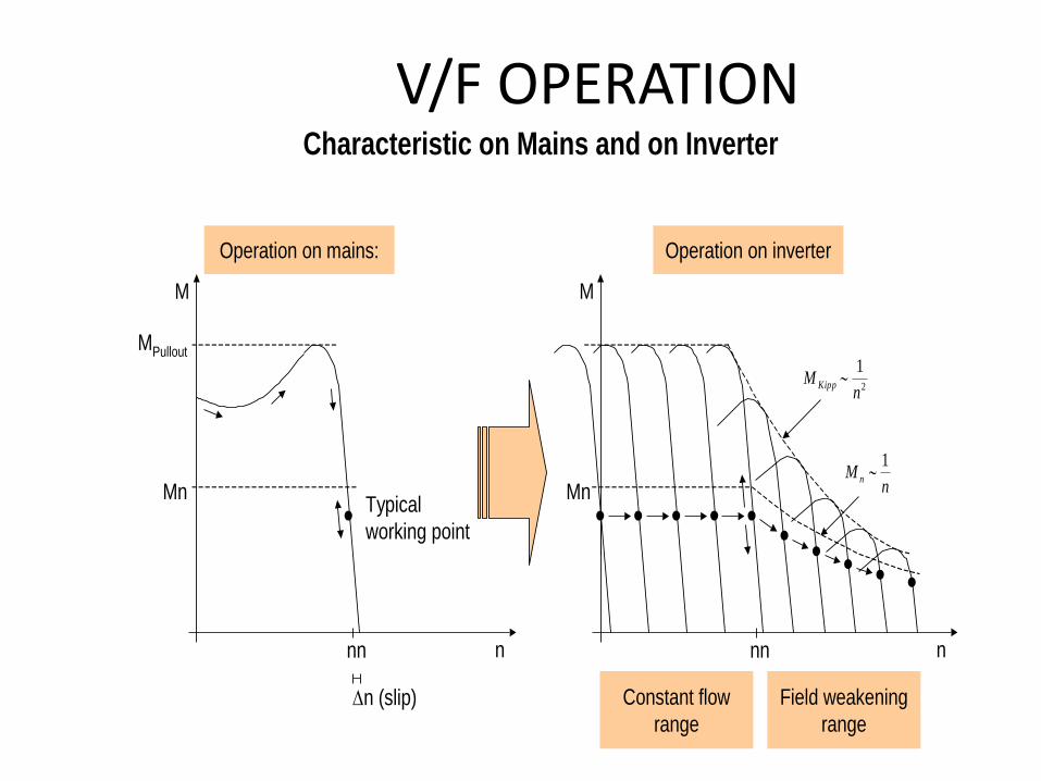
V/F OPERATION Characteristic on Mains and on Inverter
Operation on inverter
2
1
nM Kipp
Constant flow
range
Field weakening
range
nM n
1
M
n
Mn
nn
Operation on mains:
MPullout
Mn
M
n
Typical
working point
nn
n (slip)

Vector Drives • Vector drives are based on the principle that the
current driving an AC induction motor can be divided into two components: the current that produces the magnetic field flux in the stator and the current that creates the torque that causes rotation.
• The actual motor current is the vector sum of these two currents, and if they can be independently controlled, it is possible to drive the motor at full torque at any speed, right down to 0 Hz.
• There are three types of vector drives: sensorless vector, flux vector, and field-oriented control drives.
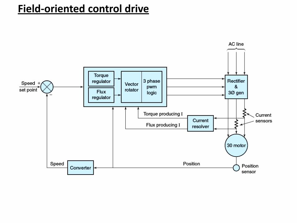
Field-oriented control drive

• Current sensors on the motor leads feed a current resolver, which identifies the flux-producing and torque-producing currents in the motor. A position sensor mounted on the shaft provides position and speed information.
• The drive electronics uses all this information to maintain two independent control loops: a speed/torque loop for control of the motor speed and torque, and a flux loop to provide a constant magnetizing stator current throughout the motor’s speed range.
• By maintaining a constant stator flux, the motor is capable of providing a constant torque from its base frequency (60 Hz) all the way down to 0 Hz. The speed/torque loop is able to determine what the moment-to-moment slip is (some slip is necessary for any induction motor) and then compensate by adjusting the rotational speed of the field very precisely within the windings so as to make up for the slip.
• This process can keep the motor running at exactly its set-point speed, regardless of the torque demand. The outputs of both the flux- and the speed/torque-control loops are combined in the vector rotator to produce a single set of three-phase voltage waveforms. These waveforms are converted into PWM and fed to the transistors in the variable-frequency generator.

• The sensorless drive predates the field-oriented control drive and cannot provide such precise control. As the name suggests, it does not require a position sensor but instead makes “guesses” based on current feedback and what it knows about the motor. This system is adequate for many applications.
• The flux vector drive does require a position sensor and maintains better control than the sensorless drive can (but not as good control as the field-oriented drive). This system estimates the flux-producing and torque-producing current vectors in the motor and uses this information to control the motor. Flux vector drives can function effectively down to 2-3 Hz

Vector Representation
I
V
t
t180° 360°
180° 360°
Cartesian coordinate system Polar coordinate system (=vector
representation)
V
I

Encoder
evaluation
Vector Control of Induction Motors with Encoder
Speed
controller
Current controller
Active current
Power
section
MM
Motor
EE
Encoder
Coordinate
transformation
Speed
- nact
- Iact, field
nset
P
C
Coordinate
transformation
P
C
Current controller
Field current
- Iact, active
Iset, active
Field
controller
Motor
model
Actual value
calculation
Iset, fieldField
Design calculation in
polar coordinate system
Values in Cartesian
coordinate systemiw
i
it
iR
iS
iT
Simplified
diagram
t
tMagnetizing current
= Field current

Vector Control of Induction Motors without Encoder
Speed
controller
Current controller
Active current
Power
section
MM
Motor
Coordinate
transformation
Speed
- nact
- Iact,field
nset
P
C
Coordinate
transformation
P
C
Current controller
Field current
- Iact, active
Iset, active
Field
controller
Motor
model
Actual value
calculation
Iset, fieldField
Simplified
diagram
Design calculation in
polar coordinate system
Values in Cartesian
coordinate systemiw
i
it
iR
iS
iT
t
tMagnetizing current
= Field current

n* _
v*s
v*
is1
is3
is2
vs1
vs3
vs2
n
Field
precontrol
Compensation with
feedforward control
VT
+
VT
-
Magnetic field calculator
C
P
2
3
3
2
' *R
R1 Field controller
Current controllerSpeed controller
_+
+
+
_
__
isp
*
isq
*
isq
isp
v*sq
v*sp
'R
R1
j ' se
v * s
v * s
is
is
*s
VT: Vector transformation
v s
v s
Field-oriented reference frame Fixed stator reference frame
To inverter
trigger equipment
Actual
values
Field
requirement
Speed
requirement
Block Diagram of Vector Control