SHOGUN - Mitsubishi Motors
538
English SHOGUN OWNER’S MANUAL
-
Upload
khangminh22 -
Category
Documents
-
view
2 -
download
0
Transcript of SHOGUN - Mitsubishi Motors

English
SH
OG
UNOWNER’S MANUAL
eng_CV_SHOGUN_Pajero08.qxd 26-12-2007 15:55 Page 1

ForewordE09200101932
Thank you for selecting a SHOGUN as your new vehicle.This owner’s manual will add to your understanding and fullenjoyment of the many fine features of this vehicle.It contains information prepared to acquaint you with theproper way to operate and maintain your vehicle for the utmostin driving pleasure.
MITSUBISHI MOTORS Europe B.V. reserves the right tomake changes in design and specifications and/or to makeadditions to or improvements in this product without obligationto install them on products previously manufactured.It is an absolute requirement for the driver to strictly observeall laws and regulations concerning vehicles.
This owner’s manual has been written in compliance withsuch laws and regulations, but some of the contents maybecome contradictory with later amendment of the laws andregulations.
Please leave this owner’s manual in this vehicle at time ofresale. The next owner will appreciate having access to theinformation contained in this owner’s manual.
Repairs to your vehicle:Vehicles in the warranty period:All warranty repairs must be carried out by a MITSUBISHIMOTORS Authorized Service Point.
Vehicles outside the warranty period:Where the vehicle is repaired is at the discretion of the owner.
Throughout this owner’s manual the words WARNING andCAUTION appear.These serve as reminders to be especially careful. Failure to followinstructions could result in personal injury or damage to your vehicle.
indicates a strong possibility of severe personal injury ordeath if instructions are not followed.
means hazards or unsafe practices that could cause minorpersonal injury or damage to your vehicle.
You will see another important symbol:NOTE: gives helpful information.
*: indicates optional equipment.It may differ according to the sales classification; refer to the sales catalogue.
Abbreviations used in this owner’s manual: LHD: Left-Hand DriveRHD: Right-Hand DriveM/T: Manual TransmissionA/T: Automatic Transmission
Information for station serviceE09300100486
OBKX08E1
BL071501 8
WARNING
CAUTION
Fuel tank capacity3-door models 69 litres
5-door models 88 litres
Petrol-powered vehiclesUnleaded petrol octane number (EN228)
95 RON or higher
FuelDiesel-powered vehicles
Fuel requirementsVehicles to comply with the Euro 4 regulation
Cetane number (EN590)
51 or higher
Vehicles to comply with the Euro 3 regulation
Cetane number
45 or higher
Refer to the “Fuel selection” for details.
Engine oil Refer to the “Maintenance” section of this owner’s manual for the SAE viscosity.
Tyre inflation pressure Refer to the “Maintenance” section for the tyre inflation pressure.
© 2007 Mitsubishi Motors Corporation
Mitsubishi Motors Europe B.V.
eng_CV_SHOGUN_Pajero08.qxd 26-12-2007 15:55 Page 2

Table of contents
1
2
3
4
5
6
7
8
9
Overview
General information
Locking and unlocking
Seat and seat belts
Instruments and controls
Starting and driving
For pleasant driving
For emergencies
Vehicle care
Maintenance
Specifications
BK-BK2008E1ENUK.en-ukTOC.fm Page 1 Wednesday, January 9, 2008 4:20 PM

Overview
Instruments and Controls (Driver’s area)E00100102052
Electric remote-controlled outside rear-view mirror switch p. 4-11
Front fog lamp switch* p. 3-66Rear fog lamp switch p. 3-67
Combination headlamps and dipper switch p. 3-58Turn-signal lever p. 3-65Headlamp washer switch* p. 3-76
Supplemental restraint system-airbag (for driver’s seat) p. 2-58Horn switch p. 3-78
Instruments p. 3-2
Windscreen wiper and washer switch p. 3-68Rear window wiper and washer switch p. 3-75
Daytime dipper button (meter illumination control) p. 3-9
Cruise control switch* p. 4-70
Fuse box lid p. 8-29
Bonnet release lever p. 8-3
Ignition switch p. 4-14
Fuel tank filler door release lever p. 3
LHDHazard warning flasher switch p. 3-66
Active stability control switch p. 4-63
Steering wheel height adjustment p. 4-8
Audio switch* p. 5-70
Sonar cancel switch* p. 4-78
Headlamp levelling switch* p. 3-62
BK-BK2008E1ENUK.en-uk-Section2.fm Page 1 Wednesday, January 9, 2008 4:26 PM

Overview
Electric remote-controlled outside rear-view mirror switch p. 4-11
Combination headlamps and dipper switch p. 3-58Turn-signal lever p. 3-65Headlamp washer switch* p. 3-76
Supplemental restraint system-airbag (for driver’s seat) p. 2-58Horn switch p. 3-78Instruments p. 3-2
Windscreen wiper and washer switch p. 3-68Rear window wiper and washer switch p. 3-75
Daytime dipper button (meter illumination control) p. 3-9
Cruise control switch* p. 4-70
Fuse box lid p. 8-29Bonnet release lever p. 8-3
Ignition switch p. 4-14
Fuel tank filler door release lever p. 3
Headlamp levelling switch* p. 3-62
Front fog lamp switch* p. 3-66Rear fog lamp switch p. 3-67
RHD
Steering wheel height adjustment p. 4-8
Hazard warning flasher switch p. 3-66
Active stability control switch p. 4-63
Audio switch* p. 5-70
Sonar cancel switch* p. 4-78
BK-BK2008E1ENUK.en-uk-Section2.fm Page 2 Wednesday, January 9, 2008 4:26 PM

Overview
Instruments and Controls (Instrument panel)E00100102788
Supplemental restraint system-airbag (for front passenger’s seat) p. 2-58
Side ventilators p. 5-2
Rear window demister switch p. 3-77
Armrest (for front seats) p. 2-10Centre console box p. 5-94Accessory socket p. 5-83
Front automatic air conditioning p. 5-4 Centre information
display p. 3-17
Cigarette lighter* p. 5-82Accessory socket* p. 5-83
Transfer shift lever p. 4-34
Rear heater*/Rear air conditioning* p. 5-15 Cup holder (for front seats)
p. 5-99
Floor ventilators* p. 5-2
Audio* p. 5-20, 5-43Mitsubishi Multi Communication System*Refer to the separate “Mitsubishi Multi Communication System owner’s manual”
Gearshift lever p. 4-23Selector lever p. 4-25
Rear differential lock switch* p. 4-42
Centre ventilators p. 5-2
Parking brake lever p. 4-6
Heated seat switch* p. 2-12
LHD
Centre accessory box* p. 5-96
Front passenger’s airbag OFF indication lamp p. 2-63
Front passenger’s airbag ON-OFF switch p. 2-63
Glove box p. 5-93
BK-BK2008E1ENUK.en-uk-Section2.fm Page 3 Wednesday, January 9, 2008 4:26 PM

Overview
RHD
Rear window demister switch p. 3-77
Front automatic air conditioning p. 5-4
Audio* p. 5-20, 5-43Mitsubishi Multi Communication System*Refer to the separate “Mitsubishi Multi Communication System owner’s manual”
Centre accessory box* p. 5-96
Armrest (for front seats) p.2-10Centre console box p. 5-94Accessory socket p. 5-83
Rear heater*/Rear air conditioning* p. 5-15
Gearshift lever p. 4-23Selector lever p. 4-25
Parking brake lever p. 4-6
Transfer shift lever p. 4-34
Cup holder (for front seats) p.5-99
Floor ventilators* p. 5-2Heated seat switch* p. 2-12
Cigarette lighter* p. 5-82Accessory socket* p. 5-83
Rear differential lock switch* p. 4-42
Glove box p. 5-93
Supplemental restraint system - airbag (for front passenger’s seat) p. 2-58
Side ventilators p. 5-2
Centre ventilators p. 5-2
Front passenger’s airbag OFF indication lamp p. 2-63
Front passenger’s airbag ON-OFF switch p. 2-63
Centre information display p. 3-17
BK-BK2008E1ENUK.en-uk-Section2.fm Page 4 Wednesday, January 9, 2008 4:26 PM

Overview
InteriorE00100202415
Sunroof switch* p. 1-21
Rear personal lamps p. 5-87, 8-38, 8-51
Electric window control p. 1-16
Electric win-dow lock switch p. 1-18
Room & map lamp p. 5-87, 8-38, 8-50Interior lamp switch p. 5-85
Seat belts p. 2-38Adjustable seat belt anchor(for front seats) p. 2-41
Cup holder (for third seat)* p. 5-101
Luggage floor box p. 5-97
Vanity mirror p. 5-78
Sun visors p. 5-77
Inside rear-view mirror p. 4-9
Armrest (for rear/second seat) p. 2-14Cup holder (for rear/second seat) p. 5-99
Seat p. 2-2Supplemental restraint system - side airbag (for front seats)* p. 2-58
Luggage compartment lamp p. 5-88, 8-38, 8-52
Roof ventilators (5-door models)* p. 5-2
Head restraints p. 2-16
LHD
Central door lock switch p. 1-9
Supplemental restraint system - curtain airbag* p. 2-58
Sunglasses holder* p. 5-98
Video entertainment system*Refer to the separate “Video entertainment system owner’s manual”
BK-BK2008E1ENUK.en-uk-Section2.fm Page 5 Wednesday, January 9, 2008 4:26 PM

Overview
RHD
Electric window control p. 1-16
Electric window lock switch p. 1-18
Luggage compartment lamp p. 5-88, 8-38, 8-52
Central door lock switch p. 1-9
Sunroof switch* p.1-21
Room & map lamp p. 5-87, 8-38, 8-50Interior lamp switch p. 5-85
Sunglasses holder* p. 5-98
Rear personal lamps p. 5-87, 8-38, 8-51
Seat belts p. 2-38Adjustable seat belt anchor(for front seats) p. 2-41
Roof ventilators (5-door models)* p. 5-2
Supplemental restraint system - curtain airbag* p. 2-58
Sun visors p. 5-77
Vanity mirror p. 5-78
Inside rear-view mirror p. 4-9
Seat p. 2-2Supplemental restraint system- side airbag (for front seats)* p. 2-58 Cup holder (for third seat)*
p. 5-101Luggage floor box p. 5-97Armrest (for rear/second seat) p. 2-14
Cup holder (for rear/second seat) p. 5-99 Head restraints p. 2-16
Video entertainment system*Refer to the separate “Video entertainment system owner’s manual”
BK-BK2008E1ENUK.en-uk-Section2.fm Page 6 Wednesday, January 9, 2008 4:26 PM

Overview
Luggage areaE00100400963
3-door models
5-door models
Accessory socket p. 5-83
Luggage hooks p. 5-105
Jack p. 6-11Jack handle p. 6-11Tools p. 6-11
Side box* p. 5-97
Jack p. 6-11Jack handle p. 6-11
Tools p. 6-11
Luggage hooks p. 5-105
Rear window washer fluid container p. 8-12
Rear shelf* p. 5-101
Luggage hooks p. 5-105
Cargo area cover* p. 5-103
Accessory socket p. 5-83
Securing bolts of spare wheel garnish p. 6-18
Video jack*Refer to the separate “Video entertainment system owner’s manual”
Securing bands of warning triangle p. 5-107
BK-BK2008E1ENUK.en-uk-Section2.fm Page 7 Wednesday, January 9, 2008 4:26 PM

Overview
Outside (Front)E00100502434
Front fog lamps* p. 3-66, 8-36, 8-42
Engine compartment p. 9-16Bonnet p. 8-3
Windscreen wiper and washer p. 3-68
Headlamps p. 3-58, 8-36, 8-38
Electric window control p. 1-16
Outside rear-view mirrors p. 4-11Approach lamps* p. 1-12
Sunroof* p. 1-21
Front turn-signal lamps p. 3-65, 8-36, 8-41
Side turn-signal lamps* p. 3-65
Position lamps p. 3-58, 8-36, 8-41
Locking and unlocking p. 1-7Keyless entry system* p. 1-5
Rear side/quarter window p. 1-20Antenna p. 5-77
Headlamp washer* p. 3-76
Rain sensor* p. 3-71
BK-BK2008E1ENUK.en-uk-Section2.fm Page 8 Wednesday, January 9, 2008 4:26 PM

Overview
Outside (Rear)E00100502564
Rear turn-signal lamps* p. 3-65, 8-36, 8-44
Fuel tank filler p. 3
Reversing lamps p. 8-36, 8-44
Licence plate lamps p. 3-58, 8-36, 8-49
Spare wheel p. 6-17 Backdoor p. 1-13
High-mounted stop lamp p. 8-36, 8-48 Rear window wiper and washer p. 3-75
Tyre inflation pressure p. 8-19Changing tyres p. 6-16Tyre rotation p. 8-21Tyre chains p. 8-23
Rear fog lamp p. 3-67, 8-36, 8-47
Stop and tail lamps* p. 3-58, 8-36, 8-44Stop lamps* p. 8-36, 8-44
Spare wheel garnish p. 6-18
Tail lamps* p. 3-58, 8-36, 8-44
3-door models 5-door modelsRear turn-signal lamps* p. 3-65, 8-36, 8-44 Rear turn-signal lamps* p. 3-65, 8-36, 8-44
Stop and tail lamps* p. 3-58, 8-36, 8-44Stop lamps* p. 8-36, 8-44
Reversing lamps p. 8-36, 8-44
Rear-view camera* p. 4-84
Corner and back sensor* p. 4-78
BK-BK2008E1ENUK.en-uk-Section2.fm Page 9 Wednesday, January 9, 2008 4:26 PM

General information
Fuel selection . . . . . . . . . . . . . . . . . . . . . . . . . . . . . . 2Filling the fuel tank . . . . . . . . . . . . . . . . . . . . . . . . . 3Installation of accessories . . . . . . . . . . . . . . . . . . . . 6Modification/alterations to the electrical or
fuel systems . . . . . . . . . . . . . . . . . . . . . . . . . . . . . 7Genuine parts . . . . . . . . . . . . . . . . . . . . . . . . . . . . . . 7Used engine oils safety instructions and
disposal information . . . . . . . . . . . . . . . . . . . . . . . 8
BK-BK2008E1ENUK.en-uk-Section3.fm Page 1 Wednesday, January 9, 2008 4:21 PM

2
General information
Fuel selectionE00200101362
NOTE● Petrol-powered vehicles have the knock control system so
that you can use unleaded petrol 91 RON as an emergentmeasure in case unleaded petrol 95 RON or higher is notavailable on journey, etc. In such a case, you don’t need toadjust the engine specially.In case of using unleaded petrol 91 RON, the engine per-formance level is reduced.
● In petrol-powered vehicles, repeatedly driving short dis-tance at low speeds can cause deposits to form in the fuelsystem and engine, resulting in poor starting and pooracceleration.If these problems occur, you are advised to add a deter-gent additive to the gasoline when you refuel the vehicle.The additive will remove the deposits, thereby returningthe engine to a normal condition. Be sure to use a genuineMITSUBISHI FUEL SYSTEM CLEANER. Using anunsuitable additive could make the engine malfunction.For details, please contact your MITSUBISHI MOTORSAuthorized Service Point.
● Poor quality petrol can cause problems such as hard start-ing, stalling, engine noise and hesitation. If your experi-ence these problems, try another brand and/or grade ofpetrol.If the check engine warning lamp flashes, have the systemchecked as soon as possible at a MITSUBISHI MOTORSAuthorized Service Point.
Recommended fuel
Petrol-powered vehicles Unleaded petrol octane number (EN228) 95 RON or higher
Diesel-powered vehicles Vehicles to comply with the Euro 4 regulation Cetane number (EN590) 51 or higher Vehicles to comply with the Euro 3 regulation Cetane number 45 or higher
CAUTION!● For petrol-powered vehicles, the use of leaded fuel
can result in serious damage to the engine and cata-lytic converter.
● Diesel-powered vehicles to comply with the Euro 4regulation are designed to use only diesel fuel thatmeets the EN 590 standard.Use of any other type of diesel fuel can adverselyaffect the engine.
BK-BK2008E1ENUK.en-uk-Section3.fm Page 2 Wednesday, January 9, 2008 4:21 PM
General information
3
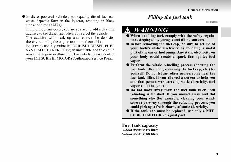
● In diesel-powered vehicles, poor-quality diesel fuel cancause deposits form in the injector, resulting in blacksmoke and rough idling.If these problems occur, you are advised to add a cleaningadditive to the diesel fuel when you refuel the vehicle.The additive will break up and remove the deposits,thereby returning the engine to a normal condition.Be sure to use a genuine MITSUBISHI DIESEL FUELSYSTEM CLEANER. Using an unsuitable additive couldmake the engine malfunction. For details, please contactyour MITSUBISHI MOTORS Authorized Service Point.
Filling the fuel tankE00200201578
Fuel tank capacity3-door models: 69 litres5-door models: 88 litres
WARNING!● When handling fuel, comply with the safety regula-
tions displayed by garages and filling stations.● Before removing the fuel cap, be sure to get rid of
your body’s static electricity by touching a metalpart of the car or fuel pump. Any static electricity onyour body could create a spark that ignites fuelvapor.
● Perform the whole refuelling process (opening thefuel tank filler door, removing the fuel cap, etc.) byyourself. Do not let any other person come near thefuel tank filler. If you allowed a person to help youand that person was carrying static electricity, fuelvapor could be ignited.
● Do not move away from the fuel tank filler untilrefueling is finished. If you moved away and didsomething else (for example, cleaning your wind-screen) partway through the refueling process, youcould pick up a fresh charge of static electricity.
● If the tank cap must be replaced, use only a MIT-SUBISHI MOTORS original part.
BK-BK2008E1ENUK.en-uk-Section3.fm Page 3 Wednesday, January 9, 2008 4:21 PM

4
General information
Refueling1. Before filling with fuel, stop the engine.2. The fuel tank filler is located on the rear right side of your
vehicle.Open the fuel tank filler door with the release leverlocated below the instrument panel.
LHD
RHD
BK-BK2008E1ENUK.en-uk-Section3.fm Page 4 Wednesday, January 9, 2008 4:21 PM
General information
5
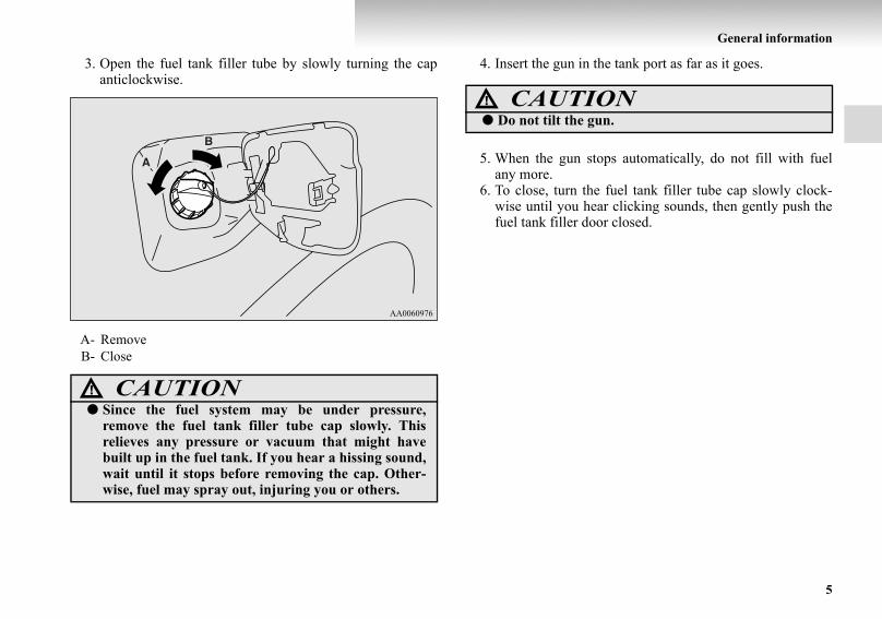
3. Open the fuel tank filler tube by slowly turning the capanticlockwise.
4. Insert the gun in the tank port as far as it goes.
5. When the gun stops automatically, do not fill with fuelany more.
6. To close, turn the fuel tank filler tube cap slowly clock-wise until you hear clicking sounds, then gently push thefuel tank filler door closed.
A- RemoveB- Close
CAUTION!● Since the fuel system may be under pressure,
remove the fuel tank filler tube cap slowly. Thisrelieves any pressure or vacuum that might havebuilt up in the fuel tank. If you hear a hissing sound,wait until it stops before removing the cap. Other-wise, fuel may spray out, injuring you or others.
CAUTION!● Do not tilt the gun.
BK-BK2008E1ENUK.en-uk-Section3.fm Page 5 Wednesday, January 9, 2008 4:21 PM

6
General information
Installation of accessoriesE00200300774
We recommend you to consult your MITSUBISHI MOTORSAuthorized Service Point.
● The installation of accessories, optional parts, should onlybe carried out within the limits prescribed by law in yourcountry, and in accordance with the guidelines fittinginstructions and warnings contained within the documentsaccompanying the parts or accessories.
● Improper installation of electrical components may causean electrical fire if incorrectly fitted. Please refer to Modi-fication/alteration to the electrical or fuel systems sectionwithin this owner’s manual.
● Using a cellular phone or radio set inside the vehicle with-out an external antenna may cause electrical system inter-ference, which could lead to unsafe vehicle operation.
● Tyres and wheels which do not meet specifications mustnot be used.Refer to the “Specifications” section for informationregarding wheel and tyre sizes.
● When fitting accessories, ensure that maximum grossvehicle weight and maximum axle weight are notexceeded.
Important points!Due to large number of accessory and replacement parts of dif-ferent manufactures available in the market, it is not possible,not only for MITSUBISHI MOTORS, but also for a MIT-SUBISHI MOTORS Authorized Service Point, to checkwhether the attachment or installation of such parts affects theoverall safety of your MITSUBISHI-vehicle.
Even when such parts are officially authorized, for example bya “general operators permit” (an appraisal for the part) orthrough the execution of the part in an officially approved man-ner of construction, or when a single operation permit follow-ing the attachment or installation of such parts, it cannot bededuced from that alone, that the driving safety of your vehiclehas not been affected.
Consider also that there basically exists no liability on the partof the appraiser or the official. Only in the case of parts (MIT-SUBISHI MOTORS original replacement or exchange parts aswell as MITSUBISHI MOTORS genuine accessories) that arerecommended and released by a MITSUBISHI MOTORSAuthorized Service Point and that are attached or installed by aMITSUBISHI MOTORS Authorized Service Point can youassume, that optimal safety has been provided. The same alsopertains to modifications of MITSUBISHI vehicle with respectto the production specifications. For your own safety, in suchcases, you should only undertake modifications according tothe recommendations of a MITSUBISHI MOTORS Author-ized Service Point.
BK-BK2008E1ENUK.en-uk-Section3.fm Page 6 Wednesday, January 9, 2008 4:21 PM

General information
7
Modification/alterations to the electrical or fuel systems
E00200400254
MITSUBISHI MOTORS has always manufactured safe, highquality vehicles. In order to maintain this safety and quality, itis important that any accessory that is to be fitted, or any modi-fications carried out which involve the electrical or fuel sys-tems, should be carried out in accordance with MITSUBISHIMOTORS guidelines.
Genuine partsE00200500330
MITSUBISHI MOTORS has gone to great lengths to bring youa superbly crafted automobile offering the highest quality anddependability.Use MITSUBISHI MOTORS genuine parts, designed andmanufactured to maintain your MITSUBISHI MOTORS auto-mobile at top performance. MITSUBISHI MOTORS genuineparts are identified by this mark and are available at all MIT-SUBISHI MOTORS Authorized Service Points.
CAUTION!● If the wiring interferes with any part of the vehicle
bodywork or improper installation methods areused, i.e. protective fuses not installed, etc.), elec-tronic devices may be adversely affected, possiblyresulting in an electrical fire or other failures thatmay cause an accident.
BK-BK2008E1ENUK.en-uk-Section3.fm Page 7 Wednesday, January 9, 2008 4:21 PM

8
General information
Used engine oils safety instructions and dis-posal information
E00200600025
Protect the environmentIt is illegal to pollute drains, water courses and soil. Useauthorized waste collection facilities, including civic amenitysites and garages providing facilities for disposal of used oiland used oil filters. If in doubt, contact your local authority foradvice on disposal.
WARNING!● Prolonged and repeated contact may cause serious
skin disorders, including dermatitis and cancer.● Avoid contact with the skin as far as possible and
wash thoroughly after any contact.● Keep used engine oils out of reach of children.
BK-BK2008E1ENUK.en-uk-Section3.fm Page 8 Wednesday, January 9, 2008 4:21 PM

1
Locking and unlocking
Keys . . . . . . . . . . . . . . . . . . . . . . . . . . . . . . . . . . . .1- 2Electronic immobilizer
(Anti-theft starting system). . . . . . . . . . . . . . . . .1- 3Keyless entry system* . . . . . . . . . . . . . . . . . . . . . .1- 5Doors . . . . . . . . . . . . . . . . . . . . . . . . . . . . . . . . . . .1- 7Central door locks . . . . . . . . . . . . . . . . . . . . . . . . .1- 9“Child-protection” rear doors (5-door models) . . .1- 11Approach lamp*. . . . . . . . . . . . . . . . . . . . . . . . . . .1- 12Backdoor . . . . . . . . . . . . . . . . . . . . . . . . . . . . . . . .1- 13Electric window control . . . . . . . . . . . . . . . . . . . . .1- 16Rear side/quarter window . . . . . . . . . . . . . . . . . . .1- 20Sunroof*. . . . . . . . . . . . . . . . . . . . . . . . . . . . . . . . .1- 21
BK-BK2008E1ENUK.en-uk-Section4.fm Page 1 Wednesday, January 9, 2008 4:22 PM

1-2
Locking and unlocking
1
KeysE00300101161
The keys fit all locks.
NOTE● The key number is stamped on the tag as indicated in the
illustration.Make a record of the key number and store the key andkey number tag in separate places, so that you can order akey in the event the original keys are lost.
Type 1
Type 2
BK-BK2008E1ENUK.en-uk-Section4.fm Page 2 Wednesday, January 9, 2008 4:22 PM

Locking and unlocking
1-3
1
● The key is a precision electronic device with a built-in sig-nal transmitter. Please observe the following in order toprevent damage.• Do not leave where it may be exposed to heat caused by
direct sunlight, such as on top of the dashboard.• Do not take the remote control transmitter apart.• Do not excessively bend the key or subject it to strong
impacts.• Keep the remote control transmitter dry.• Keep away from magnetic objects such as key holders.• Keep away from devices that produce magnetism, such
as audio systems, computers and televisions.• Do not clean with ultrasonic cleaners.• Do not leave the key where it may be exposed to high
temperature or high humidity.● The engine is designed so that it will not start if the ID
code registered in the immobilizer computer and the key’sID code do not match. Refer to the section entitled “Elec-tronic immobilizer” for details and key usage.
Electronic immobilizer (Anti-theft starting system)
E00300201087
The electronic immobilizer is designed to reduce significantlythe possibility of vehicle theft. The purpose of the system is toimmobilize the vehicle if an invalid start is attempted. A validstart attempt can only be achieved using a key “registered” tothe immobilizer system.
BK-BK2008E1ENUK.en-uk-Section4.fm Page 3 Wednesday, January 9, 2008 4:22 PM

1-4
Locking and unlocking
1
NOTE● In the following cases, the vehicle may not be able to
receive the registered ID code from the registered key andthe engine may not start.• When the key contacts a key ring or other metallic or
magnetic object (Type A)• When the key grip contacts metal of another key
(Type B)• When the key contacts or is close to other immobilizing
keys (including keys of other vehicles) (Type C)
In cases like these, remove the object or additional keyfrom the vehicle key. Then try again to start the engine.If the engine does not start, we recommend you to con-tact your MITSUBISHI MOTORS Authorized ServicePoint.
BK-BK2008E1ENUK.en-uk-Section4.fm Page 4 Wednesday, January 9, 2008 4:22 PM

Locking and unlocking
1-5
1
● Electronic immobilizer is not compatible with remotestarting systems. Use of these systems may result in vehi-cle starting problems and a loss of security protection.
● If you lose your key, order a key from your MITSUBISHIMOTORS Authorized Service Point as soon as possible.To obtain a replacement or extra spare key, take your vehi-cle and all remaining keys to your MITSUBISHIMOTORS Authorized Service Point. All the keys have tobe re-registered in the immobilizer computer unit. Theimmobilizer can register up to 8 different keys.
Keyless entry system*E00300301394
Press the remote control switch, and all doors (including thebackdoor) will be locked or unlocked as desired. It is also pos-sible to operate the door mirrors.
To lockPress the LOCK switch (1), and all doors (including the back-door) will be locked. When they are locked with the room lampswitch at the middle position (DOOR), the room lamp and theturn-signal lamps blink once.
CAUTION!● Don’t make any alterations or additions to the
immobilizer system; alterations or additions couldcause failure of the immobilizer.
1- LOCK switch2- UNLOCK switch3- Indication lamp
BK-BK2008E1ENUK.en-uk-Section4.fm Page 5 Wednesday, January 9, 2008 4:22 PM

1-6
Locking and unlocking
1
To unlockPress the UNLOCK switch (2), and all doors (including thebackdoor) will be unlocked. When they are unlocked with theroom lamp switch at the middle position (DOOR), the roomlamp will be turned on for approximately 15 seconds and theturn-signal lamps will blink twice.
NOTE● The indication lamp (3) comes on each time a switch is
pressed.● If the UNLOCK switch (2) is pressed and no door (includ-
ing the backdoor) is opened within approximately 30 sec-onds: relocking will automatically occur.
● It is possible to modify functions as follows:For further information, contact your MITSUBISHIMOTORS Authorized Service Point.• The time for automatic relocking can be changed.• The confirmation function (flashing of the turn-signal
lamps) can be set to operate only when the doors andbackdoor are locked or only when the doors and back-door are unlocked.
• The confirmation function (this indicates locking orunlocking of the doors and backdoor with the flash ofthe turn-signal lamps) can be deactivated.
• The number of times the turn-signal lamps are flashedby the confirmation function can be changed.
Operation of the outside rear-view mirrorsTo foldWithin 30 seconds of locking the doors and backdoor using theLOCK switch (1), press the LOCK switch twice rapidly to foldthe door mirrors.
To extendWithin 30 seconds of unlocking the doors and backdoor usingthe UNLOCK switch (2), press the UNLOCK switch twicerapidly to return the door mirrors to their extended positions.
NOTE● The keyless entry system does not operate in the follow-
ing conditions:• The key is left in the key cylinder.• The door (including the backdoor) is open.
● The remote control switch will operate within about 4 mfrom the vehicle. However, the operating range of theremote control switch may change if the vehicle is locatednear a power station, or radio/TV broadcasting station.
● If either of the following problems occurs, the battery maybe exhausted. We recommend you to have the batteryreplaced.• The remote control switch is operated at the correct dis-
tance from the vehicle, but the doors (including thebackdoor) are not locked/unlocked in response.
• The indication lamp (3) is dim or does not come on.● If your remote control switch is lost or damaged, please
contact your MITSUBISHI MOTORS Authorized ServicePoint for a replacement remote control switch.
BK-BK2008E1ENUK.en-uk-Section4.fm Page 6 Wednesday, January 9, 2008 4:22 PM

Locking and unlocking
1-7
1
● If you wish to add a remote control switch, we recom-mend you to contact your MITSUBISHI MOTORSAuthorized Service Point. A maximum of 4 remote control switches are available foryour vehicle.
DoorsE00300401177
To lock or unlock with the key
CAUTION!● Make sure the doors are closed: driving with doors
not completely closed is dangerous.● Never leave children in the vehicle unattended.● Be careful not to lock the doors while the key is
inside the vehicle.
1- Lock2- Unlock
BK-BK2008E1ENUK.en-uk-Section4.fm Page 7 Wednesday, January 9, 2008 4:22 PM

1-8
Locking and unlocking
1
To lock or unlock from inside the vehicle
Pull the inside door handle towards you to open the door.
To lock without using the keyFront door
Set the inside lock knob (1) to the locked position, and whilepulling the outside handle up (2), close the door (3).
1- Lock2- Unlock
BK-BK2008E1ENUK.en-uk-Section4.fm Page 8 Wednesday, January 9, 2008 4:22 PM

Locking and unlocking
1-9
1
Rear door (5-door models)
Set the inside lock knob (1) to the locked position, and closethe door (2).
“Forgotten-key-prevention” mechanismE00300600273
If the key is in the ignition switch when you push the lock knobforward with the driver’s door open, the lock knob will auto-matically return to the unlocked position.
Central door locksE00300800969
NOTE● Each of the doors can be locked or unlocked independ-
ently by using the inside lock knob.● Repeated continuous operation between lock and unlock
could activate the central door locking systems built-inprotection circuit and prevent the system from operating.If this occurs, wait about 1 minute before operating thecentral door lock switch or the key.
BK-BK2008E1ENUK.en-uk-Section4.fm Page 9 Wednesday, January 9, 2008 4:22 PM

1-10
Locking and unlocking
1
Driver’s door with keyUsing the key on the driver’s door locks or unlocks all doors(including the backdoor).
Driver’s door with central door lock switchUsing the central door lock switch locks or unlocks all doors(including the backdoor).
1- Lock 2- Unlock
1- Lock 2- Unlock
BK-BK2008E1ENUK.en-uk-Section4.fm Page 10 Wednesday, January 9, 2008 4:22 PM

Locking and unlocking
1-11
1
“Child-protection” rear doors (5-door models)
E00300900263
Child protection helps prevent the rear doors from beingopened accidentally from the inside.If the lever is set to the locked position, the rear doors cannotbe opened using the inside handle, but only with the outsidehandle.If the lever is set to the “Unlock” position, the child protectionmechanism does not function.
1- Lock2- Unlock
CAUTION!● When driving with a child in the rear seat, please
use the child protection to prevent accidental dooropening which may cause an accident.
BK-BK2008E1ENUK.en-uk-Section4.fm Page 11 Wednesday, January 9, 2008 4:22 PM

1-12
Locking and unlocking
1
Approach lamp*E00306100023
The lamps (A) in the bottom of each mirror illuminate the roadsurface while people are entering or exiting the vehicle.
These lamps turn on/off as follows:● The lamp illuminates for about 15 seconds when all the
doors (including the backdoor) are unlocked by means ofthe key in the driver’s door, the keyless entry system (if soequipped) or the central door lock switch.
● When any door or the backdoor is opened, the lamp illu-minates for about 2 minutes.If all the doors (including the backdoor) are closed whilethe lamps are on, the lamps go off 30 seconds later.
NOTE● The lamps go off immediately if:
• All the doors (including the backdoor) are locked bymeans of the key in the driver’s door, the keyless entrysystem (if so equipped) or the central door lock switch.
• The ignition switch is turned to the “ON” position.
BK-BK2008E1ENUK.en-uk-Section4.fm Page 12 Wednesday, January 9, 2008 4:22 PM

Locking and unlocking
1-13
1
BackdoorE00301300336
NOTE● The backdoor is equipped with an oil damper type back-
door stopper, enabling you to hold the backdoor at adesired position.
● While opening or closing the backdoor, you may feelslight resistance. This is a structural feature of the back-door stopper that supports the backdoor and does not indi-cate any abnormality.
To lock or unlock from outside the vehicle (Except for vehicles with keyless entry system)
WARNING!● It is dangerous to drive with the backdoor open
since carbon monoxide (CO) gas can enter the cabin.You cannot see or smell CO. It can cause uncon-sciousness and even death.
CAUTION!● When the backdoor is open, the rear-right combina-
tion lamp is obscured by the spare wheel.If the backdoor is opened while the vehicle is parkedon the road, alert other road users to the vehicle’spresence using a warning triangle or other device asrequired by local legislation.
● When closing the backdoor, always ensure your orother person’s fingers cannot be caught by the back-door.
1- Lock2- Unlock
BK-BK2008E1ENUK.en-uk-Section4.fm Page 13 Wednesday, January 9, 2008 4:22 PM

1-14
Locking and unlocking
1
To lock or unlock from inside the vehicleThe backdoor can be locked or unlocked by using the centraldoor lock switch.
Vehicles without keyless entry system, if the backdoor islocked or unlocked by using the central door lock switch, it canstill be locked or unlocked with the key.
NOTE● Repeated continuous operating between lock and unlock
could cause the central door lock’s built-in protection cir-cuit to prevent the system from operating. If this occurs,wait about 1 minute before operating the central door lockswitch.
● When the luggage compartment lamp is set to the [•] posi-tion, the luggage compartment lamp illuminates when thebackdoor is opened and turns off when it is closed.
1- Lock2- Unlock
BK-BK2008E1ENUK.en-uk-Section4.fm Page 14 Wednesday, January 9, 2008 4:22 PM

Locking and unlocking
1-15
1
To openPull the outside handle towards you to open the backdoor.
Backdoor stopperOpen the backdoor fully and then move the locking tube (A) tothe LOCK position (B); this will ensure that the backdoorremains in the fully opened position. To subsequently releasethe stopper, move the locking tube back to the UNLOCK posi-tion (C).
CAUTION!● When closing the backdoor, be careful not to trap
your hands.
BK-BK2008E1ENUK.en-uk-Section4.fm Page 15 Wednesday, January 9, 2008 4:22 PM

1-16
Locking and unlocking
1
Electric window controlE00302200185
The electric windows can only be operated with the ignitionswitch in the “ON” position.
Electric window control switchE00302300766
Each door window opens or closes while the correspondingswitch is operated.
Driver’s switch (LHD)
1- Driver’s door window2- Front passenger’s door window3- Rear left door window (5-door models)4- Rear right door window (5-door models)5- Lock switch
WARNING!● Before operating the electric window control, make
sure that nothing is capable of being trapped (head,hand, finger, etc.).
● Never leave the vehicle without removing the key.● Never leave a child (or other person who might not
be capable of safe operation of the electric windowcontrol) in the vehicle alone.
Driver’s switch (RHD)
BK-BK2008E1ENUK.en-uk-Section4.fm Page 16 Wednesday, January 9, 2008 4:22 PM

Locking and unlocking
1-17
1
NOTE● Repeated operation with the engine stopped will run down
the battery. Operate the window switches only while theengine is running.
Driver’s switchesThe driver’s switches can be used to operate all door windows.A window can be opened or closed by operating the corre-sponding switch.Press the switch down to open the window, and pull up theswitch to close it.If the switch is fully pressed down/pulled up, the door windowautomatically opens/closes completely.If you want to stop the window movement, operate the switchlightly.
Passenger’s switchesThe passenger’s switches can be used to operate the corre-sponding passenger’s door windows.Press the switch down for opening the window, and pull up theswitch for closing.
NOTE● The rear door windows only open halfway.
Passenger’s switch
BK-BK2008E1ENUK.en-uk-Section4.fm Page 17 Wednesday, January 9, 2008 4:22 PM

1-18
Locking and unlocking
1
Lock switchE00303100501
When this switch is operated, the passenger’s switches cannotbe used to open or close the door windows.To unlock, press it once again.
NOTE● The driver’s switch always can open or close any door
windows.
NOTE● It is possible to prevent the driver’s door switches from
being used to open and close the front passenger’s doorwindow and rear door windows (5-door models) while thelock switch is pressed in the “LOCK” position.For details, we recommend you to consult a MITSU-BISHI MOTORS Authorized Service Point.
Timer functionE00302400086
The door windows can be opened or closed for 30 secondsafter the ignition switch is turned off. If the driver’s door isopened during this period, the door window can be opened orclosed for another 30 seconds.However, once the driver’s door is closed, the windows cannotbe operated.
1- Lock2- Unlock
WARNING!● A child may tamper with the switch at the risk of its
hands or head being trapped in the window. Whendriving with a child in the vehicle, please press thewindow lock switch to disable the passenger’sswitches.
BK-BK2008E1ENUK.en-uk-Section4.fm Page 18 Wednesday, January 9, 2008 4:22 PM

Locking and unlocking
1-19
1
Safety mechanismE00302500218
If a hand or head is trapped in the closing window, it will lowerautomatically.Nonetheless, make sure that nobody puts their head or hand outof the window when closing a window.The lowered window will become operational after a few sec-onds.
NOTE● The safety mechanism can be activated if the driving con-
ditions or other circumstances cause the door windows tobe subjected to a physical shock similar to that caused bya trapped hand or head.
● If the safety mechanism is activated three or more times ina row, the safety mechanism will be cancelled and thedoor window will not close correctly.In such a case, the following procedure should be imple-mented to rectify this situation. If the window is open,repeatedly raise the appropriate window switch until thatwindow has been fully closed. Following this, release theswitch, raise the switch once again and hold it in this con-dition for at least 1 second, then release it. You shouldnow be able to operate all windows in the normal fashion.
WARNING!● If the safety mechanism is activated three or more
times successively, the safety mechanism will be tem-porarily cancelled.If a hand or head got trapped, a serious injury couldresult.
CAUTION!● The safety mechanism is cancelled just before the
window is fully closed. This allows the window toclose completely. Therefore be especially careful thatno fingers are trapped in the window.
BK-BK2008E1ENUK.en-uk-Section4.fm Page 19 Wednesday, January 9, 2008 4:22 PM

1-20
Locking and unlocking
1
Rear side/quarter windowE00302600091
To open1. Pull the lever towards you.
2. Push the lever towards the outside of the vehicle.3. Push the lever towards the rear of the vehicle to secure it
in place.
To closePull the lever, returning it to its original position and securing itin place.
BK-BK2008E1ENUK.en-uk-Section4.fm Page 20 Wednesday, January 9, 2008 4:22 PM

Locking and unlocking
1-21
1
Sunroof*E00302700832
The sunroof can only be operated with the ignition switch inthe “ON” position.
To open, press the switch (3).To stop the moving sunroof, press the switch (1) or (2).
NOTE● The sunroof automatically stops just before reaching the
fully open position.Press the switch again to fully open it.
To close, press switch (2).To stop the moving sunroof, press switch (1) or (3).
To tilt up, press switch (1).The rear sunroof raises for ventilation.
NOTE● When the sunroof is tilted up, the sunshade is automati-
cally opened slightly.
To tilt down, press switch (2).
Timer functionThe sunroof can be opened or closed for 30 seconds after theignition switch is turned off. If the driver’s door is opened dur-ing this period, the sunroof can be opened or closed for another30 seconds.However, once the driver’s door is closed, the sunroof cannotbe operated.
1- Tilt up2- Close, Tilt down3- Open
BK-BK2008E1ENUK.en-uk-Section4.fm Page 21 Wednesday, January 9, 2008 4:22 PM

1-22
Locking and unlocking
1
Lock switchWhen this switch is operated, the sunroof switch cannot beused to open or close the sunroof.To unlock, press it once again.
NOTE● If the sunroof switch is operated with the lock switch
pressed, a buzzer sounds to indicate the sunroof cannot beopened or closed.
● With the lock switch pressed, operation of the electricwindow control with switches other than the driver’s doorswitches is also prevented.
Safety mechanismIf a hand or head is trapped in the closing sunroof, it will re-open automatically.Nonetheless, make sure that nobody puts their head or hand outof the sunroof when opening or closing.The opened sunroof will become operational after a few sec-onds.
If the safety mechanism should be activated 5 or more timesconsecutively, normal closing of the sunroof will be aborted. Insuch an event, the following steps should be taken:
1. Press switch (2) repeatedly, setting the sunroof in the tiltup condition.
2. Once the tilt up condition has been reached, press andhold switch (2) for a period of at least 3 seconds.
3. Press switch (2) once again to fully close the sunroof.
1- Lock2- Unlock
BK-BK2008E1ENUK.en-uk-Section4.fm Page 22 Wednesday, January 9, 2008 4:22 PM

Locking and unlocking
1-23
1
4. After pressing switch (3) to perform full opening, pressswitch (2) to fully close the sunroof.
NOTE● The safety mechanism can be activated if the driving con-
ditions or other circumstances cause the sunroof to be sub-jected to a physical shock similar to that caused by atrapped hand or head.
● Avoiding stopping the sunroof before it reaches the open-ing or closing end during operations in steps 3 and 4above. If this should accidentally happen, repeat the proc-ess from step 1.
5. Following this action, it should be possible to operate thesunroof in the normal manner.
SunshadeSlide the sunshade manually to open and close it.
CAUTION!● The safety mechanism is cancelled just before the
sunroof is fully closed. This allows the sunroof toclose completely.Therefore be especially careful that no fingers aretrapped in the sunroof. CAUTION!
● Be careful that hands are not trapped when closingthe sunshade.
BK-BK2008E1ENUK.en-uk-Section4.fm Page 23 Wednesday, January 9, 2008 4:22 PM

1-24
Locking and unlocking
1
To openWhen switch (2) is pressed, the sunshade and the sunroof opentogether.
To closeWhen switch (1) is pressed, the sunshade and the sunroof closetogether.
NOTE● If the sunroof is stopped midway, the sunshade will no
longer be able to close together with the sunroof. In such asituation, press switch (2) to fully open the sunroof andthen press switch (1).
● When the sunroof is tilted up, the sunshade is automati-cally opened slightly.
● Be sure to tilt down the sunroof before closing the sun-shade.
● The sunshade cannot be closed with the sunroof opened.Do not attempt to close the sunshade when the sunroof isopened.
WARNING!● Do not put head, hands or anything else out of the
sunroof opening while driving the vehicle.● Never leave a child (or other person who might not
be capable of safe operation of the sunroof switch) inthe vehicle alone.
● Before operating the sunroof, make sure that noth-ing can get trapped (head, hand, finger, etc.).
BK-BK2008E1ENUK.en-uk-Section4.fm Page 24 Wednesday, January 9, 2008 4:22 PM

Locking and unlocking
1-25
1
NOTE● The sunroof stops just before reaching the fully open posi-
tion.If the vehicle is driven with the sunroof in this position,wind throb is lower than with the sunroof fully open.
● When leaving the vehicle unattended, make sure youclose the sunroof and remove the ignition key.
● Do not try to operate the sunroof if it is frozen closed(after snow fall or during extreme cold).
● Do not sit or place heavy luggage on the sunroof or roofopening edge.
● Release the switch as soon as the sunroof reaches the fullyopen or fully closed position.
● If the sunroof does not operate when the sunroof switch isoperated, release the switch and check whether somethingis trapped by the sunroof. If nothing is trapped, we recom-mend you to have the sunroof checked.
● Depending on the model of ski carriers or roof carriers,the sunroof may make contact with the carrier when thesunroof is tilted up. Be careful when tilting up the sunroofif such a ski carrier or a roof carrier is installed.
● Be sure to close the sunroof completely when washing thevehicle or when leaving the vehicle.
● Be careful, not to put any wax on the weatherstrip (blackrubber) around the sunroof opening. If stained with wax,the weatherstrip cannot maintain a weatherproof seal withthe sunroof.
● After washing the vehicle or after it has rained, wipe offany water that is on the sunroof before operating it.
● Operating the sunroof repeatedly with the engine station-ary will run down the battery. Operate the sunroof whilethe engine is running.
BK-BK2008E1ENUK.en-uk-Section4.fm Page 25 Wednesday, January 9, 2008 4:22 PM

BK-BK2008E1ENUK.en-uk-Section4.fm Page 26 Wednesday, January 9, 2008 4:22 PM

2
Seat and seat belts
Seats . . . . . . . . . . . . . . . . . . . . . . . . . . . . . . . . . . . .2- 2Seat arrangement . . . . . . . . . . . . . . . . . . . . . . . . . .2- 3Seat adjustment . . . . . . . . . . . . . . . . . . . . . . . . . . .2- 5Front seats . . . . . . . . . . . . . . . . . . . . . . . . . . . . . . .2- 6Rear seats (3-door models)*/Second seats
(5-door models)* . . . . . . . . . . . . . . . . . . . . . . . .2- 13Third seat (5-door models)*. . . . . . . . . . . . . . . . . .2- 16Head restraints . . . . . . . . . . . . . . . . . . . . . . . . . . . .2- 16Making a luggage area . . . . . . . . . . . . . . . . . . . . . .2- 19Making a flat seat*. . . . . . . . . . . . . . . . . . . . . . . . .2- 35Seat belts . . . . . . . . . . . . . . . . . . . . . . . . . . . . . . . .2- 38Pregnant women restraint . . . . . . . . . . . . . . . . . . .2- 43Seat belt pre-tensioner system and force
limiter system . . . . . . . . . . . . . . . . . . . . . . . . . . .2- 43Child restraint. . . . . . . . . . . . . . . . . . . . . . . . . . . . .2- 44Seat belt inspection . . . . . . . . . . . . . . . . . . . . . . . .2- 58Supplemental restraint system (SRS) - airbag . . . .2- 58
BK-BK2008E1ENUK.en-uk-Section5.fm Page 1 Wednesday, January 9, 2008 4:28 PM

2-2
Seat and seat belts
2
SeatsE00400100820
1- Front seats● To adjust forward or backward → p. 2-6● To recline the seatback → p. 2-7● To adjust seat cushion height → p. 2-8● Lumbar support adjustment (Power type, driver’s seat) → p. 2-10
● Armrest → p. 2-10● To get in and out of the rear seat
(3-door models, passenger’s seat) → p. 2-11● Heated seats* → p. 2-12
2- Rear seats (3-door models)* / Second seats (5-door models)*
● To recline the seatback → p. 2-13● Armrest → p. 2-14● To get in and out of the third seat (5-door models) → p. 2-15
3- Third seat (5-door models)*● To recline the seatback → p. 2-16
BK-BK2008E1ENUK.en-uk-Section5.fm Page 2 Wednesday, January 9, 2008 4:28 PM

Seat and seat belts
2-3
2
Seat arrangementE00400200515
By operating the front, rear/second or third seat select the desired seat arrangement.
3-door models 5-door models
Normal usage
Flat seat* → p. 2-35
BK-BK2008E1ENUK.en-uk-Section5.fm Page 3 Wednesday, January 9, 2008 4:28 PM

2-4
Seat and seat belts
2
How to stow large articles
Folding the rear seatbacks forward (3-door models)/folding the second seat-backs forward (5-door models) → p. 2-20
Folding the rear seats (3-door models)/folding the second seats (5-door models) → p. 2-22
Storage of the third seat → p. 2-25 —
Removing the third seat → p. 2-29 —
3-door models 5-door models
BK-BK2008E1ENUK.en-uk-Section5.fm Page 4 Wednesday, January 9, 2008 4:28 PM

Seat and seat belts
2-5
2
Seat adjustmentE00400300314
Adjust the driver’s seat so that you are comfortable and thatyou can reach the pedals, steering wheel, switches etc. whileretaining a clear field of vision.
WARNING!● Do not attempt to adjust the seat while driving. This
can cause loss of vehicle control and result in anaccident. After adjustments are made, ensure theseating is locked in position by attempting to movethe seat forward and rearward without using theadjusting mechanism.
● Do not allow people or children to ride in any area ofyour vehicle that is not equipped with seats and seatbelts, and make sure that everyone travelling inyour vehicle is in a seat and wearing a seat belt, or inthe case of a child is strapped in a child restraint.
● To minimize the risk of personal injury in the eventof a collision or sudden braking, the seatbacksshould always be in the almost upright positionwhile the vehicle is in motion. The protection pro-vided by the seat belts may be reduced significantlywhen the seatback is reclined. There is greater riskthat the passenger will slide under the seat belt,resulting in serious injury, when the seatback isreclined.
CAUTION!● Make sure the seat is adjusted by an adult or with
adult supervision for correct and safe operation.● Do not place a cushion or the like between your back
and the seatback while driving. The effectiveness ofthe head restraints will be reduced in the event of anaccident.
● When sliding the seats, be careful not to catch yourhand or foot.
BK-BK2008E1ENUK.en-uk-Section5.fm Page 5 Wednesday, January 9, 2008 4:28 PM

2-6
Seat and seat belts
2
Front seatsE00400400100
To adjust forward or backwardE00400500055
Manual typePull the seat adjusting lever and adjust the seat forward orbackward to the desired position, and release the adjustinglever.
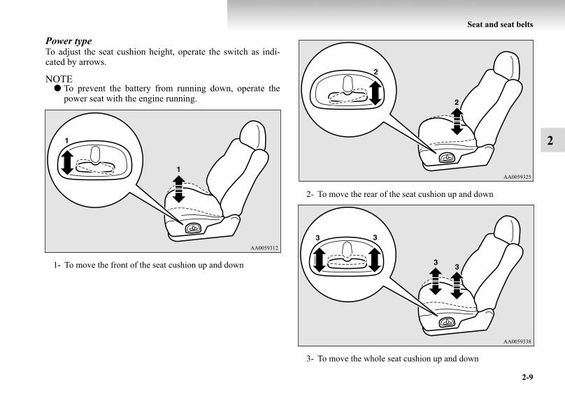
Power typeAdjust the seat by operating the switch as indicated by thearrows.
NOTE● To prevent the battery from running down, operate the
power seat with the engine running.
WARNING!● To ensure the seat is locked securely, try to move the
seat forward or backward without using the adjust-ing lever.
1- Adjustment forward2- Adjustment backward
BK-BK2008E1ENUK.en-uk-Section5.fm Page 6 Wednesday, January 9, 2008 4:28 PM

Seat and seat belts
2-7
2
To recline the seatbackE00400600056
Manual typeIn order to recline the seatback, lean forward slightly, pull theseatback lock lever up, and then lean backward to the desiredposition and release the lever. The seatback will lock in thatposition.
Power typeAdjust the seatback angle by operating the switch as indicatedby the arrows.
NOTE● To prevent the battery from running down, operate the
power seat with the engine running.CAUTION!● The reclining mechanism of the seatback is spring
loaded, causing it to return to the vertical positionwhen the lock lever is operated. When using thelever, sit close to the seatback or hold it with yourhand to control its return motion.
1- To move to forward direction2- To recline rearward
BK-BK2008E1ENUK.en-uk-Section5.fm Page 7 Wednesday, January 9, 2008 4:28 PM

2-8
Seat and seat belts
2
To adjust seat cushion heightE00400700451
Manual typeTo adjust the seat cushion height, turn the dial as shown in theillustration.
1- To move the front of the seat cushion up2- To move the front of the seat cushion down
3- To move the rear of the seat cushion up4- To move the rear of the seat cushion down
BK-BK2008E1ENUK.en-uk-Section5.fm Page 8 Wednesday, January 9, 2008 4:28 PM
Seat and seat belts
2-9
2
Power typeTo adjust the seat cushion height, operate the switch as indi-cated by arrows.
NOTE● To prevent the battery from running down, operate the
power seat with the engine running.
1- To move the front of the seat cushion up and down
2- To move the rear of the seat cushion up and down
3- To move the whole seat cushion up and down
BK-BK2008E1ENUK.en-uk-Section5.fm Page 9 Wednesday, January 9, 2008 4:28 PM

2-10
Seat and seat belts
2
Lumbar support adjustment (Power type, driver’s seat)
E00400800032
A lumbar support adjustment is located in the seatback of thedriver’s seat. To adjust the lumbar support, operate the switchas indicated by arrows.
NOTE● To prevent the battery from running down, operate the
power seat with the engine running.
ArmrestE00400900118
Slide forward the centre console lid while pressing the rightupper lever (A).
1- Strong2- Weak
BK-BK2008E1ENUK.en-uk-Section5.fm Page 10 Wednesday, January 9, 2008 4:28 PM
Seat and seat belts
2-11
2
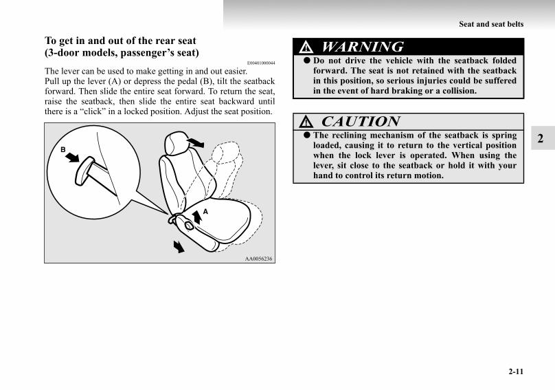
To get in and out of the rear seat (3-door models, passenger’s seat)
E00401000044
The lever can be used to make getting in and out easier.Pull up the lever (A) or depress the pedal (B), tilt the seatbackforward. Then slide the entire seat forward. To return the seat,raise the seatback, then slide the entire seat backward untilthere is a “click” in a locked position. Adjust the seat position.
WARNING!● Do not drive the vehicle with the seatback folded
forward. The seat is not retained with the seatbackin this position, so serious injuries could be sufferedin the event of hard braking or a collision.
CAUTION!● The reclining mechanism of the seatback is spring
loaded, causing it to return to the vertical positionwhen the lock lever is operated. When using thelever, sit close to the seatback or hold it with yourhand to control its return motion.
BK-BK2008E1ENUK.en-uk-Section5.fm Page 11 Wednesday, January 9, 2008 4:28 PM

2-12
Seat and seat belts
2
Heated seats*E00401100289
The heated seats can be operated with the ignition switch in the“ON” position. Operate the switch as indicated by arrows.The indication lamp (A) will illuminate while the heater is on.
1- Heater high (for quick heating).2- Heater off.3- Heater low (to keep the seat warm).
CAUTION!● Switch off seat heaters when not in use.
● Operate in the high position for quick heating. Oncethe seat is warm, set the heater to low to keep itwarm. Slight variations in seat temperature may befelt while using the heated seats. This is caused bythe operation of the heater’s internal thermostat anddoes not indicate a malfunction.
● If the following types of persons use the heated seats,they might become too hot or receive minor burns(red skin, heat blisters, etc.):• Children, elderly or ill people• People with sensitive skin• Excessively tired people• People under the influence of alcohol or sleep
inducing medication (cold medicine, etc.)● Do not place heavy objects on the seat or stick pins,
needles, or other pointed objects into it.● Do not use a blanket, cushion, or other material with
high heat insulation properties on the seat whileusing the heater; this might cause the heater elementto overheat.
● When cleaning the seat, do not use benzene, gaso-line, alcohol, or other organic solvents; this mightdamage the surface of the seat and also the heaterelement.
● If water or any other liquid is spilled on the seat,allow it to dry thoroughly before attempting to usethe heater.
● Turn the heater off immediately if it appears to bemalfunctioning during use.
CAUTION!
BK-BK2008E1ENUK.en-uk-Section5.fm Page 12 Wednesday, January 9, 2008 4:28 PM

Seat and seat belts
2-13
2
Rear seats (3-door models)*/Second seats (5-door models)*
E00402000184
To recline the seatbackE00402200157
In order to recline the seatback, lean forward slightly, pull theseatback lock lever up, and then lean backward to the desiredposition and release the lever. The seatback will lock in thatposition.WARNING!
● When a person is sitting in the middle seating posi-tion of the rear seats (3-door models)/second seats(5-door models), pull up the head restraint to aheight at which it locks in position. Be sure to makethis adjustment before starting to drive. Seriousinjuries could otherwise be suffered as the result ofan impact. Refer to “Head restraints” on page 2-16.
3-door models
5-door models
BK-BK2008E1ENUK.en-uk-Section5.fm Page 13 Wednesday, January 9, 2008 4:28 PM

2-14
Seat and seat belts
2NOTE
● Each seatback can be adjusted by the lever on its side.● On 5-door models, each of the second seat’s sidebacks (A)
is foldable. When either side of the seatback is reclined toa new position, its sideback automatically folds inwardaccordingly.
ArmrestE00402400218
For rear seats (3-door models)Press the button (A) at the top of the armrest and allow thearmrest to drop down.
CAUTION!● The reclining mechanism of the seatback is spring
loaded, causing it to return to the vertical positionwhen the lock lever is operated. When using thelever, sit close to the seatback or hold it with yourhand to control its return motion.
BK-BK2008E1ENUK.en-uk-Section5.fm Page 14 Wednesday, January 9, 2008 4:28 PM

Seat and seat belts
2-15
2
For second seats (5-door models)Lift the centre head restraint and then tilt the armrest for use asillustrated.
NOTE● Do not stand or sit on the armrest. It could break.
To get in and out of the third seat (5-door models)E00402500163
Getting in and out of the third seat can be made easily by fold-ing the second seat.Refer to “Folding the rear seats (3-door models) / Folding thesecond seats (5-door models)” on page 2-22.
CAUTION!● When storing the armrest, push the armrest
securely to prevent it from falling down while driv-ing the vehicle.
BK-BK2008E1ENUK.en-uk-Section5.fm Page 15 Wednesday, January 9, 2008 4:28 PM

2-16
Seat and seat belts
2
Third seat (5-door models)*E00402700149
To recline the seatbackE00402800124
In order to recline the seatback, lean forward slightly, pull theseatback lock lever as shown in the illustration, and then leanbackward to the desired position and release the lever. Theseatback will lock in that position.
Head restraintsE00403300474
CAUTION!● The reclining mechanism of the seatback is spring
loaded, causing it to return to the vertical positionwhen the lock lever is operated. When using thelever, sit close to the seatback or hold it with yourhand to control its return motion.
WARNING!● Driving without the head restraints in place can
cause you and your passengers serious injury ordeath in an accident. To reduce the risk of injury inan accident, always make sure the head restraintsare installed and properly positioned when the seatis occupied.
● Never place a cushion or similar device on the seat-back. This can adversely affect head restraint per-formance by increasing the distance between yourhead and the restraint.
BK-BK2008E1ENUK.en-uk-Section5.fm Page 16 Wednesday, January 9, 2008 4:28 PM

Seat and seat belts
2-17
2
To adjust heightAdjust the head restraint height so that the centre of therestraint is as close as possible to eye level to reduce thechances of injury in the event of collision. Any person too tallfor the restraint to reach their seated eye level, should adjustthe restraint as high as possible.To raise the head restraint, move it upward. To lower therestraint, move it downward while pushing the height adjustingknob (A) in the direction of the arrow. After adjustment, pushthe head restraint downward and make sure that it is locked.
To adjust forward or backwardTilt the head restraint towards you to adjust it forward. Toadjust it backward, tilt the head restraint backward.
BK-BK2008E1ENUK.en-uk-Section5.fm Page 17 Wednesday, January 9, 2008 4:28 PM

2-18
Seat and seat belts
2
To removeLift the head restraint with the height adjusting knob (A)pushed in.
To installConfirm that the head restraint is facing the correct direction,and then insert it into the seatback while pressing the heightadjusting knob (A) in the direction indicated by the arrow.
CAUTION!● Confirm that the height adjusting knob (A) is cor-
rectly adjusted as shown in the illustration, and alsolift the head restraints to ensure that they do notcome out of the seatback.
BK-BK2008E1ENUK.en-uk-Section5.fm Page 18 Wednesday, January 9, 2008 4:28 PM
Seat and seat belts
2-19
2
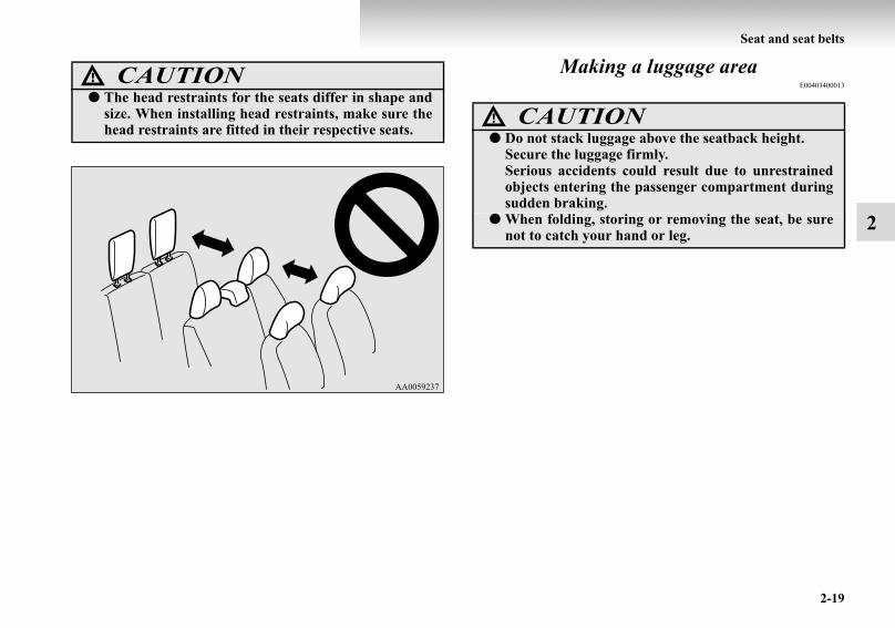
Making a luggage areaE00403400013CAUTION!
● The head restraints for the seats differ in shape andsize. When installing head restraints, make sure thehead restraints are fitted in their respective seats.
AA0059237
CAUTION!● Do not stack luggage above the seatback height.
Secure the luggage firmly.Serious accidents could result due to unrestrainedobjects entering the passenger compartment duringsudden braking.
● When folding, storing or removing the seat, be surenot to catch your hand or leg.
BK-BK2008E1ENUK.en-uk-Section5.fm Page 19 Wednesday, January 9, 2008 4:28 PM

2-20
Seat and seat belts
2
Folding the rear seatbacks forward (3-door mod-els) / Folding the second seatbacks forward (5-door models)
E00403500232
The passenger and luggage compartments can be joined byfolding the rear (3-door models) / second (5-door models) seat-back forward. This is useful for carrying long objects.
To fold1. If your vehicle is equipped with a rear shelf (3-door mod-
els) / cargo area cover (5-door models), remove it beforeperforming the following steps.Refer to “Rear shelf (3-door models)” on page 5-101 and“Cargo area cover (5-door models)” on page 5-103.
2. Lift up the knob (A) behind the seatback, then tilt the seat-back forward.
NOTE● Each seatback can be folded forward using the knob on its
side.
BK-BK2008E1ENUK.en-uk-Section5.fm Page 20 Wednesday, January 9, 2008 4:28 PM
Seat and seat belts
2-21
2
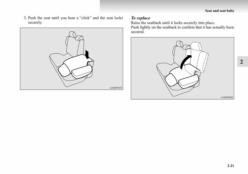
3. Push the seat until you hear a “click” and the seat lockssecurely.
To replaceRaise the seatback until it locks securely into place.Push lightly on the seatback to confirm that it has actually beensecured.
BK-BK2008E1ENUK.en-uk-Section5.fm Page 21 Wednesday, January 9, 2008 4:28 PM

2-22
Seat and seat belts
2
Folding the rear seats (3-door models) / Folding the second seats (5-door models)
E00403700221
To create luggage space, you can fold the rear (3-door models)/second (5-door models) seats.If your vehicle is equipped with the third seat, by folding thesecond seat, you can get in and out easier.
To fold1. If your vehicle is equipped with a rear shelf (3-door mod-
els) / cargo area cover (5-door models), remove it beforeperforming the following steps.Refer to “Rear shelf (3-door models)” on page 5-101 and“Cargo area cover (5-door models)” on page 5-103.
2. Lift up the knob (A) behind the seatback, then tilt the seat-back forward.
WARNING!● When driving the vehicle, do not allow anyone to sit
on the third seat if the second seat is in the folded-down position. The second seat could tip rearwardin the event of hard braking or a collision, resultingin serious injuries.
BK-BK2008E1ENUK.en-uk-Section5.fm Page 22 Wednesday, January 9, 2008 4:28 PM

Seat and seat belts
2-23
2
3. Lift the seat until you hear a “click”. To replace1. Hold the seat with your hand, then return the seat to its
original position while pushing the stopper (A).
BK-BK2008E1ENUK.en-uk-Section5.fm Page 23 Wednesday, January 9, 2008 4:28 PM

2-24
Seat and seat belts
2
2. Push the seat until you hear a “click” and the seat lockssecurely.
3. Raise the seatback until it locks securely into place.Push lightly on the seatback to confirm that it has actuallybeen secured.
BK-BK2008E1ENUK.en-uk-Section5.fm Page 24 Wednesday, January 9, 2008 4:28 PM

Seat and seat belts
2-25
2
Storage of the third seatE00404100206
By folding the third seat into the luggage floor box, large arti-cles can be stored in the vehicle.
To store1. Remove the luggage floor board (A) and the head
restraints (B).Refer to “Luggage floor box” on page 5-97 and “Headrestraints” on page 2-16.
2. Stow the removed head restraints in the luggage floor boxwith their front faces facing upward.
NOTE● Stowing the head restraints with their front faces facing
downward would prevent the third seat from beingstowed.
BK-BK2008E1ENUK.en-uk-Section5.fm Page 25 Wednesday, January 9, 2008 4:28 PM

2-26
Seat and seat belts
2
3. Pull up knob (C) on the side of the seatback, then tilt theseatback forward.
4. Push lever (D) forward, then tilt the seatback forwarduntil the seatback touches the seat cushion.
CAUTION!● Do not drive with luggage placed on the forward-
folded seatback.
BK-BK2008E1ENUK.en-uk-Section5.fm Page 26 Wednesday, January 9, 2008 4:28 PM

Seat and seat belts
2-27
2
5. Pull lever (E), fold the seat backward, and store it into theluggage floor box.
CAUTION!● Ensure that lever (E) is not operated while the seat is
occupied. The folding action of the seat in such a sit-uation could result in an unexpected accident.
● When folding the seat, be sure not to catch yourhands between seat and luggage floor box.
CAUTION!● When folding the seat away into the luggage floor
box, hold the seat by hand and fold it slowly. If theseat is not held properly, it might fall under its ownweight during folding and pinch your hand.
BK-BK2008E1ENUK.en-uk-Section5.fm Page 27 Wednesday, January 9, 2008 4:28 PM

2-28
Seat and seat belts
2
6. Fold down the stand (F).
7. Refit the luggage floor board.
To replace1. Remove the luggage floor board. And then raise the stand.2. Raise the seat forward until you hear a “click” and the seat
locks securely.
BK-BK2008E1ENUK.en-uk-Section5.fm Page 28 Wednesday, January 9, 2008 4:28 PM

Seat and seat belts
2-29
2
3. Push knob (A) forward, and raise the seatback until itlocks securely into place.After the operation, push lightly on the seatback to con-firm that it has actually been secured.
4. Refit the luggage floor board and head restraints.
Removing the third seatE00404200122
To create more luggage space, you can remove the third seat.
CAUTION!● For safety, do not allow children to remove or refit
the seat.● Be careful not to trap your hands or feet when
removing or refitting the seat. Also, be careful not todrop or trip over the seat. If necessary, have some-one help you remove it.
BK-BK2008E1ENUK.en-uk-Section5.fm Page 29 Wednesday, January 9, 2008 4:28 PM

2-30
Seat and seat belts
2
To remove1. Remove the head restraints.
Refer to “Head restraints” on page 2-16.2. Pull up the knob (A) on the side of the seatback, then tilt
the seatback forward.
3. Push the lever (B) forward, then tilt the seatback forwarduntil the seatback touches the seat cushion.
BK-BK2008E1ENUK.en-uk-Section5.fm Page 30 Wednesday, January 9, 2008 4:28 PM

Seat and seat belts
2-31
2
4. Pull the seat lock lever (C). 5. Fold the stands (D) towards you from the seat side, whilelifting the front end of the seat.
BK-BK2008E1ENUK.en-uk-Section5.fm Page 31 Wednesday, January 9, 2008 4:28 PM

2-32
Seat and seat belts
2
6. Put down the front end of the seat to the floor. In this situ-ation, the seat locking system is unlocked automatically.
7. Remove the covers (E) by turning the knob (F) anticlock-wise.
G- UnlockH- Lock
BK-BK2008E1ENUK.en-uk-Section5.fm Page 32 Wednesday, January 9, 2008 4:28 PM
Seat and seat belts
2-33
2
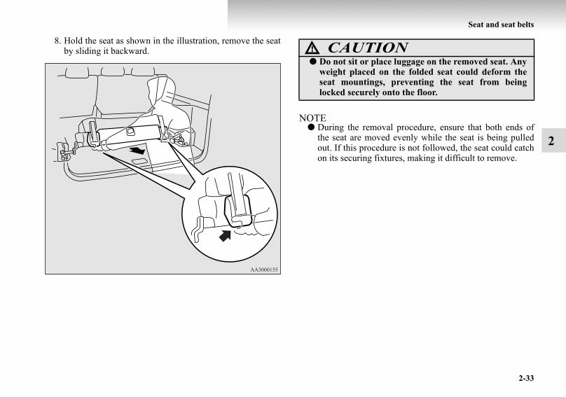
8. Hold the seat as shown in the illustration, remove the seatby sliding it backward.
NOTE● During the removal procedure, ensure that both ends of
the seat are moved evenly while the seat is being pulledout. If this procedure is not followed, the seat could catchon its securing fixtures, making it difficult to remove.
CAUTION!● Do not sit or place luggage on the removed seat. Any
weight placed on the folded seat could deform theseat mountings, preventing the seat from beinglocked securely onto the floor.
BK-BK2008E1ENUK.en-uk-Section5.fm Page 33 Wednesday, January 9, 2008 4:28 PM
2-34
Seat and seat belts
2
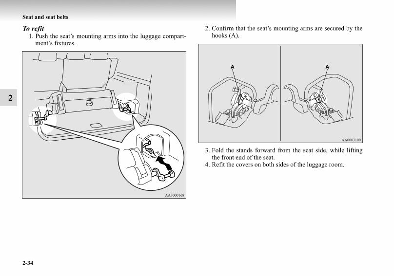
To refit1. Push the seat’s mounting arms into the luggage compart-
ment’s fixtures.
2. Confirm that the seat’s mounting arms are secured by thehooks (A).
3. Fold the stands forward from the seat side, while liftingthe front end of the seat.
4. Refit the covers on both sides of the luggage room.
BK-BK2008E1ENUK.en-uk-Section5.fm Page 34 Wednesday, January 9, 2008 4:28 PM

Seat and seat belts
2-35
2
5. Push the knob (B) forward, raise the seatback until it lockssecurely into place.After the operation, push the seatback lightly to confirmthat it has actually been secured.
6. Refit the head restraints.
Making a flat seat*E00404300048
By removing the head restraints and fully reclining the seat-backs of the seats, one large flat seat is achieved.
WARNING!● Never drive with passengers on the flat seat. This is
highly dangerous.
CAUTION!● To make a flat seat, stop the vehicle in a safe place.● Make sure the seat is adjusted by an adult or with
adult supervision for correct and safe operation.● When sliding the seat, be sure not to catch your
hand or leg.● Do not walk around on top of the seats after they
have been laid flat.● To ensure the seats are locked securely, attempt to
move them back and forth.● Do not jump on, or impact the seatbacks heavily.● To raise the seatback, put a hand on the seatback
and raise slowly. Never have a child do this opera-tion, or an unexpected accident may result.
BK-BK2008E1ENUK.en-uk-Section5.fm Page 35 Wednesday, January 9, 2008 4:28 PM

2-36
Seat and seat belts
2
1. If your vehicle is equipped with a rear shelf (3-door mod-els) / cargo area cover (5-door models), remove it beforeperforming the following steps.Refer to “Rear shelf (3-door models)” on page 5-101 and“Cargo area cover (5-door models)” on page 5-103.
2. Remove the head restraints from the front seats.If your vehicle is equipped with the third seat (5-doormodels), store the third seat into the luggage floor box.Refer to “Head restraints” on page 2-16 and “Storage ofthe third seat” on page 2-25.
3. Slide the front seats fully forward, then tip their seatbacksbackward.On 5-door models, slide the front seats backward untiltheir seatbacks touch the second seat.Refer to “To adjust forward or backward” on page 2-6 and“To recline the seatback” on page 2-7.
BK-BK2008E1ENUK.en-uk-Section5.fm Page 36 Wednesday, January 9, 2008 4:28 PM
Seat and seat belts
2-37
2
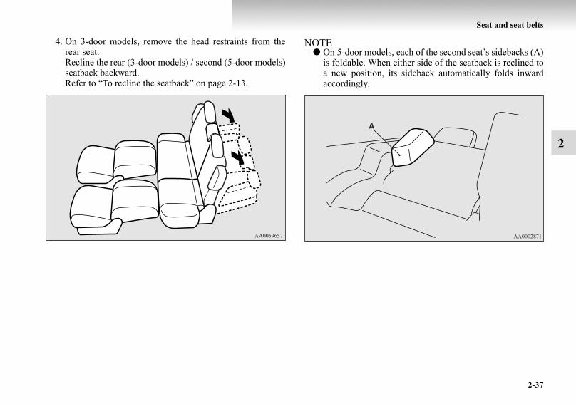
4. On 3-door models, remove the head restraints from therear seat.Recline the rear (3-door models) / second (5-door models)seatback backward.Refer to “To recline the seatback” on page 2-13.
NOTE● On 5-door models, each of the second seat’s sidebacks (A)
is foldable. When either side of the seatback is reclined toa new position, its sideback automatically folds inwardaccordingly.
BK-BK2008E1ENUK.en-uk-Section5.fm Page 37 Wednesday, January 9, 2008 4:28 PM

2-38
Seat and seat belts
2
5. On 3-door models, store the front head restraints and rearcentre head restraint between the front seats.And store the rear outboard head restraints on the side ofthe rear seat.On 5-door models, store the front head restraints betweenthe front seats.The flat seat configuration is now complete.Reverse the above procedure when returning the seat tothe normal position.
Seat beltsE00404800072
To protect you and your passengers in the event of an accident,it is most important that the seat belts be worn correctly whiledriving.The front seat belts have a pre-tensioner system. These beltsare used the same way as a conventional seat belt.Refer to “Seat belt pre-tensioner system and force limiter sys-tem” on page 2-43.
3-door models
5-door models
WARNING!● Always place the shoulder belt over your shoulder
and across your chest. Never put it behind you orunder your arm.
● One seat belt should be used by only one person.Doing otherwise can be dangerous.
● The seat belt will provide its wearer with maximumprotection if the recliner seatback is placed in fullyupright position. When the seatback is reclined,there is greater risk that the passenger will slideunder the belt, especially in a forward impact acci-dent, and may be injured by the belt or by strikingthe instrument panel or seatbacks.
● Seat belts should always be worn by every adult whodrives or rides in this vehicle, and by all childrenwho are large enough to wear seat belts properly.Other children should always use proper childrestraint systems.
● Remove any twists when using the belt.
BK-BK2008E1ENUK.en-uk-Section5.fm Page 38 Wednesday, January 9, 2008 4:28 PM

Seat and seat belts
2-39
2
3-point type seat belt (with emergency locking mechanism)
E00404900871
This type of belt requires no length adjustment. Once worn, thebelt adjusts itself to the movement of wearer, but in the event ofa sudden or strong shock, the belt automatically locks to holdthe wearer’s body.
To fasten 1. Pull the seat belt out slowly while holding the latch plate.
NOTE● When the seat belts cannot be pulled out in a locked con-
dition, pull the belts once forcefully and then return them.After that, pull the belts out slowly once again.
2. Insert the latch plate into the buckle until a “click” isheard.
● No modifications or additions should be made by theuser which will either prevent the seat belt adjustingdevices from operating to remove slack, or preventthe seat belt assembly from being adjusted toremove slack.
● Never hold a child in your arms or on your lap whenriding in this vehicle, even if you are wearing yourseat belt. To do so risks severe or fatal injury to yourchild in a collision or sudden stop.
● Always adjust the belt to a snug fit.● Always wear the lap portion of the belt over your
hips.
WARNING!
BK-BK2008E1ENUK.en-uk-Section5.fm Page 39 Wednesday, January 9, 2008 4:28 PM

2-40
Seat and seat belts
2
3. Pull the belt slightly to adjust slackness as desired.
To unfasten Hold the latch plate and push the button on the buckle.
NOTE● As the belt retracts automatically, keep the latch plate held
while retracting so that the belt stows slowly. Failure to dothis could damage the vehicle.
Seat belt reminder/warning lampE00409800338
The seat belt warning lamp is located on the instrument panel.A tone and warning lamp are used to remind the driver to fas-ten the seat belt.
When the ignition key is turned to the “ON” position, the warn-ing lamp will illuminate and a tone will sound for about 6 sec-onds. If the driver’s seat belt remains unfastened forapproximately 1 minute later, the warning lamp will flash andthe tone sound intermittently (each 12 times) when the vehicleis driven. If the driver subsequently unfastens the seat beltwhile driving, the warning lamp and tone will issue furtherwarnings. And if the seat belt remains unfastened, the warninglamp and tone will issue further warnings each time the vehiclestarts moving from a stop. When the seat belt is fastened, thewarnings will stop.
WARNING!● Never wear the lap portion of the belt across your
abdomen. During accidents it can press sharplyagainst abdomen and increase the risk of injury.
● The seat belts must not be twisted when worn.
BK-BK2008E1ENUK.en-uk-Section5.fm Page 40 Wednesday, January 9, 2008 4:28 PM
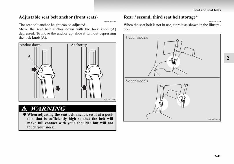
Seat and seat belts
2-41
2
Adjustable seat belt anchor (front seats)E00405000286
The seat belt anchor height can be adjusted.Move the seat belt anchor down with the lock knob (A)depressed. To move the anchor up, slide it without depressingthe lock knob (A).
Rear / second, third seat belt storage*E00405300029
When the seat belt is not in use, store it as shown in the illustra-tion.
WARNING!● When adjusting the seat belt anchor, set it at a posi-
tion that is sufficiently high so that the belt willmake full contact with your shoulder but will nottouch your neck.
Anchor down Anchor up
3-door models
5-door models
BK-BK2008E1ENUK.en-uk-Section5.fm Page 41 Wednesday, January 9, 2008 4:28 PM

2-42
Seat and seat belts
2
Seat belt plate storageAfter passing the belt through the rear notch (A), insert theplate into the front notch (B).
Seat belt buckle storageStore the seat belt buckle in the storage pocket.
Rear/Second seat
Third seat (5-door models)
BK-BK2008E1ENUK.en-uk-Section5.fm Page 42 Wednesday, January 9, 2008 4:28 PM

Seat and seat belts
2-43
2
Pregnant women restraintE00405600064
Seat belt pre-tensioner system and force limiter system
E00405700081
The driver’s seat and front passenger’s seat each have a seatbelt equipped with a pre-tensioner system.
Pre-tensioner systemE00405800747
The pre-tensioner system will retract their respective seat beltsinstantaneously, thus maximizing the seat belt’s effectiveness,if there is a frontal impact severe enough to injure the driverand/or front passenger and the ignition switch is in the “ON” or“START” position.
WARNING!● Seat belts work for everyone, including pregnant
women. Pregnant women should use the availableseat belts. This will reduce the likelihood of injury toboth the woman and the unborn child. The lap beltshould be worn across the thighs and as snug againstthe hips as possible, but not across the waist. Consultyour doctor if you have any additional questions orconcerns.
WARNING!● To obtain the best results from your pre-tensioner
seat belt, make sure you have adjusted your seatcorrectly and wear your seat belt properly.
CAUTION!● Installation of audio equipment or repairs in the
vicinity of the pre-tensioner seat belts or floor con-sole must be performed in line with MITSUBISHIMOTORS guidelines. It is important to do sobecause the work could affect the pre-tensioner sys-tems.
BK-BK2008E1ENUK.en-uk-Section5.fm Page 43 Wednesday, January 9, 2008 4:28 PM

2-44
Seat and seat belts
2NOTE
● The pre-tensioner seat belts will be activated if the vehiclesuffers a severe frontal impact, even if the seat belts arenot worn.
● The pre-tensioner seat belts are designed to work onlyonce. After the pre-tensioner seat belts have been acti-vated, we recommend you have it replaced by a MIT-SUBISHI MOTORS Authorized Service Point.
SRS warning lampE00405900083
This warning lamp is shared by the SRS airbags and the pre-tensioner seat belts.Refer to “SRS warning lamp” on page 2-75.
Force limiter systemE00406000153
In the event of a collision, each force limiter system will effec-tively absorb the load applied to the seat belt to minimize theimpact to the passenger.
Child restraintE00406401066
When transporting children in your vehicle, some type of childrestraint system should always be used according to the size ofthe child. This is required by law in most countries.The regulations concerning driving with children in the frontseat may differ from country to country. You are advised tocomply with the relevant regulations.
● If you need to scrap the vehicle, please consult aMITSUBISHI MOTORS Authorized Service Point.It is important to do so because unexpected activa-tion of the pre-tensioner seat belts could cause inju-ries.
CAUTION!
WARNING!● When possible, put children in the rear seat. Acci-
dent statistics indicate that children of all sizes andages are safer when properly restrained in the rearseat rather than in the front seat.
● Holding a child in your arms is no substitute for arestraint system. Failure to use a proper restraintsystem can result in severe or fatal injury to yourchild.
● Each child restraint device or fixing is to be usedonly by one child.
● When attaching a child restraint to the rear seat,place the front seatbacks in the upright position.Otherwise, the child could be seriously injured inthe event of hard braking or a collision.
BK-BK2008E1ENUK.en-uk-Section5.fm Page 44 Wednesday, January 9, 2008 4:28 PM

Seat and seat belts
2-45
2
Caution for installing the child restraint on vehi-cles with a front passenger airbagThe label shown here is attached on vehicles with a front pas-senger airbag.
Use rearward facing child restraints in the rear seat or turn offthe front passenger’s airbag ON-OFF switch. (Refer to “To turnan airbag off” on page 2-64.)
WARNING!● Extreme Hazard!
Do not use a rearward facing child restraint on aseat protected by an airbag in front of it!
WARNING!● A REARWARD FACING CHILD RESTRAINT
must NOT be used in the front passenger seat if thefront passenger’s airbag has not been deactivated.The force of an inflating airbag could kill or causeserious injuries to the child. A rearward facing childrestraint must only be used in the rear seat.
Front passenger’s airbag ON
BK-BK2008E1ENUK.en-uk-Section5.fm Page 45 Wednesday, January 9, 2008 4:28 PM

2-46
Seat and seat belts
2
Infants and small childrenE00406600641
When transporting infants and small children in your vehicle,follow the instruction given below.
Instruction:● For small infants, an infant carrier should be used. For
small children whose height when seated allows theshoulder belt to lie in contact with the face or the throat, achild seat should be used.
● The child restraint system should be appropriate for yourchild’s weight and height and properly fit in the vehicle.For a higher degree of safety: THE CHILD RESTRAINTSYSTEM SHOULD BE INSTALLED IN THE REARSEAT.
WARNING!● A FORWARD FACING CHILD RESTRAINT
should be used in the rear seat whenever possible; ifused in the front seat, adjust the seat to the mostrearward position.
BK-BK2008E1ENUK.en-uk-Section5.fm Page 46 Wednesday, January 9, 2008 4:28 PM

Seat and seat belts
2-47
2
● Before purchasing a child restraint system, try installing itin the rear seat to make sure there is a good fit. Because ofthe location of the seat belt buckles and the shape of theseat cushion, it may be difficult to securely install somemanufacturer’s child restraint systems.If the child restraint system can be pulled forward or toeither side easily on the seat cushion after the seat belt hasbeen tightened, choose another manufacturer’s childrestraint system.
NOTE● Depending on the seating position in the vehicle and the
child restraint system that you have, the child restraint canbe attached using one of the following two locations:• To the lower anchorage in the rear seat (3-door models)/
second seat (5-door models) ONLY if the child restrainthas ISOFIX mountings (See page 2-54).
• To the seat belt (See page 2-57).
Older childrenE00406700147
Children who have outgrown the child restraint system shouldbe seated in the rear seat and wear combination lap shoulderbelt.The lap portion of the belt should be snug and positioned lowon the abdomen so that it is below the top of the hip-bone. Oth-erwise, the belt could intrude into the child’s abdomen duringan accident and cause injury.
WARNING!● When installing a child restraint system, refer to the
instructions provided by the manufacturer of therestraint system. Failure to do so can result in severeor fatal injury to your child.
● After installation, push and pull the child restraintsystem back and forth, and side to side, to see that itis positively secured. If the child restraint system isnot installed securely, it may cause injury to thechild or other occupants in the case of accident orsudden stops.
● When the child restraint system is not in use, keepyour child restraint system secured with the seat beltor remove it from the vehicle in order to prevent itfrom being thrown around inside the vehicle duringan accident.
BK-BK2008E1ENUK.en-uk-Section5.fm Page 47 Wednesday, January 9, 2008 4:28 PM

2-48
Seat and seat belts
2
Suitability for various ISOFIX positionsE00411400038
Mass Group Size class Fixture
Vehicle ISOFIX positions
Front PassengerRear / second Outboard
Rear CentreLeft side Right side
Carrycot F ISO/L1 X X IL XG ISO/L2 X IL X X
X X X X0 - Up to 10 kg E ISO/R1 X IL IL X
X X X X0+ - Up to 13 kg E ISO/R1 X IL IL, IL*2 X
D ISO/R2 X IL IL XC ISO/R3 X IL IL X
X X X XI - 9 to 18 kg D ISO/R2 X IL IL X
C ISO/R3 X IL IL XB ISO/F2 X IUF IUF X
B1 ISO/F2X X IUF, IL*1 IUF, IL*1 X
A ISO/F3 X IUF IUF XX X X X
II - 15 to 25 kg X X X XIII - 22 to 36 kg X X X X
BK-BK2008E1ENUK.en-uk-Section5.fm Page 48 Wednesday, January 9, 2008 4:28 PM

Seat and seat belts
2-49
2
Key of letters to be inserted in the table above:● IUF- Suitable for ISOFIX forward child restraints systems of universal category approved for use in the mass group.● IL- Suitable for particular ISOFIX child restraint systems (CRS) given in the attached list.
These ISOFIX CRS are those of the “specific vehicle”, “restricted” or “semiuniversal” categories.● X- ISOFIX position not suitable for ISOFIX child restraint systems in this mass group and/or this size class.
IL (Genuine part information)
NOTE● MITSUBISHI MOTORS Europe B.V. reserves the right to changes without any prior announcement.
For detailed information, consult your MITSUBISHI MOTORS Authorized Service Point.
Genuine part No. ECE No.
*1 MZ313045 E1-04301133
*2 MZ313589 E1-04301146
BK-BK2008E1ENUK.en-uk-Section5.fm Page 49 Wednesday, January 9, 2008 4:28 PM

2-50
Seat and seat belts
2
Suitability for various seating positionsE00406800034
3-door models
*1: With front passenger’s airbag deactivated by means of front passenger’s airbag ON-OFF switch.
Key of letters to be inserted in the table above:● U- Suitable for “universal” category restraints approved for use in this mass group.● UF- Suitable for forward-facing “universal” category restraints approved for use in this mass group.● L- Suitable for particular child restraints (MITSUBISHI MOTORS genuine parts).● B- Built-in restraint approved for this mass group.● X- Seat position not suitable for children in this mass group.
Mass Group
Seating position
Front Passenger Rear OutboardRear CentreActivated Air-
bagDeactivated Air-
bag*1 Left side Right side
0 - Up to 10 kg X X X X X
0+ - Up to 13 kg X L*2 L*2, L*3 L*2, L*3 L*2, L*3
I - 9 to 18 kg L*5 L*5 L*4, L*5 L*4, L*5 L*4, L*5
II & III - 15 to 36 kg L*6 L*6 L*6 L*6 L*6
BK-BK2008E1ENUK.en-uk-Section5.fm Page 50 Wednesday, January 9, 2008 4:28 PM

Seat and seat belts
2-51
2
L (Genuine part information)
NOTE● There is no applicable MITSUBISHI MOTORS Genuine Parts to the Mass Group “0- Up to 10 kg”.
MITSUBISHI MOTORS Europe B.V. reserves the right to changes without any prior announcement.For detailed information, consult your MITSUBISHI MOTORS Authorized Service Point.
Genuine parts No. ECE No.
*2 MZ312807 E1-04301146
*3 MZ313589 E1-04301146
*4 MZ312745 E1-04301136
*5 MZ313045 E1-04301133
*6 MZ312808 E1-04301148
BK-BK2008E1ENUK.en-uk-Section5.fm Page 51 Wednesday, January 9, 2008 4:28 PM

2-52
Seat and seat belts
2
5-door models
*1: With front passenger’s airbag deactivated by means of front passenger’s airbag ON-OFF switch.*2: Adjust the angle of the seatback to the most upright position.
Key of letters to be inserted in the table above:● U- Suitable for “universal” category restraints approved for use in this mass group.● UF- Suitable for forward-facing “universal” category restraints approved for use in this mass group.● L- Suitable for particular child restraints (MITSUBISHI MOTORS genuine parts).● B- Built-in restraint approved for this mass group.● X- Seat position not suitable for children in this mass group.
Mass Group
Seating position
Front PassengerRear Out-
board
Intermediate OutboardIntermediate
CentreActivated Airbag
Deactivated Airbag*1 Left side Right side
0 - Up to 10 kg X X X U*2 U*2 X
0+ - Up to 13 kg X L*3 L*3 U*2, L*3, L*4 U*2, L*3, L*4 L*3, L*4
I - 9 to 18 kg L*6 L*6 L*5, L*6 U*2, L*5, L*6 U*2, L*5, L*6 L*5, L*6
II & III - 15 to 36 kg L*7 L*7 L*7 U*2, L*7 U*2, L*7 L*7
BK-BK2008E1ENUK.en-uk-Section5.fm Page 52 Wednesday, January 9, 2008 4:28 PM

Seat and seat belts
2-53
2
L (Genuine part information)
NOTE● There is no applicable MITSUBISHI MOTORS Genuine Parts to the Mass Group “0- Up to 10 kg”.
MITSUBISHI MOTORS Europe B.V. reserves the right to changes without any prior announcement.For detailed information, consult your MITSUBISHI MOTORS Authorized Service Point.
Genuine parts No. ECE No.
*3 MZ312807 E1-04301146
*4 MZ313589 E1-04301146
*5 MZ312745 E1-04301136
*6 MZ313045 E1-04301133
*7 MZ312808 E1-04301148
BK-BK2008E1ENUK.en-uk-Section5.fm Page 53 Wednesday, January 9, 2008 4:28 PM

2-54
Seat and seat belts
2
Installing a child restraint system to the lower anchorage (ISOFIX child restraint mountings) and tether anchorage*
E00408900169
Lower anchorage locationYour vehicle’s rear seat (3-door models) / second seat (5-doormodels) is fitted with lower anchorages for attaching a childrestraint system with ISOFIX mountings.
Tether anchorage locationsThere are 2 attachment points on the floor, located behind therear seat (3-door models) / second seat (5-door models). Theseare for securing a child restraint system tether strap to both ofthe 2 rear (3-door models) / second (5-door models) seatingpositions in your vehicle.
WARNING!● Child restraint anchorages are designed to with-
stand only those loads imposed by correctly fittedchild restraints. Under no circumstances are they tobe used for adult seat belts, or harnesses, or forattaching other items or equipment to the vehicle.
BK-BK2008E1ENUK.en-uk-Section5.fm Page 54 Wednesday, January 9, 2008 4:28 PM

Seat and seat belts
2-55
2
Child restraint system with ISOFIX mountingsThe child restraint system is designed only for seats that incor-porate lower anchorages. Retain the child restraint systemusing the lower anchorages.It is not necessary to retain the child restraint system using thevehicle’s seat belts.
To install1. Remove any foreign material in or around the connectors
and ensure the vehicle seat belt is in its normal storageposition.
2. Push the child restraint system’s connectors (A) into theslit (B) in accordance with the instructions provided bythe child restraint system’s manufacturer.
A: Child restraint system connectorsA: ConnectorB: SlitC: Vehicle seatbackD: Vehicle seat cushionE: Lower anchorage
BK-BK2008E1ENUK.en-uk-Section5.fm Page 55 Wednesday, January 9, 2008 4:28 PM

2-56
Seat and seat belts
2
3. Remove the head restraint from the location in which youwish to install a child restraint.
4. Open the cover from the tether anchor installation pointby pulling it back with your hand as illustrated.
5. Latch the top tether strap hook (F) of the child restraintsystem to the tether anchor bracket (G) and tighten the toptether strap so it is securely fastened.
6. Push and pull the child restraint system in all directions tobe sure it is firmly secured.
To removeRemove the child restraint in accordance with the instructionsprovided by the child restraint system’s manufacturer.
WARNING!● Do not latch the top tether strap hook to any place,
for example the luggage hook (H), other than thetether anchor bracket (I), or the child restraint sys-tem could not be fastened securely, resulting in seri-ous injury in the event of a collision.
BK-BK2008E1ENUK.en-uk-Section5.fm Page 56 Wednesday, January 9, 2008 4:28 PM

Seat and seat belts
2-57
2
Installing a child restraint system to a 3-point type seat belt
E00408700428
Installation:1. Fasten the seat belt to secure the child restraint system.
Make sure you hear a “click” when you insert the latchplate in the buckle.
2. Remove all slack by using the locking clip.
3. Push and pull the child restraint in all directions to be sureit is secure.
3-door models
5-door models
WARNING!● For some types of child restraint, the locking clip (A)
should be used to help avoid personal injury duringa collision or sudden manoeuvre.It must be fitted and used in accordance with thechild restraint manufacturer’s instructions.The locking clip must be removed when the childrestraint is removed.
BK-BK2008E1ENUK.en-uk-Section5.fm Page 57 Wednesday, January 9, 2008 4:28 PM

2-58
Seat and seat belts
2
Seat belt inspectionE00406300475
● Check the belts for cuts, worn or frayed webbing and forcracked or deformed metallic parts. Replace the beltassembly if it is defective.
● A dirty belt should be cleaned with neutral detergent inwarm water. After rinsing in water, let it dry in the shade.Do not attempt to bleach or re-dye the belts because thiswill affect their characteristics.
Supplemental restraint system (SRS) - airbag
E00407201407
The information written in this supplemental restraint system(SRS) section contains important points concerning the driver,front passenger, side and curtain airbags.The SRS driver and front passenger airbags are designed tosupplement the primary protection of the driver and front pas-senger side seat belt systems by providing those occupantswith protection against head and chest injuries in certain mod-erate-to-severe frontal collisions.The SRS driver and front passenger airbags employ a dualstage airbag system. The SRS driver and front passenger air-bags are controlled by the impact sensors (at the front of thevehicle) and the control unit (near the centre of the vehicle atfloor level).
The SRS side airbag (if so equipped) is designed to supplementproperly worn seat belts and provide the driver and front pas-senger with protection against chest injury in certain moderate-to-severe side impact collisions.
The SRS curtain airbags (if so equipped) are designed to sup-plement properly worn seat belts and provide the driver andpassenger with protection against head injuries in certain mod-erate-to-severe side impact collisions.
The SRS is NOT a substitute for the seat belts; for maximumprotection in all types of crashes and accidents, seat beltsshould ALWAYS be worn by everyone who drives or rides inthis vehicle.
WARNING!● We recommend you have all seat belt assemblies
including retractors and attaching hardwareinspected after any collision. We recommend thatseat belt assemblies in use during a collision bereplaced unless the collision was minor and the beltsshow no damage and continue to operate properly.
● Do not attempt to repair or replace any part of theseat belt assemblies; we recommend you have thiswork done by a MITSUBISHI MOTORS Author-ised Service Point. Incorrect repair or replacementcould reduce the effectiveness of the belts and couldresult in serious injury in the event of a collision.
● Once the pre-tensioner has been activated, it cannotbe re-used.It must be replaced together with the retractor.
BK-BK2008E1ENUK.en-uk-Section5.fm Page 58 Wednesday, January 9, 2008 4:28 PM

Seat and seat belts
2-59
2
How the supplemental restraint system worksE00407300922
The SRS includes the following components:
The airbags will operate only when the ignition switch is in the“ON” or “START” position.
The airbags deployment produces a sudden, loud noise, andreleases some smoke and powder, but these conditions are notinjurious, and do not indicate a fire in the vehicle. People withrespiratory problems may feel some temporary irritation fromchemicals used to produce the deployment; open the windowsafter airbag deployment, if safe to do so.The airbags deflate very rapidly after deployment, so there islittle danger of obscured vision.
1- Airbag module (Driver)2- Front passenger’s airbag off indication lamp3- Airbag module (Passenger)4- Front passenger’s airbag ON-OFF switch
5- Side airbag modules*6- Curtain airbag modules*
BK-BK2008E1ENUK.en-uk-Section5.fm Page 59 Wednesday, January 9, 2008 4:28 PM

2-60
Seat and seat belts
2
CAUTION!● Airbags inflate at an extremely rapid speed. In cer-
tain situations, contact with inflating airbags canresult in abrasions, light cuts, bruises, and the like.
WARNING!● IT IS VERY IMPORTANT TO BE PROPERLY
SEATED.A driver or front passenger too close to the steeringwheel or instrument panel during airbag deploy-ment can be killed or seriously injured.Airbags inflate very fast, and with great force.If the driver and passengers are not properly seatedand restrained, the airbags may not protect youproperly, and could cause serious or fatal injurieswhen it inflates.
WARNING!● Do not sit on the edge of the seat, or lean head or
chest close to the steering wheel or instrument panel.Do not put feet or legs on or against the instrumentpanel.
● Place all infants and small children in the rear seatand properly restrained using an appropriate childrestraint system.The rear seat is the safest for infants and children.
BK-BK2008E1ENUK.en-uk-Section5.fm Page 60 Wednesday, January 9, 2008 4:28 PM

Seat and seat belts
2-61
2
Use rearward facing child restraints in the rear seat or turn offthe front passenger’s airbag ON-OFF switch. (Refer to “To turnan airbag off” on page 2-64.)
WARNING!● Infants and small children should never be unre-
strained, stand up against the instrument panel orheld in your arms or on your lap. They could be seri-ously injured or killed in a collision, including whenthe airbag inflates. They should be properly seatedin the rear seat in an appropriate child restraint sys-tem. See the “Child restraint” section of this owner’smanual.
WARNING!● A REARWARD FACING CHILD RESTRAINT
must NOT be used in the front passenger seat if thefront passenger’s airbag has not been deactivated.The force of an inflating airbag could kill or causeserious injuries to the child.A rearward facing child restraint must only be usedin the rear seat.
Front passenger’s airbag ON
BK-BK2008E1ENUK.en-uk-Section5.fm Page 61 Wednesday, January 9, 2008 4:28 PM

2-62
Seat and seat belts
2
Caution for installing the child restraint on vehi-cles with a front passenger airbag
E00408800012
The label shown here is attached on vehicles with a front pas-senger airbag.
WARNING!● A FORWARD FACING CHILD RESTRAINT
should be used in the rear seat whenever possible; ifit must be used in the front passenger seat, adjustthe seat to the most rearward position. Failure to doso could kill or cause serious injuries to the child.
WARNING!● Older children should be seated in the rear seat,
properly wearing the seat belt, with an appropriatebooster seat if needed.
WARNING!● Extreme Hazard!
Do not use a rearward facing child restraint on aseat protected by an airbag in front of it!
BK-BK2008E1ENUK.en-uk-Section5.fm Page 62 Wednesday, January 9, 2008 4:28 PM

Seat and seat belts
2-63
2
Front passenger’s airbag ON-OFF switchE00410100070
The front passenger’s airbag ON-OFF switch can be used todisable the front passenger’s airbag. If you have a rearwardfacing child restraint system that cannot be fitted to any seatother than the front passenger seat, be sure to turn OFF thefront passenger’s airbag ON-OFF switch before using it. (Referto “To turn an airbag off” on page 2-64.)The front passenger’s airbag ON-OFF switch is located in theglove box.
Front passenger’s airbag OFF indication lampE00411500026
The front passenger’s airbag off indicator is located in theinstrument panel.
The indicator normally illuminates when the ignition switch isturned to the “ON” position, and goes off a few seconds later.When the front passenger’s airbag ON-OFF switch is turnedOFF, the indicator will stay on to show that the passenger frontairbag is not operational.When the front passenger’s airbag ON-OFF switch is turnedON, the indicator goes off to show that the front passenger’sairbag is operational.
BK-BK2008E1ENUK.en-uk-Section5.fm Page 63 Wednesday, January 9, 2008 4:28 PM
2-64
Seat and seat belts
2
To turn an airbag offE00410600075WARNING!
● Do not fit any accessory that makes the indicatorimpossible to see, and do not cover the indicatorwith a sticker. You would not be able to verify thestatus of the passenger airbag system.
WARNING!● To reduce risk of serious or fatal injury:
• Always remove the key from the ignition switchbefore operating an airbag ON-OFF switch. Fail-ure to do so could adversely affect the airbag per-formance.
• Wait at least 60 seconds to operate the airbag ON-OFF switch after turning the ignition switch fromthe “ON” position to the “LOCK” position.The SRS airbag system is designed to retainenough voltage to deploy the airbag.
• Always remove the key from an airbag ON-OFFswitch after operating that switch. Failure to do socould lead to improper position of the airbag ON-OFF switch.
• Do not turn OFF the front passenger’s airbag ON-OFF switch except when a rearward facing childrestraint system is fitted to the front passengerseat.
• If the indicator does not illuminate when the frontpassenger’s airbag ON-OFF switch is turned OFF,do not fit a rearward facing child restraint systemto the front passenger seat. We recommend you tohave the system inspected by a MITSUBISHIMOTORS Authorized Service Point.
• If the indicator remains on when the front passen-ger’s airbag ON-OFF switch is turned ON, do notallow anyone to sit on the front passenger seat. Werecommend you to have the system inspected by aMITSUBISHI MOTORS Authorized ServicePoint.
BK-BK2008E1ENUK.en-uk-Section5.fm Page 64 Wednesday, January 9, 2008 4:28 PM

Seat and seat belts
2-65
2
To turn an airbag off, follow these steps:1. Insert the key into the airbag ON-OFF switch, and turn it
to the “OFF” position.2. Remove the key from the key opening of that airbag ON-
OFF switch.3. Insert the key into the ignition switch, and turn the igni-
tion to the “ON” position. The front passenger’s airbagOFF indication lamp will stay on.
The front passenger’s airbag is now deactivated and will notdeploy until switched on again.
Driver’s and passenger’s front airbag systemE00407400372
The driver’s airbag is located under the padded cover in themiddle of the steering wheel. The front passenger’s airbag iscontained in the instrument panel above the glove box.The driver’s airbag inflates at two different rates according tothe severity of the impact.The front passenger’s airbag deploys at the same time as thedriver’s airbag, even if the passenger seat is not occupied, andinflates at two different rates according to the severity of theimpact.
BK-BK2008E1ENUK.en-uk-Section5.fm Page 65 Wednesday, January 9, 2008 4:28 PM

2-66
Seat and seat belts
2
Deployment of front airbagsE00407500067
The front airbags ARE DESIGNED TO DEPLOY when...
The front airbags are designed to deploy when the vehicle suf-fers a moderate to severe frontal impact. A typical condition isshown in the illustration.
The front airbags will deploy if the severity of impact is abovethe designed threshold level, comparable to an approximately25 km/h (15 mph) collision when impacting straight into a solidwall that does not move or deform. If the severity of the impactis below the above threshold level, the front airbags may notdeploy. However, this threshold speed will be considerablyhigher if the vehicle strikes an object that absorbs the impactby either deforming or moving (for example, another stationaryvehicle, pole or a guard rail).Because frontal collisions can easily move you out of position,it is important to always properly wear your seat belts. Yourseat belts will help you to keep a safe distance from the steer-ing wheel and instrument panel during the initial stages of air-bag deployment. The initial stage of airbag inflation is the mostforceful one and can possibly cause serious or fatal injuries.Moreover, the seat belts in your vehicle are your primarymeans of protection in a collision. The SRS (SupplementalRestraint System) airbags are designed to provide additionalprotection. Therefore, for your safety and the safety of all occu-pants, be sure to always properly wear your seat belts.
1- Head-on collision with a solid wall at speed of approxi-mately 25 km/h (15 mph) or higher
2- Moderate to severe frontal impact within the shaded areabetween the arrows
BK-BK2008E1ENUK.en-uk-Section5.fm Page 66 Wednesday, January 9, 2008 4:28 PM
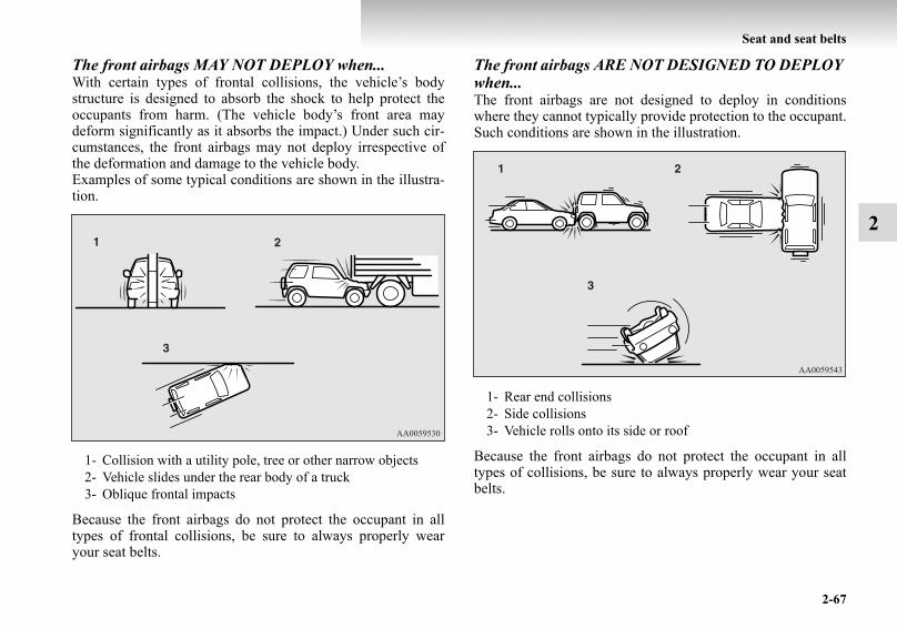
Seat and seat belts
2-67
2
The front airbags MAY NOT DEPLOY when...With certain types of frontal collisions, the vehicle’s bodystructure is designed to absorb the shock to help protect theoccupants from harm. (The vehicle body’s front area maydeform significantly as it absorbs the impact.) Under such cir-cumstances, the front airbags may not deploy irrespective ofthe deformation and damage to the vehicle body.Examples of some typical conditions are shown in the illustra-tion.
Because the front airbags do not protect the occupant in alltypes of frontal collisions, be sure to always properly wearyour seat belts.
The front airbags ARE NOT DESIGNED TO DEPLOY when...The front airbags are not designed to deploy in conditionswhere they cannot typically provide protection to the occupant.Such conditions are shown in the illustration.
Because the front airbags do not protect the occupant in alltypes of collisions, be sure to always properly wear your seatbelts.
1- Collision with a utility pole, tree or other narrow objects2- Vehicle slides under the rear body of a truck3- Oblique frontal impacts
1- Rear end collisions2- Side collisions3- Vehicle rolls onto its side or roof
BK-BK2008E1ENUK.en-uk-Section5.fm Page 67 Wednesday, January 9, 2008 4:28 PM

2-68
Seat and seat belts
2
The front airbags MAY DEPLOY when...The front airbags may deploy if the bottom of the vehicle suf-fers a moderate to severe impact (undercarriage damage).Examples of some typical conditions are shown in the illustra-tion.
Because the front airbags may deploy in certain types of unex-pected impacts as shown in the illustration, and because theseimpacts can easily move you out of position, it is important toalways properly wear your seat belts. Your seat belts will helpyou to keep a safe distance from the steering wheel and instru-ment panel during the initial stages of airbag deployment. Theinitial stage of airbag inflation is the most forceful one and canpossibly cause serious or fatal injuries if you contact it at thisstage.
1- Collision with an elevated median/island or kerb2- Vehicle travels over a deep hole/pothole3- Vehicle drives down a steep slope and hits the ground
WARNING!● Do not attach anything to the steering wheel padded
cover, such as trim material, badges, etc. It mightstrike and injure an occupant if the airbag inflates.
● Do not set anything on, or attach anything to, theinstrument panel above the glove box. It mightstrike and injure an occupant if the airbag inflates.
WARNING!● Do not attach accessories to, or put them in front of,
the windscreen. These objects could restrict the air-bag inflation, or strike and injure an occupant if theairbag inflates.
BK-BK2008E1ENUK.en-uk-Section5.fm Page 68 Wednesday, January 9, 2008 4:28 PM

Seat and seat belts
2-69
2
Side airbag system*E00407600198
The side airbags (A) are contained in the driver and front pas-senger seatbacks.The side airbag is designed to inflate only on the side of thevehicle that is impacted, even with no passenger in the frontseat.
● Do not put packages, pets or other objects betweenthe airbags and the driver or front passenger. Itcould affect airbag performance, or could causeinjury when the airbag inflates.
● Right after the airbag inflation, several airbag sys-tem components will be hot. Do not touch them; youcould be burned.
● The airbag system is designed to work only once.Once the airbags have deployed, they will not workagain. They must promptly be replaced, and we rec-ommend you to have the entire airbag systeminspected by a MITSUBISHI MOTORS AuthorizedService Point.
WARNING!
BK-BK2008E1ENUK.en-uk-Section5.fm Page 69 Wednesday, January 9, 2008 4:28 PM

2-70
Seat and seat belts
2
The label shown here is attached to the seatbacks with a sideairbag.
Curtain airbag system*E00409100243
The curtain airbags are contained in the front pillars and roofside rail. The curtain airbag is designed to inflate only on theside of the vehicle that is impacted, even with no passenger inthe front seat or rear (3-door models)/second (5-door models)seat.
BK-BK2008E1ENUK.en-uk-Section5.fm Page 70 Wednesday, January 9, 2008 4:28 PM

Seat and seat belts
2-71
2
Deployment of side airbags and curtain airbagsE00407700375
The side airbags and curtain airbags ARE DESIGNED TO DEPLOY when...The side airbags and curtain airbags are designed to deploywhen the vehicle suffers a moderate to severe side impact tothe middle of the passenger compartment.The typical condition is shown in the illustration.
The seat belts in your vehicle are your primary means of pro-tection in a collision. The SRS (Supplemental Restraint Sys-tem) side airbags and curtain airbags are designed to provideadditional protection. Therefore, for your safety and the safetyof all occupants, be sure to always properly wear your seatbelts.
The side airbags and curtain airbags MAY NOT DEPLOY when...With certain types of side collisions, the vehicle’s body struc-ture is designed to absorb the shock to help protect the occu-pants from harm. (The vehicle body’s side area may deformsignificantly as it absorbs the impact.) Under such circum-stances, the side airbags and curtain airbags may not deployirrespective of the deformation and damage to the vehiclebody. Also, depending on the location of the impact, the sideairbags and curtain airbags may not deploy simultaneously.Examples of some typical conditions are shown in the illustra-tion.
BK-BK2008E1ENUK.en-uk-Section5.fm Page 71 Wednesday, January 9, 2008 4:28 PM

2-72
Seat and seat belts
2
Because the side airbags and curtain airbags do not protect theoccupant in all types of side collisions, be sure to always prop-erly wear your seat belts.
1- Side impacts in an area away from the passenger compart-ment
2- Motorcycle or other similar small vehicle collides with theside of vehicle
3- Collision with a utility pole, tree or other narrow object
4- Oblique side impacts5- Vehicle rolls onto its side or roof
BK-BK2008E1ENUK.en-uk-Section5.fm Page 72 Wednesday, January 9, 2008 4:28 PM

Seat and seat belts
2-73
2
The side airbags and curtain airbags ARE NOT DESIGNED TO DEPLOY when...The side airbags and curtain airbags are not designed to deployin conditions where they cannot usually provide protection tothe occupant. Typical conditions are shown in the illustration.
Because the side airbags and curtain airbags do not protect theoccupant in all types of collisions, be sure to always properlywear your seat belts.
1- Head-on collisions2- Rear end collisions
WARNING!● The side airbags and curtain airbags are designed to
supplement the protection through the driver andpassenger seat belts in certain side impacts. Seatbelts should always be worn properly, and the driverand passenger should sit well back and uprightwithout leaning against the window or door.
● The side airbag and curtain airbag inflate with greatforce. The driver and passenger should not put theirarms out of the window, and should not lean againstthe door, in order to reduce risk of serious or possi-bly fatal injury from the deploying side airbag andcurtain airbag.
BK-BK2008E1ENUK.en-uk-Section5.fm Page 73 Wednesday, January 9, 2008 4:28 PM

2-74
Seat and seat belts
2
WARNING!● Do not allow any rear seat occupant to hold onto the
seatback of either front seat, in order to reduce riskof injury from a deploying side airbag. Special careshould be taken with children.
● Do not place any objects near or in front of the seat-back of either front seat. They could interfere withproper side airbag inflation, and also could causeinjury if thrown free by side airbag deployment.
● Do not place stickers, labels or additional trim onthe seatback of either front seat. They could inter-fere with proper side airbag inflation.
● Do not install seat covers on seats with side airbags.Do not re-cover the seats with side airbags. Theycould interfere with proper side airbag inflation.
WARNING!● Do not attach a microphone (A) or any other device
or object around the part where the curtain airbagsactivate such as on the windscreen, side door glass,front and rear pillars and roof side or assist grips.When the curtain airbags inflate, the microphone orother device or object will be hurled with great forceor the curtain airbags may not activate correctly,resulting in death or serious injury.
BK-BK2008E1ENUK.en-uk-Section5.fm Page 74 Wednesday, January 9, 2008 4:28 PM
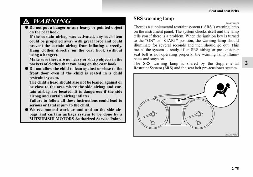
Seat and seat belts
2-75
2
SRS warning lampE00407800129
There is a supplemental restraint system (“SRS”) warning lampon the instrument panel. The system checks itself and the lamptells you if there is a problem. When the ignition key is turnedto the “ON” or “START” position, the warning lamp shouldilluminate for several seconds and then should go out. Thismeans the system is ready. If an SRS airbag or pre-tensionerseat belt is not operating properly, the warning lamp illumi-nates and stays on.The SRS warning lamp is shared by the SupplementalRestraint System (SRS) and the seat belt pre-tensioner system.
WARNING!● Do not put a hanger or any heavy or pointed object
on the coat hook.If the curtain airbag was activated, any such itemcould be propelled away with great force and couldprevent the curtain airbag from inflating correctly.Hang clothes directly on the coat hook (withoutusing a hanger).Make sure there are no heavy or sharp objects in thepockets of clothes that you hang on the coat hook.
● Do not allow the child to lean against or close to thefront door even if the child is seated in a childrestraint system.The child’s head should also not be leaned against orbe close to the area where the side airbag and cur-tain airbag are located. It is dangerous if the sideairbag and curtain airbag inflates.Failure to follow all these instructions could lead toserious or fatal injury to the child.
● We recommend work around and on the side air-bags and curtain airbags system to be done by aMITSUBISHI MOTORS Authorized Service Point.
BK-BK2008E1ENUK.en-uk-Section5.fm Page 75 Wednesday, January 9, 2008 4:28 PM

2-76
Seat and seat belts
2
SRS servicingE00407901042WARNING!
● If any of the following conditions occur, the SRSand/or seat belt pre-tensioners are not workingproperly, and we recommend you to have itinspected by a MITSUBISHI MOTORS AuthorizedService Point immediately.• The SRS warning lamp does not illuminate when
you start the vehicle.• The SRS warning lamp does not go out after sev-
eral seconds.• The SRS warning lamp illuminates while driving.
WARNING!● We recommend any maintenance performed on or
near the components of the SRS to be performed bya MITSUBISHI MOTORS Authorized ServicePoint.Improper work on the SRS components or wiringcould result in inadvertent deployment of the air-bags, or could render the SRS inoperative; eithersituation could result in serious injury.
● Do not modify your steering wheel, seat belt retrac-tor or any other SRS components. For example,replacement of the steering wheel, or modificationsto the front bumper or body structure can adverselyaffect SRS performance and lead to possible injury.
● If your vehicle has received any damage, we recom-mend you to have the SRS inspected to ensure it is inproper working order.
● On vehicles with the side airbags, do not modifyyour front seats, centre pillar and centre console.It can adversely affect SRS performance and lead topossible injury.If you found any tear scratch, crack or damage tothe seat fabric near the side airbag, the portion ofthe front and rear pillars and roof side rail, youshould have the SRS inspected by a MITSUBISHIMOTORS Authorized Service Point.
BK-BK2008E1ENUK.en-uk-Section5.fm Page 76 Wednesday, January 9, 2008 4:28 PM

Seat and seat belts
2-77
2
NOTE● When you transfer ownership of the vehicle to some other
person, we urge you to alert the new owner that it isequipped with the SRS and refer that owner to the applica-ble section in this owner’s manual.
● If your vehicle has to be scrapped do this in line with locallegislation and contact a MITSUBISHI MOTORSAuthorized Service Point to safely dismantle the airbagsystem.
BK-BK2008E1ENUK.en-uk-Section5.fm Page 77 Wednesday, January 9, 2008 4:28 PM

BK-BK2008E1ENUK.en-uk-Section5.fm Page 78 Wednesday, January 9, 2008 4:28 PM

3
Instruments and controls
Instruments. . . . . . . . . . . . . . . . . . . . . . . . . . . . . . .3- 2Indicator and warning lamps . . . . . . . . . . . . . . . . .3- 10Indicator lamps. . . . . . . . . . . . . . . . . . . . . . . . . . . .3- 12Warning lamps . . . . . . . . . . . . . . . . . . . . . . . . . . . .3- 13Centre information display* . . . . . . . . . . . . . . . . .3- 17Combination headlamps and dipper switch . . . . . .3- 58Headlamp levelling . . . . . . . . . . . . . . . . . . . . . . . .3- 62Turn-signal lever . . . . . . . . . . . . . . . . . . . . . . . . . .3- 65Hazard warning flasher switch. . . . . . . . . . . . . . . .3- 66Fog lamp switch. . . . . . . . . . . . . . . . . . . . . . . . . . .3- 66Wiper and washer switch . . . . . . . . . . . . . . . . . . . .3- 68Wiper deicer switch* . . . . . . . . . . . . . . . . . . . . . . .3- 77Rear window demister switch . . . . . . . . . . . . . . . .3- 77Horn switch . . . . . . . . . . . . . . . . . . . . . . . . . . . . . .3- 78
BK-BK2008E1ENUK.en-uk-Section6.fm Page 1 Wednesday, January 9, 2008 4:32 PM

3-2
Instruments and controls
3
InstrumentsE00500100241
TachometerE00500300458
The tachometer indicates the engine speed (r/min). Thetachometer helps you to obtain more economical driving andalso warns you of excessive engine speeds (Red zone).
1- Speedometer (km/h or mph + km/h)2- Tachometer3- Tripmeter reset button/Daytime dipper button4- Fuel gauge5- Odometer/Tripmeter/Service reminder6- Water temperature gauge
CAUTION!● When driving, watch the tachometer to make sure
that the engine speed indication does not rise intothe red zone (excessive engine rpm).
BK-BK2008E1ENUK.en-uk-Section6.fm Page 2 Wednesday, January 9, 2008 4:32 PM

Instruments and controls
3-3
3
Odometer/Tripmeter/Service reminderE00500600998
With the ignition switch in the “ON” position, odometer, tripm-eter, and service reminder indications are given.
Odometer The odometer indicates the total distance the vehicle has trav-elled.
TripmeterThe tripmeter indicates the distance travelled during a particu-lar trip or period.There are two tripmeter displays: TRIP and .TRIP can be used to measure the distance travelled sincethe current trip began. At the same time, TRIP can be usedto measure the distance from an intermediate location.To switch the display between TRIP and TRIP , pressthe reset button (B) less than 1 second.
A- Odometer/Tripmeter/Service reminderB- Reset button
TRIP ODO
Service reminder
TRIP ODO
BK-BK2008E1ENUK.en-uk-Section6.fm Page 3 Wednesday, January 9, 2008 4:32 PM

3-4
Instruments and controls
3
NOTE● If you do not push the button for about 10 seconds while
the service reminder is showing, the display will return tothe odometer indication.
● The odometer, tripmeter, and service reminder indicationsare given for 30 seconds after the ignition switch has beenturned to the “ACC” or “LOCK” position.
● After the odometer, tripmeter, and service reminder indi-cations have gone off, they come back on for about 30seconds if either of the following actions takes place.• The driver’s door is opened.• The reset button is pressed.
To reset the tripmeterTo return the display to “0”, press the reset button (B) for morethan 2 second. Only the currently displayed value will be reset.
NOTE● When disconnecting the battery terminal for a long time,
the memory of tripmeter display TRIP and arecleared, and the display returns to “0”.
Service reminderE00517700092
The service reminder shows the number of months (1) anddriving distance (3) remaining until the next 12-monthly(15,000 km or 9,000 miles) inspection. When the next inspec-tion is nearly due, the display shows “-----”. At this time, aspanner mark (2) is shown for a few seconds whenever theignition switch is turned from the “OFF” position to the “ON”position.
BK-BK2008E1ENUK.en-uk-Section6.fm Page 4 Wednesday, January 9, 2008 4:32 PM

Instruments and controls
3-5
31. The display shows the number of months and driving dis-
tance remaining until the next inspection.2. When the next inspection is nearly due, the display shows
“-----”.For further information, we recommend you to consult aMITSUBISHI MOTORS Authorized Service Point.At this time, a spanner mark is shown for a few secondswhenever the ignition switch is turned from the “OFF”position to the “ON” position.
3. When the vehicle is inspected at a MITSUBISHIMOTORS Authorized Service Point, the number ofmonths and driving distance remaining until the nextinspection will be shown.
NOTE● The indicated distance decreases in steps of 100 km (or
100 miles). The indicated number of months decreases insteps of one month.
● It is possible to change the settings for the servicereminder.For further information, we recommend you to consult aMITSUBISHI MOTORS Authorized Service Point.
BK-BK2008E1ENUK.en-uk-Section6.fm Page 5 Wednesday, January 9, 2008 4:32 PM

3-6
Instruments and controls
3
Resetting the service reminderWith the ignition switch in the “OFF” position, it is possible toreset the spanner mark (A) and “-----” indication (B). Whenthey have been reset, the number of months and driving dis-tance remaining until the next inspection are shown and thespanner mark (A) is no longer shown every time the ignitionswitch is turned from the “OFF” position to the “ON” position.
BK-BK2008E1ENUK.en-uk-Section6.fm Page 6 Wednesday, January 9, 2008 4:32 PM
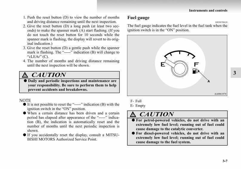
Instruments and controls
3-7
3
1. Push the reset button (D) to view the number of monthsand driving distance remaining until the next inspection.
2. Give the reset button (D) a long push (at least two sec-onds) to make the spanner mark (A) start flashing. (If youdo not touch the reset button for 10 seconds while thespanner mark is flashing, the display will revert to its orig-inal indication.)
3. Give the reset button (D) a gentle push while the spannermark is flashing. The “-----” indication (B) will change to“cLEAr” (C).
4. The number of months and driving distance remaininguntil the next inspection will be shown.
NOTE● It is not possible to reset the “-----” indication (B) with the
ignition switch in the “ON” position.● When a certain distance has been driven and a certain
period has elapsed after appearance of the “-----” indica-tion (B), the indication is automatically reset and thenumber of months until the next periodic inspection isshown.
● If you accidentally reset the display, consult a MITSU-BISHI MOTORS Authorized Service Point.
Fuel gaugeE00500700638
The fuel gauge indicates the fuel level in the fuel tank when theignition switch is in the “ON” position.
CAUTION!● Daily and periodic inspections and maintenance are
your responsibility. Be sure to perform them to helpprevent accidents and breakdowns.
F- FullE- Empty
CAUTION!● For petrol-powered vehicles, do not drive with an
extremely low fuel level; running out of fuel couldcause damage to the catalytic converter.
● For diesel-powered vehicles, do not drive with anextremely low fuel level; running out of fuel couldcause damage to the fuel system.
BK-BK2008E1ENUK.en-uk-Section6.fm Page 7 Wednesday, January 9, 2008 4:32 PM

3-8
Instruments and controls
3
NOTE● When the vehicle has been refuelled, the pointer in the
fuel gauge takes a short while to stabilize.● The fuel gauge will not give an accurate indication if the
vehicle is refuelled with the ignition switch in the “ON”position.
● When the engine on diesel-powered vehicles fails to oper-ate owing to running out of fuel, it may sometimes be dif-ficult to start after refuelling. This is due to air enteringthe fuel system. Therefore, air must be bled from the sys-tem. (Refer to “Bleeding the fuel system” on page 6-9.)
Fuel lid markThe fuel lid mark (A) indicates that the fuel tank filler door islocated on the right side of the vehicle.
Low fuel warning lampE00508100595
The warning lamp (A) illuminates when the fuel level is get-ting low (approx. 10 litres) with the ignition switch in the“ON” position. Refuel as soon as possible.
NOTE● On inclines or curves, due to the movement of fuel in the
tank, the low fuel warning lamp may indicate incorrectly.
BK-BK2008E1ENUK.en-uk-Section6.fm Page 8 Wednesday, January 9, 2008 4:32 PM
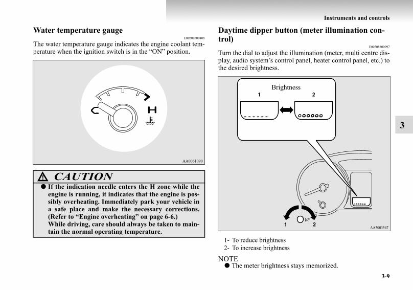
Instruments and controls
3-9
3
Water temperature gaugeE00500800408
The water temperature gauge indicates the engine coolant tem-perature when the ignition switch is in the “ON” position.
Daytime dipper button (meter illumination con-trol)
E00508800097
Turn the dial to adjust the illumination (meter, multi centre dis-play, audio system’s control panel, heater control panel, etc.) tothe desired brightness.
NOTE● The meter brightness stays memorized.
CAUTION!● If the indication needle enters the H zone while the
engine is running, it indicates that the engine is pos-sibly overheating. Immediately park your vehicle ina safe place and make the necessary corrections.(Refer to “Engine overheating” on page 6-6.)While driving, care should always be taken to main-tain the normal operating temperature.
1- To reduce brightness2- To increase brightness
Brightness
BK-BK2008E1ENUK.en-uk-Section6.fm Page 9 Wednesday, January 9, 2008 4:32 PM

3-10
Instruments and controls
3
Indicator and warning lampsE00501501353
1- Turn-signal indication lamps/Hazard warning indicationlamps → p. 3-12
2- Rear fog lamp indication lamp → p. 3-123- Position lamp indication lamp → p. 3-124- Front fog lamp indication lamp* → p. 3-125- Automatic headlamp levelling warning lamp* → p. 3-646- High-beam indication lamp → p. 3-127- Active stability control function OFF indication lamp
→ p. 4-678- Active stability control function indication lamp/Active trac-
tion control function indication lamp → p. 4-67, 4-699- Anti-lock brake system (ABS) warning lamp → p. 4-60
10- Brake warning lamp → p. 3-1311- Supplemental restraint system (SRS) warning lamp
→ p. 2-75
12- Seat belt warning lamp → p. 2-4013- A/T fluid temperature warning lamp (vehicles with A/T)
→ p. 4-3114- CRUISE indication lamp* → p. 4-7215- “SONAR OFF” indication lamp* → p. 4-8416- Diesel particulate filter (DPF) warning lamp* → p. 4-2217- Diesel preheat indication lamp (diesel-powered vehicles)
→ p. 3-1218- Fuel filter indication lamp (diesel-powered vehicles)
→ p. 3-1319- Check engine warning lamp → p. 3-1520- Charge warning lamp → p. 3-1621- Oil pressure warning lamp → p. 3-1622- Low fuel warning lamp → p. 3-823- 2WD/4WD operation indication lamp → p. 4-38
BK-BK2008E1ENUK.en-uk-Section6.fm Page 10 Wednesday, January 9, 2008 4:32 PM

Instruments and controls
3-11
3
24- Rear differential lock indication lamp* → p. 4-4325- Door-ajar warning lamp → p. 3-1726- Service reminder → p. 3-427- Sports mode indicator (vehicles with A/T) → p. 4-3028- Selector lever position indication lamps (vehicles with A/T,
“N” indication lamp is used also as A/T warning lamp)→ p. 4-27
BK-BK2008E1ENUK.en-uk-Section6.fm Page 11 Wednesday, January 9, 2008 4:32 PM

3-12
Instruments and controls
3
Indicator lampsE00501600012
Turn-signal indication lamps/Hazard warning indication lamps
E00501700068
These indication lamps blink on and off when aturn-signal lamp is operating.
NOTE● If the blinking is too fast, a lamp bulb may
be blown or a turn-signal connection maybe false.
When the hazard warning lamp switch ispressed, all turn-signal lamps will flash on andoff continuously.
High-beam indicator lampE00501800072
This indicator lamp illuminates when the highbeam is used.
Front fog lamp indication lamp*E00501900132
This indication lamp illuminates while the frontfog lamps are on.
Rear fog lamp indication lampE00502000084
This indication lamp illuminates while the rearfog lamp is on.
Position lamp indication lampE00508900102
This lamp illuminates with the lamp switch at“ ” or “ ” position.
Diesel preheat indication lamp (diesel-powered vehicles)
E00502300029
This indication lamp illuminates when the igni-tion switch is placed in the “ON” position. Asthe glow plug becomes hot, the lamp goes outand the engine can be started.
NOTE● If the engine is cold, the diesel preheat indi-
cation lamp is on for a longer time.● When the engine has not been started within
about 5 seconds after the diesel preheatindication lamp went out, return the ignitionswitch to the “LOCK” position. Then, turnthe switch to the “ON” position to preheatthe engine again.
● When the engine is warm, the diesel preheatindication lamp does not come on even ifthe ignition switch is placed in the “ON”position.
BK-BK2008E1ENUK.en-uk-Section6.fm Page 12 Wednesday, January 9, 2008 4:32 PM

Instruments and controls
3-13
3
Fuel filter indication lamp (diesel-powered vehicles)
E00509900040
This indication lamp illuminates when the igni-tion switch is turned to the “ON” position andgoes off after the engine has started. If it lightsup while the engine is running, it indicates thatwater has accumulated inside the fuel filter; ifthis happens, remove the water from the fuel fil-ter.When the lamp goes out, you can resume driv-ing. If it either does not go out or comes on fromtime to time, we recommend you to have thevehicle inspected.
Warning lampsE00502400017
Brake warning lamp (brake warning buzzer)
E00502501057
This lamp illuminates when the ignition switchis turned to the “ON” position, and goes off aftera few seconds.With the ignition switch in the “ON” position,the brake warning lamp illuminates under thefollowing conditions:
● When the parking brake lever has beenengaged.
● When the brake fluid level in the reservoirfalls to a low level.
● When the brake circuit is not operating cor-rectly.
Brake warning buzzerWhen there is a danger of brake performancebecoming compromised, a buzzer will sound toalert the driver. If this buzzer should continue tosound, park your vehicle in a safe place and werecommend you to have it checked.
NOTE● Depressing the brake pedal repeatedly may
turn on the brake warning lamp, ABS warn-ing lamp and brake warning buzzer. It isnormal if the lamp goes out and the buzzerstops sounding after a few seconds.
BK-BK2008E1ENUK.en-uk-Section6.fm Page 13 Wednesday, January 9, 2008 4:32 PM

3-14
Instruments and controls
3
NOTE● In certain cases immediately after the
engine has been started or when the brakepedal is depressed repeatedly, a noise gen-erated by operation of brake devices may beheard coming from the engine compart-ment. This type of noise is normal and thereis no need for concern. In fact, it indicatesthat the corresponding devices are operatingnormally.
● The brake system uses brake fluid pressu-rized by the pump.Please refer to “Braking” on page 4-56.
CAUTION!● In the situations listed below, brake
performance may be compromised orthe vehicle may become unstable ifbrakes are applied suddenly; conse-quently, avoid driving at high speedsor applying the brakes suddenly. Fur-thermore, the vehicle should bebrought to a stop in a safe location andto have it checked.• The brake warning lamp does not
illuminate when the parking brake isapplied or does not turn off when theparking brake is released.
• The brake warning lamp remainsilluminated during driving.
• The brake warning buzzer does notturn off.
● The vehicle should be brought to a haltin the following manner when brakeperformance has deteriorated.• Depress the brake pedal harder than
usual.Even if the brake pedal moves downto the very end of its possible stroke,keep it pressed down hard.
• Should the brakes fail, use enginebraking to reduce your speed andpull the parking brake lever.Depress the brake pedal to operatethe stop lamp to alert the vehiclesbehind you.
CAUTION!
BK-BK2008E1ENUK.en-uk-Section6.fm Page 14 Wednesday, January 9, 2008 4:32 PM

Instruments and controls
3-15
3
Check engine warning lampE00502600093
This lamp is a part of an onboard diagnostic sys-tem which monitors the emissions, engine andautomatic transmission control systems.If a problem is detected in one of these systems,this lamp illuminates.Although your vehicle will usually be drivableand not need towing, we recommend you to havethe system checked as soon as possible.This lamp will also illuminate for a few secondswhen the ignition switch is turned to the “ON”position. If it does not go off after a few seconds,we recommend you to have the vehicle checked.
NOTE● The engine electronic control module
accommodating the onboard diagnostic sys-tem has various fault data (especially aboutthe exhaust emission) stored.This data will be erased if a battery cable isdisconnected which will make a rapid diag-nosis difficult. Do not disconnect a batterycable when the check engine warning lampis ON.
CAUTION!● Prolonged driving with this lamp on
may cause further damage to the emis-sion control system. It could also affectfuel economy and drivability.
● If the lamp does not illuminate whenthe ignition switch is turned to the“ON” position, we recommend you tohave the system checked.
● If the lamp illuminates while theengine is running, avoid driving athigh speeds and we recommend you tohave the system checked.Accelerator pedal and brake pedalresponse may be negatively influencedunder these conditions.
BK-BK2008E1ENUK.en-uk-Section6.fm Page 15 Wednesday, January 9, 2008 4:32 PM

3-16
Instruments and controls
3
Charge warning lampE00502700472
This lamp illuminates when the ignition switchis turned to the “ON” position, and goes off afterthe engine has started.
Oil pressure warning lampE00502800529
This lamp illuminates when the ignition switchis turned to the “ON” position, and goes off afterthe engine has started. If it illuminates while theengine is running, the oil pressure is too low.Turn the engine off and have it inspected.CAUTION!
● If it illuminates while the engine is run-ning, there is a problem in the charg-ing system. In this case, immediatelypark your vehicle in a safe place andwe recommend you to have it checked.
CAUTION!● This warning lamp does not indicate
the amount of oil level in the engine.This must be determined by checkingthe oil level on the dipstick, while theengine is switched off.
● If this lamp illuminates when theengine oil level is not low, have itinspected.
● If you continue driving with low engineoil level or with this warning lamp illu-minated, engine seizure may occur.
BK-BK2008E1ENUK.en-uk-Section6.fm Page 16 Wednesday, January 9, 2008 4:32 PM

Instruments and controls
3-17
3
Door-ajar warning lampE00503300635
This lamp illuminates when a door or the back-door is either open or incompletely closed.If the vehicle speed reaches approximately8 km/h (5 mph) with a door or the backdoor openor incompletely closed, the warning lamp flashes8 times and a buzzer simultaneously sounds8 times as a warning.
NOTE● On vehicles with keyless entry system, the
lamp remains illuminated for a certainperiod and then goes out automatically.
● Buzzer settings can be changed at a yourMITSUBISHI MOTORS Authorized Serv-ice Point to:• No buzzer operation (buzzer disabled)• Continuous buzzer operation
Centre information display*E00517800080
When the ignition switch is turned to the “ACC” position, thescreen switches on automatically.
NOTE● Placing a cellular phone in the monitor’s small storage
compartment may weaken the phone’s reception. Thisdoes not indicate a fault with the system.
● Use of wireless devices such as transceivers or a cellularphone near the monitor may make the following conditionon the display. This does not indicate a fault with the sys-tem.• The screen goes dark temporarily.• The compass may not show the correct direction.
● Depending on the angle of view, you may see reddish hor-izontal lines on the monitor. The lines are a characteristicof the vacuum fluorescent display (VFD) used in the mon-itor. They do not indicate a fault.
CAUTION!● Before moving your vehicle, check that
the warning lamp is OFF.
CAUTION!● The driver should not operate the display while the
vehicle is in motion.
BK-BK2008E1ENUK.en-uk-Section6.fm Page 17 Wednesday, January 9, 2008 4:32 PM

3-18
Instruments and controls
3
Type 1 Type 2
1- Digital clock → p. 3-19Indicates the time.
2- Electronic compass*This display shows the direction of the vehicle.
3- Frozen road warning → p. 3-27Gives an indication when the outside temperature is 3 °C orlower.
4- Outside temperature → p. 3-265- Centre information display indications
Indicates details of each display. 6- Disc number
Shows the disc number. When no disc is inserted, it does notshow a disc number.
7- “INFO” buttonUsed to select various kinds of information for display.
8- Function buttonsPress this button to select options shown in the display.
9- “ADJ” buttonUsed for adjusting the clock and for selecting settings dis-plays.
10- Display for function buttonsThis display shows the options available for each functionbutton.
BK-BK2008E1ENUK.en-uk-Section6.fm Page 18 Wednesday, January 9, 2008 4:32 PM

Instruments and controls
3-19
3
Adjusting the timeE00518000021
Following modes are available for clock adjustment:● For vehicles with MITSUBISHI genuine audio:
“Automatic mode” and “Manual mode”● Except for vehicles with MITSUBISHI genuine audio:
“Manual mode” only
Automatic mode (MITSUBISHI genuine audio)The automatic adjustment mode can set the local time automat-ically by using the signal from the local RDS stations. In thismode, “CT” (A) (Clock Time: sent with the RDS signal) isshown in the audio display.
NOTE● Automatic clock adjustment does not take place while a
settings display is shown.
Manual modeThe manual mode is also available in case the automatic modeshows the incorrect time when the adjacent local RDS stationsare located in a different time zone. Refer to “Radio data sys-tem (RDS)” on page 5-27, 5-52.It is possible to manually adjust the time.Refer to “Changing the clock settings” on page 3-33.
BK-BK2008E1ENUK.en-uk-Section6.fm Page 19 Wednesday, January 9, 2008 4:32 PM

3-20
Instruments and controls
3
Changing the information displayE00517900010
Every time the “INFO” button is pressed lightly, the displaycan be changed to the following:
BK-BK2008E1ENUK.en-uk-Section6.fm Page 20 Wednesday, January 9, 2008 4:32 PM

Instruments and controls
3-21
3
1- Audio information → p. 5-20, 5-432- Average fuel consumption → p. 3-223- Driving range → p. 3-234- Average speed → p. 3-255- Outside temperature → p. 3-266- Altimeter → p. 3-287- Barometer → p. 3-298- Calendar → p. 3-309- Clock-only → p. 3-31
10- Blank → p. 3-31
BK-BK2008E1ENUK.en-uk-Section6.fm Page 21 Wednesday, January 9, 2008 4:32 PM

3-22
Instruments and controls
3
Average fuel consumptionE00518200052
The average fuel consumption during the period since the lastreset is shown in (A). The average value of the fuel consump-tion is graphed every 5 minutes and the data for up to 4 hoursare shown in (B).When you press the “MANUAL” function button in the autoreset mode, the mode will be changed to the manual resetmode. When you press the “AUTO” function button in themanual reset mode, the mode will be changed to the auto resetmode.
NOTE● When you turn the ignition switch to the “ON” position
after turning it from the “ON” position to the “ACC” or“LOCK” position in the manual reset mode, the auto resetmode will automatically be selected.
● When the average fuel consumption cannot be calculated,“--.-” will be shown.
● The average fuel consumption changes depending on thedriving condition (road condition, driving behavior, etc.).The indication may differ from the actual fuel consump-tion. Therefore, it is recommended to use the indication asreference.
● The unit indication can be changed to your desired setting{km/L, L/100 km, mpg (UK GALLON), or mpg (USGALLON)}.Refer to “User customization” on page 3-46.
Auto reset mode
Manual reset mode
BK-BK2008E1ENUK.en-uk-Section6.fm Page 22 Wednesday, January 9, 2008 4:32 PM

Instruments and controls
3-23
3
Resetting the average fuel consumptionPress the “RESET” function button to reset the average fuelconsumption indication.
NOTE● The average fuel consumption can be reset separately for
the auto reset mode and for the manual reset mode.● When you turn the ignition key to the “ON” position
about four hours (or more) after turning it from the “ON”position to the “ACC” or “LOCK” position in the autoreset mode, the average fuel consumption indication willautomatically be reset.
Driving rangeE00518300037
This value (A) shows the distance (in km or miles) that can bedriven on the fuel remaining in the fuel tank. The driving rangeis graphed every 5 minutes and the data for up to 4 hours areshown in (B).
BK-BK2008E1ENUK.en-uk-Section6.fm Page 23 Wednesday, January 9, 2008 4:32 PM

3-24
Instruments and controls
3
NOTE● When the driving range is 50 km (30 miles) or less, the
display shows “----”.When it is 3,000 km (2,000 miles) or more, “3,000 km” or“2,000 miles” will be shown.
● When the driving range cannot be measured, the displayshows “----”.
● The driving range is shown based on the accumulated fuelconsumption data, however, may be changed dependingon the driving condition (road condition, driving behavior,etc.). If the battery terminals are disconnected, the accu-mulated fuel consumption data will be erased. It is recom-mended to use the indication as reference.
● When the vehicle is fueled, the driving range will beupdated. However, if the amount of fueling is small, theindication may not be correct. Therefore, fill up the tankas much as possible in case of fueling.
● When the vehicle is stopped on a steep slope, the value ofthe driving range may increase. This is caused by the fuelmovement inside the tank on the slope and is not deemedas a failure.
Resetting the driving rangePress the “RESET” function button to reset the driving rangeplotted in graph.
NOTE● Pressing the “RESET” function button will not reset the
indication (C).● It is possible to set the display unit to km or miles.
Refer to “User customization” on page 3-46.
BK-BK2008E1ENUK.en-uk-Section6.fm Page 24 Wednesday, January 9, 2008 4:32 PM

Instruments and controls
3-25
3
Average speedE00518400041
The average speed during the period since the last reset isshown in (A). The average value of the vehicle speed isgraphed every 5 minutes and the data for up to 4 hours areshown in (B).When you press the “MANUAL” function button in the autoreset mode, the mode will be changed to the manual resetmode. When you press the “AUTO” function button in themanual reset mode, the mode will be changed to the auto resetmode.
NOTE● When you turn the ignition switch to the “ON” position
after turning it from the “ON” position to the “ACC” or“LOCK” position in the manual reset mode, the auto resetmode will automatically be selected.
● When the average speed cannot be calculated, “---” willbe shown.
● The unit indication can be changed to your desired setting(km/h or mph). Refer to “User customization” on page 3-46.
Auto reset mode
Manual reset mode
BK-BK2008E1ENUK.en-uk-Section6.fm Page 25 Wednesday, January 9, 2008 4:32 PM

3-26
Instruments and controls
3
Resetting the average speedPress the “RESET” function button to reset the average vehiclespeed.
NOTE● The average speed can be reset separately for the auto
reset mode and for the manual reset mode.● When you turn the ignition key to the “ON” position
about four hours (or more) after turning it from the “ON”position to the “ACC” or “LOCK” position in the autoreset mode, the average speed indication will automati-cally be reset.
Outside temperatureE00518500039
The outside temperature is graphed every 5 minutes and thedata for up to 4 hours are shown in (A). The current outsidetemperature is shown in (B).
BK-BK2008E1ENUK.en-uk-Section6.fm Page 26 Wednesday, January 9, 2008 4:32 PM
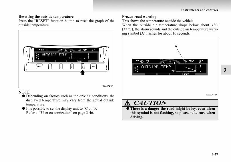
Instruments and controls
3-27
3
Resetting the outside temperaturePress the “RESET” function button to reset the graph of theoutside temperature.
NOTE● Depending on factors such as the driving conditions, the
displayed temperature may vary from the actual outsidetemperature.
● It is possible to set the display unit to °C or °F.Refer to “User customization” on page 3-46.
Frozen road warningThis shows the temperature outside the vehicle.When the outside air temperature drops below about 3 °C(37 °F), the alarm sounds and the outside air temperature warn-ing symbol (A) flashes for about 10 seconds.
CAUTION!● There is a danger the road might be icy, even when
this symbol is not flashing, so please take care whendriving.
BK-BK2008E1ENUK.en-uk-Section6.fm Page 27 Wednesday, January 9, 2008 4:32 PM

3-28
Instruments and controls
3
AltimeterE00518600027
The current elevation in units of 50 m (200 ft) is shown in (A).The elevation is graphed every 5 minutes and the data for up to4 hours are shown in (B).
To adjust the elevationIt is possible to adjust the currently indicated elevation usingthe following function buttons:
NOTE● The elevation is determined from changes in atmospheric
pressure. Depending on weather conditions, the indicatedelevation may differ from the actual elevation. Variationsin atmospheric pressure can cause different elevations tobe shown even in the same location. This behavior doesnot indicate a fault. Use the indication as a guide only.
“+”- Adjustment of elevation The elevation increases by 50 m (200 ft) every time youlightly push the “+” button.If you continue pressing the button for about 2 seconds ormore, the elevation indication is fast-forwarded. Then thesetting is changed to the elevation selected.
“-”- Adjustment of elevation The elevation decreases by 50 m (200 ft) every time youlightly push the “-” button.If you continue pressing the button for about 2 seconds ormore, the elevation indication is fast-forwarded. Then thesetting is changed to the elevation selected.
BK-BK2008E1ENUK.en-uk-Section6.fm Page 28 Wednesday, January 9, 2008 4:32 PM

Instruments and controls
3-29
3
Resetting the elevationPress the “RESET” function button to reset the elevation plot-ted in graph.
NOTE● Pressing the “RESET” function button will not reset the
indication (C).● It is possible to set the display unit to m or ft.
Refer to “User customization” on page 3-46.
BarometerE00518700015
This display shows the atmospheric pressure at the presentlocation in (A). The atmospheric pressure values are graphedevery 5 minutes and the data for up to 4 hours are shown in (B).
BK-BK2008E1ENUK.en-uk-Section6.fm Page 29 Wednesday, January 9, 2008 4:32 PM

3-30
Instruments and controls
3
Resetting the atmospheric pressurePress the “RESET” function button to reset the atmosphericpressure plotted in the graph.
NOTE● Pressing the “RESET” function button will not reset the
indication (C).● It is possible to set the display unit to hPa, mb, kPa or
inHg.Refer to “User customization” on page 3-46.
CalendarE00518800016
The date is shown. The calendar pattern can be changed to yourdesired setting.Refer to “Changing the calendar setting” on page 3-42.
BK-BK2008E1ENUK.en-uk-Section6.fm Page 30 Wednesday, January 9, 2008 4:32 PM
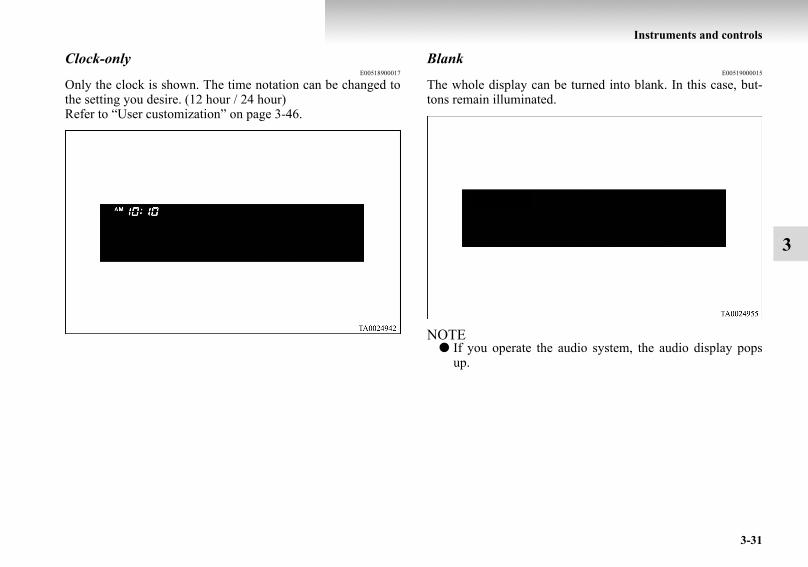
Instruments and controls
3-31
3
Clock-onlyE00518900017
Only the clock is shown. The time notation can be changed tothe setting you desire. (12 hour / 24 hour)Refer to “User customization” on page 3-46.
BlankE00519000015
The whole display can be turned into blank. In this case, but-tons remain illuminated.
NOTE● If you operate the audio system, the audio display pops
up.
BK-BK2008E1ENUK.en-uk-Section6.fm Page 31 Wednesday, January 9, 2008 4:32 PM

3-32
Instruments and controls
3
Selecting settings displaysE00519100045
Every time the “ADJ” button is pressed lightly, the display canbe changed to the following:
CAUTION!● The driver should not operate the display while the
vehicle is in motion.● When operating the system, stop the vehicle in a safe
area.
1- Changing the clock settings → p. 3-332- Adjusting the display brightness → p. 3-353- Correcting the compass* → p. 3-374- Changing the calendar setting → p. 3-425- User customization → p. 3-466- Adjusting the barometer → p. 3-54
BK-BK2008E1ENUK.en-uk-Section6.fm Page 32 Wednesday, January 9, 2008 4:32 PM

Instruments and controls
3-33
3
Changing the clock settingsE00519200017
1. Press the “ADJ” button to select the clock setting display.
BK-BK2008E1ENUK.en-uk-Section6.fm Page 33 Wednesday, January 9, 2008 4:32 PM

3-34
Instruments and controls
3
2. It is possible to adjust the clock using the function buttons
3. After making the adjustment, press the “INFO” button toselect the information display.
NOTE● Vehicles equipped with the Mitsubishi Multi Communica-
tion System (MMCS) also have a clock indication, but thetime shown by the MMCS may differ from that shown bythe centre information display because different sourcesof data are used for automatic adjustment.
“H”- Adjust “hour”.The indication increases by one hour, every time youlightly press the “H” function button. If you continuepressing the button for about 2 seconds or more, theindication is fast-forwarded, and then the setting ischanged to the hour selected.
“M”- Adjust “minute”.The indication increases by one minute, every time youlightly press the “M” function button. If you continuepressing the button for about 2 seconds or more, theindication is fast-forwarded, and then the setting ischanged to the minute selected.
“SET”- To reset the minutes to zero.The time is adjusted as described below by pressing thefunction button “SET”.
● 10:30-11:29 · · · · Change to 11:00● 11:30-12:29 · · · · Change to 12:00
In this occasion, the display flashes twice before the set-ting is changed.
BK-BK2008E1ENUK.en-uk-Section6.fm Page 34 Wednesday, January 9, 2008 4:32 PM

Instruments and controls
3-35
3
Adjusting the display brightnessE00519300018
The display brightness can be adjusted at 13 levels for bothdaytime and nighttime.
● BRIGHTNESS FOR DAYTIMEThe display brightness is adjusted when the light switch isin the “OFF” position.
● BRIGHTNESS FOR NIGHTTIMEThe display brightness is adjusted when the light switch isin the “ ” or “ ” position.
1. Press the “ADJ” button to show the brightness adjustingdisplay.
2. Press the “←” or “→” function button to select the settingyou wish to adjust (daytime or nighttime). Then press the“SELECT” function button.
BK-BK2008E1ENUK.en-uk-Section6.fm Page 35 Wednesday, January 9, 2008 4:32 PM

3-36
Instruments and controls
3
3. Use the function buttons to adjust the brightness. NOTE● If you next wish to adjust the other adjustment setting
(daytime or nighttime), press the “ADJ” button or“BACK” function button.
4. After adjustment, press the “INFO” button to select theinformation display.
NOTE● As the display brightness can be adjusted in the center
information display only, the brightness inside the metercannot be changed.
“+”- To make the display brighterThe display becomes brighter by one step, every timeyou lightly press the “+” function button. If you con-tinue pressing the button for about 2 seconds or more,the indication is fast-forwarded.
“-”- To make the display darkerThe display becomes darker by one step, every time youlightly press the “-” function button. If you continuepressing the button for about 2 seconds or more, theindication is fast-forwarded.
“SET”- To set the brightnessPress function button “SET” to set the new brightness.The display will flash twice.
BK-BK2008E1ENUK.en-uk-Section6.fm Page 36 Wednesday, January 9, 2008 4:32 PM

Instruments and controls
3-37
3
Correcting the compass*E00519400080
This compass shows the direction of the vehicle by the 8 azi-muth system.
NOTE● This system uses the earth’s magnetic field, and so may
not show the correct direction depending on the trafficcondition or in the following places where the earth’smagnetic field is disrupted.· Car parks located in buildings and tunnels· Expressways and underground cables· Area over the subway· Transforming station· Areas along the railroadIn these cases, the correct direction will be displayed oncethe vehicle returns to a place where the earth’s magneticfield is stable.
● Do not install ski racks, antennas, etc. which are attachedto the vehicle by means of a magnet. They affect the oper-ation of the compass.
● On vehicles equipped with the Mitsubishi Multi Commu-nication System (MMCS), even though the compass set-ting display is shown, correcting the compass will not bepossible.
BK-BK2008E1ENUK.en-uk-Section6.fm Page 37 Wednesday, January 9, 2008 4:32 PM

3-38
Instruments and controls
3
Setting the declinationThe declination is the difference between true north (the direc-tion of the geographic north pole) and where a compass needlepoints to. Since the declination varies from place to place, itneeds to be set for each region. Otherwise the compass will notshow the correct direction.Set the declination by the following steps:
NOTE● The default declination setting is 0 degrees. In accordance
with the illustration, set the declination setting to the dec-lination contour nearest to a region where you drive thevehicle.
● The declination can be set at intervals of 1 degrees, from28 degrees west (W28) to 28 degrees east (E28).
With a settings display showing, press the “ADJ” button andselect “COMPASS VARIANCE”.
1. Press the function button for “SELECT”.
BK-BK2008E1ENUK.en-uk-Section6.fm Page 38 Wednesday, January 9, 2008 4:32 PM

Instruments and controls
3-39
3
2. Press the function button for “←” or “ → ” to set thedesired declination.
Pressing “←” or “ → ” for more than 1 second makes thevalue change rapidly.
3. When the declination adjustment has been completed,press the “SET” function button.
BK-BK2008E1ENUK.en-uk-Section6.fm Page 39 Wednesday, January 9, 2008 4:32 PM

3-40
Instruments and controls
3
Setting the compassThe compass is usually calibrated automatically when the vehi-cle is moving. At times when complete calibration is not possi-ble, no compass indications are given. Manually set thecompass using the following procedure.
NOTE● If your vehicle has a sunroof, keep the sunroof closed
when calibrating the compass. Having the sunroof openwhen calibrating the compass could render the compassunable to correctly show directions.
With a settings display showing, press the “ADJ” button andselect “COMPASS CALIBRATION”.
1. Press the function button for “SELECT”.
BK-BK2008E1ENUK.en-uk-Section6.fm Page 40 Wednesday, January 9, 2008 4:32 PM

Instruments and controls
3-41
3
2. Press the function button for “SELECT”.
3. Turn the vehicle slowly through 360 degrees in a safe,open area with no buildings and other vehicles.
NOTE● If you wish to stop calibrating the compass part-way
through the procedure, press the “INFO” button or “ADJ”button.
NOTE● The “Completed the calibration”. message may be dis-
played even if you terminate the turn before it is completeand return to the vehicle’s original direction. The compassmay not be properly calibrated in this case, so you mustturn the vehicle through at least 360 degrees.
BK-BK2008E1ENUK.en-uk-Section6.fm Page 41 Wednesday, January 9, 2008 4:32 PM

3-42
Instruments and controls
3
4. The compass setting will finish automatically and thewords “COMPASS CALIBRATION COMPLETE” willappear on the screen.
NOTE● If your vehicle has a sunroof, do not open the sunroof
when checking the indicated direction after completingthe turn. Opening the sunroof could cause the azimuth barshown on the centre information display to freeze becauseof electromagnetic interference. Be sure to check the indi-cated direction with the sunroof closed. If the azimuth barfreezes, perform the compass calibration procedure again.
Changing the calendar settingE00519500010
The date and the calendar indication patterns can be changed.
Date setting1. Press the “ADJ” button to select the calendar setting dis-
play.
BK-BK2008E1ENUK.en-uk-Section6.fm Page 42 Wednesday, January 9, 2008 4:32 PM

Instruments and controls
3-43
3
2. Press the “←” or “→” function button to select “CALEN-DAR ADJUST”. Then press the “SELECT” function but-ton.
3. Use the function buttons to set the calendar.
"→"- Select “YEAR”, “MONTH”, “DAY” you wish tochange.“YEAR”, “MONTH”, and “DAY” are changed over byturns every time you lightly press the “→” function but-ton.
“+”- Change “YEAR”, “MONTH”, “DAY” you haveselected.The indication is changed to your desired date everytime you lightly press the “+” function button.If you continue pressing the button for about 2 secondsor more, the indication is forwarded.
“SET”- Determine the date.Press the “SET” function button. Then the displayflashes twice and the setting is changed.
BK-BK2008E1ENUK.en-uk-Section6.fm Page 43 Wednesday, January 9, 2008 4:32 PM

3-44
Instruments and controls
3
NOTE● The year changes in the following sequence: 2006 →
2007 → ... 2099 → 2006.● You can return to the previous display by pressing the
“BACK” function button.
4. After setting the date, press the “INFO” button to return tothe information display.
Changing the calendar pattern1. Press the “ADJ” button to select the calendar setting dis-
play. Press the “←” or “→” function button to select“CALENDAR PATTERN SELECT”. Then press the“SELECT” function button.
BK-BK2008E1ENUK.en-uk-Section6.fm Page 44 Wednesday, January 9, 2008 4:32 PM
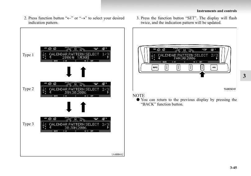
Instruments and controls
3-45
3
2. Press function button “←” or “→” to select your desiredindication pattern.
3. Press the function button “SET”. The display will flashtwice, and the indication pattern will be updated.
NOTE● You can return to the previous display by pressing the
“BACK” function button.
Type 1
Type 2
Type 3
BK-BK2008E1ENUK.en-uk-Section6.fm Page 45 Wednesday, January 9, 2008 4:32 PM

3-46
Instruments and controls
3
4. After setting the calendar pattern, press the “INFO” but-ton to return to the information display.
User customizationE00519600079
You can set the indication of unit, language, and the time nota-tion.In addition, you can return these settings to the factory defaultsettings.
Selecting the item to set1. Press the “ADJ” button to select the user customization
display.
BK-BK2008E1ENUK.en-uk-Section6.fm Page 46 Wednesday, January 9, 2008 4:32 PM

Instruments and controls
3-47
3
2. Press the function button “←” or “ → ” to select the itemyou wish to set.· “UNIT”: Changing the unit· “LANGUAGE”: Changing the language· “12h ↔ 24h”: Changing the time format· “DEFAULT”: Resetting to factory settingsPush the function button “SELECT”. The setting displayfor your selected item will appear.
Changing display unitsIt is possible to change the display units for the fuel consump-tion, driving range, average speed, outside temperature, eleva-tion, and atmospheric pressure as shown below.
FUEL ECONOMY km/L → L/100km → mpg (UK GALLON) → mpg (US GALLON)
RANGE km → milesSPEED km/h → mphOUTSIDE TEMPERATURE °C → °F
ELEVATION m → ftatmospheric pressure hPa → mb → kPa → inHg
BK-BK2008E1ENUK.en-uk-Section6.fm Page 47 Wednesday, January 9, 2008 4:32 PM

3-48
Instruments and controls
3
• Changing the display unit for fuel consumption1. Press the “←” or “ → ” function button to select “FUEL
ECONOMY”. Then press the “SELECT” function button.
2. Press the “←” or “ → ” function button to select “km/L”.Then press the “SET” function button. The display willflash twice, and the display unit will be updated to theselected one.
NOTE● You can return to the previous display by pressing the
“BACK” function button.
BK-BK2008E1ENUK.en-uk-Section6.fm Page 48 Wednesday, January 9, 2008 4:32 PM

Instruments and controls
3-49
3
3. After setting, press the “INFO” button to return to theinformation display.
Changing the languageIt is possible to set the display language of the centre informa-tion display to English, Spanish, French, German, or Italian(Portuguese).Depending on the regions, this may be set to Italian or Portu-guese.• To change the display language to English
1. Press the “←” or “ → ” function button to select “ENG-LISH”. Then press the “SET” function button. The dis-play will flash twice, and then the setting is completed tothe language selected.
NOTE● You can return to the previous display by pressing the
“BACK” function button.
BK-BK2008E1ENUK.en-uk-Section6.fm Page 49 Wednesday, January 9, 2008 4:32 PM

3-50
Instruments and controls
3
2. After setting the language, press the “INFO” button toreturn to the information display.
Changing the time notationIt is possible set the time notation to 12-hour or 24-hour.
1. Press the “←” or “ → ” function button to select “12hTIME NOTATION” or “24h TIME NOTATION”. Thenpress the “SET” function button. The display will flashtwice, and the display time notation will be updated to theselected one.
BK-BK2008E1ENUK.en-uk-Section6.fm Page 50 Wednesday, January 9, 2008 4:32 PM

Instruments and controls
3-51
3NOTE
● You can return to the previous display by pressing the“BACK” function button.
2. After setting the time notation, press the “INFO” button toreturn to the information display.12-hour 24-hour
BK-BK2008E1ENUK.en-uk-Section6.fm Page 51 Wednesday, January 9, 2008 4:32 PM

3-52
Instruments and controls
3
Returning display items to their factory settingsYou can return to the setting of each item to the factory defaultsettings.
NOTE● The factory settings are as follows:
• Fuel consumption: L/100km• Driving range: km• Average speed: km/h• Outside temperature: °C• Elevation: m• Atmospheric pressure: hPa• Display language: English• Time notation: 12-hour
1. Push the “SELECT” function button.
2. Press the “←” function button to select “YES”.
3. Press the “SELECT” function button.
BK-BK2008E1ENUK.en-uk-Section6.fm Page 52 Wednesday, January 9, 2008 4:32 PM

Instruments and controls
3-53
3
4. Once more press the “←” function button to select“YES”.
5. Press the “SET” function button.
6. The display shown below will appear, and the displayitems will return to their factory settings.
NOTE● If the battery terminals are disconnected, the settings for
the date and time may be erased. If this happens, pleaseset the date and time again.
BK-BK2008E1ENUK.en-uk-Section6.fm Page 53 Wednesday, January 9, 2008 4:32 PM

3-54
Instruments and controls
3
Adjusting the barometerE00524400017
It is possible to adjust the barometer indication and return it tothe factory setting.
NOTE● It is not necessary to adjust the barometer because it has
been adjusted at the factory.However, if you wish, adjust it using an accurate barome-ter.
To adjust the barometer1. Press the “ADJ” button to select the barometer adjustment
display.
BK-BK2008E1ENUK.en-uk-Section6.fm Page 54 Wednesday, January 9, 2008 4:32 PM

Instruments and controls
3-55
3
2. Press the “←” or “→” function button to select the“BAROMETER ADJUST” display. Then press the“SELECT” function button.
3. Adjust the barometer by pressing the function buttons.
NOTE● You can return to the previous display by pressing the
“BACK” function button.
“+”- To adjust the barometerEach gentle press of the “+” function button willincrease the indicated barometer by 2 hPa. If you con-tinue pressing the button for about 2 seconds or longer,the indication is fast-forwarded
“-”- To adjust the barometerEach gentle press of the “-” function button willdecrease the indicated barometer by 2 hPa. If you con-tinue pressing the button for about 2 seconds or longer,the indication is fast-forwarded.
“SET”- To set the barometerPress the “SET” function button. The display will flashtwice, and the new setting will be established.
BK-BK2008E1ENUK.en-uk-Section6.fm Page 55 Wednesday, January 9, 2008 4:32 PM
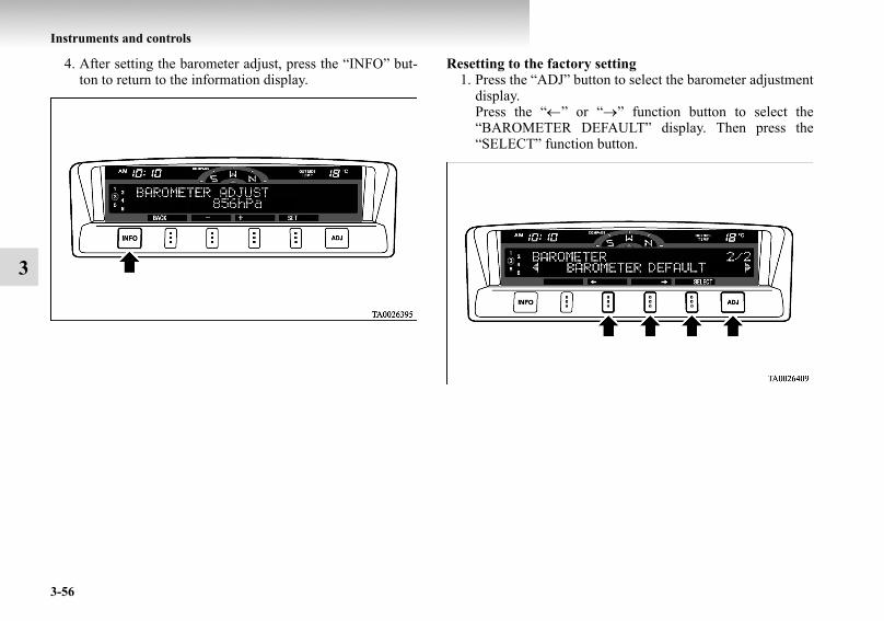
3-56
Instruments and controls
3
4. After setting the barometer adjust, press the “INFO” but-ton to return to the information display.
Resetting to the factory setting1. Press the “ADJ” button to select the barometer adjustment
display.Press the “←” or “→” function button to select the“BAROMETER DEFAULT” display. Then press the“SELECT” function button.
BK-BK2008E1ENUK.en-uk-Section6.fm Page 56 Wednesday, January 9, 2008 4:32 PM

Instruments and controls
3-57
3
2. Press the “SET” function button. The display will flashtwice and the barometer indication will return to the fac-tory setting.
NOTE● Although the barometer value is changed to the factory
setting, a barometer unit you have selected is unchanged.● You can return to the previous display by pressing the
“BACK” function button.
3. After setting the barometer default, press the “INFO” but-ton to return to the information display.
Care of the monitorE00519700012
If the monitor becomes covered in fingerprints or otherwisedirty, clean it with a soft and dry cloth.
NOTE● Don’t use a wet cloth or abrasive cleaner as this may
cause damage.
BK-BK2008E1ENUK.en-uk-Section6.fm Page 57 Wednesday, January 9, 2008 4:32 PM

3-58
Instruments and controls
3
Combination headlamps and dipper switchE00506001353
HeadlampsNOTE
● Do not leave the lights on for a long time while the engineis stationary (not running). A run-down battery couldresult.
● When it rains, or when the vehicle has been washed, theinside of the lens sometimes becomes foggy, but this doesnot indicate a functional problem. When the lamp isswitched on, the heat will remove the fog. However, ifwater gathers inside the lamp, we recommend you to haveit checked.
Type 1Rotate the switch to turn on the lamps.
OFF All lamps off
Position, tail, licence plate and instrument panel lamps on
Headlamps and other lamps go on
BK-BK2008E1ENUK.en-uk-Section6.fm Page 58 Wednesday, January 9, 2008 4:32 PM

Instruments and controls
3-59
3
Type 2Rotate the switch to turn on the lamps.
NOTE● The sensitivity of the automatic on/off control can be
adjusted.For further information, we recommend you to consult aMITSUBISHI MOTORS Authorized Service Point.
● When the headlamps are turned off by the automaticon/off control with the ignition switch in the “ON” posi-tion, the front fog lamps (if so equipped) and rear foglamps also go off. When the headlamps are subsequentlyturned back on by the automatic on/off control, the frontfog lamps also come on but the rear fog lamps stay off. Ifyou wish to turn the rear fog lamps back on, operate theswitch again.
● Do not cover the sensor (A) for the automatic on/off con-trol by affixing a sticker or label to the windscreen.
OFF All lamps off
AUTO
With the ignition switch in the “ON” position, head-lamps, position, tail, licence plate, and instrument panel lamps turn on and off automatically in accord-ance with outside light level. All lamps turn off auto-matically when the ignition switch is turned to the “OFF” position.Position, tail, licence plate and instrument panel lamps on
Headlamps and other lamps go on
BK-BK2008E1ENUK.en-uk-Section6.fm Page 59 Wednesday, January 9, 2008 4:32 PM

3-60
Instruments and controls
3
● If the lamps do not turn on or off with the switch in the“AUTO” position, manually operate the switch and werecommend you to have your vehicle checked.
Daytime running lamp*When the ignition switch is in the “ON” position and the lampswitch is set to the “OFF” position, the low beam of the head-lamps, tail lamps, etc., will illuminate.
Lamps (headlamps, fog lamps, etc.) auto-cutout function
● If the ignition key is turned to “LOCK” or “ACC” posi-tion or removed from the ignition switch, and withoutopening the driver’s door for 3 minutes while the lampswitch in the “ ” position, the lamps will turn off auto-matically.
● If the ignition key is turned to “LOCK” or “ACC” posi-tion or removed from the ignition switch and the driver’sdoor is opened within 3 minutes while the lamp switch inthe “ ” position, a buzzer will sound to warn the driverthat the lamps have not been turned off, and these lampswill automatically turn off.
NOTE● The lamp auto-cutout will not function when the lamp
switch is in the “ ” position.● When the ignition key has been turned to either the
“LOCK” or “ACC” position or removed from the ignitionswitch with the lamp switch in the “ ” position, and thelamp switch is returned to the “OFF” position withinapproximately 3 minutes, the auto-cutout function will notbe activated.
When you want to keep the lamps on● Turn the lamp switch in the “OFF” position while the
ignition key is in the “LOCK” or “ACC” position.● Turn on the lamps with the switch in the “ ” or “ ”
position again, then the lamps will remain on.● Remove the ignition key.
NOTE● For further information, we recommend you to consult
MITSUBISHI MOTORS Authorized Service Point.
Lamp monitor buzzerE00506100256
If the driver’s door is opened when the ignition key is in the“LOCK” or “ACC” position or removed from the ignitionswitch while the lamps are on, a buzzer will sound to remindthe driver to turn off the lamps.When the lamp auto-cutout function acts, the buzzer will stopautomatically.
BK-BK2008E1ENUK.en-uk-Section6.fm Page 60 Wednesday, January 9, 2008 4:32 PM
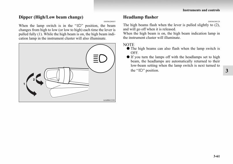
Instruments and controls
3-61
3
Dipper (High/Low beam change)E00506200055
When the lamp switch is in the “ ” position, the beamchanges from high to low (or low to high) each time the lever ispulled fully (1). While the high beam is on, the high beam indi-cation lamp in the instrument cluster will also illuminate.
Headlamp flasherE00506300128
The high beams flash when the lever is pulled slightly to (2),and will go off when it is released.When the high beam is on, the high beam indication lamp inthe instrument cluster will illuminate.
NOTE● The high beams can also flash when the lamp switch is
OFF.● If you turn the lamps off with the headlamps set to high
beam, the headlamps are automatically returned to theirlow-beam setting when the lamp switch is next turned tothe “ ” position.
BK-BK2008E1ENUK.en-uk-Section6.fm Page 61 Wednesday, January 9, 2008 4:32 PM

3-62
Instruments and controls
3
Headlamp levellingE00517400015
Headlamp levelling switch*E00517500133
Except for vehicles with discharge headlampsThe angle of the headlamp beam varies depending upon theload carried by the vehicle.The headlamp levelling dial can be used to adjust the headlampillumination distance (when the lower beam is illuminated) sothat the headlamps’ glare does not distract other drivers.Set the dial according to the following table.
NOTE● When adjusting the beam position, first put the dial in the
“0” position (the highest beam position).
CAUTION!● Always perform adjustments before driving.
Do not attempt to adjust while driving, as it couldcause an accident.
LHD
RHD
BK-BK2008E1ENUK.en-uk-Section6.fm Page 62 Wednesday, January 9, 2008 4:32 PM

Instruments and controls
3-63
3
3-door models
•:1 person:Full luggage loading
5-door models
•:1 person:Full luggage loading
Vehicle condition
Switch position “0” “0” “2” “3” “4”
Switch position 0- Driver only/Driver + 1 front passengerSwitch position 2- 5 passengers (including driver)Switch position 3- 5 passengers (including driver) + Full luggage
loadingSwitch position 4- Driver + Full luggage loading
Vehicle condition
Switch position “0” “0” “1” or
“2” “2” “3” “4”
Switch position 0- Driver only/Driver + 1 front passengerSwitch position 1- Driver + 1 front passenger + 2 passengers on
third seat (vehicles with automatic transmis-sion)
Switch position 2- Driver + 1 front passenger + 2 passengers onthird seat (vehicles with manual transmission)
Switch position 2- 7 passengers (including driver)Switch position 3- 7 passengers (including driver) + Full luggage
loadingSwitch position 4- Driver + Full luggage loading
BK-BK2008E1ENUK.en-uk-Section6.fm Page 63 Wednesday, January 9, 2008 4:32 PM
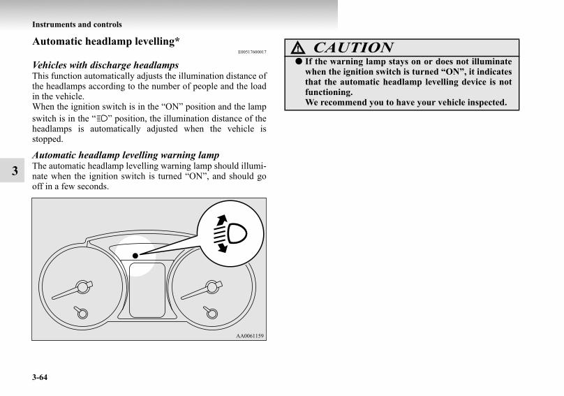
3-64
Instruments and controls
3
Automatic headlamp levelling*E00517600017
Vehicles with discharge headlampsThis function automatically adjusts the illumination distance ofthe headlamps according to the number of people and the loadin the vehicle.When the ignition switch is in the “ON” position and the lampswitch is in the “ ” position, the illumination distance of theheadlamps is automatically adjusted when the vehicle isstopped.
Automatic headlamp levelling warning lampThe automatic headlamp levelling warning lamp should illumi-nate when the ignition switch is turned “ON”, and should gooff in a few seconds.
CAUTION!● If the warning lamp stays on or does not illuminate
when the ignition switch is turned “ON”, it indicatesthat the automatic headlamp levelling device is notfunctioning.We recommend you to have your vehicle inspected.
BK-BK2008E1ENUK.en-uk-Section6.fm Page 64 Wednesday, January 9, 2008 4:32 PM

Instruments and controls
3-65
3
Turn-signal leverE00506500771
NOTE● If the lamp flashes unusually quickly, the bulb in a turn-
signal lamp may have burned out. We recommend you tohave the vehicle inspected.
● It is possible to activate the following functions. For fur-ther information, we recommend you to consult a MIT-SUBISHI MOTORS Authorized Service Point.• Sounding of a buzzer as the turn-signal lamps flash• Flashing of the turn-signal lamps when the lever is oper-
ated with the ignition switch in the “ACC” position• The turn signal-lamps 3-flash function for lane changes
can be deactivated. • The time required to operate the lever for the 3-flash
function can be adjusted.
1- Turn-signalsWhen making a normal turn, use position (1). The lever willreturn automatically when cornering is completed.
2- Lane-change signalsWhen changing lanes, use position (2). It will return to theneutral position when released.Also, when you move the lever to (2) slightly then release it,the turn-signal lamps and indication lamp in the instrumentcluster will flash 3 times.
BK-BK2008E1ENUK.en-uk-Section6.fm Page 65 Wednesday, January 9, 2008 4:32 PM

3-66
Instruments and controls
3
Hazard warning flasher switchE00506600440
Use the hazard warning flasher switch when the vehicle has tobe parked on the road for any emergency.The hazard warning flashers can always be operated, regard-less of the position of the ignition key.
Push the switch to turn on the hazard warning flashers, all turn-signal lamps flash continuously.To turn them off, push the switch again.
NOTE● It is possible for a buzzer to sound with flashing of the
turn-signal lamps. For further information, we recom-mend you to consult a MITSUBISHI MOTORS Author-ized Service Point.
Fog lamp switchE00506700047
Front fog lamp switch*E00508300281
The front fog lamps illuminate only when the headlamps or taillamps are on. Push the switch to turn on the front fog lamps,and push the switch again to turn them off.The indication lamp in the instrument cluster will illuminatewhile the front fog lamps are on.
LHD
RHD
BK-BK2008E1ENUK.en-uk-Section6.fm Page 66 Wednesday, January 9, 2008 4:32 PM

Instruments and controls
3-67
3
NOTE● The front fog lamps are automatically turned off when the
headlamps or tail lamps turn off. To turn on the front foglamps again, push the switch again when the headlamps ortail lamps turn on.
● In case of vehicles with Daytime Running Lamp, the frontfog lamp can be operated even if the lamp switch is set tothe “OFF” position.
Rear fog lamp switchE00508400123
The rear fog lamp illuminates only when the headlamps orfront fog lamps (if so equipped) are on.Push the switch to turn on the rear fog lamp, and push theswitch again to turn it off.The indication lamp in the instrument cluster will illuminatewhile the rear fog lamp is on.
Type 1
LHD
RHD
BK-BK2008E1ENUK.en-uk-Section6.fm Page 67 Wednesday, January 9, 2008 4:32 PM

3-68
Instruments and controls
3
Type 2
NOTE● The rear fog lamp is automatically turned off when the
headlamps or front fog lamps (if so equipped) turned off.To turn on the rear fog lamp again, push the switch againwhen the headlamps or front fog lamps (if so equipped)turn on.
● In case of vehicles with Daytime Running Lamp, the rearfog lamp can be operated even if the lamp switch is set tothe “OFF” position.
Wiper and washer switchE00507101191
LHD
RHD
CAUTION!● If the washer is used in cold weather, the washer
fluid sprayed against the glass may freeze, whichmay hinder visibility. Warm the glass with thedefroster or rear window demister before using thewasher.
BK-BK2008E1ENUK.en-uk-Section6.fm Page 68 Wednesday, January 9, 2008 4:32 PM

Instruments and controls
3-69
3
Windscreen wipersE00516900068
Except for vehicle with rain sensorThe windscreen wipers can be operated with the ignitionswitch in the “ON” or “ACC” position.If the blades are frozen to the windscreen or rear window, donot operate the wipers until the ice has melted and the bladesare freed, otherwise the wiper motor may be damaged.
To adjust intermittent intervalsWith the lever in the “INT” (speed-sensitive) position, theintermittent intervals can be adjusted by turning knob (A).
NOTE● The speed-sensitive-operation function of the windscreen
wipers can be deactivated.For furher information, we recommend you to consult aMITSUBISHI MOTORS Authorized Service Point.
MIST- Misting functionThe wipers will operate once.
OFF- OffINT- Intermittent (Speed sensitive)LO- SlowHI- Fast
1- Fast2- Slow
BK-BK2008E1ENUK.en-uk-Section6.fm Page 69 Wednesday, January 9, 2008 4:32 PM
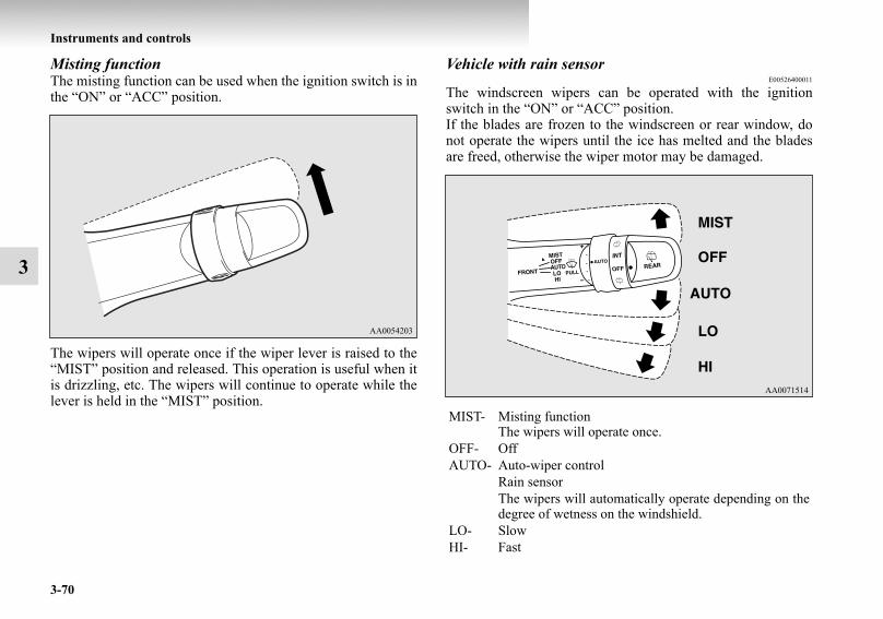
3-70
Instruments and controls
3
Misting functionThe misting function can be used when the ignition switch is inthe “ON” or “ACC” position.
The wipers will operate once if the wiper lever is raised to the“MIST” position and released. This operation is useful when itis drizzling, etc. The wipers will continue to operate while thelever is held in the “MIST” position.
Vehicle with rain sensorE00526400011
The windscreen wipers can be operated with the ignitionswitch in the “ON” or “ACC” position.If the blades are frozen to the windscreen or rear window, donot operate the wipers until the ice has melted and the bladesare freed, otherwise the wiper motor may be damaged.
MIST- Misting functionThe wipers will operate once.
OFF- OffAUTO- Auto-wiper control
Rain sensorThe wipers will automatically operate depending on thedegree of wetness on the windshield.
LO- SlowHI- Fast
BK-BK2008E1ENUK.en-uk-Section6.fm Page 70 Wednesday, January 9, 2008 4:32 PM

Instruments and controls
3-71
3
Rain sensorE00517000066
Can only be used when the ignition switch is in the “ON” posi-tion.If the lever is put in the “AUTO” position, the rain sensor (A)will detect the extent of rain (or snow, other moisture, dust,etc.) and the wipers will operate automatically.
CAUTION!● With the ignition switch in the “ON” position and
the lever in the “AUTO” position, the wipers mayautomatically operate in the situations describedbelow.If your hands get trapped, you could suffer injuriesor the wipers could malfunction. Be sure to turn theignition switch to the “OFF” position or move thelever to the “OFF” position to deactivate the rainsensor.• When cleaning the outside surface of the wind-
screen, if you touch the rain sensor.• When cleaning the outside surface of the wind-
screen, if you wipe with a cloth the rain sensor.• When using an automatic car wash.• A physical shock is applied to the windscreen.• A physical shock is applied to the rain sensor.
BK-BK2008E1ENUK.en-uk-Section6.fm Page 71 Wednesday, January 9, 2008 4:32 PM

3-72
Instruments and controls
3
NOTE● To protect the rubber parts of the wipers, this operation of
the wipers does not take place when the vehicle is station-ary and the ambient temperature is about 0 °C or lower.
● Do not cover the sensor by affixing a sticker or label to thewindscreen. Also, do not put any water-repellent coatingon the windscreen. The rain sensor would not be able todetect the extent of rain, and the wipers might stop work-ing normally.
● In the following cases, the rain sensor may be malfunc-tioning.Have the vehicle inspected by a MITSUBISHI MOTORSAuthorized Service Point.• When the wipers operate at a constant interval despite
changes in the extent of rain.• When the wipers do not operate even though it is rain-
ing.● The wipers may automatically operate when things such
as rain, dust, mud, insects, tree sap, oil or salt are affixedto the windscreen on top of the rain sensor or when thewindscreen is frozen. (Wrong operation may also occurdue to strong electromagnetic waves, etc.) Objects affixedto the windscreen will stop the wipers when the wiperscannot remove them.To make the wipers operate again, place the lever in the“LO” or “HI” position.
● Contact a MITSUBISHI MOTORS Authorized ServicePoint when replacing the windscreen or reinforcing theglass around the sensor.
To adjust the sensitivity of the rain sensorE00517100038
With the lever in the “AUTO” (rain sensor) position, it is possi-ble to adjust the sensitivity of the rain sensor by turning knob(A).
NOTE● It is possible to activate the following functions. For fur-
ther information, we recommend you to consult a MIT-SUBISHI MOTORS Authorized Service Point.• Automatic operation (rain droplet sensitive) can be
changed to intermittent operation (vehicle-speed sensi-tive).
• Automatic operation (rain droplet sensitive) can bechanged to intermittent operation (except vehicle-speedsensitive).
“+”- Higher sensitivity to rain“-”- Lower sensitivity to rain
BK-BK2008E1ENUK.en-uk-Section6.fm Page 72 Wednesday, January 9, 2008 4:32 PM

Instruments and controls
3-73
3
Misting functionE00517300030
Move the lever in the direction of the arrow and release, tooperate the wipers once.Use this function when you are driving in mist or drizzle.
The wipers will operate once if the lever is raised to the“MIST” position and released when the ignition switch is inthe “ON” or “ACC” position. The wipers will continue to oper-ate while the lever is held in the “MIST” position.
With the ignition switch in the “ON” position, if the lever ismoved to the AUTO position and pulled towards you a little,the wipers operate once.
BK-BK2008E1ENUK.en-uk-Section6.fm Page 73 Wednesday, January 9, 2008 4:32 PM

3-74
Instruments and controls
3The wipers will operate once if the lever is moved to the“AUTO” position and knob (A) is turned in the “+” directionwhen the ignition switch is “ON” position.
Windscreen washerE00507200528
The washer fluid will be sprayed onto the windscreen by pull-ing the lever toward you. The wipers operate automaticallyseveral times while the washer fluid is being sprayed.On a vehicle equipped with the headlamp washer, the head-lamp washer operates together with the windscreen washer thefirst time the windscreen washer is used if the headlamps areon.
CAUTION!● If the washer is used in cold weather, the washer
fluid sprayed against the glass may freeze resultingin poor visibility. Heat the glass with the defroster ordemister before using the washer.
BK-BK2008E1ENUK.en-uk-Section6.fm Page 74 Wednesday, January 9, 2008 4:32 PM

Instruments and controls
3-75
3
Rear window wiper and washerE00507300819
The rear window wiper and washer switch can be operatedwith the ignition switch in the “ON” or “ACC” position.
NOTE● To ensure a clear rearward view, the wiper performs sev-
eral continuous operations when the reverse gear isengaged while the switch is in the “INT” position.Following this continuous operation, the wiper will auto-matically switch to intermittent operation.
● It is possible to activate the following functions. For fur-ther information, we recommend you to consult a MIT-SUBISHI MOTORS Authorized Service Point.• Adjustment of the interval for intermittent operation• Changing intermittent wiper operation to continuous
wiper operation
INT - The wiper operates continuously for several seconds thenoperates intermittently at intervals of about every 8 sec-onds.
OFF - Off
- The washer fluid will be sprayed onto the rear windowwhen the knob is turned fully in either direction.The wipers operate automatically several times while thewasher fluid is being sprayed.
BK-BK2008E1ENUK.en-uk-Section6.fm Page 75 Wednesday, January 9, 2008 4:32 PM

3-76
Instruments and controls
3
Headlamp washer switch*E00510100231
The headlamp washer can be operated when the ignition switchis in the “ON” or “ACC” position and the headlamps are on.Push the button once and the washer fluid will be sprayed on tothe headlamps.
NOTE● If the ignition switch is in the “ON” or “ACC” position
and the headlamps are on, the headlamp washer operatestogether with the windscreen washer the first time thewindscreen washer lever is pulled.
Precautions to observe when using wipers and washers
E00507600027
● If the moving wipers become blocked by ice or otherdeposits on the glass, the motor may burn out even if thewiper switch is turned to OFF. If obstruction occurs, parkyour vehicle in a safe place, turn off the ignition, andclean the deposits from the glass so that the wipers operatesmoothly.
● Do not use the wipers when the glass is dry. They mayscratch the glass surface and the blades wear out prema-turely.
● Before using the wipers in cold weather, check that thewiper blades are not frozen onto the glass. The motor mayburn out if the wipers are used with the blades frozen ontothe glass.
● Avoid using the washer continuously for more than 20seconds. Do not operate the washer when the fluid reser-voir is empty.Otherwise, the motor may burn out.
● Periodically check the level of washer fluid in the reser-voir and refill if required.During cold weather, add a recommended washer solutionthat will not freeze in the washer reservoir. Failure to doso could result in loss of washer function and frost dam-age to the system components.
BK-BK2008E1ENUK.en-uk-Section6.fm Page 76 Wednesday, January 9, 2008 4:32 PM

Instruments and controls
3-77
3
Wiper deicer switch*E00507700060
The wiper deicer switch can be operated with the ignitionswitch in the “ON” position.When the front wipers have frozen to the windscreen at theparked positions, turning on this switch will heat the wind-screen to make the wipers operable. Press the switch and thedeicer will operate and turn on the indication lamp (A).
NOTE● The switch is automatically turned off after operating for
approximately 20 minutes. To turn off the switch while itis operating, press the switch again.
Rear window demister switchE00507900844
The rear window demister switch can be operated with theignition switch in the “ON” position.Push the switch to turn on the rear window demister. It will beturned off automatically in about 20 minutes. To turn off thedemister within 20 minutes, push the switch again.The indication lamp (A) will illuminate while the demister ison.
BK-BK2008E1ENUK.en-uk-Section6.fm Page 77 Wednesday, January 9, 2008 4:32 PM

3-78
Instruments and controls
3
NOTE● When the rear window demister switch is pushed, the
window glass becomes warm and the wipers becomeoperable.Refer to “Wiper deicer switch” on page 3-77.
● If your vehicle is equipped with heated mirrors, when therear window demister switch is pressed, the outside rear-view mirrors are defogged or defrosted. Refer to “Heatedmirror” on page 4-14.
● The demister switch is not to melt snow but to clear mist.Remove snow before use of the demister switch.
● To avoid unnecessary discharge of the battery, do not usethe rear window demister during starting of the engine orwhen the engine is not running. Turn the demister offimmediately after the window is clear.
● When cleaning the inside of the rear window, use a softcloth and wipe gently along the heater wires, being carefulnot to damage the wires.
● Do not allow objects to touch the inside of the rear win-dow glass, damaged or broken wires may result.
Horn switchE00508000347
Press the steering wheel on or around the “ ” mark.
BK-BK2008E1ENUK.en-uk-Section6.fm Page 78 Wednesday, January 9, 2008 4:32 PM

4
Starting and driving
Economical driving . . . . . . . . . . . . . . . . . . . . . . . .4- 2Driving, alcohol and drugs. . . . . . . . . . . . . . . . . . .4- 3Safe driving techniques . . . . . . . . . . . . . . . . . . . . .4- 3Running-in recommendations . . . . . . . . . . . . . . . .4- 5Parking brake . . . . . . . . . . . . . . . . . . . . . . . . . . . . .4- 6Parking . . . . . . . . . . . . . . . . . . . . . . . . . . . . . . . . . .4- 7Steering wheel height adjustment . . . . . . . . . . . . .4- 8Inside rear-view mirror . . . . . . . . . . . . . . . . . . . . .4- 9Outside rear-view mirrors . . . . . . . . . . . . . . . . . . .4- 11Ignition switch . . . . . . . . . . . . . . . . . . . . . . . . . . . .4- 14Steering wheel lock . . . . . . . . . . . . . . . . . . . . . . . .4- 18Starting . . . . . . . . . . . . . . . . . . . . . . . . . . . . . . . . . .4- 18Diesel particulate filter (DPF)* . . . . . . . . . . . . . . .4- 22Manual transmission . . . . . . . . . . . . . . . . . . . . . . .4- 23Automatic transmission INVECS-II Sports
Mode 5A/T (Intelligent & Innovative Vehicle Electronic Control System II) . . . . . . . .4- 25
Super select 4WD II (SS4 II) . . . . . . . . . . . . . . . . .4- 34Rear differential lock* . . . . . . . . . . . . . . . . . . . . . .4- 424-wheel drive operation . . . . . . . . . . . . . . . . . . . . .4- 48Inspection and maintenance following rough
road operation . . . . . . . . . . . . . . . . . . . . . . . . . . .4- 53Cautions on handling of 4-wheel drive vehicles . .4- 53
Braking . . . . . . . . . . . . . . . . . . . . . . . . . . . . . . . . . 4- 56Anti-lock brake system (ABS) . . . . . . . . . . . . . . . 4- 58Power steering system. . . . . . . . . . . . . . . . . . . . . . 4- 63Active stability & traction control (ASTC). . . . . . 4- 63Cruise control* . . . . . . . . . . . . . . . . . . . . . . . . . . . 4- 70Reversing sensor system* . . . . . . . . . . . . . . . . . . . 4- 78Rear-view camera* . . . . . . . . . . . . . . . . . . . . . . . . 4- 84Cargo loads . . . . . . . . . . . . . . . . . . . . . . . . . . . . . . 4- 88Trailer towing . . . . . . . . . . . . . . . . . . . . . . . . . . . . 4- 90
BK-BK2008E1ENUK.en-uk-Section7.fm Page 1 Wednesday, January 9, 2008 4:36 PM

4-2
Starting and driving
4
Economical drivingE00600100561
For economical driving, there are some technical requirementsthat have to be met. The prerequisite for low fuel consumptionis a properly adjusted engine. In order to achieve longer life ofthe vehicle and the most economical operation, we recommendyou to have the vehicle checked at regular intervals in accord-ance with the service standards.Fuel economy and generation of exhaust gas and noise arehighly influenced by personal driving habits as well as the par-ticular operating conditions. The following points should beobserved in order to minimize wear of brakes, tyres and engineas well as to reduce environmental pollution.
StartingAvoid rapid acceleration and sudden starts; such operation willresult in higher fuel consumption.
ShiftingShift only at an appropriate speed and engine speed. Alwaysuse the highest gear possible.The transfer shift lever should be set to “2H” when driving onnormal roads and express ways to obtain best possible fueleconomy.
City trafficFrequent starting and stopping increases the average fuel con-sumption. Use roads with smooth traffic flow whenever possi-ble. When driving on congested roads, avoid use of a low gearat high engine speeds.
IdlingThe vehicle consumes fuel even during idling. Avoid extendedidling whenever possible.
SpeedAt higher vehicle speed, more fuel is consumed. Avoid drivingat full speed. Even a slight release of the accelerator pedal willsave a significant amount of fuel.
Tyre inflation pressureCheck the tyre inflation pressures at regular intervals. Low tyreinflation pressure increases road resistance and fuel consump-tion. In addition, low tyre pressures adversely affect tyre wearand driving stability.
LoadDo not drive with unnecessary articles in the luggage compart-ment. Especially during city driving where frequent startingand stopping is necessary, the increased weight of the vehiclewill greatly affect fuel consumption. Also avoid driving withunnecessary luggage or carriers, etc., on the roof; the increasedair resistance will increase fuel consumption.
Cold engine startingStarting of a cold engine consumes more fuel.Unnecessary fuel consumption is also caused by keeping a hotengine running. After the engine is started, commence drivingas soon as possible.
Air conditioningThe use of the air conditioning will increase the fuel consump-tion.
BK-BK2008E1ENUK.en-uk-Section7.fm Page 2 Wednesday, January 9, 2008 4:36 PM

Starting and driving
4-3
4
Driving, alcohol and drugsE00600200067
Driving after drinking alcohol is one of the most frequentcauses of accidents.Your driving ability can be seriously impaired even with bloodalcohol levels far below the legal minimum. If you have beendrinking, don’t drive. Ride with a designated non-drinkingdriver, call a cab or a friend, or use public transportation.Drinking coffee or taking a cold shower will not make yousober.Similarly, prescription and nonprescription drugs affect youralertness, perception and reaction time. Consult with your doc-tor or pharmacist before driving while under the influence ofany of these medications.
Safe driving techniquesE00600300244
Driving safety and protection against injury cannot be fullyensured. However, we recommend that you pay extra attentionto the following:
Seat beltsBefore starting the vehicle, make sure that you and your pas-sengers have fastened your seat belts.
WARNING!● NEVER DRINK AND DRIVE.
Your perceptions are less accurate, your reflexes areslower and your judgment is impaired.
BK-BK2008E1ENUK.en-uk-Section7.fm Page 3 Wednesday, January 9, 2008 4:36 PM

4-4
Starting and driving
4
Floor mats Carrying children in the vehicle● Never leave your vehicle unattended with the key in the
ignition and children inside the vehicle. Children mayplay with the driving controls and this could lead to anaccident.
● Make sure that infants and small children are properlyrestrained in accordance with the laws and regulations,and for maximum protection in case of an accident.
● Prevent children from playing in the luggage compart-ment. It is quite dangerous to allow them to play therewhile the vehicle is moving.
Loading luggageWhen loading luggage, be careful not to load above the heightof seats. This is dangerous not only because rearward visionwill be obstructed, but also the luggage may be projected intothe passenger compartment under hard braking.
WARNING!● Keep floor mats clear of the pedals by correctly lay-
ing floor mats that are suitable for the vehicle.To prevent the floor mats from slipping out of posi-tion, securely retain them using the hook etc.Note that laying a floor mat over a pedal or layingone floor mat on top of another can obstruct pedaloperation and lead to a serious accident.
BK-BK2008E1ENUK.en-uk-Section7.fm Page 4 Wednesday, January 9, 2008 4:36 PM
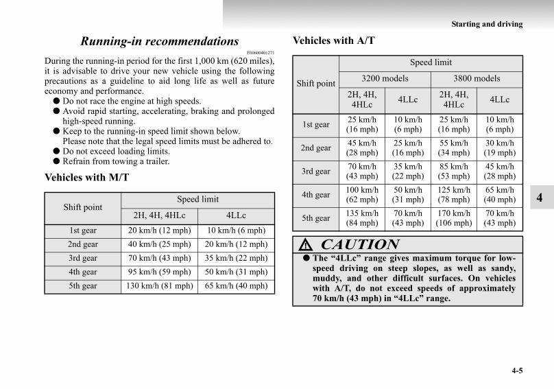
Starting and driving
4-5
4
Running-in recommendationsE00600401271
During the running-in period for the first 1,000 km (620 miles),it is advisable to drive your new vehicle using the followingprecautions as a guideline to aid long life as well as futureeconomy and performance.
● Do not race the engine at high speeds.● Avoid rapid starting, accelerating, braking and prolonged
high-speed running.● Keep to the running-in speed limit shown below.
Please note that the legal speed limits must be adhered to.● Do not exceed loading limits.● Refrain from towing a trailer.
Vehicles with M/T
Vehicles with A/T
Shift pointSpeed limit
2H, 4H, 4HLc 4LLc1st gear 20 km/h (12 mph) 10 km/h (6 mph)2nd gear 40 km/h (25 mph) 20 km/h (12 mph)3rd gear 70 km/h (43 mph) 35 km/h (22 mph)4th gear 95 km/h (59 mph) 50 km/h (31 mph)5th gear 130 km/h (81 mph) 65 km/h (40 mph)
Shift point
Speed limit
3200 models 3800 models
2H, 4H, 4HLc 4LLc 2H, 4H,
4HLc 4LLc
1st gear 25 km/h (16 mph)
10 km/h (6 mph)
25 km/h (16 mph)
10 km/h (6 mph)
2nd gear 45 km/h (28 mph)
25 km/h (16 mph)
55 km/h (34 mph)
30 km/h (19 mph)
3rd gear 70 km/h (43 mph)
35 km/h (22 mph)
85 km/h (53 mph)
45 km/h (28 mph)
4th gear 100 km/h (62 mph)
50 km/h (31 mph)
125 km/h (78 mph)
65 km/h (40 mph)
5th gear 135 km/h (84 mph)
70 km/h (43 mph)
170 km/h (106 mph)
70 km/h (43 mph)
CAUTION!● The “4LLc” range gives maximum torque for low-
speed driving on steep slopes, as well as sandy,muddy, and other difficult surfaces. On vehicleswith A/T, do not exceed speeds of approximately70 km/h (43 mph) in “4LLc” range.
BK-BK2008E1ENUK.en-uk-Section7.fm Page 5 Wednesday, January 9, 2008 4:36 PM

4-6
Starting and driving
4
Parking brakeE00600500422
To park the vehicle, first bring it to a complete stop, fully applythe parking brake lever sufficiently to hold the vehicle.
To apply the parking brake
NOTE● Apply sufficient force to the parking brake lever to hold
the vehicle stationary after the foot brake is released.● If the parking brake does not hold the vehicle stationary
after the foot brake is released, have your vehicle checkedimmediately.
To release the parking brake
1- Pull the lever up without pushing the button at the end ofhand grip.
1- Pull the lever up slightly.2- Push the button at the end of hand grip.3- Push the lever downward.
BK-BK2008E1ENUK.en-uk-Section7.fm Page 6 Wednesday, January 9, 2008 4:36 PM

Starting and driving
4-7
4
ParkingE00600600595
To park the vehicle, fully engage the parking brake, and thenmove the gearshift lever to the 1st or “R” (Reverse) positionfor vehicles with M/T, or set the selector lever to the “P”(PARK) position on A/T vehicles.
Parking on a hillTo prevent the vehicle from rolling, follow these procedures:
Parking on a downhill slopeTurn the front wheels toward the kerb and move the vehicleforward until the kerb side wheel gently touches the kerb.Apply the parking brake and place the gearshift lever into the“R” (Reverse) position (with M/T) or the selector lever into the“P” (PARK) position (with A/T).If necessary, apply chocks to wheels.
Parking on an uphill slopeTurn the front wheels away from the kerb and move the vehicleback until the kerb side wheel gently touches the kerb.Apply the parking brake and place the gearshift lever into the1st position (with M/T) or the selector lever into the “P”(PARK) position (with A/T).If necessary, apply chocks to wheels.
CAUTION!● Before driving, be sure that the parking brake is
fully released and brake warning lamp is off.If a vehicle is driven without releasing the parkingbrake, the brake will be overheated, resulting inineffective braking and possible brake failure.
● When you intend to apply the parking brake, firmlypress the brake pedal to bring the vehicle to a com-plete stop before pulling the parking brake lever.Pulling the parking brake lever with the vehiclemoving could make the rear wheels lock up, therebymaking the vehicle unstable. It could also cause theparking brake to malfunction.
● If the brake warning lamp does not extinguish whenthe parking brake is fully released, the brake systemmay be abnormal.Have your vehicle checked immediately.For details, refer to “Brake warning lamp” on page3-13.
BK-BK2008E1ENUK.en-uk-Section7.fm Page 7 Wednesday, January 9, 2008 4:36 PM

4-8
Starting and driving
4
NOTE● If your vehicle is equipped with A/T, be sure to apply the
parking brake before moving the selector lever to the “P”(PARK) position. If you move the selector lever to the “P”(PARK) position before applying the parking brake, itmay be difficult to disengage the selector lever from the“P” (PARK) position when next you drive the vehicle,requiring application of a strong force to the selector leverto move from the “P” (PARK) position.
Parking with the engine runningNever leave the engine running while you take a shortsleep/rest or while you open or close a gate or garage door, etc.Also, never leave the engine running in a closed or poorly ven-tilated place. Leaving the engine running risks injury or deathfrom accidentally moving the gearshift lever (on M/T vehicles)or the selector lever (on A/T vehicles) or the accumulation oftoxic exhaust fumes in the passenger compartment.
Where you park
When leaving the vehicleAlways remove the key from the ignition switch and lock alldoors (including the backdoor) when leaving the vehicle unat-tended.Always try to park your vehicle in a well lit area.
Steering wheel height adjustmentE00600700222
1. Release the tilt lock lever while holding the steering wheelup.
2. Adjust the steering wheel to the desired height.3. Securely lock the steering wheel by pulling the tilt lock
lever fully upward.
WARNING!● Do not park your vehicle in areas where combustible
materials such as dry grass or leaves can come incontact with a hot exhaust, since a fire could occur.
A- LockedB- Release
WARNING!● Do not attempt to adjust the steering wheel while
you are driving the vehicle.
BK-BK2008E1ENUK.en-uk-Section7.fm Page 8 Wednesday, January 9, 2008 4:36 PM

Starting and driving
4-9
4
Inside rear-view mirrorE00600800148
Adjust the rear-view mirror only after making any seat adjust-ments so you have a clear view to the rear of the vehicle.
Adjust the rear-view mirror to maximize the view through therear window.
To adjust the vertical mirror positionIt is possible to move the mirror up and down to adjust its posi-tion.
WARNING!● Do not attempt to adjust the rear-view mirror while
driving. This can be dangerous.Always adjust the mirror before driving.
Type 1
Type 2
BK-BK2008E1ENUK.en-uk-Section7.fm Page 9 Wednesday, January 9, 2008 4:36 PM

4-10
Starting and driving
4
To reduce the glareType 1The lever (A) at the bottom of the mirror can be used to adjustthe mirror to reduce the glare from the headlamps of vehiclesbehind you during night driving.
Type 2When the headlamps of the vehicles behind you are verybright, the reflection factor of the rear-view mirror is automati-cally changed to reduce the glare.
Normally, use the automatic mode. When the switch (1) ispressed, the indicator (2) illuminates and the reflection factorof the mirror is automatically changed.
NOTE● Do not hang items on, or spray glass cleaner on the sensor
(3), as reduced sensitivity could result.
1- Normal2- Anti-glare
BK-BK2008E1ENUK.en-uk-Section7.fm Page 10 Wednesday, January 9, 2008 4:36 PM

Starting and driving
4-11
4
Outside rear-view mirrorsE00600900484
Compound curved-surface mirror*On the driver’s side, a compound curved-surface mirror isused, while on the front passenger’s side, a single curved-sur-face mirror is used.
While the single curved-surface mirror has a fixed curvature,the compound curved-surface mirror has different curvaturesbetween the inner and outer sides of the boundary line (A).The inner side of the boundary line provides the same vision asthat available from an ordinary door mirror.However, the outer side of the boundary line provides a widerangle of vision compared to an ordinary door mirror.
To adjust the mirror positionE00601000105
The outside rear-view mirrors can be operated when the igni-tion switch is in the “ON” or “ACC” position.
1- Compound curved-surface mirror2- Single curved-surface mirror
WARNING!● The sense of distance that you get from an object
you see on the inner side of the mirror boundary linediffers from the sense of distance that you get froman object you see on the outer side.An object you see on the outer side of the boundaryline of the mirror will look farther away than actu-ally is as compared with an object you see on theinner side.
WARNING!● Do not attempt to adjust the rear-view mirrors while
driving. This can be dangerous.Always adjust the mirrors before driving.
● Your vehicle is equipped with convex type mirrors.Please take into consideration, that objects you seein the mirror will look smaller and farther awaycompared to a normal flat mirror.Do not use this mirror to estimate distance of follow-ing vehicles when changing lanes.
BK-BK2008E1ENUK.en-uk-Section7.fm Page 11 Wednesday, January 9, 2008 4:36 PM

4-12
Starting and driving
4
1. Place the lever (A) to the same side as the mirror whoseadjustment is desired.
2. Press the switch (B) to the left, right, up or down to adjustthe mirror position.
3. Return the lever (A) back to the middle position (•).
Retracting and extending the outside mirrorsE00618200011
The outside mirrors can be folded in towards the side windowto prevent damage when parking in narrow areas.
L- Left outside mirror adjustmentR- Right outside mirror adjustment
1- Up2- Down3- Right4- Left
CAUTION!● Do not drive the vehicle with the mirror folded in.
The lack of rearward visibility normally providedthe mirror could lead to an accident.
BK-BK2008E1ENUK.en-uk-Section7.fm Page 12 Wednesday, January 9, 2008 4:36 PM

Starting and driving
4-13
4
Retracting and extending the mirrors using the mirror retractor switchWith the ignition switch in the “ON” or “ACC” position, pushthe mirror retractor switch to retract the mirrors. Push it againto extend the mirrors to their original positions.After placing the ignition switch in the “LOCK” position, it ispossible to retract and extend the mirrors using the mirrorretractor switch for about 30 seconds.
NOTE● Be careful not to get your hands trapped while a mirror is
moving.● If you move a mirror by hand or it moves after hitting a
person or object, you may not be able to return it to itsoriginal position using the mirror retractor switch. If thishappens, push the mirror retractor switch to place the mir-ror in its retracted position and then push the switch againto return the mirror to its original position.
● If the battery voltage is low and you start the engine whileextending the mirrors, the mirrors may stop part-way. Ifthis happens, push the mirror retractor switch to retract themirrors and then push the switch again to extend them.
● When freezing has occurred and mirrors fail to operate asintended, please refrain from repeated pushing of theretractor switch as this action can result in burn-out of themirror motor circuits.
CAUTION!● It is possible to retract and extend the mirrors by
hand. After retracting a mirror using the mirrorretractor switch, however, you should extend it byusing the switch again, not by hand. If you extendedthe mirror by hand after retracting it using theswitch, it would not properly lock in position. As aresult, it could move because of the wind or vibra-tion while you are driving, taking away your rear-ward visibility.
BK-BK2008E1ENUK.en-uk-Section7.fm Page 13 Wednesday, January 9, 2008 4:36 PM

4-14
Starting and driving
4
Automatic extension of mirrorsIf the engine is stopped and started with the mirrors retracted,the mirrors automatically extend for safety when the vehiclespeed reaches 30 km/h (19 mph).
Heated mirror*E00601200312
To demist or defrost the outside rear-view mirrors, press therear window demister switch.The indication lamp (C) will illuminate while the demister ison.The heater will be turned off automatically in about20 minutes.
Ignition switchE00601400822
LOCKThe engine is stopped and the steering wheel locked. The keycan only be inserted and removed in this position.
ACCThe engine is stopped, but the electrical devices such as theradio and cigarette lighter can be operated.
ONThe engine is running, and all the vehicle’s electrical devicescan be operated.
STARTThe starter motor operates. After the engine has started, releasethe key and it will automatically return to the “ON” position.
Vehicles with M/T Vehicles with A/T
BK-BK2008E1ENUK.en-uk-Section7.fm Page 14 Wednesday, January 9, 2008 4:36 PM

Starting and driving
4-15
4
NOTE● For vehicles equipped with Daytime Running Lamps,
when the ignition switch is in the “ON” position, theheadlamp low beams etc. are turned on.Refer to “Headlamps” on page 3-58.
● Your vehicle is equipped with an electronic immobilizer.To start the engine, the ID code which the transponderinside the key sends must match the one registered to theimmobilizer computer.Refer to “Electronic immobilizer” on page 1-3.
Ignition switch illuminationIn the situations listed below, the ignition switch illuminationcomes on to facilitate insertion or removal of the ignition key.
● When any door or the backdoor is opened, the ignitionswitch illumination comes on. When it is closed, the igni-tion switch illumination becomes steadily dimmer untilcompletely going off about 15 seconds later.
● When the ignition key is removed with all the doors andthe backdoor closed, the ignition switch illuminationcomes on and stays on for about 15 seconds.
The ignition switch illumination immediately goes off if any ofthe following actions is taken while it is on.
● All the doors and the backdoor are closed, and the ignitionswitch is turned to the “ON” position.
● All the doors and the backdoor are locked using the cen-tral door locking function.
● All the doors and the backdoor are locked using the key-less entry system (if so equipped).
BK-BK2008E1ENUK.en-uk-Section7.fm Page 15 Wednesday, January 9, 2008 4:36 PM

4-16
Starting and driving
4
NOTE● It is possible to adjust the period of ignition switch illumi-
nation (the period until the ignition switch illuminationgoes off). For details, we recommend you to consult aMITSUBISHI MOTORS Authorized Service Point.
● If the illumination period of the room & map lamps or rearpersonal lamps (the period until these lamps go off) isadjusted, the period of ignition switch illumination (theperiod until the ignition switch illumination goes off) willautomatically be changed at the same time.If the illumination period of the room & map lamps or rearpersonal lamps is set to zero (in other words, the illumina-tion keep-on function is deactivated), the ignition switchillumination will not come on when the ignition switch isremoved.For information, we recommend you to consult a MIT-SUBISHI MOTORS Authorized Service Point.
To remove the keyFor vehicles with a M/T, when removing the key, push the keyin at the “ACC” position and keep it depressed until it is turnedto the “LOCK” position, and remove it.
Vehicles with M/T
BK-BK2008E1ENUK.en-uk-Section7.fm Page 16 Wednesday, January 9, 2008 4:36 PM

Starting and driving
4-17
4
For vehicles with an A/T, when removing the key, first set theselector lever to the “P” (PARK) position, and then turn the keyto the “LOCK” position, and remove it.
Vehicles with A/T
CAUTION!● Do not remove the ignition key from the ignition
switch while driving. The steering wheel will belocked, causing loss of control.
● If the engine is stopped while driving, the brake ser-vomechanism will cease to function and brakingefficiency will deteriorate. Also, the power steeringsystem will not function and it will require greatermanual effort to operate the steering.
● Do not leave the key in the “ON” position for a longtime when the engine is not running, doing so willcause the battery to be discharged.
● Do not turn the key to the “START” position whenthe engine is running, doing so could damage thestarter motor.
BK-BK2008E1ENUK.en-uk-Section7.fm Page 17 Wednesday, January 9, 2008 4:36 PM

4-18
Starting and driving
4
Steering wheel lockE00601500298
To lockRemove the key at the “LOCK” position.Turn the steering wheel until it is locked.
To unlockTurn the key to the “ACC” position while moving the steeringwheel slightly right and left.
StartingE00601600488
Tips for starting● Do not continuously operate the starter motor longer than
10 seconds; doing so could run down the battery. If theengine does not start, turn the ignition switch back to“LOCK” position, wait a few seconds, and then try again.Trying repeatedly with the starter motor still turning willdamage the starter mechanism.
CAUTION!● Remove the key when leaving the vehicle.
In some countries, it is prohibited to leave the key onthe vehicle when parked.
WARNING!● Never run the engine in a closed or poorly ventilated
area any longer than is needed to move your vehiclein or out of the area. Carbon monoxide gases areodourless and can be fatal.
CAUTION!● Never attempt to start the engine by pushing or pull-
ing the vehicle.● Do not run the engine at high rpm or drive the vehi-
cle at high speed until the engine has had chance towarm up.
● Release the ignition key as soon as the engine startsto avoid damaging the starter motor.
● If your vehicle is equipped with a turbocharger, donot stop the engine immediately after high-speed oruphill driving. First allow the engine to idle to givethe turbocharger a chance to cool down.
BK-BK2008E1ENUK.en-uk-Section7.fm Page 18 Wednesday, January 9, 2008 4:36 PM

Starting and driving
4-19
4
Starting the engine (petrol-powered vehicles)E00601701297
Normal conditionsThe starting procedure is as follows:
1. Insert the ignition key and fasten the seat belt.2. Make sure the parking brake is applied.3. Depress and hold the brake pedal.4. Make sure the selector lever is in the “P” (PARK) posi-
tion.
5. After turning the ignition key to the “ON” position, makecertain that all warning lamps are functioning properlybefore starting the engine.
6. Turn the ignition key to the “START” position withoutdepressing the accelerator pedal, and release it when theengine starts.
NOTE● A ticking noise may be heard after starting the engine.
This is not an abnormal condition. The noise will disap-pear after a short time of engine running.If the ticking noise continues after the engine is warmedup, we recommend you to have your vehicle checked.
BK-BK2008E1ENUK.en-uk-Section7.fm Page 19 Wednesday, January 9, 2008 4:36 PM

4-20
Starting and driving
4
At extreme cold ambient temperatureIf the engine won’t start, depress the accelerator pedal abouthalfway while cranking the engine. Once the engine starts,release the accelerator pedal.
Flooded engineIf the engine was flooded during starting, first operate thestarter for 5 to 6 seconds while fully depressing the acceleratorpedal, then start the engine without depressing the acceleratorpedal.
Using the MIVEC engineThe MIVEC engine automatically switches its intake-valvecontrol between a low-speed mode and a high-speed mode inaccordance with driving conditions for maximum engine per-formance.
NOTE● To protect the engine, the high-speed mode may not be
selected while the engine coolant temperature is low. Insuch a case, the engine revolutions do not rise to over5,000 rpm even if the accelerator pedal is depressed.
Starting the engine (diesel-powered vehicles)E00601800086
1. Insert the ignition key and fasten the seat belt.2. Make sure the parking brake is applied.3. Depress and hold the brake pedal.4. Fully depress the clutch pedal (M/T).5. On vehicles with M/T, place the gearshift lever in the “N”
(Neutral) position.On vehicles with A/T, make sure the selector lever is inthe “P” (PARK) position.
6. Turn the ignition key to the “ON” position.The diesel preheat indication lamp will first illuminate,and then after a short time go out, indicating that preheat-ing is completed.
CAUTION!● When starting the engine, make sure that you press
on the brake pedal. At extreme cold ambient tem-perature move your foot to the brake pedal immedi-ately after the engine has started.
Vehicles with M/T Vehicles with A/T
BK-BK2008E1ENUK.en-uk-Section7.fm Page 20 Wednesday, January 9, 2008 4:36 PM

Starting and driving
4-21
4
NOTE● If the engine is cold, the diesel preheat indication lamp is
on for a longer time.● When the engine has not been started within about 5 sec-
onds after the diesel preheat indication lamp went out,return the ignition key to the “LOCK” position. Then, turnthe key to the “ON” position to preheat the engine again.
● When the engine is warm, the diesel preheat indicationlamp does not come on even if the ignition key is placedin the “ON” position.Start the engine by turning the ignition key right to the“START” position.
7. Turn the ignition key to the “START” position withoutdepressing the accelerator pedal, and release it when theengine starts.
Fuel injection amount learning process (diesel-powered vehicles)
E00616000044
To keep exhaust emissions and engine noise low, the enginevery occasionally performs a learning process for the fuelinjection amount.The engine sounds slightly different from usual while thelearning process is taking place. The change in the enginesound does not indicate a fault.
BK-BK2008E1ENUK.en-uk-Section7.fm Page 21 Wednesday, January 9, 2008 4:36 PM

4-22
Starting and driving
4
Diesel particulate filter (DPF)*E00619800027
The diesel particulate filter (DPF) is a device that capturesmost of the particulate matter (PM) in the exhaust emissions ofthe diesel engine. The DPF automatically burns away trappedPM during vehicle operation. Under certain driving conditions,however, the DPF is not able to burn away all of the trappedPM and, as a result, an excessive amount of PM accumulatesinside it.
NOTE● To minimize the likelihood of excessive accumulation of
PM, try to avoid driving for long periods at low speedsand repeatedly driving short distances.
DPF warning lampThe DPF warning lamp comes on or flashes in the event of anabnormality in the DPF system. Provided the DPF system isworking normally, the DPF warning lamp comes on when theignition switch is turned to the “ON” position and goes off afew seconds later.
WARNING!● The DPF reaches very high temperatures. Do not
park your vehicle in areas where combustible mate-rials such as dry grass or leaves can come in contactwith a hot exhaust system since a fire could occur.
CAUTION!● Do not use any type of fuel or engine oil that is not
specified for your vehicle. Also, do not use any mois-ture-removing agent or other fuel additive. Suchsubstances could have a detrimental effect on theDPF.Refer to “Fuel selection” on page 2 and “Engine oil”on page 8-6.
BK-BK2008E1ENUK.en-uk-Section7.fm Page 22 Wednesday, January 9, 2008 4:36 PM

Starting and driving
4-23
4
If the DPF warning lamp comes on during vehicle operationSteady illumination of the DPF warning lamp shows that theDPF has not been able to burn away all of the trapped PM andthat, as a result, an excessive amount of PM has accumulatedinside it. To enable the DPF to burn away the PM, try to drivethe vehicle as follows:
● With the needle of the water temperature gauge stabilizedin roughly the middle of the scale, drive for about 20 min-utes at a speed of at least 40 km/h (25 mph).
If the DPF warning lamp subsequently stays on, contact yourMITSUBISHI MOTORS Authorized Service Point.
If the DPF warning lamp flashes during vehicle operationFlashing of the DPF warning lamp indicates an abnormality inthe DPF system. Have the system inspected by a MITSUBISHIMOTORS Authorized Service Point.
Manual transmissionE00602000072
The shift pattern is shown on the gearshift lever knob. Be sureto always fully depress the clutch pedal before attempting toshift the lever.
CAUTION!● You do not have to continuously drive exactly as
indicated above. Always strive to drive safely inaccordance with road conditions.
CAUTION!● Continuing to drive with the DPF warning lamp
flashing could result in engine trouble and DPFdamage.
CAUTION!● Do not move the gearshift lever into reverse while
the vehicle is moving forward; doing so will damagethe transmission.
● Do not rest your foot on the clutch pedal while driv-ing as this will cause premature clutch wear or dam-age.
BK-BK2008E1ENUK.en-uk-Section7.fm Page 23 Wednesday, January 9, 2008 4:36 PM

4-24
Starting and driving
4 NOTE● If it is hard to shift into 1st, depress the clutch pedal again;
the shift will then be easier to make.● To shift into reverse from the 5th gear, move the gearshift
lever to the “N” (Neutral) position, and then shift it intoreverse.
Possible driving speedE00610800574
Avoid shifting down at high speed, as this may cause excessiveengine speed (the tachometer needle into the red zone) anddamage the engine.
5th gear is an overdrive ratio and its use reduces engine speedbelow that of the 4th gear. Use 5th gear whenever vehiclespeed allows, for maximum fuel economy.
● If the clutch is engaged suddenly while the enginerevolution is high, an extremely large load will beapplied instantaneously to the power train, possiblyleading to the breakage of that component. Pleaseensure, therefore, that the clutch pedal is alwaysapplied in a slow yet firm manner.Your vehicle has a special feature to protect thepower train from damage; the engine is controlled insuch a way that excessive increase in engine revolu-tion is prevented in situations where the acceleratorpedal is depressed while the gearshift lever is in the1st position and the clutch pedal has been depressed.
CAUTION!
Shift pointSpeed limit
2H, 4H, 4HLc 4LLc
1st gear 35 km/h (22 mph) 15 km/h (9 mph)2nd gear 65 km/h (40 mph) 35 km/h (22 mph)3rd gear 105 km/h (65 mph) 55 km/h (34 mph)4th gear 145 km/h (90 mph) 75 km/h (47 mph)
BK-BK2008E1ENUK.en-uk-Section7.fm Page 24 Wednesday, January 9, 2008 4:36 PM

Starting and driving
4-25
4
Automatic transmission INVECS-II Sports Mode 5A/T (Intelligent & Innovative Vehi-
cle Electronic Control System II)E00603200101
Designed for optimum control and equipped with adaptive con-trol capabilities, the electronically controlled transmission opti-mally matches gear shifts to almost all driving and roadconditions.
NOTE● During running-in period or immediately after reconnec-
tion of the battery cable, there may be a case where gearshifts are not made smoothly. This does not indicate afaulty transmission.Gear shifts will become smooth after the transmission hasbeen shifted several times by the electronic control sys-tem.
Selector lever operationE00603300522
The transmission has 5 forward gears and 1 reverse gear.The individual gears are selected automatically, depending onthe position of the gear selector lever, the speed of the vehicleand the position of the accelerator pedal.The selector lever has 2 gates; the main gate (1) and the manualgate (2).
CAUTION!● This system is strictly intended to provide supple-
mentary functions. When travelling downhill undercertain conditions or immediately after starting offwhen the automatic transmission is cold, no auto-matic shiftdown may be made. The driver shouldshiftdown to a lower gear to use engine braking. Tryto drive safely at all time.
BK-BK2008E1ENUK.en-uk-Section7.fm Page 25 Wednesday, January 9, 2008 4:36 PM

4-26
Starting and driving
4
In the main gate, selector lever has 4 positions, and is equippedwith a lock button (A) to avoid inadvertent selection of thewrong gear.
The lock button must be pushed while the brake pedal is depressed to move the selector lever.The lock button must be pushed to move the selector lever.The lock button need not be pushed to move the selector lever.
WARNING!● If the lock button is always pushed to operate the
selector lever, the lever may be accidentally shiftedinto the “P” (PARK) or “R” (REVERSE) position.Be sure not to push the lock button when perform-ing the operations indicated by in the illustration.
BK-BK2008E1ENUK.en-uk-Section7.fm Page 26 Wednesday, January 9, 2008 4:36 PM

Starting and driving
4-27
4
NOTE● If the brake pedal is not depressed and held, the shift-lock
device activates to prevent the selector lever from beingmoved from the “P” (PARK) position.
Selector lever position indication lampsE00603500247
When the ignition switch is turned to the “ON” position, theindication lamps in the instrument panel illuminate to show theposition of the selector lever (i.e. “PARK”, “DRIVE”,“REVERSE”, etc.).
● Always depress the brake pedal when shifting theselector lever into a gear from the “P” (PARK) or“N” (NEUTRAL) position.Never put your foot on the accelerator pedal whileshifting the selector lever from the “P” (PARK) or“N” (NEUTRAL) position.
WARNING!
BK-BK2008E1ENUK.en-uk-Section7.fm Page 27 Wednesday, January 9, 2008 4:36 PM
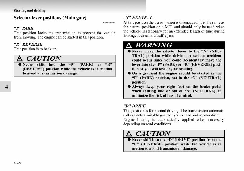
4-28
Starting and driving
4
Selector lever positions (Main gate)E00603800400
“P” PARKThis position locks the transmission to prevent the vehiclefrom moving. The engine can be started in this position.
“R” REVERSEThis position is to back up.
“N” NEUTRALAt this position the transmission is disengaged. It is the same asthe neutral position on a M/T, and should only be used whenthe vehicle is stationary for an extended length of time duringdriving, such as in a traffic jam.
“D” DRIVEThis position is for normal driving. The transmission automati-cally selects a suitable gear for your speed and acceleration.Engine braking is automatically applied when necessary,depending on road conditions.
CAUTION!● Never shift into the “P” (PARK) or “R”
(REVERSE) position while the vehicle is in motionto avoid a transmission damage.
WARNING!● Never move the selector lever to the “N” (NEU-
TRAL) position while driving. A serious accidentcould occur since you could accidentally move thelever into the “P” (PARK) or “R” (REVERSE) posi-tion or you will lose engine braking.
● On a gradient the engine should be started in the“P” (PARK) position, not in the “N” (NEUTRAL)position.
● Always keep your right foot on the brake pedalwhen shifting into or out of “N” (NEUTRAL), tominimize the risk of loss of control.
CAUTION!● Never shift into the “D” (DRIVE) position from the
“R” (REVERSE) position while the vehicle is inmotion to avoid transmission damage.
BK-BK2008E1ENUK.en-uk-Section7.fm Page 28 Wednesday, January 9, 2008 4:36 PM

Starting and driving
4-29
4
Sports modeE00603900892
Whether the vehicle is stationary or in motion, sports mode isselected by gently pushing the selector lever from the “D”(DRIVE) position into the manual gate (A). To return to “D”range operation, gently push the selector lever back into themain gate (B).
In sports mode, gear shifts can be made rapidly simply by mov-ing the selector lever backward and forward. In contrast to amanual transmission, the sports mode allows gear shifts withthe accelerator pedal depressed.
+ (SHIFT UP)Push the lever forward once to shift up one gear.
— (SHIFT DOWN)Pull the lever backward once to shift down one gear.
SHIFT UP
SHIFT DOWN
CAUTION!● In sports mode, the driver must execute upward
shifts in accordance with prevailing road conditions,taking care to keep the engine speed below the redzone.
● By rapidly moving the selector lever backward(SHIFT DOWN) twice, it is possible to skip one gear,i.e., 3rd to 1st, 4th to 2nd or 5th to 3rd. Since suddenengine braking and/or rapid acceleration can causea loss of traction, however, downshifts must be madecarefully in accordance with the vehicle’s speed.
BK-BK2008E1ENUK.en-uk-Section7.fm Page 29 Wednesday, January 9, 2008 4:36 PM

4-30
Starting and driving
4
NOTE● On petrol-powered vehicles, the upward shift may be
made automatically in sports mode when the engine revo-lutions rises and approaches the tachometer’s red zone(the red-coloured part of the tachometer dial).
● In sports mode, only the 5 forward gears can be selected.To reverse or park the vehicle, move the selector lever tothe “R” (REVERSE) or “P” (PARK) position as required.
● To maintain good running performance, the transmissionmay refuse to perform an upshift when the selector leveris moved to the “+ (SHIFT UP)” position at certain vehi-cle speeds. Also, to prevent over-revving of the engine,the transmission may refuse to perform a downshift whenthe lever is moved to the “— (SHIFT DOWN)” position atcertain vehicle speeds.
● In sports mode, downward shifts are made automaticallywhen the vehicle slows down. When the vehicle stops, 1stgear is automatically selected.
● When driving away on a slippery road, push the selectorlever forward into the “+ (SHIFT UP)” position. Thiscauses the transmission to shift into the 2nd gear which isbetter for smooth driving away on a slippery road. Pushthe selector lever to the “— (SHIFT DOWN)” side to shiftback to the 1st gear.
Sports mode indicatorE00612300254
In sports mode, the currently selected position is indicated bythe indicator (A) shown on the instrument panel.
NOTE● When sports mode is selected, the “D” indicator goes off.
BK-BK2008E1ENUK.en-uk-Section7.fm Page 30 Wednesday, January 9, 2008 4:36 PM

Starting and driving
4-31
4
When a malfunction occurs in the A/TE00615100035
When the “N” indication lamp blinksE00615200023
When the “N” indication lamp (A) blinks with the “D”(DRIVE) position or “Sports mode” being selected, the A/Tmay be malfunctioning.
When the A/T fluid temperature warning lamp comes on
E00615300109
The A/T fluid temperature warning lamp comes on when theautomatic transmission fluid temperature becomes abnormallyhigh. Normally the warning lamp comes on when the ignitionswitch is turned to the “ON” position, and then will go out aftera few seconds.
CAUTION!● If the “N” indication lamp blinks while driving in
the “D” (DRIVE) position or “Sports Mode”, theA/T safety device may be operating due to a mal-function.We recommend you to have your vehicle inspectedas soon as possible.
CAUTION!● If the lamp comes on, reduce the engine speed and
stop the vehicle in a safe area. Then set the selectorlever to “P” (PARK) position and idle the engineuntil the warning lamp goes off. When the warninglamp goes off, resume normal driving. If the warn-ing lamp does not go off, we recommend you to haveyour vehicle inspected.
BK-BK2008E1ENUK.en-uk-Section7.fm Page 31 Wednesday, January 9, 2008 4:36 PM

4-32
Starting and driving
4
Operation of the A/TE00604200342
Passing accelerationE00604500156
To gain extra acceleration in “D” (DRIVE) position, push theaccelerator to the floor. The automatic transmission will auto-matically downshift.
NOTE● In “Sports mode”, downshifts do not take place when the
accelerator is depressed all the way to the floor.
Uphill/downhill drivingE00610500089
DRIVING UPHILLThe transmission may not upshift to a higher gear if the com-puter determines the current speed cannot be maintained once ahigher gear is engaged.For smoother vehicle performance, if you release the throttlewhile climbing a steep grade, the transmission may not upshift.This is normal, as the computer is temporarily preventing shift-ing. After reaching the top of the hill, normal gear shift func-tion will resume.
DRIVING DOWNHILLWhen travelling down steep grades, the computer may auto-matically select a lower gear. This function assists engine brak-ing efforts, reducing the need for using the service brakes.
CAUTION!● Before selecting a gear with the engine running and
the vehicle stationary, fully depress the brake pedalto prevent the vehicle from creeping.The vehicle will begin to move as soon as the gear isengaged, especially when the engine speed is high, atfast idle or with the air conditioning operating, thebrakes should only be released when you are readyto drive away.
● Depress the brake pedal with the right foot at alltimes.Using the left foot could cause driver movementdelay in case of an emergency.
● Operating the accelerator pedal while the other footis resting on the brake pedal will affect braking effi-ciency and may cause premature wear of brakepads.
● To prevent sudden acceleration, never race theengine when shifting from the “P” (PARK) or “N”(NEUTRAL) position.
● Do not race the engine with brake pedal pressedwhen the vehicle is stationary.This can damage the A/T.Also, when you depress the accelerator pedal whileholding down the brake pedal with the selector leverin the “P” (PARK), “N” (NEUTRAL) or “D”(DRIVE) position, the increase in engine revolutionsmay be limited.
BK-BK2008E1ENUK.en-uk-Section7.fm Page 32 Wednesday, January 9, 2008 4:36 PM

Starting and driving
4-33
4
WaitingE00604600245
For short waiting periods, such as at traffic signals, the vehiclecan be left in gear and held stationary with the service brake.For longer waiting periods with the engine running, place theselector lever in the “N” (NEUTRAL) position and apply theparking brake, while holding the vehicle stationary with theservice brake.
ParkingE00604700161
To park the vehicle, first bring it to a complete stop, fullyengage the parking brake, and then move the selector lever tothe “P” (PARK) position.If you are going to leave the vehicle unattended, always switchoff the engine and remove the ignition key.
NOTE● On a slope, be sure to apply the parking brake before
moving the selector lever to the “P” (PARK) position. Ifyou move the selector lever to the “P” (PARK) positionbefore applying the parking brake, it may be difficult todisengage the selector lever from the “P” (PARK) positionwhen next you drive the vehicle, requiring application of astrong force to the selector lever to move from the “P”(PARK) position.
CAUTION!● Never hold the vehicle stationary on a hill using the
accelerator pedal (without using the brake pedal).Always apply the parking brake and/or servicebrakes.
BK-BK2008E1ENUK.en-uk-Section7.fm Page 33 Wednesday, January 9, 2008 4:36 PM

4-34
Starting and driving
4
When the A/T makes no speed changeE00604800348
If the transmission does not change speeds while driving, oryour vehicle does not pick up enough speed when starting onan uphill slope, it may be that there is something unusual hap-pening in the transmission, causing a safety device to activate.We recommend you to have your vehicle checked as soon aspossible.
1. If your vehicle has difficulty moving uphill, shift theselector lever into 2nd gear of the “Sports mode”.This method might not work depending on the transmis-sion malfunction.
2. Once the vehicle is moving on a level road, move theselector lever back to “D” (DRIVE).
Super select 4WD II (SS4 II)E00605700067
Shifting to rear-wheel drive or 4-wheel drive can be made byoperating the transfer shift lever (A). Shift the transfer shiftlever to an appropriate position according to the road surfaceconditions. In addition, the 2WD/4WD operation indicationlamp indicates the transfer shift lever shifting state. Refer to“2WD/4WD operation indication lamp” on page 4-38.
Vehicles with M/T
Vehicles with A/T
BK-BK2008E1ENUK.en-uk-Section7.fm Page 34 Wednesday, January 9, 2008 4:36 PM

Starting and driving
4-35
4
Shift lever position and 2WD/4WD operation indication lamp
E00605800127
: Illuminate: Remain off
Transfer shift lever position
2WD/4WD operation indi-
cation lampDriving conditions
2H Rear-wheel drive
When driving on dry paved road.
4HFull-time 4-wheel
drive
The basic position for super select 4WD II.When driving on dry paved or slippery roads.
4HLc
Centre dif-ferential
lock engaged 4-wheel drive
When driving on rough, sand or snow covered roads.
4LLc
Low range centre dif-ferential
lock engaged 4-wheel drive
When driving up or down steep hills, on rough or muddy roads (especially when increased torque is required).
CAUTION!● The “4LLc” range gives maximum torque for low-
speed driving on steep slopes, as well as sandy,muddy, and other difficult surfaces. On vehicleswith A/T, do not exceed speeds of approximately70 km/h (43 mph) in “4LLc” range.
● Do not drive your vehicle in the “4HLc” or “4LLc”position on dry paved roads and highways. Doing somay result in excessive tyre wear, increased fuel con-sumption, and possible noise generation. It may alsoincrease the differential oil temperature, which maydamage the drive system. Further, the drive trainwill be subjected to excessive loading, resulting in oilleakage, component seizure, or other serious prob-lems. On dry paved roads and highways, drive thevehicle in “2H” or “4H” only.
BK-BK2008E1ENUK.en-uk-Section7.fm Page 35 Wednesday, January 9, 2008 4:36 PM

4-36
Starting and driving
4
Transfer shift lever operationE00605900072
The transfer shift lever is operated by pushing it down and slid-ing it to the desired position.
BK-BK2008E1ENUK.en-uk-Section7.fm Page 36 Wednesday, January 9, 2008 4:36 PM

Starting and driving
4-37
4NOTE
● Shifting of the lever among “2H” ↔ “4H” ↔ “4HLc” should only be done at speeds below 100 km/h (62 mph).● When shifting from “2H” to “4H” in cold weather while the vehicle is in motion, the transmission gear may make some noise.
In cold weather, try to shift the gear while the vehicle is stopped.● When the lever is shifted between “2H” ↔ “4H” or “4H” ↔ “4HLc” while the vehicle is stopped, the 2WD/4WD operation
indication lamp blinks while the selection is in process. Drive slowly and normally after confirming that the lamp is illumi-nated. Refer to “2WD/4WD operation indication lamp” on page 4-38.
● Do not move the selector lever while the 2WD/4WD operation indication lamp is blinking.● On vehicles with cruise control, when the lever is shifted among “2H” ↔ “4H” ↔ “4HLc” while the cruise control is acti-
vated, the transfer gear may make some noise.
To shift from ToProcedure
Vehicles with M/T Vehicles with A/T
2H 4H The transfer shift lever can be operated while the vehi-cle is either moving or stationary.When the vehicle is not in motion, shift the gearshift lever to the “N” (Neutral) position before operating the transfer shift lever.When the vehicle is moving, and only while it can be steered straight ahead, and release the accelerator pedal before operating the transfer shift lever.
The transfer shift lever can be operated while the vehi-cle is either moving or stationary.When the vehicle is not in motion, shift the selector lever to the “N” (NEUTRAL) position before operating the transfer shift lever.When the vehicle is moving, and only while it can be steered straight ahead, shift the selector lever to the “D” (DRIVE) position, and release the accelerator pedal before operating the transfer shift lever.
4H 2H or 4HLc
4HLc 4H
4HLc 4LLc Stop the vehicle, depress the clutch pedal to the floor and operate the transfer shift lever.Keep depressing the clutch pedal while the 2WD/4WD operation indication lamp continues to blink.
Stop the vehicle, shift the selector lever to the “N” (NEUTRAL) position, and operate the transfer shift lever.4LLc 4HLc
CAUTION!● Do not operate the transfer shift lever while the rear wheels of the vehicle are slipping on snow or ice.
BK-BK2008E1ENUK.en-uk-Section7.fm Page 37 Wednesday, January 9, 2008 4:36 PM
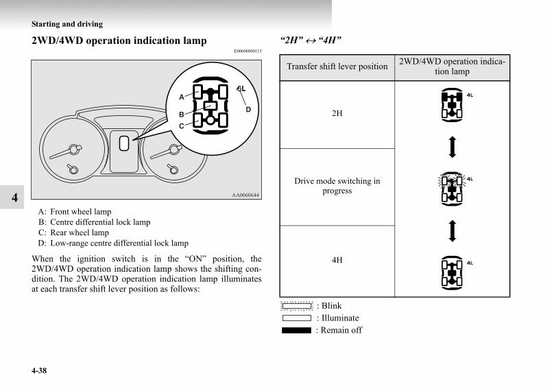
4-38
Starting and driving
4
2WD/4WD operation indication lampE00606000113
When the ignition switch is in the “ON” position, the2WD/4WD operation indication lamp shows the shifting con-dition. The 2WD/4WD operation indication lamp illuminatesat each transfer shift lever position as follows:
“2H” ↔ “4H”
: Blink: Illuminate: Remain off
A: Front wheel lampB: Centre differential lock lampC: Rear wheel lampD: Low-range centre differential lock lamp
Transfer shift lever position 2WD/4WD operation indica-tion lamp
2H
Drive mode switching in progress
4H
BK-BK2008E1ENUK.en-uk-Section7.fm Page 38 Wednesday, January 9, 2008 4:36 PM

Starting and driving
4-39
4
“2H” ↔ “4HLc”
: Blink: Illuminate: Remain off
“4H” ↔ “4HLc”
: Blink: Illuminate: Remain off
Transfer shift lever position 2WD/4WD operation indica-tion lamp
2H
Drive mode switching in progress
4HLc
Transfer shift lever position 2WD/4WD operation indica-tion lamp
4H
Drive mode switching in progress
4HLc
BK-BK2008E1ENUK.en-uk-Section7.fm Page 39 Wednesday, January 9, 2008 4:36 PM

4-40
Starting and driving
4
“4HLc” ↔ “4LLc”
: Blink: Illuminate: Remain off
NOTE● The 2WD/4WD operation indication lamp blinks while
the selection is in process. Take the following precautionswhen the indication lamp is blinking.• Keep the steering wheel in the straight ahead position
while making range selections. If you attempt to driveforward with the steering wheel turned, gear rattlingmay occur and the desired range may not actually beselected.
• If the front wheel and/or centre differential lock lampscontinue blinking after a “2H” ↔ “4H” ↔ “4HLc”selection has been made with the vehicle moving, holdthe steering wheel in the straight ahead position andslowly depress the accelerator pedal several times.
• If, after a “4HLc” ↔ “4LLc” selection has been made,the front and rear wheel lamps continue blinking and thedesired range is not actually selected, return the transfershift lever to its previous position. Place the steeringwheel in the straight ahead position, drive the vehicleforward, and release the accelerator pedal. Next, holddown the clutch pedal (with M/T) or place the selectorlever in the “N” (NEUTRAL) position (with A/T) andmake the range selection again.
Transfer shift lever position 2WD/4WD operation indica-tion lamp
4HLc
Drive mode switching in progress
4LLc
BK-BK2008E1ENUK.en-uk-Section7.fm Page 40 Wednesday, January 9, 2008 4:36 PM

Starting and driving
4-41
4
● If the front and rear wheel lamps blink rapidly (twice persecond) when you attempt to make a “4HLc” ↔ “4LLc”selection, the selection cannot be made. Stop the vehicleand release the accelerator pedal. Next, hold down theclutch pedal (with M/T) or place the selector lever in the“N” (NEUTRAL) position (with A/T) and make the rangeselection again.
CAUTION!● If a problem is detected in the transfer system, a
safety device will activate. The front and rear wheellamps will go out, the centre differential lock lampwill blink, and transfer shifting will become impossi-ble. Park your vehicle in a safe place, turn off theengine for a few moments. Restart the engine.The lamps should resume normal operation. If thelamps continue to blink, we recommend you to havethe vehicle checked as soon as possible.
BK-BK2008E1ENUK.en-uk-Section7.fm Page 41 Wednesday, January 9, 2008 4:36 PM

4-42
Starting and driving
4
Rear differential lock*E00606200043
If one wheel starts to spin freely and the vehicle becomes stuckand cannot be freed even using 4-wheel drive, the rear differen-tial lock switch (A) can be used to activate the rear differentiallock for extra traction.
Operating the rear differential lock1. Move the transfer shift lever to “4LLc” or “4HLc” posi-
tion.2. To activate the rear differential lock, press the rear differ-
ential lock switch (1).3. To deactivate the rear differential lock, press the rear dif-
ferential lock switch (2).
CAUTION!● Operate the rear differential lock switch after the
wheels are stopped. Operating the switch with thewheels turning may cause the vehicle to dart inunexpected directions.
BK-BK2008E1ENUK.en-uk-Section7.fm Page 42 Wednesday, January 9, 2008 4:36 PM

Starting and driving
4-43
4
NOTE● The rear differential lock does not operate when the trans-
fer shift lever is in “4H” or “2H” position.● When the rear differential is locked with the transfer shift
lever in “4LLc” or “4HLc” position, changing the shiftlever to “4H” or “2H” position makes the rear differentialunlock automatically.
The rear differential lock indication lampE00606300132
When the ignition switch is turned to the “ON” position, therear differential lock indication lamp (A) in the meter clusterilluminates for a few seconds then indicates the rear differentiallock’s operating status (activated or deactivated).
NOTE● The 2WD/4WD operation indication lamp also illumi-
nates for a few seconds when the ignition switch is turnedto the “ON” position.Refer to “2WD/4WD operation indication lamp” on page4-38.The status of the rear differential lock (resulting fromdepression of the rear differential lock switch) is shownby blinking or steady illumination of the rear differentiallock indication lamp.
BK-BK2008E1ENUK.en-uk-Section7.fm Page 43 Wednesday, January 9, 2008 4:36 PM

4-44
Starting and driving
4
: Blink : Illuminate (steady) : Remain off
NOTE● The indication lamp blinks while the rear differential lock
is being switched between its activated and deactivatedconditions. When the switching operation is complete, theindication lamp is either illuminated steadily or not illumi-nated.
● The active stability & traction control (ASTC) and anti-lock brake system (ABS) functions are suspended whilethe rear differential lock is activated. ASTC indicationlamp, active stability control function OFF indicationlamp, ABS warning lamp and brake warning lamp areilluminated while these functions are suspended. It doesnot indicate a problem. When the rear differential lock isdisengaged, these lamps go out and function again.Refer to “Brake warning lamp” on page 3-13, “ABSwarning lamp” on page 4-60, “ASTC indication lamp” onpage 4-64, “Active stability control function OFF indica-tion lamp” on page 4-67.
The operation state of rear differential lock
Rear differential lock indica-tion lamp
Rear differential lock deacti-vated
Switching in progress
Rear differential lock activated
BK-BK2008E1ENUK.en-uk-Section7.fm Page 44 Wednesday, January 9, 2008 4:36 PM

Starting and driving
4-45
4
● If the indication lamp continues blinking after the switchhas been pressed to deactivate the rear differential lock,hold the steering wheel in the straight ahead position thenslowly depress and release the accelerator pedal severaltimes.
● If the indication lamp continues blinking after the switchhas been pressed to activate the rear differential lock, bearin mind the following instructions:• If the vehicle speed is 12 km/h (7 mph) or higher, decel-
erate to a speed of 6 km/h (4 mph) or lower. The switch-ing operation will be completed and the indication lampwill illuminate steadily.
• If the vehicle speed is 12 km/h (7 mph) or lower, turnthe steering wheel from side to side until the indicationlamp illuminates steadily. If the vehicle is stuck in softground, make sure the area around the vehicle is clearthen repeatedly attempt to drive forward and backward.The switching operation will be completed and the indi-cation lamp will illuminate steadily.
Examples of effective use of the rear differential lock
E00606400045
When one of the wheels has fallen in a ditch
CAUTION!● Use the rear differential lock only as an emergency
measure when the vehicle is stuck and cannot befreed with the transfer shift lever in “4LLc” or“4HLc” position. Deactivate the rear differentiallock immediately after using it.
BK-BK2008E1ENUK.en-uk-Section7.fm Page 45 Wednesday, January 9, 2008 4:36 PM

4-46
Starting and driving
4
When driving on rocky roadsWhen the vehicle is unable to move because one of the wheelsis suspended in the air.
When getting out of snowWhen the vehicle is unable to get going because one of thewheels is on the snow and the other on a paved road.
BK-BK2008E1ENUK.en-uk-Section7.fm Page 46 Wednesday, January 9, 2008 4:36 PM

Starting and driving
4-47
4
Examples of incorrect use of the rear differential lock
E00606500046
WARNING!● If the “4LLc” or “4HLc” position is selected along
with the rear differential lock, the following phe-nomena appear and it is very dangerous.Please be sure to release the rear differential lock onnormal roads.• If the rear differential lock is used by mistake
when driving on a paved road: With the rear dif-ferential lock on, the power to drive the vehiclestraight ahead becomes very strong, which maymake it difficult to turn the steering wheel.
WARNING!● If the rear differential lock is used by mistake when
turning a curve or making a right or left turn at acrossing or the like: The vehicle is unable to make aturn and may go straight ahead.
BK-BK2008E1ENUK.en-uk-Section7.fm Page 47 Wednesday, January 9, 2008 4:36 PM

4-48
Starting and driving
4
4-wheel drive operationE00606600627
By selecting 4-wheel drive, both axles of the vehicle are rigidlyconnected with each other. This improves the traction charac-teristics. When turning sharp corners or moving forward andbackward repeatedly, however, the drive line is stressed, whichis felt as a braking effect. A 4-wheel drive vehicle can acceler-ate more quickly and smoothly.However, note that the braking distance is not shorter than thatof a rear-wheel drive vehicle.When using 4-wheel drive on rough roads (snow, mud, sand,etc.), it is important to operate the vehicle correctly.
NOTE● The driving posture should be more upright and closer to
the wheel than usual; adjust the seat to a good position foreasy steering and pedal operation. Be sure to wear the seatbelt.
● After driving on rough roads, check each part of the vehi-cle and wash it thoroughly with water. Refer to the “Vehi-cle care” section and “Inspection and maintenancefollowing rough road operation” on page 4-53.
WARNING!● If the rear differential lock is used by mistake except
when making an emergency escape on snow or fro-zen road: It becomes difficult to make a steady turn.
● In the case where the condition of the road is differ-ent for the right tyre to drive from the left tyre (suchas one tyre on a paved road and the other on ice),direction of the vehicle may change abruptly whenengine braking or accelerating.Do not use the rear differential lock except whenmaking an emergency escape on a snow or frozenroad, but drive with 4WD.
BK-BK2008E1ENUK.en-uk-Section7.fm Page 48 Wednesday, January 9, 2008 4:36 PM

Starting and driving
4-49
4
Driving on dry paved road and highwaySelect the “2H” or “4H” position to drive on the dry pavedroad. Especially on dry highway, never select the “4HLc” or“4LLc” position.
Driving on snowy or icy roads Set the transfer shift lever to the “4H” or “4HLc” position inaccordance with the road conditions, and then graduallydepress the accelerator pedal for a smooth start.
NOTE● The use of snow tyres and/or tyre chains is recommended.● In order to ensure that the anti-lock brake system (ABS)
will operate correctly in situations where tyre chains havebeen fitted, drive in the “4H”, “4HLc” or “4LLc” position.
● Maintain a safe distance between vehicles, avoid suddenbraking, and use engine braking (downshifting).
Driving on sandy or muddy roadsSet the transfer shift lever to the “4HLc” or “4LLc” positionand then gradually depress the accelerator pedal for a smoothstart. Keep the pressure on the accelerator pedal as constant aspossible, and drive at low speed.
CAUTION!● Selecting the “4HLc” or “4LLc” position to drive on
dry paved road will increase the fuel consumptionwith possible noise generation and early tyre wear.It may also increase the differential oil temperature,resulting in possible damage to the driving system.Further, the drive train will be subjected to excessiveloading, possibly leading to oil leakage, componentseizure, or other serious faults.
CAUTION!● Avoid sudden braking, sudden acceleration, and
sharp turning; such operations could cause skiddingand spinouts.
BK-BK2008E1ENUK.en-uk-Section7.fm Page 49 Wednesday, January 9, 2008 4:36 PM

4-50
Starting and driving
4
NOTE● Avoid sudden braking, acceleration, and turning; such
operations could result in the vehicle becoming stuck.● If the vehicle becomes stuck in sandy or muddy roads, it
can often be moved a rocking motion. Move the selectorlever rhythmically between the “D” (DRIVE) and “R”(REVERSE) position (with M/T, between 1st andReverse), while applying slight pressure to the acceleratorpedal.
● It is recommended to start the vehicle with parking brakepartially, but not completely, applied by slightly pullingthe parking brake lever.After the vehicle has become free, do not forget to releasethe parking brake.
● If it is necessary to drive in extremely muddy conditions,the use of tyre chains is recommended. Because the extentof muddy conditions is difficult to judge and the vehiclecould become bogged down very deeply, operation shouldbe at a low speed. If possible, get out of the vehicle andcheck the conditions ahead before proceeding.
● Driving over roads in coastal areas or roads on which anti-skid preparations have been spread can cause rust on thevehicle; wash the vehicle thoroughly as soon as possibleafter such use.
CAUTION!● Do not force the vehicle or drive recklessly on sandy
surfaces. In comparison with normal road surfaces,the engine and other drive-system components areput under excessive strain when driving on such asurface, and this could lead to accidents.
● If any of following conditions occur while the vehicleis being driven, immediately park your vehicle in asafe place and follow these procedures:• The needle in the temperature gauge approaches
the overheating zone.Refer to “Engine overheating” on page 6-6.
• A/T fluid temperature warning lamp illuminates.Refer to “When the A/T fluid temperature warn-ing lamp comes on” on page 4-31.
WARNING!● When attempting to rock your vehicle out of a stuck
position, be sure that the area around the vehicle isclear of people and physical objects. The rockingmotion may cause the vehicle to suddenly launchforward or backward, causing injury or damage tonearby people or objects.
BK-BK2008E1ENUK.en-uk-Section7.fm Page 50 Wednesday, January 9, 2008 4:36 PM
Starting and driving
4-51
4
Climbing sharp gradesSet the transfer shift lever to the “4LLc” position to maximizethe engine torque.
NOTE● Choose as smooth a slope as possible with few stones or
other obstacles.● Before attempting to drive up the slope, walk up it to con-
firm that the vehicle can handle the grade.
Descending sharp gradesSet the transfer shift lever to the “4LLc” position, use theengine brake (downshifting) and descend slowly.
NOTE● When descending a sharp grade, if the brakes are applied
suddenly because of an obstacle encountered, control ofthe vehicle could be lost. Before descending the slope,walk down it and confirm the path.
● Before descending a grade, it is necessary to choose theappropriate gear. Avoid changing gears or depressing theclutch while descending the grade.
● MITSUBISHI MOTORS is not responsible to the opera-tor for any damage or injury caused or liability incurredby the improper and negligent operation of a vehicle. Alltechniques of vehicle operation described herein dependon the skill and experience of the operator and other par-ticipating parties and any deviation from the recom-mended operation instructions above is at their own risk.
Turning sharp cornersWhen turning a sharp corner in the “4HLc” or “4LLc” positionat low speed, a slight difference in steering may be experiencedsimilar to as if the brakes were applied. This is called tight cor-ner braking and results from each of the 4 tyres being at a dif-ferent distance from the corner.The phenomenon is peculiar to 4-wheel drive vehicles. If thisoccurs, either straighten the steering wheel, or change to rear-wheel drive.
WARNING!● Go straight up. Do not try to traverse across a steep
slope.● If you begin to lose traction, ease off the accelerator
pedal and gently turn the steering wheel alterna-tively left and right to regain adequate tractionagain.
WARNING!● Avoid snaking down a sharp grade. Descend the
grade as straight as possible.
BK-BK2008E1ENUK.en-uk-Section7.fm Page 51 Wednesday, January 9, 2008 4:36 PM

4-52
Starting and driving
4
Crossing a stream4-wheel drive vehicles are not necessarily waterproof. If theelectrical circuits become wet, further operation of the vehiclewill be impossible; therefore, avoid crossing streams unlessabsolutely necessary. If crossing a stream is unavoidable, usethe following procedure:
1. Check depths of a stream and geographical features beforeattempting to cross a stream and ford the stream where thewater is as shallow as practicable.
2. Cross at a place where the water is less than 70 cm deep. 3. Set the transfer shift lever to the “4LLc” position.4. Drive slowly at a speed of approximately 5 km/h (3mph)
to avoid splashing too much water.
NOTE● Because the inside of the vehicle is flooded with water
when crossing at a place where the water is more than50 cm deep, we recommend you to have your vehicleinspected.
● Frequent crossing of streams can adversely affect the lifespan of the vehicle; we recommend you to take the neces-sary measures to prepare, inspect, and repair the vehicle.
CAUTION!● Do not attempt to cross a stream at a place where
the water is more than 70 cm deep.● Cross a stream temporarily for emergencies and
avoid doing so for a long period of time.● After crossing a stream, apply the brakes to be sure
they are functioning properly. If the brakes are wetand not functioning properly, dry them out by driv-ing slowly while lightly depressing the brake pedal.Inspect each part of the vehicle carefully.
BK-BK2008E1ENUK.en-uk-Section7.fm Page 52 Wednesday, January 9, 2008 4:36 PM

Starting and driving
4-53
4
Inspection and maintenance following rough road operation
E00606700048
After operating the vehicle in rough road conditions, be sure toperform the following inspection and maintenance procedures:
● Check that the vehicle has not been damaged by rocks,gravel, etc.
● Carefully wash the vehicle with water.After washing, drive the vehicle slowly while lightlydepressing the brake pedal in order to dry out the brakes.If the brakes still do not function properly, we recommendyou to have the brakes checked as soon as possible.
● Remove the insects, dried grass, etc. clogging the radiatorcore.
● After crossing a stream, be sure to have the followingitems inspected at a MITSUBISHI MOTORS AuthorizedService Point and take the necessary measures.• Check the brake system and, if necessary, have it serv-
iced.• Check the engine, transmission, transfer, and differential
oil or grease level and turbidity. If the oil or grease ismilky, it indicates water contamination. Replace it withnew oil or grease.
• Grease the propeller shaft.• Check the inside of the vehicle. If ingress of water is
found, dry the carpet etc.• Inspect the headlamps. If the headlamp bulb is flooded
with water, we recommend you to have it drained.
Cautions on handling of 4-wheel drive vehicles
E00606800401
Tyres and wheelsSince the driving torque can be applied to the 4 wheels, the per-formance of the vehicle when operating in 4-wheel drive isgreatly affected by the condition of the tyres.
Pay close attention to the tyres.● Install specified tyres on all wheels. Refer to “Tyres and
wheels” on page 9-13.● Be sure to fit all 4 tyres and wheels of the same size and
type.When replacement of any of the tyres or wheels is neces-sary, replace all of them.
● All tyres should be rotated whenever the wear differencebetween the front and rear tyres is recognizable.
BK-BK2008E1ENUK.en-uk-Section7.fm Page 53 Wednesday, January 9, 2008 4:36 PM

4-54
Starting and driving
4
Good vehicle performance cannot be expected if there is a dif-ference in wear between tyres. Refer to “Tyre rotation” on page8-21.
● Check the tyre inflation pressure regularly.● If the tyre inflation pressure is inappropriate, the transfer
gear may make some noise and shock while changing thedrive mode.
TowingIf towing is necessary, we recommend you to have it done byyour MITSUBISHI MOTORS Authorized Service Point or acommercial tow truck service.In the following cases, transport the vehicle using a tow truck.
● The engine runs but the vehicle does not move or abnor-mal noise is produced.
● Inspection of the vehicle’s underside reveals that oil orsome other fluid is leaking.
Only when you cannot receive a towing service from a MIT-SUBISHI MOTORS Authorized Service Point or commercialtow truck service, tow your vehicle carefully in accordancewith the instructions given in “Towing” on page 6-29.
CAUTION!● Always use tyres of the same size, same type, and
same brand, and which have no wear differences.Using tyres which differ in size, type, brand or thedegree of wear will cause excessive loading, resultingin possible damage to the drive system.
CAUTION!● Be sure to shift the transfer shift lever to the “2H”
position. Never try to tow with the transfer shiftlever in the “4H”, “4HLc” or “4LLc” positions andwith any of the wheels on the ground (Type A or B).This could result in damage to the vehicle’s drivingsystem, or the vehicle could become separated fromthe tow truck and unexpected accident might result.If you cannot shift the transfer shift lever to “2H”position or the transmission is malfunctioning ordamaged, transport the vehicle with all the wheelson a carriage (Type C or D) as illustrated.
BK-BK2008E1ENUK.en-uk-Section7.fm Page 54 Wednesday, January 9, 2008 4:36 PM
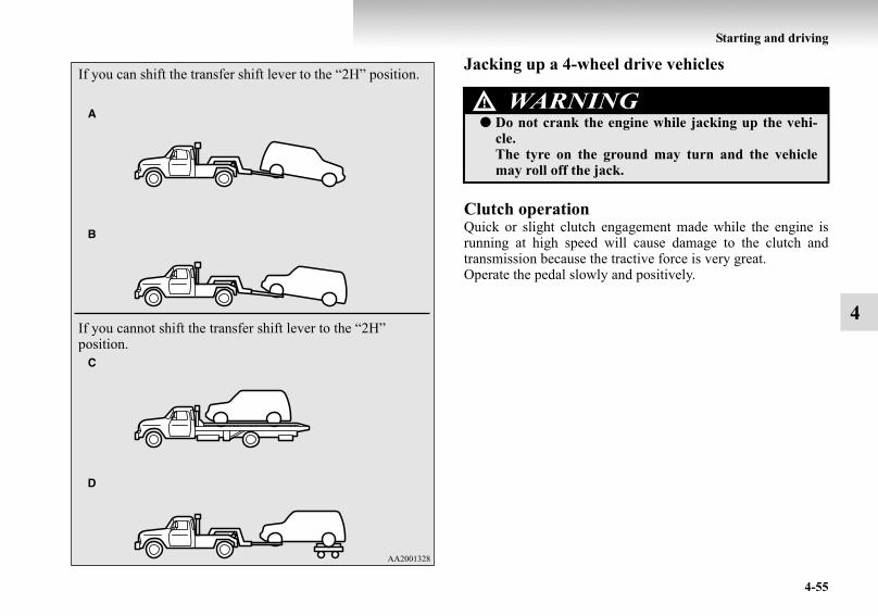
Starting and driving
4-55
4
Jacking up a 4-wheel drive vehicles
Clutch operationQuick or slight clutch engagement made while the engine isrunning at high speed will cause damage to the clutch andtransmission because the tractive force is very great.Operate the pedal slowly and positively.
If you can shift the transfer shift lever to the “2H” position.
If you cannot shift the transfer shift lever to the “2H” position.
WARNING!● Do not crank the engine while jacking up the vehi-
cle.The tyre on the ground may turn and the vehiclemay roll off the jack.
BK-BK2008E1ENUK.en-uk-Section7.fm Page 55 Wednesday, January 9, 2008 4:36 PM

4-56
Starting and driving
4
BrakingE00607000905
All the parts of the brake system are critical to safety. We rec-ommend you to have the vehicle checked at regular intervalsaccording the service booklet.
Brake systemThe service brake is divided into two brake circuits so thatwhen one brake circuit fails, the other is available to stop thevehicle. In this situation, even if the brake pedal moves downto the very end of its possible stroke, keep it pressed downhard; stop driving as soon as possible and have the brake sys-tem repaired.For details, refer to “Brake warning lamp” on page 3-13.
Power brakesThe power brakes use brake fluid pressurized by the pump topower-assist the brake. If the brake system fails during driving,the brake warning lamp comes on and a buzzer sounds continu-ously. In this case, the brake may not work properly.If this buzzer should continue to sound, park your vehicle in asafe place and have the system checked.Refer to “Brake warning lamp” on page 3-13.
NOTE● Depressing the brake pedal repeatedly may turn on the
brake warning lamp, ABS warning lamp and brake warn-ing buzzer. (The ASTC indication lamp and active stabil-ity control function OFF indication lamp also turn on.) Itis normal if the lamp goes out and the buzzer stops sound-ing after a few seconds.
● In certain cases immediately after the engine has beenstarted or when the brake pedal is depressed repeatedly, anoise generated by operation of brake devices may beheard coming from the engine compartment. This type ofnoise is normal and there is no need for concern. In fact, itindicates that the corresponding devices are operating nor-mal.
CAUTION!● Avoid driving habits that cause heavy braking and
never “ride” the brakes by resting your foot on thebrake pedal while driving.It causes brake overheating and fade.
CAUTION!● Bring the vehicle to halt in a safe location by apply-
ing the brakes gently. Applying the brakes rapidlyor driving at high speed may make the vehicleunstable.
BK-BK2008E1ENUK.en-uk-Section7.fm Page 56 Wednesday, January 9, 2008 4:36 PM

Starting and driving
4-57
4
Warning lamp● The brake warning lamp illuminates to indicate a fault in
the braking system. Read “Brake warning lamp” on page3-13.
● On vehicles with the rear differential lock, the active sta-bility & traction control (ASTC) and anti-lock brake sys-tem (ABS) functions are suspended while the reardifferential lock is activated. ASTC indication lamp,active stability control function OFF indication lamp,ABS warning lamp and brake warning lamp are illumi-nated while these functions are suspended. It does notindicate a problem. When the rear differential lock is dis-engaged, these lamps go out and function again.Refer to “Brake warning lamp” on page 3-13, “ABSwarning lamp” on page 4-60, “ASTC indication lamp” onpage 4-64, “Active stability control function OFF indica-tion lamp” on page 4-67.
When brakes are wetCheck the brake system while driving at a low speed immedi-ately after starting, especially when the brakes are wet, to con-firm they work normally.A film of water can be formed on the brake discs and preventnormal braking after driving in heavy rain or through largepuddles, or after the vehicle is washed. If this occurs, dry thebrakes out by driving slowly while lightly depressing the brakepedal.
When driving downhillIt is important to take advantage of the engine braking by shift-ing to a lower shift position while driving on steep downhillroads in order to prevent the brakes from overheating.
WARNING!● Never coast downhill with the engine OFF. Keep the
engine running whenever your vehicle is in motion.If you turn off the engine while driving, the powerbrake booster will stop working and your brakeswill not work as well.
● If the power assist is lost or if either brake hydraulicsystem stops working properly, have your vehiclechecked immediately.
WARNING!● Do not leave any objects near the brake pedal or let
a floor mat slide under it; doing so could prevent thefull pedal stroke that would be necessary in an emer-gency. Make sure that the pedal can be operatedfreely at all times. Make sure the floor mat issecurely held in place.
BK-BK2008E1ENUK.en-uk-Section7.fm Page 57 Wednesday, January 9, 2008 4:36 PM

4-58
Starting and driving
4
Brake pads● Avoid hard braking situations.
New brakes need to be broken-in by moderate use for thefirst 200 km (125 miles).
● The disc brakes are provided with a warning device whichemits a shrieking metallic sound while braking if thebrake pads have reached their wear limit.If you hear this sound, have the brake pads replacedimmediately.
Anti-lock brake system (ABS)E00607100850
Environmental conditions can have an effect on braking. Dur-ing sudden braking when there is snow, ice, oil, water etc. onthe road surface, a skid may occur. In this situation, steeringcontrol and braking effectiveness is reduced and the stoppingdistance is increased. The vehicle may also go into an uncon-trolled spin.The ABS helps prevent the wheels from locking during brak-ing, thus maintaining directional stability, ensuring controlla-bility and providing optimum braking force.
Driving hints● Always maintain the same distance from the vehicle in
front of you as you would for a vehicle not equipped withABS.Compared with vehicles not fitted with ABS, your vehiclemay require a longer stopping distance in the followingcases:• Driving on gravel or snow-covered roads.• Driving with tyre chains installed.• Driving on roads where the road surface is pitted or has
other differences in surface height.• Driving on bumpy roads or other poor driving surfaces.
● In order to ensure the anti-lock brake system (ABS) willoperate correctly in situations where tyre chains have beenfitted, drive in the “4H”, “4HLc”, or “4LLc” position.
WARNING!● Driving with worn brake pads will make it harder to
stop, and can cause an accident.
BK-BK2008E1ENUK.en-uk-Section7.fm Page 58 Wednesday, January 9, 2008 4:36 PM
Starting and driving
4-59
4
● Operation of ABS is not restricted to situations wherebrakes are applied suddenly. This system may also operateto prevent wheel lock when you are driving over man-holes, steel road-work plates, or the vehicle is driven oversteps or level differences in the road, road markings, orother surfaces which are difficult for the wheels to grip.
● When the ABS is activated, you may feel the brake pedalpulsation and the vibrations of the vehicle body and steer-ing wheel. You may also hear a characteristic noise. Atthis time, you may feel as if the pedal attempts to resistbeing depressed.This is a normal result of the ABS operation, and does notindicate a problem.In this situation, to let the ABS work for you, just holdthe brake pedal down more firmly. Do not pump thebrake. This will result in reduced braking perform-ance.
● When the engine starts and after starting to drive, youmight hear operation noise from the engine compartmentor feel a shock from the brake pedal. This is normal. TheABS is performing a self-check.
● The ABS will operate after the vehicle has accelerated to aspeed in excess of approximately 10 km/h (6 mph). Itstops operating when the vehicle decelerates to low speedbelow approximately 5 km/h (3 mph).
CAUTION!● Even the ABS cannot prevent the natural laws of
physics from acting on the vehicle. It cannot forinstance avoid accidents that may result from exces-sive speed on bends or following another vehicle tooclosely or aquaplaning. It should remain the driver’stask to observe safety precautions to judge speedsand brake applications correctly in such conditions.
● Be sure to use tyres of the same type and size on 4wheels.If tyre types or sizes are mixed, ABS may not func-tion normally.
● Never install a limited slip differential, which is notMITSUBISHI MOTORS genuine parts, as the ABSmay not function normally.We recommend you to consult a MITSUBISHIMOTORS Authorized Service Point.
BK-BK2008E1ENUK.en-uk-Section7.fm Page 59 Wednesday, January 9, 2008 4:36 PM

4-60
Starting and driving
4
ABS warning lampE00607200532
The ABS warning lamp should illuminate when the ignitionswitch is turned “ON”, and should go off in a few seconds.
NOTE● Depressing the brake pedal repeatedly may turn on the
brake warning lamp, ABS warning lamp and brake warn-ing buzzer. (The ASTC indication lamp and active stabil-ity control function OFF indication lamp also turn on.) Itis normal if the lamp goes out and the buzzer stops sound-ing after a few seconds.
● On vehicles with the rear differential lock, the active sta-bility & traction control (ASTC) and anti-lock brake sys-tem (ABS) functions are suspended while the reardifferential lock is activated. ASTC indication lamp,active stability control function OFF indication lamp,ABS warning lamp and brake warning lamp are illumi-nated while these functions are suspended. It does notindicate a problem. When the rear differential lock is dis-engaged, these lamps go out and function again.Refer to “Brake warning lamp” on page 3-13, “ASTCindication lamp” on page 4-64, “Active stability controlfunction OFF indication lamp” on page 4-67.
CAUTION!● If the warning lamp stays on or does not illuminate
when you start the vehicle, it indicates that the ABSis not functioning and that only the standard brakesystem is in operation. (In this condition the stand-ard hydraulic brake system will still function.) Werecommend you to have your vehicle inspected assoon as possible.
BK-BK2008E1ENUK.en-uk-Section7.fm Page 60 Wednesday, January 9, 2008 4:36 PM

Starting and driving
4-61
4
If the warning lamp illuminates while drivingE00607300416
If only the ABS warning lamp illuminates● Avoid hard braking and high-speed driving. Stop the vehi-
cle in a safe place.Restart the engine and check to see whether the lamp goesout after a few minutes driving; if it then remains off dur-ing driving, there is no problem.However, if the lamp does not go out, or if it lights upagain when the vehicle is driven, we recommend you tohave the vehicle checked as soon as possible.
● The ABS warning lamp can illuminate if the battery volt-age is insufficient when the engine is started. In this case,it does not indicate an ABS fault.Charge the battery by allowing the engine to idle for awhile.If the battery has been charged but the ABS warning lampcontinues to illuminate or illuminates intermittently, werecommend you to have the vehicle inspected.
If the ABS warning lamp and brake warning lamp illu-minate at the same time
● The ABS and brake force distribution function will notwork, so hard braking could make the vehicle unstable.Avoid hard braking and high-speed driving. Stop the vehi-cle in a safe place and we recommend you to have thevehicle checked.
BK-BK2008E1ENUK.en-uk-Section7.fm Page 61 Wednesday, January 9, 2008 4:36 PM

4-62
Starting and driving
4
Inspection following snowy road operationE00618300012
After driving on snowy roads, remove any snow and ice whichmay have become adhered to the wheel areas.When doing this, be careful not to damage the wheel speedsensors (A) and cables located at each wheel on vehiclesequipped with an ABS.
Front
Rear
BK-BK2008E1ENUK.en-uk-Section7.fm Page 62 Wednesday, January 9, 2008 4:36 PM

Starting and driving
4-63
4
Power steering systemE00607400084
When the engine is stopped, the power steering system will notfunction and it will require greater manual effort to operate thesteering wheel. Keep this in mind in particular when towing thevehicle. Never turn off the engine while driving.Periodically check the power steering fluid level.
Active stability & traction control (ASTC)E00613800168
The active stability & traction control (ASTC) takes overallcontrol of the anti-lock brake system, active stability controlfunction and active traction control function to maintain thevehicle’s stability and traction. Please read this section in con-junction with the pages on the anti-lock brake system, activestability control function and active traction control function.
Anti-lock brake system (ABS) → p. 4-58Active stability control function → p. 4-66Active traction control function → p. 4-68
CAUTION!● Do not hold the steering wheel in the fully turned
position (either left or right), for longer than 10 sec-onds.This can cause damage to the power steering system. CAUTION!
● Do not over-rely on the ASTC. Even when the ASTCis operating, there are limits to how far it can ensurevehicle stability; reckless driving may lead to acci-dents. Always drive carefully, taking account of theroad conditions.
● Be sure to use the same specified type and size oftyre on all 4 wheels. Otherwise, there is a possibilitythat the ASTC will not work properly.
BK-BK2008E1ENUK.en-uk-Section7.fm Page 63 Wednesday, January 9, 2008 4:36 PM

4-64
Starting and driving
4
NOTE● An operation noise may be emitted from the engine com-
partment in the following situations. The sound is associ-ated with checking the operations of the ASTC. At thistime, you may feel a shock from the brake pedal if youdepress it. These do not indicate a malfunction.• When the ignition switch is set to the “ON” position.• When the vehicle is driven for a while after the engine is
turned on.● When the ASTC is activated, you may feel a vibration in
the vehicle body or hear a whining sound from the enginecompartment.This indicates that the system is operating normally. Itdoes not indicate a malfunction.
● When the anti-lock brake system warning lamp is illumi-nated, the ASTC is not active.
● On vehicles with the rear differential lock, the ASTC andABS functions are suspended while the rear differentiallock is activated. ASTC indication lamp, active stabilitycontrol function OFF indication lamp, ABS warning lampand brake warning lamp are illuminated while these func-tions are suspended. It does not indicate a problem. Whenthe rear differential lock is disengaged, these lamps go outand function again.Refer to “Brake warning lamp” on page 3-13, “ABSwarning lamp” on page 4-60, “Active stability controlfunction OFF indication lamp” on page 4-67.
ASTC indication lampE00618000035
The ASTC indication lamp shows the operating status of theactive stability control function and active traction controlfunction. For details, see these sections of this owner’s manual:
Active stability control function indication lamp → p. 4-67Active traction control function indication lamp → p. 4-69
BK-BK2008E1ENUK.en-uk-Section7.fm Page 64 Wednesday, January 9, 2008 4:36 PM

Starting and driving
4-65
4
ASC OFF switchE00620500024
The active stability control function is automatically activatedwhen the ignition switch is turned to the “ON” position. Youcan deactivate the system by pressing the ASC OFF switchwhen the vehicle is stationary.To reactivate the active stability control function, press theASC OFF switch again. It is strongly recommended that theactive stability control function normally be kept activated.
LHD
RHD
CAUTION!● For safety, operate the ASC OFF switch with the
vehicle stationary.
BK-BK2008E1ENUK.en-uk-Section7.fm Page 65 Wednesday, January 9, 2008 4:36 PM

4-66
Starting and driving
4
Driving hintsE00618100036
When extricating the vehicle from mud, sand or fresh snowwith the transfer shift lever in the “2H”, “4H”, or “4HLc” posi-tion, you may find that operation of the ASTC prevents theengine speed from increasing in response to depression of theaccelerator pedal. If this happens and the vehicle remains stuckas a result, place the transfer shift lever in the “4LLc” positionor turn the active stability control switch OFF. The vehicle willthen be easier to extricate. (Brake control of the active tractioncontrol function is still working to prevent wheel spins whenASC OFF switch “OFF” or “4LLc” position selected.)
NOTE● If the vehicle speed increases to about 120 km/h (75 mph)
with the active stability control function deactivated, theactive stability control function automatically starts oper-ating. To subsequently stop the active stability controlfunction, stop the vehicle and press the ASC OFF switchagain.
Active stability control functionE00613900097
The active stability control function is designed to help main-tain the vehicle’s control in slippery conditions, or during rapidsteering maneuvers. It works by controlling the engine outputand brake on each wheel.
NOTE● The active stability control function does not operate
when the transfer shift lever is in the “4LLc” position.When the active stability control function is operatingwith the transfer shift lever in the “2H”, “4H” or “4HLc”position, moving the shift lever to the “4LLc” positionmakes the active stability control function deactivate auto-matically.
● On vehicles with rear differential lock, the active stabilitycontrol function does not operate when the rear differen-tial lock is activated.
BK-BK2008E1ENUK.en-uk-Section7.fm Page 66 Wednesday, January 9, 2008 4:36 PM

Starting and driving
4-67
4
Active stability control function indication lampE00614000125
The indication lamps should illuminate when the ignitionswitch is turned to the “ON” position and should go off after afew seconds.If the indication lamps stay on or do not illuminate when theignition switch is turned to the “ON” position, we recommendyou to have your vehicle inspected.
indication lamp blinks when the active stability controlfunction is operating.
indication lamp illuminates when the active stability controlfunction is deactivated by either of the following operations:
● The ASC OFF switch is pressed to deactivate the system.● The transfer shift lever is placed in the “4LLc” position.
Active stability control function indication lamp
Active stability control function OFF indication lamp
CAUTION!
● When indication lamp blinks, the active stabilitycontrol function is operating, which means that theroad is slippery or that your vehicle’s wheels arespinning excessively. If this happens, drive slowerwith less accelerator input.
● If a fault occurs in the device, the ABS warninglamp or and indication lamps illuminate aswarning. Park your vehicle in a safe place and stopthe engine. Then, start the engine again and checkwhether the ABS warning lamp or and indica-tion lamps go out.If the ABS warning lamp or and indicationlamps remains lit even after the engine has beenstarted, we recommend you to have your vehiclechecked.
BK-BK2008E1ENUK.en-uk-Section7.fm Page 67 Wednesday, January 9, 2008 4:36 PM
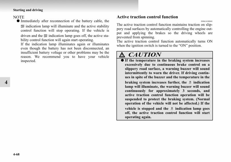
4-68
Starting and driving
4
NOTE● Immediately after reconnection of the battery cable, the
indication lamp will illuminate and the active stabilitycontrol function will stop operating. If the vehicle isdriven and the indication lamp goes off, the active sta-bility control function will again start operating.If the indication lamp illuminates again or illuminateseven though the battery has not been disconnected, aninsufficient battery voltage or other problems may be thereason. We recommend you to have your vehicleinspected.
Active traction control functionE00614100041
The active traction control function maintains traction on slip-pery road surfaces by automatically controlling the engine out-put and applying the brakes so the driving wheels areprevented from spinning.The active traction control function automatically turns ONwhen the ignition switch is turned to the “ON” position.
CAUTION!● If the temperature in the braking system increases
excessively due to continuous brake control on aslippery road surface, a warning buzzer will soundintermittently to warn the driver. If driving contin-ues in spite of the buzzer and the temperature in thebraking system increases further, the indicationlamp will illuminate, the warning buzzer will soundcontinuously for approximately 3 seconds, andactive traction control function operation will besuspended to protect the braking system. (Normaloperation of the vehicle will not be affected.) If thevehicle is stopped and the indication lamp goesoff, the active traction control function will startoperating again.
BK-BK2008E1ENUK.en-uk-Section7.fm Page 68 Wednesday, January 9, 2008 4:36 PM

Starting and driving
4-69
4
Active traction control function indication lampE00614200097
The indication lamp (1) should illuminate when the ignitionswitch is turned to the “ON” position and should go off after afew seconds.If the indication lamp stays on or does not illuminate when theignition switch is turned to the “ON” position, we recommendyou to have your vehicle inspected.When the active traction control system operates, the activetraction control function indication lamp (1) blinks and theindication lamp for the wheel (2) being subjected to antispincontrol also blinks.
Example indication: Active traction control function control-ling front-right wheel
NOTE● In the event of a fault in the active stability control func-
tion, the and indication lamps illuminate. As aresult, an indication of the active traction control functionis limited to flashing of the indication lamp for the wheel(2) being subjected to antispin control.
BK-BK2008E1ENUK.en-uk-Section7.fm Page 69 Wednesday, January 9, 2008 4:36 PM
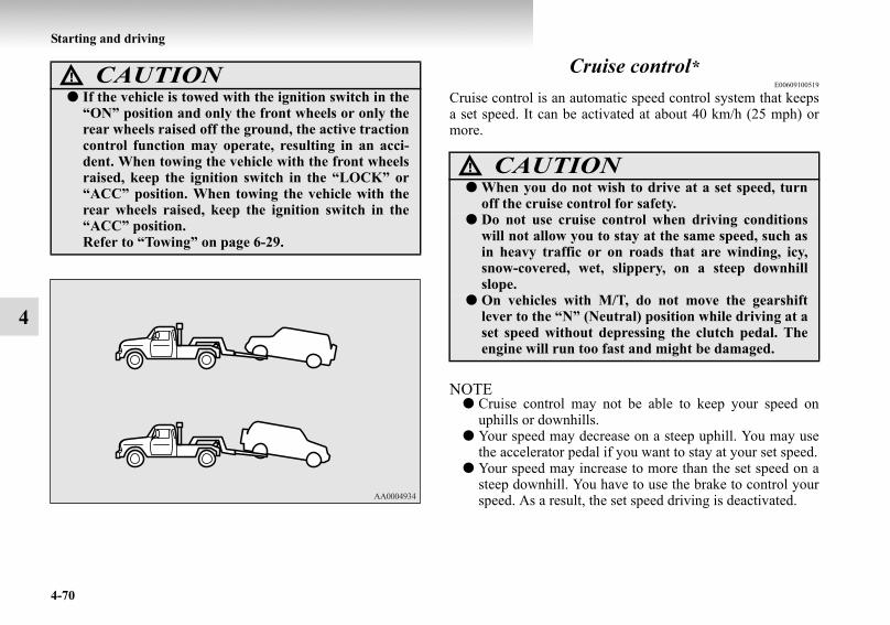
4-70
Starting and driving
4
Cruise control*E00609100519
Cruise control is an automatic speed control system that keepsa set speed. It can be activated at about 40 km/h (25 mph) ormore.
NOTE● Cruise control may not be able to keep your speed on
uphills or downhills.● Your speed may decrease on a steep uphill. You may use
the accelerator pedal if you want to stay at your set speed.● Your speed may increase to more than the set speed on a
steep downhill. You have to use the brake to control yourspeed. As a result, the set speed driving is deactivated.
CAUTION!● If the vehicle is towed with the ignition switch in the
“ON” position and only the front wheels or only therear wheels raised off the ground, the active tractioncontrol function may operate, resulting in an acci-dent. When towing the vehicle with the front wheelsraised, keep the ignition switch in the “LOCK” or“ACC” position. When towing the vehicle with therear wheels raised, keep the ignition switch in the“ACC” position.Refer to “Towing” on page 6-29.
CAUTION!● When you do not wish to drive at a set speed, turn
off the cruise control for safety.● Do not use cruise control when driving conditions
will not allow you to stay at the same speed, such asin heavy traffic or on roads that are winding, icy,snow-covered, wet, slippery, on a steep downhillslope.
● On vehicles with M/T, do not move the gearshiftlever to the “N” (Neutral) position while driving at aset speed without depressing the clutch pedal. Theengine will run too fast and might be damaged.
BK-BK2008E1ENUK.en-uk-Section7.fm Page 70 Wednesday, January 9, 2008 4:36 PM

Starting and driving
4-71
4
Cruise control switches
A- “ON OFF” switchUsed to turn on and off the cruise control.
B- “COAST SET” switchUsed to reduce the set speed and to set the desired speed.
C- “ACC RES” switch Used to increase the set speed and to return to the original setspeed.
D- “CANCEL” switchUsed to deactivate the set speed driving.
NOTE● When operating the cruise control switches, press the
cruise control switches correctly. The set speed drivingmay be deactivated automatically if two or more switchesof the cruise control are pressed at the same time.
BK-BK2008E1ENUK.en-uk-Section7.fm Page 71 Wednesday, January 9, 2008 4:36 PM

4-72
Starting and driving
4
To activateE00609300553
1. With the ignition switch in the “ON” position, press the“ON OFF” switch (A) to turn on the cruise control. The“CRUISE” indication lamp in the meter cluster will comeon.
NOTE● If the cruise control is on when the ignition switch is
turned to the “LOCK” or “ACC” position, cruise controlwill be on automatically the next time you start theengine. The “CRUISE” indication lamp will also be on.
● If the battery voltage is insufficient, the memory data forthe cruise control may be erased.As a result, the “CRUISE” indication lamp may not comeon when you restart the engine.If this happens, press the “ON OFF” switch once again toturn on the cruise control.
BK-BK2008E1ENUK.en-uk-Section7.fm Page 72 Wednesday, January 9, 2008 4:36 PM

Starting and driving
4-73
4
2. Accelerate or decelerate to your desired speed, then pressand release the “COAST SET” switch (B) when the“CRUISE” indication lamp is illuminated. The vehiclewill then maintain the desired speed.
NOTE● When you release the “COAST SET” switch, the vehicle
speed will be set.
To increase the set speedE00609400482
There are 2 ways to increase the set speed.
“ACC RES” switchPress and hold the “ACC RES” switch (C) while driving at theset speed, and your speed will then gradually increase.When you reach your desired speed, release the switch. Yournew cruising speed is now set.
To increase your speed in small amounts, press the “ACCRES” switch for less than about 1 second and release it.Each time you press the “ACC RES” switch, your vehicle willgo about 1.6 km/h (1 mph) faster.
BK-BK2008E1ENUK.en-uk-Section7.fm Page 73 Wednesday, January 9, 2008 4:36 PM

4-74
Starting and driving
4
Accelerator pedalWhile driving at the set speed, use the accelerator pedal toreach your desired speed and then press the “COAST SET”switch (B) and release the switch momentarily to set a newdesired cruising speed.
To decrease the set speedE00609500412
There are 2 ways to decrease the set speed.
“COAST SET” switchPress and hold the “COAST SET” switch (B) while driving atthe set speed, and your speed will slow down gradually.When you reach your desired speed, release the switch. Yournew cruising speed is now set.
To slow down your speed in small amounts, press the “COASTSET” switch for less than about 1 second and release it.Each time you press the “COAST SET” switch, your vehiclewill slow down by about 1.6 km/h (1 mph).
BK-BK2008E1ENUK.en-uk-Section7.fm Page 74 Wednesday, January 9, 2008 4:36 PM

Starting and driving
4-75
4
Brake pedalWhile driving at the set speed, use the brake pedal, which dis-engages the cruise control, then press the “COAST SET”switch (B) and release the switch momentarily to set a newdesired cruising speed.
To temporarily increase or decrease the speedE00619500037
To temporarily increase the speedDepress the accelerator pedal as you would normally. Whenyou release the pedal, you will return to your set speed.
BK-BK2008E1ENUK.en-uk-Section7.fm Page 75 Wednesday, January 9, 2008 4:36 PM

4-76
Starting and driving
4
To temporarily decrease the speedDepress the brake pedal to decrease the speed. To return to thepreviously set speed, press the “ACC RES” switch (C).Refer to “To resume the set speed” on page 4-77.
To deactivateE00609700632
The set speed driving can be deactivated as follows:● Press the “ON OFF” switch (A) (Cruise control will be
turned off.)● Press the “CANCEL” switch (D).● Depress the brake pedal.
The set speed driving is deactivated automatically in any of thefollowing ways.
● When you depress the clutch pedal (on vehicles withM/T).
● When your speed slows to about 15 km/h (9 mph) or morebelow the set speed because of a hill, etc.
● When your speed slows to about 40 km/h (25 mph) orless.
BK-BK2008E1ENUK.en-uk-Section7.fm Page 76 Wednesday, January 9, 2008 4:36 PM
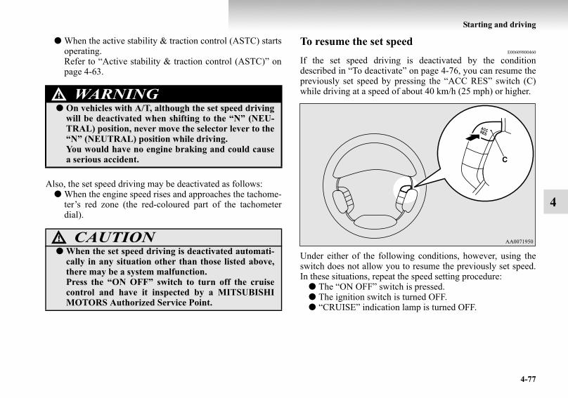
Starting and driving
4-77
4
● When the active stability & traction control (ASTC) startsoperating.Refer to “Active stability & traction control (ASTC)” onpage 4-63.
Also, the set speed driving may be deactivated as follows:● When the engine speed rises and approaches the tachome-
ter’s red zone (the red-coloured part of the tachometerdial).
To resume the set speedE00609800460
If the set speed driving is deactivated by the conditiondescribed in “To deactivate” on page 4-76, you can resume thepreviously set speed by pressing the “ACC RES” switch (C)while driving at a speed of about 40 km/h (25 mph) or higher.
Under either of the following conditions, however, using theswitch does not allow you to resume the previously set speed.In these situations, repeat the speed setting procedure:
● The “ON OFF” switch is pressed.● The ignition switch is turned OFF.● “CRUISE” indication lamp is turned OFF.
WARNING!● On vehicles with A/T, although the set speed driving
will be deactivated when shifting to the “N” (NEU-TRAL) position, never move the selector lever to the“N” (NEUTRAL) position while driving.You would have no engine braking and could causea serious accident.
CAUTION!● When the set speed driving is deactivated automati-
cally in any situation other than those listed above,there may be a system malfunction.Press the “ON OFF” switch to turn off the cruisecontrol and have it inspected by a MITSUBISHIMOTORS Authorized Service Point.
BK-BK2008E1ENUK.en-uk-Section7.fm Page 77 Wednesday, January 9, 2008 4:36 PM

4-78
Starting and driving
4
Reversing sensor system*E00615500055
This system operates when you are backing the vehicle. It usescorner and back sensors to detect an obstacle and sounds abuzzer to inform you of the approximate distance to the obsta-cle.
Corner and back sensor locationsE00618500014
There are two corner sensors (A) at the corners of the rearbumper, and two back sensors (B) in the spare wheel garnish.
Obstacle detection areasE00615600085
The detection areas of the corner and back sensors are limitedto those shown in the illustration. Because the back sensors arebuilt in the overhanging area of the vehicle (spare wheel gar-nish), the sensors are unable to detect low or thin obstacles, orobstacles on the bottom of the spare wheel garnish or the bot-tom of the centre of the rear bumper. Thus, make sure to checkthe surroundings as you operate the vehicle in a safe manner.
CAUTION!● The reversing sensor system assists you in determin-
ing the approximate distance between the vehicleand an obstacle located behind the vehicle. It haslimitations in terms of detectable areas and objects,and may not properly detect some objects. There-fore, do not place excessive confidence in the revers-ing sensor system and operate the vehicle ascarefully as you would do with a vehicle notequipped with this system.
● Make sure to check the surroundings with your owneyes to ensure safety. Do not operate the vehicle byrelying on the reversing sensor system alone.
BK-BK2008E1ENUK.en-uk-Section7.fm Page 78 Wednesday, January 9, 2008 4:36 PM

Starting and driving
4-79
4
Reversing sensor system detection areasDepending on whether the vehicle is equipped with a towingbar, you can change the reversing sensor system between thestandard mode and the towing bar mode. The towing bar modechanges the system to exclude the area in which the towing baris mounted from the detection areas.
Vehicles without towing barThe detection areas are within approximately 50 cm (A) fromthe corner sensors, 150 cm (B) from the back sensors.
Vehicles with towing barThe detection areas are within approximately 50 cm (A) fromthe corner sensors, 150 cm (B) from the back sensors. The non-detection areas (C) are within approximately 20 cm (D) fromthe bumper.
NOTE● If the rear bumper or the spare wheel garnish has been
exposed to an impact, the corner or back sensors may failand prevent the system from functioning properly. We rec-ommend you to have your vehicle inspection.
● The sensors do not detect objects located in the areadirectly below or near the bumper. If the height of anobject is lower than the mounted position of the corner orback sensors, the sensors may not continue detecting iteven if they detected it initially.
BK-BK2008E1ENUK.en-uk-Section7.fm Page 79 Wednesday, January 9, 2008 4:36 PM

4-80
Starting and driving
4
For information on how to change the detection areas, pleaserefer to “Changing the detection areas” on page 4-83.
NOTE● The buzzer may sound lower than the normal warning
sound when the corner sensor system is receiving ultra-sonic noise from other sources, but this is not a malfunc-tion. The buzzer will stop sounding and the system willreturn to normal operation after the noise is no longerreceived.
CAUTION!● The reversing sensor system may not operate prop-
erly under the following conditions:• The sensors or surroundings are covered with ice,
snow, or mud.• The sensors are frozen.• The system receives ultrasonic noise from other
sources (the horns of other vehicles, motorcycleengines, brakes, radios, pouring rain, splashingwater, tyre chains, etc.).
• The sensors are extremely hot or cold (while thevehicle is parked for a long period of time under ablazing sun or in cold weather).
• The vehicle tilts significantly.• The vehicle is driven on a rough road (with a
bumpy, gravel, hilly, or grassy surface).• The vehicle is too close to an obstacle.• The sensors or surroundings have been wiped by
hand, or stickers or accessories have beenattached.
● The reversing sensor system may not properlydetect the following:• Objects that are thin, such as wire nets or ropes.• Objects that absorb sound waves, such as snow.• Objects that are shaped with a sharp angle.• Objects with a smooth surface, such as glass.• Objects that are low, such as kerbstones.
BK-BK2008E1ENUK.en-uk-Section7.fm Page 80 Wednesday, January 9, 2008 4:36 PM
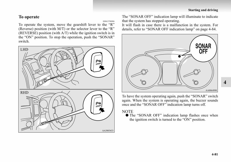
Starting and driving
4-81
4
To operateE00615700086
To operate the system, move the gearshift lever to the “R”(Reverse) position (with M/T) or the selector lever to the “R”(REVERSE) position (with A/T) while the ignition switch is inthe “ON” position. To stop the operation, push the “SONAR”switch.
The “SONAR OFF” indication lamp will illuminate to indicatethat the system has stopped operating.It will flash in case there is a malfunction in the system. Fordetails, refer to “SONAR OFF indication lamp” on page 4-84.
To have the system operating again, push the “SONAR” switchagain. When the system is operating again, the buzzer soundsonce and the “SONAR OFF” indication lamp turns off.
NOTE● The “SONAR OFF” indication lamp flashes once when
the ignition switch is turned to the “ON” position.
LHD
RHD
BK-BK2008E1ENUK.en-uk-Section7.fm Page 81 Wednesday, January 9, 2008 4:36 PM

4-82
Starting and driving
4
The warning buzzer sounds when the system detects an obsta-cle during operation.
NOTE● After pushing the “SONAR” switch, reversing sensor sys-
tem operation differs according to the detection area set-ting.• Setting when towing bar is not equipped
When the gearshift lever is moved to the “R” (Reverse)position (with M/T) or the selector lever is moved to the“R” (REVERSE) position (with A/T), the reversing sen-sor system will operate even if corner sensor operationwas stopped by pushing the “SONAR” switch.
• Setting when towing bar is equippedWhen reversing sensor system operation was stopped bypushing the “SONAR” switch, the reversing sensor sys-tem will not operate until the engine has been stoppedeven if the gearshift lever is moved to the “R” (Reverse)position (with M/T) or the selector lever is moved to the“R” (REVERSE) position (with A/T).To resume reversing sensor system operation, push the“SONAR” switch or stop and restart the engine, andthen move the gearshift lever is moved to the “R”(Reverse) position (with M/T) or the selector lever to the“R” (REVERSE) position (with A/T).
Warning for obstaclesIf there is an obstacle behind the vehicle, a warning buzzersounds to indicate the distance between the vehicle and theobstacle.
Corner sensor
Back sensor (vehicles without a towing bar)
Back sensor (vehicles with a towing bar)
Vehicle to obstacle distance Warning sound cycle
Approx. 50 to 40 cm IntermittentApprox. 40 to 25 cm Fast intermittentWithin approx. 25 cm Continuous
Vehicle to obstacle distance Warning sound cycleApprox. 150 to 80 cm IntermittentApprox. 80 to 40 cm Fast intermittentWithin approx. 40 cm Continuous
Vehicle to obstacle distance Warning sound cycleApprox. 150 to 120 cm IntermittentApprox. 120 to 60 cm Fast intermittentWithin approx. 60 cm Continuous
BK-BK2008E1ENUK.en-uk-Section7.fm Page 82 Wednesday, January 9, 2008 4:36 PM

Starting and driving
4-83
4
Changing the detection areasE00615800032
The detection areas can be changed as follows:
Vehicles with a towing barWhile the operation of the system is stopped at the “SONAR”switch, push the “SONAR” switch approximately 3 seconds ormore, and release it. The buzzer sounds twice to indicate thatthe detection area has been changed.
Vehicles without a towbarWhile the operation of the system is stopped at the “SONAR”switch, push the “SONAR” switch approximately 3 seconds ormore, and release it. The buzzer sounds once to indicate thatthe detection area has been changed.
NOTE● The detection area will not change if you keep the
“SONAR” switch pushed for 10 seconds or more.
CAUTION!● The distances given are to be used for reference only,
as errors may be caused by various factors, such astemperature, humidity, or the shape of the obstacles.
BK-BK2008E1ENUK.en-uk-Section7.fm Page 83 Wednesday, January 9, 2008 4:36 PM

4-84
Starting and driving
4
“SONAR OFF” indication lampE00615900075
In case there is a malfunction in the reversing sensor system,the “SONAR OFF” indication lamp will flash and the warningbuzzer will sound for approximately 5 seconds. Even after thebuzzer has stopped sounding, the indication lamp will continueflashing until the system reverts to the normal state. We recom-mend you to have your vehicle inspection.
Rear-view camera*E00618400013
The rear-view camera is a system that shows the view behindthe vehicle on a screen in the centre panel.
Range of view of rear-view cameraThe range of view of the rear-view camera is limited to the areashown in the illustrations. Because the camera is built in theoverhanging area of the vehicle (spare wheel garnish), it cannotshow the bottom of the spare wheel garnish and the rightbehind the vehicle (rear bumper and backdoor).When reversing, be sure to visually confirm safety around thevehicle. When reversing, be sure to visually confirm safetyaround the vehicle.
CAUTION!● The rear-view camera is an assistance system that
enables the driver to check for obstacles behind thevehicle. Its range of view is limited, so you shouldnot overly depend on it. Please drive just as carefullyas you would do with a vehicle not equipped with arear-view camera.
● Be sure to visually confirm safety around the vehiclewith your own eyes. Do not depend entirely on therear-view camera.
BK-BK2008E1ENUK.en-uk-Section7.fm Page 84 Wednesday, January 9, 2008 4:36 PM
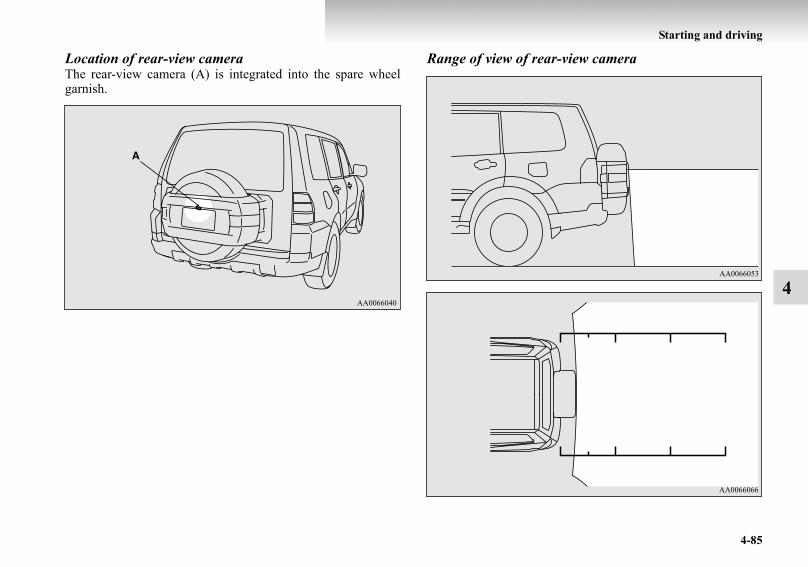
Starting and driving
4-85
4
Location of rear-view cameraThe rear-view camera (A) is integrated into the spare wheelgarnish.
Range of view of rear-view camera
BK-BK2008E1ENUK.en-uk-Section7.fm Page 85 Wednesday, January 9, 2008 4:36 PM
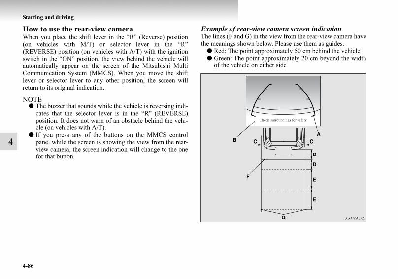
4-86
Starting and driving
4
How to use the rear-view cameraWhen you place the shift lever in the “R” (Reverse) position(on vehicles with M/T) or selector lever in the “R”(REVERSE) position (on vehicles with A/T) with the ignitionswitch in the “ON” position, the view behind the vehicle willautomatically appear on the screen of the Mitsubishi MultiCommunication System (MMCS). When you move the shiftlever or selector lever to any other position, the screen willreturn to its original indication.
NOTE● The buzzer that sounds while the vehicle is reversing indi-
cates that the selector lever is in the “R” (REVERSE)position. It does not warn of an obstacle behind the vehi-cle (on vehicles with A/T).
● If you press any of the buttons on the MMCS controlpanel while the screen is showing the view from the rear-view camera, the screen indication will change to the onefor that button.
Example of rear-view camera screen indicationThe lines (F and G) in the view from the rear-view camera havethe meanings shown below. Please use them as guides.
● Red: The point approximately 50 cm behind the vehicle● Green: The point approximately 20 cm beyond the width
of the vehicle on either side
BK-BK2008E1ENUK.en-uk-Section7.fm Page 86 Wednesday, January 9, 2008 4:36 PM

Starting and driving
4-87
4
NOTE● It is possible to set the display language of the screen to
English, Spanish, French, German, Italian, Swedish,Dutch, Danish or Portuguese.For details, please refer to the separated owner’s manualfor “Mitsubishi Multi Communication System (MMCS)”.
● When the vehicle is tilting because of the number of peo-ple in the vehicle, the weight and positioning of luggage,and/or the condition of the road surface, the lines in theview from the rear-view camera may not be accuratelypositioned relative to the actual road.
● The lines in the view from the rear-view camera are basedon a level, flat road surface. Do not use them as a guidefor distances to solid objects.
● Because the rear-view camera has a special lens, the lineson the ground between parking spaces may not look paral-lel on the screen.
● In the following situations, the screen indication may bedifficult to see. There is no abnormality.• Low light (nighttime)• When the light of the sun or the light from a vehicle’s
headlamps shines directly into the lens→ When an extremely bright spot is shown on thescreen, colour smearing* (a characteristic of CCD cam-eras) can occur.
● Colour smearing: When an extremely bright spot (forexample, sunlight that has reflected off the bumper) isshown on the screen, it appears to leave a vertical trail.
● If the camera is hot and is then cooled by rain or a carwash, the lens can mist up. This phenomenon does notindicate a malfunction.
A: Rear extremity of the rear bumperB: Spare wheel garnishC: Approx. 20 cmD: Approx. 50 cmE: Approx. 1 mF: Line (red)G: Line (green)
CAUTION!● The rear-view camera has a special lens that can
make objects shown on the screen appear to becloser or further away than they actually are.
● The line (red) shows the point approximately 50 cmbehind the rear extremity of the rear bumper.Be careful because the spare wheel garnish over-hangs for approximately 30 cm behind the rearextremity of the rear bumper.
BK-BK2008E1ENUK.en-uk-Section7.fm Page 87 Wednesday, January 9, 2008 4:36 PM

4-88
Starting and driving
4
● It is not possible to fully see obstacles when the lens isdirty. If the lens becomes contaminated by water droplets,snow, mud or oil, wipe off the contamination, taking carenot to scratch the lens.
● Please observe the following cautions. Ignoring themcould lead to a camera malfunction.• Do not subject the camera to physical shock.• Do not apply wax to the camera.• Do not splash the camera with boiling water.• Do not disassemble the camera.
Cargo loadsE00609900937
Cargo loads precautions
Loading a roof carrier
CAUTION!● Do not load cargo or luggage higher than the top of
the seatback. Be sure that your cargo or luggagecannot move once your vehicle is moving.Having the rear view blocked, and your cargo beingthrown inside the cabin if you suddenly have tobrake can cause a serious accident or injury.
● Load heavy cargo or luggage in the front of the vehi-cle. If the load in the back of the vehicle is too heavy,steering may become unstable.
CAUTION!● Use a roof carrier that properly fits your vehicle.
Do not load luggage directly onto the roof.For installation, refer to the instruction manualaccompanying the roof carrier.
BK-BK2008E1ENUK.en-uk-Section7.fm Page 88 Wednesday, January 9, 2008 4:36 PM

Starting and driving
4-89
4
Roof carrier mounting brackets*
When installing the roof carrier, use the brackets (A). Thebrackets (A) are located under each roof drip moulding (B).
NOTE● We recommend you to use a genuine MITSUBISHI roof
carrier, since the brackets to be used have a special shape.For details, we recommend you to consult a MITSU-BISHI MOTORS Authorized Service Point.
Roof carrier precaution
3-door models
5-door models
CAUTION!● Make sure that the weight of the luggage does not
exceed the allowable roof load.If the allowable roof load is exceeded, this may causedamage to the vehicle.The roof load is the total allowable load on the roof(the weight of the roof carrier plus the weight of lug-gage placed on the roof carrier).For specific figures, please refer to “Maximum roofload” on page 9-7.
● When luggage is loaded onto the vehicle, pleasemake sure to drive slowly and avoid excessivemanoeuvres such as sudden braking or quick turn-ing.In addition, place the luggage on the carrier so thatits weight is distributed evenly with the heaviestitems on the bottom. Do not load items that arewider than the roof carrier.The additional weight on the roof could raise thevehicle’s centre of gravity and affect vehicle han-dling characteristics.As a result, driving errors or emergency manoeu-vres could lead to a loss of control and result in anaccident.
● Before driving and after travelling a short distance,always check the load to make sure it is securely fas-tened to the roof carrier.Check periodically during your travel that the loadremains secure.
BK-BK2008E1ENUK.en-uk-Section7.fm Page 89 Wednesday, January 9, 2008 4:36 PM

4-90
Starting and driving
4
NOTE● To prevent wind noise or reduction in fuel economy,
remove the roof carrier when not in use.● Before using an automatic car wash, remove the roof car-
rier.● Be sure that adequate clearance is maintained for raising
the sunroof (if so equipped) when installing a roof carrier.
Trailer towingE00610000039
In order to tow a trailer with your vehicle, when having a trailertowing device mounted that meets all relevant regulations inyour area, consult a MITSUBISHI MOTORS Authorized Serv-ice Point.The regulations concerning the towing of a trailer may differfrom country to country. You are advised to obey the regula-tions in each area.
CAUTION!● Danger of Accident!
A towing bar should be fitted according to MIT-SUBISHI MOTORS guidelines.When you are going to tow a trailer, move the trans-fer shift lever to “4H” position.Selecting the “2H” drive may increase the differen-tial oil temperature, resulting in possible damage tothe driving system.Further, the drive train will be subjected to excessiveloading possibly leading to oil leakage, componentseizure, or other serious faults.
BK-BK2008E1ENUK.en-uk-Section7.fm Page 90 Wednesday, January 9, 2008 4:36 PM

Starting and driving
4-91
4
Maximum towable weight with brake and maxi-mum trailer-nose weightNever exceed the maximum towable weight with brake and themaximum trailer-nose weight as listed in the specifications.(Refer to “Vehicle weight” on page 9-7.)If you tow a trailer at an altitude of more than 1,000 m abovesea-level, reduce your weight by 10 % of the gross combina-tion weight for every increase of 1,000 m above sea-level, asthe engine output is lowered owing to decrease in atmosphericpressure.
Towing bar mounting specificationsSee the following table for fixing points (A) for the towing bar.
BK-BK2008E1ENUK.en-uk-Section7.fm Page 91 Wednesday, January 9, 2008 4:36 PM

4-92
Starting and driving
4
Item 8, 13: 5-door models onlyItem 10: at kerb weight
NOTE● The values under item 10 are applicable to unladen vehi-
cles. These values can also be varied depending on thetyre size, optional equipment and suspension conditions.
3-door models 5-door models
1 512.5 mm 794 mm2 564 mm 564 mm3 8 mm 8 mm4 124 mm 179 mm5 131 mm 131 mm6 44 mm 44 mm7 55 mm 55 mm8 — 149 mm9 139 mm 138 mm10 460 mm 477 mm11 499.7 mm 499.7 mm12 538 mm 538 mm13 — 547 mm14 576.3 mm 576.3 mm
BK-BK2008E1ENUK.en-uk-Section7.fm Page 92 Wednesday, January 9, 2008 4:36 PM
Starting and driving
4-93
4
Operating hints● Do not let the clutch slip (vehicles with a M/T only) and
do not increase the engine speed more than necessarywhen starting.
● Be sure that the driving speed does not exceed the100 km/h (62 mph) for trailer operation.It is also recommended that you obey the local regulationsin case driving speed with a trailer is limited to less than100 km/h (62 mph).
● To prevent shocks from the overrun brake, depress thebrake pedal lightly at first and then more strongly.
● To make full use of engine braking, change to a lowergear before descending a slope.
Additional precautions for vehicles equipped with an A/TThe 2nd gear (in “Sports mode”) is recommended on slopes orat low speed. Use the 1st gear (in “Sports mode”) in mountain-ous areas in order to make better use of engine braking and toassist the brake system. However, be sure that the speed doesnot exceed the maximum speed limit for the selected gear.
BK-BK2008E1ENUK.en-uk-Section7.fm Page 93 Wednesday, January 9, 2008 4:36 PM

BK-BK2008E1ENUK.en-uk-Section7.fm Page 94 Wednesday, January 9, 2008 4:36 PM
5
For pleasant driving
Ventilators . . . . . . . . . . . . . . . . . . . . . . . . . . . . . . .5- 2Front automatic air conditioning . . . . . . . . . . . . . .5- 4Rear heater* / Rear air conditioning* . . . . . . . . . .5- 15Important operation tips for the air conditioning. .5- 18Air purifier (with deodorizing function) . . . . . . . .5- 19LW/MW/FM electronic tuning radio with
CD player* . . . . . . . . . . . . . . . . . . . . . . . . . . . . .5- 20LW/MW/FM electronic tuning radio with
CD autochanger* . . . . . . . . . . . . . . . . . . . . . . . .5- 43Steering wheel remote control switch* . . . . . . . . .5- 70Error codes . . . . . . . . . . . . . . . . . . . . . . . . . . . . . . .5- 72Handling of compact discs. . . . . . . . . . . . . . . . . . .5- 74Antenna . . . . . . . . . . . . . . . . . . . . . . . . . . . . . . . . .5- 77Sun visors. . . . . . . . . . . . . . . . . . . . . . . . . . . . . . . .5- 77Ashtray*. . . . . . . . . . . . . . . . . . . . . . . . . . . . . . . . .5- 81Cigarette lighter* . . . . . . . . . . . . . . . . . . . . . . . . . .5- 82Accessory socket . . . . . . . . . . . . . . . . . . . . . . . . . .5- 83Interior lamps . . . . . . . . . . . . . . . . . . . . . . . . . . . . .5- 85Storage spaces . . . . . . . . . . . . . . . . . . . . . . . . . . . .5- 92Cup holder . . . . . . . . . . . . . . . . . . . . . . . . . . . . . . .5- 99Rear shelf (3-door models)* . . . . . . . . . . . . . . . . .5-101Cargo area cover (5-door models)* . . . . . . . . . . . .5-103Convenient hooks (5-door models)* . . . . . . . . . . .5-105
Luggage hooks . . . . . . . . . . . . . . . . . . . . . . . . . . . 5-105Coat hooks. . . . . . . . . . . . . . . . . . . . . . . . . . . . . . . 5-106Installation position for warning triangle . . . . . . . 5-107
BK-BK2008E1ENUK.en-uk-Section8.fm Page 1 Wednesday, January 9, 2008 4:41 PM

5-2
For pleasant driving
5
VentilatorsE00700100373
Front ventilators
NOTE● Do not place beverages on top of the instrument panel. If
they splash into the air conditioning ventilators, theycould damage the system.
Rear ventilators (5-door models)*
1- Centre ventilators2- Side ventilators3- Floor ventilators*
(from the centre console box)
4- Roof ventilators5- Rear floor ventilators
(from under the second seat)6- Rear floor ventilators
(from side of the third seat)
BK-BK2008E1ENUK.en-uk-Section8.fm Page 2 Wednesday, January 9, 2008 4:41 PM
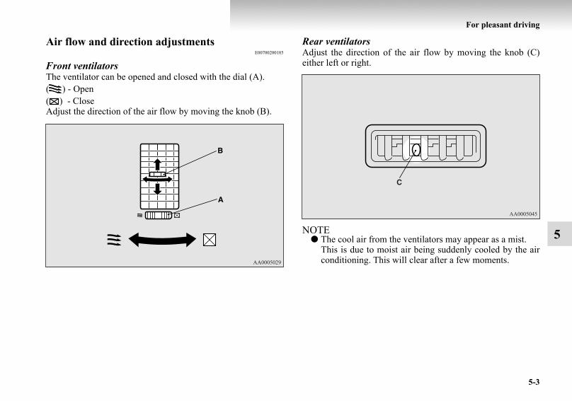
For pleasant driving
5-3
5
Air flow and direction adjustmentsE00700200185
Front ventilatorsThe ventilator can be opened and closed with the dial (A).( ) - Open( ) - CloseAdjust the direction of the air flow by moving the knob (B).
Rear ventilatorsAdjust the direction of the air flow by moving the knob (C)either left or right.
NOTE● The cool air from the ventilators may appear as a mist.
This is due to moist air being suddenly cooled by the airconditioning. This will clear after a few moments.
BK-BK2008E1ENUK.en-uk-Section8.fm Page 3 Wednesday, January 9, 2008 4:41 PM

5-4
For pleasant driving
5
Front automatic air conditioningE00702400165
The front air conditioning can only be used while the engine is running.
Control panelE00702500632
1- Temperature control dial2- Demister switch3- MODE switch4- OFF switch5- Blower speed selection dial6- AUTO switch7- Rear window demister switch → p. 3-778- Air selection switch9- Rear blower switch* → p. 5-16
10- Air condition switch11- Temperature display
12- Mode selection display13- Rear blower operation display14- Front blower speed display
BK-BK2008E1ENUK.en-uk-Section8.fm Page 4 Wednesday, January 9, 2008 4:41 PM

For pleasant driving
5-5
5
NOTE● There is an interior air temperature sensor (A) in the illus-
trated position.Never place anything on top of the sensor, since doing sowill prevent it from functioning properly.
Blower speed selection dialE00702800198
Select the blower speed by turning the blower speed selectiondial clockwise or anticlockwise. The blower speed will gradu-ally increase as the dial is turned to the right.The selected blower speed will be shown by the front blowerspeed display (A).
1- Increase2- Decrease
BK-BK2008E1ENUK.en-uk-Section8.fm Page 5 Wednesday, January 9, 2008 4:41 PM

5-6
For pleasant driving
5
Temperature control dialE00703000403
Turn the temperature control dial clockwise or anticlockwise.The selected temperature will be shown by the temperature dis-play (A).
NOTE● While the engine coolant temperature is low, the tempera-
ture of the air from the heater will be cool/cold until theengine warms up, even if you have selected warm air withthe dial.
Air selection switchE00703400436
To change the air selection, simply press the air selectionswitch.
● Outside air: Indication lamp (A) is OFFOutside air is introduced into the passenger compartment.
● Recirculated air: Indication lamp (A) is ONAir is recirculated inside the passenger compartment.
BK-BK2008E1ENUK.en-uk-Section8.fm Page 6 Wednesday, January 9, 2008 4:41 PM

For pleasant driving
5-7
5
NOTE● If you press the AUTO switch to select automatic control
after manually switching between outside air and recircu-lated air, the air selection will also be automatically con-trolled.
AUTO switchE00702600011
When the AUTO switch is pressed, the operation indicationlamp (A) illuminates and the mode selection (except for “ ”),blower speed adjustment, recirculated/outside air selection,temperature adjustment and air conditioner ON/OFF status areall controlled automatically.
CAUTION!● Normally, use the outside position to keep the wind-
screen and side windows clear and quickly removefog or frost from the windscreen.If high cooling performance is desired, or if the out-side air is dusty or otherwise contaminated use therecirculation position.Switch to the outside position periodically toincrease ventilation so that the windows do notbecome fogged up.
● Use of the recirculation position for extended timemay cause the windows to fog up.
BK-BK2008E1ENUK.en-uk-Section8.fm Page 7 Wednesday, January 9, 2008 4:41 PM

5-8
For pleasant driving
5
Air conditioning switchE00703500886
Push the switch to turn the air conditioning on, indication lamp(A) will come on.
Push the switch again to switch it off.
NOTE● If a problem is detected in the air conditioning compres-
sor, the air conditioning operation indication lamp (A)blinks. Stop the vehicle in a safe place, turn off the engine,then restart the engine. If the air conditioning operationindication lamp does not blink, there is no problem. If itdoes brink, we recommend you to have it checked.
● Sometimes, for example after using a high-pressure carwash, the condenser can get wet, and the operation indica-tion lamp (A) blinks temporarily. In this case there isnothing wrong. Stop the vehicle in a safe place, turn offthe engine, then restart the engine. Once the water evapo-rates, the blinking will stop.
CAUTION!● When using the air conditioning, the idling speed
may slightly increase as the air conditioning com-pressor is switched on/off automatically. While thevehicle with an A/T is stationary, fully depress thebrake pedal to prevent the vehicle from creeping.
BK-BK2008E1ENUK.en-uk-Section8.fm Page 8 Wednesday, January 9, 2008 4:41 PM

For pleasant driving
5-9
5
OFF switchE00702700012
Push the switch to turn off the air conditioning system.
MODE switchE00703300015
Each time the MODE switch is pressed, the mode changes tothe next one in the following sequence: “ ”→ “ ” → “ ”→ “ ” → “ ”. The selected mode is shown by the modeselection display (A). (Refer to “Changing the front modeselection” on page 5-10.)
BK-BK2008E1ENUK.en-uk-Section8.fm Page 9 Wednesday, January 9, 2008 4:41 PM

5-10
For pleasant driving
5
Demister switchE00703900037
When this switch is pressed, the mode changes to the “ ”mode. The indication lamp (A) will come on. The selectedmode is shown by the mode selection display (B). (Refer to“Changing the front mode selection” on page 5-10.)
NOTE● When the demister switch is pressed, the air conditioning
system automatically operates and outside air (as opposedto recirculated air) is selected.(Refer to “Demisting of the windscreen and door win-dows” on page 5-14.)
Changing the front mode selectionE00727100017
To change the position and amount of air flowing from the ven-tilators, push the MODE switch or demister switch. (Refer to“MODE switch” on page 5-9 and “Demister switch” on page5-10.)These symbols are used in the next several illustrations to dem-onstrate the quantity of air coming from the ventilators.
: Small amount of air from the ventilators: Medium amount of air from the ventilators: Large amount of air from the ventilators
Face positionAir flows only to the upper part of the passenger compartment.
BK-BK2008E1ENUK.en-uk-Section8.fm Page 10 Wednesday, January 9, 2008 4:41 PM

For pleasant driving
5-11
5
Foot/Face positionAir flows to the upper part of the passenger compartment, andflows to the leg area.
Foot positionAir flows mainly to the leg area.
*: Optional equipment*: Optional equipment
BK-BK2008E1ENUK.en-uk-Section8.fm Page 11 Wednesday, January 9, 2008 4:41 PM

5-12
For pleasant driving
5
Foot/Demister positionAir flows to the leg area, the windscreen and the door win-dows.
Demister positionAir flows mainly to the windscreen and the door windows.
*: Optional equipment
BK-BK2008E1ENUK.en-uk-Section8.fm Page 12 Wednesday, January 9, 2008 4:41 PM

For pleasant driving
5-13
5
Operating the system in automatic modeE00704100456
In normal conditions, use the system in the AUTO mode andfollow these procedures:
1. Push the AUTO switch.2. Select the temperature control dial to the desired tempera-
ture.
The mode selection (except for “ ”), blower speedadjustment, recirculated/outside air selection, temperatureadjustment and air conditioner ON/OFF status are all con-trolled automatically.
NOTE● When the temperature is set to the highest or the lowest
setting under the AUTO operation, the air selection andthe air conditioning will be automatically changed as fol-lows.Also, if the air selection is operated manually after anautomatic changeover, manual operation will be selected.• Quick Heating (When the temperature is set to the high-
est setting)Outside air will be introduced.
• Quick Cooling (When the temperature is set to the low-est setting)Inside air will be recirculated and the air conditioningwill operate.
CAUTION!● For vehicles with A/T, while the vehicle is stationary,
fully depress the brake pedal to prevent the vehiclefrom creeping caused by slightly increased idlingspeed when the air conditioning compressor isswitched on automatically.
BK-BK2008E1ENUK.en-uk-Section8.fm Page 13 Wednesday, January 9, 2008 4:41 PM

5-14
For pleasant driving
5
Operating the system in manual modeE00704200154
Blower speed and ventilator mode may be controlled manuallyby setting the blower speed selection dial and the MODEswitch to the desired positions.To return to automatic operation, set the AUTO operation.
Demisting of the windscreen and door windowsE00704300591
To remove frost or mist from the windscreen and door win-dows, use the MODE switch or Demister switch (“ ” or“ ”).
For ordinary demistingUse this setting to keep the windscreen and door windows clearof mist, and to keep the leg area heated.
1. Set the air selection switch (A) to the outside position.2. Set the MODE switch (B) to the “ ” position.3. Select your desired blower speed by turning the blower
speed selection dial.4. Select your desired temperature by turning the tempera-
ture control dial.5. Push the air conditioning switch (C).
CAUTION!● For safety, make sure you have a clear view through
all the windows.
BK-BK2008E1ENUK.en-uk-Section8.fm Page 14 Wednesday, January 9, 2008 4:41 PM

For pleasant driving
5-15
5
For quick demisting
1. Push the demister switch (A) to change to the “ ” posi-tion.
2. Set the blower to the maximum speed.3. Set the temperature to the highest position.
NOTE● When the demister switch is pressed, the air conditioning
will operate automatically and the outside air position willalso be selected automatically. (In this case, the air conditioning indication lamp will notchange.)
● To demist effectively, direct the air flow from the sideventilators towards the door windows.
● Do not set the temperature control dial to the max. coolposition. Cool air will blow against the window glassesand prevent demisting.
Rear heater* / Rear air conditioning*E00704600015
The rear heater can be operated when the ignition switch is inthe “ON” position.The rear air conditioning can only be used while the engine isrunning and the front air conditioning is switched on.When the front air conditioning is not switched on, only bloweroperation without cooling is possible.
Control panelE00704700016
1- Blower speed selection dial2- Main switch3- Temperature control dial
Type A
Type B
BK-BK2008E1ENUK.en-uk-Section8.fm Page 15 Wednesday, January 9, 2008 4:41 PM

5-16
For pleasant driving
5
Rear fan switch for the front seatE00705000016
When the rear blower switch is pressed, the rear blower startsoperating, the rear blower operation display (A) shows “REARON”. When the rear blower switch is pressed again, the rearblower goes off.
NOTE● Check whether or not the rear blower is operating by look-
ing at the operation display (A). The operation displayshows when the rear blower is operating.
Main switch for the rear seatE00704900018
Push the switch, and the rear blower will operate, turning theoperation indication lamp (A) on. Push the switch again, andthe rear blower will stop.
NOTE● Either the front rear switch or the rear main switch can be
used to switch the power of the rear blower ON and OFF.
BK-BK2008E1ENUK.en-uk-Section8.fm Page 16 Wednesday, January 9, 2008 4:41 PM

For pleasant driving
5-17
5
Blower speed selection dialE00705300019
The blower has 3 different speeds. Select the best speed to fityour needs.
Temperature control dialE00705500011
Type AWhen the temperature is low and you wish to increase the heat-ing performance, turn the dial to the “ON” position.
NOTE● To avoid draining of the battery, only use it while the
engine is running.
BK-BK2008E1ENUK.en-uk-Section8.fm Page 17 Wednesday, January 9, 2008 4:41 PM

5-18
For pleasant driving
5
Type BSelect the desired temperature level by turning clockwise oranticlockwise.
NOTE● If your vehicle is equipped with rear air conditioning, the
rear air conditioning will not operate unless the front airconditioning compressor is operating.Always switch the front air conditioning compressor onbefore using the rear air conditioning. If the front air con-ditioning compressor is not operating, the system will justoperate as a blower.
Important operation tips for the air conditioning
E00708300746
● Park the vehicle in the shade.Parking in the hot sun will make the vehicle insideextremely hot, and it will require more time to cool theinterior.If it is necessary to park in the sun, open the windows forthe first few minutes of air conditioning operation to expelthe hot air.
● Close the windows when the air conditioning is in use.The entry of outside air through open windows willreduce the cooling efficiency.
● Too much cooling is not good for the health. The insideair temperature should only be 5 to 6 °C below the outsideair temperature.
● When operating the system, make sure the air intake,which is located in front of the windscreen, is free ofobstructions such as leaves as snow. Leaves collected inthe air-intake plenum may reduce air flow and plug theplenum water drains.
BK-BK2008E1ENUK.en-uk-Section8.fm Page 18 Wednesday, January 9, 2008 4:41 PM

For pleasant driving
5-19
5
Air conditioning system refrigerant and lubri-cant recommendationsIf the air conditioning seems less effective than usual, the causemight be a refrigerant leak. We recommend you to have thesystem inspected.The air conditioning system in your vehicle must be chargedwith the refrigerant HFC-134a and the lubricant ND-OIL8.Use of any other refrigerant or lubricant will cause severe dam-age which will result in the need to replace your vehicle’sentire air conditioning system. The release of refrigerant intothe atmosphere is not recommended.The new refrigerant HFC-134a in your vehicle will not harmthe ozone layer.It is recommended that the refrigerant be recovered and recy-cled for further use.
During a long period of disuseThe air conditioning should be operated for at least five min-utes each week, even in cold weather. This is to prevent thecompressor from seizing and to maintain the air conditioningin the best operating condition.
Air purifier (with deodorizing function)E00708400183
An air filter is incorporated into the air conditioning system toremove pollen, dust, tobacco smells and exhaust smells.The air filter’s ability to collect pollen and dirt is reduced as itbecomes dirty, so replace it periodically. For the maintenanceinterval, refer to the “SERVICE BOOKLET”.
NOTE● Operation in certain conditions such as driving on a dusty
road and frequent use of the air conditioning can lead toreduction of service life of the filter. When the air flowrate suddenly drops or when the windscreen or windowsstart to fog up easily, the air filter requires replacement.We recommend you to have it checked.
BK-BK2008E1ENUK.en-uk-Section8.fm Page 19 Wednesday, January 9, 2008 4:41 PM

5-20
For pleasant driving
5
LW/MW/FM electronic tuning radio with CD player*
E00708500432
The audio system can be used when the ignition switch is in the“ON” or “ACC” position.
NOTE● To listen to the audio system while the engine is stopped,
turn the ignition key to the “ACC” position.● If a cellular phone is used inside the vehicle, it may create
noise from the audio equipment. This does not mean thatanything is wrong with your audio equipment. In such acase, use the cellular phone at a place as far as possiblefrom the audio equipment.
● If foreign objects or water get into the audio equipment, orif smoke or a strange odour comes from it, immediatelyturn off the audio system. We recommend you to have itchecked. Never try to repair it by yourself. Avoid continu-ous usage without inspection by a qualified person.
Volume and tone control panelE00708600114
1- PWR (On-Off) button2- VOL (Volume control) button3- Memory select buttons4- MENU button5- Sound adjust button6- Display
BK-BK2008E1ENUK.en-uk-Section8.fm Page 20 Wednesday, January 9, 2008 4:41 PM

For pleasant driving
5-21
5
To adjust the volumeE00708700229
VOL (Volume control)Press the VOL button (2) until the desired volume is reached.The status will be displayed in the display (6).
To adjust the toneE00708800653
1. Press the MENU button (4) repeatedly to select yourdesired sound customization setting to change. The orderis: EQUALIZER TYPE → LISTENER SIDE → SOUNDFIELD → BASS → MID → TREBLE → FADER →BALANCE → Sound customization mode off. The status will be displayed in the display (6).
2. Press the sound adjust button (5) to adjust the sound cus-tomization features.
ModeAdjusting operation
EQUALIZER TYPE
NONE → ROCK → POP → COUNTRY
→ R&B
R&B → COUNTRY → POP → ROCK
→ NONELISTENER SIDE LEFT RIGHT
SOUND FIELDNORMAL → STU-DIO → CLUB →
CONCERT
CONCERT → CLUB→ STUDIO → NORMAL
BASS Increase Decrease MID Increase Decrease
TREBLE Increase Decrease
FADER More sound from the front speakers
More sound from the rear speakers
BALANCE More sound from the right speakers
More sound from the left speakers
BK-BK2008E1ENUK.en-uk-Section8.fm Page 21 Wednesday, January 9, 2008 4:41 PM

5-22
For pleasant driving
5
EQUALIZER TYPE (Equalizer type select)To select the desired equalizer type.
SOUND FIELD (Sound field type select)To select the desired sound field.
BASS (Bass tone control) To select the desired bass level.
MID (Midrange tone control) To select the desired midrange level.
TREBLE (Treble tone control) To select the desired treble level.
FADER (Front/Rear balance control) To balance the volume from the F (front) and the R (rear)speakers.
BALANCE (Left/Right balance control) To balance the volume from the L (left) and the R (right)speakers.
EQUALIZER type Description
NONE Sounds good for all types of music (espe-cially for jazz and classic).
ROCK Tuned for hard rock and heavy metal with powerful drums, guitars, and vocals.
POP Tight bass and high frequency soundCOUNTRY Enhanced main vocals
R&B Clear bass and well-defined vocals
Sound field type Description
NORMAL Optimized for accurate vocal and instrument reality.
STUDIOPlaces the listener in the control room of a recording studio with a crisp and accurate forward placed sound stage.
CLUBPlaces the listener in the music at a dance or jazz club with sound coming from all direc-tions.
CONCERT
Utilizing sound reflections in the Digital Signal Processor, CONCERT gives the impression that the listener is at concert hall performance.
BK-BK2008E1ENUK.en-uk-Section8.fm Page 22 Wednesday, January 9, 2008 4:41 PM

For pleasant driving
5-23
5
Speed Compensated Volume functionE00726800277
Speed Compensated Volume function is a feature that automat-ically adjusts the VOL, BASS, MID, and TREBLE settings inaccordance with the vehicle speed. It is possible to turn thisfunction ON-OFF using the following method:
1. If you are presently pushing the MENU button (4) andmaking a tone adjustment, finish making the tone adjust-ment.
2. Push the MENU button (4) for at least about 2 seconds.The system will switch to MENU mode. Press the MENUbutton (4) repeatedly until “SCV SETTING” appears onthe display. Refer to “Function setup mode” on page 5-33.
3. Press the sound adjust button (5) to turn the “SCV SET-TING” ON and OFF.
4. To exit the menu mode, press the MENU button for 2 sec-onds or longer.
NOTE● The MENU mode will automatically shut off when either
the radio or CD is selected or the user does not operateany of the switches for 10 seconds.
BK-BK2008E1ENUK.en-uk-Section8.fm Page 23 Wednesday, January 9, 2008 4:41 PM

5-24
For pleasant driving
5
Radio control panel and displayE00708900351
1- AM/FM (FM/MW/LW selection) button2- PWR (On-Off) button3- Memory select buttons4- SEEK (Down-seek) button5- SEEK (Up-seek) button6- TUNE (Down-step) button7- TUNE (Up-step) button8- FM (FM1/FM2/FM3) indicator9- ST (Stereo) indicator
10- Preset memory number display11- Display
BK-BK2008E1ENUK.en-uk-Section8.fm Page 24 Wednesday, January 9, 2008 4:41 PM

For pleasant driving
5-25
5
To listen to the radioE00709000388
1. Press the PWR button (2) to turn the audio system on andoff.
2. Press the AM/FM button (1) to select the desired band.3. Press the TUNE button (6 or 7) or SEEK button (4 or 5) to
tune to a station, or press one of the memory select button(3) to recall a station memorised for that button.
To tune the radioE00709100318
Automatic tuningAfter pressing the SEEK button (4 or 5), the selected stationreception will start.
Manual tuningThe frequency changes every time the TUNE button (6 or 7) ispressed. The frequency changes continuously if you keep push-ing the button. Press the button to select the desired station.
To enter frequencies into the memoryE00716100440
Manual settingYou can assign to the memory select buttons (3) a maximum of18 stations in the FM band (6 FM1, 6 FM2 and 6 FM3 stations)and 6 stations each in the MW and LW band. (Stations alreadyassigned to the memory select buttons are replaced by anynewly assigned stations.)
Follow the steps described below.1. Press either the TUNE button (6 or 7) to tune the fre-
quency to be entered in the memory.2. Press one of the memory select buttons (3) for 2 seconds
or longer. The sound will be momentarily interruptedwhile the frequency is being entered into the memory.The number of the button corresponding to the entry in thememory and the frequency are displayed.
BK-BK2008E1ENUK.en-uk-Section8.fm Page 25 Wednesday, January 9, 2008 4:41 PM

5-26
For pleasant driving
5
3. The preset memory setting is retrieved by pressing thebutton for less than 2 seconds.
Automatic settingWith the method, all manually set stations in the band currentlyselected for reception are replaced with stations in the sameband that are automatically selected in order of signal strength.The radio automatically selects 6 stations in the FM band (FM3station only) and 6 stations each in the MW and LW band.
Follow the steps described below.1. With the radio mode selected, hold down the AM/FM but-
ton (1) for 2 seconds or longer. The 6 stations with thebest signal strength will automatically be assigned to thememory select buttons (3), with the lowest-frequency sta-tion being assigned to the lowest-number button.
2. When you subsequently press a memory select button toselect a channel number, the radio will begin receiving thestation assigned to that number.
NOTE● If you press the AM/FM button (1) for 2 seconds or longer
while tuning in the FM1 or FM2 band, the radio will auto-matically switch to the FM3 band, where the automaticseeking/storing will be activated.
BK-BK2008E1ENUK.en-uk-Section8.fm Page 26 Wednesday, January 9, 2008 4:41 PM

For pleasant driving
5-27
5
Radio data system (RDS)E00709200162
1- AM/FM (FM/MW/LW selection) button2- PWR (On-Off) button3- Memory select buttons4- MENU button5- SEEK (Down-seek) button6- SEEK (Up-seek) button7- TUNE (Down-step) button8- TUNE (Up-step) button9- TP (Traffic program) button
10- PTY (Program type) button11- RDS (Radio data system) indicator12- PTY (Program type) indicator13- REG (Regional program) indicator14- TP (Traffic program identification) indicator15- CT (Clock time) indicator
16- Display
BK-BK2008E1ENUK.en-uk-Section8.fm Page 27 Wednesday, January 9, 2008 4:41 PM

5-28
For pleasant driving
5
RDS uses PI (program identification) signal and AF (alterna-tive frequency) list transmitted in addition to the normal FMbroadcasting programs, and picks up the FM stations that aretransmitting the same program from the AF list and automati-cally tunes to the station with the strongest signal intensity.Therefore, you can continue listening to one program in, forexample, a long distance driving without retuning to the otherstation transmitting the same program when you are leavingthe service area of the currently receiving station.The RDS radio also features the limited reception of the pro-gram types, the break-in reception of the traffic announcementto the EON (enhanced other network) and emergency broad-cast, and the limited/unlimited reception of the regional pro-grams.
AF (Alternative Frequencies) functionE00720900090
The AF function finds a station broadcasting the same programand selects the station with the strongest signal of AF lists.The AF function is turned on at all times unless you manuallyswitch it off.
The AF function can be turned ON and OFF.Refer to “Adjusting the time” on page 3-19.
CT (Clock Time) functionE00721000085
The clock can be set automatically by using the signal from thelocal RDS stations. Refer to “Adjusting the time” on page 3-19.
REG (Regional) functionE00721100028
REG function limits to receive the stations broadcastingregional programs.Regional programming and regional networks are organizeddifferently depending on the country or area (they may bechanged according to the hour, state, or broadcast area), so ifyou don’t want to receive the regional programs automatically,you can set up REG ON not to receive regional programs.
The REG function can be turned ON and OFF.Refer to “Function setup mode” on page 5-33.
PI (Program Identification) search functionE00721200133
When travelling long distance and the recalled preset station isweak, the radio searches another frequency broadcasting thesame programming with the same PI code in AF list.If there are no frequencies broadcasting the same program-ming, the radio searches a frequency broadcasting the regionalprogramming. The radio succeeds in searching the regionalprogramming, then the display shows the REG indicator (13).If the radio does not succeed in searching the regional pro-gramming, the radio returns to the recalled preset station.
The PI function can be turned ON and OFF on some vehicles.Refer to “Function setup mode” on page 5-33.
NOTE● While searching, the audio system is muted. The display
shows “WAIT” or “SEARCH”.
BK-BK2008E1ENUK.en-uk-Section8.fm Page 28 Wednesday, January 9, 2008 4:41 PM

For pleasant driving
5-29
5
PTY (Program type)E00721300222
RDS broadcasts are classified according to program type(PTY) as follows. Use the TUNE button (7 or 8) to select yourdesired PTY.
1. NEWS2. AFFAIRS (Current affairs)3. INFO (Information)4. SPORT5. EDUCATE (Education)6. DRAMA7. CULTURE8. SCIENCE9. VARIED
10. POP M (Pop music)11. ROCK M (Rock music)12. EASY M (Easy music) 13. LIGHT M (Light classics)14. CLASSICS 15. OTHER M (Other music)16. WEATHER (Weather information)17. FINANCE18. CHILDREN19. SOCIAL20. RELIGION21. PHONE IN22. TRAVEL23. LEISURE24. JAZZ25. COUNTRY26. NATION M (National music)27. OLDIES28. FOLK M (Folk music)29. DOCUMENT
BK-BK2008E1ENUK.en-uk-Section8.fm Page 29 Wednesday, January 9, 2008 4:41 PM

5-30
For pleasant driving
5
To search for a broadcast of desired program type:1. Press the PTY button (10).2. Press the TUNE button (7 or 8) for less than 1 second at a
time to select your desired PTY.3. Two seconds after a desired PTY has been selected, the
radio will begin to search for a broadcast of your selectedPTY. During search, the selected PTY on the displayblinks.
4. When the radio picks up a station with your desired PTY,the display will show the name of the station.
NOTE● If the SEEK button (5 or 6) is pressed for less than 1 sec-
ond, the radio will try to find out another broadcast of thesame program type as currently selected.
● If no station is found with your desired PTY, the displaywill show “EMPTY” for about 5 seconds and the radiowill return to the previous station.
How to enter PTYs in the memoryE00721400089
As many as 6 PTYs can be entered in the memory.Follow the steps described below.
1. Press either the TUNE button (7 or 8) to tune the PTY tobe entered in the memory.
2. Press one of the memory select buttons (3) for 2 secondsor longer. The sound will be momentarily interruptedwhile the PTY is being entered into the memory. Thenumber of the button corresponding to the entry into thememory and the PTY are displayed.
3. The preset memory setting is retrieved by pressing thebutton and then releasing it within about 2 seconds.
BK-BK2008E1ENUK.en-uk-Section8.fm Page 30 Wednesday, January 9, 2008 4:41 PM

For pleasant driving
5-31
5
Traffic informationE00721600137
The radio will automatically tune in to traffic informationbroadcasts while receiving FM broadcasts or playing compactdiscs.To select this function:
1. Press the TP button (9). The display will show TP indica-tor (14). If the RDS data can be read, the display willshow RDS indicator (11). If not, the display will show“NO RDS” for about 5 seconds.
2. If the radio detects traffic information on either the stationcurrently selected or another station, the display will show“TRAF INF” for 5 seconds followed by a 2-second indi-cation of the frequency. Then, it will show the name of thestation broadcasting the traffic information to which youwill listen. The volume level is set separately for listeningto normal audio programs and for listening to traffic infor-mation. The volume level will therefore change automati-cally to that set when traffic information was last received.When the traffic information broadcast is over, the radiowill return to the previously received program and to thecorresponding volume level.
3. Press the TP button (9) to return to the previous condition.
NOTE● While “TP” is illuminated, the radio stops only at TP sta-
tions even if the TUNE button (7 or 8) is pressed.
BK-BK2008E1ENUK.en-uk-Section8.fm Page 31 Wednesday, January 9, 2008 4:41 PM

5-32
For pleasant driving
5
TP (Traffic information Program) search functionE00721800100
The traffic information program search function is turned on(with the TP indicator (14) shown on the display), if:
● The RDS is off for 45 seconds due to a weak signal.● The station is changed to another station without a TP sig-
nal and then 45 seconds elapse.When turning on, 5 beeps will be heard and a new TP stationwill be searched for.
Emergency broadcastsE00721700138
If an emergency broadcast is caught while receiving a FMbroadcast or playing back a compact disc, the display willshow “ALARM” and the emergency broadcast will interruptthe current program. The volume level is set separately for lis-tening to normal audio programs and for listening to emer-gency broadcasts. The volume level will therefore changeautomatically to that set when an emergency broadcast or traf-fic information broadcast was last received. When the emer-gency broadcast is over, the radio will return to the previouslyreceived program and to the corresponding volume level.
BK-BK2008E1ENUK.en-uk-Section8.fm Page 32 Wednesday, January 9, 2008 4:41 PM

For pleasant driving
5-33
5
Function setup modeE00722500205
It is possible to change the following functions:● AF● CT● REG● TP-S● PI-S*● SCV (Refer “Speed Compensated Volume function” on
page 5-23).● PHONE
1. Press the “MENU” button (4) for 2 seconds longer toselect the function setup mode.
BK-BK2008E1ENUK.en-uk-Section8.fm Page 33 Wednesday, January 9, 2008 4:41 PM

5-34
For pleasant driving
5
2. Press the “MENU” button (4) repeatedly to select themode you wish to change.The order is: AF → CT → REG → TP-S → PI-S* →SCV → PHONE → Function setup mode OFF.
NOTE● Although “PHONE” appears on the display, the PHONE
function is inoperative.
BK-BK2008E1ENUK.en-uk-Section8.fm Page 34 Wednesday, January 9, 2008 4:41 PM

For pleasant driving
5-35
5
3. Select the desired setting for each mode to be turned ONand OFF as shown below.The setting will be shown on the display.
NOTE● After selecting a mode, you can leave the function setup
mode by taking either of the following steps:• Press the “MENU” button for at least 2 seconds.• Make no entry for 10 seconds.
Example
BK-BK2008E1ENUK.en-uk-Section8.fm Page 35 Wednesday, January 9, 2008 4:41 PM

5-36
For pleasant driving
5
CD control panel and displayE00709500309
1- AM/FM button2- PWR (On-Off) button3- DISP (Title display) button4- CD (CD mode changeover) button5- RPT (Repeat) button6- RDM (Random) button7- CD eject button8- Disc-loading slot9- Fast-forward/Fast-reverse button
10- PAGE (Title scroll) button11- TRACK (Track up/down) button12- FOLDER (Folder down) button13- FOLDER (Folder up) button14- SCAN button15- DISC (Disc up/down) button
16- CD indicator17- TRACK indicator18- Track play time indicator19- RPT/RDM indicator20- SCAN indicator
BK-BK2008E1ENUK.en-uk-Section8.fm Page 36 Wednesday, January 9, 2008 4:41 PM

For pleasant driving
5-37
5
To listen to a CDE00709601062
1. Insert a disc with the label facing up, and the CD playerwill begin playing even if the radio is being used. The CDindicator (16), the track number and the playing time willappear on the display. The CD player will also start play-back when the CD button (4) is pressed with a disc in theplayer.
2. To stop the CD, turn off the power by pressing the PWRbutton (2) or change over to radio mode by pressing theAM/FM buttons (1), or eject the disc by pressing the ejectbutton (7).
NOTE● To adjust the volume and tone, refer to “To adjust the vol-
ume” on page 5-21 and “To adjust the tone” on page 5-21.● For information concerning the handling of compact
discs, refer to “Handling of compact discs” on page 5-74.
To listen to an MP3 CDThis CD player allows you to play MP3 (MPEG Audio Layer-3) files recorded on CD-ROMs, CD-Rs (recordable CDs), andCD-RWs (rewritable CDs) in ISO9660 Level 1/Level 2, Joliet,and Romeo formats. Each disc may have a maximum of16 trees, 100 folders, and 255 files per disc. During MP3 play-back, the unit can display ID3 tag information. For informationconcerning ID3 tag, refer to “CD text and MP3 title display” onpage 5-41.
1. Insert a disc containing MP3 files into the slot.2. Press the CD button (4) for 2 seconds or longer to switch
to MP3 CD mode from normal music CD mode. The dis-play shows “READING”, then playback will begin. Thefolder number and the track number will appear on thedisplay.
BK-BK2008E1ENUK.en-uk-Section8.fm Page 37 Wednesday, January 9, 2008 4:41 PM
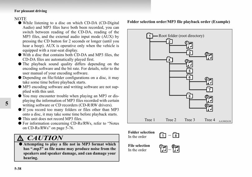
5-38
For pleasant driving
5
NOTE● While listening to a disc on which CD-DA (CD-Digital
Audio) and MP3 files have both been recorded, you canswitch between reading of the CD-DA, reading of theMP3 files, and the external audio input mode (AUX) bypressing the CD button for 2 seconds or longer (until youhear a beep). AUX is operative only when the vehicle isequipped with a rear-seat display.
● With a disc that contains both CD-DA and MP3 files, theCD-DA files are automatically played first.
● The playback sound quality differs depending on theencoding software and the bit rate. For details, refer to theuser manual of your encoding software.
● Depending on file/folder configurations on a disc, it maytake some time before playback starts.
● MP3 encoding software and writing software are not sup-plied with this unit.
● You may encounter trouble when playing an MP3 or dis-playing the information of MP3 files recorded with certainwriting software or CD recorders (CD-R/RW drivers).
● If you record too many folders or files other than MP3onto a disc, it may take some time before playback starts.
● This unit does not record MP3 files.● For information concerning CD-Rs/RWs, refer to “Notes
on CD-Rs/RWs” on page 5-76.
Folder selection order/MP3 file playback order (Example)
CAUTION!● Attempting to play a file not in MP3 format which
has “.mp3” as file name may produce noise from thespeakers and speaker damage, and can damage yourhearing.
Folder selection In the order
File selectionIn the order
Root folder (root directory)
Tree 1 Tree 2 Tree 3 Tree 4
BK-BK2008E1ENUK.en-uk-Section8.fm Page 38 Wednesday, January 9, 2008 4:41 PM
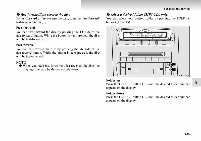
For pleasant driving
5-39
5
To fast-forward/fast-reverse the discTo fast-forward or fast-reverse the disc, press the fast-forward/fast-reverse button (9).
Fast-forwardYou can fast-forward the disc by pressing the side of thefast-forward button. While the button is kept pressed, the discwill be fast-forwarded.
Fast-reverseYou can fast-reverse the disc by pressing the side of thefast-reverse button. While the button is kept pressed, the discwill be fast-reversed.
NOTE● When you have fast-forwarded/fast-reversed the disc, the
playing-time may be shown with deviation.
To select a desired folder (MP3 CDs only)You can select your desired folder by pressing the FOLDERbuttons (12 or 13).
Folder upPress the FOLDER button (13) until the desired folder numberappears on the display.
Folder downPress the FOLDER button (12) until the desired folder numberappears on the display.
BK-BK2008E1ENUK.en-uk-Section8.fm Page 39 Wednesday, January 9, 2008 4:41 PM

5-40
For pleasant driving
5
To select a desired track You can select your desired track by using the TRACK button(11).
Track upPress the side of the TRACK button (11) repeatedly untilthe desired track number appears on the display.
Track down Press the side of the TRACK button (11) repeatedly untilthe desired track number appears on the display.
NOTE● Pressing the side of the TRACK button (11) once dur-
ing the song will cause the CD player to restart playbackfrom the beginning of the song.
To repeat a trackPress the RPT button (5) briefly while the track is playing.“RPT” will appear on the display. To exit the repeat mode,press the RPT button again.
To repeat a folder (MP3 CDs only)Press the RPT button (5) for 1 second or longer (until you heara beep). “D-RPT” will appear on the display. You can listen toall the tracks in the currently selected folder repeatedly.
NOTE● The track repeat mode will be canceled by pressing the
TRACK button (11), the SCAN button (14) or the ejectbutton (7).
● The disc repeat mode will be canceled by pressing theDISC button (15), the SCAN button (14) or the eject but-ton (7).
● With a disc that contains both CD-DA and MP3 files, therepeat mode causes only files of the same format (CD-DAonly or MP3 files only) to be repeated.
To play tracks in random orderRandom playback for a disc (music CDs only)Press the RDM button (6) briefly. “RDM” will appear on thedisplay. Tracks on the currently selected disc will be played ina random sequence.To exit the random mode, press the RDM button again.
Random playback for a folder (MP3 CDs only)Press the RDM button (6) briefly. “RDM” will appear on thedisplay. Tracks in the currently selected folder will be played ina random sequence. To exit the random mode, press the RDMbutton again.
Random playback for all folders on a disc (MP3 CDs only)Press the RDM button (6) for 1 second or longer (until youhear a beep). “D-RDM” will appear on the display. Tracksfrom all the folders on the currently selected disc will beplayed in a random sequence. To exit the random mode, brieflypress the RDM button again.
NOTE● With a disc that contains both CD-DA and MP3 files, the
random mode causes only files of the same format (CD-DA only or MP3 files only) to be played in a randomsequence.
BK-BK2008E1ENUK.en-uk-Section8.fm Page 40 Wednesday, January 9, 2008 4:41 PM
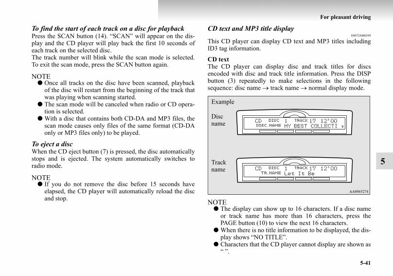
For pleasant driving
5-41
5
To find the start of each track on a disc for playbackPress the SCAN button (14). “SCAN” will appear on the dis-play and the CD player will play back the first 10 seconds ofeach track on the selected disc.The track number will blink while the scan mode is selected.To exit the scan mode, press the SCAN button again.
NOTE● Once all tracks on the disc have been scanned, playback
of the disc will restart from the beginning of the track thatwas playing when scanning started.
● The scan mode will be canceled when radio or CD opera-tion is selected.
● With a disc that contains both CD-DA and MP3 files, thescan mode causes only files of the same format (CD-DAonly or MP3 files only) to be played.
To eject a discWhen the CD eject button (7) is pressed, the disc automaticallystops and is ejected. The system automatically switches toradio mode.
NOTE● If you do not remove the disc before 15 seconds have
elapsed, the CD player will automatically reload the discand stop.
CD text and MP3 title displayE00725000399
This CD player can display CD text and MP3 titles includingID3 tag information.
CD textThe CD player can display disc and track titles for discsencoded with disc and track title information. Press the DISPbutton (3) repeatedly to make selections in the followingsequence: disc name → track name → normal display mode.
NOTE● The display can show up to 16 characters. If a disc name
or track name has more than 16 characters, press thePAGE button (10) to view the next 16 characters.
● When there is no title information to be displayed, the dis-play shows “NO TITLE”.
● Characters that the CD player cannot display are shown as“ ”.
Example
Disc name
Track name
BK-BK2008E1ENUK.en-uk-Section8.fm Page 41 Wednesday, January 9, 2008 4:41 PM

5-42
For pleasant driving
5
MP3 titleThe CD player can display folder and track titles for discsencoded with folder and track information. Press the DISP but-ton (3) for less than 1 second repeatedly to make selections inthe following sequence: folder name → track name → normaldisplay mode.
ID3 tag informationThe CD player can display ID3 tag information for files thathave been recorded with ID3 tag information.
1. Press the DISP button (3) for 2 seconds or longer toswitch to the ID3 tag information. “TAG” indicator willappear on the display.
2. Then press the DISP button for less than 1 second repeat-edly to make selections in the following sequence: albumname → track name → artist name → normal displaymode.
NOTE● To return from ID3 tag information to the folder name,
press the DISP button (3) again for 2 seconds or longer.● When there is no title information to be displayed, the dis-
play shows “NO TITLE”.● The display can show up to 16 characters. If a folder
name, track name, or item of ID3 tag information hasmore than 16 characters, press the PAGE button (10) toview the next 16 characters.
● Folder names and track names can each be displayed up toa length of 32 characters. Items of ID3 tag informationcan each be displayed up to a length of 30 characters.
● Characters that the CD player cannot display are shown as“ ”.
Example
Folder name
Track name
BK-BK2008E1ENUK.en-uk-Section8.fm Page 42 Wednesday, January 9, 2008 4:41 PM

For pleasant driving
5-43
5
LW/MW/FM electronic tuning radio with CD autochanger*
E00708500706
The audio system can be used when the ignition switch is in the“ON” or “ACC” position.
NOTE● To listen to the audio system while the engine is stopped,
turn the ignition key to the “ACC” position.● If a cellular phone is used inside the vehicle, it may create
noise from the audio equipment. This does not mean thatanything is wrong with your audio equipment. In such acase, use the cellular phone at a place as far as possiblefrom the audio equipment.
● If foreign objects or water get into the audio equipment, orif smoke or a strange odour comes from it, immediatelyturn off the audio system. We recommend you to have itchecked. Never try to repair it by yourself. Avoid continu-ous usage without inspection by a qualified person.
Volume and tone control panelE00708600433
1- PWR (On-Off) button2- VOL (Volume control) button3- Memory select buttons4- MENU button5- Sound adjust button6- Display
BK-BK2008E1ENUK.en-uk-Section8.fm Page 43 Wednesday, January 9, 2008 4:41 PM

5-44
For pleasant driving
5
To adjust the volumeE00708700274
VOL (Volume control)Press the VOL button (2) until the desired volume is reached.The status will be displayed in the display (6).
To adjust the toneE00708800666
AUDIO CONTROL ADJUSTMENT MODE1. Press the MENU button (4) repeatedly to select your
desired sound customization setting to change. The orderis: AUDIO CONTROL/SURROUND CONTROL →SUBWOOFER GAIN → EQUALIZER TYPE → LIS-TENER SIDE → SOUND FIELD → BASS → MID →TREBLE → FADER → BALANCE → Sound customiza-tion mode off. The status will be displayed in the display (6).
NOTE● The AUDIO CONTROL/SURROUND CONTROL,
SUBWOOFER GAIN can only be adjusted on vehicleswith a premium sound system.On vehicles without a premium sound system, when youpress the MENU button (4), the display starts fromEQUALIZER TYPE.
BK-BK2008E1ENUK.en-uk-Section8.fm Page 44 Wednesday, January 9, 2008 4:41 PM

For pleasant driving
5-45
5
2. Press the sound adjust button (5) to adjust the sound cus-tomization features.
SUBWOOFER GAIN (Subwoofer tone control) (for premium sound system) To select the desired subwoofer GAIN level.
EQUALIZER TYPE (Equalizer type select)To select the desired equalizer type.
LISTENER SIDE (Listener side select)To select the desired listener side.
SOUND FIELD (Sound field type select)To select the desired sound field.
ModeAdjusting operation
SUBWOOFER GAIN Increase Decrease
EQUALIZER TYPE
NONE → ROCK → POP → COUNTRY
→ R&B
R&B → COUNTRY → POP → ROCK
→ NONELISTENER SIDE LEFT RIGHT
SOUND FIELDNORMAL → STU-DIO → CLUB →
CONCERT
CONCERT → CLUB→ STUDIO → NORMAL
BASS Increase Decrease MID Increase Decrease
TREBLE Increase Decrease
FADER More sound from the front speakers
More sound from the rear speakers
BALANCE More sound from the right speakers
More sound from the left speakers
EQUALIZER type Description
NONE Sounds good for all types of music (espe-cially for jazz and classic).
ROCK Tuned for hard rock and heavy metal with powerful drums, guitars, and vocals.
POP Tight bass and high frequency soundCOUNTRY Enhanced main vocals
R&B Clear bass and well-defined vocals
Sound field type Description
NORMAL Optimized for accurate vocal and instrument reality.
STUDIOPlaces the listener in the control room of a recording studio with a crisp and accurate forward placed sound stage.
CLUBPlaces the listener in the music at a dance or jazz club with sound coming from all direc-tions.
BK-BK2008E1ENUK.en-uk-Section8.fm Page 45 Wednesday, January 9, 2008 4:41 PM

5-46
For pleasant driving
5
BASS (Bass tone control) To select the desired bass level.
MID (Midrange tone control) To select the desired midrange level.
TREBLE (Treble tone control) To select the desired treble level.
FADER (Front/Rear balance control) To balance the volume from the F (front) and the R (rear)speakers.
BALANCE (Left/Right balance control) To balance the volume from the L (left) and the R (right)speakers.
SURROUND CONTROL ADJUSTMENT MODE (for premium sound system)
1. Press the MENU button (4). The display will show“AUDIO CONTROL/SURROUND CONTROL”.
2. Press the sound adjust button(5) to align the cursor with“SURROUND CONTROL”. Then press the MENU but-ton (4) to select the surround control adjustment mode.
3. Press the MENU button (4) repeatedly to select yourdesired sound customization setting to change. The orderis: SURROUND CONTROL → SURROUND MODE →SOUND TYPE → LISTENING POSITION → Soundcustomization mode off.The status will be displayed in the display (6).
4. Press the sound adjust button (5) to adjust the sound cus-tomization features.
CONCERT
Utilizing sound reflections in the Digital Signal Processor, CONCERT gives the impression that the listener is at concert hall performance.
Sound field type Description
Cursor
BK-BK2008E1ENUK.en-uk-Section8.fm Page 46 Wednesday, January 9, 2008 4:41 PM

For pleasant driving
5-47
5
SURROUND MODE (Surround mode select) (for pre-mium sound system)To select the desired surround mode.
NOTE● 5.1ch DOLBY DIGITAL · DTS can be selected only
when DVDs recorded with Dolby Digital or DTS 5.1-channel surround are played in the rear-seat display. Withsuch DVDs, DOLBY PRO LOGIC II cannot be selected.
● Dolby Digital systems are manufactured under licensefrom Dolby Laboratories Licensing Corporation. “Dolby”and the double-D symbol are trademarks of Dolby Labo-ratories Licensing Corporation. DTS systems are manu-factured under license from Digital Theater Systems.“DTS” and “Digital Surround” are trademarks of DigitalTheater Systems.
SOUND TYPE (Sound type select) (for premium sound system)To select the desired sound type.
LISTENING POSITION (Listening position select) (for premium sound system)To select the desired listening position.
SURROUND MODE Description
5.1ch DOLBY DIGITAL · DTS
Creates a realistic three-dimensional sound field using 5.1ch technology. Gives clear surround-sound with rich presence from dig-ital sound sources.
DOLBY PRO LOGIC II
Creates a three-dimensional listening envi-ronment from CDs and other typical sound sources. Gives surround-sound with rich presence.
2CH STEREO SOUND
Gives high-quality stereo sound using a 12-speaker system.
SOUND TYPE DescriptionCINEMA The optimal setting for watching a movieMUSIC The optimal setting for listening to music
LISTENING POSITION Description
1ST SEATS The optimal setting for enjoying surround sound in the first-row seats
2ND SEATS The optimal setting for enjoying surround sound in the second-row seats
ALL SEATS The optimal setting for enjoying surround sound in all seats
BK-BK2008E1ENUK.en-uk-Section8.fm Page 47 Wednesday, January 9, 2008 4:41 PM

5-48
For pleasant driving
5
NOTE● Depending on the selected tone adjustment mode, certain
other adjustment modes cannot be used. Adjustments arenot possible as follows:• When the surround mode menu setting is “STEREO”:→ The sound type menu and listening position menucannot be used.
• When the surround mode menu setting is “5.1chDOLBY DIGITAL · DTS” or “DOLBY PRO LOGICII”:→ The sound field menu cannot be used.
• When the sound type menu setting is “CINEMA”:→ The equalizer type menu and sound field menu can-not be used.
Speed Compensated Volume functionE00726800280
Speed Compensated Volume function is a feature that automat-ically adjusts the VOL, BASS, MID, and TREBLE settings inaccordance with the vehicle speed. It is possible to turn thisfunction ON-OFF using the following method:
1. If you are presently pushing the MENU button (4) andmaking a tone adjustment, finish making the tone adjust-ment.
2. Push the MENU button (4) for at least about 2 seconds.The system will switch to MENU mode. Press the MENUbutton (4) repeatedly until “SCV SETTING” appears onthe display. Refer to “Function setup mode” on page 5-57.
3. Press the sound adjust button (5) to turn the “SCV SET-TING” ON and OFF.
4. To exit the menu mode, press the MENU button for 2 sec-onds or longer.
NOTE● The MENU mode will automatically shut off when either
the radio or CD is selected or the user does not operateany of the switches for 10 seconds.
BK-BK2008E1ENUK.en-uk-Section8.fm Page 48 Wednesday, January 9, 2008 4:41 PM

For pleasant driving
5-49
5
Radio control panel and displayE00708900436
1- AM/FM (FM/MW/LW selection) button2- PWR (On-Off) button3- Memory select button4- SEEK (Down-seek) button5- SEEK (Up-seek) button6- TUNE (Down-step) button7- TUNE (Up-step) button8- FM (FM1/FM2/FM3) indicator9- ST (Stereo) indicator
10- Preset memory number display11- Display
BK-BK2008E1ENUK.en-uk-Section8.fm Page 49 Wednesday, January 9, 2008 4:41 PM

5-50
For pleasant driving
5
To listen to the radioE00709000418
1. Press the PWR button (2) to turn the audio system on andoff.Press the AM/FM button (1) to turn on the radio if a CD isbeing played.
2. Press the AM/FM button (1) to select the desired band.3. Press the TUNE button (6 or 7) or SEEK button (4 or 5) to
tune to a station, or press one of the memory select button(3) to recall a station memorised for that button.
To tune the radioE00709100350
Automatic tuningAfter pressing the SEEK button (4 or 5), the selected stationreception will start.
Manual tuningThe frequency changes every time the TUNE button (6 or 7) ispressed. The frequency changes continuously if you keep push-ing the button. Press the button to select the desired station.
To enter frequencies into the memoryE00716100567
Manual settingYou can assign to the memory select buttons (3) a maximum of18 stations in the FM band (6 FM1, 6 FM2 and 6 FM3 stations)and 6 stations each in the MW and LW band. (Stations alreadyassigned to the memory select buttons are replaced by anynewly assigned stations.)
BK-BK2008E1ENUK.en-uk-Section8.fm Page 50 Wednesday, January 9, 2008 4:41 PM

For pleasant driving
5-51
5
Follow the steps described below.1. Press either the TUNE button (6 or 7) to tune the fre-
quency to be entered in the memory.2. Press one of the memory select buttons (3) for 2 seconds
or longer. The sound will be momentarily interruptedwhile the frequency is being entered into the memory.The number of the button corresponding to the entry in thememory and the frequency are displayed.
3. The preset memory setting is retrieved by pressing thebutton for less than 2 seconds.
Automatic settingWith the method, all manually set stations in the band currentlyselected for reception are replaced with stations in the sameband that are automatically selected in order of signal strength.The radio automatically selects 6 stations in the FM band (FM3station only) and 6 stations each in the MW and LW band.
Follow the steps described below.1. With the radio mode selected, hold down the AM/FM but-
ton (1) for 2 seconds or longer. The 6 stations with thebest signal strength will automatically be assigned to thememory select buttons (3), with the lowest-frequency sta-tion being assigned to the lowest-number button.
2. When you subsequently press a memory select button toselect a channel number, the radio will begin receiving thestation assigned to that number.
NOTE● If you press the AM/FM button (1) for 2 seconds or longer
while tuning in the FM1 or FM2 band, the radio will auto-matically switch to the FM3 band, where the automaticseeking/storing will be activated.
BK-BK2008E1ENUK.en-uk-Section8.fm Page 51 Wednesday, January 9, 2008 4:41 PM

5-52
For pleasant driving
5
Radio data system (RDS)E00709200175
1- AM/FM (FM/MW/LW selection) button2- PWR (On-Off) button3- Memory select buttons4- MENU button5- SEEK (Down-seek) button6- SEEK (Up-seek) button7- TUNE (Down-step) button8- TUNE (Up-step) button9- TP (Traffic program) button
10- PTY (Program type) button11- RDS (Radio data system) indicator12- PTY (Program type) indicator13- REG (Regional program) indicator14- TP (Traffic program identification) indicator15- CT (Clock time) indicator
16- Display
BK-BK2008E1ENUK.en-uk-Section8.fm Page 52 Wednesday, January 9, 2008 4:41 PM

For pleasant driving
5-53
5
RDS uses PI (program identification) signal and AF (alterna-tive frequency) list transmitted in addition to the normal FMbroadcasting programs, and picks up the FM stations that aretransmitting the same program from the AF list and automati-cally tunes to the station with the strongest signal intensity.Therefore, you can continue listening to one program in, forexample, a long distance driving without retuning to the otherstation transmitting the same program when you are leavingthe service area of the currently receiving station.The RDS radio also features the limited reception of the pro-gram types, the break-in reception of the traffic announcementto the EON (enhanced other network) and emergency broad-cast, and the limited/unlimited reception of the regional pro-grams.
AF (Alternative Frequencies) functionE00720900104
The AF function finds a station broadcasting the same programand selects the station with the strongest signal of AF lists.The AF function is turned on at all times unless you manuallyswitch it off.
The AF function can be turned ON and OFF.Refer to “Function setup mode” on page 5-57.
CT (Clock Time) functionE00721000098
The clock can be set automatically by using the signal from thelocal RDS stations. Refer to “Adjusting the time” on page 3-19.
REG (Regional) functionE00721100015
REG function limits to receive the stations broadcastingregional programs.Regional programming and regional networks are organizeddifferently depending on the country or area (they may bechanged according to the hour, state, or broadcast area), so ifyou don’t want to receive the regional programs automatically,you can set up REG ON not to receive regional programs.
The REG function can be turned ON and OFF.Refer to “Function setup mode” on page 5-57.
PI (Program Identification) search functionE00721200146
When travelling long distance and the recalled preset station isweak, the radio searches another frequency broadcasting thesame programming with the same PI code in AF list.If there are no frequencies broadcasting the same program-ming, the radio searches a frequency broadcasting the regionalprogramming. The radio succeeds in searching the regionalprogramming, then the display shows the REG indicator (13).If the radio does not succeed in searching the regional pro-gramming, the radio returns to the recalled preset station.
The PI function can be turned ON and OFF on some vehicles.Refer to “Function setup mode” on page 5-57.
NOTE● While searching, the audio system is muted. The display
shows “WAIT” or “SEARCH”.
BK-BK2008E1ENUK.en-uk-Section8.fm Page 53 Wednesday, January 9, 2008 4:41 PM

5-54
For pleasant driving
5
PTY (Program type)E00721300235
RDS broadcasts are classified according to program type(PTY) as follows. Use the TUNE button (7 or 8) to select yourdesired PTY.
1. NEWS2. AFFAIRS (Current affairs)3. INFO (Information)4. SPORT5. EDUCATE (Education)6. DRAMA7. CULTURE8. SCIENCE9. VARIED
10. POP M (Pop music)11. ROCK M (Rock music)12. EASY M (Easy music) 13. LIGHT M (Light classics)14. CLASSICS 15. OTHER M (Other music)16. WEATHER (Weather information)17. FINANCE18. CHILDREN19. SOCIAL20. RELIGION21. PHONE IN22. TRAVEL23. LEISURE24. JAZZ25. COUNTRY26. NATION M (National music)
27. OLDIES28. FOLK M (Folk music)29. DOCUMENT
To search for a broadcast of desired program type:1. Press the PTY button (10).2. Press the TUNE button (7 or 8) for less than 1 second at a
time to select your desired PTY.3. Two seconds after a desired PTY has been selected, the
radio will begin to search for a broadcast of your selectedPTY. During search, the selected PTY on the displayblinks.
4. When the radio picks up a station with your desired PTY,the display will show the name of the station.
BK-BK2008E1ENUK.en-uk-Section8.fm Page 54 Wednesday, January 9, 2008 4:41 PM

For pleasant driving
5-55
5
NOTE● If the SEEK button (5 or 6) is pressed for less than 1 sec-
ond, the radio will try to find out another broadcast of thesame program type as currently selected.
● If no station is found with your desired PTY, the displaywill show “EMPTY” for about 5 seconds and the radiowill return to the previous station.
How to enter PTYs in the memoryE00721400092
As many as 6 PTYs can be entered in the memory.Follow the steps described below.
1. Press either the TUNE button (7 or 8) to tune the PTY tobe entered in the memory.
2. Press one of the memory select buttons (3) for 2 secondsor longer. The sound will be momentarily interruptedwhile the PTY is being entered into the memory. Thenumber of the button corresponding to the entry into thememory and the PTY are displayed.
3. The preset memory setting is retrieved by pressing thebutton and then releasing it within about 2 seconds.
Traffic informationE00721600140
The radio will automatically tune in to traffic informationbroadcasts while receiving FM broadcasts or playing compactdiscs.To select this function:
1. Press the TP button (9). The display will show TP indica-tor (14). If the RDS data can be read, the display willshow RDS indicator (11). If not, the display will show“NO RDS” for about 5 seconds.
2. If the radio detects traffic information on either the stationcurrently selected or another station, the display will show“TRAF INF” for 5 seconds followed by a 2-second indi-cation of the frequency. Then, it will show the name of thestation broadcasting the traffic information to which youwill listen. The volume level is set separately for listeningto normal audio programs and for listening to traffic infor-mation. The volume level will therefore change automati-cally to that set when traffic information was last received.When the traffic information broadcast is over, the radiowill return to the previously received program and to thecorresponding volume level.
3. Press the TP button (9) to return to the previous condition.
NOTE● While “TP” is illuminated, the radio stops only at TP sta-
tions even if the TUNE button (7 or 8) is pressed.
BK-BK2008E1ENUK.en-uk-Section8.fm Page 55 Wednesday, January 9, 2008 4:41 PM

5-56
For pleasant driving
5
TP (Traffic information Program) search functionE00721800113
The traffic information program search function is turned on(with the TP indicator (14) shown on the display) If:
● The RDS is off for 45 seconds due to a weak signal.● The station is changed to another station without a TP sig-
nal and then 45 seconds elapse.When turning on, 5 beeps will be heard and a new TP stationwill be searched for.
BK-BK2008E1ENUK.en-uk-Section8.fm Page 56 Wednesday, January 9, 2008 4:41 PM

For pleasant driving
5-57
5
Emergency broadcastsE00721700141
If an emergency broadcast is caught while receiving a FMbroadcast or playing back a compact disc, the display willshow “ALARM” and the emergency broadcast will interruptthe current program. The volume level is set separately for lis-tening to normal audio programs and for listening to emer-gency broadcasts. The volume level will therefore changeautomatically to that set when an emergency broadcast or traf-fic information broadcast was last received. When the emer-gency broadcast is over, the radio will return to the previouslyreceived program and to the corresponding volume level.
Function setup modeE00722500218
It is possible to change the following functions:● AF● CT● REG● TP-S● PI-S*● SCV (Refer to “Speed Compensated Volume function” on
page 5-48).● PHONE
1. Press the “MENU” button (4) for 2 seconds or longer toselect the function setup mode.
BK-BK2008E1ENUK.en-uk-Section8.fm Page 57 Wednesday, January 9, 2008 4:41 PM

5-58
For pleasant driving
5
2. Press the “MENU” button (4) repeatedly to select themode you wish to change. The order is: AF → CT →REG → TP-S → PI-S* → SCV → PHONE → Functionsetup mode OFF.
NOTE● Although “PHONE” appears on the display, the PHONE
function is inoperative.
BK-BK2008E1ENUK.en-uk-Section8.fm Page 58 Wednesday, January 9, 2008 4:41 PM

For pleasant driving
5-59
5
3. Select the desired setting for each mode to be turned ONand OFF as shown below.The setting will be shown on the display.
NOTE● After selecting a mode, you can leave the function setup
mode by taking either of the following steps:• Press the “MENU” button for at least 2 seconds.• Make no entry for 10 seconds.
Example
BK-BK2008E1ENUK.en-uk-Section8.fm Page 59 Wednesday, January 9, 2008 4:41 PM

5-60
For pleasant driving
5
CD control panel and displayE00709500338
1- AM/FM button2- PWR (On-Off) button3- DISP (Title display) button4- CD (CD mode changeover) button5- RPT (Repeat) button6- RDM (Random) button7- CD eject button8- Disc-loading slot9- Fast-forward/Fast-reverse button
10- PAGE (Title scroll) button11- TRACK (Track up/down) button12- FOLDER (Folder down) button13- FOLDER (Folder up) button14- SCAN button15- LOAD button
16- DISC (Disc up) button17- DISC (Disc down) button18- CD indicator19- DISC indicator20- TRACK indicator21- RPT/RDM indicator
BK-BK2008E1ENUK.en-uk-Section8.fm Page 60 Wednesday, January 9, 2008 4:41 PM

For pleasant driving
5-61
5
To listen to a CDE00709601075
The CD can be loaded or ejected by pressing the LOAD button(15) or the eject button (7) even if the audio system power isoff.
1. Press the PWR button (2) to turn the audio system on andoff. The system turns on in the last mode used.
2. Press the CD button (4) to enter CD mode. The auto-changer will start playback if the CD is already in theautochanger.
3. To stop the CD, turn off the power by pressing the PWRbutton (2) or change over to radio mode by pressing theAM/FM button (1), or eject the disc by pressing the ejectbutton (7).
NOTE● To adjust the volume and tone, refer to “To adjust the vol-
ume” on page 5-44 and “To adjust the tone” on page 5-44.● As many as 6 CDs can be inserted into the CD auto-
changer.● For information concerning the handling of the compact
discs, refer to “Handling of compact discs” on page 5-74.
To set discs
To set a single disc1. Press the LOAD button (15) briefly.2. The autochanger will show “WAIT” on the display and
start making itself ready for disc loading.3. When the autochanger is ready for disc loading, the indi-
cator light (A) will come on and the display will show“LOAD DISC (1~6)”.
4. Insert a disc into the disc loading slot.
NOTE● If there are multiple empty slots, you can select your
desired slot by pressing the DISC buttons (16 or 17).● If you do not insert a disc for about 15 seconds after the
autochanger starts standing by for loading, the loadingstandby mode will be canceled.
BK-BK2008E1ENUK.en-uk-Section8.fm Page 61 Wednesday, January 9, 2008 4:41 PM

5-62
For pleasant driving
5
To set all the discs1. Press the LOAD button (15) for 2 seconds or longer (until
you hear a beep).2. The autochanger will select the lowest-numbered empty
slot and switch to loading standby mode.3. When the display shows “LOAD DISC (1~6)”, insert a
disc. The autochanger will then automatically select thenext empty slot and enter loading standby mode.
4. Repeat the above-described steps until every slot containsa disc. Playback will then begin with the disc that youinserted last.
NOTE● If you press the LOAD button (15) again while the auto-
changer is in loading standby mode, the loading standbymode will be canceled.
To eject discs
To eject a single discPress the eject button (7) briefly to eject the currently selecteddisc.
NOTE● If you press the eject button (7) while the display is show-
ing “LOAD DISC (1~6)”, the loading standby mode willbe canceled and the next disc will be ejected.
● If you do not remove the disc before 15 seconds haveelapsed, the autochanger will automatically reload thedisc and stop.
BK-BK2008E1ENUK.en-uk-Section8.fm Page 62 Wednesday, January 9, 2008 4:41 PM

For pleasant driving
5-63
5
To eject all the discs 1. Press the eject button (7) for 2 seconds or longer (until
you hear a beep).2. The currently selected disc will be ejected. When you
remove the ejected disc, the next disc will automaticallybe ejected.
3. Repeat the above-described steps until all of the discshave been ejected. The autochanger will then enter load-ing standby mode.
NOTE● If you do not remove an ejected disc before 15 seconds
have elapsed, the disc will be reloaded and the eject modewill be canceled. The reloaded disc will not be played.
To select a desired discYou can select your desired disc by using the DISC button (16or 17). The active disc will be indicated by “ ” on the display.
Disc upPress the DISC button (16) repeatedly until the desired discnumber appears on the display.
Disc downPress the DISC button (17) repeatedly until the desired discnumber appears on the display.
To listen to a music CD
Push the CD button (4) if the discs are already in the auto-changer. The autochanger will enter CD mode and start play-back. The disc number, the track number and the playing-timewill appear on the display. The discs in the unit will be playedconsecutively and continuously.
BK-BK2008E1ENUK.en-uk-Section8.fm Page 63 Wednesday, January 9, 2008 4:41 PM
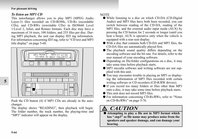
5-64
For pleasant driving
5
To listen an MP3 CDThis autochanger allows you to play MP3 (MPEG AudioLayer-3) files recorded on CD-ROMs, CD-Rs (recordableCDs), and CD-RWs (rewritable CDs) in ISO9660 Level1/Level 2, Joliet, and Romeo formats. Each disc may have amaximum of 16 trees, 100 folders, and 255 files per disc. Dur-ing MP3 playback, the unit can display ID3 tag information.For information concerning ID3 tag, refer to “CD text and MP3title display” on page 5-68.
Push the CD button (4) if MP3 CDs are already in the auto-changer.The display shows “READING”, then playback will begin.The folder number, the track number, the playing-time and“MP3” indicator will appear on the display.
NOTE● While listening to a disc on which CD-DA (CD-Digital
Audio) and MP3 files have both been recorded, you canswitch between reading of the CD-DA, reading of theMP3 files, and the external audio input mode (AUX) bypressing the CD button for 2 seconds or longer (until youhear a beep). AUX is operative only when the vehicle isequipped with a rear-seat display.
● With a disc that contains both CD-DA and MP3 files, theCD-DA files are automatically played first.
● The playback sound quality differs depending on theencoding software and the bit rate. For details, refer to theuser manual of your encoding software.
● Depending on file/folder configurations on a disc, it maytake some time before playback starts.
● MP3 encodin software and writing software are not sup-plied with this unit.
● You may encounter trouble in playing an MP3 or display-ing the information of MP3 files recorded with certainwriting software or CD recorders (CD-R/RW drivers).
● If you record too many folders or files other than MP3onto a disc, it may take some time before playback starts.
● This unit does not record MP3 files.● For information concerning CD-Rs/RWs, refer to “Notes
on CD-Rs/RWs” on page 5-76.
CAUTION!● Attempting to play a file not in MP3 format which
has “.mp3” as file name may produce noise from thespeakers and speaker damage, and can damage yourhearing.
BK-BK2008E1ENUK.en-uk-Section8.fm Page 64 Wednesday, January 9, 2008 4:41 PM

For pleasant driving
5-65
5
Folder selection order/MP3 file playback order (Example)
To fast-forward/fast-reverse the discTo fast-forward or fast-reverse the disc, press the fast-forward/fast-reverse button (9).
Fast-forwardYou can fast-forward the disc by pressing the side of thefast-forward button. While the button is kept pressed, the discwill be fast-forwarded.
Fast-reverseYou can fast-reverse the disc by pressing the side of thefast-reverse button. While the button is kept pressed, the discwill be fast-reversed.
NOTE● When you have fast-forwarded/fast-reversed the disc, the
playing-time may be shown with deviation.
Folder selection In the order
File selectionIn the order
Root folder (root directory)
Tree 1 Tree 2 Tree 3 Tree 4
BK-BK2008E1ENUK.en-uk-Section8.fm Page 65 Wednesday, January 9, 2008 4:41 PM

5-66
For pleasant driving
5
To select a desired folder (MP3 CDs only)You can select your desired folder by pressing the FOLDERbutton (12 or 13).
Folder upPress the FOLDER button (13) until the desired folder numberappears on the display.
Folder downPress the FOLDER button (12) until the desired folder numberappears on the display.
To select a desired track You can select your desired track by using the TRACK button(11).
Track upPress the side of the TRACK button (11) repeatedly untilthe desired track number appears on the display.
Track down Press the side of the TRACK button (11) repeatedly untilthe desired track number appears on the display.
NOTE● Pressing the side of the TRACK button (11) once dur-
ing the song will cause the autochanger to restart playbackfrom the beginning of the song.
To repeat a trackPress the RPT button (5) briefly while the track is playing.“RPT” will appear on the display. To exit the repeat mode,press the RPT button again.
To repeat a disc (music CDs only)Press the RPT button (5) for 1 second or longer (until you heara beep). “D-RPT” will appear on the display. You can listen tothe music CD repeatedly.
To repeat a folder (MP3 CDs only)Press the RPT button (5) for 1 second or longer (until you heara beep). You can listen to all the tracks in the currently selectedfolder repeatedly.
NOTE● The track repeat mode will be canceled by pressing the
TRACK button (11), the SCAN button (14) or the ejectbutton (7)
● The disc repeat mode will be canceled by pressing theDISC button (16 or 17), the SCAN button (14) or the ejectbutton (7).
● With a disc that contains both CD-DA and MP3 files, therepeat mode causes only files of the same format (CD-DAonly or MP3 files only) to be repeated.
BK-BK2008E1ENUK.en-uk-Section8.fm Page 66 Wednesday, January 9, 2008 4:41 PM

For pleasant driving
5-67
5
To play tracks in random orderRandom playback for a disc (music CDs only)Press the RDM button (6) briefly. “RDM” will appear on thedisplay. Tracks on the currently selected disc will be played ina random sequence.To exit the random mode, press the RDM button again.
Random playback for a folder (MP3 CDs only)Press the RDM button (6) briefly. “RDM” will appear on thedisplay. Tracks in the currently selected folder will be played ina random sequence. To exit the random mode, press the RDMbutton again.
Random playback for all discs in the autochanger (music CDs only)Press the RDM button (6) for 1 second or longer (until youhear a beep). “D-RDM” will appear on the display. Tracksfrom all the discs loaded in the autochanger will be played in arandom sequence. To exit the random mode, briefly press theRDM button again.
Random playback for all folders on a disc (MP3 CDs only)Press the RDM button (6) for 1 second or longer (until youhear a beep). “D-RDM” will appear on the display. Tracksfrom all the folders on the currently selected disc will beplayed in a random sequence. To exit the random mode, brieflypress the RDM button again.
NOTE● In the all discs random mode, if an MP3 CD has been
loaded in the autochanger, the autochanger will skip overit to the next music CD.
● With a disc that contains both CD-DA and MP3 files, therandom mode causes only files of the same format (CD-DA only or MP3 files only) to be played in a randomsequence.
To find the start of each track on a disc for playbackPress the SCAN button (14). “SCAN” will appear on the dis-play and the autochanger will play back the first 10 seconds ofeach track on the selected disc.The track number will blink while the scan mode is selected.To exit the scan mode, press the SCAN button again.
NOTE● Once all tracks on the disc have been scanned, playback
of the disc will restart from the beginning of the track thatwas playing when scanning started.
● The scan mode will be canceled when radio or CD opera-tion is selected.
● With a disc that contains both CD-DA and MP3 files, thescan mode causes only files of the same format (CD-DAonly or MP3 files only) to be played.
BK-BK2008E1ENUK.en-uk-Section8.fm Page 67 Wednesday, January 9, 2008 4:41 PM

5-68
For pleasant driving
5
CD text and MP3 title displayE00725000403
This autochanger can display CD text and MP3 titles includingID3 tag information.
CD textThe autochanger can display disc and track titles for discsencoded with disc and track title information. Press the DISPbutton (3) repeatedly to make selections in the followingsequence: disc name → track name → normal display mode.
NOTE● The display can show up to 16 characters. If a disc name
or track name has more than 16 characters, press thePAGE button (10) to view the next 16 characters.
● When there is no title information to be displayed, the dis-play shows “NO TITLE”.
● Characters that the autochanger cannot display are shownas “ ”.
MP3 titleThe autochanger can display folder and track titles for discsencoded with folder and track information. Press the DISP but-ton (3) for less than 1 second repeatedly to make selections inthe following sequence: folder name → track name → normaldisplay mode.
Example
Disc name
Track name
Example
Folder name
Track name
BK-BK2008E1ENUK.en-uk-Section8.fm Page 68 Wednesday, January 9, 2008 4:41 PM

For pleasant driving
5-69
5
ID3 tag informationThe autochanger can display ID3 tag information for files thathave been recorded with ID3 tag information.
1. Press the DISP button (3) for 2 seconds or longer toswitch to the ID3 tag information. “TAG” indicator willappear on the display.
2. Then press the DISP button for less than 1 second repeat-edly to make selections in the following sequence: albumname → track name → artist name → normal displaymode.
NOTE● To return from ID3 tag information to the folder name,
press the DISP button (3) again for 2 seconds or longer.● When there is no title information to be displayed, the dis-
play shows “NO TITLE”.● The display can show up to 16 characters. If a folder
name, track name, or item of ID3 tag information hasmore than 16 characters, press the PAGE button (10) toview the next 16 characters.
● Folder names and track names can each be displayed up toa length of 32 characters. Items of ID3 tag informationcan each be displayed up to a length of 30 characters.
● Characters that the autochanger cannot display are shownas “ ”.
To listen to a disc in the rear-seat display (vehicle with rear-seat display)
E00709700040
It is possible to listen to the audio from the rear-seat displayusing the vehicle’s speakers.
Press the CD button (4) to select the rear-seat display mode.The word “REAR” will appear at the top-left of the display.Each push of the CD button (4) changes the mode to the nextone in the following sequence: CD changer → rear-seat displaymode → CD changer.
The following operation of the rear-seat display is possiblefrom the audio system.
To make your desired selection, use the TRACK button (11) orthe FOLDER button (12 or 13) on the audio system.
NOTE● For more details about the rear-seat display, refer to the
separate owner’s manual.
Source OperationCD Track selection
MP3/WMA Folder/Track selectionVideo CD Track/Scene selection
DVD video Title/Chapter selectionDVD audio Group/Track selection
BK-BK2008E1ENUK.en-uk-Section8.fm Page 69 Wednesday, January 9, 2008 4:41 PM

5-70
For pleasant driving
5
Steering wheel remote control switch*E00710000173
The remote control switches are located on the left side of thesteering wheel.These switches can be used when the ignition switch is in the“ON” position.
NOTE● Do not push two or more of the steering wheel remote
control switches at the same time.
To turn on the powerPWR (ON-OFF) button — 3When the power is off, press this button to turn the power on.To turn the power off, press this button for 2 seconds or longer.
To adjust the volumeVolume up button — 1The volume will increase when this button is pressed.
Volume down button — 2The volume will decrease when this button is pressed.
To listen to the audio systemSelect the desired mode by lightly pressing the mode changebutton (3).The mode switches between the radio and CD with each pushof the button.
To listen to the radioTo select FM/MW/LW modeMode change button — 3Select the desired band by pressing this button.The order is: FM1 → FM2 → FM3 → MW → LW → CD →FM1.
Automatic radio tuningSeek up button — 4/Seek down button — 5After pressing these buttons, the reception of the selected sta-tion will begin.
1- Volume up button2- Volume down button3- PWR (ON-OFF)/Mode change button4- Seek up/Track up/Fast-forward button5- Seek down/Track down/Fast-reverse button
BK-BK2008E1ENUK.en-uk-Section8.fm Page 70 Wednesday, January 9, 2008 4:41 PM

For pleasant driving
5-71
5
To listen to a CDTo fast-forward/fast-reverse the discTo fast-forward or fast-reverse the disc, press the fast-forwardbutton (4) or the fast-reverse button (5).
Fast-forward button — 4You can fast-forward the disc by pressing the fast-forward but-ton. While the button is kept pressed, the disc will be fast-for-warded.
Fast-reverse button — 5You can fast-reverse the disc by pressing the fast-reverse but-ton. While the button is kept pressed, the disc will be fast-reversed.
To select a desired trackTrack up button — 4Press the button repeatedly until the desired track numberappears on the display.
Track down button — 5Press the button repeatedly until the desired track numberappears on the display.
BK-BK2008E1ENUK.en-uk-Section8.fm Page 71 Wednesday, January 9, 2008 4:41 PM

5-72
For pleasant driving
5
Error codesE00710100738
If an error code (1) appears in the display, take action in accordance with the table below.
Error display Problem Item RepairNO DISC No disc inserted Disc is not in CD player. Insert disc.
ERROR 01 Focus error Disc is not loaded correctly, or condensation on disc.
Insert disc with label facing up.Remove moisture from disc.
ERROR 02 Disc error Disc is dirty, scratched, or deformed; or exces-sive vehicle vibration.
Clean or replace disc. Retry when vibrations stop.
ERROR 03 Mechanism error Loading or eject error. Pick-up is out of posi-tion.
Eject disc and reload. If disc will not eject, have the equipment inspected.
ERROR HOT Inside of audio system is hot. Internal protection against high temperatures. Allow radio to cool by waiting about
30 minutes.
BK-BK2008E1ENUK.en-uk-Section8.fm Page 72 Wednesday, January 9, 2008 4:41 PM

For pleasant driving
5-73
5
ERROR Communication or power supply error
Communication error between external device and audio equipment. Power supply error of external device.
Consult a MITSUBISHI MOTORS Author-ized Service Point.
Error display Problem Item Repair
BK-BK2008E1ENUK.en-uk-Section8.fm Page 73 Wednesday, January 9, 2008 4:41 PM

5-74
For pleasant driving
5
Handling of compact discsE00723000106
● Use only the type of compact discs that have the markshown in the illustration below. Playback of CD-R or CD-RW discs may cause problems.
● The use of special shaped, damaged compact discs (likecracked discs) or low-quality compact discs (like warpeddiscs or burrs on the discs) will damage the CD player.
BK-BK2008E1ENUK.en-uk-Section8.fm Page 74 Wednesday, January 9, 2008 4:41 PM

For pleasant driving
5-75
5
● In the following circumstances, moisture can form ondiscs and inside the audio system, preventing normaloperation.• When there is high humidity (for example, when it is
raining).• When the temperature suddenly rises, such as right after
the heater is turned on in cold weather.
In this case, wait until the moisture has had time to dryout.
● When the CD player is subjected to violent vibrations,such as during off-road driving, the tracking may notwork.
● When storing compact discs, always store them in theirseparate cases. Never place compact discs in direct sun-light, or in any place where the temperature or humidity ishigh.
● Never touch the flat surface of the disc without a label.This will damage the disc surface and could affect thesound quality. When handling a compact disc, alwayshold it by the outer edge and the centre hole.
● To clean a disc, use a soft, clean, dry cloth. Wipe directlyfrom the centre hole toward the outer edge. Do not wipe ina circle. Never use any chemicals such as benzine, paintthinner, a disc spray cleaner, or an anti-static agent on thedisc.
● Do not use a ball point pen, felt pen, pencil, etc. to writeon the label surface of the disc.
BK-BK2008E1ENUK.en-uk-Section8.fm Page 75 Wednesday, January 9, 2008 4:41 PM

5-76
For pleasant driving
5
● Do not put additional labels (A) or stickers (B) on com-pact discs. Also, do not use any compact disc on which alabel or sticker has started to peel off or any compact discthat has stickiness or other contamination left by a peeled-off label or sticker. If you use such a compact disc, the CDplayer may stop working properly and you may not beable to eject the compact disc.
Notes on CD-Rs/RWsE00725100026
● You may have trouble playing back some CD-R/RW discsrecorded on CD recorders (CD-R/RW drives), either dueto their recording characteristics or dirt, fingerprints,scratches, etc. on the disc surface.
● CD-R/RW discs are less resistant to high temperatures andhigh humidity than ordinary music CDs. Leaving theminside a vehicle for extended periods may damage themand make playback impossible.
● The unit may not successfully play back a CD-R/RW thatwas made by the combination of writing software, a CDrecorder (CD-R/RW drive) and a disc if they are incom-patible with one another.
● This player cannot play the CD-R/RW discs if the sessionis not closed.
● This player cannot play CD-R/RW discs which containother than CD-DA or MP3 data (Video CD, etc.).
● Be sure to observe the handling instructions for the CD-R/RW disc.
WARNING!● Operating the CD player in a manner other than
specifically instructed herein may result in hazard-ous radiation exposure. Do not remove the coverand attempt to repair the CD player by yourself.There are no user serviceable parts inside. In case ofmalfunction, we recommend you to have it checked.
BK-BK2008E1ENUK.en-uk-Section8.fm Page 76 Wednesday, January 9, 2008 4:41 PM

For pleasant driving
5-77
5
AntennaE00710500048
Glass antennaAntenna leads (1) are printed on the left-hand side of the rearside window (3-door models)/quarter window (5-door models)glasses.
NOTE● When the rear side/rear quarter glass is cleaned, wipe the
glass with a soft cloth by moving the cloth along theantenna so as not to damage it.
Sun visorsE00711200811
1- To eliminate front glare2- To eliminate side glare
BK-BK2008E1ENUK.en-uk-Section8.fm Page 77 Wednesday, January 9, 2008 4:41 PM

5-78
For pleasant driving
5
Vanity mirrorE00731900090
Type 1A vanity mirror is fitted to the back of the sun visor.
Type 2A vanity mirror is fitted to the back of the sun visor.Operating the lid of the vanity mirror will automatically turnon the mirror lamp (A).
CAUTION!● If the lid of vanity mirror with lamp is kept open for
prolonged periods of time, the vehicle’s battery willbe discharged.
BK-BK2008E1ENUK.en-uk-Section8.fm Page 78 Wednesday, January 9, 2008 4:41 PM
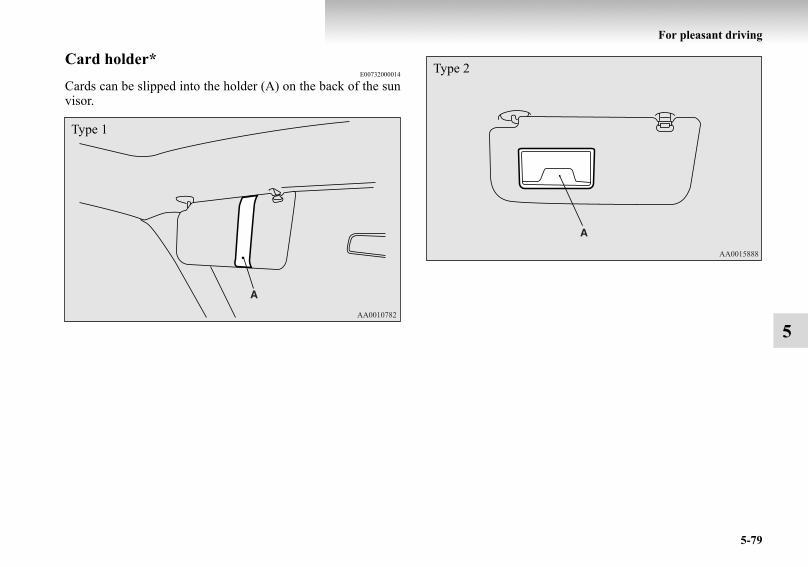
For pleasant driving
5-79
5
Card holder*E00732000014
Cards can be slipped into the holder (A) on the back of the sunvisor.
Type 1
Type 2
BK-BK2008E1ENUK.en-uk-Section8.fm Page 79 Wednesday, January 9, 2008 4:41 PM

5-80
For pleasant driving
5
Slide plate*E00732100015
To block out the glare of the sunlight from behind the insiderear-view mirror, swing down the sun visor, and then pull outthe slide plate (B).
To block out a broader range of glare from your side, swing thesun visor sideways and pull out the slide plate (B).
BK-BK2008E1ENUK.en-uk-Section8.fm Page 80 Wednesday, January 9, 2008 4:41 PM

For pleasant driving
5-81
5
Ashtray*E00711400363
To use the ashtray, open the lid.
Mounting position for moveable ashtrayThere is a mounting position on the front console box.
NOTE● The moveable ashtray can also be fitted in the cup holder
for the rear seat (3 door models) and in the cup holder forthe third seat (5 door models).Refer to “Cup holder” on page 5-99.
CAUTION!● Put out matches and cigarettes before they are
placed in the ashtray.● Don’t put papers and other things that burn into
your ashtrays. If you do, cigarettes or other smokingmaterials could set them on fire, causing damage.
● Always close the ashtray. If left open, other cigarettebutts in the ashtray may be rekindled.
BK-BK2008E1ENUK.en-uk-Section8.fm Page 81 Wednesday, January 9, 2008 4:41 PM

5-82
For pleasant driving
5
Cigarette lighter*E00711500713
The cigarette lighter can be used while the ignition switch is inthe “ON” or “ACC” position.
The cigarette lighter will automatically return to its originalposition with a “click” when ready. Pull it out for use.After use, insert the cigarette lighter to its original position inthe socket.
NOTE● Do not leave the cigarette lighter removed from its socket,
because the socket might become clogged by foreignmaterial and be short-circuited.
1- Open the lid2- Push all the way in.
CAUTION!● Do not touch the heating element or the cigarette
lighter housing, hold the knob only to prevent burns.● Do not allow children to operate or play with the cig-
arette lighter as burns may occur.● Something is wrong with the cigarette lighter if it
does not pop back out within approximately 30 sec-onds of being pushed in. We recommend you to haveit checked.
● Do not use any electric appliance that is notapproved by MITSUBISHI MOTORS. Doing socould damage the socket. If you used the cigarettelighter after damaging the socket, the cigarettelighter might pop out or fail to come out after beingpushed in.
● When the cigarette lighter socket is used as a powersource for an electric appliance, be sure that theelectric appliance operates at 12 V and has an elec-tric capacity of 120 W or less. In addition, long useof the electric appliance without running the enginemay run down the battery.
BK-BK2008E1ENUK.en-uk-Section8.fm Page 82 Wednesday, January 9, 2008 4:41 PM

For pleasant driving
5-83
5
Accessory socketE00711600701
The accessory socket can be used while the ignition switch isin the “ON” or “ACC” position.
NOTE● The two or more accessory sockets can be used simultane-
ously.
Type 1Pull out the plug (A) in the instrument panel to uncover thesocket. Use it to plug in an electrical device.
CAUTION!● Be aware that using electronic equipment with the
engine off may run the battery down.● When you connect an electrical device, make sure it
is rated at 12 V and its electrical capacity does notexceed 120 W. When using some sockets at the sametime, make sure the total power consumption of theelectrical accessories does not exceed 120 W at 12 V.
● When the accessory socket is not in use, be sure toclose the cap or plug, because the socket mightbecome clogged by foreign material and be short-circuited.
Instrument panel*
BK-BK2008E1ENUK.en-uk-Section8.fm Page 83 Wednesday, January 9, 2008 4:41 PM

5-84
For pleasant driving
5
Type 2Open the cap (B) on the centre console box and the side wall ofthe luggage compartment to uncover the socket. Use it to plugin an electrical device.
Console box*
Rear (3-door models)
Rear (5-door models)
BK-BK2008E1ENUK.en-uk-Section8.fm Page 84 Wednesday, January 9, 2008 4:41 PM

For pleasant driving
5-85
5
Interior lampsE00712000148
NOTE● If you leave the interior lamps on without running the
engine, you will run down the battery. Before you leavethe vehicle, make sure that all the interior lamps are off.
Interior lamp switchE00717300292
The interior lamp switch can be used to turn the room & maplamps and rear personal lamps on and off.
1- Luggage compartment lamp 2- Rear personal lamp3- Door courtesy lamps4- Ceiling lamp5- Interior lamp switch
Room & map lamp6- Foot lamps*
1 ( ) - The room & map lamps and rear personal lamps goon regardless of opening and closing of the doorsand backdoor.
BK-BK2008E1ENUK.en-uk-Section8.fm Page 85 Wednesday, January 9, 2008 4:41 PM

5-86
For pleasant driving
5
2(DOOR) - The room & map lamps and rear personal lamps goon when any of the doors or the backdoor isopened. When all doors and backdoor are closed,the room & map lamps and rear personal lamps areilluminated and dimmed gradually for 15 secondsand then go off.However, the lamps go off immediately withoutbeing dimmed in the following cases:
● The doors and backdoor are closed and theignition switch is turned to the “ON” position.
● All doors and backdoor are locked using thekey mechanism of the driver’s door, the cen-tral door lock switch, or the remote controlswitch of the keyless entry system (if soequipped).
NOTE● On vehicles with keyless entry system, if the
ignition key is removed with the doors andbackdoor closed, the room & map lamps andrear personal lamps are illuminated for 15seconds and then go off.The dimming period is also adjustable.For further information, we recommend youto consult a MITSUBISHI MOTORS Author-ized Service Point.
● When the room & map lamp switch is in the“ON” position, closing the doors and back-door does not cause the room & map lamps togo off.
3 ( ) - The room & map lamps and rear personal lampsare off regardless of opening and closing of thedoors and backdoor.
NOTE● When the room & map lamp switch is in the
“ON” position, the interior lamp switch can-not be used to turn off the room & map lamps.
BK-BK2008E1ENUK.en-uk-Section8.fm Page 86 Wednesday, January 9, 2008 4:41 PM

For pleasant driving
5-87
5
Room & map lampsE00717400062
With the doors and backdoor closed and the interior lampswitch in the “DOOR” or “ ” position, pressing the lens (A)illuminates the room & map lamps and pressing the lens againturns them off.If any of the doors or the backdoor is opened with the interiorlamp switch in the “DOOR” position, the room & map lampsilluminate. When it is closed, the room & map lamps aredimmed gradually for 15 seconds and then go off.
NOTE● When any of the doors or the backdoor is opened and the
interior lamp switch in the “ ” position, the room & maplamps remain on even when the lens is pressed.
Rear personal lampE00712600199
With the doors and backdoor closed and the interior lampswitch in the “DOOR” position, pressing the lens (A) makesthe lamp go on and pressing the lens again makes it go off.If any of the doors or the backdoor is opened, the lamps go on.When it is subsequently closed, the lamps are dimmed gradu-ally for 15 seconds then go off.
*: Front of the vehicle
Type 1
*
BK-BK2008E1ENUK.en-uk-Section8.fm Page 87 Wednesday, January 9, 2008 4:41 PM

5-88
For pleasant driving
5
NOTE● When the interior lamp switch is in the “ ” position, the
lamp remains off even when the lens (A) is pressed andany of the doors or the backdoor is opened.
Luggage compartment lampE00712700262
*: Front of the vehicle
Type 2
*
1 ( ) - The lamp illuminates.
2 ( ) - The lamp goes on when any of the doors or the back-door is opened. When all doors and the backdoor areclosed, the lamp is illuminated for 15 seconds thengoes off.However, the lamp goes off immediately withoutbeing dimmed in case of the followings:
● The ignition switch is turned to the “ON” posi-tion.
● All doors and the backdoor are locked using thekey mechanism of the driver’s door, the centraldoor lock switch, or the remote control switch ofthe keyless entry system (if so equipped).
BK-BK2008E1ENUK.en-uk-Section8.fm Page 88 Wednesday, January 9, 2008 4:41 PM

For pleasant driving
5-89
5
Foot lamps and ceiling lampE00726600086
The front foot lamps (A), rear foot lamp (B) and ceiling lamp(C) operate when the interior lamp switch is in the “DOOR”position.The lamps go on in case of the followings:
● Any of the doors or the backdoor is opened.● The ignition switch is turned to the “ON” position.● All doors and backdoor are unlocked using the key mech-
anism of the driver’s door, the central door lock switch orthe remote control switch of the keyless entry system(vehicle with keyless entry system).
NOTE● On vehicles with keyless entry system, when the
ignition key is removed with the doors and thebackdoor closed, the lamp is illuminated for15 seconds then goes off.The dimming period is also adjustable.For further information, we recommended you toconsult a MITSUBISHI MOTORS AuthorizedService Point.
3 ( ) - The lamp goes off.
Front foot lamps*
BK-BK2008E1ENUK.en-uk-Section8.fm Page 89 Wednesday, January 9, 2008 4:41 PM

5-90
For pleasant driving
5
NOTE● When the ignition switch is turned from the “ON” posi-
tion to the “ACC” or “LOCK” position, the lamps illumi-nate for 15 seconds and then go off.
● All doors and backdoor are unlocked using the key mech-anism of the driver’s door, the central door lock switch orthe remote control switch of the keyless entry system(vehicle with keyless entry system), the lamps illuminatefor 15 seconds and then go off.
● When any of the doors or the backdoor is opened withoutthe ignition switch in the “ON” position, the lamps illumi-nate. When it is closed, the lamps stay on for 30 secondsand then go off.However, the lamps go off immediately when all doorsare closed and locked using the key mechanism of thedriver’s door, the central door lock switch, the remotecontrol switch of the keyless entry system (vehicle withkeyless entry system).
● If you want the foot lamps and ceiling lamp to go offwhile driving, select the interior lamp switch in the “ ”position.
Rear foot lamp*
Ceiling lamp
BK-BK2008E1ENUK.en-uk-Section8.fm Page 90 Wednesday, January 9, 2008 4:41 PM

For pleasant driving
5-91
5
Door courtesy lampsE00717500047
Each door courtesy lamp illuminates when the relevant door isopened and goes off when the door is closed.
Front
Rear (5-door models)
BK-BK2008E1ENUK.en-uk-Section8.fm Page 91 Wednesday, January 9, 2008 4:41 PM

5-92
For pleasant driving
5
Lamps (room lamps, etc.) auto-cutout function (Vehicle with keyless entry system)
E00712900613
If any of the interior lamps are left switched on with the igni-tion key in any position other than “ON” or “ACC”, it goes offautomatically after approximately 30 minutes to prevent com-plete discharge of the battery.The lamp goes on again if the ignition key is turned to the“ON” or “ACC” position, any door or backdoor is opened andclosed, or the keyless entry remote control is operated.
NOTE● The interior lamp auto-cut function period can be adjusted
or deactivated. We recommend you to consult a MIT-SUBISHI MOTORS Authorized Service Point fordetailed information and assistance.
Storage spacesE00713100885
NOTE● Do not leave valuables in any storage space when leaving
the vehicle.
CAUTION!● Never leave lighters, cans of carbonated drink, and
spectacles in the cabin when parking the vehicle inhot sunshine. The cabin will become extremely hot,so lighters and other flammable items may catch fireand unopened drink cans (including beer cans) mayrupture. The heat may also deform or crack plasticspectacle lenses and other spectacle parts that aremade of plastic.
● Keep the lids of storage spaces closed while drivingthe vehicle. A lid or the contents of a storage spacecould otherwise cause injuries.
BK-BK2008E1ENUK.en-uk-Section8.fm Page 92 Wednesday, January 9, 2008 4:41 PM

For pleasant driving
5-93
5
Glove boxE00717600657
The glove box can be locked and unlocked using the key.
1- Sunglasses holder*2- Glove box3- Accessory box*4- Centre console box5- Side box* 6- Luggage floor box
1- To lock2- To unlock3- To open, pull the lever
BK-BK2008E1ENUK.en-uk-Section8.fm Page 93 Wednesday, January 9, 2008 4:41 PM

5-94
For pleasant driving
5
NOTE● When the lamp switch is in the “ ” or “ ” position,
the lower glove box lamp illuminates.● Small articles can be stored in the upper area (A) of the
glove box.
Centre console boxE00722600017
Upper and lower boxes are located inside the centre consolebox.The centre console box can also be used as an armrest.
1- Upper box 2- Lower box
BK-BK2008E1ENUK.en-uk-Section8.fm Page 94 Wednesday, January 9, 2008 4:41 PM

For pleasant driving
5-95
5
Upper boxTo open the upper box, lift the left upper release lever (A) andraise the lid.
Lower boxTo open the lower box, lift the lower release lever (B) and raisethe lid.
NOTE● It also can be used as the armrest by sliding the lid.
Refer to “Armrest” on page 2-10.
BK-BK2008E1ENUK.en-uk-Section8.fm Page 95 Wednesday, January 9, 2008 4:41 PM

5-96
For pleasant driving
5
Accessory box*E00717900096
To open, push the lid.
Card holderTo store a card, insert it into the card holder (A) until you heara click. To remove the card, give it a push. It will come outautomatically.
NOTE● The card holder can hold up to 3 cards.● Do not insert receipts and other thin pieces of paper.
BK-BK2008E1ENUK.en-uk-Section8.fm Page 96 Wednesday, January 9, 2008 4:41 PM

For pleasant driving
5-97
5
Side box*E00722700092
The box for storing articles is located inside the luggage com-partment.
Luggage floor box*E00718700280
The box for storing articles is located inside the luggage com-partment.
3-door modelsTo use the box, raise the luggage floor board by pulling up onthe strap (A).
1- To open2- To close
BK-BK2008E1ENUK.en-uk-Section8.fm Page 97 Wednesday, January 9, 2008 4:41 PM

5-98
For pleasant driving
5
5-door modelsTo use the box, raise the luggage floor board.
NOTE● On 5-door models, the luggage floor board can be
removed. This is useful for storing large articles.
Sunglasses holder*E00718600133
To open, push the lid.
NOTE● The holder may not be able to accomodate every possible
size and shape of sunglasses; it is advisable to check com-patibility before use.
CAUTION!● The holder should not be used to store anything
heavier than sunglasses. These objects could dropout.
BK-BK2008E1ENUK.en-uk-Section8.fm Page 98 Wednesday, January 9, 2008 4:41 PM

For pleasant driving
5-99
5
Cup holderE00714500408
For the front seatThe cup holder is located in front of the centre console box.
For the rear seat/second seatE00716900321
3-door modelsTo use the cup holder, press the button (A) at the top of thearmrest and allow the armrest to drop down.
CAUTION!● Do not drink beverages while driving the vehicle;
doing so could distract you and result in an accident.
BK-BK2008E1ENUK.en-uk-Section8.fm Page 99 Wednesday, January 9, 2008 4:41 PM

5-100
For pleasant driving
5
5-door models1. Lift the head restraint (B) and tilt the armrest.
2. Open the lid (C) while holding the side face of the lid withyour hand.
BK-BK2008E1ENUK.en-uk-Section8.fm Page 100 Wednesday, January 9, 2008 4:41 PM

For pleasant driving
5-101
5
For the third seat*E00719000075
The cup holder is located at the left side of the third seat.The cup holder is designed for holding cups or drink-canssecurely in its holes.
Rear shelf (3-door models)*E00722800035
The rear shelf divides the passenger compartment and luggagearea.
NOTE● Do not place luggage or other items on the rear shelf.
Remove the rear shelf when loading large items of luggage.
BK-BK2008E1ENUK.en-uk-Section8.fm Page 101 Wednesday, January 9, 2008 4:41 PM
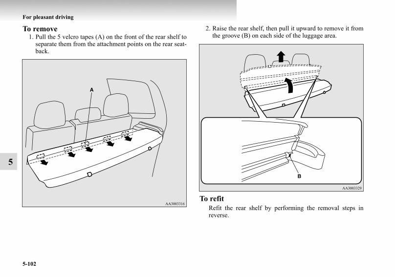
5-102
For pleasant driving
5
To remove1. Pull the 5 velcro tapes (A) on the front of the rear shelf to
separate them from the attachment points on the rear seat-back.
2. Raise the rear shelf, then pull it upward to remove it fromthe groove (B) on each side of the luggage area.
To refitRefit the rear shelf by performing the removal steps inreverse.
BK-BK2008E1ENUK.en-uk-Section8.fm Page 102 Wednesday, January 9, 2008 4:41 PM
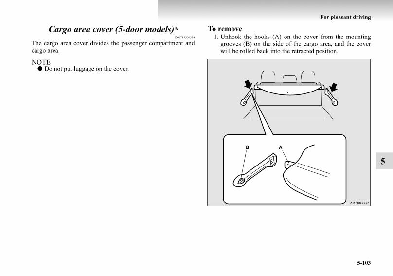
For pleasant driving
5-103
5
Cargo area cover (5-door models)*E00715500388
The cargo area cover divides the passenger compartment andcargo area.
NOTE● Do not put luggage on the cover.
To remove1. Unhook the hooks (A) on the cover from the mounting
grooves (B) on the side of the cargo area, and the coverwill be rolled back into the retracted position.
BK-BK2008E1ENUK.en-uk-Section8.fm Page 103 Wednesday, January 9, 2008 4:41 PM
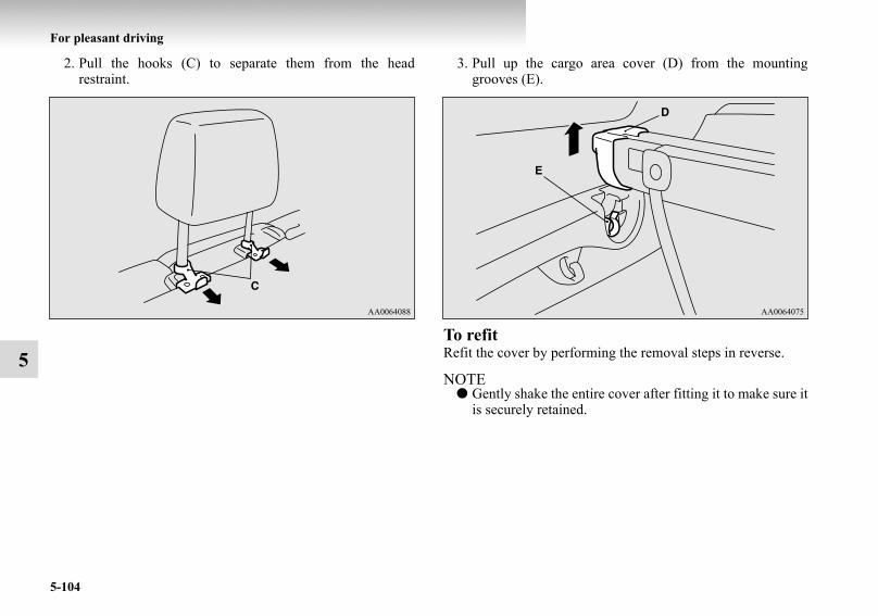
5-104
For pleasant driving
5
2. Pull the hooks (C) to separate them from the headrestraint.
3. Pull up the cargo area cover (D) from the mountinggrooves (E).
To refitRefit the cover by performing the removal steps in reverse.
NOTE● Gently shake the entire cover after fitting it to make sure it
is securely retained.
BK-BK2008E1ENUK.en-uk-Section8.fm Page 104 Wednesday, January 9, 2008 4:41 PM

For pleasant driving
5-105
5
Convenient hooks (5-door models)*E00715600099
There are four hooks (A) on the side of the luggage compart-ment.Light items of luggage can be hung from the hook.
NOTE● Do not hang heavy luggage (more than about 4 kg) on the
hook.Doing so could cause damage to the hook.
Luggage hooksE00715700306
There are hooks on the floor and the side of the luggage com-partment.Use the hooks on the floor for securing the luggage.
3-door models
BK-BK2008E1ENUK.en-uk-Section8.fm Page 105 Wednesday, January 9, 2008 4:41 PM

5-106
For pleasant driving
5
Coat hooksE00725600050
There are two hooks on the rear / second assist grips for use inhanging clothes.
CAUTION!● Do not pile up the luggage beyond the seatback
height.Secure the luggage firmly.Otherwise, serious accidents could result due to hin-dered rearward view or flying objects during sud-den braking.
5-door models
WARNING!● Do not put a hanger or any heavy or pointed object
on the coat hook. If the curtain air bag was acti-vated, any such item could be propelled away withgreat force and could prevent the curtain air bagfrom inflating correctly. Hang clothes directly on thecoat hook (without using a hanger). Make sure thereare no heavy or sharp objects in the pockets ofclothes that you hang on the coat hook.
BK-BK2008E1ENUK.en-uk-Section8.fm Page 106 Wednesday, January 9, 2008 4:41 PM

For pleasant driving
5-107
5
Installation position for warning triangleE00718400085
There are securing bands (A) for the warning triangle on thebackdoor.To remove or install the warning triangle, turn the lock knobs(B) counter clockwise, then remove the backdoor lid (C).
NOTE● The warning triangle shown in the illustration is not sup-
plied with the vehicle. It is recommended one be obtainedand carried for use if required.
BK-BK2008E1ENUK.en-uk-Section8.fm Page 107 Wednesday, January 9, 2008 4:41 PM

BK-BK2008E1ENUK.en-uk-Section8.fm Page 108 Wednesday, January 9, 2008 4:41 PM

6
For emergencies
If the vehicle breaks down . . . . . . . . . . . . . . . . . . .6- 2Emergency starting . . . . . . . . . . . . . . . . . . . . . . . .6- 2Engine overheating . . . . . . . . . . . . . . . . . . . . . . . .6- 6Bleeding the fuel system
(diesel-powered vehicles only). . . . . . . . . . . . . .6- 9Removal of water from the fuel filter
(diesel-powered vehicles only). . . . . . . . . . . . . .6- 9Tool, jack and jack handle . . . . . . . . . . . . . . . . . . .6- 11How to change a tyre . . . . . . . . . . . . . . . . . . . . . . .6- 16Towing . . . . . . . . . . . . . . . . . . . . . . . . . . . . . . . . . .6- 29Operation under adverse driving conditions . . . . .6- 35
BK-BK2008E1ENUK.en-uk-Section9.fm Page 1 Wednesday, January 9, 2008 4:46 PM

6-2
For emergencies
6
If the vehicle breaks downE00800100505
If the vehicle breaks down on the road, move it to the shoulderand use the hazard warning flashers and/or the warning triangleetc.Refer to “Hazard warning flasher switch” on page 3-66.
If the engine stops/failsVehicle operation and control are affected if the engine stops.Before moving the vehicle to a safe area, be aware of the fol-lowing:
● The brake booster becomes inoperative and the pedaleffort will increase. Press down the brake pedal harderthan usual.
● Since the power steering pump is no longer operative, thesteering wheel feels heavy when turning it. Turn the wheelwith more effort than usual.
Emergency startingE00800501287
If the engine cannot be started because the battery is weak ordead, the battery from another vehicle can be used with jumpercables to start the engine.
WARNING!● To start the engine using jumper cables connected to
another vehicles, perform the correct proceduresaccording to the instruction below. Incorrect proce-dures could result in a fire or explosion or damage tothe vehicles.
CAUTION!● Do not attempt to start the engine by pulling or
pushing the vehicle.It could damage your vehicle.
● Always wear protective eye goggles when workingnear the battery.
● Keep the battery out of the reach of children.
BK-BK2008E1ENUK.en-uk-Section9.fm Page 2 Wednesday, January 9, 2008 4:46 PM
For emergencies
6-3
6
1. Get the vehicles close enough so the jumper cables canreach, but be sure the vehicles aren’t touching each other.
2. Set the parking brake firmly on each vehicle. Put an auto-matic transmission in “P” (PARK) or a manual transmis-sion in “N” (Neutral). Turn off the ignition switch.
3. Turn off all lamps, heater and other electrical loads. 4. Make sure battery electrolyte is at the proper level.
Refer to “Battery” on page 8-16.CAUTION!
● Check the other vehicle. It must have a 12-volt bat-tery.If the other system isn’t 12-volt, shorting can dam-age both vehicles.
WARNING!● Turn off the ignition on both vehicles beforehand.
Make sure that the cables or your clothes cannot becaught by the fan or drive belt. Personal injurycould result.
WARNING!● If electrolyte fluid is not visible, or appears to be fro-
zen, Do Not Attempt Jump Starting!A battery might rupture or explode if the tempera-ture is below the freezing point or if it is not filled tothe proper level.
BK-BK2008E1ENUK.en-uk-Section9.fm Page 3 Wednesday, January 9, 2008 4:46 PM

6-4
For emergencies
6
5. Connect one end of one jumper cable to the positive (+) terminal of the discharged battery (A), and the other end to the positive(+) terminal of the booster battery (B).
*: Optional equipment
6. Connect one end of the other jumper cable to the negative (–) terminal of the booster battery (B), and the other end to theengine block of the vehicle with the discharged battery at the point farthest from the battery.
3800 models 3200 models
LHD* RHD*
BK-BK2008E1ENUK.en-uk-Section9.fm Page 4 Wednesday, January 9, 2008 4:46 PM

For emergencies
6-5
6
7. Start the engine in the vehicle which has the booster bat-tery, let the engine idle a few minutes, then start theengine in the vehicle with the discharged battery.
8. After the engine is started, disconnect the cables in thereverse order and keep the engine running for several min-utes.
WARNING!● Be sure to observe the connecting sequence of
→ → → . ● Make sure that the connection is made to the
appointed position (shown in the illustration). If theconnection is made directly to the negative side ofthe battery, the inflammable gasses generated fromthe battery might catch fire and explode.
● When connecting the jumper cable, do not connectthe positive (+) cable to the negative (–) terminal.Otherwise sparks might cause explosion of the bat-tery.
CAUTION!● Use care not to get the jumper cable caught in the
cooling fan or other rotating part in the engine com-partment.
● Use the proper cables suitable for the battery size toprevent overheating of the cables.
● Check the jumper cables for damage and corrosionbefore use.
CAUTION!● Keep the engine of the vehicle giving assistance run-
ning.
WARNING!● If the battery has to be charged while fitted in the
vehicle, disconnect the vehicle side negative (–) ter-minal connected to the battery.
● Keep sparks, cigarettes and flames away from thebattery because the battery may produce an explo-sion.
● Use adequate ventilation when charging or using thebattery in an enclosed space.
● Remove all the caps before charging the battery.● Electrolyte is corrosive diluted sulphuric acid.
If electrolyte (battery acid) comes into contact withyour hands, eyes, clothes and the painted surface ofyour vehicle, it should be thoroughly flushed withwater. If electrolyte gets in your eyes, flush themwith water immediately and thoroughly, and getprompt medical attention.
BK-BK2008E1ENUK.en-uk-Section9.fm Page 5 Wednesday, January 9, 2008 4:46 PM

6-6
For emergencies
6
NOTE● If the vehicle is put in motion without fully charging the
battery, it might cause the loss of smooth engine operationand the anti-lock brake warning lamp to illuminate.Refer to “Anti-lock brake system (ABS)” on page 4-58.
Engine overheatingE00800600991
If the water temperature gauge indication remains in the over-heating zone for a long time, the engine may be overheating. Ifthis occurs, take the following corrective measures:
1. Stop the vehicle in a safe place.2. Check whether steam is coming from the engine compart-
ment.
[If steam does not come from the engine compartment]With the engine still running, raise the bonnet to ventilatethe engine compartment.
[If steam is coming from the engine compartment]Stop the engine, and when the steam stops, raise the bon-net to ventilate the engine compartment. Restart theengine.
WARNING!● Do not open the bonnet while steam is coming from
the engine compartment. It could cause steam or hotwater to spurt out, causing burns. Hot water couldspurt out even when there is no steam coming out,and some parts will be very hot. Be very carefulwhen opening the bonnet.
● Be careful of hot steam, which could be blowing offthe reserve tank cap.
● Do not attempt to remove the radiator cap while theengine is hot.
BK-BK2008E1ENUK.en-uk-Section9.fm Page 6 Wednesday, January 9, 2008 4:46 PM

For emergencies
6-7
6
3. Confirm that the cooling fan is turning. If the fan is notturning, stop the engine immediately and have it checked.
4. After the engine coolant temperature has dropped to thenormal temperature, stop the engine.
A- Radiator capB- Cooling fanC- Reserve tank* : If so equipped
WARNING!● Be careful not to get your hands or clothes caught in
the cooling fan.
Front
*
BK-BK2008E1ENUK.en-uk-Section9.fm Page 7 Wednesday, January 9, 2008 4:46 PM

6-8
For emergencies
6
5. Check the coolant level in the reserve tank (A). 6. Add coolant to the radiator and/or reserve tank if neces-sary. (Refer to the “Maintenance” section.)
7. Examine the radiator hoses for coolant leakage and thedrive belt for looseness or damage.If there is anything wrong with the cooling system ordrive belt, we recommend you to have it check andrepaired.
WARNING!● If there is none, make sure that the engine has
cooled down before removing the radiator cap (B),because hot steam or boiling water otherwise willgush from the filler port and may scald you.
CAUTION!● Do not add coolant while the engine is hot. Suddenly
adding cold coolant could damage the engine. Waitfor the engine to cool down, then add coolant a littleat a time.
BK-BK2008E1ENUK.en-uk-Section9.fm Page 8 Wednesday, January 9, 2008 4:46 PM

For emergencies
6-9
6
Bleeding the fuel system (diesel-powered vehicles only)
E00800700149
The fuel system should be bled to remove air as describedbelow if the fuel supply is exhausted during travel.
Pump the hand pump (A) at the top of the fuel filter until thehand pump becomes stiff.Then try again to start the engine.If the engine does not start, repeat the process above.
Removal of water from the fuel filter (diesel-powered vehicles only)
E00800800140
If the fuel filter indication lamp in the instrument panel illumi-nates during driving, it indicates that water has accumulated inthe fuel filter. If this occurs, remove the water as describedbelow.
1. Loosen the drain plug (A) at the bottom of the fuel filter.
BK-BK2008E1ENUK.en-uk-Section9.fm Page 9 Wednesday, January 9, 2008 4:46 PM

6-10
For emergencies
6
2. Operate the hand pump (B) slowly 6 or 7 times in order toforce the water out through the drain plug.
3. Tighten the drain plug when water no longer comes out.4. Bleed the air in the fuel system.
(Refer to “Bleeding the fuel system” on page 6-9.)5. Check to be sure that the fuel filter indication lamp illumi-
nates when the ignition switch is turned to “ON”, and thatit goes off when the engine is started. If in doubt, we rec-ommend you to have your vehicle inspected.
CAUTION!● Do not smoke or have any other open flame near the
vehicle while bleeding the fuel system.● Be sure to carefully clean away any water drained
out because any fuel mixed with the water couldignite and cause a fire.
BK-BK2008E1ENUK.en-uk-Section9.fm Page 10 Wednesday, January 9, 2008 4:46 PM

For emergencies
6-11
6
Tool, jack and jack handleE00800900659
StorageThe storage location of the tool, jack and jack handle should beremembered in case of an emergency.
3-door models
5-door models
A- Jack handleB- Tool (wheel nut wrench)C- Jack
D- JackE- Jack handleF- Tool (wheel nut wrench)
BK-BK2008E1ENUK.en-uk-Section9.fm Page 11 Wednesday, January 9, 2008 4:46 PM

6-12
For emergencies
6
ToolE00801900483
Removing and storing the tool, jack and jack handle
E00802300178
3-door modelsTool, jack and jack handle are in the storage compartment atthe rear of the vehicle, on the right side.
1. Loose the knob (A), and remove the lid (B).
1- Wheel nut wrench
BK-BK2008E1ENUK.en-uk-Section9.fm Page 12 Wednesday, January 9, 2008 4:46 PM

For emergencies
6-13
6
2. Remove the securing bolt (C), and then take out the jack. 3. Remove the tool and the jack handle from the holder (D),and take it out.
4. Reverse the removing procedure when storing the tool,jack and jack handle.
CAUTION!● When removing and storing the items in the storage
compartment, be careful not to injure your hands orfingers.
BK-BK2008E1ENUK.en-uk-Section9.fm Page 13 Wednesday, January 9, 2008 4:46 PM

6-14
For emergencies
6
5-door modelsTool, jack and jack handle are located in the luggage floor box.
1. When the third seat is folded into the luggage floor box,raise the seat forward and return it to the original position.Refer to “Storage of the third seat” on page 2-25.
2. Remove the lid.
3. Remove the tool and the jack handle from the holder (A),and take it out.
BK-BK2008E1ENUK.en-uk-Section9.fm Page 14 Wednesday, January 9, 2008 4:46 PM

For emergencies
6-15
6
4. Pull the lid to remove it.
5. Remove the securing bolt (B), and then take out the jack.
6. Reverse the removing procedure when storing the tool,jack and jack handle.
To use the jack handleE00802400023
1. While pushing the snap pin (A), remove the inside handle(B).
BK-BK2008E1ENUK.en-uk-Section9.fm Page 15 Wednesday, January 9, 2008 4:46 PM

6-16
For emergencies
6
2. With the snap pin (C) pushed, insert the inside handleuntil it is locked.
How to change a tyreE00801201757
Before changing a tyre, first stop your vehicle in a safe, flatlocation.
1. Park the vehicle on level and stable ground.2. Set the parking brake firmly.3. On vehicles with manual transmission, turn the ignition
key to the “LOCK” position, move the gearshift lever tothe “R” (Reverse) position.On vehicles with automatic transmission, move the selec-tor lever to the “P” (PARK) position, turn the ignition keyto the “LOCK” position.
4. Turn on the hazard flashers and set up a warning triangle,flashing signal lamp, etc., at an adequate distance from thevehicle, and have all your passengers leave the vehicle.
BK-BK2008E1ENUK.en-uk-Section9.fm Page 16 Wednesday, January 9, 2008 4:46 PM

For emergencies
6-17
6
5. To prevent the vehicle from rolling when it is raised on thejack, place a chock or block (A) at the tyre that is diago-nally opposite from the tyre (B) you are changing.
NOTE● The chock shown in the illustration does not come with
your vehicle. It is recommended that you keep one in thevehicle for use if needed.
● If a chock is not available, use a stone or any other objectthat is large enough to hold the wheel in position.
6. Get the spare wheel, jack, jack handle and wheel nutwrench ready. Refer to “Tool, jack and jack handle” on page 6-11.
Spare wheel informationE00803600022
Check the air pressure of the spare wheel frequently and makesure it is ready for emergency use at any time.Maintaining the spare wheel at the highest specified air pres-sure will ensure that it can always be used under any conditions(city/high-speed driving, varying load weight, etc.).The spare wheel is stored on the outside of the backdoor.(Refer to “To remove the spare tyre” on page 6-18.)
WARNING!● Be sure to apply a chock to the correct tyre when
jacking up the vehicle. If the vehicle moves whilejacked up, the jack could slip out of position, leadingto an accident.
1- Spare wheel
BK-BK2008E1ENUK.en-uk-Section9.fm Page 17 Wednesday, January 9, 2008 4:46 PM

6-18
For emergencies
6
To remove the spare tyreE00803300016
1. Open the backdoor.2. Open the lids (A) inside of the backdoor.
CAUTION!● Grasp the spare wheel firmly when removing or
attaching it.● When removing the spare wheel, put on gloves.
Removing the spare wheel with your bare handsmay cause injury to the fingers.
● The tyre pressure should be periodically checkedand maintained at the specified pressure while thetyre is stowed.Driving with an insufficient tyre pressure can lead toan accident. If you have no choice but to drive withan insufficient tyre pressure, keep your speed downand inflate the tyre to the correct pressure as soon aspossible. (Refer to “Tyre inflation pressures” onpage 8-19.)
BK-BK2008E1ENUK.en-uk-Section9.fm Page 18 Wednesday, January 9, 2008 4:46 PM

For emergencies
6-19
6
3. Remove the bolts (B) by turning them anticlockwise withthe wheel nut wrench.
4. Close the backdoor.
BK-BK2008E1ENUK.en-uk-Section9.fm Page 19 Wednesday, January 9, 2008 4:46 PM

6-20
For emergencies
6
5. Open the spare wheel garnish (C). If necessary insert thepin (D) to the hinge (E).
6. Loosen the spare wheel bolts with the wheel nut wrench(F), then remove the spare wheel.
CAUTION!● Do not open the backdoor with the spare wheel gar-
nish open. The spare wheel garnish could swing outto the right of the vehicle, resulting in an accident.
BK-BK2008E1ENUK.en-uk-Section9.fm Page 20 Wednesday, January 9, 2008 4:46 PM

For emergencies
6-21
6
NOTE● Put the spare wheel under the vehicle body near the flat
tyre. This makes it safer if the jack slips out of position.
To change a tyreE00803200015
1. Loosen the wheel nuts a quarter turn with the wheel nutwrench. Do not remove the wheel nuts yet.
BK-BK2008E1ENUK.en-uk-Section9.fm Page 21 Wednesday, January 9, 2008 4:46 PM

6-22
For emergencies
6
2. Using the jack handle, turn the release valve (A) clock-wise until it stops.
3. Insert the jack handle in the bracket of the jack and hookthe notch (B) on the jack handle end to the claw (C) of thebracket.
BK-BK2008E1ENUK.en-uk-Section9.fm Page 22 Wednesday, January 9, 2008 4:46 PM

For emergencies
6-23
6
4. Place the jack under one of the jacking points shown inthe illustration. Use the jacking point closest to the tyreyou wish to change.
D- Front jacking point
E- Rear jacking point
WARNING!● Set the jack only at the positions shown here. If the
jack is set at a wrong position, it could dent yourvehicle or the jack might fall over and cause per-sonal injury.
● Do not use the jack on a tilted or soft surface. Other-wise, the jack might slip and cause personal injury.Always use the jack on a flat, hard surface. Beforesetting the jack, make sure there are no sand or peb-bles under the jack base.
BK-BK2008E1ENUK.en-uk-Section9.fm Page 23 Wednesday, January 9, 2008 4:46 PM

6-24
For emergencies
6
5. Move the jack handle up and down to raise the ram untiljust before the jack contacts the jacking point of the vehi-cle. Ensure that the jack will properly contact the vehiclejacking point.
NOTE● This jack is a 3 stage expansion type.
6. Raise the vehicle until the tyre is slightly off the ground.
7. Remove the wheel nuts with the wheel nut wrench, thentake the wheel off.
8. Clean out any mud, etc. on the hub surface (F), hub bolts(G) or in the installation holes (H) in the wheel, and thenmount the spare wheel.WARNING!
● Stop jacking up the vehicle as soon as the tyre israised off the ground. It is dangerous to raise thevehicle any higher.
● Do not get under your vehicle while using the jack.● Do not bump the raised vehicle or leave it sitting on
the jack for a long time. Both are very dangerous.● Do not use a jack except the one that came with your
vehicle.● The jack should not be used for any purpose other
than to change a tyre.● No one should be in your vehicle when using the
jack.● Do not start or run the engine while your vehicle is
on the jack.● Do not turn the raised wheel. The tyres still on the
ground could turn and make your vehicle fall off thejack.
CAUTION!● Handle the wheel carefully when changing the tyre,
to avoid scratching the wheel surface.
BK-BK2008E1ENUK.en-uk-Section9.fm Page 24 Wednesday, January 9, 2008 4:46 PM

For emergencies
6-25
6
9. Temporarily tighten the wheel nuts (flange nuts) untiltheir flange section comes in contact with the wheel and itis no longer loose.
NOTE● If all 4 aluminium wheels are changed to steel wheels, e.g.
when fitting winter tyres, use tapered nuts.
WARNING!● Mount the spare wheel with the valve stem (I) facing
outboard. If you cannot see the valve stem, you haveinstalled the wheel backwards.Operating the vehicle with the spare wheel installedbackwards can cause vehicle damage and result inan accident.
CAUTION!● Never apply oil to either the wheel bolts or the nuts,
or they will tighten too much.
BK-BK2008E1ENUK.en-uk-Section9.fm Page 25 Wednesday, January 9, 2008 4:46 PM

6-26
For emergencies
6
10. Put the notch (J) provided on the jack handle end on thevalve (K) of the jack.Using the jack handle, turn the release valve anticlock-wise slowly to lower the vehicle until the tyre touches theground.
11. Tighten the nuts crisscross in 2 or 3 steps until each nuthas been tightened securely.
Tightening torque105 to 125 Nm(Achieved by applying a force of 390 to 460 N at the endof the wheel nut wrench supplied with the vehicle.)
WARNING!● Be sure to open the release valve slowly. If it is
opened quickly, the vehicle will drop abruptly andthe jack may come out of position, causing a seriousaccident.
CAUTION!● Never use your foot or a pipe extension for extra
force in the wheel nut wrench. If you do so, you willtighten the nut too much.
BK-BK2008E1ENUK.en-uk-Section9.fm Page 26 Wednesday, January 9, 2008 4:46 PM

For emergencies
6-27
6
12. Lower the jack all the way and remove it. NOTE● Occasionally when the vehicle is jacked up, the grooved
portion of the designated point will not come off. Whenthis happens, rock the vehicle to lower the ram.
● If the jack is difficult to remove by hand, insert the jackhandle (L) into the bracket (M).Then using the handle, remove the jack.
CAUTION!● If the release valve is loosened too much (2 or more
turns) in the anticlockwise direction, the jack’s oilwill leak and the jack cannot be used.
● Close the release valve slowly when lowering thevehicle, or the valve may be damaged.
BK-BK2008E1ENUK.en-uk-Section9.fm Page 27 Wednesday, January 9, 2008 4:46 PM

6-28
For emergencies
6
13. Check your tyre inflation pressure at the next gasstation.The correct pressures are shown on the door label. See theillustration.
To store the flat tyre or spare tyreE00803400075
1. Attach the wheel to the spare wheel hanger (A) whilealigning the holes in the wheel with the bolts on the sparewheel hanger.Using the wheel nut wrench, tighten the spare wheel nutsfirmly.
Tightening torque37 to 54 Nm(Achieved by applying a force of 140 to 200 N at the endof the wheel nut wrench supplied with the vehicle.)
CAUTION!● After changing the tyre and driving the vehicle
about 1,000 km (620 miles), retighten the wheel nutsto make sure that they have not come loose.
● If the steering wheel vibrates when driving afterchanging the tyre, we recommend you to have thetyres checked for balance.
● Do not mix one type of tyre with another or use adifferent size from the one listed. This would causeearly wear and poor handling.
BK-BK2008E1ENUK.en-uk-Section9.fm Page 28 Wednesday, January 9, 2008 4:46 PM

For emergencies
6-29
6
2. Reverse the opening procedure when closing the sparetyre garnish.
Tightening torque for spare wheel garnish mounting bolt11 to 25 Nm(Achieved by applying a force of 40 to 92 N at the end ofthe wheel nut wrench supplied with the vehicle.)
NOTE● Have your damaged tyre repaired as soon as possible.
TowingE00801501819
If your vehicle needs to be towedIf towing is necessary, we recommend you to have it done byyour MITSUBISHI MOTORS Authorized Service Point or acommercial tow truck service.
In the following cases, transport the vehicle using a tow truck.● The engine runs but the vehicle does not move or abnor-
mal noise is produced.● Inspection of the vehicle’s underside reveals that oil or
some other fluid is leaking.If a wheel gets stuck in a ditch, do not try to tow the vehicle.Please contact your authorized MITSUBISHI MOTORSAuthorized Service Point or a commercial tow truck service forassistance.
Only when you cannot receive a towing service from a MIT-SUBISHI MOTORS Authorized Service Point or commercialtow truck service, tow your vehicle carefully in accordancewith the instructions given in “Emergency towing” in this part.
The regulations concerning towing may differ from country tocountry. It is recommended that you obey the regulations of thearea where you are driving your vehicle.
CAUTION!● The spare wheel should always be secured during
vehicle operation. If a flat tyre is changed, put theflat tyre in the spare wheel mounting position, anduse the wheel nut wrench to secure it firmly.
BK-BK2008E1ENUK.en-uk-Section9.fm Page 29 Wednesday, January 9, 2008 4:46 PM

6-30
For emergencies
6
Towing the vehicle by a tow truck
CAUTION!● This vehicle must not be towed by a tow truck using
sling lift type equipment (Type A) as illustrated.Using a sling lift will damage the bumper and frontend.
● Be sure to shift the transfer shift lever to the “2H”position and transport the vehicle with the drivingwheels on a carriage (Type C, D or E) as illustrated.Never try to tow with the transfer shift lever in the“4H”, “4HLC” or “4LLC” positions and with thefront or rear wheels on the ground (Type B or TypeC) as illustrated. This could result in the driving sys-tem damage or vehicle may jump at the carriage. Ifyou cannot shift the transfer shift lever to the “2H”position or the transmission is malfunctioning ordamaged, transport the vehicle with the all wheelson a carriage (Type D or E) as illustrated.
● If you tow a vehicle with automatic transmissionwith the driving wheels on the ground (Type B) asillustrated, make sure that the towing speed and dis-tance given below are never exceeded, causing dam-age to the transmission.
Towing speed: 50 km/h (31 mph)Towing distance: 50 km (31 miles)
For the towing speed and the towing distance, followthe local driving laws and regulations.
BK-BK2008E1ENUK.en-uk-Section9.fm Page 30 Wednesday, January 9, 2008 4:46 PM

For emergencies
6-31
6
Towing with front wheels off the ground (Type B)Place the gearshift lever in the “N” (Neutral) position (manualtransmission) or the selector lever in the “N” (NEUTRAL)position (automatic transmission).Release the parking brake.
Towing with rear wheels off the ground (Type C)Place the gearshift lever in the “N” (Neutral) position (manualtransmission) or the selector lever in the “N” (NEUTRAL)position (automatic transmission). Turn the ignition key to the“ACC” position and secure the steering wheel in a straight-ahead position with a rope or tie-down strap. Never place theignition switch in the “LOCK” position when towing.CAUTION!
● Never tow an automatic transmission vehicle withthe front wheels up (and the rear wheels on theground) (Type B) when the automatic transmissionfluid level is low. This may cause serious and expen-sive damage to the transmission.
CAUTION!● As your vehicle equipped with the Active Stability &
Traction Control system (ASTC) is towed with theignition switch in the “ON” position and only thefront wheels or only the rear wheels raised off theground, the active traction control system may oper-ate, resulting in an accident.
BK-BK2008E1ENUK.en-uk-Section9.fm Page 31 Wednesday, January 9, 2008 4:46 PM

6-32
For emergencies
6
Emergency towingIf towing service is not available in an emergency, your vehiclemay be temporarily towed by a rope secured to the towinghook.If your vehicle is to be towed by another vehicle or if yourvehicle tows another vehicle, pay careful attention to the fol-lowing points:
If your vehicle is to be towed by another vehicle1. The front towing hooks (A) and rear towing hooks (B) are
located as shown in the illustrations. Secure the tow ropeto the towing hook.
NOTE● Using a wire rope or metal chain can result in damage to
the vehicle body. It is best to use a non-metallic rope. Ifyou use a wire rope or metal chain, wrap it with cloth atany point where it touches the vehicle body.
● Use care that the tow rope is kept as horizontal as possi-ble. An angled tow rope can damage the vehicle body.
● Secure the tow rope to the same side towing hook, to keepthe tow rope as straight as possible.
Front
Rear
BK-BK2008E1ENUK.en-uk-Section9.fm Page 32 Wednesday, January 9, 2008 4:46 PM

For emergencies
6-33
6
2. Keep the engine running.If the engine is not running, turn the ignition switch to the“ACC” or “ON” position to unlock the steering wheel.
3. Place the gearshift lever in the “N” (Neutral) position(with manual transmission) or the selector lever in the “N”(NEUTRAL) position (with automatic transmission).
4. Shift the transfer shift lever to the “2H” position.5. Turn on the hazard warning lamps if required by law.
(Follow the local driving laws and regulations.)
6. During towing make sure that close contact is maintainedbetween the drivers of both vehicles, and that the vehiclestravel at low speed.
CAUTION!● When the engine is not running, the brake booster
and power steering pump do not operate. Thismeans higher brake depression force and highersteering effort are required. Therefore, vehicle oper-ation is more difficult than usual.
● Do not leave the key in the “LOCK” position or donot remove the ignition key from the ignition switchwhile driving. The steering wheel will lock, causingloss of control.
CAUTION!● Avoid sudden braking, sudden acceleration and
sharp turning; such operation could cause damageto the towing hooks or the tow rope.People in the vicinity could be injured as a result.
● When towing or being towed down a long slope, thebrakes may overheat reducing the effectiveness. Inthis situation, have your vehicle transported by atow truck.
● When the vehicle with automatic transmission is tobe towed by another vehicle with all wheels on theground, make sure that the towing speed and dis-tance given below are never exceeded, avoidingdamage to the transmission.
Towing speed: 50 km/h (31 mph)Towing distance: 50 km (31 miles)
For the towing speed and the towing distance, followthe local driving laws and regulations.
BK-BK2008E1ENUK.en-uk-Section9.fm Page 33 Wednesday, January 9, 2008 4:46 PM
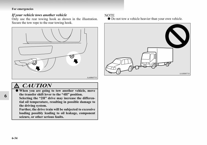
6-34
For emergencies
6
If your vehicle tows another vehicleOnly use the rear towing hook as shown in the illustration.Secure the tow rope to the rear towing hook.
NOTE● Do not tow a vehicle heavier than your own vehicle.
CAUTION!● When you are going to tow another vehicle, move
the transfer shift lever to the “4H” position.Selecting the “2H” drive may increase the differen-tial oil temperature, resulting in possible damage tothe driving system.Further, the drive train will be subjected to excessiveloading possibly leading to oil leakage, componentseizure, or other serious faults.
BK-BK2008E1ENUK.en-uk-Section9.fm Page 34 Wednesday, January 9, 2008 4:46 PM

For emergencies
6-35
6
Operation under adverse driving conditionsE00801701547
On a flooded road● Avoid flooded roads. Water could enter the brake discs,
resulting in temporarily ineffective brakes. In such cases,lightly depress the brake pedal to see if the brakes operateproperly. If they do not, lightly depress the pedal severaltimes while driving in order to dry the brake pads.
● When driving in rain or on a road with many puddles alayer of water may form between the tyres and the roadsurface.This reduces a tyre’s frictional resistance on the road,resulting in loss of steering stability and braking capabil-ity.
To cope with this, observe the following items:
On a snow-covered or frozen road ● When driving on a snow-covered or frozen road, it is rec-
ommended that you use snow tyres or tyre chains. Refer to the “Snow tyres” and “Tyre chains” sections.
● Avoid high-speed operation, sudden acceleration, abruptbrake application and sharp cornering.
● Depressing the brake pedal during travel on snowy or icyroads may cause tyre slippage and skidding. When trac-tion between the tyres and the road is reduced the wheelsmay skid and the vehicle cannot readily be brought to astop by conventional braking techniques. Braking will dif-fer, depending upon whether you have anti-lock brakes(ABS). As your vehicle is equipped with ABS, brake bypressing the brake pedal hard, and keeping it pressed.
● Allow extra distance between your vehicle and the vehiclein front of you, and avoid sudden braking.
On a bumpy or rutted road Drive as slow as possible when driving on bumpy or ruttedroads.
(a) Drive your vehicle at slow speed.(b) Do not drive on worn tyres. (c) Always maintain the specified tyre inflation pres-
sures.CAUTION!
● The impact on tyres and/or wheels when driving ona bumpy or rutted road can damage the tyre and/orwheel.
BK-BK2008E1ENUK.en-uk-Section9.fm Page 35 Wednesday, January 9, 2008 4:46 PM

BK-BK2008E1ENUK.en-uk-Section9.fm Page 36 Wednesday, January 9, 2008 4:46 PM

7
Vehicle care
Vehicle care precautions . . . . . . . . . . . . . . . . . . . .7- 2Cleaning the interior of your vehicle . . . . . . . . . . .7- 3Cleaning the exterior of your vehicle. . . . . . . . . . .7- 4
BK-BK2008E1ENUK.en-uk-Section10.fm Page 1 Wednesday, January 9, 2008 4:48 PM

7-2
Vehicle care
7
Vehicle care precautions E00900100375
In order to maintain the value of your vehicle, it is necessary toperform regular maintenance using the proper procedures.Always maintain your vehicle in compliance with any environ-mental pollution control regulations. Carefully select the mate-rials used for washing, etc., to be sure that they do not containcorrosives. If in doubt, we recommend you to consult a special-ist for selection of these materials.
CAUTION!● Cleaning products can be dangerous. Always follow
the instructions of the cleaning product supplier.● To avoid damage, never use the following to clean
your vehicle:• Gasoline• Paint Thinner• Benzine• Turpentine• Naphtha• Lacquer Thinner• Carbon Tetrachloride• Nail Polish Remover• Acetone
BK-BK2008E1ENUK.en-uk-Section10.fm Page 2 Wednesday, January 9, 2008 4:48 PM

Vehicle care
7-3
7
Cleaning the interior of your vehicleE00900200129
After cleaning the interior of your vehicle with water, cleaneror similar, wipe and dry in a shady, well-ventilated area.
Plastic, vinyl leather, fabric and flocked partsE00900300146
1. Gently wipe off with gauze or other soft cloth soaked witha 3 % aqueous solution of neutral detergent.
2. Dip cloth in fresh water and wring out well. Using thiscloth, wipe off the detergent thoroughly.
NOTE● Do not use the cleaners, conditioners, and protectants con-
taining silicons or wax.Such products may cause annoying reflections andobscure vision.
UpholsteryE00900500063
1. To maintain the value of your new vehicle, handle theupholstery carefully and keep the interior clean.Use a vacuum cleaner and brush to clean the seats. Ifstained, vinyl and synthetic leather should be cleaned withan appropriate cleaner, and cloth fabrics can be cleanedwith either upholstery cleaner or a 3 % solution of neutraldetergent in lukewarm water.
2. Clean the carpeting with a vacuum cleaner and removeany stains with carpet cleaner. Oil and grease can beremoved by lightly dabbing with a clean colourfast clothand stain remover.
CAUTION!● Do not use organic substances (solvents, kerosine,
alcohol, gasoline, etc.) or alkaline or acidic solutions.These chemicals can cause discolouring, staining orcracking of the surface.If you use cleaners or polishing agents, make suretheir ingredients do not include the substances men-tioned above.
BK-BK2008E1ENUK.en-uk-Section10.fm Page 3 Wednesday, January 9, 2008 4:48 PM

7-4
Vehicle care
7
Genuine leather*E00900600224
1. Lightly wipe off with gauze or other soft cloth soakedwith a 5 % aqueous solution of neutral detergent for wool.
2. Dip cloth in fresh water and wring it out well. Using thiscloth, wipe off the detergent thoroughly.
3. Apply leather protecting agent to the genuine leather sur-face.
NOTE● If genuine leather is wet with water or is washed in water,
wipe off water as quickly as possible with a dry, soft cloth.● Slight stains on genuine leather may be removed with
leather cleaner as well.● The genuine leather surface may be damaged if a nylon
brush or synthetic fibre is rubbed hard against it.● Organic solvents such as benzine, alcohol and gasoline,
acid or alkaline solvents may discolour the genuineleather surface. Be sure to use neutral detergents.
● Dirty genuine leather seat may mildew. Be very carefulabout oil stains and remove them quickly.
● The genuine leather surface may harden and shrink if it isexposed to direct rays of the sun for long hours. Whenyour vehicle is parked, place it in the shade as much aspossible.
● When the temperature of the vehicle interior rises in sum-mer, vinyl products left on the genuine leather seat maydeteriorate and stick to the seat.
Cleaning the exterior of your vehicleE00900700195
If the following is left on your vehicle, it may cause corrosion,discolouration and stains, wash the vehicle as soon as possible.
● Seawater, road deicing products.● Soot and dust, iron powder from factories, chemical sub-
stance (acids, alkalis, coal-tar, etc.).● Droppings from birds, carcasses of insects, tree sap, etc.
WashingE00900901152
Chemicals contained in the dirt and dust picked up from theroad surface can damage the paint coat and body of your vehi-cle if left in prolonged contact.Frequent washing and waxing is the best way to protect yourvehicle from this damage. This will also be effective in protect-ing it from environmental elements such as rain, snow, salt air,etc.Do not wash the vehicle in direct sunlight. Park the vehicle inthe shade and spray it with water to remove dust. Next, usingan ample amount of clean water and a car washing brush orsponge, wash the vehicle from top to bottom.Use a mild car washing soap if necessary. Rinse thoroughlyand wipe dry with a soft cloth. After washing the vehicle, care-fully clean the joints and flanges of the doors, bonnet, etc.,where dirt is likely to remain.
BK-BK2008E1ENUK.en-uk-Section10.fm Page 4 Wednesday, January 9, 2008 4:48 PM

Vehicle care
7-5
7
CAUTION!● When washing the under side of your vehicle or
wheel, be careful not to injure your hands.● If your vehicle has rain sensor wipers, place the
wiper switch lever in the “OFF” position to deacti-vate the rain sensor before washing the vehicle. Oth-erwise, the wipers will operate in the presence ofwater spray on the windscreen and may get dam-aged as a result.
● Refrain from excessively using a car wash as itsbrushes may scratch the paint surface, causing it tolose its gloss.Scratches will be especially visible on darker col-oured vehicles.
● Never spray or splash water on the electrical compo-nents in the engine compartment, as this mayadversely affect engine starting.Exercise caution also when washing the underbody;be careful not to spray water into the engine com-partment.
● Some types of hot water washing equipment applyhigh pressure and heat to the vehicle. They maycause heat distortion and damage to the vehicle resinparts and may result in flooding of the vehicle inte-rior. Therefore;• Maintain a distance of approx. 50 cm or more
between the vehicle body and the washing nozzle.• When washing around the door glass, hold the
nozzle at a distance of more than 50 cm and atright angles to the glass surface.
● After washing the vehicle, drive the vehicle slowlywhile lightly depressing the brake pedal severaltimes in order to dry out the brakes.Leaving the brakes wet could result in reducedbraking performance. Also, there is a possibility thatthey could freeze up or become inoperative due torust, rendering the vehicle unable to move.
● Using an automatic car wash, pay attention to thefollowing items, refering to the operation manual orconsulting a car wash operator. If the following pro-cedure is not followed, it could result in damage toyour vehicle.• The outside mirrors are retracted.• The wiper arm assembly is taped.• If your vehicle is equipped with a rear deflector or
roof rails, consult a car wash operator before usingthe car wash.
• If your vehicle has rain sensor wipers, place thewiper switch lever in the “OFF” position to deacti-vate the rain sensor.
CAUTION!
BK-BK2008E1ENUK.en-uk-Section10.fm Page 5 Wednesday, January 9, 2008 4:48 PM

7-6
Vehicle care
7
During cold weatherSalt and other chemicals spread on the roads in some areas inwinter can have a harmful effect on the vehicle body. Youshould therefore wash the vehicle as often as possible inaccordance with our care-instructions. It is recommended tohave a preservative applied and the underfloor protectionchecked before and after the cold weather season.After washing your vehicle, wipe off all waterdrops from therubber parts around the doors to prevent the doors from freez-ing.
NOTE● To prevent freezing of the weatherstripping on the doors,
bonnet, etc., they should be treated with silicone spray.
WaxingE00901000254
Waxing the vehicle will help prevent the adherence of dust androad chemicals to the paintwork. Apply a wax solution afterwashing the vehicle, or at least once every three months toassist displacing of water.Do not wax your vehicle in direct sunlight. You should waxafter the surfaces have cooled.
CAUTION!● Waxes containing high abrasive compounds should
not be used. Such waxes remove rust and stain effec-tively from the paintwork but they are harmful tothe lustre of the painted surface.Further, they are harmful to glossy surfaces such asgrille, garnish, mouldings, etc.
● Do not use petrol or paint thinners to remove roadtar or other contamination to the vehicle surface.
● Do not apply wax on the areas having black matcoating as it can cause uneven discolouration,patches, blurs, etc. If stained with wax, immediatelywipe off with a piece of soft cloth and warm water.
● On vehicles with the sunroof, be careful when wax-ing the area around the sunroof opening, not to putany wax on the weatherstrip (black rubber). Ifstained with wax, the weatherstrip cannot maintaina weatherproof seal with the sunroof.
BK-BK2008E1ENUK.en-uk-Section10.fm Page 6 Wednesday, January 9, 2008 4:48 PM

Vehicle care
7-7
7
PolishingE00901100024
The vehicle should only be polished if the paintwork hasbecome stained or lost its lustre. Matt-finish parts and plasticbumpers must not be polished, polishing these parts will stainthem or damage their finish.
Damaged paintE00901200012
Small cracks and scratches in the paint coat should be touchedup as soon as possible with MITSUBISHI touch-up paint toprevent corrosion.Check body areas facing the road or the tyres carefully fordamage to the paint coat caused by flying stones, etc. The paintcode number for your vehicle can be found on the vehicleinformation code plate in the engine compartment.
Cleaning plastic partsE00901300361
Use a sponge or chamois leather.If a car wax adheres on a grey or black rough surface of thebumper, moulding or lamps, the surface becomes white. Insuch a case, wipe it off using lukewarm water and soft cloth orchamois leather.
CAUTION!● Do not use a scrubbing brush or other hard tools as
they may damage the plastic part surface.● Do not use wax containing compound (polishing
powder) which may damage the plastic part surface.● Do not bring the plastic parts into contact with gaso-
line, light oil, brake fluids, engine oils, greases, paintthinners, and sulphuric acid (battery electrolyte)which may crack, stain or discolour the plasticparts.If they touch the plastic part, wipe them off with softcloth, chamois or the like and an aqueous solution ofneutral detergent then immediately rinse theaffected parts with water.
BK-BK2008E1ENUK.en-uk-Section10.fm Page 7 Wednesday, January 9, 2008 4:48 PM

7-8
Vehicle care
7
Chrome partsE00901400115
In order to prevent spots and corrosion of chrome parts, washwith water, dry thoroughly, and apply a special protective coat-ing. This should be done more frequently in winter.
Aluminium wheelsE00901500363
1. Remove dirt using a sponge while sprinkling water on thewheel.
2. Use neutral detergent on any dirt that cannot be removedeasily with water.Rinse off the neutral detergent after washing the wheel.
3. Dry the wheel thoroughly using a chamois leather or a softcloth.
Window glassE00901600032
The window glass can normally be cleaned using only asponge and water.Glass cleaner can be used to remove oil, grease, dead insects,etc. After washing the glass, wipe dry with a clean, dry, softcloth. Never use the same cloth to wipe the window glass aswould be used to wipe the paintwork; wax from the paintedsurfaces could adhere to the glass and reduce its transparencyand visibility.
NOTE● To clean the inside of the backdoor window, always use a
soft cloth and wipe the window glass along the demisterheater element so as not to cause damage.
Wiper bladesE00901700059
Use a soft cloth and glass cleaner to remove grease, deadinsects, etc., from the wiper blades. Replace the wiper bladeswhen they no longer wipe properly. (Refer to page 8-25.)
CAUTION!● Do not use a brush or other hard implement on the
wheels.Doing so could scratch the wheels.
● Do not use any cleaner that contains an abrasivesubstance or is acidic or alkaline. Doing so couldcause the coating on the wheels to peel or becomediscoloured or stained.
● Do not directly apply hot water using a steamcleaner or by any other means.
● Contact with seawater and road deicer can causecorrosion. Rinse off such substances as soon as pos-sible.
BK-BK2008E1ENUK.en-uk-Section10.fm Page 8 Wednesday, January 9, 2008 4:48 PM

Vehicle care
7-9
7
Cleaning the sunroof*E00901800034
Clean the inside of the sunroof with a soft cloth. Hard depositsshould be wiped away with a cloth dipped in warm, neutraldetergent solution. Wipe away the solution with a spongedipped in fresh water.
NOTE● The surface treatment on the inside of the glass may be
removed if hard cloth or organic solvent (benzine, thinner,etc.) is used.
Engine compartmentE00902100311
Clean the engine compartment at the beginning and end ofwinter. Pay particular attention to flanges, crevices and periph-eral parts where dust containing road chemicals and other cor-rosive materials might collect.If salt and other chemicals are used on the roads in your area,clean the engine compartment at least every three months.Never spray or splash water on the electrical components in theengine compartment, as this may cause damage.Do not bring the nearby parts, the plastic parts and so on intocontact with sulphuric acid (battery electrolyte) which maycrack, stain or discolour them.If they are in contact, wipe off with soft cloth, chamois or thelike and an aqueous solution of neutral detergent then immedi-ately rinse the affected parts with plenty of water.
BK-BK2008E1ENUK.en-uk-Section10.fm Page 9 Wednesday, January 9, 2008 4:48 PM

BK-BK2008E1ENUK.en-uk-Section10.fm Page 10 Wednesday, January 9, 2008 4:48 PM

8
Maintenance
Service precautions . . . . . . . . . . . . . . . . . . . . . . . .8- 2Catalytic converter . . . . . . . . . . . . . . . . . . . . . . . . .8- 3Bonnet . . . . . . . . . . . . . . . . . . . . . . . . . . . . . . . . . .8- 3Engine oil . . . . . . . . . . . . . . . . . . . . . . . . . . . . . . . .8- 6Engine coolant . . . . . . . . . . . . . . . . . . . . . . . . . . . .8- 10Washer fluid . . . . . . . . . . . . . . . . . . . . . . . . . . . . . .8- 11Brake fluid . . . . . . . . . . . . . . . . . . . . . . . . . . . . . . .8- 13Clutch fluid* . . . . . . . . . . . . . . . . . . . . . . . . . . . . .8- 14Power steering fluid . . . . . . . . . . . . . . . . . . . . . . . .8- 16Battery . . . . . . . . . . . . . . . . . . . . . . . . . . . . . . . . . .8- 16Tyres. . . . . . . . . . . . . . . . . . . . . . . . . . . . . . . . . . . .8- 19Parking brake break-in . . . . . . . . . . . . . . . . . . . . . .8- 24Wiper blade rubber replacement . . . . . . . . . . . . . .8- 25General maintenance . . . . . . . . . . . . . . . . . . . . . . .8- 27For cold and snowy weather . . . . . . . . . . . . . . . . .8- 28Fusible links . . . . . . . . . . . . . . . . . . . . . . . . . . . . . .8- 29Fuses . . . . . . . . . . . . . . . . . . . . . . . . . . . . . . . . . . .8- 29Replacement of lamp bulbs . . . . . . . . . . . . . . . . . .8- 36
BK-BK2008E1ENUK.en-uk-Section11.fm Page 1 Wednesday, January 9, 2008 4:50 PM

8-2
Maintenance
8
Service precautionsE01000100331
Adequate care of your vehicle at regular intervals serves to pre-serve the value and appearance as long as possible.Maintenance items as described in this owner’s manual can beperformed by the owner.We recommend you to have the periodic inspection and main-tenance performed by a MITSUBISHI MOTORS AuthorizedService Point or another specialist. In the event a malfunctionor other problem is discovered, we recommend you to have itchecked and repaired. This section contains information oninspection maintenance procedures that you can do yourself.Follow the instructions and cautions for each of the variousprocedures.
WARNING!● When checking or servicing the inside of the engine
compartment, make sure the engine is switched offand has had a chance to cool down.
● If it is necessary to do work in the engine compart-ment with the engine running, be especially carefulthat your clothing, hair, etc., does not become caughtby the fan, drive belts, or other moving parts.
● Do not smoke, cause sparks or allow open flamesaround fuel or battery. The fumes are flammable.
● Be extremely cautious when working around thebattery. It contains poisonous and corrosive sulphu-ric acid.
● Do not get under your vehicle with just the bodyjack supporting it. Always use automotive jackstands.
● Improper handling of components and materialsused in the vehicle can endanger your personalsafety. We recommend you to consult a specialist fornecessary information.
WARNING!
BK-BK2008E1ENUK.en-uk-Section11.fm Page 2 Wednesday, January 9, 2008 4:50 PM

Maintenance
8-3
8
Catalytic converterE01000200550
For ordinary use, there are no particular precautions except thatof using unleaded petrol.The exhaust gas scavenging devices used with the catalyticconverter are extremely efficient for the reduction of noxiousgases. The catalytic converter is installed in the exhaust sys-tem.It is important to keep the engine properly tuned to ensureproper catalyst operation and prevent possible catalyst damage.
NOTE● In case of the petrol-powered vehicles, use UNLEADED
PETROL ONLY of the type recommended in “Fuel selec-tion” on page 2.
BonnetE01000301125
To open 1. Pull the release lever towards you to unlock the bonnet.
WARNING!● As with any vehicle, do not park or operate this
vehicle in areas where combustible materials such asdry grass or leaves can come in contact with a hotexhaust since a fire could occur.
● Paint should not be applied to the catalytic con-verter.
LHD
BK-BK2008E1ENUK.en-uk-Section11.fm Page 3 Wednesday, January 9, 2008 4:50 PM

8-4
Maintenance
8
2. Raise the bonnet while pressing the safety lock.
NOTE● Only open the bonnet when the wipers are in the parked
position. Failure to do so may cause bonnet damage.
RHD
BK-BK2008E1ENUK.en-uk-Section11.fm Page 4 Wednesday, January 9, 2008 4:50 PM

Maintenance
8-5
8
3. Support the bonnet by inserting the support bar in its slot. To close 1. Unlatch the support bar and clip it in its holder.
2. Slowly lower the bonnet to a position about 30 cm abovethe closed position, then let it drop.
3. Make sure the bonnet is securely locked by softly liftingthe centre of the bonnet.
NOTE● If this does not close the bonnet, release it from a slightly
higher position.● Do not press down the bonnet hard with a hand as it may
damage the bonnet.
CAUTION!● Note that the support bar may disengage the bonnet
if the open bonnet is lifted by a strong wind. ● After inserting the support bar into the slot, make
sure the bar supports the bonnet securely from fall-ing down on to your head or body.
CAUTION!● Be careful that hands or fingers are not trapped
when closing the bonnet.
BK-BK2008E1ENUK.en-uk-Section11.fm Page 5 Wednesday, January 9, 2008 4:50 PM

8-6
Maintenance
8
Engine oilE01000401171
To check and refill engine oil
The engine oil used has a significant effect on the engine’s per-formance, service life and startability. Be sure to use oil of therecommended quality and appropriate viscosity. All engines consume a certain amount of oil during normaloperation. Therefore, it is important to check the oil level atregular intervals or before starting a long trip.
3200 models
3800 models
BK-BK2008E1ENUK.en-uk-Section11.fm Page 6 Wednesday, January 9, 2008 4:50 PM

Maintenance
8-7
8
1. Park the car on a horizontal surface.2. Switch off the engine.3. Wait a few minutes.4. Remove the dipstick and wipe it with a clean cloth.5. Reinsert the dipstick as far as it goes.6. Remove the dipstick and read the oil level, which should
always be within the range indicated.7. If the oil level is below the specified limit, remove the cap
located on the cylinder head cover and add enough oil toraise the level to within the specified range. Do not over-fill to avoid engine damage. Be sure to use the specifiedengine oil and do not mix various types of oil.
8. After adding oil, close the cap securely.9. Confirm the oil level by repeating step 4 to 6.
Use only the recommended oils with an ACEA or API classifi-cation as specified in this manual.
NOTE● Engine oil consumption is greatly influenced by payload,
engine speed, etc. It may reach 1.0 lit./1,000 km depend-ing on style of driving.
● The engine oil will deteriorate rapidly if the vehicle issubjected to severe conditions, requiring earlier oilreplacement. Please refer to the maintenance schedule.
● For handling of used engine oils, refer to page 8.
BK-BK2008E1ENUK.en-uk-Section11.fm Page 7 Wednesday, January 9, 2008 4:50 PM

8-8
Maintenance
8
Selection of engine oilPetrol-powered vehicles
● Select engine oil of the proper SAE viscosity numberaccording to the atmospheric temperature. SAE 0W-30, 5W-30, and 5W-40 engine oils can only beused if they meet ACEA A3/B3, A3/B4 or A5/B5 and APISG (or higher) specifications.
● Use engine oil conforming to the following classification:• API classification: “For service SG” or higher• ILSAC certificated oil• ACEA classification:
“For service A1/B1, A3/B3, A3/B4 or A5/B5”
NOTE● Use of additives is not recommended since they may
reduce the effectiveness of additives already included inthe engine oil. It may result in failure of the mechanicalassembly.
BK-BK2008E1ENUK.en-uk-Section11.fm Page 8 Wednesday, January 9, 2008 4:50 PM

Maintenance
8-9
8
Diesel-powered vehicles
Vehicles without diesel particulate filter (DPF)
● Select engine oil of the proper SAE viscosity numberaccording to the atmospheric temperature.
● Use engine oil conforming to the following classification:• ACEA classification:
“For service A1/B1, A3/ B3, A3/B4 or A5/B5”• API classification:
“For service CD” or higher
NOTE● Use of additives is not recommended since they may
reduce the effectiveness of additives already included inthe engine oil. It may result in failure of the mechanicalassembly.
Vehicles with diesel particulate filter (DPF)
● Select engine oil of the proper SAE viscosity numberaccording to the atmospheric temperature.
● Use engine oil conforming to the following classification:• ACEA classification:
“For service C1, C2 or C3”• JASO classification:
“For service DL-1”If those classifications are not available, contact a MIT-SUBISHI MOTORS authorized Service Point.
NOTE● Use of additives is not recommended since they may
reduce the effectiveness of additives already included inthe engine oil. It may result in failure of the mechanicalassembly.
BK-BK2008E1ENUK.en-uk-Section11.fm Page 9 Wednesday, January 9, 2008 4:50 PM

8-10
Maintenance
8
Engine coolantE01000501042
To check the coolant levelA translucent coolant reserve tank is located in the engine com-partment.The coolant level in this tank should be kept between the“LOW” and “FULL” marks when measured while the engine iscold.
To add coolantThe cooling system is a closed system and normally the loss ofcoolant should be very slight. A noticeable drop in the coolantlevel could indicate leakage. If this occurs, we recommend youto have the system checked as soon as possible.If the level should drop below the “LOW” level on the reservetank, open the lid and add coolant.Also, if the reserve tank is completely empty, remove the radia-tor cap and add coolant until the level reaches the filler neck.
Anti-freezeThe engine coolant contains an ethylene glycol anti-corrosionagent. The cylinder head and water pump housing are cast alu-minium alloy, and periodic changing of the engine coolant isnecessary to prevent corrosion of these parts.
Use “DIA QUEEN SUPER LONG LIFE COOLANT” orequivalent.MITSUBISHI Genuine Coolant has excellent protectionagainst corrosion and rust formation of all metals includingaluminium and can avoid blockages in the radiator, heater, cyl-inder head, engine block, etc.
WARNING!● Do not open the radiator cap while the engine is hot.
The coolant system is under pressure and any hotcoolant escaping could cause severe burns.
BK-BK2008E1ENUK.en-uk-Section11.fm Page 10 Wednesday, January 9, 2008 4:50 PM

Maintenance
8-11
8
Because of the necessity of this anti-corrosion agent, the cool-ant must not be replaced with plain water even in summer. Therequired concentration of anti-freeze differs depending on theexpected ambient temperature.
During cold weatherThe engine coolant mixture used at the factory provides protec-tion against freezing for temperatures as low as approximately-30 °C. The concentration should be checked before the start ofcold weather and anti-freeze added to the system if necessaryto prevent damage to engine and radiator due to freezing.
Washer fluidE01000700412
Windscreen washer fluidThe windshield washer fluid reservoir is in the engine compart-ment.Check the washer fluid level at regular intervals and addwasher fluid to reservoir if necessary.
NOTE● The washer fluid container serves the windscreen and
headlamps (if so equipped).
Ambient temperature (minimum) °C -15 -20 -25 -30 -35 -50
Anti-freeze concentra-tion % 30 35 40 45 50 60
CAUTION!● Do not use alcohol or methanol anti-freeze or any
engine coolants mixed with alcohol or methanolanti-freeze. The use of an improper anti-freeze cancause corrosion of the aluminium components.
● For effective anti-corrosion and anti-freeze per-formance, keep the anti-freeze concentration withinthe range of 30 to 60 %.Concentrations exceeding 60 % will result in areduction of both the anti-freeze and cooling per-formance thus adversely affecting the engine.
● Do not top up with water only.
BK-BK2008E1ENUK.en-uk-Section11.fm Page 11 Wednesday, January 9, 2008 4:50 PM

8-12
Maintenance
8
Rear window washer fluidE01006500063
1. Remove the rear window washer fluid reservoir filler portlid (A) on the backdoor.
2. Pull out the rear window washer fluid reservoir filler port(B) and check the washer fluid level.If the level is low, replenish the container with washerfluid.
During cold weatherE01006600019
To ensure proper operation of the washers at low temperatures,use a fluid containing an anti-freezing agent.
BK-BK2008E1ENUK.en-uk-Section11.fm Page 12 Wednesday, January 9, 2008 4:50 PM

Maintenance
8-13
8
Brake fluidE01000900401
To check the fluid levelThe brake fluid level is monitored by a float. When the brakefluid level falls below the “MIN” mark, the brake fluid warninglamp lights up.
The brake fluid level must be between the “MAX” and “MIN”marks on the reservoir.
If the level is below the “MIN” mark, check according to thefollowing procedure:
1. Turn the ignition key to the “LOCK” or “ACC” position.2. Repeatedly depress the brake pedal until significant resist-
ance is felt (normally after about 40 times).3. Check the brake fluid level in the reservoir.
The brake fluid level must be between the “MAX” and“MIN” marks on the reservoir.
The fluid level falls slightly with wear of the brake pads, butthis does not indicate any abnormality.If the brake fluid level falls markedly in a short length of time,it indicates leaks from the brake system.If this occurs, we recommend you to have the vehicle checked.
LHD
RHD
BK-BK2008E1ENUK.en-uk-Section11.fm Page 13 Wednesday, January 9, 2008 4:50 PM

8-14
Maintenance
8
Fluid typeUse brake fluid conforming to DOT3 or DOT4 from a sealedcontainer. The brake fluid is hygroscopic. Too much moisturein the brake fluid will adversely affect the brake system, reduc-ing the brake performance.
Clutch fluid*E01001000193
To check the fluid levelThe clutch fluid in the master cylinder should be checked whenperforming other underhood service. In addition, the systemshould be checked for leakage at the same time.Check to ensure that the clutch fluid level is always betweenthe “MAX” and “MIN” level markings on the fluid reservoir.
CAUTION!● Take care in handling brake fluid as it is harmful to
the eyes, may irritate your skin and also damagepainted surfaces.
● Use only the specified brake fluid.Do not mix or add different brands of brake fluid toprevent chemical reactions.Do not let any petroleum-based fluid touch, mixwith, or get into the brake fluid.This will damage the seals.
● Keep the reservoir tank cap closed to prevent thebrake fluid from deteriorating except maintenance.
● Clean the filler cap before removing and close thecap securely after maintenance.
LHD
BK-BK2008E1ENUK.en-uk-Section11.fm Page 14 Wednesday, January 9, 2008 4:50 PM

Maintenance
8-15
8
If the fluid level falls markedly in a short length of time, it indi-cates leaks from the clutch system.If this occurs, we recommend you to have the vehicle checked.
Fluid typeBrake fluid conforming to DOT 3 or DOT 4 should be used.The reservoir cap must be fully tightened to avoid contamina-tion from foreign matter or moisture.DO NOT ALLOW PETROLEUM-BASED FLUID TO CON-TACT, MIX WITH, OR OTHERWISE CONTAMINATE THEBRAKE FLUID. SEAL DAMAGE WILL RESULT.
RHD
WARNING!● Take care in handling brake fluid as it is harmful to
the eyes, may irritate your skin and also damagepainted surfaces. Wipe up any spills immediately.
BK-BK2008E1ENUK.en-uk-Section11.fm Page 15 Wednesday, January 9, 2008 4:50 PM

8-16
Maintenance
8
Power steering fluidE01001100484
To check the fluid levelCheck the fluid level in the reservoir while the engine is idling.Check to make certain that the power steering fluid level isalways between the “MAX” and “MIN” level markings on thefluid reservoir and top up the fluid, if necessary.
Fluid typeUse “Genuine MITSUBISHI Power Steering Fluid” or “ATFDEXRON III/DEXRON II”.
BatteryE01001201307
The condition of the battery is very important for quick startingof the engine and proper functioning of the vehicle’s electricalsystem. Regular inspection and care are especially important incold weather.
NOTE● Memory data for settings made by the user may be erased
when the battery is replaced. If this happens, establish thesettings again using the relevant procedures.
BK-BK2008E1ENUK.en-uk-Section11.fm Page 16 Wednesday, January 9, 2008 4:50 PM

Maintenance
8-17
8
Checking battery electrolyte level
The electrolyte level must be between the specified limit on theoutside of the battery. Replenish with distilled water as neces-sary.The inside of the battery is divided into several compartments;remove the cap from each compartment and fill to the uppermark. Do not top up beyond the upper mark because spillageduring driving could cause damage.Check the electrolyte level at least once every 4 weeks,depending on the operating conditions.If the battery is not used, it will discharge by itself with time.Check it once every 4 weeks and charge with low current asnecessary.
During cold weatherThe capacity of the battery is reduced at low temperatures. Thisis an inevitable result of its chemical and physical properties.This is why a very cold battery, particularly one that is not fullycharged, will only deliver a fraction of the starter current whichis normally available.We recommend you to have the battery checked before the startof cold weather and, if necessary, have it charged or replaced.This does not only ensure reliable starting, but a battery whichis kept fully charged also has a longer life.
Disconnection and connectionTo disconnect the battery cable, stop the engine, first discon-nect the negative (-) terminal and then the positive (+) terminal.When connecting the battery, first connect the positive (+) ter-minal and then the negative (-) terminal.
WARNING!● Keep sparks, cigarettes, and flames away from the
battery because the battery could explode.● The battery electrolyte is extremely caustic. Do not
allow it to come in contact with your eyes, skin,clothing, or the painted surfaces of the vehicle. Spiltelectrolyte should be flushed immediately withample amounts of water.Irritation to eyes or skin from contact with electro-lyte requires immediate medical attention.
● Ventilate when charging or using the battery in anenclosed space.
BK-BK2008E1ENUK.en-uk-Section11.fm Page 17 Wednesday, January 9, 2008 4:50 PM
8-18
Maintenance
8
NOTE● Keep the terminals clean. After the battery is connected,
apply terminal protection grease. To clean the terminals,use lukewarm water.
● Check to see if the battery is securely installed and cannotbe moved during travel. Also check each terminal fortightness.
● When the vehicle is to be left unused for a long period oftime, remove the battery and store it in a place where thebattery fluid will not freeze. The battery should be storedonly in a fully charged condition.
CAUTION!● Keep it out of reach of children.● Never disconnect the battery with the ignition
switch in the “ON” position; doing so could damagethe vehicle’s electrical components.
● Never short-circuit the battery; doing so could causeit to overheat and be damaged.
● If the battery is to be quick-charged, first disconnectthe battery cables.
● In order to prevent a short circuit, be sure to discon-nect the negative (-) terminal first.
● Always wear protective eye goggles when workingnear the battery.
● Do not bring nearby parts, plastic parts and so oninto contact with sulphuric acid (battery electrolyte)which may crack, stain or discolour them.If they are in contact, wipe off with soft cloth, cham-ois or the like and an aqueous solution of neutraldetergent then immediately rinse the affected partswith plenty of water.
BK-BK2008E1ENUK.en-uk-Section11.fm Page 18 Wednesday, January 9, 2008 4:50 PM

Maintenance
8-19
8
TyresE01001300239
Tyre inflation pressuresE01001401064
Check the tyre inflation pressure of all the tyres while they are cold; if insufficient or excessive, adjust to the specified value.After the tyre inflation pressure has been adjusted, check the tyres for damage and air leaks. Be sure to put caps on the valves.
WARNING!● Driving with tyres that are worn, damaged or
improperly inflated can lead to a loss of control orblow out of the tyres which can result in a collisionwith serious or fatal injury.
Tyre sizeTo 5 passengers To max. load At trailer towing
Front Rear Front Rear Front Rear265/65R17 112H265/60R18 110H 2.2 bar (220 kPa) 2.4 bar (240 kPa) 2.4 bar (240 kPa) 2.8 bar (280 kPa) 2.6 bar (260 kPa) 3.0 bar (300 kPa)
BK-BK2008E1ENUK.en-uk-Section11.fm Page 19 Wednesday, January 9, 2008 4:50 PM

8-20
Maintenance
8
Wheel conditionE01001800478
Check the tyres for cuts, cracks and other damage. Replace thetyres if there are deep cuts or cracks. Also check each tyre forpieces of metal or pebbles.The use of worn tyres can be very dangerous because of thegreater chance of skidding or hydroplaning. The tread depth ofthe tyres must exceed 1.6 mm in order for the tyres to meet theminimum requirement for use.
Tread wear indicators will appear in six places on the surfaceof the tyre as the tyre wears, thereby indicating that the tyre nolonger meets the minimum requirement for use. When thesewear indicators appear, the tyres must be replaced with newones.
When replacement of any of the tyres is necessary, replace allof them.
Replacing tyres and wheelsE01007200054
1- Location of the tread wear indicator2- Tread wear indicator
CAUTION!● Always use tyres of the same size, same type, and
same brand, and which have no wear differences.Using tyres of different size, type, brands or degreeof wear, will increase the differential oil tempera-ture, resulting in possible damage to the driving sys-tem. Further, the drive train will be subjected toexcessive loading, possibly leading to oil leakage,component seizure, or other serious faults.
CAUTION!● Avoid using different size tyres from the one listed
and the combined use of different types of tyres, asthis can affect driving safety.Refer to “Tyres and wheels” on page 9-13.
BK-BK2008E1ENUK.en-uk-Section11.fm Page 20 Wednesday, January 9, 2008 4:50 PM
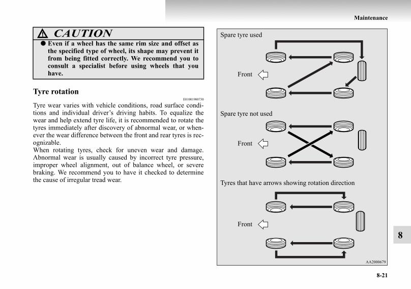
Maintenance
8-21
8
Tyre rotationE01001900730
Tyre wear varies with vehicle conditions, road surface condi-tions and individual driver’s driving habits. To equalize thewear and help extend tyre life, it is recommended to rotate thetyres immediately after discovery of abnormal wear, or when-ever the wear difference between the front and rear tyres is rec-ognizable.When rotating tyres, check for uneven wear and damage.Abnormal wear is usually caused by incorrect tyre pressure,improper wheel alignment, out of balance wheel, or severebraking. We recommend you to have it checked to determinethe cause of irregular tread wear.
● Even if a wheel has the same rim size and offset asthe specified type of wheel, its shape may prevent itfrom being fitted correctly. We recommend you toconsult a specialist before using wheels that youhave.
CAUTION! Spare tyre used
Spare tyre not used
Tyres that have arrows showing rotation direction
Front
Front
Front
BK-BK2008E1ENUK.en-uk-Section11.fm Page 21 Wednesday, January 9, 2008 4:50 PM
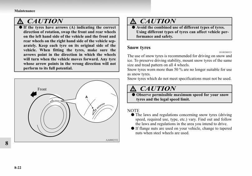
8-22
Maintenance
8
Snow tyresE01002000523
The use of snow tyres is recommended for driving on snow andice. To preserve driving stability, mount snow tyres of the samesize and tread pattern on all 4 wheels.Snow tyres worn more than 50 % are no longer suitable for useas snow tyres.Snow tyres which do not meet specifications must not be used.
NOTE● The laws and regulations concerning snow tyres (driving
speed, required use, type, etc.) vary. Find out and followthe laws and regulations in the area you intend to drive.
● If flange nuts are used on your vehicle, change to taperednuts when steel wheels are used.
CAUTION!● If the tyres have arrows (A) indicating the correct
direction of rotation, swap the front and rear wheelson the left hand side of the vehicle and the front andrear wheels on the right hand side of the vehicle sep-arately. Keep each tyre on its original side of thevehicle. When fitting the tyres, make sure thearrows point in the direction in which the wheelswill turn when the vehicle moves forward. Any tyrewhose arrow points in the wrong direction will notperform to its full potential.
Front
CAUTION!● Avoid the combined use of different types of tyres.
Using different types of tyres can affect vehicle per-formance and safety.
CAUTION!● Observe permissible maximum speed for your snow
tyres and the legal speed limit.
BK-BK2008E1ENUK.en-uk-Section11.fm Page 22 Wednesday, January 9, 2008 4:50 PM
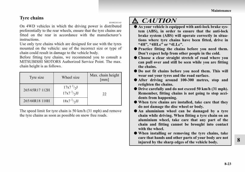
Maintenance
8-23
8
Tyre chains E01002101143
On 4WD vehicles in which the driving power is distributedpreferentially to the rear wheels, ensure that the tyre chains arefitted on the rear in accordance with the manufacturer’sinstructions.Use only tyre chains which are designed for use with the tyresmounted on the vehicle: use of the incorrect size or type ofchain could result in damage to the vehicle body.Before fitting tyre chains, we recommend you to consult aMITSUBISHI MOTORS Authorized Service Point. The max.chain height is as follows.
The speed limit for tyre chain is 50 km/h (31 mph) and removethe tyre chains as soon as possible on snow free roads.
Tyre size Wheel size Max. chain height [mm]
265/65R17 112H17x7 1/2J17x7 1/2JJ 22
265/60R18 110H 18x7 1/2JJ
CAUTION!● As your vehicle is equipped with anti-lock brake sys-
tem (ABS), in order to ensure that the anti-lockbrake system (ABS) will operate correctly in situa-tions where tyre chains have been fitted, drive in“4H”, “4HLc” or “4LLc”.
● Practice fitting the chains before you need them.Don’t expect help from other people in the cold.
● Choose a clear straight stretch of road where youcan pull over and still be seen while you are fittingthe chains.
● Do not fit chains before you need them. This willwear out your tyres and the road surface.
● After driving around 100-300 metres, stop andretighten the chains.
● Drive carefully and do not exceed 50 km/h (31 mph).Remember, fitting chains is not going to stop acci-dents from happening.
● When tyre chains are installed, take care that theydo not damage the disc wheel or body.
● An aluminium wheel can be damaged by a tyrechain while driving. When fitting a tyre chain on analuminium wheel, take care that any part of thechain and fitting cannot be brought into contactwith the wheel.
● When installing or removing the tyre chains, takecare that hands and other parts of your body are notinjured by the sharp edges of the vehicle body.
BK-BK2008E1ENUK.en-uk-Section11.fm Page 23 Wednesday, January 9, 2008 4:50 PM

8-24
Maintenance
8
NOTE● The laws and regulations concerning the use of tyre chains
vary. Always follow local laws and regulations.In most countries, it is prohibed by the law to use tyrechains on roads without snow.
Parking brake break-inE01008300010
Break-in the parking brake linings whenever the brake per-formance of the parking brake is insufficient or whenever theparking brake linings and/or discs are replaced, in order toassure the best brake performance.This procedure is described in the vehicle service manual andcan be carried out by a MITSUBISHI MOTORS AuthorizedService Point.
BK-BK2008E1ENUK.en-uk-Section11.fm Page 24 Wednesday, January 9, 2008 4:50 PM

Maintenance
8-25
8
Wiper blade rubber replacementE01008200110
1. Lift the wiper arm off the windscreen.2. Pull the wiper blade until its stopper (A) disengages from
the hook (B). Then, pull the wiper blade further to removeit.
NOTE● Do not allow the wiper arm to fall onto the windscreen; it
could damage the glass.
3. Attach the retainers (C) to a new wiper blade.Refer to the illustration to ensure that the retainers are cor-rectly aligned as you attach them.
4. Insert the wiper blade into the arm, starting with the oppo-site end of the blade from the stopper. Make sure the hook(B) is fitted correctly in the grooves in the blade.
NOTE● If retainers are not supplied with the new wiper blade, use
the retainers from the old blade.
BK-BK2008E1ENUK.en-uk-Section11.fm Page 25 Wednesday, January 9, 2008 4:50 PM

8-26
Maintenance
8
5. Push the wiper blade until the hook (B) engages securelywith the stopper (A).
Rear window wiper blade1. Lift the wiper arm off the window glass.2. Pull the wiper blade downward to disengage it from the
stopper (A) at the end of the wiper arm. Pull the wiperblade further to remove it.
3. Slide a new wiper blade through the hook (B) on the wiperarm.
NOTE● Do not allow the wiper arm to fall onto the window glass;
it could damage the glass.
BK-BK2008E1ENUK.en-uk-Section11.fm Page 26 Wednesday, January 9, 2008 4:50 PM

Maintenance
8-27
8
4. Firmly insert the retainer (C) into the groove (D) in thewiper blade.Refer to the illustration to ensure that the retainers are cor-rectly aligned as you insert them into the groove.
NOTE● If a retainer is not supplied with the new wiper blade, use
the retainer from the old blade.
General maintenanceE01002700360
Fuel, engine coolant, oil and exhaust gas leakageLook under the body of your vehicle to check for fuel, enginecoolant, oil and exhaust gas leaks.
Exterior and interior lamp operationOperate the combination lamp switch to check that all lampsare functioning properly.If the lamps do not illuminate, the probable cause is a blownfuse or defective lamp bulb. Check the fuses first. If there is noblown fuses, check the lamp bulbs.For information regarding the inspection and replacement ofthe fuses and the lamp bulbs, refer to “Fuses” on page 8-29 and“Replacement of lamp bulbs” on page 8-36.If the fuses and bulbs are all OK, we recommend you to haveyour vehicle checked and repaired.
WARNING!● If you see a suspicious fuel leak or if you smell fuel,
do not operate the vehicle; we recommend you tocall for assistance.
BK-BK2008E1ENUK.en-uk-Section11.fm Page 27 Wednesday, January 9, 2008 4:50 PM

8-28
Maintenance
8
Meter, gauge and indicator/warning lamps oper-ationRun the engine to check the operation of all meters, gauges,and indicator/warning lamps.If there is anything wrong, we recommend you to have yourvehicle inspected.
Hinges and latches lubricationCheck all latches and hinges, and, if necessary, have themlubricated.
For cold and snowy weatherE01002800299
Ventilation slotsThe ventilation slots in front of the windscreen should be keptclear of leaves or brushed clear after heavy snowfall, so that theoperation of the heating and ventilation systems will not beimpaired.
WeatherstrippingTo prevent freezing of the weatherstripping on the doors, bon-net, etc., they should be treated with silicone grease.
Additional equipmentIt is a good idea to carry a shovel or a short-handled spade inthe vehicle during the winter so that you can clear away snowif you get stranded. A small hand-brush for sweeping snow offthe vehicle and a plastic scraper for the windscreen and rearwindow are also useful.
BK-BK2008E1ENUK.en-uk-Section11.fm Page 28 Wednesday, January 9, 2008 4:50 PM
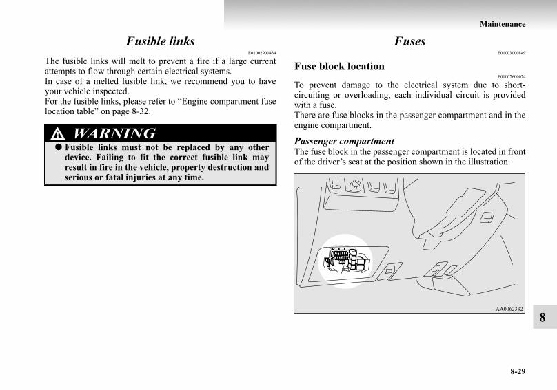
Maintenance
8-29
8
Fusible linksE01002900434
The fusible links will melt to prevent a fire if a large currentattempts to flow through certain electrical systems.In case of a melted fusible link, we recommend you to haveyour vehicle inspected. For the fusible links, please refer to “Engine compartment fuselocation table” on page 8-32.
FusesE01003000849
Fuse block locationE01007600074
To prevent damage to the electrical system due to short-circuiting or overloading, each individual circuit is providedwith a fuse.There are fuse blocks in the passenger compartment and in theengine compartment.
Passenger compartmentThe fuse block in the passenger compartment is located in frontof the driver’s seat at the position shown in the illustration.
WARNING!● Fusible links must not be replaced by any other
device. Failing to fit the correct fusible link mayresult in fire in the vehicle, property destruction andserious or fatal injuries at any time.
BK-BK2008E1ENUK.en-uk-Section11.fm Page 29 Wednesday, January 9, 2008 4:50 PM
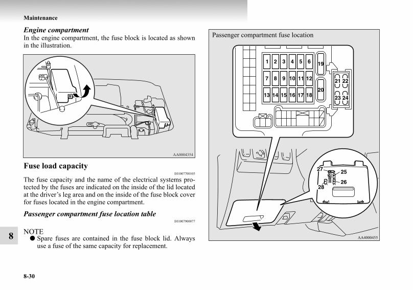
8-30
Maintenance
8
Engine compartmentIn the engine compartment, the fuse block is located as shownin the illustration.
Fuse load capacityE01007700105
The fuse capacity and the name of the electrical systems pro-tected by the fuses are indicated on the inside of the lid locatedat the driver’s leg area and on the inside of the fuse block coverfor fuses located in the engine compartment.
Passenger compartment fuse location tableE01007900077
NOTE● Spare fuses are contained in the fuse block lid. Always
use a fuse of the same capacity for replacement.
Passenger compartment fuse location
BK-BK2008E1ENUK.en-uk-Section11.fm Page 30 Wednesday, January 9, 2008 4:50 PM

Maintenance
8-31
8
● Some fuses may not be installed on your vehicle, depend-ing on the vehicle model or specifications.
● The table above shows the main equipment correspondingto each fuse. The fuse box does not contain spare 7.5 A and 15 A fuses.If a fuse of one of these capacities blows, replace it tem-porarily by borrowing the one that matches from:7.5 A: Outside rear-view mirrors15 A: Cigarette lighterReplace the borrowed fuse as soon as possible.
No. Symbol Electrical system Capacity
1 Ignition coil 10 A
2 Gauge 7.5 A
3 Reversing lamp 7.5 A
4 — — 7.5 A
5 Relay 7.5 A
6 Heated door mirror 7.5 A
7 — — 30 A
8 Engine control 7.5 A
9 Cigarette lighter 15 A
10 — — —
11 Outside rear-view mirrors 7.5 A
12 Engine control 7.5 A
13 — — —
14 Rear window wiper 15 A
15 Central door locks 15 A
16 Rear fog lamp 10 A
17 — — — 18 — — —
19 Heater 30 A
20 Rear window demister 30 A
21 Sunroof 20 A
22 Anti-lock brake system 10 A
23 Heated seat 20 A
24 Approach lamps 10 A
25 — Spare fuse 20 A 26 — Spare fuse 10 A 27 — Spare fuse 30 A 28 — Spare fuse 25 A
No. Symbol Electrical system Capacity
BK-BK2008E1ENUK.en-uk-Section11.fm Page 31 Wednesday, January 9, 2008 4:50 PM

8-32
Maintenance
8
Engine compartment fuse location tableE01008000105
Engine compartment fuse location
No. Symbol Electrical system Capacity
1 Alternator 140 A*1
2 Fuse (+B) 60 A*1
3 Ignition switch 40 A*1
4 Electric window control 30 A*1
5 Engine control 20 A*1
6 Fuel pump 20 A
7 Rear heater 25 A
8 Accessory socket 25 A
9 Fuel line heater 25 A
10 Condenser fan motor 25 A
11 Rear air conditioning 20 A
12 Wiper deicer 15 A
13 Horn 10 A
14 Automatic transmission 20 A
15 Hazard warning flasher 10 A
16 Stop lamps 15 A
17 Radio 10 A
18 Room lamp 15 A
19 Air conditioning 10 A
BK-BK2008E1ENUK.en-uk-Section11.fm Page 32 Wednesday, January 9, 2008 4:50 PM

Maintenance
8-33
8● Some fuses may not be installed on your vehicle, depend-ing on the vehicle model or specifications.
● The table above shows the main equipment correspondingto each fuse.
Identification of fuseE01008100092
20 Front fog lamps 15 A
21 — — —
22 Windscreen wiper 20 A
23 Tail lamp (right) 7.5 A
24 Tail lamp (left) 7.5 A
25 Headlamp low beam (right)10 A*2
20 A*3
26 Headlamp low beam (left)10 A*2
20 A*3
27 Headlamp high beam (right) 10 A
28 Headlamp high beam (left) 10 A
29 Audio 30 A*1
30 Heater 50 A*1
*1: Fusible link
*2: Vehicles without discharge headlamps
*3: Vehicles with discharge headlamps
No. Symbol Electrical system Capacity
7.5 A Brown10 A Red 15 A Blue 20 A Yellow (fuse type)/Light blue (fusible link type)25 A Transparent 30 A Green (fuse type)/Pink (fusible link type)40 A Green 50 A Red 60 A Yellow
140 A Reddish brown
BK-BK2008E1ENUK.en-uk-Section11.fm Page 33 Wednesday, January 9, 2008 4:50 PM

8-34
Maintenance
8
Fuse replacement E01007800122
1. Before replacing a fuse, always turn off the electrical cir-cuit concerned and place the ignition switch in the“LOCK” position.
2. Pull the fuse block lid (A) to remove it. 3. Remove the fuse puller (B) from the fuse block lid.
4. The replacement of fuses located in the driver’s seat legarea should be performed from the hole of the fuse blocklid.
BK-BK2008E1ENUK.en-uk-Section11.fm Page 34 Wednesday, January 9, 2008 4:50 PM

Maintenance
8-35
8
5. Referring to the fuse load capacity table, check the fusepertaining to the problem.
NOTE● If any system does not function but the fuse corresponding
to that system is normal, there may be a fault in the systemelsewhere. We recommend you to have your vehiclechecked.
6. Insert a new fuse of the same capacity by using the fusepuller and insert the fuse at the same place in the fuseblock.
C- Fuse is OKD- Blown fuse CAUTION!
● If the newly inserted fuse blows again after a shorttime, we recommend you to have the electrical sys-tem checked to find the cause and rectify it.
● Never use a fuse with a capacity larger than thatspecified or any substitute, such as wire, foil, etc.;doing so will cause the circuit wiring to heat up andcould cause a fire.
BK-BK2008E1ENUK.en-uk-Section11.fm Page 35 Wednesday, January 9, 2008 4:50 PM

8-36
Maintenance
8
Replacement of lamp bulbsE01003100521
Before replacing a bulb, ensure the lamp is off. Do not touchthe glass part of the new bulb with your bare fingers; the skinoil left on the glass will evaporate when the bulb gets hot andthe vapor will condense on the reflector and dim the surface.
NOTE● Do not attempt to repair or replace the lamp bulbs other
than described in this owner’s manual. For repair orreplacement, contact a MITSUBISHI MOTORS Author-ized Service Point.
● If you are unsure of how to carry out the work as required,we recommend you to consult a specialist.
● Be careful not to scratch the vehicle body when removinga lamp or lens.
● When it rains or when the vehicle has been washed, theinside of the lens sometimes becomes foggy. This is thesame phenomenon as when window glass mists up on ahumid day, and does not indicate a functional problem.When the lamp is switched on, the heat will remove thefog. However, if water gathers inside the lamp, we recom-mend you to have it checked.
Bulb capacityE01003200014
When replacing a bulb, use a new bulb with the same wattageand colour.
OutsideE01003301618
Codes in parentheses indicate bulb types.
CAUTION!● Bulbs are extremely hot immediately after being
turned off.When replacing a bulb, wait for it to cool sufficientlybefore touching it. You could otherwise be burnt.
1- Headlamps, high beam: 65 W (H9)2- Front fog lamps*: 55 W (H11)3- Headlamps, low beam with discharge lamp: 35 W (D2S)
Headlamps, low beam without discharge lamp: 55 W (H11)4- Position lamps: 5 W (W5W)5- Front turn-signal lamps: 21 W (WY21W)
BK-BK2008E1ENUK.en-uk-Section11.fm Page 36 Wednesday, January 9, 2008 4:50 PM

Maintenance
8-37
8
Codes in parentheses indicate bulb types.
CAUTION!● On vehicles with discharge headlamps, do not
attempt to disassemble or repair discharge head-lamps, and do not attempt to replace their bulbs. Ahigh voltage is present in the power circuit and inthe bulbs and bulb terminals. To avoid the risk of anelectric shock, contact a MITSUBISHI MOTORSAuthorized Service Point whenever repair orreplacement is necessary.
3-door models 5-door models
6- High-mounted stop lamp: 16 W (W16W)7- Licence plate lamps: 5 W (W5W)8- Rear fog lamp: 21 W (W21W)9- Tail lamps*: 5 W (W5W)
10- Rear turn-signal lamps*: 21 W (WY21W)11- Rear turn-signal lamps*: 21 W (WY21W)12- Stop and tail lamps*: 21/5 W (W21/5W)
Stop lamps*: 21/5 W (W21/5W)13- Reversing lamps: 21 W (W21W)
BK-BK2008E1ENUK.en-uk-Section11.fm Page 37 Wednesday, January 9, 2008 4:50 PM

8-38
Maintenance
8
InsideE01003400814
HeadlampsE01003500961
Replacement of high beam1. Remove the bulb and connector assembly (A) by turning
it anticlockwise.
1- Luggage compartment lamp: 8 W2- Door courtesy lamps*: 3.4 W3- Vanity mirror lamps*: 3 W4- Room & map lamps: 8 W5- Rear personal lamps: 8 W6- Glove box lamp: 1.4 W
BK-BK2008E1ENUK.en-uk-Section11.fm Page 38 Wednesday, January 9, 2008 4:50 PM

Maintenance
8-39
8
2. Depress the tab (B) on the harness connector and pull theharness connector (C) to remove it.
3. To install the bulb, perform the removal steps in reverse.
Replacement of low beam1. Remove the bulb and connector assembly (A) by turning
it anticlockwise.
BK-BK2008E1ENUK.en-uk-Section11.fm Page 39 Wednesday, January 9, 2008 4:50 PM

8-40
Maintenance
8
2. Depress the tab (B) on the harness connector and pull theharness connector (C) to remove it.
3. To install the bulb, perform the removal steps in reverse.
CAUTION!● Handle halogen lamp bulbs with care. The gas inside
halogen lamp bulbs is highly pressurized, so drop-ping, knocking, or scratching a halogen lamp bulbcan cause it to shatter.
● Never hold the halogen lamp bulb with a bare hand,dirty glove, etc.The oil from your hand could cause the bulb tobreak the next time the headlamps are operated.If the glass surface is dirty, it must be cleaned withalcohol, paint thinner, etc., and refit it after drying itthoroughly.
BK-BK2008E1ENUK.en-uk-Section11.fm Page 40 Wednesday, January 9, 2008 4:50 PM

Maintenance
8-41
8
Position lampsE01003700471
1. Turn the bulb socket anticlockwise to remove it. 2. Remove the bulb from the socket by pulling out.
3. To install the bulb, perform the removal steps in reverse.
Front turn-signal lampsE01003800414
1. Turn the bulb socket anticlockwise to remove it.2. Remove the bulb from the socket by pulling out
3. To install the bulb, perform the removal steps in reverse.
BK-BK2008E1ENUK.en-uk-Section11.fm Page 41 Wednesday, January 9, 2008 4:50 PM

8-42
Maintenance
8
Front fog lamps*E01004000774
1. Remove the 5 clips (A, C) and screw (B) by followingprocedures then turn up the cover (D).
2. Depress the tab (E) on the harness connector (F) and pullthe harness connector to remove it.
BK-BK2008E1ENUK.en-uk-Section11.fm Page 42 Wednesday, January 9, 2008 4:50 PM

Maintenance
8-43
8
3. Remove the entire socket and bulb assembly (G) by turn-ing it anticlockwise.
4. To install the bulb, perform the removal steps in reverse.
CAUTION!● Handle halogen lamp bulbs with care. The gas inside
halogen lamp bulbs is highly pressurized, so drop-ping, knocking, or scratching a halogen lamp bulbcan cause it to shatter.
● Never hold the halogen lamp bulb with a bare hand,dirty glove, etc.The oil from your hand could cause the bulb tobreak the next time the fog lamps are used.If the glass surface is dirty, it must be cleaned withalcohol, paint thinner, etc., and refit it after dryingthoroughly.
BK-BK2008E1ENUK.en-uk-Section11.fm Page 43 Wednesday, January 9, 2008 4:50 PM

8-44
Maintenance
8
NOTE● When refitting the clips of the cover, push the pin (H).
Rear combination lampsE01004200659
On corner side1. Remove the screws that hold the lamp unit.2. Slide the lamp unit out sideways to remove it.
Left side
BK-BK2008E1ENUK.en-uk-Section11.fm Page 44 Wednesday, January 9, 2008 4:50 PM

Maintenance
8-45
8
3. Remove the socket and bulb assemblies by turning it anti-clockwise.Remove the bulb by pulling it out.
4. To install the bulb, perform the removal steps in reverse.
Right side
A- Rear turn-signal lamp*B- Stop and tail lamp*
Stop lamp*C- Reversing lamp
3-door models 5-door models
BK-BK2008E1ENUK.en-uk-Section11.fm Page 45 Wednesday, January 9, 2008 4:50 PM

8-46
Maintenance
8
On bumper*1. Remove the lens mounting screws.
2. Remove the socket and bulb assembly together by turningit anticlockwise, and then remove the bulb by pulling itout.
3. To install the bulb, perform the removal steps in reverse.
D- Rear turn-signal lampE- Tail lamp
BK-BK2008E1ENUK.en-uk-Section11.fm Page 46 Wednesday, January 9, 2008 4:50 PM

Maintenance
8-47
8
Rear fog lampE01004100241
1. Open the spare wheel garnish (A). (Refer to “To removethe spare tyre” on page 6-18.)
2. Remove the socket and bulb assembly (B) by turning itanticlockwise, and then remove the bulb by pulling it out.
3. To install the bulb, perform the removal steps in reverse.
BK-BK2008E1ENUK.en-uk-Section11.fm Page 47 Wednesday, January 9, 2008 4:50 PM

8-48
Maintenance
8
High-mounted stop lampE01004500362
1. Insert the tip of a blade (or minus) screwdriver at the edgeof the cover and pry gently to remove the cover.
2. Remove the socket and bulb assembly together by turningit anticlockwise, and then remove the bulb by pulling itout.
3. To install the bulb, perform the removal steps in reverse.
BK-BK2008E1ENUK.en-uk-Section11.fm Page 48 Wednesday, January 9, 2008 4:50 PM
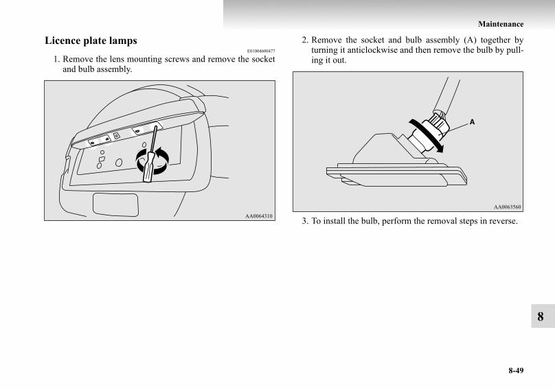
Maintenance
8-49
8
Licence plate lampsE01004600477
1. Remove the lens mounting screws and remove the socketand bulb assembly.
2. Remove the socket and bulb assembly (A) together byturning it anticlockwise and then remove the bulb by pull-ing it out.
3. To install the bulb, perform the removal steps in reverse.
BK-BK2008E1ENUK.en-uk-Section11.fm Page 49 Wednesday, January 9, 2008 4:50 PM

8-50
Maintenance
8
NOTE● When installing the lens, make sure the direction of the
lens is installed as shown in the illustration.
*: Right side of the vehicle
Room & map lampsE01004700306
1. Insert a straight blade (or minus) screwdriver with a clothover its tip into the lens and pry gently to remove it.
2. Remove the bulb from the lamp holder.
3. To install the bulb, perform the removal steps in reverse.
BK-BK2008E1ENUK.en-uk-Section11.fm Page 50 Wednesday, January 9, 2008 4:50 PM

Maintenance
8-51
8
NOTE● When installing the lens, align the tab on the lens with the
hole on the vehicle side.
Rear personal lampsE01005200151
When replacing a bulb, keep the interior lamp switch in the“ ” (OFF) position.
1. Insert a straight blade (or minus) screwdriver with a clothover its tip into the notch of the lens and pry gently toremove it.
2. Remove the bulb from the lamp holder.
NOTE● Wrap a piece of cloth around the tip of the screwdriver in
order to avoid scratching the lens.
BK-BK2008E1ENUK.en-uk-Section11.fm Page 51 Wednesday, January 9, 2008 4:50 PM

8-52
Maintenance
8
3. To install the bulb, perform the removal steps in reverse.
NOTE● When installing the lens, align the tab on the lens with the
hole on the vehicle side.
Luggage compartment lampE01005300211
1. Insert a straight blade (or minus) screwdriver with a clothover its tip into the notch of the lens and pry gently toremove the lens.
2. Remove the bulb from the lamp holder.
3. To install the bulb, perform the removal steps in reverse.
BK-BK2008E1ENUK.en-uk-Section11.fm Page 52 Wednesday, January 9, 2008 4:50 PM

Maintenance
8-53
8
NOTE● When installing the lens, align the tabs on the lens with
the holes on the vehicle side.
Door courtesy lampsE01005400195
1. Insert a straight blade (or minus) screwdriver with a clothover its tip into the edge of the lens, pry gently to removethe lens.
2. Remove the bulb from the lamp holder.
Front
BK-BK2008E1ENUK.en-uk-Section11.fm Page 53 Wednesday, January 9, 2008 4:50 PM

8-54
Maintenance
8
3. To install the bulb, perform the removal steps in reverse.
NOTE● When installing the lens, align the 2 tabs on the lens with
the notches on the vehicle side.Rear
BK-BK2008E1ENUK.en-uk-Section11.fm Page 54 Wednesday, January 9, 2008 4:50 PM

Maintenance
8-55
8
Glove box lampE01006100232
1. Pull out the bulb.
2. To install the bulb, perform the removal step in reverse.
Vanity mirror lamps*E01006200103
1. Insert a straight blade (or minus) screwdriver with a clothover its tip into the notch of the lens and pry gently toremove it.
2. Remove the bulb from the lamp holder.
3. To install the bulb, perform the removal steps in reverse.
BK-BK2008E1ENUK.en-uk-Section11.fm Page 55 Wednesday, January 9, 2008 4:50 PM

BK-BK2008E1ENUK.en-uk-Section11.fm Page 56 Wednesday, January 9, 2008 4:50 PM

9
Specifications
Vehicle labeling . . . . . . . . . . . . . . . . . . . . . . . . . . .9- 2Vehicle dimensions . . . . . . . . . . . . . . . . . . . . . . . .9- 4Vehicle performance . . . . . . . . . . . . . . . . . . . . . . .9- 6Vehicle weight . . . . . . . . . . . . . . . . . . . . . . . . . . . .9- 7Engine specifications . . . . . . . . . . . . . . . . . . . . . . .9- 11Electrical system . . . . . . . . . . . . . . . . . . . . . . . . . .9- 12Tyres and wheels . . . . . . . . . . . . . . . . . . . . . . . . . .9- 13Fuel consumption. . . . . . . . . . . . . . . . . . . . . . . . . .9- 14Notes regarding diesel fuel . . . . . . . . . . . . . . . . . .9- 15Refill capacities . . . . . . . . . . . . . . . . . . . . . . . . . . .9- 16
BK-BK2008E1ENUK.en-uk-Section12.fm Page 1 Thursday, January 10, 2008 7:49 AM
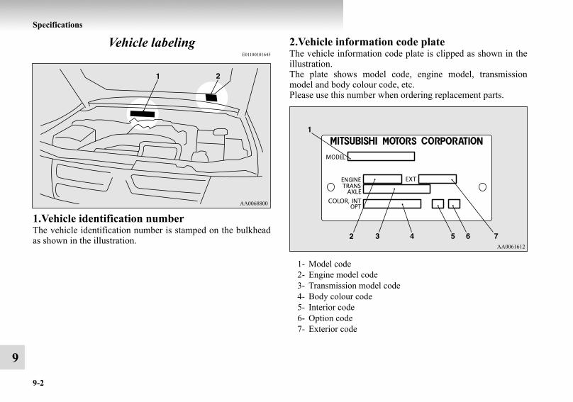
9-2
Specifications
9
Vehicle labelingE01100101645
1.Vehicle identification numberThe vehicle identification number is stamped on the bulkheadas shown in the illustration.
2.Vehicle information code plateThe vehicle information code plate is clipped as shown in theillustration.The plate shows model code, engine model, transmissionmodel and body colour code, etc.Please use this number when ordering replacement parts.
1- Model code2- Engine model code3- Transmission model code4- Body colour code5- Interior code6- Option code7- Exterior code
BK-BK2008E1ENUK.en-uk-Section12.fm Page 2 Thursday, January 10, 2008 7:49 AM

Specifications
9-3
9
Vehicle identification number plate (RHD vehicles only)This is stamped on the number plate riveted to the left frontcorner of the instrument panel pad. It is visible from outside ofthe vehicle through the windscreen.
Engine numberThe engine number is stamped on the engine cylinder block asshown in the illustration.
3200 models
3800 models
BK-BK2008E1ENUK.en-uk-Section12.fm Page 3 Thursday, January 10, 2008 7:49 AM
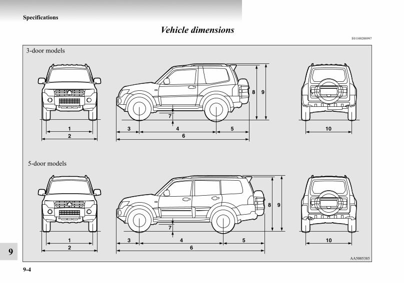
9-4
Specifications
9
Vehicle dimensionsE01100200997
5-door models
3-door models
BK-BK2008E1ENUK.en-uk-Section12.fm Page 4 Thursday, January 10, 2008 7:49 AM

Specifications
9-5
9
Item 3-door models 5-door models
1 Front track 1,560 mm 1,570 mm
2 Overall widthWithout side protector moulding 1,845 mm —With side protector moulding 1,875 mm
3 Front overhang 765 mm4 Wheel base 2,545 mm 2,780 mm5 Rear overhang 1,075 mm 1,355 mm6 Overall length 4,385 mm 4,900 mm7 Ground clearance (unladen) 225 mm8
Overall heightWithout roof rails 1,850 mm 1,870 mm
9 With roof rails 1,880 mm 1,900 mm10 Rear track 1,560 mm 1,570 mm
Minimum turning radiusBody 5.7 m 6.1 mWheel 5.3 m 5.7 m
BK-BK2008E1ENUK.en-uk-Section12.fm Page 5 Thursday, January 10, 2008 7:49 AM

9-6
Specifications
9
Vehicle performanceE01100300914
*1: Vehicles to comply with the Euro 4 regulation*2: Vehicles to comply with the Euro 3 regulation
Item3-door models 5-door models
3200 models 3800 models 3200 models 3800 models
Maximum speed
177 km/h*1, 174 km/h*2
(110 mph*1, 108 mph*2)
200 km/h (124 mph)
177 km/h*1, 174 km/h*2
(110 mph*1, 108 mph*2)
200 km/h (124 mph)
Maximum climbing ability (in 1st gear) 35 °
BK-BK2008E1ENUK.en-uk-Section12.fm Page 6 Thursday, January 10, 2008 7:49 AM
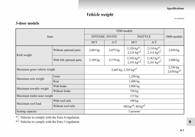
Specifications
9-7
9
Vehicle weightE01100402469
3-door models
*1: Vehicles to comply with the Euro 4 regulation*2: Vehicles to comply with the Euro 3 regulation
Item
3200 models
3800 modelsINTENSE, INVITE INSTYLE
M/T A/T M/T A/T
Kerb weightWithout optional parts 2,085 kg 2,075 kg 2,120 kg*1,
2,125 kg*22,110 kg*1, 2,115 kg*2 2,030 kg
With full optional parts 2,189 kg 2,179 kg 2,192 kg*1, 2,191 kg*2
2,182 kg*1, 2,181 kg*2 2,080 kg
Maximum gross vehicle weight 2,665 kg, 2,765 kg*3 2,530 kg, 2,630 kg*3
Maximum axle weightFront 1,250 kgRear 1,600 kg
Maximum towable weightWith brake 2,800 kgWithout brake 750 kg
Maximum trailer-nose weight 115 kg
Maximum roof loadWith roof rails 100 kg
Without roof rails 100 kg*4, 80 kg*5
Seating capacity 5 persons
BK-BK2008E1ENUK.en-uk-Section12.fm Page 7 Thursday, January 10, 2008 7:49 AM
9-8
Specifications
9
*3: In case of trailer towing*4: Vehicles with 265/65R17 size tyre*5: Vehicles with 265/60R18 size tyre
NOTE● Trailer specifications indicate the manufacturer’s recommendation.
BK-BK2008E1ENUK.en-uk-Section12.fm Page 8 Thursday, January 10, 2008 7:49 AM

Specifications
9-9
9
5-door models
*1: Vehicles to comply with the Euro 4 regulation*2: Vehicles to comply with the Euro 3 regulation*3: In case of trailer towing*4: Vehicles with 265/65R17 size tyre
Item
3200 models
3800 modelsINTENSE, INVITE INSTYLE
M/T A/T M/T A/T
Kerb weightWithout optional parts 2,265 kg 2,255 kg 2,300 kg*1,
2,305 kg*22,290 kg*1, 2,295 kg*2 2,210 kg
With full optional parts 2,391 kg 2,381 kg 2,387 kg*1, 2,386 kg*2
2,377 kg*1, 2,376 kg*2 2,275 kg
Maximum gross vehicle weight 3,030 kg, 3,125 kg*3 2,910 kg, 3,010 kg*3
Maximum axle weightFront 1,330 kg 1,300 kg
Rear 1,780 kg, 1,925 kg*3
Maximum towable weightWith brake 3,300 kgWithout brake 750 kg
Maximum trailer-nose weight 135 kg
Maximum roof loadWith roof rails 100 kg
Without roof rails 100 kg*4, 80 kg*5
Seating capacity 7 persons
BK-BK2008E1ENUK.en-uk-Section12.fm Page 9 Thursday, January 10, 2008 7:49 AM

9-10
Specifications
9
*5: Vehicles with 265/60R18 size tyre
NOTE● Trailer specifications indicate the manufacturer’s recommendation.
BK-BK2008E1ENUK.en-uk-Section12.fm Page 10 Thursday, January 10, 2008 7:49 AM

Specifications
9-11
9
Engine specificationsE01100601204
*1: Vehicles that comply with the Euro 4 regulation*2: Vehicles that comply with the Euro 3 regulation*3: 3-door models*4: 5-door models
Item3200 models
3800 modelsM/T A/T
Engine modelNo. of cylindersTotal displacementBoreStrokeCamshaftMixture preparation
4M414 in line3,200 cc98.5 mm
105.0 mmDouble overhead
Electronic injection
6G756-V (60 °)3,828 cc95.0 mm90.0 mm
Single overheadElectronic injection
Maximum output (EEC net) 118 kW/3,800 r/min*1
121 kW/3,500 r/min*2125 kW/3,800 r/min*1
121 kW/3,500 r/min*2182 kW/6,000 r/min*3
184 kW/6,000 r/min*4
Maximum torque (EEC net) 381 Nm/2,000 r/min 373 Nm/2,000 r/min 329 Nm/2,750 r/min
BK-BK2008E1ENUK.en-uk-Section12.fm Page 11 Thursday, January 10, 2008 7:49 AM

9-12
Specifications
9
Electrical systemE01100800964
*: Optional equipment
Item 3200 models 3800 models
Voltage 12 V
BatteryType (JIS) 95D31L, 80D26L* 75D23L, 80D26L*Capacity (5HR) 64 Ah, 55 Ah* 52 Ah, 55 Ah*
Alternator capacity 120 A, 140 A* 120 ASpark plug type NGK — IFR6B-K
BK-BK2008E1ENUK.en-uk-Section12.fm Page 12 Thursday, January 10, 2008 7:49 AM
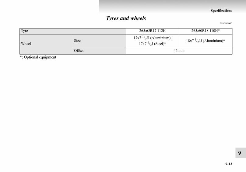
Specifications
9-13
9
Tyres and wheelsE01100901483
*: Optional equipment
Tyre 265/65R17 112H 265/60R18 110H*
WheelSize
17x7 1/2JJ (Aluminium), 17x7 1/2J (Steel)*
18x7 1/2JJ (Aluminium)*
Offset 46 mm
BK-BK2008E1ENUK.en-uk-Section12.fm Page 13 Thursday, January 10, 2008 7:49 AM

9-14
Specifications
9
Fuel consumptionE01101100270
*1: Vehicles to comply with the Euro 4 regulation*2: Vehicles to comply with the Euro 3 regulation
NOTE● The values shown above apply to a vehicle on which optional equipment has not been fitted.● The results given do not express or imply any guarantee of the fuel consumption of the particular vehicle.
The vehicle itself has not been tested and there are inevitably differences between individual vehicles of the same model. Inaddition, this vehicle may incorporate particular modifications. Furthermore, the driver’s style and road and traffic conditions,as well as the extent to which the vehicle has been driven and the standard of maintenance, will all affect its fuel consumption.
Model
Combined Urban conditions Extra-urban conditions
CO2 (g/km)Fuel
consumption(L/100 km)
CO2 (g/km)Fuel
consumption(L/100 km)
CO2 (g/km)Fuel
consumption(L/100 km)
3200 models
3-door models
M/T 244*1, 241*2 9.2*1, 9.1*2 302*1, 298*2 11.4*1, 11.2*2 211*1, 209*2 7.9*1, 7.8*2
A/T 278*1, 274*2 10.5*1, 10.3*2 346*1, 345*2 13.1*1, 13.0*2 239*1, 234*2 9.0*1, 8.8*2
5-door models
M/T 246*1, 242*2 9.3*1, 9.1*2 304*1, 298*2 11.5*1, 11.2*2 213*1, 209*2 8.0*1, 7.8*2
A/T 280*1, 274*2 10.6*1, 10.3*2 346*1, 345*2 13.1*1, 13.0*2 241*1, 234*2 9.1*1, 8.8*2
3800 models
3-door models 322 13.4 420 17.6 267 11.25-door models 324 13.5 423 17.7 268 11.2
BK-BK2008E1ENUK.en-uk-Section12.fm Page 14 Thursday, January 10, 2008 7:49 AM

Specifications
9-15
9
Notes regarding diesel fuelE01101400055
Due to the separation of paraffin, the fluidity of the fueldecreases considerably as the temperature falls. Because of thisfact there are two kinds of fuel: “summer” and “winter”.This must be considered in winter use.When travelling abroad, find out in advance about the fuelsserved in local service stations.
BK-BK2008E1ENUK.en-uk-Section12.fm Page 15 Thursday, January 10, 2008 7:49 AM

9-16
Specifications
9
Refill capacitiesE01101301774
LHD
RHD
3200 models 3800 models
3200 models 3800 models
BK-BK2008E1ENUK.en-uk-Section12.fm Page 16 Thursday, January 10, 2008 7:49 AM

Specifications
9-17
9
*: Rear washer fluid container is located on the backdoor. (Refer to “Rear window washer fluid” on page 8-12.)
No. Item Quantity Lubricants
1 Engine oil
3200 modelsOil pan 7.5 litres
Refer to page 8-6
Oil filter 1.0 litreOil cooler 1.3 litres
3800 modelsOil pan 4.3 litresOil filter 0.3 litreOil cooler 0.3 litre
2 Automatic transmission fluid 9.7 litres DIA QUEEN ATF SP III3 Brake fluid As required
Brake fluid DOT 3 or DOT 44 Clutch fluid As required
5 Washer fluidFront 5.1 litres
—Rear* 1.4 litres
6 Power steering fluid As required Genuine MITSUBISHI Power Steering Fluid or ATF DEXRON III/DEXRON II
7Engine coolant(Includes 0.65 litre in the reserve tank)
Without rear air conditioning 9.0 litres DIA QUEEN SUPER LONG LIFE COOLANT or equiva-lentWith rear air conditioning 10.5 litres
8 Manual transmission oil 3.2 litres Hypoid gear oil API classification GL-4 SAE 75W-85 or 75W-909 Transfer oil 2.8 litres
BK-BK2008E1ENUK.en-uk-Section12.fm Page 17 Thursday, January 10, 2008 7:49 AM

9-18
Specifications
9
NOTE● Points requiring routine inspection or replenishment such as the engine oil, coolant, brake fluid, clutch fluid and washer fluid
are marked white for easy identification.
No. Item Quantity Lubricants
10 Differential oilFront 1.15 litres Hypoid gear oil API classification GL-5 or higher
Above 10 °C SAE 90 Below 10 °C SAE 80WRear 1.6 litres
11 Refrigerant (air conditioning)
Without rear air conditioning 530 - 570 gHFC-134a
With rear air conditioning 850 - 890 g
BK-BK2008E1ENUK.en-uk-Section12.fm Page 18 Thursday, January 10, 2008 7:49 AM

Alphabetical index
1
AAccessory socket 5-83Accessory (Installation) 6Active stability & traction control (ASTC) 4-63Additional equipment 8-28Air conditioning
Front automatic air conditioning 5-4Important operation tips for the air conditioning 5-18Rear air conditioning 5-15
Air purifier (with deodorizing function) 5-19Airbag 2-58Antenna 5-77Anti-lock brake system (ABS) 4-58
Warning lamp 4-60Approach lamp 1-12Armrest 2-10, 2-14Ashtray 5-81Audio
Error codes 5-72Handling of compact discs 5-74LW/MW/FM electronic tuning radio with CDautochanger 5-43LW/MW/FM electronic tuning radio with CD player 5-20Steering wheel remote control switch 5-70
Automatic headlamp levelling 3-64Automatic transmission
Fluid 9-16Selector lever operation 4-25
Selector lever position 4-28Sports mode 4-29
BBackdoor 1-13Battery 8-16
Charge warning lamp 3-16Discharged battery (Emergency starting) 6-2Specification 9-12
Bleeding the fuel system 6-9Bonnet 8-3Brake
Anti-lock brake 4-58Braking 4-56Fluid 8-13, 9-16Parking brake 4-6Power brakes 4-56Warning lamp 3-13
Bulb capacity 8-36, 8-38
CCard holder 5-79, 5-96Cargo area cover 5-103Cargo loads 4-88Catalytic converter 8-3Cautions on handling of 4-wheel drive vehicles 4-53Central door locks 1-9Centre console box 5-94Centre information display 3-17
BK-BK2008E1ENUK.en-ukIX.fm Page 1 Thursday, January 10, 2008 7:53 AM

Alphabetical index
2
Changing a fuse 8-34Charge warning lamp 3-16Check engine warning lamp 3-15Child restraint 2-44Child-protection rear doors 1-11Cigarette lighter 5-82Cleaning
Aluminium wheel 7-8Chrome parts 7-8Exterior of your vehicle 7-4Genuine leather 7-4Interior of your vehicle 7-3Plastic, vinyl leather, etc 7-3Polishing 7-7Sunroof 7-9Washing 7-4Waxing 7-6
ClutchFluid 8-14, 9-16
Combination headlamps and dipper switch 3-58Convenient hook 5-105Coolant (engine) 8-10, 9-16Cruise control 4-70Cup holder 5-99Curtain airbag system 2-70
DDaytime dipper button 3-9Demister (rear window) 3-77
Diesel particulate filter (DPF) 4-22Diesel preheat indication lamp 3-12Dimensions 9-4Dipper (High/Low beam change) 3-61Door courtesy lamps 5-91, 8-38, 8-53Door-ajar warning lamp 3-17Doors
Central door locks 1-9Child-protection 1-11Lock and unlock 1-7
Driving, alcohol and drugs 4-3
EEconomical driving 4-2Electric window control 1-16Electrical system 9-12Electronic immobilizer (Anti-theft starting system) 1-3Emergency starting 6-2Engine
Coolant 8-10, 9-16MIVEC 4-20Number 9-3Oil 8-6, 9-16Overheating 6-6Specifications 9-11Used engine oils safety instructions and disposalinformation 8Water temperature gauge 3-9
Error codes 5-72
BK-BK2008E1ENUK.en-ukIX.fm Page 2 Thursday, January 10, 2008 7:53 AM
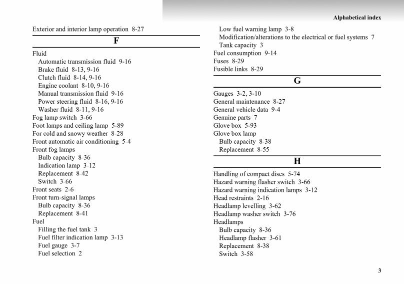
Alphabetical index
3
Exterior and interior lamp operation 8-27
FFluid
Automatic transmission fluid 9-16Brake fluid 8-13, 9-16Clutch fluid 8-14, 9-16Engine coolant 8-10, 9-16Manual transmission fluid 9-16Power steering fluid 8-16, 9-16Washer fluid 8-11, 9-16
Fog lamp switch 3-66Foot lamps and ceiling lamp 5-89For cold and snowy weather 8-28Front automatic air conditioning 5-4Front fog lamps
Bulb capacity 8-36Indication lamp 3-12Replacement 8-42Switch 3-66
Front seats 2-6Front turn-signal lamps
Bulb capacity 8-36Replacement 8-41
FuelFilling the fuel tank 3Fuel filter indication lamp 3-13Fuel gauge 3-7Fuel selection 2
Low fuel warning lamp 3-8Modification/alterations to the electrical or fuel systems 7Tank capacity 3
Fuel consumption 9-14Fuses 8-29Fusible links 8-29
GGauges 3-2, 3-10General maintenance 8-27General vehicle data 9-4Genuine parts 7Glove box 5-93Glove box lamp
Bulb capacity 8-38Replacement 8-55
HHandling of compact discs 5-74Hazard warning flasher switch 3-66Hazard warning indication lamps 3-12Head restraints 2-16Headlamp levelling 3-62Headlamp washer switch 3-76Headlamps
Bulb capacity 8-36Headlamp flasher 3-61Replacement 8-38Switch 3-58
BK-BK2008E1ENUK.en-ukIX.fm Page 3 Thursday, January 10, 2008 7:53 AM
Alphabetical index
4
Heated mirror 4-14Heated seats 2-12High-beam indicator lamp 3-12High-mounted stop lamp
Bulb capacity 8-36Replacement 8-48
Hinges and latches lubrication 8-28Horn switch 3-78
IIf the vehicle breaks down 6-2Ignition switch 4-14Indicator and warning lamps 3-10Indicator lamps 3-12Inside rear-view mirror 4-9Inspection and maintenance following rough road operation 4-
53Installation of accessories 6Installation position for warning triangle 5-107Instruments 3-2Interior lamp switch 5-85Interior lamps 5-85
JJack
Storage 6-11Jack handle 6-15
Storage 6-11Jump starting (Emergency starting) 6-2
KKeyless entry system 1-5Keys 1-2
LLabeling 9-2Lamp monitor buzzer 3-60Lamps (headlamps, fog lamp, etc.) auto-cutout function 3-60Leakage (Fuel, engine coolant, oil and exhaust gas) 8-27Licence plate lamps
Bulb capacity 8-36Replacement 8-49
Low fuel warning lamp 3-8Lubricants 9-16Luggage compartment lamp 5-88
Bulb capacity 8-38Replacement 8-52
Luggage floor box 5-97Luggage hooks 5-105LW/MW/FM electronic tuning radio with CD autochanger
5-43LW/MW/FM electronic tuning radio with CD player 5-20
MMaking a flat seat 2-35Making a luggage area 2-19Manual transmission 4-23
Fluid 9-16
BK-BK2008E1ENUK.en-ukIX.fm Page 4 Thursday, January 10, 2008 7:53 AM

Alphabetical index
5
MirrorInside rear-view mirror 4-9Outside rear-view mirrors 4-11
MIVEC engine 4-20Modification/alterations to the electrical or fuel systems 7
NNotes regarding diesel fuel 9-15
OOdometer 3-3Oil
Differential oil 9-16Engine oil 8-6, 9-16Transfer oil 9-16
Oil pressure warning lamp 3-16Operation under adverse driving conditions 6-35Outside rear-view mirrors 4-11Overheating 6-6
PParking 4-7
Parking brake 4-6Position lamps
Bulb capacity 8-36Indication lamp 3-13Replacement 8-41
Power brakes 4-56Power steering
Fluid 8-16, 9-16System 4-63
Precautions to observe when using wipers and washers 3-76Pregnant women restraint 2-43Puncture (Tyre changing) 6-16
RRadio
LW/MW/FM electronic tuning radio with CDautochanger 5-43LW/MW/FM electronic tuning radio with CD player 5-20
Rear air conditioning 5-15Rear combination lamps
Bulb capacity 8-36Replacement 8-44
Rear differential lock 4-42Rear fog lamp
Bulb capacity 8-36Indication lamp 3-12Replacement 8-47Switch 3-67
Rear heater 5-15Rear personal lamp 5-87
Bulb capacity 8-38Replacement 8-51
Rear shelf (3-door models) 5-101Rear side/quarter window 1-20Rear turn-signal lamps
Bulb capacity 8-36
BK-BK2008E1ENUK.en-ukIX.fm Page 5 Thursday, January 10, 2008 7:53 AM

Alphabetical index
6
Replacement 8-44Rear window demister switch 3-77Rear-view camera 4-84Rear-view mirror
Inside 4-9Rear-view mirror
Outside 4-11Refill capacities 9-16Removal of water from the fuel filter 6-9Replacement of lamp bulbs 8-36Reversing lamps
Bulb capacity 8-36Replacement 8-44
Reversing sensor system 4-78Roof carrier precaution 4-89Room & map lamps 5-87
Bulb capacity 8-38Replacement 8-50
Running-in recommendations 4-5
SSafe driving techniques 4-3Seat belt 2-38
Adjustable seat belt anchor 2-41Child restraint 2-44Force limiter system 2-44Inspection 2-58Pregnant women restraint 2-43Pre-tensioner system 2-43
Rear / second, third seat belt storage 2-41Seat belt reminder/warning lamp 2-40
SeatsAdjustment 2-5Armrest 2-10, 2-14Front seats 2-6Head restraints 2-16Heated seats 2-12Lumbar support 2-10Making a flat seat 2-35Making a luggage area 2-19Rear seats 2-13Seat arrangement 2-3Second seats 2-13Third seat 2-16
Service precaution 8-2Service reminder 3-3, 3-4Side airbag system 2-69Side box 5-97Snow tyres 8-22Spark plug 9-12Specifications 9-2Starting 4-18Steering
Power steering fluid 8-16, 9-16Power steering system 4-63Steering wheel height adjustment 4-8Steering wheel lock 4-18Steering wheel remote control switch 5-70
BK-BK2008E1ENUK.en-ukIX.fm Page 6 Thursday, January 10, 2008 7:53 AM
Alphabetical index
7
Stop lampsBulb capacity 8-36Replacement 8-44
Storage spaces 5-92Sun visors 5-77Sunglasses holder 5-98Sunroof 1-21Super select 4WD II 4-34Supplemental restraint system 2-58
How the supplemental restraint system works 2-59Servicing 2-76Warning lamp 2-75
TTachometer 3-2Tail lamps
Bulb capacity 8-36Replacement 8-44
Tank capacity 3Third seat 2-16Tools 6-12
Storage 6-11Towing 6-29Trailer towing 4-90Transfer oil 9-16Transmission
Automatic transmission 4-25Manual transmission 4-23
Tripmeter 3-3
Turn-signal indication lamps 3-12Turn-signal lever 3-65Tyres 8-19
How to change a tyre 6-16Inflation pressures 8-19Rotation 8-21Size (tyre and wheel) 9-13Snow tyres 8-22Tyre chains 8-23
UUsed engine oils safety instructions and disposal information 8
VVanity mirror 5-78Vanity mirror lamps
Bulb capacity 8-38Replacement 8-55
Vehicle care precautions 7-2Vehicle dimensions 9-4Vehicle identification number 9-2Vehicle identification number plate 9-3Vehicle information code plate 9-2Vehicle labeling 9-2Vehicle performance 9-6Vehicle weight 9-7Ventilators 5-2
BK-BK2008E1ENUK.en-ukIX.fm Page 7 Thursday, January 10, 2008 7:53 AM

Alphabetical index
8
WWarning lamps 3-13Washer
Fluid 8-11, 9-16Switch 3-68, 3-75, 3-76
Washing 7-4Water temperature gauge 3-9Waxing 7-6Weatherstripping 8-28Weight 9-7Wheel
Specification 9-13Wheel condition 8-20Wiper
Rear window 3-75Switch 3-68Wiper blades 8-25
Wiper deicer switch 3-77
BK-BK2008E1ENUK.en-ukIX.fm Page 8 Thursday, January 10, 2008 7:53 AM

DECLA_engels.fm Page 1 Wednesday, January 9, 2008 3:39 PM

DECLA_engels.fm Page 2 Wednesday, January 9, 2008 3:39 PM
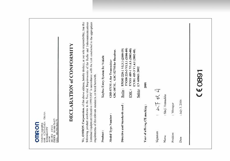
DECLA_engels.fm Page 3 Wednesday, January 9, 2008 3:39 PM

DECLA_engels.fm Page 4 Wednesday, January 9, 2008 3:39 PM

DECLA_engels.fm Page 5 Wednesday, January 9, 2008 3:39 PM

DECLA_engels.fm Page 6 Wednesday, January 9, 2008 3:39 PM