TechLine1 - ASYNCHRONOUS MOTORS
16
TechLine1 ASYNCHRONOUS MOTORS We put ideas into gear. ABM Greiffenberger Antriebstechnik
-
Upload
khangminh22 -
Category
Documents
-
view
0 -
download
0
Transcript of TechLine1 - ASYNCHRONOUS MOTORS

TechLine1ASYNCHRONOUS MOTORS
We put ideas into gear.ABM Greiffenberger Antriebstechnik

1. Overview 3
2. Three-Phase AC Motors 4
Rating Chart by model size and number of poles
3. Two-Speed Motors 5
Rating Chart by model size and number of poles
4. Single-Phase Motors 6
4.1 Rating Chart Type EK
4.2 Rating Chart Type ERKK
5. Brakes 7
6. Dimension Tables 8 - 10
7. Electrical Characteristics 11
8. Mechanical Characteristics 12 - 13
9. Options 14 - 15
Contents
TechLine 1Asynchronous Motors
Edition 07/20072
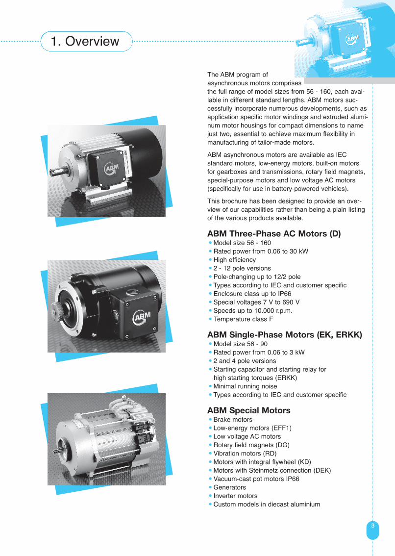
The ABM program of asynchronous motors comprisesthe full range of model sizes from 56 - 160, each avai-lable in different standard lengths. ABM motors suc-cessfully incorporate numerous developments, such asapplication specific motor windings and extruded alumi-num motor housings for compact dimensions to namejust two, essential to achieve maximum flexibility inmanufacturing of tailor-made motors.
ABM asynchronous motors are available as IEC standard motors, low-energy motors, built-on motorsfor gearboxes and transmissions, rotary field magnets,special-purpose motors and low voltage AC motors(specifically for use in battery-powered vehicles).
This brochure has been designed to provide an over-view of our capabilities rather than being a plain listingof the various products available.
ABM Three-Phase AC Motors (D)• Model size 56 - 160
• Rated power from 0.06 to 30 kW
• High efficiency
• 2 - 12 pole versions
• Pole-changing up to 12/2 pole
• Types according to IEC and customer specific
• Enclosure class up to IP66
• Special voltages 7 V to 690 V
• Speeds up to 10.000 r.p.m.
• Temperature class F
ABM Single-Phase Motors (EK, ERKK)• Model size 56 - 90
• Rated power from 0.06 to 3 kW
• 2 and 4 pole versions
• Starting capacitor and starting relay for high starting torques (ERKK)
• Minimal running noise
• Types according to IEC and customer specific
ABM Special Motors• Brake motors
• Low-energy motors (EFF1)
• Low voltage AC motors
• Rotary field magnets (DG)
• Vibration motors (RD)
• Motors with integral flywheel (KD)
• Motors with Steinmetz connection (DEK)
• Vacuum-cast pot motors IP66
• Generators
• Inverter motors
• Custom models in diecast aluminium
3
1. Overview

2. Three-Phase AC Motors
4
4
Rating Chart
All details are for S1 operation, 400 V, 50 Hz.
Bold type indicates IEC standard sizes.
Electrical details for duty cycles and ambient conditions not listed are available upon request or refer to
sections 7 and 8 (Electrical and Mechanical Characteristics).
Today, single-speed three-phase AC motors have grown in importance to become
the industrial drive. Their complete freedom from maintenance, high efficiency and
very favourable price/performance ratio are just three of their outstanding features. They are versatile in
use and are the standard solution for variable-speed drives, especially when used with frequency inverters.
D56a 0.09 2780 0.29 57 0.06 1380 0.29 50 - - - - - - - -D56b 0.18 2770 0.52 66 0.12 1350 0.52 60 - - - - - - - -D56c 0.25 2770 0.72 66 0.18 1300 0.62 61 0.06 860 0.33 45 - - - -D63a 0.18 2770 0.48 68 0.12 1360 0.43 58 - - - - - - - -D63b 0.37 2750 0.95 70 0.25 1300 0.80 68 0.09 850 0.50 50 0.06 630 0.40 42D63c 0.55 2740 1.40 70 0.37 1300 1.10 66 - - - - - - - -D71a 0.37 2800 0.95 74 0.25 1360 0.72 68 0.12 850 0.52 50 0.09 650 0.50 47D71b 0.55 2830 1.33 77 0.37 1370 1.05 70 0.18 880 0.87 56 0.12 670 0.80 40D71c 0.75 2800 1.70 74 0.55 1330 1.45 70 - - - - - - - -D80a 0.75 2770 1.80 74 0.55 1340 1.50 68 0.37 870 1.25 59 0.18 660 0.86 51D80b 1.1 2760 2.60 75 0.75 1360 2.00 72 - - - - - - - -D80c - - - - - - - - 0.55 860 1.70 61 0.25 660 1.10 55D80e 1.5 2810 3.35 79 1.1 1370 2.90 75 0.75 880 2.40 63 0.37 660 1.40 57D90Sa 1.5 2810 3.30 78 1.1 1370 2.70 75 0.75 895 2.20 68 0.37 670 1.35 60D90Sb 2.2 2800 4.80 80 1.5 1390 3.60 78 1.1 890 3.10 67 0.55 670 1.90 64D90La 2.2 2800 4.80 80 1.5 1390 3.60 78 1.1 890 3.10 67 0.55 670 1.90 64D90Lb 3 2810 6.50 82 2.2 1370 5.20 78 1.3 900 3.70 68 0.75 670 2.70 64D100La 3 2860 6.60 82 2.2 1410 5.10 79 1.5 910 4.00 77 1.1 670 3.80 69D100Lb 4 2880 8.40 86 3 1410 6.60 84 - - - - - - - -D100Lc 5.5 2860 11.5 87 4 1410 8.40 83 2.2 920 5.40 78 1.5 680 4.70 71D112Mb 5.5 2890 11.0 84 5.5 1430 11.0 86 - - - - - - - -D112M 7.5 2880 14.5 85 7.5 1430 16.0 85 - - - - - - - -D112Me 9.5 2890 18.5 87 - - - - - - - - - - - -D132Mc 11 2920 22.0 89 - - - - - - - - - - - -D132Mb - - - - 7.5 1450 16.2 86 - - - - - - - -D132Mc - - - - 11 1445 24.0 87 - - - - - - - -D132Md 15 2900 29.0 89 - - - - - - - - - - - -D132L - - - - 15 1460 32.0 87 - - - - - - - -D160MR 15 2920 28.0 88 11 1450 22.5 88 7.5 970 16.5 85 5.5 715 13.0 84D160LR 18.5 2930 34.0 89 15 1460 28.5 88 11 965 23.0 85 7.5 720 17.0 86D160LbR - - - - 18.5 1460 37.0 88 - - - - - - - -
P[kW]
Motor Type(model size)
I[A] [%]
P[kW]
I[A] [%]
P[kW]
n[r.p.m.]
n[r.p.m.]
n[r.p.m.]
n[r.p.m.]
I[A] [%]
P[kW]
I[A] [%]
2 pole/3000 r.p.m. 4 pole/1500 r.p.m. 6 pole/1000 r.p.m. 8 pole/750 r.p.m.
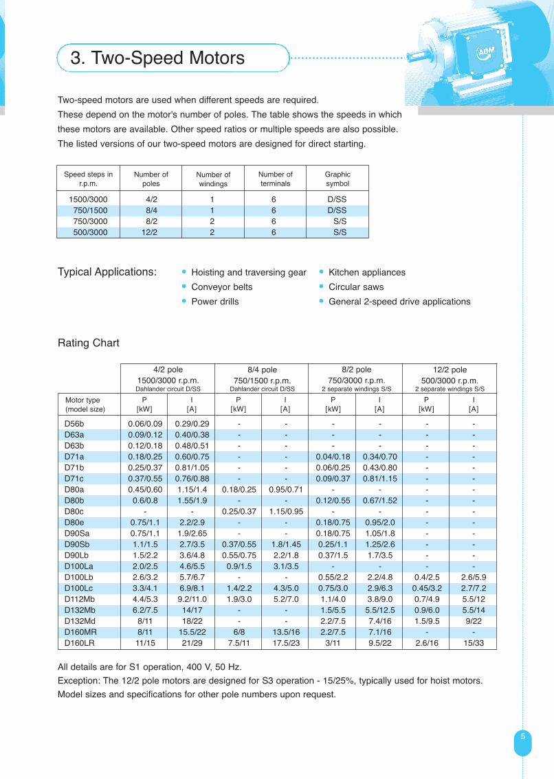
1500/3000 4/2 1 6 D/SS 750/1500 8/4 1 6 D/SS750/3000 8/2 2 6 S/S 500/3000 12/2 2 6 S/S
5
All details are for S1 operation, 400 V, 50 Hz.
Exception: The 12/2 pole motors are designed for S3 operation - 15/25%, typically used for hoist motors.
Model sizes and specifications for other pole numbers upon request.
2. Drehstrommotoren3. Two-Speed Motors
Two-speed motors are used when different speeds are required.
These depend on the motor's number of poles. The table shows the speeds in which
these motors are available. Other speed ratios or multiple speeds are also possible.
The listed versions of our two-speed motors are designed for direct starting.
Typical Applications: • Hoisting and traversing gear • Kitchen appliances
• Conveyor belts • Circular saws
• Power drills • General 2-speed drive applications
Number of poles
Number of windings
Number of terminals
Graphic symbol
Speed steps inr.p.m.
Rating Chart
D56b 0.06/0.09 0.29/0.29 - - - - - -D63a 0.09/0.12 0.40/0.38 - - - - - -D63b 0.12/0.18 0.48/0.51 - - - - - -D71a 0.18/0.25 0.60/0.75 - - 0.04/0.18 0.34/0.70 - -D71b 0.25/0.37 0.81/1.05 - - 0.06/0.25 0.43/0.80 - -D71c 0.37/0.55 0.76/0.88 - - 0.09/0.37 0.81/1.15 - -D80a 0.45/0.60 1.15/1.4 0.18/0.25 0.95/0.71 - - - -D80b 0.6/0.8 1.55/1.9 - - 0.12/0.55 0.67/1.52 - -D80c - - 0.25/0.37 1.15/0.95 - - - -D80e 0.75/1.1 2.2/2.9 - - 0.18/0.75 0.95/2.0 - -D90Sa 0.75/1.1 1.9/2.65 - - 0.18/0.75 1.05/1.8 - -D90Sb 1.1/1.5 2.7/3.5 0.37/0.55 1.8/1.45 0.25/1.1 1.25/2.6 - -D90Lb 1.5/2.2 3.6/4.8 0.55/0.75 2.2/1.8 0.37/1.5 1.7/3.5 - -D100La 2.0/2.5 4.6/5.5 0.9/1.5 3.1/3.5 - - - -D100Lb 2.6/3.2 5.7/6.7 - - 0.55/2.2 2.2/4.8 0.4/2.5 2.6/5.9D100Lc 3.3/4.1 6.9/8.1 1.4/2.2 4.3/5.0 0.75/3.0 2.9/6.3 0.45/3.2 2.7/7.2D112Mb 4.4/5.3 9.2/11.0 1.9/3.0 5.2/7.0 1.1/4.0 3.8/9.0 0.7/4.9 5.5/12D132Mb 6.2/7.5 14/17 - - 1.5/5.5 5.5/12.5 0.9/6.0 5.5/14D132Md 8/11 18/22 - - 2.2/7.5 7.4/16 1.5/9.5 9/22D160MR 8/11 15.5/22 6/8 13.5/16 2.2/7.5 7.1/16 - -D160LR 11/15 21/29 7.5/11 17.5/23 3/11 9.5/22 2.6/16 15/33
8/4 pole750/1500 r.p.m.
Dahlander circuit D/SS
4/2 pole1500/3000 r.p.m.Dahlander circuit D/SS
P[kW]
Motor type(model size)
I[A]
P[kW]
I[A]
P[kW]
P[kW]
I[A]
I[A]
12/2 pole500/3000 r.p.m.
2 separate windings S/S
8/2 pole750/3000 r.p.m.
2 separate windings S/S

4. Single-Phase Motors
6
4.1 TYPE EKSingle-phase motors with running capacitor. This type has a locked-rotor torque from 40 to 70%
depending on the size of the motor. The starting current is around 3 to 4.5 times the rated current:
These motors are ideal for machines that start easily.
Typical Applications • Blowers • Pumps
• Compressors
4.2 TYPE ERKKSingle-phase motors with running capacitor, auxiliary winding, starting capacitor and current-dependent
starting relay offer particularly favourable performance for heavy starting. The locked-rotor torque is approx.
200%. The starting current is approx. 3 to 4.5 times the rated current.
Application Examples • Screw conveyors • Metering systems
• Agitators
Rating Chart
Rating Chart
Other versions, e.g. Type ERK (single-phase motor with auxiliary winding, integral starting relay and
starting capacitor) upon request.
All details are for S1 operation,230 V, 50 Hz. Electrical details for duty cycles and ambient conditions not listed are availableupon request or refer to sections7 and 8 (Electrical andMechanical Characteristics).
All details are for S1 operation,230 V, 50 Hz. Electrical details for duty cycles and ambient conditions not listed are availableupon request or refer to sections7 and 8 (Electrical andMechanical Characteristics).
ERKK71b 0.37 2.4 12+25 0.25 1.8 12+20ERKK71c 0.55 3.6 16+40 0.37 2.65 16+25ERKK80b 0.75 5.0 25+80 0.55 3.9 20+50ERKK80e 1.1 7.0 30+100 0.75 5.2 25+80ERKK90Sb 1.5 9.5 40+120 1.1 7.4 40+100ERKK90 Lb 2.2 12.9 50+160 1.5 9.6 50+120
Motor Type(model size)
P[kW]
I[A]
CB + CA[μF]
P[kW]
I[A]
CB + CA[μF]
4 pole/1500 r.p.m.Type ERKK with running capacitor,starting capacitor and starting relay
2 pole/3000 r.p.m.Type ERKK with running capacitor,starting capacitor and starting relay
P[kW]
I[A]
CB[μF]
P[kW]
I[A]
CB[μF]
2 pole/3000 r.p.m.Type EK with running capacitor
4 pole/1500 r.p.m.Type EK with running capacitor
EK56a 0.09 0.72 3 0.06 0.62 4EK56b 0.12 1.0 5 0.09 0.85 5EK63a 0.18 1.5 5 0.12 1.05 6EK63b 0.25 1.7 10 0.18 1.45 8EK71b 0.37 2.4 12 0.25 1.8 12EK71c 0.55 3.6 16 0.37 2.65 16EK80b 0.75 5.0 25 0.55 3.9 20EK80e 1.1 7.0 30 0.75 5.2 25EK90Sb 1.5 9.5 40 1.1 7.4 40EK90Lb 2.2 12.9 50 1.5 9.6 50
Motor Type(model size)

7
5. Brakes
ABM disk brakes type EFB and ZFB are electro-mechanical safety brakes and stop
drives quickly and reliably in any operating mode. There can be no compromises
when it comes to safety, and ABM have been developing and manufacturing brakes for 60 years.
This experience has resulted in the continuous improvement of brake performance.
All brake components and functions are perfectly matched to a particular drive.
The main characteristics and benefits for the user include
• Adjustable torque • Safe braking in the event of a power loss
• Simple manual adjustment • Unlimited continuous duty
• Asbestos-free brake lining • High operating frequency
• Long lining life • Short On and Off times
Typical Applications
• Cranes, hoists • Handling and conveying systems
• Machine tools • Packaging machines
• Textile machinery • Warehousing systems
Options
• Manual ventilation in position A, B, C or D • High-speed excitation
• Friction plate corrosion-protected
Disk Brake Cross-References
56 0.9 - 3 EFB 1
63 0.9 - 3 EFB 1
71 0.7 - 7.5 EFB 2
4 - 10 ZFB 10
80 0.7 - 7.5 EFB 2
4 - 10 ZFB 10
8 - 20 ZFB 20
90 S / 1.3 - 25 EFB 3
90 L 8 - 20 ZFB 20
16 - 40 ZFB 40
100 1.3 - 25 EFB 3
16 - 40 ZFB 40
28 - 60 ZFB 60
112 M / 16 - 40 ZFB 40
112 Me 28 - 60 ZFB 60
132 Md / 28 - 60 ZFB 60
132 L 40 - 100 ZFB 100
60 - 150 ZFB 150
160 M / 60 - 150 ZFB 150
160 L 110 - 250 ZFB 250
motormodel size
braking torques[Nm]
type
Method of OperationOn ABM EFB disk brakes (single-sided brake) the brake
coil is cast into the end shield on the brake side. An
aluminium impeller acts as brake lining carrier.
In de-energized condition a thrust spring supported off the
brake end shield presses an axially moving armature
base plate against a special brake lining on the impeller.
ABM ZFB disk brakes (2 sided brake) are mounted on the
brake side end shield that also acts as one of the brake
pads.
Alloy brake disks have a special lining on both faces and
lie between end shield and magnet body with armature
base plate. In de-energized condition a number of springs
press the armature base plate against the brake disk and
bring it into contact with the end shield.
Supply VoltagesThe standard supply is 230 V AC, 50 Hz when connected
to the rectifier. Other supply voltages upon request.
The brake's OFF time can be adapted to individual
applications by AC side or DC side switching, i.e. making
precise rapid braking or delayed soft braking possible.
The operating time can be reduced with a high-speed
excitation rectifier.

8
6. Dimension Tables
Dimensions of conventional motors according to DIN EN 50347
Type : B 3, B 6, B 7, B 8, V 5, V 6
Dimensions in mm
Illustrations are for reference only and subject to change.
The dimensional tables are for the following motor types:
• Three-phase AC Motors
• Single-phase motors without capacitor(s)
• Two-speed motors
Dimensions AD and HB apply to plastic junction box. Dimensions AD’ and HB’ apply to the aluminum junction box. Key
way dimensions according DIN 6885 sheet 1.
56 90 110 94 112 71 36 9 20 56 54 66 111 - 6 188 EFB 3563 100 124 96 112 80 40 11 23 63 45 53 125 - 7 209.5 EFB 32.571 112 139 101 117 90 45 14 30 71 40 47.5 140.5 - 7 237 EFB 40
ZFB 54.580 125 158 108 124 100 50 19 40 80 40 47.5 159 - 10 273 EFB 40
ZFB 67.590S 140 177 122 140 100 56 24 50 90 51 57.5 178.5 - 10 299.5 EFB 56.5
ZFB 7790L 140 177 122 140 125 56 24 50 90 51 57.5 178.5 - 10 324.5 EFB 56.5
ZFB 77100L 160 196 130 148 140 63 28 60 100 51 57.5 198 233 12 369 EFB 56.5
ZFB 96112M 190 220 140 158 140 70 28 60 112 51 57.5 222 254 12 389 ZFB 86.5112Me 190 220 140 158 190 70 28 60 112 51 57.5 222 254 12 458 ZFB 86.5132S 216 262 181 190 140 89 38 80 132 73 84 263 308 12 456 ZFB 109132M 216 262 181 190 178 89 38 80 132 73 84 263 308 12 494 ZFB 109132Md 216 262 181 190 178 89 38 80 132 73 84 263 308 12 524 ZFB 109132L 216 262 181 190 248 89 38 80 132 73 84 263 308 12 564 ZFB 109160M 254 310 - 238 210 108 42 110 160 - 84 315 364 13 587 ZFB 124160L 254 310 - 238 254 108 42 110 160 - 84 315 364 13 631 ZFB 124
modelsize A AC AD AD’ B C D E H HB HB’ HC HD K L brake
type Δ L
56 - 80 1x M16 x 1.5 resp. 2x M16 x 1.5 on motor with brake 1x Ø 20 resp. 2x Ø 20 on motor with brake90 - 100 1x M20 x 1.5 resp. 2x M 20 x 1.5 on motor with brake 1x Ø 25 resp. 2x Ø 25 on motor with brake112 2x M20 x 1.5 2x Ø 25132 - 160 2x M25 x 1.5 2x M25 x 1.5
Motor Type(model size)
Holes for cable connection(s) in plastic junction box
Holes for cable connection(s) in aluminum junction box
9
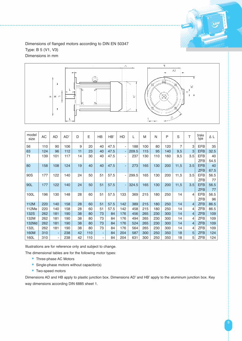
Dimensions of flanged motors according to DIN EN 50347
Type: B 5 (V1, V3)
Dimensions in mm
Illustrations are for reference only and subject to change.
The dimensional tables are for the following motor types:
• Three-phase AC Motors
• Single-phase motors without capacitor(s)
• Two-speed motors
Dimensions AD and HB apply to plastic junction box. Dimensions AD’ and HB’ apply to the aluminum junction box. Key
way dimensions according DIN 6885 sheet 1.
56 110 90 106 9 20 40 47.5 - 188 100 80 120 7 3 EFB 3563 124 96 112 11 23 40 47.5 - 209.5 115 95 140 9,5 3 EFB 32.571 139 101 117 14 30 40 47.5 - 237 130 110 160 9,5 3.5 EFB 40
ZFB 54.580 158 108 124 19 40 40 47.5 - 273 165 130 200 11,5 3.5 EFB 40
ZFB 67.590S 177 122 140 24 50 51 57.5 - 299.5 165 130 200 11,5 3.5 EFB 56.5
ZFB 7790L 177 122 140 24 50 51 57.5 - 324.5 165 130 200 11,5 3.5 EFB 56.5
ZFB 77100L 196 130 148 28 60 51 57.5 133 369 215 180 250 14 4 EFB 56.5
ZFB 96112M 220 140 158 28 60 51 57.5 142 389 215 180 250 14 4 ZFB 86.5112Me 220 140 158 28 60 51 57.5 142 458 215 180 250 14 4 ZFB 86.5132S 262 181 190 38 80 73 84 176 456 265 230 300 14 4 ZFB 109132M 262 181 190 38 80 73 84 176 494 265 230 300 14 4 ZFB 109132Md 262 181 190 38 80 73 84 176 524 265 230 300 14 4 ZFB 109132L 262 181 190 38 80 73 84 176 564 265 230 300 14 4 ZFB 109160M 310 - 238 42 110 - 84 204 587 300 250 350 18 5 ZFB 124160L 310 - 238 42 110 - 84 204 631 300 250 350 18 5 ZFB 124
modelsize AC AD AD’ D E HB HB’ HD L M N P S T brake
type Δ L

2. Drehstrommotoren
10
6. Dimension tables continued
Dimensions of the flange motors to DIN EN 50347
Type: B 14 (V18, V19)
Dimensions in mm
56 110 90 106 9 20 40 47.5 - 188 65 50 80 M5 2.5 EFB 3563 124 96 112 11 23 40 47.5 - 209.5 75 60 90 M5 2.5 EFB 32.571 139 101 117 14 30 40 47.5 - 237 85 70 105 M6 2.5 EFB 40
ZFB 54.580 158 108 124 19 40 40 47.5 - 273 100 80 120 M6 3 EFB 40
ZFB 67.590S 177 122 140 24 50 51 57.5 - 299.5 115 95 140 M8 3 EFB 56.5
ZFB 7790L 177 122 140 24 50 51 57.5 - 324.5 115 95 140 M8 3 EFB 56.5
ZFB 77100L 196 130 148 28 60 51 57.5 133 369 130 110 160 M8 3.5 EFB 56.5
ZFB 96112M 220 140 158 28 60 51 57.5 142 389 165 130 200 M10 3.5 ZFB 86.5112Me 220 140 158 28 60 51 57.5 142 458 165 130 200 M10 3.5 ZFB 86.5132S 262 181 190 38 80 73 84 176 456 215 180 250 M12 4 ZFB 109132M 262 181 190 38 80 73 84 176 494 215 180 250 M12 4 ZFB 109132Md 262 181 190 38 80 73 84 176 524 215 180 250 M12 4 ZFB 109132L 262 181 190 38 80 73 84 176 564 215 180 250 M12 4 ZFB 109
modelsize AC AD AD’ D E HB HB’ HD L M N P S T brake
type Δ L
Illustrations are for reference only and subject to change.
The dimensional tables are for the following motor types:
• Three-phase AC Motors
• Single-phase motors without capacitor(s)
• Two-speed motors
Dimensions AD and HB apply to plastic junction box. Dimensions AD’ and HB’ apply to the aluminum junction box. Key
way dimensions according DIN 6885 sheet 1.

11
7. Electrical Characteristics
Rated PowerThe power ratings given in the lists are the power output according to VDE0530 for
continuous operation S1; frequency 50 Hz; max. room temperature 40°C; max. site altitude 1000 m above
sea level.
Rated Voltage and FrequencyThe standard voltage ratings are 230/400 V or 400/690 V and rated frequency 50 Hz. Voltage fluctuations
within +/-10% are permitted. Special voltages and special frequencies are available for export, inverter
operation and use in battery-powered machines.
Two-speed motors, especially those with Dahlander circuits, are designed for one voltage only. They are
supplied for power supply 230 V or 400 V at 50 Hz. Other voltages or frequencies are possible. Motors with
two separate windings can be designed for two voltages in the ratio of 1:1.73. Further details upon
request.
Outputs for single-phase motors are based on a rated voltage of 230 V, 50 Hz.
Rated Currents and EfficienciesCurrents and efficiencies given in Table 1 are based on a rated voltage of 400 V / 50 Hz and full-load rating.
If the rated voltage changes the rated current is converted as follows: J’ = 400 x J / U’
Starting Current and Starting TorqueStarting torques and currents are a multiple of the rated values with direct starting.
Overload CapacityIn accordance with VDE0530 the motors can withstand 2 minutes at 1.5 times rated current at rated-load
operating temperature without damage to the winding.
Motor TorqueThe motor torque output at the shaft in Nm is: T [Nm] = 9550 x P [kW] / n [r.p.m.]
Temperature ClassABM electric motors are manufactured using high-grade "Overcoat" enamelled wire and wrapper material in
conjunction with solvent-free resin impregnation and meet temperature class F. Maximum temperature is
155°C. A line-side circuit-breaker with overtemperature switch provides the motor with reliable
protection in the event of an overload. For severe operating conditions (e.g. converter mode, very high
inertia starting and switching operations with more than 100 c/h) we recommend the use of temperature
sensors PTC thermistors (see Options, Section 9).

2. Drehstrommotoren
12
2. Drehstrommotoren8. Mechanical Characteristics
Shaft EndsThe standard version has a straight shaft end. Key ways have been installed prior to rotor balancing. The type
of balancing method is indicated on the rating plate after product number.
H...half key way (standard), F...full key way
Second shaft end and special shafts upon request.
Mechanical Balance QualityThe rotors are dynamically balanced as marked and meet vibration severity grade A (DIN EN 60034-14).
Motors can be supplied for vibration severity grade B (Reduced) for special quietness requirements.
Standards and RegulationsABM electric motors conform to all relevant standards and regulations:
Maximum Radial Forces Fr [N]Values are based on the centre of the
standard output shaft end when opera-
ting at 50 Hz.
56 230 270 310 -63 230 300 350 38071 260 320 370 40080 350 450 520 56090 550 750 860 920100 770 950 1090 1170112 900 1110 1270 1360132 1140 1400 - -160 - 2500 2800 3100
Fr [N]2 pole
modelsize
Fr [N]4 pole
Fr [N]6 pole
Fr [N]8 pole
Cylindrical Shaft Ends; Dimensions, Nominal Transmissible Torques DIN 748-1 -
Surface cooled squirrel cage three phase induction motors, type of construction IM B3, DIN 42673-3 - -
with roller bearings, mounting dimensions and output classification
Surface cooled squirrel cage three phase induction motors, type of construction B3, DIN 42673-4 - -
with roller bearings, size of envelope
Totally enclosed fan-cooled alternating-current polyphase motors with squirrel-cage, DIN 42677-4 - -
design B5, B10, B14, with ball bearings; maximum envelope dimensions for design
B5, B14
Tolerances of shaft extension run-out and of mounting flanges for rotating electrical DIN 42955 - -
machinery, test
General purpose three-phase induction motors having standard dimensions and DIN EN 50347 - -
outputs - Frame numbers 56 to 315 and flange numbers 65 to 740
Rotating electrical machines - Part 1: Rating and performance DIN EN 60034-1 VDE 0530 Part 1 IEC 60034-1
Rotating electrical machines - Part 5: Degrees of protection provided by the integral DIN EN 60034-5 VDE 0530 Part 5 IEC 60034-5
design of rotating electrical machines (IP code)
Rotating electrical machinery - part 6: Classification of cooling method (IC-code) DIN EN 60034-6 VDE 0530 Part 6 IEC 60034-6
Rotating electrical machines - Classification of types of constructions and mounting DIN EN 60034-7 VDE 0530 Part 7 IEC 60034-7
arrangements (IM Code)
Rotating electrical machines - Part 8: Terminal markings and direction of rotation DIN EN 60034-8 VDE 0530 Part 8 IEC 60034-8
Rotating electrical machines - Part 9: Noise limits DIN EN 60034-9 VDE 0530 Part 9 IEC 60034-9
Rotating electrical machines - Thermal protection DIN EN 60034-11 VDE 0530 Part 11 IEC 60034-11
Rotating electrical machines - Part 12: Starting performance of single-speed three-phase DIN EN 60034-12 VDE 0530 Part 12 IEC 60034-12
cage induction motors
Rotating electrical machines - Part 14: Mechanical vibration of certain machines with DIN EN 60034-14 VDE 0530 Part 14 IEC 60034-14
shaft heights 56 mm and higher - Measurement, evaluation and limits of vibration
severity
Degrees of protection provided by enclosures (IP code) DIN EN 60529 VDE 0470 Part 1 IEC 60529
Mechanical vibration; balancing; shaft and fitment key convention DIN ISO 8821 - -
Title DIN VDE IEC

13
ConfigurationsIllustrations show terminal box position A (standard unless otherwise specified). Terminal box position B, C
and D per customer specification. Cable entry can be rotated in 90° steps.
Example: B 3 / A 1 means terminal box on the right side of the motor looking from shaft end, cable entry is
from underneath.
Notes on the terminal box position and cable entry:
With foot motors terminal box position B is not avaiable, position D is available up to model size 90 only and
with position C the terminal box moves to the fan end.
Foot motor
Example of
terminal box
position and
cable entry
Flanged motor
Example of
terminal box
position and
cable entryng
Available Flange DiametersThe dimensions marked * are not according to DIN standard.
Other flange sizes upon request.
Horizontal shaft arrangement
Vertical shaft arrangement
B 35B 9 B 15B 3 B 5 B 8B 6B 14
V 9 V 19V 1 V 5 V 6V 18 V 3V 8
56 Ø 120 Ø 80, 105, 90*, 120*63 Ø 140, 120* Ø 90, 120, 80*, 105*, 140*71 Ø 160, 120*, 140* Ø 105, 140, 80*, 90*, 120*80 Ø 200, 160* Ø 120, 160, 105*, 140*90 Ø 200, 160* , 250* Ø 140, 160, 105*, 120*
100 Ø 250, 160*, 200* Ø 160, 200, 140*112 Ø 250, 200*, 300* Ø 160, 200, 250*132 Ø 300, 250*, 350* Ø 250*160 Ø 350, 300* -
model size B5 / V1 / V3 / B35 Ø [mm]
B14 / V18 / V19 / B34 Ø [mm]
B 7

PTC Thermistors according to DIN 44081Three thermistors encapsulated in one winding head (1 per phase) offer the most effective protection against
motor overheating. External controllers can be connected in the motor junction box. Nominal motor operating
temperature is 155 ºC.
Temperature SensorsTemperature sensors open an electric circuit when a pre-determined, non-adjustable temperature is reached.
Temperature sensors complying with VDE 0631 are used:
Type S01 250V; 50 Hz; 1.6 A at cos = 0.6; 2.5 A at cos = 1
Type S06 250V; 50 Hz; 6.3 A at cos = 0.6; 10 A at cos = 1
Motor current direct-on-line starting (single-phase motors only)
Temperature Measurements with KTY-SensorsKTY sensors allow measurements of winding temperature for status monitoring. Sensor resistance changes
with the temperature allowing exact measurements over a wide temperature range. Type KTY 84-130 can be
directly monitored by ABM inverter controllers type LDC CDA/CDB).
Junction BoxPlastic junction boxes are standard. Upon customer request aluminum junction boxes with integrated
rectifiers can be supplied with brake motors.
Custom Output ShaftsIn addition to straight shafts per DIN 748 custom shaft ends for custom applications are available.
Elevated Protection ClassIn addition to standard enclosure protection classes per VDE 0530, elevated protection for aggressive
environments such as damp locations, dairies and high humidity are available.
Coats of PaintMotor housings and end shields of ABM electric motors are made from corrosion-resistant aluminum. Junction
boxes and fan shrouds are made from black plastic. Typically, painting is not required. The following standard
coast of paint colors are available (1K acrylic paint): RAL 7031 (Blue grey), RAL 2002 (Vermilion), RAL 5017
(Traffic Blue), RAL 6011 (Reseda green), RAL 9005 (Jet black) and RAL 9010 (Pure white).
Other finishes upon request.
Rotary Encoders
• HTL encoder (24 V signal) with 1024 pulses, A and B channel for frequency converter applications.
• Sin - Cos - encoder (1 Vss) with 1024 pulses A, A, B, B, 0, 0 channels for applications with servo-
converter.
• Integrated sensor bearings from world known manufacturers
• TTL-encoder (5 V level signal) with 1024 pulses, A, A, B, B; 0, 0 channels for use with positioning
inverters.
Other encoders and pulse counts available upon request.
14
9. Options

15
Forced VentilationAuxiliary, electrical fans are used should the motor's own fan be inadequate in cooling. This applies to
severe working conditions such as automatic operation, low speeds (frequency inverter operation) or frequent
switching. Each auxiliary fan consists of sturdy motor/fan unit, its own junction box, a galvanized metal shroud
and glass fiber reinforced polyamide fan blades and meets IP66 enclosure class.
Junction boxes can be rotated to all positions and cable entry M16x1.5 is available in positions 1 and 3.
Power supplies: 3 AC 220-290 V / 380-500 V D/S, 50/60 Hz
1 AC 230-277 V, 50/60 Hz (Steinmetz circuit)
Dimensions of auxiliary fans in mm:
63 standard +71.5 124 107 115.0EFB 1 +91.5
71 standard +70.5 139 107 122.5EFB 2 +95.0
ZFB 10 +80.5 80 standard +65.0 157 107 131.5
EFB2 +95.0 ZFB 10, ZFB 20 +67.5
ZFB 20 +97.0 177 117 141.590 standard +70.0 177 117 141.5
EFB 3 +101.0 ZFB 20, ZFB 40 +80.5
100 standard +64.5 195 117 150.5EFB 3 +103.5
ZFB 40, ZFB 60 +64.0 ZFB 60 +70.0 219 162.5
112 standard +58.5 219 117 162.5ZFB 40, ZFB 60 +69.5
132 standard +99.0 258 127 184.0ZFB 40, 60, 100, 150 +98.0
160 standard +105.0 311 127 210.5ZFB 60, 150, 250 +96.0
model size type ΔL to ventilatedmotor
AC [mm] g [mm] AD [mm]

We put ideas into gear.ABM Greiffenberger Antriebstechnik
This is how you can contact us:
ABM Greiffenberger Antriebstechnik GmbHPostfach 140 • 95614 MarktredwitzFriedenfelser Straße 24 • D - 95615 Marktredwitz
Telephone: (49) 0 92 31/67-0 (Reception)Telefax: (49) 0 92 31/6 71 45 (Sales)
(49) 0 92 31/6 72 02 (Technical Sales)(49) 0 92 31/6 32 21 (Service dep.)
e-mail: [email protected] Germany: http://www.abm-antriebe.deInternet International: http://www.abm-drives.com
Other agencies:
Belgium • Italy • Denmark • Sweden
(Contact details available on request!)
ABM — in your proximity:
Austria:ABM Antriebstechnik GmbHOrtsstraße 18/1/5-7A - 2331 VösendorfPhone (43) 01 - 6 99 11 620 Fax (43) 01 - 6 99 11 62 23 e-mail: [email protected]
France:ABM Systèmes d`Entraînement S.A.R.L.40, rue Jean Monnet • Melpark Bat. 5F - 68200 MulhousePhone (33) 03 - 89 33 44 01 Fax (33) 03 - 89 33 44 05e-mail: [email protected]
North America:ABM DRIVES INC.2000 Ford Circle • Suite EUSA - Milford, OH 45150Phone (1) 513 - 576 - 1300 Fax (1) 513 - 576 - 4999 e-mail: [email protected]
Switzerland:ABM Greiffenberger Antriebstechnik AGOholten 3CH - 5703 SeonPhone (41) 0 62 - 775 09 60 Fax (41) 0 62 - 775 09 66 e-mail: [email protected]
The Netherlands:ABM Nederland Aandrijftechniek B.V.Postbus 108, Industrieweg 6NL - 3440 AC WoerdenPhone (31) 03 48 - 41 73 41Fax (31) 03 48 - 42 25 16 e-mail: [email protected]
P.R. China:ABM Drives (Suzhou) Co., Ltd.Kuachun Industrial Area Unit 9GChun Hui Lu, Weiting TownP.R. China - 215122 SuzhouPhone (86) 137-7199 3697e-mail: [email protected]