Asynchronous Digital Multiplexing - ucf stars
44
University of Central Florida University of Central Florida STARS STARS Retrospective Theses and Dissertations Winter 1972 Asynchronous Digital Multiplexing Asynchronous Digital Multiplexing Carlos F. Ojeda University of Central Florida Part of the Engineering Commons Find similar works at: https://stars.library.ucf.edu/rtd University of Central Florida Libraries http://library.ucf.edu This Masters Thesis (Open Access) is brought to you for free and open access by STARS. It has been accepted for inclusion in Retrospective Theses and Dissertations by an authorized administrator of STARS. For more information, please contact [email protected]. STARS Citation STARS Citation Ojeda, Carlos F., "Asynchronous Digital Multiplexing" (1972). Retrospective Theses and Dissertations. 27. https://stars.library.ucf.edu/rtd/27
-
Upload
khangminh22 -
Category
Documents
-
view
0 -
download
0
Transcript of Asynchronous Digital Multiplexing - ucf stars

University of Central Florida University of Central Florida
STARS STARS
Retrospective Theses and Dissertations
Winter 1972
Asynchronous Digital Multiplexing Asynchronous Digital Multiplexing
Carlos F. Ojeda University of Central Florida
Part of the Engineering Commons
Find similar works at: https://stars.library.ucf.edu/rtd
University of Central Florida Libraries http://library.ucf.edu
This Masters Thesis (Open Access) is brought to you for free and open access by STARS. It has been accepted for
inclusion in Retrospective Theses and Dissertations by an authorized administrator of STARS. For more information,
please contact [email protected].
STARS Citation STARS Citation Ojeda, Carlos F., "Asynchronous Digital Multiplexing" (1972). Retrospective Theses and Dissertations. 27. https://stars.library.ucf.edu/rtd/27

\
ASYNCHRONOUS DIGITAL
MULTIPLEXING
BY
CARLOS FRANCISCO OJEDA
RESEARCH REPORT
Submitted in partial fulfillment of the requirement for the degree of Master of Science in Engineering
in the Graduate Studies Program of Florida Technological University, 1972
Orlando, Florida

TABLE OF CONTENTS -. -
LIST OF ILLUSTRATIONS . . . . INTRODUCTION
Chapter
. . . . . . . . . .
iii
Page iv
1
I. ASYNCHRONOUS DIGITAL MULTIPLEXING . . . . . . 3
II.
III.
IV.
Introduction . . . . . • • • • • • Systems Presently Used . • • • • Advantages of Asynchronous Transmission Types of ADM Systems . . . • . • . . •.• Asynchronous Digital Multiplexer System Input Elastic Stores . • • • . Output Elastic Stores . • • Format Selection • • • . SunlDla ry • • • • . • . • • • • •
ADM DESIGN CONSIDERATION . . . . . . Introduction . . . . . • • Overhead Command and Bit Integrity Analysis Deviation Handling Capability Synchronization . . • . ••. Analysis of the Time to Synchronize . .
EXPERIMENTAL RESULTS .
CONCLUSIONS • • • •
APPENDIX
Smoothing Buffer Techniques . . . . . . . LIST OF REFERENCES . . . . . . . . . . . . . .
. . . . . . . .
. . . . .
. . .
. . . . . . . .
. . . . .
. . . .
3 3 4 5 7 9
12 12 16
17
17 17 21 22 24
27
29
31
40
1 8380

Figure
1.
2.
3.
4.
5.
6.
7.
8.
\
LIST OF ILLUSTRATIONS
Block Diagram of an ADM System (Stuff Condition) . . • •
Block Diagram of an ADM System {Spill Condition) . • . . .
Input Elastic Store .
Output Elastic Store
ADM Format . . . . . . . . Detailed ADM Format
Complete PN Sequence Generator
Frame Synchronizer Block Diagram
. . . . . . . . . . . . .
. . . . . . . . . . . . . . .
. .
iv
Page
8
10
11
13
15
18
23
25

1
INTRODUCTION - . -
For some time industry has been working on the feasibility of
·~· ~ ·~ .complete digital tra~smission system to supply the increasing demand
in communications. There aTe several reasons for the change from the
classical analog transmission. Among them:
1. Digital communication can supply many channels of infor
mation at one time.
2. Present technology advances together with more readily
available integrated circuits make digital communication more attrac
tive.
3. Distant communications are facilitated by digital repeaters.
4. There are some savings in communication bandwidth, etc.
"Eventually, both the military and commercial communications
will gravitate toward the all-digital communicat ions system for the
major parts of their switched systems (1)." Bell Laboratory engineers
have working models of a synchronous digital multiplexer (ADM) which
include time division multiplex circuits that interleave streams of
digital pulses, representing several different signals into one data
stream for transmission. They have experimented with various types of
communication signals including telephone, facsimile, television and
digital data (2).
This study primarily deals with asynchronous digital multi
plexing, subsequently referred to as ADM . The use of asynchronous
adaptive sampling for multiplexing several channels of data over a

2
digital link is examined. This method has proved to be an accurate
and efficient way to transmit data. System analysis and design con
sideration are described. The author has demonstrated the potentials
of such a system with a working prot otype.
\

: ...... . -~;
3
CHAPTER I
ASYNCHRONOUS DIGITAL MULTIPLEXING
Introduction
Time division multiplexing of digital signals from unrelated
sources, except for a very close frequency of operation, is a classi
cal problem in digital communication. The transmission of digital
data over relatively long distances is normally accomplished by sending
the data in serial form through a single channel generally at higher
bit rates for ease of transmission. To interleave various data channels
for communication over a single link, it is necessary to make all of
the data rates compatible, since the multiplexer master clock will
sample each channel at a precise time. This process of equalizing
the channels bit rate is termed synchronization. By proper synchroni
zation techniques it is possible to multiplex sources derived from
independent clocks varying slightly from a nominal bit rate.
Systems Presently Used (2)
Master Clock Method - The most obvious approach is to transmit
a master clock to all locations and therefore force every multiplexer
and demultiplexer to operate at exactly the same frequency. This sys
tem has some undesirable features. Since one clock provides the
necessary timing to all units "its distribution system must be extremely
reliable - protected by redundancy against technical failures as well
as man-made or natural disasters (2)." Also, since precise relative
\

4
phasing must be maintained on all data streams entering the multiplexer,
·delay_:differences encountered in cables length and changes in tempera
ture, mu_st be overcome by some sort of " elastic delay" circuitry . This
method is also called "Frequency Lock Sys t em" or "Synchronous Trans
mission."
..... : : :~--·- ... : .:.. ... .Phase Averaging Method - This t echnique uses the fact that a
.. · twa-way ~ .. system of communication has pulse streams entering and leaving
every terminal. Therefore, it is possible to establish a reference
phase for each location which is the average of a l l phases entering
that terminal. "If each location transmits t he same phase or frequen
cy to all other connected locations, it can b e shown that the resulting
reference frequencies established at the various locations are identi
cal (2)." This approach is not well develop ed at present and little
information about it is found in the litera ture .
Asynchronous Transmission Method - A thi r d technique, which
is the subject of -this paper, is to add or delete bits in such a way
as to make all the incoming data streams ma t ch a fixed rate set by
the multiplexer clock.
Advantages of Asynchronous Transmi ssion
For most applications, multip l exer and demultiplexer equipment
complexity is minimized if asynchronous t ransmission is used. The
fact that clock is not required to be t r ansmitted with the data accounts
for most of its simplicity. Clock info r mation is necessary in synchro
nous transmission to locate data bits in the receiver. The asynchronous
transmission offers a more reliable system since it is not vulnerable
to a complete black out because of a master clock failure. The

5
tremendous amount of clock cabling is eliminated in asynchronous trans
mission, making it more cost attractive and less environment dependent.
Jt is necessary to point out that for asynchronous transmission, data
synchronization must be performed. This in turn decreases the effi
cfency of the system since a portion of the format must be allocated
to synchronization data.
Types of ADM Systems
In general there are two ways to achieve rate compatibility
of various independent data ch.qnnels. They are called "Word Stuffing
Techniques" and "Pulse Stuffing Techniques."
In Word Stuffing the "basic idea is to group the transmitted
bits into words called data words. The data words are formed for
transmission and are not related to any word structure that may exist
in the customer's data stream (3)." Thus, transmission rates can be
adjusted within the network by inserting or deleting stuff words.
In Pulse Stuffing Techniques the same principle holds except
that instead of occasionally inserting or deleting stuff words, pulses
are arranged to be inserted or deleted. to make up for the frequency
difference. Pulse Stuffing Techniques can be further divided in two
basic ways, "Pulse Stuffing Synchronization" and "Pulse Spilling Syn
chronization."
In the first mode the master clock of the multiplexer is chosen
to be higher than all the channels bit rates. Then the input data
rates are increased to match the multiplexer bit rate by adding extra
dummy bits to the input as often as required. These extra pulses

carry .no information and are placed in kno\vn locations in the format .
. The~nformation on whether a particular one of these data locations
contains real -data or dummy data is encoded into a overhead channel
in the format.1
This information contained in the overhead channel
is then used in the demultiplexer to ignore the dummy data bits from
the data stream.
In the Pulse Spilling Synchronization the input data rate of
6
any channel is higher than the multiplexer bit rate. The multiplexer
channel rates are decreased by extracting input data bits as needed
and placing them in certain known locations in the overhead channel.
The presence or absence of data in the overhead channel is encoded
and transmitted also as part of the overhead channel. Thus, the in-
formation contained in the overhead channel is then decoded in the
demultiplexer and used to resture the data bits back into the pr~per
channel.
A particular system can be designed to operate with Pulse
Stuffing Synchronization only, Pulse Spilling Synchronization only or
with both modes simultaneously. This last condition is perhaps the
major contribution of this report since no attempt has been made be-
fore to utilize both stuffing and spilling synchronization in one
system.
1 . Overhead channel is a channel reserved to carry information
pertaining to stuff or spill operations.

'•
7
Asynchronous Digital Multiplexer System Structure
A basic ADM system consists of:
... : 1 .3 Input channel electronics (input elastic. stor:e, data regis-
ter, stuff or spill detector).
2. Multiplexer main frame.
3. Demultiplexer main frame.
4. Output channel electronics (output elastic store, data r:e-
gister, smoothing buffer).
Figure 1 represents a very simplified block diagram of a system
with Pulse Stuffing Synchronization with added bit signaling (4). The
digital input data to channel 1 with bit rate f1
is written into a
buffer memory located in the channel electronics. The multiplexer
fixed bit rate is labeled fi, therefore, for Pulse Stuffing Synchroni-
. f 1 f zat1on 1
> 1
. The multiplexer is shown as a commutator that combines
all the data channels plus overhead and synchronization channels on
each cycle of the commutator into a singe data stream output. In this
manner, all synchronized input signals along with overhead and framing
information can then be time division multiplexed by interleaving the
pulses from each source. The demultiplexer reverses the multiplexer
functions. Framing information is first extracted and used to divide
the high rate signal into its synchronized components. The overhead
information identifies the location of the stuffed slots in each syn-
chr:onized bit stream so that they can be removed from the data output.
Finally the signals out of the demultiplexer are replicas of the
original signals applied to a distant multiplexer.

I (F1) (F1)
1 2 3 4 r------- 2 3 4 JlJl..._J
CHANNEL ELECTRONICS
r __nnru----- \ J-----' ....;/:........, STUFFED PULSE TRAIN ~ I .-1
~
CHANNEL 1
CHANNEL
I CHANNEL 2 I ELECTRONICS
• • •
OVERHEAD I CHANNEL
• I • . •
SYNCHRONIZATION I CHANNEL
1 MULTIPLEXER
l-r-
I I
I I I I I
I I I
CENTRAL CONTROL SYSTEM
LINK
i-
....
DEMULTI-PLEXER
T I I ! · .
I I I . I SYNCHRONIZATION ~ . :
CHANNEL ' !
~ . ..
,I
1 cH'A'NNEL ELECTRONIC S
AND SMOOTHING BUFFER
CHANNEL ELECTRONICS
(Fl)
ulrLJ--OUTPUT
CHANNEL 1
I
AND SMOOTHING I OUTPUT BUFFER CHANNEL 2
• • •
COMMAND DECODER
ST'I:II'F /SPILL CONTROLLER
-• •
-- .
Fig. 1.--Block Diagram of an ADM System (Stuff Condition)
(X)

·Figure 2 represents a simplified block diagram of a system
with-rPulse Spilling Synchronization. The operation is very similar
; t.o th.e.!Pulse· Stuffing Synchronization case, except •that this time
fi < fl.
Input Elastic Stores
Each channel electronics contains a buffer memory called
Input Elastic Store (5). This buffer memory allows time slots to
be added or deleted at a rate equal to the difference between the
synchronous and asynchronous bit rates.2
The position in the buffer
store from which data is read out is compared to the position into
which the data is read in. 3 Refer to Figure 3. If the position of
the data read out gets too far ahead of the data read in, a stuff
9
command is generated and when the time comes to service tha t channel ,
the command inhibits one of the multiplexer clock pulses, thus pre-
venting read out of the memory. In this manner the multiplexer is
arranged to skip over occasionql time slots so as to make up t he
frequency difference. If the data read into the elastic store is
higher than the multiplexer rate,when the data read in ge t s too close
to the read out point a spill command is generated in the channel
electronics of that particular channel. The spill command is then
sent to the main frame of the multiplexer. When time comes to service
2The terms asynchronous bit rate and synchronous bit rate are defined here to denote the bit rate of the signals befo r e and after it has been processed by the channel electronics.
3This difference is normally referred to as t he stuff rate or spill rate.

I (Ft) (Fl)
2 3 4 I JliLJl __ ~ 2 3 4 r-------m
CHANNEL 1
CHANNEL 2
CHANNEL ELECTRONICS
STUFFED PULSE TRAIN
C HANNEL ELECTRO NIC S
• !1
• MULTIPLEXER
•
OVERHEAD CHANNEL
• • •
t-r-
f
SYNCHRONIZATION 1,--------.J--J CHANNEL
CENTRAL CONTROL SYSTEM
LIN K
11 DEMULTI-
) PLEXER ,,
SYNCHRONIZATION I-CHANNEL
i\. -• ' (Fl)
1 2 3 4 I JUlSLn __ CHA~EL
ELECTR NICS AND SMOOTHING I OUTPUT
BU Ff ER CHANNEL 1
I
H-4 C HANN EL ELECTRONIC S
I H AN D SMOOTHING I OUTPUT BUf FE R C HANNEL 2 ..
• •
I L...l COMM AN D DECODER
STUFF /S PI LL
~ CONTROLLER
..
Fig. 2.--Block Diagram of ADM System~pill Condition) ...... 0

- -··o ATA --
LOCK _ ,,,.. .. ;
~
MUX = Multiplexer
1 I
BUFFER MEMORY
--READ -'
WRITE _INHIBIT -
COMPARATOR -
11
- DATA TO ---- MUX ~
MUX CLO CK
SPILL BIT
STU FF IT B
I - TO MUX MAIN FRAME
Fig. 3.--Input Elastic Store

12
this channel, an extra data bit is read out of the channel electronics
and placed in the overhead channel.
Output Elasti~_$tores
• · ···-:~- The Output Elastic Store in the demultiplexer in a way per
forms the inverse operation of the Input Elastic Store; refer to
Figure 4. Since the extra dummy bits were removed and extra data
pulses were added by the demultiplexer main frame, the channel data
output has discontinuities. These discontinuities can be considered
as jitter. The jitter will accumulate very rapidly on signals passing
through tandem multiplexer units. Ther~fore, to reduce the amount of
jitter in the output data stream the Output Elastic Store is combined
with a smoothing buffer network. In the demultiplexer channel elec
tronics the data bits are written into the buffer memory by the
demultiplexer clock. The information is read out of the memory by
an oscillator whose frequency is voltage controlled connected in a
phase-locked loop (4). The loop acts as a low pass filter to the
discontinuity jitter and generates a frequency average of the input
bit rate and thus the original frequency of the signal is restored.
The amount of jitter removal is a function of the loop param~ters.
Some design aspects of smoothing buffering techniques is found in the
Appendix.
Format Selection
ADM format selection is one of the most important aspects to
be considered. By choosing the appropriate format, the majority of
the problems encountered in asynchronous transmission can be reduced.

SERIAL DATA ..,.. BUFFER
MEMORY
1 .._SMOOTHED DATA OUT
[.
-, ,.
DEMUX CLOCK
1 ..., WRITE READ r..,C_LO..;;....:;;.C..:.:Kr--------------• ' LOOP LOOP GAIN & FILTER
STUFF SPILL SIGNAL SIGNAL
DEMUX a Demultiplexer
CHANNEL CLOCK
PHASE· DETECTOR
Fig. 4.--0utput Elastic Store
"> 12!14 vco
l
t;
~ ·'
1-' w

14
The parameters affected the most are:
- _,. •. : .,. --- ~ 1. Possibility of tandeming various ADM 's systems .
·- ~ w. • .( . • .. 2. Amount of discontinuities in the da ta s tream .
3.
4.
5.
Jitter (caused by data discontinuities) r eduction .
4 Efficiency of the system.
Mean time of loss ·of bit integrity. 5
6. Frequency deviation handling capability.
The first three points call for a format in which each channel
is evenly distributed. The distributed overhead fo rma t shown i n Figure
5 eliminated all discontinuities due to inserting ove r head bits since
the overhead appears as another data channel. Thi s is i n contrast to
the case where fast acquisition would demand that each da t a channel
contain overhead information. Pulse Stuffing and Pulse Spilling Syn-
chronization also helps in minimizing discontinui ties s ince the stuffing
and spilling operation is only one bit and that is the smallest discon-
tinuity possible. Large discontinuity gaps are the major drawbacks of
Word Stuffing Synchronizations.
The efficiency of the system requires mi nimal number of
channels assigned to overhead information and synchronization. This
greatly depends on the performance desired and is a function of the
time to acquire synchronization and the amount of dis t urbances present
in the link between multiplexer and demultiplexer.
4Efficiency is defined as t he ratio between the number of data bits and the total number of bits per fr ame.
5The loss of bit integrity is defined as erroneously decoding the stuff or spill overhead command i n t he demultiplexer .

/
• ~CHANNEL 1
·woRDs\ \
1
2
3
p
OVERHEAD COMMAND ~ .. ----«Li
Fig. 5. --ADM Format
NNEIJ. N
. N+2 BIT PER WORD
P WORDS PER MAJOR FRAME
J-1 V1

16
-.::· .. ·. In the area of "mean time" of loss of bit integrity, there
1, : ·· , ·-- a':c r ose- rel ation between the amount of overhead coding necessary and
~:. L..c · ._: ..th_e channel error rate. To minimize the loss of bit integrity the
r'- •• --- _overhead channel is norma l l y r edundantly coded to provide a degree of
immunity to errors introduced during transmission. Some error correc
, - -- ,_ - t±ng-- c·odes like Gray codes or Ramming codes or simply r edundancy are
often used. The frequency devia t ion capacity is naturally very de
pendent on the format structure and the way to compute it is presented
in the next chapter.
Summary
A very useful and powerf ul technique for digital transmission
has been described. Its advantages and structure were discussed step
by step. Various f ormat struc t ures were studied by the researcher un
til a suitable f ormat for simul taneous stuff and spill synchronization
was chosen and briefly presented. In the next chapter a more detai led
explanation of the fo rmat perf ormance and design considerations are
given to supplement t h is presentation.
\

17
CHAPTER II
ADM DESIGN CONSIDERATIONS
Introduction
The synchronization principles described in the previous chap
ter are applied here to design an experimental multiplexer system.
Even though a specific system is being considered, the same methods
are applicable to a variety of digital transmission systems.
Overhead Command and Bit Integrity Analysis
The techniques thus far described utilizes stuffed and spilled
pulses as means of achieving synchronization. Therefore, some way of
identifying these fill pulses must be used, so that the receiving cir
cuits may discard them or replace them to regenerate the proper pulse
train. As the transmission takes place, errors may occur due to dis
turbances in the link, giving rise to faulty identification of the
fill bits and resulting in loss of bit· integrity from input to output.
In order to minimize the erroneous identification some encoding of the
overhead information is necessary. The overhead channel corresponding
to the format sho\vn in Figure 6 employs redundancy encoding by repeating
each bit three times. The decoding is done by majority detection. The
format has 16 columns and 16 rows. Column 16 is used for synchronization
and column 8 is the overhead channel. Since there are 14 data channels
left, 4 bits of binary address are necessary to address any one channel.
Each binary bit is repeated 3 times which totals 12 bits. One bit is
\

C HANNEL l
) C HANNEL 2
--- ? ~
l
.
OVERH EAD CHAN NE L
/ ...
) , l
:::
) 2
~
} 3
:,
) 4
~
}
...
CODED ADDRESS
,
STUF F OR SPILL
C OMMAND
SPILL D:ATA BIT
CHANNEL N NC CHANN EL
?. ,? SY
.
I
Fig. 6.-- Detailed ADM Format
18
. ·-
19
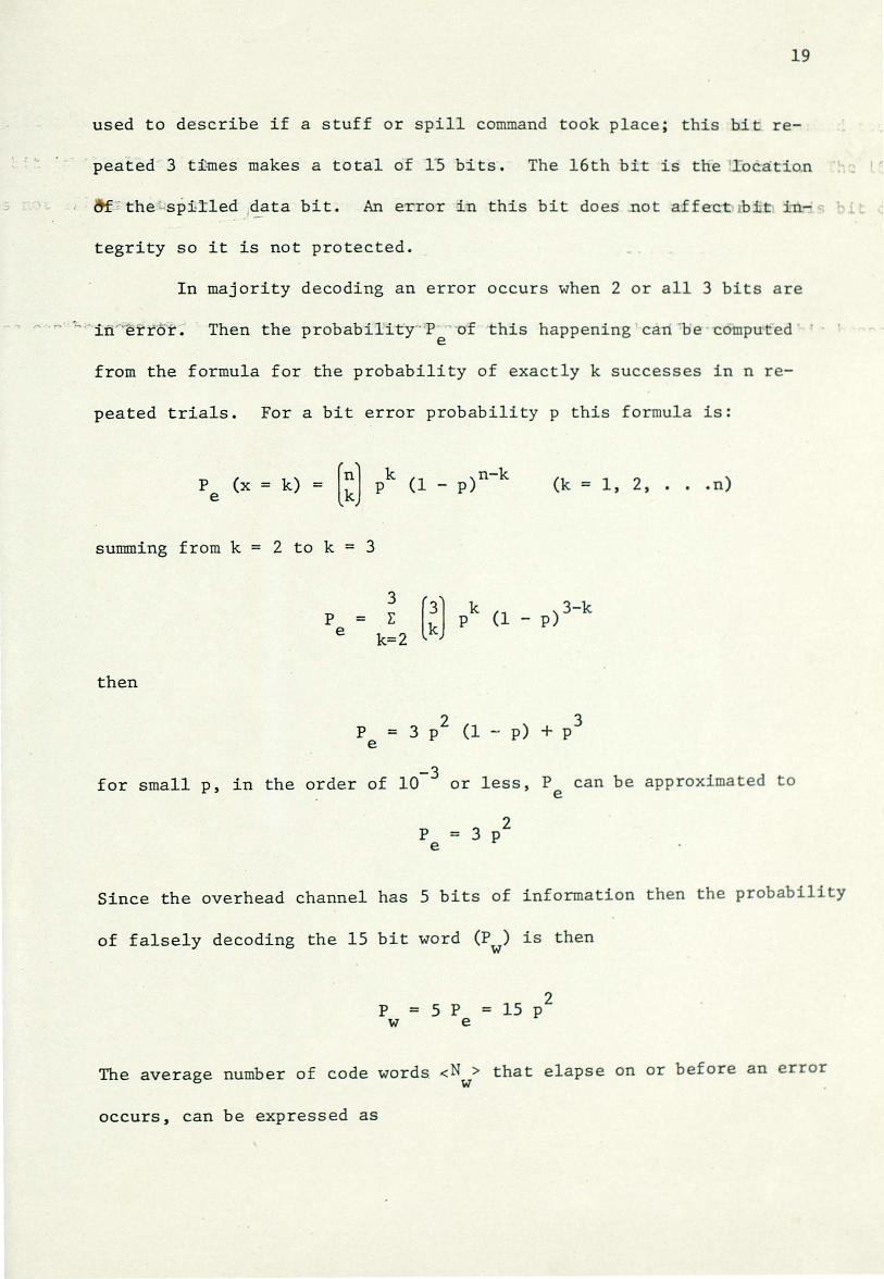
used to describe if a stuff or spill command took place ; this bit re-
peated 3 ti~es makes a total of 15 bi t s . The 16th bit is the location
~; the -spitled data bit. An erro r in this bit does ~ot affect rbit ± -
tegrity so it is not protected.
In majority decoding an error occurs when 2 or all 3 bits are
Then the probab i lity-· P of t his happening can ·be compu ted e
from the formula for the probabili ty of exactly k successes in n r e-
peated trials. For a bit error probabili t y p this formula is:
(k = 1 , 2, . . . n)
summing from k = 2 to k = 3
then
p e
3 = E
k=2
p = 3 p2 (1 - p) + p3 e
for small p, in the order of 10-3 or l ess , P can be approximated to e
p = 3 p2 e
Since the overhead channel has 5 b i t s of information then t he probability
of falsely decoding the 15 bit word (P ) is then w
p = 5 p = 15 p2
w e
The average number of code words <N > that elapse on or bef ore an error . w
occurs, can be expressed as

20
< N > = P + 2 (1 - P ) P + 3 (1 - p ) 2 p + w w w w w w
This expression can be reduced to6 -. -
1 <N>=---w p
w
- -Th~ ccrtal number of bits between errors corres ponds to a maj~r frame,
that is 256 bits; then the mean time in bits < T > between the occure
renee of these errors is found by7
< T > = e
16 (bits/row) 16 (channels ) --~~-~-~-~------~ = p
w
256
15p2
assuming a bir error probability p = 10-5
. < T > = 17 • 1010 bits
e
considering the bit rate to be 10 M bits, the average time to loss of
bit integrity is
6
7
< T > = b
N = P . {1 + 2 (1 w w
= 4 hours and 43 minutes
p ) + 3 (1 w
• } = p dd . { (1 - p ) W X W
+ (1 p )2 + ... } w
1 } 1 2 ( 1 - p ) = p w {1- ( 1-p ) }
w w 1
=-p w
< T > = (Total number of bit per maj or frame) . { < Nw>} = e
256 p
w

21
Deviation Handling Capability
· ··· if all channels make the same identical demands for overhead
access, the equation for the deviation can be written as
m = total number of overhead bits in a f r ame i ncluding overhead channel and synchronization channel
n = total number of bits per frame
s = maximum number of bits which can be stuffed or spil l ed in a frame. In this case, s = 1 s ince single stuffing techniques are considered
after some manipulations,
fj, f f = 1
n-m
For the format under consideration n = 256, m = 32, so the deviation
rate is
D.ff = 2~ 4 or .446%
This means that a system design around th i s f ormat struc t ur e can handle
14 independent data sources, each within .446% deviation from the multi
plexer bit rate. 8
8This computation can be better understood by observing that only one channel can be serviced per each major frame . If only one channel needs to be serviced and all t he r est run synchr onously , the rate of service in the limit is every 16 bits . So in this case ,
1 fj, f 1 -f- = 16 = 6. 25%.
6 f If N channels need service in the l imi t --f- = 16 ,
for N = 14,~ f
= 1 = .446%. 244

The efficiency of the system can be calculated as follows:
n-m T) = --=
n
Synchronization
256-32 256 = 87.5%
In asynchronous transmission clock information is not trans-
mitted with the data. Therefore, in order for the demultiplexer to
properly distribute the message over to the corresponding channels ,
some means of synchronization must be provided with the data. The
format taken as model reserves channel 16 for synchronization data.
9 This channel contains a complete P. N. sequence. By "complete"
it is meant that the all zeros state is added to the sequence. A
22
P. N. sequence provides good synchronization properties and very easy
implementation. Figure 7 depicts the basic circuit of a complete P . N.
sequence generator.
The 16 bit P. N. sequence is generated by a 4 bit feedback
shift register coder. The most important factor in this approach,
is that when any consecutive 4 bits out of any column are forced in-
to an identical 4 bit feedback shift register coder, if the coder is
then allowed to free run, it will generate an identical P. N. sequence
in the proper phase. The search is done on a column by column basis .
Starting with any column, the first four bits of the column are forced
into the shift register and then allowed to run. The coder output is
compared with the sequence of bits of that particular column . If the
test proves correct then the P. N. generator is g t ~d ~~ ~Lvvide frame
9A pseudo-random sequence is usually called a P . N. sequence.
A P. N. sequence generator is also called maximum length counter.

CLO
DAT
CK _ -A -
23
-.... ,, - I I ' JJ l ' \ .
I Jl
4BIT SERIAL
SHIFT REGISTER
Fig. 7.--Complete PN Sequence Generator

24
·· · synchronization to the demultiplexer. I f the t est proves ' ~rang
01 i column"_, _ the system repeats the process in the next column .
~-::: ..! t . _,; , . • ·.'..-:.: ~ ./'5.! ,.As described, every time a new col umn is searched, the. system
must wait 4 consecutive bits to be loaded into t he coder . In order to
speed the synchronization time a number of buff ers could be used to
' · 1:!.0 ua::h"S.~ JE·tfs:l of the incoming cod umns _.se t each t ime a new .coJ.umn ·s ested
3 of the 4 bits needed are already stored and ready to be loaded into
the coder at the same time the fourth bit is rea d in. This procedure
is shown graphically in Figure 8.
Analysis of the Mean Time to Synchronize
Assumptions made:
The system outputs data continuous l y and the probability of
rejecting the right column is extremely small.
With
Definitions:
Q = number of rows needed to initia lize the local P . N. sequence generator
. < C> = average number of columns sear ched before reaching the proper column
< S> = average number of rows needed to reject a "'1rong column
N = number of bits per row
< B> = average number of bits needed t o find sync
these definitions stated, the following expression can be written:
. < B> = . < C> Q N + < C>. < S> N
Where the first term corresponds to the t ime to initialize the P. N.
generator and the second is the t ime to rejec t a wrong column.
For an even number of bits per r ow and even number of columns,
the average number of columns sea r ched before the proper one is
u

\
.. .
i SERIAL DATA ST
I i
PATTERN BUFFERS
REAM ---
r-lao
1
-
-
--
4 BIT P,ARALLEI/S ERIAL SHIFT REGISHlR
•
3BIT PARALLEl/SERIAL SHIFT REG.ISTER
2 BIT PARALLEl/SERIAL SHIFT REGISTER
1 BIT SHIFT REGISTER
"
- . \ >= ....
I l l - rn I I ' - >-, , l J ) I
I
' '~ I .. • ~.
SYNC
'---------------~- SEQUENTIAL 11---t-._IN FO RM. TESTER TO
MODE CO TROL SERIAL OR PARALLEL
LOADING
DEMUX
. DEMUX = Demult iplexer
Fig. 8.--Frame Synchronizer Block Diagram
25
I f

N · (N + 1) (2), and since each column has the same probability, . then
< C> = (N + 1) (~) (~) - 1 = N ; l - 1 I
For a system which rejects a location if 15 agreements in a row .are
not achieved, S is given by
N-1 . < S> = 1::
i=l
If the upper limit of the summation were to go to infinity, S would
converge to 2. So as an approximation
then
. < S> ::::: 2
<B > = (N + l - 1) (Q + 2) N 2
By adding storage as shown in Figure 8, it is possible to eliminate
initialization time after the first initialization, so. < B> can be
reduced to
or
< B> = < C> < S> N + N (Q + < S>)
< B> = (N + l - 1) 2 N + N (Q + 2) 2
for N = 16 and Q = 4
with storage. < B> = 33 6 bits
without storage < B> = 720 bits
26

27
CHAPTER III
EXPERIMENTAL RESULTS
'1· · • ~"' - - =-H:- ·:~ -"GThe synchronization principles describ ed previously bave been
applied by the researcher to the design of an experimental multiplexer
system. The system was built and tested. The bit rate was ·chosen to
operate at medium speed 10 Mb/s, utilizing regular TTL logic. A maxi-
mum of 14 data channels were implemented. A suitable format able to
accommodate pulse stuffing and pulse spilling synchronization was de-
veloped.
The ability to organize the bit stream in such a way to accommo-
date a wide range of input signals was achieved. In a fixed overhead
format10
, the maximum deviation allowed for each channel was measured
to be ± .4% of the multiplexer nominal bit rate, in agreement with the
calculation. In a random access priority the maxi mum deviation tracked,
provided no other channel asked to be serviced, was 6. 25% as expected .
Only one minor drawback was found in the random a ccess mode . When a
channel asks to be serviced, if no other channe l i s r equesting access,
some period of time elapses before the actual stuffing or spilling
operation takes place; therefore, in the very nex t frame the same
channel since it has not been serviced yet will ask for access . Up
to three stuff pulses in a row were observed adding unnecessary jitter
10By fixed overhead format it is mean t t hat each channel has equal overhead access capability.

28
to the data but not in any amount to cause any problem .
··-: -; - ·7" :--;::- · ~ A very successful jitter reduc t ion circuit was implemented in
, i,· .. , -' the &moo:thing buffer section. ~ A phase l ocked loop acting .as a low pass
filter-removed the high frequency jitter component . Although it does
not remove very low frequency jitter, t h i s component does not signifi-
cantly impair the data. . .
One of the areas not very well devel oped in digital transmission
analysis is the problem of jitter build up , when large numbers of multi-
plexers are arranged in tandem. One of t h e main purposes in building a
prototype system was to investigate the behavior of repeaters. To
simulate a number of repeaters, a signa l was routed through a multi plexer
to demultiplexer channel. The demultipl exer channel output was used as
another channel input in the multiplexer and this repeated for all 14
channels. Although an increase in phase excursions of the signals
at lower rate was observed out of the last r epeater, it did not cause
any fundamental problems and an error f r ee data was obtained .
Even though the prototyp e system is quite flexible, a l l the
components used in the design a re easily obtained and the unit has proven
to be very reliable.

29
.L • CHAPTER IV
T CONCLUSIONS
... h.~ ... ~ •• ~;:, • • • The feasibility of pro.cessing various independent digital data
sour~es into a single stream for transmission was established by this
effort. Some new approaches in the area of synchronization and format
structure were developed and implemented.
The major conclusions gained could be summarized as follows:
Bit Stuffing and Bit Spilling Techniques are a very efficient and
flexible method of achieving data synchronization, data bit inter
leaving proved to be a very good approach when deciding an ADM format.
A very fast and accurate method of frame synchronization using
pseudo-random sequences was tested satisfactorily. It was also shown
that accumulated phase jitter can be minimized to negligible level.
The design philosophy proved to be an acceptable solution to
many problems.

\ \
APP ENDIX
SMOOTHING BUFFER TECHNIQUES

31 Loop Analysis
• s Consider the block diag r am of the PLL in Figure 2A . The loop
is composed of a phase detector, an active filter element, a vco12
arrdb~~ pTogrammable divide by N counter . The closed loop transfer -- -
function is
, ..... ,.. H(s) =
or
K F (s) K e (s) E v
0 s
e1
(s) K F (s ) K 1 + E
s N
K F (s) K H (s) = -~E.____-,--,--'v
K F(s ) K s + E v
N
v
(1)
(2)
A loop filter of the type shown in Fi gure lA has a transfer function
then
s2s+l R
2 Cs + 1
F(s) = --- = ----s1s R1 Cs
H(s) =
(3)
(4)
From servo theory the characteris tic equation of a second order l oop
becomes:
CE(s)
12 voltage controlled oscillator
2 5 + (JJ
n (5)
,

32
Fig. lA.--Phase Locked Loop Filter

Kp Vp (S)
Kv VCO GAIN SENSITMTY
F (S) V 0 (S)
l N
K p PHASE D"ETECTOR GAIN CO NSTANT
Y.JL .,..__,..._e_0 (S)
s
F(S) TRANSFER FUNCTION O F LEAD-LAG TYPE FILTER
N NUMBER OF DMDE BY STAGES IN THE FEED BACK
~ig. 2A.--Block Diagram Phase Locked Loop
33

where 0 = damping
- w = natural n
'I'
and (, t' l ...
ratio
frequency of the loop
[K K r2
w = p v n N z;;l
r/2 z;;2 [K K 0 =- p v
2 Nz;;l
H(s) = K K
p v
z;;l 2 s + w
H(s)
2 2 0 w s + w = N n n
s2 + 2 0 w
n 2
s + w n
n
The loop bandwidth is found by letting s = jw and setting
2 H (jw) = 1/2
this yields to
34
(6)
(7)
(8)
(9)
(10)
The phase detector gain constant K can be computed by noting that the p
phase detector output voltage is proportional to the phase difference
between the signals entering the detector
V = K (8. - 8 ) p p ~ 0
(11)

35
The . VCO _gain constant can be calcul ated by knm-1ing or measuring the
.VCO .transfer curve. This is done by _plotting the change in output
.• . . . frequency _over the change in i nput contro l voltage . Then the ratio of
~ frequency change over 6 of input voltage i s the VCO gain constant.
Design Criteria
Normally a few parameters are chosen before the calculation can
be carried out. First the loop bandwidth i s determined . This is done
by taking into consideration how narrow the l oop should be made in order
to perform an efficient smoothing task . Other factors like acquisition
time and the amount of input buffer needed should also be considered.
Next the loop damping ratio is chos en . This is usually o = .707
which corresponds to a critically damped sys t em .
With these two parameters we can then determine the loop natural
frequency w from equation (10). n
It is also necessary to determine K from the VCO transfer v
function curve and K norma-lly from manufa c t urer data sheets. p
With all this data it is then possib le to use equations (6)
and (7) to determine the loop f i l ter components R1 , R2 and C, and this
completes the design.
Analysis of Transient Performance
The error transfer functi on i s
2 s
E ( s) = ---=----=--------=-2 s
2 + 2 0 w s + w n n
If the system is stressed by a ramp R cycles per second the error trans -
fer function in the f requency domain takes the form

- . E (s) = r s 2 + 2 o
R 2 w s + w
n n
36
- .
if o = 1 for simplicity, the error function i n the time domain becomes
-w t E (t) = Rte n
r
Differentiating and setting the result equal to zero gives the result
dE (t) -w t - w t r R e
n n = Rw t e = 0 dt n
therefore, w t = 1 and n
Max E (t) R -1
.059 R = e = r w w n n -
2if
This result gives an idea of the necessary number of bits the elastic
store has to absorb to keep from losing bit integrity for a given fre-
quency change.
Analysis of Jitter Behavior
The smoothing buffer loop has a servo transfer function
2 2 0 w s + w n n H(s) = --~-----s2 + 2 o w s + w 2
n n
where w = natural frequency of the loop n
o = damping factor -

37
The ~~~ter could be represented as the sum of an infinite ramp super-
: i~pos€d :by a sawtooth waveform. The purpose of the loop is to track
- e · ·:. tlfeH.t-amp :perfectly and ignore the sa~vtooth. Therefore, the amount of
sawtooth tracked will be computed.
Consider a sa'\vtooth of amplitude A and period T
f(t) = * t, 0 < t < T
and
f(t + T) = f(t)
The complex Fourier series expansion of f(t) is
where
therefore
f(t) = L jn w t
C e o , (w = n o
~) T
-jnw 0
n=-oo
A c =-n T2
T
0
!T -jn w t
t e o dt 0
+-1-jnw
0
-jnw0 t e
-jn21T The second term goes to zero since e = 1 for w
0
7T -A A A ·z
c = j = j --=-- eJ n n w T 27Tn 27Tn
0
= 27T
T

38
for the case n = 0
1 JOT f(t) A !T A c =- dt = t dt =-0 T T2 0 2
hence 00
f(t) A +A !: 1 ej(nw0 t + ;) =-
'- 2 2 n=-oo n
for zero d c level and unity amplitude, the trigonometric form of
f(t) becomes
00 00
f(t) 1 !:
sin nw0 t 1 !: (t) = = gn 7T
n=l n 7T n=l
From the theory of linear circuits, the total response to f ( t) is the
sum of the components outputs y(t)
00
y(t) = l !: . {g (t)} 7T n=l n
{H(jnw ) } 0
The magnitude of the system response to the n th harmonic of the saw-
tooth is given by the complex expression
1 7T
g (t) n
max
2jnw w + w 2
on n 2 2 2
-n w + 2jnw w + w o n o n
where o = 1 and it is assumed w >> w , then the expression can be o n
approximated by
2jnw w o n
(n2 w 2) 0
Neglecting all but the first harmonic, the magnitude of the phase error
is

2w n
1TW 0
39
cycles, w >> w o n

; T . J -
- . • • t. .'r . . . LIST OF REFERENCES
40
- 1. · Ristenbatt, M.P. and Rothschild , D. R., "Asynchronous Time Multiplexing," IEEE Transactions, Comm . Tech. Com-16, No. 3, June, 1968, pp . 349- 357 .
2. Mayo, J. S. "Experimental 224 Mbs PCM Terminals, " Bell System Technical Journal, November , 1965 , pp . 1813-1841.
3. Buchner, M. M., Jr. "An Asymmetric Encoding Scheme for Word Stuffing," Bell Sys tem Technical Journal, March, 1970, pp • . 379-397.
4. Johannes, V. I. and McCullough, R. H., ' ~ultiplexing of Asyn-chronous Digita l Signals Using Pulse Stuffing with AddedBit Signaling," IEEE Transactions, Comm . Tech. Com-14, No. 5, October, 1966, pp . 562- 568 .
5. Witt, F. J. "An Experimental 224 Mbs Digital Multiplexer-Demulti-plexer Using Pulse Stuffing Synchronization," Bell System Technical Journal, J ul y , 1965 , pp . 1843-1885.