Asynchronous motors for variable frequency
56
95 Nm to 2900 Nm CPLS Asynchronous motors for variable frequency
-
Upload
khangminh22 -
Category
Documents
-
view
2 -
download
0
Transcript of Asynchronous motors for variable frequency

95 Nm to 2900 Nm
CPLSAsynchronous motors for variable frequency


CPLSAsynchronous motors for variable frequency
3Leroy-Somer - Asynchronous CPLS motors for variable frequency - 4119 en - 2017.07 / h
The range of IP23 protection CPLS asynchronous motors was designed for fixed and variable speed applications when there is little space available or (and) there is a wide speed variation range.
Supplied by frequency drives, these motors operate in an open or closed loop. They deliver their rated torques as standard (MN) up to their base speeds (n1) and then supply constant power PN from speed n1 to speed n2.
Squirrel cage motors are well suited to operation in de-fluxed mode and, thanks to adapted laminations, over a wide speed range.
Each machine is defined by its design torque, this torque being available in continuous service below the base speed thanks to efficient radial ventilation.
The performance of these motors are comparable to direct current machines and with some characteristics
of brushless motors. Inertia is reduced, they provide good dynamic performance.
DefluxingConstant torque
Decreasing torque
Constant power
Decreasing power
Introduction

4 Leroy-Somer - Asynchronous CPLS motors for variable frequency - 4119 en - 2017.07 / h
CPLSAsynchronous motors for variable frequency
Index ............................................................................................................................................................................................. 5
GeneraL InformatIon
General description ....................................................................................................................................................................... 6
Components ................................................................................................................................................................................. 6
Normal operating conditions and corrective factors ....................................................................................................................... 7
Increased winding insulation .......................................................................................................................................................... 7
Mounting arrangements ................................................................................................................................................................. 8
Position of the terminal box and the forced ventilation ................................................................................................................... 9
Characteristics of forced ventilation motors ................................................................................................................................. 10
Permissible radial loads (ball bearings) ................................................................................................................................11 to 14
Permissible radial loads (roller bearings) ............................................................................................................................ 15 to 18
Noise and vibration ..................................................................................................................................................................... 19
External finishing ......................................................................................................................................................................... 20
High Speed Configurations ......................................................................................................................................................... 21
Complete description .................................................................................................................................................................. 22
eLeCtrICaL CHaraCterIStICS
Choice of motor ........................................................................................................................................................................... 23
Choice of drive ............................................................................................................................................................................ 23
Selection example ....................................................................................................................................................................... 24
Selection tables ................................................................................................................................................................... 26 to 46
oPtIonaL eQUIPment
Encoder ................................................................................................................................................................................ 47 - 48
Reinforced bearings .................................................................................................................................................................... 49
Thermal protection ...................................................................................................................................................................... 50
Ventilation .................................................................................................................................................................................... 51
Heating ........................................................................................................................................................................................ 52
DImenSIonS
Terminal box and cable glands ..................................................................................................................................................... 53
Foot, foot and flange fixing ........................................................................................................................................................... 54
Leroy-Somer reserves the right to modify the characteristics of its products at any time in order to incorporate the latest technological developments. The information contained in this document is therefore liable to be changed without notice.
Contents

CPLSAsynchronous motors for variable frequency
5Leroy-Somer - Asynchronous CPLS motors for variable frequency - 4119 en - 2017.07 / h
altitude .................................................................................................................................................................................. 7 - 24Ambient temperature .................................................................................................................................................................... 7
Cable glands ............................................................................................................................................................. 9 - 22 - 49 - 53Connection ..................................................................................................................................................................... 6 - 47 - 48Cooling ........................................................................................................................................................................... 6 - 10 - 51CSA .............................................................................................................................................................................................. 6
Degree of protection .................................................................................................................................................... 3 - 6 - 7 - 47Dimensions .......................................................................................................................................................................... 53 - 54
end shields ................................................................................................................................................................ 6 - 9 - 20 - 49Environment .......................................................................................................................................................... 20 - 24 - 51 - 52Exploded view............................................................................................................................................................................... 6External finishing ................................................................................................................................................................... 6 - 20
flange.................................................................................................................................................................................... 6 - 54Forced ventilation ........................................................................................................................................................... 9 - 10 - 51
Heating ....................................................................................................................................................................................... 52High speed...................................................................................................................................................................... 6 - 21 - 22Humidity............................................................................................................................................................................ 6 - 7 - 52
IEC.............................................................................................................................................................................. 6 - 7 - 19 -20Insulation ................................................................................................................................................................................. 6 - 7Intermittent service .......................................................................................................................................................................7
Lifting rings ................................................................................................................................................................................... 6 noise ..................................................................................................................................................................................... 9 - 19Noise level .................................................................................................................................................................................. 19
operating positions ................................................................................................................................................................ 8 - 53Options .................................................................................................................................................................................. 6 - 53
Parts list ........................................................................................................................................................................................ 6
rotor ...................................................................................................................................................................................... 6 - 49
terminal box ............................................................................................................................................ 6 - 8 - 9 - 20 - 22 - 53 - 54Thermal protection ...................................................................................................................................................................... 50
UL ................................................................................................................................................................................................. 6
Vibration level ............................................................................................................................................................................. 19Vibrations .................................................................................................................................................................................... 19
Index

6 Leroy-Somer - Asynchronous CPLS motors for variable frequency - 4119 en - 2017.07 / h
CPLSAsynchronous motors for variable frequencyGeneral information
•CPLSseriesasynchronousmotor, frame height 112 to 250 mm.• Protection: IP23.•Mounting type: B3 or B35, all mounting positions.• Power supply: standard three-wire, power supply via frequency drive.•Winding: class F as standard. 150°C PTC sensor protection.•Magnetic laminations: designed to provide good characteristics in the usage range including in defluxed mode.Depending on the speed of use of the machine, the use of low-loss laminations allows the electrical characteristics of the motor/drive assembly to be optimised.•Rotor: aluminium or copper, depending on the size. Class A balancing as standard, to ISO 8821, by half key (letter H).•Housing: steel.• End shields: cast iron fixed by tie rods. The fixing feet are joined to the DE and NDE shields.• Terminal box: aluminium. It can be orientated every 90°, on either side of the DE shield or NDE shield.
There are only three connection cables available in the terminal box.
WARNING: the terminal boxcovermustbeclosedagainoncetheconnectionofthecablesiscomplete.•Ball bearings: C3 play, greased for life as standard.•Handling rings: depending on the types, they are fixed by screws to the machine's end shields.• Ventilation: three-phase radial auxiliary fan provides good cooling, whatever the machine's speed. The standardised cooling mode as per IEC 34-6 is IC06.Unless specified, cooling air must be between +5°C and +40°C with a humi-dity lower than 80% RH.The fan can be orientated every 90°, on either side of the DE shield or NDE shield.As standard the fan voltage is: 230/400V 50 Hz and 265/460V 60 Hz.The fan motor power varies with the size of the machine: see page 9.• Finish: paint RAL 6000 (green).Identification on the name plate fixed on the motor housing.
•Availableoptions- Drive end roller bearings- Special high-speed bearings- Class B balancing- Special shaft ends- Flanges different from the standard ones by frame height.
- Filter on radial FV (standard or Miovyl)- Cooling via pipe- Offset axial fan- Fan pressure switch- Second shaft end- PTO, PTF, KTY, PT100 sensors in the windings or end shields.
- Incremental encoder, absolute encoder- Brake.
•Otheroptionsuponrequest- Increase in the constant power ope-rating range with our CONSTANT POWER SYSTEM (patented system)
- UL CSA for the motor insulation system (file E68 554).
Description
Components
Ref. name Ref. name1 Stator in its housing 9 Terminal box seal2 Bearing flange (depending on fitting type) 10 Terminal box cover3 Bearing 11 Forced ventilation4 Fan grille 12 Fan seal5 DE shield 13 NDE shield6 Terminal box support plate 14 Closure plate7 Terminal plate 15 NDE bearing8 Terminal box body
CPLSAsynchronous motors for variable frequencyGeneral information
7Leroy-Somer - Asynchronous CPLS motors for variable frequency - 4119 en - 2017.07 / h
normal conditions for use and correction factors
Increased winding insulation
According to IEC 60034-1, standard motors can operate in the following normal conditions:• ambient temperature between +5°C
and +40°C.• altitude less than 1,000m• atmospheric pressure up to
1050 mbar.• operating zone 2 (absolute humidity
between 5 and 23 g/cm³).• ambient air chemically neutral and
dust-free.
Corrections in respect of altitude and ambient temperatureFor different conditions of use, the
power correction coefficient indicated in the table below will be indicated.
P1/P amb (°C)≤40°C
amb (°C)≤50°C
amb (°C)≤60°C
altitude≤1000m 1 0.93 0.85
altitude≤2000m 0.93 0.85 0.75
The P1/P factor gives the correction coefficientP1: corrected powerP: catalogue power.
A more detailed graph is available in the Leroy-Somer type LS three-phase asynchronous motor catalogue.
Correctionsdependingonservice:Service type
running time10 min 30 min 60 min
S2 1.6 1.3 1.1
Service type
Duty cycle25% 40% 60%
S3 1.4 1.2 1.1S6 1.4 1.3 1.2
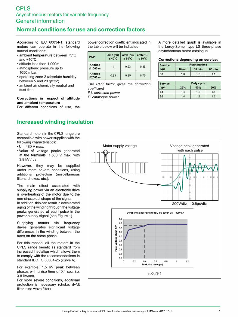
Standard motors in the CPLS range are compatible with power supplies with the following characteristics:• U = 480 V max.• Value of voltage peaks generated
at the terminals: 1,500 V max. with 3.8 kV / µs
However, they may be supplied under more severe conditions, using additional protection (miscellaneous filters, chokes, etc.).
The main effect associated with supplying power via an electronic drive is overheating of the motor due to the non-sinusoidal shape of the signal.In addition, this can result in accelerated aging of the winding through the voltage peaks generated at each pulse in the power supply signal (see Figure 1).
Supplying motors via frequency drives generates significant voltage differences in the winding between the turns on the same phase.
For this reason, all the motors in the CPLS range benefit as standard from increased insulation which allows them to comply with the recommendations in standard IEC TS 60034-25 (curve A).
For example: 1.5 kV peak between phases with a rise time of 0.4 sec, i.e. 3.8 kV/sec.For more severe conditions, additional protection is necessary (choke, dv/dt filter, sine wave filter).
Motor supply voltage
Figure 1
200 V/div. 0.5 µs/div.
Voltage peak generated with each pulse
Dv/dt limit according to IeC tS 60034-25 – curve a
Peak rise time (µs)

8 Leroy-Somer - Asynchronous CPLS motors for variable frequency - 4119 en - 2017.07 / h
CPLSAsynchronous motors for variable frequencyGeneral information
mountings and positions (IEC standard 60034-7)
foot mounted motors
IM 1001 (IM B3)- Horizontal shaft- Feet on floor
IM 1071 (IM B8)- Horizontal shaft- Feet on top
IM 1001 (IM B3)- Horizontal shaft- Feet on floor
IM 1011 (IM V5)- Vertical shaft facing down- Feet on wall
IM 1031 (IM V6)- Vertical shaft facing up- Feet on wall
(FF)flangemountedmotors
IM 3001 (IM B5)- Horizontal shaft
IM 2001 (IM B35)- Horizontal shaft- Feet on floor
IM 3011 (IM V1)- Vertical shaft facing down
IM 2011 (IM V15)- Vertical shaft facing down- Feet on wall
IM 2031 (IM V36)- Vertical shaft facing up- Feet on wall
Consult us(ft) face mounted motors
mounting arrangements
G G
Possible directions of radial loads according
to the foot position
Feet on floor onlyB3 or B35 Other positions
For motors positioned with their feet on the wall, only position B or
D is permitted for the forced ventilation unit

CPLSAsynchronous motors for variable frequencyGeneral information
9Leroy-Somer - Asynchronous CPLS motors for variable frequency - 4119 en - 2017.07 / h
Positionoftheterminalboxandtheforcedventilation
General information
2
13
4
Position of the exit from the glands in relation to the shaft end.
FRPosition of the terminal box and ventilation in relation to the
motor end shield.
F: on DE shieldR: on NDE shield
A 1
D
3
B
1
D3 A1 B1Position of the terminal box and cable glands
(For terminal box fitting possibilities, see page 52.)
A
BD
Position of the forced ventilation(viewed from shaft end)
Example:Terminal box in position A1 on DE shield, ventilation in position B mounted on the NDE shield. Designation: A1 F - B R
position of terminal box and cable glands
position of FV

10 Leroy-Somer - Asynchronous CPLS motors for variable frequency - 4119 en - 2017.07 / h
CPLSAsynchronous motors for variable frequencyGeneral informationCharacteristicsofforcedventilationmotors
CPLS motorSize "2-pole"ventilationasynchronousmotor
Cooling rated power Permissible voltage rated current frequency type LS* flange Shaft mass
IC 06 kW V A Hz mm mm kg
CPLS 112CPLS 132
0.37 220 to 240 ∆80 to 415 Y
∆ 1.7Y 1 (380 V) 50 LS 71 L FF 130
(CPLS 112)14 x 30
(CPLS 112)6.4
0.44 254 à 280 ∆440 à 480 Y
∆ 1,7 (254 V)Y 0,95 60 LS 71 L FF 165
(CPLS 132)19 x 40
(CPLS 132)
CPLS 1601.1 230 ∆ ∆ 4 50 LSES 80 L
FF 165 19 x 4010.7
1,3 265 ∆ ∆ 3.8 60 LSES 90 L 16.1
CPLS 2002.2 230 ∆ ∆ 7.8 50 LSES 90 L
FT 130 24 x 50 16.12,2 265 ∆ ∆ 6.9 60 LSES 90 L
CPLS 2503 230 ∆ ∆ 10.2 50 LSES 100 L
FT 130 28 x 6022.2
3.6 265 ∆ ∆ 10.2 60 LSES 100 LU 26,5
* LS: Eff2 LSES: IE2
If the distribution grid is different, state the frequency and voltage on the order.

CPLSAsynchronous motors for variable frequencyGeneral information
11Leroy-Somer - Asynchronous CPLS motors for variable frequency - 4119 en - 2017.07 / h
Permissible radial loads (ball bearings)
Maximum radial load permitted on the end of themainshaft,horizontalorverticalmotor,shaftendupordownand ball bearing for a service life L10hcalculatedat20,000hours.
In pulley and belt couplings, the end of the drive shaft with the pulley is subjected to a radial force Fr applied at a distance X (mm) from the support at the end of a shaft of length E. rpm
rpm
rpm
rpmrpm
rpm
rpm
rpm
rpm
rpm
rpm
rpm
rpm
rpmrpm

12 Leroy-Somer - Asynchronous CPLS motors for variable frequency - 4119 en - 2017.07 / h
CPLSAsynchronous motors for variable frequencyGeneral informationPermissible radial loads (ball bearings)
rpm
rpm
rpm
rpmrpm
rpm
rpm
rpm
rpmrpm
rpm
rpm
rpm
rpm rpm
rpm
rpm
rpm
rpmrpm

CPLSAsynchronous motors for variable frequencyGeneral information
13Leroy-Somer - Asynchronous CPLS motors for variable frequency - 4119 en - 2017.07 / h
Permissible radial loads (ball bearings)
rpm
rpm
rpm
rpmrpm
rpm
rpm
rpm
rpmrpm rpm rpm
rpm
rpm
rpm
rpm
rpm
rpm
rpm rpm

14 Leroy-Somer - Asynchronous CPLS motors for variable frequency - 4119 en - 2017.07 / h
CPLSAsynchronous motors for variable frequencyGeneral informationPermissible radial loads (ball bearings)
rpm
rpm
rpm
rpmrpm
rpmrpm
rpm
rpm
rpm
rpmrpm
rpm
rpm
rpm

CPLSAsynchronous motors for variable frequencyGeneral information
15Leroy-Somer - Asynchronous CPLS motors for variable frequency - 4119 en - 2017.07 / h
Permissible radial loads (roller bearings)
Maximum radial load permitted on the end of themainshaft,horizontalmotorandrollerbearingforaservicelifeL10hcalculatedat20,000hours.
In pulley and belt couplings, the drive shaft carrying the pulley is subjected to a radial force Fr applied at a distance X (mm) from the support at the end of a shaft of length E.
rpm
rpm
rpm
rpm rpm
rpm
rpm
rpm
rpm
rpm
rpm
rpm
rpm
rpm
rpm

16 Leroy-Somer - Asynchronous CPLS motors for variable frequency - 4119 en - 2017.07 / h
CPLSAsynchronous motors for variable frequencyGeneral informationPermissible radial loads (roller bearings)
rpm
rpm
rpm
rpm rpm
rpm
rpm
rpm
rpm rpm
rpm
rpm
rpm
rpm
rpm
rpm
rpm
rpm
rpm
rpm

CPLSAsynchronous motors for variable frequencyGeneral information
17Leroy-Somer - Asynchronous CPLS motors for variable frequency - 4119 en - 2017.07 / h
Permissible radial loads (roller bearings)
rpm
rpm
rpm
rpm
rpm
rpm
rpm
rpm
rpm
rpm
rpm
rpm
rpm
rpmrpm
rpm
rpm
rpm
rpmrpm

18 Leroy-Somer - Asynchronous CPLS motors for variable frequency - 4119 en - 2017.07 / h
CPLSAsynchronous motors for variable frequencyGeneral informationPermissible radial loads (roller bearings)
rpm
rpm
rpm
rpm
rpm
rpm
rpm
rpm
rpm
rpm
rpm
rpm
rpm
rpm
rpm

CPLSAsynchronous motors for variable frequencyGeneral information
19Leroy-Somer - Asynchronous CPLS motors for variable frequency - 4119 en - 2017.07 / h
noise and vibration
noISe LeVeLStandard IEC 6034-9 defines maximum noise levels for rotary electrical machinery. However, these values do not apply to ac machines supplied by frequency converters.The values below are therefore given for indication purposes only.
noise level (indicative)expressedasacousticpressureLp(a)
type no loaddbA
Under loaddbA
CPLS 112CPLS 132 75 79
CPLS 160 80 84
CPLS 200 82 86
CPLS 250 84 88
Tolerance: 0 / + 3 dbA Maximum frequency: 100 Hz
noise level reductionFor instances requiring lower noise levels, cooling mode IC 37 can be chosen, allowing ventilation to be installed in a less sensitive area.
For duty cycles ≤ 60%, it is possible to fit 4-pole FV motors instead of 2-pole (please enquire).
Quotations can be issued for sound traps. Noise is reduced by 5 db(A) to 10 db(A) (depending on the type of CPLS).
MACHINEVIBRATIONLEVELSMaximumvibrationmagnitudelimitsintermsofdisplacement,speedandacceleration for a frame size H (IeC 60034-14)
Vibration level
frame size H (mm)
CPLS 112 anD 132 CPLS 160 / 200 / 250
Displacementµm
Speed mm/s
accelerationm/s2
Displacementµm
Speed mm/s
accelerationm/s2
a 25 1.6 2.5 35 2.2 3.5
B 11 0.7 1.1 18 1.1 1.7

20 Leroy-Somer - Asynchronous CPLS motors for variable frequency - 4119 en - 2017.07 / h
CPLSAsynchronous motors for variable frequencyGeneral informationExternalfinishing
LEROY-SOMER motors are protected with a range of surface finishes.Surfaces receive appropriate special treatments, as shown below.
Preparation of surfaces
Surface Parts Surface treatment
Cast iron Shields - Terminal box Shot blasting + Primer
Steel Accessories Phosphate treatment + Primer
Shields - Terminal boxes - Fan covers - Grilles Electrophoresis or Hydrofour Flow coat
aluminium alloyFV motor housings - Terminal boxes Shot blasting
End shields Phosphate treatment
Polymer Fan covers - Terminal boxesVentilation grilles (FV motor)
None, but must be free from grease, casting-mould coatings,and dust which would affect paint adhesion
Paint systems
Products environment System applications
moteurs Leroy-Somer
Low aggression or or non-aggressive, temperate climate
Ia 1 polyurethane - vinyl top coat 25/30 μm
Damp, tropical climate IIa 1 Epoxy base coat 30-40 μm1 polyurethane - vinyl top coat 25/30 μm
Coastal IIIa1 Epoxy base coat 30-40 μm
1 Epoxy intermediate coat 30-40 μm1 polyurethane - vinyl top coat 25/30 μm
Chemical, aggressive or particular marine
Special systems(please consult Leroy-Somer)
Navy - NuclearSignificant contact with alkali or acid, etc.
System Ia is for moderate climates and System IIa is for general climates as defined in standard NFC 20 000 (or IEC 721.2.1).
Leroy-Somerstandardpaintcolourreference:
raL 6000
CPLS motors comply with
System Ia requirements

CPLSAsynchronous motors for variable frequencyGeneral information
21Leroy-Somer - Asynchronous CPLS motors for variable frequency - 4119 en - 2017.07 / h
HighSpeedConfiguration
To satisfy applications running at high speeds, several configurations (HV1, HV2, HV3) were defined according to the size of the CPLS and the speeds achievable.
The graph below details the various maximum speeds achievable.
CPLS 160 L, CPLS 200 L, CPLS 250 L, limited to 5,000, 4,500 and 3,800 min-1 respectively.
The table below explains the detail of each configuration.CPLS 112 CPLS 132 CPLS 1601 CPLS 2002 CPLS 2503
HV1 HV2 HV1 HV2 HV3 HV1 HV2 HV3 HV1 HV2 HV3 HV1 HV2
Maximumspeed(rpm) 3000-5000
5000-8000
3000-4300
4300-6700
6700-8000
3000-5600
5600-7000
7000-10000
2400-4000
4000-5000
5000-10000
2400-3800
3800-5000
Sealed bearings (2rS) l l
Protected bearings (2Z) l l l l l
open bearings l l l l l l
Highspeedbearings l l l
De insulated bearing l l l l l l l l4 l l l4 l l
nDe insulated bearing l l l l l l l l4 l l l4 l l
re-greasing system l l l l l l
Highperformancegrease l l l l l l l
Bearingtemperaturesensor l l l l l l
Enhancedbalancing l l l l l l l l l l l l l
Vibration control l l l l l l l lSpeed encoder adaptation > 6000 min-1 l l l l l l
Maxshaftdiameter(mm) 38 38 48 48 48 55 55 55 80 80 65 100 80
l: standard l: option1. CPLS 160 L limited to 5000 rpm CPLS 200 L limited to 4500 rpm 3. CPLS 250 L limited to 3800 rpm 4. limited to 8500 rpm
In the standard configuration, the bearings are 2RS sealed type, except for the CPLS 250 which are open bearings.
HV1 HV2
HV1
HV1
HV1
HV1
HV2
HV2
HV2
HV2
HV3
HV3
HV3
CPLShighspeedlevelselectionFrameheight
Standard
Standard
Standard
Standard
Standard
Maximummechanicalspeed(rpm)

22 Leroy-Somer - Asynchronous CPLS motors for variable frequency - 4119 en - 2017.07 / h
CPLSAsynchronous motors for variable frequencyGeneral information
* For more information, see pages 52 and 53.
CPLS-112L-0606- IM1001-B1-F-B-R-HV1
Motor type High Speed Configuration
Position of the ventilation(DE shield F or NDE R)
Position of the terminal box(DE shield F or NDE R)
Orientation of the terminal box (A-B-D)*+ orientation of the cable glands (1-2-3-4)*
Frame height and length
Winding specification
Mounting IEC 60034-7 (B3)
Orientation of the forced ventilation(A-B-D)*
Complete description

CPLSAsynchronous motors for variable frequencyElectrical characteristics
23Leroy-Somer - Asynchronous CPLS motors for variable frequency - 4119 en - 2017.07 / h
Choiceofmotor
Choiceofdrive
To assist you in quickly determining your motor/drive assembly, we have produced sizing data sheets dedicated to variable speed.
a – Initially, you must determine the nominal usable torque required by your application. The necessary torque (MN) at the nominal point (n1) defines the size of the machine in the range.The range of iso-power curves opposite allow you to make an initial approach to choose the size of the machine.
b – In the data sheet corresponding to the motor torque selected, the speed closest to that required is chosen, in accordance with the voltage available at the output from the drive.
This choice determines the type of
machine, i.e. the most suitable winding that will allow you to use the drive rating closest to your needs.That is indicated in the selection sheet.
This selection method allows you to size the motor/drive assembly corresponding to the actual need of the application.
An example of selection is given on page 23.
Our machines are tested on test benches by Leroy-Somer range drives. Where available, these characteristics may be requested from the factory.
Depending on the application, the nominal power of the machine and the rating of the machine drive may be different.
If you are working from zero speed to machine speed n1, you should choose the drive rating corresponding to the machine's rated current.
Our range of machines offers as standard a constant power range going up to twice the nominal speed (n2) without having to de-rate the drive.Thereafter, the operating power is reduced because of the rapid reduction in the maximum torque in asynchronous motors.
TAKE CARE to check that themachine bearings are capable ofoperating at the high speeds yourequire (see page 20).
taKe Care to select a drive switchingfrequencyequalatleastto 12timesthemotor'ssupplyfrequency.
Full documentation on electronic drives in the DIGIDRIVE-SK, UNIDRIVE-SP and POWERDRIVE ranges is available from our representative on request.
If you wish to increase the speed ratio n2/n1 you can use our patented CONSTANT POWER SYSTEM. It can be integrated in the terminal box, and makes it possible to operate over a wider speed range without de-rating the drive.

24 Leroy-Somer - Asynchronous CPLS motors for variable frequency - 4119 en - 2017.07 / h
CPLSAsynchronous motors for variable frequencyElectrical characteristics
UnIDrIVe SP
Selectionexample
To make the selection you need to know the torque required by your application. If the torque is known, go directly to step no. 3.
Example: I have an application which requires 6kW at 1200 min-1 in S1 service.The ambient temperature will be be +20°C in operation, altitude lower than 1000 m.The terminal box must be on the right hand side and the fan on the top of the machine when looking at the end of the shaft.
Step1: Correction factors• Correction depending on the temperature and altitude (page 7).• Correction depending on the service (page 7).
Example: there is no need to de-rate to take the service or environmental conditions into account.
Step2:CalculationofratedtorqueYou know the power and the speed; you can calculate the torque using the formula:
C = P x 9550/n
C: torque in N.mP: power in kWn: speed in min-1
Example: the torque required for my application is 127 N.m
Step3:DeterminingtheframesizeThe diagram on page 22 allows the size of the machine to be determined quickly from the torque and the speed.
Example: from the graph on page 22, I select machine CPLS 112 L
Step4:DeterminingthemachineOn the sheet for the machine you choose, depending on the voltage available on output from your drive, the closest speed or the next one above the one you need.From the selected line, you obtain main mechanical and electrical parameters that define your operating point, as well as the size of the drive and the machine product code.
Example:See the technical sheet for motor CPLS 112 L.For a voltage at the output from the drive of 360V.The next speed up from the one I need is 1215 min-1.
Step5:VerificationThe machine torque that appears on the line is the one obtained in S1 service. I check that it is equal to or greater than the one I need.If that is not the case, I move up to the next machine size.
Example: the motor torque in S1 service is 130 N.m for a need of 127 N.m; the machine size is correct.
Motor arrangement selected:Motor: CPLS 112 L 0606 B1F ARDrive: UNIDRIVE SP 27T
WARNING:youmustspecifythemaximumoperating
speed,asthechoiceofbearingsdependsonthis.

CPLSAsynchronous motors for variable frequencyElectrical characteristics
25Leroy-Somer - Asynchronous CPLS motors for variable frequency - 4119 en - 2017.07 / h
Selection tables
CPLS112M/95-115N.m
P(kW) U (V)* f(Hz) n1 (min-1) T(N.m) I (a) cos j h (%) r (W)(1)
n2 (min-1) CPLS
UnIDrIVe SP
LS Ct
8.5 320 25.9 714 114 22.7 0.87 77
1.254
1365
112M
0604
SP 16T(25A)
SP 2403(25A)
9.1 340 27.5 762 114 22.7 0.86 78 15119.7 360 29.1 812 114 22.8 0.86 79 1630
10.3 380 30.7 860 114 22.8 0.85 80 169711.0 400 32.3 908 115 23.0 0.85 81 176012.0 440 35.5 1006 114 22.7 0.84 82 208312.9 480 38.8 1107 111 22.3 0.83 83 232011.7 320 36.1 1015 109 28.4 0.89 82
0.754
2000
112M
0605
SP 22T(32A)
SP 3401(32A)
12.5 340 38.3 1081 110 28.7 0.89 83 212213.4 360 40.6 1151 110 28.6 0.89 83 224514.2 380 42.8 1217 111 28.8 0.88 84 241015.0 400 45.1 1312 109 28.5 0.89 85 260016.1 440 49.6 1424 108 27.8 0.87 86 285317.3 480 54.2 1564 106 27.3 0.87 87 315714.6 320 46.1 1316 106 35.6 0.86 85
0.492
2851
112M
0606
SP 27T(40A)
SP 3402(40A)
15.6 340 49.0 1403 106 35.6 0.86 86 306116.5 360 51.8 1488 106 35.5 0.85 87 324017.5 380 54.7 1575 106 35.5 0.85 87 342818.5 400 57.6 1663 106 35.6 0.85 88 361020.4 440 63.4 1837 106 35.5 0.84 89 417022.3 480 69.1 2009 106 35.5 0.84 89 459117.5 320 55.7 1603 104 41.3 0.86 87
0.35
347511
2M06
07
SP 33T(46A)
SP 3403(46A)
18.6 340 59.2 1708 104 41.2 0.86 88 371919.7 360 62.6 1811 104 41.1 0.86 89 401620.9 380 66.1 1916 104 41.2 0.86 89 436722.0 400 69.6 2021 104 41.1 0.85 90 461024.3 440 76.6 2232 104 41.1 0.85 90 509226.5 480 83.5 2440 104 41.0 0.85 91 557523.8 320 81.6 2390 95 55.9 0.83 91
0.163
5940
112M
0608
SP 40T(60A)
SP 4401(60A)
25.3 340 86.7 2543 95 55.9 0.83 91 633026.9 360 92.0 2702 95 56.0 0.83 92 672028.4 380 97.0 2852 95 56.0 0.83 92 711030.0 400 102 3002 95 56.2 0.83 92 747032.9 440 117 3450 91 54.1 0.85 93 800036.1 480 138 4075 84 52.3 0.88 93 8000
Motor IP23 – Ventilation IC06 – Class FService S1 – Ambient temperature 40°C – Total mass: 87 kgInertia: 0.030 kg.m² - Maximum mechanical speed: 8000 min-1
0.37 kW forced ventilation – 230/400V 50Hz
(Inominal / Heavy overload)
* voltage available on output from the drive(1): Phase-to-phase resistance valueThese indicative values are non-contractual and may be modified at any time by the manufacturer.

26 Leroy-Somer - Asynchronous CPLS motors for variable frequency - 4119 en - 2017.07 / h
CPLSAsynchronous motors for variable frequencyElectrical characteristicsSelection tables
CPLS112L/110-140N.m
P(kW) U (V)* f(Hz) n1 (min-1) T(N.m) I (a) cos j h (%) r (W)(1)
n2 (min-1) CPLS
UnIDrIVe SP
LS Ct
8.4 320 21.5 581 138 23.1 0.88 74
1.39
990
112L
0604
SP 16T(25A)
SP 2403(25A)
9.1 340 22.9 623 139 23.2 0.87 76 11309.7 360 24.2 663 140 23.2 0.87 77 1245
10.4 380 25.6 704 141 23.4 0.86 78 138511.0 400 26.9 745 141 23.4 0.86 78 148012.4 440 30 826 143 23.7 0.85 80 168013.8 480 32.3 907 145 24.0 0.85 81 190511.4 320 30.1 835 130 28.6 0.89 80
0.836
1562
112L
0605
SP 22T(32A)
SP 3401(32A)
12.2 340 32 893 130 28.5 0.89 81 170513.1 360 33.8 947 132 28.7 0.89 82 182514.0 380 35.7 1004 133 28.9 0.89 82 197015.0 400 37.6 1060 135 29.2 0.88 83 211516.6 440 41 1175 135 29.1 0.88 84 233018.2 480 45.1 1287 135 29.1 0.88 85 262514.5 320 37.9 1071 129 35.2 0.88 83
0.540
2132
112L
0606
SP 27T(40A)
SP 3402(40A)
15.6 340 40.3 1143 130 35.4 0.88 84 230216.6 360 42.7 1215 130 35.4 0.88 85 246217.5 380 45 1286 130 35.2 0.88 85 260618.5 400 47.4 1358 130 35.1 0.88 86 278520.4 440 52 1503 129 35.0 0.87 87 314722.2 480 56.9 1645 129 34.8 0.87 88 367017.3 320 46.4 1325 125 41.5 0.86 86
0.388
271511
2L06
07
SP 33T(46A)
SP 3403(46A)
18.5 340 49.3 1412 125 41.6 0.86 87 297819.7 360 52.2 1499 125 41.6 0.86 87 305120.8 380 55.1 1587 125 41.6 0.86 88 350722.0 400 58 1674 125 41.6 0.86 88 367024.2 440 64 1849 125 41.4 0.85 89 402726.9 480 69.6 2022 127 41.9 0.85 90 455023.8 320 68 1982 115 56.5 0.83 90
0.180
4917
112L
0608
SP 40T(60A)
SP 4401(60A)
25.3 340 72.2 2108 115 56.5 0.83 91 522026.9 360 76.5 2237 115 56.5 0.83 91 555028.4 380 80.7 2364 115 56.5 0.83 91 582030.0 400 85 2493 115 56.6 0.83 92 612533.1 440 94 2748 115 56.7 0.82 92 681436.2 480 102 3003 115 56.7 0.82 92 747029.5 320 88 2482 109 67.8 0.85 92
0.114
6415
112L
0609
SP 50T(74A)
SP 4402(74A)
31.2 340 93 2732 109 67.7 0.84 92 678033.3 360 99 2912 109 67.8 0.84 92 723035.0 380 104 3063 109 67.7 0.84 93 762137.0 400 110 3242 109 67.7 0.84 93 800040.8 440 121 3573 109 67.7 0.84 93 800044.6 480 140 4140 103 65.5 0.87 94 8000
Motor IP23 – Ventilation IC06 – Class FService S1 – Ambient temperature 40°C – Total mass: 97 kgInertia: 0.035 kg.m² - Maximum mechanical speed: 8,000 min-1
0.37 kW forced ventilation – 230/400V 50Hz
(Inominal / Heavy overload)
* voltage available on output from the drive(1): Phase-to-phase resistance valueThese indicative values are non-contractual and may be modified at any time by the manufacturer.

CPLSAsynchronous motors for variable frequencyElectrical characteristics
27Leroy-Somer - Asynchronous CPLS motors for variable frequency - 4119 en - 2017.07 / h
Selection tables
CPLS132S/145-170N.m
P(kW) U (V)* f(Hz) n1 (min-1) T(N.m) I (a) cos j h (%) r (W)(1)
n2 (min-1) CPLS
UnIDrIVe SP
LS Ct8.6 320 18.2 480 171 24.2 0.87 74
1.358
671
132S
0604
SP 16T(25A)
SP 2403(25A)
9.2 340 19.4 517 170 24.1 0.86 76 8219.8 360 20.5 552 170 24.1 0.85 77 932
10.4 380 21.7 588 169 24.0 0.85 78 105011.0 400 22.8 617 170 24.3 0.83 79 115912.3 440 25.1 692 170 24.2 0.83 80 136313.5 480 27.4 761 170 24.3 0.82 82 150711.7 320 24.2 657 170 30.6 0.88 79
0.880
1050
132S
0605
SP 22T(32A)
SP 3401(32A)
12.6 340 25.8 705 171 30.7 0.88 80 119013.4 360 27.3 751 170 30.6 0.87 81 133314.2 380 28.8 797 170 30.5 0.87 82 141915.0 400 30.3 842 170 30.5 0.86 82 156816.6 440 33.6 942 168 30.2 0.86 84 177718.2 480 37.2 1050 165 29.8 0.86 85 198614.6 320 29.5 816 171 36.8 0.87 82
0.59
1452
132S
0606
SP 27T(40A)
SP 3402(40A)
15.6 340 31.4 873 170 36.8 0.87 83 157016.5 360 33.2 929 170 36.6 0.86 84 174317.6 380 35.1 985 170 36.7 0.86 84 186218.5 400 36.9 1040 170 36.6 0.86 85 205820.5 440 42.0 1192 164 35.7 0.87 87 224522.4 480 46.7 1333 160 35.1 0.88 88 249117.3 320 35.2 981 168 43.4 0.86 84
0.462
1658
132S
0607
SP 33T(46A)
SP 3403(46A)
18.4 340 37.4 1048 168 43.2 0.85 85 188619.6 360 39.6 1114 168 43.2 0.85 86 200820.6 380 41.2 1165 169 43.4 0.84 86 219322.0 400 44.0 1247 168 43.3 0.84 87 235824.2 440 49.0 1398 165 42.6 0.85 88 263126.7 480 54 1547 165 42.5 0.85 89 290023.8 320 49.6 1416 160 57.1 0.85 88
0.240
2690
132S
0608
SP 40T(60A)
SP 4401(60A)
25.3 340 52.7 1510 160 56.9 0.85 89 298226.9 360 55.8 1603 160 57.0 0.84 90 316328.4 380 58.9 1697 160 56.9 0.84 90 337330.0 400 62.0 1790 160 56.9 0.84 90 355433.1 440 68.2 1976 160 56.9 0.84 91 394536.2 480 75.5 2195 157 56.1 0.84 92 433629.5 320 64 1851 152 68.7 0.85 91
0.151
3675
132S
0609
SP 50T(74A)
SP 4402(74A)
31.4 340 68.0 1971 152 68.6 0.85 91 391633.3 360 72.0 2091 152 68.6 0.85 92 435335.2 380 76.0 2211 152 68.6 0.85 92 462337.0 400 80.0 2332 152 68.4 0.85 92 486640.9 440 89.0 2601 150 67.9 0.85 93 543344.7 480 99.0 2902 145 65.9 0.86 93 606335.9 320 81.6 2378 144 80.6 0.87 92
0.101
4720
132S
0610
SP 60T(96A)
SP 4403(96A)
38.2 340 86.7 2531 144 80.5 0.87 93 502140.5 360 91.8 2684 144 80.5 0.87 93 557842.8 380 96.9 2837 144 80.5 0.87 93 590845.0 400 102 2991 144 80.3 0.86 94 623949.7 440 118 3468 135 77.4 0.88 94 690351.0 480 128 3773 129 74.0 0.88 95 7519
Motor IP23 – Ventilation IC06 – Class FService S1 – Ambient temperature 40°C – Total mass: 125 kgInertia: 0.065 kg.m² - Maximum mechanical speed: 6,700 min-1 (8,000 min-1 with HV3 configuration)0.37 kW forced ventilation – 230/400V 50Hz
(Inominal / Heavy overload)
* voltage on output from the drive(1): Phase-to-phase resistance valueThese indicative values are non-contractual and may be modified at any time by the manufacturer.

28 Leroy-Somer - Asynchronous CPLS motors for variable frequency - 4119 en - 2017.07 / h
CPLSAsynchronous motors for variable frequencyElectrical characteristicsSelection tables
CPLS132M/175-220N.m
P(kW) U (V)* f(Hz) n1 (min-1) T(N.m) I (a) cos j h (%) r (W)(1)
n2 (min-1) CPLS
UnIDrIVe SP
LS Ct11.7 320 19.1 507 220 31.5 0.88 76
904
777
132M
0605
SP 22T(32A)
SP 3401(32A)
12.6 340 20.3 544 221 31.6 0.87 78 88913.4 360 21.5 581 220 31.5 0.87 79 100214.2 380 22.7 618 219 31.4 0.86 80 110115.0 400 23.9 654 219 31.3 0.86 81 116616.7 440 26.3 727 219 31.4 0.85 82 136918.4 480 28.7 800 219 31.5 0.84 83 150514.5 320 23.1 630 220 38.0 0.86 80
610
1123
132M
0606
SP 27T(40A)
SP 3402(40A)
15.6 340 24.6 675 220 38.1 0.86 81 126616.6 360 26.0 717 220 38.1 0.85 82 141717.5 380 27.5 763 219 37.9 0.85 83 150918.5 400 28.9 806 219 37.9 0.84 84 159620.6 440 31.8 893 220 38.1 0.84 85 177122.6 480 34.7 981 220 38.1 0.83 86 194716.6 320 26.0 720 220 43.6 0.83 82
474
1424
132M
0607
SP 33T(46A)
SP 3403(46A)
18.4 340 28.7 796 221 43.6 0.86 83 149519.6 360 30.4 848 221 43.6 0.86 84 167420.8 380 32.1 899 221 43.6 0.86 85 177822.0 400 33.8 950 221 43.6 0.85 85 188124.3 440 37.2 1053 220 43.5 0.85 86 208826.3 480 41.0 1168 215 42.6 0.85 87 231922.6 320 36.8 1036 218 59.3 0.83 86
274
2050
132M
0608
SP 40T(60A)
SP 4401(60A)
25.2 340 39.1 1105 218 59.4 0.83 87 218926.8 360 41.4 1175 218 59.4 0.83 87 243928.4 380 43.7 1244 218 59.5 0.82 88 258730.0 400 46.0 1313 218 59.5 0.82 89 274533.1 440 50.6 1452 218 59.5 0.82 89 304536.2 480 56.0 1614 214 58.6 0.82 90 320829.3 320 46.4 1324 211 71.1 0.84 89
185
2632
132M
0609
SP 50T(74A)
SP 4402(74A)
31.2 340 49.3 1412 211 71.1 0.84 89 281333.1 360 52.2 1499 211 71.0 0.83 90 313135.0 380 55.1 1587 211 71.0 0.83 90 331337.0 400 58.0 1673 211 71.1 0.83 91 354940.8 440 65.0 1883 207 69.9 0.84 91 374444.6 480 72.3 2101 203 68.7 0.85 92 419035.6 320 57.6 1657 205 82.4 0.86 90
129
3280
132M
0610
SP 60T(96A)
SP 4403(96A)
37.9 340 61.2 1765 205 82.3 0.86 91 350340.2 360 64.8 1874 205 82.2 0.86 91 373142.5 380 68.4 1982 205 82.2 0.86 92 410945.0 400 72.0 2090 205 82.5 0.86 92 434749.5 440 81.7 2380 198 80.5 0.87 93 474554.1 480 93.5 2730 189 78.6 0.89 93 542243.8 320 76.8 2234 187 97.2 0.88 93
81
4449
132M
0611
SP 75T(124A)
SP 5401(124A)
46.6 340 81.6 2378 187 97.1 0.88 93 474949.4 360 86.4 2522 187 97.1 0.87 93 502152.2 380 91.2 2667 187 97.0 0.87 93 557755.0 400 96.0 2811 187 97.0 0.87 94 587860.7 440 114 3345 173 94.5 0.90 94 665062.0 480 118 3475 171 89.9 0.88 95 685149.3 320 92.0 2690 175 107.2 0.89 94
61
5349
132M
0612
SP 75T(124A)
SP 5401(124A)
52.5 340 97.8 2864 175 107.2 0.89 94 596455.6 360 103.5 3036 175 107.1 0.89 94 632558.8 380 109.3 3210 175 107.0 0.89 94 671562.0 400 115 3380 175 107.0 0.88 94 707564.0 440 131 3864 158 99.5 0.89 95 770066.0 480 143 4228 149 94.1 0.89 95 8000
Motor IP23 – Ventilation IC06 – Class FService S1 – Ambient temperature 40°C – Total mass: 143 kgInertia: 0.082 kg.m² - Maximum mechanical speed: 6,700 min-1 (8,000 min-1 with HV3 configuration)0.37 kW forced ventilation – 230/400V 50Hz
(Inominal / Heavy overload)
* voltage available on output from the drive (1): Phase-to-phase resistance valueThese indicative values are non-contractual and may be modified at any time by the manufacturer.

CPLSAsynchronous motors for variable frequencyElectrical characteristics
29Leroy-Somer - Asynchronous CPLS motors for variable frequency - 4119 en - 2017.07 / h
Selection tables
P(kW) U (V)* f(Hz) n1 (min-1) T(N.m) I (a) cos j h (%) r (W)(1)
n2 (min-1) CPLS
UnIDrIVe SP
LS Ct11.5 320 16.7 445 247 30.9 0.87 76
912
712
132L
0605
SP 22T(32A)
SP 3401(32A)
12.4 340 17.8 478 248 31.0 0.87 78 79713.2 360 18.8 509 248 30.9 0.86 79 90914.1 380 19.9 542 248 31.0 0.86 80 102115.0 400 20.9 572 250 31.2 0.86 80 108316.6 440 23.0 636 249 31.0 0.85 82 125718.3 480 25.1 700 250 31.1 0.85 83 138514.4 320 20.2 551 250 37.6 0.86 80
634
1049
132L
0606
SP 27T(40A)
SP 3402(40A)
15.5 340 21.5 590 250 37.8 0.86 81 116316.5 360 22.8 630 250 37.7 0.86 82 125317.4 380 24.0 666 250 37.7 0.85 82 138018.5 400 25.3 705 250 37.7 0.85 83 146220.4 440 27.8 781 250 37.7 0.84 84 154822.5 480 30.4 860 250 37.6 0.84 85 170617.2 320 23.8 659 249 43.7 0.86 82
460
1311
132L
0607
SP 33T(46A)
SP 3403(46A)
18.4 340 25.2 702 250 43.8 0.85 83 145519.6 360 26.7 745 250 43.8 0.85 84 154720.7 380 28.2 792 250 43.9 0.85 85 171822.0 400 29.7 837 250 43.8 0.84 85 181824.3 440 32.7 928 250 43.7 0.84 86 202226.6 480 35.6 1016 250 43.7 0.84 87 220523.7 320 32.0 906 250 58.3 0.85 86
249
2040
132L
0608
SP 40T(60A)
SP 4401(60A)
25.3 340 34.0 967 250 58.4 0.84 87 219026.9 360 36.0 1027 250 58.4 0.84 87 234028.5 380 38.0 1087 250 58.5 0.84 88 246330.0 400 40.0 1147 250 58.4 0.84 88 261333.2 440 45.0 1297 244 57.4 0.85 89 296835.8 480 51.0 1476 232 55.3 0.86 90 346629.2 320 39.4 1126 247 72.6 0.82 88
175
2572
132L
0609
SP 50T(74A)
SP 4402(74A)
31.2 340 41.8 1199 248 72.7 0.81 89 272533.3 360 44.3 1273 249 73.1 0.81 90 295935.1 380 46.7 1346 249 73.2 0.81 90 319437.0 400 49.2 1421 249 73.1 0.81 90 337640.9 440 54.1 1568 249 73.2 0.80 91 370944.7 480 59.0 1716 249 73.3 0.80 91 407035.7 320 49.2 1419 240 85.6 0.83 90
123
3229
132L
0610
SP 60T(96A)
SP 4403(96A)
38.0 340 52.3 1513 240 85.5 0.83 91 344040.3 360 55.3 1603 240 85.6 0.82 91 365242.6 380 58.4 1696 240 85.5 0.82 91 386345.0 400 61.5 1790 240 85.7 0.82 92 407349.6 440 67.6 1973 240 85.7 0.82 92 469253.0 480 75.0 2195 230 82.7 0.83 93 523543.4 320 62.4 1810 229 98.1 0.86 92
86
3937
132L
0611
SP 75T(124A)
SP 5401(124A)
46.4 340 66.3 1927 230 98.5 0.86 92 417949.2 360 70.2 2044 230 98.4 0.86 92 444852.0 380 74.1 2161 230 98.5 0.86 93 471855.0 400 78.0 2279 230 98.6 0.86 93 495960.5 440 85.8 2513 230 98.3 0.86 93 547164.0 480 95.0 2790 219 94.7 0.86 94 636354.1 320 84.0 2458 210 119 0.87 93
53
5314
132L
0612
SP 75T(124A)
SP 5401(124A)
57.6 340 89.3 2617 210 119 0.87 93 570261.0 360 94.5 2773 210 119 0.87 94 606264.4 380 99.8 2932 210 119 0.87 94 642368.0 400 105 3088 210 119 0.87 94 675470.0 440 115.5 3408 196 111 0.87 94 761072.0 480 126 3727 185 105 0.86 95 8000
CPLS132L/210-250N.m
Motor IP23 – Ventilation IC06 – Class FService S1 – Ambient temperature 40°C – Total mass: 174 kgInertia: 0.107 kg.m² - Maximum mechanical speed: 6,700 min-1 (8,000 min-1 with HV3 configuration)0.37 kW forced ventilation – 230/400V 50Hz
(Inominal / Heavy overload)
* voltage available on output from the drive (1): Phase-to-phase resistance valueThese indicative values are non-contractual and may be modified at any time by the manufacturer.

30 Leroy-Somer - Asynchronous CPLS motors for variable frequency - 4119 en - 2017.07 / h
CPLSAsynchronous motors for variable frequencyElectrical characteristicsSelection tables
P(kW) U (V)* f(Hz) n1 (min-1) T(N.m) I (a) cos j h (%) r (W)(1)
n2 (min-1) CPLS
UnIDrIVe SP
LS Ct17.2 320 16.4 444 369 45 0.87 78
520
1000
160S
0602
SP 33T(46A)
SP 3403(46A)
18.3 340 17.4 475 367 45 0.86 80 110019.6 360 18.5 509 368 45 0.86 80 115020.8 380 19.5 539 368 45 0.86 81 125022.0 400 20.5 572 367 45 0.86 82 130024.3 440 22.6 633 367 45 0.85 84 150026.7 480 24.6 694 366 45 0.84 85 165023.7 320 22.0 613 368 59 0.87 83
303
1500
160S
0603
SP 40T(60A)
SP 4401(60A)
25.2 340 23.4 655 367 59 0.86 84 160026.8 360 24.8 697 367 59 0.86 85 170028.4 380 26.1 737 368 59 0.86 85 180030.0 400 27.5 779 368 59 0.85 86 190033.2 440 30.3 864 367 59 0.85 87 210036.4 480 33.0 945 368 59 0.84 88 235029.2 320 26.0 734 380 74 0.85 85
207
1900
160S
0604
SP 50T(74A)
SP 4402(74A)
31.2 340 27.6 782 381 74 0.84 86 200033.1 360 29.0 825 383 74 0.83 86 210035.1 380 30.9 881 380 74 0.84 87 225037.0 400 32.5 930 380 74 0.83 87 240040.8 440 35.8 1030 378 74 0.83 88 265044.8 480 39.0 1125 380 74 0.82 89 295035.6 320 31.6 903 377 88 0.84 87
141
2350
160S
0605
SP 60T(96A)
SP 4403(96A)
38.0 340 33.6 963 377 88 0.84 88 250040.3 360 35.6 1024 376 88 0.83 88 265042.7 380 37.5 1080 377 88 0.83 89 281045.0 400 39.5 1140 377 88 0.82 89 310049.7 440 43.5 1260 376 88 0.82 90 345053.0 480 49.0 1426 355 83 0.85 90 415043.7 320 40.2 1159 360 101 0.88 89
98
2850
160S
0606
SP 75T(124A)
SP 5401(124A)
46.6 340 42.8 1237 360 101 0.87 90 305049.5 360 45.3 1312 360 101 0.87 90 325052.3 380 47.8 1387 360 101 0.87 91 345055.0 400 50.3 1462 360 101 0.87 91 370057.9 440 55.4 1618 342 96 0.86 91 420061.0 480 60.4 1770 329 94 0.86 92 500059.6 320 55.8 1625 350 140 0.83 92
66
4500
160S
0607
SP 100T(156A)
SP 5402(156A)
63.4 340 59.3 1730 350 140 0.83 92 480067.3 360 62.8 1835 350 140 0.83 92 500071.1 380 66.3 1943 350 140 0.83 93 520075.0 400 69.8 2045 350 140 0.83 93 550080.5 440 76.8 2256 341 137 0.82 93 670085.5 480 83.8 2468 331 134 0.82 94 735073.3 320 69.6 2036 344 165 0.86 93
38
5050
160S
0608
SP 120T(180A)
SP 6401(180A)
77.9 340 74.0 2168 343 165 0.86 93 540082.7 360 78.3 2297 344 165 0.86 94 570085.5 380 82.7 2428 336 162 0.86 94 605090.0 400 87.0 2560 336 162 0.85 94 635094.0 440 95.7 2824 318 154 0.85 94 736098.0 480 104 3087 303 148 0.84 95 800088.8 320 88.8 2608 325 190 0.89 94
26
6450
160S
0609
SP 150T(210A)
SP 6402(210A)
94.3 340 94.3 2773 325 190 0.89 94 6850100 360 99.9 2941 325 190 0.89 94 7300105 380 105 3095 324 190 0.89 95 7600110 400 111 3275 321 188 0.89 95 8000115 440 122 3609 305 179 0.89 95 8000
- - - - - - - -
CPLS160S/325-380N.m
Motor IP23 – Ventilation IC06 – Class FService S1 – Ambient temperature 40°C – Total mass: 230 kgInertia: 0.188 kg.m² - Maximum mechanical speed: 7,000 min-1 (10000 min-1 with HV3 configuration)1.1 kW forced ventilation – 230/400V 50Hz
(Inominal / Heavy overload)
* voltage available on output from the drive (1): Phase-to-phase resistance valueThese indicative values are non-contractual and may be modified at any time by the manufacturer.

CPLSAsynchronous motors for variable frequencyElectrical characteristics
31Leroy-Somer - Asynchronous CPLS motors for variable frequency - 4119 en - 2017.07 / h
Selection tables
P(kW) U (V)* f(Hz) n1 (min-1) T(N.m) I (a) cos j h (%) r (W)(1)
n2 (min-1) CPLS
UnIDrIVe SP
LS Ct17 320 12.6 332 475 44 0.89 76
590
620
160M
0602
SP 33T(46A)
SP 3403(46A)
18 340 13.3 350 480 44 0.88 77 68019 360 14.1 380 485 45 0.88 78 73021 380 14.9 400 495 45 0.88 79 75022 400 15.7 425 495 45 0.88 80 81025 440 17.3 470 495 45 0.87 81 95027 480 18.8 515 495 45 0.86 83 110024 320 16.8 457 490 59 0.89 80
349
920
160M
0603
SP 40T(60A)
SP 4401(60A)
25 340 17.9 490 490 59 0.88 81 100527 360 18.9 520 490 59 0.88 82 107029 380 20.0 550 490 59 0.88 83 112030 400 21.0 585 490 59 0.87 84 124033 440 23.1 648 490 59 0.87 85 140537 480 25.2 710 490 59 0.86 86 155229 320 20.3 563 490 71 0.88 83
240
1240
160M
0604
SP 50T(74A)
SP 4402(74A)
31 340 21.6 602 490 71 0.87 84 132033 360 22.9 641 490 71 0.87 85 139035 380 24.1 576 490 71 0.87 85 154037 400 25.4 715 490 71 0.87 86 168041 440 27.9 790 490 71 0.86 87 195045 480 30.5 871 490 71 0.86 88 212035 320 24.4 685 490 85 0.86 86
167
1580
160M
0605
SP 60T(96A)
SP 4403(96A)
37 340 25.8 730 490 85 0.86 86 175040 360 27.5 780 490 85 0.86 87 192042 380 29.0 820 490 85 0.86 87 209045 400 30.5 870 490 86 0.86 88 227049 440 33.5 960 490 86 0.85 89 246054 480 36.6 1050 490 86 0.84 89 287043 320 29.6 840 490 103 0.86 88
115
2100
160M
0606
SP 75T(124A)
SP 5401(124A)
46 340 31.5 900 490 103 0.86 88 227049 360 33.3 955 490 103 0.86 89 248052 380 35.1 1010 490 102 0.86 89 271055 400 37.0 1065 490 103 0.86 89 297060 440 40.7 1175 480 101 0.85 90 317062 480 44.4 1290 460 97 0.84 91 375059 320 40.0 1155 490 145 0.81 90
65
3300
160M
0607
SP 100T(156A)
SP 5402(156A)
63 340 42.5 1230 490 145 0.81 91 345067 360 45.0 1305 490 145 0.81 91 361071 380 47.5 1380 490 145 0.81 92 376075 400 50.0 1455 490 145 0.81 92 406081 440 55.0 1605 480 143 0.80 92 437085 480 60.0 1760 460 139 0.79 93 550072 320 49.6 1442 475 167 0.83 92
45
4050
160M
0608
SP 120T(180A)
SP 6401(180A)
76 340 52.7 1535 475 167 0.83 92 435081 360 55.8 1628 475 167 0.83 93 465086 380 58.9 1720 475 167 0.83 93 494090 400 62.0 1810 475 168 0.83 93 510098 440 68.2 2000 465 164 0.82 94 5850
103 480 74.4 2189 450 160 0.82 94 6600
CPLS160M/390-490N.m
Motor IP23 – Ventilation IC06 – Class FService S1 – Ambient temperature 40°C – Total mass: 289 kgInertia: 0.246 kg.m² - Maximum mechanical speed: 7,000 min-1 (10000 min-1 with HV3 configuration)1.1 kW forced ventilation – 230/400V 50Hz
(Inominal / Heavy overload)
* voltage available on output from the drive(1): Phase-to-phase resistance valueThese indicative values are non-contractual and may be modified at any time by the manufacturer.

32 Leroy-Somer - Asynchronous CPLS motors for variable frequency - 4119 en - 2017.07 / h
CPLSAsynchronous motors for variable frequencyElectrical characteristicsSelection tables
P(kW) U (V)* f(Hz) n1 (min-1) T(N.m) I (a) cos j h (%) r (W)(1)
n2 (min-1) CPLS
UnIDrIVe SP
SPLS / Ct SPm SPm
regen87 320 63.2 1845 450 191 0.88 93
31
4650
160M
0609 SP 150T
SP 6402
(210A)
93 340 67.1 1960 450 191 0.88 93 496098 360 71.1 2083 450 190 0.88 94 5250
104 380 75.1 2204 450 190 0.88 94 5550110 400 79.0 2320 450 192 0.88 94 5800116 440 86.9 2560 430 183 0.87 94 6500122 480 98.0 2890 405 173 0.88 94 7000106 320 88.0 2590 390 224 0.90 95
18
6177
160M
0610 SP 74X1
(238A)
SPMD14X3-1S(246A)
SPMD1423-1R(246A)
113 340 93.5 2755 390 224 0.90 95 6567119 360 99.0 2920 390 223 0.89 95 7000127 380 105 3100 390 223 0.90 95 7000132 400 110 3255 390 223 0.89 95 7000
- - - - - - - - -- - - - - - - - -
CPLS160M/390-490N.mMotor IP23 – Ventilation IC06 – Class FService S1 – Ambient temperature 40°C – Total mass: 289 kgInertia: 0.246 kg.m² - Maximum mechanical speed: 7,000 min-1 (10000 min-1 with HV3 configuration)1.1 kW forced ventilation – 230/400V 50Hz
(Inominal / Heavy overload)
* voltage available on output from the drive(1): Phase-to-phase resistance valueThese indicative values are non-contractual and may be modified at any time by the manufacturer.

CPLSAsynchronous motors for variable frequencyElectrical characteristics
33Leroy-Somer - Asynchronous CPLS motors for variable frequency - 4119 en - 2017.07 / h
Selection tables
P(kW) U (V)* f(Hz) n1 (min-1) T(N.m) I (a) cos j h (%) r (W)(1)
n2 (min-1) CPLS
UnIDrIVe SP
LS Ct24 320 11.7 320 702 60 0.91 78
540
500
160L
0603
SP 40T(60A)
SP 4401(60A)
25 340 12.4 341 702 60 0.90 79 60027 360 13.1 363 700 59 0.90 80 70028 380 13.9 387 700 59 0.90 81 75030 400 14.6 409 700 59 0.89 82 80033 440 16.1 454 698 59 0.88 83 90036 480 17.5 496 698 59 0.88 84 100029 320 14.2 395 700 71 0.90 81
380
750
160L
0604
SP 50T(74A)
SP 4402(74A)
31 340 15.1 422 700 71 0.90 82 85033 360 16.0 450 700 71 0.90 83 90035 380 16.9 477 700 71 0.89 83 95037 400 17.8 504 700 71 0.89 84 105041 440 19.6 558 700 71 0.89 85 125045 480 21.4 613 700 71 0.88 86 135036 320 17.1 485 698 85 0.90 84
268
1000
160L
0605
SP 60T(96A)
SP 4403(96A)
38 340 18.2 516 700 85 0.89 85 110040 360 19.3 549 700 85 0.89 85 120043 380 20.3 580 700 85 0.89 86 130045 400 21.4 613 700 85 0.88 87 140050 440 23.5 676 700 85 0.88 87 150054 480 25.7 743 694 84 0.88 88 165044 320 20.8 595 700 103 0.88 86
180
1350
160L
0606
SP 75T(124A)
SP 5401(124A)
47 340 22.1 634 700 102 0.88 87 145049 360 23.4 673 700 102 0.88 88 165052 380 24.7 712 700 102 0.88 88 175055 400 26.0 751 699 102 0.88 88 185060 440 28.6 830 685 100 0.87 89 205064 480 31.2 909 672 99 0.86 90 225060 320 29.2 844 679 139 0.87 89
103
2000
160L
0607
SP 100T(156A)
SP 5402(156A)
64 340 31.0 898 676 139 0.87 90 210068 360 32.9 955 676 138 0.86 90 225071 380 34.7 1010 675 138 0.86 90 237575 400 36.5 1064 673 138 0.86 91 250081 440 40.2 1175 661 136 0.85 92 290088 480 43.8 1284 654 134 0.85 92 320072 320 36.1 1053 650 165 0.86 91
69
2650
160L
0608
SP 120T(180A)
SP 6401(180A)
76 340 38.3 1119 650 165 0.85 92 285081 360 40.6 1188 650 165 0.86 92 300085 380 42.8 1254 650 165 0.85 92 315090 400 45.1 1323 649 164 0.85 92 335097 440 49.6 1459 635 161 0.85 93 3600
104 480 54.1 1595 623 159 0.84 93 395088 320 45.6 1338 625 197 0.86 93
44
3300
160L
0609
SP 150T(210A)
SP 6402(210A)
93 340 48.5 1425 625 197 0.86 93 350099 360 51.3 1509 625 197 0.86 93 3700
105 380 54.2 1596 625 197 0.86 93 3900110 400 57.0 1680 625 197 0.86 93 4150117 440 62.7 1853 603 191 0.85 94 4700125 480 68.4 2025 590 188 0.85 94 5000
CPLS160L/490-700N.m
Motor IP23 – Ventilation IC06 – Class FService S1 – Ambient temperature 40°C – Total mass: 362 kgInertia: 0.455 kg.m² - Maximum mechanical speed: 5,000 min-1
1.1 kW forced ventilation – 230/400V 50Hz
(Inominal / Heavy overload)
* voltage available on output from the drive(1): Phase-to-phase resistance valueThese indicative values are non-contractual and may be modified at any time by the manufacturer.

34 Leroy-Somer - Asynchronous CPLS motors for variable frequency - 4119 en - 2017.07 / h
CPLSAsynchronous motors for variable frequencyElectrical characteristicsSelection tables
P(kW) U (V)* f(Hz) n1 (min-1) T(N.m) I (a) cos j h (%) r (W)(1)
n2 (min-1) CPLS
UnIDrIVe SP
SP SPm SPm regen
110 320 59.2 1741 603 233 0.91 93
27
3700
160L
0610 SP 74X1
(238A)
SPMD14X3-1S(246A)
SPMD1423-1R(246A)
116 340 62.9 1852 596 230 0.90 94 4000121 360 66.6 1964 591 228 0.90 94 4300126 380 70.3 2075 582 225 0.90 94 4600132 400 74.0 2187 577 223 0.90 94 5000139 440 81.4 2411 551 213 0.90 95 5000148 480 88.8 2634 537 208 0.90 95 5000138 320 84.8 2506 526 285 0.92 94
19
5000
160L
0611 SP 74X2
(290A)
SPMD14X4-1S(290A)
SPMD1424-1R(290A)
144 340 90.1 2666 516 280 0.92 95 5000150 360 95.4 2826 507 275 0.92 95 5000155 380 100.7 2986 496 268 0.92 95 5000160 400 106.0 3146 486 263 0.91 95 5000166 440 116.6 3466 458 248 0.91 96 5000171 480 127.2 3786 432 234 0.91 96 5000
CPLS160L/490-700N.m
Motor IP23 – Ventilation IC06 – Class FService S1 – Ambient temperature 40°C – Total mass: 362 kgInertia: 0.455 kg.m² - Maximum mechanical speed: 5,000 min-1
1.1 kW forced ventilation – 230/400V 50Hz
(Inominal / Heavy overload)
* voltage available on output from the drive(1): Phase-to-phase resistance valueThese indicative values are non-contractual and may be modified at any time by the manufacturer.

CPLSAsynchronous motors for variable frequencyElectrical characteristics
35Leroy-Somer - Asynchronous CPLS motors for variable frequency - 4119 en - 2017.07 / h
Selection tables
P(kW) U (V)* f(Hz) n1 (min-1) T(N.m) I (a) cos j h (%) r (W)(1)
n2 (min-1) CPLS
UnIDrIVe SP
SPLS / Ct SPm SPm
regen35 320 14.0 376 883 91.0 0.88 78.2
278
560
200S
0604 SP 60T
SP 4403
(96A)
38 340 14.9 403 887 91.3 0.88 79.3 60540 360 15.8 431 886 91.0 0.88 80.4 67643 380 16.6 455 891 91.0 0.87 81.3 73545 400 17.5 482 890 90.7 0.87 82.2 84651 440 19.3 536 898 91.3 0.87 83.6 90956 480 21.0 588 900 91.1 0.86 84.8 106043 320 16.0 440 937 113 0.85 81.3
187.8
816
200S
0605 SP 75T
SP5401
(124A)
46 340 17.0 470 940 113 0.85 82.3 87850 360 18.0 500 944 113 0.85 83.1 95052 380 19.0 531 940 113 0.84 83.9 105155 400 20.0 561 935 112 0.84 84.7 116561 440 22.0 622 935 112 0.83 85.9 126167 480 24.0 682 937 112 0.83 86.9 135559 320 22.3 628 903 146 0.86 85.6
108.4
1171
200S
0606 SP 100T
SP 5402
(156A)
63 340 23.7 670 900 145 0.86 86.4 129067 360 25.1 712 900 145 0.86 87.0 135171 380 26.5 755 900 145 0.85 87.6 144175 400 27.9 796 900 144 0.85 88.2 158783 440 30.7 881 893 143 0.85 89.1 170090 480 33.5 966 890 143 0.85 89.9 186572 320 27.0 767 890 172 0.86 87.6
77
152520
0S06
07 SP 120TSP 6401
(180A)
77 340 28.7 820 890 172 0.86 88.2 161481 360 30.4 871 887 171 0.86 88.8 173486 380 32.1 922 884 170 0.85 89.3 182690 400 33.8 974 882 170 0.85 89.7 197499 440 37.2 1076 875 168 0.85 90.6 2186108 480 40.6 1180 870 167 0.85 91.2 236989 320 33.2 956 883 209 0.85 89.6
49.8
1917
200S
0608 SP 150T
SP 6402
(210A)
94 340 35.3 1019 880 208 0.85 90.1 2100100 360 37.4 1083 877 208 0.85 90.6 2300104 380 39.4 1143 877 207 0.85 91.0 2460110 400 41.5 1200 875 206 0.84 91.4 2600121 440 45.7 1338 866 205 0.84 91.8 2758131 480 49.8 1457 858 202 0.84 92.5 2944105 320 40.4 1170 858 247 0.84 91.1
36.4
2430
200S
0609 SP 74X2
(290A)
SPMD14X4-1S(290A)
SPMD1423-1R(246A)
112 340 42.9 1246 858 247 0.84 91.6 2600119 360 45.5 1324 856 246 0.84 91.9 2775125 380 48.0 1400 855 246 0.84 92.3 2930132 400 50.5 1474 855 245 0.84 92.6 3080146 440 55.6 1627 853 245 0.84 93.1 3380158 480 60.6 1778 848 244 0.83 93.6 3568128 320 49.6 1446 845 295 0.85 92.5
25
2930
200S
0610 SP 84X1
(335A)
SPMA14X1-2S(342A)
SPMD1421-2R(342A)
136 340 52.7 1540 843 295 0.84 92.8 3125144 360 55.8 1633 841 294 0.84 93.1 3320152 380 58.9 1726 840 293 0.84 93.4 3450160 400 62.0 1816 840 293 0.84 93.7 3712174 440 68.2 2005 830 289 0.84 94.1 4100188 480 74.4 2192 820 286 0.84 94.5 4467
Motor IP23 – Ventilation IC06 – Class FService S1 – Ambient temperature 40°C – Total mass: 505 kgInertia: 0.700 kg.m² - Maximum mechanical speed: 5000 min-1 (10000 min-1 with HV3 configuration)2.2 kW forced ventilation – 230/400V 50Hz
(Inominal / Heavy overload)
* voltage available on output from the drive(1): Phase-to-phase resistance valueThese indicative values are non-contractual and may be modified at any time by the manufacturer.
CPLS200S/680-940N.m

36 Leroy-Somer - Asynchronous CPLS motors for variable frequency - 4119 en - 2017.07 / h
CPLSAsynchronous motors for variable frequencyElectrical characteristicsSelection tables
P(kW) U (V)* f(Hz) n1 (min-1) T(N.m) I (a) cos j h (%) r (W)(1)
n2 (min-1) CPLS
UnIDrIVe SP
SP SPm SPm regen
160 320 68,0 2000 760 358 0.86 93.7
16.3
3800
200S
0611 SP 84X2
(389A)
SPMA14X2-2S(400A)
SPMD1422-2R(400A)
170 340 72,3 2125 760 357 0.86 93.9 4030180 360 76,5 2254 760 357 0.86 94.2 4257190 380 80,8 2383 760 357 0.86 94.4 4500200 400 85,0 2510 760 357 0.86 94.6 4750213 440 93.5 2764 736 345 0.85 94.9 5000228 480 102,0 3020 721 339 0.85 95.2 5000205 320 94,4 2790 702 451 0.87 94.9
9.13
5000
200S
0612 SP 84X3
(450A)
SPMD14X3-2L(468A)
SPMD1423-2R(468A)
216 340 100,3 2967 696 447 0.86 95.1 5000227 360 106,2 3145 688 442 0.86 95.3 5000238 380 112.1 3322 685 440 0.86 95.4 5000250 400 118.0 3500 683 438 0.86 95.5 5000
- 440 - - - - - - - - - - - - -- 480 - - - - - - - - - - - - -
Motor IP23 – Ventilation IC06 – Class FService S1 – Ambient temperature 40°C – Total mass: 505 kgInertia: 0.700 kg.m² - Maximum mechanical speed: 5000 min-1 (10000 min-1 with HV3 configuration)2.2 kW forced ventilation – 230/400V 50Hz
(Inominal / Heavy overload)
* voltage available on output from the drive(1): Phase-to-phase resistance valueThese indicative values are non-contractual and may be modified at any time by the manufacturer.
CPLS200S/680-940N.m

CPLSAsynchronous motors for variable frequencyElectrical characteristics
37Leroy-Somer - Asynchronous CPLS motors for variable frequency - 4119 en - 2017.07 / h
P(kW) U (V)* f(Hz) n1 (min-1) T(N.m) I (a) cos j h (%) r (W)(1)
n2 (min-1) CPLS
UnIDrIVe SP
SPLS / Ct SPm SPm
regen43 320 11.7 315 1296 115 0.86 78.7
220.4
534
200M
0603 SP 75T
SP 5401(124A)
46 340 12.4 337 1300 116 0.85 79.3 59049 360 13.1 358 1300 115 0.85 80.4 65052 380 13.9 382 1300 115 0.84 82.2 76655 400 14.6 404 1300 115 0.84 82.2 76661 440 16.1 450 1300 115 0.84 83.6 89767 480 17.5 491 1305 115 0.83 84.8 102859 320 16.2 449 1255 148 0.86 83.0
130.4
821
200M
0604 SP 100T
SP 5402(156A)
63 340 17.2 479 1260 148 0.86 83.4 89567 360 18.2 509 1260 148 0.86 84.7 96771 380 19.2 540 1260 148 0.86 85.5 105675 400 20.2 568 1260 147 0.85 86.1 111583 440 22.2 630 1254 147 0.85 87.3 124091 480 24.2 391 1254 146 0.85 88.2 137471 320 19.6 552 1230 174 0.86 85.8
91
1058
200M
0605 SP 120T
SP 6401(180A)
77 340 20.8 589 1230 173 0.86 86.5 114881 360 22.1 630 1228 173 0.86 87.2 125086 380 23.3 663 1228 173 0.85 87.8 132690 400 24.5 700 1228 173 0.85 88.3 139099 440 27.0 775 1228 172 0.85 89.2 1540108 480 29.4 847 1228 172 0.85 89.9 177088 320 24.0 683 1225 209 0.86 87.8
62.8
134020
0M06
06 SP 150TSP 6402(210A)
93 340 25.5 728 1222 209 0.86 88.5 144599 360 27.0 774 1221 208 0.86 89.1 1535105 380 28.5 819 1217 207 0.85 89.6 1626110 400 30.0 864 1215 207 0.85 90.0 1717122 440 33.0 954 1215 206 0.85 90.8 1900133 480 36.0 1045 1215 206 0.85 91.4 2080105 320 28.6 823 1222 251 0.85 89.7
42.6
1562
200M
0607 SP 74X2
(290A)
SPMD14X4-1S(290A)
SPMD1424-1R(246A)
112 340 30.3 875 1222 250 0.84 90.2 1632119 360 32.1 929 1220 250 0.84 90.6 1820125 380 33.9 983 1217 249 0.84 91.1 1963132 400 35.7 1037 1214 248 0.84 91.4 2090146 440 39.3 1145 1212 248 0.84 92.0 2320159 480 42.8 1252 1212 248 0.83 92.7 2560128 320 36.0 1041 1173 297 0.85 91.2
31
2012
200M
0608 SP 84X1
(335A)
SPMA14X1-2S(342A)
SPMD 1421-2R(342A)
136 340 38.3 1110 1168 295 0.85 91.5 2148144 360 40.5 1177 1168 295 0.85 91.9 2311152 380 42.8 1246 1164 294 0.85 92.3 2475160 400 45.0 1312 1164 293 0.85 92.6 2640176 440 49.5 1448 1157 291 0.85 93.2 2825192 480 54.0 158 1145 288 0.85 93.7 3040160 320 46.3 1355 1127 375 0.83 93.0
17.8
3087
200M
0609 SP 84X2
(389A)
SPMA14X2-2S(400A)
SPMD1422-2R(400A)
170 340 49.2 1442 1125 375 0.83 93.3 3354180 360 52.2 1532 1120 374 0.83 93.6 3593190 380 55.1 1620 1120 373 0.83 93.9 3803200 400 58.0 1706 1119 373 0.82 94.1 4042217 440 63.7 1878 1104 368 0.82 94.5 4494234 480 69.5 2053 1090 363 0.82 94.8 5000
CPLS200M/900-1300N.m
(Inominal / Heavy overload)
Motor IP23 – Ventilation IC06 – Class FService S1 – Ambient temperature 40°C – Total mass: 615 kgInertia: 0.98 kg.m² - Maximum mechanical speed: 5000 min-1 (10000 min-1 with HV3 configuration)2.2 kW forced ventilation – 230/400V 50Hz
* voltage available on output from the drive(1): Phase-to-phase resistance valueThese indicative values are non-contractual and may be modified at any time by the manufacturer.
Selection tables

38 Leroy-Somer - Asynchronous CPLS motors for variable frequency - 4119 en - 2017.07 / h
CPLSAsynchronous motors for variable frequencyElectrical characteristics
P(kW) U (V)* f(Hz) n1 (min-1) T(N.m) I (a) cos j h (%) r (W)(1)
n2 (min-1) CPLS
UnIDrIVe SP
SP SPm SPm regen
204 320 61.0 1794 1086 461 0.85 93.9
12.1
3604
200M
0610
SP 84X4(545A) SPMD
14X3-2L(468A)
SPMD1423-2R(468A)
217 340 64.9 1910 1082 460 0.85 94.1 3920227 360 68.7 2026 1068 454 0.85 94.4 4115238 380 72.5 2140 1061 451 0.85 94.6 4298250 400 76.3 2260 1057 450 0.85 94.8 4450
SP 84X3(450A)275 440 83.9 2483 1032 438 0.84 95.2 5000
300 480 91.6 2715 1010 430 0.84 95.4 5000256 320 87.9 2604 939 569 0.85 95.3
5.93
5000
200M
0611 SP 94X1
(620A)
SPMD14X2-3S(600A)
SPMD1422-3R(600A)
272 340 93.4 2768 939 569 0.85 95.5 5000287 360 98.9 2933 935 566 0.85 95.6 5000300 380 104 3098 925 560 0.85 95.7 5000315 400 110 3264 922 559 0.85 95.8 5000330 440 121 3596 877 533 0.85 96.0 5000 SP 84X4
(545A)SPMD
14X4-2LSPMD
1424-2R350 480 132 3927 852 519 0.84 96.1 5000
CPLS200M/900-1300N.m
* voltage available on output from the drive(1): Phase-to-phase resistance valueThese indicative values are non-contractual and may be modified at any time by the manufacturer.
(Inominal / Heavy overload)
Motor IP23 – Ventilation IC06 – Class FService S1 – Ambient temperature 40°C – Total mass: 615 kgInertia: 0.98 kg.m² - Maximum mechanical speed: 5000 min-1 (10000 min-1 with HV3 configuration)2.2 kW forced ventilation – 230/400V 50Hz
Selection tables

CPLSAsynchronous motors for variable frequencyElectrical characteristics
39Leroy-Somer - Asynchronous CPLS motors for variable frequency - 4119 en - 2017.07 / h
Selection tables
P(kW) U (V)* f(Hz) n1 (min-1) T(N.m) I (a) cos j h (%) r (W)(1)
n2 (min-1) CPLS
UnIDrIVe SP
SPLS / Ct SPm SPm
regen43 320 9.5 267 1537 108 0.88 81.5
248
585
200L
0603 SP 75T
SP 5401(124A)
46 340 10.1 285 1540 108 0.87 82.5 63049 360 10.7 305 1540 108 0.87 83.3 68852 380 11.3 321 1538 108 0.87 84.1 73455 400 11.9 340 1545 109 0.86 84.7 76561 440 13.1 376 1536 108 0.86 86.0 85566 480 14.3 412 1534 108 0.85 87.0 94360 320 13.2 378 1506 143 0.88 85.7
139
837
200L
0604 SP 100T
SP 5402(156A)
63 340 14.0 402 1505 142 0.88 86.5 89767 360 14.9 429 1500 142 0.88 87.1 96371 380 15.7 453 1500 142 0.87 87.7 101875 400 16.5 477 1500 141 0.87 88.2 109083 440 18.2 528 1500 141 0.87 89.1 116790 480 19.8 576 1500 141 0.86 89.9 129372 320 15.8 456 1494 169 0.87 87.7
97
1150
200L
0605 SP 120T
SP 6401(180A)
76 340 16.8 486 1496 169 0.87 88.3 111781 360 17.8 516 1494 169 0.86 88.9 118486 380 18.8 546 1493 169 0.86 89.3 125990 400 19.8 576 1490 169 0.86 89.5 130599 440 21.8 636 1485 168 0.85 90.6 1455108 480 23.8 697 1480 167 0.85 91.2 160588 320 19.4 564 1482 204 0.87 89.6
64.5
129120
0L06
06 SP 150TSP 6402(210A)
93 340 20.6 600 1479 203 0.86 90.2 137099 360 21.8 636 1480 203 0.86 90.6 1490105 380 23.0 673 1482 203 0.86 91.0 1575110 400 24.2 708 1480 203 0.86 91.3 1660121 440 26.6 781 1477 203 0.85 91.9 1815132 480 29.0 853 1460 201 0.85 92.5 2083106 320 23.8 696 1441 236 0.88 91.0
47.6
1560
200L
0607 SP 74X1
(238A)
SPMD14X3-1S(246A)
SPMD1423-1R(246A)
112 340 25.3 740 1443 237 0.88 91.4 1691119 360 26.8 786 1440 236 0.88 91.8 1802125 380 28.3 831 1440 236 0.88 92.1 1867132 400 29.8 876 1439 236 0.88 92.5 1955145 440 32.8 966 1434 235 0.87 92.9 2168155 480 35.8 1057 1397 229 0.87 93.5 2474128 320 29.6 871 1409 293 0.86 92.5
29.2
2185
200L
0608 SP 84X1
(335A)
SPMD14X1-2L(342A)
SPMD1421-2R(342A)
136 340 31.5 928 1400 291 0.86 92.9 2315144 360 33.3 982 1397 290 0.85 93.2 2442152 380 35.2 1040 1396 290 0.85 93.4 2540160 400 37.0 1094 1397 290 0.85 93.6 2680176 440 40.7 1204 1392 289 0.85 94.0 3010192 480 44.4 1316 1350 282 0.84 94.4 3400161 320 38.8 1146 1342 359 0.86 93.4
19.6
2723
200L
0609 SP 84X2
(389A)
SPMA14X2-2S(400A)
SPMA1422-2R(400A)
171 340 41.2 1218 1337 357 0.86 94.1 2890181 360 43.7 1293 1334 356 0.86 94.4 3100190 380 46.1 1365 1330 355 0.86 94.6 3250200 400 48.5 1422 1330 355 0.86 94.8 3450218 440 53.4 1584 1314 352 0.86 95.1 3750240 480 58.2 1728 1298 348 0.85 85.4 4090
CPLS200L/1100-1550N.m
(Inominal / Heavy overload)
Motor IP23 – Ventilation IC06 – Class FService S1 – Ambient temperature 40°C – Total mass: 740 kgInertia: 1.579 kg.m² - Maximum mechanical speed: 4,500 min-1
2.2 kW forced ventilation – 230/400V 50Hz
* voltage available on output from the drive(1): Phase-to-phase resistance valueThese indicative values are non-contractual and may be modified at any time by the manufacturer.

40 Leroy-Somer - Asynchronous CPLS motors for variable frequency - 4119 en - 2017.07 / h
CPLSAsynchronous motors for variable frequencyElectrical characteristicsSelection tables
P(kW) U (V)* f(Hz) n1 (min-1) T(N.m) I (a) cos j h (%) r (W)(1)
n2 (min-1) CPLS
UnIDrIVe SP
SP SPm SPmregen
206 320 50.4 1494 1317 454 0.86 94.9
12.6
3608
200L
0610
SP 84X4(545A)
SPMD14X3-2L(468A)
SPMD1423-2R(468A)
219 340 53.6 1590 1315 454 0.86 95.1 3905226 360 56.7 1683 1293 447 0.86 95.3 4150238 380 59.9 1800 1276 441 0.86 95.5 4360
SP 84X3(450A)
250 400 63.0 1872 1275 441 0.86 95.5 4500272 440 69.3 2062 1260 436 0.85 95.9 4500288 480 75.6 2251 1222 424 0.85 96.0 4500257 320 68.0 2023 1214 554 0.88 95.5
7
4500
200L
0611
SP 94X1(620A)
SPMA14X2-3S
SPMA1422-3R268 340 72.3 2152 1216 555 0.88 95.6 4500
284 360 76.5 2278 1203 549 0.88 95.8 4500SPMD
14X4-2L(552A)
SPMD1424-2R(552A)
303 380 80.8 2408 1190 549 0.88 95.9 4500SP 84X4(545A)
315 400 85.0 2533 1187 543 0.87 96.0 4500345 440 93.5 2788 1182 540 0.87 96.2 4500378 480 102 3043 1170 535 0.87 96.3 4500284 320 80.8 2406 1167 627 0.89 95.6
5.53
4500
200L
0612
SP 94X3(790A)
SPMA14X3-3S(702A)
SPMA1423-3R(702A)
309 340 85.9 2560 1153 620 0.89 95.7 4500324 360 90.9 2710 1142 614 0.88 95.8 4500
SP 94X1(620A)
340 380 96.0 2863 1134 610 0.88 95.9 4500355 400 101.0 3013 1125 605 0.88 96.0 4500391 440 111.1 3313 1095 590 0.88 96.2 4500
- - - - - - - - - - - - - - -
CPLS200L/1100-1550N.m
* voltage available on output from the drive(1): Phase-to-phase resistance valueThese indicative values are non-contractual and may be modified at any time by the manufacturer.
(Inominal / Heavy overload)
Motor IP23 – Ventilation IC06 – Class FService S1 – Ambient temperature 40°C – Total mass: 740 kgInertia: 1.579 kg.m² - Maximum mechanical speed: 4,500 min-1
2.2 kW forced ventilation – 230/400V 50Hz

CPLSAsynchronous motors for variable frequencyElectrical characteristics
41Leroy-Somer - Asynchronous CPLS motors for variable frequency - 4119 en - 2017.07 / h
Selection tables
P(kW) U (V)* f(Hz) n1 (min-1) T(N.m) I (a) cos j h (%) r (W)(1)
n2 (min-1) CPLS
UnIDrIVe SP
SPLS / Ct SPm SPm
regen58 320 10.6 297 1862 144 0.88 82.0
136
665
250S
0603 SP 100T
SP 5402(156A)
62 340 11.2 316 1875 144 0.88 82.9 72566 360 11.8 334 1886 144 0.87 83.7 77071 380 12.7 360 1880 144 0.88 84.5 78875 400 13.4 381 1876 144 0.88 85.2 84783 440 14.7 421 1880 144 0.87 86.4 99391 480 16.0 460 1888 144 0.87 87.3 111171 320 12.3 348 1947 174 0.88 84.0
99.8
757
250S
0604 SP 120T
SP 6401(180A)
76 340 13.1 372 1950 174 0.87 84.8 84481 360 13.9 396 1951 174 0.87 85.5 90386 380 14.7 420 1953 174 0.87 86.2 96390 400 15.3 439 1957 174 0.86 86.8 1050100 440 16.9 486 1961 174 0.86 87.8 1200110 480 18.5 535 1963 174 0.86 88.6 129286 320 14.6 418 1965 204 0.86 86.2
69.6
1020
250S
0605 SP 150T
SP 6402(210A)
92 340 15.6 448 1961 209 0.86 87.0 108098 360 16.5 475 1970 209 0.86 87.6 1142104 380 17.5 505 1966 209 0.86 88.1 1203110 400 18.4 531 1973 209 0.86 88.6 1292122 440 20.4 592 1968 208 0.86 89.5 1413134 480 22.4 652 1963 208 0.86 90.2 1590104 320 17.6 507 1957 245 0.87 88.1
49.8
117325
0S06
06 SP 74X2
(290A)
SPMD14X3-1S(246A)
SPMD1423-1R(246A)
111 340 18.7 540 1961 245 0.87 88.7 1263118 360 19.8 574 1964 245 0.87 89.2 1352125 380 20.9 606 1967 245 0.86 89.7 1442132 400 22.0 640 1970 245 0.86 90.1 1530145 440 24.1 703 1969 245 0.86 90.8 1740159 480 26.5 775 1958 244 0.86 91.5 1920127 320 22.1 642 1887 289 0.88 90.1
33.8
1440
250S
0607 SP 74X2
(290A)
SPMD14X4-1S(290A)
SPMD1424-1R(290A)
135 340 23.4 681 1891 289 0.88 90.6 1565144 360 24.9 726 1893 289 0.88 91.0 1645152 380 26.2 765 1896 289 0.87 91.4 1775160 400 27.5 805 1898 289 0.87 91.7 1907177 440 30.3 889 1901 289 0.87 92.3 2074193 480 33.1 973 1894 288 0.87 92.8 2340147 320 25.6 748 1876 334 0.87 91.2
25.0
1773
250S
0608 SP 84X1
(335A)
SPMD14X1-2L(342A)
SPMD1421-2R(342A)
157 340 27.3 799 1876 334 0.87 91.7 1893167 360 28.9 847 1883 334 0.87 92.0 2024176 380 30.4 892 1883 334 0.87 92.3 2185185 400 31.9 937 1885 334 0.86 92.6 2311204 440 35.5 1045 1864 331 0.87 93.1 2580223 480 39.6 1168 1825 327 0.88 93.6 2646180 320 31.5 925 1859 399 0.88 92.5
17.4
2058
250S
0609 SP 84X3
(450A) SPMA14X2-2S(400A)
SPMA1422-2R(400A)
192 340 33.6 987 1857 399 0.88 92.8 2185203 360 35.4 1040 1861 399 0.88 93.1 2375212 380 37.3 1099 1844 395 0.87 93.3 2525225 400 40.2 1185 1814 393 0.88 93.6 2580244 440 44.8 1323 1762 384 0.89 94.1 2830 SP 84X2
(389A)262 480 49.8 1473 1700 375 0.89 94.5 2980
CPLS250S/1950-1570N.m
(Inominal / Heavy overload)
Motor IP23 – Ventilation IC06 – Class FService S1 – Ambient temperature 40°C – Total mass: 1050 kgInertia: 2.65 kg.m² - Maximum mechanical speed: 5,000 min-1
3kW forced ventilation – 230/400V 50HzRe-greasable bearings (Insulated NDE as standard)
* voltage available at the output from the drive(1): Phase-to-phase resistance valueThese indicative values are non-contractual and may be modified at any time by the manufacturer.
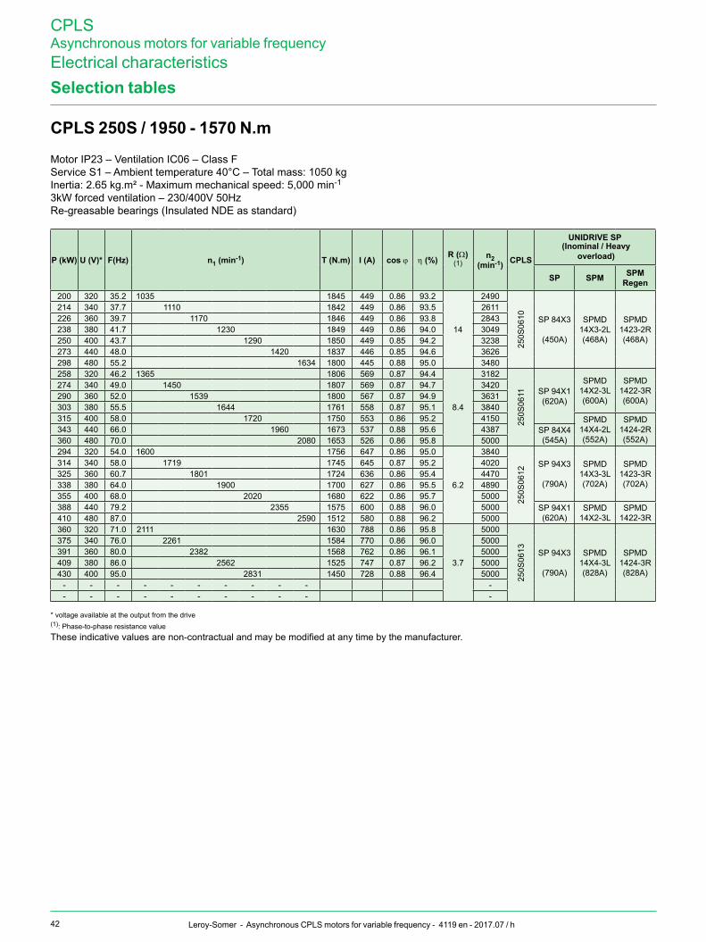
42 Leroy-Somer - Asynchronous CPLS motors for variable frequency - 4119 en - 2017.07 / h
CPLSAsynchronous motors for variable frequencyElectrical characteristicsSelection tables
P(kW) U (V)* f(Hz) n1 (min-1) T(N.m) I (a) cos j h (%) r (W)(1)
n2 (min-1) CPLS
UnIDrIVe SP
SP SPm SPmregen
200 320 35.2 1035 1845 449 0.86 93.2
14
2490
250S
0610 SP 84X3
(450A)
SPMD14X3-2L(468A)
SPMD1423-2R(468A)
214 340 37.7 1110 1842 449 0.86 93.5 2611226 360 39.7 1170 1846 449 0.86 93.8 2843238 380 41.7 1230 1849 449 0.86 94.0 3049250 400 43.7 1290 1850 449 0.85 94.2 3238273 440 48.0 1420 1837 446 0.85 94.6 3626298 480 55.2 1634 1800 445 0.88 95.0 3480258 320 46.2 1365 1806 569 0.87 94.4
8.4
3182
250S
0611 SP 94X1(620A)
SPMD14X2-3L(600A)
SPMD1422-3R(600A)
274 340 49.0 1450 1807 569 0.87 94.7 3420290 360 52.0 1539 1800 567 0.87 94.9 3631303 380 55.5 1644 1761 558 0.87 95.1 3840315 400 58.0 1720 1750 553 0.86 95.2 4150 SPMD
14X4-2L(552A)
SPMD1424-2R(552A)
343 440 66.0 1960 1673 537 0.88 95.6 4387 SP 84X4(545A)360 480 70.0 2080 1653 526 0.86 95.8 5000
294 320 54.0 1600 1756 647 0.86 95.0
6.2
3840
250S
0612
SP 94X3
(790A)
SPMD14X3-3L(702A)
SPMD1423-3R(702A)
314 340 58.0 1719 1745 645 0.87 95.2 4020325 360 60.7 1801 1724 636 0.86 95.4 4470338 380 64.0 1900 1700 627 0.86 95.5 4890355 400 68.0 2020 1680 622 0.86 95.7 5000388 440 79.2 2355 1575 600 0.88 96.0 5000 SP 94X1
(620A)SPMD
14X2-3LSPMD
1422-3R410 480 87.0 2590 1512 580 0.88 96.2 5000360 320 71.0 2111 1630 788 0.86 95.8
3.7
500025
0S06
13 SP 94X3
(790A)
SPMD14X4-3L(828A)
SPMD1424-3R(828A)
375 340 76.0 2261 1584 770 0.86 96.0 5000391 360 80.0 2382 1568 762 0.86 96.1 5000409 380 86.0 2562 1525 747 0.87 96.2 5000430 400 95.0 2831 1450 728 0.88 96.4 5000
- - - - - - - - - - -- - - - - - - - - - -
CPLS250S/1950-1570N.m
* voltage available at the output from the drive(1): Phase-to-phase resistance valueThese indicative values are non-contractual and may be modified at any time by the manufacturer.
(Inominal / Heavy overload)
Motor IP23 – Ventilation IC06 – Class FService S1 – Ambient temperature 40°C – Total mass: 1050 kgInertia: 2.65 kg.m² - Maximum mechanical speed: 5,000 min-1
3kW forced ventilation – 230/400V 50HzRe-greasable bearings (Insulated NDE as standard)

CPLSAsynchronous motors for variable frequencyElectrical characteristics
43Leroy-Somer - Asynchronous CPLS motors for variable frequency - 4119 en - 2017.07 / h
Selection tables
CPLS250M/2360-1710N.m
P(kW) U (V)* f(Hz) n1 (min-1) T(N.m) I (a) cos j h (%) r (W)(1)
n2 (min-1) CPLS
UnIDrIVe SP
SPLS / Ct SPm SPm
regen58 320 8.7 241 2298 144 0.90 81.4
142
475
250M
0603 SP 100T
SP 5402(156A)
62 340 9.2 256 2310 143 0.89 82.3 53767 360 9.9 277 2311 144 0.90 83.2 56071 380 10.4 292 2321 144 0.89 84.0 60075 400 11.0 310 2309 143 0.89 84.8 65083 440 12.0 340 2327 143 0.88 85.9 73090 480 12.8 365 2350 143 0.87 86.9 87571 320 10.4 291 2330 170 0.90 83.5
112
554
250M
0604 SP 120T
SP 6401(180A)
76 340 11.0 309 2347 171 0.90 84.4 60181 360 11.6 327 2362 171 0.89 85.1 64986 380 12.2 346 2376 171 0.89 85.8 72990 400 12.7 361 2380 170 0.88 86.4 81599 440 13.8 395 2395 170 0.87 87.5 934108 480 14.9 428 2408 170 0.86 88.3 105386 320 12.3 350 2352 203 0.89 86.0
78.2
735
250M
0605 SP 150T
SP 6402(210A)
92 340 13.1 373 2354 203 0.88 86.7 75098 360 13.9 397 2356 203 0.88 87.3 800104 380 14.7 421 2357 203 0.88 87.9 853110 400 15.5 445 2359 203 0.88 88.4 925121 440 17.1 493 2341 201 0.88 89.4 1060133 480 18.7 541 2345 202 0.88 90.1 1151104 320 15.1 432 2297 237 0.90 88.0
56.0
794
250M
0606 SP 74X1
(238A)
SPMD14X3-1S(246A)
SPMD1423-1R(246A)
111 340 16.1 462 2292 237 0.89 88.6 857118 360 17.0 489 2301 237 0.89 89.1 917125 380 18.0 519 2297 237 0.89 89.6 988132 400 18.9 547 2305 237 0.89 90.0 1065145 440 20.6 598 2314 236 0.89 90.8 1228159 480 22.5 655 2317 236 0.88 91.4 1359128 320 18.3 529 2311 288 0.89 89.8
38.0
1034
250M
0607 SP 74X2
(290A)
SPMD1404-1S(290A)
SPMD1424-1R(290A)
136 340 19.4 562 2311 287 0.89 90.3 1124144 360 20.4 592 2321 287 0.88 90.7 1227152 380 21.4 622 2330 287 0.88 91.1 1330160 400 22.4 652 2340 287 0.88 91.5 1449176 440 24.6 719 2337 286 0.88 92.1 1640192 480 27.0 791 2318 284 0.88 92.6 1807147 320 20.8 605 2320 332 0.88 91.0
28.0
1359
250M
0608 SP 84X1
(335A)
SPMD14X1-2L(342A)
SPMD1421-2R(342A)
157 340 22.2 647 2317 332 0.88 91.4 1449167 360 23.6 689 2314 331 0.88 91.8 1533176 380 24.9 728 2308 330 0.88 92.2 1666185 400 26.1 764 2311 330 0.88 92.4 1791204 440 28.7 842 2312 330 0.87 93.0 1986223 480 31.5 926 2298 328 0.87 93.4 2195180 320 25.9 757 2270 395 0.89 92.3
19.6
1543
250M
0609 SP 84X3
(450A) SPMD14X2-2L(400A)
SPMD1422-2R(400A)
192 340 27.5 805 2276 396 0.89 92.6 1648203 360 29.1 853 2270 394 0.89 93.0 1811212 380 30.4 892 2266 392 0.88 93.2 1960225 400 32.5 955 2248 391 0.88 93.5 2079244 440 35.8 1054 2211 385 0.88 93.9 2407 SP 84X2
(389A)260 480 38.2 1127 2204 380 0.87 94.3 2707
(Inominal / Heavy overload)
Motor IP23 – Ventilation IC06 – Class FService S1 – Ambient temperature 40°C – Total mass: 1200 kgInertia: 3.14 kg.m² - Maximum mechanical speed: 5,000 min-1
3kW forced ventilation – 230/400V 50HzRe-greasable bearings (Insulated NDE as standard)
* voltage available at the output from the drive(1): Phase-to-phase resistance valueThese indicative values are non-contractual and may be modified at any time by the manufacturer.

44 Leroy-Somer - Asynchronous CPLS motors for variable frequency - 4119 en - 2017.07 / h
CPLSAsynchronous motors for variable frequencyElectrical characteristicsSelection tables
P(kW) U (V)* f(Hz) n1 (min-1) T(N.m) I (a) cos j h (%) r (W)(1)
n2 (min-1) CPLS
UnIDrIVe SP
SP SPm SPmregen
200 320 29.1 853 2238 442 0.88 93.1
15.6
1898
250M
0601
0
SP 84X3
(450A)
SPMD14X3-2L(468A)
SPMD1423-2R(468A)
214 340 31.1 913 2237 443 0.88 93.4 2016226 360 32.7 961 2245 443 0.87 93.7 2195238 380 34.4 1012 2245 442 0.87 93.9 2359250 400 36.0 1060 2252 442 0.87 94.1 2522273 440 39.6 1168 2233 438 0.86 94.6 2816298 480 43.5 1285 2216 435 0.87 94.9 3122255 320 36.4 1072 2270 569 0.86 94.2
9.6
2657
250M
0601
1 SP 94X1
(620A)
SPMA14X2-3S(600A)
SPMD1422-3R(600A)
270 340 38.8 1144 2253 565 0.86 94.5 2880283 360 41.0 1211 2233 561 0.86 94.7 3090300 380 43.5 1286 2229 561 0.86 94.9 3152315 400 46.2 1367 2200 555 0.86 95.1 3422345 440 52.5 1556 2120 543 0.87 95.5 3607 SP 84X4
(545A)SPMD
14X4-2LSPMD
1424-2R370 480 57.3 1700 2080 533 0.87 95.8 4000290 320 42.6 1260 2200 646 0.85 94.9
7.0
3300
250M
0601
2 SP 94X3(790A) SPMD
14X3-3L(702A)
SPMD1423-3R(702A)
309 340 45.2 1337 2208 647 0.85 95.1 3510324 360 47.7 1413 2191 643 0.85 95.2 3810338 380 50.5 1497 2157 634 0.85 95.4 4080355 400 54.0 1600 2117 626 0.86 95.7 4230387 440 60.0 1782 2075 616 0.86 95.9 4623 SP94X1
(620A)420 480 67.0 1992 2015 605 0.85 96.1 4867360 320 57.0 1692 2032 787 0.86 95.8
4.1
4384
250M
0601
3
SP 94X3
(790A)
SPMD14X4-3L(828A)
SPMD1424-3R(828A)
380 340 60.0 1782 2037 786 0.86 95.9 4802400 360 63.0 1873 2040 786 0.85 96.0 5000420 380 66.2 1969 2038 784 0.85 96.2 5000450 400 72.3 2150 2000 778 0.87 96.3 5000480 440 80.8 2406 1905 750 0.87 96.5 5000500 480 90.0 2682 1781 711 0.87 96.6 5000434 320 81.6 2424 1711 890 0.92 96.3
3.2
3200
250M
0601
4
SP 94X4
(900A)
SPMD14X3-4L(937A)
SPMD1423-4R(937A)
461 340 86.7 2577 1710 889 0.91 96.4 3536480 360 90.0 2677 1713 874 0.91 96.5 3865510 380 98.7 2937 1659 876 0.92 96.6 3860520 400 103 3067 1620 849 0.92 96.7 4286
CPLS250M/2360-1710N.m
* voltage available at the output from the drive(1): Phase-to-phase resistance valueThese indicative values are non-contractual and may be modified at any time by the manufacturer.
(Inominal / Heavy overload)
Motor IP23 – Ventilation IC06 – Class FService S1 – Ambient temperature 40°C – Total mass: 1200 kgInertia: 3.14 kg.m² - Maximum mechanical speed: 5,000 min-1
3kW forced ventilation – 230/400V 50HzRe-greasable bearings (Insulated NDE as standard)
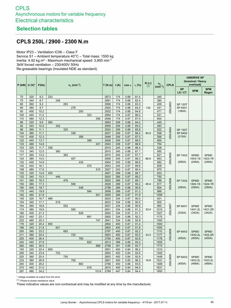
CPLSAsynchronous motors for variable frequencyElectrical characteristics
45Leroy-Somer - Asynchronous CPLS motors for variable frequency - 4119 en - 2017.07 / h
Selection tables
CPLS250L/2900-2300N.m
P(kW) U (V)* f(Hz) n1 (min-1) T(N.m) I (a) cos j h (%) r (W)(1)
n2 (min-1) CPLS
UnIDrIVe SP
SPLS / Ct SPm SPm
regen70 320 8.2 233 2873 174 0.88 81.4
132
345
250L
0603 SP 120T
SP 6401(180A)
75 340 8.7 248 2891 174 0.88 82.4 38080 360 9.2 263 2906 174 0.88 83.3 40985 380 9.7 278 2920 174 0.88 84.0 44190 400 10.2 293 2932 174 0.88 84.8 471100 440 11.2 323 2954 174 0.87 86.0 531110 480 12.3 356 2948 174 0.87 87.0 60086 320 9.9 284 2893 209 0.88 84.2
93.2
445
250L
0604 SP 150T
SP 6402(210A)
92 340 10.5 302 2909 209 0.88 85.0 48398 360 11.1 320 2924 209 0.88 85.8 522104 380 11.7 338 2937 209 0.87 86.4 558110 400 12.3 356 2948 209 0.87 87.0 596122 440 13.7 398 2926 209 0.87 88.0 665133 480 14.8 431 2943 208 0.87 88.9 754103 320 11.7 338 2910 245 0.88 86.4
66.6
538
250L
0605 SP 74X2
(290A)
SPMD14X3-1S(246A)
SPMD1423-1R(246A)
110 340 12.5 360 2910 245 0.88 87.1 585117 360 13.2 383 2915 245 0.87 87.7 621124 380 14.0 407 2908 245 0.87 88.3 663132 400 14.9 434 2904 245 0.88 88.8 682145 440 16.1 470 2943 245 0.87 89.6 808158 480 17.6 515 2927 243 0.87 90.4 875125 320 14.6 425 2807 289 0.88 88.7
45.4
65325
0L06
06 SP 74X2
(290A)
SPMD1404-1S(290A)
SPMD1424-1R(290A)
132 340 15.3 446 2820 289 0.87 89.2 750141 360 16.3 476 2825 289 0.87 89.7 786150 380 17.3 506 2828 289 0.87 90.2 817160 400 18.7 548 2788 289 0.88 90.6 804175 440 19.9 584 2858 289 0.87 91.3 966192 480 21.8 641 2859 289 0.87 91.9 1056145 320 16.7 489 2833 334 0.87 90.0
33.4
831
250L
0607 SP 84X1
(335A)
SPMD14X1-2L(342A)
SPMD1421-2R(342A)
154 340 17.7 519 2833 334 0.86 90.5 905164 360 18.8 552 2837 334 0.86 90.9 965174 380 19.9 585 2841 334 0.86 91.3 1010185 400 21.3 626 2820 334 0.87 91.7 1027203 440 23.1 681 2850 334 0.86 92.3 1175222 480 25.3 747 2841 334 0.86 92.8 1300176 320 20.4 600 2802 400 0.87 91.4
23.2
1000
250L
0608 SP 84X3
(450A)
SPMD14X2-2L(400A)
SPMD1422-2R(400A)
188 340 21.8 641 2800 400 0.87 91.9 1050200 360 23.2 683 2797 400 0.87 92.2 1110211 380 24.4 720 2803 400 0.87 92.5 1177225 400 26.4 780 2760 400 0.87 92.8 1178242 440 27.8 822 2813 396 0.86 93.3 1500260 480 30.0 888 2796 391 0.85 93.7 1772193 320 22.4 659 2801 450 0.84 96.2
18.6
1315
250L
0609 SP 84X3
(450A)
SPMD14X3-2L(468A)
SPMD1423-2L(468A)
206 340 23.9 703 2800 450 0.84 92.6 1400220 360 25.4 750 2803 450 0.84 92.9 1448233 380 26.9 795 2801 450 0.85 96.2 1531250 400 29.2 863 2768 450 0.86 93.6 1489270 440 31.0 918 2810 450 0.84 94.0 1831297 480 34.2 1014 2789 447 0.84 94.4 1950
(Inominal / Heavy overload)
Motor IP23 – Ventilation IC06 – Class FService S1 – Ambient temperature 40°C – Total mass: 1500 kgInertia: 4.92 kg.m² - Maximum mechanical speed: 3,800 min-1
3kW forced ventilation – 230/400V 50HzRe-greasable bearings (Insulated NDE as standard)
* voltage available at output from the drive(1): Phase-to-phase resistance valueThese indicative values are non-contractual and may be modified at any time by the manufacturer.

46 Leroy-Somer - Asynchronous CPLS motors for variable frequency - 4119 en - 2017.07 / h
CPLSAsynchronous motors for variable frequencyElectrical characteristicsSelection tables
P(kW) U (V)* f(Hz) n1 (min-1) T(N.m) I (a) cos j h (%) r (W)(1)
n2 (min-1) CPLS
UnIDrIVe SP
SP SPm SPmregen
250 320 29.3 867 2755 569 0.85 93.6
11.4
1658
250L
0610 SP 94X1
(620A)
SPMA14X2-3S(600A)
SPMA1422-3R(600A)
267 340 31.3 927 2753 569 0.85 93.9 1751282 360 33.0 978 2755 569 0.84 94.2 1892299 380 35.0 1038 2752 569 0.85 94.4 1982315 400 36.9 1095 2750 569 0.85 94.6 2102345 440 41.0 1217 2706 562 0.85 95.0 2371358 480 42.0 1249 2738 563 0.81 95.2 2966294 320 34.0 1008 2786 670 0.84 94.3
8.4
2000
250L
0611 SP 94X3
(790A)
SPMD14X3-3L(702A)
SPMD1423-3R(702A)
308 340 36.0 1068 2755 661 0.84 94.6 2161325 360 38.3 1137 2730 657 0.84 94.8 2310342 380 40.5 1203 2715 653 0.84 95.0 2430355 400 41.6 1249 2715 652 0.83 95.2 2700393 440 47.0 1399 2684 647 0.84 95.5 2851426 480 52.0 1548 2628 637 0.84 95.8 3050360 320 44.3 1318 2610 819 0.83 95.4
4.9
2791
250L
0612 SP 94X4
(900A)
SPMD14X4-3L(828A)
SPMD1424-3R(828A)
383 340 47.1 1402 2610 819 0.83 95.5 2971407 360 50.0 1489 2611 819 0.83 95.7 3121428 380 52.6 1567 2610 819 0.83 95.8 3360450 400 55.2 1645 2613 819 0.83 96.0 3570490 440 62.3 1837 2520 797 0.84 96.2 3800508 480 68.0 2030 2391 761 0.83 96.4 3800410 320 50.3 1500 2615 936 0.83 95.7
3.8
327025
0L06
13
SP 94X5(1010A) SPMD
14X3-4L(937A)
SPMD1423-4R(937A)
440 340 55.0 1639 2565 926 0.84 96.0 3272465 360 59.5 1773 2500 913 0.85 96.1 3334490 380 62.9 1875 2496 911 0.85 96.2 3545510 400 67.1 2000 2434 895 0.85 96.4 3665
SP 94X4(900A)540 440 75.2 2245 2300 857 0.86 96.5 3800
560 480 84.0 2509 2132 807 0.86 96.7 3800445 320 61.9 1846 2300 989 0.85 96.2
2.8
3724
250L
0614 SP 94X5
(1010A)
SPMD14X4-4L(1104A)
SPMD1424-4R(1104A)
476 340 66.3 1978 2300 989 0.85 96.3 3800503 360 70.0 2089 2300 989 0.85 96.4 3800532 380 74.0 2209 2300 989 0.85 96.5 3800560 400 81.0 2419 2212 973 0.86 96.6 3800
CPLS250L/2900-2300N.m
(Inominal / Heavy overload)
Motor IP23 – Ventilation IC06 – Class FService S1 – Ambient temperature 40°C – Total mass: 1500 kgInertia: 4.92 kg.m² - Maximum mechanical speed: 3,800 min-1
3kW forced ventilation – 230/400V 50HzRe-greasable bearings (Insulated NDE as standard)
* voltage available at output from the drive(1): Phase-to-phase resistance valueThese indicative values are non-contractual and can be modified at any time by the manufacturer.

CPLSAsynchronous motors for variable frequencyOptional equipment
47Leroy-Somer - Asynchronous CPLS motors for variable frequency - 4119 en - 2017.07 / h
encoder
InCrementaL enCoDerThis pulse generator supplies a pulse frequency proportional to the motor speed. Of a traversing hollow shaft type, with two channels at the output + Top = + complements, it may be supplied in a voltage range 5 V ±10% or 11-30 V regulated.For connections longer than 20 m, cables will be twisted pairs. The maximum length of (screened) cables should not exceed 150 m at the opto-coupler input.
BB
AA
Top 0Top 0
Signal shape
Phase angle 90
SINGLE-TuRNABSOLuTEenCoDerThe single-turn absolute encoder converts the rotation of the drive shaft into a series of "encoded electrical steps". The number of steps per revolution is determined by an optical disk. In general, one shaft rotation consists of 8,192steps, which corresponds to 13 bits. At the end of a complete encoder shaft revolution, the same values are repeated.
MuLTI-TuRNABSOLuTEenCoDerThe multi-turn absolute encoder saves the position in the revolution and also over several revolutions, with a maximum of 4096 revolutions.
Incremental encodersabsolute encoders StrengthenedPatay
incremental encoderSingle-turn multi-turn
output signals TTL HTL ~ 1 Vpp ~ 1 Vpp TTL HTL
number of points per turn 1024 std / 10,000 max 1024 std / 5,000 max 8192 std (13 bits) 1024 1024
number of absolute rotations - - 4096 max (12 bits) -
Data interface SSI / EnDat© / Hiperface© / Profibus© / CanOpen
Supply voltage 5 Vdc ±10% 11-30 Vdc 5 Vdc ±10% According to data interface 5 Vdc ±10% 11-30 Vdc
Coupling 14 mm traversing hollow shaft
Protection IP 65 minimum
Continuousmaximumspeed
6,000 rpm as standardOption 10,000 rpm with 12 mm hollow shaft 6,000 rpm 6,000 rpm
temperature range for use -20°C to +100°C -30°C to +120°C -30°C to +100°C

48 Leroy-Somer - Asynchronous CPLS motors for variable frequency - 4119 en - 2017.07 / h
CPLSAsynchronous motors for variable frequencyOptional equipmentencoder
enCoDer ConneCtIonThe use of incremental encoders in industrial environments comprising high current installations or control by electronic drives, requires industry standard, well-known basic rules to be followed.
Basicrules1 - Use screened cables. For connections longer than 20 metres, use cables with several screened twisted pairs, reinforced with an overall outer screen. The conductors in a single part are reserved for the channel and its complement: example A and Ā, B and B etc.It is recommended that conductors with a minimum standard 0.14m2 are used (recommended cable types: LIYCY 0.14 mm2).
2 - Keep the encoder connection cables as far away as possible from the power cables and avoid parallel routing.
3 - Distribute and connect the 0V and the screens in "star".
4 - Earth the screens using minimum 4 mm2 section cables.
5 - Under no circumstances connect a screen to earth at both ends. Preferably, earth a screened cable on the "user" side form the encoder signals (cabinet, PLC, meter). On the armature side, the screen must be connected to a single point, itself connected to earth generally in conformity with safety standards. On the encoder side, each screen must be perfectly isolated, both in relation to all other screens and in relation to earth or any potential.Ensure the continuity of of the screen when using connectors or connection boxes.
Precautionswhenmakingconnections1 - Under no circumstances make the connection or disconnection on the encoder side or cabinet side without first cutting the supply.
2 - For the supply, used stabilised,regulated and filtered, power supplies. Providing supply via transformers delivering an effective 5V (or 24V) at their secondary, followed by filtering rectifiers and capacitors, is prohibited, since, in reality, the continuous voltages obtained thus are:• for the 5 V: 5√2 = 7.07 V• for the 24 V: 24√2 = 33.936 V
3 - Comply with the international standards in force.
Incremental encoders(standard Leroy-Somer wiring)
12 pins 1 2 3 4 5 6 7 8 9 10 11 12
m23 connector – + A B O A B O
Screened cable White Brown Green Yellow Grey Pink Blue Red Braid Braid Braid
Male connector on the incremental encoder side

CPLSAsynchronous motors for variable frequencyOptional equipment
49Leroy-Somer - Asynchronous CPLS motors for variable frequency - 4119 en - 2017.07 / h
Insulated bearings
The use of variable speed drives with switching (PWM) can result in premature wear of the bearings.
This phenomenon is explained first of all by the presence of a shaft voltage in relation to earth: the latter, inherent in any asynchronous motor, is due to the lack of symmetry of the rotor in the rotating magnetic field and generates a circulating current in the rotor, looping via the stator through the end shields and bearings. This current can produce electrical discharges between balls and rings, thus reducing their service life.
A second source of currents may be added to the first: this concerns the high-frequency currents generated by the IGBT bridges at the output from the drive. These currents "try" to go back to their source (the drive) and take the path of least resistance: either via the housing/machine chassis/earth link, if it is correctly made; or through the coupled machine via the motor end shields and bearings in the contrary case.
The CPLS may be equipped with insulated bearings at the back (standard on CPLS 250) and on the front when the coupling on the driven machine is not sufficiently insulating. These bearings are fitted instead of the standard bearings.
INSuLATEDBEARINGCHARACTERISTICS:
The outer bearing rings are coated with a layer of electrically insulating ceramic.
The dimensions and tolerances of these bearings are identical to the standard ones used and can therefore be fitted instead, with no modifications to the motors. The breakdown voltage is 500 V.
Common mode HF currents
MotorPWM drive
EMCCABLEGLANDS
CPLS motors are fitted as standard with pre-drilled and tapped terminal boxes with the holes plugged.
EMC glands with 360° earth connection are available as an option to ensure earth continuity between the cable and the motor in accordance with the EMC directive 89/336/EEC.
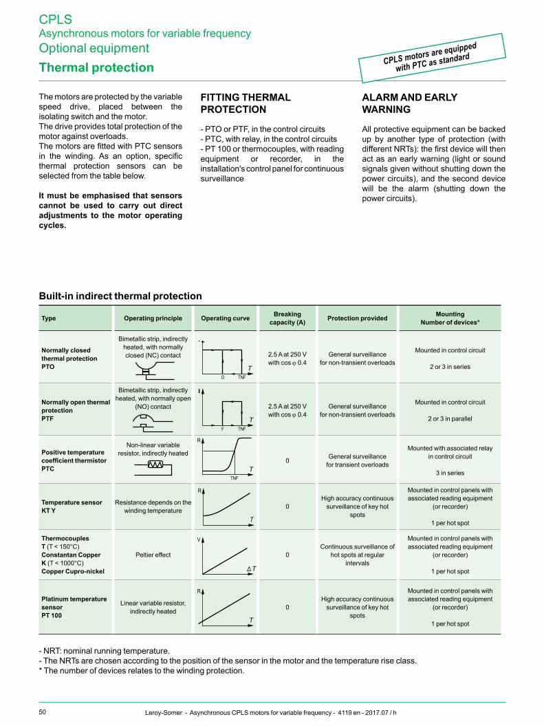
50 Leroy-Somer - Asynchronous CPLS motors for variable frequency - 4119 en - 2017.07 / h
CPLSAsynchronous motors for variable frequencyOptional equipmentThermalprotection
The motors are protected by the variable speed drive, placed between the isolating switch and the motor.The drive provides total protection of the motor against overloads.The motors are fitted with PTC sensors in the winding. As an option, specific thermal protection sensors can be selected from the table below.
Itmustbeemphasisedthatsensorscannot be used to carry out direct adjustments to themotor operatingcycles.
fIttInG tHermaL ProteCtIon
- PTO or PTF, in the control circuits- PTC, with relay, in the control circuits- PT 100 or thermocouples, with reading equipment or recorder, in the installation's control panel for continuous surveillance
ALARMANDEARLYWARNING
All protective equipment can be backed up by another type of protection (with different NRTs): the first device will then act as an early warning (light or sound signals given without shutting down the power circuits), and the second device will be the alarm (shutting down the power circuits).
CPLS motors are equipped
with PTC as standard
Built-inindirectthermalprotection
type operating principle operating curve Breaking capacity (a) Protection provided mounting
number of devices*
normally closed thermalprotectionPto
Bimetallic strip, indirectly heated, with normally closed (NC) contact 2.5 A at 250 V
with cos j 0.4General surveillance
for non-transient overloads
Mounted in control circuit
2 or 3 in series
NormallyopenthermalprotectionPtf
Bimetallic strip, indirectly heated, with normally open
(NO) contact 2.5 A at 250 Vwith cos j 0.4
General surveillancefor non-transient overloads
Mounted in control circuit
2 or 3 in parallel
Positive temperature coefficientthermistorPtC
Non-linear variable resistor, indirectly heated
0 General surveillancefor transient overloads
Mounted with associated relayin control circuit
3 in series
temperature sensorKTY
Resistance depends on the winding temperature 0
High accuracy continuous surveillance of key hot
spots
Mounted in control panels with associated reading equipment
(or recorder)
1 per hot spot
Thermocouplest (T < 150°C)Constantan CopperK (T < 1000°C)Copper Cupro-nickel
Peltier effect 0Continuous surveillance of
hot spots at regular intervals
Mounted in control panels with associated reading equipment
(or recorder)
1 per hot spot
Platinum temperature sensorPt 100
Linear variable resistor, indirectly heated 0
High accuracy continuous surveillance of key hot
spots
Mounted in control panels with associated reading equipment
(or recorder)
1 per hot spot
- NRT: nominal running temperature.- The NRTs are chosen according to the position of the sensor in the motor and the temperature rise class.* The number of devices relates to the winding protection.
I
O TNFT
I
F TNFT
R
TNFT
V
T
R
T
R
T

CPLSAsynchronous motors for variable frequencyOptional equipment
51Leroy-Somer - Asynchronous CPLS motors for variable frequency - 4119 en - 2017.07 / h
Ventilation
DETECTIONOFAIRFLOWSA pressure switch relay detects when the motor's ventilation shuts down.This is an air flow monitoring pressure switch; it may therefore provide sufficient protection against reduced air flow (clogged filter, partial obstruction of the air intake or outlet).Factory adjusted, it’s a uni-pole switch rated 1A at 250V. A "Faston" type connector is used.This detector is fitted on the forced ventilation.
aIr fILterThe forced ventilation unit can be fitted with a suction filter for use in a relatively dusty environment. There are two types of filter available.
StandardfilterThis filter, made up of polyester filter elements with an average Ashrae 52/76 gravimetric efficiency of 88% is flame retardant (class F1 to DIN 53438).It may be regenerated by quickly cleaning it (shaking it or blowing compressed air through it) or cleaning it thoroughly (soaking for a few hours in a non-aggressive detergent bath, then rinsing with clean water and drying.Washing it a maximum of two or three times is recommended.
Standard filter
"Miovyl"filterThis "long lasting" filter, made of PVC filter elements, provides optimum filtering performance for industrial applications:- average gravimetric stopping rate of 85%,
- high retention capacity,- low pressure drop- can be changed in a few seconds,- integral and permanent regeneration capability (soaking, rinsing, drying).
"Miovyl" filter
Spacerequirementsforthe"Miovyl"filteroption
CPLS motorSize
filter
diameteraJ
lengthRB
CPLS 112 Ø 211 155
CPLS 132 Ø 272 286
CPLS 160 Ø 272 340
CPLS 200/250 request a quotation
aXIaL VentILatIonIn the case where only limited height is available for installation of the motor, a connection kit allows the standard forced ventilation kit to be fitted in an axial position (option not compatible with a brake).
Spacerequirementsforforcedaxialventilation
CPLS motorSize
Axialforcedventilation
aG width re rG
CPLS 112 request a quotationCPLS 132 request a quotationCPLS 160 318 570 284CPLS 200 497 678 351CPLS 250 request a quotation
RE
RG
eXternaL VentILatIonIP55 / IC37Compliancewithflowrates
CPLS motorSize
flow ratem3/h
PressurePa
CPLS 112 300 600CPLS 132 550 750CPLS 160 1200 1500CPLS 200 2400 1600CPLS 250 2850 1650

52 Leroy-Somer - Asynchronous CPLS motors for variable frequency - 4119 en - 2017.07 / h
CPLSAsynchronous motors for variable frequencyOptional equipmentHeating
HeatInG USInG aDDItIonaL HeaterS (oPtIon)An environment with high levels of humidity and wide variations in temperature requires space heaters to be used to prevent condensation.
Made of strips insulated with glass fibre on the heads of the coil, they allow the motor's average temperature to be maintained, enabling trouble-free starting and eliminating inconvenience due to condensation (loss of insulation of the machine).
These heaters must be switched on when the machine is shut down and switched off during operation.The supply wires to the heaters are brought to the motor terminal box.
CPLS motorSize
number and power(W)
CPLS 112 2 x 25CPLS 132 2 x 25CPLS 160 2 x 25CPLS 200 2 x 50CPLS 250 4 x 50
Space heaters are supplied with 220/240V, single phase.
D.C.SuPPLYINJECTIONHeatInGAn alternative solution to the space heater is supply under reduced ac or dc voltage (10 to 15% of the nominal value) from two phases coupled in series.
This is often sufficient and avoids having to install space heaters.

CPLSAsynchronous motors for variable frequencyDimensions
53Leroy-Somer - Asynchronous CPLS motors for variable frequency - 4119 en - 2017.07 / h
TerminalboxesandcableglandsDimensions in millimetres
TerminalboxDepending on the motor's maximum nominal current (Inom), there are two types of terminal box fitted on the CPLS range:
motor typeStandardterminalbox(In≤ILIm)
ILIM (A) Fitting position I II HJ J LJ Terminals
CPLS 112 40 A / B / D 55 55 185 160 2 6 x M6CPLS 132 74 A / B / D 78.5 78.5 222 194 12.5 6 x M8CPLS 160 139 A* / B / D 118 142 295 231 4 6 x M10CPLS 200 139 A / B / D 148 180 371 292 19 6 x M10CPLS 200 380 A / B / D 148 180 371 292 19 6 x M14CPLS 250 380 A / B / D 148 180 420.5 292 48 6 x M14
* not possible for a CPLS 160 S with 60Hz forced ventilation.
motor typeLargeterminalbox(In > ILIm)
ILIM (A) Fitting position I II HJ J LJ Terminals
CPLS 112 m / L 40 B / D 63.5 122.5 211 209 0.5 6 x M8CPLS 132 L 74 A 118 142 397 231 9.5 6 x M8CPLS 132 S / m / L 74 B / D 80.5 150.5 266 260 7 6 x M8CPLS 160 L 139 A 148 180 327 292 6 6 x M12CPLS 160 S / m / L 139 B / D 86 206 330 328 4 6 x M12CPLS 200 m / L 380 A 180 235 461 420 -45 6 x M16CPLS 200 S / m / L 380 B / D 150 270 461 415 -15 6 x M16CPLS 250 S / m / L 380 A /B / D 210 210 510.5 415 -16 6 x M16
Cable glands
ILIm (a) ≤32 ≤40 ≤74 ≤139 ≤380
Pour ILIM > 380 A, terminal boxes supplied have a removable
undrilled, gland support plate.Size of glands for power 1 x M25 1 x M32 1 x M40 1 x M50 2 x M50
Size of glands for accessories / options* M16 M16 M16 M16 M16
* the number of cable glands for accessories may vary according to the options chosen.If your needs are different, please state on the order (within the limit of the terminal box's capacity).
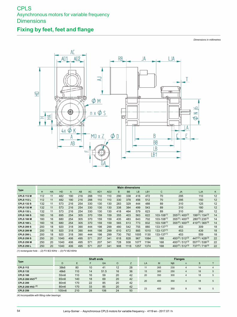
54 Leroy-Somer - Asynchronous CPLS motors for variable frequency - 4119 en - 2017.07 / h
CPLSAsynchronous motors for variable frequencyDimensionsFixingbyfeet,feetandflange
Dimensions in millimetres
typemain dimensions
H HA HD A AB AC AD1 AD2 B BB LB LB1 C JA LJA K
CPLS 112 m 112 11 482 190 216 288 110 110 290 338 416 472 70 295 110 12CPLS 112 L 112 11 482 190 216 288 110 110 330 378 456 512 70 295 150 12CPLS 132 S 132 11 573 216 254 330 130 130 283 329 444 488 89 310 125 12CPLS 132 m 132 11 573 216 254 330 130 130 338 384 499 543 89 310 180 12CPLS 132 L 132 11 573 216 254 330 130 130 418 464 579 623 89 310 260 12CPLS 160 S 160 16 695 254 305 370 159 159 355 403 563 622 103-108(1) 355(2) / 400(3) 199(2) / 154(3) 14CPLS 160 m 160 16 680 254 305 370 159 159 435 483 643 702 103-108(1) 355(2) / 400(3) 280(2)/ 235(3) 14CPLS 160 L 160 16 680 254 305 370 159 159 565 613 773 832 103-108(1) 355(2) / 400(3) 410(2) / 365(3) 14CPLS 200 S 200 18 920 318 390 444 198 299 480 542 755 880 133-137(1) 453 309 18CPLS 200 m 200 18 920 318 390 444 198 299 610 672 885 1010 133-137(1) 453 439 18CPLS 200 L 200 18 920 318 390 444 198 299 730 792 1005 1130 133-137(1) 453 559 18CPLS 250 S 250 20 1040 406 495 571 207 341 618 828 967 1084 168 493(2) / 512(3) 447(2) / 428(3) 22CPLS 250 m 250 20 1040 406 495 571 207 341 728 938 1077 1194 168 493(2) / 512(3) 557(2) / 538(3) 22CPLS 250 L 250 20 1040 406 495 571 207 341 908 1118 1257 1374 168 493(2) / 512(3) 737(2) / 718(3) 22
(1) rectangular hole - (2) FV IE2 50Hz - (3) FV IE2 60Hz
typeShaftends flanges
D E F GA O Z LA M Nj6 n S T
CPLS 112 38k6 80 10 41 12 28 11 265 230 4 14 4CPLS 132 48k6 110 14 51.5 16 36 15 300 250 4 18 5CPLS 160 55m6 110 16 59 20 42 20 350 300 4 18 5
CPLS 200 HV3(4) 65m6 140 18 69 20 4220 400 350 4 18 5
CPLS 200 80m6 170 22 85 20 42CPLS 250 HV2 (4) 80m6 170 33 85 20 42
23 400 350 8 18 5CPLS 250 100m6 210 28 106 24 50
(4) Incompatible with fitting roller bearings

CPLSAsynchronous motors for variable frequency
55Leroy-Somer - Asynchronous CPLS motors for variable frequency - 4119 en - 2017.07 / h
notes

www.leroy-somer.com
Connectwithusat:twitter.com/Leroy_Somerfacebook.com/leroysomer.nidecyoutube.com/user/LeroySomerOfficieltheautomationengineer.com (blog)
4119 en - 2017.07 / h
© 2017 Moteurs Leroy-Somer SAS. The information contained in this brochure is for guidance only and does not form part of any contract. The accuracy cannot be guaranteed as Moteurs Leroy-Somer SAS have an ongoing process of development and reserve the right to change the specification of their products without notice. Moteurs Leroy-Somer SAS. Headquarters: Bd Marcellin Leroy, CS 10015, 16915 Angoulême Cedex 9, France. Share Capital: 65 800 512 €, RCS Angoulême 338 567 258.