Group 26 - Department of ECE UCF
141
Easy Park Group 26 Jayson Asplin - EE Lorenzo Casimir - EE Muhammad Khan - CpE Peter Nguyen - CpE
-
Upload
khangminh22 -
Category
Documents
-
view
1 -
download
0
Transcript of Group 26 - Department of ECE UCF

Easy Park Group 26
Jayson Asplin - EE
Lorenzo Casimir - EE
Muhammad Khan - CpE
Peter Nguyen - CpE

Table of Contents
1 Executive Summary . . . . . . . . . . . . . . . . . . . . . . . . . . . . . . . . . . . . . . . . . . . . . . . . . . 1 2 Project Description . . . . . . . . . . . . . . . . . . . . . . . . . . . . . . . . . . . . . . . . . . . . . . . . . . . 2
2.1 Motivation . . . . . . . . . . . . . . . . . . . . . . . . . . . . . . . . . . . . . . . . . . . . . . . . . . . . 2 2.2 Goals and Objectives . . . . . . . . . . . . . . . . . . . . . . . . . . . . . . . . . . . . . . . . . . . 2
2.3 Specification . . . . . . . . . . . . . . . . . . . . . . . . . . . . . . . . . . . . . . . . . . . . . . . . . . 3 2.4 Alternative Features . . . . . . . . . . . . . . . . . . . . . . . . . . . . . . . . . . . . . . . . . . . . 3
2.4.1 Park Density . . . . . . . . . . . . . . . . . . . . . . . . . . . . . . . . . . . . . . . . . . 3 2.4.2 Primal park density . . . . . . . . . . . . . . . . . . . . . . . . . . . . . . . . . . . . . 4 2.4.3 RFID card reader . . . . . . . . . . . . . . . . . . . . . . . . . . . . . . . . . . . . . . 4 2.4.4 GPS to nearest parking spot . . . . . . . . . . . . . . . . . . . . . . . . . . . . . . 4 2.4.5 Parking payment . . . . . . . . . . . . . . . . . . . . . . . . . . . . . . . . . . . . . . . 4 2.5 House of Quality . . . . . . . . . . . . . . . . . . . . . . . . . . . . . . . . . . . . . . . . . . . . . . 7 3 Design Constraints and Standards . . . . . . . . . . . . . . . . . . . . . . . . . . . . . . . . . . . . . . . . 8 3.1 IEEE 802 Standard . . . . . . . . . . . . . . . . . . . . . . . . . . . . . . . . . . . . . . . . . . . . 8 3.1.1 802.11 Standard. . . . . . . . . . . . . . . . . . . . . . . . . . . . . . . . . . . . . . . 8 3.1.1.1 802.11a Standard . . . . . . . . . . . . . . . . . . . . . . . . . . . . . . . 8 3.1.1.2 802.11b Standard . . . . . . . . . . . . . . . . . . . . . . . . . . . . . . . 8 3.1.1.3 802.11g Standard . . . . . . . . . . . . . . . . . . . . . . . . . . . . . . 8 3.1.1.4 802.11n Standard . . . . . . . . . . . . . . . . . . . . . . . . . . . . . . . 9 3.1.1.5 802.11ac Standard . . . . . . . . . . . . . . . . . . . . . . . . . . . . . . 9 3.1.2 802.15 Standard . . . . . . . . . . . . . . . . . . . . . . . . . . . . . . . . . . . . . . . 9 3.1.2.1 802.15.1 Standard . . . . . . . . . . . . . . . . . . . . . . . . . . . . . . 9 3.1.2.1 802.15.4 Standard . . . . . . . . . . . . . . . . . . . . . . . . . . . . . 10 3.1.3 Power Supply Standards . . . . . . . . . . . . . . . . . . . . . . . . . . . . . . . . 10 3.2 IEEE Constraints . . . . . . . . . . . . . . . . . . . . . . . . . . . . . . . . . . . . . . . . . . . . . 10 3.2.1 Economic . . . . . . . . . . . . . . . . . . . . . . . . . . . . . . . . . . . . . . . . . . . 10 3.2.2 Environmental . . . . . . . . . . . . . . . . . . . . . . . . . . . . . . . . . . . . . . . . 11 3.2.3 Social . . . . . . . . . . . . . . . . . . . . . . . . . . . . . . . . . . . . . . . . . . . . . . 11 3.2.4 Ethical . . . . . . . . . . . . . . . . . . . . . . . . . . . . . . . . . . . . . . . . . . . . . . 11 3.2.5 Health and Safety . . . . . . . . . . . . . . . . . . . . . . . . . . . . . . . . . . . . . 12 3.2.6 Manufacturability . . . . . . . . . . . . . . . . . . . . . . . . . . . . . . . . . . . . . . 12 3.2.7 Sustainability . . . . . . . . . . . . . . . . . . . . . . . . . . . . . . . . . . . . . . . . . 13 3.2.8 Time . . . . . . . . . . . . . . . . . . . . . . . . . . . . . . . . . . . . . . . . . . . . . . . 13 3.2.9 Testing. . . . . . . . . . . . . . . . . . . . . . . . . . . . . . . . . . . . . . . . . . . . . 14 4 Research . . . . . . . . . . . . . . . . . . . . . . . . . . . . . . . . . . . . . . . . . . . . . . . . . . . . . . . . . . 15 4.1 Previous Projects . . . . . . . . . . . . . . . . . . . . . . . . . . . . . . . . . . . . . . . . . . . . 15 4.2 Sensors . . . . . . . . . . . . . . . . . . . . . . . . . . . . . . . . . . . . . . . . . . . . . . . . . . . . 15 4.2.1 Infrared (IR) . . . . . . . . . . . . . . . . . . . . . . . . . . . . . . . . . . . . . . . . . . 16 4.2.2 Ultrasonic . . . . . . . . . . . . . . . . . . . . . . . . . . . . . . . . . . . . . . . . . . . 17 4.2.3 Hall Effect . . . . . . . . . . . . . . . . . . . . . . . . . . . . . . . . . . . . . . . . . . . 18 4.2.4 Inductive Loop . . . . . . . . . . . . . . . . . . . . . . . . . . . . . . . . . . . . . . . . 18
4.2.5 Magnetometer . . . . . . . . . . . . . . . . . . . . . . . . . . . . . . . . . . . . . . . . 20 4.2.6 Camera (Video Image Processors) . . . . . . . . . . . . . . . . . . . . . . . 21 4.2.7 Decision on Sensor . . . . . . . . . . . . . . . . . . . . . . . . . . . . . . . . . . . . 21
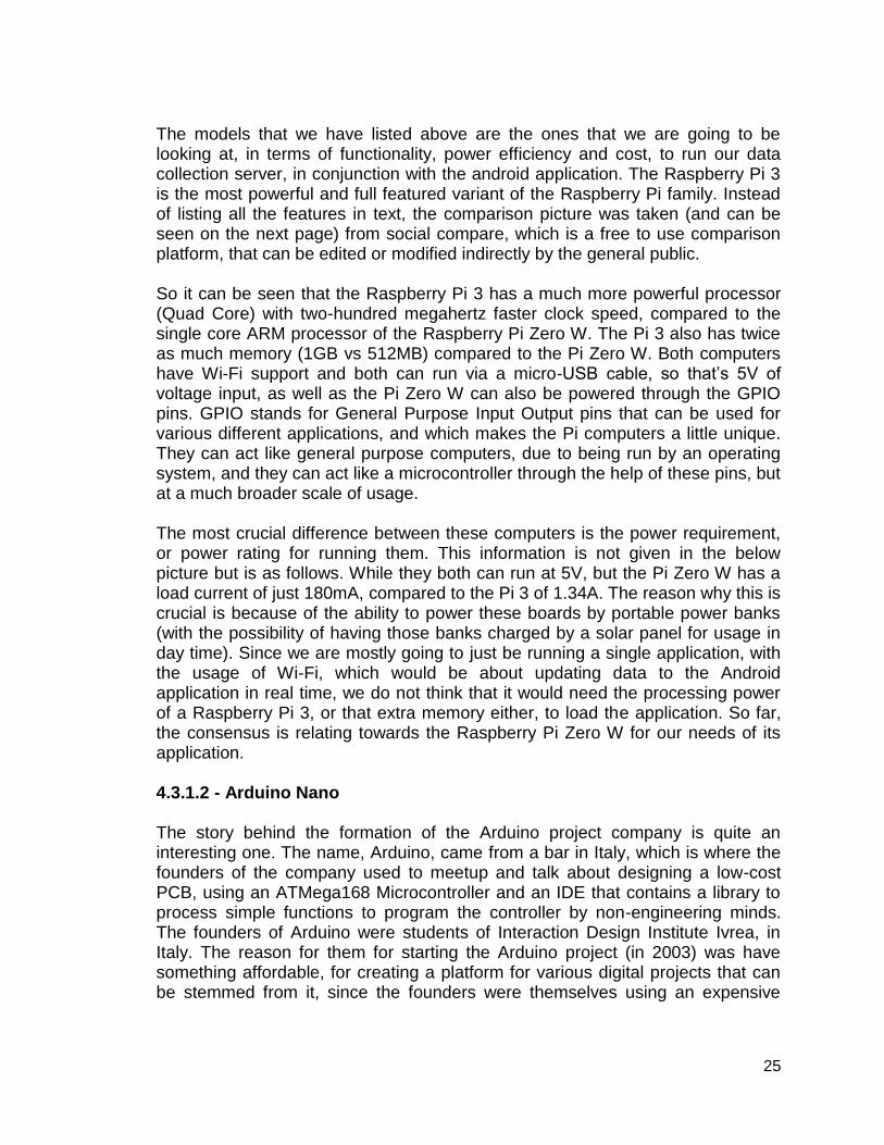
4.3 Microcontrollers . . . . . . . . . . . . . . . . . . . . . . . . . . . . . . . . . . . . . . . . . . . . . . 21 4.3.1 MCUs taken under consideration . . . . . . . . . . . . . . . . . . . . . . . . . 22 4.3.1.1 Base Station: Raspberry Pi3vs Raspberry Pi0W . . . . . . 24 4.3.1.2 Arduino Nano . . . . . . . . . . . . . . . . . . . . . . . . . . . . . . . . . 25 4.3.1.3 Texas Instruments MSP430 . . . . . . . . . . . . . . . . . . . . . . 26

4.4 Wireless Communications . . . . . . . . . . . . . . . . . . . . . . . . . . . . . . . . . . . . . 27 4.4.1 Wi-Fi . . . . . . . . . . . . . . . . . . . . . . . . . . . . . . . . . . . . . . . . . . . . . . . 28 4.4.2 Bluetooth . . . . . . . . . . . . . . . . . . . . . . . . . . . . . . . . . . . . . . . . . . . 28 4.4.2.1 Bluetooth Mesh Network . . . . . . . . . . . . . . . . . . . . . . . 29 4.4.3 ZigBee . . . . . . . . . . . . . . . . . . . . . . . . . . . . . . . . . . . . . . . . . . . . . 29 4.4.4 DASH7 . . . . . . . . . . . . . . . . . . . . . . . . . . . . . . . . . . . . . . . . . . . . . 29 4.4.5 Conclusion . . . . . . . . . . . . . . . . . . . . . . . . . . . . . . . . . . . . . . . . . . 30 4.5 Software . . . . . . . . . . . . . . . . . . . . . . . . . . . . . . . . . . . . . . . . . . . . . . . . . . . 30 4.5.1 Mobile App . . . . . . . . . . . . . . . . . . . . . . . . . . . . . . . . . . . . . . . . . . 30 4.5.1.1 App Creation . . . . . . . . . . . . . . . . . . . . . . . . . . . . . . . . . 31 4.5.1.2 Android . . . . . . . . . . . . . . . . . . . . . . . . . . . . . . . . . . . . . 32 4.5.1.2.1 Java . . . . . . . . . . . . . . . . . . . . . . . . . . . . . . . . 32 4.5.1.2.2 Python . . . . . . . . . . . . . . . . . . . . . . . . . . . . . . 32 4.5.1.2.3 Conclusion . . . . . . . . . . . . . . . . . . . . . . . . . . . 32 4.5.1.3 Choosing an IDE . . . . . . . . . . . . . . . . . . . . . . . . . . . . . . 32 4.5.1.4 JQuery Mobile . . . . . . . . . . . . . . . . . . . . . . . . . . . . . . . . 33 4.6 Networks . . . . . . . . . . . . . . . . . . . . . . . . . . . . . . . . . . . . . . . . . . . . . . . . . . . 34 4.6.1 Server . . . . . . . . . . . . . . . . . . . . . . . . . . . . . . . . . . . . . . . . . . . . . . 34 4.6.1.1 Server Setup . . . . . . . . . . . . . . . . . . . . . . . . . . . . . . . . . 34 4.6.1.2 Connecting to a Server . . . . . . . . . . . . . . . . . . . . . . . . . . 36
4.6.2 Network Topologies . . . . . . . . . . . . . . . . . . . . . . . . . . . . . . . . . . . 37 4.6.2.1 Mesh Topology . . . . . . . . . . . . . . . . . . . . . . . . . . . . . . . . 37 4.6.2.2 Star Topology . . . . . . . . . . . . . . . . . . . . . . . . . . . . . . . . . 38 4.6.2.3 Bus Topology . . . . . . . . . . . . . . . . . . . . . . . . . . . . . . . . . 38 4.6.2.4 Ring Topology . . . . . . . . . . . . . . . . . . . . . . . . . . . . . . . . 38 4.6.2.5 Tree Topology . . . . . . . . . . . . . . . . . . . . . . . . . . . . . . . . 39 4.6.2.6 Conclusion . . . . . . . . . . . . . . . . . . . . . . . . . . . . . . . . . . . 40
4.6.3 Database Management Systems . . . . . . . . . . . . . . . . . . . . . . . . . 41 4.6.3.1 MySQL . . . . . . . . . . . . . . . . . . . . . . . . . . . . . . . . . . . . . . 41 4.6.3.2 PostgreSQL . . . . . . . . . . . . . . . . . . . . . . . . . . . . . . . . . . 41 4.6.3.3 MariaDB . . . . . . . . . . . . . . . . . . . . . . . . . . . . . . . . . . . . . 42 4.6.3.4 CUBRID . . . . . . . . . . . . . . . . . . . . . . . . . . . . . . . . . . . . . 42 4.6.3.5 SQLite . . . . . . . . . . . . . . . . . . . . . . . . . . . . . . . . . . . . . . . 42 4.6.3.6 MongoDB . . . . . . . . . . . . . . . . . . . . . . . . . . . . . . . . . . . 53 4.6.3.7 Conclusion . . . . . . . . . . . . . . . . . . . . . . . . . . . . . . . . . . . 53
4.7 Power Systems . . . . . . . . . . . . . . . . . . . . . . . . . . . . . . . . . . . . . . . . . . . . . . 44 4.7.1 Battery . . . . . . . . . . . . . . . . . . . . . . . . . . . . . . . . . . . . . . . . . . . . . 44 4.7.1.1 Alkaline & Carbon Zinc . . . . . . . . . . . . . . . . . . . . . . . . . . 44 4.7.1.2 Lithium (Li) & Lithium-ion (Li-ion) . . . . . . . . . . . . . . . . . . 44 4.7.1.3 Valve-Regulated Lead-Acid (VRLA) . . . . . . . . . . . . . . . . 45 4.7.1.4 Nickel-Cadmium (NiCd) . . . . . . . . . . . . . . . . . . . . . . . . . 47 4.7.1.5 Nickel-Metal Hydride (NiMH) . . . . . . . . . . . . . . . . . . . . . 47 4.7.1.6 Battery Comparison . . . . . . . . . . . . . . . . . . . . . . . . . . . . 47 4.7.2 Photovoltaic (PV)/Solar Panel . . . . . . . . . . . . . . . . . . . . . . . . . . . . 49 4.7.2.1 Comparison of Solar Panels . . . . . . . . . . . . . . . . . . . . . 51 4.8 Power Transfer and Transmission Lines . . . . . . . . . . . . . . . . . . . . . . . . . . . 52 4.8.1 Transformers . . . . . . . . . . . . . . . . . . . . . . . . . . . . . . . . . . . . . . . . . 52 4.8.1.1 Step Down Transformer . . . . . . . . . . . . . . . . . . . . . . . . . 52 4.8.2 Aluminum vs Copper . . . . . . . . . . . . . . . . . . . . . . . . . . . . . . . . . . . 53 4.8.3 AC to DC Converters (Full Wave Rectifiers) . . . . . . . . . . . . . . . . . 54 4.8.4 DC to DC Converters (Regulators) . . . . . . . . . . . . . . . . . . . . . . . . 55

4.8.5 AC to AC converters . . . . . . . . . . . . . . . . . . . . . . . . . . . . . . . . . . . 56 4.8.6 Cycloconverters . . . . . . . . . . . . . . . . . . . . . . . . . . . . . . . . . . . . . . 56 4.8.7 Chopper AC . . . . . . . . . . . . . . . . . . . . . . . . . . . . . . . . . . . . . . . . . 57 4.8.8 Single Phase Matrix Converter . . . . . . . . . . . . . . . . . . . . . . . . . . . 57 4.8.9 MOSFET vs BJT (Switching Regulator cont.) . . . . . . . . . . . . . . . . 58 4.8.10 Power Adapters . . . . . . . . . . . . . . . . . . . . . . . . . . . . . . . . . . . . . 59 4.9 LEDs and Visibility . . . . . . . . . . . . . . . . . . . . . . . . . . . . . . . . . . . . . . . . . . . . 60 4.10 Circuit Protection . . . . . . . . . . . . . . . . . . . . . . . . . . . . . . . . . . . . . . . . . . . . 62 4.10.1 Fuses . . . . . . . . . . . . . . . . . . . . . . . . . . . . . . . . . . . . . . . . . . . . . 63 4.10.2 Circuit Breakers . . . . . . . . . . . . . . . . . . . . . . . . . . . . . . . . . . . . . 63 4.11 Comparators . . . . . . . . . . . . . . . . . . . . . . . . . . . . . . . . . . . . . . . . . . . . . . . 64 4.12 Battery Chargers . . . . . . . . . . . . . . . . . . . . . . . . . . . . . . . . . . . . . . . . . . . . 65 5 Design . . . . . . . . . . . . . . . . . . . . . . . . . . . . . . . . . . . . . . . . . . . . . . . . . . . . . . . . . . . . 68 5.1 Specifications . . . . . . . . . . . . . . . . . . . . . . . . . . . . . . . . . . . . . . . . . . . . . . . 68 5.1.1 Ultrasonic Sensor . . . . . . . . . . . . . . . . . . . . . . . . . . . . . . . . . . . . . 68 5.2.2 Microcontroller (MCU) . . . . . . . . . . . . . . . . . . . . . . . . . . . . . . . . . . 70 5.1.3 ESP8266-01 Wi-Fi . . . . . . . . . . . . . . . . . . . . . . . . . . . . . . . . . . . . 73 5.1.4 Bluetooth HM-10 . . . . . . . . . . . . . . . . . . . . . . . . . . . . . . . . . . . . . . 75 5.2 Hardware Design . . . . . . . . . . . . . . . . . . . . . . . . . . . . . . . . . . . . . . . . . . . . . 77 5.2.1 Hardware Block Diagram . . . . . . . . . . . . . . . . . . . . . . . . . . . . . . . 77 5.2.2 Schematics and System Communications . . . . . . . . . . . . . . . . . . 78 5.2.3 Duty Cycle and Efficiency . . . . . . . . . . . . . . . . . . . . . . . . . . . . . . . 79 5.2.4 MCU and Ultrasonic Sensors . . . . . . . . . . . . . . . . . . . . . . . . . . . . 79 5.2.5 MCU and LEDs . . . . . . . . . . . . . . . . . . . . . . . . . . . . . . . . . . . . . . . 80 5.2.6 MCU and Wi-Fi/Transceivers . . . . . . . . . . . . . . . . . . . . . . . . . . . . 82 5.2.7 Battery and Secondary Power Supply . . . . . . . . . . . . . . . . . . . . . 83 5.2.8 Battery and MCU . . . . . . . . . . . . . . . . . . . . . . . . . . . . . . . . . . . . . 83 5.2.9 PCB Schematic Design. . . . . . . . . . . . . . . . . . . . . . . . . . . . . . . . . 84 5.2.10 Power Management: ATmega328P . . . . . . . . . . . . . . . . . . . . . 86 5.2.11 Sensor Distance Consideration and Sensor Schematic . . . . . . . 88 5.2.12 Lithium ion Battery Protection Circuit . . . . . . . . . . . . . . . . . . . . . 90 5.2.12.1 Circuit Design Procedure . . . . . . . . . . . . . . . . . . . . . . 92 5.3 Software Design . . . . . . . . . . . . . . . . . . . . . . . . . . . . . . . . . . . . . . . . . . . . . . 92 5.3.1 Software Block Diagram . . . . . . . . . . . . . . . . . . . . . . . . . . . . . . . . 92 5.3.2 Database Entity-Relationship Diagram . . . . . . . . . . . . . . . . . . . . . 93 5.3.3 Web Server Hardware Specifications . . . . . . . . . . . . . . . . . . . . . . 95 5.3.4 Android Application Design . . . . . . . . . . . . . . . . . . . . . . . . . . . . . . 95 5.3.4.1 Homepage Design . . . . . . . . . . . . . . . . . . . . . . . . . . . . . 96 5.3.4.2 List of Garages/Lots Page . . . . . . . . . . . . . . . . . . . . . . . 97 5.3.4.3 Floor Selection . . . . . . . . . . . . . . . . . . . . . . . . . . . . . . . 98 5.3.4.4 Garage Map . . . . . . . . . . . . . . . . . . . . . . . . . . . . . . . . . 99 5.3.4.5 Labeling Parking Spots . . . . . . . . . . . . . . . . . . . . . . . . . 99 5.3.4.6 Conclusion . . . . . . . . . . . . . . . . . . . . . . . . . . . . . . . . . . 100 6 Testing . . . . . . . . . . . . . . . . . . . . . . . . . . . . . . . . . . . . . . . . . . . . . . . . . . . . . . . . . . . 101
6.1 Hardware Testing . . . . . . . . . . . . . . . . . . . . . . . . . . . . . . . . . . . . . . . . . . . 101 6.1.1 Hardware Test Environment . . . . . . . . . . . . . . . . . . . . . . . . . . . . 101 6.1.2 Solar Panel Testing . . . . . . . . . . . . . . . . . . . . . . . . . . . . . . . . . . . 101 6.1.3 MCU Testing . . . . . . . . . . . . . . . . . . . . . . . . . . . . . . . . . . . . . . . 102 6.1.4 AMS1117-3.3 DC Voltage Regulator Testing . . . . . . . . . . . . . . . 104 6.1.5 ESP8266-01 Wi-Fi testing . . . . . . . . . . . . . . . . . . . . . . . . . . . . . . 106 6.1.6 HM-10 Bluetooth testing . . . . . . . . . . . . . . . . . . . . . . . . . . . . . . . 107

6.2 Software Testing . . . . . . . . . . . . . . . . . . . . . . . . . . . . . . . . . . . . . . . . . . . . 108 6.2.1 HM-10 Bluetooth testing . . . . . . . . . . . . . . . . . . . . . . . . . . . . . . . 109 6.2.2 ESP8266-1 Wi-Fi Testing . . . . . . . . . . . . . . . . . . . . . . . . . . . . . 110 6.2.3 HC-SR04 Ultrasonic Sensor Testing . . . . . . . . . . . . . . . . . . . . . . 112 6.2.3.1 Connecting Components . . . . . . . . . . . . . . . . . . . . . . . 112 6.2.3.2 Communicating Arduino Nano and PC (Arduino IDE) . 113
6.2.3.3 Testing the Ultrasonic Sensor . . . . . . . . . . . . . . . . . . . 113 6.2.4 Testing Mobile Application . . . . . . . . . . . . . . . . . . . . . . . . . . . . . 115 6.2.4.1 Testing the mobile application procedure . . . . . . . . . . . 116 6.2.4.2 Conclusion . . . . . . . . . . . . . . . . . . . . . . . . . . . . . . . . . . 116 6.2.5 Testing Mesh Network . . . . . . . . . . . . . . . . . . . . . . . . . . . . . . . . 116 6.2.5.1 Testing the mesh network configuration/procedure . . . 116 6.2.5.2 Conclusion . . . . . . . . . . . . . . . . . . . . . . . . . . . . . . . . . . 117 6.2.6 Testing Server . . . . . . . . . . . . . . . . . . . . . . . . . . . . . . . . . . . . . . . 117 7 Project Modifications . . . . . . . . . . . . . . . . . . . . . . . . . . . . . . . . . . . . . . . . . . . . . . . . . 119 7.1 Hardware . . . . . . . . . . . . . . . . . . . . . . . . . . . . . . . . . . . . . . . . . . . . . . . . . . 119 7.1.1 - Solar Charger Selection - BQ24650 . . . . . . . . . . . . . . . . . . . . . 119 7.1.2 - New Regulators for Current PCB Layout . . . . . . . . . . . . . . . . . 121 7.1.2.1 - TVL6256(8,9)DBVR . . . . . . . . . . . . . . . . . . . . . . . . . . 121 7.1.2.2 - TPS560200DBVR . . . . . . . . . . . . . . . . . . . . . . . . . . . 121 7.1.2.3 - TPS56(2,3)200DDCR&TPS56220(1,8)DDCR . . . . . . 121 7.2 New Design . . . . . . . . . . . . . . . . . . . . . . . . . . . . . . . . . . . . . . . . . . . . . . . . 122 7.2.1 - ‘PCB 1’ Board . . . . . . . . . . . . . . . . . . . . . . . . . . . . . . . . . . . . . . 122 7.2.2 - ‘PCB 2’ Board . . . . . . . . . . . . . . . . . . . . . . . . . . . . . . . . . . . . . 124 7.2.3 - Solar Charger Board . . . . . . . . . . . . . . . . . . . . . . . . . . . . . . . . . 125 8 Administration . . . . . . . . . . . . . . . . . . . . . . . . . . . . . . . . . . . . . . . . . . . . . . . . . . . . . .126 8.1 Milestones . . . . . . . . . . . . . . . . . . . . . . . . . . . . . . . . . . . . . . . . . . . . . . . . . 126 8.2 Cost/Budgets . . . . . . . . . . . . . . . . . . . . . . . . . . . . . . . . . . . . . . . . . . . . . . 127 9 Appendix . . . . . . . . . . . . . . . . . . . . . . . . . . . . . . . . . . . . . . . . . . . . . . . . . . . . . . . . . . 130 9.1 Sources . . . . . . . . . . . . . . . . . . . . . . . . . . . . . . . . . . . . . . . . . . . . . . . . . . . 130

1
1 - Executive Summary Every day there exist a bottleneck effect of vehicles over flooding the parking garages. These drivers, goings into whatever parking lot is closest, hoping to find an empty space to continue their poorly invested studies. Students who were told that going to college is the only way to be successful. “Follow your heart and the money will follow” are one but many euphemisms into spending a good sum of their lives driving to and from school. To add further insult to injury, these drivers will see other drivers leave the garages, thinking that there may be a space available. Too bad, because they usually find more drivers looking at each other with sullen eyes. To lessen the burden a little is to build extra parking spaces, which in turn will add a monetary burden to the student as a whole. In the article “10 parking tips for students at all universities, but especially UCF” Almenas talks about some solutions/tips for student to make parking easier [45]. A solution/tip mention is to arrive about 30 to 40 minutes before your classes start. Some people just do not have the time arrive 30 to 40 minutes early due to a busy life. Arriving 30 to 40 minutes early could just result to circling around the garage because most people are in class at the moment. Another suggestion/tip is to avoid the garages that get the most traffic. Almenas says “At UCF, garages H, C, B and A are usually the worst ones to find parking” [45]. These garages generally generate the most traffic due to its location. Between 10:00 am to 3:00 pm are the hot times of when students are at school. Almenas suggest that if you had a class at 10:30 am, for example, then you should arrive before 10:00 am to be able to find a parking spot rather than being late and missing part of the class [45]. If your class does land in the hot time period Easy Park will be the solution to help students find parking. Every day is different, some students will stay at school, long after class or go to school early to do some homework. Since this is unpredictable, students will be able to look at the app to see the current amount of spots open to make the decision if they will go to school early or not. Parking improvement projects have been made in the past, but suffer from complexity and pricing. Having wires to connect to every LED serves as an unruly, concrete tangled mess that costs much more than implementing a Bluetooth device to each LED. Each LED will follow the all for one approach, where a main microcontroller and sensors will communicate with the LEDs. If the project stops here, UCF is happy. The project will require features that will most likely be ignored, but will help in endeavors of the students that choose to solve the parking issue. From this point on, the features provided is not to aid UCF’s budget constraints, but to aid each engineer's post-graduation skills and reputation.

2
2 - Project Description The scope of this project is to make it easy for students, teachers, guests, or anyone to find available parking spots in the UCF garages. For students, this is usually a major toll to find parking spaces due to the limited availability, so in essence, it would save time so that every potential driver that enters the garage can easily be directed to find a parking spot, or would be told to find alternate parking, may be in a different garage, or parking area.
The LEDs and sensors would be mounted above every row of cars on both sides. Using a mesh network, each sensor will be able to communicate with one another as to what number of spaces are available. Copper wires, providing power and control from a microcontroller to the LED will change the LEDs color to red when an object is occupying a parking space. When the space is not occupied, the LED will display green to signal motorist available parking.
2.1 - Motivation To help everyone spend the least amount of time to find parking, to help with traffic congestion, possible accidents and overall make everyone worry less about parking at UCF. For years on end, students and faculty complain about on campus parking. Why allow more purchases of decals when there are not enough spaces to support the numbers being sold? Why build a research facility instead of a new parking garage? The answer is simple, the collective body never addressed their complaints to the president of UCF himself...and money. Alas, on top of the other suggestions, there is way to make things slightly better for a majority of students. In terms of time management, the future is the Easy Park.
2.2 - Goals and Objectives The few goals of this project is to use sensors or even a deep learning algorithm to detect empty and non-empty parking spots, sending this data to a low power microcontroller that would aid in flashing LEDS for those specific parking spots. This is mostly to minimize the upfront setup cost. While the initial objective was to use ultrasonic sensors to detect and report back any available parking spaces, the goal was also create a device that is cheap enough for UCF’s board of approval and actually use the easy parking patent.
● Each sensor should be able to scan only vehicles occupied in their respective rows, depending upon the limited visibility and the hindrance of somewhat larger vehicles.

3
● The sensor would be able to provide the total time a vehicle is parked. When the garage spaces are not occupied, the entire system will be in low power mode.
● The system will have an app to view open spaces ahead of time for timely convenience
● The system will be able to count the number of cars presently parked and match it with an outside digital sign, capable of displaying “open” or “full”
● The LEDs, when the garage have empty floors or rows, will shut down to conserve energy. The alternative is to display LED when the space is occupied then turns off when the space is vacant.
● The LEDs will be emitted from above, in front of the parking space entrance. The network is mesh based for every sensor.
● For every row, the system will be able to count how many spaces are available and display it via LED signs.
● The system should have circuit protection against power surges.
2.3 - Specification This list represent how in detail the Parking device should perform.
● The parking system would be able to check for space availability at a refresh interval of 5 seconds or lower.
● The system will use ½ a watt of power ● The sensing range should be within 2 feet ● The mobile application should be updated within 5 seconds after detecting
if the parking spot is taken or not.
2.4 - Alternative Features This section includes alternative feature that could be implemented. Multiple thoughts were brainstormed, and through a series of rejections, these were the ideas that the Easy Park team could come up with. The decision as to which features to go with was based upon time consumption, costs, and feasibility. 2.4.1 - Park Density As such in previous parking projects, the Wi-Fi interface involved allows for the app based user to gauge for themselves how dense parking is at UCF from the safety of their homes. No point in implementing Wi-Fi technology to tell students what they already know. Besides, when you have a class at a certain time, and cannot plan ahead for it, you will still be stuck in the concrete maze. The Park Density will utilize the, soon to be...placed, parking sensors to showcase the number of occupied spaces per floor. Having this connected to the preexisting full/open sign in every garage will give a clear idea of the current

4
hopelessness in buying unnecessary parking decals and instead carpool or shuttle ride to campus. 2.4.2 - Primal park density This approach, if matched with the total number of parking spaces in the garage, will tell everyone that the parking garage is not full yet. Like the car scanner at McDonald’s drive-through, the device will count how many cars have entered/exited. This would most likely be overshadowed by feature one, but can be used by UCF to properly state the conditions of the garages. 2.4.3 - RFID card reader
Any faculty member would have access to a card and each card is assigned to a parking spot. The card would store the individual’s identification and a time log in which the cardholder occupied/vacated the parking spot. Authorities are alerted when an unauthorized vehicle is parked at a spot. The card reader may be fine for faculty parking, but it serves little purpose in a public university that holds more students with decals than the spaces themselves. 2.4.4 - GPS to nearest parking spot
The app itself does not need to be limited to parking space density, there can also be GPS parking to add on to make parking density more useful. The GPS parking app, as assumed, will provide the user directions to the nearest opened parking space. The main issue for this app is what to do when the destination is already taken by another driver. Well, these parking apps and devices are just aids to finding a parking space. They just may not be as useful as the ti nspire is in aiding engineers. This idea is great for open lots or the top floor of a parking garage. Another issue is that GPS only does XY positioning. Digital labeling will be required for higher floors. 2.4.5 - Parking payment There are various methods of payment, for paying for parking spaces throughout the United States, as well as many different parts of the world. A couple of well-known ones includes parking meters, pay and display and pay-by-plate. Parking meters are probably one of the oldest unchanged forms of parking payment in the United States where the price and duration of parking (either in hours or minutes) is mostly determined by the location. E.g. Parking spots in Manhattan, in New York City is frightfully expensive, all due to the posh location, and the fact that finding parking in such densely populated areas is a luck of a draw of winning the lottery. So, the entire concept of high demand of parking spaces, but low supply of them (since the city cannot be demolished and rebuilt) comes down to the same supply and demand factor, except in this case, the
5
demand would always be increasing, however, the supply would mostly remain the same, which is a shortage of spaces. Some of these machines only take quarters, while others take almost all forms of coins (depending upon how new the parking meter is). Some of the newer designs display the remaining time (in hours or minutes), while others are just analogue. The advantages of paying parking meters is firstly that, it is really close to the vehicle, so no need to walk to some central paying station. And secondly, since it only takes coins, any theft for VISA skimming is not present. The main disadvantage, however, is that not everyone carries around pennies or quarters during their day, to randomly fill up parking meters. Pay and Display parking meters are quite famously known to be present in parking lots, or basically parking that’s not on the street. A good example would be all the parking garages here at UCF. UCF use a Pay and Display payment-parking system. Just as the name mentions, Pay and Display parking works in a way that there is a central hub where people pay for their parking, in return they get a receipt for the amount that they purchased and most importantly the duration. The display part is where they need to display the receipt (to act as proof of purchase) usually at the front part on top of the dashboard, for parking. This parking system usually (not always) supports VISA cards, so the advantage is not carrying around quarters or change. However, there is always some sort of risk when using VISA cards at any open public junction (where there is a possibility of being scammed or card information being stolen), so this is not the most secure way of payment. Another disadvantage would be the wastage of time for walking to the payment station, then walking back to the vehicle to drop off the receipt, before one can go about their business, since finding parking near the payment hub station is never a guarantee. In the case of UCF’s parking garages, the probability of finding close parking to the payment station is less than 10% (this includes both, during the semester and even summer). One last disadvantage is the wastage of paper (since they’re printed receipts) and since we live in a digital world, using paper receipts just does not make much sense. Pay-by-Plate parking scheme works quite similarly to Pay and Display parking. But first to clear up a common misconception, Pay-by-Plate is not the same as Toll-by-plate (which is what’s used when driving on toll-roads). Toll-by-plate uses a transponder (that’s located on a vehicle) for detecting the vehicle during travel and payments are automatically deducted from there on. Pay-by-plate, just like pay and display, is located in parking lots where one pays using VISA debit/credit cards by inputting their license plate number, which is supposed to be the highlight of this parking system scheme, but is completely one-sided. This was done not to help the user in any way, but to make it easy on the parking official to be able to scan whoever paid for parking through an app. The only real
6
advantage for the user is not to go back and place the receipt on the dashboard, since the system already has all the information that it needs. One flaw to this approach for parking officials is that they may still have to leave the premises of their vehicle to check the number plates of vehicles that have reverse parked, since not all states require vehicles to have front number plates (or parking tags) e.g. New York city requires all the cars registered in New York to have a front and rear number plate tag, however, down here in Florida, just a rear number plate tag is needed to identify the vehicle. In other words, state-by-state consideration may be needed to implement this parking scheme. It also has the same disadvantage of pay and display parking scheme where if one cannot find parking near the payment station, then it is just an overall waste of time. After looking at these different parking system schemes, it can be seen that neither one of these really benefit the user in a way of saving time, being user friendly and also being safe and secure. In other words, it is not a truly ‘smart’ system. So in our project of Easy Park, we have several ways to amend these problems that can be seen in the public system and even at our university. One of the ways of doing so is quite simply to develop a parking system application, since in this day and age, every other person has a smartphone (that they use quite frequently), where with this application, one can pay for the parking spot ahead of time (regardless of which garage that they park in) and freely be able to park or only spend time to find parking. The parking officials can easily check the validity of this by seeing the online record payment and cross-check it in the parking garages, during their assigned times. The feature can also be improved further since our application would tell students/teachers/staff where exactly to park (given a free parking spot) and so the parking officials would also know before-hand (when someone parked by using this app, since we can share data in our database for parking information) that a certain parking spot is not only just taken, but also has been paid for, so they may not need to check or scan vehicles on those spots. One last way to also implement a smart way of parking would be to scan each vehicle entering and leaving the garage, which would update the database or web/server in real time fashion, all while scanning for parking decals, regardless of where they park, so those specific vehicles would not need to be scanned, saving time of the parking officials, as well as keeping a smooth transition or record of the happenings within parking garages.

7
2.5 - House of Quality The following figure shows the tradeoffs between market and engineering requirements. These requirements set target specifications for engineering requirements that are expected from the design. Figure 1 provides both the house of quality table and a legend with the descriptions for the arrows.
Figure 1: House of Quality & Legend

8
3 - Design Constraints and Standards Relevant standards related to the technology that will be used in the system design are identified and reviewed. This section also deals with the impact of realistic design constraints that affects the design of the Easy Park system.
3.1 - Standards Standards have to be taken into account for designing the Easy Park system. A standard dealing with local area networks and metropolitan area networks and power systems will be examined here. 3.1.1 - IEEE 802 Standard The IEEE 802 Standard is”a family of networking standards that cover the physical layer specifications of technologies from Ethernet to wireless” [38]. There are 22 subsections of IEEE 802 that are covered in the physical and data-link layer of the network layers. 3.1.1.1 - IEEE 802.11 Standard The IEEE 802.11 Standard is the standard for Wi-Fi. The original 802.11 is no longer in production due to its maximum bandwidth of 2 Mbps, which is too slow for most application nowadays. 802.11 is signal frequency is at 2.4 GHz. There are several subsection to this standard too. Some notable ones are 802.11a, 802.11b, 802.11g, 802.11n, and 802.11ac. 3.1.1.2 - 802.11a Standard The 802.11a standard was created as an extension to the original 802.11 standard. It is more commonly found in business networks due to its high cost. The 802.11a standard supports up to 54Mbps of bandwidth and its signal frequency around 5 GHz. Since the 802.11a standard has a high frequency the range small and is much harder for the signal to go through walls and other obstructions. 3.1.1.3 - 802.11b Standard Again, the 802.11b is also an extension to the original 802.11 standard. This time the bandwidth has been increased to 11 Mbps. The 802.11b standard signal frequency is at 2.4 GHz like the original 802.11 standard. Since the 802.11b standard is unregulated, devices that use the 802.11b standard can have interfere with other devices that also the 2.4 GHz range such as microwave oven and cordless phones. An advantage of using the 802.11b standard over the 802.11a is that it is cheaper, has good range, and not easily obstructed. One could say they are opposites but have their own uses.

9
3.1.1.4 - 802.11g Standard The 802.11g standard was created in an attempt to combine the best elements of both the 802.11a and 802.11b standard. This resulted in a standard that supports up to 54Mbps, like the 802.11a standard, and uses signal frequency of 2.4GHz, like the 802.11b standard. 3.1.1.5 - 802.11n Standard The 802.11n standard is the next evolution for the 802.11 standard. It was designed to “was designed to improve on 802.11g in the amount of bandwidth supported by utilizing multiple wireless signals and antennas (called MIMO technology) instead of one” [36]. The bandwidth for the 802.11n standard supports up to 300 Mbps, a huge increase from the 802.11g standard 54 Mbps bandwidth. The bandwidth is not the only thing that improved. The 802.11n standard also has a better range because of its increased signal intensity and is more resistant to signal interference with other that devices. 3.1.1.6 - 802.11ac Standard Today the most recent upgrade in use for Wi-Fi is the 802.11ac standard. It uses the dual-band wireless technology which supports both signal frequencies of 2.4 GHz and 5GHz simultaneously. Having two different signal frequency bands can be useful. The 5 GHz could be used for PC and laptops that need a faster/higher bandwidth. While other devices like a phone or tablet that does not need a faster/higher bandwidth but need a good range of use would use the 2.4 GHz band. A good feature to have on something that is being upgraded it backwards compatibility and the 802.11ac standards offer this with the 802.11b/g/n standard. The 802.11n has a bandwidth up to 1,300 Mbps for the 5 GHz band and up to 450 Mbps for the 2.4 GHz band. 3.1.2 - IEEE 802.15 Standard The 802.15 standard was created by IEEE for wireless personal area networks (WPAN). There are two main categories with the 802.15 standard: TG4 for low rate and TG3 for low rate. The data speed for versions of the TG4 is 20Kbps or 250 Kbps. Versions of the TG3 data speeds are from 11 Mbps to 55 Mbps. 3.1.2.1 - 802.15.1 Standard The IEEE 802.15.1 standard was created for Bluetooth. The Bluetooth uses 2.4 GHz ISM frequency band. This standard is now under administered under Special Interest Group (SIG) and not IEEE.

10
3.1.2.2 - 802.15.4 Standard The IEEE 802.15.4 standard is for low-data rate wireless personal area network (LR-WPAN). It was developed for “low-data-rate monitor and control applications and extended-life low-power-consumption uses” [31]. The IEEE 802.15.4 can also be known as ZigBee.
3.1.3 - Power Supply Standards The Power Supply Safety Standards, provided by CUI, encompass every aspect of a system, from the components allowed to be used for a certain circuit classification to circuitry insulation for shock prevention. The circuitry design for the Easy Park system would fall under the Extra-Low Voltage (ELV) circuit type. A maximum voltage of 9V will reside at the battery terminal and be attenuated throughout the remainder of the circuit. Our circuit would include basic insulation on the wiring from the battery. The inclusion of plastic shielding for the PCB would be necessary to prevent any short circuits on any surrounding metals we may encounter.
3.2 - Constraints In this section, multiple limitations are applied to the Easy park project in order to bring a dream thought into reality for all to view. These constraints also forces the team to think beyond open view. 3.2.1 - Economic College students today have serve themselves to ramen and other high carb meals in order to function in their day to day efforts towards graduation. Each year the costs for housing continues to increase. By a factor of 1.2, housing has increased in price since the start of freshman year. This adjustment to inflation, hinders the team's efforts in terms of strict research. An ample amount of research and testing is required in order to make sure that the team has the necessary parts. The Easy park team does not have outside funding to aid in our efforts. This will mean that the best components required for the cheapest and most Efficient Easy Park Design will not be considered. Instead whatever has been purchased first will be considered, even if new knowledge is available to supplant the hackneyed components. Furthermore it is said that UCF requires a parking system that is under ten dollars per space. So far the team has already spent $20 per potential sensor. UCF may want a cheap sensor, but the mean has a future beyond UCF so sacrifices will not be made, sadly

11
3.2.2 - Environmental Renewable energy has always been a huge factor in the design of the Easy Park system. The team has never cared much for it, but since the beginning of elementary school, three words (reduce reuse recycle) has be programmed into the minds of 1st world children. As such, it would be critical that there is at least no influence to the environment, but it depends on the design that the group chooses. The first design is to have the system use the school's power and a rechargeable battery to power the device. The battery is not biodegradable and the school’s power is not a renewable resource. The second design is different from the first in terms of position. By placing the system on the parking space, the system can implement monocrystalline or polycrystalline cells to recharge the lithium ion batteries instead of a power supplied by duke energy. However, this does not change the fact that lithium batteries are still being used. Instead the team will focus on the lifetime of the batteries and the system as a whole. Instead of using Wi-Fi as the main communication between other parking sensors, Bluetooth will be implemented into the system. It is just too bad that the team already brought Wi-Fi modules. 3.2.3 - Social The main aspect of the Easy Park project is to be way better in aiding parking for students than what it would have been if there was no parking system at all. The team would also like to have it for the system to work beyond that of UCF’s current parking system. Like the Smart Parking system, the team would like have a portable and wireless system that can be easily installed by other consumers. Furthermore, unless the final design of the Easy Park system is within the full vision of the team, the system may be mounted above the parking space. This will make maintenance tedious in terms of changing every battery per parking space when the two or more years have been met. If the bottom design is chosen, the only constraint to worry about is the battery change and broken fuses. 3.2.4 - Ethical The team does not have an end goal to make profit from the Easy Park project. The main goal is to create a project that will accelerate the graduation process. At no point will each team member hinder each other. No corners will be cut to make sure that each transition period from one project goal to the next is smooth and worry free. Even if it means pulling all-nighters to make sure that the components and research done is true in nature.

12
The team is grossly debating about increasing the personal budget and upping the standards beyond what is required for passing with an average grade. Even though solar power may not be a needed factor in the project, the team will stick with it until success is made 3.2.5 - Health and Safety Depending on how the team designs the Easy Park system, if it is mounted on top of the parking space, the device could fall on top of the individual. It is imperative that the device is light as possible to make sure that the consumer is not harmed too greatly during impact. Furthermore, by making the Easy Park Device lighter than needed, the support structure that keeps it afloat would not fall along with it. Another thing to take into account is the mechanics that helps to maintain and replace components for the system. Having to deal with UCF’s AC power would be a risk that the team would have to take into account with fuses and circuit breakers. A Red LED warning indicator will be implemented to let workers know of an open or damaged wire. The team will not be able to help in ladder falls sadly. The ground based design will aid in terms of not involving dangerous ladders and AC power. Instead, the main issue, which is also involved with the top design, is exploding batteries and corrosion. As stated before, contingencies will be implemented to make sure exploding batteries is not an issue. Furthermore, more research will be done in understanding the risks and reward of the lithium ion batteries. 3.2.6 - Manufacturability When building possible circuits, one has to take into account whether the components exists. For example Webench is able to create voltage regulators, but at the same time, to use the system is to choose a design that can be implemented in Autodesk Eagle. Furthermore, the other issue to take into account is where to purchase the parts and how long it will take to receive the components. This will affect the costs in terms of high demand for unnecessary components. The team may have to settle for less to meet the senior design quota. Wireless LED/Ultrasonic sensor: While one of the main features of this project is to blink an LED either green or red, depending upon the vacancy of a parking spot, we did our research for trying to make the LED wireless, since the location of the LED would be key to aid in visibility of the average driver that drives in the parking garage. The consensus of our results always ended up at the same place, which was, to make an LED wireless, it needs to be connected to a wireless microcontroller, as well as run on batteries, since powering the LED with

13
AC voltage from the socket would just deem the wireless idea as being useless in the first place. Then comes the fact that the wireless MCU would probably need to be able to give enough power to that LED, since these LEDs would be external devices, as in for lighting up an external environment, and at this point it could be anyone’s guess that a simple 9V battery would not really do the trick. And as far as building a customized wireless solution i.e. through coil wires, with properties of magnetic field and electromagnetic induction, that just does not justify the cost either. So we will just be using an all-in-one package product for powering the LEDS and sensors, in that way, it would be mounted at a single spot, preferably above each parking spot. 3.2.7 - Sustainability Power Use: The Easy park system will be as low powered as possible. It will specifically be able to last longer than two recharged Lithium batteries. If the ground design is used, there will be solar panels to make sure the system will maximize the lithium batteries life expectancy. However, the top design of the easy park system will provide limitless power use for the easy park system. The one constraint to take into account would be power surges, which the Easy Park system will have circuit protection for the batteries and the system as a whole. The bottom design only suffers from battery life so it does not need to worry about outages. Natural Disasters: Hurricanes, floods, tornadoes and lightning are the main Florida weather to be weary of. If the system is built on the ground, tornadoes and hurricanes would not be a factor since winds are weakest at low elevations. The device has to be low enough to not affect vehicles going over. Floods on the other had will impact the design aspect in terms of extra spending in water proofing. In open spaced garages, lightning would be an issue, but the team can set up a system to dissipate discharges that made contact with the Parking system. 3.2.8 - Time There are time restrictions that should be kept in mind. Time constraint create a template for when each part of the design should be completed. The research and testing of components should be completed by December 4, 2016. However, part selection and circuit design will be finished by the end of winter break. Factors to consider time restrictions could involve weather, schedule conflicts, family obligations, and priorities. For example, hurricane Irma warnings for school evacuation was issued prior to its arrival. Due dates for school assignments and milestones were pushed for days, even weeks. At that time, the group was skeptical on how to implement the vehicle detection project ideas before the researching was being conducted. The group alternated between ultrasonic sensors and computer vision to detect vehicles. Nobody had any experience with computer vision. This setback would require all of the team members into look
14
into algorithms that are not familiar to the group and extra guidance from a professor who specializes in the topic of computer vision. Another squeeze on the limited time available in assembling a tighter schedule and organizing tasks for initialization of the research of the project, which is something that the group does not need. Hence, time constraints are crucial in steering the direction of the project as the group went on the ultrasonic sensor route when all constraints were considered. By the end of the winter break, the prototype of the PCB layout design should be finalized. There must be additional time scheduled for PCB testing and more time for redesigning and reordering the PCB as necessary. The manufacturing and integration of the Easy Park will commence by the month of January 2017. The completed final prototype of Easy Park will be presented at the end of the spring 2018 semester (May 2018). Realistic time constraints will save the group time when continuing to stick with a current, working method over a method that may exceed time constraints, which might create better results, but time is against all of us. To combat with time constraints, milestones were set to keep the group in check for completing the tasks that were set. 3.2.9 - Testing Testing has become limited because the testing environment of the parking garage is crowded during busy UCF hours. A testing schedule in the garage needs to be constructed accordingly to test the progressive functionality of Easy Park for the showcase of the system. For the meantime, the group are testing the individual components indoors to record electrical parameters using the equipment available on UCF campus and setup the communication modules before the full integration of hardware components. There is also the constraint of testing on the top floor of the garage as there is no ceiling if the group decides to mount the prototype at an above-ground level altitude. Mounting the prototype on the ground will have to be taken into consideration for testing as the PCB in itself is not indestructible and the other components are not waterproof. Precautions will have to take effect in order to preserve the whole unit from any potential damages. Once the packaging is done and assembled onto the prototype, the test of indestructibility can be performed.

15
4 - Research Before creating the core aspects of the project, it is better to research all of the possible combinations needed to make sure that the project has feasibility. All possibly known aspects were explored. From Cycloconverter to multiple Microcontrollers, the team dumped as much knowledge required in order to make sure that during the design portion of senior design, each member is able to have a proper scope or vision as to what the endgame or final outcome of the Easy park project.
4.1 - Previous Projects A current parking system is the Baltimore/ Washington international Marshall airport parking system. This system utilizes in all in one LED display and overhead sensor. For every parking space there is an LED that displays red when occupied and green for the vice versa. Each of the parking sensors are directly connected to one another. There exist a LED display outside the entrance of every row of spaces that displays the number of unoccupied spaces in that specific row. If the rows are full of vehicles, the outside LED will display three red Xs. This design is very similar to the Easy park project in terms having an overhead sensor. Another smart parking system in similar design is called…smart parking. The website is also called smart parking. Their system consist of on ground parking infrared and hall effect sensors that is capable of wireless communication and daily data collecting for marketing and research purposes. It is capable of taking note of how long a space has been occupied, such that the information can be forwarded to payment and enforcement systems. This would mean that instead of multiple parking passes to be sold per year. The spaces can be rented straight from your smartphone. This system works well in terms of sell to other parking garage/ lot owners. The difference from the other system is that the smart parking system requires battery powered sensors. They also have a smart app that guides drivers to the nearest parking space and gives an overhead camera view of the occupancy of the parking lots.
4.2 - Sensors A sensor is a device that detects and responds to different types of input such as light, pressure, heat, change in magnetic field, and so on. Sensors are used to monitor surroundings around the globe for many practical applications and new, upcoming applications. The influence of this technology has undoubtedly increased throughout the century and will continue to do so as sensors become virtually inexpensive and universally implemented in everyday life.

16
Initially, sensors have been taken into consideration for this system. Factors need to be addressed before ultimately making the decision to implement computer vision to detect vehicles in parking spaces. The range and surrounding environment are one of the contributing factors to determine what the sensors can detect. These sensors must work given the conditions for our group to consider implementing them into our design. Power efficiency is another factor to consider in order to meet the project specification. The system on a small scale would have a smaller significance on power efficiency than the system on a large scale; thus, research into power consumption will be ensued. Choosing the best sensor of the latest technologies in the market are taken into consideration. The sensor would be essential to the design as it must adapt to the surrounding environment, which would be the parking garage. It is also necessary that it is the most economically friendly choice so that it meets the market requirement. Previous groups have compared infrared sensors, ultrasonic sensors, Hall Effect sensors, inductive loop sensors, magnetometer sensors, video-detection sensors, and so on. These comparisons will help the group on which sensor to implement in the project. Later in this section, each type of sensor will be discussed in detail for further consideration of use in this project. Power systems will be discussed in another section. 4.2.1 - Infrared (IR) Infrared sensors are widely used in traffic monitoring applications. They can detect infrared light or heat. Two types of infrared sensors to be inspected are: passive infrared (PIR) sensor and the sharp infrared sensor. PIR sensors work by using a specific light sensor to detect a specific wavelength in the IR spectrum. An object is detected when the IR light from an LED bounces off the object and into the light sensor; therefore, there is a jump of intensity which can be detected using a threshold of a reference. These sensors would operate at a short range with a narrow beam from an LED placed in front of the parking space, facing the vehicle. An ideal diagram of an object detection using IR sensor on the figure below. From the graph of linearizing ADC value and distance on the datasheet of IR distance sensor SHARP GP2Y0A21YK, distance d can be expressed from the formula: d = (1 / (a * ADC + B)) - k, where d is the distance (in cm), k is the corrective constant (found using trial-and-error method), ADC is the digitized value of voltage, a is the linear member (value is determined by the trend line equation, and b is the free member (value is determined by the trend line equation). The advantages of using a PIR sensor include energy efficiency, ease of installation, and affordability; however, they are burdened by its accuracy and misreading.

17
Figure 2: Obstacle detection using IR proximity sensor
The sharp IR sensor can do what a PIR sensor can do and measure the distance between the object and sensor then return an analog/digital value of the distance. They can be operated both day and night, and can be installed either side configuration or overhead configuration. Unfortunately, they are known to be sensitive to inclement weather conditions and ambient light. Taking into consideration of each types’ advantages and disadvantages, the IR sensor idea is scrapped for this project. 4.2.2 - Ultrasonic Commonly known as a sonar sensor. The emitter sends out an ultrasonic sound wave that is inaudible to human ears and the subsequent detection of the time lapse is between the time the wave was emitted and the time the wave bounced back to the receiver. Typical spreading velocity in air is about 340 m/s, which is used in the product with the half-time value from transmitter to receiver to calculate the measured distance from the object to the receiver. When the sensor emits a wave but no wave returns, it means that no object has been detected within the range. The Park Sense project has utilized ultrasonic sensors to detect cars. The typical range of the sensor would a few centimeters to about 4 meters. This range is more than sufficient; however, the cost accumulates as the project expands to a
18
whole parking garage, despite how inexpensive these sensors are becoming. The sensor can only detect one car at a time, but it has stable performance and accurate distance measurement. A benefit of the sensor is that its response is independent upon the surface color or optical reflectivity of an object, but the target of the sensor needs to be perpendicular as possible for optimum accuracy. Due to its susceptibility to high wind speeds, the sensor cannot withstand the potential hurricane weather that Florida is susceptible to. With everything said, a place for ultrasonic sensors is reserved for this project until the section at the end where the decision will be made. 4.2.3 - Hall Effect Sensor Hall Effect sensors are devices that vary the output voltage in response to the magnetic field. They can be used to sense current, temperature, pressure, position, etc. The Hall element is constructed from a thin sheet of conductive material with output connections perpendicular to the direction of current flow. The output voltage becomes proportional to the magnetic field strength when subjected to a magnetic field; otherwise, the current distribution across the thin metal sheet is uniform and the output voltage is zero volts. The cross product of the current vector and magnetic field vector is proportional to the Hall voltage. Like many of the other sensors aforementioned, the Hall Effect sensor is another means to detect an occupied parking space. Advantages: · No moving parts that maintains quality of operation and provides unlimited use · Low noise output · Work in wide temperature range · Long life, provides highly repeatable operation · High speed operation – over 100 kHz possible · Not affected by ambient conditions, such as humidity and vibrations Disadvantages: · Incapable of measuring current flow at distances greater than ten centimeters · External magnetic fields can interfere with true measurement of output voltage · Temperature affects sensitivity Hall Effect sensor idea sounds cool for a project idea, but, as a group, we have declined the idea due to its sensitivity and possible inaccuracies from external magnetic fields. 4.2.4 - Inductive Loop Inductive loops are widely used to detect vehicles at traffic lights. The sensor is a coil of wire that is looped to the shape of a square or circle. When current passes through the loop, the coil produces a magnetic field. When a car is parked on top

19
of the sensor, the inductance of the circuit decreases. This is how the sensor node could detect the presence of a car, the figure below illustrates that.
Figure 3: Induction-loop traffic sensor diagram
The circuitry of this sensor is simple. This provides the option of building an inductive loop rather than purchasing a pre-built one and flexibility of designing the loop as a means to meet design specifications without being limited to the specs of a purchased product. The cost of the sensor would be limited to a 16 awg machine tool wire at twelve cents per foot if purchased at Grainger. For every foot of diameter of loop, an estimated additional 3.14 foot of wire is required, so the cost of the total cost of wire for each turn times the number of turns needed yields the overall cost of the inductive loop. Therefore, this sensor might be the most affordable sensor thus far. This sensor could be embedded in the pavement of the parking space and encased in polyvinyl chloride (PVC) conduit. This makes the inductive loop near indestructible and requires low maintenance. There are few setbacks using this sensor. A minimum voltage of 12 volts is needed to generate a magnetic field that senses vehicles two feet off the ground, increasing the minimum voltage is necessary for vehicles with higher frames. Powering the inductive loop for each parking spot with that minimum voltage would be infeasible as the budget would not stay within the confines of the budget limits. It is true that embedding the loop in the pavement to make it indestructible, but pre-existing wires in the pavement pose a challenge to the installation ease. Our group liked the idea that the sensor could be designed to meet project specifications, but inductive loop does not qualify as a worthy candidate.

20
4.2.5 - Magnetometer One of the more favorable sensors by previous groups is the magnetometer sensor. Magnetometers detect changes in magnetic fields and are calibrated on the Earth’s natural magnetic field. Any change in magnetic field near the sensor will result in a different reading. Two types of magnetometers are scalar and vector: scalar sensors give readings for magnitudes of magnetic fields; vector sensors read the direction of the magnetic field in relation to the device’s orientation. Magnetometers are already being used to detect vehicles in parking and traffic monitoring systems. Embedded inside tablets/smartphones, digital maps on the screen rotate according to the physical orientation of the device. This is one of the many useful applications that magnetometers are known for. Since its popularization in mobile devices, the price of magnetometers has fallen where it could be purchased for less than a dollar in the market. This can help keep the project within the budget so that purchasing the rest of the components do not go over the budget. As far as energy efficiency, the specs of a magnetometer sensor example are shown listed below: The magnetometer small size allows it to be place in a more compact, durable housings on a pavement with just a small amount of adhesive. They could be easily retrofitted into any parking lots, not limiting to parking garages. The dimension, maintenance, installation ease and installation time requirements would be taken care of in one swoop due to its small size. The sensor would stay maintained from inside of the housing and be less prone to damages done outside of the housing. Humans will not be able to trigger the sensor for false readings since they do not have influence on the Earth’s magnetic field. The only objects going to trigger the sensor coming into the parking garage are the vehicles. Sensing range of the sensor is not an issue so that it can accurately detect a vehicle on top of the sensor. Overall, most of the design requirements can be met as far as performance goes. Cost is going to be the deal breaker at the end where the decision is being made. 4.2.6 - Camera (Video Image Processors) Video cameras were first introduced to provide roadway surveillance. They transmitted close circuit television (CCTV) image to a human operator for interpretation. As time advanced, advanced techniques were introduced, such as video image processing, to analyze a scene of interest and extract information for traffic surveillance and control. Typically, the imagery is digitized in hardware that is hosted in a personal computer. The PC also accommodated application-specific software used to calculate the desired traffic parameters. Video image processors (VIPs) have replaced some in-ground inductive loops because they

21
can detect vehicles at a wider range and can help lower maintenance costs. More than one camera can be in use to process even more data to determine traffic parameters like density and link travel time. This method of cameras can be used to monitor a number of parking spots in an area of interest. On a small scale, only a single webcam is needed. The webcam can be mounted on the ceiling of the parking garage, either pointing at the opposite row of spots or pointing downward. A webcam can cost as low as $6.99 without shipping costs. In comparison with the sensors previously mentioned, the camera approach would be relatively cost efficient as the cost per space would go down per additional space. On the other hand, the webcams run on more power than the other sensors so utilizing CCTV cameras that are already installed to monitor the parking garages. The option would be viable if we had access to these cameras and if these cameras did exist at UCF parking garages, now we are assuming this option is not possible. Another concern with video image processing is that of the communication between the camera and the server. Ideally, we would prefer the video data to be transmitted through a wireless transceiver. A large bandwidth would be required to transmit this data back to the server for an acceptable response time of processing the background images. Hardwiring the camera to the server would take care of the bandwidth problem but then there is the problem of how long this wire is from the camera to the server. A closer proximity of the two devices would keep wiring cost minimized. 4.2.7 - Decision on Sensor Our group has made the decision to use ultrasonic sensors for this project based on the doubts the group has had and inexperience with computer vision, despite the number of open source programs for image processing. The ultrasonic sensors’ susceptibility to high winds can be fixed by some durable housing. We found some waterproof ones online for a low price per sensor to stay within the budget of the group. Based on U-Park’s ultrasonic sensor specs, the sensor consumes low power, this is what we desire too. The range of the sensor will not be issue since the sensor is going to be directly above the parking space, pointing downward.
4.3 - Microcontrollers Coming to the scope of this project, the reason why we decided to use microcontrollers was basically for a single purpose, i.e. to use them with ultrasonic sensors, to detect empty or occupied parking spots in the garage, which would lead to blinking of an LED, green LED for an empty space and a red LED for an occupied spot. The other component that would attach to the microcontroller as an add-on component would be a Wi-Fi/Bluetooth module, which would help create a mesh network for the microcontrollers to talk to each

22
other, and transmitting their data back to the base network, to be used in an android app or a HTML webpage, to show an overall map of taken or untaken parking spots (more discussed about this later on). 4.3.1 - MCUs taken under consideration For this project, choosing a specific microcontroller was a vital task since everything is going to revolve around it. Out of many contenders, the three finalists were the Raspberry Pi (3), MSP430 and Arduino Nano. While most of these controllers have different specifications, and while we are sure that each of them has better usage depending on the type of application being taken into account, the main features that we were looking at where power consumption, ease of functionality, size and all while not costing a fortune. Since each microcontroller would be powering an ultrasonic sensor for one parking spot, having an efficient and low power MCU would be highly beneficial since e.g. if one complete package takes around 5W, then for 14,000 parking spaces, that would be ~ 70KW. From this small example, one can see the increase in magnitude that such a small device can make, and in this case, the Arduino Nano ends up being the most power friendly one. Talking some more about power, as I previously mentioned package, what I meant was that the package consists of three mains parts, the microcontroller, the ultrasonic sensor and the LEDs. Each of these parts can be controlled in a way that what type of them can be used, what voltage they need to run on and so on. Talking about the ease of use, or even functionality in general, we knew that the Raspberry Pi would be somewhat overkill for our needs, not because of having more a powerful processor, compared to the rest of the controllers, but rather a combination of everything. The Pi is a complete machine or rather a mini computer, mostly because it can run an independent OS, and not just rely on a bootloader. So, the term overkill would mostly be taking into account the cost of the mini-computer (which went over our budget), the functionality (which was great, but would only be underused for such a project) and more importantly, the power consumption (which would be quite a bit higher than the other two controllers). The size of a microcontroller is quite important to any project since it would mostly hinder with any design constraints that have been set. And since this is 2017, with the advancement of Moore’s law of transistor technology, it can be said that the expectation of a smaller design for doing the same work as on a larger design, would overall look more attractive to a potential consumer, as well as the implementation of it, itself. Coming to the design part, we needed something of a smaller size since what we are trying to implement is quite simple in its nature. Mounting a smaller overall package would also be simpler and it might not even look as prominent after the installation (meaning that it would not be noticeable) and that’s all that matters, as long as it functions correctly.

23
The MSP430 was originally taken into consideration for building this project upon mostly because most of having previous experience of using it in classes like embedded systems. Since it is a very common microcontroller developed by TI, there are also many previous projects done with it and a lot of other various information about it online, however, the reason why it was disregarded for this project was firstly because it didn’t support the output voltage to run the ultrasonic sensor. The sensor required 5V, whereas the MSP430 outputs 3.3V and we could not find any commonly used ultrasonic sensor that worked on that voltage. In contrast to that, it would be fair to say that some people had gotten it to work, but by using the test source output pins (that outputs 5V). Apart from this reason, the MSP430 also is two to three times more expensive than the Arduino Nano. So, cost-wise and functionality-wise, the Arduino Nano had the upper hand and for the reasons mentioned before, we ended up partially choosing this microcontroller. The reason why I said ‘partially’ was because we are looking for microcontrollers that have embedded WIFI or Bluetooth solutions as well. In this project, we are trying to develop a mesh network of sensors between MCUs located at various parking spots (preferably through Bluetooth connections since it is not only easy to implement, but has decent range of as much as twenty feet). Here at UCF, our innovation lab provides us wireless embedded solutions such as the Texas Instruments CC3100. This microcontroller has support for mobile access applications for IOS and android platforms, for controlling certain features of controller itself. There is also a newer version of the controller, namely, C3120. The advantages of such a chip is that it is a complete network processor, so it supports most, if not all WIFI bands, it has a dedicated CPU to aid in processing power, as well as memory storage space. But to make use of such a module (in terms of programming it, or using it with other MCUs), it comes in different variants, one of which is the WIFI booster pack, which is currently the cheapest module package available at the price of thirty dollars from the official TI store. While this device may not be optimal for usage for each parking space, in other words, for implementing a unified mesh network of parking spaces, due to extremely high-cost concerns, it could, however, be used as our central network server for taking in data from the mesh network and displaying it online, either on a HTML page, or a preferably an android app. Coming back to the Arduino world, their Nano microcontroller is what we are testing these days and we were able to get a single ultrasonic sensor to work. While running multiple ultrasonic sensors on a single microcontroller for detecting multiple parking spots would be ideal, since the cost per unit per parking spot would go a lot lower than our forecasted cost (which was based on one microcontroller per parking spot), which comes out to be ten dollars, it would also take the maximum usage of our controller. The negative side of this approach would be that we would also need a Bluetooth or WIFI device to add-on onto our microcontroller, which would be a vital part to enable a mesh network feature

24
between every MCU of every next parking spot. So taking that into account, the amount of devices that could be added to the MCU might be limited depending upon what the MCU can and cannot handle. The wireless transceiver that’s been taken into account is probably the most famously used WIFI transceiver as far as google internet searches are concerned. It goes by the name of ESP8266. It is actually manufactured by a Chinese based company that goes by the name of Espressif Systems. It runs on 3.3V and costs under five dollars. While our Arduino Nano gives an output of 5V, to make it compatible, we could theoretically decrease the voltage for the WIFI module by using some resistors through a voltage divider technique. However, to make things somewhat more straight-forward and simpler, we ended up using a voltage regulator that outputs 3.3V and take an input between 5-12V, to power the ESP8266. The regulator (AMS1117) is made by a company that goes with the name of ‘Advanced Monolithic Systems’, that basically designs and manufactures integrated circuits based on voltage references and power management systems. In a nutshell, the microcontroller, WIFI module, voltage regulator and ultrasonic sensor just makes it under fifteen dollars, and that’s for one parking spot. Even though the ESP8266 has a newer version that came out last year and has both technologies, WIFI and Bluetooth on a single chip (ESP32), as well as a much powerful processor and three times more SRAM space, the cost, however, is approximately twenty dollars (for that module alone), and for our uses, it is a little too over kill. Since there are around 14,000 parking spaces at UCF, having a simple product with a low-end cost is vital, since when looking at the bigger picture, it easily adds up to being a lot. 4.3.1.1 - Base Station: Raspberry Pi 3 vs Raspberry Pi0W Earlier in this project, we explained the advantages of microcontrollers, what MCUs actually are, how’re they used and most importantly, why we need them? In short, we summarized MCUs as specific task driven computers, that can be programmed a certain way, to do those tasks. Coming back to the base station, the foundation that we are talking about is the Raspberry Pi (the people that built the computer). The reason why we are calling it a foundation and not a company is because it is based on a charitable organization, based in the United Kingdom. So, this single-board mini-computer was launched somewhere in 2012 with the initial purpose of helping schools of developing countries, to help them learn computer science, in other words, the world of coding. And later on, they ended up outselling the projected margin, especially of their first model, to the general public. So this computer would be a perfect example of a general purpose computer, compared to the MCU. This computer has an OS installed on it, which is a type of a program, but this program can handle many other programs underneath, whereas an MCU just handles one written program and performs that specific functionality, that the program was intended for.
25
The models that we have listed above are the ones that we are going to be looking at, in terms of functionality, power efficiency and cost, to run our data collection server, in conjunction with the android application. The Raspberry Pi 3 is the most powerful and full featured variant of the Raspberry Pi family. Instead of listing all the features in text, the comparison picture was taken (and can be seen on the next page) from social compare, which is a free to use comparison platform, that can be edited or modified indirectly by the general public. So it can be seen that the Raspberry Pi 3 has a much more powerful processor (Quad Core) with two-hundred megahertz faster clock speed, compared to the single core ARM processor of the Raspberry Pi Zero W. The Pi 3 also has twice as much memory (1GB vs 512MB) compared to the Pi Zero W. Both computers have Wi-Fi support and both can run via a micro-USB cable, so that’s 5V of voltage input, as well as the Pi Zero W can also be powered through the GPIO pins. GPIO stands for General Purpose Input Output pins that can be used for various different applications, and which makes the Pi computers a little unique. They can act like general purpose computers, due to being run by an operating system, and they can act like a microcontroller through the help of these pins, but at a much broader scale of usage. The most crucial difference between these computers is the power requirement, or power rating for running them. This information is not given in the below picture but is as follows. While they both can run at 5V, but the Pi Zero W has a load current of just 180mA, compared to the Pi 3 of 1.34A. The reason why this is crucial is because of the ability to power these boards by portable power banks (with the possibility of having those banks charged by a solar panel for usage in day time). Since we are mostly going to just be running a single application, with the usage of Wi-Fi, which would be about updating data to the Android application in real time, we do not think that it would need the processing power of a Raspberry Pi 3, or that extra memory either, to load the application. So far, the consensus is relating towards the Raspberry Pi Zero W for our needs of its application. 4.3.1.2 - Arduino Nano The story behind the formation of the Arduino project company is quite an interesting one. The name, Arduino, came from a bar in Italy, which is where the founders of the company used to meetup and talk about designing a low-cost PCB, using an ATMega168 Microcontroller and an IDE that contains a library to process simple functions to program the controller by non-engineering minds. The founders of Arduino were students of Interaction Design Institute Ivrea, in Italy. The reason for them for starting the Arduino project (in 2003) was have something affordable, for creating a platform for various digital projects that can be stemmed from it, since the founders were themselves using an expensive

26
$100 BASIC STAMP microcontroller, at the time, which was famously used since the 1990’s. The Arduino project’s products are distributed through the General Public License, meaning that their hardware and software platforms are all open sourced, so it would not be uncommon to see many different manufacturers using their distribution platforms (basically using their own Printed Circuit Boards), but having the same or identical microcontrollers. The microcontroller that’s going to be used in this project for each parking spot is the Arduino Nano. The Nano is very small device, it only measures 18mm x 45mm. It runs on standard 5V from a mini USB-B port with power load of 19mA, giving a really low overall power consumption, which gives a good possibility of running these parking sensors on 9V batteries. The Nano can also be powered through pin-30 on the board (which supports a 6-20V from an external power supply). As with many different MCUs, the Nano supports a variety of Input/output pins, of which 8 of them are analogue and 9 of them are digital, and lastly, it also supports six pins with PWM output. PWM stands for Pulse Width Modulation and it works by sending or outputting different pulses of clock frequencies, which can be very precise in controlling devices that support PWM input, e.g. DC motors. In modern electronics, PWM is the preferred way of controlling devices that have this functionality over voltage regulation simply because some devices cannot run on really low voltages, since the variable resistors can only be precise in controlling small steps of voltage decrease till a certain extent. We will be using the D2, D4, 5V and GND pins for powering the ultrasonic sensor as well as receiving/transmitting the inputs/outputs that can be seen in the layout in the next page. We will also be using the ESP8266 (which is yet to be tested upon, so pins numbers for connection haven’t been mentioned). Essentially, in the initial testing phase, there are going to be two microcontrollers (Arduino Nanos) that would be sensing two different parking spots via ultrasonic sensors and every MCU would have this previously mentioned Wi-Fi module (ESP8266) for talking to each other, for the purpose for retrieving information of the current state of all the MCUs, so that it could be transferred to the base station, for the purpose of updating the android application in real time. The pinout diagram for the Arduino Nano can be seen in the following page for reference, for what we would be working with in this project. 4.3.1.3 - Texas Instruments MSP430 Texas instruments is an American based company that was founded in 1930, in Dallas, Texas. It is well known for semiconductor manufacturing for different types of electronic products that it sells to worldwide, or at a global scale. Because of its size, or scale of manufacturing, it is also known to be one of the

27
top ten semiconductor manufacturing companies in the world (having over 40,000 patents worldwide), where most of its revenue comes from the development of analogue chips (being the world’s largest maker) as well as embedded processors. Some kinds of products produced by TI include scientific calculators (famously known for their TI-81 graphing calculator that came out in the 80’s), Digital Light processing technology (that is very famously used in projection systems such as Cinema projectors), education technology, microcontrollers (first company to produce single-chip MCU in 1967) and also multi-core processors.
The MSP430 was also one of the microcontrollers that we took into account during the selection phase of seeing which MCU would best suited to our application in terms of price, performance, power efficiency, as well as size. As mentioned before, we initially thought of using this MCU simply because we have had previous experience of using it through code composer studio in one of our embedded systems classes, however, due to the nature of our project, the cost, compatibility and power requirement restrained us from using it. An important distinction to note is that while the MSP430 may not completely satisfy our requirements, it can still be used for more complex applications compared to an Arduino and the reason for that is mostly because of the flexibility of programming it in assembly code through its Code Composer Studio IDE, even though one also has the option for programming it through the C-programming language. Although, it can be said that since the launch of Energia’s prototyping platform and with cross-platform support for Linux, OS X, Windows, it takes the wiring framework of the Arduino and simply dropping it onto the MSP430. This has many great advantages simply because, even though, the hardware of an Arduino in this day and age is quite similar to the MSP430, or even other microcontrollers made by different various companies, but what gives an edge to the Arduino platforms has mostly always been its IDE, which makes it extremely easy for most people, that do not even have a strong programming background, to program the MCU.
4.4 - Wireless Communications Wireless communication is when data communicated wirelessly. In this section we will discuss 4 different wireless communication: Wi-Fi, Bluetooth, ZigBee, and DASH7. An advantages of using wireless communication is that the maintenance and installation cost less than a physical wire. Another advantage is that the internet can be accessed anywhere more easily. However, with advantages there are some disadvantages. A disadvantage is that it has bad security, an unauthorized person can easily obtain important data since it is spread through the air when using a wireless connection. The ISM are radio bands used by industrial, scientific and medical radio bands. We see a lot of these wireless

28
communication networks use the 2.4 GHz frequency band because you do not need a license to operate on them. 4.4.1 - Wi-Fi Wi-Fi is mainly used for full scale networks such as the accessing the internet. Wi-Fi is a LAN network, local area network and uses a star network. There is one main hub and local devices can connect to it. Wi-Fi uses a star topology because it is easy for a device to connect and disconnect to and from the main hub without interfering with other devices connected to the main hub. Wi-Fi is also not as power efficient network as other wireless options like Bluetooth Low Energy and ZigBee. Wi-Fi will be used on the main controller to connect all the device (nodes) in the garage to the internet. 4.4.2 - Bluetooth Bluetooth is primarily used for transferring information between two or more devices that are near each other. There are two type of Bluetooth Basic Rate/Enhanced Data Rate (BR/EDR) and Low Energy (LE). Bluetooth uses 2.4 GHz ISM frequency band. Basic Rate/Enhanced Data Rate are used when the user needs continuous connection to between the devices. Another condition is that it must be a point-to-point network topology to have one-to-one device connection. An example of this could be a user using Bluetooth to listen to music. The user needs continuous connection for the song to keep playing seamlessly. The second type is Low Energy Bluetooth. Unlike Basic Rate/Enhanced Data Rate Low Energy can used multiple networking topologies. This include point-to-point, broadcast, and mesh network topology. Point-to-point networking topology is used when there is a one-to-one communication between devices. A broadcast network topology is used when there a one-to-many situation such as. Lastly, a mesh network topology is used for many-to-many device communication such as a large-scale device network. Bluetooth Low Energy also stays in sleep mode until a connection is needed to transfer data. In "Introducing Bluetooth Mesh Networking," Kolderup stated, "It is ideally suited for building automation, sensor networks, and other IoT solutions where tens, hundreds, or thousands of devices need to reliably and securely communicate with one another"[44]. Easy Park utilizes sensor networks, a network between the units and the main controller. Bluetooth LE characteristics also line up with the specification we need. We do not need anything that consumes a lot of power and we are not transferring large amounts of data. Therefore Bluetooth LE will be our choice of wireless communication for transferring the data between each unit and each unit to the main controller.

29
4.4.2.1 - Bluetooth Mesh Network Mesh networks are good for low power consumption but its downfall is that it can have bad throughput and latency. This is due to the data going to the next device (node) until it reaches the main controller which causes a bad latency. Bluetooth mesh network is simply a mesh network that utilizes Bluetooth as its wireless communication to transfer data. Mesh networking on Bluetooth Low Energy is compatible with Bluetooth 4.0 and higher. Bluetooth mesh networking advantages over other wireless mesh solutions are that it an industrial-grade solution, proven global interoperability, and is a mature/trusted technology. Good interoperability helps assure that the products will work with other vendors. This is done by using full-stack implementation and an interoperability-centric approach. The Bluetooth mesh networks uses the flood-based approach. The flood-based approach is best suited for Bluetooth mesh network because it is simple, reliable and scalable. It has multiple paths which ensures the data gets to the final destination. The downside of using the flood-based approach is that it goes through each device (node). This means the when there is activity going on, it will wake the other devices to transmit the data to the main controller. However, for Easy Park we will be utilizing the power from garage instead using a battery so this will not be an issue. If were to implement the Easy Park device with a battery instead due to placement of the device where there it is not near a power source. We would need to also create another device that will have a power source that is connect to the garage. 4.4.3 - ZigBee Another good wireless communication considered is the ZigBee. ZigBee is also another mesh network protocol that uses low power consumption and is good for transferring small amounts of data. ZigBee uses the IEEE 802.15.4 standard and uses the 2.4 GHz ISM frequency band. The disadvantage of using ZigBee is that it has interoperability issues. Having another ZigBee device nearby could interfere with each other. Another disadvantage is that is has a short range. So if your networks has devices that are near each other and only need to send small amounts of data then ZigBee is a good option. For Easy Park each device will be near each other so this will not be an issue of the distance. 4.4.4 - DASH7 DASH7 is an ““instant-on”, long range, low power wireless communications standard for applications requiring modest bandwidth like text messages, sensor readings, or location-based advertising coordinates” [37]. Instant-on is having an instant connection. Unlike Bluetooth LE, Wi-Fi and ZigBee which need a manual connection has to be made in order to have a connection. DASH7 also operates

30
on a wireless radio spectrum usually between 315 MHz and 915 MHz. This provides a long range and very good indoor signal propagation. This is good for the networking inside the garages because the garage is large and made of concrete. Only a small amount of power is needed to power DASH7 to communicate between devices. 4.4.5 - Conclusion All in all, all the wireless communication mentioned can be good Easy Park. Using wireless communication is a cleaner solution when transferring data instead of using wires. Cars will be passing over these wire and could possibly damage them making it a less reliable way of communication. Even with good protection of these wires it would still create a mess inside the garage with wires going everywhere. Maintenance is can also be an issue when using wire compared to wireless communication. Finding the problem can take some time when using wires but in a mesh wireless communication the node that isn’t sending any data is the problem. Also a having a problem with a node still doesn’t result in the network failing. Wire could possibly shut down entire sections if the wired network isn’t laid out correctly.
4.5 - Software In this section we will research the different aspects of the software side of this project. Topics we will research are mobile apps and servers. 4.5.1 - Mobile App In this section we will discuss the app aspect of this project. The app should assist the user of where to find parking without having to physically be at the garage to find parking. The app will help users find a better solution to where and when they should park at UCF. In this project, we are trying to create a mesh network between all parking spots that talk to each other, basically each microcontroller transmitting its information from each parking spot to another, when reaching the final parking spot (which collects all the data in real-time) and transmits the data to a central base station. This base station would be our network hub, or network server, which would have full communication to the internet, and which would take all this information and update the mapping conditions of the android application that we would be creating on our smartphone. By ‘mapping conditions’, we mean to say that the android application would act as a virtual map, being reflected upon the real world scenario of the parking garage. E.g. a row of cars on the first floor, in the real world, with our eyes, can be seen in all three dimensions, but what’s important to understand over here is that we are only looking for information such as what car spots have been taken and what haven’t, and more importantly,

31
updating this information to the server station as quick as possible, as not to incur any delays for the application being updated. Since this application is not going to be a three-dimension based one, but rather a two-dimension one, what would be seen on the smartphone would basically be numbered parking spots of different rows at various locations of the parking garage. This would not only be easy to build, as a software developer, but also be more effective, as it might be easier to understand. The reason why we chose to build this application in the android world is simply because the android mobile operating system is namely the most used and most famous mobile OS that’s readily available to be played around with. When we say most used, we mean that in the world of smartphones, over 85% of them are using the android OS, the same way in the world of computers, Microsoft Windows has had a dominance since many years now, and for a reason, it is known as the most advanced operating system in the world. 4.5.1.1 - App Creation So, for building or creating any type of application, there is usually code involved, and more importantly an IDE (these days, to make our life easier) to make sense of it. An IDE stands for Integrated Development Environment. This is an environment which consists of libraries and packages, which most software developers use to program their code. There are many different types of IDEs for different programming languages, and different operating systems also use their own specific programming language as well. E.g. the android operating systems main competitor is iOS, where iOS is built using a programming language called objective-c, whereas android, on the other hand, is built using the Java programming language. So, the IDE that we would be using for programming our android application would eclipse, which is actually the default IDE for application development for Android. Another main alternative would be Google's beta version of their Android Studio. This is a long-term beta release, meaning that it keeps getting updates from google, however, it does suffer from bugs. So, for small applications, it might be a good place to start, although, for our needs we will be using Eclipse, since we already have previous experience using this IDE. An SDK stands for software development kit and it comes with many important tools needed for application development. It is already supported by our IDE, and one of the important tools that we will be using is something called ADB, which stands for Android debug bridge and the simplest way for explaining this is that, it enables a client-server protocol between devices. So, this would be needed for the base station to communicate with the android application, for giving information about vacant or taken parking spaces. And lastly, to keep track of any changes of our application, we would be using GitHub, which is an open source repository online. In this way, any last commits that are made to the application can be seen by everyone on team, as well as managing different files in accordance.

32
4.5.1.2 - Android There are two main languages when creating an android app. These two languages are Java and Python. In this section we will discuss the similarities, differences and which one we will use for this project. 4.5.1.2.1 - Java Java is the most popular programming language for android apps. Java uses object-oriented programming. Java has become the most prominent programming language for app creation. A few reasons why is because java offers portability in a network, the code is robust, and is object-oriented. Java offers portability in a network. The source code from java is compiled into bytecode. A java virtual machine (JVM) then interprets the bytecode into code that can run on the computer. This is how java is portable in a network. Other languages compile code into a binary file and binary files are platform-specific. Another reason to why java is prominent programming language for app creation is that the code is robust. Objects in java do not contain references to data external to itself. The JVM also checks each object to ensure integrity of the code. Lastly, java is an object-oriented language. Object-oriented programming revolves around the idea of objects. These objects can inherit code that is common to the class it is in. 4.5.1.2.2 - Python An alternative to java for programming an android app there is python. Python is also an object-oriented language. What differs from java is that has dynamic semantics. This make python a good contender for app development. With dynamic semantics, it makes the code more readable and also reduces the cost of the programs maintenance. Python is also easier to learn than java. 4.5.1.2.3 Conclusion For android the choice would be Java. Java is robust language and is used everywhere in all application. Java is the primary language used for making android apps. There are also many resource for Java and android app creation. Although python is an easier language to learn, we already know Java well which gives Java an advantage over Python for our project. 4.5.1.2 Choosing an IDE An IDE stands for integrated development environment. It is the piece of software to write software. Deciding on which IDE to use is important because of the features it provides. The two IDE that are discussed is Eclipse and Android Studio. Eclipse was the former main IDE for android app development but

33
Android Studio is now the official IDE. Google no longer supports Android Developer Tools (ADT) Plugin. Eclipse uses ADT to develop android apps on Eclipse but since it is no longer supported so using Android Studio the way to go. In Eclipse, workspaces were used to manage related projects. It was possible to work on multiple apps in a workspace. Android Studio uses something else called modules. From the main code to function to libraries, they each inhabit its own module. Library projects from Eclipse would now be Library modules. There are a few reasons to why Android Studio is better to use than Eclipse. Android Studio uses Gradle build system and is integrated into Android Studio itself. The code completion is better on Android Studio than Eclipse. Better code completion can results to time saving on coding. Another reason to use Android Studio over Eclipse is the IDE’s user interface. Rajput says “Android Studio tend to get me where we want to be a little more promptly and effortlessly than their counterparts in Eclipse” [55]. Being able to use the IDE’s user interface can lead to being more productive. Android Studio was an IDE built for developing android apps while Eclipse on the other hand is an all- purpose IDE which is versatile. The system itself is more forgiving when using Android Studio. Since Eclipse is a larger IDE it needs more RAM and CPU from the computer. This can make Android Studio run faster than Eclipse which will save time on the project. To conclude, Android Studio would be the choice of IDE. With the reasons mentioned, it just shows how much easier and better it can be to Android Studio. Since google no longer supports ADT plugin for Eclipse it could mean there are bugs and it is not update-to-date with androids itself. Android Studio was made for the purpose of Android app creation. 4.5.1.3 JQuery Mobile Another alternative to using Java with Android Studio is to use JQuery Mobile. JQuery Mobile is a “touch-optimized HTML5 UI development framework that allows you to develop cross platform websites as well as apps which work across all popular smartphones, tablets and desktops.” [57]. JQuery Mobile framework is built on top of JQuery library but has also has its own separate library which is used to develop websites and mobile apps. JQuery Mobile is also built on top of JQueryUI, which is also built on top JQuery. JQueryUI is a set of user interface components and features, hence the ‘UI” in JQueryUI. Components including buttons, dialog boxes, sliders, drag/drop functionality to name a few. JQuery was designed to “simplify and standardize scripting across browsers” [57]. Its main focus is on lower level design of the app which can include creating elements or manipulating the Document Object Model (DOM). The benefit of using JQuery Mobile is that it is cross-platform. Instead of developing a separate app for iOS and android you could just use JQuery Mobile to create a cross-platform app. JQuery uses HTML, CSS, and JavaScript,

34
languages that are common all mobile devices and websites. JQuery Mobile being able to be cross-platform gives it a huge advantage over other programming language. You would only need to code once for the mobile app which reduces the time working on making the app and improves productivity. Another advantage of using JQuery Mobile is that you will not have to deal with app store approval, such as the Apple’s app store and Android’s play store. It can be a lengthy process of getting the app approval to get a native app for iOS users. Another advantage is that since JQuery Mobile is a type of web app, when a user refreshes the page it is already updated to the latest version. JQuery can be the solution to some problems but there are also some drawbacks. It is simply not as powerful as its counterparts like Apple or Android. JQuery Mobile also are limited to capabilities such as accessing the camera. To conclude, JQuery Mobile can be a good tool to use. It can be easy and fast to learn which helps if you are new to scripting languages. Some key features that make JQuery Mobile great is that it is cross-platform, it can be used across different operating systems. Making an app for iOS, then Android, and then Windows Phone can be redundant. Generally the app should look the same across the app. Users could get confused if it looks different, they could compare with a friend with a different phone and think it is a different app. All the different operating systems should all get the same features too. Another key feature is that JQuery Mobile works on HTML5 which is configured for developing web pages with minimal scripting. So JQuery Mobile being cross-platform and utilizing HTML5 reduced the amount of code/ work needed which improved productivity immensely.
4.6 Networks In this section we will discuss the about networks. This includes servers, network topologies, and database management systems. 4.6.1 - Servers Easy Park will have a phone app. For this phone app it will need to connect to the Easy Park devices in the garage it will need to connect to a server to get the data. In this section we will discuss different ways to setup a server and connect to a server. 4.6.1.1 - Server Setup In this section we will discuss 5 common approaches to setup a server for a phone application: have everything on one server, a separate database server, a load balancer, a HTTP accelerator, and a master-slave database replication. Some key elements to look at when considering the different approaches are performance, scalability, availability, cost, and ease of management.

35
The first approach is to have everything is on one server. A typical web application would include web server, application server, and a database server. This approach is useful when an application needs to be setup quickly. Of the five mentioned this one is easiest and simplest of them. Since everything is on one server, this means that the application and database use the same server resources resulting in poor performance. The second approach is to have separate database server. Unlike the first approach, the database is now separated from everything else. The database and application will use different server resource and would boost the performance of the server. The approach is a step up from the first approach. It is still simple but with better performance gains. There can be a decrease in performance if the two server network connection is high-latency or if there is not enough bandwidth to support the amount of data being transferred. The third approach is to add a load balancer. Adding a load balancer can improve the performance and reliability by splitting the workload to multiple servers. The benefit of using multiple servers is that if one of the servers load balance fail then other servers will take care of the workload until the server is back to normal. Scaling by adding more servers is also known as horizontal scaling. A disadvantage of using the load balancer is that it can become a performance bottleneck if there is not sufficient resources. Another disadvantage is that if load balance goes down then there is a chance the whole server will also go down. This is due to the nature of the load balance being a single point of failure. This can be solved by using a high availability setup where the infrastructure does not have a single point of failure. If the environment needs scalability by adding more server then this is the approach to take. The fourth approach is to use an HTTP accelerator, also known as caching HTTP reverse proxy. Using HTTP accelerator can reduce the time it takes serve content to a user. This is done by the “HTTP accelerator is caching responses from a web or application server in memory, so future requests for the same content can be served quickly, with less unnecessary interaction with the web or application servers”[30]. A good use for this approach is when an environment uses many commonly accessed files. The advantage to using this approach is that it can improve performance and this is done by reducing the CPU load. Since this approach utilizes caching, having a low cache-hit rate can cause a reduction in performance. The last approach is to use a master-slave database replication. Using this approach can improve the performance of a database system that performs more reads than write instructions. This approach will need a master and one or more slave’s nodes. This approach is good for when the environment needs an increased read performance for the database and this is done by spreading reads across the slaves. It can also improve write speeds by using the master only for updates. The disadvantage of using a master-slave database is that the

36
updates to the slaves are asynchronous. This could mean the slave’s contents could be outdated. Another disadvantage is that a case where the master node fails, updates cannot be performed on the database until the master node is back to a healthy state. To conclude, all five of the approaches are good for Easy Park. Having everything on one server approach is good because it is simple and easy to implement. When on a budget, having a minimum number of servers is ideal. The second approach, having a separate database server, only needs one more server for the database and if the first approach has performance issues the second approach would be a good fall back. Using a load balancer approach is also another good fall back for the first approach because like second approach, the third approach adds more servers to improve performance. What differs is that the third approach good for scaling and has more servers. The fourth approach, using an HTTP accelerator, is not as useful as the other approaches. Easy Park is not an environment with content-heavy dynamic web applications. The master-slave database replication approach would also work well with Easy Park app would mainly be reading data from the server. Since there are multiple types of server, combining them could make for an even greater server. We could build a server combining the load balancer and master-slave database replication approach. For Easy Park, the first approach will suffice due to its simplicity. If Easy Park expands then it would ideal to have a server that uses load balance and master-slave database replication approaches. 4.6.1.2 - Connecting to a Server The first way to connect a mobile app to a server is to have a direct connection. It will have a direct connection using standard telnet/Ssh. The advantage of directly connecting the server and the mobile app is that is simple, there is no additional cost to develop a back-end application and maintaining additional hardware. However, since it is a direction connection it has no scalability and can only use the standard telnet/Ssh protocol function. The second way to connect a mobile app to a server is to connect the mobile app directly to the server-side application, the software program will be running on a remote server. Again, it is a direct connection and there is no additional cost to maintain additional hardware. Scaling is possible unlike the first way but take time and effort. It is also more complex than the first way. A third way is to use the same web application to get information. This way uses the REST API, representational state transfer. The REST API is great since it uses HTTP, it can essential be used by any programming language. An advantage of using this method is that it easy to develop the client side and easily scalable.
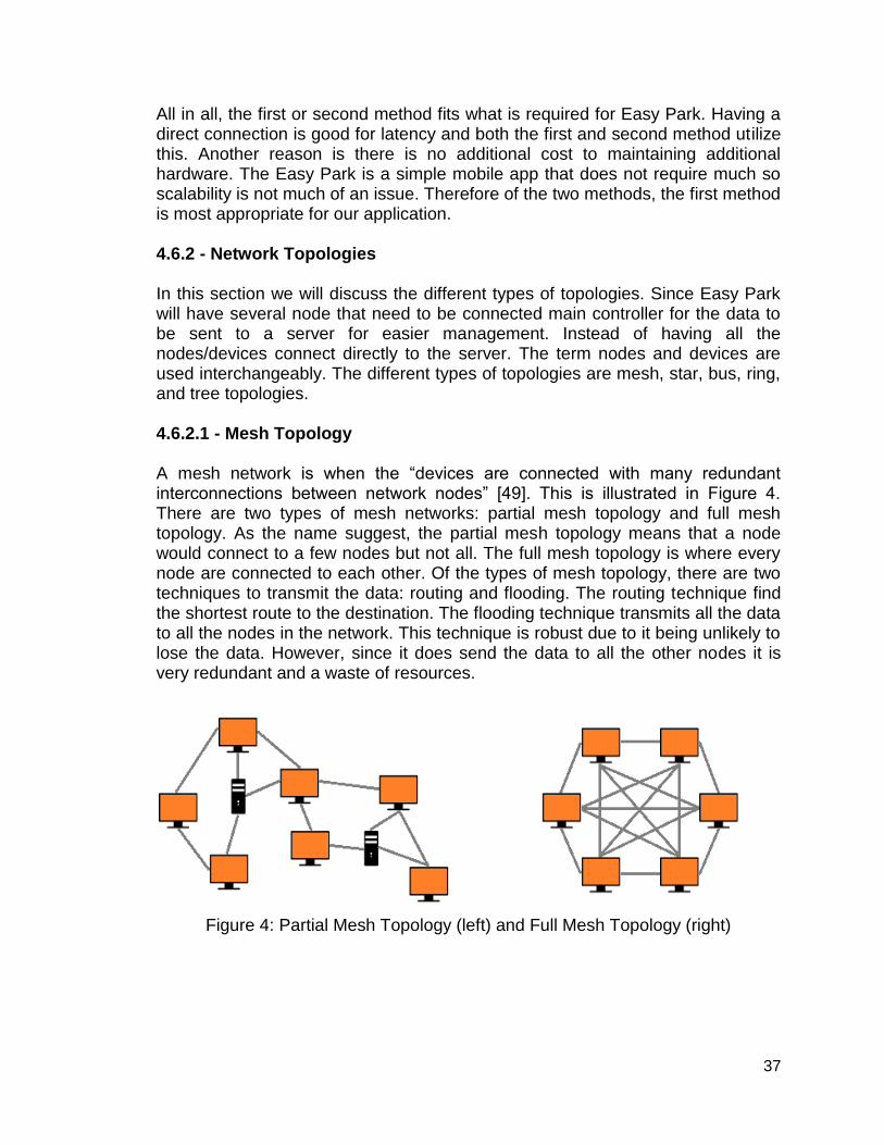
37
All in all, the first or second method fits what is required for Easy Park. Having a direct connection is good for latency and both the first and second method utilize this. Another reason is there is no additional cost to maintaining additional hardware. The Easy Park is a simple mobile app that does not require much so scalability is not much of an issue. Therefore of the two methods, the first method is most appropriate for our application. 4.6.2 - Network Topologies In this section we will discuss the different types of topologies. Since Easy Park will have several node that need to be connected main controller for the data to be sent to a server for easier management. Instead of having all the nodes/devices connect directly to the server. The term nodes and devices are used interchangeably. The different types of topologies are mesh, star, bus, ring, and tree topologies. 4.6.2.1 - Mesh Topology A mesh network is when the “devices are connected with many redundant interconnections between network nodes” [49]. This is illustrated in Figure 4. There are two types of mesh networks: partial mesh topology and full mesh topology. As the name suggest, the partial mesh topology means that a node would connect to a few nodes but not all. The full mesh topology is where every node are connected to each other. Of the types of mesh topology, there are two techniques to transmit the data: routing and flooding. The routing technique find the shortest route to the destination. The flooding technique transmits all the data to all the nodes in the network. This technique is robust due to it being unlikely to lose the data. However, since it does send the data to all the other nodes it is very redundant and a waste of resources.
Figure 4: Partial Mesh Topology (left) and Full Mesh Topology (right)

38
4.6.2.2 - Star Topology A star topology is when the “devices are connected to a central computer” [49]. This central computer is the hub and node would communicate using this hub. This is shown in Figure 5. The advantage of this node is that is a node fails then it will not have an effect on the rest of the network. The star topology also makes it easy to troubleshoot, setup, and modify. The disadvantage of using this topology is that is the hub fails then the whole entire network goes down too.
Figure 5: Star Topology
4.6.2.3 - Bus Topology A bus topology is when the devices are connected by one cable. The bus topology has exactly two endpoints and is also known as linear bus topology or backbone. This can be illustrated in Figure 6. An example that uses this bus topology is an Ethernet system. An advantage of using this topology is that it cost effective and would usually use less wires/cables than other network topology. The disadvantage of using this topology is that if the main cable fails then the whole network fails. Also, if there is heavy networking traffic then there can be a decrease in performance.
Figure 6: Bus Topology
4.6.2.4 - Ring Topology A ring topology is when the devices are all connected in a ring formation. This can be shown in Figure 7. Each node will be connected to exactly two other nodes. The last node will connect to the first node creating a full circle, ring. Repeaters are used when the ring topology has a lot of nodes. For example, it there were 1,000 nodes then the data would transmit to all 999 nodes or until the final destination is reached which can lead to data loss. Repeaters are then place

39
somewhere in the network to prevent data loss. When the ring topology is made bidirectional it is call dual ring topology. In the dual ring topology, there are two ring networks and if one of these fail then the second ring can serve as a backup making this a robust topology. Although it can be robust, if an actual computer goes down then it will disrupt the network. Adding or removing a node will also disrupt the network. The good thing about this network is that when adding more nodes is does not have an effect on transmitting.
Figure 7: Ring Topology
4.6.2.5 - Tree Topology A tree topology is when there is a “root node and all other nodes are connected to it forming a hierarchy” [48]. The tree topology is also known a hierarchical topology since the tree forms a hierarchy. It is mainly used in a wide area network and is good for workstations that are located in groups. The tree topology is essential a combination of the bus and star topologies. The disadvantage of using this topology is if the central hub fails then the whole network fails. The tree topology is illustrated in Figure 8.
Figure 8: Tree Topology

40
4.6.2.6 - Conclusion To conclude, the mesh topology is the best of the choices mentioned. Easy Park will have many nodes, one for each parking spot. With the mesh topology, it can be managed and troubleshot easily which would ideal since we are working with a lot of nodes. Of the two types of mesh networking the partial mesh would better fit the needs for Easy Park. A full mesh network would be too redundant and not needed. And of the two types of mesh networking are the two techniques. The flooding technique would work best with Easy Park. It is redundant but it is unlikely for the data to be loss. This will keep the mobile app as up-to-date as possible which the users will need real time updates. Using the star topology alone is not ideal because Easy Park uses a lot of nodes. The bus topology could work by using multiple bus topology, a bus topology of bus topology. However, since it is a bus topology having too many nodes can decrease the performance of the network. Again, there are too many nodes to use the ring topology. Having a large amount of nodes in a ring topology will mean the data will go through could mean data loss and repeaters can make the network more expensive. Plus if one of the nodes were to fail, the entire network would also fail. Since the tree topology is essentially a combination of a bus topology and star topology as mentioned it is not a good choice for Easy Park because there are too many nodes. Table 1 shows the comparison of the network topologies mentioned.
Table 1: Comparison of Network Topology
Mesh Star Bus Ring Tree
Connection between other
nodes
Yes No No Yes Yes
Host Failure? Run Fail Run Fail Fail
Node Failure? Run Run Run Fail Partial
Ease of Troubleshooti
ng/ maintenance
Easy Easy Easy Difficult Difficult
Ease of Adding more
node
Average Average East Difficult Easy

41
4.6.3 Database Management Systems In the creation of a mobile application, we are going to need a database management system (DBMS). The purpose of using a DBMS is to store the data of when a car is parked or not and how many spots are open. Rouse states “The DBMS essentially serves as an interface between the database and end users or application programs, ensuring that data is consistently organized and remains easily accessible”[]. So having a DBMS is important for Easy Park since there will be data that will be recorded for the mobile application. The 3 important things that a DBMS manages is the data, database engine, and database schema. The advantages of using a DBMS is that lets the end users and application programmers access and use the same data concurrently. The DBMS uses a central storage of data that can accessed by multiple users. Using a central storage and management of data can provide data abstraction and independence. It also has good data security when it comes to data. Another good element of a central storage is that it has the ability to recover from crashes quickly which include restart and recoverability. There are many different DBMS software out there but for this project we will be using one that is free and open source. The six free DBMS considered are, MySQL, PostgreSQL, MariaDB, CUBRID, SQLite, and MongoDB. 4.6.3.1 MySQL MySQL is one of the more popular, free, open source DBMS. MySQL is owned by Oracle but was previously a community-driven open source DBMS. Since the DBMS is no longer a community-driven open source DBMS user feel that it is not a free, open source DBMS anymore. An advantage of using MySQL is that it can be used even when there is no network available. Another advantage is that the library can be embedded into a standalone application. 4.6.3.2 PostgreSQL PostgreSQL is “developed by a group of companies and individuals which grouped in PostgreSQL Global Development Group” [51]. A key feature of PostgreSQL that separates it from other DBMS is that it an object-oriented DBMS. Which makes it good for app developers who create object-oriented programs. Extensibility and standard compliance is what PostgreSQL emphasis is on: PostgreSQL run on all major operating systems and is fully ACID compliant. ACID stands for atomicity, consistency, isolation, and durability. An advantage of using PostgreSQL is that you can create custom data types and query methods. Another feature that makes PostgreSQL more extensible is that it runs stored procedures in many programming languages including some of the big programming languages like java, python, C/C++ and many more.

42
PostgreSQL uses a MVCC system which required regular “vacuuming” which can cause problems in high transaction rate environment. MVCC stands for multi-version concurrency control. Unlike MySQL which is runs under one company, it is developed by a community which can lead to fair amounts of effort for adding improvements. 4.6.3.3 MariaDB MariaDB was developed by the original developer of MySQL. Its purpose was to develop a free and open source DBMS and keep it this way for as long as possible. As what happened to MySQL, it got owned by Oracle and now does not feel free and open source. Big tech companies like Wikipedia, Facebook and Google use MariaDB. Show that using this DBMS shows great promises. It offers a drop-in replace functionality for MySQL. An advantage of using this DBMS is that it has high scalability with easy integration. Its core functions are that of MySQL which a great DBMS already. A disadvantage of using this DBMS is that it has no memcached interface which helps speeds up the database. 4.6.3.4 CUBRID Cubrid was developed by Naver Search Solutions and has an emphasis for web applications. Unlike PostgreSQL which was has an emphasis on extensibility, Cubrid only works on Windows and Linux. However, it does interact with popular programming languages like PHP, Python, and many more due to the software being released under the GNU General Public. An advantage of Cubrid is that is has online backup, GUI tools and drivers for development languages, and database replication and transaction consistency. Another good advantage is that it supports native database sharding for horizontal and vertical scalability. Database sharding is a type of database that partitions very large database into smaller and faster data. This can be more easily managed and are called data shards. Horizontal scalability is “the ability to connect multiple hardware or software entities, such as servers, so that they work as a single logical unit” [54]. And vertical scalability can be described as “the ability to increase the capacity of existing hardware or software by adding resources” [51]. The disadvantage of using Cubrid does not have a script debugger. So if a problem does occur debugging will be more difficult. 4.6.3.5 SQLite SQLite differs from the other free DBMS mentioned. It is not a client-service DBMS but is instead embedded into the end program. As Putra states, “It’s a popular choice as embedded database software for local/client storage in application software such as web browsers” [51]. If Easy Park was to implement a web browser too then SQLite can be used. This BDMS is also used by some popular companies such as Apple, Facebook, and Google. Which has shown that it reliable. If bugs were to show up, the developers would provide a list of

43
bugs and chronologies of code changes whenever they make a release to inform the people who use this DBMS. These well-known companies and people who SQLite will be able to act accordingly to these bug. An advantage of using this DBMS is that there are no separate server process, file format is cross-platform, and transactions are ACID compliant. Another key advantage of using SQLite is that it has compact library and runs even faster with more memory. SQLite is not good for client/server applications, large datasets, and high concurrency. 4.6.3.6 MongoDB MongoDB was developed by people behind DoubleClick, ShopWiki, and Gilt Groupe. The advantage of using MongoDB is its real-time apps with in-memory storage engine. Using MongoDB can be good for mobile apps, product catalogs, and content management. The disadvantage of using this DBMS is that it does not work well with application needing complex transactions, does not drop-ion for legacy applications, and this DBMS changes and evolves quickly. 4.6.3.7 Conclusion To sum it all up, using a DBMS will definitely benefit Easy Park so using one is imperative. Some DBMS fit the needs for Easy Park while other could work but not as well. For Easy Park we will need a DBMS that is reliable, easy to use, and fast. MySQL best fits the need of a DBMS for Easy Park. PostgreSQL is good for object-oriented programming. The database for Easy Park could possible use this but it not to the extent of other mobile apps. PostgreSQL is good for mobile apps for games. MariaDB could also be a good option but for Easy Park scalability is not really needed. The number of parking spot do not really change drastically or needed modifies that frequently. MariaDB also does not have memcached interface, this means it possible it is not as fast as other DBMS. Easy Parks needs something that is fast because users will use it in real time. Therefore, a faster database is better suited for Easy Park. CUBRID is a good choice is scalability was important but for Easy Park, scalability is not much of an issue. However, CUBRID does support a native database sharding making which could resulting to faster performance. SQLite does not fit the requirement for which Easy Park’s database will need. Although some of SQLite does benefit the Easy Park database it also comes with some disadvantages that Easy Park will need. Easy Park will have large datasets and will need high concurrency. MongoDB is for real-time app which Easy Park is. The data on the app will be in real-time as users will need to the current parking spots in real time.

44
4.7 - Power System The use of batteries seems to be the best option in powering each system as limiting the number of wires is part of the objective. Assuming that the project can be expanded to the whole garage, exposed wires would make the garage look sloppy and the project itself less innovative in public eye. We want the power system to stay in close proximity to each associated system but also remain concealed at the same time. There are many power alternatives that can be implemented in this project. Choosing the appropriate power system would optimize the usage for each unit. This power system must make use of low power, have a good power efficiency, have a slow discharge rate, and minimize maintenance costs. The following subsections describes and compares the types of power systems that is most suitable to power this sensor-based system. 4.7.1 - Battery A battery is a device that is able to store electrical energy in the form of chemical energy, and is able to provide power to electrical devices with its external connections. Three characteristics of each type of battery to be inspected are: energy density, life cycle, and operational capacity without recharge. To extend the battery life, this battery system must have an in-and-out cycle for turning the device on/off and a very low power consumption state when the device is on. Battery life affects maintenance costs. The longer the battery life, the less frequent one has to replace the battery; thus, minimizes maintenance costs. The chemistry types of disposable and rechargeable batteries will both be examined carefully in the following passage and their comparisons will be shown in a latter section. 4.7.1.1 - Alkaline & Carbon Zinc Commonly packaged as non-rechargeable batteries and has the advantage of being readily available in most retailers. Standard alkaline batteries are more prone to leaking than other battery types, also damaging to electronics. Carbon zinc batteries are suitable for low-drain devices, but their capacity is the lowest of any battery of the non-rechargeable batteries. 4.7.1.2 - Lithium (Li) & Lithium-ion (Li-ion) Lithium batteries are lightweight, compared to alkaline batteries. They have a long shelf life so that a device will retain most of its charge for years and an even longer shelf life at cool temperatures (~68°F). Rechargeable lithium batteries are not available in household sizes like AA and AAA, only available in 9V size. They are more expensive than other types of batteries, but compensates by storing a substantial amount of power with a high-drain performance.
45
Li-ion batteries are common batteries in consumer electronics and the most popular rechargeable battery in portable devices like laptop computers and digital cameras. The lithium ions alternate from the negative electrode and positive electrode during the discharging and charging cycles respectively. The charge/discharge efficiency is between 80 to 90%. They have a higher volt per cell, slow discharge when not used, and a high energy density. Circuit protection is needed for overvoltage when charging and under-voltage when discharging, another factor to consider when choosing this battery type. 4.7.1.3 - Valve-Regulated Lead-Acid (VRLA) The oldest, common type of rechargeable battery dating back to the 1800s. Sometimes called sealed lead-acid (SLA) battery. Lead acid batteries are available worldwide in many sizes and capacities at a low cost. Used in many standby/back-up/emergency scenarios to deliver power to electrical installations. Their energy density is not on par with the other battery types, yet their power density is high with large surge currents. Different types of lead acid battery classifications will be looked at as well. The most common type of lead acid battery is the automotive battery, also known an SLI (starting, lighting, and ignition) battery. Primarily useful for the starting or shallow cycle service to start an engine as very large starting current needs delivered for a short time. Noted that SLI batteries are not recommended for most photovoltaic (PV) applications, up to two years of useful years of useful service could be provided in small PV systems where the average daily depth of discharge is limited to 10-20%. The other types of lead acid batteries are commonly used in PV systems that could work well in our power system, discussed down below. One of the batteries used in PV systems is the lead-antimony battery of which uses antimony as the primary alloying element with lead in the plated grids. Typically used in electrically operated vehicles where deep cycle long-life performance is required. Their use has their advantages and disadvantages. Advantages include providing greater mechanical strength than pure lead grids, deep discharge, and high discharge rate performance. Their lifetime is prolonged when operated at higher temperatures. One disadvantage is a high self-discharge rate. A high self-discharge rate affects the maintenance cost as the battery is going to need replaced sooner than later. Although lead-antimony batteries are well suited to application in PV systems due to their deep cycle capability and abuse tolerance, they require a frequent need of water additions depending on the temperature and amount of overcharge. Ways of minimizing the frequency of water additions are by using catalytic recombination caps of a cost of around $20 or battery designs with excess electrolyte reservoirs.

46
The second type of lead acid battery used in PV systems is the lead-calcium battery of which uses calcium as the primary alloying element with lead in the plate grids. Like lead-antimony batteries, they provide greater mechanical strength than pure lead grids. A low self-discharge rate and low maintenance requirements gives this battery an edge over lead-antimony batteries. Disadvantages include poor acceptance after deep discharges and shortened battery life at higher operating temperatures if discharged to greater than 25% depth of discharge repeatedly. Next type of lead acid battery is the captive electrolyte lead-acid battery. The name of the battery implies that the electrolyte is immobilized in some manner and the battery is sealed under normal operating conditions. Known for their PV applications because they are spill proof, easily transported, and require no water additions, ideal for remote applications where maintenance is not readily available. However, this battery suffers from their intolerance of excessive overcharge and loss of electrolyte, which is increased by high temperatures. Battery charge controller regulation set points are adjusted to prevent it from overcharging. Due to the sensitivity of this battery technology, captive electrolyte lead-acid batteries may be rejected to apply in practice for this project. Maximizing the battery life is going to be the hardest part in charging a VRLA battery so looking at the different charging techniques to do so. A simple constant current/constant voltage charger is a temporary solution to charging VRLA batteries, however the battery life expectancy will be greatly reduced as quoted by the manufacturer. The proper solution to charging VRLA batteries is by using an intelligent charger; not only is it cost effective, it is also environmentally friendly. Important to remember that VRLA batteries have a self-discharge rate of approximately 5% per month, less than most other forms of rechargeable batteries. Recommended that recharging the battery until it reaches about 70% of its capacity (approximately 2.1 volts per cell), stated from manufacturers. Another factor to consider when charging is the ambient temperature. As the temperature rises, the electrochemical activity in the battery increases, so the charging voltage should be reduced to prevent overcharge. Conversely, as the temperature decreases, the charging voltage should be increased to prevent undercharging. Looking at the different charging techniques, a modified constant-voltage charging method would be the best approach for quick charging/a fast charging cycle. Above all else, it is important to limit the initial charging current to prevent damage to this battery. This charging method consists of three stages: the bulk stage, the charging begins with constant charging current until a certain voltage, called the gassing voltage, is reached.; the absorption stage, the charger maintains this voltage until the current decreases to a value equal to a tenth of the charging current; the float stage, the voltage is reduced and held constant at a lower voltage, called the float voltage, while the current is reduced to less than

47
1% of the battery capacity and can maintain the battery charge indefinitely. This process can take hours. To reduce the charging time, a practical solution is to initialize the current and voltage at a higher starting point. The maximum temperature recommended for fast charging is 50°C (122°F), however maintenance charging can generally proceed above that temperature. 4.7.1.4 - Nickel-Cadmium (NiCd) Nickel-cadmium batteries are hard to find nowadays, not for good reason though. They can deliver enough power to high-drain devices for only a short period of time due to its low capacity. For any size battery, NiCd is always has the lowest capacity compared to its competition. It contains toxic cadmium so the battery cannot be disposed of in conventional ways, a Hazardous Materials collection facility is where the batteries are supposed to be taken. No other battery type has less nominal voltage than NiCd’s 1.2V and, on top of that, NiCd batteries discharge quickly. Overall, NiCd are obsolete rechargeable batteries and those having been replaced by Nickel-Metal Hydrides (NiMH) gave our group no reason to consider this battery type. 4.7.1.5 - Nickel-Metal Hydride (NiMH) By the turn of this century, NiMH batteries became widely available and are superior to NiCd batteries in every way. Like its predecessor, NiHM holds a nominal voltage of 1.2V. Their capacities are about two to three times of NiCd’s for any battery size on average. Energy density is close to that of the Li-ion battery, which is good. The charge/discharge efficiency is about 66%. A great addition to a NiMH battery is that it is environmentally-friendly design allows it to be disposed of without visiting a Hazardous Materials collection facility. NiMH batteries charge the same as NiCd so modifications to a NiCd battery charger would be unnecessary. NiMH structure has its share of disadvantages too. When the battery is overcharged, NiMH produces much excess heat from a buildup of hydrogen which can cause the cell to rupture. Therefore, an advanced charging algorithm would need to be implemented with the use of this battery and ample ventilation is required for the sensor and battery are enclosed in a small space. 4.7.1.6 - Battery Comparison In the previous section, the disadvantages of the NiCd battery outweighed its advantages and explored how NiMH batteries are far superior to NiCd. The three battery types of interest now are the lead-acid, NiMH, and lithium-ion. The advantages and disadvantages of each battery are going to be compared side-by -side to see which battery type is going work well in the power outage situation
48
so then the battery could act as a backup source of power to keep Easy Park running smoothly. The self-discharge rate of a rechargeable battery is the first main concern that needs to be addressed. This rate is the percentage of the total battery capacity loss by a battery while in the stored or unused condition. According to the table below, the rate for the lead-acid battery is the lowest at 5% discharge per month. The Li-ion battery does not fall behind at less than 10%, but the NiMH battery discharges at a much greater rate when not used. Therefore, we cannot integrate the NiMH battery into the Easy Park’s backup power system since the capacity of the battery would most probably be flushed by the time in time of a power outage. NiMH will still be used as reference in later comparisons so that we do not neglect any advantages it has. The life cycle of the battery estimates the amount of times that the battery can be charged and discharged before failure. The average life cycle for lead acid battery is 250 cycles and for NiMH is 400 cycles, while the average life cycle for Li-ion battery ranges from 750 to 1500 cycles (refer to the table below). Li-ion batteries fare better than the other battery types from inspection. The maintenance requirement of the battery is essential as low maintenance minimizes the cost of extending longevity of the Easy Park system. Lead acid batteries must be replaced every three to six months. NiMH must be replaced every sixty to ninety days. However, there is no maintenance requirement for Li-ion. In the long run, Li-ion is the best option for low maintenance specification. In addition to maintenance, safety requirements are of the utmost important for everybody to prevent harm coming one’s way. Protection circuit is mandatory for Li-ion batteries, whereas the other battery types are thermally stable. The option of fuse protection is available if necessary. As previously mentioned earlier, lead-acid batteries have been used in many standby/back-up/emergency situations. The main problem is the weight and volume of a typical lead-acid battery because it is larger than the NiMH battery and Li-ion battery. Portability gives the other battery types an edge over lead-acid batteries, but a smaller amount of space is needed for a Li-ion battery than a NiMH battery for the same amount energy because the specific energy density of Li-on batteries is greater than of NiMH. Battery operation shall be acknowledged when deciding on which battery is needed for the application of Easy Park. Li-ion batteries are under best operation when discharged partially and then completely charged. NiMH and lead-acid batteries are both best operated the opposite way, that is, by completely discharging and charging entirely. In a backup power situation, high-drain performance is not necessary as we do not want the battery to completely discharge quickly. In the end, Li-ion has proven to be the reliable type of battery we need to implement in Easy Park. Lead-acid and NiMH had their share of

49
advantages and disadvantages, just it is not a viable option for Easy Park. Table 2 contain the battery characteristics viewed side-by-side for the rechargeable batteries discussed above.
Table 2: Rechargeable battery comparisons
4.7.2 - Photovoltaic (PV)/Solar Panel Photovoltaic systems convert sunlight to direct current electricity. When the sunlight is more intense and strikes a PV module perpendicular to its surface, more dc current is produced. PV modules have minimal failure rates and projected service lifetimes of up to thirty years. Sunlight is a clean, renewable resource; thus, PV systems are environmentally friendly. Photovoltaic solar energy source would be a great candidate for low power systems that have access to the sunrays. Higher power systems are usually run by arrays of solar panels. Solar power cannot be solely relied on as weather conditions cannot guarantee enough sunlight to power this project, yet this renewable energy provides the power efficiency needed and can keep the battery running for a long period of time by recharging the battery. With good things said, there are some drawbacks that should be addressed when considering utilizing a PV source. The

50
generated power from the PV source are due to the following factors: solar irradiance (power per unit area received from the Sun), temperature, and type of silicon used in PV system. More solar irradiation means more generated power. Performance suffers as temperature rises. The panels will have to be cooled off somehow if heated for too long. The three main types of PV cells are: amorphous, monocrystalline, and polycrystalline. They will be discussed in detail to narrow down which cells would contribute the most in terms of cost and power efficiency. Amorphous: It is the non-crystalline form of silicon. Widely used in pocket calculators. Amorphous silicon panels are formed by vapor-depositing a thin layer of silicon material on a substrate material such as glass or metal. These cells are flexible, cheap, and durable but inefficient as well. The low efficiency rate is partly due to the Staebler-Wronski effect, which manifests itself in the first hours when the panels are exposed to sunlight, and results in a decrease in the energy yield of an amorphous silicon panel from ten percent to around seven percent. Their lower manufacturing costs make these cells very cost competitive. There have been improvements lately that allows stacking of the thin films to manufacture better efficiency out of them. Each layer of the thin film amorphous silicon PV cell is adjusted to work best at a certain frequency of light allowing the other light to travel through to the next level. This technique is only applied to amorphous PV cells since their cells are more transparent than the other types of PV cells. Monocrystalline (Mono-Si): This is a type of PV cell that is made of silicon cut from a single crystal of silicon and is the base material for silicon chips used in virtually all electronic equipment. Mono-Si consists of silicon in which the crystal lattice of the entire solid is continuous, unbroken to its edges, and free of any grain boundaries. Most silicon monocrystals are grown by the Czochralski process into ingots of up to two meters in length, weighing several hundred kilograms, then sliced into thin wafers of a few hundred microns for further processing. This is done to optimize performance and lower the costs of a single monocrystalline solar cell. Although this process lowers the costs of a single monocrystalline solar cell, monocrystalline solar panels have become expensive. Keep in mind, these cells are very brittle, safeguarding them in a strong frame is advised. The main highlight of monocrystalline solar panels is that they can have the highest efficiency rates since they can be prepared intrinsic, consisting of exceedingly pure silicon. The efficiency rates range from fifteen to twenty percent. Also, the Mono-Si solar panels require the least amount of space and still output the highest amount of power output, which makes them space-efficient. Polycrystalline (Poly-Si): Used as a raw material by the solar photovoltaic and electronics industry. These cells are made up of a large number of crystals. Poly-Si is produced from metallurgical grade silicon by a chemical process, called
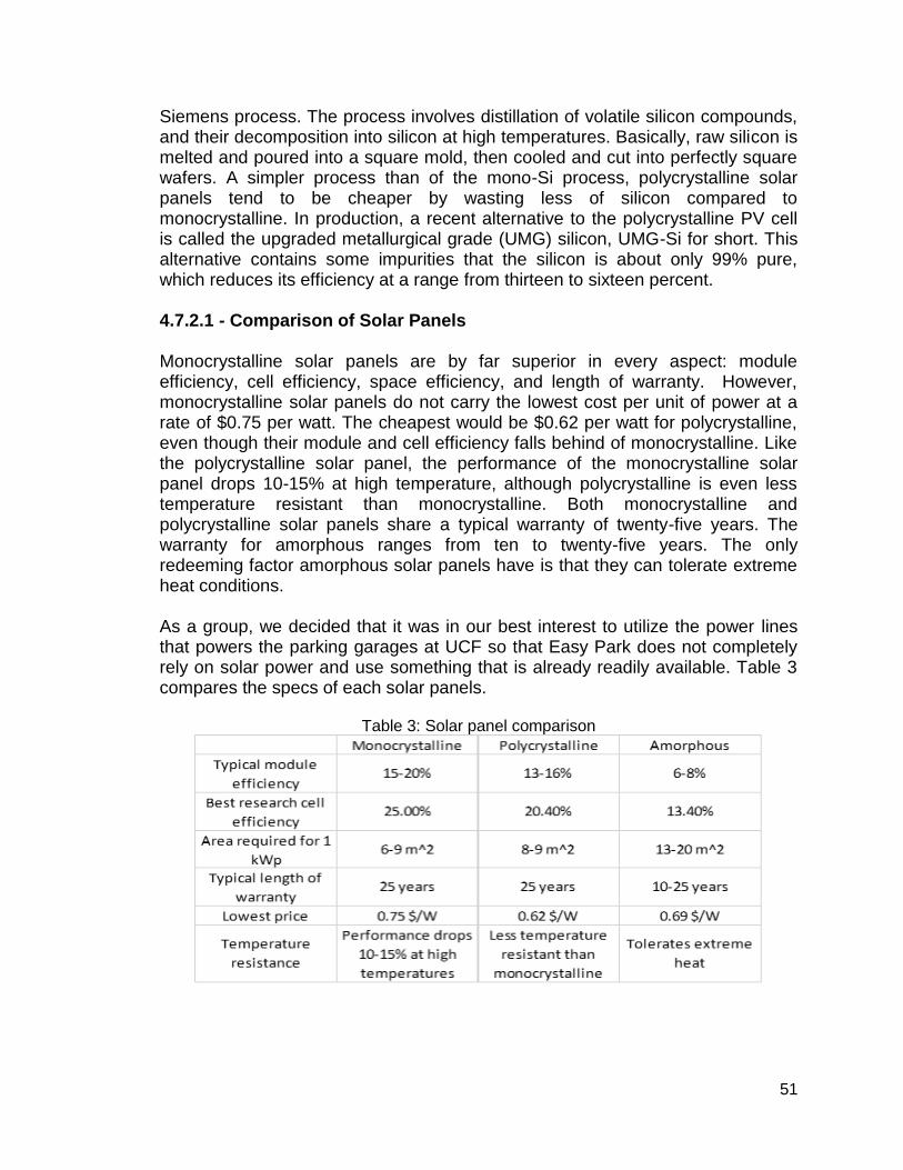
51
Siemens process. The process involves distillation of volatile silicon compounds, and their decomposition into silicon at high temperatures. Basically, raw silicon is melted and poured into a square mold, then cooled and cut into perfectly square wafers. A simpler process than of the mono-Si process, polycrystalline solar panels tend to be cheaper by wasting less of silicon compared to monocrystalline. In production, a recent alternative to the polycrystalline PV cell is called the upgraded metallurgical grade (UMG) silicon, UMG-Si for short. This alternative contains some impurities that the silicon is about only 99% pure, which reduces its efficiency at a range from thirteen to sixteen percent. 4.7.2.1 - Comparison of Solar Panels Monocrystalline solar panels are by far superior in every aspect: module efficiency, cell efficiency, space efficiency, and length of warranty. However, monocrystalline solar panels do not carry the lowest cost per unit of power at a rate of $0.75 per watt. The cheapest would be $0.62 per watt for polycrystalline, even though their module and cell efficiency falls behind of monocrystalline. Like the polycrystalline solar panel, the performance of the monocrystalline solar panel drops 10-15% at high temperature, although polycrystalline is even less temperature resistant than monocrystalline. Both monocrystalline and polycrystalline solar panels share a typical warranty of twenty-five years. The warranty for amorphous ranges from ten to twenty-five years. The only redeeming factor amorphous solar panels have is that they can tolerate extreme heat conditions. As a group, we decided that it was in our best interest to utilize the power lines that powers the parking garages at UCF so that Easy Park does not completely rely on solar power and use something that is already readily available. Table 3 compares the specs of each solar panels.
Table 3: Solar panel comparison

52
4.8 - Power Transfer and Transmission lines To properly address the issue of how to supply power to the parking system is to ask how many volts is required and what kind of transmission line is being used in the UCF parking garages. The Easy Park device will be designed to be cheap and simple enough to be implemented into parking garages. This means that it will consume power equivalent to about 15 volts. Most US transmission lines are high voltage, single phase Alternating Currents. This means that in order to deliver power over long distances, the voltage needs to be high enough, such that the power is not dissipated by the insulation wrapped on the lines and the air around it. The insulation is there because of skin effect (where current flows towards the edge of the transmission lines). This will also mean that the parking system will required AC to DC converting properties to utilize the MCUs and other components. In the UCF parking garages, there are many lights and few elevators that is powered on a daily basis. The garages are using distribution lines, since there is no need for long distance travel just to power lights alone. A step down voltage is involved to use the garage lights and elevators. The motors in the elevator may require AC, but parking system will work even in conditions where DC power is not provided. For the time being, preparing for what-if scenarios is o.k. 4.8.1 - Transformers The transformer is usually a magnetic core with two windings wrapped around opposite ends. The ratio between the numbers of loops between wrappings is proportional to the voltage drop and current rise. Power is lost when transitioning from one voltage stage to the next, but the loss is miniscule. There are single and three phase power transformers. There are also 3 winding transformers as well, but that is if the project requires different AC voltage levels. Three phase power is overall a more sufficient supply to use in today’s power demands. This is due to the three phases of Alternating current, being 120 degrees in phase from one another. This will result in power never reaching zero, unlike a single phase. It would be expected for UCF to run on three phase power since the university have appliances running 24 hours a day. Too bad the US standard is single phase 60 Hz. 4.8.1.1 - Step down Transformer In the United States it is standard to utilize the 120 V Alternating Current power system. This reason is because most appliances used today does not require more voltage for home and business use. With the parking system, this would require a step down transformer. The parking system at most will now require 9 volts. Even if it requires a lesser amount, this can be solved by using a simple voltage divider (connecting in series with an extra resistor or more MCUs).

53
To achieve step down voltage status with a transformer is to have less windings on the secondary stage vs the primary stage. A 10 to 1 winding or turn ratio to step down from 120VAC to 12VAC. The issue is that by stepping down the voltage by a factor of 10 will step up the current by that same factor. A higher gauge of wires will be required to handle the increase in current in the second windings. The transformer will lose power due to heat loss if the ratio between the input and output voltages are too high. This is mainly due to the increase in current on the second windings. The good out of this is that more current means faster charging, but in return there may be an explosion risk. To rectify this issue is to decide between copper and aluminum use on the output of the transformer. Of course the input is also included. After careful consideration, the team decides to abandon the use of transformers. The reasons being is that in terms of building one ourselves, this will mean involving with very high and dangerous currents. The UCF department does not have curriculums specifically meant for designing transformers physically. Theoretical knowledge is not enough, safety knowledge also needs inclusion. Furthermore, would be how to incorporate the system to where it does not affect UCF’s power lines in the parking garage. The team is pretty certain that UCF would not let their inexperienced student touch dangerous components with in the garage. An alternative to this would be to use prebuilt transformers that can be plugged into an outlet. This would require for UCF to incorporate outlets into the parking garages. However, most likely the project will lean towards battery power. In conclusion, transformers are not as required for the moment. 4.8.2 - Aluminum vs Copper Copper is the most common conductive metal that comes to mind as an international standard. This metal has great tensile strength, thermal and electrical conductivity, and a melting point of about 1000 degrees Celsius. Aluminum has 61 percent of the conductive properties of copper. The better aspect of aluminum is that it is 70 percent lighter than copper. This will help in making sure the transformer is not too bulky, but aluminum windings will need to be thicker in order to compete with copper. Furthermore, the connectors for aluminum must be rated for further usage. Soldering with aluminum is also difficult. Copper is mainly for building use or appliance usage, while aluminum is for high voltage power lines. Aluminum is only taken into consideration if weight and cost is of importance. Therefore for this project, just to be on the safe side, copper will be used. Small components are being made, such as the transformer and other components. The group can afford copper.

54
4.8.3 - AC to DC Converters (Full Wave Rectifiers) After stepping down the Voltage to a manageable level, the next step is to convert the AC voltage to DC. A bridge rectifier is taken into consideration in power converting. This device consists of 4 diodes that forces the AC current to pass in one direction only. This may not be enough in terms of not providing a steady current, which does not switch from zero to 12 at random. Capacitors are needed in order to minimize this effect. The capacitor works to absorb extra energy from the source and then dissipate that energy to the parking device when needed. This means that during voltage drops and rises below the necessary voltage line of the parking device, the capacitor will supply energy. The greater the capacitance, the less of a rippling effect with the voltage beyond the second winding in a transformer. The main issue of capacitors is costs vs longevity. The cheaper electrolytic capacitors, for the project, costs about 5 dollars, while the much more expensive film capacitors costs about 100 dollars. The issue is that the electrolytic capacitor usually does not last a long period of time. At max use, the capacitor will last for about a 1-2 years. This does not mean capacitors cannot be used. They still have the potential to last for a very long time. Full wave rectifiers have an efficiency of about 80 percent. This is due to points in the output reaching zero, every n periods of time. The half wave requires half of the amount of diodes, but at the cost of half the efficiency. There has to be diodes that can account for the negative directions of the input wave, otherwise huge gaps of zero volts will appear every period. A half wave filter will have a harder time ridding of the ripple effect vs a full wave rectified filter. To make sure that a capacitor based filter will last longer is to use a full wave rectifier Another, yet different rectifier that is capable of AC to DC conversion and is called the Pulse width modulated rectifier. PWM rectifiers are capable of providing feedback energy, constant DC voltage control, Unity power factor, and low input current harmonics. PWM rectifiers can be divided into two group, depending on circuit type: voltage or current type. The current based PWM rectifier functions in terms of regulating the input voltage from zero, but requires for the supply voltage to be higher than the output voltage. The Voltage based PWM rectifier provides a smoother voltage output that the current based PWM. The PWM rectifier can function as active filters. When applied to vehicle the filter does not consume reactive power. This allows for the vehicles involved to recover. The main advantage of the PWM Rectifier is to reduce higher order harmonics. They are mainly used for wind turbines and utilizes diodes are switches to create the AC to DC converting properties. The information on PWM is too new in terms of detailed explanation so therefore will not be explored any further.

55
4.8.4 - DC to DC Converters (Regulators) A regulator takes an input voltage from a DC source and converts it into another DC voltage level. The regulator comes after filtering the AC to DC power supply of the parking system. Most likely 12 volts is too much for the system. Even though diodes are involved in the full wave rectifier, the voltage drop of the output is about 1.4 volts. This would mean more components to make up for the extra power. There are two types to take into account. The linear and the switching regulators. A linear regulator consists of a resistive voltage drop in series with the load. The switching regulator stores the input energy periodically, while releasing the energy at the necessary voltage levels. The switching regulator can use a transformer, capacitor, or inductor for energy storage. The switching regulator works by rapidly switching a series element on and off. This will allow for high efficiency since the switching element is either fully conducting or off. The linear regulator remains the better choice for most applications. Its forte mainly focuses on stepping down from one voltage level to the next. Most likely the better choice since the project is stepping down. The plan is to mainly step down to 3 voltage levels such that the efficiency does not suffer too much. The efficiency will be low to medium in this case. Some of the power loss will be due to heat. The complexity is low and easy to manage in terms of costs. There is also no ripple in the output and is little in terms of noise. Now the main issue is what if the required regulator is a step up. This would require adding a battery to the DC source or to simply lower the turns or winding ratio of the transformer. By simplicity, it is more towards making your own transformer instead of buying one. It is better to lower the turn’s ratio in the transformer since the efficiency of the linear regulator will cause for the battery to lose power at a higher rate. The switching regulator is capable of step up, invert, and step down voltage leveling. The complexity is about medium to high due to inductors, diodes, and filter capacitors in the integrated circuit; but in return it has high efficiency. The main point of interest is that the system runs well at high load currents. There will be an efficiency loss due to the transformer’s step up output current. The noise is medium to high in terms of rippling. The costs is higher due to outside components. The switching regulator will be taken into consideration if more than 0.5 watts of power is wasted by the linear regulator. The thing is that there exists a linear regulator that can cause an input voltage to drop from 12V to 5V, with a power loss under 0.5 watts. The one thing to consider is to use the switching regulator to convert and drop from AC to DC, without the use of a transformer.

56
4.8.5 - AC to AC converters The transformer is the main idea in powering the parking system without the use of batteries. Batteries will remain the first resort because the circuits involved in rectifiers are tedious. Just as the DC to DC is able to change input voltage levels, the AC to AC converter is able to do the same, but with AC as the output. Also, the converter is able to change the frequency of the input to whatever ye may desire. This would be good in terms of making it easier to produce a DC voltage with little to no rippling by increasing the output frequency of the AC to AC converter. So far through extensive research, there have not been any mainstream AC to AC converters, other than the transformers. Traditional AC to AC converters have had a hidden step in between the two ACs. The converter works by taking the AC power source, shift it into a DC source, and then finally convert back into an AC source. Very inefficient in today’s standard, but it works to not convince power companies to consider it outside of Transformers. Current transformers are quite small and is not that of a greater issue in terms of an alternative replacement. The main aspect is to create or find a circuit that is capable of doing what a transformer can, but not overheat in the process. Exploring multiple ideas may lead to an innovative way in the road to mainstream AC to AC conversion. 4.8.6 - Cycloconverters A Cycloconverter converts a constant frequency AC into another AC waveform. This would be used in terms of the full wave rectifier of the linear regulator, doubling the frequency of the input wave. If there was ever a point as to needing components that run off of AC power, this would be useful. In turn if the Cycloconverter was used to step down the input voltage first, it would be a cheaper alternative over the transformer. Cycloconverter are capable of running and converting single phase or three phase AC power into another single or three phase output AC power. They are usually used in the industry via driving induction and synchronous motors. Mainly for high power application, which is perfect for stepping down voltage sources. The main focus of the Cycloconverter is its usage in terms of single phase to single phase conversion. The Cycloconverter is made of two back to back full wave rectifiers. Between the rectifiers would be the load or the output voltage. The instantaneous power of the input and out is equal in a Cycloconverter. This is because there are no inductors or capacitors involved in the system. In return the output voltage has complex harmonics, which requires heavy filtering machinery. This device cannot be used since there does not exist current usage interns of voltage to voltage changes. It is more towards frequency alterations. That is all it does sadly. AC to AC is not as simple as DC to DC.

57
4.8.7 - Chopper AC An AC Chopper is able to convert the input AC voltage to that of a different amplitude. The main issue is that the individual cannot control what output frequency the chopper would produce. As long as the frequency is higher than the original frequency, it would make DC conversion easier for the AC to DC converters. If the frequency becomes more of an issue, then using the Cycloconverter will adjust accordingly to loss in frequency. There does exist AC choppers that is capable of changing the voltage magnitude and not affect the frequency; their application is in terms of high power. Choppers works by periodically opening and closing switches to provide an average voltage output. This can be done via Pulse width modulation, frequency modulation, Variable frequency, variable pulse width, current limit control, and etc. they are also capable of filtering. The true counterpart of the AC chopper is the DC chopper. The DC chopper was the original design that functions the same way as the AC chopper. A pulse width modulator that breaks the input Voltages into manageable sections to be amplified or bucked to desired voltage levels, The AC choppers mainly used to control the load voltage from an AC source. They offer simplicity, and ability to control large amounts of power, and is very efficient. In return for such advantages are the drawbacks of requiring protection from outside voltage surges and increased heating that causes a decrease in resistance in the system. The system offers fast response and good control to make up for this. The system is also mainly used for motors so it may not be used. 4.8.8 - Single Phase Matrix Converter A matrix converter utilizes a bidirectional controlled switch to produce AC to AC conversion as an alternative to Pulse Width Modulation Rectifiers. The bidirectional switches allows for control in the power factor. The bilateral switches are not within manual or outside control. The matrix converter has drawbacks in terms of aw limited voltage ratio and high frequency operations. For a basic Matrix converter, there exists 4 bidirectional switches that is capable of conducting in forward blocking and reverse voltage. These modes are there to make sure that current is moving towards both directions alone. The Matrix converter is capable of changing a fixed Frequency and Voltage source into a variable voltage and frequency output. The Matrix converter does not require DC link or DC inputs to function. Alas, just like the PWM rectifier, there are limited applications of this circuit theory. It is one way to rid the DC link in an AC to AC converter.
58
4.8.9 - MOSFET vs BJT (Switching regulator cont.) The Metal oxide Semiconductor field effect Transistor traditionally are not meant for high powered applications. Versions where high powered use are created are called power MOSFETs. The true name of the power MOSFET is the double diffused vertical MOSFET or the VMOS. The Power MOSFET is a three terminal, unipolar semiconductor device. The MOSFET is a majority carrier device. This means that there are no recombination delays and allows for the MOSFET to achieve very high bandwidths and switching times. The Gate is connected openly to the source, thus allowing for high input impedance and a good capacitor if needed. Their drain to source resistance increases as the temperature increases. This would make it a better capacitor than the cheaper aluminum cathode and anode based capacitors. To further support this device, the MOSFET has no 2nd breakdown area and has a very low on resistance and no junction voltage drop when forward biased. The Bipolar Junction Transistor is the older version of transistor technology. It consists of a three terminals, three layers, and two junctions. It is preferably used in common emitter for most appliances. Just like the MOSFET there exists another version of the BJT called the Power BJT. The main difference from the Original BJT is that there is an extra layer called the Collector Drift Region. The collector drift region determines the breakdown voltage of the Power BJT. Unlike the power MOSFET, there exists a second breakdown in the power BJT. These regions are be avoided since it may cause failure of the BJT. Electrical Engineers are leaning more towards MOSFETS than BJTS, but the main difference has to do with frequency of the power source. The MOSFET turn off feature does not allow for reverse recombination since it is a majority carrier device. This would mean lower switching times and thus lower losses per switch. At high frequencies, this device would be a good choice, but it would be better to choose the BJT for lower frequencies, due to the MOSFET’s higher on resistance and conduction losses. Another thought to bring up is the control aspect of the two devices. The BJT is a current based system, while the MOSFET is a voltage based system. In terms of post transformer step downs, the MOSFET would be superior due to not having to worry about currents in the amps range. Most microcontrollers does not require such an ample amount of amperage. Furthermore, it is easier to stabilize voltage than it is to stabilize current. The MOSFET is able to support parallel operation with ease, while the BJT resistivity gets worse as temperature increases. Therefore, in order to reduce stress the BJT, resistors are required for parallel operation. The MOSFET is for low powered operations and is simple in design. When it comes to saturation, the MOSFET does not have one, it instead allows for direct flow from drain to source.

59
This occurs during periods when the gate voltage is high. Once the gate voltage is removed, this ohm region will disappear quickly. The BJT has the saturation of carriers when the base current is too high. Carriers are stored there and when the base current is removed, it will take time to completely remove to stored charges. BJTs are much larger in average than the MOSFET, but in return for the size, it is much cheaper to manufacture than the MOSFET. MOSFETs are not so expensive to not be taken into consideration. It is possible to purchase a MOSFET that is capable of handling 20 amps/ 500 Volts for 5 bucks. The BJT are more towards amplification than the MOSFET. Due to high switching, the MOSFET is also much noisier that the BJT. 4.8.10 - Power Adapters In this project, we have considered different ways of powering the MCU circuit and the sensors connected to it. Some of those different ways includes designing our own step down (AC - DC) transformer and using a battery to power up the circuit (while charging it through solar power). Our main source of power is surely going to be through battery power since our circuit is not very power hungry and we need the circuit to be portable, which also eliminates unnecessary wires hanging around in the garage. While the battery would take care of the primary power, we would also have an input connector for live power from the wall. This would mostly be in the form of an external power adapter for two main reasons. Firstly, we do not want to reinvent the wheel and do something that has already been done before, but most importantly, having a built-in power supply would only increase the size of the actual circuit. Power adapters are usually linear regulators that can be plugged into a wall to provide a safer power output that the average citizen can use. Most appliances that are not battery power already comes with one pre built into the system. Portable powered devices utilize them in terms of recharge or as an alternate means to power the device, while increasing the life of the internal battery or power supply. The size of the power adapter depends on the ratio of power transfer. High wattage will result in large and bulky power supplies, but by implementing switching technology, smaller and less conspicuous power adapter can be implemented. The linear power adapters are less efficient, due to power being loss to heat. In return, they are less affected by outside changes. The linear power adapters will require specific input AC power values to work well. This is fine since the US only requires one type to work with. The switching power supply can handle a larger range of power, without the power being dissipated to heat.

60
Because the device consists of a regulator, filter, and transformer all built in one; the device will have to be replaced since the cost to repair is much more than the device itself. Not that it matters, the power adapter in today's standards is relatively cheap. A simple usb charger can be bought for 5 dollars on amazon. The frequency of adapter replacement will mainly be due to the capacitor meant to decrease DC rippling. Whether it is the linear or the switching adapter, the electrolytic capacitor will be used due to how cheap it is. They are also common in power adapter failures, but in terms of being able to minimize rippling over time. The switching based adapters, although very efficient will fail more since the system is very sensitive to minor changes. Furthermore outside forces, such as lightning will also affect the longevity of the switching power adapters. Another benefit to take into account is that since the adapters are external power supplies, the Easy Park system will be lighter and less bulky. That is if assuming that the system will only require AC power, if the battery is still involved the adapter will still benefit the core design of the Easy Park system in terms of decreased size and increased safety. The safety aspect will require not building the system with an internal transformer like the current microwaves, irons, etc. Furthermore, the external power adapter can still support world usage of the Easy Park system. Worldwide, there exists multiple power types from single to 3 phase of varying frequencies. There also exist multiple adapters and plugs to convert those power supplies to what is needed for the Easy Park System. Adapters offer an alternative and additive similar to that of batteries, except it still is an external power supply. In conclusion, the power adapter provides a secondary means of powering the Easy Park Device, it also provides a more efficient way to recharge the build in battery and to reduce stress onto the battery if ever needs be. Furthermore if it ever comes a point where the battery inside the system to falter, the power adapter can shoulder the burden of powering the system. Built in indicator can be made to indicate battery failure and at the same time keep the system running during busy traffic times at UCF. However the team so far does not require the usage of AC power. The use will be limited for testing use, but can be used to expand the capabilities of the Easy Park system if deemed necessary later on. Batteries still remains the top contender in powering the Easy Park system
4.9 - LEDs and Visibility Light Emitting Diodes are semiconductor what when voltage is applied produces light. Because they are diodes, their life time does not result in failure. It is more towards diminishing light over usage. If a heat sink is not incorporated, the LEDs my burn out. The more common LED colors are red, green, blue, and amber. To produce white requires multi colored LEDs. An idea that comes to mind when the parking garages are not used, the LEDs that signal that a parking space is open can be used as lights for the parking garage. This is based off of the assumption

61
that the LEDs are bright enough to replace the current lights in the garage since LEDs are 90 percent more efficient that incandescent lighting. LEDs offer lower energy consumption, longer lifetime, and smaller size than incandescent bulbs. To produce the color has to do with affect the bandgap energy of the diode. Changing the bandgap energy affects the recombination between electron and empty positive energy spaces called holes. When they recombine, photons are created. These photons are packets of light that the diodes are able to produce. The wavelength affects what form of visible light on the spectrum is visible. Specific materials have wavelength close to or equivalent to the desired colors. For example, to produce a red LED requires it to be made with Gallium Arsenide and about 2 volts. The two volts also applies to green LEDS. Lights are the core aspect of the Smart parking project. The Baltimore/ Washington Airport also defined lights as the most important aspect in their system. Most parking systems today Utilizes the Red and Green color scheme. It is with good reason in Americans at a very young age have been doctrine into thinking that red means stop and green means go. Street lights, stop signs, railroad crossings, etc. There is little reason in complicating thing like changing the color schemes to a less indoctrinated version. In regards to LED visibility, will it be better to have single or multiple colored LEDs? Adjusting the brightness of the LED requires thinking about the core concept of what it is. For example BJTs are current based amplifiers, while MOSFETs are voltage based. The LEDs function in the same way as the BJT in terms of increasing brightness with increased base current. If done in terms of voltage, the diode will saturate at a constant level of brightness. The LED requires a series resistance to apply an extra boost in power. Furthermore, in order to achieve maximum brightness is to make the resistor almost nonexistent. Just enough that the diode is in turn-on mode. The multi colored diodes are no different from regular single colored ones. The main difference is in terms of price and variety of colors. For the multi colored diodes, each of diodes contained shares a common ground, while each of them separately needs to be powered.
Table 4: LED Color Guide (Permission Requested)
Description Wavelength Voltage min
Voltage Max
Brightness
Red 660 2.0 2.5 Standard
Blue 470 3.5 4.0 High
Green 520 3.5 4.0 High

62
In conclusion, it would be better to implement a one color system in indication if the parking space is open or closed. The reason being is that the red green system will have that multiple red light be left on when a space is not occupied. This is considered a waste in power and money since the red LED is not necessary in indicating the occupancy of a parking space. Instead, just having a green LED be left on when a space is open and no LED when a space is occupied in better. The green LED supports the Easy park system in terms of the voltage requirement. It is closer to 5 volts so the linear regulator required will lasts longer. Furthermore, the Green LED is the brightest and does not require a huge supply of power to view the LED. As for when the garage is no longer occupied, the system will be in low power mode so the LEDs will not be left on for extended periods of time.
4.10 - Circuit Protection The Easy park system may be directly connected to UCF’s main power supply. For this reason is why exploring contingencies against shorts is necessary. These faults have the potential to permanently damage some, if not all of the parking sensors and LEDs. To find that after a power loss that most of the components are no longer usable, is not something that any business or corporation would desire. The costs to replace a parking system will cost thousands for the entire garage. Of Course, if the system was battery powered, then there would be no need of alternatives in keeping the system intact. What if the diode or capacitor that filters the voltage regulator no longer functions? Wouldn't it be nice to have an extra capacitor just in case? Circuit protection is a weak line designed and installed to prevent overheating of wires and to protect electronic equipment. If there are multiple electronics near materials capable of igniting, the main aspect is to prevent wires from burning the insulation. These ignitions are due to the resistivity of the wires. Amperage tells what amount of amps is needed to burn specific wire sizes and resistivity. Even if the insulation was to burn alone, the PCB layout around the wire may be damaged, rendering the device useless. Amperage is not the only factor to consider. The Voltage drop of the device is also important. There are two of many methods in stopping a wire from overheating: the first requires utilizing thermal devices to break the circuit if the wire reaches a high temperature threshold. Another method is to have devices that react to the magnetic field around the wire of high amperage. There will be an alternative path beyond the obsolete wire. Fuses are the thermal devices, set in series with the wire, designed to open at a specific amperage. Circuit breakers are capable of doing both forms of faulty wiring detection. Circuit breakers does not require spears like the fuses do, after a fault. They are interchangeable, but Circuit breakers becomes more expensive at higher amperages. The fuses are usually the less expensive of the two. Designing the system may require having a device for every wire connection, but the ACYC standard does not require devices near

63
the power supply. A real life example of these devices is when changing the fuses in your vehicle. Specific components will not function because the fuse have faulted and is connected in series with the dash lights. 4.10.1 - Fuses Fuses are thermal devices that contains a line that melts when the maximum amperage is achieved. The Fuse type used depends on the amperage of the wire in series with it. Fuses creates open circuits and prevent surge current from overflowing the system. This would mean that any other components sharing the same node as the one with the surge current will suffer the same fate of beyond repair. There are three types of fuses: fast, slow, and semiconductor. Fast and semiconductor type fuses responds the fastest to electrical surges, but in return they are more susceptible to device startups. To fix this issue requires to increase the Amperage of the fuse beyond the amperage of the wire connected to it. Another way is to add mechanisms that are capable of bypassing the initial short bursts in power. The slow based fuses have a spring mechanism to delay the blown feature. This will allow for fuses to survive the initial power up surges, of some devices. In return, the device will be more sensitive to outside temperatures. When a fuse is blown, it must be replaced by a new one. Overtime, these devices will deteriorate, and will eventually have to be replaced. If soldered, this will make thing tedious, but there already exists methods to replace fuses without soldering. Fuse holders and blocks allows for quick replacement of fuses. The specific fuse that goes with these are called bladed fuses. Bladed fuses are plastic bodies with two prongs that are designed to fit into the sockets of fuse holders and blocks. These blades are usually used in high circuits ranging from 20 to 80 amperes. The primary advantage of fuse will be low costs and size vs maintenance. 4.10.2 - Circuit Breakers Circuit breakers are mechanical latches that opens when triggered thermally or mechanically by a surge current. They are similar to fuses, except does not require as much replacement. There are two categories of Circuit breakers: magnetic and thermal based. The magnetic based circuit breakers functions by having an inductor near the Circuit breaker. When current flows into the inductor, the magnetic circuit breaker will react the flux lines of the generating magnetic field and open the internal switch. The thermal version requires the use of thermal static metals. Similar to thermostats, the thermal based circuit breaker opens at a temperature beyond what’s tolerated.

64
Magnetic breakers have a high versatility rating in the electrical industry. Circuit can be designed for shunt, relay, or voltage trips; light based indication, auxiliary contacts, and switches. The device is sensitive to current, applied voltages and the frequency of sources. In return for having high sensitivity, these devices are also affected by the brief surge power when a device turns on. To counter the issue would mean to add extra component that affects the magnet in the coil. Doing so will provide a greater frequency range, such that the switches are not easily affected by outside occurrences. Thus the costs and weight of the device will increase. This would make the magnetic circuit a longer lasting and expensive version of the slow based fuse. Furthermore, the magnetic circuit breaker is also affected by physical shakes. While the magnetic breaker is leading the industry in versatility, the thermal breaker is leading in innovation. The key benefit of thermal breakers is that unlike fuses and magnetic breakers, they do not suffer from minute startups. This is why most appliances utilizes this device. The device is unique in terms of providing temperature sensitivity. It is also able to provide precise calibration for good circuit protection. A fusion of the magnetic and the thermal breakers also exists. There are multiple variations in terms of push reset, waterproofing, and physical switches. No matter which form of circuit protection is chosen, when a fault occurs, the Easy Park device will still have to be physically looked upon. Circuit breakers will allow for multiple uses by flipping the switches that connects components in series to one another. They are more expensive and unnecessary since changing fuses are cheaper and much easier through the use of built in bladed fuses. This is the reason why most cars utilizes the bladed fuse system.
4.11 - Comparators There needs to be a way for the microcontroller to communicate with the physical components in the Easy park project. The main goal is to have the microcontroller activate the LEDs when certain conditions are obtained. This would be easy via directly connecting the microcontroller to the LED. There exists the issue of multiple diodes existing on one LED. This can also be solved by having more pins to directly connect the LED. As stated in previous sections. The colors of the LED is dependent upon the voltage level. The potential microcontroller may not provide multiple ranges of voltages in order to provide the maximum brightness and color scheme of the LEDs. This would require outside components or voltage/ currents even greater than what the Microcontroller can supply. The microcontroller can at least be able to command a comparator. A comparator is a device that compares two voltages and outputs a signal, telling which is larger. The output voltage can be set by another DC input. This DC input can represent the voltage required for maximum output of a red diode, while

65
another comparator can have a voltage output that represents the green output. This will allow for specializations of certain area on the PCB, when built. Comparators are commonly used to digitize analog signals. This is mainly if the DC voltage input of the comparator is equal to one. By setting the comparator to zero volts for the second input, when one of the microcontroller pins are connected to the first input, the comparator will function. What will happen is that when the microcontroller attached ultrasonic sensor detects a vehicle within a certain distance, the microcontroller will output from zero volts to one volts or higher. The comparator will have the V positive >V negative condition satisfied and will output whatever voltage specified. When the condition is opposite, the comparator will output zero volts. This is why the comparator is meant for analog to digital communication. An operational amplifier can function as a cheap imitation of a comparator. OP amps have a well-balanced difference input and high gain. To get it to work as a comparator requires for the positive voltage to be set to a much higher level than that of the negative voltage. The negative voltage is then set to the required voltage of the specific diode. The resulting output would be saturated and will be equal to V negative. The disadvantages is that after saturation, the op amp has a slow recovery time to its equilibrium state. This also means it would take time to saturate to the desired voltage. Furthermore is the issue of finding a power supply great enough to saturate the OP Amp. In conclusion, the need for comparators is unnecessary since the MCU can directly turn on and off specific voltages. According to its data sheet, the MCU should be able to output 5 volts DC at its digital ports, thus eliminating the need for a comparator. This will instead promote the use of linear regulators to step down the 5 volts to 3.2 volts for the Green LEDs to operate on.
4.12 - Battery Chargers One does not simply link a battery to solar panels that supplies power and expect the battery to charge properly. The team so far would like to expand their knowledge by dipping into today's standards of battery charging. As stated in section 4.7.1, batteries utilizes chemical to store power that can later be implemented later on. The question that is unknown to the Easy Park group is how to recharge a battery or how does a charger works? Researching battery chargers will aid in the design of the solar chargers that the Easy Park team will implement into the final Easy park design. Before discussing chargers, the first thing that needs to be explored is how a battery works. This was discussed in section 4.7.1, but not in supreme detail. The battery should remind engineers of a semiconductor, in terms of how it operates. There are three parts, the cathode, anode, and the electrolyte. The electrolyte separates the two other parts and is what channels the electricity when the two

66
chemicals, cathode and anode, makes contact. This means that the battery are not separated by its round side, but by three cylinders of varying radiuses and of similar height. The electrolyte is mainly there to channel current from the chemical reactions of the cathode and the anode. From the positive end to the negative end of the battery, current flows. The battery by itself does not produce current, but the battery itself is very reactive. This requires for the battery to have somewhere to flow the charges being produced. When the battery is not connected to anything, it is in thermal equilibrium. There exists no outside conditions to promote a chemical reaction between the cathode and the anode. Once the battery is shorted or is connected to a load, it will produce a chemical reaction. The cathode has more positive ions and the anode had more negative ions. The cathode surrounds the anode and the anode. When flow is encouraged, positive charges of the cathode are allowed to combine with negative charges of the anodes to produce current that is channeled through the electrolyte. There are two ways of producing current, one is from dispersing from a material of high concentration to a material of low concentration. This is called diffusion. The other method requires an electric field or voltage that causes for electrons to flow opposite of the parallel voltage. This is call drifting. These two current types, drift and diffusion, aids in producing current that powers the load or a short. If there is no incentive to produce current, there is no chemical reaction between the cathode and the anode of the battery. After an X amount of time, the battery’s chemicals has achieved thermal equilibrium and the flow of electrons ceases. Thus stepping into the domain of battery types required, which has already been stated in section 4.7.1. The thing to expand between the two battery types is what happens when the batteries are shorted. There are two types of batteries, primary and secondary. Primary are disposable batteries. The secondary are rechargeable batteries. When both are shorted, the primary battery will produce a low current output, due to its high internal impedance. The primary battery will only produce current for a very long period of time. The secondary battery on the other hand will overheat and will eventually explode. Thus the importance of a protective circuit is necessary for cases where the solar panels charging the battery, ends up producing zero volts. Zero volts is equivalent to a short and will shorten the lifetime of the secondary battery. This mainly applies to Easy Park’s lithium ion secondary batteries. The next topic is to explore the charging aspect of the battery charger. A battery charger reverts the chemical makeup of a post used secondary battery by doping extra electrons into the battery. The charges of the cathode and the anode was neutral, but by adding extra electrons, it creates an environment where the battery can output more power during future use. There are simple chargers and smart chargers. The simple chargers continue to charge until the battery

67
explodes. The smart charger has a built in MCU that stops charging the battery when it is full. To recharge a battery, current is crucial in starting and reversing chemical reactions that produces the electrons that powers devices connected to it. Recharging a battery requires forcing current into it. Since current flows from high voltage to low voltage, this will require a battery charger of greater voltage than of the battery itself. So for the custom solar charger, its voltage will need to be greater than the 9V battery, and there needs to be a smart meter that prevents the battery from overcharging. A boost converter will definitely be needed and a simple MCU will need to be researched and acquired.

68
5.0 - Design After researching multiple component combinations and comparing them with possible outcomes. The team has already decided what is needed and has settled between two similar designs. The key factor in the design is creating a system where it will hang from the ceiling of the garage or to place the system onto the bottom, where the parking spaces are located. Both options will be explored further and only one PCB design will be chosen.
5.1 Specifications In this section we discuss the specifications of the main components we chose for our Easy Park devices. Some of the components in this section are ultrasonic sensor, microprocessor, wifi module, and bluetooth low energy module. 5.1.1 Ultrasonic Sensor Ultrasonic sensors were chosen over the video image processors due to its simplicity, inexpensive cost, and accurate distance measurement. The cost per space would have been reduced from implementing cameras into the parking garage system, but the time factor was taken into serious consideration as none of the team had any prior experience with image processing and an optimum effort would be required of the entire team to researching, designing, and debugging a VIP system. Orientation of the sensor is important in detecting objects. Ultrasonic sensors can be mounted in any orientation, just as long as it can detect a vehicle at an area of interest and has crossed the distance threshold set by the distance parameters in the source code. The HC-SR04 ultrasonic sensor was chosen specifically because the datasheet provided a HC-SR04 library in the Arduino IDE, which can still be used in programming the Atmel ATMega328P microcontroller. The table below lists the module pin assignments along with the pin function descriptions.
Table 5: Module pin assignments
Pin Number Pin Symbol Pin Function Description
1 VCC 5V DC power supply – 15 mA
2 Trig Trigger pin (INPUT)
3 Echo Receive pin (OUTPUT)
4 GND 0V DC ground

69
The next table display the maximum or minimum constraints imposed by the sensor, the inner workings and what it is capable of.
Table 6: Hardware specifications
Operating Voltage +5V-DC (4.5V min., 5.5V max.)
Operating Current 15 mA
Operating Frequency 40 kHz
Working Current 15 mA (10 mA min., 20 mA max.)
Quiescent Current <2 mA
Maximum Range 4-5 m
Closest Range 2-500 cm
Measuring Angle 30 degrees
Effectual Angle <15 degrees
Input Trigger Signal 10 us TTL pulse
Board Dimensions 4.3×2.0×1.5 cm
Board Connections 10.16×0.254 cm Pitch Right Angle Header Pins
Lifespan 2 years, minimum
Weight approx. 10 grams
The following figure gives the dimensions of the HR-SR04 sensor, with a test of performance, as stated in the table of hardware specifications.

70
Figure 9: HR-SR04 dimensions and test of performance
5.1.2 Microcontroller (MCU) The microcontroller is an essential part of the project since it is the main controller for everything that connectors to it (e.g. sonar sensors). There are many MCU’s out there, but we selected the Atmel Atmega328p for a few essential reasons. It is a powerful 8-bit microprocessor that can execute 131 instructions in a clock cycle, all while being low power, using Atmel’s AVR microarchitecture, which is a RISC (reduced instruction set computing) based architecture. The following table shows the rest of the specifications of this MCU:
Table 7: Microcontroller Specification
Processing speed 20Mhz (up to 20 MIPS Throughput)
General purpose registers 8
Data retention time 20 years (85C), 100 years (25C)
SRAM storage 2KBytes
EEPROM storage 1KByte
Programmable I/O lines 23
Operating Voltage 1.8 - 5.5V
Temperature Range -40C to 85C

71
Current @ 20Mhz (5V) ~ 20 mA
Current @ 20Mhz (3.3V) ~ 9 mA
Flash memory storage 32KBytes
For programming the Atmel ATMega328P, we will be using the Arduino IDE since it already has good support for this MCU. We already did a preliminary test for testing an ultrasonic sensor and it worked without a hitch. For programming any MCU, it is vitally important to understand the layout, or in other ways, the pin-out diagram; since the entire design constraint, in terms of programming, as well as physical availability of specific pins can hinder the overall project. So, the following picture shows the pin-layout as well as what the Arduino IDE relates to those pins as:
Table 8: Atmel ATMega328P Pin-Layout
Pin Number Pin Symbol Arduino Function
1 PC6 reset
2 PD0 Digital Pin 0
3 PD1 Digital Pin 1
4 PD2 Digital Pin 2
5 PD3 Digital Pin 3
6 PD4 Digital Pin 4
7 VCC VCC
8 GND GND
9 PB6 Crystal
10 PB7 Crystal
11 PD5 Digital Pin 5
12 PD6 Digital Pin 6
13 PD7 Digital Pin 7
14 PB0 Digital Pin 8
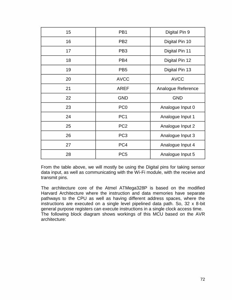
72
15 PB1 Digital Pin 9
16 PB2 Digital Pin 10
17 PB3 Digital Pin 11
18 PB4 Digital Pin 12
19 PB5 Digital Pin 13
20 AVCC AVCC
21 AREF Analogue Reference
22 GND GND
23 PC0 Analogue Input 0
24 PC1 Analogue Input 1
25 PC2 Analogue Input 2
26 PC3 Analogue Input 3
27 PC4 Analogue Input 4
28 PC5 Analogue Input 5
From the table above, we will mostly be using the Digital pins for taking sensor data input, as well as communicating with the Wi-Fi module, with the receive and transmit pins. The architecture core of the Atmel ATMega328P is based on the modified Harvard Architecture where the instruction and data memories have separate pathways to the CPU as well as having different address spaces, where the instructions are executed on a single level pipelined data path. So, 32 x 8-bit general purpose registers can execute instructions in a single clock access time. The following block diagram shows workings of this MCU based on the AVR architecture:

73
Figure 10: Atmel ATMega328P Architecture
5.1.3 ESP8266-01 Wi-Fi This Wi-Fi module is well known in the industry for usage in low power, mobile applications. In our case, it is going to be a fundamental part of creating the mesh network, where multiple MCUs with these Wi-Fi modules are going to be talking to each other (This module does not have a built-in ROM, however, it comes equipped with an external SPI flash chip). Its features include having a 32-bit, low power Tensilica L106 MCU with nominal clock speed of 80 MHz and maximum speed of 160 MHz. The rest of the features and specifications have been mentioned in the following table:

74
Table 9: ESP8266-01 Wi-Fi Specification
Feature Type/Description
Wi-Fi Protocols 802.11 b/g/n
Type of Antenna PCB Trace
Operating Voltage 3.0~3.6V
Operating Current ~80mA
Operating Temperature Range -40°~125° (C)
Package Size 14.3mm x 24.8mm x 3mm
Security WPA/WPA2
Encryption WEP/TKIP/AES
Network Protocols IPv4, TCP/UDP/HTTP/FTP
Frequency Range 2.4G-2.5G (2400M-2483.5M)
External SPI Flash 1MB (can be extended up to 16MB)
Storage Temperature -40°~125° (C)
User Configuration AT Instruction Set, Cloud Server, Android/ iOS App
Wi-Fi mode station/softAP/SoftAP + station
Standby power consumption <1.0mV
Deep sleep power <10uA
The ESP8266-01 is a wireless network transceiver that can either act as a host or a slave, depending upon the configuration of the programing environment. When acting as a host, it boots up from the data stored on an external flash, which is also helped by a cache that this module has, which overall helps in improving application performance. This Wi-Fi module can be used with a variety of microcontrollers due to commonly used interface connectivity such as SPI/SDIO and I2C/UART. The following is a block diagram of this module:

75
Figure 11: ESP8266-01 Wi-Fi Module
The module that we are using consists of 8 pins. The following table shows the description and workability of these pins (Pin numbers vary by manufacturer):
Table 10: ESP8266-01 Wi-Fi Pinout
Pin Number Pin Name Function
1 GND Ground (0V potential)
2 GPIO2 General Purpose Pin
3 GPIO0 General Purpose Pin
4 RXID Data Receiving Pin (UART0)
5 VCC Positive Input Supply (+3.3V)
6 RST External Reset Pin (Active Low)
7 CH_PD Chip Enable Pin (Active High)
8 TXID Data Transmit Pin (UART0)
5.1.4 Bluetooth HM-10 In addition to the Wi-Fi module, we had to consider the usage of Bluetooth, specifically the HM-10 (which is based on the BLE 4.0 specification). The main reason for choosing Bluetooth over Wi-Fi would be the lower power consumption (calculated to be a factor of 10) since our overall circuit would be portable and running on a battery. There are many different variants of the HM-10, designed by different manufacturers e.g. AT-09, however, the commonality to all these modules is that they use the same or similar chips i.e. CC2540/CC2541 which

76
are originally made by Texas Instruments. The following table shows the specifications and features of the HM-10:
Table 11: Bluetooth HM-10 Specification
Feature Description
BT Version Bluetooth Specification V4.0 BLE
Working frequency 2.4GHz ISM band
Modulation method GFSK(Gaussian Frequency Shift Keying)
Speed Synchronous/Asynchronous: 6k bytes
Security Authentication and Encryption
Input Voltage/Power +3.3VDC/ 50mA
Range 100m (open space)
Power (Sleep Mode) 400uA~1.5mA
Power (Active Mode) 8.5mA
Working Temperature -5 ~ 65 C
Dimension 26.9mm x 13mm x 2.2 mm
The following table shows the pinout descriptions:
Table 12: Bluetooth HM-10 Pinout
Pin-Name Description
STATE Connection status (LOW when not connected, HIGH when connected)
VCC +2 ~ 3.6V (Positive Voltage Potential)
GND GND (0 voltage potential)
TXID Serial UART Transmit
RXID Serial UART Receive
BRK Break pin. When there is an active connection, bringing the BRK pin LOW breaks the connection

77
5.2 Hardware Design In this section, we will go into further detail about the hardware design. 5.2.1 Hardware Block Diagram
The hardware design that the block diagram represents consists of a microcontroller, power supply, wireless communication device, LEDs, and protective coating of the Easy park Device. The core power source will be batteries in order to allow for wireless capabilities. The batteries will also allow for the use of a secondary power supply. The secondary power supply could be either AC adapter recharge based or photovoltaic based. The AC adapter recharger is based on the ceiling design of Easy Park, while the photovoltaic design is based off the bottom design. The bottom and the top design are similar in structure and layout. Each ultrasonic sensor will be responsible for one parking space. There will be a central unit with sensor attached. The other sensors will be directly connected to each other. Each sensor will also have an LED module that will be placed in front of the parking space. Furthermore, this layout will work no matter if the parking system placed at the top or on the parking spaces. The benefit of the top design Easy Park is that there will be no need for protection from other cars. Furthermore, the system can be recharged by the main power supply of the UCF garage, thus minimizing the need of batteries. This will mean a shift in what is considered the main power supply. The main power supply will be the AC adapter, while the secondary supply will be the batteries. The design will have to take account into parts that can withstand the weight of the sensors and LEDs. Furthermore, there needs to be a protective coating that can withstand the impact if the device ever detaches itself from the hanging mechanism. The bottom design will continue to use rechargeable lithium batteries as the main power supply, while utilizing photovoltaic panels to recharge them over the course of photon exposure. The main benefit of the design is portability and fast component and device replacement. If needed to provide maintenance with the parking device, there will be no need to use step ladders. The device will always be within view and will be easily managed. The cons will be that the LEDs that signals the driver to the location of the parking spot will be out of view the closer the driver is to the space. Not that it matters since the driver will already have a very good guess as to where the opened parking space is located. Therefore, the proper design to go with will be the bottom design, unless there exists other benefits that the Top Easy Park design can offer. Considering that finding an outlet to the garages main power supply will require direct tampering

78
with the Parking garages lighting system. As the project explores more of the bottom Easy park design, the benefits will speak for itself.
Figure 12: Hardware Block Diagram
5.2.2 Schematics and System Communications In this section, all connections of the MCU to all components will be explored with schematics also provided. This table will be needed in order to compare all possible voltage and current setups. It will also decide between the use of wireless or direct connections between the LED/ Polycrystalline panels and the Sensors/ Batteries.
Table 13: Basic Hardware specs
Component Voltage range Current range
ATMega328P(MCU) 4.5V - 5.5V 9mA-20mA
ESP8266-01 Wi-Fi/trans 3.0V-3.6V 80mA
HC-SR04 sensor 4.5-5.5V 10mA-20mA
Green LEDs 3.0V-3.4V 20mA-30mA
Batteries(Recharge) 9V 1000mAh
Solar Panels Voltage 2.2 Volts 0.10A

79
The main bulk in communications and circuit connection is the ATMega328P microcontroller. Most of the components requires less than 5 volts. The pins to the microcontroller outputs roughly 5 volts. This means that connects will mainly require multiple voltage regulators. Furthermore is the setup of the Easy park device's main power supply. The batteries may be set up for both modules instead of placing it for the ultrasonic sensors and MCU. This is mainly in account for the extra ESP8266-01 Wi-Fi/transceiver modules. Of Course, the team will take into account power efficiency. Bluetooth would make things easier, but much more expensive. In order to aid in designing the schematics needed, the team decided to utilize Texas instruments’ Webench software. This allows for pre-built schematics to be made based from given input and output parameters. 5.2.3 Duty Cycle and Efficiency For each of the circuit designs presented. The sufficient operating temperature will be around 30 degrees Celsius, but is more than capable of going above or below that threshold, at least until the wires melt. Circuit Breakers and fuses will prevent such a disaster when needed. The Duty cycle refers closely to Pulse width modulation, in terms of how long the pulses of Voltage max output occurs. For example, if the Duty cycle is 30 percent, this means that 30 percent of an X amount of time, the system will output a voltage max. The duty cycle is not taken into consideration as much due to the high frequency of the regulator. Most likely if the circuit ever overheats, it is because of the low duty cycle. The efficiency of a circuit or device describes how well the system can transfer input power to its output load. This means that if the efficiency is about 70 percent, 30 percent of the input power is lost by heat. Most of the time, the best efficiency is dictated via switching or complex linear regulators, specifically meant to take an input range and output a constant. 5.2.4 MCU and Ultrasonic Sensors For the Easy Park ATMega328 MCU to connect properly with the HC-SR04 Ultrasonic sensor, will require a connection to the 4.5 to 5.5 voltage pins of the MCU and a circuit that is able to output the same voltage range. Furthermore, the pin is also able to provide sufficient current, within the 10mA to 20mA range, which the microcontroller already does. As is expected since the HC-SR04 was specifically meant to be an attachment to this Arduino board. The team does have waterproof sensors, but will require further testing and implementation since the data sheet appears to be no longer available.
80
5.2.5 MCU and LEDs Although the LEDs will be on a separate module, aside from the MCU, the system will still be directly connected to the MCU. The MCU will be powered by the batteries and the other components will be powered by the MCU. The Easy Park system requires for the ultrasonic sensor to be perpendicular to the parking floor to work properly. This would mean that the sensor will be placed in the middle of the parking space. Furthermore, the LED display will have to be placed in front of the parking space for visual reasons. The LED module will have 4 Green LEDs in parallel, sharing the same input from the regulated MCU source. Each LED will be in series with a Resistor for proper lumens control. For now, the resistance of the LEDs will be 100 ohms. After the resistor, each LED will be grounded. The key aspect of the Voltage regulator is to produce a finite 3.2V output, such that the voltage divided LED resistors does not fluctuate the LED brightness. The pins from the AtMega fluctuates between 4.5 to 5.5 volts. However, in order to accommodate the total LED amperage of 0.12 amps, proper circuit regulation must be included in the Voltage regulator. As from the table of primitive specs, the green LED requires 0.03 Amps. Multiplied by 4 is about 0.12 Amps. The green LEDs were chosen in terms of lumens output. The green LEDs outputs multiple times the Lumens of the blue and red LEDS. Furthermore, the system only needs the LED to turn one when a space is occupied. The software team will program the power saving aspects with the MCUs. The core of the buck converter circuit for the MCU and the LED 4x matrix is the TLV 62568 DBVR chip. This circuit is able to output a constant voltage of 3.2 Volts, while outputting the 0.12 Amps required to power the LEDs. The price of the chips is about $0.38. The 2.2 uH inductor needs to be ordered outside from campus. The price of the inductor is roughly $0.19. The rest of the circuit consists of capacitors and resistors that can easily be obtained. Furthermore, the chip can be ordered for free testing, such that other circuit types can be explored as a contingency.

81
Figure 13: Schematic of the Buck Converter (MCU to LEDs)
Figure 14: Efficiency and Duty Cycle of the Buck Converter (MCU to LEDs)
One viewable aspect is that the efficiency is above 90 percent, no matter what voltage range input or current output. Furthermore, as long as the current required for the LEDs is at the sufficient 0.12 Amps, the duty cycle will remain at 30 percent. Any lower and the circuit will not function properly, even at is high 721 KHz frequency. The other viewable aspect is that Vin represents the pin voltages of the MCU, while the Load will be parallel to the 4x LEDs.

82
5.2.6 MCU and Wi-Fi/Transceivers Another important aspect to the Easy Park system is the connection of the AtMega to the ESP8266-01 Wi-Fi/transmitter. Considering how the mesh network works, the master unit will communicate with other units wirelessly. This single device will be able to receive and transmit instructions to other Easy Park modules. The AtMega MCU will still have the 4.5 to 5.5 volt range of operation. The desired output of the Voltage regulator is 3.2 since the range of communication is more towards proximity of other parking sensors around. The nearest sensor is about five to seven feet away. The Wi-Fi module can easily surpass that, but the must take into account for power surges. The current needed is the highest of all devices, 80 mA. The LEDs required 0.12A due to there being four in parallel.
Figure 15: Schematic of the Buck Converter (MCU to Wi-Fi/Trans)
Figure 16: Efficiency and Duty Cycle of the Buck Converter (MCU to Wi-Fi/Trans)

83
As seen from the four previous figures, in regards to the buck converters, the LED and Wi-Fi/ Transceiver designs are every similar, except that the load impedances are different. This means that the circuit involved is mainly meant for providing the necessary voltage to the loads. This means that for the schematic design, placing the LEDs in parallel with the Wi-Fi module and the buck converter is the ideal design. The load represents the LEDs and the Wi-Fi/transceivers. However, the design still requires separate circuits because the LEDs and the MCU purposes are different. 5.2.7 Battery and Secondary Power Supply One method to charge the battery is to use photovoltaic panels. These panels would be in close proximity to the LED. The recharge capabilities of the parking system can be hindered by vehicles and people that could block photons from the parking garage lights beaming down to the panels. We require to find a solar panels that not only can charge the battery overnight, yet also have small dimensions (~2.5” x 2.5” x 0.5”) for portability. From the research of finding a suitable panel, there is apparent trade-off between dimensions and output current. The smaller dimensions of the panel, the lower output current and vice versa. The solar panel is not sufficient enough to charge the battery completely overnight. More research needs to be done in order to select an appropriate secondary power supply to charge the battery. 5.2.8 Battery and MCU The operating voltage of the MCU is from 1.8 volts to 5.5 volts and the group decided to operate the MCU at 5 volts. The connection from the battery to the MCU needs a buck converter to step down the voltage from 9 volts to 5 volts. The TPS62122 device was selected since it is highly efficient at 96% efficiency, suitable for this low-power project. The input voltage Vin ranges from 2 V to 15 V and an output voltage range between 1.2 V to 5.5 V with a low output ripple voltage. The maximum output current is 75 mA with 11-μA quiescent current in power save mode. Inductor L1 is used to resist the change in the output current of the buck converter when stepping down the voltage so that current going into the MCU is not affected as much.

84
Figure 17: Schematic of the Buck Converter Circuit (Battery to MCU)
Figure 18: Efficiency and Duty Cycle of Buck Converter Circuit (Battery to MCU)
5.2.9 PCB Schematic Design The PCB schematic design was build down below:

85
Figure 19: Rough PCB Schematic Design

86
5.2.10 Power Management: ATmega328P To power the ATmega328P microcontroller, the electrical parameters were examined at conditions when the microcontroller is in use. A 3V lithium coin cell button battery was suggested at the initial draft of this project. The problem with using coin cell batteries is that they have a very low capacity and will drain quickly under a 20+ mA load. One solution to maximizing the battery life is by maximizing the amount of time spent in power-save/sleep mode. The table below lists the amount of current consumption of the ATmega328P microcontroller. Note: 1. Values with Minimizing Power Consumption enabled (0xFF). 2. Typical values at 25°C. Maximum values are test limits in production. 3. The current consumption values include input leakage current. 4. No clock is applied to the pad during power-down mode. Limiting the VCC of the ATmega328P microcontroller at a low voltage within the safe operating voltage threshold will limit the maximum frequency for the clock speed, so the maximum frequency is dependent on VCC. Figure 20 below represents the maximum frequency versus VCC curve. The curve is linear between 1.8V < VCC < 2.7V and between 2.7V < VCC < 4.5V. The maximum frequency is at a constant frequency of 20 MHz between 4.5V < VCC < 5.5V.
Table 14: Atmega328P DC characteristics – TA = -40°C to 85/105°C, VCC = 1.8V to 5.5V (unless otherwise noted)

87
Figure 20: Maximum frequency vs. VCC
Sleep modes enable the application to shut down unused modules in the MCU, thereby saving power. In general, sleep modes should be used as much as possible and all functions not needed should be disabled. The power-down and ADC noise reduction modes will be used extensively so that power consumption can be greatly reduced while keeping as few as possible of the functions of the device are operating. The current consumption for the two sleep modes are in the microamp range; thus, a low power consumption is achieved in the microwatt range from the current consumption and voltages from the DC characteristics table above. The ADC noise reduction mode would be used throughout the less busy time frames. When entering this mode, the CPU stops running but allows the ADC, the external interrupts, the 2-wire Serial Interface address watch, Timer/Counter2, and the WDT to continue operating if mode is enabled; as a result, this improves the noise environment for the ADC, enabling higher resolution measurements. An external level interrupt will then wake up the MCU from ADC noise reduction mode to continue normal operations. The ATmega328P MCU would automatically enable the power-down mode at a specific time in the evening so that it will not have run throughout the night until a time when traffic typically begins to arise in the morning. All port pins will be configured to use minimum power when entering a sleep mode and no pins drive resistive loads. Since the I/O clock and the ADC clock are stopped in the previously mentioned sleep modes, the input buffers of the device will be disabled, and, in return, that ensures that no power is consumed by the input logic when not needed.

88
5.2.11 Sensor Distance Consideration and Sensor Schematic To initialize the module, the Trig and Echo pins of the HC-SR04 must be set. The Trig pin must receive a pulse of +5V or at least 10 us that will initiate the sensor to transmit out eight cycles of ultrasonic burst at an operating frequency of 40 kHz and wait for the reflected ultrasonic bursts. The Echo pin is the data pin – used in taking distance measurements. A timer is set when ECHO goes to HIGH (5V). Once an ultrasonic burst is detected, the ECHO pin would go LOW (GND) and the timer will stop running; thus, the half-time value from transmitter to receiver is known to calculate the measured distance from the object to the receiver in the distance equation: d = v*t, where v is 340 meters per second (the speed of sound). A timing diagram for this event is illustrated down below.
Figure 21: HR-SR04 timing diagram
There are four basic components to the sensor: transmitter/receiver, comparator, detector circuit, and solid-state output. The schematics of the ultrasonic transceiver are shown in Figure 22. The transmitter is activated once the on-off switch S1 closes. The working principles of ultrasonic wave transmitter circuit are as follows:
● 40 to 50 kHz signal generated/transmitted ultrasonic sound by microcontroller.
● The signal is passed to a resistor to safety when the signal is refracted forward a series of diodes and transistors.
● The signal is fed to a current amplifier that consists of a combination of two pairs of transistors and diodes (D1-T1, D2-T2).
● When the signal from the input logic high (+5V), the current will pass through diode D1, then current will bias transistor T1.
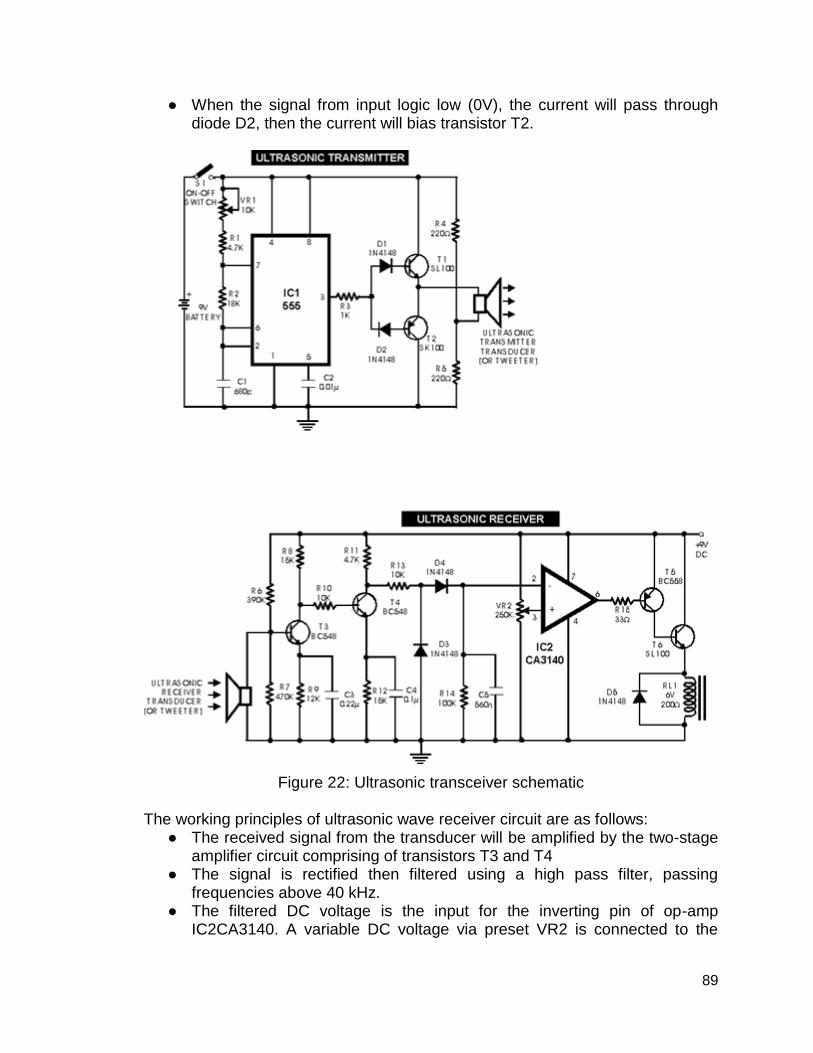
89
● When the signal from input logic low (0V), the current will pass through diode D2, then the current will bias transistor T2.
Figure 22: Ultrasonic transceiver schematic
The working principles of ultrasonic wave receiver circuit are as follows:
● The received signal from the transducer will be amplified by the two-stage amplifier circuit comprising of transistors T3 and T4
● The signal is rectified then filtered using a high pass filter, passing frequencies above 40 kHz.
● The filtered DC voltage is the input for the inverting pin of op-amp IC2CA3140. A variable DC voltage via preset VR2 is connected to the
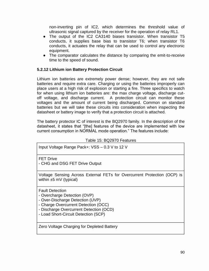
90
non-inverting pin of IC2, which determines the threshold value of ultrasonic signal captured by the receiver for the operation of relay RL1.
● The output of the IC2 CA3140 biases transistor. When transistor T5 conducts, it supplies base bias to transistor T6; when transistor T6 conducts, it actuates the relay that can be used to control any electronic equipment.
● The comparator calculates the distance by comparing the emit-to-receive time to the speed of sound.
5.2.12 Lithium ion Battery Protection Circuit Lithium ion batteries are extremely power dense; however, they are not safe batteries and require extra care. Charging or using the batteries improperly can place users at a high risk of explosion or starting a fire. Three specifics to watch for when using lithium ion batteries are: the max charge voltage, discharge cut-off voltage, and discharge current. A protection circuit can monitor these voltages and the amount of current being discharged. Common on standard batteries but we will take these circuits into consideration when inspecting the datasheet or battery image to verify that a protection circuit is attached. The battery protector IC of interest is the BQ2970 family. In the description of the datasheet, it states that “[the] features of the device are implemented with low current consumption in NORMAL mode operation.” The features include:
Table 15: BQ2970 Features
Input Voltage Range Pack+: VSS – 0.3 V to 12 V
FET Drive - CHG and DSG FET Drive Output
Voltage Sensing Across External FETs for Overcurrent Protection (OCP) is within ±5 mV (typical)
Fault Detection - Overcharge Detection (OVP) - Over-Discharge Detection (UVP) - Charge Overcurrent Detection (OCC) - Discharge Overcurrent Detection (OCD) - Load Short-Circuit Detection (SCP)
Zero Voltage Charging for Depleted Battery

91
Factory Programmed Fault Protection Thresholds - Fault Detection Voltage Thresholds - Fault Trigger Timers - Fault Recovery Times
Modes of Operation without Battery Charger Enabled - NORMAL Mode ICC = 4 μA - Shutdown Iq = 100 nA
Operating Temperature Range TA = -40°C to +85°C
Package: - 6-Pin DSE (1.50 mm x 1.50 mm x 0.75 mm)
The figure below contains the schematic for the protection circuit. The block in the schematic is the 6-pin WSON. The BAT pin is the input supply for the device and is connected to the positive terminal of the battery pack and a 0.1 μF capacitor connected to ground for filtering noise. The VSS pin is an input to the device for cell negative ground reference. The V- pin is a sense node used to detect overcurrent charging or overcurrent discharging. The DOUT pin is an output to control the discharge FET. The COUT pin is an output to control the charge FET.
Figure 23: Typical Application Schematic, bq2970

92
5.2.12.1 Circuit Design Procedure The design parameters must be obtained to meet protection requirements named in the specifics. We must select the FET according to the maximum desired discharge current so that the overcurrent circuit does not trigger until the discharge current is above this value. The total resistance tolerated across the two external FETs is given by OCD voltage divided by maximum operating discharge current. The charge overcurrent detection threshold shall be determined by the product of the tolerated resistance found earlier and maximum charge current for battery pack. FET choice should meet the following criteria: Vdss = 25 V, each FET Rds ON = 7.5 mΩ at Tj = 25°C, and Vgs = 2.5 V. Keep Imax greater 50 A to allow for short circuit current for 350 μs (max delay timer) so using CSD1646Q3 FET would do for the application. TI also recommend placing a high impedance 5-MΩ across the gate source of each external FET to deplete any charge on the gate-source capacitance. This procedure will be used once we decide on the appropriate lithium ion battery for Easy Park.
5.3 - Software Design We will be using MySQL database for updating parking spots as they’re being taken up or being left empty (with the help of the data from the Wi-Fi communication through the mesh network). There would be three parts of software interface and connection from taking input from MCUs in the parking garage, to displaying it on an App. The first part is updating the database from the input of the mesh network (which would work by setting up TRIGGERS in the database). The second part is using PhpMyAdmin to write php scripts for connecting the MySQL database to an HTML webpage. And the third part is creating an Android App that would take inputs from that HTML page and keep updating the App after some refresh intervals. 5.3.1 - Software Block Diagram The software block diagram is shown in Figure 24. The MCU on the custom PCB will get input from the ultrasonic sensor. If the parking spot is open the LED will immediately turn green. The information is then transferred through a mesh network to finally meet at a “main microcontroller” which will then send the data through Wi-Fi to a server. The server will interpret the data and will then display the data “open” or true to the app accordingly. The app will have a garage map to help the user find a parking spot. This is the visual of how the user will be able to find a parking spot with the app. The user could also just use how full the garage or lot is to find a parking garage to find parking in instead of going through to the garage map. Then they could just use the LEDs implemented inside the garage to find a row with an empty parking spot. This route would be good for people who do not like using the phone or an electronic while driving. Using the app while driving can be very

93
dangerous so maybe implementing a speech feature could help the user keep off the phone. Something like Siri, Google Assistant, or Cortana could help keep the hands and eyes off the phone. Without the app, the ultrasonic sensor, custom PCB with the MCU, and the LED would be all that would be needed. The ultrasonic sensor and the LED are already independent to the main microcontroller. Even if the server fails the devices in the garage are still functioning. The Bluetooth module on the custom PCB with the microcontroller is the only bridge connecting the hardware to the software.
Figure 24: Software Block Diagram
5.3.2 - Database Entity-Relationship Diagram The following picture shows an ER diagram which our MySQL model would roughly be based on. So, UCF has two types of parking garages, one indoor and the other, outdoor. Since our project is mostly indoor dependent, all the indoor parking garages have been listed. Every garage has a certain number of floors and every floor has a certain number of spaces. An MCU can belong to one or more spaces, and every MCU would have a Wi-Fi module as well as one or more sensors.

94
Figure 25: ER Diagram
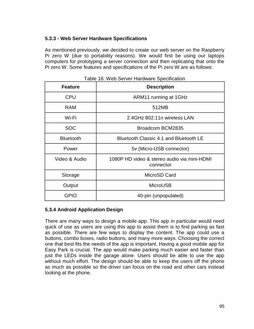
95
5.3.3 - Web Server Hardware Specifications As mentioned previously, we decided to create our web server on the Raspberry Pi zero W (due to portability reasons). We would first be using our laptops computers for prototyping a server connection and then replicating that onto the Pi zero W. Some features and specifications of the Pi zero W are as follows:
Table 16: Web Server Hardware Specification
Feature Description
CPU ARM11 running at 1GHz
RAM 512MB
Wi-Fi 2.4GHz 802.11n wireless LAN
SOC Broadcom BCM2835
Bluetooth Bluetooth Classic 4.1 and Bluetooth LE
Power 5v (Micro-USB connector)
Video & Audio 1080P HD video & stereo audio via mini-HDMI connector
Storage MicroSD Card
Output MicroUSB
GPIO 40-pin (unpopulated)
5.3.4 Android Application Design There are many ways to design a mobile app. This app in particular would need quick of use as users are using this app to assist them is to find parking as fast as possible. There are few ways to display the content. The app could use a buttons, combo boxes, radio buttons, and many more ways. Choosing the correct one that best fits the needs of the app is important. Having a good mobile app for Easy Park is crucial. The app would make parking much easier and faster than just the LEDs inside the garage alone. Users should be able to use the app without much effort. The design should be able to keep the users off the phone as much as possible so the driver can focus on the road and other cars instead looking at the phone.

96
5.3.4.1 Homepage Design There are many different ways to approach the homepage. Having a login would change what the first appearance of the app will look versus something that does not include a user database. In Figure 26 and Figure 27, it illustrates what the homepages could possible look like. The homepage could be a login screen which is shown in Figure 26. A login screen would be needed if the user would like to use a payment feature. Instead of the user going to the parking pay station to pay for parking. They could just use the payment feature to save time. With the installment of a login feature. The database now will need to keep track of data for user now. It would need to keep track of their name, address, and car. So that when they use the payment feature UCF parking service or any parking services will know that they paid for parking. The car information will need to include a license plate number to verify a unique car and the car itself to easily identify it. The UCF parking service worker can check for tags or decals but when they come across a car that does not have any they need to check in the system if the car has paid for a temporary parking permit. This can be another app on its own which only UCF parking services will have access to. If the user does choose to pay through the Easy Park app then when they park they will not be able to back in park. The license plate will need to be revealed so that the parking service works can see the license plate easier. If the car is back in it is possible they parked too far back such that worker will not be able to confirm the license plate number. Even if the car is not backed up all the way, this will still give works a hard time to see the license plate. This problem can simply be avoided by not letting the users back in park. Creating a login and having a user database will now need have security involved and needs to be protected. This results in additional results. Now the user can have saved data in the app, they could also choose to save their credit card number to make parking even faster. However, if a user chooses not to sign up and not have an account it should function just the same but without the payment parking feature. The homepage illustrated in Figure 26 will only show up when the user first install the Easy Park app, when the user logs off, or when the system logs the user off. The app should be able to keep the user logged in until the user logs off or until the system logs the user off. This will help speed the process of using this app. Having to sign in every time or skipping the front page is a waste of time. The app should also remember if the user chose to log in to begin with. If the user initially skipped the login the app should go straight to the page with list of garages and lots. An option to sign in should also be available to the user if they choose to sign up. This should be shown at the top of every page. This is also where the user’s name should be displayed if the user was logged in. This is illustrated in Figure 27 and 29 for when the user is signed in and Figure 28 for when the user hasn’t signed in and can sign up. By pressing on the name it should go to the users setting to edit their information. Pressing on sign up

97
should lead the user to the same sign up page given the user who create an account for the first time. After the login, the screen would transition to the next page which would be shown in Figure 27. Another transition could be the use other locations such as Rosen, Downtown, or a regional campuses could also be used in the same app. If there was no login, this would eliminate the login homepage, and no location option then Figure 27 would be the homepage. In our current design there is no location option due to their only being one location, UCF main campus. Easy Park’s goal is only for UCF parking. Adding location feature could confuse the user. However, if Easy Park does expand to other campuses then implementing a location page will not be too much trouble.
Figure 26: Homepage Login Figure 27: List of Garages 5.3.4.2 List of Garages/Lots Page The next page, which is shown in Figure 27, which would go after the homepage is the list of garages and lots or this would be the homepage if there was no user login. It is important that this page is done correctly. This is the page the users will go to and use the most. The user will need to be able to read and use the app as easily as possible. This mobile app is supposed to help users find parking fast and if they cannot operate the mobile app swiftly then it would not serve its complete purpose. As shown in Figure 27, the Lots section is cut off in the image. This is to show that it can be scrolled down. Creating another page for the Lots would just slow down the user's productivity. A new page would need to be

98
loaded. Another way to implement a scroll would be from left to right. We went with the approach to scroll down because of usability. Users who use many app are used to scrolling down for the same content. A swipe to the left or right usually meant something new or something else which could confuse the user. There a few ways to display how full the garage is. A way to display this could be to use by text based and there are a few ways to do this. Display the percentage of how full the garage/lot is or show the ratio of the garage. For example, Garage A: 70% or Garage A: 576/1024. Using a percentage is alright but the users will not know the actual number of how many spots are next. Showing the ratio is much more useful but now the user will have to do math to find out how many parking spots are open. This can be solved by only showing the number of spots available. In our design we chose to not use numbers but a bar to show how full the garage is. The bar is also color coded, a glance could easily tell the user how full the garage is. At 90% full the bar is red, at 70% full the bar is range, at 50% full the bar is yellow, and less than 50% full is green. A color coded bar to indicate how full the garage works best due to how easy it is to read. For example, If I quickly saw red for Garage A but saw green for Garage B and Garage B is only a bit further to the classroom. Going to class is more important than trying to find a place to park your car. So finding parking quickly and getting to class is of the essence. Another key feature about our design is the bookmark feature. The bookmark feature would save the garages and lots that are most common to the user. Something to be added would be to add a section on top for only the bookmarked pages. As of the design now, the bookmark is only shown at the top of their respective section. Having a bookmark is very useful for reusability. This is meant for people to use every time they park at UCF, which for students would be daily. The bookmark shall be saved locally so that users who do not want to sign in should still be able to use the mobile app as if someone who were signed in. 5.3.4.3 - Floor Selection
The floor selection page is shown in Figure 28. The way to display how full the floor is using the same technique as how full a garage was. A colored bar showing the percentage of how full the garage is. Again, this technique was used to let user use the app swiftly. Something that differs from the page showing how full the garages and lots are that it does not have the bookmark feature. The garage will usually fill in a linear fashion. Where the previous floor fills up before the next floor gets filled up. But when the garages are already fully saturated. Parks spots are very limited so the user should be picky when it comes to which floor they will park on.
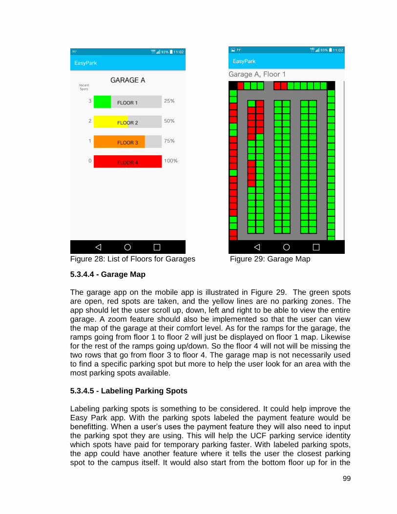
99
Figure 28: List of Floors for Garages Figure 29: Garage Map
5.3.4.4 - Garage Map The garage app on the mobile app is illustrated in Figure 29. The green spots are open, red spots are taken, and the yellow lines are no parking zones. The app should let the user scroll up, down, left and right to be able to view the entire garage. A zoom feature should also be implemented so that the user can view the map of the garage at their comfort level. As for the ramps for the garage, the ramps going from floor 1 to floor 2 will just be displayed on floor 1 map. Likewise for the rest of the ramps going up/down. So the floor 4 will not will be missing the two rows that go from floor 3 to floor 4. The garage map is not necessarily used to find a specific parking spot but more to help the user look for an area with the most parking spots available. 5.3.4.5 - Labeling Parking Spots Labeling parking spots is something to be considered. It could help improve the Easy Park app. With the parking spots labeled the payment feature would be benefitting. When a user’s uses the payment feature they will also need to input the parking spot they are using. This will help the UCF parking service identity which spots have paid for temporary parking faster. With labeled parking spots, the app could have another feature where it tells the user the closest parking spot to the campus itself. It would also start from the bottom floor up for in the

100
garages. The user could pick the closest parking in the garage or overall with all the lots and garages. The garage map would need to label the parking spots. When the users zooms out to a certain amount the labels will disappear to keep a cleaner look of the garage map. There are a few ways we can label the parking spots. We could label floor, then the row, then the parking spot number. It could consist of four digits. For example, Floor 1, Row 1, parking spot 5 would just be labeled as 1105. This would limit the amount of row possible but we can add another digit which would make it 5 digits long, this would be too many number to glance at. To solve this we could use letters instead which would let there be 26 rows. Enough for a UCF parking garage. This will then be labeled as 1A05. 5.3.4.6 - Conclusion The Easy Park mobile app is made to assist users to find parking faster. The app is only optional and can only benefit the user. However, if they choose not to use the app there are still LED’s inside the garage to help the user find parking. Each page on the app is used to help the user find a parking spot as swiftly as possible. The design choices we made were to help the user read, comprehend, and use the information as efficiently as possible. A thing to note is that when the garage is full around by 12:00pm the app could help users find parking spot where they normally would not look due to it being a waste of time trying to look for a parking spot far away from their classroom. Going from one garage can take couple of times rather than circling around the same garage.

101
6 – Testing Vigorous testing needs to be done before any products go out on the market. Testing all the possible different scenarios to be sure the product will work in the real world with few problems.
6.1 - Hardware Testing In this section we discuss the hardware testing. Faulty hardware can be harder to repair compared to software repairs. It might be hard to find out which component is not working properly when there are many different components in the system. So hardware testing is crucial to a complete product. 6.1.1 - Hardware Test Environment The majority of hardware testing will be performed at the Senior Design laboratory at UCF, located in Engineering 1, room 456. The laboratory equipment provided at the ten stations of the lab includes:
● Tektronix MSO 4034B Digital Mixed Signal Oscilloscope, 350 MHz, 4 Channel
● Tektronix AFG 3022 Dual Channel Arbitrary Function Generator, 25 MHz ● Tektronix DMM 4050 6 ½ Digit Precision Multimeter ● Agilent E3630A Triple Output DC Power Supply ● Dell OptiPlex 960 Computer
Note: Additional instruments and equipment items available for checkout. The hardware testing of the solar panel should be limited to outdoor garage testing and will be tested by measuring and recording the open-circuit voltages and output currents in varying altitudes for inside the garage and in different weather characteristics of cloud cover and shadow castings (excluding extreme weather conditions for safety purposes) for outside the garage (including the top of the garage where the panels are also exposed to sky conditions). Results obtained from outdoor testing will be replicated indoors and modeled to the circuit using the DC power supply provided in the laboratory. The hardware testing could be simulated indoors for approximations and convenience, however outside testing will yield the most accurate results. 6.1.2 - Solar Panel Testing Table 20 below shows the open-circuit voltages and the output current by two STP001P solar panel in series, manufactured by UL-SOLAR Inc. The panel will be measured in various lighting conditions that could be applied during operation of charging the battery. These conditions will happen throughout the times of the day, so they do affect both the current and voltages directly. The currents and

102
voltages were measured with no load using the DMM in the lab. The dimensions of the panels are 5 x 5 x 0.19 inch.
Table 20: Solar Panel Voltages & Currents
Types of lighting Open-circuit voltage, VOC
(V) Output current, IO (uA)
Regular lights inside (main SD lights are on)
4.58 145
Extra lighting (favorable conditions)
7.87 575
Dim lighting (simulated garage lighting)
1.75 30
The results were not promising. The battery would not be able to charge completely overnight by the output current, also known as the charge rate, of the solar panel. All the output currents from testing are in the micro range, meaning that the solar panels are going to take weeks to charge the battery completely. A bigger solar panel would be able to increase the output current from a panel, thus can reduce the amount of time it takes to charge the battery. The small dimensions specification for Easy Park would become violated and installation ease would cease. More time is being allocated into finding an appropriate module to charge the battery module for Easy Park. Best case scenario, the rated maximum power of the STP001P solar panel is 1 W (so a combined rated maximum power of 2 W when panels are connected in series). For example, a 9 V battery was connected in parallel with the solar panel for charging and has a capacity of 600 mAh. The charge rate would be determined by dividing the rated maximum power by the nominal voltage of the battery. This yields a charge rate of 0.222 A, or 222 mA. The charge time can be determined by the capacity of the battery divided by the charge rate. Hence, the charge time to charge an empty battery completely would be approximately 2.7 hours. 6.1.3 - MCU Testing Hardware testing of the microcontroller is the most important to integrate all of the components together as it is going to be the core of the PCB board. The entire Easy Park system will not work without microcontrollers. Verifying that all of the components are connected to the microcontroller in the corresponding pin

103
base on the ATmega328 pin layout. The values of the components, such as the resistors, capacitors, and inductors, should be about the same as the proposed overall design schematic. Once all the connections are verified, the microcontroller should be powered. The Multimeter would be used to measure/test the voltage at each pin of the board to check that the measured voltages closely match the expected voltage values. If a component does not work as intended, there might be some software issues that need debugging in the code. The microcontroller and ultrasonic sensor functions properly if the measured distances displayed on the computer screen are correct, or close to the measured distances. No response from the microcontroller means that there is a problem with the microcontroller, assuming the other hardware components were tested with success. Connections to the microcontroller would need to be checked again, or a different microcontroller would replace the old one to avoid any further complications and stress. We tested the digital pins of the Arduino MCU chip varying the voltage input from a range of voltage values. Apparently, there is a built-in voltage regulator from the input voltage levels of 7V to 9V. The digital pins would output around 5V when set to HIGH. Any input voltages lower than 3.8V would render the digital pins useless as they output 0V. The voltage when all pins are set to LOW is 0.61mV to 0.93mV at Vin = 3.8V. The voltage when all pins are off is 1mV to 2mV at Vin = 5V. The voltage when all pins are off is 1.6mV to 2.49mV at Vin = 9V. Table 21 lists the results from testing in the lab.
Table 21: MCU digital pin testing
Input Voltage (V) Input Current (A)
Are all pins outputting the same?
Digital Pin Average Voltage (HIGH)
1 0 Y 0
2 0 Y 0
3.8 (lowest operating voltage)
0.007 Y 2.718-2.719
4 0.008 Y 2.912-2.913
5 0.012 Y 3.8927-3.8948
6 0.018 Y 4.8246-4.839

104
7 0.019 Y 5.037-5.042
8 0.019 Y 5.052-5.053
9 0.019 Y 5.059-5.060
6.1.4 - AMS1117-3.3 DC Voltage Regulator Testing The AMS1117 voltage regulator is able to step down a range of 4.75 to 12 volts, down to 3.3 volts and is capable of handling up to 0.8 amps of current. The importance of this regulator is as a contingency to whether or not the AtMega MCU can output power to all components connected to it. If the MCU fails to deliver results, the linear regulator will shoulder the burden by stepping down the 9 volt power source to 3.3 volts in order to power the Bluetooth, Wi-Fi, and LED matrix. Of course, the Easy park team would love to build a linear regulator that can match to these standards or even close to modern technology. The team has not forgotten, but if the current future regulator fails, this regulator will serve as a backup until a proper design is replicated. Testing the AMS1117 linear regulator is simple enough since there are imprinted letters that lets users know which of the three pins are which. Reading from left to right, there is the Vin, Vout, and Gnd pins. A DC power supply will have its positive end connected with the input of the linear regulator. The ground of the regulator will be connected with the ground of the DC power supply. A Digital Multimeter will be used to measure, with the positive end, the output voltage of the regulator, while the negative end of the DMM will be connected to the ground node, shared with the other components. Voltage will be taken from the regulator via varying input constant DC voltages. From 3 volt to 9 volts, is the testing range for the DMM. There are multiple reasons for testing in this manner. The first reason is to ensure that the control voltage regulator is in proper working order, in accordance to the datasheets provided. Each regulator manufactured in different and does not perform exactly the same as the others made by the same company. Furthermore, in order to maximize energy efficiency is to find the minimum operation requirements of the regulator. The second reason is that the MCU may operate from 3.3 to 5 volts for every Digital Pin, when it is set to HIGH. This will require the use of the regulator for components that operates at 3.3 V. Also, the regulator may not work properly when these voltages are applied. The regulator may not be able to step a voltage of 3.8 to 3.3. This may warrant the need of a custom regulator outside of this one.

105
Below is Figure 30, which is a physical representation of how the testing is implemented. In the figure, there exists circular pluses, minuses, and Xs per corresponding block. Each block has a name to represents the components used for testing the voltage regulator. Circular black nodes means that the extending lines are directly connected. Over laps without these nodes are not connected. The linear regulator’s plus represents the input voltage, the minus represents the ground, and the X represents the output voltage to be measured by the DMM. The DMM is also grounded. DC power supplies power to the regulator via its own plus. The DC power also grounds the entire circuit with the minus.
Figure 30: Breadboard Layout Block Diagram
Table 22: Linear Regulator’s voltage output
Input Voltage (DC Power) Output Voltage (Regulator)
3 2.116
4 3.066
5 3.29
6 3.297
7 3.298
8 3.299
9 3.298
The table above represent the testing results of the linear regulator testing. As expected, the device works at voltages above 5 volts. Going any lower does not make voltage matching any easier for the regulator. The voltage of the MCU will not be able to go above 5 volts to have the linear regulator output 3.3 volts exactly. It would be better to build a regulator that matches the voltage

106
fluctuations of the MCU, and leave this regulator as a bridge in powering components that the MCU cannot properly do. 6.1.5 - ESP8266-01 Wi-Fi testing The ESP8266-01 Wi-Fi module requires 3.3 volts and 80mA for it to function properly. This device is one of the components that the MCU will power directly. As stated in the previous section, figuring out the minimum voltage requirements that the device can still properly function on is crucial for good power management. This testing is also done to make sure if there is a built in voltage regulator to factor in. Knowing this will save the trouble of devising a custom regulator to match the MCU digital port fluctuations. Testing of the ESP8266-01 Wi-Fi module is very similar to testing the linear regulator. There are 8 pins. A data sheet is used to identify the pins, since there are none printed on the board. GPIO0, GPIO2, CH_PD, and VCC will be set to 3.3 volts. GND will be set the DC Power’s negative port. TXID will be set to the DMM’s positive port. The GPIO pins are general pins that activates the program inside the WI-FI module, when not connected to the MCU. CH_PD enables the module to work and the VCC powers the device. The TXID pin transmits data from the Wi-Fi to the MCU, so it will be measured. There is a blinking blue LED program that uses the LEDs built onto the module. This program represents if the device can perform preloaded instructions, under varying conditions. From 2.0 to 4.0 volts, the device will take in this voltage and if the LEDs are blinking, it is able to work in these conditions.
Table 23: Wi-Fi voltage output
Input Voltage Transmitted Voltage Blinking LED
2.3 2.257 no
2.5 2.45 yes
3.3 3.257 yes
3.9 3.856 yes
The above Table 23 represents the voltage output findings of the WI-FI module. The transmitted voltage is almost close to the input voltages. The reason why it is not exact is that about 0.040 volts of the DC power is supplying power to the LEDs. Furthermore, there exists a red LED that lets users know that the device is being supplied power. The input voltage of 2.5 represents the lowest possible voltage that the device can function in performing the preloaded program. Also, the device can perform beyond 3.9 volts, but the main idea in this testing is to know if there is a built in regulator. Our findings indicates that unless the MCU is

107
able to output a voltage above 3.9, there is no need for a custom voltage regulator. 6.1.6 - HM-10 Bluetooth testing The HM-10 Bluetooth requires 3.6 volts and a current of 20mA to operate. The device can also function below these standards. This device will be used by all Easy Park devices to promote the use of the mesh network and will be powered by the MCU. Unlike the Wi-Fi module, this device comes with imprinted words that tells the user the operating voltage range and port functions. The Easy Park team suspects a built in voltage regulator. This will mean that this device will also not require an outside regulator, and is very compatible to the AtMega MCU, which it should. So is the Ultrasonic sensor. Testing of the HM-10 Bluetooth module is very similar to testing the ESP8266-01 Wi-Fi module. There are 3 pins of importance: TXD, VCC, and GND. GND will be set the DC Power’s negative port. TXD will be set to the DMM’s positive port. The VCC powers the device. The TXD pin transmits data from the Bluetooth to the MCU, so it will be measured. There is a blinking red LED program that uses the LEDs built onto the module. This program represents if the device can transmit data properly. If the LED does not flash but is on, this will represent the stopping point of the testing in terms of lowering the voltage input. From 2.1 to 4.0 volts, the device will take in this voltage and if the LEDs are blinking, it is able to work in these conditions. The operating current 8 to 9 amps. The Bluetooth may require more for outputting signals, but the Easy Park devices are roughly 10-15 feet away from each other. The blinking means it is transmitting signals so supplying amps to the device is not of high concern. The table below presents Easy Park’s findings in the functionality of the Bluetooth module. 2.2 volts represents the lowest possible voltage for the Bluetooth device. Keep in mind that the range is unknown at this point. It isn’t until 4 volts that 3.3 output voltage is truly possible. At 3.3 volts, the device outputs 2.883 volts, not the desired 3.3 volts. In conclusion, the stated power input of 3.6-6V is true. The Bluetooth requires any voltage above 3.6 volts to function well. This device does not need a custom voltage regulator, which is also expected.
Table 24: Wi-Fi voltage output
Input Voltage Transmitted Voltage Blinking LED
2.1 1.766 no
2.2 1.833 yes
3.0 2.630 yes

108
3.3 2.833 yes
3.6 3.265 yes
4.0 3.302 yes
5.0 3.303 yes
6.2 - Software Testing The following pictures in Figure 31 and Figure 32 shows both testing’s of the Bluetooth and Wi-Fi modules with the Arduino Nano microcontroller individually.
Figure 31: Bluetooth module testing picture

109
Figure 32: Wi-Fi module testing picture
6.2.1 - HM-10 Bluetooth testing
Testing the Bluetooth module and getting it to respond was a little tricky because of the many variants of this module available, made by different manufacturers. In other words, identifying what variant that we were working on and finding the right source of information online for setting it up was usually the difficult part. In the online world, many people had their own ways of testing and using the HM-10. And after much research, we found out two main ways that the HM-10 can be used for testing, one is through hardware serial ports and the other is through the Arduino IDE’s software serial configuration, using the Digital pins on our microcontroller (Arduino Nano). The hardware serial consists of communicating with the HM-10 through a UART interface using AT commands, however we weren’t able to get it to run since we weren’t able to find sufficient information (e.g. code) available online (as mentioned before, due to the large variance of this Bluetooth module). Software serial decreases the continuous use of the AT commands through the serial monitor terminal for programming the module, as the commands are just written and defined in code, and the flashed onto the Bluetooth module. Fortunately enough, we were able to find an open source piece of code that enabled us to detect and run the HM-10 through software serial. This is just the first step since our main goal is to make two hm-10’s communicate with each other, in fashion of forming a mesh network. The following table shows how the Bluetooth module was connected to our Arduino Nano:

110
Table 17: Pin connections for Bluetooth LE and Arduino Nano
HM-10 (Bluetooth LE Module) Arduino Nano (ATMega328P)
TX (Pin) RX (Pin 7) - Software Defined
RX (Pin) TX (Pin 8) - Software Defined
VCC 5V (Positive Potential)
GND GND
The table above may make better sense by looking at this piece of code below. Over here, we are simply instantiating pins 7 and 8, which correspond to digital pins D7 and D8 on the Arduino Nano. The way it is setup is that, the microcontroller is flashed with this piece of code, which then starts listening on those specified pins for data from the HM-10, after transmitting data through the serial monitor by processing AT Commands. E.g. just by typing a simple AT command gave us an ‘OK’ message, meaning that everything is connected the right way. In other words, the MCU sends from its TX (D8) to the Bluetooth modules RX (receive pin) an AT command, and then the Bluetooth module gets that information and sends it back to the MCU from its TX (transmit pin) to the MCUs RX (D7). It is important to understand that the transmitting and receiving baud rates match up, otherwise nothing or garbage values would be display in return. In this case, the baud rate for both, the MCU and Bluetooth modules are set a 9600. This HM-10 module can also be programmed using an android app and changes can also be viewed directly when being programmed from a microcontroller, on the app. This give an extra edge of debugging this Bluetooth module. 6.2.2 - ESP8266-01 Wi-Fi Testing Testing the ESP-01 has been quite the challenge and it is something that one cannot know by just reading the data sheet or any other included manual since there are a lot more factors that come into play. Starting off, this Wi-Fi module can be programmed in the same way as the HM-10 (Bluetooth module) i.e. through hardware and software serial interfaces through the microcontroller, including even an easier approach i.e. using a USB to TTL adapter or FDTI cable. Using the last approach eliminates the middle-man (the microcontroller), enabling the Wi-Fi module to be directly connected to the computer and programmed by the IDE (after some driver installation). Luckily, thanks to the community and some other contributing people, the Arduino IDE has a package that specifically supports most variants of the ESP8266, which can be downloaded through the board’s manager.
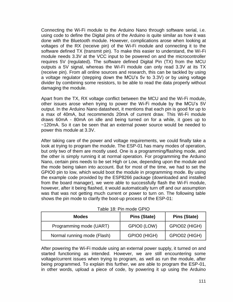
111
Connecting the Wi-Fi module to the Arduino Nano through software serial, i.e. using code to define the Digital pins of the Arduino is quite similar as how it was done with the Bluetooth module. However, complications arose when looking at voltages of the RX (receive pin) of the Wi-Fi module and connecting it to the software defined TX (transmit pin). To make this easier to understand, the Wi-Fi module needs 3.3V at the VCC input to be powered on and the microcontroller requires 5V (regulated). The software defined Digital Pin (TX) from the MCU outputs a 5V signal, whereas the Wi-Fi module can only read 3.3V at its TX (receive pin). From all online sources and research, this can be tackled by using a voltage regulator (stepping down the MCU’s 5v to 3.3V) or by using voltage divider by combining some resistors, to be able to read the data properly without damaging the module. Apart from the TX, RX voltage conflict between the MCU and the Wi-Fi module, other issues arose when trying to power the Wi-Fi module by the MCU’s 5V output. In the Arduino Nano datasheet, it mentions that each pin is good for up to a max of 40mA, but recommends 20mA of current draw. This Wi-Fi module draws 60mA - 80mA on idle and being turned on for a while, it goes up to ~120mA. So it can be seen that an external power source would be needed to power this module at 3.3V. After taking care of the power and voltage requirements, we could finally take a look at trying to program the module. The ESP-01 has many modes of operation, but only two of them are mostly used. One is a programming/flashing mode, and the other is simply running it at normal operation. For programming the Arduino Nano, certain pins needs to be set High or Low, depending upon the module and the mode being taken into account. But for most of the time, we had to set the GPIO0 pin to low, which would boot the module in programming mode. By using the example code provided by the ESP8266 package (downloaded and installed from the board manager), we were able to successfully flash the Wi-Fi module, however, after it being flashed, it would automatically turn off and our assumption was that was not getting much current or power to turn on. The following table shows the pin mode to clarify the boot-up process of the ESP-01:
Table 18: Pin mode GPIO
Modes Pins (State) Pins (State)
Programming mode (UART) GPIO0 (LOW) GPIO02 (HIGH)
Normal running mode (Flash) GPIO0 (HIGH) GPIO02 (HIGH)
After powering the Wi-Fi module using an external power supply, it turned on and started functioning as intended. However, we are still encountering some voltage/current issues when trying to program, as well as run the module, after being programmed. To explain this further, we are able to program the ESP-01, in other words, upload a piece of code, by powering it up using the Arduino

112
Nanos 3.3V output pin, after which the module abruptly turns off. Now after we reconfigure the pins (enabling the Wi-Fi module to run in flash/normal running mode), it refuses to turn on using the modules rated ~40mA (pin) power rating, even though it ran perfectly fine when it was in programming mode, where the code was uploaded successfully. On the other hand, the module turns on as expected when it’s in normal operating mode, after being powered by an external DC power source, although when trying to program it using this external source, it would just continuously fail from the code being uploaded in the IDE. We have tried to make some assumptions of this problem being an unclean external voltage source since the only time it fails is during the upload process or when programming the module. A few remedies that might fix this issue would be to use a capacitor in series with the VCC pin, to give a clean supply of current, removing any possibilities of spikes. Another idea that we had was to use a similar external power source for both devices, the Wi-Fi module, as well as the MCU e.g. by using a 9V battery and then stepping down its voltage through a voltage regulator for the 5V MCU input and 3.3V for the Wi-Fi module and test out the results that way. 6.2.3 - HC-SR04 Ultrasonic Sensor Testing The name of the ultrasonic sensor we are using are HC-SR04. These ultrasonic sensors are not waterproof so they cannot not be used on the top floor of the garage currently. We are using the Arduino Nano board with the ATMega328p microprocessor to test the ultrasonic sensor. In the remainder of this section we talk about how the components are connected, how they communicate with the computer or IDE, and what testing were done with the components. 6.2.3.1 - Connecting components We used a breadboard to connect the components together to make things easier. First, the Arduino Nano is placed on the breadboard. Then the ultrasonic sensor was connected to the appropriate pins microprocessor by the holes on the breadboard with wires. There are four connections that are on the ultrasonic sensor that need be connected to the microprocessor. These connections include, Vcc, trigger, echo, and ground. The Vcc is connected to the 5v pin on the microcontroller, the trig can be connected to any open pin such as pin D3, and the echo can also be connected to any open pin as long as it was not taken such as pin D5. After all the wire were connected, we connected the Arduino Nano to the computer via USB. The connections are shown in Table 19.
Table 19: Pin connections for Ultrasonic Sensor and Arduino Nano
HC-SR04 (Ultrasonic Sensor Module)
Arduino Nano (ATMega328P)
TX (Pin) RX (Pin 2) - Software Defined

113
RX (Pin) TX (Pin 4) - Software Defined
VCC 5V (Positive Potential)
GND GND
6.2.3.2 - Communicating Arduino Nano and PC (Arduino IDE) Using the Arduino IDE we ran a sample code to get the ultrasonic sensor to get a reading. For the computer to communicate with the Arduino it uses UART, serial communication. The serial is set to a baud rate of 9600. Using the functions from the Arduino IDE library, the pinMode function sets a pin to either input or output. The trigger pin is set to output. When the trigger pin is set to high, it will trigger the ultrasonic sensor to output a signal. This signal is an ultrasonic sound at 40 kHz. Next, the trigger pin is set to low. This is done by using the digital Write function, it sets the pin to either low or high. Low is set to ground or 0V and high is set to 5V. The trigger pin is first set to low mode for a short time to ensure a clean high pulse. After a delay of a few microseconds, the trigger is set to high to output a signal for another 10 microseconds then to low again. Using the pinMode function again, the echo pin is set to input. Then the pulse IN function is used read the pulse, which can be either high or low, and get an input from the echo of the output signal. The pulse IN function returns the duration of the time it took for the trigger pin to output the sound and echo receive the input. This time is given in microseconds. To interpret the time it took for the sound to travel the distance we can use an equation. The speed at which sound travels at is 1130 feet per second, this equates to 73.746 microseconds per inch. The total duration is divided by 73.746 to get the distance the sound traveled. Since the sound is traveling to the object and back we need to divide the duration of the total time the sound travel by two. This will give the distance one way to the object. For the metric (centimeter) equation, the speed at which sound travels is 340 meters per second which then equates to 29 microseconds per centimeter. Again, the total duration needs to be divided by the 29 then by 2 to get the distance the sound traveled to the object. 6.2.3.3 - Testing the Ultrasonic Sensor A depth sensor reading test was performed on each ultrasonic sensor to ensure the distance reading is reading correctly to detect objects, small and large. The distance was measured to read the actual distance from where the sensor is pointing at to an object using the measuring tape to the nearest inch/centimeter and compared to distance calculated from the Arduino IDE using the values received from the ultrasonic sensors. A slight deviation value from the actual distance is allowed, preferably +/- an inch, to consider the sensor is functioning properly. Different objects were placed in the field of vision of the sensor to make observations on how the readings change from object-to-object.

114
Another test was done on the connection between the sensor and microcontroller, verifying that there are no loose connections on the pins of the microcontroller and the wires are connected to each of their respective pins. Once the test on one sensor is complete, the next test involves multiple sensors that would be connected to a single microcontroller, making sure that all of the sensors communicated with the microcontroller. For Easy Park, we do not need the highest accuracy so measuring to the nearest inch or nearest centimeter will detect vehicles just fine. In fact, there is a lot of leeway for the accuracy since there are many different cars. The measurements were taken from the tips of the ultrasonic sensor to a book placed along the ruler to measure the distance. The measurements resulted in about an eighth of an inch in deviation. This is a good result as it rounds to the correct nearest inch. We also measured a distance of about 12 feet (144 inches) from the sensor to the book. The results were about 146 to 147 inches from the computer monitor. These are good results considering the 12 foot was measured in approximation. For Easy Park, we probably do not need the ultrasonic sensor to read a distance of 12 feet since the sensor is going to be located in close proximity, pointing directly at the vehicle in a perpendicular angle, but knowing the ultrasonic sensor can read distance to at least 12 feet is a good indication that the ultrasonic sensor is capable of a long range of distances. As mentioned before in the research section for ultrasonic sensor, it is best to keep the measurement in a straight line as much as possible for optimum accuracy. However, with this in mind we still tested how the ultrasonic sensor would work with objects that are in an angle. This angle was done by eyeballing the angle of the object and the ultrasonic sensor. The test kept the ultrasonic sensor perpendicular with the floor pointing up and then having an object, such as a book, above it at about 10 inches. We tilted the book gradually until the results became incorrect. This resulted in the objected to be tilted at about 45 degrees, anything larger than 45 degrees would result in an incorrect measurement. Since the angles were being eyeballed the degrees could be about 3 degrees off, given the confidence of how well we can eyeball the angle of an object. It would be safe to say that if the object were to be angle at less than 35 degrees the ultrasonic sensor measure will still be correct. Ideally, one microcontroller will be installed for two or three parking spots, depending on the decision on where to mount the PCB unit. The datasheet stated that the effectual angle of the sensor is less than 15 degrees, an effectual angle far less than the experimental results found at the lab. The ultrasonic sensors cannot be tested on a full-scale model garage as our group has not acquired exclusive access to a whole garage. Scheduling the testing of the sensors in a UCF garage on an uneventful day or period would need to take place in order to gain relevant information of the true functionality in a parking garage environment.

115
In addition to sensor testing, the amount of time it takes for the sound wave to reflect back to the transducer of the receiver of the sensor. Information feedback from the sensor is needed for the microcontroller needs to be consistently fast so that this information can be uploaded to the database and become updated on the application interface, close to real time. 6.2.4 - Testing Mobile Application Our mobile app will only be for android users at the moment. We could possibly use swift to create an app for iOS user and visual studios which uses C# for windows phones applications. We could also possibly use JQuery Mobile to create the app since the code will work for all the 3 major phone operating systems. When testing the mobile app we should test in the perspective of the users. So the mobile app should be published in the Google Play store or the Apple App Store so that the user will be able to download the mobile application. The mobile app will be test through an emulator of the operating system. It can also be tested on physical mobile phones. Testing the mobile application will also involve the use of the mesh network. This demonstrates the entire Easy Park project as a whole. The end results will be displayed on the mobile application. 6.2.4.1 - Testing the mobile application procedure
1. The app will open up to a splash screen followed by a page listing the garages.
2. The garages should show how full the garages are. There are four different color scales to easily identify how full the garages are. At greater than or equal to 90% full the bar is red, at 70%-89% full the bar is orange, at 50%-69% full the bar is yellow, and less than 50% full is green.
a. Trigger the first node, wait a few seconds for the data to be relayed and updated in the database. The app should automatically refresh so the change should happen without touching the phone. Check the app for the following. Repeat until all four nodes are occupied.
b. Test if the colored progress bars are working i. If none or one of the parking spots are taken the bar should
appear green. ii. If two of the parking spots are taken the bar should appear
yellow. iii. If three of the parking spots are taken the bar should appear
orange. iv. If all four parking spots are taken the bar should appear red.
3. Next choose a garage. a. The garage should list the floors in the garage.

116
i. The list of floors should show will display how full the floor the same way the garages are displayed.
ii. The same test can applied as step 2. 4. Pick a floor.
a. A map of the floor will be shown, green spot are open and red spots are taken.
b. The same test can applied as step 2 but instead look for changes in the parking spot and not a progress bar.
6.2.4.2 - Conclusion To conclude, testing the mobile application before it gets published is imperative to a good product. For Easy Park, the mobile app can play an even more important role for a user to find parking. The LEDs inside the garage can only help the users to a certain extent. Testing the mobile app to make sure that the user can easily setup and use the app sets a good example of a first impression. Each step should go through the entire app testing each page and the features. Testing the app can show signs of ambiguity which would need to be fixed to make the app more usable. It also can also help make better design. Some features might work but maybe it can be made better. Maybe some design choices that were made were not as good as it seems and needs to be approached another way. 6.2.5 - Testing Mesh Network To test the mesh network, a minimum of three Easy Park devices will be needed to test the mesh network. There is a minimum of three devices to test the mesh network so that we can test if the middle fails the network will still be functioning and the failed node is the only one not working. The Easy Park will also be referred to as a node. The mesh network is connected through Bluetooth LE. It is then connected to another device that has a Wi-Fi module attached. This device will send the data from the mesh network to the server. A strong network is good for Easy Park. In Figure 33, the circles represent Easy Park device 2 and the square represents Easy Park device 1. Easy Park device 1 is the device with the WiFi module while Easy park device 2 is the device without the WiFi module and utilizes the ATmega328p-pu. 6.2.5.1 - Testing the mesh network configuration/procedure The test configuration we used will have four nodes in the mesh network, 3 nodes without the WiFi module and 1 with the WiFi module. The nodes will be in a square formation. Node 1 will be able to connect either node 2 or 3. Both node 2 and 3 will only connect to node 4. Node 4 should the connect to the server/database update the data.

117
Figure 33: Layout of Mesh Network
The first run though would trigger node 1, it should then attempt to connect to node 2. If node 2 is busy or a bad node then node 1 should attempt to connect to node 3. If node 3 is busy or a bad node it should attempt to connect node 2 again if it was busy. Node 1 should will alternate back and forth until the data has been sent. A message is sent back to node 1 letting it know the data has been received. Node 2 and 3 only path is to node 4. So the data for node 1 will be relayed through node 2 or 3 to get to node 4. 6.2.5.2 - Conclusion Testing the mesh network was successful. Node 4 was able to receive the data from each node, node 1 data was relayed through node 2 and 3. A problem did occur while testing. If we to take occupy or leave all the node at the same time. Only three of the nodes would update properly. Since BLE can only connect two BLE modules at one time.. Node 4 will send the data to the server first, update, then be available to be connected to. There will be only two connections when all the spots are occupied. So either node 2 or 3 will be able to connect to Node 4 and the gets sent successfully. However, when node 1 connected to either node 2 or 3 the data gets lost. This is because this node, either node 2 or 3, has its own data to be sent and will lose the data from node 1 that needs to be relayed. This could be fixed possibly by using a threading, a stack, or a linked list. 6.2.6 - Testing Server Testing the server is one the last test that should be made since the server connects the hardware to the software together. To test the server we will need a node, this is the same node as the Easy Park device with a Bluetooth LE module attached. This node will then communicate to the device with a Wi-Fi module and this device will communicate directly with the server. The server is then used to communicate with the mobile app. This test will only work if all the other tests were successful. The other tests include, the mesh network test, the app test. If these two tests are successful then we can use these components in the server test.
118
The Easy Park device should default the parking spot to be false, there is no car parked there. This is just simply having the sensor not reaching below the threshold. The threshold for the sensor to trigger true is at less than 3 feet. So have nothing above the sensor at a minimum of 3 feet, this is assuming the sensor is perpendicular with the ground. Check if the value of the node’s ID is false. Then have something above the sensor at less than 3 feet. Check if the value has changed and also measure the time it took to change, that is if the value did change. If the result did change this means the server is functioning up to this part. The time it takes from the mesh network to transmit the data should be less than 2 seconds. This time is part of the requirement of having the mobile app be updated to the current state in less than 5 seconds. So 2 seconds to receive the data and about 2 seconds to send the data to the mobile app. Next, the mobile app should be updated in less than 5 seconds after the sensor has changed its state. If the app is updated then the server is working properly. The next test is only for the server and the app. This tests the server database is also working properly. This test would need the app test to be successful as parts of that test are used in this test. To begin, open the app. Create a new account and login. The server should save this data so that next time the user can login. Next, sign out and sign back in. If all this is done successfully then the server is working properly. If the other tests were not done yet or completely successful, there is another way to test the server. We will just use the serial monitor on the computer to input and receive data. We can use two computers for this: one for functioning as the mesh network and another function as the app.
1. On the computer for the mesh network serial monitor, send and ID with a data that returns false.
2. Check the server to see if the data went through. 3. Then check the computer for the app serial monitor and see if the data
was received from the server. 4. Repeat step 1 but change the false value to true. 5. Keep a timer to see how long until the data from the computer with the
mesh network serial monitor enters the data to the server receives the data. Again this should be less than 2 seconds.
6. Repeat step 3. Still keep track of the time. The time it takes for the data from the computer for the mesh network serial monitor to the computer for the app serial monitor displays the data should be less than 5 seconds.
7. If all steps were successful then the server is working properly.

119
7 - Project Modifications In this section, we will go through the final hardware and software modifications made to the project during Senior Design 2. The modifications include changes made to the printed circuit board designs and the progress made from the CpE team. The inclusion of the solar charger in the project was not previously mentioned and will be described in the hardware discussion.
7.1 - Hardware In this section, we will discuss the hardware modifications made to the project for finalization. 7.1.1 - Solar Charger Selection - BQ24650 Our selection is the BQ24650 device, a highly-integrated switch-mode battery charge controller from Texas Instruments (TI). It charges the lithium-ion battery in different phases. A precondition phase will charge the battery at ten percent of the charging rate if the battery is completely depleted, the battery becomes prepared to accept more charge after 30 minutes.. Next, a constant-current fast charging phase charges at a hundred percent of the charging rate until the voltage reaches a certain voltage. A constant-voltage phase comes into effect that supplies enough current to maintain the max voltage constant. A decrease in charging current will happen as a result of the voltage maintenance. The charging will terminate once the charging current drops below ten percent of the charging rate. The regulation of the battery voltage is programmed using a resistor divider at the output of the solar charger. We set the battery regulation voltage to 8.4V by using equation (1) and setting VBAT equal to 8.4V and R1 equal to 100 kΩ. R2 was calculated to be 300 kΩ.
VBAT = 2.1V � [1+R2/R1] (1)
The charging current is determined by a current sense resistor RSR. It was the group’s decision to set the charging current to 200 mA by using a 200 mΩ resistor. The equation used to calculate the value of the sense resistor is shown in equation (2) by setting ICHARGE equal to 200 mA.
ICHARGE = 40mV/RSR (2) The other parameters are determined based on the charging rate. The inductor and output capacitor selection depends on it. The pre-charging rate is ten percent of the charging rate, which is 20mA in this case. The charging termination will occur when current supplied to the battery is less than ten percent of the charging rate.

120
Figure 34: PV curve for 1W panels in series
Maximum power point tracking (MPPT) is an electronic device that outputs the maximum amount of power from the solar panel. To harvest the most power from the sun, the maximum power point has to be determined. We decided to connect two panels in series, then tested the panels with multiple resistor loads under 100 ohms and one a bit over 100 ohms in parallel to the panels for currents and voltages on a bright, sunny day. The 85.4 Ω resistor yielded the most power of 1.2384 W with a voltage of 10.32V and current of about 120 mA. This voltage will be discussed further on implementation with the TI chip. The PV curve for the panels is illustrated by the MATLAB plot in Figure 34. The TI chip implements maximum power point tracking for the solar panels in series by regulating the input voltage coming from the panels. This allows us to extract the panel’s maximum output power. A constant voltage algorithm is used, the simplest MPPT method, and is preset with a constant voltage. From testing the panels on a typical sunny day, we have found the voltage at which the solar panel is at its maximum power is at 10.32V. The voltage at the MPPSET pin is regulated to 1.2V. This gives the regulation voltage shown in equation (3), where VMPPSET is set to 10.32V and the resistor values R3 and R4 were determined based on the availability on Mouser Electronics. We selected a 357 kΩ resistor for R3 and a 47 kΩ resistor for R4, which yields VMPPSET value of 10.31V.

121
VMPPSET = 1.2V � [1+R3/R4] (3) 7.1.2 - New Regulators for Current PCB Layout In this section, we will discuss the hardware aspect of the project in great detail. This includes the voltage regulator selections for the battery, schematic design for each parking spot, and the solar charger. The selection of the voltage regulators was aided with the help of the Webench designer. This software, developed by TI, allows for multiple regulator selections. Based off of the necessary voltage and current specifications, the PCB components is properly powered by the lithium-ion battery. The software aids the selections with number of parts, chip sizes, price, and power efficiency. Three, regulator centered, circuit designs were chosen, offering over 90 percent power efficiency. Also the TPS62122 circuit design was scrapped. 7.1.2.1 - TVL6256(8,9)DBVR TI’s TLV is a high efficiency step-down buck converter. This device takes an input voltage range of 2.5V to 5.5V and outputs from 0.6V to input. The device provides soft start up, over current protection, and thermal shutdown protection. This regulator also provides up to 95 percent efficiency. The TLV regulator is needed for communication between the wifi module and the CPE team. As of today, the device is in proper working order, capable of providing 5 to 3.3 voltage regulation and allows over 150mA of current to power and program the wifi module via USB. 7.1.2.2 - TPS560200DBVR Unlike the previous regulator, this TPS chip will be used more frequent. The TPS is a synchronous monolithic buck converter that offers 0.5 A of continuous output current. This chip has similar features with the previous regulator. However, the TPS is meant to take an input of 4.5 to 17 volts and output 0.8 to 6.5 volts. The importance of the 0.5 A of continuous current is that the chip will be used to power both the wifi and bluetooth PCB components. These devices may require more current than specified, mainly due to the wifi/ bluetooth module communication range. This regulator is meant to step down a 9 volt battery input and output 3.3 volts. The input voltage so far is too high for our current regulator. 7.1.2.3 - TPS56(2,3)200DDCR&TPS56220(1,8)DDCR Just like the previous chips. Each of the different TPS chip versions offers similar features. The TPS56X is a better version of the TPS56220X chips. Each chip offers a 4.5 to 17 volt input step down to an output of 0.76 to 7 volts regulation. The chips are very similar substitutions in terms of TI parts availability. The

122
purpose of the regulator is to step down 9V battery input and regulate to an output of 5V for the ultrasonic sensor and MCU or 3.3 volts for the bluetooth. The regulators alone can replace the previous ones, but does not offer as much efficiency and parts availability. The chips work properly as of today.
7.2 - New Design
The custom printed circuit boards (PCBs) were designed by the EE members of Group 26 and were fabricated by OSH Park. Three PCB designs are utilized in the final prototype of the entire wireless mesh network of Easy Park. The updated layout now requires that the LED is directly powered by the MCU, and for other components to be powered by the battery source. There is also the inclusion of the BQ MPPT solar charger to recharge the batteries of PCB 1 and 2. The Final design will also require for the Bluetooth and wifi to not have a ground copper in order to minimize signal interference.
7.2.1 - ‘PCB 1’ Board This PCB is the brain of Easy Park. It contains the ESP-12F WiFi module in the network. The board houses a HM-10 BLE module and a 6 pin male header for the WiFi module. The 6 pin is used for programming the module itself. A HC-SR04 ultrasonic sensor and 5050-G3500 SMD green LED are mounted, facing upright, for vehicle detection. A total of three regulator circuits are used on this board. A single regulator circuit will manage both the WiFi and BLE modules. These modules requires 3.3V, while the sensor requires 5V, using a different regulator circuit. Lastly, there is an internal WiFi regulator connected to one of the header pins. The pins provide the required 3.3V via USB. Implemented using a two-layer design, the components are almost exclusively mounted on the surface of the board. Screenshots of the schematic and PCB layout of ‘PCB 1’ are shown in Fig. 35 and 36.
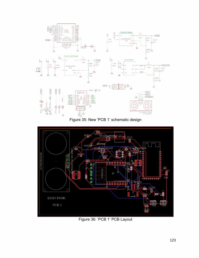
123
Figure 35: New ‘PCB 1’ schematic design
Figure 36: ’PCB 1’ PCB Layout

124
7.2.2 - ‘PCB 2’ Board The next PCBs are extensions of PCB 1. No WiFi module is onboard here as the ATMega328P microchip replaces it. There is also a 16MHz crystal. Similar to PCB 1, this board houses the BLE, ultrasonic sensor, and the SMD green LED. A 2x3 ICSP header and 1x3 header was included on the board. Whether we want to install a bootloader or upload sketches for the MCU, it will serve as a programming contingency. The board was implemented using a two-layer design, with a ground plane on the top and bottom layer. most the components are completely surface-mounted. Screenshots of the schematic and PCB layout of ‘PCB 2’ are shown in Fig. 37 and 38.
Figure 37: New ‘PCB 2’ schematic design
Figure 38: ’PCB 2’ PCB Layout
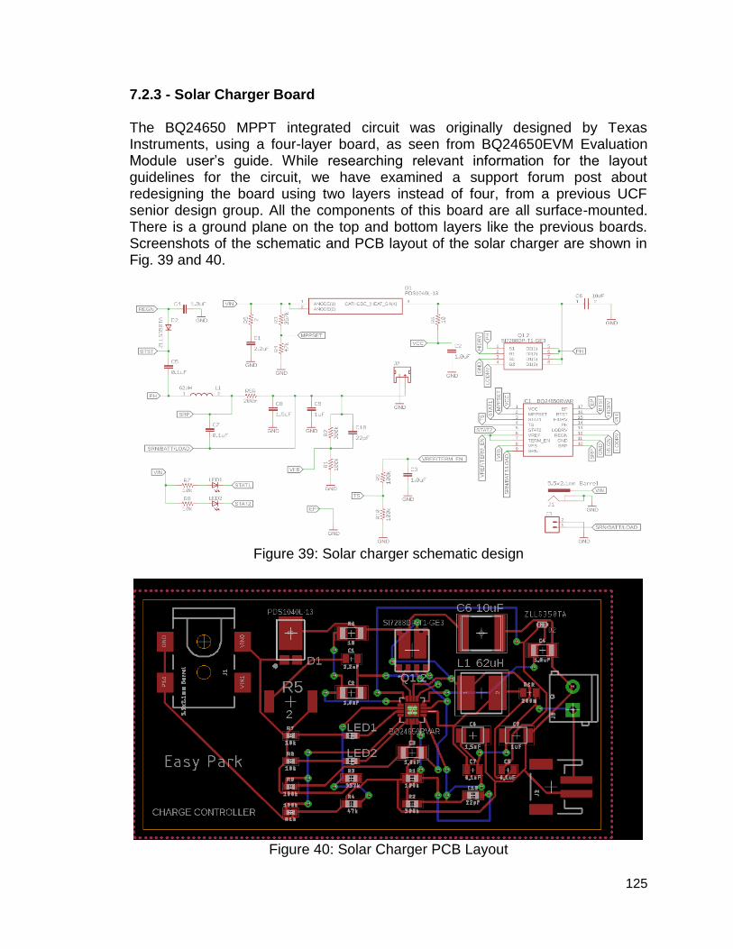
125
7.2.3 - Solar Charger Board The BQ24650 MPPT integrated circuit was originally designed by Texas Instruments, using a four-layer board, as seen from BQ24650EVM Evaluation Module user’s guide. While researching relevant information for the layout guidelines for the circuit, we have examined a support forum post about redesigning the board using two layers instead of four, from a previous UCF senior design group. All the components of this board are all surface-mounted. There is a ground plane on the top and bottom layers like the previous boards. Screenshots of the schematic and PCB layout of the solar charger are shown in Fig. 39 and 40.
Figure 39: Solar charger schematic design
Figure 40: Solar Charger PCB Layout

126
8 - Administration This section contains the management portion of the project. It will first examine the planned schedule of the project in the milestone section. Next, it will discuss the budget plans of the Easy Park design. In this area, we concentrated on research what parts work best for our project and determining what would give the optimum results from the design. Multiple testing was performed on different model numbers to compare and decide on which module works to ensure optimization in the hardware design based on the results found in the lab.
8.1 - Milestones The milestones dates were set based on the corresponding task and with accordance with the schedule and responsibilities of each team member. The first half of the milestones contain the tasks for throughout the semester of Senior Design I with start dates and due dates for task completion. These tasks are based on research, familiarization, and testing with the components of the system. The second half of the milestones contain the tasks for throughout the semester of Senior Design II with start dates and due dates for task completion. These tasks are based on prototyping the PCB, debugging the hardware and software components, and finalizing the design for Easy Park. These dates are only estimates for completions so adjustments will be made to complete the task(s) with minimal delays. Unfortunately, due to the impact of Hurricane Irma, the estimated dates of completion have been postponed about a week after the presence of the hurricane. The due date of this document remained the same though. Also, testing of components was postponed because some of the components were initially shipped from China which typically takes around two to three weeks for arrival. Additional testing will be made over the break and the semester of Senior Design II to complete the future tasks on schedule. Table 25 lists the tasks with start and due dates for the semester of Senior Design I and Senior Design II.
Table 25: Milestones for project tasks with start and due dates
SENIOR DESIGN I
Tasks Start Date Due Date
Choose a project idea and learn from the time consumption
August 23, 2017 August 31, 2017
Provide rules and doctrines to promote speedy choices
August 23, 2017 N/A
Create contingency potential August 23, 2017 September 14, 2017
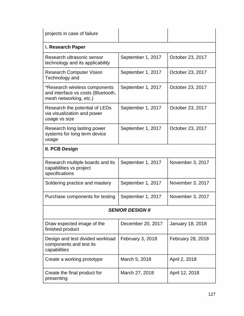
127
projects in case of failure
I. Research Paper
Research ultrasonic sensor technology and its applicability
September 1, 2017 October 23, 2017
Research Computer Vision Technology and
September 1, 2017 October 23, 2017
*Research wireless components and interface vs costs (Bluetooth, mesh networking, etc.)
September 1, 2017 October 23, 2017
Research the potential of LEDs via visualization and power usage vs size
September 1, 2017 October 23, 2017
Research long lasting power systems for long term device usage
September 1, 2017 October 23, 2017
II. PCB Design
Research multiple boards and its capabilities vs project specifications
September 1, 2017 November 3, 2017
Soldering practice and mastery September 1, 2017 November 3, 2017
Purchase components for testing September 1, 2017 November 3, 2017
SENIOR DESIGN II
Draw expected image of the finished product
December 20, 2017 January 18, 2018
Design and test divided workload components and test its capabilities
February 3, 2018 February 28, 2018
Create a working prototype March 5, 2018 April 2, 2018
Create the final product for presenting
March 27, 2018 April 12, 2018

128
8.2 - Cost/Budgets This project is financed by the group members of Easy Park. Our budget for this project is $300 as it is not sponsored on behalf of any company. Preferably we would like the overall unit of the system to cost less than $20, excluding the costs of servers and apps. The budget of the project would have been much larger if sponsorship for the project would become accessible for the group as it would have influenced the group to pick a different project idea such as the ones that would require more components to research, thus would increase the costs of the project. Table 26 shows a list with purchased parts that were used for this project. The costs of ordering additional quantity per component for testing will count towards the budget. Components that are readily available will not be counted toward the budget since these components were bought prior to the commencement of this project, but they will be listed down in the table below that contains the total cost column as zero dollars ($0). Resistors and capacitors are not included/listed in the budget since they only cost a few cents and are provided in the Senior Design lab located at UCF inside the Engineering 1 building. The table includes the components for testing and quantities. Estimated costs of the PCB has not been added to the cost of the project because of additional research needs to be made in order to reach greater power efficiency from our current final schematic design.
Table 26: Costs of items for the project
Parts Quantity Unit Price Development Cost
AMS117-5 Voltage Regulator 10 $0.81 $8.10
AMS117-3.3 Voltage Regulator 5 $1.80 $9.00
Arduino Nano 8 $3.88 $31.04
Barrel Jacks Adapters and connectors 10 $0.67 $6.70
Breadboard 6 $3.32 $19.89
ESP8266 w/ breakout board 3 $4.10 $12.30
ESP-12F w/ breakout board 1 $10.00 $10.00
HC-SR04 10 $1.70 $17.00
HM-10 /w breakout board 4 $10.00 $40.00
Jumper Cables 120 $0.05 $6.00
Solar Buddy (MPPT) 1 $24.95 $24.95
Solar Panels (.5W) 3 $1.95 $5.85
Solar Panels (1W) 5 $3.95 $19.75
Total Cost $210.58

129
Table 27 shows the cost for creating an Easy Park device. There are three
different sections to the Easy Park System. Easy Park device 1 has the Wi-Fi
module that is utilized it as its processor and used PCB design 1. This cost came
to around $40.00. Easy Park device 2 utilizes the ATmega328p-pu as its
processor and uses the PCB 2 design. Easy Park device 2 came to cost around
$32.00. A solar charger was created to charge the batteries on Easy Park
devices 1 and 2. The cost to build the solar charger came to around $20.00. The
cost of the devices can be dropped about five to ten dollars for each Easy Park
device. A bulk of the cost came to producing the custom PCBs. With mass
production of these it could easily reduce the cost of each module.
Table 27: Cost of items for each Easy Park Device

130
9.0 Appendix
9.1 Sources [1] Allen, M. (2017). Single Phase vs. Three Phase Power: What You Need to Know?. [online] Datacenters.com. Available at: https://www.datacenters.com/news/information-technology/149-single-phase-vs-three-phase-power-what-you-need-to-know [Accessed 2 Nov. 2017]. [2] Anixter.com. (2017). Copper vs. Aluminum Conductors | Anixter. [online] Available at: https://www.anixter.com/en_us/resources/literature/wire-wisdom/copper-vs-aluminum-conductors.html [Accessed 2 Nov. 2017]. [3] Bauer, J. (2017). Single-Phase Pulse Width Modulated Rectifier. Acta Polytechnica, [online] 48(3), pp.84-87. Available at: https://ojs.cvut.cz/ojs/index.php/ap/article/viewFile/1025/857 [Accessed 2 Nov. 2017]. [4] Dimensionengineering.com. (2017). A beginner's guide to switching regulators. [online] Available at: https://www.dimensionengineering.com/info/switching-regulators [Accessed 2 Nov. 2017]. [5] Electrical4u.com. (2017). Cycloconverter | Electrical4u. [online] Available at: https://www.electrical4u.com/cycloconverter/ [Accessed 2 Nov. 2017]. [6] Electronic Circuits and Diagram-Electronics Projects and Design. (2017). Choppers and Types -Ac and DC chopper circuits. [online] Available at: http://www.circuitstoday.com/choppers-an-introduction [Accessed 2 Nov. 2017]. [7] En.wikipedia.org. (2017). Rectifier. [online] Available at: https://en.wikipedia.org/wiki/Rectifier [Accessed 2 Nov. 2017]. [8] Gudino, M. (2017). Linear vs. Switch Mode. [online] www.arrow.com. Available at: https://www.arrow.com/en/research-and-events/articles/types-of-switching-dc-dc-converters [Accessed 2 Nov. 2017]. [9] Intersil.com. (2017). Linear vs. Switching Regulators | Power Management | Intersil. [online] Available at: https://www.intersil.com/en/products/power-management/linear-vs-switching-regulators.html [Accessed 2 Nov. 2017]. [10] Mahendar, B., Sravan Kumar, P. and Shruthi, M. (2017). Design and Implementation of AC Chopper.International Journal of Emerging Engineering Research and Technology, [online] 2(1), pp.36-41. Available at: http://www.ijeert.org/pdf/v2-i1/7.pdf [Accessed 2 Nov. 2017]. [11] Parking.bwiairport.com. (2017). Smart Park Technology | BWI Parking. [online] Available at: https://parking.bwiairport.com/smart-park-technology/ [Accessed 2 Nov. 2017]. [12] Power Electronics A to Z. (2017). Comparison of MOSFET with BJT - Power Electronics A to Z. [online] Available at: http://www.completepowerelectronics.com/comparison-of-mosfet-with-bjt/ [Accessed 2 Nov. 2017]. [13] Schweber, B. (2017). Understanding the Advantages and Disadvantages of Linear Regulators. [online] www.Digikey.com. Available at:

131
https://www.digikey.com/en/articles/techzone/2017/sep/understanding-the-advantages-and-disadvantages-of-linear-regulators [Accessed 2 Nov. 2017]. [14] Smartparking.com. (2017). In-Ground Vehicle Detection Sensors | Parking Space Technology | Smart Parking. [online] Available at: https://www.smartparking.com/technologies/in-ground-vehicle-detection-sensors [Accessed 2 Nov. 2017]. [15] Taofeng, L., Hui, O., Yong, K., Jian, X., Shengfang, F., Kai, Z. and Pengju, Z. (2017). The Research of Single-phase PWM Rectifier Based on Direct Current Control Technology. IEEE. [online] Available at: http://ieeexplore.ieee.org/stamp/stamp.jsp?arnumber=5406856 [Accessed 2 Nov. 2017]. [16] Williams, D. (2017). AC-DC Converters - Disassembling a Linear Power Supply. [online] Allaboutcircuits.com. Available at: https://www.allaboutcircuits.com/technical-articles/disassembling-a-rectifier/ [Accessed 2 Nov. 2017]. [17] Williams, D. (2017). Calculating the Lifespan of Electrolytic Capacitors with De-Rating. [online] Allaboutcircuits.com. Available at: https://www.allaboutcircuits.com/news/calculating-the-lifespan-of-electrolytic-capacitors-with-de-rating/ [Accessed 2 Nov. 2017]. [18] Agarwal, T. (2017). Different Types of Comparators with Thier Working. [online] Edgefx Kits Official Blog. Available at: http://www.edgefxkits.com/blog/different-types-of-comparators/ [Accessed 2 Nov. 2017]. [19] Bluesea.com. (2017). Circuit Protection - Blue Sea Systems. [online] Available at: https://www.bluesea.com/resources/96 [Accessed 2 Nov. 2017]. [20] Electronics Hub. (2017). Light Emitting Diode | LED Types, Colors and Applications. [online] Available at: http://www.electronicshub.org/light-emitting-diode-basics/ [Accessed 2 Nov. 2017]. [21] Energystar.gov. (2017). Learn About LED Bulbs. [online] Available at: https://www.energystar.gov/products/lighting_fans/light_bulbs/learn_about_led_bulbs [Accessed 2 Nov. 2017]. [22] Mancini, R. (2017). Designing with comparators. [online] EDN. Available at: https://www.edn.com/design/analog/4353925/Designing-with-comparators [Accessed 2 Nov. 2017]. [23] Mechprod.com. (2017). Circuit Protection - Types. [online] Available at: http://www.mechprod.com/circuit-protection---types [Accessed 2 Nov. 2017]. [24] Power Electronics A to Z. (2017). Power BJT Tutorial: Power Electronics A to Z. [online] Available at: http://www.completepowerelectronics.com/power-bjt/ [Accessed 2 Nov. 2017]. [25] Power Electronics A to Z. (2017). Power MOSFET Tutorial: Power Electronics A to Z. [online] Available at: http://www.completepowerelectronics.com/power-mosfet/ [Accessed 2 Nov. 2017]. [26] www.tutorialspoint.com. (2017). Power Electronics Matrix Converters. [online] Available at:

132
https://www.tutorialspoint.com/power_electronics/power_electronics_matrix_converters.htm [Accessed 2 Nov. 2017]. [27]Poor, R. (2017). Wireless Mesh Networks | Sensors Magazine. [online] Sensorsmag.com. Available at: http://www.sensorsmag.com/components/wireless-mesh-networks [Accessed 3 Nov. 2017]. [28]T. Agarwal, "Types of Wireless Communication and Its Applications", ElProCus - Electronic Projects for Engineering Students, 2017. [Online]. Available: https://www.elprocus.com/types-of-wireless-communication-applications/. [Accessed: 03- Nov- 2017]. [29]"4 ways to connect a remote server to your mobile app", Svitla.com, 2017. [Online]. Available: https://svitla.com/blog/4-ways-to-connect-a-remote-server-to-your-mobile-app. [Accessed: 03- Nov- 2017]. [30]M. Anicas, "5 Common Server Setups For Your Web Application | DigitalOcean", Digitalocean.com, 2017. [Online]. Available: https://www.digitalocean.com/community/tutorials/5-common-server-setups-for-your-web-application. [Accessed: 03- Nov- 2017]. [31]L. Frenzel, "What’s The Difference Between IEEE 802.15.4 And ZigBee Wireless?", Electronic Design, 2017. [Online]. Available: http://www.electronicdesign.com/what-s-difference-between/what-s-difference-between-ieee-802154-and-zigbee-wireless. [Accessed: 03- Nov- 2017]. [32]B. Ray, "The ZigBee Vs WiFi Battle For M2M Communication", Link-labs.com, 2017. [Online]. Available: https://www.link-labs.com/blog/zigbee-vs-wifi-802-11ah. [Accessed: 03- Nov- 2017]. [33]B. Ray, "The ZigBee Vs WiFi Battle For M2M Communication", Link-labs.com, 2017. [Online]. Available: https://www.link-labs.com/blog/zigbee-vs-wifi-802-11ah. [Accessed: 03- Nov- 2017]. [34]B. Ray, "Bluetooth Vs. Bluetooth Low Energy: What's The Difference?", Link-labs.com, 2017. [Online]. Available: https://www.link-labs.com/blog/bluetooth-vs-bluetooth-low-energy. [Accessed: 03- Nov- 2017]. [35]"Bluetooth Mesh FAQ | Bluetooth Technology Website", Bluetooth.com, 2017. [Online]. Available: https://www.bluetooth.com/what-is-bluetooth-technology/how-it-works/le-mesh/mesh-faq. [Accessed: 03- Nov- 2017]. [36]B. Mitchell, "What's 802.11? What These Wireless Standards Mean", Lifewire, 2017. [Online]. Available: https://www.lifewire.com/wireless-standards-802-11a-802-11b-g-n-and-802-11ac-816553. [Accessed: 03- Nov- 2017]. [37]"What is DASH7? | Haystack Technologies", Haystacktechnologies.com, 2017. [Online]. Available: http://haystacktechnologies.com/products-and-services/what-is-dash7/. [Accessed: 03- Nov- 2017]. [38]M. Rouse, "IEEE 802 Wireless Standards: Fast Reference - Reference from WhatIs.com", SearchMobileComputing, 2017. [Online]. Available: http://searchmobilecomputing.techtarget.com/definition/IEEE-802-Wireless-Standards-Fast-Reference. [Accessed: 03- Nov- 2017]. [39]"Evaluating Different Protocols Wireless Networks | DigiKey", Digikey.com, 2017. [Online]. Available: https://www.digikey.com/en/articles/techzone/2012/jan/evaluating-the-different-

133
protocols-for-low-power-wireless-networks-in-industrial-automation. [Accessed: 03- Nov- 2017]. [40]T. Struyk, "What is the difference between Bluetooth and Wi-Fi?", Techopedia.com, 2017. [Online]. Available: https://www.techopedia.com/2/27881/networks/wireless/what-is-the-difference-between-bluetooth-and-wi-fi. [Accessed: 03- Nov- 2017]. [41]"Difference between Bluetooth and WiFi | EngineersGarage", Engineersgarage.com, 2017. [Online]. Available: https://www.engineersgarage.com/contribution/difference-between-bluetooth-and-wifi. [Accessed: 03- Nov- 2017]. [42]"Low Energy: Mesh | Bluetooth Technology Website", Bluetooth.com, 2017. [Online]. Available: https://www.bluetooth.com/what-is-bluetooth-technology/how-it-works/le-mesh. [Accessed: 03- Nov- 2017]. [43]"How it works | Bluetooth Technology Website", Bluetooth.com, 2017. [Online]. Available: https://www.bluetooth.com/what-is-bluetooth-technology/how-it-works. [Accessed: 03- Nov- 2017]. [44]K. Kolderup, "Introducing Bluetooth Mesh Networking | Bluetooth Technology Website", Blog.bluetooth.com, 2017. [Online]. Available: https://blog.bluetooth.com/introducing-bluetooth-mesh-networking. [Accessed: 03- Nov- 2017]. [45]J. Almenas, "10 parking tips for students at all universities, but especially UCF", Orlando Weekly, 2017. [Online]. Available: https://www.orlandoweekly.com/orlando/10-parking-tips-for-students-at-all-universities-but-especially-ucf/Content?oid=2515419. [Accessed: 03- Nov- 2017]. [46]A. Kanungo, "Which language is better for app development? Python or Java?", Quora, 2017. [Online]. Available: https://www.quora.com/Which-language-is-better-for-app-development-Python-or-Java. [Accessed: 03- Nov- 2017]. [47]C. Nerney, "The latest mobile programming languages for application developers", Mobile Business Insights, 2017. [Online]. Available: https://mobilebusinessinsights.com/2016/01/the-latest-mobile-programming-languages-for-application-developers/. [Accessed: 03- Nov- 2017]. [48]"Types of Network Topology | Computer Network Tutorial | Studytonight", Studytonight.com, 2017. [Online]. Available: http://www.studytonight.com/computer-networks/network-topology-types. [Accessed: 03- Nov- 2017]. [49]V. Beal, "What Are Network Topologies? Webopedia Study Guide", Webopedia.com, 2017. [Online]. Available: https://www.webopedia.com/quick_ref/topologies.asp. [Accessed: 03- Nov- 2017]. [50]"Bluetooth vs Wi-Fi - Difference and Comparison | Diffen", Diffen.com, 2017. [Online]. Available: http://www.diffen.com/difference/Bluetooth_vs_Wifi. [Accessed: 03- Nov- 2017]. [51]A. Putra, "List of the 7 Best Free Database Management Systems", Better Tech Tips, 2017. [Online]. Available: http://www.bettertechtips.com/linux/free-database-management-system/. [Accessed: 14- Nov- 2017].

134
[52]J. Champagne, "The Top 7 Free and Open Source Database Software Solutions - Capterra Blog", Blog.capterra.com, 2017. [Online]. Available: https://blog.capterra.com/free-database-software/. [Accessed: 14- Nov- 2017]. [53]M. Rouse, "What is database management system (DBMS)? - Definition from WhatIs.com", SearchSQLServer, 2015. [Online]. Available: http://searchsqlserver.techtarget.com/definition/database-management-system. [Accessed: 14- Nov- 2017]. [54]D. Beaumont, "How to explain vertical and horizontal scaling in the cloud - Cloud computing news", Cloud computing news, 2014. [Online]. Available: https://www.ibm.com/blogs/cloud-computing/2014/04/explain-vertical-horizontal-scaling-cloud/. [Accessed: 14- Nov- 2017]. [55]M. Rajput, "Why Android Studio Is Better For Android Developers Instead Of Eclipse - DZone Mobile", dzone.com, 2017. [Online]. Available: https://dzone.com/articles/why-android-studio-better. [Accessed: 17- Nov- 2017]. [56]N. O'Higgins, "3 Pros and Cons to Building Mobile Apps with JQuery Mobile and HTML5", Niallohiggins.com, 2017. [Online]. Available: http://niallohiggins.com/2011/09/23/3-pros-cons-mobile-apps-with-jquery-mobile-and-html5/. [Accessed: 17- Nov- 2017]. [57]S. Chauhan, "What is jQuery Mobile and how is it different from jQuery and jQueryUI?", Dotnettricks.com, 2017. [Online]. Available: http://www.dotnettricks.com/learn/jquerymobile/what-is-jquery-mobile-and-how-is-it-different-from-jquery-and-jqueryui. [Accessed: 17- Nov- 2017]. [58] M. Bluejay, “Your guide to types of household batteries (AAA, AA, C, D, and 9V sizes),” Battery Guide -- Battery types, pros & cons, comparisons, tips & tricks, 2016. [Online]. Available: https://michaelbluejay.com/batteries/. [Accessed: 02-Dec-2017]. [59] C. Honsberg and S. Bowden, “Battery Information,” Battery Information | PVEducation. [Online]. Available: http://pveducation.org/pvcdrom/batteries/remaining. [Accessed: 02-Dec-2017]. [60] Solar Electricity, 207ADAD. [Online]. Available: http://www.fsec.ucf.edu/en/consumer/solar_electricity/index.htm. [Accessed: 02-Dec-2017]. [61] “Inductive Loop Write up.” Marsh Product, 10-Nov-2000. [62] “Infrared distance sensor,” Infrared distance sensor [Robotic & Microcontroller Educational Knowledgepage - Network of Excellence], 13-Nov-2015. [Online]. Available: http://home.roboticlab.eu/en/examples/sensor/ir_distance. [Accessed: 02-Dec-2017]. [63] H. S. and I. M., “Optimal Battery Charger Fed by Photovoltaic System based on Decreased Charging Current Method,” International Journal of Computer Applications, vol. 139, no. 12, pp. 12–21, 2016. [64] “Li-Ion & LiPoly Batteries,” Protection Circuitry | Li-Ion & LiPoly Batteries | Adafruit Learning System. [Online]. Available: https://learn.adafruit.com/li-ion-and-lipoly-batteries/protection-circuitry. [Accessed: 02-Dec-2017].

135
[65] Reducing Arduino Power Consumption. [Online]. Available: https://learn.sparkfun.com/tutorials/reducing-arduino-power-consumption. [Accessed: 02-Dec-2017]. [66] “Ultrasonic Switch,” Electronics Circuits & Hobby. [Online]. Available: http://www.electronic-circuits-diagrams.com/ultrasonic-switch-circuit/. [Accessed: 02-Dec-2017]. [67] “5.1 VIDEO IMAGE PROCESSORS,” Video Image Processors. [Online]. Available: https://ntl.bts.gov/DOCS/96100/ch05/ch05_01.html. [Accessed: 02-Dec-2017]. [68] “Which Solar Panel Type is Best? Mono-, Polycrystalline or Thin Film?,” Energy Informative. [Online]. Available: http://energyinformative.org/best-solar-panel-monocrystalline-polycrystalline-thin-film/. [Accessed: 02-Dec-2017]. [69] “HC-SR04 User Guide.” ELECFreaks. [70] A. M. Bagher, “Types of Solar Cells and Application,” American Journal of Optics and Photonics, vol. 3, no. 5, pp. 94–110, 2015. [71] “ATmega328P Xplained Mini User Guide.” Atmel, San Jose, 2015. [72] Texas Instruments, “Cost Effective Voltage and Current Protection Integrated Circuit for Single-Cell Li-Ion and Li-Polymer Batteries,” bq297xx datasheet, Mar. 2014 [Revised May 2016]. [73] T. Morgan, “Guide to charging Sealed Lead Acid batteries.” [74] “Hallbook.” Honeywell, Freeport. [75] M., Morris., “COMPARISON OF RECHARGEABLE BATTERY TECHNOLOGIES” ASME Early Career Technical Journal. pp. 148-155, 2012. [76] M. Martinez and J. Bernabe, “Batteries in PV Systems,” Batteries in PV systems, pp. 27–34, 2011. [77] “Power Supply Safety Standards, Agencies and Marks.” CUI Inc., Tualatin, 2014. [78] N. Singamsetti and S. Tosunoglu, “A Review of Rechargeable Battery Technologies.” [79] “Ultrasonic Transducer Technical Notes.” OLYMPUS CORPORATION, 2011. [80] Texas Instruments, “4.5-V to 17-V Input, 500-mA Synchronous Step-Down Converter With Advanced Eco-Mode,” TPS560200 datasheet, Sept. 2013 [Revised Feb. 2016].[Online]. Available:http://www.ti.com/lit/ds/symlink/tps560200.pdf.[Accessed: 02-Apr-2018]. [81] Texas Instruments, “ 1-A High Efficiency Synchronous Buck Converter in SOT Package,” TLV62568 datasheet, Nov. 2016 [Revised Nov. 2017].[Online] Available:http://www.ti.com/lit/ds/symlink/tlv62568.pdf.[Accessed: 02-Apr-2018]. [82] Texas Instruments, “4.5-V To 17-V Input, 2-A, 3-A Synchronous Step-Down Voltage Regulator In 6 Pin SOT-23,” TPS56x200 datasheet, Jan. 2014 [Revised June. 2016].[Online] Available:http://www.ti.com/lit/ds/symlink/tps563200.pdf.[Accessed: 02-Apr-2018].

136
[83] Texas Instruments, “4.5-V to 17-V Input, 2-A Synchronous Step-Down Voltage Regulator in 6-Pin SOT-23,” TPS56220x datasheet, Dec. 2015 [Revised April. 2017].[Online] Available:http://www.ti.com/lit/ds/symlink/tps562201.pdf.[Accessed: 02-Apr-2018]. [84] Texas Instruments, “bq24650 Synchronous Switch-Mode Battery Charge Controller for Solar Power With Maximum Power Point Tracking,” bq24650 datasheet, July. 2010 [Revised April. 2016].[Online] Available:http://www.ti.com/lit/ds/symlink/bq24650.pdf.[Accessed: 02-Apr-2018]. [85] Texas Instruments, “15-V, 75-mA Highly Efficient Buck Converter,” TPS6212x datasheet, July. 2010 [Revised Aug. 2015].[online] Available:http://www.ti.com/lit/ds/slvsad5a/slvsad5a.pdf.[Accessed: 02-Apr-2018].