SpectreRF Workshop - ECE Computing
101
Mixer Design Using SpectreRF ________________________________________________________________________ November 2005 Product Version 6.0 1 SpectreRF Workshop Mixer Design Using SpectreRF MMSIM6.0USR2 November 2005
-
Upload
khangminh22 -
Category
Documents
-
view
1 -
download
0
Transcript of SpectreRF Workshop - ECE Computing

Mixer Design Using SpectreRF ________________________________________________________________________
November 2005 Product Version 6.0 1
SpectreRF Workshop
Mixer Design Using SpectreRF
MMSIM6.0USR2
November 2005

Mixer Design Using SpectreRF ________________________________________________________________________
November 2005 Product Version 6.0 2
Contents
Mixer Design Measurements .......................................................................... 3
Purpose............................................................................................................................ 3 Audience ......................................................................................................................... 3 Overview......................................................................................................................... 3
Introduction to Mixers..................................................................................... 3 The Design Example: A Differential Input Mixer.......................................... 4
Testbench ........................................................................................................................ 5 Example Measurements Using SpectreRF...................................................... 6
Lab1: Voltage Conversion Gain Versus LO Signal Power (Swept PSS with PAC) ...... 6 Lab2: Voltage Conversion Gain Versus RF Frequency (PSS and Swept PAC)........... 16 Lab3: Voltage Conversion Gain Versus RF Frequency (PSS and Swept PXF) ........... 21 Lab4: Power Conversion Gain Versus RF Frequency (QPSS)..................................... 26 Lab5: Periodic S-Parameters (PSS and PSP)................................................................ 31 Lab6: Noise, Noise Figures and Noise Summary (PSS and Pnoise) ........................... 38 Lab7: Port-to-Port Isolation Among RF, IF and LO Ports (PSS and Swept PAC) ..... 44 Lab8: Mixer Performance with a Blocking Signal (QPSS, QPAC, and QPNoise) ..... 55 Lab9: IP3 Calculation (Swept QPSS and QPAC)........................................................ 66 Lab10: IP3 Calculation (QPSS with Shooting Engine or Flexible Balance Engine) ... 74 Lab11: Rapid IP3 (PAC)............................................................................................... 84 Lab12: Compression Distortion Summary (PAC)....................................................... 88 Lab13: Rapid IP2 (PAC)............................................................................................... 92 Lab14: IM2 Distortion Summary (PAC) ...................................................................... 97
Conclusion...................................................................................................100 Reference.....................................................................................................101

Mixer Design Using SpectreRF ________________________________________________________________________
November 2005 Product Version 6.0 3
Mixer Design Measurements
The procedures described in this workshop are deliberately broad and generic. Your specific design might require procedures that are slightly different from those described here.
Purpose This workshop describes how to use SpectreRF in the Analog Design Environment to measure parameters which are important in design verification of mixers. New features of MMSIM6.0USR2 are included.
Audience Users of SpectreRF in the Analog Design Environment.
Overview This application note describes a basic set of the most useful measurements for mixers.
Introduction to Mixers Mixers are key components in both receivers and transmitters. Mixers translate signals from one frequency band to another. The output of the mixer consists of multiple images of the mixers input signal where each image is shifted up or down by multiples of the local oscillator (LO) frequency. The most important mixer output signals are usually the signals translated up and down by one LO frequency. In an ideal situation, the mixer output would be an exact replica of the input signal. In reality mixer output is distorted due to non-linearity in the mixer. In addition, the mixer components and a non-ideal LO signal introduce more noise to the output. Bad design might also cause leakage effects, complicating the design of the complete system. Noise performance and rejection of out-of-band interferers are both critical to the receiver system because they both limit the receiver system's sensitivity. Linearity is important to transmitter performance, where you want an error-free output signal.

Mixer Design Using SpectreRF ________________________________________________________________________
November 2005 Product Version 6.0 4
The Design Example: A Differential Input Mixer The mixer measurements described in this workshop are calculated using SpectreRF in the Analog Design Environment. The design investigated is the differential input mixer shown in below:
The example circuit, a single balanced differential down-converting mixer, runs with a local oscillator at f(LO) = 5 GHz. The range of interest is baseband output noise from 1 kHz to 10 MHz. The RF signal frequency used for the simulation is around 5001 MHz.

Mixer Design Using SpectreRF ________________________________________________________________________
November 2005 Product Version 6.0 5
Testbench Use the mixer measurements testbench shown in below to measure typical mixer characteristics. Use a PORT component and match impedance for each of the inputs and the output.
■ To supply a LO input to the mixer, use a port (PORT1) with a matching resistor
and transfer the single-ended signal into the differential with an ideal passband balun.
■ To represent the RF input to the mixer, use a port (PORT0) which is matched with
the mixer input. ■ To use the differential output for measurements, match the output port (PORT3)
to the output impedance of the mixer. Simulate the resulting testbench as follows ■ Set the LO bias voltage to 1.5 V and the mixer supply of 2.5 V. ■ Set the LO port to sinusoidal source for all the measurements described in this
workshop. ■ Set the RF port to either dc or sinusoidal source, depending on the requirements
of each measurement. The RF port has a dc bias of 0.5 V. ■ For both LO and RF ports, the amplitude and frequency of the signal are
parameterized as plo, prf and frf. You usually specify the amplitude in dBm. In addition, for the RF port specify the small signal parameter PAC Magnitude. Use pacmag or pacdbm, depending on the units you prefer.
■ Set the Output Port to dc with no bias.

Mixer Design Using SpectreRF ________________________________________________________________________
November 2005 Product Version 6.0 6
Example Measurements Using SpectreRF
The Mixer measurements described in the following labs are calculated using SpectreRF in the Analog Design Environment. We’ll begin our examination of the flow by bringing up the Cadence Design Framework II environment and look at a full view of our reference design: Change directory to… Action: cd to ./mixer directory Action: Invoke tool icfb& Action: In the CIW window, select Tools->Library Manager…
Lab1: Voltage Conversion Gain Versus LO Signal Power (Swept PSS with PAC)
A mixer's frequency converting action is characterized by conversion gain or loss. The voltage conversion gain is the ratio of the RMS voltages of the IF and RF signals. The power conversion gain is the ratio of the power delivered to the load and the available RF input power. When the mixer's input impedance and load impedance are both equal to the source impedance, the power and voltage conversion gains, in decibels, are the same. Note that when you load a mixer with a high impedance filter, this condition is not satisfied. You can calculate the voltage convergence gain in two ways: ■ Using a small-signal analysis, like PSS with PAC or PXF. The PSS with PAC or
PXF analyses supply the small-signal gain information. You can use either PAC or PXF analysis to compute the voltage gain.
■ Using a two-tone large-signal QPSS analysis which is more time-consuming.
The power convergence gain, in general, requires that you run the two-tone large-signal QPSS analysis.
This example measures the variation of conversion gain with the power of the LO signal. Action 1-1: In the Library Manager window, open the schematic view of the mixer_testbench design in the library RFWorkshop Action 1-2: Select the PORT0 source by placing the mouse cursor over it and clicking the left mouse button. Then in the Virtuoso Schematic Editor select Edit—Properties—Objects… The Edit Object Properties window for the port cell should come up…

Mixer Design Using SpectreRF ________________________________________________________________________
November 2005 Product Version 6.0 7

Mixer Design Using SpectreRF ________________________________________________________________________
November 2005 Product Version 6.0 8
Action1-3: Click ok on the Edit Object Properties window to close it, Select PORT1 and show properties:

Mixer Design Using SpectreRF ________________________________________________________________________
November 2005 Product Version 6.0 9
Action1-4: Make sure PORT3 is set to DC type.
Action1-5: Check and save the schematic. Action1-6: From the Mixer_testbench schematic, start the Virtuoso Analog Design Environment with the Tools—Analog Environment command.

Mixer Design Using SpectreRF ________________________________________________________________________
November 2005 Product Version 6.0 10
Action1-7: You can choose Session—Load State, load state “Lab1_VCGvsLO_PSSPAC” and skip to Action1-12 or …
Action1-8: In Vituoso Analog Design Environment, choose Analyses—Choose… Action1-9: In the Choosing Analyses window, select the pss button in the Analysis field of the window. Set the fundamental frequency parameter, flo = 5 GHz. Set errpreset = moderate. Click Sweep and enter plo as the Variable Name parameter to sweep LO power. Click Sweep Range and set Start =
-10 dBm and Stop = 20 dBm. This sweeps LO power from a small value to a value above the expected gain saturation. The form should look this:

Mixer Design Using SpectreRF ________________________________________________________________________
November 2005 Product Version 6.0 11
Action1-10: In the Choosing Analyses window, select the pac button in the Analysis field of the window. Set fixed input frequency point to the RF signal frequency, 5001 MHz. Select sidebands either by specifying Maximum sidebands = 2 or using Select from range. Set the maximum sideband to 2 as you are only interested in the first harmonics of LO. The form should look like:

Mixer Design Using SpectreRF ________________________________________________________________________
November 2005 Product Version 6.0 12
Action1-11: Make sure the Enabled button is on. In the Choosing Analyses window,
hit the OK button. Now your Virtuoso Analog Design Environment will look like:

Mixer Design Using SpectreRF ________________________________________________________________________
November 2005 Product Version 6.0 13
Action1-12: In your Analog Design Environment, Choose Simulation—Netlist and Run or click the Netlist and Run icon to start the simulation. Action1-13: After the simulation completes, in the Virtuoso Analog Design
Environment, Choose Results—Direct Plot—Main Form. Action1-14: In the Direct Plot Form, select the pac button, and configure the form as follows:

Mixer Design Using SpectreRF ________________________________________________________________________
November 2005 Product Version 6.0 14
Action1-15: Select port3 on schematic. You should get the following waveform:

Mixer Design Using SpectreRF ________________________________________________________________________
November 2005 Product Version 6.0 15
The PAC analysis computes gain directly only when you set the pacmag parameter to 1 V. Otherwise, take a ratio of the output and input. The maximum conversion gain value is reached somewhere above 15 dBm. Use this value for the plo parameter in the following measurements. Action1-16: After viewing the waveforms, click Cancel in the Direct Plot form. Close the waveform window.

Mixer Design Using SpectreRF ________________________________________________________________________
November 2005 Product Version 6.0 16
Lab2: Voltage Conversion Gain Versus RF Frequency (PSS and Swept PAC) This example measures how conversion gain varies with the frequency of the stimuli.
Action2-1: If not already open, open the schematic view of the mixer_testbench design in the library RFWorkshop
Action2-2: Set port as you did in Lab1. Action2-3: From the Mixer_testbench schematic, start the Virtuoso Analog Design Environment with the Tools—Analog Environment command. Action2-4: You can choose Session—Load State, load state
“Lab2_VCGvsRF_PSSPAC” and skip to Action2-9 or … Action2-5: In Vituoso Analog Design Environment, choose Analyses—Choose… Action2-6: In the Choosing Analyses window, select the pss button in the Analysis field of the window and set the form as follows:

Mixer Design Using SpectreRF ________________________________________________________________________
November 2005 Product Version 6.0 17
Action2-7: In the Choosing Analyses window, select the pac button in the Analysis field of the window. Set the RF input frequency to sweep from 5 G + 1 kHz to 5 G + 10 MHz. Select sidebands either by specifying Maximum sidebands = 2 or using Select from range. The form looks like:
Action2-8: Make sure the Enabled button is on. In the Choosing Analyses window, hit the OK button. Now your Virtuoso Analog Design Environment will look like:

Mixer Design Using SpectreRF ________________________________________________________________________
November 2005 Product Version 6.0 18
Action2-9: In your Analog Design Environment, Choose Simulation—Netlist and Run or click the Netlist and Run icon to start the simulation. Action2-10: After the simulation completes, in the Virtuoso Analog Design
Environment, choose Results—Direct Plot—Main Form. Action2-11: In the Direct Plot Form, select the pac button, and configure the form as follows:

Mixer Design Using SpectreRF ________________________________________________________________________
November 2005 Product Version 6.0 19
Action2-12: Select port3 on schematic. The waveform window shows up:

Mixer Design Using SpectreRF ________________________________________________________________________
November 2005 Product Version 6.0 20
Since the sweep type in the analysis was linear by default, uniform frequency points display along the X-axis in the above plot. For a large frequency range, set the sweep type to logarithmic as it is by default. The same PAC analysis generates results you can use to measure RF to LO isolation and will be used in measurements that follow. Action2-13: Close the waveform window and click Cancel in the Direct Plot form.

Mixer Design Using SpectreRF ________________________________________________________________________
November 2005 Product Version 6.0 21
Lab3: Voltage Conversion Gain Versus RF Frequency (PSS and Swept PXF) This example measures the small-signal voltage conversion gain using the PXF analysis.
Action3-1: If not already open, open the schematic view of the mixer_testbench design in the library RFWorkshop
Action3-2: Set ports as you did in lab1. Action3-3: From the Mixer_testbench schematic, start the Virtuoso Analog Design Environment with the Tools—Analog Environment command. Action3-4: You can choose Session—Load State, load state
“Lab3_VCGvsRF_PSSPXF” and skip to Action3-9 or … Action3-5: In Vituoso Analog Design Environment, choose Analyses—Choose… Action3-6: In the Choosing Analyses window, select the pss button in the Analysis field of the window. Set the fundamental frequency parameter, flo = 5 GHz or use Auto Calculate button. Set errpreset = moderate. The form will the same as in Action2-6. Action3-7: In the Choosing Analyses window, select the pxf button in the Analysis field of the window. Sweep the output frequency from 1 kHz to 10 MHz. Select sidebands either by specifying Maximum sidebands = 2 or using Select from range. The form looks like:

Mixer Design Using SpectreRF ________________________________________________________________________
November 2005 Product Version 6.0 22
Note that Maximum sidebands = 2 is good for this example, other circuits might require a different value. Set the Output by specifying output as Voltage with Positive Output Node being the Ifp net and Negative Output Node being the Ifn net.

Mixer Design Using SpectreRF ________________________________________________________________________
November 2005 Product Version 6.0 23
Action3-8: Make sure the Enabled button is on. In the Choosing Analyses window, hit the OK button. Now your Virtuoso Analog Design Environment will look like:
Action3-9: In your Analog Design Environment, Choose Simulation—Netlist and Run or click the Netlist and Run icon to start the simulation. Action3-10: After the simulation completes, in the Virtuoso Analog Design
Environment, choose Results—Direct Plot—Main Form. Action3-11: In the Direct Plot Form, select the pss button, and configure the form as follows:

Mixer Design Using SpectreRF ________________________________________________________________________
November 2005 Product Version 6.0 24
Action3-12: Select output port0 on schematic. The waveform shows up:

Mixer Design Using SpectreRF ________________________________________________________________________
November 2005 Product Version 6.0 25
Action3-13: After viewing the waveforms, click Cancel in the Direct Plot form
The sweep type in the analysis is logarithmic by default. The large frequency range in above figure requires a logarithmic X-axis.
Yet another way to measure small-signal gain is to use the PSS and PSP analyses to get the gain and noise parameters with one simulation. You may want to refer to SpectreRF user guide Appendix L (using psp and pnoise analysis) for more details. You can also set up an appropriate QPSS analysis to measure large-signal gain. Set LO as a large tone on the Plo port. Use a sinusoidal voltage source for the Prf port. This analysis models the signal at a particular frequency going through the mixer. In the Direct Plot form for QPSS, the Voltage and Power Gain provide all the needed information.

Mixer Design Using SpectreRF ________________________________________________________________________
November 2005 Product Version 6.0 26
Lab4: Power Conversion Gain Versus RF Frequency (QPSS) You can measure the Power Conversion Gain and Power Dissipation for an unmatched source and load using a QPSS analysis. If the effect of the RF tone is small, you might use a PSS analysis instead, as mentioned in previous sections. The QPSS and PSS analyses provide only spectrum data, not a scalar value, of the total power. To get a scalar value for total power, work through the summation over the harmonics and sidebands. In general, most of the power is in the main output harmonics. Note: Some users might not be fully aware of the notion of the port and they might get wrong results by relying on a 50 Ohm resistance for the port. To get the correct results for unmatched ports, you need to save the currents on the power supply terminals.
Action4-1: If not already open, open the schematic view of the mixer_testbench design in the library RFWorkshop Action4-2: From the Mixer_testbench schematic, start the Virtuoso Analog Design Environment with the Tools—Analog Environment command. Action4-3: Select the PORT0 source by placing the mouse cursor over it and clicking the left mouse button. Then in the Virtuoso Schematic Editor select Edit—Properties—Objects… The Edit Object Properties window for the port cell should come up. Make sure the properties are set as follows:
Parameter Value
Resistance 50 ohm
Port Number 1
DC voltage 500 mV
Source type sine
Frequency name 1 RF1
Frequency 1 frf1
Amplitude 1 (dBm) prf
Action4-4: Check and save the schematic. Action4-5: You can choose Session—Load State, load state “Lab4_PCG_QPSS”
and skip to Action4-12 or … Action4-6: In Virtuoso Analog Design Environment, choose Analyses—Choose… Action4-7: In the Choosing Analyses window, select the qpss button in the Analysis

Mixer Design Using SpectreRF ________________________________________________________________________
November 2005 Product Version 6.0 27
field of the window. Set LO as a large tone with flo = 5 GHz. Set RF as a moderate tone with frf = 5.01 GHz. Set errpreset to moderate. Limit the maximum harmonic value to the maximum index of interest plus one more. For this example, set LO = 5 and RF = 3. You might select any reasonable number of LO harmonics since the large tone is modeled in the time domain and you can analyze up to 40 harmonics without runtime penalty.

Mixer Design Using SpectreRF ________________________________________________________________________
November 2005 Product Version 6.0 28
Action4-8: Make sure the Enabled button is on. In the Choosing Analyses window, hit the OK button. Action4-9: In the Virtuoso Analog Design Environment window, choose Outputs— To Be Saved—Select on Schematic. Action4-10: In the schematic, select the positive terminals of port0, port3 and V0.
The terminals are circled in the schematic window after you select them, indicate that you will save the currents at these nodes.
Action4-11: press Esc with your cursor in the schematic window to end the selections. Now your Virtuoso Analog Design Environment will look like:
Action4-12: In your Analog Design Environment, Choose Simulation—Netlist and Run or click the Netlist and Run icon to start the simulation. Action4-13: After the simulation completes, in the Virtuoso Analog Design
Environment, choose Results—Direct Plot—Main Form. Action4-14: In the Direct Plot Form, select the qpss button, and configure the form as follows:

Mixer Design Using SpectreRF ________________________________________________________________________
November 2005 Product Version 6.0 29

Mixer Design Using SpectreRF ________________________________________________________________________
November 2005 Product Version 6.0 30
Action4-15: Select output port3 and input port0 on schematic.
Action4-16: Close the waveform window, click Cancel in the Direct Plot form

Mixer Design Using SpectreRF ________________________________________________________________________
November 2005 Product Version 6.0 31
Lab5: Periodic S-Parameters (PSS and PSP) The receiver amplifies the small input signals to the point where they can be processed by the baseband section. You develop a gain budget where every stage in the receiver is assigned the gain it is expected to provide. Therefore, the signal gain or loss provided by the mixer must be known. There are various ways of characterizing gain and all are derived from the mixer's S-parameters. As such, it must be easy to calculate the various S-parameters of the circuit and apply the various gain metrics. Action5-1: If not already open, open the schematic view of the mixer_testbench design in the library RFWorkshop Action5-2: Select the PORT0 source by placing the mouse cursor over it and clicking the left mouse button. Then in the Virtuoso Schematic Editor select Edit—Properties—Objects… The Edit Object Properties window for the
port cell should come up. Change the source type to dc. Blank out all the Second Sinusoid fields before setting the Source type to dc.
Parameter Value
Resistance 50 ohm
Port Number 1
DC voltage 500 mV
Source type dc
PAC Magnitude ( blank )
For small-signal analysis, in many cases it would be sufficient to treat the RF input as small signal (for example, by setting the source type to dc). However, sometimes it is important to analyze additional noise folding terms induced by the RF input (larger signal interfere). In those cases, the RF source is a large signal and the source type is sine.
Action5-3: set lo port to sine type and output port to dc type. Action5-4: Check and save the schematic. Action5-5: From the Mixer_testbench schematic, start the Virtuoso Analog Design Environment with the Tools—Analog Environment command. Action5-6: You can choose Session—Load State, load state
“Lab5_SParameter_PSSPSP” and skip to Action5-11 or …

Mixer Design Using SpectreRF ________________________________________________________________________
November 2005 Product Version 6.0 32
Action5-7: In Vituoso Analog Design Environment, choose Analyses—Choose… Action5-8: In the Choosing Analyses window, select the pss button in the Analysis field of the window. Set the form as you did in Action2-6. Action5-9: In the Choosing Analyses window, select the psp button in the Analysis field of the window and set the form as follows:
Action5-10: Make sure the Enabled button is on. In the Choosing Analyses window, hit the OK button.

Mixer Design Using SpectreRF ________________________________________________________________________
November 2005 Product Version 6.0 33
Now your Virtuoso Analog Design Environment will look like:
Action5-11: In your Analog Design Environment, Choose Simulation—Netlist and Run or click the Netlist and Run icon to start the simulation. Action5-12: After the simulation completes, in the Virtuoso Analog Design
Environment, choose Results—Direct Plot—Main Form. Action5-13: In the Direct Plot Form, select the psp button, and configure the form as follows:

Mixer Design Using SpectreRF ________________________________________________________________________
November 2005 Product Version 6.0 34

Mixer Design Using SpectreRF ________________________________________________________________________
November 2005 Product Version 6.0 35
Action5-14: In the Direct Plot form, click on the S11, S21, S12 and S22. Here shows the waveforms:
Action5-15: Close the waveform window. Action5-16: In the Direct Plot form, choose sp function, set plot type to Rectangular and Modifier to dB20. Plot S21. Action5-17: In the Direct Plot form, choose GAIN and click OK button to plot the
input to output gain;

Mixer Design Using SpectreRF ________________________________________________________________________
November 2005 Product Version 6.0 36
You should get the plot as below:

Mixer Design Using SpectreRF ________________________________________________________________________
November 2005 Product Version 6.0 37
Action5-18: Close waveform window, click Cancel in the Direct Plot form. Close the
waveform window.
PSP GAIN differs from the PSP S21 gain and the Pnoise gain because PSP GAIN is independent of input match (determined by the impedance of the RF port). PSP S21and Pnoise gains will vary depending on the input match. PSP Gain is the voltage gain from the internal port voltage source to the output. You can refer to SpectreRF user guide Appendix L (using psp and pnoise analysis) for more details.

Mixer Design Using SpectreRF ________________________________________________________________________
November 2005 Product Version 6.0 38
Lab6: Noise, Noise Figures and Noise Summary (PSS and Pnoise) Because the noise from the mixer is moderated by the LNA’s gain, it places a limit on how small a signal can be resolved. The sensitivity of the receiver is then adversely affected. Noise is measured using the noise figure (NF), which is a measure of how much noise the mixer adds to the signal relative to the noise that is already present in the signal. An NF of 0 dB is ideal, meaning that the mixer adds no noise. An NF of 3 dB implies that the mixer adds an amount of noise equal to that already present in the signal. For a mixer alone, an NF of 15 dB is typical. Running the PSS and PNoise analyses produces all the needed information which includes total output noise and noise figure.
Action6-1: If not already open, open the schematic view of the mixer_testbench design in the library RFWorkshop Action6-2: Select the PORT0 source, set the source type to dc. Select the PORT3,
set the source type to dc and set PORT1 to sine. Action6-3: Check and save the schematic. Action6-4: From the Mixer_testbench schematic, start the Virtuoso Analog Design Environment with the Tools—Analog Environment command. Action6-5: You can choose Session—Load State, load state “Lab6_PNOISE” and
skip to Action6-10 or … Action6-6: In Vituoso Analog Design Environment, choose Analyses—Choose… Action6-7: In the Choosing Analyses window, select the pss button in the Analysis field of the window and set the form as you did in Action2-6. Action6-8: In the Choosing Analyses window, select the pnoise button in the
Analysis field of the window and set up the form as follows:

Mixer Design Using SpectreRF ________________________________________________________________________
November 2005 Product Version 6.0 39
Action6-9: Make sure the Enabled button is on. In the Choosing Analyses window, hit the OK button. Now your Virtuoso Analog Design Environment will look like:

Mixer Design Using SpectreRF ________________________________________________________________________
November 2005 Product Version 6.0 40
Action6-10: In your Analog Design Environment, Choose Simulation—Netlist and Run or click the Netlist and Run icon to start the simulation. Action6-11: In the Virtuoso Analog Design Environment, Choose Results—Direct Plot—Main Form. Action6-12: In the Direct Plot Form, select the pnoise button, and configure the form as follows:

Mixer Design Using SpectreRF ________________________________________________________________________
November 2005 Product Version 6.0 41
Action6-13: Click the Plot Button. Action6-14: The waveform window will show up. In waveform window, click on New
Subwindow button. Action6-15: In the Direct Plot form, set the Function to Output Noise and configure
the form as follows:
Action6-16: Click the Plot button. The waveform window should look like this:

Mixer Design Using SpectreRF ________________________________________________________________________
November 2005 Product Version 6.0 42
Action6-17: After viewing the waveforms, click Cancel in the Direct Plot form
It is Valuable to know the main contributors of noise in a system, once the noise performance of the circuit is calculated. This information is readily available from a Pnoise simulation. Action6-18: In the Virtuoso Analog Design Environment window, choose Results—
Print—Noise Summary. The Noise Summary form appears. Action6-19: Fill in the form as shown here.

Mixer Design Using SpectreRF ________________________________________________________________________
November 2005 Product Version 6.0 43
Action6-20: Click the ALL Types button in the FILTER section. Action6-21: Click OK in the Noise Summary form.
Action6-22: After viewing the noise summary, close it by selecting Window—Close.

Mixer Design Using SpectreRF ________________________________________________________________________
November 2005 Product Version 6.0 44
Lab7: Port-to-Port Isolation Among RF, IF and LO Ports (PSS and Swept PAC) The isolation required between a mixer's ports depends on the circuit and the architecture of the product. Isolation is critical for the mixer to function properly. You can combine PAC and PXF analyses to produce transfer functions from different ports to each other. One suggested configuration might be to set up a PAC analysis with nonzero pacmag parameter at the signal input (the RF port) A PXF analysis with the IF port as the output probe This example uses pacmag = 1 for simplicity. Action7-1: If not already open, open the schematic view of the mixer_testbench
design in the library RFWorkshop Action7-2: Select the PORT0 source by placing the mouse cursor over it and clicking the left mouse button. Then in the Virtuoso Schematic Editor select Edit—Properties—Objects… The Edit Object Properties window for the port cell should come up. Change the port properties as follows:
Parameter Value
Resistance 50 ohm
Port Number 1
DC voltage 500 mV
Source type dc
PAC Magnitude pacmag
Action7-3: Click OK on the Edit Object Properties window to close it. Action7-4: Set the source type of PORT1 to sine, and PORT3 to dc. Action7-5: Check and save the schematic. Action7-6: From the Mixer_testbench schematic, start the Virtuoso Analog Design Environment with the Tools—Analog Environment command. Action7-7: You can choose Session—Load State, load state “Lab7_Isolation_PAC”
and skip to Action7-14 or … Action7-8: In Vituoso Analog Design Environment, choose Analyses—Choose… Action7-9: In the Choosing Analyses window, select the pss button in the Analysis field of the window. Set up the form as follows:

Mixer Design Using SpectreRF ________________________________________________________________________
November 2005 Product Version 6.0 45
PSS simulation is set up here to check the LO feed through. PXF is a small signal analysis. LO feedthrough is a large-signal effect and shouldn't be measured using a small-signal analysis.

Mixer Design Using SpectreRF ________________________________________________________________________
November 2005 Product Version 6.0 46
Action7-10: In the Choosing Analyses window, select the pac button in the Analysis field of the window. Set up the form as follows:
Action7-11: Make sure the Enabled button is on. In the Choosing Analyses window, hit the OK button. PAC simulation is set up here to check the RF feed through. Now your Virtuoso Analog Design Environment will look like:

Mixer Design Using SpectreRF ________________________________________________________________________
November 2005 Product Version 6.0 47
Action7-12: In your Analog Design Environment, choose Simulation—Netlist and Run or click the Netlist and Run icon to start the simulation. After the simulation runs, use the Direct Plot feature to plot the results. To avoid desensitizing the stage following the mixer with high-level LO signal feedthrough to the output, measure LO-to-IF isolation. Use the results of the PSS analysis with the LO port as input and IF port as output to measure the level of isolation. Action7-13: In the Virtuoso Analog Design Environment, Choose Results—Direct Plot—Main Form. Action7-14: In the Direct Plot Form, select the pss button, and configure the form as follows:

Mixer Design Using SpectreRF ________________________________________________________________________
November 2005 Product Version 6.0 48
Action7-15: In the schematic, select the net IFp as the output and net VLO as input. Action7-16: In the waveform window, select Maker—Place—Trace Maker to place a
maker at first harmonic 5 GHz.

Mixer Design Using SpectreRF ________________________________________________________________________
November 2005 Product Version 6.0 49
The following waveform shows the LO to IF feedthrough:
LO-to-RF feedthrough affects the functionality of LNAs and antennas and causes the dc offset because of self-mixing of Mixer. Use the results of the PSS analysis with the LO port as input and RF port as output to measure the LO-to-RF feedthrough. Action7-17: In the Direct Plot Form, change the Plotting Mode to Replace. Action7-18: In the schematic, select the net RF as the output and net VLO as input. Action7-19: In the waveform window, select Maker—Place—Trace Maker to place a
maker at first harmonic 5 GHz. The following waveform shows the LO to IF feedthrough:

Mixer Design Using SpectreRF ________________________________________________________________________
November 2005 Product Version 6.0 50
RF-to-LO feedthrough affects the local oscillator by letting strong interferers at the input pass to the LO. Measure RF-to-LO feedthrough using the PAC analysis results. Action7-20: In the Direct Plot Form, select the pac button, and configure the form as follows:

Mixer Design Using SpectreRF ________________________________________________________________________
November 2005 Product Version 6.0 51
Action7-21: Select -1 in Output Harmonics to represent the down-converted RF signal
and click on the VLO net to select the LO port as the output instance. The following waveform shows the RF to LO feedthrough:

Mixer Design Using SpectreRF ________________________________________________________________________
November 2005 Product Version 6.0 52
RF-to-IF feedthrough might create an even-order distortion problem for homodyne receivers. Measure RF-to-IF feedthrough using the PAC analysis results with two simple changes. Action7-22: In the Direct Plot Form, select the pac button, and configure the form as follows:

Mixer Design Using SpectreRF ________________________________________________________________________
November 2005 Product Version 6.0 53
Action7-23: Select 0 in Output Harmonics and select the IF output PORT3. The
following waveform shows the RF to IF feedthrough:

Mixer Design Using SpectreRF ________________________________________________________________________
November 2005 Product Version 6.0 54
Action7-24: Click Cancel in the Direct Plot form. Close the waveform window.

Mixer Design Using SpectreRF ________________________________________________________________________
November 2005 Product Version 6.0 55
Lab8: Mixer Performance with a Blocking Signal (QPSS, QPAC, and QPNoise) Large interfering signals are called blockers. Blocking signals reduce the mixer's gain and deteriorate the mixer's noise performance. As such, you need to measure the gain and noise of a mixer in the presence of a blocking signal. All major communication standards include blocking requirements for both mobile and base stations. The requirements use several in-band and multiple out-of-band blocking signals. Because a mixer has both signal and LO inputs, you should use the multi-tone large signal QPSS analysis for these measurements. Follow the QPSS analysis with QPAC and QPNoise analyses to measure gain and NF variations versus the level of the interfering signal. In the QPSS analysis, model the blocker as a moderate tone. Action8-1: If not already open, open the schematic view of the mixer_testbench
design in the library RFWorkshop Action8-2: From the Mixer_testbench schematic, start the Virtuoso Analog Design Environment with the Tools—Analog Environment command. Action8-3: Select the PORT0 source. Use the Edit—Properties—Objects command
to ensure that the port properties are set as described below:
Parameter Value
Resistance 50 ohm
Port Number 1
DC voltage 500 mV
Source type sine
Frequency name 1 RF1
Frequency 1 5.003G
Amplitude 1 (dBm) prf
PAC magnitude (dBm) -30
Action8-4: Make sure the source type of PORT1 is set to sine and PORT3 dc type. Action8-5: Check and save the schematic. Action8-6: You can choose Session—Load State, load state
“Lab8_Blocker_QPSSQPACQPnoise” and skip to Action8-14 or … Action8-7: In Vituoso Analog Design Environment, choose Analyses—Choose…

Mixer Design Using SpectreRF ________________________________________________________________________
November 2005 Product Version 6.0 56
Action8-8: In the Choosing Analyses window, select the qpss button in the Analysis field of the window. Represent the blocking signal by setting the moderate tone frequency frf = 5.003 GHz. Represent a small-signal RF input by setting a fixed value for the pacm parameter. For example, in this example pacm = -30 dB. In the QPSS analysis, sweep the parameter prf from -50 dB to -8 dB. The form should look like this:

Mixer Design Using SpectreRF ________________________________________________________________________
November 2005 Product Version 6.0 57

Mixer Design Using SpectreRF ________________________________________________________________________
November 2005 Product Version 6.0 58
Action8-9: Make sure the Enabled button is on. In the Choosing Analyses window, hit the apply button. Action8-10: In the Choosing Analyses window, select the qpac button in the Analysis
field of the window. input frequency = 5.001 GHz and Sweep type = absolute. The form should look like this:

Mixer Design Using SpectreRF ________________________________________________________________________
November 2005 Product Version 6.0 59
Action8-11: Make sure the Enabled button is on. In the Choosing Analyses window, hit the apply button. Action8-12: In the Choosing Analyses window, select the qpnoise button in the
Analysis field of the window. Use a 1 MHz frequency point and Maximum clock order = 10. Set Output probe as PORT3 and Input source as PORT0. Use the Reference sideband as (1 0) to represent a downconverted RF signal relative to the IF output signal, 1 MHz + 1 * f (LO) = f (RF). The form should look like this:

Mixer Design Using SpectreRF ________________________________________________________________________
November 2005 Product Version 6.0 60
Action8-13: Make sure the Enabled button is on. In the Choosing Analyses window, hit the OK button. Now your Virtuoso Analog Design Environment will look like
Action8-14: In your Analog Design Environment, choose Simulation—Netlist and Run or click the Netlist and Run icon to start the simulation. When the simulation ends, we can check how the blocking signal affect the performance of the Mixer. Action8-15: In the Virtuoso Analog Design Environment, Choose Results—Direct Plot—Main Form. Action8-16: In the Direct Plot Form, select the qpac button, and configure the form as follows:

Mixer Design Using SpectreRF ________________________________________________________________________
November 2005 Product Version 6.0 61
Action8-17: Select PORT3. Here shows the Blocker Effect on Voltage Gain

Mixer Design Using SpectreRF ________________________________________________________________________
November 2005 Product Version 6.0 62
Action8-18: Close the waveform window. Action8-19: In the Direct Plot Form, select the qpnoise button, and configure the form as follows:

Mixer Design Using SpectreRF ________________________________________________________________________
November 2005 Product Version 6.0 63
Action8-20: Click on Plot button. The waveform window appears. Double click on X- axis and change the Sweep Var filed to prf . Here shows the Blocker Effect on Noise Figure:
Action8-21: Close the waveform window. Click Cancel in the Direct Plot form. \

Mixer Design Using SpectreRF ________________________________________________________________________
November 2005 Product Version 6.0 64
Intermodulation Distortion and Intercept Points Mixer distortion limits the sensitivity of a receiver if there is a large interfering signal present that is within the bandwidth of the RF input filter (a characteristic known as selectivity). There are two aspects of distortion that are of concern: ■ Compression ■ Intermodulation Distortion The 1 dB compression point (CP1) is the point where the output power of the fundamental crosses the line that represents the output power extrapolated from small-signal conditions minus 1 dB. The 3rd order intercept point (IP3) is the point where the third-order term as extrapolated from small-signal conditions crosses the extrapolated power of the fundamental. Intermodulation distortion occurs when signals at frequencies 1f and 2f mix together to
form the response at 212 ff − and 122 ff − . If 1f and 2f are close enough in frequency,
then the intermodulation products 212 ff − and 122 ff − will be in-band and so will
interfere with the reception of the input signal. (When choosing 1f and 2f , perform a PAC analysis to determine the bandwidth of the circuit, and place them in the middle of the bandwidth, close enough in frequency so that their intermodulation terms will also be well within the bandwidth.) Distortion of the output signal occurs because several of the odd-order intermodulation tones fall within the bandwidth of the circuit. Intermodulation distortion is typically measured in the form of an intercept point. You determine the 3rd order intercept point (IP3) by plotting the power of the fundamental and the 3rd order intermodulation product versus the input power. Both input and output power should be plotted in some form of dB. Extrapolate both curves from low power level and identify where they cross, that is the intercept point. To make this determination and to be comfortable with the accuracy of the results, you must have a broad region where both curves follow their asymptotic behavior. When in the asymptotic region, the slope of an nth order distortion product will have a slope of n. Thus, when measuring IP3, the fundamental power curve is extrapolated from where the curve has a slope of 1 over a broad region. The 3rd order intermodulation product is extrapolated from a point where its curve has a slope of 3 over a broad region.
In previous version of SpectreRF, user can use either qpss-based or qpac-based method to calculation IP3 in a system contains mixer and LO. In qpss-based method, three-tone qpss analysis with LO, RF1 and RF2 frequencies ωLO, ωRF1 and ωRF2 is run at a given RF power level. IM3 of harmonic 2ωRF1-ωRF2–ωLO is obtain from the solution. Assuming RF power is low enough and IM3 is dominated by leading order VRF
3 terms, log(VIM3) is expected to be linear function of log(VRF) with a slope of 3. IP3 is then extrapolated from VIM3. Here VIM3 and VRF are amplitudes of IM3 and RF signals, respectively. This method requires very high accuracy to accommodate large dynamic range between RF and LO signals because they are mixed in the same solution vector. For large circuit, it also relies on speed and convergence of multi- tone qpss.

Mixer Design Using SpectreRF ________________________________________________________________________
November 2005 Product Version 6.0 65
In the qpac-based method, a two-tone qpss analysis at frequenciesωRF1 and ωLO is run first. Then RF2 input is included as small signal by qpac analysis to calculate IM3 at 2ωRF1-ωRF2–ωLO. As in the qpss-based method, it also has to cover dynamic range between RF1 and LO and depends on convergence of two-tone qpss.
Compared to qpss-based approach, the qpac approach reduces computation from three-tone qpss to two-tone qpss plus a qpac by applying first order perturbation to RF2 signal. The amount of computation can be further reduced if we treat both RF signals as perturbation to the steady-state operating point at LO frequency with zero RF input. In this way, leading order intermodulation between RF1 and RF2 in IM3 can be computed directly from third order perturbation. In MMSIM60USR2, SpectreRF provides perturbative approach to solve weakly nonlinear circuit. The method does not require explicit high order derivatives from device model. All equations are formulated in the form of RF harmonics. They can be implemented in both time and frequency domains.
For nonlinear system, the circuit equation can be expressed as:
( ) svFvL NL ⋅=+⋅ ε
Here the first term is the linear part, the second one is the nonlinear part, and s is RF input source. Parameter ε is introduced to keep track of order of perturbation expansion. Under weakly nonlinear condition, nonlinear part is small compared to the linear part, so the above equation can be solved by using Born approximation iteratively:
( ))1(1)1()( −− ⋅−= nNL
n uFLvu
where u(n) is the approximation of v and it accurate to the order or O(εn).
Since the evaluation of FNL takes full nonlinear device evaluation of F and its first derivative, no higher order derivative is needed. This allows us to carry out higher order perturbations without modifications in current device models. Also, the dynamic range of perturbation calculations covers only RF signals. It gives the perturbative method advantages in terms of accuracy.

Mixer Design Using SpectreRF ________________________________________________________________________
November 2005 Product Version 6.0 66
Lab9: IP3 Calculation (Swept QPSS and QPAC) Action9-1: If not already open, open the schematic view of the mixer_testbench design in the library RFWorkshop Action9-2: Select the PORT0 source. Use the Edit—Properties—Objects command
to ensure that the port properties are set as described below:
Parameter Value
Resistance 50 ohm
Port Number 1
DC voltage 500 mV
Source type sine
Frequency name 1 RF1
Frequency 1 frf1
Amplitude 1 (dBm) prf
PAC magnitude (dBm) prf
Action9-3: Click ok on the Edit Object Properties window to close. Action9-4: Check and save the schematic. Action9-5: From the Mixer_testbench schematic, start the Virtuoso Analog Design Environment with the Tools—Analog Environment command. Action9-6: You can choose Session—Load State, load state
“Lab9_IP3_QPSSQPAC” and skip to Action9-12 or … Action9-7: In Vituoso Analog Design Environment, choose Analyses—Choose… Action9-8: In the Choosing Analyses window, select the qpss button in the Analysis field of the window and set the form as follows:

Mixer Design Using SpectreRF ________________________________________________________________________
November 2005 Product Version 6.0 67

Mixer Design Using SpectreRF ________________________________________________________________________
November 2005 Product Version 6.0 68
Action9-9: Make sure the Enabled button is on. In the Choosing Analyses window, hit the apply button. Action9-10: In the Choosing Analyses window, select the qpac button in the Analysis
field of the window. Set the frequency of the small signal very close to f(RF), for example 5.0011 GHz. In the Select from range option of the Sidebands section, highlight the harmonics of interest. Limit the harmonics to second order in the large tone (Set Clock order = 2), from 0 Hz to 6 GHz. The example does not use the 3rd harmonic of the moderate tone, so remove them from the list. The form should look like this:

Mixer Design Using SpectreRF ________________________________________________________________________
November 2005 Product Version 6.0 69
Action9-11: Make sure the Enabled button is on. In the Choosing Analyses window, hit the OK button. Now your Virtuoso Analog Design Environment will look like:
Action9-12: In your Analog Design Environment, Choose Simulation—Netlist and Run or click the Netlist and Run icon to start the simulation. When the simulation completes, use the Direct Plot feature to view the results. Action9-13: In the Virtuoso Analog Design Environment, Choose Results—Direct Plot—Main Form. Action9-14: To plot the 1 dB compression point, click qpss analysis in Direct Plot
form. Select Compression Point. Select a point in the linear region for an extrapolation or leave it blank to use default value. The output harmonic is (-1 1) or 1 MHz.

Mixer Design Using SpectreRF ________________________________________________________________________
November 2005 Product Version 6.0 70
Action9-15: Select output Port3 on schematic. You then see the value of P1dB value
as shown in follows:

Mixer Design Using SpectreRF ________________________________________________________________________
November 2005 Product Version 6.0 71
Action9-16: Close the waveform window. Action9-17: To plot IP3, select qpac analysis in the Direct Plot Form, select IPN
Curves button, select Variable sweep and choose -40 dB for the prf extrapolation. If the first extrapolation point you select is not in the linear range of the IM1 and IM3 curves, you might want to reset the extrapolation point later. To plot the third order input referred intercept point, set the first order harmonic to (-1 0) or 1.1 MHz, and the third order harmonic to (1 -2), or 0.9 MHz. Since the mixer is down-converting to the baseband, the first harmonic is calculated as:
f(small signal) - f(LO) = 5.0011GHz - 5GHz = 1.1MHz The third harmonic is at 0.9 MHz or -0.9 MHz depending on the freqaxis you selected in the QPAC Options form.. The form should look like this:

Mixer Design Using SpectreRF ________________________________________________________________________
November 2005 Product Version 6.0 72
Action9-18: Select output Port3 on the schematic. The third order input referred
intercept point is calculated and curves of harmonics versus prf are presented as shown in below:

Mixer Design Using SpectreRF ________________________________________________________________________
November 2005 Product Version 6.0 73
Action9-19: After viewing the waveforms, click Cancel in the Direct Plot form Note: For more accurate results, you may want to set errpreset = conservative when setting up QPSS analysis. Initially, when you do not know the exact location of the linear region for IM3 and IM1, you may use errpreset = moderate to get a better understanding of your design. When the linear region is known, defining a single point simulation with errpreset = conservative is typically more accurate and less time-consuming.

Mixer Design Using SpectreRF ________________________________________________________________________
November 2005 Product Version 6.0 74
Lab10: IP3 Calculation (QPSS with Shooting Engine or Flexible Balance Engine) To calculate IP3, the other way is to apply the LO and two moderate RF input tones in a single QPSS analyses. Action10-1: If not already open, open the schematic view of the mixer_testbench design in the library RFWorkshop Action10-2: Select the PORT0 source. Use the Edit—Properties—Objects command
to ensure that the port properties are set as described below:
Parameter Value
Resistance 50 ohm
Port Number 1
DC voltage 500 mV
Source type sine
Frequency name 1 RF1
Frequency 1 frf1
Amplitude 1 (dBm) prf
Frequency name 2 RF2
Frequency 2 frf1+0.1M
Amplitude 2 (dBm) prf
Action10-3: Click ok on the Edit Object Properties window to close. Action10-4: Check and save the schematic. Action10-5: From the Mixer_testbench schematic, start the Virtuoso Analog Design Environment with the Tools—Analog Environment command. Action10-6: You can choose Session—Load State, load state
“Lab10_IP3_QPSS_shooting” and skip to Action10-10 or … Action10-7: In Vituoso Analog Design Environment, choose Analyses—Choose… Action10-8: In the Choosing Analyses window, select the qpss button in the Analysis field of the window and set the form as follows:

Mixer Design Using SpectreRF ________________________________________________________________________
November 2005 Product Version 6.0 75
Mixer Design Using SpectreRF ________________________________________________________________________
November 2005 Product Version 6.0 76
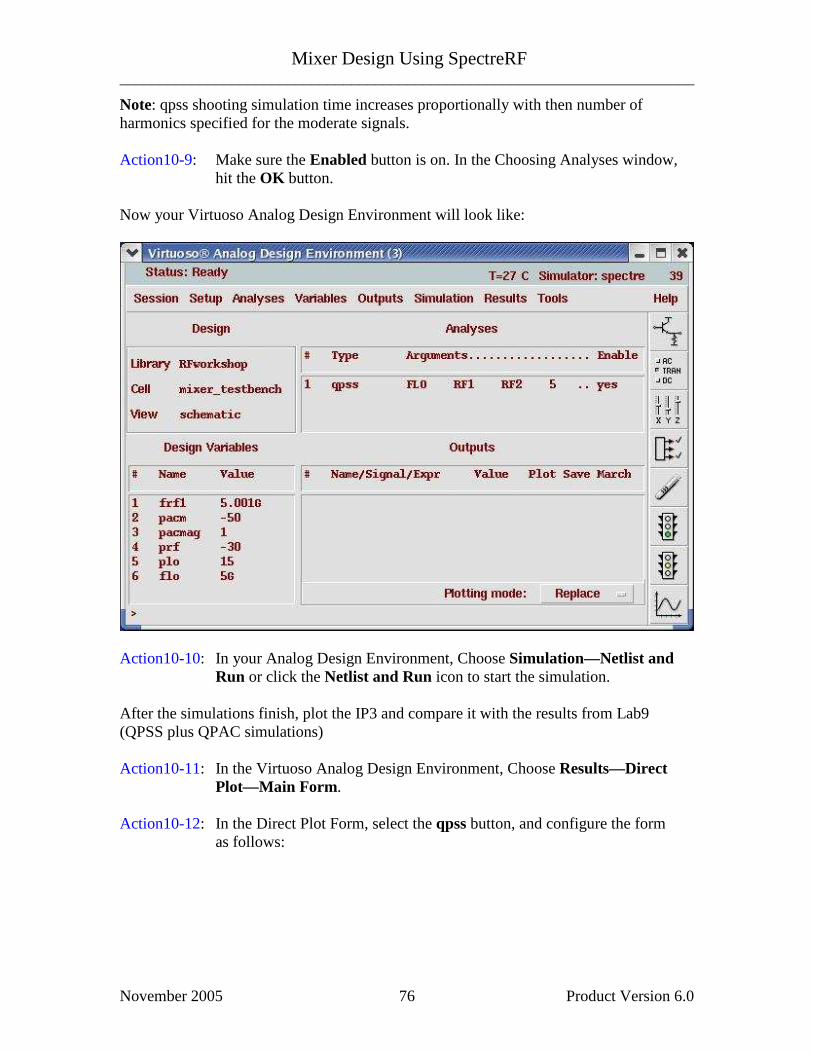
Note: qpss shooting simulation time increases proportionally with then number of harmonics specified for the moderate signals. Action10-9: Make sure the Enabled button is on. In the Choosing Analyses window, hit the OK button. Now your Virtuoso Analog Design Environment will look like:
Action10-10: In your Analog Design Environment, Choose Simulation—Netlist and Run or click the Netlist and Run icon to start the simulation. After the simulations finish, plot the IP3 and compare it with the results from Lab9 (QPSS plus QPAC simulations) Action10-11: In the Virtuoso Analog Design Environment, Choose Results—Direct Plot—Main Form. Action10-12: In the Direct Plot Form, select the qpss button, and configure the form as follows:

Mixer Design Using SpectreRF ________________________________________________________________________
November 2005 Product Version 6.0 77

Mixer Design Using SpectreRF ________________________________________________________________________
November 2005 Product Version 6.0 78
Action10-13: Select output Port3 on schematic. The IP3 calculation results should look
like this:
Action10-14: After viewing the waveforms, click Cancel in the Direct Plot form Action10-15: You can choose Session—Load State, load state
“Lab10_IP3_QPSS_FB” and skip to Action10-22 or … Action10-16: In Vituoso Analog Design Environment, choose Analyses—Choose… Action10-17: In the Choosing Analyses window, select the qpss button in the Analysis field of the window. Action10-18: In Engine filed, choose Flexible Balance. Action10-19: In field of Function Tones, choose FLO. Change the Maxharms to 15,
because Flexible balance algorithmic need more harmonics to calculate. Click Update.

Mixer Design Using SpectreRF ________________________________________________________________________
November 2005 Product Version 6.0 79
Action10-20: Put 10n in the field of Additional Time for Stabilization (stab). The form should look like this:

Mixer Design Using SpectreRF ________________________________________________________________________
November 2005 Product Version 6.0 80
Action10-21: Make sure the Enabled button is on. In the Choosing Analyses window, hit the OK button. Note: The following parameters are required by HB method: 1. Flexible Balance Flag: Harmonic balance engine shares the same PSS/QPSS statement with time-domain engine and is invoked by setting flag flexbalance=yes in the analysis statement. A toggle button is available for user to switch between time domain shooting and HB in ADE PSS and QPSS set up form. 2. Maximum harmonic: In PSS, maximum harmonic is specified by harms. In QPSS, it is specified by maxharms for each tone. It is important to point out that harms in PSS and the first maxharms value in QPSS are output parameters in time-domain method. However, they are input parameters in HB method and have direct impact on the accuracy and performance of the simulations. A proper choice of the maximum harmonic depends on signal waveform and circuit nonlinearity. The faster the signal varies with time, or the more nonlinear the circuit is, the more harmonics are needed to represent the solution accurately. In multi-tone mixer cases, since the large LO tone has higher power level than moderate RF tones and causes more nonlinear effects, usually more harmonics are used for large tone than moderate tones. Maximum harmonic also depends on the order of nonlinear effect user wants to study. For example, for mixer IP3 measurement, maxhamrs of moderate tones must be at least set to 2 in order to capture the IM3 mode at frequency LOωωω −− 212 .
3. tstab: Similar to time domain shooting method, tstab is a valid parameter for initial transient analysis in HB. The default tstab for both PSS and QPSS is one cycle of signal period. For QPSS analysis, user can choose the specific tone during tstab period and only one tone is allowed. One additional cycle is run for FFT. If tstab is set to 0, dc results will be used as initial condition for HB. Oversample factor is optional HB parameter. In PSS/QPSS statement, user can use oversamplefactor=m to specify oversample factor. Spectre will oversample and by actor for each tone. As a result, size of Fourier transform is increased by . For multi-tone cases, user can also specify oversample=[m1 ,m2, m3, ...] to oversample the tones by factor . Size of Fourier transform is therefore increased by . Default oversample factor is 1. It should be pointed out that even with oversampling, user must make sure maximum harmonic meets the accuracy requirement on results he is interested in. Now your Virtuoso Analog Design Environment will look like:

Mixer Design Using SpectreRF ________________________________________________________________________
November 2005 Product Version 6.0 81
Action10-22: In your Analog Design Environment, Choose Simulation—Netlist and Run or click the Netlist and Run icon to start the simulation. As the simulation progresses, note messages in the simulation output log window that are different from time domain qpss:

Mixer Design Using SpectreRF ________________________________________________________________________
November 2005 Product Version 6.0 82
After the simulations finish, plot the IP3 and compare it with the result from the one simulated with shooting engine. Action10-23: In the Virtuoso Analog Design Environment, Choose Results—Direct Plot—Main Form. Action10-24: In the Direct Plot Form, select the qpss button, and configure the form the
same as for shooting engine. Action10-25: Select output Port3 on schematic. The IP3 calculation results should look like this:
Note: The Flexible Balance engine provides same results as with the shooting engine but in this case in a much reduced simulation time. For multi-tone cases such as mixers, HB is significantly more efficient than the shooting QPSS method due to its natural representation of circuit equations.

Mixer Design Using SpectreRF ________________________________________________________________________
November 2005 Product Version 6.0 83
HB method is advantageous over time domain method in handling frequency dependent components. In post-layout circuits with large amount of linear elements, HB also demonstrates better performance than shooting. However PSS HB is also advantageous over time domain for weakly non linear circuits (for strongly non linear circuits, time domain prevails). For circuits driven by multi-tone stimulus, it is better to use HB QPSS other than HB PSS. As HB multi-tone simulation does not have the convergence and speed issues encountered in shooting QPSS, HB QPSS should always be used to simulate multi-tone circuits. HB PSS analysis using beat frequency as fundamental is very inefficient in handling multi-tone cases. When source frequencies are closely spaced, their common frequency is so low that hundreds or even thousands of harmonics must be used. Action10-26: Close the waveform window and click Cancel on the Direct Plot form.

Mixer Design Using SpectreRF ________________________________________________________________________
November 2005 Product Version 6.0 84
Lab11: Rapid IP3 (PAC) Rapid Ip2/Ip3 based on perturbation technology extends both shooting and flexible balance. It is new feature of MMSIM6.0USR2. Rapid IM (IP2, IP3) calculations are an order of magnitude faster than using flexible balance or shooting alone. Action11-1: If not already open, open the schematic view of the mixer_testbench design in the library RFWorkshop Action11-2: From the Mixer_testbench schematic, start the Virtuoso Analog Design Environment with the Tools—Analog Environment command. Action11-3: Select the PORT0 source. Use the Edit—Properties—Objects command
to ensure that the port properties are set as described below:
Parameter Value
Resistance 50 ohm
Port Number 1
DC voltage 500 mV
Source type dc
PAC magnitude (dBm) pacm
Action11-4: Click ok on the Edit Object Properties window to close it. Action11-5: Check and save the schematic. Action11-6: You can choose Session—Load State, load state
“Lab11_Rapid_IP3_PAC” and skip to Action11-11 or … Action11-7: In Vituoso Analog Design Environment, choose Analyses—Choose… Action11-8: In the Choosing Analyses window, select the pss button in the Analysis
field of the window and set the form as shown in Action2-6 Action11-9: In the Choosing Analyses window, select the pac button in the Analysis
field of the window. Choose Rapid IP3 as Specialized Analyses. Set the Input Source 1 to /PORT0 by select PORT0 on the schematic. Push the ESC key on your keyboard to terminate the selection process. Set the Freq of source 1 to 5001M and Freq of Source 2 to 5001.1M. Set the Frequency of IM Output Signal as 0.9M and the frequency of Linear Output Signal as 1.1M. The form should look like:

Mixer Design Using SpectreRF ________________________________________________________________________
November 2005 Product Version 6.0 85
Action11-10: Make sure the Enabled button is on. In the Choosing Analyses window, hit the OK button. Now your Virtuoso Analog Design Environment will look like:

Mixer Design Using SpectreRF ________________________________________________________________________
November 2005 Product Version 6.0 86
Action11-11: In your Analog Design Environment, Choose Simulation—Netlist and Run or click the Netlist and Run icon to start the simulation. As the simulation progresses, note messages in the simulation output log window that are similar to the following:

Mixer Design Using SpectreRF ________________________________________________________________________
November 2005 Product Version 6.0 87
Action11-12: In the Direct Plot Form, select the qac button, and choose Rapid IP3. The form looks like:
Action11-13: Click on Plot Button. The calculated IP3 appears in the waveform
window:
Action11-14: Close the waveform window and click cancel on the Direct Plot form..

Mixer Design Using SpectreRF ________________________________________________________________________
November 2005 Product Version 6.0 88
Lab12: Compression Distortion Summary (PAC) Action12-1: If not already open, open the schematic view of the mixer_testbench design in the library RFWorkshop Action12-2: Select the PORT0. Use the Edit—Properties—Objects command to
ensure that the port properties are set as described below:
Parameter Value
Resistance 50 ohm
Port Number 1
DC voltage 500 mV
Source type dc
PAC Magnitude (dBm) pacm
Action12-3: Click ok on the Edit Object Properties window to close it. Acrion12-4: Check and save the schematic. Action12-5: From the Mixer_testbench schematic, start the Virtuoso Analog Design Environment with the Tools—Analog Environment command. Action12-6: You can choose Session—Load State, load state
“Lab12_CompDistorSmry_PAC” and skip to Action12-11 or … Action12-7: In Vituoso Analog Design Environment, choose Analyses—Choose… Action12-8: In the Choosing Analyses window, select the pss button in the Analysis
field of the window and set the form as shown in Action2-6. Action12-9: In the Choosing Analyses window, select the pac button in the Analysis field of the window and set the form as follows:

Mixer Design Using SpectreRF ________________________________________________________________________
November 2005 Product Version 6.0 89
In the above form, the Maximum Non-linear Harmonics is not specified, the default value 4 is taken. Action12-10: Make sure the Enabled button is on. In the Choosing Analyses window, hit the OK button.

Mixer Design Using SpectreRF ________________________________________________________________________
November 2005 Product Version 6.0 90
Now your Virtuoso Analog Design Environment will look like:
Action12-11: In your Analog Design Environment, choose Simulation—Netlist and Run or click the Netlist and Run icon to start the simulation. As the simulation progresses, note messages in the simulation output log window that are similar to the following:
Action12-12: After the simulation completes, go to Virtuoso Analog Design
Environment, choose Results—Print—PAC Distortion Summary.

Mixer Design Using SpectreRF ________________________________________________________________________
November 2005 Product Version 6.0 91
Results Display Window shows up:
Action12-13: After viewing the results, close it by selecting Window—Close.

Mixer Design Using SpectreRF ________________________________________________________________________
November 2005 Product Version 6.0 92
Lab13: Rapid IP2 (PAC) Action13-1: If not already open, open the schematic view of the mixer_testbench design in the library RFWorkshop Action13-2: Select the PORT0 source by placing the mouse cursor over it and clicking the left mouse button. Then in the Virtuoso Schematic Editor select Edit—Properties—Objects… The Edit Object Properties window for the port cell should come up. Set the source type to sine.
Parameter Value
Resistance 50 ohm
Port Number 1
DC voltage 500 mV
Source type DC
Action13-3: Click ok on the Edit Object Properties window to close it. Action13-4: check and save the schematic. Action13-5: From the Mixer_testbench schematic, start the Virtuoso Analog Design Environment with the Tools—Analog Environment command. Action13-6: You can choose Session—Load State, load state
“Lab13_Rapid_IP2_PAC” and skip to Action13-12 or … Action13-7: In Vituoso Analog Design Environment, choose Analyses—Choose… Action13-8: In the Choosing Analyses window, select the pss button in the Analysis field of the window and set the form as follows:

Mixer Design Using SpectreRF ________________________________________________________________________
November 2005 Product Version 6.0 93
Action13-9: Make sure the Enabled button is on. In the Choosing Analyses window, hit the apply button. Action13-10: In the Choosing Analyses window, select the pac button in the Analysis
field of the window. In the field of Specialized Analyses, choose rapid IP2. Set the Input Source 1 to /PORT0 by select PORT0 on the schematic. Push the ESC key on your keyboard to terminate the selection process. Set the Freq of source 1 to 5001M and Freq of Source 2 to 5001.1M. Set the Frequency of IM Output Signal as 0.1M and the frequency of Linear Output Signal as 1.1M. The form should look like:

Mixer Design Using SpectreRF ________________________________________________________________________
November 2005 Product Version 6.0 94
Action13-11: Make sure the Enabled button is on. In the Choosing Analyses window, hit the OK button. Now your Virtuoso Analog Design Environment will look like:

Mixer Design Using SpectreRF ________________________________________________________________________
November 2005 Product Version 6.0 95
Action13-12: In your Analog Design Environment, Choose Simulation—Netlist and Run or click the Netlist and Run icon to start the simulation. As the simulation progresses, note messages in the simulation output log window that are similar to the following:
Action13-13: In the Virtuoso Analog Design Environment, Choose Results—Direct Plot—Main Form.

Mixer Design Using SpectreRF ________________________________________________________________________
November 2005 Product Version 6.0 96
Action13-14: In the Direct Plot Form, select the pac button in analysis field and choose Rapid IP2 in the Function field.
Action13-15: Click Plot button.
Action13-16: Close the waveforms window, click Cancel in the Direct Plot form.

Mixer Design Using SpectreRF ________________________________________________________________________
November 2005 Product Version 6.0 97
Lab14: IM2 Distortion Summary (PAC) Action14-1: If not already open, open the schematic view of the mixer_testbench design in the library RFWorkshop Action14-2: Make sure the source type of PORT0 is sine.
Parameter Value
Resistance 50 ohm
Port Number 1
DC voltage 500 mV
Source Type DC
Action14-3: Check and save the schematic. Action14-4: From the Mixer_testbench schematic, start the Virtuoso Analog Design Environment with the Tools—Analog Environment command. Action14-5: You can choose Session—Load State, load state
“Lab14_IM2DistorSmary_PAC” and skip to Action14-10 or … Action14-6: In Vituoso Analog Design Environment, choose Analyses—Choose… Action14-7: In the Choosing Analyses window, select the pss button in the Analysis field of the window and set the form as you did in Rapid IP2 simulation. Action14-8: In the Choosing Analyses window, select the pac button in the Analysis
field of the window. In the filed of Specialized Analyses, choose IM2 Distortion Summary. Set the Input Source 1 to /PORT0 by select PORT0 on the schematic. Push the ESC key on your keyboard to terminate the selection process. Set the Freq of source 1 to 5001M and Freq of Source 2 to 5001.1M. Set the Frequency of IM Output Signal as 0.1M. The form should look like:

Mixer Design Using SpectreRF ________________________________________________________________________
November 2005 Product Version 6.0 98
Action14-9: Make sure the Enabled button is on. In the Choosing Analyses window, hit the OK button. Now your Virtuoso Analog Design Environment will look like:

Mixer Design Using SpectreRF ________________________________________________________________________
November 2005 Product Version 6.0 99
Action14-10: In your Analog Design Environment, Choose Simulation—Netlist and Run or click the Netlist and Run icon to start the simulation. As the simulation progresses, note messages in the simulation output log window that are similar to the following:
Action14-11: In the Virtuoso Analog Design Environment, Choose Results—Print—
PAC Distortion Summary. The Results Display Window shows the PAC IM2 Distortion Summary.

Mixer Design Using SpectreRF ________________________________________________________________________
November 2005 Product Version 6.0 100
The distortion is listed dB for each instance. Due to very low RF input power, the distortion is very small. Action14-12: After viewing the distortion summary report, close it by selecting
Window—Close.
Conclusion This workshop highlights how to use SpectreRF to simulate a Mixer efficiently and extract design parameters such as IP3, 1dB compression point or port-to-port isolation. Various techniques using PSS, Pnoise, PAC and QPSS analyses are being presented. SpectreRF Flexible Balance and Time domain algorithms accuracies are also demonstrated and compared. .

Mixer Design Using SpectreRF ________________________________________________________________________
November 2005 Product Version 6.0 101
Reference [1] "The Designer's Guide to Spice & Spectre", Kenneth S. Kundert, Kluwer
Academic Publishers, 1995. [2] "Microwave Transistor Amplifiers", Guillermo Gonzalez, Prentice Hall, 1984. [3] "RF Microelectronics", Behzad Razavi. Prentice Hall, NJ, 1998. [4] "The Design of CMOS Radio Frequency Integrated Circuits", Thomas H. Lee.
Cambridge University Press, 1998.