How to Build 5KVA Inverter PMW
229
HOW TO BUILD 12V CHARGER AND PMW INVERTER (250- 5000WATTS) 13V 5A ADJUSTABLE REGULATOR USING LM338 Description. This 13V/5A power supply is based on the famous LM338 IC from the ST Microelectronics. The IC has time dependent current limiting, thermal regulation and is available in 3 lead transistor package. The IC can easily supply well over 5A at an output voltage range between 1.2V and 30V. In this circuit the output voltage is determined by the two resistors R1 and R2.The output voltage can be varied by adjusting the R2.Diodes D2 and D3 are protection diodes. Capacitors C1 and C5 are filter capacitors while C2 and C3 are decoupling capacitors. 1
Transcript of How to Build 5KVA Inverter PMW

HOW TO BUILD 12V CHARGER AND PMW INVERTER (250-5000WATTS)
13V 5A ADJUSTABLE REGULATOR USING LM338Description.
This 13V/5A power supply is based on the famous LM338 IC from the ST Microelectronics. TheIC has time dependent current limiting, thermal regulation and is available in 3 lead transistor package. The IC can easily supply well over 5A at an output voltage range between 1.2V and 30V.
In this circuit the output voltage is determined by the two resistors R1 and R2.The outputvoltage can be varied by adjusting the R2.Diodes D2 and D3 are protection diodes. Capacitors C1 and C5 are filter capacitors while C2 and C3 are decoupling capacitors.
1
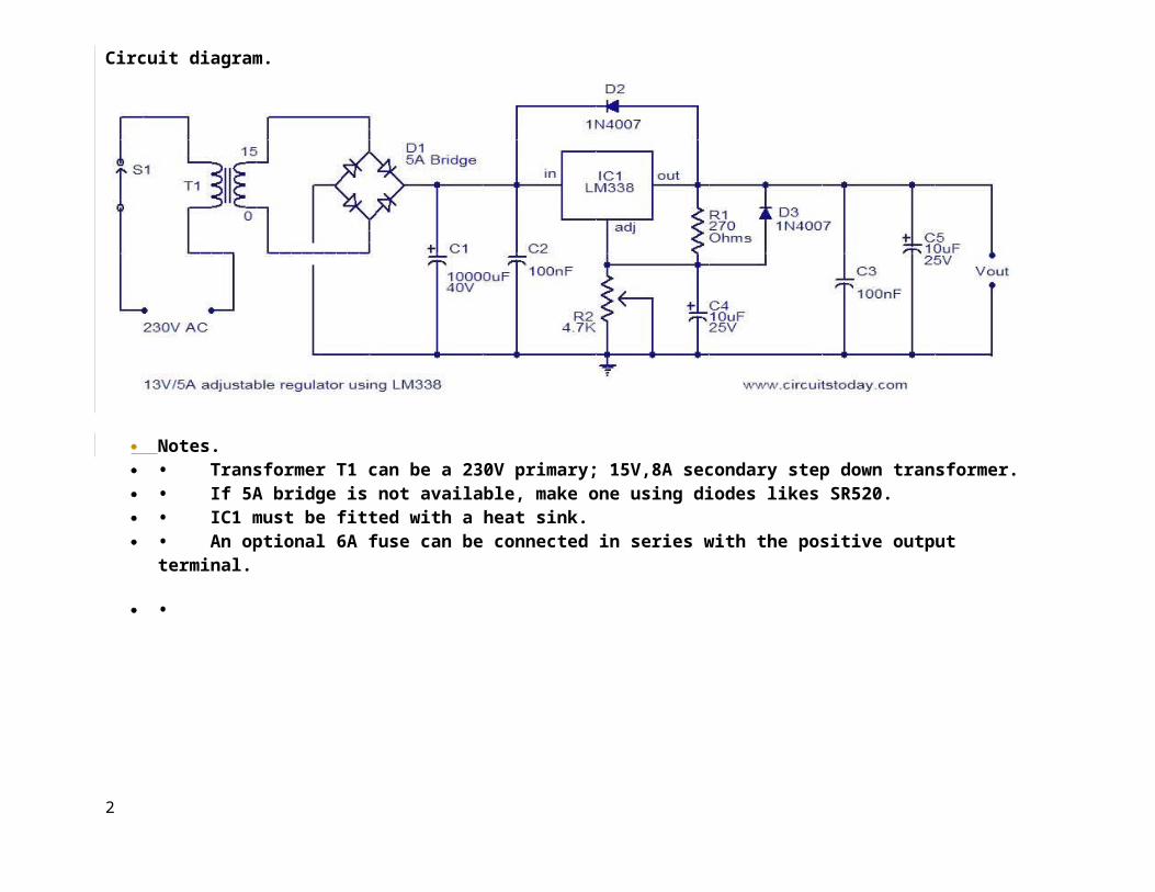
Circuit diagram.
Notes. • Transformer T1 can be a 230V primary; 15V,8A secondary step down transformer. • If 5A bridge is not available, make one using diodes likes SR520. • IC1 must be fitted with a heat sink. • An optional 6A fuse can be connected in series with the positive output
terminal.
•
2

Switch S1 can be used as an ON/OFF switch. • 8A transformer and 5A diodes make this circuit a bit costly.
So assemble this circuit only if you have real need. • Many low cost/low current adjustable regulators for
beginners are there in the power supply section.
How to Add Variable Voltage to Your ATX Based Bench Power Supply
152,000 views Edited by Tipper and 17 others Edited 3 days ago
If you've built a bench power supply using an old ATX computer power supply, you may feel limited by the choice of voltages + 3.3V, + 5V, and +/- 12V DC. Suppose you're breadboarding a circuit that's meant tobe run off a 9V battery? This is how to build an add-on variable-voltage "module" for your power supply.
The hand drawn circuit is the same circuit drawn in a bit more pcb board friendly way using a LM317 regulator. There is one caveat of using +12V and -12V to achieve 24V as we will be doing:the +12V can typically supply lots of current - 6A minimum for a really small supply, often double or triple that. The -12V line, however, can often only drain a fraction of that. My supply is rated for .3A on the -12V line, for example. Before you add this module, you'll have to make sure that your -12V line is rated for1.5A at a MINIMUM. If you're drawing for your project much less than the 1.5A max of the regulator, you may be fine, but you could very easily run into problems later.
3

Steps1.
1
4

Gather the materials required and construct the circuit from the circuit diagram. It would be a good idea to get the datasheet forthe regulator from the manufacturers website.
2.
2
3. Get some banana leads and connect the +12V and -12V outputs from your modded ATX supply and connect it to the input of your variable module. Use a multimeter to measure the
5

4. output voltage.
3
Once you have built the circuit test it carefully and measure the output voltage. You should be able to vary the voltage from about 1.5Vup to 22V by turning the variable resistor. If you are using the LM317the output current will be restricted to 1.5A, if using the LM338K it should be slightly higher check the datasheet for exact information.
Tips Voltage regulators are under constant improvements; for instance,
LM338T has a 5A max current rating.
6
I used a small piece of veroboard to build this little addon. Youcould use matrix board or design a small PCB. It wouldn't be difficult.
Make sure that the +12V binding post is well isolated from groundand from the -12V binding post.
If you use the LM317 the pins are labeled differently on the datasheet pin-out diagram: Common = Adj, Vreg = Vout, Line Voltage = Vin. So the pins from left to right are; Common, Vreg, Line Voltage.
During use the regulator may get hot. Use a heatsink if necessary.
Use sensible wire lengths if creating a permanent connection to the ATX supply.
Warnings Use common sense. If you find the regulator gets hot use a
heatsink. If you've already built an ATX Power Supply based bench/lab
supply, you've already run the risks - this project is less dangerous. Soldering irons can burn you, hand tools can cut you; don't drink and hack.
Since any part on your circuit isn't really 0v(gnd) when you put it into your ATX case don't let any part touch anything, even thecase.
Things You'll Need
You will need the following materials:
1x LM317 or LM338K Voltage regulator (With heatsink and heatsink paste)
1x 100nF Capacitors (ceramic or tantalum)
7

1x 1uF Capacitors Electrolytic
1X 1N4001 or 1N4002 Power Diode
1X 120 Ohm resistor
1x 5k Ohm variable resistor
Optional
o Some Veroboard or a matrix board and some suitably thick wire for connecting the circuit.
o A small enclosure about the size of a wall wart to put the circuit in.
Indispensable
o An ATX power Supply already modded to provide +12V, -12V, +5V and -5V
Step 1: Getting StartedThe first order of business is that of safety. While I'm reasonably sure thatthere isn't enough residual energy to stop your heart, those capacitors can still bite, and that can cause significant pain and maybe even burns. So be paranoid when getting close to the internal circuitry. It would probably be agood idea to put on some insulating gloves. Also (obviously) make sure the thing is unplugged. You are responsible for your own safety!
Here are the tools/parts needed:
Drill
8

Needle-nose pliers Soldering iron 3 x "Banana Jack" Insulated Binding Post sets 1 x bag of "#6" Ring Tongue Terminals (16-14 gauge) Rubber feet Small bit of heat shrink. Screwdriver Wire strippers
Ok, let's get to voiding some warranties!
Step 2: Opening Up
9

Open the PSU and make an assessment of the space you have to work with. Make sure that there won't be any clearance issues for the binding posts or wires.
Once you have decided how your PSU will be configured, mark with pencil whereyou want to drill the holes later on. This will help you in cutting the wiresto the appropriate length.
Step 3: Wires, Wires Everywhere
10

You will be met with the daunting task of sorting through a hundred wires of different colors. The only colors we care about are Black, Red, Orange, Yellow and Green. Any other colors are superfluous and you can cut them at the circuit board.
The green wire is what tells the power supply to turn on from stand-by mode, we want to just solder it to a ground (black) wire. Put some heat shrink on this so it won't short out on anything else. This will tell the PSU to be constantly on without a computer.
Cut all of the other wires down to about a foot, and remove any zip-ties or cable organizers. You should have a forest of wires with no connectors.
The colors represent:
11

YELLOW = 12 VoltsRED = 5 VoltsORANGE = 3.3 VoltsBLACK = Common Ground.
Now, theoretically, you could be done. Just hook the wires to 4 large alligator clips (one for each color set) or some other terminals. This might be handy if you're just going to be powering one thing, such as a ham radio, electric motor or lights.
Step 4: Grouping Wires
Group the 4 wire colors together and cut them to length to where you marked where the posts would go. Use the wire strippers to take off the insulation
12

and stick about 3-4 wires into one tongue terminal. Then crimp them. The exact number of wires per voltage rail depends on the wattage of the PSU. Mine was a 400W and there are about 9 wires per rail. You need all these wires so that you can get all of the current rated for that rail.
Step 5: Holes
13

Now we come to the drilling. With most power supply units, you won't be able to completely remove the circuit board from the chassis. But you should be able to remove it partially and wrap it in plastic so that it doesn't get contaminated by metal shavings.
Onces you have the holes drilled, file away any rough spots and wipe down thechassis with a damp cloth.
This might be a good time to figure out something for that hole the old wiring harness used to go through. I used a washer and the head of a bolt to make a cap, and epoxied it in there. But this is purely cosmetic and unimportant.
14

Step 6: Putting It Together
15

Now comes the fun bit. Install the binding posts while using a small screwdriver to make sure they're all orientated right when you're tightening them down.
Install the tongue terminals onto the back of the binding posts and tighten them down good and snug with the pliers. This might be tricky if you have a high-wattage PSU as you will have more wires. The most the posts shown in these pictures can take is 4 tongue terminals.
After that's done, close up the power supply.
I had some clearance issues with mine- the 90mm fan just wouldn't fit. I figured since it will not be acting as the exhaust fan for a computer anymore, it wouldn't be needed anyway. So I removed it.
17

You need some way of clearly marking which post is which voltage. You could go super polished and make a color-coded decal in Illustrator and print it atyour local print shop, but I'm lazy... and cheap. So I used some permanent markers.
You could also take some plastic or vinyl paint and color each post. Whateverputs a bee in your bonnet.
Lastly, stick on the rubber feet on what you want to be the bottom.
Step 8: Conclusion
19

My 400 Watt power supply can deliver 23 Amps through the 12V rail, and 40 Amps through the 5V. That's very good for something that, aside from the initial cost of the PSU, cost about $10.
Step 9: Updates
Originality
This project is not necessarily original and has been done by many people.
The most "together" project is that of this guy: http://www.wikihow.com/Convert-a-Computer-ATX-Power-Supply-to-a-Lab-Power-Supply
There are a multitude of other projects, but I feel mine and his are the bestI've seen so far.
20

Issue of the Resistor
Power supplies need a certain minimum load to work properly. The min. load for mine is around 0.8 amps. Thus if you plan on powering LED's or other suchlow-power device exclusively, you'll need a resistor to provide a load. Otherwise you will damage the PSU.
A meaty 10-Ohm, 10 watt resistor from Radio Shack is a good choice. Wire it across 12 volt and ground.
-12V and -5V lines
It has been brought to my attention that the -12V and -5 lines are pretty handy for diversifying the voltages this thing can produce. These are the white and blue wires I told you to cut earlier.
Of course, adding them is simple, it's just a matter of getting two extra binding posts and connecting the wires to them. It's just a question of "Do Ineed these?"
I didn't, all I really needed was the 12V line. But as I said, if you need them, they're easy to install.
UPDATE 12-1-11
Still going strong! This little PSU has been super handy
21

How to Convert a Computer ATX Power Supply to a Lab Power Supply
1,831,000 views
Edited by Abizarl and 45 others Edited 14 days ago
Computer power supplies cost around US$30, but lab power supplies can run you $100 or more! By converting the cheap (free) ATX power supplies that can be found in any discarded computer, you can get a phenomenal lab power supply with huge current outputs, short circuit protection, and reasonably tight voltage regulation on the 5V line.
On most power supply units (PSUs), the other lines are unregulated.
Ad
Steps1. 1. 12. Look online or at your local computer store for an ATX computer power
supply, or dismantle an old computer and remove the power supply from the case.
3. Ad4. 2. 25. Unplug the power cable from the power supply and turn off the switch on
the back (if there is one). Also, be sure you are not grounded so that remaining voltage doesn't flow through you to ground.
6. 3. 37. Remove the screws that attach the power supply to the computer case and
remove the power supply.8. 4. 49. Cut off the connectors (leave a few inches of wire on the connectors so
that you can use them later on for other projects).10. 5. 5
22

11. Discharge the power supply by letting it sit unconnected for a fewdays. Some people suggest attaching a 10 ohm resistor between a black and red wire (from the power cables on the output side), however this is only guaranteed to drain the low voltage capacitors on the output - which aren't dangerous to begin with! It could leave the high-voltage capacitors charged, resulting in a potentially dangerous - or even
lethal - situation.
6
Gather the parts you need: binding posts (terminals), a LED with a current-limiting resistor, a switch (optional), a power resistor (10 ohm, 10W or greater wattage, see Tips), and heat shrink tubing.
12. 7
23

Open up the power supply unit by removing the screws connecting the topand the bottom of the PSU case.
12. 813. Bundle wires of the same colors together. If you have wires not
listed here (brown, etc), see the Tips. 14.15. The color code for the wires is: Red = +5V, Black = Ground (0V),
White = -5V, Yellow = +12V, Blue = -12V, Orange = +3.3V, Purple = +5V Standby (not used), Gray = power is on (output), and Green = PS_ON#
24

(turn DC on by shorting to ground).
9
Drill holes in a free area of the power supply case by marking the center of the holes with a nail and a tap from the hammer. Use a Dremelto drill the starting holes followed by a hand reamer to enlarge the holes until they are the right size by test fitting the binding posts. Also, drill holes for the power ON LED and a Power switch (optional).
25

o 10ooo Screw the binding posts into their corresponding holes and attach
the nut on the back.o 16. 11o Connect all the pieces together. o o Connect one of the red wires to the power resistor, all the
remaining red wires to the red binding posts;o o Connect one of the black wires to the other end of the power
resistor, one black wire to the cathode (shorter lead) of the LED,one black wire to the DC-On switch, all the remaining black wires to the black binding post;
o o Connect the white to the -5V binding post, yellow to the +12V binding post, the blue to the -12V binding post, the gray to a resistor (330 ohm) and attach it to the anode (longer lead) of the LED;
26

Note that some power supplies may have either a gray or brown wireto represent "power good"/"power ok". (Most PSU's have a smaller orange wire that is used for sensing-- 3.3V- and this wire is usually paired at the connector to another orange wire. Make sure this wire is connected to the other orange wires, otherwise your lab power supply won't stay on.) This wire should be connected to either an orange wire (+3.3V) or a red wire (+5V) for the power supply to function. When in doubt, try the lower voltage first (+3.3V). If a power supply is non ATX or AT compliant, it may haveits own color scheme. If yours looks different that the pictures shown here, make sure you reference the position of the wires attached to the AT/ATX connector rather than the colors.
o Connect the green wire to the other terminal on the switch.
o Make sure that the soldered ends are insulated in heat shrink tubing.
27

o Organize the wires with a electrical tape or zip-ties.
12
Check for loose connections by gently tugging on them. Inspect for barewire, and cover it to prevent a short circuit. Put a drop of super-glue
28

to stick the LED to its hole. Put the cover back on.
13
Plug the power cable into the back of the power supply and into an AC socket. Flip the main cutoff switch on the PSU if there is one. Check to see if the LED light comes on. If it has not, then power up by flipping the switch you placed on the front. Plug in a 12V bulb into the different sockets to see if the PSU works, also check with a digital voltmeter. Make sure you do not short any wires out. It should look good and work like a charm!
Tips
• You can use your power supply 12V output as a car battery charger!Be careful, though: if your battery is too discharged, the power supplyshort circuit protection will trigger. In that case, it's better to puta 10 Ohm, 10/20 Watts resistor in series with the 12 V output, in orderto not overload the power supply. Once the battery is near 12V charge(you can use a tester to verify that), you can remove the resistor, in order to charge the remaining of the battery. This can save you if your car has an old battery, if it's winter and your car
29

does not want to turn on, or if you accidentally left the lights or theradio on for hours and hours.
• You can also convert this to a variable voltage power supply - butthat is another article (hint: Uses a 317 IC with power transistor).
• Feel free to add some pizazz to the dull grey box.
• The +5VSB line is +5V standby (so the motherboard's power buttons,Wake on LAN, etc. work). This typically provides 500-1000 mA of current, even when the main DC outputs are "off". It might be useful todrive an LED from this as an indication that the mains are on.
• You can add a 3.3 volt output (such as to power 3V battery-powereddevices) to the supply by hooking the orange wires to a post (making sure the brown wire remains connected to an orange wire) but beware that they share the same power output as the 5 volt, and thus you must not exceed the total power output of these two outputs.
• If you are not sure of the power supply, test it in the computer before you harvest. Does the computer power on? Does the PSU fan come on? You can place your voltmeter leads into an extra plug (for disk drives). It should read close to 5V (between red and black wires). A supply that you have pulled may look dead because it does not have a load on its outputs and the enable output may not be grounded (green wire).
• Options: You don't need an additional switch, just connect the green and a black wire together. The PSU will be controlled by the rearswitch, if there is one. You also don't need an LED, just ignore the gray wire. Cut it short and insulate it from the rest.
• If you don't feel like soldering nine wires together to a binding post (as is the case with the ground wires) you can snip them at the PCB. 1-3 wires should be fine. This includes cutting any wires that youdon't ever plan on using.
• The voltages that can be output by this unit are 24v (+12, -12), 17v (+5, -12), 12v (+12, GND), 10v (+5, -5), 7v (+12, +5), 5v (+5, GND)
30

which should be sufficient for most electrical testing. Many ATX power supplies with a 24-pin connector for motherboards will not supply the -5V lead. Look for ATX power supplies with a 20-pin connector, a 20+4-pin connector, or an AT power supply if you need -5V.
• ATX power supplies are switched-mode power supplies (info at http://en.wikipedia.org/wiki/Switched_mode_power_supply); they must always have some load to operate properly. The power resistor is there to "waste" energy, which will give off heat; therefore it should be mounted on the metal wall for proper cooling (you can also pick up a heat sink to mount on your resistor, just make sure the heat sink doesn't short circuit anything). If you will always have something connected to the supply when it is on, you may leave out the power resistor. You can also consider using a lighted 12v switch, which will act as the load necessary to turn on the power supply.
Show 12 more tips
Ad
Warnings
• A computer power supply is fine for testing purposes, or for running simple electronics (eg battery chargers, soldering irons) but will never produce power like a good lab power supply, so if you intendon using your power supply for more than just testing, buy yourself a good lab supply. There is a reason they cost so much.
• If you suspect the power supply is damaged, do not use it! If it is damaged, the protection circuitry may not work. Normally, a protection circuit will slowly discharge the high voltage capacitors - but if the supply was connected to 240V while set at 120V (for example), the protection circuits have probably been destroyed. If so, the power supply might not shut down when it is overloaded or when it begins to fail.
• Do not touch any lines leading to capacitors. Capacitors are cylinders, wrapped in a thin plastic sheath, with exposed metal at the top with a + or K usually. Solid-state capacitors are shorter, a little
31

wider in diameter, and do not have a plastic sheath. They retain a charge much like batteries do, but unlike batteries, they can dischargeextremely fast. Even if you have discharged the unit, you should avoid touching any points on the board except where necessary. Use a probe toconnect anything you might touch to ground before beginning any work.
• Ensure that you discharge the capacitors. Plug in the power supply, turn on the power (short the Power (green) wire to ground, thenunplug the power supply until the fan stops spinning.
• When drilling the metal case, make sure no metal filings get inside the PSU. These could cause shorts, which in turn could cause a fire, extreme heat or dangerous electrical spikes on one of your outputs which will break your new lab power supply which you worked so hard on.
• Line voltage can kill (anything above 30 milliamps/volts can kill you in a matter of time if it somehow penetrates your skin), and at thevery least give you a painful shock. Make sure that you have removed the power cord before doing the conversion and have discharged the capacitors as described in the steps above. If in doubt, use a multimeter.
• Do not remove the circuit board unless you must. The traces and solder on the underside could still have high voltage on them if you didn't let the PSU sit long enough. If you must remove it, use a meter to check for voltage on the pins of the largest capacitors. When you replace the board, make sure that the plastic sheet goes back under theboard.
• The resulting power supply will provide high output power. It might happen you create an electric arc at the low voltage outputs or fry the circuit you are working on, if you make any mistake. Lab PSUs have adjustable current limitation for a reason.
• Only power supply technicians should attempt this.
• This will certainly void any warranty.
32

• The original article said to make sure you are grounded. That was incorrect and dangerous. Make sure you are NOT grounded when working onpower supplies so that power doesn't flow through you to ground.
Things You'll Need
•
An ATX power supply of any rating above 150 Watt (can be found from an obsolete computer, online, or at your local computer store)
•Wire cutters
•Needle nose pliers
•Drill
•Reamer
•Soldering Iron & Solder
•Electrical Tape
•Heat Shrink Tubing & Heat Gun
•Binding posts
•LED
•Current limiting resistor for the LED (330 ohms)
•Power resistor to load the power supply
•Low Wattage Switch
•Computer Power Cable
33

Adjustable Power Supply 1.2 – 30V 5A using LM338
See Other projects in : Mini Projects • Variable Supply And: 5A regulated power supply, Adjustable dc power supply, LM338
Posted by momename - July 9, 2012 at 12:00 am
If you want to a variable dc voltage power supply circuit during 1.2V to 30Vdc and can provide a current maximum to 5A.We may be have the many ways such as: to be modified the LM317 Variable Regulator 0-30V 1A by add the power transistor MJ2955 in circuit following Power supply regulator 1.2V-20V and 3V-6V-9V-12V 3Amp or will build the Variable dc regulator 0-30V 5A circuit to be well as well, But these methods. Rather cumbersome and wasting too money.However we can build this circuit easily and cheap, By using the packages IC No. LM338 only one, Similar to the LM317 IC number, but itcan supply up to 5A, as the circuit shown in Fig.How this circuit worksThe transformer T1 converts the AC 220V to 24 Vac, so be rectified thecurrent by the bridge diode rectifier BD1 – 10A 400V. Until DCV has come out that the filter capacitor C1 is equal to 35 volt.The IC1 is the heart of the operation of this circuit. By the voltage output value obtained from the IC depends on the voltage value at the Adj pin of IC1, or can be varied by adjusting the VR1.However output voltage will be approximately equal to 1.25+1.25VR1/R1The output voltage at the output pin of the IC1 is a more powerful filter with the capacitor C3.
34

The creation You must to place all devices in the PCB to completely, for the IC LM338K should install with a large heat sink. and all device has the poles. Caution connected the correct, especially electrolytic capacitor.
35

Figure 2 The PCB layout and components layout
NOTE :Because IC number is high price.You may use the LM317 and transistor, to expand the current demand.
36

Best DC power supply 3Amp to adjust 1.2V-20V & 3V-6V-9V-12V
See Other projects in : Cool Projects • Mini Projects • Power supply And: 2N3055, Adjustable dc power supply, LM317, Multi voltage regulated dc power supply
Posted by momename - April 3, 2014 at 2:30 am
This is the high quality power supply to provide high current 3A. And still adjust voltage in steps from 3V, 6V, 9V, 12V. adjust voltage is continuous 1.25V to 20V. Using LM317T and 2N3055 are main parts so easy to made and cheap.
Friends would known the power supply as well. Because you must use in various circuit experiment. It originally had a small supply current, when found projects that uses lot of current. Such as an audio amplifier circuit so provide current is not enough.This project can help you. Because of provide high current 3A. And still adjust voltage in steps from 3V, 6V, 9V, 12V. adjust voltage is continuous. And you do not have to worry. This creates a simple and economical. If interested, please read on.
How it worksIn the circuit below can be seen that, when opening switch S1 is current through the transformer. To convert from 220V AC to 18V, then through diode bridge rectifier BD1. But is a DC supply that still not smooth. Then, a filter capacitor C1 serves electricity, out of BD1 to be more smooth with the LED1 to show that power is supplied to already.
When the filter current is smooth on one order. The current will through the regulator circuit that the main components are IC1(LM317T)and Q1(2N3055).
-IC1 is the regulator IC number : LM317T.-Q1 is power transistor NPN type number : 2N3055.-Before the DC volt through IC1 would have C2 served filter noise off.
37

When we adjust the variable resistor VR1 or rotary switches S3 twist choose it. Will cause changes the voltage at the ADJ pin and OUT pin of IC1. Which will be resulting the voltage drop across the base pin and the emitter pin of transistor Q1 changes. Makes the voltage on theconnector is changed accordingly. And before the voltage is applied tocurrent C3 filter to smooth again.
Detail see in circuit image.
The Circuit diagram of Power supply regulator 1_2V-20V and 3V-6V-9V-12V 3Amp With LM317T and 2N3055.
Components listIC1____LM317T__3 terminal positive adjustable regulator___ = 1 pcs.Q1_____2N3055___15A 60V NPN transistor__________________ = 1 pcs.
38

Q2_____TIP32____4A___60V PNP transistor__________________ = 1 pcs.C1_____6,800uF 35V Electrolytic capacitors______________ = 1 pcs.C3_____33uF 35V ________”___________”____________________ = 1 pcs.C2_____0.01uF 50V____Ceramic___Capacitor__________________ = 1 pcs.R1_____15 ohms 1W____Resistor_____________________________ = 1 pcs.R2_____150 ohms 0.5W__Resistor____________________________ = 1 pcs.R3_____470 ohms 0.5W__Resistor____________________________ = 1 pcs.R4_____150 ohms 0.5W__Resistor____________________________ = 1 pcs.R5_____15K______0.5W__Resistor____________________________ = 1 pcs.R6,R11__1K______0.5W__Resistor____________________________ = 2 pcs.R8____220 ohms___”_______”________________________________ = 1 pcs.R9____560 ohms___”_______”________________________________ = 1 pcs.R10___33 ohms___”_______”________________________________ = 1 pcs.R12___1.2K_____”_______”_________________________________ = 1 pcs.R12___220 ohms___”_______”________________________________ = 1 pcs.
T1-3A 18V transformer_____________________________________ = 1 pcs.LED1___ color as you need_________________________________ = 1 pcs.SW1____Selector switch___see text_________________________ = 1 pcs.PCB,Heatsink,and others…
How to buildThis project is not much equipment. I soldered components onto the perforated board. Place position equipment according to the circuit. As Figure 2 the PCB layout. and assemble all components as Figure 3. The Q1 should be hold on a large heat sink. It is very hot during use.Switches are connected correctly. If you are a beginner must sedation.Before entering power should review several times. To prevent damage, do not happen. In particular, Position pin diode, Capacitor electrolytic, transistors, IC1.
If something goes wrong, you will have the full power and 3A, which are talented enough to, show you how. “I make with myself, have a proud and active needs, in save “.
39
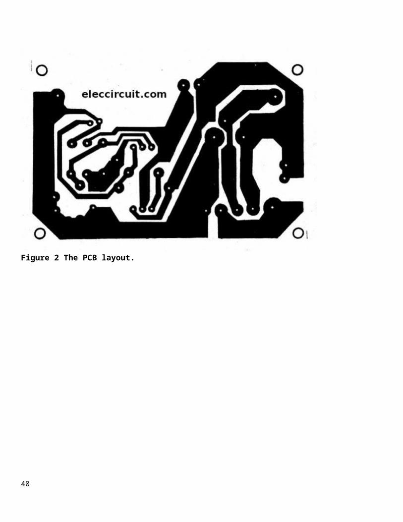
Figure 2 The PCB layout.
40

Figure 3 assemble all components layout to the PCB.
Note:
You will also this projects :1.2V-25V at 3Amp Adjustable Regulators using LM350T instead. By remove both transistors as MR OHM 1970 suggest us.
The circuit above list may be unnecessary for you. Because large. And too expensive. see below circuits better
41

My first Variable DC Power Supply 1.2V to 30V 1A by LM317
See Other projects in : Mini Projects • Variable Supply And: 0-30V power supply, Adjustable dc power supply, LM317
Posted by momename - March 22, 2014 at 6:00 am
If you are beginner in electronics and you want to have a great power supply. This project is design for you. It can supply voltage 1.2V to 30V at all range is 1A.
New update Please read below this article.
This is the First DC power supply in my life that made to use in many projects. It is ideal for those who want to adjust voltage from 1.25V to 30V and currents up to 1A. Which is sufficient for normal use Such as is power supply instead of an one 1.5V AA battery or when you want to listen to music from a 30-watt amplifier that required voltage of 24V 1A, it can be done easily.
In the days before that we commonly used the transistor that is very difficult, large, and probably more expensive ICs. But this circuit can be created with a single IC is LM317 The LM317 or LM117 series of adjustable 3-terminal positive voltage regulators is capable of supplying in excess of 1.5A over a 1.2V to 37V output range,And has many special features that I like are :• Output Voltage Tolerance 1%• Line Regulation 0.01%• Load Regulation 0.3%• Prevent the deposition temperature.• Short-circuit protection.• Ripple is eliminated with ratio of 80dB• Maximum input voltage 40V
The working of circuitsFollowed circuits below, the transformer T1 is changed a AC 220V down as AC 24V to the bridge diode rectifier D1(1N4001) to D4(1N4001) thereis dc voltage into the filter capacitor C1 equal to DC35V
42

The output voltage from IC1 Depending on the Voltage Adj pin of the IC. Or to adjust the VR1.The VR1 is control output dc voltage 0V(1.25V) to 30V(32V) or 37V maximum voltage at 1.5A max all range.
Calculate the LM317 output voltage
And we can calculate output voltage equal to:Vout = 1.25 x 1+ (Rp/R1)- Vref = 1.25V- Typically R1 is 220 ohms or 240 ohms as datasheet. I use 220 ohms.- Normally as datasheet I see them use VR= 5K (Pontentiometer) But I have VR-10K only since it easy to use.Rp = (VR1 x R2) / (VR1 + R2)
Then we testit,Suppose, rotate VR1 to lowest resistance cause Rp = 0 hms. put it in formula above:Vout = 1.25 x 1+(0/220)= 1.25VBut when adjust VR1 to maximum resistance VR1 and R2 are parallel together. Rp = 5.46K = 5460 ohms. test it in formula above:
43

Vout = 1.25 x 1+(5460/220)= 32.2V
Then the capacitor C3 is Better performance filter of IC1.The diode D5 and D6 ( both is 1N4007) is the protector from external voltage to reverse to makes the damage to the IC1.
How to builds
If you want to see PCB layout and component layout and fully content.
Update:Many begin friends tell me this project difficult to adjust voltage output. so I add potentiometer 1K and parallel 1K-resistor together. then connects them to VR1 as Figure below.
44

You will see that we can adjust voltage at VR2 (new) is 4volts since resistance sum of 500 ohms approximately.
45

For example I set volage is 9V with rotate VR1 is 8.00V and rotate VR2easily to control the output voltage of 9.00V.
46

0-60 volt DC variable power supply using LM317&LM337
See Other projects in : Cool Projects • Variable Supply And: Adjustable dc power supply, Dual output power supply, LM317, LM337
Posted by momename - January 2, 2013 at 6:26 am
If you want a power supply that covers most applications. This circuitmay be what you’re looking for. The price you deny difficult. With thefollowing features.1. On signal mode can supply DC voltage between 0 volt and 60 volt2. Can provide DC dual variable on positive, negative and ground are +/- 0-30 volts.3. Can supply current out maximum about 1.5 A.4. Use the most popular IC are LM317T and LM337T, so do not have to worry about finding the device, and it certainly easy.
Before construction, we study the properties of important devices, is regulator IC.
Choosing a regulator IC.The regulator IC is used to regulates DC voltage, which in this circuit we use an IC numeber of LM317T for the positive voltage and the LM337 for the negative voltage. Both IC have the same features. Thus, So describes specific number LM317T only.The LM317T is readymade regulator IC can use to adjust voltage from 1.25 volt to 37 volt, there is 3 leg, body same the regulated IC number 7805.But it batter that can provides to 1.5 A and get input voltage from 3 volt to 40 volt It’s easy to applications and, of these features have advantages over the regular letters IC 78xx series a lot.In addition, Internal the IC is also circuit is fully protected are the short-circuit protection, input overthe voltage protection, over load protection. And another interesting feature is the elimination the ripple.The output voltage (Vo) Determined from the formula.Vo =1.251+(R2/R1)
47

The R1 is the resistance constant. Which should be between 120-240 Ohm. The R2 can be adjusted from a minimum value (0 ohm) to the value we want. If R2 is equal to 0 ohm minimum output the voltage of about 1.25 volts.
Figure 1 0-60 volt DC variable power supply circuits using LM317&LM337
How to make LM317 start at 0 voltsIn electronic circuits require constant voltage. Would not be necessary to make the voltage at output of LM317T down to 0 volt. However, in the experiments will be necessary to adjust the the voltage. The IC LM317T, there is a weakness in this is the output the voltage minimum adj pin is connected to ground is equal to 1.25 volts.
But there are tricks to make LM317T adjustable voltage output is 0 volts. By creating a lower reference voltage to 0 volt to 1.25V (-1.25volt). Then to the adjWill be able to adjust the output the voltage to0 volt.
48

The negative voltage regulated IC number LM337T as same is if adj pin connect to ground will get lowest output voltage into -1.25 volt. Which if adjust as 0 volt reference voltage of +1.25 volts, it must beconnected to the adj pin of the IC only.
How this circuit worksIn figure 1 is this complete circuit. The Diodes D1-D4 are regtifier ACV from 24 volts of transformer is DCV of about 33 volts both positive and negative voltage. The capacitor C1 and C4 is voltage filter from the bridge diode to smooth. The R1,D5 and D6 are made the reference voltage of +1.25 volts to the LM337T to adjust to 0 volt.
The R3,D10 and D11 make voltage -1.25 volts to LM317T to it can adjustto 0 volt as well.The D7,D8 and D12,D13 protects voltage backward voltage from output. Which may makes IC Which may cause damage to the IC. The C2 and C5 areconnected to reduce noise signal that from adjustable the potentiometer (VR1,VR2) and makes voltage at output to smooth up.
Judicially built and tested before applications.This project has a few amount of equipment. We can assemble onto the versatile PCB. Check the circuit for error. When you are sure all the wires and components are installed correctly.After examining successfully assemble the devices. Then, try to applies AC power. If not was wrong. Hold the DC voltmeter measure on the positive output. And then Rotate VR1 you can read the voltage from0-30 volt. If everything is correct ,then move the lead of meter to measure the negative. And then adjust the VR2 can read voltage from 0-30 volts. Everything is ready to applications, However if the malfunction, disconnect the transformer. Then find unusual.
How to build this projectsThis project is not used many components so can assemble on the universal PCB board. But can make a Single-sided PCB layout as Figure 2. And see the wiring and various components layout can view of the example in Figure 3. But be carefull the polarity of the electrolytic capacitors and Diodes and both IC1-LM317,IC2-LM337 correctly and hold proper the heatsink.
49

Figure 2 The Single-sided PCB layout
Figure 3 The components layout of this projects
50

Dual power supply 3V,5V,6V,9V,12,15V with LM317,LM337
See Other projects in :Power supply And: Dual output power supply, LM317, LM337
Posted by momename - September 6, 2007 at 11:45 pm
Here is the variable dual lab power supplycircuit.You can select voltage levels are 3V,5V,6V,9V,12,15V at 1Aand -3V,-5V,-6V,-9V,-12V,-15V at 1A, use IC LM317 (for positive volt) and LM337 (for negative volt), Controls Voltage Output by S2 For +Voutand S3 for -Vout.The transformer is 2A size. And the both IC holds heat sink.Read detail more in circuit.
Our friends is looking for a dual power supply positive, negative and ground for a experiments various circuits.In some times we need to have experiments about a OP-amp IC – LM741. Which must to use level voltage power supply of +9 volts and -9 volts,or when we a preamplifiers circuit or tone control circuits but they uses supply voltage of +15 volts and -15 voltsWe think this circuit will respond your needs certainly because….- Can provide the positive, negative voltage at size 3, 5, 6, 9, 12 and 15 volts respectively and the current output under 1.5 amps.- Easy to use with rotating selector switch to selects level voltage as you want, Do not have a voltsmeter measure the output voltage.It is circuits simple and cheap to make because the IC that have been popular are LM317 and LM337.
How it worksAs show figure below , there are the didoe 1N4001 – D3 and D4 acting full-wave rectifier side the positive voltage. Then so filter waveformto smooth with a capacitor C1(2,200uF) , Then entered to input of IC1(LM317T) that is a positive regulated IC, it can adjust voltage to changing of 1.2-37 volts and provide the maximum output current of 1.5amps
51

-The output voltage can change as value of resistor R2 and changes resistanes of R3 to R8, by selector switch S2 to choose the resistanceas you want , to we have a voltage level from 3, 5, 6, 9, 12 and 15 volts.-The capacitor C7(22uF) is determined an impedance and reduce a transient on output of IC1-LM317T-The capacitor C3(0.1uF) is used when we install the IC1 far from C1 too much.-The capacitor C5(22uF) act reduce the ripple signal before it is amplified when the high output voltage up.-For the capacitor C9 that act reduce the ripple that appear on the output.-Both diode(1N4001) D5 and D7 for protects the IC1 from discharging ofC7 and C5 when the input is shorted circuit.-The negative section like the positive as above . The diode D1 and D2are rectifier diode in full wave negative model, by has IC2-LM337T is the negative DC regulated IC. For all resistors and capacitors that also act as same as the positive as described above
52

Note:
Next ideas,if you want to other voltage in variable voltage form e.g. 4.5V,7.5V,13V etc. You can add the VR1 in adj pin of the IC1-LM317 andIC2- LM337
53

Dual Variable Regulator power supply 5-25V by LM7805,LM7905
See Other projects in : Mini Projects • Variable Supply • Worked Surely And: 7805 regulator circuits, Adjustable dc power supply, Dual outputpower supply, IC-7905
Posted by momename - October 30, 2008 at 5:58 am
The top cheap dual variable regulated power supply. It can adjust the dc voltage with +5V to +25V and -5V to -25V at current 1 amp, suited for testing the linear ICs only by op-amp and very easy.IntroducingWhen you want Dual power supply Variable Regulator be simple. I begs for to advise this circuit, because use the integrated circuit LM7805 and IC 7905. Make have Voltage +5V to +25V and -5V to -25V unless. VR1for Adjustable + Volt output,VR2 for adjustable -volt output. Still pay current get about 1A enough with general usability. The important factor is you should use Transformer at enough size doesn’t lower 2A and IC all stick let off the heat with.
The DC power supply that has the positive voltage output and negative all in one form, and also can fine output voltage that need much in experiments the Linear ICs, especially op-amp.Therefore, this power supplies so it is necessary on the experiments table all of those electronic player. Or will be used in the laboratory by various educational institutions. The need is not so bad. Saving money does not need to buy the foreign trade balance.Building is easy, because the IC regulator 3-pin, Popular Numbers 7805and 7905 controlled positive voltage and negative voltage respectively, by adjustable output voltage can be between from 5 to 25volts, both positive and negative independently. Okay let’s see how itworks.
54

SEE image: 5 volt power supply circuit
How it worksThis circuit is shown below.-The transformer-T1 converts voltage AC 220V(or 120V for friends in USA) reduced to DC 25V.They diode D1-D4 is used to be rectifier to charge from ACV to DCV both positive and negative voltage is compared to the 0V point, or center taps of T1.- then the dc volt is filtered with two capacitors C1,C2 for the dc current is smooth up.- Three capacitor C3,C4 and C8 is used for protect a oscillated that may be with IC1 and IC2- The main of circuit, is two IC1 and IC2 are dc regulator form 3 pin number IC-7805 and IC-7905. Which will be regulated to DC current output are +5 volt and -5 volt respectively.
-When we put VR1 and VR2 into middle leg of IC1 and IC2 to adjust the output voltage.The diode D5,D6 as act to Prevent the voltage from external backward into ICs, which it may be damage. For example the voltage from a external large capacitors etc. but if there is the bad voltage into
55

this circuit, it will flow through D5,D6 until the end and D7, D8 likewiseWhen you want to change the voltage higher than 5V, simply adjust the VR1 and VR2, the higher the value the more resistance, the output voltage will increase as well.
How to build it This project uses a few electronic equipments, and is not very detailed. I think that we can soldering all equipment onto the peforated board. Thus saving costs and reducing time to build up. and you can make the PCB as Figure 2 is Copper layout of this project. andFigure 3 is components layout
Figure 2 Actual-size,Single-sided PCB layout
56

Figure 3 The components layout
You should put a low before their devices, such as diodes, resistors etc, then put them up high.- The VR1 and VR2 are mounted on the face of this power supply, to easy the voltage adjustment.- The IC1 and IC2 should be a little cooler (the heat sink) to aid cooling. Be careful about the polarity of the circuit, capacitors and diodes, must be placed correctly.
Because DC regulator IC is a high current one ampere. Therefore, usingthe wiring the circuit, so it should be larger than 0.5 square millimeters. To minimize voltage loss in the cable, which will take place on the current lot.The box of this dc power supply, you can use any plastic box, large enough to contain it, to get comfortable. The terminals output 3-pole connector are the positive, negative and ground terminals.If you want to fire both positive and negative changes to the VR1 and VR2 together it is variable resistor has a second layer using the same.Bring it to useWhen it is ready, then try to see what voltage changes or not. By
57

adjusting VR1 and VR2 in the direction with the lowest resistance. Measuring output voltage need be +5 V and-5V. Adjusted in the oppositedirection to the highest resistance. Will be output voltage of about 25V or higher, little does not matter. Manage marked voltage levels. On the face completely. You should use a transformer at full current because it is the heart.
Note: For some people who want to the circuit easier.
DC Power Supply 5-22V by IC 7805
Here is circuit DC Power supply Adjustable Voltage 5V to 22V 1A by IC 7805.It easy to make circuit and low cost too.
58

Dual Adjustable Power Supply CircuitDescriptionThis is the circuit diagram of a dual adjustable power supply using IC’sLM 317 & LM 337.LM 317 is able to deliver a maximum of 1.5 A at a rangeof 1.2 V to +30V .LM 337 is the negative complement of LM317.They alsohave a built in short circuit protection.Here the circuit is wired to produce a dual adjustable output of ( +15 ,0 , -15 ).The capacitors C1 to C8 provides filtering and ripplerejection.Resistors R1 & R2 controls output of LM 317.Resistors R3 & R4controls the output of LM 337 .R1 and R4 can be turned to vary thepositive and negative voltages.This circuit is a must on an electronichobbyists workbench.Notes
1. The transformer should be anything that produces a min of 3 A with (24 024 ) output voltage.
2. The voltage range can be further increased by increasing transformeroutput within the limits of IC.
3. Do not connect a load drawing more than 2A at output.The IC,s must befitted with heat sinks for better protection.Parts ListC1, C2 2200 uF 50V Electrolytic CapacitorC3, C4, C5, C7 2.2 uF 50V Electrolytic CapacitorC6, C8 100 uF 50V Electrolytic CapacitorR1, R4 5K PotentiometerR2, R3 220 Ohms 1/4 W ResistorD1 to D4 IN 4007 DiodesU1 LM317 U2 LM337 T1 24 0 24 Center Tapped 2 Ampere TransformerS1 SPST 2 Ampere SwitchExtra Heat sinks for two IC’s , Power Cord, Casing, Wire etc
59

Dual Adjustable Power Supply Circuit Diagram.
Dual power supply circuit
60

Dual Variable Regulator power supply5-25V by LM7805,LM7905The top cheap dual variable regulated power supply. It can adjust the dc voltage with +5V to +25V and -5V to -25V at current 1 amp, suited for testing the linear ICsonly by op-amp and very easy.IntroducingWhen you want Dual power supply Variable Regulator be simple. I begs for to advise this circuit, because use the integrated circuit LM7805 and IC 7905. Make have Voltage +5V to +25V and -5V to -25V unless. VR1 for Adjustable + Volt output,VR2 foradjustable -volt output. Still pay current get about 1A enough with general usability. The important factor is you should use Transformer at enough size doesn’tlower 2A and IC all stick let off the heat with.The DC power supply that has the positive voltage output and negative all in one form, and also can fine output voltage that need much in experiments the Linear ICs,especially op-amp.Therefore, this power supplies so it is necessary on the experiments table all of those electronic player. Or will be used in the laboratory by various educational institutions. The need is not so bad. Saving money does not need to buy the foreign trade balance.Building is easy, because the IC regulator 3-pin, Popular Numbers 7805 and 7905 controlled positive voltage and negative voltage respectively, by adjustable output voltage can be between from 5 to 25 volts, both positive and negative independently.Okay let’s see how it works.
SEE image: 5 volt power supply circuitHow it worksThis circuit is shown below.-The transformer-T1 converts voltage AC 220V(or 120V for friends in USA) reduced to DC 25V.They diode D1-D4 is used to be rectifier to charge from ACV to DCV both positive and negative voltage is compared to the 0V point, or center taps of T1.- then the dc volt is filtered with two capacitors C1,C2 for the dc current is
61

smooth up.- Three capacitor C3,C4 and C8 is used for protect a oscillated that may be with IC1and IC2- The main of circuit, is two IC1 and IC2 are dc regulator form 3 pin number IC-7805and IC-7905. Which will be regulated to DC current output are +5 volt and -5 volt respectively.
-When we put VR1 and VR2 into middle leg of IC1 and IC2 to adjust the output voltage.The diode D5,D6 as act to Prevent the voltage from external backward into ICs, whichit may be damage. For example the voltage from a external large capacitors etc. but if there is the bad voltage into this circuit, it will flow through D5,D6 until the end and D7, D8 likewiseWhen you want to change the voltage higher than 5V, simply adjust the VR1 and VR2, the higher the value the more resistance, the output voltage will increase as well.
How to build it This project uses a few electronic equipments, and is not very detailed. I think
62

that we can soldering all equipment onto the peforated board. Thus saving costs and reducing time to build up. and you can make the PCB as Figure 2 is Copper layout of this project. and Figure 3 is components layout
Figure 2 Actual-size,Single-sided PCB layout
Figure 3 The components layout
63

You should put a low before their devices, such as diodes, resistors etc, then put them up high.- The VR1 and VR2 are mounted on the face of this power supply, to easy the voltage adjustment.- The IC1 and IC2 should be a little cooler (the heat sink) to aid cooling. Be careful about the polarity of the circuit, capacitors and diodes, must be placed correctly.
Because DC regulator IC is a high current one ampere. Therefore, using the wiring the circuit, so it should be larger than 0.5 square millimeters. To minimize voltageloss in the cable, which will take place on the current lot.The box of this dc power supply, you can use any plastic box, large enough to contain it, to get comfortable. The terminals output 3-pole connector are the positive, negative and ground terminals.If you want to fire both positive and negative changes to the VR1 and VR2 together it is variable resistor has a second layer using the same.Bring it to useWhen it is ready, then try to see what voltage changes or not. By adjusting VR1 and VR2 in the direction with the lowest resistance. Measuring output voltage need be +5V and-5V. Adjusted in the opposite direction to the highest resistance. Will be output voltage of about 25V or higher, little does not matter. Manage marked voltagelevels. On the face completely. You should use a transformer at full current becauseit is the heart.
Note: For some people who want to the circuit easier.
64

12V Regulated DC Power Supply
Components:
Step-down transformer 12V
Bridge rectifier (DF02M) or 4 1N4001 diodes
2200µF, 35V capacitor
100nF ceramic capacitor
10µF, 35V capacitor
LM7812 lm7812 pin configuration
In this circuit, transformer of 12V secondary voltage is used. With the filter
capacitor of 2200µF, the voltage entering the voltage regulator IC is
approximately equals to peak voltage of the wave form minus 1.4; where 1.4 is the
p-n junction voltage drop across two diodes as each half cycle passes through two
diodes. That is
Vpeak - 1.4 = (Vrms x √2) - 1.4
65

(12 x √2) - 1.4 = 15.6
hence filtered DC voltage applied to the input of LM7812 is 15.6V.
If you need output voltage of 5V, 6V, 8V, 9V and so on, you will only change your
transformer to the one with secondary voltage relative to what you want. Replace
your voltage regulators with LM7805, LM7806, LM7808, LM7809... accordingly. Also
note that the capacitor must be replaced with the one that has voltage greater
than the peak voltage.
0-35V Variable DC Power Supply
66

Components:
Step-down transformer 30V
Bridge rectifier (DF02M) or 4 1N4003 diodes
2200µF, 50V capacitor
2 1N4002
2 Resistors: 1K & 180ohms
Potentiometer: 5K
LM317
Red LED
lm317 pin configuration
In this circuit, I used LM317 (an adjustable voltage regulator IC). The input
voltage to the IC is approximately 41V. You can check my 12V regulated DC power
supply and Dua DC power supply where I explained in a simple way voltage entering
voltage regulator IC with Vrms-Vpeak relationship and diode p-n junction voltage
drop. In this circuit, p-n junction voltage concept play a vital role: it will be
discussed here.
LM317 provides an internal reference voltage of 1.25 V between the output and
adjustments terminals. This is used to set a constant current flow across an
external resistor divider giving an output voltage VO of:
Click
here for LM317 calculator
note that 'VO = VREF (1 + R2/R1) + IADJR2' is what you will see in the data sheet.
Since I am using it to explain circuit on this page I have to change 'R2' to 'VR'
to correspond with the circuit.
The device was designed to minimize the term IADJ (100 µA max) and to maintain it
very constant with line and load changes.
67

VO is 1.25V (the minimum output voltage) when potentiometer VR turned to zero and
is 36.47V when VR turned fully to give 5K. In order to get an output voltage of 0V
when VR is turned to 'zero' diode D1 and D2 are connected in series to the output
as it in the circuit. P-N junction voltage drop of 0.7V of each diode give total
of 1.4V which completely remove its minimum output of 1.25V. Also 1.4V is cut from
the maximum to get 35.07V.
68

12V battery level indicator circuit with LED bar /dot displayLM3914.The heart of this circuit is the LM3914 from national semiconductors. TheLM3914 can sense voltage levels and can drive a display of 10 LEDs in dotmode or bar mode. The bar mode and dot mode can be externally set and more than one ICs can be cascaded together to gat an extended display. The IC can operate from a wide supply voltage (3V to 25V DC). The brightness of the LEDs can be programmed using an external resistor. The LED outputs of LM3914 are TTL and CMOS compatible.Description.
In the circuit diagram LEDs D1 toD10 displays the level of the battery ineither dot or bargraph mode. Resistor R4 connected between pins 6,7 and ground controls the brightness of the LEDs. Resistors R1 and POT R2 formsa voltage divider network and the POT R2 can be used for calibration.
The circuit shown here is designed in order to monitor between 10.5V to 15V DC. The calibration of the circuit can be done as follows. After setting up the circuit connect a 12V DC source to the input. Now adjust the 10K POT to get the LED10 glow (in dot mode) or LEDs up to 10 glow (inbar mode). Now decrease the voltage in steps and at 10.5 volts only LED1 will glow. Switch S1 can be used to select between dot mode and bar graphmode. When S1 is closed, pin9 of the IC gets connected to the positive supply and bar graph mode gets enabled. When switch S1 is open pin9 of the IC gets disconnected to the positive supply and the display goes to the dot mode.With little modification the circuit can be used to monitor other voltageranges. For this just remove the resistor R3 and connect the upper level voltage to the input. Now adjust the POT R2 until LED 10 glows (in dot mode). Remove the upper voltage level and connect the lower level to the input. Now connect a high value POT (say 500K) in the place of R3 and adjust it until LED1 alone glows. Now remove the POT, measure the currentresistance across it and connect a resistor of the same value in the place of R3. The level monitor is ready.
69

Circuit diagram of battery level indicator using LM3914.
Battery level indicator circuit using LM3914Cascading two LM3914.
Two or more LM3914 ICs can be cascaded together to get an extendeddisplay. The schematic of two LM3914 ICs cacaded together to get a 20 LED
70

voltage level indicator is shown below.
Cascading two LM3914
71

Few other battery level related circuits that you may like.
1.Simple battery level indicator : This circuit can be used for monitoring thelevel of 3V batteries. The circuit is based on MN13811G from Panasonic.MN13811G is a CMOS voltage detector IC that can be used a variety ofvoltage monitoring applications. In the circuit LED D1 will flash whenever the battery voltage drops below 2.4 volts.
2.3 LED battery level indicator : A 3 LED battery level indicator thatcan be used for monitoring the voltage level of 12V automobile battery isshown here. Three states of the battery ie; below 11.5V, between 11.5 and13.5 and above 13.5 are shown by the glowing of LEDs.
3. Flashing battery monitor : This circuit can be used for monitoring thevoltage level of 6 to 12V batteries. The circuit is based on transistorsand the voltage level at which the LED starts flashing can be adjusted byusing a potentiometer.
72

What is Power Inverter?
Power in the topic of this article is used to qualify the inverter so as to differentiate it
from a logic inverter. If not otherwise stated, anywhere I write 'inverter' in this article, I
mean 'power inverter'. An inverter is a basic component of any independent power system that
produces AC power from DC. Inverters convert DC power stored in batteries or from PV module
into AC power to run conventional appliances. Another application of inverter is in the case
of uninterruptible power supply where the inverter with the aid of 12V DC battery is able to
generate up to 110/220VAC (in this article, we shall focus our discussion on 220V, 50Hz AC
output) that can be used to power most house and office appliances depending on their power
rating.
An inverter consists of the following: pulse generator (or oscillator), gate or base driver
circuit (optional), power switch (semiconductor switches) and step-up transformer. The block
diagram of an inverter is shown below.
(a)
(b)
Figure1 Block diagram of inverter
Pulse generator: This is the signal processing and control circuit that generates the logic-
level control signals used to turn the power switch (semiconductor switches) ON and OFF. There
are many different circuits that one can adopt and use as pulse generator or oscillator, in
fact many ICs that need few external components to be connected are available in the market
for use. Such ICs include but not limited to NE555, CD4047, SG3524. The output of this circuit
is either sent to the power switch directly the or via the driver circuit for amplification
73

before it is sent to the power switch as the case may be. Of course, the choice depends on the
design and/or transistors used as power switch.
Driver circuit: This circuit amplifies the signal from pulse generator to levels required by
the power switch and provides electrical isolation when required between the power switch and
the logic level signal processing circuit (pulse generator)
Power switch: Semiconductors like power transistors (Bipolar Junction Transistors or Metal-
Oxide Semiconductor Field-Effect Transistors) and thyristors are used here as switching
devices. They should be sized to withstand the high current of the primary winding (low
voltage side) of the transformer.
Transformer: Transformers are of various types: step up, step down, autotransformer etc. They
comprise of primary and secondary windings which may or may not be isolated from each other.
The windings are electrically interlinked by a common magnetic circuit and operate based on
the principle of electromagnetic induction. The number of turns of primary and secondary
winding is related to their voltages and currents with the following equations.
Where,
= Number of turns of the primary
= Number of turns of the secondary
= Primary voltage
= Secondary voltage
= Primary current
= Secondary current
74

The size of transformer is proportional to its power. For an ideal (lossless) transformer, the
input power equals the output power; but in practice, there is no lossless transformer.
Inverter Output Wave-form
One of the things one has to put into consideration when designing every components of
inverter; of course any electrical or electronics system is the out. In the case of inverter,
we have to put into consideration output wave-form in terms of peak and RMS values, and power
output. For now, let us put power output aside as we shall discuss that later in this article.
In conventional AC power system, the output wave-form is pure sine-wave as shown in figure 2
below. The relationship between the peak and RSM value of pure sine-wave is given by
OR
Where,
= Peak voltage
= RMS or effective voltage
= Peak current
= RMS or effective current
RMS is the root mean square or effective value of an alternating current. It is equivalent to
steady DC current which gives the same amount of heat when flows through a given circuit for a
given time as thus AC.
75

The above equation was not brought from heaven but a derived equation from the interpretation
of RMS ( i.e, square Root of Mean of the Square value) using standard equation of sinusoidal
alternating current (AC),
OR
figure 2, pure sine-wave
Let us stop sine-wave at this junction since the inverter output is not sine-wave but square-
wave as it is not easy to generate sine-wave from DC. We would talk more on square-wave. Wave-
form shown in figure 3 was the output of my first inverter. I have designed, built and been
using it since 2005 and still working perfectly. Nevertheless, there is a problem with the
inverter and the problem is actually with the peak voltage of the output wave-form. The wave-
form as shown in figure 3 below has peak value equal to RMS value. As I designed it for RMS
voltage of 220V, the peak voltage also equal to 220V, hence some appliances that operate on DC
voltage from AC supply may not work. Check my 12V regulated DC power supplyto see how I have
used peak voltage to determine the voltage applied to LM7812 (voltage regulator IC). This
problem was not thought of until I tried to used it with my desktop computer and it was not
coming on. I sat back and checked my design very well, I could not fish out the problem until
after some months. The problem was quite inexperience as I was so much in hurry to design and
build an inverter for my use and by myself without putting into consideration all necessary
76

things. As I said earlier, it is still working perfectly except that my desktop computer
(other appliances I use at home work with it) that does not work with it. Of course my laptop
works perfectly with it.
figure 3, square-wave
This problem leads to introduction of what is called modified sine-wave as shown in figure 4.
In this wave-form, the peak value is designed to equal to the peak of sinusoidal voltage that
will give the same RMS voltage for which the inverter is being designed. As you can see in
figure 4, there is clearance in-between two half cycles. This is called duty cycle. Duty
cycle that will give peak and RMS value that equal to that of sine-wave is 25% of period of
a complete oscillation. Don't worry, I will use a simple mathematics to show you how I came
about this.
figure 4, modified sine-wave
77

figure 5, modified sine-wave showing duty cycle x,half period (cycle) y and complete period (cycle) t, Peak voltage
and RMS voltage .
From figure 5,
Therefore, pulse duration
I want you to follow how I will use 'square Root of Mean of the Square value'
Square value
78

Therefore, Mean of the Square value of a complete cycle (2 halve
cycle)
square Root of Mean of the Square value
If we square both sides, the above equation becomes
By multiplying both sides by t, we are left with
Now let us divide both sides by
By collecting like terms
79

Therefore duty cycle of period t of a
complete cycle.
You don't have to be too worry if you don't understand that mathematical illustration. It is
not even needed in the design of inverter as I only used it to show you how I arrived at 25%
so that in future when I mention duty cycle you understand it and its significant.
Mode of operation
Figure 6, 7 and 8 bellow will be used to describe mode of operation of an inverter. When I
said mode of operation, I mean process of converting DC voltage to AC voltage. Let's start
from figure 6 which is the first stage; switches SW1 and SW4 are closed while SW2 and SW3 are
opened. This makes current to flow in the direction shown with the arrows. These operation
last for just 5ms in 50Hz modified sine-wave inverter with duty cycle of 25% (discussed above)
and 10ms in the case of inverter with square-wave shown in figure 3 above. I want you to take
note of the direction through which current flows through the load during this half cycle (A
to B).
The second stage is only identified with modified sine-wave inverter. This is when all
switches are opened. This is shown in figure 7 when no current flows as all the switches are
opened. This is called duty cycle and occurs in-between two halves and last for 5ms in the
case of modified sine-wave inverter with duty cycle of 25% discussed earlier in this article.
Third stage of the cycle occurs when switches SW2 and SW3 are closed while SW1 and SW4 opened
and current flows through the load from B to A (just opposite of what happen in the first
stage) in the direction shown in figure 8 with the arrows. This also last for 5ms.
80

Last stage of the cycle is just the repetition of the second stage when all the switches are
opened and no current flows. As I said earlier, it only occurs in modified sine wave inverter.
The stages are repeated continuously until the inverter is turned off.
The duration of each of the four stages is 5ms; this implies that a complete cycle will last
for 20ms. That is, the period t is 20ms
Since period ; where f is the frequency of the AC voltage we want to achieve
Then . That is the frequency of the inverter.
If you are designing an inverter just like what I called my first inverter of the output wave-
form as in figure 3, second and the last stages will not be there. However, first and third
stages will have duration of 10ms each giving total of 20ms for a complete cycle just like the
modified sine-wave above.
Figure 6, first stage of the process of converting DC voltage
to AC
81

Figure 7, second and last stage (in modified sine-wave) of
the process of converting DC voltage to AC
Figure 8, third stage of the process of converting DC voltage
to AC
The process discussed above is a bridge type inverter. AC voltage is achieved just like that:
without transformer. Application of transformer in the method depends on the battery voltage
and desired AC voltage output.
82

Another method which I will quickly discuss is the use of two switches and transformer with
center tapped primary winding. This is the method commonly found in inverter. Figure 9, 10 and
11 show the arrangement and the process involved.
Figure 9, first stage of the process of converting DC
voltage to AC using center tapped primary winding
transformer
Figure 10, second and last stage (in modified sine-wave)
of the process of converting DC voltage to AC using
center tapped primary winding transformer
83

Figure 11, third stage of the process of converting DC
voltage to AC using center tapped primary winding
transformer
I have used switches to discuss process of converting DC voltage to AC in inverter to let you
have clearer picture of what transpires. When I mentioned switches, I know many of you will
probably think of those wall switches in our houses. You are not too wrong anyway because
'switch is switch', but different switches for different purposes. Before now, electromagnetic
switches that operated like a door bell were used for this purpose. Today, solid state
electronic switches like BJT, MosFet, thyristor are employed. The use of electronic switches
eliminates the unpleasant noise generated by those electromagnetic switches of those days, and
also makes control of switching easy.
Sizing of Various Components of Inverter
I said it earlier that when designing any electrical or electronics system, the output is
always the focus of the design. Therefore I will start my design from the outermost component.
Output socket/connector and Switch-over relay(optional)
Switch-over relay is used if you are designing your inverter to be interconnected with your
utility supply. It switches over from inverter output to utility, vice versa automatically as
84

the case may be depending on your design. Don't worry, I will still tell you more on this in
my inverter circuits.
Use the formula:
and
Where,
P is the power capacity of the inverter you are designing
V is the output voltage (the RMS voltage)
I is the output current (the RMS current)
Your output socket/connector and switch-over relay should be rated with current above the
calculated value I above. Don't be too worried about RMS: this is the voltage or current your
meter reads and displays when you measure voltage directly from the wall socket or your
current using clamp-on meter or ammeter. Next is the transformer.
Transformer
Primary and secondary winding current calculation
First, we assume the worst case of efficiency of 80%
Input power therefore equals
The secondary winding current,
85

My preferred type of inverter is the one with center tapped primary winding transformer
described above with figure 9-11. The reasons are simple: simplicity in switches arrangement
and reduced current in each half of the primary winding. With my choice of center tapped
primary winding transformer, half cycle current will only flow in each of the half winding.
Current through each of the winding is given by:
Primary winding for inverter with square-wave in figure 3,
Where
is the effective current flowing through the primary windings
is the total current delivered by the battery for a complete cycle.
Note: the use of lower case letter 'rms' is to differentiate primary rms values from
secondary. Please let us stick to this convention in this article.
is the voltage of the battery for which you are designing your inverter. e.g. 12V, 24V,48V…
Therefore,
86

For inverter with modified sine-wave in figure 4,
Therefore,
Wire gauge selection
Wire gauge is chosen base on the chosen current density of your design. Current density is the
circular-mils per ampere of the insulated copper wire. It is chosen base on different
conditions like: application (types of transformer), ease of heat dissipation and so on. For
most transformer designed in conventional way, using the standard design rules for insulation,
and having reasonable efficiency and safe temperature rise, the wire is commonly run at
current density in the approximate range of 500 to 1000 circular-mils per ampere.
Now multiply your calculated currents (primary and secondary) above by the current density to
get their correspondent circular-mils. Then check your wire table- published in many reference
books and in manufacturers’ literature, to select the appropriate wire AWG for your windings.
One of such tables can be found at http://en.wikipedia.org
87

Core geometric
Figure 12, E-I type laminated iron core
i, j,k and l are all in inches
Window (W) = i x j
Cross sectional area (a) = k x l
Silicon iron is the most common transformer core either as junks or new in the market and it
has flux density, B of 13000gauss. Power is related to Wa of the core by formula below.
Therefore,
in inch4; F = 1 for square waveform.
F is the ratio of rms to average value. For modified sine-wave with duty cycle of 25%, F is
1.414. Therefore for modified sine-wave
88

in inch4
So while selecting your core in the market, look for one with core geometric (i.e, Wa product)
that will give you the desired power for your inverter.
Number of turns
Using the basic transformer design equation:
Primary turns (square-wave: )
Primary turns (modified sine-wave: )
Each half of the primary windingsis .
89

Secondary turns
Switches
You may wonder why I keep referring those transistors as switches. Yeah they do exactly what
switches do. They are MosFets, bipolar junction transistors (BJT) and thyristors (silicon
control rectifier). Though thyristors can deliver very high current and are used for high
power inverter, its switching circuitry is complex. MosFets and BJT are two switches that I
have used in my designs, but mostly MosFets. MosFets allow higher current than BJT. Unlike
BJT which is current driven MosFet is voltage controlled, hence lesser power in the driver
circuit.
The drain-source (MosFet) or collector-emitter (BJT) current is the effective current of the
primary windings. Therefore transistor with drain-source or collector-emitter current far
above the effective current should be chosen. In a case where the current is several hundreds
of ampere and one cannot get a single transistor that can deliver this current, multiple
transistors of the same type will be used. The transistors will be connected in parallel such
that the current spread across them equally. For instance, if the current is 100ampere and the
available transistor can deliver 30ampere, four or more of the transistor should be used. It
is always advisable to use transistor with drain-source or collector-emitter far above the
effective current in application like this.
Oscillator/driver
I intentionally put the two together as there is no much as far as design of inverter is
concerned. The driver can actually be omitted if not needed. As I explained above driver is
introduced when oscillator is not given us the required voltage level needed to drive Mosfets
or current that is enough to fire the BJTs to deliver required collector-emitter current. It
is nothing but an amplifier circuit.
90

Free multivibrator circuits are available online and in various electronic textbook that you
can make use of. My preferred multivibrators are those ICs; what I did was surfing internet
for data sheets of different multivibrator ICs. Of course all you need is in the data sheet
only for you to make little adjustment/modification that will make it fits in to your design.
What you need to do most of the time is to calculate frequency determining components of the
circuit as it is presented in the data sheet.
Battery
The common battery used in inverter is a lead-acid battery of the type used in automobiles,
sized to operate for few hours. Automotive batteries are often used because they are
relatively inexpensive. Ideally, inverter should use deep cycle lead-acid batteries that have
thicker plates and more electrolyte reserves than automotive batteries and allow for deep
discharge without seriously reducing the life of the battery or causing damage to it. In a
well designed inverter, deep cycle batteries can last up to ten years.
In a case where deep cycle battery is not available for use, truck batteries can be used. They
have thicker plates than car batteries, almost of the same thickness as deep cycle batteries.
This will extend the battery life in an inverter significantly compared to a car battery.
Battery size calculation and specification
Batteries are rated in ampere-hour (Ah) and the sizing depends on your need: on how long you
want the inverter to work relative to the loads you place on it. The formula below gives you
the required battery size.
Discharge capacity arise from the fact that one does not use complete battery capacity. Only
certain percentage (discharge capacity) of the battery would be used. A deep-cycle battery can
be discharged up to 80% (actual value depends on your low voltage disconnect) of its capacity.
Conclusion
91

All you need to design and build your own working power inverter has been discussed in this
article. Nevertheless, there are some other features that are not mentioned in this article
that can be added to your inverter. these include: charger and charger controller, low
voltage disconnect circuitry, overload/short circuit protector, high temperature shutdown and
so on. All these will be discuss as we come across them in my inverter circuits.
92

250 to 5000 watts PWM DC/AC 220V Power Inverter
93

94

101

108

This is a heavy duty design of a Pulse Width Modulator DC/AC inverter using the chip SG3524 .I've been using it as a backup to power up all my house when outages occur since aprox. 6 years non stop.
112

If you like the work and intend to build the circuit don't forget to click onthe "follow" button so I know how many people benefit from the design, Thanks.
Notes:
1>The schematic circuit design is for a 250 watt output, while the pics are of my 1500 watts inverter that i built, to increase the power of the circuit you have to add more of the Q7 and Q8 transistors in parallel, each pair you add will increase your power by 250 watts, ex: to get 750 watts of power fromthe inverter you need to add in parallel 2 of Q7 and 2 of Q8 to the original design.
2> If you increase the power transistors you have to enlarge the T2 transformer to match the new needs, the circuit's transformer is rated 25 amps to handle 250 watts of 220v, for every 1 additional amp you need on the 220v side you have to increase 10 amps on the 12v side, of course there are limits to the thickness of the winding so if you need more than 750 watts i recommend that you use a 24VDC supply instead of 12 volts:
DC voltage and Transformer "T2" winding recommendation:Power Supply Winding750w 12VDC P:24V "12-0-12" / S:220V1500w 24VDC P:48V "24-0-24" / S:220V2250w 36VDC P:72V "36-0-36" / S:220V3000w 48VDC P:96V "48-0-48" / S:220V3750w 60VDC P:120V "60-0-60" / S:220V4500w 72VDC P:144V "72-0-72" / S:220V5250w 84VDC P:168V "84-0-84" / S:220V*The transformer should be "center tapped" at the primary side.**You can make the secondary 110v if needed.***The transformer in the pic is a custom made (48V center tapped / 220v ) 2000 watts, weights like 10 kilos.
3>R1 is to set the PWM duty cycle to 220v. Connect voltmeter to the output ofyour inverter and vary VR1 till the voltage reads 220V.
113

4> R2 is to set the frequency to 50 or 60 Hz (R2 range is between 40Hz to 75Hz), so guys that do not have a frequency meter are advised to blindly put this variable resistor mid-way which should drop you in the range of 50~60 Hz.If you want you can substitue the variable resistor with a fixed resistor using the following formula: F = 1.3 / (RxC)in our case to get a 50Hz output we remove both the 100K and the variable 100K both from pin 6 and we put instead a 260K fixed resistor and we leave the 0.1uF (the 104 cap) as it is, this change should give out a fixed 50Hz asper the formula :1.3 / (260,000 ohm x 0.0000001 farad) = 50HzBut in reality it will not exactly give 50Hz because the 260K resistor has a specific error value margin so does the capacitor, that's why i recommend a variable resistor so that accurate calibration can be achieved.
5> Use either tantalum or polyester film "as in pic" for the 104 caps, ceramic disc caps change value once hot and this in turn changes the frequency of the inverter so they are not recommended.
6>Pin 10 of the SG3524 can be used to auto shut down the inverter, once a positive voltage is given instead of negative to pin10, the SG3524 will stop oscillating. This is useful for persons wanting to add some cosmetic makeup to their inverters like overload cutoff, low battery cutoff or overheating cutoff.
7> Wiring connections on the power stage side should be thick enough to handle the huge amps drain from the batteries. I marked them with dark black on the schema also I included a pic so you see how thick those wires must be.
8>The design does not include a battery charger since each person will be building a custom version of the inverter with specific power needs. If you are ordering a custom made transformer you can ask them to take out for you an additional output wire on the primary side to give 14v (between point 0 and this new wire) and use it to charge a 12v battery, of course this needs aseperate circuit to control charging auto cut-off. But anyway this is not advisable because it will shorten the life of the transformer itself since using it as a charger will toast the enamel coating layer of the copper wires
114

over time. Anyway .. YES can be done to reduce cost.
9> A cooling fan will be needed to reduce heat off the heat sinks and transformer, i recommend getting a 220v fan and connecting it to the output T2 transformer, when you power up the circuit the fan will start this will always give you a simple way to know that 220v is present and everything is OK.. You can use a computer's old power supply fan if you like.Note that the fan must suck air out from the inverter case and NOT blow inside, so install it the correct way or it will be useless.Also note how I fixed both the heat sinks and where the fan is, in a way thatthe fan sucks hot air from like a channel between the 2 heatsinks.
10> 2 circuit breakers are recommended instead of fuses, one on the DC side and one on the AC side, depending on your designEx: for a 24vDC ( 1500 watts design ) put a 60Amp breaker on the DC side and a 6Amp on the AC side.For every 1amp of 220vAC you will be draining like 8 to 10 Amps from the 12v battery, make your calculations !
11> The 2 Heat sinks should be big enough to cool the transistors, they are separate and should NOT touch each other. "see the pics"
12> Important: If you're building a big design that uses more than 24VDC as power source, make sure not to supply the driver circuit with more than 24v maximum. (EX: If you have 4 batteries 4x12 = 48v , connect the v+ supply of the driver circuit to the second battery's (+) terminal with a thin 1 mm wirewhich is more than enough. this supplies the driver circuit with +24v while supplies the power transformer with +48v) "see the batteries pic example"
13> "Optional" : Deep Cycle batteries are your best choice, consider them forbest results .. read more
14> Be cautious when building this circuit it involves high voltage which is lethal, any part you touch when the circuit is ON could give you a nasty painful jolt, specially the heat-sinks, never touch them when the circuit is on to see if the transistors are hot !! I ate it several times :)
115

15> The optional "Low voltage warning" is already embedded in the PCB layout,you can disregard it and not install it's components if you do not need it. It does not affect the functionality of the main circuit.
16>The Motorola 2N6277 is a durable heavy duty power transistor, it is used in many US tanks for it's reliability but unfortunately it is a very hard to find part, instead you can substitute each 2N6277 with 2 x 2N3773 or any equivalent.
17> I've included an optional "Battery level indicator" circuit diagram that has 4 LEDs, you can see it installed on the front panel of my inverter pic, it is functioning great and shows precisely how much juice the batteries still have. I have included a small relay that is powered by the last LED to auto shutoff the inverter once last LED is off.
18> Also included an optional "Overload circuit", it is very easy to build and can be calibrated to the desired overload current threshold cutoff point through the potentiometer VR1.R1 is rated 5watts for inverters upto 1000 watts. For bigger versions of the inverter like 1000 to 3000 watts inverters, replace R1 (1 ohm, 5watts) with (1 ohm, 17watts) which should handle loads upto 10 VA.Make sure you install a proper relay to handle big current drains.
19> Please guys take your time to read and understand my notes, browse and read the posts and questions asked by others because there are many useful information listed in replies. The main reason for me not answering your question is because it has already been asked before and answered upon.
20> It would be nice and inspiring for others if you take some photos and show us how you built your version, any additions to the circuit are mostly welcomed to be listed here, we can all benefit from them.
21> Please click on the "I've made it" button/icon if you did build the circuit so I know how many people benefit from this design.
116

WELCOME TO THE HOME OF SHARING IDEAS, SHARING TALENTS AND NOT SHARING ABUSES AND INSULTS
Please this post is not for people who wants to learn how to solder, and for people that cannot identify the simplest components.So as the founder of the post I would like to start up with a simple 250 to 5000 watts PWM DC – AC 220v power inverter. I hope this forum allows the display of .jpg and .pdf file -The schematic circuit design is for a 250 wattoutput, while the pics are of my 1500 watts inverter that i built, to increase the power of the circuit you have to add more of the Q7 and Q8 transistors in parallel, each pair you add will increase your power by 250 watts, ex: to get 750 watts of power from the inverter you need to add 2 of Q7 and 2 of Q8 to the original design.
--If you increase the power transistors you have to enlarge the T2 transformer to match the new needs, the circuit's transformer is rated 25 amps to handle 250 watts of 220v, for every 1 additional amp you need on the 220v side you have to increase 10 amps on the 12v side, of course there are limits to the thickness of the winding so if you need more than 750 watts i recommend that you use a 24VDC supply instead of 12 volts:
DC voltage and Transformer "T2" winding recommendation: Power Supply Winding 750w 12VDC P:24V "12-0-12" / S:220V1500w 24VDC P:48V "24-0-24" / S:220V2250w 36VDC P:72V "36-0-36" / S:220V3000w 48VDC P:96V "48-0-48" / S:220V3750w 60VDC P:120V "60-0-60" / S:220V4500w 72VDC P:144V "72-0-72" / S:220V5250w 84VDC P:168V "84-0-84" / S:220V*The transformer should be "center tapped" at the primary side.**You can make the secondary 110v if needed.***The transformer in the pic is a custom made (48V center tapped / 220v ) 2000 watts
--R1 is to set the PWM to 220v--R2 is to set the frequency to 50 or 60 Hz
117

--Use either tantalum or polyester film "as in pic" for the 104 caps, ceramicdisc caps change value once hot and this in turn changes the frequency of theinverter so they are not recommended.--Wiring should be thick enough to handle the huge amps drain from the batteries.--The design does not include a battery charger since each person will be building a custom version of the inverter with specific power needs.--A cooling fan will be needed to reduce heat off the heat sinks and transformer, i recommend getting a 220v fan and connecting it to the output T2 transformer, when you power up the circuit the fan will start this will always give you a simple way to know that 220v is present and everything is OK..
--2 circuit breakers are recommended instead of fuses, one on the DC side andone on the AC side, depending on your designEx: for a 24vDC ( 1500 watts design ) put a 60Amp breaker on the DC side and a 6Amp on the AC side.For every 1amp of 220vAC you will be draining like 8 to 10 Amps from the 12v battery, make your calculations !
-- The 2 Heat sinks should be big enough to cool the transistors, they are separate and should NOT touch each other.
--Be cautious when building this circuit it involves high voltage which is lethal, any part you touch when the circuit is ON could give you a nasty painful jolt, specially the heat-sinks, never touch them when the circuit is on to see if the transistors are hot !!
Hi Sir Nick - I hope you're having a great day! First of all, let me extend my heartfelt thanks to you! I am extremely amazed that you're giving out a schematic diagram as wonderful as this, so thank you so much! -- Anyway, I am in process of building this circuit though my knowledge on electronics is too slim -- My dad's helping me out to finish this project since he has solid background on electronics. I'vecouple of questions for you, your reply will be highly appreciated.
118

(a) We're trying to integrate the 'Pure Sine Wave' driver that you have in this link (bit.tly/1zQvCsT) to the "Power Driver" of this PWM DC/AC 220v Power Inverter --
We bought 8pcs of 2N3773 to come up with 500watts power. My question related to this are
(a.1) is it OK to have 500watts of transistors and 500watts of T2 Transformer without allowance? Or shall I lower down the wattage of mytransistors?
(a.b) Is it OK to connect the Pure Sine Wave driver you showed in bit.tly/1zQvCsT to the Power Driver of the diagram above (250 to 5000 watts PWM DC/AC 220V Power Inverter)? We want to have at least 500watts of Pure Sine Wave inverter, I'm thinking if there's a need toadjust anything on the Pure Sine Wave driver in bit.tly/1zQvCsT ...
(b) May we have the values of the D1 and D2 in the Power Driver above?
(c) Are there any alternatives for 2.2uF/400volts in the filter? Unfortunately we had a hard time looking for one earlier :(
Your help will be greatly appreciated. Again, thanks Nick!
Frankly I don't recommend that you build the Pure sine wave inverter, it has a very basic code which isn't perfect, although you'll see a pure sinewave on the oscilloscope but when you apply a load all sorts of weird problems start to show.
I highly recommend that you build this one here based on the sg3524 chip, this is a heavy duty design that has been tweaked over time for perfection, you'll be amazed of it's performance and durability.
a1: no problem with the number of transistors, adding more does not affect T2 in anyway.
a2: yes can be done.
b: those are general purpose 6amp diodes, don't install them if not available, they don't affect performance.
119

c: unfortunately you MUST put the 2.2 or you'll not see pure sinewave.
Regards to your dad.
Nick
Hi Nick, hope you're having a good time. I appreciate that you informed me beforehand that the pure sine wave diagram you have here is not recommendable -- However, I'm curious if there's a way to, at least modify this PWM circuit to have a Pure sine wave output? Most ofthe threads I read online states that PWM is not capable of running electric fans and air conditioning units, how true is that? Also, I want to know if I still need to PROGRAM the "16F628A" in your pure sine wave diagram or a ready made 16F628A will work out just fine? Sorry to bug you..
Oh, sorry to flood your comments section, I have last question; I asked a transformer manufacturer to provide me the T2 transformer rated @ 500watts, if I got it correctly; since the computation is amps= Watts/Voltage, 500w/12v = 41.67amps therefore, it's like 4.167amps in 220v, and following same formula; Watts = amps x volts = 916.74watts in 220vAC -- would this mean that I could load as much as 900watts in 220vAC side? THANK YOU -- SORRY for taking much of your time. Oh by the way I'm a computer technician and currently working asa Sr. Technical Support associate for one of American Companies (We'reoutsourced) so if I could help you with anything about PCs I will be happy to repay your goodness
Hi nickk, can I use IRF3205 mosfet instead of IRFP250 mosfet ? How much watts give each pair of IRFP250 ? For 750 watts how many IRFP250 mosfet require?
Any equivalent should work, check equivalent tables.
thanks nick
120

121

Hi Nick, first of all excellent work! I have some old trashed UPS's parts that I'm planning on using for this project and I will need yourexpertise.
1. Can this transformers be used ?they came from Smart UPS 5000 (APC).They are connected in series to reach the 24v.
2. I was also planning on using the Power Transistors from the same UPS they are 75639P Mosfet 56A 100V N-channel ultrafet
3. Can someone provide eagle files with the PCB or PDF to print and etch ?
Thanks to you all.
122

I will send you my pictures of your realized project,it works one year!off greed system
123

Great work MrNickk ...my question ,, why you did not use PIC (Micro-controller) in this highpower circuit and use it in low power circuit ??? !!! one of my friends told me using PIC is more efficient than anything else , because it's PWM signal dose not affected by heat rather than 3524 which it's capacitors and itself are affected.he mean PIC is good than 3524 !!!
PIC needs programming, something I'm not good at. With respect to yourfriend, read my "note #5"
you should not use 2 transformers in parallel.
any equivalent should work, yes this is a modified sine wave.
sir, i made the circuit, when I tested it I got 3.5v at the B1 and B2 to me is good. but I have challenge on transistor. I have (qm50dx-h) transistor is high power rated. can I use it for 2000watt output. if yes please tell me required changes on the PCB. thanks.
Any equivalent should work without any changes to the driving circuit.
Hello,
You need a battery power source to power up this circuit, you can't run it on some small transformer as a DC source.
try to remove the diode in the transformer.... i have made this circuit and it is working very well without the diode.
im using a 12-0-12 1500 Watts transformer
Thanks to nickk for sharing this... God Bless!
Thanks for this great circuit, I m a student my project is 1500watts inverter, I v seen this circuit plz my problem is voltage value of 10uf, 47uf, 1uf, 4700uf, 220uf pls is not in list. Plz help.
u can use a minimum of 16 volts for it...
124

Thanks for this great circuit, I m a student my project is 1500watts inverter, I v seen this circuit plz my problem is voltage value of 10uf, 47uf, 1uf, 4700uf, 220uf pls is not in list. Plz help.
125

Simple PWM inverter circuit diagram using PWM chip SG3524Here is a simple PWM dc to ac voltage inverter circuit based on IC SG 3524. The SG3524 IC chips is a fixed frequency PWM (Pulse Width Modulation) voltageregulator control circuit, with indifferent outputs for single ended or push pull applications. The SG3524 IC integrated circuit has all the functions necessary for the production of a regulating power supply, electrical inverter or switching regulator on a single chip.Moreover it can be used as the control element for high power output purposes. We know pulse width modulation PWM theory, i.e. a method of adjusting the width of the pulses in a pulse train relative to a control signal. If greater the control voltage, wider is the resultant pulses. Using a sinusoidal frequency as the control voltage for pulse width modulator circuits, it is likely to generate a high power waveform whose average voltage varies with the sine wave, which is suitable for driving ac loads.Also recommended:
555 timer IC based Inverter circuit Simple MOSFET inverter circuit
PWM chip SG3524 application notes Regulating power supply. Electrical inverter or switching regulator on a single chip. Transformer-coupled dc-to-dc converters. Transformer less voltage doublers, and polarity-converter applications
employing fixed-frequency, pulse-width modulation (PWM) techniques. The complementary output allows either single-ended or push-pull
application. Each device includes an on-chip regulator, error amplifier, programmable oscillator, pulse-steering flip-flop, two uncommitted pass transistors, a high-gain comparator, current-limiting and shutdown circuitry.
Circuit schematic of PWM inverter
126

Click on the circuit diagram for enlarged view
Components required1. Power supply (12 V)2. Resistors (10kΩ; 4.7kΩ x 2; 100kΩ x 2; 1kΩ, 1W x 3; 100Ω x 2; 20kΩ;
0.1Ω; 200kΩ,2W)3. Electrolytic capacitors (0.1µF x 2; 0.001µF; 1µF; 100µF)4. PWM chip IC35245. Transformer (12-0-12 V primary, 220V secondary)
Working of PWM inverter circuit The IC SG3524 operates at a fixed frequency, the oscillation frequency
is determined by one timing resistor RT and one timing capacitor CT.
RT set up a constant charging current for CT. So there exists a linear ramp voltage at CT, which is connected to the comparator.
Comparator provides a linear control of the output pulse width (duration) by the error amplifier.
127

The SG3524 contains an inbuilt 5V regulator that supplies as a reference voltage, also providing the SG3524 internal regulator controlcircuitry.
The inside reference voltage is divided on the outside by a resistor network to give a reference to inbuilt error amplifier. (External reference can also be used).
The output is sensed by a subsequent resistor divider network and the error signal is amplified. This voltage is then compared with the linear voltage ramp at timing capacitor CT, thus producing a pulse width modulation (PWM) pulse.
The resultant PWM pulse from the comparator is passed to the corresponding output pass transistor (Q1, Q2 refer block diagram) usingthe pulse steering flip flop, which is synchronously toggled by the oscillator output.
Internal block diagram of PWM chip SG3524
The oscillator output pulse also acts as an inhibiting pulse to make sure that both the transistors are never turned ON simultaneously. The duration of this pulse is determined by the value of CT.
The pin 11 and 14 are connected to the TIP transistor for driving the transformer. T1 is a 12-0-12 V primary, 220V secondary, 300VA transformer.
When signal at pin 14 is high, upper transistor is switched ON and current flows from the +12V source via the upper half of the transformer to the ground.
When 11 of the IC pin goes high, lower transistor gets switched ON and current flows from the +12V source via the lower half of the transformer primary and sinks to the ground.
Thus we got positive and negative half cycles of 220V AC supply.
128
How To Test a CapacitorIn this article, we will go over different tests that we can use to tell whether a capacitor is good or not, all by utilizing the functions of a digital multimeter.
There are many checks we can do to see if a capacitor is functioning the way it should. We will use and exploit the characteristics and behaviors that a capacitor should show if it is good and, in thus doing so, determine whether its is good or defective.
So let's start:
Test a Capacitor with an Ohmmeter of a Multimeter
A very good test you can do is to check a capacitor with your multimeter set on the ohmmeter setting.
By taking the capacitor's resistance, we can determine whether the capacitor is good or bad.
To do this test, We take the ohmmeter and place the probes across the leads of the capacitor. The orientation doesn't matter, because resistance isn't polarized.
If we read a very low resistance (near 0Ω) across the capacitor, we know the capacitor is defective. It is reading as if there is a short across it.
If we read a very high resistance across the capacitor (several MΩ), this is a sign that the capacitor likely is defective as well. It is reading as if there is an open across the capacitor.
129

A normal capacitor would have a resistance reading up somewhere in between these 2 extremes, say, anywhere in the tens of thousands or hundreds of thousand of ohms. But not 0Ω or several MΩ.
This is a simple but effective method for finding out if a capacitor is defective or not.
Test a Capacitor with a Multimeter in the Capacitance Setting
Another check you can do is check the capacitance of the capacitor with a multimeter, if you have a capacitance meter on your multimeter.All you have to do is read the capacitance that is on the exterior of the capacitor and take the multimeter probes and place them on the leads of the capacitor. Polarity doesn't matter.
This is the same as the how the setup is for the first illustration, only now the multimeter is set to the capacitance setting.
You should read a value near the capacitance rating of the capacitor. Due to tolerance and the fact that (specifically, electrolytic capacitors) may dry up, you may read a little less in value than the capacitance of the rating. This is fine. If it is a little lower, it is still a good capacitor. However, if you read a significantly lower capacitance or none at all, this is a sure sign that the capacitor is defective and needs to be replaced.
Checking the capacitance of a capacitor is a great test for determining whether a capacitor is good or not.
Test a Capacitor with a Voltmeter
Another test you can do to check if a capacitor is good or not is a voltage test.
Afterall, capacitors are storage devices. They store a potential difference of charges across their plate, which are voltages. The anode has a positive voltage and the cathode has a negative voltage.
A test that you can do is to see if a capacitor is working as normal is to charge it up with a voltage and then read the voltage across the
130

terminals. If it reads the voltage that you charged it to, then the capacitor is doing its job and can retain voltage across its terminals. If it is not charging up and reading voltage, this is a sign the capacitor is defective.
To charge the capacitor with voltage, apply DC voltage to the capacitor leads. Now polarity is very important for polarized capacitors (electrolytic capacitors). If you are dealing with a polarized capacitor, then you must observe polarity and the correct lead assignments. Positive voltage goes to the anode (the longer lead)of the capacitor and negative or ground goes to the cathode (the shorter lead) of the capacitor. Apply a voltage which is less than thevoltage rating of the capacitor for a few seconds. For example, feed a25V capacitor 9 volts and let the 9 volts charge it up for a few seconds. As long as you're not using a huge, huge capacitor, then it will charge in a very short period of time, just a few seconds. After the charge is finished, disconnect the capacitor from the voltage source and read its voltage with the multimeter. The voltage at first should read near the 9 volts (or whatever voltage) you fed it. Note that the voltage will discharge rapidly and head down to 0V because the capacitor is discharging its voltage through the multimeter. However, you should read the charged voltage value at first before it rapidly declines. This is the behavior of a healthy and a good capacitor. If it will not retain voltage, it is defective and should be replaced.
So there you have it, 4 strong tests that you can do (all or either/or) to test whether a capacitor is good or not.
131

HOW TO TEST COMPONENTS. To do this you need "TEST GEAR." The best item of Test Gearis a MULTIMETER. It can test almost 90% of all components. And that's what we will do in this eBook:
CONTENTSAnalogue MultimeterAudio StagesBatteries - testingBurnt ResistorBuying A MultimeterCapacitorsCapacitors - decoupling capsCapacitors in ParallelCells - batteriesCircuit SymbolsCo-Ax CablesColour Code (Resistor)CoilsContinuity Creating any value of RCurrent - measuringDamper DiodesDarlington TransistorsDigital ChipsDigital MultimeterDiodes replacing a diodeEarth Leakage DetectorsElectrolytics
MultimetersNon-polar Capacitor (electrolytic)Open Circuit"Open" Resistor - damagedOpto-couplersParallel - resistorsParallel and Series Capacitors
Piezo Diaphragms Piezo BuzzersPotentiometersPots - testing Power DiodesRelaysRemote ControlsResistor Colour CodeResistor NetworksResistors - seriesRipple FactorSchottky DiodesSCRsShort CircuitSignal InjectorSilicon diodes
132

FETsFocus pots FusesGermanium DiodesImpedance - of a stageIC's - also called Digital ChipsIC's - Analogue Chips"In-Circuit" testingInductorsInductors - measuring Integrated CircuitsIsolation TransformerLEDsLogic Probe MkIIBLogic Probe - SimpleLogic Probe - using CD4001Logic Probe - using CD4011Making your own componentsMeasuring ResistanceMeasuring VoltageMica Washers and InsulatorsMotor - testing MOSFETs
SolderingSpark GapsSuper Probe MkIISurface Mount - PacksSurface-Mount ResistorsSurface-Mount Resistor MarkingsSwitchesSymbolsTesting A CircuitTesting A ResistorTesting Components "In-Circuit"TransformersTransistor OutlinesTransistorsTriacsUnknown resistors - testingUsing A MultimeterVoltage RegulatorsVoltages on a circuitYokesZener Diodes4-Band Resistors5-Band Resistors
MULTIMETERSThere are two types: DIGITAL and ANALOGUEA Digital Multimeter has a set of digits on the display and an Analogue Multimeter has a scale with a pointer (or needle). You really need both types to cover the number of tests needed for designing and repair-work. We will discuss how they work, how to use themand some of the differences between them.
133

DIGITAL AND ANALOGUE MULTIMETERS
BUYING A MULTIMETERThere are many different types on the market.The cost is determined by the number of ranges and also the extra featuressuch as diode tester, buzzer (continuity), transistor tester, high DC current and others.Since most multimeters are reliable and accurate, buy one with the greatest number of ranges at the lowest cost. This article explains the difference between a cheap analogue meter, an expensive analogue meter and a digital meter. You will then be able to work out which two meters you should buy.
Multimeters are sometimes called a "meter", a "VOM" (Volts-Ohms-Milliamps or Volt Ohm Meter) or "multi-tester" or even "a tester" - they are all the same.
134

USING A MULTIMETERAnalogue and digital multimeters have either a rotary selector switch or push buttons to select the appropriate function and range. Some Digital Multimeter (DMMs) are auto ranging; they automatically select the correct range of voltage, resistance, or current when doing a test. However you need to select the function.
Before making any measurement you need to know what you are checking. If you are measuring voltage, select the AC range (10v, 50v, 250v, or 1000v) or DC range (0.5v, 2.5v, 10v, 50v, 250v, or 1000v). If you are measuring resistance, select the Ohms range (x1, x10, x100, x1k, x10k). If you are measuring current, select the appropriate current range DCmA 0.5mA, 50mA, 500mA. Every multimeter is different however the photo below shows a low cost meter with the basic ranges.
The most important point to remember is this:You must select a voltage or current range that is bigger or HIGHER than the maximum expected value, so the needle does not swing across the scale and hit the "end stop."If you are using a DMM (Digital Multi Meter), the meter will indicate if the voltage or current is higher than the selected scale, by showing "OL" - this means "Overload." If you are measuring resistance such as 1M on the
135

x10 range the "OL" means "Open Loop" and you will need to change the range. Some meters show "1' on the display when the measurement is higher than the display will indicate and some flash a set of digits to show over-voltage or over-current. A "-1" indicates the leads should be reversed for a "positive reading." If it is an AUTO RANGING meter, it will automatically produce a reading, otherwise the selector switch must be changed to another range.
The Common (negative) lead ALWAYS fits into the "COM" socket. The red lead fits into the
red socket for Voltage and Resistance. Place the red lead (red banana plug)into "A" (for HIGH CURRENT "Amps")
or mA,uA for LOW CURRENT.
136

The black "test lead" plugs into the socket marked "-" "Common", or "Com," and the red "test lead" plugs into meter socket marked "+" or "V-W-mA." The third banana socket measures HIGH CURRENT and the positive (red lead) plugs into this. You DO NOT move the negative "-" lead at any time. The following two photos show the test leads fitted to a digital meter. The probes and plugs have "guards" surrounding the probe tips and also theplugs so you can measure high voltages without getting near the voltage-source.
Analogue meters have an "Ohms Adjustment" to allow for the change in voltage of the battery inside the meter (as it gets old).
137

"Ohms Adjust" is also called "ZERO SET"The sensitivity of this meter is 20,000ohms/volt
on the DC ranges and 5k/v on the AC ranges
Before taking a resistance reading (each time on any of the Ohms scales) you need to "ZERO SET" the scale, by touching the two probes together andadjust the pot until the needle reads "0" (swings FULL SCALE). If the pointer does not reach full scale, the batteries need replacing. Digital multimeters do not need "zero adjustment."
MEASURING VOLTAGEMost of the readings taken with a multimeter will be VOLTAGE readings.Before taking a reading, you should select the highest range and if the needle does not move up scale (to the right), you can select another range.Always switch to the highest range before probing a circuit and keep your fingers away from the component being tested. If the meter is Digital, select the highest range or use the auto-ranging feature, by selecting "V." The meter will automatically produce a result, even if the voltage is AC or DC. If the meter is not auto-ranging, you will have to select if the voltage is from a DC source or if the voltage is from an AC source. DC means Direct Current and the voltage is coming from a battery or supply where the voltage is steady and not changing and AC means Alternating Current where the voltage is coming from a voltage that is rising and falling. You can measure the voltage at different points in a circuit by connectingthe black probe to chassis. This is the 0v reference and is commonly
138

called "Chassis" or "Earth" or "Ground" or "0v."The red lead is called the "measuring lead" or "measuring probe" and it can measure voltages at any point in a circuit. Sometimes there are "test points" on a circuit and these are wires or loops designed to hold the tipof the red probe (or a red probe fitted with a mini clip). You can also measure voltages ACROSS A COMPONENT. In other words, the reading is taken in PARALLEL with the component. It may be the voltage across a transistor, resistor, capacitor, diode or coil. In most cases this voltage will be less than the supply voltage. If you are measuring the voltage in a circuit that has a HIGH IMPEDANCE, the reading will be inaccurate, up to 90% !!!, if you use a cheap analoguemeter.
Here's a simple case. The circuit below consists of two 1M resistors in series. The voltage at the mid point will be 5v when nothing is connected to the mid point. But if we use a cheap analogue multimeter set to 10v, the resistance of the meter will be about 100k, if the meter has a sensitivity of 10k/v and the reading will be incorrect. Here how it works:Every meter has a sensitivity. The sensitivity of the meter is the sensitivity of the movement and is the amount of current required to deflect the needle FULL SCALE. This current is very small, normally 1/10th of a milliamp and corresponds to a sensitivity of 10k/volt (or 1/30th mA, for a sensitivity of 30k/v).If an analogue meter is set to 10v, the internal resistance of the meter will be 100k for a 10k/v movement. If this multimeter is used to test the following circuit, the reading willbe inaccurate.The reading should be 5v as show in diagram A.But the analogue multimeter has an internal resistance of 100k and it creates a circuit shown in C. The top 1M and 100k from the meter create a combined PARALLEL resistance of 90k. This forms a series circuit with the lower 1M and the meter will read less than 1v If we measure the voltage across the lower 1M, the 100k meter will form a value of resistance with the lower 1M and it will read less than 1v If the multimeter is 30k/v, the readings will be 2v. See how easy it is toget a totally inaccurate reading.
139

This introduces two new terms:HIGH IMPEDANCE CIRCUIT and "RESISTORS in SERIES and PARALLEL."
If the reading is taken with a Digital Meter, it will be more accurate as a DMM does not take any current from the circuit (to activate the meter). In other words it has a very HIGH input impedance. Most Digital Multimeters have a fixed input resistance (impedance) of 10M - no matter what scale is selected. That's the reason for choosing a DMM for high impedance circuits. It also gives a reading that is accurate to about 1%.
140

MEASURING VOLTAGES IN A CIRCUITYou can take many voltage-measurements in a circuit. You can measure "across" a component, or between any point in a circuit and either the positive rail or earth rail (0v rail). In the following circuit, the 5 most important voltage-measurements are shown. Voltage "A" is across the electret microphone. It should be between 20mV and 500mV. Voltage "B" should be about 0.6v. Voltage "C" should be about half-rail voltage. This allows the transistor to amplify both the positive and negative parts of the waveform. Voltage "D" should be about 1-3v. Voltage "E" should be the battery voltage of 12v.
MEASURING VOLTAGES IN A CIRCUIT
MEASURING CURRENTYou will rarely need to take current measurements, however most multimeters have DC current ranges such as 0.5mA, 50mA, 500mA and 10Amp (via the extra banana socket) and some meters have AC current ranges. Measuring the current of a circuit will tell you a lot of things. If you know the normal current, a high or low current can let you know if the circuit is overloaded or not fully operational.
Current is always measured when the circuit is working (i.e: with power applied). It is measured IN SERIES with the circuit or component under test.The easiest way to measure current is to remove the fuse and take a
141

reading across the fuse-holder. Or remove one lead of the battery or turn the project off, and measure across the switch.If this is not possible, you will need to remove one end of a component and measure with the two probes in the "opening." Resistors are the easiest things to desolder, but you may have to cut a track in some circuits. You have to get an "opening" so that a current reading can be taken. The following diagrams show how to connect the probes to take a CURRENT reading. Do not measure the current ACROSS a component as this will create a "short-circuit."The component is designed to drop a certain voltage and when you place theprobes across this component, you are effectively adding a "link" or "jumper" and the voltage at the left-side of the component will appear on the right-side. This voltage may be too high for the circuit being supplied and the result will be damage.
Measuring current through a resistor
142

Measuring the current of a globe
143

Do NOT measure the CURRENT of a battery(by placing the meter directly across the terminals)A battery will deliver a very HIGH current
and damage the meter
Do not measure the "current a battery will deliver" by placing the probes across the terminals. It will deliver a very high current and damage the meter instantly. There are special battery testing instruments for this purpose. When measuring across an "opening" or "cut," place the red probe on the wire that supplies the voltage (and current) and the black probe on the other wire. This will produce a "POSITIVE" reading. A positive reading is an UPSCALE READING and the pointer will move across the scale - to the right. A "NEGATIVE READING" will make the pointer hit the "STOP" at the left of the scale and you will not get a reading. If youare using a Digital Meter, a negative sign "-" will appear on the screen to indicate the probes are around the wrong way. No damage will be caused.It just indicates the probes are connected incorrectly. If you want an accurate CURRENT MEASUREMENT, use a digital meter.
MEASURING RESISTANCE Turn a circuit off before measuring resistance. If any voltage is present, the value of resistance will be incorrect. In most cases you cannot measure a component while it is in-circuit. This is because the meter is actually measuring a voltage across a component and calling it a "resistance." The voltage comes from the battery inside the meter. If any other voltage is present, the meter will produce a falsereading. If you are measuring the resistance of a component while still "in circuit," (with the power off) the reading will be lower than the true
144

reading. Measuring resistance
Measuring resistance of a heater (via the leads)
145

Measuring the resistance of a piece of resistance-wire
Measuring the resistance of a resistor
146
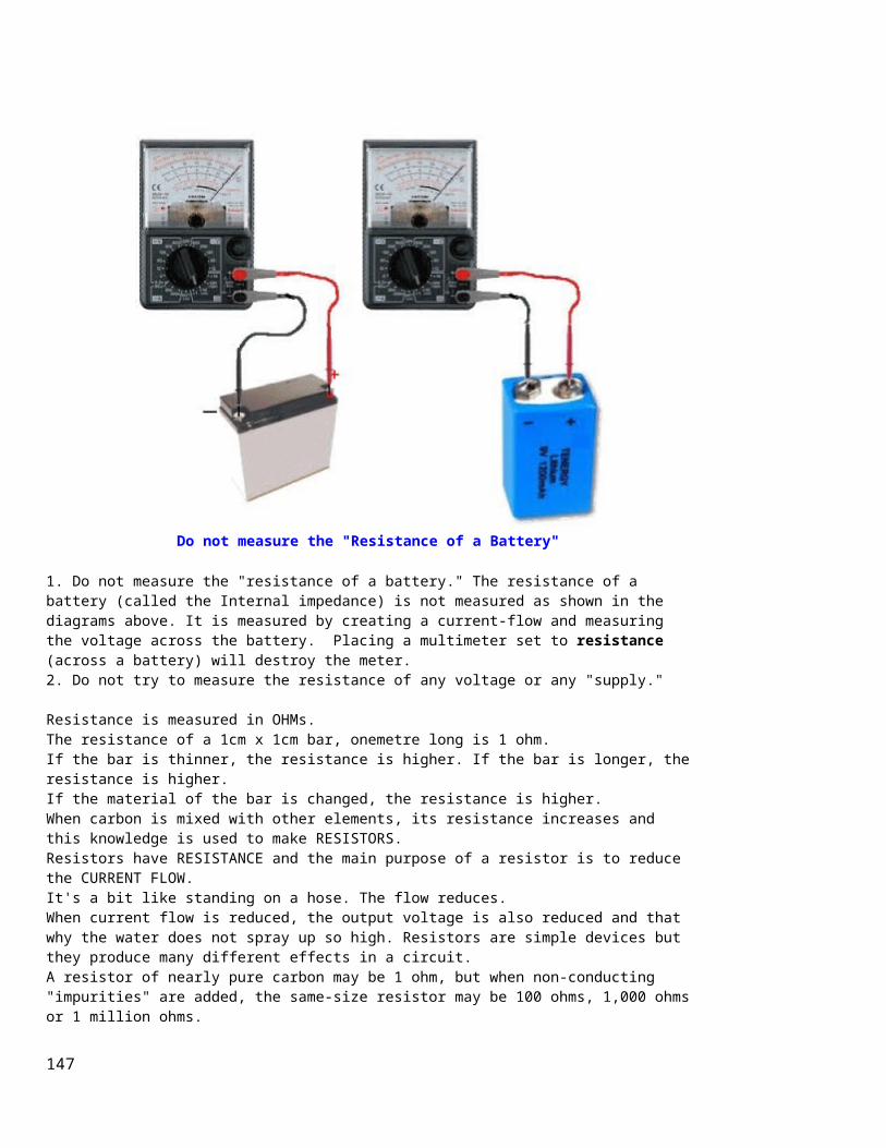
Do not measure the "Resistance of a Battery"
1. Do not measure the "resistance of a battery." The resistance of a battery (called the Internal impedance) is not measured as shown in the diagrams above. It is measured by creating a current-flow and measuring the voltage across the battery. Placing a multimeter set to resistance (across a battery) will destroy the meter. 2. Do not try to measure the resistance of any voltage or any "supply."
Resistance is measured in OHMs. The resistance of a 1cm x 1cm bar, onemetre long is 1 ohm. If the bar is thinner, the resistance is higher. If the bar is longer, theresistance is higher. If the material of the bar is changed, the resistance is higher. When carbon is mixed with other elements, its resistance increases and this knowledge is used to make RESISTORS. Resistors have RESISTANCE and the main purpose of a resistor is to reduce the CURRENT FLOW. It's a bit like standing on a hose. The flow reduces. When current flow is reduced, the output voltage is also reduced and that why the water does not spray up so high. Resistors are simple devices but they produce many different effects in a circuit. A resistor of nearly pure carbon may be 1 ohm, but when non-conducting "impurities" are added, the same-size resistor may be 100 ohms, 1,000 ohmsor 1 million ohms.
147
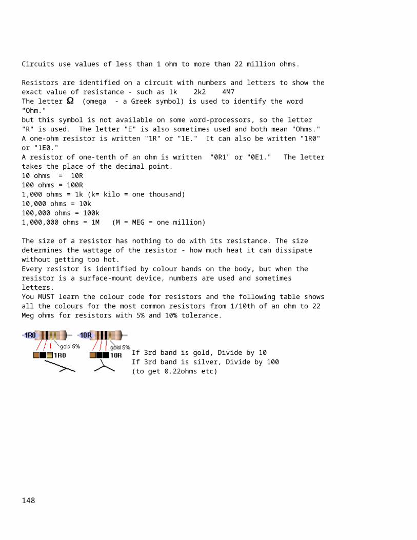
Circuits use values of less than 1 ohm to more than 22 million ohms.
Resistors are identified on a circuit with numbers and letters to show theexact value of resistance - such as 1k 2k2 4M7The letter (omega - a Greek symbol) is used to identify the word "Ohm."but this symbol is not available on some word-processors, so the letter "R" is used. The letter "E" is also sometimes used and both mean "Ohms."A one-ohm resistor is written "1R" or "1E." It can also be written "1R0" or "1E0." A resistor of one-tenth of an ohm is written "0R1" or "0E1." The lettertakes the place of the decimal point. 10 ohms = 10R 100 ohms = 100R1,000 ohms = 1k (k= kilo = one thousand)10,000 ohms = 10k 100,000 ohms = 100k 1,000,000 ohms = 1M (M = MEG = one million)
The size of a resistor has nothing to do with its resistance. The size determines the wattage of the resistor - how much heat it can dissipate without getting too hot. Every resistor is identified by colour bands on the body, but when the resistor is a surface-mount device, numbers are used and sometimes letters. You MUST learn the colour code for resistors and the following table showsall the colours for the most common resistors from 1/10th of an ohm to 22 Meg ohms for resistors with 5% and 10% tolerance.
If 3rd band is gold, Divide by 10If 3rd band is silver, Divide by 100(to get 0.22ohms etc)
148

Reading 4-band resistorsThe most "common" type of resistor has 4 bands and is called the 10% resistor. It now has a tolerance of 5% but is still called the "10% type" as the colours increase by 20% so that a resistor can be 10% higher or 10%lower than a particular value and all the resistors produced in a batch can be used. The first 3 bands produce the resistance and the fourth band is the "tolerance" band. Gold = 5% (Silver =10% but no modern resistors are 10%!! - they are 5% 2% or 1%)
149

150

Here is another well-designed resistor colour code chart:
151

Download the program and save it on your desk-top for future reference:ColourCode.exe (520KB)ColourCode.zip (230KB)ColourCode.rar (180KB)
RESISTORS LESS THAN 10 OHMSWhen the third band is gold, it indicates the value of the "colors" must be divided by 10.Gold = "divide by 10" to get values 1R0 to 8R2When the third band is silver, it indicates the value of the "colors" mustbe divided by 100. (Remember: more letters in the word "silver" thus the divisor is "a larger division.")Silver = "divide by 100" to get values R1 to R82e.g: 0R1 = 0.1 ohm 0R22 = point 22 ohms See 4th Column above for examples.
The letters "R, k and M" take the place of a decimal point.e.g: 1R0 = 1 ohm 2R2 = 2 point 2 ohms 22R = 22 ohms
152

2k2 = 2,200 ohms 100k = 100,000 ohms2M2 = 2,200,000 ohms
HOW TO REMEMBER THE COLOUR CODE:Each colour has a "number" (or divisor) corresponding to it. Most of the colours are in the same order as in the spectrum. You can see the spectrum in a rainbow. It is: ROY G BIV and the colours for resistors are in the same sequence.
black brown - colour of increasing temperaturered orange yellow green blue (indigo - that part of the spectrum between blue and violet)violet gray white colour value No of zero'ssilver -2 divide by 100gold -1 divide by 10black 0 No zerosbrown 1 0red 2 00orange 3 ,000 or kyellow 4 0,000green 5 00,000blue 6 Mviolet 7 gray 8 white 9
153

Here are some common ways to remember the colour code: Bad Beer Rots Our Young Guts, But Vodka Goes WellBright Boys Rave Over Young Girls But Violet Gets WedBad Boys Rave Over Young Girls But Violet Gets Wed with Gold and Silver.
Reading 5-band resistors:5-band resistors are easy to read if you remember two simple points. The first three bands provide the digits in the answer and the 4th band supplies the number of zero's.
Reading "STANDARD VALUES" (on 5-band resistors)5-band resistors are also made in "Standard Values" but will have different colours to 4-band "common" resistors - and will be confusing if you are just starting out. For instance, a 47k 5% resistor with 4-bands will be: yellow-purple-orange-gold. For a 47k 1% resistor the colours willbe yellow-purple-black-red-brown. The brown colour-band represents 1%. The first two colour-bands for a STANDARD VALUE or "common value" in 1% or5% will be the SAME. These two bands provide the digits in the answer. It's the 3rd band for a 5% resistor that is expanded into two bands in a 1% resistor. But it's easy to follow. For a standard value, the 3rd band in a 1% resistor is BLACK. This represents a ZERO in the answer. (For 5-band resistors BLACK represents a ZERO when in the third band. This is different to 4-band resistors where black represents the word OHMS! If the third band is BROWN, the answer will be 1).
154

So the 4th band has to represent one-less ZERO and is one colour UP THE COLOUR CHART! In other words the 3rd and 4th bands (combined) on a 1% resistor produces the same number of zero's as the 3rd band on a 5% resistor!
Resistors come in a range of values and the two most common are the E12 and E24 series. The E12 series comes in twelve values for each decade. TheE24 series comes in twenty-four values per decade.
E12 series - 10, 12, 15, 18, 22, 27, 33, 39, 47, 56, 68, 82
E24 series - 10, 11, 12, 13, 15, 16, 18, 20, 22, 24, 27, 30, 33, 36, 39, 43, 47, 51, 56, 62, 68, 75, 82, 91
Here is the complete list of 1% 1/4watt resistors from:CIRCUIT SPECIALISTS. The following list covers 10 ohms (10R) to 1M.To buy 1% resistors from Circuit Specialists, click: HERE.
10R12R115R18R222R127R430R133R236R539R247R549R951R156R268R175R82R590R9100R
121R150R182R200R221R240R249R274R301R332R348R392R402R475R499R565R604R681R750R
806R825R909R1k01k211k51k822k2k212k22k432k492k672k743k013k323k483k573k74
3k833k924k024k224k644k754k74k874k995k115k235k365k495k625k765k96k046k196k81
7k157k57k8771k58k068k258k458k668k879k099k319k539k7610k11k12k12k112k413k
14k715k15k816k917k417k818k220k22k122k623k724k927k429k430k133k234k836k538k3
39k240k244k246k447k47k549k951k153k656k261k968k169k875k082k590k90k995k3100k
121k147k150k182k200k212k221k226k249k274k301k332k357k392k475k487k499k562k604k1M
Here is the list of 1% resistors from suppliers (such as Farnell):
1R01R21R52R22R7
13R15R16R18R20R
68R75R82R91R100R
360R390R430R470R510R
1k82k02k22k42k7
9k110k11k12k13k
47k51k56k62k68k
240k270k300k330k360k
155

3R33R94R75R66R26R87R58R29R110R11R12R
22R24R27R30R33R36R39R43R47R51R56R62R
110R120R130R150R160R180R200R220R240R270R300R330R
560R620R680R750R820R910R1k1k11k21k31k51k6
3k3k33k63k94k34k75k15k66k26k87k58k2
15k16k18k20k22k24k27k30k33k36k39k43k
75k82k91k100k110k120k130k150k160k180k200k220k
390k430k470k510k560k620k680k750k820k910k1M
Surface Mount Resistors
156

157

3-digit Surface Mount resistors on a PC board
158

4-digit Surface Mount resistors on a PC board
The photo above shows surface mount resistors on a circuit board. The components that are not marked are capacitors (capacitors are NEVER marked).All the SM resistors in the above photos conform to a 3-digit or 4-digit code. But there are a number of codes, and the 4-digit code caters for high tolerance resistors, so it's getting very complicated. Here is a basic 3-digit SM resistor:
A 330k SM resistor
The first two digits represent the two digits in the answer. The third
159

digit represents the number of zero's you must place after the two digits.The answer will be OHMS. For example: 334 is written 33 0 000. This is written 330,000 ohms. The comma can be replaced by the letter "k". The final answer is: 330k.222 = 22 00 = 2,200 = 2k2 473 = 47 000 = 47,000 = 47k474 = 47 0000 = 470,000 = 470k105 = 10 00000 = 1,000,000 = 1M = one million ohmsThere is one trick you have to remember. Resistances less than 100 ohms are written: 100, 220, 470. These are 10 and NO zero's = 10 ohms = 10R or 22 and no zero's = 22R or 47 and no zero's = 47R. Sometimes the resistor is marked: 10, 22 and 47 to prevent a mistake.
Remember:R = ohmsk = kilo ohms = 1,000 ohmsM = Meg = 1,000,000 ohmsThe 3 letters (R, k and M) are put in place of the decimal point. This wayyou cannot make a mistake when reading a value of resistance.
THE COMPLETE RANGE OF SM RESISTORMARKINGSClick to see the complete range of SM resistor markings for 3-digit code:
Click to see the complete range of SM resistor markings for 4-digit code:
0000 is a value on a surface-mount resistor. It is a zero-ohm LINK!Resistances less than 10 ohms have 'R' to indicate the position of the decimal point.Here are some examples:
Three Digit Examples Four Digit Examples330 is 33 ohms - not 330
ohms1000 is 100 ohms - not
1000 ohms
221 is 220 ohms 4992 is 49 900 ohms,or 49k9
683 is 68 000 ohms, or68k
1623 is 162 000 ohms,or 162k
105 is 1 000 000 ohms,or 1M
0R56 or R56 is 0.56 ohms
8R2 is 8.2 ohms
160

A new coding system has appeared on 1% types. This is known as the EIA-96 marking method. It consists of a three-character code. The first two digits signify the 3 significant digits of the resistor value, using the lookup table below. The third character - a letter - signifies the multiplier.
code value
code value
code value
code value
code value
code value
01 100 17 147 33 215 49 316 65 464 81 68102 102 18 150 34 221 50 324 66 475 82 69803 105 19 154 35 226 51 332 67 487 83 71504 107 20 158 36 232 52 340 68 499 84 73205 110 21 162 37 237 53 348 69 511 85 75006 113 22 165 38 243 54 357 70 523 86 76807 115 23 169 39 249 55 365 71 536 87 78708 118 24 174 40 255 56 374 72 549 88 80609 121 25 178 41 261 57 383 73 562 89 82510 124 26 182 42 267 58 392 74 576 90 84511 127 27 187 43 274 59 402 75 590 91 86612 130 28 191 44 280 60 412 76 604 92 88713 133 29 196 45 287 61 422 77 619 93 90914 137 30 200 46 294 62 432 78 634 94 93115 140 31 205 47 301 63 442 79 649 95 95316 143 32 210 48 309 64 453 80 665 96 976
The multiplier letters are as follows:
letter mult
letter
mult
F 100000 B 10
E 10000 A 1
D 1000XorS
0.1
C 100YorR
0.01
22A is a 165 ohm resistor, 68C is a 49900 ohm (49k9) and 43E a 2740000
161

(2M74). This marking scheme applies to 1% resistors only.
A similar arrangement can be used for 2% and 5% tolerance types. The multiplier letters are identical to 1% ones, but occur before the number code and the following code is used:
2%
5%code
value
code
value
code
value
code
value
01 100 13 330 25 100 37 33002 110 14 360 26 110 38 36003 120 15 390 27 120 39 39004 130 16 430 28 130 40 43005 150 17 470 29 150 41 47006 160 18 510 30 160 42 51007 180 19 560 31 180 43 56008 200 20 620 32 200 44 62009 220 21 680 33 220 45 68010 240 22 750 34 240 46 75011 270 23 820 35 270 47 82012 300 24 910 36 300 48 910
With this arrangement, C31 is 5%, 18000 ohm (18k), and D18 is 510000 ohms (510k) 2% tolerance. Always check with an ohm-meter (a multimeter) to make sure.
Chip resistors come in the following styles and ratings: Style: 0402, 0603, 0805, 1206, 1210, 2010, 2512, 3616, 4022 Power Rating: 0402(1/16W), 0603(1/10W), 0805(1/8W), 1206(1/4W), 1210(1/3W), 2010(3/4W), 2512(1W), 3616(2W), 4022(3W) Tolerance: 0.1%, 0.5%, 1%, 5% Temperature Coefficient: 25ppm 50ppm 100ppm
EIA marking code for surface mount (SMD)resistors
01S = 1R 02S = 1R0203S = 1R0504S = 1R0705S = 1R106S = 1R1307S = 1R1508S = 1R1809S = 1R21
01R = 10R 02R = 10R203R = 10R504R = 10R705R = 11R06R = 11R307R = 11R508R = 11R809R = 12R1
01A = 100R02A = 102R03A = 105R04A = 107R05A = 110R06A = 113R07A = 115R08A = 118R09A = 121R
01B = 1k 02B = 1k0203B = 1k0504B = 1k0705B = 1k106B = 1k1307B = 1k1508B = 1k1809B = 1k21
01C = 10k 02C = 10k203C = 10k504C = 10k705C = 11k06C = 11k307C = 11k508C = 11k809C = 12k1
01D = 100k02D = 102k03D = 105k04D = 107k05D = 110k06D = 113k07D = 115k08D = 118k09D = 121k
01E = 1M 02E = 1M0203E = 1M0504E = 1M0705E = 1M106E = 1M1307E = 1M1508E = 1M1809E = 1M21
01F = 10M
18F = 15M
30F = 20M
162

10S = 1R2411S = 1R2712S = 1R313S = 1R3314S = 1R3715S = 1R416S = 1R4317S = 1R4718S = 1R519S = 1R54
20S = 1R5821S = 1R6222S = 1R6523S = 1R6924S = 1R7425S = 1R7826S = 1R8227S = 1R8728S = 1R9129S = 1R96
30S = 2R031S = 2R0532S = 2R1033S = 2R1534S = 2R2135S = 2R2636S = 2R3237S = 2R3738S = 2R4339S = 2R49
40S = 2R5541S = 2R6142S = 2R6743S = 2R7444S = 2R8045S = 2R8746S = 2R9447S = 3R0148S = 3R0949S = 3R16
50S = 3R2451S = 3R3252S = 3R453S = 3R4854S = 3R5755S = 3R6556S = 3R7457S = 3R8358S = 3R9259S = 4R02
60S = 4R1261S = 4R2262S = 4R3263S = 4R4264S = 4R5365S = 4R6466S = 4R75
10R = 12R411R = 12R712R = 13R13R = 13R314R = 13R715R = 14R16R = 14R317R = 14R718R = 15R19R = 15R4
20R = 15R821R = 16R222R = 16R523R = 16R924R = 17R425R = 17R826R = 18R227R = 18R728R = 19R129R = 19R6
30R = 20R031R = 20R532R = 21R033R = 21R534R = 22R135R = 22R636R = 23R237R = 23R738R = 24R339R = 24R9
40R = 25R541R = 26R142R = 26R743R = 27R444R = 28R045R = 28R746R = 29R447R = 30R148R = 30R949R = 31R6
50R = 32R451R = 33R252R = 34R053R = 34R854R = 35R755R = 36R556R = 37R457R = 38R358R = 39R259R = 40R2
60R = 41R261R = 42R262R = 43R263R = 44R264R = 45R365R = 46R466R = 47R5
10A = 124R11A = 127R12A = 130R13A = 133R14A = 137R15A = 140R16A = 143R17A = 147R18A = 150R19A = 154R
20A = 158R21A = 162R22A = 165R23A = 169R24A = 174R25A = 178R26A = 182R27A = 187R28A = 191R29A = 196R
30A = 200R31A = 205R32A = 210R33A = 215R34A = 221R35A = 226R36A = 232R37A = 237R38A = 243R39A = 249R
40A = 255R41A = 261R42A = 267R43A = 274R44A = 280R45A = 287R46A = 294R47A = 301R48A = 309R49A = 316R
50A = 324R51A = 332R52A = 340R53A = 348R54A = 357R55A = 365R56A = 374R57A = 383R58A = 392R59A = 402R
60A = 412R61A = 422R62A = 432R63A = 442R64A = 453R65A = 464R66A = 475R
10B = 1k2411B = 1k2712B = 1k313B = 1k3314B = 1k3715B = 1k416B = 1k4317B = 1k4718B = 1k519B = 1k54
20B = 1k5821B = 1k6222B = 1k6523B = 1k6924B = 1k7425B = 1k7826B = 1k8227B = 1k8728B = 1k9129B = 1k96
30B = 2k031B = 2k0532B = 2k1033B = 2k1534B = 2k2135B = 2k2636B = 2k3237B = 2k3738B = 2k4339B = 2k49
40B = 2k5541B = 2k6142B = 2k6743B = 2k7444B = 2k8045B = 2k8746B = 2k9447B = 3k0148B = 3k0949B = 3k16
50B = 3k2451B = 3k3252B = 3k453B = 3k4854B = 3k5755B = 3k6556B = 3k7457B = 3k8358B = 3k9259B = 4k02
60B = 4k1261B = 4k2262B = 4k3263B = 4k4264B = 4k5365B = 4k6466B = 4k75
10C = 12k411C = 12k712C = 13k13C = 13k314C = 13k715C = 14k16C = 14k317C = 14k718C = 15k19C = 15k4
20C = 15k821C = 16k222C = 16k523C = 16k924C = 17k425C = 17k826C = 18k227C = 18k728C = 19k129C = 19k6
30C = 20k031C = 20k532C = 21k033C = 21k534C = 22k135C = 22k636C = 23k237C = 23k738C = 24k339C = 24k9
40C = 25k541C = 26k142C = 26k743C = 27k444C = 28k045C = 28k746C = 29k447C = 30k148C = 30k949C = 31k6
50C = 32k451C = 33k252C = 34k053C = 34k854C = 35k755C = 36k556C = 37k457C = 38k358C = 39k259C = 40k2
60C = 41k261C = 42k262C = 43k263C = 44k264C = 45k365C = 46k466C = 47k5
10D = 124k11D = 127k12D = 130k13D = 133k14D = 137k15D = 140k16D = 143k17D = 147k18D = 15k19D = 154k
20D = 158k21D = 162k22D = 165k23D = 169k24D = 174k25D = 178k26D = 182k27D = 187k28D = 191k29D = 196k
30D = 200k31D = 205k32D = 210k33D = 215k34D = 221k35D = 226k36D = 232k37D = 237k38D = 243k39D = 249k
40D = 255k41D = 261k42D = 267k43D = 274k44D = 280k45D = 287k46D = 294k47D = 301k48D = 309k49D = 316k
50D = 324k51D = 332k52D = 340k53D = 348k54D = 357k55D = 365k56D = 374k57D = 383k58D = 392k59D = 402k
60D = 412k61D = 422k62D = 432k63D = 442k64D = 453k65D = 464k66D = 475k
10E = 1M2411E = 1M2712E = 1M313E = 1M3314E = 1M3715E = 1M416E = 1M4317E = 1M4718E = 1M519E = 1M54
20E = 1M5821E = 1M6222E = 1M6523E = 1M6924E = 1M7425E = 1M7826E = 1M8227E = 1M8728E = 1M9129E = 1M96
30E = 2M031E = 2M0532E = 2M1033E = 2M1534E = 2M2135E = 2M2636E = 2M3237E = 2M3738E = 2M4339E = 2M49
40E = 2M5541E = 2M6142E = 2M6743E = 2M7444E = 2M8045E = 2M8746E = 2M9447E = 3M0148E = 3M0949E = 3M16
50E = 3M2451E = 3M3252E = 3M453E = 3M4854E = 3M5755E = 3M6556E = 3M7457E = 3M8358E = 3M9259E = 4M02
60E = 4M1261E = 4M2262E = 4M3263E = 4M4264E = 4M5365E = 4M6466E = 4M75
163

67S = 4R8768S = 4R9969S = 5R11
70S = 5R2371S = 5R3672S = 5R4973S = 5R6274S = 5R7675S = 5R976S = 6R0477S = 6R1978S = 6R3479S = 6R49
80S = 6R6581S = 6R8182S = 6R9883S = 7R1584S = 7R3285S = 7R586S = 7R6887S = 7R8788S = 8R0689S = 8R25
90S = 8R4591S = 8R6692S = 8R8793S = 9R0994S = 9R3195S = 9R5396S = 9R76
67R = 48R768R = 49R969R = 51R1
70R = 52R371R = 53R672R = 54R973R = 56R274R = 57R675R = 59R076R = 60R477R = 61R978R = 63R479R = 64R9
80R = 66R581R = 68R182R = 69R883R = 71R584R = 73R285R = 75R086R = 76R887R = 78R788R = 80R689R = 82R5
90R = 84R591R = 86R692R = 88R793R = 90R994R = 93R195R = 95R396R = 97R6
67A = 487R68A = 499R69A = 511R
70A = 523R71A = 536R72A = 549R73A = 562R74A = 576R75A = 590R76A = 604R77A = 619R78A = 634R79A = 649R
80A = 665R81A = 681R82A = 698R83A = 715R84A = 732R85A = 750R86A = 768R87A = 787R88A = 806R89A = 825R
90A = 845R91A = 866R92A = 887R93A = 909R94A = 931R95A = 953R96A = 976R
67B = 4k8768B = 4k9969B = 5k11
70B = 5k2371B = 5k3672B = 5k4973B = 5k6274B = 5k7675B = 5k976B = 6k0477B = 6k1978B = 6k3479B = 6k49
80B = 6k6581B = 6k8182B = 6k9883B = 7k1584B = 7k3285B = 7k586B = 7k6887B = 7k8788B = 8k0689B = 8k25
90B = 8k4591B = 8k6692B = 8k8793B = 9k0994B = 9k3195B = 9k5396B = 9k76
67C = 48k768C = 49k969C = 51k1
70C = 52k371C = 53k672C = 54k973C = 56k274C = 57k675C = 59k076C = 60k477C = 61k978C = 63k479C = 64k9
80C = 66k581C = 68k182C = 69k883C = 71k584C = 73k285C = 75k086C = 76k887C = 78k788C = 80k689C = 82k5
90C = 84k591C = 86k692C = 88k793C = 90k994C = 93k195C = 95k396C = 97k6
67D = 487k68D = 499k69D = 511k
70D = 523k71D = 536k72D = 549k73D = 562k74D = 576k75D = 590k76D = 604k77D = 619k78D = 634k79D = 649k
80D = 665k81D = 681k82D = 698k83D = 715k84D = 732k85D = 750k86D = 768k87D = 787k88D = 806k89D = 825k
90D = 845k91D = 866k92D = 887k93D = 909k94D = 931k95D = 953k96D = 976k
67E = 4M8768E = 4M9969E = 5M11
70E = 5M2371E = 5M3672E = 5M4973E = 5M6274E = 5M7675E = 5M976E = 6M0477E = 6M1978E = 6M3479E = 6M49
80E = 6M6581E = 6M8182E = 6M9883E = 7M1584E = 7M3285E = 7M586E = 7M6887E = 7M8788E = 8M0689E = 8M25
90E = 8M4591E = 8M6692E = 8M8793E = 9M0994E = 9M3195E = 9M5396E = 9M76
If you want an accurate RESISTANCE measurement, remove the resistor from the circuit and use a Digital meter.
SURFACE MOUNT COMPONENTS - PACKSTalking Electronics has packs of components for the repairman. The following packs are available:
SURFACE MOUNT RESISTOR PACK consists of 1 off each standard value 10 ohms to 1M & 2M2 (60 resistors) $14.20 including pack and post
SURFACE MOUNT CAPACITOR PACK consists of:2 - 10p 5 - 47p 5 - 100p 5 - 470p 5 - 1n 5 - 10n 5 - 22n 5 - 100n 5 - 1u 16v electrolytic 5 - 10u 16v electrolytic (40 components) $23.80 including pack and post
SURFACE MOUNT DIODE PACK consists of:5 - 1N 4148 (marked as "A6")
164

$10.00 including pack and post
SURFACE MOUNT TRANSISTOR PACK consists of:5 - BC 848 (marked as "1K") NPN5 - BC858 PNP$10.00 including pack and post
emailColin Mitchellfor details on how to pay by credit card or PayPal.
CREATING ANY VALUE OF RESISTANCEAny value of resistance can be created by connecting two resistors in PARALLEL or SERIES. You can also create a higher wattage resistor by connecting them in SERIESOR PARALLEL. We are only going to cover two EQUAL VALUE resistors in SERIES or in PARALLEL. If you want to create a "Special Value," simply connect two resistors and read the value with a Digital Meter. Keep changing the values until you get the required value. We are not going into series or Parallel formulae. You can easily find a value with a multimeter.
TWO EQUAL-VALUE RESISTORS IN SERIESTwo equal-value resistors IN SERIES creates a value of DOUBLE. You simply ADD the values. This can be done with any to two values as shown. Three equal-value resistors in series is three times the value.
TWO EQUAL-VALUE RESISTORS IN PARALLELTwo equal-value resistors IN PARALLEL creates a value of HALF. Three
165

equal-value resistors in parallel is equal to one-third the value.
If you want a particular value and it is not available, here is a chart. Use 2 resistors in series or parallel as shown:
Required
ValueR1 Series/
Parallel R2 Actualvalue:
10 4R7 S 4R7 9R412 10 S 2R2 12R215 22 P 47 14R918 22 P 100 18R22 10 S 12 2227 22 S 4R7 26R733 22 S 10 32R39 220 P 47 38R747 22 S 27 4956 47 S 10 5768 33 S 33 6682 27 S 56 83
There are other ways to combine 2 resistors in parallel or series to get aparticular value. The examples above are just one way. 4R7 = 4.7 ohms
TESTING A RESISTOR To check the value of a resistor, it should be removed from the circuit. The surrounding components can affect the reading and make it lower. Resistors VERY RARELY change value, but if it is overheated or damaged,
166

the resistance can increase. You can take the reading of a resistor "in-circuit" in one direction then the other, as the surrounding components may have diodes and this will alter the reading. You can also test a resistor by feeling its temperature-rise. It is getting too hot if you cannot hold your finger on it (some "metal film" resistors are designed to tolerate quite high temperatures).
TESTING AN "AC" RESISTOR There is no such thing as an "AC" resistor. Resistors are just "resistors"and they can be in AC circuits or DC circuits. Resistors can be given names such as "Safety Resistor" "Ballast Resistor" "LOAD Resistor" "FeedResistor" "Dropper Resistor" or "Supply Resistor." These are just normalresistors with a normal resistance - except a "Safety Resistor."A safety resistor is made of a flame-proof material such as metal-oxide-film and not carbon-composition. It is designed to "burn out" when too much current flows BUT NOT CATCH FIRE. It is a low-value resistor and has a voltage-drop across it but this is not intentional. The voltage-drop is to create a "heating-effect" to burn out the resistor. In all the other types of resistor, the voltage-drop is intentional. A Ballast resistor is a normal resistor and can be called a Power resistor, Dropper resistor, Supply resistor or Feed resistor. It is designed to reduce the voltage from one source and deliver a lower voltage. It is a form of: "in-line" resistor. A Load Resistor is generally connected across the output of a circuit and turns the energy it receives, into heat.
RESISTOR NETWORKS To reduce the number of resistors in a circuit, some engineers use a set of identical resistors in a package called a Single-In-Line (SIL) resistor network. It is made with many resistors of the same value, all inone package. One end of each resistor is connected all the other resistorsand this is the common pin, identified as pin 1 and has a dot on the package. These packages are very reliable but to make sure all the resistors are asstated, you need to locate pin 1. All values will be identical when referenced to this pin.
167

RESISTOR NETWORKS
Some resistor networks have a "4S" printed on the component. The 4S indicates the package contains 4 independent resistors that are not wired together inside. The housing has eight leads as shown in the second image.
Independent resistors have an even number of pins and measuring between each pair will produce identical values. Resistance between any pair will indicate leakage and may be a fault.
TESTING A POSISTOR
A Posistor is a resistor that connects in series with the degaussing coil around the picture tube or Monitor. When cold, it has a very low resistance and a large current flows when the monitor or TV is switched on. This current heats up the Posistor and the resistance increases. This causes the current to decrease and any magnetism in the shadow mask is removed. The posistor can one or two elements and it is kept warm so the resistance remains high. Many Posistors have a second element inside the case that connects directly to the supply to keep the Positive Temperature
168

Coefficient resistor high so that the current through the degaussing coil falls to almost zero. This constant heat eventually destroys the package. The heavy current that flows when a set is turned ON also causes the posistor to crack and break and this results in poor purity on the screen - as the shadow mask gradually becomes magnetic..Posistors have different resistance values from different manufacturers and must be replaced with an identical type. They can be checked for very low resistance when cold but any loose piecesinside the case will indicate a damaged component.
A "BURNT" RESISTOR - normally and technically called a "burnt-out"resistor.The resistance of a "burnt" resistor can sometimes be determined by scraping away the outer coating - if the resistor has a spiral of resistance-material. You may be able to find a spot where the spiral has been damaged.
Clean the "spot" (burnt section of the spiral) very carefully and make sure you can get a good contact with the spiral and the tip of your probe.Measure from one lead of the resistor to the end of the damaged spiral. Then measure from the other lead to the other end of the spiral. Add the two values and you have an approximate value for the resistor. Youcan add a small amount for the damaged section. This process works very well for damaged wire-wound resistors. They can bepulled apart and each section of the resistance-wire (nichrome wire) measured and added to get the full resistance.
There is another way to determine the value of a damaged resistor. Get a set of resistors of the same wattage as the damaged component and
169

start with a high value. It's handy to know if the resistor is in the range: 10ohm to 100ohms or 1k to 10k etc, but this is not essential. Start with a very high value and turn the circuit ON. You can perform voltage tests and if you know the expected output voltage, decrease the resistance until this voltage is obtained. If you do not know the expected voltage, keep reducing the value of resistance until the circuit works as designed. This is the best advice in a situation where you do not know the value of a resistor.
There is a third way to determine the value and this requires measuring the voltage drop across the resistor and the current-flow. By multiplying the two you will get a wattage and this must be less than the wattage of the resistor being replaced. TESTING POTENTIOMETERS (variable resistors)To check the value of a variable resistor, it should be removed from circuit or at least 2 legs should be removed. A Rheostat is a variable resistor using only one end and the middle connected to a circuit. The resistance between the two outside pins is the value marked on the component and the centre leg will change from nearly zero to the full resistance as the shaft is rotated. "Pots" generally suffer from "crackle" when turned and this can be fixed by spraying up the shaft and into the pot via the shaft with a tube fixed to a can of "spray-lubricant" (contact cleaner). "Pre-set pots" and "trim pots" are miniature versions of a potentiometer and they are all tested the same.
FOCUS POTSFocus pots quite often get a spot of dirt where the wiper touches the track. Cleaning with spray fixes the bad focus but if the pot is leaking to chassis from inside the pot (due to the high voltage on the terminals) simply remove it from the chassis and leave it floating (this will restorethe high voltage to the picture tube) or you can use one from an old chassis.
MAKING YOUR OWN RESISTOR, CAPACITOR, INDUCTOR or DIODEQuite often you will not have the exact value of resistance or capacitancefor a repair. We have already covered placing resistors and capacitors in parallel and series:
170

Resistors in Parallel and/or Series Capacitors in Parallel and/or Series
Here are some extras:
RESISTORSTwo 1k 0.5watt resistors in parallel produces a 470R 1watt resistor. Two 1k 0.5watt resistors in series produces a 2k 1watt resistor.
CAPACITORSTwo 100n 100v capacitors in series produces a 50n capacitor @200v
INDUCTORS: Two inductors in series - ADD THE VALUES
DIODES: Two 1Amp 400v diodes in series produces a 1Amp 800v diode Two 1Amp 400v diodes in parallel produces a 2Amp 400v diode
ZENER DIODES: Zener diodes can be connected in series to get a higher voltage. Two 12v zener diodes in series produces a 24v zener.
CONTINUITYSome multimeters have a "buzzer" that detects when the probes are touchingeach other or the resistance between the probes is very LOW. This is called a CONTINUITY TESTER. You can use the resistance scale "x1" or "x10" to detect low values of resistance. Set the pointer to "0" (right end of the scale) by touching the probes together and adjusting the "zero ohms" control. When taking a reading, you will have to decide if a low value of resistance is a short-circuit or an "operating value." For instance, the cold resistance of a 12v car globe is very low (about 2 ohms) and it increases (about 6 times) to 12 ohms when hot. The "resistance of a circuit" may be very low as the electrolytics in the circuit are uncharged. This may not indicate a true "short-circuit."The measurement across a diode is not a resistance-value but a "voltage-drop" and that is why the needle swings nearly full-scale. Leads and wires and cords have a small resistance and depending on the length of the lead, this small resistance may be affecting a circuit. Remember this:When a circuit takes 1 amp, and the resistance of the leads is 1 ohm, the voltage drop across the leads will be 1v. That's why a 12v battery supplying a circuit with these leads will have 11v at the circuit.
171

Note:Turn off the equipment before making any continuity tests. The presence ofeven a small voltage (from an electrolytic) can give a false reading.You can determine the resistance of a lead very accurately by taking the example above and applying it to your circuit. If the battery is 12.6v and the voltage across the circuit is 10v, when the current is 2.6 amps, the resistance of the "leads" is 12.6 - 10 = 2.6 R=V/I = 2.6/2.6 = 1ohm. By making the lead shorter or using thicker wire, the resistance will be less and the voltage on the project will increase. When taking readings in a circuit that has a number of diodes built-into IC's (Integrated Circuits) and transistors, some Continuity Testers will beep and give a false reading. The following circuit has the advantage of providing a beep when a short-circuit is detected but does not detect the small voltage drop across a diode. This is ideal when testing logic circuits as it is quick and you can listen for the beep while concentrating on the probe. Using a multimeter is much slower.
CONTINUITY TESTER
You can build the circuit on Matrix Board and add it to your Test Equipment. You will need lots of "Test Equipment" and they can be built from circuitsin this eBook.
TESTING FUSES, LEADS AND WIRESAll these components come under the heading TESTING for CONTINUITY. Turn off all power to the equipment before testing for shorts and continuity. Use the low resistance "Ohms Scale" or CONTINUITY range on your multimeter. All fuses, leads and wires should have a low, very low or zeroresistance. This proves they are working.
A BLOWN FUSE
172

The appearance of a fuse after it has "blown" can tell you a lot about thefault in the circuit. If the inside of the glass tube (of the fuse) is totally blackened, the fuse has been damaged very quickly. This indicates a very high current haspassed through the fuse. Depending on the rating of the fuse, (current rating) you will be able to look for components that can pass a high current when damaged - such as high power transistors, FETs, coils, electrolytics. Before re-connecting the supply, you should test the "SUPPLY RAILS" for resistance. This is done by measuring them on a low OHMs range in one direction then reverse the leads to see if the resistance is low in the other direction. A reading can be very low at the start because electrolytics need time to charge-up and if the reading gradually increases, the power rail does not have a short. An overload can occur when the supply voltage rises to nearly full voltage, so you sometimes have to fit a fuse and see how long it takes to "blow."If the fuse is just slightly damaged, you will need to read the next part of this eBook, to see how and why this happens:
FAST AND SLOW BLOW FUSESThere are many different sizes, shapes and ratings of a fuse. They are allcurrent ratings as a fuse does not have a voltage rating. Some fuses are designed for cars as they fit into the special fuse holders. A fuse can bedesigned for 50mA, 100mA, 250mA, 315mA, 500mA, 1Amp, 1.5amp, 2amp, 3amp, 3.15amp 5amp, 10amp, 15amp, 20amp, 25amp, 30amp, 35amp, 50amp and higher.
Some fuses are fast-blow and some are slow-blow. A "normal" fuse consists of a length of thin wire. Or it may be a loop of wire that is thin near the middle of the fuse. This is the section that will "burn-out."A "normal" fuse is a fast-blow fuse. For instance, a 1amp fuse will remainintact when up to 1.25 amp flows. When a circuit is turned on, it may take2-3 amps for a very short period of time and a normal 1 amp fuse will get very hot and the wire will stretch but not "burn-out." You can see the wire move when the supply turns on. If the current increases to 2amps, the fuse will still remain intact. It needs about 3 amp to heat up the wire to red-hot and burn out. If the current increases to 5 amp, the wire VOLATILISES (burns-out) and deposits carbon-black on the inside of the glass tube.A slow-blow fuse uses a slightly thicker piece of wire and the fuse is made of two pieces of wire joined in the middle with a dob of low-temperature solder. Sometimes one of the pieces of wire is a spring and when the current rises to 2.5 amp, the heat generated in the wire melts the solder and the two pieces of wire "spring apart."A slow-blow fuse will allow a higher current-surge to pass through the fuse and the wire will not heat up and sag.
173

Thus the fuse is not gradually being damaged and it will remain in a perfect state for a long period of time. A fuse does not protect electronic equipment from failing. It acts AFTER the equipment has failed. It will then protect a power supply from delivering a high current to a circuit that has failed. If a slow-blow fuse has melted the solder, it could be due to a slight overload, slight weakening of the fuse over a period of time or the current-rating may be too low. You can try another fuse to see what happens. You can replace a fast-acting fuse (normal fuse) with a slow blow if the fast-acting fuse has been replaced a few times due to deterioration when the equipment is turned on. But you cannot replace a slow-blow fuse with a fast acting fuse as it willbe damaged slightly each time the equipment is turned on and eventually fail.
TESTING COILS, INDUCTORS and YOKESCoils, inductors, chokes and yokes are just coils (turns) of wire. The wire may be wrapped around a core made of iron or ferrite. It is labeled "L" on a circuit board. You can test this component for continuity between the ends of the windingand also make sure there is no continuity between the winding and the core. The winding can be less than one ohm, or greater than 100 ohms. A coil of wire is also called an INDUCTOR and it might look like a very simple component, but it can operate in a very complex way. The way it works is a discussion for another eBook. It is important to understand the turns are insulated but a slight fracture in the insulationcan cause two turns to touch each other and this is called a "SHORTED TURN" or you can say the inductor has "SHORTED TURNS." When this happens, the inductor allows the circuit to draw MORE CURRENT. This causes the fuse to "blow."The quickest way to check an inductor is to replace it, but if you want tomeasure the inductance, you can use an INDUCTANCE METER. You can then compare the inductance with a known good component. An inductor with a shorted turn will have a very low or zero inductance, however you may not be able to detect the fault when it is not working in a circuit as the fault may be created by a high voltage generated between two of the turns. Faulty yokes (both horizontal and vertical windings) can cause the pictureto reduce in size and/or bend or produce a single horizontal line. A TV or monitor screen is the best piece of Test Equipment as it has identified the fault. It is pointless trying to test the windings further as you will not be able to test them under full operating conditions. The
174

fault may not show up when a low voltage (test voltage) is applied.
MEASURING AND TESTING INDUCTORSInductors are measured with an INDUCTANCE METER but the value of some inductors is very small and some Inductance Meters do not give an accuratereading. The solution is to measure a larger inductor and note the reading. Now putthe two inductors in SERIES and the values ADD UP - just like resistors inSERIES. This way you can measure very small inductors. VERY CLEVER!
TESTING SWITCHES and RELAYSSwitches and relays have contacts that open and close mechanically and youcan test them for CONTINUITY. However these components can become intermittent due to dirt or pitting of the surface of the contacts due to arcing as the switch is opened. It is best to test these items when the operating voltage and current is present as they quite often fail due to the arcing. A switch can work 49 times then fail on each 50th operation. The same with a relay. It can failone time in 50 due to CONTACT WEAR. If the contacts do not touch each other with a large amount of force and with a large amount of the metal touching, the current flowing through thecontacts will create HEAT and this will damage the metal and sometimes reduce the pressure holding the contact together. This causes more arcing and eventually the switch heats up and starts to burn. Switches are the biggest causes of fire in electrical equipment and households.
A relay also has a set of contacts that can cause problems. There are many different types of relays and basically they can be put into two groups. 1. An electromagnetic relay is a switch operated by magneticforce. This force is generated by current through a coil. The relay opens and closes aset of contacts. The contacts allow a current to flow and this current can damage the contacts. Connect 5v or 12v to the coil (or 24v) and listen for the "click" of the points closing. Measure the resistance across the points tosee if they are closing. You really need to put a load on the points to see if they are clean and can carry a current.The coil will work in either direction. If not, the relay is possibly a CMOS relay or Solid State relay.
2. An electronic relay (Solid State Relay) does not have a winding. It works on the principle of an opto-coupler and uses a LED and Light
175

Activated SCR or Opto-TRIAC to produce a low resistance on the output. Thetwo pins that energise the relay (the two input pins) must be connected to5v (or 12v) around the correct way as the voltage is driving a LED (with series resistor). The LED illuminates and activates a light-sensitive device.
CAPACITORSCapacitors are one of the most difficult things to test. That's because they don't give a reading on a multimeter and their value can range from 1p to 100,000u. A faulty capacitor may be "open" when measured with a multimeter, and a good capacitor will also be "open." You need a piece of test equipment called a CAPACITANCE METER to measure the value of a capacitor.
HOW A CAPACITOR WORKSThere are two ways to describe how a capacitor works. Both are correct andyou have to combine them to get a full picture. A capacitor has INFINITE resistance between one lead and the other. This means no current flows through a capacitor. But it works in another way. Suppose you have a strong magnet on one side of a door and a piece of metal on the other. By sliding the magnet up and down the door, the metal rises and falls. The metal can be connected to a pump and you can pump water by sliding themagnet up and down. A capacitor works in exactly the same way. If you raise a voltage on one lead of a capacitor, the other lead will rise to the same voltage. This needs more explaining - we are keeping the discussion simple. It works just like the magnetic field of the magnet through a door. The next concept is this:Capacitors are equivalent to a tiny rechargeable battery. They store energy when the supply-voltage is present and release it when the supply drops.
176

These two concepts can be used in many ways and that's why capacitors perform tasks such as filtering, time-delays, passing a signal from one stage to another and create many different effects in a circuit.
CAPACITOR VALUESThe basic unit of capacitance is the FARAD. (C) This is the value used in all equations, but it is a very large value. A one FARAD capacitor would be the size of a car if made with plates and paper. Most electronic circuits use capacitors with smaller values such as 1p to 1,000u. 1p is about equal to two parallel wires 2cm long. 1p is one picofarad.
The easiest way to understand capacitor values is to start with a value of1u. This is one microfarad and is one-millionth of a Farad. A 1 microfaradcapacitor is about 1cm long and the diagram shows a 1u electrolytic.
Smaller capacitors are ceramic and they look like the following. This is a100n ceramic:
177
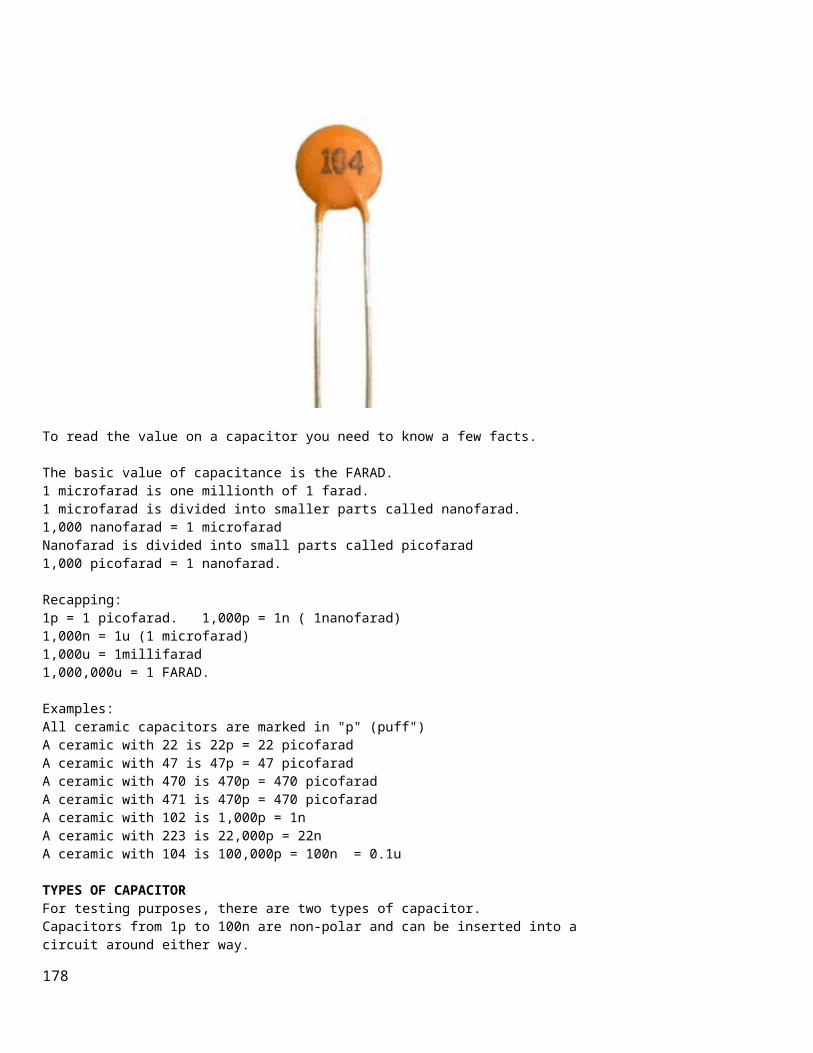
To read the value on a capacitor you need to know a few facts.
The basic value of capacitance is the FARAD. 1 microfarad is one millionth of 1 farad. 1 microfarad is divided into smaller parts called nanofarad.1,000 nanofarad = 1 microfaradNanofarad is divided into small parts called picofarad1,000 picofarad = 1 nanofarad.
Recapping:1p = 1 picofarad. 1,000p = 1n ( 1nanofarad) 1,000n = 1u (1 microfarad)1,000u = 1millifarad 1,000,000u = 1 FARAD.
Examples:All ceramic capacitors are marked in "p" (puff")A ceramic with 22 is 22p = 22 picofaradA ceramic with 47 is 47p = 47 picofaradA ceramic with 470 is 470p = 470 picofaradA ceramic with 471 is 470p = 470 picofaradA ceramic with 102 is 1,000p = 1nA ceramic with 223 is 22,000p = 22nA ceramic with 104 is 100,000p = 100n = 0.1u
TYPES OF CAPACITORFor testing purposes, there are two types of capacitor. Capacitors from 1p to 100n are non-polar and can be inserted into a circuit around either way.
178

Capacitors from 1u to 100,000u are electrolytics and are polarised. They must be fitted so the positive lead goes to the supply voltage and the negative lead goes to ground (or earth). There are many different sizes, shapes and types of capacitor. They are all the same. They consist of two plates with an insulating material between. The two plates can be stacked in layers or rolled together. The important factor is the insulating material. It must be very thin to keep things small. This gives the capacitor its VOLTAGE RATING. If a capacitor sees a voltage higher than its rating, the voltage will "jump through" the insulating material or around it. If this happens, a carbon deposit is left behind and the capacitor becomes"leaky" or very low resistance, as carbon is conductive. CERAMIC CAPACITORSNearly all small capacitors are ceramic capacitors as this material is cheap and the capacitor can be made in very thin layers to produced a highcapacitance for the size of the component. This is especially true for surface-mount capacitors. All capacitors are marked with a value and the basic unit is: "p" for "puff" However NO surface mount capacitors are marked and they are very difficult to test.
VALUE: VALUE WRITTEN ONTHE
179

COMPONENT:0.1p0.22p 0.47p1.0p2.2p4.7p5.6p8.2p10p 22p 47p 56p 100p 220p 470p 560p820p 1,000p (1n) 2200p (2n2) 4700p (4n7) 8200p (8n2) 10n 22n 47n 100n 220n 470n 1u
0p10p220p471p02p24p75p68p210 or 10p22 or 22p47 or 47p56 or 56p100 on 101220 or 221470 or 471560 or 561820 or 821102222 472 822 103 223 473 104 224 474105
POLYESTER, POLYCARBONATE, POLYSTYRENE, MYLAR, METALLISED POLYESTER, ("POLY"), MICA and other types of CAPACITORThere are many types of capacitor and they are chosen for their reliability, stability, temperate-range and cost. For testing and repair work, they are all the same. Simply replace with exactly the same type and value.
180
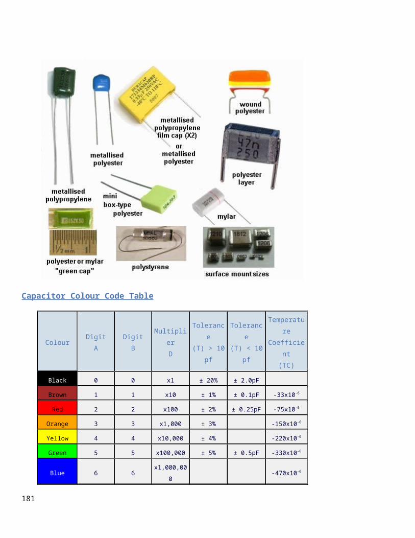
Capacitor Colour Code Table
ColourDigitA
DigitB
MultiplierD
Tolerance
(T) > 10pf
Tolerance
(T) < 10pf
Temperature
Coefficient(TC)
Black 0 0 x1 ± 20% ± 2.0pF
Brown 1 1 x10 ± 1% ± 0.1pF -33x10-6
Red 2 2 x100 ± 2% ± 0.25pF -75x10-6
Orange 3 3 x1,000 ± 3% -150x10-6
Yellow 4 4 x10,000 ± 4% -220x10-6
Green 5 5 x100,000 ± 5% ± 0.5pF -330x10-6
Blue 6 6x1,000,00
0 -470x10-6
181

Violet 7 7 -750x10-6
Grey 8 8 x0.01 +80%,-20%
White 9 9 x0.1 ± 10% ± 1.0pF
Gold x0.1 ± 5%
Silver x0.01 ± 10%
182

ELECTROLYTIC and TANTALUM CAPACITORSElectrolytics and Tantalums are the same for testing purposes but their performance is slightly different in some circuits. A tantalum is smaller for the same rating as an electrolytic and has a better ability at delivering a current. They are available up to about 1,000u, at about 50v but their cost is much higher than an electrolytic.
Electrolytics are available in 1u, 2u2 3u3 4u7 10u, 22u, 47u, 100u, 220u, 330u, 470u, 1,000u, 2,200u, 3,300u, 4,700u, 10,000u and higher. The "voltage" or "working voltage" can be: 3.3v, 10v, 16v, 25v, 63v, 100v,200v and higher. There is also another important factor that is rarely covered in text books. It is RIPPLE FACTOR. This is the amount of current that can enter and leave an electrolytic. This current heats up the electrolytic and that is why some electrolytics are much larger than others, even though the capacitance and voltage-ratings are the same. If you replace an electrolytic with a "miniature" version, it will heat upand have a very short life. This is especially important in power supplies
183

where current (energy) is constantly entering and exiting the electrolyticas its main purpose is to provide a smooth output from a set of diodes that delivers "pulsing DC." (see "Power Diodes")
NON-POLAR CAPACITORS (ELECTROLYTICS)Electrolytics are also available in non-polar values. It sometimes has theletters "NP" on the component. Sometimes the leads are not identified. This is an electrolytic that does not have a positive and negative lead but two leads and either lead can be connected to the positive or negativeof the circuit. These electrolytics are usually connected to the output of an amplifier (such as in a filter near the speaker) where the signal is rising and falling.A non-polar electrolytic can be created from two ordinary electrolytics byconnecting the negative leads together and the two positive leads become the new leads. For example: two 100u 63velectrolytics will produce a 47u 63v non-polar electrolytic. In the circuit below, the non-polar capacitor is replaced with two electrolytics.
184

PARALLEL and SERIES CAPACITORSCapacitors can be connected in PARALLEL and/or SERIES for a number of reasons. 1. If you do not have the exact value, two or more connected in parallel or series can produce the value you need. 2. Capacitors connected in series will produce one with a higher voltage rating. 3. Capacitors connected in parallel will produce a larger-value capacitance.
Here are examples of two equal capacitors connected in series or parallel and the results they produce:
185

VOLTAGE RATING OF CAPACITORCapacitors have a voltage rating, stated as WV for working voltage, or WVDC. This specifies the maximum voltage that can be applied across the capacitor without puncturing the dielectric. Voltage ratings for "poly," mica and ceramic capacitors are typically 50v to 500 VDC. Ceramic capacitors with ratings of 1kv to 5kv are also available. Electrolytic capacitors are commonly available in 6v, 10v 16v, 25v, 50v, 100v, 150v, and 450v ratings.
THE SIZE OF A CAPACITOR - RIPPLE FACTOR The size of a capacitor depends on a number of factors, namely the value of the capacitor (in microfarads etc) and the voltage rating. But there isalso another factor that is most important. It is the RIPPLE FACTOR. Ripple Factor is the amount of voltage-fluctuation the capacitor (electrolytic) can withstand without getting too hot. When current flows in and out of an electrolytic, it gets hot and this will eventually dry-out the capacitor as some of the liquid inside the capacitor escapes through the seal. It's a very slow process but over a period of years, the capacitor looses its capacitance. If you have two identical 1,000u 35v electrolytics and one is smaller, itwill get hotter when operating in a circuit and that's why it is necessaryto choose the largest electrolytic.
CAUTIONIf a capacitor has a voltage rating of 63v, do not put it in a 100v circuit as the insulation (called the dielectric) will be punctured and the capacitor will "short-circuit." It's ok to replace a 0.22uF 50WV capacitor with 0.22uF 250WVDC.
SAFETYA capacitor can store a charge for a period of time after the equipment isturned off. High voltage electrolytic caps can pose a safety hazard. Thesecapacitors are in power supplies and some have a resistor across them, called a bleed resistor, to discharge the cap after power is switched off.
If a bleed resistor is not present the cap can retain a charge after the equipment is unplugged.
How to discharge a capacitorDo not use a screwdriver to short between the terminals as this will damage the capacitor internally and the screwdriver. Use a 1k 3watt or 5watt resistor on jumper leads and keep them connected for a few seconds to fully discharge the electro. Test it with a voltmeter to make sure all the energy has been removed.
186

Before testing any capacitors, especially electrolytics, you should look to see if any are damaged, overheated or leaking. Swelling at the top of an electrolytic indicates heating and pressure inside the case and will result in drying out of the electrolyte. Any hot or warm electrolytic indicates leakage and ceramic capacitors with portions missing indicates something has gone wrong.
TESTING A CAPACITORThere are two things you can test with a multimeter:1. A short-circuit within the capacitor2. Capacitor values above 1u.
You can test capacitors in-circuit for short-circuits. Use the x1 ohms range. To test a capacitor for leakage, you need to remove it or at least one lead must be removed. Use the x10k range on an analogue or digital multimeter. For values above 1u you can determine if the capacitor is charging by using an analogue meter. The needle will initially move across the scale to indicate the cap is charging, then go to "no deflection." Any permanentdeflection of the needle will indicate leakage. You can reverse the probes to see if the needle moves in the opposite direction. This indicates it has been charged. Values below 1u will not respond to charging and the needle will not deflect. This does not work with a digital meter as the resistance range does not output any current and the electrolytic does not charge.
Rather than spending money on a capacitance meter, it is cheaper to replace any suspect capacitor or electrolytic. Capacitors can produce very unusual faults and no piece of test equipment is going to detect the problem. In most cases, it is a simple matter to solder another capacitor across the suspect component and view or listen to the result. This saves all the worry of removing the component and testing it with equipment that cannot possibly give you an accurate reading when the full voltage and current is not present. It is complete madness to even think of testing critical components such as capacitors, with TEST EQUIPMENT. You are fooling yourself. If the Test Equipment says the component is ok, you will look somewhere else and wastea lot of time.
FINDING THE VALUE OF A CAPACITORIf you want to find the value of a surface-mount capacitor or one where the markings have been removed, you will need a CAPACITANCE METER. Here is
187

a simple circuit that can be added to your meter to read capacitor values from 10p to 10u. The full article can be found HERE.
ADD-ON CAPACITANCE METER
REPLACING A CAPACITORAlways replace a capacitor with the exact same type. A capacitor may be slightly important in a circuit or it might be extremely critical. A manufacturer may have taken years to select the right type of capacitor due to previous failures. A capacitor just doesn't have a "value of capacitance." It may also has an effect called "tightening of the rails."In other words, a capacitor has the ability to react quickly and either absorb or deliver energy to prevent spikes or fluctuations on the rail. This is due to the way it is constructed. Some capacitors are simply plates of metal film while others are wound in a coil. Some capacitors arelarge while others are small. They all react differently when the voltage fluctuates. Not only this, but some capacitors are very stable and all these features go into the decision for the type of capacitor to use. You can completely destroy the operation of a circuit by selecting the wrong type of capacitor. No capacitor is perfect and when it gets charged or discharged, it appearsto have a small value of resistance in series with the value of capacitance. This is known as "ESR" and stands for EQUIVALENT SERIES RESISTANCE. This effectively makes the capacitor slightly slower to chargeand discharge.
188
We cannot go into the theory on selecting a capacitor as it would be larger than this eBook so the only solution is to replace a capacitor withan identical type. However if you get more than one repair with identical faults, you should ask other technicians if the original capacitor comes from a faulty batch.
The author has fixed TV's and fax machines where the capacitors have been inferior and alternate types have solved the problem. Some capacitor are suitable for high frequencies, others for low frequencies.
DECOUPLING CAPACITORSA Decoupling Capacitor can severe one, two or three functions. You need tothink of a decoupling capacitor as a miniature battery with the ability todeliver a brief pulse of energy when ever the line-voltage drops and also absorb a brief pulse of energy when ever the line voltage rises (or spikes). Decoupling capacitor can range from 100n to 1,000u. 100n capacitors are designed to absorb spikes and also have the effect of tightening-up the rails for high frequencies. They have no effect on low frequencies such as audio frequencies. These capacitors are generally ceramic and have very low internal impedance and thus they can operate at high frequencies. Capacitors above about 10u are used for decoupling and these are nearly always electrolytics. Decoupling means "tightening-up the power rails." The electrolytic acts just like a miniature rechargeable battery, supplying a small number of components in a circuit with a smooth and stable voltage. The electrolytic is usually fed from a dropper resistor and this resistor charges the electrolytic and adds to the ability of the electrolytic to create a "separate power supply."These two components help remove spikes as an electrolytic cannot remove spikes if connected directly to the supply rails - it's internal impedanceis high and the spikes are not absorbed. Decoupling capacitors are very difficult to test. They rarely fail but if a project is suffering from unknown glitches and spikes, it is best to simply add more 100n decoupling caps on the underside of the board and replace all electrolytics. Some small electrolytics will dry out due to faulty manufacture and simplyreplacing every one on a board will solve the problem. Some of the functions of a decoupling capacitor are: Removing ripple - hum or buzz in the background of an amplifierRemoving glitches or spikes.Separating one stage from another to reduce or remove MOTORBOATING - a lowfrequency sound due to the output putting a pulse on the power rails that
189

is picked up by the pre-amplifier section and amplified.
TESTING DIODESDiodes can have 4 different faults. 1. Open circuit in both directions.2. Low resistance in both directions. 3. Leaky. 4. Breakdown under load.
TESTING A DIODE ON AN ANALOGUE METERTesting a diode with an Analogue Multimeter can be done on any of the resistance ranges. [The high resistance range is best - it sometimes has ahigh voltage battery for this range but this does not affect our testing]There are two things you must remember. 1. When the diode is measured in one direction, the needle will not move at all. The technical term for this is the diode is reverse biased. It will not allow any current to flow. Thus the needle will not move. When the diode is connected around the other way, the needle will swing tothe right (move up scale) to about 80% of the scale. This position represents the voltage drop across the junction of the diode and is NOT a resistance value. If you change the resistance range, the needle will moveto a slightly different position due to the resistances inside the meter. The technical term for this is the diode is forward biased. This indicatesthe diode is not faulty. The needle will swing to a slightly different position for a "normal diode" compared to a Schottky diode. This is due to the different junctionvoltage drops. However we are only testing the diode at very low voltage and it may break-down when fitted to a circuit due to a higher voltage being present or due to a high current flowing.
2. The leads of an Analogue Multimeter have the positive of the battery connected to the black probe and the readings of a "good diode" are shown in the following two diagrams:
190

The diode is REVERSE BIASED in the diagram above and diodes not conduct.
The diode is FORWARD BIASED in the diagram above and it conducts
TESTING A DIODE ON A DIGITAL METERTesting a diode with a Digital Meter must be done on the "DIODE" setting as a digital meter does not deliver a current through the probes on some of the resistance settings and will not produce an accurate reading.
191

The best thing to do with a "suspect" diode is to replace it. This is because a diode has a number of characteristics that cannot be tested withsimple equipment. Some diodes have a fast recovery for use in high frequency circuits. They conduct very quickly and turn off very quickly sothe waveform is processed accurately and efficiently. If the diode is replaced with an ordinary diode, it will heat up as does not have the high-speed characteristic. Other diodes have a low drop across them and if an ordinary is used, it will heat up. Most diodes fail by going: SHORT-CIRCUIT. This can be detected by a low resistance (x1 or x10 Ohms range) in both directions. A diode can also go OPEN CIRCUIT. To locate this fault, place an identicaldiode across the diode being tested. A leaky diode can be detected by a low reading in one direction and a slight reading the other direction. However this type of fault can only be detected when the circuit is working. The output of the circuit will be low and sometimes the diode heats up (more than normal). A diode can go open under full load conditions and perform intermittently.
Diodes come in pairs in surface-mount packages and 4 diodes can be found in a bridge. They are also available in pairs that look like a 3-leaded transistor. The line on the end of the body of a diode indicates the cathode and you cannot say "this is the positive lead." The correct way to describe the leads is to say the "cathode lead." The other lead is the anode. The cathode is defined as the electrode (or lead) through which an electric current flows out of a device. The following diagrams show different types of diodes:
192

POWER DIODESTo understand how a power diode works, we need to describe a few things. This has NEVER been described before, so read carefully. The 240v AC (called the "mains") consists of two wires, one is called the ACTIVE and the other is NEUTRAL. Suppose you touch both wires. You will get a shock. The neutral is connected to an earth wire (or rod driven intothe ground or connected to a water pipe) at the point where the electricity enters the premises and you do not get a shock from the NEUTRAL. But the voltage on the active is rising to +345v then goes to -345v at therate of 50 times per second (for a complete cycle). 345v is the peak voltage of 240v. You never get a 240v shock. (It is a 345v shock.)In other words, if you touch the two wires at a particular instant, you would get a POSITIVE 345v shock and at another instant you would get a negative 345v shock. This is shown in the diagram below. We now transfer this concept to the output of a transformer. The diagram shows an AC waveform on the output of the secondary.
193

This voltage is rising 15v higher than the bottom lead then it is 15v LOWER than the bottom lead. The bottom lead is called "zero volts." You have to say one lead or wire is not "rising and falling" as you need a "reference" or starting-point" or "zero point" for voltage measurements. The diode only conducts when the voltage is "above zero" (actually when itis 0.7v above zero) and does not conduct (at all) when the voltage goes below zero. This is shown on the output of the Power Diode. Only the positive peaks orthe positive parts of the waveform appear on the output and this is called"pulsing DC." This is called "half-wave" and is not used in a power supply. We have used it to describe how the diode works. The electrolyticscharge during the peaks and deliver energy when the diode is not delivering current. This is how the output becomes a steady DC voltage. Power supplies use FULL WAVE rectification and the other half of the AC waveform is delivered to the output (and fills in the "gaps") and appears as shown in "A."
194

ONE FAULTY DIODEOne diode in a bridge can go open (any of the 4 diodes will produce the same effect) and produce an output voltage that can be slightly lower thanthe original voltage. The actual "voltage-drop" will depend on the currenttaken by the circuit and the ability of the transformer to produce the required voltage and current during half-wave operation. The voltage during each half cycle (when none of the diodes is delivering any energy to the circuit) is maintained by the electrolytic and its size (relative to the current taken by the circuit) will determine the size of the ripplethat will result when the diode fails. The ripple will be 100 to 1,000 times greater after the failure of a diode, depending on the value of the filter capacitor.To locate the faulty diode, simply get a diode and place it across each ofthe diodes in the bridge (in turn) when the circuit is working.
195

For a bridge rectifier, the ripple-frequency will be twice the mains frequency and its ripple will be very small if the electrolytic is the correct value. When a diode fails, the ripple-frequency will be equal to mains-frequency and the amplitude will increase considerably. You may even hear background hum from audio equipment.If you cannot find a faulty diode, the filter capacitor will be at fault. Turn off the equipment and connect an electrolytic across the filter capacitor via jumper leads. Turn the power ON and see if the hum has reduced.
DAMPER DIODESA damper diode is a diode that detects a high voltage and SQUELCHES IT (reduces it - removes it). The signal that it squelches is a voltage that is in the opposite direction to the "supply voltage" and is produced by the collapsing of a magnetic field. Whenever a magnetic filed collapses, it produces a voltage in the winding that is opposite to the supply voltage and can be much higher. This is the principle of a flyback circuitor EHT circuit. The high voltage comes from the transformer. The diode is placed so that the signal passes through it and less than 0.5v appears across it. A damper diode can be placed across the coil of a relay, incorporated intoa transistor or FET or placed across a winding of a flyback transformer toprotect the driving transistor or FET. It can also be called a "Reverse-Voltage Protection Diode," "Spike Suppression Diode," or "Voltage Clamp Diode."The main characteristic of a Damper Diode is HIGH SPEED so it can detect the spike and absorb the energy. It does not have to be a high-voltage diode as the high voltage in the circuit is being absorbed by the diode.
SILICON, GERMANIUM AND SCHOTTKY DIODESWhen testing a diode with an analogue meter, you will get a low reading inone direction and a high (or NO READING) in the other direction. When reading in the LOW direction, the needle will swing nearly full scale and
196

the reading is not a resistance-value but a reflection of the characteristic voltage drop across the junction of the diode. As we mentioned before, a resistance reading is really a voltage reading and themeter is measuring the voltage of the battery minus the voltage-drop across the diode. Since Silicon, Germanium and Schottky Diodes have slightly different characteristic voltage drops across the junction, you will get a slightly different reading on the scale. This does not represent one diode being better than the other or capable of handling a higher current or any otherfeature. The quickest, easiest and cheapest way to find, fix and solve a problem caused by a faulty diode is to replace it. There is no piece of test equipment capable of testing a diode fully, and the circuit you are working on is actually the best piece of test equipment as it is identifying the fault UNDER LOAD.
Only very simple tests can be done with a multimeter and it is best to check a diode with an ANALOGUE MULTIMETER as it outputs a higher current though the diode and produces a more-reliable result. A Digital meter can produce false readings as it does not apply enough current to activate the junction.Fortunately almost every digital multimeter has a diode test mode. Using this, a silicon diode should read a voltage drop between 0.5v to 0.8v in the forward direction and open in the reverse direction. For a germanium diode, the reading will be lower, around 0.2v - 0.4v in the forward direction. A bad diode will read zero volts in both directions.
REPLACING A DIODEIt is alway best to replace a diode with the same type but quite often this is not possible. Many diodes have unusual markings or colours or "in-house" letters. This is only a general guide because many diodes have special features, especially when used in high-frequency circuits. However if you are desperate to get a piece of equipment working, here arethe steps:Determine if the diode is a signal diode, power diode, or zener diode. For a signal diode, try 1N4148. For a power diode (1 amp) try 1N4004. (for up to 400v)For a power diode (3 amp) try 1N5404. (for up to 400v)For a high-speed diode, try UF4004 (for up to 400v)
If you put an ordinary diode in a high-speed application, it will get veryhot very quickly. To replace an unknown zener diode, start with a low voltage such as 6v2 and see if the circuit works.
197

The size of a diode and the thickness of the leads will give an idea of the current-capability of the diode. Keep the leads short as the PC board acts as a heat-sink. You can also add fins to the leads to keep the diode cool.
LIGHT EMITTING DIODES (LEDs)Light Emitting Diodes (LEDs) are diodes that produce light when current flows from anode to cathode. The LED does not emit light when it is revered-biased. It is used as a low current indicator in many types of consumer and industrial equipment, such as monitors, TV’s, printers, hi-fisystems, machinery and control panels.The light produced by a LED can be visible, such as red, green, yellow or white. It can also be invisible and these LEDs are called Infrared LEDs. They are used in remote controls and to see if they are working, you need to point a digital camera at the LED and view the picture on the camera screen. An LED needs about 2v - 3.6v across its leads to make it emit light, but this voltage must be exact for the type and colour of the LED. The simplest way to deliver the exact voltage is to have a supply that is higher than needed and include a voltage-dropping resistor. The value of the resistor must be selected so the current is between 2mA and 25mA. The cathode of the LED is identified by a flat on the side of the LED. Thelife expectancy of a LED is about 100,000 hours. LEDs rarely fail but theyare very sensitive to heat and they must be soldered and de-soldered quickly. They are one of the most heat-sensitive components. Light emitting diodes cannot be tested with most multimeters because the characteristic voltage across them is higher than the voltage of the battery in the meter.However a simple tester can be made by joining 3 cells together with a 220R resistor and 2 alligator clips:
LED TESTER
Connect the clips to a LED and it will illuminate in only one direction. The colour of the LED will determine the voltage across it. You can measure this voltage if you want to match two or more LEDs for identical
198

operation. Red LEDs are generally 1.7v to 1.9v. - depending on the quality such as "high-bright"Green LEDs are 1.9v to 2.3v.Orange LEDs are about 2.3v and White LEDs and IR LEDs are about 3.3v to 3.6v. The illumination produced by a LED is determined by the quality of the crystal. It is the crystal that produces the colour and you need to replace a LED with the same quality to achieve the same illumination. Never connect a LED across a battery (such as 6v or 9v), as it will be instantly damaged. You must have a resistor in series with the LED to limit the current.
ZENER DIODESAll diodes are Zener diodes. For instance a 1N4148 is a 120v zener diode as this is its reverse breakdown voltage. And a zener diode can be used as an ordinary diode in a circuit with a voltage that is below the zener value. For instance, 20v zener diodes can be used in a 12v power supply as the voltage never reaches 20v, and the zener characteristic is never reached. Most diodes have a reverse breakdown voltage above 100v, while most zenersare below 70v. A 24v zener can be created by using two 12v zeners in series and a normal diode has a characteristic voltage of 0.7v. This can be used to increase the voltage of a zener diode by 0.7v. See the diagram above. It uses 3 ordinary diodes to increase the output voltage of a 3-terminal regulator by 2.1v. To tests a zener diode you need a power supply about 10v higher than the zener of the diode. Connect the zener across the supply with a 1k to 4k7 resistor and measure the voltage across the diode. If it measures less than 1v, reverse the zener. If the reading is high or low in both directions, the zener is damaged.
Here is a zener diode tester. The circuit will test up to 56v zeners.
199

ZENER DIODE TESTER
TRANSFORMERLESS POWER SUPPLYHere's a circuit that uses zener diodes in a power supply to show how theywork. This clever design uses 4 diodes in a bridge to produce a fixed voltage power supply capable of supplying 35mA. If we put 2 zener diodes in a bridge with two ordinary power diodes, the bridge will break-down at the voltage of the zener. This is what we have done. If we use 18v zeners, the output will be 17v4.
SUPPLY USING ZENER DIODES
When the incoming voltage is positive at the top, the left zener provides 18v limit (and the other zener produces a drop of 0.6v). This allows the right zener to pass current just like a normal diode. The output is 17v4.The same with the other half-cycle. You cannot use this type of bridge in a normal power supply as the zener diode will "short" when the input voltage reaches the zener value. The concept only works in the circuit above.
VOLTAGE REGULATORSA Voltage Regulator takes a high input voltage and delivers a fixed outputvoltage. Providing the input voltage is 4v above the output voltage, the regulator will deliver a fixed output voltage with almost no ripple. Voltage regulators are also called "3-TERMINAL REGULATORS" or "REGULATOR IC's" - although this name is not generally used. In most cases, a voltage regulator gets quite hot and for this reason it has a high failure-rate. If a regulator is not getting hot (or warm) it has either failed or the circuit is not operating.
200

A regulator can only decrease the voltage. It cannot increase the current.This means the current being supplied to a circuit must also be available from the circuit supplying the regulator. All regulators have different pin-outs, so you need to find the input pin and output pin and make sure the voltage-difference is at least 4v. Some regulators will work with a difference as low as 1v, so you need to read the specifications for the type you are servicing.Some regulators are called “negative voltage regulators” and the input voltage will be negative and the output will be negative. You need to test a voltage regulator with the power "ON". Make sure you do not allow the probes to short any of the pins together asthis will destroy the regulator or the circuit being supplied. With the power turned off or the regulator removed from the circuit, you can test it with a multimeter set to resistance to see if it is ok. If anyresistance readings are very low or zero ohms, the regulator is damaged.
TRANSFORMERSAll transformers and coils are tested the same way. This includes chokes, coils, inductors, yokes, power transformers, EHT transformers (flyback transformers), switch mode transformers, isolation transformers, IF transformers, baluns, and any device that has turns of wire around a former. All these devices can go faulty. The coating on the wire is called insulation or "enamel" and this can crack or become overheated or damaged due to vibration or movement. When two turns touch each other, a very interesting thing happens. The winding becomes two separate windings.
We will take the case of a single winding such as a coil. This is shown inthe first diagram above and the winding is wound across a former and back again, making two layers. The bottom and top layers touch at the point shown in the diagram and the current that originally passed though A, B, C, D now passes though A & D.
Winding B C becomes a separate winding as shown in the second diagram. In other words the coil becomes a TRANSFORMER with a SHORT CIRCUIT on the secondary winding as shown in the third diagram. When the output wires of a transformer are shorted together, it delivers avery high current because you have created a SHORT-CIRCUIT. This short-
201

circuit causes the transformer to get very hot. That’s exactly what happens when any coil or transformer gets a “shorted turn.” The shorted turns can be a single turn or many turns. It is not possible to measure a fault like this with a multimeter as you don’t know the exact resistance of a working coil or winding and the resistance of a faulty winding may be only 0.001 ohms less. However when a transformer or coil is measured with an inductance meter, an oscillating voltage (or spike) is delivered into the core as magnetic flux, then the magnetic flux collapses and passes the energy into the winding to produce a waveform. The inductance meter reads this and produces a value of inductance in Henry (milliHenry or microHenry.)This is done with the transformer removed from the circuit and this can bea very difficult thing to do, as most transformers have a number of connections. If the coil or transformer has a shorted turn, the energy from the magnetic flux will pass into the turns that are shorted and produce a current. Almost no voltage will be detected from winding. The reading from the inductance meter will be low or very low and you haveto work out if it is correct. However there is one major problem with measuring a faulty transformer or coil. It may only become faulty when power is applied. The voltage between the turns may be sparking or jumping a gap and creating a problem. A tester is not going to find this fault. Secondly, an inductance meter may produce a reading but you do not know ifthe reading is correct. An improved tester is a RING TESTER. The circuit for a ring tester can be found here:
http://www.flippers.com/pdfs/k7205.pdf
It sends a pulse to the coil and counts the number of returning pulses or "rings." A faulty coil (or winding) may return one pulse but nearly all the energy will be passed to the shorted turns and you will be able to seethis on the scale. You will only get one or two return pulses, whereas a good winding will return more pulses.
One way to detect a faulty power transformer is to connect it to the supply and feel the temperature-rise (when nothing is connected to the secondary). It should NOT get hot. Detecting shorted turns is not easy to diagnose as you really need anotheridentical component to compare the results. Most transformers get very hot when a shorted turn has developed. It may deliver a voltage but the heat generated and a smell from the transformer will indicate a fault.
202

ISOLATION TRANSFORMERAn isolation transformer is a piece of Test Equipment that provides "MainsVoltage" but the voltage is "floating." You will still get a shock if you touch the two output leads, but it has a special use when testing unknown equipment. Many electrical appliances are fully insulated and only have two leads connected to the mains. When you take these appliances apart, you do not know which end of say a heating element is connected to the "live" (active) side of the mains andwhich end connects to the neutral. I am not suggesting you carry out the following tests, but they are described to show how an isolation transformer works.If you touch a soldering iron on the "live" (active) end of the heating element it will cause a short-circuit. However when the appliance is connected to the main via an isolation transformer, you can touch an earthed soldering iron on either end of the heater as both leads from the isolation transformer are "floating."Note: As soon as you earth one lead of the output an isolation transformer, the other lead becomes "active."You can make your own Isolation Transformer by connecting two identical transformers "back-to-back."The following diagram shows how this is done:
You can use any transformers providing the primary and secondary voltages are the same. The current capability of the secondary winding does not matter. However if you want a supply that has almost the same voltage as your "Mains," you need two transformers with the same voltages. This handy isolation transformer will provide you with "Mains Voltage" butwith a limited current. In other words it will have a limited capability to supply "wattage." If you are using two 15VA transformers, you will only be able to test an appliance rated at 15 watts. This has some advantages and some disadvantages. If you are working on a project, and a short-circuit occurs, the damage will be limited to 15 watts. If you are using two transformers with different VA ratings, the lower rating will be the capability of the combination.
203

If the secondaries are not equal, you will get a higher or lower "Mains Voltage."If you get two old TV's or Monitors with a rating on the compliance plate of 45 watts, or 90 watts, you can assume the transformers are capable of delivering this wattage and making an isolation transformer will enable you to test similar items with the safety of being isolated from the mains. Colin Mitchell designs a lot of "LED lighting lamps" that are connected directly to the mains. He always works with an isolating transformer, justto be safe. Working on exposed "mains" devices is extremely nerve-wracking and you have to very careful.
DETERMINING THE SPECS OF A TRANSFORMERSuppose you have a "mains transformer" with unknown output voltages and unknown current capability. You must be sure it is a mains transformer designed for operation on 50Hz or 60Hz. Switch-Mode transformers operate at frequencies 40kHz and higher and are not covered in this discussion. To be on the safe-side, connect the unknown transformer to the output of your isolating transformer. Since the transformer will take almost no current when not loaded, the output voltages it produces will be fairly accurate. Measure the input AC voltage and output AC voltage. If the transformer has loaded your isolating transformer it will be faulty. Mains transformers are approx 15 VA for 500gm, 30VA for 1kgm 50VA for 2kgm and and 100VA for 2.5kgm. VA stands for Volts-Amps and is similar to saying watts. Watts is used forDC circuits, while VA refers to AC circuits. Once you have the weight of the transformer and the output voltage, you can work out the current capability of the secondary. For transformers up to 30vA, the output voltage on no-load is 30% higher than the final "loaded voltage."This is due to the poor regulation of these small devices. If the transformer is 15VA and the output voltage will be 15v AC, the current will be 1 amp AC. You can check the "quality" of the transformer, (the regulation) by fully loading the output and measuring the final voltage. If the transformer hasa number of secondaries, the VA rating must be divided between all the windings.
OPTO ISOLATORS and OPTO COUPLERSOpto Isolators and Opto Couplers are the same thing. A common opto-coupleris 4N35. It is used to allow two circuits to exchange signals yet remain
204

electrically isolated. The signal is applied to the LED, which shines on asilicon NPN photo-transistor in the IC.The light is proportional to the signal, so the signal is transferred to the photo transistor to turn it on a proportional amount. Opto-couplers can have Light Activated SCR's, photodiodes, TRIAC's and other semiconductor devices as an output. The 4N35 opto-coupler schematic is shown below:
An opto-Coupler using a TRIAC
TESTING AN OPTO COUPLERMost multimeters cannot test the LED on the input of an opto-coupler because the ohms range does not have a voltage high enough to activate theLED with at least 2mA. You need to set-up the test-circuit shown above with a 1k resistor on the input and 1k5 on the output. When the 1k is connected to 12v, the output LED will illuminate. The opto-coupler should be removed from circuit to perform this test.
TRANSISTORS
205

Transistors are solid-state devices and although they operate completely differently to a diode, they appear as two back-to-back diodes when tested. There are basically 2 types of transistor NPN and PNP. A transistor is sometimes referred to as BJT (Bi-polar Junction Transistor) to distinguish it from other types of transistor such as FieldEffect transistor, Programmable Unijunction Transistor and others. In the following diagram, two diodes are connected together and although the construction of a transistor is more complex, we see the transistor astwo diodes when testing it.
A TRANSISTOR APPEARS AS TWO DIODES WHEN TESTING IT
All transistors have three leads. Base (b), Collector (c), and Emitter (e).For an NPN transistor, the arrow on the emitter points away from the base.
It is fortunate that the arrow on both symbols points in the direction of the flow of current (Conventional Current) and this makes it easy to describe testing methods using our simplified set of instructions. The symbols have been drawn exactly as they appear on a circuit diagram.
All transistors are the same but we talk about digital and analogue transistors. There is no difference between the two. The difference is the circuit. And the only other slight difference between transistors is the fact that some have inbuilt diodes and resistors to simplify the rest of the circuit. All transistors work the same way. The only difference is the amount of
206

amplification they provide, the current and voltage they can withstand andthe speed at which they work. For simple testing purposes, they are all the same.
NPN transistors are the most common and for an NPN transistor, the following applies. (the opposite applies for PNP)To test a transistor, there is one thing you have to know:When the base voltage is higher than the emitter, current flows though thecollector-emitter leads. As the voltage is increased on the base, nothing happens until the voltagereaches 0.55v. At this point a very small current flows through the collector-emitter leads. As the voltage is increased, the current-flow increases. At about 0.75v, the current-flow is a MAXIMUM. (can be as high as 0.9v). That's how it works. A transistor also needs current to flow into the base to perform this amplifying function and this is the one feature that separates an ordinary transistor from a FET.
If the voltage on the base is 0v, then instantly goes to 0.75v, the transistor initially passes NO current, then FULL current. The transistor is said to be working in its two states: OFF then ON (sometimes called: "cut-off" and "saturation"). These are called digital states and the transistor is said to be a DIGITAL TRANSISTOR or aSWITCHING TRANSISTOR , working in DIGITAL MODE.
If the base is delivered 0.5v, then slowly rises to 0.75v and slowly to 0.65v, then 0.7v, then 0.56v etc, the transistor is said to be working in ANALOGUE MODE and the transistor is an ANALOGUE TRANSISTOR. Since a transistor is capable of amplifying a signal, it is said to be an active device. Components such as resistors, capacitors, inductors and diodes are not able to amplify and are therefore known as passive components.
In the following tests, use your finger to provide the TURN ON voltage forthe base (this is 0.55v to 0.7v) and as you press harder, more current flows into the base and thus more current flows through the collector-emitter terminals. As more current flows, the needle of the multimeter moves UP-SCALE.
TESTING A TRANSISTOR ON A DIGITAL METERTesting a transistor with a Digital Meter must be done on the "DIODE" setting as a digital meter does not deliver a current through the probes on some of the resistance settings and will not produce an accurate reading. The "DIODE" setting must be used for diodes and transistors. It should
207

also be called a "TRANSISTOR" setting.
TESTING AN unknown TRANSISTOR The first thing you may want to do is test an unknown transistor for COLLECTOR, BASE AND EMITTER. You also want to perform a test to find out if it is NPN or PNP. That's what this test will provide. You need a cheap multimeter called an ANALOGUE METER - a multimeter with a scale and pointer (needle). It will measure resistance values (normally used to test resistors) - (youcan also test other components) and Voltage and Current. We use the resistance settings. It may have ranges such as "x10" "x100" "x1k" "x10"Look at the resistance scale on the meter. It will be the top scale. The scale starts at zero on the right and the high values are on the left.This is opposite to all the other scales.When the two probes are touched together, the needle swings FULL SCALE andreads "ZERO." Adjust the pot on the side of the meter to make the pointer read exactly zero.
How to read: "x10" "x100" "x1k" "x10" Up-scale from the zero mark is "1" When the needle swings to this position on the "x10" setting, the value is10 ohms. When the needle swings to "1" on the "x100" setting, the value is 100 ohms. When the needle swings to "1" on the "x1k" setting, the value is 1,000 ohms = 1k. When the needle swings to "1" on the "x10k" setting, the value is 10,000 ohms = 10k. Use this to work out all the other values on the scale. Resistance values get very close-together (and very inaccurate) at the high end of the scale. [This is just a point to note and does not affect testing a transistor.]
Step 1 - FINDING THE BASE and determining NPN or PNPGet an unknown transistor and test it with a multimeter set to "x10"Try the 6 combinations and when you have the black probe on a pin and the red probe touches the other pins and the meter swings nearly full scale, you have an NPN transistor. The black probe is BASEIf the red probe touches a pin and the black probe produces a swing on theother two pins, you have a PNP transistor. The red probe is BASEIf the needle swings FULL SCALE or if it swings for more than 2 readings, the transistor isFAULTY.
208

Step 2 - FINDING THE COLLECTOR and EMITTERSet the meter to "x10k." For an NPN transistor, place the leads on the transistor and when you press hard on the two leads shown in the diagram below, the needle will swing almost full scale.
209

For a PNP transistor, set the meter to "x10k" place the leads on the transistor and when you press hard on the two leads shown in the diagram below, the needle willswing almost full scale.
210

SIMPLEST TRANSISTOR TESTERThe simplest transistor tester uses a 9v battery, 1k resistor and a LED (any colour). Keep trying a transistor in all different combinations untilyou get one of the circuits below. When you push on the two leads, the LEDwill get brighter. The transistor will be NPN or PNP and the leads will be identified:
211

The leads of some transistors will need to be bent so the pins are in the same positions as shown in the diagrams. This helps you see how the transistor is being turned on. This works with NPN, PNP transistors and Darlington transistors.
HEATSINKING Heat generated by current flowing between the collector and emitter leads
212

of a transistor causes its temperature to rise. This heat must be conducted away from the transistor otherwise the rise may be high enough to damage the P-N junctions inside the device. Power transistors produce alot of heat, and are therefore usually mounted on a piece of aluminium with fins, called a HEATSINK.This draws heat away, allowing it to handle more current. Low-power signaltransistors do not normally require heat sinking. Some transistors have a metal body or fin to connect to a larger heatsink. If the transistor is connected to a heatsink with a mica sheet (mica washer), it can be damagedor cracked and create a short-circuit. (See Testing Mica Washers). Or a small piece of metal may be puncturing the mica. Sometimes white compound called Heatsink Compound is used to conduct heat through the mica. This isvery important as mica is a very poor conductor of heat and the compound is needed to provide maximum thermal conduction.
TRANSISTOR FAILURETransistor can fail in a number of ways. They have forward and reverse voltage ratings and once these are exceeded, the transistor will ZENER or conduct and may fail. In some cases a high voltage will "puncture" the transistor and it will fail instantly. In fact it will fail much faster via a voltage-spike than a current overload.
It may fail with a "short" between any leads, with a collector-emitter short being the most common. However failures will also create shorts between all three leads. A shorted transistor will allow a large current to flow, and cause other components to heat up. Transistors can also develop an open circuit between base and collector, base and emitter or collector and emitter.The first step in identifying a faulty transistor is to check for signs ofoverheating. It may appear to be burnt, melted or exploded. When the equipment is switched off, you can touch the transistor to see if it feelsunusually hot. The amount of heat you feel should be proportional to the size of the transistor's heat sink. If the transistor has no heat sink, yet is very hot, you can suspect a problem.DO NOT TOUCH A TRANSISTOR IF IT IS PART OF A CIRCUIT THAT CARRIES 240VAC. Always switch off the equipment before touching any components.
TRANSISTOR REPLACEMENTIf you can't get an exact replacement, refer to a transistor substitution guide to identify a near equivalent.
The important parameters are:- Voltage- Current
213

- Wattage- Maximum frequency of operation
The replacement part should have parameters equal to or higher than the original.
Points to remember:- Polarity of the transistor i.e. PNP or NPN.- At least the same voltage, current and wattage rating.- Low frequency or high frequency type.- Check the pinout of the replacement part- Use a desoldering pump to remove the transistor to prevent damage to the
printed circuit board.- Fit the heat sink. - Check the mica washer and use heat-sink compound- Tighten the nut/bolt - not too tight or too loose.- Horizontal output transistors with an integrated diode should be replaced with the same type.
DIGITAL TRANSISTORSThere is no such thing as a DIGITAL TRANSISTOR, however some transistors are available with built-in resistors between base and emitter (to save space on the board) and these transistors are often used in digital circuits. The transistor will amplify analogue signals but when the signalis 0v then immediately goes to a voltage above 0.7v, the transistor is in a DIGITAL CIRCUIT and the transistor is called a DIGITAL TRANSISTOR. It is tested like an ordinary transistor but the low value resistor between base and emitter will produce a low reading in both directions.
DARLINGTON TRANSISTORSA DARLINGTON TRANSISTOR is two transistors in a single package with three leads. They are internally connected in cascade so the gain of the pair isvery high. This allows a very small input signal to produce a large signalat the output. They have three leads (Base, Collector and Emitter and can be PNP or NPN) and are equivalent to the leads of a standard individual transistor, but with a very high gain. The second advantage of a Darlington Transistor is its high input impedance. It puts very little load on the previous circuit. Some Darlington transistors have a built-in diode and/or built-in resistorand this will produce a low reading in both directions between the base and emitter leads.
214

Darlington transistors are tested the same as an ordinary transistor and amultimeter will produce about the same deflection, even though you will bemeasuring across two junctions, (and a base-emitter resistor is present).
HORIZONTAL OUTPUT TRANSISTORS, SWITCH-MODE TRANSISTORS, FLYBACK TRANSISTORS, POWER TRANSISTORS, VERTICAL TRANSISTORS . . . .These are all names given to a transistor when it is used in a particular circuit. ALL these transistors are the same for testing purposes. We are not testing for gain, maximum voltage, speed of operation or any special feature. We are just testing to see if the transistor is completely faulty and SHORTED. A transistor can have lots of other faults and the circuit using the transistor is the best piece of TEST EQUIPMENT as it is detecting the fault.
TESTING MOSFETs and FETsMOSFETs and JFETs are all part of the FET family. MOSFET stands for Metal Oxide Semiconductor Field Effect Transistor. FETs operate exactly the same as a "normal" transistor except they have different names for the input and output leads and the voltage between thegate and the source has to between 2v to 5v for the device to turn on fully. A FET requires almost NO CURRENT into the Gate for it to turn on and when it does, the voltage between drain and source is very low (only afew mV). This allows them to pass very high currents without getting hot. There is a point where they start to turn on and the input voltage must
215

rise higher than this so the FET turns on FULLY and does not get hot. Field Effect Transistors are difficult to test with a multimeter, but "fortunately" when a power MOSFET blows, it is completely damaged. All theleads will show a short circuit. 99% of bad MOSFETs will have GS, GD and DS shorted. The following symbols show some of the different types of MOSFETs:
Most MOSFET transistors cannot be tested with a multimeter. This due to the fact that the Gate needs 2v - 5v to turn on the device and this voltage is not present on the probes of either meter set to any of the ohms ranges. You need to build the following Test Circuit:
216

Touching the Gate will increase the voltage on the Gate and the MOSFET will turn on and illuminate the LED. Removing your finger will turn the LED off.
SILICON CONTROLLED RECTIFIERs (SCR)The Silicon Controlled Rectifier (SCR) is a semiconductor device that is amember of a family of control devices known as Thyristors. It is a 3-leaded device and when a small current enters the Gate, the thyristor turns on. AND STAYS ON. It only conducts current between Anode and Cathode in one direction and it is mainly only used in DC circuits. When it is used with AC, it will only conduct for a maximum of half the cycle.
217

To understand how an SCR "latches" when the gate is provided with a small current, we can replace it with two transistors as shown in diagram B above. When the ON button is pressed, the BC547 transistor turns on. This turns ON the BC557 and it takes over from the action of the switch. To turn the circuit off, the OFF button removes the voltage from the base of the BC547.
218

Testing an SCRAn SCR can be tested with some multimeters but a minimum current Anode-to-Cathode is needed to keep the device turned on. Some multimeters do not provide this amount of current and the SCR Tester circuit above is the best way to test these devices. Shorted SCRs can usually be detected with an ohmmeter check (SCRs usually fail shorted rather than open).Measure the anode-to-cathode resistance in both the forward and reverse direction; a good SCR should measure near infinity in both directions.Small and medium-size SCRs can also be gated ON with an ohmmeter (on a digital meter use the Diode Check Function). Forward bias the SCR with theohmmeter by connecting the black ( - ) lead to the anode and the red ( + )lead to the cathode (because the + of the battery is connected to the negative lead, in most analogue multimeters). Momentarily touch the gate lead to the anode while the probes are still touching both leads; this will provide a small positive turn-on voltage to the gate and the cathode-to-anode resistance reading will drop to a low value. Even after removing the gate voltage, the SCR will stay conducting. Disconnecting the meter leads from the anode or cathode will cause the SCR to revert to its non-conducting state.When making the above test, the meter impedance acts as the SCR load. On larger SCRs, it may not latch ON because the test current is not above theSCR holding current.
Using the SCR TesterConnect an SCR and press Switch2. The lamp should not illuminate. If it illuminates, the SCR is around the wrong way or it is faulty. Keep Switch 2 PRESSED. Press Sw1 very briefly. The lamp or motor will turnON and remain ON. Release Sw 2 and press it again. The Lamp or motor will be OFF.
TRIACsA triac is a bidirectional, three-terminal dual, back-to-back thyristor (SCR) switch. This device will conduct current in both directions when a small current is constantly applied to the Gate. If the gate is given a small, brief, current during any instant of a cycle, it will remain triggered during the completion of the cycle until the current though the Main Terminals drops to zero. This means it will conduct both the positive and negative half-cycles of an AC waveform. If it is tuned on (with a brief pulse) half-way up the positive waveform, it will remain on until the wave rises and finally reaches zero. If it is then turned on (with a brief pulse) part-way on thenegative wave, the result will be pulses of energy and the end result willbe about 50% of the full-energy delivered at a rate of 100 times per
219

second for a 50HZ supply. TRIACs are particularly suited for AC power control applications such as motor speed control, light dimmers, temperature control and many others.
Using the TRIAC TesterConnect a TRIAC and press Switch2. The lamp should not illuminate. If it illuminates, the TRIAC is faulty. Keep Switch 2 PRESSED. Press Sw1 very briefly. The lamp or motor will turnON and remain ON. If the lamp does not turn on, reverse the TRIAC as the current into the gate must produce a slight voltage between Gate and Main Terminal 1. Release Sw 2 and press it again. The Lamp or motor will be OFF.
220

MICA WASHERS AND INSULATORSPlastic insulating sheets (washers) between a transistor and heatsink are most often made from mica but some are plastic and these get damaged over a period of time, turn dark and become cracked. The plastic eventually becomes carbonized and conducts current and can affect the operation of the appliance. You can see the difference between a mica sheet (washer) and plastic by looking where it extends from under the transistor. Replace all plastic insulators as they eventually fail.
SPARK GAPSSome TV's and monitors with a CRT (picture tube), have spark gaps either on the socket at the end of the tube or on the chassis. These can consist of two wires inside a plastic holder or a glass tube or special resistive device. The purpose of a spark gap is to take any flash-over (from inside the tube), to earth. This prevents damage to the rest of the circuit. However if the tube constantly flashes over, a carbon track builds up between the wires and effectively reduces the screen voltage. This can cause brightness and/or focus problems. Removing the spark-gap will restore the voltage. These are not available as a spare component and it's best to get one froma discarded chassis.
CO-AX CABLESCo-Ax cables can produce very high losses and it seems impossible that a few metres of cable will reduce the signal. The author has had a 3 metre cable reduce the signal to "snow" so be aware that this can occur. Faults can also come from a splitter and/or balun as well as dirty plugs and sockets. This can result in very loud bangs in the sound on digital reception.
221

TESTING EARTH LEAKAGE DETECTORS orResidual Current Devices orGround Fault Circuit Interrupters or GFCIAn Earth Leakage Detector or Sensor is a circuit designed to continuously monitor the imbalance in the current in a pair of load carrying conductors. These two conductors are normally the Active and Neutral. Should the imbalance current reach 30mA the sensor will "trip" and remove the voltage(and current) from the line being monitored. Some detectors will trip at 15mA. You cannot alter the sensitivity of the device however there are a number of faults in these devices that can be fixed. In some devices the contact pressure for the 10Amp or 15 Amp contacts is very weak and they arc and produce an open circuit. The result is this: When you press the rest button, power is not restored to the output. Clean the contacts with a small file and bend the metal strips to the contacts so they make a very strong contact. The other fault is the trip mechanism. The magnetism from the coil does not allow the pin to move and "trip" the contacts. It may be due to a small metal filing or the pin not moving freely enough. All good Earth Leakage Detectors have a TEST BUTTON. This connects a resistor between the active line and earth so that 15mA or 30mA flows. The detector should trip immediately. Make sure the trigger mechanism trips when the test button is pressed.None of the electronics in the detector can be replaced however you can test the mechanical operation and the pressure on the contacts when the unit is removed from the power. Do not work on the device when it is connected to the mains.
TESTING CELLS AND BATTERIESThere is an enormous number of batteries and cells on the market and a number of "battery testers." Instead of buying a battery tester that may give you a false reading, here is a method of testing cells that is guaranteed to work. There are two types of cell: a rechargeable cell and a non rechargeable cell.
The easiest way to test a rechargeable cell is to put a group of them in an appliance and use them until the appliance "runs down" or fails to work. If you consider the cells did not last very long, remove them and check the voltage of each cell. The cell or cells with the lowest voltage will be faulty. You can replace them with new cells or good cells you have
222

in reserve. There is no other simple way to test a rechargeable cell. You cannot test the "current of a cell" by using an ammeter. A rechargeable cell can deliver 10 amps or more, even when nearly dischargedand you cannot determine a good cell for a faulty cell.
Dry cells are classified as "non-rechargeable" cells. DRY CELLS and MANGANESE CELLS are the same thing. These produce 1.5v per cell (manganese means the Manganese Dioxide depolariser inside the cell. All "dry cells" use manganese dioxide).ALKALINE CELLS produce between 2 - 10 times more energy than a "dry cell" and produce 1.5v per cell. Alkaline cells can fail for no reason at any stage in their life and are not recommended for emergency situations. The output voltage of some Alkaline cells can fall to 0.7v or 0.9v for notapparent reason. There are lots of other cells including "button cells," hearing-aid cells,air cells, and they produce from 1.2v to 3v per cell.
Note:Lithium cells are also called "button cells" and they produce 3v per cell.
Lithium cells are non-rechargeable (they are generally called "button cells") but some Lithium cells can be recharged. These are Lithium-ion cells and generally have a voltage of 3.6v. Some Lithium-ion cells look exactly like 3v Lithium cells, so you have to read the data on the cell before charging. You cannot test the voltage of a cell and come to any conclusion as to theage of the cell or how much energy remains. The voltage of a cell is characteristic to the chemicals used and the actual voltage does not tell you its condition. Some "dry cells" deliver 1.5v up to the end of their life whereas others drop to about 1.1v very quickly. Once you know the name of the cell that drops to 1.1v, avoid them as the operation of the equipment "drops off" very quickly.
However if you have a number of different cells and need to know which ones to keep, here's the solution:
1. Check the voltage and use those with a voltage above 1.1v2. Next, select 500mA or 10A range on a meter and place the probes on a cell. For a AAA or AA cell, the current should be over 500mA and the needle will swing full scale very quickly. Keep the testing short as you are short-circuiting the cell but it is the only way to determine the internal impedance of the cell and this has a
223

lot to do with its stage-of-charge. This will give you a cell with a good terminal voltage and a good current capability.
This also applies to button cells, but the maximum current they will deliver will be less. If you want to get the last of the energy out of a group of cells they canbe used in the following circuits:
TESTING PIEZO DIAPHRAGMS and PIEZO BUZZERSThere are two types of piezo devices that produce a sound. They are called PIEZO DIAPHRAGMS and PIEZO BUZZERS. A piezo diaphragm consists of two metal plates with a ceramic material between. The ceramic expands and contracts when an alternating voltage is placed on the two plates and this causes the main plate to "dish" and "bow."This creates a high-pitched sound. There are no other components inside the case and it requires an AC voltage of the appropriate frequency to produce a sound. A piezo buzzer has a transistor and coil enclosed and when supplied with aDC voltage, the buzzer produces a sound. Both devices can look exactly the same and the only way to tell them apartis by connecting a 9v battery. One device may have "+' and "-" on the caseto indicate it is a piezo buzzer, but supplying 9v will make the buzzer produce a sound while the piezo diaphragm will only produce a "click."
224

A piezo diaphragm will produce a click when connected to 9v DC.
A piezo buzzer will produce a tone when connected to a DC voltage.
How a PIEZO BUZZER WORKSA Piezo Buzzer contains a transistor, coil, and piezo diaphragm and produces sound when a voltage is applied. The buzzer in the circuit above is a PIEZO BUZZER.
225

The circuit starts by the base receiving a small current from the 220k resistor. This produces a small magnetic flux in the inductor and after a very short period of time the current does not increase. This causes the magnetic flux to collapse and produce a voltage in the opposite direction that is higher than the applied voltage.3 wires are soldered to pieces of metal on the top and bottom sides of a ceramic substrate that expands sideways when it sees a voltage. The voltage on the top surface is passed to the small electrode and this positive voltage is passed to the base to turn the transistor ON again. This time it is turned ON more and eventually the transistor is fully turned ON and the current through the inductor is not an INCREASING CURRENT by a STATIONARY CURRENT and once again the magnetic flux collapsesand produces a very high voltage in the opposite direction. This voltage is passed to the piezo diaphragm and causes the electrode to "Dish" and
226

produce the characteristic sound. At the same time a small amount is "picked-off" and sent to the transistor to create the next cycle.
TESTING A CIRCUITWhenever you test a circuit, the TEST EQUIPMENT puts "a load" or "a change" on it. It does not matter if the test equipment is a multimeter, Logic Probe, CRO, Tone Injector or simply a LED and resistor. There are two things you need to know. 1. The IMPEDANCE of the circuit at the location you are testing, and2. The amount of load you are adding to the circuit via the test equipment.
There is also one other hidden factor. The test equipment may be injecting"hum" due to its leads or the effect of your body at absorbing hum from the surroundings or the test equipment may be connected to the mains. These will affect the reading on the test equipment and also any output ofthe circuit. Sometimes the test equipment will prevent the circuit from working and sometimes it will just change the operating conditions slightly. You have to be aware of this.The last section of this eBook covers High and Low Impedance and understanding impedance is something you need to know. The point to note here is the fact that the equipment (and the reading) can be upset by hum and resistance/capacitance effects of test equipment. This is particularly critical in high impedance and high frequency circuits.
TESTING INTEGRATED CIRCUITS (IC's)Integrated Circuits can be tested with a LOGIC PROBE. A Logic Probe will tell you if a line is HIGH, LOW or PULSING. Most logic circuits operate on 5v and a Logic Probe is connected to the 5vsupply so the readings are accurate for the voltages being tested. A Logic Probe can also be connected to a 12v CMOS circuit. You can make your own Logic Probe and learn how to use it from the following link:
http://www.talkingelectronics.com/projects/LogicProbeMkIIB/LogicProbeMk-IIB.html
227

228

229