Build GUIDE - ImmersionRC
33
Build GUIDE Preliminary: v0.3 21 Jan 2013
-
Upload
khangminh22 -
Category
Documents
-
view
1 -
download
0
Transcript of Build GUIDE - ImmersionRC

Build GUIDE
Preliminary: v0.3 21 Jan 2013

Important Note:This build log is currently a work in progress that can really benefit from input from anyoneusing it. Please send any suggestions/updates to [email protected] and we will bedelighted to incorporate them in the manual.A video build log is in progress and will be released shortly.
Pre-requisites, General● 2mm Hex driver, for installation of the motor mounting screws, and TNut screws● Small Phillips screwdriver (watchmaker’s size, for Hitec selftapping servo screws)● Battery, HobbyKing Zippy Compact 4s4000 recommended for most builds. See the
section ‘Battery Choices’ for more details.● 3M VHB (or similar) doublesided tape for ESC mounting● M3 x 8mm screws for motor mounting (low profile head, 2mm or less)● Flight Controller, OpenPilot, or DJI Naza recommended (see below for a DJIspecific
build)● Two lengths of ~AWG14 wire, red and black, approx. 10cm long (Battery hookup)● Two lengths of ~AWG20 wire, red and black, approx. 20cm long (Naza hookup)● Extender cables to connect the motors to the ESCs, length depends upon motors and
ESCs used.● XT60, or Deans connector according to the battery used● 4mm singlesided selfadhesive foam for camera mounting● Tilt servo, HS65MG highly recommended● FPV Camera, FatShark CMOS highly recommended
Pre-requisites, Build using DJI Components● DJI NazaLite, or NazaM V2 (smaller BEC from the Lite is preferred for most builds)● 4 x DJI 2212/920kV motors, or similar● 8” DJI Phantom props (small arm version), or DJI 1038 props (new style) for the long arm
version

The Anatomy of a XuGong
The Foldable Arms, Motor Mounts, and MotorsThe foldable arms, milled out of a solid plate of 5mm Aluminium, allow the XuGong to collapse toa size which fits easily into the average Shoe Box/Hand Bag/Back Pack, etc.
Whether the long, or shortarm version is built, the pivot points allow the four motors to pivot intothe center of the frame for storage and transport. While in this position, the prop blades aremuch easier to protect from damage than they are on a more traditional quadcopter.

The Anti-Jello PlateThe AntiJello plate consists of an FR4 plate, laid out with PCB traces, which route the powerbetween the battery, and the four ESCs.It includes a selection of holes for silicone dampers, the number of which, and the durometer(hardness) of which, determine the tradeoff between video quality, and aerobatic flightcharacteristics.Two kinds of dampers are available, the black ones included with the product, which are good forslowflying photo/video work, and some harder red dampers, for more aggressive flying.The red dampers have a slightly different tooling, to leave more material in the center.
The Frame AssemblyThe Frame, constructed mainly of a very sturdy black FR4 material, holds (and protects) thebattery, and all of the electronics. The flight controller sits in a protected box in the center of theframe. The A/V Tx, and UHF Rx can optionally be placed in the recesses each side of the frame,keeping them protected against crash damage.
An alternative frame assembly will be made available in early January 2014, which will be madeof carbon fibre, with lightweight anodized aluminium nuts and screws.This version works well for two types of Quad flyers, the long range fanatic, who wants to shedevery gram from the weight of the quad, and the poser :), who just wants a quad to lookfantastic.

The GoPro Camera AssemblyThe GoPro camera assembly includes a padded support for a GoPro 3 (any edition), an optionalsupport for an SD camera (FatShark CMOS, with ‘GoPro equivalent’ Lens, highly reommended).
For the standard version of the XuGong, a simple tiltonly gimbal using a Hitec HS65MG servo(or similar) is supported. This is a fairly robust mechanism, which works well for a quad whichwill be crammed into a backpack during travel.The ‘HB’ version of this servo works also, but the gears are a bit fragile for this application.
A brushless gimbal is under development for the XuGong, and will be available in early 2014.Several 3rdparty brushless gimbals have been successfully used on the XuGong, including theTarot, which with a few simple modifications can be mounted on the XuGong’s front bulkhead.
Building the XuGong... Component Selection:There are a huge number of different components available to build multicopters these days. The

cost of these components, along with their quality, and compatibility, varies widely.The component selections below are based upon our experience to date, and will result in asuccessful foldable quadcopter build.
Flight ControllerMost of the XuGong prototypes built by the ImmersionRC team have used various versions ofthe DJI Naza Flight controller.This experience will be reflected in this build log, it will be the flight controller used during thebuild.
The NazaM Lite is, in some ways, more suitable than the newer V2, due to its much smaller(and thus easier to mount) LED/Power unit.
Of course, any flight controller designed to fly quads, assuming reasonable physical size, will dojust fine as a replacement for the Naza.For use with the OpenPilot, and similar FCs, a standard pattern of 4 holes is provided on thebottom plate of the frame.
MotorsAs for the flight controller, most of the XuGong prototypes have used the stock DJI motors (DJI2212/920kV). These are generally priced fairly reasonably, and fit the frame arms nicely.They are also compatible with either the 8” DJI props used on the smaller version of the XuGong,the XuGong8, and the 10” (1038) props used on the XuGong10.
PropsOne of the most common causes for crashing during the XuGong development was due toprops breaking in flight. The earlier 8” DJI props were generally the culprit.Graupner 8” carbon fibre props do work as reasonable replacements, but require a smallamount of drilling/filing to allow them to fit on the shafts of the stock DJI motors.
For the 10” version of the XuGong, the newer 1038 props from DJI work very nicely, and are yetto fail for us in flight.
Tip: Even though the XuGong is designed to reduce the transmission of vibration to thecamera, well balanced props are still a good idea.
BatterySeveral batteries are compatible with the XuGong, and should be selected based upon the kindof flight characteristics required. A battery box 30mm height, with 2.4mm required for theretaining ring of the rubber feet means that a 28mm tall battery fits comfortably, but nothing taller.
Battery mAh Height Width Length Weight Status/Time

NanoTech 3.32550C
3300 28mm 44mm 135mm 327g recommended
Lunenier 3.3,4s, 35C
3300 27mm 44mm 135mm 330g Good candiate,to be tested
Zippy Compact25C, 2700
2700 21mm 44mm 138mm 278g 12 minute flighttime
Zippy Compact4000, 25CPREFERRED
4000 28mm 43mm 145mm 385g 210mAh/minute of flightw/1038 props
NanoTech 2.235870C
2200 33mm 35mm 105mm 246g too tall forbetas
The battery box dimensions are: 30mm H x 48mm W x 125mm deep
Remember that the battery plays a big part in the determination of the Center of Gravity of theXuGong. A heavier camera, or a brushless camera gimbal, can be compensated for by a heavierbattery. In addition, a noseheavy XuGong can be balanced by sliding the battery rearwards inthe battery bay, and padding the front of it with a small block of foam.
For pure flighttime, the Zippy Compact 4000, 4s, 25C, is a good choice (Hobby King PartNumber ZC.4000.4S.25). This pack is used on most of the ImmersionRC prototype XuGongs.
A/V TransmitterThis will be a little predictable, but we do highly recommend an ImmersionRC product for the A/Vtransmitter. For licensefree use, on 5.8GHz, the 25mW 5.8GHz Tx is a good choice, and willcomply with CE standards for use in Europe.For longerranage use, or where a radio license is available, the popular 600mW 5.8GHztransmitter is also a very good choice.The top and bottom frame plates for the stock XuGong are designed to fit the transmitterbetween them, protecting it from damage caused by most ‘hard langings’.A small piece of 3M VHB tape keeps the transmitter firmly attached to the side of the quad.
A/V Transmitter AntennaThe bottom plate of the XuGong has a ‘hook’ designed to mount one of our 5.8GHz SpiroNETomnidirectional antennas. This is positioned so as to keep the antenna below the craft, in clearview of the groundbased receiver, and the correct distance from the A/V Tx for the standardcable length.
FPV CameraEven though the video output of the gimbalmounted GoPro may be used as an FPV camera, it

is not really recommended. GoPro cameras have been known to shut down, losing their videofeed, for several reasons (too hot, too cold, dead battery, .. just because it is the third Sunday ofthe month…).To avoid the stress of having to use the Flight Controller’s ‘Return Home’ function to recover a‘blind’ quadcoper, a secondary FPV camera is highly recommended.The gimbal was designed for use with the FatShark CMOS camera. Lightweight, and with verygood performance in difficult lighting situations.A wideangle lense is recommended in order to let the CMOS camera see the same (or similar)FPV as the GoPro. This makes framing shots while filming with the GoPro much easier.
Radio Control systemContinuing on the predictable theme, we highly recommend the ImmersionRC EzUHF receiversfor use in the control of the XuGong. These can be easily programmed to emit a PPM streamfrom one of the servo outputs, which is compatible with the PPM mode of the Naza controller.This greatly simplifies wiring, and enables even the 4 channel EzUHF receiver to supply the 5channels required to fly the quad, plus additional channels for gimbal (and other) control.Any of the EzUHF receivers, can be used with the XuGong, this list currently includes the 4channel, 8 channel ‘lite’, and 8 channel diversity.
At the other end of the radio link, there are several radios compatible with the EzUHF. Ourcurrent favourite is the FrSKY Taranis, with our new JR EzUHF Module plugged in the back.
With the EzUHF, even with the 4 channel unit, radio control range will exceed the rangeachievable by the quad itself.
For the EzUHF Rx Antenna, a full ½ wave dipole is highly recommended if range of more than afew kilometers is required.This antenna can be constructed using the monopole antennas which are shipped stock with theEzUHF Receivers. Take a length of the cable commonly used for bicycle brake cables, thesame length as the monopole, and solder it to the side of the monopole SMA connector. Theflexible nature of this cable will allow the antenna to deform during takeoff and landing, and foldout to create a solid dipole during flight.
Mount the receiver on the back of the quadcopter, near the ‘tail’, with the dipole mountedvertically behind it.
Building the XuGong... Basic Concepts:
Concept #1: Introducing the IRC T-NutThe IRC TNut is a unique design which allows very strong joints between FR4 plates, whilecaptivating the nyloc nut during assembly.

Using these is easy, just insert the nyloc nut into the plastic part, and push the two into theTSlot. The parts will be retained to allow the second FR4 plate to be mated, and the screwinserted.
Tip: if you have difficulties to insert the nyloc nut and the plastic part in the TSlot, first squeezethe lower part in and twist the top in the hole instead of inserting it from the side

Concept #2: Anti-Jello Dampers

Jello (or rather Jelly as it is called in the UK), might be good to eat, but it is not appreciated inaerial video productions. The XuGong arm assembly is mounted to the frame using antivibrationdampers, similar to those used on the DJI ZenMuse.
To install them, first push one side of each of them into the holes in the top of the frame plate. Ifthey resist, a gentle rotation generally convinced them to drop into place.
Once the PCB containing the upper arm assembly is ready to mount (check and double checkthat all soldering has been completed before mounting it), press it lightly against the dampers,and onebyone, tease the upper part of the dampers through the hole in the PCB.
A pair of tweezers, like the ones below, work a treat for teasing these in. Just close thetweezers, sneak them around the back of the damper, and use them to poke the upper rim intothe hole.
Building the XuGong... Step-by-Step:
Step 1: GoPro mount

a) Servo mount: HS65MGUsing two of the selftapping screws supplied with the HS65MG servo, mount the servo into oneof the GoPro mounting arms, as shown below:
b) Servo HornUsing the second pair of selftapping screws supplied with the HS65HB servo, screw the servohorn onto the leftside GoPro mounting plate, as shown below:
c) Right-side GoPro bearingTake a M3 x 10mm screw, and pass it through the rightside GoPro mounting plate, so that thehead of the screw sits in the milled recess in the plate. Mount the rightside mounting bracket,

and secure with an M3 nyloc nut.

d) T-Nut installation, Finalize GoPro AssemblyInstall the plastic nut holders into the two GoPro sideplates.
Mount the two plates to the GoPro frontplate:

Mount the lower and back plates. Note the position of the slot in the back plate, and thecorresponding slot in the lower plate.
Finally, screw the servo horn to the servo.
Tip: To avoid broken servo pinions later in the build, rotate the servo horn on the servo so thatwhen the mount is level, the servo is at it’s midpoint.

Step 2: The Frame
a) Silicone Feet installationFirst step in building the frame is to install the rubber feet. Don’t leave this until the end, sincethey are difficult to install once the frame is assembled.
Lay out the bottom frame plate as shown below, and tease the feet into place.NOTE: The ‘Hook’ as it has been described, in the topleft of the photo here is for mounting the5.8GHz SpiroNet Antenna. A small piece of 3M VHB tape holds the antenna securely on thebottom of the Quad.
b) Anti-Jello Damper installationThe antijello dampers should be installed next, as shown below. Again, don’t leave these untillater in the installation procedure, since they are difficult to install later.

c) Frame Side-plate InstallNext step is to install the side plates. Use the pictures below as a guide, to install the TNutassemblies, and screw the frame together.Don’t forget the inner ‘firewall’, which protects the flightcontroller from a runaway battery, in theevent of a serious crash, and the front firewall.
Finally you should have something that looks like this, from below:

Don’t close it just now, as you’ll still need access to the inside to fix the controller and the GPSmount.
Step 3: The Foldable arms
Power Distribution PlateFirst step on the foldable arms is to attach them to the round power distribution PCB.Do this with the supplied M4 bolts, and nyloc screws.Note that the PCB is mounted under the arms, as shown below:

ESC MountingThe ESCs sit below the center spider as shown below. On beta units the best way to mountthem is with a piece of 3M VHB doublesided tape. Avoid mounting them with tiewraps, oranything else that wraps around the center spider, since that will impede the ability to fold thecopter.
Tip: If possible, try to avoid ‘peel & stick’ type thicker foam tapes, the adhesive on these willlast for a short while, but eventually will give way (this was recommended in previous versionsof the build log)
Tip: Note that the ESCs should not be mounted too close to the center plate, or the capacitorthat is usually sticking out of the end of the ESC will become a great way to transmit vibrationbetween the arm, and the frame.
Soldering Cables to the Power Distribution PlateNow that the ESCs are installed, you can complete all of the soldering to the power distributionplate.Starting with the ESCs, cut the ESC power wires to the correct length to allow them to besoldered directly onto the pads on the board. Note that for DJI ESCs, the positive and negativeterminals are positioned correctly to line up directly with the power cables, without crossingwires. Ensure that with the ESCs used, the red ESC power wire is soldered to the + terminal,and the black ESC power wire is soldered to the terminal.
Warning: Do not get these wires backwards… ESCs are not very forgiving if wired to a LiPobackwards!. Check, and doublecheck!
Next, solder two lengths of 14 AWG (or similar) siliconecoated wire to the pads market BATT.To start with, use a length of approx 10cm, these can be cut down to the correct length laterwhen the battery is selected and installed.
Next step is to solder two lengths of thinner siliconecoated wire to the pads marked NAZA. Startwith a length of about 10cm, and as for the power cables above, these will be cut down to lengthlater in the build. For both the power, and these cables, try to use color coded wire, red andblack, to avoid any magic smoke later when they are hooked up backwards.
Final soldering step is the A/V Tx power cable. This should be approx 10cm long, and besoldered onto the pads marked NAZA, since they need to exit on the right side of the quad,nearest the antenna mount on the lower frame plate. The frame is designed for an ImmersionRC600mW Tx, mounted in the recess in the right side of the frame, which protects it from impactfrom all sides.

Once all of the cables are soldered, to reduce spaghetti later, take a couple of nylon tiewrapsand bundle the 4 ESC cables together close to the power plate.
This assembly should look just like the photo below. Please double, and triple check the polarityof all of the wiring at this point. The plate is not easy to remove and reinstall later.

Installation of the arm assembly on the frameThis is where your XuGong finally starts to take shape. Assuming that you mounted the rubberdampers on the upper frame plate earlier in this procedure, you can drop the arm assembly ontothem, and start the process of pulling them through the plate.Run the servo cable bundle, and the naza power cables, through the hole in the top frame forlater hookup. The battery cables should be run through the gap between the top frame plate, andthe power plate, at the rear of the assembly.
For the first time mounting this plate, there will almost definitely be some cursing, but trust us, itgets easier (our record is 60 seconds to get them all installed).
The easiest way to mount them is to start at the front, apply downwards pressure on the topplate, while teasing the dampers through the holes in the power plate using a small screwdriver,or ideally a pair of angled tweezers. Once part of the damper is through the hole, it is possible topull the rest through from the top.
Motor InstallationMount the motors on the ends of the foldable arms using the spacer plates supplied, andM3x8mm screws.
Warning: Ensure that the screws are not too long, and will touch the motor windings. This willdestroy the motor, and will potentially create a short circuit between motors on the conductivealuminium arms.
Tip: For builds using the standard DJI motors, and standard DJI ESCs, it should be obvious atthis point that the motor wires are too short, and won’t reach the ESCs.
For the shorter wires, the easiest way to extend them is to remove the heatshrink over thebullet connector, unsolder the bullet, and solder in a length of suitable siliconecoated wirebefore applying heatshrink to the joint, and the bullet.Be sure to carefully select the length of the wire so that when installed, the arm can pivotcorrectly to fold the motors into the center of the frame. On the other hand, ensure that there isnot too much cable ‘dangling’ under the arms, and possibly getting wrapped around the props.The cables should go on the opposite side of the rotation, to avoid getting pinched between thearms. Front arms fold in from the front side, rear arms fold in from the side.
Another alternative is to eliminate the bullet connectors altogether, and directly solder themotors to the ESCs. For a very robust installation, eliminating as many connectors aspossible is a good thing.

Note: This image shows some custom 3dprinted ESC housings. We will be publishing thesedesigns shortly!
Mounting the GPS/CompassHoles in the top plate are provided for the standard DJI GPS/Compass. Even though it istempting to stick the GPS directly onto the back of the upper plate of the frame, it is highlyrecommended to use the standard DJI ‘stalk’ supplied with the GPS.
Mount them with the nuts on the exterior part and the screw head in the inside, otherwise thebattery won’t fit in the compartment (and more seriously, the end of the screw shafts will tear thebattery housing, and potentially cause a fire).
The recommended height of the GPS above the top of the props is approx. 10mm. This requirestrimming 10mm from the standard GPS Carbon Fibre ‘stalk’.
Prop Installation
Props should be installed as shown in the picture below. The motor direction will be determinedlater once the Naza is fired up for the first time

As with any quad build, take great care to make sure that the props are rotating in the correctdirection, have the correct CW/CCW prop on each motor, and are correctly wired to the Naza.One you are sure that they are wired/attached correctly, check again!
Step 5: Flight Controller HookupRecent versions of the Naza GPS have a rather long strain relief on the connector that plugs intothe Naza. This is a little too long to sit in the electronics compartment of the XuGong.There are various ways to deal with this, the simplest is to very carefully cut back the strain reliefplastic with a sharp knife, taking extreme care not to cut into the cables themselves.Alternatively a short extension cable ships in recent XuGong boxes, use this to extend the GPScable.
Connect one of the 3pin to 3pin servo cables which ship with the Naza to connector X2
Connect the 3pin servo connector from the LED module to X3
Connect the tilt gimbal servo to F2
Warning: Set Failsafe on the EzUHF BEFORE connecting to the Naza. If this is not done, theNaza calibration cannot be performed successfully
Building the XuGong... Electronics Installation & Configuration:
1) Setting up the EzUHF ReceiverThe EzUHF receiver should have its firmware upgraded to v1.48, or later before installing on theXuGong. A matching firmware revision should be installed in the EzUHF transmitter.
With this firmware revision, and v1.30 or later of the ImmersionRC tools, it is easy to configureCH1 of any model of EzUHF Rx to be a PPM stream containing all channels.

To switch to a PPM output, switch to the Servo Mapping tab of the Rx setup, and change theCH1 servo output to PPM Muxed.
Bind the receiver to the transmitter, either using the button on the Rx, or the ImmersionRC tools,Bind/RSSI tab of the Rx setup page.
When correctly bound, the LED on the Rx should be ‘breathing’, indicating normal operation.
The only cable hookup to the EzUHF should be a single servo cable, between connector X2 onthe NAZA, and CH1 of the EzUHF receiver.
2) Setting up the NazaNaza gain settings depend heavily upon the configuration of the XuGong.Default settings are generally a good place to start from, and then fine tuning can be performedfollowing one of the multiple guides available with a quick google search.
Note that it is extremely important to correctly setup the position of the GPS vs. the center ofgravity of the Quad. The values below should be used.
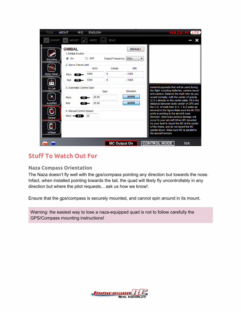
Stuff To Watch Out For
Naza Compass OrientationThe Naza doesn’t fly well with the gps/compass pointing any direction but towards the nose.Infact, when installed pointing towards the tail, the quad will likely fly uncontrollably in anydirection but where the pilot requests... ask us how we know!.
Ensure that the gps/compass is securely mounted, and cannot spin around in its mount.
Warning: the easiest way to lose a nazaequipped quad is not to follow carefully theGPS/Compass mounting instructions!
Crash SurvivalThe XuGong was designed to survive the occasional crash, without permanent damage. Nothingis more frustrating than launching from the perfect location, after a day of hiking, and breaking aplastic arm. Three fundamental survival techniques are inherent to the design:
1. The XuGong’s CNC’d aluminium arms are designed to bend in a serious crash, and be bentback without tools.
2. The silicone rubber ‘antijello’ mount is designed to break loose in a crash, absorbing much ofthe shock that would normally go into destroying the quad.
3. The plastic ‘pegs’ on the arm locking mechanism are designed to break in a headon crash,while protecting the rest of the quad. A few of these small plastic parts should be carried asspares.
In practice, during approx. 1 year of testing before the XuGong was announced, we experiencedseveral serious crashes. The most common was DJI props (1st generation 8” props) breakingwhile several 10s of meters in the air. In every case, the repair was as simple as bending thearms gently back into shape, replacing the prop, and relaunching.
During a particularly fun session at the beach, a XuGong with exhausted battery dropped about50 meters onto the sand, landing bellydown. The arms bent down about 30 degrees. Uponchanging the battery, and bending the arms back into shape, the quad was relaunched, and afew more hours of photo/video taking took place uneventfully.
Lastly, several headon crashes took place, generally while fencehopping (forgetting to hop). Inthese cases the small white arm release would snap off, but is easy to replace in the field.

Replacing the plastic arm-locking partsTo replace the plastic locking part, take a sharp object, and press the black pegs which pokethrough the bottom of the arm.
Warning: When the part is released, ensure that the spring, which is sandwiched between thearm and the white plastic part, doesn’t ‘boing’ into the middle of next week!A few spare springs are included in your box, don’t throw these away!

Flight Time vs. Battery Selection & Prop ChoiceExample 1:With a 4000mAh zippy compact pack, Stock DJI 2212 motors, DJI 1038 props, in forward flightthe consumption is approx. 210mAh per minute of flight. This results in an approx. 17 minuteflight time, enough for comfortable 5km out, 5km back, flights (10km total).
AUW is approx. 1400g with this configuration, with GoPro + battery installed.
(This system was used for one of the XuGong promotional videos here:https://vimeo.com/78925542)
For those of you familiar with the ‘ecalc’ multicopter calculator, the following values get close tothis setup:

Parts List
FR4 pieces, Main body
Top Plate, FR4 x1
Bottom Plate, FR4 x1
Side Plate, FR4 x2
Front Bulkhead, FR4 x1
Battery Bulkhead, FR4 x1

FR4 pieces, GoPro Mount
Right camera mount, FR4 x1
Left camera mount, FR4 x1
Camera box front, FR4 x1
Camera box back, FR4 x1
Camera box right, FR4 x1
Camera box left, FR4 x1
Camera box bottom, FR4 x1
FPV Camera mount, FR4 x1

Plastic parts
GoPro Lens Adapter x1
Camera Gimbal Bushing x1
Arm Locking Pivot x4
TNut Plug x28
Arm Pivot Washers x4
Silicone Rubber Parts
Damper Rubbers, Std x8

Rubber Feet x4
Metal Parts
Ball bearing x16
Spring, large x4
Spring. small x16
Screws, M3x8 x28
Screws, M4x16Arm pivot screws
x4

Aluminium Arms
Center Spider(8” or 10” version, dependingupon product purchased)
x1
Outer Arms(8” or 10” version, dependingupon product purchased)
x4