How to Build a Passivhaus
27
How to Build a Passivhaus Rules of Thumb
-
Upload
khangminh22 -
Category
Documents
-
view
0 -
download
0
Transcript of How to Build a Passivhaus

How to Build a Passivhaus Rules of Thumb
About the Passivhaus TrustThe Passivhaus Trust is an independent, non-profit organisation that provides leadership in the UK for the adoption of the Passivhaus standard and methodology. Its aim is to promote the principles of Passivhaus as a highly effective way of reducing energy use and carbon emissions from buildings in the UK, as well as providing high standards of comfort and building health.
The Passivhaus Trust aims to:
Preserve the integrity of Passivhaus standards and methodology.
Promote Passivhaus principles to the industry and government.
Undertake research and development on Passivhaus standards in the UK.
AuthorsJonathan Hines, Director, ArchitypeSally Godber, Partner, WARM: Low Energy Building PracticeBill Butcher, Director, Green Building StoreMark Siddall, Director, LEAPPaul Jennings, Director, ALDASNick Grant, Director, Elemental SolutionsAlan Clarke, Director, Alan Clarke EngineeringKym Mead, Associate Director, Passivhaus TrustChris Parsons, Director, Parsons + Whittley Architects
The Passivhaus Trust would like to thank the following people for taking the time to collectively review the information within this guide.
Nick Grant, Kym Mead, Mark Siddall, Peter Warm, Marion Baeli, Lynne Sullivan
Cover Image: Burnham Overy Staithe Architect: Parsons + Whittley Architects Client: Hastoe HA Photo Credit: Debbie Harris, 2up Photography
For more information:
www.passivhaustrust.org.uk
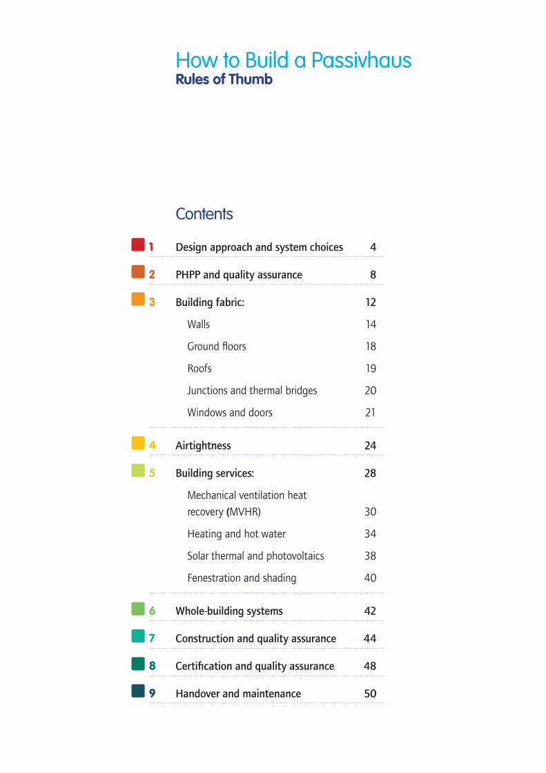
How to Build a Passivhaus Rules of Thumb
1 Design approach and system choices 4
2 PHPP and quality assurance 8
3 Building fabric: 12
Walls 14
Ground floors 18
Roofs 19
Junctions and thermal bridges 20
Windows and doors 21
4 Airtightness 24
5 Building services: 28
Mechanical ventilation heat
recovery (MVHR) 30
Heating and hot water 34
Solar thermal and photovoltaics 38
Fenestration and shading 40
6 Whole-building systems 42
7 Construction and quality assurance 44
8 Certification and quality assurance 48
9 Handover and maintenance 50
Contents

Design approach
There are many factors influencing your approach to designing a building, including: location and site; your client’s brief, budget, and programme; funding requirements and regulatory standards; and your own design philosophy.
Passivhaus should be seen as one of the fundamental factors influencing design as it cannot be achieved simply by meeting each separate technical standard such as airtightness or window U-values. Passivhaus should become an integrated part of your design approach, underpinning, and even inspiring, all the other factors influencing your design.
Choosing the design approach
To ensure that Passivhaus is integrated into the design of the very earliest ideas, its principles and standards must be understood by all members of the design team.
Key early decisions that may be difficult or impossible to change later – including siting, orientation, building form, and fenestration – have a major impact on the viability and economy of achieving Passivhaus.
It is recommended that the design is modelled using the Passivhaus Planning Package (PHPP) at the earliest
opportunity, in order to test and shape these key early design decisions. PHPP should be seen and used as a powerful design tool, helping you to develop your design approach, rather than as a procedure for proving compliance later, when it might be too late.
Explore the impact of the building’s form-factor ratio, the area of external envelope through which heat will escape compared to the area of usable internal building area, and you will quickly discover that whilst almost anything can be made to work, the better this ratio is then the more economic the solution. Aim for a ratio of 0.3 or less.
Test the influence of altering the building’s siting and orientation, or the total and relative quantity of glazing on each elevation, and you will be able to understand the way in which simple environmental principles influence the energy efficiency of a building’s performance. Achieving good design requires not only the solving of a multitude of design challenges, but in the development of creative synergy between them.
Good Passivhaus design requires a fully integrated design approach, out of which an even greater creative synergy can be developed. This will produce buildings that not only meet the client’s brief, and look and feel good, but do actually work with proven energy efficiency and excellent comfort.
1
Passivhaus Planning Package (PHPP) Manual cover
Design approach and system choices Jonathan Hines
Summary Passivhaus should inform and influence every aspect of your design approach and choice of construction system. This need not be seen as limiting creativity of design nor as restricting what construction system to adopt. To achieve an economic solution, Passivhaus must be understood and integrated into the design approach and system choice from the outset.
4 Rules of Thumb Design Approach and System Choices
Form-Factor Ratio

System choices
Passivhaus does not dictate any particular construction system. Indeed, practically any construction system can be used and adapted to achieve Passivhaus, though each will have its own advantages and challenges for your particular project.
The important issue to consider is which construction system is best suited to achieve the stringent requirements of Passivhaus – such as airtightness, elimination of thermal bridging and appropriate U-values – given the particular building type you are designing, its function and the form you are developing.
As a general rule avoid mixing different systems within one building, as this introduces interfaces that will make achieving Passivhaus challenging and more expensive than it needs to be.
System choices for Passivhaus developments
Construction systems can generally be classified as lightweight with less thermal mass (such as timber or steel frame) or as heavyweight with more thermal mass (such as masonry or concrete frame), although elements of thermal mass can be introduced to timber or steel.
The high levels of fabric performance and carefully controlled solar gain lead to internal environmental conditions remaining very stable. Passivhaus does not generally require either light or heavy thermal mass, and other considerations such as function, occupancy and climate will influence this choice.
An important factor in choice of system, is the likely procurement route, and the availability of an appropriate contractor. Thus if you are working on a domestic project and local builders are experienced in traditional masonry, choose masonry as you are more likely to achieve Passivhaus by working with the available skill base.
On larger projects there may be pressure to use steel frame due to its familiarity to large contractors and consequent cost advantages, so you may need to choose steel frame and adapt it to suit Passivhaus.
Similarly, key aspects of construction detailing should inform system choice. Details and junctions need to be designed with construction and assembly on site under realistic conditions (eg weather!) in mind. This is to avoid site compromises or later changes under pressures such as time, cost and materials availability during construction that can easily compromise design and cost.
Key Passivhaus issues with each of the main construction systems are summarised below:
Steel frame: • address potential thermal bridge with connection of
columns to foundations
• ensure steel structure does not pass through the thermal envelope at floors, roofs or for ancillary elements of the building
• achieving airtightness on the inner side of the wall will be challenging, if not impossible, due to the number of structural penetrations. Ideally locate the airtightness line within the wall and on the outside of the structure where it can be continuous and unbroken by the structure
• avoid heavy external cladding hung off the structure, or excessive cantilevered structures, as this will create unnecessary thermal bridging.
ABOVE: Masonry construction. Photo: Architype. LEFT: Typical concrete frame construction. Photo: Architype.
Rules of Thumb Design Approach and System Choices 5
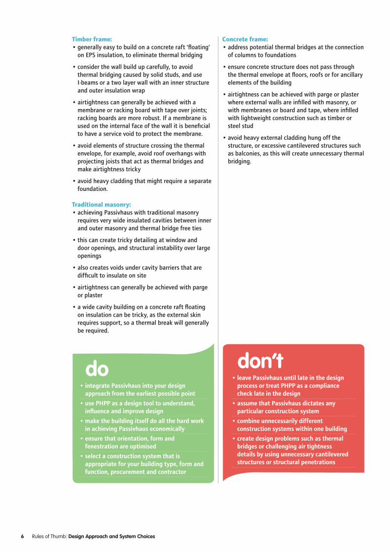
Timber frame: • generally easy to build on a concrete raft ‘floating’
on EPS insulation, to eliminate thermal bridging
• consider the wall build up carefully, to avoid thermal bridging caused by solid studs, and use I-beams or a two layer wall with an inner structure and outer insulation wrap
• airtightness can generally be achieved with a membrane or racking board with tape over joints; racking boards are more robust. If a membrane is used on the internal face of the wall it is beneficial to have a service void to protect the membrane.
• avoid elements of structure crossing the thermal envelope, for example, avoid roof overhangs with projecting joists that act as thermal bridges and make airtightness tricky
• avoid heavy cladding that might require a separate foundation.
Traditional masonry:• achieving Passivhaus with traditional masonry
requires very wide insulated cavities between inner and outer masonry and thermal bridge free ties
• this can create tricky detailing at window and door openings, and structural instability over large openings
• also creates voids under cavity barriers that are difficult to insulate on site
• airtightness can generally be achieved with parge or plaster
• a wide cavity building on a concrete raft floating on insulation can be tricky, as the external skin requires support, so a thermal break will generally be required.
•integratePassivhausintoyourdesignapproachfromtheearliestpossiblepoint
•usePHPPasadesigntooltounderstand,influenceandimprovedesign
•makethebuildingitselfdoallthehardworkinachievingPassivhauseconomically
•ensurethatorientation,formandfenestrationareoptimised
•selectaconstructionsystemthatisappropriateforyourbuildingtype,formandfunction,procurementandcontractor
do
Concrete frame:• address potential thermal bridges at the connection
of columns to foundations
• ensure concrete structure does not pass through the thermal envelope at floors, roofs or for ancillary elements of the building
• airtightness can be achieved with parge or plaster where external walls are infilled with masonry, or with membranes or board and tape, where infilled with lightweight construction such as timber or steel stud
• avoid heavy external cladding hung off the structure, or excessive cantilevered structures such as balconies, as this will create unnecessary thermal bridging.
•leavePassivhausuntillateinthedesignprocessortreatPHPPasacompliancechecklateinthedesign
•assumethatPassivhausdictatesanyparticularconstructionsystem
•combineunnecessarilydifferentconstructionsystemswithinonebuilding
•createdesignproblemssuchasthermalbridgesorchallengingairtightnessdetailsbyusingunnecessarycantileveredstructuresorstructuralpenetrations
don’t
6 Rules of Thumb Design Approach and System Choices

That
ch c
asse
tte
inst
allm
ent.
Phot
o: A
dapt
Phot
o: A
dapt
Phot
o: Y
ogin
i Pat
el
Case Study Enterprise Centre
The Enterprise Centre, a new development by the Adapt Low Carbon Group at the University of East Anglia (UEA) in Norwich, is aiming to achieve both Passivhaus certification and BREEAM outstanding ratings, as well as having one of the lowest embodied carbon footprints of any building of its size in the UK.
The development hopes to be the first to offer both Passivhaus performance alongside natural and bio-renewable materials sourced through local supply chains. The design team hosted a number of workshops with local suppliers to determine which locally sourced products could be used in the construction of the building.
Shading analysis was undertaken to calculate the optimal level of shading for comfortable internal conditions.
Future climate data was generated by the UEA Climate Team, and used to simulate a range of design scenarios in PHPP to identify the most robust solution over an 87-year period. The lifecycle carbon study, including embodied carbon, allowed optimisation of the building mass, glazing ratios, shading and natural ventilation design.
Rules of Thumb Design Approach and System Choices 7

8 Rules of Thumb PHPP and Quality Assurance
Introduction
Training in the use of PHPP is strongly recommended, in order to be fully competent with the software. This section is aimed at those who have undertaken training and are embarking on one of their first Passivhaus projects.
Climate and altitude
Check carefully that you have identified the right weather data set. The map on on page 11 is very useful. The 22 data sets follow county boundaries, use additional county maps if you’re unsure which set to use.
Entering the altitude of your site is just as important. Most of the data sets are from locations less than 50 metres above sea level, and if your site is significantly higher than the weather station this could easily add 1 kWh or more to the heating demand. Conversely some sets are at quite high altitude – the Severn set for instance uses data from RAF Lynham, which is at 150 metres.
Heat loss areas
Heat loss areas in Passivhaus are measured to the outside of the thermal envelope. This can be less straightforward than the SAP internal measurement methodology, as what constitutes the outside of the thermal envelope may not be immediately clear. Put simply, the thermal envelope ends at the last element used in your U-value calculation. So for a masonry wall with fully filled cavity the last element is the exterior brick or block; for a timber frame wall with a ventilated cavity and rain-screen, the thermal envelope will end on the outside of the timber frame wall, because the thermal performance of the rain-screen and cavity are unpredictable and are therefore ignored. Using dimensions which match the element build-ups you use for U-value calculations will help ensure an accurate PHPP model.
A critical eye
Passivhaus certifiers will be keeping a watchful eye out for things that will affect the building performance in practice, for example:
• manufacturer/supplier claims for material conductivities – if you are unsure use standard values from the PHPP handbook
• correct inclusion of repeating thermal bridges (refer to BS 6946 for guidance)
• can the insulation be easily constructed without air gaps between or behind the material?
• areas that are likely to be damp (e.g. in contact with ground), as conductivity of porous elements such as open-cell insulation or lightweight blocks can vary significantly with moisture content
• is there a risk of thermal bypass?
So, be critical about the information you’re given. For example, are insulation conductivities stated using the
Heat loss areas must join up!
Summary The Passivhaus Planning Package (PHPP) is a very useful and powerful design tool, but it is easy to misinterpret the conventions, giving erroneous results. Avoiding these simple mistakes can reduce the need to find additional energy savings late on in a project. In a worst-case scenario, such mistakes might mean that a project cannot achieve certification.
Be conservative with values, as the thermal performance of elements very rarely gets better during design development. Optimistic inputs will be a problem later!
2 Use of PHPP and quality assuranceSally Godber

correct conventions? (E.g. 90/90 values, see www.bbacerts.co.uk for further information)
Window entries
Unlike the UK’s National Calculation Methods (NCMs), such as SAP and SBEM, where each rough opening can be considered as one window, PHPP needs accurate window entries, which count each casement separately. Entering two adjacent window casements as one means that the frame losses are underestimated, and the solar gains overestimated. Also, opening windows nearly always have thicker frames than fixed, so it is good practice to assume that all windows are opening ones early on in a design; this should avoid underestimating frame heat losses.
Using an installation psi-value of 0.04W/m2K is a good conservative estimate for early design, and can easily be improved upon. This typically represents a window installed into a standard timber frame.
Primary energy
For most Passivhaus dwellings in the UK the primary energy target is easily met. The exceptions are when providing heating and/or hot water by direct electric or when using a district heating system/central plant. For this reason in most cases the primary energy does not need to be modelled early in design.
Ventilation rates
PHPP generally assumes a ventilation rate of around 0.3 air changes per hour (ACH), which is based on German property sizes and occupancy rates. For most UK homes, which are smaller and more densely occupied, higher ventilation rates are required.
MVHR duct data
The fresh air and exhaust ducts from the MVHR to the outside environment are essentially outdoor spaces within the thermal envelope and can add significantly to the heat loss of your design. Be realistic about the duct lengths, diameters and the amount of insulation which will be fitted. Where the MVHR is located right against an external wall, duct lengths of >1.5m are still likely. 160mm diameter ducts and 25mm insulation are typical values for a domestic installation and closed cell insulation should be used to avoid condensation problems.
Multiple MVHRs
If your design includes more than one ventilation unit, for example in a terrace of houses or block of flats, you must use the Additional Vent sheet which is included in the more recent versions of PHPP. Although this sheet is challenging to use, it is vital to do so, as without it you will underestimate duct losses significantly.
A test to see if you’re using the ‘Additional Vent’ sheet correctly is to fill in the ‘Ventilation’ sheet for a single ventilation unit, with associated duct lengths. Change the flowrate to represent the area served by that ventilation unit. The efficiency should be similar to the overall value in the ‘Additional Vent’ sheet.
Shading
The shading sheet is probably the trickiest within PHPP to get right, and it’s worth reading the PHPP manual carefully so you understand the instructions, especially about averaging reveal figures. It’s not sensible to be overly conservative and assume more shading than there is, because this can hide overheating problems. Be clear and reasonable in your assumptions and a Certifier is unlikely to disagree with you. If you are at all uncertain, get a Certifier appointed and agree the shading strategy early on.
For very complex shading it is possible to use separate software to calculate the shading such as IES, TAS or Ecotect. See page 94 of the PHPP manual for more information.
Whilst it is possible to get carried away worrying about shading accuracy, a good design should not be too sensitive to exact shading values as this suggests there is probably too much glazing. It is better to be more conservative in your assumptions.
Rules of Thumb PHPP and Quality Assurance 9
Input into PHPP of two casement windows
3
3

Overheating
The overheating check in PHPP is basic, and as such shouldn’t be used for non-residential or complex residential buildings. PHPP considers the building as one zone, distributing the gains evenly and as a result won’t identify high solar gains concentrated in one room. Be cautious about using high ventilation rates to solve an overheating issue, as this may not be realistic due to security or noise issues. A useful stress test is:
• Use the IHG sheet to accurately represent the actual internal gains – and consider modelling various scenarios to demonstrate differences in user behaviour. Note this will require several additional sheets to be filled in such as the hot water and electricity sheets. To represent small buildings with high occupancy, a value of 7W/m2 is reasonable if no other data is available.
• Input minimum user-operated summer shading. If you are building the house for yourself then you may be willing to open and shut blinds 10 times a day but the next residents may have a different view!
• In our experience the effectiveness of MVHR ‘summer bypass’ mode is overstated in PHPP so set at half normal vent rate (0.2ACH, for example).
• Assume no natural ventilation during the day.
• Assume half the achievable night time ventilation – again in most cases this is user determined, and be careful about assuming internal doors are open.
The upper limit for certification is to keep the building below 25°C for <10% of the year, and best practice is <5% of the year. It is likely the latter will become a certification criteria in future.
•engagewithabuildingdesignerattheearliestopportunity
•modelyourdesigninPHPPattheearlydesignstages
•makesureyouareusingthecorrectclimatedatawithinPHPP
do
•assumethatabuildingspecificationfromapreviousdevelopmentwillsuitallfuturePassivhausbuildings
•beover-reliantonglazing
don’t
Typical TFA markup where inclusions/exclusions can easily be identified
10 Rules of Thumb PPH and Quality Assurance
Solar gains
Whilst it is possible to build almost anything to the Passivhaus standard, be cautious about projects with large expanses of glass. These will have a strong reliance on high performance glazing but the structure that surrounds glass is more complex and therefore probably won’t perform as well. In addition, the building is highly reliant on the weather for both internal comfort and energy consumption – this does not make it easy to achieve the comfort and energy requirements!
QA process
It is easy to make mistakes with any modelling software, so having a robust QA procedure within your organisation is key. Ideally there will be someone who can look over your PHPP on a regular basis. Clear mark-ups of treated floor area, heat loss areas, windows and shading make for easy checking, as does keeping previous versions of your PHPP.
If your experience is limited employ a Certifier early on in a project to check what you’re doing, agree any points of contention and provide any hand-holding you may need. Whilst certification usually starts pre-construction, having some experienced input (especially before planning) will ensure you’re on the right track.

Rules of Thumb PPH and Quality Assurance 11
UK regional climate data
1 Central London
2 Thames Valley
3 South East England
4 South England
5 South West England
6 Severn
7 Midlands
8 West Pennines
9 NW England/SW Scotland
10 Borders
11 North East England
12 East Pennines
13 East Anglia
14 Wales
15 West Scotland
16 East Scotland
17 North East Scotland
18 Highlands
19 Western Isles
20 Orkney
21 Shetland
22 Northern Ireland
For more information visit The Passivhaus Trust website: www.passivhaustrust.org.uk

12 Rules of Thumb Building Fabric
Introduction
All construction types can achieve the Passivhaus standard. The decision over construction type often comes down to
• building form and planning restrictions
• ease of achieving a good thermal envelope
• cost restraints, buildability, speed, material availability, risk, client preference and local skills.
Form factor
Compactness of building form makes it easier to achieve Passivhaus standards, because the heat loss area (envelope) is minimised in relation to the building’s volume. In general the larger the building the easier it is to achieve the standard, including airtightness. However, for Passivhaus we are interested in heat loss per m2 of Treated Floor Area (TFA) – therefore high ceilings and double height spaces all contribute to the volume but not the habitable floor area. As a rule, terraced housing will need less insulation than detached houses, and a block of flats less still. Integral garages, ornate dormer windows, bay windows, or an intricate building footprint, all worsen the ratio between a building’s envelope and it’s volume, and make it more difficult to achieve Passivhaus.
Essential elements of the thermal envelope
1 Rainscreen
2 Wind tight vapour open layer
3 Super insulation
4 Air tight layer
5 Structural zone
6 Service zone
Please note: The above list does not suggest that the elements will be arranged in this order.
The above building forms are able to achieve the Passivhaus Standard but a higher performance specification to the built fabric is likely. Images by Toby Rollason
Summary The fabric, or envelope, of a Passivhaus needs to achieve high thermal and airtight performance whilst providing structural stability and weather protection. For building durability the design also needs to eliminate the danger of interstitial condensation forming within the structure. This section will look at general principles to consider regarding design and construction of the building fabric.
3 Building fabric Bill Butcher
Principles of design
To help obtain the high energy standards necessary for Passivhaus, it is crucial that the design of a building allows it to be buildable. The essential principles, both in the design and the build processes, to be considered by the whole team throughout the whole process in delivering a Passivhaus are:
Continuity of super insulation There has to be a consistency of ‘wrapping’ the whole building, with particular attention to the junctions of the different fabric elements.
Minimising thermal bridgingThe need for structural integrity, and the need to allow light and access into a building leads inevitably to the use of different materials with different thermal properties. Good design of each of these details to minimise the thermal loss is crucial both to keep heating demand down and to avoid cold spots where condensation might form.
Maintaining airtightnessPassivhaus buildings need to achieve 0.6 air changes/hour @ 50 Pascals, approximately 15 times more airtight than the present UK Building Regulation requirements.
The airtightness strategy needs to include a continuous layer joining each of the fabric components, using an appropriate material robust enough to last the lifetime of a building. Not only does an effective airtightness layer stop draughts and
reduces energy consumption (by limiting heat loss), it also protects the fabric of a building by preventing internal warm humid air from passing into the fabric, where it could form interstitial condensation. To minimise this risk, a rule of thumb is for the airtightness layer to be within the first third of the insulation build-up from the warm side. Beyond that third, it is advisable for the detail to be ‘modelled’ (e.g. in WUFI hygrothermal modelling software) to ascertain the risk.
Minimising thermal bypassA thermal bypass is the wicking of heat from a building by air movement around and through its fabric. A breather membrane layer on the cold side of the building’s fabric will help avoid some of the more common examples. Heavy weight or lightweight construction?
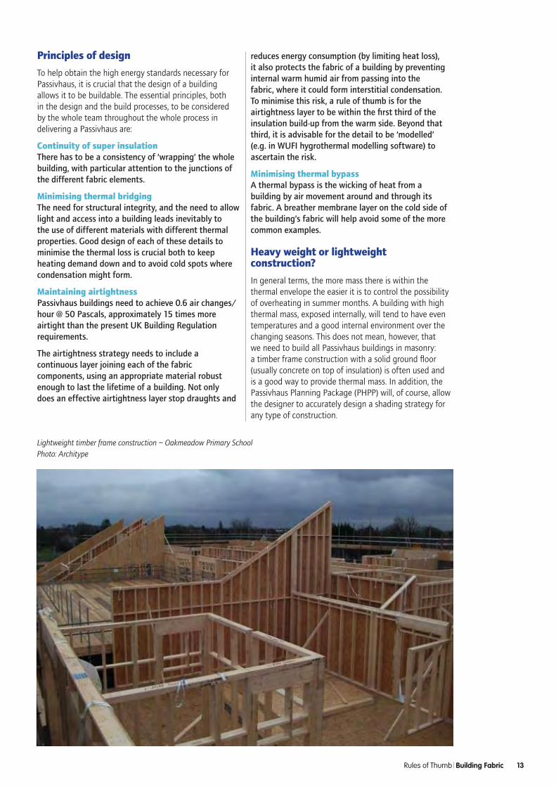
In general terms, the more mass there is within the thermal envelope the easier it is to control the possibility of overheating in summer months. A building with high thermal mass, exposed internally, will tend to have even temperatures and a good internal environment over the changing seasons. This does not mean, however, that we need to build all Passivhaus buildings in masonry: a timber frame construction with a solid ground floor (usually concrete on top of insulation) is often used and is a good way to provide thermal mass. In addition, the Passivhaus Planning Package (PHPP) will, of course, allow the designer to accurately design a shading strategy for any type of construction.
Lightweight timber frame construction – Oakmeadow Primary SchoolPhoto: Architype
Rules of Thumb Building Fabric 13

ABOVE: Larsen timber trussesPhoto: Eco Arc Architects
BELOW: I beam portal framePhoto: Conker Conservation
14 Rules of Thumb Building Fabric Sponsored by Kingspan Insulation
1 Walls
Introduction
Typically wall, roof and floor elements in Passivhaus buildings should aspire to: a U-value of between 0.10 W/m2K to 0.15 W/m2K, whatever the construction method employed; minimal thermal bridging; and ideally an internal service void so that services do not penetrate the airtight/vapour barrier. The thickness of the wall construction needed to achieve the required thermal performance will vary greatly, possibly from 300mm to 500mm, depending on the chosen insulation and construction type used. This section looks at the advantages and disadvantages of typical UK wall construction techniques.
Timber construction
Timber frameCan be site fabricated (known as ‘stick construction’) or prefabricated in a factory situation delivered to site in panels.
Timber stud The most common timber framing system would typically use 144/44mm timber studs at 600mm centres when filled with insulation.This would not normally achieve a recommended u-value of 0.1 – 0.15W/m2K, particularly when extra studs have to be inserted for structural reasons around window openings. Therefore additional insulation is required, usually applied externally over the whole frame, covering junctions and studs.
TJI joist systemTruss Joist I-joists or TJI joists have a lot of advantages and offer a relatively economic way to attain low U-values. They are available in many sizes and are structurally strong, with minimal thermal bridging due to the slim compressed timber web.
Double timber studs This is a relatively simple way of achieving the depth of insulation needed, whilst providing the buildings structure or skeleton.
Larsen trusses Though not offering structural support to a building, Larsen trusses offer a useful method of containing insulation and giving support for a cladding board and rain screen, such as rendering or timber cladding. Larsen trusses can be used in conjunction with timber framing or masonry walls in new build or retrofit projects. They are very simple to use and can be built on site or prefabricated.
Component materials with timber frame
This section looks at the types of materials used with timber frame construction, to make up the rest of the walls.
In a timber frame wall construction, the windtight layer (also known as the breather membrane) can be a rigid board or membrane, which will need taping to eliminate thermal bypass. Modern ‘vapour open’ but windtight and water-resistant materials allow any moisture within the fabric to evaporate harmlessly to the outside.
Insulation in timber frame walls can be of any type, either flexible insulation can be used between studs to cope with the thermal movement of the timber, minimising the possibility of air pockets which can lead to thermal
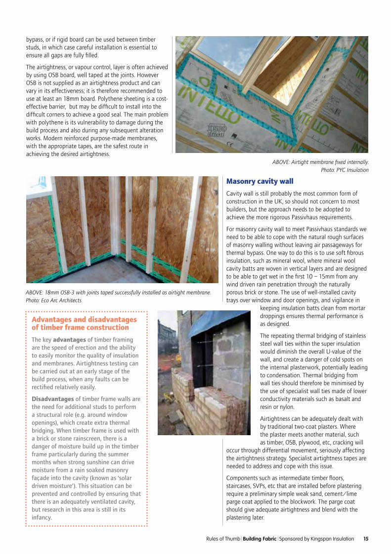
ABOVE: 18mm OSB-3 with joints taped successfully installed as airtight membrane. Photo: Eco Arc Architects
ABOVE: Airtight membrane fixed internally. Photo: PYC Insulation
bypass, or if rigid board can be used between timber studs, in which case careful installation is essential to ensure all gaps are fully filled.
The airtightness, or vapour control, layer is often achieved by using OSB board, well taped at the joints. However OSB is not supplied as an airtightness product and can vary in its effectiveness; it is therefore recommended to use at least an 18mm board. Polythene sheeting is a cost-effective barrier, but may be difficult to install into the difficult corners to achieve a good seal. The main problem with polythene is its vulnerability to damage during the build process and also during any subsequent alteration works. Modern reinforced purpose-made membranes, with the appropriate tapes, are the safest route in achieving the desired airtightness.
Masonry cavity wall
Cavity wall is still probably the most common form of construction in the UK, so should not concern to most builders, but the approach needs to be adopted to achieve the more rigorous Passivhaus requirements.
For masonry cavity wall to meet Passivhaus standards we need to be able to cope with the natural rough surfaces of masonry walling without leaving air passageways for thermal bypass. One way to do this is to use soft fibrous insulation, such as mineral wool, where mineral wool cavity batts are woven in vertical layers and are designed to be able to get wet in the first 10 – 15mm from any wind driven rain penetration through the naturally porous brick or stone. The use of well-installed cavity trays over window and door openings, and vigilance in
keeping insulation batts clean from mortar droppings ensures thermal performance is as designed.
The repeating thermal bridging of stainless steel wall ties within the super insulation would diminish the overall U-value of the wall, and create a danger of cold spots on the internal plasterwork, potentially leading to condensation. Thermal bridging from wall ties should therefore be minimised by the use of specialist wall ties made of lower conductivity materials such as basalt and resin or nylon.
Airtightness can be adequately dealt with by traditional two-coat plasters. Where the plaster meets another material, such as timber, OSB, plywood, etc, cracking will
occur through differential movement, seriously affecting the airtightness strategy. Specialist airtightness tapes are needed to address and cope with this issue.
Components such as intermediate timber floors, staircases, SVPs, etc that are installed before plastering require a preliminary simple weak sand, cement/lime parge coat applied to the blockwork. The parge coat should give adequate airtightness and blend with the plastering later.
Rules of Thumb Building Fabric Sponsored by Kingspan Insulation 15
Advantages and disadvantages of timber frame construction
The key advantages of timber framing are the speed of erection and the ability to easily monitor the quality of insulation and membranes. Airtightness testing can be carried out at an early stage of the build process, when any faults can be rectified relatively easily.
Disadvantages of timber frame walls are the need for additional studs to perform a structural role (e.g. around window openings), which create extra thermal bridging. When timber frame is used with a brick or stone rainscreen, there is a danger of moisture build up in the timber frame particularly during the summer months when strong sunshine can drive moisture from a rain soaked masonry façade into the cavity (known as ‘solar driven moisture’). This situation can be prevented and controlled by ensuring that there is an adequately ventilated cavity, but research in this area is still in its infancy.

Disadvantages Masonry cavity wall is a slower construction method than timber frame and It is more difficult to check the quality of the continuity of insulation, (e.g. the cleanliness from mortar dropping, etc.). Airtightness testing occurs later in the building programme which can make it more difficult to rectify hidden faults. The absence of a service void means that more care is needed in services design and execution. Although electric cabling can be buried in the plaster effectively, badly installed back boxes can create weak points. A longer structural drying out period will affect the first season’s heating demand
Advantages and disadvantages of masonry cavity wall
Advantages Materials are readily available, and the construction method is familar to local labour, though not necessarily to the stringent Passivhaus standards. Being a heavyweight construction, traditional blockwork gives excellent thermal storage and soundproofing properties. There is no danger of interstitial condensation and holes in the plaster airtightness layer are always repaired as part of redecoration work.Masonry cavity wall can be the cheapest construction method and is still the most common house building construction method in the UK so its use will avoid taking builders outside of their experience and ‘comfort zone’, and hence avoid over-pricing due to perceptions of risk.
RIGHT: Partial fill cavity with rigid insulation Photos: Kingspan Insulation
The Greenhauses offer an example of affordable Passivhaus level construction in a tight urban setting. The development includes a row of three-storey terraces (Block A) and two five-storey apartment buildings (Blocks B & C). Both Blocks A and B are Passivhaus certified.
The primary façade material is brick, complementing the surrounding architecture. To minimise the remaining construction thickness whilst achieving the required thermal performance and airtightness, the Kingspan TEK® Building System was specified for Block A. A 90 mm thick layer of Kingspan Kooltherm® K12 Framing Board was fixed outside the panel with an airtight membrane taped to its internal face.
On Block B, Kingspan TEK® Cladding Panels were fixed to the concrete floor slab using angled cleats. The build-up mirrored those in Block A with the airtight membrane sealed to the concrete frame and soffits with airtight tape.
Both build-up’s achieved a final external wall U-value of 0.10 W/m2.K, and the detailing, in combination with the Kingspan TEK® proprietary jointing system, ensured air loss was below 0.6 air changes per hour @ 50 Pa.
Case Study The Greenhauses at Sulgrave Gardens
16 Rules of Thumb Building Fabric Sponsored by Kingspan Insulation
Solid masonry with external insulation
This in theory is the easiest method to attain the Passivhaus goals for walling, and can be achieved with a wide choice of rigid and semi rigid insulation materials. The structure, usually of concrete or blockwork, is inside the thermal envelope providing good thermal mass. The airtightness layer is usually applied to the outside of the structure in the form of a flattening render coat, in preparation for the adhesive layer for the insulation. Thermally broken mechanical fixings are usually required. The rainscreen is commonly a render system, with integral keying membrane.
It is crucial to inhibit air movement between the insulation and the structural walling, as any thermal bypass would seriously diminish the thermal performance. It is important to have a flat surface on which to fix the insulation and to apply adhesive evenly with a notched trowel.
Advantages and disadvantages of solid masonry with external insulation
Advantages Insulation and structure are completely separated, meaning that thermal bridging can be minimised. With this system, quality of workmanship is, on the whole, visible, making quality assurance easier. There is also no need for cavity trays with this method of construction. All trades can proceed within the building without the worry of damaging the airtightness layer.
Disadvantages External rendering can be easily damaged because there is no structure behind it. If heavier cladding (such as brick slips) is used there may be significant thermal bridging problems if supported off the internal structure. Contractors in the UK do not appear to be experienced yet in the care needed to minimise thermal bypass, and external insulation systems to reach Passivhaus standards seem expensive in the UK at the present.
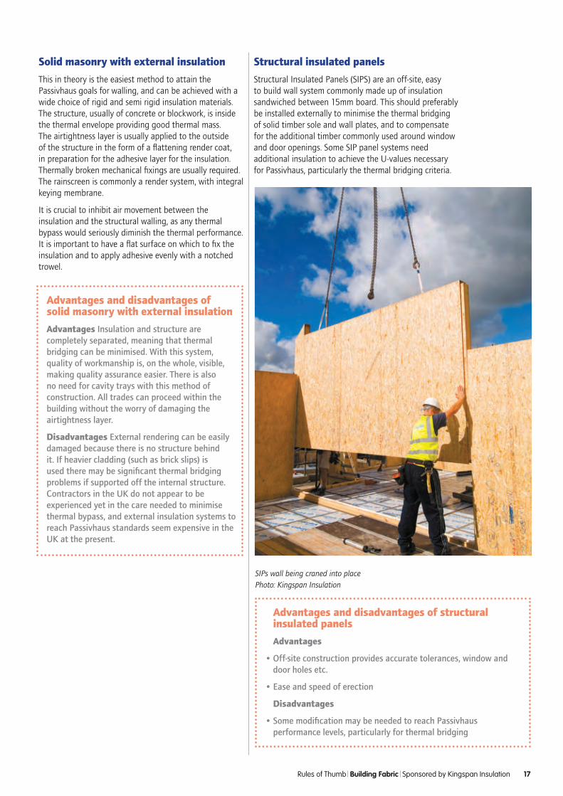
Structural insulated panels
Structural Insulated Panels (SIPS) are an off-site, easy to build wall system commonly made up of insulation sandwiched between 15mm board. This should preferably be installed externally to minimise the thermal bridging of solid timber sole and wall plates, and to compensate for the additional timber commonly used around window and door openings. Some SIP panel systems need additional insulation to achieve the U-values necessary for Passivhaus, particularly the thermal bridging criteria.
SIPs wall being craned into place Photo: Kingspan Insulation
Rules of Thumb Building Fabric Sponsored by Kingspan Insulation 17
Advantages and disadvantages of structural insulated panels
Advantages
• Off-site construction provides accurate tolerances, window and door holes etc.
• Ease and speed of erection
Disadvantages
• Some modification may be needed to reach Passivhaus performance levels, particularly for thermal bridging
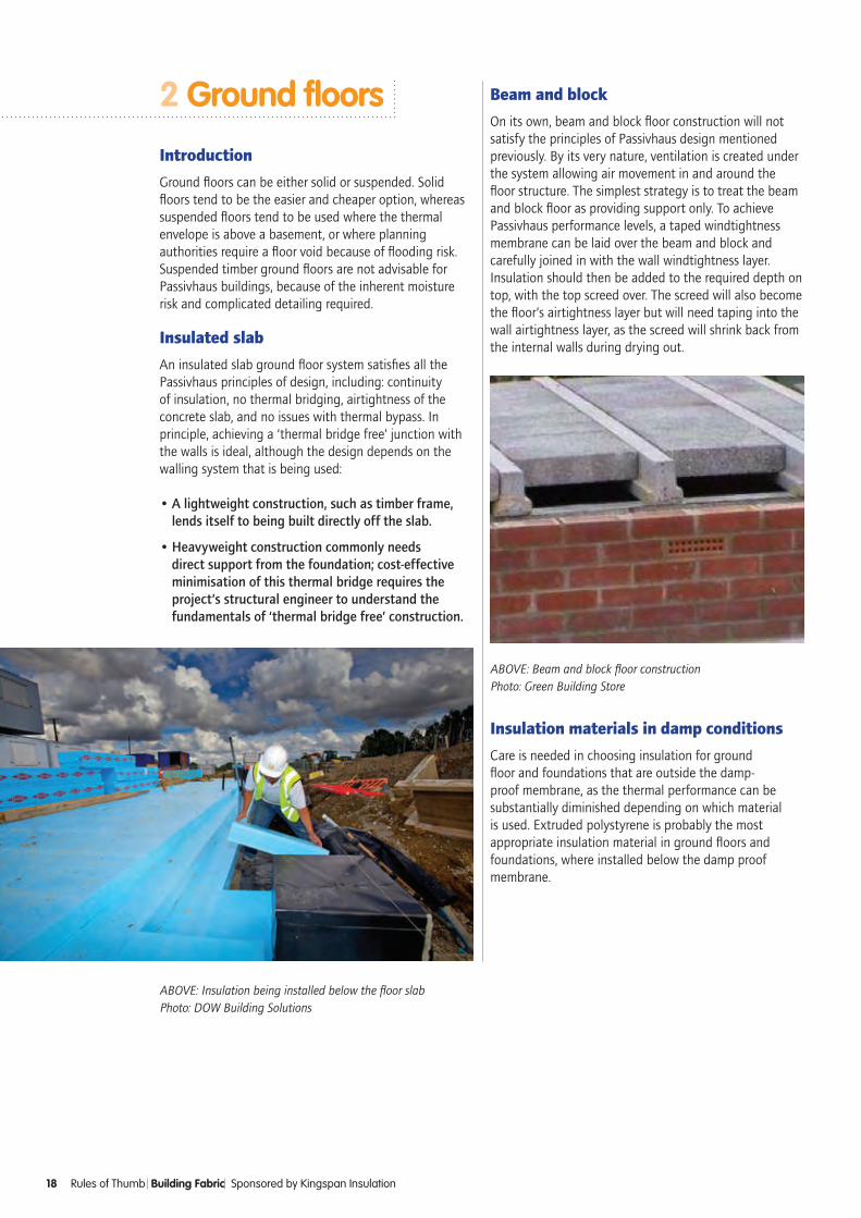
ABOVE: Insulation being installed below the floor slab Photo: DOW Building Solutions
ABOVE: Beam and block floor constructionPhoto: Green Building Store
2 Ground floors
Introduction
Ground floors can be either solid or suspended. Solid floors tend to be the easier and cheaper option, whereas suspended floors tend to be used where the thermal envelope is above a basement, or where planning authorities require a floor void because of flooding risk. Suspended timber ground floors are not advisable for Passivhaus buildings, because of the inherent moisture risk and complicated detailing required.
Insulated slab
An insulated slab ground floor system satisfies all the Passivhaus principles of design, including: continuity of insulation, no thermal bridging, airtightness of the concrete slab, and no issues with thermal bypass. In principle, achieving a ‘thermal bridge free’ junction with the walls is ideal, although the design depends on the walling system that is being used:
• A lightweight construction, such as timber frame, lends itself to being built directly off the slab.
• Heavyweight construction commonly needs direct support from the foundation; cost-effective minimisation of this thermal bridge requires the project’s structural engineer to understand the fundamentals of ‘thermal bridge free’ construction.
Beam and block
On its own, beam and block floor construction will not satisfy the principles of Passivhaus design mentioned previously. By its very nature, ventilation is created under the system allowing air movement in and around the floor structure. The simplest strategy is to treat the beam and block floor as providing support only. To achieve Passivhaus performance levels, a taped windtightness membrane can be laid over the beam and block and carefully joined in with the wall windtightness layer. Insulation should then be added to the required depth on top, with the top screed over. The screed will also become the floor’s airtightness layer but will need taping into the wall airtightness layer, as the screed will shrink back from the internal walls during drying out.
18 Rules of Thumb Building Fabric Sponsored by Kingspan Insulation
Insulation materials in damp conditions
Care is needed in choosing insulation for ground floor and foundations that are outside the damp-proof membrane, as the thermal performance can be substantially diminished depending on which material is used. Extruded polystyrene is probably the most appropriate insulation material in ground floors and foundations, where installed below the damp proof membrane.
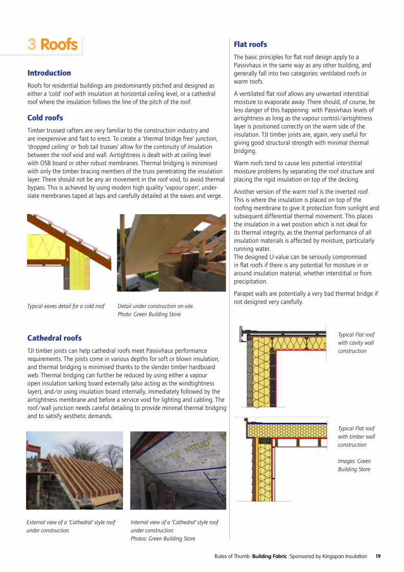
Typical eaves detail for a cold roof
External view of a ‘Cathedral’ style roof under construction
Internal view of a ‘Cathedral’ style roof under construction. Photos: Green Building Store
Typical Flat roof with cavity wall construction
Typical Flat roof with timber wall construction
Images: Green Building Store
Rules of Thumb Building Fabric Sponsored by Kingspan Insulation 19
Flat roofs
The basic principles for flat roof design apply to a Passivhaus in the same way as any other building, and generally fall into two categories: ventilated roofs or warm roofs.
A ventilated flat roof allows any unwanted interstitial moisture to evaporate away. There should, of course, be less danger of this happening with Passivhaus levels of airtightness as long as the vapour control/airtightness layer is positioned correctly on the warm side of the insulation. TJI timber joists are, again, very useful for giving good structural strength with minimal thermal bridging.
Warm roofs tend to cause less potential interstitial moisture problems by separating the roof structure and placing the rigid insulation on top of the decking.
Another version of the warm roof is the inverted roof. This is where the insulation is placed on top of the roofing membrane to give it protection from sunlight and subsequent differential thermal movement. This places the insulation in a wet position which is not ideal for its thermal integrity, as the thermal performance of all insulation materials is affected by moisture, particularly running water. The designed U-value can be seriously compromised in flat roofs if there is any potential for moisture in or around insulation material, whether interstitial or from precipitation.
Parapet walls are potentially a very bad thermal bridge if not designed very carefully.
Detail under construction on-site. Photo: Green Building Store
3 Roofs
Introduction
Roofs for residential buildings are predominantly pitched and designed as either a ‘cold’ roof with insulation at horizontal ceiling level, or a cathedral roof where the insulation follows the line of the pitch of the roof.
Cold roofs
Timber trussed rafters are very familiar to the construction industry and are inexpensive and fast to erect. To create a ‘thermal bridge free’ junction, ‘dropped ceiling’ or ‘bob tail trusses’ allow for the continuity of insulation between the roof void and wall. Airtightness is dealt with at ceiling level with OSB board or other robust membranes. Thermal bridging is minimised with only the timber bracing members of the truss penetrating the insulation layer. There should not be any air movement in the roof void, to avoid thermal bypass. This is achieved by using modern high quality ‘vapour open’, under-slate membranes taped at laps and carefully detailed at the eaves and verge.
Cathedral roofs
TJI timber joists can help cathedral roofs meet Passivhaus performance requirements. The joists come in various depths for soft or blown insulation, and thermal bridging is minimised thanks to the slender timber hardboard web. Thermal bridging can further be reduced by using either a vapour open insulation sarking board externally (also acting as the windtightness layer), and/or using insulation board internally, immediately followed by the airtightness membrane and before a service void for lighting and cabling. The roof/wall junction needs careful detailing to provide minimal thermal bridging and to satisfy aesthetic demands.
Types of thermal bridge
There are essentially three types of thermal bridge:
• Repeating thermal bridges
• Linear thermal bridges: The Y-value (psi-value)
• Nodal thermal bridges: The X-value (chi-value)
Linear and nodal thermal bridges are determined in accordance with BS EN ISO 10211. Linear thermal bridges occur at the junctions between two building elements. Nodal thermal bridges arise when three building elements intersect (e.g. a corner between two walls and a floor) or where a single element (e.g. a steel beam) penetrates the insulation.
Zero thermal bridging concepts
The concept of ‘zero thermal bridging’ can only be used successfully when using external dimensions. Due to geometry it is not possible to achieve zero thermal bridging using internal dimensions. The Passivhaus Standard considers a detail to be ‘thermal bridge free’ when the psi-value is <0.01W/mK.
4 Junctions and thermal bridges Mark Siddall
Introduction
In a building that meets the Passivhaus Standard the junctions and interfaces require specific attention. It is at these points in the building fabric that heat loss can occur through thermal bridges; furthermore low surface temperatures can result in surface condensation and mould growth. Unaddressed thermal bridges can increase fabric heat loss by over 30%. This chapter considers the impact that thermal bridging and reduced surface temperatures can have upon building performance.
Thermal bridges and energy calculations
It is possible to calculate thermal bridges using internal and external dimensions. The use of internal dimensions tends to underestimate heat loss. The use of external dimensions tends to overestimate heat loss. The two methods should not be combined.
The Passivhaus Standard uses external dimensions whilst UK conventions utilise internal dimensions. Calculations based upon UK conventions should not be used when calculating the heat loss from a building that is designed to meet the Passivhaus Standard. Likewise thermal bridging calculations developed for the Passivhaus Standard should not be used in SAP or iSBEM calculations.
do•minimisecomplexity–thisreducesthe
chanceoferrorandcanassistbuildability
•atjunctionsbetweenelements,insulatinglayersshouldmeetwithoutanygaps
•insulatinglayersshouldjoinwithoutinterruptionormisalignment
•designedgesandcornerstohaveasobtuseanglesaspossible
•duringthedesignprocessensurethatsimplerobustdetailsaredevelopedwithadequateconstructiontolerance
don’t•allowdisruptionstothethermalenvelope-
whereanunavoidabledisruptionismadetoaninsulatinglayer,thethermalresistanceintheinsulationshouldbeashighaspossible
•underestimateconstructiontolerances
20 Rules of Thumb Building Fabric
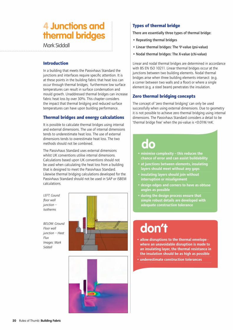
LEFT: Gound floor wall junction – Isotherms
BELOW: Ground Floor wall junction – Heat FluxImages: Mark Siddall
5 Windows and doorsSally Godber
Introduction
Manufacturers are not used to providing thermal performance data in a format suitable for inclusion in PHPP, so spend time reviewing the exact frame, glazing and spacer specification they provide for each window. This is usually easier for certified windows but still take care.
Once you have interpreted manufacturer information and put it into PHPP, we would recommend sending a copy back to the manufacturer for them to confirm the values you have taken.
Performance
It is not necessary to use certified windows as long as manufacturers can supply data to EN 10077 to fill in the ‘Components’ worksheet in PHPP. In particular, ask for separate frame U-values (head, cill and jamb); and glazing U-values need to be given to 2 decimal places.
If you are planning to use a non-certified window it is important to check the average temperature of the internal surface of the installed window does not drop below 16°C internally, at the lowest external design conditions, otherwise cold down draughts may occur. Certified windows have already been checked against an external temperature of –10°C, but in many parts of England the external design temperature might be much higher, meaning that poorer performing window frames (possibly even non-insulated) might be allowed.
To achieve the 16°C, non-insulated window frames must be well-wrapped with insulation on site.
Note that windows smaller than the standard test window size are unlikely to achieve the performance target due to the higher ratio of (poorer performing) frame relative to (high efficiency) glazing. However, their small size means they will not usually cause discomfort.
Whatever door and window options you choose, it must fit the overall energy balance in PHPP. PHPP is a fantastic tool for assessing different frame and glazing options and comparing costs, but be careful to ensure other factors are taken into account.
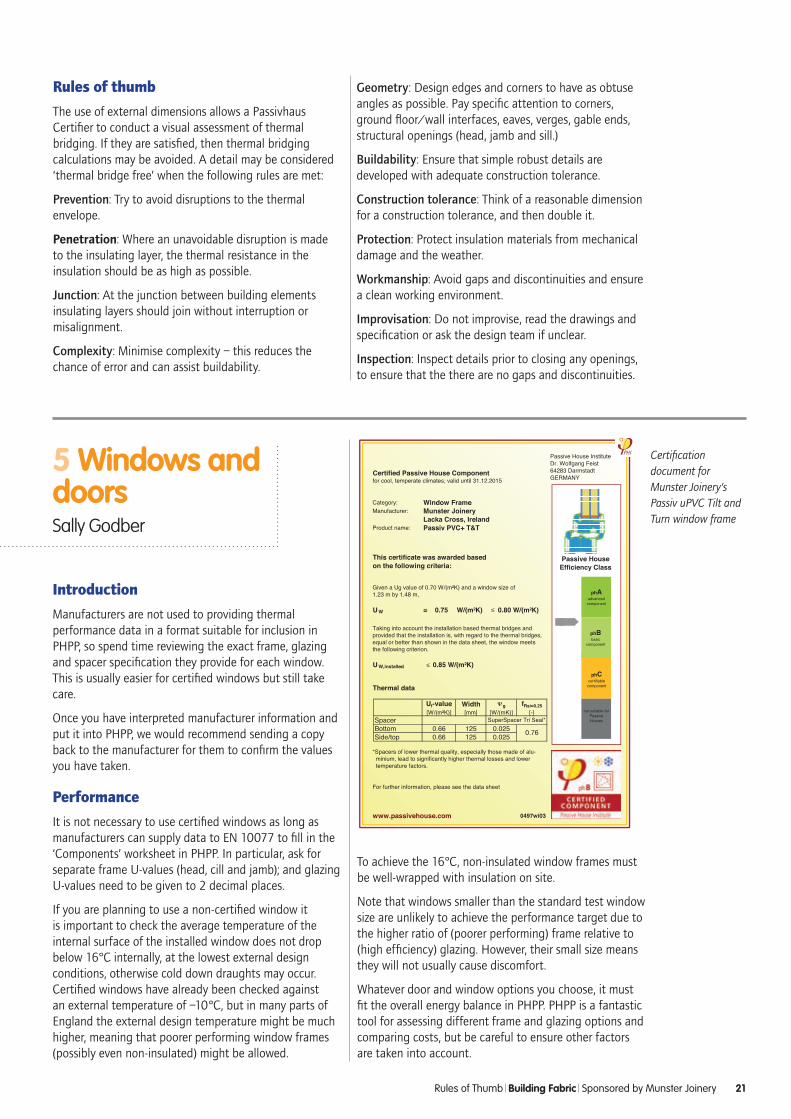
Certification document for Munster Joinery’s Passiv uPVC Tilt and Turn window frame
Rules of Thumb Building Fabric Sponsored by Munster Joinery 21
Rules of thumb
The use of external dimensions allows a Passivhaus Certifier to conduct a visual assessment of thermal bridging. If they are satisfied, then thermal bridging calculations may be avoided. A detail may be considered ‘thermal bridge free’ when the following rules are met:
Prevention: Try to avoid disruptions to the thermal envelope.
Penetration: Where an unavoidable disruption is made to the insulating layer, the thermal resistance in the insulation should be as high as possible.
Junction: At the junction between building elements insulating layers should join without interruption or misalignment.
Complexity: Minimise complexity – this reduces the chance of error and can assist buildability.
Geometry: Design edges and corners to have as obtuse angles as possible. Pay specific attention to corners, ground floor/wall interfaces, eaves, verges, gable ends, structural openings (head, jamb and sill.)
Buildability: Ensure that simple robust details are developed with adequate construction tolerance.
Construction tolerance: Think of a reasonable dimension for a construction tolerance, and then double it.
Protection: Protect insulation materials from mechanical damage and the weather.
Workmanship: Avoid gaps and discontinuities and ensure a clean working environment.
Improvisation: Do not improvise, read the drawings and specification or ask the design team if unclear.
Inspection: Inspect details prior to closing any openings, to ensure that the there are no gaps and discontinuities.
22 Rules of Thumb Building Fabric Sponsored by Munster Joinery
Support
Some manufacturers are willing to provide support, for example help with airtightness detailing, installation psi-value calculations and site visits.
Another reason to get manufacturers involved early is to ensure that proposed window sizes are achievable; typically opening windows that are wider than 1.2m can cause problems.
Airtightness
Passivhaus certification of windows requires no airtightness testing to be undertaken, so tread with care. Whilst most certified windows have got a precedent of meeting the airtightness standard, it is recommended to ensure the manufacturer confirms their windows are suitable.
Spacer widths
The performance of sealed glazing units varies with thickness of the frame. A good frame should have a rebate >48mm to allow sufficient glazing options. For triple glazing, 18-20mm cavities are optimum for Argon – 16mm or less gives inferior performance. Krypton is generally unsuitable except for special purposes where narrow cavities are required.
Frames and energy balance
Generally frames perform worse than glazing so small windows, or those with lots of mullions and transoms should be minimised.
When picking a window frame, the dimensions should always be considered as well as frame U-value. While it can be tempting to choose the frame with the best U-value, there is often a trade-off between performance and thickness. A slimmer yet worse performing frame can sometimes prove the better option, as the amount of glazing (which has a better U-value) is optimised and solar gains are increased.
The new Passivhaus window Certificates from the Passivhaus Institut include an A to C rating which gives an indication of the balance between frames and glazing, becauses gains are considered as well as losses. However, the best approach is to model the various options in PHPP as the ‘best’ option can vary between projects.
Inward and outward opening windows can perform equally well, although inward opening windows allow external shutters, blinds or insect mesh to be fitted, and are usually easier to wrap in insulation thus helping achieve better thermal performance.
Glazing
Triple glazing gives the best energy balance, even in the UK climate, and is needed to meet comfort requirements and to avoid condensation and mould at the edges.
The glazing g-value (Solar Factor) refers to the fraction of solar heat that transmits through the glass and is just as important as the glazing U-value in this optimisation process, so ask for both to 2 decimal places. Note that Building Regulations only considers losses, so a manufacturer’s ‘high performance’ glazing will often have a low U-value but also very low g-value which is likely to give a poor energy balance in PHPP. Manufacturers will have a range of glass they can supply, with varying costs so ask for alternatives.
Take care to look at the light transmittance of the glass as well; usually the light transmittance percentage is roughly in line with the g-value.
Other standards such as Secured by Design or Building Regulations, may dictate that security glass is used. Generally toughened glass does not impact on performance but laminated glass almost certainly will.
Rooflights
When installing horizontal glass (rooflights) the glazing performance changes; this must be taken into account in the U-value. For example, glazing with a stated U-value of 0.60W/m2K should be entered as 0.90W/m2K in PHPP when it is installed horizontally to take account of this. EN673 has a calculator to determine this accurately.
Note that rooflights are very difficult to shade from overheating in summer.
It is very hard to achieve good installation details with a rooflight, although manufacturers have developed installation kits that improve performance.
Glazed doors
Whilst a number of sites have met the airtightness criteria whilst using sliding doors, their use needs careful consideration as the airtightness often degrades faster than a standard door due to wear and tear. This is particularly important if the door is directly next to a living space where a draft could be felt. Tilt and slide doors are inherently more airtight, and may be cheaper than parallel slide versions.
Bi-fold or folding-sliding doors are generally expensive at the level of airtightness needed for a Passivhaus. In addition, it is very difficult to get as good installation psi-values as a normal window/door because of the frame configuration.
Consider using glazed doors as these have a better energy balance than solid doors.

Case Study Coventry Eco House
Installation
For best thermal performance, position frames near the centre of the insulation line. Optimisation of such details in thermal bridging software is worthwhile. However, deep external reveals increase the solar shading which may or may not be advantageous.
The frame dimensions and the way it opens (inward/outward) will determine how much insulation can be wrapped around the frame. For inward opening windows generally insulate externally; for outward opening windows insulate internally.
Thresholds also need careful consideration as they are a difficult area for achieving good thermal performance.
In addition, airtightness needs to be considered when detailing window installations.
Note that there is little or no benefit to wrapping aluminium-clad frames with insulation externally.
Non-conforming components
Some components will not achieve the 0.85W/m2K target and this may be acceptable as long as they are not adjacent to habitable areas where people are likely to spend significant time.
do•minimisetransomsandmullionsinglass
•checkwindowsizesareachievablewiththemanufacturer
•usePHPPtoassesswholecomponentperformance,don’tjustrelyonwholewindowU-values
•lookatwhatglazingoptionsthemanufacturercanoffer
•considercertifiedandnon-certifiedwindows
don’t•assumetheframeu-valueisthesamefor
thewindowsill,headandjam.CheckthePHIComponentcertificateormanufacturers3rdpartytestcertificateforperformance
•forgettoadjusttheperformanceofanyrooflightswithinthePHPPcalculation
Munster Joinery supplied windows for a social housing development on behalf of Orbit Heart of England Housing Association. The Coventry Eco House development consisted of two units built to the Passivhaus standard using the Beattie Passive system.
Munster Joinery were able to supply their Passiv uPVC Tilt and Turn window within two weeks from order from their Warwickshire factory.
The window is certified as a Passivhaus suitable component by the Passive House Institute in Germany.
Thermal Data
Rules of Thumb Building Fabric Sponsored by Munster Joinery 23

Introduction
Airtightness often appears to be the most difficult element to achieve in Passivhaus projects, yet once a robust airtight design is in place, delivery is primarily about rigor and attention to detail.
Passivhaus airtightness targets
The Passivhaus airtightness target is < 0.6 ACH-1 @ 50 Pa for newbuild projects and < 1.0 ACH-1 @ 50 Pa for EnerPHit refurbishment projects. This compares with UK Building Regulations, where a maximum Air Permeability of 10m3/hr/m2 @ 50 Pa is commonly permitted. Hence the Passivhaus airtightness requirements for newbuild are some 15 times more onerous than UK Building Regulations, while insulation requirements will typically only be 3 to 4 times more demanding than Building Regulations. Therefore it is not surprising that UK contractors often find the stringent Passivhaus airtightness requirements particularly difficult to meet.
The quoted targets are the final acceptance value; it is sensible to leave a margin to allow for the leakage often found around services that are installed after the first airtightness test. This should be at least 25%, which means aiming for preliminary test results of:
• < 0.45 ACH-1 @ 50 Pa for newbuild projects and
• < 0.75 ACH-1 @ 50 Pa for refurbishment projects
Airtightness testing procedures
When carrying out an airtightness test, a steady-state condition is established, when the air blown out of the building by the fan is balanced by the air re-entering the building through various cracks, gaps and openings. Typically this is at a pressure of 50 Pascals (Pa), about the same as a 20 mile-an-hour wind acting upon the volume under test, not forgetting that wind speed rises with distance above ground if testing in high-rise blocks.
Testing is carried out in the UK in conformance with the ATTMA (Air Tightness Testing & Measurement Association) 2010 editions of the standards TSL1 (dwellings) and TSL2 (non-dwellings). These are available as a free download from www.attma.org. A new scheme for quality control of testers was established on 1st January 2015.
Summary In this chapter we discuss the Passivhaus requirement for an excellent level of airtightness and explain the principles of airtightness testing, highlighting where dwellings leak and how to go about meeting the airtightness target for a project.
Airtightness Paul Jennings
A small calibrated fan mounted in a window board fitted in an open kitchen window during testing
4
24 Rules of Thumb Airtightness
Small calibrated fan mounted in a window board fitted in an open kitchen window during testing.
Requirements for a multi-point test
• A minimum of 7 readings, typically 10 to 12 readings, at ≈5 Pa intervals, 15 or more readings recommended in windy conditions
• At least 1 reading at a pressure differential of magnitude >50 Pa
• No readings at pressure differentials of magnitude >100 Pa
• The zero-flow pressure differential (e.g. wind-induced) shall have a magnitude of no more than 5 Pa
• The correlation coefficient, r2, must be > 0.980
• The airflow exponent, n, (a measure of the turbulence of the airflow through the various leaks) must be: 0.5 < n < 1.0

Locating leaks
As well as the calibrated test equipment used in measuring the airflow through the building, there is a range of ancillary equipment that a testing organisation will probably use when testing a building, and particularly when investigating leakage after an unsatisfactory initial test. Although the back of one’s hand is often completely adequate for tracking down leakage sites in more leaky buildings, leakage rates can be so low in Passivhaus projects that it becomes unreliable. Even the more sensitive human eyeball cannot always be relied upon, hence we use chemical smoke, thermographic cameras and extending vane anemometers when searching for leakage. Another common tactic is to fix a square metre section of polythene or similar membrane over the surface of a wall that we suspect is leaking. Under depressurisation, if the membrane bulges into the property, there is clearly a leak through that wall construction. A common gross leak that we routinely find is through door locks, even in very expensive Passivhaus-certified doors.
Air barrier strategy
Deciding what sealing products and processes are required to deliver the target airtightness leads to the development of a formal air barrier strategy. For clarity and ease of communication, we suggest that this is summarised in the manner shown below, tailored for an individual project:
The figure below summarises the air barrier strategy to deliver Passivhaus airtightness in a newbuild warm-roof dwelling. For a specific project the manufacturer of sealing tapes and airtightness membranes should be detailed, and a list of penetrations and how they are to be sealed would also be needed. Your project would be individual and almost certainly different, but summarising it in this way is an essential step in communicating how the Passivhaus target is to be achieved. The next step should be to prepare a set of airtightness drawings, detailing the line of the airtightness barrier on plans and sections.
Using chemical smoke to check for leakage between upper floorboards
Specifications for airtightness
When specifying airtightness for a building where the target is to achieve Passivhaus or EnerPHit certification, it is essential to specify the airtightness process as well as the airtightness target and the sealing materials and process to be used.
Quality assurance and airtightness champions
This is the key role in ensuring an airtight design and quality assurance is satisfactorily delivered on site, and Passivhaus projects not adopting this approach are at risk of sealing failures that can lead to costly additional works and delays.
Rules of Thumb Airtightness 25
Example of an Air Barrier Strategy simplified for clarity
Thermographic image of a leaky door lock, where the blue key hole is much cooler than the adjacent metal lock. Photos: Paul Jennnings
Extending vane anemometer showing a high air velocity of 2.1 m/s through a gap at the head of a balcony window
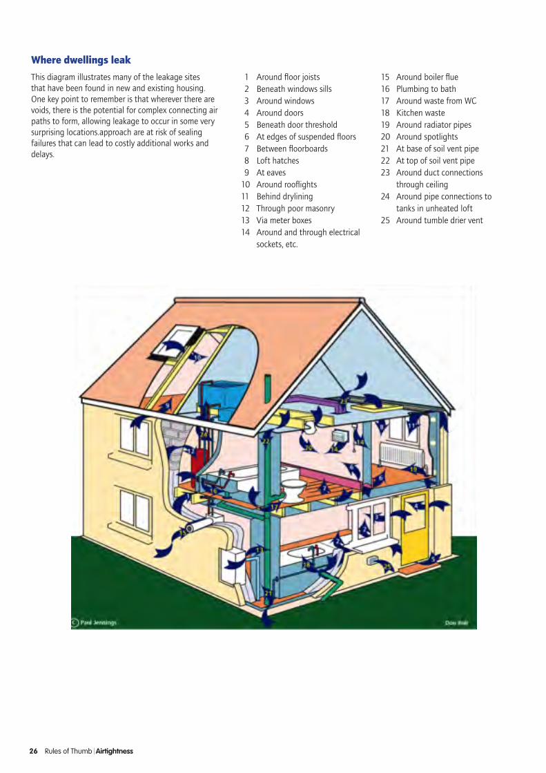
Where dwellings leak
This diagram illustrates many of the leakage sites that have been found in new and existing housing. One key point to remember is that wherever there are voids, there is the potential for complex connecting air paths to form, allowing leakage to occur in some very surprising locations.approach are at risk of sealing failures that can lead to costly additional works and delays.
1 Around floor joists 2 Beneath windows sills 3 Around windows 4 Around doors 5 Beneath door threshold 6 At edges of suspended floors 7 Between floorboards 8 Loft hatches 9 At eaves 10 Around rooflights11 Behind drylining12 Through poor masonry13 Via meter boxes14 Around and through electrical
sockets, etc.
15 Around boiler flue16 Plumbing to bath17 Around waste from WC 18 Kitchen waste19 Around radiator pipes20 Around spotlights21 At base of soil vent pipe22 At top of soil vent pipe23 Around duct connections
through ceiling24 Around pipe connections to
tanks in unheated loft25 Around tumble drier vent
26 Rules of Thumb Airtightness

do•developaformalairbarrierstrategy
•appointornominateaqualityassuranceandairtightnesschampion
•theairtightnesstestingorganisationmustbeacceptabletothecertifyingbody
•pressurisationanddepressurisationtestingmustbecarriedoutandtheresultsaveraged
•foraPassivhausorEnerPHitacceptancetest,thebuildingmustbefinished,notemporarysealing,otherthantoexcludetheventilationsystem,ispermitted
don’t•assumethatsomethingissealed–always
check
•calculateairchangesusingtheATTMAvolume;thePHIinstitutehasmuchmoredetailedcalculationrequirementsandtheresultingvolumecanbe20%smaller,makingithardertopasstheairtightnesstest
•allowtheconstructionprogramtooverridequalityrequirements–remedyingairtightnessdefectsattheendofabuildcanbedisruptive,costlyandsignificantlydelaycompletion
Rules of Thumb Airtightness 27
Air barrier applications
LEFT AND RIGHT: Fully sealed vapour and airtight layers Images: Ecological Building Systems
LEFT AND RIGHT: Sealing around windowsImages: Ecological Building Systems
LEFT AND RIGHT: Sealing pipes and cables. Photos: Ecological Building Systems