
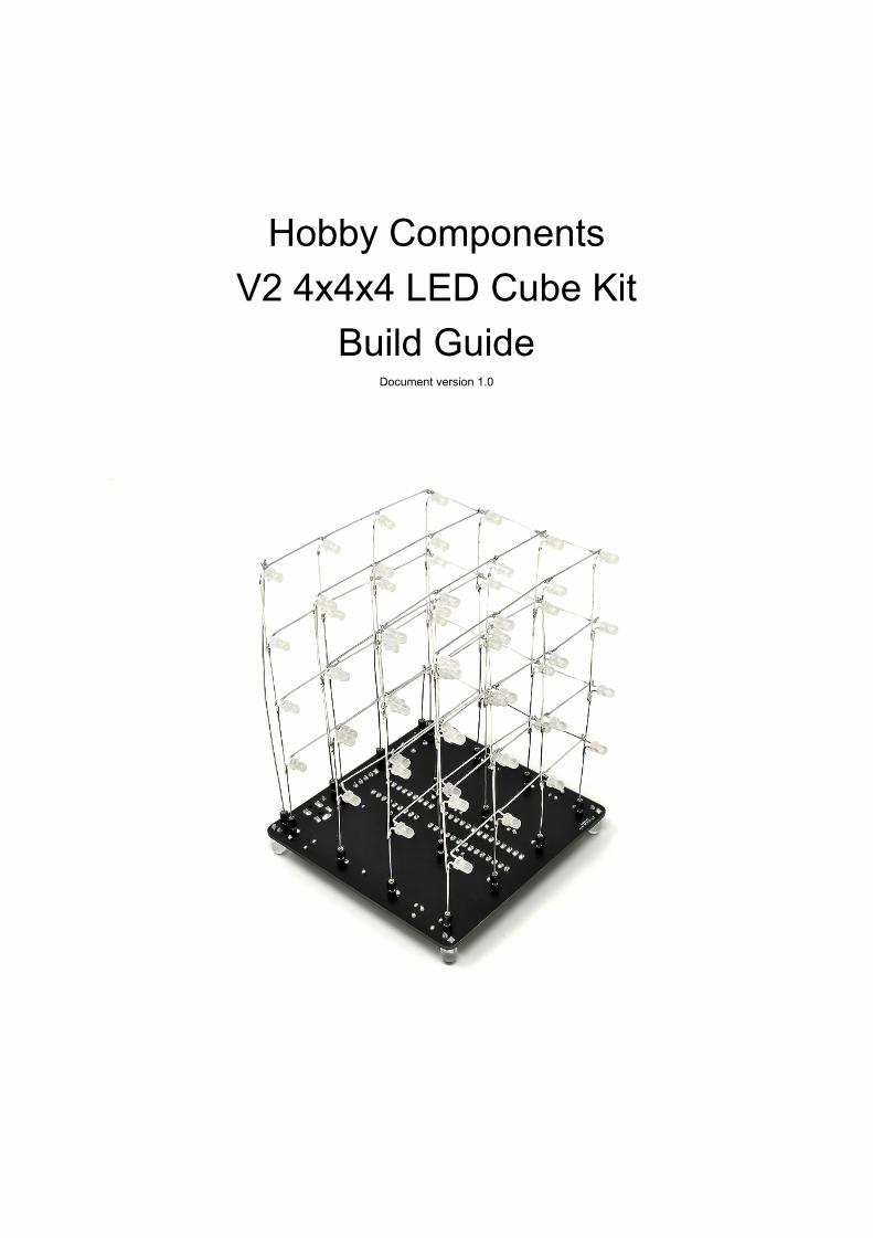
Hobby Components V2 4x4x4 LED Cube Kit Build Guide
24
Hobby Components V2 4x4x4 LED Cube Kit Build Guide Document version 1.0
-
Upload
khangminh22 -
Category
Documents
-
view
0 -
download
0
Transcript of Hobby Components V2 4x4x4 LED Cube Kit Build Guide
Hobby Components V2 4x4x4 LED Cube Kit
Build Guide Document version 1.0

PLEASE NOTE
This build guide is for version 2 cube kits only. If you have an older version kit (V1 or V1.1) you can find the correct build guide on our blog site here:
https://blog.hobbycomponents.com/?p=412
To make this kit as easy to build as possible we have designed it to only use through-hole components. However, some familiarity with soldering is required to construct this kit .
DISCLAIMER
This document is provided "as is". Hobby Components Ltd makes no warranties, whether express, implied or statutory, including, but not limited to, implied warranties of merchantability and fitness for a particular purpose, accuracy or lack of negligence. Hobby Components Ltd shall not, in any circumstances, be liable for any damages, including, but not limited to, special, incidental or consequential damages for any reason whatsoever.
COPYRIGHT NOTICE This document, including content and artwork is copyright of Hobby Components Ltd and may not be reproduced without written permission. If you paid for or received a copy of this manual from a source other than Hobby Components Ltd, please contact us at [email protected]
Before You Start
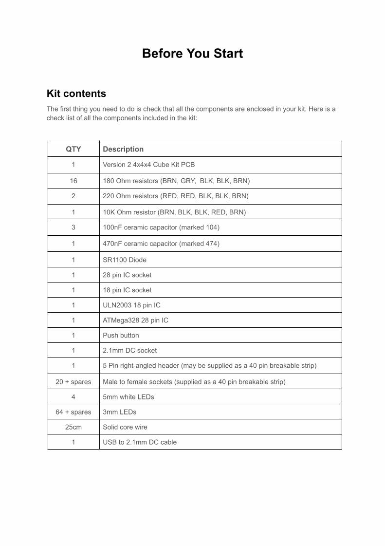
Kit contents The first thing you need to do is check that all the components are enclosed in your kit. Here is a check list of all the components included in the kit:
QTY Description
1 Version 2 4x4x4 Cube Kit PCB
16 180 Ohm resistors (BRN, GRY, BLK, BLK, BRN)
2 220 Ohm resistors (RED, RED, BLK, BLK, BRN)
1 10K Ohm resistor (BRN, BLK, BLK, RED, BRN)
3 100nF ceramic capacitor (marked 104)
1 470nF ceramic capacitor (marked 474)
1 SR1100 Diode
1 28 pin IC socket
1 18 pin IC socket
1 ULN2003 18 pin IC
1 ATMega328 28 pin IC
1 Push button
1 2.1mm DC socket
1 5 Pin right-angled header (may be supplied as a 40 pin breakable strip)
20 + spares Male to female sockets (supplied as a 40 pin breakable strip)
4 5mm white LEDs
64 + spares 3mm LEDs
25cm Solid core wire
1 USB to 2.1mm DC cable
Required tools
In order to build the cube, you will need the following tools:
1. Soldering Iron (Ideally with a fine tip)
2. Solder
3. A small pair of snips or side cutters
4. A pair of small, long nose pliers
Recommended
4x4x4 V2 Cube kit LED template (SKU: HCPROT0101)
OR:
A piece of perspex / plywood which will be used as a jig for soldering the LEDs that make up the cube
3mm drill bit and drill
Part 1: Building the PCB
Soldering notes Take the PCB out of your kit and you’ll notice that one side of the PCB has white silkscreen printed on it with the other side being completely blank. All components, apart from the male to female sockets, will be soldered to the silkscreen side of the PCB.
Soldering tips: When soldering components to a circuit board it is always best to start with the smallest components first. This helps keep the board flat and stops access to pads from being restricted by larger components. We have deliberately ordered the steps within the guide so that components are soldered in order of height.
The first step is to start by soldering the resistors. In your kit these will be marked appropriately. The orientation of most of the components doesn’t matter but we will point out any components where the orientation does matter. In these cases it is important to make sure you have them inserted correctly.
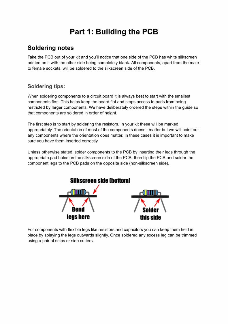
Unless otherwise stated, solder components to the PCB by inserting their legs through the appropriate pad holes on the silkscreen side of the PCB, then flip the PCB and solder the component legs to the PCB pads on the opposite side (non-silkscreen side).
For components with flexible legs like resistors and capacitors you can keep them held in place by splaying the legs outwards slightly. Once soldered any excess leg can be trimmed using a pair of snips or side cutters.
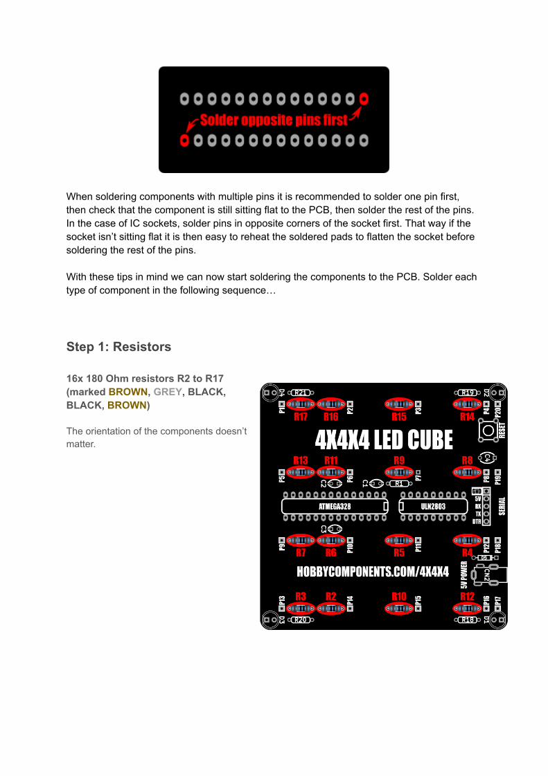
When soldering components with multiple pins it is recommended to solder one pin first, then check that the component is still sitting flat to the PCB, then solder the rest of the pins. In the case of IC sockets, solder pins in opposite corners of the socket first. That way if the socket isn’t sitting flat it is then easy to reheat the soldered pads to flatten the socket before soldering the rest of the pins.
With these tips in mind we can now start soldering the components to the PCB. Solder each type of component in the following sequence…
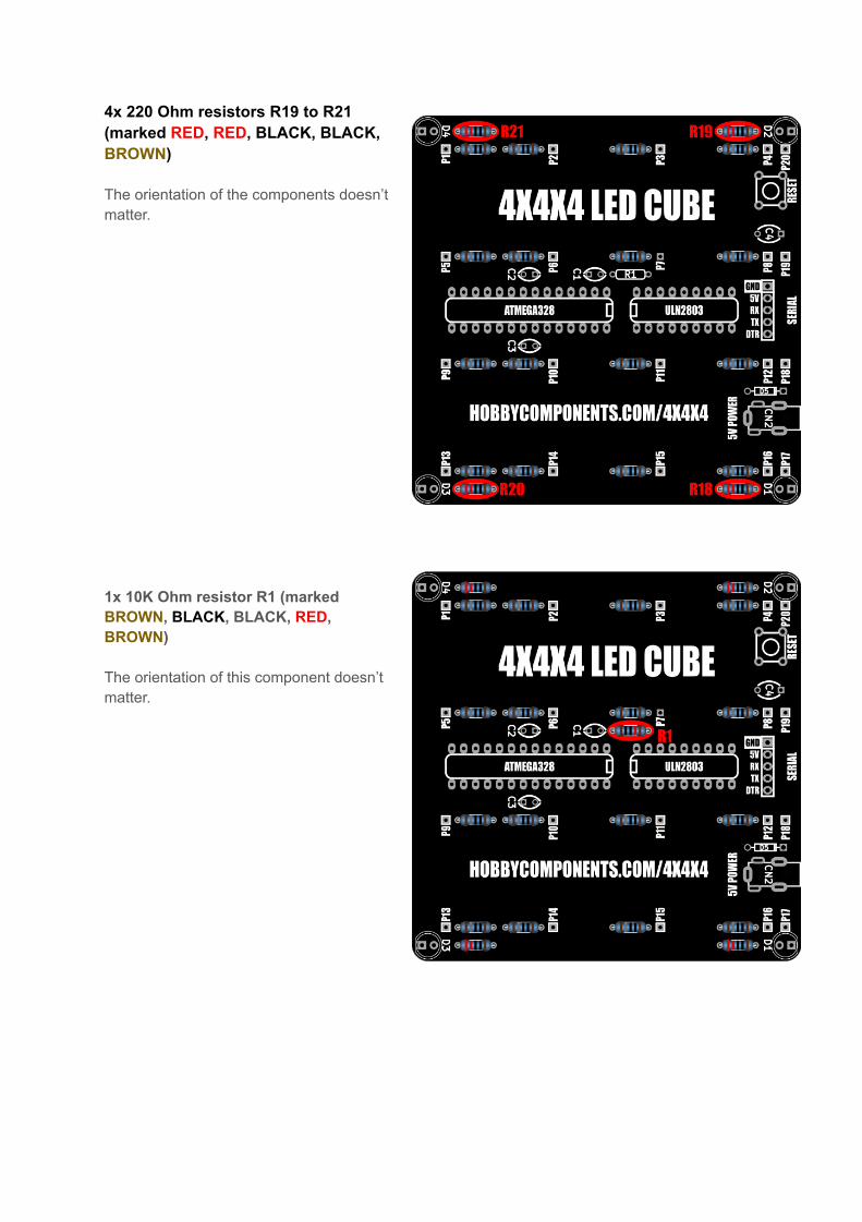
Step 1: Resistors
16x 180 Ohm resistors R2 to R17 (marked BROWN , GREY , BLACK, BLACK, BROWN )
The orientation of the components doesn’t matter.
4x 220 Ohm resistors R19 to R21 (marked RED , RED , BLACK, BLACK, BROWN )
The orientation of the components doesn’t matter.
1x 10K Ohm resistor R1 (marked BROWN , BLACK , BLACK, RED , BROWN )
The orientation of this component doesn’t matter.

Step 2: Diode
1x SR1100 Diode D5
Note that the orientation of the diode is important - solder it to the PCB with the silver band pointing to the edge of the PCB.
Step 3: IC sockets
1x 18 pin & 1x 28 pin IC socket
In both cases solder the sockets with the notch end of the socket pointing into the PCB. Be careful when inserting the sockets that none of the pins bend under the socket instead of going through its pad hole - they should drop into holes without any resistance.

Step 3: Serial port
1x 5 pin right-angled header
This may be supplied as a 40 way strip which can be broken into a 5 pin section. Solder this header with the pins pointing to the outside of the PCB.
Step 4: Capacitors
3x 100nF ceramic capacitors C1, C2, & C3 (marked 104)
1x 470nF ceramic capacitor C4 (marked 474)
The orientation of the components doesn’t matter.

Step 5: Switch
1x Push button switch
Note that the orientation of the switch is important - referencing the image, insert the switch into the PCB so that the pins are on the top and bottom sides of the switch.
Step 6: 5V Power socket
1x DC Socket
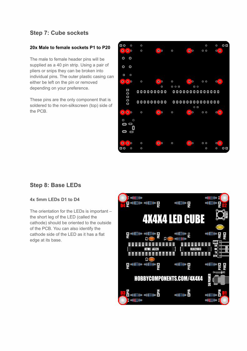
Step 7: Cube sockets
20x Male to female sockets P1 to P20
The male to female header pins will be supplied as a 40 pin strip. Using a pair of pliers or snips they can be broken into individual pins. The outer plastic casing can either be left on the pin or removed depending on your preference.
These pins are the only component that is soldered to the non-silkscreen (top) side of the PCB.
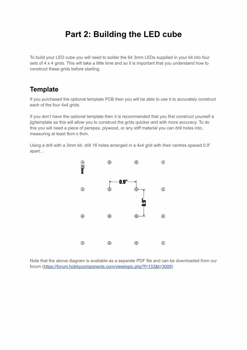
Step 8: Base LEDs
4x 5mm LEDs D1 to D4
The orientation for the LEDs is important – the short leg of the LED (called the cathode) should be oriented to the outside of the PCB. You can also identify the cathode side of the LED as it has a flat edge at its base.

Step 9: ICs
1x 28 Pin ATMega328
1x 18 pin ULN2803
Insert the ICs into their sockets. Note that the orientation of the IC’s is important – at one end of each IC you will notice a semi circle cut into the case. When the IC’s are inserted into the board these should point to the inside of the PCB.
Part 2: Building the LED cube
To build your LED cube you will need to solder the 64 3mm LEDs supplied in your kit into four sets of 4 x 4 grids. This will take a little time and so it is important that you understand how to construct these grids before starting.
Template If you purchased the optional template PCB then you will be able to use it to accurately construct each of the four 4x4 grids.
If you don’t have the optional template then it is recommended that you first construct yourself a jig/template as this will allow you to construct the grids quicker and with more accuracy. To do this you will need a piece of perspex, plywood, or any stiff material you can drill holes into, measuring at least 8cm x 8cm.
Using a drill with a 3mm bit, drill 16 holes arranged in a 4x4 grid with their centres spaced 0.9” apart…
.
Note that the above diagram is available as a separate PDF file and can be downloaded from our forum ( https://forum.hobbycomponents.com/viewtopic.php?f=133&t=3009 )
Before you start building here’s a few tips:
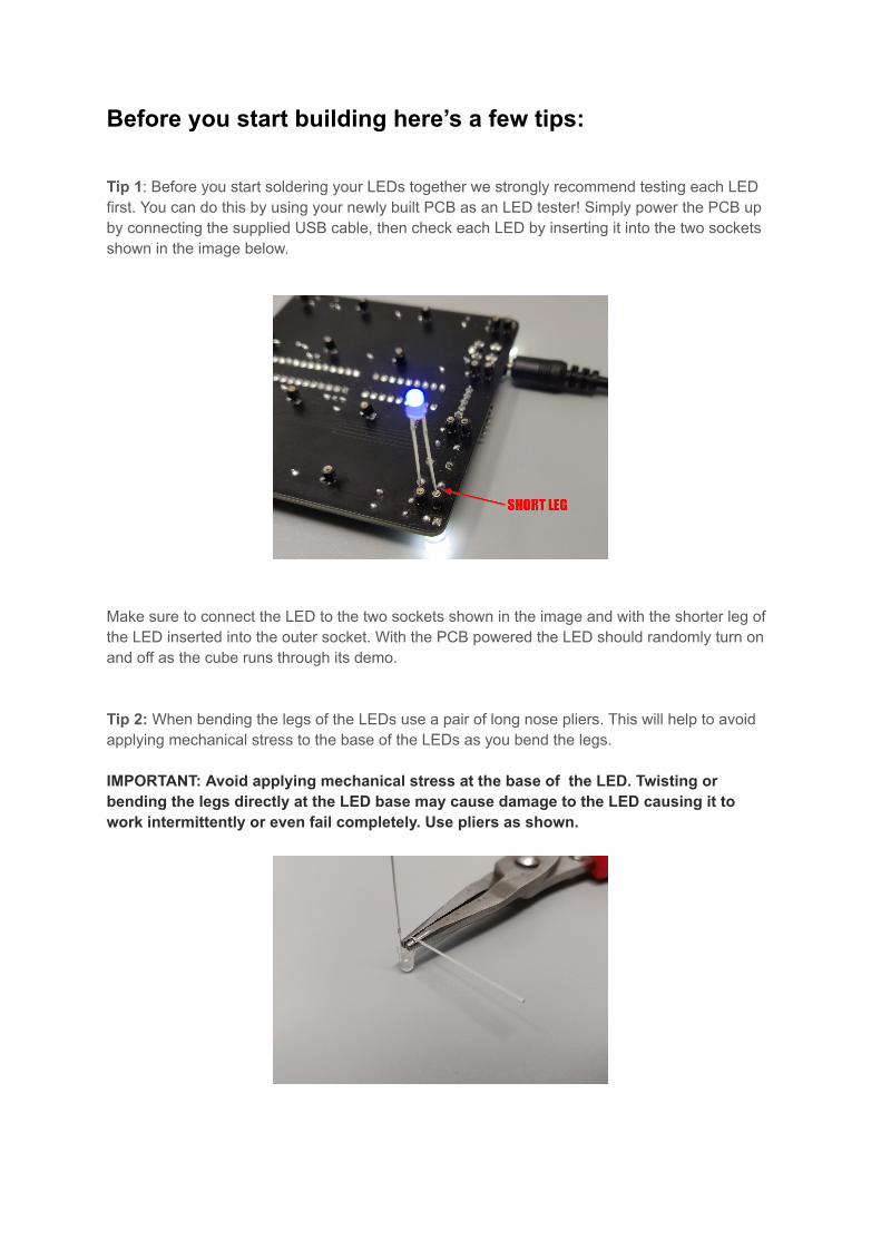
Tip 1 : Before you start soldering your LEDs together we strongly recommend testing each LED first. You can do this by using your newly built PCB as an LED tester! Simply power the PCB up by connecting the supplied USB cable, then check each LED by inserting it into the two sockets shown in the image below.
Make sure to connect the LED to the two sockets shown in the image and with the shorter leg of the LED inserted into the outer socket. With the PCB powered the LED should randomly turn on and off as the cube runs through its demo.
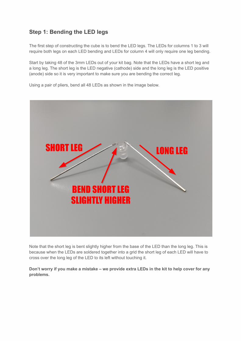
Tip 2: When bending the legs of the LEDs use a pair of long nose pliers. This will help to avoid applying mechanical stress to the base of the LEDs as you bend the legs.
IMPORTANT: Avoid applying mechanical stress at the base of the LED. Twisting or bending the legs directly at the LED base may cause damage to the LED causing it to work intermittently or even fail completely. Use pliers as shown.
Step 1: Bending the LED legs
The first step of constructing the cube is to bend the LED legs. The LEDs for columns 1 to 3 will require both legs on each LED bending and LEDs for column 4 will only require one leg bending.
Start by taking 48 of the 3mm LEDs out of your kit bag. Note that the LEDs have a short leg and a long leg. The short leg is the LED negative (cathode) side and the long leg is the LED positive (anode) side so it is very important to make sure you are bending the correct leg.
Using a pair of pliers, bend all 48 LEDs as shown in the image below.
Note that the short leg is bent slightly higher from the base of the LED than the long leg. This is because when the LEDs are soldered together into a grid the short leg of each LED will have to cross over the long leg of the LED to its left without touching it.
Don’t worry if you make a mistake – we provide extra LEDs in the kit to help cover for any problems.
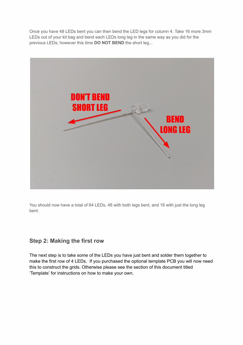
Once you have 48 LEDs bent you can then bend the LED legs for column 4. Take 16 more 3mm LEDs out of your kit bag and bend each LEDs long leg in the same way as you did for the previous LEDs; however this time DO NOT BEND the short leg...
You should now have a total of 64 LEDs, 48 with both legs bent, and 16 with just the long leg bent.
Step 2: Making the first row
The next step is to take some of the LEDs you have just bent and solder them together to make the first row of 4 LEDs. If you purchased the optional template PCB you will now need this to construct the grids. Otherwise please see the section of this document titled ‘Template’ for instructions on how to make your own.
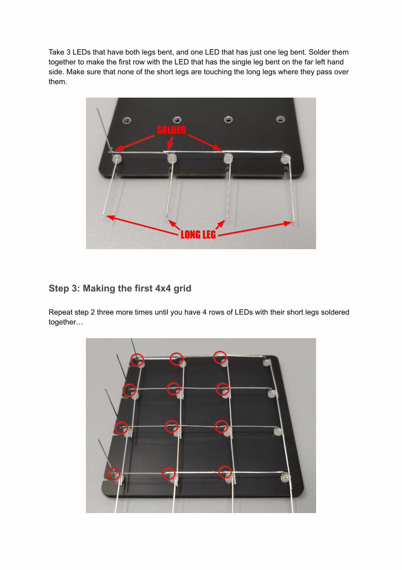
Take 3 LEDs that have both legs bent, and one LED that has just one leg bent. Solder them together to make the first row with the LED that has the single leg bent on the far left hand side. Make sure that none of the short legs are touching the long legs where they pass over them.
Step 3: Making the first 4x4 grid
Repeat step 2 three more times until you have 4 rows of LEDs with their short legs soldered together…
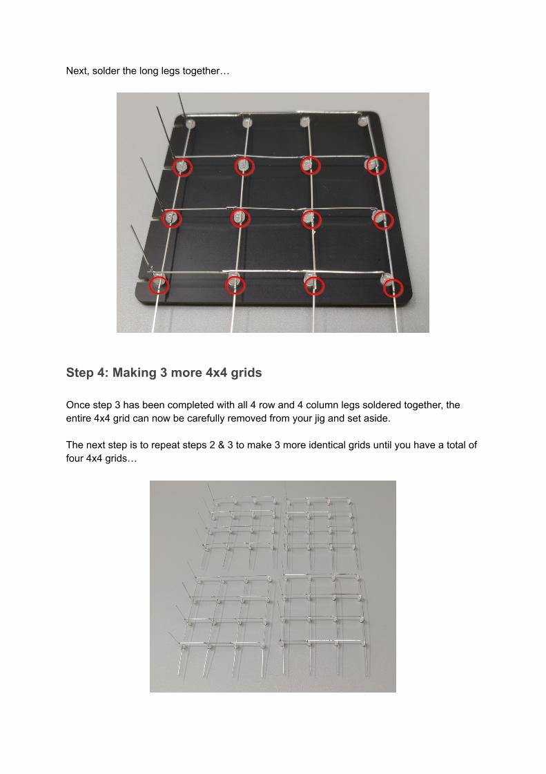
Next, solder the long legs together…
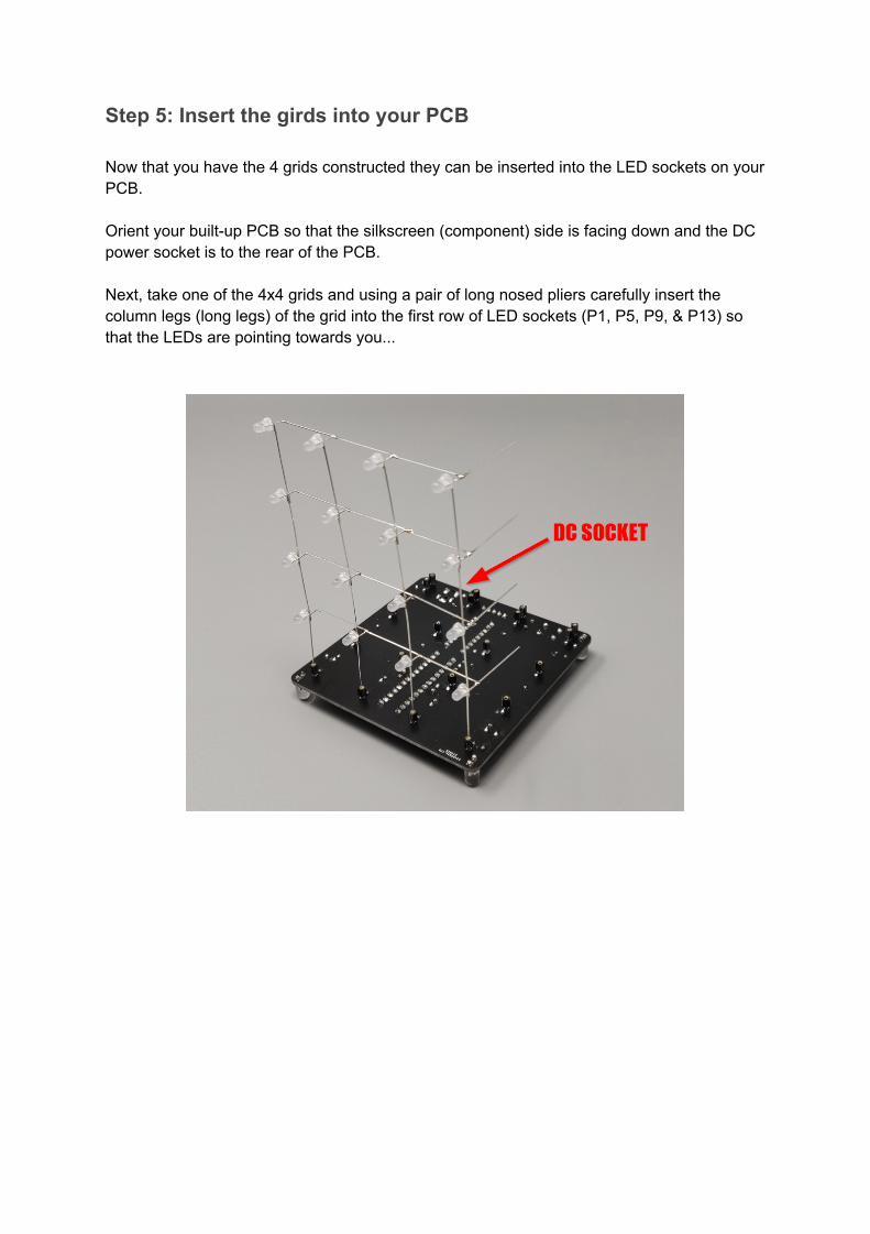
Step 4: Making 3 more 4x4 grids
Once step 3 has been completed with all 4 row and 4 column legs soldered together, the entire 4x4 grid can now be carefully removed from your jig and set aside.
The next step is to repeat steps 2 & 3 to make 3 more identical grids until you have a total of four 4x4 grids…
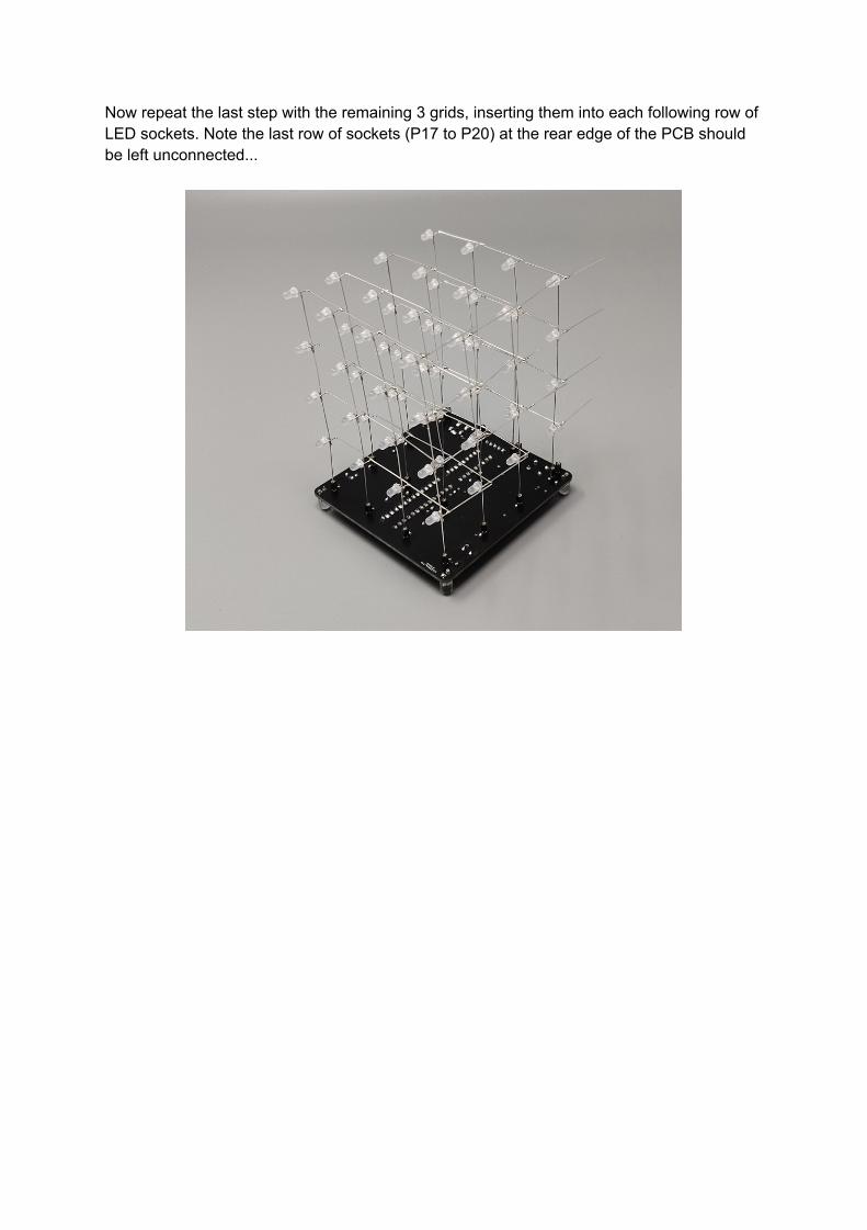
Step 5: Insert the girds into your PCB
Now that you have the 4 grids constructed they can be inserted into the LED sockets on your PCB.
Orient your built-up PCB so that the silkscreen (component) side is facing down and the DC power socket is to the rear of the PCB.
Next, take one of the 4x4 grids and using a pair of long nosed pliers carefully insert the column legs (long legs) of the grid into the first row of LED sockets (P1, P5, P9, & P13) so that the LEDs are pointing towards you...
Now repeat the last step with the remaining 3 grids, inserting them into each following row of LED sockets. Note the last row of sockets (P17 to P20) at the rear edge of the PCB should be left unconnected...
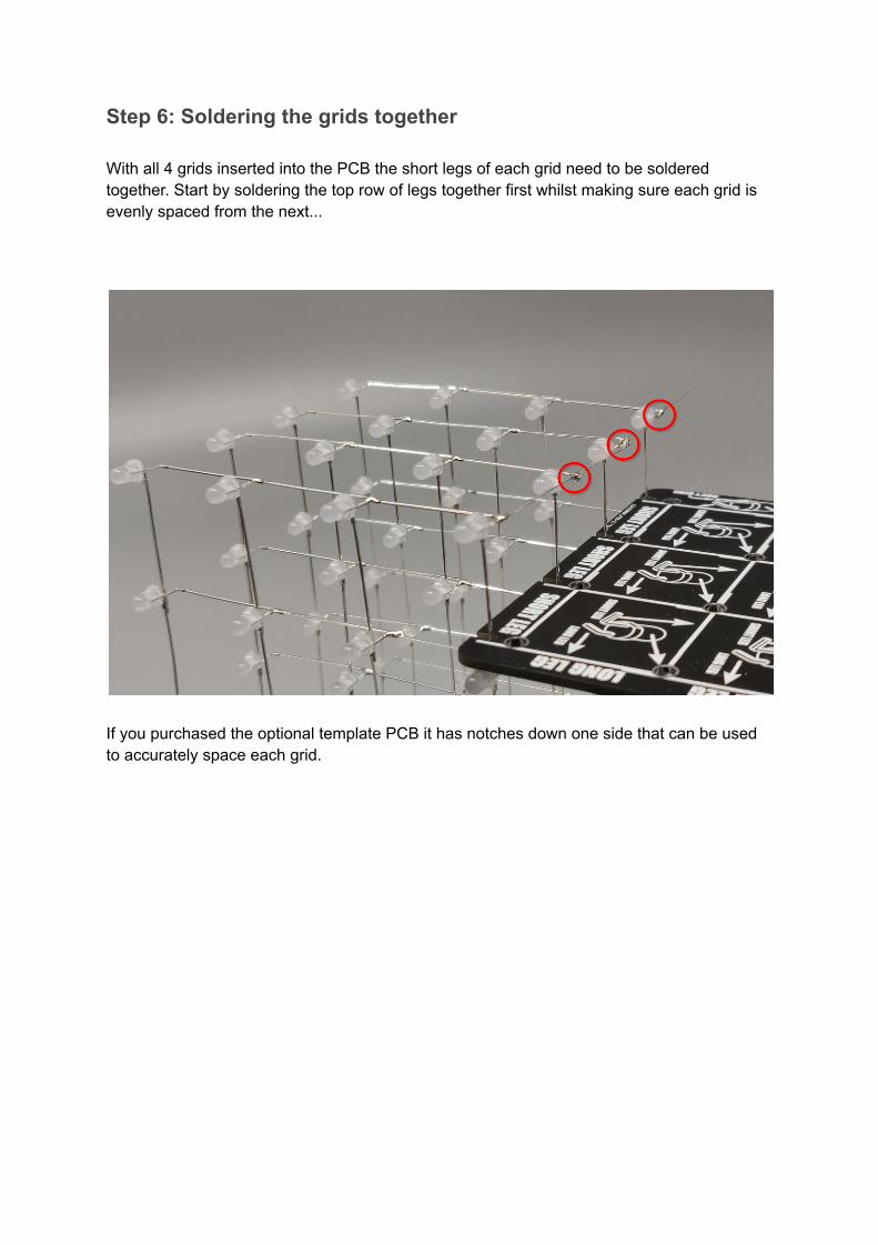
Step 6: Soldering the grids together
With all 4 grids inserted into the PCB the short legs of each grid need to be soldered together. Start by soldering the top row of legs together first whilst making sure each grid is evenly spaced from the next...
If you purchased the optional template PCB it has notches down one side that can be used to accurately space each grid.

Repeat this step for the other 3 rows of short legs…
The short legs on the rear 4x4 grid can be trimmed with a pair of snips/side cutters as they don’t need to be connected to anything.
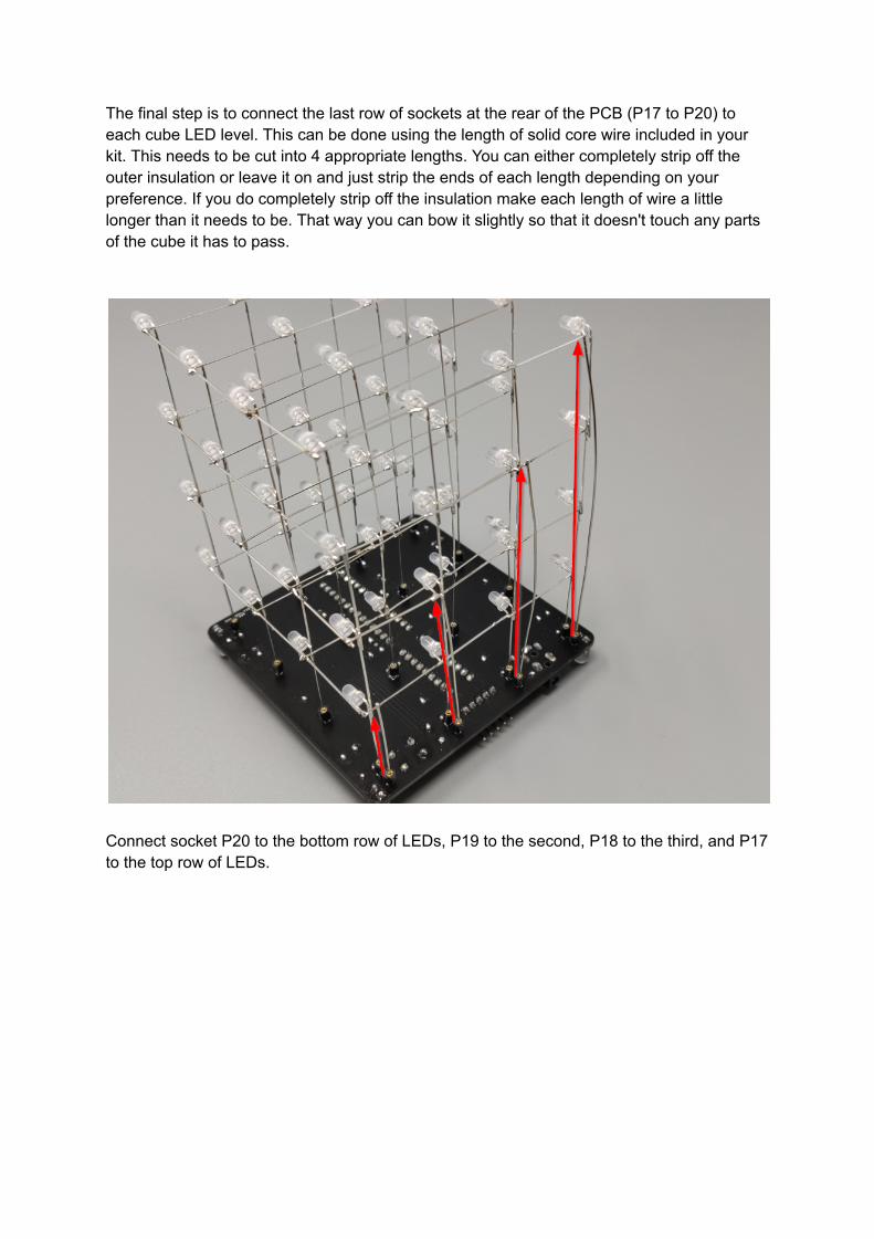
The final step is to connect the last row of sockets at the rear of the PCB (P17 to P20) to each cube LED level. This can be done using the length of solid core wire included in your kit. This needs to be cut into 4 appropriate lengths. You can either completely strip off the outer insulation or leave it on and just strip the ends of each length depending on your preference. If you do completely strip off the insulation make each length of wire a little longer than it needs to be. That way you can bow it slightly so that it doesn't touch any parts of the cube it has to pass.
Connect socket P20 to the bottom row of LEDs, P19 to the second, P18 to the third, and P17 to the top row of LEDs.

Step 7: Testing your cube
Your cube kit is now complete. Give the cube and PCB a final inspection for any shorts or unsoldered connections. If everything looks good you can now connect the USB cable to the DC power socket and a suitable USB 5V power supply. The cube doesn’t require much power so most types of standard USB supplies should work fine with it.
When powered up (or reset via the reset button) the pre-flashed demo program will first turn on all the LEDs for a few seconds. This is useful for checking that all the LEDs are working correctly. If not you can use the spare LEDs in your kit to replace them.
Step 8: Enjoy your cube!
Should you have any questions or problems whilst building your cube just post your question on our support forum via the link below - we’re happy to help..
https://forum.hobbycomponents.com/viewtopic.php?f=133&t=3009
Arduino users
One final note - for anyone familiar with programming Arduinos, your cube is also Arduino compatible! This means you can reprogram your cube with your own animations. To help you do this we have written an Arduino library that will provide an easy way to write your own sketches. You can find the library on our support forum here:
https://forum.hobbycomponents.com/viewtopic.php?f=58&t=3007
Note that to reprogram your cube via the Arduino IDE you will also need a 5V USB to serial adapter such as one of the following:
https://hobbycomponents.com/usb-interface/586-ch340-usb-to-ttl-serial-adaptor
https://hobbycomponents.com/usb-interface/41-ftdi-usb-serial-port-adapter