
Chapter 18: VRF, MPLS, and MPLS Layer 3 VPNs
43
Chapter 18: VRF, MPLS, and MPLS Layer 3 VPNs Instructor Materials CCNP Enterprise: Advanced Routing
-
Upload
khangminh22 -
Category
Documents
-
view
3 -
download
0
Transcript of Chapter 18: VRF, MPLS, and MPLS Layer 3 VPNs

Chapter 18: VRF, MPLS, and MPLS Layer 3 VPNs
Instructor Materials
CCNP Enterprise: Advanced Routing

2© 2016 Cisco and/or its affiliates. All rights reserved. Cisco Confidential
Chapter 18 Content
This chapter covers the following content:
• Implementing and Verifying VRF-Lite - This section introduces VRF and how to
configure and verify a VRF-Lite implementation.
• An Introduction to MPLS Operations - This section introduces MPLS and
explores the main MPLS topics, such as LSRs, LDP, LSP, and label switching.
• An Introduction to MPLS Layer 3 VPNs - This section introduces the concept of
MPLS Layer 3 VPNs.

3© 2016 Cisco and/or its affiliates. All rights reserved. Cisco Confidential
Implementing and Verifying VRF-Lite• VRF is a technology for creating separate virtual routers on a single physical router.
• VRF-Lite provides VRF without MPLS. Router interfaces, routing tables, and
forwarding tables are isolated on an instance-by-instance basis and therefore prevent
traffic from one VRF instance from interfering with another VRF instance.
• VRF is an essential component of the MPLS L3VPN architecture and provides
increased router functionality through segmentation in lieu of using multiple devices.
• This section introduces you to VRF and demonstrates how you can configure and
verify VRF-Lite in a Cisco network.

4© 2016 Cisco and/or its affiliates. All rights reserved. Cisco Confidential
Implementing and Verifying VRF-Lite
VRF-Lite Overview
• By default, all router interfaces, the
routing table, and any forwarding
tables are associated with the
global VRF instance.
• What you’ve been calling your
routing table is actually the routing
table of the global VRF instance.
• If you need to divide your router up
into multiple virtual routers, you
can do so by creating additional
VRF instances, which also creates
additional routing and forwarding
tables.
Consider this scenario: for security reasons, you need to build three different networks so that traffic
in each network is isolated from traffic in the other networks. However, you only want to build a
single physical network to accomplish this. You can do this by using VRF. Figure 18-1 shows a single
physical topology that is divided into three different logically isolated networks.

5© 2016 Cisco and/or its affiliates. All rights reserved. Cisco Confidential
Implementing and Verifying VRF-Lite
Creating and Verifying VRF Instances
Example 18-1 shows how the ip vrf
vrf-name command is used on each
of the routers to create the VRF
instances.
To verify that the VRF instances are
created, use the show ip vrf
command as shown in Example 18-
2 for R1. Notice that the Interfaces
column is empty. You need to
assign interfaces to each of the
VRF instances to separate and
isolate the traffic.

6© 2016 Cisco and/or its affiliates. All rights reserved. Cisco Confidential
Implementing and Verifying VRF-Lite
Creating and Verifying VRF Instances (Cont.)
To assign an interface to a VRF,
use the ip vrf forwarding vrf-name
command in interface configuration
mode, as shown in in Example 18-
3.
Using the show ip vrf command
again, you can verify that each
interface has been assigned to the
correct VRF instance, as shown in
Example 18-4.

7© 2016 Cisco and/or its affiliates. All rights reserved. Cisco Confidential
Implementing and Verifying VRF-Lite
Creating and Verifying VRF Instances (Cont.)
If a single physical interface
supports multiple VRF instances,
the physical interface needs to be
broken into subinterfaces.
Therefore, Gi3/0 needs to be
broken into subinterfaces.
Example 18-5 shows how to create
the subinterfaces and assign them
to the correct VRF instances. It also
shows the use of the show ip vrf
command to verify that the
interfaces are in the correct VRF
instances.

8© 2016 Cisco and/or its affiliates. All rights reserved. Cisco Confidential
Implementing and Verifying VRF-Lite
Creating and Verifying VRF Instances (Cont.)
Next, you can configure network
addressing on R1. Example 18-6
shows the IP addressing configuration
of each of the interfaces on R1, based
on Figure 18-1.
Notice that the subinterfaces must be
configured with dot1q encapsulation,
or you can’t assign an IP address to
the interface. Also, note that when you
configure R2’s subinterfaces
connecting to R1, they need to be
configured with the same VLAN
numbers.
You can use the show ip vrf interfaces command to verify the IP address assigned to the
interface, the VRF instance the interface is in, and whether the interface is up or down.
9© 2016 Cisco and/or its affiliates. All rights reserved. Cisco Confidential
Implementing and Verifying VRF-Lite
Creating and Verifying VRF Instances (Cont.)
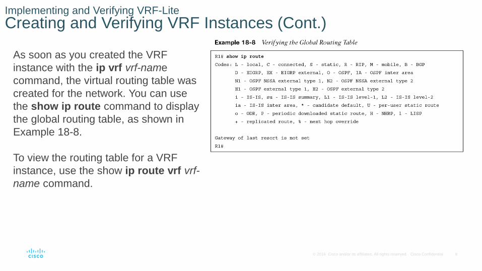
As soon as you created the VRF
instance with the ip vrf vrf-name
command, the virtual routing table was
created for the network. You can use
the show ip route command to display
the global routing table, as shown in
Example 18-8.
To view the routing table for a VRF
instance, use the show ip route vrf vrf-
name command.

10© 2016 Cisco and/or its affiliates. All rights reserved. Cisco Confidential
Implementing and Verifying VRF-Lite
Creating and Verifying VRF Instances (Cont.)
You can now configure R2. Example
18-10 shows the configuration required
on R2.

11© 2016 Cisco and/or its affiliates. All rights reserved. Cisco Confidential
Implementing and Verifying VRF-Lite
Creating and Verifying VRF Instances (Cont.)
Example 18-11 displays the output of the
show ip vrf interfaces command and the
show ip route vrf vrf_name commands to
verify that R2 has been configured correctly.

12© 2016 Cisco and/or its affiliates. All rights reserved. Cisco Confidential
Implementing and Verifying VRF-Lite
Creating and Verifying VRF Instances (Cont.)
Now you can configure R3. Example
18-12 shows the configuration required
on R3.

13© 2016 Cisco and/or its affiliates. All rights reserved. Cisco Confidential
Implementing and Verifying VRF-Lite
Creating and Verifying VRF Instances (Cont.)
Example 18-13 shows the output of the
show ip vrf interfaces command and
the show ip route vrf command to
verify that R3 has been configured
correctly.
Above is a partial image of Example 18-13

14© 2016 Cisco and/or its affiliates. All rights reserved. Cisco Confidential
Implementing and Verifying VRF-Lite
Creating and Verifying VRF Instances (Cont.)
To verify connectivity when using VRF
instances, you must specify the VRF instance
with the ping command. If you do not, the
global routing table is used instead of the VRF
routing table.
Example 18-14 shows a series of pings from
R1 to R2. The first ping, with a destination of
10.0.12.2, fails because the VRF instance was
not specified; therefore, the global routing table
is being used. The second ping specifies the
GREEN VRF but is using an IP address in the
RED VRF; therefore, the ping fails. The last
ping uses the correct VRF (RED) and an IP
address in the RED VRF (10.0.12.2); therefore,
the ping is successful. This is a great example
of how VRF instances provide isolation.

15© 2016 Cisco and/or its affiliates. All rights reserved. Cisco Confidential
Implementing and Verifying VRF-Lite
Creating and Verifying VRF Instances (Cont.)
Example 18-15 shows the output of
the RED VRF routing table. At this
point, you have only directly connected
and local routes. For all the routers to
learn about all the other networks, you
can use static or dynamic routing. The
following examples use EIGRP as the
dynamic routing protocol to provide full
connectivity for each of the VRF
instances.

16© 2016 Cisco and/or its affiliates. All rights reserved. Cisco Confidential
Implementing and Verifying VRF-Lite
Creating and Verifying VRF Instances (Cont.)
To configure EIGRP for multiple VRF
instances, you use EIGRP named
configuration mode because it permits you to
create multiple address families, as shown in
Example 18-16.
• Enter the EIGRP named configuration
mode by using the router eigrp name
command in global configuration mode.
• Next, create an address family for each of
the VRF instances. You accomplish this
with the address-family ipv4 vrf vrf-name
autonomous-system as-number
command.
• Then specify any EIGRP configuration
commands that are needed for your
scenario. In this case, you are enabling the
routing process on only certain interfaces.

17© 2016 Cisco and/or its affiliates. All rights reserved. Cisco Confidential
Implementing and Verifying VRF-Lite
Creating and Verifying VRF Instances (Cont.)
To verify that the interfaces are
participating in the EIGRP process
for the correct VRF instance, use
the show ip eigrp vrf vrf-name
interfaces command.

18© 2016 Cisco and/or its affiliates. All rights reserved. Cisco Confidential
Implementing and Verifying VRF-Lite
Creating and Verifying VRF Instances (Cont.)
When all the other routers have been
configured for EIGRP, you can verify
neighbor adjacencies by using the
show ip eigrp vrf vrf-name
neighbors command. As before,
because you are dealing with multiple
VRF instances, you will notice that
each show command in Example 18-
18 displays only the neighbors that
are within that VRF instance.
By using the ping vrf vrf-name ipv4-
address command, as shown in
Example 18-20, you can verify that
connectivity exists from R1 to R3.

19© 2016 Cisco and/or its affiliates. All rights reserved. Cisco Confidential
An Introduction to MPLS Operations• Multiprotocol Label Switching (MPLS) is a packet-forwarding method that makes
forwarding decisions based on labels instead of on the Layer 3 destination of the
packet.
• MPLS was designed to support many different Layer 3 protocols, but in this section we
focus on IP only.
• MPLS is not much faster than traditional IP routing.
• MPLS decreases forwarding overhead on core routers, making them more efficient.
• MPLS can forward other Layer 3 protocols besides IPv4, and MPLS supports multiple
services, such as unicast routing, multicast routing, VPNs, Traffic Engineering (TE),
QoS, and Any Transport Over MPLS (AToM). Therefore, MPLS is very efficient and
flexible.

20© 2016 Cisco and/or its affiliates. All rights reserved. Cisco Confidential
An Introduction to MPLS Operations
MPLS LIB and LFIB
In Figure 18-2, notice that the control plane of the
MPLS-enabled router is responsible for
exchanging labels with other MPLS-enabled
routers, using a label distribution protocol in
addition to exchanging routing information using
routing protocols to populate the IP routing table
(RIB).
After labels have been exchanged, the label
information is used to populate the LIB, and then
the best label information can be used to populate
the Forwarding Information Base (FIB) so
unlabeled packets can be labeled and the LFIB
labeled packets can be forwarded, or labels can
be removed when packets need to be forwarded
by the FIB.

21© 2016 Cisco and/or its affiliates. All rights reserved. Cisco Confidential
An Introduction to MPLS Operations
Label Switching Routers
Examine Figure 18-3. Routers R1 through R5 are part of the MPLS domain. They are known as label
switching routers (LSRs) because they support MPLS. They understand MPLS labels and can
receive and transmit labeled packets on their interfaces.
In this case, R1 and R5 are considered edge LSRs, and R2, R3, and R4 are considered intermediate
LSRs. An edge LSR sits at the edge of the MPLS domain and adds labels to packets that are
entering the MPLS domain (known as an ingress LSR), removes labels from packets that will be
leaving the MPLS domain (known as an egress LSR), and even forwards packets as needed based
on labels or the lack of a label. An intermediate LSR sits within the MPLS domain and primarily
forwards packets using label information.

22© 2016 Cisco and/or its affiliates. All rights reserved. Cisco Confidential
An Introduction to MPLS Operations
Label-Switched PathThe label-switched path (LSP) is the cumulative labeled path (sequence of routers) that a labeled packet
takes through the MPLS domain.
• It is a unidirectional path, as shown in Figure 18-4; therefore, in a complex network with multiple
potential paths between source and destination, it is possible that the LSP from source to destination
could be different from the LSP that is used for the return traffic.
• Typically the same path in reverse is used for the return traffic because of the underlying dynamic
routing protocols, such as OSPF and EIGRP, that are used to build the symmetrical network and its
forwarding paths.
• In this case, the LSP from R1 to 10.0.0.0/24 uses labels 87, 11, 65, and 23. Along the path, each
router examines the label to make a forwarding decision, removes the label, adds a new label if
required, and then forwards the packet.

23© 2016 Cisco and/or its affiliates. All rights reserved. Cisco Confidential
An Introduction to MPLS Operations
Labels
For MPLS to work, a label needs to be added to
the packet. The label is added as a shim header
between the Layer 2 frame header and the Layer 3
packet header. Figure 18-5 shows the placement of
the MPLS label shim header. The label is 4 bytes
(32 bits) in size and contains four different fields,
as shown in Figure 18-6.
MPLS-enabled routers automatically assign
labels to every network that they know about.
How does a router know about a network? It can
be locally configured by configuring an IP
address on a router interface and issuing the no
shutdown command on the interface, or
through the propagation of routing information
with dynamic routing protocols such as OSPF
and EIGRP.

24© 2016 Cisco and/or its affiliates. All rights reserved. Cisco Confidential
An Introduction to MPLS Operations
Label Distribution Protocol
• In order to build the LSP, labels need to be shared/distributed with directly connected
LSRs. This is done using a label distribution protocol such as Label Distribution Protocol
(LDP), which is the most common protocol in use when sharing/distributing labels for IPv4
prefixes.
• When MPLS has been enabled on an interface, LDP hello packets are sent out the
interface to the destination multicast address 224.0.0.2 (the all routers multicast address),
using UDP port 646. Any device on that same link that is also enabled for MPLS and that
receives the hello packet forms an LDP TCP session using port 646 with the neighboring
device so that label information can be exchanged.
• Within the hello packet is an LDP ID that is used to uniquely identify the neighbor and the
label space, which will either be per platform (same label used out all interfaces for a single
destination) or per interface (different label used out each interface for a single network).
• When establishing the LDP TCP session between two LSRs, one of the routers needs to
be the active router. The active router is responsible for setting up the TCP session. The
router with the higher LDP ID is selected as the active router and sets up the TCP session
between the two routers.

25© 2016 Cisco and/or its affiliates. All rights reserved. Cisco Confidential
An Introduction to MPLS Operations
Label Distribution Protocol (Cont.)
Figure 18-8 shows how R1 distributes its label of 19 for network 10.0.0.0/24 out all MPLS-
enabled interfaces. R2 distributes its label of 87 for network 10.0.0.0/24 out all MPLS-enabled
interfaces. R3 distributes its label of 11 for network 10.0.0.0/24 out all MPLS-enabled interfaces.
R4 distributes its label of 65 for network 10.0.0.0/24 out all MPLS-enabled interfaces. And R5
distributes its label of 23 for network 10.0.0.0/24 out all MPLS-enabled interfaces after the TCP
sessions have been established.

26© 2016 Cisco and/or its affiliates. All rights reserved. Cisco Confidential
An Introduction to MPLS Operations
Penultimate Hop Popping
Review Figure 18-9 and pay close attention to
R5. R5 must do two lookups when it receives
a labeled packet destined to 10.0.0.0/24. First,
it must look in the LFIB because it received a
labeled frame. In this case, there is no label
out. Therefore, it must remove the label and
make a forwarding decision based on a
second lookup, using the FIB to forward the
packet. This is not efficient. The solution to this
inefficiency is penultimate hop popping (PHP).
With PHP, R4 pops the label before sending
the packet to R5. IP address in network
10.0.0.0/24. In Figure 18-10, R5 has
advertised the label “pop” to R4, and R4 has
populated its LFIB accordingly.

27© 2016 Cisco and/or its affiliates. All rights reserved. Cisco Confidential
An Introduction to MPLS Layer 3 VPNs• MPLS Layer 3 VPNs provide peer-to-peer connectivity between private customer sites
across a shared network.
• The MPLS domain is referred to as the P-network, and the customer sites are referred
to as the C-network.
• This section explores how you can use MPLS Layer 3 VPNs to connect your private
networks over your provider’s public network.

28© 2016 Cisco and/or its affiliates. All rights reserved. Cisco Confidential
An Introduction to MPLS Layer 3 VPNs
MPLS Domain Connecting Customer Sites Together Example
Figure 18-11 shows a provider (such as an ISP) MPLS domain, with Customer A and
Customer B both using the same MPLS domain to connect their own private sites together.

29© 2016 Cisco and/or its affiliates. All rights reserved. Cisco Confidential
An Introduction to MPLS Layer 3 VPNs
MPLS Domain Connecting Customer Sites Together Example (Cont.)• The CE (customer edge) routers connect to the PE (provider edge) routers of the MPLS domain. The PE
routers, PE_R1 and PE_R5 in Figure 18-11, are the ingress and egress LSRs for the MPLS domain.
• The P (provider) routers, such as P_R2, P_R3, and P_R4 in Figure 18-11, are the intermediate LSRs of
the MPLS domain.
• The goal is to have Customer A Site 1 and Customer A Site 2 exchange their local routing information
over the MPLS domain and then forward traffic as needed from Site 1 and Site 2 over the MPLS domain.
The same would be true for Customer B Site 1 and Customer B Site 2.
• Due to the nature of the MPLS Layer 3 VPN, overlapping address spaces between customers is of no
concern. Therefore, Customer A and Customer B can be using the same private IP address space.

30© 2016 Cisco and/or its affiliates. All rights reserved. Cisco Confidential
An Introduction to MPLS Layer 3 VPNs
MPLS Domain Connecting Customer Sites Together Example (Cont.)• In order to support multiple customers, the PE routers need to use VRF instances, as shown in Figure
18-12, to isolate customer information and traffic from other customers.
• A different VRF instance needs to be created for each customer, and the interface that connects to
the customer’s CE router needs to be associated with the VRF.
• The CE router and the PE router exchange IPv4 routes using a routing protocol such as RIP (Routing
Information Protocol), EIGRP (Enhanced Interior Gateway Routing Protocol), OSPF (Open Shortest
Path First), or BGP (Border Gateway Protocol), and the routes are placed in the customer-specific
VRF table on the PE router.
• From the customer’s perspective, the PE router is simply another router in the customer’s network, but
it is under the control of the provider. However, note that all P routers are hidden from the customer.

31© 2016 Cisco and/or its affiliates. All rights reserved. Cisco Confidential
An Introduction to MPLS Layer 3 VPNs
MPLS Domain Connecting Customer Sites Together Example (Cont.)• After the PE routers learn routes from the CE routers, the PE routers redistribute the routes into
Multiprotocol-Interior Border Gateway Protocol (MP-BGP) so they can be exchanged with other PE routers.
• When another PE router receives the routes, they are redistributed into an IGP and placed in the correct
customer VRF instance so they can be exchanged with the CE router, as shown in Figure 18-13.
• The P routers are not participating in BGP. Only the PE routers are. They are forming an MP-IBGP neighbor
relationship with each other and exchanging the routes using the underlying network that is built with an
Interior Gateway Protocol (IGP) such as OSPF or Intermediate System-to-Intermediate System (IS-IS).
• The PE routers and the P routers are using a dynamic routing protocol to learn about all the destinations in
the P network, and only the PE routers are using MP-IBGP on top of that to exchange the customer routes.

32© 2016 Cisco and/or its affiliates. All rights reserved. Cisco Confidential
An Introduction to MPLS Layer 3 VPNs
MPLS Layer 3 VPNv4 Address
• If all customer routes are being redistributed into
MP-BGP, BGP handles identical network prefixes
that belong to different customers by using a route
distinguisher (RD) to expand the customer’s IP
prefix so that it includes a unique value that
distinguishes it from the other identical prefixes.
• The RD is generated and used by the PE routers
on a per-customer VRF instance basis. The RD is
used regardless of whether there are overlapping
address spaces.
• The unique 64-bit RD is prepended to the 32-bit
customer prefix (IPv4 route) to create a 96-bit
unique prefix called a VPNv4 address, as shown
in Figure 18-14. This VPNv4 address is
exchanged by the MP-IBGP neighboring routers.

33© 2016 Cisco and/or its affiliates. All rights reserved. Cisco Confidential
An Introduction to MPLS Layer 3 VPNs
PE Routers Exchanging VPNv4 Routes
The following steps occur:
Step 1. The CE router and PE router exchange routes using a dynamic routing protocol such as OSPF
or EIGRP.
Step 2. The PE router places the customer-specific routes in the customer-specific VRF table.
Step 3. The routes in the customer’s VRF table are redistributed into MP-BGP as VPNv4 routes.
Step 4. The PE routers exchange VPNv4 routes over their MP-IBGP peering.
Step 5. The PE router redistributes the VPNv4 routes as OSPF, EIGRP, and other types of routes into
the customer-specific VRF table.
Step 6. The PE router and CE router exchange routes using a dynamic routing protocol such as OSPF
or EIGRP.

34© 2016 Cisco and/or its affiliates. All rights reserved. Cisco Confidential
An Introduction to MPLS Layer 3 VPNs
MPLS Layer 3 VPN Label Stack
For the MPLS domain to forward traffic, a label stack is required. Specifically, two labels are
required for traffic to be successfully forwarded through the MPLS domain. The first label that
is attached to the packet is a VPN label, and the second label that is attached is the LDP label,
as shown in Figure 18-16.
• When the IP packet arrives at the ingress PE router, the PE router attaches both labels.
• The egress router uses the VPN label to determine customer specifics about the packet
and what should be done with it.
• The LDP label is used for label switching from PE to PE in the MPLS domain.
• VPN labels are learned from PE routers over the MP-IBGP peering, and the LDP labels are
learned using the methods we explored in the “An Introduction to MPLS Operations”
section of this chapter.

35© 2016 Cisco and/or its affiliates. All rights reserved. Cisco Confidential
An Introduction to MPLS Layer 3 VPNs
VPN Label Assignment
When PE_R5 learns of 10.0.2.0/24 from CE_RB, it places it in the Customer B VRF instance. It then
redistributes it into MP-BGP and thus creates a VPNv4 route of 1:110:10.0.2.0/24. This VPNv4 route needs a
VPN label created for it so that forwarding will be successful. In this case, PE_R5 assigns it the label 35.
This label is shared with PE_R1 over the MP-IBGP peering they have. Any time PE_R1 receives an IP
packet that is destined for 10.0.2.0/24, it knows to attach the label 35 so the packet can be forwarded.
However, this label is known only by the PE routers. Therefore, if PE_R1 forwards this VPN packet to P_R2,
it will be dropped because it has no idea what the VPN label 35 means. Therefore, the LDP label is needed
to forward the packet from PE_R1 and PE_R5.

36© 2016 Cisco and/or its affiliates. All rights reserved. Cisco Confidential
An Introduction to MPLS Layer 3 VPNs
Label Switched Path
Figure 18-18 shows how LDP is used to
exchange labels that have been
generated by the PE routers (ingress and
egress LSRs) and the P routers
(intermediate LSRs). PE_R5 tells P_R4
to pop the label. P_R4 tells P_R3 to use
the label 52. P_R3 tells P_R2 to use the
label 10. P_R2 tells PE_R1 to use the
label 99.
In Figure 18-19, the complete LSP is
now ready to label switch the VPN
packet from PE_R1 to PE_R5.

37© 2016 Cisco and/or its affiliates. All rights reserved. Cisco Confidential
An Introduction to MPLS Layer 3 VPNs
Label Switched Path (Cont.)When an IP packet destined to 10.0.2.0/24 arrives at PE_R1 from CE_RA, PE_R1 determines that the packet
needs a VPN label of 35. Now, PE_R5 will know what to do with the VPN packet and an LDP label of 99 so that
the VPN packet can be label switched through the MPLS domain. When the label stack is complete, PE_R1
sends the labelstacked packet to P_R2. When P_R2 receives it, it only examines the LDP label. Based on the
LFIB, it states that the label 99 needs to be swapped to 10 and forwarded to P_R3. When P_R3 receives it, it
only examines the LDP label. Based on the LFIB, it states that the label 10 needs to be swapped to 52 and
forwarded to P_R4. When P_R4 receives
it, it only examines the LDP label.
Based on the LFIB, it states that the label
52 needs to be popped and forwarded to
P_R5. Now PE_R5 only needs to read
the VPN label, which is 35. Based on the
scenario, the label is removed, and the
VRF instance for Customer B is used to
forward the IP packet to the CE_RB
router.

38© 2016 Cisco and/or its affiliates. All rights reserved. Cisco Confidential
Prepare for the Exam

39© 2016 Cisco and/or its affiliates. All rights reserved. Cisco Confidential
Prepare for the Exam
Key Topics for Chapter 18
Description
The purpose of VRF
Configuring VRF on R1 with the ip vrf command
Assigning interfaces to the VRF instances with the ip vrf
forwarding command
Creating subinterfaces on R1 and assigning them to the
correct VRF instances
Verifying the interface IP address, VRF, and protocol
configurations
Verifying the VRF routing tables

40© 2016 Cisco and/or its affiliates. All rights reserved. Cisco Confidential
Prepare for the Exam
Key Topics for Chapter 18 (Cont.)
Description
MPLS LIB and LFIB The benefit of PHP
Label switching routers MPLS Layer 3 VPNs
Label-switched path The Layer 3 VPNv4 address and
route distinguishers
Labels How routes are learned by CE
routers over an MPLS Layer 3 VPN
Label Distribution Protocol MPLS Layer 3 VPN label stack

41© 2016 Cisco and/or its affiliates. All rights reserved. Cisco Confidential
Prepare for the Exam
Key Terms for Chapter 18
Term
VRF intermediate LSR MPLS Layer 3 VPN
VRF-Lite egress LSR P-network
MPLS ingress LSR C-network
LIB LSP CE router
LFIB LDP PE router
RIB Label P router
FIB LDP label VPNv4 address
LSR VPN label label stack
edge LSR PHP

42© 2016 Cisco and/or its affiliates. All rights reserved. Cisco Confidential
Prepare for the Exam
Command Reference for Chapter 18
Task Command Syntax
Define a VRF instance and enter VRF configuration mode
for the instance (in global configuration mode)
ip vrf vrf-name
Associate an interface or a subinterface with a VRF instance
(in interface configuration mode)
ip vrf forwarding vrf-name
Display configured VRF instances and associated router
interfaces
show ip vrf
Display the routes in the global routing table show ip route
Display the routes in the routing table for the VRF specified
in the command
show ip route vrf vrf-name
Display all VRF-enabled interfaces on the router, including
their IP addresses and whether the protocol is up or down
show ip vrf interfaces
Test IP connectivity for a specific VRF ping vrf vrf-name ipv4-address