
Performance Evaluation of MPLS Path Restoration Schemes using OMNET
Upload
khangminh22Category
view
0download
0
© 2021 Nokia. Use subject to Terms available at: www.nokia.com
7450 ETHERNET SERVICE SWITCH7750 SERVICE ROUTER7950 EXTENSIBLE ROUTING SYSTEMVIRTUALIZED SERVICE ROUTER
MPLS GUIDE RELEASE 21.5.R1
3HE 17154 AAAB TQZZA 01
Issue: 01
May 2021
MPLS GUIDE RELEASE 21.5.R1

MPLS GUIDERELEASE 21.5.R1
2 © 2021 Nokia. Use subject to Terms available at: www.nokia.com
3HE 17154 AAAB TQZZA 01
Nokia is committed to diversity and inclusion. We are continuously reviewing our customer documentation and consulting with standards bodies to ensure that terminology is inclusive and aligned with the industry. Our future customer documentation will be updated accordingly.
This document includes Nokia proprietary and confidential information, which may not be distributed or disclosed to any third parties without the prior written consent of Nokia.
This document is intended for use by Nokia’s customers (“You”/”Your”) in connection with a product purchased or licensed from any company within Nokia Group of Companies. You agree to notify Nokia of any errors you may find in this document; however, should you elect to use this document for any purpose(s) for which it is not intended, You understand and warrant that any determinations You may make or actions You may take will be based upon Your independent judgment and analysis of the content of this document.
Nokia reserves the right to make changes to this document without notice. At all times, the controlling version is the one available on Nokia's site.
No part of this document may be modified.
NO WARRANTY OF ANY KIND, EITHER EXPRESS OR IMPLIED, INCLUDING BUT NOT LIMITED TO ANY WARRANTY OF AVAILABILITY, ACCURACY, RELIABILITY, TITLE, NON-INFRINGEMENT, MERCHANTABILITY OR FITNESS FOR A PARTICULAR PURPOSE, IS MADE IN RELATION TO THE CONTENT OF THIS DOCUMENT. IN NO EVENT WILL NOKIA BE LIABLE FOR ANY DAMAGES, INCLUDING BUT NOT LIMITED TO SPECIAL, DIRECT, INDIRECT, INCIDENTAL OR CONSEQUENTIAL OR ANY LOSSES, SUCH AS BUT NOT LIMITED TO LOSS OF PROFIT, REVENUE, BUSINESS INTERRUPTION, BUSINESS OPPORTUNITY OR DATA THAT MAY ARISE FROM THE USE OF THIS DOCUMENT OR THE INFORMATION IN IT, EVEN IN THE CASE OF ERRORS IN OR OMISSIONS FROM THIS DOCUMENT OR ITS CONTENT.
Copyright and trademark: Nokia is a registered trademark of Nokia Corporation. Other product names mentioned in this document may be trademarks of their respective owners.
© 2021 Nokia.

MPLS GUIDE RELEASE 21.5.R1
3HE 17154 AAAB TQZZA 01 © 2021 Nokia. Use subject to Terms available at: www.nokia.com
3
Table of Contents1 Getting Started..............................................................................131.1 About This Guide.......................................................................................131.2 Nokia Router Configuration Process .........................................................15
2 MPLS and RSVP............................................................................172.1 MPLS.........................................................................................................172.1.1 MPLS Label Stack .....................................................................................172.1.1.1 Label Values..............................................................................................192.1.1.2 Reserved Label Blocks..............................................................................202.1.2 MPLS Entropy Label and Hash Label .......................................................212.1.2.1 Hash Label ................................................................................................212.1.2.2 Entropy Label ............................................................................................222.1.2.3 Inserting and Processing the Entropy Label at LERs and LSRs ...............232.1.2.4 Mapping Entropy Label Capability at LSP Stitching Points .......................242.1.2.5 Entropy Label on OAM Packets ................................................................252.1.2.6 Impact of EL and ELI on MTU and Label Stack Depth .............................252.1.3 Label Switching Routers............................................................................262.1.3.1 LSP Types .................................................................................................262.1.4 Bidirectional Forwarding Detection for MPLS LSPs ..................................272.1.4.1 Bootstrapping and Maintaining the BFD Session ......................................282.1.4.2 LSP BFD Configuration .............................................................................292.1.4.3 Enabling and Implementing Limits for LSP BFD on a Node......................302.1.4.4 BFD Configuration on RSVP-TE LSPs......................................................302.1.4.5 Using LSP BFD for LSP Path Protection...................................................322.1.4.6 MPLS/RSVP on Broadcast Interface.........................................................392.1.5 MPLS Facility Bypass Method of MPLS Fast Re-Route (FRR).................392.1.6 Manual Bypass LSP ..................................................................................402.1.6.1 PLR Bypass LSP Selection Rules .............................................................402.1.6.2 FRR Facility Background Evaluation Task ...............................................422.1.7 Uniform FRR Failover Time ......................................................................442.1.8 Automatic Bandwidth Allocation for RSVP LSPs.......................................442.1.8.1 Enabling and Disabling Auto-Bandwidth Allocation on an LSP.................442.1.8.2 Autobandwidth on LSPs with Secondary or Secondary Standby
Paths .........................................................................................................452.1.8.3 Measurement of LSP Bandwidth ...............................................................482.1.8.4 Passive Monitoring of LSP Bandwidth.......................................................502.1.8.5 Periodic Automatic Bandwidth Adjustment................................................502.1.8.6 Overflow-Triggered Auto-Bandwidth Adjustment ......................................522.1.8.7 Manually-Triggered Auto-Bandwidth Adjustment ......................................532.1.8.8 Operational Bandwidth Carryover between Active Paths..........................532.1.9 LSP Failure Codes ....................................................................................542.1.10 Labeled Traffic Statistics ...........................................................................582.1.10.1 Interface Statistics .....................................................................................582.1.10.2 Traffic Statistics for Stacked Tunnels ........................................................592.1.10.3 Traffic Statistics Details and Scale ............................................................60

MPLS GUIDERELEASE 21.5.R1
4 © 2021 Nokia. Use subject to Terms available at: www.nokia.com
3HE 17154 AAAB TQZZA 01
2.1.10.4 RSVP-TE and MPLS-TP Traffic Statistics .................................................602.2 RSVP.........................................................................................................612.2.1 Using RSVP for MPLS...............................................................................632.2.1.1 RSVP Traffic Engineering Extensions for MPLS.......................................632.2.1.2 Hello Protocol ............................................................................................632.2.1.3 MD5 Authentication of RSVP Interface .....................................................642.2.1.4 Configuring Authentication using Keychains .............................................642.2.2 Reservation Styles.....................................................................................652.2.2.1 RSVP Message Pacing .............................................................................662.2.3 RSVP Overhead Refresh Reduction .........................................................662.2.4 RSVP Graceful Restart Helper ..................................................................672.2.5 Enhancements to RSVP Control Plane Congestion Control .....................682.2.6 BFD for RSVP-TE......................................................................................692.2.7 RSVP-TE LSP Statistics............................................................................702.2.8 P2MP RSVP-TE LSP Statistics .................................................................702.2.8.1 Configuring RSVP P2MP LSP Egress Statistics .......................................712.2.8.2 Configuring RSVP P2MP LSP Ingress Statistics.......................................722.2.8.3 Configuring Implicit Null.............................................................................742.2.9 Using Unnumbered Point-to-Point Interface in RSVP ...............................752.2.9.1 Operation of RSVP FRR Facility Backup over Unnumbered
Interface.....................................................................................................762.3 MPLS Transport Profile .............................................................................782.3.1 MPLS-TP Model ........................................................................................792.3.2 MPLS-TP Provider Edge and Gateway .....................................................802.3.2.1 VLL Services .............................................................................................802.3.2.2 Spoke SDP Termination ............................................................................812.3.3 MPLS-TP LSR...........................................................................................832.3.4 Detailed Descriptions of MPLS-TP............................................................832.3.4.1 MPLS-TP LSPs .........................................................................................832.3.4.2 MPLS-TP on Pseudowires ........................................................................842.3.5 MPLS-TP Maintenance Identifiers.............................................................842.3.5.1 Generic Associated Channel .....................................................................892.3.5.2 MPLS-TP Operations, Administration and Maintenance (OAM) ...............902.3.5.3 PW Control Channel Status Notifications (Static Pseudowire
Status Signaling) .......................................................................................942.3.5.4 PW Control Channel Status Request Mechanism.....................................962.3.5.5 Pseudowire Redundancy and Active / Standby Dual Homing...................962.3.5.6 Lock Instruct and Loopback for MPLS-TP Pseudowires ...........................972.3.5.7 MPLS-TP LSP Protection ..........................................................................982.3.6 Alarm Indication Signal (AIS)...................................................................1012.3.7 Configuring MPLS-TP .............................................................................1022.3.7.1 Configuration Overview ...........................................................................1022.3.7.2 Node-Wide MPLS-TP Parameter Configuration......................................1032.3.7.3 Node-Wide MPLS-TP Identifier Configuration.........................................1042.3.7.4 Static LSP and Pseudowire (VC) Label and Tunnel Ranges ..................1052.3.7.5 Interface Configuration for MPLS-TP ......................................................1062.3.7.6 LER Configuration for MPLS-TP .............................................................1082.3.7.7 Intermediate LSR Configuration for MPLS-TP LSPs...............................1152.3.8 MPLS-TP Show Commands....................................................................116

MPLS GUIDE RELEASE 21.5.R1
3HE 17154 AAAB TQZZA 01 © 2021 Nokia. Use subject to Terms available at: www.nokia.com
5
2.3.8.1 Static MPLS Labels .................................................................................1162.3.8.2 MPLS-TP Tunnel Configuration...............................................................1172.3.8.3 MPLS-TP Path configuration ..................................................................1182.3.8.4 MPLS-TP Protection................................................................................1212.3.8.5 MPLS TP Node Configuration .................................................................1222.3.8.6 MPLS-TP Interfaces ................................................................................1242.3.9 MPLS-TP Debug Commands .................................................................1242.4 Traffic Engineering ..................................................................................1272.4.1 TE Metric (IS-IS and OSPF) ....................................................................1272.4.2 Admin Group Support on Facility Bypass Backup LSP...........................1282.4.2.1 Procedures at Head-End Node ...............................................................1282.4.2.2 Procedures at PLR Node.........................................................................1292.4.3 Manual and Timer Resignal of RSVP-TE Bypass LSP ...........................1312.4.3.1 RSVP-TE Bypass LSP Path SRLG Information Update in Manual
and Timer Resignal MBB.........................................................................1332.4.3.2 RSVP-TE Bypass LSP Path Administrative Group Information
Update in Manual and Timer Resignal MBB ...........................................1362.4.4 RSVP-TE LSP Active Path Administrative Group Information
Update in Timer Resignal MBB ...............................................................1372.4.5 Diff-Serv Traffic Engineering ...................................................................1382.4.5.1 Mapping of Traffic to a Diff-Serv LSP......................................................1392.4.5.2 Admission Control of Classes..................................................................1392.4.5.3 RSVP Control Plane Extensions .............................................................1442.4.5.4 IGP Extensions........................................................................................1442.4.5.5 Diff-Serv TE Configuration and Operation...............................................1442.4.6 Diff-Serv TE LSP Class Type Change under Failure ..............................1482.4.6.1 LSP Primary Path Retry Procedures .......................................................1482.4.6.2 Bandwidth Sharing Across Class Types..................................................1512.4.6.3 Downgrading the CT of Bandwidth Sharing LSP Paths ..........................1522.4.6.4 Upgrading the CT of Bandwidth Sharing LSP Paths ...............................1532.5 Advanced MPLS/RSVP Features............................................................1542.5.1 Extending RSVP LSP to use Loopback Interfaces Other than
Router-id..................................................................................................1542.5.2 LSP Path Change....................................................................................1542.5.3 Manual LSP Path Switch .........................................................................1552.5.4 Make-Before-Break (MBB) Procedures for LSP/Path Parameter
Configuration Change..............................................................................1562.5.5 Automatic Creation of RSVP-TE LSP Mesh............................................1572.5.5.1 Automatic Creation of RSVP Mesh LSP: Configuration and
Behavior ..................................................................................................1582.5.5.2 Automatic Creation of RSVP One-Hop LSP: Configuration and
Behavior ..................................................................................................1622.5.6 IGP Shortcut and Forwarding Adjacency ................................................1642.5.6.1 IGP Shortcut Feature Configuration ........................................................1662.5.6.2 IPv4 IGP Shortcuts using SR-TE LSP Feature Configuration .................1692.5.6.3 SR Shortest Path Tunnel Over RSVP-TE IGP Shortcut Feature
Configuration ...........................................................................................1742.5.6.4 Using LSP Relative Metric with IGP Shortcut..........................................1772.5.6.5 ECMP Considerations .............................................................................178

MPLS GUIDERELEASE 21.5.R1
6 © 2021 Nokia. Use subject to Terms available at: www.nokia.com
3HE 17154 AAAB TQZZA 01
2.5.6.6 Handling of Control Packets ....................................................................1792.5.6.7 Forwarding Adjacency .............................................................................1792.5.6.8 SR Shortest Path Tunnel Over RSVP-TE Forwarding Adjacency...........1812.5.6.9 LDP Forwarding over IGP Shortcut .........................................................1812.5.6.10 LDP Forwarding over Static Route Shortcut Tunnels..............................1822.5.6.11 Handling of Multicast Packets .................................................................1822.5.6.12 MPLS Entropy Label on Shortcut Tunnels ..............................................1832.5.7 Disabling TTL Propagation in an LSP Shortcut .......................................1832.5.8 RSVP-TE LSP Signaling using LSP Template ........................................1842.5.9 Shared Risk Link Groups.........................................................................1852.5.9.1 Enabling Disjoint Backup Paths...............................................................1852.5.9.2 SRLG Penalty Weights for Detour and Bypass LSPs .............................1872.5.9.3 Static Configurations of SRLG Memberships ..........................................1892.5.10 TE Graceful Shutdown ............................................................................1912.5.11 Soft Preemption of Diff-Serv RSVP LSP .................................................1912.5.12 Least-Fill Bandwidth Rule in CSPF ECMP Selection ..............................1912.5.13 Inter-Area TE LSP (ERO Expansion Method) .........................................1922.5.13.1 Area Border Node FRR Protection for Inter-Area LSP............................1922.5.13.2 Inter-Area LSP support of OSPF Virtual Links ........................................1962.5.13.3 Area Border Node FRR Protection for Inter-Area LSP............................1962.5.14 Timer-based Reversion for RSVP-TE LSPs............................................1982.5.15 LSP Tagging and Auto-Bind Using Tag Information ...............................1992.5.15.1 Internal Route Color to LSP Color Matching Algorithm ...........................2012.5.15.2 LSP Admin Tag use in Tunnel Selection for VPRN and E-VPN
Auto-Bind.................................................................................................2012.5.15.3 LSP Admin Tag Use for BGP Next Hop or BGP Prefix for Labeled
and Unlabeled Unicast Routes ................................................................2022.5.16 LSP Self-Ping ..........................................................................................2032.5.16.1 Detailed Behavior of LSP Self-Ping.........................................................2042.5.16.2 Considerations for Scaled Scenarios ......................................................2062.5.17 Accounting for Dark Bandwidth ...............................................................2062.6 Point-to-Multipoint (P2MP) RSVP LSP....................................................2082.6.1 Application in Video Broadcast................................................................2082.6.2 P2MP LSP Data Plane ............................................................................2092.6.2.1 Procedures at Ingress LER Node............................................................2092.6.2.2 Procedures at LSR Node.........................................................................2102.6.2.3 Procedures at Branch LSR Node ............................................................2102.6.2.4 Procedures at Egress LER Node ............................................................2102.6.2.5 Procedures at BUD LSR Node................................................................2112.6.3 Ingress Path Management for P2MP LSP Packets.................................2112.6.3.1 Ingress P2MP Path Management on XCM/IOM/IMMs ...........................2132.6.4 RSVP Control Plane in a P2MP LSP.......................................................2142.6.5 Forwarding Multicast Packets over RSVP P2MP LSP in the Base
Router......................................................................................................2172.6.5.1 Procedures at Ingress LER Node............................................................2172.6.5.2 Procedures at Egress LER Node ............................................................2182.7 MPLS Service Usage ..............................................................................2212.7.1 Service Distribution Paths .......................................................................2212.8 MPLS/RSVP Configuration Process Overview........................................222

MPLS GUIDE RELEASE 21.5.R1
3HE 17154 AAAB TQZZA 01 © 2021 Nokia. Use subject to Terms available at: www.nokia.com
7
2.9 Configuration Notes.................................................................................2232.10 Configuring MPLS and RSVP with CLI....................................................2252.10.1 MPLS Configuration Overview ................................................................2252.10.1.1 LSPs........................................................................................................2252.10.1.2 Paths .......................................................................................................2252.10.1.3 Router Interface.......................................................................................2262.10.1.4 Choosing the Signaling Protocol .............................................................2262.10.2 Basic MPLS Configuration.......................................................................2262.10.3 Common Configuration Tasks .................................................................2272.10.4 Configuring MPLS Components ..............................................................2282.10.4.1 Configuring Global MPLS Parameters ....................................................2282.10.4.2 Configuring an MPLS Interface ...............................................................2292.10.4.3 Configuring MPLS Paths .........................................................................2292.10.4.4 Configuring an MPLS LSP.......................................................................2302.10.4.5 Configuring a Static LSP .........................................................................2312.10.4.6 Configuring Manual Bypass Tunnels.......................................................2312.10.4.7 Configuring RSVP Parameters................................................................2332.10.4.8 Configure RSVP Message Pacing Parameters .......................................2332.10.4.9 Configuring Graceful Shutdown...............................................................2342.11 MPLS Configuration Management Tasks................................................2352.11.1 Deleting MPLS.........................................................................................2352.11.2 Modifying MPLS Parameters...................................................................2352.11.3 Modifying an MPLS LSP..........................................................................2352.11.4 Modifying MPLS Path Parameters ..........................................................2362.11.5 Modifying MPLS Static LSP Parameters .................................................2362.11.6 Deleting an MPLS Interface.....................................................................2372.12 RSVP Configuration Management Tasks................................................2382.12.1 Modifying RSVP Parameters...................................................................2382.12.2 Modifying RSVP Message Pacing Parameters .......................................2382.12.3 Deleting an Interface from RSVP ............................................................239
3 GMPLS .........................................................................................2413.1 GMPLS....................................................................................................2413.1.1 Example Applications ..............................................................................2413.1.1.1 Use Case 1: Dynamic Connection Setup with Constraints......................2423.1.1.2 Use Case 2: Multi-Layer Resiliency.........................................................2433.2 GMPLS UNI Architecture.........................................................................2453.2.1 Addressing and End-to-End gLSP Architecture ......................................2463.3 1830 PSS Identifiers................................................................................2483.4 Recovery Reference Models ...................................................................2493.4.1 End to End Recovery (IP-layer)...............................................................2503.4.2 End to End ECMP ...................................................................................2503.4.3 End to End Load Sharing Using a Load Sharing GMPLS Tunnel
Group.......................................................................................................2513.4.4 End to End Recovery (GMPLS Layer).....................................................2523.4.4.1 Unprotected gLSP ...................................................................................2523.4.4.2 Full LSP Rerouting ..................................................................................2533.4.4.3 1: N Protection.........................................................................................2543.4.4.4 Optical Segment Recovery......................................................................256

MPLS GUIDERELEASE 21.5.R1
8 © 2021 Nokia. Use subject to Terms available at: www.nokia.com
3HE 17154 AAAB TQZZA 01
3.5 GMPLS Configuration Overview..............................................................2593.6 LMP and IPCC Configuration ..................................................................2603.6.1 Configuration of IP Communication Channels for LMP and RSVP .........2603.6.2 Configuring LMP......................................................................................2623.6.3 Configuring Traffic Engineering Links and Data Bearers ........................2643.7 Configuring MPLS Paths for GMPLS ......................................................2673.8 Configuring RSVP in GMPLS..................................................................2693.9 Configuring a GMPLS LSP on the UNI....................................................2713.9.1 gLSP Constraints.....................................................................................2733.10 Bandwidth................................................................................................2743.11 Shared Risk Link Groups.........................................................................2753.12 Optical Network Segment Recovery........................................................2773.13 Configuration of End-to-End GMPLS Recovery ......................................2783.14 GMPLS Tunnel Groups ...........................................................................2813.15 Configuring IP and MPLS in an Overlay Network to Use a GMPLS
LSP..........................................................................................................2843.16 Configuration Notes.................................................................................285
4 Label Distribution Protocol .......................................................2874.1 Label Distribution Protocol.......................................................................2874.1.1 LDP and MPLS........................................................................................2874.1.2 LDP Architecture .....................................................................................2884.1.3 Subsystem Interrelationships ..................................................................2894.1.3.1 Memory Manager and LDP .....................................................................2904.1.3.2 Label Manager.........................................................................................2904.1.3.3 LDP Configuration ...................................................................................2904.1.3.4 Logger .....................................................................................................2904.1.3.5 Service Manager .....................................................................................2914.1.4 Execution Flow ........................................................................................2914.1.4.1 Initialization..............................................................................................2914.1.4.2 Session Lifetime ......................................................................................2914.1.5 Label Exchange ......................................................................................2934.1.5.1 Other Reasons for Label Actions.............................................................2934.1.5.2 Cleanup ...................................................................................................2934.1.5.3 Configuring Implicit Null Label .................................................................2934.1.6 Global LDP Filters ...................................................................................2944.1.6.1 Per LDP Peer FEC Import and Export Policies .......................................2954.1.7 Configuring Multiple LDP LSR ID ............................................................2954.1.7.1 Advertisement of FEC for Local LSR ID ..................................................2964.1.8 Extend LDP policies to mLDP .................................................................2964.1.8.1 Recursive FEC behavior .........................................................................2974.1.8.2 Import Policy............................................................................................2974.1.9 LDP FEC Resolution Per Specified Community......................................2984.1.9.1 Configuration ...........................................................................................2994.1.9.2 Operation.................................................................................................2994.1.10 T-LDP hello reduction..............................................................................3014.1.11 Tracking a T-LDP Peer with BFD ............................................................3024.1.12 Link LDP Hello Adjacency Tracking with BFD.........................................3034.1.13 LDP LSP Statistics ..................................................................................303

MPLS GUIDE RELEASE 21.5.R1
3HE 17154 AAAB TQZZA 01 © 2021 Nokia. Use subject to Terms available at: www.nokia.com
9
4.1.14 MPLS Entropy Label................................................................................3044.1.15 Importing LDP Tunnels to Non-Host Prefixes to TTM .............................3044.2 TTL Security for BGP and LDP ...............................................................3054.3 ECMP Support for LDP ...........................................................................3064.3.1 Label Operations .....................................................................................3064.3.2 Weighted ECMP Support for LDP ...........................................................3074.4 Unnumbered Interface Support in LDP ...................................................3094.4.1 Feature Configuration..............................................................................3094.4.2 Operation of LDP over an Unnumbered IP Interface...............................3094.4.2.1 Link LDP..................................................................................................3104.4.2.2 Targeted LDP ..........................................................................................3114.4.2.3 FEC Resolution .......................................................................................3114.5 LDP over RSVP Tunnels .........................................................................3124.5.1 Signaling and Operation ..........................................................................3144.5.1.1 LDP Label Distribution and FEC Resolution............................................3144.5.1.2 Default FEC Resolution Procedure .........................................................3144.5.1.3 FEC Resolution Procedure When prefer-tunnel-in-tunnel is
Enabled ...................................................................................................3154.5.2 Rerouting Around Failures.......................................................................3154.5.2.1 LDP-over-RSVP Tunnel Protection .........................................................3154.5.2.2 ABR Protection ........................................................................................3164.6 LDP over RSVP Without Area Boundary.................................................3174.6.1 LDP over RSVP and ECMP ....................................................................3184.7 Weighted Load Balancing for LDP over RSVP........................................3194.7.1 Interaction with Class-Based Forwarding ...............................................3204.8 Class-based Forwarding of LDP Prefix Packets over IGP
Shortcuts ................................................................................................3224.8.1 Configuration and Operation ...................................................................3224.8.1.1 LSR and/or LER Roles with FC-to-Set Configuration .............................3234.9 LDP ECMP Uniform Failover...................................................................3264.10 LDP Fast-Reroute for IS-IS and OSPF Prefixes......................................3284.10.1 LDP FRR Configuration...........................................................................3284.10.1.1 Reducing the Scope of the LFA Calculation by SPF...............................3294.10.2 LDP FRR Procedures..............................................................................3304.10.2.1 ECMP Considerations .............................................................................3314.10.2.2 LDP FRR and LDP Shortcut....................................................................3314.10.2.3 LDP FRR and LDP-over-RSVP...............................................................3314.10.2.4 LDP FRR and RSVP Shortcut (IGP Shortcut) .........................................3324.10.3 IS-IS and OSPF Support for Loop-Free Alternate Calculation ................3324.10.3.1 Loop-Free Alternate Calculation in the Presence of IGP shortcuts .........3364.10.3.2 Loop-Free Alternate Calculation for Inter-Area/inter-Level Prefixes........3374.10.3.3 Loop-Free Alternate Shortest Path First (LFA SPF) Policies ..................3374.11 LDP FEC to BGP Label Route Stitching..................................................3384.11.1 Configuration ...........................................................................................3394.11.2 Detailed LDP FEC Resolution .................................................................3404.11.3 Detailed BGP Labeled Route Resolution ................................................3414.11.4 Data Plane Forwarding............................................................................3414.12 LDP-SR Stitching for IPv4 prefixes .........................................................3424.12.1 LDP-SR Stitching Configuration ..............................................................342

MPLS GUIDERELEASE 21.5.R1
10 © 2021 Nokia. Use subject to Terms available at: www.nokia.com
3HE 17154 AAAB TQZZA 01
4.12.2 Stitching in the LDP-to-SR Direction .......................................................3444.12.3 Stitching in the SR-to-LDP Direction .......................................................3454.13 LDP FRR LFA Backup using SR Tunnel for IPv4 Prefixes......................3484.14 LDP Remote LFA ....................................................................................3504.15 Automatic LDP rLFA................................................................................3514.16 Automatic Creation of a Targeted Hello Adjacency and LDP
Session....................................................................................................3554.16.1 Feature Configuration..............................................................................3554.16.2 Feature Behavior .....................................................................................3564.17 Multicast P2MP LDP for GRT..................................................................3604.18 LDP P2MP Support .................................................................................3614.18.1 LDP P2MP Configuration ........................................................................3614.18.2 LDP P2MP Protocol.................................................................................3614.18.3 Make Before Break (MBB).......................................................................3614.18.4 ECMP Support.........................................................................................3614.18.5 Inter-AS Non-segmented mLDP..............................................................3624.18.5.1 In-band Signaling with Non-segmented mLDP Trees in GRT .................3624.18.5.2 LDP Recursive FEC Process ..................................................................3634.18.5.3 Supported Recursive Opaque Values .....................................................3664.18.5.4 Optimized Option C and Basic FEC Generation for Inter-AS..................3674.18.5.5 Basic Opaque Generation When Root PE is Resolved Using BGP........3674.18.5.6 Redundancy and Resiliency ....................................................................3714.18.5.7 ASBR Physical Connection .....................................................................3724.18.5.8 OAM ........................................................................................................3724.18.5.9 ECMP Support.........................................................................................3744.18.5.10 Dynamic mLDP and Static mLDP Co-existing on the Same Node..........3764.18.6 Intra-AS Non-segmented mLDP .............................................................3774.18.6.1 ABR MoFRR for Intra-AS ........................................................................3784.18.6.2 Interaction with an Inter-AS Non-segmented mLDP Solution..................3784.18.6.3 Intra-AS/Inter-AS Option B ......................................................................3784.18.7 ASBR MoFRR .........................................................................................3794.18.7.1 IGP MoFRR Versus BGP (ASBR) MoFRR..............................................3794.18.7.2 ASBR MoFRR Leaf Behavior ..................................................................3834.18.7.3 ASBR MoFRR ASBR Behavior ...............................................................3834.18.7.4 MoFRR Root AS Behavior.......................................................................3844.18.7.5 Traffic Flow..............................................................................................3854.18.7.6 Failure Detection and Handling ...............................................................3854.18.7.7 Failure Scenario ......................................................................................3864.18.7.8 ASBR MoFRR Consideration ..................................................................3874.18.7.9 ASBR MoFRR Opaque Support ..............................................................3884.18.8 MBB for MoFRR ......................................................................................3884.18.9 Add-path for Route Reflectors .................................................................3894.19 Multicast LDP Fast Upstream Switchover ...............................................3904.19.1 Feature Configuration..............................................................................3904.19.2 Feature Behavior .....................................................................................3914.19.3 Uniform Failover from Primary to Backup ILM.........................................3934.20 Multi-Area and Multi-Instance Extensions to LDP ..................................3954.20.1 LDP Shortcut for BGP Next-Hop Resolution ...........................................3954.20.2 LDP Shortcut for IGP Routes ..................................................................396

MPLS GUIDE RELEASE 21.5.R1
3HE 17154 AAAB TQZZA 01 © 2021 Nokia. Use subject to Terms available at: www.nokia.com
11
4.20.2.1 LDP Shortcut Configuration.....................................................................3964.20.2.2 IGP Route Resolution..............................................................................3974.20.2.3 LDP Shortcut Forwarding Plane ..............................................................3984.20.3 ECMP Considerations .............................................................................3984.20.4 Disabling TTL Propagation in an LSP Shortcut .......................................3984.21 LDP Graceful Handling of Resource Exhaustion.....................................4004.21.1 LDP Base Graceful Handling of Resources ............................................4004.22 LDP Enhanced Graceful Handling of Resources ....................................4024.22.1 LSR Overload Notification .......................................................................4024.22.2 LSR Overload Protection Capability ........................................................4034.22.3 Procedures for LSR overload protection .................................................4044.23 LDP-IGP Synchronization........................................................................4064.24 MLDP Resolution using Multicast RTM...................................................4094.24.1 Other Considerations for Multicast RTM MLDP Resolution ....................4104.25 Bidirectional Forwarding Detection for LDP LSPs ...................................4114.25.1 Bootstrapping and Maintaining LSP BFD Sessions ................................4114.25.2 BFD Configuration on LDP LSPs ............................................................4134.26 User Guidelines and Troubleshooting Procedures..................................4164.26.1 Common Procedures...............................................................................4164.26.2 Base Resource Handling Procedures .....................................................4164.26.3 Enhanced Resource Handling Procedures .............................................4204.27 LDP IPv6 Control and Data Planes .........................................................4244.27.1 LDP Operation in an IPv6 Network..........................................................4244.27.2 Link LDP..................................................................................................4254.27.3 Targeted LDP ..........................................................................................4254.27.4 FEC Resolution .......................................................................................4264.27.5 LDP Session Capabilities ........................................................................4274.27.6 LDP Adjacency Capabilities ....................................................................4284.27.7 Address and FEC Distribution .................................................................4304.27.8 Controlling IPv6 FEC Distribution During an Upgrade to SR OS
Supporting LDP IPv6...............................................................................4334.27.9 Handling of Duplicate Link-Local IPv6 Addresses in FEC
Resolution................................................................................................4344.27.10 IGP and Static Route Synchronization with LDP.....................................4364.27.11 BFD Operation.........................................................................................4364.27.12 Services Using SDP with an LDP IPv6 FEC ...........................................4374.27.13 Mirror Services and Lawful Intercept .......................................................4384.27.13.1 Configuration at mirror source node ........................................................4384.27.13.2 Configuration at mirror destination node .................................................4384.27.14 Static Route Resolution to a LDP IPv6 FEC............................................4394.27.15 IGP Route Resolution to a LDP IPv6 FEC ..............................................4404.27.16 OAM Support with LDP IPv6 ...................................................................4404.27.17 LDP IPv6 Interoperability Considerations................................................4414.27.17.1 Interoperability with Implementations Compliant with RFC 7552 ............4414.27.17.2 LDP IPv6 32-bit LSR-ID...........................................................................4424.27.17.3 Interoperability with Implementations Compliant with RFC 5036 for
IPv4 LDP Control Plane Only .................................................................4494.28 LDP Process Overview............................................................................4504.29 Configuring LDP with CLI ........................................................................451

MPLS GUIDERELEASE 21.5.R1
12 © 2021 Nokia. Use subject to Terms available at: www.nokia.com
3HE 17154 AAAB TQZZA 01
4.29.1 LDP Configuration Overview ...................................................................4514.29.2 Basic LDP Configuration .........................................................................4514.29.3 Common Configuration Tasks .................................................................4514.29.3.1 Enabling LDP...........................................................................................4524.29.3.2 Configuring FEC Originate Parameters...................................................4524.29.3.3 Configuring Graceful-Restart Helper Parameters....................................4534.29.3.4 Applying Export and Import Policies........................................................4544.29.3.5 Targeted Session Parameters.................................................................4554.29.3.6 Interface Parameters ...............................................................................4554.29.3.7 Session Parameters ................................................................................4564.29.3.8 LDP Signaling and Services ....................................................................4574.30 LDP Configuration Management Tasks...................................................4614.30.1 Disabling LDP..........................................................................................4614.30.2 Modifying Targeted Session Parameters ................................................4614.30.3 Modifying Interface Parameters ..............................................................462
5 Standards and Protocol Support ..............................................463

MPLS GUIDE RELEASE 21.5.R1
Getting Started
3HE 17154 AAAB TQZZA 01 © 2021 Nokia. Use subject to Terms available at: www.nokia.com
13
1 Getting Started
1.1 About This Guide
This guide describes the services and protocol support provided by the router and presents examples to configure and implement MPLS, RSVP, and LDP protocols.
This guide is organized into functional chapters and provides concepts and descriptions of the implementation flow, as well as Command Line Interface (CLI) syntax and command usage.
The topics and commands described in this document apply to the:
• 7450 ESS• 7750 SR• 7950 XRS• VSR
Table 1 lists the available chassis types for each SR OS router.
For a list of unsupported features by platform and chassis, refer to the SR OS 21.x.Rx Software Release Notes, part number 3HE 17177 000x TQZZA.
Command outputs shown in this guide are examples only; actual displays may differ depending on supported functionality and user configuration.
Table 1 Supported SR OS Router Chassis Types
7450 ESS 7750 SR 7950 XRS
• 7450 ESS-7/12 • 7750 SR-a4/a8• 7750 SR-1e/2e/3e• 7750 SR-12e• 7750 SR-1s/2s• 7750 SR-1• 7750 SR-7/12• 7750 SR-7s/14-s
• 7950 XRS-16c• 7950 XRS-20/40• 7950 XRS-20e

Getting Started
14
MPLS GUIDERELEASE 21.5.R1
© 2021 Nokia. Use subject to Terms available at: www.nokia.com
3HE 17154 AAAB TQZZA 01
Note: The SR OS CLI trees and command descriptions can be found in the following guides:
• 7450 ESS, 7750 SR, 7950 XRS, and VSR Classic CLI Command Reference Guide• 7450 ESS, 7750 SR, 7950 XRS, and VSR Clear, Show, and Tools Command
Reference Guide (for both MD-CLI and Classic CLI)• 7450 ESS, 7750 SR, 7950 XRS, and VSR MD-CLI Command Reference Guide
Note: Content previously found in this guide related to Segment Routing and PCE has been moved to the 7750 SR and 7950 XRS Segment Routing and PCE User Guide.
Note: This guide generically covers Release 21.x.Rx content and may contain some content that will be released in later maintenance loads. Please refer to the SR OS 21.x.Rx Software Release Notes, part number 3HE 17177 000x TQZZA, for information about features supported in each load of the Release 21.x.Rx software.

MPLS GUIDE RELEASE 21.5.R1
Getting Started
3HE 17154 AAAB TQZZA 01 © 2021 Nokia. Use subject to Terms available at: www.nokia.com
15
1.2 Nokia Router Configuration Process
Table 2 lists the tasks necessary to configure MPLS applications functions.
This guide is presented in an overall logical configuration flow. Each section describes a software area and provides CLI syntax and command usage to configure parameters for a functional area.
Table 2 Configuration Process
Area Task Section
MPLS and RSVP protocol configuration
MPLS Configuration Common Configuration Tasks
Configure RSVP parameters Configuring RSVP Parameters
MPLS configuration management MPLS Configuration Management Tasks
RSVP configuration management RSVP Configuration Management Tasks
GMPLS protocol configuration
Configure LMP and IPCC LMP and IPCC Configuration
Configure MPLS paths for GMPLS Configuring MPLS Paths for GMPLS
Configure RSVP in GMPLS Configuring RSVP in GMPLS
Configure a GMPLS LSP on the UNI Configuring a GMPLS LSP on the UNI
Configure Bandwidth Bandwidth
Configure end-to-end GMPLS recovery Configuration of End-to-End GMPLS Recovery
Configure IP and MPLS in an overlay network to use a GMPLS LSP
Configuring IP and MPLS in an Overlay Network to Use a GMPLS LSP
Label Distribution Protocol (LDP) configuration
Configure LDP Configuring LDP with CLI
LDP configuration management LDP Configuration Management Tasks

Getting Started
16
MPLS GUIDERELEASE 21.5.R1
© 2021 Nokia. Use subject to Terms available at: www.nokia.com
3HE 17154 AAAB TQZZA 01

MPLS GUIDE RELEASE 21.5.R1
MPLS and RSVP
3HE 17154 AAAB TQZZA 01 © 2021 Nokia. Use subject to Terms available at: www.nokia.com
17
2 MPLS and RSVP
2.1 MPLS
Multiprotocol Label Switching (MPLS) is a label switching technology that provides the ability to set up connection-oriented paths over a connectionless IP network. MPLS facilitates network traffic flow and provides a mechanism to engineer network traffic patterns independently from routing tables. MPLS sets up a specific path for a sequence of packets. The packets are identified by a label inserted into each packet. MPLS is not enabled by default and must be explicitly enabled.
MPLS is independent of any routing protocol but is considered multiprotocol because it works with the Internet Protocol (IP), Asynchronous Transport Mode (ATM), and frame relay network protocols.
2.1.1 MPLS Label Stack
MPLS requires a set of procedures to enhance network layer packets with label stacks which thereby turns them into labeled packets. Routers that support MPLS are known as Label Switching Routers (LSRs). In order to transmit a labeled packet on a particular data link, an LSR must support the encoding technique which, when given a label stack and a network layer packet, produces a labeled packet.
In MPLS, packets can carry not just one label, but a set of labels in a stack. An LSR can swap the label at the top of the stack, pop the stack, or swap the label and push one or more labels into the stack. The processing of a labeled packet is completely independent of the level of hierarchy. The processing is always based on the top label, without regard for the possibility that some number of other labels may have been above it in the past, or that some number of other labels may be below it at present.
As described in RFC 3032, MPLS Label Stack Encoding, the label stack is represented as a sequence of label stack entries. Each label stack entry is represented by 4 octets. Figure 1 displays the label placement in a packet.

MPLS and RSVP
18
MPLS GUIDERELEASE 21.5.R1
© 2021 Nokia. Use subject to Terms available at: www.nokia.com
3HE 17154 AAAB TQZZA 01
Figure 1 Label Placement
A stack can carry several labels, organized in a last in/first out order. The top of the label stack appears first in the packet and the bottom of the stack appears last, as shown in Figure 2.
Figure 2 Label Packet Placement
The label value at the top of the stack is looked up when a labeled packet is received. A successful lookup reveals:
• The next hop where the packet is to be forwarded.• The operation to be performed on the label stack before forwarding.
In addition, the lookup may reveal outgoing data link encapsulation and other information needed to properly forward the packet.
An empty label stack can be thought of as an unlabeled packet. An empty label stack has zero (0) depth. The label at the bottom of the stack is referred to as the Level 1 label. The label above it (if it exists) is the Level 2 label, and so on. The label at the top of the stack is referred to as the Level m label.
0 1 2 3 4 5 6 7 8 9 0 1 2 3 4 5 6 7 8 9 0 1 2 3 4 5 6 7 8 9 0
0 2
Label 1 Exp S TTL
2 3
1
OSSG013
Table 3 Packet/Label Field Description
Field Description
Label This 20-bit field carries the actual value (unstructured) of the label.
Exp This 3-bit field is reserved for experimental use. It is currently used for Class of Service (CoS).
S This bit is set to 1 for the last entry (bottom) in the label stack, and 0 for all other label stack entries.
TTL This 8-bit field is used to encode a TTL value.
OSSG014
Layer 2 Header Top Label … Bottom Label Data Packet
MPLS GUIDE RELEASE 21.5.R1
MPLS and RSVP
3HE 17154 AAAB TQZZA 01 © 2021 Nokia. Use subject to Terms available at: www.nokia.com
19
Labeled packet processing is independent of the level of hierarchy. Processing is always based on the top label in the stack which includes information about the operations to perform on the packet's label stack.
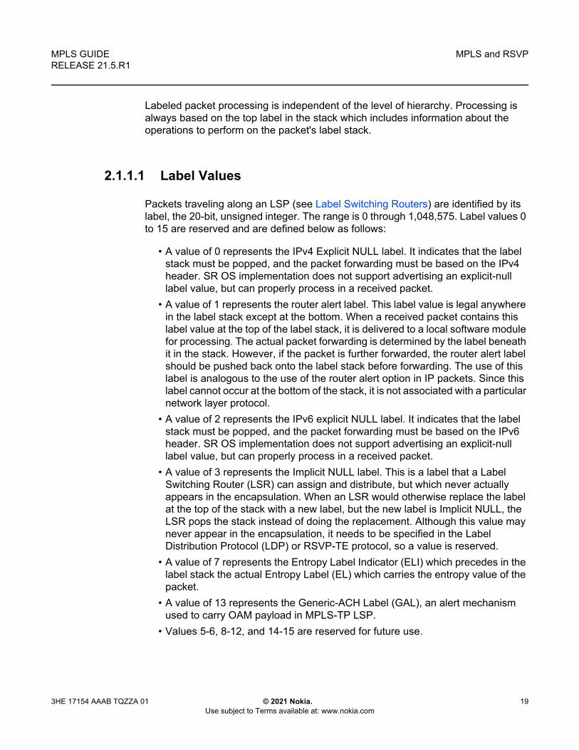
2.1.1.1 Label Values
Packets traveling along an LSP (see Label Switching Routers) are identified by its label, the 20-bit, unsigned integer. The range is 0 through 1,048,575. Label values 0 to 15 are reserved and are defined below as follows:
• A value of 0 represents the IPv4 Explicit NULL label. It indicates that the label stack must be popped, and the packet forwarding must be based on the IPv4 header. SR OS implementation does not support advertising an explicit-null label value, but can properly process in a received packet.
• A value of 1 represents the router alert label. This label value is legal anywhere in the label stack except at the bottom. When a received packet contains this label value at the top of the label stack, it is delivered to a local software module for processing. The actual packet forwarding is determined by the label beneath it in the stack. However, if the packet is further forwarded, the router alert label should be pushed back onto the label stack before forwarding. The use of this label is analogous to the use of the router alert option in IP packets. Since this label cannot occur at the bottom of the stack, it is not associated with a particular network layer protocol.
• A value of 2 represents the IPv6 explicit NULL label. It indicates that the label stack must be popped, and the packet forwarding must be based on the IPv6 header. SR OS implementation does not support advertising an explicit-null label value, but can properly process in a received packet.
• A value of 3 represents the Implicit NULL label. This is a label that a Label Switching Router (LSR) can assign and distribute, but which never actually appears in the encapsulation. When an LSR would otherwise replace the label at the top of the stack with a new label, but the new label is Implicit NULL, the LSR pops the stack instead of doing the replacement. Although this value may never appear in the encapsulation, it needs to be specified in the Label Distribution Protocol (LDP) or RSVP-TE protocol, so a value is reserved.
• A value of 7 represents the Entropy Label Indicator (ELI) which precedes in the label stack the actual Entropy Label (EL) which carries the entropy value of the packet.
• A value of 13 represents the Generic-ACH Label (GAL), an alert mechanism used to carry OAM payload in MPLS-TP LSP.
• Values 5-6, 8-12, and 14-15 are reserved for future use.

MPLS and RSVP
20
MPLS GUIDERELEASE 21.5.R1
© 2021 Nokia. Use subject to Terms available at: www.nokia.com
3HE 17154 AAAB TQZZA 01
The router uses labels for MPLS, RSVP-TE, LDP, BGP Label Unicast, Segment Routing, as well as packet-based services such as VLL and VPLS.
Label values 16 through 1,048,575 are defined as follows:
• label values 16 through 31 are reserved for future use• label values 32 through 18,431 are available for static LSP, MPLS-TP LSP, and
static service label assignments. The upper bound of this range, which is also the lower bound of the dynamic label range, is configurable such that the user can expand or shrink the static or dynamic label range.
• label values 18,432 through 524,287 (1,048,575 in FP4 system profile B) are assigned dynamically by RSVP, LDP, and BGP control planes for both MPLS LSP and service labels.
• label values 524,288 through 1,048,575 are not assigned by SR OS in system profiles other than FP4 profile B, and thus no POP or SWAP label operation is possible in that range and for those system profiles. However, a PUSH operation, with a label from the full range 32 through 1,048,575 if signaled by some downstream LSR for LSP or service, is supported.
• The user can carve out a range of the dynamic label space dedicated for labels of the following features:- Segment Routing Global Block (SRGB) and usable by Segment Routing in
OSPF and ISIS.- Reserved Label Block for applications such as SR policy, MPLS forwarding
policy, and the assignment of a static label to the SID of a ISIS or OSPF adjacency and adjacency set.
2.1.1.2 Reserved Label Blocks
Reserved label blocks are used to reserve a set of labels for allocation for various applications. These reserved label blocks are separate from the existing ranges such as the static-labels-range, and are not tied to the bottom of the labels range. For example, a reserved range may be used as a Segment Routing Local Block (SRLB) for local segment identifiers (SIDs). Ranges are reserved from the dynamic label range and up to four reserved label block ranges may be configured on a system.
A reserved label block is configured using the following:
configrouter
mpls-labelsreserved-label-block <name>
start <start-value> end <end-value>exit
no reserved-label-block <name

MPLS GUIDE RELEASE 21.5.R1
MPLS and RSVP
3HE 17154 AAAB TQZZA 01 © 2021 Nokia. Use subject to Terms available at: www.nokia.com
21
A range can be configured up to the maximum supported MPLS label value on the system.
2.1.2 MPLS Entropy Label and Hash Label
The router supports both the MPLS entropy label, as specified in RFC 6790, and the flow-aware transport (FAT) label (the FAT label is also known as the hash label), as specified in RFC 6391. LSR nodes in a network can load-balance labeled packets in a more granular way than by hashing on the standard label stack by demarking the presence of individual flows on the LSP. The labels also remove the need to have an LSR inspect the payload below the label stack and check for an IPv4 or IPv6 header to determine how to apply load balancing.
The hash label is primarily applicable to Layer 2 services such as VLL and VPLS, while the entropy label (EL) is applicable to more general scenarios where a common way to indicate flows on a wide range of services suitable for load balancing is required.
The application of a hash label or an entropy label is mutually exclusive for a service.
2.1.2.1 Hash Label
The hash label is supported on VLL, VPRN, or VPLS services bound to any MPLS type encapsulated SDPs, as well as to a VPRN service using auto-bind-tunnel with the resolution-filter set to any MPLS tunnel type. When enabled, the ingress data path is modified such that the result of the hash on the payload packet header is communicated to the egress data path for use as the value of the label field of the hash label. The egress data path appends the hash label to the bottom of the stack (BoS) and sets the S-bit to 1. The user enables the signaling of the hash-label capability under a VLL spoke SDP, a VPLS spoke SDP or mesh SDP, or an IES or VPRN spoke SDP interface by adding the signal-capability option. When this capability is enabled, the decision to insert the hash label on the user and control plane packets by the local PE is determined by the outcome of the signaling process and may override the local PE configuration.

MPLS and RSVP
22
MPLS GUIDERELEASE 21.5.R1
© 2021 Nokia. Use subject to Terms available at: www.nokia.com
3HE 17154 AAAB TQZZA 01
2.1.2.2 Entropy Label
The MPLS entropy label provides a similar function to the hash label but is applicable to a wider range of services. The entropy label is appended directly below the tunnel label. As with the hash label, the value of the entropy label is calculated based on a hash of the packet payload header.
The router supports the entropy label for the following services and protocols:
• VPRN• EVPN VPLS and Epipe• RFC 3107 MP-BGP tunnels• RSVP and LDP LSPs used as shortcuts for static, IGP and BGP route resolution• VLLs, including BGP VPWS, IES/VPRN, and VPLS spoke SDP termination, but
not including Apipe and Cpipe• LDP VPLS and BGP-AD VPLS• PW ports bound to a specific physical port supporting PW-SAPs used for Epipe
VLL, IES, VPRN, and Enhanced Subscriber Management services
It is supported when used with the following tunnel types:
• RSVP-TE: Configured and auto-LSPs • LDP• Segment Routing (shortest path, configured SR-TE and SR-TE auto-LSPs) • BGP
The entropy label is not supported on P2MP LSPs.
The entropy label indicated (ELI) label (value=7) is a special-purpose label that indicates that the entropy label follows in the stack. It is always placed immediately below the tunnel label to which hashing applies. Therefore, the EL results in two labels being inserted in the MPLS label stack; the EL and its accompanying ELI.
Three criteria are used to determine if an EL and an ELI are inserted on a labeled packet belonging to a service by an ingress LER:
• The Entropy Label Capability (ELC), which is the ability of the egress LER to receive and process the ELThe ingress LER associates the ELC with the LSP tunnel to be used to transport the service. ELC signaling is supported for RSVP and LDP and causes the router to signal ELC to upstream peers. ELC is configured on these services by using the config>router>rsvp>entropy-label-capability and config>router>ldp>entropy-label-capability commands.

MPLS GUIDE RELEASE 21.5.R1
MPLS and RSVP
3HE 17154 AAAB TQZZA 01 © 2021 Nokia. Use subject to Terms available at: www.nokia.com
23
ELC signaling is not supported for BGP or SR tunnels. For these services, configure the ingress LER (or LSR at a stitching point to a BGP or SR segment) with ELC for this tunnel type using the override-tunnel-elc command for BGP or for the IGP if using SR.
• Whether a specific tunnel at the ingress LER supports ELSupport for EL on a specific tunnel is configurable to prevent exceeding the maximum supported label stack depth due to the additional EL and ELI label (see Impact of EL and ELI on MTU and Label Stack Depth for more information). For RSVP and SR-TE LSPs, it is configured using the entropy-label command under the LSP, LSP template, or MPLS contexts.
• Whether the use of EL has been configured for the serviceRefer to the L2 Services and EVPN Guide, L3 Services Guide, and the Unicast Routing Protocols Guide for more information about entropy label configuration on services.
Each of these conditions must be true before the ingress LER inserts the EL and ELI into the label stack.
An LSR for RSVP and LDP tunnels passes the ELC from the downstream LSP segment to upstream peers. However, releases of SR OS that do not support EL functionality do not pass the ELC to their peers.
2.1.2.3 Inserting and Processing the Entropy Label at LERs and LSRs
This section describes entropy label processing. Details specific to particular services or other tunnel types are described in the L2 Services and EVPN Guide, L3 Services Guide, and the Unicast Routing Protocols Guide.
2.1.2.3.1 Ingress LER
The SR OS router follows the procedures at the ingress LER as specified in Section 4.2 of RFC 6790. In general, the router inserts an EL in a packet if the egress LER for the LSP tunnel has signaled support for ELs, the EL is configured for the service that the packet belongs to, and the EL is not disabled for an RSVP LSP. If there are multiple LSPs in a hierarchy (for example, LDP over RSVP), the router only inserts a single EL and ELI pair under the innermost LSP label closest to the service payload that has advertised EL capability. The router does not insert an EL in a packet belonging to a service for which the hash label has been configured, even if the far end for the LSP tunnel has advertised ELC. The system instead inserts a hash label, as specified by the hash label feature.

MPLS and RSVP
24
MPLS GUIDERELEASE 21.5.R1
© 2021 Nokia. Use subject to Terms available at: www.nokia.com
3HE 17154 AAAB TQZZA 01
If the downstream LSR or LER has signaled implicit or explicit NULL label for a tunnel that is ELC, the router still inserts the EL when required by the service. This ensures consistent behavior as well as ensuring that entropy as determined by the ingress LER is maintained where a tunnel with an implicit NULL label is stitched at a downstream LSR.
2.1.2.3.2 LSR
If an LSR is configured for load balancing and an EL is found in the label stack, the LSR takes the EL into account in the hashing algorithm as follows:
• label-only: Only use the EL as input to the hash routine. The rest of the label stack is ignored.
• label-ip: Only use the EL and the IP packet as input to the hash routine. The rest of the label stack is ignored.
An EL and its associated ELI are not exposed when a tunnel label is swapped at an LSR acting as an LSP stitching point. Therefore, the EL and ELI are forwarded as any other packet on the LSP.
2.1.2.3.3 Egress LER
If an EL is detected in the label stack at an egress LER for a tunnel where the tunnel label that the EL is associated with is popped, then the EL is also popped and the packet is processed as normal. This occurs whether or not the system has signaled ELC.
If an ELI is popped that has the BoS bit set, then the system discards the packet and raises a trap.
2.1.2.4 Mapping Entropy Label Capability at LSP Stitching Points
A router acting as a stitching point between two LSPs maps the ELC received in signaling for a downstream segment to the upstream segment for the level in the LSP hierarchy being stitched.

MPLS GUIDE RELEASE 21.5.R1
MPLS and RSVP
3HE 17154 AAAB TQZZA 01 © 2021 Nokia. Use subject to Terms available at: www.nokia.com
25
If an LSR is stitching an RSVP or LDP segment to a downstream segment of a tunnel type that does not support ELC signaling (for example, BGP) and override-tunnel-elc is configured at the LSR for to downstream segment, then the system signals ELC on the upstream LSP segment. The override-tunnel-elc command must be configured to reflect whether all possible downstream LERs are entropy-label-capable; otherwise, packets with an EL are discarded by a downstream LER that is not entropy-label-capable.
The mapping of ELC across LDP-BGP stitching points is not supported. If a downstream tunnel endpoint signals ELC, this signal is not automatically propagated upstream. The EL and ELI are not inserted on these LSPs by the ingress LER.
2.1.2.5 Entropy Label on OAM Packets
Service OAM packets or OAM packets within the context of a shortcut (for example, ICMP Ping or traceroute packets), also include an EL and ELI if ELC is signaled for the corresponding tunnel and the entropy-label command is enabled for the service. The EL and ELI is inserted at the same level in the label stack as it is in user data packets, which is under the innermost LSP label closest to the service payload that has advertised ELC. The EL and ELI therefore always reside at a different level in the label stack than the special-purpose labels related to the service payload (such as the Router Alert label). OAM packets at the LSP level, such as LSP ping and LSP trace, do not have the EL and ELI inserted.
2.1.2.6 Impact of EL and ELI on MTU and Label Stack Depth
If EL insertion is configured for a VPLS or VLL service, the MTU of the SDP binding is automatically reduced to account for the overhead of the EL and ELI labels. The MTU is reduced whether or not the LSP tunnel used by the service is entropy-label-capable.
The EL requires the insertion of two additional labels in the label stack. In some cases, the insertion of EL and ELI may result in an unsupported label stack depth or large changes in the label stack depth during the lifetime of an LSP. For RSVP LSPs, the entropy-label command under the config>router>mpls and config>router>mpls>lsp contexts provides local control at the head-end of an LSP over whether the entropy label is inserted on an LSP irrespective of the entropy label capability signaled from the egress LER, and control over how the additional label stack depth is accounted for. This control allows a user to avoid entropy label insertion where there is a risk of the label stack becoming too deep.

MPLS and RSVP
26
MPLS GUIDERELEASE 21.5.R1
© 2021 Nokia. Use subject to Terms available at: www.nokia.com
3HE 17154 AAAB TQZZA 01
2.1.3 Label Switching Routers
LSRs perform the label switching function. LSRs perform different functions based on its position in an LSP. Routers in an LSP do one of the following:
• The router at the beginning of an LSP is the ingress label edge router (ILER). The ingress router can encapsulate packets with an MPLS header and forward it to the next router along the path. An LSP can only have one ingress router.
• A Label Switching Router (LSR) can be any intermediate router in the LSP between the ingress and egress routers. An LSR swaps the incoming label with the outgoing MPLS label and forwards the MPLS packets it receives to the next router in the MPLS path (LSP). An LSP can have 0 to 253 transit routers.
• The router at the end of an LSP is the egress label edge router (eLER). The egress router strips the MPLS encapsulation which changes it from an MPLS packet to a data packet, and then forwards the packet to its final destination using information in the forwarding table. Each LSP can have only one egress router. The ingress and egress routers in an LSP cannot be the same router.
A router in your network can act as an ingress, egress, or transit router for one or more LSPs, depending on your network design.
An LSP is confined to one IGP area for LSPs using constrained-path. They cannot cross an autonomous system (AS) boundary.
Static LSPs can cross AS boundaries. The intermediate hops are manually configured so the LSP has no dependence on the IGP topology or a local forwarding table.
2.1.3.1 LSP Types
The following are LSP types:
• Static LSPs — A static LSP specifies a static path. All routers that the LSP traverses must be configured manually with labels. No signaling such as RSVP or LDP is required.
• Signaled LSP — LSPs are set up using a signaling protocol such as RSVP-TE or LDP. The signaling protocol allows labels to be assigned from an ingress router to the egress router. Signaling is triggered by the ingress routers. Configuration is required only on the ingress router and is not required on intermediate routers. Signaling also facilitates path selection.There are two signaled LSP types:

MPLS GUIDE RELEASE 21.5.R1
MPLS and RSVP
3HE 17154 AAAB TQZZA 01 © 2021 Nokia. Use subject to Terms available at: www.nokia.com
27
- Explicit-path LSPs — MPLS uses RSVP-TE to set up explicit path LSPs. The hops within the LSP are configured manually. The intermediate hops must be configured as either strict or loose meaning that the LSP must take either a direct path from the previous hop router to this router (strict) or can traverse through other routers (loose). You can control how the path is set up. They are similar to static LSPs but require less configuration. See RSVP.
- Constrained-path LSPs — The intermediate hops of the LSP are dynamically assigned. A constrained path LSP relies on the Constrained Shortest Path First (CSPF) routing algorithm to find a path which satisfies the constraints for the LSP. In turn, CSPF relies on the topology database provided by the extended IGP such as OSPF or IS-IS. Once the path is found by CSPF, RSVP uses the path to request the LSP set up. CSPF calculates the shortest path based on the constraints provided such as bandwidth, class of service, and specified hops.
If fast reroute is configured, the ingress router signals the routers downstream. Each downstream router sets up a detour for the LSP. If a downstream router does not support fast reroute, the request is ignored and the router continues to support the LSP. This can cause some of the detours to fail, but otherwise the LSP is not impacted.
No bandwidth is reserved for the rerouted path. If the user enters a value in the bandwidth parameter in the config>router>mpls>lsp>fast-reroute context, it has no effect on the LSP backup LSP establishment.
Hop-limit parameters specifies the maximum number of hops that an LSP can traverse, including the ingress and egress routers. An LSP is not set up if the hop limit is exceeded. The hop count is set to 255 by default for the primary and secondary paths. It is set to 16 by default for a bypass or detour LSP path.
2.1.4 Bidirectional Forwarding Detection for MPLS LSPs
BFD for MPLS LSPs monitors the LSP between its LERs, regardless of how many LSRs the LSP may traverse. Therefore, it enables local faults on individual LSPs to be detected, whether or not they also affect forwarding for other LSPs or IP packet flows. This makes BFD for MPLS LSPs ideal for monitoring LSPs carrying specific high-value services, where detecting forwarding failures in the minimal amount of time is critical. The system raises an SNMP trap, and indicates the BFD session state in show and tools dump commands if an LSP BFD session goes down. It can also optionally determine the availability of the tunnel in TTM for use by applications, or trigger a switchover of the LSP from the currently active path to a backup path.

MPLS and RSVP
28
MPLS GUIDERELEASE 21.5.R1
© 2021 Nokia. Use subject to Terms available at: www.nokia.com
3HE 17154 AAAB TQZZA 01
The system supports LSP BFD on RSVP LSPs. See Label Distribution Protocol for information about using LSP BFD on LDP LSPs see the 7750 SR and 7950 XRS Segment Routing and PCE User Guide for information about Seamless BFD on SR-TE LSPs. BFD packets are encapsulated in an MPLS label stack corresponding to the FEC that the BFD session is associated with, as described in Section 7 of RFC 5884, Bidirectional Forwarding Detection (BFD) for MPLS Label Switched Paths (LSPs).
Since RSVP LSPs are unidirectional, a routed return path is used for the BFD control packets from the egress LER towards the ingress LER.
2.1.4.1 Bootstrapping and Maintaining the BFD Session
A BFD session on an LSP is bootstrapped using LSP ping. LSP ping is used to exchange the local and remote discriminator values to use for the BFD session for a particular MPLS LSP or FEC.
SR OS supports the sending of periodic LSP ping messages on an LSP for which LSP BFD has been configured, as specified in RFC 5884. The ping messages are sent, along with the bootstrap TLV, at a configurable interval for LSPs on which bfd-enable has been configured. The default interval is 60 s, with a maximum interval of 300 s. The LSP ping echo request message uses the system IP address as the default source address. An alternative source address consisting of any routable address that is local to the node may be configured, and is used if the local system IP address is not routable from the far-end node.
The periodic LSP ping interval is configured using the config>router>mpls>lsp>bfd>lsp-ping-interval seconds command.
The no lsp-ping-interval command reverts to the default of 60 s.
LSP BFD sessions are recreated after a high-availability switchover between active and standby CPMs. However, some disruption may occur to LSP ping due to LSP BFD.
At the tail end of an LSP, sessions are recreated on the standby CPM following an HA switchover. The following current information is lost from an active tools dump test-oam lsp-bfd tail display:
Note: SR OS does not take any action if a remote system fails to respond to a periodic LSP ping message. However, when the show>test-oam>lsp-bfd command is executed, it displays a return code of zero and a replying node address of 0.0.0.0 if the periodic LSP ping times out.

MPLS GUIDE RELEASE 21.5.R1
MPLS and RSVP
3HE 17154 AAAB TQZZA 01 © 2021 Nokia. Use subject to Terms available at: www.nokia.com
29
• handle• seqNum• rc• rsc
Any new, incoming bootstrap requests are dropped until LSP BFD has become active. When LSP BFD has finished becoming active, new bootstrap requests are considered.
2.1.4.2 LSP BFD Configuration
There are four steps to configuring LSP BFD.
1. Configure a BFD template.2. Enable LSP BFD on the tail node and configure the maximum number of LSP
BFD sessions at the tail node.
3. Apply a BFD template to the LSP or LSP path.4. Enable BFD on the LSP or LSP path.
LSP BFD uses BFD templates to set generic BFD session parameters.
The BFD template is configured as follows:
configrouter
bfdbfd-template name
transmit-interval transmit-intervalreceive-interval receive-intervalecho-receive echo-intervalmultiplier multiplierexit
Network processor BFD is not supported for LSPs. The minimum supported BFD receive or transmit timer interval for RSVP LSPs is 100 milliseconds. Therefore, an error is generated if a user tries to bind a BFD template with the type cpm-np command or any unsupported transmit or receive interval value to an LSP. An error is generated when the user attempts to commit changes to a BFD template that is already bound to an LSP if the new values are invalid for LSP BFD.
Note: The default number of LSP BFD sessions is zero.

MPLS and RSVP
30
MPLS GUIDERELEASE 21.5.R1
© 2021 Nokia. Use subject to Terms available at: www.nokia.com
3HE 17154 AAAB TQZZA 01
BFD templates may be used by different BFD applications (for example, LSPs or pseudowires). If the BFD timer values are changed in a template, the BFD sessions on LSPs or spoke SDPs to which that template is bound tries to renegotiate their timers to the new values.
The bfd-template uses a begin-commit model. To edit any value within the BFD template, a <begin> needs to be executed before the template context has been entered. However, a value is stored temporarily in the template-module until the commit is issued. Values are actually used once the commit is issued.
2.1.4.3 Enabling and Implementing Limits for LSP BFD on a Node
The config>router>lsp-bfd command enables support for LSP BFD and allows an upper limit to the number of supported sessions at the tail end node for LSPs, where it is disabled by default. This is useful because BFD resources are shared among applications using BFD, so a user may wish to set an upper limit to ensure that a certain number of BFD sessions are reserved for other applications. This is important at the tail end of LSPs where no per-LSP configuration context exists.
LSP BFD is enabled or disabled on a node-wide basis using the bfd-sessions max-limit command under the config>router>lsp-bfd context. This command also enables the maximum number of LSP BFD sessions that can be established at the tail end of LSPs to be limited.
The default is disabled. The max-limit parameter specifies the maximum number of LSP BFD sessions that the system allows to be established at the tail end of LSPs.
2.1.4.4 BFD Configuration on RSVP-TE LSPs
LSP BFD is applicable to configured RSVP LSPs as well as mesh-p2p and one-hop-p2p auto-LSPs.
LSP BFD is configured on an RSVP-TE LSP, or on the primary or secondary path of an RSVP-TE LSP, under the bfd context at the LSP head end.
A BFD template must always be configured first. BFD is then enabled using the bfd-enable command.
configrouter
mplslsp
bfd[no] bfd-template <name>

MPLS GUIDE RELEASE 21.5.R1
MPLS and RSVP
3HE 17154 AAAB TQZZA 01 © 2021 Nokia. Use subject to Terms available at: www.nokia.com
31
[no] bfd-enable[no] wait-for-up-timer <value>exit
When BFD is configured at the LSP level, BFD packets follow the currently active path of the LSP.
The bfd-template provides the control packet timer values for the BFD session to use at the LSP head end. Since there is no LSP configuration at the tail end of an RSVP LSP, the BFD state machine at the tail end initially uses system-wide default parameters (the timer values are: min-tx: 1sec, min-rx: 1sec). The head end then attempts to adjust the control packet timer values when it transitions to the INIT state.
The BFD command wait-for-up-timer allows RSVP LSPs BFD sessions to come up during certain MBB and switchover events when the current active path is not BFD degraded (that is, BFD is not down). It is only applicable in cases where failure-action failover-or-down is also configured (see Using LSP BFD for LSP Path Protection) and applies to the following:
• a path undergoing MBB when BFD is up on the original path• the initial administrative enable of an LSP• signaling retry of non-standby secondary paths
The wait-for-up-timer command is configurable at either the lsp>bfd, primary>bfd, or secondary>bfd context. The value that the system uses is the one configured under the same context in which bfd-enable is configured. The wait-for-up-timer has a range of 1-60 seconds and a default of 4 seconds.
BFD is configured at the primary path level, as follows:
configrouter
mplslsp
primary <path-name>bfd
[no] bfd-template name <name>[no] bfd-enable[no] wait-for-up-timer <value>exit
BFD is configured on both standby and non-standby secondary paths as follows:
configrouter
mplslsp
secondary <path-name>bfd
[no] bfd-template <name>
MPLS and RSVP
32
MPLS GUIDERELEASE 21.5.R1
© 2021 Nokia. Use subject to Terms available at: www.nokia.com
3HE 17154 AAAB TQZZA 01
[no] bfd-enable[no] wait-for-up-timer <value>exit
BFD sessions are not established on these paths unless they are made active, unless failure-action failover-or-down is configured. See Using LSP BFD for LSP Path Protection. If failure-action failover-or-down is configured then the top three best-preference primary and standby paths (primary and up to two standby paths, or three standby paths if no primary is present) are programmed in the IOM, and BFD sessions are established on all of them.
It is not possible to configure LSP BFD on a secondary path or on P2MP LSPs.
LSP BFD at the LSP level and the path level is mutually exclusive. That is, if LSP BFD is already configured for the LSP then its configuration for the path is blocked. Likewise it cannot be configured on the LSP if it is already configured at the path level.
LSP BFD is supported on auto-LSPs. In this case, LSP BFD is configured on mesh-p2p and one-hop-p2p auto-LSPs using the LSP template, as follows:
Configrouter
mplslsp-template template-name {mesh-p2p | one-hop-p2p}
bfd[no] bfd-template name[no] bfd-enableexit
2.1.4.5 Using LSP BFD for LSP Path Protection
SR OS can determine the forwarding state of an LSP from the LSP BFD session, allowing users of the LSP to determine whether their transport is operational. If BFD is down on an LSP path, then the path is considered to be BFD degraded by the system.
Using the failure-action command, a user can configure the action taken by the system if BFD fails for an RSVP LSP or LDP prefix list. There are three possible failure actions:
• failure-action down — the LSP is marked as unusable in TTM when BFD on the LSP goes down. This is applicable to RSVP and LDP LSPs.

MPLS GUIDE RELEASE 21.5.R1
MPLS and RSVP
3HE 17154 AAAB TQZZA 01 © 2021 Nokia. Use subject to Terms available at: www.nokia.com
33
• failure-action failover — when LSP BFD goes down on the currently active path, then the LSP switches from the primary path to the secondary path, or from the currently active secondary path to the next-best preference secondary path. This is applicable to RSVP LSPs.
• failover-action failover-or-down — similar to failover-action failover, when LSP BFD goes down on the currently active path, then the LSP switches from the primary path to the secondary path, or from the currently active secondary path to the next best preference secondary path. However, failover-or-down also supports the ability to run BFD sessions simultaneously on the primary and up to two other secondary or standby paths. The system does not switch to a standby path for which the BFD session is down. If all BFD sessions for the LSP are down, then the LSP is marked as unusable in TTM. This is applicable to RSVP LSPs and SR-TE LSPs. See the 7750 SR and 7950 XRS Segment Routing and PCE User Guide for further details of its use for SR-TE LSPs.
In all cases, an SNMP trap is raised indicating that BFD has gone down on the LSP.
2.1.4.5.1 Failure-action down
The failure-action down command is supported for point-to-point RSVP (including mesh point-to-point and one-hop point-to-point auto-LSPs) and LDP LSPs. This command is configured within the config>router>mpls>lsp>bfd, config>router>mpls>lsp-template>bfd, or config>router>ldp>lsp-bfd contexts. For RSVP LSPs, it is only supported at the LSP level and not at the primary or secondary path levels. When configured, an LSP is made unavailable as a transport if BFD on the LSP goes down.
If BFD is disabled, MPLS installs the LSP as “usable” in the TTM. The failure-action configuration is ignored.
If BFD is enabled and no failure-action is configured, MPLS installs the LSP as “usable” in the TTM regardless of the BFD session state. BFD generates BFD Up and BFD Down traps.
If BFD is enabled and failure-action down is configured:
• BFD traps are still generated when the BFD state machine transitions.
Note: It is recommended that BFD control packet timers are configured to a value that is large enough to allow for transient data path disruptions that may occur when the underlying transport network recovers following a failure.

MPLS and RSVP
34
MPLS GUIDERELEASE 21.5.R1
© 2021 Nokia. Use subject to Terms available at: www.nokia.com
3HE 17154 AAAB TQZZA 01
• If the BFD session is up for the active path of the LSP, the LSP is installed as “usable” in the TTM. If the BFD session is down for the active path, the LSP is installed as “not-usable” in the TTM.
• When an LSP is first activated using the no shutdown command, and its LSP BFD session first starts to come up, the LSP is installed as “not-usable” in the TTM to any user until the BFD session transitions to the up state, despite the FEC for the corresponding LSP being installed by the TTM. Users include all protocols, including those in RTM. A tunnel that is marked as down in the TTM is not available to RTM, and all routes using it are withdrawn. SDP auto-bind does not make use of an LSP until it is installed as “usable”.
• If the BFD session is up on the active path and the LSP is installed as “usable” in the TTM, and if the LSP switches from its current active path to a new path, the system triggers a new BFD bootstrap using LSP ping for the new path, and waits for a maximum of 10 s for the BFD session to come up on the new path before switching traffic to it. If the BFD session does not come up on the new path after 10 s, the system switches to the new path anyway and install the LSP as “not-usable” in the TTM. This is the only scenario where a switch of the active path can be delayed due to BFD transition state.
• If the BFD session is down on the active path and the LSP was already installed as “not-usable” in the TTM, then the system immediately switches to the new path without waiting for BFD to become operationally up.
• If BFD is disabled, MPLS installs the LSP as “usable” in the TTM. The failure-action configuration is ignored. LSP ping and LSP trace are still able to test an LSP when BFD is disabled.
2.1.4.5.2 Failure-action failover
The failure-action failover command is supported for point-to-point RSVP LSPs (except mesh point-to-point and one-hop point-to-point auto-LSPs because these do not have a secondary path). When failure action failover is configured, the system triggers a failover from the currently active path to the secondary path, the next-best preference secondary path, or the secondary-standby path of an LSP when an LSP BFD session configured at the LSP level transitions from an up state to a down state. Unlike failure-action failover-or-down, this failure action does not affect how LSP paths are programmed in the data path and only runs LSP BFD on the active path.
The LSP is always marked as usable in the TTM, regardless of the BFD session state and BFD traps that are generated when the BFD state machine transitions. If BFD is enabled and failure-action failover is configured, the following conditions apply.
Note: BFD session state is never used to trigger a switch of the active path when failure-action down is configured.

MPLS GUIDE RELEASE 21.5.R1
MPLS and RSVP
3HE 17154 AAAB TQZZA 01 © 2021 Nokia. Use subject to Terms available at: www.nokia.com
35
• It is possible to bring the LSP up regardless the current BFD session state.• If the BFD session transitions from up to down, the current path immediately
switches to the next-best preference standby path. • If MBB is triggered, then this occurs immediately on the primary path, regardless
the BFD session state. • If the operator is concerned about detecting data path failures that may not be
detected by the control plane, Nokia recommends that the revert timer be set to its maximum value.
• LSP BFD only runs on the currently active path. It cannot determine if any non-active paths (for example, a secondary path or primary path during reversion) that the system switches to is up and forwarding. The system relies on the normal control plane mechanisms.
Table 4 describes how the system behaves if a user changes the failure-action while BFD is down. The LSP remains on the current path unless (or until) the control plane takes action or the revert timer expires.
2.1.4.5.3 LSP Active Path Failover Triggers
The active path of an LSP is switched to an alternative path in the following cases:
• the active path goes into degraded state due to FRR or soft preemption• the active path is degraded due to the BFD session going from up to down (only
applicable if the failure action is set to failover or failover-or-down)• reverting from a secondary or standby path to the primary path (with or without
a reverter time configured)• switching between secondary or standby paths due to path preference
Table 4 Changes to the Failure Action while BFD is Down
Action Combination (old action/new action)
Tunnel flag in TTM
None/Down as unusable
None/Failover as usable
Down/None as usable
Down/Failover as usable
Failover/None as usable
Failover/Down as unusable

MPLS and RSVP
36
MPLS GUIDERELEASE 21.5.R1
© 2021 Nokia. Use subject to Terms available at: www.nokia.com
3HE 17154 AAAB TQZZA 01
• switching between secondary or standby paths due to the tools perform router mpls switch-path or force-switch-path commands
• switching due to an MBB on the active path where the old and new path have the same bfd-enable configuration
• switching from the primary path to secondary or standby paths due to the tools perform router mpls manual-switch-path command
Table 5 describes path switchover events depending on the failure action configuration.
Table 5 Path Switchover Triggers based on BFD Failure Action Configuration
BFD failure-action configuration
Old active path New active path Switchover to new path
bfd-enable configuration at LSP or path
BFD session state
bfd-enable configuration at LSP or path
no failure-action failure-action failover
Any Any Any Switch immediately without checking the BFD session state on new path.
failure-action down
BFD enabled BFD session up
BFD enabled Wait for a maximum of 10 seconds for the BFD session to come up on the new path before switching. If the BFD session does not come up on the new path after 10 seconds, switch anyway.
BFD disabled Switch immediately without checking the BFD session state on new path.
BFD session down
BFD enabled Switch immediately without checking the BFD session state on new path.
BFD disabled Switch immediately without checking the BFD session state on new path.

MPLS GUIDE RELEASE 21.5.R1
MPLS and RSVP
3HE 17154 AAAB TQZZA 01 © 2021 Nokia. Use subject to Terms available at: www.nokia.com
37
For failure-action failover-or-down, a path is in the degraded state if it has BFD enabled and the BFD session is not up. Switching between primary, standby, and secondary paths of the LSP will follow rules of best path selection algorithm, for example, a non-degraded path is better than a degraded path and a degraded primary is better than a degraded standby or secondary path. Since the BFD degraded state affects LSP active path selection, waiting for BFD to come up on new path is already accounted for and these cases have been excluded from Table 6.
Switching to an MBB path requires waiting for the BFD session to come up on the new MBB path. These cases are described in Table 6. This applies to MBB on both active and inactive paths to reduce the toggling of a BFD degraded state on the path.
BFD disabled — BFD enabled Wait for a maximum of 10 seconds for the BFD session to come up on the new path before switching. If the BFD session does not come up on the new path after 10 seconds, switch anyway.
BFD disabled Switch immediately without checking the BFD session state on new path.
Table 5 Path Switchover Triggers based on BFD Failure Action Configuration (Continued)
BFD failure-action configuration
Old active path New active path Switchover to new path
bfd-enable configuration at LSP or path
BFD session state
bfd-enable configuration at LSP or path
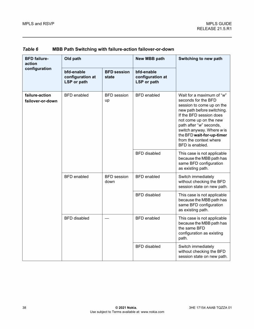
MPLS and RSVP
38
MPLS GUIDERELEASE 21.5.R1
© 2021 Nokia. Use subject to Terms available at: www.nokia.com
3HE 17154 AAAB TQZZA 01
Table 6 MBB Path Switching with failure-action failover-or-down
BFD failure-action configuration
Old path New MBB path Switching to new path
bfd-enable configuration at LSP or path
BFD session state
bfd-enable configuration at LSP or path
failure-actionfailover-or-down
BFD enabled BFD session up
BFD enabled Wait for a maximum of “w” seconds for the BFD session to come up on the new path before switching. If the BFD session does not come up on the new path after “w” seconds, switch anyway. Where w is the BFD wait-for-up-timer from the context where BFD is enabled.
BFD disabled This case is not applicable because the MBB path has same BFD configuration as existing path.
BFD enabled BFD session down
BFD enabled Switch immediately without checking the BFD session state on new path.
BFD disabled This case is not applicable because the MBB path has same BFD configuration as existing path.
BFD disabled — BFD enabled This case is not applicable because the MBB path has the same BFD configuration as existing path.
BFD disabled Switch immediately without checking the BFD session state on new path.

MPLS GUIDE RELEASE 21.5.R1
MPLS and RSVP
3HE 17154 AAAB TQZZA 01 © 2021 Nokia. Use subject to Terms available at: www.nokia.com
39
2.1.4.6 MPLS/RSVP on Broadcast Interface
The MPLS/RSVP on Broadcast Interface feature allows MPLS/RSVP to distinguish neighbors from one another when the outgoing interface is a broadcast interface connecting to multiple neighbors over a broadcast domain. More specifically, in the case where a BFD session towards a specific neighbor on the broadcast domain goes down, the consecutive actions (for example, FRR switchover) only concerns the LSPs of the affected neighbor. Previously, the actions would have been taken on the LSPs of all neighbors over the outgoing interface.
2.1.5 MPLS Facility Bypass Method of MPLS Fast Re-Route (FRR)
The MPLS facility bypass method of MPLS Fast Re-Route (FRR) functionality is extended to the ingress node.
The behavior of an LSP at an ingress LER with both fast reroute and a standby LSP path configured is as follows:
• When a downstream detour becomes active at a point of local repair (PLR):The ingress LER switches to the standby LSP path. If the primary LSP path is repaired subsequently at the PLR, the LSP switches back to the primary path. If the standby goes down, the LSP is switched back to the primary, even though it is still on the detour at the PLR. If the primary goes down at the ingress while the LSP is on the standby, the detour at the ingress is cleaned up and for one-to-one detours a “path tear” is sent for the detour path. In other words, the detour at the ingress does not protect the standby. If and when the primary LSP is again successfully re-signaled, the ingress detour state machine is restarted.
• When the primary fails at the ingress:The LSP switches to the detour path. If a standby is available then LSP would switch to standby on expiration of hold-timer. If hold-timer is disabled then switchover to standby would happen immediately. On successful global revert of primary path, the LSP would switch back to the primary path.
• Admin groups are not taken into account when creating detours for LSPs.

MPLS and RSVP
40
MPLS GUIDERELEASE 21.5.R1
© 2021 Nokia. Use subject to Terms available at: www.nokia.com
3HE 17154 AAAB TQZZA 01
2.1.6 Manual Bypass LSP
SR OS implements dynamic bypass tunnels as defined in RFC 4090, Fast Reroute Extensions to RSVP-TE for LSP Tunnels. When an LSP is signaled and the local protection flag is set in the session_attribute object and/or the FRR object in the path message indicates that facility backup is desired, the PLR establishes a bypass tunnel to provide node and link protection. The bypass tunnel is selected if a bypass LSP that merges in a downstream node with the protected LSP exists, and if this LSP satisfies the constraints in the FRR object.
With the manual bypass feature, an LSP can be preconfigured from a PLR that is used exclusively for bypass protection. When a Path message for a new LSP requests bypass protection, the node first checks if a manual bypass tunnel satisfying the path constraints exists. If one is found, it is selected. If no manual bypass tunnel is found, the router dynamically signals a bypass LSP in the default behavior. Users can disable the dynamic bypass creation on a per node basis using the CLI.
A maximum of 1000 associations of primary LSP paths can be made with a single manual bypass by default. The max-bypass-associations integer command allows to increase or decrease the number of associations. If dynamic bypass creation is disabled on the node, it is recommended to configure additional manual bypass LSPs to handle the required number of associations.
Refer to Configuring Manual Bypass Tunnels for configuration information.
2.1.6.1 PLR Bypass LSP Selection Rules
The PLR uses rules to select a bypass LSP among multiple manual and dynamic bypass LSPs at the time of establishment of the primary LSP path or when searching for a bypass for a protected LSP which does not have an association with a bypass tunnel: Figure 3 shows an example of bypass tunnel nodes.
Figure 3 Bypass Tunnel Nodes
al_0204
A B C D
E F

MPLS GUIDE RELEASE 21.5.R1
MPLS and RSVP
3HE 17154 AAAB TQZZA 01 © 2021 Nokia. Use subject to Terms available at: www.nokia.com
41
The rules are:
1. The MPLS task in the PLR node checks if an existing manual bypass satisfies the constraints. If the path message for the primary LSP path indicated node protection desired, which is the default LSP FRR setting at the head end node, MPLS task searches for a node-protect bypass LSP. If the path message for the primary LSP path indicated link protection desired, then it searches for a link-protect bypass LSP.
2. If multiple manual bypass LSPs satisfying the path constraints exist, it prefers a manual-bypass terminating closer to the PLR over a manual bypass terminating further away. If multiple manual bypass LSPs satisfying the path constraints terminate on the same downstream node, it selects one with the lowest IGP path cost or if in a tie, picks the first one available.
3. If none satisfies the constraints and dynamic bypass tunnels have not been disabled on PLR node, then the MPLS task in the PLR checks if any of the already established dynamic bypasses of the requested type satisfy the constraints.
4. If none do, then the MPLS task asks CSPF to check if a new dynamic bypass of the requested type, node-protect or link-protect, can be established.
5. If the path message for the primary LSP path indicated node protection desired, and no manual bypass was found after Step 1, and/or no dynamic bypass LSP was found after one attempt of performing Step 3, the MPLS task repeats Steps 1 to 3 looking for a suitable link-protect bypass LSP. If none are found, the primary LSP has no protection and the PLR node must clear the “local protection available” flag in the IPv4 address sub-object of the RRO starting in the next Resv refresh message it sends upstream. Node protection continues to be attempted using a background re-evaluation process.
6. If the path message for the primary LSP path indicated link protection desired, and no manual bypass was found after step 1, and/or no dynamic bypass LSP was found after performing Step 3, the primary LSP has no protection and the PLR node must clear the “local protection available” flag in the IPv4 address sub-object of the RRO starting in the next RESV refresh message it sends upstream. The PLR will not search for a node-protect’ bypass LSP in this case.
7. If the PLR node successfully makes an association, it must set the “local protection available” flag in the IPv4 address sub-object of the RRO starting in the next RESV refresh message it sends upstream.
8. For all primary LSP that requested FRR protection but are not currently associated with a bypass tunnel, the PLR node on reception of RESV refresh on the primary LSP path repeats Steps 1 to 7.
If the user disables dynamic-bypass tunnels on a node while dynamic bypass tunnels were activated and were passing traffic, traffic loss will occur on the protected LSP. Furthermore, if no manual bypass exist that satisfy the constraints of the protected LSP, the LSP will remain without protection.

MPLS and RSVP
42
MPLS GUIDERELEASE 21.5.R1
© 2021 Nokia. Use subject to Terms available at: www.nokia.com
3HE 17154 AAAB TQZZA 01
If the user configures a bypass tunnel on node B and dynamic bypass tunnels have been disabled, LSPs which have been previously signaled and which were not associated with any manual bypass tunnel, for example, none existed, are associated with the manual bypass tunnel if suitable. The node checks for the availability of a suitable bypass tunnel for each of the outstanding LSPs every time a RESV message is received for these LSPs.
If the user configures a bypass tunnel on node B and dynamic bypass tunnels have not been disabled, LSPs which have been previously signaled over dynamic bypass tunnels will not automatically be switched into the manual bypass tunnel even if the manual bypass is a more optimized path. The user will have to perform a make before break at the head end of these LSPs.
If the manual bypass goes into the down state in node B and dynamic bypass tunnels have been disabled, node B (PLR) will clear the “protection available” flag in the RRO IPv4 sub-object in the next RESV refresh message for each affected LSP. It will then try to associate each of these LSPs with one of the manual bypass tunnels that are still up. If it finds one, it will make the association and set again the “protection available” flag in the next RESV refresh message for each of these LSPs. If it could not find one, it will keep checking for one every time a RESV message is received for each of the remaining LSPs. When the manual bypass tunnel is back UP, the LSPs which did not find a match are associated back to this tunnel and the protection available flag is set starting in the next RESV refresh message.
If the manual bypass goes into the down state in node B and dynamic bypass tunnels have not been disabled, node B will automatically signal a dynamic bypass to protect the LSPs if a suitable one does not exist. Similarly, if an LSP is signaled while the manual bypass is in the down state, the node will only signal a dynamic bypass tunnel if the user has not disabled dynamic tunnels. When the manual bypass tunnel is back into the UP state, the node will not switch the protected LSPs from the dynamic bypass tunnel into the manual bypass tunnel.
2.1.6.2 FRR Facility Background Evaluation Task
The MPLS Fast Re-Route (FRR) feature implements a background task to evaluate Path State Block (PSB) associations with bypass LSP. The following is the task evaluation behavior.
• For PSBs that have facility FRR enabled but no bypass association, the task triggers a FRR protection request.
• For PSBs that have requested node-protect bypass LSP but are currently associated with a link-protect bypass LSP, the task triggers a node-protect FRR request.

MPLS GUIDE RELEASE 21.5.R1
MPLS and RSVP
3HE 17154 AAAB TQZZA 01 © 2021 Nokia. Use subject to Terms available at: www.nokia.com
43
• For PSBs that have LSP statistics enabled but the statistic index allocation failed, the task re-attempts index allocation.
The MPLS FRR background task thus enables PLRs to be aware of the missing node protection and lets them regularly probe for a node-bypass. Figure 4 shows an example of FRR node protection.
Figure 4 FRR Node-Protection Example
The following describes an LSP scenario where:
• LSP 1: from PE_1 to PE_2, with CSPF, FRR facility node-protect enabled• P_1 protects P_2 with bypass-nodes P_1 -P_3 - P_4 - PE_4 -PE_2• If P_4 fails, P_1 tries to establish the bypass-node three times• When the bypass-node creation fails, P_1 will protect link P_1-P_2• P_1 protects the link to P_2 through P_1 - P_5 - P_2• P_4 returns online
LSP 1 has requested node protection, but due to the lack of an available path, it can only obtain link protection. Therefore, every 60 seconds the PSB background task triggers the PLR for LSP 1 to search for a new path that can provide node protection. Once P_4 is back online and such a path is available, a new bypass tunnel is signaled and LSP 1 gets associated with this new bypass tunnel.
al_0205
P_5
PE_4PE_3
PE_1 P_1 P_2 PE_2
P_3 P_4

MPLS and RSVP
44
MPLS GUIDERELEASE 21.5.R1
© 2021 Nokia. Use subject to Terms available at: www.nokia.com
3HE 17154 AAAB TQZZA 01
2.1.7 Uniform FRR Failover Time
The failover time during FRR consists of a detection time and a switchover time. The detection time corresponds to the time it takes for the RSVP control plane protocol to detect that a network IP interface is down or that a neighbor/next-hop over a network IP interface is down. The control plane can be informed of an interface down event when event is due to a failure in a lower layer such in the physical layer. The control plane can also detect the failure of a neighbor/next-hop on its own by running a protocol such as Hello, Keep-Alive, or BFD.
The switchover time is measured from the time the control plane detects the failure of the interface or neighbor/next-hop to the time the XCMs or IOMs completes the reprogramming of all the impacted ILM or service records in the data path. This includes the time it takes for the control plane to send a down notification to all XCMs or IOMs to request a switch to the backup NHLFE.
Uniform Fast-Reroute (FRR) failover enables the switchover of MPLS and service packets from the outgoing interface of the primary LSP path to that of the FRR backup LSP within the same amount of time regardless of the number of LSPs or service records. This is achieved by updating Ingress Label Map (ILM) records and service records to point to the backup Next-Hop Label to Forwarding Entry (NHLFE) in a single operation.
2.1.8 Automatic Bandwidth Allocation for RSVP LSPs
2.1.8.1 Enabling and Disabling Auto-Bandwidth Allocation on an LSP
This section discusses an auto-bandwidth hierarchy configurable in the config>router>mpls>lsp context.
Adding auto-bandwidth at the LSP level starts the measurement of LSP bandwidth described in Measurement of LSP Bandwidth and allows auto-bandwidth adjustments to take place based on the triggers described in Periodic Automatic Bandwidth Adjustment.
When an LSP is first established, the bandwidth reserved along its primary path is controlled by the bandwidth parameter in the config>router>mpls>lsp>primary context, whether or not the LSP has auto-bandwidth enabled, while the bandwidth reserved along a secondary path is controlled by the bandwidth parameter in the config>router>mpls>lsp>secondary context. When auto-bandwidth is enabled

MPLS GUIDE RELEASE 21.5.R1
MPLS and RSVP
3HE 17154 AAAB TQZZA 01 © 2021 Nokia. Use subject to Terms available at: www.nokia.com
45
and a trigger occurs, the system will attempt to change the bandwidth of the LSP to a value between min-bandwidth and max-bandwidth, which are configurable values in the lsp>auto-bandwidth context. min-bandwidth is the minimum bandwidth that auto-bandwidth can signal for the LSP, and max-bandwidth is the maximum bandwidth that can be signaled. The user can set the min-bandwidth to the same value as the primary path bandwidth but the system will not enforce this restriction. The system will allow:
• no min-bandwidth to be configured. In this case, the implicit minimum is 0 Mb/s.• no max-bandwidth to be configured, as long as overflow-triggered auto-
bandwidth is not configured. In this case, the implicit maximum is infinite (effectively 100 Gb/s).
• the configured primary path bandwidth to be outside the range of min-bandwidth to max-bandwidth
• auto-bandwidth parameters can be changed at any time on an operational LSP; in most cases, the changes have no immediate impact, but subsequent sections will describe some exceptions
All of the auto-bandwidth adjustments discussed are performed using MBB procedures.
Auto bandwidth can be added to an operational LSP at any time (without the need to shut down the LSP or path), but no bandwidth change occurs until a future trigger event. Auto bandwidth may also be removed from an operational LSP at any time and this causes an immediate MBB bandwidth change to be attempted using the configured primary path bandwidth.
A change to the configured bandwidth of an auto-bandwidth LSP has no immediate effect. The change only occurs if the LSP/path goes down (due to failure or administrative action) and comes back up, or if auto-bandwidth is removed from the LSP. The operator can force an auto-bandwidth LSP to be resized immediately to an arbitrary bandwidth using the appropriate tools commands.
2.1.8.2 Autobandwidth on LSPs with Secondary or Secondary Standby Paths
Autobandwidth is supported for LSPs that have secondary or secondary standby paths. A secondary path is only initialized at its configured bandwidth when it is established, and the bandwidth is adjusted only when the secondary path becomes active.
This description makes use of the following terminology:

MPLS and RSVP
46
MPLS GUIDERELEASE 21.5.R1
© 2021 Nokia. Use subject to Terms available at: www.nokia.com
3HE 17154 AAAB TQZZA 01
• current_BW: the last known reserved bandwidth for the LSP; may be the value of a different path from the currently active path
• operational BW: the last known reserved BW for a given path, as recorded in the MIB
• configured BW: the bandwidth explicitly configured for the LSP path by the user in CLI
• active path: the path (primary or secondary) the LSP currently uses to forward traffic
• signaled BW: the new BW value signaled during an MBB
A secondary or standby secondary path is initially signaled with its configured bandwidth. Setup for the secondary path is triggered only when the active path goes down or becomes degraded (for example, due to FRR or preemption). An auto-BW triggered bandwidth adjustment (auto bandwidth MBB) only takes place on the active path. For example, if an auto-BW adjustment occurs on the primary path, which is currently active, no adjustment is made at that time to the secondary path since that path is not active.
When the active path changes, the current_bw is updated to the operational bandwidth of the newly active path. While the auto-BW MBB on the active path is in progress, a statistics sample could be triggered, and this would be collected in the background. Auto-bandwidth computations will use the current_bw of the newly active path. In case the statistics sample collection results in a bandwidth adjustment, the in-progress auto-BW MBB is restarted. If after five attempts, the auto-BW MBB fails, the current_bw and secondary operational BW remain unchanged.
For a secondary or standby secondary path, if the active path for an LSP changes (without the LSP going down), an auto-BW MBB is triggered for the new active path. The bandwidth used to signal the MBB is the operational bandwidth of the previous active path. If the MBB fails, it will retry with a maximum of five attempts. The reserved bandwidth of the newly active path will therefore be its configured bandwidth until the MBB succeeds.
For a secondary path where the active path goes down, the LSP will go down temporarily until the secondary path is setup. If the LSP goes down, all statistics and counters are cleared, so the previous path operational bandwidth is lost. That is, the operational BW of a path is not persistent across LSP down events. In this case, there is no immediate bandwidth adjustment on the secondary path.
The following algorithm is used to determine the signaled bandwidth on a newly active path:
1. For a path that is operationally down, signaled_bw = config_bw.

MPLS GUIDE RELEASE 21.5.R1
MPLS and RSVP
3HE 17154 AAAB TQZZA 01 © 2021 Nokia. Use subject to Terms available at: www.nokia.com
47
2. For the active path, if an auto-BW MBB adjustment is in progress, signaled_bw = previous path operational BW for the first five attempts. For the remaining attempts, the signaled BW = operational BW.
3. For an MBB on the active path (other than an auto-BW MBB), MBB signaled BW = operational BW.
4. For an MBB on the inactive path, MBB signaled BW = configured BW.
If the primary path is not the currently active path and it has not gone down, then any MBB uses the configured BW for the primary path. However, if the configured BW is changed for a path that is currently not active, then a config change MBB is not triggered.
If the standby is SRLG enabled, and the active path is the standby, and the primary comes up, this will immediately trigger a delayed retry MBB on the standby. If the delayed retry MBB fails, immediate reversion to the primary occurs regardless of the retry timer.
When the system reverts from a secondary standby or secondary path to the primary path, a Delayed Retry MBB is attempted to bring bandwidth of the standby path back to its configured bandwidth. Delayed Retry MBB is attempted once, and if it fails, the standby is torn down. A Delayed Retry MBB has highest priority among all MBBs, so it will take precedence over any other MBB in progress on the standby path (for example, Config change or Preemption).
The system will carry-over the last signaled BW of the LSP over multiple failovers. For example, if an LSP is configured with auto-BW for some time, and adjusts its currently reserved bandwidth for the primary, and Monitor mode is then enabled, BW adjustment on the primary ceases, but the BW remains reserved at the last adjusted value. Next, the LSP fails over to a secondary or secondary standby. The secondary will inherit the last reserved BW of the primary, but then disable further adjustment as long as monitoring mode is enabled.
The system’s ability to carry-over the last signaled BW across failovers has the following limitations:
• Case 1: If the LSP fails over from path1 to path2 and the AutoBW MBB on path2 is successful, the last signaled BW is carried over when the LSP reverts back to path1 or fails over to a new path3. This may trigger an AutoBW MBB on the new active path to adjust its bandwidth to last signaled BW.
• Case 2: If the LSP fails over from path1 to path2 and the AutoBW MBB on path2 is still in progress and the LSP reverts back to path1 or fails over to a new path3, the last signaled BW is carried over to the new active path (path1 or path3) and this may result in an AutoBW MBB on that path.

MPLS and RSVP
48
MPLS GUIDERELEASE 21.5.R1
© 2021 Nokia. Use subject to Terms available at: www.nokia.com
3HE 17154 AAAB TQZZA 01
• Case 3: If the LSP fails over from path1 to path2 and the AutoBW MBB on path2 fails (after 5 retry attempts), the last signaled BW from when path1 was active is lost. Therefore, when the LSP reverts back to path1 or fails over to a new path3, the original signaled BW from path1 is not carried over. However the signaled bandwidth of path2 is carried over to the new active path (path1 or path3) and may trigger an AutoBW on that path.
2.1.8.3 Measurement of LSP Bandwidth
Automatic adjustment of RSVP LSP bandwidth based on measured traffic rate into the tunnel requires the LSP to be configured for egress statistics collection at the ingress LER. The following CLI shows an example:
config router mpls lsp nameegress-statisticsaccounting-policy 99collect-statsno shutdown
exit
All LSPs configured for accounting, including any configured for auto-bandwidth based on traffic measurements, must reference the same accounting policy. An example configuration of such an accounting-policy is shown below: in the CLI example below.
config logaccounting-policy 99collection-interval 5
record combined-mpls-lsp-egressexit
exit
The record combined-mpls-lsp-egress command in the accounting policy has the effect of recording both egress packet and byte counts and bandwidth measurements based on the byte counts if auto-bandwidth is enabled on the LSP.
When egress statistics are enabled the CPM collects stats from of all XCMs or IOMs involved in forwarding traffic belonging to the LSP (whether the traffic is currently leaving the ingress LER via the primary LSP path, a secondary LSP path, an FRR detour path or an FRR bypass path). The egress statistics have counts for the number of packets and bytes forwarded per LSP on a per-forwarding class, per-priority (in-profile vs. out-of-profile) basis. When auto-bandwidth is configured for an LSP the ingress LER calculates a traffic rate for the LSP as follows:
Average data rate of LSP[x] during interval[i] = F(x, i)—F(x, i-1)/sample interval

MPLS GUIDE RELEASE 21.5.R1
MPLS and RSVP
3HE 17154 AAAB TQZZA 01 © 2021 Nokia. Use subject to Terms available at: www.nokia.com
49
F(x, i) — The total number of bytes belonging to LSP[x], regardless of forwarding-class or priority, at time[i]
sample interval = time[i] — time [i-1], time[i+1] — time[i], and so on.
The sample interval is the product of sample-multiplier and the collection-interval specified in the auto-bandwidth accounting policy. A default sample-multiplier for all LSPs may be configured using the config>router>mpls>auto-bandwidth-defaults command but this value can be overridden on a per-LSP basis at the config>router>mpls>lsp>auto-bandwidth context. The default value of sample-multiplier (the value that would result from the no auto-bandwidth-defaults command) is 1, which means the default sample interval is 300 seconds.
Over a longer period of time called the adjust interval the router keeps track of the maximum average data rate recorded during any constituent sample interval. The adjust interval is the product of adjust-multiplier and the collection-interval specified in the auto-bandwidth accounting-policy. A default adjust-multiplier for all LSPs may be configured using the config>router>mpls>auto-bandwidth-multiplier command but this value can be overridden on a per-LSP basis at the config>router>mpls>lsp>auto-bandwidth context. The default value of adjust-multiplier (the value that would result from the no auto-bandwidth-multiplier command) is 288, which means the default adjust interval is 86400 seconds or 24 hours. The system enforces the restriction that adjust-multiplier is equal to or greater than sample-multiplier. It is recommended that the adjust-multiplier be an integer multiple of the sample-multiplier.
The collection-interval in the auto-bandwidth accounting policy can be changed at any time, without disabling any of the LSPs that rely on that policy for statistics collection.
The sample-multiplier (at the mpls>auto-bandwidth level or the lsp>auto-bandwidth level) can be changed at any time. This will have no effect until the beginning of the next sample interval. In this case the adjust-interval does not change and information about the current adjust interval (such as the remaining adjust-multiplier, the maximum average data rate) is not lost when the sample-multiplier change takes effect.
The system allows adjust-multiplier (at the mpls level or the lsp>auto-bandwidth level) to be changed at any time as well but in this case the new value shall have no effect until the beginning of the next adjust interval.
Byte counts collected for LSP statistics include layer 2 encapsulation (Ethernet headers and trailers) and therefore average data rates measured by this feature include Layer 2 overhead as well.

MPLS and RSVP
50
MPLS GUIDERELEASE 21.5.R1
© 2021 Nokia. Use subject to Terms available at: www.nokia.com
3HE 17154 AAAB TQZZA 01
2.1.8.4 Passive Monitoring of LSP Bandwidth
The system offers the option to measure the bandwidth of an RSVP LSP (see Measurement of LSP Bandwidth) without taking any action to adjust the bandwidth reservation, regardless of how different the measured bandwidth is from the current reservation. Passive monitoring is enabled using the config>router>mpls>lsp>auto-bandwidth>monitor-bandwidth command.
The show>router>mpls>lsp detail command can be used to view the maximum average data rate in the current adjust interval and the remaining time in the current adjust interval.
2.1.8.5 Periodic Automatic Bandwidth Adjustment
Automatic bandwidth allocation is supported on any RSVP LSP that has MBB enabled. MBB is enabled in the config>router>mpls>lsp context using the adaptive command. If the monitor-bandwidth command is enabled in config>router>mpls>lsp>auto-bandwidth context, the LSP is not resignaled to adjust its bandwidth to the calculated values.
If an eligible RSVP LSP is configured for auto-bandwidth, by entering auto-bandwidth at the config>router>mpls>lsp context, then the ingress LER decides every adjust interval whether to attempt auto-bandwidth adjustment. The following parameters are defined:
• current_bw — The currently reserved bandwidth of the LSP; this is the operational bandwidth that is already maintained in the MIB.
• measured_bw — The maximum average data rate in the current adjust interval.• signaled_bw — The bandwidth that is provided to the CSPF algorithm and
signaled in the SENDER_TSPEC and FLOWSPEC objects when an auto-bandwidth adjustment is attempted.
• min — The configured min-bandwidth of the LSP.• max — The configured max-bandwidth of the LSP.• up% — The minimum difference between measured_bw and current_bw,
expressed as a percentage of current_bw, for increasing the bandwidth of the LSP.
• up — The minimum difference between measured_bw and current_bw, expressed as an absolute bandwidth relative to current_bw, for increasing the bandwidth of the LSP. This is an optional parameter; if not defined the value is 0.

MPLS GUIDE RELEASE 21.5.R1
MPLS and RSVP
3HE 17154 AAAB TQZZA 01 © 2021 Nokia. Use subject to Terms available at: www.nokia.com
51
• down% — The minimum difference between current_bw and measured_bw, expressed as a percentage of current_bw, for decreasing the bandwidth of the LSP.
• down — The minimum difference between current_bw and measured_bw, expressed as an absolute bandwidth relative to current_bw, for decreasing the bandwidth of the LSP. This is an optional parameter; if not defined the value is 0.
At the end of every adjust interval the system decides if an auto-bandwidth adjustment should be attempted. The heuristics are as follows:
• If the measured bandwidth exceeds the current bandwidth by more than the percentage threshold and also by more than the absolute threshold then the bandwidth is re-signaled to the measured bandwidth (subject to min and max constraints).
• If the measured bandwidth is less than the current bandwidth by more than the percentage threshold and also by more than the absolute threshold then the bandwidth is re-signaled to the measured bandwidth (subject to min and max constraints).
• If the current bandwidth is greater than the max bandwidth then the LSP bandwidth is re-signaled to max bandwidth, even if the thresholds have not been triggered.
• If the current bandwidth is less than the min bandwidth then the LSP bandwidth is re-signaled to min bandwidth, even if the thresholds have not been triggered.
Changes to min-bandwidth, max-bandwidth and any of the threshold values (up, up%, down, down%) are permitted at any time on an operational LSP but the changes have no effect until the next auto-bandwidth trigger (for example, adjust interval expiry).
If the measured bandwidth exceeds the current bandwidth by more than the percentage threshold and also by more than the absolute threshold then the bandwidth is re-signaled to the measured bandwidth (subject to min and max constraints).
The adjust-interval and maximum average data rate are reset whether the adjustment succeeds or fails. If the bandwidth adjustment fails (for example, CSPF cannot find a path) then the existing LSP is maintained with its existing bandwidth reservation. The system does not retry the bandwidth adjustment (for example, per the configuration of the LSP retry-timer and retry-limit).

MPLS and RSVP
52
MPLS GUIDERELEASE 21.5.R1
© 2021 Nokia. Use subject to Terms available at: www.nokia.com
3HE 17154 AAAB TQZZA 01
2.1.8.6 Overflow-Triggered Auto-Bandwidth Adjustment
For cases where the measured bandwidth of an LSP has increased significantly since the start of the current adjust interval it may be desirable for the system to preemptively adjust the bandwidth of the LSP and not wait until the end of the adjust interval.
The following parameters are defined:
• current_bw — The currently reserved bandwidth of the LSP.• sampled_bw — The average data rate of the sample interval that just ended.• measured_bw — The maximum average data rate in the current adjust interval.• signaled_bw — The bandwidth that is provided to the CSPF algorithm and
signaled in the SENDER_TSPEC and FLOWSPEC objects when an auto-bandwidth adjustment is attempted.
• max — The configured max-bandwidth of the LSP.• %_threshold — The minimum difference between sampled_bw and current_bw,
expressed as a percentage of the current_bw, for counting an overflow event.• min_threshold — The minimum difference between sampled_bw and
current_bw, expressed as an absolute bandwidth relative to current_bw, for counting an overflow event. This is an optional parameter; if not defined the value is 0.
When a sample interval ends it is counted as an overflow if:
• The sampled bandwidth exceeds the current bandwidth by more than the percentage threshold and by more than the absolute bandwidth threshold (if defined).
• When the number of overflow samples reaches a configured limit, an immediate attempt is made to adjust the bandwidth to the measured bandwidth (subject to the min and max constraints).
If the bandwidth adjustment is successful then the adjust-interval, maximum average data rate and overflow count are all reset. If the bandwidth adjustment fails then the overflow count is reset but the adjust-interval and maximum average data rate continue with current values. It is possible that the overflow count will once again reach the configured limit before the end of adjust-interval is reached and this will once again trigger an immediate auto-bandwidth adjustment attempt.
The overflow configuration command fails if the max-bandwidth of the LSP has not been defined.

MPLS GUIDE RELEASE 21.5.R1
MPLS and RSVP
3HE 17154 AAAB TQZZA 01 © 2021 Nokia. Use subject to Terms available at: www.nokia.com
53
The threshold limit can be changed on an operational auto-bandwidth LSP at any time and the change should take effect at the end of the current sample interval (for example, if the user decreases the overflow limit to a value lower than the current overflow count then auto-bandwidth adjustment will take place as soon as the sample interval ends). The threshold values can also be changed at any time (for example, %_threshold and min_threshold) but the new values will not take effect until the end of the current sample interval.
2.1.8.7 Manually-Triggered Auto-Bandwidth Adjustment
Manually-triggered auto-bandwidth adjustment feature is configured with the tools>perform>router>mpls adjust-autobandwidth [lsp lsp-name [force [bandwidth mbps]]] command to attempt immediate auto-bandwidth adjustment for either one specific LSP or all active LSPs. If the LSP is not specified then the system assumes the command applies to all LSPs. If an LSP name is provided then the command applies to that specific LSP only and the optional force parameter (with or without a bandwidth) can be used.
If force is not specified (or the command is not LSP-specific) then measured_bw is compared to current_bw and bandwidth adjustment may or may not occur
If force is specified and a bandwidth is not provided then the threshold checking is bypassed but the min and max bandwidth constraints are still enforced.
If force is specified with a bandwidth (in Mb/s) then signaled_bw is set to this bandwidth. There is no requirement that the bandwidth entered as part of the command fall within the range of min-bandwidth to max-bandwidth.
The adjust-interval, maximum average data rate and overflow count are not reset by the manual auto-bandwidth command, whether or not the bandwidth adjustment succeeds or fails. The overflow count is reset only if the manual auto-bandwidth adjustment is successful.
2.1.8.8 Operational Bandwidth Carryover between Active Paths
SR OS supports carrying over of the operational bandwidth (for example, the last successfully signaled bandwidth) of an LSP path to the next active path following a switchover. The new active path can be a secondary or a primary path. The bandwidth is not lost even when the previously active path fails. The last successfully signaled bandwidth is known as the last adjusted bandwidth.

MPLS and RSVP
54
MPLS GUIDERELEASE 21.5.R1
© 2021 Nokia. Use subject to Terms available at: www.nokia.com
3HE 17154 AAAB TQZZA 01
This feature is enabled using the configure router mpls lsp auto-bandwidth use-last-adj-bw command.
When enabled, secondary paths are initially signaled with the last adjusted bandwidth of the primary, and not the configured bandwidth. If signaling a secondary at this bandwidth fails after some number of retries, then the path fails rather than falling back to using the configured bandwidth. The number of retries of secondary paths at the last adjusted bandwidth is configured using the secondary-retry-limit command under use-last-adj-bw.
A shutdown of the primary or any configuration change events that cause a switch to a secondary, uses the last adjusted bandwidth. The user can toggle use-last-adj-bw at any time; this does not require an administrative shutdown of auto bandwidth, however, the new value is not used until the next path switchover.
If the revert timer is enabled, the primary is re-signaled before the revert timer expires with its configured bandwidth. An auto-bandwidth MBB using the last adjusted bandwidth of the secondary occurs immediately on switching back when the revert timer expires. If the system switches to a new path while an auto-bandwidth MBB is in progress on the previously active path, then the bandwidth used to signal the new path is the new value that was being attempted on the old path (rather than the last adjusted bandwidth). This means that the new path establishes with the most up to date bandwidth for the LSP (provided sufficient network resources are available) rather than a potentially out of date bandwidth.
2.1.9 LSP Failure Codes
Table 7 lists the MPLS LSP path failure codes and their meanings. These failure codes are indicated in the FailureCode output field of the show router mpls lsp path detail command, as well as in the TIMETRA MPLS MIB.
Note: The last adjusted bandwidth value is reset on a shutdown of MPLS, the LSP, or autobandwidth.
Table 7 LSP Failure Codes
LSP Failure Code (Value) Meaning
noError (0) Indicates no errors for this LSP.

MPLS GUIDE RELEASE 21.5.R1
MPLS and RSVP
3HE 17154 AAAB TQZZA 01 © 2021 Nokia. Use subject to Terms available at: www.nokia.com
55
admissionControlError (1) An RSVP admission control failure occurred at some point along the path of an LSP. This is recorded as a result of a PathErr message.
noRouteToDestination (2) No route could be found toward the requested destination.
trafficControlSystemError (3) An error in the traffic control system due to an unsupported traffic parameter, for example a bad FLOWSPEC, TSPEC or ADSPEC value.
routingError (4) There is a problem with the route defined for the LSP, for example the ERO is truncated.
noResourcesAvailable (5) Insufficient system or protocol resources are available to complete the request, for example, out of memory or out of resources such as NHLFE indexes or labels. This error code is also used for RSVP packet decode failures such as. bad object length or unknown sub-object.
badNode (6) Indicates a bad node in the path hop list at head-end or ERO at transit.
routingLoop (7) A routing loop was detected for the LSP path.
labelAllocationError (8) Unable to allocate a label for the LSP path.
badL3PID (9) The router has received a PathErr with the error code “Routing problem” and the error value “Unsupported L3PID.” This indicates that a downstream LSR does not support the protocol type “L3PID”.
tunnelLocallyRepaired (10) A PLR has triggered a local repair at some point along the path of the LSP.
unknownObjectClass (11) A downstream LSR rejected an RSVP message because it contained an Unknown object class - Error code 13 as defined in RFC 2205, Resource ReSerVation Protocol (RSVP) - Version 1 Functional Specification.
unknownCType (12) A downstream LSR rejected an RSVP message due to an Unknown object C-type - Error code 14 as defined in RFC 2205.
noEgressMplsInterface (13) An egress MPLS interface could not be found for the LSP path.
noEgressRsvpInterface (14) An egress RSVP interface could not be found for the LSP path.
Table 7 LSP Failure Codes (Continued)
LSP Failure Code (Value) Meaning

MPLS and RSVP
56
MPLS GUIDERELEASE 21.5.R1
© 2021 Nokia. Use subject to Terms available at: www.nokia.com
3HE 17154 AAAB TQZZA 01
looseHopsInFRRLsp (15) The path calculated for the FRR enabled LSP contains loose hops.
unknown (16) Indicates an error not covered by one of the other known errors for this LSP.
retryExceeded (17) The retry limit for the LSP path has been exceeded.
noCspfRouteOwner (18) No IGP instance was found that has a route to the LSP destination.
noCspfRouteToDestination (19)
CSPF was unable to find a route to the requested destination that satisfies all of the constraints.
hopLimitExceeded (20) The hop-limit for the LSP path has been exceeded.
looseHopsInManualBypassLsp (21)
A manual bypass LSP contains loose hops.
emptyPathInManualBypassLsp (22)
A manual bypass LSP uses an empty path.
lspFlowControlled (23) The router initiated flow control for path messages for paths that have not yet been established.
srlgSecondaryNotDisjoint (24) The secondary path is not SRLG disjoint from the primary path.
srlgPrimaryCspfDisabled (25) An SRLG disjoint path could not be found for the secondary because CSPF is disabled on the primary.
srlgPrimaryPathDown (26) An SRLG disjoint path could not be found for the secondary because the primary is down.
localLinkMaintenance (27) A TE link (RSVP interface) local to this LSR or on a remote LSR used by the LSP is in TE graceful shutdown. The link that has been gracefully shutdown is also identified.
unexpectedCtObject (28) A downstream LSR does not recognize something about the content of the diffserv class type object.
unsupportedCt (29) A downstream LSR does not support the signaled Diffserv class type.
invalidCt (30) Indicates the signaled diffserv class type is invalid, for example it is 0.
invCtAndSetupPri (31) The combination of signaled Diffserv class type and setup priority does not map to a valid Diffserv TE class.
Table 7 LSP Failure Codes (Continued)
LSP Failure Code (Value) Meaning

MPLS GUIDE RELEASE 21.5.R1
MPLS and RSVP
3HE 17154 AAAB TQZZA 01 © 2021 Nokia. Use subject to Terms available at: www.nokia.com
57
invCtAndHoldPri (32) The combination of signaled diffserv class type and hold priority does not map to a valid Diffserv TE class.
invCtAndSetupAndHoldPri (33) The combination of signaled Diffserv class type and setup priority and hold priority does not map to a valid Diffserv TE class.
localNodeMaintenance (34) The local LSR or a remote LSR used by the LSP is in TE graceful shutdown due to maintenance The LSR that s shutdown is also identified.
softPreemption (35) The LSP path is under soft pre-emption.
p2mpNotSupported (36) An LSR does not support P2MP LSPs.
badXro (37) An LSR for the LSP encountered a badly formed exclude route object, for example a sub-object is missing or unrecognized.
localNodeInXro (38) The Exclude Route Object includes the local node.
routeBlockedByXro (39) The Exclude Route Object prevents the LSP path from being established at all.
xroTooComplex (40) The Exclude Route Object contains too many entries or is too complex to calculate a path. If an SR OS router receives an XRO with more than 5 sub-objects then it will be rejected.
rsvpNotSupported (41) Maps to SubErrorCode 8 for ErrorCode 24 (Routing error) from RFC 3209. An LSR will send ErrorCode=24, SubErrorCode=8 when it receives PATH for P2MP LSP but P2MP is not supported on that router.
conflictingAdminGroups (42) The specified admin groups contradict for example the same group is both included and excluded.
nodeInIgpOverload (43) An LSR along the path of the LSP has advertised the ISIS overload state.
srTunnelDown (44) An SR tunnel is admin or operationally down.
fibAddFailed (45) An LSP path could not be added to the FIB for example if IOM programming fails for an SR-TE tunnel.
labelStackExceeded (46) The label stack depth for an SR-TE LSP exceeds the max-sr-labels.
pccDown (47) The PCC or the PCEP channel to the PCC is down.
Table 7 LSP Failure Codes (Continued)
LSP Failure Code (Value) Meaning

MPLS and RSVP
58
MPLS GUIDERELEASE 21.5.R1
© 2021 Nokia. Use subject to Terms available at: www.nokia.com
3HE 17154 AAAB TQZZA 01
2.1.10 Labeled Traffic Statistics
SR OS provides a wide range of capabilities for collecting statistics of labeled traffic. This section provides an overview of these capabilities.
2.1.10.1 Interface Statistics
By default, the system continuously collects statistics (packet and octet counts) of MPLS traffic on ingress and egress of MPLS interfaces. These statistics can be accessed, for example, using the show>router>mpls>interface statistics command.
pccError (48) An error has been received from the PCC related to this LSP. Such errors relate to processing requests, message objects, or TLVs.
pceDown (49) The Path Computation Element or PCEP channel is down.
pceError (50) An error has been received from the PCE related to this LSP. Such errors relate to processing requests, message objects, or TLVs.
pceUpdateWithEmptyEro (51) MPLS received an update from PCE with an empty ERO.
pceInitLspDisabled (52) The related config>router>mpls>pce-initiated-lsp context for this LSP type is disabled.
adminDown (53) A related MPLS path is disabled.
srlgPathWithSidHops (59) Configuration conflicts with the use of a path with hops consisting of SID labels.
Table 7 LSP Failure Codes (Continued)
LSP Failure Code (Value) Meaning
MPLS GUIDE RELEASE 21.5.R1
MPLS and RSVP
3HE 17154 AAAB TQZZA 01 © 2021 Nokia. Use subject to Terms available at: www.nokia.com
59
In addition, the system can provide auxiliary statistics (packet and octet counts) for a specific type of labeled traffic on ingress and egress of MPLS interfaces. The config>router>mpls>aux-stats command accesses these statistics and also specifies which types of labeled traffic should be counted. The sr keyword refers to any type of MPLS-SR traffic (such as SR-OSPF, SR-ISIS, SR-TE). After being enabled and configured, auxiliary statistics can be viewed, monitored, and cleared. The two types of statistics (global or default MPLS statistics and auxiliary statistics) are independent; clearing one counter does not affect the values of the other counter.
For both types of statistics, implicit null on ingress is not regarded as labeled traffic and octet counts include L2 headers and trailers.
Segment Routing traffic statistics have a dependency with the ability to account for dark bandwidth in IGP-TE advertisements.
2.1.10.2 Traffic Statistics for Stacked Tunnels
The nature of MPLS allows for LSPs, owned by a given protocol, to be tunneled into an LSP that is owned by another protocol. Typical examples of this capability are LDP over RSVP-TE, SR over RSVP-TE, and LDP over SR-TE. Also, in a variety of constructs (SR-TE LSPs, SR Policies) SR OS uses hierarchical NHLFEs where a single (top) NHLFE that models the forwarding actions towards the next hop, can be referenced by one or more (inner) NHLFEs that model the forwarding actions for the rest of the end-to-end path.
SR OS enables collecting the traffic statistics from the majority of all supported types of tunnels. In cases where statistics collection is enabled on multiple labels of the stack, SR OS provides the capability to collect traffic statistics on two labels of the MPLS stack. Any label needs to be processed (as part of ILM or NHLFE processing) for statistics to be collected. For example, a node acting as an LSR for an RSVP-TE LSP (that transports an LDP LSP) can collect statistics for the RSVP-TE LSP but does not collect stats for the LDP LSP. A node acting as an LER for that same RSVP-TE LSP is, however, able to collect statistics for the LDP LSP.
To control whether statistics are collected on one or two labels, use the following command:
configure>system>ip>mpls>label-stack-statistics-count label-stack-id
This command does not enable statistics collection. It only controls on how many labels, out of those that have statistics collection enabled, statistics collection is effectively performed.

MPLS and RSVP
60
MPLS GUIDERELEASE 21.5.R1
© 2021 Nokia. Use subject to Terms available at: www.nokia.com
3HE 17154 AAAB TQZZA 01
If the MPLS label stack represents more than two stacked tunnels, the system collects statistics on the outermost (top) label for which statistics collection is enabled (if above value is 1 or 2), and collects statistics on the innermost (bottom) label for which statistics collection is enabled (if above value is 2).
2.1.10.3 Traffic Statistics Details and Scale
For RSVP-TE and LDP, statistics are provided per forwarding class and as “in-profile” or “out-of-profile”. For all other labeled constructs, statistics are provided regardless of the forwarding class and the QoS profile. Altogether, labeled constructs share 128k statistic indices (on ingress and on egress independently). Statistics with FC and QoS profile consume 16 indices.
2.1.10.4 RSVP-TE and MPLS-TP Traffic Statistics
See RSVP-TE LSP Statistics and P2MP RSVP-TE LSP Statistics for information about RSVP-TE and MPLS-TP traffic statistics.

MPLS GUIDE RELEASE 21.5.R1
MPLS and RSVP
3HE 17154 AAAB TQZZA 01 © 2021 Nokia. Use subject to Terms available at: www.nokia.com
61
2.2 RSVP
The Resource Reservation Protocol (RSVP) is a network control protocol used by a host to request specific qualities of service from the network for particular application data streams or flows. RSVP is also used by routers to deliver quality of service (QoS) requests to all nodes along the path(s) of the flows and to establish and maintain state to provide the requested service. RSVP requests generally result in resources reserved in each node along the data path. MPLS leverages this RSVP mechanism to set up traffic engineered LSPs. RSVP is not enabled by default and must be explicitly enabled.
RSVP requests resources for simplex flows. It requests resources only in one direction (unidirectional). Therefore, RSVP treats a sender as logically distinct from a receiver, although the same application process may act as both a sender and a receiver at the same time. Duplex flows require two LSPs, to carry traffic in each direction.
RSVP is not a routing protocol. RSVP operates with unicast and multicast routing protocols. Routing protocols determine where packets are forwarded. RSVP consults local routing tables to relay RSVP messages.
RSVP uses two message types to set up LSPs, PATH and RESV. Figure 5 depicts the process to establish an LSP.
• The sender (the ingress LER (ILER)), sends PATH messages toward the receiver, (the egress LER (eLER)) to indicate the FEC for which label bindings are desired. PATH messages are used to signal and request label bindings required to establish the LSP from ingress to egress. Each router along the path observes the traffic type. PATH messages facilitate the routers along the path to make the necessary bandwidth reservations and distribute the label binding to the router upstream.
• The eLER sends label binding information in the RESV messages in response to PATH messages received.
• The LSP is considered operational when the ILER receives the label binding information.
Figure 5 Establishing LSPs
OSSG015
ILER
1
LSR
2
LSR
3
ELER
4
PATH
RESV
LSP
PATH PATH
RESV RESV
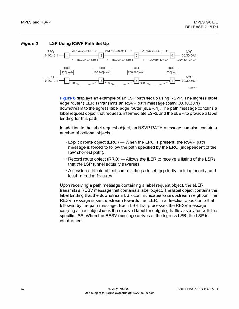
MPLS and RSVP
62
MPLS GUIDERELEASE 21.5.R1
© 2021 Nokia. Use subject to Terms available at: www.nokia.com
3HE 17154 AAAB TQZZA 01
Figure 6 LSP Using RSVP Path Set Up
Figure 6 displays an example of an LSP path set up using RSVP. The ingress label edge router (ILER 1) transmits an RSVP path message (path: 30.30.30.1) downstream to the egress label edge router (eLER 4). The path message contains a label request object that requests intermediate LSRs and the eLER to provide a label binding for this path.
In addition to the label request object, an RSVP PATH message can also contain a number of optional objects:
• Explicit route object (ERO) — When the ERO is present, the RSVP path message is forced to follow the path specified by the ERO (independent of the IGP shortest path).
• Record route object (RRO) — Allows the ILER to receive a listing of the LSRs that the LSP tunnel actually traverses.
• A session attribute object controls the path set up priority, holding priority, and local-rerouting features.
Upon receiving a path message containing a label request object, the eLER transmits a RESV message that contains a label object. The label object contains the label binding that the downstream LSR communicates to its upstream neighbor. The RESV message is sent upstream towards the ILER, in a direction opposite to that followed by the path message. Each LSR that processes the RESV message carrying a label object uses the received label for outgoing traffic associated with the specific LSP. When the RESV message arrives at the ingress LSR, the LSP is established.
1
PATH:30.30.30.1
label
100|push
100 200 300
RESV:10.10.10.1 RESV:10.10.10.1 RESV:10.10.10.1 RESV:10.10.10.1
3
PATH:30.30.30.1
42
PATH:30.30.30.1 NYC
30.30.30.1
SFO
10.10.10.1
1 3 42
NYC
30.30.30.1
SFO
10.10.10.1
label
100|200|swap
label
200|300|swap
label
300|pop
OSSG016

MPLS GUIDE RELEASE 21.5.R1
MPLS and RSVP
3HE 17154 AAAB TQZZA 01 © 2021 Nokia. Use subject to Terms available at: www.nokia.com
63
2.2.1 Using RSVP for MPLS
Hosts and routers that support both MPLS and RSVP can associate labels with RSVP flows. When MPLS and RSVP are combined, the definition of a flow can be made more flexible. Once an LSP is established, the traffic through the path is defined by the label applied at the ingress node of the LSP. The mapping of label to traffic can be accomplished using a variety of criteria. The set of packets that are assigned the same label value by a specific node are considered to belong to the same FEC which defines the RSVP flow.
For use with MPLS, RSVP already has the resource reservation component built-in which makes it ideal to reserve resources for LSPs.
2.2.1.1 RSVP Traffic Engineering Extensions for MPLS
RSVP has been extended for MPLS to support automatic signaling of LSPs. To enhance the scalability, latency, and reliability of RSVP signaling, several extensions have been defined. Refresh messages are still transmitted but the volume of traffic, the amount of CPU utilization, and response latency are reduced while reliability is supported. None of these extensions result in backward compatibility problems with traditional RSVP implementations.
2.2.1.2 Hello Protocol
The Hello protocol detects the loss of a neighbor node or the reset of a neighbor’s RSVP state information. In standard RSVP, neighbor monitoring occurs as part of RSVP’s soft-state model. The reservation state is maintained as cached information that is first installed and then periodically refreshed by the ingress and egress LSRs. If the state is not refreshed within a specified time interval, the LSR discards the state because it assumes that either the neighbor node has been lost or its RSVP state information has been reset.
The Hello protocol extension is composed of a hello message, a hello request object and a hello ACK object. Hello processing between two neighbors supports independent selection of failure detection intervals. Each neighbor can automatically issue hello request objects. Each hello request object is answered by a hello ACK object.

MPLS and RSVP
64
MPLS GUIDERELEASE 21.5.R1
© 2021 Nokia. Use subject to Terms available at: www.nokia.com
3HE 17154 AAAB TQZZA 01
2.2.1.3 MD5 Authentication of RSVP Interface
When enabled on an RSVP interface, authentication of RSVP messages operates in both directions of the interface.
A node maintains a security association with its neighbors for each authentication key. The following items are stored in the context of this security association:
• The HMAC-MD5 authentication algorithm.• Key used with the authentication algorithm.• Lifetime of the key. A key is user-generated key using a third party software/
hardware and enters the value as static string into CLI configuration of the RSVP interface. The key will continue to be valid until it is removed from that RSVP interface.
• Source Address of the sending system.• Latest sending sequence number used with this key identifier.
The RSVP sender transmits an authenticating digest of the RSVP message, computed using the shared authentication key and a keyed-hash algorithm. The message digest is included in an Integrity object which also contains a Flags field, a Key Identifier field, and a Sequence Number field. The RSVP sender complies to the procedures for RSVP message generation in RFC 2747, RSVP Cryptographic Authentication.
An RSVP receiver uses the key together with the authentication algorithm to process received RSVP messages.
When a PLR node switches the path of the LSP to a bypass LSP, it does not send the Integrity object in the RSVP messages over the bypass tunnel. If an integrity object is received from the MP node, then the message is discarded since there is no security association with the next-next-hop MP node.
The MD5 implementation does not support the authentication challenge procedures in RFC 2747.
2.2.1.4 Configuring Authentication using Keychains
The use of authentication mechanism is recommended to protect against malicious attack on the communications between routing protocol neighbors. These attacks could aim to either disrupt communications or to inject incorrect routing information into the systems routing table. The use of authentication keys can help to protect the routing protocols from these types of attacks.

MPLS GUIDE RELEASE 21.5.R1
MPLS and RSVP
3HE 17154 AAAB TQZZA 01 © 2021 Nokia. Use subject to Terms available at: www.nokia.com
65
Within RSVP, authentication must be explicitly configured through the use of the authentication keychain mechanism. This mechanism allows for the configuration of authentication keys and allows the keys to be changed without affecting the state of the protocol adjacencies.
To configure the use of an authentication keychain within RSVP, use the following steps:
1. Configure an authentication keychain within the config>system>security context. The configured keychain must include at least on valid key entry, using a valid authentication algorithm for the RSVP protocol.
2. Associate the configure authentication keychain with RSVP at the interface level of the CLI, this is done with the auth-keychain name command.
For a key entry to be valid, it must include a valid key, the current system clock value must be within the begin and end time of the key entry, and the algorithm specified in the key entry must be supported by the RSVP protocol.
The RSVP protocol supports the following algorithms:
• clear text password• HMAC-MD5• HMC-SHA-1
Error handling:
• If a keychain exists but there are no active key entries with an authentication type that is valid for the associated protocol then inbound protocol packets will not be authenticated and discarded, and no outbound protocol packets should be sent.
• If keychain exists but the last key entry has expired, a log entry is raised indicating that all keychain entries have expired. The RSVP protocol requires that the protocol not revert to an unauthenticated state and requires that the old key is not to be used, therefore, once the last key has expired, all traffic is discarded.
2.2.2 Reservation Styles
LSPs can be signaled with explicit reservation styles. A reservation style is a set of control options that specify a number of supported parameters. The style information is part of the LSP configuration. SR OS supports two reservation styles:

MPLS and RSVP
66
MPLS GUIDERELEASE 21.5.R1
© 2021 Nokia. Use subject to Terms available at: www.nokia.com
3HE 17154 AAAB TQZZA 01
• Fixed Filter (FF) — The Fixed Filter (FF) reservation style specifies an explicit list of senders and a distinct reservation for each of them. Each sender has a dedicated reservation that is not shared with other senders. Each sender is identified by an IP address and a local identification number, the LSP ID. Because each sender has its own reservation, a unique label and a separate LSP can be constructed for each sender-receiver pair. For traditional RSVP applications, the FF reservation style is ideal for a video distribution application in which each channel (or source) requires a separate pipe for each of the individual video streams.
• Shared Explicit (SE) — The Shared Explicit (SE) reservation style creates a single reservation over a link that is shared by an explicit list of senders. Because each sender is explicitly listed in the RESV message, different labels can be assigned to different sender-receiver pairs, thereby creating separate LSPs. If FRR option is enabled for the LSP and selects the facility FRR method at the head-end node, only the SE reservation style is allowed. Furthermore, if a PLR node receives a path message with fast-reroute requested with facility method and the FF reservation style, it will reject the reservation. The one-to-one detour method supports both FF and SE styles.
2.2.2.1 RSVP Message Pacing
When a flood of signaling messages arrive because of topology changes in the network, signaling messages can be dropped which results in longer set up times for LSPs. RSVP message pacing controls the transmission rate for RSVP messages, allowing the messages to be sent in timed intervals. Pacing reduces the number of dropped messages that can occur from bursts of signaling messages in large networks.
2.2.3 RSVP Overhead Refresh Reduction
The RSVP refresh reduction feature consists of the following capabilities implemented in accordance to RFC 2961, RSVP Refresh Overhead Reduction Extensions:
• RSVP message bundling — This capability is intended to reduce overall message handling load. The system supports receipt and processing of bundled message only, but no transmission of bundled messages.

MPLS GUIDE RELEASE 21.5.R1
MPLS and RSVP
3HE 17154 AAAB TQZZA 01 © 2021 Nokia. Use subject to Terms available at: www.nokia.com
67
• Reliable message delivery — This capability consists of sending a message-id and returning a message-ack for each RSVP message. It can be used to detect message loss and support reliable RSVP message delivery on a per hop basis. It also helps reduce the refresh rate since the delivery becomes more reliable.
• Summary refresh — This capability consists of refreshing multiples states with a single message-id list and sending negative ACKs (NACKs) for a message_id which could not be matched. The summary refresh capability reduce the amount of messaging exchanged and the corresponding message processing between peers. It does not however reduce the amount of soft state to be stored in the node.
These capabilities can be enabled on a per-RSVP-interface basis are referred to collectively as “refresh overhead reduction extensions”. When the refresh-reduction is enabled on a system RSVP interface, the node indicates this to its peer by setting a refresh-reduction- capable bit in the flags field of the common RSVP header. If both peers of an RSVP interface set this bit, all the above three capabilities can be used. Furthermore, the node monitors the settings of this bit in received RSVP messages from the peer on the interface. As soon as this bit is cleared, the node stops sending summary refresh messages. If a peer did not set the “refresh-reduction-capable” bit, a node does not attempt to send summary refresh messages.
The RSVP Overhead Refresh Reduction is supported with both RSVP P2P LSP path and the S2L path of an RSVP P2MP LSP instance over the same RSVP interface.
2.2.4 RSVP Graceful Restart Helper
The gr-helper command enables the RSVP Graceful Restart Helper feature.
The RSVP-TE Graceful Restart helper mode allows the SR OS based system (the helper node) to provide another router that has requested it (the restarting node) a grace period, during which the system will continue to use RSVP sessions to neighbors requesting the grace period. This is typically used when another router is rebooting its control plane but its forwarding plane is expected to continue to forward traffic based on the previously available Path and Resv states.
The user can enable Graceful Restart helper on each RSVP interface separately. When the GR helper feature is enabled on an RSVP interface, the node starts inserting a new Restart_Cap Object in the Hello packets to its neighbor. The restarting node does the same and indicates to the helper node the desired Restart Time and Recovery Time.

MPLS and RSVP
68
MPLS GUIDERELEASE 21.5.R1
© 2021 Nokia. Use subject to Terms available at: www.nokia.com
3HE 17154 AAAB TQZZA 01
The GR Restart helper consists of a couple of phases. Once it loses Hello communication with its neighbor, the helper node enters the Restart phase. During this phase, it preserves the state of all RSVP sessions to its neighbor and waits for a new Hello message.
Once the Hello message is received indicating the restarting node preserved state, the helper node enters the recovery phase in which it starts refreshing all the sessions that were preserved. The restarting node will activate all the stale sessions that are refreshed by the helper node. Any Path state that did not get a Resv message from the restarting node once the Recovery Phase time is over is considered to have expired and is deleted by the helper node causing the proper Path Tear generation downstream.
The duration of the restart phase (recovery phase) is equal to the minimum of the neighbor’s advertised Restart Time (Recovery Time) in its last Hello message and the locally configured value of the max-restart (max-recovery) parameter.
When GR helper is enabled on an RSVP interface, its procedures apply to the state of both P2P and P2MP RSVP LSP to a neighbor over this interface.
2.2.5 Enhancements to RSVP Control Plane Congestion Control
The RSVP control plane makes use of a global flow control mechanism to adjust the rate of Path messages for unmapped LSP paths sent to the network under congestion conditions. When a Path message for establishing a new LSP path or retrying an LSP path that failed is sent out, the control plane keeps track of the rate of successful establishment of these paths and adjusts the number of Path messages it sends per second to reflect the success ratio.
In addition, an option to enable an exponential back-off retry-timer is available. When an LSP path establishment attempt fails, the path is put into retry procedures and a new attempt is performed at the expiry of the user-configurable retry-timer. By default, the retry time is constant. The exponential back-off timer procedures will double the value of the user configurable retry-timer value at every failure of the attempt to adjust to the potential network congestion that caused the failure. An LSP establishment fails if no Resv message was received and the Path message retry-timer expired, or a PathErr message was received before the timer expired.
Three enhancements to this flow-control mechanism to improve congestion handling in the rest of the network are supported.

MPLS GUIDE RELEASE 21.5.R1
MPLS and RSVP
3HE 17154 AAAB TQZZA 01 © 2021 Nokia. Use subject to Terms available at: www.nokia.com
69
The first enhancement is the change to the LSP path retry procedure. If the establishment attempt failed due to a Path message timeout and no Resv was received, the next attempt is performed at the expiry of a new LSP path initial retry-timer instead of the existing retry-timer. While the LSP path initial retry-timer is still running, a refresh of the Path message using the same path and the same LSP-id is performed according to the configuration of the refresh-timer. Once the LSP path initial retry-timer expires, the ingress LER then puts this path on the regular retry-timer to schedule the next path signaling using a new computed path by CSPF and a new LSP-id.
The benefits of this enhancement is that the user can now control how many refreshes of the pending PATH state can be performed before starting a new retry-cycle with a new LSP-id. This is all done without affecting the ability to react faster to failures of the LSP path, which will continue to be governed by the existing retry-timer. By configuring the LSP path initial retry-timer to values that are larger than the retry-timer, the ingress LER will decrease the probability of overwhelming a congested LSR with new state while the previous states installed by the same LSP are lingering and will only be removed after the refresh timeout period expires.
The second enhancement consists of applying a jitter +/- 25% to the value of the retry-timer similar to how it is currently done for the refresh timer. This will further decrease the probability that ingress LER nodes synchronize their sending of Path messages during the retry-procedure in response to a congestion event in the network.
The third enhances the RSVP flow control mechanism by taking into account new parameters: outstanding CSPF requests, Resv timeouts and Path timeouts.
2.2.6 BFD for RSVP-TE
BFD will notify RSVP-TE if the BFD session goes down, in addition to notifying other configured BFD enabled protocols (for example, OSPF, IS-IS, and PIM). This notification will then be used by RSVP-TE to begin the reconvergence process. This greatly accelerates the overall RSVP-TE response to network failures.
All encapsulation types supporting IPv4 and IPv6 are supported because all BFD packets are carried in IPv4 and IPv6 packets; this includes Frame Relay and ATM.
BFD is supported on the following interfaces:
• Ethernet (Null, Dot1Q & QinQ)• Spoke SDPs• LAG interfaces

MPLS and RSVP
70
MPLS GUIDERELEASE 21.5.R1
© 2021 Nokia. Use subject to Terms available at: www.nokia.com
3HE 17154 AAAB TQZZA 01
The following interfaces are supported only on the 7750 SR and 7450 ESS:
• VSM interfaces• POS interfaces (including APS)• Channelized interfaces (PPP, HDLC, FR, and ATM) on ASAP (priority 1) and
channelized MDAs (priority 2) including link bundles and IMA
2.2.7 RSVP-TE LSP Statistics
This feature provides the following counters:
• Per forwarding class forwarded in-profile packet count• Per forwarding class forwarded in-profile byte count• Per forwarding class forwarded out of profile packet count • Per forwarding class forwarded out of profile byte count
The counters are available for an RSVP LSP at the egress datapath of an ingress LER and at the ingress datapath of an egress LER. No LSR statistics are provided.
2.2.8 P2MP RSVP-TE LSP Statistics
This feature provides the following counters for a RSVP P2MP LSP instance:
• Per forwarding class forwarded in-profile packet count.• Per forwarding class forwarded in-profile byte count.• Per forwarding class forwarded out of profile packet count. • Per forwarding class forwarded out of profile byte count.
The above counters are provided for the following LSR roles:
• At ingress LER, a set of per P2MP LSP instance counters for packets forwarded to the P2MP LSP instance without counting the replications is provided. In other words, a packet replicated over multiple branches of the same P2MP LSP instance will count once as long as at least one LSP branch forwarded it.
• At BUD LSR and egress LER, per ILM statistics are provided. These counters will include all packets received on the ILM, whether they match a L2/L3 MFIB record or not. ILM stats will work the same way as for a P2P LSP. In other words, they will count all packets received on the primary ILM, including packets received over the bypass LSP.

MPLS GUIDE RELEASE 21.5.R1
MPLS and RSVP
3HE 17154 AAAB TQZZA 01 © 2021 Nokia. Use subject to Terms available at: www.nokia.com
71
When MBB is occurring for an S2L path of an RSVP P2MP LSP, paths of the new and old S2L will both receive packets on the egress LER. Both packets are forwarded to the fabric and outgoing PIM/IGMP interfaces until the older path is torn down by the ingress LER. In this case, packet duplication should be counted.
• No branch LSR statistics are provided. • The P2MP LSP statistics share the same pool of counters and stat indices the
P2P LSP share on the node. Each P2P/P2MP RSVP LSP or LDP FEC consumes one stat index for egress stats and one stat index for ingress stats.
• The user can retrieve the above counters in four different ways:- In CLI display of the output of the show command applied to a specific
instance, or a specific template instance, of a RSVP P2MP.- In CLI display of the output of the monitor command applied to a specific
instance, or a specific template instance, of a RSVP P2MP.- Via an SNMP interface by querying the MIB. - Via an accounting file if statistics collection with the default or user specified
accounting policy is enabled for the MPLS LSP stats configuration contexts.• OAM packets that are forwarded using the LSP encapsulation, for example,
P2MP LSP Ping and P2MP LSP Trace, are also included in the above counters.
The user can determine if packets are dropped for a given branch of a P2MP RSVP LSP by comparing the egress counters at the ingress LER with the ILM counters at the egress LER or BUD LSR.
Octet counters are for the entire frame and so include the label stack and the L2 header and padding similar to the existing P2P RSVP LSP and LDP FEC counters. As such, ingress and egress octet counters for an LSP may slightly differ if the type of interface or encapsulation is different (POS, Ethernet NULL, Ethernet Dot1.Q).
2.2.8.1 Configuring RSVP P2MP LSP Egress Statistics
At ingress LER, the configuration of the egress statistics is under the MPLS P2MP LSP context when carrying multicast packets over a RSVP P2MP LSP in the base routing instance. This is the same configuration as the one already supported with P2P RSVP LSP.
configrouter
[no] mpls[no] lsp lsp-name p2mp-lsp
[no] egress-statisticsaccounting-policy policy-idno accounting-policy

MPLS and RSVP
72
MPLS GUIDERELEASE 21.5.R1
© 2021 Nokia. Use subject to Terms available at: www.nokia.com
3HE 17154 AAAB TQZZA 01
[no] collect-stats[no] shutdown
If there are no stat indices available when the user performs the ‘no shutdown’ command for the egress statistics node, the command fails.
The configuration is in the P2MP LSP template when the RSVP P2MP LSP is used as an I-PMSI or S-PMSI in multicast VPN or in VPLS/B-VPLS.
configrouter
[no] mplslsp-template template-name p2mpno lsp-template template-name
[no] egress-statisticsaccounting-policy policy-idno accounting-policy[no] collect-stats
If there are no stat indices available at the time an instance of the P2MP LSP template is signaled, no stats are allocated to the instance, but the LSP is brought up. In this case, an operational state of out-of-resources is shown for the egress stats in the show output of the P2MP LSP S2L path.
2.2.8.2 Configuring RSVP P2MP LSP Ingress Statistics
When the ingress LER signals the path of the S2L sub-LSP, it includes the name of the LSP and that of the path in the Session Name field of the Session Attribute object in the Path message. The encoding is as follows:
Session Name: lsp-name::path-name, where lsp-name component is encoded as follows:
1. P2MP LSP via user configuration for L3 multicast in global routing instance: “LspNameFromConfig”
2. P2MP LSP as I-PMSI or S-PMSI in L3 mVPN: templateName-SvcId-mTTmIndex
3. P2MP LSP as I-PMSI in VPLS/B-VPLS: templateName-SvcId-mTTmIndex
The ingress statistics CLI configuration allows the user to match either on the exact name of the P2MP LSP as configured at the ingress LER or on a context which matches on the template name and the service-id as configured at the ingress LER.
configrouter
[no] mplsingress-statistics
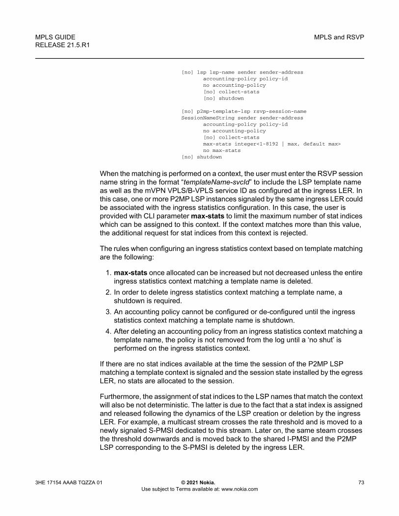
MPLS GUIDE RELEASE 21.5.R1
MPLS and RSVP
3HE 17154 AAAB TQZZA 01 © 2021 Nokia. Use subject to Terms available at: www.nokia.com
73
[no] lsp lsp-name sender sender-addressaccounting-policy policy-idno accounting-policy[no] collect-stats[no] shutdown
[no] p2mp-template-lsp rsvp-session-nameSessionNameString sender sender-address
accounting-policy policy-idno accounting-policy[no] collect-statsmax-stats integer<1-8192 | max, default max>no max-stats
[no] shutdown
When the matching is performed on a context, the user must enter the RSVP session name string in the format “templateName-svcId” to include the LSP template name as well as the mVPN VPLS/B-VPLS service ID as configured at the ingress LER. In this case, one or more P2MP LSP instances signaled by the same ingress LER could be associated with the ingress statistics configuration. In this case, the user is provided with CLI parameter max-stats to limit the maximum number of stat indices which can be assigned to this context. If the context matches more than this value, the additional request for stat indices from this context is rejected.
The rules when configuring an ingress statistics context based on template matching are the following:
1. max-stats once allocated can be increased but not decreased unless the entire ingress statistics context matching a template name is deleted.
2. In order to delete ingress statistics context matching a template name, a shutdown is required.
3. An accounting policy cannot be configured or de-configured until the ingress statistics context matching a template name is shutdown.
4. After deleting an accounting policy from an ingress statistics context matching a template name, the policy is not removed from the log until a ‘no shut’ is performed on the ingress statistics context.
If there are no stat indices available at the time the session of the P2MP LSP matching a template context is signaled and the session state installed by the egress LER, no stats are allocated to the session.
Furthermore, the assignment of stat indices to the LSP names that match the context will also be not deterministic. The latter is due to the fact that a stat index is assigned and released following the dynamics of the LSP creation or deletion by the ingress LER. For example, a multicast stream crosses the rate threshold and is moved to a newly signaled S-PMSI dedicated to this stream. Later on, the same steam crosses the threshold downwards and is moved back to the shared I-PMSI and the P2MP LSP corresponding to the S-PMSI is deleted by the ingress LER.

MPLS and RSVP
74
MPLS GUIDERELEASE 21.5.R1
© 2021 Nokia. Use subject to Terms available at: www.nokia.com
3HE 17154 AAAB TQZZA 01
2.2.8.3 Configuring Implicit Null
The implicit null label option allows a router egress LER to receive MPLS packets from the previous hop without the outer LSP label. The operation of the previous hop is referred to as penultimate hop popping (PHP).
This option is signaled by the egress LER to the previous hop during the LSP signaling with RSVP control protocol. In addition, the egress LER can be configured to receive MPLS packet with the implicit null label on a static LSP.
The user can configure your router to signal the implicit null label value over all RSVP interfaces and for all RSVP LSPs for which this node is the egress LER using the implicit-null-label command in the config>router>rsvp context.
The user must shut down RSVP before being able to change the implicit null configuration option.
The user can also override the RSVP level configuration for a specific RSVP interface:
config>router>rsvp>if>implicit-null-label {enable | disable}
All LSPs for which this node is the egress LER and for which the path message is received from the previous hop node over this RSVP interface will signal the implicit null label. This means that if the egress LER is also the merge-point (MP) node, then the incoming interface for the path refresh message over the bypass dictates if the packet will use the implicit null label or not; the same applies to a 1-to-1 detour LSP.
By default, an RSVP interface inherits the RSVP level configuration. The user must shut down the RSVP interface before being able to change the implicit null configuration option.
The egress LER does not signal the implicit null label value on P2MP RSVP LSPs. However, the PHP node can honor a Resv message with the label value set to the implicit null value when the egress LER is a third party implementation.
The implicit null label option is also supported on a static label LSP. The following commands can be used to cause the node to push or to swap to an implicit null label on the MPLS packet:
config>router>mpls>static-lsp>push implicit-null-label nexthop ip-address
Note: The RSVP interface must be shutdown regardless of whether the new value for the interface is the same or different than the one it is currently using.

MPLS GUIDE RELEASE 21.5.R1
MPLS and RSVP
3HE 17154 AAAB TQZZA 01 © 2021 Nokia. Use subject to Terms available at: www.nokia.com
75
config>router>mpls>if>label-map>swap implicit-null-label nexthop ip-address
2.2.9 Using Unnumbered Point-to-Point Interface in RSVP
This feature introduces the use of unnumbered IP interface as a Traffic Engineering (TE) link for the signaling of RSVP P2P LSP and P2MP LSP.
An unnumbered IP interface is identified uniquely on a router in the network by the tuple {router-id, ifIndex}. Each side of the link assigns a system-wide unique interface index to the unnumbered interface. ISIS, OSPF, RSVP, and OAM modules will use this tuple to advertise the link information, signal LSP paths over this unnumbered interface, or send and respond to an MPLS echo request message over an unnumbered interface.
The interface borrowed IP address is used exclusively as the source address for IP packets that are originated from the interface and needs to be configured to an address different from system interface for the FRR bypass LSP to come up at the ingress LER.
The borrowed IP address for an unnumbered interface is configured using the following CLI command with a default value set to the system interface address:
config>router>if>unnumbered [ip-int-name | ip-address]
The support of unnumbered TE link in IS-IS consists of adding a new sub-TLV of the extended IS reachability TLV, which encodes the Link Local and Link Remote Identifiers as defined in RFC 5307.
The support of unnumbered TE link in OSPF consists of adding a new sub-TLV, which encodes the same Link Local and Link Remote Identifiers in the Link TLV of the TE area opaque LSA and sends the local Identifier in the Link Local Identifier TLV in the TE link local opaque LSA as per RFC 4203.
The support of unnumbered TE link in RSVP implements the signaling of unnumbered interfaces in ERO/RRO as per RFC 3477 and the support of IF_ID RSVP_HOP object with a new Ctype as per Section 8.1.1 of RFC 3473. The IPv4 Next/Previous Hop Address field is set to the borrowed IP interface address.
The unnumbered IP is advertised by IS-IS TE and OSPF TE, and CSPF can include them in the computation of a path for a P2P LSP or for the S2L of a P2MP LSP. This feature does not, however, support defining an unnumbered interface a hop in the path definition of an LSP.

MPLS and RSVP
76
MPLS GUIDERELEASE 21.5.R1
© 2021 Nokia. Use subject to Terms available at: www.nokia.com
3HE 17154 AAAB TQZZA 01
A router creates an RSVP neighbor over an unnumbered interface using the tuple {router-id, ifIndex}. The router-id of the router that advertised a given unnumbered interface index is obtained from the TE database. As a result, if TE is disabled in IS-IS or OSPF, a non-CSPF LSP with the next-hop for its path is over an unnumbered interface will not come up at the ingress LER since the router-id of the neighbor that has the next-hop of the path message cannot be looked up. In this case, the LSP path will remain in operationally down state with a reason noRouteToDestination. If a PATH message was received at the LSR in which TE was disabled and the next-hop for the LSP path is over an unnumbered interface, a PathErr message is sent back to the ingress LER with the Routing Problem error code of 24 and an error value of 5 “No route available toward destination”.
All MPLS features available for numbered IP interfaces are supported, with the exception of the following:
• Configuring a router-id with a value other than system.• Signaling of an LSP path with an ERO based a loose/strict hop using an
unnumbered TE link in the path hop definition.• Signaling of one-to-one detour LSP over unnumbered interface.• Unnumbered RSVP interface registration with BFD.• RSVP Hello and all Hello related capabilities such as Graceful-restart helper.• The user SRLG database feature. The user-srlg-db option under MPLS allows
the user to manually enter the SRLG membership of any link in the network in a local database at the ingress LER. The user cannot enter an unnumbered interface into this database and as such, all unnumbered interfaces are considered as having no SRLG membership if the user enabled the user-srlg-db option.
This feature also extends the support of lsp-ping, p2mp-lsp-ping, lsp-trace, and p2mp-lsptrace to P2P and P2MP LSPs that have unnumbered TE links in their path.
2.2.9.1 Operation of RSVP FRR Facility Backup over Unnumbered Interface
When the Point-of-Local Repair (PLR) node activates the bypass LSP by sending a PATH message to refresh the path state of protected LSP at the Merge-Point (MP) node, it must use an IPv4 tunnel sender address in the sender template object that is different than the one used by the ingress LER in the PATH message. These are the procedures specified in RFC 4090 that are followed in the SR OS implementation.

MPLS GUIDE RELEASE 21.5.R1
MPLS and RSVP
3HE 17154 AAAB TQZZA 01 © 2021 Nokia. Use subject to Terms available at: www.nokia.com
77
The router uses the address of the outgoing interface of the bypass LSP as the IPv4 tunnel sender address in the sender template object. This address is different from the system interface address used in the sender template of the protected LSP by the ingress LER and so, there are no conflicts when the ingress LER acts as a PLR.
When the PLR is the ingress LER node and the outgoing interface of the bypass LSP is unnumbered, it is required that the user assigns to the interface a borrowed IP address that is different from the system interface. If not, the bypass LSP will not come up.
In addition, the PLR node will include the IPv4 RSVP_HOP object (C-Type=1) or the IF_ID RSVP_HOP object (C-Type=3) in the PATH message if the outgoing interface of the bypass LSP is numbered or unnumbered respectively.
When the MP node receives the PATH message over the bypass LSP, it will create the merge-point context for the protected LSP and associate it with the existing state if any of the following is satisfied:
• Change in C-Type of the RSVP_HOP object, or• C-Type is IF_ID RSVP_HOP and did not change but IF_ID TLV is different, or• Change in IPv4 Next/Previous Hop Address in RSVP_HOP object regardless of
the C-Type value.
These procedures at PLR and MP nodes are followed in both link-protect and node-protect FRR. If the MP node is running a pre-Release 11.0 implementation, it will reject the new IF_ID C-Type and will drop the PATH over bypass. This will result in the protected LSP state expiring at the MP node, which will tear down the path. This is the case in general when node-protect FRR is enabled and the MP node does not support unnumbered RSVP interface.

MPLS and RSVP
78
MPLS GUIDERELEASE 21.5.R1
© 2021 Nokia. Use subject to Terms available at: www.nokia.com
3HE 17154 AAAB TQZZA 01
2.3 MPLS Transport Profile
MPLS can be used to provide a network layer to support packet transport services. In some operational environments, it is desirable that the operation and maintenance of such an MPLS based packet transport network follow operational models typical in traditional optical transport networks (for example, SONET/SDH), while providing additional OAM, survivability and other maintenance functions targeted at that environment.
MPLS-TP defines a profile of MPLS targeted at transport applications. This profile defines the specific MPLS characteristics and extensions required to meet transport requirements, while retaining compliance to the standard IETF MPLS architecture and label switching paradigm. The basic requirements are architecture for MPLS-TP are described by the IETF in RFC 5654, RFC 5921, and RFC 5960, in order to meet two objectives:
1. To enable MPLS to be deployed in a transport network and operated in a similar manner to existing transport technologies.
2. To enable MPLS to support packet transport services with a similar degree of predictability to that found in existing transport networks.
In order to meet these objectives, MPLS-TP has a number of high level characteristics:
• It does not modify the MPLS forwarding architecture, which is based on existing pseudowire and LSP constructs. Point-to-point LSPs may be unidirectional or bi-directional. Bi-directional LSPs must be congruent (that is, co-routed and follow the same path in each direction). The system supports bidirectional co-routed MPLS-TP LSPs.
• There is no LSP merging.• OAM, protection, and forwarding of data packets can operate without IP
forwarding support. When static provisioning is used, there is no dependency on dynamic routing or signaling.
• LSP and pseudowire monitoring is only achieved through the use of OAM and does not rely on control plane or routing functions to determine the health of a path. For example, LDP hello failures do not trigger protection.
• MPLS-TP can operate in the absence of an IP control plane and IP forwarding of OAM traffic. MPLS-TP is only supported on static LSPs and PWs.
The system supports MPLS-TP on LSPs and PWs with static labels. MPLS-TP is not supported on dynamically signaled LSPs and PWs. MPLS-TP is supported for Epipe, Apipe, and Cpipe VLLs, and Epipe spoke SDP termination on IES, VPRN and VPLS. Static PWs may use SDPs that use either static MPLS-TP LSPs or RSVP-TE LSPs.

MPLS GUIDE RELEASE 21.5.R1
MPLS and RSVP
3HE 17154 AAAB TQZZA 01 © 2021 Nokia. Use subject to Terms available at: www.nokia.com
79
The following MPLS-TP OAM and protection mechanisms, defined by the IETF, are supported:
• MPLS-TP Generic Associated Channel for LSPs and PWs (RFC 5586)• MPLS-TP Identifiers (RFC 6370)• Proactive CC, CV, and RDI using BFD for LSPs (RFC 6428)• On-Demand CV for LSPs and PWs using LSP Ping and LSP Trace (RFC 6426)• 1-for-1 Linear protection for LSPs (RFC 6378)• Static PW Status Signaling (RFC 6478)
The system can play the role of an LER and an LSR for static MPLS-TP LSPs, and a PE/T-PE and an S-PE for static MPLS-TP PWs. It can also act as a S-PE for MPLS-TP segments between an MPLS network that strictly follows the transport profile, and an MPLS network that supports both MPLS-TP and dynamic IP/MPLS.
2.3.1 MPLS-TP Model
Figure 7 shows a high level functional model for MPLS-TP in SR OS. LSP A and LSP B are the working and protect LSPs of an LSP tunnel. These are modeled as working and protect paths of an MPLS-TP LSP in SR OS. MPLS-TP OAM runs in-band on each path. 1:1 linear protection coordinates the working and protect paths, using a protection switching coordination protocol (PSC) that runs in-band on each path over a Generic Associated Channel (G-ACh) on each path. Each path can use either an IP numbered, IP unnumbered, or MPLS-TP unnumbered (that is, non-IP) interface.
Figure 7 MPLS-TP Model
al_0221
MPLS-TPTunnel
PWOAM
PW PW Services see SDP as per IP/MPLS case
Each direction of TP LSP presented asunidirectional SDP to service
Abstracts underlying LSPs towards SDP;PSC (linear protection) picks working LSP
MPLS manages independent bidirectionalMPLS-TP LSP paths
Numbered and unnumbered interface
PSC
Path A
Port/VLAN
Port/VLAN
Path B
ProtectWorking
Interface Interface
SDP
MPLS-TP LSP
PWTP Link/Interface
ETHPort
PSC
ETHPort
TP Link/Interface
PW
LSPOAM
Server LayerOAM
LSP A(bidir)
LSP A(bidir)

MPLS and RSVP
80
MPLS GUIDERELEASE 21.5.R1
© 2021 Nokia. Use subject to Terms available at: www.nokia.com
3HE 17154 AAAB TQZZA 01
All MPLS-TP LSPs are bidirectional co-routed, as detailed in RFC5654. That is, the forward and backward directions follow the same route (in terms of links and nodes) across the network. Both directions are set up, monitored and protected as a single entity. Therefore, both ingress and egress directions of the same LSP segment are associated at the LER and LSR and use the same interface (although this is not enforced by the system).
In the above model, an SDP can use one MPLS-TP LSP. This abstracts the underlying paths towards the overlying services, which are transported on pseudowires. Pseudowires are modeled as spoke SDPs and can also use MPLS-TP OAM. PWs with static labels may use SDPs that, in turn, use either signaled RSVP-TE LSPs or one static MPLS-TP LSP.
2.3.2 MPLS-TP Provider Edge and Gateway
This section describes some example roles for the system in an MPLS-TP network.
2.3.2.1 VLL Services
The system may use MPLS TP LSPs, and PWs, to transport point to point virtual leased line services. The router may play the role of a terminating PE or switching PE for VLLs. Epipe, Apipe, and Cpipe VLLs are supported.
Figure 8 illustrates the use of the system as a T-PE for services in an MPLS-TP domain, and as a S-PE for services between an MPLS-TP domain and an IP/MPLS domain. Static PWs with MPLS-TP identifiers, originating in the MPLS-TP network, are transported over static MPLS-TP LSPs. These either terminate on a local SAP on the system, or are switched to another PW segment across the IP/MPLS network. The PW segment in the IP/MPLS network may have static labels or be signaled using T-LDP.

MPLS GUIDE RELEASE 21.5.R1
MPLS and RSVP
3HE 17154 AAAB TQZZA 01 © 2021 Nokia. Use subject to Terms available at: www.nokia.com
81
Figure 8 MPLS-TP Provider Edge and Gateway, VLL Services
2.3.2.2 Spoke SDP Termination
Figure 9 and Figure 10 illustrate the model for spoke SDP termination on VPLS and IES/VPRN services, respectively. Similar to the VLL case, the static MPLS-TP PW may terminate on an interface belonging to the service on the router at the border between the MPLS-TP and IP/MPLS networks, or be switched to another PW segment to be terminated on a remote PE.
al_0895
SAP
TP LSP
MPLS-TP IP/MPLS
BFD CC/VLSP-PingLinear Protection
MEP, BFD (LSP) andProtection EndpointMIP
VCCV-PingStatic-PW Status
IP/MPLS SideMPLS-TP Identifiers on PWDynamic IP LSPStatic PWStatic PW StatusPW RedundancyOn-Demand CV
MPLS-TP SideMPLS-TP IdentifiersStatic LSPBFD CC/CVLinear ProtectionOn-Demand CVStatic PWStatic PW StatusPW RedundancyOn-Demand CV
TP LSPPW Segment (Static)
PW Segment (Static) PW Segment (Static)
PW Switching Point
IP LSP
SAP SAP
SAP

MPLS and RSVP
82
MPLS GUIDERELEASE 21.5.R1
© 2021 Nokia. Use subject to Terms available at: www.nokia.com
3HE 17154 AAAB TQZZA 01
Figure 9 MPLS-TP Provider Edge and Gateway, Spoke SDP Termination on VPLS
Figure 10 MPLS-TP Provider Edge and Gateway, Spoke SDP Termination on IES/VPRN
al_0896
SAP
TP LSP
MPLS-TP IP/MPLS
BFD CC/VLSP-PingLinear Protection
MEP, BFD (LSP) andProtection EndpointMIP
VCCV-PingStatic-PW Status
IP/MPLS SideMPLS-TP Identifiers on PWDynamic IP LSPStatic PWStatic PW StatusPW Redundancy as TodayOn-Demand CV
MPLS-TP SideMPLS-TP IdentifiersStatic LSPBFD CC/CVLinear ProtectionOn-Demand CVStatic PWStatic PW StatusPW RedundancyOn-Demand CV
TP LSPPW Segment (Static)
PW Segment (Static) PW Segment (Static)
PW Switching Point
IP LSP
SAP VPLS
VPLS
al_0897
SAP
TP LSP
MPLS-TP IP/MPLS
BFD CC/VLSP-PingLinear Protection
MEP, BFD (LSP) andProtection EndpointMIP
VCCV-PingStatic-PW Status
IP/MPLS SideMPLS-TP Identifiers on PWDynamic IP LSPStatic PWStatic PW StatusPW Redundancy as TodayOn-Demand CV
MPLS-TP SideMPLS-TP IdentifiersStatic LSPBFD CC/CVLinear ProtectionOn-Demand CVStatic PWStatic PW StatusPW RedundancyOn-Demand CV
TP LSPPW Segment (Static)
PW Segment (Static) PW Segment (Static)
PW Switching Point
IP LSP
SAP VRF
VRF

MPLS GUIDE RELEASE 21.5.R1
MPLS and RSVP
3HE 17154 AAAB TQZZA 01 © 2021 Nokia. Use subject to Terms available at: www.nokia.com
83
2.3.3 MPLS-TP LSR
The SR OS MPLS-TP LSR model is illustrated in MPLS-TP LSR. The system is able to swap a statically configured LSP label on an ingress path to a statically configured LSP label on an egress path. Bidirectional co-routed MPLS TP LSPs are supported by configuring the forward and reverse paths of the LSP to use the same ports on ingress and egress.
Figure 11 MPLS-TP LSR
2.3.4 Detailed Descriptions of MPLS-TP
2.3.4.1 MPLS-TP LSPs
SR OS supports the configuration of MPLS-TP tunnels, which comprise a working and, optionally, a protect LSP. In SR OS, a tunnel is referred to as an LSP, while an MPLS-TP LSP is referred to as a path. It is then possible to bind an MPLS-TP tunnel to an SDP.
MPLS-TP LSPs (that is, paths) with static labels are supported. MPLS-TP is not supported for signaled LSPs.
al_0898
TP LSP
MPLS-TP MPLS-TP
BFD CC/VLSP-PingLinear Protection
MEP, BFD (LSP) andProtection EndpointMIP
VCCV-PingStatic-PW Status
MPLS-TP SideMPLS-TP IdentifiersStatic LSPBFD CC/CVLinear ProtectionOn-Demand CVStatic PWStatic PW StatusPW RedundancyOn-Demand CV
PW (Static)
LSP Label SwapLSP MIP
TP LSP

MPLS and RSVP
84
MPLS GUIDERELEASE 21.5.R1
© 2021 Nokia. Use subject to Terms available at: www.nokia.com
3HE 17154 AAAB TQZZA 01
Both bidirectional associated (where the forward and reverse directions of a bidirectional LSP are associated at a given LER, but may take different routes through the intervening network) and bidirectional co-routed (where the forward and reverse directions of the LSP are associated at each LSR, and take the same route through the network) are possible in MPLS-TP. However, only bidirectional co-routed LSPs are supported.
It is possible to configure MPLS-TP identifiers associated with the LSP, and MPLS-TP OAM parameters on each LSP of a tunnel. MPLS-TP protection is configured for a tunnel at the level of the protect path level. Both protection and OAM configuration is managed via templates, in order to simplify provisioning for large numbers of tunnels.
The router may play the role of either an LER or an LSR.
2.3.4.2 MPLS-TP on Pseudowires
MPLS-TP is supported on PWs with static labels. The provisioning model supports RFC6370-style PW path identifiers for MPLS-TP PWs.
MPLS-TP PWs reuse the static PW provisioning model of previous SR OS releases. Including the use of the PW-switching key work to distinguish an S-PE. Therefore, the primary distinguishing feature for an MPLS-TP PW is the ability to configure MPLS-TP PW path identifiers, and to support MPLS-TP OAM and static PW status signaling.
The system can perform the role of a T-PE or an S-PE for a PW with MPLS-TP.
A spoke SDP with static PW labels and MPLS-TP identifiers and OAM capabilities can use an SDP that uses either an MPLS-TP tunnel, or that uses regular RSVP-TE LSPs. The control word is supported for all MPLS-TP PWs.
2.3.5 MPLS-TP Maintenance Identifiers
MPLS-TP is designed for use both with, and without, a control plane. MPLS-TP therefore specifies a set of identifiers that can be used for objects in either environment. This includes a path and maintenance identifier architecture comprising Node, Interface, PW and LSP identifiers, Maintenance Entity Groups (MEGs), Maintenance End Points (MEPs) and Maintenance Intermediate Points (MIPs). These identifiers are specified in RFC6370.

MPLS GUIDE RELEASE 21.5.R1
MPLS and RSVP
3HE 17154 AAAB TQZZA 01 © 2021 Nokia. Use subject to Terms available at: www.nokia.com
85
MPLS-TP OAM and protection switching operates within a framework that is designed to be similar to existing transport network maintenance architectures. MPLS-TP introduces concept of maintenance domains to be managed and monitored. In these, Maintenance Entity Group End Points (MEPs) are edges of a maintenance domain. OAM of a maintenance level must not leak beyond corresponding MEP and so MEPs typically reside at the end points of LSPs and PWs. Maintenance Intermediate Points (MIPS) define intermediate nodes to be monitored. Maintenance Entity Groups (MEGs) comprise all the MEPs and MIPs on an LSP or PW.
Figure 12 MPLS-TP Maintenance Architecture
Both IP-compatible and ICC (ITU-T carrier code) based identifiers for the above objects are specified in the IETF, but only the IP-compatible identifiers defined in RFC6370 are supported.
SR OS supports the configuration of the following node and interface related identifiers:
• Global_ID: this is similar to the global ID that can be configured for Dynamic MS-PWs. However, in MPLS-TP this should be set to the AS# of the node. If not explicitly configured, then it assumes the default value of 0. In SR OS, the source Global ID for an MPLS-TP Tunnel is taken to be the Global ID configured at the LER. The destination Global ID is optional in the tunnel configuration. If it is not configured, then it is taken as the same as the source Global ID.
• Node_ID: This is a 32-bit value assigned by the operator within the scope of the Global_ID. The system supports the configuration of an IPv4 formatted address <a.b.c.d> or an unsigned 32-bit integer for the MPLS-TP Node ID at each node. The node ID must be unique within the scope of the global ID, but there is no requirement for it to be a valid routable IP address. Indeed, a node-id can represent a separate IP-compatible addressing space that may be separate
al_0226
MEP MIP
LSP
LER LSR A LSR B LER
MIP MEPMEG

MPLS and RSVP
86
MPLS GUIDERELEASE 21.5.R1
© 2021 Nokia. Use subject to Terms available at: www.nokia.com
3HE 17154 AAAB TQZZA 01
from the IP addressing plan of the underlying network. If no node ID is configured, then the node ID is taken to be the system interface IPv4 address of the node. When configuring a tunnel at an LER, either an IPv4 or an unsigned integer Node ID can be configured as the source and destination identifiers, but both ends must be of the same type.
• IF_ID: This is an MPLS-TP section layer identifier at the MPLS interface level. On the router, this is used to provide an identifier for the LSP-Trace DSMAP when an IP identifier is not available. The IF_ID is a 64-bit identifier of an MPLS-TP interface on a node that is unique within the scope of a Global_ID. It is composed of the Node_ID and the IF_Num. The IF_Num is a node-wide unique identifier for an MPLS-TP interface. On the router, this is primarily used for supporting the DSMAP TLV in LSP Trace using MPLS-TP identifiers with unnumbered MPLS-TP interfaces.
Statically configured LSPs are identified using GMPLS-compatible identifiers with the addition of a Tunnel_Num and LSP_Num. As in RSVP-TE, tunnels represent, for example, a set of working and protect LSPs. These are GMPLS-compatible because GMPLS chosen by the IETF as the control plane for MPLS-TP LSPs, although this is not supported in Release 11.0 of the software. PWs are identified using a PW Path ID which has the same structure as FEC129 AII Type 2.
SR OS derives the identifiers for MEPs and MIPs on LSPs and PWs based on the configured identifiers for the MPLS-TP Tunnel, LSP or PW Path ID, for use in MPLS-TP OAM and protection switching, as per RFC6370.
The information models for LSPs and PWs are illustrated in Figure 13 and Figure 14. The figures use the terminology defined in RFC6370.

MPLS GUIDE RELEASE 21.5.R1
MPLS and RSVP
3HE 17154 AAAB TQZZA 01 © 2021 Nokia. Use subject to Terms available at: www.nokia.com
87
Figure 13 MPLS-TP LSP and Tunnel Information Model
The MPLS-TP Tunnel ID and LSP ID are not to be confused with the RSVP-TE tunnel id implemented on the router system. Table 8 shows how these map to the X and Y ends of the tunnel shown in Figure 13 for the case of co-routed bidirectional LSPs.
al_0227
MEPs MIP
LSP_a
meg_id =isp_id
mep_id =global_id::node_id::tunnel_id::isp_num
mip_id =node_id::0
isp_id =x-tunnel_id::y-tunnel_id::isp_num
x-tunnel_id =global_id::node_id::tunnel_numx-tunnel if_id = node_id::if_num
if_id =node_id::if_num
Working
LER X LSR A LSR B LER Y
MIP
MIP
LSP_b
Protect
global_idnode_id
LSR C LSR D
MIP
MEPs
MEG
Table 8 Mapping from RSVP-TE to MPLS-TP Maintenance Identifiers
RSVP-TE Identifier MPLS-TP Maintenance Identifier
Tunnel Endpoint Address Node ID (Y)
Tunnel ID (X) Tunnel Num (X)
Extended Tunnel ID Node ID (X)
Tunnel Sender Address Node ID (X)
LSP ID LSP Num

MPLS and RSVP
88
MPLS GUIDERELEASE 21.5.R1
© 2021 Nokia. Use subject to Terms available at: www.nokia.com
3HE 17154 AAAB TQZZA 01
Figure 14 MPLS-TP PW Information Model
In the PW information model shown in Figure 14, the MS-PW is identified by the PW Path ID that is composed of the full AGI:SAII:TAII. The PW Path ID is also the MEP ID at the T-PEs, so a user does not have to explicitly configure a MEP ID; it is automatically derived by the system. For MPLS-TP PWs with static labels, although the PW is not signaled end-to-end, the directionality of the SAII and TAII is taken to be the same as for the equivalent label mapping message that is from downstream to upstream. This is to maintain consistency with signaled pseudowires using FEC 129.
On the system, an S-PE for an MS-PW with static labels is configured as a pair of spoke SDPs bound together in an VLL service using the VC-switching command. Therefore, the PW Path ID configured at the spoke SDP level at an S-PE must contain the Global-ID, Node-ID and AC-ID at the far end T-PEs, not the local S-PE. The ordering of the SAII:TAII in the PW Path ID where static PWs are used should be consistent with the direction of signaling of the egress label to a spoke SDP forming that segment, if that label were signaled using T-LDP (in downstream unsolicited mode). VCCV Ping will check the PW ID in the VCCV Ping echo request message against the configured PW Path ID for the egress PW segment.
Figure 15 shows an example of how the PW Path IDs can be configured for a simple two-segment MS-PW.
al_0228
MEPs MIP
PW_a
Note: PW Path ID is Structuredas per FEC129 All Type 2
meg_id =pw_path_idmep_id =agi::global_id::node_id::ac_id
mip_id =node_id::0
pw_path_id =agi::saii::taii
Primary
T-PE X S-PE A S-PE B T-PE Y
MIP
MIP
PW_b
Secondary
global_idnode_id
S-PE C S-PE D
MIP
MEPs
MEG

MPLS GUIDE RELEASE 21.5.R1
MPLS and RSVP
3HE 17154 AAAB TQZZA 01 © 2021 Nokia. Use subject to Terms available at: www.nokia.com
89
Figure 15 Example usage of PW Identifiers
2.3.5.1 Generic Associated Channel
MPLS-TP requires that all OAM traffic be carried in-band on both directions of an LSP or PW. This is to ensure that OAM traffic always shares fate with user data traffic. This is achieved by using an associated control channel on an LSP or PW, similar to that used today on PWs. This creates a channel, which is used for OAM, protection switching protocols (for example, LSP linear protection switching coordination), and other maintenance traffic., and is known as the Generic Associated Channel (G-ACh).
RFC5586 specifies mechanisms for implementing the G-ACh, relying on the combination of a reserved MPLS label, the Generic-ACH Label (GAL), as an alert mechanism (value=13) and Generic Associated Channel Header (G-ACH) for MPLS LSPs, and using the Generic Associated Channel Header, only, for MPLS PWs (although the GAL is allowed on PWs). The purpose of the GAL is to indicate that a G-ACH resides at the bottom of the label stack, and is only visible when the bottom non-reserved label is popped. The G-ACH channel type is used to indicate the packet type carried on the G-ACh. Packets on a G-ACh are targeted to a node containing a MEP by ensuring that the GAL is pushed immediately below the label that is popped at the MEP (for example, LSP endpoint or PW endpoint), so that it can be inspected as soon as the label is popped. A G-ACh packet is targeted to a node containing a MIP by setting the TTL of the LSP or PW label, as applicable, so that it
al_0890
VC-Switching
Spoke-SDPSpoke-SDP
T-PEglobal_id: 1node_id: 10.0.0.10ac_id: 1
T-PEglobal_id: 2node_id: 10.0.0.30
S-PEglobal_id: 1node_id: 10.0.0.20
SAP SAP
Epipevll
pw-path-id:agi: 0SAII: 1:10.0.0.10:1TAII: 2:10.0.0.30:2
pw-path-id:agi: 0SAII: 2:10.0.0.30:2TAII: 1:10.0.0.10:1
pw-path-id:agi: 0SAII: 1:10.0.0.10:1TAII: 2:10.0.0.30:2
pw-path-id:agi: 0SAII: 2:10.0.0.30:2TAII: 1:10.0.0.10:1

MPLS and RSVP
90
MPLS GUIDERELEASE 21.5.R1
© 2021 Nokia. Use subject to Terms available at: www.nokia.com
3HE 17154 AAAB TQZZA 01
expires at that node, in a similar manner to the SR OS implementation of VCCV for MS-PWs.
Figure 16 Label for LSP and PW G-ACh Packets
The system supports the G-ACh on static pseudowires and static LSPs.
2.3.5.2 MPLS-TP Operations, Administration and Maintenance (OAM)
This section details the MPLS-TP OAM mechanisms that are supported.
2.3.5.2.1 On-Demand Connectivity Verification (CV) using LSP-Ping
MPLS–TP supports mechanisms for on demand CC/CV as well as route tracing for LSPs and PWs. These are required to enable an operator to test the initial configuration of a transport path, or to assist with fault isolation and diagnosis. On demand CC/CV and route tracing for MPLS-TP is based on LSP-Ping and is described in RFC6426. Three possible encapsulations are specified in that RFC:
• IP encapsulation, using the same label stack as RFC 8029, or encapsulated in the IPv4 G-ACh channel with a GAL/ACH
• and non-IP encapsulation with GAL/ACH for LSPs and ACH for PWs.
In IP-encapsulation, LSP-Ping packets are sent over the MPLS LSP for which OAM is being performed and contain an IP/UDP packet within them. The On-demand CV echo response message is sent on the reverse path of the LSP, and the reply contains IP/UDP headers followed by the On-demand CV payload.
al_0230
LSP Label LSP Label
LSP OAM PacketLabel Stack
PW OAM PacketLabel Stack
GAL PW Label
ACH ACH
Payload Payload

MPLS GUIDE RELEASE 21.5.R1
MPLS and RSVP
3HE 17154 AAAB TQZZA 01 © 2021 Nokia. Use subject to Terms available at: www.nokia.com
91
In non-IP environments, LSP ping can be encapsulated with no IP/UDP headers in a G-ACh and use a source address TLV to identify the source node, using forward and reverse LSP or PW associated channels on the same LSP or PW for the echo request and reply packets. In this case, no IP/UDP headers are included in the LSP-Ping packets.
The routers support the following encapsulations:
• IP encapsulation with ACH for PWs (as per VCCV type 1). • IP encapsulation without ACH for LSPs using labeled encapsulation• Non-IP encapsulation with ACH for both PWs and LSPs.
LSP Ping and VCCV Ping for MPLS-TP use two new FEC sub-types in the target FEC stack in order to identify the static LSP or static PW being checked. These are the Static LSP FEC sub-type, which has the same format as the LSP identifier described above, and the Static PW FEC sub-type,. These are used in-place of the currently defined target FEC stack sub-TLVs.
In addition, MPLS-TP uses a source/destination TLV to carry the MPLS-TP global-id and node-id of the target node for the LSP ping packet, and the source node of the LSP ping packet.
LSP Ping and VCCV-Ping for MPLS-TP can only be launched by the LER or T-PE. The replying node therefore sets the TTL of the LSP label or PW label in the reply packet to 255 to ensure that it reaches the node that launched the LSP ping or VCCV Ping request.
Downstream Mapping Support
RFC 8029 specifies four address types for the downstream mapping TLV for use with IP numbered and unnumbered interfaces, as listed in Table 9:
RFC 6426 adds address type 5 for use with Non IP interfaces, including MPLS-TP interfaces. In addition, this RFC specifies that type 5 must be used when non-IP ACH encapsulation is used for LSP Trace.
Table 9 Downstream Mapping (RFC 8029)
Type # Address Type K Octets Reference
1 IPv4 Numbered 16 RFC 8029
2 IPv4 Unnumbered 16
3 IPv6 Numbered 40
4 IPv6 Unnumbered 28

MPLS and RSVP
92
MPLS GUIDERELEASE 21.5.R1
© 2021 Nokia. Use subject to Terms available at: www.nokia.com
3HE 17154 AAAB TQZZA 01
It is possible to send and respond to a DSMAP/DDMAP TLV in the LSP Trace packet for numbered IP interfaces as per RFC8029. In this case, the echo request message contains a downstream mapping TLV with address type 1 (IPv4 address) and the IPv4 address in the DDMAP/DSMAP TLV is taken to be the IP address of the IP interface that the LSP uses. The LSP trace packet therefore contains a DSMAP TLV in addition to the MPLS-TP static LSP TLV in the target FEC stack.
DSMAP/DDMAP is not supported for pseudo wires.
2.3.5.2.2 Proactive CC, CV and RDI
Proactive Continuity Check (CC) is used to detect a loss of continuity defect (LOC) between two MEPs in a MEG. Proactive Connectivity Verification (CV) is used to detect an unexpected connectivity defect between two MEPs (for example, mis-merging or mis-connection), as well as unexpected connectivity within the MEG with an unexpected MEP. This feature implements both functions using proactive generation of OAM packets by the source MEP that are processed by the peer sink MEP. CC and CV packets are always sent in-band such that they fate share with user traffic, either on an LSP, PW or section and are used to trigger protection switching mechanisms.
Proactive CC/CV based on bidirectional forwarding detection (BFD) for MPLS-TP is described in RFC6428. BFD packets are sent using operator configurable timers and encapsulated without UDP/IP headers on a standardized G-ACh channel on an LSP or PW. CC packets simply consist of a BFD control packet, while CV packets also include an identifier for the source MEP in order that the sink MEP can detect if it is receiving packets from an incorrect peer MEP, indicating a mis-connectivity defect. Other defect types (including period mis-configuration defect) should be supported. When a supported defect is detected, an appropriate alarm is generated (for example, log, SNMP trap) at the receiving MEP and all traffic on the associated transport path (LSP or PW) is blocked. This is achieved using linear protection for CC defects, and by blocking the ingress data path for CV defects. The system supports both a CC-only mode and a combine CC/CV mode, as defined in RFC6428.
When an LSP with CV is first configured, the LSP is held in the CV defect state for 3.5 seconds after the first valid CV packet is received.

MPLS GUIDE RELEASE 21.5.R1
MPLS and RSVP
3HE 17154 AAAB TQZZA 01 © 2021 Nokia. Use subject to Terms available at: www.nokia.com
93
Figure 17 BFD Used for Proactive CC on MPLS-TP LSP
Figure 18 BFD Used for Proactive CV on MPLS-TP LSP
Linear protection switching of LSPs (see below) is triggered based on a CC or CV defect detected by BFD CC/CV.
RFC6428 defines two BFD session modes: Coordinated mode, in which the session state on both directions of the LSP is coordinated and constructed from a single, bidirectional BFD session, and independent mode, in which two independent sessions are bound together at a MEP. Coordinated mode is supported.
BFD is supported on MPLS-TP LSPs. When BFD_CV detects a mis-connectivity on an LSP, the system will drop all incoming non-OAM traffic with the LSP label (at the LSP termination point) instead of forwarding it to the associated SAP or PW segment.
The following GACh channel types are supported for the combined CC/CV mode:
al_0231
LSP1
BFD Running on G-AChOptimized for Transport Network Operation• No UDP Headers• No Rate Negotiation (Static Configuration)
LER A LSR A LSR B LER B
al_0232
LSP1
LSP2
Mis-connection(Mis-swap)
BFD Packet Injected Into LSP 2• MEP ID (x)
BFD Packet Received on LSP 1• MEP ID (x)
LER A LSR A LSR B LER B
LSR B LER C

MPLS and RSVP
94
MPLS GUIDERELEASE 21.5.R1
© 2021 Nokia. Use subject to Terms available at: www.nokia.com
3HE 17154 AAAB TQZZA 01
• 0x22 for BFD CC with no IP encapsulation• 0x23 for BFD CV
The following G-ACh channel types are used for the CC-only mode:
• 0x07
2.3.5.2.3 BFD-based RDI
RDI provides a mechanism whereby the source MEP can be informed of a downstream failure on an LSP, and can either raise an alarm, or initiate a protection switching operation. In the case of BFD based CC/CV, RDI is communicated using the BFD diagnostic field in BFD CC/CV messages. The following diagnostic codes are supported:
1 - Control Detection Time Expired
9 - mis-connectivity defect
2.3.5.3 PW Control Channel Status Notifications (Static Pseudowire Status Signaling)
MPLS-TP introduces the ability to support a full range of OAM and protection / redundancy on PWs for which no dynamic T-LDP control plane exists. Static PW status signaling is used to advertise the status of a PW with statically configured labels by encapsulating the PW status TLV in a G-ACh on the PW. This mechanism enables OAM message mapping and PW redundancy for such PWs, as defined in RFC6478. This mechanism is known as control channel status signaling in SR OS.
PW control channel status notifications use a similar model to T-LDP status signaling. That is, in general, status is always sent to the nearest neighbor T-PE or S-PE and relayed to the next segment by the S-PE. To achieve this, the PW label TTL is set to 1 for the G-ACh packet containing the status message.
Control channel status notifications are disabled by default on a spoke SDP. If they are enabled, then the default refresh interval is set to zero (although this value should be configurable in CLI). That is, when a status bit changes, three control channel status packets are sent consecutively at one-second intervals, and then the transmitter will fall silent. If the refresh timer interval is non-zero, then status messages will continue to be sent at that interval. The system supports the configuration of a refresh timer of 0, or from 10-65535 seconds. The recommended value is 600 seconds.

MPLS GUIDE RELEASE 21.5.R1
MPLS and RSVP
3HE 17154 AAAB TQZZA 01 © 2021 Nokia. Use subject to Terms available at: www.nokia.com
95
The system supports the optional acknowledgment of a PW control channel status message.
In order to constrain the CPU resources consumed processing control channel status messages, the system implements a credit-based mechanism. If a user enables control channel status on a PW[n], then a certain number of credits c_n are consumed from a CPM-wide pool of max_credit credits. The number of credits consumed is inversely proportional to the configured refresh timer (the first three messages at 1 second interval do not count against the credit). If the current_credit ≤ 0, then control channel status signaling cannot be configured on a PW (but the PW can still be configured and no shutdown).
If a PE with a non-zero refresh timer configured does not receive control channel status refresh messages for 3.5 time the specified timer value, then by default it will time out and assume a PW status of zero.
A trap is generated if the refresh timer times-out.
If PW redundancy is configured, the system will always consider the literal value of the PW status; a time-out of the refresh timer will not impact the choice of the active transit object for the VLL service. The result of this is that if the refresh timer times-out, and a given PW is currently the active PW, then the system will not fail-over to an alternative PW if the status is zero and some lower-layer OAM mechanism; for example, BFD has not brought down the LSP due to a connectivity defect. It is recommended that the PW refresh timer be configured with a much longer interval than any proactive OAM on the LSP tunnel, so that the tunnel can be brought down before the refresh timer expires if there is a CC defect.
A unidirectional continuity fault on a RSVP TE LSP may not result in the LSP being brought down before the received PW status refresh timer expires. It is therefore recommended that either bidirectional static MPLS-TP LSPs with BFD CC, or additional protection mechanisms; for example, FRR be used on RSVP-TE LSPs carrying MPLS-TP PWs. This is particularly important in active/standby PW dual homing configurations, where the active / standby forwarding state or operational state of every PW in the redundancy set must be accurately reflected at the redundant PE side of the configuration.
A PW with a refresh timer value of zero is always treated as having not expired.
The system implements a hold-down timer for control-channel-status PW-status bits in order to suppress bouncing of the status of a PW. For a specific spoke SDP, if the system receives 10 PW-status change events in 10 seconds, the system will hold-down the spoke SDP on the local node with the last received non-zero PW-status bits for 20 seconds. It will update the local spoke with the most recently received PW-status. This hold down timer is not persistent across shutdown/no-shutdown events.
MPLS and RSVP
96
MPLS GUIDERELEASE 21.5.R1
© 2021 Nokia. Use subject to Terms available at: www.nokia.com
3HE 17154 AAAB TQZZA 01
2.3.5.4 PW Control Channel Status Request Mechanism
The system implements an optional PW control channel status request mechanism. This enhances the existing control channel status mechanism so that a peer that has stale PW status for the far-end of a PW can request that the peer PE send a static PW status update. Accurate and current information about the far end status of a PW is important for proper operation of PW redundancy. This mechanism ensures a consistent view of the control plane is maintained, as far as possible, between peer nodes. It is not intended to act as a continuity check between peer nodes.
2.3.5.5 Pseudowire Redundancy and Active / Standby Dual Homing
PW redundancy is supported for static MPLS-TP pseudowires. However, instead of using T-LDP status signaling to signal the forwarding state of a PW, control channel status signaling is used.
The following PW redundancy scenarios must be supported:
• MC-LAG and MC-APS with single and multi-segment PWs interconnecting the PEs.
• MS-PW (S-PE) Redundancy between VLL PEs with single-homed CEs.• Dual-homing of a VLL service into redundant IES or VPRN PEs, with active/
standby PWs.• Dual-homing of a VLL service into a VPLS with active/standby PWs.
Active/standby dual-homing into routed VPLS is not supported in for MPLS-TP PWs. This is because it relies on PW label withdrawal of the standby PW in order to take down the VPLS instance, and hence the associated IP interface. Instead, it is possible to enable BGP multi-homing on a routed VPLS that has MPLS-TP PWs as spokes, and for the PW status of each spoke SDP to be driven (using control channel status) from the active or standby forwarding state assigned to each PW by BGP.
It is possible to configure inter-chassis backup (ICB) PWs as static MPLS-TP PWs with MPLS-TP identifiers. Only MPLS-TP PWs are supported in the same endpoint. That is, PWs in an endpoint must either be all MPLS-TP, or none of them must be MPLS-TP. This implies that an ICB used in an endpoint for which other PWs are MPLS TP must also be configured as an MPLS-TP PW.
A failover to a standby pseudowire is initiated based on the existing supported methods (for example, failure of the SDP).

MPLS GUIDE RELEASE 21.5.R1
MPLS and RSVP
3HE 17154 AAAB TQZZA 01 © 2021 Nokia. Use subject to Terms available at: www.nokia.com
97
2.3.5.6 Lock Instruct and Loopback for MPLS-TP Pseudowires
On the 7750 SR and 7450 ESS, the MPLS-TP supports lock instruct and loopback for PWs, including the ability to:
• administratively lock a spoke SDP with MPLS-TP identifiers• divert traffic to and from an external device connected to a SAP• create a data path loopback on the corresponding PW at a downstream S-PE or
T-PE that was not originally bound to the spoke SDP being tested• forward test traffic from an external test generator into an administratively locked
PW, while simultaneously blocking the forwarding of user service traffic
MPLS-TP provides the ability to conduct test service throughput for PWs, through the configuration of a loopback on an administratively locked pseudowire. To conduct a service throughput test, an administrative lock is applied at each end of the PW. A test service that contains the SAP connected to the external device is used to inject test traffic into the PW. Lock request messaging is not supported.
A lock can be applied using the CLI or NMS. The forwarding state of the PW can be either active or standby.
After the PW is locked it can be put into loopback mode (for two way tests) so the ingress data path in the forward direction is cross connected to the egress data path in the reverse direction of the PW. The loopback can be configured through the CLI or NMS.
The PW loopback is created at the PW level, so everything under the PW label is looped back. This distinguishes a PW loopback from a service loopback, where only the native service packets are looped back.
The following MPLS-TP loopback configuration is supported:
• An MPLS-TP loopback can be created for an epipe, cpipe or apipe VLL.• Test traffic can be inserted at an epipe, cpipe or apipe VLL endpoint or at an
epipe spoke-sdp termination on a VPLS interface.
For more information about configuring lock instruct and loopback for MPLS-TP Pseudowires see, the 7450 ESS, 7750 SR, 7950 XRS, and VSR Services Overview Guide and the 7450 ESS, 7750 SR, 7950 XRS, and VSR Layer 2 Services and EVPN Guide: VLL, VPLS, PBB, and EVPN.

MPLS and RSVP
98
MPLS GUIDERELEASE 21.5.R1
© 2021 Nokia. Use subject to Terms available at: www.nokia.com
3HE 17154 AAAB TQZZA 01
2.3.5.7 MPLS-TP LSP Protection
Linear 1-for-1 protection of MPLS-TP LSPs is supported, as defined in RFC. This applies only to LSPs (not PWs).
This is supported edge-to-edge on an LSP, between two LERs, where normal traffic is transported either on the working LSP or on the protection LSP using a logical selector bridge at the source of the protected LSP.
At the sink LER of the protected LSP, the LSP that carries the normal traffic is selected, and that LSP becomes the working LSP. A protection switching coordination (PSC) protocol coordinates between the source and sink bridge, which LSP is used, as working path and protection path. The PSC protocol is always carried on a G-ACh on the protection LSP.
The system supports single-phased coordination between the LSP endpoints, in which the initiating LER performs the protection switchover to the alternate path and informs the far-end LER of the switch.
Bidirectional protection switching is achieved by the PSC protocol coordinating between the two end points to determine which of the two possible paths (that is the working or protect path), transmits user traffic at any given time.
It is possible to configure non-revertive or revertive behavior. For non-revertive, the LSP will not switch back to the working path when the PSC switchover requests end, while for revertive configurations, the LSP always returns back to the working path when the switchover requests end.
The following figures illustrate the behavior of linear protection in more detail.
Figure 19 Normal Operation
al_0233
AWorking
SelectorBridge
Selector
Protection
Z
Working
SelectorBridge
Selector
Normal Condition
Protection

MPLS GUIDE RELEASE 21.5.R1
MPLS and RSVP
3HE 17154 AAAB TQZZA 01 © 2021 Nokia. Use subject to Terms available at: www.nokia.com
99
Figure 20 Failed Condition
In normal condition, user data packets are sent on the working path on both directions, from A to Z and Z to A.
A defect in the direction of transmission from node Z to node A impacts the working connection Z-to-A, and initiates the detection of a defect at the node A.
Figure 21 Failed Condition - Switching at A
al_0234
AWorking
SelectorBridge
Selector
Protection
Z
Working
SelectorBridge
Selector
Detected Alarm
Protection
al_0235
AWorking
SelectorBridge
Selector
Protection
1
1
APS-1
Z
Working
SelectorBridge
Selector
Protection

MPLS and RSVP
100
MPLS GUIDERELEASE 21.5.R1
© 2021 Nokia. Use subject to Terms available at: www.nokia.com
3HE 17154 AAAB TQZZA 01
Figure 22 Failed Condition - Switching at Z
The unidirectional PSC protocol initiates protection switching: the selector bridge at node A is switched to protection connection A-to-Z and the selector at node A switches to protection connection Z to-A. The PSC packet, sent from node A to node Z, requests a protection switch to node Z.
After node Z validates the priority of the protection switch request, the selector at node Z is switched to protection connection A-to-Z and the selector bridge at the node Z is switched to protection connection Z-to-A. The PSC packet, sent from node Z to node A, is used as acknowledge, informing node A about the switching.
If BFD CC or CC/CV OAM packets are used to detect defects on the working and protection paths, they are inserted on both working and protection paths. Packets are sent whether or not the path is selected as the currently active path. Linear protection switching is also triggered on receipt of an AIS with the LDI bit set.
The following operator commands are supported:
• Forced Switch• Manual Switch• Clear
al_0236
AWorking
SelectorBridge
Selector
Protection
1 2
21
APS-2
Z
Working
SelectorBridge
Selector
Protection

MPLS GUIDE RELEASE 21.5.R1
MPLS and RSVP
3HE 17154 AAAB TQZZA 01 © 2021 Nokia. Use subject to Terms available at: www.nokia.com
101
2.3.6 Alarm Indication Signal (AIS)
When a MEP at a server layer (such as a link layer with respect to a given LSP) detects a failure, the server MEP notifies a co-located client layer of the condition. The client layer then generates Alarm Indication Signal (AIS) packets downstream in the client layer. These fault OAM messages are generated by intermediate nodes where a client LSP is switched, as per RFC 6427. This means that AIS packets are only inserted at an LSP MIP. AIS is used by the receiving MEP to suppress client layer traps caused by the upstream server layer failure; for example, if BFD CC is running on the LSP, then AIS will suppress the generation of multiple traps due to loss of CC.
Figure 23 illustrates an example of the operation of AIS in MPLS-TP.
Figure 23 Example of AIS in MPLS-TP
In the example, a failure of the Ethernet link layer between PE1 and LSR1 is detected at LSR1, which raises a local trap. LSPs transiting the LSR may be running CC OAM, such as BFD, and have AIS packets injected into them at LSR1. These AIS messages are received by the corresponding downstream MEP and processed. The failure of the Ethernet link between PE1 and LSR1 means that CC OAM on the LSPs is not received by the MEPs at PE2. Normally, this would cause multiple traps to be raised at PE2, but the reception of AIS causes PE2 to suppress the local generation of traps related to the failed LSP.
LER1 LSR1 LER2
LSPtunnel
1
Eth Link Layer Eth Link Layer
Local alarm raised aboutEthernet link failure
2 AIS injectedinto at LSR
3 BFD DOWN trapssuppressed at LER
Legend:
LSP MIP
LSP MEPBFD CCAIS
25535

MPLS and RSVP
102
MPLS GUIDERELEASE 21.5.R1
© 2021 Nokia. Use subject to Terms available at: www.nokia.com
3HE 17154 AAAB TQZZA 01
For traps to be suppressed successfully, the AIS message must arrive and be processed at the far-end PE or LER in sufficient time for the initial alarm to be suppressed. Therefore, the router implements a 2.5 secs hold-down timer for such traps on MPLS-TP LSPs.
Fault management for MPLS-TP, including AIS, is specified in RFC 6427.
The router supports:
• receiving and processing of AIS messages at LSP MEPs (at the LER)• generation of AIS messages at LSP MIPs (at the LSR) in response to a failure
of the ingress link• suppression of SNMP traps indicating changes in the state of a BFD session,
which result from the failure of the LSP data path upstream of a receiving LER; these traps would otherwise be sent to the 5620 SAM
• suppression of any BFD state machine Up/Down changes that occur while AIS is being received; there is no buffering or storage of state machine changes that occur during this period. This suppression only applies to Up/Down state change traps; other traps that would be expected are observed as normal.
• inclusion of the Link Down Indication (LDI) in an AIS message. This triggers a switchover of LSP linear protection if used on the LSP.
• insertion of AIS in the downstream direction of the transit path if a unidirectional fault is detected at an LSR. This suppresses CC traps at the downstream LER. However, the BFD session will still go down, causing RDI to be sent upstream in BFD, which will cause an alarm at the upstream LER.
2.3.7 Configuring MPLS-TP
This section describes the steps required to configure MPLS-TP.
2.3.7.1 Configuration Overview
The following steps must be performed in order to configure MPLS-TP LSPs or PWs.
At the router LER and LSR:
1. Create an MPLS-TP context, containing nodal MPLS-TP identifiers. This is configured under config>router>mpls>mpls-tp.
2. Ensure that a sufficient range of labels is reserved for static LSPs and PWs. This range is configured under config>router>mpls-labels>static-label-range.

MPLS GUIDE RELEASE 21.5.R1
MPLS and RSVP
3HE 17154 AAAB TQZZA 01 © 2021 Nokia. Use subject to Terms available at: www.nokia.com
103
3. Ensure that a range of tunnel identifiers is reserved for MPLS-TP LSPs under config>router>mpls-mpls-tp>tp-tunnel-id-range.
4. A user may optionally configure MPLS-TP interfaces, which are interfaces that do not use IP addressing or ARP for next hop resolution. These can only be used by MPLS-TP LSPs.
At the router LER, configure:
1. OAM Templates. These contain generic parameters for MPLS-TP proactive OAM. An OAM template is configured under config>router>mpls>mpls-tp>oam-template.
2. BFD templates. These contain generic parameters for BFD used for MPLS-TP LSPs. A BFD template is configured under config>router>bfd>bfd-template.
3. Protection templates. These contain generic parameters for MPLS-TP 1-for-1 linear protection. A protection template is configured under config>router>mpls>mpls-tp>protection-template.
4. MPLS-TP LSPs are configured under config>router>mpls>lsp mpls-tp5. Pseudowires using MPLS-TP are configured as spoke SDPs with static PW
labels.
At an LSR, a use must configure an LSP transit-path under config>router>mpls>mpls-tp>transit-path.
The following sections describe these configuration steps in more detail.
2.3.7.2 Node-Wide MPLS-TP Parameter Configuration
Generic MPLS-TP parameters are configured under config>router>mpls>mpls-tp. If a user configures no mpls, normally the entire MPLS configuration is deleted. However, in the case of MPLS-TP a check that there is no other MPLS-TP configuration; for example, services or tunnels using MPLS-TP on the node, is performed.
The MPLS-TP context is configured as follows:
configrouter
mpls[no] mpls-tp
. . .[no] shutdown

MPLS and RSVP
104
MPLS GUIDERELEASE 21.5.R1
© 2021 Nokia. Use subject to Terms available at: www.nokia.com
3HE 17154 AAAB TQZZA 01
MPLS-TP LSPs may be configured if the MPLS-TP context is administratively down (shutdown), but they will remain down until the MPLS-TP context is configured as administratively up. No programming of the data path for an MPLS-TP path occurs until the following are all true:
• MPLS-TP context is no shutdown• MPLS-TP LSP context is no shutdown• MPLS-TP Path context is no shutdown
A shutdown of MPLS-TP will therefore bring down all MPLS-TP LSPs on the system.
The MPLS-TP context cannot be deleted if MPLS-TP LSPs or SDPs exist on the system.
2.3.7.3 Node-Wide MPLS-TP Identifier Configuration
MPLS-TP identifiers are configured for a node under the following CLI tree:
configrouter
mplsmpls-tp
global-id <global-id>node-id {<ipv4address> | | <1.. .4,294,967,295>}[no] shutdownexit
The default value for the global-id is 0. This is used if the global-id is not explicitly configured. If a user expects that inter domain LSPs are configured, then it is recommended that the global ID should be set to the local ASN of the node, as configured under config>system. If two-byte ASNs are used, then the most significant two bytes of the global-id are padded with zeros.
The default value of the node-id is the system interface IPv4 address. The MPLS-TP context cannot be administratively enabled unless at least a system interface IPv4 address is configured because MPLS requires that this value is configured.
These values are used unless overridden at the LSP or PW end-points, and apply only to static MPLS-TP LSPs and PWs.
In order to change the values, config>router>mpls>mpls-tp must be in the shutdown state. This will bring down all of the MPLS-TP LSPs on the node. New values are propagated to the system when a no shutdown is performed.

MPLS GUIDE RELEASE 21.5.R1
MPLS and RSVP
3HE 17154 AAAB TQZZA 01 © 2021 Nokia. Use subject to Terms available at: www.nokia.com
105
2.3.7.4 Static LSP and Pseudowire (VC) Label and Tunnel Ranges
The SR OS reserves a range of labels for use by static LSPs, and a range of labels for use by static pseudowires (SVCs) that is LSPs and pseudowires with no dynamic signaling of the label mapping. These are configured as follows:
configrouter
mpls-labels[no] static-label max-lsp-labels <number>
static-svc-label <number>
<number>: indicates the maximum number of labels for the label type.
The minimum label value for the static LSP label starts at 32 and expands all the way to the maximum number specified. The static VC label range is contiguous with this. The dynamic label range exists above the static VC label range (the label ranges for the respective label type are contiguous). This prevents fragmentation of the label range.
The MPLS-TP tunnel ID range is configured as follows:
configrouter
mplsmpls-tp
[no] tp-tunnel-id-range <start-id> <end-id>
The tunnel ID range referred to here is a contiguous range of RSVP-TE Tunnel IDs is reserved for use by MPLS TP, and these IDs map to the MPLS-TP Tunnel Numbers. There are some cases where the dynamic LSPs may have caused fragmentation to the number space such that contiguous range {max-min} is not available. In these cases, the command will fail.
There is no default value for the tunnel id range, and it must be configured to enable MPLS-TP.
If a configuration of the tunnel ID range fails, then the system will give a reason. This could be that the initially requested range, or the change to the allocated range, is not available that is tunnel IDs in that range have already been allocated by RSVP-TE. Allocated Tunnel IDs are visible using a show command.
Changing the LSP or static VC label ranges does not require a reboot.
The static label ranges for LSPs, above, apply only to static LSPs configured using the CLI tree for MPLS-TP specified in this section. Different scalability constraints apply to static LSPs configured using the following CLI introduced in earlier SR OS releases:

MPLS and RSVP
106
MPLS GUIDERELEASE 21.5.R1
© 2021 Nokia. Use subject to Terms available at: www.nokia.com
3HE 17154 AAAB TQZZA 01
config>router>mpls>static-lsp
config>router>mpls>if>label-map
The scalability applying to labels configured using this CLI is enforced as follows:
• A maximum of 1000 static LSP names may be configured with a PUSH operation.
• A maximum of 1000 LSPs with a POP or SWAP operation may be configured.
These two limits are independent of one another, giving a combined limit of 1000 PUSH and 1000 POP/SAP operations configured on a node.
The static LSP and VC label spaces are contiguous. Therefore, the dimensioning of these label spaces requires careful planning by an operator as increasing the static LSP label space impacts the start of the static VC label space, which may already-deployed
2.3.7.5 Interface Configuration for MPLS-TP
It is possible for MPLS-TP paths to use both numbered IP numbered interfaces that use ARP/static ARP, or IP unnumbered interfaces. MPLS-TP requires no changes to these interfaces. It is also possible to use a new type of interface that does not require any IP addressing or next-hop resolution.
RFC 7213 provides guidelines for the usage of various Layer 2 next-hop resolution mechanisms with MPLS-TP. If protocols such as ARP are supported, then they should be used. However, in the case where no dynamic next hop resolution protocol is used, it should be possible to configure a unicast, multicast or broadcast next-hop MAC address. The rationale is to minimize the amount of configuration required for upstream nodes when downstream interfaces are changes. A default multicast MAC address for use by MPLS-TP point-to-point LSPs has been assigned by IANA (Value: 01-00-5e-90-00-00). This value is configurable on the router to support interoperability with third-party implementations that do not default to this value, and this no default value is implemented on the router.
In order to support these requirements, a new interface type, known as an unnumbered MPLS-TP interface is introduced. This is an unnumbered interface that allows a broadcast or multicast destination MAC address to be configured. An unnumbered MPLS-TP interface is configured using the unnumbered-mpls-tp keyword, as follows:
configrouter
interface <if-name> [unnumbered-mpls-tp]

MPLS GUIDE RELEASE 21.5.R1
MPLS and RSVP
3HE 17154 AAAB TQZZA 01 © 2021 Nokia. Use subject to Terms available at: www.nokia.com
107
port <port-id>[:encap-val]mac <local-mac-address>static-arp <remote-mac-addr>//ieee-address needs to support mcast and bcast
exit
The remote-mac-address may be any unicast, broadcast of multicast address. However, a broadcast or multicast remote-mac-address is only allowed in the static-arp command on Ethernet unnumbered interfaces when the unnumbered-mpls-tp keyword has been configured. This also allows the interface to accept packets on a broadcast or any multicast MAC address. If a packet is received with a unicast destination MAC address, then it is checked against the configured <local-mac-address> for the interface, and dropped if it does not match. When an interface is of type unnumbered-mpls-tp, only MPLS-TP LSPs are allowed on that interface; other protocols are blocked from using the interface.
An unnumbered MPLS-TP interface is assumed to be point-to-point, and therefore users must ensure that the associated link is not broadcast or multicast in nature if a multicast or broadcast remote MAC address is configured.
The following is a summary of the constraints of an unnumbered MPLS-TP interface:
• It is unnumbered and may borrow/use the system interface address• It prevents explicit configuration of a borrowed address• It prevents IP address configuration• It prevents all protocols except mpls• It prevents deletion if an MPLS-TP LSP is bound to the Interface
MPLS-TP is only supported over Ethernet ports. The system will block the association of an MPLS-TP LSP to an interface whose port is non-Ethernet.
If required, the IF_Num is configured under a MEP context under the MPLS interface. The mpls-tp-mep context is created under the interface as shown below. The if-num parameter, when concatenated with the Node ID, forms the IF_ID (as per RFC 6370), which is the identifier of this MEP. It is possible to configure this context whether the interface is IP numbered, IP unnumbered, or MPLS-TP unnumbered:
configrouter
mplsinterface <ip-int-name>
mpls-tp-mep[no] ais-enable[no] if-num <if-num>[no] if-num-validation [enable | disable]
...exit

MPLS and RSVP
108
MPLS GUIDERELEASE 21.5.R1
© 2021 Nokia. Use subject to Terms available at: www.nokia.com
3HE 17154 AAAB TQZZA 01
The if-num-validation command is used to enable or disable validation of the if-num in LSP Trace packet against the locally configured if-num for the interface over which the LSP Trace packet was received at the egress LER. This is because some implementations do not perform interface validation for unnumbered MPLS-TP interfaces and instead set the if-num in the DSMAP TLV to 0. The default is enabled.
AIS insertion is configured using the ais-enable command under the mpls-tp-mep context on an MPLS interface.
2.3.7.6 LER Configuration for MPLS-TP
2.3.7.6.1 LSP and Path Configuration
MPLS-TP tunnels are configured using the mpls-tp LSP type at an LER under the LSP configuration, using the following CLI tree:
configrouter
mplslsp <xyz> [bypass-only | p2mp-lsp | mpls-tp <src-tunnel-num>]
to node-id {<a.b.c.d> | <1.. .4,294,967,295>}dest-global-id <global-id>dest-tunnel-number <tunnel-num>[no] working-tp-path
lsp-num <lsp-num>in-label <in-label>out-label <out-label> out-link <if-name>
[next-hop <ipv4-address>][no] mep
[no] bfd-enable [cc | cc-cv][no] bfd-trap-suppression[no] oam-template <name>[no] shutdownexit
[no] shutdownexit
[no] protect-tp-pathlsp-num <lsp-num>in-label <in-label>out-label <out-label> out-link <if-name>
[next-hop <ipv4-address> ][no] mep
[no] bfd-enable [cc | cc-cv][no] bfd-trap-suppression[no] oam-template <name>[no] protection-template <name>[no] shutdownexit
[no] shutdownexit

MPLS GUIDE RELEASE 21.5.R1
MPLS and RSVP
3HE 17154 AAAB TQZZA 01 © 2021 Nokia. Use subject to Terms available at: www.nokia.com
109
<if-name> could be numbered or unnumbered interface using an Ethernet port.
<src-tunnel-num> is a mandatory create time parameter for mpls-tp tunnels, and has to be assigned by the user based on the configured range of tunnel ids. The src-global-id used for the LSP ID is derived from the node-wide global-id value configured under config>router>mpls>mpls-tp. A tunnel can not be brought up unless the global-id is configured.
The from address of an LSP to be used in the tunnel identifier is taken to be the local node’s node-id/global-id, as configured under config>router>mpls>mpls-tp. If that is not explicitly configured, either, then the default value of the system interface IPv4 address is used
The to node-id address may be entered in 4-octet IPv4 address format or unsigned 32-bit format. This is the far-end node-id for the LSP, and does do need to be routable IP addresses.
The from and to addresses are used as the from and to node-id in the MPLS-TP Tunnel Identifier used for the MEP ID.
Each LSP consists of a working-tp-path and, optionally, a protect-tp-path. The protect-tp-path provides protection for the working-tp-path is 1:1 linear protection is configured (see below). Proactive OAM, such as BFD, is configured under the MEP context of each path. Protection for the LSP is configured under the protect-tp-path MEP context.
The to global-id is an optional parameter. If it is not entered, then the destination global ID takes the default value of 0. Global ID values of 0 are allowed and indicate that the node’s configured Global ID should be used. If the local global ID value is 0, then the remote to global ID must also be 0. The to global ID value cannot be changed if an LSP is in use by an SDP.
The to tunnel number is an optional parameter. If it is not entered, then it is taken to be the same value as the source tunnel number.
LSPs are assumed to be bidirectional and co-routed. Therefore, the system will assume that the incoming interface is the same as the out-link.
The next-hop ip-address can only be configured if the out-link if-name refers to a numbered IP interface. In this case, the system will determine the interface to use to reach the configured next-hop, but will check that the user-entered value for the out-link corresponds to the link returned by the system. If they do not correspond, then the path will not come up. If a user changes the physical port referred to in the interface configuration, BFD, if configured on the LSP, will go down. Users must ensure that an LSP is moved to a different interface with a different port configuration in order to change the port that it uses. This is enforced by blocking the next-hop configuration for an unnumbered interface.

MPLS and RSVP
110
MPLS GUIDERELEASE 21.5.R1
© 2021 Nokia. Use subject to Terms available at: www.nokia.com
3HE 17154 AAAB TQZZA 01
There is no check made that a valid ARP entry exists before allowing a path to be un shut. Therefore, a path is only held down if BFD is down. If static ARP is not configured for the interface, then it is assumed that dynamic ARP is used. The result is that if BFD is not configured, a path can come up before ARP resolution has completed for an interface. If BFD is not used, then it is recommended that the connectivity of the path is explicitly checked using on-demand CC/CV prior to sending user traffic on it.
The following is a list of additional considerations for the configuration of MPLS-TP LSPs and paths:
• The working-tp-path must be configured before the protect-tp-path.• Likewise, the protect-tp-path must be deleted first before the working-tp-path.• The lsp-num parameter is optional. The default values are 1 for the working-tp-
path and 2 for protect-tp-path.• The mep context must be deleted before a path can be deleted.• An MPLS interface needs to be created under config>router>mpls>interface
before using/specifying the out-label/out-link in the Forward path for an MPLS-TP LSP. Creation of the LSP fails if the corresponding mpls interface does not exist even though the specified router interface may be valid.
• The system programs the MPLS-TP LSP information upon a no shutdown command of the TP-Path only on the very first no shutdown. The working-tp-path is programmed as the primary and the protect-tp-path is programmed as the backup.
• The system will not deprogram the IOM on an admin shutdown of the MPLS-TP path. Traffic will gracefully move to the other TP-Path if valid, as determined by the proactive MPLS-TP OAM. This should not result in traffic loss. However it is recommended that the user does moves traffic to the other TP-Path through a tools command before performing the admin shutdown command of an Active TP-Path.
• Deletion of the out-label/out-link sub-command under the MPLS-TP Path is not allowed once configured. These can only be modified.
• MPLS allows the deletion of an admin shutdown TP-Path. This causes MPLS to deprogram the corresponding TP-Path forwarding information from IOM. This can cause traffic loss for certain users that are bound to the MPLS-TP LSP.
• MPLS will not deprogram the IOM on a specific interface admin shut/clear unless the interface is a System Interface. However, if MPLS informs the TP-OAM module that the MPLS interface has gone down, then it triggers a switch to the standby tp-path if the associated interface went down and if it is valid.
• If a MEP is defined and shut down, the corresponding path is also operationally down. The MEP admin state is applicable only when a MEP is created from an MPLS-TP path.

MPLS GUIDE RELEASE 21.5.R1
MPLS and RSVP
3HE 17154 AAAB TQZZA 01 © 2021 Nokia. Use subject to Terms available at: www.nokia.com
111
• It is not mandatory to configure BFD or protection on an MPLS-TP path in order to bring the LSP up.
• If bfd-enable cc is configured, then CC-only mode using ACh channel 0x07 is used. If bfd-enable cc_v is configured, then BFD CC packets use channel 0x22 and CV packets use channel 0x23.
• Under the MEP context, the bfd-trap-suppression command allows the reception of AIS packets on the path to suppress BFD Down traps if a BFD session goes down on that path.
The protection template is associated with an LSP as a part of the MEP on the protect path. If only a working path is configured, then the protection template is not configured.
BFD cannot be enabled under the MEP context unless a named BFD template is configured.
2.3.7.6.2 Support for Downstream Mapping Information
In order to validate the downstream mapping for an LSP, a node sending a DSMAP TLV must include the incoming and (optionally) outgoing IF_Num values for the interfaces that it expects the LSP to transit. Additionally, it will include the out-label for the LSP in the Label TLV for the DSMAP in the echo request message.
The incoming and outgoing if-num values correspond to the incoming and outgoing interfaces transited by an LSP at the next hop LER and LSR are configured using the dsmap command, as follows:
configrouter
mplslsp
working-tp-pathmep
dsmap <in-if-num>[:<out-if-num>]
configrouter
mplslsp
protect-tp-pathmep
dsmap <in-if-num>[:<out-if-num>]
configrouter
mplsmpls-tp
transit-path

MPLS and RSVP
112
MPLS GUIDERELEASE 21.5.R1
© 2021 Nokia. Use subject to Terms available at: www.nokia.com
3HE 17154 AAAB TQZZA 01
forward-pathmip
dsmap <in-if-num>[:<out-if-num>]exit
reverse-pathmip
dsmap <in-if-num>[:<out-if-num>]exit
A node sending a DSMAP TLV includes these in-if-num and out-if-num (if configured) values. Additionally, it includes the out-label for the LSP in the Label TLV for the DSMAP in the echo request message.
2.3.7.6.3 Proactive CC/CV (using BFD) Configuration
Generally applicable proactive OAM parameters are configured using templates.
Proactive CC and CV uses BFD parameters such as Tx/Rx timer intervals, multiplier and other session/fault management parameters which are specific to BFD. These are configured using a BFD Template. The BFD Template may be used for non-MPLS-TP applications of BFD, and therefore contains the full set of possible configuration parameters for BFD. Only a sub-set of these may be used for any given application.
Generic MPLS-TP OAM and fault management parameters are configured in the OAM Template.
Named templates are referenced from the MPLS-TP Path MEP configuration, so different parameter values are possible for the working and protect paths of a tunnel.
The BFD Template is configured as follows:
configrouter
bfd[no] bfd-template <name>
[no] transmit-interval <transmit-interval>[no] receive-interval <receive-interval>[no] echo-receive <echo-interval>[no] multiplier <multiplier>[no] type <cpm-np>exit
The parameters are as follows:

MPLS GUIDE RELEASE 21.5.R1
MPLS and RSVP
3HE 17154 AAAB TQZZA 01 © 2021 Nokia. Use subject to Terms available at: www.nokia.com
113
• transmit-interval transmit-interval and the rx receive-interval: These are the transmit and receive timers for BFD packets. If the template is used for MPLS-TP, then these are the timers used by CC packets. Values are in ms: 10 ms to 100 000 ms, with 1ms granularity. Default 10ms for CPM3 or better, 1 sec for other hardware. For MPLS-TP CV packets, a transmit interval of 1 s is always used.
• multiplier multiplier: Integer 3 to 20. Default: 3. This parameter is ignored for MPLS-TP combined cc-v BFD sessions, and the default of 3 used, as per RFC6428.
• echo-receive echo-interval: Sets the minimum echo receive interval (in ms), for a session. Values: 100 ms to 100 000 ms. Default: 100. This parameter is not used by a BFD session for MPLS-TP.
• type cpm-np: This selects the CPM network processor as the local termination point for the BFD session. This is enabled by default.
If the BFD timer values as shown above are changed in a template, any BFD sessions on MEPs to which that template is bound will try to renegotiate their timers to the new values.
Commands within the BFD-template use a begin-commit model. To edit any value within the BFD template, a begin needs to be executed once the template context has been entered. However, a value will still be stored temporarily until the commit is issued. Once the commit is issued, values will actually be used by other modules like the mpls-tp module and BFD module.
A BFD template is referenced from the OAM template. The OAM Template is configured as follows:
configrouter
mplsmpls-tp
[no] oam-template <name>[no] bfd-template <name>[no] hold-time-down <interval>[no] hold-time-up <interval>
exit
• hold-time-down interval: 0-5000 deciseconds, 10ms steps, default 0. This is equivalent to the standardized hold-off timer.
Caution: The BFD implementations in some MPLS-TP peer nodes may not be able handle renegotiation, as allowed by Section 3.7.1 of RFC6428, and may take the BFD session down. This can result in undesired behavior, such as an unexpected protection switching event. We recommend that users of the system exercise caution when modifying the BFD timer values after a BFD session is up.

MPLS and RSVP
114
MPLS GUIDERELEASE 21.5.R1
© 2021 Nokia. Use subject to Terms available at: www.nokia.com
3HE 17154 AAAB TQZZA 01
• hold-time-up interval: 0-500 centiseconds in 100ms steps, default 2 seconds This is an additional timer that can be used to reduce BFD bouncing.
• bfd-template name: This is the named BFD template to use for any BFD sessions enabled under a MEP for which the OAM template is configured.
An OAM template is then applied to a MEP as described above.
2.3.7.6.4 Protection templates and Linear Protection Configuration
Protection templates defines the generally applicable protection parameters for an MPLS-TP tunnel. Only linear protection is supported, and so the application of a named template to an MPLS-TP tunnel implies that linear protection is used.
A template is configured as follows:
configrouter
mplsmpls-tp
protection-template <name>[no] revertive[no] wait-to-restore <interval>rapid-psc-timer <interval>slow-psc-timer <interval>exit
The allowed values are as follows:
• wait-to-restore interval: 0-720 seconds, 1 sec steps, default 300 seconds. This is applicable to revertive mode only.
• rapid-psc-timer interval: [10, 100, 1000ms]. Default 100ms • slow-psc-timer interval: 5s-60s. Default: 5s• revertive: Selects revertive behavior. Default: no revertive.
LSP Linear Protection operations are enacted using the following tools>perform commands.
tools>perform>router>mplstp-tunnel
clear {<lsp-name> | id <tunnel-id>}force {<lsp-name> | id <tunnel-id>}lockout {<lsp-name> | id <tunnel-id>}manual {<lsp-name> | id <tunnel-id>}
exitexit

MPLS GUIDE RELEASE 21.5.R1
MPLS and RSVP
3HE 17154 AAAB TQZZA 01 © 2021 Nokia. Use subject to Terms available at: www.nokia.com
115
To minimize outage times, users should use the “mpls-tp protection command” (for example, force/manual) to switch all the relevant MPLS-TP paths before executing the following commands:
• clear router mpls interface <>• config router mpls interface <> shut
2.3.7.7 Intermediate LSR Configuration for MPLS-TP LSPs
The forward and reverse directions of the MPLS-TP LSP Path at a transit LSR are configured using the following CLI tree:
configrouter
mplsmpls-tp
transit-path <path-name>[no] path-id {lsp-num <lsp-num> | working-path | protect-path
[src-global-id <global-id>]src-node-id {<ipv4address> | <1.. .4,294,967,295>}src-tunnel-num <tunnel-num>[dest-global-id <global-id>]dest-node-id {<ipv4address> | <1.. .4,294,967,295>}[dest-tunnel-num <tunnel-num>]}
forward-pathin-label <in-label> out-label <out-label>
out-link <if-name> [next-hop <ipv4-next-hop>]reverse-path
in-label <in-label> out-label <out-label>[out-link <if-name> [next-hop <ipv4-next-hop>]
[no] shutdown
The src-tunnel-num and dest-tunnel-num are consistent with the source and destination of a label mapping message for a signaled LSP.
If dest-tunnel-num is not entered in CLI, the dest-tunnel-num value is taken to be the same as the SRC-tunnel-num value.
If any of the global-id values are not entered, the value is taken to be 0.
If the src-global-id value is entered, but the dest-global-id value is not entered, dest-global-id value is the same as the src-global-id value.
The lsp-num must match the value configured in the LER for a given path. If no explicit lsp-num is configured, then working-path or protect-path must be specified (equating to 1 or 2 in the system).

MPLS and RSVP
116
MPLS GUIDERELEASE 21.5.R1
© 2021 Nokia. Use subject to Terms available at: www.nokia.com
3HE 17154 AAAB TQZZA 01
The forward path must be configured before the reverse path. The configuration of the reverse path is optional.
The LSP-ID (path-id) parameters apply with respect to the downstream direction of the forward LSP path, and are used to populate the MIP ID for the path at this LSR.
The reverse path configuration must be deleted before the forward path.
The forward-path (and reverse-path if applicable) parameters can be configured with or without the path-id, but they must be configured if MPLS-TP OAM is to be able to identify the LSR MIP.
The transit-path can be no shutdown (as long as the forward-path/reverse-path parameters have been configured properly) with or without identifiers.
The path-id and path-name must be unique on the node. There is a one to one mapping between a given path-name and path-id.
Traffic can not pass through the transit-path if the transit-path is in the shutdown state.
2.3.8 MPLS-TP Show Commands
2.3.8.1 Static MPLS Labels
The following new commands show the details of the static MPLS labels.
show>router>mpls-labels>label <start-label> [<end-label> [in-use | <label-owner>]]
show>router>mpls-labels>label-range
An example output is as follows:
*A:mlstp-dutA# show router mplsmpls mpls-labels*A:mlstp-dutA# show router mpls labellabel label-range*A:7950 XRS-20# show router mpls-labels label-range=======================================================================Label Ranges=======================================================================Label Type Start Label End Label Aging Available Total-----------------------------------------------------------------------Static 32 18431 - 18400 18400Dynamic 18432 524287 0 505856 505856

MPLS GUIDE RELEASE 21.5.R1
MPLS and RSVP
3HE 17154 AAAB TQZZA 01 © 2021 Nokia. Use subject to Terms available at: www.nokia.com
117
Seg-Route 0 0 - 0 505856=======================================================================
2.3.8.2 MPLS-TP Tunnel Configuration
These commands show the configuration of a given tunnel.
show>router>mpls>tp-lsp
A sample output is as follows:
*A:mlstp-dutA# show router mpls tp-lsp- tp-lsp [<lsp-name>] [status {up | down}] [from <ip-address> | to <ip-address>]
[detail]- tp-lsp [<lsp-name>] path [protect | working] [detail]- tp-lsp [<lsp-name>] protection
<lsp-name> : [32 chars max] - accepts * as wildcard char<path> : keyword - Display LSP path information.<protection> : keyword - Display LSP protection information.<up | down> : keywords - Specify state of the LSP<ip-address> : a.b.c.d<detail> : keyword - Display detailed information.
*A:mlstp-dutA# show router mpls tp-lsppathprotectionto <a.b.c.d><lsp-name>"lsp-32" "lsp-33" "lsp-34" "lsp-35" "lsp-36" "lsp-37" "lsp-38" "lsp-39""lsp-40" "lsp-41"
status {up | down}from <ip-address>detail
*A:mlstp-dutA# show router mpls tp-lsp "lsp-"lsp-32" "lsp-33" "lsp-34" "lsp-35" "lsp-36" "lsp-37" "lsp-38" "lsp-39""lsp-40" "lsp-41"
*A:mlstp-dutA# show router mpls tp-lsp "lsp-32"
===============================================================================MPLS MPLS-TP LSPs (Originating)===============================================================================LSP Name To Tun Protect Adm Opr
Id Path-------------------------------------------------------------------------------lsp-32 0.0.3.234 32 No Up Up-------------------------------------------------------------------------------LSPs : 1===============================================================================
*A:mlstp-dutA# show router mpls tp-lsp "lsp-32" detail

MPLS and RSVP
118
MPLS GUIDERELEASE 21.5.R1
© 2021 Nokia. Use subject to Terms available at: www.nokia.com
3HE 17154 AAAB TQZZA 01
===============================================================================MPLS MPLS-TP LSPs (Originating) (Detail)===============================================================================-------------------------------------------------------------------------------Type : Originating-------------------------------------------------------------------------------LSP Name : lsp-32LSP Type : MplsTp LSP Tunnel ID : 32From Node Id: 0.0.3.233+ To Node Id : 0.0.3.234Adm State : Up Oper State : UpLSP Up Time : 0d 04:50:47 LSP Down Time : 0d 00:00:00Transitions : 1 Path Changes : 2
DestGlobalId: 42 DestTunnelNum : 32
2.3.8.3 MPLS-TP Path configuration
This can reuse and augment the output of the current show commands for static LSPs. They should also show if BFD is enabled on a given path. If this referring to a transit path, this should also display (among others) the path-id (7 parameters) for a given transit-path-name, or the transit-path-name for a given the path-id (7 parameters)
show>router>mpls>tp-lsp>path
A sample output is as follows:
===============================================================================*A:mlstp-dutA# show router mpls tp-lsp path
===============================================================================MPLS-TP LSP Path Information===============================================================================LSP Name : lsp-32 To : 0.0.3.234Admin State : Up Oper State : Up
-------------------------------------------------------------------------------Path NextHop InLabel OutLabel Out I/F Admin Oper-------------------------------------------------------------------------------Working 32 32 AtoB_1 Up DownProtect 2080 2080 AtoC_1 Up Up===============================================================================LSP Name : lsp-33 To : 0.0.3.234Admin State : Up Oper State : Up
-------------------------------------------------------------------------------Path NextHop InLabel OutLabel Out I/F Admin Oper-------------------------------------------------------------------------------Working 33 33 AtoB_1 Up DownProtect 2082 2082 AtoC_1 Up Up===============================================================================LSP Name : lsp-34 To : 0.0.3.234

MPLS GUIDE RELEASE 21.5.R1
MPLS and RSVP
3HE 17154 AAAB TQZZA 01 © 2021 Nokia. Use subject to Terms available at: www.nokia.com
119
Admin State : Up Oper State : Up
-------------------------------------------------------------------------------Path NextHop InLabel OutLabel Out I/F Admin Oper-------------------------------------------------------------------------------Working 34 34 AtoB_1 Up DownProtect 2084 2084 AtoC_1 Up Up===============================================================================LSP Name : lsp-35 To : 0.0.3.234Admin State : Up Oper State : Up
-------------------------------------------------------------------------------Path NextHop InLabel OutLabel Out I/F Admin Oper-------------------------------------------------------------------------------Working 35 35 AtoB_1 Up DownProtect 2086 2086 AtoC_1 Up Up===============================================================================LSP Name : lsp-36 To : 0.0.3.234Admin State : Up Oper State : Up
-------------------------------------------------------------------------------Path NextHop InLabel OutLabel Out I/F Admin Oper-------------------------------------------------------------------------------Working 36 36 AtoB_1 Up DownProtect 2088 2088 AtoC_1 Up Up===============================================================================LSP Name : lsp-37 To : 0.0.3.234Admin State : Up Oper State : Up
-------------------------------------------------------------------------------Path NextHop InLabel OutLabel Out I/F Admin Oper-------------------------------------------------------------------------------Working 37 37 AtoB_1 Up DownProtect 2090 2090 AtoC_1 Up Up===============================================================================LSP Name : lsp-38 To : 0.0.3.234Admin State : Up Oper State : Up
-------------------------------------------------------------------------------Path NextHop InLabel OutLabel Out I/F Admin Oper-------------------------------------------------------------------------------Working 38 38 AtoB_1 Up DownProtect 2092 2092 AtoC_1 Up Up===============================================================================LSP Name : lsp-39 To : 0.0.3.234Admin State : Up Oper State : Up
-------------------------------------------------------------------------------Path NextHop InLabel OutLabel Out I/F Admin Oper-------------------------------------------------------------------------------Working 39 39 AtoB_1 Up DownProtect 2094 2094 AtoC_1 Up Up===============================================================================LSP Name : lsp-40 To : 0.0.3.234Admin State : Up Oper State : Up
-------------------------------------------------------------------------------Path NextHop InLabel OutLabel Out I/F Admin Oper-------------------------------------------------------------------------------

MPLS and RSVP
120
MPLS GUIDERELEASE 21.5.R1
© 2021 Nokia. Use subject to Terms available at: www.nokia.com
3HE 17154 AAAB TQZZA 01
Working 40 40 AtoB_1 Up DownProtect 2096 2096 AtoC_1 Up Up===============================================================================LSP Name : lsp-41 To : 0.0.3.234Admin State : Up Oper State : Up
-------------------------------------------------------------------------------Path NextHop InLabel OutLabel Out I/F Admin Oper-------------------------------------------------------------------------------Working 41 41 AtoB_1 Up DownProtect 2098 2098 AtoC_1 Up Up
*A:mlstp-dutA# show router mpls tp-lsp "lsp-32" path working
===============================================================================MPLS-TP LSP Working Path Information
LSP: "lsp-32"===============================================================================LSP Name : lsp-32 To : 0.0.3.234Admin State : Up Oper State : Up
-------------------------------------------------------------------------------Path NextHop InLabel OutLabel Out I/F Admin Oper-------------------------------------------------------------------------------Working 32 32 AtoB_1 Up Down===============================================================================*A:mlstp-dutA# show router mpls tp-lsp "lsp-32" path protect
===============================================================================MPLS-TP LSP Protect Path Information
LSP: "lsp-32"===============================================================================LSP Name : lsp-32 To : 0.0.3.234Admin State : Up Oper State : Up
-------------------------------------------------------------------------------Path NextHop InLabel OutLabel Out I/F Admin Oper-------------------------------------------------------------------------------Protect 2080 2080 AtoC_1 Up Up===============================================================================
*A:mlstp-dutA# show router mpls tp-lsp "lsp-32" path protect detail
===============================================================================MPLS-TP LSP Protect Path Information
LSP: "lsp-32" (Detail)===============================================================================LSP Name : lsp-32 To : 0.0.3.234Admin State : Up Oper State : Up
Protect path information-------------------------------------------------------------------------------Path Type : Protect LSP Num : 2Path Admin : Up Path Oper : UpOut Interface : AtoC_1 Next Hop Addr : n/aIn Label : 2080 Out Label : 2080Path Up Time : 0d 04:52:17 Path Dn Time : 0d 00:00:00Active Path : Yes Active Time : 0d 00:52:56

MPLS GUIDE RELEASE 21.5.R1
MPLS and RSVP
3HE 17154 AAAB TQZZA 01 © 2021 Nokia. Use subject to Terms available at: www.nokia.com
121
MEP informationMEP State : Up BFD : ccOAM Templ : privatebed-oam-template CC Status : inService
CV Status : unknownProtect Templ : privatebed-protection-template WTR Count Down: 0 secondsRX PDU : SF (1,1) TX PDU : SF (1,1)Defects :===============================================================================
*A:mlstp-dutA# show router mpls tp-lsp "lsp-32" path working detail
===============================================================================MPLS-TP LSP Working Path Information
LSP: "lsp-32" (Detail)===============================================================================LSP Name : lsp-32 To : 0.0.3.234Admin State : Up Oper State : Up
Working path information-------------------------------------------------------------------------------Path Type : Working LSP Num : 1Path Admin : Up Path Oper : DownDown Reason : ccFault ifDnOut Interface : AtoB_1 Next Hop Addr : n/aIn Label : 32 Out Label : 32Path Up Time : 0d 00:00:00 Path Dn Time : 0d 00:53:01Active Path : No Active Time : n/a
MEP informationMEP State : Up BFD : ccOAM Templ : privatebed-oam-template CC Status : outOfService
CV Status : unknown===============================================================================*A:mlstp-dutA#
2.3.8.4 MPLS-TP Protection
The following output shows the protection configuration for a given tunnel, which path in a tunnel is currently working and which is protect, and whether the working or protect is currently active.
show>router>mpls>tp-lsp>protection
A sample output is as follows:
*A:mlstp-dutA# show router mpls tp-lsp protection
===============================================================================MPLS-TP LSP Protection InformationLegend: W-Working, P-Protect,===============================================================================LSP Name Admin Oper Path Ingr/Egr Act. Rx PDU
State State State Label Path Tx PDU-------------------------------------------------------------------------------

MPLS and RSVP
122
MPLS GUIDERELEASE 21.5.R1
© 2021 Nokia. Use subject to Terms available at: www.nokia.com
3HE 17154 AAAB TQZZA 01
lsp-32 Up Up W Down 32/32 No SF (1,1)P Up 2080/2080 Yes SF (1,1)
lsp-33 Up Up W Down 33/33 No SF (1,1)P Up 2082/2082 Yes SF (1,1)
lsp-34 Up Up W Down 34/34 No SF (1,1)P Up 2084/2084 Yes SF (1,1)
lsp-35 Up Up W Down 35/35 No SF (1,1)P Up 2086/2086 Yes SF (1,1)
lsp-36 Up Up W Down 36/36 No SF (1,1)P Up 2088/2088 Yes SF (1,1)
lsp-37 Up Up W Down 37/37 No SF (1,1)P Up 2090/2090 Yes SF (1,1)
lsp-38 Up Up W Down 38/38 No SF (1,1)P Up 2092/2092 Yes SF (1,1)
lsp-39 Up Up W Down 39/39 No SF (1,1)P Up 2094/2094 Yes SF (1,1)
lsp-40 Up Up W Down 40/40 No SF (1,1)P Up 2096/2096 Yes SF (1,1)
lsp-41 Up Up W Down 41/41 No SF (1,1)P Up 2098/2098 Yes SF (1,1)
-------------------------------------------------------------------------------No. of MPLS-TP LSPs: 10===============================================================================
2.3.8.5 MPLS TP Node Configuration
The following output shows the Global ID, Node ID and other general MPLS-TP configurations for the node.
show>router>mpls>mpls-tp
A sample output is as follows:
*A:mlstp-dutA# show router mpls mpls-tp- mpls-tp
oam-template - Display MPLS-TP OAM Template informationprotection-tem* - Display MPLS-TP Protection Template informationstatus - Display MPLS-TP system configurationtransit-path - Display MPLS-TP Tunnel information
*A:mlstp-dutA# show router mpls mpls-tp oam-template
===============================================================================MPLS-TP OAM Templates===============================================================================Template Name : privatebed-oam-template Router ID : 1BFD Template : privatebed-bfd-template Hold-Down Time: 0 centiseconds
Hold-Up Time : 20 deciseconds===============================================================================
*A:mlstp-dutA# show router mpls mpls-tp protection-template

MPLS GUIDE RELEASE 21.5.R1
MPLS and RSVP
3HE 17154 AAAB TQZZA 01 © 2021 Nokia. Use subject to Terms available at: www.nokia.com
123
===============================================================================MPLS-TP Protection Templates===============================================================================Template Name : privatebed-protection-template Router ID : 1Protection Mode: one2one Direction : bidirectionalRevertive : revertive Wait-to-Restore: 300secRapid-PSC-Timer: 10ms Slow-PSC-Timer : 5sec===============================================================================
*A:mlstp-dutA# show router mpls mpls-tp status
===============================================================================MPLS-TP Status===============================================================================Admin Status : UpGlobal ID : 42 Node ID : 0.0.3.233Tunnel Id Min : 1 Tunnel Id Max : 4096===============================================================================
*A:mlstp-dutA# show router mpls mpls-tp transit-path- transit-path [<path-name>] [detail]
<path-name> : [32 chars max]<detail> : keyword - Display detailed information.
A:mplstp-dutC# show router mpls mpls-tp transit-path- transit-path [<path-name>] [detail]
<path-name> : [32 chars max]<detail> : keyword - Display detailed information.
A:mplstp-dutC# show router mpls mpls-tp transit-path<path-name>"tp-32" "tp-33" "tp-34" "tp-35" "tp-36" "tp-37" "tp-38" "tp-39""tp-40" "tp-41"
detail
A:mplstp-dutC# show router mpls mpls-tp transit-path "tp-32"
===============================================================================MPLS-TP Transit tp-32 Path Information===============================================================================Path Name : tp-32Admin State : Up Oper State : Up
------------------------------------------------------------------Path NextHop InLabel OutLabel Out I/F------------------------------------------------------------------FP 2080 2081 CtoB_1RP 2081 2080 CtoA_1===============================================================================
A:mplstp-dutC# show router mpls mpls-tp transit-path "tp-32" detail

MPLS and RSVP
124
MPLS GUIDERELEASE 21.5.R1
© 2021 Nokia. Use subject to Terms available at: www.nokia.com
3HE 17154 AAAB TQZZA 01
===============================================================================MPLS-TP Transit tp-32 Path Information (Detail)===============================================================================Path Name : tp-32Admin State : Up Oper State : Up-------------------------------------------------------------------------------Path ID configurationSrc Global ID : 42 Dst Global ID : 42Src Node ID : 0.0.3.234 Dst Node ID : 0.0.3.233LSP Number : 2 Dst Tunnel Num: 32
Forward Path configurationIn Label : 2080 Out Label : 2081Out Interface : CtoB_1 Next Hop Addr : n/a
Reverse Path configurationIn Label : 2081 Out Label : 2080Out Interface : CtoA_1 Next Hop Addr : n/a===============================================================================A:mplstp-dutC#
2.3.8.6 MPLS-TP Interfaces
The following output is an example of mpls-tp specific information.
*A:mlstp-dutA# show router interface "AtoB_1"
===============================================================================Interface Table (Router: Base)===============================================================================Interface-Name Adm Opr(v4/v6) Mode Port/SapId
IP-Address PfxState-------------------------------------------------------------------------------AtoB_1 Down Down/-- Network 1/2/3:1
Unnumbered If[system] n/a-------------------------------------------------------------------------------Interfaces : 1
2.3.9 MPLS-TP Debug Commands
The following command provides the debug command for an MPLS-TP tunnel:
tools>dump>router>mpls>tp-tunnel <lsp-name> [clear]
The following is a sample output:
A:mlstp-dutA# tools dump router mpls tp-tunnel- tp-tunnel <lsp-name> [clear]

MPLS GUIDE RELEASE 21.5.R1
MPLS and RSVP
3HE 17154 AAAB TQZZA 01 © 2021 Nokia. Use subject to Terms available at: www.nokia.com
125
- tp-tunnel id <tunnel-id> [clear]
<lsp-name> : [32 chars max]<tunnel-id> : [1..61440]<clear> : keyword - clear stats after reading
*A:mlstp-dutA# tools dump router mpls tp-tunnel "lsp-"lsp-32" "lsp-33" "lsp-34" "lsp-35" "lsp-36" "lsp-37" "lsp-38" "lsp-39""lsp-40" "lsp-41"*A:mlstp-dutA# tools dump router mpls tp-tunnel "lsp-32"
Idx: 1-32 (Up/Up): pgId 4, paths 2, operChg 1, Active: ProtectTunnelId: 42::0.0.3.233::32-42::0.0.3.234::32PgState: Dn, Cnt/Tm: Dn 1/000 04:00:48.160 Up:3/000 00:01:25.840MplsMsg: tpDn 0/000 00:00:00.000, tunDn 0/000 00:00:00.000
wpDn 0/000 00:00:00.000, ppDn 0/000 00:00:00.000wpDel 0/000 00:00:00.000, ppDel 0/000 00:00:00.000tunUp 1/000 00:00:02.070
Paths:Work (Up/Dn): Lsp 1, Lbl 32/32, If 2/128 (1/2/3 : 0.0.0.0)Tmpl: ptc: , oam: privatebed-oam-template (bfd: privatebed-bfd-template(np)-
10 ms)Bfd: Mode CC state Dn/Up handle 160005/0Bfd-CC (Cnt/Tm): Dn 1/000 04:00:48.160 Up:1/000 00:01:23.970State: Admin Up (1::1::1) port Up , if Dn , operChg 2DnReasons: ccFault ifDn
Protect (Up/Up): Lsp 2, Lbl 2080/2080, If 3/127 (5/1/1 : 0.0.0.0)Tmpl: ptc: privatebed-protection-template, oam: privatebed-oam-template (bfd:
privatebed-bfd-template(np)-10 ms)Bfd: Mode CC state Up/Up handle 160006/0Bfd-CC (Cnt/Tm): Dn 0/000 00:00:00.000 Up:1/000 00:01:25.410State: Admin Up (1::1::1) port Up , if Up , operChg 1
Aps: Rx - 5, raw 3616, nok 0(), txRaw - 3636, revert YPdu: Rx - 0x1a-21::0101 (SF), Tx - 0x1a-21::0101 (SF)State: PF:W:L LastEvt pdu (L-SFw/R-SFw)Tmrs: slowDefects: None Now: 000 05:02:19.130
Seq Event state TxPdu RxPdu Dir Act Time=== ====== ======== ========== ========== ===== ==== ================000 start UA:P:L SF (0,0) NR (0,0) Tx--> Work 000 00:00:02.080001 pdu UA:P:L SF (0,0) SF (0,0) Rx<-- Work 000 00:01:24.860002 pdu UA:P:L SF (0,0) NR (0,0) Rx<-- Work 000 00:01:26.860003 pUp NR NR (0,0) NR (0,0) Tx--> Work 000 00:01:27.440004 pdu NR NR (0,0) NR (0,0) Rx<-- Work 000 00:01:28.760005 wDn PF:W:L SF (1,1) NR (0,0) Tx--> Prot 000 04:00:48.160006 pdu PF:W:L SF (1,1) NR (0,1) Rx<-- Prot 000 04:00:48.160007 pdu PF:W:L SF (1,1) SF (1,1) Rx<-- Prot 000 04:00:51.080
The following command shows the free MPLS tunnel IDs available between two values, start-range and end-range.
tools>dump>router>mpls>free-tunnel-id <start-range> <end-range>

MPLS and RSVP
126
MPLS GUIDERELEASE 21.5.R1
© 2021 Nokia. Use subject to Terms available at: www.nokia.com
3HE 17154 AAAB TQZZA 01
The following command provides a debug tool to view control-channel-status signaling packets.
*A:bksim1611# /debug service id 700 sdp 200:700 event-type ?{config-change |oper-status-change | neighbor-discovery | control-channel-status}
*A:bksim1611# /debug service id 700 sdp 200:700 event-type control-channel-status
*A:bksim1611#1 2012/08/31 09:56:12.09 EST MINOR: DEBUG #2001 Base PW STATUS SIG PKT (RX):"PW STATUS SIG PKT (RX)::Sdp Bind 200:700 Instance 3
Version : 0x0PW OAM Msg Type : 0x27Refresh Time : 0xaTotal TLV Length : 0x8Flags : 0x0TLV Type : 0x96aTLV Len : 0x4PW Status Bits : 0x0
"
2 2012/08/31 09:56:22.09 EST MINOR: DEBUG #2001 Base PW STATUS SIG PKT (RX):"PW STATUS SIG PKT (RX)::Sdp Bind 200:700 Instance 3
Version : 0x0PW OAM Msg Type : 0x27Refresh Time : 0xaTotal TLV Length : 0x8Flags : 0x0TLV Type : 0x96aTLV Len : 0x4PW Status Bits : 0x0
"
3 2012/08/31 09:56:29.44 EST MINOR: DEBUG #2001 Base PW STATUS SIG PKT (TX):"PW STATUS SIG PKT (TX)::Sdp Bind 200:700 Instance 3
Version : 0x0PW OAM Msg Type : 0x27Refresh Time : 0x1eTotal TLV Length : 0x8Flags : 0x0TLV Type : 0x96aTLV Len : 0x4PW Status Bits : 0x0

MPLS GUIDE RELEASE 21.5.R1
MPLS and RSVP
3HE 17154 AAAB TQZZA 01 © 2021 Nokia. Use subject to Terms available at: www.nokia.com
127
2.4 Traffic Engineering
Without traffic engineering (TE), routers route traffic according to the SPF algorithm, disregarding congestion or packet types.
With TE, network traffic is routed efficiently to maximize throughput and minimize delay. TE facilitates traffic flows to be mapped to the destination through a different (less congested) path other than the one selected by the SPF algorithm.
MPLS directs a flow of IP packets along a label switched path (LSP). LSPs are simplex, meaning that the traffic flows in one direction (unidirectional) from an ingress router to an egress router. Two LSPs are required for duplex traffic. Each LSP carries traffic in a specific direction, forwarding packets from one router to the next across the MPLS domain.
When an ingress router receives a packet, it adds an MPLS header to the packet and forwards it to the next hop in the LSP. The labeled packet is forwarded along the LSP path until it reaches the destination point. The MPLS header is removed and the packet is forwarded based on Layer 3 information such as the IP destination address. The physical path of the LSP is not constrained to the shortest path that the IGP would choose to reach the destination IP address.
2.4.1 TE Metric (IS-IS and OSPF)
When the use of the TE metric is selected for an LSP, the shortest path computation after the TE constraints are applied will select an LSP path based on the TE metric instead of the IGP metric. The user configures the TE metric under the MPLS interface. Both the TE and IGP metrics are advertised by OSPF and IS-IS for each link in the network. The TE metric is part of the TE extensions of both IGP protocols.
A typical application of the TE metric is to allow CSPF to represent a dual TE topology for the purpose of computing LSP paths.
An LSP dedicated for real-time and delay sensitive user and control traffic has its path computed by CSPF using the TE metric. The user configures the TE metric to represent the delay figure, or a combined delay/jitter figure, of the link. In this case, the shortest path satisfying the constraints of the LSP path will effectively represent the shortest delay path.
An LSP dedicated for non-delay sensitive user and control traffic has its path computed by CSPF using the IGP metric. The IGP metric could represent the link bandwidth or some other figure as required.

MPLS and RSVP
128
MPLS GUIDERELEASE 21.5.R1
© 2021 Nokia. Use subject to Terms available at: www.nokia.com
3HE 17154 AAAB TQZZA 01
When the use of the TE metric is enabled for an LSP, CSPF will first prune all links in the network topology that do not meet the constraints specified for the LSP path. These constraints include bandwidth, admin-groups, and hop limit. CSPF will then run an SPF on the remaining links. The shortest path among the all SPF paths is selected based on the TE metric instead of the IGP metric which is used by default. The TE metric is only used in CSPF computations for MPLS paths and not in the regular SPF computation for IP reachability.
2.4.2 Admin Group Support on Facility Bypass Backup LSP
This feature provides for the inclusion of the LSP primary path admin-group constraints in the computation of a Fast ReRoute (FRR) facility bypass backup LSP to protect the primary LSP path by all nodes in the LSP path.
This feature is supported with the following LSP types and in both intra-area and inter-area TE where applicable:
• Primary path of a RSVP P2P LSP.• S2L path of an RSVP P2MP LSP instance • LSP template for an S2L path of an RSVP P2MP LSP instance.• LSP template for auto-created RSVP P2P LSP in intra-area TE.
2.4.2.1 Procedures at Head-End Node
The user enables the signaling of the primary LSP path admin-group constraints in the FRR object at the ingress LER with the following CLI command:
config>router>mpls>lsp>fast-reroute>propagate-admin-group
When this command is enabled at the ingress LER, the admin-group constraints configured in the context of the P2P LSP primary path, or the ones configured in the context of the LSP and inherited by the primary path, are copied into the FAST_REROUTE object. The admin-group constraints are copied into the include-any or exclude-any fields.
The ingress LER propagates these constraints to the downstream nodes during the signaling of the LSP to allow them to include the admin-group constraints in the selection of the FRR backup LSP for protecting the LSP primary path.

MPLS GUIDE RELEASE 21.5.R1
MPLS and RSVP
3HE 17154 AAAB TQZZA 01 © 2021 Nokia. Use subject to Terms available at: www.nokia.com
129
The ingress LER will insert the FAST_REROUTE object by default in a primary LSP path message. If the user disables the object using the following command, the admin-group constraints will not be propagated: config>router>mpls>no frr-object.
The same admin-group constraints can be copied into the Session Attribute object. They are intended for the use of an LSR, typically an ABR, to expand the ERO of an inter-area LSP path. They are also used by any LSR node in the path of a CSPF or non-CSPF LSP to check the admin-group constraints against the ERO regardless if the hop is strict or loose. These are governed strictly by the command:
config>router>mpls>lsp>propagate-admin-group
In other words, the user may decide to copy the primary path admin-group constraints into the FAST_REROUTE object only, or into the Session Attribute object only, or into both.
The PLR rules for processing the admin-group constraints can make use of either of the two object admin-group constraints.
2.4.2.2 Procedures at PLR Node
The user enables the use of the admin-group constraints in the association of a manual or dynamic bypass LSP with the primary LSP path at a Point-of-Local Repair (PLR) node using the following global command:
config>router>mpls>admin-group-frr
When this command is enabled, each PLR node reads the admin-group constraints in the FAST_REROUTE object in the Path message of the LSP primary path. If the FAST_REROUTE object is not included in the Path message, then the PLR will read the admin-group constraints from the Session Attribute object in the Path message.
If the PLR is also the ingress LER for the LSP primary path, then it just uses the admin-group constraint from the LSP and/or path level configurations.
Whether the PLR node is also the ingress LER or just an LSR for the protected LSP primary path, the outcome of the ingress LER configuration dictates the behavior of the PLR node and is summarized in Table 10.

MPLS and RSVP
130
MPLS GUIDERELEASE 21.5.R1
© 2021 Nokia. Use subject to Terms available at: www.nokia.com
3HE 17154 AAAB TQZZA 01
The PLR node then uses the admin-group constraints along with other constraints, such as hop-limit and SRLG, to select a manual or dynamic bypass among those that are already in use.
Table 10 Bypass LSP Admin-Group Constraint Behavior
Ingress LER Configuration
Session Attribute FRR Object Bypass LSP at PLR (LER/LSF) follows admin-group constraints
1 frr-objectlsp>no propagate-admin group lsp>frr>propagate-admin-group
Admin color constraints not sent
Admin color constraints sent
Yes
2 frr-object lsp>propagate-admin-group lsp>frr>propagate-admin group
Admin color constraints sent
Admin color constraints sent
Yes
3 frr-object lsp>propagate-admin group lsp>frr>no propagate-admin-group
Admin color constraints sent
Admin color constraints not sent
No
4 No frr-object lsp>propagate-admin group lsp>frr>propagate-admin-group
Admin color constraints sent
Not present Yes
5 No frr-object lsp>no propagate-admin group lsp>frr>propagate-admin-group
Admin color constraints not sent
Not present No
6 No frr-object lsp>propagate-admin group lsp>frr>no propagate-admin-group
Admin color constraints sent
Not present Yes

MPLS GUIDE RELEASE 21.5.R1
MPLS and RSVP
3HE 17154 AAAB TQZZA 01 © 2021 Nokia. Use subject to Terms available at: www.nokia.com
131
If none of the manual or dynamic bypass LSP satisfies the admin-group constraints, and/or the other constraints, the PLR node will request CSPF for a path that merges the closest to the protected link or node and that includes or excludes the specified admin-group IDs.
If the user changes the configuration of the above command, it will not have any effect on existing bypass associations. The change will only apply to new attempts to find a valid bypass.
2.4.3 Manual and Timer Resignal of RSVP-TE Bypass LSP
The config>router>mpls>bypass-resignal-timer command triggers the periodic global re-optimization of all dynamic bypass LSP paths associated with RSVP P2P LSP. The operation is performed at each expiry of the user-configurable bypass LSP resignal timer.
When this command is enabled, MPLS requests to CSPF for the best path for each dynamic bypass LSP originated on this node. The constraints, hop limit, SRLG and admin-group constraints, of the first associated LSP primary path that originally triggered the signaling of the bypass LSP must be satisfied. To do this, MPLS saves the original Path State Block (PSB) of that LSP primary path, even if the latter is torn down.
If CSPF returns no path or returns a new path with a cost that is lower than the current path, MPLS does not signal the new bypass path. If CSPF returns a new path with a cost that is lower than the current one, MPLS signals it. Also, if the new bypass path is SRLG strict disjoint with the primary path of the original PSB while the current path is SRLG loose disjoint, the manual bypass path is resignaled regardless of cost comparison.
After the new path is successfully signaled, MPLS evaluates each PSB of each PLR (that is, each unique avoid-node or avoid-link constraint) associated with the current bypass LSP path to check if the corresponding LSP primary path constraints are still satisfied by the new bypass LSP path. If so, the PSB association is moved to the new bypass LSP.
Each PSB for which the constraints are not satisfied remains associated with the PLR on the current bypass LSP and is checked at the next background PSB re-evaluation, or at the next timer or manual bypass re-optimization. Additionally, if SRLG FRR loose disjointness is configured using the configure router mpls srlg-frr command and the current bypass LSP is SRLG disjoint with a primary path while the new bypass LSP is not SRLG disjoint, the PSB association is not moved.

MPLS and RSVP
132
MPLS GUIDERELEASE 21.5.R1
© 2021 Nokia. Use subject to Terms available at: www.nokia.com
3HE 17154 AAAB TQZZA 01
If a specific PLR associated with a bypass LSP is active, the corresponding PSBs remain associated with the current PLR until the Global Revertive Make-Before-Break (MBB) tears down all corresponding primary paths, which also causes the current PLR to be removed.
Additionally, PSBs that have not been moved by the dynamic or manual re-optimization of a bypass LSP, as a result of the PSB constraints not being met by the new signaled bypass LSP path, are re-evaluated by the FRR background task, which handles cases where the PSB has requested node protection but its current PLR is a link-protect.
This feature is not supported with inter-area dynamic bypass LSP and bypass LSP protecting S2L paths of a P2MP LSP.
The tools>perform>router>mpls>resignal-bypass command performs a manual re-optimization of a specific dynamic or manual bypass LSP, or of all dynamic bypass LSPs.
The name of a manual bypass LSP is configured by the user. The name of a dynamic bypass LSP is displayed in the output of show>router>mpls>bypass-tunnel dynamic detail.
The delay option triggers the global re-optimization of all dynamic bypass LSPs at the expiry of the specified delay. Effectively, this option forces the global bypass resignal timer to expire after an amount of time equal to the value of the delay parameter. This option has no effect on a manual bypass LSP.
However, when the bypass LSP name is specified, the named dynamic or manual bypass LSP is signaled and the associations moved only if the new bypass LSP path has a lower cost than the current one. This behavior is different from that of the similar command for the primary or secondary active path of an LSP, which signals and switches to the new path regardless of the cost comparison. This handling is required because a bypass LSP can have a large number of PSB associations and the associated processing churn is much higher.
In the specific case where the name corresponds to a manual bypass LSP, the LSP is torn down and resignaled using the new path provided by CSPF if no PSB associations exist. If one or more PSB associations exist but no PLR is active, the command fails and the user is prompted to explicitly enter the force option. In this case, the manual bypass LSP is torn down and resignaled, temporarily leaving the associated LSP primary paths unprotected. If one or more PLRs associated with the manual bypass LSP is active, the command fails.
Note: While it is in the preceding state, the older PLR does not get any new PSB association until the PLR is removed. When the last PLR is removed, the older bypass LSP is torn down.

MPLS GUIDE RELEASE 21.5.R1
MPLS and RSVP
3HE 17154 AAAB TQZZA 01 © 2021 Nokia. Use subject to Terms available at: www.nokia.com
133
Finally, and as with the timer based resignal, the PSB associations are checked for the SRLG and admin group constraints using the updated information provided by CSPF for the current path and new path of the bypass LSP. More details are provided in sections RSVP-TE Bypass LSP Path SRLG Information Update in Manual and Timer Resignal MBB and RSVP-TE Bypass LSP Path Administrative Group Information Update in Manual and Timer Resignal MBB.
2.4.3.1 RSVP-TE Bypass LSP Path SRLG Information Update in Manual and Timer Resignal MBB
This feature enhances procedures of the timer and manual resignal (both delay and lsp options) of the RSVP-TE bypass LSP path by updating the SRLG information of the links of the current path and checking for SRLG disjointness constraint. The following sequence describes the timer and manual resignal enhancements.
1. CSPF updates the SRLG membership of the current bypass LSP path and checks if the path violates the SRLG constraint of the first primary path that was associated with a PLR of this bypass LSP. This is referred to as the initial Path State Block (initial PSB).
2. CSPF attempts a new path computation for the bypass LSP using the initial PSB constraints.
3. MPLS uses the information returned by CSPF and determines if the new bypass path is more optimal.
a. If SRLG FRR strict disjointness is configured (configure>router>mpls> srlg-frr strict) and CSPF indicates the updated SRLG information of current path violated the SRLG constraint of the PLR of the initial PSB, the new path is more optimal.
b. Otherwise, MPLS performs additional checks using the PLR of the initial PSB to determine if the new path is more optimal. Table 11 summarizes the possible cases of bypass path optimality determination.
Table 11 Determination of Bypass LSP Path Optimality
PLR SRLG Constraint Check a SRLG FRR Configuration (Strict/Loose)
Path Cumulative Cost Comparison a
Path Cumulative SRLG Weight Comparison a
More Optimal Path
Current Path
New Path
Disjoint Disjoint — New Cost < Current Cost
— New

MPLS and RSVP
134
MPLS GUIDERELEASE 21.5.R1
© 2021 Nokia. Use subject to Terms available at: www.nokia.com
3HE 17154 AAAB TQZZA 01
Note:a. This check of the current path makes use of the updated SRLG and cost information provided by
CSPF.
4. If the path returned by CSPF is found to be a more optimal bypass path with respect to the PLR of the initial PSB, the following sequence of actions is taken:
i. MPLS signals and programs the new path.ii. MPLS moves to the new bypass path the PSB associations of all PLRs
which evaluation against Table 11 results in the new bypass path being more optimal.
Disjoint Disjoint — New Cost ≥ Current Cost
— Current
Disjoint Not Disjoint — — — Current
Not Disjoint
Not Disjoint — — — New
Not Disjoint
Not Disjoint Strict — — Current
Not Disjoint
Not Disjoint Loose New Cost < Current Cost
— New
Not Disjoint
Not Disjoint Loose New Cost > Current Cost
— Current
Not Disjoint
Not Disjoint Loose New Cost = Current Cost
New SRLG Weight < Current SRLG Weight
New
Not Disjoint
Not Disjoint Loose New Cost = Current Cost
New SRLG Weight ≥ Current SRLG Weight
Current
Table 11 Determination of Bypass LSP Path Optimality (Continued)
PLR SRLG Constraint Check a SRLG FRR Configuration (Strict/Loose)
Path Cumulative Cost Comparison a
Path Cumulative SRLG Weight Comparison a
More Optimal Path
Current Path
New Path

MPLS GUIDE RELEASE 21.5.R1
MPLS and RSVP
3HE 17154 AAAB TQZZA 01 © 2021 Nokia. Use subject to Terms available at: www.nokia.com
135
iii. Among the remaining PLRs, if the updated SRLG information of the current bypass path changed and SRLG FRR loose disjointness is configured (configure>router>mpls>srlg-frr), MPLS keeps this PLR PSB association with the current bypass path.
iv. Among the remaining PLRs, if the updated SRLG information of the current bypass path changed and SRLG strict disjointness is configured (configure>router>mpls>srlg-frr strict), MPLS evaluates the SRLG constraint of each PLR and performs the following actions.
i. MPLS keeps with the current bypass path the PSB associations of all PLRs where the SRLG constraint is not violated by the updated SRLG information of the current bypass path.These PSBs are re-evaluated at the next timer or manual resignal MBB following the same procedure, as described in RSVP-TE Bypass LSP Path SRLG Information Update in Manual and Timer Resignal MBB.
ii. MPLS detaches from current bypass path the PSB associations of all PLRs where the SRLG constraint is violated by the updated SRLG information of the current bypass path.These orphaned PSBs are re-evaluated by the FRR background task, which checks unprotected PSBs on a regular basis and following the same procedure, as described in RSVP-TE Bypass LSP Path SRLG Information Update in Manual and Timer Resignal MBB.
5. If the path returned by CSPF is found to be less optimal then the current bypass path or if CSPF did not return a new path, the following actions are performed.
i. If the updated SRLG information of the current bypass path did not change, MPLS keeps the current bypass path and the PSB associations of all PLRs.
ii. If the updated SRLG information of the current bypass path changed and SRLG FRR loose disjointness is configured (configure>router>mpls>srlg-frr), MPLS keeps the current bypass path and the PSB associations of all PLRs.
iii. If the updated SRLG information of the current bypass path changed and SRLG strict disjointness is configured (configure>router>mpls>srlg-frr strict), MPLS evaluates the SRLG constraint of each PLR and performs the following actions.
i. MPLS keeps with the current bypass path the PSB associations of all PLRs where the SRLG constraint is not violated by the updated SRLG information of the current bypass path.These PSBs are re-evaluated at the next timer or manual resignal MBB following the same procedure, as described in RSVP-TE Bypass LSP Path SRLG Information Update in Manual and Timer Resignal MBB.
ii. MPLS detaches from current bypass path the PSB associations of all PLRs where the SRLG constraint is violated by the updated SRLG information of the current bypass path.

MPLS and RSVP
136
MPLS GUIDERELEASE 21.5.R1
© 2021 Nokia. Use subject to Terms available at: www.nokia.com
3HE 17154 AAAB TQZZA 01
These orphaned PSBs are re-evaluated by the FRR background task, which checks unprotected PSBs on a regular basis and following the same procedure, as described in RSVP-TE Bypass LSP Path SRLG Information Update in Manual and Timer Resignal MBB.
2.4.3.2 RSVP-TE Bypass LSP Path Administrative Group Information Update in Manual and Timer Resignal MBB
This feature enhances procedures of the timer and manual resignal (both delay and lsp options) of a RSVP-TE bypass LSP path by updating the administrative group information of the current path links and checking for administrative group constraints. The following sequence describes the timer and manual resignal enhancements.
1. CSPF updates the administrative group membership of the current bypass LSP path and checks if the path violates the administrative group constraints of the first primary path which was associated with this bypass LSP. This is referred to as the initial PSB.
2. CSPF attempts a new path computation for the bypass LSP using the PLR constraints of the initial PSB.
3. MPLS uses the information returned by CSPF and determines if the new bypass path is more optimal.
a. If CSPF indicated the updated administrative group information of current path violated the administrative group constraint of the initial PSB, then the new path is more optimal.
b. Otherwise, the new path is more optimal only if its metric is lower than the updated metric of the current bypass path.
4. If the path returned by CSPF is found to be a more optimal bypass path then the following sequence of actions is performed.
i. MPLS signals and programs the new path.ii. Since the administrative group constraint is not part of the PLR definition,
MPLS evaluates the PSBs of all PLRs associated with the current bypass, and takes the following actions.
i. MPLS moves to the new bypass path the PSB associations in which the administrative group constraints are not violated by the new bypass path.
ii. Among the remaining PSBs, MPLS keeps with the current bypass path the PSB associations in which the administrative group constraints are not violated by the updated administrative group information of the current bypass path.

MPLS GUIDE RELEASE 21.5.R1
MPLS and RSVP
3HE 17154 AAAB TQZZA 01 © 2021 Nokia. Use subject to Terms available at: www.nokia.com
137
These PSBs are re-evaluated at the next timer or manual resignal MBB following the same procedure, as described in RSVP-TE Bypass LSP Path Administrative Group Information Update in Manual and Timer Resignal MBB.
iii. Among the remaining PSBs, MPLS detaches from current bypass path the PSB associations in which the administrative group constraints are violated by the updated administrative group information of the current bypass path.These orphaned PSBs are re-evaluated by the FRR background task, which checks unprotected PSBs on a regular basis and following the same procedure, as described in RSVP-TE Bypass LSP Path Administrative Group Information Update in Manual and Timer Resignal MBB.
5. If the path returned by CSPF is found to be less optimal than the current bypass path or if CSPF did not return a new path, the following actions are performed.
i. If the updated administrative group information of the current bypass path did not change, MPLS keeps the current bypass path and all PSB associations.
ii. If the updated administrative group information of the current bypass path has changed, MPLS evaluates the PSBs of all PLRs associated with the current bypass, and performs the following actions.
i. MPLS keeps with the current bypass path the PSB associations in which the administrative group constraints are not violated by the updated administrative group information of the current bypass path.
ii. MPLS detaches from current bypass path the PSB associations in which the administrative group constraints are violated by the updated administrative group information of the current bypass path.These orphaned PSBs are re-evaluated by the FRR background task, which checks unprotected PSBs on a regular basis and following the same procedure, as described in RSVP-TE Bypass LSP Path Administrative Group Information Update in Manual and Timer Resignal MBB.
2.4.4 RSVP-TE LSP Active Path Administrative Group Information Update in Timer Resignal MBB
This feature enhances the procedures of the timer resignal and of the delay option of the manual resignal of the active path of a RSVP-TE LSP. The feature updates the administrative group information of the links of the current path and checks for administrative group constraint. MPLS performs the following sequence of actions.

MPLS and RSVP
138
MPLS GUIDERELEASE 21.5.R1
© 2021 Nokia. Use subject to Terms available at: www.nokia.com
3HE 17154 AAAB TQZZA 01
1. CSPF checks the validity and updates the administrative group membership of the current active path. The validity of the path means that each TE link used by the path is still in the TE-DB, which ensures the continuous path form ingress to egress.
2. CSPF attempts a new path computation for the active path.3. If CSPF returns a new path, MPLS performs the following actions.
a. If CSPF finds the current path is invalid, MPLS signals and programs the new path.
b. If the updated administrative group membership of the current path violates the path administrative group constraint, MPLS signals and programs the new path.
c. If the updated administrative group membership of current path does not violate the path administrative group constraint, MPLS signals the new path only if its cumulative metric is different from the updated cumulative metric of the current path.
4. If CSPF returns no path, MPLS keeps the current path regardless of whether the updated administrative group membership of the current path violates the path administrative group constraint.This behavior of SR OS prevents unnecessary blackholing of traffic as a result of potential TE database churn, in which case a compliant path for the administrative group constraint is found at the next resignal timer expiry.
2.4.5 Diff-Serv Traffic Engineering
Diff-Serv traffic engineering (TE) provides the ability to manage bandwidth on a per-TE class basis as per RFC 4124. In the base traffic engineering, LER computes LSP paths based on available BW of links on the path. Diff-Serv TE adds ability to perform this on a per-TE class basis.
A TE class is a combination of Class Type and LSP priority. A Class Type is mapped to one or more system Forwarding Classes using a configuration profile. The operator sets different limits for admission control of LSPs in each TE class over each TE link. Eight TE classes are supported. Admission control of LSP paths bandwidth reservation is performed using the Maximum Allocation Bandwidth Constraint Model as per RFC 4125.

MPLS GUIDE RELEASE 21.5.R1
MPLS and RSVP
3HE 17154 AAAB TQZZA 01 © 2021 Nokia. Use subject to Terms available at: www.nokia.com
139
2.4.5.1 Mapping of Traffic to a Diff-Serv LSP
An LER allows the operator to map traffic to a Diff-Serv LSP using one of the following methods:
1. Explicit RSVP SDP configuration of a VLL, VPLS, or VPRN service2. Class-based forwarding in an RSVP SDP. The operator can enable the checking
by RSVP that a Forwarding Class (FC) mapping to an LSP under the SDP configuration is compatible with the Diff-Serv Class Type (CT) configuration for this LSP.
3. The auto-bind-tunnel RSVP-TE option in a VPRN service4. Static routes with indirect next-hop being an RSVP LSP name
2.4.5.2 Admission Control of Classes
There are a couple of admission control decisions made when an LSP with a specified bandwidth is to be signaled. The first is in the head-end node. CSPF will only consider network links that have sufficient bandwidth. Link bandwidth information is provided by IGP TE advertisement by all nodes in that network.
Another decision made is local CAC and is performed when the RESV message for the LSP path is received in the reverse direction by a SR OS in that path. The bandwidth value selected by the egress LER is checked against link bandwidth, otherwise the reservation is rejected. If accepted, the new value for the remaining link bandwidth is advertised by IGP at the next advertisement event.
Both of these admission decisions are enhanced to be performed at the TE class level when Diff-Serv TE is enabled. In other words, CSPF in the head-end node will need to check the LSP bandwidth against the ‘unreserved bandwidth’ advertised for all links in the path of the LSP for that TE class which consists of a combination of a CT and a priority. Same for the admission control at SR OS receiving the Resv message.
2.4.5.2.1 Maximum Allocation Model
The admission control rules for this model are described in RFC 4125. Each CT shares a percentage of the Maximum Reservable Link Bandwidth through the user-configured BC for this CT. The Maximum Reservable Link Bandwidth is the link bandwidth multiplied by the RSVP interface subscription factor.

MPLS and RSVP
140
MPLS GUIDERELEASE 21.5.R1
© 2021 Nokia. Use subject to Terms available at: www.nokia.com
3HE 17154 AAAB TQZZA 01
The sum of all BC values across all CTs will not exceed the Maximum Reservable Link Bandwidth. In other words, the following rule is enforced:
SUM (BCc) =< Max-Reservable-Bandwidth, 0 ≤ c ≤ 7
An LSP of class-type CTc, setup priority p, holding priority h (h=<p), and bandwidth B is admitted into a link if the following condition is satisfied:
B ≤ Unreserved Bandwidth for TE-Class[i]
where TE-Class [i] maps to < CTc, p > in the definition of the TE classes on the node. The bandwidth reservation is effected at the holding priority; that is, in TE-class [j] = <CTc, h>. As such, the reserved bandwidth for CTc and the unreserved bandwidth for the TE classes using CTc are updated as follows:
Reserved(CTc) = Reserved(CTc) + B
Unreserved TE-Class [j] = BCc - SUM (Reserved(CTc,q)) for 0≤ q ≤ h
Unreserved TE-Class [i] = BCc - SUM (Reserved(CTc,q)) for 0≤ q ≤ p
The same is done to update the unreserved bandwidth for any other TE class making use of the same CTc. These new values are advertised to the rest of the network at the next IGP-TE flooding.
When Diff-Serv is disabled on the node, this model degenerates into a single default CT internally with eight preemption priorities and a non-configurable BC equal to the Maximum Reservable Link Bandwidth. This would behave exactly like CT0 with eight preemption priorities and BC= Maximum Reservable Link Bandwidth if Diff-Serv was enabled.
2.4.5.2.2 Russian Doll Model
The RDM model is defined using the following equations:
SUM (Reserved (CTc)) ≤ BCb,
where the SUM is across all values of c in the range b ≤ c ≤ (MaxCT - 1), and BCb is the bandwidth constraint of CTb.
BC0= Max-Reservable-Bandwidth, so that:
SUM (Reserved(CTc)) ≤ Max-Reservable-Bandwidth,
where the SUM is across all values of c in the range 0 ≤ c ≤ (MaxCT - 1)

MPLS GUIDE RELEASE 21.5.R1
MPLS and RSVP
3HE 17154 AAAB TQZZA 01 © 2021 Nokia. Use subject to Terms available at: www.nokia.com
141
An LSP of class-type CTc, setup priority p, holding priority h (h=<p), and bandwidth B is admitted into a link if the following condition is satisfied:
B ≤ Unreserved Bandwidth for TE-Class[i],
where TE-Class [i] maps to < CTc, p > in the definition of the TE classes on the node. The bandwidth reservation is effected at the holding priority, that is, in TE-class [j] = <CTc, h>. As such, the reserved bandwidth for CTc and the unreserved bandwidth for the TE classes using CTc are updated as follows:
Reserved(CTc) = Reserved(CTc) + B
Unreserved TE-Class [j] = Unreserved (CTc, h) = Min [
BCc - SUM (Reserved (CTb, q) for 0≤q ≤ h, c ≤ b ≤ 7,
BC(c-1) – SUM (Reserved (CTb, q) for 0≤q ≤ h, (c-1) ≤ b ≤ 7,
…….
BC0 - SUM (Reserved (CTb, q) for 0≤q ≤ h, 0 ≤ b ≤ 7]
Unreserved TE-Class [i] = Unreserved (CTc, p) = Min [
BCc - SUM (Reserved (CTb, q) for 0≤q ≤ p, c ≤ b ≤ 7,
BC(c-1) – SUM (Reserved (CTb, q) for 0≤q ≤ p, (c-1) ≤ b ≤ 7,
…….
BC0 - SUM (Reserved (CTb, q) for 0≤q ≤ p, 0 ≤ b ≤7]
The same is done to update the unreserved bandwidth for any other TE class making use of the same CTc. These new values are advertised to the rest of the network at the next IGP-TE flooding.
Example CT Bandwidth Sharing with RDM
Below is a simple example with two CT values (CT0, CT1) and one priority 0 as shown in Figure 24.

MPLS and RSVP
142
MPLS GUIDERELEASE 21.5.R1
© 2021 Nokia. Use subject to Terms available at: www.nokia.com
3HE 17154 AAAB TQZZA 01
Figure 24 RDM with Two Class Types
Suppose CT1 bandwidth, or the CT1 percentage of Maximum Reservable Bandwidth to be more accurate is 100 Mb/s and CT2 bandwidth is 100 Mb/s and link bandwidth is 200 Mb/s. BC constraints can be calculated as follows.
BC1 = CT1 Bandwidth = 100 Mb/s.
BC0 = {CT1 Bandwidth} + {CT0 Bandwidth} = 200 Mb/s.
Suppose an LSP comes with CT1, setup and holding priorities of 0 and a bandwidth of 50 Mb/s.
Figure 25 First LSP Reservation
According to the RDM admission control policy:
Reserved (CT1, 0) = 50 ≤ 100 Mb/s
Reserved (CT0, 0) + Reserved (CT1, 0) = 50 ≤ 200 Mb/s
This results in the following unreserved bandwidth calculation.
Unreserved (CT1, 0) = BC1 – Reserved (CT1, 0) = 100 – 50 = 50 Mb/s
al_0206
BC0
BC1
CT1 CT1+CT0
al_0207
BC0
BC1
CT1+CT0CT1
50 MB, Reserved

MPLS GUIDE RELEASE 21.5.R1
MPLS and RSVP
3HE 17154 AAAB TQZZA 01 © 2021 Nokia. Use subject to Terms available at: www.nokia.com
143
Unreserved (CT0, 0) = BC0 – Reserved (CT0, 0) – Reserved (CT1, 0) = 200 – 0 – 50= 150 Mb/s.
The bandwidth reserved by a doll is not available to itself or any of the outer dolls.
Suppose now another LSP comes with CT0, setup and holding priorities of 0 and a bandwidth 120 Mb/s.
Figure 26 Second LSP Reservation
Reserved (CT0, 0) = 120 ≤ 150 Mb/s
Reserved (CT0, 0) + Reserved (CT1, 0) = 120 + 50 = 170 ≤ 200 Mb/s
Unreserved (CT0, 0) = 150 -120 = 30 Mb/s
If we simply checked BC1, the formula would yield the wrong results:
Unreserved (CT1, 0) = BC1 – Reserved (CT1, 0) = 100 -50 = 50 Mb/s
Because of the encroaching of CT0 into CT1, we would need to deduct the overlapping reservation. This would then yield:
Unreserved (CT1, 0) = BC0 – Reserved (CT0, 0) – Reserved (CT1, 0) = 200 – 120 - 50 = 30 Mb/s, which is the correct figure.
Extending the formula with both equations:
Unreserved (CT1, 0) = Min [BC1 – Reserved (CT1, 0), BC0 – Reserved (CT0, 0) – Reserved (CT1, 0)] = Min [100 – 50, 200 – 120 – 50] = 30 Mb/s
An outer doll can encroach into an inner doll, reducing the bandwidth available for inner dolls.
al_0208
BC0
BC1
50 MB, Reserved
120 MB, Reserved,20 MB taken from CT1

MPLS and RSVP
144
MPLS GUIDERELEASE 21.5.R1
© 2021 Nokia. Use subject to Terms available at: www.nokia.com
3HE 17154 AAAB TQZZA 01
2.4.5.3 RSVP Control Plane Extensions
RSVP will use the Class Type object to carry LSP class-type information during path setup. Eight values are supported for class-types 0 through 7 as per RFC 4124. Class type 0 is the default class which is supported today on the router.
One or more forwarding classes will map to a Diff-Serv class type trough a system level configuration.
2.4.5.4 IGP Extensions
IGP extensions are defined in RFC 4124. Diff-Serv TE advertises link available bandwidth, referred to as unreserved bandwidth, by OSPF TE or IS-IS TE on a per TE class basis. A TE class is a combination of a class type and an LSP priority. In order to reduce the amount of per TE class flooding required in the network, the number of TE classes is set to eight. This means that eight class types can be supported with a single priority or four class types with two priorities, and so on. In that case, the operator configures the desired class type on the LSP such that RSVP-TE can signal it in the class-type object in the path message.
IGP will continue to advertise the existing Maximum Reservable Link Bandwidth TE parameter to mean the maximum bandwidth that can be booked on a given interface by all classes. The value advertised is adjusted with the link subscription factor.
2.4.5.5 Diff-Serv TE Configuration and Operation
2.4.5.5.1 RSVP Protocol Level
The following are the configuration steps at the RSVP protocol level:
1. The operator enables Diff-Serv TE by executing the diffserv-te command in the config>router>rsvp context. When this command is enabled, IS-IS and OSPF will start advertising available bandwidth for each TE class configured under the diffserv-te node. The operator can disable Diff-Serv TE globally by using the no form of the command.

MPLS GUIDE RELEASE 21.5.R1
MPLS and RSVP
3HE 17154 AAAB TQZZA 01 © 2021 Nokia. Use subject to Terms available at: www.nokia.com
145
2. The enabling or disabling of Diff-Serv on the system requires that the RSVP and MPLS protocol be shutdown. The operator must execute the no shutdown command in each context once all parameters under both protocols are defined. When saved in the configuration file, the no shutdown command is automatically inserted under both protocols to make sure they come up after a node reboot.
3. IGP will advertise the available bandwidth in each TE class in the unreserved bandwidth TE parameter for that class for each RSVP interface in the system.
4. In addition, IGP will continue to advertise the existing Maximum Reservable Link Bandwidth TE parameter so the maximum bandwidth that can be booked on a given interface by all classes. The value advertised is adjusted with the link subscription factor configured in the config>router>rsvp>if>subscription percentage context.
5. The operator can overbook (underbook) the maximum reservable bandwidth of a given CT by overbooking (underbooking) the interface maximum reservable bandwidth by configuring the appropriate value for the subscription percentage parameter.
6. The diffserv-te command will only have effect if the operator has already enabled TE at the IS-IS and/or OSPF routing protocol levels:config>router>isis>traffic-engineeringand/or: config>router>ospf>traffic-engineering
7. The following Diff-Serv TE parameters are configured globally under the diffserv-te node. They apply to all RSVP interfaces on the system. Once configured, these parameters can only be changed after shutting down the MPLS and RSVP protocols:a. Definition of TE classes, TE Class = {Class Type (CT), LSP priority}. Eight TE classes can be supported. There is no default TE class once Diff-Serv is enabled. The operator must explicitly define each TE class. However, when Diff-Serv is disabled there is an internal use of the default CT (CT0) and eight preemption priorities as shown in Table 12.
Table 12 Internal TE Class Definition when Diff-Serv TE is Disabled
Class Type (CT internal)
LSP Priority
0 7
0 6
0 5
0 4

MPLS and RSVP
146
MPLS GUIDERELEASE 21.5.R1
© 2021 Nokia. Use subject to Terms available at: www.nokia.com
3HE 17154 AAAB TQZZA 01
b. A mapping of the system forwarding class to CT. The default settings are shown in Table 13.
c. Configuration of the percentage of RSVP interface bandwidth each CT shares, for example, the Bandwidth Constraint (BC), using the class-type-bw command. The absolute value of the CT share of the interface bandwidth is derived as the percentage of the bandwidth advertised by IGP in the maximum reservable link bandwidth TE parameter, for example, the link bandwidth multiplied by the RSVP interface subscription percentage parameter. Note that this configuration also exists at the RSVP interface level and the interface specific configured value overrides the global configured value. The BC value can be changed at any time. The operator can specify the BC for a CT which is not used in any of the TE class definition but that does not get used by any LSP originating or transiting this node.
0 3
0 2
0 1
0 0
Table 13 Default Mapping of Forwarding Class to TE Class
FC ID FC Name FC Designation Class Type (CT)
7 Network Control NC 7
6 High-1 H1 6
5 Expedited EF 5
4 High-2 H2 4
3 Low-1 L1 3
2 Assured AF 2
1 Low-2 L2 1
0 Best Effort BE 0
Table 12 Internal TE Class Definition when Diff-Serv TE is Disabled
Class Type (CT internal)
LSP Priority

MPLS GUIDE RELEASE 21.5.R1
MPLS and RSVP
3HE 17154 AAAB TQZZA 01 © 2021 Nokia. Use subject to Terms available at: www.nokia.com
147
d. Configuration of the Admission Control Policy to be used: only the Maximum Allocation Model (MAM) is supported. The MAM value represents the bandwidth constraint models for the admission control of an LSP reservation to a link.
2.4.5.5.2 RSVP Interface Level
The following are the configuration steps at the RSVP interface level.
1. The operator configures the percentage of RSVP interface bandwidth each CT shares, for example, the BC, using the class-type-bw command. The value entered at the interface level overrides the global value configured under the diffserv-te node.
2. The operator can overbook (underbook) the maximum reservable bandwidth of a given CT by overbooking (underbooking) the interface maximum reservable bandwidth via configuring the appropriate value for the subscription percentage parameter in the config>router>rsvp>interface context.
3. .Both the BC value and the subscription parameter can be changed at any time.
2.4.5.5.3 LSP and LSP Path Levels
The following are the configuration steps at the LSP and LSP path levels.
1. The operator configures the CT in which the LSP belongs by configuring the class-type ct-number command at the LSP level and/or the path level. The path level value overrides the LSP level value. By default, an LSP belongs to CT0.
2. Only one CT per LSP path is allowed per RFC 4124, Protocol Extensions for Support of Diffserv-aware MPLS Traffic Engineering. A multi-class LSP path is achieved through mapping multiple system Forwarding Classes to a CT.
3. The signaled CT of a dynamic bypass must always be CT0 regardless of the CT of the primary LSP path. The setup and hold priorities must be set to default values, for example, 7 and 0 respectively. This assumes that the operator configured a couple of TE classes, one which combines CT0 and a priority of 7 and the other which combines CT0 and a priority of 0. If not, the bypass LSP will not be signaled and will go into the down state.
4. The operator cannot configure the CT, setup priority, and holding priority of a manual bypass. They are always signaled with CT0 and the default setup and holding priorities.
5. The signaled CT, setup priority and holding priority of a detour LSP matches those of the primary LSP path it is associated with.

MPLS and RSVP
148
MPLS GUIDERELEASE 21.5.R1
© 2021 Nokia. Use subject to Terms available at: www.nokia.com
3HE 17154 AAAB TQZZA 01
6. The operator can also configure the setup and holding priorities for each LSP path.
7. An LSP which does not have the CT explicitly configured will behave like a CT0 LSP when Diff-Serv is enabled.
If the operator configured a combination of a CT and a setup priority and/or a combination of a CT and a holding priority for an LSP path that are not supported by the user-defined TE classes, the LSP path is kept in a down state and error code is shown within the show command output for the LSP path.
2.4.6 Diff-Serv TE LSP Class Type Change under Failure
An option to configure a main Class Type (CT) and a backup CT for the primary path of a Diff-Serv TE LSP is provided. The main CT is used under normal operating conditions, for example, when the LSP is established the first time and when it gets re-optimized due to timer based or manual resignal. The backup CT is used when the LSP retries under failure.
The use of backup Class Type (CT) by an LSP is enabled by executing the config>router>mpls>lsp>primary>backup-class-type ct-number command at the LSP primary path level.
When this option is enabled, the LSP will use the CT configured using the following commands (whichever is inherited at the primary path level) as the main CT:
• config>router>mpls>lsp>class-type ct-number• config>router>mpls>lsp>primary>class-type ct-number
The main CT is used at initial establishment and during a manual or a timer based resignal Make-Before-Break (MBB) of the LSP primary path. The backup CT is used temporarily to signal the LSP primary path when it fails and goes into retry.
Note that any valid values may be entered for the backup CT and main CT, but they cannot be the same. No check is performed to make sure that the backup CT is a lower CT in Diff-Serv Russian-Doll Model (RDM) admission control context.
The secondary paths of the same LSP are always signaled using the main CT as in existing implementation.
2.4.6.1 LSP Primary Path Retry Procedures
This feature behaves according to the following procedures.

MPLS GUIDE RELEASE 21.5.R1
MPLS and RSVP
3HE 17154 AAAB TQZZA 01 © 2021 Nokia. Use subject to Terms available at: www.nokia.com
149
• When an LSP primary path retries due a failure, for example, it fails after being in the up state, or undergoes any type of MBB, MPLS will retry a new path for the LSP using the main CT. If the first attempt failed, the head-end node performs subsequent retries using the backup CT. This procedure must be followed regardless if the currently used CT by this path is the main or backup CT. This applies to both CSPF and non-CSPF LSPs.
• The triggers for using the backup CT after the first retry attempt are:- A local interface failure or a control plane failure (hello timeout, and so on).- Receipt of a PathErr message with a notification of a FRR protection
becoming active downstream and/or receipt of a Resv message with a ‘Local-Protection-In-Use’ flag set. This invokes the FRR Global Revertive MBB.
- Receipt of a PathErr message with error code=25 (Notify) and sub-code=7 (Local link maintenance required) or a sub-code=8 (Local node maintenance required). This invokes the TE Graceful Shutdown MBB. Note that in this case, only a single attempt is performed by MBB as in current implementation; only the main CT is retried.
- Receipt of a Resv refresh message with the ‘Preemption pending’ flag set or a PathErr message with error code=34 (Reroute) and a value=1 (Reroute request soft preemption). This invokes the soft preemption MBB.
- Receipt of a ResvTear message.- A configuration change MBB.
• When an unmapped LSP primary path goes into retry, it uses the main CT until the number of retries reaches the value of the new main-ct-retry-limit parameter. If the path did not come up, it must start using the backup CT at that point in time. By default, this parameter is set to infinite value. The new main-ct-retry-limit parameter has no effect on an LSP primary path, which retries due to a failure event. This parameter is configured using the main-ct-retry-limit command in the config>router>mpls>lsp context. If the user entered a value of the main-ct-retry-limit parameter that is greater than the LSP retry-limit, the number of retries will still stop when the LSP primary path reaches the value of the LSP retry-limit. In other words, the meaning of the LSP retry-limit parameter is not changed and always represents the upper bound on the number of retries. The unmapped LSP primary path behavior applies to both CSPF and non-CSPF LSPs.
• An unmapped LSP primary path is a path that never received a Resv in response to the first path message sent. This can occur when performing a “shut/no-shut” on the LSP or LSP primary path or when the node reboots. An unmapped LSP primary path goes into retry if the retry timer expired or the head-end node received a PathErr message before the retry timer expired.
• When the clear>router>mpls>lsp command is executed, the retry behavior for this LSP is the same as in the case of an unmapped LSP.

MPLS and RSVP
150
MPLS GUIDERELEASE 21.5.R1
© 2021 Nokia. Use subject to Terms available at: www.nokia.com
3HE 17154 AAAB TQZZA 01
• If the value of the parameter main-ct-retry-limit is changed, the new value will only be used at the next time the LSP path is put into a “no-shut” state.
• The following is the behavior when the user changes the main or backup CT:- If the user changes the LSP level CT, all paths of the LSP are torn down and
resignaled in a break-before-make fashion. Specifically, the LSP primary path is torn down and resignaled even if it is currently using the backup CT.
- If the user changes the main CT of the LSP primary path, the path is torn down and resignaled even if it is currently using the backup CT.
- If the user changes the backup CT of an LSP primary path when the backup CT is in use, the path is torn down and is resignaled.
- If the user changes the backup CT of an LSP primary path when the backup CT is not in use, no action is taken. If however, the path was in global Revertive, gshut, or soft preemption MBB, the MBB is restarted. This actually means the first attempt is with the main CT and subsequent ones, if any, with the new value of the backup CT.
- Consider the following priority of the various MBB types from highest to lowest: Delayed Retry, Preemption, Global Revertive, Configuration Change, and TE Graceful Shutdown. If an MBB request occurs while a higher priority MBB is in progress, the latter MBB is restarted. This actually means the first attempt is with the main CT and subsequent ones, if any, with the new value of the backup CT.
• If the least-fill option is enabled at the LSP level, then CSPF must use least-fill equal cost path selection when the main or backup CT is used on the primary path.
• When the resignal timer expires, CSPF will try to find a path with the main CT. The head-end node must resignal the LSP even if the new path found by CSPF is identical to the existing one since the idea is to restore the main CT for the primary path. If a path with main CT is not found, the LSP remains on its current primary path using the backup CT. This means that the LSP primary path with the backup CT may no longer be the most optimal one. Furthermore, if the least-fill option was enabled at the LSP level, CSPF will not check if there is a more optimal path, with the backup CT, according to the least-fill criterion and, so, will not raise a trap to indicate the LSP path is eligible for least-fill re-optimization.
• When the user performs a manual resignal of the primary path, CSPF will try to find a path with the main CT. The head-end node must resignal the LSP as in current implementation.
• If a CPM switchover occurs while an the LSP primary path was in retry using the main or backup CT, for example, was still in operationally down state, the path retry is restarted with the main CT until it comes up. This is because the LSP path retry count is not synchronized between the active and standby CPMs until the path becomes up.

MPLS GUIDE RELEASE 21.5.R1
MPLS and RSVP
3HE 17154 AAAB TQZZA 01 © 2021 Nokia. Use subject to Terms available at: www.nokia.com
151
• When the user configured secondary standby and non-standby paths on the same LSP, the switchover behavior between primary and secondary is the same as in existing implementation.
This feature is not supported on a P2MP LSP.
2.4.6.2 Bandwidth Sharing Across Class Types
In order to allow different levels of booking of network links under normal operating conditions and under failure conditions, it is necessary to allow sharing of bandwidth across class types.
This feature introduces the Russian-Doll Model (RDM) Diff-Serv TE admission control policy described in RFC 4127, Russian Dolls Bandwidth Constraints Model for Diffserv-aware MPLS Traffic Engineering. This mode is enabled using the following command: config>router>rsvp>diffserv-te rdm.
The Russian Doll Model (RDM) LSP admission control policy allows bandwidth sharing across Class Types (CTs). It provides a hierarchical model by which the reserved bandwidth of a CT is the sum of the reserved bandwidths of the numerically equal and higher CTs. Figure 27 shows an example.
Figure 27 RDM Admission Control Policy Example
CT2 has a bandwidth constraint BC2 which represents a percentage of the maximum reservable link bandwidth. Both CT2 and CT1 can share BC1 which is the sum of the percentage of the maximum reservable bandwidth values configured for CT2 and CT1 respectively. Finally, CT2, CT1, and CT0 together can share BC0 which is the sum of the percentage of the maximum reservable bandwidth values configured for CT2, CT1, and CT0 respectively. The maximum value for BC0 is of course the maximum reservable link bandwidth.
al_0209
BC0
BC2
CT2 CT2+CT1 CT2+CT1+CT0
BC1

MPLS and RSVP
152
MPLS GUIDERELEASE 21.5.R1
© 2021 Nokia. Use subject to Terms available at: www.nokia.com
3HE 17154 AAAB TQZZA 01
What this means in practice is that CT0 LSPs can use up to BC0 in the absence of LSPs in CT1 and CT2. When this occurs and a CT2 LSP with a reservation less than or equal to BC2 requests admission, it is only admitted by preempting one or more CT0 LSPs of lower holding priority than this LSP setup priority. Otherwise, the reservation request for the CT2 LSP is rejected.
It is required that multiple paths of the same LSP share common link bandwidth since they are signaled using the Shared Explicit (SE) style. Specifically, two instances of a primary path, one with the main CT and the other with the backup CT, must temporarily share bandwidth while MBB is in progress. Also, a primary path and one or many secondary paths of the same LSP must share bandwidth whether they are configured with the same or different CTs.
2.4.6.3 Downgrading the CT of Bandwidth Sharing LSP Paths
Consider a link configured with two class types CT0 and CT1 and making use of the RDM admission control model as shown in Figure 28.
Figure 28 Sharing bandwidth when an LSP primary path is downgraded to backup CT
Consider an LSP path Z occupying bandwidth B at CT1. BC0 being the sum of all CTs below it, the bandwidth occupied in CT1 is guaranteed to be available in CT0. When new path X of the same LSP for CT0 is setup, it will use the same bandwidth B as used by path Z as shown in Figure 28 (a). When path Z is torn down the same bandwidth now occupies CT0 as shown in Figure 28 (b). Even if there were no new BW available in CT0 as can be seen in Figure 28 (c), path X can always share the bandwidth with path Z.
al_0210
A B
C
LSP Z and X share the same BW
When LSP is torn down,the same BW moves to CT0CT0
CT1 CT1
BC0 = CT0 + CT1
BC1 = CT1
BC0 = CT0 + CT1
BC1 = CT1
BC0 = CT0 + CT1
BC1 = CT1
In case all BW in CT0 was used, LSPX BW is still available for sharing

MPLS GUIDE RELEASE 21.5.R1
MPLS and RSVP
3HE 17154 AAAB TQZZA 01 © 2021 Nokia. Use subject to Terms available at: www.nokia.com
153
CSPF at the head-end node and CAC at the transit LSR node will share bandwidth of an existing path when its CT is downgraded in the new path of the same LSP.
2.4.6.4 Upgrading the CT of Bandwidth Sharing LSP Paths
When upgrading the CT the following issue can be apparent. Assume an LSP path X exists with CT0. An attempt is made to upgrade this path to a new path Z with CT1 using an MBB.
Figure 29 Sharing Bandwidth When an LSP Primary Path is Upgraded to Main CT
In Figure 29 (a), if the path X occupies the bandwidth as shown it can not share the bandwidth with the new path Z being setup. If a condition exists, as shown in Figure 29, (b) the path Z can never be setup on this particular link.
Consider Figure 29 (c). The CT0 has a region that overlaps with CT1 as CT0 has incursion into CT1. This overlap can be shared. However, in order to find whether such an incursion has occurred and how large the region is, it is required to know the reserved bandwidths in each class. Currently, IGP-TE advertises only the unreserved bandwidths. Hence, it is not possible to compute these overlap regions at the head end during CSPF. Moreover, the head end needs to then try and mimic each of the traversed links exactly which increases the complexity.
CSPF at the head-end node will only attempt to signal the LSP path with an upgraded CT if the advertised bandwidth for that CT can accommodate the bandwidth. In other words, it will assume that in the worst case this path will not share bandwidth with another path of the same LSP using a lower CT.
al_0211
A
C
CT1
BC0 = CT0 + CT1
BC1 = CT1
B
BC0 = CT0 + CT1
BC1 = CT1
BC0 = CT0 + CT1
BC1 = CT1
Shareable region due to CT0 occupying CT1bandwidth
No BWavailable

MPLS and RSVP
154
MPLS GUIDERELEASE 21.5.R1
© 2021 Nokia. Use subject to Terms available at: www.nokia.com
3HE 17154 AAAB TQZZA 01
2.5 Advanced MPLS/RSVP Features
This section describes advanced MPLS/RSVP features.
2.5.1 Extending RSVP LSP to use Loopback Interfaces Other than Router-id
It is possible to configure the address of a loopback interface, other than the router-id, as the destination of an RSVP LSP, or a P2MP S2L sub-LSP. In the case of a CSPF LSP, CSPF searches for the best path that matches the constraints across all areas and levels of the IGP where this address is reachable. If the address is the router-id of the destination node, then CSPF selects the best path across all areas and levels of the IGP for that router-id; regardless of which area and level the router-id is reachable as an interface.
In addition, the user can now configure the address of a loopback interface, other than the router-id, as a hop in the LSP path hop definition. If the hop is strict and corresponds to the router-id of the node, the CSPF path can use any TE enabled link to the downstream node, based on best cost. If the hop is strict and does not correspond to the router-id of the node, then CSPF will fail.
2.5.2 LSP Path Change
The tools perform router mpls update-path {lsp lsp-name path current-path-name new-path new-path-name} command instructs MPLS to replace the path of the primary or secondary LSP.
The primary or secondary LSP path is indirectly identified via the current-path-name value. In existing implementation, the same path name cannot be used more than once in a given LSP name.
This command is also supported on an SNMP interface.
This command applies to both CSPF LSP and to a non-CSPF LSP. However, it will only be honored when the specified current-path-name has the adaptive option enabled. The adaptive option can be enabled the LSP level or at the path level.
The new path must be first configured in CLI or provided via SNMP. The configure >router>mpls>path path-name command is used to enter the path.

MPLS GUIDE RELEASE 21.5.R1
MPLS and RSVP
3HE 17154 AAAB TQZZA 01 © 2021 Nokia. Use subject to Terms available at: www.nokia.com
155
The command fails if any of the following conditions are satisfied:
• The specified current-path-name of this LSP does not have the adaptive option enabled.
• The specified new-path-name value does not correspond to a previously defined path.
• The specified new-path-name value exists but is being used by any path of the same LSP, including this one.
When the command is executed, MPLS performs the following procedures:
• MPLS performs a single MBB attempt to move the LSP path to the new path.• If the MBB is successful, MPLS updates the new path.
- MPLS writes the corresponding NHLFE in the data path if this path is the current backup path for the primary.
- If the current path is the active LSP path, it will update the path, write the new NHLFE in the data path, which will cause traffic to switch to the new path.
• If the MBB is not successful, the path retains its current value. • The update-path MBB has the same priority as the manual resignal MBB.
2.5.3 Manual LSP Path Switch
This feature provides a new command to move the path of an LSP from a standby secondary to another standby secondary.
The base version of the command allows the path of the LSP to move from a standby (or an active secondary) to another standby of the same priority. If a new standby path with a higher priority or a primary path comes up after the tools perform command is executed, the path re-evaluation command runs and the path is moved to the path specified by the outcome of the re-evaluation.
The CLI command for the base version is:
tools>perform>router>mpls>switch-path>lsp lsp-name path path-name
The sticky version of the command can be used to move from a standby path to any other standby path regardless of priority. The LSP remains in the specified path until this path goes down or the user performs the no form of the tools perform command.
The CLI commands for the sticky version are:

MPLS and RSVP
156
MPLS GUIDERELEASE 21.5.R1
© 2021 Nokia. Use subject to Terms available at: www.nokia.com
3HE 17154 AAAB TQZZA 01
tools>perform>router>mpls>force-switch-path>lsp lsp-name path path-name
tools>perform>router>mpls>no force-switch-path lsp lsp-name
2.5.4 Make-Before-Break (MBB) Procedures for LSP/Path Parameter Configuration Change
When an LSP is switched from an existing working path to a new path, it is desirable to perform this in a hitless fashion. The Make-Before-Break (MBB) procedure consist of first signaling the new path when it is up, and having the ingress LER move the traffic to the new path. Only then the ingress LER tears down the original path.
MBB procedure is invoked during the following operations:
1. Timer based and manual resignal of an LSP path.2. Fast-ReRoute (FRR) global revertive procedures.3. Soft Pre-emption of an LSP path.4. Traffic-Engineering (TE) graceful shutdown procedures.5. Update of secondary path due to an update to primary path SRLG.6. LSP primary or secondary path name change.7. LSP or path configuration parameter change.
In a prior implementation, item 7 covers the following parameters:
1. Changing the primary or secondary path bandwidth parameter on the fly.2. Enabling the frr option for an LSP.
This feature extends the coverage of the MBB procedure to most of the other LSP level and Path level parameters as follows:
1. Changes to include/exclude of admin groups at LSP and path levels.Enabling/disabling LSP level path-computation local-cspf option.
2. Enabling/disabling LSP level metric-type parameter.3. Enabling/disabling LSP level propagate-admin-group option.4. Enabling/disabling LSP level hop-limit option in the fast-reroute context.5. Enabling the LSP level least-fill option.6. Enabling/disabling LSP level adspec option.7. Changing between node-protect and “no node-protect” (link-protect) values in
the LSP level fast-reroute option.

MPLS GUIDE RELEASE 21.5.R1
MPLS and RSVP
3HE 17154 AAAB TQZZA 01 © 2021 Nokia. Use subject to Terms available at: www.nokia.com
157
8. Changing LSP primary or secondary path priority values (setup-priority and hold-priority).
9. Changing LSP primary or secondary path class-type value and primary path backup-class-type value.
10. Changing LSP level and path level hop-limit parameter value.11. Enabling/disabling primary or secondary path record and record-label options.
This feature is not supported on a manual bypass LSP.
P2MP Tree Level Make-before-break operation is supported if changes are made to the following parameters on LSP-Template:
• Changing Bandwidth on P2MP LSP-Template.• Enabling Fast Re-Route on P2MP LSP-Template.
2.5.5 Automatic Creation of RSVP-TE LSP Mesh
This feature enables the automatic creation of an RSVP point-to-point LSP to a destination node whose router-id matches a prefix in the specified peer prefix policy. This LSP type is referred to as auto-LSP of type mesh.
The user can associate multiple templates with the same or different peer prefix policies. Each application of an LSP template with a given prefix in the prefix list will result in the instantiation of a single CSPF computed LSP primary path using the LSP template parameters as long as the prefix corresponds to a router-id for a node in the TE database. Each instantiated LSP will have a unique LSP-id and a unique tunnel-ID.
Up to five (5) peer prefix policies can be associated with a given LSP template at all times. Each time the user executes the above command with the same or different prefix policy associations, or the user changes a prefix policy associated with an LSP template, the system re-evaluates the prefix policy. The outcome of the re-evaluation will tell MPLS if an existing LSP needs to be torn down or if a new LSP needs to be signaled to a destination address that is already in the TE database.
If a /32 prefix is added to (removed from) or if a prefix range is expanded (shrunk) in a prefix list associated with an LSP template, the same prefix policy re-evaluation described above is performed.

MPLS and RSVP
158
MPLS GUIDERELEASE 21.5.R1
© 2021 Nokia. Use subject to Terms available at: www.nokia.com
3HE 17154 AAAB TQZZA 01
The trigger to signal the LSP is when the router with a router-id the matching a prefix in the prefix list appears in the TE database. The signaled LSP is installed in the Tunnel Table Manager (TTM) and is available to applications such as LDP-over-RSVP, resolution of BGP label routes, resolution of BGP, IGP, and static routes. It is, however, not available to be used as a provisioned SDP for explicit binding or auto-binding by services.
If the one-hop option is specified instead of a prefix policy, this command enables the automatic signaling of one-hop point-to-point LSPs using the specified template to all directly connected neighbors. This LSP type is referred to as auto-LSP of type one-hop. Although the provisioning model and CLI syntax differ from that of a mesh LSP only by the absence of a prefix list, the actual behavior is quite different. When the above command is executed, the TE database will keep track of each TE link that comes up to a directly connected IGP neighbor whose router-id is discovered. It then instructs MPLS to signal an LSP with a destination address matching the router-id of the neighbor and with a strict hop consisting of the address of the interface used by the TE link. The auto-lsp command with the one-hop option will result in one or more LSPs signaled to the neighboring router.
An auto-created mesh or one-hop LSP can have egress statistics collected at the ingress LER by adding the egress-statistics node configuration into the LSP template. The user can also have ingress statistics collected at the egress LER using the same ingress-statistics node in CLI used with a provisioned LSP. The user must specify the full LSP name as signaled by the ingress LER in the RSVP session name field of the Session Attribute object in the received Path message.
2.5.5.1 Automatic Creation of RSVP Mesh LSP: Configuration and Behavior
2.5.5.1.1 Feature Configuration
The user first creates an LSP template of type mesh P2P:
config>router>mpls>lsp-template template-name mesh-p2p
Inside the template the user configures the common LSP and path level parameters or options shared by all LSPs using this template.
Then the user references the peer prefix list which is defined inside a policy statement defined in the global policy manager.
config>router>mpls>auto-lsp lsp-template template-name policy peer-prefix-policy

MPLS GUIDE RELEASE 21.5.R1
MPLS and RSVP
3HE 17154 AAAB TQZZA 01 © 2021 Nokia. Use subject to Terms available at: www.nokia.com
159
The user can associate multiple templates with same or different peer prefix policies. Each application of an LSP template with a given prefix in the prefix list will result in the instantiation of a single CSPF computed LSP primary path using the LSP template parameters as long as the prefix corresponds to a router-id for a node in the TE database. This feature does not support the automatic signaling of a secondary path for an LSP. If the user requires the signaling of multiple LSPs to the same destination node, he/she must apply a separate LSP template to the same or different prefix list which contains the same destination node. Each instantiated LSP will have a unique LSP-id and a unique tunnel-ID. This feature also does not support the signaling of a non-CSPF LSP. The selection of the no cspf option in the LSP template is therefore blocked.
Up to 5 peer prefix policies can be associated with a given LSP template at all times. Each time the user executes the above command, with the same or different prefix policy associations, or the user changes a prefix policy associated with an LSP template, the system re-evaluates the prefix policy. The outcome of the re-evaluation will tell MPLS if an existing LSP needs to be torn down or a new LSP needs to be signaled to a destination address which is already in the TE database.
If a /32 prefix is added to (removed from) or if a prefix range is expanded (shrunk) in a prefix list associated with an LSP template, the same prefix policy re-evaluation described above is performed.
The user must perform a no shutdown command of the template before it takes effect. Once a template is in use, the user must shutdown the template before effecting any changes to the parameters except for those LSP parameters for which the change can be handled with the Make-Before-Break (MBB) procedures. These parameters are bandwidth and enabling fast-reroute with or without the hop-limit or node-protect options. For all other parameters, the user shuts down the template and once a it is added, removed or modified, the existing instances of the LSP using this template are torn down and re-signaled.
Finally the auto-created mesh LSP can be signaled over both numbered and unnumbered RSVP interfaces.

MPLS and RSVP
160
MPLS GUIDERELEASE 21.5.R1
© 2021 Nokia. Use subject to Terms available at: www.nokia.com
3HE 17154 AAAB TQZZA 01
2.5.5.1.2 Feature Behavior
Whether the prefix list contains one or more specific /32 addresses or a range of addresses, an external trigger is required to indicate to MPLS to instantiate an LSP to a node which address matches an entry in the prefix list. The objective of the feature is to provide an automatic creation of a mesh of RSVP LSP to achieve automatic tunneling of LDP-over-RSVP. The external trigger is when the router with the router-id matching an address in the prefix list appears in the TE database. In the latter case, the TE database provides the trigger to MPLS which means this feature operates with CSPF LSP only.
Each instantiation of an LSP template results in RSVP signaling and installing state of a primary path for the LSP to the destination router. The auto- LSP is installed in the Tunnel Table Manager (TTM) and is available to applications such as LDP-over-RSVP, resolution of BGP label routes, resolution of BGP, IGP, and static routes. The auto-LSP can also be used for auto-binding by a VPRN service. The auto-LSP is however not available to be used in a provisioned SDP for explicit binding by services. Therefore, an auto-LSP can also not be used directly for auto-binding of a PW template with the use-provisioned-sdp option in BGP-AD VPLS or FEC129 VLL service. However, an auto-binding of a PW template to an LDP LSP, which is then tunneled over an RSVP auto-LSP is supported.
If the user changes the bandwidth parameter in the LSP template, an MBB is performed for all LSPs using the template. If however the auto-bandwidth option was enabled in the template, the bandwidth parameter change is saved but will only take effect at the next time the LSP bounces or is re-signaled.
Except for the MBB limitations to the configuration parameter change in the LSP template, MBB procedures for manual and timer based re-signaling of the LSP, for TE Graceful Shutdown and for soft pre-emption are supported.
Note that the use of the tools perform router mpls update-path command with a mesh LSP is not supported.
The one-to-one option under fast-reroute is also not supported.
If while the LSP is UP, with the bypass backup path activated or not, the TE database loses the router-id, it will perform an update to MPLS module which will state router-id is no longer in TE database. This will cause MPLS to tear down all mesh LSPs to this router-id. Note however that if the destination router is not a neighbor of the ingress LER and the user shuts down the IGP instance in the destination router, the router-id corresponding to the IGP instance will only be deleted from the TE database in the ingress LER after the LSA/LSP ages out. If the user brought back up the IGP

MPLS GUIDE RELEASE 21.5.R1
MPLS and RSVP
3HE 17154 AAAB TQZZA 01 © 2021 Nokia. Use subject to Terms available at: www.nokia.com
161
instance before the LSA/LSP aged out, the ingress LER deletes and re-installs the same router-id at the receipt of the updated LSA/LSP. In other words, the RSVP LSPs destined to this router-id will get deleted and re-established. All other failure conditions will cause the LSP to activate the bypass backup LSP or to go down without being deleted.
2.5.5.1.3 Multi-Area and Multi-Instance Support
A router which does not have TE links within a given IGP area/level will not have its router-id discovered in the TE database by other routers in this area/level. In other words, an auto-LSP of type P2P mesh cannot be signaled to a router which does not participate in the area/level of the ingress LER.
A mesh LSP can however be signaled using TE links all belonging to the same IGP area even if the router-id of the ingress and egress routers are interfaces reachable in a different area. In this case, the LSP is considered to be an intra-area LSP.
If multiple instances of ISIS or OSPF are configured on a router, each with its own router-id value, the TE database in other routers are able to discover TE links advertised by each instance. In such a case, an instance of an LSP can be signaled to each router-id with a CSPF path computed using TE links within each instance.
Finally, if multiple instances of ISIS or OSPF are configured on a destination router each with the same router-id value, a single instance of LSP is signaled from other routers. If the user shuts down one IGP instance, this is no op as long as the other IGP instances remain up. The LSP will remain up and will forward traffic using the same TE links. The same behavior exists with a provisioned LSP.
2.5.5.1.4 Mesh LSP Name Encoding and Statistics
When the ingress LER signals the path of a mesh auto-LSP, it includes the name of the LSP and that of the path in the Session Name field of the Session Attribute object in the Path message. The encoding is as follows:
Session Name: <lsp-name::path-name>, where lsp-name component is encoded as follows:
TemplateName-DestIpv4Address-TunnelId
Where DestIpv4Address is the address of the destination of the auto-created LSP.
At ingress LER, the user can enable egress statistics for the auto-created mesh LSP by adding the following configuration to the LSP template:

MPLS and RSVP
162
MPLS GUIDERELEASE 21.5.R1
© 2021 Nokia. Use subject to Terms available at: www.nokia.com
3HE 17154 AAAB TQZZA 01
configrouter
[no] mplslsp-template template-name mesh-p2p]no lsp-template template-name
[no] egress-statisticsaccounting-policy policy-idno accounting-policyno] collect-stats
If there are no stat indices available when an LSP is instantiated, the assignment is failed and the egress-statistics field in the show command for the LSP path is in the operational DOWN state but in admin UP state.
An auto-created mesh LSP can also have ingress statistics enabled on the egress LER as long as the user specifies the full LSP name following the above syntax.
config>router>mpls>ingress-statistics>lsp lsp-name sender ip-address
2.5.5.2 Automatic Creation of RSVP One-Hop LSP: Configuration and Behavior
2.5.5.2.1 Feature Configuration
The user first creates an LSP template of type one-hop:
config>router>mpls>lsp-template template-name one-hop-p2p
Then the user enables the automatic signaling of one-hop LSP to all direct neighbors using the following command:
config>router>mpls>auto-lsp lsp-template template-name one-hop
The LSP and path parameters and options supported in an LSP template of type one-hop-p2p are that same as in the LSP template of type mesh-p2p except for the parameter from which is not allowed in a template of type one-hop-p2p. The show command for the auto-LSP displays the actual outgoing interface address in the ‘from’ field.
Finally the auto-created one-hop LSP can be signaled over both numbered and unnumbered RSVP interfaces.

MPLS GUIDE RELEASE 21.5.R1
MPLS and RSVP
3HE 17154 AAAB TQZZA 01 © 2021 Nokia. Use subject to Terms available at: www.nokia.com
163
2.5.5.2.2 Feature Behavior
Although the provisioning model and CLI syntax differ from that of a mesh LSP only by the absence of a prefix list, the actual behavior is quite different. When the above command is executed, the TE database will keep track of each TE link which comes up to a directly connected IGP neighbor which router-id is discovered. It then instructs MPLS to signals an LSP with a destination address matching the router-id of the neighbor and with a strict hop consisting of the address of the interface used by the TE link. Therefore, the auto-lsp command with the one-hop option will result in one or more LSPs signaled to the IGP neighbor.
Only the router-id of the first IGP instance of the neighbor which advertises a TE link will cause the LSP to be signaled. If subsequently another IGP instance with a different router-id advertises the same TE link, no action is taken and the existing LSP is kept up. If the router-id originally used disappears from the TE database, the LSP is kept up and is associated now with the other router-id.
The state of a one-hop LSP once signaled follows the following behavior:
• If the interface used by the TE link goes down or BFD times out and the RSVP interface registered with BFD, the LSP path moves to the bypass backup LSP if the primary path is associated with one.
• If while the one-hop LSP is UP, with the bypass backup path activated or not, the association of the TE-link with a router-id is removed in the TE databases, the one-hop LSP is torn down. This would be the case if the interface used by the TE link is deleted or if the interface is shutdown in the context of RSVP.
• If while the LSP is UP, with the bypass backup path activated or not, the TE database loses the router-id, it will perform two separate updates to MPLS module. The first one updates the loss of the TE link association which will cause action (B) above for the one-hop LSP. The other update will state router-id is no longer in TE database which will cause MPLS to tear down all mesh LSPs to this router-id. A shutdown at the neighbor of the IGP instance which advertised the router-id will cause the router-id to be removed from the ingress LER node immediately after the last IGP adjacency is lost and is not subject to age-out as for a non-directly connected destination router.
All other feature behavior, limitations, and statistics support are the same as for an auto-LSP of type mesh-p2p.
MPLS and RSVP
164
MPLS GUIDERELEASE 21.5.R1
© 2021 Nokia. Use subject to Terms available at: www.nokia.com
3HE 17154 AAAB TQZZA 01
2.5.6 IGP Shortcut and Forwarding Adjacency
The RSVP-TE LSP or SR-TE LSP shortcut for IGP route resolution supports packet forwarding to IGP learned routes using an RSVP-TE LSP. This is also referred to as IGP shortcut. This feature instructs IGP to include RSVP-TE LSPs and SR-TE LSPs that originate on this node and terminate on the router ID of a remote node as direct links with a metric equal to the metric provided by MPLS. During the IP reach to determine the reachability of nodes and prefixes, LSPs are overlaid and the LSP metric is used to determine the subset of paths that are equal to the lowest cost to reach a node or a prefix. When computing the cost of a prefix that is resolved to the LSP, if the user enables the relative-metric option for this LSP, the IGP applies the shortest IGP cost between the endpoints of the LSP, plus the value of the offset, instead of using the LSP operational metric.
When a prefix is resolved to a tunnel next hop, the packet is sent labeled with the label stack corresponding to the NHLFE of the RSVP LSP and the explicit-null IPv6 label at the bottom of the stack in the case of an IPv6 prefix. Any network event causing an RSVP LSP to go down will trigger a full SPF computation which may result in installing a new route over another RSVP LSP shortcut as tunnel next hop or over a regular IP next hop.
When igp-shortcut is enabled at the IGP instance level, all RSVP-TE and SR-TE LSPs originating on this node are eligible by default as long as the destination address of the LSP, as configured in config>router>mpls>lsp>to, corresponds to a router-id of a remote node. LSPs with a destination corresponding to an interface address or any other loopback interface address of a remote node are automatically not considered by IS-IS or OSPF. The user can, however, exclude a specific RSVP-TE LSP or a SR-TE LSP from being used as a shortcut for resolving IGP routes as explained in IGP Shortcut Feature Configuration.
It is specifically recommended to disable the igp-shortcut option on RSVP LSP which has the cspf option disabled unless the full explicit path of the LSP is provided in the path definition. MPLS tracks in RTM the destination or the first loose-hop in the path of a non CSPF LSP and as such this can cause bouncing when used within IGP shortcuts.
Note: Dijkstra will always use the IGP link metric to build the SPF tree and the LSP metric value does not update the SPF tree calculation.

MPLS GUIDE RELEASE 21.5.R1
MPLS and RSVP
3HE 17154 AAAB TQZZA 01 © 2021 Nokia. Use subject to Terms available at: www.nokia.com
165
The SPF in OSPF or IS-IS only uses RSVP LSPs as forwarding adjacencies, IGP shortcuts, or as endpoints for LDP-over-RSVP. These applications of RSVP LSPs are mutually exclusive at the IGP instance level. If two or more options are enabled in the same IGP instance, forwarding adjacency takes precedence over the shortcut application which takes precedence over the LDP-over-RSVP application. The SPF in IGP uses SR-TE LSPs as IGP shortcuts only.
Table 14 summarizes the outcome in terms of RSVP LSP role of mixing these configuration options.
The igp-shortcut shutdown command disables the resolution of IGP routes using IGP shortcuts.
Table 14 RSVP LSP Role As Outcome of LSP level and IGP level configuration options
IGP Instance level configurations
LSP level configuration
advertise-tunnel-link enabled / igp-shortcut enabled / ldp-over-rsvp enabled
advertise-tunnel-link enabled / igp-shortcut enabled / ldp-over-rsvp disabled
advertise-tunnel-link enabled / igp-shortcut disabled / ldp-over-rsvp disabled
advertise-tunnel-link disabled / igp-shortcut disabled / ldp-over-rsvp disabled
advertise-tunnel-link disabled / igp-shortcut enabled / ldp-over-rsvp enabled
advertise-tunnel-link disabled / igp-shortcut disabled / ldp-over-rsvp enabled
igp-shortcut enabled / ldp-over-rsvp enabled
Forwarding Adjacency
Forwarding Adjacency
Forwarding Adjacency
None IGP Shortcut
LDP-over-RSVP
igp-shortcut enabled / ldp-over-rsvp disabled
Forwarding Adjacency
Forwarding Adjacency
Forwarding Adjacency
None IGPShortcut
None
igp-shortcut disabled / ldp-over-rsvp enabled
None None None None None LDP-over-RSVP
igp-shortcut disabled / ldp-over-rsvp disabled
None None None None None None

MPLS and RSVP
166
MPLS GUIDERELEASE 21.5.R1
© 2021 Nokia. Use subject to Terms available at: www.nokia.com
3HE 17154 AAAB TQZZA 01
2.5.6.1 IGP Shortcut Feature Configuration
The following CLI objects enable the resolution over IGP IPv4 shortcuts of IPv4 and IPv6 prefixes within an ISIS instance, of IPv6 prefixes within an OSPFv3 instance, and of IPv4 prefixes within an OSPFv2 instance.
A:Reno 194# configure router isisigp-shortcut
[no] shutdowntunnel-next-hop
family {ipv4, ipv6}resolution {any|disabled|filter|match-family-ip}resolution-filter
[no] rsvpexit
exitexit
exit
A:Reno 194# configure router ospfigp-shortcut
[no] shutdowntunnel-next-hop
family {ipv4}resolution {any|disabled|filter|match-family-ip}resolution-filter
[no] rsvpexit
exitexit
exit
A:Reno 194# configure router ospf3#igp-shortcut
[no] shutdowntunnel-next-hop
family {ipv6}resolution {any|disabled|filter}resolution-filter
[no] rsvpexit
exitexit
exit
The new resolution node igp-shortcut is introduced to provide flexibility in the selection of the IP next hops or the tunnel types for each of the IPv4 and IPv6 prefix families.
When the IPv4 family option is enabled, the IS-IS or OSPF SPF includes the IPv4 IGP shortcuts in the IP reach calculation of IPv4 nodes and prefixes. RSVP-TE LSPs terminating on a node identified by its router ID can be used to reach IPv4 prefixes owned by this node or for which this node is the IPv4 next hop.

MPLS GUIDE RELEASE 21.5.R1
MPLS and RSVP
3HE 17154 AAAB TQZZA 01 © 2021 Nokia. Use subject to Terms available at: www.nokia.com
167
When the IPv6 family option is enabled, the IS-IS or OSPFv3 SPF includes the IPv4 IGP shortcuts in the IP reach calculation of IPv6 nodes and prefixes. RSVP-TE LSPs terminating on a node identified by its router ID can be used to reach IPv6 prefixes owned by this node or for which this node is the IPv6 next hop. The IPv6 option is supported in both ISIS MT=0 and MT=2.
The IS-IS or OSPFv3 IPv6 routes resolved to IPv4 IGP shortcuts are used to forward packets of IS-IS or OSPFv3 prefixes matching these routes but are also used to resolve the BGP next hop of BGP IPv6 prefixes, resolve the indirect next hop of static IPv6 routes, and forward CPM-originated IPv6 packets.
In the data path, a packet for an IPv6 prefix has a label stack that consists of the IPv6 Explicit-Null label value of 2 at the bottom of the label stack followed by the label of the IPv4 RSVP-TE LSP.
The following commands provide control of the use of an RSVP-TE LSP in IGP shortcuts:
• config>router>mpls>lsp# [no] igp-shortcut lfa-protect | lfa-only]• config>router>mpls>lsp# igp-shortcut relative-metric offset
An LSP can be excluded from being used as an IGP shortcut for forwarding IPv4 and IPv6 prefixes, or the LSP in the LFA SPF can be used to protect the primary IP next hop of an IPv4 or IPv6 prefix.
2.5.6.1.1 IGP Shortcut Binding Construct
The SR OS tunnel-next-hop construct binds IP prefixes to IPv4 IGP shortcuts on a per-prefix family basis.
The following details the behavior of the construct.
• The construct supports the IPv4 and IPv6 families. It allows each family to resolve independently to either an IGP shortcut next hop using the unicast RTM or to the IP next hop using the multicast RTM.
• The advertise-tunnel-link (forwarding adjacency) takes priority over igp-shortcut if both CLI options are enabled. This is overall and not per family.
• The following commands are enabled based on the following relative priorities (from highest to lowest):- advertise-tunnel-link (IPv4 family with OSPFv2, IPv4, and IPv6 families
with IS-IS MT=0 and IPv6 family in MT=2, no support in OSPFv3)- igp-shortcut (IPv4 family in OSPFv2, IPv6 family in OSPFv3, IPv4 and
IPv6 families in IS-IS MT=0 and IPv6 family in MT=2)

MPLS and RSVP
168
MPLS GUIDERELEASE 21.5.R1
© 2021 Nokia. Use subject to Terms available at: www.nokia.com
3HE 17154 AAAB TQZZA 01
- ldp-over-rsvp (IPv4 FECs only)More details can be found in RSVP LSP Role As Outcome of LSP level and IGP level configuration options.
• No default behavior exists for IPv4 prefixes to automatically resolve to RSVP LSPs used as IGP shortcut by enabling the igp-shortcut context only. The IPv4 family must be enabled and the resolution-filter set to the value of rsvp which selects the RSVP-TE tunnel type.
• A [no] shutdown command under the igp-shortcut context enforces that the IGP shortcut context cannot be enabled unless at least one family is configured under the tunnel-next-hop node to a value other than resolution disabled, which is the default value for all families and that a tunnel type is selected if the resolution is set to filter.
• To disable IGP shortcuts globally, shutdown the igp-shortcut context.• When computing the backup next hop of an IPv4 or IPv6 prefix, LFA considers
the IP links and tunnels of the selected tunnel type which are the result of the configuration of the tunnel-next-hop for the IPv4 or IPv6 prefix family.
The resolution outcome for each of the IPv4 and IPv6 prefix families is summarized in Table 15. The description and behavior of the SRv4 and SRv6 families are described in SR Shortest Path Tunnel Over RSVP-TE IGP Shortcut Feature Configuration. The description and behavior of the sr-te resolution option using SR-TE IGP shortcuts are described in IPv4 IGP Shortcuts using SR-TE LSP Feature Configuration.
Table 15 IGP Shortcut Binding Resolution Outcome
igp-shortcutCLI context
IP family(v4/v6)CLI config
SR family(v4/v6)CLI config
IPv4 ECMPNH SETComputed
SRv4 ECMPNH SETComputed
IPv6 ECMPNH SETComputed
SRv6 ECMPNH SETComputed
0 shutdown — — IP (unicast RTM)
IP (mcast RTM)
IP (unicast RTM)
IP (mcast RTM)
1 no shutdown resolution disabled
resolution disabled
IP (mcast RTM)
IP (mcast RTM)
IP (mcast RTM)
IP (mcast RTM)
resolution match-family-ip
IP (mcast RTM)
IP (mcast RTM)
IP (mcast RTM)
IP (mcast RTM)
2 no shutdown resolution-filter {rsvp}
resolution disabled
RSVP+IP IP (mcast RTM)
RSVP+IP IP (mcast RTM)
resolution match-family-ip
RSVP+IP RSVP+IP RSVP+IP RSVP+IP

MPLS GUIDE RELEASE 21.5.R1
MPLS and RSVP
3HE 17154 AAAB TQZZA 01 © 2021 Nokia. Use subject to Terms available at: www.nokia.com
169
2.5.6.2 IPv4 IGP Shortcuts using SR-TE LSP Feature Configuration
The configuration value of sr-te is added to the resolution-filter context of the igp-shortcut construct. When enabled, this value allows IGP to resolve IPv4 prefixes, IPv6 prefixes, and LDP IPv4 prefix FECs over SR-TE LSPs used as IGP shortcuts.
In addition, the value of any in the resolution-filter context allows the user to resolve IP prefixes and LDP FECs to either RSVP-TE or SR-TE LSPs used as IGP shortcuts.
A:Reno 194# configure router isisigp-shortcut
[no] shutdowntunnel-next-hop
family {ipv4, ipv6}resolution {any|disabled|filter|match-family-ip}resolution-filter
[no] rsvp[no] sr-teexit
exitexit
exit
A:Reno 194# configure router ospfigp-shortcut
[no] shutdowntunnel-next-hop
3 no shutdown resolution-filter {sr-te}
resolution disabled
SRTE+IP IP (mcast RTM)
SRTE+IP IP (mcast RTM)
resolution match-family-ip
SRTE+IP IP (mcast RTM)
SRTE+IP IP (mcast RTM)
4 no shutdown resolution {any}/resolution-filter {rsvp,sr-te}
resolution disabled
RSVP+IP IP (mcast RTM)
RSVP+IP IP (mcast RTM)
SRTE+IP IP (mcast RTM)
SRTE+IP IP (mcast RTM)
resolution match-family-ip
RSVP+IP RSVP+IP RSVP+IP RSVP+IP
SRTE+IP IP (mcast RTM)
SRTE+IP IP (mcast RTM)
Table 15 IGP Shortcut Binding Resolution Outcome (Continued)
igp-shortcutCLI context
IP family(v4/v6)CLI config
SR family(v4/v6)CLI config
IPv4 ECMPNH SETComputed
SRv4 ECMPNH SETComputed
IPv6 ECMPNH SETComputed
SRv6 ECMPNH SETComputed

MPLS and RSVP
170
MPLS GUIDERELEASE 21.5.R1
© 2021 Nokia. Use subject to Terms available at: www.nokia.com
3HE 17154 AAAB TQZZA 01
family {ipv4}resolution {any|disabled|filter|match-family-ip}resolution-filter
[no] rsvp[no] sr-teexit
exitexit
exit
A:Reno 194# configure router ospf3igp-shortcut
[no] shutdowntunnel-next-hop
family {ipv6}resolution {any|disabled|filter}resolution-filter
[no] rsvp[no] sr-teexit
exitexit
exit
See Family Prefix Resolution and Tunnel Selection Rules for an explanation of the rules for the resolution of IPv4 prefixes, IPv6 prefixes, and LDP FECs, and for the selection of the tunnel types on a per family basis.
2.5.6.2.1 Family Prefix Resolution and Tunnel Selection Rules
The IGP instance SPF routine performs the Dijkstra tree calculation on the topology with IP links only and saves the information in both the unicast routing table and in the multicast routing table. It then performs the IP reach calculation in the multicast routing table for each prefix family that disabled IGP shortcuts. Concurrently, it lays the tunnels on the tree and performs the IP reach calculation in the unicast routing table for each prefix family that enabled IGP shortcuts.
The following are the details of the resolution of prefix families in the unicast or multicast routing tables.
a. OSPF supports IPv4 prefixes by enabling family=ipv4. IPv4 prefix resolution in the unicast routing table can mix IP and tunnel next hops with the preference given to tunnel next hops. A maximum of 64 ECMP tunnel and IP next hops can be programmed for an IPv4 prefix.
b. OSPFv3 supports IPv6 prefixes by enabling family=ipv6. IPv6 prefix resolution in the unicast routing table can mix IP and tunnel next hops with the preference given to tunnel next hops. A maximum of 64 ECMP tunnel and IP next hops can be programmed for an IPv6 prefix.

MPLS GUIDE RELEASE 21.5.R1
MPLS and RSVP
3HE 17154 AAAB TQZZA 01 © 2021 Nokia. Use subject to Terms available at: www.nokia.com
171
c. IS-IS supports IPv4 prefixes in MT=0 by enabling family=ipv4 and ipv6 prefixes in both MT=0 and MT=2 by enabling family=ipv6. IPv4 and IPv6 prefix resolution in the unicast routing table can mix IP and tunnel next hops with the preference given to tunnel next hops. A maximum of 64 ECMP tunnel and IP next hops can be programmed for an IPv4 or IPv6 prefix.
d. family=ipv4 also enables the resolution in the unicast routing table of LDP IPv4 prefix FEC in OSPF or IS-IS. When prefer-tunnel-in-tunnel is enabled (disabled) in LDP, an LDP FEC selects tunnel next hops (IP next hops) only and does not mix these next hop types when both are eligible in the unicast routing table. A maximum of 32 ECMP tunnels next hops can be programmed for a LDP FEC.LDP IPv6 prefix FECs are not supported over IPv4 IGP shortcuts when enabling family=ipv6. A consequence of this is that if the corresponding IPv6 prefix resolves to tunnel next hops only, the LDP IPv6 prefix FEC will remain unresolved.
e. In all cases, the IP reach calculation in the unicast routing table will first follow the ECMP tunnel and IP next hop selection rules, described in ECMP Considerations, when resolving a prefix over IGP shortcuts. After the set of ECMP tunnel and IP next hops have been selected, the preference of tunnel type is then applied based on the user setting of the resolution of the family of the prefix. If the user enabled resolution of the prefix family to both RSVP-TE and SR-TE tunnel types, the TTM tunnel preference value is used to select one type for the prefix. In other words, RSVP-TE LSP type is preferred to a SR-TE LSP type on a per-prefix basis.
f. One or more SR-TE LSPs can be selected in the unicast routing table if resolution=filter and the resolution-filter=sr-te.
g. One or more SR-TE LSPs can also be selected in the unicast routing table if resolution=any and one or more SR-TE LSPs are available but no RSVP-TE LSPs are available for resolving the prefix by IGP.
h. An intra-area IP prefix of family=ipv4, or family=ipv6, or an LDP IPv4 prefix FEC always resolves to a single type of tunnel rsvp-te or sr-te. rsvp-te type is preferred if both types are allowed by the prefix family resolution and both types exist in the set of tunnel next hops of the prefix. The feature does not support mixing tunnel types per prefix.
i. An inter-area IP prefix of family=ipv4, or family=ipv6, or an LDP IPv4 prefix FECs always resolves to a single tunnel type and selects the tunnel next hops to the advertising ABR node from the most preferred tunnel type if the prefix family resolution allowed both types. If the prefix resolves to multiple ABR next hops, ABR nodes with the preferred tunnel type are selected. In other words, if RSVP-TE LSPs exist to at least one ABR node, ABR nodes that are the tail-end of only SR-TE LSPs will not be used in the set of ECMP tunnel next hops for the inter-area prefix.

MPLS and RSVP
172
MPLS GUIDERELEASE 21.5.R1
© 2021 Nokia. Use subject to Terms available at: www.nokia.com
3HE 17154 AAAB TQZZA 01
j. The feature does not support configuring a different tunnel type per prefix family in resolution-filter. The no shutdown command within the igp-shortcut context fails if the user configured family=ipv4 to resolve to sr-te and family=ipv6 to rsvp-te or vice-versa. This is true for both inter-area and intra-area prefixes.The feature does, however, support selecting the best tunnel-type per prefix within each family as explained in ( e). For instance, family=ipv4 and family=ipv6 can both configure resolution=any. On a per prefix-basis, the best tunnel type is selected, thus allowing both tunnel types to be deployed in the network.
k. The user can set resolution=disabled for each family independently, which disables IGP shortcuts for the corresponding prefix family in this IGP instance. IP Prefixes and LDP FECs of this family will resolve over IP links in the multicast routing table.
2.5.6.2.2 Application Support
SR-TE IGP shortcuts can be used in the following applications.
a. family=ipv4 resolves IPv4 prefixes in RTM for the following: - IGP routes- indirect next hop of static routes- BGP next hop of BGP routes- LDP IPv4 prefix FEC
b. family=ipv6 resolves IPv6 prefixes in RTM for the following: - IGP routes- indirect next hop of static routes- BGP next hop of BGP routes
c. When an LDP IPv4 FEC prefix is resolved to one or more SR-TE LSPs, then the following applications can resolve to LDP in TTM: - L2 service FECs- BGP next hop of VPN IPv4/IPv6 prefixes- BGP next hop of EVPN routes- BGP next hop of IPv4 prefixes- BGP next hop of IPv6 prefixes (6PE)- IGP IPv4 routes (ldp-shortcut feature)- indirect next hop of IPv4 static routes
MPLS GUIDE RELEASE 21.5.R1
MPLS and RSVP
3HE 17154 AAAB TQZZA 01 © 2021 Nokia. Use subject to Terms available at: www.nokia.com
173
d. When an LDP IPv4 FEC prefix is resolved to one or more SR-TE LSPs, then the following applications cannot resolve to LDP in TTM: - next hop of BGP LU routes
2.5.6.2.3 Loop-free Alternate (LFA) Protection Support
The following are the details of the Loop-free Alternate (LFA) Protection Support.
a. Prefixes that use one or more SR-TE LSPs as their primary next hops are automatically protected by one of the LFA features, base LFA, remote LFA, or TI-LFA, when enabled on any of the SR-TE LSPs.
b. If the user enables the lfa-only option for a specified SR-TE LSP, then if the application prefix has a single IP primary next hop (no ECMP next hops), it can be protected by an LFA backup that uses an SR-TE LSP.
c. Application prefixes that resolve in TTM to an LDP IPv4 prefix FEC, which itself is resolved to one or more SR-TE LSPs, are equally protected either by the SR-TE LSP FRR ( a) or the LDP LFA backup using an SR-TE LSP ( b).
d. Assume resolution=disabled for one prefix family (for example, IPv6) while it is enabled to sr-te for the other (for example, IPv4). Also, assume a node is resolving an IPv6 prefix and an IPv4 prefix, both of which share the same downstream parent node in the Dijkstra tree. If the IPv4 prefix is protected by the LFA of one or more SR-TE LSP primary next hops ( a), the feature supports computing a LFA IP backup next hop for the IPv6 prefix which is resolved to a IP primary next hop. This behavior aligns with the behavior over RSVP-TE LSP used as IGP shortcut for IPv6 and IPv4 prefixes.
Note: Next hops of BGP LU routes cannot resolve to LDP in TTM because SR OS supports three levels of hierarchy in the data path and, because SR-TE LSP is a hierarchical LSP already, this makes the BGP-over-LDP-over-SRTE a 4-level hierarchy. BGP will keep these BGP-LU routes unresolved.
Note: The LFA SPF calculation cannot check that the outgoing interface of the protecting SR-TE LSP is different from the primary next hop of the prefix. The prefix will still be protected by either the ECMP next hops or the LFA backup next hop of the first segment of the protecting SR-TE LSP. This is a difference in behavior with that of an RSVP-TE LSP used with the lfa-only option. In that case, such an LSP is excluded from being used as a LFA backup next hop.

MPLS and RSVP
174
MPLS GUIDERELEASE 21.5.R1
© 2021 Nokia. Use subject to Terms available at: www.nokia.com
3HE 17154 AAAB TQZZA 01
e. Assume resolution=disabled for one prefix family (for example, IPv6) while it is enabled to sr-te for the other (for example, IPv4). Also, assume a node is resolving an IPv6 prefix and an IPv4 prefix, both of which share the same downstream parent node in the Dijkstra tree. If the IPv4 prefix resolves to a single primary IP next hop but is protected by the LFA backup next hop that uses an SR-TE LSP ( b), the feature does not support computing an LFA IP backup next hop for IPv6 prefix, which then remains unprotected. This is a limitation of the feature that also exists with RSVP-TE LSP used as IGP shortcut for IPv6 and IPv4 prefixes.This behavior also applies if the configuration of the resolution command for IPv4 and IPv6 families are reversed.If the user enabled the remote LFA or the TI-LFA feature and enabled the use of SR IPv6 or SR IPv6 tunnels as an LFA backup next hop by the LDP IPv6 or IPv4 FEC prefix (LDP fast-reroute backup-sr-tunnel option), the LDP FEC is protected if such a backup SR tunnel is found.
2.5.6.3 SR Shortest Path Tunnel Over RSVP-TE IGP Shortcut Feature Configuration
Two prefix family values of srv4 and srv6 are added to the igp-shortcut construct.
When enabled, the srv4 value allows IGP to resolve SR-ISIS IPv4 tunnels in MT=0 or SR-OSPF IPv4 tunnels over RSVP-TE LSPs used as IGP shortcuts.
When enabled, the srv6 value allows IGP to resolve SR-ISIS IPv6 tunnels in MT=0 over RSVP-TE LSPs used as IGP shortcuts.
A:Reno 194# configure router isisigp-shortcut
[no] shutdowntunnel-next-hop
family {srv4, srv6}resolution {disabled | match-family-ip}exit
exitexit
A:Reno 194# configure router ospfigp-shortcut
[no] shutdowntunnel-next-hop
family {srv4}resolution {disabled | match-family-ip}exit
exit

MPLS GUIDE RELEASE 21.5.R1
MPLS and RSVP
3HE 17154 AAAB TQZZA 01 © 2021 Nokia. Use subject to Terms available at: www.nokia.com
175
exit
See Family Prefix Resolution and Tunnel Selection Rules for an explanation of the rules for the resolution of SR-ISIS IPv4 tunnels, SR-ISIS IPv6 tunnels, and SR-OSPF IPV4 tunnels, and the selection of the tunnel types on a per-family basis.
2.5.6.3.1 Family Prefix Resolution and Tunnel Selection Rules
The following are the details of the resolution of prefix families in the unicast or multicast routing tables.
a. family=srv4 enables the resolution of SR-OSPF IPv4 tunnels and SR-ISIS IPv4 tunnels in MT=0 over RSVP-TE IPv4 IGP shortcuts. A maximum of 32 ECMP tunnel next hops can be programmed for an SR-OSPF or an SR-ISIS IPv4 tunnel.
b. family=srv6 enables the resolution of SR-ISIS IPv6 tunnels in MT=0 over RSVP-TE IPv4 IGP shortcuts. A maximum of 32 ECMP tunnel next hops can be programmed for an SR-ISIS IPv6 tunnel.
c. One or more RSVP-TE LSPs can be selected if resolution=match-family-ip and the corresponding IPv4 or IPv6 prefix is resolved to RSVP-TE LSPs.
d. An SR tunnel cannot resolve to SR-TE IGP shortcuts. If resolution=match-family-ip and the corresponding IPv4 or IPv6 prefix is resolved to SR-TE LSPs, the SR tunnel is resolved to IP next hops in the multicast routing table.
e. For an SR tunnel corresponding to an inter-area prefix with best routes via multiple ABRs, setting resolution=match-family-ip means the SR tunnel can resolve to RSVP-TE LSPs to one or more ABR nodes. If, however, only SR-TE LSPs exist to any of the ABR nodes, IGP will not include this ABR in the selection of ECMP next hops for the tunnel. If there exists no RSVP-TE LSPs to all ABR nodes, the inter-area prefix is resolved to IP next hops in the multicast routing table.
Note: Segment routing is not supported in IS-IS MT=2.
Note: While this feature is intended to tunnel SR-ISIS IPv4 and IPv6 tunnels and SR-OSPF IPv4 tunnels over RSVP-TE IPv4 IGP shortcuts, an SR-TE LSP that has its first segment (ingress LER role) or its next segment (LSR role) correspond to one of these SR-ISIS or SR-OSPF tunnels will also be tunneled over RSVP-TE LSP.

MPLS and RSVP
176
MPLS GUIDERELEASE 21.5.R1
© 2021 Nokia. Use subject to Terms available at: www.nokia.com
3HE 17154 AAAB TQZZA 01
f. resolution=disabled is the default value for the srv4 and srv6 families and means that SR-ISIS and SR-OSPF tunnels are resolved to IP links in the multicast routing table.
2.5.6.3.2 Application Support
The following describes how SR-ISIS IPv4 or IPv6 or a SR-OSPF IPv4 tunnels are resolved.
a. When an SR-ISIS IPv4 or an SR-OSPF IPv4 tunnel is resolved to one or more RSVP-TE LSPs, then the following applications can resolve to the SR-ISIS or SR-OSPF tunnel in TTM: - L2 service FECs- BGP next hop of VPN IPv4/IPv6 prefixes- BGP next hop of EVPN routes- BGP next hop of IPv4 prefixes- BGP next hop of IPv6 prefixes (6PE)- next hop of a BGP LU IPv4 route- indirect next hop of IPv4 static routes
b. When an SR-ISIS IPv6 tunnel is resolved to one or more RSVP-TE LSPs, then the following applications can resolve to the SR-ISIS tunnel in TTM:- L2 service FECs- next hop of VPN-IPv4 and VPN-IPv6 over a spoke SDP interface using the
SR tunnel- indirect next hop of IPv6 static routes
c. When an SR-ISIS IPv4 or an SR-OSPF IPv4 tunnel is resolved to one or more RSVP-TE LSPs, then the following applications cannot resolve in TTM to a SR-TE LSP that is using an SR-ISIS or SR-OSPF segment: - next hop of a BGP LU route
Note: Next hops of BGP LU routes cannot resolve to LDP in TTM to a SR-TE LSP that is using an SR-ISIS or SR-OSPF segment because SR OS supports three levels of hierarchy in the data path and, because SR-TE LSP is a hierarchical LSP already, this makes the BGP-over-SRTE-over-RSVPTE a 4-level hierarchy. BGP will keep these BGP-LU routes unresolved.

MPLS GUIDE RELEASE 21.5.R1
MPLS and RSVP
3HE 17154 AAAB TQZZA 01 © 2021 Nokia. Use subject to Terms available at: www.nokia.com
177
2.5.6.3.3 Loop-free Alternate (LFA) Protection Support
The following are the details of the Loop-free Alternate (LFA) Protection Support.
a. Prefixes that resolve to one or more RSVP-TE LSPs as their primary next hops are automatically protected by RSVP-TE LSP FRR if enabled.
b. If the user enables the lfa-only option for a specified RSVP-TE LSP, then if the SR-ISIS or SR-OSPF tunnel has a single IP primary next hop (no ECMP next hops), it can be protected by a FRR backup that uses a RSVP-TE LSP.
c. Applications that resolve in TTM to an SR-ISIS or SR-OSPF tunnel, which itself is resolved to one or more RSVP-TE LSPs, will equally be protected either by the RSVP-TE LSP FRR ( a) or the SR LFA using a RSVP-TE LSP ( b).
d. Assume family=ipv4 resolves to RSVP-TE in the unicast routing table while family=srv4 resolves to IP links in the multicast routing table. If the IP prefix of an SR tunnel is resolved to a RSVP-TE LSP primary next hop, and is protected by RSVP-TE LSP FRR ( a), this feature supports computing an LFA next hop for the SR IPv4 tunnel of the same prefix using IP next hops.
e. Assume family=ipv4 or family=ipv6 resolves to RSVP-TE in the unicast routing table while family=srv4 or family=srv6 resolves to IP links in the multicast routing table. If the IP prefix of an SR IPv4 or SR IPv6 tunnel is resolved to a single IP primary next hop and is protected by an SR LFA backup using an RSVP-TE LSP FRR ( b), the feature does not support computing a LFA next hop for the SR IPv4 or SR IPv6 tunnel and remains unprotected. If, however, the user enabled the remote LFA or the TI-LFA feature, then an SR backup next hop may be found for the SR IPv4 or SR IPv6 tunnel, which then becomes protected.
2.5.6.4 Using LSP Relative Metric with IGP Shortcut
By default, the absolute metric of the LSP is used to compute the contribution of a IGP shortcut to the total cost of a prefix or a node after the SPF is complete. The absolute metric is the operational metric of the LSP populated by MPLS in the Tunnel Table Manager (TTM). This corresponds to the cumulative IGP-metric of the LSP path returned by CSPF or the static admin metric value of the LSP if the user configured one using the config>router>mpls>lsp>metric command. Note that MPLS populates the TTM with the maximum metric value of 16777215 in the case of a CSPF LSP using the TE-metric and a non-CSPF LSP with a loose or strict hop in the path. A non-CSPF LSP with an empty hop in the path definition returns the IGP cost for the destination of the LSP.
The user enables the use of the relative metric for an IGP shortcut with the following CLI command:

MPLS and RSVP
178
MPLS GUIDERELEASE 21.5.R1
© 2021 Nokia. Use subject to Terms available at: www.nokia.com
3HE 17154 AAAB TQZZA 01
config>router>mpls>lsp>igp-shortcut relative-metric [offset]
IGP will apply the shortest IGP cost between the endpoints of the LSP plus the value of the offset, instead of the LSP operational metric, when computing the cost of a prefix which is resolved to the LSP.
The offset value is optional and it defaults to zero. An offset value of zero is used when the relative-metric option is enabled without specifying the offset parameter value.
The minimum net cost for a prefix is capped to the value of one (1) after applying the offset:
Prefix cost = max(1, IGP cost + relative metric offset)
Note that the TTM continues the show the LSP operational metric as provided by MPLS. In other words, applications such as LDP-over-RSVP (when IGP shortcut is disabled) and BGP and static route shortcuts will continue to use the LSP operational metric.
The relative-metric option is mutually exclusive with the lfa-protect or the lfa-only options. In other words, an LSP with the relative-metric option enabled cannot be included in the LFA SPF and vice-versa when the igp-shortcut option is enabled in the IGP.
Finally, it should be noted that the relative-metric option is ignored when forwarding adjacency is enabled in IS-IS or OSPF by configuring the advertise-tunnel-link option. In this case, IGP advertises the LSP as a point-to-point unnumbered link along with the LSP operational metric capped to the maximum link metric allowed in that IGP.
2.5.6.5 ECMP Considerations
When you enable ECMP on the system and multiple equal-cost paths exist for a prefix, the following selection criteria are used to pick up the set of next hops to program in the data path:
• for a destination = tunnel-endpoint (including external prefixes with tunnel-endpoint as the next hop):- select tunnel with lowest tunnel-index (ip next hop is never used in this
case)• for a destination != tunnel-endpoint:
- exclude LSPs with metric higher than underlying IGP cost between the endpoint of the LSP

MPLS GUIDE RELEASE 21.5.R1
MPLS and RSVP
3HE 17154 AAAB TQZZA 01 © 2021 Nokia. Use subject to Terms available at: www.nokia.com
179
- prefer tunnel next hop over ip next hop- within tunnel next hops:
i. select lowest endpoint to destination costii. if same endpoint to destination cost, select lowest endpoint node
router-idiii. if same router-id, select lowest tunnel-index
- within ip next hops:• select lowest downstream router-id• if same downstream router-id, select lowest interface-index
• Although no ECMP is performed across both the IP and tunnel next hops, the tunnel endpoint lies in one of the shortest IGP paths for that prefix. As a result, the tunnel next hop is always selected as long as the prefix cost using the tunnel is equal or lower than the IGP cost.
The ingress IOM will spray the packets for a prefix over the set of tunnel next hops and IP next hops based on the hashing routine currently supported for IPv4 packets.
2.5.6.6 Handling of Control Packets
All control plane packets that require an RTM lookup and whose destination is reachable over the RSVP shortcut are forwarded over the shortcut. This is because RTM keeps a single route entry for each prefix unless there is ECMP over different outgoing interfaces.
Interface bound control packets are not impacted by the RSVP shortcut since RSVP LSPs with a destination address different than the router-id are not included by IGP in its SPF calculation.
2.5.6.7 Forwarding Adjacency
The forwarding adjacency feature can be enabled independently from the IGP shortcut feature in CLI. To enable forwarding adjacency, the user enters the following command in IS-IS or OSPF:
• config>router>isis>advertise-tunnel-link• config>router>ospf>advertise-tunnel-link

MPLS and RSVP
180
MPLS GUIDERELEASE 21.5.R1
© 2021 Nokia. Use subject to Terms available at: www.nokia.com
3HE 17154 AAAB TQZZA 01
If both igp-shortcut and advertise-tunnel-link options are enabled for a given IGP instance, then the advertise-tunnel-link will win. With this feature, ISIS or OSPF advertises an RSVP LSP as a link so that other routers in the network can include it in their SPF computations. An SR-TE LSP is not supported with forwarding adjacency. The RSVP LSP is advertised as an unnumbered point-to-point link and the link LSP/LSA has no TE opaque sub-TLVs as per RFC 3906 Calculating Interior Gateway Protocol (IGP) Routes Over Traffic Engineering Tunnels.
When the forwarding adjacency feature is enabled, each node advertises a p2p unnumbered link for each best metric tunnel to the router-id of any endpoint node. The node does not include the tunnels as IGP shortcuts in SPF computation directly. Instead, when the LSA/LSP advertising the corresponding P2P unnumbered link is installed in the local routing database, then the node performs an SPF using it like any other link LSA/LSP. The link bi-directional check requires that a link, regular link or tunnel link, exists in the reverse direction for the tunnel to be used in SPF.
The forwarding adjacency feature supports forwarding of both IPv4 and IPv6 prefixes. Specifically, it supports family IPv4 in OSPFv2, family IPv6 in OSPFv3, families IPv4 and IPv6 in ISIS MT=0, and family IPv6 in ISIS MT=2. Note that the igp-shortcut option under the LSP name governs the use of the LSP with both the igp-shortcut and the advertise-tunnel-link options in IGP. Table 16 describes the interactions of the actions of the forwarding adjacency feature.
Table 16 Impact of LSP Level Configuration on IGP Shortcut and Forwarding Adjacency Features
LSP Level Configuration Actions with IGP ShortcutFeature
Actions with Forwarding Adjacency Feature
igp-shortcut Tunnel is used in main SPF, but is not used in LFA SPF
Tunnel is advertised as a P2P link if it has the best LSP metric, is used in the main SPF if advertised, but is not used in LFA SPF
igp-shortcut lfa-protect Tunnel is used in main SPF, and is used in LFA SPF
Tunnel is advertised as a P2P link if it has the best LSP metric, is used in the main SPF if advertised, and is used in LFA SPF regardless of whether it is advertised or not
igp-shortcut lfa-only Tunnel is not used in main SPF, but is used in LFA SPF
Tunnel is not advertised as a P2P link, if not used in main SPF, but is used in LFA SPF

MPLS GUIDE RELEASE 21.5.R1
MPLS and RSVP
3HE 17154 AAAB TQZZA 01 © 2021 Nokia. Use subject to Terms available at: www.nokia.com
181
2.5.6.8 SR Shortest Path Tunnel Over RSVP-TE Forwarding Adjacency
This feature is enabled by configuring both the segment routing and forwarding adjacency features within an IS-IS instance in a multi-topology MT=0.
Both IPv4 and IPv6 SR-ISIS tunnels can be resolved and further tunneled over one or more RSVP-TE LSPs used as forwarding adjacencies.
This feature uses the following procedures.
• The forwarding adjacency feature only advertises into IS-IS RSVP-TE LSPs. SR-TE LSPs are not supported.
• An SR-ISIS tunnel (node SID) can have up to 32 next hops, some of which can resolve to a forwarding adjacency and some to a direct IP link. When the router ecmp value is configured lower than the number of next hops for the SR-ISIS tunnel, the subset of next hops selected prefers a forwarding adjacency over an IP link.
• In SR OS, ECMP and LFA are mutually exclusive on per-prefix basis. This is not specific to SR-ISIS but also applies to IP FRR, LDP FRR, and SR-ISIS FRR. If an SR-ISIS tunnel has one or more next hops that resolve to forwarding adjacencies, each next hop is protected by the FRR mechanism of the RSVP-TE LSP through which it is tunneled. In this case, LFA backup is not programmed by IS-IS.
• If an SR-ISIS tunnel has a single primary next hop that resolves to a direct link (not to a forwarding adjacency), base LFA may protect it if a loop-free alternate path exists. The LFA path may or may not use a forwarding adjacency.
• IS-IS does not compute a remote LFA or a TI-LFA backup for an SR-ISIS tunnel when forwarding adjacency is enabled in the IS-IS instance, even if these two types of LFAs are enabled in the configuration of that same IS-IS instance.
2.5.6.9 LDP Forwarding over IGP Shortcut
The user can enable LDP FECs over IGP shortcuts by configuring T-LDP sessions to the destination of the RSVP LSP. In this case, LDP FEC is tunneled over the RSVP LSP, effectively implementing LDP-over-RSVP without having to enable the ldp-over-rsvp option in OSPF or IS-IS. The ldp-over-rsvp and igp-shortcut options are mutually exclusive under OSPF or IS-IS.

MPLS and RSVP
182
MPLS GUIDERELEASE 21.5.R1
© 2021 Nokia. Use subject to Terms available at: www.nokia.com
3HE 17154 AAAB TQZZA 01
2.5.6.10 LDP Forwarding over Static Route Shortcut Tunnels
Similar to LDP forwarding over IGP shortcut tunnels, the user can enable the resolution of LDP FECs over static route shortcuts by configuring T-LDP sessions and a static route that provides tunneled next hops corresponding to RSVP LSPs. In this case, indirect tunneled next hops in a static route are preferred over IP indirect next hops. For more information, refer to the 7450 ESS, 7750 SR, 7950 XRS, and VSR Router Configuration Guide.
2.5.6.11 Handling of Multicast Packets
This feature supports multicast Reverse-Path Check (RPF) in the presence of IGP shortcuts. When the multicast source for a packet is reachable via an IGP shortcut, the RPF check fails since PIM requires a bi-directional path to the source but IGP shortcuts are unidirectional.
The implementation of the IGP shortcut feature provides IGP with the capability to populate the multicast RTM with the prefix IP next-hop when both the igp-shortcut option and the multicast-import option are enabled in IGP.
This change is made possible with the enhancement introduced by which SPF keeps track of both the direct first hop and the tunneled first hop of a node that is added to the Dijkstra tree.
Note that IGP will not pass LFA next-hop information to the mcast RTM in this case. Only ECMP next-hops are passed. As a consequence, features such as PIM Multicast-Only FRR (MoFRR) will only work with ECMP next-hops when IGP shortcuts are enabled.
Finally, note that the concurrent enabling of the advertise-tunnel-link option and the multicast-import option will result a multicast RTM that is a copy of the unicast RTM and is populated with mix of IP and tunnel NHs. RPF will succeed for a prefix resolved to a IP NH, but will fail for a prefix resolved to a tunnel NH. Table 17 summarizes the interaction of the igp-shortcut and advertise-tunnel-link options with unicast and multicast RTMs.
Table 17 Impact of IGP Shortcut and Forwarding Adjacency on Unicast and Multicast RTM
Unicast RTM (Primary SPF)
Multicast RTM (Primary SPF)
Unicast RTM (LFA SPF)
Multicast RTM (LFA SPF)
OSPF igp-shortcut √ √ 1 √ X 3
advertise-tunnel-link √ √ 2 √ √ 4

MPLS GUIDE RELEASE 21.5.R1
MPLS and RSVP
3HE 17154 AAAB TQZZA 01 © 2021 Nokia. Use subject to Terms available at: www.nokia.com
183
Notes:1. Multicast RTM is different from unicast RTM as it is populated with IP NHs only, including ECMP
IP NHs. RPF check can be performed for all prefixes.2. Multicast RTM is a copy of the unicast RTM and, so, is populated with mix of IP and tunnel NHs.
RPF will succeed for a prefix resolved to a IP NH but will fail for a prefix resolved to a tunnel NH.3. LFA NH is not computed for the IP primary next-hop of a prefix passed to multicast RTM even if
the same IP primary next-hop ends up being installed in the unicast RTM. The LFA next-hop will, however, be computed and installed in the unicast RTM for a primary IP next-hop of a prefix.
4. Multicast RTM is a copy of the unicast RTM and, so, is populated with mix of IP and tunnel LFA NHs. RPF will succeed for a prefix resolved to a primary or LFA IP NH but will fail for a prefix resolved to a primary or LFA tunnel NH.
2.5.6.12 MPLS Entropy Label on Shortcut Tunnels
The router supports the MPLS entropy label (RFC 6790) on RSVP-TE LSPs used for IGP and BGP shortcuts. LSR nodes in a network can load-balance labeled packets in a more granular way than by hashing on the standard label stack. See MPLS Entropy Label and Hash Label for more information.
To configure insertion of the entropy label on IGP or BGP shortcuts, use the entropy-label command under the configure>router context.
2.5.7 Disabling TTL Propagation in an LSP Shortcut
This feature provides the option for disabling TTL propagation from a transit or a locally generated IP packet header into the LSP label stack when an RSVP LSP is used as a shortcut for BGP next-hop resolution, a static-route-entry next-hop resolution, or for an IGP route resolution.
A transit packet is a packet received from an IP interface and forwarded over the LSP shortcut at ingress LER.
IS-IS igp-shortcut √ √ 1 √ X 3
advertise-tunnel-link √ √ 2 √ √ 4
Table 17 Impact of IGP Shortcut and Forwarding Adjacency on Unicast and Multicast RTM
Unicast RTM (Primary SPF)
Multicast RTM (Primary SPF)
Unicast RTM (LFA SPF)
Multicast RTM (LFA SPF)

MPLS and RSVP
184
MPLS GUIDERELEASE 21.5.R1
© 2021 Nokia. Use subject to Terms available at: www.nokia.com
3HE 17154 AAAB TQZZA 01
A locally-generated IP packet is any control plane packet generated from the CPM and forwarded over the LSP shortcut at ingress LER.
TTL handling can be configured for all RSVP LSP shortcuts originating on an ingress LER using the following global commands:
config>router>mpls>[no] shortcut-transit-ttl-propagate config>router>mpls>[no] shortcut-local-ttl-propagate
These commands apply to all RSVP LSPs which are used to resolve static routes, BGP routes, and IGP routes.
When the no form of the above command is enabled for local packets, TTL propagation is disabled on all locally generated IP packets, including ICMP Ping, trace route, and OAM packets that are destined to a route that is resolved to the LSP shortcut. In this case, a TTL of 255 is programmed onto the pushed label stack. This is referred to as pipe mode.
Similarly, when the no form is enabled for transit packets, TTL propagation is disabled on all IP packets received on any IES interface and destined to a route that is resolved to the LSP shortcut. In this case, a TTL of 255 is programmed onto the pushed label stack.
2.5.8 RSVP-TE LSP Signaling using LSP Template
An LSP template can be used for signaling RSVP-TE LSP to far-end PE node that is detected based on auto-discovery method by a client application. RSVP-TE P2MP LSP signaling based on LSP template is supported for Multicast VPN application on SR OS platform. LSP template avoids an explicit LSP or LSP S2L configuration for a node that is dynamically added as a receiver.
An LSP template has the option to configure TE parameters that apply to LSP that is set up using the template. TE options that are currently supported are:
• adaptive• admin-group• bandwidth• CSPF calculation• fast-reroute• hop-limit• record-label• retry-timer

MPLS GUIDE RELEASE 21.5.R1
MPLS and RSVP
3HE 17154 AAAB TQZZA 01 © 2021 Nokia. Use subject to Terms available at: www.nokia.com
185
2.5.9 Shared Risk Link Groups
Shared Risk Link Groups (SRLGs) is a feature that allows the user to establish a backup secondary LSP path or a FRR LSP path which is disjoint from the path of the primary LSP. Links that are members of the same SRLG represent resources sharing the same risk, for example, fiber links sharing the same conduit or multiple wavelengths sharing the same fiber.
When the SRLG option is enabled on a secondary path, CSPF includes the SRLG constraint in the computation of the secondary LSP path. CSPF would return the list of SRLG groups along with the ERO during primary path CSPF computation. At a subsequent establishment of a secondary path with the SRLG constraint, the MPLS task queries again CSPF providing the list of SRLG group numbers to be avoided. If the primary path was not successfully computed, MPLS assumes an empty SRLG list for the primary. CSPF prunes all links with interfaces which belong to the same SRLGs as the interfaces included in the ERO of the primary path. If CSPF finds a path, the secondary is setup. If not, MPLS keeps retrying the requests to CSPF.
When the SRLG option is enabled on FRR, CSPF includes the SRLG constraint in the computation of a FRR detour or bypass for protecting the primary LSP path. CSPF prunes all links with interfaces which belong to the same SRLG as the interface, which is being protected, that is, the outgoing interface at the PLR the primary path is using. If one or more paths are found, the MPLS task selects one based on best cost and signals the bypass/detour. If not and the user included the strict option, the bypass/detour is not setup and the MPLS task keeps retrying the request to CSPF. Otherwise, if a path exists which meets the other TE constraints, other than the SRLG one, the bypass/detour is setup.
A bypass or a detour LSP is not intended to be SRLG disjoint from the entire primary path. This is because only the SRLGs of the outgoing interface at the PLR the primary path is using are avoided.
2.5.9.1 Enabling Disjoint Backup Paths
A typical application of the SRLG feature is to provide for an automatic placement of secondary backup LSPs or FRR bypass/detour LSPs that minimizes the probability of fate sharing with the path of the primary LSP (Figure 30).
The following details the steps necessary to create shared risk link groups:
• For primary/standby SRLG disjoint configuration:- Create an SRLG-group, similar to admin groups.- Link the SRLG-group to MPLS interfaces.

MPLS and RSVP
186
MPLS GUIDERELEASE 21.5.R1
© 2021 Nokia. Use subject to Terms available at: www.nokia.com
3HE 17154 AAAB TQZZA 01
- Configure primary and secondary LSP paths and enable SRLG on the secondary LSP path. Note that the SRLG secondary LSP path(s) will always perform a strict CSPF query. The srlg-frr command is irrelevant in this case.
• For FRR detours/bypass SRLG disjoint configuration:- Create an SRLG group, similar to admin groups.- Link the SRLG group to MPLS interfaces.- Enable the srlg-frr (strict/non-strict) option, which is a system-wide
parameter, and it force every LSP path CSPF calculation, to take the configured SRLG membership(s) (and propagated through the IGP opaque-te-database) into account.
- Configure primary FRR (one-to-one/facility) LSP path(s). Consider that each PLR will create a detour/bypass that will only avoid the SRLG memberships configured on the primary LSP path egress interface. In a one-to-one case, detour-detour merging is out of the control of the PLR. As such, the latter will not ensure that its detour is prohibited to merge with a colliding one. For facility bypass, with the presence of several bypass type to bind to, the following priority rules are followed:
1. Manual bypass disjoint2. Manual bypass non-disjoint (eligible only if srlg-frr is non-strict)3. Dynamic disjoint4. Dynamic non-disjoint (eligible only if srlg-frr is non-strict)Non-CSPF manual bypass is not considered.

MPLS GUIDE RELEASE 21.5.R1
MPLS and RSVP
3HE 17154 AAAB TQZZA 01 © 2021 Nokia. Use subject to Terms available at: www.nokia.com
187
Figure 30 Shared Risk Link Groups
This feature is supported on OSPF and IS-IS interfaces on which RSVP is enabled.
2.5.9.2 SRLG Penalty Weights for Detour and Bypass LSPs
The likelihood of paths with links sharing SRLG values with a primary path being used by a bypass or detour LSP can be configured if a penalty weight is specified for the link. The higher the penalty weight, the less desirable it is to use the link with a given SRLG.
Figure 31 illustrates the operation of SRLG penalty weights.
SRLG 1SRLG 2Primary Path (FRR, node protection)
Bypass tunnel taking SRLG into account
Secondary path taking SRLG into accountFig_33

MPLS and RSVP
188
MPLS GUIDERELEASE 21.5.R1
© 2021 Nokia. Use subject to Terms available at: www.nokia.com
3HE 17154 AAAB TQZZA 01
Figure 31 SRLG Penalty Weight Operation
The primary LSP path includes a link between A and D with SRLG (1) and (2). The bypass around this link through nodes B and C includes links (a) and (d), which are members of SRLG (1), and links (b) and (c), which are members of SRLG 2. If the link metrics are equal, then this gives four ECMP paths from A to D via B and C:
• (a), (d), (e)• (a), (c), (e)• (b), (c), (e)• (b), (d), (e)
Two of these paths include undesirable (from a reliability perspective) link (c). SRLG penalty weights or costs can be used to provide a tiebreaker between these paths so that the path including (c) is less likely to be chosen. For example, if the penalty associated with SRLG (1) is 5, and the penalty associated with SRLG (2) is 10, and the penalty associated with SRLG (3) is 1, then the cumulative penalty of each of the paths above is calculated by summing the penalty weights for each SRLG that a path has in common with the primary path:
• (a), (d), (e) = 10• (a), (c), (e) = 15• (b), (c), (e) = 20• (b), (d), (e) = 15
Therefore path (a), (d), (e) is chosen since it has the lowest cumulative penalty.
Penalties are applied by summing the values for SRLGs in common with the protected part of the primary path.
A
B
D
C
(1),(2)
(a)(1) (b)(2) (e)(3)
(c)(2)uWave
(d)(1)
Primary LSP path(1),(2) SRLGs
Legend:
24823

MPLS GUIDE RELEASE 21.5.R1
MPLS and RSVP
3HE 17154 AAAB TQZZA 01 © 2021 Nokia. Use subject to Terms available at: www.nokia.com
189
A user can define a penalty weight value associate with an SRLG group using the penalty-weight parameter of the srlg-group command under the configure>router-if-attribute context. If an SRLG penalty weight is configured, then CSPF will include the SRLG penalty weight in the computation of an FRR detour or bypass for protecting the primary LSP path at a PLR node. Links with a higher SRLG penalty should be more likely to be pruned than links with a lower SRLG penalty.
Note that the configured penalty weight is not advertised in the IGP.
An SRLG penalty weight is applicable whenever an SRLG group is applied to an interface, including in the static SRLG database. However, penalty weights are used in bypass and detour path computation only when the srlg-frr (loose) flag is enabled.
2.5.9.3 Static Configurations of SRLG Memberships
This feature provides operations with the ability to manually enter the link members of SRLG groups for the entire network at any SR OS which will need to signal LSP paths (for example, a head-end node).
The operator may explicitly enable the use by CSPF of the SRLG database. In that case, CSPF will not query the TE database for IGP advertised interface SRLG information.
Note, however, that the SRLG secondary path computation and FRR bypass/detour path computation remains unchanged.
There are deployments where the SR OS will interoperate with routers that do not implement the SRLG membership advertisement via IGP SRLG TLV or sub-TLV.
In these situations, the user is provided with the ability to enter manually the link members of SRLG groups for the entire network at any SR OS which will need to signal LSP paths, for example, a head-end node.
The user enters the SRLG membership information for any link in the network by using the interface ip-int-name srlg-group group-name command in the config>router>mpls> srlg-database>router-id context. An interface can be associated with up to 5 SRLG groups for each execution of this command. The user can associate an interface with up to 64 SRLG groups by executing the command multiple times. The user must also use this command to enter the local interface SRLG membership into the user SRLG database. The user deletes a specific interface entry in this database by executing the no form of this command.
The group-name must have been previously defined in the srlg-group group-name value group-value command in the config>router>if-attribute. The maximum number of distinct SRLG groups the user can configure on the system is 1024.

MPLS and RSVP
190
MPLS GUIDERELEASE 21.5.R1
© 2021 Nokia. Use subject to Terms available at: www.nokia.com
3HE 17154 AAAB TQZZA 01
The parameter value for router-id must correspond to the router ID configured under the base router instance, the base OSPF instance or the base IS-IS instance of a given node. Note however that a single user SRLG database is maintained per node regardless if the listed interfaces participate in static routing, OSPF, IS-IS, or both routing protocols. The user can temporarily disable the use by CSPF of all interface membership information of a specific router ID by executing the shutdown command in the config>router>mpls> srlg-database> router-id context. In this case, CSPF will assume these interfaces have no SRLG membership association. The operator can delete all interface entries of a specific router ID entry in this database by executing the no router-id router-address command in the config>router>mpls> srlg-database context.
CSPF will not use entered SRLG membership if an interface is not listed as part of a router ID in the TE database. If an interface was not entered into the user SRLG database, it is assumed that it does not have any SRLG membership. CSPF will not query the TE database for IGP advertised interface SRLG information.
The operator enables the use by CSPF of the user SRLG database by entering the user-srlg-db enable command in the config>router>mpls context. When the MPLS module makes a request to CSPF for the computation of an SRLG secondary path, CSPF will query the local SRLG and computes a path after pruning links which are members of the SRLG IDs of the associated primary path. Similarly, when MPLS makes a request to CSPF for a FRR bypass or detour path to associate with the primary path, CSPF queries the user SRLG database and computes a path after pruning links which are members of the SRLG IDs of the PLR outgoing interface.
The operator can disable the use of the user SRLG database by entering the user-srlg-db disable in command in the config>router>mpls context. CSPF will then resumes queries into the TE database for SRLG membership information. However, the user SRLG database is maintained
The operator can delete the entire SRLG database by entering the no srlg-database command in the config>router>mpls context. In this case, CSPF will assume all interfaces have no SRLG membership association if the user has not disabled the use of this database.

MPLS GUIDE RELEASE 21.5.R1
MPLS and RSVP
3HE 17154 AAAB TQZZA 01 © 2021 Nokia. Use subject to Terms available at: www.nokia.com
191
2.5.10 TE Graceful Shutdown
Graceful shutdown provides a method to bulk re-route transit LSPs away from the node during software upgrade of a node. A solution is described in RFC 5817, Graceful Shutdown in MPLS and Generalized MPLS Traffic Engineering Networks. This is achieved in this RFC by using a PathErr message with a specific error code Local Maintenance on TE link required flag. When a LER gets this message, it performs a make-before-break on the LSP path to move the LSP away from the links/nodes which IP addresses were indicated in the PathErr message.
Graceful shutdown can flag the affected link/node resources in the TE database so other routers will signal LSPs using the affected resources only as a last resort. This is achieved by flooding an IGP TE LSA/LSP containing link TLV for the links under graceful shutdown with the TE metric set to 0xffffffff and 0 as unreserved bandwidth.
2.5.11 Soft Preemption of Diff-Serv RSVP LSP
A Diff-Serv LSP can preempt another LSP of the same or of a different CT if its setup priority is strictly higher (numerically lower) than the holding priority of that other LSP.
2.5.12 Least-Fill Bandwidth Rule in CSPF ECMP Selection
When multiples equal-cost paths satisfy the constraints of a given RSVP LSP path, CSPF in the router head-end node will select a path so that LSP bandwidth is balanced across the network links. In releases prior to R7.0, CSPF used a random number generator to select the path and returned it to MPLS. In the course of time, this method actually balances the number of LSP paths over the links in the network; it does not necessarily balance the bandwidth across those links.
The least-fill path selection algorithm identifies the single link in each of the equal cost paths which has the least available bandwidth in proportion to its maximum reserved bandwidth. It then selects the path which has the largest value of this figure. The net effect of this algorithm is that LSP paths are spread over the network links over time such that percentage link utilization is balanced. When the least-fill option is enabled on an LSP, during a manual reset CSPF will apply this method to all path calculations of the LSP, also at the time of the initial configuration.

MPLS and RSVP
192
MPLS GUIDERELEASE 21.5.R1
© 2021 Nokia. Use subject to Terms available at: www.nokia.com
3HE 17154 AAAB TQZZA 01
2.5.13 Inter-Area TE LSP (ERO Expansion Method)
Inter-area contiguous LSP scheme provides end-to-end TE path. Each transit node in an area can set up a TE path LSP based on TE information available within its local area.
A PE node initiating an inter-area contiguous TE LSP does partial CSPF calculation to include its local area border router as a loose node.
Area border router on receiving a PATH message with loose hop ERO does a partial CSPF calculation to the next domain border router as loose hop or CSPF to reach the final destination.
2.5.13.1 Area Border Node FRR Protection for Inter-Area LSP
This feature enhances the prior implementation of an inter-area RSVP P2P LSP by making the ABR selection automatic at the ingress LER. The user will not need to include the ABR as a loose-hop in the LSP path definition.
CSPF adds the capability to compute all segments of a multi-segment intra-area or inter-area LSP path in one operation.
Figure 32 illustrates the role of each node in the signaling of an inter-area LSP with automatic ABR node selection.
Figure 32 Automatic ABR Node Selection for Inter-Area LSP
CSPF for an inter-area LSP operates as follows:
ABR1_2
P2–Merge Point
P1–PLR[S] Strict Hop[L] Loose Hop
ABR2_1
PE1 PE2
al_0241
P3
P2
P1ABR1_1ERO: P2 [S], ABR2_1 [S], PE2 [L]
LSP Path EmptyComputed ERO: P1[S], ABR1_1 [S], PE2 [L]
ERO: P3 [S], PE2 [S]

MPLS GUIDE RELEASE 21.5.R1
MPLS and RSVP
3HE 17154 AAAB TQZZA 01 © 2021 Nokia. Use subject to Terms available at: www.nokia.com
193
1. CSPF in the Ingress LER node determines that an LSP is inter-area by doing a route lookup with the destination address of a P2P LSP (that is the address in the to field of the LSP configuration). If there is no intra-area route to the destination address, the LSP is considered as inter-area.
2. When the path of the LSP is empty, CSPF will compute a single-segment intra-area path to an ABR node that advertised a prefix matching with the destination address of the LSP.
3. When the path of the LSP contains one or more hops, CSPF will compute a multi-segment intra-area path including the hops that are in the area of the Ingress LER node.
4. When all hops are in the area of the ingress LER node, the calculated path ends on an ABR node that advertised a prefix matching with the destination address of the LSP.
5. When there are one or more hops that are not in the area of the ingress LER node, the calculated path ends on an ABR node that advertised a prefix matching with the first hop-address that is not in the area of the ingress LER node.
6. Note the following special case of a multi-segment inter-area LSP. If CSPF hits a hop that can be reached via an intra-area path but that resides on an ABR, CSPF only calculates a path up to that ABR. This is because there is a better chance to reach the destination of the LSP by first signaling the LSP up to that ABR and continuing the path calculation from there on by having the ABR expand the remaining hops in the ERO. This behavior can be illustrated in the Figure 33. The TE link between ABR nodes D and E is in area 0. When node C computes the path for LSP from C to B which path specified nodes C and D as loose hops, it would fail the path computation if CSPF attempted a path all the way to the last hop in the local area, node E. Instead, CSPF stops the path at node A which will further expand the ERO by including link D-E as part of the path in area 0.
Figure 33 CSPF for an Inter-area LSPArea 1 Area 2
Node DNode C Node A Node B
Node E
Area 3
al_0905

MPLS and RSVP
194
MPLS GUIDERELEASE 21.5.R1
© 2021 Nokia. Use subject to Terms available at: www.nokia.com
3HE 17154 AAAB TQZZA 01
7. If there is more than 1 ABR that advertised a prefix, CSPF will calculate a path for all ABRs. Only the shortest path is withheld. If more than one path has the shortest path, CSPF will pick a path randomly or based on the least-fill criterion if enabled. If more than one ABR satisfies the least-fill criterion, CSPF will also pick one path randomly.
8. The path for an intra-area LSP path will not be able to exit and re-enter the local area of the ingress LER. This behavior was possible in prior implementation when the user specified a loose hop outside of the local area or when the only available path was via TE links outside of the local area.
2.5.13.1.1 Rerouting of Inter-Area LSP
In prior implementation, an inter-area LSP path would have been re-routed if a failure or a topology change occurred in the local or a remote area while the ABR loose-hop in the path definition was still up. If the exit ABR node went down, went into IS-IS overload, or was put into node TE graceful shutdown, the LSP path will remain down at the ingress LER.
One new behavior introduced by the automatic selection of ABR is the ability of the ingress LER to reroute an inter-area LSP primary path via a different ABR in the following situations:
• When the local exit ABR node fails, There are two cases to consider:- The primary path is not protected at the ABR and, so, is torn down by the
previous hop in the path. In this case the ingress LER will retry the LSP primary path via the ABR which currently has the best path for the destination prefix of the LSP.
- The primary path is protected at the ABR with a manual or dynamic bypass LSP. In this case the ingress LER will receive a Path Error message with a notification of a protection becoming active downstream and a RESV with a Local-Protection-In-Use flag set. At the receipt of first of these two messages, the ingress LER will then perform a Global Revertive Make-Before-Break (MBB) to re-optimize the LSP primary path via the ABR which currently has the best path for the destination prefix of the LSP.
• When the local exit ABR node goes into IS-IS overload or is put into node TE Graceful Shutdown. In this case, the ingress LER will perform a MBB to re-optimize the LSP primary path via the ABR which currently has the best path for the destination prefix of the LSP. The MBB is performed at the receipt of the PathErr message for the node TE shutdown or at the next timer or manual re-optimization of the LSP path in the case of the receipt of the IS-IS overload bit.

MPLS GUIDE RELEASE 21.5.R1
MPLS and RSVP
3HE 17154 AAAB TQZZA 01 © 2021 Nokia. Use subject to Terms available at: www.nokia.com
195
2.5.13.1.2 Behavior of MPLS Options in Inter-Area LSP
The automatic ABR selection for an inter-area LSP does not change prior implementation inter-area LSP behavior of many of the LSP and path level options. There is, however, a number of enhancements introduced by the automatic ABR selection feature as explained in the following.
• Features such as path bandwidth reservation and admin-groups continue to operate within the scope of all areas since they rely on propagating the parameter information in the Path message across the area boundary.
• The TE graceful shutdown and soft preemption features will continue to support MBB of the LSP path to avoid the link or node that originated the PathErr message as long as the link or node is in the local area of the ingress LER. If the PathErr originated in a remote area, the ingress LER will not be able to avoid the link or node when it performs the MBB since it computes the path to the local ABR exit router only. There is, however, an exception to this for the TE graceful shutdown case only. An enhancement has been added to cause the upstream ABR nodes in the current path of the LSP to record the link or node to avoid and will use it in subsequent ERO expansions. This means that if the ingress LER computes a new MBB path which goes via the same exit ABR router as the current path and all ABR upstream nodes of the node or link which originated the PathErr message are also selected in the new MBB path when the ERO is expanded, the new path will indeed avoid this link or node. The latter is a new behavior introduced with the automatic ABR selection feature.
• The support of MBB to avoid the ABR node when the node is put into TE Graceful Shutdown is a new behavior introduced with the automatic ABR selection feature.
• The metric-type te option in CSPF cannot be propagated across the area boundary and will operate within the scope of the local area of the ingress LER node. This is a new behavior introduced with the automatic ABR selection feature.
• The srlg option on bypass LSP will continue to operate locally at each PLR within each area. The PLR node protecting the ABR will check the SRLG constraint for the path of the bypass within the local area.
• The srlg option on secondary path is allowed to operate within the scope of the local area of the ingress LER node with the automatic ABR selection feature.
• The least-fill option support with an inter-area LSP is introduced with the automatic ABR selection feature. When this option is enabled, CSPF applies the least-fill criterion to select the path segment to the exit ABR node in the local area.
• 1The PLR node must indicate to CSPF that a request to one-to-one detour LSP path must remain within the local area. If the destination for the detour, which is the same as that of the LSP, is outside of the area, CSPF must return no path.

MPLS and RSVP
196
MPLS GUIDERELEASE 21.5.R1
© 2021 Nokia. Use subject to Terms available at: www.nokia.com
3HE 17154 AAAB TQZZA 01
• The propagate-admin-group option under the LSP will still need to be enabled on the inter-area LSP if the user wants to have admin-groups propagated across the areas.
• With the automatic ABR selection feature, timer based re-signal of the inter-area LSP path is supported and will re-signal the path if the cost of the path segment to the local exit ABR changed. The cost shown for the inter-area LSP at ingress LER is the cost of the path segments to the ABR node.
2.5.13.2 Inter-Area LSP support of OSPF Virtual Links
The OSPF virtual link extends area 0 for a router that is not connected to area 0. As a result, it makes all prefixes in area 0 reachable via an intra-area path but in reality, they are not since the path crosses the transit area through which the virtual link is set up to reach the area 0 remote nodes.
The TE database in a router learns all of the remote TE links in area 0 from the ABR connected to the transit area, but an intra-area LSP path using these TE links cannot be signaled within area 0 since none of these links is directly connected to this node.
This inter-area LSP feature can identify when the destination of an LSP is reachable via a virtual link. In that case, CSPF will automatically compute and signal an inter-area LSP via the ABR nodes that is connected to the transit area.
However, when the ingress LER for the LSP is the ABR connected to the transit area and the destination of the LSP is the address corresponding to another ABR router-id in that same transit area, CSPF will compute and signal an intra-area LSP using the transit area TE links, even when the destination router-id is only part of area 0.
2.5.13.3 Area Border Node FRR Protection for Inter-Area LSP
For protection of the area border router, the upstream node of the area border router acts as a point-of-local-repair (PLR), and the next-hop node to the protected domain border router is the merge-point (MP). Both manual and dynamic bypass are available to protect area border node.
Manual bypass protection works only when a proper completely strict path is provisioned that avoids the area border node.
Dynamic bypass protection provides for the automatic computation, signaling, and association with the primary path of an inter-area P2P LSP to provide ABR node protection. Figure 34 illustrates the role of each node in the ABR node protection using a dynamic bypass LSP.

MPLS GUIDE RELEASE 21.5.R1
MPLS and RSVP
3HE 17154 AAAB TQZZA 01 © 2021 Nokia. Use subject to Terms available at: www.nokia.com
197
Figure 34 ABR Node Protection Using Dynamic Bypass LSP
In order for a PLR node within the local area of the ingress LER to provide ABR node protection, it must dynamically signal a bypass LSP and associate it with the primary path of the inter-area LSP using the following new procedures:
• The PLR node must inspect the node-id RRO of the LSP primary path to determine the address of the node immediately downstream of the ABR in the other area.
• The PLR signals an inter-area bypass LSP with a destination address set to the address downstream of the ABR node and with the XRO set to exclude the node-id of the protected ABR node.
• The request to CSPF is for a path to the merge-point (that is the next-next-hop in the RRO received in the RESV for the primary path) along with the constraint to exclude the protected ABR node and the include/exclude admin-groups of the primary path. If CSPF returns a path that can only go to an intermediate hop, then the PLR node signals the dynamic bypass and will automatically include the XRO with the address of the protected ABR node and propagate the admin-group constraints of the primary path into the Session Attribute object of the bypass LSP. Otherwise, the PLR signals the dynamic bypass directly to the merge-point node with no XRO object in the Path message.
• If a node-protect dynamic bypass cannot be found or signaled, the PLR node attempts a link-protect dynamic bypass LSP. As in existing implementation of dynamic bypass within the same area, the PLR attempts in the background to signal a node-protect bypass at the receipt of every third Resv refresh message for the primary path.
• Refresh reduction over dynamic bypass will only work if the node-id RRO also contains the interface address. Otherwise the neighbor will not be created once the bypass is activated by the PLR node. The Path state will then time out after three refreshes following the activation of the bypass backup LSP.
ABR1_2
P2–Merge Point
P1–PLR
ERO::ABR1_2 [S], P2 [L]XRO:ABR1_1
ABR2_1
PE1 PE2
al_0240
P3
P2
P1ABR1_1ERO: P2 [S], ABR2_1 [S], PE2 [L]
LSP Path EmptyComputed ERO: P1[S], ABR1_1 [S], PE2 [L]
ERO: P3 [S], PE2 [S]

MPLS and RSVP
198
MPLS GUIDERELEASE 21.5.R1
© 2021 Nokia. Use subject to Terms available at: www.nokia.com
3HE 17154 AAAB TQZZA 01
Note that a one-to-one detour backup LSP cannot be used at the PLR for the protection of the ABR node. As a result, a PLR node will not signal a one-to-one detour LSP for ABR protection. In addition, an ABR node will reject a Path message, received from a third party implementation, with a detour object and with the ERO having the next-hop loose. This is performed regardless if the cspf-on-loose-hop option is enabled or not on the node. In other words, the router as a transit ABR for the detour path will reject the signaling of an inter-area detour backup LSP.
2.5.14 Timer-based Reversion for RSVP-TE LSPs
The following secondary to primary path reversion is supported for RSVP-TE LSPs:
• Configurable timer-based reversion for primary LSP path• Manual reversion from secondary to primary path
Normally, an RSVP-TE LSP automatically switches back from using a secondary path to the primary path as soon as the primary path recovers. In some deployments, it is useful to delay reversion or allow manual reversion, rather than allowing an LSP to revert to the primary path as soon as it is available. This feature provides a method to manage fail-overs in the network.
If manual reversion is used, a fall-back timer-based mechanism is required in case a human operator fails to execute the switch back to the primary path. This function is also useful to stagger reversion for large numbers of LSPs.
A reversion timer for an LSP is configured using the CLI as follows:
configrouter
[no] mplslsp
[no] revert-timer <timer-value>
When configured, the revert timer is started as soon as a primary path recovers. The LSP does not revert from the currently used secondary path to the primary path until the timer expires. When configured, the revert-timer is used instead of the existing hold timer.
The timer value can be configured in one minute increments, up to 4320 minutes (72 hours). Once a timer has started, it can be modified using this command. If a new value is entered, then the current timer is canceled (without reverting the LSP) and then restarted using the new value. The revert timer should always be configured to a higher value than the hold timer. This prevents the router from reverting to the primary path and sending traffic before the downstream LSRs have programmed their data path.

MPLS GUIDE RELEASE 21.5.R1
MPLS and RSVP
3HE 17154 AAAB TQZZA 01 © 2021 Nokia. Use subject to Terms available at: www.nokia.com
199
The no form of the command cancels any currently outstanding revert timer and causes the LSP to revert to the primary path if it is up.
If the LSP secondary path fails while the revert timer is still running, the system cancels the revert- timer and the LSP will revert to the primary path immediately. A user can manually force an LSP to revert to the primary path while the revert-timer is still running, using the following tools command:
tools>perform>router>mpls revert lsp lsp-name
This command forces the early expiry of the revert timer for the LSP. The primary path must be up in order for this command to work.
2.5.15 LSP Tagging and Auto-Bind Using Tag Information
RSVP and SR-TE LSPs can be configured with an administrative tag.
The primary application of LSP tagging is to enable the system to resolve to specific transport tunnels (or groups of eligible transport tunnels) for BGP routes for applications such as BGP labeled unicast, VPRN, or EVPN. Additionally, LSP tagging specifies a finer level of granularity on the next-hop or the far-end prefix associated with a BGP labeled unicast route or unlabeled BGP route shortcut tunnels.
LSP tagging is supported using the following capabilities in SR OS.
• The ability to associate a color with an exported BGP route. This is signaled using the BGP Color Extended Community described in Section 4.3 of draft-ietf-idr-tunnel-encaps-03. This provides additional context associated with a route that an upstream router can use to help select a distinct transport for traffic associated with that route.
• The ability to define a set of administrative tags on a node for locally-coloring imported routes and consequent use in transport tunnel selection. Up to 256 discrete tag values are supported.
• The ability to configure a set of administrative tags on an RSVP or SR-TE LSP. This tag is used by applications to refer to the LSP (or set of LSPs with the same tag) for the purposes of transport tunnel selection. Up to four tags are supported per LSP.
• The ability to apply one or more administrative tags to include or exclude as an action to a matching route in a BGP route policy. Different admin-tag values can be applied to different VPRN routes, such that different VPRNs can ultimately share the same set of tunnels by having the same admin-tags associated to their VPN routes via matching on RT extended community values.

MPLS and RSVP
200
MPLS GUIDERELEASE 21.5.R1
© 2021 Nokia. Use subject to Terms available at: www.nokia.com
3HE 17154 AAAB TQZZA 01
• The ability to match an administrative tag in a route policy for the following service types to the list of available RSVP or SR-TE tunnels (potentially filtered by the resolution filter):- BGP labeled unicast and BGP shortcuts- VPRN with auto-bind-tunnel- EVPN with auto-bind-tunnel
The following provides an overview of how the feature is intended to operate:
1. Configure a nodal database of admin-tags. Each tag is automatically assigned an internal color. The nodal admin tag database is configured under config>router>admin-tags in the CLI.
2. Optionally, configure export route policies associating routes with a color extended community. The color extended community allows for a color to be advertised along with specific routes, intended to indicate some property of a transport that a route can be associated with.
3. Configure a named route-admin-tag-policy containing a list of admin-tags to include or exclude. The route-admin-tag-policy is configured under config>router>admin-tags in the CLI. Up to eight include and exclude statements are supported per policy.
4. Configure a named route-admin-tag-policy as an action against matching routes in a route policy. An internal route color is applied to matching routes. Examples of a match are on a BGP next-hop or an extended community; for example, the color extended community specified in Section 4.3 of draft-ietf-idr-tunnel-encaps-03. That is, if that policy is later used as an import policy by a service, routes received from, for example, a matching BGP next hop or color-extended community in the policy will be given the associated internal color.
5. Configure admin-tags on RSVP or SR-TE LSPs so that different groups of LSPs can be treated differently by applications that intend to use them. More than one admin-tag can be configured against a specified LSP. Admin-tags are configured using the admin-tag command under config>router>mpls>lsp in the CLI.
6. Apply a route policy to a service or other object as an import policy. The system then matches the internal color policy of a route against corresponding LSP internal colors in the tunnel table. That set of LSPs can subsequently be limited by a resolution filter. For BGP-LU and BGP shortcut routes, the resolution filter can optionally be restricted to only those LSPs matching the pattern of admin-tags in the route-admin-tag-policy (otherwise the resolution fails) using the enforce-strict-tunnel-tagging option. If enforce-strict-tunnel-tagging is not

MPLS GUIDE RELEASE 21.5.R1
MPLS and RSVP
3HE 17154 AAAB TQZZA 01 © 2021 Nokia. Use subject to Terms available at: www.nokia.com
201
specified, then the router falls back to untagged LSPs. The tunnels that VPRN and EVPN services can auto-bind to can also be restricted using the enforce-strict-tunnel-tagging option in the auto-bind-tunnel configuration for the service. The following subsections provide more details about how the matching algorithm works.
2.5.15.1 Internal Route Color to LSP Color Matching Algorithm
This section describes how the matrix of include or exclude colors in a route-admin-tag-policy policy-name, which is assigned to a route, are matched against LSP internal colors. This is a generic algorithm. The following sections provide further details of how this applies to specific use cases.
Internal color matching occurs before any resolution filter is applied.
The following selection process assumes the system starts with a set of eligible RSVP and SR-TE LSPs to the appropriate BGP next hop.
1. Prune the following RSVP and SR-TE LSPs from the eligible set:- uncolored LSPs- LSPs where none of the internal colors match any "include" color for the
route - LSPs where any of the internal colors match any "exclude" color for the
route2. If none of the LSPs match, then the default behavior is that the route does not
resolve. Depending on the context, configure a fall-back method, as described in LSP Admin Tag use in Tunnel Selection for VPRN and E-VPN Auto-Bind.
3. If a route does not have an admin-tag policy, it is assumed that the operator does not wish to express a preference for the LSP to use. Therefore, routes with no admin-tag policy can still resolve to any tagged or untagged LSP.
This selection process results in a set of one or more ECMP LSPs, which may be further reduced by a resolution filter.
2.5.15.2 LSP Admin Tag use in Tunnel Selection for VPRN and E-VPN Auto-Bind
For VPRN, EVPN-VPLS, and EVPN-VPWS, routes may be imported via peer route import policies that contain route admin-tag policies or via VRF import for VPRN and VSI import for E-VPN VPLS used for auto-bind-tunnel.

MPLS and RSVP
202
MPLS GUIDERELEASE 21.5.R1
© 2021 Nokia. Use subject to Terms available at: www.nokia.com
3HE 17154 AAAB TQZZA 01
VRF import and VSI import policies take precedence over the peer route import policy.
For policies that contain route admin-tag policies, the set of available RSVP and SR-TE LSPs in TTM are first pruned as described in Internal Route Color to LSP Color Matching Algorithm. This set may then be further reduced by a resolution filter. If weighted-ecmp is configured, then this is applied across the resulting set.
Routes with no admin-tag, or a tag that is not explicitly excluded by the route admin tag policy, can still resolve to any tagged or untagged LSP but matching tagged LSPs are used in preference to any other. It is possible that following the resolution filter no eligible RSVP or SR-TE LSP exists. By default, the system will fall back to regular auto-bind behavior using LDP, SR-ISIS, SR-OSPF, or any other lower priority configured tunnel type, otherwise the resolution will fail. That is, matching admin-tagged RSVP or SR-TE LSPs are used in preference to other LSP types, whether tagged or untagged. However, it is possible on a per-service basis to enforce that only specific tagged tunnels should be considered, otherwise resolution will fail, using the enforce-strict-tunnel-tagging command in the auto-bind-tunnel context.
For E-VPN VPWS, VSI import is not supported. Therefore, admin-tag policies can only be applied via a peer route import policy based on a match on the route target for the BGP peer for the VPWS.
2.5.15.3 LSP Admin Tag Use for BGP Next Hop or BGP Prefix for Labeled and Unlabeled Unicast Routes
A specific LSP can be selected as transport to a specified BGP next hop for BGP labeled unicast and unlabeled BGP routes tunneled over RSVP and SR-TE LSPs.
Routes are imported via import route policies. Named routing policies may contain route admin-tag policies. For route import policies that contain route admin-tag policies, the set of available RSVP and SR-TE LSPs in TTM are first pruned as described in Internal Route Color to LSP Color Matching Algorithm.
This set may then be further reduced by a resolution filter.
If weighted-ecmp is configured, then this is applied across the resulting set.

MPLS GUIDE RELEASE 21.5.R1
MPLS and RSVP
3HE 17154 AAAB TQZZA 01 © 2021 Nokia. Use subject to Terms available at: www.nokia.com
203
Routes with no admin-tag can still resolve to any tagged or untagged LSP. It is possible that, following the resolution filter, no eligible RSVP or SR-TE LSP exists. By default, the system falls back to using LDP, SR-ISIS, SR-OSPF, or any other lower-priority tunnel type; otherwise the resolution fails. That is, matching admin-tagged RSVP or SR-TE LSPs are preferred to other LSP types. On a per-address family basis, the enforce-strict-tunnel-tagging command in the next-hop-resolution filter for BGP labeled routes or shortcut tunnels can be used to enforce that only tagged tunnels are considered; otherwise, resolution fails.
2.5.16 LSP Self-Ping
LSP Self-ping is specified in RFC 7746, Label Switched Path (LSP) Self-Ping. LSP Self-ping provides a lightweight, periodic connectivity check by the head-end LER of an LSP with no session state in the tail-end LER. LSP Self-ping checks that an LSP data path has been programmed following the receipt of the RESV message for the path. LSP Self-ping defines a new OAM packet with a locally unique session ID. The IP source address of this packet is set to the address of the egress LER, and the destination address is set to that of the ingress LER, such that when the packet exits the egress LER the packet is simply forwarded back to the ingress LER. LSP Self-ping is a distinct OAM mechanism from LSP ping, despite the similar name.
SR OS supports LSP Self-ping for point-to-point RSVP-TE LSPs and point-to-point RSVP auto-LSPs, including PCC-initiated and PCC-controlled LSPs, and PCC-initiated and PCE-controlled LSPs.
An SR OS router can use LSP Self-ping to test that the data path of an LSP has been fully programmed along its length before moving traffic onto it. When enabled, LSP Self-ping packets are periodically sent on a candidate path that the router intends to switch to, for example, during primary or secondary switching (with FRR on the primary) or MBB of a path, following the receipt of the RESV message, until a reply is received from the far end. When a reply is received, the system determines that the data path of the LSP must have been programmed. LSP Self-ping is used instead of the LSP hold timer (config>router>mpls>hold-timer). This is particularly useful in multi-vendor networks where certain nodes may take unexpectedly long times to program their data path.
LSP BFD is not supported if LSP Self-ping is enabled. The router ignores the LSP Self Ping configuration if configure>router>mpls>lsp>bfd>failure-action failover-or-down is configured for an LSP.
LSP Self-ping is configured under the MPLS context using the lsp-self-ping command.
configure

MPLS and RSVP
204
MPLS GUIDERELEASE 21.5.R1
© 2021 Nokia. Use subject to Terms available at: www.nokia.com
3HE 17154 AAAB TQZZA 01
routermpls
[no] lsp-self-pinginterval <seconds>timeout <seconds>timeout-action {retry | switch}rsvp-te {enable | disable}
LSP Self-ping is enabled for all RSVP-TE LSPs using the rsvp-te enable command. However, it is possible to enable or disable LSP Self-ping for a specific LSP or LSP template regardless of the setting at the MPLS level.
The interval command sets the interval, in seconds, that periodic LSP Self-ping packets are sent. The timeout command configures a timer that is started when the first LSP Self-ping packet for a given event is sent on an LSP path. The timeout-action specifies what action to take if no LSP Self-ping reply is received before the timer expires. If timeout-action is set to retry, then the router tries to signal a new path and the process repeats (see Detailed Behavior of LSP Self-Ping for more information). If timeout-action is set to switch, then the router uses the new path regardless and stops the LSP Self-ping cycle.
LSP Self-ping can also be enabled or disabled for a given LSP or LSP template:
configure router mplslsp
lsp-self-ping {enable | disable | inherit}
configure router mplslsp-template
lsp-self-ping {enable | disable | inherit}
By default, LSPs and LSP templates inherit the configuration at the MPLS level. However, LSP Self-ping may be enabled for a specific LSP or LSP template using the lsp-self-ping enable command. LSP Self-ping may be explicitly disabled for a given LSP or LSP template, even if enabled at the MPLS level, using the lsp-self-ping disable command.
2.5.16.1 Detailed Behavior of LSP Self-Ping
When LSP Self-ping is enabled, destination UDP port 8503 is opened and a unique session ID is allocated for each RSVP LSP path. When an RESV message is received following a resignaling event, LSP Self-ping packets are sent at configurable periodic intervals until a reply is received from the far end for that session ID.

MPLS GUIDE RELEASE 21.5.R1
MPLS and RSVP
3HE 17154 AAAB TQZZA 01 © 2021 Nokia. Use subject to Terms available at: www.nokia.com
205
LSP Self-ping applies in cases where the active path is changed, while the previous active path remains up, whether it is FRR/MBB or pre-empted. These cases are as follows:
• Primary in degraded state -> standby or secondary path• Standby or secondary path -> primary path (reversion)• Standby or secondary path -> another standby or secondary path
(tools>perform>router>mpls>switch-path command or path preference change)
• Degraded standby/secondary path -> degraded primary path (degraded primary is preferred to degraded standby/secondary path)
• MBB on active path
A path can go to a degraded state either due to FRR active (only on the primary path), soft pre-emption, or LSP BFD down (when the failure action is failover).
The system does not activate a candidate path until the first LSP Self-ping reply is received, subject to the timeout. The LSP Self-ping timer is started when the RESV message is received. The system will then periodically send LSP Self-ping packets until the timer expires or the first LSP Self-ping reply is received, whichever comes first. If the timeout expires before an LSP Self-ping reply has been received and the timeout-action is set to retry, then the system tears down the candidate path (in the case of switching between paths) and go back to CSPF for a new path. The system will then start the LSP Self-ping cycle again after a new path is obtained. In the case of switching between paths, the system retries immediately and increments the retry counter. In the case of MBB, the system retries immediately, but will not increment the retry counter, which has the effect of continuously repeating the retry/LSP Self-ping cycle until a new path is successfully established.
If no timeout is configured, then the default value is used.
Note: If the configured timeout value is changed for an LSP with an in-progress LSP Self-ping session, the previous timer will complete, and the new value is not used until the next lsp-self-ping session.

MPLS and RSVP
206
MPLS GUIDERELEASE 21.5.R1
© 2021 Nokia. Use subject to Terms available at: www.nokia.com
3HE 17154 AAAB TQZZA 01
2.5.16.2 Considerations for Scaled Scenarios
The router can send LSP Self-ping packets at a combined rate across all sessions of 125 packets per second. This means that it takes 10 seconds to detect that the data plane is forwarding for 1250 LSPs. If the number of currently in-progress LSP Self-ping sessions reaches 125 PPS with no response, then the system continues with these LSP Self-ping sessions until the timeout is reached and is not able to test additional LSP paths. In scaled scenarios, it is recommended that the lsp-self-ping interval and timeout values be configured so that LSP Self-ping sessions are completed (either successfully or through timing out) so that all required LSP paths are tested within an acceptable timeframe. A count of the number of LSP Self-ping and OAM resource exhaustion timeouts is shown in the output of the show>router>mpls>lsp detail and show>router>mpls>lsp-self-ping commands.
2.5.17 Accounting for Dark Bandwidth
In traffic engineered networks, IGP-TE advertisements are used to distribute bandwidth availability on each link. This bandwidth availability information only accounts for RSVP-TE LSP set-ups and tear-downs. However, network deployments often have labeled traffic (other than RSVP-TE LSP) flowing on the same links as these RSVP-TE LSPs, in particular when MPLS Segment Routing (MPLS-SR) is deployed. The bandwidth consumed by this labeled traffic is often referred to as dark bandwidth.
The bandwidth consumed by, for example, MPLS-SR traffic is not accounted for in IGP-TE advertisements. This unaccounted-for traffic may result in suboptimal constrained routing decisions or contention for the access to the bandwidth resource. SR OS enables accounting for dark bandwidth in IGP-TE advertisement and provides the means to control the behavior of this accounting.
To configure dark bandwidth accounting:
1. Enable collection of traffic statistics for dark bandwidth, using the command configure>router>mpls>aux-stats sr
2. Enable dark bandwidth accounting on each SE, using the command configure>router>rsvp>dbw-accounting
Note: Only one keyword parameter is available (sr) for this command, so only MPLS-SR is considered as contributing to dark bandwidth.

MPLS GUIDE RELEASE 21.5.R1
MPLS and RSVP
3HE 17154 AAAB TQZZA 01 © 2021 Nokia. Use subject to Terms available at: www.nokia.com
207
3. Configure the dark bandwidth accounting parameters to control the behavior of the system.
When dark bandwidth accounting is enabled, the system samples dark bandwidth at the end of every sample interval and computes an average after sample-multiplier samples. The system applies a multiplier (dbw-multiplier) to the computed average dark bandwidth and then determines whether an IGP-TE update is required based on whether one of the thresholds (up-threshold or down-threshold) has been crossed. If an IGP-TE advertisement is required, the bandwidth information is updated, considering that dark bandwidth has the highest priority among the eight available priorities. These thresholds represent a change of Maximum Reservable Bandwidth (OSPF) or Maximum Reservable Link Bandwidth (IS-IS) compared to the previously advertised bandwidth. These parameters are generally global parameters, but it is possible to override the global value of some parameters on a per-interface basis.
The show>router>rsvp>status command allows the user to view, on a global or per-interface basis, key values associated with the dark bandwidth accounting process.
Note: After dark bandwidth has been enabled, auxiliary statistics collection cannot be disabled. Dark bandwidth accounting must be disabled (no dbw-accounting) before auxiliary statistics collection can be disabled.

MPLS and RSVP
208
MPLS GUIDERELEASE 21.5.R1
© 2021 Nokia. Use subject to Terms available at: www.nokia.com
3HE 17154 AAAB TQZZA 01
2.6 Point-to-Multipoint (P2MP) RSVP LSP
Point-to-multipoint (P2MP) RSVP LSP allows the source of multicast traffic to forward packets to one or many multicast receivers over a network without requiring a multicast protocol, such as PIM, to be configured in the network core routers. A P2MP LSP tree is established in the control plane which path consists of a head-end node, one or many branch nodes, and the leaf nodes. Packets injected by the head-end node are replicated in the data plane at the branching nodes before they are delivered to the leaf nodes.
2.6.1 Application in Video Broadcast
Figure 35 illustrates the use of the 7450 ESS, 7750 SR, and 7950 XRS in triple play application (TPSDA). The Broadband Service Router (BSR) is a 7750 SR and the Broadband Service Aggregator (BSA) is the 7450 ESS.
Figure 35 Application of P2MP LSP in Video Broadcast
OSSG260
IGMPQuarter
IPCore
PIM
P2MP LSP TreeH-VPLS Spoke
PIM
DHCPServer
VideoSource
BSABSA
BSR BSR
BSA BSA

MPLS GUIDE RELEASE 21.5.R1
MPLS and RSVP
3HE 17154 AAAB TQZZA 01 © 2021 Nokia. Use subject to Terms available at: www.nokia.com
209
A PIM-free core network can be achieved by deploying P2MP LSPs using other core routers. The router can act as the ingress LER receiving the multicast packets from the multicast source and forwarding them over the P2MP LSP.
A router can act as a leaf for the P2MP LSP tree initiated from the head-end router co-located with the video source. The router can also act as a branch node serving other leaf nodes and supports the replication of multicast packets over P2MP LSPs.
2.6.2 P2MP LSP Data Plane
A P2MP LSP is a unidirectional label switched path (LSP) which inserts packets at the root (ingress LER) and forwards the exact same replication of the packet to one or more leaf nodes (egress LER). The packet can be replicated at the root of P2MP LSP tree and/or at a transit LSR which acts as a branch node for the P2MP LSP tree.
Note that the data link layer code-point, for example Ethertype when Ethernet is the network port, continues to use the unicast codepoint defined in RFC 3032, MPLS Label Stack Encoding, and which is used on P2P LSP. This change is specified in draft-ietf-mpls-multicast-encaps, MPLS Multicast Encapsulations.
When a router sends a packet over a P2MP LSP which egresses on an Ethernet-based network interface, the Ethernet frame uses a MAC unicast destination address when sending the packet over the primary P2MP LSP instance or over a P2P bypass LSP). Note that a MAC multicast destination address is also allowed in the draft-ietf-mpls-multicast-encaps. Therefore, at the ingress network interface on an Ethernet port, the router can accept both types of Ethernet destination addresses.
2.6.2.1 Procedures at Ingress LER Node
The following procedures occur at the root of the P2MP LSP (head-end or ingress LER node):
1. First, the P2MP LSP state is established via the control plane. Each leaf of the P2MP LSP will have a next-hop label forwarding entry (NHLFE) configured in the forwarding plane for each outgoing interface.
2. The user maps a specific multicast destination group address to the P2MP LSP in the base router instance by configuring a static multicast group under a tunnel interface representing the P2MP LSP.
3. An FTN entry is programmed at the ingress of the head-end node that maps the FEC of a received user IP multicast packet to a list of outgoing interfaces (OIF) and corresponding NHLFEs.

MPLS and RSVP
210
MPLS GUIDERELEASE 21.5.R1
© 2021 Nokia. Use subject to Terms available at: www.nokia.com
3HE 17154 AAAB TQZZA 01
4. The head-end node replicates the received IP multicast packet to each NHLFE. Replication is performed at ingress toward the fabric and/or at egress forwarding engine depending on the location of the OIF.
5. At ingress, the head-end node performs a PUSH operation on each of the replicated packets.
2.6.2.2 Procedures at LSR Node
The following procedures occur at an LSR node that is not a branch node:
• The LSR performs a label swapping operation on a leaf of the P2MP LSP. This is a conventional operation of an LSR in a P2P LSP. An ILM entry is programmed at the ingress of the LSR to map an incoming label to a NHLFE.
The following is an exception handling procedure for control packets received on an ILM in an LSR.
• Packets that arrive with the TTL in the outer label expiring are sent to the CPM for further processing and are not forwarded to the egress NHLFE.
2.6.2.3 Procedures at Branch LSR Node
The following procedures occur at an LSR node that is a branch node:
• The LSR performs a replication and a label swapping for each leaf of the P2MP LSP. An ILM entry is programmed at the ingress of the LSR to map an incoming label to a list of OIF and corresponding NHLFEs.
• There is a limit of 127 OIF/NHLFEs per ILM entry.
The following is an exception handling procedure for control packets received on an ILM in a branch LSR:
• Packets that arrive with the TTL in the outer label expiring are sent to the CPM for further processing and not copied to the LSP branches.
2.6.2.4 Procedures at Egress LER Node
The following procedures occur at the leaf node of the P2MP LSP (egress LER):

MPLS GUIDE RELEASE 21.5.R1
MPLS and RSVP
3HE 17154 AAAB TQZZA 01 © 2021 Nokia. Use subject to Terms available at: www.nokia.com
211
• The egress LER performs a pop operation. An ILM entry is programmed at the ingress of the egress LER to map an incoming label to a list of next-hop/OIF.
The following is an exception handling procedure for control packets received on an ILM in an egress LER.
• The packet is sent to the CPM for further processing if there is any of the IP header exception handling conditions set after the label is popped: 127/8 destination address, router alert option set, or any other options set.
2.6.2.5 Procedures at BUD LSR Node
The following are procedures at an LSR node which is both a branch node and an egress leaf node (bud node):
• The bud LSR performs a pop operation on one or many replications of the received packet and a swap operation of the remaining replications. An ILM entry is programmed at ingress of the LSR to map the incoming label to list of NHLFE/OIF and next-hop/OIF.Note however, the exact same packets are replicated to an LSP leaf and to a local interface.
The following are the exception handling procedures for control packets received on an ILM in a bud LSR:
• Packets which arrive with the TTL in the outer label expiring are sent to the CPM and are not copied to the LSP branches.
• Packets whose TTL does not expire are copied to all branches of the LSP. The local copy of the packet is sent to the CPM for further processing if there is any of the IP header exception handling conditions set after the label is popped: 127/8 destination address, router alert option set, or any other options set.
2.6.3 Ingress Path Management for P2MP LSP Packets
The SR OS provides the ingress multicast path management (IMPM) capability that allows users to manage the way IP multicast streams are forwarded over the router’s fabric and to maximize the use of the fabric multicast path capacity.

MPLS and RSVP
212
MPLS GUIDERELEASE 21.5.R1
© 2021 Nokia. Use subject to Terms available at: www.nokia.com
3HE 17154 AAAB TQZZA 01
IMPM consists of two components, a bandwidth policy and a multicast information policy. The bandwidth policy configures the parameters of the multicast paths to the fabric. This includes the multicast queue parameters of each path. The multicast information policy configures the bandwidth and preference parameters of individual multicast flows corresponding to a channel, for example, a <*,G> or a <S,G>, or a bundle of channels.
By default, the XCM (on the 7950 XRS) and the IOM/IMM (on the 7750 SR and 7450 ESS) ingress data paths provides two multicast paths through the fabric referred to as high-priority path and low-priority path respectively. When a multicast packet is received on an ingress network or access interface or on a VPLS SAP, the packet’s classification will determine its forwarding class and priority or profile as per the ingress QoS policy. This then determines which of the SAP or interface multicast queues it must be stored in. By default SAP and interface expedited forwarding class queues forward over the high-priority multicast path and the non-expedited forwarding class queues forward over the low-priority multicast path.
When IMPM on the ingress FP is enabled on the 7950 XRS, 7750 SR, or 7450 ESS, one or more multicast paths are enabled depending on the hardware in use. In addition, for all routers, multicast flows managed by IMPM are stored in a separate shared multicast queue for each multicast path. These queues are configured in the bandwidth policy.
IMPM maps a packet to one of the paths dynamically based on monitoring the bandwidth usage of each packet flow matching a <*,G> or <S,G> record. The multicast bandwidth manager also assigns multicast flows to a primary path based on the flow preference until the rate limits of each path is reached. At that point in time, a multicast flow is mapped to the secondary flow. If a path congests, the bandwidth manager will remove and black-hole lower preference flows to guarantee bandwidth to higher preference flows. The preference of a multicast flow is configured in the multicast info policy.
A packet received on a P2MP LSP ILM is managed by IMPM when IMPM is enabled on the ingress XMA or the ingress FP and the packet matches a specific multicast record. When IMPM is enabled but the packet does not match a multicast record, or when IMPM is disabled, a packet received on a P2MP LSP ILM is mapped to a multicast path.

MPLS GUIDE RELEASE 21.5.R1
MPLS and RSVP
3HE 17154 AAAB TQZZA 01 © 2021 Nokia. Use subject to Terms available at: www.nokia.com
213
2.6.3.1 Ingress P2MP Path Management on XCM/IOM/IMMs
On an ingress XCM or IOM/IMM, there are multiple multicast paths available to forward multicast packets, depending on the hardware being used. Each path has a set of multicast queues and associated with it. Two paths are enabled by default, a primary path and a secondary path, and represent the high-priority and low-priority paths respectively. Each VPLS SAP, access interface, and network interface will have a set of per forwarding class multicast and/or broadcast queues which are defined in the ingress QoS policy associated with them. The expedited queues are attached to the primary path while the non-expedited queues are attached to secondary path.
When IMPM is enabled and/or when a P2MP LSP ILM exists on the ingress XCM or IOM/IMM, the remaining multicast paths are also enabled. 16 multicast paths are supported by default with 28 on 7950 XRS systems and 7750 SR-12e systems, with the latter having the tools perform system set-fabric-speed fabric-speed-b. One path remains as a secondary path and the rest are primary paths.
A separate pair of shared multicast queues is created on each of the primary paths, one for IMPM managed packets and one for P2MP LSP packets not managed by IMPM. The secondary path does not forward IMPM managed packets or P2MP LSP packets. These queues have a default rate (PIR=CIR) and CBS/MBS/low-drop-tail thresholds, but these can be changed under the bandwidth policy.
A VPLS snooped packet, a PIM routed packet, or a P2MP LSP packet is managed by IMPM if it matches a <*,G> or a <S,G> multicast record in the ingress forwarding table and IMPM is enabled on the ingress XMA or the FP where the packet is received. The user enables IMPM on the ingress XMA data path or the FP data path using the config>card>fp>ingress>mcast-path-management command.
A packet received on an IP interface and to be forwarded to a P2MP LSP NHLFE or a packet received on a P2MP LSP ILM is not managed by IMPM when IMPM is disabled on the ingress XMA or the FP where the packet is received or when IMPM is enabled but the packet does not match any multicast record. A P2MP LSP packet duplicated at a branch LSR node is an example of a packet not managed by IMPM even when IMPM is enabled on the ingress XMA or the FP where the P2MP LSP ILM exists. A packet forwarded over a P2MP LSP at an ingress LER and which matches a <*,G> or a <S,G> is an example of a packet which is not managed by IMPM if IMPM is disabled on the ingress XMA or the FP where the packet is received.
When a P2MP LSP packet is not managed by IMPM, it is stored in the unmanaged P2MP shared queue of one of the primary multicast paths.

MPLS and RSVP
214
MPLS GUIDERELEASE 21.5.R1
© 2021 Nokia. Use subject to Terms available at: www.nokia.com
3HE 17154 AAAB TQZZA 01
By default, non-managed P2MP LSP traffic is distributed across the IMPM primary paths using hash mechanisms. This can be optimized by enabling IMPM on any forwarding complex, which allows the system to redistribute this traffic on all forwarding complexes across the IMPM paths to achieve a more even capacity distribution. Be aware that enabling IMPM will cause routed and VPLS (IGMP and PIM) snooped IP multicast groups to be managed by IMPM.
The above ingress data path procedures apply to packets of a P2MP LSP at ingress LER, LSR, branch LSR, bud LSR, and egress LER. Note that in the presence of both IMPM managed traffic and unmanaged P2MP LSP traffic on the same ingress forwarding plane, the user must account for the presence of the unmanaged traffic on the same path when setting the rate limit for an IMPM path in the bandwidth policy.
2.6.4 RSVP Control Plane in a P2MP LSP
P2MP RSVP LSP is specified in RFC 4875, Extensions to Resource Reservation Protocol - Traffic Engineering (RSVP-TE) for Point-to-Multipoint TE Label Switched Paths (LSPs).
A P2MP LSP is modeled as a set of source-to-leaf (S2L) sub-LSPs. The source or root, for example the head-end node, triggers signaling using one or multiple path messages. A path message can contain the signaling information for one or more S2L sub-LSPs. The leaf sub-LSP paths are merged at branching points.
A P2MP LSP is identified by the combination of <P2MP ID, tunnel ID, extended tunnel ID> part of the P2MP session object, and <tunnel sender address, LSP ID> fields in the P2MP sender_template object.
A specific sub-LSP is identified by the <S2L sub-LSP destination address> part of the S2L_SUB_LSP object and an ERO and secondary ERO (SERO) objects.
The following are characteristics of this feature:
• Supports the de-aggregated method for signaling the P2MP RSVP LSP. Each root to leaf is modeled as a P2P LSP in the RSVP control plane. Only data plane merges the paths of the packets.
• Each S2L sub-LSP is signaled in a separate path message. Each leaf node responds with its own resv message. A branch LSR node will forward the path message of each S2L sub-LSP to the downstream LSR without replicating it. It will also forward the resv message of each S2L sub-LSP to the upstream LSR without merging it with the resv messages of other S2L sub-LSPs of the same P2MP LSP. The same is done for subsequent refreshes of the path and resv states.

MPLS GUIDE RELEASE 21.5.R1
MPLS and RSVP
3HE 17154 AAAB TQZZA 01 © 2021 Nokia. Use subject to Terms available at: www.nokia.com
215
• The node will drop aggregated RSVP messages on the receive side if originated by another vendor’s implementation.
• The user configures a P2MP LSP by specifying the optional create-time parameter p2mp-lsp following the LSP name. Next, the user creates a primary P2MP instance using the keyword primary-p2mp-instance. Then a path name of each S2L sub-LSP must added to the P2MP instance using the keyword s2l-path. The paths can be empty paths or can specify a list of explicit hops. The path name must exist and must have been defined in the config>router>mpls>path context.
• The same path name can be re-used by more than one S2L of the primary P2MP instance. However the to keyword must have a unique argument per S2L as it corresponds to the address of the egress LER node.
• The user can configure a secondary instance of the P2MP LSP to backup the primary one. In this case, the user enters the name of the secondary P2MP LSP instance under the same LSP name. One or more secondary instances can be created. The trigger for the head-end node to switch the path of the LSP from the primary P2MP instance to the secondary P2MP instance is to be determined. This could be based on the number of leaf LSPs which went down at any given time.
• The following parameters can be used with a P2MP LSP: adaptive, cspf, exclude, fast-reroute, from, hop-limit, include, metric, retry-limit, retry-timer, resignal-timer.
• The following parameters cannot be used with a P2MP LSP: adspec, primary, secondary, to.
• The node ingress LER will not inset an adspec object in the path message of an S2L sub-LSP. If received in the resv message, it is dropped. The operational MTU of an S2L path is derived from the MTU of the outgoing interface of that S2L path.
• The to parameter is not available at the LSP level but at the path level of each S2L sub-LSP of the primary or secondary instance of this P2MP LSP.
• The hold-timer configured in the config>router>mpls>hold-timer context applies when signaling or re-signaling an individual S2L sub-LSP path. It does not apply when the entire tree is signaled or re-signaled.
• The head-end node can add and/or remove a S2L sub-LSP of a specific leaf node without impacting forwarding over the already established S2L sub-LSPs of this P2MP LSP and without re-signaling them.
• The head-end node performs a make-before break (MBB) on an individual S2L path of a primary P2MP instance whenever it applies the FRR global revertive procedures to this path. If CSPF finds a new path, RSVP signals this S2L path with the same LSP-ID as the existing path.

MPLS and RSVP
216
MPLS GUIDERELEASE 21.5.R1
© 2021 Nokia. Use subject to Terms available at: www.nokia.com
3HE 17154 AAAB TQZZA 01
• All other configuration changes, such as adaptive/no-adaptive (when an MBB is in progress), metric-type te, no-frr, path-computation-method/no path-computation-method, result in the tear-down and re-try of all affected S2L paths.
• MPLS requests CSPF to re-compute the whole set of S2L paths of a given active P2MP instance each time the P2MP re-signal timer expires. The P2MP re-signal timer is configured separately from the P2P LSP. MPLS performs a global MBB and moves each S2L sub-LSP in the instance into its new path using a new P2MP LSP ID if the global MBB is successful. This is regardless of the cost of the new S2L path.
• MPLS will request CSPF to re-compute the whole set of S2L paths of a given active P2MP instance each time the user performs a manual re-signal of the P2MP instance. MPLS then always performs a global MBB and moves each S2L sub-LSP in the instance into its new path using a new P2MP LSP ID if the global MBB is successful. This is regardless of the cost of the new S2L path. The user executes a manual re-signal of the P2MP LSP instance using the command: tools>perform>router>mpls>resignal p2mp-lsp lsp-name p2mp-instance instance-name.
• When performing global MBB, MPLS runs a separate MBB on each S2L in the P2MP LSP instance. If an S2L MBB does not succeed the first time, MPLS will re-try the S2L using the re-try timer and re-try count values inherited from P2MP LSP configuration. However, there is a global MBB timer set to 600 seconds and which is not configurable. If the global MBB succeeds, for example, all S2L MBBs have succeeded, before the global timer expires, MPLS moves the all S2L sub-LSPs into their new path. Otherwise when this timer expires, MPLS checks if all S2L paths have at least tried once. If so, it then aborts the global MBB. If not, it will continue until all S2Ls have re-tried once and then aborts the global MBB. Once global MBB is aborted, MPLS will move all S2L sub-LSPs into the new paths only if the set of S2Ls with a new path found is a superset of the S2Ls which have a current path which is up.
• While make-before break is being performed on individual S2L sub-LSP paths, the P2MP LSP will continue forwarding packets on S2L sub-LSP paths which are not being re-optimized and on the older S2L sub-LSP paths for which make-before-break operation was not successful. MBB will therefore result in duplication of packets until the old path is torn down.
• The MPLS data path of an LSR node, branch LSR node, and bud LSR node is able to re-merge S2L sub-LSP paths of the same P2MP LSP in case their ILM is on different incoming interfaces and their NHLFE is on the same or different outgoing interfaces. This could occur anytime there are equal cost paths through this node for the S2L sub-LSPs of this P2MP LSP.
• Link-protect FRR bypass using P2P LSPs is supported. In link protect, the PLR protecting an interface to a branch LSR will only make use of a single P2P bypass LSP to protect all S2L sub-LSPs traversing the protected interface.

MPLS GUIDE RELEASE 21.5.R1
MPLS and RSVP
3HE 17154 AAAB TQZZA 01 © 2021 Nokia. Use subject to Terms available at: www.nokia.com
217
• Refresh reduction on RSVP interface and on P2P bypass LSP protecting one or more S2L sub-LSPs.
• A manual bypass LSP cannot be used for protecting S2L paths of a P2MP LSP.• The following MPLS features do operate with P2MP LSP:
- BFD on RSVP interface.- MD5 on RSVP interface.- IGP metric and TE metric for computing the path of the P2MP LSP with
CSPF.- SRLG constraint for computing the path of the P2MP LSP with CSPF.
SRLG is supported on FRR backup path only.- TE graceful shutdown.- Admin group constraint.
• The following MPLS features are not operable with P2MP LSP:- Class based forwarding over P2MP RSVP LSP.- LDP-over-RSVP where the RSVP LSP is a P2MP LSP.- Diff-Serv TE.- Soft preemption of RSVP P2MP LSP.
2.6.5 Forwarding Multicast Packets over RSVP P2MP LSP in the Base Router
Multicast packets are forwarded over the P2MP LSP at the ingress LER based on a static join configuration of the multicast group against the tunnel interface associated with the originating P2MP LSP. At the egress LER, packets of a multicast group are received from the P2MP LSP via a static assignment of the specific <S,G> to the tunnel interface associated with a terminating LSP.
2.6.5.1 Procedures at Ingress LER Node
To forward multicast packets over a P2MP LSP, perform the following steps:
1. Create a tunnel interface associated with the P2MP LSP: config>router>tunnel-interface rsvp-p2mp lsp-name. (The config>router>pim>tunnel-interface command has been discontinued.)

MPLS and RSVP
218
MPLS GUIDERELEASE 21.5.R1
© 2021 Nokia. Use subject to Terms available at: www.nokia.com
3HE 17154 AAAB TQZZA 01
2. Add static multicast group joins to the PIM interface, either as a specific <S,G> or as a <*,G>: config>router>igmp>tunnel-if>static>group>source ip-address and config>router>igmp>tunnel-if>static>group>starg.
The tunnel interface identifier consists of a string of characters representing the LSP name for the RSVP P2MP LSP. Note that MPLS will actually pass to PIM a more structured tunnel interface identifier. The structure will follow the one BGP uses to distribute the PMSI tunnel information in BGP multicast VPN as specified in draft-ietf-l3vpn-2547bis-mcast-bgp, Multicast in MPLS/BGP IP VPNs. The format is: <extended tunnel ID, reserved, tunnel ID, P2MP ID> as encoded in the RSVP-TE P2MP LSP session_attribute object in RFC 4875.
The user can create one or more tunnel interfaces in PIM and associate each to a different RSVP P2MP LSP. The user can then assign static multicast group joins to each tunnel interface. Note however that a given <*,G> or <S,G> can only be associated with a single tunnel interface.
A multicast packet which is received on an interface and which succeeds the RPF check for the source address is replicated and forwarded to all OIFs which correspond to the branches of the P2MP LSP. The packet is sent on each OIF with the label stack indicated in the NHLFE of this OIF. The packets will also be replicated and forwarded natively on all OIFs which have received IGMP or PIM joins for this <S,G>.
The multicast packet can be received over a PIM or IGMP interface which can be an IES interface, a spoke SDP-terminated IES interface, or a network interface.
In order to duplicate a packet for a multicast group over the OIF of both P2MP LSP branches and the regular PIM or IGMP interfaces, the tap mask for the P2MP LSP and that of the PIM based interfaces will need to be combined into a superset MCID.
2.6.5.2 Procedures at Egress LER Node
2.6.5.2.1 Procedures with a Primary Tunnel Interface
The user configures a tunnel interface and associates it with a terminating P2MP LSP leaf using the command: config>router>tunnel-interface rsvp-p2mp lsp-name sender sender-address. The config>router>pim>tunnel-interface command has been discontinued.

MPLS GUIDE RELEASE 21.5.R1
MPLS and RSVP
3HE 17154 AAAB TQZZA 01 © 2021 Nokia. Use subject to Terms available at: www.nokia.com
219
The tunnel interface identifier consists of a couple of string of characters representing the LSP name for the RSVP P2MP LSP followed by the system address of the ingress LER. The LSP name must correspond to a P2MP LSP name configured by the user at the ingress LER and must not contain the special character “:” Note that MPLS will actually pass to PIM a more structured tunnel interface identifier. The structure will follow the one BGP uses to distribute the PMSI tunnel information in BGP multicast VPN as specified in draft-ietf-l3vpn-2547bis-mcast-bgp.The format is: <extended tunnel ID, reserved, tunnel ID, P2MP ID> as encoded in the RSVP-TE P2MP LSP session_attribute object in RFC 4875.
The egress LER accepts multicast packets using the following methods:
1. The regular RPF check on unlabeled IP multicast packets, which is based on routing table lookup.
2. The static assignment which specifies the receiving of a multicast group <*,G> or a specific <S,G> from a primary tunnel-interface associated with an RSVP P2MP LSP.
One or more primary tunnel interfaces in the base router instance can be configured. In other words, the user is able to receive different multicast groups, <*,G> or specific <S,G>, from different P2MP LSPs. This assumes that the user configured static joins for the same multicast groups at the ingress LER to forward over a tunnel interface associated with the same P2MP LSP.
A multicast info policy CLI option allows the user to define a bundle and specify channels in the bundle that must be received from the primary tunnel interface. The user can apply the defined multicast info policy to the base router instance.
At any given time, packets of the same multicast group can be accepted from either the primary tunnel interface associated with a P2MP LSP or from a PIM interface. These are mutually exclusive options. As soon as a multicast group is configured against a primary tunnel interface in the multicast info policy, it is blocked from other PIM interfaces.
However, if the user configured a multicast group to be received from a given primary tunnel interface, there is nothing preventing packets of the same multicast group from being received and accepted from another primary tunnel interface. However, an ingress LER will not allow the same multicast group to be forwarded over two different P2MP LSPs. The only possible case is that of two ingress LERs forwarding the same multicast group over two P2MP LSPs towards the same egress LER.
A multicast packet received on a tunnel interface associated with a P2MP LSP can be forwarded over a PIM or IGMP interface which can be an IES interface, a spoke SDP-terminated IES interface, or a network interface.

MPLS and RSVP
220
MPLS GUIDERELEASE 21.5.R1
© 2021 Nokia. Use subject to Terms available at: www.nokia.com
3HE 17154 AAAB TQZZA 01
Note that packets received from a primary tunnel-interface associated with a terminating P2MP LSP cannot be forwarded over a tunnel interface associated with an originating P2MP LSP.

MPLS GUIDE RELEASE 21.5.R1
MPLS and RSVP
3HE 17154 AAAB TQZZA 01 © 2021 Nokia. Use subject to Terms available at: www.nokia.com
221
2.7 MPLS Service Usage
Nokia routers enable service providers to deliver VPNs and Internet access using Generic Routing Encapsulation (GRE) and/or MPLS tunnels, with Ethernet interfaces and/or SONET/SDH (on the 7750 SR and 7450 ESS) interfaces.
2.7.1 Service Distribution Paths
A service distribution path (SDP) acts as a logical way of directing traffic from one router to another through a uni-directional (one-way) service tunnel. The SDP terminates at the far-end router which directs packets to the correct service egress service access point (SAP) on that device. All services mapped to an SDP use the same transport encapsulation type defined for the SDP (either GRE or MPLS).
For information about service transport tunnels, refer to the Service Distribution Paths (SDPs) section in the 7450 ESS, 7750 SR, 7950 XRS, and VSR Services Overview Guide. They can support up to eight forwarding classes and can be used by multiple services. Multiple LSPs with the same destination can be used to load-balance traffic.

MPLS and RSVP
222
MPLS GUIDERELEASE 21.5.R1
© 2021 Nokia. Use subject to Terms available at: www.nokia.com
3HE 17154 AAAB TQZZA 01
2.8 MPLS/RSVP Configuration Process Overview
Figure 36 displays the process to configure MPLS and RSVP parameters.
Figure 36 MPLS and RSVP Configuration and Implementation Flow
al_0212
Start
Run
Enable MPLS
Configure MPLS Interface Parameters
Configure RSVP Interface Parameters
Configure Path Parameters
Configure LSP Parameters
Configure LSP–Path Parameters

MPLS GUIDE RELEASE 21.5.R1
MPLS and RSVP
3HE 17154 AAAB TQZZA 01 © 2021 Nokia. Use subject to Terms available at: www.nokia.com
223
2.9 Configuration Notes
This section describes MPLS and RSVP caveats.
• Interfaces must already be configured in the config>router>interface context before they can be specified in MPLS and RSVP.
• A router interface must be specified in the config>router>mpls context in order to apply it or modify parameters in the config>router>rsvp context.
• A system interface must be configured and specified in the config>router>mpls context.
• Paths must be created before they can be applied to an LSP.

MPLS and RSVP
224
MPLS GUIDERELEASE 21.5.R1
© 2021 Nokia. Use subject to Terms available at: www.nokia.com
3HE 17154 AAAB TQZZA 01

MPLS GUIDE RELEASE 21.5.R1
MPLS and RSVP
3HE 17154 AAAB TQZZA 01 © 2021 Nokia. Use subject to Terms available at: www.nokia.com
225
2.10 Configuring MPLS and RSVP with CLI
This section provides information to configure MPLS and RSVP using the command line interface.
2.10.1 MPLS Configuration Overview
Multiprotocol Label Switching (MPLS) enables routers to forward traffic based on a simple label embedded into the packet header. A router examines the label to determine the next hop for the packet, saving time for router address lookups to the next node when forwarding packets. MPLS is not enabled by default and must be explicitly enabled.
In order to implement MPLS, the following entities must be configured:
2.10.1.1 LSPs
To configure MPLS-signaled label-switched paths (LSPs), an LSP must run from an ingress router to an egress router. Configure only the ingress router and configure LSPs to allow the software to make the forwarding decisions or statically configure some or all routers in the path. The LSP is set up by Resource Reservation Protocol (RSVP), through RSVP signaling messages. The router automatically manages label values. Labels that are automatically assigned have values ranging from 1,024 through 1,048,575 (see Label Values).
A static LSP is a manually set up LSP where the nexthop IP address and the outgoing label are explicitly specified.
2.10.1.2 Paths
To configure signaled LSPs, you must first create one or more named paths on the ingress router. For each path, the transit routers (hops) in the path are specified.

MPLS and RSVP
226
MPLS GUIDERELEASE 21.5.R1
© 2021 Nokia. Use subject to Terms available at: www.nokia.com
3HE 17154 AAAB TQZZA 01
2.10.1.3 Router Interface
At least one router interface and one system interface must be defined in the config>router>interface context in order to configure MPLS on an interface.
2.10.1.4 Choosing the Signaling Protocol
In order to configure a static or a RSVP signaled LSP, you must enable MPLS on the router, which automatically enables RSVP and adds the system interface into both contexts. Any other network IP interface, other than loopbacks, added to MPLS is also automatically enabled in RSVP and becomes a TE link. When the interface is enabled in RSVP, the IGP instance will advertise the Traffic Engineering (TE) information for the link to other routers in the network in order to build their TE database and compute CSPF paths. Operators must enable the traffic-engineering option in the ISIS or OSPF instance for this. Operators can also configure under the RSVP context of the interface the RSVP protocol parameters for that interface.
If only static label switched paths are used in your configurations, operators must manually define the paths through the MPLS network. Label mappings and actions configured at each hop must be specified. Operators can disable RSVP on the interface if it is used only for incoming or outgoing static LSP label by shutting down the interface in the RSVP context. The latter causes IGP to withdraw the TE link from its advertisement which removes it from its local and neighbors TE database.
If dynamic LSP signaling is implemented in an operator’s network then they must keep RSVP enabled on the interfaces they want to use for explicitly defined or CSPF calculated LSP path.
2.10.2 Basic MPLS Configuration
This section provides information to configure MPLS and configuration examples of common configuration tasks. To enable MPLS, you must configure at least one MPLS interface. The other MPLS configuration parameters are optional. This follow displays an example of an MPLS configuration.
ALA-1>config>router>if-attr# info----------------------------------------------admin-group "green" 15admin-group "yellow" value 20admin-group "red" value 25----------------------------------------------A:ALA-1>config>router>mpls# info------------------------------------------

MPLS GUIDE RELEASE 21.5.R1
MPLS and RSVP
3HE 17154 AAAB TQZZA 01 © 2021 Nokia. Use subject to Terms available at: www.nokia.com
227
interface "system"exitinterface "StaticLabelPop"
admin-group "green"label-map 50
popno shutdown
exitexitinterface "StaticLabelPop"
label-map 35swap 36 nexthop 10.10.10.91no shutdown
exitexitpath "secondary-path"
no shutdownexitpath "to-NYC"
hop 1 10.10.10.104 strictno shutdown
exitlsp "lsp-to-eastcoast"
to 10.10.10.104from 10.10.10.103fast-reroute one-to-oneexitprimary "to-NYC"exitsecondary "secondary-path"exitno shutdown
exitstatic-lsp "StaticLabelPush"
to 10.10.11.105push 60 nexthop 10.10.11.105no shutdown
exitno shutdown
----------------------------------------------A:ALA-1>config>router>mpls#
2.10.3 Common Configuration Tasks
This section provides a brief overview of the tasks to configure MPLS and provides the CLI commands.
The following protocols must be enabled on each participating router.
• MPLS• RSVP (for RSVP-signaled MPLS only), which is automatically enabled when
MPLS is enabled.

MPLS and RSVP
228
MPLS GUIDERELEASE 21.5.R1
© 2021 Nokia. Use subject to Terms available at: www.nokia.com
3HE 17154 AAAB TQZZA 01
In order for MPLS to run, you must configure at least one MPLS interface in the config>router>mpls context.
• An interface must be created in the config>router>interface context before it can be applied to MPLS.
• In the config>router>mpls context, configure path parameters for configuring LSP parameters. A path specifies some or all hops from ingress to egress. A path can be used by multiple LSPs.
• When an LSP is created, the egress router must be specified in the to command and at least one primary or secondary path must be specified. All other statements under the LSP hierarchy are optional.
2.10.4 Configuring MPLS Components
Use the MPLS and RSVP CLI syntax in the following sections to configure MPLS components.
2.10.4.1 Configuring Global MPLS Parameters
Admin groups can signify link colors, such as red, yellow, or green. MPLS interfaces advertise the link colors it supports. CSPF uses the information when paths are computed for constrained-based LSPs. CSPF must be enabled in order for admin groups to be relevant.
To configure MPLS admin-group parameters, enter the following commands:
CLI Syntax: if-attributeadmin-group group-name value group-valuemplsfrr-objectresignal-timer minutes
The following displays an admin group configuration example:
ALA-1>config>router>if-attr# info----------------------------------------------admin-group "green" value 15admin-group "yellow" value 20admin-group "red" value 25----------------------------------------------A:ALA-1>config>router>mpls# info----------------------------------------------
resignal-timer 500...

MPLS GUIDE RELEASE 21.5.R1
MPLS and RSVP
3HE 17154 AAAB TQZZA 01 © 2021 Nokia. Use subject to Terms available at: www.nokia.com
229
----------------------------------------------A:ALA-1>config>router>mpls#
2.10.4.2 Configuring an MPLS Interface
Configure the label-map parameters if the interface is used in a static LSP. To configure an MPLS interface on a router, enter the following commands:
CLI Syntax: config>router>mplsinterface
no shutdownadmin-group group-name [group-name...(up to 32 max)]label-map
popswapno shutdown
srlg-group group-name [group-name...(up to 5 max)]te-metric value
The following displays an interface configuration example:
A:ALA-1>config>router>mpls# info----------------------------------------------...
interface "to-104"admin-group "green"admin-group "red"admin-group "yellow"label-map 35
swap 36 nexthop 10.10.10.91no shutdown
exitexitno shutdown
...----------------------------------------------A:ALA-1>config>router>mpls#
2.10.4.3 Configuring MPLS Paths
Configure an LSP path to use in MPLS. When configuring an LSP, the IP address of the hops that the LSP should traverse on its way to the egress router must be specified. The intermediate hops must be configured as either strict or loose meaning that the LSP must take either a direct path from the previous hop router to this router (strict) or can traverse through other routers (loose).
Use the following CLI syntax to configure a path:

MPLS and RSVP
230
MPLS GUIDERELEASE 21.5.R1
© 2021 Nokia. Use subject to Terms available at: www.nokia.com
3HE 17154 AAAB TQZZA 01
CLI Syntax: config>router> mplspath path-name
hop hop-index ip-address {strict | loose}no shutdown
The following displays a path configuration example:
A:ALA-1>config>router>mpls# info------------------------------------------
interface "system"exitpath "secondary-path"
hop 1 10.10.0.121 stricthop 2 10.10.0.145 stricthop 3 10.10.0.1 strictno shutdown
exitpath "to-NYC"
hop 1 10.10.10.103 stricthop 2 10.10.0.210 stricthop 3 10.10.0.215 loose
exit------------------------------------------A:ALA-1>config>router>mpls#
2.10.4.4 Configuring an MPLS LSP
Configure an LSP path for MPLS. When configuring an LSP, you must specify the IP address of the egress router in the to statement. Specify the primary path to be used. Secondary paths can be explicitly configured or signaled upon the failure of the primary path. All other statements are optional.
The following displays an MPLS LSP configuration:
A:ALA-1>config>router>mplp# info----------------------------------------------...
lsp "lsp-to-eastcoast"to 192.168.200.41rsvp-resv-style ffpath-computation-method local-cspfinclude "red"exclude "green"adspecfast-reroute one-to-oneexitprimary "to-NYC"
hop-limit 10exitsecondary "secondary-path"
bandwidth 50000exit

MPLS GUIDE RELEASE 21.5.R1
MPLS and RSVP
3HE 17154 AAAB TQZZA 01 © 2021 Nokia. Use subject to Terms available at: www.nokia.com
231
no shutdownexitno shutdown
----------------------------------------------A:ALA-1>config>router>mpls#
2.10.4.5 Configuring a Static LSP
An LSP can be explicitly (statically) configured. Static LSPs are configured on every node along the path. The label’s forwarding information includes the address of the next hop router.
Use the following CLI syntax to configure a static LSP:
CLI Syntax: config>router>mplsstatic-lsp lsp-name
to ip-addresspush out-label nexthop ip-addr no shutdown
The following displays a static LSP configuration example:
A:ALA-1>config>router>mpls# info----------------------------------------------...
static-lsp "static-LSP"to 10.10.10.124push 60 nexthop 10.10.42.3no shutdown
exit...----------------------------------------------A:ALA-1>config>router>mpls#
2.10.4.6 Configuring Manual Bypass Tunnels
Consider the following network setup.
A----B----C----D
| |
E----F
The user first configures the option to disable the dynamic bypass tunnels on node B if required. The CLI for this configuration is:

MPLS and RSVP
232
MPLS GUIDERELEASE 21.5.R1
© 2021 Nokia. Use subject to Terms available at: www.nokia.com
3HE 17154 AAAB TQZZA 01
config>router>mpls>dynamic-bypass [disable | enable]
By default, dynamic bypass tunnels are enabled.
Next, the user configures an LSP on node B, such as B-E-F-C to be used only as bypass. The user specifies each hop in the path, for example, the bypass LSP has a strict path.
Note that including the bypass-only keyword disables the following options under the LSP configuration:
• bandwidth • fast-reroute• secondary
The following LSP configuration options are allowed:
• adaptive• adspec• exclude• hop-limit• include• metric-type• path-computation-method local-cspf
The following example displays a bypass tunnel configuration:
A:ALA-48>config>router>mpls>path# info-------------------------------------------...
path "BEFC"hop 10 10.10.10.11 stricthop 20 10.10.10.12 stricthop 30 10.10.10.13 strictno shutdown
exit
lsp "bypass-BC"to 10.10.10.15primary "BEFC"exitno shutdown
...-------------------------------------------A:ALA-48>config>router>mpls>path#

MPLS GUIDE RELEASE 21.5.R1
MPLS and RSVP
3HE 17154 AAAB TQZZA 01 © 2021 Nokia. Use subject to Terms available at: www.nokia.com
233
Next, the user configures an LSP from A to D and indicates fast-reroute bypass protection by selecting facility as the FRR method (config>router>mpls>lsp>fast-reroute facility). If the LSP goes through B, and bypass is requested, and the next hop is C, and there is a manually configured bypass-only tunnel from B to C, excluding link BC, then node B uses that.
2.10.4.7 Configuring RSVP Parameters
RSVP is used to set up LSPs. RSVP must be enabled on the router interfaces that are participating in signaled LSPs. The keep-multiplier and refresh-time default values can be modified in the RSVP context.
Initially, interfaces are configured in the config>router>mpls>interface context. Only these existing (MPLS) interfaces are available to modify in the config>router> rsvp context. Interfaces cannot be directly added in the RSVP context.
The following example displays an RSVP configuration example:
A:ALA-1>config>router>rsvp# info----------------------------------------------interface "system"
no shutdownexitinterface to-104
hello-interval 4000no shutdown
exitno shutdown
----------------------------------------------A:ALA-1>config>router>rsvp#
2.10.4.8 Configure RSVP Message Pacing Parameters
RSVP message pacing maintains a count of the messages that were dropped because the output queue for the egress interface was full.
Use the following CLI syntax to configure RSVP parameters:
CLI Syntax: config>router>rsvpno shutdownmsg-pacing
period milli-secondsmax-burst number
The following example displays a RSVP message pacing configuration example:
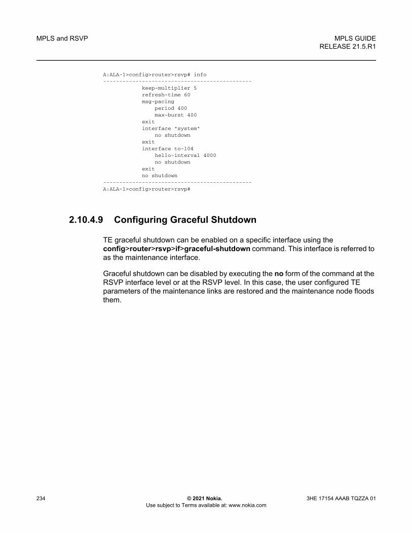
MPLS and RSVP
234
MPLS GUIDERELEASE 21.5.R1
© 2021 Nokia. Use subject to Terms available at: www.nokia.com
3HE 17154 AAAB TQZZA 01
A:ALA-1>config>router>rsvp# info----------------------------------------------
keep-multiplier 5refresh-time 60msg-pacing
period 400max-burst 400
exitinterface "system"
no shutdownexitinterface to-104
hello-interval 4000no shutdown
exitno shutdown
----------------------------------------------A:ALA-1>config>router>rsvp#
2.10.4.9 Configuring Graceful Shutdown
TE graceful shutdown can be enabled on a specific interface using the config>router>rsvp>if>graceful-shutdown command. This interface is referred to as the maintenance interface.
Graceful shutdown can be disabled by executing the no form of the command at the RSVP interface level or at the RSVP level. In this case, the user configured TE parameters of the maintenance links are restored and the maintenance node floods them.

MPLS GUIDE RELEASE 21.5.R1
MPLS and RSVP
3HE 17154 AAAB TQZZA 01 © 2021 Nokia. Use subject to Terms available at: www.nokia.com
235
2.11 MPLS Configuration Management Tasks
This section discusses MPLS configuration management tasks.
2.11.1 Deleting MPLS
NOTE: In order to remove the MPLS instance, MPLS must be disabled (shutdown) and all SDP bindings to LSPs removed. If MPLS is not shutdown first, when the no mpls command is executed, a warning message on the console displays indicating that MPLS is still administratively up.
When MPLS is shut down, the no mpls command deletes the protocol instance and removes all configuration parameters for the MPLS instance. To disable MPLS, use the shutdown command.
To remove MPLS on a router, enter the following command:
CLI Syntax: config>router# no mpls
2.11.2 Modifying MPLS Parameters
2.11.3 Modifying an MPLS LSP
Some MPLS LSP parameters such as primary and secondary, must be shut down before they can be edited or deleted from the configuration.
The following displays a MPLS LSP configuration example. Refer to the LSP configuration in Configuring an MPLS LSP.
A:ALA-1>>config>router>mpls>lsp# info----------------------------------------------
shutdownto 10.10.10.104from 10.10.10.103rsvp-resv-style ff
Note: You must shut down MPLS entities in order to modify parameters. Re-enable (no shutdown) the entity for the change to take effect.

MPLS and RSVP
236
MPLS GUIDERELEASE 21.5.R1
© 2021 Nokia. Use subject to Terms available at: www.nokia.com
3HE 17154 AAAB TQZZA 01
include "red"exclude "green"fast-reroute one-to-oneexitprimary "to-NYC"
hop-limit 50exitsecondary "secondary-path"exit
----------------------------------------------A:ALA-1>config>router>mpls#
2.11.4 Modifying MPLS Path Parameters
In order to modify path parameters, the config>router>mpls>path context must be shut down first.
The following displays a path configuration example. Refer to Configuring MPLS Paths.
A:ALA-1>config>router>mpls# info#------------------------------------------echo "MPLS"#------------------------------------------...
path "secondary-path"hop 1 10.10.0.111 stricthop 2 10.10.0.222 stricthop 3 10.10.0.123 strictno shutdown
exitpath "to-NYC"
hop 1 10.10.10.104 stricthop 2 10.10.0.210 strictno shutdown
exit...----------------------------------------------A:ALA-1>config>router>mpls#
2.11.5 Modifying MPLS Static LSP Parameters
In order to modify static LSP parameters, the config>router>mpls>path context must be shut down first.
The following displays a static LSP configuration example. Refer to the static LSP configuration in Configuring a Static LSP.
A:ALA-1>config>router>mpls# info

MPLS GUIDE RELEASE 21.5.R1
MPLS and RSVP
3HE 17154 AAAB TQZZA 01 © 2021 Nokia. Use subject to Terms available at: www.nokia.com
237
----------------------------------------------...
static-lsp "static-LSP"to 10.10.10.234push 102704 nexthop 10.10.8.114no shutdown
exitno shutdown
----------------------------------------------A:ALA-1>config>router>mpls#
2.11.6 Deleting an MPLS Interface
In order to delete an interface from the MPLS configuration, the interface must be shut down first.
Use the following CLI syntax to delete an interface from the MPLS configuration:
CLI Syntax: mpls[no] interface ip-int-name
shutdown
ALA-1>config>router>if-attr# info----------------------------------------------admin-group "green" value 15admin-group "yellow" value 20admin-group "red" value 25----------------------------------------------A:ALA-1>config>router>mpls# info----------------------------------------------...
interface "system"exitno shutdown
----------------------------------------------A:ALA-1>config>router>mpls#

MPLS and RSVP
238
MPLS GUIDERELEASE 21.5.R1
© 2021 Nokia. Use subject to Terms available at: www.nokia.com
3HE 17154 AAAB TQZZA 01
2.12 RSVP Configuration Management Tasks
This section discusses RSVP configuration management tasks.
2.12.1 Modifying RSVP Parameters
Only interfaces configured in the MPLS context can be modified in the RSVP context.
The no rsvp command deletes this RSVP protocol instance and removes all configuration parameters for this RSVP instance.
The shutdown command suspends the execution and maintains the existing configuration.
The following example displays a modified RSVP configuration example:
A:ALA-1>config>router>rsvp# info----------------------------------------------
keep-multiplier 5refresh-time 60msg-pacing
period 400max-burst 400
exitinterface "system"exitinterface "test1"
hello-interval 5000exitno shutdown
----------------------------------------------A:ALA-1>config>router>rsvp#
2.12.2 Modifying RSVP Message Pacing Parameters
RSVP message pacing maintains a count of the messages that were dropped because the output queue for the egress interface was full.
The following example displays command usage to modify RSVP parameters:
The following example displays a modified RSVP message pacing configuration example. Refer to Configure RSVP Message Pacing Parameters.
A:ALA-1>config>router>rsvp# info----------------------------------------------

MPLS GUIDE RELEASE 21.5.R1
MPLS and RSVP
3HE 17154 AAAB TQZZA 01 © 2021 Nokia. Use subject to Terms available at: www.nokia.com
239
keep-multiplier 5refresh-time 60msg-pacing
period 200max-burst 200
exitinterface "system"exitinterface "to-104"exitno shutdown
----------------------------------------------A:ALA-1>config>router>rsvp#
2.12.3 Deleting an Interface from RSVP
Interfaces cannot be deleted directly from the RSVP configuration. An interface must have been configured in the MPLS context, which enables it automatically in the RSVP context. The interface must first be deleted from the MPLS context. This removes the association from RSVP.
See Deleting an MPLS Interface for information on deleting an MPLS interface.

MPLS and RSVP
240
MPLS GUIDERELEASE 21.5.R1
© 2021 Nokia. Use subject to Terms available at: www.nokia.com
3HE 17154 AAAB TQZZA 01

MPLS GUIDE RELEASE 21.5.R1
GMPLS
3HE 17154 AAAB TQZZA 01 © 2021 Nokia. Use subject to Terms available at: www.nokia.com
241
3 GMPLS
3.1 GMPLS
The Generalized Multi-Protocol Label Switching (GMPLS) User to Network Interface (UNI) permits dynamic provisioning of optical transport connections between IP routers and optical network elements in order to reduce the operational time and administrative overhead required to provision new connectivity. The optical transport connections typically originate and terminate in an IP/MPLS controlled domain and traverse an intermediate optical transport network. The GMPLS UNI model is based on an overlay approach, whereby the IP/MPLS control plane is transported transparently over the intermediate transport network, which itself is controlled by a GMPLS control plane.
The UNI provides a clear demarcation point between the domains of responsibility of the parties involved in managing the overlying IP/MPLS network and the underlying optical network. For example, these parties could be two divisions in a service provider organization, or a subscriber/client of the service provider and the service provider itself.
The UNI has a client part, the UNI-C, and a network part, the UNI-N. In the Nokia solution, the UNI-C is an SR OS system, such as a 7750 SR or a 7950 XRS, while the UNI-N is an optical device; for example, an 1830 PSS.
Control plane related information is exchanged between the UNI-C and the UNI-N using a dedicated out of band communication channel. Note that the adjacent optical network element and the router assume that they are connected to a trusted peer, and thus assume a secure communication. This is achieved by physically securing the link carrying the control channel between the two.
Based on standardized UNI messaging (RFC 4208), the UNI-C indicates to the UNI-N which far-end peer UNI-C node (corresponding to a remote router) to make an optical transport connection to. This path request can include additional path attributes to indicate requirements such as bandwidth, priority and diversity/resiliency parameters.
3.1.1 Example Applications
This section summarizes some of the use cases that the GMPLS UNI may be used to address.

GMPLS
242
MPLS GUIDERELEASE 21.5.R1
© 2021 Nokia. Use subject to Terms available at: www.nokia.com
3HE 17154 AAAB TQZZA 01
3.1.1.1 Use Case 1: Dynamic Connection Setup with Constraints
This use case aims to solve inefficiencies between IP and transport teams within an operator for connectivity setup; for example:
• Process complexity, with complex database exchange, parsing and filtering• Long-winded organizational communication prior to path establishment
It therefore aims to optimize IP/Optical transport team interactions by removing complex processes, and reduces per-connection provisioning in the optical core.
The UNI should allow the setup/maintenance/release of connections across an intermediate optical transport network from a UNI-C router to another remote UNI-C router. The routers are connected to an optical network that consists of optical cross connects (OXCs), and the interconnection between the OXC and the router is based on the GMPLS UNI (RFC 4208). The UNI-C routers are 7750 SR or 7950 XRS nodes, while the UNI-N OXC is the Nokia1830 PSS. The UNI connection is instantiated using a GMPLS LSP (gLSP).
The UNI-C router is always the initiator of the connection. The only per-connection configuration occurs at the UNI-C, and it is operator initiated. Connections to any of the remote UNI-C routers are signaled over the UNI. The initiation of a connection request is via CLI or SNMP to the UNI-C router.
Signaling is based on RSVP-TE (RFC 4208). Constraints can be signaled with a connection setup request. These include bandwidth, protection type, and latency. In the event that a connection could not be established, a correct (descriptive) error code is returned to the initiator.

MPLS GUIDE RELEASE 21.5.R1
GMPLS
3HE 17154 AAAB TQZZA 01 © 2021 Nokia. Use subject to Terms available at: www.nokia.com
243
Figure 37 Dynamic Connection Setup
3.1.1.2 Use Case 2: Multi-Layer Resiliency
The objective of this application is to ensure optical network path diversity for primary/backup paths of an overlay IP network. It thus aims to resolve situations where the UNI-C router has no topological visibility of the optical network, and to allow the router to indicate that paths have to be either co-routed or avoid specific optical nodes or links along a path.
Route diversity for LSPs from single homed UNI-C router and dual-homed UNI-C router is a common requirement in optical transport networks. Dual homing is typically used to avoid a single point of failure (for example, the UNI link or OXC) or to allow two disjoint connections to form a protection group.
For the dual-homing case, it is possible to establish two connections from the source router to the same destination router where one connection is using one UNI link to, for example, OXC1 and the other connection is using the UNI link to OXC2. In order to avoid single points of failure within the optical network, it is necessary to also ensure path (gLSP) diversity within the provider network in order to achieve end-to-end diversity for the two gLSPs between the two routers.
G.709
MPLS
UNI
BEFORE AFTER
24850

GMPLS
244
MPLS GUIDERELEASE 21.5.R1
© 2021 Nokia. Use subject to Terms available at: www.nokia.com
3HE 17154 AAAB TQZZA 01
Figure 38 Multi-Layer Resiliency
As the two connections are entering the provider network at different OXC devices, the OXC device that receives the connection request for the second connection needs to be capable of determining the additional path computation constraints such that the path of the second LSP is disjointed with respect to the already established first connection entering the network at a different PE device.
24853
R2 OXC2 R4OXC4 OXC6 OXC8
R1 OXC1 R3OXC3
gLSP2
OXC5 OXC7
UNI
UNI
UNIUNI
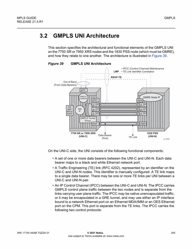
MPLS GUIDE RELEASE 21.5.R1
GMPLS
3HE 17154 AAAB TQZZA 01 © 2021 Nokia. Use subject to Terms available at: www.nokia.com
245
3.2 GMPLS UNI Architecture
This section specifies the architectural and functional elements of the GMPLS UNI on the 7750 SR or 7950 XRS nodes and the 1830 PSS node (which must be GMRE), and how they relate to one another. The architecture is illustrated in Figure 39.
Figure 39 GMPLS UNI Architecture
On the UNI-C side, the UNI consists of the following functional components:
• A set of one or more data bearers between the UNI-C and UNI-N. Each data bearer maps to a black and white Ethernet network port.
• A Traffic Engineering (TE) link (RFC 4202), represented by an identifier on the UNI-C and UNI-N nodes. This identifier is manually configured. A TE link maps to a single data bearer. There may be one or more TE links per UNI between a UNI-C and UNI-N pair.
• An IP Control Channel (IPCC) between the UNI-C and UNI-N. The IPCC carries GMPLS control plane traffic between the two nodes and is separate from the links carrying user plane traffic. The IPCC may be native unencapsulated traffic, or it may be encapsulated in a GRE tunnel, and may use either an IP interface bound to a network Ethernet port on an Ethernet MDA/IMM or an OES Ethernet port on the CPM. This port is separate from the TE links. The IPCC carries the following two control protocols:
al_0900
gLSP
GMRE Node IPGMPLSLoopback
NWIF
IGPBGP
MPLS/RSVP
gLSP
gLSP
gLSP
gLSP
gLSP
x/y/z
v/w/xd/e/f
Data Bearer(Port)
7750 SR or 7950 XRS(UNI-C)
1830 PSS(UNI-N)TE Link
GMPLS TunnelGroup
a/b/c
g/h/i
RSVP-TE
Out of Band(From Data Bearers)
LMP• IPCC (Control Channel) Maintenance• TE Link Identifier Correlation
GMPLS
246
MPLS GUIDERELEASE 21.5.R1
© 2021 Nokia. Use subject to Terms available at: www.nokia.com
3HE 17154 AAAB TQZZA 01
- LMP — This is responsible for checking the correlation between the UNI-C/UNI-N and the TE link/Data Bearer identifiers, and maintaining the IPCC adjacency between the UNI-C and UNI-N.
- RSVP-TE — RSVP-TE runs on the same network interface as LMP. The next hop from an RSVP-TE perspective is the UNI-N. RSVP-TE is used to establish and maintain a GMPLS LSP.
• gLSP — The GMPLS LSP. At the UNI-C, this is a control plane object representing the TE-Link in the RSVP-TE control plane. Although this is an LSP, there is no explicit MPLS label in the data path at the UNI-C; the gLSP maps to a data bearer of the TE link to / from the UNI-N. When a gLSP is signaled to a far-end UNI-C node, the optical network establishes bidirectional connectivity between one of the data bearers in the TE link on the UNI-N at the ingress to the optical network, and one of the data bearers on the TE link on the egress UNI-N node connected to the far end UNI-C node.
• Network Interface — When a gLSP is successfully established, a network interface can be bound to the gLSP. The network interface then uses the data bearer associated with the gLSP to forward traffic. This network interface can be used by any applicable protocol associated with an overlying IP/MPLS network. The network interface is bound to the gLSPs via a GMPLS tunnel group.
• GMPLS Tunnel Group: A GMPLS tunnel group is a bundle of gLSPs providing an abstraction of the data bearers that are intended to be associated to one IP interface. A GMPLS tunnel group only exists on the UNI-C node and not on the 1830 PSS UNI-N node.
Although Figure 39 shows a single 7750 SR or 7950 XRS node connected to a single UNI-N (1830 PSS), it is possible to multi-home a router into more than one (usually two) UNI-Ns at the edge of the optical network. In this case, a separate IPCC, set of data bearers, and set of TE links, are required between the 7750 SR or 7950 XRS and each UNI-N.
3.2.1 Addressing and End-to-End gLSP Architecture
The GMPLS UNI assumed a flat addressing scheme between the UNI-C nodes and the optical network. In this model, a common addressing scheme is used between the UNI-C (IP router) and UNI-N (optical edge). The UNI-C and UNI-N must be in the same subnet. Also, none of the UNI-C addresses can overlap or clash with any of the GMPLS-aware nodes in the optical network. This does not mandate that the whole IP network share a common address space with the optical network, as a separate loopback address can be used for the GMPLS UNI on the UNI-C.

MPLS GUIDE RELEASE 21.5.R1
GMPLS
3HE 17154 AAAB TQZZA 01 © 2021 Nokia. Use subject to Terms available at: www.nokia.com
247
The ERO Expansion (RFC 5151) model is assumed for the GMPLS LSPs. The UNI-C is not exposed to the full ERO between the UNI-N nodes. Instead, the full ERO is inserted at the UNI-N. This model limits the sharing of topology information between the UNI-N and UNI-C.

GMPLS
248
MPLS GUIDERELEASE 21.5.R1
© 2021 Nokia. Use subject to Terms available at: www.nokia.com
3HE 17154 AAAB TQZZA 01
3.3 1830 PSS Identifiers
This section describes the various identifiers used on the 1830 PSS that are relevant to configuring the GMPLS UNI on the 7750 SR or 7950 XRS node in conjunction with the 1830 PSS. Figure 40 illustrates the identifier architecture of a 1830 PSS multi-shelf system. The multi-shelf system consists of a control plane node and one or more data plane nodes. The following identifiers are used:
• GMRE node IP— This is the IP loopback address used for GMPLS protocols such as LMP and RSVP.
• IPCC IP address (also known as DcnGatewayAddress)— This is the source/destination address for IPCC maintenance messages such as LMP hellos and LMP config messages. When only one IPCC exists between a 7750 SR or 7950 XRS and 1830 PSS pair, this may be the same as the IP management loopback.
• CP Node ID — This is a non-routable identifier for the control plane node. It is used for identifying this node in the optical domain; for example, the session/sender template. It is also used in the RSVP ERO to identify the 1830 PSS node.
• DP Node ID — This is a non-routable identifier for a data plane node. This identifies a particular data plane shelf in the optical domain.
• TE Link IDs — The TE Link ID is unique across a set of DP and CP nodes forming an 1830 PSS.
Figure 40 Identifier Architecture
LMP/RSVP-TE
IPCC Maintenance
CP Node ID
DP Node ID
7750 SR or 7950 XRS 1830 PSS
DataPlaneshelf
Multi-shelf system
al_0903
TE Link 1
IPCC
TE Link 2
TE Link 3
TE Link 4
NWIP IF
IPLB GMRE node IP
IPCCIP IF

MPLS GUIDE RELEASE 21.5.R1
GMPLS
3HE 17154 AAAB TQZZA 01 © 2021 Nokia. Use subject to Terms available at: www.nokia.com
249
3.4 Recovery Reference Models
This section details the supported recovery reference models. These models are based on the mechanisms specified in RFC 4872 and RFC 4873.
Figure 41 presents a generalized reference model in which the 7750 SR or 7950 XRS UNI-C nodes are dual-homed at the link layer to the 1830 PSS UNI-N nodes. Not all elements of this architecture may be required in all deployment cases.
Figure 41 General GMPLS UNI Interconnection Architecture
This reference model includes two 7750 SR or 7950 XRS nodes, each hosting a UNI-C function, at the edge of each IP network facing two 1830 PSS nodes, each hosting a UNI-N function. A full mesh of black and while Ethernet links interconnects neighboring UNI-C nodes and UNI-N nodes. Parallel links may exist, so that a given 7750 SR or 7950 XRS UNI-C is connected to a neighbor 1830 PSS UNI-N by more than one Ethernet link.
Each router hosting a UNI-C has an IPCC to each of the two 1830 PSS UNI-Ns. Likewise, each 1830 PSS hosting UNI-N has an IPCC to both of the 7750 SR or 7950 XRS UNI-Cs that it is connected to. IPCCs only exist between UNI-C and UNI-N nodes, and not between UNI-C nodes. A control plane (LMP and RSVP) adjacency therefore exists between each UNI-C and it's corresponding UNI-Ns.
Recovery in the following domains is supported in the following locations:
SR/XRS
UNI-C UNI-N
UNI-C
BWEth
>=1 parallel links
SR/XRS
UNI-CUNI-N
UNI-N UNI-C
BWEth
OTN/photonicswitches
UNI-N
End to End (UNI-C to UNI-C)
Optical Segment (UNI-N to UNI-N)UNI Segment
UNI-C to UNI-CUNI Segment
UNI-C to UNI-C
24855

GMPLS
250
MPLS GUIDERELEASE 21.5.R1
© 2021 Nokia. Use subject to Terms available at: www.nokia.com
3HE 17154 AAAB TQZZA 01
• End to End — Between the 7750 SR or 7950 XRS UNI-C nodes at each end of a gLSP.
• Optical Segment — Between 1830 PSS UNI-N nodes at each edge of the optical network.
The following subsections detail some example recovery options that are possible using either GMPLS, or a combination of GMPLS mechanisms and mechanisms in the overlay IP network. Note that some of the functionality shown in one of the scenarios can be used in combination with functionality in another scenario, for example optical SRLG diversity.
The objective of GMPLS here is to minimize the disruption to the overlay IP network while simultaneously maximizing the utilization of both the gLSPs and the resources in the underlying optical network (or UNI links).
3.4.1 End to End Recovery (IP-layer)
End to end recovery applies to protection against failures at any point along the entire path between a local UNI-C and a far end UNI-C. In the context of the GMPLS UNI, recovery can be implemented in the overlay IP network either at Layer 3 or Layer 2, with assistance from the underlay optical network, with optional additional protection and/or restoration of gLSPs by GMPLS.
3.4.2 End to End ECMP
Figure 42 illustrates the first model. Multiple gLSPs are established between a pair of remote UNI-C nodes. Each gLSP is bound to a separate IP network interface at the UNI-C. RSVP signaling across the UNI is used to ensure that the gLSPs are SRLG diverse (by explicitly signaling the SRLG list to avoid in an XRO for every gLSP, or automatically collecting the SRLG list for a gLSP which does not have an XRO, and then signaling a subsequent gLSP including this collected list in its XRO). Protection is provided at the IP layer by hashing across the IP network interfaces associated with each gLSP. The operational state of each IP interface can be tied to the operational state of its gLSP (controlled using RSVP) or using mechanisms in the IP overlay such as BFD.

MPLS GUIDE RELEASE 21.5.R1
GMPLS
3HE 17154 AAAB TQZZA 01 © 2021 Nokia. Use subject to Terms available at: www.nokia.com
251
Figure 42 End-to-End ECMP with gLSP Diversity Across Single UNI-C
3.4.3 End to End Load Sharing Using a Load Sharing GMPLS Tunnel Group
Figure 43 shows the case where multiple gLSPs, instantiated as black and white Ethernet ports, are bundled together in a similar manner to LAG, using a GMPLS tunnel group. That is, each member gLSP of a tunnel group effectively maps to a member port, which runs end to end between remote UNI-Cs. Note that a LAG does not and cannot terminate on the neighboring 1830 PSS UNI-N. A single IP network interface is bound to the bundle of ports represented by the gLSPs. LACP does not run across the bundle; RSVP signaling is instead used to convey the state of the gLSP and thus the corresponding member port of the tunnel group. Traffic is load shared across the tunnel group members.
SR/XRS
UNI-C UNI-N
UNI-C
SRLG
SR/XRS
UNI-CUNI-N
UNI-N UNI-C
OTN/photonicswitches
SRLGDiverse
UNI-N
End to End (UNI-C to UNI-C)
Optical Segment (UNI-N to UNI-N)UNI Segment
UNI-C to UNI-CUNI Segment
UNI-C to UNI-C
24856
IPIP
Path, PathErr
ECMP ECMP

GMPLS
252
MPLS GUIDERELEASE 21.5.R1
© 2021 Nokia. Use subject to Terms available at: www.nokia.com
3HE 17154 AAAB TQZZA 01
Figure 43 End-to-End Load Sharing GMPLS Tunnel Group with gLSP Path Diversity
3.4.4 End to End Recovery (GMPLS Layer)
3.4.4.1 Unprotected gLSP
The default level of E2E recovery is unprotected. In this case, a gLSP can only recover from a failure when the downstream resource that failed is recovered. Figure 44 illustrates this. When a gLSP fails in the optical network, a failure notification is propagated to the source UNI-C node e.g. using a PathErr or a NotifyErr LSP Failure message. The source UNI-C node takes no action, but will continue to refresh the PATH message for this gLSP, which may be rerouted around the failure by the optical network e.g. if the IGP in the optical network reconverges. The gLSP is treated as operationally down until a message indicating that the gLSP has been restored is received by the router. For example, a Notify Error LSP Restored.
SR/XRS
UNI-C UNI-N
UNI-C
SRLG
SR/XRS
UNI-CUNI-N
UNI-N UNI-C
OTN/photonicswitches
SRLGDiverse
UNI-N
End to End (UNI-C to UNI-C)
Optical Segment (UNI-N to UNI-N)UNI Segment
UNI-C to UNI-CUNI Segment
UNI-C to UNI-C
24857
Path, PathErr
Tunnelgroup
IPTunnelgroup
IP

MPLS GUIDE RELEASE 21.5.R1
GMPLS
3HE 17154 AAAB TQZZA 01 © 2021 Nokia. Use subject to Terms available at: www.nokia.com
253
Figure 44 gLSP Re-Establishment (PATH Refresh)
3.4.4.2 Full LSP Rerouting
Full LSP rerouting (or restoration), specified in RFC 4872 section 11, switches normal traffic to an alternate LSP that is not even partially established until after the working LSP failure occurs. The new alternate route is selected at the LSP head-end node; it may reuse resources of the failed LSP at intermediate nodes and may include additional intermediate nodes and/or links.
SR/XRS
UNI-C UNI-N
UNI-C
SRLG
SR/XRS
UNI-CUNI-N
UNI-N UNI-C
OTN/photonicswitches
SRLGDiverse
UNI-N
End to End (UNI-C to UNI-C)
Optical Segment (UNI-N to UNI-N)UNI Segment
UNI-C to UNI-CUNI Segment
UNI-C to UNI-C
24858
Path, PathErr
X Tunnelgroup
IPTunnelgroup
IP

GMPLS
254
MPLS GUIDERELEASE 21.5.R1
© 2021 Nokia. Use subject to Terms available at: www.nokia.com
3HE 17154 AAAB TQZZA 01
Figure 45 Full LSP Rerouting
3.4.4.3 1: N Protection
In 1:N (N ≥1) protection, the protecting LSP path is a fully provisioned and resource-disjoint LSP path from the N working LSP paths. The N working LSP paths may also be mutually resource-disjoint. Coordination between end-nodes is required when switching from one of the working paths to the protecting path. Although RFC4872 allows extra traffic on the protecting path, this is not supported by the 7750 SR or 7950 XRS. Figure 46 illustrates this protection architecture when N=1, while Figure 47 shows the case for N>1.
SR/XRS
UNI-C UNI-N
SRLG
SR/XRS
UNI-CUNI-N
UNI-N UNI-C
OTN/photonicswitches
SRLGDiverse
UNI-N
24859
Path, PathErr
Notify, NotifyErr
IP
UNI-C
IP
AlternateWorking (primary)
Path Resv
Legend:

MPLS GUIDE RELEASE 21.5.R1
GMPLS
3HE 17154 AAAB TQZZA 01 © 2021 Nokia. Use subject to Terms available at: www.nokia.com
255
Figure 46 1:N Protection, with N=1 (RFC4872)
Figure 47 N>1 Protection
al_0712
Legend:
SR/XRS SR/XRSSRLGDiverse
OTN/PhotonicSwitches
UNI-NSRLG
Notify, Notify Err
Path, Path ErrResv, Resv Err
UNI-C
UNI-NUNI-C Path(Protecting)
Resv
UNI-N UNI-C
WorkingProtecting
UNI-N UNI-C
IPIP
al_0906
Path, (Association) Path ErrResv, Resv Err
Legend:
SR/XRS SR/XRSSRLGDiverse
OTN/PhotonicSwitches
UNI-NSRLG
Notify, Notify Err
UNI-C
UNI-NUNI-C Path(Protecting)
Resv
UNI-N UNI-C
WorkingProtecting
UNI-N UNI-C
IPIPIP IP
1N

GMPLS
256
MPLS GUIDERELEASE 21.5.R1
© 2021 Nokia. Use subject to Terms available at: www.nokia.com
3HE 17154 AAAB TQZZA 01
3.4.4.4 Optical Segment Recovery
Optical segment protection refers to the ability of the optical network to protect the span of a gLSP between ingress and egress UNI-N nodes. It does not require any protection switching on the UNI-C nodes. However, it does require the UNI-C to signal a request for a particular segment protection type towards the UNI-N in the PATH message for a gLSP. The optical network may either accept this request, reject it or respond with an alternative. Segment protection is defined in RFC 4873.
Figure 48 Optical Segment Protection Domain
Signaling of the following segment protection types is supported by the 7750 SR and 7950 XRS:
• Unprotected — The path is not protected against failure.• Source-Based Reroute (SBR) — In this mechanism (also known as Full
Rerouting), a path is restored after a failure, but the success of restoration depends on the available resources. This can reroute traffic in 200 ms or more.
• Guaranteed Restoration (GR) — A shared backup is assigned to the path, and recovery resources are reserved. If they cannot be reserved on a shared path, then this falls back to SBR. This can reroute traffic in 50 ms or less. This mechanism is also known as 1+shared standby. This is also known as Rerouting without extra traffic, or shared mesh restoration.
• Sub-network Connection Protection (SNCP) — This provides 50 ms protection in the case of a single failure. This is also known as 1+1 bidirectional path protection.
SR/XRS
UNI-C UNI-N
UNI-C
SRLG
SR/XRS
UNI-CUNI-N
UNI-N UNI-C
OTN/photonicswitches
SRLGDiverse
UNI-N
24860
Path, PathErrSegment protection type
Resv, ResvErr
tunnelgroup
IPtunnelgroup
IP
Optical Segment (UNI-N to UNI-N)

MPLS GUIDE RELEASE 21.5.R1
GMPLS
3HE 17154 AAAB TQZZA 01 © 2021 Nokia. Use subject to Terms available at: www.nokia.com
257
• Path Restoration Combined (PRC) — This provides 50 ms protection, even in the case of multiple failures. This is also known as SNCP with SBR.

GMPLS
258
MPLS GUIDERELEASE 21.5.R1
© 2021 Nokia. Use subject to Terms available at: www.nokia.com
3HE 17154 AAAB TQZZA 01

MPLS GUIDE RELEASE 21.5.R1
GMPLS
3HE 17154 AAAB TQZZA 01 © 2021 Nokia. Use subject to Terms available at: www.nokia.com
259
3.5 GMPLS Configuration Overview
The Generalized Multi-Protocol Label Switching (GMPLS) User to Network Interface (UNI) permits dynamic provisioning of optical transport connections between IP routers and optical network elements in order to reduce the operational time and administrative overhead required to provision new connectivity.

GMPLS
260
MPLS GUIDERELEASE 21.5.R1
© 2021 Nokia. Use subject to Terms available at: www.nokia.com
3HE 17154 AAAB TQZZA 01
3.6 LMP and IPCC Configuration
3.6.1 Configuration of IP Communication Channels for LMP and RSVP
Configuration starts with enabling the IP Communication Channel (IPCC) between the 7750 SR or 7950 XRS UNI-C and the adjacent UNI-N. The IPCC is a data communication channel for LMP and RSVP. For each different UNI-C and UNI-N adjacency, a different IPCC must be configured.
A numbered network IP interface is bound to the port connected to the DCN or directly to the 1830 PSS.
GMPLS protocols use a new loopback address type, called a GMPLS loopback, on the IPCC. The address of this loopback is termed the local GMPLS router ID. Packets that do not belong to a GMPLS protocol that are destined for this loopback address will be dropped. An interface is configured as a GMPLS loopback using the interface interface-name gmpls-loopback command.
CLI Syntax: configrouter
interface local-gmpls-router-id-name gmpls-loopbackaddress local-gmpls-loopback-address
The destination address of the LMP and RSVP control plane packets should be set to the LMP/GMPLS loopback of the 1830 PSS. The 1830 PSS does that via a dedicated subnet on a VLAN interface on the management port. Another VLAN extends a separate subnet for management purposes. On the 7750 SR or 7950 XRS, the LMP and RSVP control plane packets should be sent to the next-hop for the GMPLS/LMP loopback address of the neighboring 1830 PSS. The 1830 PSS and the GMPLS router IDs must be in the same subnet. It is possible to operate over a routed DCN if the RSVP control plane messages do not set the IP router alert bit. Otherwise only direct IP connectivity over a Layer 2 network will work.
If the IPCC goes down, an existing TE Link or gLSP to a given peer UNI-N node is not torn down just because the IPCC is down. However, if the IPCC is down, then it is not possible to establish new gLSPs or TE Links, and a trap indicating a degraded state is raised.
The IPCC can use GRE encapsulation. This may be required in some network deployments where a routed DCN is used and is shared between multiple applications, in order to conceal GMPLS control plane traffic.

MPLS GUIDE RELEASE 21.5.R1
GMPLS
3HE 17154 AAAB TQZZA 01 © 2021 Nokia. Use subject to Terms available at: www.nokia.com
261
GRE encapsulation requires that a controlTunnel loopback interface representing the GRE tunnel is configured using the interface interface-name control-tunnel command. One IP tunnel can then be created on this interface. The local end tunnel IP address is configured using the interface primary IP address. The remote end tunnel IP address can be configured using the ip-tunnel command. GRE encapsulation is used by default for the IP tunnel.
Only the primary IPv4 interface address and only one IP tunnel per interface are allowed. Up to four tunnels can be configured using multiple controlTunnel loopback interfaces.
A static route is required to take the new controlTunnel interface as a next hop.
The following example illustrates the commands required to enable GRE tunneling on IP control channels to a given peer UNI-N.
In this example, an IPCC is established between the 7750 SR (10.20.40.40) and the 1830 PSS (10.20.50.50). Packets destined for 10.20.50.50 will match a static route pointing to interface “myTunneltf1”, which is a controlTunnel loopback interface. When this interface is matched as a next hop, the system will add GRE encapsulation (in the CPM) to the packet and send it out using the source address 10.3.30.10 and destination address 10.3.30.1 for the tunnel (outer) IP header.
configure router "Base"|<cpm-vr-name> -> cpm-vr-name "management" notsupported.
interface "ipcc" gmpls-loopbackaddress 10.20.40.40/32
exitinterface "myTunnelItf1" control-tunnel -> new ifType: controlTunnel(32)
address 10.3.30.10/32 -> tunnel local addressip-tunnel
remote-ip 10.3.30.1 -> tunnel remote address, gre encapimplicit
... -> future commands may be added,e.g. encap (default will be gre)
exitno shutdown -> interface is operationally up
only if remote-ip is reachableexitstatic-route-entry 10.20.50.50/32 -> static route pointing to
IPCC remoteend
next-hop "myTunnelItf1" -> interface of new controlTunnelifType can be configured asnext-hop
no shutdownexit
Note: GRE may be configured for IPCCs using a network interface or CPM port.

GMPLS
262
MPLS GUIDERELEASE 21.5.R1
© 2021 Nokia. Use subject to Terms available at: www.nokia.com
3HE 17154 AAAB TQZZA 01
exitstatic-route-entry 10.3.30.1/32 -> eventually static route to reach
tunnel remote end may be needednext-hop 10.3.10.1
no shutdownexit
exitexit
3.6.2 Configuring LMP
LMP is used to establish and maintain an IPCC between adjacent peers, as well as to correlate the local and remote identifiers for the TE links that it controls. Some attributes must be configured locally on a per-peer basis, such as the LMP peer information, TE link information, and per-peer protocol related parameters.
The config>router>lmp>peer peer-cp-node-id command creates a context per LMP peer. The peer-cp-node-id parameter specifies the control plane identifier of the adjacent UNI-N. It is an IPv4 or unsigned integer-formatted address that is used by the UNI-C for LMP and RSVP-TE messages if a peer-loopback address is not subsequently configured. The local GMPLS router ID is used as the source address.
A static route must have previously been configured to this peer router ID. Dynamic routing (for example, using OSPF over the IPCC in order to resolve routes to the peer GMPLS router ID) is not supported. The local loopback address to use as the local GMPLS router ID should also be configured.
The LMP messages are sent over the interface corresponding to the IPCC that has been configured previously. The LMP session can be associated with one or more TE links that have been configured previously.
A control channel to an LMP peer is configured using the config>router>lmp>lmp-peer peer-cp-node-id>control-channel command. Control channels are indexed using the lmp-cc-id parameter, which corresponds to the lmpCcId object in the LMP MIB.
The following CLI tree illustrates the key commands for configuring LMP.
CLI Syntax: configrouter
[no] lmp[no] te-link te-link-id
link-name te-link-nameremote-id id[no] data-bearer data-bearer-id
port port-id

MPLS GUIDE RELEASE 21.5.R1
GMPLS
3HE 17154 AAAB TQZZA 01 © 2021 Nokia. Use subject to Terms available at: www.nokia.com
263
remote-id id[no] shutdown
[no] shutdowngmpls-loopback-address local-gmpls-loopback-
address[no] peer peer-cp-node-id
peer-loopback-address peer-loopback-addressretransmission-interval intervalretry-limit limit[no] control-channel lmp-cc-id
peer-interface-address ipcc-destination-addr
hello interval interval dead-interval interval
passive[no] shutdown
te-link te-link-id[no] shutdown
peer lmp-peer-address...[no] shutdown
[no] shutdown
If peer-loopback-address is entered, then this is used as the routable peer address, otherwise the peer-cp-node-id is assumed to correspond to a routable peer loopback.
The peer-interface-address is mandatory and is the destination address of the IPCC on the peer UNI-N used to reach the GMPLS Router ID of the peer. It corresponds to the lmpCcRemoteIpAddr in RFC 4631. If the peer-interface-address is used as the destination IP address in the IP packet on the IPCC, then the router local interface address is used as the source IP address.
A te-link is configured under config>router>lmp>te-link. The te-link parameter under config>router>lmp>peer then assigns the control of the TE-links to the LMP protocol to a given peer. Each TE-Link can only be assigned to a single LMP peer.
The LMP protocol-specific attributes such as timers and retransmission retries are configured for each LMP peer under config>router>lmp>peer.
The hello interval ranges from 1000 to 65 535 ms. The default hello interval is 1000 ms.
The hello dead-interval ranges from 3000 to 65 535 ms. The default hello dead interval is 4000 ms.
The retransmission-interval ranges from 10 to 4 294 967 295 ms in 10-ms intervals, with a default of 500 ms.

GMPLS
264
MPLS GUIDERELEASE 21.5.R1
© 2021 Nokia. Use subject to Terms available at: www.nokia.com
3HE 17154 AAAB TQZZA 01
The ttl command allows the user to configure the TTL of the IP control channel for RSVP and LMP packets to a value other than 1 (default). The range of values is 2 - 255. This enables multi-hop data communication networks between the UNI-C and UNI-N.
In order to configure an IPCC to a specific LMP peer to use an OES Ethernet port on the CPM, then the configuration must refer to a GMPLS loopback IP address that exists within a virtual management router that has an interface on that CPM Ethernet port. The IPCC to a specific LMP peer is created within a named management virtual router as follows:
CLI Syntax: config>router>lmppeer peer-node-id
control-channel-router router-namegmpls-loopback-address ipv4-address
The default router instance is “Base”.
The router-name parameter specifies the 64-byte name of a virtual router instance.
3.6.3 Configuring Traffic Engineering Links and Data Bearers
Traffic engineering (TE) links are configured under the config>router>lmp with a specific command, te-link, to create a specific context to hold TE specific configuration information pertinent to the local and remote identifiers, and physical resources assigned to the te-link. Only one data bearer per TE link is supported.
The te-link association is the creation of an association between a TE-link and data-bearing physical ports. Under the TE-link context, different data bearers can be configured via the data-bearer command. The data bearer is assigned a complete physical port, using port<x/y/z> (slot-number/MDA-number/port-number) as input.
Note that a data bearer cannot be associated with a port in a LAG.
A TE-link has a unique link-id, which identifies it in RSVP-TE signaling.
The remote-id is the unnumbered link identifier at far-end of the TE link as advertised by the LMP peer that is the UNI-N.
The TE-link has associated physical resources which are assigned to the TE-link by configuring the data-bearer under the config>router>te-link context.

MPLS GUIDE RELEASE 21.5.R1
GMPLS
3HE 17154 AAAB TQZZA 01 © 2021 Nokia. Use subject to Terms available at: www.nokia.com
265
The operator must also configure the remote data-bearer link identifier under the data bearer subcontext.
Note that LMP does not correlate the local and remote Layer 2 interface identifiers (such as MAC addresses) for the data bearer. It only correlates the local and remote TE Link and Data Bearer link identifiers. The association between the Layer 2 interface address and the data bearer must be correctly configured at the UNI-C and UNI-N. The show>router>lmp>te-link command displays the local link ID, remote link ID, and associated port ID to assist with this.
The CLI tree for creating TE Links under LMP is as follows. Note that there are also some RSVP-specific TE Link parameters that are configured under a separate gmpls context (see below):
configrouter
[no] lmp[no] te-link te-link-id
link-name te-link-nameremote-id id[no] data-bearer data-bearer-id
port port-idremote-id id[no] shutdown
[no] shutdown[no] shutdown
The te-link-id can take the form of an unsigned integer or 64 character (max) name: [1 to 2147483690] | te-link-name: 64 char max
Upon creation, only the unsigned integer needs to be specified. Once the link is created the user can configure the link name (for example, link-name te-link-name). From here, the user can refer to this te-link by either the unsigned integer or the ASCII name.
Note that LMP will normally assume a data bearer is operationally up, even if no MAC layer or a valid PCS IDLE stream is received. This is because a neighboring UNI-N may not generate a PCS IDLE stream and instead transparently transports the MAC layer from the far end, which won't be up unless a gLSP is configured. In order to prevent LMP from using a port for which there is a local fault on the data bearer, indicated by loss of light, a user must configure report-alarm on the Ethernet port, as follows:
config>port>ethernet>report-alarm signal-fail
Only ports with report-alarm signal-fail configured can be included in LMP, and that report-alarm signal-fail cannot be subsequently removed from a port in LMP.

GMPLS
266
MPLS GUIDERELEASE 21.5.R1
© 2021 Nokia. Use subject to Terms available at: www.nokia.com
3HE 17154 AAAB TQZZA 01
RSVP requires that all traffic engineering attributes for TE Links are configured under the config>router>gmpls>te-link context.
configrouter
[no] gmplste-link te-link-id
[no] shutdown
where te-link-id: [1..2147483690] | te-link-name: 32 char max
If a path (also refer to the description of a GMPLS path configuration, below) without an explicit te-link for the first hop is configured, the system will automatically select a TE Link to use for a gLSP path based on the lowest available TE Link ID with a matching bandwidth (if a bandwidth is configured for the gLSP). During a data-bearer link allocation request, an RSVP -requested gLSP BW could be either a non-zero value as per RFC 3471 signal-type (see below), or it could be zero. These are the following cases.
Case 1: Requested BW is non-zero as per RFC 3471 Signal-type configuration
• When a TE (or TE/DB) link is configured in the related hop LMP checks whether the related port BW is the same (exact match) as the requested BW, and allocates the port (provided any other checks are successful).
• When the related Hop is empty, LMP finds a db-link port to the peer with a matching the requested BW, and allocates it.
Case 2: Requested BW is Zero
• When TE (or TE/DB) link is configured in the related hop, LMP allocates the port (provided the other checks are OK), and provides the port BW to RSVP to use in signaling.
• When the related Hop is empty, LMP finds the first available db-link to the peer (based on lower db-link Id), and allocates it and provides the port BW to RSVP to use in signaling.

MPLS GUIDE RELEASE 21.5.R1
GMPLS
3HE 17154 AAAB TQZZA 01 © 2021 Nokia. Use subject to Terms available at: www.nokia.com
267
3.7 Configuring MPLS Paths for GMPLS
To establish an end-to-end connection between two 7750 SR or 7950 XRS nodes through a GMPLS network, a path is required, which is configured via the config>router>gmpls>path path-name context.
The path context consists of a set of numbered entries, each entry representing a resource that the gLSP must follow. The te-link ID is the ID allocated at the node referred to in the hop.
When interoperating with the Nokia 1830 PSS, at least the first and penultimate hops of the gLSP should be included.
The following CLI tree is used to configure a gLSP path:
config>router>gmplspath path-nameno path path-name
hop hop-index node-id node-id [te-link te-link-id][strict | loose]
no hop hop-indexno shutdownshutdown
where:
node-id: IPv4 address a.b.c.d | 1830-data-plane-node-id 32-bit unsigned integer
In general, the 7750 SR or 7950 XRS node is able to populate the ERO with every hop along the gLSP path from ingress UNI-N to egress UNI-C. However, normally only a loose path across the optical network (from ingress UNI-N to egress UNI-N) is required because the optical network is responsible for path selection between ingress and egress UNI-N. Therefore the user will normally just configure hop 1 and hop 4 in the above example. For interoperability with the 1830 PSS, the user must configure a TE Link ID to use on the final hop in the ERO towards the destination UNI-C.
The following example shows how the Path should be configured for interoperability with the 1830 PSS.
Consider the following topology:
A B C D E F
[unic1]------[unin1]-----------[unin2]------[unic2]
where A-F are the TE Link IDs assigned at each end of a link.

GMPLS
268
MPLS GUIDERELEASE 21.5.R1
© 2021 Nokia. Use subject to Terms available at: www.nokia.com
3HE 17154 AAAB TQZZA 01
Path configuration on unic1:
Hop 1 unic1 A strict
Hop 2 unin2 E loose

MPLS GUIDE RELEASE 21.5.R1
GMPLS
3HE 17154 AAAB TQZZA 01 © 2021 Nokia. Use subject to Terms available at: www.nokia.com
269
3.8 Configuring RSVP in GMPLS
RSVP-TE must be enabled on the SR OS towards the adjacent UNI-N in order to configure a GMPLS label-switched path (gLSP).
RSVP parameters specific to GMPLS are configured under the config>router>gmpls context.
This creates a new instance of RSVP for use in GMPLS signaling.
Global parameters for GMPLS are configured as follows:
configrouter
gmplsno gmpls
peer peer-cp-node-idgr-helper-time max-recovery recovery-interval max-restart restart-intervalno gr-helper-timekeep-multiplier numberno keep-multiplierno rapid-retransmit-timerapid-retransmit-time hundred-millisecondsno rapid-retry-limitrapid-retry-limit limitno refresh-timerefresh-time secondsno refresh-timelsp-init-retry-timeout secondsno lsp-init-retry-timeoutno shutdownshutdown
The default max-restart interval for GMPLS is 180 s.
The LMP Peer is configured under config>router>gmpls>peer peer-cp-node-id, where the peer-cp-node-id is control plane identifier of the adjacent optical cross connect (UNI-N node). RSVP uses the destination address returned by LMP for this peer control plane node ID as the destination address, and the loopback address referenced under config>router>lmp>gmpls-loopback-address local-gmpls-loopback-address as the local router ID to use for the session.
RSVP will come up if at least one IPCC is up.
RSVP hellos and support for graceful restart helper functionality are supported. RSVP Graceful Restart Helper procedures implemented by the router also apply when the IPCC goes down and comes back up, or when the neighboring peer control plane restarts.
The following CLI tree is used for configuring RSVP parameters for each LMP peer:

GMPLS
270
MPLS GUIDERELEASE 21.5.R1
© 2021 Nokia. Use subject to Terms available at: www.nokia.com
3HE 17154 AAAB TQZZA 01
configrouter
gmplspeer peer-cp-node-idno peer peer-cp-node-id
lsp-hold-timer hold-timerno lsp-hold-timerhello-interval millisecondsno shutdownshutdown
The per-peer lsp-hold-timer hold-timer parameter is used to configure a node-wide hold-down time. This timer is started when a RESV for a new gLSP is first received, or a failed gLSP path is restored (or the router is notified of a restoration following segment recovery) in order to give the optical network time to program its data path. The value range is 5 to 300 s, with a default of 60 s. A member of a GMPLS tunnel group is not considered up until the hold-timer has expired. Note that different optical network technologies have different data path programing/setup times.
Note that the no hello-interval command sets the hello-interval to the default value of 3000 ms. Configuring hello-interval 0 will disable hellos in GMPLS.

MPLS GUIDE RELEASE 21.5.R1
GMPLS
3HE 17154 AAAB TQZZA 01 © 2021 Nokia. Use subject to Terms available at: www.nokia.com
271
3.9 Configuring a GMPLS LSP on the UNI
A GMPLS LSP is configured under config>router>gmpls>lsp name gmpls-uni. The optional gmpls-uni keyword indicates that the LSP is an RSVP signaled GMPLS LSP, which is profiled for the GMPLS UNI that is it uses the set of functions and CLI commands applicable to an overlay gLSP, rather than a peer model gLSP. Only overlay model gLSPs are supported; this is the default type of GMPLS LSP. The router can only act as an LER terminating a gLSP, and cannot switch a GMPLS that is it cannot act as a GMPLS LSR
GMPLS LSPs use the working path and protect path terminology from RFC 4872. Each gLSP configuration is composed of a working path and an optional protect path if end-to-end recovery is used.
Note that on-the-fly changes to an LSP or LSP path configuration are not allowed. This is because MBB is not supported for gLSPs. The LSP or LSP Path must be shut down to make configuration changes.
A GMPLS LSP (gLSP) is configured using the following CLI tree:
configrouter
gmplslsp lsp-name [gmpls-uni]no lsp lsp-name
to remote-uni-c-gmpls-router-idswitching-type {dcsc}no switching-typeencoding-type {line}no encoding-typegeneralized-pid {ethernet}no generalized-pide2e-protection-type {unprotected | 1toN | sbr}no e2e-protection-typeprotect-path path-nameno protect-path path-name
peer peer-gmpls-router-idno peerbandwidth signal-type rfc3471-nameno bandwidth exclude-srlg group-name [group-name...(upto 5 max)]no exclude-srlgsegment-protection-type {unprotected | sbr | gr | sncp | prc}no segment-protection-typeno shutdownshutdown
revert-timer timer-value //1 to 1800 seconds, default 0no revert-timerretry-limit limitno retry-limitno shutdownshutdownworking-path path-nameno working-path path-name

GMPLS
272
MPLS GUIDERELEASE 21.5.R1
© 2021 Nokia. Use subject to Terms available at: www.nokia.com
3HE 17154 AAAB TQZZA 01
bandwidth signal-type rfc3471-nameno bandwidthexclude-srlg group-name [group-name...(upto 5 max)]no exclude-srlgpeer peer-gmpls-router-idno peer bandwidthsegment-protection-type {unprotected | sbr | gr | sncp | prc}no segment-protection-typeno shutdownshutdown
no shutdownshutdown
The loopback address of the remote router (UNI-C) must be configured after the to keyword and takes an IPv4 address as input.
The switching-type indicates the type of switching required for the gLSP. This can take a number of values, as defined in RFC 3471, and extended in RFC 6004 and RFC 7074 for Ethernet VPL (EVPL) services. The default CLI value is DCSC. This is the only supported value.
The encoding-type configuration specifies the encoding type of the payload carried by the gLSP. line, indicating 8B/10B encoding, is the only supported type.
The generalized-pid parameter specifies the type of payload carried by the gLSP. Standard ethertype values are used for packet and Ethernet LSPs (see RFC 3471). Only Ethernet (value 33) is supported.
Note that gLSPs are inherently bidirectional. That is, both directions of the gLSP are bound together. The destination UNI-C node will automatically bind an incoming gLSP PATH message to the corresponding egress direction based on the session name in the session object.
Any gLSP that needs to be bound to a specific TE Link (as referred to in the pPATH), will only be allowed if the corresponding TE Link exists under config>router>gmpls. Constraints such as HOP definition, SRLG, BW, and so on, will be checked before signaling the gLSP.
Since RSVP signaling operates out of band, refresh reduction is not supported. RSVP authentication is not supported on the 1830 PSS UNI-N, but MD5 authentication is implemented.
A configurable retry-timer is supported.
A configurable retry-limit for each gLSP is supported, with a range of 0 to 10000, and a default of 0.

MPLS GUIDE RELEASE 21.5.R1
GMPLS
3HE 17154 AAAB TQZZA 01 © 2021 Nokia. Use subject to Terms available at: www.nokia.com
273
The working-path and protect-path command allows paths to be configured for the gLSP. At least a working-path must be configured, although the path-name that it references may contain an empty path. The optional working-path>peer and protect-path>peer commands allow the user to specify a first hop UNI-N node to use for the gLSP path. The protect path is only configurable for 1:N recovery option.
Reversion from the protect path to the working path is supported.
RSVP uses the Fixed Filter (FF) style of RESV. The signaled MTU is hard-coded to 9212 bytes, as appropriate for Ethernet gLSPs.
The default setup and hold priorities are 5 and 1, respectively, and cannot be configured. gLSP preemption is not supported.
Record and record-label are enabled by default and no user configurable command is therefore provided.
3.9.1 gLSP Constraints
Each gLSP can be configured with the following constraints:
• Bandwidth• SRLG• Protection

GMPLS
274
MPLS GUIDERELEASE 21.5.R1
© 2021 Nokia. Use subject to Terms available at: www.nokia.com
3HE 17154 AAAB TQZZA 01
3.10 Bandwidth
The bandwidth associated with a gLSP is configured with the bandwidth command, and can take the RFC 3471 signal type name as input.
The signaled bandwidth is then used for path computation and admission in the GMPLS domain.
By default, the actual interface bandwidth is used. If the user configures a bandwidth greater than the local data bearer bandwidth, then the gLSP establishment will be blocked. If the user configures a bandwidth less than or equal to the local data bearer bandwidth, then that bandwidth is signaled to the UNI-N.
The bandwidth required for the LSP is configured under the path context as follows. Note that the system will do an exact match check of the gLSP bandwidth against the data bearer bandwidth:
configrouter
gmplslsp gmpls-tunnel-name [gmpls-uni]
to remote-uni-c-gmpls-router-idworking-path path-name
bandwidth signal-type rfc3471-name
The possible signal-type values are:
ds0 | ds1 | e1 | ds2 | e2 | ethernet | e3 | ds3 | sts-1 | fast-ethernet | e4 | fc-0-133m | oc-3/stm-1 | fc-0-266m | fc-0-531m | oc-12/stm-4 | gige | fc-0-1062m | oc-48/stm-16 | oc-192/stm-64 | 10gige-ieee | oc-768/stm-256 | 100gige-ieee
The code points to use for 10gige-ieee and 100gige-ieee are not yet registered with IANA. The following values are therefore used:
• 10G IEEE: 0x4E9502F9• 100G IEEE: 0x503A43B7

MPLS GUIDE RELEASE 21.5.R1
GMPLS
3HE 17154 AAAB TQZZA 01 © 2021 Nokia. Use subject to Terms available at: www.nokia.com
275
3.11 Shared Risk Link Groups
Shared Risk Link Groups (SRLG) are used in the context of a gLSP to ensure that diverse paths can be taken for different gLSPs through the optical network. For example, consider the network shown in Figure 49:
Figure 49 SRLG Example
In this dual-homing scenario, the primary gLSP takes TE-Link 1-A, and C-2, while the secondary gLSP path takes TE-Links 1-D and F-2. In order to ensure that a failure in the underlying optical network does not affect both the primary and secondary paths for the gLSP, the SRLG list used by the optical network for the primary path is shared with the UNI-C (1) by the UNI-N (A) at the time the gLSP is established along the primary path. When the secondary path is signaled, the UNI-C (1) will signal the SRLG list to avoid to the UNI-N (D). Note that a similar procedure is beneficial even if a UNI-C is not dual homed to the optical network, but diverse primary and secondary paths are required through the optical network.
The 7750 SR and 7950 XRS routers support two methods for indicating a set of SRLGs to exclude:
• Explicit configuration of an SRLG list for a gLSP path. These are signaled in the XRO of the RSVP PATH message towards the optical network
• Automatic SRLG collection for a gLSP, using the procedures specified in draft-ietf-ccamp-rsvp-te-srlg-collect-04.txt, and operate as follows:- Retrieving SRLG information from a UNI-N for an existing gLSP Path —
When a dual-homed UNI-C device intends to establish a gLSP path to the same destination UNI-N device via another UNI-N node, it can request the SRLG information for an already established gLSP path by setting the SRLG information flag in the LSP attributes sub-object of the RSVP PATH
24854
OXC-4Router-ID
60.60.60.60/32
OXC-5Router-ID
70.70.70.70/32
OXC-6Router-ID
80.80.80.80/32
OXC-1Router-ID
30.30.30.30/32
OXC-2Router-ID
40.40.40.40/32
OXC-3Router-ID
50.50.50.50/32
7750-2Router-ID
20.20.20.20/32
7750-1Router-ID
10.10.10.10/32
A B C 21
D E F
link-ID 3500VID 55VID 75
link-ID 2500VID 50VID 70
link-ID 1500VID 80VID 90

GMPLS
276
MPLS GUIDERELEASE 21.5.R1
© 2021 Nokia. Use subject to Terms available at: www.nokia.com
3HE 17154 AAAB TQZZA 01
message using a new SRLG flag. This path would be the primary path for a gLSP established by the router UNI-C. As long as the SRLG information flag is set in the PATH message, the UNI-N node inserts the SRLG sub-object as defined in draft-ietf-ccamp-rsvp-te-srlg-collect-04.txt into the RSVP RESV message that contains the current SRLG information for the gLSP path. Note that the provider network's policy may have been configured so as not to share SRLG information with the client network. In this case the SRLG sub-object is not inserted in the RESV message even if the SRLG information flag was set in the received PATH message. Note that the SRLG information is assumed to be always up-to-date by the UNI-C.
- Establishment of a new gLSP path with SRLG diversity constraints — When a dual-homed UNI-C device sends an LSP setup requests to a UNI-N for a new gLSP path that is required to be SRLG diverse with respect to an existing gLSP path that is entering the optical network via another UNI-N, the UNI-C sets a new SRLG diversity flag in the LSP attributes sub-object of the PATH message that initiates the setup of this new gLSP path. This path would be the protect path of a gLSP established by the router. When the UNI-N receives this request it calculates a path to the given destination and uses the received SRLG information as path computation constraints.
The router collects SRLG by default. SRLG collection occurs on all paths of the gLSP. The collected SRLG list is visible to the user via a show command. The recorded SRLGs are then used to populate the XRO. Only best effort (loose) SRLG diversity is supported.
Automated SRLG diversity is supported for the working and protect paths of the following end to end protection types:
• 1:N• LSPs that form a part of a load sharing tunnel group
Already-established gLSPs within a load-sharing tunnel group or for which 1:N recovery is configured can be made mutually diverse by applying a shutdown / no shutdown operation. GMPLS LSPs with other types of protection can be made mutually SRLG-diverse by performing a shutdown of the gLSP, reconfiguring the SRLG list to exclude using the exclude-srlg command, and then applying a no shutdown of the gLSP.

MPLS GUIDE RELEASE 21.5.R1
GMPLS
3HE 17154 AAAB TQZZA 01 © 2021 Nokia. Use subject to Terms available at: www.nokia.com
277
3.12 Optical Network Segment Recovery
The router may request a particular GMPLS recovery type for a gLSP path segment that spans the optical network. This refers to the protection afforded to the gLSP path between the UNI-N nodes. The router supports the following segment protection types (code points are also shown):
• Unprotected: 0x00• Source-Based Reroute (SBR) (Known as Full Rerouting in the IETF): 0x01• Guaranteed Restoration (GR) (Also known as shared mesh restoration): 0x02• Sub-network Connection Protection (SNCP) (1+1 bidirectional protection): 0x10• Path Restoration Combined (PRC): 0x11
These resiliency options are configured under the segment-protection-type command for a given path.
configrouter
gmplslsp gmpls-tunnel-name [gmpls-uni]
to remote-uni-c-gmpls-router-idworking-path path-name
[no] segment-protection-type {unprotected | sbr | gr | sncp | prc}...[no] shutdown
The default segment-protection-type setting is unprotected.
If the requested protection type cannot be satisfied by the optical network, the router will generate a CLI warning and an SNMP trap.
Table 18 lists the recommended combinations of segment protection type and end-to-end protection type.
Table 18 Combinations of End-to-End and Segment Protection
E2E/Segment Unprotected SBR GR SNCP PRC
Unprotected Yes Yes Yes Yes Yes
1:1/1:N Yes Yes Yes Yes —
Full Rerouting Yes — — Yes —

GMPLS
278
MPLS GUIDERELEASE 21.5.R1
© 2021 Nokia. Use subject to Terms available at: www.nokia.com
3HE 17154 AAAB TQZZA 01
3.13 Configuration of End-to-End GMPLS Recovery
End-to-end GMPLS recovery is configured at the LSP level using the e2e-protection-type command, as follows:
configrouter
gmplslsp gmpls-tunnel-name [gmpls-uni]
to remote-uni-c-gmpls-router-ide2e-protection-type [unprotected | 1toN | sbr]revert-timer timer-value
The protection type names are common to those used in the optical network. The protection types are as follows:
• unprotected — 0x00• 1toN — 1:N protection. Extra traffic is not supported. Note that 1:1 protection is
a special case of 1:N. 0x04• sbr — Full LSP rerouting; 0x01
The default end-to-end protection type is unprotected.
It is possible to configure segment protection on a path independently of the type of end-to-end protection that is configured.
1toN protection requires the configuration of multiple working paths and a protect path for a GMPLS LSP. The working paths are then associated with different GMPLS Tunnel Groups. Configuration is as follows:
configrouter
gmplslsp lsp-name gmpls-uni
to remote-uni-c-gmpls-router-ide2e-protection-type 1toN // Only these types are allowed for gmpls-uniswitching-type ethernetencoding-type ethernetgeneralized-pid ethernetrevert-timer timer-valueretry-limit limit
working-path path-name1 [lmp-peer <peer-gmpls-router-id>] ...[no] shutdownworking-path path-name2 [lmp-peer peer-gmpls-router-id] ...[no] shutdown
working-path path-name3 [lmp-peer peer-gmpls-router-id] ...[no] shutdown
protect-path path-name4 [lmp-peer peer-gmpls-router-id] ...[no] shutdown

MPLS GUIDE RELEASE 21.5.R1
GMPLS
3HE 17154 AAAB TQZZA 01 © 2021 Nokia. Use subject to Terms available at: www.nokia.com
279
The LSP is then bound to one or more GMPLS tunnel groups. Load sharing or 1:N protection may be used across the working paths. The load sharing case is described below.
For the non-load sharing 1:N case, a single LSP is assigned to each tunnel group, as follows:
For the head end node:
config > gmpls-tunnel-group 2 createtype head-endfar-end remote-uni-c-router-idmode protectionmember 1 create
glsp session-name lsp-name:path-name1no shutdown
no shutdownconfig > gmpls-tunnel-group 3
type head-endfar-end remote-uni-c-router-idmode protectionmember 1 create
glsp session-name lsp-name:path-name1no shutdown
no shutdownconfig > gmpls-tunnel-group 4
type head-endfar-end remote-uni-c-router-idmode protectionmember 1 create
glsp session-name lsp-name:path-name1no shutdown
no shutdown
For the tail end node:
config > gmpls-tunnel-group 2type tail-endfar-end remote-uni-c-router-idmode protectionmember 1 create
glsp session-name lsp-name:path-name1no shutdown
no shutdownconfig > gmpls-tunnel-group 3
type tail-endfar-end remote-uni-c-router-idmode protectionmember 1 create
glsp session-name lsp-name:path-name1no shutdown
no shutdownconfig > gmpls-tunnel-group 4
type tail-endfar-end remote-uni-c-router-idmode protection

GMPLS
280
MPLS GUIDERELEASE 21.5.R1
© 2021 Nokia. Use subject to Terms available at: www.nokia.com
3HE 17154 AAAB TQZZA 01
member 1 createglsp session-name lsp-name:path-name1no shutdown
no shutdown
A shutdown of a working path does not trigger a switchover to the protect path. The user should either use the tools>perform>router>gmpls force or manual commands, or shut down the TE-Link, data bearer, or port associated with the gLSP path.

MPLS GUIDE RELEASE 21.5.R1
GMPLS
3HE 17154 AAAB TQZZA 01 © 2021 Nokia. Use subject to Terms available at: www.nokia.com
281
3.14 GMPLS Tunnel Groups
A GMPLS tunnel group is a bundle of gLSPs providing an abstraction of the data bearers that are intended to be associated to one IP interface. This object allows, for example, end-to-end load balancing across the set of data bearers corresponding to a set of gLSPs. A gLSP is bound to a GMPLS tunnel group by a gLSP tunnel (session) name at both the head end and the tail end UNI-C nodes of the gLSP. A sender address (the far-end) may optionally be configured for the tail end of a gLSP in case different head end nodes use overlapping gLSP tunnel names.
configgmpls-tun-grp gmpls-tun-grp-id
type {head-end | tail-end}far-end remote-uni-c-router-idmode {load-sharing | active-standby}no mode
[no] member-threshold threshold [action down]member mem-id [create]
glsp session-name nameno glsp session-name name[no] shutdown
...[no] shutdown
gmpls-tun-grp-id is an unsigned integer from 1 to 1024, shared with the Ethernet tunnel ID range.
The GMPLS Tunnel Group must be configured as either at both the head-end or tail-end of a set of member gLSPs (identified using the head-end or tail-end keywords). These keywords are mutually exclusive.
Nodes at the head-end initiate signaling of gLSPs. The far-end is the far end of the GMPLS tunnel group. If this node is a head end, then the far end address is taken as the to address for the member gLSPs. Each gLSP that is bound to the tunnel group must have a to address matching the far end address. A binding is held down if a gLSP to and the tunnel group to do not match.
Nodes at the tail end wait for the first path message for a gLSP. The far-end-address address must be configured at the tail end. It is the GMPLS Router ID of the head-end UNI-C (the remote-uni-c-node-id), and must be configured at the tail end UNI-C of a gLSP. The combination of session-name and remote-uni-c-node-id provides a unique key to bind an incoming gLSP setup request to a tunnel group. A binding to the tunnel group is held down at the tail end until a gLSP PATH message with a matching session-name and source address that matches the tunnel group's far-end address is received.
At the tail end, the session-name is composed of the LSP name and Path name as configured at the head end

GMPLS
282
MPLS GUIDERELEASE 21.5.R1
© 2021 Nokia. Use subject to Terms available at: www.nokia.com
3HE 17154 AAAB TQZZA 01
If load-sharing is configured, then all of the gLSPs must terminate on the same far-end node. All of the ports used by gLSPs in a load-sharing must be equivalent in that they must have the same named QoS policy, bandwidth, and so on. Once more than one gLSP is associated with a tunnel group, the QoS policy/scheduler policy cannot be changed in any of the ports. All gLSPs must be unprotected end-to-end in load-sharing mode. Segment protection is allowed for gLSPs associated in load sharing mode to a GMPLS tunnel group.
In active-standby mode, only one member gLSP can be associated with the tunnel group.
All members of a tunnel group must be of the same bandwidth.
The member-threshold is the number of member gLSPs that must be operationally up before the gmpls tunnel group is considered operationally up.
A member of a GMPLS tunnel group may be treated as down for one of the following reasons. These reason codes are recorded in the tmnxGmplsTunGrpMemberTable in the MIB:
• adminDn — The member or the related tunnel-grp is administratively down.• wpLspDn — The associated working lsp-path is down.• wpPortDn — The data-bearer port associated with the working lsp-path is down.• wpPortNoRsrc — The data-bearer port associated with the working lsp-path has
no resource to support the services over the gmpls-tunnel-grp logical port.• ppLspDn — The associated protect lsp-path is down.• ppPortDn — The data-bearer port associated with the protect lsp-path is down.• ppPortNoRsrc — The data-bearer port associated with the protect lsp-path has
no resource to support the services over the gmpls-tunnel-grp logical port.
Note that in the case of wpPortNoRsrc and ppPortNoRsrc, the term 'resources' relates to QoS or ACL related resources. For example, this can happen when a subsequent physical or data bearing port is added to a GMPLS tunnel group, which already has services running over it. If the new-complex does not have the resources to support those services over that GMPLS tunnel group, the related member operState would be down with reasonCode PortNoRsrc. If a gLSP is already established on a data bearer when a resource failure is experienced, the RSVP PATH message A-Bit is updated so that both ends ensure that the LSP Path is held down.
The user should free resources from the complex, and shutdown/no shutdown the GMPLS tunnel group member. This repeats the resource check, which will bring the member operUp if it passes.

MPLS GUIDE RELEASE 21.5.R1
GMPLS
3HE 17154 AAAB TQZZA 01 © 2021 Nokia. Use subject to Terms available at: www.nokia.com
283
A gLSP associated with a tunnel group member will be down if the member is operationally down, or a fault is detected on the associated data bearer.
If a member is in the admin down state, a gLSP will not be set-up. If a gLSP is already up, the RSVP Path message A-Bit is updated so that both ends of the gLSP path are kept down.

GMPLS
284
MPLS GUIDERELEASE 21.5.R1
© 2021 Nokia. Use subject to Terms available at: www.nokia.com
3HE 17154 AAAB TQZZA 01
3.15 Configuring IP and MPLS in an Overlay Network to Use a GMPLS LSP
IP and MPLS is able to use GMPLS LSPs as transport by bringing a numbered or unnumbered IP interface to an endpoint of one or more gLSPs. This IP interface appears as any other IP interface bound to a network port. The IP interface is bound to the GMPLS tunnel group by a GMPLS tunnel group number configured in the port command.
The GMPLS tunnel group number must correspond to a locally configured GMPLS tunnel group.
The following CLI tree illustrates where the GMPLS tunnel group is referenced. This must be done at the nodes at the tunnel groups at both ends of the transport service.
configrouter
interface if-nameaddress a.b.c.d | ipv6-addressport gmpls-tunnel-group gmpls-tunnel-group-id

MPLS GUIDE RELEASE 21.5.R1
GMPLS
3HE 17154 AAAB TQZZA 01 © 2021 Nokia. Use subject to Terms available at: www.nokia.com
285
3.16 Configuration Notes
This section describes GMPLS caveats.
• Interfaces must already be configured in the config>router>interface context before they can be specified in GMPLS.
• A router interface must be specified in the config>router>mpls context in order to apply it or modify parameters in the config>router>rsvp context.
• A system interface must be configured and specified in the config>router>mpls context.
• Paths must be created before they can be applied to an LSP.

GMPLS
286
MPLS GUIDERELEASE 21.5.R1
© 2021 Nokia. Use subject to Terms available at: www.nokia.com
3HE 17154 AAAB TQZZA 01

MPLS GUIDE RELEASE 21.5.R1
Label Distribution Protocol
3HE 17154 AAAB TQZZA 01 © 2021 Nokia. Use subject to Terms available at: www.nokia.com
287
4 Label Distribution Protocol
4.1 Label Distribution Protocol
Label Distribution Protocol (LDP) is a protocol used to distribute labels in non-traffic-engineered applications. LDP allows routers to establish label switched paths (LSPs) through a network by mapping network-layer routing information directly to data link layer-switched paths.
An LSP is defined by the set of labels from the ingress Label Switching Router (LSR) to the egress LSR. LDP associates a Forwarding Equivalence Class (FEC) with each LSP it creates. A FEC is a collection of common actions associated with a class of packets. When an LSR assigns a label to a FEC, it must let other LSRs in the path know about the label. LDP helps to establish the LSP by providing a set of procedures that LSRs can use to distribute labels.
The FEC associated with an LSP specifies which packets are mapped to that LSP. LSPs are extended through a network as each LSR splices incoming labels for a FEC to the outgoing label assigned to the next hop for the given FEC. The next-hop for a FEC prefix is resolved in the routing table. LDP can only resolve FECs for IGP and static prefixes. LDP does not support resolving FECs of a BGP prefix.
LDP allows an LSR to request a label from a downstream LSR so it can bind the label to a specific FEC. The downstream LSR responds to the request from the upstream LSR by sending the requested label.
LSRs can distribute a FEC label binding in response to an explicit request from another LSR. This is known as Downstream On Demand (DOD) label distribution. LSRs can also distribute label bindings to LSRs that have not explicitly requested them. This is called Downstream Unsolicited (DU).
4.1.1 LDP and MPLS
LDP performs the label distribution only in MPLS environments. The LDP operation begins with a hello discovery process to find LDP peers in the network. LDP peers are two LSRs that use LDP to exchange label/FEC mapping information. An LDP session is created between LDP peers. A single LDP session allows each peer to learn the other's label mappings (LDP is bi-directional) and to exchange label binding information.

Label Distribution Protocol
288
MPLS GUIDERELEASE 21.5.R1
© 2021 Nokia. Use subject to Terms available at: www.nokia.com
3HE 17154 AAAB TQZZA 01
LDP signaling works with the MPLS label manager to manage the relationships between labels and the corresponding FEC. For service-based FECs, LDP works in tandem with the Service Manager to identify the virtual leased lines (VLLs) and Virtual Private LAN Services (VPLSs) to signal.
An MPLS label identifies a set of actions that the forwarding plane performs on an incoming packet before discarding it. The FEC is identified through the signaling protocol (in this case, LDP) and allocated a label. The mapping between the label and the FEC is communicated to the forwarding plane. In order for this processing on the packet to occur at high speeds, optimized tables are maintained in the forwarding plane that enable fast access and packet identification.
When an unlabeled packet ingresses the router, classification policies associate it with a FEC. The appropriate label is imposed on the packet, and the packet is forwarded. Other actions that can take place before a packet is forwarded are imposing additional labels, other encapsulations, learning actions, and so on When all actions associated with the packet are completed, the packet is forwarded.
When a labeled packet ingresses the router, the label or stack of labels indicates the set of actions associated with the FEC for that label or label stack. The actions are performed on the packet and then the packet is forwarded.
The LDP implementation provides DOD, DU, ordered control, liberal label retention mode support.
4.1.2 LDP Architecture
LDP comprises a few processes that handle the protocol PDU transmission, timer-related issues, and protocol state machine. The number of processes is kept to a minimum to simplify the architecture and to allow for scalability. Scheduling within each process prevents starvation of any particular LDP session, while buffering alleviates TCP-related congestion issues.
The LDP subsystems and their relationships to other subsystems are illustrated in Figure 50. This illustration shows the interaction of the LDP subsystem with other subsystems, including memory management, label management, service management, SNMP, interface management, and RTM. In addition, debugging capabilities are provided through the logger.
Communication within LDP tasks is typically done by inter-process communication through the event queue, as well as through updates to the various data structures. The primary data structures that LDP maintains are:

MPLS GUIDE RELEASE 21.5.R1
Label Distribution Protocol
3HE 17154 AAAB TQZZA 01 © 2021 Nokia. Use subject to Terms available at: www.nokia.com
289
• FEC/label database — Contains all FEC to label mappings that include both sent and received. It also contains both address FECs (prefixes and host addresses) and service FECs (L2 VLLs and VPLS)
• Timer database — Contains all timers for maintaining sessions and adjacencies• Session database — Contains all session and adjacency records, and serves as
a repository for the LDP MIB objects
4.1.3 Subsystem Interrelationships
The sections below describe how LDP and the other subsystems work to provide services. Figure 50 shows the interrelationships among the subsystems.
Figure 50 Subsystem Interrelationships
OSSRG017
Protocol
Memory
Mgr
Label
Mgr
Send/
Receive
Send/
Receive
Timer
Logger
Service
Mgr
Interface
MgrRTM
Config
(CLI/SNMP) Timer DB FEC/
Label DB
LDP MIB Session DB
Event
Queue
Event
Queue
Event
Queue

Label Distribution Protocol
290
MPLS GUIDERELEASE 21.5.R1
© 2021 Nokia. Use subject to Terms available at: www.nokia.com
3HE 17154 AAAB TQZZA 01
4.1.3.1 Memory Manager and LDP
LDP does not use any memory until it is instantiated. It pre-allocates some amount of fixed memory so that initial startup actions can be performed. Memory allocation for LDP comes out of a pool reserved for LDP that can grow dynamically as needed. Fragmentation is minimized by allocating memory in larger chunks and managing the memory internally to LDP. When LDP is shut down, it releases all memory allocated to it.
4.1.3.2 Label Manager
LDP assumes that the label manager is up and running. LDP will abort initialization if the label manager is not running. The label manager is initialized at system boot up; hence, anything that causes it to fail will likely imply that the system is not functional. The router uses the dynamic label range to allocate all dynamic labels, including RSVP and BGP allocated labels and VC labels.
4.1.3.3 LDP Configuration
The router uses a single consistent interface to configure all protocols and services. CLI commands are translated to SNMP requests and are handled through an agent-LDP interface. LDP can be instantiated or deleted through SNMP. Also, LDP targeted sessions can be set up to specific endpoints. Targeted-session parameters are configurable.
4.1.3.4 Logger
LDP uses the logger interface to generate debug information relating to session setup and teardown, LDP events, label exchanges, and packet dumps. Per-session tracing can be performed.

MPLS GUIDE RELEASE 21.5.R1
Label Distribution Protocol
3HE 17154 AAAB TQZZA 01 © 2021 Nokia. Use subject to Terms available at: www.nokia.com
291
4.1.3.5 Service Manager
All interaction occurs between LDP and the service manager, since LDP is used primarily to exchange labels for Layer 2 services. In this context, the service manager informs LDP when an LDP session is to be set up or torn down, and when labels are to be exchanged or withdrawn. In turn, LDP informs service manager of relevant LDP events, such as connection setups and failures, timeouts, labels signaled/withdrawn.
4.1.4 Execution Flow
LDP activity in the operating system is limited to service-related signaling. Therefore, the configurable parameters are restricted to system-wide parameters, such as hello and keepalive timeouts.
4.1.4.1 Initialization
LDP makes sure that the various prerequisites, such as ensuring the system IP interface is operational, the label manager is operational, and there is memory available, are met. It then allocates itself a pool of memory and initializes its databases.
4.1.4.2 Session Lifetime
In order for a targeted LDP (T-LDP) session to be established, an adjacency must be created. The LDP extended discovery mechanism requires hello messages to be exchanged between two peers for session establishment. After the adjacency establishment, session setup is attempted.
4.1.4.2.1 Adjacency Establishment
In the router, the adjacency management is done through the establishment of a Service Distribution Path (SDP) object, which is a service entity in the Nokia service model.
The Nokia service model uses logical entities that interact to provide a service. The service model requires the service provider to create configurations for four main entities:

Label Distribution Protocol
292
MPLS GUIDERELEASE 21.5.R1
© 2021 Nokia. Use subject to Terms available at: www.nokia.com
3HE 17154 AAAB TQZZA 01
• Customers • Services• Service Access Paths (SAPs) on the local routers• Service Distribution Points (SDPs) that connect to one or more remote routers.
An SDP is the network-side termination point for a tunnel to a remote router. An SDP defines a local entity that includes the system IP address of the remote routers and a path type. Each SDP comprises:
• The SDP ID• The transport encapsulation type, either MPLS or GRE• The far-end system IP address
If the SDP is identified as using LDP signaling, then an LDP extended hello adjacency is attempted.
If another SDP is created to the same remote destination, and if LDP signaling is enabled, no further action is taken, since only one adjacency and one LDP session exists between the pair of nodes.
An SDP is a uni-directional object, so a pair of SDPs pointing at each other must be configured in order for an LDP adjacency to be established. Once an adjacency is established, it is maintained through periodic hello messages.
4.1.4.2.2 Session Establishment
When the LDP adjacency is established, the session setup follows as per the LDP specification. Initialization and keepalive messages complete the session setup, followed by address messages to exchange all interface IP addresses. Periodic keepalives or other session messages maintain the session liveliness.
Since TCP is back-pressured by the receiver, it is necessary to be able to push that back-pressure all the way into the protocol. Packets that cannot be sent are buffered on the session object and re-attempted as the back-pressure eases.

MPLS GUIDE RELEASE 21.5.R1
Label Distribution Protocol
3HE 17154 AAAB TQZZA 01 © 2021 Nokia. Use subject to Terms available at: www.nokia.com
293
4.1.5 Label Exchange
Label exchange is initiated by the service manager. When an SDP is attached to a service (for example, the service gets a transport tunnel), a message is sent from the service manager to LDP. This causes a label mapping message to be sent. Additionally, when the SDP binding is removed from the service, the VC label is withdrawn. The peer must send a label release to confirm that the label is not in use.
4.1.5.1 Other Reasons for Label Actions
Other reasons for label actions include:
• MTU changes: LDP withdraws the previously assigned label, and re-signals the FEC with the new MTU in the interface parameter.
• Clear labels: When a service manager command is issued to clear the labels, the labels are withdrawn, and new label mappings are issued.
• SDP down: When an SDP goes administratively down, the VC label associated with that SDP for each service is withdrawn.
• Memory allocation failure: If there is no memory to store a received label, it is released.
• VC type unsupported: When an unsupported VC type is received, the received label is released.
4.1.5.2 Cleanup
LDP closes all sockets, frees all memory, and shuts down all its tasks when it is deleted, so its memory usage is 0 when it is not running.
4.1.5.3 Configuring Implicit Null Label
The implicit null label option allows an egress LER to receive MPLS packets from the previous hop without the outer LSP label. The user can configure to signal the implicit operation of the previous hop is referred to as penultimate hop popping (PHP). This option is signaled by the egress LER to the previous hop during the FEC signaling by the LDP control protocol.
Enable the use of the implicit null option, for all LDP FECs for which this node is the egress LER, using the following command:

Label Distribution Protocol
294
MPLS GUIDERELEASE 21.5.R1
© 2021 Nokia. Use subject to Terms available at: www.nokia.com
3HE 17154 AAAB TQZZA 01
config>router>ldp>implicit-null-label
When the user changes the implicit null configuration option, LDP withdraws all the FECs and re-advertises them using the new label value.
4.1.6 Global LDP Filters
Both inbound and outbound LDP label binding filtering are supported.
Inbound filtering is performed by way of the configuration of an import policy to control the label bindings an LSR accepts from its peers. Label bindings can be filtered based on:
• Prefix-list: Match on bindings with the specified prefix/prefixes.• Neighbor: Match on bindings received from the specified peer.
The default import policy is to accept all FECs received from peers.
Outbound filtering is performed by way of the configuration of an export policy. The Global LDP export policy can be used to explicitly originate label bindings for local interfaces. The Global LDP export policy does not filter out or stop propagation of any FEC received from neighbors. Use the LDP peer export prefix policy for this purpose.
By default, the system does not interpret the presence or absence of the system IP in global policies, and as a result always exports a FEC for that system IP. The consider-system-ip-in-gep command causes the system to interpret the presence or absence of the system IP in global export policies in the same way as it does for the IP addresses of other interfaces.
Export policy enables configuration of a policy to advertise label bindings based on:
• Direct: All local subnets.• Prefix-list: Match on bindings with the specified prefix or prefixes.
The default export policy is to originate label bindings for system address only and to propagate all FECs received from other LDP peers.
Finally, the 'neighbor interface' statement inside a global import policy is not considered by LDP.

MPLS GUIDE RELEASE 21.5.R1
Label Distribution Protocol
3HE 17154 AAAB TQZZA 01 © 2021 Nokia. Use subject to Terms available at: www.nokia.com
295
4.1.6.1 Per LDP Peer FEC Import and Export Policies
The FEC prefix export policy provides a way to control which FEC prefixes received from prefixes received from other LDP and T-LDP peers are re-distributed to this LDP peer.
The user configures the FEC prefix export policy using the following command:
config>router>ldp>session-params>peer>export-prefixes policy-name
By default, all FEC prefixes are exported to this peer.
The FEC prefix import policy provides a mean of controlling which FEC prefixes received from this LDP peer are imported and installed by LDP on this node. If resolved these FEC prefixes are then re-distributed to other LDP and T-LDP peers.
The user configures the FEC prefix export policy using the following command:
config>router>ldp>session-params>peer>import-prefixes policy-name
By default, all FEC prefixes are imported from this peer.
4.1.7 Configuring Multiple LDP LSR ID
The multiple LDP LSR-ID feature provides the ability to configure and initiate multiple Targeted LDP (T-LDP) sessions on the same system using different LDP LSR-IDs. In the current implementation, all T-LDP sessions must have the LSR-ID match the system interface address. This feature continues to allow the use of the system interface by default, but also any other network interface, including a loopback, address on a per T-LDP session basis. The LDP control plane will not allow more than a single T-LDP session with different local LSR ID values to the same LSR-ID in a remote node.
An SDP of type LDP can use a provisioned targeted session with the local LSR-ID set to any network IP for the T-LDP session to the peer matching the SDP far-end address. If, however, no targeted session has been explicitly pre-provisioned to the far-end node under LDP, then the SDP will auto-establish one but will use the system interface address as the local LSR ID.
An SDP of type RSVP must use an RSVP LSP with the destination address matching the remote node LDP LSR-ID. An SDP of type GRE can only use a T-LDP session with a local LSR-ID set to the system interface.
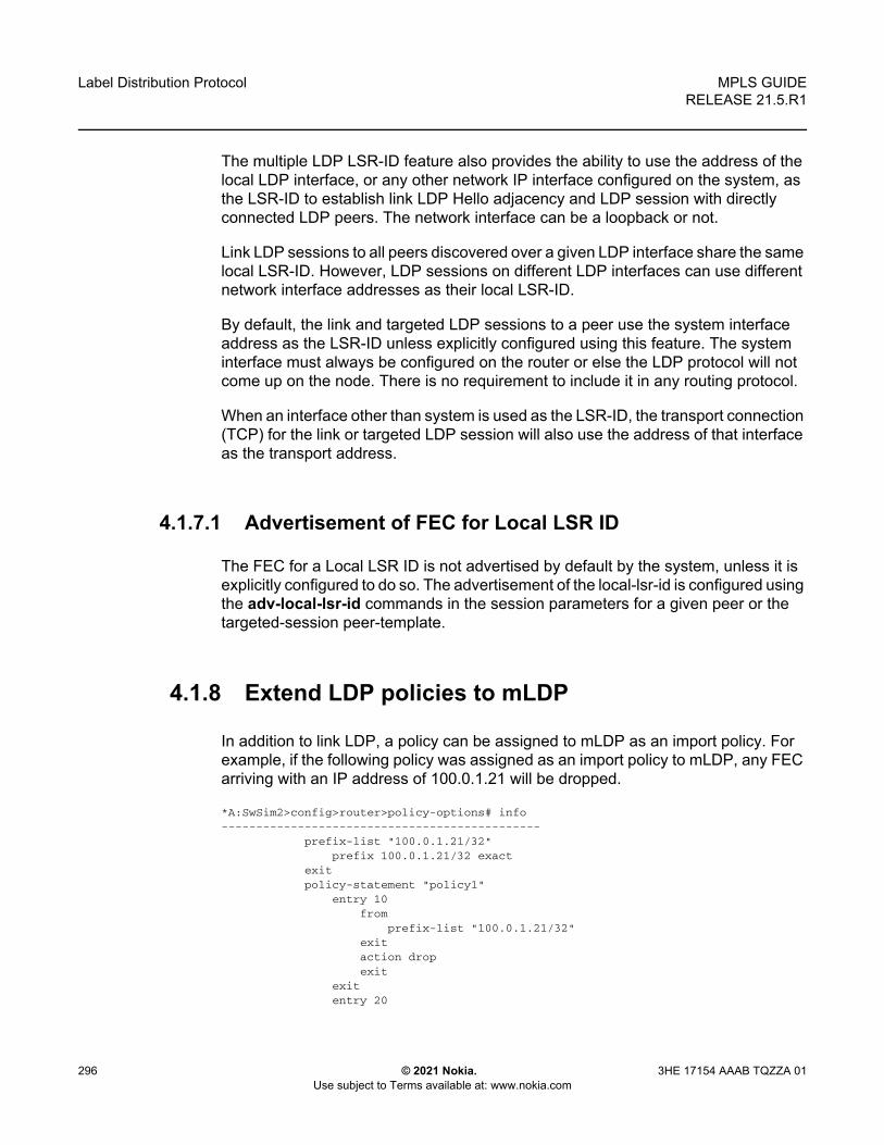
Label Distribution Protocol
296
MPLS GUIDERELEASE 21.5.R1
© 2021 Nokia. Use subject to Terms available at: www.nokia.com
3HE 17154 AAAB TQZZA 01
The multiple LDP LSR-ID feature also provides the ability to use the address of the local LDP interface, or any other network IP interface configured on the system, as the LSR-ID to establish link LDP Hello adjacency and LDP session with directly connected LDP peers. The network interface can be a loopback or not.
Link LDP sessions to all peers discovered over a given LDP interface share the same local LSR-ID. However, LDP sessions on different LDP interfaces can use different network interface addresses as their local LSR-ID.
By default, the link and targeted LDP sessions to a peer use the system interface address as the LSR-ID unless explicitly configured using this feature. The system interface must always be configured on the router or else the LDP protocol will not come up on the node. There is no requirement to include it in any routing protocol.
When an interface other than system is used as the LSR-ID, the transport connection (TCP) for the link or targeted LDP session will also use the address of that interface as the transport address.
4.1.7.1 Advertisement of FEC for Local LSR ID
The FEC for a Local LSR ID is not advertised by default by the system, unless it is explicitly configured to do so. The advertisement of the local-lsr-id is configured using the adv-local-lsr-id commands in the session parameters for a given peer or the targeted-session peer-template.
4.1.8 Extend LDP policies to mLDP
In addition to link LDP, a policy can be assigned to mLDP as an import policy. For example, if the following policy was assigned as an import policy to mLDP, any FEC arriving with an IP address of 100.0.1.21 will be dropped.
*A:SwSim2>config>router>policy-options# info----------------------------------------------
prefix-list "100.0.1.21/32"prefix 100.0.1.21/32 exact
exitpolicy-statement "policy1"
entry 10from
prefix-list "100.0.1.21/32"exitaction dropexit
exitentry 20

MPLS GUIDE RELEASE 21.5.R1
Label Distribution Protocol
3HE 17154 AAAB TQZZA 01 © 2021 Nokia. Use subject to Terms available at: www.nokia.com
297
exitdefault-action acceptexit
exit
The policy can be assigned to mLDP using the configure router ldp import-mcast-policy policy1 command. Based on this configuration, the prefix list will match the mLDP outer FEC and the action will be executed.
The mLDP import policy is useful for enforcing root only functionality on a network. For a PE to be a root only, enable the mLDP import policy to drop any arriving FEC on the P router.
4.1.8.1 Recursive FEC behavior
In the case of recursive FEC, the prefix list will match the outer root. For example, for recursive FEC <outerROOT, opaque <ActualRoot, opaque<lspID>> the import policy will work on the outerROOT of the FEC.
The policy only matches to the outer root address of the FEC and no other field in the FEC.
4.1.8.2 Import Policy
For mLDP, a policy can be assigned as an import policy only. Import policies only affect FECs arriving to the node, and will not affect the self-generated FECs on the node. The import policy will cause the multicast FECs received from the peer to be rejected and stored in the LDP database but not resolved. Therefore, the show router ldp binding command will display the FEC but the FEC will not be shown by the show router ldp binding active command. The FEC is not resolved if it is not allowed by the policy.
Only global import policies are supported for mLDP FEC. Per-peer import policies are not supported.
As defined in RFC 6388 for P2MP FEC, SR OS will only match the prefix against the root node address field of the FEC, and no other fields. This means that the policy will work on all P2MP Opaque types.
Note: mLDP import policies are only supported for IPv4 FECs.

Label Distribution Protocol
298
MPLS GUIDERELEASE 21.5.R1
© 2021 Nokia. Use subject to Terms available at: www.nokia.com
3HE 17154 AAAB TQZZA 01
The P2MP FEC Element is encoded as shown in Figure 51.
Figure 51 P2MP FEC Element Encoding
4.1.9 LDP FEC Resolution Per Specified Community
LDP communities provide separation between groups of FECs at the LDP session level. LDP sessions are assigned a community value and any FECs received or advertised over them are implicitly associated with that community.
SR OS supports multiple targeted LDP sessions over a specified network IP interface between LDP peer systems, each with its own local LSR ID. This makes it especially suitable for building multiple LDP overlay topologies over a common IP infrastructure, each with their own community.
LDP FEC resolution per specified community is supported in combination with stitching to SR or BGP tunnels as follows.
• Although a FEC is only advertised within a given LDP community, FEC can resolve to SR or BGP tunnels if those are the only available tunnels.
• If LDP has received a label from an LDP peer with an assigned community, that FEC is assigned the community of that session.
• If no LDP peer has advertised the label, LDP leaves the FEC with no community.• The FEC may be resolvable over an SR or BGP tunnel, but the community it is
assigned at the stitching node depends on whether LDP has also advertised that FEC to that node, and the community assigned to the LDP session over which the FEC was advertised.
P2MP Type (0x06) Address Family Address Length
100 1 2 3
1 2 3 4 5 6 7 8 9 0 2 3 4 5 76 8 9 0 1 32 4 5 6 7 98 0 1
sw0863
Root Node Address
Opaque Length Opaque Value
Note: The community value only has local significance to a node. The user must therefore ensure that communities are assigned consistently to sessions across the network.

MPLS GUIDE RELEASE 21.5.R1
Label Distribution Protocol
3HE 17154 AAAB TQZZA 01 © 2021 Nokia. Use subject to Terms available at: www.nokia.com
299
4.1.9.1 Configuration
A community is assigned to an LDP session by configuring a community string in the corresponding session parameters for the peer or the targeted session peer template. A community only applies to a local-lsr-id for a session. It is never applied to a system FEC or local static FEC. The no local-lsr-id or local-lsr-id system commands are synonymous and mean that there is no local LSR ID for a session. A system FEC or static FEC cannot have a community associated with it and is therefore not advertised over an LDP session with a configured community. Only a single community string can be configured for a session towards a specified peer or within a specified targeted peer template. The FEC advertised by the adv-local-lsr-id command is automatically put in the community configured on the session.
The specified community is only associated to IPv4 and IPv6 Address FECs incoming or outgoing on the relevant session, and not to IPv4/IPv6 P2MP FECs, or service FECs incoming/outgoing on the session.
Static FECs are treated as having no community associated with them, even if they are also received over another session with an assigned community. A mismatch is declared if this situation arises.
4.1.9.2 Operation
If a FEC is received over a session of a specified community, it is assumed to be associated with that community and is only broadcast to peers using sessions of that community. Likewise, a FEC received over a session with no community is only broadcast over other sessions with no community.
If a FEC is received over a session that does not have an assigned community, the FEC is treated as if it was received from a session with a differing assigned community. In other words, any particular FEC must only be received from sessions with a single, assigned community or no community. In any other case (from sessions with differing communities, or from a combination of sessions with a community and sessions without a community), the FEC is considered to have a community mismatch.
The following procedures apply.
1. The system remembers the first community (including no community) of the session that a FEC is received on.
2. If the same FEC is subsequently received over a session with a differing community, the FEC is marked as mismatched and the system raises a trap indicating community mismatch.

Label Distribution Protocol
300
MPLS GUIDERELEASE 21.5.R1
© 2021 Nokia. Use subject to Terms available at: www.nokia.com
3HE 17154 AAAB TQZZA 01
3. After a FEC has been marked as mismatched, the FEC is no longer advertised over sessions (or resolved to sessions) that differ either from the original community or in whether a community has been assigned. This can result in asymmetrical leaking of traffic between communities in certain cases, as illustrated by the following scenario. It is therefore recommended that FEC mismatches be resolved as soon as possible after they occur.Consider a triangle topology of Nodes A-B-C with iLDP sessions between them, using community=RED. At bootstrap, all the adv-local-lsrId FECs are exchanged, and the FECs are activated correctly as per routing. On each node, for each FEC there will be a [local push] and a [local swap] as there is more than one peer advertising such a FEC. At this point all FECs are marked as being RED.- Focusing on Node C, consider:
• Node A-owned RED FEC=X/32 • Node B-owned RED FEC=Y/32
- On Node C, the community of the session to node B is changed to BLUE. The consequence of this on Node C follows:
• The [swap] operation for the remote Node A RED FEC=X/32 is de-programmed, as the Node B peer now BLUE, and therefore are not receiving Node A FEC=X/32 from B. Only the push is left programmed.
• The [swap] operation for the remote Node B RED FEC=Y/32, is still programmed, even though this RED FEC is in mismatch, as it is received from both the BLUE peer Node B and the RED peer Node C.
4. When a session community changes, the session is flapped and the FEC community audited. If the original session is flapped, the FEC community changes as well. The following scenarios illustrate the operation of FEC community auditing.- Scenario A
• The FEC comes in on blue session A. The FEC is marked blue.• The FEC comes in on red session B. The FEC is marked “mismatched”
and stays blue.• Session B is changed to green. Session B is bounced. The FEC
community is audited, stays blue, and stays mismatched.- Scenario B
• The FEC comes in on blue session A. The FEC is marked blue.
Note: Subsequent traps due to a mismatch for a FEC arriving over a session of the same community (or no community) are squelched for a period of 60 seconds after the first trap. The trap indicates the session and the community of the session, but does not need to indicate the FEC itself.

MPLS GUIDE RELEASE 21.5.R1
Label Distribution Protocol
3HE 17154 AAAB TQZZA 01 © 2021 Nokia. Use subject to Terms available at: www.nokia.com
301
• The FEC comes in on red session B. The FEC is marked “mismatched” and stays blue.
• Session A is changed to red. The FEC community audit occurs. The “mismatch” indication is cleared and the FEC is marked as red. The FEC remains red when session A comes back up.
- Scenario C• The FEC comes in on blue session A. The FEC is marked blue.• The FEC comes in on red session B. The FEC is marked
“mismatched” and stays blue.• Session A goes down. The FEC community audit occurs. The FEC is
marked as red and the “mismatch” indication is cleared. The FEC is advertised over red session B.
• Session A subsequently comes back up and it is still blue. The FEC remains red but is marked “mismatched”. The FEC is no longer advertised over blue session A.
The community mismatch state for a prefix FEC is visible through the show>router>ldp>bindings>prefixes command output, while the community mismatch state is visible via a MIB flag (in the vRtrLdpNgAddrFecFlags object).
The fact that a FEC is marked “mismatched” has no bearing on its accounting with respect to the limit of the number of FECs that may be received over a session.
The ability of a policy to reject a FEC is independent of the FEC mismatch. A policy prevents the system from using the label for resolution, but if the corresponding session is sending community-mismatched FECs, there is a problem and it should be flagged. For example, the policy and community mismatch checks are independent, and a FEC should still be marked with a community mismatch, if needed, per the rules above
4.1.10 T-LDP hello reduction
This feature implements a new mechanism to suppress the transmission of the Hello messages following the establishment of a Targeted LDP session between two LDP peers. The Hello adjacency of the targeted session does not require periodic transmission of Hello messages as in the case of a link LDP session. In link LDP, one or more peers can be discovered over a given network IP interface and as such, the

Label Distribution Protocol
302
MPLS GUIDERELEASE 21.5.R1
© 2021 Nokia. Use subject to Terms available at: www.nokia.com
3HE 17154 AAAB TQZZA 01
periodic transmission of Hello messages is required to discover new peers in addition to the periodic Keep-Alive message transmission to maintain the existing LDP sessions. A Targeted LDP session is established to a single peer. Thus, once the Hello Adjacency is established and the LDP session is brought up over a TCP connection, Keep-Alive messages are sufficient to maintain the LDP session.
When this feature is enabled, the targeted Hello adjacency is brought up by advertising the Hold-Time value the user configured in the Hello timeout parameter for the targeted session. The LSR node will then start advertising an exponentially increasing Hold-Time value in the Hello message as soon as the targeted LDP session to the peer is up. Each new incremented Hold-Time value is sent in a number of Hello messages equal to the value of the Hello reduction factor before the next exponential value is advertised. This provides time for the two peers to settle on the new value. When the Hold-Time reaches the maximum value of 0xffff (binary 65535), the two peers will send Hello messages at a frequency of every [(65535-1)/local helloFactor] seconds for the lifetime of the targeted-LDP session (for example, if the local Hello Factor is three (3), then Hello messages will be sent every 21844 seconds).
Both LDP peers must be configured with this feature to bring gradually their advertised Hold-Time up to the maximum value. If one of the LDP peers does not, the frequency of the Hello messages of the targeted Hello adjacency will continue to be governed by the smaller of the two Hold-Time values. This feature complies to draft-pdutta-mpls-tldp-hello-reduce.
4.1.11 Tracking a T-LDP Peer with BFD
BFD tracking of an LDP session associated with a T-LDP adjacency allows for faster detection of the liveliness of the session by registering the peer transport address of a LDP session with a BFD session. The source or destination address of the BFD session is the local or remote transport address of the targeted or link (if peers are directly connected) Hello adjacency which triggered the LDP session.
By enabling BFD for a selected targeted session, the state of that session is tied to the state of the underneath BFD session between the two nodes. The parameters used for the BFD are set with the BFD command under the IP interface which has the source address of the TCP connection.

MPLS GUIDE RELEASE 21.5.R1
Label Distribution Protocol
3HE 17154 AAAB TQZZA 01 © 2021 Nokia. Use subject to Terms available at: www.nokia.com
303
4.1.12 Link LDP Hello Adjacency Tracking with BFD
LDP can only track an LDP peer using the Hello and Keep-Alive timers. If an IGP protocol registered with BFD on an IP interface to track a neighbor, and the BFD session times out, the next-hop for prefixes advertised by the neighbor are no longer resolved. This however does not bring down the link LDP session to the peer since the LDP peer is not directly tracked by BFD.
In order to properly track the link LDP peer, LDP needs to track the Hello adjacency to its peer by registering with BFD.
The user effects Hello adjacency tracking with BFD by enabling BFD on an LDP interface:
config>router>ldp>if-params>if>enable-bfd [ipv4][ipv6]
The parameters used for the BFD session, that is, transmit-interval, receive-interval, and multiplier, are those configured under the IP interface:
config>router>if>bfd
The source or destination address of the BFD session is the local or remote address of link Hello adjacency. When multiple links exist to the same LDP peer, a Hello adjacency is established over each link. However, a single LDP session will exist to the peer and will use a TCP connection over one of the link interfaces. Also, a separate BFD session should be enabled on each LDP interface. If a BFD session times out on a specific link, LDP will immediately bring down the Hello adjacency on that link. In addition, if there are FECs that have their primary NHLFE over this link, LDP triggers the LDP FRR procedures by sending to IOM and line cards the neighbor/next-hop down message. This will result in moving the traffic of the impacted FECs to an LFA next-hop on a different link to the same LDP peer or to an LFA backup next-hop on a different LDP peer depending on the lowest backup cost path selected by the IGP SPF.
As soon as the last Hello adjacency goes down as a result of the BFD timing out, the LDP session goes down and the LDP FRR procedures will be triggered. This will result in moving the traffic to an LFA backup next-hop on a different LDP peer.
4.1.13 LDP LSP Statistics
RSVP-TE LSP statistics is extended to LDP to provide the following counters:
• Per-forwarding-class forwarded in-profile packet count

Label Distribution Protocol
304
MPLS GUIDERELEASE 21.5.R1
© 2021 Nokia. Use subject to Terms available at: www.nokia.com
3HE 17154 AAAB TQZZA 01
• Per-forwarding-class forwarded in-profile byte count• Per-forwarding-class forwarded out-of-profile packet count• Per-forwarding-class forwarded out-of-profile byte count
The counters are available for the egress data path of an LDP FEC at ingress LER and at LSR. Because an ingress LER is also potentially an LSR for an LDP FEC, combined egress data path statistics will be provided whenever applicable.
4.1.14 MPLS Entropy Label
The router supports the MPLS entropy label (RFC 6790) on LDP LSPs used for IGP and BGP shortcuts. This allows LSR nodes in a network to load-balance labeled packets in a much more granular fashion than allowed by simply hashing on the standard label stack.
To configure insertion of the entropy label on IGP or BGP shortcuts, use using the entropy-label command under the configure router context.
4.1.15 Importing LDP Tunnels to Non-Host Prefixes to TTM
When an LDP LSP is established, TTM is automatically populated with the corresponding tunnel. This automatic behavior does not apply to non-host prefixes. The config>router>ldp>import-tunnel-table command allows for TTM to be populated with LDP tunnels to such prefixes in a controlled manner for both IPv4 and IPv6.

MPLS GUIDE RELEASE 21.5.R1
Label Distribution Protocol
3HE 17154 AAAB TQZZA 01 © 2021 Nokia. Use subject to Terms available at: www.nokia.com
305
4.2 TTL Security for BGP and LDP
The BGP TTL Security Hack (BTSH) was originally designed to protect the BGP infrastructure from CPU utilization-based attacks. It is derived from the fact that the vast majority of ISP EBGP peerings are established between adjacent routers. Since TTL spoofing is considered nearly impossible, a mechanism based on an expected TTL value can provide a simple and reasonably robust defense from infrastructure attacks based on forged BGP packets.
While TTL Security Hack (TSH) is most effective in protecting directly connected peers, it can also provide a lower level of protection to multi-hop sessions. When a multi-hop BGP session is required, the expected TTL value can be set to 255 minus the configured range-of-hops. This approach can provide a qualitatively lower degree of security for BGP (such as a DoS attack could, theoretically, be launched by compromising a box in the path). However, BTSH will catch a vast majority of observed distributed DoS (DDoS) attacks against EBGP.
TSH can be used to protect LDP peering sessions as well. For details, see draft-chen-ldp-ttl-xx.txt, TTL-Based Security Option for LDP Hello Message.
The TSH implementation supports the ability to configure TTL security per BGP/LDP peer and evaluate (in hardware) the incoming TTL value against the configured TTL value. If the incoming TTL value is less than the configured TTL value, the packets are discarded and a log is generated.

Label Distribution Protocol
306
MPLS GUIDERELEASE 21.5.R1
© 2021 Nokia. Use subject to Terms available at: www.nokia.com
3HE 17154 AAAB TQZZA 01
4.3 ECMP Support for LDP
ECMP support for LDP performs load balancing for LDP based LSPs by having multiple outgoing next-hops for a given IP prefix on ingress and transit LSRs.
An LSR that has multiple equal cost paths to a given IP prefix can receive an LDP label mapping for this prefix from each of the downstream next-hop peers. As the LDP implementation uses the liberal label retention mode, it retains all the labels for an IP prefix received from multiple next-hop peers.
Without ECMP support for LDP, only one of these next-hop peers is selected and installed in the forwarding plane. The algorithm used to determine the next-hop peer to be selected involves looking up the route information obtained from the RTM for this prefix and finding the first valid LDP next-hop peer (for example, the first neighbor in the RTM entry from which a label mapping was received). If, for some reason, the outgoing label to the installed next-hop is no longer valid, say the session to the peer is lost or the peer withdraws the label, a new valid LDP next-hop peer is selected out of the existing next-hop peers and LDP reprograms the forwarding plane to use the label sent by this peer.
With ECMP support, all the valid LDP next-hop peers, those that sent a label mapping for a given IP prefix, are installed in the forwarding plane. In both cases, ingress LER and transit LSR, an ingress label are mapped to the next hops that are in the RTM and from which a valid mapping label has been received. The forwarding plane then uses an internal hashing algorithm to determine how the traffic is distributed amongst these multiple next-hops, assigning each “flow” to a particular next-hop.
The hash algorithm at LER and transit LSR are described in the "Traffic Load Balancing Options" in the 7450 ESS, 7750 SR, 7950 XRS, and VSR Interface Configuration Guide.
LDP supports up to 64 ECMP next hops. LDP takes its maximum limit from the lower of config>router>ecmp and config>router>ldp>max-ecmp-routes.
4.3.1 Label Operations
If an LSR is the ingress for a given IP prefix, LDP programs a push operation for the prefix in the forwarding engine. This creates an LSP ID to the Next Hop Label Forwarding Entry (NHLFE) (LTN) mapping and an LDP tunnel entry in the forwarding plane. LDP will also inform the Tunnel Table Manager (TTM) of this tunnel. Both the LTN entry and the tunnel entry will have a NHLFE for the label mapping that the LSR received from each of its next-hop peers.
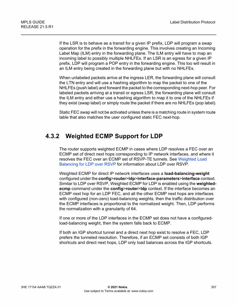
MPLS GUIDE RELEASE 21.5.R1
Label Distribution Protocol
3HE 17154 AAAB TQZZA 01 © 2021 Nokia. Use subject to Terms available at: www.nokia.com
307
If the LSR is to behave as a transit for a given IP prefix, LDP will program a swap operation for the prefix in the forwarding engine. This involves creating an Incoming Label Map (ILM) entry in the forwarding plane. The ILM entry will have to map an incoming label to possibly multiple NHLFEs. If an LSR is an egress for a given IP prefix, LDP will program a POP entry in the forwarding engine. This too will result in an ILM entry being created in the forwarding plane but with no NHLFEs.
When unlabeled packets arrive at the ingress LER, the forwarding plane will consult the LTN entry and will use a hashing algorithm to map the packet to one of the NHLFEs (push label) and forward the packet to the corresponding next-hop peer. For labeled packets arriving at a transit or egress LSR, the forwarding plane will consult the ILM entry and either use a hashing algorithm to map it to one of the NHLFEs if they exist (swap label) or simply route the packet if there are no NHLFEs (pop label).
Static FEC swap will not be activated unless there is a matching route in system route table that also matches the user configured static FEC next-hop.
4.3.2 Weighted ECMP Support for LDP
The router supports weighted ECMP in cases where LDP resolves a FEC over an ECMP set of direct next hops corresponding to IP network interfaces, and where it resolves the FEC over an ECMP set of RSVP-TE tunnels. See Weighted Load Balancing for LDP over RSVP for information about LDP over RSVP.
Weighted ECMP for direct IP network interfaces uses a load-balancing-weight configured under the config>router>ldp>interface-parameters>interface context. Similar to LDP over RSVP, Weighted ECMP for LDP is enabled using the weighted-ecmp command under the config>router>ldp context. If the interface becomes an ECMP next hop for an LDP FEC, and all the other ECMP next hops are interfaces with configured (non-zero) load-balancing weights, then the traffic distribution over the ECMP interfaces is proportional to the normalized weight. Then, LDP performs the normalization with a granularity of 64.
If one or more of the LDP interfaces in the ECMP set does not have a configured-load-balancing weight, then the system falls back to ECMP.
If both an IGP shortcut tunnel and a direct next hop exist to resolve a FEC, LDP prefers the tunneled resolution. Therefore, if an ECMP set consists of both IGP shortcuts and direct next hops, LDP only load balances across the IGP shortcuts.

Label Distribution Protocol
308
MPLS GUIDERELEASE 21.5.R1
© 2021 Nokia. Use subject to Terms available at: www.nokia.com
3HE 17154 AAAB TQZZA 01
Note:
• LDP only uses configured LDP interface load balancing weights with non-LDP over RSVP resolutions.
• Weights are normalized across all possible next-hops for a FEC. If the number of ECMP routes configured with the configure>router>ldp>max-ecmp-routes is less than the actual number of next-hops, traffic is load-balanced using the normalized weights from the first max-ecmp-routes next-hop. This can cause load distribution within the LDP max-ecmp-routes that is not representative of the distribution that would occur across all ECMP next-hops.

MPLS GUIDE RELEASE 21.5.R1
Label Distribution Protocol
3HE 17154 AAAB TQZZA 01 © 2021 Nokia. Use subject to Terms available at: www.nokia.com
309
4.4 Unnumbered Interface Support in LDP
This feature allows LDP to establish Hello adjacency and to resolve unicast and multicast FECs over unnumbered LDP interfaces.
This feature also extends the support of lsp-ping, p2mp-lsp-ping, and ldp-treetrace to test an LDP unicast or multicast FEC which is resolved over an unnumbered LDP interface.
4.4.1 Feature Configuration
This feature does not introduce a new CLI command for adding an unnumbered interface into LDP. Rather, the fec-originate command is extended to specify the interface name because an unnumbered interface does not have an IP address of its own. The user can, however, specify the interface name for numbered interfaces.
See the CLI section for the changes to the fec-originate command.
4.4.2 Operation of LDP over an Unnumbered IP Interface
Consider the setup shown in Figure 52.
Figure 52 LDP Adjacency and Session over Unnumbered Interface
LSR A and LSR B have the following LDP identifiers respectively:
<LSR Id=A> : <label space id=0>
<LSR Id=B> : <label space id=0>
There are two P2P unnumbered interfaces between LSR A and LSR B. These interfaces are identified on each system with their unique local link identifier. In other words, the combination of {Router-ID, Local Link Identifier} uniquely identifies the interface in OSPF or IS-IS throughout the network.
al_0213
LSR-A:0I/F 1
I/F 2
LSR-B:0

Label Distribution Protocol
310
MPLS GUIDERELEASE 21.5.R1
© 2021 Nokia. Use subject to Terms available at: www.nokia.com
3HE 17154 AAAB TQZZA 01
A borrowed IP address is also assigned to the interface to be used as the source address of IP packets which need to be originated from the interface. The borrowed IP address defaults to the system loopback interface address, A and B respectively in this setup. The user can change the borrowed IP interface to any configured IP interface, loopback or not, by applying the following command:
config>router>if>unnumbered [<ip-int-name | ip-address>]
When the unnumbered interface is added into LDP, it will have the following behavior.
4.4.2.1 Link LDP
Hello adjacency will be brought up using link Hello packet with source IP address set to the interface borrowed IP address and a destination IP address set to 224.0.0.2.
As a consequence of (1), Hello packets with the same source IP address should be accepted when received over parallel unnumbered interfaces from the same peer LSR-ID. The corresponding Hello adjacencies would be associated with a single LDP session.
The transport address for the TCP connection, which is encoded in the Hello packet, will always be set to the LSR-ID of the node regardless if the user enabled the interface option under config>router>ldp>if-params>if>ipv4>transport-address.
The user can configure the local-lsr-id option on the interface and change the value of the LSR-ID to either the local interface or to some other interface name, loopback or not, numbered or not. If the local interface is selected or the provided interface name corresponds to an unnumbered IP interface, the unnumbered interface borrowed IP address will be used as the LSR-ID. In all cases, the transport address for the LDP session will be updated to the new LSR-ID value but the link Hello packets will continue to use the interface borrowed IP address as the source IP address.
The LSR with the highest transport address, that is, LSR-ID in this case, will bootstrap the TCP connection and LDP session.
Source and destination IP addresses of LDP packets are the transport addresses, that is, LDP LSR-IDs of systems A and B in this case.
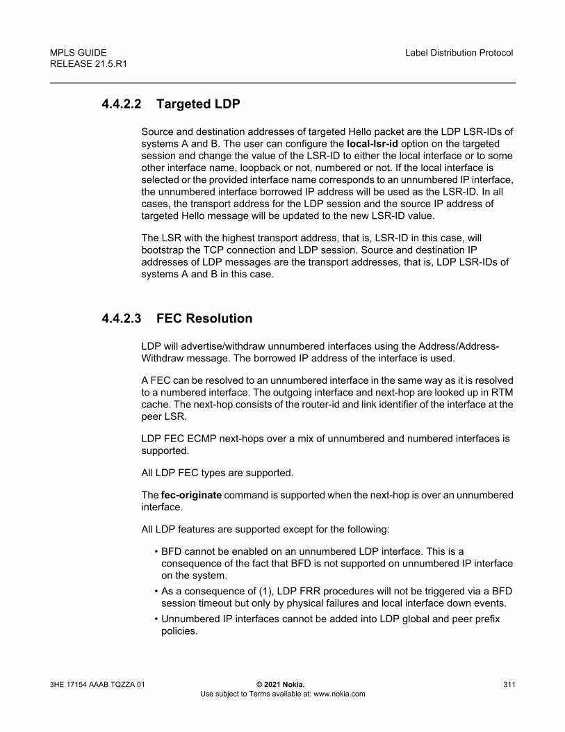
MPLS GUIDE RELEASE 21.5.R1
Label Distribution Protocol
3HE 17154 AAAB TQZZA 01 © 2021 Nokia. Use subject to Terms available at: www.nokia.com
311
4.4.2.2 Targeted LDP
Source and destination addresses of targeted Hello packet are the LDP LSR-IDs of systems A and B. The user can configure the local-lsr-id option on the targeted session and change the value of the LSR-ID to either the local interface or to some other interface name, loopback or not, numbered or not. If the local interface is selected or the provided interface name corresponds to an unnumbered IP interface, the unnumbered interface borrowed IP address will be used as the LSR-ID. In all cases, the transport address for the LDP session and the source IP address of targeted Hello message will be updated to the new LSR-ID value.
The LSR with the highest transport address, that is, LSR-ID in this case, will bootstrap the TCP connection and LDP session. Source and destination IP addresses of LDP messages are the transport addresses, that is, LDP LSR-IDs of systems A and B in this case.
4.4.2.3 FEC Resolution
LDP will advertise/withdraw unnumbered interfaces using the Address/Address-Withdraw message. The borrowed IP address of the interface is used.
A FEC can be resolved to an unnumbered interface in the same way as it is resolved to a numbered interface. The outgoing interface and next-hop are looked up in RTM cache. The next-hop consists of the router-id and link identifier of the interface at the peer LSR.
LDP FEC ECMP next-hops over a mix of unnumbered and numbered interfaces is supported.
All LDP FEC types are supported.
The fec-originate command is supported when the next-hop is over an unnumbered interface.
All LDP features are supported except for the following:
• BFD cannot be enabled on an unnumbered LDP interface. This is a consequence of the fact that BFD is not supported on unnumbered IP interface on the system.
• As a consequence of (1), LDP FRR procedures will not be triggered via a BFD session timeout but only by physical failures and local interface down events.
• Unnumbered IP interfaces cannot be added into LDP global and peer prefix policies.

Label Distribution Protocol
312
MPLS GUIDERELEASE 21.5.R1
© 2021 Nokia. Use subject to Terms available at: www.nokia.com
3HE 17154 AAAB TQZZA 01
4.5 LDP over RSVP Tunnels
LDP over RSVP-TE provides end-to-end tunnels that have two important properties, fast reroute and traffic engineering which are not available in LDP. LDP over RSVP-TE is focused at large networks (over 100 nodes in the network). Simply using end-to-end RSVP-TE tunnels will not scale. While an LER may not have that many tunnels, any transit node will potentially have thousands of LSPs, and if each transit node also has to deal with detours or bypass tunnels, this number can make the LSR overly burdened.
LDP over RSVP-TE allows tunneling of user packets using an LDP LSP inside an RSVP LSP. The main application of this feature is for deployment of MPLS based services, for example, VPRN, VLL, and VPLS services, in large scale networks across multiple IGP areas without requiring full mesh of RSVP LSPs between PE routers.
Figure 53 LDP over RSVP Application
The network displayed in Figure 53 consists of two metro areas, Area 1 and 2 respectively, and a core area, Area 3. Each area makes use of TE LSPs to provide connectivity between the edge routers. In order to enable services between PE1 and PE2 across the three areas, LSP1, LSP2, and LSP3 are set up using RSVP-TE. There are in fact 6 LSPs required for bidirectional operation but we will refer to each bi-directional LSP with a single name, for example, LSP1. A targeted LDP (T-LDP) session is associated with each of these bidirectional LSP tunnels. That is, a T-LDP adjacency is created between PE1 and ABR1 and is associated with LSP1 at each end. The same is done for the LSP tunnel between ABR1 and ABR2, and finally between ABR2 and PE2. The loopback address of each of these routers is advertised using T-LDP. Similarly, backup bidirectional LDP over RSVP tunnels, LSP1a and LSP2a, are configured by way of ABR3.
IP/MPLSCore Network
(Area 3)
IP/MPLSMetro Network
(Area 2)
IP/MPLSMetro Network
(Area 1)
ABR 1 ABR 2
ABR 3ABR 4
PE 2
LSP3
LSP2
LSP1aLSP2a
LSP1
PE 1
al_0901

MPLS GUIDE RELEASE 21.5.R1
Label Distribution Protocol
3HE 17154 AAAB TQZZA 01 © 2021 Nokia. Use subject to Terms available at: www.nokia.com
313
This setup effectively creates an end-to-end LDP connectivity which can be used by all PEs to provision services. The RSVP LSPs are used as a transport vehicle to carry the LDP packets from one area to another. Only the user packets are tunneled over the RSVP LSPs. The T-LDP control messages are still sent unlabeled using the IGP shortest path.
In this application, the bi-directional RSVP LSP tunnels are not treated as IP interfaces and are not advertised back into the IGP. A PE must always rely on the IGP to look up the next hop for a service packet. LDP-over-RSVP introduces a new tunnel type, tunnel-in-tunnel, in addition to the existing LDP tunnel and RSVP tunnel types. If multiple tunnels types match the destination PE FEC lookup, LDP will prefer an LDP tunnel over an LDP-over-RSVP tunnel by default.
The design in Figure 53 allows a service provider to build and expand each area independently without requiring a full mesh of RSVP LSPs between PEs across the three areas.
To participate in a VPRN service, the PE1 and PE2 perform the autobind to LDP. The LDP label which represents the target PE loopback address is used below the RSVP LSP label. Therefore a 3 label stack is required.
In order to provide a VLL service, PE1 and PE2 are still required to set up a targeted LDP session directly between them. Again a 3 label stack is required, the RSVP LSP label, followed by the LDP label for the loopback address of the destination PE, and finally the pseudowire label (VC label).
This implementation supports a variation of the application in Figure 53, in which area 1 is an LDP area. In that case, PE1 will push a two label stack while ABR1 will swap the LDP label and push the RSVP label as illustrated in Figure 54. LDP-over-RSVP tunnels can also be used as IGP shortcuts.
Figure 54 LDP over RSVP Application Variant
IP/MPLSCore Network(RSVP Area 3)
IP/MPLSMetro Network(RSVP Area 2)
IP/MPLSMetro Network(LDP Area 1)
ABR 1 ABR 2
ABR 3ABR 4
PE 2
LSP3
LSP2
LDP LSP1aLSP2a
LDPLSP1
PE 1
al_0902

Label Distribution Protocol
314
MPLS GUIDERELEASE 21.5.R1
© 2021 Nokia. Use subject to Terms available at: www.nokia.com
3HE 17154 AAAB TQZZA 01
4.5.1 Signaling and Operation
4.5.1.1 LDP Label Distribution and FEC Resolution
The user creates a targeted LDP (T-LDP) session to an ABR or the destination PE. This results in LDP hellos being sent between the two routers. These messages are sent unlabeled over the IGP path. Next, the user enables LDP tunneling on this T-LDP session and optionally specifies a list of LSP names to associate with this T-LDP session. By default, all RSVP LSPs which terminate on the T-LDP peer are candidates for LDP-over-RSVP tunnels. At this point in time, the LDP FECs resolving to RSVP LSPs are added into the Tunnel Table Manager as tunnel-in-tunnel type.
If LDP is running on regular interfaces also, the prefixes LDP learns are going to be distributed over both the T-LDP session as well as regular IGP interfaces. LDP FEC prefixes with a subnet mask lower or equal than 32 will be resolved over RSVP LSPs. The policy controls which prefixes go over the T-LDP session, for example, only /32 prefixes, or a particular prefix range.
LDP-over-RSVP works with both OSPF and ISIS. These protocols include the advertising router when adding an entry to the RTM. LDP-over-RSVP tunnels can be used as shortcuts for BGP next-hop resolution.
4.5.1.2 Default FEC Resolution Procedure
When LDP tries to resolve a prefix received over a T-LDP session, it performs a lookup in the Routing Table Manager (RTM). This lookup returns the next hop to the destination PE and the advertising router (ABR or destination PE itself). If the next-hop router advertised the same FEC over link-level LDP, LDP will prefer the LDP tunnel by default unless the user explicitly changed the default preference using the system wide prefer-tunnel-in-tunnel command. If the LDP tunnel becomes unavailable, LDP will select an LDP-over-RSVP tunnel if available.
When searching for an LDP-over-RSVP tunnel, LDP selects the advertising router(s) with best route. If the advertising router matches the T-LDP peer, LDP then performs a second lookup for the advertising router in the Tunnel Table Manager (TTM) which returns the user configured RSVP LSP with the best metric. If there are more than one configured LSP with the best metric, LDP selects the first available LSP.
If all user configured RSVP LSPs are down, no more action is taken. If the user did not configure any LSPs under the T-LDP session, the lookup in TTM will return the first available RSVP LSP which terminates on the advertising router with the lowest metric.

MPLS GUIDE RELEASE 21.5.R1
Label Distribution Protocol
3HE 17154 AAAB TQZZA 01 © 2021 Nokia. Use subject to Terms available at: www.nokia.com
315
4.5.1.3 FEC Resolution Procedure When prefer-tunnel-in-tunnel is Enabled
When LDP tries to resolve a prefix received over a T-LDP session, it performs a lookup in the Routing Table Manager (RTM). This lookup returns the next hop to the destination PE and the advertising router (ABR or destination PE itself).
When searching for an LDP-over-RSVP tunnel, LDP selects the advertising router(s) with best route. If the advertising router matches the targeted LDP peer, LDP then performs a second lookup for the advertising router in the Tunnel Table Manager (TTM) which returns the user configured RSVP LSP with the best metric. If there are more than one configured LSP with the best metric, LDP selects the first available LSP.
If all user configured RSVP LSPs are down, then an LDP tunnel will be selected if available.
If the user did not configure any LSPs under the T-LDP session, a lookup in TTM will return the first available RSVP LSP which terminates on the advertising router. If none are available, then an LDP tunnel will be selected if available.
4.5.2 Rerouting Around Failures
Every failure in the network can be protected against, except for the ingress and egress PEs. All other constructs have protection available. These constructs are LDP-over-RSVP tunnel and ABR.
4.5.2.1 LDP-over-RSVP Tunnel Protection
An RSVP LSP can deal with a failure in two ways:
• If the LSP is a loosely routed LSP, then RSVP will find a new IGP path around the failure, and traffic will follow this new path. This may involve some churn in the network if the LSP comes down and then gets re-routed. The tunnel damping feature was implemented on the LSP so that all the dependent protocols and applications do not flap unnecessarily.
• If the LSP is a CSPF-computed LSP with the fast reroute option enabled, then RSVP will switch to the detour path very quickly. From that point, a new LSP will be attempted from the head-end (global revertive). When the new LSP is in place, the traffic switches over to the new LSP with make-before-break.

Label Distribution Protocol
316
MPLS GUIDERELEASE 21.5.R1
© 2021 Nokia. Use subject to Terms available at: www.nokia.com
3HE 17154 AAAB TQZZA 01
4.5.2.2 ABR Protection
If an ABR fails, then routing around the ABR requires that a new next-hop LDP-over-RSVP tunnel be found to a backup ABR. If an ABR fails, then the T-LDP adjacency fails. Eventually, the backup ABR becomes the new next hop (after SPF converges), and LDP learns of the new next-hop and can reprogram the new path.

MPLS GUIDE RELEASE 21.5.R1
Label Distribution Protocol
3HE 17154 AAAB TQZZA 01 © 2021 Nokia. Use subject to Terms available at: www.nokia.com
317
4.6 LDP over RSVP Without Area Boundary
The LDP over RSVP capability set includes the ability to stitch LDP-over-RSVP tunnels at internal (non-ABR) OSPF and IS-IS routers.
Figure 55 LDP over RSVP Without ABR Stitching Point
In Figure 55, assume that the user wants to use LDP over RSVP between router A and destination “Dest”. The first thing that happens is that either OSPF or IS-IS will perform an SPF calculation resulting in an SPF tree. This tree specifies the lowest possible cost to the destination. In the example shown, the destination “Dest” is reachable at the lowest cost through router X. The SPF tree will have the following path: A>C>E>G>X.
Using this SPF tree, router A will search for the endpoint that is closest (farthest/highest cost from the origin) to “Dest” that is eligible. Assuming that all LSPs in the above diagram are eligible, LSP endpoint G will be selected as it terminates on router G while other LSPs only reach routers C and E, respectively.
IGP and LSP metrics associated with the various LSP are ignores; only tunnel endpoint matters to IGP. The endpoint that terminates closest to “Dest” (highest IGP path cost) will be selected for further selection of the LDP over RSVP tunnels to that endpoint. The explicit path the tunnel takes may not match the IGP path that the SPF computes.
al_0214
10
10 10 20
25
25
25
Link & IGP Cost
SPF Path
25
25 LSP3A>C
LSP2A>C>E
LSP1A>B>D>F>G
20 15
H K
E G X Dest.C
A
B D F

Label Distribution Protocol
318
MPLS GUIDERELEASE 21.5.R1
© 2021 Nokia. Use subject to Terms available at: www.nokia.com
3HE 17154 AAAB TQZZA 01
If router A and G have an additional LSP terminating on router G, there would now be two tunnels both terminating on the same router closest to the final destination. For IGP, it does not make any difference on the numbers of LDPs to G, only that there is at least one LSP to G. In this case, the LSP metric will be considered by LDP when deciding which LSP to stitch for the LDP over RSVP connection.
The IGP only passes endpoint information to LDP. LDP looks up the tunnel table for all tunnels to that endpoint and picks up the one with the least tunnel metric. There may be many tunnels with the same least cost. LDP FEC prefixes with a subnet mask lower or equal than 32 will be resolved over RSVP LSPs within an area.
4.6.1 LDP over RSVP and ECMP
ECMP for LDP over RSVP is supported (also see ECMP Support for LDP). If ECMP applies, all LSP endpoints found over the ECMP IGP path will be installed in the routing table by the IGP for consideration by LDP. IGP costs to each endpoint may differ because IGP selects the farthest endpoint per ECMP path.
LDP will choose the endpoint that is highest cost in the route entry and will do further tunnel selection over those endpoints. If there are multiple endpoints with equal highest cost, then LDP will consider all of them.

MPLS GUIDE RELEASE 21.5.R1
Label Distribution Protocol
3HE 17154 AAAB TQZZA 01 © 2021 Nokia. Use subject to Terms available at: www.nokia.com
319
4.7 Weighted Load Balancing for LDP over RSVP
Weighted load balancing (Weighted ECMP) is supported for LDP over RSVP (LoR), when the LDP next hop resolves to an IGP shortcut tunnel over RSVP, when it resolves to a static route with next hops which in turn uses RSVP tunnels, and where the tunneling option is configured for the LDP peer (classical LDP over RSVP). Weighted load balancing is supported for both push and swap NHLFEs.
At a high level, the feature operates as follows.
• All of the RSVP LSPs in the ECMP set should have a load-balancing-weight configured, otherwise non-weighted ECMP behavior is used.
• The normalized weight of each RSVP LSP is calculated based on its configured load-balancing weight. The calculation is performed by LDP to a resolution of 64. These next hops are then populated in TTM.
• RTM entries are updated accordingly for LDP shortcuts.• When weighted ECMP is configured for LDP, the normalized weight is
downloaded to the IOM when the LDP route is resolved. This occurs for both push and swap NHLFEs.
• LDP labeled packets are then sprayed in proportion to the normalized weight of the RSVP LSPs that they are forwarded over.
• There is no per-service differentiation between packets. LDP labeled packets from all services are sprayed in proportion to the normalized weight.
• Tunnel-in-tunnel takes precedence over the existence of a static route with a tunneled next hop. That is, if tunneling is configured, then LDP uses these LSPs rather than those used by the static route. This means that LDP may use different tunnels to those pointed to by static routes.
Weighted ECMP for LDP over RSVP, when using IGP shortcuts or static routes, is enabled as follows:
configrouter
ldp[no] weighted-ecmp
However, in case of classic LoR, weighted ECMP only needs to be configured under LDP. The maximum number of ECMP tunnels is taken from the lower of the config>router>ecmp and config>router>ldp>max-ecmp-routes commands.
The following configuration illustrates the case of LDP resolving to a static route with one or more indirect next hops and a set of RSVP tunnels specified in the resolution filter:

Label Distribution Protocol
320
MPLS GUIDERELEASE 21.5.R1
© 2021 Nokia. Use subject to Terms available at: www.nokia.com
3HE 17154 AAAB TQZZA 01
config>routerstatic-route-entry 192.0.2.102/32
indirect 192.0.2.2tunnel-next-hop
resolution-filterrsvp-te
lsp "LSP-ABR-1-1"lsp "LSP-ABR-1-2"lsp "LSP-ABR-1-3"exit
exitindirect 192.0.2.3
tunnel-next-hopresolution-filter
rsvp-telsp "LSP-ABR-2-1"lsp "LSP-ABR-2-2"lsp "LSP-ABR-2-3"exit
exitno shutdown
exit
If both config>router>weighted-ecmp and config>router>ldp>weighted-ecmp are configured, then the weights of all of the RSVP tunnels for the static route are normalized to 64 and these are used to spray LDP labeled packets across the set of LSPs. This applies across all shortcuts (static and IGP) to which a route is resolved to the far-end prefix.
4.7.1 Interaction with Class-Based Forwarding
Class Based Forwarding (CBF) is not supported together with Weighted ECMP in LoR.
If both weighted ECMP and class-forwarding are configured under LDP, then LDP uses weighted ECMP only if all LSP next hops have non-default-weighted values configured. If any of the ECMP set LSP next hops do not have the weight configured, then LDP uses CBF. Otherwise, LDP uses CBF if possible. If weighted ECMP is configured for both LDP and the IGP shortcut for the RSVP tunnel, (config>router>weighted-ecmp), then weighted ECMP is used.
LDP resolves and programs FECs according to the weighted ECMP information if the following conditions are met.
• LDP has both CBF and weighted ECMP fully configured.• All LSPs in ECMP set have both a load-balancing weight and CBF information
configured.• weighted-ecmp is enabled under config>router.

MPLS GUIDE RELEASE 21.5.R1
Label Distribution Protocol
3HE 17154 AAAB TQZZA 01 © 2021 Nokia. Use subject to Terms available at: www.nokia.com
321
Subsequently, deleting the CBF configuration has no effect; however, deleting the weighted ECMP configuration causes LDP to resolve according to CBF, if complete, consistent CBF information is available. Otherwise LDP sprays over all the LSPs equally, using non-weighted ECMP behavior.
If the IGP shortcut tunnel using the RSVP LSP does not have complete weighted ECMP information (for example, config>router>weighted-ecmp is not configured or one or more of the RSVP tunnels has no load-balancing-weight) then LDP attempts CBF resolution. If the CBF resolution is complete and consistent, then LDP programs that resolution. If a complete, consistent CBF resolution is not received, then LDP sprays over all the LSPs equally, using regular ECMP behavior.
Where entropy labels are supported on LoR, the entropy label (both insertion and extraction at LER for the LDP label and hashing at LSR for the LDP label) is supported when weighted ECMP is in use.
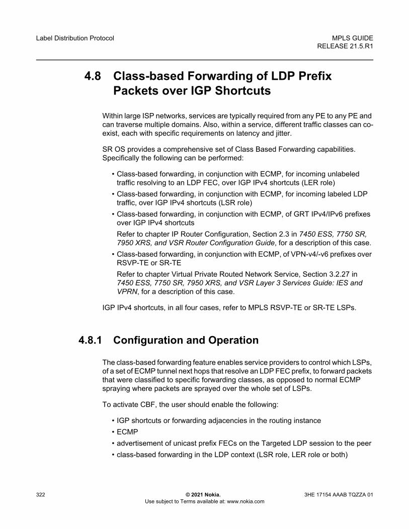
Label Distribution Protocol
322
MPLS GUIDERELEASE 21.5.R1
© 2021 Nokia. Use subject to Terms available at: www.nokia.com
3HE 17154 AAAB TQZZA 01
4.8 Class-based Forwarding of LDP Prefix Packets over IGP Shortcuts
Within large ISP networks, services are typically required from any PE to any PE and can traverse multiple domains. Also, within a service, different traffic classes can co-exist, each with specific requirements on latency and jitter.
SR OS provides a comprehensive set of Class Based Forwarding capabilities. Specifically the following can be performed:
• Class-based forwarding, in conjunction with ECMP, for incoming unlabeled traffic resolving to an LDP FEC, over IGP IPv4 shortcuts (LER role)
• Class-based forwarding, in conjunction with ECMP, for incoming labeled LDP traffic, over IGP IPv4 shortcuts (LSR role)
• Class-based forwarding, in conjunction with ECMP, of GRT IPv4/IPv6 prefixes over IGP IPv4 shortcutsRefer to chapter IP Router Configuration, Section 2.3 in 7450 ESS, 7750 SR, 7950 XRS, and VSR Router Configuration Guide, for a description of this case.
• Class-based forwarding, in conjunction with ECMP, of VPN-v4/-v6 prefixes over RSVP-TE or SR-TERefer to chapter Virtual Private Routed Network Service, Section 3.2.27 in 7450 ESS, 7750 SR, 7950 XRS, and VSR Layer 3 Services Guide: IES and VPRN, for a description of this case.
IGP IPv4 shortcuts, in all four cases, refer to MPLS RSVP-TE or SR-TE LSPs.
4.8.1 Configuration and Operation
The class-based forwarding feature enables service providers to control which LSPs, of a set of ECMP tunnel next hops that resolve an LDP FEC prefix, to forward packets that were classified to specific forwarding classes, as opposed to normal ECMP spraying where packets are sprayed over the whole set of LSPs.
To activate CBF, the user should enable the following:
• IGP shortcuts or forwarding adjacencies in the routing instance• ECMP• advertisement of unicast prefix FECs on the Targeted LDP session to the peer• class-based forwarding in the LDP context (LSR role, LER role or both)

MPLS GUIDE RELEASE 21.5.R1
Label Distribution Protocol
3HE 17154 AAAB TQZZA 01 © 2021 Nokia. Use subject to Terms available at: www.nokia.com
323
The FC-to-Set based configuration mode is controlled by the following commands:
config>router>mpls>class-forwarding-policy policy-name
config>router>mpls>class-forwarding-policy>fc> {be | l2 | af | l1 | h2 | ef | h1 | nc} forwarding-set value
config>router>mpls>class-forwarding-policy>default-set value
config>router>mpls>lsp>class-forwarding>forwarding-set policy policy-name set set-id
The last command applies to the lsp-template context. So, LSPs that are created from that template, acquire the assigned CBF configurations.
Multiple FCs can be assigned to a given set. Also, multiple LSPs can map to the same (policy, set) pair. However, an LSP cannot map to more than one (policy, set) pair.
Both configuration modes are mutually exclusive on a per LSP basis.
The CBF behavior depends on the configuration used, and on whether CBF was enabled for the LER and/or LSR role(s). The table below illustrates the different modes of operation of Class Based Forwarding depending on the node functionality where enabled, and on the type of configuration present in the ECMP set.
These modes of operation are explained in following sections.
4.8.1.1 LSR and/or LER Roles with FC-to-Set Configuration
Both LSR and LER roles behave in the same way with this type of configuration.
Before installing CBF information in the forwarding path, the system performs a consistency check on the CBF information of the ECMP set of tunnel next hops that resolve an LDP prefix FEC.
If no LSP, in the full ECMP set, has been assigned with a class forwarding policy configuration, the set is considered as inconsistent from a CBF perspective. The system, then, programs in the forwarding path, the whole ECMP set without any CBF information, and regular ECMP spraying occurs over the full set.
If the ECMP set is assigned to more than one class forwarding policy, the set is inconsistent from a CBF perspective. Then, the system programs, in the forwarding path, the whole ECMP set without any CBF information, and regular ECMP spraying occurs over the full set.

Label Distribution Protocol
324
MPLS GUIDERELEASE 21.5.R1
© 2021 Nokia. Use subject to Terms available at: www.nokia.com
3HE 17154 AAAB TQZZA 01
A full ECMP set is consistent from a CBF perspective when the ECMP:
• is assigned to a single class forwarding policy• contains either an LSP assigned to the default set (implicit or explicit), or• contains an LSP assigned to a non-default set that has explicit FC mappings
If there is no default set in a consistent ECMP set, the system automatically selects one set as the default one. The selected set is one set with the lowest ID among those referenced by the LSPs of the ECMP set.
If the ECMP set is consistent from a CBF perspective, the system programs in the forwarding path all the LSPs which have CBF configuration, and packets classified to a given FC are forwarded by using the LSPs of the corresponding forwarding set.
If there are more than one LSPs in a forwarding set, the system performs a modulo operation on these LSPs only to select one. As a result, ECMP spraying occurs for multiple packets of this forwarding class. Also, the system programs, in the forwarding path, the remaining LSPs of the ECMP set, without any CBF information. These LSPs are not used for class-based forwarding.
If there is no operational LSP in a given forwarding set, the system forwards packets which have been classified to the corresponding forwarding class onto the default set. Additionally, if there is no operational LSP in the default set, the system reverts to regular ECMP spraying over the full ECMP set.
If the user changes (by adding, modifying or deleting) the CBF configuration associated to an LSP that was previously selected as part of an ECMP set, then the FEC resolution is automatically updated, and a CBF consistency check is performed. Moreover, the user changes can update the forwarding configuration.
The LSR role applies to incoming labeled LDP traffic whose FEC is resolved to IGP IPv4 shortcuts.
The LER role applies to the following:
• IPv4 and IPv6 prefixes in GRT (with an IPv4 BGP NH)• VPN-v4 and VPN-v6 routes
However, LER does not apply to any service which uses either explicit binding to an SDP (static or T-LDP signaled services), or auto-binding to SDP (BGP-AD VPLS, BGP-VPLS, BGP-VPWS, Dynamic MS-PW).
For BGP-LU, ECMP+CBF is supported only in the absence of the VPRN label. Therefore, ECMP+CBF is not supported when a VPRN label runs on top of BGP-LU (itself running over LDPoRSVP).

MPLS GUIDE RELEASE 21.5.R1
Label Distribution Protocol
3HE 17154 AAAB TQZZA 01 © 2021 Nokia. Use subject to Terms available at: www.nokia.com
325
The CBF capability is available with any system profile. The number of sets is limited to four with system profile None or A, and to six with system profile B. This capability does not apply to CPM generated packets, including OAM packets, which are looked-up in RTM, and which are forwarded over tunnel next hops. These packets are forwarded by using either regular ECMP, or by selecting one nexthop from the set.

Label Distribution Protocol
326
MPLS GUIDERELEASE 21.5.R1
© 2021 Nokia. Use subject to Terms available at: www.nokia.com
3HE 17154 AAAB TQZZA 01
4.9 LDP ECMP Uniform Failover
LDP ECMP uniform failover allows the fast re-distribution by the ingress data path of packets forwarded over an LDP FEC next-hop to other next-hops of the same FEC when the currently used next-hop fails. The switchover is performed within a bounded time, which does not depend on the number of impacted LDP ILMs (LSR role) or service records (ingress LER role). The uniform failover time is only supported for a single LDP interface or LDP next-hop failure event.
This feature complements the coverage provided by the LDP Fast-ReRoute (FRR) feature, which provides a Loop-Free Alternate (LFA) backup next-hop with uniform failover time. Prefixes that have one or more ECMP next-hop protection are not programmed with a LFA back-up next-hop, and vice-versa.
The LDP ECMP uniform failover feature builds on the concept of Protect Group ID (PG-ID) introduced in LDP FRR. LDP assigns a unique PG-ID to all FECs that have their primary Next-Hop Label Forwarding Entry (NHLFE) resolved to the same outgoing interface and next-hop.
When an ILM record (LSR role) or LSPid-to-NHLFE (LTN) record (LER role) is created on the IOM, it has the PG-ID of each ECMP NHLFE the FEC is using.
When a packet is received on this ILM/LTN, the hash routine selects one of the up to 32, or the ECMP value configured on the system, whichever is less, ECMP NHLFEs for the FEC based on a hash of the packet’s header. If the selected NHLFE has its PG-ID in DOWN state, the hash routine re-computes the hash to select a backup NHLFE among the first 16, or the ECMP value configured on the system, whichever is less, NHLFEs of the FEC, excluding the one that is in DOWN state. Packets of the subset of flows that resolved to the failed NHLFE are thus sprayed among a maximum of 16 NHLFEs.
LDP then re-computes the new ECMP set to exclude the failed path and downloads it into the IOM. At that point, the hash routine will update the computation and begin spraying over the updated set of NHLFEs.
LDP sends the DOWN state update of the PG-ID to the IOM when the outgoing interface or a specific LDP next-hop goes down. This can be the result of any of the following events:
• Interface failure detected directly.• Failure of the LDP session detected via T-LDP BFD or LDP Keep-Alive.• Failure of LDP Hello adjacency detected via link LDP BFD or LDP Hello.

MPLS GUIDE RELEASE 21.5.R1
Label Distribution Protocol
3HE 17154 AAAB TQZZA 01 © 2021 Nokia. Use subject to Terms available at: www.nokia.com
327
In addition, PIP will send an interface down event to the IOM if the interface failure is detected by other means than the LDP control plane or BFD. In that case, all PG-IDs associated with this interface will have their state updated by the IOM.
When tunneling LDP packets over an RSVP LSP, it is the detection of the T-LDP session going down, via BFD or Keep-Alive, which triggers the LDP ECMP uniform failover procedures. If the RSVP LSP alone fails and the latter is not protected by RSVP FRR, the failure event will trigger the re-resolution of the impacted FECs in the slow path.
When a multicast LDP (mLDP) FEC is resolved over ECMP links to the same downstream LDP LSR, the PG-ID DOWN state will cause packets of the FEC resolved to the failed link to be switched to another link using the linear FRR switchover procedures.
The LDP ECMP uniform failover is not supported in the following forwarding contexts:
• VPLS BUM packets.• Packets forwarded to an IES/VPRN spoke-interface.• Packets forwarded towards VPLS spoke in routed VPLS.
Finally, the LDP ECMP uniform failover is only supported for a single LDP interface, LDP next-hop, or peer failure event.

Label Distribution Protocol
328
MPLS GUIDERELEASE 21.5.R1
© 2021 Nokia. Use subject to Terms available at: www.nokia.com
3HE 17154 AAAB TQZZA 01
4.10 LDP Fast-Reroute for IS-IS and OSPF Prefixes
LDP Fast Re-Route (FRR) is a feature which allows the user to provide local protection for an LDP FEC by pre-computing and downloading to the IOM or XCM both a primary and a backup NHLFE for this FEC.
The primary NHLFE corresponds to the label of the FEC received from the primary next-hop as per standard LDP resolution of the FEC prefix in RTM. The backup NHLFE corresponds to the label received for the same FEC from a Loop-Free Alternate (LFA) next-hop.
The LFA next-hop pre-computation by IGP is described in RFC 5286 – “Basic Specification for IP Fast Reroute: Loop-Free Alternates”. LDP FRR relies on using the label-FEC binding received from the LFA next-hop to forward traffic for a given prefix as soon as the primary next-hop is not available. This means that a node resumes forwarding LDP packets to a destination prefix without waiting for the routing convergence. The label-FEC binding is received from the loop-free alternate next-hop ahead of time and is stored in the Label Information Base since LDP on the router operates in the liberal retention mode.
This feature requires that IGP performs the Shortest Path First (SPF) computation of an LFA next-hop, in addition to the primary next-hop, for all prefixes used by LDP to resolve FECs. IGP also populates both routes in the Routing Table Manager (RTM).
4.10.1 LDP FRR Configuration
The user enables Loop-Free Alternate (LFA) computation by SPF under the IS-IS or OSPF routing protocol level:
config>router>isis>loopfree-alternatesconfig>router>ospf>loopfree-alternates
The above commands instruct the IGP SPF to attempt to pre-compute both a primary next-hop and an LFA next-hop for every learned prefix. When found, the LFA next-hop is populated into the RTM along with the primary next-hop for the prefix.
Next the user enables the use by LDP of the LFA next-hop by configuring the following option:
config>router>ldp>fast-reroute

MPLS GUIDE RELEASE 21.5.R1
Label Distribution Protocol
3HE 17154 AAAB TQZZA 01 © 2021 Nokia. Use subject to Terms available at: www.nokia.com
329
When this command is enabled, LDP will use both the primary next-hop and LFA next-hop, when available, for resolving the next-hop of an LDP FEC against the corresponding prefix in the RTM. This will result in LDP programming a primary NHLFE and a backup NHLFE into the IOM or XCM for each next-hop of a FEC prefix for the purpose of forwarding packets over the LDP FEC.
Because LDP can detect the loss of a neighbor/next-hop independently, it is possible that it switches to the LFA next-hop while IGP is still using the primary next-hop. In order to avoid this situation, it is recommended to enable IGP-LDP synchronization on the LDP interface:
config>router>if>ldp-sync-timer seconds
4.10.1.1 Reducing the Scope of the LFA Calculation by SPF
The user can instruct IGP to not include all interfaces participating in a specific IS-IS level or OSPF area in the SPF LFA computation. This provides a way of reducing the LFA SPF calculation where it is not needed.
config>router>isis>level>loopfree-alternate-excludeconfig>router>ospf>area>loopfree-alternate-exclude
If IGP shortcut are also enabled in LFA SPF, the LSPs with destination address in that IS-IS level or OSPF area are also not included in the LFA SPF calculation.
The user can also exclude a specific IP interface from being included in the LFA SPF computation by IS-IS or OSPF:
config>router>isis>interface> loopfree-alternate-excludeconfig>router>ospf>area>interface> loopfree-alternate-exclude
When an interface is excluded from the LFA SPF in IS-IS, it is excluded in both level 1 and level 2. When the user excludes an interface from the LFA SPF in OSPF, it is excluded in all areas. However, the above OSPF command can only be executed under the area in which the specified interface is primary and once enabled, the interface is excluded in that area and in all other areas where the interface is secondary. If the user attempts to apply it to an area where the interface is secondary, the command will fail.
Finally, the user can apply the same above commands for an OSPF instance within a VPRN service:
config>service>vprn>ospf>area>loopfree-alternate-excludeconfig>service>vprn>ospf>area>interface>loopfree-alternate-exclude

Label Distribution Protocol
330
MPLS GUIDERELEASE 21.5.R1
© 2021 Nokia. Use subject to Terms available at: www.nokia.com
3HE 17154 AAAB TQZZA 01
4.10.2 LDP FRR Procedures
The LDP FEC resolution when LDP FRR is not enabled operates as follows. When LDP receives a FEC, label binding for a prefix, it will resolve it by checking if the exact prefix, or a longest match prefix when the aggregate-prefix-match option is enabled in LDP, exists in the routing table and is resolved against a next-hop which is an address belonging to the LDP peer which advertised the binding, as identified by its LSR-id. When the next-hop is no longer available, LDP de-activates the FEC and de-programs the NHLFE in the data path. LDP will also immediately withdraw the labels it advertised for this FEC and deletes the ILM in the data path unless the user configured the label-withdrawal-delay option to delay this operation. Traffic that is received while the ILM is still in the data path is dropped. When routing computes and populates the routing table with a new next-hop for the prefix, LDP resolves again the FEC and programs the data path accordingly.
When LDP FRR is enabled and an LFA backup next-hop exists for the FEC prefix in RTM, or for the longest prefix the FEC prefix matches to when aggregate-prefix-match option is enabled in LDP, LDP will resolve the FEC as above but will program the data path with both a primary NHLFE and a backup NHLFE for each next-hop of the FEC.
In order perform a switchover to the backup NHLFE in the fast path, LDP follows the uniform FRR failover procedures which are also supported with RSVP FRR.
When any of the following events occurs, LDP instructs in the fast path the IOM on the line cards to enable the backup NHLFE for each FEC next-hop impacted by this event. The IOM line cards do that by simply flipping a single state bit associated with the failed interface or neighbor/next-hop:
1. An LDP interface goes operationally down, or is admin shutdown. In this case, LDP sends a neighbor/next-hop down message to the IOM line cards for each LDP peer it has adjacency with over this interface.
2. An LDP session to a peer went down as the result of the Hello or Keep-Alive timer expiring over a specific interface. In this case, LDP sends a neighbor/next-hop down message to the IOM line cards for this LDP peer only.
3. The TCP connection used by a link LDP session to a peer went down, due say to next-hop tracking of the LDP transport address in RTM, which brings down the LDP session. In this case, LDP sends a neighbor/next-hop down message to the IOM line cards for this LDP peer only.
4. A BFD session, enabled on a T-LDP session to a peer, times-out and as a result the link LDP session to the same peer and which uses the same TCP connection as the T-LDP session goes also down. In this case, LDP sends a neighbor/next-hop down message to the IOM line cards for this LDP peer only.

MPLS GUIDE RELEASE 21.5.R1
Label Distribution Protocol
3HE 17154 AAAB TQZZA 01 © 2021 Nokia. Use subject to Terms available at: www.nokia.com
331
5. A BFD session enabled on the LDP interface to a directly connected peer, times-out and brings down the link LDP session to this peer. In this case, LDP sends a neighbor/next-hop down message to the IOM line cards for this LDP peer only. BFD support on LDP interfaces is a new feature introduced for faster tracking of link LDP peers.
The tunnel-down-dump-time option or the label-withdrawal-delay option, when enabled, does not cause the corresponding timer to be activated for a FEC as long as a backup NHLFE is still available.
4.10.2.1 ECMP Considerations
Whenever the SPF computation determined that there is more than one primary next-hop for a prefix, it will not program any LFA next-hop in RTM. In this case, the LDP FEC will resolve to the multiple primary next-hops, which provides the required protection.
Also, when the system ECMP value is set to ecmp=1 or to no ecmp, which translates to the same and is the default value, SPF can use the overflow ECMP links as LFA next-hops in these two cases.
4.10.2.2 LDP FRR and LDP Shortcut
When LDP FRR is enabled in LDP and the ldp-shortcut option is enabled in the router level, in transit IPv4 packets and specific CPM generated IPv4 control plane packets with a prefix resolving to the LDP shortcut are protected by the backup LDP NHLFE.
4.10.2.3 LDP FRR and LDP-over-RSVP
When LDP-over-RSVP is enabled, the RSVP LSP is modeled as an endpoint, that is, the destination node of the LSP, and not as a link in the IGP SPF. Thus, it is not possible for IGP to compute a primary or alternate next-hop for a prefix which FEC path is tunneled over the RSVP LSP. Only LDP is aware of the FEC tunneling but it cannot determine on its own a loop-free backup path when it resolves the FEC to an RSVP LSP.
As a result, LDP does not activate the LFA next-hop it learned from RTM for a FEC prefix when the FEC is resolved to an RSVP LSP. LDP will activate the LFA next-hop as soon as the FEC is resolved to direct primary next-hop.

Label Distribution Protocol
332
MPLS GUIDERELEASE 21.5.R1
© 2021 Nokia. Use subject to Terms available at: www.nokia.com
3HE 17154 AAAB TQZZA 01
LDP FEC tunneled over an RSVP LSP due to enabling the LDP-over-RSVP feature will thus not support the LDP FRR procedures and will follow the slow path procedure of prior implementation.
When the user enables the lfa-only option for an RSVP LSP, as described in Loop-Free Alternate Calculation in the Presence of IGP shortcuts, the LSP will not be used by LDP to tunnel an LDP FEC even when IGP shortcut is disabled but LDP-over-RSVP is enabled in IGP.
4.10.2.4 LDP FRR and RSVP Shortcut (IGP Shortcut)
When an RSVP LSP is used as a shortcut by IGP, it is included by SPF as a P2P link and can also be optionally advertised into the rest of the network by IGP. Thus the SPF is able of using a tunneled next-hop as the primary next-hop for a given prefix. LDP is also able of resolving a FEC to a tunneled next-hop when the IGP shortcut feature is enabled.
When both IGP shortcut and LFA are enabled in IS-IS or OSPF, and LDP FRR is also enabled, then the following additional LDP FRR capabilities are supported:
1. A FEC which is resolved to a direct primary next-hop can be backed up by a LFA tunneled next-hop.
2. A FEC which is resolved to a tunneled primary next-hop will not have an LFA next-hop. It will rely on RSVP FRR for protection.
The LFA SPF is extended to use IGP shortcuts as LFA next-hops as explained in Loop-Free Alternate Calculation in the Presence of IGP shortcuts.
4.10.3 IS-IS and OSPF Support for Loop-Free Alternate Calculation
SPF computation in IS-IS and OSPF is enhanced to compute LFA alternate routes for each learned prefix and populate it in RTM.
Figure 56 illustrates a simple network topology with point-to-point (P2P) interfaces and highlights three routes to reach router R5 from router R1.

MPLS GUIDE RELEASE 21.5.R1
Label Distribution Protocol
3HE 17154 AAAB TQZZA 01 © 2021 Nokia. Use subject to Terms available at: www.nokia.com
333
Figure 56 Topology with Primary and LFA Routes
The primary route is by way of R3. The LFA route by way of R2 has two equal cost paths to reach R5. The path by way of R3 protects against failure of link R1-R3. This route is computed by R1 by checking that the cost for R2 to reach R5 by way of R3 is lower than the cost by way of routes R1 and R3. This condition is referred to as the loop-free criterion. R2 must be loop-free with respect to source node R1.
The path by way of R2 and R4 can be used to protect against the failure of router R3. However, with the link R2-R3 metric set to 5, R2 sees the same cost to forward a packet to R5 by way of R3 and R4. Thus R1 cannot guarantee that enabling the LFA next-hop R2 will protect against R3 node failure. This means that the LFA next-hop R2 provides link-protection only for prefix R5. If the metric of link R2-R3 is changed to 8, then the LFA next-hop R2 provides node protection since a packet to R5 will always go over R4. In other words it is required that R2 becomes loop-free with respect to both the source node R1 and the protected node R3.
Consider the case where the primary next-hop uses a broadcast interface as illustrated in Figure 57.
5
al_0215
R1
5
5
5
55 (8)
R3
R5Primary RouteLFA Link-Protect Route
LFA Node-Protect Route
R4
R2

Label Distribution Protocol
334
MPLS GUIDERELEASE 21.5.R1
© 2021 Nokia. Use subject to Terms available at: www.nokia.com
3HE 17154 AAAB TQZZA 01
Figure 57 Example Topology with Broadcast Interfaces
In order for next-hop R2 to be a link-protect LFA for route R5 from R1, it must be loop-free with respect to the R1-R3 link’s Pseudo-Node (PN). However, since R2 has also a link to that PN, its cost to reach R5 by way of the PN or router R4 are the same. Thus R1 cannot guarantee that enabling the LFA next-hop R2 will protect against a failure impacting link R1-PN since this may cause the entire subnet represented by the PN to go down. If the metric of link R2-PN is changed to 8, then R2 next-hop will be an LFA providing link protection.
The following are the detailed rules for this criterion as provided in RFC 5286:
• Rule 1: Link-protect LFA backup next-hop (primary next-hop R1-R3 is a P2P interface): Distance_opt(R2, R5) < Distance_opt(R2, R1) + Distance_opt(R1, R5)and, Distance_opt(R2, R5) ≥ Distance_opt(R2, R3) + Distance_opt(R3, R5)
• Rule 2: Node-protect LFA backup next-hop (primary next-hop R1-R3 is a P2P interface): Distance_opt(R2, R5) < Distance_opt(R2, R1) + Distance_opt(R1, R5)and,Distance_opt(R2, R5) < Distance_opt(R2, R3) + Distance_opt(R3, R5)
• Rule 3: Link-protect LFA backup next-hop (primary next-hop R1-R3 is a broadcast interface):Distance_opt(R2, R5) < Distance_opt(R2, R1) + Distance_opt(R1, R5)and,Distance_opt(R2, R5) < Distance_opt(R2, PN) + Distance_opt(PN, R5)where; PN stands for the R1-R3 link Pseudo-Node.
5
5
al_0216
R1
5
5
5
5
5 (8)
R3
PN
R5Primary RouteLFA Link-Protect Route
R4
R2

MPLS GUIDE RELEASE 21.5.R1
Label Distribution Protocol
3HE 17154 AAAB TQZZA 01 © 2021 Nokia. Use subject to Terms available at: www.nokia.com
335
For the case of P2P interface, if SPF finds multiple LFA next-hops for a given primary next-hop, it follows the following selection algorithm:
1. It will pick the node-protect type in favor of the link-protect type. 2. If there is more than one LFA next-hop within the selected type, then it will pick
one based on the least cost. 3. If more than one LFA next-hop with the same cost results from Step B, then SPF
will select the first one. This is not a deterministic selection and will vary following each SPF calculation.
For the case of a broadcast interface, a node-protect LFA is not necessarily a link protect LFA if the path to the LFA next-hop goes over the same PN as the primary next-hop. Similarly, a link protect LFA may not guarantee link protection if it goes over the same PN as the primary next-hop.
The selection algorithm when SPF finds multiple LFA next-hops for a given primary next-hop is modified as follows:
1. The algorithm splits the LFA next-hops into two sets: - The first set consists of LFA next-hops which do not go over the PN used
by primary next-hop.- The second set consists of LFA next-hops which do go over the PN used by
the primary next-hop.2. If there is more than one LFA next-hop in the first set, it will pick the node-protect
type in favor of the link-protect type. 3. If there is more than one LFA next-hop within the selected type, then it will pick
one based on the least cost. 4. If more than one LFA next-hop with equal cost results from Step C, SPF will
select the first one from the remaining set. This is not a deterministic selection and will vary following each SPF calculation.
5. If no LFA next-hop results from Step D, SPF will rerun Steps B-D using the second set.
This algorithm is more flexible than strictly applying Rule 3 above; the link protect rule in the presence of a PN and specified in RFC 5286. A node-protect LFA which does not avoid the PN; does not guarantee link protection, can still be selected as a last resort. The same thing, a link-protect LFA which does not avoid the PN may still be selected as a last resort. Both the computed primary next-hop and LFA next-hop for a given prefix are programmed into RTM.

Label Distribution Protocol
336
MPLS GUIDERELEASE 21.5.R1
© 2021 Nokia. Use subject to Terms available at: www.nokia.com
3HE 17154 AAAB TQZZA 01
4.10.3.1 Loop-Free Alternate Calculation in the Presence of IGP shortcuts
In order to expand the coverage of the LFA backup protection in a network, RSVP LSP based IGP shortcuts can be placed selectively in parts of the network and be used as an LFA backup next-hop.
When IGP shortcut is enabled in IS-IS or OSPF on a given node, all RSVP LSP originating on this node and with a destination address matching the router-id of any other node in the network are included in the main SPF by default.
In order to limit the time it takes to compute the LFA SPF, the user must explicitly enable the use of an IGP shortcut as LFA backup next-hop using one of a couple of new optional argument for the existing LSP level IGP shortcut command:
config>router>mpls>lsp>igp-shortcut [lfa-protect | lfa-only]
The lfa-protect option allows an LSP to be included in both the main SPF and the LFA SPFs. For a given prefix, the LSP can be used either as a primary next-hop or as an LFA next-hop but not both. If the main SPF computation selected a tunneled primary next-hop for a prefix, the LFA SPF will not select an LFA next-hop for this prefix and the protection of this prefix will rely on the RSVP LSP FRR protection. If the main SPF computation selected a direct primary next-hop, then the LFA SPF will select an LFA next-hop for this prefix but will prefer a direct LFA next-hop over a tunneled LFA next-hop.
The lfa-only option allows an LSP to be included in the LFA SPFs only such that the introduction of IGP shortcuts does not impact the main SPF decision. For a given prefix, the main SPF always selects a direct primary next-hop. The LFA SPF will select a an LFA next-hop for this prefix but will prefer a direct LFA next-hop over a tunneled LFA next-hop.
Thus the selection algorithm when SPF finds multiple LFA next-hops for a given primary next-hop is modified as follows:
1. The algorithm splits the LFA next-hops into two sets:- the first set consists of direct LFA next-hops- the second set consists of tunneled LFA next-hops. after excluding the
LSPs which use the same outgoing interface as the primary next-hop.2. The algorithms continues with first set if not empty, otherwise it continues with
second set.3. If the second set is used, the algorithm selects the tunneled LFA next-hop which
endpoint corresponds to the node advertising the prefix.

MPLS GUIDE RELEASE 21.5.R1
Label Distribution Protocol
3HE 17154 AAAB TQZZA 01 © 2021 Nokia. Use subject to Terms available at: www.nokia.com
337
- If more than one tunneled next-hop exists, it selects the one with the lowest LSP metric.
- If still more than one tunneled next-hop exists, it selects the one with the lowest tunnel-id.
- If none is available, it continues with rest of the tunneled LFAs in second set.4. Within the selected set, the algorithm splits the LFA next-hops into two sets:
- The first set consists of LFA next-hops which do not go over the PN used by primary next-hop.
- The second set consists of LFA next-hops which go over the PN used by the primary next-hop.
5. If there is more than one LFA next-hop in the selected set, it will pick the node-protect type in favor of the link-protect type.
6. If there is more than one LFA next-hop within the selected type, then it will pick one based on the least total cost for the prefix. For a tunneled next-hop, it means the LSP metric plus the cost of the LSP endpoint to the destination of the prefix.
7. If there is more than one LFA next-hop within the selected type (ecmp-case) in the first set, it will select the first direct next-hop from the remaining set. This is not a deterministic selection and will vary following each SPF calculation.
8. If there is more than one LFA next-hop within the selected type (ecmp-case) in the second set, it will pick the tunneled next-hop with the lowest cost from the endpoint of the LSP to the destination prefix. If there remains more than one, it will pick the tunneled next-hop with the lowest tunnel-id.
4.10.3.2 Loop-Free Alternate Calculation for Inter-Area/inter-Level Prefixes
When SPF resolves OSPF inter-area prefixes or IS-IS inter-level prefixes, it will compute an LFA backup next-hop to the same exit area/border router as used by the primary next-hop.
4.10.3.3 Loop-Free Alternate Shortest Path First (LFA SPF) Policies
An LFA SPF policy allows the user to apply specific criteria, such as admin group and SRLG constraints, to the selection of a LFA backup next-hop for a subset of prefixes that resolve to a specific primary next-hop. See more details in the section titled “Loop-Free Alternate Shortest Path First (LFA SPF) Policies” in the Routing Protocols Guide.

Label Distribution Protocol
338
MPLS GUIDERELEASE 21.5.R1
© 2021 Nokia. Use subject to Terms available at: www.nokia.com
3HE 17154 AAAB TQZZA 01
4.11 LDP FEC to BGP Label Route Stitching
The stitching of an LDP FEC to a BGP labeled route allows the LDP capable PE devices to offer services to PE routers in other areas or domains without the need to support BGP labeled routes.
This feature is used in a large network to provide services across multiple areas or autonomous systems. Figure 58 shows a network with a core area and regional areas.
Figure 58 Application of LDP to BGP FEC Stitching
Specific /32 routes in a regional area are not redistributed into the core area. Therefore, only nodes within a regional area and the ABR nodes in the same area exchange LDP FECs. A PE router, for example, PE21, in a regional area learns the reachability of PE routers in other regional areas by way of RFC 3107 BGP labeled routes redistributed by the remote ABR nodes by way of the core area. The remote ABR then sets the next-hop self on the labeled routes before re-distributing them into the core area. The local ABR for PE2, for example, ABR3 may or may not set next-hop self when it re-distributes these labeled BGP routes from the core area to the local regional area.
When forwarding a service packet to the remote PE, PE21 inserts a VC label, the BGP route label to reach the remote PE, and an LDP label to reach either ABR3, if ABR3 sets next-hop self, or ABR1.
al_0217
DSLAM2
PE21
LDP
LBLREQ
LBLREQ
LBLRSP
LBLRSP
Redistribute(DSLAM Prefix)
LDP
i-BGP (LBL)
PE22
SVC LBL2121
311SVC LBL
334
ABR3
ABR4

MPLS GUIDE RELEASE 21.5.R1
Label Distribution Protocol
3HE 17154 AAAB TQZZA 01 © 2021 Nokia. Use subject to Terms available at: www.nokia.com
339
In the same network, an MPLS capable DSLAM also act as PE router for VLL services and will need to establish a PW to a PE in a different regional area by way of router PE21, acting now as an LSR. To achieve that, PE21 is required to perform the following operations:
• Translate the LDP FEC it learned from the DSLAM into a BGP labeled route and re-distribute it by way of Interior Border Gateway Protocol (IBGP) within its area. This is in addition to redistributing the FEC to its LDP neighbors in the same area.
• Translate the BGP labeled routes it learns through IBGP into an LDP FEC and re-distribute it to its LDP neighbors in the same area. In the application in Figure 58, the DSLAM requests the LDP FEC of the remote PE router using LDP Downstream on Demand (DoD).
• When a packet is received from the DSLAM, PE21 swaps the LDP label into a BGP label and pushes the LDP label to reach ABR3 or ABR1. When a packet is received from ABR3, the top label is removed and the BGP label is swapped for the LDP label corresponding to the DSLAM FEC.
4.11.1 Configuration
You enable stitching of routes between the LDP and BGP by configuring separately tunnel table route export policies in both protocols and enabling the advertising of RFC 3107 formatted labeled routes for prefixes learned from LDP FECs.
The route export policy in BGP instructs BGP to listen to LDP route entries in the CPM tunnel table. If a /32 LDP FEC prefix matches an entry in the export policy, BGP originates a BGP labeled route, stitches it to the LDP FEC, and re-distributes the BGP labeled route to its IBGP neighbors.
The user adds LDP FEC prefixes with the statement ‘from protocol ldp’ in the configuration of the existing BGP export policy at the global level, the peer-group level, or at the peer level using the commands:
• config>router>bgp>export policy-name• config>router>bgp>group>export policy-name• config>router>bgp>group>neighbor>export policy-name
To indicate to BGP to evaluate the entries with the ‘from protocol ldp’ statement in the export policy when applied to a specific BGP neighbor, use commands:
• config>router>bgp>group>neighbor>family label-ipv4• config>router>bgp>group>neighbor>advertise-ldp-prefix

Label Distribution Protocol
340
MPLS GUIDERELEASE 21.5.R1
© 2021 Nokia. Use subject to Terms available at: www.nokia.com
3HE 17154 AAAB TQZZA 01
Without this, only core IPv4 routes learned from RTM are advertised as BGP labeled routes to this neighbor. And the stitching of LDP FEC to the BGP labeled route is not performed for this neighbor even if the same prefix was learned from LDP.
The tunnel table route export policy in LDP instructs LDP to listen to BGP route entries in the CPM Tunnel Table. If a /32 BGP labeled route matches a prefix entry in the export policy, LDP originates an LDP FEC for the prefix, stitches it to the BGP labeled route, and re-distributes the LDP FEC its IBGP neighbors.
The user adds BGP labeled route prefixes with the statement ‘from protocol bgp’ in the configuration of a new LDP tunnel table export policy using the command:
config>router>ldp>export-tunnel-table policy-name.
The ‘from protocol’ statement has an effect only when the protocol value is ldp. Policy entries with protocol values of rsvp, bgp, or any value other than ldp are ignored at the time the policy is applied to LDP.
4.11.2 Detailed LDP FEC Resolution
When an LSR receives a FEC-label binding from an LDP neighbor for a given specific FEC1 element, the following procedures are performed.
1. LDP installs the FEC if:- It was able to perform a successful exact match or a longest match, if
aggregate-prefix-match option is enabled in LDP, of the FEC /32 prefix with a prefix entry in the routing table.
- The advertising LDP neighbor is the next-hop to reach the FEC prefix.2. When such a FEC-label binding has been installed in the LDP FIB, LDP will
perform the following:- Program a push and a swap NHLFE entries in the egress data path to
forward packets to FEC1.- Program the CPM tunnel table with a tunnel entry for the NHLFE.- Advertise a new FEC-label binding for FEC1 to all its LDP neighbors
according to the global and per-peer LDP prefix export policies.- Install the ILM entry pointing to the swap NHLFE.
3. When BGP learns the LDP FEC by way of the CPM tunnel table and the FEC prefix exists in the BGP route export policy, it will perform the following:- Originate a labeled BGP route for the same prefix with this node as the next-
hop and advertise it by way of IBGP to its BGP neighbors, for example, the local ABR/ASBR nodes, which have the advertise-ldp-prefix enabled.

MPLS GUIDE RELEASE 21.5.R1
Label Distribution Protocol
3HE 17154 AAAB TQZZA 01 © 2021 Nokia. Use subject to Terms available at: www.nokia.com
341
- Install the ILM entry pointing to the swap NHLFE programmed by LDP.
4.11.3 Detailed BGP Labeled Route Resolution
When an LSR receives a BGP labeled route by way of IBGP for a given specific /32 prefix, the following procedures are performed.
1. BGP resolves and installs the route in BGP if:- An LDP LSP to the BGP neighbor exists, for example, the ABR or ASBR,
which advertised it and which is the next-hop of the BGP labeled route. 2. When the BGP route is installed, BGP programs the following:
- Push NHLFE in the egress data path to forward packets to this BGP labeled route.
- The CPM tunnel table with a tunnel entry for the NHLFE.3. When LDP learns the BGP labeled route from the CPM tunnel table and the
prefix exists in the new LDP tunnel table route export policy, it does the following:- Advertise a new LDP FEC-label binding for the same prefix to its LDP
neighbors according the global and per-peer LDP export prefix policies. If LDP already advertised a FEC for the same /32 prefix after receiving it from an LDP neighbor then no action is required. For LDP neighbors that negotiated LDP Downstream on Demand (DoD), the FEC is advertised only when this node receives a Label Request message for this FEC from its neighbor.
- Install the ILM entry pointing to the BGP NHLFE if a new LDP FEC-label binding is advertised. If an ILM entry exists and points to an LDP NHLFE for the same prefix then no update to the ILM entry is performed. The LDP route is always preferred over the BGP labeled route.
4.11.4 Data Plane Forwarding
When a packet is received from an LDP neighbor, the LSR swaps the LDP label into a BGP label and pushes the LDP label to reach the BGP neighbor, for example, ABR/ASBR, which advertised the BGP labeled route with itself as the next-hop.
When a packet is received from a BGP neighbor such as an ABR/ASBR, the top label is removed and the BGP label is swapped for the LDP label to reach the next-hop for the prefix.

Label Distribution Protocol
342
MPLS GUIDERELEASE 21.5.R1
© 2021 Nokia. Use subject to Terms available at: www.nokia.com
3HE 17154 AAAB TQZZA 01
4.12 LDP-SR Stitching for IPv4 prefixes
This feature enables stitching between an LDP FEC and SR node-SID route for the same IPv4 /32prefix.
4.12.1 LDP-SR Stitching Configuration
The user enables the stitching between an LDP FEC and SR node-SID route for the same prefix by configuring the export of SR (LDP) tunnels from the CPM Tunnel Table Manager (TTM) into LDP (IGP).
In the LDP-to-SR data path direction, the existing tunnel table route export policy in LDP, which was introduced for LDP-BGP stitching, is enhanced to support the export of SR tunnels from the TTM to LDP. The user adds the config>router>policy-options>policy-statement>entry>from protocol isis [instance instance-id] or protocol ospf [instance instance-id] configuration to the LDP tunnel table export policy using the following command:
config>router>ldp>export-tunnel-table policy-name
The user can restrict the export to LDP of SR tunnels from a specific prefix list. The user can also restrict the export to a specific IGP instance by optionally specifying the instance ID in the from statement.
The from protocol statement has an effect only when the protocol value is isis, ospf, or bgp. Policy entries configured with any other value are ignored when the policy is applied. If the user configures multiple from statements in the same policy or does not include the from statement but adds a default accept action, then LDP will follow the TTM selection rules as described in the “Segment Routing Tunnel Management” in the 7450 ESS, 7750 SR, 7950 XRS, and VSR Unicast Routing Protocols Guide to select a tunnel to which it will stitch the LDP ILM to:
• LDP selects the tunnel from the lowest TTM preference protocol. • If IS-IS and BGP protocols have the same preference, then LDP uses the default
TTM protocol preference to select the protocol.• Within the same IGP protocol, LDP selects the lowest instance ID.

MPLS GUIDE RELEASE 21.5.R1
Label Distribution Protocol
3HE 17154 AAAB TQZZA 01 © 2021 Nokia. Use subject to Terms available at: www.nokia.com
343
When this policy is enabled in LDP, LDP listens to SR tunnel entries in the TTM. If an LDP FEC primary next hop cannot be resolved using an RTM route and a SR tunnel of type SR-ISIS or SR-OSPF to the same destination exists in TTM, LDP programs an LDP ILM and stitches it to the SR node-SID tunnel endpoint. LDP also originates an FEC for the prefix and re-distributes it to its LDP and T-LDP peers. The latter allows an LDP FEC that is tunneled over a RSVP-TE LSP to have its ILM stitched to an SR tunnel endpoint. When a LDP FEC is stitched to a SR tunnel, forwarded packets benefit from the protection provided by the LFA/remote LFA backup next-hop of the SR tunnel.
When resolving a FEC, LDP prefers the RTM over the TTM when both resolutions are possible. That is, swapping the LDP ILM to a LDP NHLFE is preferred over stitching the LDP ILM to an SR tunnel endpoint.
In the SR-to-LDP data path direction, the SR mapping server provides a global policy for prefixes corresponding to the LDP FECs the SR needs to stitch to. See “Segment Routing Mapping Server” in the 7450 ESS, 7750 SR, 7950 XRS, and VSR Unicast Routing Protocols Guide for more information. As a result, a tunnel table export policy is not required. Instead, you can export to an IGP instance the LDP tunnels for FEC prefixes advertised by the mapping server using the following commands:
• config>router>isis>segment-routing>export-tunnel-table ldp• config>router>ospf>segment-routing>export-tunnel-table ldp
When this command is enabled in the segment-routing context of an IGP instance, IGP listens to LDP tunnel entries in the TTM. When a /32 LDP tunnel destination matches a prefix for which IGP has received a prefix-SID sub-TLV from a mapping server, IGP instructs the SR module to program the SR ILM and stitch it to the LDP tunnel endpoint. The SR ILM can stitch to an LDP FEC resolved over either link LDP or T-LDP. In the latter case, the stitching is performed to an LDP-over-RSVP tunnel. When an SR tunnel is stitched to an LDP FEC, packets forwarded will benefit from the FRR protection of the LFA backup next-hop of the LDP FEC.
When resolving a node SID, IGP will prefer a prefix SID received in an IP Reach TLV over a prefix SID received via the mapping server. That is, swapping the SR ILM to a SR NHLFE is preferred over stitching it to a LDP tunnel endpoint. Refer to the “Segment Routing Mapping Server Prefix SID Resolution” in the 7450 ESS, 7750 SR, 7950 XRS, and VSR Unicast Routing Protocols Guide for more information about prefix SID resolution.
It is recommended to enable the bfd-enable option on the interfaces in both LDP and IGP instance contexts to speed up the failure detection and the activation of the LFA/remote-LFA backup next-hop in either direction. This is particularly true if the injected failure is a remote failure.
This feature is limited to IPv4 /32 prefixes in both LDP and SR.

Label Distribution Protocol
344
MPLS GUIDERELEASE 21.5.R1
© 2021 Nokia. Use subject to Terms available at: www.nokia.com
3HE 17154 AAAB TQZZA 01
4.12.2 Stitching in the LDP-to-SR Direction
Stitching in data-plane from the LDP-to-SR direction is based on the LDP module monitoring the TTM for a SR tunnel of a prefix matching an entry in the LDP TTM export policy.
Figure 59 Stitching in the LDP-to-SR Direction
In Figure 59, the boundary router R1 performs the following procedure to effect stitching:
Step 1. Router R1 is at the boundary between an SR domain and LDP domain and is configured to stitch between SR and LDP.
Step 2. Link R1-R2 is LDP-enabled, but router R2 does not support SR (or SR is disabled).
Step 3. Router R1 receives a prefix-SID sub-TLV in an IS-IS IP reachability TLV originated by router Ry for prefix Y.
Step 4. R1 resolves the prefix-SID and programs an NHLFE on the link towards the next-hop in the SR domain. R1 programs an SR ILM and points it to this NHLFE.
Step 5. Because R1 is programmed to stitch LDP to SR, the LDP in R1 discovers in TTM the SR tunnel to Y. LDP programs an LDP ILM and points it to the SR tunnel. As a result, both the SR ILM and LDP ILM now point to the SR tunnel, one via the SR NHLFE and the other via the SR tunnel endpoint.
Step 6. R1 advertises the LDP FEC for the prefix Y to all its LDP peers. R2 is now able to install a LDP tunnel towards Ry.
0970
Prefix Y,Node SID=20
R1
R3
R2
R4
R5Ry Rx
Prefix X, LDPLabel=5135
Mapping ServerPrefix Y, SID=20
SR Domain LDP Domain

MPLS GUIDE RELEASE 21.5.R1
Label Distribution Protocol
3HE 17154 AAAB TQZZA 01 © 2021 Nokia. Use subject to Terms available at: www.nokia.com
345
Step 7. If R1 finds multiple SR tunnels to destination prefix Y, it uses the following steps of the TTM tunnel selection rules to select the SR tunnel.
i. R1 selects the tunnel from the lowest preference IGP protocol. ii. Select the protocol using the default TTM protocol preference.iii. Within the same IGP protocol, R1 uses the lowest instance ID to select
the tunnel. Step 8. If the user concurrently configured the from protocol ospf, from protocol
isis, and from protocol bgp statements in the same LDP tunnel table export policy, or did not include the from statement but added a default action of accept, R1 will select the tunnel to destination prefix Y to stitch the LDP ILM to using the TTM tunnel selection rules:
i. R1 selects the tunnel from the lowest preference protocol. ii. If any two or all of IS-IS, OSPF, and BGP protocols have the same
preference, then R1 selects the protocol using the default TTM protocol preference.
iii. Within the same IGP protocol, R1 uses the lowest instance ID to select the tunnel.
Step 9. The user enables SR in R2. R2 resolves the prefix SID for Y and installs the SR ILM and the SR NHLFE. R2 is now able of forwarding packets over the SR tunnel to router Ry. No processing occurs in R1 because the SR ILM is already programmed.
Step 10. The user disables LDP on the interface R1-R2 (both directions) and the LDP FEC ILM and NHLFE are removed in R1. The same occurs in R2 which can then only forward using the SR tunnel towards Ry.
4.12.3 Stitching in the SR-to-LDP Direction
The stitching in data-plane from the SR-to-LDP direction is based on the IGP monitoring the TTM for a LDP tunnel of a prefix matching an entry in the SR TTM export policy.
In Figure 59, the boundary router R1 performs the following procedure to effect stitching:
Note: If R1 has already resolved a LDP FEC for prefix Y, it has an ILM for it, but this ILM is not be updated to point towards the SR tunnel. This is because LDP resolves in RTM first before going to TTM and, therefore, prefers the LDP tunnel over the SR tunnel. Similarly, if an LDP FEC is received after the stitching is programmed, the LDP ILM is updated to point to the LDP NHLFE because LDP can resolve the LDP FEC in RTM.

Label Distribution Protocol
346
MPLS GUIDERELEASE 21.5.R1
© 2021 Nokia. Use subject to Terms available at: www.nokia.com
3HE 17154 AAAB TQZZA 01
Step 1. Router R1 is at the boundary between a SR domain and a LDP domain and is configured to stitch between SR and LDP.Link R1-R2 is LDP enabled but router R2 does not support SR (or SR is disabled).
Step 2. R1 receives an LDP FEC for prefix X owned by router Rx further down in the LDP domain.RTM in R1 shows that the interface to R2 is the next-hop for prefix X.
Step 3. LDP in R1 resolves this FEC in RTM and creates an LDP ILM for it with, for example, ingress label L1, and points it to an LDP NHLFE towards R2 with egress label L2.
Step 4. Later on, R1 receives a prefix-SID sub-TLV from the mapping server R5 for prefix X.
Step 5. IGP in R1 is resolving in its routing table the next-hop of prefix X to the interface to R2. R1 knows that R2 did not advertise support of Segment Routing and, thus, SID resolution for prefix X in routing table fails.
Step 6. IGP in R1 attempts to resolve prefix SID of X in TTM because it is configured to stitch SR-to-LDP. R1 finds a LDP tunnel to X in TTM, instructs the SR module to program a SR ILM with ingress label L3, and points it to the LDP tunnel endpoint, consequently stitching ingress L3 label to egress L2 label.
Step 7. The user enables segment routing on R2.Step 8. IGP in R1 discovers that R2 supports SR via the SR capability.
Because R1 still has a prefix-SID for X from the mapping server R5, it maintains the stitching of the SR ILM for X to the LDP FEC unchanged.
Step 9. The operator disables the LDP interface between R1 and R2 (both directions) and the LDP FEC ILM and NHLFE for prefix X are removed in R1.
Note:
• Here, two ILMs, the LDP and SR, are pointing to the same LDP tunnel one via NHLFE and one via tunnel endpoint.
• No SR tunnel to destination X should be programmed in TTM following this resolution step.
• A trap will be generated for prefix SID resolution failure only after IGP fails to complete Step 5 and Step 6. The existing trap for prefix SID resolution failure is enhanced to state whether the prefix SID which failed resolution was part of mapping server TLV or a prefix TLV.

MPLS GUIDE RELEASE 21.5.R1
Label Distribution Protocol
3HE 17154 AAAB TQZZA 01 © 2021 Nokia. Use subject to Terms available at: www.nokia.com
347
Step 10. This triggers the re-evaluation of the SIDs. R1 first attempts the resolution in routing table and since the next-hop for X now supports SR, IGP instructs the SR module to program a NHLFE for prefix-SID of X with egress label L4 and outgoing interface to R2. R1 installs a SR tunnel in TTM for destination X. R1 also changes the SR ILM with ingress label L3 to point to the SR NHLFE with egress label L4. Router R2 now becomes the SR-LDP stitching router.
Step 11. Later, router Rx, which owns prefix X, is upgraded to support SR. R1 now receives a prefix-SID sub-TLV in a ISIS or OSPF prefix TLV originated by Rx for prefix X. The SID information may or may not be the same as the one received from the mapping server R5. In this case, IGP in R1 will prefer the prefix-SID originated by Rx and update the SR ILM and NHLFE with appropriate labels.
Step 12. Finally, the operator cleans up the mapping server and removes the mapping entry for prefix X, which then gets withdrawn by IS-IS.

Label Distribution Protocol
348
MPLS GUIDERELEASE 21.5.R1
© 2021 Nokia. Use subject to Terms available at: www.nokia.com
3HE 17154 AAAB TQZZA 01
4.13 LDP FRR LFA Backup using SR Tunnel for IPv4 Prefixes
The user enables the use of SR tunnel as a remote LFA or as a TI-LFA backup tunnel next hop by an LDP FEC via the following CLI command:
CLI Syntax: config>router>ldp>fast-reroute [backup-sr-tunnel]
As a pre-requisite, the user must enable the stitching of LDP and SR in the LDP-to-SR direction as explained in LDP-SR Stitching Configuration. That is because the LSR must perform the stitching of the LDP ILM to SR tunnel when the primary LDP next-hop of the FEC fails. Thus, LDP must listen to SR tunnels programmed by the IGP in TTM, but the mapping server feature is not required.
Assume the backup-sr-tunnel option is enabled in LDP and the {loopfree-alternates remote-lfa} option and/or the {loopfree-alternates ti-lfa} option is enabled in the IGP instance, and that LDP was able to resolve the primary next hop of the LDP FEC in RTM. IGP SPF will run both the base LFA and the TI-LFA algorithms and if it does not find a backup next hop for a prefix of an LDP FEC, it will also run the remote LFA algorithm. If IGP finds a TI-LFA or a remote LFA tunnel next hop, LDP programs the primary next hop of the FEC using an LDP NHLFE and programs the LFA backup next hop using an LDP NHLFE pointing to the SR tunnel endpoint.
The behavior of the feature is similar to the LDP-to-SR stitching feature described in the LDP-SR Stitching for IPv4 prefixes section, except the behavior is augmented to allow the stitching of an LDP ILM/LTN to an SR tunnel for the LDP FEC backup NHLFE when the primary LDP NHLFE fails.
The following is the behavior of this feature:
• When LDP resolves a primary next hop in RTM and a TI-LFA or a remote LFA backup next hop using SR tunnel in TTM, LDP programs a primary LDP NHLFE as usual and a backup LDP NHLFE pointing to the SR tunnel, which has the TI-LFA or remote LFA backup for the same prefix.
• If the LDP FEC primary next hop failed and LDP has pre-programmed a TI-LFA or a remote LFA next hop with an LDP backup NHLFE pointing to the SR tunnel, the LDP ILM/LTN switches to it.
Note: The LDP packet is not “tunneled” over the SR tunnel. The LDP label is actually stitched to the segment routing label stack. LDP points both the LDP ILM and the LTN to the backup LDP NHLFE which itself uses the SR tunnel endpoint.

MPLS GUIDE RELEASE 21.5.R1
Label Distribution Protocol
3HE 17154 AAAB TQZZA 01 © 2021 Nokia. Use subject to Terms available at: www.nokia.com
349
• If the LDP FEC primary next hop becomes unresolved in RTM, LDP switches the resolution to a SR tunnel in TTM, if one exists, as per the LDP-to-SR stitching procedures described in Stitching in the LDP-to-SR Direction.
• If both the LDP primary next hop and a regular LFA next hop become resolved in RTM, the LDP FEC programs the primary and backup NHLFEs as usual.
• It is recommended to enable the bfd-enable option on the interfaces in both LDP and IGP instance contexts to speed up the failure detection and the activation of the LFA/TI-LFA/remote-LFA backup next hop in either direction.
Note: If, for some reason, the failure impacted only the LDP tunnel primary next hop but not the SR tunnel primary next hop, the LDP backup NHLFE will effectively point to the primary next hop of the SR tunnel and traffic of the LDP ILM/LTN will follow this path instead of the TI-LFA or remote LFA next hop of the SR tunnel until the latter is activated.

Label Distribution Protocol
350
MPLS GUIDERELEASE 21.5.R1
© 2021 Nokia. Use subject to Terms available at: www.nokia.com
3HE 17154 AAAB TQZZA 01
4.14 LDP Remote LFA
LDP Remote LFA (rLFA) builds on the pre-existing capability to compute repair paths to a remote LFA node (or PQ node), which puts the packets onto the shortest path without looping them back to the node that forwarded them over the repair tunnel. Refer to 7450 ESS, 7750 SR, 7950 XRS, and VSR Unicast Routing Protocols Guide section Remote LFA with Segment Routing for further information about rLFA computation. In SR OS, a repair tunnel can also be an SR tunnel, however this section describes an LDP-in-LDP tunnel.
A prerequisite for configuring LDP rLFA is to enable Remote LFA computation using the following command:
config>router>isis>loopfree-alternates remote-lfa
Finally, enable attaching rLFA information to RTM entries using the following command:
config>router>isis>loopfree-alternates augment-route-table
This command attaches rLFA-specific information to route entries that are necessary for LDP to program repair tunnels towards the PQ node using a specific neighbor.
In addition, enable tunneling on both the PQ node and the source node using the following command:
config>router>ldp>targ-session>peer>tunneling
Figure 60 shows the general principles of LDP rLFA operation.
Note: LDP rLFA is only available with IS-IS.

MPLS GUIDE RELEASE 21.5.R1
Label Distribution Protocol
3HE 17154 AAAB TQZZA 01 © 2021 Nokia. Use subject to Terms available at: www.nokia.com
351
Figure 60 General Principles of LDP rLFA Operation
In Figure 60, S is the source node and D is the destination node. The primary path is the direct link between S and D. The rLFA algorithm has determined the PQ node. In the event of a failure between S and D, for traffic not to loopback to S, the traffic must be sent directly to the PQ node. An LDP targeted session is required between PQ and S. Over that T-LDP session, the PQ node advertises label 23 for FEC D. All other labels are link LDP bindings, which allow traffic to reach the PQ node. On S, LDP creates an NHLFE that has two labels, where label 23 is the inner label. Label 23 is tunneled up to the PQ node, which then forwards traffic on the shortest path to D.
4.15 Automatic LDP rLFA
The manual LDP rLFA configuration method requires the user to specify beforehand, on each node, the list of peers with which a targeted session will be established. See LDP Remote LFA for information about the rLFA LDP tunneling technology, and how to configure LDP to establish targeted sessions.
sw0922
15
D S
N
PQ
1123
7723
32
58 23
Note: LDP rLFA applies to IPv4 FECs only. LDP rLFA requires the targeted sessions (between Source node and PQ node) to be manually configured beforehand (the system does not automatically set-up T-LDP sessions towards the PQ nodes that the rLFA algorithm has identified). These targeted sessions must be set up with router IDs that match the ones the rLFA algorithm uses. LDP rLFA is designed to be operated in LDP-only environments; as such, LDP does not establish rLFA backups when in the presence of LDP over RSVP-TE or LDP over SR-TE tunnels. OAM (lsp-trace) is not supported over the repair tunnels.

Label Distribution Protocol
352
MPLS GUIDERELEASE 21.5.R1
© 2021 Nokia. Use subject to Terms available at: www.nokia.com
3HE 17154 AAAB TQZZA 01
This section describes the automatic LDP rLFA mechanisms used to automatically establish targeted LDP sessions without the need to specify, on each node, the list of peers with which the targeted sessions must be established. The automatic LDP rLFA method considerably minimizes overall configuration, and increases dynamic flexibility.
The basic principles of operation for the automatic LDP rLFA capability are described in LDP Remote LFA. In the example shown in Figure 60, considering a failure on the shortest path between S and D nodes, S needs a targeted LDP session towards the PQ node to learn the label-binding information configured on PQ node for FEC D. As a prerequisite, the LFA algorithm has run successfully and the PQ node information is attached to the route entries used by LDP.
Enable remote LFA computation using the following command:
config>router>isis>loopfree-alternates>remote-lfa
Enable attaching rLFA information to RTM entries using the following command:
config>router>isis>loopfree-alternates>augment-route-table
In the Figure 60 scenarios, because the S node requires the T-LDP session, it should initiate the T-LDP session request. The PQ node will receive the request for this session. Therefore, S node configuration is as follows:
configure router ldp targeted-session auto-tx ipv4{
tunneling falseadmin-state enable
}
And PQ node configuration is as follows:
configure router ldp targeted-session auto-rx ipv4{
tunneling trueadmin-state enable
}
Based on the preceding configurations, the S node, using the PQ node information attached to the route entries, automatically starts sending LDP targeted Hello messages to the PQ node. The PQ node accepts them and the T-LDP session is established. For the same reason, as in case of manual LDP rLFA, enabling tunneling at the PQ node is required to enable PQ to send to S the label that it is bound to FEC D. In such a simple configuration, if there is a change in both the network topology and the PQ node of S for FEC D, S will automatically kill the session to the previous PQ node and establish a new one (toward the new PQ node).

MPLS GUIDE RELEASE 21.5.R1
Label Distribution Protocol
3HE 17154 AAAB TQZZA 01 © 2021 Nokia. Use subject to Terms available at: www.nokia.com
353
In typical network deployments, each node is potentially the source node as well as the PQ node of a source node for a specific destination FEC. Therefore, all nodes may have both auto-tx and auto-rx configured and enabled. Nodes may also have other configurations defined (for example, peer, peer-template, and so on).
There are several implications (explicit or implicit) of having multiple configurations on a peer (either explicit or implicit).
One implication is that LDP operates using precedence levels. When a targeted session is established with a peer, LDP uses the session parameters with the highest precedence. The order of precedence is as follows (highest to lowest):
• peer• template• auto-tx• auto-rx• sdp
Let us consider the case where a T-LDP session is needed between nodes A (source) and B (PQ node). If A has auto-tx enabled and a per-peer configuration for B also exists, A will establish the session using the parameters defined in the per-peer configuration for B, instead of using those defined under auto-tx. The same applies on B. However, if B uses per-peer configuration for A and the chosen configuration does not enable tunneling, LDP rLFA will not work because the PQ node will not tunnel the FEC/label bindings. This mechanism also applies to auto-tx and auto-rx.
In a typical scenario in which the auto-tx and auto-rx modes are both enabled on a node that will act as the PQ node, and the node chooses the auto-tx configuration for the T-LDP session (because it has the higher precedence than auto-rx), LDP rLFA will only work if tunneling is enabled under auto-tx. The configuration from which the session parameters are taken is indicated in the show>router>ldp>targ-peer detail command (“creator” label).
Another implication is that redundant T-LDP sessions may remain up after a topology change when they are no longer required. The following clear command enables the operator to delete these redundant T-LDP sessions.
Note: It is not possible to configure parameters specifically for automatic T-LDP sessions. The system inherits parameters, either those defined for the IPv4 family (under targeted-session) or the default parameters of the system. This applies to hello, hello-reduction, and keepalive configurations. Also, the automatic T-LDP session can use parameters defined for the peer-transport configuration if the specified address is the router ID of the peer.

Label Distribution Protocol
354
MPLS GUIDERELEASE 21.5.R1
© 2021 Nokia. Use subject to Terms available at: www.nokia.com
3HE 17154 AAAB TQZZA 01
clear>router>ldp>targeted-auto-rx>hold-time seconds
The operator must run the command during a specific time window on all nodes on which auto-rx is configured. The hold-time value should be greater than the hello-timer value plus the time required to run the clear command on all applicable nodes. A system check will verify that a non-zero value is configured; no other checks are enforced. It is the responsibility of the operator to ensure that the configured non-zero value is long enough to meet the preceding criterion.
While the hold timer for the clear command is in progress, the remaining timeout value can be displayed using the tools>dump>router>ldp>timers command.
The clear command is not synchronized to the standby CPM. If an operator does a clear with a large hold-time value and the CPM does a switchover during this time, the operator needs to restart the clear on the newly active CPM.
Note: The following considerations apply when configuring automatic LDP rLFA:
• works with IS-IS only• only supports IPv4 FECs• local-lsr-id configuration and templates are not supported• lsp-trace on backup path is not supported

MPLS GUIDE RELEASE 21.5.R1
Label Distribution Protocol
3HE 17154 AAAB TQZZA 01 © 2021 Nokia. Use subject to Terms available at: www.nokia.com
355
4.16 Automatic Creation of a Targeted Hello Adjacency and LDP Session
This feature enables the automatic creation of a targeted Hello adjacency and LDP session to a discovered peer.
4.16.1 Feature Configuration
The user first creates a targeted LDP session peer parameter template:
config>router>ldp>targ-session>peer-template template-name
Inside the template the user configures the common T-LDP session parameters or options shared by all peers using this template. These are the following:
bfd-enable, hello, hello-reduction, keepalive, local-lsr-id, and tunneling.
The tunneling option does not support adding explicit RSVP LSP names. LDP will select RSVP LSP for an endpoint in LDP-over-RSVP directly from the Tunnel Table Manager (TTM).
Then the user references the peer prefix list which is defined inside a policy statement defined in the global policy manager.
config>router>ldp>targ-session>peer-template-map peer-template template-name policy peer-prefix-policy
Each application of a targeted session template to a given prefix in the prefix list will result in the establishment of a targeted Hello adjacency to an LDP peer using the template parameters as long as the prefix corresponds to a router-id for a node in the TE database. The targeted Hello adjacency will either trigger a new LDP session or will be associated with an existing LDP session to that peer.
Up to five (5) peer prefix policies can be associated with a single peer template at all times. Also, the user can associate multiple templates with the same or different peer prefix policies. Thus multiple templates can match with a given peer prefix. In all cases, the targeted session parameters applied to a given peer prefix are taken from the first created template by the user. This provides a more deterministic behavior regardless of the order in which the templates are associated with the prefix policies.

Label Distribution Protocol
356
MPLS GUIDERELEASE 21.5.R1
© 2021 Nokia. Use subject to Terms available at: www.nokia.com
3HE 17154 AAAB TQZZA 01
Each time the user executes the above command, with the same or different prefix policy associations, or the user changes a prefix policy associated with a targeted peer template, the system re-evaluates the prefix policy. The outcome of the re-evaluation will tell LDP if an existing targeted Hello adjacency needs to be torn down or if an existing targeted Hello adjacency needs to have its parameters updated on the fly.
If a /32 prefix is added to (removed from) or if a prefix range is expanded (shrunk) in a prefix list associated with a targeted peer template, the same prefix policy re-evaluation described above is performed.
The template comes up in the no shutdown state and as such it takes effect immediately. Once a template is in use, the user can change any of the parameters on the fly without shutting down the template. In this case, all targeted Hello adjacencies are updated.
4.16.2 Feature Behavior
Whether the prefix list contains one or more specific /32 addresses or a range of addresses, an external trigger is required to indicate to LDP to instantiate a targeted Hello adjacency to a node which address matches an entry in the prefix list. The objective of the feature is to provide an automatic creation of a T-LDP session to the same destination as an auto-created RSVP LSP to achieve automatic tunneling of LDP-over-RSVP. The external trigger is when the router with the matching address appears in the Traffic Engineering database. In the latter case, an external module monitoring the TE database for the peer prefixes provides the trigger to LDP. As a result of this, the user must enable the traffic-engineering option in ISIS or OSPF.
Each mapping of a targeted session peer parameter template to a policy prefix which exists in the TE database will result in LDP establishing a targeted Hello adjacency to this peer address using the targeted session parameters configured in the template. This Hello adjacency will then either get associated with an LDP session to the peer if one exists or it will trigger the establishment of a new targeted LDP session to the peer.
The SR OS supports multiple ways of establishing a targeted Hello adjacency to a peer LSR:

MPLS GUIDE RELEASE 21.5.R1
Label Distribution Protocol
3HE 17154 AAAB TQZZA 01 © 2021 Nokia. Use subject to Terms available at: www.nokia.com
357
• User configuration of the peer with the targeted session parameters inherited from the config>router>ldp>targ-session>ipv4 in the top level context or explicitly configured for this peer in the config>router>ldp>targ-session>peer context and which overrides the top level parameters shared by all targeted peers. Let us refer to the top level configuration context as the global context. Some parameters only exist in the global context; their value will always be inherited by all targeted peers regardless of which event triggered it.
• User configuration of an SDP of any type to a peer with the signaling tldp option enabled (default configuration). In this case the targeted session parameter values are taken from the global context.
• User configuration of a (FEC 129) PW template binding in a BGP-VPLS service. In this case the targeted session parameter values are taken from the global context.
• User configuration of a (FEC 129 type II) PW template binding in a VLL service (dynamic multi-segment PW). In this case the target session parameter values are taken from the global context
• User configuration of a mapping of a targeted session peer parameter template to a prefix policy when the peer address exists in the TE database. In this case, the targeted session parameter values are taken from the template.
• Features using an LDP LSP, which itself is tunneled over an RSVP LSP (LDP-over-RSVP), as a shortcut do not trigger automatically the creation of the targeted Hello adjacency and LDP session to the destination of the RSVP LSP. The user must configure manually the peer parameters or configure a mapping of a targeted session peer parameter template to a prefix policy. These features are:- BGP shortcut (next-hop-resolution shortcut-tunnel option in BGP), - IGP shortcut (igp-shortcut option in IGP), - LDP shortcut for IGP routes (ldp-shortcut option in router level), - static route LDP shortcut (ldp option in a static route), - VPRN service (auto-bind-tunnel resolution-filter ldp option), and
Since the above triggering events can occur simultaneously or in any arbitrary order, the LDP code implements a priority handling mechanism in order to decide which event overrides the active targeted session parameters. The overriding trigger will become the owner of the targeted adjacency to a given peer and will be shown in show router ldp targ-peer.
Table 19 summarizes the triggering events and the associated priority.

Label Distribution Protocol
358
MPLS GUIDERELEASE 21.5.R1
© 2021 Nokia. Use subject to Terms available at: www.nokia.com
3HE 17154 AAAB TQZZA 01
Any parameter value change to an active targeted Hello adjacency caused by any of the above triggering events is performed by having LDP immediately send a Hello message with the new parameters to the peer without waiting for the next scheduled time for the Hello message. This allows the peer to adjust its local state machine immediately and maintains both the Hello adjacency and the LDP session in UP state. The only exceptions are the following:
• The triggering event caused a change to the local-lsr-id parameter value. In this case, the Hello adjacency is brought down which will also cause the LDP session to be brought down if this is the last Hello adjacency associated with the session. A new Hello adjacency and LDP session will then get established to the peer using the new value of the local LSR ID.
• The triggering event caused the targeted peer shutdown option to be enabled. In this case, the Hello adjacency is brought down which will also cause the LDP session to be brought down if this is the last Hello adjacency associated with the session.
Table 19 Targeted LDP Adjacency Triggering Events and Priority
Triggering Event Automatic Creation of Targeted Hello Adjacency
Active Targeted Adjacency Parameter Override Priority
Manual configuration of peer parameters (creator=manual)
Yes 1
Mapping of targeted session template to prefix policy (creator=template)
Yes 2
Manual configuration of SDP with signaling tldp option enabled (creator=service manager)
Yes 3
PW template binding in BGP-AD VPLS (creator=service manager)
Yes 3
PW template binding in FEC 129 VLL (creator=service manager)
Yes 3
LDP-over-RSVP as a BGP/IGP/LDP/Static shortcut
No —
LDP-over-RSVP in VPRN auto-bind No —
LDP-over-RSVP in BGP Label Route resolution
No —

MPLS GUIDE RELEASE 21.5.R1
Label Distribution Protocol
3HE 17154 AAAB TQZZA 01 © 2021 Nokia. Use subject to Terms available at: www.nokia.com
359
Finally, the value of any LDP parameter which is specific to the LDP/TCP session to a peer is inherited from the config>router>ldp>session-params>peer context. This includes MD5 authentication, LDP prefix per-peer policies, label distribution mode (DU or DOD), and so on.

Label Distribution Protocol
360
MPLS GUIDERELEASE 21.5.R1
© 2021 Nokia. Use subject to Terms available at: www.nokia.com
3HE 17154 AAAB TQZZA 01
4.17 Multicast P2MP LDP for GRT
The P2MP LDP LSP setup is initiated by each leaf node of multicast tree. A leaf PE node learns to initiate a multicast tree setup from client application and sends a label map upstream towards the root node of the multicast tree. On propagation of label map, intermediate nodes that are common on path for multiple leaf nodes become branch nodes of the tree.
Figure 61 illustrates wholesale video distribution over P2MP LDP LSP. Static IGMP entries on edge are bound to P2MP LDP LSP tunnel-interface for multicast video traffic distribution.
Figure 61 Video Distribution using P2MP LDP
al_0218
PE Node(LEAF)
PE Node(LEAF)
PE Node(LEAF) Transit
Node(BLUE)
TransitNode
(BLUE)
BranchNode(RED)
ProviderNetwork
Edge Node(ROOT)
ProviderNetwork
Edge Node(ROOT)
CE Node(RCVR)
CE Node(SOURCE)
PE1 PE2
CE Node(SOURCE)
CE Node(RCVR)
CE Node(RCVR)
CE Node(RCVR)
CE Node(RCVR)
CE Node(RCVR)
IP MulticastJoin
IP MulticastJoin
IP MulticastJoin
IP MulticastJoin
IP MulticastJoin
PE Node(LEAF)
PE Node(LEAF)
PE Node(LEAF)

MPLS GUIDE RELEASE 21.5.R1
Label Distribution Protocol
3HE 17154 AAAB TQZZA 01 © 2021 Nokia. Use subject to Terms available at: www.nokia.com
361
4.18 LDP P2MP Support
4.18.1 LDP P2MP Configuration
A node running LDP also supports P2MP LSP setup using LDP. By default, it would advertise the capability to a peer node using P2MP capability TLV in LDP initialization message.
This configuration option per interface is provided to restrict/allow the use of interface in LDP multicast traffic forwarding towards a downstream node. Interface configuration option does not restrict/allow exchange of P2MP FEC by way of established session to the peer on an interface, but it would only restrict/allow use of next-hops over the interface.
4.18.2 LDP P2MP Protocol
Only a single generic identifier range is defined for signaling multipoint tree for all client applications. Implementation on the 7750 SR or 7950 XRS reserves the range (1..8292) of generic LSP P2MP-ID on root node for static P2MP LSP.
4.18.3 Make Before Break (MBB)
When a transit or leaf node detects that the upstream node towards the root node of multicast tree has changed, it follows graceful procedure that allows make-before-break transition to the new upstream node. Make-before-break support is optional. If the new upstream node does not support MBB procedures then the downstream node waits for the configured timer before switching over to the new upstream node.
4.18.4 ECMP Support
If multiple ECMP paths exist between two adjacent nodes on the then the upstream node of the multicast receiver programs all entries in forwarding plane. Only one entry is active based on ECMP hashing algorithm.

Label Distribution Protocol
362
MPLS GUIDERELEASE 21.5.R1
© 2021 Nokia. Use subject to Terms available at: www.nokia.com
3HE 17154 AAAB TQZZA 01
4.18.5 Inter-AS Non-segmented mLDP
This feature allows multicast services to use segmented protocols and span them over multiple autonomous systems (ASs), like in unicast services. As IP VPN or GRT services span multiple IGP areas or multiple ASs, either due to a network designed to deal with scale or as result of commercial acquisitions, operators may require inter-AS VPN (unicast) connectivity. For example, an inter-AS VPN can break the IGP, MPLS, and BGP protocols into access segments and core segments, allowing higher scaling of protocols by segmenting them into their own islands. SR OS allows for similar provision of multicast services and for spanning these services over multiple IGP areas or multiple ASs.
mLDP supports non-segmented mLDP trees for inter-AS solutions, applicable for multicast services in the GRT (Global Routing Table) where they need to traverse mLDP point-to-multipoint tunnels as well as NG-MVPN services.
4.18.5.1 In-band Signaling with Non-segmented mLDP Trees in GRT
mLDP can be used to transport multicast in GRT. For mLDP LSPs to be generated, a multicast request from the leaf node is required to force mLDP to generate a downstream unsolicited (DU) FEC toward the root to build the P2MP LSPs.
For inter-AS solutions, the root might not be in the leaf’s RTM or, if it is present, it is installed using BGP with ASBRs acting as the leaf’s local AS root. Therefore, the leaf’s local AS intermediate routers might not know the path to the root.
Control protocols used for constructing P2MP LSPs contain a field that identifies the address of a root node. Intermediate nodes are expected to be able to look up that address in their routing tables; however, this is not possible if the route to the root node is a BGP route and the intermediate nodes are part of a BGP-free core (for example, if they use IGP).
To enable an mLDP LSP to be constructed through a BGP-free segment, the root node address is temporarily replaced by an address that is known to the intermediate nodes and is on the path to the true root node. For example, Figure 62 shows the procedure when the PE-2 (leaf) receives the route for root through ASBR3. This route resembles the root next-hop ASBR-3. The leaf, in this case, generates an LDP FEC which has an opaque value, and has the root address set as ASBR-3. This opaque value has additional information needed to reach the root from ASBR-3. As a result, the SR core AS3 only needs to be able to resolve the local AS ASBR-3 for the LDP FEC. The ASBR-3 uses the LDP FEC opaque value to find the path to the root.

MPLS GUIDE RELEASE 21.5.R1
Label Distribution Protocol
3HE 17154 AAAB TQZZA 01 © 2021 Nokia. Use subject to Terms available at: www.nokia.com
363
Figure 62 Inter-AS Option C
Because non-segmented d-mLDP requires end-to-end mLDP signaling, the ASBRs support both mLDP and BGP signaling between them.
4.18.5.2 LDP Recursive FEC Process
For inter-AS networks where the leaf node does not have the root in the RTM or where the leaf node has the root in the RTM using BGP, and the leaf’s local AS intermediate nodes do not have the root in their RTM because they are not BGP-enabled, RFC 6512 defines a recursive opaque value and procedure for LDP to build an LSP through multiple ASs.
For mLDP to be able to signal through a multiple-AS network where the intermediate nodes do not have a routing path to the root, a recursive opaque value is needed. The LDP FEC root resolves the local ASBR, and the recursive opaque value contains the P2MP FEC element, encoded as specified in RFC 6513, with a type field, a length field, and a value field of its own.
RFC 6826 section 3 defines the Transit IPv4 opaque for P2MP LDP FEC, where the leaf in the local AS wants to establish an LSP to the root for P2MP LSP. Figure 63 shows this FEC representation.
1024
PE-2(LEAF)10.0.0.8
SR Core AS3 SR Core AS1
MPBGP vpn-ipv4iBGP Label Route
MPBGP vpn-ipv4iBGP Label Route
mLDP mLDP mLDP
Source
VPRN-1RD 60:60
VPRN-1RD 600:600
RTM:Root next-hop ASBR-3(Protocol BGP Label-Route)
Leaf RootIntermediate Nodes in AS3do not have the Root intheir Routing Table
RTM:Root next-hop ASBR-1(Protocol BGP Label-Route)
RTM:Root next-hop “localnode AS1” (Protocol IGP)
IGP IGP
eBGP Label Route
ASBR-310.0.0.21
ASBR-110.0.0.2
PE-1(ROOT-1)10.0.0.14

Label Distribution Protocol
364
MPLS GUIDERELEASE 21.5.R1
© 2021 Nokia. Use subject to Terms available at: www.nokia.com
3HE 17154 AAAB TQZZA 01
Figure 63 mLDP FEC for Single AS with Transit IPv4 Opaque
Figure 64 shows an inter-AS FEC with recursive opaque based on RFC 6512.
Figure 64 mLDP FEC for Inter-AS with Recursive Opaque Value
As shown in Figure 64, the root “10.0.0.21” is an ASBR and the opaque value contains the original mLDP FEC. As such, in the leaf’s AS where the actual root “10.0.0.14” is not known, the LDP FEC can be routed using the local root of ASBR. When the FEC arrives at an ASBR that co-locates in the same AS as the actual root, an LDP FEC with transit IPv4 opaque is generated. The end-to-end picture for inter-AS mLDP for non-VPN multicast is shown in Figure 65.
1025.1
LDP Fec:Root 10.0.0.14
Opaque <S1, G1>
PE-2(LEAF)10.0.0.8
SR Core AS1Host Source
Join S1, G1
PIM Join(S1, G1)
PIM Join(S1, G1)
S1, G110.60.3.2, 192.0.2.60
IGP, eBGP, mLDP
PE-1(ROOT-1)10.0.0.14
1026.1
PE-2(LEAF)10.0.0.8
SR Core AS3 SR Core AS1
IGP, iBGP, mLDP
Host Source
Join S1, G1
PIM Join(S1, G1)
LDP Fec: Root 10.0.0.21Opaque <Root 10.0.0.14,
Opaque <S1, G1>>
LDP Fec: Root 10.0.0.2Opaque <Root 10.0.0.14,
Opaque <S1, G1>>
LDP Fec:Root 10.0.0.14
Opaque <S1, G1>PIM Join(S1, G1)
S1, G110.60.3.2, 192.0.2.60
IGP, iBGP, mLDPeBGP, mLDP
ASBR-310.0.0.21
ASBR-110.0.0.2
PE-1(ROOT-1)10.0.0.14

MPLS GUIDE RELEASE 21.5.R1
Label Distribution Protocol
3HE 17154 AAAB TQZZA 01 © 2021 Nokia. Use subject to Terms available at: www.nokia.com
365
Figure 65 Non-VPN mLDP with Recursive Opaque for Inter-AS
As shown in Figure 65, the leaf is in AS3s where the AS3 intermediate nodes do not have the ROOT-1 in their RTM. The leaf has the S1 installed in the RTM via BGP. All ASBRs are acting as next-hop-self in the BGP domain. The leaf resolving the S1 via BGP will generate an mLDP FEC with recursive opaque, represented as:
Leaf FEC: <Root=ASBR-3, opaque-value=<Root=Root-1, <opaque-value = S1,G1>>>
This FEC will be routed through the AS3 Core to ASBR-3.
At ASBR-3 the FEC will be changed to:
ASBR-3 FEC: <Root=ASBR-1, opaque-value=<Root=Root-1, <opaque-value = S1,G1>>>
This FEC will be routed from ASBR-3 to ASBR-1. ASBR-1 is co-located in the same AS as ROOT-1. Therefore, the ASBR-1 does not need a FEC with a recursive opaque value.
ASBR-1 FEC: <Root=Root-1, <opaque-value =S1,G1>>
1027
PE-2(LEAF)10.0.0.8
SR Core AS3 SR Core AS1
IGP, iBGP, mLDP
Host Source
Join S1, G1
PIM Join(S1, G1)
BGP update:Prefix: Source, NH ASBR-1, Label X
RT Ext Com: XXVRF RT IMP Ext Com ASBT-1:0
Source AS Ext Com: 2:0
LDP Fec: Root 10.0.0.21Opaque <Root 10.0.0.14,
Opaque <S1, G1>>
LDP Fec: Root 10.0.0.2Opaque <Root 10.0.0.14,
Opaque <S1, G1>>
LDP Fec:Root 10.0.0.14
Opaque <S1, G1>
BGP update:Prefix: Source, NH ASBR-3, Label Y
RT Ext Com: XXVRF RT IMP Ext Com ASBT-3:0
Source AS Ext Com: 2:0
BGP update:Prefix: Source, NH Root-1, Label Z
RT Ext Com: XXVRF RT IMP Ext Com Root-1:0
Source AS Ext Com: 2:0
PIM Join(S1, G1)
S1, G110.60.3.2, 192.0.2.60
IGP, iBGP, mLDPeBGP, mLDP
ASBR-310.0.0.21
ASBR-110.0.0.2
PE-1(ROOT-1)10.0.0.14
Note: AS3 intermediate nodes do not have ROOT-1 in their RTM; that is, are not BGP-capable.

Label Distribution Protocol
366
MPLS GUIDERELEASE 21.5.R1
© 2021 Nokia. Use subject to Terms available at: www.nokia.com
3HE 17154 AAAB TQZZA 01
This process allows all multicast services to work over inter-AS networks. All d-mLDP opaque types can be used in a FEC with a recursive opaque value.
4.18.5.3 Supported Recursive Opaque Values
A recursive FEC is built using the Recursive Opaque Value and VPN-Recursive Opaque Value types (opaque values 7 and 8 respectively). All SR non-recursive opaque values can be recursively embedded into a recursive opaque.
Table 20 displays all supported opaque values in SR OS.
Table 20 Opaque Types Supported By SR OS
Opaque Type
Opaque Name RFC SR OS Use FEC Representation
1 Generic LSP Identifier
RFC 6388 VPRN Local AS <Root, Opaque<P2MPID>>
3 Transit IPv4 Source TLV Type
RFC 6826 IPv4 multicast over mLDP in GRT
<Root, Opaque<SourceIPv4, GroupIPv4>>
4 Transit IPv6 Source TLV Type
RFC 6826 IPv6 multicast over mLDP in GRT
<Root, Opaque<SourceIPv6, GroupIPv6>>
7 Recursive Opaque Value
RFC 6512 Inter-AS IPv4 multicast over mLDP in GRT
<ASBR, Opaque<Root, Opaque<SourceIPv4, GroupIPv4>>>
Inter-AS IPv6 multicast over mLDP in GRT
<ASBR, Opaque<Root, Opaque<SourceIPv6, GroupIPv6>>>
Inter-AS Option C MVPN over mLDP
<ASBR, Opaque<Root, Opaque<P2MPID>>>
8 VPN-Recursive Opaque Value
RFC 6512 Inter-AS Option B MVPN over mLDP
<ASBR, Opaque <RD, Root, P2MPID>>
250 Transit VPNv4 Source TLV Type
RFC 7246 In-band signaling for VPRN <Root, Opaque<SourceIPv4 or RPA, GroupIPv4, RD>>
251 Transit VPNv6 Source TLV Type
RFC 7246 In-band signaling for VPRN <Root, Opaque<SourceIPv6 or RPA, GroupIPv6, RD>>

MPLS GUIDE RELEASE 21.5.R1
Label Distribution Protocol
3HE 17154 AAAB TQZZA 01 © 2021 Nokia. Use subject to Terms available at: www.nokia.com
367
4.18.5.4 Optimized Option C and Basic FEC Generation for Inter-AS
Not all leaf nodes can support label route or recursive opaque, so recursive opaque functionality can be transferred from the leaf to the ASBR, as shown in Figure 66.
Figure 66 Optimized Option C — Leaf Router Not Responsible for Recursive FEC
In Figure 66, the root advertises its unicast routes to ASBR-3 using IGP, and the ASBR-3 advertises these routes to ASBR-1 using label-BGP. ASBR-1 can redistribute these routes to IGP with next-hop ASBR-1. The leaf will resolve the actual root 10.0.0.14 using IGP and will create a type 1 opaque value <Root 10.0.0.14, Opaque <8193>> to ASBR-1. In addition, all P routers in AS 2 will know how to resolve the actual root because of BGP-to-IGP redistribution within AS 2.
ASBR-1 will attempt to resolve the 10.0.0.14 actual route via BGP, and will create a recursive type 7 opaque value <Root 10.0.0.2, Opaque <10.0.0.14, 8193>>.
4.18.5.5 Basic Opaque Generation When Root PE is Resolved Using BGP
For inter-AS or intra-AS MVPN, the root PE (the PE on which the source resides) loopback IP address is usually not advertised into each AS or area. As such, the P routers in the ASs or areas that the root PE is not part of are not able to resolve the root PE loopback IP address. To resolve this issue, the leaf PE, which has visibility of the root PE loopback IP address using BGP, creates a recursive opaque with an outer root address of the local ASBR or ABR and an inner recursive opaque of the actual root PE.
sw0065
Family: VPN-IPV4, LABEL-IPV4For Family IPV4:
BGPredistribute to IGP
Advertise Label-RouteNHS
LDP FEC: Root 10.0.02Opaque < 10.0.0.14,
PMPID 8193>
LDP FEC: Root 10.0.14Opaque <PMPID 8193>
LDP FEC: Root 10.0.14Opaque <PMPID 8193>
Family: VPN-IPV4, LABEL-IPV4For Family IPV4:
IGP redistribute to Label BGP
MP-BGP: MVPN-IPv4 address familyRoute Type: Intra-ASI-PMSI A-D
NextHop: 10.0.0.14NLRI: RD 60:60 10.0.0.14
PTA: PMSI-Tunnel, mLDP P2MP LSP, tunnelId: root: 10.0.0.14 Opaque: 8193
IGP, mLDP, iBGP
VPRN-1RD 60:60
S1, G110.60.3.2, 192.0.2.60
Join S1, G1Join S2, G2
VPRN-1RD 60:60
NHSNHSHost Source
eBGP, mLDP
ASBR-110.0.0.21
SR CoreAS2
SR CoreAS2
ASBR-310.0.0.2
ROOT10.0.0.14
LEAF10.0.0.8
IGP, mLDP, iBGP

Label Distribution Protocol
368
MPLS GUIDERELEASE 21.5.R1
© 2021 Nokia. Use subject to Terms available at: www.nokia.com
3HE 17154 AAAB TQZZA 01
Some non-Nokia routers do not support recursive opaque FEC when the root node loopback IP address is resolved using IBGP or EBGP. These routers will accept and generate a basic opaque type. In such cases, there should not be any P routers between a leaf PE and ASBR or ABR, or any P routers between ASBR or ABR and the upstream ASBR or ABR. Figure 67 shows an example of this situation.
Figure 67 Example AS
In Figure 67, the leaf HL1 is directly attached to ABR HL2, and ABR HL2 is directly attached to ABR HL3. In this case, it is possible to generate a non-recursive opaque simply because there is no P router that cannot resolve the root PE loopback IP address in between any of the elements. All elements are BGP-speaking and have received the root PE loopback IP address via IBGP or EBGP.
In addition, SR OS does not generate a recursive FEC. The global generate-basic-fec-only command disables recursive opaque FEC generation when the provider desires basic opaque FEC generation on the node. In Figure 67, the basic non-recursive FEC is generated even if the root node HL6 is resolved via BGP (IBGP or EBGP).
Currently, when the root node HL6 systemIP is resolved via BGP, a recursive FEC is generated by the leaf node HL1:
HL1 FEC = <HL2, <HL6, OPAQUE>>
When the generate-basic-fec-only command is enabled on the leaf node or any ABR, they will generate a basic non-recursive FEC:
HL1 FEC = <HL6, OPAQUE>
When this FEC arrives at HL2, if the generate-basic-fec-only command is enabled then HL2 will generate the following FEC:
sw0047
Client(s)
Single AS
mLDP label map
IGMP Join
mLDP label map
mLDP label map
mLDP label map
mLDP label map
LBL-iBGPLBL-iBGP
NHS NHSNHSNHS
LBL-iBGPLBL-iBGPLBL-iBGP
HL1ISIS + L-BGP ISIS + L-BGPL-BGP L-BGP ISIS + L-BGP
HL2 HL3 HL4 HL5 HL6Zone 1 IP Core Zone 2 Source

MPLS GUIDE RELEASE 21.5.R1
Label Distribution Protocol
3HE 17154 AAAB TQZZA 01 © 2021 Nokia. Use subject to Terms available at: www.nokia.com
369
HL2 FEC = <HL6, OPAQUE>
If there are any P routers between the leaf node and an ASBR or ABR, or any P routers between ASBRs or ABRs that do not have the root node (HL6) in their RTM, then this type 1 opaque FEC will not be resolved and forwarded upstream, and the solution will fail.
4.18.5.5.1 Leaf and ABR Behavior
When generate-basic-fec-only is enabled on a leaf node, LDP generates a basic opaque type 1 FEC.
When generate-basic-fec-only is enabled on the ABR, LDP will accept a lower FEC of basic opaque type 1 and generate a basic opaque type 1 upper FEC. LDP then stitches the lower and upper FECs together to create a cross connect.
When generate-basic-fec-only is enabled and the ABR receives a lower FEC of:
a. recursive FEC with type 7 opaque — The ABR will stitch the lower FEC to an upper FEC with basic opaque type 1.
b. any FEC type other than a recursive FEC with type 7 opaque or a non-recursive FEC with type 1 basic opaque — ABR will process the packet in the same manner as when generate-basic-fec-only is disabled.
4.18.5.5.2 Intra-AS Support
ABR uses IBGP and peers between systemIP or loopback IP addresses, as shown in Figure 68.

Label Distribution Protocol
370
MPLS GUIDERELEASE 21.5.R1
© 2021 Nokia. Use subject to Terms available at: www.nokia.com
3HE 17154 AAAB TQZZA 01
Figure 68 ABR and IBGP
The generate-basic-fec-only command is supported on leaf PE and ABR nodes. The generate-basic-fec-only command only interoperates with intra-AS as option C, or opaque type 7 with inner opaque type 1. No other opaque type is supported.
4.18.5.5.3 Opaque Type Behavior with Basic FEC Generation
Table 21 describes the behavior of different opaque types when the generate-basic-fec-only command is enabled or disabled.
sw0051
Client(s)
HL4ISIS + L-BGP ISIS + L-BGPL-iBGP L-iBGP ISIS + L-BGP
HL3 HL2 HL2 HL3 HL4Zone 1 IP Core Zone 2
AS1Source
iBGP session, betweensystem IP or loopback interface
LDP session betweensystem IP or loopback interfaces
LDP session betweensystem IP or loopback interfaces
iBGP session, betweensystem IP or loopback interface
Table 21 Opaque Type Behavior with Basic FEC Generation
FEC Opaque Type generate-basic-fec-only Enabled
1 Generate type 1 basic opaque when FEC is resolved using BGP route
3 Same behavior as when generate-basic-fec-only is disabled
4 Same behavior as when generate-basic-fec-only is disabled
7 with inner type 1 Generate type 1 basic opaque
7 with inner type 3 or 4 Same behavior as when generate-basic-fec-only is disabled
8 with inner type 1 Same behavior as when generate-basic-fec-only is disabled

MPLS GUIDE RELEASE 21.5.R1
Label Distribution Protocol
3HE 17154 AAAB TQZZA 01 © 2021 Nokia. Use subject to Terms available at: www.nokia.com
371
4.18.5.5.4 Inter-AS Support
In the inter-AS case, the ASBRs use EBGP as shown in Figure 69.
The two ASBRs become peers via local interface. The generate-basic-fec-only command can be used on the LEAF or the ASBR to force SR OS to generate a basic opaque FEC when the actual ROOT is resolved via BGP. The opaque type behavior is on par with the intra-AS scenario as shown in Figure 68.
Figure 69 ASBR and EBGP
The generate-basic-fec-only command is supported on LEAF PE and ASBR nodes in case of inter-AS. The generate-basic-fec-only command only interoperates with inter-AS as option C and opaque type 7 with inner opaque type 1.
4.18.5.6 Redundancy and Resiliency
For mLDP, MoFRR is supported with the IGP domain; for example, ASBRs that are not directly connected. MoFRR is not supported between directly connected ASBRs, such as ASBRs that are using EBGP without IGP.
Figure 70 ASBRs Using EBGP Without IGP
sw0133
Clients Source
LDP sessionbetween
SystemIP orlookbackinterfaces
LDP sessionbetween
SystemIP orlookbackinterfaces
eBGP session,between local
interface
eBGP session,between local
interface
ISIS + L-BGP eBGP eBGPISIS + L-BGP ISIS + L-BGPHL4
AS2AS1
IP Core AS3HL3 HL2 HL2 HL3 HL4
1034
MoFRR
eBGPNo
MoFRR
MoFRRMoFRR
eBGPNo
MoFRR
SR Core AS3 SR Core AS1SR Core AS2
Host Source
ASBR-3 ASBR-21 ASBR-20 ASBR-1
VPRN-1RD 60:60
VPRN-1RD 600:600
Leaf ROOT

Label Distribution Protocol
372
MPLS GUIDERELEASE 21.5.R1
© 2021 Nokia. Use subject to Terms available at: www.nokia.com
3HE 17154 AAAB TQZZA 01
4.18.5.7 ASBR Physical Connection
Non-segmented mLDP functions with ASBRs directly connected or connected via an IGP domain, as shown in Figure 70.
4.18.5.8 OAM
LSPs are unidirectional tunnels. When an LSP ping is sent, the echo request is transmitted via the tunnel and the echo response is transmitted via the vanilla IP to the source. Similarly, for a p2mp-lsp-ping, on the root, the echo request is transmitted via the mLDP P2MP tunnel to all leafs and the leafs use vanilla IP to respond to the root.
The echo request for mLDP is generated carrying a root Target FEC Stack TLV, which is used to identify the multicast LDP LSP under test at the leaf. The Target FEC Stack TLV must carry an mLDP P2MP FEC Stack Sub-TLV from RFC 6388 or RFC 6512. See Figure 71.
Figure 71 ECHO Request Target FEC Stack TLV
The same concept applies to inter-AS and non-segmented mLDP. The leafs in the remote AS should be able to resolve the root via GRT routing. This is possible for inter-AS Option C where the root is usually in the leaf RTM, which is a next-hop ASBR.
For inter-AS Option B where the root is not present in the leaf RTM, the echo reply cannot be forwarded via the GRT to the root. To solve this problem, for inter-AS Option B, the SR OS uses VPRN unicast routing to transmit the echo reply from the leaf to the root via VPRN.
1041
Address Family
Opaque Length
Root LSR Address
Opaque Value...
Addr Length
0 1 2 3 4 5 6 7 8 9 0 1 2 3 4 5 6 7 8 9 0 1 2 3 4 5 6 7 8 9 0 11 2 3

MPLS GUIDE RELEASE 21.5.R1
Label Distribution Protocol
3HE 17154 AAAB TQZZA 01 © 2021 Nokia. Use subject to Terms available at: www.nokia.com
373
Figure 72 MVPN Inter-AS Option B OAM
As shown in Figure 72, the echo request for VPN recursive FEC is generated from the root node by executing the p2mp-lsp-ping with the vpn-recursive-fec option. When the echo request reaches the leaf, the leaf uses the sub-TLV within the echo request to identify the corresponding VPN via the FEC which includes the RD, the root, and the P2MP-ID.
After identifying the VPRN, the echo response is sent back via the VPRN and unicast routes. There should be a unicast route (for example, root 10.0.0.14, as shown in Figure 72) present in the leaf VPRN to allow the unicast routing of the echo reply back to the root via VPRN. To distribute this root from the root VPRN to all VPRN leafs, a loopback interface should be configured in the root VPRN and distributed to all leafs via MP-BGP unicast routes.
The OAM functionality for Options B and C is summarized in Table 22.
Notes:
1. For SR OS, all P2MP mLDP FEC types will respond to the vpn-recursive-fec echo request. Leafs in the local-AS and inter-AS Option C will respond to the recursive-FEC TLV echo request in addition to the leafs in the inter-AS Option B.
a. For non inter-AS Option B where the root system IP is visible through the GRT, the echo reply will be sent via the GRT, that is, not via the VPRN.
2. This vpn-recursive-fec is a Nokia proprietary implementation, and therefore third-party routers will not recognize the recursive FEC and will not generate an echo respond.
1042
OAM P2MP_LSP Ping:FEC Stack Sub-TLV (NH:0.0.0.0 <RD:60:60 root 10.0.0.14 P2MP-ID: 8193> )
oam p2mp-lsp-ping vpn-recursive-fec ldp <8193>
LEAF
7750-110.0.0.8
ECMP ECHO-RESP via VPRN unicast
ROOT-1
7750-410.0.0.14
SR Core AS1
Host Source
ASBR-110.0.0.21
ASBR-310.0.0.2
VPRN-1RD 60:60LoopB:
10.0.0.14
systemIPas VPRNLoopback
VPRN-1RD 600:600
SR Core AS3

Label Distribution Protocol
374
MPLS GUIDERELEASE 21.5.R1
© 2021 Nokia. Use subject to Terms available at: www.nokia.com
3HE 17154 AAAB TQZZA 01
a. The user can generate the p2mp-lsp-ping without the vpn-recursive-fec to discover non-Nokia routers in the local-AS and inter-AS Option C, but not the inter-AS Option B leafs.
4.18.5.9 ECMP Support
In Figure 73, the leaf discovers the ROOT-1 from all three ASBRs (ASBR-3, ASBR-4 and ASBR-5).
Figure 73 ECMP Support
The leaf chooses which ASBR will be used for the multicast stream using the following process.
Table 22 OAM Functionality for Options B and C
OAM Command (for mLDP)
Leaf and Root in Same AS
Leaf and Root in Different AS (Option B)
Leaf and Root in Different AS (Option C)
p2mp-lsp-ping ldp ✓ ✓
p2mp-lsp-ping ldp-ssm ✓ ✓
p2mp-lsp-ping ldp vpn-recursive-fec
✓ ✓ ✓
p2mp-lsp-trace
1035
IGP, iBGP, mLDP eBGP, mLDP IGP, iBGP, mLDP
Join S1, G1 S1, G110.60.3.2, 192.0.2.60
PE-2(LEAF)10.0.0.8
ASBR-310.0.0.21
ASBR-110.0.0.2
PE-1(ROOT-1)10.0.0.14
SR Core AS3 SR Core AS1
Host SourceVPRN-1RD 60:60
ASBR-210.0.0.20
ASBR-510.0.0.23
ASBR-410.0.0.22
VPRN-1RD 600:600

MPLS GUIDE RELEASE 21.5.R1
Label Distribution Protocol
3HE 17154 AAAB TQZZA 01 © 2021 Nokia. Use subject to Terms available at: www.nokia.com
375
1. The leaf determines the number of ASBRs that should be part of the hash calculation.The number of ASBRs that are part of the hash calculation comes from the configured ECMP (config>router>ecmp). For example, if the ECMP value is set to 2, only two of the ASBRs will be part of the hash algorithm selection.
2. After deciding the upstream ASBR, the leaf determines whether there are multiple equal cost paths between it and the chosen ASBR.- If there are multiple ECMP paths between the leaf and the ASBR, the leaf
performs another ECMP selection based on the configured value in config>router>ecmp. This is a recursive ECMP lookup.
- The first lookup chooses the ASBR and the second lookup chooses the path to that ASBR.For example, if the ASBR 5 was chosen in Figure 73, there are three paths between the leaf and ASBR-5. As such, a second ECMP decision is made to choose the path.
3. At ASBR-5, the process is repeated. For example, in Figure 73, ASBR-5 will go through steps 1 and 2 to choose between ASBR-1 and ASBR-2, and a second recursive ECMP lookup to choose the path to that ASBR.
When there are several candidate upstream LSRs, the LSR must select one upstream LSR. The algorithm used for the LSR selection is a local matter. If the LSR selection is done over a LAN interface and the Section 6 procedures are applied, the procedure described in ECMP Hash Algorithm should be applied to ensure that the same upstream LSR is elected among a set of candidate receivers on that LAN.
The ECMP hash algorithm ensures that there is a single forwarder over the LAN for a particular LSP.
4.18.5.9.1 ECMP Hash Algorithm
The ECMP hash algorithm requires the opaque value of the FEC (see Table 20) and is based on RFC 6388 section 2.4.1.1.
• The candidate upstream LSRs are numbered from lower to higher IP addresses.• The following hash is performed: H = (CRC32 (Opaque Value)) modulo N,
where N is the number of upstream LSRs. The “Opaque Value” is the field identified in the FEC element after “Opaque Length”. The “Opaque Length” indicates the size of the opaque value used in this calculation.
• The selected upstream LSR U is the LSR that has the number H above.

Label Distribution Protocol
376
MPLS GUIDERELEASE 21.5.R1
© 2021 Nokia. Use subject to Terms available at: www.nokia.com
3HE 17154 AAAB TQZZA 01
4.18.5.10 Dynamic mLDP and Static mLDP Co-existing on the Same Node
When creating a static mLDP tunnel, the user must configure the P2MP tunnel ID.
Example: *A:SwSim2>config>router# tunnel-interfaceno tunnel-interface ldp-p2mp p2mp-id sender sender-
addresstunnel-interface ldp-p2mp p2mp-id sender sender-
address [root-node]
This p2mp-id can coincide with a dynamic mLDP p2mp-id (the dynamic mLDP is created by the PIM automatically without manual configuration required). If the node has a static mLDP and dynamic mLDP with same label and p2mp-id, there will be collisions and OAM errors.
Do not use a static mLDP and dynamic mLDP on same node. If it is necessary to do so, ensure that the p2mp-id is not the same between the two tunnel types.
Static mLDP FECs originate at the leaf node. If the FEC is resolved using BGP, it will not be forwarded downstream. A static mLDP FEC will only be created and forwarded if it is resolved using IGP. For optimized Option C, the static mLDP can originate at the leaf node because the root is exported from BGP to IGP at the ASBR; therefore the leaf node resolves the root using IGP.
In the optimized Option C scenario, it is possible to have a static mLDP FEC originate from a leaf node as follows:
static-mLDP <Root: ROOT-1, Opaque: <p2mp-id-1>>
A dynamic mLDP FEC can also originate from a separate leaf node with the same FEC:
dynamic-mLDP <Root: ROOT-1, Opaque: <p2mp-id-1>>
In this case, the tree and the up-FEC will merge the static mLDP and dynamic mLDP traffic at the ASBR. The user must ensure that the static mLDP p2mp-id is not used by any dynamic mLDP LSPs on the path to the root.
Figure 74 illustrates the scenario where one leaf (LEAF-1) is using dynamic mLDP for NG-MVPN and a separate leaf (LEAF-2) is using static mLDP for a tunnel interface.

MPLS GUIDE RELEASE 21.5.R1
Label Distribution Protocol
3HE 17154 AAAB TQZZA 01 © 2021 Nokia. Use subject to Terms available at: www.nokia.com
377
Figure 74 Static and Dynamic mLDP Interaction
In Figure 74, both FECs generated by LEAF-1 and LEAF-2 are identical, and the ASBR-3 will merge the FECs into a single upper FEC. Any traffic arriving from ROOT-1 to ASBR-3 over VPRN-1 will be forked to LEAF-1 and LEAF-2, even if the tunnels were signaled for different services.
4.18.6 Intra-AS Non-segmented mLDP
Non-segmented mLDP intra-AS (inter-area) is supported on option Band C only. Figure 75 shows a typical intra-AS topology. With a backbone IGP area 0 and access non- backbone IGP areas 1 and 2. In these topologies, the ABRs usually does next-hop-self for BGP label routes, which requires recursive FEC.
Figure 75 Intra-AS Non-segmented Topology
For option B, the ABR routers change the next hop of the MVPN AD routes to the ABR system IP or Loopback IP. The next-hop-self command for BGP does not change the next hop of the MVPN AD routes. Instead, a BGP policy can be used to change the MVPN AD routes next hop at the ABR.
sw0066
mLDP Up FEC<Root:10.0.0.14,Opaque<8010>>
Dynamic mLDP FEC<Root:10.0.0.14,Opaque<8010>>
Static mLDP FEC<Root:10.0.0.14,Opaque<8010>>
IGP, mLDP, iBGP
VPRN-1RD 60:60
S1, G110.60.3.2, 192.0.2.60
Join S1, G1
Join S1, G1
VPRN-1RD 600:600
Host Source
eBGP, mLDP
ASBR-310.0.0.21
SR CoreAS3
SR CoreAS4
SR CoreAS1
PE-1 (ROOT-1)10.0.0.14
PE-2 (LEAF-1)10.0.0.8
PE-3 (LEAF-2)10.0.0.21
IGP, mLDP, iBGP
ASBR-110.0.0.2
sw0443
OSPF 0.0.0.2OSPF 0.0.0.1
ABRNH-Self
RR
ABRNH-Self
RR
IP VPN
IP VPN
IP VPN IP VPN
OSPF 0.0.0.0Instance 0 Source
ClientIGMP join
ClientIGMP join
ClientIGMP join
RP

Label Distribution Protocol
378
MPLS GUIDERELEASE 21.5.R1
© 2021 Nokia. Use subject to Terms available at: www.nokia.com
3HE 17154 AAAB TQZZA 01
In the meantime a BGP policy can be used to change the MVPN AD routes nexthop at the ABR.
4.18.6.1 ABR MoFRR for Intra-AS
With ABR MoFRR in the intra-AS environment, the leaf will choose a local primary ABR and a backup ABR, with separate mLDP signaling toward these two ABRs. In addition, each path from a leaf to the primary ABR and from a leaf to the backup ABR will support IGP MoFRR. This behavior is similar to ASBR MoFRR in the inter-AS environment; for more details, see ASBR MoFRR.
MoFRR is only supported for intra-AS option C, with or without RR.
4.18.6.2 Interaction with an Inter-AS Non-segmented mLDP Solution
Intra-AS option C will be supported in conjunction to inter-AS option B or C. Intra-AS option C with inter-AS option B is not supported.
4.18.6.3 Intra-AS/Inter-AS Option B
For intra/inter-AS option B the root is not visible on the leaf. LDP is responsible for building the recursive FEC and signaling the FEC to ABR/ASBR on the leaf. The ABR/ASBR needs to have the PMSI AD router to re-build the FEC (recursive or basic) depending on if they are connected to another ABR/ASBR or to a root node. LDP must import the MVPN PMSI AD routes. To reduce resource usage, importing of the MVPN PMSI AD routes is done manually using the configure router ldp import-pmsi-routes mvpn command. When enabled, LDP will request BGP to provide the LDP task with all of the MVPN PMSI AD routes and LDP will cache these routes internally. If import-pmsi-routes mvpn is disabled, MVPN will discard the cached routes to save resources.
The import-pmsi-routes mvpn command is enabled if there is an upgrade from a software version that does not support this inter-AS case. Otherwise, by default import-pmsi-routes mvpn is disabled for MVPN inter-AS, MVPN intra-AS, and EVPN, so LDP does not cache any MVPN PMSI AD routes.

MPLS GUIDE RELEASE 21.5.R1
Label Distribution Protocol
3HE 17154 AAAB TQZZA 01 © 2021 Nokia. Use subject to Terms available at: www.nokia.com
379
4.18.7 ASBR MoFRR
ASBR MoFRR in the inter-AS environment allows the leaf PE to signal a primary path to the remote root through the first ASBR and a backup path through the second ASBR, so that there is an active LSP signaled from the leaf node to the first local root (ASBR-1 in Figure 76) and a backup LSP signaled from the leaf node to the second local root (ASBR-2 in Figure 76) through the best IGP path in the AS.
Using Figure 76 as an example, ASBR-1 and ASBR-2 are local roots for the leaf node, and ASBR-3 and ASBR-4 are local roots for ASBR-1 or ASBR-2. The actual root node (ROOT-1) is also a local root for ASBR-3 and ASBR-4.
Figure 76 BGP Neighboring for MoFRR
In Figure 76, ASBR-2 is a disjointed ASBR; with the AS spanning from the leaf to the local root, which is the ASBR selected in the AS, the traditional IGP MoFRR is used. ASBR MoFRR is used from the leaf node to the local root, and IGP MoFRR is used for any P router that connects the leaf node to the local root.
4.18.7.1 IGP MoFRR Versus BGP (ASBR) MoFRR
The local leaf can be the actual leaf node that is connected to the host, or an ASBR node that acts as the local leaf for the LSP in that AS, as illustrated in Figure 77.
sw0084
VPRN-1RD 60:60 S1, G1
10.60.3.2, 192.0.2.60
VPRN-1RD 60:60
Host Source
LEAF ROOT-1
ASBR-410.0.0.8
ASBR-210.0.0.20
AS2AS2
ASBR-110.0.0.21
ASBR-310.0.0.2
BGP NeighborBGP NeighborBGP Neighbor

Label Distribution Protocol
380
MPLS GUIDERELEASE 21.5.R1
© 2021 Nokia. Use subject to Terms available at: www.nokia.com
3HE 17154 AAAB TQZZA 01
Figure 77 ASBR Node Acting as Local Leaf
Two types of MoFRR can exist in a unique AS:
• IGP MoFRR — When the mcast-upstream-frr command is enabled for LDP, the local leaf selects a single local root, either ASBR or actual, and creates a FEC towards two different upstream LSRs using LFA/ECMP for the ASBR route. If there are multiple ASBRs directed towards the actual root, the local leaf only selects a single ASBR; for example, ASBR-1 in Figure 78. In this example, LSPs are not set up for ASBR-2. The local root ASBR-1 is selected by the local leaf and the primary path is set up to ASBR-1, while the backup path is set up through ASBR-2.For more information, see Multicast LDP Fast Upstream Switchover.
Figure 78 IGP MoFRR
sw0086
VPRN-1RD 60:60 S1, G1
10.60.3.2, 192.0.2.60
VPRN-1RD 60:60
Host Source
LEAF ROOT-1
BGP NeighborBGP NeighborBGP Neighbor
Local Leaf for ROOT-1Local Leaf forASBR-3 and ASBR-4
Local Leaf for ROOT-1Local Leaf forASBR-3 and ASBR-4
ASBR-410.0.0.8
ASBR-210.0.0.20
AS1AS2
ASBR-110.0.0.21
ASBR-310.0.0.2
sw0087
VPRN-1RD 60:60
Host
LEAF
Primary
Backup
ASBR-210.0.0.20
AS2
ASBR-110.0.0.21

MPLS GUIDE RELEASE 21.5.R1
Label Distribution Protocol
3HE 17154 AAAB TQZZA 01 © 2021 Nokia. Use subject to Terms available at: www.nokia.com
381
• ASBR MoFRR — When the mcast-upstream-asbr-frr command is enabled for LDP, and the mcast-upstream-frr command is not enabled, the local leaf will select a single ASBR as the primary ASBR and another ASBR as the backup ASBR. The primary and backup LSPs will be set to these two ASBRs, as shown in Figure 79. Because the mcast-upstream-frr command is not configured, IGP MoFRR will not be enabled in the AS2, and therefore none of the P routers will perform local IGP MoFRR.BGP neighboring and sessions can be used to detect BGP peer failure from the local leaf to the ASBR, and can cause a MoFRR switch from the primary LSP to the backup LSP. Multihop BFD can be used between BGP neighbors to detect failure more quickly and remove the primary BGP peer (ASBR-1 in Figure 79) and its routes from the routing table so that the leaf can switch to the backup LSP and backup ASBR.
Figure 79 ASBR MoFRR
The mcast-upstream-frr and mcast-upstream-asbr-frr commands can be configured together on the local leaf of each AS to create a high-resilience MoFRR solution. When both commands are enabled, the local leaf will set up ASBR MoFRR first and set up a primary LSP to one ASBR (ASBR-1 in Figure 80) and a backup LSP to another ASBR (ASBR-2 in Figure 80). In addition, the local leaf will protect each LSP using IGP MoFRR through the P routers in that AS.
sw0083
VPRN-1RD 60:60
Host
LEAF
Primary
Backup
ASBR-2Acting as P Router
10.0.0.20
AS2
P Router
P Router
ASBR-110.0.0.21

Label Distribution Protocol
382
MPLS GUIDERELEASE 21.5.R1
© 2021 Nokia. Use subject to Terms available at: www.nokia.com
3HE 17154 AAAB TQZZA 01
Figure 80 ASBR MoFRR and IGP MoFRR
At each AS, either command can be configured; for example, in Figure 80, the leaf is configured with mcast-upstream-asbr-frr enabled and will set up a primary LSP to ASBR-1 and a backup LSP to ASBR-2. ASBR-1 and ASBR-2 are configured with mcast-upstream-frr enabled, and will both perform IGP MoFRR to ASBR-3 only. ASBR-2 can select ASBR-3 or ASBR-4 as its local root for IGP MoFRR; in this example, ASBR-2 has selected ASBR-3 as its local root.
There are no ASBRs in the root AS (AS-1), so IGP MoFRR will be performed if mcast-upstream-frr is enabled on ASBR-3.
The mcast-upstream-frr and mcast-upstream-asbr-frr commands work separately depending on the desired behavior. If there is more than one local root, then mcast-upstream-asbr-frr can provide extra resiliency between the local ASBRs, and mcast-upstream-frr can provide extra redundancy between the local leaf and the local root by creating a disjointed LSP for each ASBR.
If the mcast-upstream-asbr-frr command is disabled and mcast-upstream-frr is enabled, and there is more than one local root, only a single local root will be selected and IGP MoFRR can provide local AS resiliency.
In the actual root AS, only the mcast-upstream-frr command needs to be configured.
sw0079
VPRN-1RD 60:60 S1, G1
10.60.3.2, 192.0.2.60
VPRN-1RD 60:60
Host Source
LEAF ROOT-1
BGP Neighbor
In the Root-AS its regular MoFRRNot ASBR MoFRR
B-B and P-B merge into a single LSP
mcast-upstream-asbr-frr mcast-upstream-frr
PP-P
P-B
B-P
P
B
B-B
B-P
ASBR-410.0.0.8
ASBR-210.0.0.20
AS1AS2
ASBR-110.0.0.21
ASBR-310.0.0.2
MergeB
Note: Enabling both the mcast-upstream-frr and mcast-upstream-asbr-frr commands can cause extra multicast traffic to be created. Ensure that the network is designed and the appropriate commands are enabled to meet network resiliency needs.

MPLS GUIDE RELEASE 21.5.R1
Label Distribution Protocol
3HE 17154 AAAB TQZZA 01 © 2021 Nokia. Use subject to Terms available at: www.nokia.com
383
4.18.7.2 ASBR MoFRR Leaf Behavior
With inter-AS MoFRR at the leaf, the leaf will select a primary ASBR and a backup ASBR. These ASBRs are disjointed ASBRs.
The primary and backup LSPs will be set up using the primary and backup ASBRs, as illustrated in Figure 81.
Figure 81 ASBR MoFRR Leaf Behavior
4.18.7.3 ASBR MoFRR ASBR Behavior
Each LSP at the ASBR will create its own primary and backup LSPs.
As shown in Figure 82, the primary LSP from the leaf to ASBR-1 will generate a primary LSP to ASBR-3 (P-P) and a backup LSP to ASBR-4 (P-B). The backup LSP from the leaf also generates a backup primary to ASBR-4 (B-P) and a backup backup to ASBR-3 (B-B). When two similar FECs of an LSP intersect, the LSPs will merge.
sw0082
VPRN-1RD 60:60
Host
LEAF
P:FEC:<ASBR1, opaque<root-1, pmpid>>
B:FEC:<ASBR2, opaque<root-1, pmpid>>
P
B
ASBR-210.0.0.20
AS2
ASBR-110.0.0.21
Note: Using Figure 81 as a reference, ensure that the paths to ASBR-1 and ASBR-2 are disjointed from the leaf. MLDP does not support TE and cannot create two disjointed LSPs from the leaf to ASBR-1 and ASBR-2. The operator and IGP architect must define the disjointed paths.

Label Distribution Protocol
384
MPLS GUIDERELEASE 21.5.R1
© 2021 Nokia. Use subject to Terms available at: www.nokia.com
3HE 17154 AAAB TQZZA 01
Figure 82 ASBR MoFRR ASBR Behavior
4.18.7.4 MoFRR Root AS Behavior
In the root AS, MoFRR is based on regular IGP MoFRR. At the root, there are primary and backup LSPs for each of the primary and backup LSPs that arrive from the neighboring AS, as shown in Figure 83.
Figure 83 MoFRR Root AS Behavior
sw0080
VPRN-1RD 60:60
Host
LEAF
P:FEC:<ASBR1, opaque<root-1, pmpid>>
B:FEC:<ASBR2, opaque<root-1, pmpid>>
P-B:FEC:<ASBR4, opaque<root-1, pmpid>>P-P:FEC:<ASBR3, opaque<root-1, pmpid>>
B-B:FEC:<ASBR3, opaque<root-1, pmpid>>B-P:FEC:<ASBR4, opaque<root-1, pmpid>>
P-P
P-B
B-B
P
B
B-PASBR-4
10.0.0.8ASBR-210.0.0.20
AS2
ASBR-110.0.0.21
ASBR-310.0.0.2
sw0088
VPRN-1RD 60:60 S1, G1
10.60.3.2, 192.0.2.60
VPRN-1RD 60:60
Host Source
LEAF ROOT-1
BGP Neighbor
Regular MoFRR in the Root-AS,not ASBR MoFRR
P-PP-P
P-B
B-B
P
B
B-P
B-P
ASBR-410.0.0.8
ASBR-210.0.0.20
AS1AS2
ASBR-110.0.0.21
ASBR-310.0.0.2
B-B Mergeto P-P
P-B Mergeto B-P
P:FEC:<ASBR1, opaque<root-1, pmpid>>
B:FEC:<ASBR2, opaque<root-1, pmpid>>
P-B:FEC:<ASBR4, opaque<root-1, pmpid>>
B-B:FEC:<ASBR4, opaque<root-1, pmpid>>
P-P:FEC:<ASBR3, opaque<root-1, pmpid>>P-B:FEC:<root-1, opaque<pmpid>>P-P:FEC:<root-1, opaque<pmpid>>
B-B:FEC:<root-1, opaque<pmpid>>B-P:FEC:<root-1, opaque<pmpid>>
B-P:FEC:<ASBR3, opaque<root-1, pmpid>>

MPLS GUIDE RELEASE 21.5.R1
Label Distribution Protocol
3HE 17154 AAAB TQZZA 01 © 2021 Nokia. Use subject to Terms available at: www.nokia.com
385
4.18.7.5 Traffic Flow
Figure 84 illustrates traffic flow based on the LSP setup. The backup LSPs of the primary and backup LSPs (B-B, P-B) will be blocked in the non-leaf AS.
Figure 84 Traffic Flow
4.18.7.6 Failure Detection and Handling
Failure detection can be achieved by using either of the following:
• IGP failure detection- Enabling BFD is recommended for IGP protocols or static route (if static
route is used for IGP forwarding). This enables faster IGP failure detection.- IGP can detect P router failures for IGP MoFRR (single AS).- If the ASBR fails, IGP can detect the failure and converge the route table to
the local leaf. The local leaf in an AS can be either the ASBR or the actual leaf.
- IGP routes to the ASBR address must be deleted for IGP failure to be handled.
• BGP failure detection- BGP neighboring must be established between the local leaf and each
ASBR. Using multi-hop BFD for ASBR failure is recommended.- Each local leaf will attempt to calculate a primary ASBR or backup ASBR.
The local leaf will set up a primary LSP to the primary ASBR and a backup LSP to the backup ASBR. If the primary ASBR has failed, the local leaf will remove the primary ASBR from the next-hop list and will allow traffic to be processed from the backup LSP and the backup ASBR.
- BGP MoFRR can offer faster ASBR failure detection than IGP MoFRR.
sw0089
VPRN-1RD 60:60 S1, G1
10.60.3.2,192.0.2.60
VPRN-1RD 60:60
Host Source
LEAF ROOT-1
P-PP-P
P-B
B-B
P
B
B-P
B-P
B-B P-BP-B
ASBR-410.0.0.8
ASBR-210.0.0.20
AS2AS2
ASBR-110.0.0.21
ASBR-310.0.0.2

Label Distribution Protocol
386
MPLS GUIDERELEASE 21.5.R1
© 2021 Nokia. Use subject to Terms available at: www.nokia.com
3HE 17154 AAAB TQZZA 01
- BGP MoFRR can also be activated via IGP changes, such as if the node detects a direct link failure, or if IGP removes the BGP neighbor system IP address from the routing table. These events can cause a switch from the primary ASBR to a backup ASBR. It is recommended to deploy IGP and BFD in tandem for fast failure detection.
4.18.7.7 Failure Scenario
As shown in Figure 85, when ASBR-3 fails, ASBR-1 will detect the failure using ASBR MoFRR and will enable the primary backup path (P-B). This is the case for every LSP that has been set up for ASBR MoFRR in any AS.
Figure 85 Failure Scenario 1
In another example, as shown in Figure 86, failure on ASBR-1 will cause the attached P router to generate a route update to the leaf, removing the ASBR-1 from the routing table and causing an ASBR-MoFRR on the leaf node.
Figure 86 Failure Scenario 2
sw0085
VPRN-1RD 60:60 S1, G1
10.60.3.2, 192.0.2.60
VPRN-1RD 60:60
Host Source
LEAF ROOT-1
P-PP-P
P-B
B-B
P
B
B-P
B-P
B-B P-BP-B
ASBR-410.0.0.8
ASBR-210.0.0.20
AS2AS2
ASBR-110.0.0.21
ASBR-310.0.0.2
sw0093
VPRN-1RD 60:60 S1, G1
10.60.3.2, 192.0.2.60
VPRN-1RD 60:60
Host Source
IGP update removesASBR-1, causing
ASBR MoFRR
LEAF ROOT-1
P-PP-P
P-B
B-BB
B-P
B-P
B-B P-BP-B
ASBR-410.0.0.8
ASBR-210.0.0.20
AS2AS2
ASBR-110.0.0.21
ASBR-310.0.0.2

MPLS GUIDE RELEASE 21.5.R1
Label Distribution Protocol
3HE 17154 AAAB TQZZA 01 © 2021 Nokia. Use subject to Terms available at: www.nokia.com
387
4.18.7.8 ASBR MoFRR Consideration
As illustrated in Figure 87, it is possible for the ASBR-1 primary-primary (P-P) LSP to be resolved using ASBR-3, and for the ASBR-2 backup-primary (B-P) LSP to be resolved using the same ASBR-3.
Figure 87 Resolution via ASBR-3
In this case, both the backup-primary LSP and primary-primary LSP will be affected when a failure occurs on ASBR-3, as illustrated in Figure 88.
Figure 88 ASBR-3 Failure
In Figure 88, the MoFRR can switch to the primary-backup LSP between ASBR-4 and ASBR-1 by detecting BGP MoFRR failure on ASBR-3.
sw0081
VPRN-1RD 60:60 S1, G1
10.60.3.2, 192.0.2.60
VPRN-1RD 60:60
Host Source
LEAF ROOT-1
BGP Neighbor
Regular MoFRR in the Root-AS,not ASBR MoFRR
P-PP-P
P-B
B-P
P
B
B-B
B-P
ASBR-410.0.0.8
ASBR-210.0.0.20
AS1AS2
ASBR-110.0.0.21
ASBR-310.0.0.2
B-B Mergeto P-P
P-B Mergeto B-P
P:FEC:<ASBR1, opaque<root-1, pmpid>>
B:FEC:<ASBR2, opaque<root-1, pmpid>>
P-B:FEC:<ASBR4, opaque<root-1, pmpid>>
B-B:FEC:<ASBR4, opaque<root-1, pmpid>>
P-P:FEC:<ASBR3, opaque<root-1, pmpid>>P-B:FEC:<root-1, opaque<pmpid>>P-P:FEC:<root-1, opaque<pmpid>>
B-B:FEC:<root-1, opaque<pmpid>>B-P:FEC:<root-1, opaque<pmpid>>
B-P:FEC:<ASBR3, opaque<root-1, pmpid>>
sw0078
VPRN-1RD 60:60 S1, G1
10.60.3.2,192.0.2.60
VPRN-1RD 60:60
Host Source
LEAF ROOT-1
P-PP-P
P-B
B-P
P
B
B-B
B-P
B-B P-B
ASBR-410.0.0.8
ASBR-210.0.0.20
AS2AS2
ASBR-110.0.0.21
ASBR-310.0.0.2

Label Distribution Protocol
388
MPLS GUIDERELEASE 21.5.R1
© 2021 Nokia. Use subject to Terms available at: www.nokia.com
3HE 17154 AAAB TQZZA 01
It is strongly recommended that LDP signaling be enabled on all links between the local leaf and local roots, and that all P routers enable ASBR MoFRR and IGP MoFRR. If only LDP signaling is configured, the routing table may resolve a next-hop for LDP FEC when there is no LDP signaling and the primary or backup MoFRR LSPs may not be set up.
ASBR MoFRR guarantees that ASBRs will be disjointed, but does not guarantee that the path from the local leaf to the local ASBR will be disjointed. The primary and backup LSPs take the best paths as calculated by IGP, and if IGP selects the same path for the primary ASBR and the backup ASBR, then the two LSPs will not be disjointed. Ensure that 2 disjointed paths are created to the primary and backup ASBRs.
4.18.7.9 ASBR MoFRR Opaque Support
Table 23 lists the FEC opaque types that are supported by ASBR MoFRR.
4.18.8 MBB for MoFRR
Any optimization of the MoFRR primary LSP should be performed by the Make Before Break (MBB) mechanism. For example, if the primary LSP fails, a switch to the backup LSP will occur and the primary LSP will be signaled. After the primary LSP is successfully re-established, MoFRR will switch from the backup LSP to the primary LSP.
Table 23 ASBR MoFRR Opaque Support
FEC Opaque Type Supported for ASBR MoFRR
Type 1 ✓
Type 3
Type 4
Type 7, inner type 1 ✓
Type 7, inner type 3 or 4
Type 8, inner type 1 ✓
Type 250
Type 251

MPLS GUIDE RELEASE 21.5.R1
Label Distribution Protocol
3HE 17154 AAAB TQZZA 01 © 2021 Nokia. Use subject to Terms available at: www.nokia.com
389
MBB is performed from the leaf node to the root node, and as such it is not performed per autonomous system (AS); the MBB signaling must be successful from the leaf PE to the root PE, including all ASBRs and P routers in between.
The conditions of MBB for mLDP LSPs are:
• re-calculation of the SFP• failure of the primary ASBR
If the primary ASBR fails and a switch is made to the backup ASBR, and the backup ASBR is the only other ASBR available, the MBB mechanism will not signal any new LSP and will use this backup LSP as the primary.
4.18.9 Add-path for Route Reflectors
If the ASBRs and the local leaf are connected by a route reflector, the BGP add-path command must be enabled on the route reflector for mcast-vpn-ipv4 and mcast-vpn-ipv6, or for label-ipv4 if Option C is used. The add-path command forces the route reflector to advertise all ASBRs to the local leaf as the next hop for the actual root.
If the add-path command is not enabled for the route reflector, only a single ASBR will be advertised to the local root, and ASBR MoFRR will not be available.

Label Distribution Protocol
390
MPLS GUIDERELEASE 21.5.R1
© 2021 Nokia. Use subject to Terms available at: www.nokia.com
3HE 17154 AAAB TQZZA 01
4.19 Multicast LDP Fast Upstream Switchover
This feature allows a downstream LSR of a multicast LDP (mLDP) FEC to perform a fast switchover and source the traffic from another upstream LSR while IGP and LDP are converging due to a failure of the upstream LSR which is the primary next-hop of the root LSR for the P2MP FEC. In essence it provides an upstream Fast-Reroute (FRR) node-protection capability for the mLDP FEC packets. It does it at the expense of traffic duplication from two different upstream nodes into the node which performs the fast upstream switchover.
The detailed procedures for this feature are described in draft-pdutta-mpls-mldp-up-redundancy.
4.19.1 Feature Configuration
The user enables the mLDP fast upstream switchover feature by configuring the following option in CLI:
config>router>ldp>mcast-upstream-frr
When this command is enabled and LDP is resolving a mLDP FEC received from a downstream LSR, it checks if an ECMP next-hop or a LFA next-hop exist to the root LSR node. If LDP finds one, it programs a primary ILM on the interface corresponding to the primary next-hop and a backup ILM on the interface corresponding to the ECMP or LFA next-hop. LDP then sends the corresponding labels to both upstream LSR nodes. In normal operation, the primary ILM accepts packets while the backup ILM drops them. If the interface or the upstream LSR of the primary ILM goes down causing the LDP session to go down, the backup ILM will then start accepting packets.
In order to make use of the ECMP next-hop, the user must configure the ecmp value in the system to at least two (2) using the following command:
config>router>ecmp
In order to make use of the LFA next-hop, the user must enable LFA using the following commands:
config>router>isis>loopfree-alternates
config>router>ospf>loopfree-alternates

MPLS GUIDE RELEASE 21.5.R1
Label Distribution Protocol
3HE 17154 AAAB TQZZA 01 © 2021 Nokia. Use subject to Terms available at: www.nokia.com
391
Enabling IP FRR or LDP FRR using the following commands is not strictly required since LDP only needs to know where the alternate next-hop to the root LSR is to be able to send the Label Mapping message to program the backup ILM at the initial signaling of the tree. Thus enabling the LFA option is sufficient. If however, unicast IP and LDP prefixes need to be protected, then these features and the mLDP fast upstream switchover can be enabled concurrently:
config>router>ip-fast-reroute
config>router>ldp>fast-reroute
4.19.2 Feature Behavior
This feature allows a downstream LSR to send a label binding to a couple of upstream LSR nodes but only accept traffic from the ILM on the interface to the primary next-hop of the root LSR for the P2MP FEC in normal operation, and accept traffic from the ILM on the interface to the backup next-hop under failure. Obviously, a candidate upstream LSR node must either be an ECMP next-hop or a Loop-Free Alternate (LFA) next-hop. This allows the downstream LSR to perform a fast switchover and source the traffic from another upstream LSR while IGP is converging due to a failure of the LDP session of the upstream peer which is the primary next-hop of the root LSR for the P2MP FEC. In a sense it provides an upstream Fast-Reroute (FRR) node-protection capability for the mLDP FEC packets.
Caution: The mLDP FRR fast switchover relies on the fast detection of loss of **LDP session** to the upstream peer to which the primary ILM label had been advertised. We strongly recommend that you perform the following:
1. Enable BFD on all LDP interfaces to upstream LSR nodes. When BFD detects the loss of the last adjacency to the upstream LSR, it will bring down immediately the LDP session which will cause the IOM to activate the backup ILM.
2. If there is a concurrent TLDP adjacency to the same upstream LSR node, enable BFD on the T-LDP peer in addition to enabling it on the interface.
3. Enable ldp-sync-timer option on all interfaces to the upstream LSR nodes. If an LDP session to the upstream LSR to which the primary ILM is resolved goes down for any other reason than a failure of the interface or of the upstream LSR, routing and LDP will go out of sync. This means the backup ILM will remain activated until the next time SPF is rerun by IGP. By enabling IGP-LDP synchronization feature, the advertised link metric will be changed to max value as soon as the LDP session goes down. This in turn will trigger an SPF and LDP will likely download a new set of primary and backup ILMs.

Label Distribution Protocol
392
MPLS GUIDERELEASE 21.5.R1
© 2021 Nokia. Use subject to Terms available at: www.nokia.com
3HE 17154 AAAB TQZZA 01
Figure 89 mLDP LSP with Backup Upstream LSR Nodes
Upstream LSR U in Figure 89 is the primary next-hop for the root LSR R of the P2MP FEC. This is also referred to as primary upstream LSR. Upstream LSR U’ is an ECMP or LFA backup next-hop for the root LSR R of the same P2MP FEC. This is referred to as backup upstream LSR. Downstream LSR Z sends a label mapping message to both upstream LSR nodes and programs the primary ILM on the interface to LSR U and a backup ILM on the interface to LSR U’. The labels for the primary and backup ILMs must be different. LSR Z thus will attract traffic from both of them. However, LSR Z will block the ILM on the interface to LSR U’ and will only accept traffic from the ILM on the interface to LSR U.
In case of a failure of the link to LSR U or of the LSR U itself causing the LDP session to LSR U to go down, LSR Z will detect it and reverse the ILM blocking state and will immediately start receiving traffic from LSR U’ until IGP converges and provides a new primary next-hop, and ECMP or LFA backup next-hop, which may or may not be on the interface to LSR U’. At that point LSR Z will update the primary and backup ILMs in the data path.
The LDP uses the interface of either an ECMP next-hop or a LFA next-hop to the root LSR prefix, whichever is available, to program the backup ILM. ECMP next-hop and LFA next-hop are however mutually exclusive for a given prefix. IGP installs the ECMP next-hop in preference to an LFA next-hop for a prefix in the Routing Table Manager (RTM).
If one or more ECMP next-hops for the root LSR prefix exist, LDP picks the interface for the primary ILM based on the rules of mLDP FEC resolution specified in RFC 6388:
al_0219
U’
R
Z
10
5 4
U
Leaf Leaf

MPLS GUIDE RELEASE 21.5.R1
Label Distribution Protocol
3HE 17154 AAAB TQZZA 01 © 2021 Nokia. Use subject to Terms available at: www.nokia.com
393
1. The candidate upstream LSRs are numbered from lower to higher IP address.2. The following hash is performed: H = (CRC32(Opaque Value)) modulo N,
where N is the number of upstream LSRs. The Opaque Value is the field identified in the P2MP FEC Element right after 'Opaque Length' field. The 'Opaque Length' indicates the size of the opaque value used in this calculation.
3. The selected upstream LSR U is the LSR that has the number H.
LDP then picks the interface for the backup ILM using the following new rules:
if (H + 1 < NUM_ECMP) {
// If the hashed entry is not last in the next-hops then pick up the next as backup.
backup = H + 1;
} else {
// Wrap around and pickup the first.
backup = 1;
}
In some topologies, it is possible that none of ECMP or LFA next-hop will be found. In this case, LDP programs the primary ILM only.
4.19.3 Uniform Failover from Primary to Backup ILM
When LDP programs the primary ILM record in the data path, it provides the IOM with the Protect-Group Identifier (PG-ID) associated with this ILM and which identifies which upstream LSR is protected.
In order for the system to perform a fast switchover to the backup ILM in the fast path, LDP applies to the primary ILM uniform FRR failover procedures similar in concept to the ones applied to an NHLFE in the existing implementation of LDP FRR for unicast FECs. There are however important differences to note. LDP associates a unique Protect Group ID (PG–ID) to all mLDP FECs which have their primary ILM on any LDP interface pointing to the same upstream LSR. This PG-ID is assigned per upstream LSR regardless of the number of LDP interfaces configured to this LSR. As such this PG-ID is different from the one associated with unicast FECs and which is assigned to each downstream LDP interface and next-hop. If however a failure

Label Distribution Protocol
394
MPLS GUIDERELEASE 21.5.R1
© 2021 Nokia. Use subject to Terms available at: www.nokia.com
3HE 17154 AAAB TQZZA 01
caused an interface to go down and also caused the LDP session to upstream peer to go down, both PG-IDs have their state updated in the IOM and thus the uniform FRR procedures will be triggered for both the unicast LDP FECs forwarding packets towards the upstream LSR and the mLDP FECs receiving packets from the same upstream LSR.
When the mLDP FEC is programmed in the data path, the primary and backup ILM record thus contain the PG-ID the FEC is associated with. The IOM also maintains a list of PG-IDs and a state bit which indicates if it is UP or DOWN. When the PG-ID state is UP the primary ILM for each mLDP FEC is open and will accept mLDP packets while the backup ILM is blocked and drops mLDP packets. LDP sends a PG-ID DOWN notification to IOM when it detects that the LDP session to the peer is gone down. This notification will cause the backup ILMs associated with this PG-ID to open and accept mLDP packets immediately. When IGP re-converges, an updated pair of primary and backup ILMs is downloaded for each mLDP FEC by LDP into the IOM with the corresponding PG-IDs.
If multiple LDP interfaces exist to the upstream LSR, a failure of one interface will bring down the link Hello adjacency on that interface but not the LDP session which is still associated with the remaining link Hello adjacencies. In this case, the upstream LSR updates in IOM the NHLFE for the mLDP FEC to use one of the remaining links. The switchover time in this case is not managed by the uniform failover procedures.

MPLS GUIDE RELEASE 21.5.R1
Label Distribution Protocol
3HE 17154 AAAB TQZZA 01 © 2021 Nokia. Use subject to Terms available at: www.nokia.com
395
4.20 Multi-Area and Multi-Instance Extensions to LDP
In order to extend LDP across multiple areas of an IGP instance or across multiple IGP instances, the current standard LDP implementation based on RFC 3036 requires that all /32 prefixes of PEs be leaked between the areas or instances. This is because an exact match of the prefix in the routing table is required to install the prefix binding in the LDP Forwarding Information Base (FIB). Although a router will do this by default when configured as Area Border Router (ABR), this increases the convergence of IGP on routers when the number of PE nodes scales to thousands of nodes.
Multi-area and multi-instance extensions to LDP provide an optional behavior by which LDP installs a prefix binding in the LDP FIB by simply performing a longest prefix match with an aggregate prefix in the routing table (RIB). That way, the ABR will be configured to summarize the /32 prefixes of PE routers. This method is compliant to RFC 5283, LDP Extension for Inter-Area Label Switched Paths (LSPs).
4.20.1 LDP Shortcut for BGP Next-Hop Resolution
LDP shortcut for BGP next-hop resolution shortcuts allow for the deployment of a ‘route-less core’ infrastructure on the 7750 SR and 7950 XRS. Many service providers either have or intend to remove the IBGP mesh from their network core, retaining only the mesh between routers connected to areas of the network that require routing to external routes.
Shortcuts are implemented by utilizing Layer 2 tunnels (that is, MPLS LSPs) as next hops for prefixes that are associated with the far end termination of the tunnel. By tunneling through the network core, the core routers forwarding the tunnel have no need to obtain external routing information and are immune to attack from external sources.
The tunnel table contains all available tunnels indexed by remote destination IP address. LSPs derived from received LDP /32 route FECs will automatically be installed in the table associated with the advertising router-ID when IGP shortcuts are enabled.
Evaluating tunnel preference is based on the following order in descending priority:
1. LDP /32 route FEC shortcut2. Actual IGP next-hop

Label Distribution Protocol
396
MPLS GUIDERELEASE 21.5.R1
© 2021 Nokia. Use subject to Terms available at: www.nokia.com
3HE 17154 AAAB TQZZA 01
If a higher priority shortcut is not available or is not configured, a lower priority shortcut is evaluated. When no shortcuts are configured or available, the IGP next-hop is always used. Shortcut and next-hop determination is event driven based on dynamic changes in the tunneling mechanisms and routing states.
Refer to the 7450 ESS, 7750 SR, 7950 XRS, and VSR Unicast Routing Protocols Guide for details on the use of LDP FEC and RSVP LSP for BGP Next-Hop Resolution.
4.20.2 LDP Shortcut for IGP Routes
The LDP shortcut for IGP route resolution feature allows forwarding of packets to IGP learned routes using an LDP LSP. When LDP shortcut is enabled globally, IP packets forwarded over a network IP interface will be labeled with the label received from the next-hop for the route and corresponding to the FEC-prefix matching the destination address of the IP packet. In such a case, the routing table will have the shortcut next-hop as the best route. If such a LDP FEC does not exist, then the routing table will have the regular IP next-hop and regular IP forwarding will be performed on the packet.
An egress LER advertises and maintains a FEC, label binding for each IGP learned route. This is performed by the existing LDP fec-originate capability.
4.20.2.1 LDP Shortcut Configuration
The user enables the use of LDP shortcut for resolving IGP routes by entering the global command config>router>ldp-shortcut.
This command enables forwarding of user IP packets and specified control IP packets using LDP shortcuts over all network interfaces in the system which participate in the IS-IS and OSPF routing protocols. The default is to disable the LDP shortcut across all interfaces in the system.

MPLS GUIDE RELEASE 21.5.R1
Label Distribution Protocol
3HE 17154 AAAB TQZZA 01 © 2021 Nokia. Use subject to Terms available at: www.nokia.com
397
4.20.2.2 IGP Route Resolution
When LDP shortcut is enabled, LDP populates the RTM with next-hop entries corresponding to all prefixes for which it activated an LDP FEC. For a given prefix, two route entries are populated in RTM. One corresponds to the LDP shortcut next-hop and has an owner of LDP. The other one is the regular IP next-hop. The LDP shortcut next-hop always has preference over the regular IP next-hop for forwarding user packets and specified control packets over a given outgoing interface to the route next-hop.
The prior activation of the FEC by LDP is done by performing an exact match with an IGP route prefix in RTM. It can also be done by performing a longest prefix-match with an IGP route in RTM if the aggregate-prefix-match option is enabled globally in LDP.
This feature is not restricted to /32 FEC prefixes. However only /32 FEC prefixes will be populated in the CPM Tunnel Table for use as a tunnel by services.
All user packets and specified control packets for which the longest prefix match in RTM yields the FEC prefix will be forwarded over the LDP LSP. Currently, the control packets that could be forwarded over the LDP LSP are ICMP ping and UDP-traceroute. The following is an example of the resolution process.
Assume the egress LER advertised a FEC for some /24 prefix using the fec-originate command. At the ingress LER, LDP resolves the FEC by checking in RTM that an exact match exists for this prefix. Once LDP activated the FEC, it programs the NHLFE in the egress data path and the LDP tunnel information in the ingress data path tunnel table.
Next, LDP provides the shortcut route to RTM which will associate it with the same /24 prefix. There will be two entries for this /24 prefix, the LDP shortcut next-hop and the regular IP next-hop. The latter was used by LDP to validate and activate the FEC. RTM then resolves all user prefixes which succeed a longest prefix match against the /24 route entry to use the LDP LSP.
Assume now the aggregate-prefix-match was enabled and that LDP found a /16 prefix in RTM to activate the FEC for the /24 FEC prefix. In this case, RTM adds a new more specific route entry of /24 and has the next-hop as the LDP LSP but it will still not have a specific /24 IP route entry. RTM then resolves all user prefixes which succeed a longest prefix match against the /24 route entry to use the LDP LSP while all other prefixes which succeed a longest prefix-match against the /16 route entry will use the IP next-hop.

Label Distribution Protocol
398
MPLS GUIDERELEASE 21.5.R1
© 2021 Nokia. Use subject to Terms available at: www.nokia.com
3HE 17154 AAAB TQZZA 01
4.20.2.3 LDP Shortcut Forwarding Plane
Once LDP activated a FEC for a given prefix and programmed RTM, it also programs the ingress Tunnel Table in forwarding engine with the LDP tunnel information.
When an IPv4 packet is received on an ingress network interface, or a subscriber IES interface, or a regular IES interface, the lookup of the packet by the ingress forwarding engine will result in the packet being sent labeled with the label stack corresponding to the NHLFE of the LDP LSP when the preferred RTM entry corresponds to an LDP shortcut.
If the preferred RTM entry corresponds to an IP next-hop, the IPv4 packet is forwarded unlabeled.
4.20.3 ECMP Considerations
When ECMP is enabled and multiple equal-cost next-hops exit for the IGP route, the ingress forwarding engine sprays the packets for this route based on hashing routine currently supported for IPv4 packets.
When the preferred RTM entry corresponds to an LDP shortcut route, spraying will be performed across the multiple next-hops for the LDP FEC. The FEC next-hops can either be direct link LDP neighbors or T-LDP neighbors reachable over RSVP LSPs in the case of LDP-over-RSVP but not both. This is as per ECMP for LDP in existing implementation.
When the preferred RTM entry corresponds to a regular IP route, spraying will be performed across regular IP next-hops for the prefix.
4.20.4 Disabling TTL Propagation in an LSP Shortcut
This feature provides the option for disabling TTL propagation from a transit or a locally generated IP packet header into the LSP label stack when an LDP LSP is used as a shortcut for BGP next-hop resolution, a static-route next-hop resolution, or for an IGP route resolution.
A transit packet is a packet received from an IP interface and forwarded over the LSP shortcut at ingress LER.
A locally-generated IP packet is any control plane packet generated from the CPM and forwarded over the LSP shortcut at ingress LER.

MPLS GUIDE RELEASE 21.5.R1
Label Distribution Protocol
3HE 17154 AAAB TQZZA 01 © 2021 Nokia. Use subject to Terms available at: www.nokia.com
399
TTL handling can be configured for all LDP LSP shortcuts originating on an ingress LER using the following global commands:
config>router>ldp>[no] shortcut-transit-ttl-propagate
config>router>ldp>[no] shortcut-local-ttl-propagate
These commands apply to all LDP LSPs which are used to resolve static routes, BGP routes, and IGP routes.
When the no form of the above command is enabled for local packets, TTL propagation is disabled on all locally generated IP packets, including ICMP Ping, traceroute, and OAM packets that are destined to a route that is resolved to the LSP shortcut. In this case, a TTL of 255 is programmed onto the pushed label stack. This is referred to as pipe mode.
Similarly, when the no form is enabled for transit packets, TTL propagation is disabled on all IP packets received on any IES interface and destined to a route that is resolved to the LSP shortcut. In this case, a TTL of 255 is programmed onto the pushed label stack.

Label Distribution Protocol
400
MPLS GUIDERELEASE 21.5.R1
© 2021 Nokia. Use subject to Terms available at: www.nokia.com
3HE 17154 AAAB TQZZA 01
4.21 LDP Graceful Handling of Resource Exhaustion
This feature enhances the behavior of LDP when a data path or a CPM resource required for the resolution of a FEC is exhausted. In prior releases, the LDP module shuts down. The user is required to fix the issue causing the FEC scaling to be exceeded and to restart the LDP module by executing the unshut command.
4.21.1 LDP Base Graceful Handling of Resources
This feature implements a base graceful handling capability by which the LDP interface to the peer, or the targeted peer in the case of Targeted LDP (T-LDP) session, is shutdown. If LDP tries to resolve a FEC over a link or a targeted LDP session and it runs out of data path or CPM resources, it will bring down that interface or targeted peer which will bring down the Hello adjacency over that interface to the resolved link LDP peer or to the targeted peer. The interface is brought down in LDP context only and is still available to other applications such as IP forwarding and RSVP LSP forwarding.
Depending of what type of resource was exhausted, the scope of the action taken by LDP will be different. Some resource such as NHLFE have interface local impact, meaning that only the interface to the downstream LSR which advertised the label is shutdown. Some resources such as ILM have global impact, meaning that they will impact every downstream peer or targeted peer which advertised the FEC to the node. The following are examples to illustrate this.
• For NHLFE exhaustion, one or more interfaces or targeted peers, if the FEC is ECMP, will be shut down. ILM is maintained as long as there is at least one downstream for the FEC for which the NHLFE has been successfully programmed.
• For an exhaustion of an ILM for a unicast LDP FEC, all interfaces to peers or all target peers which sent the FEC will be shutdown. No deprogramming of data path is required since FEC is not programmed.
• An exhaustion of ILM for an mLDP FEC can happen during primary ILM programming, MBB ILM programming, or multicast upstream FRR backup ILM programming. In all cases, the P2MP index for the mLDP tree is deprogrammed and the interfaces to each downstream peer which sent a Label Mapping message associated with this ILM are shutdown.

MPLS GUIDE RELEASE 21.5.R1
Label Distribution Protocol
3HE 17154 AAAB TQZZA 01 © 2021 Nokia. Use subject to Terms available at: www.nokia.com
401
After the user has taken action to free resources up, he/she will require manually unshut the interface or the targeted peer to bring it back into operation. This then re-establishes the Hello adjacency and resumes the resolution of FECs over the interface or to the targeted peer.
Detailed guidelines for using the feature and for troubleshooting a system which activated this feature are provided in the following sections.
This behavior is the default behavior and interoperates with the SR OS based LDP implementation and any other third party LDP implementation.
The following data path resources can trigger this mechanism:
• NHLFE• ILM• Label-to-NHLFE (LTN)• Tunnel Index• P2MP Index
The following CPM resources can trigger this mechanism:
• Label allocation

Label Distribution Protocol
402
MPLS GUIDERELEASE 21.5.R1
© 2021 Nokia. Use subject to Terms available at: www.nokia.com
3HE 17154 AAAB TQZZA 01
4.22 LDP Enhanced Graceful Handling of Resources
This feature is an enhanced graceful handling capability which is supported only among SR OS based implementations. If LDP tries to resolve a FEC over a link or a targeted session and it runs out of data path or CPM resources, it will put the LDP/T-LDP session into overload state. As a result, it will release to its LDP peer the labels of the FECs which it could not resolve and will also send an LDP notification message to all LDP peers with the new status load of overload for the FEC type which caused the overload. The notification of overload is per FEC type, that is, unicast IPv4, P2MP mLDP and so on, and not per individual FEC. The peer which caused the overload and all other peers will stop sending any new FECs of that type until this node updates the notification stating that it is no longer in overload state for that FEC type. FECs of this type previously resolved and other FEC types to this peer and all other peers will continue to forward traffic normally.
After the user has taken action to free resources up, he/she will require manually clear the overload state of the LDP/T-LDP sessions towards its peers.
The enhanced mechanism will be enabled instead of the base mechanism only if both LSR nodes advertise this new LDP capability at the time the LDP session is initialized. Otherwise, they will continue to use the base mechanism.
This feature operates among SR OS LSR nodes using a couple of private vendor LDP capabilities:
• The first one is the LSR Overload Status TLV to signal or clear the overload condition.
• The second one is the Overload Protection Capability Parameter which allows LDP peers to negotiate the use or not of the overload notification feature and hence the enhanced graceful handling mechanism.
When interoperating with an LDP peer which does not support the enhanced resource handling mechanism, the router reverts automatically to the default base resource handling mechanism.
The following are the details of the mechanism.
4.22.1 LSR Overload Notification
When an upstream LSR is overloaded for a FEC type, it notifies one or more downstream peer LSRs that it is overloaded for the FEC type.
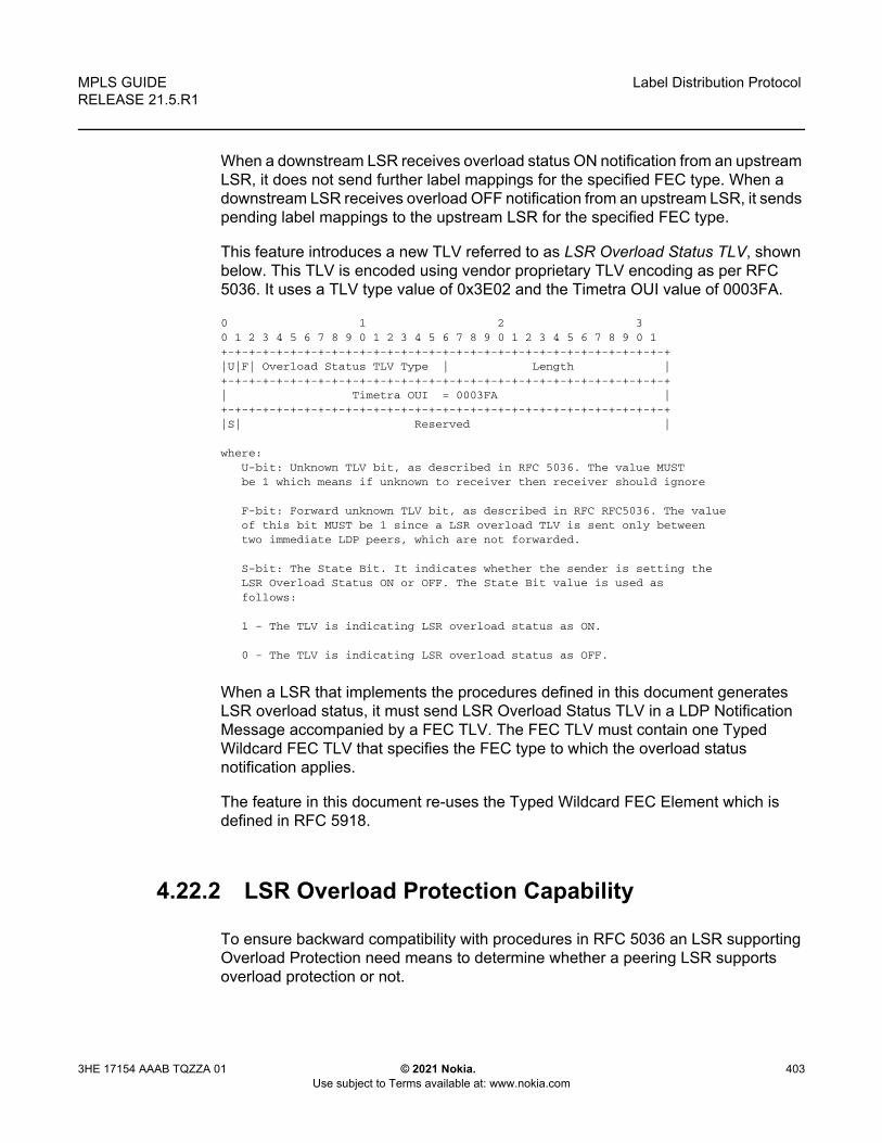
MPLS GUIDE RELEASE 21.5.R1
Label Distribution Protocol
3HE 17154 AAAB TQZZA 01 © 2021 Nokia. Use subject to Terms available at: www.nokia.com
403
When a downstream LSR receives overload status ON notification from an upstream LSR, it does not send further label mappings for the specified FEC type. When a downstream LSR receives overload OFF notification from an upstream LSR, it sends pending label mappings to the upstream LSR for the specified FEC type.
This feature introduces a new TLV referred to as LSR Overload Status TLV, shown below. This TLV is encoded using vendor proprietary TLV encoding as per RFC 5036. It uses a TLV type value of 0x3E02 and the Timetra OUI value of 0003FA.
0 1 2 30 1 2 3 4 5 6 7 8 9 0 1 2 3 4 5 6 7 8 9 0 1 2 3 4 5 6 7 8 9 0 1+-+-+-+-+-+-+-+-+-+-+-+-+-+-+-+-+-+-+-+-+-+-+-+-+-+-+-+-+-+-+-+-+|U|F| Overload Status TLV Type | Length |+-+-+-+-+-+-+-+-+-+-+-+-+-+-+-+-+-+-+-+-+-+-+-+-+-+-+-+-+-+-+-+-+| Timetra OUI = 0003FA |+-+-+-+-+-+-+-+-+-+-+-+-+-+-+-+-+-+-+-+-+-+-+-+-+-+-+-+-+-+-+-+-+|S| Reserved |
where:U-bit: Unknown TLV bit, as described in RFC 5036. The value MUSTbe 1 which means if unknown to receiver then receiver should ignore
F-bit: Forward unknown TLV bit, as described in RFC RFC5036. The valueof this bit MUST be 1 since a LSR overload TLV is sent only betweentwo immediate LDP peers, which are not forwarded.
S-bit: The State Bit. It indicates whether the sender is setting theLSR Overload Status ON or OFF. The State Bit value is used asfollows:
1 - The TLV is indicating LSR overload status as ON.
0 - The TLV is indicating LSR overload status as OFF.
When a LSR that implements the procedures defined in this document generates LSR overload status, it must send LSR Overload Status TLV in a LDP Notification Message accompanied by a FEC TLV. The FEC TLV must contain one Typed Wildcard FEC TLV that specifies the FEC type to which the overload status notification applies.
The feature in this document re-uses the Typed Wildcard FEC Element which is defined in RFC 5918.
4.22.2 LSR Overload Protection Capability
To ensure backward compatibility with procedures in RFC 5036 an LSR supporting Overload Protection need means to determine whether a peering LSR supports overload protection or not.

Label Distribution Protocol
404
MPLS GUIDERELEASE 21.5.R1
© 2021 Nokia. Use subject to Terms available at: www.nokia.com
3HE 17154 AAAB TQZZA 01
An LDP speaker that supports the LSR Overload Protection procedures as defined in this document must inform its peers of the support by including a LSR Overload Protection Capability Parameter in its initialization message. The Capability parameter follows the guidelines and all Capability Negotiation Procedures as defined in RFC 5561. This TLV is encoded using vendor proprietary TLV encoding as per RFC 5036. It uses a TLV type value of 0x3E03 and the Timetra OUI value of 0003FA.
0 1 2 30 1 2 3 4 5 6 7 8 9 0 1 2 3 4 5 6 7 8 9 0 1 2 3 4 5 6 7 8 9 0 1+-+-+-+-+-+-+-+-+-+-+-+-+-+-+-+-+-+-+-+-+-+-+-+-+-+-+-+-+-+-+-+-+|U|F| LSR Overload Cap TLV Type | Length |+-+-+-+-+-+-+-+-+-+-+-+-+-+-+-+-+-+-+-+-+-+-+-+-+-+-+-+-+-+-+-+-+| Timetra OUI = 0003FA |+-+-+-+-+-+-+-+-+-+-+-+-+-+-+-+-+-+-+-+-+-+-+-+-+-+-+-+-+-+-+-+-+|S| Reserved |+-+-+-+-+-+-+-+-+
Where:
U and F bits : MUST be 1 and 0 respectively as per section 3 of LDPCapabilities [RFC5561].
S-bit : MUST be 1 (indicates that capability is being advertised).
4.22.3 Procedures for LSR overload protection
The procedures defined in this document apply only to LSRs that support Downstream Unsolicited (DU) label advertisement mode and Liberal Label Retention Mode. An LSR that implements the LSR overload protection follows the following procedures:
1. An LSR must not use LSR overload notification procedures with a peer LSR that has not specified LSR Overload Protection Capability in Initialization Message received from the peer LSR.
2. When an upstream LSR detects that it is overloaded with a FEC type then it must initiate an LDP notification message with the S-bit ON in LSR Overload Status TLV and a FEC TLV containing the Typed Wildcard FEC Element for the specified FEC type. This message may be sent to one or more peers.
3. After it has notified peers of its overload status ON for a FEC type, the overloaded upstream LSR can send Label Release for a set of FEC elements to respective downstream LSRs to off load its LIB to below a certain watermark.
4. When an upstream LSR that was previously overloaded for a FEC type detects that it is no longer overloaded, it must send an LDP notification message with the S-bit OFF in LSR Overload Status TLV and FEC TLV containing the Typed Wildcard FEC Element for the specified FEC type.

MPLS GUIDE RELEASE 21.5.R1
Label Distribution Protocol
3HE 17154 AAAB TQZZA 01 © 2021 Nokia. Use subject to Terms available at: www.nokia.com
405
5. When an upstream LSR has notified its peers that it is overloaded for a FEC type, then a downstream LSR must not send new label mappings for the specified FEC type to the upstream LSR.
6. When a downstream LSR receives LSR overload notification from a peering LSR with status OFF for a FEC type then the receiving LSR must send any label mappings for the FEC type which were pending to the upstream LSR for which are eligible to be sent now.
7. When an upstream LSR is overloaded for a FEC type and it receives Label Mapping for that FEC type from a downstream LSR then it can send Label Release to the downstream peer for the received Label Mapping with LDP Status Code as No_Label_Resources as defined in RFC 5036.

Label Distribution Protocol
406
MPLS GUIDERELEASE 21.5.R1
© 2021 Nokia. Use subject to Terms available at: www.nokia.com
3HE 17154 AAAB TQZZA 01
4.23 LDP-IGP Synchronization
The SR OS supports the synchronization of an IGP and LDP based on a solution described in RFC 5443, which consists of setting the cost of a restored link to infinity to give both the IGP and LDP time to converge. When a link is restored after a failure, the IGP sets the link cost to infinity and advertises it. The actual value advertised in OSPF is 0xFFFF (65535). The actual value advertised in an IS-IS regular metric is 0x3F (63) and in IS-IS wide-metric is 0xFFFFFE (16777214). This synchronization feature is not supported on RIP interfaces.
When the LDP synchronization timer subsequently expires, the actual cost is put back and the IGP readvertises it and uses it at the next SPF computation. The LDP synchronization timer is configured using the following command:
config>router>if> [no] ldp-sync-timer seconds
The SR OS also supports an LDP End of LIB message, as defined in RFC 5919, that allows a downstream node to indicate to its upstream peer that it has advertised its entire label information base. The effect of this on the IGP-LDP synchronization timer is described below.
If an interface belongs to both IS-IS and OSPF, a physical failure will cause both IGPs to advertise an infinite metric and to follow the IGP-LDP synchronization procedures. If only one IGP bounces on this interface or on the system, then only the affected IGP advertises the infinite metric and follows the IGP-LDP synchronization procedures.
Next, an LDP Hello adjacency is brought up with the neighbor. The LDP synchronization timer is started by the IGP when the LDP session to the neighbor is up over the interface. This is to allow time for the label-FEC bindings to be exchanged.
When the LDP synchronization timer expires, the link cost is restored and is readvertised. The IGP will announce a new best next hop and LDP will use it if the label binding for the neighbor’s FEC is available.
If the user changes the cost of an interface, the new value is advertised at the next flooding of link attributes by the IGP. However, if the LDP synchronization timer is still running, the new cost value will only be advertised after the timer expires. The new cost value will also be advertised after the user executes any of the following commands:
• tools>perform>router>isis>ldp-sync-exit • tools>perform>router>ospf>ldp-sync-exit• config>router>if>no ldp-sync-timer

MPLS GUIDE RELEASE 21.5.R1
Label Distribution Protocol
3HE 17154 AAAB TQZZA 01 © 2021 Nokia. Use subject to Terms available at: www.nokia.com
407
• config>router>ospf>disable-ldp-sync• router>isis>disable-ldp-sync
If the user changes the value of the LDP synchronization timer parameter, the new value will take effect at the next synchronization event. If the timer is still running, it will continue to use the previous value.
If parallel links exist to the same neighbor, then the bindings and services should remain up as long as there is one interface that is up. However, the user-configured LDP synchronization timer still applies on the interface that failed and was restored. In this case, the router will only consider this interface for forwarding after the IGP readvertises its actual cost value.
The LDP End of LIB message is used by a node to signal completion of label advertisements, using a FEC TLV with the Typed Wildcard FEC element for all negotiated FEC types. This is done even if the system has no label bindings to advertise. The SR OS also supports the Unrecognized Notification TLV (RFC 5919) that indicates to a peer node that it will ignore unrecognized status TLVs. This indicates to the peer node that it is safe to send End of LIB notifications even if the node is not configured to process them.
The behavior of a system that receives an End of LIB status notification is configured through the CLI on a per-interface basis:
config>router>if>[no] ldp-sync-timer seconds end-of-lib
If the end-of lib option is not configured, then the LDP synchronization timer is started when the LDP Hello adjacency comes up over the interface, as described above. Any received End of LIB LDP messages are ignored.
If the end-of-lib option is configured, then the system will behave as follows on the receive side:
• The ldp-sync-timer is started.• If LDP End of LIB Typed Wildcard FEC messages are received for every FEC
type negotiated for a given session to an LDP peer for that IGP interface, the ldp-sync-timer is terminated and processing proceeds as if the timer had expired, that is, by restoring the IGP link cost.
• If the ldp-sync-timer expires before the LDP End of LIB messages are received for every negotiated FEC type, then the system restores the IGP link cost.
• The receive side will drop any unexpected End of LIB messages.
If the end-of-lib option is configured, then the system will also send out an End of LIB message for prefix and P2MP FECs once all FECs are sent for all peers that have advertised the Unrecognized Notification Capability TLV.

Label Distribution Protocol
408
MPLS GUIDERELEASE 21.5.R1
© 2021 Nokia. Use subject to Terms available at: www.nokia.com
3HE 17154 AAAB TQZZA 01
See the 7450 ESS, 7750 SR, 7950 XRS, and VSR Router Configuration Guide for the CLI command descriptions for LDP-IGP Synchronization.

MPLS GUIDE RELEASE 21.5.R1
Label Distribution Protocol
3HE 17154 AAAB TQZZA 01 © 2021 Nokia. Use subject to Terms available at: www.nokia.com
409
4.24 MLDP Resolution using Multicast RTM
When unicast services use IGP shortcuts, IGP shortcut next-hops are installed in the RTM. Therefore, for multicast P2MP MLDP, the leaf node will resolve the root using these IGP shortcuts. Currently MLDP can not be resolved using IGP shortcuts. To avoid this, MLDP does a lookup in the multicast RTM. IGP shortcuts are not installed in MRTM. The command configure router ldp resolve-root-using forces MLDP do next-hop lookups in the RTM or MRTM.
By default, the configure router ldp resolve-root-using command is set to ucast-rtm and MLDP uses the unicast RTM for resolution of the FEC in all cases. When MLDP uses the unicast RTM to resolve the FEC, it will not resolve the FEC if its next hop is resolved using an IGP shortcut.
To force MLDP resolution to use the multicast RTM, use the configure router ldp resolve-root-using mcast-rtm command. When this command is enabled:
• For FEC resolution using IGP, static or local, the ROOT in this FEC is resolved using the multicast RTM.
• A FEC being resolved using BGP is recursive, so the FEC next-hop (ASBR/ABR) is resolved using the multicast RTM first and, if this fails, it is resolved using the unicast RTM. This next-hop needs to be recursively resolved again using IGP/Static-Route or Local, this second resolution (recursive resolution) uses the multicast RTM only; see Figure 90.
• When configure router ldp resolve-root-using ucast-rtm is set, MLDP uses the unicast RTM to resolve the FEC and will not resolve the FEC if its next hop is resolved using an IGP shortcut.
For inter-AS or intra-AS, IGP shortcuts are limited to each AS or area connecting LEAF to ASBR, ASBR to ASBR, or ASBR to ROOT.

Label Distribution Protocol
410
MPLS GUIDERELEASE 21.5.R1
© 2021 Nokia. Use subject to Terms available at: www.nokia.com
3HE 17154 AAAB TQZZA 01
Figure 90 Recursive FEC Behavior
In Figure 90, the FEC between LEAF and ASBR-3 is resolved using an IGP shortcut. When the configure ldp resolve-root-using is set to mcast-rtm, the inner Root 100.0.0.14 will be resolved using the multicast RTM first. If the multicast RTM lookup fails, then a second lookup for 100.0.0.14 is done in the unicast RTM. Resolution of 100.0.0.14 results in a next-hop of 100.0.0.21 which is ASBR-3, as such ASBR-3 100.0.0.21 is resolved only using multicast RTM when mcast-rtm is enabled.
4.24.1 Other Considerations for Multicast RTM MLDP Resolution
When configure ldp resolve-root-using is set to mcast-rtm and then changed to ucast-rtm there is traffic disruption. If MoFRR is enabled, by toggling from mcast-rtm to ucast-rtm (or the other way around) the MoFRR is not utilized. In fact, MoFRR is torn down and re-established using the new routing table.
The mcast-rtm only has a local effect. All MLDP routing calculations on this specific node will use MRTM and not RTM.
If mcast-rtm is enabled, all MLDP functionality will be based on MRTM. This includes MoFRR, ASBR-MoFRR, policy-based SPMSI, and non-segmented inter-AS.
sw0442
AS2
LDP Fec:Root 100.0.014
Opaque <PMPID 8193>
LDP Fec: Root 100.0.0.21Opaque <100.0.0.14,
Opaque <PMPID 8193>>
LDP Fec: Root 100.0.0.2Opaque <100.0.0.14,
Opaque <PMPID 8193>>
AS3
LEAF ASBR-1ASBR-3
Host
LeafROOT
100.0.0.14ASBR-1 Local AS
100.0.0.2ASBR-3 Remote AS
100.0.0.21
VPRN-1RD 600:600
VPRN-1RD 60:60
IGP Shortcut connectingASBR to Root
IGP Shortcut connectingASBR to ASBR
IGP Shortcut connectingLEAF to ASBR
Inner Root 100.0.0.14 (First resolutionusing BGR to ASBR-3)Inner Root recursive resolution of ASBR-3100.0.0.21 for Inner RootInner Root recursive resolution of ASBR-1100.0.0.2 for Inner Root
Outer Root 100.0.0.14 M-RTM
M-RTM
M-RTM
*M-RTM firstU-RTM second
M-RTM firstU-RTM second
Source
SR Core SR Core

MPLS GUIDE RELEASE 21.5.R1
Label Distribution Protocol
3HE 17154 AAAB TQZZA 01 © 2021 Nokia. Use subject to Terms available at: www.nokia.com
411
4.25 Bidirectional Forwarding Detection for LDP LSPs
Bidirectional forwarding detection (BFD) for MPLS LSPs monitors the LSP between its LERs, irrespective of how many LSRs the LSP may traverse. This feature enables the detection of faults that are local to individual LSPs, whether or not they also affect forwarding for other LSPs or IP packet flows. BFD for MPLS LSPs is ideal for monitoring LSPs that carry high-value services, and for which the quick detection of forwarding failures is critical. If an LSP BFD session goes down, the system raises an SNMP trap and indicates the BFD session state in the show and tools dump commands.
SR OS supports LSP BFD on RSVP and LDP LSPs. See MPLS and RSVP for information on using LSP BFD on RSVP LSPs. BFD packets are encapsulated in an MPLS label stack corresponding to the FEC that the BFD session is associated with, as described in RFC 5884, Section 7. SR OS does not support the monitoring of multiple ECMP paths that are associated with the same LDP FEC which is using multiple LSP BFD sessions simultaneously. However, LSP BFD still provides continuity checking for paths associated with a target FEC. LDP provides a single path to LSP BFD, corresponding with the first resolved lower interface index next-hop, and the first resolved lower TID index for LDP-over-RSVP cases. The path may potentially change over the lifetime of the FEC, based on resolution changes. The system tracks the changing path and maintains the LSP BFD session.
Since LDP LSPs are unidirectional, a routed return path is used for the BFD control packets traveling from the egress LER to the ingress LER.
4.25.1 Bootstrapping and Maintaining LSP BFD Sessions
A BFD session on an LSP is bootstrapped using LSP ping. LSP ping is used to exchange the local and remote discriminator values to use for the BFD session for a specific MPLS LSP or FEC.
The process for bootstrapping an LSP BFD session for LDP is the same as for RSVP, as described in Bidirectional Forwarding Detection for MPLS LSPs.

Label Distribution Protocol
412
MPLS GUIDERELEASE 21.5.R1
© 2021 Nokia. Use subject to Terms available at: www.nokia.com
3HE 17154 AAAB TQZZA 01
SR OS supports the sending of periodic LSP ping messages on an LSP for which LSP BFD has been configured, as specified in RFC 5884. The ping messages are sent, along with the bootstrap TLV, at a configurable interval for LSPs where bfd-enable is configured. The default interval is 60 s, with a maximum interval of 300 s. The LSP ping echo request message uses the system IP address as the default source address. An alternative source address consisting of any routable address that is local to the node may be configured and used if the local system IP address is not routable from the far-end node.
The periodic LSP ping interval is configured using the config>router>ldp>lsp-bfd prefix-list>lsp-ping-interval seconds command.
Configuring an LSP ping interval of 0 disables periodic LSP ping for LDP FECs matching the specified prefix list. The no lsp-ping-interval command reverts to the default of 60 s.
LSP BFD sessions are recreated after a high-availability switchover between active and standby CPMs. However, some disruption may occur to LSP ping as a result LSP BFD.
At the head end of an LSP, sessions are bootstrapped if the local and remote discriminators are not known. The sessions experience jitter at 0 to 25% of a retry time of 5 seconds. A side effect of the bootstrapping is that the following current information will be lost from an active show test-oam lsp-bfd display:
• Replying Node• Latest Return Code• Latest Return SubCode• Bootstrap Retry Count• Tx Lsp Ping Requests• Rx Lsp Ping Replies
If the local and remote discriminators are known, the system immediately begins generating periodic LSP pings. The pings will experience jitter at 0 to 25% of the lsp-ping-interval time of 60 to 300 seconds. The lsp-ping-interval time is synchronized across by LSP BFD. A side effect of the bootstrapping is that the following current information will be lost from an active show test-oam lsp-bfd display:
• Replying Node
Note: SR OS does not take any action if a remote system fails to respond to a periodic LSP ping message. However, when the show>test-oam>lsp-bfd command is executed, it will display a return code of zero and a replying node address of 0.0.0.0 if the periodic LSP ping times out.

MPLS GUIDE RELEASE 21.5.R1
Label Distribution Protocol
3HE 17154 AAAB TQZZA 01 © 2021 Nokia. Use subject to Terms available at: www.nokia.com
413
• Latest Return Code• Latest Return SubCode• Bootstrap Retry Count• Tx Lsp Ping Requests• Rx Lsp Ping Replies
At the tail end of an LSP, sessions are recreated on the standby CPM following a switchover. The side effect of this is that the following current information will be lost from an active tools dump test-oam lsp-bfd tail display:
• handle• seqNum• rc• rsc
New, incoming bootstrap requests will be dropped until the LSP BFD session is active. When the LSP BFD session is active, new bootstrap requests are considered.
4.25.2 BFD Configuration on LDP LSPs
Use the following syntax to configure LSP BFD for LDP.
CLI Syntax: configrouter
ldp[no] lsp-bfd prefix-list-name
priority priority-levelno prioritybfd-template bfd-template-nameno bfd-templatesource-address ip-addressno source-address[no] bfd-enable lsp-ping-interval secondsno lsp-ping-intervalexit

Label Distribution Protocol
414
MPLS GUIDERELEASE 21.5.R1
© 2021 Nokia. Use subject to Terms available at: www.nokia.com
3HE 17154 AAAB TQZZA 01
The lsp-bfd command creates the context for LSP BFD configuration for a set of LDP LSPs with a FEC matching the one defined by the prefix-list-name parameter. The default is no lsp-bfd. Configuring no lsp-bfd for a specified prefix list will remove LSP BFD for all matching LDP FECs except those that also match another LSP BFD prefix list. The prefix-list-name parameter refers to a named prefix list configured in the config>router>policy-options context.
Up to 16 instances of LSP BFD can be configured under LDP in the base router instance.
The optional priority command configures a priority value that is used to order the processing if multiple prefix lists are configured. The default value is 1.
If more than one prefix in a prefix list, or more than one prefix list, contains a prefix that corresponds to the same LDP FEC, then the system will test the prefix against the configured prefix lists in the following order:
1. numerically by priority-level2. alphabetically by prefix-list-name
The system will use the first matching configuration, if one exists.
If an LSP BFD is removed for a prefix list, but there remains another LSP BFD configuration with a prefix list match, then any FECs matched against that prefix will be rematched against the remaining prefix list configurations in the same manner as described above.
A non-existent prefix list is equivalent to an empty prefix list. When a prefix list is created and populated with prefixes, LDP will match its FECs against that prefix list. It is not necessary to configure a named prefix list in the config>router>policy-options context before specifying a prefix list using the config>router>ldp>lsp-bfd command.
If a prefix list contains a longest match corresponding to one or more LDP FECs, the BFD configuration is applied to all of the matching LDP LSPs.
Only /32 IPv4 and /128 IPv6 host prefix FECs will be considered for BFD. BFD on PW FECs uses VCCV BFD.
The source-address command is used to configure the source address of periodic LSP ping packets and BFD control packets for LSP BFD sessions associated with LDP prefixes in the prefix list. The default value is the system IP address. If the system IP address is not routable from the far-end node of the BFD session, then an alternative routable IP address local to the source node should be used.

MPLS GUIDE RELEASE 21.5.R1
Label Distribution Protocol
3HE 17154 AAAB TQZZA 01 © 2021 Nokia. Use subject to Terms available at: www.nokia.com
415
The system will not initialize an LSP BFD session if there is a mismatch between the address family of the source address and the address family of the prefix in the prefix list.
If the system has both IPv4 and IPv6 system IP addresses, and the source-address command is not configured, then the system will use a source address of the matching address family for IPv4 and IPv6 prefixes in the prefix list.
The bfd-template command applies the specified BFD template to the BFD sessions for LDP LSPs with FECs that match the prefix list. The default is no bfd-template. The named BFD template must first be configured using the config>router>bfd>bfd-template command before it can be referenced by LSP BFD, otherwise a CLI error is generated. The minimum receive interval and transmit interval supported for LSP BFD on LDP LSPs is 1 second.
The bfd-enable command enables BFD on the LDP LSPs with FECs that match the prefix list.

Label Distribution Protocol
416
MPLS GUIDERELEASE 21.5.R1
© 2021 Nokia. Use subject to Terms available at: www.nokia.com
3HE 17154 AAAB TQZZA 01
4.26 User Guidelines and Troubleshooting Procedures
4.26.1 Common Procedures
When troubleshooting a LDP resource exhaustion situation on an LSR, the user must first determine which of the LSR and its peers supports the enhanced handling of resources. This is done by checking if the local LSR or its peers advertised the LSR Overload Protection Capability:
*A:Sim>config>router>ldp# show router ldp status
===============================================================================LDP Status for IPv4 LSR ID 0.0.0.0
IPv6 LSR ID ::===============================================================================Created at : 01/08/19 17:57:06Last Change : 01/08/19 17:57:06Admin State : UpIPv4 Oper State : Down IPv6 Oper State : DownIPv4 Down Time : 0d 00:12:58 IPv6 Down Time : 0d 00:12:58IPv4 Oper Down Rea*: systemIpDown IPv6 Oper Down Reason: systemIpDownIPv4 Oper Down Eve*: 0 IPv6 Oper Down Events: 0Tunn Down Damp Time: 3 sec Weighted ECMP : DisabledLabel Withdraw Del*: 0 sec Implicit Null Label : DisabledShort. TTL Local : Enabled Short. TTL Transit : EnabledConsiderSysIPInGep : DisabledImp Ucast Policies : Exp Ucast Policies :
pol1 noneImp Mcast Policies :
pol1policy2policy-3policy-fourpol-five
Tunl Exp Policies : None Tunl Imp Policies : NoneFRR : Disabled Mcast Upstream FRR : DisabledMcast Upst ASBR FRR: Disabled
4.26.2 Base Resource Handling Procedures
Step 1
If the peer OR the local LSR does not support the Overload Protection Capability it means that the associated adjacency [interface/peer] will be brought down as part of the base resource handling mechanism.

MPLS GUIDE RELEASE 21.5.R1
Label Distribution Protocol
3HE 17154 AAAB TQZZA 01 © 2021 Nokia. Use subject to Terms available at: www.nokia.com
417
The user can determine which interface or targeted peer was shut down, by applying the following commands:
- [show router ldp interface resource-failures]
- [show router ldp targ-peer resource-failures]
show router ldp interface resource-failures===============================================================================LDP Interface Resource Failures===============================================================================srl srrsru4 sr4-1-5-1===============================================================================
show router ldp targ-peer resource-failures===============================================================================LDP Peers Resource Failures===============================================================================10.20.1.22 192.168.1.3===============================================================================
A trap is also generated for each interface or targeted peer:
16 2013/07/17 14:21:38.06 PST MINOR: LDP #2003 Base LDP Interface Admin State"Interface instance state changed - vRtrID: 1, Interface sr4-1-5-1, administrative state: inService, operational state: outOfService"
13 2013/07/17 14:15:24.64 PST MINOR: LDP #2003 Base LDP Interface Admin State"Interface instance state changed - vRtrID: 1, Peer 10.20.1.22, administrative state: inService, operational state: outOfService"
The user can then check that the base resource handling mechanism has been applied to a specific interface or peer by running the following show commands:
- [show router ldp interface detail]
- [show router ldp targ-peer detail]
show router ldp interface detail===============================================================================LDP Interfaces (Detail)===============================================================================-------------------------------------------------------------------------------Interface "sr4-1-5-1"-------------------------------------------------------------------------------Admin State : Up Oper State : DownOper Down Reason : noResources <----- //link LDP resource exhaustion handledHold Time : 45 Hello Factor : 3Oper Hold Time : 45Hello Reduction : Disabled Hello Reduction *: 3Keepalive Timeout : 30 Keepalive Factor : 3Transport Addr : System Last Modified : 07/17/13 14:21:38

Label Distribution Protocol
418
MPLS GUIDERELEASE 21.5.R1
© 2021 Nokia. Use subject to Terms available at: www.nokia.com
3HE 17154 AAAB TQZZA 01
Active Adjacencies : 0Tunneling : DisabledLsp Name : NoneLocal LSR Type : SystemLocal LSR : NoneBFD Status : DisabledMulticast Traffic : Enabled-------------------------------------------------------------------------------
show router ldp discovery interface "sr4-1-5-1" detail===============================================================================LDP Hello Adjacencies (Detail)===============================================================================-------------------------------------------------------------------------------Interface "sr4-1-5-1"-------------------------------------------------------------------------------Local Address : 192.168.2.110 Peer Address : 192.168.0.2Adjacency Type : Link State : Down===============================================================================
show router ldp targ-peer detail===============================================================================LDP Peers (Detail)===============================================================================-------------------------------------------------------------------------------Peer 10.20.1.22-------------------------------------------------------------------------------Admin State : Up Oper State : DownOper Down Reason : noResources <----- // T-LDP resource exhaustion handledHold Time : 45 Hello Factor : 3Oper Hold Time : 45Hello Reduction : Disabled Hello Reduction Fact*: 3Keepalive Timeout : 40 Keepalive Factor : 4Passive Mode : Disabled Last Modified : 07/17/13 14:15:24Active Adjacencies : 0 Auto Created : NoTunneling : EnabledLsp Name : NoneLocal LSR : NoneBFD Status : DisabledMulticast Traffic : Disabled-------------------------------------------------------------------------------
show router ldp discovery peer 10.20.1.22 detail===============================================================================LDP Hello Adjacencies (Detail)===============================================================================-------------------------------------------------------------------------------Peer 10.20.1.22-------------------------------------------------------------------------------Local Address : 192.168.1.110 Peer Address : 10.20.1.22Adjacency Type : Targeted State : Down <-----//T-LDP resource exhaustion handled===============================================================================
Step 2

MPLS GUIDE RELEASE 21.5.R1
Label Distribution Protocol
3HE 17154 AAAB TQZZA 01 © 2021 Nokia. Use subject to Terms available at: www.nokia.com
419
Besides interfaces and targeted peer, locally originated FECs may also be put into overload. These are the following:
- unicast fec-originate pop
- multicast local static p2mp-fec type=1 [on leaf LSR]
- multicast local Dynamic p2mp-fec type=3 [on leaf LSR]
The user can check if only remote and/or local FECs have been set in overload by the resource base resource exhaustion mechanism using the following command:
- [tools dump router ldp instance]
The relevant part of the output is described below:
{...... snip......}Num OLoad Interfaces: 4 <----- //#LDP interfaces resource in exhaustionNum Targ Sessions: 72 Num Active Targ Sess: 62Num OLoad Targ Sessions: 7 <----- //#T-LDP peers in resource exhaustionNum Addr FECs Rcvd: 0 Num Addr FECs Sent: 0Num Addr Fecs OLoad: 1 <----- //# of local/remote unicast FECs in OverloadNum Svc FECs Rcvd: 0 Num Svc FECs Sent: 0Num Svc FECs OLoad: 0 <----- // # of local/remote service Fecs in OverloadNum mcast FECs Rcvd: 0 Num Mcast FECs Sent: 0Num mcast FECs OLoad: 0 <----- // # of local/remote multicast Fecs in Overload{...... snip......}
When at least one local FEC has been set in overload the following trap will occur:
23 2013/07/17 15:35:47.84 PST MINOR: LDP #2002 Base LDP Resources Exhausted"Instancestate changed - vRtrID: 1, administrative state: inService, operationa l state:inService"
Step 3
After the user has detected that at least, one link LDP or T-LDP adjacency has been brought down by the resource exhaustion mechanism, he/she must protect the router by applying one or more of the following to free resources up:
• Identify the source for the [unicast/multicast/service] FEC flooding.• Configure the appropriate [import/export] policies and/or delete the excess
[unicast/multicast/service] FECs not currently handled.
Step 4
Next, the user has to manually attempt to clear the overload (no resource) state and allow the router to attempt to restore the link and targeted sessions to its peer.

Label Distribution Protocol
420
MPLS GUIDERELEASE 21.5.R1
© 2021 Nokia. Use subject to Terms available at: www.nokia.com
3HE 17154 AAAB TQZZA 01
One of the following commands can be used:
- [clear router ldp resource-failures]
• Clears the overload state and attempt to restore adjacency and session for LDP interfaces and peers.
• Clear the overload state for the local FECs.
- [clear router ldp interface ifName]
- [clear router ldp peer peerAddress]
• Clears the overload state and attempt to restore adjacency and session for LDP interfaces and peers.
• These two commands *DO NOT* Clear the overload state for the local FECs.
4.26.3 Enhanced Resource Handling Procedures
Step 1
If the peer and the local LSR do support the Overload Protection Capability it means that the LSR will signal the overload state for the FEC type which caused the resource exhaustion as part of the enhanced resource handling mechanism.
In order to verify if the local router has received or sent the overload status TLV, perform the following:
-[show router ldp session detail]show router ldp session 192.168.1.1 detail-------------------------------------------------------------------------------Session with Peer 192.168.1.1:0, Local 192.168.1.110:0-------------------------------------------------------------------------------Adjacency Type : Both State : EstablishedUp Time : 0d 00:05:48Max PDU Length : 4096 KA/Hold Time Remaining : 24Link Adjacencies : 1 Targeted Adjacencies : 1Local Address : 192.168.1.110 Peer Address : 192.168.1.1Local TCP Port : 51063 Peer TCP Port : 646Local KA Timeout : 30 Peer KA Timeout : 45Mesg Sent : 442 Mesg Recv : 2984FECs Sent : 16 FECs Recv : 2559Addrs Sent : 17 Addrs Recv : 1054
Note: Because of the dynamic nature of FEC distribution and resolution by LSR nodes, one cannot predict exactly which FECs and which interfaces or targeted peers will be restored after performing the following commands if the LSR activates resource exhaustion again.

MPLS GUIDE RELEASE 21.5.R1
Label Distribution Protocol
3HE 17154 AAAB TQZZA 01 © 2021 Nokia. Use subject to Terms available at: www.nokia.com
421
GR State : Capable Label Distribution : DUNbr Liveness Time : 0 Max Recovery Time : 0Number of Restart : 0 Last Restart Time : NeverP2MP : Capable MP MBB : CapableDynamic Capability : Not Capable LSR Overload : CapableAdvertise : Address/Servi* BFD Operational Status : inServiceAddr FEC OverLoad Sent : Yes Addr FEC OverLoad Recv : No <----// this LSR sent overLoad for unicast FEC type to peerMcast FEC Overload Sent: No Mcast FEC Overload Recv: NoServ FEC Overload Sent : No Serv FEC Overload Recv : No-------------------------------------------------------------------------------
show router ldp session 192.168.1.110 detail-------------------------------------------------------------------------------Session with Peer 192.168.1.110:0, Local 192.168.1.1:0-------------------------------------------------------------------------------Adjacency Type : Both State : EstablishedUp Time : 0d 00:08:23Max PDU Length : 4096 KA/Hold Time Remaining : 21Link Adjacencies : 1 Targeted Adjacencies : 1Local Address : 192.168.1.1 Peer Address : 192.168.1.110Local TCP Port : 646 Peer TCP Port : 51063Local KA Timeout : 45 Peer KA Timeout : 30Mesg Sent : 3020 Mesg Recv : 480FECs Sent : 2867 FECs Recv : 16Addrs Sent : 1054 Addrs Recv : 17GR State : Capable Label Distribution : DUNbr Liveness Time : 0 Max Recovery Time : 0Number of Restart : 0 Last Restart Time : NeverP2MP : Capable MP MBB : CapableDynamic Capability : Not Capable LSR Overload : CapableAdvertise : Address/Servi* BFD Operational Status : inServiceAddr FEC OverLoad Sent : No Addr FEC OverLoad Recv : Yes <----// this LSR received overLoad for unicast FEC type from peerMcast FEC Overload Sent: No Mcast FEC Overload Recv: NoServ FEC Overload Sent : No Serv FEC Overload Recv : No===============================================================================
A trap is also generated:
70002 2013/07/17 16:06:59.46 PST MINOR: LDP #2008 Base LDP Session State Change"Session state is operational. Overload Notification message is sent to/from peer
192.168.1.1:0 with overload state true for fec type prefixes"
Step 2
Besides interfaces and targeted peer, locally originated FECs may also be put into overload. These are the following:
- unicast fec-originate pop
- multicast local static p2mp-fec type=1 [on leaf LSR]
- multicast local Dynamic p2mp-fec type=3 [on leaf LSR]

Label Distribution Protocol
422
MPLS GUIDERELEASE 21.5.R1
© 2021 Nokia. Use subject to Terms available at: www.nokia.com
3HE 17154 AAAB TQZZA 01
The user can check if only remote and/or local FECs have been set in overload by the resource enhanced resource exhaustion mechanism using the following command:
- [tools dump router ldp instance]
The relevant part of the output is described below:
Num Entities OLoad (FEC: Address Prefix ): Sent: 7 Rcvd: 0 <-----// # of session in OvLd for fec-type=unicast
Num Entities OLoad (FEC: PWE3 ): Sent: 0 Rcvd: 0 <-----// # of session in OvLd for fec-type=service
Num Entities OLoad (FEC: GENPWE3 ): Sent: 0 Rcvd: 0 <-----// # of session in OvLd for fec-type=service
Num Entities OLoad (FEC: P2MP ): Sent: 0 Rcvd: 0 <-----// # of session in OvLd for fec-type=MulticastP2mp
Num Entities OLoad (FEC: MP2MP UP ): Sent: 0 Rcvd: 0 <-----// # of session in OvLd for fec-type=MulticastMP2mp
Num Entities OLoad (FEC: MP2MP DOWN ): Sent: 0 Rcvd: 0 <-----// # of session in OvLd for fec-type=MulticastMP2mp
Num Active Adjacencies: 9Num Interfaces: 6 Num Active Interfaces: 6Num OLoad Interfaces: 0 <----- // link LDP interfaces in resource
exhaustionshould be zero when Overload Protection Capability is supportedNum Targ Sessions: 72 Num Active Targ Sess: 67Num OLoad Targ Sessions: 0 <----- // T-LDP peers in resource exhaustion
should be zero if Overload Protection Capability is supportedNum Addr FECs Rcvd: 8667 Num Addr FECs Sent: 91Num Addr Fecs OLoad: 1 <-----
// # of local/remote unicast Fecs in OverloadNum Svc FECs Rcvd: 3111 Num Svc FECs Sent: 0Num Svc FECs OLoad: 0 <-----
// # of local/remote service Fecs in OverloadNum mcast FECs Rcvd: 0 Num Mcast FECs Sent: 0Num mcast FECs OLoad: 0 <-----
// # of local/remote multicast Fecs in OverloadNum MAC Flush Rcvd: 0 Num MAC Flush Sent: 0
When at least one local FEC has been set in overload the following trap will occur:
69999 2013/07/17 16:06:59.21 PST MINOR: LDP #2002 Base LDP Resources Exhausted"Instance state changed - vRtrID: 1, administrative state: inService, operationalstate: inService"
Step 3
After the user has detected that at least one overload status TLV has been sent or received by the LSR, he/she must protect the router by applying one or more of the following to free resources up:
• Identify the source for the [unicast/multicast/service] FEC flooding. This is most likely the LSRs which session received the overload status TLV.

MPLS GUIDE RELEASE 21.5.R1
Label Distribution Protocol
3HE 17154 AAAB TQZZA 01 © 2021 Nokia. Use subject to Terms available at: www.nokia.com
423
• Configure the appropriate [import/export] policies and/or delete the excess [unicast/multicast/service] FECs from the FEC type in overload.
Step 4
Next, the user has to manually attempt to clear the overload state on the affected sessions and for the affected FEC types and allow the router to clear the overload status TLV to its peers.
One of the following commands can be used depending if the user wants to clear all sessions or at once or one session at a time:
- [clear router ldp resource-failures]
• Clears the overload state for the affected sessions and FEC types.• Clear the overload state for the local FECs.
- [clear router ldp session a.b.c.d overload fec-type {services | prefixes | multicast}]
• Clears the overload state for the specified session and FEC type.• Clears the overload state for the local FECs.
Note: Because of the dynamic nature of FEC distribution and resolution by LSR nodes, one cannot predict exactly which sessions and which FECs will be cleared after performing the following commands if the LSR activates overload again.

Label Distribution Protocol
424
MPLS GUIDERELEASE 21.5.R1
© 2021 Nokia. Use subject to Terms available at: www.nokia.com
3HE 17154 AAAB TQZZA 01
4.27 LDP IPv6 Control and Data Planes
SR OS extends the LDP control plane and data plane to support LDP IPv6 adjacency and session using 128-bit LSR-ID.
The implementation allows for concurrent support of independent LDP IPv4 (32-bit LSR-ID) and IPv6 (128-bit LSR-ID) adjacencies and sessions between peer LSRs and over the same or different set of interfaces.
4.27.1 LDP Operation in an IPv6 Network
LDP IPv6 can be enabled on the SR OS interface. Figure 91 shows the LDP adjacency and session over an IPv6 interface.
Figure 91 LDP Adjacency and Session over an IPv6 Interface
LSR-A and LSR-B have the following IPv6 LDP identifiers respectively:
• <LSR Id=A/128> : <label space id=0>• <LSR Id=B/128> : <label space id=0>
By default, A/128 and B/128 use the system interface IPv6 address.
The following sections describe the behavior when LDP IPv6 is enabled on the interface.
al_0627
LSR-A:0
I/F 1
I/F 2LSR-B:0
Note: Although the LDP control plane can operate using only the IPv6 system address, the user must configure the IPv4-formatted router ID for OSPF, IS-IS, and BGP to operate properly.

MPLS GUIDE RELEASE 21.5.R1
Label Distribution Protocol
3HE 17154 AAAB TQZZA 01 © 2021 Nokia. Use subject to Terms available at: www.nokia.com
425
4.27.2 Link LDP
The SR OS LDP IPv6 implementation uses a 128-bit LSR-ID as defined in draft-pdutta-mpls-ldp-v2-00. See LDP Process Overview for more information about interoperability of this implementation with 32-bit LSR-ID, as defined in RFC 7552.
Hello adjacency will be brought up using link Hello packet with source IP address set to the interface link-local unicast address and a destination IP address set to the link-local multicast address FF02:0:0:0:0:0:0:2.
The transport address for the TCP connection, which is encoded in the Hello packet, will be set to the LSR-ID of the LSR by default. It will be set to the interface IPv6 address if the user enabled the interface option under one of the following contexts:
• config>router>ldp>if-params>ipv6>transport-address• config>router>ldp>if-params>if>ipv6>transport-address
The interface global unicast address, meaning the primary IPv6 unicast address of the interface, is used.
The user can configure the local-lsr-id option on the interface and change the value of the LSR-ID to either the local interface or to another interface name, loopback or not. The global unicast IPv6 address corresponding to the primary IPv6 address of the interface is used as the LSR-ID. If the user invokes an interface which does not have a global unicast IPv6 address in the configuration of the transport address or the configuration of the local-lsr-id option, the session will not come up and an error message will be displayed.
The LSR with the highest transport address will bootstrap the IPv6 TCP connection and IPv6 LDP session.
Source and destination addresses of LDP/TCP session packets are the IPv6 transport addresses.
4.27.3 Targeted LDP
Source and destination addresses of targeted Hello packet are the LDP IPv6 LSR-IDs of systems A and B.

Label Distribution Protocol
426
MPLS GUIDERELEASE 21.5.R1
© 2021 Nokia. Use subject to Terms available at: www.nokia.com
3HE 17154 AAAB TQZZA 01
The user can configure the local-lsr-id option on the targeted session and change the value of the LSR-ID to either the local interface or to some other interface name, loopback or not. The global unicast IPv6 address corresponding to the primary IPv6 address of the interface is used as the LSR-ID. If the user invokes an interface which does not have a global unicast IPv6 address in the configuration of the transport address or the configuration of the local-lsr-id option, the session will not come up and an error message will be displayed. In all cases, the transport address for the LDP session and the source IP address of targeted Hello message will be updated to the new LSR-ID value.
The LSR with the highest transport address (in this case, the LSR-ID) will bootstrap the IPv6 TCP connection and IPv6 LDP session.
Source and destination IP addresses of LDP/TCP session packets are the IPv6 transport addresses (in this case, LDP LSR-IDs of systems A and B).
4.27.4 FEC Resolution
LDP will advertise and withdraw all interface IPv6 addresses using the Address/Address-Withdraw message. Both the link-local unicast address and the configured global unicast addresses of an interface are advertised.
All LDP FEC types can be exchanged over a LDP IPv6 LDP session like in LDP IPv4 session.
The LSR does not advertise a FEC for a link-local address and, if received, the LSR will not resolve it.
A IPv4 or IPv6 prefix FEC can be resolved to an LDP IPv6 interface in the same way as it is resolved to an LDP IPv4 interface. The outgoing interface and next-hop are looked up in RTM cache. The next-hop can be the link-local unicast address of the other side of the link or a global unicast address. The FEC is resolved to the LDP IPv6 interface of the downstream LDP IPv6 LSR that advertised the IPv4 or IPv6 address of the next hop.
An mLDP P2MP FEC with an IPv4 root LSR address, and carrying one or more IPv4 or IPv6 multicast prefixes in the opaque element, can be resolved to an upstream LDP IPv6 LSR by checking if the LSR advertised the next-hop for the IPv4 root LSR address. The upstream LDP IPv6 LSR will then resolve the IPv4 P2MP FEC to one of the LDP IPV6 links to this LSR.

MPLS GUIDE RELEASE 21.5.R1
Label Distribution Protocol
3HE 17154 AAAB TQZZA 01 © 2021 Nokia. Use subject to Terms available at: www.nokia.com
427
A PW FEC can be resolved to a targeted LDP IPv6 adjacency with an LDP IPv6 LSR if there is a context for the FEC with local spoke-SDP configuration or spoke-SDP auto-creation from a service such as BGP-AD VPLS, BGP-VPWS or dynamic MS-PW.
4.27.5 LDP Session Capabilities
LDP supports advertisement of all FEC types over an LDP IPv4 or an LDP IPv6 session. These FEC types are: IPv4 prefix FEC, IPv6 prefix FEC, IPv4 P2MP FEC, PW FEC 128, and PW FEC 129.
In addition, LDP supports signaling the enabling or disabling of the advertisement of the following subset of FEC types both during the LDP IPv4 or IPv6 session initialization phase, and subsequently when the session is already up.
• IPv4 prefix FEC—This is performed using the State Advertisement Control (SAC) capability TLV as specified in RFC 7473. The SAC capability TLV includes the IPv4 SAC element having the D-bit (Disable-bit) set or reset to disable or enable this FEC type respectively. The LSR can send this TLV in the LDP Initialization message and subsequently in a LDP Capability message.
• IPv6 prefix FEC—This is performed using the State Advertisement Control (SAC) capability TLV as specified in RFC 7473. The SAC capability TLV includes the IPv6 SAC element having the D-bit (Disable-bit) set or reset to disable or enable this FEC type respectively. The LSR can send this TLV in the LDP Initialization message and subsequently in a LDP Capability message to update the state of this FEC type.
• P2MP FEC—This is performed using the P2MP capability TLV as specified in RFC 6388. The P2MP capability TLV has the S-bit (State-bit) with a value of set or reset to enable or disable this FEC type respectively. Unlike the IPv4 SAC and IPv6 SAC capabilities, the P2MP capability does not distinguish between IPv4 and IPv6 P2MP FEC. The LSR can send this TLV in the LDP Initialization message and, subsequently, in a LDP Capability message to update the state of this FEC type.
Note: Beginning in Release 13.0, a P2MP FEC with an IPv6 root LSR address, carrying one or more IPv4 or IPv6 multicast prefixes in the opaque element, is not supported. Manually configured mLDP P2MP LSP, NG-mVPN, and dynamic mLDP will not be able to operate in an IPv6-only network.

Label Distribution Protocol
428
MPLS GUIDERELEASE 21.5.R1
© 2021 Nokia. Use subject to Terms available at: www.nokia.com
3HE 17154 AAAB TQZZA 01
During LDP session initialization, each LSR indicates to its peers which FEC type it supports by including the capability TLV for it in the LDP Initialization message. The SR OS implementation will enable the above FEC types by default and will thus send the corresponding capability TLVs in the LDP initialization message. If one or both peers advertise the disabling of a capability in the LDP Initialization message, no FECs of the corresponding FEC type will be exchanged between the two peers for the lifetime of the LDP session unless a Capability message is sent subsequently to explicitly enable it. The same behavior applies if no capability TLV for a FEC type is advertised in the LDP initialization message, except for the IPv4 prefix FEC which is assumed to be supported by all implementations by default.
Dynamic Capability, as defined in RFC 5561, allows all above FEC types to update the enabled or disabled state after the LDP session initialization phase. An LSR informs its peer that it supports the Dynamic Capability by including the Dynamic Capability Announcement TLV in the LDP Initialization message. If both LSRs advertise this capability, the user is allowed to enable or disable any of the above FEC types while the session is up and the change takes effect immediately. The LSR then sends a SAC Capability message with the IPv4 or IPv6 SAC element having the D-bit (Disable-bit) set or reset, or the P2MP capability TLV in a Capability message with the S-bit (State-bit) set or reset. Each LSR then takes the consequent action of withdrawing or advertising the FECs of that type to the peer LSR. If one or both LSRs did not advertise the Dynamic Capability Announcement TLV in the LDP Initialization message, any change to the enabled or disabled FEC types will only take effect at the next time the LDP session is restarted.
The user can enable or disable a specific FEC type for a given LDP session to a peer by using the following CLI commands:
• config>router>ldp>session-params>peer>fec-type-capability p2mp• config>router>ldp>session-params>peer>fec-type-capability prefix-ipv4
• config>router>ldp>session-params>peer>fec-type-capability prefix-ipv6
4.27.6 LDP Adjacency Capabilities
Adjacency-level FEC-type capability advertisement is defined in draft-pdutta-mpls-ldp-adj-capability. By default, all FEC types supported by the LSR are advertised in the LDP IPv4 or IPv6 session initialization; see LDP Session Capabilities for more information. If a given FEC type is enabled at the session level, it can be disabled over a given LDP interface at the IPv4 or IPv6 adjacency level for all IPv4 or IPv6 peers over that interface. If a given FEC type is disabled at the session level, then FECs will not be advertised and enabling that FEC type at the adjacency level will not have any effect. The LDP adjacency capability can be configured on link Hello adjacency only and does not apply to targeted Hello adjacency.

MPLS GUIDE RELEASE 21.5.R1
Label Distribution Protocol
3HE 17154 AAAB TQZZA 01 © 2021 Nokia. Use subject to Terms available at: www.nokia.com
429
The LDP adjacency capability TLV is advertised in the Hello message with the D-bit (Disable-bit) set or reset to disable or enable the resolution of this FEC type over the link of the Hello adjacency. It is used to restrict which FECs can be resolved over a given interface to a peer. This provides the ability to dedicate links and data path resources to specific FEC types. For IPv4 and IPv6 prefix FECs, a subset of ECMP links to a LSR peer may be each be configured to carry one of the two FEC types. An mLDP P2MP FEC can exclude specific links to a downstream LSR from being used to resolve this type of FEC.
Like the LDP session-level FEC-type capability, the adjacency FEC-type capability is negotiated for both directions of the adjacency. If one or both peers advertise the disabling of a capability in the LDP Hello message, no FECs of the corresponding FEC type will be resolved by either peer over the link of this adjacency for the lifetime of the LDP Hello adjacency, unless one or both peers sends the LDP adjacency capability TLV subsequently to explicitly enable it.
The user can enable or disable a specific FEC type for a given LDP interface to a peer by using the following CLI commands:
• config>router>ldp>if-params>if>ipv4/ipv6>fec-type-capability p2mp-ipv4• config>router>ldp>if-params>if>ipv4/ipv6>fec-type-capability p2mp-ipv6• config>router>ldp>if-params>if>ipv4/ipv6>fec-type-capability prefix-ipv4• config>router>ldp>if-params>if> ipv4/ipv6>fec-type-capability prefix-ipv6
These commands, when applied for the P2MP FEC, deprecate the existing command multicast-traffic {enable | disable} under the interface. Unlike the session-level capability, these commands can disable multicast FEC for IPv4 and IPv6 separately.
The encoding of the adjacency capability TLV uses a PRIVATE Vendor TLV. It is used only in a hello message to negotiate a set of capabilities for a specific LDP IPv4 or IPv6 hello adjacency.
0 1 2 30 1 2 3 4 5 6 7 8 9 0 1 2 3 4 5 6 7 8 9 0 1 2 3 4 5 6 7 8 9 0 1+-+-+-+-+-+-+-+-+-+-+-+-+-+-+-+-+-+-+-+-+-+-+-+-+-+-+-+-+-+-+-+-+|1|0| ADJ_CAPABILITY_TLV | Length |+-+-+-+-+-+-+-+-+-+-+-+-+-+-+-+-+-+-+-+-+-+-+-+-+-+-+-+-+-+-+-+-+| VENDOR_OUI |+-+-+-+-+-+-+-+-+-+-+-+-+-+-+-+-+-+-+-+-+-+-+-+-+-+-+-+-+-+-+-+-+|S| Reserved | |+-+-+-+-+-+-+-+-+ +| Adjacency capability elements |+ +| |+-+-+-+-+-+-+-+-+-+-+-+-+-+-+-+-+-+-+-+-+-+-+-+-+-+-+-+-+-+-+-+-+

Label Distribution Protocol
430
MPLS GUIDERELEASE 21.5.R1
© 2021 Nokia. Use subject to Terms available at: www.nokia.com
3HE 17154 AAAB TQZZA 01
The value of the U-bit for the TLV is set to 1 so that a receiver must silently ignore if the TLV is deemed unknown.
The value of the F-bit is 0. After being advertised, this capability cannot be withdrawn; thus, the S-bit is set to 1 in a hello message.
Adjacency capability elements are encoded as follows:
0 1 2 3 4 5 6 7+-+-+-+-+-+-+-+-+|D| CapFlag |+-+-+-+-+-+-+-+-+
D bit: Controls the capability state.
1 : Disable capability
0 : Enable capability
CapFlag: The adjacency capability
1 : Prefix IPv4 forwarding
2 : Prefix IPv6 forwarding
3 : P2MP IPv4 forwarding
4 : P2MP IPv6 forwarding
5 : MP2MP IPv4 forwarding
6 : MP2MP IPv6 forwarding
Each CapFlag appears no more than once in the TLV. If duplicates are found, the D-bit of the first element is used. For forward compatibility, if the CapFlag is unknown, the receiver must silently discard the element and continue processing the rest of the TLV.
4.27.7 Address and FEC Distribution
After an LDP LSR initializes the LDP session to the peer LSR and the session comes up, local IPv4 and IPv6 interface addresses are exchanged using the Address and Address Withdraw messages. Similarly, FECs are exchanged using Label Mapping messages.

MPLS GUIDE RELEASE 21.5.R1
Label Distribution Protocol
3HE 17154 AAAB TQZZA 01 © 2021 Nokia. Use subject to Terms available at: www.nokia.com
431
By default, IPv6 address distribution is determined by whether the Dual-stack capability TLV, which is defined in RFC 7552, is present in the Hello message from the peer. This coupling is introduced because of interoperability issues found with existing third-party LDP IPv4 implementations.
The following is the detailed behavior:
• If the peer sent the dual-stack capability TLV in the Hello message, then IPv6 local addresses will be sent to the peer. The user can configure a new address export policy to further restrict which local IPv6 interface addresses to send to the peer. If the peer explicitly stated enabling of LDP IPv6 FEC type by including the IPv6 SAC TLV with the D-bit (Disable-bit) set to 0 in the initialization message, then IPv6 FECs will be sent to the peer. FEC prefix export policies can be used to restrict which LDP IPv6 FEC can be sent to the peer.
• If the peer sent the dual-stack capability TLV in the Hello message, but explicitly stated disabling of LDP IPv6 FEC type by including the IPv6 SAC TLV with the D-bit (Disable-bit) set to 1 in the initialization message, then IPv6 FECs will not be sent but IPv6 local addresses will be sent to the peer. A CLI is provided to allow the configuration of an address export policy to further restrict which local IPv6 interface addresses to send to the peer. FEC prefix export policy has no effect because the peer explicitly requested disabling the IPv6 FEC type advertisement.
• If the peer did not send the dual-stack capability TLV in the Hello message, then no IPv6 addresses or IPv6 FECs will be sent to that peer, regardless of the presence or not of the IPv6 SAC TLV in the initialization message. This case is added to prevent interoperability issues with existing third-party LDP IPv4 implementations. The user can override this by explicitly configuring an address export policy and a FEC export policy to select which addresses and FECs to send to the peer.
The above behavior applies to LDP IPv4 and IPv6 addresses and FECs. The procedure is summarized in the flowchart diagrams in Figure 92 and Figure 93.

Label Distribution Protocol
432
MPLS GUIDERELEASE 21.5.R1
© 2021 Nokia. Use subject to Terms available at: www.nokia.com
3HE 17154 AAAB TQZZA 01
Figure 92 LDP IPv6 Address and FEC Distribution Procedure
al_0625
IPv4 LSRand
IPv6 FEC?
End
N
NN
N
N
Y
Y
Y
Y
Y
Begin
Send LABEL
Sawdual-stack
TVL?
Policyaccept?
Prefixexp policyconfig’d?
Nego.FEC cap.enabled?

MPLS GUIDE RELEASE 21.5.R1
Label Distribution Protocol
3HE 17154 AAAB TQZZA 01 © 2021 Nokia. Use subject to Terms available at: www.nokia.com
433
Figure 93 LDP IPv6 Address and FEC Distribution Procedure
4.27.8 Controlling IPv6 FEC Distribution During an Upgrade to SR OS Supporting LDP IPv6
A FEC for each of the IPv4 and IPv6 system interface addresses is advertised and resolved automatically by the LDP peers when the LDP session comes up, regardless of whether the session is IPv4 or IPv6.
al_0624
Addr familysame asLSR id?
EndN
NN
N
N
N
Y
Y
Y
Y
Y
Y
Begin
Send ADDR
Sawdual-stack
TVL?
Policyaccept?
Addressexp policyconfig’d?
adv-adj-onlyconfig’d?
Is adjacentaddr?

Label Distribution Protocol
434
MPLS GUIDERELEASE 21.5.R1
© 2021 Nokia. Use subject to Terms available at: www.nokia.com
3HE 17154 AAAB TQZZA 01
To avoid the automatic advertisement and resolution of IPv6 system FEC when the LDP session is IPv4, the following procedure must be followed before and after the upgrade to the SR OS version which introduces support of LDP IPv6.
1. Before the upgrade, implement a global prefix policy which rejects prefix [::0/0 longer] to prevent IPv6 FECs from being installed after the upgrade.
2. In MISSU case:- If new IPv4 sessions are created on the node, the per-peer FEC-capabilities
must be configured to filter out IPv6 FECs.- Until an existing IPv4 session is flapped, FEC-capabilities have no effect on
filtering out IPv6 FECs, thus the import global policy must remain configured in place until the session flaps. Alternatively, a per-peer-import-policy [::0/0 longer] can be associated with this peer.
3. In cold upgrade case:- If new IPv4 sessions are created on the node, the per-peer FEC-capabilities
must be configured to filter out IPv6 FECs.- On older, pre-existing IPv4 sessions, the per-peer FEC-capabilities must be
configured to filter out IPv6 FECs.4. When all LDP IPv4 sessions have dynamic capabilities enabled, with per-peer
FEC-capabilities for IPv6 FECs disabled, then the GLOBAL IMPORT policy can be removed.
4.27.9 Handling of Duplicate Link-Local IPv6 Addresses in FEC Resolution
Link-local IPv6 addresses are scoped to a link and, as such, duplicate addresses can be used on different links to the same or different peer LSR. When the duplicate addresses exist on the same LAN, routing will detect them and block one of them. In all other cases, duplicate links are valid because they are scoped to the local link.
In this section, LLn refers to Link-Local address (n).
Figure 94 shows FEC resolution in a LAN.

MPLS GUIDE RELEASE 21.5.R1
Label Distribution Protocol
3HE 17154 AAAB TQZZA 01 © 2021 Nokia. Use subject to Terms available at: www.nokia.com
435
Figure 94 FEC Resolution in LAN
LSR B resolves a mLDP FEC with the root node being Root LSR. The route lookup shows that best route to loopback of Root LSR is {interface if-B and next-hop LL1}.
However, LDP will find that both LSR A and LSR C advertised address LL1 and that there are hello adjacencies (IPv4 or IPv6) to both A and C. In this case, a change is made so that an LSR only advertises link-local IPv6 addresses to a peer for the links over which it established a Hello adjacency to that peer. In this case, LSR C will advertise LL1 to LSR E but not to LSRs A, B, and D. This behavior will apply with both P2P and broadcast interfaces.
Ambiguity also exists with prefix FEC (unicast FEC); the above solution also applies.
FEC Resolution over P2P links
---------(LL1)-[C]------
|
[Root LSR]-------[A]-(LL1)-----[B] ------(LL4)-[D]------
| |
|-(LL2)---------|
| |
|-(LL3)---------|
LSR B resolves an mLDP FEC with root node being Root LSR. The route lookup shows that best route to loopback of Root LSR is {interface if-B and next-hop LL1}.
• Case 1—LDP is enabled on all links. This case has no ambiguity. LDP will only select LSR A because the address LL1 from LSR C is discovered over a different interface. This case also applies to prefix FEC (unicast FEC) and thus no ambiguity in the resolution.
MPLS_02
[Root LSR]
(LL3)-[C]-(LL1)
(LL2)-[D]
[E]
[A]-(LL1) [LAN] [B]

Label Distribution Protocol
436
MPLS GUIDERELEASE 21.5.R1
© 2021 Nokia. Use subject to Terms available at: www.nokia.com
3HE 17154 AAAB TQZZA 01
• Case 2—LDP is disabled on link A-B with next-hop LL1; LSR B can still select one of the two other interfaces to upstream LSR A as long as LSR A advertised LL1 address in the LDP session.
4.27.10 IGP and Static Route Synchronization with LDP
The IGP-LDP synchronization and the static route to LDP synchronization features are modified to operate on a dual-stack IPv4/IPv6 LDP interface as follows:
1. If the router interface goes down or both LDP IPv4 and LDP IPv6 sessions go down, IGP sets the interface metric to maximum value and all static routes with the ldp-sync option enabled and resolved on this interface will be de-activated.
2. If the router interface is up and only one of the LDP IPv4 or LDP IPv6 interfaces goes down, no action is taken.
3. When the router interface comes up from a down state, and one of either the LDP IPv4 or LDP IPv6 sessions comes up, IGP starts the sync timer at the expiry of which the interface metric is restored to its configured value. All static routes with the ldp-sync option enabled are also activated at the expiry of the timer.
Given the above behavior, it is recommended that the user configures the sync timer to a value which allows enough time for both the LDP IPv4 and LDP IPv6 sessions to come up.
4.27.11 BFD Operation
The operation of BFD over a LDP interface tracks the next-hop of prefix IPv4 and prefix IPv6 in addition to tracking of the LDP peer address of the Hello adjacency over that link. This tracking is required as LDP can now resolve both IPv4 and IPv6 prefix FECs over a single IPv4 or IPv6 LDP session and, as such, the next-hop of a prefix will not necessarily match the LDP peer source address of the Hello adjacency. The failure of either or both of the BFD session tracking the FEC next-hop and the one tracking the Hello adjacency will cause the LFA backup NHLFE for the FEC to be activated, or the FEC to be re-resolved if there is no FRR backup.
The following CLI command allows the user to decide if they want to track only with an IPv4 BFD session, only with an IPv6 BFD session, or both:
config>router>ldp>if-params>if>bfd-enable [ipv4] [ipv6]

MPLS GUIDE RELEASE 21.5.R1
Label Distribution Protocol
3HE 17154 AAAB TQZZA 01 © 2021 Nokia. Use subject to Terms available at: www.nokia.com
437
This command provides the flexibility required in case the user does not need to track both Hello adjacency and next-hops of FECs. For example, if the user configures bfd-enable ipv6 only to save on the number of BFD sessions, then LDP will track the IPv6 Hello adjacency and the next-hops of IPv6 prefix FECs. LDP will not track next-hops of IPv4 prefix FECs resolved over the same LDP IPv6 adjacency. If the IPv4 data plane encounters errors and the IPv6 Hello adjacency is not affected and remains up, traffic for the IPv4 prefix FECs resolved over that IPv6 adjacency will be black-holed. If the BFD tracking the IPv6 Hello adjacency times out, then all IPv4 and IPv6 prefix FECs will be updated.
The tracking of a mLDP FEC has the following behavior:
• IPv4 and IPv6 mLDP FECs will only be tracked with the Hello adjacency because they do not have the concept of downstream next-hop.
• The upstream LSR peer for an mLDP FEC supports the multicast upstream FRR procedures, and the upstream peer will be tracked using the Hello adjacency on each link or the IPv6 transport address if there is a T-LDP session.
• The tracking of a targeted LDP peer with BFD does not change with the support of IPv6 peers. BFD tracks the transport address conveyed by the Hello adjacency which bootstrapped the LDP IPv6 session.
4.27.12 Services Using SDP with an LDP IPv6 FEC
The SDP of type LDP with far-end and tunnel-farend options using IPv6 addresses is supported. The addresses need not be of the same family (IPv6 or IPv4) for the SDP configuration to be allowed. The user can have an SDP with an IPv4 (or IPv6) control plane for the T-LDP session and an IPv6 (or IPv4) LDP FEC as the tunnel.
Because IPv6 LSP is only supported with LDP, the use of a far-end IPv6 address will not be allowed with a BGP or RSVP/MPLS LSP. In addition, the CLI will not allow an SDP with a combination of an IPv6 LDP LSP and an IPv4 LSP of a different control plane. As a result, the following commands are blocked within the SDP configuration context when the far-end is an IPv6 address:
• bgp-tunnel• lsp• mixed-lsp-mode
SDP admin groups are not supported with an SDP using an LDP IPv6 FEC, and the attempt to assign them is blocked in CLI.

Label Distribution Protocol
438
MPLS GUIDERELEASE 21.5.R1
© 2021 Nokia. Use subject to Terms available at: www.nokia.com
3HE 17154 AAAB TQZZA 01
Services which use LDP control plane (such as T-LDP VPLS and R-VPLS, VLL, and IES/VPRN spoke interface) will have the spoke-SDP (PW) signaled with an IPv6 T-LDP session when the far-end option is configured to an IPv6 address. The spoke-SDP for these services binds by default to an SDP that uses a LDP IPv6 FEC, which prefix matches the far end address. The spoke-SDP can use a different LDP IPv6 FEC or a LDP IPv4 FEC as the tunnel by configuring the tunnel-far-end option. In addition, the IPv6 PW control word is supported with both data plane packets and VCCV OAM packets. Hash label is also supported with the above services, including the signaling and negotiation of hash label support using T-LDP (Flow sub-TLV) with the LDP IPv6 control plane. Finally, network domains are supported in VPLS.
4.27.13 Mirror Services and Lawful Intercept
The user can configure a spoke-SDP bound to an LDP IPv6 LSP to forward mirrored packets from a mirror source to a remote mirror destination. In the configuration of the mirror destination service at the destination node, the remote-source command must use a spoke-SDP with a VC-ID that matches the one that is configured in the mirror destination service at the mirror source node. The far-end option will not be supported with an IPv6 address.
This also applies to the configuration of the mirror destination for a LI source.
4.27.13.1 Configuration at mirror source node
Use the following rules and syntax to configure at the mirror source node.
• The sdp-id must match an SDP which uses LDP IPv6 FEC• Configuring egress-vc-label is optional.
config mirror mirror-dest 10
CLI Syntax: no spoke-sdp sdp-id:vc-idspoke-sdp sdp-id:vc-id [create]
egressvc-label egress-vc-label
4.27.13.2 Configuration at mirror destination node
Use the following rules and syntax to configure at the mirror destination node.

MPLS GUIDE RELEASE 21.5.R1
Label Distribution Protocol
3HE 17154 AAAB TQZZA 01 © 2021 Nokia. Use subject to Terms available at: www.nokia.com
439
• The far-end ip-address command is not supported with LDP IPv6 transport tunnel. The user must reference a spoke-SDP using a LDP IPv6 SDP coming from mirror source node.
• In the spoke-sdp sdp-id:vc-id command, vc-id should match that of the spoke-sdp configured in the mirror-destination context at mirror source node.
• Configuring ingress-vc-label is optional; both static and t-ldp are supported.configure mirror mirror-dest 10 remote-source
CLI Syntax: far-end ip-address [vc-id vc-id] [ing-svc-label ingress-vc-label | tldp] [icb]
no far-end ip-address spoke-sdp sdp-id:vc-id [create]
ingress-vc-label ingress-vc-label exit
no shutdownexit
exit
Mirroring and LI will also be supported with PW redundancy feature when the endpoint spoke-SDP, including the ICB, is using a LDP IPv6 tunnel.
4.27.14 Static Route Resolution to a LDP IPv6 FEC
An LDP IPv6 FEC can be used to resolve a static IPv6 route with an indirect next-hop matching the FEC prefix. The user configures a resolution filter to specify the LDP tunnel type to be selected from TTM:
config>router>static-route-entry ip-prefix/prefix-length [mcast]
indirect ip-addresstunnel-next-hop
[no] disallow-igpresolution {any | disabled | filter}resolution-filter[no] ldp
A static route of an IPv6 prefix cannot be resolved to an indirect next-hop using a LDP IPv4 FEC. An IPv6 prefix can only be resolved to an IPv4 next-hop using the 6-over-4 encapsulation by which the outer IPv4 header uses system IPv4 address as source and the next-hop as a destination. So the following example will return an error:
A:SRU4>config>router# static-route-entry 3ffe::30/128 indirect 192.168.1.1 tunnel-next-hopresolution-filter ldp
MINOR: CLI LDP not allowed for 6over4.
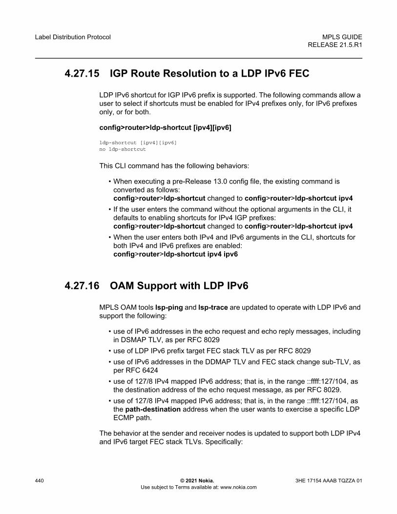
Label Distribution Protocol
440
MPLS GUIDERELEASE 21.5.R1
© 2021 Nokia. Use subject to Terms available at: www.nokia.com
3HE 17154 AAAB TQZZA 01
4.27.15 IGP Route Resolution to a LDP IPv6 FEC
LDP IPv6 shortcut for IGP IPv6 prefix is supported. The following commands allow a user to select if shortcuts must be enabled for IPv4 prefixes only, for IPv6 prefixes only, or for both.
config>router>ldp-shortcut [ipv4][ipv6]
ldp-shortcut [ipv4][ipv6]no ldp-shortcut
This CLI command has the following behaviors:
• When executing a pre-Release 13.0 config file, the existing command is converted as follows:config>router>ldp-shortcut changed to config>router>ldp-shortcut ipv4
• If the user enters the command without the optional arguments in the CLI, it defaults to enabling shortcuts for IPv4 IGP prefixes:config>router>ldp-shortcut changed to config>router>ldp-shortcut ipv4
• When the user enters both IPv4 and IPv6 arguments in the CLI, shortcuts for both IPv4 and IPv6 prefixes are enabled:config>router>ldp-shortcut ipv4 ipv6
4.27.16 OAM Support with LDP IPv6
MPLS OAM tools lsp-ping and lsp-trace are updated to operate with LDP IPv6 and support the following:
• use of IPv6 addresses in the echo request and echo reply messages, including in DSMAP TLV, as per RFC 8029
• use of LDP IPv6 prefix target FEC stack TLV as per RFC 8029• use of IPv6 addresses in the DDMAP TLV and FEC stack change sub-TLV, as
per RFC 6424• use of 127/8 IPv4 mapped IPv6 address; that is, in the range ::ffff:127/104, as
the destination address of the echo request message, as per RFC 8029. • use of 127/8 IPv4 mapped IPv6 address; that is, in the range ::ffff:127/104, as
the path-destination address when the user wants to exercise a specific LDP ECMP path.
The behavior at the sender and receiver nodes is updated to support both LDP IPv4 and IPv6 target FEC stack TLVs. Specifically:

MPLS GUIDE RELEASE 21.5.R1
Label Distribution Protocol
3HE 17154 AAAB TQZZA 01 © 2021 Nokia. Use subject to Terms available at: www.nokia.com
441
1. The IP family (IPv4/IPv6) of the UDP/IP echo request message will always match the family of the LDP target FEC stack TLV as entered by the user in the prefix option.
2. The src-ip-address option is extended to accept IPv6 address of the sender node. If the user did not enter a source IP address, the system IPv6 address will be used. If the user entered a source IP address of a different family than the LDP target FEC stack TLV, an error is returned and the test command is aborted.
3. The IP family of the UDP/IP echo reply message must match that of the received echo request message.
4. For lsp-trace, the downstream information in DSMAP/DDMAP will be encoded as the same family as the LDP control plane of the link LDP or targeted LDP session to the downstream peer.
5. The sender node inserts the experimental value of 65503 in the Router Alert Option in the echo request packet’s IPv6 header as per RFC 5350. Once a value is allocated by IANA for MPLS OAM as part of draft-ietf-mpls-oam-ipv6-rao, it will be updated.
Finally, vccv-ping and vccv-trace for a single-hop PW are updated to support IPv6 PW FEC 128 and FEC 129 as per RFC 6829. In addition, the PW OAM control word is supported with VCCV packets when the control-word option is enabled on the spoke-SDP configuration. The value of the Channel Type field is set to 0x57, which indicates that the Associated Channel carries an IPv6 packet, as per RFC 4385.
4.27.17 LDP IPv6 Interoperability Considerations
4.27.17.1 Interoperability with Implementations Compliant with RFC 7552
The SR OS implementation uses a 128-bit LSR-ID, as defined in RFC 7552, to establish an LDP IPv6 Hello adjacency and session with a peer LSR. This allows a routable system IPv6 address to be used by default to bring up the LDP task on the router and establish link LDP and T-LDP sessions to other LSRs, as is the common practice with LDP IPv4 in existing customer deployments. More importantly, this allows for the establishment of control plane independent LDP IPv4 and LDP IPv6 sessions between two LSRs over the same interface or set of interfaces. The SR OS implementation allows for multiple separate LDP IPv4 and LDP IPv6 sessions between two routers over the same interface or a set of interfaces, as long as each session uses a unique LSR-ID (32-bit for IPv4 and 128-bit for IPv6).

Label Distribution Protocol
442
MPLS GUIDERELEASE 21.5.R1
© 2021 Nokia. Use subject to Terms available at: www.nokia.com
3HE 17154 AAAB TQZZA 01
The SR OS LDP IPv6 implementation complies with the control plane procedures defined in RFC 7552 for establishing an LDP IPv6 Hello adjacency and LDP session. However, the implementation does not interoperate, by default, with third-party implementations of this standard since the latter encode a 32-bit LSR-ID in the IPv6 Hello message while SR OS encodes a 128-bit LSR-ID.
To assure interoperability in deployments strictly adhering to RFC 7552, SR OS provides the option for configuring and encoding a 32-bit LSR-ID in the LDP IPv6 Hello message. When this option is enabled, an SR OS LSR establishes an LDP IPv6 Hello adjacency and an LDP IPv6 session with an RFC 7552 compliant peer or targeted peer LSR, using a 32-bit LSR-ID and a 128-bit transport address. See LDP IPv6 32-bit LSR-ID for more information.
In a dual-stack IPv4/IPV6 interface environment, the SR OS based LSR will not originate both IPv6 and IPv4 Hello messages with the configured 32-bit LSR-ID value when both IPv4 and IPv6 contexts are enabled on the same LDP interface. This behavior is allowed in RFC 7552 for migration purposes. However, the SR OS implements separate IPv4 and IPv6 Hello adjacencies and LDP sessions with different LSR-ID values for the LDP IPv4 (32-bit value) and LDP IPv6 (32-bit or 128-bit value) Hello adjacencies. Therefore, the LDP IPv4 and LDP IPv6 sessions are independent in the control plane.
However, if the peer LSR sends both IPv4 and IPv6 Hello messages using the same 32-bit LSR-ID value, as allowed in RFC 7552, only a single LDP session with the local 32-bit LSR-ID will come up toward that peer LSR-ID, depending on which of the IPv4 or IPv6 adjacencies came up first.
The dual-stack capability TLV, in the Hello message, is used by an LSR to inform its peer that it is capable of establishing either an LDP IPv4 or LDP IPv6 session, and the IP family preference for the LDP Hello adjacency for the resulting LDP session.
Finally, the SR OS LDP implementation inter-operates with an implementation using a 32-bit LSR-ID, as defined in RFC 7552, to establish an IPv4 LDP session and to resolve both IPv4 and IPv6 prefix FECs. In this case, the dual-stack capability TLV indicates implicitly the LSR support for resolving IPv6 FECs over an IPv4 LDP session.
4.27.17.2 LDP IPv6 32-bit LSR-ID
The SR OS implementation provides the option for configuring and encoding a 32-bit LSR-ID in the LDP IPv6 Hello message to achieve interoperability in deployments strictly adhering to RFC 7552.

MPLS GUIDE RELEASE 21.5.R1
Label Distribution Protocol
3HE 17154 AAAB TQZZA 01 © 2021 Nokia. Use subject to Terms available at: www.nokia.com
443
The LSR-ID of an LDP Label Switched Router (LSR) is a 32-bit integer used to uniquely identify it in a network. SR OS also supports LDP IPv6 in both the control plane and data plane. However, the implementation uses a 128-bit LSR-ID, as defined in draft-pdutta-mpls-ldp-v2 to establish an LDP IPv6 Hello adjacency and session with a peer LSR.
The SR OS LDP IPv6 implementation complies with the control plane procedures defined in RFC 7552 for establishing an LDP IPv6 Hello adjacency and LDP session. However, the SR OS LDP IPv6 implementation does not interoperate with third-party implementations of this standard, since the latter encode a 32-bit LSR-ID in the IPv6 Hello message while SR OS encodes a 128-bit LSR-ID.
When this feature is enabled, an SR OS LSR will be able to establish an LDP IPv6 Hello adjacency and an LDP IPv6 session with an RFC 7552 compliant peer or targeted peer LSR, using a 32-bit LSR-ID and a 128-bit transport address.
4.27.17.2.1 Feature Configuration
This user configures the 32-bit LSR-ID on a LDP peer or targeted peer using the following CLI:
config>router>ldp>interface-parameters>interface>ipv6>local-lsr-id interface [32bit-format]
config>router>ldp>interface-parameters>interface>ipv6>local-lsr-id interface-name interface-name [32bit-format]
config>router>ldp>targeted-session>peer>local-lsr-id interface-name [32bit-format]
When the local-lsr-id command is enabled with the 32bit-format option, an SR OS LSR will be able to establish a LDP IPv6 Hello adjacency and a LDP IPv6 session with a RFC 7552 compliant peer or targeted peer LSR using a 32-bit LSR-ID set to the value of the IPv4 address of the specified local LSR-ID interface and a 128-bit transport address set to the value of the IPv6 address of the specified local LSR-ID interface.
Note: The system interface cannot be used as a local LSR-ID with the 32bit-format option enabled as it is the default LSR-ID and transport address for all LDP sessions to peers and targeted peers on this LSR. This configuration is blocked in CLI.

Label Distribution Protocol
444
MPLS GUIDERELEASE 21.5.R1
© 2021 Nokia. Use subject to Terms available at: www.nokia.com
3HE 17154 AAAB TQZZA 01
If the user enables the 32bit-format option in the IPv6 context of a running LDP interface or in the targeted session peer context of a running IPv6 peer, the already established LDP IPv6 Hello adjacency and LDP IPv6 session will be brought down and re-established with the new 32-bit LSR-ID value.
The detailed control plane procedures are provided in LDP LSR IPv6 Operation with 32-bit LSR-ID.
4.27.17.2.2 LDP LSR IPv6 Operation with 32-bit LSR-ID
Consider the setup shown in Figure 95.
Figure 95 LDP Adjacency and Session over IPv6 Interface
LSR A and LSR B have the following LDP parameters.
LSR A:
• Interface I/F1 : link local address = fe80::a1 • Interface I/F2 : link local address = fe80::a2• Interface LoA1: IPv4 address = <A1/32>; primary IPv6 unicast address = <A2/
128>• Interface LoA2: IPv4 address = <A3/32>; primary IPv6 unicast address = <A4/
128>• local-lsr-id (config>router>ldp>interface-parameters>interface>ipv6) =
interface LoA1; option 32bit-format enabled- LDP identifier = {<LSR Id=A1/32> : <label space id=0>}; transport address
= <A2/128>• local-lsr-id (config>>router>ldp>targeted-session>peer) = interface LoA2;
option 32bit-format enabled- LDP identifier = {<LSR Id=A3/32> : <label space id=0>}; transport address
= <A4/128>
LSR B:
• Interface I/F1 : link local address = fe80::b1 • Interface I/F2 : link local address = fe80::b2
sw0242
LS-A:0 LSR-B:0I/F 1
I/F 2

MPLS GUIDE RELEASE 21.5.R1
Label Distribution Protocol
3HE 17154 AAAB TQZZA 01 © 2021 Nokia. Use subject to Terms available at: www.nokia.com
445
• Interface LoB1: IPv4 address = <B1/32>; primary IPv6 unicast address = <B2/128>
• Interface LoB2: IPv4 address = <B3/32>; primary IPv6 unicast address = <B4/128>
• local-lsr-id (config>router>ldp>interface-parameters>interface>ipv6) = interface LoB1; option 32bit-format enabled- LDP identifier = {<LSR Id=B1/32> : <label space id=0>}; transport address
= <B2/128>• local-lsr-id (config>router>ldp>targeted-session>peer) = interface LoB2;
option 32bit-format enabled- LDP identifier = {<LSR Id=B3/32> : <label space id=0>}; transport address
= <B4/128>
Link LDP
When the IPv6 context of interfaces I/F1 and I/F2 are brought up, the following procedures are performed.
• LSR A (LSR B) sends a IPv6 Hello message with source IP address set to the link-local unicast address of the specified local LSR ID interface, for example, fe80::a1 (fe80::a2), and a destination IP address set to the link-local multicast address ff02:0:0:0:0:0:0:2.
• LSR A (LSR B) sets the LSR-ID in LDP identifier field of the common LDP PDU header to the 32-bit IPv4 address of the specified local LSR-ID interface LoA1 (LoB1), for example, A1/32 (B1/32). If the specified local LSR-ID interface is unnumbered or does not have an IPv4 address configured, the adjacency will not come up and an error will be returned (lsrInterfaceNoValidIp (17) in output of 'show router ldp interface detail').
• LSR A (LSR B) sets the transport address TLV in the Hello message to the IPv6 address of the specified local LSR-ID interface LoA1 (LoB1), for example, A2/128 (B2/128).If the specified local LSR-ID interface is unnumbered or does not have an IPv6 address configured, the adjacency will not come up and an error will be returned (interfaceNoValidIp (16) in output of 'show router ldp interface detail'.
• LSR A (LSR B) includes in each IPv6 Hello message the dual-stack TLV with the transport connection preference set to IPv6 family.- If the peer is a third-party LDP IPv6 implementation and does not include
the dual-stack TLV, then LSR A (LSR B) resolves IPv6 FECs only because IPv6 addresses will not be advertised in Address messages as per RFC 7552 [ldp-ipv6-rfc].

Label Distribution Protocol
446
MPLS GUIDERELEASE 21.5.R1
© 2021 Nokia. Use subject to Terms available at: www.nokia.com
3HE 17154 AAAB TQZZA 01
- If the peer is a third-party LDP IPv6 implementation and includes the dual-stack TLV with transport connection preference set to IPv4, LSR A (LSR B) will not bring up the Hello adjacency and discard the Hello message. If the LDP session was already established, then LSRA(B) will send a fatal Notification message with status code of 'Transport Connection Mismatch' (0x00000032)' and restart the LDP session [ldp-ipv6-rfc]. In both cases, a new counter for the transport connection mismatches will be incremented in the output of 'show router ldp statistics'.
• The LSR with highest transport address takes on the active role and initiates the TCP connection for the LDP IPv6 session using the corresponding source and destination IPv6 transport addresses.
Targeted LDP
Similarly, when the new option is invoked on a targeted IPv6 peer, the router sends a IPv6 targeted Hello message with source IP address set to the global unicast IPv6 address corresponding to the primary IPv6 address of the specified interface and a destination IP address set to configured IPv6 address of the peer. The LSR-ID field in the LDP identifier in the common LDP PDU header is set the 32-bit address of the specified interface. If the specified interface does not have an IPv4 address configured the adjacency will not come up. Any subsequent adjacency or session level messages will be sent with the common LDP PDU header set as above.
When the targeted IPv6 peer contexts are brought up, the following procedures are performed.
• LSR A (LSR B) sends a IPv6 Hello message with source IP address set to the primary IPv6 unicast address of the specified local LSR ID interface LoA2(LoB2), for example, A4/128 (B4/128), and a destination IP address set to the peer address B4/128(A4/128).
• LSR A (LSR B) sets the LSR-ID in LDP identifier field of the common LDP PDU header to the 32-bit IPv4 address of the specified local LSR-ID interface LoA2(LoB2), for example, A3/32 (B3/32). If the specified local LSR-ID interface is unnumbered or does not have an IPv4 address configured, the adjacency will not come up and an error will be returned.
• LSR A (LSR B) sets the transport address TLV in the Hello message to the IPv6 address of the specified local LSR-ID interface LoA2 (LoB2), for example, A4/128 (B4/128).If the specified local LSR-ID interface is unnumbered or does not have an IPv6 address configured, the adjacency will not come up and an error will be returned.
• LSR A (LSR B) includes in each IPv6 Hello message the dual-stack TLV with the preference set to IPv6 family.

MPLS GUIDE RELEASE 21.5.R1
Label Distribution Protocol
3HE 17154 AAAB TQZZA 01 © 2021 Nokia. Use subject to Terms available at: www.nokia.com
447
- If the peer is a third-party LDP IPv6 implementation and does not include the dual-stack TLV, then LSR A (LSR B) resolves IPv6 FECs only since IPv6 addresses will not be advertised in Address messages as per RFC 7552 [ldp-ipv6-rfc].
- If the peer is a third-party LDP IPv6 implementation and includes the dual-stack TLV with transport connection preference set to IPv4, LSR A (LSR B) will not bring up the Hello adjacency and discard the Hello message. If the LDP session was already established, then LSRA(B) will send a fatal Notification message with status code of 'Transport Connection Mismatch' (0x00000032)' and restart the LDP session [ldp-ipv6-rfc]. In both cases, a new counter for the transport connection mismatches will be incremented in the output of 'show router ldp statistics'.
• The LSR with highest transport address takes on the active role and initiates the TCP connection for the LDP IPv6 session using the corresponding source and destination IPv6 transport addresses.
Link and Targeted LDP Feature Interaction
The following describes feature interactions.
• LSR A (LSR B) will not originate both IPv6 and IPv4 Hello messages with the configured 32-bit LSR-ID value when both IPv4 and IPv6 contexts are enabled on the same LDP interface (dual-stack LDP IPv4/IPv6). This behavior is allowed in RFC 7552 for migration purposes but SR OS implements separate IPv4 and IPv6 Hello adjacencies and LDP sessions with different LSR-ID values. Therefore, an IPv6 context which uses a 32-bit LSR-ID address matching that of the IPv4 context on the same interface will not be allowed to be brought up (no shutdown will fail) and vice-versa. Furthermore, an IPv6 context of any interface or targeted peer which uses a 32-bit LSR-ID address matching that of an IPv4 context of any other interface, an IPv6 context of any other interface using 32-bit LSR-ID, a targeted IPv4 peer, a targeted IPv6 peer using 32-bit LSR-ID, or an auto T-LDP IPv4 template on the same router will not be allowed to be brought up (no shutdown will fail) and vice-versa.
• With the introduction of a 32-bit LSR-ID for a IPv6 LDP interface or peer, it is possible to configure the same IPv6 transport address for an IPv4 LSR-ID and an IPv6 LSR-ID on the same node. For instance, assume the following configuration:- Interface I/F1:
• local-lsr-id (config>router>ldp>interface-parameters>interface>ipv6) = interface LoA1; option 32bit-format enabled.

Label Distribution Protocol
448
MPLS GUIDERELEASE 21.5.R1
© 2021 Nokia. Use subject to Terms available at: www.nokia.com
3HE 17154 AAAB TQZZA 01
• LDP identifier = {<LSR Id=A1/32> : <label space id=0>}; transport address = <A2/128>
- Interface I/F2:• local-lsr-id (config>router>ldp>interface-
parameters>interface>ipv6) = interface LoA1;• LDP identifier = {<LSR Id=A2/128> : <label space id=0>}; transport
address = <A2/128> - Targeted Session:
• local-lsr-id (config>router>ldp> targeted-session>peer) = interface LoA1;
• LDP identifier = {<LSR Id=A2/128> : <label space id=0>}; transport address = <A2/128>
The above configuration will result in two interfaces and a targeted session with the same local end transport IPv6 address but the local LSR-ID for interface I/F1 is different.If an IPv6 Hello adjacency over interface I/F1 towards a given peer comes up first and initiates an IPv6 LDP session, then the other two Hello adjacencies to the same peer will not come up.If one of the IPv6 Hello adjacencies of interface I/F2 or Targeted Session 1 comes up first to a peer, it will trigger an IPv6 LDP session shared by both these adjacencies and the Hello adjacency over interface I/F1 to the same peer will not come up.
4.27.17.2.3 Migration Considerations
Migrating Services from LDP IPv4 Session to 32-bit LSR-ID LDP IPv6 Session
Assume the user deploys on a SR OS based LSR a service bound to a SDP which auto-creates the IPv4 targeted LDP session to a peer LSR running a third party LDP implementation. In this case, the auto-created T-LDP session uses the system interface IPv4 address as the local LSR-ID and as the local transport address because there is no targeted session configured in LDP to set these parameters away from default values.

MPLS GUIDE RELEASE 21.5.R1
Label Distribution Protocol
3HE 17154 AAAB TQZZA 01 © 2021 Nokia. Use subject to Terms available at: www.nokia.com
449
When both LSR nodes are being migrated to using LDP IPv6 with a 32-bit LSR-ID, the user must configure the IPv6 context of the local LDP interfaces to use a local LSR-ID interface different than the system interface and with the 32bit-format option enabled. Similarly, the user must configure a new Targeted session in LDP with that same local LSR-ID interface and with the 32bit-format option enabled. This will result in a LDP IPv6 session triggered by the link LDP IPv6 Hello adjacency or the targeted IPv6 Hello adjacency which came up first. This LDP IPv6 session uses the IPv4 address and the IPv6 address of the configured local LSR-ID interface as the LSR-ID and transport address respectively.
The user must then modify the service configuration on both ends to use a far-end address matching the far-end IPv6 transport address of the LDP IPv6 session. On the SR OS based LSR, this can be done by creating a new IPv6 SDP of type LDP with the far-end address matching the far-end IPv6 transport address.
If the service enabled PW redundancy, the migration may be eased by creating a standby backup PW bound to the IPv6 SDP and adding it to the same VLL or VPLS endpoint the spoke-sdp bound to the IPv4 SDP belongs to. Then, activate the backup PW using the command 'tools>perform>service>id>endpoint>force-switchover sdp-id:vc-id'. This make the spoke-sdp bound to the IPv6 SDP the primary PW. Finally, the spoke-sdp bound to the IPv4 SDP can be deleted.
4.27.17.3 Interoperability with Implementations Compliant with RFC 5036 for IPv4 LDP Control Plane Only
The SR OS implementation supports advertising and resolving IPv6 prefix FECs over an LDP IPv4 session using a 32-bit LSR-ID, in compliance with RFC 7552. When introducing an LSR based on the SR OS in a LAN with a broadcast interface, it can peer with third-party LSR implementations that support RFC 7552 and LSRs that do not. When it peers, using an IPv4 LDP control plane, with a third-party LSR implementation that does not support it, the advertisement of IPv6 addresses or IPv6 FECs to that peer may cause it to bring down the IPv4 LDP session.
That is, there are deployed third-party LDP implementations that are compliant with RFC 5036 for LDP IPv4, but that are not compliant with RFC 5036 for handling IPv6 address or IPv6 FECs over an LDP IPv4 session. To resolve this issue, RFC 7552 modifies RFC 5036 by requiring implementations complying with RFC 7552 to check for the dual-stack capability TLV in the IPv4 Hello message from the peer. Without the peer advertising this TLV, an LSR must not send IPv6 addresses and FECs to that peer. The SR OS implementation supports this requirement.

Label Distribution Protocol
450
MPLS GUIDERELEASE 21.5.R1
© 2021 Nokia. Use subject to Terms available at: www.nokia.com
3HE 17154 AAAB TQZZA 01
4.28 LDP Process Overview
Figure 96 displays the process to provision basic LDP parameters.
Figure 96 LDP Configuration and Implementation
MPLS_01
(*) if some of the needed resources are not available consider implementing stricter import-policies and/or enabling the per-peer fec-limit functionality.
Start
Create an LDP Instance in admin shutdown state
Check that any ILM/LTN/NHLFE resources are available in relationship with theamount of LDP FECs, peers, and policies the node is expected to manage.(*)
If applicable, apply LDP global Import/Export policies
Configure session parameters (such as policies, lbl-distribution,capabilities, and so on.)
If applicable, apply tcp-session-parameters (such as security, path-mtu, ttl)
Configure interface parameters (such as v4, v6, hello,keepalive, transport-address, bfd, and so on.)
Configure targeted-session (such as policies, auto-tldp-templates,bfd, hello, keepalive, lsr-id, and so on.)
Complete LDP instance tuning with ttl settings, moFrr/Frr, implicit-null,graceful-restart (if needed), stitching to BGP or SR, egress-stats, and so on.
Admin no shut the LDP Instance
After a period of time, to allow the TCP sessions to be established andthe FECs to be exchanged, check that no session has gone in overload(if supported by peer) or has been operationally shutdown because of
resource exhaustions.
Observe no errors in the [show router ldp statistics] protocol stats
End

MPLS GUIDE RELEASE 21.5.R1
Label Distribution Protocol
3HE 17154 AAAB TQZZA 01 © 2021 Nokia. Use subject to Terms available at: www.nokia.com
451
4.29 Configuring LDP with CLI
This section provides information to configure LDP using the command line interface.
4.29.1 LDP Configuration Overview
When the implementation of LDP is instantiated, the protocol is in the no shutdown state. In addition, targeted sessions are then enabled. The default parameters for LDP are set to the documented values for targeted sessions in draft-ietf-mpls-ldp-mib-09.txt.
LDP must be enabled in order for signaling to be used to obtain the ingress and egress labels in frames transmitted and received on the service distribution path (SDP). When signaling is off, labels must be manually configured when the SDP is bound to a service.
4.29.2 Basic LDP Configuration
This section provides information to configure LDP and remove configuration examples of common configuration tasks.
The LDP protocol instance is created in the no shutdown (enabled) state.
The following displays the default LDP configuration.
A:ALA-1>config>router>ldp# info----------------------------------------------
session-parametersexitinterface-parametersexittargeted-sessionexitno shutdown
----------------------------------------------A:ALA-1>config>router>ldp#
4.29.3 Common Configuration Tasks
This section provides an overview of the tasks to configure LDP and provides the CLI commands.

Label Distribution Protocol
452
MPLS GUIDERELEASE 21.5.R1
© 2021 Nokia. Use subject to Terms available at: www.nokia.com
3HE 17154 AAAB TQZZA 01
4.29.3.1 Enabling LDP
LDP must be enabled in order for the protocol to be active. MPLS does not need to be enabled on the router except if the network interface uses the Packet over Sonet (POS) encapsulation (Sonet path encapsulation type set to ppp-auto). In this case, MPLS must be enabled and the interface name added into MPLS to allow for the MPLSCP to come up on the PPP link between the two peers and for MPLS to be used on the interface. MPLS is enabled in the config>router>mpls context.
Use the following syntax to enable LDP on a router:
CLI Syntax: ldp
Example: config>router# ldp
The following displays the enabled LDP configuration.
A:ALA-1>config>router# info----------------------------------------------...#------------------------------------------echo "LDP Configuration"#------------------------------------------
ldpsession-parametersexitinterface-parametersexittargeted-sessionexit
exit----------------------------------------------...A:ALA-1>config>router#
4.29.3.2 Configuring FEC Originate Parameters
A FEC can be added to the LDP IP prefix database with a specific label operation on the node. Permitted operations are pop or swap. For a swap operation, an incoming label can be swapped with a label in the range of 16 to 1048575. If a swap- label is not configured then the default value is 3.
A route table entry is required for a FEC with a pop operation to be advertised. For a FEC with a swap operation, a route-table entry must exist and user configured next-hop for swap operation must match one of the next-hops in route-table entry.
Use the following syntax to configure FEC originate parameters:

MPLS GUIDE RELEASE 21.5.R1
Label Distribution Protocol
3HE 17154 AAAB TQZZA 01 © 2021 Nokia. Use subject to Terms available at: www.nokia.com
453
CLI Syntax: config>router>ldpfec-originate ip-prefix/mask [advertised-label in-label] next-hop ip-address [swap-label out-label]
fec-originate ip-prefix/mask [advertised-label in-label] pop
The following displays a FEC originate configuration example.
A:ALA-5>config>router# info----------------------------------------------
fec-originate 10.1.1.1/32 popfec-originate 10.1.2.1/32 advertised-label 1000 next-hop 10.10.1.2fec-originate 10.1.3.1/32 advertised-label 1001 next-hop 10.10.2.3
swap-label 131071session-parametersexitinterface-parametersexittargeted-sessionexit
exit----------------------------------------------A:ALA-5>config>router>ldp#
4.29.3.3 Configuring Graceful-Restart Helper Parameters
Graceful-restart helper advertises to its LDP neighbors by carrying the fault tolerant (FT) session TLV in the LDP initialization message, assisting the LDP in preserving its IP forwarding state across the restart. Nokia’s recovery is self-contained and relies on information stored internally to self-heal. This feature is only used to help third-party routers without a self-healing capability to recover.
Maximum recovery time is the time (in seconds) the sender of the TLV would like the receiver to wait, after detecting the failure of LDP communication with the sender.
Neighbor liveness time is the time (in seconds) the LSR is willing to retain its MPLS forwarding state. The time should be long enough to allow the neighboring LSRs to re-sync all the LSPs in a graceful manner, without creating congestion in the LDP control plane.
Use the following syntax to configure graceful-restart parameters:
CLI Syntax: config>router>ldp
[no] graceful-restart

Label Distribution Protocol
454
MPLS GUIDERELEASE 21.5.R1
© 2021 Nokia. Use subject to Terms available at: www.nokia.com
3HE 17154 AAAB TQZZA 01
4.29.3.4 Applying Export and Import Policies
Both inbound and outbound label binding filtering are supported. Inbound filtering allows a route policy to control the label bindings an LSR accepts from its peers. An import policy can accept or reject label bindings received from LDP peers.
Label bindings can be filtered based on:
• Neighbor — Match on bindings received from the specified peer.• Prefix-list — Match on bindings with the specified prefix/prefixes.
Outbound filtering allows a route policy to control the set of LDP label bindings advertised by the LSR. An export policy can control the set of LDP label bindings advertised by the router. By default, label bindings for only the system address are advertised and propagate all FECs that are received. All other local interface FECs can be advertised using policies.
Matches can be based on:
• All — all local subnets.• Match — match on bindings with the specified prefix/prefixes.
Use the following syntax to apply import and export policies:
CLI Syntax: config>router>ldpexport policy-name [policy-name...(upto 32 max)]import policy-name [policy-name...(upto 32 max)]
The following displays export and import policy configuration examples.
A:ALA-1>config>router# info----------------------------------------------
export "LDP-export"fec-originate 192.168.1.1/32 popfec-originate 192.168.2.1/32 advertised-label 1000 next-hop 10.10.1.2import "LDP-import"session-parametersexitinterface-parametersexittargeted-sessionexit
----------------------------------------------A:ALA-1>config>router#
Note: Static FECs cannot be blocked using an export policy.

MPLS GUIDE RELEASE 21.5.R1
Label Distribution Protocol
3HE 17154 AAAB TQZZA 01 © 2021 Nokia. Use subject to Terms available at: www.nokia.com
455
4.29.3.5 Targeted Session Parameters
Use the following syntax to specify targeted-session parameters:
CLI Syntax: config>router# ldptargeted-session
disable-targeted-sessionexport-prefixes policy-name [policy-name...(up to 5
max)]ipv4
hello timeout factorkeepalive timeout factor
import-prefixes policy-name [policy-name...(up to 5 max)]
peer ip-addresshello timeout factorkeepalive timeout factorno shutdowntunneling
lsp lsp-name
The following example displays an LDP configuration example:
A:ALA-1>config>router>ldp# info----------------------------------------------...
targeted-sessionipv4
hello 120 3keepalive 120 3
exitpeer 10.10.10.104
hello 240 3keepalive 240 3
exitexit
----------------------------------------------A:ALA-1>config>router>ldp#
4.29.3.6 Interface Parameters
Use the following syntax to configure interface parameters:
CLI Syntax: config>router# ldpinterface-parameters
interface ip-int-name [dual stack]bfd-enable [ipv4][ipv6]ipv4/ipv6

Label Distribution Protocol
456
MPLS GUIDERELEASE 21.5.R1
© 2021 Nokia. Use subject to Terms available at: www.nokia.com
3HE 17154 AAAB TQZZA 01
hello timeout factorkeepalive timeout factortransport-address {system | interface}
no shutdownipv4/ipv6
hello timeout factorkeepalive timeout factortransport-address {system | interface}
The following example displays an interface parameter configuration example:
A:ALA-1>config>router>ldp# info----------------------------------------------...
interface-parametersinterface "to-DUT1" dual-stack
ipv4hello 240 3keepalive 240 3
exitexit
exit----------------------------------------------A:ALA-1>config>router>ldp#
4.29.3.7 Session Parameters
Use the following syntax to specify session parameters:
CLI Syntax: config>router# ldpsession-parameters
peer ip-addresstcp-session-parameters
peer transport ip-addressauth-keychain nameauthentication-key [authentication-key | hash-key]
[hash | hash2 | custom]ttl-security min-ttl-value [log log-id]
The following example displays an LDP configuration example:
A:ALA-1>config>router>ldp# info----------------------------------------------
export "LDP-export"import "LDP-import"session-parameters
peer 10.1.1.1exitpeer 10.10.10.104exit

MPLS GUIDE RELEASE 21.5.R1
Label Distribution Protocol
3HE 17154 AAAB TQZZA 01 © 2021 Nokia. Use subject to Terms available at: www.nokia.com
457
exittcp-session-parameters
peer-transport 10.10.10.104authentication-key "E7GtYNZHTAaQqVMRDbfNIZpLtHg4ECOk" hash2
exitexitinterface-parameters
interface "to-DUT1" dual-stackipv4
hello 240 3keepalive 240 3
exitexit
exittargeted-session
ipv4hello 120 3keepalive 120 3
exitpeer 10.10.10.104
hello 240 3keepalive 240 3
exitexit
----------------------------------------------A:ALA-1>config>router>ldp#
4.29.3.8 LDP Signaling and Services
When LDP is enabled, targeted sessions can be established to create remote adjacencies with nodes that are not directly connected. When service distribution paths (SDPs) are configured, extended discovery mechanisms enable LDP to send periodic targeted hello messages to the SDP far-end point. The exchange of LDP hellos trigger session establishment. The SDP signaling default enables tldp. The service SDP uses the targeted-session parameters configured in the config>router>ldp>targeted-session context.
The SDP LDP and LSP commands are mutually exclusive; either one LSP can be specified or LDP can be enabled. If LDP is already enabled on an MPLS SDP, then an LSP cannot be specified on the SDP. If an LSP is specified on an MPLS SDP, then LDP cannot be enabled on the SDP.
To enable LDP on the SDP when an LSP is already specified, the LSP must be removed from the configuration using the no lsp lsp-name command. For more information about configuring SDPs, refer to the 7450 ESS, 7750 SR, 7950 XRS, and VSR Services Overview Guide.
The following example displays the command syntax usage to configure enable LDP on an MPLS SDP:

Label Distribution Protocol
458
MPLS GUIDERELEASE 21.5.R1
© 2021 Nokia. Use subject to Terms available at: www.nokia.com
3HE 17154 AAAB TQZZA 01
CLI Syntax: config>service>sdp#ldpsignaling {off | tldp}
The following displays an example of an SDP configuration showing the signaling default tldp enabled.
A:ALA-1>config>service>sdp# info detail----------------------------------------------
description "MPLS: to-99"far-end 10.10.10.99signaling tldppath-mtu 4462keep-alive
hello-time 10hold-down-time 10max-drop-count 3timeout 5no message-lengthno shutdown
exitno shutdown
----------------------------------------------A:ALA-1>config>service>sdp#
The following displays an example of an SDP configuration for the 7750 SR, showing the signaling default tldp enabled.
A:ALA-1>config>service>sdp# info detail----------------------------------------------
description "MPLS: to-99"far-end 10.10.10.99ldpsignaling tldppath-mtu 4462keep-alive
hello-time 10hold-down-time 10max-drop-count 3timeout 5no message-lengthno shutdown
exitno shutdown
----------------------------------------------A:ALA-1>config>service>sdp#
The following shows a working configuration of LDP over RSVP-TE (1) where tunnels look like the second example (2):
Example 1: LDP over RSVP-TE
*A:ALA-1>config>router>ldp# info----------------------------------------------
prefer-tunnel-in-tunnel

MPLS GUIDE RELEASE 21.5.R1
Label Distribution Protocol
3HE 17154 AAAB TQZZA 01 © 2021 Nokia. Use subject to Terms available at: www.nokia.com
459
interface-parametersinterface "port-1/1/3"exitinterface "port-lag-1"exit
exittargeted-session
peer 10.51.0.1shutdowntunneling
lsp "to_P_1"exit
exitpeer 10.51.0.17
shutdowntunneling
lsp "to_P_6"exit
exitexit
----------------------------------------------*A:ALA-1>config>router>ldp#
Example 2: Tunnels
ALA-1>config>router>if-attr# info----------------------------------------------
admin-group "lower" value 2admin-group "upper" value 1----------------------------------------------*A:ALA-1>config>router>mpls# info----------------------------------------------
resignal-timer 30interface "system"exitinterface "port-1/1/3"exitinterface "port-lag-1"exitpath "dyn"
no shutdownexitlsp "to_P_1"
to 10.51.0.1cspffast-reroute facilityexitprimary "dyn"exitno shutdown
exitlsp "to_P_6"
to 10.51.0.17cspffast-reroute facilityexitprimary "dyn"

Label Distribution Protocol
460
MPLS GUIDERELEASE 21.5.R1
© 2021 Nokia. Use subject to Terms available at: www.nokia.com
3HE 17154 AAAB TQZZA 01
exitno shutdown
exitno shutdown
----------------------------------------------*A:ALA-1>config>router>mpls#

MPLS GUIDE RELEASE 21.5.R1
Label Distribution Protocol
3HE 17154 AAAB TQZZA 01 © 2021 Nokia. Use subject to Terms available at: www.nokia.com
461
4.30 LDP Configuration Management Tasks
This section discusses LDP configuration management tasks.
4.30.1 Disabling LDP
The no ldp command disables the LDP protocol on the router. All parameters revert to the default settings. LDP must be shut down before it can be disabled.
Use the following command syntax to disable LDP:
CLI Syntax: no ldpshutdown
4.30.2 Modifying Targeted Session Parameters
The modification of LDP targeted session parameters does not take effect until the next time the session goes down and is re-establishes. Individual parameters cannot be deleted. The no form of a targeted-session parameter command reverts modified values back to the default. Different default parameters can be configured for IPv4 and IPv6 LDP targeted hello adjacencies.
The following example displays the command syntax usage to revert targeted session parameters back to the default values:
Example: config>router# ldpconfig>router>ldp# targeted-sessionconfig>router>ldp>tcp-session-params>peer# no authentication-key
config>router>ldp>targ-session# no disable-targeted-session
config>router>ldp>targ-session>ipv4# no hello config>router>ldp>targ-session>ipv4# no keepalive config>router>ldp>targ-session# no peer 10.10.10.104
The following output displays the default values:
A:ALA-1>config>router>ldp>targeted# info detail----------------------------------------------
no disable-targeted-sessionno import-prefixesno export-prefixes
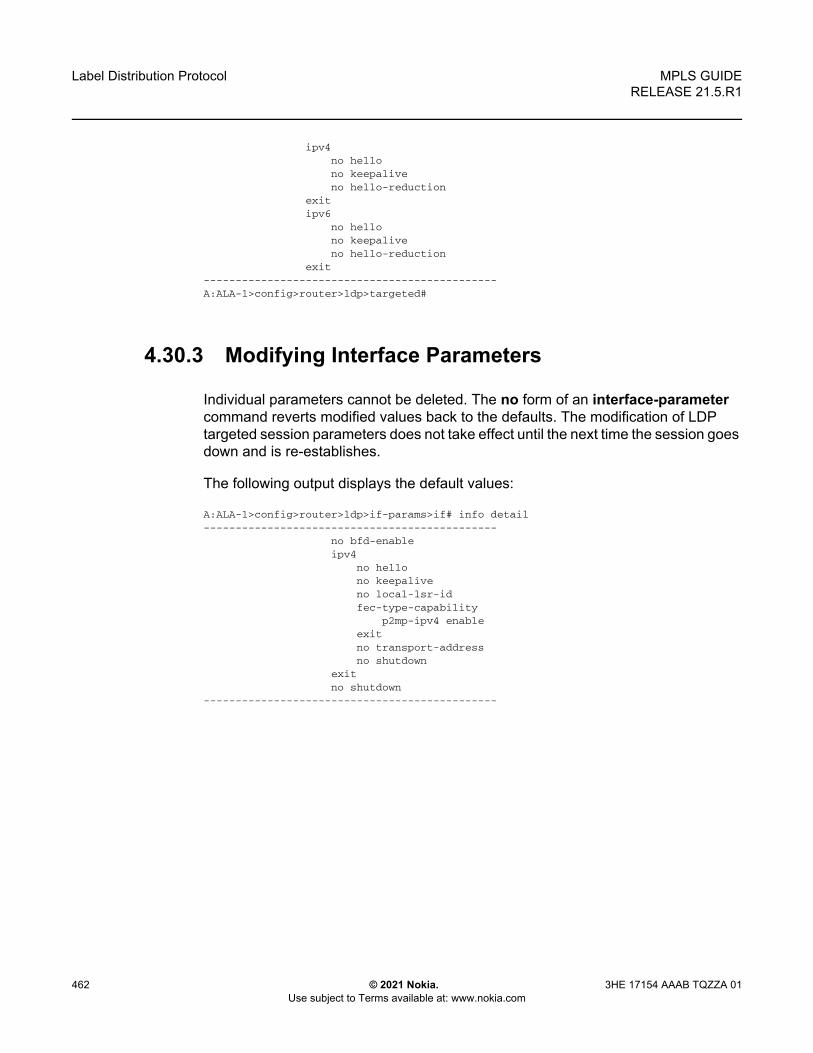
Label Distribution Protocol
462
MPLS GUIDERELEASE 21.5.R1
© 2021 Nokia. Use subject to Terms available at: www.nokia.com
3HE 17154 AAAB TQZZA 01
ipv4no hellono keepaliveno hello-reduction
exitipv6
no hellono keepaliveno hello-reduction
exit----------------------------------------------A:ALA-1>config>router>ldp>targeted#
4.30.3 Modifying Interface Parameters
Individual parameters cannot be deleted. The no form of an interface-parameter command reverts modified values back to the defaults. The modification of LDP targeted session parameters does not take effect until the next time the session goes down and is re-establishes.
The following output displays the default values:
A:ALA-1>config>router>ldp>if-params>if# info detail----------------------------------------------
no bfd-enableipv4
no hellono keepaliveno local-lsr-idfec-type-capability
p2mp-ipv4 enableexitno transport-addressno shutdown
exitno shutdown
----------------------------------------------

MPLS GUIDE RELEASE 21.5.R1
Standards and Protocol Support
3HE 17154 AAAB TQZZA 01 © 2021 Nokia. Use subject to Terms available at: www.nokia.com
463
5 Standards and Protocol Support
Access Node Control Protocol (ANCP)draft-ietf-ancp-protocol-02, Protocol for Access Node Control Mechanism in
Broadband NetworksRFC 5851, Framework and Requirements for an Access Node Control Mechanism
in Broadband Multi-Service Networks
Application Assurance (AA)3GPP Release 12, ADC rules over Gx interfacesRFC 3507, Internet Content Adaptation Protocol (ICAP)
Asynchronous Transfer Mode (ATM)AF-ILMI-0065.000 Version 4.0, Integrated Local Management Interface (ILMI)AF-PHY-0086.001 Version 1.1, Inverse Multiplexing for ATM (IMA) SpecificationAF-TM-0121.000 Version 4.1, Traffic Management SpecificationGR-1113-CORE Issue 1, Asynchronous Transfer Mode (ATM) and ATM Adaptation
Layer (AAL) Protocols Generic RequirementsGR-1248-CORE Issue 3, Generic Requirements for Operations of ATM Network
Elements (NEs)RFC 1626, Default IP MTU for use over ATM AAL5RFC 2684, Multiprotocol Encapsulation over ATM Adaptation Layer 5
Bidirectional Forwarding Detection (BFD)draft-ietf-idr-bgp-ls-sbfd-extensions-01, BGP Link-State Extensions for Seamless
BFDRFC 5880, Bidirectional Forwarding Detection (BFD)RFC 5881, Bidirectional Forwarding Detection (BFD) IPv4 and IPv6 (Single Hop)RFC 5882, Generic Application of Bidirectional Forwarding Detection (BFD)RFC 5883, Bidirectional Forwarding Detection (BFD) for Multihop Paths
Note: The information provided in this chapter is subject to change without notice and may not apply to all platforms.
Nokia assumes no responsibility for inaccuracies.

Standards and Protocol Support
464
MPLS GUIDERELEASE 21.5.R1
© 2021 Nokia. Use subject to Terms available at: www.nokia.com
3HE 17154 AAAB TQZZA 01
RFC 7130, Bidirectional Forwarding Detection (BFD) on Link Aggregation Group (LAG) Interfaces
RFC 7880, Seamless Bidirectional Forwarding Detection (S-BFD)RFC 7881, Seamless Bidirectional Forwarding Detection (S-BFD) for IPv4, IPv6, and
MPLSRFC 7883, Advertising Seamless Bidirectional Forwarding Detection (S-BFD)
Discriminators in IS-ISRFC 7884, OSPF Extensions to Advertise Seamless Bidirectional Forwarding
Detection (S-BFD) Target Discriminators
Border Gateway Protocol (BGP)draft-hares-idr-update-attrib-low-bits-fix-01, Update Attribute Flag Low Bits
Clarificationdraft-ietf-idr-add-paths-guidelines-08, Best Practices for Advertisement of Multiple
Paths in IBGPdraft-ietf-idr-best-external-03, Advertisement of the best external route in BGPdraft-ietf-idr-bgp-flowspec-oid-03, Revised Validation Procedure for BGP Flow
Specificationsdraft-ietf-idr-bgp-gr-notification-01, Notification Message support for BGP Graceful
Restartdraft-ietf-idr-bgp-ls-app-specific-attr-01, Application Specific Attributes
Advertisement with BGP Link-Statedraft-ietf-idr-bgp-optimal-route-reflection-10, BGP Optimal Route Reflection (BGP-
ORR)draft-ietf-idr-error-handling-03, Revised Error Handling for BGP UPDATE Messagesdraft-ietf-idr-flowspec-interfaceset-03, Applying BGP flowspec rules on a specific
interface setdraft-ietf-idr-flowspec-path-redirect-05, Flowspec Indirection-id Redirect - localised
IDdraft-ietf-idr-flowspec-redirect-ip-02, BGP Flow-Spec Redirect to IP Actiondraft-ietf-idr-link-bandwidth-03, BGP Link Bandwidth Extended Communitydraft-ietf-idr-long-lived-gr-00, Support for Long-lived BGP Graceful Restartdraft-ietf-sidr-origin-validation-signaling-04, BGP Prefix Origin Validation State
Extended CommunityRFC 1772, Application of the Border Gateway Protocol in the InternetRFC 1997, BGP Communities AttributeRFC 2385, Protection of BGP Sessions via the TCP MD5 Signature OptionRFC 2439, BGP Route Flap DampingRFC 2545, Use of BGP-4 Multiprotocol Extensions for IPv6 Inter-Domain Routing

MPLS GUIDE RELEASE 21.5.R1
Standards and Protocol Support
3HE 17154 AAAB TQZZA 01 © 2021 Nokia. Use subject to Terms available at: www.nokia.com
465
RFC 2858, Multiprotocol Extensions for BGP-4RFC 2918, Route Refresh Capability for BGP-4RFC 3107, Carrying Label Information in BGP-4RFC 4271, A Border Gateway Protocol 4 (BGP-4)RFC 4360, BGP Extended Communities AttributeRFC 4364, BGP/MPLS IP Virtual Private Networks (VPNs)RFC 4456, BGP Route Reflection: An Alternative to Full Mesh Internal BGP (IBGP)RFC 4486, Subcodes for BGP Cease Notification MessageRFC 4659, BGP-MPLS IP Virtual Private Network (VPN) Extension for IPv6 VPNRFC 4684, Constrained Route Distribution for Border Gateway Protocol/
MultiProtocol Label Switching (BGP/MPLS) Internet Protocol (IP) Virtual Private Networks (VPNs)
RFC 4724, Graceful Restart Mechanism for BGP - helper modeRFC 4760, Multiprotocol Extensions for BGP-4RFC 4798, Connecting IPv6 Islands over IPv4 MPLS Using IPv6 Provider Edge
Routers (6PE)RFC 5004, Avoid BGP Best Path Transitions from One External to AnotherRFC 5065, Autonomous System Confederations for BGPRFC 5291, Outbound Route Filtering Capability for BGP-4RFC 5396, Textual Representation of Autonomous System (AS) Numbers - asplainRFC 5492, Capabilities Advertisement with BGP-4RFC 5549, Advertising IPv4 Network Layer Reachability Information with an IPv6
Next HopRFC 5575, Dissemination of Flow Specification RulesRFC 5668, 4-Octet AS Specific BGP Extended CommunityRFC 6286, Autonomous-System-Wide Unique BGP Identifier for BGP-4RFC 6793, BGP Support for Four-Octet Autonomous System (AS) Number SpaceRFC 6810, The Resource Public Key Infrastructure (RPKI) to Router ProtocolRFC 6811, Prefix Origin ValidationRFC 6996, Autonomous System (AS) Reservation for Private UseRFC 7311, The Accumulated IGP Metric Attribute for BGPRFC 7607, Codification of AS 0 ProcessingRFC 7674, Clarification of the Flowspec Redirect Extended CommunityRFC 7752, North-Bound Distribution of Link-State and Traffic Engineering (TE)
Information Using BGPRFC 7854, BGP Monitoring Protocol (BMP)RFC 7911, Advertisement of Multiple Paths in BGPRFC 7999, BLACKHOLE Community

Standards and Protocol Support
466
MPLS GUIDERELEASE 21.5.R1
© 2021 Nokia. Use subject to Terms available at: www.nokia.com
3HE 17154 AAAB TQZZA 01
RFC 8092, BGP Large Communities AttributeRFC 8212, Default External BGP (EBGP) Route Propagation Behavior without
PoliciesRFC 8571, BGP - Link State (BGP-LS) Advertisement of IGP Traffic Engineering
Performance Metric Extensions
Broadband Network Gateway (BNG) - Control and User Plane Separation (CUPS)3GPP 23.007, Restoration procedures3GPP 29.244, Interface between the Control Plane and the User Plane nodes3GPP 29.281, General Packet Radio System (GPRS) Tunnelling Protocol User
Plane (GTPv1-U)BBF TR-459, Control and User Plane Separation for a Disaggregated BNGRFC 8300, Network Service Header (NSH)
Circuit EmulationRFC 4553, Structure-Agnostic Time Division Multiplexing (TDM) over Packet
(SAToP)RFC 5086, Structure-Aware Time Division Multiplexed (TDM) Circuit Emulation
Service over Packet Switched Network (CESoPSN)RFC 5287, Control Protocol Extensions for the Setup of Time-Division Multiplexing
(TDM) Pseudowires in MPLS Networks
EthernetIEEE 802.1AB, Station and Media Access Control Connectivity DiscoveryIEEE 802.1ad, Provider BridgesIEEE 802.1ag, Connectivity Fault ManagementIEEE 802.1ah, Provider Backbone BridgesIEEE 802.1ak, Multiple Registration ProtocolIEEE 802.1aq, Shortest Path BridgingIEEE 802.1ax, Link AggregationIEEE 802.1D, MAC BridgesIEEE 802.1p, Traffic Class ExpeditingIEEE 802.1Q, Virtual LANsIEEE 802.1s, Multiple Spanning TreesIEEE 802.1w, Rapid Reconfiguration of Spanning TreeIEEE 802.1X, Port Based Network Access Control

MPLS GUIDE RELEASE 21.5.R1
Standards and Protocol Support
3HE 17154 AAAB TQZZA 01 © 2021 Nokia. Use subject to Terms available at: www.nokia.com
467
IEEE 802.3ac, VLAN TagIEEE 802.3ad, Link AggregationIEEE 802.3ah, Ethernet in the First MileIEEE 802.3x, Ethernet Flow ControlITU-T G.8031/Y.1342, Ethernet Linear Protection SwitchingITU-T G.8032/Y.1344, Ethernet Ring Protection SwitchingITU-T Y.1731, OAM functions and mechanisms for Ethernet based networks
Ethernet VPN (EVPN)draft-ietf-bess-evpn-igmp-mld-proxy-05, IGMP and MLD Proxy for EVPNdraft-ietf-bess-evpn-irb-mcast-04, EVPN Optimized Inter-Subnet Multicast (OISM)
Forwarding - ingress replicationdraft-ietf-bess-evpn-pref-df-06, Preference-based EVPN DF Electiondraft-ietf-bess-evpn-prefix-advertisement-11, IP Prefix Advertisement in EVPNdraft-ietf-bess-evpn-proxy-arp-nd-08, Operational Aspects of Proxy-ARP/ND in
EVPN Networksdraft-ietf-bess-evpn-virtual-eth-segment-06, EVPN Virtual Ethernet Segmentdraft-ietf-bess-pbb-evpn-isid-cmacflush-00, PBB-EVPN ISID-based CMAC-FlushRFC 7432, BGP MPLS-Based Ethernet VPNRFC 7623, Provider Backbone Bridging Combined with Ethernet VPN (PBB-EVPN)RFC 8214, Virtual Private Wire Service Support in Ethernet VPNRFC 8317, Ethernet-Tree (E-Tree) Support in Ethernet VPN (EVPN) an Provider
Backbone Bridging EVPN (PBB-EVPN)RFC 8365, A Network Virtualization Overlay Solution Using Ethernet VPN (EVPN)RFC 8560, Seamless Integration of Ethernet VPN (EVPN) with Virtual Private LAN
Service (VPLS) and Their Provider Backbone Bridge (PBB) EquivalentsRFC 8584, DF Election and AC-influenced DF Election
Frame RelayANSI T1.617 Annex D, DSS1 - Signalling Specification For Frame Relay Bearer
ServiceFRF.1.2, PVC User-to-Network Interface (UNI) Implementation AgreementFRF.12, Frame Relay Fragmentation Implementation AgreementFRF.16.1, Multilink Frame Relay UNI/NNI Implementation AgreementFRF.5, Frame Relay/ATM PVC Network Interworking ImplementationFRF2.2, PVC Network-to-Network Interface (NNI) Implementation Agreement

Standards and Protocol Support
468
MPLS GUIDERELEASE 21.5.R1
© 2021 Nokia. Use subject to Terms available at: www.nokia.com
3HE 17154 AAAB TQZZA 01
ITU-T Q.933 Annex A, Additional procedures for Permanent Virtual Connection (PVC) status management
Generalized Multiprotocol Label Switching (GMPLS)draft-ietf-ccamp-rsvp-te-srlg-collect-04, RSVP-TE Extensions for Collecting SRLG
InformationRFC 3471, Generalized Multi-Protocol Label Switching (GMPLS) Signaling
Functional DescriptionRFC 3473, Generalized Multi-Protocol Label Switching (GMPLS) Signaling
Resource ReserVation Protocol-Traffic Engineering (RSVP-TE) ExtensionsRFC 4204, Link Management Protocol (LMP)RFC 4208, Generalized Multiprotocol Label Switching (GMPLS) User-Network
Interface (UNI): Resource ReserVation Protocol-Traffic Engineering (RSVP-TE) Support for the Overlay Model
RFC 4872, RSVP-TE Extensions in Support of End-to-End Generalized Multi-Protocol Label Switching (GMPLS) Recovery
RFC 5063, Extensions to GMPLS Resource Reservation Protocol (RSVP) Graceful Restart - helper mode
gRPC Remote Procedure Calls (gRPC)cert.proto version 0.1.0, gRPC Network Operations Interface (gNOI) Certificate
Management Servicefile.proto version 0.1.0, gRPC Network Operations Interface (gNOI) File Servicegnmi.proto version 0.7.0, gRPC Network Management Interface (gNMI) Service
SpecificationPROTOCOL-HTTP2, gRPC over HTTP2system.proto Version 1.0.0, gRPC Network Operations Interface (gNOI) System
Service
Intermediate System to Intermediate System (IS-IS)draft-ietf-isis-mi-02, IS-IS Multi-Instancedraft-kaplan-isis-ext-eth-02, Extended Ethernet Frame Size SupportISO/IEC 10589:2002 Second Edition, Intermediate system to Intermediate system
intra-domain routeing information exchange protocol for use in conjunction with the protocol for providing the connectionless-mode Network Service (ISO 8473)
RFC 1195, Use of OSI IS-IS for Routing in TCP/IP and Dual EnvironmentsRFC 2973, IS-IS Mesh Groups

MPLS GUIDE RELEASE 21.5.R1
Standards and Protocol Support
3HE 17154 AAAB TQZZA 01 © 2021 Nokia. Use subject to Terms available at: www.nokia.com
469
RFC 3359, Reserved Type, Length and Value (TLV) Codepoints in Intermediate System to Intermediate System
RFC 3719, Recommendations for Interoperable Networks using Intermediate System to Intermediate System (IS-IS)
RFC 3787, Recommendations for Interoperable IP Networks using Intermediate System to Intermediate System (IS-IS)
RFC 4971, Intermediate System to Intermediate System (IS-IS) Extensions for Advertising Router Information
RFC 5120, M-ISIS: Multi Topology (MT) Routing in IS-ISRFC 5130, A Policy Control Mechanism in IS-IS Using Administrative TagsRFC 5301, Dynamic Hostname Exchange Mechanism for IS-ISRFC 5302, Domain-wide Prefix Distribution with Two-Level IS-ISRFC 5303, Three-Way Handshake for IS-IS Point-to-Point AdjacenciesRFC 5304, IS-IS Cryptographic AuthenticationRFC 5305, IS-IS Extensions for Traffic Engineering TERFC 5306, Restart Signaling for IS-IS - helper modeRFC 5307, IS-IS Extensions in Support of Generalized Multi-Protocol Label
Switching (GMPLS)RFC 5308, Routing IPv6 with IS-ISRFC 5309, Point-to-Point Operation over LAN in Link State Routing ProtocolsRFC 5310, IS-IS Generic Cryptographic AuthenticationRFC 6119, IPv6 Traffic Engineering in IS-ISRFC 6213, IS-IS BFD-Enabled TLVRFC 6232, Purge Originator Identification TLV for IS-ISRFC 6233, IS-IS Registry Extension for PurgesRFC 6329, IS-IS Extensions Supporting IEEE 802.1aq Shortest Path BridgingRFC 7775, IS-IS Route Preference for Extended IP and IPv6 ReachabilityRFC 7794, IS-IS Prefix Attributes for Extended IPv4 and IPv6 ReachabilityRFC 7987, IS-IS Minimum Remaining LifetimeRFC 8202, IS-IS Multi-Instance - single topologyRFC 8570, IS-IS Traffic Engineering (TE) Metric Extensions - delay metricRFC 8919, IS-IS Application-Specific Link Attributes
Internet Protocol (IP) — Fast Reroutedraft-ietf-rtgwg-lfa-manageability-08, Operational management of Loop Free
AlternatesRFC 5286, Basic Specification for IP Fast Reroute: Loop-Free AlternatesRFC 7431, Multicast-Only Fast Reroute

Standards and Protocol Support
470
MPLS GUIDERELEASE 21.5.R1
© 2021 Nokia. Use subject to Terms available at: www.nokia.com
3HE 17154 AAAB TQZZA 01
RFC 7490, Remote Loop-Free Alternate (LFA) Fast Reroute (FRR)
Internet Protocol (IP) — Generaldraft-grant-tacacs-02, The TACACS+ ProtocolRFC 768, User Datagram ProtocolRFC 793, Transmission Control ProtocolRFC 854, Telnet Protocol SpecificationsRFC 1350, The TFTP Protocol (revision 2)RFC 2347, TFTP Option ExtensionRFC 2348, TFTP Blocksize OptionRFC 2349, TFTP Timeout Interval and Transfer Size OptionsRFC 2428, FTP Extensions for IPv6 and NATsRFC 2784, Generic Routing Encapsulation (GRE)RFC 2818, HTTP Over TLSRFC 2890, Key and Sequence Number Extensions to GRERFC 3164, The BSD syslog ProtocolRFC 4250, The Secure Shell (SSH) Protocol Assigned NumbersRFC 4251, The Secure Shell (SSH) Protocol ArchitectureRFC 4252, The Secure Shell (SSH) Authentication Protocol - publickey, passwordRFC 4253, The Secure Shell (SSH) Transport Layer ProtocolRFC 4254, The Secure Shell (SSH) Connection ProtocolRFC 4511, Lightweight Directory Access Protocol (LDAP): The ProtocolRFC 4513, Lightweight Directory Access Protocol (LDAP): Authentication Methods
and Security Mechanisms - TLSRFC 4632, Classless Inter-domain Routing (CIDR): The Internet Address
Assignment and Aggregation PlanRFC 5082, The Generalized TTL Security Mechanism (GTSM)RFC 5246, The Transport Layer Security (TLS) Protocol Version 1.2 - TLS client,
RSA public keyRFC 5656, Elliptic Curve Algorithm Integration in the Secure Shell Transport Layer -
ECDSARFC 5925, The TCP Authentication OptionRFC 5926, Cryptographic Algorithms for the TCP Authentication Option (TCP-AO)RFC 6398, IP Router Alert Considerations and Usage - MLDRFC 6528, Defending against Sequence Number AttacksRFC 7011, Specification of the IP Flow Information Export (IPFIX) Protocol for the
Exchange of Flow Information

MPLS GUIDE RELEASE 21.5.R1
Standards and Protocol Support
3HE 17154 AAAB TQZZA 01 © 2021 Nokia. Use subject to Terms available at: www.nokia.com
471
RFC 7012, Information Model for IP Flow Information ExportRFC 7230, Hypertext Transfer Protocol (HTTP/1.1): Message Syntax and RoutingRFC 7231, Hypertext Transfer Protocol (HTTP/1.1): Semantics and ContentRFC 7232, Hypertext Transfer Protocol (HTTP/1.1): Conditional RequestsRFC 7301, Transport Layer Security (TLS) Application Layer Protocol Negotiation
Extension
Internet Protocol (IP) — Multicastcisco-ipmulticast/pim-autorp-spec01, Auto-RP: Automatic discovery of Group-to-RP
mappings for IP multicast - version 1draft-ietf-bier-pim-signaling-08, PIM Signaling Through BIER Coredraft-ietf-idmr-traceroute-ipm-07, A "traceroute" facility for IP Multicastdraft-ietf-l2vpn-vpls-pim-snooping-07, Protocol Independent Multicast (PIM) over
Virtual Private LAN Service (VPLS)RFC 1112, Host Extensions for IP MulticastingRFC 2236, Internet Group Management Protocol, Version 2RFC 2365, Administratively Scoped IP MulticastRFC 2375, IPv6 Multicast Address AssignmentsRFC 2710, Multicast Listener Discovery (MLD) for IPv6RFC 3306, Unicast-Prefix-based IPv6 Multicast AddressesRFC 3376, Internet Group Management Protocol, Version 3RFC 3446, Anycast Rendevous Point (RP) mechanism using Protocol Independent
Multicast (PIM) and Multicast Source Discovery Protocol (MSDP)RFC 3590, Source Address Selection for the Multicast Listener Discovery (MLD)
ProtocolRFC 3618, Multicast Source Discovery Protocol (MSDP)RFC 3810, Multicast Listener Discovery Version 2 (MLDv2) for IPv6RFC 3956, Embedding the Rendezvous Point (RP) Address in an IPv6 Multicast
AddressRFC 3973, Protocol Independent Multicast - Dense Mode (PIM-DM): Protocol
Specification (Revised) - auto-RP groupsRFC 4541, Considerations for Internet Group Management Protocol (IGMP) and
Multicast Listener Discovery (MLD) Snooping SwitchesRFC 4604, Using Internet Group Management Protocol Version 3 (IGMPv3) and
Multicast Listener Discovery Protocol Version 2 (MLDv2) for Source-Specific Multicast
RFC 4607, Source-Specific Multicast for IPRFC 4608, Source-Specific Protocol Independent Multicast in 232/8

Standards and Protocol Support
472
MPLS GUIDERELEASE 21.5.R1
© 2021 Nokia. Use subject to Terms available at: www.nokia.com
3HE 17154 AAAB TQZZA 01
RFC 4610, Anycast-RP Using Protocol Independent Multicast (PIM)RFC 4611, Multicast Source Discovery Protocol (MSDP) Deployment ScenariosRFC 5059, Bootstrap Router (BSR) Mechanism for Protocol Independent Multicast
(PIM)RFC 5186, Internet Group Management Protocol Version 3 (IGMPv3) / Multicast
Listener Discovery Version 2 (MLDv2) and Multicast Routing Protocol Interaction
RFC 5384, The Protocol Independent Multicast (PIM) Join Attribute FormatRFC 5496, The Reverse Path Forwarding (RPF) Vector TLVRFC 6037, Cisco Systems' Solution for Multicast in MPLS/BGP IP VPNsRFC 6512, Using Multipoint LDP When the Backbone Has No Route to the RootRFC 6513, Multicast in MPLS/BGP IP VPNsRFC 6514, BGP Encodings and Procedures for Multicast in MPLS/IP VPNsRFC 6515, IPv4 and IPv6 Infrastructure Addresses in BGP Updates for Multicast
VPNsRFC 6516, IPv6 Multicast VPN (MVPN) Support Using PIM Control Plane and
Selective Provider Multicast Service Interface (S-PMSI) Join MessagesRFC 6625, Wildcards in Multicast VPN Auto-Discover RoutesRFC 6826, Multipoint LDP In-Band Signaling for Point-to-Multipoint and Multipoint-
to-Multipoint Label Switched PathRFC 7246, Multipoint Label Distribution Protocol In-Band Signaling in a Virtual
Routing and Forwarding (VRF) Table ContextRFC 7385, IANA Registry for P-Multicast Service Interface (PMSI) Tunnel Type
Code PointsRFC 7716, Global Table Multicast with BGP Multicast VPN (BGP-MVPN)
ProceduresRFC 7761, Protocol Independent Multicast - Sparse Mode (PIM-SM): Protocol
Specification (Revised)RFC 8279, Multicast Using Bit Index Explicit Replication (BIER)RFC 8296, Encapsulation for Bit Index Explicit Replication (BIER) in MPLS and Non-
MPLS Networks - MPLS encapsulationRFC 8401, Bit Index Explicit Replication (BIER) Support via IS-ISRFC 8444, OSPFv2 Extensions for Bit Index Explicit Replication (BIER)RFC 8487, Mtrace Version 2: Traceroute Facility for IP MulticastRFC 8534, Explicit Tracking with Wildcard Routes in Multicast VPN - (C-*,C-*)
wildcardRFC 8556, Multicast VPN Using Bit Index Explicit Replication (BIER)

MPLS GUIDE RELEASE 21.5.R1
Standards and Protocol Support
3HE 17154 AAAB TQZZA 01 © 2021 Nokia. Use subject to Terms available at: www.nokia.com
473
Internet Protocol (IP) — Version 4RFC 791, Internet ProtocolRFC 792, Internet Control Message ProtocolRFC 826, An Ethernet Address Resolution ProtocolRFC 951, Bootstrap Protocol (BOOTP) - relayRFC 1034, Domain Names - Concepts and FacilitiesRFC 1035, Domain Names - Implementation and SpecificationRFC 1191, Path MTU Discovery - router specificationRFC 1519, Classless Inter-Domain Routing (CIDR): an Address Assignment and
Aggregation StrategyRFC 1534, Interoperation between DHCP and BOOTPRFC 1542, Clarifications and Extensions for the Bootstrap ProtocolRFC 1812, Requirements for IPv4 RoutersRFC 1918, Address Allocation for Private InternetsRFC 2003, IP Encapsulation within IPRFC 2131, Dynamic Host Configuration ProtocolRFC 2132, DHCP Options and BOOTP Vendor ExtensionsRFC 2401, Security Architecture for Internet ProtocolRFC 3021, Using 31-Bit Prefixes on IPv4 Point-to-Point LinksRFC 3046, DHCP Relay Agent Information Option (Option 82)RFC 3768, Virtual Router Redundancy Protocol (VRRP)RFC 4884, Extended ICMP to Support Multi-Part Messages - ICMPv4 and ICMPv6
Time Exceeded
Internet Protocol (IP) — Version 6RFC 2464, Transmission of IPv6 Packets over Ethernet NetworksRFC 2529, Transmission of IPv6 over IPv4 Domains without Explicit TunnelsRFC 3122, Extensions to IPv6 Neighbor Discovery for Inverse Discovery
SpecificationRFC 3315, Dynamic Host Configuration Protocol for IPv6 (DHCPv6)RFC 3587, IPv6 Global Unicast Address FormatRFC 3596, DNS Extensions to Support IP version 6RFC 3633, IPv6 Prefix Options for Dynamic Host Configuration Protocol (DHCP)
version 6RFC 3646, DNS Configuration options for Dynamic Host Configuration Protocol for
IPv6 (DHCPv6)RFC 3736, Stateless Dynamic Host Configuration Protocol (DHCP) Service for IPv6

Standards and Protocol Support
474
MPLS GUIDERELEASE 21.5.R1
© 2021 Nokia. Use subject to Terms available at: www.nokia.com
3HE 17154 AAAB TQZZA 01
RFC 3971, SEcure Neighbor Discovery (SEND)RFC 3972, Cryptographically Generated Addresses (CGA)RFC 4007, IPv6 Scoped Address ArchitectureRFC 4193, Unique Local IPv6 Unicast AddressesRFC 4291, Internet Protocol Version 6 (IPv6) Addressing ArchitectureRFC 4443, Internet Control Message Protocol (ICMPv6) for the Internet Protocol
Version 6 (IPv6) SpecificationRFC 4861, Neighbor Discovery for IP version 6 (IPv6)RFC 4862, IPv6 Stateless Address Autoconfiguration - router functionsRFC 4890, Recommendations for Filtering ICMPv6 Messages in FirewallsRFC 4941, Privacy Extensions for Stateless Address Autoconfiguration in IPv6RFC 5007, DHCPv6 LeasequeryRFC 5095, Deprecation of Type 0 Routing Headers in IPv6RFC 5722, Handling of Overlapping IPv6 FragmentsRFC 5798, Virtual Router Redundancy Protocol (VRRP) Version 3 for IPv4 and IPv6
- IPv6RFC 5952, A Recommendation for IPv6 Address Text RepresentationRFC 6092, Recommended Simple Security Capabilities in Customer Premises
Equipment (CPE) for Providing Residential IPv6 Internet Service - Internet Control and Management, Upper-Layer Transport Protocols, UDP Filters, IPsec and Internet Key Exchange (IKE), TCP Filters
RFC 6106, IPv6 Router Advertisement Options for DNS ConfigurationRFC 6164, Using 127-Bit IPv6 Prefixes on Inter-Router LinksRFC 6437, IPv6 Flow Label SpecificationRFC 8021, Generation of IPv6 Atomic Fragments Considered HarmfulRFC 8200, Internet Protocol, Version 6 (IPv6) SpecificationRFC 8201, Path MTU Discovery for IP version 6
Internet Protocol Security (IPsec)draft-ietf-ipsec-isakmp-mode-cfg-05, The ISAKMP Configuration Methoddraft-ietf-ipsec-isakmp-xauth-06, Extended Authentication within ISAKMP/Oakley
(XAUTH)RFC 2401, Security Architecture for the Internet ProtocolRFC 2403, The Use of HMAC-MD5-96 within ESP and AHRFC 2404, The Use of HMAC-SHA-1-96 within ESP and AHRFC 2405, The ESP DES-CBC Cipher Algorithm With Explicit IVRFC 2406, IP Encapsulating Security Payload (ESP)RFC 2407, IPsec Domain of Interpretation for ISAKMP (IPsec DoI)

MPLS GUIDE RELEASE 21.5.R1
Standards and Protocol Support
3HE 17154 AAAB TQZZA 01 © 2021 Nokia. Use subject to Terms available at: www.nokia.com
475
RFC 2408, Internet Security Association and Key Management Protocol (ISAKMP)RFC 2409, The Internet Key Exchange (IKE)RFC 2410, The NULL Encryption Algorithm and Its Use With IPsecRFC 3526, More Modular Exponential (MODP) Diffie-Hellman group for Internet Key
Exchange (IKE)RFC 3566, The AES-XCBC-MAC-96 Algorithm and Its Use With IPsecRFC 3602, The AES-CBC Cipher Algorithm and Its Use with IPsecRFC 3706, A Traffic-Based Method of Detecting Dead Internet Key Exchange (IKE)
PeersRFC 3947, Negotiation of NAT-Traversal in the IKERFC 3948, UDP Encapsulation of IPsec ESP PacketsRFC 4106, The Use of Galois/Counter Mode (GCM) in IPsec ESPRFC 4210, Internet X.509 Public Key Infrastructure Certificate Management Protocol
(CMP)RFC 4211, Internet X.509 Public Key Infrastructure Certificate Request Message
Format (CRMF)RFC 4301, Security Architecture for the Internet ProtocolRFC 4303, IP Encapsulating Security PayloadRFC 4307, Cryptographic Algorithms for Use in the Internet Key Exchange Version
2 (IKEv2)RFC 4308, Cryptographic Suites for IPsecRFC 4434, The AES-XCBC-PRF-128 Algorithm for the Internet Key Exchange
Protocol (IKE)RFC 4543, The Use of Galois Message Authentication Code (GMAC) in IPsec ESP
and AHRFC 4868, Using HMAC-SHA-256, HMAC-SHA-384, and HMAC-SHA-512 with
IPSecRFC 4945, The Internet IP Security PKI Profile of IKEv1/ISAKMP, IKEv2 and PKIXRFC 5019, The Lightweight Online Certificate Status Protocol (OCSP) Profile for
High-Volume EnvironmentsRFC 5280, Internet X.509 Public Key Infrastructure Certificate and Certificate
Revocation List (CRL) ProfileRFC 5282, Using Authenticated Encryption Algorithms with the Encrypted Payload
of the IKEv2 ProtocolRFC 5903, ECP Groups for IKE and IKEv2RFC 5998, An Extension for EAP-Only Authentication in IKEv2RFC 6379, Suite B Cryptographic Suites for IPsecRFC 6380, Suite B Profile for Internet Protocol Security (IPsec)

Standards and Protocol Support
476
MPLS GUIDERELEASE 21.5.R1
© 2021 Nokia. Use subject to Terms available at: www.nokia.com
3HE 17154 AAAB TQZZA 01
RFC 6712, Internet X.509 Public Key Infrastructure -- HTTP Transfer for the Certificate Management Protocol (CMP)
RFC 6960, X.509 Internet Public Key Infrastructure Online Certificate Status Protocol - OCSP
RFC 7296, Internet Key Exchange Protocol Version 2 (IKEv2)RFC 7321, Cryptographic Algorithm Implementation Requirements and Usage
Guidance for Encapsulating Security Payload (ESP) and Authentication Header (AH)
RFC 7383, Internet Key Exchange Protocol Version 2 (IKEv2) Message Fragmentation
RFC 7427, Signature Authentication in the Internet Key Exchange Version 2 (IKEv2)RFC 7468, Textual Encodings of PKIX, PKCS, and CMS Structures
Label Distribution Protocol (LDP)draft-pdutta-mpls-ldp-adj-capability-00, LDP Adjacency Capabilitiesdraft-pdutta-mpls-ldp-v2-00, LDP Version 2draft-pdutta-mpls-mldp-up-redundancy-00, Upstream LSR Redundancy for Multi-
point LDP Tunnelsdraft-pdutta-mpls-multi-ldp-instance-00, Multiple LDP Instancesdraft-pdutta-mpls-tldp-hello-reduce-04, Targeted LDP Hello ReductionRFC 3037, LDP ApplicabilityRFC 3478, Graceful Restart Mechanism for Label Distribution Protocol - helper modeRFC 5036, LDP SpecificationRFC 5283, LDP Extension for Inter-Area Label Switched Paths (LSPs)RFC 5443, LDP IGP SynchronizationRFC 5561, LDP CapabilitiesRFC 5919, Signaling LDP Label Advertisement CompletionRFC 6388, Label Distribution Protocol Extensions for Point-to-Multipoint and
Multipoint-to-Multipoint Label Switched PathsRFC 6512, Using Multipoint LDP When the Backbone Has No Route to the RootRFC 6826, Multipoint LDP in-band signaling for Point-to-Multipoint and Multipoint-to-
Multipoint Label Switched PathsRFC 7032, LDP Downstream-on-Demand in Seamless MPLSRFC 7473, Controlling State Advertisements of Non-negotiated LDP ApplicationsRFC 7552, Updates to LDP for IPv6

MPLS GUIDE RELEASE 21.5.R1
Standards and Protocol Support
3HE 17154 AAAB TQZZA 01 © 2021 Nokia. Use subject to Terms available at: www.nokia.com
477
Layer Two Tunneling Protocol (L2TP) Network Server (LNS)draft-mammoliti-l2tp-accessline-avp-04, Layer 2 Tunneling Protocol (L2TP) Access
Line Information Attribute Value Pair (AVP) ExtensionsRFC 2661, Layer Two Tunneling Protocol "L2TP"RFC 2809, Implementation of L2TP Compulsory Tunneling via RADIUSRFC 3438, Layer Two Tunneling Protocol (L2TP) Internet Assigned Numbers:
Internet Assigned Numbers Authority (IANA) Considerations UpdateRFC 3931, Layer Two Tunneling Protocol - Version 3 (L2TPv3)RFC 4719, Transport of Ethernet Frames over Layer 2 Tunneling Protocol Version 3
(L2TPv3)RFC 4951, Fail Over Extensions for Layer 2 Tunneling Protocol (L2TP) "failover"
Multiprotocol Label Switching (MPLS)draft-ietf-mpls-lsp-ping-ospfv3-codepoint-02, OSPFv3 CodePoint for MPLS LSP
PingRFC 3031, Multiprotocol Label Switching ArchitectureRFC 3032, MPLS Label Stack EncodingRFC 3270, Multi-Protocol Label Switching (MPLS) Support of Differentiated Services
- E-LSPRFC 3443, Time To Live (TTL) Processing in Multi-Protocol Label Switching (MPLS)
NetworksRFC 4023, Encapsulating MPLS in IP or Generic Routing Encapsulation (GRE)RFC 4182, Removing a Restriction on the use of MPLS Explicit NULLRFC 5332, MPLS Multicast EncapsulationsRFC 5884, Bidirectional Forwarding Detection (BFD) for MPLS Label Switched
Paths (LSPs)RFC 6374, Packet Loss and Delay Measurement for MPLS Networks - Delay
Measurement, Channel Type 0x000CRFC 6424, Mechanism for Performing Label Switched Path Ping (LSP Ping) over
MPLS TunnelsRFC 6425, Detecting Data Plane Failures in Point-to-Multipoint Multiprotocol Label
Switching (MPLS) - Extensions to LSP PingRFC 6790, The Use of Entropy Labels in MPLS ForwardingRFC 7510, Encapsulating MPLS in UDPRFC 7746, Label Switched Path (LSP) Self-PingRFC 7876, UDP Return Path for Packet Loss and Delay Measurement for MPLS
Networks - Delay MeasurementRFC 8029, Detecting Multiprotocol Label Switched (MPLS) Data-Plane Failures

Standards and Protocol Support
478
MPLS GUIDERELEASE 21.5.R1
© 2021 Nokia. Use subject to Terms available at: www.nokia.com
3HE 17154 AAAB TQZZA 01
Multiprotocol Label Switching — Transport Profile (MPLS-TP)RFC 5586, MPLS Generic Associated ChannelRFC 5921, A Framework for MPLS in Transport NetworksRFC 5960, MPLS Transport Profile Data Plane ArchitectureRFC 6370, MPLS Transport Profile (MPLS-TP) IdentifiersRFC 6378, MPLS Transport Profile (MPLS-TP) Linear ProtectionRFC 6426, MPLS On-Demand Connectivity and Route TracingRFC 6427, MPLS Fault Management Operations, Administration, and Maintenance
(OAM)RFC 6428, Proactive Connectivity Verification, Continuity Check and Remote Defect
indication for MPLS Transport ProfileRFC 6478, Pseudowire Status for Static PseudowiresRFC 7213, MPLS Transport Profile (MPLS-TP) Next-Hop Ethernet Addressing
Network Address Translation (NAT)draft-ietf-behave-address-format-10, IPv6 Addressing of IPv4/IPv6 Translatorsdraft-ietf-behave-v6v4-xlate-23, IP/ICMP Translation Algorithmdraft-miles-behave-l2nat-00, Layer2-Aware NATdraft-nishitani-cgn-02, Common Functions of Large Scale NAT (LSN)RFC 4787, Network Address Translation (NAT) Behavioral Requirements for Unicast
UDPRFC 5382, NAT Behavioral Requirements for TCPRFC 5508, NAT Behavioral Requirements for ICMPRFC 6146, Stateful NAT64: Network Address and Protocol Translation from IPv6
Clients to IPv4 ServersRFC 6333, Dual-Stack Lite Broadband Deployments Following IPv4 ExhaustionRFC 6334, Dynamic Host Configuration Protocol for IPv6 (DHCPv6) Option for Dual-
Stack LiteRFC 6887, Port Control Protocol (PCP)RFC 6888, Common Requirements For Carrier-Grade NATs (CGNs)RFC 7753, Port Control Protocol (PCP) Extension for Port-Set AllocationRFC 7915, IP/ICMP Translation Algorithm
Network Configuration Protocol (NETCONF)RFC 5277, NETCONF Event NotificationsRFC 6020, YANG - A Data Modeling Language for the Network Configuration
Protocol (NETCONF)

MPLS GUIDE RELEASE 21.5.R1
Standards and Protocol Support
3HE 17154 AAAB TQZZA 01 © 2021 Nokia. Use subject to Terms available at: www.nokia.com
479
RFC 6022, YANG Module for NETCONF MonitoringRFC 6241, Network Configuration Protocol (NETCONF)RFC 6242, Using the NETCONF Protocol over Secure Shell (SSH)RFC 6243, With-defaults Capability for NETCONFRFC 8342, Network Management Datastore Architecture (NMDA) - Startup,
Candidate, Running and Intended datastoresRFC 8525, YANG LibraryRFC 8526, NETCONF Extensions to Support the Network Management Datastore
Architecture - <get-data> operation
Open Shortest Path First (OSPF)RFC 1586, Guidelines for Running OSPF Over Frame Relay NetworksRFC 1765, OSPF Database OverflowRFC 2328, OSPF Version 2RFC 3101, The OSPF Not-So-Stubby Area (NSSA) OptionRFC 3509, Alternative Implementations of OSPF Area Border RoutersRFC 3623, Graceful OSPF Restart Graceful OSPF Restart - helper modeRFC 3630, Traffic Engineering (TE) Extensions to OSPF Version 2RFC 4203, OSPF Extensions in Support of Generalized Multi-Protocol Label
Switching (GMPLS)RFC 4222, Prioritized Treatment of Specific OSPF Version 2 Packets and
Congestion AvoidanceRFC 4552, Authentication/Confidentiality for OSPFv3RFC 4576, Using a Link State Advertisement (LSA) Options Bit to Prevent Looping
in BGP/MPLS IP Virtual Private Networks (VPNs)RFC 4577, OSPF as the Provider/Customer Edge Protocol for BGP/MPLS IP Virtual
Private Networks (VPNs)RFC 5185, OSPF Multi-Area AdjacencyRFC 5187, OSPFv3 Graceful Restart - helper modeRFC 5243, OSPF Database Exchange Summary List OptimizationRFC 5250, The OSPF Opaque LSA OptionRFC 5309, Point-to-Point Operation over LAN in Link State Routing ProtocolsRFC 5340, OSPF for IPv6RFC 5642, Dynamic Hostname Exchange Mechanism for OSPFRFC 5709, OSPFv2 HMAC-SHA Cryptographic AuthenticationRFC 5838, Support of Address Families in OSPFv3RFC 6549, OSPFv2 Multi-Instance ExtensionsRFC 6987, OSPF Stub Router Advertisement

Standards and Protocol Support
480
MPLS GUIDERELEASE 21.5.R1
© 2021 Nokia. Use subject to Terms available at: www.nokia.com
3HE 17154 AAAB TQZZA 01
RFC 7684, OSPFv2 Prefix/Link Attribute AdvertisementRFC 7770, Extensions to OSPF for Advertising Optional Router CapabilitiesRFC 8362, OSPFv3 Link State Advertisement (LSA) ExtensibilityRFC 8920, OSPF Application-Specific Link Attributes
OpenFlowTS-007 Version 1.3.1, OpenFlow Switch Specification - OpenFlow-hybrid switches
Path Computation Element Protocol (PCEP)draft-alvarez-pce-path-profiles-04, PCE Path Profilesdraft-dhs-spring-pce-sr-p2mp-policy-00, PCEP extensions for p2mp sr policydraft-ietf-pce-segment-routing-08, PCEP Extensions for Segment RoutingRFC 5440, Path Computation Element (PCE) Communication Protocol (PCEP)RFC 8231, Path Computation Element Communication Protocol (PCEP) Extensions
for Stateful PCERFC 8281, PCEP Extensions for PCE-initiated LSP Setup in a Stateful PCE Model
Point-to-Point Protocol (PPP)RFC 1332, The PPP Internet Protocol Control Protocol (IPCP)RFC 1377, The PPP OSI Network Layer Control Protocol (OSINLCP)RFC 1661, The Point-to-Point Protocol (PPP)RFC 1662, PPP in HDLC-like FramingRFC 1877, PPP Internet Protocol Control Protocol Extensions for Name Server
AddressesRFC 1989, PPP Link Quality MonitoringRFC 1990, The PPP Multilink Protocol (MP)RFC 1994, PPP Challenge Handshake Authentication Protocol (CHAP)RFC 2153, PPP Vendor ExtensionsRFC 2516, A Method for Transmitting PPP Over Ethernet (PPPoE)RFC 2615, PPP over SONET/SDHRFC 2686, The Multi-Class Extension to Multi-Link PPPRFC 2878, PPP Bridging Control Protocol (BCP)RFC 4638, Accommodating a Maximum Transit Unit/Maximum Receive Unit (MTU/
MRU) Greater Than 1492 in the Point-to-Point Protocol over Ethernet (PPPoE)
RFC 5072, IP Version 6 over PPP

MPLS GUIDE RELEASE 21.5.R1
Standards and Protocol Support
3HE 17154 AAAB TQZZA 01 © 2021 Nokia. Use subject to Terms available at: www.nokia.com
481
Policy Management and Credit Control3GPP TS 29.212 Release 11, Policy and Charging Control (PCC); Reference points
- Gx support as it applies to wireline environment (BNG)RFC 4006, Diameter Credit-Control ApplicationRFC 6733, Diameter Base Protocol
Pseudowiredraft-ietf-l2vpn-vpws-iw-oam-04, OAM Procedures for VPWS InterworkingMFA Forum 9.0.0, The Use of Virtual trunks for ATM/MPLS Control Plane
InterworkingMFA Forum 12.0.0, Multiservice Interworking - Ethernet over MPLSMFA Forum 13.0.0, Fault Management for Multiservice Interworking v1.0MFA Forum 16.0.0, Multiservice Interworking - IP over MPLSRFC 3916, Requirements for Pseudo-Wire Emulation Edge-to-Edge (PWE3)RFC 3985, Pseudo Wire Emulation Edge-to-Edge (PWE3)RFC 4385, Pseudo Wire Emulation Edge-to-Edge (PWE3) Control Word for Use
over an MPLS PSNRFC 4446, IANA Allocations for Pseudowire Edge to Edge Emulation (PWE3)RFC 4447, Pseudowire Setup and Maintenance Using the Label Distribution
Protocol (LDP)RFC 4448, Encapsulation Methods for Transport of Ethernet over MPLS NetworksRFC 4619, Encapsulation Methods for Transport of Frame Relay over Multiprotocol
Label Switching (MPLS) NetworksRFC 4717, Encapsulation Methods for Transport Asynchronous Transfer Mode
(ATM) over MPLS NetworksRFC 4816, Pseudowire Emulation Edge-to-Edge (PWE3) Asynchronous Transfer
Mode (ATM) Transparent Cell Transport ServiceRFC 5085, Pseudowire Virtual Circuit Connectivity Verification (VCCV): A Control
Channel for PseudowiresRFC 5659, An Architecture for Multi-Segment Pseudowire Emulation Edge-to-EdgeRFC 5885, Bidirectional Forwarding Detection (BFD) for the Pseudowire Virtual
Circuit Connectivity Verification (VCCV)RFC 6073, Segmented PseudowireRFC 6310, Pseudowire (PW) Operations, Administration, and Maintenance (OAM)
Message MappingRFC 6391, Flow-Aware Transport of Pseudowires over an MPLS Packet Switched
Network

Standards and Protocol Support
482
MPLS GUIDERELEASE 21.5.R1
© 2021 Nokia. Use subject to Terms available at: www.nokia.com
3HE 17154 AAAB TQZZA 01
RFC 6575, Address Resolution Protocol (ARP) Mediation for IP Interworking of Layer 2 VPNs
RFC 6718, Pseudowire RedundancyRFC 6829, Label Switched Path (LSP) Ping for Pseudowire Forwarding Equivalence
Classes (FECs) Advertised over IPv6RFC 6870, Pseudowire Preferential Forwarding Status bitRFC 7023, MPLS and Ethernet Operations, Administration, and Maintenance (OAM)
InterworkingRFC 7267, Dynamic Placement of Multi-Segment PseudowiresRFC 7392, Explicit Path Routing for Dynamic Multi-Segment Pseudowires - ER-TLV
and ER-HOP IPv4 Prefix
Quality of Service (QoS)RFC 2430, A Provider Architecture for Differentiated Services and Traffic
Engineering (PASTE)RFC 2474, Definition of the Differentiated Services Field (DS Field) in the IPv4 and
IPv6 HeadersRFC 2597, Assured Forwarding PHB GroupRFC 3140, Per Hop Behavior Identification CodesRFC 3246, An Expedited Forwarding PHB (Per-Hop Behavior)
Remote Authentication Dial In User Service (RADIUS)RFC 2865, Remote Authentication Dial In User Service (RADIUS)RFC 2866, RADIUS AccountingRFC 2867, RADIUS Accounting Modifications for Tunnel Protocol SupportRFC 2868, RADIUS Attributes for Tunnel Protocol SupportRFC 2869, RADIUS ExtensionsRFC 3162, RADIUS and IPv6RFC 4818, RADIUS Delegated-IPv6-Prefix AttributeRFC 5176, Dynamic Authorization Extensions to RADIUSRFC 6911, RADIUS attributes for IPv6 Access NetworksRFC 6929, Remote Authentication Dial-In User Service (RADIUS) Protocol
Extensions

MPLS GUIDE RELEASE 21.5.R1
Standards and Protocol Support
3HE 17154 AAAB TQZZA 01 © 2021 Nokia. Use subject to Terms available at: www.nokia.com
483
Resource Reservation Protocol — Traffic Engineering (RSVP-TE)draft-newton-mpls-te-dynamic-overbooking-00, A Diffserv-TE Implementation Model
to dynamically change booking factors during failure eventsRFC 2702, Requirements for Traffic Engineering over MPLSRFC 2747, RSVP Cryptographic AuthenticationRFC 2961, RSVP Refresh Overhead Reduction ExtensionsRFC 3097, RSVP Cryptographic Authentication -- Updated Message Type ValueRFC 3209, RSVP-TE: Extensions to RSVP for LSP TunnelsRFC 3473, Generalized Multi-Protocol Label Switching (GMPLS) Signaling
Resource ReserVation Protocol-Traffic Engineering (RSVP-TE) Extensions - IF_ID RSVP_HOP object with unnumbered interfaces and RSVP-TE graceful restart helper procedures
RFC 3477, Signalling Unnumbered Links in Resource ReSerVation Protocol - Traffic Engineering (RSVP-TE)
RFC 3564, Requirements for Support of Differentiated Services-aware MPLS Traffic Engineering
RFC 3906, Calculating Interior Gateway Protocol (IGP) Routes Over Traffic Engineering Tunnels
RFC 4090, Fast Reroute Extensions to RSVP-TE for LSP TunnelsRFC 4124, Protocol Extensions for Support of Diffserv-aware MPLS Traffic
EngineeringRFC 4125, Maximum Allocation Bandwidth Constraints Model for Diffserv-aware
MPLS Traffic EngineeringRFC 4127, Russian Dolls Bandwidth Constraints Model for Diffserv-aware MPLS
Traffic EngineeringRFC 4561, Definition of a Record Route Object (RRO) Node-Id Sub-ObjectRFC 4875, Extensions to Resource Reservation Protocol - Traffic Engineering
(RSVP-TE) for Point-to-Multipoint TE Label Switched Paths (LSPs)RFC 4950, ICMP Extensions for Multiprotocol Label SwitchingRFC 5151, Inter-Domain MPLS and GMPLS Traffic Engineering -- Resource
Reservation Protocol-Traffic Engineering (RSVP-TE) ExtensionsRFC 5712, MPLS Traffic Engineering Soft PreemptionRFC 5817, Graceful Shutdown in MPLS and Generalized MPLS Traffic Engineering
Networks
Routing Information Protocol (RIP)RFC 1058, Routing Information Protocol

Standards and Protocol Support
484
MPLS GUIDERELEASE 21.5.R1
© 2021 Nokia. Use subject to Terms available at: www.nokia.com
3HE 17154 AAAB TQZZA 01
RFC 2080, RIPng for IPv6RFC 2082, RIP-2 MD5 AuthenticationRFC 2453, RIP Version 2
Segment Routing (SR)draft-bashandy-rtgwg-segment-routing-uloop-06, Loop avoidance using Segment
Routingdraft-filsfils-spring-srv6-net-pgm-insertion-04, SRv6 NET-PGM extension: Insertiondraft-ietf-6man-spring-srv6-oam-10, Operations, Administration, and Maintenance
(OAM) in Segment Routing Networks with IPv6 Data plane (SRv6)draft-ietf-bess-srv6-services-07, SRv6 BGP based Overlay Servicesdraft-ietf-idr-bgp-ls-segment-routing-ext-16, BGP Link-State extensions for Segment
Routingdraft-ietf-idr-bgp-ls-segment-routing-msd-09, Signaling MSD (Maximum SID Depth)
using Border Gateway Protocol Link-Statedraft-ietf-idr-segment-routing-te-policy-09, Advertising Segment Routing Policies in
BGPdraft-ietf-isis-mpls-elc-10, Signaling Entropy Label Capability and Entropy Readable
Label Depth Using IS-IS - advertising ELCdraft-ietf-lsr-flex-algo-08, IGP Flexible Algorithmdraft-ietf-lsr-isis-srv6-extensions-14, IS-IS Extension to Support Segment Routing
over IPv6 Dataplanedraft-ietf-ospf-mpls-elc-12, Signaling Entropy Label Capability and Entropy
Readable Label-stack Depth Using OSPF - advertising ELCdraft-ietf-rtgwg-segment-routing-ti-lfa-01, Topology Independent Fast Reroute using
Segment Routingdraft-ietf-spring-conflict-resolution-05, Segment Routing MPLS Conflict Resolutiondraft-ietf-spring-segment-routing-policy-08, Segment Routing Policy Architecturedraft-ietf-teas-sr-rsvp-coexistence-rec-02, Recommendations for RSVP-TE and
Segment Routing LSP co-existencedraft-voyer-6man-extension-header-insertion-10, Deployments With Insertion of
IPv6 Segment Routing Headersdraft-voyer-pim-sr-p2mp-policy-02, Segment Routing Point-to-Multipoint Policydraft-voyer-spring-sr-p2mp-policy-03, SR Replication Policy for P2MP Service
DeliveryRFC 8287, Label Switched Path (LSP) Ping/Traceroute for Segment Routing (SR)
IGP-Prefix and IGP-Adjacency Segment Identifiers (SIDs) with MPLS Data Planes
RFC 8476, Signaling Maximum SID Depth (MSD) Using OSPF - node MSD

MPLS GUIDE RELEASE 21.5.R1
Standards and Protocol Support
3HE 17154 AAAB TQZZA 01 © 2021 Nokia. Use subject to Terms available at: www.nokia.com
485
RFC 8491, Signaling Maximum SID Depth (MSD) Using IS-IS - node MSDRFC 8660, Segment Routing with the MPLS Data PlaneRFC 8661, Segment Routing MPLS Interworking with LDPRFC 8663, MPLS Segment Routing over IP - BGP SR with SR-MPLS-over-UDP/IPRFC 8665, OSPF Extensions for Segment RoutingRFC 8666, OSPFv3 Extensions for Segment RoutingRFC 8667, IS-IS Extensions for Segment RoutingRFC 8669, Segment Routing Prefix Segment Identifier Extensions for BGPRFC 8754, IPv6 Segment Routing Header (SRH)RFC 8986, Segment Routing over IPv6 (SRv6) Network Programming
Simple Network Management Protocol (SNMP)RFC 1157, A Simple Network Management Protocol (SNMP)RFC 1215, A Convention for Defining Traps for use with the SNMPRFC 1901, Introduction to Community-based SNMPv2RFC 3410, Introduction and Applicability Statements for Internet Standard
Management FrameworkRFC 3411, An Architecture for Describing Simple Network Management Protocol
(SNMP) Management FrameworksRFC 3412, Message Processing and Dispatching for the Simple Network
Management Protocol (SNMP)RFC 3413, Simple Network Management Protocol (SNMP) ApplicationsRFC 3414, User-based Security Model (USM) for version 3 of the Simple Network
Management Protocol (SNMPv3)RFC 3415, View-based Access Control Model (VACM) for the Simple Network
Management Protocol (SNMP)RFC 3416, Version 2 of the Protocol Operations for the Simple Network
Management Protocol (SNMP)RFC 3417, Transport Mappings for the Simple Network Management Protocol
(SNMP) - SNMP over UDP over IPv4RFC 3584, Coexistence between Version 1, Version 2, and Version 3 of the Internet-
standard Network Management FrameworkRFC 3826, The Advanced Encryption Standard (AES) Cipher Algorithm in the SNMP
User-based Security Model

Standards and Protocol Support
486
MPLS GUIDERELEASE 21.5.R1
© 2021 Nokia. Use subject to Terms available at: www.nokia.com
3HE 17154 AAAB TQZZA 01
Simple Network Management Protocol (SNMP) - Management Information Base (MIB)draft-ietf-snmpv3-update-mib-05, Management Information Base (MIB) for the
Simple Network Management Protocol (SNMP)draft-ietf-isis-wg-mib-06, Management Information Base for Intermediate System to
Intermediate System (IS-IS)draft-ietf-mboned-msdp-mib-01, Multicast Source Discovery protocol MIBdraft-ietf-mpls-ldp-mib-07, Definitions of Managed Objects for the Multiprotocol Label
Switching, Label Distribution Protocol (LDP)draft-ietf-mpls-lsr-mib-06, Multiprotocol Label Switching (MPLS) Label Switching
Router (LSR) Management Information Base Using SMIv2draft-ietf-mpls-te-mib-04, Multiprotocol Label Switching (MPLS) Traffic Engineering
Management Information Basedraft-ietf-ospf-mib-update-08, OSPF Version 2 Management Information Basedraft-ietf-vrrp-unified-mib-06, Definitions of Managed Objects for the VRRP over
IPv4 and IPv6 - IPv6ianaaddressfamilynumbers-mib, IANA-ADDRESS-FAMILY-NUMBERS-MIBianagmplstc-mib, IANA-GMPLS-TC-MIBianaiftype-mib, IANAifType-MIBianaiprouteprotocol-mib, IANA-RTPROTO-MIBIEEE8021-CFM-MIB, IEEE P802.1ag(TM) CFM MIBIEEE8021-PAE-MIB, IEEE 802.1X MIBIEEE8023-LAG-MIB, IEEE 802.3ad MIBLLDP-MIB, IEEE P802.1AB(TM) LLDP MIBRFC 1212, Concise MIB DefinitionsRFC 1213, Management Information Base for Network Management of TCP/IP-
based Internets: MIB-IIRFC 1724, RIP Version 2 MIB ExtensionRFC 2021, Remote Network Monitoring Management Information Base Version 2
using SMIv2RFC 2115, Management Information Base for Frame Relay DTEs Using SMIv2RFC 2206, RSVP Management Information Base using SMIv2RFC 2213, Integrated Services Management Information Base using SMIv2RFC 2494, Definitions of Managed Objects for the DS0 and DS0 Bundle Interface
TypeRFC 2514, Definitions of Textual Conventions and OBJECT-IDENTITIES for ATM
ManagementRFC 2515, Definitions of Managed Objects for ATM Management

MPLS GUIDE RELEASE 21.5.R1
Standards and Protocol Support
3HE 17154 AAAB TQZZA 01 © 2021 Nokia. Use subject to Terms available at: www.nokia.com
487
RFC 2578, Structure of Management Information Version 2 (SMIv2)RFC 2579, Textual Conventions for SMIv2RFC 2580, Conformance Statements for SMIv2RFC 2787, Definitions of Managed Objects for the Virtual Router Redundancy
ProtocolRFC 2819, Remote Network Monitoring Management Information BaseRFC 2856, Textual Conventions for Additional High Capacity Data TypesRFC 2863, The Interfaces Group MIBRFC 2864, The Inverted Stack Table Extension to the Interfaces Group MIBRFC 2933, Internet Group Management Protocol MIBRFC 3014, Notification Log MIBRFC 3165, Definitions of Managed Objects for the Delegation of Management
ScriptsRFC 3231, Definitions of Managed Objects for Scheduling Management OperationsRFC 3273, Remote Network Monitoring Management Information Base for High
Capacity NetworksRFC 3419, Textual Conventions for Transport AddressesRFC 3498, Definitions of Managed Objects for Synchronous Optical Network
(SONET) Linear Automatic Protection Switching (APS) ArchitecturesRFC 3592, Definitions of Managed Objects for the Synchronous Optical Network/
Synchronous Digital Hierarchy (SONET/SDH) Interface TypeRFC 3593, Textual Conventions for MIB Modules Using Performance History Based
on 15 Minute IntervalsRFC 3635, Definitions of Managed Objects for the Ethernet-like Interface TypesRFC 3637, Definitions of Managed Objects for the Ethernet WAN Interface SublayerRFC 3877, Alarm Management Information Base (MIB)RFC 3895, Definitions of Managed Objects for the DS1, E1, DS2, and E2 Interface
TypesRFC 3896, Definitions of Managed Objects for the DS3/E3 Interface TypeRFC 4001, Textual Conventions for Internet Network AddressesRFC 4022, Management Information Base for the Transmission Control Protocol
(TCP)RFC 4113, Management Information Base for the User Datagram Protocol (UDP) RFC 4220, Traffic Engineering Link Management Information BaseRFC 4273, Definitions of Managed Objects for BGP-4RFC 4292, IP Forwarding Table MIBRFC 4293, Management Information Base for the Internet Protocol (IP)RFC 4631, Link Management Protocol (LMP) Management Information Base (MIB)

Standards and Protocol Support
488
MPLS GUIDERELEASE 21.5.R1
© 2021 Nokia. Use subject to Terms available at: www.nokia.com
3HE 17154 AAAB TQZZA 01
RFC 4878, Definitions and Managed Objects for Operations, Administration, and Maintenance (OAM) Functions on Ethernet-Like Interfaces
RFC 7420, Path Computation Element Communication Protocol (PCEP) Management Information Base (MIB) Module
SFLOW-MIB Version 1.3 (Draft 5), sFlow MIB
TimingGR-1244-CORE Issue 3, Clocks for the Synchronized Network: Common Generic
CriteriaGR-253-CORE Issue 3, SONET Transport Systems: Common Generic CriteriaIEEE 1588-2008, IEEE Standard for a Precision Clock Synchronization Protocol for
Networked Measurement and Control SystemsITU-T G.781, Synchronization layer functionsITU-T G.813, Timing characteristics of SDH equipment slave clocks (SEC)ITU-T G.8261, Timing and synchronization aspects in packet networksITU-T G.8262, Timing characteristics of synchronous Ethernet equipment slave
clock (EEC)ITU-T G.8264, Distribution of timing information through packet networksITU-T G.8265.1, Precision time protocol telecom profile for frequency
synchronizationITU-T G.8275.1, Precision time protocol telecom profile for phase/time
synchronization with full timing support from the networkRFC 3339, Date and Time on the Internet: TimestampsRFC 5905, Network Time Protocol Version 4: Protocol and Algorithms Specification
Two-Way Active Measurement Protocol (TWAMP)RFC 5357, A Two-Way Active Measurement Protocol (TWAMP) - server,
unauthenticated modeRFC 5938, Individual Session Control Feature for the Two-Way Active Measurement
Protocol (TWAMP)RFC 6038, Two-Way Active Measurement Protocol (TWAMP) Reflect Octets and
Symmetrical Size FeaturesRFC 8545, Well-Known Port Assignments for the One-Way Active Measurement
Protocol (OWAMP) and the Two-Way Active Measurement Protocol (TWAMP) - TWAMP
RFC 8762, Simple Two-Way Active Measurement Protocol - unauthenticated

MPLS GUIDE RELEASE 21.5.R1
Standards and Protocol Support
3HE 17154 AAAB TQZZA 01 © 2021 Nokia. Use subject to Terms available at: www.nokia.com
489
Virtual Private LAN Service (VPLS)RFC 4761, Virtual Private LAN Service (VPLS) Using BGP for Auto-Discovery and
SignalingRFC 4762, Virtual Private LAN Service (VPLS) Using Label Distribution Protocol
(LDP) SignalingRFC 5501, Requirements for Multicast Support in Virtual Private LAN ServicesRFC 6074, Provisioning, Auto-Discovery, and Signaling in Layer 2 Virtual Private
Networks (L2VPNs)RFC 7041, Extensions to the Virtual Private LAN Service (VPLS) Provider Edge (PE)
Model for Provider Backbone BridgingRFC 7117, Multicast in Virtual Private LAN Service (VPLS)
Voice and VideoDVB BlueBook A86, Transport of MPEG-2 TS Based DVB Services over IP Based
NetworksETSI TS 101 329-5 Annex E, QoS Measurement for VoIP - Method for determining
an Equipment Impairment Factor using Passive MonitoringITU-T G.1020 Appendix I, Performance Parameter Definitions for Quality of Speech
and other Voiceband Applications Utilizing IP Networks - Mean Absolute Packet Delay Variation & Markov Models
ITU-T G.107, The E Model - A computational model for use in planningITU-T P.564, Conformance testing for voice over IP transmission quality assessment
modelsRFC 3550, RTP: A Transport Protocol for Real-Time Applications - Appendix A.8RFC 4585, Extended RTP Profile for Real-time Transport Control Protocol (RTCP)-
Based Feedback (RTP/AVPF)RFC 4588, RTP Retransmission Payload Format
Wireless Local Area Network (WLAN) Gateway3GPP TS 23.402, Architecture enhancements for non-3GPP accesses - S2a
roaming based on GPRS
Yet Another Next Generation (YANG)RFC 6991, Common YANG Data TypesRFC 7950, The YANG 1.1 Data Modeling LanguageRFC 7951, JSON Encoding of Data Modeled with YANG

Standards and Protocol Support
490
MPLS GUIDERELEASE 21.5.R1
© 2021 Nokia. Use subject to Terms available at: www.nokia.com
3HE 17154 AAAB TQZZA 01
Yet Another Next Generation (YANG) - OpenConfig Modulesopenconfig-aaa.yang version 0.4.0, OpenConfig AAA Moduleopenconfig-aaa-radius.yang version 0.3.0, OpenConfig AAA RADIUS Moduleopenconfig-aaa-tacacs.yang version 0.3.0, OpenConfig AAA TACACS+ Moduleopenconfig-acl.yang version 1.0.0, OpenConfig ACL Moduleopenconfig-bfd.yang version 0.1.0, OpenConfig BFD Moduleopenconfig-bgp.yang version 3.0.1, OpenConfig BGP Moduleopenconfig-bgp-common.yang version 3.0.1, OpenConfig BGP Common Moduleopenconfig-bgp-common-multiprotocol.yang version 3.0.1, OpenConfig BGP
Common Multiprotocol Moduleopenconfig-bgp-common-structure.yang version 3.0.1, OpenConfig BGP Common
Structure Moduleopenconfig-bgp-global.yang version 3.0.1, OpenConfig BGP Global Moduleopenconfig-bgp-neighbor.yang version 3.0.1, OpenConfig BGP Neighbor Moduleopenconfig-bgp-peer-group.yang version 3.0.1, OpenConfig BGP Peer Group
Moduleopenconfig-bgp-policy.yang version 4.0.1, OpenConfig BGP Policy Moduleopenconfig-if-aggregate.yang version 2.0.0, OpenConfig Interfaces Aggregated
Moduleopenconfig-if-ethernet.yang version 2.0.0, OpenConfig Interfaces Ethernet Moduleopenconfig-if-ip.yang version 2.0.0, OpenConfig Interfaces IP Moduleopenconfig-if-ip-ext.yang version 2.0.0, OpenConfig Interfaces IP Extensions
Moduleopenconfig-interfaces.yang version 2.0.0, OpenConfig Interfaces Moduleopenconfig-isis.yang version 0.3.0, OpenConfig IS-IS Moduleopenconfig-isis-policy.yang version 0.3.0, OpenConfig IS-IS Policy Moduleopenconfig-isis-routing.yang version 0.3.0, OpenConfig IS-IS Routing Moduleopenconfig-lacp.yang version 1.1.0, OpenConfig LACP Moduleopenconfig-lldp.yang version 0.1.0, OpenConfig LLDP Moduleopenconfig-local-routing.yang version 1.0.1, OpenConfig Local Routing Moduleopenconfig-mpls.yang version 2.3.0, OpenConfig MPLS Moduleopenconfig-mpls-ldp.yang version 3.0.2, OpenConfig MPLS LDP Moduleopenconfig-mpls-rsvp.yang version 2.3.0, OpenConfig MPLS RSVP Moduleopenconfig-mpls-te.yang version 2.3.0, OpenConfig MPLS TE Moduleopenconfig-network-instance.yang version 0.8.0, OpenConfig Network Instance
Moduleopenconfig-packet-match.yang version 1.0.0, OpenConfig Packet Match Moduleopenconfig-platform.yang version 0.12.2, OpenConfig Platform Module

MPLS GUIDE RELEASE 21.5.R1
Standards and Protocol Support
3HE 17154 AAAB TQZZA 01 © 2021 Nokia. Use subject to Terms available at: www.nokia.com
491
openconfig-platform-fan.yang version 0.1.1, OpenConfig Platform Fan Moduleopenconfig-platform-linecard.yang version 0.1.2, OpenConfig Platform Linecard
Moduleopenconfig-relay-agent.yang version 0.1.0, OpenConfig Relay Agent Moduleopenconfig-routing-policy.yang version 3.0.0, OpenConfig Routing Policy Moduleopenconfig-rsvp-sr-ext.yang version 0.1.0, OpenConfig RSVP-TE and SR
Extensions Moduleopenconfig-system-logging.yang version 0.3.1, OpenConfig System Logging
Moduleopenconfig-system-terminal.yang version 0.3.0, OpenConfig System Terminal
Moduleopenconfig-telemetry.yang version 0.5.0, OpenConfig Telemetry Moduleopenconfig-vlan.yang version 2.0.0, OpenConfig VLAN Module

Standards and Protocol Support
492
MPLS GUIDERELEASE 21.5.R1
© 2021 Nokia. Use subject to Terms available at: www.nokia.com
3HE 17154 AAAB TQZZA 01

Customer Document and Product Support
Customer DocumentationCustomer Documentation Welcome Page
Technical SupportProduct Support Portal
Documentation FeedbackCustomer Documentation Feedback

© 2021 Nokia.3HE 17154 AAAB TQZZA 01
Copyright © 2022 FDOKUMEN