Dalitz analysis of the three-body charmless decays B+→K+π+π- and B+→K+K+K
Upload
khangminh22Category
view
0download
0
Nokia — Proprietary and confidential.Use pursuant to applicable agreements.
7210 SERVICE ACCESS SWITCH | RELEASE 11.0.R5
7210 SAS-K 2F6C4T, K 3SFP+ 8C MPLS Guide
3HE 14597 AAAB TQZZA
Edition: 01
September 2019
7210 SAS-K 2F6C4T, K 3SFP+ 8C MPLS Guide

2
7210 SAS-K 2F6C4T, K 3SFP+ 8C MPLS Guide
3HE 14597 AAAB TQZZA Edition: 01
Nokia is a registered trademark of Nokia Corporation. Other products and company names mentioned herein may be trademarks or tradenames of their respective owners.
The information presented is subject to change without notice. No responsibility is assumed for inaccuracies contained herein.
© 2019 Nokia.
Contains proprietary/trade secret information which is the property of Nokia and must not be made available to, or copied or used by anyone outside Nokia without its written authorization. Not to be used or disclosed except in accordance with applicable agreements.

7210 SAS-K 2F6C4T, K 3SFP+ 8C MPLS Guide
Edition: 01 3HE 14597 AAAB TQZZA 3
Table of Contents
1 Getting Started..............................................................................111.1 About This Guide.......................................................................................111.1.1 Document Structure and Content ..............................................................111.2 7210 SAS Modes of Operation..................................................................121.3 7210 SAS Port Modes...............................................................................151.4 Nokia 7210 SAS-K 2F6C4T and 7210 SAS-K 3SFP+ 8C Router
Configuration Process ...............................................................................17
2 MPLS and RSVP ...........................................................................192.1 In This Chapter ..........................................................................................192.2 MPLS.........................................................................................................192.2.1 MPLS Label Stack .....................................................................................192.2.1.1 Label Values..............................................................................................212.2.2 Label Switching Routers............................................................................222.2.2.1 LSP Types .................................................................................................232.3 MPLS Pseudowire Hash Label Support ....................................................242.4 MPLS Facility Bypass Method of MPLS Fast Re-Route (FRR).................252.4.1 Manual Bypass LSP ..................................................................................252.4.1.1 PLR Bypass LSP Selection Rules .............................................................262.4.1.2 FRR Node-Protection (Facility) .................................................................282.4.1.3 Uniform FRR Failover Time.......................................................................292.5 RSVP.........................................................................................................292.5.1 Using RSVP for MPLS...............................................................................312.5.1.1 RSVP Traffic Engineering Extensions for MPLS.......................................322.5.2 Reservation Styles.....................................................................................332.5.2.1 RSVP Message Pacing .............................................................................342.5.3 RSVP Overhead Refresh Reduction .........................................................342.5.3.1 Configuring Implicit Null.............................................................................352.5.4 Using Unnumbered Point-to-Point Interface in RSVP ...............................352.5.4.1 Operation of RSVP FRR Facility Backup over Unnumbered
Interface.....................................................................................................372.5.5 PCEP Support for RSVP-TE LSPs............................................................382.6 MPLS Traffic Engineering..........................................................................392.6.1 TE Metric (IS-IS and OSPF) ......................................................................392.7 Advanced MPLS/RSVP Features..............................................................402.7.1 LSP Path Change......................................................................................402.7.2 Manual LSP Path Switch ...........................................................................412.7.3 Make-Before-Break (MBB) Procedures for LSP/Path Parameter
Configuration Change................................................................................422.7.4 Shared Risk Link Groups...........................................................................422.7.4.1 Enabling Disjoint Backup Paths.................................................................432.7.4.2 Static Configurations of SRLG Memberships ............................................442.7.5 TE Graceful Shutdown ..............................................................................462.8 MPLS/RSVP Configuration Process Overview..........................................462.9 Configuration Notes...................................................................................47

4
7210 SAS-K 2F6C4T, K 3SFP+ 8C MPLS Guide
3HE 14597 AAAB TQZZA Edition: 01
2.10 Configuring MPLS and RSVP with CLI......................................................492.11 MPLS Configuration Overview ..................................................................492.11.1 LSPs..........................................................................................................492.11.2 Paths .........................................................................................................492.11.3 Router Interface.........................................................................................492.11.4 Choosing the Signaling Protocol ...............................................................502.12 Basic MPLS Configuration.........................................................................502.13 Common Configuration Tasks ...................................................................512.13.1 Configuring MPLS Components ................................................................522.13.2 Configuring Global MPLS Parameters ......................................................522.13.3 Configuring an MPLS Interface .................................................................522.13.4 Configuring MPLS Paths ...........................................................................532.13.5 Configuring an MPLS LSP.........................................................................542.13.5.1 Configuring a Static LSP ...........................................................................552.13.6 Configuring Manual Bypass Tunnels.........................................................552.14 Configuring RSVP Parameters..................................................................572.14.1 Configuring RSVP Message Pacing Parameters ......................................572.14.2 Configuring Graceful Shutdown.................................................................582.15 MPLS Configuration Management Tasks..................................................582.15.1 Modifying MPLS Parameters.....................................................................592.15.2 Modifying an MPLS LSP............................................................................592.15.3 Modifying MPLS Path Parameters ............................................................592.15.4 Modifying MPLS Static LSP Parameters ...................................................602.15.5 Deleting an MPLS Interface.......................................................................602.16 RSVP Configuration Management Tasks..................................................612.16.1 Modifying RSVP Parameters.....................................................................612.16.2 Modifying RSVP Message Pacing Parameters .........................................622.16.3 Deleting an Interface from RSVP ..............................................................622.17 MPLS/RSVP Command Reference ..........................................................632.17.1 Command Hierarchies...............................................................................632.17.1.1 Configuration Commands..........................................................................632.17.1.2 Show Commands ......................................................................................662.17.1.3 Tools Commands ......................................................................................672.17.1.4 Clear Commands.......................................................................................672.17.1.5 Debug Commands.....................................................................................672.17.2 Command Descriptions .............................................................................692.17.2.1 MPLS Configuration Commands ...............................................................692.17.2.2 RSVP Configuration Commands .............................................................1062.17.2.3 Show Commands ....................................................................................1182.17.2.4 Tools Commands ....................................................................................1412.17.2.5 Clear Commands.....................................................................................1432.17.2.6 Debug Commands...................................................................................144
3 Label Distribution Protocol .......................................................1553.1 In This Chapter ........................................................................................1553.2 Label Distribution Protocol.......................................................................1553.2.1 LDP and MPLS........................................................................................1563.2.2 LDP Architecture .....................................................................................1563.2.3 Subsystem Interrelationships ..................................................................157

7210 SAS-K 2F6C4T, K 3SFP+ 8C MPLS Guide
Edition: 01 3HE 14597 AAAB TQZZA 5
3.2.3.1 Memory Manager and LDP .....................................................................1583.2.3.2 Label Manager.........................................................................................1593.2.3.3 LDP Configuration ...................................................................................1593.2.3.4 Logger .....................................................................................................1593.2.3.5 Service Manager .....................................................................................1593.2.4 Execution Flow ........................................................................................1593.2.4.1 Initialization..............................................................................................1603.2.4.2 Session Lifetime ......................................................................................1603.2.5 Label Exchange ......................................................................................1613.2.5.1 Other Reasons for Label Actions.............................................................1613.2.5.2 Cleanup ...................................................................................................1623.2.5.3 Configuring Implicit Null Label .................................................................1623.2.5.4 Global LDP Filters ...................................................................................1623.2.6 ECMP Support for LDP ...........................................................................1633.2.6.1 Label Operations .....................................................................................1643.2.7 Unnumbered Interface Support in LDP ...................................................1653.2.7.1 Feature Configuration..............................................................................1653.2.7.2 Operation of LDP over an Unnumbered IP Interface...............................1653.2.8 LDP Fast-Reroute for IS-IS and OSPF Prefixes......................................1683.2.8.1 LDP FRR Configuration...........................................................................1683.2.8.2 LDP FRR Procedures..............................................................................1703.2.8.3 IS-IS and OSPF Support for Loop-Free Alternate Calculation ................1723.2.9 Multi-Area and Multi-Instance Extensions to LDP ...................................1773.3 LDP Process Overview............................................................................1783.4 Configuring LDP with CLI ........................................................................1813.5 LDP Configuration Overview ...................................................................1813.6 Basic LDP Configuration ........................................................................1813.7 Common Configuration Tasks .................................................................1813.7.1 Enabling LDP...........................................................................................1813.7.2 Configuring Graceful-Restart Helper Parameters....................................1823.7.3 Applying Export and Import Policies........................................................1823.7.4 Targeted Session Parameters.................................................................1833.7.5 Interface Parameters ...............................................................................1833.7.6 Session Parameters ................................................................................1843.7.7 LDP Signaling and Services ...................................................................1853.8 LDP Configuration Management Tasks...................................................1863.8.1 Disabling LDP..........................................................................................1863.8.2 Modifying Targeted Session Parameters ................................................1863.8.3 Modifying Interface Parameters ..............................................................1873.9 LDP Command Reference ......................................................................1893.9.1 Command Hierarchies.............................................................................1893.9.1.1 LDP Commands ......................................................................................1893.9.1.2 Show Commands ....................................................................................1903.9.1.3 Clear Commands.....................................................................................1913.9.1.4 Debug Commands...................................................................................1923.9.1.5 Tools Commands ....................................................................................1923.9.2 Command Descriptions ...........................................................................1933.9.2.1 Configuration Commands........................................................................1933.9.2.2 Show Commands ....................................................................................214

6
7210 SAS-K 2F6C4T, K 3SFP+ 8C MPLS Guide
3HE 14597 AAAB TQZZA Edition: 01
3.9.2.3 Clear Commands.....................................................................................2403.9.2.4 Debug Commands...................................................................................2423.9.2.5 Tools Commands ....................................................................................245
4 PCEP ............................................................................................2514.1 Introduction to PCEP...............................................................................2514.2 Base Implementation of PCE ..................................................................2544.3 PCEP Session Establishment and Maintenance.....................................2574.4 PCEP Parameters ...................................................................................2584.4.1 PCC Configuration...................................................................................2594.4.2 LSP Initiation ...........................................................................................2594.4.3 PCC-Initiated and PCE-Computed or PCE-Controlled LSPs ..................2604.5 PCEP Support for RSVP-TE LSPs..........................................................2634.5.1 RSVP-TE LSP Configuration for a PCC Router ......................................2634.5.2 Behavior of the LSP Path Update............................................................2644.5.2.1 Path Update with Empty ERO .................................................................2654.5.3 Behavior of LSP MBB..............................................................................2654.5.3.1 PCC-Controlled LSPs..............................................................................2664.5.3.2 PCE-Computed LSPs..............................................................................2664.5.3.3 PCE-Controlled LSPs ..............................................................................2674.5.4 Behavior of Secondary LSP Paths ..........................................................2704.5.5 PCE Path Profile Support ........................................................................2704.6 LSP Path Diversity and Bidirectionality Constraints ................................2724.7 PCEP Configuration Command Reference .............................................2754.7.1 Command Hierarchies.............................................................................2754.7.1.1 PCEP Commands ...................................................................................2754.7.1.2 Show Commands ....................................................................................2754.7.1.3 Tools Commands ....................................................................................2764.7.2 Command Descriptions ...........................................................................2764.7.2.1 PCEP Commands ...................................................................................2764.7.2.2 Show Commands ....................................................................................2804.7.2.3 Tools Commands ....................................................................................288
5 Standards and Protocol Support ..............................................291

7210 SAS-K 2F6C4T, K 3SFP+ 8C MPLS Guide
Edition: 01 3HE 14597 AAAB TQZZA 7
List of Tables
1 Getting Started..............................................................................11Table 1 Supported Modes of Operation and Configuration Methods ....................14Table 2 Supported Port Modes by Mode of Operation ..........................................16Table 3 7210 SAS Platforms Supporting Port Modes ...........................................16Table 4 Configuration Process ..............................................................................18
2 MPLS and RSVP ...........................................................................19Table 5 Packet/Label Field Description .................................................................20Table 6 Output Fields: MPLS Bypass Tunnel .....................................................119Table 7 Output Fields: MPLS Interface ..............................................................120Table 8 Output Fields: MPLS Label ....................................................................122Table 9 Output Fields: MPLS label .....................................................................123Table 10 Output Fields: MPLS LSP ......................................................................125Table 11 Output Fields: MPLS Path ....................................................................128Table 12 Output Fields: MPLS Static LSP ...........................................................130Table 13 Output Fields: MPLS Status .................................................................131Table 14 Output Fields: RSVP Interface ...............................................................135Table 15 Output Fields: RSVP Session ................................................................139Table 16 Output Fields: RSVP Statistics .............................................................140Table 17 Output Fields: RSVP Status .................................................................141
3 Label Distribution Protocol .......................................................155Table 18 Keepalive Timeout Factor Default Values .............................................202Table 19 Hello Timeout Factor Default Values .....................................................204Table 20 Output Fields: LDP Auth-keychain ........................................................214Table 21 Output Fields: LDP Bindings ................................................................224Table 22 Output Fields: LDP Discovery ..............................................................225Table 23 Output Fields: LDP Interface ..................................................................227Table 24 Output Fields: LDP Parameters ............................................................229Table 25 Output Fields: LDP Session ..................................................................232Table 26 Output Fields: Session Parameters ........................................................233Table 27 Output Fields: LDP Status ......................................................................235Table 28 Output Fields: LDP Targeted Peer .........................................................238
4 PCEP ............................................................................................251Table 29 Base PCEP TLVs, Objects, and Messages ............................................255Table 30 PCEP Path Profile Extension Objects and TLVs ....................................273Table 31 Output Fields: PCEP PCC ......................................................................281Table 32 Output Fields: PCEP PCC LSP ............................................................283Table 33 Output Fields: PCEP PCC Path Request .............................................284Table 34 Output Fields: PCEP PCC Peer ............................................................286Table 35 Output Fields: PCEP PCC Status .........................................................287

8
7210 SAS-K 2F6C4T, K 3SFP+ 8C MPLS Guide
3HE 14597 AAAB TQZZA Edition: 01

7210 SAS-K 2F6C4T, K 3SFP+ 8C MPLS Guide
Edition: 01 3HE 14597 AAAB TQZZA 9
List of Figures
2 MPLS and RSVP ...........................................................................19Figure 1 Label Placement........................................................................................20Figure 2 Label Packet Placement............................................................................20Figure 3 Bypass Tunnel Nodes ...............................................................................26Figure 4 FRR Node-Protection Example .................................................................28Figure 5 Establishing LSPs......................................................................................30Figure 6 LSP Using RSVP Path Set Up ..................................................................31Figure 7 Shared Risk Link Groups...........................................................................44Figure 8 MPLS and RSVP Configuration and Implementation Flow .......................47Figure 9 Manual Bypass Tunnels ............................................................................55
3 Label Distribution Protocol .......................................................155Figure 10 Subsystem Interrelationships ..................................................................158Figure 11 LDP Adjacency and Session over Unnumbered Interface ......................165Figure 12 Topology with Primary and LFA Routes ..................................................173Figure 13 Example Topology with Broadcast Interfaces .........................................174Figure 14 Basic LDP Parameter Provisioning .........................................................178Figure 15 LDP Configuration and Implementation...................................................179
4 PCEP ............................................................................................251Figure 16 NSP Functional Modules .........................................................................252Figure 17 NRC-P Architecture .................................................................................253Figure 18 PCEP Session Initialization .....................................................................257

10
7210 SAS-K 2F6C4T, K 3SFP+ 8C MPLS Guide
3HE 14597 AAAB TQZZA Edition: 01

7210 SAS-K 2F6C4T, K 3SFP+ 8C MPLS Guide Getting Started
Edition: 01 3HE 14597 AAAB TQZZA 11
1 Getting Started
This chapter provides process flow information to configure MPLS, RSVP, and LDP protocols. It also provides an overview of the document organization and content, and describes the terminology used in this guide.
1.1 About This Guide
This guide describes system concepts and provides configuration examples to configure the boot option file (BOF) on the following 7210 SAS platforms, operating in one of the modes described in Table 1. If multiple modes of operation apply, they are explicitly noted in the topic.
• 7210 SAS-K 2F6C4T
• 7210 SAS-K 3SFP+ 8C
See section 1.2 for information about the modes of operation supported by the 7210 SAS product family.
1.1.1 Document Structure and Content
This guide uses the following structure to describe features and configuration content.
Note: Unless explicitly noted otherwise, the phrase “Supported on all 7210 SAS platforms as described in this document” is used to indicate that the topic and CLI commands apply to the following 7210 SAS platforms implicitly operating in the specified modes only.
• access-uplink mode of operation
7210 SAS-K 2F6C4T, and 7210 SAS-K 3SFP+ 8C
• network mode of operation
7210 SAS-K 2F6C4T and 7210 SAS-K 3SFP+ 8C,
Note: This guide generically covers Release 11.0 content and may include some content that will be released in later maintenance loads. Refer to the 7210 SAS OS Software Release Notes 11.0Rx, part number 3HE14615000xTQZZA, for information about features supported in each load of the Release 11.0 software.

Getting Started
12
7210 SAS-K 2F6C4T, K 3SFP+ 8C MPLS Guide
3HE 14597 AAAB TQZZA Edition: 01
• This guide is organized into functional chapters and provides concepts and descriptions of the implementation flow. Each chapter describes a software area and provides CLI syntax and command usage to configure parameters for the functional area.
• Command outputs shown in this guide are examples only; actual displays may differ depending on supported functionality and user configuration.
• Unless explicitly noted, the CLI commands and their configuration is similar for both network and access-uplink operating modes for features applicable to both modes of operation.
1.2 7210 SAS Modes of Operation
Unless explicitly noted, the phrase “mode of operation” and “operating mode” refers to the current operating mode of the 7210 SAS router. Each operating mode provides configuration access to a specific group of CLI commands.
The following modes of operation are supported by the 7210 SAS product family.
• access-uplink
In the access-uplink operating mode, the 7210 SAS router uplinks to the network using Layer 2 Ethernet VLAN switching (without IP/MPLS).
Platforms Supported: 7210 SAS-D, 7210 SAS-Dxp, 7210 SAS-E, 7210 SAS-K 2F1C2T, 7210 SAS-K 2F6C4T, 7210 SAS-K 3SFP+ 8C, 7210 SAS-M, and 7210 SAS-T
• network
In the network operating mode, the 7210 SAS router uses IP/MPLS uplinks to the network. The IP routing protocols and MPLS functionality is available; refer to the appropriate 7210 SAS software user guide for more information about supported features.
Platforms Supported: 7210 SAS-K 2F6C4T, 7210 SAS-K 3SFP+ 8C, 7210 SAS-M, 7210 SAS-Mxp, 7210 SAS-R6, 7210 SAS-R12, 7210 SAS-Sx/S 1/10GE, 7210 SAS-Sx 10/100GE, 7210 SAS-T, and 7210 SAS-X
Note: Not all CLI commands are supported on all 7210 SAS platforms in all modes of operation. Users can only configure CLI commands supported by the current operating mode of the router. Refer to the 7210 SAS OS Software Release Notes 11.0Rx, part number 3HE14615000xTQZZA, and to the appropriate 7210 SAS software user guide for information about features and capabilities supported by a 7210 SAS platform when operating in a specific mode.

7210 SAS-K 2F6C4T, K 3SFP+ 8C MPLS Guide Getting Started
Edition: 01 3HE 14597 AAAB TQZZA 13
• satellite
In the satellite operating mode, the 7210 SAS platform uses high-capacity uplinks (for example, 10GE ports on the 7210 SAS-Mxp and 100GE ports on the 7210 SAS-Sx 10/100GE) to connect to the 7750 SR host. The 7210 SAS router is managed by the 7750 SR host. There is no direct CLI access to the satellite node, and all services and protocols are configured on the host.
Platforms Supported: 7210 SAS-Mxp, 7210 SAS-Sx/S 1/10GE, and 7210 SAS-Sx 10/100GE
• standalone
In the standalone operating mode, the 7210 SAS platform supports IP/MPLS uplinks. It is operated and managed independently.
The functionality and features available on the standalone 7210 SAS platform are similar to the network operating mode. The standalone mode is primarily used to differentiate between a node being managed by the 7750 SR host (in the satellite operating mode), and a node managed independently (standalone operating mode).
Platforms Supported: 7210 SAS-Mxp, 7210 SAS-Sx/S 1/10GE, and 7210 SAS-Sx 10/100GE
• standalone-VC
In the standalone-VC operating mode, a set of 7210 SAS devices are stacked to provide larger 1GE/10GE port density and control-plane redundancy. The stack of nodes is provisioned and managed as a single chassis, and not as individual nodes.
The functionality and features available on the 7210 SAS platform are similar to the network operating mode, with additional capabilities, such as control-plane redundancy with non-stop routing and non-stop services.
Platforms Supported: 7210 SAS-Sx/S 1/10GE
For 7210 SAS platforms that support multiple explicit modes of operation (Table 1), the operating mode must be configured in the Boot Option File (BOF) to ensure the router boots up in the specified mode. For example, the 7210 SAS-M supports access-uplink and network modes of operation, and the 7210 SAS-Sx/S 1/10GE supports satellite, standalone, and standalone-VC mode of operations. In some cases, the 7210 SAS router operates in a specific mode implicitly, and explicit configuration is not required.
Refer to the appropriate Basic System Configuration Guide for boot options and information about how to boot the 7210 SAS platform in a specific operating mode.
Table 1 lists the supported modes of operation and the configuration methods for the 7210 SAS platforms. Unless explicitly noted otherwise, the operating mode is supported on all variants of the specific 7210 SAS platform.

Getting Started
14
7210 SAS-K 2F6C4T, K 3SFP+ 8C MPLS Guide
3HE 14597 AAAB TQZZA Edition: 01
Notes:
1. Supports MPLS uplinks only and implicitly operates in network mode
2. By default, the 7210 SAS-K 2F6C4T and 7210 SAS-K 3SFP+ 8C boot up in the network mode of operation. These platforms also allow the use of access-uplink port mode (without explicit BOF configuration), which provides the option to use Layer 2 uplinks instead of IP/MPLS uplinks to the network core, similar to the 7210 SAS-K 2F1C2T router.
3. Implicitly operates in network mode when standalone mode of operation is configured
4. See section 1.3 for information about port mode configuration
Table 1 Supported Modes of Operation and Configuration Methods
7210 SAS Platform Mode of Operation and Configuration Method
Network Access-Uplink Standalone Standalone-VC Satellite
7210 SAS-D Implicit Implicit
7210 SAS-Dxp Implicit Implicit
7210 SAS-E Implicit Implicit
7210 SAS-K 2F1C2T Implicit Implicit
7210 SAS-K 2F6C4T 2 Port Mode 4 Configuration
Port Mode 4 Configuration
Implicit
7210 SAS-K 3SFP+ 8C 2 Port Mode 4 Configuration
Port Mode 4 Configuration
Implicit
7210 SAS-M Explicit BOF Configuration
Explicit BOF Configuration
Implicit
7210 SAS-Mxp Implicit 3 Explicit BOF Configuration
Explicit BOF Configuration
7210 SAS-R6 1 Implicit Implicit
7210 SAS-R12 1 Implicit Implicit
7210 SAS-Sx/S 1/10GE Implicit 3 Explicit BOF Configuration
Explicit BOF Configuration
Explicit BOF Configuration
7210 SAS-Sx 10/100GE Implicit 3 Explicit BOF Configuration
Explicit BOF Configuration
Explicit BOF Configuration
7210 SAS-T Explicit BOF Configuration
Explicit BOF Configuration
Implicit
7210 SAS-X 1 Implicit Implicit

7210 SAS-K 2F6C4T, K 3SFP+ 8C MPLS Guide Getting Started
Edition: 01 3HE 14597 AAAB TQZZA 15
1.3 7210 SAS Port Modes
Unless explicitly noted, the phrase “port mode” refers to the current port configuration of the 7210 SAS node. The 7210 SAS platform supports the configuration of the following port modes.
• access port mode
Access ports are configured for customer-facing traffic if Service Access Points (SAPs) are required. The appropriate encapsulation type must be configured to distinguish the services on the port; services are configured on the port based on the encapsulation value.
Access ports can be configured on all the 7210 SAS platforms.
• access-uplink port mode
Access-uplink ports provide native Ethernet connectivity in service provider transport or in an infrastructure network. With this option, the encap-type can be configured to only QinQ. Access-uplink SAPs, which are QinQ SAPs, can only be configured on an access-uplink port to allow the operator to differentiate multiple services being carried over a single uplink port.
This is the default port mode of a 7210 SAS node in the access-uplink mode of operation.
• network port mode
Network ports are configured for network-facing traffic in the service provider transport or infrastructure network, and provide IP/MPLS uplinks.
This is the default port mode of a 7210 SAS node in the network or standalone mode of operation.
• hybrid port mode
Hybrid ports are configured for access and network facing traffic, and allow a single port to operate in both access and network modes.
Port modes available for configuration on a 7210 SAS node are determined by the current mode of operation of the router.
Table 2 lists the port mode configuration support per 7210 SAS mode of operation.
Note: The 7210 SAS-K 2F6C4T and 7210 SAS-K 3SFP+ 8C are unique; all port modes listed in Table 2 are available for configuration on the router, regardless of the current mode of operation.

Getting Started
16
7210 SAS-K 2F6C4T, K 3SFP+ 8C MPLS Guide
3HE 14597 AAAB TQZZA Edition: 01
Note:
1. Port modes are configured on the 7750 SR host and managed by the host.
Table 3 lists the port mode configuration supported by the 7210 SAS product family. Refer to the appropriate Interface Configuration Guide for detailed information about configuring the port modes for a specific platform.
Table 2 Supported Port Modes by Mode of Operation
Mode of Operation Supported Port Mode
Access Network Hybrid Access-uplink
Access-Uplink ✓ ✓
Network ✓ ✓ ✓
Satellite 1
Standalone ✓ ✓ ✓
Standalone-VC ✓ ✓ ✓
Table 3 7210 SAS Platforms Supporting Port Modes
Platform Port Mode
Access Network Hybrid Access-uplink
7210 SAS-D Yes No No Yes
7210 SAS-Dxp Yes No No Yes
7210 SAS-E Yes No No Yes
7210 SAS-K 2F1C2T Yes No No Yes
7210 SAS-K 2F6C4T Yes Yes Yes Yes
7210 SAS-K 3SFP+ 8C Yes Yes Yes Yes
7210 SAS-M Yes Yes 1 Yes 2 Yes 3
7210 SAS-Mxp Yes Yes Yes No
7210 SAS-R6 IMM (IMMv1) and IMM-b (IMMv2)
Yes Yes Yes No

7210 SAS-K 2F6C4T, K 3SFP+ 8C MPLS Guide Getting Started
Edition: 01 3HE 14597 AAAB TQZZA 17
Notes:
1. Network ports are supported only if the node is operating in network mode.
2. Hybrid ports are supported only if the node is operating in network mode.
3. Access-uplink ports are supported only if the node is operating in access-uplink mode.
1.4 Nokia 7210 SAS-K 2F6C4T and 7210 SAS-K 3SFP+ 8C Router Configuration Process
Table 4 lists the tasks necessary to configure MPLS applications functions.
This guide is presented in an overall logical configuration flow. Each section describes a software area and provides CLI syntax and command usage to configure parameters for a functional area.
7210 SAS-R6 IMM-c 100GE (IMM-c 1CFP4 or IMM-c 1QSFP28)
Yes Yes No No
7210 SAS-R12 IMM-b Yes Yes Yes No
7210 SAS-R12 IMM-c 100GE (IMM-c 1CFP4 or IMM-c 1QSFP28)
Yes Yes No No
7210 SAS-Sx/S 1/10GE Yes Yes Yes No
7210 SAS-Sx 10/100GE Yes Yes Yes No
7210 SAS-T Yes Yes 1 Yes 2 Yes 3
7210 SAS-X Yes Yes Yes No
Table 3 7210 SAS Platforms Supporting Port Modes (Continued)
Platform Port Mode
Access Network Hybrid Access-uplink

Getting Started
18
7210 SAS-K 2F6C4T, K 3SFP+ 8C MPLS Guide
3HE 14597 AAAB TQZZA Edition: 01
Table 4 Configuration Process
Area Task Chapter/Section
Protocol configuration Configure MPLS protocols:
• MPLS MPLS
• RSVP RSVP
• LDP Label Distribution Protocol
• PCEP PCEP
Reference List of IEEE, IETF, and other proprietary entities
Standards and Protocol Support

7210 SAS-K 2F6C4T, K 3SFP+ 8C MPLS Guide MPLS and RSVP
Edition: 01 3HE 14597 AAAB TQZZA 19
2 MPLS and RSVP
2.1 In This Chapter
This chapter provides information to configure MPLS and RSVP.
2.2 MPLS
Multiprotocol Label Switching (MPLS) is a label switching technology that provides the ability to set up connection-oriented paths over a connectionless IP network. MPLS facilitates network traffic flow and provides a mechanism to engineer network traffic patterns independently from routing tables. MPLS sets up a specific path for a sequence of packets. The packets are identified by a label inserted into each packet. MPLS is not enabled by default and must be explicitly enabled.
MPLS is independent of any routing protocol but is considered multiprotocol because it works with the Internet Protocol (IP) and frame relay network protocols.
The 7210 SAS routers enable service providers to deliver virtual private networks (VPNs) and Internet access using MPLS tunnels, with Ethernet interfaces.
On the 7210 SAS-K 2F6C4T and 7210 SAS-K 3SFP+ 8C, is designed to fit into a network using the principles of seamless MPLS architecture which enable access devices with smaller IP routing scale (both control-plane RIB and FIB) and smaller MPLS scale (both control-plane and FIB) to be used to deploy MPLS end-to-end and benefit from the traffic engineering and resiliency mechanism that MPLS provides. The MPLS features and capabilities available on the 7210 SAS-K 2F6C4T and 7210 SAS-K 3SFP+ 8C are described in this user guide.
2.2.1 MPLS Label Stack
MPLS requires a set of procedures to enhance network layer packets with label stacks, which turns them into labeled packets. Routers that support MPLS are called Label Switching Routers (LSRs). To transmit a labeled packet on a specific data link, an LSR must support the encoding technique which, when given a label stack and a network layer packet, produces a labeled packet.

MPLS and RSVP
20
7210 SAS-K 2F6C4T, K 3SFP+ 8C MPLS Guide
3HE 14597 AAAB TQZZA Edition: 01
In MPLS, packets can carry not just one label, but a set of labels in a stack. An LSR can swap the label at the top of the stack, pop the stack, or swap the label and push one or more labels into the stack. The processing of a labeled packet is completely independent of the level of hierarchy. The processing is always based on the top label, without regard for the possibility that some number of other labels may have been above it in the past, or that some number of other labels may be below it at present.
As described in RFC 3032, MPLS Label Stack Encoding, the label stack is represented as a sequence of label stack entries. Each label stack entry is represented by 4 octets. Figure 1 shows the label placement in a packet. Table 5 describes the fields.
Figure 1 Label Placement
A stack can carry several labels, organized in a last in/first out order. The top of the label stack appears first in the packet and the bottom of the stack appears last (Figure 2).
Figure 2 Label Packet Placement
The label value at the top of the stack is looked up when a labeled packet is received. A successful lookup reveals:
Table 5 Packet/Label Field Description
Field Description
Label This 20-bit field carries the actual value (unstructured) of the label.
Exp This 3-bit field is reserved for experimental use. It is currently used for Class of Service (CoS).
S This bit is set to 1 for the last entry (bottom) in the label stack, and 0 for all other label stack entries.
TTL This 8-bit field is used to encode a TTL value.
0 1 2 3 4 5 6 7 8 9 0 1 2 3 4 5 6 7 8 9 0 1 2 3 4 5 6 7 8 9 0
0 2
Label 1 Exp S TTL
2 3
1
OSSG013
OSSG014
Layer 2 Header Top Label … Bottom Label Data Packet
7210 SAS-K 2F6C4T, K 3SFP+ 8C MPLS Guide MPLS and RSVP
Edition: 01 3HE 14597 AAAB TQZZA 21
• The next hop where the packet is to be forwarded.
• The operation to be performed on the label stack before forwarding.
In addition, the lookup may reveal outgoing data link encapsulation and other information needed to properly forward the packet.
An empty label stack can be thought of as an unlabeled packet. An empty label stack has zero (0) depth. The label at the bottom of the stack is referred to as the Level 1 label. The label above it (if it exists) is the Level 2 label, and so on. The label at the top of the stack is referred to as the Level m label.
Labeled packet processing is independent of the level of hierarchy. Processing is always based on the top label in the stack which includes information about the operations to perform on the packet's label stack.
2.2.1.1 Label Values
Packets travelling along an LSP (see Label Switching Routers) are identified by its label, the 20-bit, unsigned integer. The range is 0 through 1,048,575. Label values 0-15 are reserved and are defined below as follows:
• A value of 0 represents the IPv4 Explicit NULL Label. This Label value is legal only at the bottom of the Label stack. It indicates that the Label stack must be popped, and the packet forwarding must be based on the IPv4 header.
• A value of 1 represents the router alert Label. This Label value is legal anywhere in the Label stack except at the bottom. When a received packet contains this Label value at the top of the Label stack, it is delivered to a local software module for processing. The actual packet forwarding is determined by the Label beneath it in the stack. However, if the packet is further forwarded, the router alert Label should be pushed back onto the Label stack before forwarding. The use of this Label is analogous to the use of the router alert option in IP packets. Since this Label cannot occur at the bottom of the stack, it is not associated with a particular network layer protocol.
• A value of 3 represents the Implicit NULL Label. This is a Label that a Label Switching Router (LSR) can assign and distribute, but which never actually appears in the encapsulation. When an LSR would otherwise replace the Label at the top of the stack with a new Label, but the new Label is Implicit NULL, the LSR pops the stack instead of doing the replacement. Although this value may never appear in the encapsulation, it needs to be specified in the RSVP, so a value is reserved.
• Values 4-15 are reserved for future use.
MPLS and RSVP
22
7210 SAS-K 2F6C4T, K 3SFP+ 8C MPLS Guide
3HE 14597 AAAB TQZZA Edition: 01
7210 SAS devices use labels for MPLS, RSVP-TE, and LDP, as well as packet-based services such as VLL and VPLS.
Label values 16 through 1,048,575 are defined as follows:
• Label values 16 through 31 are reserved for future use.
• Label values 32 through 1,023 are available for static assignment.
• Label values 1,024 through 2,047 are reserved for future use.
• Label values 2,048 through 18,431 are statically assigned for services.
• Label values 32768through 131,071 are dynamically assigned for both MPLS and services.
• Label values 131,072 through 1,048,575 are reserved for future use.
2.2.2 Label Switching Routers
LSRs perform the label switching function. LSRs perform different functions based on it’s position in an LSP. Routers in an LSP do one of the following:
• The router at the beginning of an LSP is the ingress label edge router (ILER). The ingress router can encapsulate packets with an MPLS header and forward it to the next router along the path. An LSP can only have one ingress router.
• A Label Switching Router (LSR) can be any intermediate router in the LSP between the ingress and egress routers. An LSR swaps the incoming label with the outgoing MPLS label and forwards the MPLS packets it receives to the next router in the MPLS path (LSP). An LSP can have 0-253 transit routers.
• The router at the end of an LSP is the egress label edge router (ELER). The egress router strips the MPLS encapsulation which changes it from an MPLS packet to a data packet, and then forwards the packet to its final destination using information in the forwarding table. Each LSP can have only one egress router. The ingress and egress routers in an LSP cannot be the same router.
A router in your network can act as an ingress, egress, or transit router for one or more LSPs, depending on your network design.
An LSP is confined to one IGP area for LSPs using constrained-path. They cannot cross an autonomous system (AS) boundary.
Static LSPs can cross AS boundaries. The intermediate hops are manually configured so the LSP has no dependence on the IGP topology or a local forwarding table.

7210 SAS-K 2F6C4T, K 3SFP+ 8C MPLS Guide MPLS and RSVP
Edition: 01 3HE 14597 AAAB TQZZA 23
2.2.2.1 LSP Types
The following are LSP types:
• Static LSPs — A static LSP specifies a static path. All routers that the LSP traverses must be configured manually with labels. No signaling such as RSVP or LDP is required.
• Signaled LSP — LSPs are set up using a signaling protocol such as RSVP-TE or LDP. The signaling protocol allows labels to be assigned from an ingress router to the egress router. Signaling is triggered by the ingress routers. Configuration is required only on the ingress router and is not required on intermediate routers. Signaling also facilitates path selection.
There are two signaled LSP types:
− Explicit-path LSPs — MPLS uses RSVP-TE to set up explicit path LSPs. The hops within the LSP are configured manually. The intermediate hops must be configured as either strict or loose meaning that the LSP must take either a direct path from the previous hop router to this router (strict) or can traverse through other routers (loose). You can control how the path is set up. They are similar to static LSPs but require less configuration. See RSVP.
− Constrained-path LSPs — The intermediate hops of the LSP are dynamically assigned. A constrained path LSP relies on the Constrained Shortest Path First (CSPF) routing algorithm to find a path which satisfies the constraints for the LSP. In turn, CSPF relies on the topology database provided by the extended IGP such as OSPF or IS-IS.
Once the path is found by CSPF, RSVP uses the path to request the LSP set up. CSPF calculates the shortest path based on the constraints provided such as bandwidth, class of service, and specified hops.
If fast reroute is configured, the ingress router signals the routers downstream. Each downstream router sets up a detour for the LSP. If a downstream router does not support fast reroute, the request is ignored and the router continues to support the LSP. This can cause some of the detours to fail, but otherwise the LSP is not impacted.
No bandwidth is reserved for the rerouted path. If the user enters a value in the bandwidth parameter in the config>router>mpls>lsp>fast-reroute context, it will have no effect on the LSP backup LSP establishment.
Hop-limit parameters specifies the maximum number of hops that an LSP can traverse, including the ingress and egress routers. An LSP is not set up if the hop limit is exceeded. The hop count is set to 255 by default for the primary and secondary paths. It is set to 16 by default for a bypass or detour LSP path.

MPLS and RSVP
24
7210 SAS-K 2F6C4T, K 3SFP+ 8C MPLS Guide
3HE 14597 AAAB TQZZA Edition: 01
The 7210 SAS-K 2F6C4T and 7210 SAS-K 3SFP+ 8C support the following functionality:
• MPLS LSR functionality.
• MPLS LER functionality with the following support:
− Static LSPs.
− RSVP signaled LSPs with support for both explicit-path LSP and constrained-path LSPs.
• Support for FRR one-to-one and FRR facility bypass for RSVP signaled LSPs.
2.3 MPLS Pseudowire Hash Label Support
The MPLS pseudowire hash label allows LSR nodes in a network to load balance labeled packets in a more granular manner than by hashing on the standard label stack. Using the hash label also removes the need to have an LSR inspect the payload below the label stack to check for an IPv4 or IPv6 header.
In packets forwarded over an LSP, an MPLS hash label is inserted by the ingress LER at the bottom of the label stack. The label value is the result of the hash of the packet headers (the packet header fields that are used depend on the capability of the ingress LER node). The ingress LER hash routine guarantees that the spraying of packets by an LSR hashing on the extended label stack, which includes the hash label, maintains packet ordering within a conversation. LSR hashing pertains to multiple LDP ECMP paths or multiple paths over a LAG network port.
Note:
• On 7210 SAS devices, the pseudowire hash label is not used by the ingress node for the purpose of ECMP hashing and LAG hashing. It is available for use by the transit MPLS LSR nodes. Refer to the 7210 SAS-D, Dxp, E, K 2F1C2T, K 2F6C4T, K 3SFP+ 8C Interface Configuration Guide for a description of the fields used by the ingress LER for the purpose of ECMP and LAG hashing.
• The pseudowire hash label is supported for VLL services with spoke-SDP, VPLS services with spoke-SDP and mesh SDP, and RVPLS services with spoke-SDP.
• When a hash label is added at the ingress LER, it is marked with an LSP EXP value of 0.

7210 SAS-K 2F6C4T, K 3SFP+ 8C MPLS Guide MPLS and RSVP
Edition: 01 3HE 14597 AAAB TQZZA 25
2.4 MPLS Facility Bypass Method of MPLS Fast Re-Route (FRR)
The MPLS facility bypass method of MPLS Fast Re-Route (FRR) functionality is extended to the ingress node.
The behavior of an LSP at an ingress LER with both fast reroute and a standby LSP path configured is as follows:
• When a down stream detour becomes active at a point of local repair (PLR):
The ingress LER switches to the standby LSP path. If the primary LSP path is repaired subsequently at the PLR, the LSP will switch back to the primary path. If the standby goes down, the LSP is switched back to the primary, even though it is still on the detour at the PLR. If the primary goes down at the ingress while the LSP is on the standby, the detour at the ingress is cleaned up and for one-to-one detours a “path tear” is sent for the detour path. In other words, the detour at the ingress does not protect the standby. If and when the primary LSP is again successfully re-signaled, the ingress detour state machine will be restarted.
• When the primary fails at the ingress:
The LSP switches to the detour path. If a standby is available then LSP would switch to standby on expiration of hold-timer. If hold-timer is disabled then switchover to standby would happen immediately. On successful global revert of primary path, the LSP would switch back to the primary path.
• Admin groups are not taken into account when creating detours for LSPs.
2.4.1 Manual Bypass LSP
The 7210 SAS supports Manual bypass tunnels, on implementation of the Manual bypass feature a LSP can be preconfigured from a PLR which is used exclusively for bypass protection. If a path message for a new LSP requests for bypass protection, the node checks if a manual bypass tunnel satisfying the path constraints exists. If a tunnel is found, it is selected. If no such tunnel exists by default, the 7210 SAS dynamically signals a bypass LSP.
Users can disable the dynamic bypass creation on a per node basis using the CLI.
A maximum of 1000 associations of primary LSP paths can be made with a single manual bypass at the PLR node. If dynamic bypass creation is disabled on the node, it is recommended to configure additional manual bypass LSPs to handle the required number of associations.

MPLS and RSVP
26
7210 SAS-K 2F6C4T, K 3SFP+ 8C MPLS Guide
3HE 14597 AAAB TQZZA Edition: 01
2.4.1.1 PLR Bypass LSP Selection Rules
Figure 3 shows the bypass tunnel nodes.
Figure 3 Bypass Tunnel Nodes
The PLR uses the following rules to select a bypass LSP among multiple manual and dynamic bypass LSPs at the time of establishment of the primary LSP path or when searching for a bypass for a protected LSP which does not have an association with a bypass tunnel:
1. The MPLS/RSVP task in the PLR node checks if an existing manual bypass satisfies the constraints. If the path message for the primary LSP path indicated node protection desired, which is the default LSP FRR setting at the head end node, MPLS/RSVP task searches for a node-protect’ bypass LSP. If the path message for the primary LSP path indicated link protection desired, then it searches for a link-protect bypass LSP.
2. If multiple manual bypass LSPs satisfying the path constraints exist, it will prefer a manual-bypass terminating closer to the PLR over a manual bypass terminating further away. If multiple manual bypass LSPs satisfying the path constraints terminate on the same downstream node, it selects one with the lowest IGP path cost or if in a tie, picks the first one available.
3. If none satisfies the constraints and dynamic bypass tunnels have not been disabled on PLR node, then the MPLS/RSVP task in the PLR will check if any of the already established dynamic bypasses of the requested type satisfies the constraints.
4. If none do, then the MPLS/RSVP task will ask CSPF to check if a new dynamic bypass of the requested type, node-protect or link-protect, can be established.
5. If the path message for the primary LSP path indicated node protection desired, and no manual bypass was found after Step 1, and/or no dynamic bypass LSP was found after 3 attempts of performing Step 3, the MPLS/RSVP task will repeat Steps 1-3 looking for a suitable link-protect bypass LSP. If none are found, the primary LSP will have no protection and the PLR node must clear the “local protection available” flag in the IPv4 address sub-object of the RRO starting in the next Resv refresh message it sends upstream.
sw0537
A B C
E F
D

7210 SAS-K 2F6C4T, K 3SFP+ 8C MPLS Guide MPLS and RSVP
Edition: 01 3HE 14597 AAAB TQZZA 27
6. If the path message for the primary LSP path indicated link protection desired, and no manual bypass was found after step 1, and/or no dynamic bypass LSP was found after performing Step 3, the primary LSP will have no protection and the PLR node must clear the “local protection available” flag in the IPv4 address sub-object of the RRO starting in the next RESV refresh message it sends upstream. The PLR will not search for a node-protect’ bypass LSP in this case.
7. If the PLR node successfully makes an association, it must set the “local protection available” flag in the IPv4 address sub-object of the RRO starting in the next RESV refresh message it sends upstream.
8. For all primary LSP that requested FRR protection but are not currently associated with a bypass tunnel, the PLR node on reception of RESV refresh on the primary LSP path repeats Steps 1-7.
If the user disables dynamic-bypass tunnels on a node while dynamic bypass tunnels were activated and were passing traffic, traffic loss will occur on the protected LSP. Furthermore, if no manual bypass exist that satisfy the constraints of the protected LSP, the LSP will remain without protection.
If the user configures a bypass tunnel on node B and dynamic bypass tunnels have been disabled, LSPs which have been previously signaled and which were not associated with any manual bypass tunnel, for example, none existed, will be associated with the manual bypass tunnel if suitable. The node checks for the availability of a suitable bypass tunnel for each of the outstanding LSPs every time a RESV message is received for these LSPs.
If the user configures a bypass tunnel on node B and dynamic bypass tunnels have not been disabled, LSPs which have been previously signaled over dynamic bypass tunnels will not automatically be switched into the manual bypass tunnel even if the manual bypass is a more optimized path. The user will have to perform a make before break at the head end of these LSPs.
If the manual bypass goes into the down state in node B and dynamic bypass tunnels have been disabled, node B (PLR) will clear the “protection available” flag in the RRO IPv4 sub-object in the next RESV refresh message for each affected LSP. It will then try to associate each of these LSPs with one of the manual bypass tunnels that are still up. If it finds one, it will make the association and set again the “protection available” flag in the next RESV refresh message for each of these LSPs. If it could not find one, it will keep checking for one every time a RESV message is received for each of the remaining LSPs. When the manual bypass tunnel is back UP, the LSPs which did not find a match will be associated back to this tunnel and the protection available flag is set starting in the next RESV refresh message.

MPLS and RSVP
28
7210 SAS-K 2F6C4T, K 3SFP+ 8C MPLS Guide
3HE 14597 AAAB TQZZA Edition: 01
If the manual bypass goes into the down state in node B and dynamic bypass tunnels have not been disabled, node B will automatically signal a dynamic bypass to protect the LSPs if a suitable one does not exist. Similarly, if an LSP is signaled while the manual bypass is in the down state, the node will only signal a dynamic bypass tunnel if the user has not disabled dynamic tunnels. When the manual bypass tunnel is back into the UP state, the node will not switch the protected LSPs from the dynamic bypass tunnel into the manual bypass tunnel.
2.4.1.2 FRR Node-Protection (Facility)
The MPLS Fast Re-Route (FRR) functionality enables PLRs to be aware of the missing node protection and lets them regularly probe for a node-bypass. Figure 4 describes an LSP scenario.
Figure 4 FRR Node-Protection Example
Where:
• LSP 1: between PE_1 to PE_2, with CSPF, FRR facility node-protect enabled.
• P_1 protects P_2 with bypass-nodes P_1 -P_3 - P_4 - PE_4 -PE_2.
• If P_4 fails, P_1 tries to establish the bypass-node three times.
• When the bypass-node creation fails, P_1 will protect link P_1-P_2.
• P_1 protects the link to P_2 through P_1 - P_5 - P_2.
• P_4 returns online.
sw0538
PE_1 PE_1 PE_2
PE_5
PE_2
PE_3 PE_3 PE_4 PE_4

7210 SAS-K 2F6C4T, K 3SFP+ 8C MPLS Guide MPLS and RSVP
Edition: 01 3HE 14597 AAAB TQZZA 29
Since LSP 1 had requested node protection, but due to lack of any available path, it could only obtain link protection. Therefore, every 60 seconds the PLR for LSP 1 will search for a new path that might be able to provide node protection. Once P_4 is back online and such a path is available, A new bypass tunnel will be signaled and LSP 1 will get associated with this new bypass tunnel.
2.4.1.3 Uniform FRR Failover Time
The failover time during FRR consists of a detection time and a switchover time. The detection time corresponds to the time it takes for the RSVP control plane protocol to detect that a network IP interface is down or that a neighbor/next-hop over a network IP interface is down. The control plane can be informed of an interface down event when event is due to a failure in a lower layer such in the physical layer. The control plane can also detect the failure of a neighbor/next-hop on its own by running a protocol such as Hello, Keep-Alive, or BFD.
The switchover time is measured from the time the control plane detected the failure of the interface or neighbor/next-hop to the time the IOM completed the reprogramming of all the impacted ILM or service records in the data path. This includes the time it takes for the control plane to send a down notification to all IOMs to request a switch to the backup NHLFE.
Uniform Fast-Reroute (FRR) failover enables the switchover of MPLS and service packets from the outgoing interface of the primary LSP path to that of the FRR backup LSP within the same amount of time regardless of the number of LSPs or service records. This is achieved by updating Ingress Label Map (ILM) records and service records to point to the backup Next-Hop Label to Forwarding Entry (NHLFE) in a single operation.
2.5 RSVP
The Resource Reservation Protocol (RSVP) is a network control protocol used by a host to request specific qualities of service from the network for particular application data streams or flows. RSVP is also used by routers to deliver quality of service (QoS) requests to all nodes along the path(s) of the flows and to establish and maintain state to provide the requested service. RSVP requests generally result in resources reserved in each node along the data path. MPLS leverages this RSVP mechanism to set up traffic engineered LSPs. RSVP is not enabled by default and must be explicitly enabled.

MPLS and RSVP
30
7210 SAS-K 2F6C4T, K 3SFP+ 8C MPLS Guide
3HE 14597 AAAB TQZZA Edition: 01
RSVP requests resources for simplex flows. It requests resources only in one direction (unidirectional). Therefore, RSVP treats a sender as logically distinct from a receiver, although the same application process may act as both a sender and a receiver at the same time. Duplex flows require two LSPs, to carry traffic in each direction.
RSVP is not a routing protocol. RSVP operates with unicast and multicast routing protocols. Routing protocols determine where packets are forwarded. RSVP consults local routing tables to relay RSVP messages.
RSVP uses two message types to set up LSPs, PATH and RESV. Figure 5 shows the process to establish an LSP.
• The sender (the ingress LER (ILER)), sends PATH messages toward the receiver, (the egress LER (ELER)) to indicate the FEC for which label bindings are desired. PATH messages are used to signal and request label bindings required to establish the LSP from ingress to egress. Each router along the path observes the traffic type.
PATH messages facilitate the routers along the path to make the necessary bandwidth reservations and distribute the label binding to the router upstream.
• The ELER sends label binding information in the RESV messages in response to PATH messages received.
• The LSP is considered operational when the ILER receives the label binding information.
Figure 5 Establishing LSPs
Figure 6 shows an example of an LSP path set up using RSVP. The ingress label edge router (ILER 1) transmits an RSVP path message (path: 30.30.30.1) downstream to the egress label edge router (ELER 4). The path message contains a label request object that requests intermediate LSRs and the ELER to provide a label binding for this path.
OSSG015
ILER
1
LSR
2
LSR
3
ELER
4
PATH
RESV
LSP
PATH PATH
RESV RESV

7210 SAS-K 2F6C4T, K 3SFP+ 8C MPLS Guide MPLS and RSVP
Edition: 01 3HE 14597 AAAB TQZZA 31
Figure 6 LSP Using RSVP Path Set Up
In addition to the label request object, an RSVP PATH message can also contain a number of optional objects:
• Explicit route object (ERO) — When the ERO is present, the RSVP path message is forced to follow the path specified by the ERO (independent of the IGP shortest path).
• Record route object (RRO) — Allows the ILER to receive a listing of the LSRs that the LSP tunnel actually traverses.
• A session attribute object controls the path set up priority, holding priority, and local-rerouting features.
Upon receiving a path message containing a label request object, the ELER transmits a RESV message that contains a label object. The label object contains the label binding that the downstream LSR communicates to its upstream neighbor. The RESV message is sent upstream towards the ILER, in a direction opposite to that followed by the path message. Each LSR that processes the RESV message carrying a label object uses the received label for outgoing traffic associated with the specific LSP. When the RESV message arrives at the ingress LSR, the LSP is established.
2.5.1 Using RSVP for MPLS
Hosts and routers that support both MPLS and RSVP can associate labels with RSVP flows. When MPLS and RSVP are combined, the definition of a flow can be made more flexible. Once an LSP is established, the traffic through the path is defined by the label applied at the ingress node of the LSP. The mapping of label to traffic can be accomplished using a variety of criteria. The set of packets that are assigned the same label value by a specific node are considered to belong to the same FEC which defines the RSVP flow.
1
PATH:30.30.30.1
label
100|push
100 200 300
RESV:10.10.10.1 RESV:10.10.10.1 RESV:10.10.10.1 RESV:10.10.10.1
3
PATH:30.30.30.1
42
PATH:30.30.30.1 NYC
30.30.30.1
SFO
10.10.10.1
1 3 42
NYC
30.30.30.1
SFO
10.10.10.1
label
100|200|swap
label
200|300|swap
label
300|pop
OSSG016

MPLS and RSVP
32
7210 SAS-K 2F6C4T, K 3SFP+ 8C MPLS Guide
3HE 14597 AAAB TQZZA Edition: 01
For use with MPLS, RSVP already has the resource reservation component built-in which makes it ideal to reserve resources for LSPs.
2.5.1.1 RSVP Traffic Engineering Extensions for MPLS
RSVP has been extended for MPLS to support automatic signaling of LSPs. To enhance the scalability, latency, and reliability of RSVP signaling, several extensions have been defined. Refresh messages are still transmitted but the volume of traffic, the amount of CPU utilization, and response latency are reduced while reliability is supported. None of these extensions result in backward compatibility problems with traditional RSVP implementations.
2.5.1.1.1 Hello Protocol
The Hello protocol detects the loss of a neighbor node or the reset of a neighbor’s RSVP state information. In standard RSVP, neighbor monitoring occurs as part of the RSVP soft-state model. The reservation state is maintained as cached information that is first installed and then periodically refreshed by the ingress and egress LSRs. If the state is not refreshed within a specified time interval, the LSR discards the state because it assumes that either the neighbor node has been lost or its RSVP state information has been reset.
The Hello protocol extension is composed of a hello message, a hello request object and a hello ACK object. Hello processing between two neighbors supports independent selection of failure detection intervals. Each neighbor can automatically issue hello request objects. Each hello request object is answered by a hello ACK object.
2.5.1.1.2 MD5 Authentication of RSVP Interface
When enabled on an RSVP interface, authentication of RSVP messages operates in both directions of the interface.
A node maintains a security association with its neighbors for each authentication key. The following items are stored in the context of this security association:
• The HMAC-MD5 authentication algorithm.
• Key used with the authentication algorithm.

7210 SAS-K 2F6C4T, K 3SFP+ 8C MPLS Guide MPLS and RSVP
Edition: 01 3HE 14597 AAAB TQZZA 33
• Lifetime of the key. A key is user-generated key using a third party software/hardware and enters the value as static string into CLI configuration of the RSVP interface. The key will continue to be valid until it is removed from that RSVP interface.
• Source Address of the sending system.
• Latest sending sequence number used with this key identifier.
The RSVP sender transmits an authenticating digest of the RSVP message, computed using the shared authentication key and a keyed-hash algorithm. The message digest is included in an Integrity object which also contains a Flags field, a Key Identifier field, and a Sequence Number field. The RSVP sender complies to the procedures for RSVP message generation in RFC 2747, RSVP Cryptographic Authentication.
An RSVP receiver uses the key together with the authentication algorithm to process received RSVP messages.
When a PLR node switches the path of the LSP to a bypass LSP, it does not send the Integrity object in the RSVP messages over the bypass tunnel. If an integrity object is received from the MP node, then the message is discarded since there is no security association with the next-next-hop MP node.
The MD5 implementation does not support the authentication challenge procedures in RFC 2747.
2.5.2 Reservation Styles
LSPs can be signaled with explicit reservation styles. A reservation style is a set of control options that specify a number of supported parameters. The style information is part of the LSP configuration. SR OS supports two reservation styles:
Note that if FRR option is enabled for the LSP and selects the facility FRR method at the head-end node, only the SE reservation style is allowed. Furthermore, if a PLR node receives a path message with fast-reroute requested with facility method and the FF reservation style, it will reject the reservation. The one-to-one detour method supports both FF and SE styles.

MPLS and RSVP
34
7210 SAS-K 2F6C4T, K 3SFP+ 8C MPLS Guide
3HE 14597 AAAB TQZZA Edition: 01
2.5.2.1 RSVP Message Pacing
When a flood of signaling messages arrive because of topology changes in the network, signaling messages can be dropped which results in longer set up times for LSPs. RSVP message pacing controls the transmission rate for RSVP messages, allowing the messages to be sent in timed intervals. Pacing reduces the number of dropped messages that can occur from bursts of signaling messages in large networks.
2.5.3 RSVP Overhead Refresh Reduction
The RSVP refresh reduction feature consists of the following capabilities implemented in accordance to RFC 2961, RSVP Refresh Overhead Reduction Extensions:
• RSVP message bundling — This capability is intended to reduce overall message handling load. The 7210 SAS supports receipt and processing of bundled message only, but no transmission of bundled messages.
• Reliable message delivery: — This capability consists of sending a message-id and returning a message-ack for each RSVP message. It can be used to detect message loss and support reliable RSVP message delivery on a per hop basis. It also helps reduce the refresh rate since the delivery becomes more reliable.
• Summary refresh — This capability consists of refreshing multiples states with a single message-id list and sending negative ACKs (NACKs) for a message_id which could not be matched. The summary refresh capability reduces the amount of messaging exchanged and the corresponding message processing between peers. It does not, however, reduce the amount of soft state to be stored in the node.
These capabilities can be enabled on a per-RSVP-interface basis are referred to collectively as “refresh overhead reduction extensions”. When the refresh-reduction is enabled on an RSVP interface, the node indicates this to its peer by setting a refresh-reduction- capable bit in the flags field of the common RSVP header. If both peers of an RSVP interface set this bit, all the above three capabilities can be used. Furthermore, the node monitors the settings of this bit in received RSVP messages from the peer on the interface. As soon as this bit is cleared, the node stops sending summary refresh messages. If a peer did not set the “refresh-reduction-capable” bit, the node does not attempt to send summary refresh messages.
7210 SAS-K 2F6C4T, K 3SFP+ 8C MPLS Guide MPLS and RSVP
Edition: 01 3HE 14597 AAAB TQZZA 35
2.5.3.1 Configuring Implicit Null
The implicit null label option allows a router egress LER to receive MPLS packets from the previous hop without the outer LSP label. The operation of the previous hop is referred to as penultimate hop popping (PHP).
This option is signaled by the egress LER to the previous hop during the LSP signaling with RSVP control protocol. In addition, the egress LER can be configured to receive MPLS packet with the implicit null label on a static LSP.
The user can configure your router to signal the implicit null label value over all RSVP interfaces and for all RSVP LSPs for which this node is the egress LER using the implicit-null-label command in the config>router>rsvp context. The user must shutdown RSVP before being able to change the implicit null configuration option.
All LSPs for which this node is the egress LER and for which the path message is received from the previous hop node over this RSVP interface will signal the implicit null label. This means that if the egress LER is also the merge-point (MP) node, then the incoming interface for the path refresh message over the bypass dictates if the packet will use the implicit null label or not. The same applies for a 1-to-1 detour LSP.
The implicit null label option is also supported on a static label LSP. The following commands can be used to cause the node to push or to swap to an implicit null label on the MPLS packet:
config>router>mpls>static-lsp>push implicit-null-label nexthop ip-address
config>router>mpls>if>label-map>swap implicit-null-label nexthop ip-address
2.5.4 Using Unnumbered Point-to-Point Interface in RSVP
This feature introduces the use of unnumbered IP interface as a Traffic Engineering (TE) link for the signaling of RSVP P2P LSP.
An unnumbered IP interface is identified uniquely on a router in the network by the tuple {router-id, ifIndex}. Each side of the link assigns a system-wide unique interface index to the unnumbered interface. ISIS, OSPF, RSVP, and OAM modules use this tuple to advertise the link information, signal LSP paths over this unnumbered interface, or send and respond to an MPLS echo request message over an unnumbered interface.

MPLS and RSVP
36
7210 SAS-K 2F6C4T, K 3SFP+ 8C MPLS Guide
3HE 14597 AAAB TQZZA Edition: 01
The interface-borrowed IP address is used exclusively as the source address for IP packets that originates from the interface and needs to be configured to an address different from system interface for the FRR bypass LSP to come up at the ingress LER.
The borrowed IP address for an unnumbered interface is configured using the following CLI command, with a default value set to the system interface address:
configure>router>interface>unnumbered [ip-int-name | ip-address].
The support of unnumbered TE link in IS-IS consists of adding a new sub-TLV of the extended IS as per RFC 5307 reachability TLV, which encodes the Link Local and Link Remote Identifiers as defined in RFC 5307.
The support of unnumbered TE link in OSPF consists of adding a new sub-TLV, which encodes the same Link Local and Link Remote Identifiers in the Link TLV of the TE area opaque LSA and sends the local Identifier in the Link Local Identifier TLV in the TE link local opaque LSA as per RFC 4203.
The support of unnumbered TE link in RSVP implements the signaling of unnumbered interfaces in ERO/RRO as per RFC 3477 and the support of IF_ID RSVP_HOP object with a new C-Type as per Section 8.1.1 of RFC 3473. The IPv4 Next/Previous Hop Address field is set to the borrowed IP interface address.
The unnumbered IP is advertised by IS-IS TE and OSPF TE, and CSPF can include them in the computation of a path for a P2P LSP. This feature does not, however, support defining an unnumbered interface as a hop in the path definition of an LSP.
A router creates an RSVP neighbor over an unnumbered interface using the tuple {router-id, ifIndex}. The router-id of the router which advertised a given unnumbered interface index is obtained from the TE database. As as result, if traffic engineering is disabled in IS-IS or OSPF, a non-CSPF LSP with the next-hop for its path is over an unnumbered interface will not come up at the ingress LER since the router-id of the neighbor which has the next-hop of the path message cannot be looked up. In this case, the LSP path remains in the operationally down state with the reason “noRouteToDestination”. If a PATH message was received at the LSR in which traffic engineering was disabled and the next-hop for the LSP path is over an unnumbered interface, a PathErr message will be sent back to the ingress LER with the Routing Problem error code 24 and an error value of 5 “No route available toward destination”.
This feature supports all of the MPLS features available for numbered IP interfaces, with the following exceptions:
• Configuring a router-id with a value other than system.
7210 SAS-K 2F6C4T, K 3SFP+ 8C MPLS Guide MPLS and RSVP
Edition: 01 3HE 14597 AAAB TQZZA 37
• Signaling an LSP path with an ERO based loose/strict hop using an unnumbered TE link in the path hop definition.
• Signaling of one-to-one detour LSP over unnumbered interface.
• Soft preemption of LSP path using unnumbered interface.
• Inter-area LSP.
• Unnumbered RSVP interface registration with BFD.
• RSVP Hello and all Hello-related capabilities, such as Graceful-restart helper.
• The user SRLG database feature. The user-srlg-db option under MPLS allows the user to manually enter the SRLG membership of any link in the network in a local database at the ingress LER. The user cannot enter an unnumbered interface into this database and as such all unnumbered interfaces will be considered as having no SRLG membership if the user has enabled the user-srlg-db option.
This feature also extends the support of lsp-ping, lsp-trace, and P2P LSPs that have unnumbered TE links in their path.
2.5.4.1 Operation of RSVP FRR Facility Backup over Unnumbered Interface
When the Point-of-Local Repair (PLR) node activates the bypass LSP by sending a PATH message to refresh the path state of protected LSP at the Merge-Point (MP) node, it must use an IPv4 tunnel sender address in the sender template object which is different than the one used by the ingress LER in the PATH message. These are the procedures specified in RFC 4090 and which are followed in the node implementation.
The node uses the address of the outgoing interface of the bypass LSP as the IPv4 tunnel sender address in the sender template object. This address will be different from the system interface address used in the sender template of the protected LSP by the ingress LER and thus there are no conflicts when the ingress LER acts as a PLR.
In addition, the PLR node will include the IPv4 RSVP_HOP object (C-Type=1) or the IF_ID RSVP_HOP object (C-Type=3) in the PATH message if the outgoing interface of the bypass LSP is numbered or unnumbered respectively.
Note: When the PLR is the ingress LER node and the outgoing interface of the bypass LSP is unnumbered, it is required that the user assigns to the interface a borrowed IP address which is different from the system interface. If not, the bypass LSP will not come up.

MPLS and RSVP
38
7210 SAS-K 2F6C4T, K 3SFP+ 8C MPLS Guide
3HE 14597 AAAB TQZZA Edition: 01
When the MP node receives the PATH message over the bypass LSP, it will create the merge-point context for the protected LSP and associate it with the existing state if any of the following is satisfied:
• Change in C-Type of the RSVP_HOP object
• C-Type is IF_ID RSVP_HOP and did not change but IF_ID TLV is different
• Change in IPv4 Next/Previous Hop Address in RSVP_HOP object regardless of the C-Type value
These procedures at PLR and MP nodes are followed in both link-protect and node-protect FRR.
2.5.5 PCEP Support for RSVP-TE LSPs
The Path Computation Element Communication Protocol (PCEP) is one of several protocols used for communication between a wide area network (WAN) software-defined network (SDN) controller and network elements.
The 7210 SAS operates as a PCE Client (PCC) only, supporting PCC capabilities for RSVP-TE LSPs.
The following MPLS-level and LSP-level CLI commands are used to configure RSVP-TE LSPs in a router acting as a PCC.
• config>router>mpls>
pce-report rsvp-te {enable | disable}
• config>router>mpls>lsp>
path-profile profile-id [path-group group-id]
pce-computation
pce-control
pce-report {enable | disable | inherit}
Note: If the MP node is running a pre-R9.0 R4 implementation, it will reject the new IF_ID C-Type and drop the PATH over bypass. This will result in the protected LSP state expiring at the MP node, which will tear down the path. This would be the case in general when node-protect FRR is enabled and the MP node does not support unnumbered RSVP interface.

7210 SAS-K 2F6C4T, K 3SFP+ 8C MPLS Guide MPLS and RSVP
Edition: 01 3HE 14597 AAAB TQZZA 39
2.6 MPLS Traffic Engineering
Without traffic engineering, routers route traffic according to the SPF algorithm, disregarding congestion or packet types.
With traffic engineering, network traffic is routed efficiently to maximize throughput and minimize delay. Traffic engineering facilitates the mapping of traffic flows to the destination through a different (less congested) path other than the one selected by the SPF algorithm.
MPLS directs a flow of IP packets along a label switched path (LSP). LSPs are simplex, meaning that the traffic flows in one direction (unidirectional) from an ingress router to an egress router. Two LSPs are required for duplex traffic. Each LSP carries traffic in a specific direction, forwarding packets from one router to the next across the MPLS domain.
When an ingress router receives a packet, it adds an MPLS header to the packet and forwards it to the next hop in the LSP. The labeled packet is forwarded along the LSP path until it reaches the destination point. The MPLS header is removed and the packet is forwarded based on Layer 3 information such as the IP destination address. The physical path of the LSP is not constrained to the shortest path that the IGP would choose to reach the destination IP address.
2.6.1 TE Metric (IS-IS and OSPF)
When the use of the TE metric is selected for an LSP, the shortest path computation after the TE constraints are applied will select an LSP path based on the TE metric instead of the IGP metric. The user configures the TE metric under the MPLS interface. Both the TE and IGP metrics are advertised by OSPF and IS-IS for each link in the network. The TE metric is part of the traffic engineering extensions of both IGP protocols.
A typical application of the TE metric is to allow CSPF to represent a dual TE topology for the purpose of computing LSP paths.
An LSP dedicated for real-time and delay sensitive user and control traffic has its path computed by CSPF using the TE metric. The user configures the TE metric to represent the delay figure, or a combined delay/jitter figure, of the link. In this case, the shortest path satisfying the constraints of the LSP path will effectively represent the shortest delay path.
MPLS and RSVP
40
7210 SAS-K 2F6C4T, K 3SFP+ 8C MPLS Guide
3HE 14597 AAAB TQZZA Edition: 01
An LSP dedicated for non delay sensitive user and control traffic has its path computed by CSPF using the IGP metric. The IGP metric could represent the link bandwidth or some other figure as required.
When the use of the TE metric is enabled for an LSP, CSPF will first prune all links in the network topology that do not meet the constraints specified for the LSP path. These constraints include bandwidth, admin-groups, and hop limit. CSPF will then run an SPF on the remaining links. The shortest path among the all SPF paths will be selected based on the TE metric instead of the IGP metric used by default. The TE metric is only used in CSPF computations for MPLS paths and not in the regular SPF computation for IP reachability.
2.7 Advanced MPLS/RSVP Features
2.7.1 LSP Path Change
The tools perform router mpls update-path {lsp lsp-name path current-pathname new-path new-path-name} command instructs MPLS to replace the path of the primary or secondary LSP.
The primary or secondary LSP path is indirectly identified via the current-path-name value. In existing implementation, the same path name cannot be used more than once in a given LSP name.
This command is also supported on an SNMP interface.
This command applies to both CSPF LSP and to a non-CSPF LSP. However, it will only be honored when the specified current-path-name has the adaptive option enabled. The adaptive option can be enabled the LSP level or at the path level.
The new path must be first configured in CLI or provided via SNMP. The config router mpls path path-name CLI command is used to enter the path.
The command fails if any of the following conditions are satisfied:
• The specified current-path-name of this LSP does not have the adaptive option enabled.
• The specified new-path-name value does not correspond to a previously defined path.
• The specified new-path-name value exists but is being used by any path of the same LSP, including this one.

7210 SAS-K 2F6C4T, K 3SFP+ 8C MPLS Guide MPLS and RSVP
Edition: 01 3HE 14597 AAAB TQZZA 41
When the command is executed, MPLS performs the following procedures:
• MPLS performs a single MBB attempt to move the LSP path to the new path.
• If the MBB is successful, MPLS updates the new path.
− MPLS writes the corresponding NHLFE in the data path if this path is the current backup path for the primary.
− If the current path is the active LSP path, it will update the path, write the new NHLFE in the data path, which will cause traffic to switch to the new path.
• If the MBB is not successful, the path retains it current value.
• The update-path MBB has the same priority as the manual re-signal MBB.
2.7.2 Manual LSP Path Switch
This feature provides a new command to move the path of an LSP from a standby secondary to another standby secondary.
The base version of the command allows the path of the LSP to move from a standby (or an active secondary) to another standby of the same priority. If a new standby path with a higher priority or a primary path comes up after the tools perform command is executed, the path re-evaluation command runs and the path is moved to the path specified by the outcome of the re-evaluation.
The CLI command for the base version is:
tools perform router mpls switch-path lsp lsp-name path path-name
The sticky version of the command can be used to move from a standby path to any other standby path regardless of priority. The LSP remains in the specified path until this path goes down or the user performs the no form of the tools perform command.
The CLI commands for the sticky version are:
tools perform router mpls force-switch-path lsp lsp-name path path-name
tools perform router mpls no force-switch-path lsp lsp-name

MPLS and RSVP
42
7210 SAS-K 2F6C4T, K 3SFP+ 8C MPLS Guide
3HE 14597 AAAB TQZZA Edition: 01
2.7.3 Make-Before-Break (MBB) Procedures for LSP/Path Parameter Configuration Change
When an LSP is switched from an existing working path to a new path, it is desirable to perform this in a hitless fashion. The Make-Before-Break (MBB) procedure consist of first signaling the new path when it is up, and having the ingress LER move the traffic to the new path. Only then the ingress LER tears down the original path.
MBB procedure is raised during the following operations:
• Timer based and manual re-signal of an LSP path.
• Fast-ReRoute (FRR) global revertive procedures.
• Traffic-Engineering (TE) graceful shutdown procedures.
2.7.4 Shared Risk Link Groups
Shared Risk Link Groups (SRLGs) is a feature that allows the user to establish a backup secondary LSP path or a FRR LSP path which is disjoint from the path of the primary LSP. Links that are members of the same SRLG represent resources sharing the same risk, for example, fiber links sharing the same conduit or multiple wavelengths sharing the same fiber.
When the SRLG option is enabled on a secondary path, CSPF includes the SRLG constraint in the computation of the secondary LSP path. This requires that the primary LSP already be established and up since the head-end LER needs the most current ERO computed by CSPF for the primary path. CSPF would return the list of SRLG groups along with the ERO during primary path CSPF computation. At a subsequent establishment of a secondary path with the SRLG constraint, the MPLS/RSVP task will query again CSPF providing the list of SLRG group numbers to be avoided. CSPF prunes all links with interfaces which belong to the same SRLGs as the interfaces included in the ERO of the primary path. If CSPF finds a path, the secondary is setup. If not, MPLS/RSVP will keep retrying the requests to CSPF.
When the SRLG option is enabled on FRR, CSPF includes the SRLG constraint in the computation of a FRR detour or bypass for protecting the primary LSP path. CSPF prunes all links with interfaces which belong to the same SRLG as the interface which is being protected, for example, the outgoing interface at the PLR the primary path is using. If one or more paths are found, the MPLS/RSVP task will select one based on best cost and will signal the bypass/detour. If not and the user included the strict option, the bypass/detour is not setup and the MPLS/RSVP task will keep retrying the request to CSPF. Otherwise, if a path exists which meets the other TE constraints, other than the SRLG one, the bypass/detour is setup.

7210 SAS-K 2F6C4T, K 3SFP+ 8C MPLS Guide MPLS and RSVP
Edition: 01 3HE 14597 AAAB TQZZA 43
A bypass or a detour LSP path is not guaranteed to be SRLG disjoint from the primary path. This is because only the SRLG constraint of the outgoing interface at the PLR that the primary path is using is avoided.
2.7.4.1 Enabling Disjoint Backup Paths
The following details the steps necessary to create shared risk link groups:
• For primary/standby SRLG disjoint configuration:
− Create an SRLG-group similar to admin groups.
− Link the SRLG-group to MPLS interfaces.
− Configure primary and secondary LSP paths and enable SRLG on the secondary LSP path. Note that the SRLG secondary LSP path(s) will always perform a strict CSPF query. The srlg-frr command is irrelevant in this case (For more information, see srlg-frr)
• For FRR detours/bypass SRLG disjoint configuration:
− Create an SRLG group, similar to admin groups.
− Link the SRLG group to MPLS interfaces.
− Enable the srlg-frr (strict/non-strict) option, which is a system-wide parameter, and it force every LSP path CSPF calculation, to take the configured SRLG membership(s) (and propagated through the IGP opaque-te-database) into account.
− Configure primary FRR (one-to-one/facility) LSP path(s). Consider that each PLR will create a detour/bypass that will only avoid the SRLG membership(s) configured on the primary LSP path egress interface. In a one-to-one case, detour-detour merging is out of the control of the PLR, thus the latter will not ensure that its detour will be prohibited to merge with a colliding one. For facility bypass, with the presence of several bypass type to bind to, the following priority rules will be followed:
1. Manual bypass disjoint
2. Manual bypass non-disjoint (eligible only if srlg-frr is non-strict)
3. Dynamic disjoint
4. Dynamic non-disjoint (eligible only if srlg-frr is non-strict)
Non-CSPF manual bypass is not considered.
A typical application of the SRLG feature is to provide for an automatic placement of secondary backup LSPs or FRR bypass/detour LSPs that minimizes the probability of fate sharing with the path of the primary LSP (Figure 7).

MPLS and RSVP
44
7210 SAS-K 2F6C4T, K 3SFP+ 8C MPLS Guide
3HE 14597 AAAB TQZZA Edition: 01
Figure 7 Shared Risk Link Groups
This feature is supported on OSPF and IS-IS interfaces on which RSVP is enabled.
2.7.4.2 Static Configurations of SRLG Memberships
This feature provides operations with the ability to enter manually the link members of SRLG groups for the entire network at any 7210 SAS node which will need to signal LSP paths (for example, a head-end node).
The operator may explicitly enables the use by CSPF of the SRLG database. In that case, CSPF will not query the TE database for IGP advertised interface SRLG information.
Note, however, that the SRLG secondary path computation and FRR bypass/detour path computation remains unchanged.
SRLG 1SRLG 2Primary Path (FRR, node protection)
Bypass tunnel taking SRLG into account
Secondary path taking SRLG into accountFig_33

7210 SAS-K 2F6C4T, K 3SFP+ 8C MPLS Guide MPLS and RSVP
Edition: 01 3HE 14597 AAAB TQZZA 45
There are deployments where the 7210 SAS will interpret with routers that do not implement the SRLG membership advertisement through IGP SRLG TLV or sub-TLV.
In these situations, the user is provided with the ability to enter manually the link members of SRLG groups for the entire network at any 7210 SAS node which will need to signal LSP paths, for example, a head-end node.
The user enters the SRLG membership information for any link in the network by using the interface ip-int-name srlg-group group-name command in the config>router>mpls> srlg-database>router-id context. An interface can be associated with up to 5 SRLG groups for each execution of this command. The user can associate an interface with up to 64 SRLG groups by executing the command multiple times. The user must also use this command to enter the local interface SRLG membership into the user SRLG database. The user deletes a specific interface entry in this database by executing the no form of this command.
The group-name must have been previously defined in the SRLG srlg-group group-name value group-value command in the config>router>mpls. The maximum number of distinct SRLG groups the user can configure on the system is 1024.
The parameter value for router-id must correspond to the router ID configured under the base router instance, the base OSPF instance or the base IS-IS instance of a given node. Note however, that a single user SLRG database is maintained per node regardless if the listed interfaces participate in static routing, OSPF, IS-IS, or both routing protocols. The user can temporarily disable the use by CSPF of all interface membership information of a specific router ID by executing the shutdown command in the config>router>mpls>srlg-database>router-id context. In this case, CSPF will assume these interfaces have no SRLG membership association. The operator can delete all interface entries of a specific router ID entry in this database by executing the no router-id router-address command in the config>router>mpls>srlg-database context.
CSPF will not use entered SRLG membership if an interface is not listed as part of a router ID in the TE database. If an interface was not entered into the user SRLG database, it will be assumed that it does not have any SRLG membership. CSPF will not query the TE database for IGP advertised interface SRLG information.
The operator enables the use by CSPF of the user SRLG database by entering the user-srlg-db enable command in the config>router>mpls context. When the MPLS module makes a request to CSPF for the computation of an SRLG secondary path, CSPF will query the local SRLG and computes a path after pruning links which are members of the SRLG IDs of the associated primary path. Similarly, when MPLS makes a request to CSPF for a FRR bypass or detour path to associate with the primary path, CSPF queries the user SRLG database and computes a path after pruning links which are members of the SRLG IDs of the PLR outgoing interface.

MPLS and RSVP
46
7210 SAS-K 2F6C4T, K 3SFP+ 8C MPLS Guide
3HE 14597 AAAB TQZZA Edition: 01
The operator can disable the use of the user SRLG database by entering the user-srlg-db disable in command in the config>router>mpls context. CSPF will then resumes queries into the TE database for SRLG membership information. However, the user SRLG database is maintained
The operator can delete the entire SRLG database by entering the no srlg-database command in the config>router>mpls context. In this case, CSPF will assume all interfaces have no SRLG membership association if the user has not disabled the use of this database.
2.7.5 TE Graceful Shutdown
Graceful shutdown provides a method to bulk re-route transit LSPs away from the node during software upgrade of a node. A solution is described in RFC 5817, Graceful Shutdown in MPLS and Generalized MPLS Traffic Engineering Networks. This is achieved in this draft by using a PathErr message with a specific error code Local Maintenance on TE link required flag. When a LER gets this message, it performs a make-before-break on the LSP path to move the LSP away from the links/nodes which IP addresses were indicated in the PathErr message.
Graceful shutdown can flag the affected link/node resources in the TE database so other routers will signal LSPs using the affected resources only as a last resort. This is achieved by flooding an IGP TE LSA/LSP containing link TLV for the links under graceful shutdown with the traffic engineering metric set to 0xffffffff and 0 as unreserved bandwidth.
2.8 MPLS/RSVP Configuration Process Overview
Figure 8 shows the process to configure MPLS and RSVP parameters.

7210 SAS-K 2F6C4T, K 3SFP+ 8C MPLS Guide MPLS and RSVP
Edition: 01 3HE 14597 AAAB TQZZA 47
Figure 8 MPLS and RSVP Configuration and Implementation Flow
2.9 Configuration Notes
This section describes MPLS and RSVP guidelines and caveats.
• Interfaces must already be configured in the config>router>interface context before they can be specified in MPLS and RSVP.
• A router interface must be specified in the config>router>mpls context in order to apply it or modify parameters in the config>router>rsvp context.
• A system interface must be configured and specified in the config>router>mpls context.
• Paths must be created before they can be applied to an LSP.
sw0539
Start
Configure MPLS Interface Parameters
Configure RSVP Interface Parameters
Configure Path Parameters
Configure LSP Parameters
Configure LSP-Path Parameters
Enable MPLS
Run

MPLS and RSVP
48
7210 SAS-K 2F6C4T, K 3SFP+ 8C MPLS Guide
3HE 14597 AAAB TQZZA Edition: 01

7210 SAS-K 2F6C4T, K 3SFP+ 8C MPLS Guide MPLS and RSVP
Edition: 01 3HE 14597 AAAB TQZZA 49
2.10 Configuring MPLS and RSVP with CLI
This section provides information to configure MPLS and RSVP using the command line interface.
2.11 MPLS Configuration Overview
Multiprotocol Label Switching (MPLS) enables routers to forward traffic based on a simple label embedded into the packet header. A router examines the label to determine the next hop for the packet, saving time for router address lookups to the next node when forwarding packets. MPLS is not enabled by default and must be explicitly enabled.
2.11.1 LSPs
To configure MPLS-signaled label-switched paths (LSPs), an LSP must run from an ingress router to an egress router. Configure only the ingress router and configure LSPs to allow the software to make the forwarding decisions or statically configure some or all routers in the path. The LSP is set up by Resource Reservation Protocol (RSVP), through RSVP signaling messages. The automatically manages label values. Labels that are automatically assigned have values ranging from 1,024 through 1,048,575. See section 2.2.1.1 for more information.
A static LSP is a manually set up LSP where the next hop IP address and the outgoing label are explicitly specified.
2.11.2 Paths
To configure signaled LSPs, you must first create one or more named paths on the ingress router. For each path, the transit routers (hops) in the path are specified.
2.11.3 Router Interface
At least one router interface and one system interface must be defined in the config>router>interface context in order to configure MPLS on an interface.

MPLS and RSVP
50
7210 SAS-K 2F6C4T, K 3SFP+ 8C MPLS Guide
3HE 14597 AAAB TQZZA Edition: 01
2.11.4 Choosing the Signaling Protocol
If only static label switched paths are used in your configurations, then you must manually define the paths through the MPLS network. Label mappings and actions configured at each hop must be specified. You do not need to enable RSVP if you are configuring static LSPs.
If dynamic LSP signaling is implemented in your network, then RSVP must be specified. Enable signaling protocols only on the links where the functionality is required.
In order to implement MPLS, the following entities must be enabled:
• MPLS must be enabled on all routers that are part of an LSP.
• RSVP must be enabled on the same routers.
When MPLS is enabled and either RSVP is also enabled, MPLS uses RSVP to set up the configured LSPs. For example, when you configure an LSP with both MPLS and RSVP running, RSVP initiates a session for the LSP. RSVP uses the local router as the RSVP session sender and the LSP destination as the RSVP session receiver. When the RSVP session is created, the LSP is set up on the path created by the session. If the session is not successfully created, RSVP notifies MPLS, MPLS can then either initiate backup paths or retry the initial path.
2.12 Basic MPLS Configuration
This section provides information to configure MPLS and configuration examples of common configuration tasks. To enable MPLS on routers, you must configure at least one MPLS interface. The other MPLS configuration parameters are optional. This follow displays an example of an MPLS configuration.
A:ALA-1>config>router>mpls# info------------------------------------------
admin-group "green" 15admin-group "yellow" 20admin-group "red" 25interface "system"exitinterface "StaticLabelPop"
admin-group "green"label-map 50
popno shutdown
exitexitinterface "StaticLabelPop"

7210 SAS-K 2F6C4T, K 3SFP+ 8C MPLS Guide MPLS and RSVP
Edition: 01 3HE 14597 AAAB TQZZA 51
label-map 35swap 36 nexthop 10.10.10.91no shutdown
exitexitpath "secondary-path"
no shutdownexitpath "to-NYC"
hop 1 10.10.10.104 strictno shutdown
exitlsp "lsp-to-eastcoast"
to 10.10.10.104from 10.10.10.103fast-reroute one-to-oneexitprimary "to-NYC"exitsecondary "secondary-path"exitno shutdown
exitstatic-lsp "StaticLabelPush"
to 10.10.11.105push 60 nexthop 10.10.11.105no shutdown
exitno shutdown
----------------------------------------------A:ALA-1>config>router>mpls#
2.13 Common Configuration Tasks
This section provides a brief overview of the tasks to configure MPLS and provides the CLI commands.
The following protocols must be enabled on each participating router.
• MPLS
• RSVP (for RSVP-signaled MPLS only)
• LDP
In order for MPLS to run, you must configure at least one MPLS interface in the config>router>mpls context.
• An interface must be created in the config>router>interface context before it can be applied to MPLS.

MPLS and RSVP
52
7210 SAS-K 2F6C4T, K 3SFP+ 8C MPLS Guide
3HE 14597 AAAB TQZZA Edition: 01
• In the config>router>mpls context, configure path parameters for configuring LSP parameters. A path specifies some or all hops from ingress to egress. A path can be used by multiple LSPs.
• When an LSP is created, the egress router must be specified in the to command and at least one primary or secondary path must be specified. All other statements under the LSP hierarchy are optional.
2.13.1 Configuring MPLS Components
2.13.2 Configuring Global MPLS Parameters
Admin groups can signify link colors, such as red, yellow, or green. MPLS interfaces advertise the link colors it supports. CSPF uses the information when paths are computed for constrained-based LSPs. CSPF must be enabled in order for admin groups to be relevant.
Use the following syntax to configure MPLS admin-group parameters.
CLI Syntax: mplsadmin-group group-name group-valuefrr-objectresignal-timer minutes
The following is a sample admin group configuration output.
A:ALA-1>config>router>mpls# info----------------------------------------------
resignal-timer 500admin-group "green" 15admin-group "yellow" 20admin-group "red" 25
...----------------------------------------------A:ALA-1>config>router>mpls#
2.13.3 Configuring an MPLS Interface
Configure the label-map parameters if the interface is used in a static LSP. Use the following syntax to configure an MPLS interface on a router.
CLI Syntax: config>router>mpls

7210 SAS-K 2F6C4T, K 3SFP+ 8C MPLS Guide MPLS and RSVP
Edition: 01 3HE 14597 AAAB TQZZA 53
interfaceno shutdownadmin-group group-name [group-name...(up to 32 max)]label-map
popswapno shutdown
srlg-group group-name [group-name...(up to 5 max)]te-metric value
The following is a sample interface configuration output.
A:ALA-1>config>router>mpls# info----------------------------------------------...
interface "to-104"admin-group "green"admin-group "red"admin-group "yellow"label-map 35
swap 36 nexthop 10.10.10.91no shutdown
exitexitno shutdown
...----------------------------------------------A:ALA-1>config>router>mpls#
2.13.4 Configuring MPLS Paths
Configure an LSP path to use in MPLS. When configuring an LSP, the IP address of the hops that the LSP should traverse on its way to the egress router must be specified. The intermediate hops must be configured as either strict or loose meaning that the LSP must take either a direct path from the previous hop router to this router (strict) or can traverse through other routers (loose).
Use the following syntax to configure a path.
CLI Syntax: config>router> mplspath path-namehop hop-index ip-address {strict|loose}no shutdown
The following is a sample path configuration output.
A:ALA-1>config>router>mpls# info------------------------------------------
interface "system"

MPLS and RSVP
54
7210 SAS-K 2F6C4T, K 3SFP+ 8C MPLS Guide
3HE 14597 AAAB TQZZA Edition: 01
exitpath "secondary-path"
hop 1 10.10.0.121 stricthop 2 10.10.0.145 stricthop 3 10.10.0.1 strictno shutdown
exitpath "to-NYC"
hop 1 10.10.10.103 stricthop 2 10.10.0.210 stricthop 3 10.10.0.215 loose
exit------------------------------------------A:ALA-1>config>router>mpls#
2.13.5 Configuring an MPLS LSP
Configure an LSP path for MPLS. When configuring an LSP, you must specify the IP address of the egress router in the to statement. Specify the primary path to be used. Secondary paths can be explicitly configured or signaled upon the failure of the primary path. All other statements are optional.
The following is a sample MPLS LSP configuration output.
A:ALA-1>config>router>mplp# info----------------------------------------------...
lsp "lsp-to-eastcoast"to 192.168.200.41rsvp-resv-style ffcspfinclude "red"exclude "green"adspecfast-reroute one-to-oneexitprimary "to-NYC"
hop-limit 10exitsecondary "secondary-path"
bandwidth 50000exitno shutdown
exitno shutdown
----------------------------------------------A:ALA-1>config>router>mpls#

7210 SAS-K 2F6C4T, K 3SFP+ 8C MPLS Guide MPLS and RSVP
Edition: 01 3HE 14597 AAAB TQZZA 55
2.13.5.1 Configuring a Static LSP
An LSP can be explicitly (statically) configured. Static LSPs are configured on every node along the path. The label’s forwarding information includes the address of the next hop router.
Use the following syntax to configure a static LSP.
CLI Syntax: config>router>mplsstatic-lsp lsp-nameto ip-addresspush out-label nexthop ip-addr no shutdown
The following is a sample static LSP configuration output.
A:ALA-1>config>router>mpls# info----------------------------------------------...
static-lsp "static-LSP"to 10.10.10.124push 60 nexthop 10.10.42.3no shutdown
exit...----------------------------------------------A:ALA-1>config>router>mpls#
2.13.6 Configuring Manual Bypass Tunnels
Consider the network setup in Figure 9 that shows nodes A through F.
Figure 9 Manual Bypass Tunnels
The user first configures the option to disable the dynamic bypass tunnels.
Listed below are the steps to configure the manual bypass tunnels:
sw0689E F
A B C D

MPLS and RSVP
56
7210 SAS-K 2F6C4T, K 3SFP+ 8C MPLS Guide
3HE 14597 AAAB TQZZA Edition: 01
1. Configure the option to disable the dynamic bypass tunnels on the 7210 SAS node B (if required). The CLI for this configuration is:config>router>mpls>dynamic-bypass [disable | enable]The dynamic bypass tunnels are enabled by default.
2. Configure an LSP on node B, such as B-E-F-C which is used only as bypass. The user specifies each hop in the path, for example, the bypass LSP has a strict path.
Note that including the bypass-only keyword disables the following options under the LSP configuration:
• bandwidth
• fast-reroute
• secondary
The following LSP configuration options are allowed:
• adaptive
• adspec
• cspf
• exclude
• hop-limit
• include
• metric
The following is a sample bypass tunnel configuration output.
A:7210 SAS>config>router>mpls>path# info-------------------------------------------
...path "BEFC"
hop 10 10.10.10.11 stricthop 20 10.10.10.12 stricthop 30 10.10.10.13 strictno shutdown
exit
lsp "bypass-BC"to 10.10.10.15primary "BEFC"exitno shutdown
...-------------------------------------------A:7210 SAS >config>router>mpls>path#

7210 SAS-K 2F6C4T, K 3SFP+ 8C MPLS Guide MPLS and RSVP
Edition: 01 3HE 14597 AAAB TQZZA 57
• Configure an LSP from A to D and indicate fast-reroute bypass protection, select the facility as “FRR method”. (Config>router>mpls>lsp>fast-reroute facility).
Observe if the following criteria apply:
− If the LSP passes through B
− A bypass is requested
− The next hop is C
− A manually configured bypass-only tunnel exists from B to C (excluding link B to C)
Result: Node B uses the manually configured bypass-only tunnel from B to C.
2.14 Configuring RSVP Parameters
RSVP is used to set up LSPs. RSVP must be enabled on the router interfaces that are participating in signaled LSPs. The keep-multiplier and refresh-time default values can be modified in the RSVP context.
Initially, interfaces are configured in the config>router>mpls>interface context. Only these existing (MPLS) interfaces are available to modify in the config>router> rsvp context. Interfaces cannot be directly added in the RSVP context.
The following is a sample RSVP configuration output.
A:ALA-1>config>router>rsvp# info----------------------------------------------interface "system"
no shutdownexitinterface to-104
hello-interval 4000no shutdown
exitno shutdown
----------------------------------------------A:ALA-1>config>router>rsvp#
2.14.1 Configuring RSVP Message Pacing Parameters
RSVP message pacing maintains a count of the messages that were dropped because the output queue for the egress interface was full.
Use the following syntax to configure RSVP parameters.
MPLS and RSVP
58
7210 SAS-K 2F6C4T, K 3SFP+ 8C MPLS Guide
3HE 14597 AAAB TQZZA Edition: 01
CLI Syntax: config>router>rsvpno shutdownmsg-pacingperiod milli-secondsmax-burst number
The following is a sample RSVP message pacing configuration output.
A:ALA-1>config>router>rsvp# info----------------------------------------------
keep-multiplier 5refresh-time 60msg-pacing
period 400max-burst 400
exitinterface "system"
no shutdownexitinterface to-104
hello-interval 4000no shutdown
exitno shutdown
----------------------------------------------A:ALA-1>config>router>rsvp#
2.14.2 Configuring Graceful Shutdown
Enable TE graceful shutdown on the maintenance interface using the config>router>rsvp>interface>graceful-shutdown command.
Disable graceful shutdown by executing the no form of the command at the RSVP interface level or at the RSVP level. This restores the user-configured TE parameters of the maintenance links, and the 7210 SAS maintenance node floods them.
2.15 MPLS Configuration Management Tasks
This section discusses the MPLS configuration management tasks.

7210 SAS-K 2F6C4T, K 3SFP+ 8C MPLS Guide MPLS and RSVP
Edition: 01 3HE 14597 AAAB TQZZA 59
2.15.1 Modifying MPLS Parameters
2.15.2 Modifying an MPLS LSP
Some MPLS LSP parameters, such as primary and secondary, must be shut down before they can be edited or deleted from the configuration.
The following is a sample MPLS LSP configuration output.
A:ALA-1>>config>router>mpls>lsp# info----------------------------------------------
shutdownto 10.10.10.104from 10.10.10.103rsvp-resv-style ffinclude "red"exclude "green"fast-reroute one-to-oneexitprimary "to-NYC"
hop-limit 50exitsecondary "secondary-path"exit
----------------------------------------------A:ALA-1>config>router>mpls#
2.15.3 Modifying MPLS Path Parameters
In order to modify path parameters, the config>router>mpls>path context must be shut down first.
The following is a sample path configuration output.
A:ALA-1>config>router>mpls# info#------------------------------------------echo "MPLS"#------------------------------------------...
path "secondary-path"hop 1 10.10.0.111 stricthop 2 10.10.0.222 strict
Note: You must shut down MPLS entities in order to modify parameters. Re-enable (no shutdown) the entity for the change to take effect.
MPLS and RSVP
60
7210 SAS-K 2F6C4T, K 3SFP+ 8C MPLS Guide
3HE 14597 AAAB TQZZA Edition: 01
hop 3 10.10.0.123 strictno shutdown
exitpath "to-NYC"
hop 1 10.10.10.104 stricthop 2 10.10.0.210 strictno shutdown
exit...----------------------------------------------A:ALA-1>config>router>mpls#
2.15.4 Modifying MPLS Static LSP Parameters
In order to modify static LSP parameters, the config>router>mpls>path context must be shut down first.
The following displays a static LSP configuration example. Refer to the static LSP configuration on Configuring a Static LSP.
A:ALA-1>config>router>mpls# info----------------------------------------------...
static-lsp "static-LSP"to 10.10.10.234push 102704 nexthop 10.10.8.114no shutdown
exitno shutdown
----------------------------------------------A:ALA-1>config>router>mpls#
2.15.5 Deleting an MPLS Interface
In order to delete an interface from the MPLS configuration, the interface must be shut down first.
Use the following syntax to delete an interface from the MPLS configuration output.
CLI Syntax: mpls[no] interface ip-int-nameshutdown
A:ALA-1>config>router>mpls# info----------------------------------------------...admin-group "green" 15
7210 SAS-K 2F6C4T, K 3SFP+ 8C MPLS Guide MPLS and RSVP
Edition: 01 3HE 14597 AAAB TQZZA 61
admin-group "red" 25admin-group "yellow" 20interface "system"exitno shutdown
----------------------------------------------A:ALA-1>config>router>mpls#
2.16 RSVP Configuration Management Tasks
This section describes the RSVP configuration management tasks.
2.16.1 Modifying RSVP Parameters
Only interfaces configured in the MPLS context can be modified in the RSVP context.
The no rsvp command deletes this RSVP protocol instance and removes all configuration parameters for this RSVP instance.
The shutdown command suspends the execution and maintains the existing configuration.
The following is a sample modified RSVP configuration output.
A:ALA-1>config>router>rsvp# info----------------------------------------------
keep-multiplier 5refresh-time 60msg-pacing
period 400max-burst 400
exitinterface "system"exitinterface "test1"
hello-interval 5000exitno shutdown
----------------------------------------------A:ALA-1>config>router>rsvp#
MPLS and RSVP
62
7210 SAS-K 2F6C4T, K 3SFP+ 8C MPLS Guide
3HE 14597 AAAB TQZZA Edition: 01
2.16.2 Modifying RSVP Message Pacing Parameters
RSVP message pacing maintains a count of the messages that were dropped because the output queue for the egress interface was full.
The following is a sample modified RSVP message pacing configuration output.
A:ALA-1>config>router>rsvp# info----------------------------------------------
keep-multiplier 5refresh-time 60msg-pacing
period 200max-burst 200
exitinterface "system"exitinterface "to-104"exitno shutdown
----------------------------------------------A:ALA-1>config>router>rsvp#
2.16.3 Deleting an Interface from RSVP
Interfaces cannot be deleted directly from the RSVP configuration. An interface must have been configured in the MPLS context and then the RSVP context. The interface must first be deleted from the MPLS context. This removes the association from RSVP.
See Deleting an MPLS Interface for information on deleting an MPLS interface.

7210 SAS-K 2F6C4T, K 3SFP+ 8C MPLS Guide MPLS and RSVP
Edition: 01 3HE 14597 AAAB TQZZA 63
2.17 MPLS/RSVP Command Reference
2.17.1 Command Hierarchies
• Configuration Commands
− MPLS Commands
− MPLS LSP Commands
− MPLS Path Commands
− RSVP Commands
• Show Commands
• Tools Commands
• Clear Commands
• Debug Commands
2.17.1.1 Configuration Commands
2.17.1.1.1 MPLS Commands
config — router
— [no] mpls— dynamic-bypass [enable | disable]— [no] frr-object— hold-timer seconds— no hold-timer— [no] interface ip-int-name
— [no] admin-group group-name [group-name...(up to 5 max)]— label-map in-label— no label-map in-label
— no pop— pop— no shutdown— shutdown— swap out-label nexthop ip-address— swap implicit-null-label nexthop ip-address— no swap
— no shutdown— shutdown— [no] srlg-group group-name [group-name...(up to 5 max)]— te-metric metric

MPLS and RSVP
64
7210 SAS-K 2F6C4T, K 3SFP+ 8C MPLS Guide
3HE 14597 AAAB TQZZA Edition: 01
— no te-metric— pce-report rsvp-te {enable | disable}— resignal-timer minutes— no resignal-timer— [no] shutdown— [no] srlg-database
— [no] router-id router-addr — [no] interface ip-addr srlg-group group-name [group-
name...(up to 5 max)]— [no] shutdown
— [no] srlg-frr [strict]— [no] static-lsp lsp-name
— no push label— push label nexthop ip-address— [no] shutdown— to ip-address
— [no] static-lsp-fast-retry seconds— user-srlg-db [enable | disable]
2.17.1.1.2 MPLS LSP Commands
config — router
— [no] mpls— [no] lsp lsp-name [bypass-only
— [no] adaptive— [no] adspec— bgp-transport-tunnel include | exclude— [no] cspf [use-te-metric]— [no] exclude group-name [group-name...(up to 5 max)]— fast-reroute frr-method— no fast-reroute
— bandwidth rate-in-mbps— no bandwidth— hop-limit number— no hop-limit— [no] node-protect
— from ip-address— hop-limit number— no hop-limit— [no] include group-name [group-name...(up to 5 max)]— path-profile profile-id [path-group group-id]— no path-profile profile-id— [no] pce-computation— [no] pce-control— pce-report {enable | disable | inherit}— [no] primary path-namex
— [no] adaptive— bandwidth rate-in-mpbs— no bandwidth— [no] exclude group-name [group-name...(up to 5 max)]

7210 SAS-K 2F6C4T, K 3SFP+ 8C MPLS Guide MPLS and RSVP
Edition: 01 3HE 14597 AAAB TQZZA 65
— hop-limit number— no hop-limit — [no] include group-name [group-name...(up to 5 max)]— [no] record— [no] record-label— [no] shutdown
— retry-limit number— no retry-limit— retry-timer seconds— no retry-timer— rsvp-resv-style [se | ff]— [no] secondary path-name
— [no] adaptive— bandwidth rate-in-mbps— no bandwidth— [no] exclude group-name [group-name...(up to 5 max)]— hop-limit number— no hop-limit — [no] include group-name [group-name...(up to 5 max)]— [no] path-preference— [no] record— [no] record-label— [no] shutdown — [no] srlg— [no] standby
— [no] shutdown— to ip-address
2.17.1.1.3 MPLS Path Commands
config— router
— [no] mpls— [no] p2p-active-path-fast-retry— [no] path path-name
— hop hop-index ip-address {strict | loose}— no hop hop-index — [no] shutdown
— [no] static-lsp lsp-name— push label nexthop ip-address — no push out-label— to ip-addr— [no] shutdown
2.17.1.1.4 RSVP Commands
config— router
— [no] rsvp

MPLS and RSVP
66
7210 SAS-K 2F6C4T, K 3SFP+ 8C MPLS Guide
3HE 14597 AAAB TQZZA Edition: 01
— [no] implicit-null-label— [no] interface ip-int-name
— authentication-key [authentication-key | hash-key] [hash | hash2]— no authentication-key— [no] bfd-enable— hello-interval milli-seconds— no hello-interval— [no] refresh-reduction
— [no] reliable-delivery— [no] shutdown— subscription percentage— no subscription
— keep-multiplier number— no keep-multiplier— [no] msg-pacing
— max-burst number— no max-burst— period milli-seconds— no period
— rapid-retransmit-time hundred-milliseconds— no rapid-retransmit-time— rapid-retry-limit number— no rapid-retry-limit— refresh-time seconds— no refresh-time
— [no] shutdown
2.17.1.2 Show Commands
show — router
— mpls— bypass-tunnel [to ip-address] [protected-lsp name] [dynamic | manual]
[detail]— interface [ip-int-name|ip-address] [label-map label] — interface [ip-int-name|ip-address]— label start-label [end-label | in-use | label-owner]— label-range — lsp [lsp-name] [status {up|down}] [from ip-address| to ip-address] [detail]— lsp {transit | terminate} [status {up|down}] [from ip-address | to ip-address |
lsp-name name] [detail]— lsp count— lsp lsp-name activepath— lsp [lsp-name] path [path-name] [status {up | down}] [detail]— srlg-database [router-id ip-address] [interface ip-address]— static-lsp [lsp-name]— static-lsp {transit | terminate}— static-lsp count— status

7210 SAS-K 2F6C4T, K 3SFP+ 8C MPLS Guide MPLS and RSVP
Edition: 01 3HE 14597 AAAB TQZZA 67
show— router
— rsvp— interface [interface [ip-int-name]] statistics [detail]— neighbor [ip-address] [detail]— session [session-type] [from ip-address| to ip-address| lsp-name name]
[status {up|down}][detail]— statistics— status
2.17.1.3 Tools Commands
tools— perform
— router— mpls
— cspf to ip-addr [from ip-addr] [bandwidth bandwidth] [include-bitmap bitmap] [exclude-bitmap bitmap] [hop-limit limit] [exclude-address excl-addr [excl-addr...(up to 8 max)]] [use-te-metric] [strict-srlg] [srlggroup grp-id...(up to 8 max)] [skip-interface interface-name]
— resignal {lsp lsp-name path path-name | delay minutes}— switch-path [lsp lsp-name] [path path-name]
2.17.1.4 Clear Commands
clear— router
— mpls— interface [ip-int-name]— lsp lsp-name
— rsvp— interface [ip-int-name] [statistics]— statistics
2.17.1.5 Debug Commands
debug— router
— mpls [lsp lsp-name] [sender source-address] [endpoint endpoint-address] [tunnel-id tunnel-id] [lsp-id lsp-id]
— no mpls— [no] event
— all [detail]— no all

MPLS and RSVP
68
7210 SAS-K 2F6C4T, K 3SFP+ 8C MPLS Guide
3HE 14597 AAAB TQZZA Edition: 01
— frr [detail]— no frr— iom [detail]— no iom— lsp-setup [detail]— no lsp-setup— mbb [detail]— no mbb— misc [detail]— no misc— xc [detail]— no xc
— rsvp [lsp lsp-name] [sender source-address] [endpoint endpoint-address] [tunnel-id tunnel-id] [lsp-id lsp-id] [interface ip-int-name]
— no rsvp— [no] event
— all [detail]— no all— auth — no auth— misc [detail]— no misc— nbr [detail]— no nbr— path [detail]— no path— resv [detail]— no resv— rr — no rr
— [no] packet— all [detail]— no all— ack— bundle [detail]— no bundle— hello [detail]— no hello— path [detail]— no path— patherr [detail]— no patherr— pathtear [detail]— no pathtear— resv [detail]— no resv— resverr [detail]— no resverr— resvtear [detail]— no resvtear— srefresh [detail]— no srefresh

7210 SAS-K 2F6C4T, K 3SFP+ 8C MPLS Guide MPLS and RSVP
Edition: 01 3HE 14597 AAAB TQZZA 69
2.17.2 Command Descriptions
• MPLS Configuration Commands
• RSVP Configuration Commands
• Show Commands
• Tools Commands
• Clear Commands
• Debug Commands
2.17.2.1 MPLS Configuration Commands
• Generic Commands
• MPLS Commands
• MPLS Interface Commands
• LSP Commands
• Primary and Secondary Path Commands
• LSP Path Commands
• Static LSP Commands
2.17.2.1.1 Generic Commands
shutdown
Syntax [no] shutdown
Context config>router>mplsconfig>router>mpls>interfaceconfig>router>mpls>lsp>primary config>router>mpls>lsp>secondary
SupportedPlatforms
Supported on all 7210 SAS platforms as described in this document
Description This command administratively disables an entity. When disabled, an entity does not change, reset, or remove any configuration settings or statistics.
MPLS is not enabled by default and must be explicitly enabled (no shutdown).

MPLS and RSVP
70
7210 SAS-K 2F6C4T, K 3SFP+ 8C MPLS Guide
3HE 14597 AAAB TQZZA Edition: 01
The operational state of the entity is disabled as well as the operational state of any entities contained within. Many objects must be shut down before they may be deleted.
The no form of this command places the entity into an administratively enabled state.
Default no shutdown
2.17.2.1.2 MPLS Commands
mpls
Syntax [no] mpls
Context config>router
SupportedPlatforms
Supported on all 7210 SAS platforms as described in this document
Description This command enables the context to configure MPLS parameters. MPLS is not enabled by default and must be explicitly enabled (no shutdown). The shutdown command administratively disables MPLS.
MPLS must be shut down before the MPLS instance can be deleted. If MPLS is not shut down, when the no mpls command is executed, a warning message on the console displays indicating that MPLS is still administratively up.
The no form of this command deletes this MPLS protocol instance, which removes all configuration parameters for this MPLS instance.
dynamic-bypass
Syntax dynamic-bypass [enable | disable]
no dynamic-bypass
Context config>router>mpls
SupportedPlatforms
Supported on all 7210 SAS platforms as described in this document
Description This command disables the creation of dynamic bypass LSPs in FRR. One or more manual bypass LSPs must be configured to protect the primary LSP path at the PLR nodes.
Note: Implicit NULL must be enabled for the use of Manual Bypass or Dynamic Bypass (FRR facility) if the 7210 SAS is used as an egress LER or is a merge point.

7210 SAS-K 2F6C4T, K 3SFP+ 8C MPLS Guide MPLS and RSVP
Edition: 01 3HE 14597 AAAB TQZZA 71
Default dynamic bypass
frr-object
Syntax [no] frr-object
Context config>router>mpls
SupportedPlatforms
Supported on all 7210 SAS platforms as described in this document
Description This command specifies whether fast reroute for LSPs using the facility bypass method is signaled with or without the fast reroute object using the one-to-one keyword. The value is ignored if fast reroute is disabled for the LSP or if the LSP is using one-to-one backup.
By default, the value is inherited by all LSPs.
Default frr-object
hold-timer
Syntax hold-timer seconds
no hold-timer
Context config>router>mpls
SupportedPlatforms
Supported on all 7210 SAS platforms as described in this document
Description This command configures the amount of time that the ingress node waits before programming its data plane and declaring to the service module that the LSP is up.
The no form of this command disables the hold timer.
Default 1 second
Parameters seconds — Specifies the hold time, in seconds.
Values 0 to 10
pce-report
Syntax pce-report rsvp-te {enable | disable}
Context config>router>mpls
SupportedPlatforms
Supported on all 7210 SAS platforms as described in this document

MPLS and RSVP
72
7210 SAS-K 2F6C4T, K 3SFP+ 8C MPLS Guide
3HE 14597 AAAB TQZZA Edition: 01
Description This command configures the reporting mode for RSVP-TE LSPs.
The PCC LSP database is synchronized with the PCE LSP database using the PCEP PCRpt (PCE report) message for PCC-controlled, PCE-computed, and PCE-controlled LSPs.
The global MPLS-level pce-report command enables or disables PCE reporting for all RSVP-TE LSPs during PCE LSP database synchronization. The PCC reports both CSPF and non-CSPF LSPs.
The LSP-level pce-report command (in the config>router>mpls>lsp>pce-report context) overrides the global configuration for reporting an LSP to the PCE. The default configuration, which inherits the global MPLS-level configuration, is disabled (using the pce-report rsvp-te disable command).
The default configuration controls the introduction of a PCE into an existing network and allows the user to decide whether all RSVP-TE LSPs should be reported. If PCE reporting for an LSP is disabled, either because of the inheritance of the global MPLS configuration or because of LSP-level configuration, enabling the pce-control option for the LSP has no effect.
Default pce-report rsvp-te disable
Parameters rsvp-te — Specifies PCE reporting for all RSVP-TE LSPs.
enable — Keyword to enable PCE reporting.
disable — Keyword to disable PCE reporting.
Values enable, disable
resignal-timer
Syntax resignal-timer minutes
no resignal-timer
Context config>router>mpls
SupportedPlatforms
Supported on all 7210 SAS platforms as described in this document
Description This command configures the value for the LSP resignal timer. The resignal timer is the wait time, in minutes, before the software attempts to resignal the LSPs.
When the resignal timer expires, if the new computed path for an LSP has a better metric than the current recorded hop list, an attempt is made to resignal that LSP using the make-before-break mechanism. If the attempt to resignal an LSP fails, the LSP continues to use the existing path and a resignal is attempted the next time the timer expires.
The no form of this command disables timer-based LSP resignaling.
Default no resignal-timer
7210 SAS-K 2F6C4T, K 3SFP+ 8C MPLS Guide MPLS and RSVP
Edition: 01 3HE 14597 AAAB TQZZA 73
Parameters minutes — Specifies the time the software waits before attempting to resignal the LSPs.
Values 30 to 10080
srlg-frr
Syntax srlg-frr [strict]
no srlg-frr
Context config>router>mpls
SupportedPlatforms
Supported on all 7210 SAS platforms as described in this document
Description This command enables or disables the use of the Shared Risk Link Group (SRLG) constraint in the computation of an FRR bypass or detour LSP for any primary LSP path on the system.
When this command is enabled, CSPF includes the SRLG constraint in the computation of an FRR detour or bypass for protecting the primary LSP path.
CSPF prunes all links with interfaces that belong to the same SRLG as the interface being protected, where the interface being protected is the outgoing interface at the PLR used by the primary path. If one or more paths are found, the MPLS/RSVP task selects one path based on best cost and signals the setup of the FRR bypass or detour LSP. If no path is found and the user included the strict option, the FRR bypass or detour LSP is not set up and the MPLS/RSVP task keeps retrying the request to CSPF. If a path exists that meets the other TE constraints, other than the SRLG one, the bypass or detour LSP is set up.
An FRR bypass or detour LSP is not guaranteed to be SRLG disjoint from the primary path. This is because only the SRLG constraint of the outgoing interface at the PLR that the primary path is using is checked.
When the MPLS/RSVP task is searching for a SRLG bypass tunnel to associate with the primary path of the protected LSP, the task performs the following steps.
• First, the task checks for any configured manual bypass LSP that has CSPF enabled and that satisfies the SLRG constraints.
• The task then skips any non-CSPF bypass LSP in the search because there is no ERO returned with which to check the SLRG constraint.
• If no path is found, the task checks for an existing dynamic bypass LSP that satisfies the SLRG and other primary path constraints.
• If no bypass path is found, the task makes a request to CSPF to create one.

MPLS and RSVP
74
7210 SAS-K 2F6C4T, K 3SFP+ 8C MPLS Guide
3HE 14597 AAAB TQZZA Edition: 01
When the primary path of the LSP is set up and is operationally up, any subsequent changes to the SRLG group membership of an interface that the primary path is using will not be considered by the MPLS/RSVP task at the PLR for bypass or detour LSP association until the next opportunity that the primary path is resignaled. The path may be resignaled because of a failure or a make-before-break (MBB) operation. An MBB operation occurs as a result of a global revertive operation, a reoptimization of the LSP path (timer-based or manual), or a user change to any of the path constraints.
When the bypass or detour path is set up and is operationally up, subsequent changes to the SRLG group membership of an interface that the bypass or detour LSP path is using would not be considered by the MPLS/RSVP task at the PLR until the next opportunity that the association with the primary LSP path is rechecked. The association is rechecked if the bypass path is reoptimized. Detour paths are not reoptimized and are resignaled if the primary path is down.
Enabling or disabling the srlg-frr command takes effect only after LSP paths are resignaled, which is done by shutting down and reenabling MPLS. Another option is using the tools perform router mpls resignal command. While using the tools command might have less service impact, only originating LSPs can be resignaled using the tools command. If local transit and bypass LSPs must also be resignaled, the tools command must be executed on all ingress nodes in the network. The same might be locally achieved by disabling and enabling using the configure router mpls dynamic-bypass command, but this can trigger the LSP to go down and traffic loss to occur when the detour or bypass LSP is in use.
An RSVP interface can belong to a maximum of 64 SRLG groups. Configure the SRLG groups using the config router mpls srlg-group command. Configure the SRLG groups that an RSVP interface belongs to using the srlg-group command in the config>router>mpls>interface context.
The no form of this command reverts to the default value.
Default no srlg-frr
Parameters strict — Specifies the name of the SRLG group within a virtual router instance.
Values default: no slr-frr
non-strict: srlg-frr
strict: srlg-frr strict
user-srlg-db
Syntax user-srlg-db [enable | disable]
Context config>router>mpls
SupportedPlatforms
Supported on all 7210 SAS platforms as described in this document

7210 SAS-K 2F6C4T, K 3SFP+ 8C MPLS Guide MPLS and RSVP
Edition: 01 3HE 14597 AAAB TQZZA 75
Description This command enables the use of CSPF by the user SRLG database. When the MPLS module makes a request to CSPF for the computation of an SRLG secondary path, CSPF queries the local SRLG and computes a path after pruning links that are members of the SRLG IDs of the associated primary path. When MPLS makes a request to CSPF for an FRR bypass or detour path to associate with the primary path, CSPF queries the user SRLG database and computes a path after pruning links that are members of the SRLG IDs of the PLR outgoing interface.
If an interface was not entered into the user SRLG database, it is assumed that it does not have any SRLG membership. CSPF will not query the TE database for IGP advertised interface SRLG information.
The disable keyword disables the use of the user SRLG database. CSPF then resumes queries into the TE database for SRLG membership information. The user SRLG database is maintained.
Default user-srlg-db disable
Parameters enable — Keyword to enable the use of the user SRLG database.
disable — Keyword to disable the use of the user SRLG database.
srlg-database
Syntax [no] srlg-database
Context config>router>mpls
SupportedPlatforms
Supported on all 7210 SAS platforms as described in this document
Description This command enables the context to manually enter the link members of SRLG groups for the entire network at any node that needs to signal LSP paths (for example, a head-end node).
The no form of this command deletes the entire SRLG database. CSPF assumes all interfaces have no SRLG membership association if the database was not disabled using the config router mpls user-srlg-db disable command.
router-id
Syntax [no] router-id ip-address
Context config>router>mpls>srlg-database
SupportedPlatforms
Supported on all 7210 SAS platforms as described in this document

MPLS and RSVP
76
7210 SAS-K 2F6C4T, K 3SFP+ 8C MPLS Guide
3HE 14597 AAAB TQZZA Edition: 01
Description This command enables the context to manually enter the link members of SRLG groups for a specific router in the network. The user must also use this command to enter the local interface SRLG membership into the user SRLG database. Use by CSPF of all interface SRLG membership information of a specific router ID may be temporarily disabled by shutting down the node. If this occurs, CSPF assumes these interfaces have no SRLG membership association.
The no form of this command deletes all interface entries under the router ID.
Parameters ip-address — Specifies the router ID for this system. This must be the router ID configured under the base router instance, the base OSPF instance or the base IS-IS instance.
Values a.b.c.d
interface
Syntax interface ip-address srlg-group group-name [group-name...(up to 5 max)]
no interface ip-address [srlg-group group-name...(up to 5 max)]
Context config>router>mpls>srlg-database>router-id
SupportedPlatforms
Supported on all 7210 SAS platforms as described in this document
Description This command enable the user to manually enter the SRLG membership information for any link in the network, including links on this node, into the user SRLG database.
An interface can be associated with up to five SRLG groups for each execution of this command. The user can associate an interface with up to 64 SRLG groups by executing the command multiple times.
CSPF does not use entered SRLG membership if an interface is not validated as part of a router ID in the routing table.
The no form of this command deletes a specific interface entry in this user SRLG database. The group-name must already exist in the config>router>mpls>srlg-group context.
Parameters ip-int-name — Specifies the name of the network IP interface. An interface name cannot be in the form of an IP address.
srlg-group group-name — Specifies the SRLG group name. Up to 1024 group names can be defined in the config>router>mpls context. The SRLG group names must be identical across all routers in a single domain.
label-map
Syntax [no] label-map in-label

7210 SAS-K 2F6C4T, K 3SFP+ 8C MPLS Guide MPLS and RSVP
Edition: 01 3HE 14597 AAAB TQZZA 77
Context config>router>mpls>interface
SupportedPlatforms
Supported on all 7210 SAS platforms as described in this document
Description This command is used on transit routers when a static LSP is defined. The static LSP on the ingress router is initiated using the config router mpls static-lsp lsp-name command. An in-label can be associated with either a pop or swap action, but not both. If both actions are specified, the last action specified takes effect.
The no form of this command deletes the static LSP configuration associated with the in-label.
Parameters in-label — Specifies the incoming MPLS label on which to match.
Values 32 to 1023
pop
Syntax [no] pop
Context config>router>mpls>if>label-map
SupportedPlatforms
Supported on all 7210 SAS platforms as described in this document
Description This command specifies that the incoming label must be popped (removed). No label stacking is supported for a static LSP. The service header follows the top label. After the label is popped, the packet is forwarded based on the service header.
The no form of this command removes the pop action for the in-label.
shutdown
Syntax [no] shutdown
Context config>router>mpls>if>label-map
SupportedPlatforms
Supported on all 7210 SAS platforms as described in this document
Description This command disables the label map definition. This drops all packets that match the in-label specified in the label-map command.
The no form of this command administratively enables the defined label map action.
Default no shutdown

MPLS and RSVP
78
7210 SAS-K 2F6C4T, K 3SFP+ 8C MPLS Guide
3HE 14597 AAAB TQZZA Edition: 01
swap
Syntax swap out-label nexthop ip-address
swap implicit-null-label nexthop ip-address
no swap
Context config>router>mpls>interface>label-map
SupportedPlatforms
Supported on all 7210 SAS platforms as described in this document
Description This command swaps the incoming label and specifies the outgoing label and next-hop IP address on an LSR for a static LSP.
The no form of this command removes the swap action associated with the in-label.
Parameters implicit-null-label — Keyword to specify the use of the implicit label value for the outgoing label of the swap operation.
out-label — Specifies the label value to be swapped with the in-label. Label values 16 through 1,048,575 are defined as follows.
• Label values16 through 31 are reserved.
• Label values 32 through 1,023 are available for static assignment.
• Label values 1,024 through 2,047 are reserved for future use.
• Label values 2,048 through 18,431 are statically assigned for services.
• Label values 28,672 through 131,071 are dynamically assigned for both MPLS and services.
• Label values 131,072 through 1,048,575 are reserved for future use.
Values 16 to 1048575
nexthop ip-address — Specifies the IP address to forward to. If an ARP entry for the next hop exists, the static LSP is marked operational. If an ARP entry does not exist, the operational status of the static LSP is set to down and the software continuously tries to ARP for the configured next hop at fixed intervals.
static-lsp
Syntax [no] static-lsp lsp-name
Context config>router>mpls
SupportedPlatforms
Supported on all 7210 SAS platforms as described in this document
Description This command configures a static LSP on the ingress router. The static LSP is a manually set up LSP where the next-hop IP address and the outgoing label (push) must be specified.
The no form of this command deletes this static LSP and associated information.

7210 SAS-K 2F6C4T, K 3SFP+ 8C MPLS Guide MPLS and RSVP
Edition: 01 3HE 14597 AAAB TQZZA 79
The LSP must be shut down first in order to delete it. If the LSP is not shut down, the no static-lsp lsp-name command generates a warning message on the console indicating that the LSP is administratively up.
Parameters lsp-name — Specifies a name that identifies the LSP, up to 32 alphanumeric characters.
push
Syntax no push label
push label nexthop ip-address
Context config>router>mpls>static-lsp
SupportedPlatforms
Supported on all 7210 SAS platforms as described in this document
Description This command specifies the label to be pushed on the label stack and the next-hop IP address for the static LSP.
The no form of this command removes the association of the label to push for the static LSP.
Parameters label — Specifies the label to push on the label stack. Label values 16 through 1048575 are defined as follows.
• Label values16 through 31 are reserved.
• Label values 32 through 1023 are available for static assignment.
• Label values 1024 through 2047 are reserved for future use.
• Label values 2048 through 18431 are statically assigned for services.
• Label values 28672 through 131071 are dynamically assigned for both MPLS and services.
• Label values 131072 through 1048575 are reserved for future use.
Values 16 to 1048575
nexthop ip-address — Specifies the IP address of the next hop towards the LSP egress router. If an ARP entry for the next hop exists, the static LSP is marked operational.
If ARP entry does not exist, software sets the operational status of the static LSP to down and continuously tries to ARP for the configured next hop at a fixed interval.
shutdown
Syntax [no] shutdown
Context config>router>mpls>static-lsp
SupportedPlatforms
Supported on all 7210 SAS platforms as described in this document

MPLS and RSVP
80
7210 SAS-K 2F6C4T, K 3SFP+ 8C MPLS Guide
3HE 14597 AAAB TQZZA Edition: 01
Description This command administratively disables the static LSP.
The no form of this command administratively enables the static LSP.
Default shutdown
to
Syntax to ip-address
Context config>router>mpls>static-lsp
SupportedPlatforms
Supported on all 7210 SAS platforms as described in this document
Description This command configures the system IP address of the egress router for the static LSP. This command is required while creating an LSP. For LSPs that are used as transport tunnels for services, the to IP address must be the system IP address. If the to address does not match the SDP address, the LSP is not included in the SDP definition.
Parameters ip-address — Specifies the system IP address of the egress router.
static-lsp-fast-retry
Syntax static-lsp-fast-retry seconds
[no] static-lsp-fast-retry
Context config>router>mpls
SupportedPlatforms
Supported on all 7210 SAS platforms as described in this document
Description This command configures the value used as the fast retry timer for a static LSP.
When a static LSP is trying to come up, the MPLS request for the ARP entry of the LSP next hop may fail when it is made while the next hop is still down or unavailable. In that case, MPLS starts a retry timer before making the next request. This functionality allows the user to configure the retry timer, so that the LSP comes up as soon as the next hop is up.
The no form of this command reverts to the default value.
Default no static-fast-retry-timer
Parameters seconds — Specifies the value, in seconds, used as the fast retry timer for a static LSP.
Values 1 to 30

7210 SAS-K 2F6C4T, K 3SFP+ 8C MPLS Guide MPLS and RSVP
Edition: 01 3HE 14597 AAAB TQZZA 81
2.17.2.1.3 MPLS Interface Commands
interface
Syntax [no] interface ip-int-name
Context config>router>mpls
SupportedPlatforms
Supported on all 7210 SAS platforms as described in this document
Description This command configures MPLS protocol support on an IP interface. No MPLS commands are executed on an IP interface where MPLS is not enabled. An MPLS interface must be explicitly enabled (no shutdown).
The no form of this command deletes all MPLS commands, such as label-map, that are defined under the interface. The MPLS interface must be shut down first to delete the interface definition. If the interface is not shut down, the no interface ip-int-name command does nothing except issue a warning message on the console indicating that the interface is administratively up.
Default shutdown
Parameters ip-int-name — Specifies the name of the network IP interface, up to 32 alphanumeric characters. An interface name cannot be in the form of an IP address. If the string contains special characters (#, $, spaces, etc.), the entire string must be enclosed within double quotes.
admin-group
Syntax [no] admin-group group-name [group-name...(up to 5 max)]
Context config>router>mpls>interface
SupportedPlatforms
Supported on all 7210 SAS platforms as described in this document
Description This command associates admin groups with the interface.
The user can apply admin groups to an IES, VPRN, network IP, or MPLS interface. Each single operation of the admin-group command allows a maximum of five groups to be specified at a time. However, a maximum of 32 groups can be added to a specific interface through multiple operations.
After an admin group is bound to one or more interfaces, its value cannot be changed until all bindings are removed. The configured admin-group membership is applied in all levels and areas the interface is participating in. The same interface cannot have different memberships in different levels or areas.

MPLS and RSVP
82
7210 SAS-K 2F6C4T, K 3SFP+ 8C MPLS Guide
3HE 14597 AAAB TQZZA Edition: 01
Only the admin groups bound to an MPLS interface are advertised in TE link TLVs and sub-TLVs when the traffic-engineering option is enabled in IS-IS or OSPF. IES and VPRN interfaces do not have their attributes advertised in TE TLVs.
The user can also delete all memberships of an interface by not specifying a group name.
The no form of this command deletes the association of this interface with one or more of the admin groups.
Default no admin-group
Parameters group-name — Specifies the name of the group, up to 32 characters. The association of group name and value should be unique within an IP/MPLS domain.
srlg-group
Syntax [no] srlg-group group-name [group-name...(up to 5 max)]
Context config>router>mpls>interface
SupportedPlatforms
Supported on all 7210 SAS platforms as described in this document
Description This command defines the association of RSVP interface to an SRLG group. An interface can belong to up to 64 SRLG groups. However, each single operation of the srlg-group command allows a maximum of five groups to be specified at a time.
The no form of this command deletes the association of the interface to the SRLG group.
Parameters group-name — Specifies the name of the SRLG group within a virtual router instance, up to 32 characters.
te-metric
Syntax te-metric value
no te-metric
Context config>router>mpls>interface
SupportedPlatforms
Supported on all 7210 SAS platforms as described in this document
Description This command configures the traffic engineering metric used on the interface. This metric is in addition to the interface metric used by IGP for the shortest path computation.

7210 SAS-K 2F6C4T, K 3SFP+ 8C MPLS Guide MPLS and RSVP
Edition: 01 3HE 14597 AAAB TQZZA 83
This metric is flooded as part of the TE parameters for the interface using an opaque LSA or an LSP. The IS-IS TE metric is encoded as sub-TLV 18 as part of the extended IS reachability TLV. The metric value is encoded as a 24-bit unsigned integer. The OSPF TE metric is encoded as a sub-TLV Type 5 in the link TLV. The metric value is encoded as a 32-bit unsigned integer.
When the use of the TE metric is enabled for an LSP, CSPF first prunes all links in the network topology that do not meet the constraints specified for the LSP path. Such constraints include bandwidth, admin-groups, and hop limit. Then, CSPF runs an SPF on the remaining links. The shortest path among the all SPF paths is selected based on the TE metric instead of the IGP metric, which is used by default.
The TE metric in CSPF LSP path computation can be configured by entering the config router mpls lsp cspf use-te-metric command.
The TE metric is only used in CSPF computations for MPLS paths and not in the regular SPF computation for IP reachability. The value of the IGP metric is advertised in the TE metric sub-TLV by IS-IS and OSPF.
The no form of this command reverts to the default value.
Default no te-metric
Parameters value — Specifies the metric value.
Values 1 to 16777215
2.17.2.1.4 LSP Commands
lsp
Syntax [no] lsp lsp-name [bypass-only]
Context config>router>mpls
SupportedPlatforms
Supported on all 7210 SAS platforms as described in this document
Description This command creates an LSP that is signaled dynamically by the 7210 SAS.
When the LSP is created, the egress router must be specified using the to command and at least one primary or secondary path must be specified. All other statements under the LSP hierarchy are optional. Notre that the maximum number of static configurable LSPs is 4.
LSPs are created in the administratively down (shutdown) state.
The no form of this command deletes the LSP. All configuration information associated with this LSP is lost. The LSP must be administratively shutdown before it can be deleted.

MPLS and RSVP
84
7210 SAS-K 2F6C4T, K 3SFP+ 8C MPLS Guide
3HE 14597 AAAB TQZZA Edition: 01
Parameters lsp-name — Specifies a name that identifies the LSP. The LSP name can be up to 32 characters and must be unique.
bypass-only — Keyword to specify an LSP as a manual bypass LSP exclusively. When a path message for a new LSP requests bypass protection, the PLR first checks if a manual bypass tunnel satisfying the path constraints exists. If one is found, the 7210 SAS selects it. If no manual bypass tunnel is found, the 7210 SAS dynamically signals a bypass LSP in the default behavior. The CLI for this feature includes a command that provides the option to disable dynamic bypass creation on a per-node basis.
adaptive
Syntax [no] adaptive
Context config>router>mpls>lsp
SupportedPlatforms
Supported on all 7210 SAS platforms as described in this document
Description This command configures the make-before-break (MBB) functionality for an LSP or LSP path. When enabled for the LSP, MBB is performed for the primary path and all the secondary paths of the LSP.
Default adaptive
adspec
Syntax [no] adspec
Context config>router>mpls>lsp
SupportedPlatforms
Supported on all 7210 SAS platforms as described in this document
Description This command specifies that the advertised data (ADSPEC) object is included in RSVP messages for this LSP. The ADSPEC object is used by the ingress LER to discover the minimum value of the MTU for links in the path of the LSP. By default, the ingress LER derives the LSP MTU from that of the outgoing interface of the LSP path.
A bypass LSP always signals the ADSPEC object because it protects both primary paths that signal the ADSPEC object and primary paths that do not. The MTU of LSP at ingress LER may change to a different value from that derived from the outgoing interface, even if the primary path has ADSPEC disabled.
Default no adspec

7210 SAS-K 2F6C4T, K 3SFP+ 8C MPLS Guide MPLS and RSVP
Edition: 01 3HE 14597 AAAB TQZZA 85
bgp-transport-tunnel
Syntax bgp-transport-tunnel {include | exclude}
Context config>router>mpls>lsp
SupportedPlatforms
Supported on all 7210 SAS platforms as described in this document
Description This command enables or disables RSVP-TE LSP to be used as a transport LSP for BGP tunnel routes.
Default bgp-transport-tunnel exclude
Parameters include — Keyword that enables RSVP-TE LSP to be used as transport LSP from ingress PE to ASBR in the local AS.
exclude — Keyword that disables RSVP-TE LSP to be used as transport LSP from ingress PE to ASBR in the local AS.
cspf
Syntax [no] cspf [use-te-metric]
Context config>router>mpls>lsp
SupportedPlatforms
Supported on all 7210 SAS platforms as described in this document
Description This command configures Constrained Shortest Path First (CSPF) computation for constrained-path LSPs. Constrained-path LSPs are the ones that take configuration constraints into account. CSPF is also used to calculate the detour routes when the fast-reroute command is enabled.
Explicitly configured LSPs where each hop from ingress to egress is specified do not use CSPF. The LSP will be set up using RSVP signaling from ingress to egress.
If an LSP is configured with fast-reroute frr-method specified but does not enable CSPF, neither global revertive nor local revertive is available for the LSP to recover.
Default no cspf
Parameters use-te-metric — Keyword to specify the use of the TE metric for the purpose of the LSP path computation by CSPF.
exclude
Syntax [no] exclude group-name [group-name...(up to 5 max)]
MPLS and RSVP
86
7210 SAS-K 2F6C4T, K 3SFP+ 8C MPLS Guide
3HE 14597 AAAB TQZZA Edition: 01
Context config>router>mpls>lsp
SupportedPlatforms
Supported on all 7210 SAS platforms as described in this document
Description This command configures the admin groups to be excluded when an LSP is set up in the primary or secondary contexts.
Each single operation of the exclude command allows a maximum of five groups to be specified at a time. However, a maximum of 32 groups can be specified per LSP by using multiple operations. The admin groups are defined in the config>router>mpls>admin-group context.
The no form of this command removes the exclude command.
Default no exclude
Parameters group-name — Specifies the existing group-name to be excluded when an LSP is set up.
fast-reroute
Syntax fast-reroute frr-method
no fast-reroute
Context config>router>mpls>lsp
SupportedPlatforms
Supported on all 7210 SAS platforms as described in this document
Description This command configures a precomputed detour LSP from each node in the path of the LSP. In case of failure of a link or LSP between two nodes, traffic is immediately rerouted on the precomputed detour LSP, which avoids packet loss.
When the fast-reroute command is enabled, each node along the path of the LSP tries to establish a detour LSP, as follows.
• Each upstream node sets up a detour LSP that avoids only the immediate downstream node and merges back on to the actual path of the LSP as soon as possible.
If it is not possible to set up a detour LSP that avoids the immediate downstream node, a detour can be set up to the downstream node on a different interface.
• The detour LSP may take one or more hops (see hop-limit) before merging back to the main LSP path.
• When the upstream node detects a downstream link or node failure, the ingress router switches traffic to a standby path, if one was set up for the LSP.
Fast reroute is available only for the primary path. No configuration is required on the transit hops of the LSP. The ingress router signals all intermediate routers using RSVP to set up their detours. TE must be enabled for fast-reroute to work.

7210 SAS-K 2F6C4T, K 3SFP+ 8C MPLS Guide MPLS and RSVP
Edition: 01 3HE 14597 AAAB TQZZA 87
CSPF must be enabled for fast rerouter to work. If an LSP is configured with fast-reroute frr-method specified but without CSPF enabled, neither global revertive nor local revertive is available for the LSP to recover.
The no form of this fast-reroute command removes the detour LSP from each node on the primary path. This command also removes configuration information about the hop-limit and the bandwidth for the detour routes.
The no form of fast-reroute hop-limit command reverts to the default value.
Default no fast-reroute
Parameters ffr-method — Specifies the fast reroute method to use.
Values one-to-one — Keyword to specify that a label switched path is established that intersects the original LSP somewhere downstream of the point of link or node failure. For each LSP that is backed up, a
separate backup LSP is established.
bandwidth
Syntax bandwidth rate-in-mbps
no bandwidth
Context config>router>mpls>lsp>fast-reroute
SupportedPlatforms
Supported on all 7210 SAS platforms as described in this document
Description This command configures reserved bandwidth on the detour path. When configuring an LSP, specify the traffic rate associated with the LSP.
When configuring the fast-reroute command, allocate bandwidth for the rerouted path. The bandwidth rate does not need to be the same as the bandwidth allocated for the LSP.
Default no bandwidth
Parameters rate-in-mbps — Specifies the amount of bandwidth, in Mb/s, to be reserved for the LSP path.
hop-limit
Syntax hop-limit limit
no hop-limit
Context config>router>mpls>lsp>fast-reroute

MPLS and RSVP
88
7210 SAS-K 2F6C4T, K 3SFP+ 8C MPLS Guide
3HE 14597 AAAB TQZZA Edition: 01
SupportedPlatforms
Supported on all 7210 SAS platforms as described in this document
Description This command configures how many more routers a detour can traverse compared to the LSP itself on a fast reroute. For example, if an LSP traverses four routers, any detour for the LSP can be no more than ten router hops, including the ingress and egress routers.
The no form of this command reverts to the default value.
Default 16
Parameters limit — Specifies the maximum number of hops.
Values 0 to 255
node-protect
Syntax [no] node-protect
Context config>router>mpls>lsp>fast-reroute
SupportedPlatforms
Supported on all 7210 SAS platforms as described in this document
Description This command enables or disables node and link protection on the specified LSP. Node protection ensures that traffic from an LSP traversing a neighboring router reaches its destination even if the neighboring router fails.
Default node-protect
from
Syntax from ip-address
Context config>router>mpls>lsp
SupportedPlatforms
Supported on all 7210 SAS platforms as described in this document
Description This optional command specifies the IP address of the ingress router for the LSP. When this command is not specified, the system IP address is used. IP addresses that are not defined in the system are allowed. If an invalid IP address is entered, LSP bring-up fails and an error is logged.
If an interface IP address is specified as the from address, and the egress interface of the next-hop IP address is a different interface, the LSP is not signaled. As the egress interface changes because of changes in the routing topology, an LSP recovers if the from IP address is the system IP address and not a specific interface IP address.

7210 SAS-K 2F6C4T, K 3SFP+ 8C MPLS Guide MPLS and RSVP
Edition: 01 3HE 14597 AAAB TQZZA 89
Only one from address can be configured.
Default system IP address
Parameters ip-address — Specifies the IP address of the ingress router. This can be either the interface or the system IP address. If the IP address is local, the LSP must egress through that local interface, which ensures local strictness.
Values system IP or network interface IP addresses
Default system IP address
hop-limit
Syntax hop-limit number
no hop-limit
Context config>router>mpls>lspconfig>router>mpls>lsp>fast-reroute
SupportedPlatforms
Supported on all 7210 SAS platforms as described in this document
Description This command configures the maximum number of hops that an LSP can traverse, including the ingress and egress routers. An LSP is not set up if the hop limit is exceeded. This value can be changed dynamically for an LSP that is already set up with the following implications.
• If the new value is less than the current number of hops of the established LSP, the LSP is brought down. The 7210 SAS then tries to re-establish the LSP within the new hop-limit number.
• If the new value is equal to or greater than the current number hops of the established LSP, the LSP is not affected.
The no form of this command reverts to the default value.
Default 255
Parameters number — Specifies the number of hops the LSP can traverse, expressed as an integer.
Values 2 to 255
include
Syntax [no] include group-name [group-name...(up to 5 max)]
Context config>router>mpls>lspconfig>router>mpls>lsp>primaryconfig>router>mpls>lsp>secondary

MPLS and RSVP
90
7210 SAS-K 2F6C4T, K 3SFP+ 8C MPLS Guide
3HE 14597 AAAB TQZZA Edition: 01
SupportedPlatforms
Supported on all 7210 SAS platforms as described in this document
Description This command configures the admin groups to be included when an LSP is set up. Up to five groups per operation can be specified, up to 32 maximum.
The no form of this command deletes the specified groups in the specified context.
Default no include
Parameters group-name — Specifies admin groups to be included when an LSP is set up.
metric
Syntax metric metric
Context config>router>mpls>lsp
SupportedPlatforms
Supported on all 7210 SAS platforms as described in this document
Description This command configures the metric for this LSP, which is used to select an LSP among a set of LSPs that are destined to the same egress router. The LSP with the lowest metric is selected.
Default 1
Parameters metric — Specifies the metric for this LSP.
Values 1 to 65535
path-profile
Syntax path-profile profile-id [path-group group-id]
no path-profile profile-id
Context config>router>mpls>lsp
SupportedPlatforms
Supported on all 7210 SAS platforms as described in this document
Description This command configures the PCE path profile and path group ID.
The PCE supports the computation of disjoint paths for two LSPs originating or terminating on the same or different PE routers. To indicate this constraint to the PCE, the user configures the PCE path profile ID and path group ID to which the PCE-computed or PCE-controlled LSP belongs. Because the PCC passes these parameters transparently to the PCE, the parameters are opaque data to the router.

7210 SAS-K 2F6C4T, K 3SFP+ 8C MPLS Guide MPLS and RSVP
Edition: 01 3HE 14597 AAAB TQZZA 91
The association of the optional path group ID allows the PCE to determine the profile ID to use with this path group ID. Although one path group ID is allowed for each profile ID, you can execute the path-profile command multiple times and enter the same path group ID with multiple profile IDs. A maximum of five path-profile profile-id [path-group group-id] entries can be associated with the same LSP.
Parameters profile-id — Specifies the profile ID.
Values 1 to 4294967295
group-id — Specifies the path group ID.
Values 0 to 4294967295
pce-computation
Syntax [no] pce-computation
Context config>router>mpls>lsp
SupportedPlatforms
Supported on all 7210 SAS platforms as described in this document
Description This command enables the PCE-computed LSP mode of operation for an RSVP-TE LSP.
The user can grant only path computation requests (PCE-computed) or both path computation requests and path updates (PCE-controlled) to a PCE for a specific LSP.
The pce-computation command sends the path computation request to the PCE instead of the local CSPF. Enabling this option allows the PCE to perform path computations for the LSP at the request of the PCC router only. This is used in cases where the user wants to use the PCE-specific path computation algorithm instead of the local router CSPF algorithm.
The enabling of the pce-computation requires that the cspf option first be enabled; otherwise, this configuration is rejected. Conversely, an attempt to disable the cspf option on an RSVP-TE LSP that has the pce-computation command or pce-control command enabled is rejected.
Default no pce-computation
pce-control
Syntax [no] pce-control
Context config>router>mpls>lsp
SupportedPlatforms
Supported on all 7210 SAS platforms as described in this document
Description This command enables the PCE-controlled LSP mode of operation for an RSVP-TE LSP.

MPLS and RSVP
92
7210 SAS-K 2F6C4T, K 3SFP+ 8C MPLS Guide
3HE 14597 AAAB TQZZA Edition: 01
Using the pce-control command, the PCC router delegates full control of the LSP to the PCE (PCE-controlled). As a result, PCE acts in an active stateful mode for this LSP. The PCE can reroute the path following a failure or reoptimize the path and update the router without an update request from the PCC router.
The user can delegate CSPF and non-CSPF LSPs, or LSPs that have the pce-computation option enabled or disabled. The LSP maintains the latest active path computed by the PCE or the PCC router at the time it is delegated. The PCE only updates the path at the next network event or reoptimization.
The enabling of the pce-control command requires that the cspf option first be enabled; otherwise, this configuration is rejected. Conversely, an attempt to disable the cspf option on an RSVP-TE LSP that has the pce-control command or pce-computation command enabled is rejected.
If PCE reporting is disabled for the LSP, either because of inheritance from the MPLS-level configuration or because of LSP-level configuration, enabling the pce-control option for the LSP has no effect.
Default no pce-control
pce-report
Syntax pce-report {enable | disable | inherit}
Context config>router>mpls>lsp
SupportedPlatforms
Supported on all 7210 SAS platforms as described in this document
Description This command configures the reporting mode to a PCE for an RSVP-TE LSP.
The PCC LSP database is synchronized with the PCE LSP database using the PCEP PCRpt (PCE Report) message for PCC-controlled, PCE-computed, and PCE-controlled LSPs.
Use the global MPLS-level pce-report command (config>router>mpls>pce-report) to enable or disable PCE reporting for all RSVP-TE LSPs during PCE LSP database synchronization.
The LSP-level pce-report command overrides the global configuration for reporting an LSP to the PCE. The default configuration is to inherit the global MPLS-level configuration. The inherit option reconfigures the LSP to inherit the global configuration.
Default pce-report inherit
Parameters enable — Keyword to enable PCE reporting.
disable — Keyword to disable PCE reporting.
inherit — Keyword to inherit the global configuration for PCE reporting.

7210 SAS-K 2F6C4T, K 3SFP+ 8C MPLS Guide MPLS and RSVP
Edition: 01 3HE 14597 AAAB TQZZA 93
to
Syntax to ip-address
Context config>router>mpls>lsp
SupportedPlatforms
Supported on all 7210 SAS platforms as described in this document
Description This command configures the system IP address of the egress router for the LSP. This command is mandatory to create an LSP.
An IP address for which a route does not exist is allowed in the configuration. If the LSP signaling fails because the destination is not reachable, an error is logged and the LSP operational status is set to down.
Parameters ip-address — Specifies the system IP address of the egress router.
retry-limit
Syntax retry-limit number
no retry-limit
Context config>router>mpls>lsp
SupportedPlatforms
Supported on all 7210 SAS platforms as described in this document
Description This optional command specifies the number of attempts software should make to re-establish the LSP after it has failed LSP. After each successful attempt, the counter is reset to zero.
When the specified number is reached, no more attempts are made, and the LSP path is put into the shutdown state.
Use the config router mpls lsp lsp-name no shutdown command to bring up the path after the retry limit is exceeded.
The no form of this command reverts to the default value.
Default 0
Parameters number — Specifies the number of times the 7210 SAS attempts to re-establish the LSP after it has failed. Allowed values are integers; 0 indicates to retry forever.
Values 0 to 10000

MPLS and RSVP
94
7210 SAS-K 2F6C4T, K 3SFP+ 8C MPLS Guide
3HE 14597 AAAB TQZZA Edition: 01
retry-timer
Syntax retry-timer seconds
no retry-timer
Context config>router>mpls>lsp
SupportedPlatforms
Supported on all 7210 SAS platforms as described in this document
Description This command configures the time, in seconds, for LSP re-establishment attempts after the LSP has failed.
The no form of this command reverts to the default value.
Default 30
Parameters seconds — Specifies the amount of time, in seconds, between attempts to re-establish the LSP after it has failed.
Values 1 to 600
rsvp-resv-style
Syntax rsvp-resv-style [se | ff]
Context config>router>mpls>lsp
SupportedPlatforms
Supported on all 7210 SAS platforms as described in this document
Description This command configures the RSVP reservation style, shared explicit (se) or fixed filter (ff). A reservation style is a set of control options that specify a number of supported parameters. The style information is part of the LSP configuration.
Default se
Parameters ff — Fixed filter is single reservation with an explicit scope. This reservation style specifies an explicit list of senders and a distinct reservation for each of them. A specific reservation request is created for data packets from a particular sender. The reservation scope is determined by an explicit list of senders.
se — Shared explicit is shared reservation with a limited scope. This reservation style specifies a shared reservation environment with an explicit reservation scope. This reservation style creates a single reservation over a link that is shared by an explicit list of senders. Because each sender is explicitly listed in the RESV message, different labels can be assigned to different sender-receiver pairs, thereby creating separate LSPs.

7210 SAS-K 2F6C4T, K 3SFP+ 8C MPLS Guide MPLS and RSVP
Edition: 01 3HE 14597 AAAB TQZZA 95
shutdown
Syntax [no] shutdown
Context config>router>mpls>lsp
SupportedPlatforms
Supported on all 7210 SAS platforms as described in this document
Description This command disables the existing LSP including the primary and any standby secondary paths.
To shut down only the primary path, enter the config router mpls lsp lsp-name primary path-name shutdown command.
To shut down a specific standby secondary path, enter the config router mpls lsp lsp-name secondary path-name shutdown command. The existing configuration of the LSP is preserved.
The no form of this command restarts the LSP. LSPs are created in a shutdown state. Use this command to administratively bring up the LSP.
Default shutdown
2.17.2.1.5 Primary and Secondary Path Commands
primary
Syntax primary path-name
no primary
Context config>router>mpls>lsp
SupportedPlatforms
Supported on all 7210 SAS platforms as described in this document
Description This command configures a preferred path for the LSP. This command is optional only if the secondary path-name is included in the LSP definition. Only one primary path can be defined for an LSP.
Some of the attributes of the LSP, such as the bandwidth and hop-limit, can be optionally specified as the attributes of the primary path. The attributes specified in the primary path-name command override the LSP attributes.
The no form of this command deletes the association of this path-name from the LSP lsp-name. All configurations specific to this primary path, such as record, bandwidth, and hop limit, are deleted. The primary path must be first shut down to delete it.

MPLS and RSVP
96
7210 SAS-K 2F6C4T, K 3SFP+ 8C MPLS Guide
3HE 14597 AAAB TQZZA Edition: 01
The no form of this command results in no action except a warning message on the console indicating that the primary path is administratively up.
Parameters path-name — Specifies the case-sensitive alphanumeric name label for the LSP path, up to 32 characters.
secondary
Syntax [no] secondary path-name
Context config>router>mpls>lsp
SupportedPlatforms
Supported on all 7210 SAS platforms as described in this document
Description This command configures an alternative path that the LSP uses if the primary path is not available. This command is optional and is not required if the config router mpls lsp lsp-name primary path-name command is specified. After the switch over from the primary to the secondary, the 7210 SAS software continuously tries to revert to the primary path. The switch back to the primary path is based on the retry-timer interval.
Up to eight secondary paths can be specified. All the secondary paths are considered equal and the first available path is used. The 7210 SAS software does not switch back between secondary paths.
The 7210 SAS software starts the signaling of all non-standby secondary paths at the same time. Retry counters are maintained for each unsuccessful attempt. When the retry limit is reached on a path, the 7210 SAS software does not attempt to signal the path and administratively shuts down the path. The first successfully established path is made the active path for the LSP.
The no form of this command removes the association between this path-name and lsp-name. All specific configurations for this association are deleted. The secondary path must be shutdown first to delete it.
The no secondary path-name command results in no action except a warning message on the console indicating that the secondary path is administratively up.
Parameters path-name — Specifies the case-sensitive alphanumeric name label for the LSP path, up to 32 characters.
adaptive
Syntax [no] adaptive
Context config>router>mpls>lsp>primaryconfig>router>mpls>lsp>secondary

7210 SAS-K 2F6C4T, K 3SFP+ 8C MPLS Guide MPLS and RSVP
Edition: 01 3HE 14597 AAAB TQZZA 97
SupportedPlatforms
Supported on all 7210 SAS platforms as described in this document
Description This command enables the MBB functionality for an LSP or a primary or secondary LSP path. When enabled for the LSP, an MBB operation is performed for primary path and all the secondary paths of the LSP.
Default adaptive
bandwidth
Syntax bandwidth rate-in-mbps
no bandwidth
Context config>router>mpls>lsp>primary config>router>mpls>lsp>secondary
SupportedPlatforms
Supported on all 7210 SAS platforms as described in this document
Description This command specifies the amount of bandwidth to be reserved for the LSP path.
The no form of this command resets bandwidth parameters (no bandwidth is reserved).
Default no bandwidth
Parameters rate-in-mbps — Specfies the amount of bandwidth reserved for the LSP path in Mb/s.
Values 0 to 100000
exclude
Syntax [no] exclude group-name [group-name...(up to 5 max)]
Context config>router>mpls>lsp>primaryconfig>router>mpls>lsp>secondary
SupportedPlatforms
Supported on all 7210 SAS platforms as described in this document
Description This command specifies the admin groups to be excluded when an LSP is set up. Up to 5 groups per operation can be specified, up to 32 maximum. The admin groups are defined in the config>router>mpls>admin-group context.
The no form of this command removes the exclude command.
Default no exclude
Parameters group-name — Specifies the existing group name to be excluded when an LSP is set up.

MPLS and RSVP
98
7210 SAS-K 2F6C4T, K 3SFP+ 8C MPLS Guide
3HE 14597 AAAB TQZZA Edition: 01
hop-limit
Syntax hop-limit number
no hop-limit
Context config>router>mpls>lsp>primary config>router>mpls>lsp>secondary
SupportedPlatforms
Supported on all 7210 SAS platforms as described in this document
Description This command overrides the config router mpls lsp hop-limit command. This command specifies the total number of hops that an LSP traverses, including the ingress and egress routers.
This value can be changed dynamically for an LSP that is already set up with the following implications:
• If the new value is less than the current hops of the established LSP, the LSP is brought down. MPLS then tries to re-establish the LSP within the new hop-limit number.
• If the new value is equal or more than the current hops of the established LSP, the LSP is unaffected.
The no form of this command reverts to the values defined under the LSP definition using the config router mpls lsp lsp-name hop-limit command.
Default no hop-limit
Parameters number — Specifies the number of hops the LSP can traverse, expressed as an integer.
Values 2 to 255
path-preference
Syntax [no] path-preference value
Context config>router>mpls>lsp>secondary
SupportedPlatforms
Supported on all 7210 SAS platforms as described in this document
Description This command enables the use of path preference among configured standby secondary paths per LSP.
If all standby secondary paths have a default path-preference value, a non-standby secondary path remains an active path, while a standby secondary is available. A standby secondary path configured with highest priority (lowest path-preference value) must be made the active path when the primary is not in use. Path preference can be configured on standby secondary path.
7210 SAS-K 2F6C4T, K 3SFP+ 8C MPLS Guide MPLS and RSVP
Edition: 01 3HE 14597 AAAB TQZZA 99
The no form of this command reverts to the default value.
Default 255
Parameters value — Specifies an alternate path for the LSP if the primary path is not available.
Values 1 to 255
record
Syntax [no] record
Context config>router>mpls>lsp>primary config>router>mpls>lsp>secondary
SupportedPlatforms
Supported on all 7210 SAS platforms as described in this document
Description This command enables recording of all the hops that an LSP path traverses. Enabling record increases the size of the PATH and RESV refresh messages for the LSP, because this information is carried end-to-end along the path of the LSP. The increase in control traffic per LSP may impact scalability.
The no form of this command disables the recording of all the hops for the specified LSP. There are no restrictions as to when the no command can be used.
The no form of this command also disables the record-label command.
Default record
record-label
Syntax [no] record-label
Context config>router>mpls>lsp>primary config>router>mpls>lsp>secondary
SupportedPlatforms
Supported on all 7210 SAS platforms as described in this document
Description This command enables recording of all the labels at each node that an LSP path traverses. Enabling the record-label command also enables the record command, if it is not already enabled.
The no form of this command disables the recording of the hops that an LSP path traverses.
Default record-label

MPLS and RSVP
100
7210 SAS-K 2F6C4T, K 3SFP+ 8C MPLS Guide
3HE 14597 AAAB TQZZA Edition: 01
srlg
Syntax [no] srlg
Context config>router>mpls>lsp>secondary
SupportedPlatforms
Supported on all 7210 SAS platforms as described in this document
Description This command enables the use of the SRLG constraint in the computation of a secondary path for an LSP at the head-end LER.
When this feature is enabled, CSPF includes the SRLG constraint in the computation of the secondary LSP path. CSPF requires that the primary LSP already be established and in the up state, because the head-end LER needs the most current ERO computed by CSPF for the primary path. CSPF would return the list of SRLG groups along with the ERO during primary path CSPF computation. At a subsequent establishment of a secondary path with the SRLG constraint, the MPLS/RSVP task queries CSPF again, which provides the list of SLRG group numbers to be avoided. CSPF prunes all links with interfaces that belong to the same SRLGs as the interfaces included in the ERO of the primary path. If CSPF finds a path, the secondary is set up. If CSPF does not find a path, MPLS/RSVP keeps retrying the requests to CSPF.
If CSPF is not enabled on the LSP, a secondary path of that LSP that includes the SRLG constraint is shut down and a specific failure code indicates the exact reason for the failure in the show router mpls lsp path detail command output.
At initial primary LSP path establishment, if primary does not come up or primary is not configured, SRLG secondary is not signaled and is put in the down state. A specific failure code indicates the exact reason for the failure in show router mpls lsp path detail command output. However, if a non-SRLG secondary path was configured, such as a secondary path with the SRLG option disabled, the MPLS/RSVP task signals it and the LSP use it.
As soon as the primary path is configured and successfully established, MPLS/RSVP moves the LSP to the primary and signals all SRLG secondary paths.
Any time the primary path is reoptimized, has undergone MBB, or has come back up after being down, the MPLS/RSVP task checks with CSPF if the SRLG secondary should be resignaled. If MPLS/RSVP finds that the current secondary path is no longer SRLG disjoint, for example, it became ineligible and puts it on a delayed MBB immediately after the expiry of the retry timer. If MBB fails at the first try, the secondary path is torn down and the path is put on retry.
At the next opportunity that the primary path goes down, the LSP uses the path of an eligible SRLG secondary if it is in the up state. If all secondary eligible SLRG paths are in the down state, MPLS/RSVP uses a non SRLG secondary if configured and in the up state. If while the LSP is using a non SRLG secondary, an eligible SRLG secondary came back up, MPLS/RSVP does not switch the path of the LSP to it. As soon as primary is resignaled and comes up with a new SLRG list, MPLS/RSVP resignals the secondary using the new SRLG list.
A secondary path that becomes ineligible as a result of an update to the SRLG membership list of the primary path has the ineligibility status removed when any of the following occurs.

7210 SAS-K 2F6C4T, K 3SFP+ 8C MPLS Guide MPLS and RSVP
Edition: 01 3HE 14597 AAAB TQZZA 101
• A successful MBB of the standby SRLG path, which makes it eligible again.
• The standby path goes down. MPLS/RSVP puts the standby on retry at the expiry of the retry timer. If successful, it becomes eligible. If not successful after the retry-timer expires or the number of retries reaches the number configured under the retry-limit parameter, it is left down.
• The primary path goes down. In this case, the ineligible secondary path is immediately torn down and is resignaled only when the primary comes back up with a new SRLG list.
When primary path of the LSP is set up and is operationally up, any subsequent changes to the SRLG group membership of an interface the primary path is using would not be considered until the next opportunity the primary path is resignaled. The primary path may be resignaled because of a failure or an MBB operation. MBB occurs as a result of a global revertive operation, a timer-based or manual reoptimization of the LSP path, or an operator change to any of the path constraints.
When an SRLG secondary path is set up and is operationally up, any subsequent changes to the SRLG group membership of an interface the secondary path is using would not be considered until the next opportunity the secondary path is resignaled. The secondary path is resignaled because of a failure, a resignaling of the primary path, or an MBB operation. MBB occurs as a result of a timer-based or manual reoptimization of the secondary path, or an operator change to any of the path constraints of the secondary path, including enabling or disabling the SRLG constraint.
Also, the user-configured include or exclude admin group statements for this secondary path are also checked together with the SRLG constraints by CSPF.
The no form of this command reverts to the default value.
Default no srlg
standby
Syntax [no] standby
Context config>router>mpls>lsp>secondary
SupportedPlatforms
Supported on all 7210 SAS platforms as described in this document
Description The secondary path LSP is normally signaled when the primary path LSP fails. The standby command ensures that the secondary path LSP is signaled and maintained indefinitely in a hot-standby state. When the primary path is re-established, the traffic is switched back to the primary path LSP.
The no form of this command specifies that the secondary LSP is signaled when the primary path LSP fails.

MPLS and RSVP
102
7210 SAS-K 2F6C4T, K 3SFP+ 8C MPLS Guide
3HE 14597 AAAB TQZZA Edition: 01
2.17.2.1.6 LSP Path Commands
hop
Syntax hop hop-index ip-address {strict | loose}
no hop hop-index
Context config>router>mpls>path
SupportedPlatforms
Supported on all 7210 SAS platforms as described in this document
Description This command configures the IP address of the hops that the LSP should traverse on its way to the egress router. The IP address can be the interface IP address or the system IP address. If the system IP address is specified, the LSP can choose the best available interface.
Optionally, the LSP ingress and egress IP address can be included as the first and the last hop. A hop list can include the ingress interface IP address, the system IP address, and the egress IP address of any of the hops being specified.
The no form of this command deletes hop list entries for the path. All the LSPs currently using this path are affected. Additionally, all services actively using these LSPs are affected. The path must be shut down first to delete the hop from the hop list. The no hop hop-index command results in no action except a warning message on the console indicating that the path is administratively up.
Parameters hop-index — Specifies the hop index, which is used to order the specified hops. The LSP always traverses from the lowest hop index to the highest. The hop index does not need to be sequential.
Values 1 to 1024
ip-address — Specifies the system or network interface IP address of the transit router. The IP address can be the interface IP address or the system IP address. If the system IP address is specified, the LSP can choose the best available interface. A hop list can also include the ingress interface IP address, the system IP address, and the egress IP address of any of the specified hops.
loose — Keyword that specifies the route taken by the LSP from the previous hop to this hop can traverse through other routers. Multiple hop entries with the same IP address are flagged as errors. Either the loose or strict keyword must be specified.
strict — Keyword that specifies the LSP must take a direct path from the previous hop router to this router. No transit routers between the previous router and this router are allowed. If the IP address specified is the interface address, that is the interface the LSP must use. If there are direct parallel links between the previous router and this router and if system IP address is specified, any one of the available interfaces can be used by the LSP. The user must ensure that the previous router and this router have a direct link. Multiple hop entries with the same IP address are flagged as errors. Either the loose or strict keyword must be specified.

7210 SAS-K 2F6C4T, K 3SFP+ 8C MPLS Guide MPLS and RSVP
Edition: 01 3HE 14597 AAAB TQZZA 103
p2p-active-path-fast-retry
Syntax p2p-active-path-fast-retry seconds
no p2p-active-path-fast-retry
Context config>router>mpls
SupportedPlatforms
Supported on all 7210 SAS platforms as described in this document
Description This command configures a global parameter to apply a shorter retry timer for the first try after an active LSP path went down because of a local failure or the receipt of a RESVTear. This timer is used only on the first try. Subsequent retries continue to be governed by the existing LSP level retry timer.
Default 0 (disabled)
Parameters seconds — Specifies the retry timer, in seconds.
Values 1 to 10 seconds
path
Syntax [no] path path-name
Context config>router>mpls
SupportedPlatforms
Supported on all 7210 SAS platforms as described in this document
Description This command configures the path to be used for an LSP. A path can be used by multiple LSPs. A path can specify some or all hops from ingress to egress, and they can be either strict or loose. A path can also be empty (no path-name specified) in which case the LSP is set up based on IGP (best effort) calculated shortest path to the egress router. Paths are created in a shutdown state. A path must be shut down before making any changes (adding or deleting hops) to the path. When a path is shut down, any LSP using the path becomes operationally down.
To create a strict path from the ingress to the egress router, the ingress and egress routers must be included in the path statement.
The no form of this command deletes the path and all its associated configuration information. All the LSPs that are currently using this path are affected. All the services that are actively using these LSPs are also affected. A path must be shutdown and unbound from all LSPs using the path before it can be deleted. The no path path-name command results in no action except a warning message on the console indicating that the path may be in use.
Parameters path-name — Specifies a unique case-sensitive alphanumeric name label for the LSP path, up to 32 characters.

MPLS and RSVP
104
7210 SAS-K 2F6C4T, K 3SFP+ 8C MPLS Guide
3HE 14597 AAAB TQZZA Edition: 01
shutdown
Syntax [no] shutdown
Context config>router>mpls>path
SupportedPlatforms
Supported on all 7210 SAS platforms as described in this document
Description This command disables the existing LSPs using this path. All services using these LSPs are affected. Binding information, however, is retained in those LSPs. Paths are created in the shutdown state.
The no form of this command administratively enables the path. All LSPs where this path is defined as primary or as standby secondary are established or re-established.
Default shutdown
2.17.2.1.7 Static LSP Commands
static-lsp
Syntax [no] static-lsp lsp-name
Context config>router>mpls
SupportedPlatforms
Supported on all 7210 SAS platforms as described in this document
Description This command configures a static LSP on the ingress router. The static LSP is a manually set up LSP where the next-hop IP address and the outgoing label (push) must be specified.
The LSP must be shut down first to delete it. If the LSP is not shut down, the no static-lsp lsp-name command does nothing except generate a warning message on the console indicating that the LSP is administratively up.
The no form of this command deletes this static LSP and associated information.
Parameters lsp-name — Specifies the name that identifies the LSP, up to 32 alphanumeric characters.
push
Syntax push label nexthop ip-address
no push label

7210 SAS-K 2F6C4T, K 3SFP+ 8C MPLS Guide MPLS and RSVP
Edition: 01 3HE 14597 AAAB TQZZA 105
Context config>router>mpls>static-lsp
SupportedPlatforms
Supported on all 7210 SAS platforms as described in this document
Description This command specifies the label to be pushed onto the label stack and the next-hop IP address for the static LSP.
The no form of this command removes the association of the label to push for the static LSP.
Parameters label — Specifies the label to push on the label stack. Label values 16 through 1,048,575 are defined as follows.
• Label values16 through 31 are reserved.
• Label values 32 through 1023 are available for static assignment.
• Label values 1024 through 2047 are reserved for future use.
• Label values 2048 through 18431 are statically assigned for services.
• Label values 28672 through 131071 are dynamically assigned for both MPLS and services.
• Label values 131072 through 1048575 are reserved for future use.
Values 16 to 1048575
nexthop ip-address — Specifies the IP address of the next hop towards the LSP egress router. If an ARP entry for the next hop exists, the static LSP is marked operational. If an ARP entry does not exist, the software sets the operational status of the static LSP to down and continues to send an ARP request for the configured next hop at fixed intervals.
shutdown
Syntax [no] shutdown
Context config>router>mpls>static-lsp
SupportedPlatforms
Supported on all 7210 SAS platforms as described in this document
Description This command administratively disables the static LSP.
The no form of this command administratively enables the static LSP.
Default shutdown
to
Syntax to ip-address
Context config>router>mpls>static-lsp

MPLS and RSVP
106
7210 SAS-K 2F6C4T, K 3SFP+ 8C MPLS Guide
3HE 14597 AAAB TQZZA Edition: 01
SupportedPlatforms
Supported on all 7210 SAS platforms as described in this document
Description This command configures the system IP address of the egress router for the static LSP. This command is required when creating an LSP. For LSPs that are used as transport tunnels for services, the to IP address must be the system IP address.
Parameters ip-address — Specifies the system IP address of the egress router.
2.17.2.2 RSVP Configuration Commands
• Generic Commands
• RSVP Commands
• Interface Commands
• Message Pacing Commands
2.17.2.2.1 Generic Commands
shutdown
Syntax [no] shutdown
Context config>router>rsvpconfig>router>rsvp>interface
SupportedPlatforms
Supported on all 7210 SAS platforms as described in this document
Description This command disables the RSVP protocol instance or the RSVP-related functions for the interface. The RSVP configuration information associated with this interface is retained. When RSVP is administratively disabled, all the RSVP sessions are torn down. The existing configuration is retained.
The no form of this command administratively enables RSVP on the interface.
Default shutdown

7210 SAS-K 2F6C4T, K 3SFP+ 8C MPLS Guide MPLS and RSVP
Edition: 01 3HE 14597 AAAB TQZZA 107
2.17.2.2.2 RSVP Commands
rsvp
Syntax [no] rsvp
Context config>router
SupportedPlatforms
Supported on all 7210 SAS platforms as described in this document
Description This command enables the context to configure RSVP protocol parameters. RSVP is not enabled by default and must be explicitly enabled (no shutdown).
RSVP is used to set up LSPs. RSVP should be enabled on all router interfaces that participate in signaled LSPs.
The no form of this command deletes this RSVP protocol instance and removes all configuration parameters for this RSVP instance. To suspend the execution and maintain the existing configuration, use the shutdown command. RSVP must be shut down before the RSVP instance can be deleted. If RSVP is not shut down, the no rsvp command does nothing except issue a warning message on the console indicating that RSVP is still administratively enabled.
Default no shutdown
bfd-enable
Syntax [no] bfd-enable
Context config>router>rsvp>interface
SupportedPlatforms
Supported on all 7210 SAS platforms as described in this document
Description This command enables the use of bi-directional forwarding (BFD) to control the state of the associated RSVP interface. This causes RSVP to register the interface with the BFD session on that interface.
Configure the BFD session parameters, such as transmit-interval, receive-interval, and multiplier, under the IP interface in the config>router>interface>bfd context.
It is possible that the BFD session on the interface was started because of a prior registration with another protocol, for example, OSPF or IS-IS.
MPLS and RSVP
108
7210 SAS-K 2F6C4T, K 3SFP+ 8C MPLS Guide
3HE 14597 AAAB TQZZA Edition: 01
The registration of an RSVP interface with BFD is performed at the time the neighbor gets its first session, which is when this node sends or receives a new Path message over the interface. However, if the session does not come up, because of not receiving a Resv for a new path message sent after the maximum number of retries, the LSP is shut down and the node deregisters with BFD. In general, the registration of RSVP with BFD is removed as soon as the last RSVP session is cleared.
The registration of an RSVP interface with BFD is performed independent of whether an RSVP hello is enabled on the interface. However, hello timeout clears all sessions towards the neighbor and RSVP deregisters with BFD at the clearing of the last session.
An RSVP session is associated with a neighbor based on the interface address the path message is sent to. If multiple interfaces exist to the same node, each interface is treated as a separate RSVP neighbor. The user must enable BFD on each interface, and RSVP registers with the BFD session running with each of those neighbors independently.
Similarly, the disabling of BFD on the interface results in removing registration of the interface with BFD.
When a BFD session transitions to the down state, the following actions are triggered:
• for RSVP signaled LSPs, activation of FRR bypass/detour backup (PLR role), global revertive (head-end role), and switchover to secondary, if any (head-end role), for affected LSPs with FRR enabled
• switchover to secondary, if any, and scheduling of retries for signaling the primary path of the non-FRR-affected LSPs (head-end role).
The no form of this command removes BFD from the associated RSVP protocol adjacency.
Default no bfd-enable
graceful-shutdown
Syntax [no] graceful-shutdown
Context config>router>rsvpconfig>router>rsvp>interface
SupportedPlatforms
Supported on all 7210 SAS platforms as described in this document
Description This command initiates a graceful shutdown of the specified RSVP interface (maintenance interface) or all RSVP interfaces on the node (maintenance node), if applied at the RSVP level.
Note: For more information about the list of protocols that support BFD, see the 7210 SAS-D, Dxp, E, K 2F1C2T, K 2F6C4T, K 3SFP+ 8C Router Configuration Guide.

7210 SAS-K 2F6C4T, K 3SFP+ 8C MPLS Guide MPLS and RSVP
Edition: 01 3HE 14597 AAAB TQZZA 109
To initiate a graceful shutdown, the maintenance node generates a PathErr message with a specific error sub-code of Local Maintenance on TE Link required for each LSP that is exiting the maintenance interface.
The node performs a single MBB attempt for all adaptive CSPF LSPs it originates and LSP paths using the maintenance interfaces. If an alternative path for an affected LSP is not found, the LSP is maintained on its current path. The maintenance node also tears down and resignals any detour LSP path using listed maintenance interfaces as soon as they are not active.
The maintenance node floods an IGP TE LSA/LSP containing Link TLV for the links under graceful shutdown with the TE metric set to 0xffffffff and the unreserved bandwidth parameter set to zero.
A head-end LER node, upon receipt of the PathErr message, performs a single MBB attempt on the affected adaptive CSPF LSP. If an alternative path is not found, the LSP is maintained on its current path.
A node does not take any action on the paths of the following originating LSPs after receiving the PathErr message:
• an adaptive CSPF LSP for which the PathErr indicates a node address in the address list and the node corresponds to the destination of the LSP. In this case, there are no alternative paths that can be found.
• an adaptive CSPF LSP whose path has explicit hops defined using the listed maintenance interfaces or nodes.
• a CSPF LSP with the adaptive option disabled and where the current path is over the listed maintenance interfaces in the PathErr message. These are not subject to MBB.
• a non-CSPF LSP where the current path is over the listed maintenance interfaces in the PathErr message
The head-end LER node, upon receipt of the updates IPG TE LSA/LSP for the maintenance interfaces, updates the TE database. This information is used at the next scheduled CSPF computation for any LSP with a path that traverses any of the maintenance interfaces.
The no form of this command disables the graceful shutdown operation at the RSVP interface level or the RSVP level. The configured TE parameters of the maintenance links are restored and the maintenance node floods the links.
keep-multiplier
Syntax keep-multiplier number
no keep-multiplier
Context config>router>rsvp
SupportedPlatforms
Supported on all 7210 SAS platforms as described in this document

MPLS and RSVP
110
7210 SAS-K 2F6C4T, K 3SFP+ 8C MPLS Guide
3HE 14597 AAAB TQZZA Edition: 01
Description This command specifies an integer used by RSVP to declare that a reservation is down or the neighbor is down.
The no form of this command reverts to the default value.
Default 3
Parameters number — Specifies the keep-multiplier value.
Values 1 to 255
refresh-reduction-over-bypass
Syntax refresh-reduction-over-bypass [enable | disable]
Context config>router>rsvp
SupportedPlatforms
Supported on all 7210 SAS platforms as described in this document
Description This command enables the refresh reduction capabilities over all bypass tunnels originating on this 7210 SAS PLR node or terminating on this 7210 SAS Merge Point (MP) node.
By default, this command is disabled. Because a bypass tunnel may merge with the primary LSP path in a node downstream of the next hop, there is no direct interface between the PLR and the MP node, and it is possible the latter will not accept summary refresh messages received over the bypass.
When disabled, the node as a PLR or MP will not set the “Refresh-Reduction-Capable” bit on RSVP messages pertaining to LSP paths tunneled over the bypass. The node will also not send Message-ID in RSVP messages. This effectively disables summary refresh.
Default disable
rapid-retransmit-time
Syntax rapid-retransmit-time hundred-milliseconds
no rapid-retransmit-time
Context config>router>rsvp
SupportedPlatforms
Supported on all 7210 SAS platforms as described in this document
Description This command configures the value of the rapid retransmission interval. This is used in the retransmission mechanism based on an exponential backoff timer to handle unacknowledged message_id objects.

7210 SAS-K 2F6C4T, K 3SFP+ 8C MPLS Guide MPLS and RSVP
Edition: 01 3HE 14597 AAAB TQZZA 111
The RSVP-TE message with the same message-id is retransmitted every 2 × rapid-retransmit-time interval.
The node stops the retransmission of unacknowledged RSVP messages in the following cases when the updated backoff interval exceeds the value of the regular refresh interval or when the number of retransmissions reaches the value of the rapid-retry-limit parameter, whichever comes first.
The rapid retransmission Interval must be smaller than the regular refresh interval configured using the config router rsvp refresh-time command.
The no form of this command reverts to the default value.
Default 5
Parameters hundred-milliseconds — Specifies the rapid retransmission interval.
Values 1 to 100, in units of 100 msec
rapid-retry-limit
Syntax rapid-retry-limit limit
no rapid-retry-limit
Context config>router>rsvp
SupportedPlatforms
Supported on all 7210 SAS platforms as described in this document
Description This command configures the value of the rapid retry limit. This is used in the retransmission mechanism based on an exponential backoff timer in order to handle unacknowledged message_id objects. The RSVP message with the same message_id is retransmitted every 2 × rapid-retransmit-time interval.
The node stops the retransmission of unacknowledged RSVP messages whenever the updated backoff interval exceeds the value of the regular refresh interval or the number of retransmissions reaches the value of the rapid-retry-limit command, whichever comes first.
The no form of this command reverts to the default value.
Default 3
Parameters limit — Specifies the value of the rapid retry limit.
Values 1 to 6, integer values
refresh-time
Syntax refresh-time seconds
MPLS and RSVP
112
7210 SAS-K 2F6C4T, K 3SFP+ 8C MPLS Guide
3HE 14597 AAAB TQZZA Edition: 01
no refresh-time
Context config>router>rsvp
SupportedPlatforms
Supported on all 7210 SAS platforms as described in this document
Description This command configures the interval between the successive Path and Resv refresh messages. RSVP declares the session down after it misses the consecutive refresh messages value configured in the keep-multiplier command.
The no form of this command reverts to the default value.
Default 30 seconds
Parameters seconds — Specifies the refresh time, in seconds.
Values 1 to 65535
2.17.2.2.3 Interface Commands
interface
Syntax [no] interface ip-int-name
Context config>router>rsvp
SupportedPlatforms
Supported on all 7210 SAS platforms as described in this document
Description This command enables RSVP protocol support on an IP interface. No RSVP commands are executed on an IP interface where RSVP is not enabled.
The no form of this command deletes all RSVP commands, such as hello-interval and subscription, that are defined for the interface. The RSVP interface must be shutdown before it can be deleted. If the interface is not shut down, the no interface ip-int-name command does nothing except issue a warning message on the console indicating that the interface is administratively up.
Default shutdown
Parameters ip-int-name — Specifies the name of the network IP interface. An interface name cannot be in the form of an IP address. If the string contains special characters (#, $, spaces, etc.), the entire string must be enclosed within double quotes.
Values 1 to 32 alphanumeric characters

7210 SAS-K 2F6C4T, K 3SFP+ 8C MPLS Guide MPLS and RSVP
Edition: 01 3HE 14597 AAAB TQZZA 113
authentication-key
Syntax authentication-key [authentication-key | hash-key] [hash | hash2]
no authentication-key
Context config>router>rsvp>interface
SupportedPlatforms
Supported on all 7210 SAS platforms as described in this document
Description This command configures the authentication key used between RSVP neighbors to authenticate RSVP messages. Authentication uses the MD-5 message-based digest.
When enabled on an RSVP interface, authentication of RSVP messages operates in both directions of the interface.
A node maintains a security association using one authentication key for each interface to a neighbor. The following items are stored in the context of this security association:
• HMAC-MD5 authentication algorithm
• key used with the authentication algorithm
• lifetime of the key; the user-entered key is valid until the user deletes it from the interface
• source address of the sending system
• latest sending sequence number used with this key identifier
An RSVP sender transmits an authenticating digest of the RSVP message, computed using the shared authentication key and a keyed-hash algorithm. The message digest is included in an integrity object that also contains a flags field, a key identifier field, and a sequence number field. The RSVP sender complies with the procedures for RSVP message generation in RFC 2747, RSVP Cryptographic Authentication.
An RSVP receiver uses the key together with the authentication algorithm to process received RSVP messages.
The MD5 implementation does not support the authentication challenge procedures in RFC 2747.
The no form of this command disables authentication.
Default no authentication-key
Parameters authentication-key — Specifies the authentication key. The key can be any combination of ASCII characters up to 16 characters in length (unencrypted). If the string contains special characters (#, $, spaces, etc.), the entire string must be enclosed within double quotes.
hash-key — Specifies the hash key. The key can be any combination of up 33 alphanumeric characters. If spaces are used in the string, enclose the entire string in quotation marks (“ ”).

MPLS and RSVP
114
7210 SAS-K 2F6C4T, K 3SFP+ 8C MPLS Guide
3HE 14597 AAAB TQZZA Edition: 01
This is useful when a user must configure the parameter, but for security purposes the actual unencrypted key value is not provided.
hash — Keyword to specify the key is entered in an encrypted form. If the hash parameter is not used, the key is assumed to be in a non-encrypted, clear text form. For security, all keys are stored in encrypted form in the configuration file with the hash parameter specified.
hash2 — Keyword to specify the key is entered in a more complex encrypted form. If the
hash2 parameter is not used, the less encrypted hash form is assumed.
hello-interval
Syntax hello-interval milli-seconds
no hello-interval
Context config>router>rsvp>interface
SupportedPlatforms
Supported on all 7210 SAS platforms as described in this document
Description This command configures the time interval between RSVP hello messages.
RSVP hello packets detect loss of RSVP connectivity with the neighboring node. Hello packets detect the loss of the neighbor more quickly than it would take for the RSVP session to time out based on the refresh interval. After the loss of the of keep-multiplier number consecutive hello packets, the neighbor is declared to be in a down state.
The no form of this command reverts to the default value. To disable sending hello messages, set the value to zero.
Default 3000 milliseconds
Parameters milli-seconds — Specifies the RSVP hello interval in milliseconds, in multiples of 1000. A 0 (zero) value disables the sending of RSVP hello messages.
Values 0 to 60000 milliseconds (in multiples of 1000)
implicit-null-label
Syntax implicit-null-label [enable | disable]
no implicit-null-label
Context config>router>rsvp
SupportedPlatforms
Supported on all 7210 SAS platforms as described in this document
7210 SAS-K 2F6C4T, K 3SFP+ 8C MPLS Guide MPLS and RSVP
Edition: 01 3HE 14597 AAAB TQZZA 115
Description This command enables the use of the implicit null label for all LSPs signaled by RSVP on the node.
All LSPs for which this node is the egress LER and for which the path message is received from the previous hop node over this RSVP interface signals the implicit null label. If the egress LER is also the merge-point (MP) node, the incoming interface for the path refresh message over the bypass dictates whether the packet uses the implicit null label. The same is true for a 1-to-1 detour LSP.
The RSVP interface must be shut down before changing the implicit-null-label command.
The no form of this command reverts the RSVP interface to using the RSVP level configuration value.
Default disable
Parameters enable — Keyword to enable the implicit null label.
disable — Keyword to disable the implicit null label.
refresh-reduction
Syntax [no] refresh-reduction
Context config>router>rsvp>interface
SupportedPlatforms
Supported on all 7210 SAS platforms as described in this document
Description This command enables the use of the RSVP overhead refresh reduction capabilities on this RSVP interface.
The no form of this command reverts to the default value.
Default no refresh-reduction
reliable-delivery
Syntax [no] reliable-delivery
Context config>router>rsvp>interface>refresh-reduction
SupportedPlatforms
Supported on all 7210 SAS platforms as described in this document

MPLS and RSVP
116
7210 SAS-K 2F6C4T, K 3SFP+ 8C MPLS Guide
3HE 14597 AAAB TQZZA Edition: 01
Description This command configures reliable delivery of RSVP messages over the RSVP interface. When the refresh-reduction command is enabled on an interface and the reliable-delivery command is disabled, the router sends a message_id and not set ACK desired in the RSVP messages over the interface. The router does not expect an ACK but accepts it if received. The node also accepts message IDs and replies with an ACK when requested. In this case, if the neighbor set the “refresh-reduction-capable” bit in the flags field of the common RSVP header, the node enters summary refresh for a specific message_id it sent regardless of whether it received an ACK to this message from the neighbor.
Finally, when the reliable-delivery command is enabled on any interface, RSVP message pacing is disabled on all RSVP interfaces on the system; for example, the user cannot enable the msg-pacing option in the config>router>rsvp context, and an error message is returned in the CLI. When the msg-pacing option is enabled, the user cannot enable the reliable delivery option on any interface on this system. An error message is also generated in the CLI after such an attempt.
The no form of this command reverts to the default value.
Default no reliable-delivery
subscription
Syntax subscription percentage
no subscription
Context config>router>rsvp>interface
SupportedPlatforms
Supported on all 7210 SAS platforms as described in this document
Description This command configures the percentage of the link bandwidth that RSVP can use for reservation and sets a limit for the amount of over-subscription or under-subscription allowed on the interface.
When the subscription is set to zero, no new sessions are permitted on this interface. If the percentage value is exceeded, the reservation is rejected and a log message is generated.
The no form of this command reverts to the default value.
Default 100
Parameters percentage — Specifies the percentage of the interface bandwidth that RSVP allows to be used for reservations.
Values 0 to 1000

7210 SAS-K 2F6C4T, K 3SFP+ 8C MPLS Guide MPLS and RSVP
Edition: 01 3HE 14597 AAAB TQZZA 117
2.17.2.2.4 Message Pacing Commands
msg-pacing
Syntax [no] msg-pacing
Context config>router>rsvp
SupportedPlatforms
Supported on all 7210 SAS platforms as described in this document
Description This command configures RSVP message pacing, in which the specified number of RSVP messages, specified in the max-burst command, are sent in a configured interval, specified in the period command. A count is kept of the messages that are dropped because the output queue for the interface used for message pacing is full.
Default no msg-pacing
max-burst
Syntax max-burst number
no max-burst
Context config>router>rsvp>msg-pacing
SupportedPlatforms
Supported on all 7210 SAS platforms as described in this document
Description This command configures the maximum number of RSVP messages that are sent in the specified period under normal operating conditions.
Default 650
Parameters number — Specifies the maximum number of RSVP messages.
Values 100 to 1000, in increments of 10
period
Syntax period milli-seconds
no period
Context config>router>rsvp>msg-pacing
SupportedPlatforms
Supported on all 7210 SAS platforms as described in this document

MPLS and RSVP
118
7210 SAS-K 2F6C4T, K 3SFP+ 8C MPLS Guide
3HE 14597 AAAB TQZZA Edition: 01
Description This command configures the time interval, in milliseconds, during which the router can send the specified number of RSVP messages, as specified in the max-burst command.
Default 100
Parameters milli-seconds — Specifies the time period during which the router can send RSVP messages.
Values 100 to 1000 milliseconds, in increments of 10 milliseconds
2.17.2.3 Show Commands
• Show MPLS Commands
• Show RSVP Commands
2.17.2.3.1 Show MPLS Commands
bypass-tunnel
Syntax bypass-tunnel [to ip-address] [protected-lsp [lsp-name]] [dynamic | manual] [detail]
Context show>router>mpls
SupportedPlatforms
Supported on all 7210 SAS platforms as described in this document
Description If fast reroute is enabled on an LSP and the facility method is selected, instead of creating a separate LSP for every LSP that is to be backed up, a single LSP is created that serves as a backup for a set of LSPs. Such an LSP tunnel is called a bypass tunnel.
Parameters ip-address — Specifies the IP address of the egress router.
lsp-name — Specifies the name of the LSP protected by the bypass tunnel.
dynamic — Displays dynamically assigned labels for bypass protection.
manual — Displays manually assigned labels for bypass protection.
detail — Displays detailed information.
Output The following output is an example of MPLS bypass tunnel information, and Table 6 describes the output fields.
Sample Output
*A:Dut-A>show>router>mpls# bypass-tunnel===============================================================================

7210 SAS-K 2F6C4T, K 3SFP+ 8C MPLS Guide MPLS and RSVP
Edition: 01 3HE 14597 AAAB TQZZA 119
MPLS Bypass Tunnels===============================================================================Legend : m - Manual d - Dynamic===============================================================================To State Out I/F Out Label Reserved Protected Type
BW (Kbps) LSP Count-------------------------------------------------------------------------------10.10.36.3 Up lag-1:10 131066 0 2 d
10.10.23.2 Up lag-1:10 130454 0 4 d
10.10.46.4 Up lag-2 130592 0 4 d
10.10.36.6 Up lag-2 130591 0 2 d-------------------------------------------------------------------------------Bypass Tunnels : 4===============================================================================*A:Dut-A>show>router>mpls#
interface
Syntax interface [ip-int-name | ip-address] [label-map label]
interface [ip-int-name | ip-address]
Context show>router>mpls
SupportedPlatforms
Supported on all 7210 SAS platforms as described in this document
Description This command displays MPLS interface information.
Parameters ip-int-name — Specifies the name of the network IP interface. An interface name cannot be in the form of an IP address. If the string contains special characters (#, $, spaces, etc.), the entire string must be enclosed within double quotes.
ip-address — Specifies the system or network interface IP address.
Table 6 Output Fields: MPLS Bypass Tunnel
Label Description
To The system IP address of the egress router
State The LSP administrative state
Out I/F Specifies the name of the network IP interface
Out Label Specifies the incoming MPLS label on which to match
Reserved BW (Kbps) Specifies the amount of bandwidth in kilobytes per second (Kb/s) reserved for the LSP

MPLS and RSVP
120
7210 SAS-K 2F6C4T, K 3SFP+ 8C MPLS Guide
3HE 14597 AAAB TQZZA Edition: 01
label — Specifies the MPLS label on which to match.
Values 32 to 1048575
Output The following output is an example of MPLS interface information, and Table 7 describes the output fields.
Sample Output
A:7210SAS# show router mpls interface
===============================================================================MPLS Interfaces===============================================================================Interface Port-id Adm Opr TE-metric-------------------------------------------------------------------------------system system Up Up None
Admin Groups NoneSrlg Groups None
ip-10.10.2.3 1/1/15 Up Up NoneAdmin Groups NoneSrlg Groups None
ip-10.10.5.3 1/1/1 Up Up NoneAdmin Groups NoneSrlg Groups None
ip-10.10.11.3 1/1/3 Up Up NoneAdmin Groups NoneSrlg Groups None
ip-10.10.12.3 lag-1 Up Up NoneAdmin Groups NoneSrlg Groups None
-------------------------------------------------------------------------------Interfaces : 5===============================================================================*A:7210SAS#
Table 7 Output Fields: MPLS Interface
Label Description
Interface The interface name
Port-id The port ID displayed in slot/mda/port format
Adm Specifies the administrative state of the interface
Opr Specifies the operational state of the interface
Srlg Groups Specifies the shared risk link group (SRLG) names
Te-metric Specifies the traffic engineering metric used on the interface
Interfaces The total number of interfaces

7210 SAS-K 2F6C4T, K 3SFP+ 8C MPLS Guide MPLS and RSVP
Edition: 01 3HE 14597 AAAB TQZZA 121
label
Syntax label start-label [end-label | in-use | label-owner]
Context show>router>mpls
SupportedPlatforms
Supported on all 7210 SAS platforms as described in this document
Description This command displays MPLS labels exchanged.
Parameters start-label — Specifies the label value assigned at the ingress router.
end-label — Specifies the label value assigned for the egress router.
in-use — Specifies the number of in-use labels displayed.
label-owner — Specifies the owner of the label.
Output The following output is an example of MPLS label information, and Table 8 describes the output fields.
Sample Output
*A:SRU4>config>router>mpls# show router mpls label 202=================================================================MPLS Label 202=================================================================Label Label Type Label Owner-----------------------------------------------------------------202 static-lsp STATIC-----------------------------------------------------------------
Transmitted Displays the number of packets and octets transmitted from the interface
Received Displays the number of packets and octets received
In Label Specifies the ingress label
In I/F Specifies the ingress interface
Out Label Specifies the egress label
Out I/F Specifies the egress interface
Next Hop Specifies the next hop IP address for the static LSP
Type Specifies whether the label value is statically or dynamically assigned
Table 7 Output Fields: MPLS Interface (Continued)
Label Description

MPLS and RSVP
122
7210 SAS-K 2F6C4T, K 3SFP+ 8C MPLS Guide
3HE 14597 AAAB TQZZA Edition: 01
In-use labels in entire range : 5057=================================================================*A:SRU4>config>router>mpls#
label-range
Syntax label-range
Context show>router>mpls
SupportedPlatforms
Supported on all 7210 SAS platforms as described in this document
Description This command displays the MPLS label range.
Output The following output is an example of MPLS label range information, and Table 9 describes the output fields.
Sample Output
*A:Dut-A# show router mpls-labels label-range
============================================================================Label Ranges============================================================================Label Type Start Label End Label Aging Available Total----------------------------------------------------------------------------Static 32 18431 - 18399 18400Dynamic 18432 131071 0 112635 112640
Seg-Route 0 0 - 0 112640============================================================================*A:Dut-A#
Table 8 Output Fields: MPLS Label
Label Description
Label Displays the value of the label
Label Type Specifies whether the label value is statically or dynamically assigned
Label Owner The label owner
In-use labels in entire range
The total number of labels being used by RSVP

7210 SAS-K 2F6C4T, K 3SFP+ 8C MPLS Guide MPLS and RSVP
Edition: 01 3HE 14597 AAAB TQZZA 123
lsp
Syntax lsp lsp-name [status {up | down}] [from ip-address | to ip-address] [detail]
lsp {transit | terminate} [status {up | down}] [from ip-address | to ip-address | lsp-name name] [detail]
lsp count
lsp lsp-name activepath
lsp lsp-name path [path-name] [status {up | down}] [detail]
lsp [lsp-name] path [path-name] mbb
Context show>router>mpls
SupportedPlatforms
Supported on all 7210 SAS platforms as described in this document
Description This command displays LSP details.
Parameters lsp lsp-name — Specifies the name of the LSP used in the path.
status up — Displays an LSP that is operationally up.
status down — Displays an LSP that is operationally down.
from ip-address — Displays the IP address of the ingress router for the LSP.
to ip-address — Displays the IP address of the egress router for the LSP.
transit — Displays the number of static LSPs that transit through the router.
terminate — Displays the number of static LSPs that terminate at the router.
name — Specifies the IP address of the named LSP.
lsp count — Displays the total number of LSPs.
activepath — Displays the present path being used to forward traffic.
Table 9 Output Fields: MPLS label
Label Description
Label Type Displays the information about static-lsp, static-svc, and dynamic label types
Start Label The label value assigned at the ingress router
End Label The label value assigned for the egress router
Aging The number of labels released from a service that are transitioning back to the label pool. Labels are aged 15 seconds.
Total Available The number of label values available

MPLS and RSVP
124
7210 SAS-K 2F6C4T, K 3SFP+ 8C MPLS Guide
3HE 14597 AAAB TQZZA Edition: 01
path-name — Specifies the name of the path carrying the LSP.
mbb — Displays make-before-break (MBB) information.
detail — Displays detailed information.
Output The following output is an example of MPLS LSP information, and Table 10 describes the output fields.
Sample Output
*A:SRU4>config>router>mpls# show router mpls lsp "to_10_20_1_1_cspf"===============================================================================MPLS LSPs (Originating)===============================================================================LSP Name To Fastfail Adm Opr
Config-------------------------------------------------------------------------------to_10_20_1_1_cspf 10.20.1.1 No Up Up-------------------------------------------------------------------------------LSPs : 1===============================================================================*A:SRU4>config>router>mpls#
===============================================================================*A:7210-SAS>show>router>mpls# lsp A detail
===============================================================================MPLS LSPs (Originating) (Detail)===============================================================================-------------------------------------------------------------------------------Type : Originating-------------------------------------------------------------------------------LSP Name : A LSP Tunnel ID : 1From : 2.2.2.2 To : 10.100.100.100Adm State : Up Oper State : DownLSP Up Time : 0d 00:00:00 LSP Down Time : 0d 00:05:42Transitions : 2 Path Changes : 2Retry Limit : 0 Retry Timer : 30 secSignaling : RSVP Resv. Style : SEHop Limit : 255 Negotiated MTU : 0Adaptive : Enabled ClassType : 0FastReroute : Disabled Oper FR : DisabledCSPF : Disabled ADSPEC : DisabledMetric : 0Include Grps: Exclude Grps :None NoneType : RegularLsp Least Fill : DisabledLdpOverRsvp : Enabled VprnAutoBind : EnabledOper Metric : 65535
Primary : A Down Time : 0d 00:05:42Bandwidth : 0 Mbps===============================================================================*A:7210-SAS>show>router>mpls# lsp 2 detail

7210 SAS-K 2F6C4T, K 3SFP+ 8C MPLS Guide MPLS and RSVP
Edition: 01 3HE 14597 AAAB TQZZA 125
Table 10 Output Fields: MPLS LSP
Label Description
LSP Name The name of the LSP used in the path
To The system IP address of the egress router for the LS.
Adm State Down — The path is administratively disabled
Up — The path is administratively enabled
Oper State Down — The path is operationally down
Up — The path is operationally up
Oper State Down — The path is operationally down
Up — The path is operationally up
LSPs The total number of LSPs configured
From The IP address of the ingress router for the LSP
LSP Up Time The length of time the LSP has been operational
Transitions The number of transitions that have occurred for the LSP
Retry Limit The number of attempts that the software should make to re-establish the LSP after it has failed
Signaling Specifies the signaling style
Hop Limit The maximum number of hops that an LSP can traverse, including the ingress and egress routers
Fast Reroute/FastFail Config
enabled — Fast reroute is enabled. In the event of a failure, traffic is immediately rerouted on the precomputed detour LSP, which minimizes packet loss.
disabled — There is no detour LSP from each node on the primary path
ADSPEC enabled — The LSP includes advertising data (ADSPEC) objects in RSVP messages
disabled — The LSP does not include advertising data (ADSPEC) objects in RSVP messages
Primary The preferred path for the LSP
Secondary The alternate path that the LSP uses if the primary path is not available.
Bandwidth The amount of bandwidth in megabits per second (Mbps) reserved for the LSP path.

MPLS and RSVP
126
7210 SAS-K 2F6C4T, K 3SFP+ 8C MPLS Guide
3HE 14597 AAAB TQZZA Edition: 01
srlg-database
Syntax srlg-database [router-id ip-address] [interface ip-address]
Context show>router>mpls
SupportedPlatforms
Supported on all 7210 SAS platforms as described in this document
Description This command displays MPLS SRLG database information.
LSP Up Time The total time in increments that the LSP path has been operational
LSP Tunnel ID The value that identifies the label switched path that is signaled for this entry
To The IP address of the egress router for the LSP
LSP Down Time The total time, in increments, that the LSP path has not been operational
Path Changes The number of path changes this LSP has had. For every path change (path down, path up, path change), a corresponding syslog/trap (if enabled) is generated.
Retry Timer The time, in seconds, for LSP re-establishment attempts after an LSP failure
Resv Style se — Specifies a shared reservation environment with a limited reservation scope. This reservation style creates a single reservation over a link that is shared by an explicit list of senders.
ff — Specifies a shared reservation environment with an explicit reservation scope. Specifies an explicit list of senders and a distinct reservation for each of them.
Negotiated MTU The size of the maximum transmission unit (MTU) that is negotiated during establishment of the LSP
FR Hop Limit The total number of hops a detour LSP can take before merging back onto the main LSP path
LastResignalAttempt
Displays the system up time when the last attempt to resignal this LSP was made
VprnAutoBind Displays the status on the VPRN auto-bind feature as enabled or disabled
Table 10 Output Fields: MPLS LSP (Continued)
Label Description

7210 SAS-K 2F6C4T, K 3SFP+ 8C MPLS Guide MPLS and RSVP
Edition: 01 3HE 14597 AAAB TQZZA 127
Parameters router-id ip-address — Specifies a 32-bit integer that uniquely identifies the router in the AS. To ensure uniqueness, this may default to the value of one of the router's IPv4 host addresses, represented as a 32-bit unsigned integer, if IPv4 is configured on the router. The router ID can be either the local one or a remote router.
interface ip-address — Specifies the IP address of the interface.
path
Syntax path [path-name] [lsp-binding]
Context show>router>mpls
SupportedPlatforms
Supported on all 7210 SAS platforms as described in this document
Description This command displays MPLS paths.
Parameters path-name — Specifies the unique name label for the LSP path.
lsp-binding — Displays binding information.
Output The following output is an example of MPLS path information, and Table 11 describes the output fields.
Sample Output
*A:SRU4>config>router>mpls# show router mpls path===============================================================================MPLS Path:===============================================================================Path Name Adm Hop Index IP Address Strict/Loose-------------------------------------------------------------------------------to_110_20_1_1 Up no hops n/a n/a
to_110_20_1_2 Up no hops n/a n/a
to_110_20_1_3 Up no hops n/a n/a
to_110_20_1_4 Up no hops n/a n/a
to_110_20_1_5 Up no hops n/a n/a
to_110_20_1_6 Up no hops n/a n/a
to_110_20_1_110 Up no hops n/a n/a
to_10_8_100_15 Up no hops n/a n/a
to_10_20_1_20 Up no hops n/a n/a
to_10_20_1_22 Up no hops n/a n/a
to_10_100_1_1 Up no hops n/a n/a

MPLS and RSVP
128
7210 SAS-K 2F6C4T, K 3SFP+ 8C MPLS Guide
3HE 14597 AAAB TQZZA Edition: 01
------------------------------------------------------------------------------Paths : 11===============================================================================*A:SRU4>config>router>mpls#
static-lsp
Syntax static-lsp [lsp-name]
static-lsp [lsp-type {transit | terminate}]
static-lsp count
Context show>router>mpls
SupportedPlatforms
Supported on all 7210 SAS platforms as described in this document
Description This command displays MPLS static LSP information.
Parameters lsp-name — Specifies a name that identifies the LSP.
lsp-type — Specifies the type that identifies the LSP.
transit — Displays the number of static LSPs that transit the router.
Table 11 Output Fields: MPLS Path
Label Description
Path Name The unique name label for the LSP path
Adm Down — the path is administratively disabled
Up — the path is administratively enabled
Hop Index The value used to order the hops in a path
IP Address The IP address of the hop that the LSP should traverse on the way to the egress router
Strict/Loose Strict — the LSP must take a direct path from the previous hop router to the next router
Loose — the route taken by the LSP from the previous hop to the next hop can traverse through other routers
LSP Name The name of the LSP used in the path
Binding Primary — the preferred path for the LSP
Secondary — the standby path for the LSP
Paths Total number of paths configured

7210 SAS-K 2F6C4T, K 3SFP+ 8C MPLS Guide MPLS and RSVP
Edition: 01 3HE 14597 AAAB TQZZA 129
terminate — Displays the number of static LSPs that terminate at the router.
Values transit, terminate
count — Displays the number of static LSPs that originate and terminate at the router.
Output The following output is an example of MPLS static LSP information, and Table 12 describes the output fields.
Sample Output
A:ALA-12# show router mpls static-lsp===============================================================================MPLS Static LSPs (Originating)===============================================================================Lsp Name To Next Hop Out Label Out I/F Adm Opr-------------------------------------------------------------------------------NYC_SJC_customer2 10.20.1.10 10.10.1.4 1020 1/1/1 Up Up-------------------------------------------------------------------------------LSPs : 1===============================================================================A:ALA-12#
*A:SRU4>config>router>mpls# show router mpls static-lsp transit===============================================================================MPLS Static LSPs (Transit)===============================================================================In Label In Port Out Label Out Port Next Hop Adm Opr-------------------------------------------------------------------------------240 aps-1 440 1/1/10 10.22.11.3 Up Up241 aps-1 441 1/1/10 10.22.11.3 Up Up242 aps-1 442 1/1/10 10.22.11.3 Up Up243 aps-1 443 1/1/10 10.22.11.3 Up Up244 aps-1 444 1/1/10 10.22.11.3 Up Up245 aps-1 445 1/1/10 10.22.11.3 Up Up246 aps-1 446 1/1/10 10.22.11.3 Up Up247 aps-1 447 1/1/10 10.22.11.3 Up Up248 aps-1 448 1/1/10 10.22.11.3 Up Up249 aps-1 449 1/1/10 10.22.11.3 Up Up250 aps-1 450 1/1/10 10.22.11.3 Up Up251 aps-1 451 1/1/10 10.22.11.3 Up Up252 aps-1 452 1/1/10 10.22.11.3 Up Up253 aps-1 453 1/1/10 10.22.11.3 Up Up...207 3/2/8 407 1/1/9 10.22.10.3 Up Up208 3/2/8 408 1/1/9 10.22.10.3 Up Up209 3/2/8 409 1/1/9 10.22.10.3 Up Up-------------------------------------------------------------------------------LSPs : 256===============================================================================*A:SRU4>config>router>mpls#
A:ALA-12# show router mpls static-lsp terminate===============================================================================MPLS Static LSPs (Terminate)===============================================================================In Label In I/F Out Label Out I/F Next Hop Adm Opr

MPLS and RSVP
130
7210 SAS-K 2F6C4T, K 3SFP+ 8C MPLS Guide
3HE 14597 AAAB TQZZA Edition: 01
-------------------------------------------------------------------------------1021 1/1/1 n/a n/a n/a Up Up-------------------------------------------------------------------------------LSPs : 1===============================================================================A:ALA-12#
status
Syntax status
Context show>router>mpls
SupportedPlatforms
Supported on all 7210 SAS platforms as described in this document
Description This command displays MPLS operation information.
Output The following output is an example of MPLS status information, and Table 13 describes the output fields.
Sample Output
*A:7210SAS# show router mpls status
===============================================================================MPLS Status===============================================================================
Table 12 Output Fields: MPLS Static LSP
Label Description
Lsp Name The name of the LSP used in the path
To The system IP address of the egress router for the LSP
Next Hop The system IP address of the next hop in the LSP path
In I/F The ingress interface
Out Label The egress label
Out I/F The egress interface
Adm Down — the path is administratively disabled
Up — the path is administratively enabled
Opr Down — the path is operationally down
Up — the path is operationally up
LSPs The total number of static LSPs
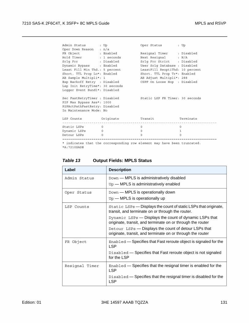
7210 SAS-K 2F6C4T, K 3SFP+ 8C MPLS Guide MPLS and RSVP
Edition: 01 3HE 14597 AAAB TQZZA 131
Admin Status : Up Oper Status : UpOper Down Reason : n/aFR Object : Enabled Resignal Timer : DisabledHold Timer : 1 seconds Next Resignal : N/ASrlg Frr : Disabled Srlg Frr Strict : DisabledDynamic Bypass : Enabled User Srlg Database : DisabledLeast Fill Min Thd.: 5 percent LeastFill ReoptiThd: 10 percentShort. TTL Prop Lo*: Enabled Short. TTL Prop Tr*: EnabledAB Sample Multipli*: 1 AB Adjust Multipli*: 288Exp Backoff Retry : Disabled CSPF On Loose Hop : DisabledLsp Init RetryTime*: 30 secondsLogger Event Bundl*: Disabled
Sec FastRetryTimer : Disabled Static LSP FR Timer: 30 secondsP2P Max Bypass Ass*: 1000P2PActPathFastRetry: DisabledIn Maintenance Mode: No
LSP Counts Originate Transit Terminate-------------------------------------------------------------------------------Static LSPs 0 0 0Dynamic LSPs 0 0 1Detour LSPs 0 0 0===============================================================================* indicates that the corresponding row element may have been truncated.*A:7210SAS#
Table 13 Output Fields: MPLS Status
Label Description
Admin Status Down — MPLS is administratively disabled
Up — MPLS is administratively enabled
Oper Status Down — MPLS is operationally down
Up — MPLS is operationally up
LSP Counts Static LSPs — Displays the count of static LSPs that originate, transit, and terminate on or through the router.
Dynamic LSPs — Displays the count of dynamic LSPs that originate, transit, and terminate on or through the router
Detour LSPs — Displays the count of detour LSPs that originate, transit, and terminate on or through the router
FR Object Enabled — Specifies that Fast reroute object is signaled for the LSP
Disabled — Specifies that Fast reroute object is not signaled for the LSP
Resignal Timer Enabled — Specifies that the resignal timer is enabled for the LSP
Disabled — Specifies that the resignal timer is disabled for the LSP

MPLS and RSVP
132
7210 SAS-K 2F6C4T, K 3SFP+ 8C MPLS Guide
3HE 14597 AAAB TQZZA Edition: 01
2.17.2.3.2 Show RSVP Commands
interface
Syntax interface [ip-int-name | ip-address] statistics [detail]
Context show>router>rsvp
SupportedPlatforms
Supported on all 7210 SAS platforms as described in this document
Description This command shows RSVP interfaces.
Parameters ip-int-name — Specifies the name of the network IP interface. An interface name cannot be in the form of an IP address. If the string contains special characters (#, $, spaces, etc.), the entire string must be enclosed within double quotes.
ip-address — Specifies the system or network interface IP address.
statistics — Displays IP address and the number of packets sent and received on an interface-basis.
detail — Displays detailed information.
Output The following output is an example of RSVP interface information, and Table 14 describes the fields.
Sample Output
*A:A:ALA-1>show>router>rsvp# interface detail
===============================================================================RSVP Interfaces (Detailed)===============================================================================-------------------------------------------------------------------------------Interface : system-------------------------------------------------------------------------------Interface : systemPort ID : systemAdmin State : Up Oper State : UpActive Sessions : 0 Active Resvs : 0Total Sessions : 0
Hold Timer Displays the amount of time that the ingress node holds before programming its data plane and declaring the LSP up to the service module
Table 13 Output Fields: MPLS Status (Continued)
Label Description

7210 SAS-K 2F6C4T, K 3SFP+ 8C MPLS Guide MPLS and RSVP
Edition: 01 3HE 14597 AAAB TQZZA 133
Subscription : 100 % Port Speed : 0 MbpsTotal BW : 0 Mbps Aggregate : DsablHello Interval : 3000 ms Hello Timeouts : 0Authentication : DisabledAuth Rx Seq Num : n/a Auth Key Id : n/aAuth Tx Seq Num : n/a Auth Win Size : n/aRefresh Reduc. : Disabled Reliable Deli. : DisabledBfd Enabled : No Graceful Shut. : Disabled
Percent Link Bandwidth for Class TypesLink Bw CT0 : 100 Link Bw CT4 : 0Link Bw CT1 : 0 Link Bw CT5 : 0Link Bw CT2 : 0 Link Bw CT6 : 0Link Bw CT3 : 0 Link Bw CT7 : 0
Bandwidth Constraints for Class Types (Kbps)BC0 : 0 BC4 : 0BC1 : 0 BC5 : 0BC2 : 0 BC6 : 0BC3 : 0 BC7 : 0
Bandwidth for TE Class Types (Kbps)TE0-> Resv. Bw : 0 Unresv. Bw : 0TE1-> Resv. Bw : 0 Unresv. Bw : 0TE2-> Resv. Bw : 0 Unresv. Bw : 0TE3-> Resv. Bw : 0 Unresv. Bw : 0TE4-> Resv. Bw : 0 Unresv. Bw : 0TE5-> Resv. Bw : 0 Unresv. Bw : 0TE6-> Resv. Bw : 0 Unresv. Bw : 0TE7-> Resv. Bw : 0 Unresv. Bw : 0No Neighbors.-------------------------------------------------------------------------------Interface : ip-10.10.12.3-------------------------------------------------------------------------------Interface : ip-10.10.12.3Port ID : 1/1/9Admin State : Up Oper State : UpActive Sessions : 1 Active Resvs : 0Total Sessions : 1Subscription : 100 % Port Speed : 1000 MbpsTotal BW : 1000 Mbps Aggregate : DsablHello Interval : 3000 ms Hello Timeouts : 0Authentication : DisabledAuth Rx Seq Num : n/a Auth Key Id : n/aAuth Tx Seq Num : n/a Auth Win Size : n/aRefresh Reduc. : Disabled Reliable Deli. : DisabledBfd Enabled : No Graceful Shut. : Disabled
Percent Link Bandwidth for Class TypesLink Bw CT0 : 100 Link Bw CT4 : 0Link Bw CT1 : 0 Link Bw CT5 : 0Link Bw CT2 : 0 Link Bw CT6 : 0Link Bw CT3 : 0 Link Bw CT7 : 0
Bandwidth Constraints for Class Types (Kbps)BC0 : 1000000 BC4 : 0BC1 : 0 BC5 : 0BC2 : 0 BC6 : 0BC3 : 0 BC7 : 0

MPLS and RSVP
134
7210 SAS-K 2F6C4T, K 3SFP+ 8C MPLS Guide
3HE 14597 AAAB TQZZA Edition: 01
Bandwidth for TE Class Types (Kbps)TE0-> Resv. Bw : 0 Unresv. Bw : 1000000TE1-> Resv. Bw : 0 Unresv. Bw : 1000000TE2-> Resv. Bw : 0 Unresv. Bw : 1000000TE3-> Resv. Bw : 0 Unresv. Bw : 1000000TE4-> Resv. Bw : 0 Unresv. Bw : 1000000TE5-> Resv. Bw : 0 Unresv. Bw : 1000000TE6-> Resv. Bw : 0 Unresv. Bw : 1000000TE7-> Resv. Bw : 0 Unresv. Bw : 1000000Neighbors : 10.10.12.2-------------------------------------------------------------------------------Interface : ip-10.10.4.3-------------------------------------------------------------------------------Interface : ip-10.10.4.3Port ID : 1/1/8Admin State : Up Oper State : UpActive Sessions : 1 Active Resvs : 0Total Sessions : 1Subscription : 100 % Port Speed : 1000 MbpsTotal BW : 1000 Mbps Aggregate : DsablHello Interval : 3000 ms Hello Timeouts : 0Authentication : DisabledAuth Rx Seq Num : n/a Auth Key Id : n/aAuth Tx Seq Num : n/a Auth Win Size : n/aRefresh Reduc. : Disabled Reliable Deli. : DisabledBfd Enabled : No Graceful Shut. : Disabled
Percent Link Bandwidth for Class TypesLink Bw CT0 : 100 Link Bw CT4 : 0Link Bw CT1 : 0 Link Bw CT5 : 0Link Bw CT2 : 0 Link Bw CT6 : 0Link Bw CT3 : 0 Link Bw CT7 : 0
Bandwidth Constraints for Class Types (Kbps)BC0 : 1000000 BC4 : 0BC1 : 0 BC5 : 0BC2 : 0 BC6 : 0BC3 : 0 BC7 : 0
Bandwidth for TE Class Types (Kbps)TE0-> Resv. Bw : 0 Unresv. Bw : 1000000TE1-> Resv. Bw : 0 Unresv. Bw : 1000000TE2-> Resv. Bw : 0 Unresv. Bw : 1000000TE3-> Resv. Bw : 0 Unresv. Bw : 1000000TE4-> Resv. Bw : 0 Unresv. Bw : 1000000TE5-> Resv. Bw : 0 Unresv. Bw : 1000000TE6-> Resv. Bw : 0 Unresv. Bw : 1000000TE7-> Resv. Bw : 0 Unresv. Bw : 1000000Neighbors : 10.10.4.2-------------------------------------------------------------------------------Interface : ip-10.10.2.3-------------------------------------------------------------------------------Interface : ip-10.10.2.3Port ID : 1/1/4Admin State : Up Oper State : DownActive Sessions : 0 Active Resvs : 0Total Sessions : 0Subscription : 100 % Port Speed : 0 Mbps

7210 SAS-K 2F6C4T, K 3SFP+ 8C MPLS Guide MPLS and RSVP
Edition: 01 3HE 14597 AAAB TQZZA 135
Total BW : 0 Mbps Aggregate : DsablHello Interval : 3000 ms Hello Timeouts : 0Authentication : DisabledAuth Rx Seq Num : n/a Auth Key Id : n/aAuth Tx Seq Num : n/a Auth Win Size : n/aRefresh Reduc. : Disabled Reliable Deli. : DisabledBfd Enabled : No Graceful Shut. : Disabled
Percent Link Bandwidth for Class TypesLink Bw CT0 : 100 Link Bw CT4 : 0Link Bw CT1 : 0 Link Bw CT5 : 0Link Bw CT2 : 0 Link Bw CT6 : 0Link Bw CT3 : 0 Link Bw CT7 : 0
Bandwidth Constraints for Class Types (Kbps)BC0 : 0 BC4 : 0BC1 : 0 BC5 : 0BC2 : 0 BC6 : 0BC3 : 0 BC7 : 0
Bandwidth for TE Class Types (Kbps)TE0-> Resv. Bw : 0 Unresv. Bw : 0TE1-> Resv. Bw : 0 Unresv. Bw : 0TE2-> Resv. Bw : 0 Unresv. Bw : 0TE3-> Resv. Bw : 0 Unresv. Bw : 0TE4-> Resv. Bw : 0 Unresv. Bw : 0TE5-> Resv. Bw : 0 Unresv. Bw : 0TE6-> Resv. Bw : 0 Unresv. Bw : 0TE7-> Resv. Bw : 0 Unresv. Bw : 0No Neighbors.===============================================================================
Table 14 Output Fields: RSVP Interface
Label Description
Interface The name of the IP interface
Total Sessions The total number of RSVP sessions on this interface
This count includes sessions that are active, as well as sessions that have been signaled but a response has not yet been received.
Active Sessions The total number of active RSVP sessions on this interface
Total BW The amount of bandwidth in megabits per second (mbps) available to be reserved for the RSVP protocol on the interface
Resv BW The amount of bandwidth in mega-bits per seconds (mbps) reserved on this interface
A value of zero indicates that no bandwidth is reserved.
Adm Down — The RSVP interface is administratively disabled
Up — The RSVP interface is administratively enabled

MPLS and RSVP
136
7210 SAS-K 2F6C4T, K 3SFP+ 8C MPLS Guide
3HE 14597 AAAB TQZZA Edition: 01
Opr Down — The RSVP interface is operationally down
Up — The RSVP interface is operationally up
Port ID Specifies the physical port bound to the interface
Active Resvs The total number of active RSVP sessions that have reserved bandwidth
Subscription Specifies the percentage of the link bandwidth that RSVP can use for reservation
When the value is zero, no new sessions are permitted on this interface.
Port Speed Specifies the speed for the interface
Unreserved BW Specifies the amount of unreserved bandwidth
Reserved BW Specifies the amount of bandwidth in megabits per second (mbps) reserved by the RSVP session on this interface
A value of zero indicates that no bandwidth is reserved.
Total BW Specifies the amount of bandwidth in megabits per second (mbps) available to be reserved for the RSVP protocol on this interface
Hello Interval Specifies the length of time, in seconds, between the hello packets that the router sends on the interface
This value must be the same for all routers attached to a common network. When the value is zero, the sending of hello messages is disabled.
Refresh Time Specifies the interval between the successive path and resv refresh messages
RSVP declares the session down after it misses ((keep-multiplier + 0.5) × 1.5 × refresh-time)) consecutive refresh messages.
Hello Timeouts The total number of hello messages that timed out on this RSVP interface
Neighbors The IP address of the RSVP neighbor
Sent The total number of error free RSVP packets that have been transmitted on the RSVP interface
Recd The total number of error free RSVP packets received on the RSVP interface
Total Packets The total number of RSVP packets, including errors, received on the RSVP interface
Table 14 Output Fields: RSVP Interface (Continued)
Label Description

7210 SAS-K 2F6C4T, K 3SFP+ 8C MPLS Guide MPLS and RSVP
Edition: 01 3HE 14597 AAAB TQZZA 137
neighbor
Syntax neighbor [ip-address] [detail]
Context show>router>rsvp
SupportedPlatforms
Supported on all 7210 SAS platforms as described in this document
Description This command shows neighbor information.
Parameters ip-address — Displays RSVP information about the specified IP address.
detail — Displays detailed information.
Bad Packets The total number of RSVP packets with errors transmitted on the RSVP interface
Paths The total number of RSVP PATH messages received on the RSVP interface
Path Errors The total number of RSVP PATH ERROR messages transmitted on the RSVP interface
Path Tears The total number of RSVP PATH TEAR messages received on the RSVP interface
Resvs The total number of RSVP RESV messages received on the RSVP interface
Resv Confirms The total number of RSVP RESV CONFIRM messages received on the RSVP interface
Resv Errors Total RSVP RESV ERROR messages received on RSVP interface
Resv Tears Total RSVP RESV TEAR messages received on RSVP interface
Refresh Summaries Total RSVP RESV summary refresh messages received on interface
Refresh Acks Total RSVP RESV acknowledgment messages received when refresh reduction is enabled on the RSVP interface
Hellos Total RSVP RESV HELLO REQ messages received on the interface
Bfd Enabled Yes — BFD is enabled on the RSVP interface
No — BFD is disabled on the RSVP interface
Table 14 Output Fields: RSVP Interface (Continued)
Label Description
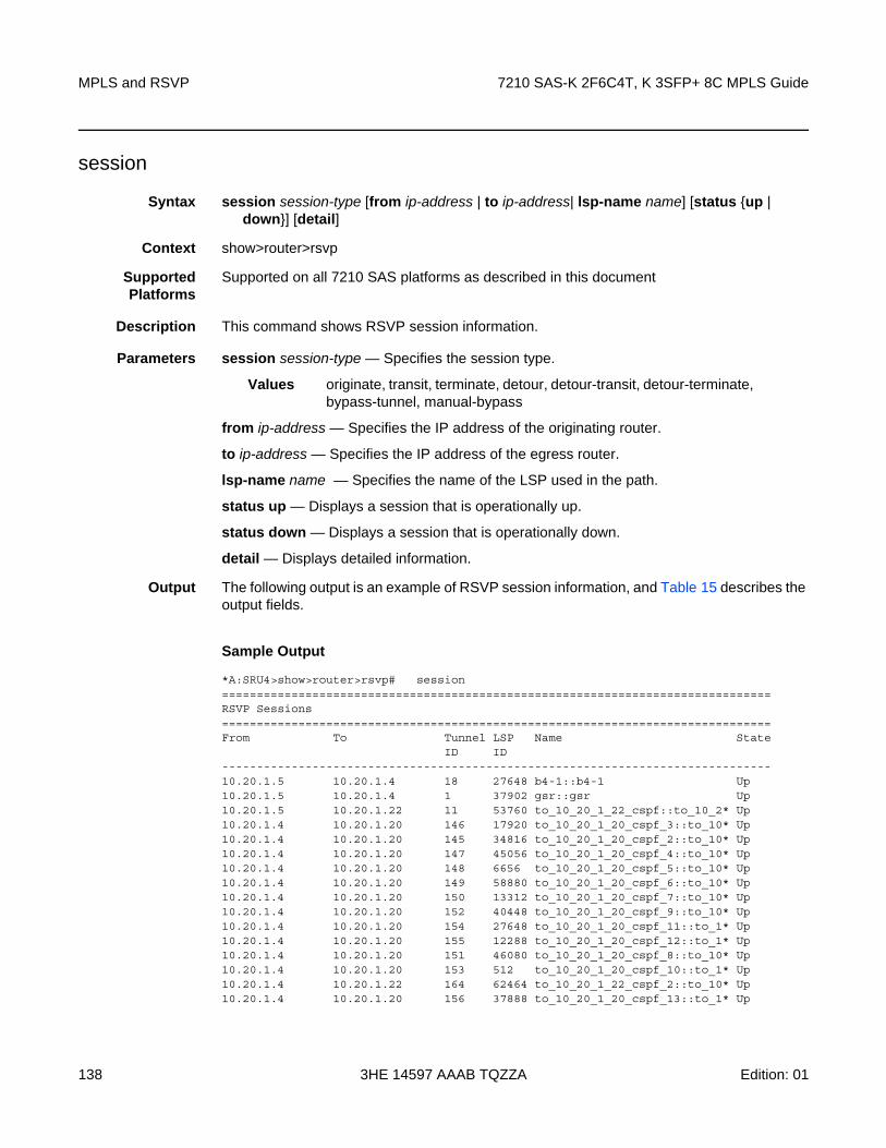
MPLS and RSVP
138
7210 SAS-K 2F6C4T, K 3SFP+ 8C MPLS Guide
3HE 14597 AAAB TQZZA Edition: 01
session
Syntax session session-type [from ip-address | to ip-address| lsp-name name] [status {up | down}] [detail]
Context show>router>rsvp
SupportedPlatforms
Supported on all 7210 SAS platforms as described in this document
Description This command shows RSVP session information.
Parameters session session-type — Specifies the session type.
Values originate, transit, terminate, detour, detour-transit, detour-terminate, bypass-tunnel, manual-bypass
from ip-address — Specifies the IP address of the originating router.
to ip-address — Specifies the IP address of the egress router.
lsp-name name — Specifies the name of the LSP used in the path.
status up — Displays a session that is operationally up.
status down — Displays a session that is operationally down.
detail — Displays detailed information.
Output The following output is an example of RSVP session information, and Table 15 describes the output fields.
Sample Output
*A:SRU4>show>router>rsvp# session===============================================================================RSVP Sessions===============================================================================From To Tunnel LSP Name State
ID ID-------------------------------------------------------------------------------10.20.1.5 10.20.1.4 18 27648 b4-1::b4-1 Up10.20.1.5 10.20.1.4 1 37902 gsr::gsr Up10.20.1.5 10.20.1.22 11 53760 to_10_20_1_22_cspf::to_10_2* Up10.20.1.4 10.20.1.20 146 17920 to_10_20_1_20_cspf_3::to_10* Up10.20.1.4 10.20.1.20 145 34816 to_10_20_1_20_cspf_2::to_10* Up10.20.1.4 10.20.1.20 147 45056 to_10_20_1_20_cspf_4::to_10* Up10.20.1.4 10.20.1.20 148 6656 to_10_20_1_20_cspf_5::to_10* Up10.20.1.4 10.20.1.20 149 58880 to_10_20_1_20_cspf_6::to_10* Up10.20.1.4 10.20.1.20 150 13312 to_10_20_1_20_cspf_7::to_10* Up10.20.1.4 10.20.1.20 152 40448 to_10_20_1_20_cspf_9::to_10* Up10.20.1.4 10.20.1.20 154 27648 to_10_20_1_20_cspf_11::to_1* Up10.20.1.4 10.20.1.20 155 12288 to_10_20_1_20_cspf_12::to_1* Up10.20.1.4 10.20.1.20 151 46080 to_10_20_1_20_cspf_8::to_10* Up10.20.1.4 10.20.1.20 153 512 to_10_20_1_20_cspf_10::to_1* Up10.20.1.4 10.20.1.22 164 62464 to_10_20_1_22_cspf_2::to_10* Up10.20.1.4 10.20.1.20 156 37888 to_10_20_1_20_cspf_13::to_1* Up

7210 SAS-K 2F6C4T, K 3SFP+ 8C MPLS Guide MPLS and RSVP
Edition: 01 3HE 14597 AAAB TQZZA 139
10.20.1.4 10.20.1.20 157 24064 to_10_20_1_20_cspf_14::to_1* Up10.20.1.4 10.20.1.20 158 19968 to_10_20_1_20_cspf_15::to_1* Up10.20.1.4 10.20.1.20 161 59904 to_10_20_1_20_cspf_18::to_1* Up...10.20.1.3 10.20.1.4 54 23088 to_110_20_1_4_cspf_4::to_11* Up-------------------------------------------------------------------------------Sessions : 1976===============================================================================* indicates that the corresponding row element may have been truncated.*A:SRU4>show>router>rsvp#
A:ALA-12# show router rsvp session lsp-name A_C_2::A_C_2 status up===============================================================================RSVP Sessions===============================================================================From To Tunnel LSP Name State
ID ID-------------------------------------------------------------------------------10.20.1.1 10.20.1.3 2 40 A_C_2::A_C_2 Up-------------------------------------------------------------------------------Sessions : 1===============================================================================A:ALA-12#
statistics
Syntax statistics
Context show>router>rsvp
SupportedPlatforms
Supported on all 7210 SAS platforms as described in this document
Table 15 Output Fields: RSVP Session
Label Description
From The IP address of the originating router
To The IP address of the egress router
Tunnel ID The IP address of the tunnel’s ingress node supporting this RSVP session
LSP ID The ID assigned by the agent to this RSVP session
Name The administrative name assigned to the RSVP session by the agent
State Down — the operational state of this RSVP session is down
Up — the operational state of this RSVP session is up

MPLS and RSVP
140
7210 SAS-K 2F6C4T, K 3SFP+ 8C MPLS Guide
3HE 14597 AAAB TQZZA Edition: 01
Description This command displays global statistics in the RSVP instance.
Output The following output is an example of RSVP statistics information, and Table 16 describes the output fields.
Sample Output
*A:SRU4>show>router>rsvp# statistics===============================================================================RSVP Global Statistics===============================================================================PATH Timeouts : 1026 RESV Timeouts : 182===============================================================================*A:SRU4>show>router>rsvp#
status
Syntax rsvp status
Context show>router>rsvp
SupportedPlatforms
Supported on all 7210 SAS platforms as described in this document
Description This command displays RSVP status.
Output The following output is an example of RSVP status information, and Table 17 describes the output fields.
Sample Output
*A:SRU4>show>router>rsvp# status===============================================================================RSVP Status===============================================================================Admin Status : Up Oper Status : UpKeep Multiplier : 3 Refresh Time : 30 secMessage Pacing : Disabled Pacing Period : 100 msecMax Packet Burst : 650 msgs Refresh Bypass : Disabled===============================================================================*A:SRU4>show>router>rsvp#
Table 16 Output Fields: RSVP Statistics
Label Description
PATH Timeouts The total number of path timeouts
RESV Timeouts The total number of RESV timeouts

7210 SAS-K 2F6C4T, K 3SFP+ 8C MPLS Guide MPLS and RSVP
Edition: 01 3HE 14597 AAAB TQZZA 141
2.17.2.4 Tools Commands
cspf
Syntax cspf to ip-addr [from ip-addr] [bandwidth bandwidth] [include-bitmap bitmap] [exclude-bitmap bitmap] [hop-limit limit] [exclude-address excl-addr [excl-addr...(up to 8 max)]] [use-te-metric] [strict-srlg] [srlg-group grp-id...(up to 8 max)] [skip-interface interface-name]
Context tools>perform>router>mpls
SupportedPlatforms
Supported on all 7210 SAS platforms as described in this document
Description This command computes a CSPF path with specified user constraints.
Parameters to ip-addr — Specifies the destination IP address.
Table 17 Output Fields: RSVP Status
Label Description
Admin Status Down — RSVP is administratively disabled
Up — RSVP is administratively enabled
Oper Status Down — RSVP is operationally down
Up — RSVP is operationally up
Keep Multiplier Displays the keep-multiplier number used by RSVP to declare that a reservation is down or the neighbor is down
Refresh Time Displays the refresh-time interval, in seconds, between the successive Path and Resv refresh messages
Message Pacing Enabled — RSVP messages, specified in the max-burst command, are sent in a configured interval, specified in the period command
Disabled — Message pacing is disabled. RSVP message transmission is not regulated
Pacing Period Displays the time interval, in milliseconds, when the router can send the specified number of RSVP messages specified in the rsvp max-burst command
Max Packet Burst Displays the maximum number of RSVP messages that are sent in the specified period under normal operating conditions

MPLS and RSVP
142
7210 SAS-K 2F6C4T, K 3SFP+ 8C MPLS Guide
3HE 14597 AAAB TQZZA Edition: 01
from ip-addr — Specifies the originating IP address.
bandwidth bandwidth — Specifies the amount of bandwidth in mega-bits per second (Mbps) to be reserved.
include-bitmap bitmap — Specifies to include a bit-map that specifies a list of admin groups that should be included during setup.
exclude-bitmap bitmap — Specifies to exclude a bit-map that specifies a list of admin groups that should be included during setup.
hop-limit limit — Specifies the total number of hops a detour LSP can take before merging back onto the main LSP path.
exclude-address ip-addr — Specifies IP addresses, up to 8, that should be included during setup.
use-te-metric — Specifies the use of the traffic engineering metric used on the interface.
strict-srlg — Specifies whether to associate the LSP with a bypass or signal a detour if a bypass or detour satisfies all other constraints except the SRLG constraints.
srlg-group grp-id — Specifies up to 8 Shared Risk Link Groups (SRLGs). An SRLG group represents a set of interfaces which could be subject to the same failures or defects and therefore, share the same risk of failing.
Values 0 to 4294967295
skip-interface interface-name — Specifies an interface name that should be skipped during setup.
Output The following output is an example of MPLS CSPF information.
Sample Output
*A:Dut-C# tools perform router mpls cspf to 10.20.1.6
Req CSPF for all ECMP pathsfrom: this node to: 10.20.1.6 w(no Diffserv) class: 0 , setup Priority 7, Hold
Priority 0 TE Class: 7
CSPF PathTo : 10.20.1.6Path 1 : (cost 2000)
Src: 10.20.1.3 (= Rtr)Egr: unnumbered lnkId 4 -
> Ingr: unnumbered lnkId 2 Rtr: 10.20.1.5 (met 1000)Egr: unnumbered lnkId 3 -
> Ingr: unnumbered lnkId 3 Rtr: 10.20.1.6 (met 1000)Dst: 10.20.1.6 (= Rtr)
Path 2 : (cost 2000)Src: 10.20.1.3 (= Rtr)Egr: unnumbered lnkId 5 -
> Ingr: unnumbered lnkId 5 Rtr: 10.20.1.4 (met 1000)Egr: unnumbered lnkId 3 -
> Ingr: unnumbered lnkId 2 Rtr: 10.20.1.6 (met 1000)
7210 SAS-K 2F6C4T, K 3SFP+ 8C MPLS Guide MPLS and RSVP
Edition: 01 3HE 14597 AAAB TQZZA 143
Dst: 10.20.1.6 (= Rtr)
*A:Dut-C#
resignal
Syntax resignal {lsp lsp-name path path-name | delay minutes}
Context tools>perform>router>mpls
SupportedPlatforms
Supported on all 7210 SAS platforms as described in this document
Description This command resignals a specific LSP path. The minutes parameter configures the global timer of all LSPs for resignal. If only lsp-name and path-name are provided, the LSP is resignaled immediately.
Parameters lsp-name — Specifies an existing LSP name to resignal.
path-name — Specifies an existing path name to resignal.
delay minutes — Sets the global timer of all LSPs to resignal.
switch-path
Syntax switch-path [lsp lsp-name] [path path-name]
Context tools>perform>router>mpls
SupportedPlatforms
Supported on all 7210 SAS platforms as described in this document
Description This command moves a standby (or an active secondary) path to another standby path of the same priority. If a new standby path with a higher priority or a primary path comes up after the tools perform command is executed, the path re-evaluation command runs and the path is moved to the path specified by the outcome of the re-evaluation.
Parameters lsp-name — Specifies the name of an existing LSP to move.
path-name — Specifies the path name to which to move the specified LSP.
2.17.2.5 Clear Commands
interface
Syntax interface ip-int-name

MPLS and RSVP
144
7210 SAS-K 2F6C4T, K 3SFP+ 8C MPLS Guide
3HE 14597 AAAB TQZZA Edition: 01
Context clear>router>mpls
SupportedPlatforms
Supported on all 7210 SAS platforms as described in this document
Description This command resets or clears statistics for MPLS interfaces.
Parameters ip-int-name — Specifies the name of an existing IP interface. If the string contains special characters (#, $, spaces, etc.), the entire string must be enclosed within double quotes.
lsp
Syntax lsp lsp-name
Context clear>router>mpls
SupportedPlatforms
Supported on all 7210 SAS platforms as described in this document
Description This command resets and restarts an LSP.
Parameters lsp-name — Specifies the name of the LSP to clear, up to 64 characters.
statistics
Syntax statistics
Context clear>router>rsvp
SupportedPlatforms
Supported on all 7210 SAS platforms as described in this document
Description This command clears global statistics for the RSVP instance; for example, the command clears path and resv timeout counters.
2.17.2.6 Debug Commands
mpls
Syntax mpls [lsp lsp-name] [sender source-address] [endpoint endpoint-address] [tunnel-id tunnel-id] [lsp-id lsp-id]
no mpls
Context debug>router

7210 SAS-K 2F6C4T, K 3SFP+ 8C MPLS Guide MPLS and RSVP
Edition: 01 3HE 14597 AAAB TQZZA 145
SupportedPlatforms
Supported on all 7210 SAS platforms as described in this document
Description This command enables and configures debugging for MPLS.
Parameters lsp-name — Specifies the name that identifies the LSP, which can be up to 32 characters and must be unique.
source-address — Specifies the system IP address of the sender.
endpoint-address — Specifies the far-end system IP address.
tunnel-id — Specifies the MPLS SDP ID.
Values 0 to 4294967295
lsp-id — Specifies the LSP ID.
Values 1 to 65535
ip-int-name — Specifies th name that identifies the interface. The interface name can be up to 32 characters and must be unique. If the string contains special characters (#, $, spaces, etc.), the entire string must be enclosed within double quotes.
event
Syntax [no] event
Context debug>router>mplsdebug>router>rsvp
SupportedPlatforms
Supported on all 7210 SAS platforms as described in this document
Description This command enables debugging for specific events.
The no form of this command disables the debugging.
all
Syntax all [detail]
no all
Context debug>router>mpls>eventdebug>router>rsvp>event
SupportedPlatforms
Supported on all 7210 SAS platforms as described in this document
Description This command debugs all events.
The no form of this command disables the debugging.

MPLS and RSVP
146
7210 SAS-K 2F6C4T, K 3SFP+ 8C MPLS Guide
3HE 14597 AAAB TQZZA Edition: 01
Parameters detail — Displays detailed information about all events.
auth
Syntax auth
no auth
Context debug>router>rsvp>event
SupportedPlatforms
Supported on all 7210 SAS platforms as described in this document
Description This command debugs authentication events.
The no form of this command disables the debugging.
Parameters detail — Displays detailed information about authentication events.
frr
Syntax frr [detail]
no frr
Context debug>router>mpls>event
SupportedPlatforms
Supported on all 7210 SAS platforms as described in this document
Description This command debugs fast reroute events.
The no form of this command disables the debugging.
Parameters detail — Displays detailed information about reroute events.
iom
Syntax iom [detail]
no iom
Context debug>router>mpls>event
SupportedPlatforms
Supported on all 7210 SAS platforms as described in this document
Description This command debugs MPLS IOM events.
The no form of this command disables the debugging.

7210 SAS-K 2F6C4T, K 3SFP+ 8C MPLS Guide MPLS and RSVP
Edition: 01 3HE 14597 AAAB TQZZA 147
Parameters detail — Displays detailed information about MPLS IOM events.
lsp-setup
Syntax lsp-setup [detail]
no lsp-setup
Context debug>router>mpls>event
SupportedPlatforms
Supported on all 7210 SAS platforms as described in this document
Description This command debugs LSP setup events.
The no form of this command disables the debugging.
Parameters detail — Displays detailed information about LSP setup events.
mbb
Syntax mbb [detail]
no mbb
Context debug>router>mpls>event
SupportedPlatforms
Supported on all 7210 SAS platforms as described in this document
Description This command debugs the state of the most recent invocation of the make-before-break (MBB) functionality.
The no form of this command disables the debugging.
Parameters detail — Displays detailed information about MBB events.
misc
Syntax misc [detail]
no misc
Context debug>router>mpls>eventdebug>router>rsvp>event
SupportedPlatforms
Supported on all 7210 SAS platforms as described in this document
Description This command debugs miscellaneous events.
MPLS and RSVP
148
7210 SAS-K 2F6C4T, K 3SFP+ 8C MPLS Guide
3HE 14597 AAAB TQZZA Edition: 01
The no form of this command disables the debugging.
Parameters detail — Displays detailed information about miscellaneous events.
xc
Syntax xc [detail]
no xc
Context debug>router>mpls>event
SupportedPlatforms
Supported on all 7210 SAS platforms as described in this document
Description This command debugs cross connect events.
The no form of this command disables the debugging.
Parameters detail — Displays detailed information about cross connect events.
rsvp
Syntax [lsp lsp-name] [sender source-address] [endpoint endpoint-address] [tunnel-id tunnel-id] [lsp-id lsp-id] [interface ip-int-name]
no rsvp
Context debug>router
SupportedPlatforms
Supported on all 7210 SAS platforms as described in this document
Description This command enables and configures debugging for RSVP.
Parameters lsp-name — Specifies the name that identifies the LSP, which can be up to 32 characters and must be unique.
source-address — Specifies the system IP address of the sender.
endpoint-address — Specifies the far-end system IP address.
tunnel-id — Specifies the RSVP tunnel ID.
Values 0 to 4294967295
lsp-id — Specifies the LSP ID.
Values 1 to 65535
ip-int-name — Specifies the interface name. The interface name can be up to 32 characters and must be unique. If the string contains special characters (#, $, spaces, etc.), the entire string must be enclosed within double quotes.
7210 SAS-K 2F6C4T, K 3SFP+ 8C MPLS Guide MPLS and RSVP
Edition: 01 3HE 14597 AAAB TQZZA 149
nbr
Syntax nbr [detail]
no nbr
Context debug>router>rsvp>event
SupportedPlatforms
Supported on all 7210 SAS platforms as described in this document
Description This command debugs neighbor events.
The no form of this command disables the debugging.
Parameters detail — Displays detailed information about neighbor events.
path
Syntax path [detail]
no path
Context debug>router>rsvp>event
SupportedPlatforms
Supported on all 7210 SAS platforms as described in this document
Description This command debugs path-related events.
The no form of this command disables the debugging.
Parameters detail — Displays detailed information about path-related events.
resv
Syntax resv [detail]
no resv
Context debug>router>rsvp>event
SupportedPlatforms
Supported on all 7210 SAS platforms as described in this document
Description This command debugs RSVP reservation events.
The no form of this command disables the debugging.
Parameters detail — Displays detailed information about RSVP reservation events.

MPLS and RSVP
150
7210 SAS-K 2F6C4T, K 3SFP+ 8C MPLS Guide
3HE 14597 AAAB TQZZA Edition: 01
rr
Syntax rr
no rr
Context debug>router>rsvp>event
SupportedPlatforms
Supported on all 7210 SAS platforms as described in this document
Description This command debugs refresh reduction events.
The no form of this command disables the debugging.
Parameters detail — Displays detailed information about refresh reduction events.
packet
Syntax [no] packet
Context debug>router>rsvp>
SupportedPlatforms
Supported on all 7210 SAS platforms as described in this document
Description This command debugs packets.
The no form of this command disables the debugging.
ack
Syntax ack [detail]
no ack
Context debug>router>rsvp>packet
SupportedPlatforms
Supported on all 7210 SAS platforms as described in this document
Description This command debugs ACK packets.
The no form of this command disables the debugging.
Parameters detail — Displays detailed information about RSVP ACK packets.

7210 SAS-K 2F6C4T, K 3SFP+ 8C MPLS Guide MPLS and RSVP
Edition: 01 3HE 14597 AAAB TQZZA 151
bundle
Syntax bundle [detail]
no bundle
Context debug>router>rsvp>packet
SupportedPlatforms
Supported on all 7210 SAS platforms as described in this document
Description This command debugs bundle packets.
The no form of this command disables the debugging.
Parameters detail — Displays detailed information about RSVP bundle packets.
all
Syntax all [detail]
no all
Context debug>router>rsvp>packet
SupportedPlatforms
Supported on all 7210 SAS platforms as described in this document
Description This command debugs all packets.
The no form of this command disables the debugging.
Parameters detail — Displays detailed information about all RSVP packets.
hello
Syntax hello [detail]
no hello
Context debug>router>rsvp>packet
SupportedPlatforms
Supported on all 7210 SAS platforms as described in this document
Description This command debugs hello packets.
The no form of this command disables the debugging.
Parameters detail — Displays detailed information about hello packets.

MPLS and RSVP
152
7210 SAS-K 2F6C4T, K 3SFP+ 8C MPLS Guide
3HE 14597 AAAB TQZZA Edition: 01
path
Syntax path [detail]
no path
Context debug>router>rsvp>packet
SupportedPlatforms
Supported on all 7210 SAS platforms as described in this document
Description This command enables debugging for RSVP path packets.
The no form of this command disables the debugging.
Parameters detail — Displays detailed information about path-related events.
patherr
Syntax patherr [detail]
no patherr
Context debug>router>rsvp>packet
SupportedPlatforms
Supported on all 7210 SAS platforms as described in this document
Description This command debugs path error packets.
The no form of this command disables the debugging.
Parameters detail — Displays detailed information about path error packets.
pathtear
Syntax pathtear [detail]
no pathtear
Context debug>router>rsvp>packet
SupportedPlatforms
Supported on all 7210 SAS platforms as described in this document
Description This command debugs path tear packets.
The no form of this command disables the debugging.
Parameters detail — Displays detailed information about path tear packets.

7210 SAS-K 2F6C4T, K 3SFP+ 8C MPLS Guide MPLS and RSVP
Edition: 01 3HE 14597 AAAB TQZZA 153
resv
Syntax resv [detail]
no resv
Context debug>router>rsvp>packet
SupportedPlatforms
Supported on all 7210 SAS platforms as described in this document
Description This command enables debugging for RSVP RESV packets.
The no form of this command disables the debugging.
Parameters detail — Displays detailed information about RSVP RESV events.
resverr
Syntax resverr [detail]
no resverr
Context debug>router>rsvp>packet
SupportedPlatforms
Supported on all 7210 SAS platforms as described in this document
Description This command debugs ResvErr packets.
The no form of this command disables the debugging.
Parameters detail — Displays detailed information about ResvErr packets.
resvtear
Syntax resvtear [detail]
no resvtear
Context debug>router>rsvp>packet
SupportedPlatforms
Supported on all 7210 SAS platforms as described in this document
Description This command debugs ResvTear packets.
The no form of this command disables the debugging.
Parameters detail — Displays detailed information about ResvTear packets.
MPLS and RSVP
154
7210 SAS-K 2F6C4T, K 3SFP+ 8C MPLS Guide
3HE 14597 AAAB TQZZA Edition: 01
srefresh
Syntax srefresh [detail]
no srefresh
Context debug>router>rsvp>packet
SupportedPlatforms
Supported on all 7210 SAS platforms as described in this document
Description This command debugs srefresh packets.
The no form of this command disables the debugging.
Parameters detail — Displays detailed information about RSVP srefresh packets.

7210 SAS-K 2F6C4T, K 3SFP+ 8C MPLS Guide Label Distribution Protocol
Edition: 01 3HE 14597 AAAB TQZZA 155
3 Label Distribution Protocol
3.1 In This Chapter
This chapter provides information to enable Label Distribution Protocol (LDP).
3.2 Label Distribution Protocol
Label Distribution Protocol (LDP) is a protocol used to distribute labels in non-traffic-engineered applications. LDP allows routers to establish label switched paths (LSPs) through a network by mapping network-layer routing information directly to data link layer-switched paths.
An LSP is defined by the set of labels from the ingress Label Switching Router (LSR) to the egress LSR. LDP associates a Forwarding Equivalence Class (FEC) with each LSP it creates. A FEC is a collection of common actions associated with a class of packets. When an LSR assigns a label to a FEC, it must let other LSRs in the path know about the label. LDP helps to establish the LSP by providing a set of procedures that LSRs can use to distribute labels.
The FEC associated with an LSP specifies which packets are mapped to that LSP. LSPs are extended through a network as each LSR splices incoming labels for a FEC to the outgoing label assigned to the next hop for the given FEC.
LDP allows an LSR to request a label from a downstream LSR so it can bind the label to a specific FEC. The downstream LSR responds to the request from the upstream LSR by sending the requested label.
LSRs can distribute a FEC label binding in response to an explicit request from another LSR. This is known as Downstream On Demand (DOD) label distribution. LSRs can also distribute label bindings to LSRs that have not explicitly requested them. This is called Downstream Unsolicited (DUS).

Label Distribution Protocol
156
7210 SAS-K 2F6C4T, K 3SFP+ 8C MPLS Guide
3HE 14597 AAAB TQZZA Edition: 01
3.2.1 LDP and MPLS
LDP performs the label distribution only in MPLS environments. The LDP operation begins with a hello discovery process to find LDP peers in the network. LDP peers are two LSRs that use LDP to exchange label/FEC mapping information. An LDP session is created between LDP peers. A single LDP session allows each peer to learn the other's label mappings (LDP is bi-directional) and to exchange label binding information.
LDP signaling works with the MPLS label manager to manage the relationships between labels and the corresponding FEC. For service-based FECs, LDP works in tandem with the Service Manager to identify the virtual leased lines (VLLs) and Virtual Private LAN Services (VPLSs) to signal.
An MPLS label identifies a set of actions that the forwarding plane performs on an incoming packet before discarding it. The FEC is identified through the signaling protocol (in this case, LDP) and allocated a label. The mapping between the label and the FEC is communicated to the forwarding plane. In order for this processing on the packet to occur at high speeds, optimized tables are maintained in the forwarding plane that enable fast access and packet identification.
When an unlabeled packet ingresses the router, classification policies associate it with a FEC. The appropriate label is imposed on the packet, and the packet is forwarded. Other actions that can take place before a packet is forwarded are imposing additional labels, other encapsulations, learning actions, etc. When all actions associated with the packet are completed, the packet is forwarded.
When a labeled packet ingresses the router, the label or stack of labels indicates the set of actions associated with the FEC for that label or label stack. The actions are preformed on the packet and then the packet is forwarded.
The LDP implementation supports DUS, ordered control, and the liberal label retention mode.
3.2.2 LDP Architecture
LDP comprises a few processes that handle the protocol PDU transmission, timer-related issues, and protocol state machine. The number of processes is kept to a minimum to simplify the architecture and to allow for scalability. Scheduling within each process prevents starvation of any particular LDP session, while buffering alleviates TCP-related congestion issues.

7210 SAS-K 2F6C4T, K 3SFP+ 8C MPLS Guide Label Distribution Protocol
Edition: 01 3HE 14597 AAAB TQZZA 157
The LDP subsystems and their relationships to other subsystems are illustrated in Figure 10. This illustration shows the interaction of the LDP subsystem with other subsystems, including memory management, label management, service management, SNMP, interface management, and routing table management (RTM). In addition, debugging capabilities are provided through the logger.
Communication within LDP tasks is typically done by inter-process communication through the event queue, as well as through updates to the various data structures. The primary data structures that LDP maintains are:
• FEC/label database
This database contains all the FEC to label mappings that include, both sent and received. It also contains both address FECs (prefixes and host addresses) as well as service FECs (L2 VLLs and VPLS).
• timer database
This database contains all the timers for maintaining sessions and adjacencies.
• session database
This database contains all the session and adjacency records, and serves as a repository for the LDP MIB objects.
3.2.3 Subsystem Interrelationships
The sections below describe how LDP and the other subsystems work to provide services.

Label Distribution Protocol
158
7210 SAS-K 2F6C4T, K 3SFP+ 8C MPLS Guide
3HE 14597 AAAB TQZZA Edition: 01
Figure 10 Subsystem Interrelationships
3.2.3.1 Memory Manager and LDP
LDP does not use any memory until it is instantiated. It pre-allocates some amount of fixed memory so that initial startup actions can be performed. Memory allocation for LDP comes out of a pool reserved for LDP that can grow dynamically as needed. Fragmentation is minimized by allocating memory in larger chunks and managing the memory internally to LDP. When LDP is shut down, it releases all memory allocated to it.
OSSRG017
Protocol
Memory
Mgr
Label
Mgr
Send/
Receive
Send/
Receive
Timer
Logger
Service
Mgr
Interface
MgrRTM
Config
(CLI/SNMP) Timer DB FEC/
Label DB
LDP MIB Session DB
Event
Queue
Event
Queue
Event
Queue
7210 SAS-K 2F6C4T, K 3SFP+ 8C MPLS Guide Label Distribution Protocol
Edition: 01 3HE 14597 AAAB TQZZA 159
3.2.3.2 Label Manager
LDP assumes that the label manager is up and running. LDP will abort initialization if the label manager is not running. The label manager is initialized at system boot-up; hence, anything that causes it to fail will likely imply that the system is not functional. The 7210 devices uses a label range from 28672 (28K) to 131071 (128K-1) to allocate all dynamic labels, including RSVP allocated labels and VC labels.
3.2.3.3 LDP Configuration
The 7210 devices uses a single consistent interface to configure all protocols and services. CLI commands are translated to SNMP requests and are handled through an agent-LDP interface. LDP can be instantiated or deleted through SNMP. Also, LDP targeted sessions can be set up to specific endpoints. Targeted-session parameters are configurable.
3.2.3.4 Logger
LDP uses the logger interface to generate debug information relating to session setup and teardown, LDP events, label exchanges, and packet dumps. Per-session tracing can be performed.
3.2.3.5 Service Manager
All interaction occurs between LDP and the service manager, since LDP is used primarily to exchange labels for Layer 2 services. In this context, the service manager informs LDP when an LDP session is to be set up or torn down, and when labels are to be exchanged or withdrawn. In turn, LDP informs service manager of relevant LDP events, such as connection setups and failures, timeouts, labels signaled/withdrawn.
3.2.4 Execution Flow
LDP activity is limited to service-related signaling. Therefore, the configurable parameters are restricted to system-wide parameters, such as hello and keepalive timeouts.
Label Distribution Protocol
160
7210 SAS-K 2F6C4T, K 3SFP+ 8C MPLS Guide
3HE 14597 AAAB TQZZA Edition: 01
3.2.4.1 Initialization
MPLS must be enabled when LDP is initialized. LDP makes sure that the various prerequisites, such as ensuring the system IP interface is operational, the label manager is operational, and there is memory available, are met. It then allocates itself a pool of memory and initializes its databases.
3.2.4.2 Session Lifetime
In order for a targeted LDP (T-LDP) session to be established, an adjacency must be created. The LDP extended discovery mechanism requires hello messages to be exchanged between two peers for session establishment. After the adjacency establishment, session setup is attempted.
3.2.4.2.1 Adjacency Establishment
In the router, the adjacency management is done through the establishment of a Service Distribution Path (SDP) object, which is a service entity in the Nokia service model. The Nokia service model uses logical entities that interact to provide a service. The service model requires the service provider to create configurations for four main entities:
• customers
• services
• Service Access Paths (SAPs) on the local routers
• Service Distribution Points (SDPs) that connect to one or more remote routers
An SDP is the network-side termination point for a tunnel to a remote router. An SDP defines a local entity that includes the system IP address of the remote routers and a path type. Each SDP comprises the following:
• SDP ID
• transport encapsulation type, MPLS
• far-end system IP address
If the SDP is identified as using LDP signaling, then an LDP extended hello adjacency is attempted.
If another SDP is created to the same remote destination, and if LDP signaling is enabled, no further action is taken, since only one adjacency and one LDP session exists between the pair of nodes.

7210 SAS-K 2F6C4T, K 3SFP+ 8C MPLS Guide Label Distribution Protocol
Edition: 01 3HE 14597 AAAB TQZZA 161
An SDP is a unidirectional object, so a pair of SDPs pointing at each other must be configured in order for an LDP adjacency to be established. Once an adjacency is established, it is maintained through periodic hello messages.
3.2.4.2.2 Session Establishment
When the LDP adjacency is established, the session setup follows as per the LDP specification. Initialization and keep-alive messages complete the session setup, followed by address messages to exchange all interface IP addresses. Periodic keepalives or other session messages maintain the session liveliness. Since TCP is back-pressured by the receiver, it is necessary to be able to push that back-pressure all the way into the protocol. Packets that cannot be sent are buffered on the session object and re-attempted as the back-pressure eases.
3.2.5 Label Exchange
Label exchange is initiated by the service manager. When an SDP is attached to a service (for example, the service gets a transport tunnel), a message is sent from the service manager to LDP. This causes a label mapping message to be sent. Additionally, when the SDP binding is removed from the service, the VC label is withdrawn. The peer must send a label release to confirm that the label is not in use.
3.2.5.1 Other Reasons for Label Actions
Other reasons for label actions include:
• MTU changes
LDP withdraws the previously assigned label, and re-signals the FEC with the new MTU in the interface parameter.
• clear labels
When a service manager command is issued to clear the labels, the labels are withdrawn, and new label mappings are issued.
• SDP down
When an SDP goes administratively down, the VC label associated with that SDP for each service is withdrawn.
• memory allocation failure
If there is no memory to store a received label, it is released.

Label Distribution Protocol
162
7210 SAS-K 2F6C4T, K 3SFP+ 8C MPLS Guide
3HE 14597 AAAB TQZZA Edition: 01
• VC type unsupported
When an unsupported VC type is received, the received label is released.
3.2.5.2 Cleanup
LDP closes all sockets, frees all memory, and shuts down all its tasks when it is deleted, so its memory usage is 0 when it is not running.
3.2.5.3 Configuring Implicit Null Label
The implicit null label option allows an egress LER to receive MPLS packets from the previous hop without the outer LSP label. The user can configure to signal the implicit operation of the previous hop is referred to as penultimate hop popping (PHP). This option is signaled by the egress LER to the previous hop during the FEC signaling by the LDP control protocol.
Enable the use of the implicit null option, for all LDP FECs for which this node is the egress LER, using the following command:
config>router>ldp>implicit-null-label
When the user changes the implicit null configuration option, LDP withdraws all the FECs and re-advertises them using the new label value.
3.2.5.4 Global LDP Filters
Outbound filtering is performed by way of the configuration of an export policy. The Global LDP export policy can be used to explicitly originate label bindings for local interfaces. The Global LDP export policy does not filter out or stop propagation of any FEC received from neighbors. Use the LDP peer export prefix policy for this purpose.
The system IP address AND static FECs cannot be blocked using an export policy.
Finally, the 'neighbor interface' statement inside a global import policy is not considered by LDP.

7210 SAS-K 2F6C4T, K 3SFP+ 8C MPLS Guide Label Distribution Protocol
Edition: 01 3HE 14597 AAAB TQZZA 163
3.2.5.4.1 Per LDP Peer FEC Import and Export Policies
The FEC prefix export policy provides a way to control which FEC prefixes received from prefixes received from other LDP and T-LDP peers are re-distributed to this LDP peer.
The user configures the FEC prefix export policy using the following command:
config>router>ldp>session-params>peer>export-prefixes policy-name
By default, all FEC prefixes are exported to this peer.
The FEC prefix import policy provides a mean of controlling which FEC prefixes received from this LDP peer are imported and installed by LDP on this node. If resolved these FEC prefixes are then re-distributed to other LDP and T-LDP peers.
The user configures the FEC prefix export policy using the following command:
config>router>ldp>session-params>peer>import-prefixes policy-name
By default, all FEC prefixes are imported from this peer.
3.2.6 ECMP Support for LDP
This feature performs load balancing for LDP-based LSPs by supporting multiple outgoing next-hops for a specific IP prefix on ingress and transit LSRs.
An LSR that has multiple equal cost paths to a specific IP prefix can receive an LDP label mapping for this prefix from each downstream next-hop peer. The LDP implementation uses the liberal label retention mode to retain all the labels for an IP prefix received from multiple next-hop peers.
Without ECMP support, only one of these next-hop peers is selected and installed in the forwarding plane. The the next-hop peer selection algorithm looks up the route information obtained from the routing table manager (RTM) for this prefix and finds the first valid LDP next-hop peer (for example, the first neighbor in the RTM entry from which a label mapping was received). If the outgoing label to the installed next-hop is no longer valid (for example, if the session to the peer is lost or the peer withdraws the label), a new valid LDP next-hop peer is selected from the existing next-hop peers, and LDP reprograms the forwarding plane to use the label sent by this peer.
Label Distribution Protocol
164
7210 SAS-K 2F6C4T, K 3SFP+ 8C MPLS Guide
3HE 14597 AAAB TQZZA Edition: 01
With ECMP support, all the valid LDP next-hop peers (peers that sent a label mapping for a specific IP prefix) are installed in the forwarding plane. In ingress LER and transit LSR, an ingress label is mapped to the next-hops that are in the RTM and from which a valid mapping label has been received. The forwarding plane then uses an internal hashing algorithm to determine how traffic will be distributed amongst these multiple next-hops, assigning each flow to a specific next-hop.
For more information about hash algorithms at LER and transit LSR, refer to “LAG Hashing” in the 7210 SAS-D, Dxp, E, K 2F1C2T, K 2F6C4T, K 3SFP+ 8C Interface Configuration Guide.
3.2.6.1 Label Operations
If an LSR is the ingress for a specific IP prefix, LDP programs a push operation for the prefix in the forwarding engine and creates an LSP ID for the mapped next-hop label forwarding entry (NHLFE) (LTN) and an LDP tunnel entry in the forwarding plane. LDP also informs the tunnel table manager (TTM) of this tunnel. Both the LTN entry and the tunnel entry have an NHLFE for the label mapping that the LSR received from each of its next-hop peers.
If the LSR behaves as a transit for a specific IP prefix, LDP programs a swap operation for the prefix in the forwarding engine. Programming a swap operation results in the creation of an incoming label map (ILM) entry in the forwarding plane. The ILM entry must map an incoming label to multiple NHLFEs. If the LSR is an egress for a specific IP prefix, LDP programs a POP entry in the forwarding engine. Programming a POP entry results in the creation of an ILM entry in the forwarding plane, but NHLFE entries are not created.
When unlabeled packets arrive at the ingress LER, the forwarding plane consults the LTN entry and uses a hashing algorithm to map the packet to one of the NHLFEs (push label), and forwards the packet to the corresponding next-hop peer. For labeled packets arriving at a transit or egress LSR, the forwarding plane consults the ILM entry and either uses a hashing algorithm to map it to one of the NHLFEs (swap label), or routes the packet if there are no NHLFEs (pop label).
A static FEC swap is not activated unless there is a matching route in the system route table that also matches the user-configured static FEC next hop.
Note: LDP ECMP and LDP LFA are mutually exclusive.

7210 SAS-K 2F6C4T, K 3SFP+ 8C MPLS Guide Label Distribution Protocol
Edition: 01 3HE 14597 AAAB TQZZA 165
3.2.7 Unnumbered Interface Support in LDP
This feature allows LDP to establish a Hello adjacency and to resolve unicast FECs over unnumbered LDP interfaces.
This feature also extends lsp-ping support to include testing an LDP unicast resolved over an unnumbered LDP interface.
3.2.7.1 Feature Configuration
This feature does not introduce a new CLI command for adding an unnumbered interface into LDP. Instead, the fec-originate command is extended to specify the interface name, because an unnumbered interface does not have an IP address of its own. The user can, however, specify an interface name for numbered interfaces.
See the CLI command reference for the changes to the fec-originate command.
3.2.7.2 Operation of LDP over an Unnumbered IP Interface
Consider the setup shown in Figure 11.
Figure 11 LDP Adjacency and Session over Unnumbered Interface
LSR A and LSR B have the following LDP identifiers respectively:
• <LSR Id=A> : <label space id=0>
• <LSR Id=B> : <label space id=0>
There are two P2P unnumbered interfaces between LSR A and LSR B. These interfaces are identified on each system with their unique local link identifier. In other words, the combination of {Router-ID, Local Link Identifier} uniquely identifies the interface in OSPF or IS-IS throughout the network.
al_0213
LSR-A:0I/F 1
I/F 2
LSR-B:0

Label Distribution Protocol
166
7210 SAS-K 2F6C4T, K 3SFP+ 8C MPLS Guide
3HE 14597 AAAB TQZZA Edition: 01
A borrowed IP address is also assigned to the interface to be used as the source address of IP packets which need to be originated from the interface. The borrowed IP address defaults to the system loopback interface address (A and B respectively in this setup). The user can change the borrowed IP interface to any configured IP interface, loopback or not, by applying the following command:
config>router>if>unnumbered [ip-int-name | ip-address]
When the unnumbered interface is added into LDP, it will have the behavior described in the following sections.
3.2.7.2.1 Link LDP
1. Hello adjacency will be brought up using link Hello packet with source IP address set to the interface borrowed IP address and a destination IP address set to 224.0.0.2.
2. As a consequence of item 1, Hello packets with the same source IP address should be accepted when received over parallel unnumbered interfaces from the same peer LSR-ID. The corresponding Hello adjacencies would be associated with a single LDP session.
3. The transport address for the TCP connection, which is encoded in the Hello packet, will always be set to the LSR-ID of the node regardless if the user enabled the interface option under config>router>ldp>if-params>if> ipv4>transport-address.
4. The user can configure the local-lsr-id option on the interface and change the value of the LSR-ID to either the local interface or to some other interface name, loopback or not, numbered or not. If the local interface is selected or the provided interface name corresponds to an unnumbered IP interface, the unnumbered interface-borrowed IP address will be used as the LSR-ID. In all cases, the transport address for the LDP session will be updated to the new LSR-ID value but the link Hello packets will continue to use the interface-borrowed IP address as the source IP address.
5. The LSR with the highest transport address, that is., LSR-ID in this case, will bootstrap the TCP connection and LDP session.
6. Source and destination IP addresses of LDP packets are the transport addresses; that is, LDP LSR-IDs of systems A and B in this case.
3.2.7.2.2 Targeted LDP
1. Source and destination addresses of targeted Hello packet are the LDP LSR-IDs of systems A and B.

7210 SAS-K 2F6C4T, K 3SFP+ 8C MPLS Guide Label Distribution Protocol
Edition: 01 3HE 14597 AAAB TQZZA 167
2. The user can configure the local-lsr-id option on the targeted session and change the value of the LSR-ID to either the local interface or to some other interface name, loopback or not, numbered or not. If the local interface is selected or the provided interface name corresponds to an unnumbered IP interface, the unnumbered interface-borrowed IP address will be used as the LSR-ID. In all cases, the transport address for the LDP session and the source IP address of targeted Hello message will be updated to the new LSR-ID value.
3. The LSR with the highest transport address (that is, LSR-ID in this case) will bootstrap the TCP connection and LDP session.
4. Source and destination IP addresses of LDP messages are the transport addresses; that is, LDP LSR-IDs of systems A and B in this case.
3.2.7.2.3 FEC Resolution
1. LDP will advertise/withdraw unnumbered interfaces using the Address/Address-Withdraw message. The borrowed IP address of the interface is used.
2. An FEC can be resolved to an unnumbered interface in the same way as it is resolved to a numbered interface. The outgoing interface and next-hop are looked up in the RTM cache. The next-hop consists of the router-id and link identifier of the interface at the peer LSR.
3. LDP FEC ECMP next-hops over a mix of unnumbered and numbered interfaces is supported.
4. All LDP FEC types are supported.
5. The fec-originate command is supported when the next-hop is over an unnumbered interface.
All LDP features are supported except for the following:
1. BFD cannot be enabled on an unnumbered LDP interface. This is a consequence of the fact that BFD is not supported on unnumbered IP interface on the system.
2. As a consequence of item 1, LDP FRR procedures will not be triggered via a BFD session timeout but only by physical failures and local interface down events.
3. Unnumbered IP interfaces cannot be added into LDP global and peer prefix policies.

Label Distribution Protocol
168
7210 SAS-K 2F6C4T, K 3SFP+ 8C MPLS Guide
3HE 14597 AAAB TQZZA Edition: 01
3.2.8 LDP Fast-Reroute for IS-IS and OSPF Prefixes
LDP Fast Re-Route (FRR) is a feature which allows the user to provide local protection for an LDP FEC by precomputing and downloading to IOM both a primary and a backup NHLFE for this FEC.
The primary NHLFE corresponds to the label of the FEC received from the primary next-hop as per standard LDP resolution of the FEC prefix in RTM. The backup NHLFE corresponds to the label received for the same FEC from a Loop-Free Alternate (LFA) next-hop.
The LFA next-hop precomputation by IGP is described in RFC 5286 – “Basic Specification for IP Fast Reroute: Loop-Free Alternates”. LDP FRR relies on using the label-FEC binding received from the LFA next-hop to forward traffic for a given prefix as soon as the primary next-hop is not available. This means that a node resumes forwarding LDP packets to a destination prefix without waiting for the routing convergence. The label-FEC binding is received from the loop-free alternate next-hop ahead of time and is stored in the Label Information Base since LDP on the router operates in the liberal retention mode.
This feature requires that IGP performs the Shortest Path First (SPF) computation of an LFA next-hop, in addition to the primary next-hop, for all prefixes used by LDP to resolve FECs. IGP also populates both routes in the Routing Table Manager (RTM).
3.2.8.1 LDP FRR Configuration
The user enables Loop-Free Alternate (LFA) computation by SPF under the IS-IS or OSPF routing protocol level:
config>router>isis>loopfree-alternateconfig>router>ospf>loopfree-alternate
The above commands instruct the IGP SPF to attempt to precompute both a primary next-hop and an LFA next-hop for every learned prefix. When found, the LFA next-hop is populated into the RTM along with the primary next-hop for the prefix.
Next the user enables the use by LDP of the LFA next-hop by configuring the following option:
config>router>ldp>fast-reroute

7210 SAS-K 2F6C4T, K 3SFP+ 8C MPLS Guide Label Distribution Protocol
Edition: 01 3HE 14597 AAAB TQZZA 169
When this command is enabled, LDP will use both the primary next-hop and LFA next-hop, when available, for resolving the next-hop of an LDP FEC against the corresponding prefix in the RTM. This will result in LDP programming a primary NHLFE and a backup NHLFE into the IOMXCM for each next-hop of a FEC prefix for the purpose of forwarding packets over the LDP FEC.
Note that because LDP can detect the loss of a neighbor/next-hop independently, it is possible that it switches to the LFA next-hop while IGP is still using the primary next-hop. In order to avoid this situation, it is recommended to enable IGP-LDP synchronization on the LDP interface:
config>router>interface>ldp-sync-timer seconds
3.2.8.1.1 Reducing the Scope of the LFA Calculation by SPF
The user can instruct IGP to not include all interfaces participating in a specific IS-IS level or OSPF area in the SPF LFA computation. This provides a way of reducing the LFA SPF calculation where it is not needed.
config>router>isis>level>loopfree-alternate-excludeconfig>router>ospf>area>loopfree-alternate-exclude
Note that if IGP shortcut are also enabled in LFA SPF, LSPs with destination address in that IS-IS level or OSPF area are also not included in the LFA SPF calculation.
The user can also exclude a specific IP interface from being included in the LFA SPF computation by IS-IS or OSPF:
config>router>isis>interface> loopfree-alternate-excludeconfig>router>ospf>area>interface> loopfree-alternate-exclude
Note that when an interface is excluded from the LFA SPF in IS-IS, it is excluded in both level 1 and level 2. When the user excludes an interface from the LFA SPF in OSPF, it is excluded in all areas. However, the above OSPF command can only be executed under the area in which the specified interface is primary and once enabled, the interface is excluded in that area and in all other areas where the interface is secondary. If the user attempts to apply it to an area where the interface is secondary, the command will fail.

Label Distribution Protocol
170
7210 SAS-K 2F6C4T, K 3SFP+ 8C MPLS Guide
3HE 14597 AAAB TQZZA Edition: 01
3.2.8.2 LDP FRR Procedures
The LDP FEC resolution when LDP FRR is not enabled operates as follows. When LDP receives a FEC, label binding for a prefix, it will resolve it by checking if the exact prefix, or a longest match prefix when the aggregate-prefix-match option is enabled in LDP, exists in the routing table and is resolved against a next-hop which is an address belonging to the LDP peer that advertised the binding, as identified by its LSR-id. When the next-hop is no longer available, LDP deactivates the FEC and deprograms the NHLFE in the data path. LDP will also immediately withdraw the labels it advertised for this FEC and deletes the ILM in the data path unless the user configured the label-withdrawal-delay option to delay this operation. Traffic that is received while the ILM is still in the data path is dropped. When routing computes and populates the routing table with a new next-hop for the prefix, LDP resolves again the FEC and programs the data path accordingly.
When LDP FRR is enabled and an LFA backup next-hop exists for the FEC prefix in RTM, or for the longest prefix the FEC prefix matches to when aggregate-prefix-match option is enabled in LDP, LDP will resolve the FEC as above but will program the data path with both a primary NHLFE and a backup NHLFE for each next-hop of the FEC.
In order perform a switchover to the backup NHLFE in the fast path, LDP follows the uniform FRR failover procedures which are also supported with RSVP FRR.
When any of the following events occurs, LDP instructs in the fast path the IOM to enable the backup NHLFE for each FEC next-hop impacted by this event. The IOM do that by simply flipping a single state bit associated with the failed interface or neighbor/next-hop:
1. An LDP interface goes operationally down, or is admin shutdown. In this case, LDP sends a neighbor/next-hop down message to the IOM for each LDP peer it has adjacency with over this interface.
2. An LDP session to a peer went down as the result of the Hello or Keep-Alive timer expiring over a specific interface. In this case, LDP sends a neighbor/next-hop down message to the IOM for this LDP peer only.
3. The TCP connection used by a link LDP session to a peer went down, due say to next-hop tracking of the LDP transport address in RTM, which brings down the LDP session. In this case, LDP sends a neighbor/next-hop down message to the IOM for this LDP peer only.
4. A BFD session, enabled on a T-LDP session to a peer, times-out and as a result the link LDP session to the same peer and which uses the same TCP connection as the T-LDP session goes also down. In this case, LDP sends a neighbor/next-hop down message to the IOM for this LDP peer only.

7210 SAS-K 2F6C4T, K 3SFP+ 8C MPLS Guide Label Distribution Protocol
Edition: 01 3HE 14597 AAAB TQZZA 171
5. A BFD session enabled on the LDP interface to a directly connected peer, times-out and brings down the link LDP session to this peer. In this case, LDP sends a neighbor/next-hop down message to the IOM for this LDP peer only. BFD support on LDP interfaces is a new feature introduced for faster tracking of link LDP peers. See Section 1.2.1 for more details.
The tunnel-down-damp-time option or the label-withdrawal-delay option, when enabled, does not cause the corresponding timer to be activated for a FEC as long as a backup NHLFE is still available.
3.2.8.2.1 Link LDP Hello Adjacency Tracking with BFD
LDP can only track an LDP peer with which it established a link LDP session with using the Hello and Keep-Alive timers. If an IGP protocol registered with BFD on an IP interface to track a neighbor, and the BFD session times out, the next-hop for prefixes advertised by the neighbor are no longer resolved. This however does not bring down the link LDP session to the peer since the LDP peer is not directly tracked by BFD. More importantly the LSR-id of the LDP peer may not coincide with the neighbor’s router-id IGP is tracking by way of BFD.
In order to properly track the link LDP peer, LDP needs to track the Hello adjacency to its peer by registering with BFD. This way, the peer next-hop is tracked.
The user enables Hello adjacency tracking with BFD by enabling BFD on an LDP interface:
config>router>ldp>interface-parameters>interface>bfd-enable
The parameters used for the BFD session, i.e., transmit-interval, receive-interval, and multiplier, are those configured under the IP interface in existing implementation:
config>router>interface>bfd
When multiple links exist to the same LDP peer, a Hello adjacency is established over each link but only a single LDP session will exist to the peer and will use a TCP connection over one of the link interfaces. Also, a separate BFD session should be enabled on each LDP interface. If a BFD session times out on a specific link, LDP will immediately bring down the Hello adjacency on that link. In addition, if the there are FECs which have their primary NHLFE over this link, LDP triggers the LDP FRR procedures by sending to IOM the neighbor/next-hop down message. This will result in moving the traffic of the impacted FECs to an LFA next-hop on a different link to the same LDP peer or to an LFA backup next-hop on a different LDP peer depending on the lowest backup cost path selected by the IGP SPF.

Label Distribution Protocol
172
7210 SAS-K 2F6C4T, K 3SFP+ 8C MPLS Guide
3HE 14597 AAAB TQZZA Edition: 01
As soon as the last Hello adjacency goes down due to BFD timing out, the LDP session goes down and the LDP FRR procedures will be triggered. This will result in moving the traffic to an LFA backup next-hop on a different LDP peer.
3.2.8.2.2 LDP FRR and RSVP Shortcut (IGP Shortcut)
When an RSVP LSP is used as a shortcut by IGP, it is included by SPF as a P2P link and can also be optionally advertised into the rest of the network by IGP. Thus the SPF is able of using a tunneled next-hop as the primary next-hop for a given prefix. LDP is also able of resolving a FEC to a tunneled next-hop when the IGP shortcut feature is enabled.
When both IGP shortcut and LFA are enabled in IS-IS or OSPF, and LDP FRR is also enabled, then the following additional LDP FRR capabilities are supported:
1. A FEC which is resolved to a direct primary next-hop can be backed up by a LFA tunneled next-hop.
2. A FEC which is resolved to a tunneled primary next-hop will not have an LFA next-hop. It will rely on RSVP FRR for protection.
The LFA SPF is extended to use IGP shortcuts as LFA next-hops as explained inIS-IS and OSPF Support for Loop-Free Alternate Calculation.
3.2.8.3 IS-IS and OSPF Support for Loop-Free Alternate Calculation
SPF computation in IS-IS and OSPF is enhanced to compute LFA alternate routes for each learned prefix and populate it in RTM.
Figure 12 illustrates a simple network topology with point-to-point (P2P) interfaces and highlights three routes to reach router R5 from router R1.
Note: Use of RSVP shortcut is supported only with LDR FRR LFA. It is not supported in the main SFP.

7210 SAS-K 2F6C4T, K 3SFP+ 8C MPLS Guide Label Distribution Protocol
Edition: 01 3HE 14597 AAAB TQZZA 173
Figure 12 Topology with Primary and LFA Routes
The primary route is by way of R3. The LFA route by way of R2 has two equal cost paths to reach R5. The path by way of R3 protects against failure of link R1-R3. This route is computed by R1 by checking that the cost for R2 to reach R5 by way of R3 is lower than the cost by way of routes R1 and R3. This condition is referred to as the loop-free criterion. R2 must be loop-free with respect to source node R1.
The path by way of R2 and R4 can be used to protect against the failure of router R3. However, with the link R2-R3 metric set to 5, R2 sees the same cost to forward a packet to R5 by way of R3 and R4. Thus R1 cannot guarantee that enabling the LFA next-hop R2 will protect against R3 node failure. This means that the LFA next-hop R2 provides link-protection only for prefix R5. If the metric of link R2-R3 is changed to 8, then the LFA next-hop R2 provides node protection since a packet to R5 will always go over R4. In other words it is required that R2 becomes loop-free with respect to both the source node R1 and the protected node R3.
Consider the case where the primary next-hop uses a broadcast interface as illustrated in Figure 13
5
al_0215
R1
5
5
5
55 (8)
R3
R5Primary RouteLFA Link-Protect Route
LFA Node-Protect Route
R4
R2

Label Distribution Protocol
174
7210 SAS-K 2F6C4T, K 3SFP+ 8C MPLS Guide
3HE 14597 AAAB TQZZA Edition: 01
Figure 13 Example Topology with Broadcast Interfaces
In order for next-hop R2 to be a link-protect LFA for route R5 from R1, it must be loop-free with respect to the R1-R3 link’s Pseudo-Node (PN). However, since R2 has also a link to that PN, its cost to reach R5 by way of the PN or router R4 are the same. Thus R1 cannot guarantee that enabling the LFA next-hop R2 will protect against a failure impacting link R1-PN since this may cause the entire subnet represented by the PN to go down. If the metric of link R2-PN is changed to 8, then R2 next-hop will be an LFA providing link protection.
The following are the detailed rules for this criterion as provided in RFC 5286:
• Rule 1: Link-protect LFA backup next-hop (primary next-hop R1-R3 is a P2P interface):
Distance_opt(R2, R5) < Distance_opt(R2, R1) + Distance_opt(R1, R5)
and,
Distance_opt(R2, R5) >= Distance_opt(R2, R3) + Distance_opt(R3, R5)
• Rule 2: Node-protect LFA backup next-hop (primary next-hop R1-R3 is a P2P interface):
Distance_opt(R2, R5) < Distance_opt(R2, R1) + Distance_opt(R1, R5)
and,
Distance_opt(R2, R5) < Distance_opt(R2, R3) + Distance_opt(R3, R5)
• Rule 3: Link-protect LFA backup next-hop (primary next-hop R1-R3 is a broadcast interface):
5
5
al_0216
R1
5
5
5
5
5 (8)
R3
PN
R5Primary RouteLFA Link-Protect Route
R4
R2

7210 SAS-K 2F6C4T, K 3SFP+ 8C MPLS Guide Label Distribution Protocol
Edition: 01 3HE 14597 AAAB TQZZA 175
Distance_opt(R2, R5) < Distance_opt(R2, R1) + Distance_opt(R1, R5)
and,
Distance_opt(R2, R5) < Distance_opt(R2, PN) + Distance_opt(PN, R5)
where; PN stands for the R1-R3 link Pseudo-Node.
For the case of P2P interface, if SPF finds multiple LFA next-hops for a given primary next-hop, it follows the following selection algorithm:
a. It will pick the node-protect type in favor of the link-protect type.
b. If there is more than one LFA next-hop within the selected type, then it will pick one based on the least cost.
c. If more than one LFA next-hop with the same cost results from Step B, then SPF will select the first one. This is not a deterministic selection and will vary following each SPF calculation.
For the case of a broadcast interface, a node-protect LFA is not necessarily a link protect LFA if the path to the LFA next-hop goes over the same PN as the primary next-hop. Similarly, a link protect LFA may not guarantee link protection if it goes over the same PN as the primary next-hop.
The selection algorithm when SPF finds multiple LFA next-hops for a given primary next-hop is modified as follows:
a. The algorithm splits the LFA next-hops into two sets:
− The first set consists of LFA next-hops which do not go over the PN used by primary next-hop.
− The second set consists of LFA next-hops which do go over the PN used by the primary next-hop.
b. If there is more than one LFA next-hop in the first set, it will pick the node-protect type in favor of the link-protect type.
c. If there is more than one LFA next-hop within the selected type, then it will pick one based on the least cost.
d. If more than one LFA next-hop with equal cost results from Step C, SPF will select the first one from the remaining set. This is not a deterministic selection and will vary following each SPF calculation.
e. If no LFA next-hop results from Step D, SPF will rerun Steps B-D using the second set.

Label Distribution Protocol
176
7210 SAS-K 2F6C4T, K 3SFP+ 8C MPLS Guide
3HE 14597 AAAB TQZZA Edition: 01
Note this algorithm is more flexible than strictly applying Rule 3 above; the link protect rule in the presence of a PN and specified in RFC 5286. A node-protect LFA which does not avoid the PN; does not guarantee link protection, can still be selected as a last resort. The same thing, a link-protect LFA which does not avoid the PN may still be selected as a last resort.Both the computed primary next-hop and LFA next-hop for a given prefix are programmed into RTM.
3.2.8.3.1 Loop-Free Alternate Calculation in the Presence of IGP shortcuts
In order to expand the coverage of the LFA backup protection in a network, RSVP LSP based IGP shortcuts can be placed selectively in parts of the network and be used as an LFA backup next-hop.
When IGP shortcut is enabled in IS-IS or OSPF on a given node, all RSVP LSP originating on this node and with a destination address matching the router-id of any other node in the network are included in the main SPF by default. Use of RSVP tunnel as an IGP shortcut in the main SFP is not supported on the 7210 SAS-K 2F6C4T or 7210 SAS-K 3SFP+ 8C.
In order to limit the time it takes to compute the LFA SPF, the user must explicitly enable the use of an IGP shortcut as LFA backup next-hop using one of a couple of new optional argument for the existing LSP level IGP shortcut command:
config>router>mpls>lsp>igp-shortcut [lfa-only]
The lfa-only option allows an LSP to be included in the LFA SPFs only such that the introduction of IGP shortcuts does not impact the main SPF decision. For a given prefix, the main SPF always selects a direct primary next-hop. The LFA SPF will select a an LFA next-hop for this prefix but will prefer a direct LFA next-hop over a tunneled LFA next-hop. Only this option is supported on the 7210 SAS-K 2F6C4T and 7210 SAS-K 3SFP+ 8C to improve coverage.
Thus the selection algorithm in Section 1.3 when SPF finds multiple LFA next-hops for a given primary next-hop is modified as follows:
a. The algorithm splits the LFA next-hops into two sets:
− the first set consists of direct LFA next-hops
− the second set consists of tunneled LFA next-hops. after excluding the LSPs which use the same outgoing interface as the primary next-hop.
b. The algorithms continues with first set if not empty, otherwise it continues with second set.
c. If the second set is used, the algorithm selects the tunneled LFA next-hop which endpoint corresponds to the node advertising the prefix.

7210 SAS-K 2F6C4T, K 3SFP+ 8C MPLS Guide Label Distribution Protocol
Edition: 01 3HE 14597 AAAB TQZZA 177
− If more than one tunneled next-hop exists, it selects the one with the lowest LSP metric.
− If still more than one tunneled next-hop exists, it selects the one with the lowest tunnel-id.
− If none is available, it continues with rest of the tunneled LFAs in second set.
d. Within the selected set, the algorithm splits the LFA next-hops into two sets:
− The first set consists of LFA next-hops which do not go over the PN used by the primary next-hop.
− The second set consists of LFA next-hops which go over the PN used by the primary next-hop.
e. If there is more than one LFA next-hop in the selected set, it will pick the node-protect type in favor of the link-protect type.
f. If there is more than one LFA next-hop within the selected type, then it will pick one based on the least total cost for the prefix. For a tunneled next-hop, it means the LSP metric plus the cost of the LSP endpoint to the destination of the prefix.
g. If there is more than one LFA next-hop within the selected type (ecmp-case) in the first set, it will select the first direct next-hop from the remaining set. This is not a deterministic selection and will vary following each SPF calculation.
h. If there is more than one LFA next-hop within the selected type (ecmp-case) in the second set, it will pick the tunneled next-hop with the lowest cost from the endpoint of the LSP to the destination prefix. If there remains more than one, it will pick the tunneled next-hop with the lowest tunnel-id.
3.2.8.3.2 Loop-Free Alternate Shortest Path First (LFA SPF) Policies
An LFA SPF policy allows the user to apply specific criteria, such as admin group and SRLG constraints, to the selection of a LFA backup next-hop for a subset of prefixes that resolve to a specific primary next-hop. See more details in the section titled “Loop-Free Alternate Shortest Path First (LFA SPF) Policies” in the Routing Protocols Guide.
3.2.9 Multi-Area and Multi-Instance Extensions to LDP
To extend LDP across multiple areas of an IGP instance or across multiple IGP instances, the current standard LDP implementation based on RFC 3036 requires that all the /32 prefixes of PEs be leaked between the areas or instances. This is because an exact match of the prefix in the routing table has to install the prefix binding in the LDP Forwarding Information Base (FIB).

Label Distribution Protocol
178
7210 SAS-K 2F6C4T, K 3SFP+ 8C MPLS Guide
3HE 14597 AAAB TQZZA Edition: 01
Multi-area and multi-instance extensions to LDP provide an optional behavior by which LDP installs a prefix binding in the LDP FIB by simply performing a longest prefix match with an aggregate prefix in the routing table (RIB). The ABR is configured to summarize the /32 prefixes of PE routers. This method is compliant with RFC 5283, “LDP Extension for Inter-Area Label Switched Paths (LSPs)”.
3.3 LDP Process Overview
Figure 14 shows the basic LDP parameter provisioning process.
Figure 14 Basic LDP Parameter Provisioning
Figure 15 shows the LDP configuration and implementation process.
sw0535
Start
Apply Export/Import Policies
Configure LDP Interface Parameters
Configure Targeted Session Parameters
Configure Path Parameters
Configure Peer Parameters
Enable LDP
Enable
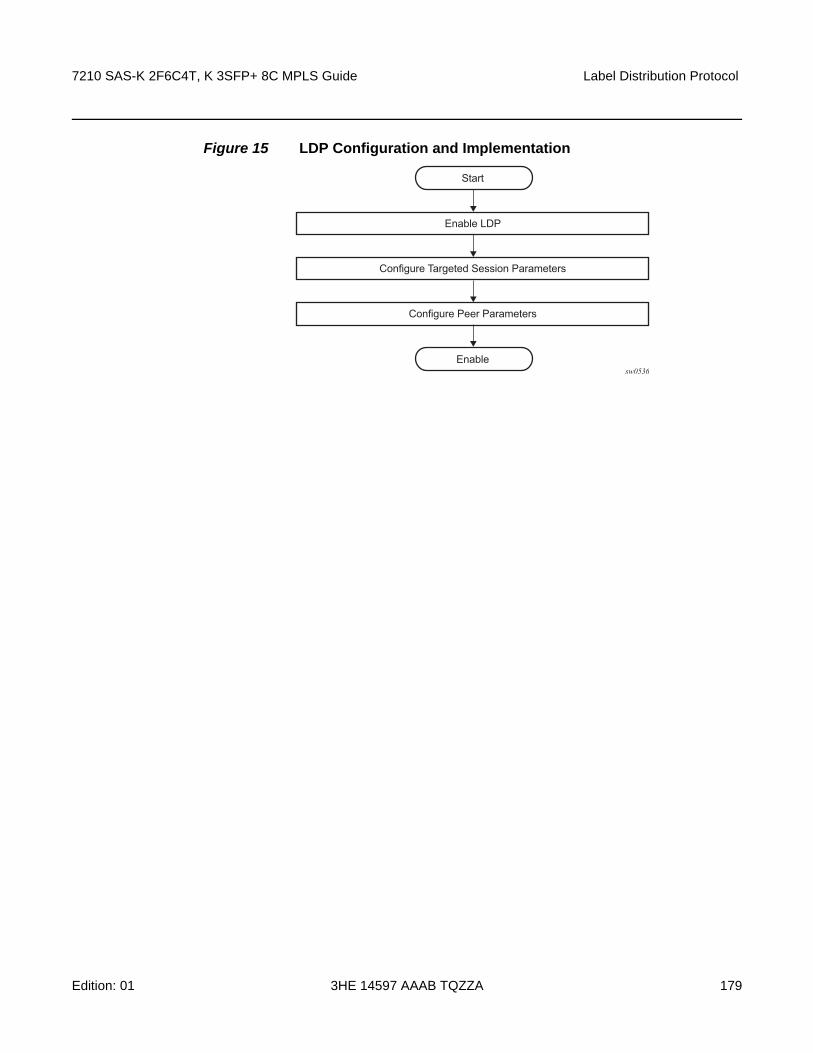
7210 SAS-K 2F6C4T, K 3SFP+ 8C MPLS Guide Label Distribution Protocol
Edition: 01 3HE 14597 AAAB TQZZA 179
Figure 15 LDP Configuration and Implementation
sw0536
Start
Configure Targeted Session Parameters
Configure Peer Parameters
Enable LDP
Enable

Label Distribution Protocol
180
7210 SAS-K 2F6C4T, K 3SFP+ 8C MPLS Guide
3HE 14597 AAAB TQZZA Edition: 01

7210 SAS-K 2F6C4T, K 3SFP+ 8C MPLS Guide Label Distribution Protocol
Edition: 01 3HE 14597 AAAB TQZZA 181
3.4 Configuring LDP with CLI
This section provides information to configure LDP using the command line interface.
3.5 LDP Configuration Overview
When the implementation of LDP is instantiated, the protocol is in the no shutdown state. In addition, targeted sessions are then enabled. The default parameters for LDP are set to the documented values for targeted sessions in draft-ietf-mpls-ldp-mib-09.txt.
3.6 Basic LDP Configuration
This chapter provides information to configure LDP and remove configuration examples of common configuration tasks.
The LDP protocol instance is created in the no shutdown (enabled) state.
3.7 Common Configuration Tasks
3.7.1 Enabling LDP
LDP must be enabled in order for the protocol to be active. MPLS must also be enabled. MPLS is enabled in the config>router>mpls context.
Use the following syntax to enable LDP on a router.
CLI Syntax: ldp
Example: config>router# ldp
Label Distribution Protocol
182
7210 SAS-K 2F6C4T, K 3SFP+ 8C MPLS Guide
3HE 14597 AAAB TQZZA Edition: 01
3.7.2 Configuring Graceful-Restart Helper Parameters
Graceful-restart helper advertises to its LDP neighbors by carrying the fault tolerant (FT) session TLV in the LDP initialization message, assisting the LDP in preserving its IP forwarding state across the restart. Nokia’s recovery is self-contained and relies on information stored internally to self-heal. This feature is only used to help third-party routers without a self-healing capability to recover.
Maximum recovery time is the time (in seconds) the sender of the TLV would like the receiver to wait, after detecting the failure of LDP communication with the sender.
Neighbor liveness time is the time (in seconds) the LSR is willing to retain its MPLS forwarding state. The time should be long enough to allow the neighboring LSRs to re-sync all the LSPs in a graceful manner, without creating congestion in the LDP control plane.
Use the following syntax to configure graceful-restart parameters.
CLI Syntax: config>router>ldp[no] graceful-restart
[no] maximum-recovery-time interval[no] neighbor-liveness-time interval
3.7.3 Applying Export and Import Policies
Both inbound and outbound label binding filtering are supported. Inbound filtering allows a route policy to control the label bindings an LSR accepts from its peers. An import policy can accept or reject label bindings received from LDP peers.
Label bindings can be filtered based on:
• Neighbor — Match on bindings received from the specified peer.
• Interface — Match on bindings received from a neighbor or neighbors adjacent over the specified interface.
• Prefix-list — Match on bindings with the specified prefix/prefixes.
Outbound filtering allows a route policy to control the set of LDP label bindings advertised by the LSR. An export policy can control the set of LDP label bindings advertised by the router. By default, label bindings for only the system address are advertised and propagate all FECs that are received.
Matches can be based on:
7210 SAS-K 2F6C4T, K 3SFP+ 8C MPLS Guide Label Distribution Protocol
Edition: 01 3HE 14597 AAAB TQZZA 183
• Loopback — loopback interfaces.
• All — all local subnets.
• Match — match on bindings with the specified prefix/prefixes.
Use the following syntax to apply import and export policies.
CLI Syntax: config>router>ldpexport policy-name [policy-name...(upto 32 max)]import policy-name [policy-name...(upto 32 max)]
3.7.4 Targeted Session Parameters
Use the following syntax to specify targeted-session parameters.
CLI Syntax: config>router# ldptargeted-sessiondisable-targeted-sessionhello timeout factorkeepalive timeout factorpeer ip-address
no bfd-enablehello timeout factorkeepalive timeout factorno shutdown
The following is a sample LDP configuration output.
A:ALA-1>config>router>ldp# info----------------------------------------------...
targeted-sessionhello 5000 255keepalive 5000 255peer 10.10.10.104
hello 2500 104keepalive 15 3
exitexit
----------------------------------------------A:ALA-1>config>router>ldp#
3.7.5 Interface Parameters
Use the following syntax to configure interface parameters.

Label Distribution Protocol
184
7210 SAS-K 2F6C4T, K 3SFP+ 8C MPLS Guide
3HE 14597 AAAB TQZZA Edition: 01
CLI Syntax: config>router# ldpinterface-parametershello timeout factorkeepalive timeout factortransport-address {system|interface}interface ip-int-name
hello timeout factorkeepalive timeout factortransport-address {system|interface}no shutdown
The following is a sample interface parameter configuration output.
A:ALU_SIM11>config>router>ldp# info----------------------------------------------
aggregate-prefix-matchprefix-exclude "sample"exit
graceful-restartexit
session-parameterspeer 1.1.1.1
ttl-security 1exit
exitinterface-parameters
interface "a"exit
exittargeted-sessionexit
----------------------------------------------
3.7.6 Session Parameters
Use the following syntax to specify session parameters.
CLI Syntax: config>router# ldpsession-parameterspeer ip-address
auth-keychain nameauthentication-key [authentication-key|hash-key]
[hash|hash2]
A:ALA-1>config>router>ldp# info----------------------------------------------
session-parameterspeer 10.10.10.104authentication-key "3WErEDozxyQ" hashexit

7210 SAS-K 2F6C4T, K 3SFP+ 8C MPLS Guide Label Distribution Protocol
Edition: 01 3HE 14597 AAAB TQZZA 185
exittargeted-session
hello 5000 255keepalive 5000 255peer 10.10.10.104
no bfd-enablehello 2500 100keepalive 15 3exit
exit----------------------------------------------A:ALA-1>config>router>ldp#
3.7.7 LDP Signaling and Services
When LDP is enabled, targeted sessions can be established to create remote adjacencies with nodes that are not directly connected. When service distribution paths (SDPs) are configured, extended discovery mechanisms enable LDP to send periodic targeted hello messages to the SDP’s far-end point. The exchange of LDP hellos trigger session establishment. The SDP’s signaling default enables tldp. The service SDP uses the targeted-session parameters configured in the config>router>ldp>targeted-session context.
Use the following syntax to configure enable LDP on an MPLS SDP.
CLI Syntax: config>service>sdp#signaling {off|tldp}
The following is a sample SDP configuration output showing the signaling default tldp enabled.
A:ALA-1>config>service>sdp# info detail----------------------------------------------
description "MPLS: to-99"far-end 10.10.10.99lsp A_D_1signaling tldppath-mtu 4462keep-alive
hello-time 10hold-down-time 10max-drop-count 3timeout 5no message-lengthno shutdown
exitno shutdown
----------------------------------------------A:ALA-1>config>service>sdp#

Label Distribution Protocol
186
7210 SAS-K 2F6C4T, K 3SFP+ 8C MPLS Guide
3HE 14597 AAAB TQZZA Edition: 01
3.8 LDP Configuration Management Tasks
This section describes the LDP configuration management tasks.
3.8.1 Disabling LDP
The no ldp command disables the LDP protocol on the router. All parameters revert to the default settings. LDP must be shut down before it can be disabled.
Use the following command syntax to disable LDP.
CLI Syntax: no ldpshutdown
3.8.2 Modifying Targeted Session Parameters
The modification of LDP targeted session parameters does not take effect until the next time the session goes down and is re-establishes. Individual parameters cannot be deleted. The no form of a targeted-session parameter command reverts modified values back to the default.
The following shows the command usage to revert targeted session parameters back to the default values.
Example: config>router# ldpconfig>router>ldp# targeted-sessionconfig>router>ldp>targeted# no authentication-keyconfig>router>ldp>targeted# no disable-targeted-sessionconfig>router>ldp>targeted# no helloconfig>router>ldp>targeted# no keepalive config>router>ldp>targeted# no peer 10.10.10.99
The following output displays the default values.
A:ALA-1>config>router>ldp>targeted# info detail----------------------------------------------
no disable-targeted-sessionhello 45 3keepalive 40 4
----------------------------------------------A:ALA-1>config>router>ldp>targeted#

7210 SAS-K 2F6C4T, K 3SFP+ 8C MPLS Guide Label Distribution Protocol
Edition: 01 3HE 14597 AAAB TQZZA 187
3.8.3 Modifying Interface Parameters
The modification of LDP targeted session parameters does not take effect until the next time the session goes down and is re-establishes. Individual parameters cannot be deleted. The no form of a interface-parameter command reverts modified values back to the defaults.

Label Distribution Protocol
188
7210 SAS-K 2F6C4T, K 3SFP+ 8C MPLS Guide
3HE 14597 AAAB TQZZA Edition: 01

7210 SAS-K 2F6C4T, K 3SFP+ 8C MPLS Guide Label Distribution Protocol
Edition: 01 3HE 14597 AAAB TQZZA 189
3.9 LDP Command Reference
3.9.1 Command Hierarchies
• LDP Commands
• Show Commands
• Clear Commands
• Debug Commands
• Tools Commands
3.9.1.1 LDP Commands
config— router
— [no] ldp— [no] aggregate-prefix-match
— prefix-exclude policy-name [policy-name...(up to 5 max)]— no prefix-exclude— [no] shutdown
— export policy-name [policy-name...(up to 5 max)]— no export— fast-reroute— no fast-reroute— fec-originate ip-prefix/mask [advertised-label in-label] [swap-label out-label]
interface interface-name— fec-originate ip-prefix/mask [advertised-label in-label] next-hop ip-address
[swap-label out-label]— fec-originate ip-prefix/mask [advertised-label in-label] next-hop ip-address
[swap-label out-label] interface interface-name— fec-originate ip-prefix/mask [advertised-label in-label] pop— no fec-originate ip-prefix/mask interface interface-name— no fec-originate ip-prefix/mask next-hop ip-address — no fec-originate ip-prefix/mask next-hop ip-address interface interface-name— no fec-originate ip-prefix/mask pop— [no] graceful-restart
— maximum-recovery-time interval— no maximum-recovery-time— neighbor-liveness-time interval— no neighbor-liveness-time
— [no] implicit-null-label— import policy-name [policy-name...(up to 5 max)]— interface-parameters
— [no] interface ip-int-name— bfd-enable

Label Distribution Protocol
190
7210 SAS-K 2F6C4T, K 3SFP+ 8C MPLS Guide
3HE 14597 AAAB TQZZA Edition: 01
— no bfd-enable— ipv4
— fec-type-capability— prefix-ipv4 {enable | disable}
— hello timeout factor— no hello— keepalive timeout factor— no keepalive— [no] shutdown— transport-address {system | interface}
— label-withdrawal-delay seconds— session-parameters
— [no] peer ip-address— export-addresses policy-name [policy-name ... (up to 5 max)]— no export-addresses— export-prefixes policy-name [policy-name ... (up to 5 max)]— no export-prefixes— fec-type-capability
— prefix-ipv4 {enable | disable}— fec129-cisco-interop {enable | disable}
— import-prefixes policy-name [policy-name ... (up to 5 max)]— no import-prefixes
— [no] shutdown— targeted-session
— [no] disable-targeted-session— ipv4
— hello timeout factor— no hello— hello-reduction {enable factor | disable}— no hello-reduction— keepalive timeout factor — no keepalive
— peer ip-address— no peer ip-address
— hello timeout factor— no hello— keepalive timeout factor — no keepalive— local-lsr-id interface-name— no local-lsr-id— [no] shutdown
3.9.1.2 Show Commands
show— router
— ldp — auth-keychain [keychain]— bindings active [fec-type prefixes] [prefix ip-prefix/mask] [egress-nh ip-
address | egress-if port-id | egress-lsp tunnel-id] [summary]— bindings active
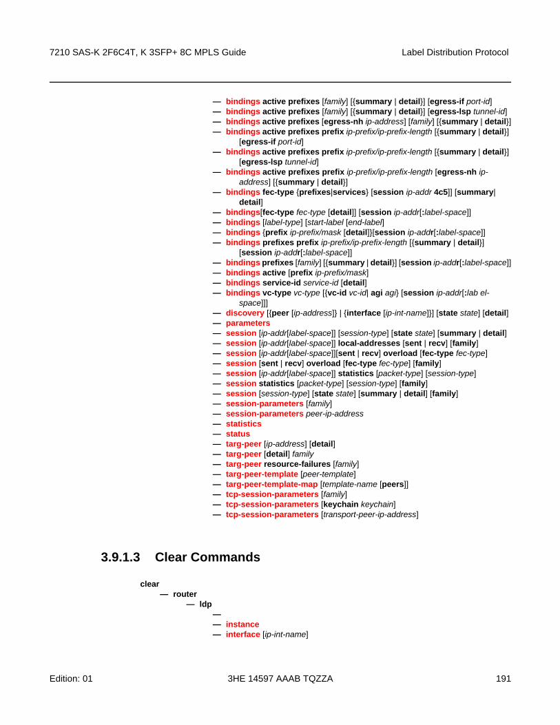
7210 SAS-K 2F6C4T, K 3SFP+ 8C MPLS Guide Label Distribution Protocol
Edition: 01 3HE 14597 AAAB TQZZA 191
— bindings active prefixes [family] [{summary | detail}] [egress-if port-id]— bindings active prefixes [family] [{summary | detail}] [egress-lsp tunnel-id]— bindings active prefixes [egress-nh ip-address] [family] [{summary | detail}]— bindings active prefixes prefix ip-prefix/ip-prefix-length [{summary | detail}]
[egress-if port-id]— bindings active prefixes prefix ip-prefix/ip-prefix-length [{summary | detail}]
[egress-lsp tunnel-id]— bindings active prefixes prefix ip-prefix/ip-prefix-length [egress-nh ip-
address] [{summary | detail}]— bindings fec-type {prefixes|services} [session ip-addr 4c5]] [summary|
detail]— bindings[fec-type fec-type [detail]] [session ip-addr[:label-space]] — bindings [label-type] [start-label [end-label]— bindings {prefix ip-prefix/mask [detail]}[session ip-addr[:label-space]]— bindings prefixes prefix ip-prefix/ip-prefix-length [{summary | detail}]
[session ip-addr[:label-space]]— bindings prefixes [family] [{summary | detail}] [session ip-addr[:label-space]]— bindings active [prefix ip-prefix/mask] — bindings service-id service-id [detail]— bindings vc-type vc-type [{vc-id vc-id| agi agi} [session ip-addr[:lab el-
space]]]— discovery [{peer [ip-address]} | {interface [ip-int-name]}] [state state] [detail] — parameters— session [ip-addr[label-space]] [session-type] [state state] [summary | detail]— session [ip-addr[label-space]] local-addresses [sent | recv] [family]— session [ip-addr[label-space]][sent | recv] overload [fec-type fec-type]— session [sent | recv] overload [fec-type fec-type] [family]— session [ip-addr[label-space]] statistics [packet-type] [session-type]— session statistics [packet-type] [session-type] [family]— session [session-type] [state state] [summary | detail] [family]— session-parameters [family]— session-parameters peer-ip-address— statistics— status— targ-peer [ip-address] [detail]— targ-peer [detail] family— targ-peer resource-failures [family]— targ-peer-template [peer-template]— targ-peer-template-map [template-name [peers]]— tcp-session-parameters [family]— tcp-session-parameters [keychain keychain]— tcp-session-parameters [transport-peer-ip-address]
3.9.1.3 Clear Commands
clear— router
— ldp—— instance— interface [ip-int-name]

Label Distribution Protocol
192
7210 SAS-K 2F6C4T, K 3SFP+ 8C MPLS Guide
3HE 14597 AAAB TQZZA Edition: 01
— peer [ip-address] [statistics]— session [ip-addr[:label-space]] [statistics]— statistics
3.9.1.4 Debug Commands
[no] debug — router
— [no] ldp— [no] interface interface-name
— [no] event— [no] messages
— [no] packet [detail]— hello [detail]— no hello
— peer ip-address— [no] event
— [no] bindings— [no] messages
— [no] packet— hello [detail]— no hello— init [detail]— no init— [no] keepalive— label [detail]— no label
3.9.1.5 Tools Commands
tools— dump
— ldp-treetrace {prefix ip-prefix/mask | manual-prefix ip-prefix/mask}[path-destination ip-address] [trace-tree]
— router— ldp
— instance— interface ip-int-name— memory-usage— peer ip-address— session ip-addr[label-space] [connection | peer | adjacency]— sockets— timers [session ip-addr[label-space]]
— static-route ldp-sync-status— perform
— router— isis
— ldp-sync-exit

7210 SAS-K 2F6C4T, K 3SFP+ 8C MPLS Guide Label Distribution Protocol
Edition: 01 3HE 14597 AAAB TQZZA 193
— run-manual-spf— ospf
— ldp-sync-exit— refresh-lsas [lsa-type] [area-id]— run-manual-spf [externals-only]
3.9.2 Command Descriptions
• Configuration Commands
• Show Commands
• Clear Commands
• Debug Commands
• Tools Commands
3.9.2.1 Configuration Commands
• Generic Commands
• LDP Global Commands
• Session Parameters Commands
• Targeted Session Commands
3.9.2.1.1 Generic Commands
shutdown
Syntax [no] shutdown
Context config>router>ldpconfig>router>ldp>targ-session>peerconfig>router>ldp>interface-parameters>interface>ipv4config>router>ldp>interface-parameters>ipv4config>router>ldp>aggregate-prefix-match
SupportedPlatforms
Supported on all 7210 SAS platforms as described in this document
Description This command administratively disables an entity. When disabled, an entity does not change, reset, or remove any configuration settings or statistics.

Label Distribution Protocol
194
7210 SAS-K 2F6C4T, K 3SFP+ 8C MPLS Guide
3HE 14597 AAAB TQZZA Edition: 01
The operational state of the entity is disabled as well as the operational state of any entities contained within. Many objects must be shut down before they may be deleted.
Unlike other commands and parameters where the default state is not indicated in the configuration file, the shutdown and no shutdown states are always indicated in system generated configuration files.
The no form of this command places an entity in an administratively enabled state.
Default no shutdown
3.9.2.1.2 LDP Global Commands
ldp
Syntax [no] ldp
Context config>router
SupportedPlatforms
Supported on all 7210 SAS platforms as described in this document
Description This command enables the context to configure LDP parameters. LDP is not enabled by default and must be explicitly enabled (no shutdown).
To suspend the LDP protocol, use the shutdown command. Configuration parameters are not affected. The LDP instance must first be disabled using the shutdown command before being deleted.
The no form of this command deletes the LDP protocol instance, removing all associated configuration parameters.
aggregate-prefix-match
Syntax [no] aggregate-prefix-match
Context config>router>ldp
SupportedPlatforms
Supported on all 7210 SAS platforms as described in this document
Description The command enables LDP to use the aggregate prefix match function rather than requiring an exact prefix match.
When this command is enabled, LDP performs the following procedures for all prefixes. When an LSR receives a FEC-label binding from an LDP neighbor for a specific FEC1 element, it installs the binding in the LDP FIB if:
7210 SAS-K 2F6C4T, K 3SFP+ 8C MPLS Guide Label Distribution Protocol
Edition: 01 3HE 14597 AAAB TQZZA 195
• it is able to perform a successful longest IP match of the FEC prefix with an entry in the routing table
• the advertising LDP neighbor is the next-hop to reach the FEC prefix
When the FEC-label binding has been installed in the LDP FIB, LDP programs an NHLFE entry in the egress data path to forward packets to FEC1. LDP also advertises a new FEC-label binding for FEC1 to all its LDP neighbors.
When a new prefix appears in the routing table, LDP inspects the LDP FIB to determine if this prefix is a closer match for any of the installed FEC elements. For any FEC for which this is true, LDP may have to update the NHLFE entry for this FEC.
When a prefix is removed from the routing table, LDP checks the LDP FIB for all FEC elements that matched this prefix to determine if another match exists in the routing table. If another match exists, it updates the NHLFE entry. If not, it sends a label withdraw message to its LDP neighbors to remove the binding.
If the next hop for a routing prefix changes, LDP updates the LDP FIB entry for the FEC elements that matched this prefix. It also updates the NHLFE entry for these FEC elements.
The no form of this command disables the use of the aggregate prefix match function and deletes the configuration. LDP then performs only exact prefix matching for FEC elements.
Default no aggregate-prefix-match
prefix-exclude
Syntax prefix-exclude policy-name [policy-name... (up to 5 max)]
no prefix-exclude
Context config>router>ldp>aggregate-prefix-match
SupportedPlatforms
Supported on all 7210 SAS platforms as described in this document
Description This command specifies the policy name containing the prefixes to be excluded from the aggregate prefix match function. Against each excluded prefix, LDP performs an exact match of a specific FEC element prefix, rather than a longest prefix match of one or more LDP FEC element prefixes when it receives a FEC-label binding or when a change to this prefix occurs in the routing table.
The no form of this command removes all policies from the configuration.
Default no prefix-exclude.
Parameters policy-name — Specifies the import route policy name. Allowed values are any string up to 32 characters long composed of printable, 7-bit ASCII characters. If the string contains special characters (#, $, spaces, etc.), the entire string must be enclosed within double quotes.

Label Distribution Protocol
196
7210 SAS-K 2F6C4T, K 3SFP+ 8C MPLS Guide
3HE 14597 AAAB TQZZA Edition: 01
export
Syntax export policy-name [policy-name … (up to 5 max)]
no export
Context config>router>ldp
SupportedPlatforms
Supported on all 7210 SAS platforms as described in this document
Description This command specifies the export route policies that determine which routes are exported to LDP. Policies are configured in the config>router>policy-options context.
If no export policy is specified, non-LDP routes are not exported from the routing table manager to LDP, and LDP-learned routes are exported only to LDP neighbors. The currenty implementation of the export policy (outbound filtering) can be used only to add FECs for label propagation. The export policy does not control propagation of FECs that an LSR receives from its neighbors.
If multiple policy names are specified, the policies are evaluated in the order they are specified. The first policy that matches is applied. If multiple export commands are issued, the last command entered overrides the previous command. A maximum of five policy names can be specified. Specified names must already be defined.
The no form of this command removes all policies from the configuration.
Default no export
Parameters policy-name — Specifies the export route policy name. Allowed values are any string up to 32 characters composed of printable, 7-bit ASCII characters. If the string contains special characters (#, $, spaces, etc.), the entire string must be enclosed within double quotes.
fast-reroute
Syntax fast-reroute
no fast-reroute
Context config>router>ldp
SupportedPlatforms
Supported on all 7210 SAS platforms as described in this document
Description This command enables LDP Fast-Reroute (FRR). When enabled, LDP uses both the primary next hop and LFA next hop, when available, for resolving the next hop of an LDP FEC against the corresponding prefix in the routing table. This results in LDP programming a primary NHLFE and a backup NHLFE into the forwarding engine for each next hop of a FEC prefix for the purpose of forwarding packets over the LDP FEC.

7210 SAS-K 2F6C4T, K 3SFP+ 8C MPLS Guide Label Distribution Protocol
Edition: 01 3HE 14597 AAAB TQZZA 197
The backup NHLFE is enabled for each affected FEC next hop when any of the following events occurs.
• An LDP interface goes operationally down or is administratively shut down. In this case, LDP sends a neighbor/next-hop down message to the IOM for each LDP peer it has adjacency with over this interface.
• An LDP session to a peer goes down because the Hello or keepalive timer has expired over a specific interface. In this case, LDP sends a neighbor/next-hop down message to the IOM for this LDP peer only.
• The TCP connection used by a link LDP session to a peer goes down, because, for example, next-hop tracking of the LDP transport address in RTM brings down the LDP session. In this case, LDP sends a neighbor/next-hop down message to the IOM for this LDP peer only.
• A BFD session, enabled on a T-LDP session to a peer, times out and causes the link LDP session to the same peer, which uses the same TCP connection as the T-LDP session, to also go down. In this case, LDP sends a neighbor/next-hop down message to the IOM for this LDP peer only.
• A BFD session enabled on the LDP interface to a directly connected peer times out and brings down the link LDP session to this peer. In this case, LDP sends a neighbor/next-hop down message to the IOM for this LDP peer only. BFD support on LDP interfaces is a recent feature that provides faster tracking of link LDP peers.
The tunnel-down-damp-time command or the label-withdrawal-delay command, when enabled, do not cause the corresponding timer to be activated for a FEC as long as a backup NHLFE is still available.
Because LDP can detect the loss of a neighbor/next-hop independently, it is possible that it will switch to the LFA next hop while IGP is still using the primary next hop. Also, when the interface for the previous primary next hop is restored, IGP may reconverge before LDP completes the FEC exchange with its neighbor over that interface. This may cause LDP to deprogram the LFA next hop from the FEC and blackhole traffic. To avoid this situation, IGP-LDP synchronization should be enabled on the LDP interface.
When the SPF computation determines there is more than one primary next hop for a prefix, it does not program an LFA next hop in RTM. The LDP FEC will resolve to the multiple primary next hops that provide the required protection.
The no form of this command disables LDP FRR.
Default no fast-reroute
fec-originate
Syntax fec-originate ip-prefix/mask [advertised-label in-label] [swap-label out-label] interface interface-name
fec-originate ip-prefix/mask [advertised-label in-label] next-hop ip-address [swap-label out-label]

Label Distribution Protocol
198
7210 SAS-K 2F6C4T, K 3SFP+ 8C MPLS Guide
3HE 14597 AAAB TQZZA Edition: 01
fec-originate ip-prefix/mask [advertised-label in-label] next-hop ip-address [swap-label out-label] interface interface-name
fec-originate ip-prefix/mask [advertised-label in-label] pop
no fec-originate ip-prefix/mask interface interface-name
no fec-originate ip-prefix/mask next-hop ip-address
no fec-originate ip-prefix/mask next-hop ip-address interface interface-name
no fec-originate ip-prefix/mask pop
Context config>router>ldp
SupportedPlatforms
Supported on all 7210 SAS platforms as described in this document
Description This command adds a FEC to the LDP prefix database with a specific label operation on the node.
Permitted operations are swap to originate a FEC for which the LSR is not egress or pop to originate a FEC for which the LSR is egress.
The next-hop, advertised-label, and swap-label keywords are optional. If next-hop is configured but no out-label is specified, a swap occurs with label 3, such as, pop and forward to the next hop. If the next-hop and swap-label are configured, a regular swap occurs. If no parameters are specified, a pop and route is performed.
Parameters ip-prefix/mask — Specifies the information for the IP prefix and mask length.
Values
next-hop — Keyword to specify the IP address of the next hop of the prefix.
advertised-label — Keyword to specify the label advertised to the upstream peer. If not configured, the label advertised should be from the label pool. If the configured static label is not available, the IP prefix is not advertised.
out-label — Specifies the number of labels to send to the peer associated with this FEC. If configured, the LSR should swap the label with the configured swap-label. If not configured, the default action is pop if the next-hop parameter is not defined.
Values 16 to 1048575
in-label — Specifies the number of labels to send to the peer associated with this FEC.
Values 32 to 1023
pop — Keyword to specify to pop the label and transmit without the label.
interface interface-name — Specifies the name of the interface that the label for the originated FEC is swapped to. For an unnumbered interface, this parameter is mandatory because there is no address for the next hop. For a numbered interface, it is optional.
ip-address/mask ipv4-prefix: a.b.c.d
ipv4-prefix-le: 0 to 32

7210 SAS-K 2F6C4T, K 3SFP+ 8C MPLS Guide Label Distribution Protocol
Edition: 01 3HE 14597 AAAB TQZZA 199
graceful-restart
Syntax [no] graceful-restart
Context config>router>ldp
SupportedPlatforms
Supported on all 7210 SAS platforms as described in this document
Description This command enables graceful restart helper.
The no form of this command disables graceful restart.
Default no graceful-restart
implicit-null-label
Syntax [no] implicit-null-label
Context config>router>ldp
SupportedPlatforms
Supported on all 7210 SAS platforms as described in this document
Description This command enables the implicit null label. Use this command to signal the IMPLICIT NULL option for all LDP FECs for which this node is the egress LER.
The no form of this command disables the signaling of the implicit null label.
Default no implicit-null-label
maximum-recovery-time
Syntax maximum-recovery-time interval
no maximum-recovery-time
Context config>router>ldp>graceful-restart
SupportedPlatforms
Supported on all 7210 SAS platforms as described in this document
Description This command configures the local maximum recovery time.
The no form of this command reverts to the default value.
Default 120
Parameters interval — Specifies the length of time, in seconds.
Values 15 to 1800

Label Distribution Protocol
200
7210 SAS-K 2F6C4T, K 3SFP+ 8C MPLS Guide
3HE 14597 AAAB TQZZA Edition: 01
neighbor-liveness-time
Syntax neighbor-liveness-time interval
no neighbor-liveness-time
Context config>router>ldp>graceful-restart
SupportedPlatforms
Supported on all 7210 SAS platforms as described in this document
Description This command configures the neighbor liveness time.
The no form of this command reverts to the default value.
Default 120
Parameters interval — Specifies the length of time, in seconds.
Values 5 to 300
import
Syntax import policy-name [policy-name … (up to 5 max)]
no import
Context config>router>ldp
SupportedPlatforms
Supported on all 7210 SAS platforms as described in this document
Description This command configures import route policies to determine which label bindings (FECs) are accepted from LDP neighbors. Policies are configured in the config>router>policy-options context.
If no import policy is specified, LDP accepts all label bindings from configured LDP neighbors. Import policies can be used to limit or modify the routes accepted and their corresponding parameters and metrics.
If multiple policy names are specified, the policies are evaluated in the order they are specified. The first policy that matches is applied. If multiple import commands are issued, the last command entered overrides the previous command. A maximum of five policy names can be specified. The specified names must already be defined.
The no form of this command removes all policies from the configuration.
Default no import

7210 SAS-K 2F6C4T, K 3SFP+ 8C MPLS Guide Label Distribution Protocol
Edition: 01 3HE 14597 AAAB TQZZA 201
Parameters policy-name — Specifies the import route policy name. Allowed values are any string up to 32 characters composed of printable, 7-bit ASCII characters. If the string contains special characters (#, $, spaces, etc.), the entire string must be enclosed within double quotes.
label-withdrawal-delay
Syntax label-withdrawal-delay seconds
Context config>router>ldp
SupportedPlatforms
Supported on all 7210 SAS platforms as described in this document
Description This command configures the time interval, in seconds, that LDP will delay the withdrawal of the FEC-label binding it distributed to its neighbors when FEC is deactivated. When the timer expires, LDP then sends a label withdrawal for the FEC to all its neighbors. This is applicable only to LDP transport tunnels (IPv4 prefix FECs) and is not applicable to pseudowires (service FECs).
Default no label-withdrawal-delay
Parameters seconds — Specifies the time that LDP delays the withdrawal of the FEC-label binding it distributed to its neighbors when FEC is deactivated.
Values 3 to 120
keepalive
Syntax keepalive timeout factor
no keepalive
Context config>router>ldp>interface-parameters>interface>ipv4config>router>ldp>interface-parameters>ipv4config>router>ldp>targ-session>ipv4config>router>ldp>targ-session>peer
SupportedPlatforms
Supported on all 7210 SAS platforms as described in this document
Description This command configures the time, in seconds, that LDP waits before tearing down the session. The factor parameter is the keepalive interval.
If no LDP messages are exchanged for the configured amount of time, the LDP session is torn down. Keepalive timeout is usually three times the keepalive interval. To maintain the session permanently, regardless of the activity, set the value to zero.

Label Distribution Protocol
202
7210 SAS-K 2F6C4T, K 3SFP+ 8C MPLS Guide
3HE 14597 AAAB TQZZA Edition: 01
When the LDP session is being set up, the keepalive timeout is negotiated to the lower of the two peers. When a operational value is agreed upon, the keepalive factor derives the value of the keepalive interval. The session needs to be flapped for the new settings to work.
The no form of this command at the interface level sets the timeout and factor to the values defined under the interface-parameters level.
The no form of this command at the peer level sets the timeout and factor to the values defined under the targeted-session level.
Default The default value is dependent upon the CLI context. Table 18 lists the keepalive timeout factor default values.
Parameters timeout — Specifies the time, in seconds, that LDP waits before tearing down the session.
Values 3 to 65535
factor — Specifies the number of keepalive messages, expressed as a decimal integer, that should be sent on an idle LDP session in the keepalive timeout interval.
Values 1 to 255
local-lsr-id
Syntax local-lsr-id interface-name
no local-lsr-id
Context config>router>ldp>targeted-session>peer
SupportedPlatforms
Supported on all 7210 SAS platforms as described in this document
Description This command enables the use of the address of a specific interface as the LSR ID for the hello adjacency of a T-LDP session. The interface can be a regular interface or a loopback interface, including the system interface.
Table 18 Keepalive Timeout Factor Default Values
Context Timeout Factor
config>router>ldp>if-params 30 3
config>router>ldp>targ-session 40 4
config>router>ldp>if-params>if Inherits values from interface-parameters context
config>router>ldp>targ-session>peer Inherits values from targeted-session context

7210 SAS-K 2F6C4T, K 3SFP+ 8C MPLS Guide Label Distribution Protocol
Edition: 01 3HE 14597 AAAB TQZZA 203
By default, a T-LDP session uses the system interface address as the LSR ID; however, the system interface must always be configured on the router or the LDP protocol will not come up on the node. There is no requirement to include the system interface in any routing protocol.
At initial configuration, the T-LDP session remains down while the specified interface is down. LDP does not try to bring it up using the system interface.
If the LSR ID is changed on the fly while the T-LDP session is up, LDP immediately tears down the session and attempts to establish one using the new LSR ID, regardless of the operational state of the new interface.
If the interface used as the LSR ID goes down, the T-LDP session also goes down.
The user-configured LSR ID is used exclusively for extended peer discovery to establish the T-LDP hello adjacency. It is also used as the transport address for the TCP session of the LDP session when it is bootstrapped by the T-LDP hello adjacency. The user-configured LSR ID is, however, not used in basic peer discovery to establish a link-level LDP hello adjacency.
The no form of this command reverts to the default behavior, in which case the system interface address is used as the LSR ID.
Default no local-lsr-id
Parameters interface-name — Specifies the name of the network IP interface. An interface name cannot be in the form of an IP address. If the string contains special characters (#, $, spaces, etc.), the entire string must be enclosed within double quotes.
Values 1 to 32 characters
interface-parameters
Syntax interface-parameters
Context config>router>ldp
SupportedPlatforms
Supported on all 7210 SAS platforms as described in this document
Description This command enables the context to configure LDP interfaces and parameters applied to LDP interfaces.
prefix-ipv4
Syntax prefix-ipv4 {enable | disable}
Context config>router>ldp>interface-params>interface>ipv4>fec-type-capability

Label Distribution Protocol
204
7210 SAS-K 2F6C4T, K 3SFP+ 8C MPLS Guide
3HE 14597 AAAB TQZZA Edition: 01
SupportedPlatforms
Supported on all 7210 SAS platforms as described in this document
Description This command enables and disables IPv4 prefix FEC capability on the interface.
Parameters enable — Keyword to enable IPv4 FEC capability.
disable — Keyword to disable IPv4 FEC capability.
hello
Syntax hello timeout factor
no hello
Context config>router>ldp>interface-parameters>interface>ipv4config>router>ldp>interface-parameters>ipv4config>router>ldp>targ-session>ipv4config>router>ldp>targ-session>peer
SupportedPlatforms
Supported on all 7210 SAS platforms as described in this document
Description This command configures the time interval to wait before declaring a neighbor down. The factor parameter derives the hello interval.
Hold time is local to the system and sent in the hello messages to the neighbor. Hold time cannot be less than three times the hello interval.
When LDP session is being set up, the hold-down time is negotiated to the lower of the two peers. After a operational value is agreed upon, the hello factor is used to derive the value of the hello interval. The session needs to be flapped for the new settings to operate.
The no form of this command at the targeted-session level sets the hello timeout and the hello factor to the default values.
The no form of this command at the peer level sets the hello timeout and the hello factor to the value defined under the targeted-session level.
Default The default value is dependent upon the CLI context. Table 19 lists the hello timeout factor default values.
Table 19 Hello Timeout Factor Default Values
Context Timeout Factor
config>router>ldp>if-params 15 3
config>router>ldp>targ-session 45 3

7210 SAS-K 2F6C4T, K 3SFP+ 8C MPLS Guide Label Distribution Protocol
Edition: 01 3HE 14597 AAAB TQZZA 205
Parameters timeout — Specifies the time interval, in seconds, that LDP waits before declaring a neighbor down.
Values 3 to 65535
factor — Specifies the number of keepalive messages that should be sent on an idle LDP session in the hello timeout interval.
Values 1 to 255
hello-reduction
Syntax hello-reduction {enable factor | disable}
no hello-reduction
Context config>router>ldp>targ-session>ipv4
SupportedPlatforms
Supported on all 7210 SAS platforms as described in this document
Description This command enables the suppression of periodic targeted hello messages between LDP peers after the targeted LDP session is brought up.
When this feature is enabled, the target hello adjacency is brought up by advertising the hold-time value that the user configured in the hello timeout parameter for the targeted session. The LSR node starts advertising an exponentially increasing hold-time value in the hello message as soon as the targeted LDP session to the peer is up. Each new incremented hold-time value is sent in several hello messages equal to the value of the argument factor (the dampening factor) before the next exponential value is advertised. This functionality provides time for the two peers to settle on the new value. When the hold-time reaches the maximum value of 0xffff (binary 65535), the two peers send hello messages at a frequency of every [(65535-1)/local helloFactor] seconds for the lifetime of the targeted-LDP session; for example, if the local hello factor is three (3), hello messages are sent every 21844 seconds.
The LSR node continues to compute the frequency of sending the hello messages based on the minimum of its local hold-time value and the one advertised by its peer, as in RFC 5036. For the targeted LDP session to suppress the periodic hello messages, both peers must bring their advertised hold-time to the maximum value. If one of the LDP peers does not, the frequency of the hello messages sent by both peers continues to be governed by the smaller of the two hold-time values.
config>router>ldp>if-params>if Inherits values from interface-parameters context
config>router>ldp>targ-session>peer Inherits values from targeted-session context
Table 19 Hello Timeout Factor Default Values (Continued)
Context Timeout Factor
Label Distribution Protocol
206
7210 SAS-K 2F6C4T, K 3SFP+ 8C MPLS Guide
3HE 14597 AAAB TQZZA Edition: 01
When the user enables the hello-reduction command on the LSR node while the targeted LDP session to the peer is operationally up, the change takes effect immediately. The LSR node starts advertising an exponentially increasing hold-time value in the hello message, starting with the currently configured hold-time value.
When the user disables the hello-reduction command while the targeted LDP session to the peer is operationally up, the change in the hold-time from 0xffff (binary 65535) to the user-configured value for this peer takea effect immediately. The local LSR immediately advertises the user-configured hold-time value and does not wait until the next scheduled time to send a hello to make sure the peer adjusts its local hold timeout value.
In general, any configuration change to the parameters of the T-LDP hello adjacency (modifying the hello adjacency hello timeout or factor, enabling or disabling hello-reduction, or modifying the hello-reduction factor) causes the LSR node to immediately trigger an updated hello message with the updated hold-time value without waiting for the next scheduled time to send a hello.
The no form of this command disables hello reduction.
Default no hello-reduction
Parameters disable — Keyword that disables hello reduction.
factor — Specifies the hello-reduction dampening factor.
Values 3 to 20
interface
Syntax [no] interface ip-int-name
Context config>router>ldp>if-params
SupportedPlatforms
Supported on all 7210 SAS platforms as described in this document
Description This command enables LDP on the specified IP interface. The LDP interface must be disabled using the shutdown command before it can be deleted.
The no form of this command deletes the LDP interface and all configuration information associated with the LDP interface.
Parameters ip-int-name — Specifies the name of an existing interface. If the string contains special characters (#, $, spaces, etc.), the entire string must be enclosed within double quotes.
bfd-enable
Syntax bfd-enable
7210 SAS-K 2F6C4T, K 3SFP+ 8C MPLS Guide Label Distribution Protocol
Edition: 01 3HE 14597 AAAB TQZZA 207
no bfd-enable
Context config>router>ldp>interface-parameters>interface
SupportedPlatforms
Supported on all 7210 SAS platforms as described in this document
Description This command enables tracking of the hello adjacency to an LDP peer using BFD.
When this command is enabled on an LDP interface, LDP registers with BFD and starts tracking the LSR ID of all peers it formed hello adjacencies with over that LDP interface. The LDP hello mechanism determines the remote address to be used for the BFD session. The parameters used for the BFD session, that is, transmit-interval, receive-interval, and multiplier, are those configured under the IP interface in the config router interface bfd command.
When multiple links exist to the same LDP peer, a hello adjacency is established over each link and a separate BFD session is enabled on each LDP interface. If a BFD session times out on a specific link, LDP immediately associates the LDP session with one of the remaining hello adjacencies and triggers the LDP FRR procedures. As soon as the last hello adjacency goes down because of BFD timing out, the LDP session goes down and the LDP FRR procedures are triggered.
The no form of this command disables BFD on the LDP interface.
Default no bfd-enable
ipv4
Syntax ipv4
Context config>router>ldp>interface-parameters>interfaceconfig>router>ldp>interface-parametersconfig>router>ldp>targeted-session
SupportedPlatforms
Supported on all 7210 SAS platforms as described in this document
Description This command enables the context to configure IPv4 LDP parameters for the interface.
transport-address
Syntax transport-address {interface | system}
Note: For more information about the list of protocols that support BFD, see 7210 SAS-D, Dxp, E, K 2F1C2T, K 2F6C4T, K 3SFP+ 8C Router Configuration Guide.

Label Distribution Protocol
208
7210 SAS-K 2F6C4T, K 3SFP+ 8C MPLS Guide
3HE 14597 AAAB TQZZA Edition: 01
no transport-address
Context config>router>ldp>interface-parameters>interface>ipv4config>router>ldp>interface-parameters>ipv4
SupportedPlatforms
Supported on all 7210 SAS platforms as described in this document
Description This command configures the transport address used when setting up LDP TCP sessions. The transport address can be configured as interface or system. The transport address can be configured globally (applies to all LDP interfaces) or per interface. The most specific value is used.
With the transport-address command, users set up the LDP interface to the connection that can be set to the interface address or system address. However, there can be an issue of which address to use when there are parallel adjacencies. This address selection situation can also occur when there is a link and a targeted adjacency, because targeted adjacencies request the session to be set up only to the system IP address.
The transport-address value should not be interface if multiple interfaces exist between two LDP neighbors.
Depending on the first adjacency formed, the TCP endpoint is chosen. If one LDP interface is set up as transport-address interface and another as transport-address system, depending on which adjacency was set up first, the TCP endpoint addresses are determined. After that, because the hello contains the LSR ID, the LDP session can be checked to verify that it is set up and then the adjacency can be matched to the session.
For any specific ILDP interface, as the local-lsr-id parameters is changed to interface, the transport-address configuration loses effectiveness, because it is ignored and the ILDP session always uses the relevant interface IP address as the transport address even though system is chosen.
The no form of this command at the global level reverts the transport address to the default value.
The no form of this command at the interface level sets the transport address to the value defined under the global level.
Default system
Parameters interface — Keyword to specify the IP interface address is used to set up the LDP session between neighbors. The transport address interface cannot be used if multiple interfaces exist between two neighbors, since only one LDP session is set up between two neighbors.
system — Keyword to specify the system IP address is used to set up the LDP session between neighbors.

7210 SAS-K 2F6C4T, K 3SFP+ 8C MPLS Guide Label Distribution Protocol
Edition: 01 3HE 14597 AAAB TQZZA 209
3.9.2.1.3 Session Parameters Commands
session-parameters
Syntax session-parameters
Context config>router>ldp
SupportedPlatforms
Supported on all 7210 SAS platforms as described in this document
Description This command enables the context to configure peer-specific parameters.
peer
Syntax [no] peer ip-address
Context config>router>ldp>session-parameters
SupportedPlatforms
Supported on all 7210 SAS platforms as described in this document
Description This command configures parameters for an LDP peer.
Parameters ip-address — Specifies the IP address of the LDP peer, in dotted decimal notation.
export-addresses
Syntax export-addresses policy-name [policy-name ... (up to 5 max)]
no export-addresses
Context config>router>ldp>session-params>peer
SupportedPlatforms
Supported on all 7210 SAS platforms as described in this document
Description This command configures the export prefix policy to local addresses advertised to this peer.
Policies are configured in the config>router>policy-options context. A maximum of five policy names can be specified. The specified names must already be defined.
The no form of this command removes the policy from the configuration.
Default no export-addresses

Label Distribution Protocol
210
7210 SAS-K 2F6C4T, K 3SFP+ 8C MPLS Guide
3HE 14597 AAAB TQZZA Edition: 01
Parameters policy-name — Specifies the export-prefix route policy name. Allowed values are any string up to 32 characters composed of printable, 7-bit ASCII characters excluding double quotes. If the string contains spaces, use double quotes to delimit the start and end of the string.
export-prefixes
Syntax export-prefixes policy-name [policy-name ... (up to 5 max)]
no export-prefixes
Context config>router>ldp>session-params>peer
SupportedPlatforms
Supported on all 7210 SAS platforms as described in this document
Description This command configures the export route policy used to determine which prefixes received from other LDP and T-LDP peers are redistributed to this LDP peer via the LDP/T-LDP session to this peer. A prefix that is filtered out (deny) is not exported. A prefix that is filtered in (accept) is exported.
If no export policy is specified, all FEC prefixes learned are exported to this LDP peer. This policy is applied in addition to the global LDP policy and targeted session policy.
Policies are configured in the config>router>policy-options context. A maximum of five policy names can be specified. The peer address must be the peer LSR ID address. The specified names must already be defined.
The no form of this command removes the policy from the configuration.
Default no export-prefixes
Parameters policy-name — Specifies the export-prefix route policy name. Allowed values are any string up to 32 characters composed of printable, 7-bit ASCII characters excluding double quotes. If the string contains spaces, use double quotes to delimit the start and end of the string.
fec-type-capability
Syntax fec-type-capability
Context config>router>ldp>session-params>peerconfig>router>ldp>interface-params>interface>ipv4
SupportedPlatforms
Supported on all 7210 SAS platforms as described in this document
Description This command enables the context to configure FEC type capabilities for the session or interface.
7210 SAS-K 2F6C4T, K 3SFP+ 8C MPLS Guide Label Distribution Protocol
Edition: 01 3HE 14597 AAAB TQZZA 211
prefix-ipv4
Syntax prefix-ipv4 {enable | disable}
Context config>router>ldp>session-params>peer>fec-type-capability
SupportedPlatforms
Supported on all 7210 SAS platforms as described in this document
Description This command enables or disables IPv4 prefix FEC capability on the session or interface.
Default prefix-ipv4 enable
Parameters enable — Keyword to specify that IPv4 prefix FEC capability is enabled.
disable — Keyword to specify that IPv4 prefix FEC capability is disabled.
fec129-cisco-interop
Syntax [no] fec129-cisco-interop
Context config>router>ldp>session-params>peer
SupportedPlatforms
Supported on all 7210 SAS platforms as described in this document
Description This command configures whether LDP provides translation between non-compliant FEC 129 Cisco formats. Peer LDP sessions must be manually configured towards the non-compliant Cisco PEs.
When enabled, Cisco non-compliant format is used to send and interpret received label release messages. The FEC129 SAII and TAII fields are reversed.
The no form of this command disables use and support of Cisco non-compliant forms. The peer address must be the peer LSR ID address.
Default no fec129-cisco-interop
import-prefixes
Syntax import-prefixes policy-name [policy-name ... (up to 5 max)]
no import-prefixes
Context config>router>ldp>session-params>peer
SupportedPlatforms
Supported on all 7210 SAS platforms as described in this document

Label Distribution Protocol
212
7210 SAS-K 2F6C4T, K 3SFP+ 8C MPLS Guide
3HE 14597 AAAB TQZZA Edition: 01
Description This command configures the import FEC prefix policy to determine which prefixes received from this LDP peer are imported and installed by LDP on this node. If resolved, these FEC prefixes are then redistributed to other LDP and T-LDP peers. A FEC prefix that is filtered out (deny) is not imported. A FEC prefix that is filtered in (accept) is imported.
If no import policy is specified, the node imports all prefixes received from this LDP/T-LDP peer. This policy is applied in addition to the global LDP policy and targeted session policy. Policies are configured in the config>router>policy-options context. A maximum of five policy names can be specified. The peer address has to be the peer LSR ID address. The specified names must already be defined.
The no form of this command removes the policy from the configuration.
Default no import-prefixes
Parameters policy-name — Specifies the import-prefix route policy name. Allowed values are any string up to 32 characters composed of printable, 7-bit ASCII characters excluding double quotes. If the string contains spaces, use double quotes to delimit the start and end of the string.
3.9.2.1.4 Targeted Session Commands
targeted-session
Syntax targeted-session
Context config>router>ldp
SupportedPlatforms
Supported on all 7210 SAS platforms as described in this document
Description This command configures targeted LDP sessions. Targeted sessions are LDP sessions between non-directly connected peers. Hello messages are sent directly to the peer platform instead of to all the routers on this subnet multicast address.
The discovery messages for an indirect LDP session are addressed to the specified peer and not to the multicast address.
disable-targeted-session
Syntax [no] disable-targeted-session
Context config>router>ldp>targ-session
SupportedPlatforms
Supported on all 7210 SAS platforms as described in this document

7210 SAS-K 2F6C4T, K 3SFP+ 8C MPLS Guide Label Distribution Protocol
Edition: 01 3HE 14597 AAAB TQZZA 213
Description This command disables support for SDP triggered automatic generated targeted sessions. Targeted sessions are LDP sessions between non-directly connected peers. The discovery messages for an indirect LDP session are addressed to the specified peer and not to the multicast address.
The no form of this command enables the set up of any targeted sessions.
Default no disable-targeted-session
peer
Syntax [no] peer ip-address
Context config>router>ldp>targeted-session
SupportedPlatforms
Supported on all 7210 SAS platforms as described in this document
Description This command configures parameters for an LDP peer.
Parameters ip-address — Specifies the IP address of the LDP peer in dotted decimal notation.
tunneling
Syntax [no] tunneling
Context config>router>ldp>targ-session>peer
SupportedPlatforms
Supported on all 7210 SAS platforms as described in this document
Description This command enables LDP over tunnels.
The no form of this command disables tunneling.
Default no tunneling
lsp
Syntax [no] lsp lsp-name
Context config>router>ldp>targ-session>tunneling
SupportedPlatforms
Supported on all 7210 SAS platforms as described in this document
Label Distribution Protocol
214
7210 SAS-K 2F6C4T, K 3SFP+ 8C MPLS Guide
3HE 14597 AAAB TQZZA Edition: 01
Description This command configures a specific LSP destined to this peer and to be used for tunneling of LDP FEC over RSVP. A maximum of four RSVP LSPs can be explicitly used for tunneling LDP FECs to the T-LDP peer.
It is not necessary to specify an RSVP LSP in this context unless there is a need to restrict the tunneling to selected LSPs. All RSVP LSPs with a “to” address matching that of the T-LDP peer are eligible by default. The user can also exclude specific LSP names by using the ldp-over-rsvp exclude command in the configure>router>mpls>lsp context.
Default no tunneling
3.9.2.2 Show Commands
auth-keychain
Syntax auth-keychain [keychain]
Context show>router>ldp
SupportedPlatforms
Supported on all 7210 SAS platforms as described in this document
Description This command displays LDP sessions using a particular authentication keychain.
Parameters keychain — Specifies an existing keychain name.
Output The following output is an example of LDP authentication keychain information, and Table 20 describes the output fields.
Sample Output
*A:ALA-48>config>router>ldp# show router ldp auth-keychain===============================================================================LDP Peers===============================================================================Peer TTL Security Min-TTL-Value Authentication Auth key chain-------------------------------------------------------------------------------10.20.1.3 Disabled n/a Disabled eta_keychain1-------------------------------------------------------------------------------No. of Peers: 1===============================================================================*A:ALA-48>config>router>ldp#
Table 20 Output Fields: LDP Auth-keychain
Label Description
Peer The IP address of the peer

7210 SAS-K 2F6C4T, K 3SFP+ 8C MPLS Guide Label Distribution Protocol
Edition: 01 3HE 14597 AAAB TQZZA 215
bindings
Syntax bindings active
bindings active prefixes [family] [{summary | detail}] [egress-if port-id]
bindings active prefixes [family] [{summary | detail}] [egress-lsp tunnel-id]
bindings active prefixes [egress-nh ip-address] [family] [{summary | detail}]
bindings prefix ip-prefix/ip-prefix-length [{summary | detail}] [egress-if port-id]
bindings prefix ip-prefix/ip-prefix-length [{summary | detail}] [egress-lsp tunnel-id]
bindings prefix ip-prefix/ip-prefix-length [egress-nh ip-address] [{summary | detail}]
bindings fec-type {prefixes|services} [session ip-addr 4c5]] [summary| detail]
bindings p2mp source ip-address group mcast-address
bindings [fec-type fec-type [detail]] [session ip-addr[:label-space]]
bindings [fec-type fec-type [detail]] [session ip-addr[:label-space]]
bindings label-type start-label [end-label]
bindings {prefix ip-prefix/mask [detail]} [session ip-addr[:label-space]]
Context show>router>ldp
SupportedPlatforms
Supported on all 7210 SAS platforms as described in this document
Description This command displays the contents of the label information base.
Parameters family — Specifies the family type.
Values ipv4
summary — Displays information in a summarized format.
detail — Displays detailed information.
session ip-addr — Displays configuration information about LDP sessions.
ip-prefix — Specifies information for the specified IP prefix and mask length. Host bits must be 0.
ip-prefix-length — Specifies the length of the IP prefix.
TTL Security Indicates whether LDP peering session security is enabled
Min-TTL-Value The minimum TTL value for an incoming packet
Authentication Indicates whether authentication using MD5 message-based digest protocol is enabled
Auth key chain Indicates the authentication keychain associated with the session, if applicable
Table 20 Output Fields: LDP Auth-keychain (Continued)
Label Description

Label Distribution Protocol
216
7210 SAS-K 2F6C4T, K 3SFP+ 8C MPLS Guide
3HE 14597 AAAB TQZZA Edition: 01
label-space — Specifies the label space identifier that the router is advertising on the interface.
Values 0 to 65535
mask — Specifies the 32-bit address mask used to indicate the bits of an IP address that are being used for the subnet address.
Values 0 to 32
ip-address — Specifies the egress IP address.
start-label — Specifies a label value to begin the display.
Values 16 to 1048575
end-label — Specifies a label value to end the display.
Values 17 to 1048575
vc-type — Specifies the VC type to display.
Values ethernet, vlan, mirror
vc-id — Specifies the VC ID to display.
Values 1 to 4294967295
group multicast-address — Displays the P2MP group multicast address bindings.
Values a.b.c.d
service-id — Specifies the service ID number to display.
Values 1 to 2147483647
Output The following output is an example of LDP bindings information, and Table 21 describes the output fields.
Sample Output
A:7210SAS# show router ldp bindings
===============================================================================LDP LSR ID: 2.2.2.2===============================================================================Legend: U - Label In Use, N - Label Not In Use, W - Label Withdrawn
S - Status Signaled Up, D - Status Signaled DownE - Epipe Service, V - VPLS Service, M - Mirror ServiceA - Apipe Service, F - Fpipe Service, I - IES Service, R - VPRN serviceP - Ipipe Service, WP - Label Withdraw PendingBU - Alternate Next-hop for Fast Re-Route, TLV - (Type, Length: Value)
===============================================================================LDP Prefix Bindings===============================================================================Prefix IngLbl EgrLbl EgrIntf/ EgrNextHop
Peer LspId-------------------------------------------------------------------------------10.1.1.1/32 -- 262143 1/1/3:12 10.11.12.1
1.1.1.110.1.1.1/32 131069U 131069 -- --

7210 SAS-K 2F6C4T, K 3SFP+ 8C MPLS Guide Label Distribution Protocol
Edition: 01 3HE 14597 AAAB TQZZA 217
6.6.6.610.2.2.2/32 131071U -- -- --
1.1.1.110.2.2.2/32 131071U -- -- --
6.6.6.6..........10.6.6.6/32 -- 131071 1/1/9:26 10.11.26.6
6.6.6.6-------------------------------------------------------------------------------No. of Prefix Bindings: 10===============================================================================
===============================================================================LDP Generic P2MP Bindings===============================================================================P2MP-Id RootAddrInterface Peer IngLbl EgrLbl EgrIntf/ EgrNextHop
LspId-------------------------------------------------------------------------------8193 10.1.1.173732 1.1.1.1 131065U -- -- --
8193 10.2.2.273728 1.1.1.1 -- 262139 1/1/3:12 10.11.12.1
88194 10.6.6.673738 6.6.6.6 131054U -- -- --
8195 10.6.6.673739 6.6.6.6 131053U -- -- --
-------------------------------------------------------------------------------No. of Generic P2MP Bindings: 13===============================================================================
===============================================================================LDP In-Band-SSM P2MP Bindings===============================================================================SourceGroupInterface RootAddr
Peer IngLbl EgrLbl EgrIntf/ EgrNextHop--------------------------------------------------------------------------------------------------------------------------------------------------------------No Matching Entries Found===============================================================================
===============================================================================LDP Service FEC 128 Bindings===============================================================================Type VCId SvcId SDPId Peer IngLbl EgrLbl LMTU RMTU--------------------------------------------------------------------------------------------------------------------------------------------------------------No Matching Entries Found===============================================================================
===============================================================================LDP Service FEC 129 Bindings===============================================================================

Label Distribution Protocol
218
7210 SAS-K 2F6C4T, K 3SFP+ 8C MPLS Guide
3HE 14597 AAAB TQZZA Edition: 01
AGI SAIITAII
Type SvcId SDPId Peer IngLbl EgrLbl LMTU RMTU--------------------------------------------------------------------------------------------------------------------------------------------------------------No Matching Entries Found===============================================================================A:7210SAS#
A:7210SAS# show router ldp bindings p2mp-id 8193 root 2.2.2.2 detail
===============================================================================LDP LSR ID: 2.2.2.2===============================================================================Legend: U - Label In Use, N - Label Not In Use, W - Label Withdrawn
WP - Label Withdraw Pending, BU - Alternate Next-hop for Fast Re-Route===============================================================================LDP Generic P2MP Bindings===============================================================================-------------------------------------------------------------------------------P2MP Type : 1 P2MP-Id : 8193
Root-Addr : 10.2.2.2-------------------------------------------------------------------------------Ing Lbl : -- Peer : 1.1.1.1Egr Lbl : 262139Egr Int/LspId : 1/1/3:12EgrNextHop : 10.11.12.1Egr. Flags : None Ing. Flags : NoneMetric : 1 Mtu : 1560-------------------------------------------------------------------------------P2MP Type : 1 P2MP-Id : 8193
Root-Addr : 2.2.2.2-------------------------------------------------------------------------------Ing Lbl : -- Peer : 6.6.6.6Egr Lbl : 131059Egr Int/LspId : 1/1/9:26EgrNextHop : 10.11.26.6Egr. Flags : None Ing. Flags : NoneMetric : 1 Mtu : 1560===============================================================================No. of Generic P2MP Bindings: 2===============================================================================A:7210SAS#A:7210SAS# show router ldp bindings active fec-type p2mp
===============================================================================LDP Generic P2MP Bindings (Active)===============================================================================P2MP-Id RootAddrInterface Op IngLbl EgrLbl EgrIntf/ EgrNextHop
LspId-------------------------------------------------------------------------------8193 10.1.1.173731 Pop 131064 -- -- --
8193 10.1.1.1

7210 SAS-K 2F6C4T, K 3SFP+ 8C MPLS Guide Label Distribution Protocol
Edition: 01 3HE 14597 AAAB TQZZA 219
78195 10.6.6.673738 Pop 131058 -- -- --
-------------------------------------------------------------------------------No. of Generic P2MP Active Bindings: 15===============================================================================
===============================================================================LDP In-Band-SSM P2MP Bindings (Active)===============================================================================SourceGroupInterface RootAddr
Op IngLbl EgrLbl EgrIntf/ EgrNextHop--------------------------------------------------------------------------------------------------------------------------------------------------------------No Matching Entries Found===============================================================================A:7210SAS#
A:7210SAS# show router ldp bindings fec-type p2mp detail
===============================================================================LDP LSR ID: 2.2.2.2===============================================================================Legend: U - Label In Use, N - Label Not In Use, W - Label Withdrawn
WP - Label Withdraw Pending, BU - Alternate Next-hop for Fast Re-Route===============================================================================LDP Generic P2MP Bindings===============================================================================-------------------------------------------------------------------------------P2MP Type : 1 P2MP-Id : 8193
Root-Addr : 1.1.1.1-------------------------------------------------------------------------------Ing Lbl : 131053U Peer : 6.6.6.6Egr Lbl : --Egr Int/LspId : --EgrNextHop : --Egr. Flags : None Ing. Flags : None===============================================================================No. of Generic P2MP Bindings: 13===============================================================================
===============================================================================LDP In-Band-SSM P2MP Bindings===============================================================================No Matching Entries Found===============================================================================A:7210SAS#
A:7210SAS# show router ldp bindings p2mp-id 8193 root 2.2.2.2 detail
===============================================================================LDP LSR ID: 2.2.2.2===============================================================================Legend: U - Label In Use, N - Label Not In Use, W - Label Withdrawn
WP - Label Withdraw Pending, BU - Alternate Next-hop for Fast Re-Route===============================================================================

Label Distribution Protocol
220
7210 SAS-K 2F6C4T, K 3SFP+ 8C MPLS Guide
3HE 14597 AAAB TQZZA Edition: 01
LDP Generic P2MP Bindings===============================================================================-------------------------------------------------------------------------------P2MP Type : 1 P2MP-Id : 8193
Root-Addr : 2.2.2.2-------------------------------------------------------------------------------Ing Lbl : -- Peer : 1.1.1.1Egr Lbl : 262139Egr Int/LspId : 1/1/3:12EgrNextHop : 10.11.12.1Egr. Flags : None Ing. Flags : NoneMetric : 1 Mtu : 1560-------------------------------------------------------------------------------P2MP Type : 1 P2MP-Id : 8193
Root-Addr : 2.2.2.2-------------------------------------------------------------------------------Ing Lbl : -- Peer : 6.6.6.6Egr Lbl : 131059Egr Int/LspId : 1/1/9:26EgrNextHop : 10.11.26.6Egr. Flags : None Ing. Flags : NoneMetric : 1 Mtu : 1560===============================================================================No. of Generic P2MP Bindings: 2===============================================================================A:7210SAS#
The following outputs pertain to unicast FEC resolved over an unnumbered interface.A:7210SAS# # show router ldp bindings active===============================================================================Legend: (S) - Static (M) - Multi-homed Secondary Support
(B) - BGP Next Hop (BU) - Alternate Next-hop for Fast Re-Route===============================================================================LDP Prefix Bindings (Active)===============================================================================Prefix Op IngLbl EgrLbl EgrIntf/LspId EgrNextHop-------------------------------------------------------------------------------10.20.1.1/32 Push -- 262143 1/1/1 Unnumbered10.20.1.1/32 Swap 262138 262143 1/1/1 Unnumbered10.20.1.2/32 Push -- 262143 lag-1 Unnumbered10.20.1.2/32 Swap 262139 262143 lag-1 Unnumbered10.20.1.3/32 Pop 262143 -- -- --10.20.1.4/32 Push -- 262143 2/1/2 Unnumbered10.20.1.4/32 Swap 262142 262143 2/1/2 Unnumbered10.20.1.5/32 Push -- 262143 2/1/1 Unnumbered10.20.1.5/32 Swap 262141 262143 2/1/1 Unnumbered10.20.1.6/32 Push -- 262140 2/1/2 Unnumbered10.20.1.6/32 Swap 262140 262140 2/1/2 Unnumbered-------------------------------------------------------------------------------No. of Prefix Active Bindings: 11===============================================================================A:7210SAS#A:7210SAS# show router ldp bindings===============================================================================LDP LSR ID: 10.20.1.3===============================================================================Legend: U - Label In Use, N - Label Not In Use, W - Label Withdrawn

7210 SAS-K 2F6C4T, K 3SFP+ 8C MPLS Guide Label Distribution Protocol
Edition: 01 3HE 14597 AAAB TQZZA 221
S - Status Signaled Up, D - Status Signaled DownE - Epipe Service, V - VPLS Service, M - Mirror ServiceA - Apipe Service, F - Fpipe Service, I - IES Service, R - VPRN serviceP - Ipipe Service, WP - Label Withdraw Pending, C - Cpipe ServiceBU - Alternate For Fast Re-Route, TLV - (Type, Length: Value)
===============================================================================LDP Prefix Bindings===============================================================================Prefix IngLbl EgrLbl EgrIntf/ EgrNextHop
Peer LspId-------------------------------------------------------------------------------10.20.1.1/32 -- 262143 1/1/1 Unnumbered
10.20.1.110.20.1.1/32 262138U 262142 -- --
10.20.1.210.20.1.1/32 262138U 262138 -- --
10.20.1.410.20.1.1/32 262138U 262138 -- --
10.20.1.510.20.1.2/32 262139U 262142 -- --
10.20.1.110.20.1.2/32 -- 262143 lag-1 Unnumbered
10.20.1.210.20.1.2/32 262139U 262139 -- --
10.20.1.410.20.1.2/32 262139U 262139 -- --
10.20.1.510.20.1.3/32 262143U -- -- --
10.20.1.110.20.1.3/32 262143U -- -- --
10.20.1.210.20.1.3/32 262143U -- -- --
10.20.1.410.20.1.3/32 262143U -- -- --
10.20.1.510.20.1.4/32 262142U 262141 -- --
10.20.1.110.20.1.4/32 262142U 262141 -- --
10.20.1.210.20.1.4/32 -- 262143 2/1/2 Unnumbered
10.20.1.410.20.1.4/32 262142U 262141 -- --
10.20.1.510.20.1.5/32 262141U 262138 -- --
10.20.1.110.20.1.5/32 262141U 262139 -- --
10.20.1.210.20.1.5/32 262141U 262141 -- --
10.20.1.410.20.1.5/32 -- 262143 2/1/1 Unnumbered
10.20.1.510.20.1.6/32 262140U 262140 -- --
10.20.1.110.20.1.6/32 262140U 262138 -- --
10.20.1.210.20.1.6/32 262140N 262140 2/1/2 Unnumbered
10.20.1.410.20.1.6/32 262140U 262140 -- --
10.20.1.5

Label Distribution Protocol
222
7210 SAS-K 2F6C4T, K 3SFP+ 8C MPLS Guide
3HE 14597 AAAB TQZZA Edition: 01
-------------------------------------------------------------------------------No. of Prefix Bindings: 24===============================================================================A:7210SAS#
A:7210SAS# show router ldp bindings detail
===============================================================================LDP LSR ID: 10.20.1.3===============================================================================Legend: U - Label In Use, N - Label Not In Use, W - Label Withdrawn
S - Status Signaled Up, D - Status Signaled DownE - Epipe Service, V - VPLS Service, M - Mirror ServiceA - Apipe Service, F - Fpipe Service, I - IES Service, R - VPRN serviceP - Ipipe Service, WP - Label Withdraw Pending, C - Cpipe ServiceBU - Alternate For Fast Re-Route, TLV - (Type, Length: Value)
===============================================================================LDP Prefix Bindings===============================================================================-------------------------------------------------------------------------------Prefix : 10.20.1.1/32-------------------------------------------------------------------------------Ing Lbl : -- Peer : 10.20.1.1Egr Lbl : 262143Egr Int/LspId : 1/1/1EgrNextHop : UnnumberedEgr. Flags : None Ing. Flags : NoneEgr If Name : ip-10.10.2.3Metric : 1000 Mtu : 1500-------------------------------------------------------------------------------Prefix : 10.20.1.1/32-------------------------------------------------------------------------------Ing Lbl : 262138U Peer : 10.20.1.2Egr Lbl : 262142Egr Int/LspId : --EgrNextHop : --Egr. Flags : None Ing. Flags : NoneEgr If Name : n/a-------------------------------------------------------------------------------Prefix : 10.20.1.1/32-------------------------------------------------------------------------------Ing Lbl : 262138U Peer : 10.20.1.4Egr Lbl : 262138Egr Int/LspId : --EgrNextHop : --Egr. Flags : None Ing. Flags : NoneEgr If Name : n/a-------------------------------------------------------------------------------Prefix : 10.20.1.1/32-------------------------------------------------------------------------------Ing Lbl : 262138U Peer : 10.20.1.5Egr Lbl : 262138Egr Int/LspId : --EgrNextHop : --Egr. Flags : None Ing. Flags : NoneEgr If Name : n/a-------------------------------------------------------------------------------Prefix : 10.20.1.2/32

7210 SAS-K 2F6C4T, K 3SFP+ 8C MPLS Guide Label Distribution Protocol
Edition: 01 3HE 14597 AAAB TQZZA 223
-------------------------------------------------------------------------------Ing Lbl : 262139U Peer : 10.20.1.1Egr Lbl : 262142Egr Int/LspId : --EgrNextHop : --Egr. Flags : None Ing. Flags : NoneEgr If Name : n/a-------------------------------------------------------------------------------
A:7210SAS# show router ldp session local-addresses===============================================================================LDP Session Local-Addresses===============================================================================-------------------------------------------------------------------------------Session with Peer 10.20.1.2:0, Local 10.20.1.3:0-------------------------------------------------------------------------------Sent Addresses: 10.1.1.1 10.10.12.3 10.10.22.3 10.20.1.3
10.180.2.3 10.180.3.3 10.180.5.3 10.180.11.310.181.2.3 10.181.3.3 10.181.5.3 10.181.11.310.182.2.3 10.182.3.3 10.182.5.3 10.182.11.3
Recv Addresses: 10.2.2.2 10.10.12.2 10.20.1.2 10.180.1.210.180.3.2 10.180.4.2 10.181.1.2 10.181.3.210.181.4.2 10.182.1.2 10.182.3.2 10.182.4.2
-------------------------------------------------------------------------------Session with Peer 10.20.1.4:0, Local 10.20.1.3:0-------------------------------------------------------------------------------Sent Addresses: 10.1.1.1 10.10.12.3 10.10.22.3 10.20.1.3
10.180.2.3 10.180.3.3 10.180.5.3 10.180.11.310.181.2.3 10.181.3.3 10.181.5.3 10.181.11.310.182.2.3 10.182.3.3 10.182.5.3 10.182.11.3
Recv Addresses: 10.10.22.4 10.20.1.4 10.180.4.4 10.180.6.410.180.9.4 10.180.11.4 10.181.4.4 10.181.6.410.181.9.4 10.181.11.4 10.182.4.4 10.182.6.410.182.9.4 10.182.11.4
-------------------------------------------------------------------------------Session with Peer 10.20.1.5:0, Local 10.20.1.3:0-------------------------------------------------------------------------------Sent Addresses: 10.1.1.1 10.10.12.3 10.10.22.3 10.20.1.3
10.180.2.3 10.180.3.3 10.180.5.3 10.180.11.310.181.2.3 10.181.3.3 10.181.5.3 10.181.11.310.182.2.3 10.182.3.3 10.182.5.3 10.182.11.3
Recv Addresses: 10.20.1.5 10.180.5.5 10.180.6.5 10.180.10.510.181.5.5 10.181.6.5 10.181.10.5 10.182.5.510.182.6.5 10.182.10.5
===============================================================================A:7210SAS#

Label Distribution Protocol
224
7210 SAS-K 2F6C4T, K 3SFP+ 8C MPLS Guide
3HE 14597 AAAB TQZZA Edition: 01
discovery
Syntax discovery [{peer [ip-address]} | {interface [ip-int-name]}] [state state] [detail] [adjacency-type type]
Table 21 Output Fields: LDP Bindings
Label Description
Legend U: Label In Use
N: Label Not In Use
W: Label Withdrawn
S: Status Signaled Up
D: Status Signaled Down
E: Epipe service
V: VPLS service
M: Mirror service
A: Apipe service
F: Fpipe service
I: IES service
R: VPRN service
P: Ipipe service
WP: Label Withdraw Pending
C: Cpipe service
TLV: (Type, Length: Value)
Type The service type exchanging labels. The possible types displayed are VPLS, Epipe, Spoke, and Unknown.
VCId The value used by each end of an SDP tunnel to identify the VC
SvcID The unique service identification number identifying the service in the service domain
Peer The IP address of the peer
Op Label Operation carried out (can be one of: pop, swap, or push)
EgrNextHop The next-hop gateway IP address
EgrIntf/LspId
Displays the LSP Tunnel ID (not the LSP path ID)
IngLbl The ingress LDP label
U — Label in use
R — Label released
EgrLbl The egress LDP label
LMTU The local MTU value
RMTU The remote MTU value
No. of Service Bindings
The total number of LDP bindings on the router
7210 SAS-K 2F6C4T, K 3SFP+ 8C MPLS Guide Label Distribution Protocol
Edition: 01 3HE 14597 AAAB TQZZA 225
Context show>router>ldp
SupportedPlatforms
Supported on all 7210 SAS platforms as described in this document
Description This command displays the status of the interfaces participating in LDP discovery.
Parameters peer ip-address — Displays the IP address of the peer.
ip-int-name — Specifies the name of an existing interface. If the string contains special characters (#, $, spaces, etc.), the entire string must be enclosed within double quotes.
state — Displays the current operational state of the adjacency.
Values established, trying, down
detail — Displays detailed information.
adjacency-type type — Displays the adjacency type.
Values link, targeted
Output The following output is an example of LDP discovery information, and Table 22 describes the output fields.
Sample Output
ALU-12# show router ldp discovery===============================================================================LDP Hello Adjacencies===============================================================================Interface Name Local Addr Peer Addr AdjType State-------------------------------------------------------------------------------N/A 10.10.10.103 10.10.10.93 Targ TryingN/A 10.10.10.103 10.10.10.104 Targ Estabto-104 10.0.0.103 224.0.0.2 Link Trying-------------------------------------------------------------------------------No. of Hello Adjacencies: 3===============================================================================ALU-12#
Table 22 Output Fields: LDP Discovery
Label Description
Interface Name The name of the interface
Local Addr The IP address of the originating (local) router
Peer Addr The IP address of the peer
Adj Type The adjacency type between the LDP peer and LDP session is targeted
State Established — adjacency is established

Label Distribution Protocol
226
7210 SAS-K 2F6C4T, K 3SFP+ 8C MPLS Guide
3HE 14597 AAAB TQZZA Edition: 01
interface
Syntax interface [ip-int-name | ip-address] [detail]
Context show>router>ldp
SupportedPlatforms
Supported on all 7210 SAS platforms as described in this document
Description This command displays configuration information about LDP interfaces.
Parameters ip-int-name — Specifies the name of an existing interface. If the string contains special characters (#, $, spaces, etc.), the entire string must be enclosed within double quotes.
ip-address — Specifies the IP address of the LDP neighbor.
detail — Displays detailed information.
Trying — adjacency is not yet established
No. of Hello Adjacencies
The total number of hello adjacencies discovered
Up Time The amount of time the adjacency has been enabled
Hold-Time Remaining
The time left before a neighbor is declared to be down
Hello Mesg Recv The number of hello messages received for this adjacency
Hello Mesg Sent The number of hello messages that have been sent for this adjacency
Remote Cfg Seq No
The configuration sequence number that was in the hello received when this adjacency started up. This configuration sequence number changes when there is a change of configuration.
Remote IP Address
The IP address used on the remote end for the LDP session
Local Cfg Seq No The configuration sequence number that was used in the hello sent when this adjacency started up. This configuration sequence number changes when there is a change of configuration.
Local IP Address The IP address used locally for the LDP session
Table 22 Output Fields: LDP Discovery (Continued)
Label Description

7210 SAS-K 2F6C4T, K 3SFP+ 8C MPLS Guide Label Distribution Protocol
Edition: 01 3HE 14597 AAAB TQZZA 227
Output The following output is an example of LDP interface information, and Table 23 describes the output fields.
Sample Output
*A:ALU_SIM11>show>router>ldp# interface===============================================================================LDP Interfaces===============================================================================Interface Adm Opr Hello Hold KA KA Transport
Factor Time Factor Timeout Address-------------------------------------------------------------------------------a Up Up 3 15 3 30 System-------------------------------------------------------------------------------No. of Interfaces: 1===============================================================================*A:ALU_SIM11>show>router>ldp# interface detail*A:ALU_SIM11>show>router>ldp#===============================================================================LDP Interfaces (Detail)===============================================================================Interface "a"-------------------------------------------------------------------------------Admin State : Up Oper State : UpHold Time : 15 Hello Factor : 3Keepalive Timeout : 30 Keepalive Factor : 3Transport Addr : System Last Modified : 07/06/2010 10:36:59Active Adjacencies : 1Tunneling : DisabledLsp Name : None===============================================================================*A:ALU_SIM11>show>router>ldp#
Table 23 Output Fields: LDP Interface
Label Description
Interface Specifies the interface associated with the LDP instance
Adm Up — The LDP is administratively enabled
Down — The LDP is administratively disabled
Opr Up — The LDP is operationally enabled
Down — The LDP is operationally disabled
Hello Factor The value by which the hello timeout should be divided to give the hello-time between LDP hello messages
LDP uses hello messages to discover neighbors and to detect loss of connectivity with its neighbors.

Label Distribution Protocol
228
7210 SAS-K 2F6C4T, K 3SFP+ 8C MPLS Guide
3HE 14597 AAAB TQZZA Edition: 01
parameters
Syntax parameters
Context show>router>ldp
SupportedPlatforms
Supported on all 7210 SAS platforms as described in this document
Description This command displays configuration information about LDP parameters.
Output The following output is an example of LDP parameters information, and Table 24 describes the output fields.
Sample Output
*A:SRU4>config>router>ldp# show router ldp parameters===============================================================================LDP Parameters (LSR ID 110.20.1.4)===============================================================================-------------------------------------------------------------------------------Graceful Restart Parameters
Hold Time The hello-time, also known as hold-time
It is the time interval, in seconds, that LDP waits before declaring a neighbor to be down. Hello timeout is local to the system and is sent in the hello messages to a neighbor.
KA Factor The value by which the keepalive timeout should be divided to give the keepalive time between LDP keepalive messages. LDP keepalive messages are sent to keep the LDP session from timing out when no other LDP traffic is being sent between the neighbors.
KA Timeout The time interval, in seconds, that LDP waits before tearing down a session. If no LDP messages are exchanged during this time interval, the LDP session is torn down. Generally the value is configured to be 3 times the keepalive time (the time interval between successive LDP keepalive messages).
Auth Enabled — Authentication using MD5 message based digest protocol is enabled
Disabled — No authentication is used
No. of Interface The total number of LDP interfaces
Table 23 Output Fields: LDP Interface (Continued)
Label Description

7210 SAS-K 2F6C4T, K 3SFP+ 8C MPLS Guide Label Distribution Protocol
Edition: 01 3HE 14597 AAAB TQZZA 229
-------------------------------------------------------------------------------Nbor Liveness Time : 5 sec Max Recovery Time : 30-------------------------------------------------------------------------------Interface Parameters-------------------------------------------------------------------------------Keepalive Timeout : 30 sec Keepalive Factor : 3Hold Time : 15 sec Hello Factor : 3Propagate Policy : system Transport Address : systemDeaggregate FECs : False Route Preference : 9Label Distribution : downstreamUnsolicited Label Retention : liberalControl Mode : ordered Loop Detection : none-------------------------------------------------------------------------------Targeted Session Parameters-------------------------------------------------------------------------------Keepalive Timeout : 40 sec Keepalive Factor : 4Hold Time : 45 sec Hello Factor : 3Passive Mode : False Targeted Sessions : Enabled===============================================================================*A:SRU4>config>router>ldp#
session
Syntax session [ip-addr[label-space] local-addresses [sent | recv] ip-addr ip-address
session [ip-addr[label-space] [session-type] [state state] [summary | detail]
Table 24 Output Fields: LDP Parameters
Label Description
Keepalive Timeout The factor used to derive the Keepalive interval
Keepalive Factor The time interval, in seconds, that LDP waits before tearing down the session
Hold-Time The time left before a neighbor is declared down
Hello Factor The value by which the hello timeout should be divided to give the hello time between LDP hello messages. LDP uses hello messages to discover neighbors and detect loss of connectivity with its neighbors.
Auth Enabled — Authentication using MD5 message based digest protocol is enabled
Disabled — No authentication is used
Passive-Mode true — LDP responds only when it gets a connect request from a peer and will not attempt to actively connect to its neighbors
false — LDP actively tries to connect to its peers
Targeted-Sessions true — Targeted sessions are enabled
false — Targeted sessions are disabled

Label Distribution Protocol
230
7210 SAS-K 2F6C4T, K 3SFP+ 8C MPLS Guide
3HE 14597 AAAB TQZZA Edition: 01
session [ip-addr[label-space] local-addresses [sent|recv] [family]
session [ip-addr[label-space] [sent | recv] overload [fec-type fec-type]
session [sent|recv] overload [fec-type fec-type] [family]
session [ip-addr[label-space] statistics [packet-type] [session-type]
session statistics [packet-type] [session-type] [family]
session [session-type] [state state] [summary | detail] [family]
Context show>router>ldp
SupportedPlatforms
Supported on all 7210 SAS platforms as described in this document
Description This command displays configuration information about LDP sessions.
Parameters ip-address — Specifies the IP address of the LDP peer.
label-space — Specifies the label space identifier that the router is advertising on the interface.
Values 0 to 65535
detail — Displays detailed information.
statistics packet-type — Specifies the packet type.
Values hello, keepalive, init, label, notification, address
session-type — Specifies to display the session type.
family — Displays IPv4 LDP session information.
Values link, targeted, both
Output The following output is an example of LDP session information, and Table 25 describes the output fields.
Sample Output
*A:SRU4>config>router>ldp# show router ldp session==============================================================================LDP Sessions==============================================================================Peer LDP Id Adj Type State Msg Sent Msg Recv Up Time------------------------------------------------------------------------------10.1.1.1:0 Link Nonexistent 2 1 0d 00:00:0410.8.100.15:0 Both Nonexistent 14653 21054 0d 12:48:2510.20.1.20:0 Both Established 105187 84837 0d 12:48:2710.20.1.22:0 Both Established 144586 95148 0d 12:48:2310.22.10.2:0 Link Nonexistent 4 2 0d 00:00:1610.22.11.2:0 Link Nonexistent 4 4 0d 00:00:1410.22.13.2:0 Link Nonexistent 5 6 0d 00:00:2010.66.33.1:0 Link Nonexistent 6 7 0d 00:00:2510.66.34.1:0 Link Nonexistent 2 2 0d 00:00:0510.66.35.1:0 Link Nonexistent 4 4 0d 00:00:1410.20.1.1:0 Targeted Nonexistent 0 1 0d 00:00:0410.20.1.3:0 Both Established 94 97 0d 00:00:5510.20.1.5:0 Both Established 230866 286216 0d 12:48:27
7210 SAS-K 2F6C4T, K 3SFP+ 8C MPLS Guide Label Distribution Protocol
Edition: 01 3HE 14597 AAAB TQZZA 231
10.20.1.110:0 Link Nonexistent 2 2 0d 00:00:0510.0.0.1:0 Link Nonexistent 2 2 0d 00:00:05------------------------------------------------------------------------------No. of Sessions: 15==============================================================================*A:SRU4>config>router>ldp#
*A:SRU4>config>router>ldp# show router ldp session 10.20.1.20:0==============================================================================LDP Sessions==============================================================================Peer LDP Id Adj Type State Msg Sent Msg Recv Up Time------------------------------------------------------------------------------10.20.1.20:0 Both Established 105204 84859 0d 12:49:05------------------------------------------------------------------------------No. of Sessions: 1==============================================================================*A:SRU4>config>router>ldp#
*7210SAS# show router ldp session detail
===============================================================================LDP Sessions (Detail)===============================================================================Legend: DoD - Downstream on Demand (for address FEC's only)
DU - Downstream Unsolicited===============================================================================-------------------------------------------------------------------------------Session with Peer 2.2.2.2:0, Local 1.1.1.1:0-------------------------------------------------------------------------------Adjacency Type : Both State : EstablishedUp Time : 0d 00:07:48Max PDU Length : 4096 KA/Hold Time Remaining: 29Link Adjacencies : 1 Targeted Adjacencies : 1Local Address : 1.1.1.1 Peer Address : 2.2.2.2Local TCP Port : 646 Peer TCP Port : 50980Local KA Timeout : 30 Peer KA Timeout : 30Mesg Sent : 478 Mesg Recv : 480FECs Sent : 182 FECs Recv : 170Addrs Sent : 13 Addrs Recv : 16GR State : Capable Label Distribution : DUNbr Liveness Time : 0 Max Recovery Time : 0MP MBB : Not CapableDynamic Capability: Not CapableAdvertise : Address/Servi* BFD Operational Status: inService-------------------------------------------------------------------------------Session with Peer 3.3.3.3:0, Local 1.1.1.1:0-------------------------------------------------------------------------------Adjacency Type : Both State : EstablishedUp Time : 0d 00:07:48Max PDU Length : 4096 KA/Hold Time Remaining: 29Link Adjacencies : 1 Targeted Adjacencies : 1Local Address : 1.1.1.1 Peer Address : 3.3.3.3Local TCP Port : 646 Peer TCP Port : 49823Local KA Timeout : 30 Peer KA Timeout : 30Mesg Sent : 502 Mesg Recv : 418FECs Sent : 124 FECs Recv : 124

Label Distribution Protocol
232
7210 SAS-K 2F6C4T, K 3SFP+ 8C MPLS Guide
3HE 14597 AAAB TQZZA Edition: 01
Addrs Sent : 13 Addrs Recv : 5GR State : Capable Label Distribution : DUNbr Liveness Time : 0 Max Recovery Time : 0MP MBB : Not CapableDynamic Capability: Not CapableAdvertise : Address/Servi* BFD Operational Status: inService-------------------------------------------------------------------------------Session with Peer 4.4.4.4:0, Local 1.1.1.1:0-------------------------------------------------------------------------------Adjacency Type : Targeted State : EstablishedUp Time : 0d 00:07:47Max PDU Length : 4096 KA/Hold Time Remaining: 36Link Adjacencies : 0 Targeted Adjacencies : 1Local Address : 1.1.1.1 Peer Address : 4.4.4.4Local TCP Port : 646 Peer TCP Port : 51307Local KA Timeout : 40 Peer KA Timeout : 40Mesg Sent : 122 Mesg Recv : 124FECs Sent : 36 FECs Recv : 36Addrs Sent : 13 Addrs Recv : 3GR State : Capable Label Distribution : DUNbr Liveness Time : 0 Max Recovery Time : 0MP MBB : Not CapableDynamic Capability: Not CapableAdvertise : Service BFD Operational Status: inService===============================================================================* indicates that the corresponding row element may have been truncated.
session-parameters
Syntax session-parameters [family]
session-parameters [peer-ip-address]
Table 25 Output Fields: LDP Session
Label Description
Peer LDP ID The IP address of the LDP peer
Adj Type The adjacency type between the LDP peer and LDP session is targeted
Link — Specifies that this adjacency is a result of a link hello
Targeted — Specifies that this adjacency is a result of a targeted hello
State Established — The adjacency is established
Trying — The adjacency is not yet established
Mesg Sent The number of messages sent
Mesg Rcvd The number of messages received
Up Time The amount of time the adjacency has been enabled

7210 SAS-K 2F6C4T, K 3SFP+ 8C MPLS Guide Label Distribution Protocol
Edition: 01 3HE 14597 AAAB TQZZA 233
Context show>router>ldp
SupportedPlatforms
Supported on all 7210 SAS platforms as described in this document
Description This command displays LDP peer information.
Parameters family — Specifies a peer family for which to display information.
Values ipv4
ip-address — Specifies the IP address of a targeted LDP peer for which to display information.
ipv4-address — a.b.c.d
Output The following output is an example of LDP session parameters, and Table 26 describes the output fields.
Sample Output
===============================================================================LDP IPv4 Session Parameters===============================================================================-------------------------------------------------------------------------------Peer : 10.12.12.12-------------------------------------------------------------------------------DOD : Disabled Adv Adj Addr Only : DisabledFEC129 Cisco Inter*: DisabledPE-ID MAC Flush In*: DisabledFec Limit : 0 Fec Limit Threshold: 90Fec Limit Log Only : DisabledImport Policies : None Export Policies : NoneIPv4 Prefix Fec Cap: EnabledP2MP Fec Cap : DisabledAddress Export : None===============================================================================No. of IPv4 Peers: 1===============================================================================* indicates that the corresponding row element may have been truncated.
===============================================================================
Table 26 Output Fields: Session Parameters
Label Description
Peer Displays the IP address of the peer
DOD Indicates whether Downstream on Demand (DOD) label distribution is enabled
Adv Adj Addr Only Indicates whether the LDP router advertises only the local IPv4 or IPv6 interfaces it uses to establish hello adjacencies with an LDP peer

Label Distribution Protocol
234
7210 SAS-K 2F6C4T, K 3SFP+ 8C MPLS Guide
3HE 14597 AAAB TQZZA Edition: 01
statistics
Syntax statistics
Context show>router>ldp
SupportedPlatforms
Supported on all 7210 SAS platforms as described in this document
Description This command displays LDP statistics information.
status
Syntax status
Context show>router>ldp
SupportedPlatforms
Supported on all 7210 SAS platforms as described in this document
Description This command displays LDP status information.
Output The following output is an example of LDP status information, and Table 27 describes the fields.
Sample Output
*A:Dut-A# show router ldp status=============================================================================LDP Status for IPv4 LSR ID 10.20.1.1:0IPv6 LSR ID ::[0]=============================================================================Created at : 02/18/15 20:43:15Last Change : 02/18/15 20:43:15Admin State : Up
FEC129 Cisco Interop
Indicates whether LDP will provide translation between non-compliant FEC 129 formats of Cisco
enabled — Cisco non-compliant format is used to send and interpret received label release messages
disabled — Cisco non-compliant format is not used or supported. The peer address must be the peer LSR-ID address
FEC Limit Displays the limit of the number of FECs that an LSR accepts from a peer and adds to the LDP label database, if configured
Table 26 Output Fields: Session Parameters (Continued)
Label Description

7210 SAS-K 2F6C4T, K 3SFP+ 8C MPLS Guide Label Distribution Protocol
Edition: 01 3HE 14597 AAAB TQZZA 235
IPv4 Oper State : Up IPv6 Oper State : DownIPv4 Up Time : 0d 01:33:06 IPv6 Down Time : 0d 01:33:06IPv4 Oper Down Rea*: n/a IPv6 Oper Down Reason: systemIpDownIPv4 Oper Down Eve*: 0 IPv6 Oper Down Events: 0Tunn Down Damp Time: 3 secLabel Withdraw Del*: 0 sec Implicit Null Label : DisabledShort. TTL Local : Enabled Short. TTL Transit : EnabledImport Policies : None Export Policies : NoneTunl Exp Policies : None Class-Forwarding : EnabledFRR : Disabled Mcast Upstream FRR : DisabledMP MBB Time : 3Aggregate Prefix : False Agg Prefix Policies : None-----------------------------------------------------------------------------Capabilities-----------------------------------------------------------------------------Dynamic : Enabled P2MP : EnabledIPv4 Prefix Fec : Enabled IPv6 Prefix Fec : EnabledService Fec128 : Enabled Service Fec129 : EnabledMP MBB : Enabled Overload : Enabled=============================================================================* indicates that the corresponding row element may have been truncated.
Table 27 Output Fields: LDP Status
Label Description
Admin State Up — The LDP is administratively enabled
Down — The LDP is administratively disabled
Oper State Up — The LDP is operationally enabled
Down — The LDP is operationally disabled
Created at The date and time when the LDP instance was created
Up Time The time, in hundredths of a second, that the LDP instance has been operationally up
Last Change The date and time when the LDP instance was last modified
Oper Down Events The number of times the LDP instance has gone operationally down since the instance was created
Active Adjacencies The number of active adjacencies (established sessions) associated with the LDP instance
Active Sessions The number of active sessions (session in some form of creation) associated with the LDP instance
Active Interfaces The number of active (operationally up) interfaces associated with the LDP instance
Inactive Interfaces The number of inactive (operationally down) interfaces
associated with the LDP instance
Active Peers The number of active LDP peers

Label Distribution Protocol
236
7210 SAS-K 2F6C4T, K 3SFP+ 8C MPLS Guide
3HE 14597 AAAB TQZZA Edition: 01
Inactive Peers The number of inactive LDP peers
Addr FECs Sent The number of labels that have been sent to the peer associated with this FEC
Addr FECs Recv The number of labels that have been received from the peer associated with this FEC
Serv FECs Sent The number of labels that have been sent to the peer associated with this FEC
Serv FECs Recv The number of labels that have been received from the peer associated with this FEC
Attempted Sessions The total number of attempted sessions for this LDP instance
No Hello Err The total number of Session Rejected or No Hello Error notification messages sent or received by this LDP instance
Param Adv Err The total number of Session Rejected or Parameters Advertisement Mode Error notification messages sent or received by this LDP instance
Max PDU Err The total number of Session Rejected or Parameters Max PDU Length Error notification messages sent or received by this LDP instance
Label Range Err The total number of Session Rejected or Parameters Label Range Error notification messages sent or received by this LDP instance
Bad LDP Id Err The number of bad LDP identifier fatal errors detected for sessions associated with this LDP instance
Bad PDU Len Err The number of bad PDU length fatal errors detected for sessions associated with this LDP instance
Bad Mesg Len Err The number of bad message length fatal errors detected for sessions associated with this LDP instance
Bad TLV Len Err The number of bad TLV length fatal errors detected for sessions associated with this LDP instance
Malformed TLV Err The number of malformed TLV value fatal errors detected for sessions associated with this LDP instance
Shutdown Notif Sent The number of shutdown notifications sent related to sessions associated with this LDP instance
Table 27 Output Fields: LDP Status (Continued)
Label Description

7210 SAS-K 2F6C4T, K 3SFP+ 8C MPLS Guide Label Distribution Protocol
Edition: 01 3HE 14597 AAAB TQZZA 237
targ-peer
Syntax targ-peer [ip-address] [detail]
targ-peer [detail] family
targ-peer resource-failures [family]
Context show>router>ldp
SupportedPlatforms
Supported on all 7210 SAS platforms as described in this document
Description This command displays targeted LDP peer information.
Parameters detail — Displays detailed information.
family — Specifies a peer family for which to display information.
Values ipv4
ip-address — Specifies the IP address of a targeted LDP peer for which to display information.
resource-failures — Displays resource failure information for targeted LDP peers.
Output The following sample output shows targeted LDP peer information, and Table 28 describes the output fields.
Sample Output
===============================================================================LDP IPv4 Targeted Peers===============================================================================Peer Adm/ Hello Hold KA KA Auto
Opr Fctr Time Fctr Time Created-------------------------------------------------------------------------------1.1.1.1 Up/Up 3 45 4 40 yes
2.2.2.2 Up/Up 3 45 4 40 yes
3.3.3.3 Up/Up 3 45 4 40 yes
5.5.5.5 Up/Up 3 45 4 40 yes
Keepalive Expired Err The number of session Keepalive timer expired errors detected for sessions associated with this LDP instance
Shutdown Notif Recv The number of shutdown notifications received related to sessions associated with this LDP instance
Table 27 Output Fields: LDP Status (Continued)
Label Description

Label Distribution Protocol
238
7210 SAS-K 2F6C4T, K 3SFP+ 8C MPLS Guide
3HE 14597 AAAB TQZZA Edition: 01
6.6.6.6 Up/Up 3 45 4 40 yes
-------------------------------------------------------------------------------No. of IPv4 Targeted Peers: 5===============================================================================
===============================================================================
Table 28 Output Fields: LDP Targeted Peer
Label Description
Peer The IP address of the peer
Adm Up — The LDP is administratively enabled
Down — The LDP is administratively disabled
Opr Up — The LDP is operationally enabled
Down — The LDP is operationally disabled
Hello Fctr The value by which the hello timeout should be divided to give the hello time, for example, the time interval (in s), between LDP hello messages. LDP uses hello messages to discover neighbors and to detect loss of connectivity with its neighbors.
Hold Time The hello time or hold time. The time interval (in seconds) that LDP waits before declaring a neighbor to be down. Hello timeout is local to the system and is sent in the hello messages to a neighbor.
KA Fctr The value by which the keepalive timeout is divided to calculate the keepalive time, for example, the time interval (in seconds) between LDP keepalive messages. LDP keepalive messages are sent to keep the LDP session from timing out when no other LDP traffic is being sent between the neighbors.
KA Time The time interval (in seconds) that LDP waits before tearing down a session. If no LDP messages are exchanged during this time interval, the LDP session is torn down. Generally, the value is configured to be 3 times the keepalive time (the time interval between successive LDP keepalive messages).
Auth Enabled — Authentication using MD5 message-based digest protocol is enabled
Disabled — No authentication is used
Passive Mode
The mode used to set up LDP sessions. This value is only applicable to targeted sessions and not to LDP interfaces.
True — LDP responds only when it gets a connect request from a peer and will not attempt to actively connect to its neighbors
False — LDP actively tries to connect to its peers
7210 SAS-K 2F6C4T, K 3SFP+ 8C MPLS Guide Label Distribution Protocol
Edition: 01 3HE 14597 AAAB TQZZA 239
targ-peer-template
Syntax targ-peer-template [peer-template]
Context show>router>ldp
SupportedPlatforms
Supported on all 7210 SAS platforms as described in this document
Description This command displays information about targeted LDP peer templates.
Parameters peer-template — Specifies the name of a peer template, up to 32 characters.
targ-peer-template-map
Syntax targ-peer-template-map [template-name [peer]]
Context show>router>ldp
SupportedPlatforms
Supported on all 7210 SAS platforms as described in this document
Description This command displays information about targeted LDP peer template mapping.
Parameters template-name — Specifies the name of a template map, up to 32 characters.
peer — Displays peer information.
tcp-session-parameters
Syntax tcp-session-parameters [family]
tcp-session-parameters [keychain keychain]
tcp-session-parameters [transport-peer-ip-address]
Context show>router>ldp
Auto Created
Specifies that a targeted peer was automatically created through service manager
For an LDP interface, this value is always false
No. of Peers
The total number of LDP peers
Table 28 Output Fields: LDP Targeted Peer (Continued)
Label Description

Label Distribution Protocol
240
7210 SAS-K 2F6C4T, K 3SFP+ 8C MPLS Guide
3HE 14597 AAAB TQZZA Edition: 01
SupportedPlatforms
Supported on all 7210 SAS platforms as described in this document
Description This command displays information about the TCP transport session of an LDP peer.
Parameters family — Specifies a peer family for which to display information.
Values ipv4
keychain — Specifies the name of an auth-keychain, up to 32 characters.
transport-peer-ip-address — Specifies the IP address of a TCP transport peer for which to display information.
Values
3.9.2.3 Clear Commands
instance
Syntax instance
Context clear>router>ldp
SupportedPlatforms
Supported on all 7210 SAS platforms as described in this document
Description This command resets the LDP instance.
interface
Syntax interface [ip-int-name]
Context clear>router>ldp
SupportedPlatforms
Supported on all 7210 SAS platforms as described in this document
Description This command clears statistics for LDP interfaces.
Parameters ip-int-name — Specifies the name of an existing interface. If the string contains special characters (#, $, spaces and other special characters), the entire string must be enclosed within double quotes.
ipv4-address — a.b.c.d

7210 SAS-K 2F6C4T, K 3SFP+ 8C MPLS Guide Label Distribution Protocol
Edition: 01 3HE 14597 AAAB TQZZA 241
peer
Syntax peer [ip-address] [statistics]
Context clear>router>ldp
SupportedPlatforms
Supported on all 7210 SAS platforms as described in this document
Description This command restarts or clears statistics for LDP targeted peers.
Parameters ip-address — Specifies the IP address of a targeted peer.
statistics — Keyword that clears only the statistics for a targeted peer.
session
Syntax session [ip-addr[:label-space]] [statistics]
Context clear>router>ldp
SupportedPlatforms
Supported on all 7210 SAS platforms as described in this document
Description This command clears statistics for LDP sessions.
Parameters label-space — Specifies the label space identifier that the router is advertising on the interface.
Values 0 to 65535
statistics — Keyword that clears only the statistics for a session.
statistics
Syntax statistics
Context clear>router>ldp
SupportedPlatforms
Supported on all 7210 SAS platforms as described in this document
Description This command clears LDP instance statistics.

Label Distribution Protocol
242
7210 SAS-K 2F6C4T, K 3SFP+ 8C MPLS Guide
3HE 14597 AAAB TQZZA Edition: 01
3.9.2.4 Debug Commands
The following output is an example debug LDP configuration that is described in this section.
A:ALA-12# debug router ldp peer 10.10.10.104A:ALA-12>debug>router>ldp# show debug ldpdebug
router "Base"ldp peer 10.10.10.104
eventbindingsmessages
exitpacket
helloinitkeepalivelabel
exitexit
exitexitA:ALA-12>debug>router>ldp#
ldp
Syntax [no] ldp
Context debug>router
SupportedPlatforms
Supported on all 7210 SAS platforms as described in this document
Description This command configures LDP debugging.
interface
Syntax [no] interface interface-name
Context debug>router>ldp
SupportedPlatforms
Supported on all 7210 SAS platforms as described in this document
Description This command debugs an LDP interface.
Parameters interface-name — Specifies the name of an existing interface.

7210 SAS-K 2F6C4T, K 3SFP+ 8C MPLS Guide Label Distribution Protocol
Edition: 01 3HE 14597 AAAB TQZZA 243
peer
Syntax [no] peer ip-address
Context debug>router>ldp
SupportedPlatforms
Supported on all 7210 SAS platforms as described in this document
Description This command debugs an LDP peer.
Parameters ip-address — Specifies the IP address of the LDP peer.
event
Syntax [no] event
Context debug>router>ldp>peer
SupportedPlatforms
Supported on all 7210 SAS platforms as described in this document
Description This command configures debugging for specific LDP events.
bindings
Syntax [no] bindings
Context debug>router>ldp>peer>event
SupportedPlatforms
Supported on all 7210 SAS platforms as described in this document
Description This command displays debugging information about addresses and label bindings learned from LDP peers for LDP bindings.
The no form of this command disables the debugging output.
messages
Syntax [no] messages
Context debug>router>ldp>peer>event
SupportedPlatforms
Supported on all 7210 SAS platforms as described in this document

Label Distribution Protocol
244
7210 SAS-K 2F6C4T, K 3SFP+ 8C MPLS Guide
3HE 14597 AAAB TQZZA Edition: 01
Description This command displays specific information (for example, message type, source, and destination) regarding LDP messages sent to and received from LDP peers.
The no form of this command disables debugging output for LDP messages.
packet
Syntax packet [detail]
no packet
Context debug>router>ldp>peer
SupportedPlatforms
Supported on all 7210 SAS platforms as described in this document
Description This command enables debugging for specific LDP packets.
The no form of this command disables the debugging output.
Parameters detail — Displays detailed information.
hello
Syntax hello [detail]
no hello
Context debug>router>ldp>peer>packet
SupportedPlatforms
Supported on all 7210 SAS platforms as described in this document
Description This command enables debugging for LDP hello packets.
The no form of this command disables the debugging output.
Parameters detail — Displays detailed information.
init
Syntax init [detail]
no init
Context debug>router>ldp>peer>packet
SupportedPlatforms
Supported on all 7210 SAS platforms as described in this document

7210 SAS-K 2F6C4T, K 3SFP+ 8C MPLS Guide Label Distribution Protocol
Edition: 01 3HE 14597 AAAB TQZZA 245
Description This command enables debugging for LDP Init packets.
The no form of this command disables the debugging output.
Parameters detail — Displays detailed information.
keepalive
Syntax [no] keepalive
Context debug>router>ldp>peer>packet
SupportedPlatforms
Supported on all 7210 SAS platforms as described in this document
Description This command enables debugging for LDP Keepalive packets.
The no form of this command disables the debugging output.
label
Syntax label [detail]
no label
Context debug>router>ldp>peer>packet
SupportedPlatforms
Supported on all 7210 SAS platforms as described in this document
Description This command enables debugging for LDP Label packets.
The no form of this command disables the debugging output.
Parameters detail — Displays detailed information.
3.9.2.5 Tools Commands
peer
Syntax peer ip-address
Context tools>dump>router>ldp
SupportedPlatforms
Supported on all 7210 SAS platforms as described in this document

Label Distribution Protocol
246
7210 SAS-K 2F6C4T, K 3SFP+ 8C MPLS Guide
3HE 14597 AAAB TQZZA Edition: 01
Description This command dumps information for an LDP peer.
instance
Syntax instance
Context tools>dump>router>ldp
SupportedPlatforms
Supported on all 7210 SAS platforms as described in this document
Description This command dumps information for the LDP instance.
interface
Syntax interface ip-int-name
Context tools>dump>router>ldp
SupportedPlatforms
Supported on all 7210 SAS platforms as described in this document
Description This command dumps information for an LDP interface.
Parameters ip-int-name — Specifies the name of an existing router.
memory-usage
Syntax memory-usage
Context tools>dump>router>ldp
SupportedPlatforms
Supported on all 7210 SAS platforms as described in this document
Description This command dumps memory usage information for LDP.
peer
Syntax peer ip-address
Context tools>dump>router>ldp
SupportedPlatforms
Supported on all 7210 SAS platforms as described in this document

7210 SAS-K 2F6C4T, K 3SFP+ 8C MPLS Guide Label Distribution Protocol
Edition: 01 3HE 14597 AAAB TQZZA 247
Description This command dumps information for an LDP peer.
session
Syntax session ip-addr[label-space] [connection | peer | adjacency]
Context tools>dump>router>ldp
SupportedPlatforms
Supported on all 7210 SAS platforms as described in this document
Description This command dumps information for an LDP session.
Parameters ip-addr[label-space] — Dumps information for the specified IP address and label space identifier.
Values ip-addr[label-spa*]: ipv4-address:label-space]label-space — 0 to 65535
connection — Filters output for connection information.
peer — Filters output for peering information.
adjacency — Filters output for adjacency information.
sockets
Syntax sockets
Context tools>dump>router>ldp
SupportedPlatforms
Supported on all 7210 SAS platforms as described in this document
Description This command dumps information for all LDP sockets.
timers
Syntax timers [session ip-addr[label-space]]
Context tools>dump>router>ldp
SupportedPlatforms
Supported on all 7210 SAS platforms as described in this document
Description This command dumps information for LDP timers.

Label Distribution Protocol
248
7210 SAS-K 2F6C4T, K 3SFP+ 8C MPLS Guide
3HE 14597 AAAB TQZZA Edition: 01
static-route
Syntax static-route ldp-sync-status
Context tools>dump>router
SupportedPlatforms
Supported on all 7210 SAS platforms as described in this document
Description This command dumps the sync status of LDP interfaces that static-route tracks.
Parameters ldp-sync-status — Displays the sync status of LDP interfaces that static-route tracks.
ldp-sync-exit
Syntax ldp-sync-exit
Context tools>perform>router>isis
SupportedPlatforms
Supported on all 7210 SAS platforms as described in this document
Description This command terminates LDP synchronization and restores the actual cost of an IS-IS interface.
run-manual-spf
Syntax run-manual-spf
Context tools>perform>router>isis
SupportedPlatforms
Supported on all 7210 SAS platforms as described in this document
Description This command runs the Shortest Path First (SPF) algorithm.
ldp-sync-exit
Syntax ldp-sync-exit
Context tools>perform>router>ospf
SupportedPlatforms
Supported on all 7210 SAS platforms as described in this document

7210 SAS-K 2F6C4T, K 3SFP+ 8C MPLS Guide Label Distribution Protocol
Edition: 01 3HE 14597 AAAB TQZZA 249
Description This command terminates LDP synchronization and restores the actual cost of an OSPF interface.
refresh-lsas
Syntax refresh-lsas [lsa-type] [area-id]
Context tools>perform>router>ospf
SupportedPlatforms
Supported on all 7210 SAS platforms as described in this document
Description This command refreshes LSAs for OSPF.
run-manual-spf
Syntax run-manual-spf [externals-only]
Context tools>perform>router>ospf
SupportedPlatforms
Supported on all 7210 SAS platforms as described in this document
Description This command runs the Shorted Path First (SPF) algorithm.
Parameters externals-only — Runs external only SPF.

Label Distribution Protocol
250
7210 SAS-K 2F6C4T, K 3SFP+ 8C MPLS Guide
3HE 14597 AAAB TQZZA Edition: 01

7210 SAS-K 2F6C4T, K 3SFP+ 8C MPLS Guide PCEP
Edition: 01 3HE 14597 AAAB TQZZA 251
4 PCEP
This chapter provides information about the Path Computation Element (PCE) Communication Protocol (PCEP).
4.1 Introduction to PCEP
PCEP is one of several protocols used for communication between a wide area network (WAN) software-defined network (SDN) controller and network elements.
The Nokia WAN SDN Controller is known as the Network Services Platform (NSP). The NSP is a set of applications built on a common framework that hosts and integrates them by providing common functions. The applications are developed in a Java environment.
The NSP provides two major functions:
• programmable multi-vendor service provisioning
• network resource control, including resource management at Layer 0 (optical path), Layer 1 (ODU path), Layer 2 (MPLS tunnel), and at the IP flow level
The network discovery and control function implements a common set of standards-based southbound interfaces to the network elements for both topology discovery and tunnel and flow programming. A virtual SR OS (vSROS) applies the southbound interfaces to the network elements and the adaptation layer to the applications. The southbound interfaces include IGP and the Network Functions Manager - Packet (NFM-P) for topology discovery, PCEP for handling path computation requests and LSP state updates with the network elements, and forwarding plane programming protocols such as Openflow, BGP flowspec, and I2RS.
The above NSP functions are provided in a number of modules that can be used together or separately as shown in Figure 16.
Note: The 7210 SAS operates as a PCE Client (PCC) only, supporting PCC capabilities for RSVP-TE LSPs. References to PCE router operation apply to the Network Services Platform (NSP) or to a virtualized Service Router (VSR) operating in the control and management domain of the NSP, and are included for informational purposes only.

PCEP
252
7210 SAS-K 2F6C4T, K 3SFP+ 8C MPLS Guide
3HE 14597 AAAB TQZZA Edition: 01
Figure 16 NSP Functional Modules
The two main components of the NSP are:
• Network Services Director (NSD)
The NSD is a programmable and multi-vendor service provisioning tool that provides a single and simple API to the user and OSS. It implements a service model abstraction and adapts to each vendor-specific service model. It supports provisioning services such as E-Line, E-LAN, E-Tree, Layer 3 VPN, traffic steering, and service chaining.
• Network Resource Controller (NRC)
The NRC implements separate modules for computing and managing optimal paths for optical tunnels (NRC-T) and MPLS tunnels (NRC-P), and for computing optimal routing and placement of IP flows (NRC-F). In addition, a resource controller for inter-layer IP and optical path computation and more complex inter-domain MPLS path computation is provided as part of the Network Resource Controller Cross Domain (NRC-X).
26698
NRC-X
Hierarchical PCE
Optical PCEIP/MPLS PCE
ReST/Netconf
NRC-T: Network Resource Control Transport
NRC-P: Network Resource Control Packet
NRC-X: Network Resource Control Cross Domain
Inter-layer/domain PathComputation
Netconf/PCEP Top o Disc
NRC-T
ReST/Netconf
Optical PathComputation
Netconf/PCEP EMS
NRC-P
ReST/Netconf
BGP-LS/IGP-TE PCEP
NRC-F
MULTI-VENDOR, MULTI-DOMAIN, MULTI-LAYER NETWORK
ReST/Netconf
Flow Placement MPLS Path Computation
PCEP/OF/BGP Top o Disc
NSD
ReST/Netconf
ServiceProvisioning
Service ConnectionFunction
EMS Netconf SNMP CLI PCEP

7210 SAS-K 2F6C4T, K 3SFP+ 8C MPLS Guide PCEP
Edition: 01 3HE 14597 AAAB TQZZA 253
The Network Resource Controller - Packet (NRC-P) implements the stateful PCE for packet networks. Figure 17 shows the NRC-P architecture and its main components.
Figure 17 NRC-P Architecture
The NRC-P has the following architecture:
• a single Virtual Machine (VM) handling the Java implementation of an MPLS path computation engine, a TE graph database, and an LSP database
• a plug-in adapter with the Nokia CPROTO interface, providing reliable, TCP-based message delivery between vSROS and Java-VM. The plug-in adapter implements a compact encoding/decoding (codec) function for the message content using Google ProtoBuf. Google ProtoBuf also provides for automatic C++ (vSROS side) and Java (Java-VM side) code generation to process the exchanged message content.
• a single VM running a vSROS image that handles the functions of topology discovery of multiple IGP instances and areas via IGP and NFM-P. For larger network domains, one VM running the vSROS image can be dedicated to a specific function.
PathComputation
EngineLSDB
Extended TEDatabase
TEDB
Java VM
CPROTOInterface
vSROS Controller
Topology Learning(BGP-LS, IGP),
PCE PCEP
vSROS Controller
Topology Learning(BGP-LS, IGP),
PCE PCEP
Network Elements
26697

PCEP
254
7210 SAS-K 2F6C4T, K 3SFP+ 8C MPLS Guide
3HE 14597 AAAB TQZZA Edition: 01
The PCE module uses PCEP to communicate with its PCCs, and communicates with other PCEs to coordinate inter-domain path computation. Each router acting as a PCC initiates a PCEP session to the PCE in its domain.
When the user enables PCE control for one or more RSVP-TE LSPs, the PCE owns the path updating and periodic reoptimization of the LSPs. In this case, the PCE acts in an active stateful role. The PCE can also act in a passive stateful role for other LSPs on the router by discovering the LSPs and taking into account their resource consumption when computing the path for the LSPs it has control ownership of.
The following is a high-level description of the PCE and PCC capabilities:
• base PCEP implementation, as defined in RFC 5440
• active and passive stateful PCE LSP update, as defined in draft-ietf-pce-stateful-pce
• delegation of LSP control to the PCE
• synchronization of the LSP database with network elements for PCE-controlled LSPs and network element-controlled LSPs
• support for PCC-initiated LSPs, as defined in draft-ietf-pce-stateful-pce
• support for LSP path diversity across different LERs using extensions to the PCE path profile, as defined in draft-alvarez-pce-path-profiles
• support for LSP path bidirectionality constraints using extensions to the PCE path profile, as defined in draft-alvarez-pce-path-profiles
4.2 Base Implementation of PCE
The base implementation of the PCE uses the PCEP extensions defined in RFC 5440.
The main functions of PCEP are:
• PCEP session establishment, maintenance, and closing
• path computation requests using the PCReq message
• path computation replies using the PCRep message
• notification messages (PCNtf) by which the PCEP speaker can inform its peer about events, such as path request cancellation by the PCC or path computation cancellation by the PCE
• error messages (PCErr) by which the PCEP speaker can inform its peer about errors related to processing requests, message objects, or TLVs
Table 29 lists the base PCEP TLVs, objects, and messages.

7210 SAS-K 2F6C4T, K 3SFP+ 8C MPLS Guide PCEP
Edition: 01 3HE 14597 AAAB TQZZA 255
Note:
1. Nokia proprietary
The behavior and limitations of the implementation of the objects in Table 29 are as follows.
• The PCE treats all supported objects received in a PCReq message as mandatory, regardless of whether the P-flag in the object’s common header is set (mandatory object) or not (optional object).
• The PCC implementation always sets the B-flag (B=1) in the metric object containing the hop metric value, which means that a bound value must be included in PCReq message. The PCE returns the computed value in the PCRep message with flags set identically to the PCReq message.
Table 29 Base PCEP TLVs, Objects, and Messages
TLV, Object, or Message Contained in Object
Contained in Message
OPEN Object N/A OPEN, PCErr
Request Parameter (RP) Object N/A PCReq, PCRep, PCErr, PCNtf
NO-PATH Object N/A PCRep
END-POINTS Object N/A PCReq
BANDWIDTH Object N/A PCReq, PCRep, PCRpt 1
METRIC Object N/A PCReq, PCRep, PCRpt 1
Explicit Route Object (ERO) N/A PCRep
Reported Route Object (RRO) N/A PCRpt 1
LSPA Object N/A PCReq, PCRep, PCRpt 1
Include Route Object (IRO) N/A PCReq, PCRep
SVEC Object N/A PCReq
NOTIFICATION Object N/A PCNtf
PCEP-ERROR Object N/A PCErr
LOAD-BALANCING Object N/A PCReq
CLOSE Object N/A CLOSE

PCEP
256
7210 SAS-K 2F6C4T, K 3SFP+ 8C MPLS Guide
3HE 14597 AAAB TQZZA Edition: 01
• The PCC implementation always sets flags B=0 and C=1 in the metric object for the IGP or TE metric values in the PCReq message. This means that the request is to optimize (minimize) the metric without providing a bound value. The PCE returns the computed value in the PCRep message with flags set identically to the PCReq message.
• The IRO and LOAD-BALANCING objects are not part of the NSP PCE feature. If the PCE receives a PCReq message with one or more of these objects, it ignores them regardless of the setting of the P-flag, and processes the path computations normally.
• The LSPA, metric, and bandwidth objects are also included in the PCRpt message. The inclusion of these objects in the PCRpt message is proprietary to Nokia.
The following features are not supported on the 7210 SAS:
• PCE discovery using IS-IS, as defined in RFC 5089, and OSPF, as defined in RFC 5088, along with corresponding extensions for discovering stateful PCE, as defined in draft-sivabalan-pce-disco-stateful
• security of the PCEP session using MD5 or TLS between PCEP peers
• PCEP synchronization optimization as defined in draft-ietf-pce-stateful-sync-optimizations
• support of end-to-end secondary backup paths for an LSP. PCE standards do not currently support an LSP container with multiple paths, and the PCE treats each request as a path with a unique PLSP-ID. It is up to the router to tie the two paths together to create 1:1 protection and to request path or SRLG diversity among them when it makes the request to the PCE.
• jitter, latency, and packet loss metrics support as defined in RFC 7471 and draft-ietf-isis-te-metric-extensions, and their use in the PCE metric object as defined in draft-ietf-pce-pcep-service-aware

7210 SAS-K 2F6C4T, K 3SFP+ 8C MPLS Guide PCEP
Edition: 01 3HE 14597 AAAB TQZZA 257
4.3 PCEP Session Establishment and Maintenance
PCEP operates over TCP using destination TCP port 4189. The PCC always initiates the connection. When the user configures the PCEP local address and the peer address on the PCC, the PCC initiates a TCP connection to the PCE. When a connection is established, the PCC and PCE exchange OPEN messages, which initializes the PCEP session and exchanges the session parameters to be negotiated.
The PCC always tries to reach the remote PCE address in-band; the local address configured by the user is used for in-band sessions.
A keepalive mechanism is used as an acknowledgment of the acceptance of the session within the negotiated parameters. It is also used as a maintenance function to detect whether the PCEP peer is still alive.
The negotiated parameters include the keepalive timer and the dead-timer, and one or more PCEP capabilities such as support of stateful PCE and the LSP Path type.
Figure 18 shows the PCEP session initialization steps.
Figure 18 PCEP Session Initialization
If the session to the PCE times out, the router acting as a PCC keeps the last successfully programmed path provided by the PCE until the session to the PCE is reestablished. Any subsequent change to the LSP state is synchronized at the time the session is reestablished.
PCC
TCPSYN
TCP SYN+ACK
TCP ACK
PCEP OPEN
PCEP KEEP ALIVE
PCEP KEEP ALIVE
PCEP OPEN
PCE
26696

PCEP
258
7210 SAS-K 2F6C4T, K 3SFP+ 8C MPLS Guide
3HE 14597 AAAB TQZZA Edition: 01
When a PCEP session to a peer times out or closes, the rate at which the PCEP speaker attempts to reestablish the session is subject to an exponential back-off mechanism.
4.4 PCEP Parameters
The following PCEP parameters are user-configurable on the PCC:
• keepalive timer
A PCEP speaker must send a keepalive message if no other PCEP message is sent to the peer at the expiry of this timer. This timer is restarted every time a PCEP message is sent or the keepalive message is sent.
The keepalive mechanism is asymmetric, which allows each peer to use a different keepalive timer value.
The range of this timer is 1 to 255 seconds and the default value is 30 seconds.
• dead timer
This timer tracks the amount of time a PCEP speaker waits after the receipt of the last PCEP message before declaring its peer down.
The dead timer mechanism is asymmetric, which allows each PCEP speaker to propose a different dead timer value to its peer to detect session timeouts.
The range of this timer is 1 to 255 seconds and the default value is 120 seconds.
• maximum rate of unknown messages
When the rate of received unrecognized or unknown messages reaches the configured limit, the PCEP speaker closes the session to the peer.
The range of this message rate is 1 to 255 messages per minute and the default value is 10 messages per minute.
• session reestablishment and state timeout
If the PCEP session to the PCE goes down, all delegated PCC-initiated LSPs have their state maintained in the PCC and are not timed out. The PCC continues to try reestablishing the PCEP session. When the PCEP session is reestablished, the LSP database is synchronized with the PCE database, and any LSP that went down since the last time the PCEP session was up has its path updated by the PCE.

7210 SAS-K 2F6C4T, K 3SFP+ 8C MPLS Guide PCEP
Edition: 01 3HE 14597 AAAB TQZZA 259
4.4.1 PCC Configuration
The following PCC parameters can be modified while the PCEP session is operational:
• report-path-constraints
• unknown-message-rate
The following PCC parameters cannot be modified while the PCEP session is operational:
• local-address
• keepalive
• dead-timer
• peer (regardless of shutdown state)
4.4.2 LSP Initiation
An LSP that is configured on the router is referred to as a PCC-initiated LSP. An LSP that is not configured on the router, but is instead created by the PCE at the request of an application or a service instantiation, is referred to as a PCE-initiated LSP.
The 7210 SAS supports three modes of operation for PCC-initiated LSPs, which are configurable on a per-LSP basis:
• PCC-initiated and PCC-controlled
When the path of the LSP is computed and updated by the router acting as a PCE Client (PCC), the LSP is referred to as PCC-initiated and PCC-controlled.
A PCC-initiated and PCC-controlled LSP has the following characteristics:
− The LSP can contain strict or loose hops, or a combination of both.
− CSPF is supported for RSVP-TE LSPs. Local path computation takes the form of hop-to-label translation for LSPs.
− LSPs can be reported to synchronize the LSP database of a stateful PCE server using the pce-report option. In this case, the PCE acts in passive stateful mode for this LSP. The LSP path cannot be updated by the PCE. The control of the LSP is maintained by the PCC.
• PCC-initiated and PCE-computed
When the path of the LSP is computed by the PCE at the request of the PCC, it is referred to as PCC-initiated and PCE-computed.

PCEP
260
7210 SAS-K 2F6C4T, K 3SFP+ 8C MPLS Guide
3HE 14597 AAAB TQZZA Edition: 01
A PCC-initiated and PCE-computed LSP has the following characteristics:
− The pce-computation option must be enabled for the LSP so that the PCE can perform path computation at the request of the PCC only. The PCC retains control.
− LSPs can be reported to synchronize the LSP database of a stateful PCE server using the pce-report option. In this case, the PCE acts in passive stateful mode for this LSP.
• PCC-initiated and PCE-controlled
When the path of the LSP is updated by the PCE following a delegation from the PCC, it is referred to as PCC-initiated and PCE-controlled.
A PCC-initiated and PCE-controlled LSP has the following characteristics:
− The pce-control option must be enabled for the LSP so that the PCE can perform path updates following a network event without an explicit request from the PCC. The PCC delegates full control.
− The pce-report option must be enabled for LSPs that cannot be delegated to the PCE. The PCE acts in active stateful mode for this LSP.
4.4.3 PCC-Initiated and PCE-Computed or PCE-Controlled LSPs
The following is the procedure for configuring and programming a PCC-initiated LSP when control is delegated to the PCE.
Step 1. The LSP configuration is created on the PE router via CLI or via the OSS/NSP NFM-P.
The configuration dictates which PCE control mode is desired: active (pce-control and pce-report options enabled) or passive (pce-computation enabled and pce-control disabled).
Step 2. PCC assigns a unique PLSP-ID to the LSP. The PLSP-ID uniquely identifies the LSP on a PCEP session and must remain constant during its lifetime. PCC on the router must keep track of the association of the PLSP-ID to the Tunnel-ID and Path-ID, and use the latter to communicate with MPLS about a specific path of the LSP. PCC also uses the SRP-ID to correlate PCRpt messages for each new path of the LSP.
Step 3. The PE router does not validate the entered path. However, in the 7210 SAS, the PCE supports the computation of a path for an LSP with empty-hops in its path definition. While PCC will include the IRO objects in the PCReq message to PCE, the PCE will ignore them and compute the path with the other constraints except the IRO.

7210 SAS-K 2F6C4T, K 3SFP+ 8C MPLS Guide PCEP
Edition: 01 3HE 14597 AAAB TQZZA 261
Step 4. The PE router sends a PCReq message to the PCE to request a path for the LSP, and includes the LSP parameters in the METRIC object, the LSPA object, and the BANDWIDTH object. The PE router also includes the LSP object with the assigned PLSP-ID. At this point, the PCC does not delegate the control of the LSP to the PCE.
Step 5. The PCE computes a new path, reserves the bandwidth, and returns the path in a PCRep message with the computed ERO in the ERO object. It also includes the LSP object with the unique PLSP-ID, the METRIC object with any computed metric value, and the BANDWIDTH object.
Step 6. The PE router updates the CPM and the data path with the new path.
Up to this step, the PCC and PCE are using passive stateful PCE procedures. The next steps will synchronize the LSP database of the PCC and PCE for both PCE-computed and PCE-controlled LSPs. They will also initiate the active PCE stateful procedures for the PCE-controlled LSP only.
Step 7. The PE router sends a PCRpt message to update the PCE with an Up state, and also sends the RRO as confirmation. It now includes the LSP object with the unique PLSP-ID. For a PCE-controlled LSP, the PE router also sets the delegation control flag to delegate control to the PCE. The state of the LSP is now synchronized between the router and the PCE.
Step 8. Following a network event or a reoptimization, the PCE computes a new path for a PCE-controlled LSP and returns it in a PCUpd message with the new ERO. It will include the LSP object with the same unique PLSP-ID assigned by the PCC, as well as the Stateful Request Parameter (SRP) object with a unique SRP-ID-number to track error and state messages specific to this new path.
Step 9. The PE router updates the CPM and the data path with the new path.
Step 10. The PE router sends a PCRpt message to inform the PCE that the older path is deleted. It includes the unique PLSP-ID value in the LSP object and the R (Remove) bit set.
Step 11. The PE router sends a new PCRpt message to update PCE with an Up state, and also sends the RRO to confirm the new path. The state of the LSP is now synchronized between the router and the PCE.
Note: To enable the PCE to use the SRLG path diversity and admin-group constraints in the path computation, the user must configure the SRLG and admin-group membership against the MPLS interface and enable the traffic-engineering option in IGP. This causes IGP to flood the link SRLG and admin-group membership in its participating area, and for the PCE to learn it in its TE database.
PCEP
262
7210 SAS-K 2F6C4T, K 3SFP+ 8C MPLS Guide
3HE 14597 AAAB TQZZA Edition: 01
Step 12. If PCE owns the delegation of the LSP and is making a path update, MPLS will initiate the LSP and update the operational value of the changed parameters while the configured administrative values will not change. Both the administrative and operational values are shown in the details of the LSP path in MPLS.
Step 13. If the user makes any configuration change to the PCE-computed or PCE-controlled LSP, MPLS requests that the PCC first revoke delegation in a PCRpt message (PCE-controlled only), and then MPLS and PCC follow the above steps to convey the changed constraint to PCE which will result in the programming of a new path into the data path, the synchronization of the PCC and PCE LSP databases, and the return of delegation to PCE.
The preceding procedure is followed when the user performs a no shutdown command on a PCE-controlled or PCE-computed LSP. The starting point is an LSP which is administratively down with no active path. For an LSP with an active path, the following items may apply:
a. If the user has enabled the pce-computation option on a PCC-controlled LSP with an active path, no action is performed until the next time the router needs a path for the LSP following a network event of a LSP parameter change. At that point, the prior procedure is followed.
b. If the user has enabled the pce-control option on a PCC-controlled or PCE-computed LSP with an active path, the PCC will issue a PCRpt message to the PCE with an Up state, as well as the RRO of the active path. It will set the delegation control flag to delegate control to the PCE. The PCE will keep the active path of the LSP and make no updates to it until the next network event or reoptimization. At that point, the prior procedure is followed.

7210 SAS-K 2F6C4T, K 3SFP+ 8C MPLS Guide PCEP
Edition: 01 3HE 14597 AAAB TQZZA 263
4.5 PCEP Support for RSVP-TE LSPs
This section describes the support of PCC-initiated RSVP-TE LSPs. PCEP support of an RSVP-TE LSP is described in LSP Initiation with the following differences:
• each primary and secondary path is assigned its own unique path LSP-ID (PLSP-ID)
• the PCC indicates to the PCE the state of each path (either up or down) and which path is currently active and carrying traffic (active state)
4.5.1 RSVP-TE LSP Configuration for a PCC Router
The following MPLS-level and LSP-level CLI commands are used to configure RSVP-TE LSPs in a router acting as a PCEP Client (PCC).
• config>router>mpls>
pce-report rsvp-te {enable | disable}
• config>router>mpls>lsp>
path-profile profile-id [path-group group-id]
pce-computation
pce-control
pce-report {enable | disable | inherit}
The cspf option must be enabled on the LSP before the pce-computation or pce-control options can be enabled. An attempt to disable the cspf option on an RSVP-TE LSP that has the pce-computation or pce-control options enabled will be rejected.
If the LSP has disabled PCE reporting, either due to inheritance from the MPLS-level configuration or due to LSP-level configuration, enabling the pce-control option for the LSP has no effect. To help troubleshoot this situation, the output of the show commands for the LSP displays the operational values of both the pce-report and pce-control options.
Note: The PCE function implemented in the NSP and referred to as the NRC-P, supports only Shared Explicit (SE) style bandwidth management for RSVP-TE LSPs. The PCEP does not support the ability of the PCC to convey this value to the PCE. Therefore, whether the LSP configuration option rsvp-resv-style is set to se or ff, the PCE will always use the SE style in the CSPF computation of the path for a PCE-computed or PCE-controlled RSVP-TE LSP.

PCEP
264
7210 SAS-K 2F6C4T, K 3SFP+ 8C MPLS Guide
3HE 14597 AAAB TQZZA Edition: 01
A manual bypass LSP does not support any of the PCE-related commands. Reporting a bypass LSP to the PCE is not required because the bypass LSP does not book bandwidth.
All other MPLS, LSP, and path-level commands are supported, with the exception of the following commands:
• least-fill
• srlg (on secondary standby path)
For more information about RSVP-TE PCC instantiation modes, see LSP Initiation.
4.5.2 Behavior of the LSP Path Update
When the pce-control option is enabled, the PCC delegates control of the RSVP-TE LSP to the PCE.
The NRC-P sends a path update using the PCUpd message in the following cases:
• a failure event that impacts a link or a node in the path of a PCE-controlled LSP
The operation is performed by the PCC as a Make-Before-Break (MBB) if the LSP remained in the up state due to protection provided by FRR or a secondary path. If the LSP went down, the update brings it into the up state. A PCRpt message is sent by the PCC for each change to the state of the LSP during this process. See Behavior of LSP MBB for more information.
• a topology change that impacts a link in the path of a PCE-controlled LSP
This topology change can be a change to the IGP metric, the TE metric, admin-group, or SRLG membership of an interface. This update is performed as an MBB by the PCC.
• the user has performed a manual resignal of a PCE-controlled RSVP-TE LSP path from the NRC-P
This update is performed as an MBB by the PCC.
• the user has performed a Global Concurrent Optimization (GCO) on a set of PCE-controlled RSVP-TE LSPs from the NRC-P
This update is performed as an MBB by the PCC.
The procedures for the path update are described in LSP Initiation. However, for an RSVP-TE LSP, the PCUpd message from the PCE contains the interface IP address or system IP address in the computed ERO. The PCC signals the path using the ERO returned by the PCE and, if successful, programs the data path, then sends the PCRpt message with the resulting RRO and hop labels provided by RSVP-TE signaling.

7210 SAS-K 2F6C4T, K 3SFP+ 8C MPLS Guide PCEP
Edition: 01 3HE 14597 AAAB TQZZA 265
If the signaling of the ERO fails, the ingress LER returns a PCErr message to the PCE with the LSP Error code field of the LSP-ERROR-CODE TLV set to a value of 8 (RSVP signaling error).
If the no adaptive option is set for the RSVP-TE LSP, the ingress LER cannot perform an MBB for the LSP. A PCUpd message received from the PCE is then failed by the ingress LER, which returns a PCErr message to the PCE with the LSP Error code field of the LSP-ERROR-CODE TLV set to a value of 8 (RSVP signaling error).
4.5.2.1 Path Update with Empty ERO
When the NRC-P reoptimizes the path of a PCE-controlled RSVP-TE LSP, it is possible that a path that satisfies the constraints of the LSP no longer exists. In this case, the NRC-P sends a PCUpd message with an empty ERO, which forces the PCC to bring down the path of the RSVP-TE LSP.
The NRC-P sends a PCUpd message with an empty ERO if any of the following cases are true:
• the requested bandwidth is the same as the current bandwidth, which avoids bringing down the path due to a resignal during an MBB transition
• local protection is not currently in use, which avoids bringing down a path that activated an FRR backup path. The LSP can remain on the FRR backup path until a new primary path can be found by the NRC-P.
• the links of the current path are all operationally up, which allows the NRC-P to ensure that the RSVP control plane will report the path down when a link is down and not prematurely bring the path down with an empty ERO
4.5.3 Behavior of LSP MBB
In addition to the MBB support when the PCC receives a path update, as described in Behavior of the LSP Path Update, an RSVP-TE LSP supports the MBB procedure for any parameter configuration change, including the PCEP-related commands when they result in a change to the path of the LSP.
If the user adds or modifies the path-profile command for an RSVP-TE LSP, a configuration change MBB is only performed if the pce-computation, pce-report, or pce-control options are enabled on the LSP. Otherwise, no action occurs. When pce-computation, pce-report, or pce-control are enabled on the LSP, the path update MBB (tools>perform>router>mpls>update-path) fails, resulting in no operation.

PCEP
266
7210 SAS-K 2F6C4T, K 3SFP+ 8C MPLS Guide
3HE 14597 AAAB TQZZA Edition: 01
MBB is also supported for the manual resignal MBB type.
If the LSP goes into an MBB state at the ingress LER, the behavior is dependent on the operating mode of the LSP.
4.5.3.1 PCC-Controlled LSPs
All MBB types are supported for PCC-controlled LSPs. The LSP MBB procedures for a PCC-controlled LSP (pce-computation and pce-control disabled) are as follows.
1. MPLS submits a path request, including the updated path constraints, to the local CSPF.
2. If the local CSPF returns a path, the PCC signals the LSP with the RSVP control plane and moves traffic to the new MBB path. If pce-report is enabled for this LSP, the PCC sends a PCRpt message with the delegation bit clear to retain control and containing the RRO and LSP objects, with the LSP-IDENTIFIERS TLV containing the LSP-ID of the new MBB path. The message includes the metric, LSPA, and bandwidth objects where the P-flag is clear, which indicates the operational values of these parameters. Unless the user disables the report-path-constraints option under the pcc context, the PCC also includes a second set of metric, LSPA, and bandwidth objects with the P-flag set to convey to the PCE the constraints of the path.
3. If the CSPF returns no path or the RSVP-TE signaling of the returned path fails, MPLS puts the LSP into retry mode and sends a request to the local CSPF every retry-timer seconds and up to the value of retry-count.
4. When pce-report is enabled for the LSP and the FRR global revertive MBB is triggered following a bypass LSP activation by a PLR in the network, the PCC issues an updated PCRpt message with the new RRO reflecting the PLR and RRO hops. The PCE releases the bandwidth on the links that are no longer used by the LSP path.
4.5.3.2 PCE-Computed LSPs
All MBB types are supported for PCE-computed LSPs. The LSP MBB procedures for a PCE-computed LSP (pce-computation enabled and pce-control disabled) are as follows.
1. The PCC issues a PCReq for the same PLSP-ID and includes the updated constraints in the metric, LSPA, and bandwidth objects.
− If the PCE successfully finds a path, it replies with a PCRep message with the ERO.

7210 SAS-K 2F6C4T, K 3SFP+ 8C MPLS Guide PCEP
Edition: 01 3HE 14597 AAAB TQZZA 267
− If the PCE does not find a path, it replies with a PCRep message containing the No-Path object.
2. If the PCE returns a path, the PCC signals the LSP with the RSVP control plane and moves traffic to the new MBB path. If pce-report is enabled for this LSP, the PCC sends a PCRpt message with the delegation D-bit clear to retain control and containing the RRO and LSP objects, with the LSP-IDENTIFIERS TLV containing the LSP-ID of the new MBB path. The message includes the metric, LSPA, and bandwidth objects where the P-flag is clear, which indicates the operational values of these parameters. Unless the user disables the report-path-constraints option under the pcc context, the PCC also includes a second set of metric, LSPA, and bandwidth objects with the P-flag set to convey to the PCE the constraints of the path.
3. If the PCE returns no path or the RSVP-TE signaling of the returned path fails, MPLS puts the LSP into retry mode and sends a request to PCE every retry-timer seconds and up to the value of retry-count.
4. When the pce-report is enabled for the LSP and the FRR global revertive MBB is triggered following a bypass LSP activation by a PLR in the network, the PCC issues an updated PCRpt message with the new RRO reflecting the PLR and RRO hops. The PCE releases the bandwidth on the links that are no longer used by the LSP path.
5. If the user changes the RSVP-TE LSP configuration from pce-computation to no pce-computation, MBB procedures are not supported. In this case, the LSP path is torn down and is put into retry mode to compute a new path from the local CSPF on the router to signal the LSP.
4.5.3.3 PCE-Controlled LSPs
The LSP MBB procedures for a PCE-controlled LSP (pce-control enabled) are as follows.
1. The PCC temporarily removes delegation by sending a PCRpt message for the corresponding path LSP-ID (PLSP-ID) with the delegation D-bit clear.
2. For an LSP with pce-computation disabled, MPLS submits a path request to the local CSPF, which includes the updated path constraints.
Note: Items 1 through 5 of the following procedure apply to the config change, and manual resignal MBB types. The delayed retry MBB type used with the SRLG on secondary standby LSP feature is not supported with a PCE-controlled LSP. See Behavior of Secondary LSP Paths for information about the SRLG on secondary standby LSP feature.

PCEP
268
7210 SAS-K 2F6C4T, K 3SFP+ 8C MPLS Guide
3HE 14597 AAAB TQZZA Edition: 01
3. For an LSP with pce-computation enabled, the PCC issues a PCReq for the same PLSP-ID and includes the updated constraints in the metric, LSPA, or bandwidth objects.
− If the PCE successfully finds a path, it replies with a PCRep message with the ERO.
− If the PCE does not find a path, it replies with a PCRep message containing the No-Path object.
4. If the local CSPF or the PCE returns a path, the PCC performs the following actions.
− The PCC signals the LSP with the RSVP control plane and moves traffic to the new MBB path. It then sends a PCRpt message with the delegation D-bit set to return delegation and containing the RRO and LSP objects, with the LSP-IDENTIFIERS TLV containing the LSP-ID of the new MBB path. The message includes the metric, LSPA, and bandwidth objects where the P-flag is clear, which indicates the operational values of these parameters. Unless the user disabled the report-path-constraints option under the pcc context, the PCC also includes a second set of metric, LSPA, or bandwidth objects with the P-flag set to convey to the PCE the constraints of the path.
− The PCC sends a PathTear message to delete the state of the older path in the network. The PCC then sends a PCRpt message to the PCE with the older path LSP (PLSP-ID) and the remove R-bit set to also have the PCE remove the state of that LSP from its database.
5. If the local CSPF or the PCE returns no path or the RSVP-TE signaling of the returned path fails, the router makes no further requests. That is, there is no retry for the MBB.
− The PCC sends a PCErr message to the PCE with the LSP Error code field of the LSP-ERROR-CODE TLV set to a value of 8 (RSVP signaling error) if the MBB failed due to a RSVP-TE signaling error.
− The PCC sends a PCRpt message with the delegation D-bit set to return delegation and containing the RRO and LSP objects, with the LSP-IDENTIFIERS TLV containing the LSP-ID of the currently active path. The message includes the metric, LSPA, and bandwidth objects where the P-flag is clear to indicate the operational values of these parameters. Unless the user disabled the report-path-constraints option under the pcc context, the PCC also includes a second set of metric, LSPA, and bandwidth objects with the P-flag set to convey to the PCE the constraints of the path.
6. The ingress LER takes no action in the case of a network event triggered MBB, such as FRR global revertive or TE graceful shutdown.
− The ingress PE keeps the information as required and sets the state of MBB to one of the FRR global revertive or TE graceful shutdown MBB values but does not perform the MBB action.

7210 SAS-K 2F6C4T, K 3SFP+ 8C MPLS Guide PCEP
Edition: 01 3HE 14597 AAAB TQZZA 269
− The NRC-P computes a new path for the global revertive MBB due to a failure event. This computation uses the PCUpd message to update the path using the MBB procedure described in Behavior of the LSP Path Update. The activation of a bypass LSP by a point of local repair (PLR) in the network causes the PCC to issue an updated PCRpt message with the new RRO reflecting the PLR and RRO hops. The PCE will release the bandwidth on the links that are no longer used by the LSP path.
− The NRC-P computes a new path for the TE graceful shutdown MBB if the RSVP-TE is using the TE metric, because the TE metric of the link in TE graceful shutdown is set to infinity. This computation uses the PCUpd message to update the path using the MBB procedure described in Behavior of the LSP Path Update.
− The NRC-P does not act on the TE graceful shutdown MBB if the RSVP-TE is using the IGP metric; however, the user can perform a manual resignal of the LSP path from the NRC-P to force a new path computation, which accounts for the newly available bandwidth on the link that caused the MBB event. This computation uses the PCUpd message to update the path using the MBB procedure described in Behavior of the LSP Path Update.
− The user can perform a manual resignal of the LSP path from the ingress LER, which forces an MBB for the path as per the remove-delegation/MBB/return-delegation procedures described in this section.
− If the user performs no pce-control while the LSP still has the state for any of the network event triggered MBBs, the MBB is performed immediately by the PCC as described in the procedures in PCE-Computed LSPs for a PCE-computed LSP and as described in the procedures in PCC-Controlled LSPs for a PCC-controlled LSP.
7. The timer-based manual resignal MBB behaves like the TE graceful shutdown MBB. The user can perform a manual resignal of the LSP path from the ingress LER or from the PCE.
8. The path update MBB (tools>perform>router>mpls>update-path) fails, which results in no operation. This is true in all cases when the RSVP-TE LSP enables the pce-report option.

PCEP
270
7210 SAS-K 2F6C4T, K 3SFP+ 8C MPLS Guide
3HE 14597 AAAB TQZZA Edition: 01
4.5.4 Behavior of Secondary LSP Paths
Each of the primary, secondary standby, and secondary non-standby paths of the same LSP must use a separate path LSP-ID (PLSP-ID). The PCE function of the NSP, the NRC-P, checks the LSP-IDENTIFIERS TLV in the LSP object and can identify which PLSP-IDs are associated with the same LSP or the same RSVP-TE session. The parameters are the IPv4 Tunnel Sender Address, the Tunnel ID, the Extended Tunnel ID, and the IPv4 Tunnel Endpoint Address. This approach allows the use of all the PCEP procedures for all three types of LSP paths.
The PCC indicates to the PCE the following states for the path in the LSP object: down, up (signaled but not carrying traffic), or active (signaled and carrying traffic).
The PCE tracks active paths and displays them in the NSP GUI. It also provides only the tunnel ID of an active PLSP-ID to a destination prefix when a request is made by a service or a steering application.
The PCE recomputes the paths of all PLSP-IDs that are affected by a network event. The user can select each path separately on the NSP GUI and trigger a manual resignal of one or more paths of the RSVP-TE LSP.
4.5.5 PCE Path Profile Support
The PCE path profile ID and path group ID are configured at the LSP level (config>router>mpls>lsp>path-profile).
The NRC-P can enforce path disjointedness and bidirectionality among a pair of forward and a pair of reverse LSP paths. Both pairs of LSP paths must use a unique path group ID along with the same path profile ID.
If the user wants to apply path disjointedness and path bidirectionality constraints to RSVP-TE LSP paths, it is important to follow the following guidelines. The user can configure the following sets of LSP paths:
Note: Enabling the srlg option on a secondary standby path results in no operation. The NRC-P supports link and SRLG disjointedness using the PCE path profile. The user can apply the PCE path profile to the primary and secondary paths of the same LSP. See PCE Path Profile Support for more information.
7210 SAS-K 2F6C4T, K 3SFP+ 8C MPLS Guide PCEP
Edition: 01 3HE 14597 AAAB TQZZA 271
• a set consisting of a pair of forward RSVP-TE LSPs and a pair of reverse RSVP-TE LSPs, each with a single primary or secondary path. The pair of forward LSPs can originate and terminate on different routers. The pair of reverse LSPs must mirror the forward pair. In this case, the path profile ID and the path group ID configured for each LSP must match. Because each LSP has a single path, the bidirectionality constraint applies automatically to the forward and reverse LSPs, which share the same originating node and the same terminating routers.
• a pair consisting of a forward RSVP-TE LSP and a reverse RSVP-TE LSP, each with a primary path and a single secondary path, or each with two secondary paths. Because the two paths of each LSP inherit the same LSP level path profile ID and path group ID configuration, the NRC-P path computation algorithm cannot guarantee that the primary paths in both directions meet the bidirectionality constraint. That is, it is possible that the primary path for the forward LSP shares the same links as the secondary path of the reverse LSP and vice-versa.

PCEP
272
7210 SAS-K 2F6C4T, K 3SFP+ 8C MPLS Guide
3HE 14597 AAAB TQZZA Edition: 01
4.6 LSP Path Diversity and Bidirectionality Constraints
The PCE path profile defined in draft-alvarez-pce-path-profiles is used to request path diversity or a disjoint for two or more LSPs originating on the same or different PE routers. It is also used to request that paths of two unidirectional LSPs between the same two routers use the same TE links. This is referred to as the bidirectionality constraint.
Path profiles are defined directly on the NRC-P Policy Manager with a number of LSP path constraints, which are metrics with upper bounds specified, and with an objective, which are metrics optimized with no bounds specified. The NRC-P Policy Manager allows the following PCE constraints to be configured within each PCE path profile:
• path diversity, node-disjoint, link-disjoint
• path bidirectionality, symmetric reverse route preferred, symmetric reverse route required
• maximum path IGP metric (cost)
• maximum path TE metric
• maximum hop count
The user can also specify the PCE objective used to optimize the path of the LSP in the PCE path profile, one of:
• IGP metric (cost)
• TE metric
• hops (span)
The CSPF algorithm will optimize the objective. If a constraint is provided for the same metric, the CSPF algorithm ensures that the selected path achieves a lower or equal value to the bound value specified in the constraint.
For hop-count metrics, if a constraint is sent in a metric object and is also specified in a PCE profile referenced by the LSP, the constraint in the metric object is used.
For IGP and TE metrics, if an objective is sent in a metric object and is also specified in a PCE profile referenced by the LSP, the objective in the path profile is used.
The constraints in the bandwidth object and the LSPA object, specifically the include and exclude admin-group constraints and setup and hold priorities, are not supported in the PCE profile.

7210 SAS-K 2F6C4T, K 3SFP+ 8C MPLS Guide PCEP
Edition: 01 3HE 14597 AAAB TQZZA 273
To indicate the path diversity and bidirectionality constraints to the PCE, the user must configure the profile ID and path group ID of the PCE path to which the LSP belongs. The path group ID does not need to be defined in the PCE as part of the path profile configuration and identifies implicitly the set of paths that must have the path diversity constraint applied.
The user can only associate a single path group ID with a specific PCE path profile ID for an LSP. However, the same path group ID can be associated with multiple PCE profile IDs for the same LSP.
The path profiles are inferred using the path ID in the path request by the PCC. When the PE router acting as a PCC wants to request path diversity from a set of other LSPs belonging to a path group ID value, it adds a new PATH-PROFILE object in the PCReq message. The object contains the path profile ID and the path group ID as an extended ID field. In other words, the diversity metric is carried in an opaque way from the PCC to the PCE.
The bidirectionality constraint operates the same way as the diversity constraint. The user can configure a PCE profile with both the path diversity and bidirectionality constraints. The PCE will check if there is an LSP in the reverse direction that belongs to the same path group ID as an originating LSP it is computing the path for, and will enforce the constraint.
To ensure that the PCE is aware of the path diversity and bidirectionality constraints for an LSP that is delegated but for which there is no prior state in the NRC-P LSP database, the PATH-PROFILE object is included in the PCRpt message with the P-flag set in the common header to indicate that the object must be processed. This is proprietary to Nokia.
Table 30 lists the new objects and TLVs introduced in the PCE path profile.
Note:
1. Nokia proprietary
Table 30 PCEP Path Profile Extension Objects and TLVs
TLV, Object, or Message Contained in Object Contained in Message
PATH-PROFILE-CAPABILITY TLV
OPEN OPEN
PATH-PROFILE Object N/A PCReq, PCRpt 1
PCEP
274
7210 SAS-K 2F6C4T, K 3SFP+ 8C MPLS Guide
3HE 14597 AAAB TQZZA Edition: 01
A PATH-PROFILE object can contain multiple TLVs containing each profile ID and extend ID, and should be processed properly. If multiple PATH-PROFILE objects are received, the first object is interpreted and the others are ignored. The PCC and the PCE support all PCEP capability TLVs defined in this document and will always advertise them. If the OPEN object received from a PCEP speaker does not contain one or more of the capabilities, the PCE or PCC will not use them during that PCEP session.

7210 SAS-K 2F6C4T, K 3SFP+ 8C MPLS Guide PCEP
Edition: 01 3HE 14597 AAAB TQZZA 275
4.7 PCEP Configuration Command Reference
4.7.1 Command Hierarchies
• PCEP Commands
• Show Commands
• Tools Commands
4.7.1.1 PCEP Commands
config— router
— [no] pcep— [no] pcc
— dead-timer seconds— no dead-timer— keepalive seconds— no keepalive— local-address ip-address— no local-address— [no] peer ip-address
— [no] shutdown— [no] report-path-constraints— [no] shutdown— unknown-message-rate msg/min— no unknown-message-rate
4.7.1.2 Show Commands
show— router
— pcep— pcc
— detail — lsp-db [lsp-type lsp_type] [delegated-pce ip-address] — lsp-db [lsp-type lsp_type] from ip-address [delegated-pce ip-address] — lsp-db [lsp-type lsp_type] lsp lsp-name [delegated-pce ip-address] — lsp-db [lsp-type lsp_type] to ip-address [tunnel-id [tunnel-id]] — lsp-db [lsp-type lsp_type] tunnel-id [tunnel-id] — path-request [lsp-type {rsvp-p2p}] [dest ip-address] [detail] — peer [ip-address] [detail] — status

PCEP
276
7210 SAS-K 2F6C4T, K 3SFP+ 8C MPLS Guide
3HE 14597 AAAB TQZZA Edition: 01
4.7.1.3 Tools Commands
tools— dump
— router— pcep
— pcc lsp [plsp-id plsp-id]— pcc lsp lsp-type lsp-type [tunnel-id tunnel-id]
4.7.2 Command Descriptions
• PCEP Commands
• Show Commands
• Tools Commands
4.7.2.1 PCEP Commands
pcep
Syntax [no] pcep
Context config>router
SupportedPlatforms
Supported on all 7210 SAS platforms as described in this document
Description This command enables the Path Computation Element Communication Protocol (PCEP) and enters the context to configure PCEP parameters.
The no form of this command disables PCEP.
pcc
Syntax [no] pcc
Context config>router>pcep
SupportedPlatforms
Supported on all 7210 SAS platforms as described in this document
Description This command enables the context to configure PCC parameters.

7210 SAS-K 2F6C4T, K 3SFP+ 8C MPLS Guide PCEP
Edition: 01 3HE 14597 AAAB TQZZA 277
The no form of this command disables PCC.
dead-timer
Syntax dead-timer seconds
no dead-timer
Context config>router>pcep>pcc
SupportedPlatforms
Supported on all 7210 SAS platforms as described in this document
Description This command configures the PCEP session dead-timer value, which is the amount of time a PCEP speaker waits after the receipt of the last PCEP message before declaring its peer down.
The dead-timer mechanism is asymmetric, which means that each PCEP speaker can propose a different dead-timer value to its peer to use to detect session timeout.
The no form of this command reverts to the default value.
Default 120
Parameters seconds — Specifies the dead timer value, in seconds.
Values 1 to 255
keepalive
Syntax keepalive seconds
no keepalive
Context config>router>pcep>pcc
SupportedPlatforms
Supported on all 7210 SAS platforms as described in this document
Description This command configures the PCEP session keepalive value. A PCEP speaker must send a keepalive message if no other PCEP message is sent to the peer at the expiry of this timer. This timer is restarted every time a PCEP message or keepalive message is sent.
The keepalive mechanism is asymmetric, which means that each peer can use a different keepalive timer value at its end.
The no form of this command reverts to the default value.
Default 30
PCEP
278
7210 SAS-K 2F6C4T, K 3SFP+ 8C MPLS Guide
3HE 14597 AAAB TQZZA Edition: 01
Parameters seconds — Specifies the keepalive value, in seconds.
Values 1 to 255
local-address
Syntax local-address ip-address
no local-address
Context config>router>pcep>pcc
SupportedPlatforms
Supported on all 7210 SAS platforms as described in this document
Description This command configures the local address of the PCEP speaker.
The PCEP protocol operates over TCP using destination TCP port 4189. The PCE client (PCC) always initiates the connection. When the user configures the PCEP local address and the peer address on the PCC, the PCC initiates a TCP connection to the PCE. When the connection is established, the PCC and PCE exchange OPEN messages, which initializes the PCEP session and exchanges the session parameters to be negotiated.
The PCC checks if the remote PCE address is reachable in-band. Out-of-band sessions are not supported.
The no form of this command removes the configured local address of the PCEP speaker.
Parameters ip-address — Specifies the IP address of the PCEP speaker to be used for in-band sessions.
peer
Syntax [no] peer ip-address
Context config>router>pcep>pcc
SupportedPlatforms
Supported on all 7210 SAS platforms as described in this document
Description This command configures the IP address of a peer PCEP speaker. The address is used as the destination address in the PCEP session messages to a PCEP peer.
The no form of this command removes the specified peer PCEP speaker.
Parameters ip-address — Specifies the IP address of the PCEP peer to be used as the destination address in the PCEP session.
Values a.b.c.d

7210 SAS-K 2F6C4T, K 3SFP+ 8C MPLS Guide PCEP
Edition: 01 3HE 14597 AAAB TQZZA 279
report-path-constraints
Syntax [no] report-path-constraints
Context config>router>pcep>pcc
SupportedPlatforms
Supported on all 7210 SAS platforms as described in this document
Description This command enables the inclusion of LSP path constraints in the PCE report messages sent from the PCC to a PCE.
For the PCE to know about the original constraints for an LSP that is delegated but for which there is no prior state in its LSP database (for example, if no PCReq message was sent for the same PLSP-ID), the following proprietary behavior applies:
• The PCC appends a duplicate of each of the LSPA, metric, and bandwidth objects in the PCRpt message. The only difference between two objects of the same type is that the P-flag is set in the common header of the duplicate object to indicate that it is a mandatory object for processing by the PCE.
• The value of the metric or bandwidth in the duplicate object contains the original constraint value, while the first object contains the operational value. This is applicable to hop metrics in the metric and bandwidth objects only. The 7210 SAS PCC does not support configuring a boundary on the path computation IGP or TE metrics.
• The path computation on the PCE must use the first set of objects when updating a path if the PCRpt message contained a single set. If the PCRpt message contained a duplicate set, PCE path computation must use the constraints in the duplicate set.
The no form of this command disables the preceding behavior in case of interoperability issues with third-party PCE implementations.
Default report-path-constraints
shutdown
Syntax [no] shutdown
Context config>router>pcep>pccconfig>router>pcep>pcc>peer
SupportedPlatforms
Supported on all 7210 SAS platforms as described in this document
Description This command administratively disables the PCC process.
The following PCC parameters can be modified without shutting down the PCEP session:
• report-path-constraints
• unknown-message-rate

PCEP
280
7210 SAS-K 2F6C4T, K 3SFP+ 8C MPLS Guide
3HE 14597 AAAB TQZZA Edition: 01
The following PCC parameters can only be modified when the PCEP session is shut down:
• local-address
• keepalive
• dead-timer
• peer
The no form of this command administratively enables the PCC process.
Default shutdown
unknown-message-rate
Syntax unknown-message-rate msg/min
no unknown-message-rate
Context config>router>pcep>pcc
SupportedPlatforms
Supported on all 7210 SAS platforms as described in this document
Description This command configures the maximum rate of unknown messages that can be received during a PCEP session.
When the rate of received unrecognized or unknown messages reaches the configured limit, the PCEP speaker closes the session to the peer.
The no form of this command reverts to the default value.
Default 10
Parameters msg/min — Specifies the rate of unknown messages, in messages per minute.
Values 1 to 255
4.7.2.2 Show Commands
detail
Syntax detail
Note: The following command outputs are examples only; actual displays may differ depending on supported functionality and user configuration.

7210 SAS-K 2F6C4T, K 3SFP+ 8C MPLS Guide PCEP
Edition: 01 3HE 14597 AAAB TQZZA 281
Context show>router>pcep>pcc
SupportedPlatforms
Supported on all 7210 SAS platforms as described in this document
Description This command displays PCEP PCC detailed information.
Output The following output is an example of PCEP PCC detailed information, and Table 31 describes the output fields.
Sample Output
*A:ZBG>show>router>pcep# pcc detail===============================================================================Path Computation Element Protocol (PCEP) Path Computation Client (PCC) Info===============================================================================Admin Status : Down Oper Status : DownUnknown Msg Limit : 10 msg/minKeepalive Interval : 50 seconds DeadTimer Interval : 150 secondsCapabilities List : stateful-delegate stateful-pce rsvp-pathAddress : 10.10.10.10Report Path Constraints: TrueOpen Wait Timer : 60 seconds Keep Wait Timer : 60 secondsSync Timer : 60 seconds Request Timer : 120 secondsConnection Timer : 60 seconds Allow Negotiations : FalseMax Sessions : 1 Max Unknown Req : 1000===============================================================================*A:ZBG>show>router>pcep#
Table 31 Output Fields: PCEP PCC
Label Description
Admin Status The administrative status of the PCC
Oper Status The operational status of the PCC
Unknown Msg Limit The maximum rate of unknown messages that can be received on a PCEP session
Keepalive Interval The specified keepalive interval for the PCEP session
DeadTimer Interval The specified dead time interval for the PCEP session
Capabilities List The capabilities list for the PCEP session
Address The local IP address of the PCEP speaker
Report Path Constraints Indicates whether to include LSP path constraints in the PCE report messages sent from the PCC to a PCE
Open Wait Timer The value of the open wait timer for the PCEP session
Keep Wait Timer The value of the keep wait timer for the PCEP session

PCEP
282
7210 SAS-K 2F6C4T, K 3SFP+ 8C MPLS Guide
3HE 14597 AAAB TQZZA Edition: 01
lsp-db
Syntax lsp-db [lsp-type lsp_type] [delegated-pce ip-address]
lsp-db [lsp-type lsp_type] from ip-address [delegated-pce ip-address]
lsp-db [lsp-type lsp_type] lsp lsp-name [delegated-pce ip-address]
lsp-db [lsp-type lsp_type] to ip-address [tunnel-id [tunnel-id]]
lsp-db [lsp-type lsp_type] tunnel-id [tunnel-id]
Context show>router>pcep>pcc
SupportedPlatforms
Supported on all 7210 SAS platforms as described in this document
Description This command displays PCEP PCC LSP information.
Parameters lsp_type — Specifies the type of LSP to display. The only available option is RSVP-TE point-to-point LSPs (rsvp-p2p).
tunnel-id — Specifies a tunnel ID.
Values 1 to 65535
ip-address — Specifies an IPv4 address.
Values a.b.c.d
Output The following output is an example of PCEP PCC LSP information, and Table 32 describes the output fields.
Sample Output
*A:ZBG# show router pcep pcc lsp-db===============================================================================
Sync Timer The value of the synchronization timer for the PCEP session
Request Timer The value of the request timer for the PCEP session
Connection Timer The value of the keep wait timer for the PCEP session
Allow Negotiations Indicates where negotiations between PCEP PCC and PCE are allowed
Max Sessions The maximum number of PCEP sessions on the router
Max Unknown Req The maximum number of unknown requests for PCEP sessions on the router
Table 31 Output Fields: PCEP PCC (Continued)
Label Description

7210 SAS-K 2F6C4T, K 3SFP+ 8C MPLS Guide PCEP
Edition: 01 3HE 14597 AAAB TQZZA 283
PCEP Path Computation Client (PCC) LSP Update Info===============================================================================PCEP-specific LSP ID: 1LSP ID : 21504 LSP Type : rsvp-p2pTunnel ID : 1 Extended Tunnel Id : 10.20.1.3LSP Name : test_lsp::fully_looseSource Address : 10.20.1.3 Destination Address : 10.20.1.1LSP Delegated : True Delegate PCE Address: 10.120.210.36Oper Status : active-------------------------------------------------------------------------------PCEP-specific LSP ID: 2LSP ID : 21510 LSP Type : rsvp-p2pTunnel ID : 1 Extended Tunnel Id : 10.20.1.3LSP Name : test_lsp::stdby_fully_loose_2Source Address : 10.20.1.3 Destination Address : 10.20.1.1LSP Delegated : True Delegate PCE Address: 10.120.210.36Oper Status : up===============================================================================*A:ZBG#
path-request
Syntax path-request [lsp-type {rsvp-p2p}] [dest ip-address] [detail]
Context show>router>pcep>pcc
SupportedPlatforms
Supported on all 7210 SAS platforms as described in this document
Table 32 Output Fields: PCEP PCC LSP
Label Description
PCEP-specific LSP ID The PCEP-specific LSP identifier
LSP ID The LSP identifier
Tunnel ID The tunnel identifier for the LSP
LSP Name The configured LSP name
Source Address The source IP address of the LSP
LSP Delegated The delegation status of the LSP
Oper Status The operational status of the LSP
LSP Type The type of the LSP
Extended Tunnel Id The expanded tunnel identifier for the LSP
Destination Address The destination IP address of the LSP
Delegate PCE Address The IP address of the delegate PCE router

PCEP
284
7210 SAS-K 2F6C4T, K 3SFP+ 8C MPLS Guide
3HE 14597 AAAB TQZZA Edition: 01
Description This command displays PCEP PCC path request information.
Parameters lsp-type — Specifies the type of LSP to display. The only available option is RSVP-TE point-to-point LSPs.
ip-address — Specifies the destination IPv4 address to display.
Values a.b.c.d
detail — Displays detailed path request information.
Output The following output is an example of PCEP PCC path request information, and Table 33 describes the output fields.
Sample Output
*A:ZBG# show router pcep pcc path-request===============================================================================PCEP Path Computation Client (PCC) Path Computation Request (PCReq) Info===============================================================================Request ID : 4 Message State : sent-for-computeTunnel ID : 2 Extended Tunnel Id : 10.20.1.3LSP ID : 62468 LSP Type : rsvp-p2pLSP Name : test_lsp::fully_looseSource Address : 10.20.1.3 Destination Address: 10.20.1.1SVEC Id : 4 LSP Bandwidth : 0===============================================================================*A:ZBG#
Table 33 Output Fields: PCEP PCC Path Request
Label Description
Request ID The PCEP PCC path request identifier
Tunnel ID The tunnel identifier for the LSP
LSP ID The LSP identifier
LSP Name The configured LSP name
Source Address The source IP address of the LSP
SVEC Id The synchronization vector identifier
Message State The current state of the request
Extended Tunnel Id The expanded tunnel identifier for the LSP
LSP Type The type of the LSP
Destination Address The destination IP address of the LSP
LSP Bandwidth The bandwidth of the LSP

7210 SAS-K 2F6C4T, K 3SFP+ 8C MPLS Guide PCEP
Edition: 01 3HE 14597 AAAB TQZZA 285
peer
Syntax peer [ip-address] [detail]
Context show>router>pcep>pcc
SupportedPlatforms
Supported on all 7210 SAS platforms as described in this document
Description This command displays PCEP PCC peer information.
Parameters ip-address — Specifies a peer IPv4 address to display.
Values a.b.c.d
detail — Displays detailed peer information.
Output The following output is an example of a PCEP PCC peer information, and Table 34 describes the output fields.
Sample Output
*A:ZBG>show>router>pcep>pcc# peer detail===============================================================================PCEP Path Computation Client (PCC) Peer Info===============================================================================IP Address : 10.10.10.11Admin Status : Down Oper Status : DownPeer Capabilities : (Not Specified)Speaker ID : (Undefined)Sync State : not-initialized Peer Overloaded : FalseSession Establish Time: 0d 00:00:00Oper Keepalive : N/A Oper DeadTimer : N/ASession Setup Count : 0 Session Setup Fail Count: 0-------------------------------------------------------------------------------Statistics Information-------------------------------------------------------------------------------
Sent Received-------------------------------------------------------------------------------PC Request Message 0 0PC Reply Message 0 0PC Error Message 0 0PC Notification Message 0 0PC Keepalive Message 0 0PC Update Message 0 0PC Report Message 0 0Path Report 0 0Path Request 0 0-------------------------------------------------------------------------------===============================================================================*A:ZBG>show>router>pcep>pcc#
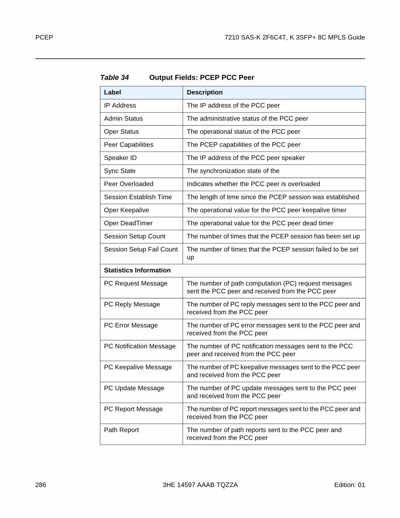
PCEP
286
7210 SAS-K 2F6C4T, K 3SFP+ 8C MPLS Guide
3HE 14597 AAAB TQZZA Edition: 01
Table 34 Output Fields: PCEP PCC Peer
Label Description
IP Address The IP address of the PCC peer
Admin Status The administrative status of the PCC peer
Oper Status The operational status of the PCC peer
Peer Capabilities The PCEP capabilities of the PCC peer
Speaker ID The IP address of the PCC peer speaker
Sync State The synchronization state of the
Peer Overloaded Indicates whether the PCC peer is overloaded
Session Establish Time The length of time since the PCEP session was established
Oper Keepalive The operational value for the PCC peer keepalive timer
Oper DeadTimer The operational value for the PCC peer dead timer
Session Setup Count The number of times that the PCEP session has been set up
Session Setup Fail Count The number of times that the PCEP session failed to be set up
Statistics Information
PC Request Message The number of path computation (PC) request messages sent the PCC peer and received from the PCC peer
PC Reply Message The number of PC reply messages sent to the PCC peer and received from the PCC peer
PC Error Message The number of PC error messages sent to the PCC peer and received from the PCC peer
PC Notification Message The number of PC notification messages sent to the PCC peer and received from the PCC peer
PC Keepalive Message The number of PC keepalive messages sent to the PCC peer and received from the PCC peer
PC Update Message The number of PC update messages sent to the PCC peer and received from the PCC peer
PC Report Message The number of PC report messages sent to the PCC peer and received from the PCC peer
Path Report The number of path reports sent to the PCC peer and received from the PCC peer

7210 SAS-K 2F6C4T, K 3SFP+ 8C MPLS Guide PCEP
Edition: 01 3HE 14597 AAAB TQZZA 287
status
Syntax status
Context show>router>pcep>pcc
SupportedPlatforms
Supported on all 7210 SAS platforms as described in this document
Description This command displays PCEP PCC status information.
Output The following output is an example of PCEP PCC status information, and Table 35 describes the output fields.
Sample Output
*A:ZBG>show>router>pcep>pcc# status===============================================================================Path Computation Element Protocol (PCEP) Path Computation Client (PCC) Info===============================================================================Admin Status : Down Oper Status : DownUnknown Msg Limit : 10 msg/minKeepalive Interval : 50 seconds DeadTimer Interval : 150 secondsCapabilities List : stateful-delegate stateful-pce rsvp-pathAddress : 10.10.10.10Report Path Constraints: True-------------------------------------------------------------------------------PCEP Path Computation Client (PCC) Peer Info-------------------------------------------------------------------------------Peer Admin State/Oper State Oper Keepalive/Oper DeadTimer-------------------------------------------------------------------------------10.10.10.11 Down/Down Not-Applicable/Not-Applicable-------------------------------------------------------------------------------===============================================================================*A:ZBG>show>router>pcep>pcc#
Path Request The path requests sent to the PCC peer and received from the PCC peer
Table 34 Output Fields: PCEP PCC Peer (Continued)
Label Description
Table 35 Output Fields: PCEP PCC Status
Label Description
Admin Status The administrative status of the PCC
Oper Status The operational status of the PCC

PCEP
288
7210 SAS-K 2F6C4T, K 3SFP+ 8C MPLS Guide
3HE 14597 AAAB TQZZA Edition: 01
4.7.2.3 Tools Commands
pcc
Syntax pcc lsp [plsp-id plsp-id]
pcc lsp lsp-type lsp-type [tunnel-id tunnel-id]
Context tools>dump>router>pcep
SupportedPlatforms
Supported on all 7210 SAS platforms as described in this document
Description This command displays PCEP PCC LSP information.
Parameters lsp — Keyword used to display LSP information.
plsp-id — Specifies the ID of a PCC LSP. Only information for the PCC LSP with the specified ID is displayed.
Values 1 to 1048575
Unknown Msg Limit The maximum rate of unknown messages that can be received on a PCEP session
Keepalive Interval The specified keepalive interval for the PCEP session
DeadTimer Interval The specified dead time interval for the PCEP session
Capabilities List The capabilities list for the PCEP session
Address The local IP address of the PCEP speaker
Report Path Constraints Indicates whether to include LSP path constraints in the PCE report messages sent from the PCC to a PCE
PCEP Path Computation Client (PCC) Peer Info
Peer The IP address of the PCC peer
Admin State/Oper State The administrative and operational states of the PCC peer
Oper Keepalive/Oper DeadTimer
The operational keepalive and dead timer intervals of the PCC peer
Table 35 Output Fields: PCEP PCC Status (Continued)
Label Description

7210 SAS-K 2F6C4T, K 3SFP+ 8C MPLS Guide PCEP
Edition: 01 3HE 14597 AAAB TQZZA 289
lsp-type — Specifies an LSP type. Only information for LSPs matching the specified type is displayed.
Values rsvp-p2p
tunnel-id — Specifies a tunnel ID. Only information for the tunnel with the specified ID is displayed.
Values 1 to 65535

PCEP
290
7210 SAS-K 2F6C4T, K 3SFP+ 8C MPLS Guide
3HE 14597 AAAB TQZZA Edition: 01

7210 SAS-K 2F6C4T, K 3SFP+ 8C MPLS Guide Standards and Protocol Support
Edition: 01 3HE 14597 AAAB TQZZA 291
5 Standards and Protocol Support
BGP
draft-ietf-idr-add-paths-04, Advertisement of Multiple Paths in BGP is supported on M(N), T(N), X, Mxp, Sx/S-1/10GE, Sx-10/100GE, R6, and R12
draft-ietf-sidr-origin-validation-signaling-04, BGP Prefix Origin Validation State Extended Community is supported on K12, K30, M(N), T(N), X, Mxp, Sx/S-1/10GE, Sx-10/100GE, Sx/S-1/10GE-VC, R6, and R12
RFC 1772, Application of the Border Gateway Protocol in the Internet is supported on K12, K30, M(N), T(N), X, Mxp, Sx/S-1/10GE, Sx-10/100GE, Sx/S-1/10GE-VC, R6, and R12
RFC 1997, BGP Communities Attribute is supported on K12, K30, M(N), T(N), X, Mxp, Sx/S-1/10GE, Sx-10/100GE, Sx/S-1/10GE-VC, R6, and R12
RFC 2385, Protection of BGP Sessions via the TCP MD5 Signature Option is supported on K12, K30, M(N), T(N), X, Mxp, Sx/S-1/10GE, Sx-10/100GE, Sx/S-1/10GE-VC, R6, and R12
RFC 2439, BGP Route Flap Damping is supported on K12, K30, M(N), T(N), X, Mxp, Sx/S-1/10GE, Sx-10/100GE, Sx/S-1/10GE-VC, R6, and R12
RFC 2545, Use of BGP-4 Multiprotocol Extensions for IPv6 Inter-Domain Routing is supported on K12, M(N), T(N), X, Mxp, Sx/S-1/10GE, Sx-10/100GE, Sx/S-1/10GE-VC, R6, and R12
RFC 2858, Multiprotocol Extensions for BGP-4 is supported on K12, K30, M(N), T(N), X, Mxp, Sx/S-1/10GE, Sx-10/100GE, Sx/S-1/10GE-VC, R6, and R12
RFC 2918, Route Refresh Capability for BGP-4 is supported on K12, K30, M(N), T(N), X, Mxp, Sx/S-1/10GE, Sx-10/100GE, Sx/S-1/10GE-VC, R6, and R12
RFC 3107, Carrying Label Information in BGP-4 is supported on K12, K30, M(N), T(N), X, Mxp, Sx/S-1/10GE, Sx-10/100GE, Sx/S-1/10GE-VC, R6, and R12
RFC 3392, Capabilities Advertisement with BGP-4 is supported on K12, K30, M(N), T(N), X, Mxp, Sx/S-1/10GE, Sx-10/100GE, Sx/S-1/10GE-VC, R6, and R12
RFC 4271, A Border Gateway Protocol 4 (BGP-4) is supported on K12, K30, M(N), T(N), X, Mxp, Sx/S-1/10GE, Sx-10/100GE, Sx/S-1/10GE-VC, R6, and R12
RFC 4360, BGP Extended Communities Attribute is supported on K12, K30, M(N), T(N), X, Mxp, Sx/S-1/10GE, Sx-10/100GE, Sx/S-1/10GE-VC, R6, and R12
RFC 4364, BGP/MPLS IP Virtual Private Networks (VPNs) is supported on K12, K30, M(N), T(N), X, Mxp, Sx/S-1/10GE, Sx-10/100GE, R6, and R12
Note: The information presented is subject to change without notice.
Nokia assumes no responsibility for inaccuracies contained herein.

Standards and Protocol Support
292
7210 SAS-K 2F6C4T, K 3SFP+ 8C MPLS Guide
3HE 14597 AAAB TQZZA Edition: 01
RFC 4456, BGP Route Reflection: An Alternative to Full Mesh Internal BGP (IBGP) is supported on K12, K30, M(N), T(N), X, Mxp, Sx/S-1/10GE, Sx-10/100GE, Sx/S-1/10GE-VC, R6, and R12
RFC 4659, BGP-MPLS IP Virtual Private Network (VPN) Extension for IPv6 VPN is supported on K12, M(N), T(N), X, Mxp, Sx/S-1/10GE, Sx-10/100GE, R6, and R12
RFC 4724, Graceful Restart Mechanism for BGP (Helper Mode) is supported on K12, K30, M(N), T(N), X, Mxp, Sx/S-1/10GE, Sx-10/100GE, Sx/S-1/10GE-VC, R6, and R12
RFC 4760, Multiprotocol Extensions for BGP-4 is supported on K12, K30, M(N), T(N), X, Mxp, Sx/S-1/10GE, Sx-10/100GE, Sx/S-1/10GE-VC, R6, and R12
RFC 4798, Connecting IPv6 Islands over IPv4 MPLS Using IPv6 Provider Edge Routers (6PE) is supported on K12, M(N), T(N), X, Mxp, Sx/S-1/10GE, Sx-10/100GE, R6, and R12
RFC 4893, BGP Support for Four-octet AS Number Space is supported on K12, K30, M(N), T(N), X, Mxp, Sx/S-1/10GE, Sx-10/100GE, Sx/S-1/10GE-VC, R6, and R12
RFC 5004, Avoid BGP Best Path Transitions from One External to Another is supported on K12, K30, M(N), T(N), X, Mxp, Sx/S-1/10GE, Sx-10/100GE, Sx/S-1/10GE-VC, R6, and R12
RFC 5291, Outbound Route Filtering Capability for BGP-4 is supported on K12, K30, M(N), T(N), X, Mxp, Sx/S-1/10GE, Sx-10/100GE, Sx/S-1/10GE-VC, R6, and R12
RFC 5668, 4-Octet AS Specific BGP Extended Community is supported on K12, K30, M(N), T(N), X, Mxp, Sx/S-1/10GE, Sx-10/100GE, Sx/S-1/10GE-VC, R6, and R12
RFC 6811, Prefix Origin Validation is supported on K12, K30, M(N), T(N), X, Mxp, Sx/S-1/10GE, Sx-10/100GE, Sx/S-1/10GE-VC, R6, and R12
Circuit Emulation
RFC 4553, Structure-Agnostic Time Division Multiplexing (TDM) over Packet (SAToP) is supported on M(N)
RFC 5086, Structure-Aware Time Division Multiplexed (TDM) Circuit Emulation Service over Packet Switched Network (CESoPSN) is supported on M(N)
RFC 5287, Control Protocol Extensions for the Setup of Time-Division Multiplexing (TDM) Pseudowires in MPLS Networks is supported on M(N)

7210 SAS-K 2F6C4T, K 3SFP+ 8C MPLS Guide Standards and Protocol Support
Edition: 01 3HE 14597 AAAB TQZZA 293
Ethernet
IEEE 802.1AB, Station and Media Access Control Connectivity Discovery is supported on D, E, Dxp, K5, K12, K30, M(A,N), T(A,N), X, Mxp, Sx/S-1/10GE, Sx-10/100GE, Sx/S-1/10GE-VC, R6, and R12
IEEE 802.1ad, Provider Bridges is supported on D, E, Dxp, K5, K12, K30, M(A,N), T(A,N), X, Mxp, Sx/S-1/10GE, Sx-10/100GE, Sx/S-1/10GE-VC, R6, and R12
IEEE 802.1ag, Connectivity Fault Management is supported on D, E, Dxp, K5, K12, K30, M(A,N), T(A,N), X, Mxp, Sx/S-1/10GE, Sx-10/100GE, Sx/S-1/10GE-VC, R6, and R12
IEEE 802.1ah, Provider Backbone Bridges is supported on M(N), X, and T(N)
IEEE 802.1ax, Link Aggregation is supported on D, E, Dxp, K5, K12, K30, M(A,N), T(A,N), X, Mxp, Sx/S-1/10GE, Sx-10/100GE, Sx/S-1/10GE-VC, R6, and R12
IEEE 802.1D, MAC Bridges is supported on D, E, Dxp, K5, K12, K30, M(A,N), T(A,N), X, Mxp, Sx/S-1/10GE, Sx-10/100GE, Sx/S-1/10GE-VC, R6, and R12
IEEE 802.1p, Traffic Class Expediting is supported on D, E, Dxp, K5, K12, K30, M(A,N), T(A,N), X, Mxp, Sx/S-1/10GE, Sx-10/100GE, Sx/S-1/10GE-VC, R6, and R12
IEEE 802.1Q, Virtual LANs is supported on D, E, Dxp, K5, K12, K30, M(A,N), T(A,N), X, Mxp, Sx/S-1/10GE, Sx-10/100GE, Sx/S-1/10GE-VC, R6, and R12
IEEE 802.1s, Multiple Spanning Trees is supported on D, E, Dxp, K5, K12, K30, M(A,N), T(A,N), X, Mxp, Sx/S-1/10GE, Sx-10/100GE, Sx/S-1/10GE-VC, R6, and R12
IEEE 802.1w, Rapid Reconfiguration of Spanning Tree is supported on D, E, Dxp, K5, K12, K30, M(A,N), T(A,N), X, Mxp, Sx/S-1/10GE, Sx-10/100GE, Sx/S-1/10GE-VC, R6, and R12
IEEE 802.1X, Port Based Network Access Control is supported on D, E, Dxp, K5, K12, K30, M(A,N), T(A,N), X, Mxp, Sx/S-1/10GE, Sx-10/100GE, Sx/S-1/10GE-VC, R6, and R12
IEEE 802.3ab, 1000BASE-T is supported on D, E, Dxp, K5, K12, K30, M(A,N), T(A,N), X, Mxp, Sx/S-1/10GE, Sx-10/100GE, Sx/S-1/10GE-VC, R6, and R12
IEEE 802.3ac, VLAN Tag is supported on D, E, Dxp, K5, K12, K30, M(A,N), T(A,N), X, Mxp, Sx/S-1/10GE, Sx-10/100GE, Sx/S-1/10GE-VC, R6, and R12
IEEE 802.3ad, Link Aggregation is supported on D, E, Dxp, K5, K12, K30, M(A,N), T(A,N), X, Mxp, Sx/S-1/10GE, Sx-10/100GE, Sx/S-1/10GE-VC, R6, and R12
IEEE 802.3ae, 10 Gb/s Ethernet is supported on Dxp, K30, M(A,N), T(A,N), X, Mxp, Sx/S-1/10GE, Sx-10/100GE, Sx/S-1/10GE-VC, R6, and R12
IEEE 802.3ah, Ethernet in the First Mile is supported on D, E, Dxp, K5, K12, K30, M(A,N), T(A,N), X, Mxp, Sx/S-1/10GE, Sx-10/100GE, Sx/S-1/10GE-VC, R6, and R12
IEEE 802.3ba, 40 Gb/s and 100 Gb/s Ethernet is supported on R6, R12, and Sx-10/100GE

Standards and Protocol Support
294
7210 SAS-K 2F6C4T, K 3SFP+ 8C MPLS Guide
3HE 14597 AAAB TQZZA Edition: 01
IEEE 802.3i, Ethernet is supported on D, E, Dxp, K5, K12, K30, M(A,N), T(A,N), X, Mxp, Sx/S-1/10GE, Sx-10/100GE, Sx/S-1/10GE-VC, R6, and R12
IEEE 802.3u, Fast Ethernet is supported on D, E, Dxp, K5, K12, K30, M(A,N), T(A,N), X, Mxp, Sx/S-1/10GE, Sx-10/100GE, Sx/S-1/10GE-VC, R6, and R12
IEEE 802.3z, Gigabit Ethernet is supported on D, E, Dxp, K5, K12, K30, M(A,N), T(A,N), X, Mxp, Sx/S-1/10GE, Sx-10/100GE, Sx/S-1/10GE-VC, R6, and R12
ITU-T G.8032, Ethernet Ring Protection Switching is supported on D, E, Dxp, K5, K12, K30, M(A,N), T(A,N), X, Mxp, Sx/S-1/10GE, Sx-10/100GE, Sx/S-1/10GE-VC, R6, and R12
ITU-T Y.1731, OAM functions and mechanisms for Ethernet based networks is supported on D, E, Dxp, K5, K12, K30, M(A,N), T(A,N), X, Mxp, Sx/S-1/10GE, Sx-10/100GE, Sx/S-1/10GE-VC, R6, and R12
Fast Reroute
draft-ietf-rtgwg-lfa-manageability-08, Operational management of Loop Free Alternates is supported on K12, K30, M(N), T(N), X, Mxp, Sx/S-1/10GE, Sx-10/100GE, Sx/S-1/10GE-VC, R6, and R12
RFC 5286, Basic Specification for IP Fast Reroute: Loop-Free Alternates is supported on K12, K30, M(N), T(N), X, Mxp, Sx/S-1/10GE, Sx-10/100GE, Sx/S-1/10GE-VC, R6, and R12
Internet Protocol (IP) — General
draft-grant-tacacs-02, The TACACS+ Protocol is supported on D, E, Dxp, K5, K12, K30, M(A,N), T(A,N), X, Mxp, Sx/S-1/10GE, Sx-10/100GE, Sx/S-1/10GE-VC, R6, and R12
RFC 768, User Datagram Protocol is supported on D, E, Dxp, K5, K12, K30, M(A,N), T(A,N), X, Mxp, Sx/S-1/10GE, Sx-10/100GE, Sx/S-1/10GE-VC, R6, and R12
RFC 793, Transmission Control Protocol is supported on D, E, Dxp, K5, K12, K30, M(A,N), T(A,N), X, Mxp, Sx/S-1/10GE, Sx-10/100GE, Sx/S-1/10GE-VC, R6, and R12
RFC 854, TELNET Protocol Specifications is supported on D, E, Dxp, K5, K12, K30, M(A,N), T(A,N), X, Mxp, Sx/S-1/10GE, Sx-10/100GE, Sx/S-1/10GE-VC, R6, and R12
RFC 951, Bootstrap Protocol (BOOTP) is supported on D, E, Dxp, K5, K12, K30, M(A,N), T(A,N), X, Mxp, Sx/S-1/10GE, Sx-10/100GE, Sx/S-1/10GE-VC, R6, and R12
RFC 1034, Domain Names - Concepts and Facilities is supported on D, E, Dxp, K5, K12, K30, M(A,N), T(A,N), X, Mxp, Sx/S-1/10GE, Sx-10/100GE, Sx/S-1/10GE-VC, R6, and R12
7210 SAS-K 2F6C4T, K 3SFP+ 8C MPLS Guide Standards and Protocol Support
Edition: 01 3HE 14597 AAAB TQZZA 295
RFC 1035, Domain Names - Implementation and Specification is supported on D, E, Dxp, K5, K12, K30, M(A,N), T(A,N), X, Mxp, Sx/S-1/10GE, Sx-10/100GE, Sx/S-1/10GE-VC, R6, and R12
RFC 1350, The TFTP Protocol (revision 2) is supported on D, E, Dxp, K5, K12, K30, M(A,N), T(A,N), X, Mxp, Sx/S-1/10GE, Sx-10/100GE, Sx/S-1/10GE-VC, R6, and R12
RFC 1534, Interoperation between DHCP and BOOTP is supported on D, E, Dxp, K5, K12, K30, M(A,N), T(A,N), X, Mxp, Sx/S-1/10GE, Sx-10/100GE, Sx/S-1/10GE-VC, R6, and R12
RFC 1542, Clarifications and Extensions for the Bootstrap Protocol is supported on D, E, Dxp, K5, K12, K30, M(A,N), T(A,N), X, Mxp, Sx/S-1/10GE, Sx-10/100GE, Sx/S-1/10GE-VC, R6, and R12
RFC 2131, Dynamic Host Configuration Protocol is supported on D, E, Dxp, K5, K12, K30, M(A,N), T(A,N), X, Mxp, Sx/S-1/10GE, Sx-10/100GE, Sx/S-1/10GE-VC, R6, and R12
RFC 2347, TFTP Option Extension is supported on D, E, Dxp, K5, K12, K30, M(A,N), T(A,N), X, Mxp, Sx/S-1/10GE, Sx-10/100GE, Sx/S-1/10GE-VC, R6, and R12
RFC 2348, TFTP Blocksize Option is supported on D, E, Dxp, K5, K12, K30, M(A,N), T(A,N), X, Mxp, Sx/S-1/10GE, Sx-10/100GE, Sx/S-1/10GE-VC, R6, and R12
RFC 2349, TFTP Timeout Interval and Transfer Size Options is supported on D, E, Dxp, K5, K12, K30, M(A,N), T(A,N), X, Mxp, Sx/S-1/10GE, Sx-10/100GE, Sx/S-1/10GE-VC, R6, and R12
RFC 2428, FTP Extensions for IPv6 and NATs is supported on D, E, Dxp, K12, K30, M(A,N), T(A,N), X, Mxp, Sx/S-1/10GE, Sx-10/100GE, Sx/S-1/10GE-VC, R6, and R12
RFC 2865, Remote Authentication Dial In User Service (RADIUS) is supported on D, E, Dxp, K5, K12, K30, M(A,N), T(A,N), X, Mxp, Sx/S-1/10GE, Sx-10/100GE, Sx/S-1/10GE-VC, R6, and R12
RFC 2866, RADIUS Accounting is supported on D, E, Dxp, K5, K12, K30, M(A,N), T(A,N), X, Mxp, Sx/S-1/10GE, Sx-10/100GE, Sx/S-1/10GE-VC, R6, and R12
RFC 3046, DHCP Relay Agent Information Option (Option 82) is supported on D, E, Dxp, K5, K12, K30, M(A,N), T(A,N), X, Mxp, Sx/S-1/10GE, Sx-10/100GE, Sx/S-1/10GE-VC, R6, and R12
RFC 3596, DNS Extensions to Support IP version 6 is supported on D, E, Dxp, K12, K30, M(A,N), T(A,N), X, Mxp, Sx/S-1/10GE, Sx-10/100GE, Sx/S-1/10GE-VC, R6, and R12
RFC 3768, Virtual Router Redundancy Protocol (VRRP) is supported on K12, K30, M(N), T(N), X, Mxp, Sx/S-1/10GE, Sx-10/100GE, Sx/S-1/10GE-VC, R6, and R12
RFC 4250, The Secure Shell (SSH) Protocol Assigned Numbers is supported on D, E, Dxp, K5, K12, K30, M(A,N), T(A,N), X, Mxp, Sx/S-1/10GE, Sx-10/100GE, Sx/S-1/10GE-VC, R6, and R12

Standards and Protocol Support
296
7210 SAS-K 2F6C4T, K 3SFP+ 8C MPLS Guide
3HE 14597 AAAB TQZZA Edition: 01
RFC 4251, The Secure Shell (SSH) Protocol Architecture is supported on D, E, Dxp, K5, K12, K30, M(A,N), T(A,N), X, Mxp, Sx/S-1/10GE, Sx-10/100GE, Sx/S-1/10GE-VC, R6, and R12
RFC 4252, The Secure Shell (SSH) Authentication Protocol (password only) is supported on D, E, Dxp, K5, K12, K30, M(A,N), T(A,N), X, Mxp, Sx/S-1/10GE, Sx-10/100GE, Sx/S-1/10GE-VC, R6, and R12
RFC 4253, The Secure Shell (SSH) Transport Layer Protocol is supported on D, E, Dxp, K5, K12, K30, M(A,N), T(A,N), X, Mxp, Sx/S-1/10GE, Sx-10/100GE, Sx/S-1/10GE-VC, R6, and R12
RFC 4254, The Secure Shell (SSH) Connection Protocol is supported on D, E, Dxp, K5, K12, K30, M(A,N), T(A,N), X, Mxp, Sx/S-1/10GE, Sx-10/100GE, Sx/S-1/10GE-VC, R6, and R12
RFC 4632, Classless Inter-domain Routing (CIDR): The Internet Address Assignment and Aggregation Plan is supported on D, E, Dxp, K5, K12, K30, M(A,N), T(A,N), X, Mxp, Sx/S-1/10GE, Sx-10/100GE, Sx/S-1/10GE-VC, R6, and R12
RFC 5880, Bidirectional Forwarding Detection (BFD) is supported on K12, K30, M(N), T(N), X, Mxp, Sx/S-1/10GE, Sx-10/100GE, Sx/S-1/10GE-VC, R6, and R12
RFC 5881, Bidirectional Forwarding Detection (BFD) IPv4 and IPv6 (Single Hop) is supported on K12, K30, M(N), T(N), X, Mxp, Sx/S-1/10GE, Sx-10/100GE, Sx/S-1/10GE-VC, R6, and R12
RFC 5883, Bidirectional Forwarding Detection (BFD) for Multihop Paths is supported on K12, K30, M(N), T(N), X, Mxp, Sx/S-1/10GE, Sx-10/100GE, Sx/S-1/10GE-VC, R6, and R12
RFC 6528, Defending against Sequence Number Attacks is supported on D, E, Dxp, K5, K12, K30, M(A,N), T(A,N), X, Mxp, Sx/S-1/10GE, Sx-10/100GE, Sx/S-1/10GE-VC, R6, and R12
IP — Multicast
RFC 1112, Host Extensions for IP Multicasting is supported on K12, K30, M(N), T(N), X, Mxp, Sx/S-1/10GE, Sx-10/100GE, Sx/S-1/10GE-VC, R6, and R12
Note: Only IPv4 is supported.
Note: Only IPv4 is supported.

7210 SAS-K 2F6C4T, K 3SFP+ 8C MPLS Guide Standards and Protocol Support
Edition: 01 3HE 14597 AAAB TQZZA 297
RFC 2236, Internet Group Management Protocol, Version 2 is supported on K12, K30, M(N), T(N), X, Mxp, Sx/S-1/10GE, Sx-10/100GE, Sx/S-1/10GE-VC, R6, and R12
RFC 3306, Unicast-Prefix-based IPv6 Multicast Addresses is supported on D, E, Dxp, K5, K12, K30, M(A,N), T(A,N), X, Mxp, Sx/S-1/10GE, Sx-10/100GE, Sx/S-1/10GE-VC, R6, and R12
RFC 3376, Internet Group Management Protocol, Version 3 is supported on K12, K30, M(N), T(N), X, Mxp, Sx/S-1/10GE, Sx-10/100GE, Sx/S-1/10GE-VC, R6, and R12
RFC 3446, Anycast Rendevous Point (RP) mechanism using Protocol Independent Multicast (PIM) and Multicast Source Discovery Protocol (MSDP) is supported on K12, K30, M(N), T(N), X, Mxp, Sx/S-1/10GE, Sx-10/100GE, Sx/S-1/10GE-VC, R6, and R12
RFC 4601, Protocol Independent Multicast - Sparse Mode (PIM-SM): Protocol Specification (Revised) is supported on K12, K30, M(N), T(N), X, Mxp, Sx/S-1/10GE, Sx-10/100GE, Sx/S-1/10GE-VC, R6, and R12
RFC 4604, Using Internet Group Management Protocol Version 3 (IGMPv3) and Multicast Listener Discovery Protocol Version 2 (MLDv2) for Source-Specific Multicast is supported on K12, K30, M(N), T(N), X, Mxp, Sx/S-1/10GE, Sx-10/100GE, Sx/S-1/10GE-VC, R6, and R12
RFC 4607, Source-Specific Multicast for IP is supported on K12, K30, M(N), T(N), X, Mxp, Sx/S-1/10GE, Sx-10/100GE, Sx/S-1/10GE-VC, R6, and R12
RFC 4608, Source-Specific Protocol Independent Multicast in 232/8 is supported on K12, K30, M(N), T(N), X, Mxp, Sx/S-1/10GE, Sx-10/100GE, Sx/S-1/10GE-VC, R6, and R12
RFC 4610, Anycast-RP Using Protocol Independent Multicast (PIM) is supported on K12, K30, M(N), T(N), X, Mxp, Sx/S-1/10GE, Sx-10/100GE, Sx/S-1/10GE-VC, R6, and R12
Note: IGMP v1, v2, v3 is supported.
Note: MSDP is not supported.
Note: MLD is not supported.

Standards and Protocol Support
298
7210 SAS-K 2F6C4T, K 3SFP+ 8C MPLS Guide
3HE 14597 AAAB TQZZA Edition: 01
RFC 5059, Bootstrap Router (BSR) Mechanism for Protocol Independent Multicast (PIM) is supported on K12, K30, M(N), T(N), X, Mxp, Sx/S-1/10GE, Sx-10/100GE, Sx/S-1/10GE-VC, R6, and R12
RFC 5384, The Protocol Independent Multicast (PIM) Join Attribute Format is supported on K12, K30, M(N), T(N), X, Mxp, Sx/S-1/10GE, Sx-10/100GE, Sx/S-1/10GE-VC, R6, and R12
RFC 6513, Multicast in MPLS/BGP IP VPNs is supported on T(N), Mxp, R6, and R12
RFC 6514, BGP Encodings and Procedures for Multicast in MPLS/IP VPNs is supported on T(N), Mxp, R6, and R12
RFC 6515, IPv4 and IPv6 Infrastructure Addresses in BGP Updates for Multicast VPNs is supported on T(N), Mxp, R6, and R12
RFC 6625, Wildcards in Multicast VPN Auto-Discover Routes is supported on T(N), Mxp, R6, and R12
RFC 6826, Multipoint LDP In-Band Signaling for Point-to-Multipoint and Multipoint-to-Multipoint Label Switched Path is supported on T(N), Mxp, R6, and R12
RFC 7385, IANA Registry for P-Multicast Service Interface (PMSI) Tunnel Type Code Points is supported on T(N), Mxp, R6, and R12
IP — Version 4
RFC 791, Internet Protocol is supported on D, E, Dxp, K5, K12, K30, M(A,N), T(A,N), X, Mxp, Sx/S-1/10GE, Sx-10/100GE, Sx/S-1/10GE-VC, R6, and R12
RFC 792, Internet Control Message Protocol is supported on D, E, Dxp, K5, K12, K30, M(A,N), T(A,N), X, Mxp, Sx/S-1/10GE, Sx-10/100GE, Sx/S-1/10GE-VC, R6, and R12
RFC 826, An Ethernet Address Resolution Protocol is supported on D, E, Dxp, K5, K12, K30, M(A,N), T(A,N), X, Mxp, Sx/S-1/10GE, Sx-10/100GE, Sx/S-1/10GE-VC, R6, and R12
Note: Only IPv4 is supported.
Note: Only IPv4 is supported.
Note: Only IPv4 is supported.

7210 SAS-K 2F6C4T, K 3SFP+ 8C MPLS Guide Standards and Protocol Support
Edition: 01 3HE 14597 AAAB TQZZA 299
RFC 1519, Classless Inter-Domain Routing (CIDR): an Address Assignment and Aggregation Strategy is supported on D, E, Dxp, K5, K12, K30, M(A,N), T(A,N), X, Mxp, Sx/S-1/10GE, Sx-10/100GE, Sx/S-1/10GE-VC, R6, and R12
RFC 1812, Requirements for IPv4 Routers is supported on D, E, Dxp, K5, K12, K30, M(A,N), T(A,N), X, Mxp, Sx/S-1/10GE, Sx-10/100GE, Sx/S-1/10GE-VC, R6, and R12
RFC 1981, Path MTU Discovery for IP version 6 is supported on K12, K30, M(N), T(N), X, Mxp, Sx/S-1/10GE, Sx-10/100GE, Sx/S-1/10GE-VC, R6, and R12
RFC 2401, Security Architecture for Internet Protocol is supported on K12, K30, M(N), T(N), X, Mxp, Sx/S-1/10GE, Sx-10/100GE, Sx/S-1/10GE-VC, R6, and R12
RFC 2460, Internet Protocol, Version 6 (IPv6) Specification is supported on K12, K30, M(N), T(N), X, Mxp, Sx/S-1/10GE, Sx-10/100GE, Sx/S-1/10GE-VC, R6, and R12
IP — Version 6
RFC 2464, Transmission of IPv6 Packets over Ethernet Networks is supported on K12, K30, M(N), T(N), X, Mxp, Sx/S-1/10GE, Sx-10/100GE, Sx/S-1/10GE-VC, R6, and R12
RFC 3021, Using 31-Bit Prefixes on IPv4 Point-to-Point Links is supported on K12, K30, M(N), T(N), X, Mxp, Sx/S-1/10GE, Sx-10/100GE, Sx/S-1/10GE-VC, R6, and R12
RFC 3122, Extensions to IPv6 Neighbor Discovery for Inverse Discovery Specification is supported on K12, K30, M(N), T(N), X, Mxp, Sx/S-1/10GE, Sx-10/100GE, Sx/S-1/10GE-VC, R6, and R12
RFC 3587, IPv6 Global Unicast Address Format is supported on K12, K30, M(N), T(N), X, Mxp, Sx/S-1/10GE, Sx-10/100GE, Sx/S-1/10GE-VC, R6, and R12
RFC 4007, IPv6 Scoped Address Architecture is supported on K12, K30, M(N), T(N), X, Mxp, Sx/S-1/10GE, Sx-10/100GE, Sx/S-1/10GE-VC, R6, and R12
RFC 4193, Unique Local IPv6 Unicast Addresses is supported on K12, K30, M(N), T(N), X, Mxp, Sx/S-1/10GE, Sx-10/100GE, Sx/S-1/10GE-VC, R6, and R12
RFC 4291, Internet Protocol Version 6 (IPv6) Addressing Architecture is supported on K12, K30, M(N), T(N), X, Mxp, Sx/S-1/10GE, Sx-10/100GE, Sx/S-1/10GE-VC, R6, and R12
RFC 4443, Internet Control Message Protocol (ICMPv6) for the Internet Protocol Version 6 (IPv6) Specification is supported on K12, K30, M(N), T(N), X, Mxp, Sx/S-1/10GE, Sx-10/100GE, Sx/S-1/10GE-VC, R6, and R12
Note: Supported only for OSPFv3 authentication; not supported for services.

Standards and Protocol Support
300
7210 SAS-K 2F6C4T, K 3SFP+ 8C MPLS Guide
3HE 14597 AAAB TQZZA Edition: 01
RFC 4861, Neighbor Discovery for IP version 6 (IPv6) is supported on K12, K30, M(N), T(N), X, Mxp, Sx/S-1/10GE, Sx-10/100GE, Sx/S-1/10GE-VC, R6, and R12
RFC 4862, IPv6 Stateless Address Autoconfiguration (Router Only) is supported on K12, K30, M(N), T(N), X, Mxp, Sx/S-1/10GE, Sx-10/100GE, Sx/S-1/10GE-VC, R6, and R12
RFC 5095, Deprecation of Type 0 Routing Headers in IPv6 is supported on K12, K30, M(N), T(N), X, Mxp, Sx/S-1/10GE, Sx-10/100GE, Sx/S-1/10GE-VC, R6, and R12
RFC 5952, A Recommendation for IPv6 Address Text Representation is supported on K12, K30, M(N), T(N), X, Mxp, Sx/S-1/10GE, Sx-10/100GE, Sx/S-1/10GE-VC, R6, and R12
RFC 6106, IPv6 Router Advertisement Options for DNS Configuration is supported on K12, K30, M(N), T(N), X, Mxp, Sx/S-1/10GE, Sx-10/100GE, Sx/S-1/10GE-VC, R6, and R12
RFC 6164, Using 127-Bit IPv6 Prefixes on Inter-Router Links is supported on K12, K30, M(N), T(N), X, Mxp, Sx/S-1/10GE, Sx-10/100GE, Sx/S-1/10GE-VC, R6, and R12
IPsec
RFC 2401, Security Architecture for the Internet Protocol is supported on K12, K30, M(N), T(N), X, Mxp, Sx/S-1/10GE, Sx-10/100GE, Sx/S-1/10GE-VC, R6, and R12
RFC 2406, IP Encapsulating Security Payload (ESP) is supported on K12, K30, M(N), T(N), X, Mxp, Sx/S-1/10GE, Sx-10/100GE, Sx/S-1/10GE-VC, R6, and R12
IS-IS
draft-ietf-isis-mi-02, IS-IS Multi-Instance is supported on K12, K30, M(N), T(N), X, Mxp, Sx/S-1/10GE, Sx-10/100GE, Sx/S-1/10GE-VC, R6, and R12
draft-kaplan-isis-ext-eth-02, Extended Ethernet Frame Size Support is supported on K12, K30, M(N), T(N), X, Mxp, Sx/S-1/10GE, Sx-10/100GE, Sx/S-1/10GE-VC, R6, and R12
Note: Only for use with OSPFv3 authentication; not supported for services.
Note: Only for use with OSPFv3 authentication; not supported for services.

7210 SAS-K 2F6C4T, K 3SFP+ 8C MPLS Guide Standards and Protocol Support
Edition: 01 3HE 14597 AAAB TQZZA 301
ISO/IEC 10589:2002, Second Edition, Nov. 2002, Intermediate system to Intermediate system intra-domain routeing information exchange protocol for use in conjunction with the protocol for providing the connectionless-mode Network Service (ISO 8473) is supported on K12, K30, M(N), T(N), X, Mxp, Sx/S-1/10GE, Sx-10/100GE, Sx/S-1/10GE-VC, R6, and R12
RFC 1195, Use of OSI IS-IS for Routing in TCP/IP and Dual Environments is supported on K12, K30, M(N), T(N), X, Mxp, Sx/S-1/10GE, Sx-10/100GE, Sx/S-1/10GE-VC, R6, and R12
RFC 3359, Reserved Type, Length and Value (TLV) Codepoints in Intermediate System to Intermediate System is supported on K12, K30, M(N), T(N), X, Mxp, Sx/S-1/10GE, Sx-10/100GE, Sx/S-1/10GE-VC, R6, and R12
RFC 3719, Recommendations for Interoperable Networks using Intermediate System to Intermediate System (IS-IS) is supported on K12, K30, M(N), T(N), X, Mxp, Sx/S-1/10GE, Sx-10/100GE, Sx/S-1/10GE-VC, R6, and R12
RFC 3787, Recommendations for Interoperable IP Networks using Intermediate System to Intermediate System (IS-IS) is supported on K12, K30, M(N), T(N), X, Mxp, Sx/S-1/10GE, Sx-10/100GE, Sx/S-1/10GE-VC, R6, and R12
RFC 4971, Intermediate System to Intermediate System (IS-IS) Extensions for Advertising Router Information is supported on K12, K30, M(N), T(N), X, Mxp, Sx/S-1/10GE, Sx-10/100GE, Sx/S-1/10GE-VC, R6, and R12
RFC 5120, M-ISIS: Multi Topology (MT) Routing in IS-IS is supported on K12, M(N), T(N), X, Mxp, Sx/S-1/10GE, Sx-10/100GE, R6, and R12
RFC 5130, A Policy Control Mechanism in IS-IS Using Administrative Tags is supported on K12, K30, M(N), T(N), X, Mxp, Sx/S-1/10GE, Sx-10/100GE, Sx/S-1/10GE-VC, R6, and R12
RFC 5301, Dynamic Hostname Exchange Mechanism for IS-IS is supported on K12, K30, M(N), T(N), X, Mxp, Sx/S-1/10GE, Sx-10/100GE, Sx/S-1/10GE-VC, R6, and R12
RFC 5302, Domain-wide Prefix Distribution with Two-Level IS-IS is supported on K12, K30, M(N), T(N), X, Mxp, Sx/S-1/10GE, Sx-10/100GE, Sx/S-1/10GE-VC, R6, and R12
RFC 5303, Three-Way Handshake for IS-IS Point-to-Point Adjacencies is supported on K12, K30, M(N), T(N), X, Mxp, Sx/S-1/10GE, Sx-10/100GE, Sx/S-1/10GE-VC, R6, and R12
RFC 5304, IS-IS Cryptographic Authentication is supported on K12, K30, M(N), T(N), X, Mxp, Sx/S-1/10GE, Sx-10/100GE, Sx/S-1/10GE-VC, R6, and R12
RFC 5305, IS-IS Extensions for Traffic Engineering TE is supported on K12, K30, M(N), T(N), X, Mxp, Sx/S-1/10GE, Sx-10/100GE, Sx/S-1/10GE-VC, R6, and R12
RFC 5306, Restart Signaling for IS-IS (Helper Mode) is supported on K12, K30, M(N), T(N), X, Mxp, Sx/S-1/10GE, Sx-10/100GE, Sx/S-1/10GE-VC, R6, and R12
Standards and Protocol Support
302
7210 SAS-K 2F6C4T, K 3SFP+ 8C MPLS Guide
3HE 14597 AAAB TQZZA Edition: 01
RFC 5308, Routing IPv6 with IS-IS is supported on K12, M(N), T(N), X, Mxp, Sx/S-1/10GE, Sx-10/100GE, R6, and R12
RFC 5309, Point-to-Point Operation over LAN in Link State Routing Protocols is supported on K12, K30, M(N), T(N), X, Mxp, Sx/S-1/10GE, Sx-10/100GE, Sx/S-1/10GE-VC, R6, and R12
RFC 5310, IS-IS Generic Cryptographic Authentication is supported on K12, K30, M(N), T(N), X, Mxp, Sx/S-1/10GE, Sx-10/100GE, Sx/S-1/10GE-VC, R6, and R12
RFC 6232, Purge Originator Identification TLV for IS-IS is supported on K12, K30, M(N), T(N), X, Mxp, Sx/S-1/10GE, Sx-10/100GE, Sx/S-1/10GE-VC, R6, and R12
RFC 6233, IS-IS Registry Extension for Purges is supported on K12, K30, M(N), T(N), X, Mxp, Sx/S-1/10GE, Sx-10/100GE, Sx/S-1/10GE-VC, R6, and R12
draft-ietf-isis-mi-02, IS-IS Multi-Instance is supported on K12, K30, M(N), T(N), X, Mxp, Sx/S-1/10GE, Sx-10/100GE, Sx/S-1/10GE-VC, R6, and R12
draft-ietf-isis-segment-routing-extensions-04, IS-IS Extensions for Segment Routing is supported on K12, K30, and Mxp
Management
draft-ieft-snmpv3-update-mib-05, Management Information Base (MIB) for the Simple Network Management Protocol (SNMP) is supported on D, E, Dxp, K5, K12, K30, M(A,N), T(A,N), X, Mxp, Sx/S-1/10GE, Sx-10/100GE, Sx/S-1/10GE-VC, R6, and R12
draft-ietf-idr-bgp4-mib-05, Definitions of Managed Objects for the Fourth Version of Border Gateway Protocol (BGP-4) is supported on K12, K30, M(N), T(N), X, Mxp, Sx/S-1/10GE, Sx-10/100GE, Sx/S-1/10GE-VC, R6, and R12
draft-ietf-isis-wg-mib-06, Management Information Base for Intermediate System to Intermediate System (IS-IS) is supported on K12, K30, M(N), T(N), X, Mxp, Sx/S-1/10GE, Sx-10/100GE, Sx/S-1/10GE-VC, R6, and R12
draft-ietf-mpls-ldp-mib-07, Definitions of Managed Objects for the Multiprotocol Label Switching, Label Distribution Protocol (LDP) is supported on K12, K30, M(N), T(N), X, Mxp, Sx/S-1/10GE, Sx-10/100GE, Sx/S-1/10GE-VC, R6, and R12
draft-ietf-mpls-lsr-mib-06, Multiprotocol Label Switching (MPLS) Label Switching Router (LSR) Management Information Base Using SMIv2 is supported on K12, K30, M(N), T(N), X, Mxp, Sx/S-1/10GE, Sx-10/100GE, Sx/S-1/10GE-VC, R6, and R12
Note: K12, K30, M(N), support only a single instance and can operate in multi-instance deployment as it supports the processing of TLVs for multi-instance support.

7210 SAS-K 2F6C4T, K 3SFP+ 8C MPLS Guide Standards and Protocol Support
Edition: 01 3HE 14597 AAAB TQZZA 303
draft-ietf-mpls-te-mib-04, Multiprotocol Label Switching (MPLS) Traffic Engineering Management Information Base is supported on K12, K30, M(N), T(N), X, Mxp, Sx/S-1/10GE, Sx-10/100GE, Sx/S-1/10GE-VC, R6, and R12
draft-ietf-ospf-mib-update-08, OSPF Version 2 Management Information Base is supported on K12, K30, M(N), T(N), X, Mxp, Sx/S-1/10GE, Sx-10/100GE, Sx/S-1/10GE-VC, R6, and R12
ianaaddressfamilynumbers-mib, IANA-ADDRESS-FAMILY-NUMBERS-MIB is supported on K12, K30, M(N), T(N), X, Mxp, Sx/S-1/10GE, Sx-10/100GE, Sx/S-1/10GE-VC, R6, and R12
ianaiftype-mib, IANAifType-MIB is supported on D, E, Dxp, K5, K12, K30, M(A,N), T(A,N), X, Mxp, Sx/S-1/10GE, Sx-10/100GE, Sx/S-1/10GE-VC, R6, and R12
ianaiprouteprotocol-mib, IANA-RTPROTO-MIB is supported on K12, K30, M(N), T(N), X, Mxp, Sx/S-1/10GE, Sx-10/100GE, Sx/S-1/10GE-VC, R6, and R12
IEEE8021-CFM-MIB, IEEE P802.1ag(TM) CFM MIB is supported on D, E, K5, K12, K30, M(A,N), T(A,N), X, Mxp, Sx/S-1/10GE, Sx-10/100GE, Sx/S-1/10GE-VC, R6, and R12
IEEE8021-PAE-MIB, IEEE 802.1X MIB is supported on D, E, Dxp, K5, K12, K30, M(A,N), T(A,N), X, Mxp, Sx/S-1/10GE, Sx-10/100GE, Sx/S-1/10GE-VC, R6, and R12
IEEE8023-LAG-MIB, IEEE 802.3ad MIB is supported on D, E, Dxp, K5, K12, K30, M(A,N), T(A,N), X, Mxp, Sx/S-1/10GE, Sx-10/100GE, Sx/S-1/10GE-VC, R6, and R12
LLDP-MIB, IEEE P802.1AB(TM) LLDP MIB is supported on D, E, Dxp, K5, K12, K30, M(A,N), T(A,N), X, Mxp, Sx/S-1/10GE, Sx-10/100GE, Sx/S-1/10GE-VC, R6, and R12
RFC 1157, A Simple Network Management Protocol (SNMP) is supported on D, E, Dxp, K5, K12, K30, M(A,N), T(A,N), X, Mxp, Sx/S-1/10GE, Sx-10/100GE, Sx/S-1/10GE-VC, R6, and R12
RFC 1215, A Convention for Defining Traps for use with the SNMP is supported on D, E, Dxp, K5, K12, K30, M(A,N), T(A,N), X, Mxp, Sx/S-1/10GE, Sx-10/100GE, Sx/S-1/10GE-VC, R6, and R12
RFC 1724, RIP Version 2 MIB Extension is supported on Mxp
RFC 2021, Remote Network Monitoring Management Information Base Version 2 using SMIv2 is supported on D, E, Dxp, K5, K12, K30, M(A,N), T(A,N), X, Mxp, Sx/S-1/10GE, Sx-10/100GE, Sx/S-1/10GE-VC, R6, and R12
RFC 2115, Management Information Base for Frame Relay DTEs Using SMIv2 is supported on D, E, Dxp, K5, K12, K30, M(A,N), T(A,N), X, Mxp, Sx/S-1/10GE, Sx-10/100GE, Sx/S-1/10GE-VC, R6, and R12
RFC 2138, Remote Authentication Dial In User Service (RADIUS) is supported on D, E, Dxp, K5, K12, K30, M(A,N), T(A,N), X, Mxp, Sx/S-1/10GE, Sx-10/100GE, Sx/S-1/10GE-VC, R6, and R12

Standards and Protocol Support
304
7210 SAS-K 2F6C4T, K 3SFP+ 8C MPLS Guide
3HE 14597 AAAB TQZZA Edition: 01
RFC 2206, RSVP Management Information Base using SMIv2 is supported on K12, K30, M(N), T(N), X, Mxp, Sx/S-1/10GE, Sx-10/100GE, Sx/S-1/10GE-VC, R6, and R12
RFC 2213, Integrated Services Management Information Base using SMIv2 is supported on D, E, Dxp, K5, K12, K30, M(A,N), T(A,N), X, Mxp, Sx/S-1/10GE, Sx-10/100GE, Sx/S-1/10GE-VC, R6, and R12
RFC 2494, Definitions of Managed Objects for the DS0 and DS0 Bundle Interface Type is supported on M(N)
RFC 2571, An Architecture for Describing SNMP Management Frameworks is supported on D, E, Dxp, K5, K12, K30, M(A,N), T(A,N), X, Mxp, Sx/S-1/10GE, Sx-10/100GE, Sx/S-1/10GE-VC, R6, and R12
RFC 2572, Message Processing and Dispatching for the Simple Network Management Protocol (SNMP) is supported on D, E, Dxp, K5, K12, K30, M(A,N), T(A,N), X, Mxp, Sx/S-1/10GE, Sx-10/100GE, Sx/S-1/10GE-VC, R6, and R12
RFC 2573, SNMP Applications is supported on D, E, Dxp, K5, K12, K30, M(A,N), T(A,N), X, Mxp, Sx/S-1/10GE, Sx-10/100GE, Sx/S-1/10GE-VC, R6, and R12
RFC 2574, User-based Security Model (USM) for version 3 of the Simple Network Management Protocol (SNMPv3) is supported on D, E, Dxp, K5, K12, K30, M(A,N), T(A,N), X, Mxp, Sx/S-1/10GE, Sx-10/100GE, Sx/S-1/10GE-VC, R6, and R12
RFC 2575, View-based Access Control Model (VACM) for the Simple Network Management Protocol (SNMP) is supported on D, E, Dxp, K5, K12, K30, M(A,N), T(A,N), X, Mxp, Sx/S-1/10GE, Sx-10/100GE, Sx/S-1/10GE-VC, R6, and R12
RFC 2578, Structure of Management Information Version 2 (SMIv2) is supported on D, E, Dxp, K5, K12, K30, M(A,N), T(A,N), X, Mxp, Sx/S-1/10GE, Sx-10/100GE, Sx/S-1/10GE-VC, R6, and R12
RFC 2579, Textual Conventions for SMIv2 is supported on D, E, Dxp, K5, K12, K30, M(A,N), T(A,N), X, Mxp, Sx/S-1/10GE, Sx-10/100GE, Sx/S-1/10GE-VC, R6, and R12
RFC 2787, Definitions of Managed Objects for the Virtual Router Redundancy Protocol is supported on K12, M(N), T(N), X, Mxp, Sx/S-1/10GE, Sx-10/100GE, Sx/S-1/10GE-VC, R6, and R12
RFC 2819, Remote Network Monitoring Management Information Base is supported on D, E, Dxp, K5, K12, K30, M(A,N), T(A,N), X, Mxp, Sx/S-1/10GE, Sx-10/100GE, Sx/S-1/10GE-VC, R6, and R12
RFC 2856, Textual Conventions for Additional High Capacity Data Types is supported on D, E, Dxp, K5, K12, K30, M(A,N), T(A,N), X, Mxp, Sx/S-1/10GE, Sx-10/100GE, Sx/S-1/10GE-VC, R6, and R12

7210 SAS-K 2F6C4T, K 3SFP+ 8C MPLS Guide Standards and Protocol Support
Edition: 01 3HE 14597 AAAB TQZZA 305
RFC 2863, The Interfaces Group MIB is supported on D, E, Dxp, K5, K12, K30, M(A,N), T(A,N), X, Mxp, Sx/S-1/10GE, Sx-10/100GE, Sx/S-1/10GE-VC, R6, and R12
RFC 2864, The Inverted Stack Table Extension to the Interfaces Group MIB is supported on D, E, Dxp, K5, K12, K30, M(A,N), T(A,N), X, Mxp, Sx/S-1/10GE, Sx-10/100GE, Sx/S-1/10GE-VC, R6, and R12
RFC 2933, Internet Group Management Protocol MIB is supported on D, E, Dxp, K5, K12, K30, M(A,N), T(A,N), X, Mxp, Sx/S-1/10GE, Sx-10/100GE, Sx/S-1/10GE-VC, R6, and R12
RFC 3014, Notification Log MIB is supported on D, E, Dxp, K5, K12, K30, M(A,N), T(A,N), X, Mxp, Sx/S-1/10GE, Sx-10/100GE, Sx/S-1/10GE-VC, R6, and R12
RFC 3164, The BSD syslog Protocol is supported on D, E, Dxp, K5, K12, K30, M(A,N), T(A,N), X, Mxp, Sx/S-1/10GE, Sx-10/100GE, Sx/S-1/10GE-VC, R6, and R12
RFC 3165, Definitions of Managed Objects for the Delegation of Management Scripts is supported on D, E, Dxp, K5, K12, K30, M(A,N), T(A,N), X, Mxp, Sx/S-1/10GE, Sx-10/100GE, Sx/S-1/10GE-VC, R6, and R12
RFC 3231, Definitions of Managed Objects for Scheduling Management Operations is supported on D, E, Dxp, K5, K12, K30, M(A,N), T(A,N), X, Mxp, Sx/S-1/10GE, Sx-10/100GE, Sx/S-1/10GE-VC, R6, and R12
RFC 3273, Remote Network Monitoring Management Information Base for High Capacity Networks is supported on D, E, Dxp, K5, K12, K30, M(A,N), T(A,N), X, Mxp, Sx/S-1/10GE, Sx-10/100GE, Sx/S-1/10GE-VC, R6, and R12
RFC 3416. Version 2 of the Protocol Operations for the Simple Network Management Protocol (SNMP) is supported on D, E, Dxp, K5, K12, K30, M(A,N), T(A,N), X, Mxp, Sx/S-1/10GE, Sx-10/100GE, Sx/S-1/10GE-VC, R6, and R12
RFC 3417, Transport Mappings for the Simple Network Management Protocol (SNMP) (SNMP over UDP over IPv4) is supported on D, E, Dxp, K5, K12, K30, M(A,N), T(A,N), X, Mxp, Sx/S-1/10GE, Sx-10/100GE, Sx/S-1/10GE-VC, R6, and R12
RFC 3419, Textual Conventions for Transport Addresses is supported on D, E, Dxp, K5, K12, K30, M(A,N), T(A,N), X, Mxp, Sx/S-1/10GE, Sx-10/100GE, Sx/S-1/10GE-VC, R6, and R12
RFC 3584, Coexistence between Version 1, Version 2, and Version 3 of the Internet-standard Network Management Framework is supported on D, E, Dxp, K5, K12, K30, M(A,N), T(A,N), X, Mxp, Sx/S-1/10GE, Sx-10/100GE, Sx/S-1/10GE-VC, R6, and R12
RFC 3593, Textual Conventions for MIB Modules Using Performance History Based on 15 Minute Intervals is supported on Dxp, K5, K12, K30, M(A,N), T(A,N), X, Mxp, Sx/S-1/10GE, Sx-10/100GE, Sx/S-1/10GE-VC, R6, and R12

Standards and Protocol Support
306
7210 SAS-K 2F6C4T, K 3SFP+ 8C MPLS Guide
3HE 14597 AAAB TQZZA Edition: 01
RFC 3635, Definitions of Managed Objects for the Ethernet-like Interface Types is supported on D, E, Dxp, K5, K12, K30, M(A,N), T(A,N), X, Mxp, Sx/S-1/10GE, Sx-10/100GE, Sx/S-1/10GE-VC, R6, and R12
RFC 3826, The Advanced Encryption Standard (AES) Cipher Algorithm in the SNMP User-based Security Model is supported on D, E, Dxp, K5, K12, K30, M(A,N), T(A,N), X, Mxp, Sx/S-1/10GE, Sx-10/100GE, Sx/S-1/10GE-VC, R6, and R12
RFC 3877, Alarm Management Information Base (MIB) is supported on D, E, Dxp, K5, K12, K30, M(A,N), T(A,N), X, Mxp, Sx/S-1/10GE, Sx-10/100GE, Sx/S-1/10GE-VC, R6, and R12
RFC 3895, Definitions of Managed Objects for the DS1, E1, DS2, and E2 Interface Types is supported on M(N)
RFC 4001, Textual Conventions for Internet Network Addresses is supported on D, E, K5, K12, K30, M(A,N), T(A,N), X, Mxp, Sx/S-1/10GE, Sx-10/100GE, Sx/S-1/10GE-VC, R6, and R12
RFC 4022, Management Information Base for the Transmission Control Protocol (TCP) is supported on D, E, K5, K12, K30, M(A,N), T(A,N), X, Mxp, Sx/S-1/10GE, Sx-10/100GE, Sx/S-1/10GE-VC, R6, and R12
RFC 4113, Management Information Base for the User Datagram Protocol (UDP) is supported on D, E, K5, K12, K30, M(A,N), T(A,N), X, Mxp, Sx/S-1/10GE, Sx-10/100GE, Sx/S-1/10GE-VC, R6, and R12
RFC 4220, Traffic Engineering Link Management Information Base is supported on K12, K30, M(N), T(N), X, Mxp, Sx/S-1/10GE, Sx-10/100GE, Sx/S-1/10GE-VC, R6, and R12
RFC 4292, IP Forwarding Table MIB is supported on K12, K30, M(N), T(N), X, Mxp, Sx/S-1/10GE, Sx-10/100GE, Sx/S-1/10GE-VC, R6, and R12
RFC 4293, Management Information Base for the Internet Protocol (IP) is supported on D, E, K5, K12, K30, M(A,N), T(A,N), X, Mxp, Sx/S-1/10GE, Sx-10/100GE, Sx/S-1/10GE-VC, R6, and R12
RFC 6241, Network Configuration Protocol (NETCONF) is supported on K5, K12, R6, and R12
RFC 6242, Using the NETCONF Protocol over Secure Shell (SSH) is supported on K5, K12, R6, and R12
MPLS — General
RFC 3031, Multiprotocol Label Switching Architecture is supported on K12, K30, M(N), T(N), X, Mxp, Sx/S-1/10GE, Sx-10/100GE, Sx/S-1/10GE-VC, R6, and R12
Note: Support for DS1, E1 only.

7210 SAS-K 2F6C4T, K 3SFP+ 8C MPLS Guide Standards and Protocol Support
Edition: 01 3HE 14597 AAAB TQZZA 307
RFC 3032, MPLS Label Stack Encoding is supported on K12, K30, M(N), T(N), X, Mxp, Sx/S-1/10GE, Sx-10/100GE, Sx/S-1/10GE-VC, R6, and R12
RFC 3443, Time To Live (TTL) Processing in Multi-Protocol Label Switching (MPLS) Networks is supported on K12, K30, M(N), T(N), X, Mxp, Sx/S-1/10GE, Sx-10/100GE, Sx/S-1/10GE-VC, R6, and R12
RFC 4182, Removing a Restriction on the use of MPLS Explicit NULL is supported on K12, K30, M(N), T(N), X, Mxp, Sx/S-1/10GE, Sx-10/100GE, Sx/S-1/10GE-VC, R6, and R12
RFC 5332, MPLS Multicast Encapsulations is supported on T(N), Mxp, R6, and R12
MPLS — GMPLS
draft-ietf-ccamp-rsvp-te-srlg-collect-04, RSVP-TE Extensions for Collecting SRLG Information is supported on K12, K30, M(N), T(N), X, Mxp, Sx/S-1/10GE, Sx-10/100GE, Sx/S-1/10GE-VC, R6, and R12
MPLS — LDP
draft-pdutta-mpls-ldp-adj-capability-00, LDP Adjacency Capabilities is supported on K12, K30, M(N), T(N), X, Mxp, Sx/S-1/10GE, Sx-10/100GE, Sx/S-1/10GE-VC, R6, and R12
draft-pdutta-mpls-ldp-v2-00, LDP Version 2 is supported on K12, K30, M(N), T(N), X, Mxp, Sx/S-1/10GE, Sx-10/100GE, Sx/S-1/10GE-VC, R6, and R12
draft-pdutta-mpls-tldp-hello-reduce-04, Targeted LDP Hello Reduction is supported on K12, K30, M(N), T(N), X, Mxp, Sx/S-1/10GE, Sx-10/100GE, Sx/S-1/10GE-VC, R6, and R12
RFC 3037, LDP Applicability is supported on K12, K30, M(N), T(N), X, Mxp, Sx/S-1/10GE, Sx-10/100GE, Sx/S-1/10GE-VC, R6, and R12
RFC 3478, Graceful Restart Mechanism for Label Distribution Protocol (Helper Mode) is supported on K12, K30, M(N), T(N), X, Mxp, Sx/S-1/10GE, Sx-10/100GE, Sx/S-1/10GE-VC, R6, and R12
RFC 5036, LDP Specification is supported on K12, K30, M(N), T(N), X, Mxp, Sx/S-1/10GE, Sx-10/100GE, Sx/S-1/10GE-VC, R6, and R12
RFC 5283, LDP Extension for Inter-Area Label Switched Paths (LSPs) is supported on K12, K30, M(N), T(N), X, Mxp, Sx/S-1/10GE, Sx-10/100GE, Sx/S-1/10GE-VC, R6, and R12
RFC 5443, LDP IGP Synchronization is supported on K12, K30, M(N), T(N), X, Mxp, Sx/S-1/10GE, Sx-10/100GE, Sx/S-1/10GE-VC, R6, and R12
RFC 5561, LDP Capabilities is supported on K12, K30, M(N), T(N), X, Mxp, Sx/S-1/10GE, Sx-10/100GE, Sx/S-1/10GE-VC, R6, and R12

Standards and Protocol Support
308
7210 SAS-K 2F6C4T, K 3SFP+ 8C MPLS Guide
3HE 14597 AAAB TQZZA Edition: 01
RFC 6388, Label Distribution Protocol Extensions for Point-to-Multipoint and Multipoint-to-Multipoint Label Switched Paths is supported on T(N), Mxp, R6, and R12
MPLS — MPLS-TP
RFC 5586, MPLS Generic Associated Channel is supported on T(N), R6, and R12
RFC 5921, A Framework for MPLS in Transport Networks is supported on T(N), R6, and R12
RFC 5960, MPLS Transport Profile Data Plane Architecture is supported on T(N), R6, and R12
RFC 6370, MPLS Transport Profile (MPLS-TP) Identifiers is supported on T(N), R6, and R12
RFC 6378, MPLS Transport Profile (MPLS-TP) Linear Protection is supported on T(N), R6, and R12
RFC 6426, MPLS On-Demand Connectivity and Route Tracing is supported on T(N), R6, and R12
RFC 6428, Proactive Connectivity Verification, Continuity Check and Remote Defect indication for MPLS Transport Profile is supported on T(N), R6, and R12
RFC 6478, Pseudowire Status for Static Pseudowires is supported on T(N), R6, and R12
RFC 7213, MPLS Transport Profile (MPLS-TP) Next-Hop Ethernet Addressing is supported on T(N), R6, and R12
MPLS — OAM
RFC 6424, Mechanism for Performing Label Switched Path Ping (LSP Ping) over MPLS Tunnels is supported on K12, K30, M(N), T(N), X, Mxp, Sx/S-1/10GE, Sx-10/100GE, Sx/S-1/10GE-VC, R6, and R12
RFC 6425, Detecting Data Plane Failures in Point-to-Multipoint Multiprotocol Label Switching (MPLS) - Extensions to LSP Ping is supported on T(N), Mxp, R6, and R12
MPLS — RSVP-TE
RFC 2702, Requirements for Traffic Engineering over MPLS is supported on K12, K30, M(N), T(N), X, Mxp, Sx/S-1/10GE, Sx-10/100GE, Sx/S-1/10GE-VC, R6, and R12
Note: P2MP LSPs only.
7210 SAS-K 2F6C4T, K 3SFP+ 8C MPLS Guide Standards and Protocol Support
Edition: 01 3HE 14597 AAAB TQZZA 309
RFC 2747, RSVP Cryptographic Authentication is supported on K12, K30, M(N), T(N), X, Mxp, Sx/S-1/10GE, Sx-10/100GE, Sx/S-1/10GE-VC, R6, and R12
RFC 2961, RSVP Refresh Overhead Reduction Extensions is supported on K12, K30, M(N), T(N), X, Mxp, Sx/S-1/10GE, Sx-10/100GE, Sx/S-1/10GE-VC, R6, and R12
RFC 3097, RSVP Cryptographic Authentication -- Updated Message Type Value is supported on K12, K30, M(N), T(N), X, Mxp, Sx/S-1/10GE, Sx-10/100GE, Sx/S-1/10GE-VC, R6, and R12
RFC 3209, RSVP-TE: Extensions to RSVP for LSP Tunnels is supported on K12, K30, M(N), T(N), X, Mxp, Sx/S-1/10GE, Sx-10/100GE, Sx/S-1/10GE-VC, R6, and R12
RFC 3477, Signalling Unnumbered Links in Resource ReSerVation Protocol - Traffic Engineering (RSVP-TE) is supported on K12, K30, M(N), T(N), X, Mxp, Sx/S-1/10GE, Sx-10/100GE, Sx/S-1/10GE-VC, R6, and R12
RFC 4090, Fast Reroute Extensions to RSVP-TE for LSP Tunnels is supported on K12, K30, M(N), T(N), X, Mxp, Sx/S-1/10GE, Sx-10/100GE, Sx/S-1/10GE-VC, R6, and R12
RFC 4561, Definition of a Record Route Object (RRO) Node-Id Sub-Object is supported on K12, K30, M(N), T(N), X, Mxp, Sx/S-1/10GE, Sx-10/100GE, Sx/S-1/10GE-VC, R6, and R12
RFC 4875, Extensions to Resource Reservation Protocol - Traffic Engineering (RSVP-TE) for Point-to-Multipoint TE Label Switched Paths (LSPs) is supported on T(N), Mxp, R6, and R12
RFC 4950, ICMP Extensions for Multiprotocol Label Switching is supported on K12, K30, M(N), T(N), X, Mxp, Sx/S-1/10GE, Sx-10/100GE, Sx/S-1/10GE-VC, R6, and R12
RFC 5817, Graceful Shutdown in MPLS and Generalized MPLS Traffic Engineering Networks is supported on K12, K30, M(N), T(N), X, Mxp, Sx/S-1/10GE, Sx-10/100GE, Sx/S-1/10GE-VC, R6, and R12
OSPF
draft-ietf-ospf-prefix-link-attr-06, OSPFv2 Prefix/Link Attribute Advertisement is supported on K12, K30, M(N), T(N), X, Mxp, Sx/S-1/10GE, Sx-10/100GE, Sx/S-1/10GE-VC, R6, and R12
RFC 1765, OSPF Database Overflow is supported on K12, K30, M(N), T(N), X, Mxp, Sx/S-1/10GE, Sx-10/100GE, Sx/S-1/10GE-VC, R6, and R12
RFC 2328, OSPF Version 2 is supported on K12, K30, M(N), T(N), X, Mxp, Sx/S-1/10GE, Sx-10/100GE, Sx/S-1/10GE-VC, R6, and R12
RFC 3101, The OSPF Not-So-Stubby Area (NSSA) Option is supported on K12, K30, M(N), T(N), X, Mxp, Sx/S-1/10GE, Sx-10/100GE, Sx/S-1/10GE-VC, R6, and R12

Standards and Protocol Support
310
7210 SAS-K 2F6C4T, K 3SFP+ 8C MPLS Guide
3HE 14597 AAAB TQZZA Edition: 01
RFC 3509, Alternative Implementations of OSPF Area Border Routers is supported on K12, K30, M(N), T(N), X, Mxp, Sx/S-1/10GE, Sx-10/100GE, Sx/S-1/10GE-VC, R6, and R12
RFC 3623, Graceful OSPF Restart Graceful OSPF Restart (Helper Mode) is supported on K12, K30, M(N), T(N), X, Mxp, Sx/S-1/10GE, Sx-10/100GE, Sx/S-1/10GE-VC, R6, and R12
RFC 3630, Traffic Engineering (TE) Extensions to OSPF Version 2 is supported on K12, K30, M(N), T(N), X, Mxp, Sx/S-1/10GE, Sx-10/100GE, Sx/S-1/10GE-VC, R6, and R12
RFC 4222, Prioritized Treatment of Specific OSPF Version 2 Packets and Congestion Avoidance is supported on K12, K30, M(N), T(N), X, Mxp, Sx/S-1/10GE, Sx-10/100GE, Sx/S-1/10GE-VC, R6, and R12
RFC 4552, Authentication/Confidentiality for OSPFv3 is supported on K12, M(N), T(N), X, Mxp, Sx/S-1/10GE, Sx-10/100GE, R6, and R12
RFC 4576, Using a Link State Advertisement (LSA) Options Bit to Prevent Looping in BGP/MPLS IP Virtual Private Networks (VPNs) is supported on K12, K30, M(N), T(N), X, Mxp, Sx/S-1/10GE, Sx-10/100GE, R6, and R12
RFC 4577, OSPF as the Provider/Customer Edge Protocol for BGP/MPLS IP Virtual Private Networks (VPNs) is supported on K12, K30, M(N), T(N), X, Mxp, Sx/S-1/10GE, Sx-10/100GE, R6, and R12
RFC 4970, Extensions to OSPF for Advertising Optional Router Capabilities is supported on K12, K30, M(N), T(N), X, Mxp, Sx/S-1/10GE, Sx-10/100GE, Sx/S-1/10GE-VC, R6, and R12
RFC 5185, OSPF Multi-Area Adjacency is supported on K12, K30, M(N), T(N), X, Mxp, Sx/S-1/10GE, Sx-10/100GE, Sx/S-1/10GE-VC, R6, and R12
RFC 5187, OSPFv3 Graceful Restart (Helper Mode) is supported on K12, K30, M(N), T(N), X, Mxp, Sx/S-1/10GE, Sx-10/100GE, R6, and R12
RFC 5243, OSPF Database Exchange Summary List Optimization is supported on K12, K30, M(N), T(N), X, Mxp, Sx/S-1/10GE, Sx-10/100GE, Sx/S-1/10GE-VC, R6, and R12
RFC 5250, The OSPF Opaque LSA Option is supported on K12, K30, M(N), T(N), X, Mxp, Sx/S-1/10GE, Sx-10/100GE, Sx/S-1/10GE-VC, R6, and R12
RFC 5309, Point-to-Point Operation over LAN in Link State Routing Protocols is supported on K12, K30, M(N), T(N), X, Mxp, Sx/S-1/10GE, Sx-10/100GE, Sx/S-1/10GE-VC, R6, and R12
RFC 5340, OSPF for IPv6 is supported on K12, K30, M(N), T(N), X, Mxp, Sx/S-1/10GE, Sx-10/100GE, Sx/S-1/10GE-VC, R6, and R12
RFC 5838, Support of Address Families in OSPFv3 is supported on K12, K30, M(N), T(N), X, Mxp, Sx/S-1/10GE, Sx-10/100GE, Sx/S-1/10GE-VC, R6, and R12
RFC 6987, OSPF Stub Router Advertisement is supported on K12, K30, M(N), T(N), X, Mxp, Sx/S-1/10GE, Sx-10/100GE, Sx/S-1/10GE-VC, R6, and R12

7210 SAS-K 2F6C4T, K 3SFP+ 8C MPLS Guide Standards and Protocol Support
Edition: 01 3HE 14597 AAAB TQZZA 311
draft-ietf-ospf-prefix-link-attr-06, OSPFv2 Prefix/Link Attribute Advertisement is supported on K12, K30, and Mxp
draft-ietf-ospf-segment-routing-extensions-04, OSPF Extensions for Segment Routing is supported on K12, K30, and Mxp
Pseudowire
draft-ietf-l2vpn-vpws-iw-oam-04, OAM Procedures for VPWS Interworking is supported on K12, K30, M(N), T(N), X, Mxp, Sx/S-1/10GE, Sx-10/100GE, Sx/S-1/10GE-VC, R6, and R12
RFC 3916, Requirements for Pseudo- Wire Emulation Edge-to-Edge (PWE3) is supported on K12, K30, M(N), T(N), X, Mxp, Sx/S-1/10GE, Sx-10/100GE, Sx/S-1/10GE-VC, R6, and R12
RFC 3985, Pseudo Wire Emulation Edge-to-Edge (PWE3) is supported on K12, K30, M(N), T(N), X, Mxp, Sx/S-1/10GE, Sx-10/100GE, Sx/S-1/10GE-VC, R6, and R12
RFC 4385, Pseudo Wire Emulation Edge-to-Edge (PWE3) Control Word for Use over an MPLS PSN is supported on K12, K30, M(N), T(N), X, Mxp, Sx/S-1/10GE, Sx-10/100GE, Sx/S-1/10GE-VC, R6, and R12
RFC 4446, IANA Allocations for Pseudowire Edge to Edge Emulation (PWE3) is supported on K12, K30, M(N), T(N), X, Mxp, Sx/S-1/10GE, Sx-10/100GE, Sx/S-1/10GE-VC, R6, and R12
RFC 4447, Pseudowire Setup and Maintenance Using the Label Distribution Protocol (LDP) is supported on K12, K30, M(N), T(N), X, Mxp, Sx/S-1/10GE, Sx-10/100GE, Sx/S-1/10GE-VC, R6, and R12
RFC 4448, Encapsulation Methods for Transport of Ethernet over MPLS Networks is supported on K12, K30, M(N), T(N), X, Mxp, Sx/S-1/10GE, Sx-10/100GE, Sx/S-1/10GE-VC, R6, and R12
RFC 5659, An Architecture for Multi-Segment Pseudowire Emulation Edge-to-Edge is supported on K12, K30, M(N), T(N), X, Mxp, Sx/S-1/10GE, Sx-10/100GE, Sx/S-1/10GE-VC, R6, and R12
RFC 6073, Segmented Pseudowire is supported on K12, K30, M(N), T(N), X, Mxp, Sx/S-1/10GE, Sx-10/100GE, Sx/S-1/10GE-VC, R6, and R12
RFC 6310, Pseudowire (PW) Operations, Administration, and Maintenance (OAM) Message Mapping is supported on K12, K30, M(N), T(N), X, Mxp, Sx/S-1/10GE, Sx-10/100GE, Sx/S-1/10GE-VC, R6, and R12
RFC 6391, Flow-Aware Transport of Pseudowires over an MPLS Packet Switched Network is supported on K12, K30, Mxp, R6, and R12
RFC 6718, Pseudowire Redundancy is supported on K12, K30, M(N), T(N), X, Mxp, Sx/S-1/10GE, Sx-10/100GE, Sx/S-1/10GE-VC, R6, and R12

Standards and Protocol Support
312
7210 SAS-K 2F6C4T, K 3SFP+ 8C MPLS Guide
3HE 14597 AAAB TQZZA Edition: 01
RFC 6870, Pseudowire Preferential Forwarding Status bit is supported on K12, K30, M(N), T(N), X, Mxp, Sx/S-1/10GE, Sx-10/100GE, Sx/S-1/10GE-VC, R6, and R12
RFC 7023, MPLS and Ethernet Operations, Administration, and Maintenance (OAM) Interworking is supported on K12, K30, M(N), T(N), X, Mxp, Sx/S-1/10GE, Sx-10/100GE, Sx/S-1/10GE-VC, R6, and R12
RFC 7267, Dynamic Placement of Multi-Segment Pseudowires is supported on K12, K30, M(N), T(N), X, Mxp, Sx/S-1/10GE, Sx-10/100GE, Sx/S-1/10GE-VC, R6, and R12
Quality of Service
RFC 2430, A Provider Architecture for Differentiated Services and Traffic Engineering (PASTE) is supported on D, E, Dxp, K5, K12, K30, M(A,N), T(A,N), X, Mxp, Sx/S-1/10GE, Sx-10/100GE, Sx/S-1/10GE-VC, R6, and R12
RFC 2474, Definition of the Differentiated Services Field (DS Field) in the IPv4 and IPv6 Headers is supported on D, E, Dxp, K5, K12, K30, M(A,N), T(A,N), X, Mxp, Sx/S-1/10GE, Sx-10/100GE, Sx/S-1/10GE-VC, R6, and R12
RFC 2598, An Expedited Forwarding PHB is supported on D, E, Dxp, K5, K12, K30, M(A,N), T(A,N), X, Mxp, Sx/S-1/10GE, Sx-10/100GE, Sx/S-1/10GE-VC, R6, and R12
RFC 3140, Per Hop Behavior Identification Codes is supported on D, E, Dxp, K5, K12, K30, M(A,N), T(A,N), X, Mxp, Sx/S-1/10GE, Sx-10/100GE, Sx/S-1/10GE-VC, R6, and R12
RFC 3260, New Terminology and Clarifications for Diffserv is supported on D, E, Dxp, K5, K12, K30, M(A,N), T(A,N), X, Mxp, Sx/S-1/10GE, Sx-10/100GE, Sx/S-1/10GE-VC, R6, and R12
RIP
RFC 1058, Routing Information Protocol is supported on Mxp
RFC 2082, RIP-2 MD5 Authentication is supported on Mxp
RFC 2453, RIP Version 2 is supported on Mxp
Timing
GR-1244-CORE, Clocks for the Synchronized Network: Common Generic Criteria, Issue 3, May 2005 is supported on D-ETR, Dxp-ETR, K5, K12, K30, M(A,N), T(A,N), X, Mxp, Sx/S-1/10GE, Sx-10/100GE, R6, and R12
GR-253-CORE, SONET Transport Systems: Common Generic Criteria. Issue 3, September 2000 is supported on D-ETR, Dxp-ETR, K5, K12, K30, M(A,N), T(A,N), X, Mxp, Sx/S-1/10GE, Sx-10/100GE, R6, and R12

7210 SAS-K 2F6C4T, K 3SFP+ 8C MPLS Guide Standards and Protocol Support
Edition: 01 3HE 14597 AAAB TQZZA 313
IEEE 1588-2008, IEEE Standard for a Precision Clock Synchronization Protocol for Networked Measurement and Control Systems is supported on D-ETR, Dxp-ETR, K5, K12, K30, M(A,N), T(A,N), X, Mxp, Sx-1/10GE, R6, and R12
ITU-T G.781, Synchronization layer functions, issued 09/2008 is supported on D-ETR, Dxp-ETR, K5, K12, K30, M(A,N), T(A,N), X, Mxp, Sx/S-1/10GE, Sx-10/100GE, R6, and R12
ITU-T G.813, Timing characteristics of SDH equipment slave clocks (SEC), issued 03/2003 is supported on D-ETR, Dxp-ETR, K5, K12, K30, M(A,N), T(A,N), X, Mxp, Sx/S-1/10GE, Sx-10/100GE, R6, and R12
ITU-T G.8261, Timing and synchronization aspects in packet networks, issued 04/2008 is supported on D-ETR, Dxp-ETR, K5, K12, M(A,N), T(A,N), X, Mxp, Sx/S-1/10GE, Sx-10/100GE, R6, and R12
ITU-T G.8262, Timing characteristics of synchronous Ethernet equipment slave clock (EEC), issued 08/2007 is supported on D-ETR, Dxp-ETR, K5, K12, K30, M(A,N), T(A,N), X, Mxp, Sx/S-1/10GE, Sx-10/100GE, R6, and R12
ITU-T G.8264, Distribution of timing information through packet networks, issued 10/2008 is supported on D-ETR, Dxp-ETR, K5, K12, K30, M(A,N), T(A,N), X, Mxp, Sx/S-1/10GE, Sx-10/100GE, R6, and R12
ITU-T G.8265.1, Precision time protocol telecom profile for frequency synchronization, issued 10/2010 is supported on D-ETR, Dxp-ETR, K5, K12, M(A,N), T(A,N), X, Mxp, Sx-1/10GE, R6, and R12
ITU-T G.8275.1, Precision time protocol telecom profile for phase/time synchronization with full timing support from the network, issued 07/2014 is supported on K12, K30, M(N), T(N), X, Mxp, R6, and R12
RFC 5905, Network Time Protocol Version 4: Protocol and Algorithms Specification is supported on D, E, Dxp, K5, K12, K30, M(A,N), T(A,N), X, Mxp, Sx/S-1/10GE, Sx-10/100GE, Sx/S-1/10GE-VC, R6, and R12
VPLS
RFC 4761, Virtual Private LAN Service (VPLS) Using BGP for Auto-Discovery and Signaling is supported on K12, K30, M(N), T(N), X, Mxp, Sx/S-1/10GE, Sx-10/100GE, Sx/S-1/10GE-VC, R6, and R12
RFC 4762, Virtual Private LAN Service (VPLS) Using Label Distribution Protocol (LDP) Signaling is supported on K12, K30, M(N), T(N), X, Mxp, Sx/S-1/10GE, Sx-10/100GE, Sx/S-1/10GE-VC, R6, and R12
RFC 5501, Requirements for Multicast Support in Virtual Private LAN Services is supported on K12, K30, M(N), T(N), X, Mxp, Sx/S-1/10GE, Sx-10/100GE, Sx/S-1/10GE-VC, R6, and R12
RFC 6074, Provisioning, Auto-Discovery, and Signaling in Layer 2 Virtual Private Networks (L2VPNs) is supported on K12, K30, M(N), T(N), X, Mxp, Sx/S-1/10GE, Sx-10/100GE, Sx/S-1/10GE-VC, R6, and R12

Standards and Protocol Support
314
7210 SAS-K 2F6C4T, K 3SFP+ 8C MPLS Guide
3HE 14597 AAAB TQZZA Edition: 01

Customer Document and Product Support
Customer documentationCustomer Documentation Welcome Page
Technical SupportProduct Support Portal
Documentation feedbackCustomer Documentation Feedback

© 2019 Nokia.3HE 14597 AAAB TQZZA
Copyright © 2022 FDOKUMEN


![FYdgYdcYf]k Yf\ FYdgYj]f]k - Samagra](https://static.fdokumen.com/doc/165x107/631f358f13819e2fbb0fa1db/fydgydcyfk-yf-fydgyjfk-samagra.jpg)