
SharpStreamer Pro PCIE-7210 Installation and Use
108
SharpStreamer™ Pro PCIE-7210/7211 Installation and Use P/N: 6806800V01A March 2018
-
Upload
khangminh22 -
Category
Documents
-
view
1 -
download
0
Transcript of SharpStreamer Pro PCIE-7210 Installation and Use

SharpStreamer™ Pro PCIE-7210/7211Installation and UseP/N: 6806800V01AMarch 2018

© Copyright 2018 Artesyn Embedded Technologies, Inc.
All rights reserved.
TrademarksArtesyn Embedded Technologies, Artesyn and the Artesyn Embedded Technologies logo are trademarks and service marks of Artesyn Embedded Technologies, Inc. All other names and logos referred to are trade names, trademarks, or registered trademarks of their respective owners. © 2018 Artesyn Embedded Technologies, Inc. All rights reserved. For full legal terms and conditions, please visit www.artesyn.com/legal.
NoticeWhile reasonable efforts have been made to assure the accuracy of this document, Artesyn assumes no liability resulting from any omissions in this document, or from the use of the information obtained therein. Artesyn reserves the right to revise this document and to make changes from time to time in the content hereof without obligation of Artesyn to notify any person of such revision or changes.
Electronic versions of this material may be read online, downloaded for personal use, or referenced in another document as a URL to an Artesyn website. The text itself may not be published commercially in print or electronic form, edited, translated, or otherwise altered without the permission of Artesyn.
It is possible that this publication may contain reference to or information about Artesyn products (machines and programs), programming, or services that are not available in your country. Such references or information must not be construed to mean that Artesyn intends to announce such Artesyn products, programming, or services in your country.
Limited and Restricted Rights LegendIf the documentation contained herein is supplied, directly or indirectly, to the U.S. Government, the following notice shall apply unless otherwise agreed to in writing by Artesyn.
Use, duplication, or disclosure by the Government is subject to restrictions as set forth in subparagraph (b)(3) of the Rights in Technical Data clause at DFARS 252.227-7013 (Nov. 1995) and of the Rights in Noncommercial Computer Software and Documentation clause at DFARS 252.227-7014 (Jun. 1995).
Contact AddressArtesyn Embedded Technologies
Marketing Communications
2900 S. Diablo Way, Suite 190
Tempe, Arizona 85282

Contents
SharpStreamer™ Pro PCIE-7210/7211 Installation and Use (6806800V01A) 3
About this Manual . . . . . . . . . . . . . . . . . . . . . . . . . . . . . . . . . . . . . . . . . . . . . . . . . . . . . . . . . . . . . . . . . . . . . . . 11
Safety Notes . . . . . . . . . . . . . . . . . . . . . . . . . . . . . . . . . . . . . . . . . . . . . . . . . . . . . . . . . . . . . . . . . . . . . . . . . . . . . 15
Sicherheitshinweise . . . . . . . . . . . . . . . . . . . . . . . . . . . . . . . . . . . . . . . . . . . . . . . . . . . . . . . . . . . . . . . . . . . . . . 19
1 Introduction . . . . . . . . . . . . . . . . . . . . . . . . . . . . . . . . . . . . . . . . . . . . . . . . . . . . . . . . . . . . . . . . . . . . . . . . . 23
1.1 Features . . . . . . . . . . . . . . . . . . . . . . . . . . . . . . . . . . . . . . . . . . . . . . . . . . . . . . . . . . . . . . . . . . . . . . . . . . . 231.2 Hardware Overview . . . . . . . . . . . . . . . . . . . . . . . . . . . . . . . . . . . . . . . . . . . . . . . . . . . . . . . . . . . . . . . . . 241.3 Software Overview . . . . . . . . . . . . . . . . . . . . . . . . . . . . . . . . . . . . . . . . . . . . . . . . . . . . . . . . . . . . . . . . . 251.4 Standard Compliances . . . . . . . . . . . . . . . . . . . . . . . . . . . . . . . . . . . . . . . . . . . . . . . . . . . . . . . . . . . . . . 261.5 Ordering and Support Information . . . . . . . . . . . . . . . . . . . . . . . . . . . . . . . . . . . . . . . . . . . . . . . . . . . . 26
2 Hardware Preparation and Installation . . . . . . . . . . . . . . . . . . . . . . . . . . . . . . . . . . . . . . . . . . . . . . . . . 29
2.1 Unpacking and Inspecting PCIE-7210/7211 Card . . . . . . . . . . . . . . . . . . . . . . . . . . . . . . . . . . . . . . . 292.2 Environmental, Thermal, and Power Requirements . . . . . . . . . . . . . . . . . . . . . . . . . . . . . . . . . . . . . 30
2.2.1 Environmental and Thermal Requirements . . . . . . . . . . . . . . . . . . . . . . . . . . . . . . . . . . . . . . 302.2.2 Power Requirements . . . . . . . . . . . . . . . . . . . . . . . . . . . . . . . . . . . . . . . . . . . . . . . . . . . . . . . . . 31
2.3 Precautions . . . . . . . . . . . . . . . . . . . . . . . . . . . . . . . . . . . . . . . . . . . . . . . . . . . . . . . . . . . . . . . . . . . . . . . . 322.3.1 ESD Prevention . . . . . . . . . . . . . . . . . . . . . . . . . . . . . . . . . . . . . . . . . . . . . . . . . . . . . . . . . . . . . . 33
2.4 PCIE-7210/7211 Card Installation and Removal . . . . . . . . . . . . . . . . . . . . . . . . . . . . . . . . . . . . . . . . 342.4.1 PCIE-7210/7211 Card Installation . . . . . . . . . . . . . . . . . . . . . . . . . . . . . . . . . . . . . . . . . . . . . . 342.4.2 PCIE-7210/7211 Card Removal . . . . . . . . . . . . . . . . . . . . . . . . . . . . . . . . . . . . . . . . . . . . . . . . 35
3 Functional Description . . . . . . . . . . . . . . . . . . . . . . . . . . . . . . . . . . . . . . . . . . . . . . . . . . . . . . . . . . . . . . . 37
3.1 CPU Complex . . . . . . . . . . . . . . . . . . . . . . . . . . . . . . . . . . . . . . . . . . . . . . . . . . . . . . . . . . . . . . . . . . . . . . 383.1.1 Intel Skylake Processor. . . . . . . . . . . . . . . . . . . . . . . . . . . . . . . . . . . . . . . . . . . . . . . . . . . . . . . . 383.1.2 Intel Skylake PCH . . . . . . . . . . . . . . . . . . . . . . . . . . . . . . . . . . . . . . . . . . . . . . . . . . . . . . . . . . . . 38
3.2 DDR4 2133 Memory . . . . . . . . . . . . . . . . . . . . . . . . . . . . . . . . . . . . . . . . . . . . . . . . . . . . . . . . . . . . . . . . 393.3 SSD Memory . . . . . . . . . . . . . . . . . . . . . . . . . . . . . . . . . . . . . . . . . . . . . . . . . . . . . . . . . . . . . . . . . . . . . . . 393.4 Ethernet Controller . . . . . . . . . . . . . . . . . . . . . . . . . . . . . . . . . . . . . . . . . . . . . . . . . . . . . . . . . . . . . . . . . 39
3.4.1 82599 . . . . . . . . . . . . . . . . . . . . . . . . . . . . . . . . . . . . . . . . . . . . . . . . . . . . . . . . . . . . . . . . . . . . . . 393.4.2 I210 . . . . . . . . . . . . . . . . . . . . . . . . . . . . . . . . . . . . . . . . . . . . . . . . . . . . . . . . . . . . . . . . . . . . . . . . 40

SharpStreamer™ Pro PCIE-7210/7211 Installation and Use (6806800V01A)4
Contents
3.5 Power . . . . . . . . . . . . . . . . . . . . . . . . . . . . . . . . . . . . . . . . . . . . . . . . . . . . . . . . . . . . . . . . . . . . . . . . . . . . . 403.6 Interface Mechanism . . . . . . . . . . . . . . . . . . . . . . . . . . . . . . . . . . . . . . . . . . . . . . . . . . . . . . . . . . . . . . . . 40
3.6.1 High Speed IO subsystem . . . . . . . . . . . . . . . . . . . . . . . . . . . . . . . . . . . . . . . . . . . . . . . . . . . . . 403.6.2 Low Speed Serial Interface . . . . . . . . . . . . . . . . . . . . . . . . . . . . . . . . . . . . . . . . . . . . . . . . . . . . 41
3.6.2.1 Two-wire interface . . . . . . . . . . . . . . . . . . . . . . . . . . . . . . . . . . . . . . . . . . . . . . . . . . 413.6.2.2 SVID . . . . . . . . . . . . . . . . . . . . . . . . . . . . . . . . . . . . . . . . . . . . . . . . . . . . . . . . . . . . . . . 42
3.6.3 Boot Controller . . . . . . . . . . . . . . . . . . . . . . . . . . . . . . . . . . . . . . . . . . . . . . . . . . . . . . . . . . . . . . 423.7 Micro SD card . . . . . . . . . . . . . . . . . . . . . . . . . . . . . . . . . . . . . . . . . . . . . . . . . . . . . . . . . . . . . . . . . . . . . . 42
3.7.1 MicroSD as Firmware Recovery Option. . . . . . . . . . . . . . . . . . . . . . . . . . . . . . . . . . . . . . . . . . 433.7.2 MicroSD as Non-Volatile Storage . . . . . . . . . . . . . . . . . . . . . . . . . . . . . . . . . . . . . . . . . . . . . . . 443.7.3 MicroSD as Boot Device . . . . . . . . . . . . . . . . . . . . . . . . . . . . . . . . . . . . . . . . . . . . . . . . . . . . . . . 44
3.8 Temperature Sensors . . . . . . . . . . . . . . . . . . . . . . . . . . . . . . . . . . . . . . . . . . . . . . . . . . . . . . . . . . . . . . . 443.9 Clock Distribution . . . . . . . . . . . . . . . . . . . . . . . . . . . . . . . . . . . . . . . . . . . . . . . . . . . . . . . . . . . . . . . . . . 453.10 Reset Management . . . . . . . . . . . . . . . . . . . . . . . . . . . . . . . . . . . . . . . . . . . . . . . . . . . . . . . . . . . . . . . . . 453.11 JTAG . . . . . . . . . . . . . . . . . . . . . . . . . . . . . . . . . . . . . . . . . . . . . . . . . . . . . . . . . . . . . . . . . . . . . . . . . . . . . . 46
4 Controls, Indicators, and Connectors . . . . . . . . . . . . . . . . . . . . . . . . . . . . . . . . . . . . . . . . . . . . . . . . . . . 47
4.1 Connectors . . . . . . . . . . . . . . . . . . . . . . . . . . . . . . . . . . . . . . . . . . . . . . . . . . . . . . . . . . . . . . . . . . . . . . . . 474.1.1 PCIE-7210/7211 Faceplate View . . . . . . . . . . . . . . . . . . . . . . . . . . . . . . . . . . . . . . . . . . . . . . . 474.1.2 Edge Connector 1 . . . . . . . . . . . . . . . . . . . . . . . . . . . . . . . . . . . . . . . . . . . . . . . . . . . . . . . . . . . . 484.1.3 Edge Connector 2 . . . . . . . . . . . . . . . . . . . . . . . . . . . . . . . . . . . . . . . . . . . . . . . . . . . . . . . . . . . . 514.1.4 Micro USB UART Port . . . . . . . . . . . . . . . . . . . . . . . . . . . . . . . . . . . . . . . . . . . . . . . . . . . . . . . . . 584.1.5 MicroUSB Port . . . . . . . . . . . . . . . . . . . . . . . . . . . . . . . . . . . . . . . . . . . . . . . . . . . . . . . . . . . . . . . 58
4.2 LEDs . . . . . . . . . . . . . . . . . . . . . . . . . . . . . . . . . . . . . . . . . . . . . . . . . . . . . . . . . . . . . . . . . . . . . . . . . . . . . . 594.3 Controls . . . . . . . . . . . . . . . . . . . . . . . . . . . . . . . . . . . . . . . . . . . . . . . . . . . . . . . . . . . . . . . . . . . . . . . . . . . 664.4 Switch Settings for MC1000 and Micro Platforms . . . . . . . . . . . . . . . . . . . . . . . . . . . . . . . . . . . . . . . 68
5 BIOS . . . . . . . . . . . . . . . . . . . . . . . . . . . . . . . . . . . . . . . . . . . . . . . . . . . . . . . . . . . . . . . . . . . . . . . . . . . . . . . . 71
5.1 Accessing the BIOS Setup Screen . . . . . . . . . . . . . . . . . . . . . . . . . . . . . . . . . . . . . . . . . . . . . . . . . . . . . 715.1.1 Menu Bar. . . . . . . . . . . . . . . . . . . . . . . . . . . . . . . . . . . . . . . . . . . . . . . . . . . . . . . . . . . . . . . . . . . . 745.1.2 Legend Bar . . . . . . . . . . . . . . . . . . . . . . . . . . . . . . . . . . . . . . . . . . . . . . . . . . . . . . . . . . . . . . . . . . 745.1.3 Field Help . . . . . . . . . . . . . . . . . . . . . . . . . . . . . . . . . . . . . . . . . . . . . . . . . . . . . . . . . . . . . . . . . . . 755.1.4 General Help . . . . . . . . . . . . . . . . . . . . . . . . . . . . . . . . . . . . . . . . . . . . . . . . . . . . . . . . . . . . . . . . 76
5.2 Configuring BIOS Setup Settings . . . . . . . . . . . . . . . . . . . . . . . . . . . . . . . . . . . . . . . . . . . . . . . . . . . . . 76

Contents
SharpStreamer™ Pro PCIE-7210/7211 Installation and Use (6806800V01A) 5
5.2.1 Main Menu . . . . . . . . . . . . . . . . . . . . . . . . . . . . . . . . . . . . . . . . . . . . . . . . . . . . . . . . . . . . . . . . . . 775.2.2 Advanced Menu . . . . . . . . . . . . . . . . . . . . . . . . . . . . . . . . . . . . . . . . . . . . . . . . . . . . . . . . . . . . . 78
5.2.2.1 Boot Configuration . . . . . . . . . . . . . . . . . . . . . . . . . . . . . . . . . . . . . . . . . . . . . . . . . . 795.2.2.2 Console Redirection Setup . . . . . . . . . . . . . . . . . . . . . . . . . . . . . . . . . . . . . . . . . . . 80
5.2.3 Security Menu . . . . . . . . . . . . . . . . . . . . . . . . . . . . . . . . . . . . . . . . . . . . . . . . . . . . . . . . . . . . . . . 835.2.4 Power Menu . . . . . . . . . . . . . . . . . . . . . . . . . . . . . . . . . . . . . . . . . . . . . . . . . . . . . . . . . . . . . . . . . 845.2.5 Boot Menu . . . . . . . . . . . . . . . . . . . . . . . . . . . . . . . . . . . . . . . . . . . . . . . . . . . . . . . . . . . . . . . . . . 855.2.6 Exit Menu . . . . . . . . . . . . . . . . . . . . . . . . . . . . . . . . . . . . . . . . . . . . . . . . . . . . . . . . . . . . . . . . . . . 87
5.3 BIOS Boot Parameter . . . . . . . . . . . . . . . . . . . . . . . . . . . . . . . . . . . . . . . . . . . . . . . . . . . . . . . . . . . . . . . . 88
6 Software Information . . . . . . . . . . . . . . . . . . . . . . . . . . . . . . . . . . . . . . . . . . . . . . . . . . . . . . . . . . . . . . . . . 93
6.1 OS and BBS Information . . . . . . . . . . . . . . . . . . . . . . . . . . . . . . . . . . . . . . . . . . . . . . . . . . . . . . . . . . . . . 936.2 Firmware Upgrade . . . . . . . . . . . . . . . . . . . . . . . . . . . . . . . . . . . . . . . . . . . . . . . . . . . . . . . . . . . . . . . . . . 93
A MaxCore Firmware Upgrade . . . . . . . . . . . . . . . . . . . . . . . . . . . . . . . . . . . . . . . . . . . . . . . . . . . . . . . . . . . 95
A.1 MaxCore Firmware Upgrade . . . . . . . . . . . . . . . . . . . . . . . . . . . . . . . . . . . . . . . . . . . . . . . . . . . . . . . . . 95A.1.1 Obtaining Revisions of Firmware Components . . . . . . . . . . . . . . . . . . . . . . . . . . . . . . . . . . . 95A.1.2 Upgrade Procedure. . . . . . . . . . . . . . . . . . . . . . . . . . . . . . . . . . . . . . . . . . . . . . . . . . . . . . . . . . . 96A.1.3 Troubleshooting . . . . . . . . . . . . . . . . . . . . . . . . . . . . . . . . . . . . . . . . . . . . . . . . . . . . . . . . . . . . 102
A.1.3.1 CPLD FW Upgrade Failed . . . . . . . . . . . . . . . . . . . . . . . . . . . . . . . . . . . . . . . . . . . . 102A.1.3.2 BMC FW Upgrade Failed . . . . . . . . . . . . . . . . . . . . . . . . . . . . . . . . . . . . . . . . . . . . 103A.1.3.3 BMC Cannot Be Accessed Via IP address . . . . . . . . . . . . . . . . . . . . . . . . . . . . . . 103
B Related Documentation . . . . . . . . . . . . . . . . . . . . . . . . . . . . . . . . . . . . . . . . . . . . . . . . . . . . . . . . . . . . . . 105
B.1 Artesyn Embedded Technologies - Embedded Computing Documentation . . . . . . . . . . . . . . . 105

SharpStreamer™ Pro PCIE-7210/7211 Installation and Use (6806800V01A)6
Contents

List of Tables
SharpStreamer™ Pro PCIE-7210/7211 Installation and Use (6806800V01A) 7
Table 1-1 Standard Compliances . . . . . . . . . . . . . . . . . . . . . . . . . . . . . . . . . . . . . . . . . . . . . . . . . . . . . . . . . . 26Table 1-2 Ordering Information . . . . . . . . . . . . . . . . . . . . . . . . . . . . . . . . . . . . . . . . . . . . . . . . . . . . . . . . . . . 26Table 1-3 Ordering Information . . . . . . . . . . . . . . . . . . . . . . . . . . . . . . . . . . . . . . . . . . . . . . . . . . . . . . . . . . . 27Table 2-1 Environmental and Thermal Requirements . . . . . . . . . . . . . . . . . . . . . . . . . . . . . . . . . . . . . . . . 31Table 2-2 Power Requirements . . . . . . . . . . . . . . . . . . . . . . . . . . . . . . . . . . . . . . . . . . . . . . . . . . . . . . . . . . . 31Table 4-1 Edge Connector 1 Pinout . . . . . . . . . . . . . . . . . . . . . . . . . . . . . . . . . . . . . . . . . . . . . . . . . . . . . . . . 48Table 4-2 PCIE-7210/7211 Card Edge Connector 2 Pinout . . . . . . . . . . . . . . . . . . . . . . . . . . . . . . . . . . . . 51Table 4-3 Micro USB-UART port pinout . . . . . . . . . . . . . . . . . . . . . . . . . . . . . . . . . . . . . . . . . . . . . . . . . . . . 58Table 4-4 Micro USB port pinout . . . . . . . . . . . . . . . . . . . . . . . . . . . . . . . . . . . . . . . . . . . . . . . . . . . . . . . . . . 58Table 4-5 Sleep Signal Status . . . . . . . . . . . . . . . . . . . . . . . . . . . . . . . . . . . . . . . . . . . . . . . . . . . . . . . . . . . . . 59Table 4-6 Faceplate LEDs . . . . . . . . . . . . . . . . . . . . . . . . . . . . . . . . . . . . . . . . . . . . . . . . . . . . . . . . . . . . . . . . . 60Table 4-7 CPU1 and CPU2 NIC 82599 LEDs . . . . . . . . . . . . . . . . . . . . . . . . . . . . . . . . . . . . . . . . . . . . . . . . . 61Table 4-8 CPU1 I210 LEDs . . . . . . . . . . . . . . . . . . . . . . . . . . . . . . . . . . . . . . . . . . . . . . . . . . . . . . . . . . . . . . . . 62Table 4-9 CPU2 i210 LEDs . . . . . . . . . . . . . . . . . . . . . . . . . . . . . . . . . . . . . . . . . . . . . . . . . . . . . . . . . . . . . . . . 64Table 4-10 CPU1 and CPU2 USB2240 LEDs . . . . . . . . . . . . . . . . . . . . . . . . . . . . . . . . . . . . . . . . . . . . . . . . . . 65Table 4-11 Switch S6 Settings . . . . . . . . . . . . . . . . . . . . . . . . . . . . . . . . . . . . . . . . . . . . . . . . . . . . . . . . . . . . . 67Table 4-12 Switch Settings for MaxCore MC1000/Micro . . . . . . . . . . . . . . . . . . . . . . . . . . . . . . . . . . . . . . . 69Table 5-1 BIOS Setup Menu Bar . . . . . . . . . . . . . . . . . . . . . . . . . . . . . . . . . . . . . . . . . . . . . . . . . . . . . . . . . . . 74Table 5-2 Legend Keys . . . . . . . . . . . . . . . . . . . . . . . . . . . . . . . . . . . . . . . . . . . . . . . . . . . . . . . . . . . . . . . . . . . 75Table 5-3 Main Menu . . . . . . . . . . . . . . . . . . . . . . . . . . . . . . . . . . . . . . . . . . . . . . . . . . . . . . . . . . . . . . . . . . . . 77Table 5-4 Advanced Menu . . . . . . . . . . . . . . . . . . . . . . . . . . . . . . . . . . . . . . . . . . . . . . . . . . . . . . . . . . . . . . . 79Table 5-5 Boot Configuration . . . . . . . . . . . . . . . . . . . . . . . . . . . . . . . . . . . . . . . . . . . . . . . . . . . . . . . . . . . . . 80Table 5-6 Console Redirection Setup . . . . . . . . . . . . . . . . . . . . . . . . . . . . . . . . . . . . . . . . . . . . . . . . . . . . . . 81Table 5-7 Security Menu . . . . . . . . . . . . . . . . . . . . . . . . . . . . . . . . . . . . . . . . . . . . . . . . . . . . . . . . . . . . . . . . . 84Table 5-8 Boot Menu . . . . . . . . . . . . . . . . . . . . . . . . . . . . . . . . . . . . . . . . . . . . . . . . . . . . . . . . . . . . . . . . . . . . 85Table 5-9 Exit Menu . . . . . . . . . . . . . . . . . . . . . . . . . . . . . . . . . . . . . . . . . . . . . . . . . . . . . . . . . . . . . . . . . . . . . 87Table B-1 Artesyn Embedded Technologies - Embedded Computing Publications . . . . . . . . . . . . . . 105

SharpStreamer™ Pro PCIE-7210/7211 Installation and Use (6806800V01A)8
List of Tables

List of Figures
SharpStreamer™ Pro PCIE-7210/7211 Installation and Use (6806800V01A) 9
Figure 1-1 Mechanical Layout . . . . . . . . . . . . . . . . . . . . . . . . . . . . . . . . . . . . . . . . . . . . . . . . . . . . . . 25Figure 3-1 SharpStreamer™ Pro PCIE-7210/7211 Block Diagram . . . . . . . . . . . . . . . . . . . . . . . . 37Figure 3-2 microSD Card Location . . . . . . . . . . . . . . . . . . . . . . . . . . . . . . . . . . . . . . . . . . . . . . . . . . 43Figure 3-3 Location of Temperature Sensors - Secondary Side . . . . . . . . . . . . . . . . . . . . . . . . . . 45Figure 4-1 PCIE-7210/7211 Faceplate . . . . . . . . . . . . . . . . . . . . . . . . . . . . . . . . . . . . . . . . . . . . . . . 47Figure 4-2 General Usage LEDs . . . . . . . . . . . . . . . . . . . . . . . . . . . . . . . . . . . . . . . . . . . . . . . . . . . . . 59Figure 4-3 Faceplate LEDs . . . . . . . . . . . . . . . . . . . . . . . . . . . . . . . . . . . . . . . . . . . . . . . . . . . . . . . . . . 60Figure 4-4 Location of CPU1 and CPU2 NIC 82599 LEDs . . . . . . . . . . . . . . . . . . . . . . . . . . . . . . . . 61Figure 4-5 Location of CPU1 i210 LEDs . . . . . . . . . . . . . . . . . . . . . . . . . . . . . . . . . . . . . . . . . . . . . . 62Figure 4-6 Location of CPU2 I210 LED Top . . . . . . . . . . . . . . . . . . . . . . . . . . . . . . . . . . . . . . . . . . . . 63Figure 4-7 Location of CPU2 i210 LEDs Bottom . . . . . . . . . . . . . . . . . . . . . . . . . . . . . . . . . . . . . . . 63Figure 4-8 Location of CPU1 USB2240 LEDs . . . . . . . . . . . . . . . . . . . . . . . . . . . . . . . . . . . . . . . . . . 64Figure 4-9 Location of CPU2 USB2240 LEDs . . . . . . . . . . . . . . . . . . . . . . . . . . . . . . . . . . . . . . . . . . 65Figure 4-10 Reset Button S1 Location . . . . . . . . . . . . . . . . . . . . . . . . . . . . . . . . . . . . . . . . . . . . . . . . . 66Figure 4-11 Reset Button S2 and S3 Location . . . . . . . . . . . . . . . . . . . . . . . . . . . . . . . . . . . . . . . . . . 67Figure 4-12 Switch Settings S6 Location . . . . . . . . . . . . . . . . . . . . . . . . . . . . . . . . . . . . . . . . . . . . . . 68Figure 4-13 Switch Settings for MaxCore MC1000/Micro . . . . . . . . . . . . . . . . . . . . . . . . . . . . . . . . 68Figure 5-1 BIOS Setup Screen . . . . . . . . . . . . . . . . . . . . . . . . . . . . . . . . . . . . . . . . . . . . . . . . . . . . . . . 72Figure 5-2 General Help Menu . . . . . . . . . . . . . . . . . . . . . . . . . . . . . . . . . . . . . . . . . . . . . . . . . . . . . . 76Figure 5-3 Main Menu . . . . . . . . . . . . . . . . . . . . . . . . . . . . . . . . . . . . . . . . . . . . . . . . . . . . . . . . . . . . . 77Figure 5-4 Advanced Menu . . . . . . . . . . . . . . . . . . . . . . . . . . . . . . . . . . . . . . . . . . . . . . . . . . . . . . . . . 78Figure 5-5 Boot Configuration . . . . . . . . . . . . . . . . . . . . . . . . . . . . . . . . . . . . . . . . . . . . . . . . . . . . . . 79Figure 5-6 Console Redirection Setup . . . . . . . . . . . . . . . . . . . . . . . . . . . . . . . . . . . . . . . . . . . . . . . 80Figure 5-7 Security Menu . . . . . . . . . . . . . . . . . . . . . . . . . . . . . . . . . . . . . . . . . . . . . . . . . . . . . . . . . . 83Figure 5-8 Power Menu . . . . . . . . . . . . . . . . . . . . . . . . . . . . . . . . . . . . . . . . . . . . . . . . . . . . . . . . . . . . 84Figure 5-9 Boot Menu . . . . . . . . . . . . . . . . . . . . . . . . . . . . . . . . . . . . . . . . . . . . . . . . . . . . . . . . . . . . . 85Figure 5-10 Exit Menu . . . . . . . . . . . . . . . . . . . . . . . . . . . . . . . . . . . . . . . . . . . . . . . . . . . . . . . . . . . . . . 87Figure A-1 Dual Image Configuration . . . . . . . . . . . . . . . . . . . . . . . . . . . . . . . . . . . . . . . . . . . . . . . . 98Figure A-2 Firmware Update - Upgrade . . . . . . . . . . . . . . . . . . . . . . . . . . . . . . . . . . . . . . . . . . . . . . 99

SharpStreamer™ Pro PCIE-7210/7211 Installation and Use (6806800V01A)10
List of Figures

SharpStreamer™ Pro PCIE-7210/7211 Installation and Use (6806800V01A) 11
About this Manual
Overview of ContentsThis manual is divided into the following chapters and appendices.
Safety Notes on page 15 provides information about the safety regulations that should be observed while operating the product.
Sicherheitshinweise on page 19 provides information about German translation of the chapter, “Safety Notes”.
Introduction on page 23 provides a brief overview of the product features, hardware and software overview, standard safety compliances, and ordering information.
Hardware Preparation and Installation on page 29 provides information about the procedure for unpacking the product, environmental and power requirements, and installation and removal instructions.
Functional Description on page 37 provides information about the functional blocks in the SharpStreamer™ Pro PCIE-7210/7211 card block diagram.
Controls, Indicators, and Connectors on page 47 provides information about the controls, indicators, connectors, and pin assignments associated with the PCIE-7210/7211 card.
BIOS on page 71 provides the BIOS setup configuration information.
Software Information on page 93 provides references to software installation and use manuals related to OS, BBS, and firmware upgrade.
Appendix A, MaxCore Firmware Upgrade, on page 95 provides MaxCore firmware upgrade procedure and also provides troubleshooting information.
Appendix B, Related Documentation, on page 105 provides a listing of related product documentation, manufacturer’s documents and industry standard specifications.
SharpStreamer™ Pro PCIE-7210/7211 Installation and Use (6806800V01A)
About this Manual
12
About this Manual
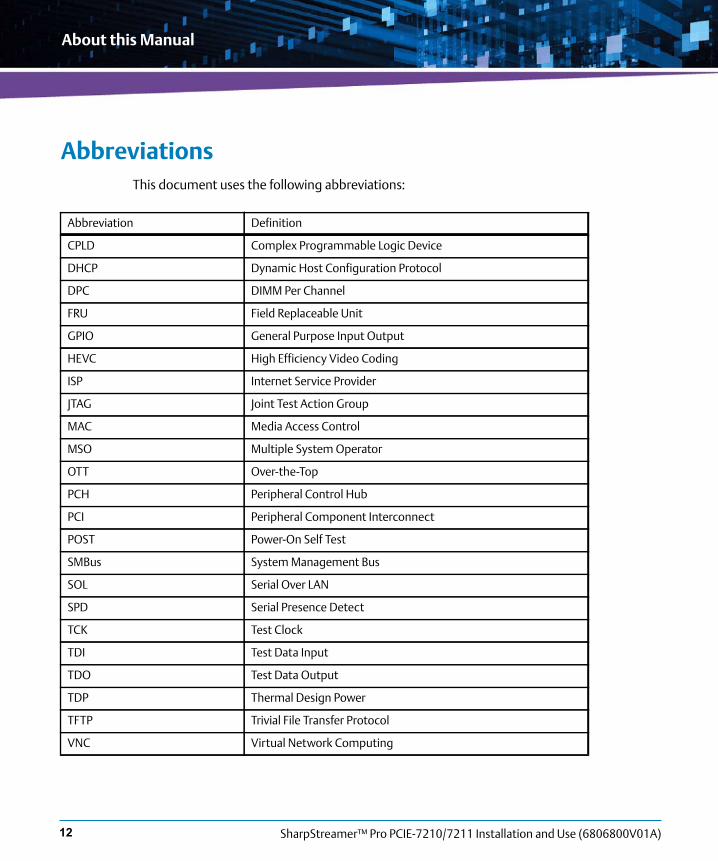
AbbreviationsThis document uses the following abbreviations:
Abbreviation Definition
CPLD Complex Programmable Logic Device
DHCP Dynamic Host Configuration Protocol
DPC DIMM Per Channel
FRU Field Replaceable Unit
GPIO General Purpose Input Output
HEVC High Efficiency Video Coding
ISP Internet Service Provider
JTAG Joint Test Action Group
MAC Media Access Control
MSO Multiple System Operator
OTT Over-the-Top
PCH Peripheral Control Hub
PCI Peripheral Component Interconnect
POST Power-On Self Test
SMBus System Management Bus
SOL Serial Over LAN
SPD Serial Presence Detect
TCK Test Clock
TDI Test Data Input
TDO Test Data Output
TDP Thermal Design Power
TFTP Trivial File Transfer Protocol
VNC Virtual Network Computing

About this Manual
SharpStreamer™ Pro PCIE-7210/7211 Installation and Use (6806800V01A) 13
ConventionsThe following table describes the conventions used throughout this manual.
Notation Description
0x00000000 Typical notation for hexadecimal numbers (digits are 0 through F), for example used for addresses and offsets
0b0000 Same for binary numbers (digits are 0 and 1)
bold Used to emphasize a word
Screen Used for on-screen output and code related elements or commands in body text
Courier + Bold Used to characterize user input and to separate it from system output
Reference Used for references and for table and figure descriptions
File > Exit Notation for selecting a submenu
<text> Notation for variables and keys
[text] Notation for software buttons to click on the screen and parameter description
... Repeated item for example node 1, node 2, ..., node 12
.
.
.
Omission of information from example/command that is not necessary at the time being.
.. Ranges, for example: 0..4 means one of the integers 0,1,2,3, and 4 (used in registers).
| Logical OR.

SharpStreamer™ Pro PCIE-7210/7211 Installation and Use (6806800V01A)
About this Manual
14
About this Manual
Summary of ChangesThis manual has been revised and replaces all prior editions.
Indicates a hazardous situation which, if not avoided, could result in death or serious injury.
Indicates a hazardous situation which, if not avoided, may result in minor or moderate injury
Indicates a property damage message.
No danger encountered. Pay attention to important information.
Notation Description
Part Number Publication Date Description
6806800V01A March 2018 Initial version. Document title changed to SharpStreamerTM Pro PCIE-7210/7211.
6806800U29D September 2017 Updated copyrights information and section BIOS Boot Parameter on page 88.
6806800U29C February 2017 Added a section BIOS Boot Parameter on page 88.
6806800U29B January 2017 Updated Chapter 6, Software Information, on page 93.
Added Appendix A, MaxCore Firmware Upgrade, on page 95.
6806800U29A October 2016 Initial version.

SharpStreamer™ Pro PCIE-7210/7211 Installation and Use (6806800V01A) 15
Safety Notes
This section provides warnings that precede potentially dangerous procedures throughout this manual. Instructions contained in the warnings must be followed during all phases of operation, service, and repair of this equipment. You should also employ all other safety precautions necessary for the operation of the equipment in your operating environment. Failure to comply with these precautions or with specific warnings elsewhere in this manual could result in personal injury or damage to the equipment.
Artesyn intends to provide all necessary information to install and handle the product in this manual. Because of the complexity of this product and its various uses, we do not guarantee that the given information is complete. If you need additional information, ask your Artesyn representative.
The product has been designed to meet the standard industrial safety requirements. It must not be used except in its specific area of office telecommunication industry and industrial control.
Only personnel trained by Artesyn or persons qualified in electronics or electrical engineering are authorized to install, remove or maintain the product.
The information given in this manual is meant to complete the knowledge of a specialist and must not be used as replacement for qualified personnel.
Keep away from live circuits inside the equipment. Operating personnel must not remove equipment covers. Only factory authorized service personnel or other qualified service personnel may remove equipment covers for internal subassembly or component replacement or any internal adjustment.
Do not install substitute parts or perform any unauthorized modification of the equipment or the warranty may be voided. Contact your local Artesyn representative for service and repair to make sure that all safety features are maintained.
EMCThis equipment has been tested and found to comply with the limits for a Class A digital device, pursuant to Part 15 of the FCC Rules. These limits are designed to provide reasonable protection against harmful interference when the equipment is operated in a commercial environment. This equipment generates, uses, and can radiate radio frequency energy and, if not installed and used in accordance with the instruction manual, may cause harmful interference to radio communications.

SharpStreamer™ Pro PCIE-7210/7211 Installation and Use (6806800V01A)
Safety Notes
16
Operation of this equipment in a residential area is likely to cause harmful interference in which case the user will be required to correct the interference at his own expense. Changes or modifications not expressly approved by Artesyn Embedded Technologies could void the user's authority to operate the equipment. Board products are tested in a representative system to show compliance with the above mentioned requirements. A proper installation in a compliant system will maintain the required performance. Use only shielded cables when connecting peripherals to assure that appropriate radio frequency emissions compliance is maintained.
Operation
Product DamageSurface of the Product High humidity and condensation on the product surface causes short circuits.Do not operate the product outside the specified environmental limits. Make sure the product is completely dry and there is no moisture on any surface before applying power.
Overheating and Product DamageOperating the product without forced air cooling may lead to overheating and thus damage of the product.When operating the product, make sure that forced air cooling is available in the enclosure.
Data CorruptionIf power to the unit is removed while a firmware update is in progress to the card flash memory, the changes will not be saved, and worse, the flash memory may be corrupted. In such case the card is likely to remain in non-operable state and will require reconditioning by qualified repair services.

Safety Notes
SharpStreamer™ Pro PCIE-7210/7211 Installation and Use (6806800V01A) 17
Installation
Damage of CircuitsElectrostatic discharge and incorrect installation and removal of the product can damage circuits or shorten their life.Before touching the product or electronic components, make sure that your are working in an ESD-safe environment.
Product DamageIncorrect installation of the product can cause damage of the product.Only use appropriate tools when installing/removing the product to avoid damage/deformation to the card and/or PCB.
EnvironmentAlways dispose equipment that is finally taken out of operation according to your country’s legislation and manufacturer’s instructions.

SharpStreamer™ Pro PCIE-7210/7211 Installation and Use (6806800V01A)
Safety Notes
18

SharpStreamer™ Pro PCIE-7210/7211 Installation and Use (6806800V01A) 19
Sicherheitshinweise
Dieses Kapitel enthält Hinweise, die potentiell gefährlichen Prozeduren innerhalb dieses Handbuchs vorrangestellt sind. Beachten Sie unbedingt in allen Phasen des Betriebs, der Wartung und der Reparatur des Systems die Anweisungen, die diesen Hinweisen enthalten sind. Sie sollten außerdem alle anderen Vorsichtsmaßnahmen treffen, die für den Betrieb des Produktes innerhalb Ihrer Betriebsumgebung notwendig sind. Wenn Sie diese Vorsichtsmaßnahmen oder Sicherheitshinweise, die an anderer Stelle diese Handbuchs enthalten sind, nicht beachten, kann das Verletzungen oder Schäden am Produkt zur Folge haben.
Artesyn Embedded Technologies ist darauf bedacht, alle notwendigen Informationen zum Einbau und zum Umgang mit dem Produkt in diesem Handbuch bereit zu stellen. Da es sich jedoch um ein komplexes Produkt mit vielfältigen Einsatzmöglichkeiten handelt, können wir die Vollständigkeit der im Handbuch enthaltenen Informationen nicht garantieren. Falls Sie weitere Informationen benötigen sollten, wenden Sie sich bitte an die für Sie zuständige Geschäftsstelle von Artesyn.
Das System erfüllt die für die Industrie geforderten Sicherheitsvorschriften und darf ausschließlich für Anwendungen in der Telekommunikationsindustrie und im Zusammenhang mit Industriesteuerungen verwendet werden.
Einbau, Wartung und Betrieb dürfen nur von durch Artesyn ausgebildetem oder im Bereich Elektronik oder Elektrotechnik qualifiziertem Personal durchgeführt werden. Die in diesem Handbuch enthaltenen Informationen dienen ausschließlich dazu, das Wissen von Fachpersonal zu ergänzen, können dieses jedoch nicht ersetzen.
Halten Sie sich von stromführenden Leitungen innerhalb des Produktes fern. Entfernen Sie auf keinen Fall Abdeckungen am Produkt. Nur werksseitig zugelassenes Wartungspersonal oder anderweitig qualifiziertes Wartungspersonal darf Abdeckungen entfernen, um Komponenten zu ersetzen oder andere Anpassungen vorzunehmen.
Installieren Sie keine Ersatzteile oder führen Sie keine unerlaubten Veränderungen am Produkt durch, sonst verfällt die Garantie. Wenden Sie sich für Wartung oder Reparatur bitte an die für Sie zuständige Geschäftsstelle von Artesyn. So stellen Sie sicher, dass alle sicherheitsrelevanten Aspekte beachtet werden.

SharpStreamer™ Pro PCIE-7210/7211 Installation and Use (6806800V01A)
Sicherheitshinweise
20
EMVDas Produkt wurde in einem Artesyn Standardsystem getestet. Es erfüllt die für digitale Geräte der Klasse A gültigen Grenzwerte in einem solchen System gemäß den FCC-Richtlinien Abschnitt 15 bzw. EN 55022 Klasse A. Diese Grenzwerte sollen einen angemessenen Schutz vor Störstrahlung beim Betrieb des Produktes in Gewerbe- sowie Industriegebieten gewährleisten.
Das Produkt arbeitet im Hochfrequenzbereich und erzeugt Störstrahlung. Bei unsachgemäßem Einbau und anderem als in diesem Handbuch beschriebenen Betrieb können Störungen im Hochfrequenzbereich auftreten.
Wird das Produkt in einem Wohngebiet betrieben, so kann dies mit grosser Wahrscheinlichkeit zu starken Störungen führen, welche dann auf Kosten des Produktanwenders beseitigt werden müssen. Änderungen oder Modifikationen am Produkt, welche ohne ausdrückliche Genehmigung von Artesyn durchgeführt werden, können dazu führen, dass der Anwender die Genehmigung zum Betrieb des Produktes verliert. Boardprodukte werden in einem repräsentativen System getestet, um zu zeigen, dass das Board den oben aufgeführten EMV-Richtlinien entspricht. Eine ordnungsgemässe Installation in einem System, welches die EMV-Richtlinien erfüllt, stellt sicher, dass das Produkt gemäss den EMV-Richtlinien betrieben wird. Verwenden Sie nur abgeschirmte Kabel zum Anschluss von Zusatzmodulen. So ist sichergestellt, dass sich die Aussendung von Hochfrequenzstrahlung im Rahmen der erlaubten Grenzwerte bewegt.
Warnung! Dies ist eine Einrichtung der Klasse A. Diese Einrichtung kann im Wohnbereich Funkstörungen verursachen. In diesem Fall kann vom Betreiber verlangt werden, angemessene Maßnahmen durchzuführen.
Betrieb
Beschädigung des ProduktesHohe Luftfeuchtigkeit und Kondensat auf der Oberfläche des Produktes können zu Kurzschlüssen führen.Betreiben Sie das Produkt nur innerhalb der angegebenen Grenzwerte für die relative Luftfeuchtigkeit und Temperatur. Stellen Sie vor dem Einschalten des Stroms sicher, dass sich auf dem Produkt kein Kondensat befindet.

Sicherheitshinweise
SharpStreamer™ Pro PCIE-7210/7211 Installation and Use (6806800V01A) 21
Überhitzung und Beschädigung des ProduktesBetreiben Sie das Produkt ohne Zwangsbelüftung, kann das Produkt überhitzt und schließlich beschädigt werden.Bevor Sie das Produkt betreiben, müssen Sie sicher stellen, dass das Gerät über eine Zwangskühlung verfügt.
Fehlerhafter DatenbestandWenn sie die Spannungsversorgung des Produkts abschalten, während Programmdaten im Flashspeicher aktualisiert, werden, können diese Daten nicht korrekt gespeichert werden. In diesem Fall ist das Produkt mit hoher Wahrscheinlichkeit nicht mehr betriebsbereit und die Funktionsfähigkeit muß durch einen qualifizierten Reparaturdienst wieder hergestellt werden.
Installation
Beschädigung von SchaltkreisenElektrostatische Entladung und unsachgemäßer Ein- und Ausbau des Produktes kannSchaltkreise beschädigen oder ihre Lebensdauer verkürzen.Bevor Sie das Produkt oder elektronische Komponenten berühren, vergewissern Sie sich, daßSie in einem ESD-geschützten Bereich arbeiten.
Beschädigung des ProduktesFehlerhafte Installation des Produktes kann zu einer Beschädigung des Produktes führen. Verwenden Sie geeignetes Werkzeug, um das Produkt zu installieren/deinstallieren. Auf diese Weise vermeiden Sie, dass das card oder die Platine deformiert oder zerstört wird
UmweltschutzEntsorgen Sie alte elektronische Baugruppen stets gemäß der in Ihrem Land gültigen Gesetzgebung und den Empfehlungen des Herstellers.

SharpStreamer™ Pro PCIE-7210/7211 Installation and Use (6806800V01A)
Sicherheitshinweise
22

Chapter 1
SharpStreamer™ Pro PCIE-7210/7211 Installation and Use (6806800V01A) 23
Introduction
This chapter provides a brief overview of SharpStreamer™ Pro PCIE-7210/7211 card, its features and applications, hardware and software overview, standard compliance, and ordering information.
The Artesyn SharpStreamer Pro PCIE-7210/7211 high performance video accelerator card enables service provider networks to offer HEVC video transcoding services quickly and dynamically. As an add-on card, the PCIE-7210/7211 offers quick and scalable integration with MaxCore server architecture to meet the demands of Internet Service Providers (ISPs) and Multiple System Operators (MSOs).
With a focus on the high density and low power demands of video streaming applications such as OTT streaming servers, mobile network optimization, video conferencing and broadcast equipment, Artesyn employs Intel® Xeon® E3-1578Lv5 (codename Skylake-H) GPU accelerated devices in small, scalable PCI Express card footprints that are easily deployable in off-the-shelf platforms. Each SharpStreamer Pro PCIE-7210/7211 CPU is capable of up to eight (8) streams of 1080p30 H.265/High Efficiency Video Coding (HEVC) transcodes, or four (4) streams of 1080p60 H.265/HEVC transcodes. Each CPU offers one (1) 4KP60 HEVC, or up to two (2) 4KP30 HECV transcodes.
The SharpStreamer Pro solution is easily deployable, portable, and does not constrain operators to a single type of equipment to monetize Over-the-Top (OTT) streaming content. It also offers network scalability for increased subscribers to pay as you go, adding more cards and density from small to large servers as needed. Compared to software-only solutions, the SharpStreamer Pro PCIE-7210/7211 requires far fewer servers and much less operational cost to power video transcoding services.
The SharpStreamer Pro PCIE-7210/7211 is equipped with a Software Development Kit comprised of the Intel® Media Server Studio Essentials runtime files with the Intel® Iris™ Pro Graphics P580 fixed-function hardware acceleration, monitoring and processor subsystems, O/S, and management tools for easy integration with server host processing environments.
1.1 FeaturesThe following are the main features of the PCIE-7210/7211:
PCIe Full length Full height card (312mm x 111.15mm) compatible with MaxCore system.
Two Intel® Xeon® processors E3-1578Lv5 (Skylake-H) as accelerators.
Two 10 Gigabit Ethernet controllers for inter processor communication (82599).

Introduction
SharpStreamer™ Pro PCIE-7210/7211 Installation and Use (6806800V01A)24
Two DDR4 SODIMM modules connected to each Intel® Xeon® ProcessorE3-1578L v5 / E3-1585L v5 each with 8GB memory.
Two uSD card slots supporting up to 32GB, one for each processor.
Two USB 2.0 ports on faceplate one from each processor.
One common serial console interface on faceplate for both processors.
One SSD interface connected to each PCH supporting upto 128 GB.
One 1GE Interface connected to each PCH for MaxCore communication (I210).
1.2 Hardware OverviewThe SharpStreamer™ Pro PCIE-7210/7211 card is designed for the Artesyn MaxCore™ platform. The PCIE-7210/7211 is an IntelE3-1578L v5 / E3-1585L v5 PCI Express card for MaxCore server based installations in a video broadcasting and data server environment. The card has PCIe x16 Gen 3 bus connected to standard gold finger edge.

Introduction
SharpStreamer™ Pro PCIE-7210/7211 Installation and Use (6806800V01A) 25
In the MaxCore implementation, each CPU communicates with the host server through a direct-attached PCI Express x8 Gen 3 link. The PCI Express version utilizes a non-transparent PCI Express x16 Gen 3 (128Gbps) bridge to connect to the host’s PCI Express interface. Each CPU supports up to 32GB of removable DDR4 dual channel memory. The PCIE-7210/7211 card consumes power (> 75W) from the PCI Express slot as well as expansion connector. The card has been designed to integrate into today’s industry leading and NEBS-ready platforms.
1.3 Software OverviewThe software is delivered in the form of software components. These software components contain necessary binaries, utilities, tools to enable PCIE-7210/7211 card function as mCPU/aCPU for upgrading firmware and for media transcoding. See, Chapter 6, Software Information, on page 93.
Figure 1-1 Mechanical Layout
C358
C362
C643
R1490R1489
R1488R1
487
R148
4
R148
3
R963
C360
C644
C642
R764
R957
R941R960R953
R942
R958
R944
R952
R962
R563
C180
7C3
56
R532
R531R978
R956
R969
M12
C530
R982R767
R713
C1824
C364
C528
R499
C323
R409
M33
R1492
U23
R358
R357
R356
R355
R353
U94
R149
5R1
494
Y2C1
782
R732
R561
C352
C353
C354
C351
R436
R437R562
R564
C291R977
R481
R766
R1142R1113
R440
R439
R438
R380
U71
C531
C296
R723
E27
U53
C536
C534
R715
E2L51R488
C542
C546
C544
C676C304R489
R484
C259
L18
C822
C821
C820
C819
C271
Y9
C826C825
C824
C823
R354
C814
C813
C812
C811
R1491
U38C818
C817
C816
C815
C178
3
C357
C359
R828
R544
R434
R1452
R7
R545
R543
R143
7
R1431
R145
6
R458
R1443
R1432R1450R7
84
U36
C355
C361
C295 U35
C290R985
R132
7
L30
C306
C677
D26
R485
J14
C251
R789
U21
C254
C253
R331
C850
C844R88
R48 R4
7
R124
2
R156R124R90R89
R46
R142
9
R142
8
R143
6
R144
7
U93 C176
4
C1762
R1438
R435
R1422
R143
4
R1423
R1445
R1441
R1439
R1433
Y11
C1725
R382
R133
9C1
724
C172
3
Y10
R479
C591
C583R805
M28
R332
E19
U78
R1166
U37
Q17
C456
C420
R1448R1424
R1425
R1444
C172
6
R129
0
R129
1R134
7
R136
6R7
31
U87
M24
M38
U63
C589
R1162
C455
R736
R141
3 R761
R988
L34
C585
C272
R362
R364
C830
C829
R365
L27
L26
U50Y3
R706
R705
C428
R1404
R1446
R579
R1245
U74
C443
C426
C421
C429
C422
C597
R363
U24
R361
R360
C834
C833
M25
R635
U33
C434
R593
C437
C436
R598
R596
R604U44
R595R590
R603
C446
R606
L25
J11
R2
R861 R877
R876
R129
4
C1718
R817
C471
C459
R634
R637
R644
R643
R641R629
R633
R627
R630
C462
C460
C457
U46R632
C447
C449
U45
C1367
L24
R3
C1346
C1345
C1342
C1341
C469
R647
C1338
C1337
C1334
C1333
M26
C140
2
C248
R123
7C1
389
C136
6
U86
R823
XJ4
XJ3
R1238R1239
C138
2
R1280
R1279
C147
9
U84
C146
1
C138
3
C172
2
C172
1
C139
0
C572
C571
C568
C567
C520
R223
R126
1R1
251
C140
4
C139
6
C569
C573
C602
C601
C649
M27
R762
U15
C517
C513
C198
C186C182
R239
R701
R235
R231
R854R8
55
C185
C183
R237
U14
R230 R228
R236
R244
R234
C178
C184
R242
R238
R220
C570
C574
E18
C222
C227
C228
U18
R306
U19
C499
C510
U52
U90
P4
L16
U49
U16
E17
C196
C199
C194
C476
R247
R245
C190
L12
L28
C230
R304
C221
C229
C231
P9
P2C498 R689
L15
L13
R279
Q10
R248
C482
C479 C170
R667
R674
R673
R666R665
R662
R664
C490
C172
R675
U47
C174
S6M34
L17
M11
R698
R697
R696
R693R692
R686
R685
R699
C1823
C493
C492
R511
R281
U17
C208
C206
L14
Q11
C200
R252
C555
R681
C478
R679
R656
R678
R655
R651
C552R669
BF5
M30
C169
P12
R293R294R295
C556
E16
R272
C553
C554
P13
BF4
D22
D21
J1
C242
C241
J13
C238
C239
J12
C244
S2
S3
M1
M31R778
R776
R318 C411
Q4
R10
U20
C243
C11
C15
C652
R782
R190
R191
R79
R84
R783
R781
R780
R186
C127
C10
R192R169
C337
C336
C334
R425 R429
R416
R415
R419
C576
R773
M29
L4
L41
C292
R728
R383
R319
R322R52 C76
R78
R321 R320 R3
81
C78
C79
C131C84
R80
R493
R179
R178
R5
R6
E13
M2
C125
C129
R161 R158
C166
C159
C947
R160
R1207
M9
C345
R427
R417
BF6
L5
C54
C57
C418
C412
Q5
R53
R71
C70
R56
U3
R57
R67
R87R83
E4
C617
C85
C83
R824
R830 R848
R189
R180
L9
R1204
C163
R325
R212
L6
C51
C69
C115
C65
C107 C110
R72
U4
R60
R137
C128
M3
C116
C59
R70
R177
R176
R55
R69
R495
C130
R188
R184
R913R168
R175
R174
R162
R500
R497
R459
R271
R185
L8
R146R143L57
C106 C105
C109
C112
R135
R141
C121U6 R150
R140R133
R138
R149
C136
C117
C119
C120
R154
R851
R746
M19
C973
R118
4R1197
R120
0 R1193
C113
R1206R151
R119
5
R1203
R8
R852R853
J3
C987
XJ1
XJ2
C110
9
C109
6
C955
C106
7
C105
8
U81
C952
C1021
C999
C971
C978
C972
C935
C934
C140
M4
C139
R1182
R210
C1888
R204
R203R195
R194
R208
R209
C189
8
C1875
C1901
R100
5C3
35
M20
C979
L1
C929
C928
C936
C931
C930C419
C148
C150
C154
C941
C940
C939
C938C937 C933
C675
C155 C146
C145
C153
C157
C156
C138
C151
C320
R200
Y7
C688
C1881
C144 R215
R197
R196
R206
U96
C1899
C1876 R167
R102
4
R100
6R4
24C5
96
C23R15
R11
R1189
R965
E20
C39
C152
U26
R389
L20
D27
R205
R426
C685
C1886
C1885
C1878
R402
R401R310
R433
C190
0
C1887
C1880
C1873
R1028
R1025
R270
R1034
R1032
C689
U98
L2
C19R118
7C3
0
C32
R30
R36
R28
U1
R25
R20
R22
R27
R35
C318
C42
C88
R38
R95
C313 C92
C307R102
R387
U97
Y1
R441
R1013
U40
C1867
C1866
C1865
C1864
C389C397
C399
M13
U62
C590
R804
L3
C723
C722
C33
C45
C29 U2
R23
C43
C709
C708
C93
C94
C91 R108
R109
R104
R106
R117R101
R103
C101C100
C102
R122
R119U5 R118
L7
U22
U11
C165
R490
L23
C395
C405
R351
R369
R371C407
L19
C720
C716
C717
C718
C719
C721
C715
C714
C713
C712
C315
U25
C158
R101
4R4
00
R759
C1839
C1906
C669C667
R836
C1908
C1907
C1905 C614R903
R846
U72
R444
R904
Y4
R373
M21
C276
U75
C599
C600C741
U13
C168
R826
R1105
C605
R378
U73U65
C615
R858
C606R9
01
R900
R905R866
R885
R379
U64
C604
C603
R457
R453
L21
R1101
U66
R967R947
R955
U70
R966
R948
R964
R943
R971
U57
C9R730 R932
R4
R809
R810
R950
R951
M22
C305
D25
R478
M37
R407
C324
U27
R410
C328
C725
C724
C326
C322
R406
C731
C730
C729
C728
C727
C726
C737
C735
C734
C733
C732
C739
C738
C736
R148
6R1
485
R110
3R1
097
C363
D5
106.65 mm
312 mm
6
9
2
9LABEL
COUNTRY OF ORIGIN
9
9
10
15 24
6
5
5271
B82
REV NOASSY
9
52 71
2
259
9
B12
5271
A38
B32
144146
541 341
641 441
143145
B37
BT1
2
2
BE1
7 814
A24
A45
B1
10
1928
9
52 71
B11
260
259
260
1015
602
AD1
5910
1524
A24
A45
24
9
17
A26
10
1928
10
B82
AD1
BE1
5
85 4
A26
K
AP1
814
9
52 71
25
2415
71PA
2D
9
17
B1
BT1
B11 B12
641441
541341
541341
144 146
A38
260
259
259
260
7
13
9
5271
2
2
LABEL
25
19
CPU2CPU1

Introduction
SharpStreamer™ Pro PCIE-7210/7211 Installation and Use (6806800V01A)26
1.4 Standard CompliancesThe PCIE-7210/7211 card meets the following standards.
The PCIE-7210/7211 card is designed to comply only with MaxCore Server.
1.5 Ordering and Support InformationUse the part number given in the following table, when ordering a card, supported software packages, or requesting support information. Consult your local Artesyn sales representative for more information.
PCIe-7210/7211 variants support I210 and SSD
Table 1-1 Standard Compliances
Standard Description
47CFR15 (FCC) Class A ANSI C63.4
EN 55032,CISPR 32 Class A
ICES-003 Class A
Radiated Emissions
47CFR15 (FCC) ANSI C63.4
EN 55032, CISPR 32 Class A
ICES-003 Class A
Conducted Emissions
EN 300 386 v1.6.1: 2012 EN 61000-4-2: 2009 ESD
EN 300 386 v1.6.1: 2012 EN 61000-4-3: 2010 Radiated Immunity
EN 300 386 v1.6.1: 2012 EN 61000-4-4: 2012 EFT
EN 300 386 v1.6.1: 2012 EN 61000-4-11:2004 Voltage Dips and Interrupts
Table 1-2 Ordering Information
Part Number Description
PCIE-7211-2-32GB PCIE card with two 3GHz Intel® Xeon® E3-1585L v5 CPUs, 32GB SSD per CPU, 16GB RAM per CPU.
PCIE-7211-2-128GB PCIE card with two 3GHz Intel® Xeon® E3-1585L v5 CPUs, 128GB SSD per CPU, 16GB RAM per CPU

Introduction
SharpStreamer™ Pro PCIE-7210/7211 Installation and Use (6806800V01A) 27
PCIE-7210-2 (EOL) and PCIE-7210-2-3GHZ(EOL) variants are EOL now, do not support I210 and SSD.
PCIE-7210-2-32GB PCIE card with two 2GHz Intel® Xeon® E3-1578L v5 CPUs, 32GB SSD per CPU, 16GB RAM per CPU.
Table 1-3 Ordering Information
Part Number Description
PCIE-7210-2 (EOL) PCIE card with two 2 GHz Intel® Xeon® E3-1578L v5 CPUs and 16 GB RAM per CPU.
PCIE-7210-2-3GHZ(EOL) PCIE card with two 3GHz Intel® Xeon® E3-1585L v5 CPUs and 16 GB RAM per CPU.
Table 1-2 Ordering Information
Part Number Description

Introduction
SharpStreamer™ Pro PCIE-7210/7211 Installation and Use (6806800V01A)28

Chapter 2
SharpStreamer™ Pro PCIE-7210/7211 Installation and Use (6806800V01A) 29
Hardware Preparation and Installation
This chapter provides information on unpacking and inspecting the card procedures and safety precautions to be followed while handling the card. The environmental, thermal, and power requirements, and the installation and removal procedures of the card are also explained in this chapter.
2.1 Unpacking and Inspecting PCIE-7210/7211 Card
Shipment Inspection
To inspect the shipment, perform the following steps:
1. Verify that you have received all items of your shipment:
One SharpStreamer™ Pro PCIE-7210/7211 card.
One printed copy of Quick Start Guide.
One printed copy of Safety Notes Summary.
Any optional items ordered.
2. Check your shipment and report any damage or differences to the Contact Center at [email protected].
Damage of CircuitsElectrostatic discharge and incorrect installation and removal of the card can damage circuits or shorten their life.
Make sure that you are working in an ESD-safe environment, before touching the card or electronic components.

Hardware Preparation and Installation
SharpStreamer™ Pro PCIE-7210/7211 Installation and Use (6806800V01A)30
3. Remove the desiccant bag shipped with the card and dispose it according to your country’s legislation.
2.2 Environmental, Thermal, and Power RequirementsThis section contains the environmental, thermal, and power requirements of the PCIE-7210/7211 card.
2.2.1 Environmental and Thermal Requirements
Make sure the card is thoroughly inspected before shipment. If any damage has occurred during transportation please contact our Contact Center immediately.
Operating temperatures refer to the temperature of the incoming air passing across the card and out of the faceplate and not the temperature of the components.
Card DamageHigh humidity and condensation on the card surface causes short circuits.Do not operate the card outside the specified environmental limits. Make sure that the card is completely dry and there is no moisture on its surface before applying power.

Hardware Preparation and Installation
SharpStreamer™ Pro PCIE-7210/7211 Installation and Use (6806800V01A) 31
The following table provides the environmental and the thermal requirements for the PCIE-7210/7211 card.
2.2.2 Power Requirements
The following table provides the typical power consumed by the PCIE-7210/7211 card.
Table 2-1 Environmental and Thermal Requirements
Requirement Operating Non-Operating
Temperature 0°C to 35°C -40°C to 70°C
Minimum Airflow
(Reference to sea level)500 LFM (2.5 m/sec)400 LFM (2 m/sec) for 35°C Operation
-
Temperature Change 30°C/hr 30°C/hr
Relative Humidity 5% to 85% Non-Condensing 5% to 90% Non-Condensing but not to exceed 0.024 kg of water per kg of dry air
Shock and Vibration 0.1G’s 5 to 200Hz EN 300 019-2-2 Class 2.3
Altitude Up to 1800m
With 40°C operation between 1800m and 4000m
Up to 12000m
Table 2-2 Power Requirements
Mode PCIe slot power with expansion connector
Idle 63.6 W (+/- 10%)
Active 82.2 W (+/- 10%)
Peak 138W (+/- 10%)
Idle: All two CPUs at Linux login prompt.
Active: When the CPUs are in Transcoding state at room temperature.
Peak: When both CPUs are at 35°C Ambient temperature.

Hardware Preparation and Installation
SharpStreamer™ Pro PCIE-7210/7211 Installation and Use (6806800V01A)32
2.3 Precautions
To reduce the risk of personal injury, fire, or damage to the equipment, do not overload the AC supply circuit that provides power to the chassis.
The card must be powered and connected only to a controlled voltage source.
To avoid shock, make sure that the power cables are connected to a properly wired and grounded receptacles.
Electrostatic DischargeDo not touch the circuit with bare hands.The static electricity of the human body may damage the ElectroStatic Sensitive Devices (ESSDs) on the circuit.Make sure that you wear an ElectroStatic Discharge (ESD) preventive wrist strap or antistatic glove to prevent the static electricity from hurting you or damaging the device.Keep your personal objects such as your clothes away from the system. To prevent the static electricity from damaging the device, it is recommended to wear antistatic clothes.
Pin DamageIf the is not fully aligned with the interface in the backplane, too much force may twist the pins on the card or backplane.Do not exert too much force when you insert the card.

Hardware Preparation and Installation
SharpStreamer™ Pro PCIE-7210/7211 Installation and Use (6806800V01A) 33
2.3.1 ESD Prevention
Static electricity may hurt you or damage the device. To minimize the damage, pay attention to the following points:
Before touching the card or electronic components, make sure that you are working in an ESD safe environment.
Before you operate the device, wear the ESD-preventive wrist strap. Both terminals of the ESD preventive wrist strap must contact well. One terminal touches your bare skin, and the other is inserted in the jack at the front or back side of the shelf.
Avoid moving as much as possible. Movement gathers static electricity around you.
Do not touch the solder point, pin, or bare circuit.
Do not leave the device in the place where others can operate it.
Install the device at once after you take it out of the anti-static package. If you need to lay down the device, place it back in the anti-static package. Do not lay the device on the shelf or cabinet.
Monitor the temperature and humidity of the equipment room. Warm air decreases the humidity but increases the static electricity in the room.
Damage of CircuitsElectrostatic discharge and incorrect module installation and removal can damage circuits or shorten their life. Before touching the module or electronic components, make sure that you are working in an ESD safe environment.

Hardware Preparation and Installation
SharpStreamer™ Pro PCIE-7210/7211 Installation and Use (6806800V01A)34
2.4 PCIE-7210/7211 Card Installation and RemovalThis section contains the PCIE-7210/7211 card installation and removal procedures.
2.4.1 PCIE-7210/7211 Card Installation
To install the PCIE-7210/7211 card, perform the following steps:
1. Use anti-static pads and attach an ESD strap to your wrist. Attach the other end of the ESD strap to an electrical ground (For more details, refer to the section Precautions on page 32).
2. Identify the system in which the PCIE-7210/7211 card is to be installed.
3. Remove the system cover.
Shipping the card along with a server is not recommended. If you still need to ship the card along with the server, ensure the card is properly secured in the server. Check if necessary precautions were followed to keep the card resistive against wobbling. Otherwise, there are chances of card getting damaged. For more information about securing the PCIe card in a server, refer to MaxCore product documentation.
You must allow the card to cool for 30 minutes, before removing it. In case you try to touch the card, the heat sink could be hot enough to burn your skin.
For detailed information about the PCIe card installation, refer to MaxCore product documentation.

Hardware Preparation and Installation
SharpStreamer™ Pro PCIE-7210/7211 Installation and Use (6806800V01A) 35
4. Insert the PCIE-7210/7211 card into the PCIe slot, secure it, and ensure that the card is properly fitted in the PCIe slot.
5. Lock the slot ejectors, close the system cover and then power on the system.
2.4.2 PCIE-7210/7211 Card Removal
To remove the PCIE-7210/7211 card, perform the following steps:
1. Make sure you are in an ESD-safe environment.
2. Power off the system, disconnect the system from the electrical outlet and peripherals and remove any cables connected to the card.
3. Remove the system cover.
Make sure that the card has enough air flow after closing the system with the cover. Refer to MaxCore MC3000 Platform Installation and Use manual for setting the fan speed accordingly.
The CPU transcoding performance is directly related to the airflow and cooling ability of the server in which the card is installed.
Wait at least 30 minutes for the card to cool down as the heat sink could be extremely hot.

Hardware Preparation and Installation
SharpStreamer™ Pro PCIE-7210/7211 Installation and Use (6806800V01A)36
4. Remove the screw holding the front panel bracket and gently pull the PCIE-7210/7211 card from the slot.
5. Close the cover of the system.
Place the PCIE-7210/7211 card into an ESD-protective bag and seal it appropriately.

Chapter 3
SharpStreamer™ Pro PCIE-7210/7211 Installation and Use (6806800V01A) 37
Functional Description
This chapter describes the functional blocks of the SharpStreamer™ Pro PCIE-7210/7211 card. The PCIE-7210/7211 server accelerator card provides the processor subsystem for the Artesyn MaxCore system. The PCIE-7210/7211 comes in a PCI Express like form factor with MaxCore-specific modifications and extensions.
The PCIE-7210/7211 card contains two Intel® Xeon® Processors E3-1578L v5 / E3-1585L v5 with built-in graphics to transcode the video more efficiently and allow the host to handle other network functions.
The following figure depicts the functional block diagram of SharpStreamer™ Pro PCIE-7210/7211 card.
Figure 3-1 SharpStreamer™ Pro PCIE-7210/7211 Block Diagram

Functional Description
SharpStreamer™ Pro PCIE-7210/7211 Installation and Use (6806800V01A)38
3.1 CPU ComplexThe CPU complex of PCIE-7210/7211 card comprises an Intel E3-1578L v5 / E3-1585L v5 processor and a PCH.
3.1.1 Intel Skylake Processor
Skylake is an Intel core-2015 platform. It is 64 bit, multi core processor built on 14nm process technology. The H-processor line is offered in a 2-Chip Platform and is connected to a discrete PCH chip on the motherboard. It is a BGA1440 Package supporting the GT2 and GT4 Graphics Configuration. E3-1578L v5 / E3-1585L v5 processor supports different technologies and it has features like greater CPU and GPU performance and reduces consumption of power.
3.1.2 Intel Skylake PCH
The H-Processor line of the Skylake is offered in a two chip platform. Platform Controlled Hub (PCH) is a separate IC along with the E3-1578L v5 / E3-1585L v5 processor. PCH controls certain data paths and support functions used in conjunction with Intel E3-1578L v5 / E3-1585L v5 processor. The PCH provides extensive I/O support.
The following are some of its key features:
ACPI Power Management Logic Support
PCI express Base specification
USB Dual Role/OTG Capability
Super Speed Inter Chip (SSIC)
Direct Media Interface (DMI)
Serial Peripheral Interface (SPI)
Enhanced Serial Peripheral Interface (eSPI)
Flexible I/O—Allows some high speed I/O signals to be configured as PCIe*, SATA or USB 3.0.
General Purpose Input Output (GPIO)
Low Pin Count (LPC) interface

Functional Description
SharpStreamer™ Pro PCIE-7210/7211 Installation and Use (6806800V01A) 39
Interrupt controller
Timer functions
3.2 DDR4 2133 MemoryThe PCIE-7210/7211 card comes with four DDR4 SODIMM channels, two on each E3-1578L v5 / E3-1585L v5 processor. Each DIMM is populated with 8GB of memory. That means, each processor has an 16GB DDR4 memory (8GB on each channel) running at DDR4-2133 speed, resulting a total 32GB of memory on each PCIE-7210/7211 card.
3.3 SSD MemoryThe PCIE-7211-2 card comes with two on board SSD Memory interfaces, one for each processor. Each SSD memory supports upto 128GB.
Note: PCIE-7210-2(EOL) and PCIE-7210-2-3GHZ(EOL) variants do not have SSD Memory interface.
3.4 Ethernet Controller
3.4.1 82599
This is a PCIe port Gen2 x8 interface, which is connected to a dual port Ethernet controller. It appears to the E3 software as 2 unique MAC addresses.
The 82599 provides complete functionality to support up to two 10 Gb/s ports.
Each DDR4 SODIMM channel is expandable up to 16GB.
Functional Description
SharpStreamer™ Pro PCIE-7210/7211 Installation and Use (6806800V01A)40
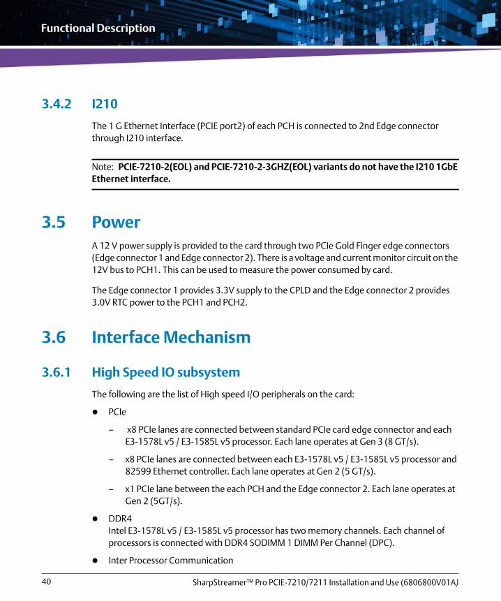
3.4.2 I210
The 1 G Ethernet Interface (PCIE port2) of each PCH is connected to 2nd Edge connector through I210 interface.
Note: PCIE-7210-2(EOL) and PCIE-7210-2-3GHZ(EOL) variants do not have the I210 1GbE Ethernet interface.
3.5 PowerA 12 V power supply is provided to the card through two PCIe Gold Finger edge connectors (Edge connector 1 and Edge connector 2). There is a voltage and current monitor circuit on the 12V bus to PCH1. This can be used to measure the power consumed by card.
The Edge connector 1 provides 3.3V supply to the CPLD and the Edge connector 2 provides 3.0V RTC power to the PCH1 and PCH2.
3.6 Interface Mechanism
3.6.1 High Speed IO subsystem
The following are the list of High speed I/O peripherals on the card:
PCIe
– x8 PCIe lanes are connected between standard PCIe card edge connector and each E3-1578L v5 / E3-1585L v5 processor. Each lane operates at Gen 3 (8 GT/s).
– x8 PCIe lanes are connected between each E3-1578L v5 / E3-1585L v5 processor and 82599 Ethernet controller. Each lane operates at Gen 2 (5 GT/s).
– x1 PCIe lane between the each PCH and the Edge connector 2. Each lane operates at Gen 2 (5GT/s).
DDR4Intel E3-1578L v5 / E3-1585L v5 processor has two memory channels. Each channel of processors is connected with DDR4 SODIMM 1 DIMM Per Channel (DPC).
Inter Processor Communication

Functional Description
SharpStreamer™ Pro PCIE-7210/7211 Installation and Use (6806800V01A) 41
Two 10 Gigabit Ethernet controllers are used between E3-1578L v5 / E3-1585L v5 processors for Inter CPU communication. Each device operates at 10 Gb speed.
SATA
– Two SATA ports are connected between each PCH and the Edge connector 2. Each port operates at 6 GB speed.
– One SATA port is connected between each Skylake PCH and the on board SSD module. Each port operates at 6 GB speed.
USB2.0
– Two USB2.0 ports are connected between each PCH and the Edge connector 2.
– One USB2.0 port is connected between each PCH and the Front panel USB connector.
LPC
– This interface is used between Edge connector 2, PCH, and CPLD.
– This interface is connected to the MaxCore server through the Edge connector 2.
– Speed of LPC Interface is 24MHz.
GEOne GE port is connected between each Skylake PCH and the 2nd card edge connector through I210 device.
3.6.2 Low Speed Serial Interface
3.6.2.1 Two-wire interface
System Management LogicThe System management Logic (SML) is a low speed connection for low power state mode for manageability communication.
System Management BusThe System Management Bus (SMBus) is used as interface between devices.
I2C0The I2C0 interface is connected to the inlet and outlet onboard temperature sensors.

Functional Description
SharpStreamer™ Pro PCIE-7210/7211 Installation and Use (6806800V01A)42
3.6.2.2 SVID
The System V interface Definition (SVID) is a 3-wire digital interface used to transfer power management information between the Master and Slave. In PCIE-7210/7211, the processor acts as a Master and the voltage regulators act as slaves for this SVID interface.
3.6.3 Boot Controller
The boot controller is responsible for managing the boot process. The boot process loads a boot image that is stored in 128 Mbit on board SPI FLASH connected to each PCH device.
3.7 Micro SD cardThere are two microSD slots available on each PCIE-7210/7211 card. Each microSD card goes to one of the respective PCH (J2 for PCH1 and J8 for PCH2). The microSD card slot is designed either for a non- volatile storage space, and/or as a Firmware recovery option.
The microSD cards need to be inserted into their slots before power is applied to the card. The microSD slots are not hot swappable.
First insert the microSD card into the slot on PCIE-7210/7211 and then install the PCIE-7210/7211 card into the server.

Functional Description
SharpStreamer™ Pro PCIE-7210/7211 Installation and Use (6806800V01A) 43
The following figure shows the location of the microSD card slots on the PCIE-7210/7211 card.
3.7.1 MicroSD as Firmware Recovery Option
The microSD can be used as a BIOS recovery option. For this you need to perform the following steps:
1. Format the microSD card as FAT32, then copy the recovery firmware onto the card.
2. Insert the microSD card into the socket, and install the PCIE-7210/7211 card into the server.
3. Boot the server to a Linux CentOS.
4. Run the PCIE-7210/7211 command to recover the firmware.
Figure 3-2 microSD Card Location
CPU1- Micro SD card slot CPU2- Micro SD card slot
The process to write the recovery BIOS into the firmware over the microSD bus can take about 10 minutes.

Functional Description
SharpStreamer™ Pro PCIE-7210/7211 Installation and Use (6806800V01A)44
3.7.2 MicroSD as Non-Volatile Storage
The microSD slots can accommodate up to 32GB of flash storage that can be used as storage, similar to a flash thumb drive.
3.7.3 MicroSD as Boot Device
By default, during the card boot operation, the BIOS will first look for a boot record on the microSD storage device. If no boot record is found, then the card tries to PXE boot from the Server. If this is not successful, the processor reboots and tries the boot sequence again. The boot sequence can be modified in the BIOS.
3.8 Temperature SensorsThere are several temperature sensors on the PCIE-7210/7211 card. Two SPD memory temperature sensor devices on the card scattered around the card. Each SPD device has a temperature sensor in addition.The SPD temperature sensor can be used to measure the surrounding air temperature to the card corners. Also, there are temperature sensors built into each SODIMM modules.

Functional Description
SharpStreamer™ Pro PCIE-7210/7211 Installation and Use (6806800V01A) 45
Figure 3-3 shows the location of the temperature sensors on the card.
3.9 Clock DistributionClocking for each CPU complex consists of two input crystals. One 24 Mhz crystal to drive all the main buses and a 32.768 Khz crystal to drive the real time clock. Processor clocks are driven from PCH device. Each CPU has a dual channel memory, each memory channel provides an 1066.67 Mhz clock to their respective memory channel.
3.10 Reset ManagementEach PCH reset is controlled by the CPLD. CPU and Peripheral reset are controlled by PCH. During power up the CPLD state machine drives the reset control to each CPU during an induced reset from the front panel reset switch.
For more information about Reset button, refer the section Controls on page 66.
Figure 3-3 Location of Temperature Sensors - Secondary Side
U68 Temperature SensorU91 Temperature Sensor
Functional Description
SharpStreamer™ Pro PCIE-7210/7211 Installation and Use (6806800V01A)46
3.11 JTAGThe PCIe slot JTAG pins are mapped to the CPLD JTAG programming pins.
CPLD programming port at connector P2 (Independent connector for CPLD)
E3-1578L v5 / E3-1585L v5 and PCH JTAG pins are connected to XDP connector

Chapter 4
SharpStreamer™ Pro PCIE-7210/7211 Installation and Use (6806800V01A) 47
Controls, Indicators, and Connectors
This chapter contains information about the controls, indicators, and connectors associated with the PCIE-7210/7211 card.
4.1 Connectors
4.1.1 PCIE-7210/7211 Faceplate View
The following figure shows the faceplate view of PCIE-7210/7211 card.
Figure 4-1 PCIE-7210/7211 Faceplate
Push Button Reset CPU1
Push Button Reset CPU2
USB2.0 CPU1
USB2.0 CPU2
Console via USB 2.0CPU1 & CPU2
User LED CPU1
User LED CPU2

Controls, Indicators, and Connectors
SharpStreamer™ Pro PCIE-7210/7211 Installation and Use (6806800V01A)48
The PCIE-7210/7211 card comes with two gold finger edge connectors referred as Edge Connector 1 and Edge Connector 2.
4.1.2 Edge Connector 1
This section provides information about the PCIE-7210/7211 card Edge Connector 1 (Gold Finger) pinout.
Table 4-1 Edge Connector 1 Pinout
Pin # Name Side B Description Name Side A Description
1 +12V +12 Volt power PRSNT#1 PCIe edge present input
2 +12V +12 Volt power +12V +12 Volt power
3 +12V +12 Volt power +12V +12 Volt power
4 GND Ground GND Ground
5 SMCLK PCIE EDGE SMBCLK SMBus (System Management Bus) Clock
JTAG2 PCIe Edge Test Clock (TCK)
6 SMDAT PCIE EDGE SMBDAT SMBus (System Management Bus) Data
JTAG3 PCIe Edge Test Data Input (TDI)
7 GND Ground JTAG4 PCIe Edge Test Data Output (TDO)
8 +3.3V 3.3 Volt power JTAG5 PCIe Edge Test Mode Select (TMS)
9 JTAG1 PCIE EDGE TRST L TRST# (Test Reset) resets the JTAG interface
+3.3V 3.3 Volt power
10 3.3V AUX 3.3 Volt auxiliary power +3.3V 3.3 Volt power
11 WAKE# Signal for Link reactivation PRST# Reset
Mechanical Key
12 RSVD Reserved GND Ground
13 GND Ground REFCLK+ Reference clock
14 Tx_P(0) Transmitter Lane 0 REFCLK- Differential pair

Controls, Indicators, and Connectors
SharpStreamer™ Pro PCIE-7210/7211 Installation and Use (6806800V01A) 49
15 Tx_N(0) Differential pair GND Ground
16 GND Ground Rx_P(0) Receiver Lane 0
17 PRSNT2# Hot-Plug presence detect Rx_N(0) Differential pair
18 GND Ground GND Ground
19 Tx_P(1) Transmitter Lane 1 RSVD Reserved
20 Tx_N(1) Differential pair GND Ground
21 GND Ground Rx_P(1) Receiver Lane 1
22 GND Ground Rx_N(1) Differential pair
23 Tx_P(2) Transmitter Lane 2 GND Ground
24 Tx_N(2) Differential pair GND Ground
25 GND Ground Rx_P(2) Receiver Lane 2
26 GND Ground Rx_N(2) Differential pair
27 Tx_P(3) Transmitter Lane 3 GND Ground
28 Tx_N(3) Differential pair GND Ground
29 GND Ground Rx_P(3) Receiver Lane 3
30 RSVD Reserved Rx_N(3) Differential pair
31 PRSNT2# Hot-Plug presence detect GND Ground
32 GND Ground RSVD Reserved
33 Tx_P(4) Transmitter Lane 4 RSVD Reserved
34 Tx_N(4) Differential pair GND Ground
35 GND Ground Rx_P(4) Receiver Lane 4
36 GND Ground Rx_N(4) Differential pair
37 Tx_P(5) Transmitter Lane 5 GND Ground
38 Tx_N(5) Differential pair GND Ground
39 GND Ground Rx_P(5) Receiver Lane 5
40 GND Ground Rx_N(5) Differential pair
Table 4-1 Edge Connector 1 Pinout (continued)
Pin # Name Side B Description Name Side A Description

Controls, Indicators, and Connectors
SharpStreamer™ Pro PCIE-7210/7211 Installation and Use (6806800V01A)50
41 Tx_P(6) Transmitter Lane 6 GND Ground
42 Tx_N(6) Differential pair GND Ground
43 GND Ground Rx_P(6) Receiver Lane 6
44 GND Ground Rx_N(6) Differential pair
45 Tx_P(7) Transmitter Lane 7 GND Ground
46 Tx_N(7) Differential pair GND Ground
47 GND Ground Rx_P(7) Receiver Lane7
48 PRSNT2# Hot-Plug presence detect Rx_N(7) Differential pair
49 GND Ground GND Ground
50 Tx_P(8) Transmitter Lane 8 RSVD Reserved
51 Tx_N(8) Differential pair GND Ground
52 GND Ground Rx_P(8) Receiver Lane 8
53 GND Ground Rx_N(8) Differential pair
54 Tx_P(9) Transmitter Lane 9 GND Ground
55 Tx_N(9) Differential pair GND Ground
56 GND Ground Rx_P(9) Receiver Lane 9
57 GND Ground Rx_N(9) Differential pair
58 Tx_P(10) Transmitter Lane 10 GND Ground
59 Tx_N(10) Differential pair GND Ground
60 GND Ground Rx_P(10) Receiver Lane 10
61 GND Ground Rx_N(10) Differential pair
62 Tx_P(11) Transmitter Lane 11 GND Ground
63 Tx_N(11) Differential pair GND Ground
64 GND Ground Rx_P(11) Receiver Lane 11
65 GND Ground Rx_N(11) Differential pair
66 Tx_P(12) Transmitter Lane 12 GND Ground
Table 4-1 Edge Connector 1 Pinout (continued)
Pin # Name Side B Description Name Side A Description

Controls, Indicators, and Connectors
SharpStreamer™ Pro PCIE-7210/7211 Installation and Use (6806800V01A) 51
4.1.3 Edge Connector 2
This section provides information about the PCIE-7210/7211 card Edge Connector 2 pinout.
67 Tx_N(12) Differential pair GND Ground
68 GND Ground Rx_P(12) Receiver Lane 12
69 GND Ground Rx_N(12) Differential pair
70 Tx_P(13) Transmitter Lane 13 GND Ground
71 Tx_N(13) Differential pair GND Ground
72 GND Ground Rx_P(13) Receiver Lane 13
73 GND Ground Rx_N(13) Differential pair
74 Tx_P(14) Transmitter Lane 14 GND Ground
75 Tx_N(14) Differential pair GND Ground
76 GND Ground Rx_P(14) Receiver Lane 14
77 GND Ground Rx_N(14) Differential pair
78 Tx_P(15) Transmitter Lane 15 GND Ground
79 Tx_N(15) Differential pair GND Ground
80 GND Ground Rx_P(15) Receiver Lane 15
81 PRSNT#2 Hot plug present detect Rx_N(14) Differential pair
82 RSVD#2 Reserved GND Ground
Table 4-1 Edge Connector 1 Pinout (continued)
Pin # Name Side B Description Name Side A Description
Table 4-2 PCIE-7210/7211 Card Edge Connector 2 Pinout
Pin # Name Side B Description Name Side A Description
1 +12V +12 Volt power +12V +12 Volt power
2 +12V +12 Volt power +12V +12 Volt power
3 +12V +12 Volt power +12V +12 Volt power

Controls, Indicators, and Connectors
SharpStreamer™ Pro PCIE-7210/7211 Installation and Use (6806800V01A)52
4 +12V +12 Volt power +12V +12 Volt power
5 +12V +12 Volt power +12V +12 Volt power
6 +12V +12 Volt power +12V +12 Volt power
7 GND Ground GND Ground
8 CON_VBAT
Battery supply voltage CON SLOT ID0
Board identification address bits
9 CON_SMB_ALERT_N
SM Bus alert signal CON SLOT ID1
10 GND Ground CON SLOT ID2
11 PCH2_UART1_EXT_TXD
UART1 transmitter of PCH2 CON SLOT ID3
Mechanical Key
12 PCH2_UART1_EXT_RXD
UART1 receiver of PCH2 GND Ground
13 GND Ground PCH1_UART1_EXT_TXD
UART1 transmitter of PCH1
14 GND Ground PCH1_UART1_EXT_RXD
UART1 receiver of PCH1
15 PCH2_USB2_BMC_DP
USB port of PCH2 GND Ground
16 PCH2_USB2_BMC_DM
Differential pair GND Ground
17 GND Ground PCH1_USB2_BMC_DP
USB port of PCH1
Table 4-2 PCIE-7210/7211 Card Edge Connector 2 Pinout (continued)
Pin # Name Side B Description Name Side A Description

Controls, Indicators, and Connectors
SharpStreamer™ Pro PCIE-7210/7211 Installation and Use (6806800V01A) 53
18 GND Ground PCH1_USB2_BMC_DM
Differential pair
19 PCH2_GE0_EXT_RX_D_P
Gigabit Ethernet port receiver of PCH2 (Diff pair)
GND Ground
20 PCH2_GE0_EXT_RX_D_M
GND Ground
21 GND Ground PCH2_GE0_EXT_TX_D_P
Gigabit Ethernet port transmitter of PCH2 (Diff pair)
22 GND Ground PCH2_GE0_EXT_TX_D_M
23 PCH1_GE0_EXT_RX_D_P
Gigabit Ethernet port receiver of PCH1 (Diff pair)
GND Ground
24 PCH1_GE0_EXT_RX_D_M
GND Ground
25 GND Ground PCH1_GE0_EXT_TX_D_P
Gigabit Ethernet port transmitter of PCH1 (Diff pair)
26 GND Ground PCH1_GE0_EXT_TX_D_M
27 PCH2_CLK_100M_REFCLK_DP
Reference Clock of PCH2 GND Ground
28 PCH2_CLK_100M_REFCLK_DN
Differential pair GND Ground
Table 4-2 PCIE-7210/7211 Card Edge Connector 2 Pinout (continued)
Pin # Name Side B Description Name Side A Description

Controls, Indicators, and Connectors
SharpStreamer™ Pro PCIE-7210/7211 Installation and Use (6806800V01A)54
29 GND Ground PCH1_100M_REFCLK_DP
Reference Clock of PCH1
30 GND Ground PCH1_100M_REFCLK_DN
Differential pair
31 CON_EXT_PRSNT_N
PCIe edge present input GND Ground
32 NC Not connected NC Not connected
33 NC Not connected NC Not connected
34 NC Not connected NC Not connected
35 NC Not connected NC Not connected
36 NC Not connected NC Not connected
37 NC Not connected NC Not connected
38 NC Not connected NC Not connected
39 GND Ground GND Ground
40 PCH2_LPC_LAD0
LPC Port of PCH2 bus PCH2_LPC_LFRAME_N
LPC Frame of PCH2
41 PCH2_LPC_LAD1
PCH2_SERIRQ
LPC Interrupt signal
42 PCH2_LPC_LAD2
PCH_SKL2_PLTRST_N
LPC reset signal
43 PCH2_LPC_LAD3
GND Ground
44 GND Ground PCH2_CLKOUT_LPC0
LPC clock of PCH2
Table 4-2 PCIE-7210/7211 Card Edge Connector 2 Pinout (continued)
Pin # Name Side B Description Name Side A Description

Controls, Indicators, and Connectors
SharpStreamer™ Pro PCIE-7210/7211 Installation and Use (6806800V01A) 55
45 PCH1_LPC_LAD0
LPC Port of PCH1 bus GND Ground
46 PCH1_LPC_LAD1
PCH1_LPC_LFRAME_N
LPC Frame of PCH1
47 PCH1_LPC_LAD2
PCH1_SERIRQ
LPC Interrupt signal
48 PCH1_LPC_LAD3
PCH_SKL1_PLTRST_N
LPC reset signal
49 GND Ground GND Ground
50 PCH2_USB2_IOMOD_DP
USB2 port of PCH2 PCH1_CLKOUT_LPC0
LPC clock of PCH1
51 PCH2_USB2_IOMOD_DM
Differential pair GND Ground
52 GND Ground PCH1_USB2_IOMOD_DP
USB2 port of PCH1
53 GND Ground PCH1_USB2_IOMOD_DM
Differential pair
54 PCH2_P2E_EXT_RX_D_P
PCIe receiver of PCH2 (Diff pair)
GND Ground
55 PCH2_P2E_EXT_RX_D_M
GND Ground
56 GND Ground PCH2_P2E_EXT_TX_D_P
PCIe transmitter of PCH2 (Diff pair)
57 GND Ground PCH2_P2E_EXT_TX_D_M
Table 4-2 PCIE-7210/7211 Card Edge Connector 2 Pinout (continued)
Pin # Name Side B Description Name Side A Description

Controls, Indicators, and Connectors
SharpStreamer™ Pro PCIE-7210/7211 Installation and Use (6806800V01A)56
58 PCH2_SATA1_RX_D_P
SATA1receiver Port of PCH2
(Diff pair)
GND Ground
59 PCH2_SATA1_RX_D_M
GND Ground
60 GND Ground PCH2_SATA1_TX_D_P
SATA1 transmitter port of PCH2 (Diff pair)
61 GND Ground PCH2_SATA1_TX_D_M
62 PCH2_SATA0_RX_D_P
SATA0receiver port of PCH2 (Diff pair)
GND Ground
63 PCH2_SATA0_RX_D_M
GND Ground
64 GND Ground PCH2_SATA0_TX_D_P
SATA0 transmitter port of PCH2 (Diff pair)
65 GND Ground PCH2_SATA0_TX_D_M
66 PCH1_P2E_EXT_RX_D_P
PCIe receiver of PCH1 (Diff pair)
GND Ground
67 PCH1_P2E_EXT_RX_D_M
GND Ground
68 GND Ground PCH1_P2E_EXT_TX_D_P
PCIe transmitter of PCH1
(Diff pair)
69 GND Ground PCH1_P2E_EXT_TX_D_M
Table 4-2 PCIE-7210/7211 Card Edge Connector 2 Pinout (continued)
Pin # Name Side B Description Name Side A Description

Controls, Indicators, and Connectors
SharpStreamer™ Pro PCIE-7210/7211 Installation and Use (6806800V01A) 57
70 PCH1_SATA1_RX_D_P
SATA1 receiver port of PCH1 (Diff pair)
GND Ground
71 PCH1_SATA1_RX_D_M
GND Ground
72 GND Ground PCH1_SATA1_TX_D_P
SATA1 transmitter port of PCH1 (Diff pair)
73 GND Ground PCH1_SATA1_TX_D_M
74 PCH1_SATA0_RX_D_P
SATA0 receiver port of PCH1 (Diff pair)
GND Ground
75 PCH1_SATA0_RX_D_M
GND Ground
76 GND Ground PCH1_SATA0_TX_D_P
SATA0 transmitter port of PCH1 (Diff pair)
77 GND Ground PCH1_SATA0_TX_D_M
78 NC Not connected GND Ground
79 NC Not connected GND Ground
80 GND Ground NC Not connected
81 GND Ground NC Not connected
82 CON_MNGR_PRSNT_N
Management signal GND Ground
Table 4-2 PCIE-7210/7211 Card Edge Connector 2 Pinout (continued)
Pin # Name Side B Description Name Side A Description

Controls, Indicators, and Connectors
SharpStreamer™ Pro PCIE-7210/7211 Installation and Use (6806800V01A)58
4.1.4 Micro USB UART Port
The micro USB-UART port is the UART0 port of the PCH through CP2105-F01-GMR silabs device.
4.1.5 MicroUSB Port
The micro USB port is the USB 1 port of the PCH.
Table 4-3 Micro USB-UART port pinout
Pin Name
1 VBUS
2 Data-
3 Data+
4 Identification
5 GND
Table 4-4 Micro USB port pinout
Pin Name
1 VCC 5V
2 Data-
3 Data+
4 Identification
5 GND

Controls, Indicators, and Connectors
SharpStreamer™ Pro PCIE-7210/7211 Installation and Use (6806800V01A) 59
4.2 LEDsThe following figure shows the general usage LEDs D17, D15, D13, D14, D16, D14, D12, and D10.
Figure 4-2 General Usage LEDs
Table 4-5 Sleep Signal Status
LED Representation Value Status
D17 CPU 2 - In sleep state
1 LED will not glow.
CPU 2 - Out of sleep state
0 LED will be glowing.
D15 CPU 1 - In sleep state
1 LED will not glow.
CPU 1 - Out of sleep state
0 LED will be glowing.
61D51D 31D 11DD17 41D 21D 01D
K KKK K KKK

Controls, Indicators, and Connectors
SharpStreamer™ Pro PCIE-7210/7211 Installation and Use (6806800V01A)60
The following figure shows the faceplate LEDs D22 and D21.
By default, the LEDs D17 and D15 will be glowing.
Figure 4-3 Faceplate LEDs
Table 4-6 Faceplate LEDs
LED Processor Value Status
D21 CPU1 Blinking Red On board power failure /CPU shutdown by OS
Green CPU power UP
None CPU power OFF
D22 CPU2 Blinking Red On board power failure /CPU shutdown by OS
Green CPU power UP
None CPU power OFF
Table 4-5 Sleep Signal Status (continued)
LED Representation Value StatusD2
2D2
1

Controls, Indicators, and Connectors
SharpStreamer™ Pro PCIE-7210/7211 Installation and Use (6806800V01A) 61
The following figure shows the CPU1 and CPU2 NIC 82599 LEDs D40, D44, D36, and D32.
Figure 4-4 Location of CPU1 and CPU2 NIC 82599 LEDs
Table 4-7 CPU1 and CPU2 NIC 82599 LEDs
Label # Color Status Description
Debug LEDs
D32 Green Port 0 CPU1 - LINK/ACTIVITY (Asserted steady when link is established and there is no transmit or receive activity.
Blinking when there is link and receive or Transmit activity.)
D36 Green Port 1 CPU1 - LINK/ACTIVITY (Asserted steady when link is established and there is no transmit or receive activity.
Blinking when there is link and receive or Transmit activity.)
D40 Green Port 0 CPU2 - LINK/ACTIVITY (Asserted steady when link is established and there is no transmit or receive activity.
Blinking when there is link and receive or Transmit activity.)
D40
D44
D32
D36
K K KK
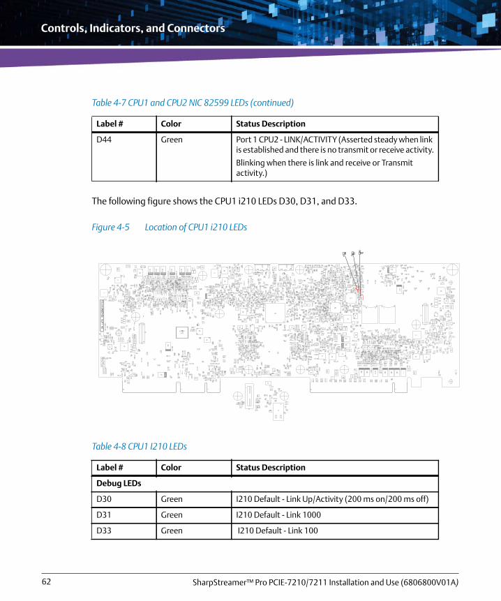
Controls, Indicators, and Connectors
SharpStreamer™ Pro PCIE-7210/7211 Installation and Use (6806800V01A)62
The following figure shows the CPU1 i210 LEDs D30, D31, and D33.
D44 Green Port 1 CPU2 - LINK/ACTIVITY (Asserted steady when link is established and there is no transmit or receive activity.
Blinking when there is link and receive or Transmit activity.)
Figure 4-5 Location of CPU1 i210 LEDs
Table 4-8 CPU1 I210 LEDs
Label # Color Status Description
Debug LEDs
D30 Green I210 Default - Link Up/Activity (200 ms on/200 ms off)
D31 Green I210 Default - Link 1000
D33 Green I210 Default - Link 100
Table 4-7 CPU1 and CPU2 NIC 82599 LEDs (continued)
Label # Color Status Description

Controls, Indicators, and Connectors
SharpStreamer™ Pro PCIE-7210/7211 Installation and Use (6806800V01A) 63
The following figure shows the CPU2 i210 LEDs D27, D28, and D29.
Figure 4-6 Location of CPU2 I210 LED Top
Figure 4-7 Location of CPU2 i210 LEDs Bottom

Controls, Indicators, and Connectors
SharpStreamer™ Pro PCIE-7210/7211 Installation and Use (6806800V01A)64
The following figure shows the CPU1 USB2240 LED D3.
Table 4-9 CPU2 i210 LEDs
Label # Color Status Description
Debug LEDs
D27 Green I210 Default - Link Up/Activity (200 ms on/200 ms off)
D28 Green I210 Default - Link 1000
D29 Green I210 Default - Link 100
Figure 4-8 Location of CPU1 USB2240 LEDs
D3
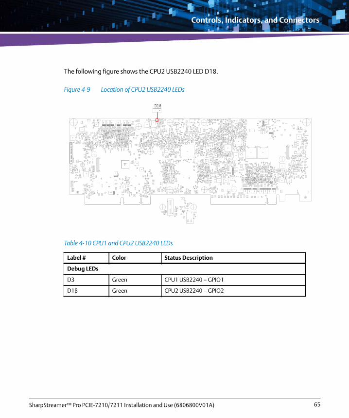
Controls, Indicators, and Connectors
SharpStreamer™ Pro PCIE-7210/7211 Installation and Use (6806800V01A) 65
The following figure shows the CPU2 USB2240 LED D18.
Figure 4-9 Location of CPU2 USB2240 LEDs
Table 4-10 CPU1 and CPU2 USB2240 LEDs
Label # Color Status Description
Debug LEDs
D3 Green CPU1 USB2240 – GPIO1
D18 Green CPU2 USB2240 – GPIO2
D18

Controls, Indicators, and Connectors
SharpStreamer™ Pro PCIE-7210/7211 Installation and Use (6806800V01A)66
4.3 ControlsA reset button is available at the rear side of the PCIE-7210/7211 card. By pressing the reset button (labeled as S1), CPLD on the card get reset. The following figure shows the reset button location on the PCIE-7210/7211 card.
There are two reset buttons available at the faceplate of the PCIE-7210/7211 card.
By pressing the button (labeled as S3), PCH1 on the card gets reset.
By pressing the button (labeled as S2), PCH2 on the card gets reset.
The following figure shows the reset button locations on the card.
Figure 4-10 Reset Button S1 Location
CPLD Reset Button S1
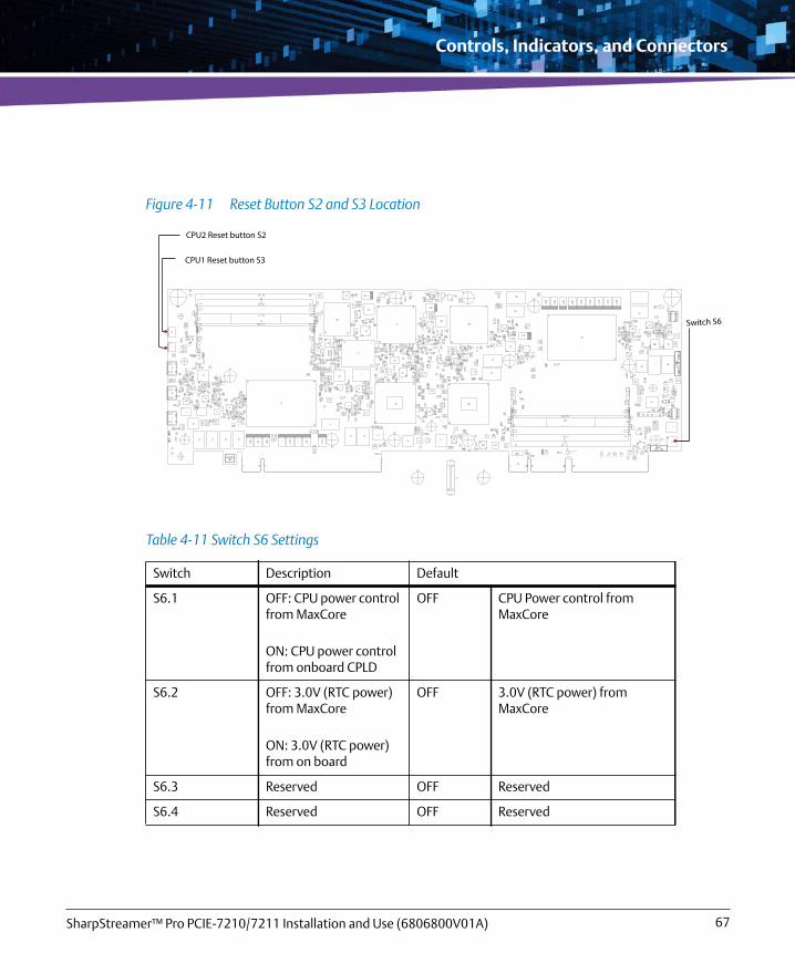
Controls, Indicators, and Connectors
SharpStreamer™ Pro PCIE-7210/7211 Installation and Use (6806800V01A) 67
Figure 4-11 Reset Button S2 and S3 Location
Table 4-11 Switch S6 Settings
Switch Description Default
S6.1 OFF: CPU power control from MaxCore
ON: CPU power control from onboard CPLD
OFF CPU Power control from MaxCore
S6.2 OFF: 3.0V (RTC power) from MaxCore
ON: 3.0V (RTC power) from on board
OFF 3.0V (RTC power) from MaxCore
S6.3 Reserved OFF Reserved
S6.4 Reserved OFF Reserved
CPU1 Reset button S3
CPU2 Reset button S2
Switch S6
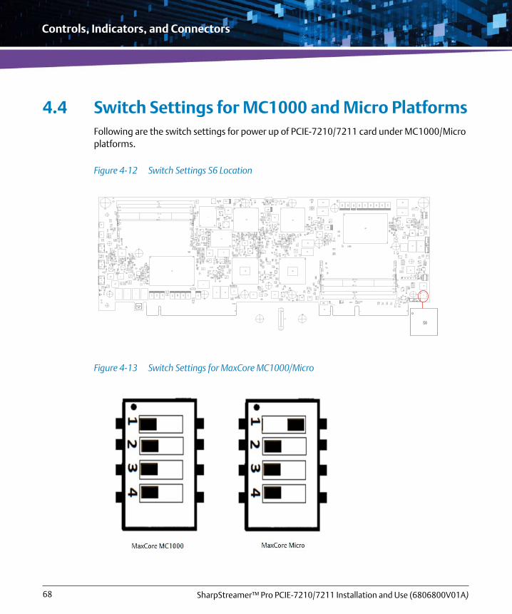
Controls, Indicators, and Connectors
SharpStreamer™ Pro PCIE-7210/7211 Installation and Use (6806800V01A)68
4.4 Switch Settings for MC1000 and Micro PlatformsFollowing are the switch settings for power up of PCIE-7210/7211 card under MC1000/Micro platforms.
Figure 4-12 Switch Settings S6 Location
Figure 4-13 Switch Settings for MaxCore MC1000/Micro

Controls, Indicators, and Connectors
SharpStreamer™ Pro PCIE-7210/7211 Installation and Use (6806800V01A) 69
Table 4-12 Switch Settings for MaxCore MC1000/Micro
Switch MaxCore 1000 MaxCore Micro
S6.1 OFF (left side position) ON (right side position)
S6.2 OFF (left side position) OFF (left side position)
S6.3 OFF (left side position) OFF (left side position)
S6.4 OFF (left side position) OFF (left side position)

Controls, Indicators, and Connectors
SharpStreamer™ Pro PCIE-7210/7211 Installation and Use (6806800V01A)70
Chapter 5
SharpStreamer™ Pro PCIE-7210/7211 Installation and Use (6806800V01A) 71
BIOS
This chapter describes about BIOS setup, serial port configuration parameters, steps to access the BIOS setup screen, and configuring the BIOS settings.
The Basic Input Output System (BIOS) acts as an interface between the operating system and the hardware of the card. Before loading the operating system, BIOS performs basic hardware tests and prepares the card for the initial boot-up procedure.
Using BIOS Setup, you can perform the following tasks:
Obtain system information
Hardware set-up utility for setting configuration data
Boot configuration for a flexible boot order
The BIOS Setup program is required to configure the hardware of the card. This configuration is necessary for operating the card and the peripherals connected to it. The configuration data is stored as part of a boot flash, since the configuration data storage needs to be non-volatile.
5.1 Accessing the BIOS Setup ScreenWhen the system is turned on or rebooted, the presence and functionality of the system components is tested by POST (Power-On Self Test).
Do not enable Core C-States and Intel Turbo Mode. They are disabled intentionally.
The menus shown in the figures in this chapter are from a typical system. The actual menus displayed on the screen may be different and depend on the hardware and features installed on the system.

BIOS
SharpStreamer™ Pro PCIE-7210/7211 Installation and Use (6806800V01A)72
To access BIOS Setup screen, press <F2> when the message Press <F2> to enter BIOS setup appears on the screen. The following figure depicts a sample BIOS Setup screen.
Select Save and Exit after making a selection in the setup menus. This procedure stores the selections displayed in the menus in CMOS. At the time of next boot up, BIOS configures the system according to the setup selection stored in CMOS.
For more details, refer to the section Exit Menu on page 87. CMOS is a generic term, which is used to refer to the storage device that stores BIOS configuration data.
Figure 5-1 BIOS Setup Screen
BIOS Setup screenMenu Bar Legend Bar

BIOS
SharpStreamer™ Pro PCIE-7210/7211 Installation and Use (6806800V01A) 73
In order to navigate setup, use the arrow keys on the key to highlight items on the menu. All other navigation possibilities are shown at the bottom of the menu. Additionally, an item-specific help is displayed on the right hand side of the menu window. It displays the help text for the currently selected field.
If you have performed any unwanted changes or not sure about configuration settings, restore the default values.
To restore default values:
1. Press <F2> on the key to return to setup.
2. Press <F9> to restore the system defaults.
Or
1. Press <F2> to return to the BIOS setup.
2. Go to the Exit menu and select Load setup Defaults.The default BIOS values are loaded and the values will affect all setup items and also the previously altered reset options.
Make sure that BIOS is properly configured prior to installing the operating system and its drivers.
If any changes are saved in the setup, the next time when the card boots, BIOS configures the system according to the setup selections stored. If those values cause the system boot to fail, reboot and enter setup to get the default values or to change the selections that caused the failure.
The default values set become effective only after saving and exiting the BIOS setup. Till then, they are loaded only for display purposes.

BIOS
SharpStreamer™ Pro PCIE-7210/7211 Installation and Use (6806800V01A)74
5.1.1 Menu Bar
Table 5-1 provides information about the BIOS Setup screen menu bar options.
5.1.2 Legend Bar
The keys listed in the legend bar below on the Figure 5-1 screen are used to make selections on screen or to move out of the current menu. The legend keys and their alternate options are explained in Table 5-2. All submenus are indicated by ‘>’.
To select an item, use the arrow keys to move the cursor to the desired field and then use the plus (+) and minus (-) value keys to select a value for that field. After that, use Save Change Without Exit command in the Exit menu to save the values currently displayed in all the menus.
Table 5-1 BIOS Setup Menu Bar
Menu Description
Main Configuring the basic system.
Advanced Setting the advanced features available on the system chipset.
Security Setting the security password.
Power Setting advanced power features available on the system chipset.
Boot Changing the boot device order.
Exit Moving out of the current menu.
Incorrect settings can cause the system to malfunction. To rectify mistakes, use <F2> on the key to return to setup and restore the system defaults by pressing <F9>. Alternatively you can press <F2> to return to the BIOS setup and go to the Exit menu and select Load setup Defaults.

BIOS
SharpStreamer™ Pro PCIE-7210/7211 Installation and Use (6806800V01A) 75
To display a submenu, use the arrow keys to move the cursor to the desired submenu and then press <Enter>.
5.1.3 Field Help
The help text of the selected field is displayed on the right side of the screen. By scrolling through each field, the related help text of the active selection is displayed.
Table 5-2 Legend Keys
Key Function
F1 Displays general help window.
Esc Exits the menu or the BIOS Setup program without saving any changes.
Left and Right Arrow Keys Selects a different menu (moves the cursor left or right).
Up and Down Arrow Keys Select an item (moves cursor up and down).
F5 or F6 Change values
Enter Executes command or selects a submenu.
F9 Loads the defaults configuration values for this menu.
F10 Saves the changes and exits.
PgUp or PgDn Moves cursor to next or previous page.

BIOS
SharpStreamer™ Pro PCIE-7210/7211 Installation and Use (6806800V01A)76
5.1.4 General Help
You can press <F1>on the key in any menu context to invoke the general help window. The general help window describes the legend keys and their alternates as shown in the following figure. The scroll bar on the right side of any window indicates that there is more than one page of information in the window.
5.2 Configuring BIOS Setup SettingsThis section provides BIOS configuration in each of the menu options.
Figure 5-2 General Help Menu

BIOS
SharpStreamer™ Pro PCIE-7210/7211 Installation and Use (6806800V01A) 77
5.2.1 Main Menu
To view the Main menu, select the Main tab from the menu bar.
To modify menu screen items, scroll down the Main screen. The following screen appears.
The following table provides the list of features that can be configured in Main menu.
By default, the Main tab is selected on the BIOS Setup screen.
Figure 5-3 Main Menu
Table 5-3 Main Menu
Selection Options/Format Description
Language English/French/Chinese/Japanese Set the setup language

BIOS
SharpStreamer™ Pro PCIE-7210/7211 Installation and Use (6806800V01A)78
5.2.2 Advanced Menu
To view Advanced menu, select Advanced tab from the menu bar.
Use the legend keys to make a selection or exit in/from the Advanced menu.
System Time HH:MM:SS Set the system time
System Date MM/DD/YYYY Set the system date
Table 5-3 Main Menu
Selection Options/Format Description
Figure 5-4 Advanced Menu

BIOS
SharpStreamer™ Pro PCIE-7210/7211 Installation and Use (6806800V01A) 79
The following table provides the frequently configurable settings in the Advanced menu. The other configurations shown in the Advanced menu are default values and need not be configured.
5.2.2.1 Boot Configuration
The following figure shows the Boot Configuration submenu.
Table 5-4 Advanced Menu
Feature Description
Boot Configuration To select the boot configuration.
Console Redirection To change console redirection parameter.
Figure 5-5 Boot Configuration

BIOS
SharpStreamer™ Pro PCIE-7210/7211 Installation and Use (6806800V01A)80
The following table provides information about options in the Boot Configuration submenu and their default values.
5.2.2.2 Console Redirection Setup
The following figure shows the Console Redirection Setup submenu screen. The settings are applied to all ports, if selected. Individual submenus are available, if there is a need for separate port configuration.
The values shown in the tables enclosed within brackets [...] indicate the default settings.
Table 5-5 Boot Configuration
Feature Options Description
Numlock [On]
Off
Enables or disables Numlock.
Figure 5-6 Console Redirection Setup

BIOS
SharpStreamer™ Pro PCIE-7210/7211 Installation and Use (6806800V01A) 81
The following table provides information about the feature options in the Console Redirection Setup submenu and their defaults values.
Table 5-6 Console Redirection Setup
Feature Option Description
Console Serial Redirection
[Enabled]
Disabled
Enables or disables the Console Redirection.
Terminal Type [VT_100]
VT_100+
VT_UTF8
PC_ANSI
Selects the terminal type.
Baud Rate [115200]
57600
38400
19200
9600
4800
2400
1200
Selects the baud rate.
Data Bits 7 Bits
[8 Bits]
Selects the data bits.
Parity [none]
Even
Odd
Selects the parity.
Stop Bits [1 Bit]
2 Bits
Selects the stop bits.
Flow Control [None]
RTS/CTS
XON/XOFF
Selects the flow control.

BIOS
SharpStreamer™ Pro PCIE-7210/7211 Installation and Use (6806800V01A)82
Information Wait Time 0 Second
2 Second
[5 Second]
10 Second
30 Second
Selects the information screen display time.
C.R. After Post [Yes]
No
Selects if the Console Redirections is enabled after Post.
Text Mode Resolution AUTO
[Force 80x25]
Force 80x24 (DEL FIRST ROW)
Force 80x24 (DEL LAST ROW)
Selects the text mode resolution.
AutoRefresh Disabled
[Enabled]
Selects if the terminal will be refreshed after a console is detected.
FailSafeBaudRate [Disabled]
Enabled
Selects if the baud rate automatically changes to one of the terminals it can be detected.
ACPI SPCR Table [Disabled]
Enabled
Selects if the SPCR ACPI table will be included (for Windows EMS).
Table 5-6 Console Redirection Setup (continued)
Feature Option Description

BIOS
SharpStreamer™ Pro PCIE-7210/7211 Installation and Use (6806800V01A) 83
5.2.3 Security Menu
To view the Security menu, select Security tab from the menu bar. Use the legend keys to make a selection and exit from the Security menu. The Security menu appears as shown in the following figure.
The following table provides other options in the Security menu and their defaults.
Figure 5-7 Security Menu
The values shown in the tables enclosed within brackets [...] indicate the default settings.

BIOS
SharpStreamer™ Pro PCIE-7210/7211 Installation and Use (6806800V01A)84
5.2.4 Power Menu
To view the Power menu, select the Power tab from the menu bar. The Power menu is displayed which looks similar to the following figure.
Table 5-7 Security Menu
Feature Option Description
Set Supervisor Password - Sets the password
Figure 5-8 Power Menu

BIOS
SharpStreamer™ Pro PCIE-7210/7211 Installation and Use (6806800V01A) 85
5.2.5 Boot Menu
To view the Boot menu, select Boot tab on the menu bar. The Boot menu screen is displayed as shown below.
The following table provides options in the Boot menu and their default settings.
Figure 5-9 Boot Menu
Table 5-8 Boot Menu
Feature Option Description
Boot Type Dual Boot Type
Legacy Boot Type
[UEFI Boot Type]
Selects the boot type
Quick Boot [Enabled]
Disabled
Enables or disables the quick boot feature which skip certain tests to decrease the boot time
Quiet Boot [Enabled]
Disabled
Enables or disables the booting in text mode

BIOS
SharpStreamer™ Pro PCIE-7210/7211 Installation and Use (6806800V01A)86
Network Stack [Disabled]
Enabled
Enables or disables UEFI and Legacy network support
PXE Boot capability [Disabled]
UEFI:IPv4
UEFI:IPv6
UEFI:IPv4/IPv6
Legacy
Enables or disables the alternate PXE boot modes
Power Up In Standby Support
[Disabled] -
Add Boot Options First
Last
[Auto]
Selects the position of an added boot device
ACPI Selection Acpi1.0B
Acpi3.0
Acpi4.0
[Acpi5.0]
Selects the supported ACPI version
USB Boot [Enabled]
Disabled
Enables or disables USB boot support
EFI Device First [Disabled]
Enabled
Selects if UEFI (if enabled) or Legacy (if disabled) is the first boot device
Timeout [2] Selects the timeout in seconds before the first boot attempt
Automatic Failover Disabled
[Enabled]
Selects if another boot devices is used after the first one failed
EFI - Change EFI boot order settings
Legacy - Change Legacy boot order settings
Table 5-8 Boot Menu (continued)
Feature Option Description

BIOS
SharpStreamer™ Pro PCIE-7210/7211 Installation and Use (6806800V01A) 87
5.2.6 Exit Menu
To view the Exit menu, select Exit tab from the menu bar. Use the legend keys to make a selection or exit to the main menu. The Exit menu screen looks similar to the figure below.
The following table provides Exit menu features and their description.
The values shown in the tables enclosed within brackets [...] indicate the default settings.
Figure 5-10 Exit Menu
Table 5-9 Exit Menu
Feature Description
Exit Saving Changes Exits the setup and saves the changes

BIOS
SharpStreamer™ Pro PCIE-7210/7211 Installation and Use (6806800V01A)88
5.3 BIOS Boot ParameterThe BIOS reads the boot parameters from CPLD's shared memory and interprets the parameters for various purposes. The BIOS Boot Parameters are supported from BIOS version 2.1.5. The following is the supported BIOS Boot parameter list:
fw_con_br=9600/19200/38400/57600/115200 # BIOS Setup > Advanced > Console Redirection-Baud Rate
fw_sata=off/on # BIOS Setup > Advanced >|PCH-IO Configuration > SATA Configuration > SATA Controller(s)
fw_sata_mode=ahci/raid # BIOS Setup > Advanced >|PCH-IO Configuration > SATA Configuration > SATA Mode Selectionfw_sata_alpm=on/off # BIOS Setup > Advanced >|PCH-IO Configuration > SATA Configuration > Aggressive LPM Support
fw_usb=off/on # BIOS Setup > Advanced > USB Configuration > USB BIOS Support
fw_usb0=off/on # BIOS Setup > Advanced > PCH-IO Configuration > USB Configuration > USB HS Physical Connector #0 /*-- MicroSD */
Save Changes Without Exit Saves the changes without exiting
Exit Discarding Changes Exits the setup and discards the changes
Load Setup Defaults Loads the default setup parameter
Discard Changes Discards all changes performed
Table 5-9 Exit Menu (continued)
Feature Description

BIOS
SharpStreamer™ Pro PCIE-7210/7211 Installation and Use (6806800V01A) 89
fw_usb1=off/on # BIOS Setup > Advanced > PCH-IO Configuration > USB Configuration > USB HS Physical Connector #1 /* Front Panel USB */
fw_usb2=off/on # BIOS Setup > Advanced > PCH-IO Configuration > USB Configuration > USB HS Physical Connector #2 /* backplane USB */
fw_usb3=off/on # BIOS Setup > Advanced > PCH-IO Configuration > USB Configuration > USB HS Physical Connector #3 /* backplane USB */
fw_pci_spread=off/on # BIOS Setup > Advanced > System Agent (SA) Configuration > PEG Port Configuration > PCIe Spread Spectrum Clocking
fw_primary_display=auto/igfx/peg/pchpci/sg # BIOS Setup > Advanced > System Agent (SA) Configuration > Graphics Configuration -> Primary Display
fw_internal_graphics=off/on # BIOS Setup > Advanced > System Agent SA) Configuration > Graphics Configuration -> Internal Graphics
fw_uefi_dual_vga=off/on # BIOS Setup > Advanced > System Agent (SA) Configuration > Graphics Configuration > Dual Vga controllers Support
fw_cpu_x2apic=off/on # BIOS Setup > Advanced > System Agent (SA) Configuration > X2APIC Opt Out

BIOS
SharpStreamer™ Pro PCIE-7210/7211 Installation and Use (6806800V01A)90
fw_cpu_hp=off/on # BIOS Setup > power > CPU Configuration > Hardware Prefetcherfw_cpu_acp=off/on # BIOS Setup > power > CPU Configuration > Adjacent Cache Line Prefetch
fw_cpu_vt=off/on # BIOS Setup > power > CPU Configuration > Intel (VMX) Virtualization Technology
fw_cpu_ht=off/on # BIOS Setup > power > CPU Configuration > Hyper-Threading
fw_cpu_tm=off/on # BIOS Setup > power > Power & Performance > CPU - Power Management Control > Turbo Mode
fw_cpu_cstates=off/on # BIOS Setup > power > Power & Performance > CPU - Power Management Control > CPU C State Control > CPU C State
fw_skip_shell=off/on # BIOS Setup->Advanced->Boot Configuration->Skip Internal EFI Shell
fw_cpu_cslimit=c0c1/c2/c3/c6/Auto # BIOS Setup > power > Power & Performance > CPU - Power \Management Control > Package C State Limit
fw_boot_type=dual /uefi # BIOS Setup > Boot > Boot Type
fw_PxeBoot=off/on # BIOS Setup > Boot > NetworkStack
fw_boot_netprot=ipv4/ipv6/ipv4v6 # BIOS Setup > Boot > PXE Boot capability
fw_boot_usb=off/On # BIOS Setup > Boot > USB Boot
fw_boot_order=[<bootdev>{[,<bootdev>]}]
bootdev: full name of a boot option, as it is shown by the BIOS,

BIOS
SharpStreamer™ Pro PCIE-7210/7211 Installation and Use (6806800V01A) 91
or one of the following predefined selfspeaking names
efisdcard # EFI on board microSD
sdcard # legacy option - on board SD card
efiobsata # EFI On board SATA
efiiomsata0
efiiomsata1
obsata # legacy option - on board SATA
efishell
efinet4 (MAC) # MAC - MAC address in the form XX-XX-XX-XX-XX-XX
efinet6 (MAC) # MAC - MAC address in the form XX-XX-XX-XX-XX-XX

BIOS
SharpStreamer™ Pro PCIE-7210/7211 Installation and Use (6806800V01A)92

Chapter 6
SharpStreamer™ Pro PCIE-7210/7211 Installation and Use (6806800V01A) 93
Software Information
This chapter provides references to software installation and use manuals related to OS, Basic Blade Services (BBS) software installation, and firmware upgrades of PCIE-721x card.
6.1 OS and BBS InformationFor more information about the OS and Basic Blade Services (BBS) software installation and booting procedure of a PCIE-721x card installed in MaxCore MC3000 Platform, refer to MaxCore™ MC3000 Platform Software Installation and Use manual.
6.2 Firmware UpgradeFor more information about the firmware upgrades (CPLD and BIOS upgrades), refer to MaxCore™ MC3000 Platform Software Installation and Use manual.

Software Information
SharpStreamer™ Pro PCIE-7210/7211 Installation and Use (6806800V01A)94

Appendix A
SharpStreamer™ Pro PCIE-7210/7211 Installation and Use (6806800V01A) 95
MaxCore Firmware Upgrade
A.1 MaxCore Firmware UpgradeThere are several firmware elements in a MaxCore system that may need upgrades throughout the product’s life cycle. Some firmware elements are part of the system itself and some reside on PCIe cards. This section provides information on how to upgrade the firmware elements that are part of the system only. The following is the list of firmware elements that come under this group:
BMC firmware
Glue CPLD logic
Companion CPLD logic
IO-Module CPLD logic
This section is not intended to describe the firmware upgrades for elements on Artesyn PCIe cards. You can ignore this chapter, if you are using Artesyn’s SSF to upgrade Firmware components. SSF is the preferred method to upgrade the MaxCore firmware. For more information, refer to System Services Framework for MaxCore™ Platform XML Interface Guide.
A.1.1 Obtaining Revisions of Firmware Components
The firmware upgrade of a firmware component is necessary only if firmware components are not found to be up-to-date.
All the examples provided in the following sections are by assuming that the BMC’s IP address is the default of 192.168.201.9. If the address has been modified (for example, via the WEB interface) replace the default with the modified address accordingly in the examples.
It is strongly recommended to upgrade all the firmware elements to their latest version, if any of the upgrades is due. Performing only selective firmware upgrades is not recommended, because this may lead to incompatibilities between the BMC firmware version and CPLD logic elements.

MaxCore Firmware Upgrade
SharpStreamer™ Pro PCIE-7210/7211 Installation and Use (6806800V01A)96
You can manage the system firmware elements as HPM.1 components. You can determine the revision of the HPM.1 firmware components using the tool called ipmitool. You can download it from http://ipmitool.sourceforge.net.
You need to install this tool on a remote machine (for example, on a PC). You need to have a network connection from the remote machine to the BMC.
You can run the following command to determine the revisions:
./ipmitool –I lan –H 192.168.201.9 –U admin –P admin hpm check
A.1.2 Upgrade Procedure
This section describes the step-by-step procedure to upgrade firmware images on a MaxCore MC3000 prototype.
Procedure
To upgrade the firmware elements, perform the following steps:
1. Upgrade the BMC Firmware The BMC firmware should always be the first element to be upgraded. You can skip this step, if the BMC firmware already has the latest version.
There are different versions of ipmitool available, each using different command sets to the BMC. MaxCore has been tested with ipmitool version v.1.8.14 and it is strongly recommended to use this version of ipmitool in order to avoid errors when communicating with the BMC.

MaxCore Firmware Upgrade
SharpStreamer™ Pro PCIE-7210/7211 Installation and Use (6806800V01A) 97
You can upgrade the BMC firmware through the BMC’s web browser accessed from the remote machine (network connection from remote machine to BMC required) through the IP address 192.168.201.9 with Username admin and Password admin
BMC firmware revisions higher or equal to version 1.5.0 support two firmware images (active and inactive) to be maintained.
Firmware upgrades via web browser are only supported by firmware revisions higher than v1.0.10 (the BMC firmware revision can be retrieved with ipmitool, refer to Obtaining Revisions of Firmware Components on page 95). In case the BMC firmware revision installed does not support upgrades via the web browser, the BMC FW EEPROM needs to be extracted from its socket on the MaxCore backplane and needs to be reprogrammed with a flasher hardware device (this option is required for very first prototypes only).

MaxCore Firmware Upgrade
SharpStreamer™ Pro PCIE-7210/7211 Installation and Use (6806800V01A)98
To view more details, open the Dual Image Configuration screen by clicking Firmware Update > Dual Image Configuration.
In the Dual Image Configuration screen, choose the required Image (that need to be booted after firmware option upgrade) and click Save.
Figure A-1 Dual Image Configuration

MaxCore Firmware Upgrade
SharpStreamer™ Pro PCIE-7210/7211 Installation and Use (6806800V01A) 99
To open Firmware Update screen, click Firmware Update > Firmware Update from menu bar.
Figure A-2 Firmware Update - Upgrade
Do not modify the image to be updated. Never update the image you have booted successfully from.

MaxCore Firmware Upgrade
SharpStreamer™ Pro PCIE-7210/7211 Installation and Use (6806800V01A)100
Select Preserve Configuration to preserve the network configuration (IP, username, password, DHCP, VLAN).
Click Enter Update Mode and follow the wizard through the upgrade. Select Full Flash check box to perform a complete firmware upgrade always.
2. Upgrade the Companion CPLD
You can skip this step, if the Companion CPLD firmware already has the most recent version. For more information, refer to MaxCore MC3000 Release Notes.Use the following command to upgrade the IO-CPLD../ipmitool –I lan –H 192.168.201.9 –U admin –P admin hpm upgrade mc3000-cpld-companion-0.2.6.hpm component 3 force
3. Upgrade the Glue CPLDYou can skip this step, if the Glue CPLD firmware already has the most recent version. Use the following command to upgrade the Glue CPLD.
In any case, if you observe that the firmware upgrade fails, repeat the firmware upgrade procedure again.
Firmware upgrade progress is not seen immediately. As the first step, the ipmitool loads the firmware image into the BMC. This may take some time (~30sec). In the next step, the ipmitool states Writing firmware: 100% completed. Please do not stop execution at this point, ipmitool is still working!
Wait until the following message appears “Firmware upgrade procedure successful” (~2min).

MaxCore Firmware Upgrade
SharpStreamer™ Pro PCIE-7210/7211 Installation and Use (6806800V01A) 101
./ipmitool –I lan –H 192.168.201.9 –U admin –P admin hpm upgrade mc3000-cpld-glue-0.3.0.hpm component 2 force
4. Upgrade the IO-Module CPLD You can skip this step, if you have already programmed the actual firmware. Use the following command to upgrade the IO-CPLD../ipmitool –I lan –H 192.168.201.9 –U admin –P admin hpm upgrade mc3000-cpld-iomod-0.4.0 component 4 force
If you observe that the firmware upgrade fails, repeat the firmware upgrade procedure again.
Firmware upgrade progress is not seen immediately. As the first step, the ipmitool loads the firmware image into the BMC. This may take some time (~2min). In the next step, the ipmitool states "Writing firmware: 100% completed".Please do not stop execution at this point, ipmitool is still working! Wait until the following message appears "Firmware upgrade procedure successful" (~3min).

MaxCore Firmware Upgrade
SharpStreamer™ Pro PCIE-7210/7211 Installation and Use (6806800V01A)102
5. Remove and reinsert power plug.
A.1.3 Troubleshooting
This section is provided in this chapter to assist you with troubleshooting.
A.1.3.1 CPLD FW Upgrade Failed
Do not switch off system power until "ipmitool prompts Firmware upgrade procedure successful" or "Firmware upgrade procedure failed" message. Upgrading the "IO-Module" CPLD may take very long (~25min).
In any case, if you observe that the firmware upgrade fails, repeat the firmware upgrade procedure again.
You cannot see the Firmware upgrade progress immediately. As the first step, the ipmitool loads the firmware image into the BMC. This may take some time (~2min). In the next step, the ipmitool states Writing firmware: 100% completed.Please do not stop execution at this point, ipmitool is still working! Wait until the following message appears Firmware upgrade procedure successful (~3min).
The “IO-Module” CPLD on early MaxCore prototypes cannot be upgraded at all (even when the revision can be read). Any attempt will fail during programming immediately. The revision of the respective system module can be determined only by dismounting the device and evaluating the part number at the PCB (8406843P41A PCB REV A). Contact your local Artesyn executive, if the firmware upgrade on such a system becomes necessary.Subsequent firmware upgrades can be performed much faster due to a change in the I2C controller implementation in the CPLDs.

MaxCore Firmware Upgrade
SharpStreamer™ Pro PCIE-7210/7211 Installation and Use (6806800V01A) 103
In case when ipmitool reports “Firmware upgrade procedure failed” message, power cycle the system, and evaluate the firmware revision of the firmware component just programmed (for more details refer to Obtaining Revisions of Firmware Components on page 95, and if the revision programmed is not performed before, repeat the firmware upgrade procedure. If subsequent CPLD firmware upgrade fails, contact your local Artesyn executive.
A.1.3.2 BMC FW Upgrade Failed
In such a case, power cycle the system and repeat the firmware upgrade. If subsequent BMC firmware upgrade fails, contact your local Artesyn executive.
A.1.3.3 BMC Cannot Be Accessed Via IP address
In case the BMC is not accessible via its IP address anymore there is a possibility to set the BMC to its factory defaults by pressing the reset button at the IO module (the BMC will automatically reboot).
After the reboot, you can access the BMC via the IP192.168.201.9, username admin and password admin. The DHCP will be in Off mode.

MaxCore Firmware Upgrade
SharpStreamer™ Pro PCIE-7210/7211 Installation and Use (6806800V01A)104

Appendix B
SharpStreamer™ Pro PCIE-7210/7211 Installation and Use (6806800V01A) 105
Related Documentation
B.1 Artesyn Embedded Technologies - Embedded Computing DocumentationThe publications listed below are referenced in this manual. You can obtain electronic copies of Artesyn Embedded Technologies - Embedded Computing publications by contacting your local Artesyn sales office. For released products, you can also visit our Web site for the latest copies of our product documentation.
1. Go to www.artesyn.com/computing/support/product/technical-documentation.php.
2. Under FILTER OPTIONS, click the Document types drop-down list box to select the type of document you are looking for.
3. In the Search text box, type product or manual name and click Filter.
Table B-1 Artesyn Embedded Technologies - Embedded Computing Publications
Document Title Publication Number
SharpStreamer Pro PCIE-7210/7211 Quick Start Guide 6806800V06
SharpStreamer Pro PCIE-7210/7211 Safety Notes Summary 6806800V07
MaxCore MC3000 Platform Installation and Use 6806800T88
MaxCore MC3000 Platform Software Installation and Use 6806800U97

Related Documentation
SharpStreamer™ Pro PCIE-7210/7211 Installation and Use (6806800V01A)106


Artesyn Embedded Technologies, Artesyn and the Artesyn Embedded Technologies logo are trademarks and service marks of Artesyn Embedded Technologies, Inc.All other product or service names are the property of their respective owners.© 2018 Artesyn Embedded Technologies, Inc.