LaserJet Pro M426, M427 LaserJet Pro M402, M403 - Laser ...
1328
Repair Manual www.hp.com/support/ljM402 www.hp.com/support/ljM403 www.hp.com/support/ljM426MFP www.hp.com/support/ljM427MFP For printer theory and troubleshooting information, see the Troubleshooting Manual. HEWLETT-PACKARD 2 1 M402d M402n M402dn M402dw M403n M403d M403dn M403dw 2 1 M426dw M426fdn M426fdw M427dw M427fdn M427fdw LaserJet Pro M426, M427 LaserJet Pro M402, M403
-
Upload
khangminh22 -
Category
Documents
-
view
0 -
download
0
Transcript of LaserJet Pro M426, M427 LaserJet Pro M402, M403 - Laser ...

Repair Manual
www.hp.com/support/ljM402www.hp.com/support/ljM403www.hp.com/support/ljM426MFPwww.hp.com/support/ljM427MFPFor printer theory and troubleshootinginformation, see the Troubleshooting Manual.
HEWLETT-PACKARD
2
1
M402dM402nM402dnM402dwM403nM403dM403dnM403dw
2
1
M426dwM426fdnM426fdwM427dwM427fdnM427fdw
LaserJet Pro M426, M427LaserJet Pro M402, M403


LaserJet Pro M402, M403 and LaserJet Pro M426, M427
Repair Manual

Copyright and License
© Copyright 2015 HP Development Company, L.P.
Reproduction, adaptation, or translation without prior written permission is prohibited, except as allowed under the copyright laws.
The information contained herein is subject to change without notice.
The only warranties for HP products and services are set forth in the express warranty statements accompanying such products and services. Nothing herein should be construed as constituting an additional warranty. HP shall not be liable for technical or editorial errors or omissions contained herein.
Edition 1, 9/2015

Conventions used in this guide
TIP: Helpful hints or shortcuts.
Reinstallation tip: Reinstallation helpful hints, shortcuts, or considerations.
NOTE: Information that explains a concept or how to complete a task.
IMPORTANT: Information that help the user to avoid potential printer error conditions.
CAUTION: Procedures that the user must follow to avoid losing data or damaging the printer.
WARNING! Procedures that the user must follow to avoid personal injury, catastrophic loss of data, or extensive damage to the printer.
ENWW iii

iv Conventions used in this guide ENWW

For additional service and support informationHP service personnel, go to the Service Access Work Bench (SAW) at http://h41302.www4.hp.com/km/saw/home.do.
Channel partners, go to HP Channel Services Network (CNS) at https://h30125.www3.hp.com/hpcsn.
At these locations, find information on the following topics:
● Install and configure
● Printer specifications
● Up-to-date control panel message (CPMD) troubleshooting
● Solutions for printer issues and emerging issues
● Remove and replace part instructions and videos
● Service advisories
● Warranty and regulatory information
To access HP PartSurfer information from any mobile device, go to http://partsurfermobile.hp.com/ or scan the Quick Response (QR) code below.
ENWW v

vi For additional service and support information ENWW

Table of contents
1 Removal and replacement .............................................................................................................................. 1
For additional service and support ........................................................................................................................ 2Removal and replacement strategy ...................................................................................................................... 3
Introduction ......................................................................................................................................... 3Considerations during removal and replacement .............................................................................. 3Electrostatic discharge ........................................................................................................................ 4Required tools ..................................................................................................................................... 4Fasteners used in this printer .............................................................................................................. 5
Service approach .................................................................................................................................................... 6Before performing service .................................................................................................................. 6After performing service ..................................................................................................................... 6Post-service test .................................................................................................................................. 6
Print-quality test ............................................................................................................... 6Removal and replacement procedures ................................................................................................................. 7
Customer self-repair (CSR) A parts and assemblies ........................................................................... 7RL2-0656-000CN multipurpose tray roller ...................................................................... 8
Introduction .................................................................................................... 8Step 1: Remove the roller ............................................................................... 8Step 2: Unpack the replacement assembly .................................................. 10Step 3: Install the roller ................................................................................ 11
RM2-5392-000CN 250-sheet paper input tray .............................................................. 13Introduction .................................................................................................. 13Step 1: Remove Tray 2 .................................................................................. 13Step 2: Unpack the replacement assembly .................................................. 14Step 3: Install Tray 2 ..................................................................................... 14
RM2-5413-000CN optional Tray 3 ................................................................................. 16Introduction .................................................................................................. 16Step 1: Remove optional Tray 3 ................................................................... 16Step 2: Unpack the replacement assembly .................................................. 17Step 3: Install optional Tray 3 ...................................................................... 18
RM2-5452-000CN Tray 2 paper pickup roller assembly ................................................ 20Introduction .................................................................................................. 20
ENWW vii

Step 1: Remove Tray 2 .................................................................................. 20Step 2: Remove the pickup roller assembly (Tray 2) ................................... 21Step 3: Unpack the replacement assembly .................................................. 23Step 4: Install the pickup roller assembly (Tray 2) ....................................... 24Step 5: Install Tray 2 ..................................................................................... 25
RM2-5741-000CN optional Tray 3 paper pickup roller assembly ................................. 27Introduction .................................................................................................. 27Step 1: Remove optional Tray 3 ................................................................... 27Step 2: Remove the paper pickup roller assembly (optional Tray 3) ........... 28Step 3: Unpack the replacement assembly .................................................. 30Step 4: Install the paper pickup roller assembly (optional Tray 3) .............. 31Step 5: Install optional Tray 3 ...................................................................... 32
RM2-5397-000CN Tray 2 separation roller assembly ................................................... 34Introduction .................................................................................................. 34Step 1: Remove Tray 2 .................................................................................. 34Step 2: Remove the separation pad roller assembly (Tray 2) ...................... 35Step 3: Unpack the replacement assembly .................................................. 36Step 4: Install the separation pad roller assembly (Tray 2) ......................... 36Step 5: Install Tray 2 ..................................................................................... 37
RM2-5745-000CN optional Tray 3 separation roller assembly ..................................... 39Introduction .................................................................................................. 39Step 1: Remove Tray 3 .................................................................................. 39Step 2: Remove the separation roller assembly (optional Tray 3) .............. 40Step 3: Unpack the replacement assembly .................................................. 41Step 4: Install the separation roller assembly (optional Tray 3) ................. 42Step 5: Install Tray 3 ..................................................................................... 43
Removal and replacement: External panels, covers, and doors ...................................................... 45Removal and replacement: Damper sheets ................................................................... 46
Introduction .................................................................................................. 46Step 1: Remove the damper sheets ............................................................. 46Step 2: Unpack the replacement assembly .................................................. 47Step 3: Install the damper sheets ................................................................ 47
Removal and replacement: Rear USB cover ................................................................... 46Introduction .................................................................................................. 49Step 1: Remove the rear USB cover .............................................................. 49Step 2: Unpack the replacement assembly .................................................. 50Step 3: Install the rear USB cover ................................................................. 51
Removal and replacement: Support shaft ..................................................................... 53Introduction .................................................................................................. 53Step 1: Remove the support shaft ............................................................... 53Step 2: Unpack the replacement assembly .................................................. 54
viii ENWW

Step 3: Install the support shaft .................................................................. 55Removal and replacement: Cartridge door assembly .................................................... 57
Introduction .................................................................................................. 57Step 1: Remove the cartridge door assembly .............................................. 57Step 2: Unpack the replacement assembly .................................................. 60Step 3: Install the cartridge door assembly ................................................. 61
Removal and replacement: Pressure-release link ......................................................... 64Introduction .................................................................................................. 64Step 1: Remove the cartridge door assembly .............................................. 64Step 2: Remove the pressure-release link ................................................... 67Step 3: Unpack the replacement assembly .................................................. 68Step 4: Install the pressure-release link ...................................................... 68Step 5: Install the cartridge door assembly ................................................. 69
Removal and replacement: Left cover ............................................................................ 73Introduction .................................................................................................. 73Step 1: Remove the rear USB cover .............................................................. 74Step 2: Remove the rear network cover (M402d and M403d) ..................... 75Step 3: Remove Tray 2 .................................................................................. 75Step 4: Remove the cartridge door assembly .............................................. 76Step 5: Remove the left cover ...................................................................... 78Step 6: Unpack the replacement assembly .................................................. 80Step 7: Install the left cover ......................................................................... 80Step 8: Install the cartridge door assembly ................................................. 82Step 9: Install Tray 2 ..................................................................................... 85Step 10: Install the rear network cover (M402d and M403d) ...................... 85Step 11: Install the rear USB cover ............................................................... 85
Removal and replacement: Right cover ......................................................................... 87Introduction .................................................................................................. 87Step 1: Remove Tray 2 .................................................................................. 87Step 2: Remove the cartridge door assembly .............................................. 88Step 3: Remove the right cover .................................................................... 90Step 4: Unpack the replacement assembly .................................................. 91Step 5: Install the right cover ....................................................................... 92Step 6: Install the cartridge door assembly ................................................. 94Step 7: Install Tray 2 ..................................................................................... 97
Removal and replacement: Rear door assembly ........................................................... 98Introduction .................................................................................................. 98Step 1: Remove Tray 2 .................................................................................. 99Step 2: Remove the cartridge door assembly .............................................. 99Step 3: Remove the left cover .................................................................... 102Step 4: Remove the right cover .................................................................. 103
ENWW ix

Step 5: Remove the rear door assembly .................................................... 104Step 6: Unpack the replacement assembly ............................................... 105Step 7: Install the rear door assembly ....................................................... 106Step 8: Install the right cover ..................................................................... 107Step 9: Install the left cover ....................................................................... 109Step 10: Install the cartridge door assembly ............................................. 110Step 11: Install Tray 2 ................................................................................. 113
Removal and replacement: Cassette rear cover .......................................................... 114Introduction ................................................................................................ 114Step 1: Remove Tray 2 ................................................................................ 115Step 2: Remove the cartridge door assembly ............................................ 115Step 3: Remove the left cover .................................................................... 118Step 4: Remove the right cover .................................................................. 119Step 5: Remove the rear door assembly .................................................... 120Step 6: Remove the cassette rear cover .................................................... 121Step 7: Unpack the replacement assembly ............................................... 123Step 8: Install the cassette rear door assembly ........................................ 124Step 9: Install the rear door assembly ....................................................... 125Step 10: Install the right cover ................................................................... 125Step 11: Install the left cover ..................................................................... 127Step 12: Install the cartridge door assembly ............................................. 128Step 13: Install Tray 2 ................................................................................. 132
Removal and replacement: Top cover (M427/M426) ................................................... 133Introduction ................................................................................................ 133Step 1: Remove Tray 2 ................................................................................ 134Step 2: Remove the cartridge door assembly ............................................ 134Step 3: Remove the left cover .................................................................... 137Step 4: Remove the right cover .................................................................. 138Step 5: Remove the integrated scanner assembly (M427/M426) ............. 140Step 6: Remove the control panel (M427/M426) ....................................... 144Step 7: Remove the top cover (M427/M426) ............................................. 148Step 8: Unpack the replacement assembly ............................................... 149Step 9: Remove the cable guide (M427/M426) .......................................... 150Step 10: Install the cable guide (M427/M426) ........................................... 151Step 11: Install the top cover (M427/M426) .............................................. 153Step 12: Install the control panel (M427/M426) ........................................ 155Step 13: Install the integrated scanner assembly (M427/M246) .............. 159Step 14: Install the right cover ................................................................... 164Step 15: Install the left cover ..................................................................... 166Step 16: Install the cartridge door assembly ............................................. 167Step 17: Install Tray 2 ................................................................................. 171
x ENWW

Removal and replacement: Cable guide (M427/M426) ................................................ 172Introduction ................................................................................................ 172Step 1: Remove Tray 2 ................................................................................ 173Step 2: Remove the cartridge door assembly ............................................ 173Step 3: Remove the left cover .................................................................... 176Step 4: Remove the right cover .................................................................. 177Step 5: Remove the control panel (M427/M426) ....................................... 178Step 6: Remove the integrated scanner assembly (M427/M246) ............. 182Step 7: Remove the top cover (M427/M426) ............................................. 187Step 8: Remove the cable guide (M427/M426) .......................................... 188Step 9: Unpack the replacement assembly ............................................... 190Step 10: Install the cable guide (M427/M426) ........................................... 190Step 11: install the top cover (M427/M426) .............................................. 192Step 12: Install the integrated scanner assembly (M427/M246) .............. 194Step 13: Install the control panel (M427/M426) ........................................ 199Step 14: Install the right cover ................................................................... 203Step 15: Install the left cover ..................................................................... 205Step 16: Install the cartridge door assembly ............................................. 206Step 17: Install Tray 2 ................................................................................. 210
Removal and replacement: Top cover (M403/M402) ................................................... 211Introduction ................................................................................................ 211Step 1: Remove Tray 2 ................................................................................ 212Step 2: Remove the cartridge door assembly ............................................ 212Step 3: Remove the left cover .................................................................... 215Step 4: Remove the right cover .................................................................. 216Step 5: Remove the top cover (M403/M402) ............................................. 217Step 6: Remove the 2-line LCD operator and indication covers (M403/M402) .......................................................................................................... 219Step 7: Unpack the replacement assembly ............................................... 220Step 8: Install the 2-line LCD operator and indication covers (M403/M402) .......................................................................................................... 221Step 9: Install the top cover (M403/M402) ................................................ 222Step 10: Install the right cover ................................................................... 224Step 11: Install the left cover ..................................................................... 226Step 12: Install the cartridge door assembly ............................................. 227Step 13: Install Tray 2 ................................................................................. 231
Removal and replacement: 2-line LCD operator and indication covers (M403/M402) ............................................................................................................................ 232
Introduction ................................................................................................ 232Step 1: Remove Tray 2 ................................................................................ 233Step 2: Remove the cartridge door assembly ............................................ 233
ENWW xi

Step 3: Remove the left cover .................................................................... 236Step 4: Remove the right cover .................................................................. 237Step 5: Remove the top cover (M403/M402) ............................................. 238Step 6: Remove the 2-line LCD operator and indication covers (M403/M402) .......................................................................................................... 240Step 7: Unpack the replacement assembly ............................................... 241Step 8: Install the 2-line LCD operator and indication covers (M403/M402) .......................................................................................................... 242Step 9: Install the top cover (M403/M402) ................................................ 243Step 10: Install the right cover ................................................................... 245Step 11: Install the left cover ..................................................................... 247Step 12: Install the cartridge door assembly ............................................. 248Step 13: Install Tray 2 ................................................................................. 252
Removal and replacement: Paper delivery tray (output bin) ....................................... 253Introduction ................................................................................................ 253Step 1: Remove Tray 2 ................................................................................ 254Step 2: Remove the cartridge door assembly ............................................ 255Step 3: Remove the left cover .................................................................... 257Step 4: Remove the right cover .................................................................. 258Step 5: Remove the integrated scanner assembly (M427/M246) ............. 259Step 6: Remove the control panel (M427/M246) ....................................... 264Step 7: Remove the top cover (M427/M426) ............................................. 268Step 8: Remove the top cover (M403/M402) ............................................. 269Step 9: Remove the paper delivery tray (output bin) ................................ 271Step 10: Unpack the replacement assembly ............................................. 272Step 11: Install the paper delivery tray (output bin) ................................. 272Step 12: Install the top cover (M403/M402) .............................................. 273Step 13: Install the top cover (M427/M426) .............................................. 275Step 14: Install the control panel (M427/M246) ........................................ 277Step 15: Install the integrated scanner assembly (M427/M246) .............. 281Step 16: Install the right cover ................................................................... 286Step 17: Install the left cover ..................................................................... 288Step 18: Install the cartridge door assembly ............................................. 289Step 19: Install Tray 2 ................................................................................. 293
Removal and replacement: Integrated scanner assembly (M427/M426) ................... 294Introduction ................................................................................................ 294Step 1: Remove Tray 2 ................................................................................ 295Step 2: Remove the cartridge door assembly ............................................ 295Step 3: Remove the left cover .................................................................... 298Step 4: Remove the ISA (M427/M426) ....................................................... 299Step 5: Unpack the replacement assembly ............................................... 304
xii ENWW

Step 6: Install the ISA (M427/M426) .......................................................... 305Step 7: Install the left cover ....................................................................... 310Step 8: Install the cartridge door assembly ............................................... 311Step 9: Install Tray 2 ................................................................................... 315
Removal and replacement: ISA lift assembly and slider pin (M427/M426) ................ 294Introduction ................................................................................................ 316Step 1: Remove the slider pin (M427/M426) ............................................. 317Step 2: Remove the ISA lift assembly (M427/M426) ................................. 317Step 3: Unpack the replacement assembly ............................................... 319Step 4: Install the ISA lift assembly (M427/M426) .................................... 320Step 5: Install the slider pin (M427/M426) ................................................ 322
Removal and replacement: Internal parts and assemblies ............................................................ 324Removal and replacement: Fuser ................................................................................. 325
Introduction ................................................................................................ 325Step 1: Remove Tray 2 ................................................................................ 326Step 2: Remove the cartridge door assembly ............................................ 326Step 3: Remove the left cover .................................................................... 329Step 4: Remove the right cover .................................................................. 330Step 5: Remove the rear door assembly .................................................... 331Step 6: Remove the fuser ........................................................................... 332Step 7: Unpack the replacement assembly ............................................... 335Step 8: Install the fuser .............................................................................. 336Step 9: Install the rear door assembly ....................................................... 339Step 10: Install the right cover ................................................................... 340Step 11: Install the left cover ..................................................................... 342Step 12: Install the cartridge door assembly ............................................. 343Step 13: Install Tray 2 ................................................................................. 346
Removal and replacement: Registration assembly ..................................................... 347Introduction ................................................................................................ 347Step 1: Remove Tray 2 ................................................................................ 348Step 2: Remove the cartridge door assembly ............................................ 349Step 3: Remove the left cover .................................................................... 351Step 4: Remove the right cover .................................................................. 353Step 5: Remove the rear door assembly .................................................... 354Step 6: Remove the integrated scanner assembly (M427/M246) ............. 355Step 7: Remove the control panel (M427/M426) ....................................... 360Step 8: Remove the top cover (M427/M426) ............................................. 364Step 9: Remove the top cover (M403/M402) ............................................. 365Step 10: Remove the paper delivery tray (output bin) .............................. 366Step 11: Remove the fuser ......................................................................... 367Step 12: Remove the registration assembly .............................................. 370
ENWW xiii

Step 13: Unpack the replacement assembly ............................................. 373Step 14: Install the registration assembly ................................................. 374Step 15: Install the fuser ............................................................................ 376Step 16: Install the paper delivery tray (output bin) ................................. 379Step 17: Install the top cover (M403/M402) .............................................. 380Step 18: Install the top cover (M427/M426) .............................................. 382Step 19: Install the control panel (M427/M246) ........................................ 384Step 20: Install the integrated scanner assembly (M427/M246) .............. 388Step 21: Install the rear door assembly ..................................................... 393Step 22: Install the right cover ................................................................... 394Step 23: Install the left cover ..................................................................... 396Step 24: Install the cartridge door assembly ............................................. 397Step 25: Install Install Tray 2 ...................................................................... 401
Removal and replacement: Main motor (M1) ............................................................... 402Introduction ................................................................................................ 402Step 1: Remove Tray 2 ................................................................................ 403Step 2: Remove the cartridge door assembly ............................................ 403Step 3: Remove the right cover .................................................................. 405Step 4: Remove the main motor (M1) ........................................................ 406Step 5: Unpack the replacement assembly ............................................... 407Step 6: Install the main motor (M1) ........................................................... 407Step 7: Install the right cover ..................................................................... 408Step 8: Install the cartridge door assembly ............................................... 410Step 9: Install Tray 2 ................................................................................... 413
Removal and replacement: Power switch printed circuit assembly ............................ 414Introduction ................................................................................................ 414Step 1: Remove Tray 2 ................................................................................ 415Step 2: Remove the cartridge door assembly ............................................ 415Step 3: Remove the right cover .................................................................. 418Step 4: Remove the power switch PCA ....................................................... 419Step 5: Unpack the replacement assembly ............................................... 421Step 6: Install the power switch PCA .......................................................... 422Step 7: Install the right cover ..................................................................... 423Step 8: Install the cartridge door assembly ............................................... 425Step 9: Install Tray 2 ................................................................................... 428
Removal and replacement: Fax PCA (M427/M426) ...................................................... 429Introduction ................................................................................................ 429Step 1: Remove Tray 2 ................................................................................ 430Step 2: Remove the cartridge door assembly ............................................ 430Step 3: Remove the left cover .................................................................... 433Step 4: Remove the fax PCA (M427/M426) ................................................ 434
xiv ENWW
Step 5: Unpack the replacement assembly ............................................... 435Step 6: Install the fax PCA (M427/M426) ................................................... 436Step 7: Install the left cover ....................................................................... 437Step 8: Install the cartridge door assembly ............................................... 438Step 9: Install Tray 2 ................................................................................... 442
Removal and replacement: Walkup USB PCA (M427/M426) ........................................ 443Introduction ................................................................................................ 443Step 1: Remove Tray 2 ................................................................................ 444Step 2: Remove the cartridge door assembly ............................................ 444Step 3: Remove the left cover .................................................................... 447Step 4: Remove the fax PCA ....................................................................... 448Step 5: Remove the walkup USB PCA (M427/M426) .................................. 449Step 6: Unpack the replacement assembly ............................................... 451Step 7: Install the walkup USB PCA (M427/M426) ..................................... 451Step 8: Install the fax PCA .......................................................................... 453Step 9: Install the left cover ....................................................................... 454Step 10: Install the cartridge door assembly ............................................. 455Step 9: Install Tray 2 ................................................................................... 459
Removal and replacement: Wireless PCA ..................................................................... 460Introduction ................................................................................................ 460Step 1: Remove Tray 2 ................................................................................ 461Step 2: Remove the cartridge door assembly ............................................ 461Step 3: Remove the left cover .................................................................... 464Step 4: Remove the wireless PCA ............................................................... 465Step 5: Unpack the replacement assembly ............................................... 466Step 6: Install the wireless PCA .................................................................. 467Step 7: Install the left cover ....................................................................... 468Step 8: Install the cartridge door assembly ............................................... 469Step 9: Install Tray 2 ................................................................................... 473
Removal and replacement: Formatter PCA .................................................................. 474Introduction ................................................................................................ 474Step 1: Remove Tray 2 ................................................................................ 475Step 2: Remove the cartridge door assembly ............................................ 475Step 3: Remove the left cover .................................................................... 478Step 4: Remove the fax PCA ....................................................................... 479Step 5: Remove the wireless PCA ............................................................... 480Step 6: Remove the formatter PCA ............................................................ 481Step 7: Unpack the replacement assembly ............................................... 483Step 8: Install the formatter PCA ............................................................... 483Step 9: Install the wireless PCA .................................................................. 485Step 10: Install the fax PCA ........................................................................ 486
ENWW xv

Step 11: Install the left cover ..................................................................... 487Step 12: Install the cartridge door assembly ............................................. 488Step 13: Install Tray 2 ................................................................................. 492
Removal and replacement: Fan (FM1) .......................................................................... 493Introduction ................................................................................................ 493Step 1: Remove Tray 2 ................................................................................ 494Step 2: Remove the cartridge door assembly ............................................ 494Step 3: Remove the left cover .................................................................... 496Step 4: Remove the fan (FM1) .................................................................... 498Step 5: Unpack the replacement assembly ............................................... 499Step 6: Install the fan (FM1) ....................................................................... 500Step 7: Install the left cover ....................................................................... 501Step 8: Install the cartridge door assembly ............................................... 502Step 9: Install Tray 2 ................................................................................... 506
Removal and replacement: Fan holder (FM1) .............................................................. 507Introduction ................................................................................................ 507Step 1: Remove Tray 2 ................................................................................ 508Step 2: Remove the cartridge door assembly ............................................ 508Step 3: Remove the left cover .................................................................... 511Step 4: Remove the fan (FM1) .................................................................... 512Step 5: Remove the fan holder (FM1) ......................................................... 514Step 6: Unpack the replacement assembly ............................................... 516Step 7: Install the fan holder (FM1) ............................................................ 517Step 8: Install the fan (FM1) ....................................................................... 518Step 9: Install the left cover ....................................................................... 519Step 10: Install the cartridge door assembly ............................................. 521Step 11: Install Tray 2 ................................................................................. 524
Removal and replacement: Laser scanner assembly .................................................. 525Introduction ................................................................................................ 525Step 1: Remove Tray 2 ................................................................................ 526Step 2: Remove the cartridge door assembly ............................................ 526Step 3: Remove the left cover .................................................................... 529Step 4: Remove the right cover .................................................................. 530Step 5: Remove the integrated scanner assembly (M427/M246) ............. 531Step 6: Remove the control panel (M427/M246) ....................................... 536Step 7: Remove the top cover (M427/M426) ............................................. 540Step 8: Remove the top cover (M403/M402) ............................................. 541Step 9: Remove the paper delivery tray (output bin) ................................ 543Step 10: Remove the laser scanner assembly ........................................... 544Step 11: Unpack the replacement assembly ............................................. 544Step 12: Install the laser scanner assembly .............................................. 545
xvi ENWW
Step 13: Install the paper delivery tray (output bin) ................................. 546Step 14: Install the top cover (M403/M402) .............................................. 546Step 15: Install the top cover (M427/M426) .............................................. 548Step 16: Install the control panel (M427/M246) ........................................ 551Step 17: Install the integrated scanner assembly (M427/M246) .............. 555Step 18: Install the right cover ................................................................... 560Step 19: Install the left cover ..................................................................... 562Step 20: Install the cartridge door assembly ............................................. 563Step 21: Install Tray 2 ................................................................................. 566
Removal and replacement: Sheet-metal formatter bracket and formatter PCA ........ 567Step 1: Remove Tray 2 ................................................................................ 567Step 2: Remove the cartridge door assembly ............................................ 568Step 3: Remove the left cover .................................................................... 570Step 4: Remove the right cover .................................................................. 572Step 5: Remove the integrated scanner assembly (M427/M246) ............. 573Step 6: Remove the control panel (M427/M246) ....................................... 578Step 7: Remove the top cover (M427/M426) ............................................. 582Step 8: Remove the top cover (M403/M402) ............................................. 583Step 9: Remove the sheet-metal formatter bracket and formatter PCA .. 584Step 10: Install the sheet-metal formatter bracket and formatter PCA ... 587Step 11: Install the top cover (M403/M402) .............................................. 589Step 12: Install the top cover (M427/M426) .............................................. 590Step 13: Install the control panel (M427/M246) ........................................ 593Step 14: Install the integrated scanner assembly (M427/M246) .............. 597Step 15: Install the right cover ................................................................... 602Step 16: Install the left cover ..................................................................... 604Step 17: Install the cartridge door assembly ............................................. 605Step 18: Install Tray 2 ................................................................................. 608
Removal and replacement: NFC FFC ............................................................................. 609Introduction ................................................................................................ 609Step 1: Remove Tray 2 ................................................................................ 610Step 2: Remove the cartridge door assembly ............................................ 611Step 3: Remove the left cover .................................................................... 613Step 4: Remove the right cover .................................................................. 615Step 5: Remove the integrated scanner assembly (M427/M246) ............. 616Step 6: Remove the control panel (M427/M246) ....................................... 621Step 7: Remove the top cover (M427/M426) ............................................. 625Step 8: Remove the NFC PCA cover (M427/M426) ..................................... 626Step 9: Remove the top cover (M403/M402) ............................................. 627Step 10: Remove the paper delivery tray (output bin) .............................. 628Step 11: Remove the NFC PCA .................................................................... 629
ENWW xvii

Step 12: Remove the NFC FFC .................................................................... 629Step 13: Unpack the replacement assembly ............................................. 631Step 14: Install the NFC FFC ....................................................................... 631Step 15: Install the NFC PCA ....................................................................... 633Step 16: Install the paper delivery tray (output bin) ................................. 635Step 17: Install the top cover (M403/M402) .............................................. 635Step 18: Install the NFC PCA cover (M427/M426) ...................................... 637Step 19: Install the top cover (M427/M426) .............................................. 638Step 20: Install the control panel (M427/M246) ........................................ 640Step 21: Install the integrated scanner assembly (M427/M246) .............. 644Step 22: Install the right cover ................................................................... 649Step 23: Install the left cover ..................................................................... 651Step 24: Install the cartridge door assembly ............................................. 652Step 25: Install Tray 2 ................................................................................. 655
Removal and replacement: Control panel FFC, (M403/M402) ..................................... 656Introduction ................................................................................................ 656Step 1: Remove Tray 2 ................................................................................ 657Step 2: Remove the cartridge door assembly ............................................ 657Step 3: Remove the left cover .................................................................... 660Step 4: Remove the right cover .................................................................. 661Step 5: Remove the top cover (M403/M402) ............................................. 662Step 6: Remove the paper delivery tray (output bin) ................................ 664Step 7: Remove the control panel FFC ....................................................... 665Step 8: Unpack the replacement assembly ............................................... 666Step 9: Install the control panel FFC .......................................................... 666Step 10: Install the paper delivery tray (output bin) ................................. 668Step 11: Install the top cover (M403/M402) .............................................. 668Step 12: Install the right cover ................................................................... 670Step 13: Install the left cover ..................................................................... 672Step 14: Install the cartridge door assembly ............................................. 673Step 15: Install Tray 2 ................................................................................. 677
Removal and replacement: Formatter FFC .................................................................. 678Introduction ................................................................................................ 678Step 1: Remove Tray 2 ................................................................................ 679Step 2: Remove the cartridge door assembly ............................................ 680Step 3: Remove the left cover .................................................................... 682Step 4: Remove the right cover .................................................................. 683Step 5: Remove the integrated scanner assembly (M427/M246) ............. 684Step 6: Remove the control panel (M427/M246) ....................................... 689Step 7: Remove the top cover (M427/M426) ............................................. 693Step 8: Remove the top cover (M403/M402) ............................................. 694
xviii ENWW

Step 9: Remove the sheet-metal formatter bracket and formatter PCA .. 696Step 10: Remove the formatter FFC ........................................................... 698Step 11: Unpack the replacement assembly ............................................. 699Step 12: Install the formatter FFC .............................................................. 700Step 13: Install the sheet-metal formatter bracket and formatter PCA ... 701Step 14: Install the top cover (M403/M402) .............................................. 703Step 15: Install the top cover (M427/M426) .............................................. 705Step 16: Install the control panel (M427/M246) ........................................ 708Step 17: Install the integrated scanner assembly (M427/M246) .............. 712Step 18: Install the right cover ................................................................... 717Step 19: Install the left cover ..................................................................... 719Step 20: Install the cartridge door assembly ............................................. 720Step 21: Install Tray 2 ................................................................................. 723
Removal and replacement: DC controller ..................................................................... 724Introduction ................................................................................................ 724Step 1: Remove Tray 2 ................................................................................ 725Step 2: Remove the cartridge door assembly ............................................ 726Step 3: Remove the left cover .................................................................... 728Step 4: Remove the right cover .................................................................. 730Step 5: Remove the rear door assembly .................................................... 731Step 6: Remove the integrated scanner assembly (M427/M246) ............. 732Step 7: Remove the control panel (M427/M246) ....................................... 737Step 8: Remove the top cover (M427/M426) ............................................. 741Step 9: Remove the top cover (M403/M402) ............................................. 742Step 10: Remove the paper delivery tray (output bin) .............................. 743Step 11: Remove the sheet-metal formatter bracket and formatter ....... 744Step 12: Remove the DC controller ............................................................ 746Step 13: Unpack the replacement assembly ............................................. 748Step 14: Install the DC controller ............................................................... 749Step 15: Install the sheet-metal formatter bracket and formatter .......... 751Step 16: Install the paper delivery tray (output bin) ................................. 754Step 17: Install the top cover (M403/M402) .............................................. 754Step 18: Install the top cover (M427/M426) .............................................. 756Step 19: Install the control panel (M427/M246) ........................................ 758Step 20: Install the integrated scanner assembly (M427/M246) .............. 762Step 21: Install the rear door assembly ..................................................... 767Step 22: Install the right cover ................................................................... 768Step 23: Install the left cover ..................................................................... 770Step 24: Install the cartridge door assembly ............................................. 771Step 25: Install Tray 2 ................................................................................. 775
Removal and replacement: Tag-cable assembly (toner-cartridge memory) .............. 776
ENWW xix
Introduction ................................................................................................ 776Step 1: Remove Tray 2 ................................................................................ 777Step 2: Remove the cartridge door assembly ............................................ 778Step 3: Remove the left cover .................................................................... 780Step 4: Remove the right cover .................................................................. 781Step 5: Remove the integrated scanner assembly (M427/M246) ............. 782Step 6: Remove the control panel (M427/M246) ....................................... 787Step 7: Remove the top cover (M427/M426) ............................................. 791Step 8: Remove the top cover (M403/M402) ............................................. 792Step 9: Remove the paper delivery tray (output bin) ................................ 794Step 10: Remove the sheet-metal formatter bracket and formatter PCA .............................................................................................................. 795Step 11: Remove the tag-cable assembly (toner-cartridge memory) ...... 797Step 12: Unpack the replacement assembly ............................................. 798Step 13: Install the tag-cable assembly (toner-cartridge memory) ......... 799Step 14: Install the sheet-metal formatter bracket and formatter PCA ... 800Step 15: Install the paper delivery tray (output bin) ................................. 803Step 16: Install the top cover (M403/M402) .............................................. 803Step 17: Install the top cover (M427/M426) .............................................. 805Step 18: Install the control panel (M427/M246) ........................................ 807Step 19: Install the integrated scanner assembly (M427/M246) .............. 811Step 20: Install the right cover ................................................................... 816Step 21: Install the left cover ..................................................................... 818Step 22: Install the cartridge door assembly ............................................. 819Step 23: Install Tray 2 ................................................................................. 823
Removal and replacement: Connecting PCA ................................................................ 824Introduction ................................................................................................ 824Step 1: Remove Tray 2 ................................................................................ 825Step 2: Remove the cartridge door assembly ............................................ 826Step 3: Remove the left cover .................................................................... 828Step 4: Remove the right cover .................................................................. 830Step 5: Remove the integrated scanner assembly (M427/M246) ............. 831Step 6: Remove the control panel (M427/M246) ....................................... 836Step 7: Remove the top cover (M427/M426) ............................................. 840Step 8: Remove the top cover (M403/M402) ............................................. 841Step 9: Remove the paper delivery tray (output bin) ................................ 842Step 10: Remove the sheet-metal formatter bracket and formatter PCA .............................................................................................................. 843Step 11: Remove the connecting PCA ........................................................ 845Step 12: Unpack the replacement assembly ............................................. 847Step 13: Install the connecting PCA ........................................................... 847
xx ENWW

Step 14: Install the sheet-metal formatter bracket and formatter PCA ... 849Step 15: Install the paper delivery tray (output bin) ................................. 851Step 16: Install the top cover (M403/M402) .............................................. 852Step 17: Install the top cover (M427/M426) .............................................. 854Step 18: Install the control panel (M427/M246) ........................................ 856Step 19: Install the integrated scanner assembly (M427/M246) .............. 860Step 20: Install the right cover ................................................................... 865Step 21: Install the left cover ..................................................................... 867Step 22: Install the cartridge door assembly ............................................. 868Step 23: Install Tray 2 ................................................................................. 872
Removal and replacement: Laser scanner FFC ............................................................ 873Introduction ................................................................................................ 873Step 1: Remove Tray 2 ................................................................................ 874Step 2: Remove the cartridge door assembly ............................................ 875Step 3: Remove the left cover .................................................................... 877Step 4: Remove the right cover .................................................................. 879Step 5: Remove the integrated scanner assembly (M427/M246) ............. 880Step 6: Remove the control panel (M427/M246) ....................................... 885Step 7: Remove the top cover (M427/M426) ............................................. 889Step 8: Remove the top cover (M403/M402) ............................................. 890Step 9: Remove the paper delivery tray (output bin) ................................ 891Step 10: Remove the sheet-metal formatter bracket and formatter PCA .............................................................................................................. 892Step 11: Remove the tag-cable assembly ................................................. 894Step 12: Remove the laser scanner FFC ..................................................... 896Step 13: Unpack the replacement assembly ............................................. 898Step 14: Install the laser scanner FFC ........................................................ 899Step 15: Install the tag-cable assembly .................................................... 901Step 16: Install the sheet-metal formatter bracket and formatter PCA ... 903Step 17: Install the paper delivery tray (output bin) ................................. 905Step 18: Install the top cover (M403/M402) .............................................. 906Step 19: Install the top cover (M427/M426) .............................................. 908Step 20: Install the control panel (M427/M246) ........................................ 910Step 21: Install the integrated scanner assembly (M427/M246) .............. 914Step 22: Install the right cover ................................................................... 919Step 23: Install the left cover ..................................................................... 921Step 24: Install the cartridge door assembly ............................................. 922Step 25: Install Tray 2 ................................................................................. 926
Removal and replacement: High-voltage power supply .............................................. 927Introduction ................................................................................................ 927Step 1: Remove Tray 2 ................................................................................ 928
ENWW xxi

Step 2: Remove the cartridge door assembly ............................................ 929Step 3: Remove the left cover .................................................................... 931Step 4: Remove the right cover .................................................................. 932Step 5: Remove the integrated scanner assembly (M427/M246) ............. 933Step 6: Remove the control panel (M427/M246) ....................................... 938Step 7: Remove the top cover (M427/M426) ............................................. 942Step 8: Remove the top cover (M403/M402) ............................................. 943Step 9: Remove the paper delivery tray (output bin) ................................ 945Step 10: Remove the sheet-metal formatter bracket and formatter PCA .............................................................................................................. 946Step 11: Remove the HVPS ......................................................................... 948Step 12: Unpack the replacement assembly ............................................. 950Step 13: Install the HVPS ............................................................................ 951Step 14: Install the sheet-metal formatter bracket and formatter PCA ... 953Step 15: Install the paper delivery tray (output bin) ................................. 956Step 16: Install the top cover (M403/M402) .............................................. 956Step 17: Install the top cover (M427/M426) .............................................. 958Step 18: Install the control panel (M427/M246) ........................................ 960Step 19: Install the integrated scanner assembly (M427/M246) .............. 964Step 20: Install the right cover ................................................................... 969Step 21: Install the left cover ..................................................................... 971Step 22: Install the cartridge door assembly ............................................. 972Step 23: Install Tray 2 ................................................................................. 976
Removal and replacement: Low-voltage power supply .............................................. 977Introduction ................................................................................................ 977Step 1: Remove Tray 2 ................................................................................ 978Step 2: Remove the cartridge door assembly ............................................ 979Step 3: Remove the left cover .................................................................... 981Step 4: Remove the right cover .................................................................. 983Step 5: Remove the integrated scanner assembly (M427/M246) ............. 984Step 6: Remove the control panel (M427/M246) ....................................... 989Step 7: Remove the top cover (M427/M426) ............................................. 993Step 8: Remove the top cover (M403/M402) ............................................. 994Step 9: Remove the paper delivery tray (output bin) ................................ 995Step 10: Remove the fan (FM1) .................................................................. 996Step 11: Remove the sheet-metal formatter bracket and formatter PCA .............................................................................................................. 997Step 12: Remove the LVPS ......................................................................... 999Step 13: Unpack the replacement assembly ........................................... 1003Step 14: Install the LVPS .......................................................................... 1004Step 15: Install the sheet-metal formatter bracket and formatter PCA . 1008
xxii ENWW

Step 16: Install the fan (FM1) ................................................................... 1010Step 17: Install the paper delivery tray (output bin) ............................... 1011Step 18: Install the top cover (M403/M402) ............................................ 1012Step 19: Install the top cover (M427/M426) ............................................ 1014Step 20: Install the control panel (M427/M246) ..................................... 1016Step 21: Install the integrated scanner assembly (M427/M246) ............ 1020Step 23: Install the right cover ................................................................. 1025Step 24: Install the left cover ..................................................................... 519Step 25: Install the cartridge door assembly .......................................... 1028Step 26: Install Tray 2 .............................................................................. 1032
Removal and replacement: NFC cover (M427/M426) ................................................ 1033Introduction .............................................................................................. 1033Step 1: Remove Tray 2 .............................................................................. 1034Step 2: Remove the cartridge door assembly ......................................... 1034Step 3: Remove the left cover .................................................................. 1037Step 4: Remove the right cover ................................................................ 1038Step 6: Remove the integrated scanner assembly (M427/M246) ........... 1040Step 5: Remove the control panel (M427/M426) .................................... 1044Step 7: Remove the top cover (M427/M426) ........................................... 1048Step 8: Remove the NFC cover (M427/M426) .......................................... 1049Step 9: Unpack the replacement assembly ............................................. 1050Step 10: Install the NFC cover (M427/M426) ........................................... 1050Step 11: Install the top cover (M427/M426) ............................................ 1051Step 12: install the control panel (M427/M426) ..................................... 1053Step 12: Install the integrated scanner assembly (M427/M246) ............ 1057Step 13: Install the right cover ................................................................. 1062Step 14: Install the left cover ................................................................... 1064Step 15: Remove the cartridge door assembly ....................................... 1065Step 16: Install Tray 2 .............................................................................. 1069
Removal and replacement: NFC PCA .......................................................................... 1070Introduction .............................................................................................. 1070Step 1: Remove Tray 2 .............................................................................. 1071Step 2: Remove the cartridge door assembly ......................................... 1072Step 3: Remove the left cover .................................................................. 1074Step 4: Remove the right cover ................................................................ 1075Step 5: Remove the integrated scanner assembly (M427/M246) ........... 1076Step 6: Remove the control panel (M427/M426) .................................... 1081Step 7: Remove the top cover (M427/M426) ........................................... 1085Step 8: Remove the NFC cover (M427/M426) .......................................... 1086Step 9: Remove the top cover (M403/M402) ........................................... 1087Step 10: Remove the NFC PCA .................................................................. 1088
ENWW xxiii

Step 11: Unpack the replacement assembly ........................................... 1089Step 12: Install the NFC PCA ..................................................................... 1090Step 13: Install the top cover (M403/M402) ............................................ 1091Step 14: Install the NFC cover (M427/M426) ........................................... 1093Step 15: Install the top cover (M427/M426) ............................................ 1094Step 16: Install the control panel (M427/M426) ..................................... 1096Step 17: Install the integrated scanner assembly (M427/M246) ............ 1100Step 18: Install the right cover ................................................................. 1105Step 19: Install the left cover ................................................................... 1107Step 20: Remove the cartridge door assembly ....................................... 1108Step 21: Install Tray 2 .............................................................................. 1112
Removal and replacement: Control-panel assembly (M403/M402) ......................... 1113Introduction .............................................................................................. 1113Step 1: Remove Tray 2 .............................................................................. 1114Step 2: Remove the cartridge door assembly ......................................... 1114Step 3: Remove the left cover .................................................................. 1117Step 4: Remove the right cover ................................................................ 1118Step 5: Remove the top cover (M403/M402) ........................................... 1119Step 6: Remove the paper delivery tray (output bin) .............................. 1121Step 7: Remove the control-panel assembly (M403/M402) ................... 1122Step 8: Unpack the replacement assembly ............................................. 1122Step 9: Install the control-panel assembly (M403/M402) ...................... 1123Step 10: Install the paper delivery tray (output bin) ............................... 1124Step 11: Install the top cover (M403/M402) ............................................ 1124Step 12: Install the right cover ................................................................. 1126Step 13: Install the left cover ................................................................... 1128Step 14: Install the cartridge door assembly .......................................... 1129Step 15: Install Tray 2 .............................................................................. 1133
Removal and replacement: Control panel (M427/M426) and control panel sub assemblies .................................................................................................................. 1134
Introduction .............................................................................................. 1134Step 1: Remove the control panel mount cover (M427/M426) ............... 1135Step 2: Remove the control panel (M427/M426) .................................... 1137Step 3: Remove the control panel mount base (M427/M426) ................ 1140Step 4: Remove the control panel mount chassis assembly (M427/M426) ........................................................................................................ 1141Step 5: Remove Tray 2 .............................................................................. 1142Step 6: Remove the cartridge door assembly ......................................... 1143Step 7: Remove the left cover .................................................................. 1145Step 8: Remove the control panel 22-pin FFC (M427/M426) .................. 1147Step 9: Unpack the replacement assembly ............................................. 1149
xxiv ENWW

Step 10: Install the control panel 22-pin FFC (M427/M426) ................... 1150Step 11: Install the left cover ................................................................... 1152Step 12: Install the cartridge door assembly .......................................... 1153Step 13: Install Tray 2 .............................................................................. 1157Step 14: Install the control panel mount chassis assembly (M427/M426) ........................................................................................................ 1157Step 15: Install the control panel mount base (M427/M426) ................. 1158Step 16: Install the control panel (M427/M426) ..................................... 1159Step 17: Install the control panel mount cover (M427/M426) ................ 1163
Removal and replacement: Trays ................................................................................................. 1165Removal and replacement: Tray 2 .............................................................................. 1165
RM2-5392-000CN 250-sheet paper input tray ....................................... 1166RM2-5452-000CN Tray 2 paper pickup roller assembly ......................... 1168RM2-5397-000CN Tray 2 separation roller assembly ............................. 1175
Removal and replacement: Accessories ....................................................................................... 1180550-sheet paper feeder ............................................................................................. 1180
C5F97-69001 optional 550-sheet paper feeder ..................................... 1181RM2-5413-000CN optional Tray 3 ........................................................... 1186RM2-5741-000CN optional Tray 3 paper pickup roller assembly ........... 1190RM2-5745-000CN optional Tray 3 separation roller assembly .............. 1197
2 Parts and diagrams .................................................................................................................................. 1203
For additional service and support ................................................................................................................. 1204Order parts, accessories, and supplies ........................................................................................................... 1205
Ordering ........................................................................................................................................ 1205Orderable parts ............................................................................................................................. 1205Supplies ......................................................................................................................................... 1205Accessories .................................................................................................................................... 1206Customer self-repair parts ........................................................................................................... 1206
How to use the parts lists and diagrams ........................................................................................................ 1207Document feeder and image scanner ............................................................................................................. 1208
Main assemblies ............................................................................................................................ 1208Covers, printer base ......................................................................................................................................... 1210
Covers, M402 and M403 ................................................................................................................ 1210Covers, M426 and M427 ................................................................................................................ 1212
Internal components, printer base ................................................................................................................. 1214Internal components, printer base (1 of 3) .................................................................................. 1214Internal components, printer base (2 of 3) .................................................................................. 1216Internal components, printer base (3 of 3) .................................................................................. 1218
550-sheet paper feeder .................................................................................................................................. 1220Covers, 550-sheet paper feeder ................................................................................................... 1220
ENWW xxv

Main body, 550-sheet paper feeder ............................................................................................. 1222Alphabetical parts list ..................................................................................................................................... 1224Numerical parts list ......................................................................................................................................... 1231
Index .......................................................................................................................................................... 1239
xxvi ENWW

List of tables
Table 2-1 Supplies .......................................................................................................................................................... 1205Table 2-2 Accessories ..................................................................................................................................................... 1206Table 2-3 Main assemblies (document feeder and image scanner) .............................................................................. 1209Table 2-4 Covers, M402 and M403 ................................................................................................................................. 1211Table 2-5 Covers, M426 and M427 ................................................................................................................................. 1213Table 2-6 Internal components, printer base (1 of 3) .................................................................................................... 1215Table 2-7 Internal components, printer base (2 of 3) .................................................................................................... 1217Table 2-8 Internal components, printer base (3 of 3) .................................................................................................... 1219Table 2-9 Covers, 550-sheet paper feeder .................................................................................................................... 1221Table 2-10 Main body, 550-sheet paper feeder ............................................................................................................ 1223
ENWW xxvii

xxviii ENWW
List of figures
Figure 1-1 Screwdrivers ........................................................................................................................................................ 5Figure 1-2 Open the toner-cartridge door ............................................................................................................................ 9Figure 1-3 Release two tabs ................................................................................................................................................. 9Figure 1-4 Remove the roller .............................................................................................................................................. 10Figure 1-5 Recycle and unpack ........................................................................................................................................... 10Figure 1-6 Install the roller ................................................................................................................................................. 11Figure 1-7 Engage two tabs ................................................................................................................................................ 11Figure 1-8 Close the toner-cartridge door ......................................................................................................................... 12Figure 1-9 Remove the tray ................................................................................................................................................ 14Figure 1-10 Recycle and unpack ......................................................................................................................................... 14Figure 1-11 Install the tray ................................................................................................................................................. 15Figure 1-12 Pull the tray out of the printer ........................................................................................................................ 17Figure 1-13 Release and remove the tray .......................................................................................................................... 17Figure 1-14 Recycle and unpack ......................................................................................................................................... 18Figure 1-15 Install the tray ................................................................................................................................................. 18Figure 1-16 Close the tray .................................................................................................................................................. 19Figure 1-17 Remove the tray .............................................................................................................................................. 21Figure 1-18 Tilt the printer backward ................................................................................................................................ 21Figure 1-19 Place the printer bottom-side face forward ................................................................................................... 22Figure 1-20 Release one tab ............................................................................................................................................... 22Figure 1-21 Remove the roller holder ................................................................................................................................ 23Figure 1-22 Recycle and unpack ......................................................................................................................................... 23Figure 1-23 Install the roller holder ................................................................................................................................... 24Figure 1-24 Check the tab .................................................................................................................................................. 24Figure 1-25 Rotate the printer forward .............................................................................................................................. 25Figure 1-26 Place the printer in the operational position ................................................................................................. 25Figure 1-27 Install the tray ................................................................................................................................................. 26Figure 1-28 Pull the tray out of the printer ........................................................................................................................ 28Figure 1-29 Release and remove the tray .......................................................................................................................... 28Figure 1-30 Turn the accessory over .................................................................................................................................. 29Figure 1-31 Release the assembly ..................................................................................................................................... 29Figure 1-32 Rotate the assembly up .................................................................................................................................. 30
ENWW xxix

Figure 1-33 Remove the assembly ..................................................................................................................................... 30Figure 1-34 Recycle and unpack ......................................................................................................................................... 31Figure 1-35 Install the roller assembly .............................................................................................................................. 31Figure 1-36 Release the assembly ..................................................................................................................................... 32Figure 1-37 Check the installation ..................................................................................................................................... 32Figure 1-38 Install the tray ................................................................................................................................................. 33Figure 1-39 Close the tray .................................................................................................................................................. 33Figure 1-40 Remove the tray .............................................................................................................................................. 35Figure 1-41 Release the assembly ..................................................................................................................................... 35Figure 1-42 Remove the assembly ..................................................................................................................................... 36Figure 1-43 Recycle and unpack ......................................................................................................................................... 36Figure 1-44 Install the assembly ........................................................................................................................................ 37Figure 1-45 Release the assembly ..................................................................................................................................... 37Figure 1-46 Install the tray ................................................................................................................................................. 38Figure 1-47 Pull the tray out of the printer ........................................................................................................................ 40Figure 1-48 Release and remove the tray .......................................................................................................................... 40Figure 1-49 Release the assembly ..................................................................................................................................... 41Figure 1-50 Remove the assembly ..................................................................................................................................... 41Figure 1-51 Recycle and unpack ......................................................................................................................................... 42Figure 1-52 Install the assembly ........................................................................................................................................ 42Figure 1-53 Release the assembly ..................................................................................................................................... 43Figure 1-54 Install the tray ................................................................................................................................................. 43Figure 1-55 Close the tray .................................................................................................................................................. 44Figure 1-56 Remove the damper sheets ............................................................................................................................ 47Figure 1-57 Recycle and unpack ......................................................................................................................................... 47Figure 1-58 Install the damper sheets ............................................................................................................................... 48Figure 1-59 Pull the cover straight off ............................................................................................................................... 50Figure 1-60 Remove the cover ........................................................................................................................................... 50Figure 1-61 Recycle and unpack ......................................................................................................................................... 51Figure 1-62 Align the tabs on the cover ............................................................................................................................. 51Figure 1-63 Install the cover ............................................................................................................................................... 52Figure 1-64 Release the support shaft .............................................................................................................................. 54Figure 1-65 Remove the support shaft .............................................................................................................................. 54Figure 1-66 Recycle and unpack ......................................................................................................................................... 55Figure 1-67 Align the hinge ................................................................................................................................................ 55Figure 1-68 Install the support shaft ................................................................................................................................. 56Figure 1-69 Release the support shaft .............................................................................................................................. 58Figure 1-70 Remove the guide ........................................................................................................................................... 58Figure 1-71 Remove the link arm ....................................................................................................................................... 59Figure 1-72 Remove the door ............................................................................................................................................. 59Figure 1-73 Release the left-side retainer arm .................................................................................................................. 60
xxx ENWW

Figure 1-74 Recycle and unpack ......................................................................................................................................... 60Figure 1-75 Engage the left-side retainer arm .................................................................................................................. 61Figure 1-76 Install the door ................................................................................................................................................ 61Figure 1-77 Install the pressure-release link ..................................................................................................................... 62Figure 1-78 Install the guide .............................................................................................................................................. 62Figure 1-79 Align the hinge ................................................................................................................................................ 63Figure 1-80 Install the support shaft ................................................................................................................................. 63Figure 1-81 Release the support shaft .............................................................................................................................. 65Figure 1-82 Remove the guide ........................................................................................................................................... 65Figure 1-83 Remove the link arm ....................................................................................................................................... 66Figure 1-84 Remove the door ............................................................................................................................................. 66Figure 1-85 Release the left-side retainer arm .................................................................................................................. 67Figure 1-86 Release the pressure-release link .................................................................................................................. 67Figure 1-87 Remove the pressure-release link .................................................................................................................. 68Figure 1-88 Recycle and unpack ......................................................................................................................................... 68Figure 1-89 Align the keyed portion of the pin .................................................................................................................. 69Figure 1-90 Install the pressure-release link ..................................................................................................................... 69Figure 1-91 Engage the left-side retainer arm .................................................................................................................. 70Figure 1-92 Install the door ................................................................................................................................................ 70Figure 1-93 Install the pressure-release link ..................................................................................................................... 71Figure 1-94 Install the guide .............................................................................................................................................. 71Figure 1-95 Align the hinge ................................................................................................................................................ 72Figure 1-96 Install the support shaft ................................................................................................................................. 72Figure 1-97 Pull the cover straight off ............................................................................................................................... 74Figure 1-98 Remove the cover ........................................................................................................................................... 75Figure 1-99 Pull the cover straight off ............................................................................................................................... 75Figure 1-100 Remove the tray ............................................................................................................................................ 76Figure 1-101 Release the support shaft ............................................................................................................................ 76Figure 1-102 Remove the guide ......................................................................................................................................... 77Figure 1-103 Remove the link arm ..................................................................................................................................... 77Figure 1-104 Remove the door ........................................................................................................................................... 78Figure 1-105 Release the left-side retainer arm ............................................................................................................... 78Figure 1-106 Remove one screw ........................................................................................................................................ 79Figure 1-107 Release two bosses and three tabs .............................................................................................................. 79Figure 1-108 Remove the cover ......................................................................................................................................... 80Figure 1-109 Recycle and unpack ...................................................................................................................................... 80Figure 1-110 Install the cover ............................................................................................................................................ 81Figure 1-111 Engage three tabs and two bosses .............................................................................................................. 81Figure 1-112 Install one screw ........................................................................................................................................... 81Figure 1-113 Engage the left-side retainer arm ................................................................................................................ 82Figure 1-114 Install the door .............................................................................................................................................. 82
ENWW xxxi

Figure 1-115 Install the pressure-release link ................................................................................................................... 83Figure 1-116 Install the guide ............................................................................................................................................ 83Figure 1-117 Align the hinge .............................................................................................................................................. 84Figure 1-118 Install the support shaft ............................................................................................................................... 84Figure 1-119 Install the tray ............................................................................................................................................... 85Figure 1-120 Install the cover ............................................................................................................................................ 85Figure 1-121 Align the tabs on the cover ........................................................................................................................... 86Figure 1-122 Install the cover ............................................................................................................................................ 86Figure 1-123 Remove the tray ............................................................................................................................................ 88Figure 1-124 Release the support shaft ............................................................................................................................ 88Figure 1-125 Remove the guide ......................................................................................................................................... 89Figure 1-126 Remove the link arm ..................................................................................................................................... 89Figure 1-127 Remove the door ........................................................................................................................................... 90Figure 1-128 Release the left-side retainer arm ............................................................................................................... 90Figure 1-129 Remove one screw ........................................................................................................................................ 91Figure 1-130 Release two bosses and three tabs .............................................................................................................. 91Figure 1-131 Remove the cover ......................................................................................................................................... 91Figure 1-132 Recycle and unpack ...................................................................................................................................... 92Figure 1-133 Install the cover ............................................................................................................................................ 92Figure 1-134 Engage two bosses and one tab ................................................................................................................... 93Figure 1-135 Check the power switch and cartridge door assembly button .................................................................... 93Figure 1-136 Install one screw ........................................................................................................................................... 93Figure 1-137 Engage the left-side retainer arm ................................................................................................................ 94Figure 1-138 Install the door .............................................................................................................................................. 94Figure 1-139 Install the pressure-release link ................................................................................................................... 95Figure 1-140 Install the guide ............................................................................................................................................ 95Figure 1-141 Align the hinge .............................................................................................................................................. 96Figure 1-142 Install the support shaft ............................................................................................................................... 96Figure 1-143 Install the tray ............................................................................................................................................... 97Figure 1-144 Remove the tray ............................................................................................................................................ 99Figure 1-145 Release the support shaft .......................................................................................................................... 100Figure 1-146 Remove the guide ....................................................................................................................................... 100Figure 1-147 Remove the link arm ................................................................................................................................... 101Figure 1-148 Remove the door ........................................................................................................................................ 101Figure 1-149 Release the left-side retainer arm ............................................................................................................. 102Figure 1-150 Remove one screw ...................................................................................................................................... 102Figure 1-151 Release two bosses and three tabs ............................................................................................................ 103Figure 1-152 Remove the cover ....................................................................................................................................... 103Figure 1-153 Remove one screw ...................................................................................................................................... 104Figure 1-154 Release two bosses and three tabs ............................................................................................................ 104Figure 1-155 Remove the cover ....................................................................................................................................... 104
xxxii ENWW

Figure 1-156 Duplex models, lower the duplex feed assembly ...................................................................................... 105Figure 1-157 Remove two screws .................................................................................................................................... 105Figure 1-158 Recycle and unpack .................................................................................................................................... 106Figure 1-159 Install the rear cover ................................................................................................................................... 106Figure 1-160 Install two screws ....................................................................................................................................... 107Figure 1-161 Install the cover .......................................................................................................................................... 107Figure 1-162 Engage two bosses and one tab ................................................................................................................. 108Figure 1-163 Check the power switch and cartridge door assembly button .................................................................. 108Figure 1-164 Install one screw ......................................................................................................................................... 108Figure 1-165 Install the cover .......................................................................................................................................... 109Figure 1-166 Engage three tabs and two bosses ............................................................................................................ 109Figure 1-167 Install one screw ......................................................................................................................................... 110Figure 1-168 Engage the left-side retainer arm .............................................................................................................. 110Figure 1-169 Install the door ........................................................................................................................................... 111Figure 1-170 Install the pressure-release link ................................................................................................................ 111Figure 1-171 Install the guide .......................................................................................................................................... 112Figure 1-172 Align the hinge ............................................................................................................................................ 112Figure 1-173 Install the support shaft ............................................................................................................................. 113Figure 1-174 Install the tray ............................................................................................................................................. 113Figure 1-175 Remove the tray ......................................................................................................................................... 115Figure 1-176 Release the support shaft .......................................................................................................................... 116Figure 1-177 Remove the guide ....................................................................................................................................... 116Figure 1-178 Remove the link arm ................................................................................................................................... 117Figure 1-179 Remove the door ........................................................................................................................................ 117Figure 1-180 Release the left-side retainer arm ............................................................................................................. 118Figure 1-181 Remove one screw ...................................................................................................................................... 118Figure 1-182 Release two bosses and three tabs ............................................................................................................ 119Figure 1-183 Remove the cover ....................................................................................................................................... 119Figure 1-184 Remove one screw ...................................................................................................................................... 120Figure 1-185 Release two bosses and three tabs ............................................................................................................ 120Figure 1-186 Remove the cover ....................................................................................................................................... 120Figure 1-187 Duplex models, lower the duplex feed assembly ...................................................................................... 121Figure 1-188 Remove two screws .................................................................................................................................... 121Figure 1-189 Locate the hinge retainer ........................................................................................................................... 122Figure 1-190 Release the retainer and the hinge pin ...................................................................................................... 122Figure 1-191 Remove the cover ....................................................................................................................................... 123Figure 1-192 Recycle and unpack .................................................................................................................................... 123Figure 1-193 Engage the right-side hinge and pin .......................................................................................................... 124Figure 1-194 Engage the left-side hinge and retainer .................................................................................................... 124Figure 1-195 Install the rear cover ................................................................................................................................... 125Figure 1-196 Install two screws ....................................................................................................................................... 125
ENWW xxxiii

Figure 1-197 Install the cover .......................................................................................................................................... 126Figure 1-198 Engage two bosses and one tab ................................................................................................................. 126Figure 1-199 Check the power switch and cartridge door assembly button .................................................................. 126Figure 1-200 Install one screw ......................................................................................................................................... 127Figure 1-201 Install the cover .......................................................................................................................................... 127Figure 1-202 Engage three tabs and two bosses ............................................................................................................ 128Figure 1-203 Install one screw ......................................................................................................................................... 128Figure 1-204 Engage the left-side retainer arm .............................................................................................................. 129Figure 1-205 Install the door ........................................................................................................................................... 129Figure 1-206 Install the pressure-release link ................................................................................................................ 130Figure 1-207 Install the guide .......................................................................................................................................... 130Figure 1-208 Align the hinge ............................................................................................................................................ 131Figure 1-209 Install the support shaft ............................................................................................................................. 131Figure 1-210 Install the tray ............................................................................................................................................. 132Figure 1-211 Remove the tray ......................................................................................................................................... 134Figure 1-212 Release the support shaft .......................................................................................................................... 135Figure 1-213 Remove the guide ....................................................................................................................................... 135Figure 1-214 Remove the link arm ................................................................................................................................... 136Figure 1-215 Remove the door ........................................................................................................................................ 136Figure 1-216 Release the left-side retainer arm ............................................................................................................. 137Figure 1-217 Remove one screw ...................................................................................................................................... 137Figure 1-218 Release two bosses and three tabs ............................................................................................................ 138Figure 1-219 Remove the cover ....................................................................................................................................... 138Figure 1-220 Remove one screw ...................................................................................................................................... 139Figure 1-221 Release two bosses and three tabs ............................................................................................................ 139Figure 1-222 Remove the cover ....................................................................................................................................... 139Figure 1-223 Raise the ISA ............................................................................................................................................... 140Figure 1-224 Remove the ISA FFC cover .......................................................................................................................... 140Figure 1-225 Disconnect three FFCs ................................................................................................................................ 141Figure 1-226 Remove one screw ...................................................................................................................................... 141Figure 1-227 Pass the wire through the opening ............................................................................................................ 142Figure 1-228 Release one tab and rotate the slider pin .................................................................................................. 142Figure 1-229 Remove the slider pin ................................................................................................................................. 143Figure 1-230 Rotate the ISA towards the rear of the printer ........................................................................................... 143Figure 1-231 Release the ISA ........................................................................................................................................... 144Figure 1-232 Remove the ISA ........................................................................................................................................... 144Figure 1-233 Disconnect one connector .......................................................................................................................... 145Figure 1-234 Remove one screw ...................................................................................................................................... 145Figure 1-235 Release two tabs ........................................................................................................................................ 146Figure 1-236 Remove the cover ....................................................................................................................................... 146Figure 1-237 Remove one screw ...................................................................................................................................... 147
xxxiv ENWW

Figure 1-238 Remove two screws .................................................................................................................................... 147Figure 1-239 Lift up the control-panel assembly ............................................................................................................ 148Figure 1-240 Remove the control-panel assembly ......................................................................................................... 148Figure 1-241 Remove the USB cable ................................................................................................................................ 149Figure 1-242 Remove the cover ....................................................................................................................................... 149Figure 1-243 Recycle and unpack .................................................................................................................................... 150Figure 1-244 Release one tab .......................................................................................................................................... 150Figure 1-245 Release the guide ....................................................................................................................................... 151Figure 1-246 Remove the guide ....................................................................................................................................... 151Figure 1-247 Position the guide on the printer ............................................................................................................... 152Figure 1-248 Install the guide .......................................................................................................................................... 152Figure 1-249 Check the guide .......................................................................................................................................... 153Figure 1-250 Install the cover .......................................................................................................................................... 153Figure 1-251 Engage four bosses .................................................................................................................................... 154Figure 1-252 Rotate the front edge of the cover down ................................................................................................... 154Figure 1-253 Install the USB PCA ..................................................................................................................................... 155Figure 1-254 Install five screws ....................................................................................................................................... 155Figure 1-255 Install the control-panel FFC cover ............................................................................................................ 156Figure 1-256 Install the control-panel assembly ............................................................................................................ 156Figure 1-257 Install two screws ....................................................................................................................................... 157Figure 1-258 Remove one screw ...................................................................................................................................... 157Figure 1-259 Install the cover .......................................................................................................................................... 158Figure 1-260 Engage two tabs ......................................................................................................................................... 158Figure 1-261 Install one screw ......................................................................................................................................... 159Figure 1-262 Connect one connector ............................................................................................................................... 159Figure 1-263 Position the ISA on the printer ................................................................................................................... 160Figure 1-264 Engage the hinge pins with the holders ..................................................................................................... 160Figure 1-265 Rotate the ISA towards the front of the printer ......................................................................................... 161Figure 1-266 Pass the wire through the opening ............................................................................................................ 161Figure 1-267 Install one screw ......................................................................................................................................... 162Figure 1-268 Install the slider pin .................................................................................................................................... 162Figure 1-269 Secure the slider pin ................................................................................................................................... 163Figure 1-270 Connect three FFCs ..................................................................................................................................... 163Figure 1-271 Install the ISA FFC cover .............................................................................................................................. 164Figure 1-272 Lower the ISA .............................................................................................................................................. 164Figure 1-273 Install the cover .......................................................................................................................................... 165Figure 1-274 Engage two bosses and one tab ................................................................................................................. 165Figure 1-275 Check the power switch and cartridge door assembly button .................................................................. 165Figure 1-276 Install one screw ......................................................................................................................................... 166Figure 1-277 Install the cover .......................................................................................................................................... 166Figure 1-278 Engage three tabs and two bosses ............................................................................................................ 167
ENWW xxxv

Figure 1-279 Install one screw ......................................................................................................................................... 167Figure 1-280 Engage the left-side retainer arm .............................................................................................................. 168Figure 1-281 Install the door ........................................................................................................................................... 168Figure 1-282 Install the pressure-release link ................................................................................................................ 169Figure 1-283 Install the guide .......................................................................................................................................... 169Figure 1-284 Align the hinge ............................................................................................................................................ 170Figure 1-285 Install the support shaft ............................................................................................................................. 170Figure 1-286 Install the tray ............................................................................................................................................. 171Figure 1-287 Remove the tray ......................................................................................................................................... 173Figure 1-288 Release the support shaft .......................................................................................................................... 174Figure 1-289 Remove the guide ....................................................................................................................................... 174Figure 1-290 Remove the link arm ................................................................................................................................... 175Figure 1-291 Remove the door ........................................................................................................................................ 175Figure 1-292 Release the left-side retainer arm ............................................................................................................. 176Figure 1-293 Remove one screw ...................................................................................................................................... 176Figure 1-294 Release two bosses and three tabs ............................................................................................................ 177Figure 1-295 Remove the cover ....................................................................................................................................... 177Figure 1-296 Remove one screw ...................................................................................................................................... 178Figure 1-297 Release two bosses and three tabs ............................................................................................................ 178Figure 1-298 Remove the cover ....................................................................................................................................... 178Figure 1-299 Disconnect one connector .......................................................................................................................... 179Figure 1-300 Remove one screw ...................................................................................................................................... 179Figure 1-301 Release two tabs ........................................................................................................................................ 180Figure 1-302 Remove the cover ....................................................................................................................................... 180Figure 1-303 Remove one screw ...................................................................................................................................... 181Figure 1-304 Remove two screws .................................................................................................................................... 181Figure 1-305 Lift up the control-panel assembly ............................................................................................................ 182Figure 1-306 Remove the control-panel assembly ......................................................................................................... 182Figure 1-307 Raise the ISA ............................................................................................................................................... 183Figure 1-308 Remove the ISA FFC cover .......................................................................................................................... 183Figure 1-309 Disconnect three FFCs ................................................................................................................................ 184Figure 1-310 Remove one screw ...................................................................................................................................... 184Figure 1-311 Pass the wire through the opening ............................................................................................................ 185Figure 1-312 Release one tab and rotate the slider pin .................................................................................................. 185Figure 1-313 Remove the slider pin ................................................................................................................................. 186Figure 1-314 Rotate the ISA towards the rear of the printer ........................................................................................... 186Figure 1-315 Release the ISA ........................................................................................................................................... 187Figure 1-316 Remove the ISA ........................................................................................................................................... 187Figure 1-317 Remove the USB cable ................................................................................................................................ 188Figure 1-318 Remove the cover ....................................................................................................................................... 188Figure 1-319 Release one tab .......................................................................................................................................... 189
xxxvi ENWW

Figure 1-320 Release the guide ....................................................................................................................................... 189Figure 1-321 Remove the guide ....................................................................................................................................... 190Figure 1-322 Recycle and unpack .................................................................................................................................... 190Figure 1-323 Position the guide on the printer ............................................................................................................... 191Figure 1-324 Install the guide .......................................................................................................................................... 191Figure 1-325 Check the guide .......................................................................................................................................... 192Figure 1-326 Install the cover .......................................................................................................................................... 192Figure 1-327 Engage four bosses .................................................................................................................................... 193Figure 1-328 Rotate the front edge of the cover down ................................................................................................... 193Figure 1-329 Install the USB PCA ..................................................................................................................................... 194Figure 1-330 Install five screws ....................................................................................................................................... 194Figure 1-331 Position the ISA on the printer ................................................................................................................... 195Figure 1-332 Engage the hinge pins with the holders ..................................................................................................... 195Figure 1-333 Rotate the ISA towards the front of the printer ......................................................................................... 196Figure 1-334 Pass the wire through the opening ............................................................................................................ 196Figure 1-335 Install one screw ......................................................................................................................................... 197Figure 1-336 Install the slider pin .................................................................................................................................... 197Figure 1-337 Secure the slider pin ................................................................................................................................... 198Figure 1-338 Connect three FFCs ..................................................................................................................................... 198Figure 1-339 Install the ISA FFC cover .............................................................................................................................. 199Figure 1-340 Lower the ISA .............................................................................................................................................. 199Figure 1-341 Install the control-panel FFC cover ............................................................................................................ 200Figure 1-342 Install the control-panel assembly ............................................................................................................ 200Figure 1-343 Install two screws ....................................................................................................................................... 201Figure 1-344 Remove one screw ...................................................................................................................................... 201Figure 1-345 Install the cover .......................................................................................................................................... 202Figure 1-346 Engage two tabs ......................................................................................................................................... 202Figure 1-347 Install one screw ......................................................................................................................................... 203Figure 1-348 Connect one connector ............................................................................................................................... 203Figure 1-349 Install the cover .......................................................................................................................................... 204Figure 1-350 Engage two bosses and one tab ................................................................................................................. 204Figure 1-351 Check the power switch and cartridge door assembly button .................................................................. 204Figure 1-352 Install one screw ......................................................................................................................................... 205Figure 1-353 Install the cover .......................................................................................................................................... 205Figure 1-354 Engage three tabs and two bosses ............................................................................................................ 206Figure 1-355 Install one screw ......................................................................................................................................... 206Figure 1-356 Engage the left-side retainer arm .............................................................................................................. 207Figure 1-357 Install the door ........................................................................................................................................... 207Figure 1-358 Install the pressure-release link ................................................................................................................ 208Figure 1-359 Install the guide .......................................................................................................................................... 208Figure 1-360 Align the hinge ............................................................................................................................................ 209
ENWW xxxvii

Figure 1-361 Install the support shaft ............................................................................................................................. 209Figure 1-362 Install the tray ............................................................................................................................................. 210Figure 1-363 Remove the tray ......................................................................................................................................... 212Figure 1-364 Release the support shaft .......................................................................................................................... 213Figure 1-365 Remove the guide ....................................................................................................................................... 213Figure 1-366 Remove the link arm ................................................................................................................................... 214Figure 1-367 Remove the door ........................................................................................................................................ 214Figure 1-368 Release the left-side retainer arm ............................................................................................................. 215Figure 1-369 Remove one screw ...................................................................................................................................... 215Figure 1-370 Release two bosses and three tabs ............................................................................................................ 216Figure 1-371 Remove the cover ....................................................................................................................................... 216Figure 1-372 Remove one screw ...................................................................................................................................... 217Figure 1-373 Release two bosses and three tabs ............................................................................................................ 217Figure 1-374 Remove the cover ....................................................................................................................................... 217Figure 1-375 Remove one screw ...................................................................................................................................... 218Figure 1-376 Release one boss and one tab .................................................................................................................... 218Figure 1-377 Remove the cover ....................................................................................................................................... 219Figure 1-378 Rotate the top edge of the operator cover ................................................................................................. 219Figure 1-379 Remove the cover ....................................................................................................................................... 220Figure 1-380 Remove the cover ....................................................................................................................................... 220Figure 1-381 Recycle and unpack .................................................................................................................................... 221Figure 1-382 Install the cover .......................................................................................................................................... 221Figure 1-383 Position the operator cover on the printer ................................................................................................. 222Figure 1-384 Install the cover .......................................................................................................................................... 222Figure 1-385 Install the cover .......................................................................................................................................... 223Figure 1-386 Engage four bosses and tabs ..................................................................................................................... 223Figure 1-387 Engage one boss and one tab ..................................................................................................................... 224Figure 1-388 Install one screw ......................................................................................................................................... 224Figure 1-389 Install the cover .......................................................................................................................................... 225Figure 1-390 Engage two bosses and one tab ................................................................................................................. 225Figure 1-391 Check the power switch and cartridge door assembly button .................................................................. 225Figure 1-392 Install one screw ......................................................................................................................................... 226Figure 1-393 Install the cover .......................................................................................................................................... 226Figure 1-394 Engage three tabs and two bosses ............................................................................................................ 227Figure 1-395 Install one screw ......................................................................................................................................... 227Figure 1-396 Engage the left-side retainer arm .............................................................................................................. 228Figure 1-397 Install the door ........................................................................................................................................... 228Figure 1-398 Install the pressure-release link ................................................................................................................ 229Figure 1-399 Install the guide .......................................................................................................................................... 229Figure 1-400 Align the hinge ............................................................................................................................................ 230Figure 1-401 Install the support shaft ............................................................................................................................. 230
xxxviii ENWW

Figure 1-402 Install the tray ............................................................................................................................................. 231Figure 1-403 Remove the tray ......................................................................................................................................... 233Figure 1-404 Release the support shaft .......................................................................................................................... 234Figure 1-405 Remove the guide ....................................................................................................................................... 234Figure 1-406 Remove the link arm ................................................................................................................................... 235Figure 1-407 Remove the door ........................................................................................................................................ 235Figure 1-408 Release the left-side retainer arm ............................................................................................................. 236Figure 1-409 Remove one screw ...................................................................................................................................... 236Figure 1-410 Release two bosses and three tabs ............................................................................................................ 237Figure 1-411 Remove the cover ....................................................................................................................................... 237Figure 1-412 Remove one screw ...................................................................................................................................... 238Figure 1-413 Release two bosses and three tabs ............................................................................................................ 238Figure 1-414 Remove the cover ....................................................................................................................................... 238Figure 1-415 Remove one screw ...................................................................................................................................... 239Figure 1-416 Release one boss and one tab .................................................................................................................... 239Figure 1-417 Remove the cover ....................................................................................................................................... 240Figure 1-418 Rotate the top edge of the operator cover ................................................................................................. 240Figure 1-419 Remove the cover ....................................................................................................................................... 241Figure 1-420 Remove the cover ....................................................................................................................................... 241Figure 1-421 Recycle and unpack .................................................................................................................................... 242Figure 1-422 Install the cover .......................................................................................................................................... 242Figure 1-423 Position the operator cover on the printer ................................................................................................. 243Figure 1-424 Install the cover .......................................................................................................................................... 243Figure 1-425 Install the cover .......................................................................................................................................... 244Figure 1-426 Engage four bosses and tabs ..................................................................................................................... 244Figure 1-427 Engage one boss and one tab ..................................................................................................................... 245Figure 1-428 Install one screw ......................................................................................................................................... 245Figure 1-429 Install the cover .......................................................................................................................................... 246Figure 1-430 Engage two bosses and one tab ................................................................................................................. 246Figure 1-431 Check the power switch and cartridge door assembly button .................................................................. 246Figure 1-432 Install one screw ......................................................................................................................................... 247Figure 1-433 Install the cover .......................................................................................................................................... 247Figure 1-434 Engage three tabs and two bosses ............................................................................................................ 248Figure 1-435 Install one screw ......................................................................................................................................... 248Figure 1-436 Engage the left-side retainer arm .............................................................................................................. 249Figure 1-437 Install the door ........................................................................................................................................... 249Figure 1-438 Install the pressure-release link ................................................................................................................ 250Figure 1-439 Install the guide .......................................................................................................................................... 250Figure 1-440 Align the hinge ............................................................................................................................................ 251Figure 1-441 Install the support shaft ............................................................................................................................. 251Figure 1-442 Install the tray ............................................................................................................................................. 252
ENWW xxxix

Figure 1-443 Remove the tray ......................................................................................................................................... 254Figure 1-444 Release the support shaft .......................................................................................................................... 255Figure 1-445 Remove the guide ....................................................................................................................................... 255Figure 1-446 Remove the link arm ................................................................................................................................... 256Figure 1-447 Remove the door ........................................................................................................................................ 256Figure 1-448 Release the left-side retainer arm ............................................................................................................. 257Figure 1-449 Remove one screw ...................................................................................................................................... 257Figure 1-450 Release two bosses and three tabs ............................................................................................................ 258Figure 1-451 Remove the cover ....................................................................................................................................... 258Figure 1-452 Remove one screw ...................................................................................................................................... 259Figure 1-453 Release two bosses and three tabs ............................................................................................................ 259Figure 1-454 Remove the cover ....................................................................................................................................... 259Figure 1-455 Raise the ISA ............................................................................................................................................... 260Figure 1-456 Remove the ISA FFC cover .......................................................................................................................... 260Figure 1-457 Disconnect three FFCs ................................................................................................................................ 261Figure 1-458 Remove one screw ...................................................................................................................................... 261Figure 1-459 Pass the wire through the opening ............................................................................................................ 262Figure 1-460 Release one tab and rotate the slider pin .................................................................................................. 262Figure 1-461 Remove the slider pin ................................................................................................................................. 263Figure 1-462 Rotate the ISA towards the rear of the printer ........................................................................................... 263Figure 1-463 Release the ISA ........................................................................................................................................... 264Figure 1-464 Remove the ISA ........................................................................................................................................... 264Figure 1-465 Disconnect one connector .......................................................................................................................... 265Figure 1-466 Remove one screw ...................................................................................................................................... 265Figure 1-467 Release two tabs ........................................................................................................................................ 266Figure 1-468 Remove the cover ....................................................................................................................................... 266Figure 1-469 Remove one screw ...................................................................................................................................... 267Figure 1-470 Remove two screws .................................................................................................................................... 267Figure 1-471 Lift up the control-panel assembly ............................................................................................................ 268Figure 1-472 Remove the control-panel assembly ......................................................................................................... 268Figure 1-473 Remove the USB cable ................................................................................................................................ 269Figure 1-474 Remove the cover ....................................................................................................................................... 269Figure 1-475 Remove one screw ...................................................................................................................................... 270Figure 1-476 Release one boss and one tab .................................................................................................................... 270Figure 1-477 Remove the cover ....................................................................................................................................... 271Figure 1-478 Release two tabs ........................................................................................................................................ 271Figure 1-479 Recycle and unpack .................................................................................................................................... 272Figure 1-480 Engage two tabs ......................................................................................................................................... 273Figure 1-481 Install the cover .......................................................................................................................................... 273Figure 1-482 Engage four bosses and tabs ..................................................................................................................... 274Figure 1-483 Engage one boss and one tab ..................................................................................................................... 274
xl ENWW

Figure 1-484 Install one screw ......................................................................................................................................... 275Figure 1-485 Install the cover .......................................................................................................................................... 275Figure 1-486 Engage four bosses .................................................................................................................................... 276Figure 1-487 Rotate the front edge of the cover down ................................................................................................... 276Figure 1-488 Install the USB PCA ..................................................................................................................................... 277Figure 1-489 Install five screws ....................................................................................................................................... 277Figure 1-490 Install the control-panel FFC cover ............................................................................................................ 278Figure 1-491 Install the control-panel assembly ............................................................................................................ 278Figure 1-492 Install two screws ....................................................................................................................................... 279Figure 1-493 Remove one screw ...................................................................................................................................... 279Figure 1-494 Install the cover .......................................................................................................................................... 280Figure 1-495 Engage two tabs ......................................................................................................................................... 280Figure 1-496 Install one screw ......................................................................................................................................... 281Figure 1-497 Connect one connector ............................................................................................................................... 281Figure 1-498 Position the ISA on the printer ................................................................................................................... 282Figure 1-499 Engage the hinge pins with the holders ..................................................................................................... 282Figure 1-500 Rotate the ISA towards the front of the printer ......................................................................................... 283Figure 1-501 Pass the wire through the opening ............................................................................................................ 283Figure 1-502 Install one screw ......................................................................................................................................... 284Figure 1-503 Install the slider pin .................................................................................................................................... 284Figure 1-504 Secure the slider pin ................................................................................................................................... 285Figure 1-505 Connect three FFCs ..................................................................................................................................... 285Figure 1-506 Install the ISA FFC cover .............................................................................................................................. 286Figure 1-507 Lower the ISA .............................................................................................................................................. 286Figure 1-508 Install the cover .......................................................................................................................................... 287Figure 1-509 Engage two bosses and one tab ................................................................................................................. 287Figure 1-510 Check the power switch and cartridge door assembly button .................................................................. 287Figure 1-511 Install one screw ......................................................................................................................................... 288Figure 1-512 Install the cover .......................................................................................................................................... 288Figure 1-513 Engage three tabs and two bosses ............................................................................................................ 289Figure 1-514 Install one screw ......................................................................................................................................... 289Figure 1-515 Engage the left-side retainer arm .............................................................................................................. 290Figure 1-516 Install the door ........................................................................................................................................... 290Figure 1-517 Install the pressure-release link ................................................................................................................ 291Figure 1-518 Install the guide .......................................................................................................................................... 291Figure 1-519 Align the hinge ............................................................................................................................................ 292Figure 1-520 Install the support shaft ............................................................................................................................. 292Figure 1-521 Install the tray ............................................................................................................................................. 293Figure 1-522 Remove the tray ......................................................................................................................................... 295Figure 1-523 Release the support shaft .......................................................................................................................... 296Figure 1-524 Remove the guide ....................................................................................................................................... 296
ENWW xli

Figure 1-525 Remove the link arm ................................................................................................................................... 297Figure 1-526 Remove the door ........................................................................................................................................ 297Figure 1-527 Release the left-side retainer arm ............................................................................................................. 298Figure 1-528 Remove one screw ...................................................................................................................................... 298Figure 1-529 Release two bosses and three tabs ............................................................................................................ 299Figure 1-530 Remove the cover ....................................................................................................................................... 299Figure 1-531 Raise the ISA ............................................................................................................................................... 300Figure 1-532 Remove the ISA FFC cover .......................................................................................................................... 300Figure 1-533 Disconnect three FFCs ................................................................................................................................ 301Figure 1-534 Remove one screw ...................................................................................................................................... 301Figure 1-535 Pass the wire through the opening ............................................................................................................ 302Figure 1-536 Release one tab and rotate the slider pin .................................................................................................. 302Figure 1-537 Remove the slider pin ................................................................................................................................. 303Figure 1-538 Rotate the ISA towards the rear of the printer ........................................................................................... 303Figure 1-539 Release the ISA ........................................................................................................................................... 304Figure 1-540 Remove the ISA ........................................................................................................................................... 304Figure 1-541 Recycle and unpack .................................................................................................................................... 305Figure 1-542 Position the ISA on the printer ................................................................................................................... 305Figure 1-543 Engage the hinge pins with the holders ..................................................................................................... 306Figure 1-544 Rotate the ISA towards the front of the printer ......................................................................................... 306Figure 1-545 Pass the wire through the opening ............................................................................................................ 307Figure 1-546 Install one screw ......................................................................................................................................... 307Figure 1-547 Install the slider pin .................................................................................................................................... 308Figure 1-548 Secure the slider pin ................................................................................................................................... 308Figure 1-549 Connect three FFCs ..................................................................................................................................... 309Figure 1-550 Install the ISA FFC cover .............................................................................................................................. 309Figure 1-551 Lower the ISA .............................................................................................................................................. 310Figure 1-552 Install the cover .......................................................................................................................................... 310Figure 1-553 Engage three tabs and two bosses ............................................................................................................ 311Figure 1-554 Install one screw ......................................................................................................................................... 311Figure 1-555 Engage the left-side retainer arm .............................................................................................................. 312Figure 1-556 Install the door ........................................................................................................................................... 312Figure 1-557 Install the pressure-release link ................................................................................................................ 313Figure 1-558 Install the guide .......................................................................................................................................... 313Figure 1-559 Align the hinge ............................................................................................................................................ 314Figure 1-560 Install the support shaft ............................................................................................................................. 314Figure 1-561 Install the tray ............................................................................................................................................. 315Figure 1-562 Release one tab and rotate the slider pin .................................................................................................. 317Figure 1-563 Remove the slider pin ................................................................................................................................. 317Figure 1-564 Lower the support arm ............................................................................................................................... 318Figure 1-565 Before proceeding take note ...................................................................................................................... 318
xlii ENWW

Figure 1-566 Remove one screw ...................................................................................................................................... 319Figure 1-567 Remove the support arm ............................................................................................................................ 319Figure 1-568 Recycle and unpack .................................................................................................................................... 320Figure 1-569 Install the lift assembly .............................................................................................................................. 320Figure 1-570 Lower the lift assembly .............................................................................................................................. 321Figure 1-571 Before proceeding take note ...................................................................................................................... 321Figure 1-572 Install one screw ......................................................................................................................................... 322Figure 1-573 Install the slider pin .................................................................................................................................... 322Figure 1-574 Secure the slider pin ................................................................................................................................... 323Figure 1-575 Remove the tray ......................................................................................................................................... 326Figure 1-576 Release the support shaft .......................................................................................................................... 327Figure 1-577 Remove the guide ....................................................................................................................................... 327Figure 1-578 Remove the link arm ................................................................................................................................... 328Figure 1-579 Remove the door ........................................................................................................................................ 328Figure 1-580 Release the left-side retainer arm ............................................................................................................. 329Figure 1-581 Remove one screw ...................................................................................................................................... 329Figure 1-582 Release two bosses and three tabs ............................................................................................................ 330Figure 1-583 Remove the cover ....................................................................................................................................... 330Figure 1-584 Remove one screw ...................................................................................................................................... 331Figure 1-585 Release two bosses and three tabs ............................................................................................................ 331Figure 1-586 Remove the cover ....................................................................................................................................... 331Figure 1-587 Duplex models, lower the duplex feed assembly ...................................................................................... 332Figure 1-588 Remove two screws .................................................................................................................................... 332Figure 1-589 Disconnect one connector .......................................................................................................................... 333Figure 1-590 Remove the cover ....................................................................................................................................... 333Figure 1-591 Disconnect two connectors ........................................................................................................................ 334Figure 1-592 Remove four screws ................................................................................................................................... 334Figure 1-593 Release the pressure-release arm ............................................................................................................. 335Figure 1-594 Remove the fuser ....................................................................................................................................... 335Figure 1-595 Recycle and unpack .................................................................................................................................... 336Figure 1-596 Install the fuser ........................................................................................................................................... 336Figure 1-597 Connect the pressure-release arm ............................................................................................................. 337Figure 1-598 Install four screws ...................................................................................................................................... 337Figure 1-599 Connect two connectors ............................................................................................................................. 338Figure 1-600 Install the cover .......................................................................................................................................... 338Figure 1-601 Connect one connector ............................................................................................................................... 339Figure 1-602 Install the rear cover ................................................................................................................................... 339Figure 1-603 Install two screws ....................................................................................................................................... 340Figure 1-604 Install the cover .......................................................................................................................................... 340Figure 1-605 Engage two bosses and one tab ................................................................................................................. 341Figure 1-606 Check the power switch and cartridge door assembly button .................................................................. 341
ENWW xliii
Figure 1-607 Install one screw ......................................................................................................................................... 341Figure 1-608 Install the cover .......................................................................................................................................... 342Figure 1-609 Engage three tabs and two bosses ............................................................................................................ 342Figure 1-610 Install one screw ......................................................................................................................................... 343Figure 1-611 Engage the left-side retainer arm .............................................................................................................. 343Figure 1-612 Install the door ........................................................................................................................................... 344Figure 1-613 Install the pressure-release link ................................................................................................................ 344Figure 1-614 Install the guide .......................................................................................................................................... 345Figure 1-615 Align the hinge ............................................................................................................................................ 345Figure 1-616 Install the support shaft ............................................................................................................................. 346Figure 1-617 Install the tray ............................................................................................................................................. 346Figure 1-618 Remove the tray ......................................................................................................................................... 349Figure 1-619 Release the support shaft .......................................................................................................................... 349Figure 1-620 Remove the guide ....................................................................................................................................... 350Figure 1-621 Remove the link arm ................................................................................................................................... 350Figure 1-622 Remove the door ........................................................................................................................................ 351Figure 1-623 Release the left-side retainer arm ............................................................................................................. 351Figure 1-624 Remove one screw ...................................................................................................................................... 352Figure 1-625 Release two bosses and three tabs ............................................................................................................ 352Figure 1-626 Remove the cover ....................................................................................................................................... 353Figure 1-627 Remove one screw ...................................................................................................................................... 353Figure 1-628 Release two bosses and three tabs ............................................................................................................ 353Figure 1-629 Remove the cover ....................................................................................................................................... 354Figure 1-630 Duplex models, lower the duplex feed assembly ...................................................................................... 354Figure 1-631 Remove two screws .................................................................................................................................... 355Figure 1-632 Raise the ISA ............................................................................................................................................... 355Figure 1-633 Remove the ISA FFC cover .......................................................................................................................... 356Figure 1-634 Disconnect three FFCs ................................................................................................................................ 356Figure 1-635 Remove one screw ...................................................................................................................................... 357Figure 1-636 Pass the wire through the opening ............................................................................................................ 357Figure 1-637 Release one tab and rotate the slider pin .................................................................................................. 358Figure 1-638 Remove the slider pin ................................................................................................................................. 358Figure 1-639 Rotate the ISA towards the rear of the printer ........................................................................................... 359Figure 1-640 Release the ISA ........................................................................................................................................... 359Figure 1-641 Remove the ISA ........................................................................................................................................... 360Figure 1-642 Disconnect one connector .......................................................................................................................... 360Figure 1-643 Remove one screw ...................................................................................................................................... 361Figure 1-644 Release two tabs ........................................................................................................................................ 361Figure 1-645 Remove the cover ....................................................................................................................................... 362Figure 1-646 Remove one screw ...................................................................................................................................... 362Figure 1-647 Remove two screws .................................................................................................................................... 363
xliv ENWW

Figure 1-648 Lift up the control-panel assembly ............................................................................................................ 363Figure 1-649 Remove the control-panel assembly ......................................................................................................... 364Figure 1-650 Remove the USB cable ................................................................................................................................ 364Figure 1-651 Remove the cover ....................................................................................................................................... 365Figure 1-652 Remove one screw ...................................................................................................................................... 365Figure 1-653 Release one boss and one tab .................................................................................................................... 366Figure 1-654 Remove the cover ....................................................................................................................................... 366Figure 1-655 Release two tabs ........................................................................................................................................ 367Figure 1-656 Disconnect one connector .......................................................................................................................... 367Figure 1-657 Remove the cover ....................................................................................................................................... 368Figure 1-658 Disconnect two connectors ........................................................................................................................ 368Figure 1-659 Remove four screws ................................................................................................................................... 369Figure 1-660 Release the pressure-release arm ............................................................................................................. 369Figure 1-661 Remove the fuser ....................................................................................................................................... 370Figure 1-662 Place the printer bottom-side face forward .............................................................................................. 370Figure 1-663 Remove one screw and the guide ............................................................................................................... 371Figure 1-664 Move the link arm out of the way ............................................................................................................... 371Figure 1-665 Remove two screws .................................................................................................................................... 372Figure 1-666 Move the pressure-release arm out of the way ......................................................................................... 372Figure 1-667 Release the assembly ................................................................................................................................. 373Figure 1-668 Remove the assembly ................................................................................................................................ 373Figure 1-669 Recycle and unpack .................................................................................................................................... 374Figure 1-670 Install the assembly .................................................................................................................................... 374Figure 1-671 Install the pressure-release arm ................................................................................................................ 375Figure 1-672 Install two screws ....................................................................................................................................... 375Figure 1-673 Place the printer bottom-side face forward .............................................................................................. 376Figure 1-674 Install the guide .......................................................................................................................................... 376Figure 1-675 Install the fuser ........................................................................................................................................... 377Figure 1-676 Connect the pressure-release arm ............................................................................................................. 377Figure 1-677 Install four screws ...................................................................................................................................... 378Figure 1-678 Connect two connectors ............................................................................................................................. 378Figure 1-679 Install the cover .......................................................................................................................................... 379Figure 1-680 Connect one connector ............................................................................................................................... 379Figure 1-681 Engage two tabs ......................................................................................................................................... 380Figure 1-682 Install the cover .......................................................................................................................................... 380Figure 1-683 Engage four bosses and tabs ..................................................................................................................... 381Figure 1-684 Engage one boss and one tab ..................................................................................................................... 381Figure 1-685 Install one screw ......................................................................................................................................... 382Figure 1-686 Install the cover .......................................................................................................................................... 382Figure 1-687 Engage four bosses .................................................................................................................................... 383Figure 1-688 Rotate the front edge of the cover down ................................................................................................... 383
ENWW xlv

Figure 1-689 Install the USB PCA ..................................................................................................................................... 384Figure 1-690 Install five screws ....................................................................................................................................... 384Figure 1-691 Install the control-panel FFC cover ............................................................................................................ 385Figure 1-692 Install the control-panel assembly ............................................................................................................ 385Figure 1-693 Install two screws ....................................................................................................................................... 386Figure 1-694 Remove one screw ...................................................................................................................................... 386Figure 1-695 Install the cover .......................................................................................................................................... 387Figure 1-696 Engage two tabs ......................................................................................................................................... 387Figure 1-697 Install one screw ......................................................................................................................................... 388Figure 1-698 Connect one connector ............................................................................................................................... 388Figure 1-699 Position the ISA on the printer ................................................................................................................... 389Figure 1-700 Engage the hinge pins with the holders ..................................................................................................... 389Figure 1-701 Rotate the ISA towards the front of the printer ......................................................................................... 390Figure 1-702 Pass the wire through the opening ............................................................................................................ 390Figure 1-703 Install one screw ......................................................................................................................................... 391Figure 1-704 Install the slider pin .................................................................................................................................... 391Figure 1-705 Secure the slider pin ................................................................................................................................... 392Figure 1-706 Connect three FFCs ..................................................................................................................................... 392Figure 1-707 Install the ISA FFC cover .............................................................................................................................. 393Figure 1-708 Lower the ISA .............................................................................................................................................. 393Figure 1-709 Install the rear cover ................................................................................................................................... 394Figure 1-710 Install two screws ....................................................................................................................................... 394Figure 1-711 Install the cover .......................................................................................................................................... 395Figure 1-712 Engage two bosses and one tab ................................................................................................................. 395Figure 1-713 Check the power switch and cartridge door assembly button .................................................................. 395Figure 1-714 Install one screw ......................................................................................................................................... 396Figure 1-715 Install the cover .......................................................................................................................................... 396Figure 1-716 Engage three tabs and two bosses ............................................................................................................ 397Figure 1-717 Install one screw ......................................................................................................................................... 397Figure 1-718 Engage the left-side retainer arm .............................................................................................................. 398Figure 1-719 Install the door ........................................................................................................................................... 398Figure 1-720 Install the pressure-release link ................................................................................................................ 399Figure 1-721 Install the guide .......................................................................................................................................... 399Figure 1-722 Align the hinge ............................................................................................................................................ 400Figure 1-723 Install the support shaft ............................................................................................................................. 400Figure 1-724 Install the tray ............................................................................................................................................. 401Figure 1-725 Remove the tray ......................................................................................................................................... 403Figure 1-726 Release the support shaft .......................................................................................................................... 403Figure 1-727 Remove the guide ....................................................................................................................................... 404Figure 1-728 Remove the link arm ................................................................................................................................... 404Figure 1-729 Remove the door ........................................................................................................................................ 405
xlvi ENWW

Figure 1-730 Release the left-side retainer arm ............................................................................................................. 405Figure 1-731 Remove one screw ...................................................................................................................................... 406Figure 1-732 Release two bosses and three tabs ............................................................................................................ 406Figure 1-733 Remove the cover ....................................................................................................................................... 406Figure 1-734 Remove the motor ...................................................................................................................................... 407Figure 1-735 Recycle and unpack .................................................................................................................................... 407Figure 1-736 Install the motor ......................................................................................................................................... 408Figure 1-737 Install the cover .......................................................................................................................................... 408Figure 1-738 Engage two bosses and one tab ................................................................................................................. 409Figure 1-739 Check the power switch and cartridge door assembly button .................................................................. 409Figure 1-740 Install one screw ......................................................................................................................................... 409Figure 1-741 Engage the left-side retainer arm .............................................................................................................. 410Figure 1-742 Install the door ........................................................................................................................................... 410Figure 1-743 Install the pressure-release link ................................................................................................................ 411Figure 1-744 Install the guide .......................................................................................................................................... 411Figure 1-745 Align the hinge ............................................................................................................................................ 412Figure 1-746 Install the support shaft ............................................................................................................................. 412Figure 1-747 Install the tray ............................................................................................................................................. 413Figure 1-748 Remove the tray ......................................................................................................................................... 415Figure 1-749 Release the support shaft .......................................................................................................................... 416Figure 1-750 Remove the guide ....................................................................................................................................... 416Figure 1-751 Remove the link arm ................................................................................................................................... 417Figure 1-752 Remove the door ........................................................................................................................................ 417Figure 1-753 Release the left-side retainer arm ............................................................................................................. 418Figure 1-754 Remove one screw ...................................................................................................................................... 418Figure 1-755 Release two bosses and three tabs ............................................................................................................ 419Figure 1-756 Remove the cover ....................................................................................................................................... 419Figure 1-757 Release one tab .......................................................................................................................................... 420Figure 1-758 Remove the switch lever ............................................................................................................................ 420Figure 1-759 Disconnect one connector .......................................................................................................................... 421Figure 1-760 Release one tab and remove the PCA ......................................................................................................... 421Figure 1-761 Recycle and unpack .................................................................................................................................... 422Figure 1-762 Install the PCA ............................................................................................................................................. 422Figure 1-763 Connect one connector and install the wire harness in the guide ............................................................. 423Figure 1-764 Install the switch lever ................................................................................................................................ 423Figure 1-765 Install the cover .......................................................................................................................................... 424Figure 1-766 Engage two bosses and one tab ................................................................................................................. 424Figure 1-767 Check the power switch and cartridge door assembly button .................................................................. 424Figure 1-768 Install one screw ......................................................................................................................................... 425Figure 1-769 Engage the left-side retainer arm .............................................................................................................. 425Figure 1-770 Install the door ........................................................................................................................................... 426
ENWW xlvii

Figure 1-771 Install the pressure-release link ................................................................................................................ 426Figure 1-772 Install the guide .......................................................................................................................................... 427Figure 1-773 Align the hinge ............................................................................................................................................ 427Figure 1-774 Install the support shaft ............................................................................................................................. 428Figure 1-775 Install the tray ............................................................................................................................................. 428Figure 1-776 Remove the tray ......................................................................................................................................... 430Figure 1-777 Release the support shaft .......................................................................................................................... 431Figure 1-778 Remove the guide ....................................................................................................................................... 431Figure 1-779 Remove the link arm ................................................................................................................................... 432Figure 1-780 Remove the door ........................................................................................................................................ 432Figure 1-781 Release the left-side retainer arm ............................................................................................................. 433Figure 1-782 Remove one screw ...................................................................................................................................... 433Figure 1-783 Release two bosses and three tabs ............................................................................................................ 434Figure 1-784 Remove the cover ....................................................................................................................................... 434Figure 1-785 Remove four screws ................................................................................................................................... 435Figure 1-786 Disconnect one connector and remove the PCA ........................................................................................ 435Figure 1-787 Recycle and unpack .................................................................................................................................... 436Figure 1-788 Connect one connector and install the PCA ............................................................................................... 436Figure 1-789 Install four screws ...................................................................................................................................... 437Figure 1-790 Install the cover .......................................................................................................................................... 437Figure 1-791 Engage three tabs and two bosses ............................................................................................................ 438Figure 1-792 Install one screw ......................................................................................................................................... 438Figure 1-793 Engage the left-side retainer arm .............................................................................................................. 439Figure 1-794 Install the door ........................................................................................................................................... 439Figure 1-795 Install the pressure-release link ................................................................................................................ 440Figure 1-796 Install the guide .......................................................................................................................................... 440Figure 1-797 Align the hinge ............................................................................................................................................ 441Figure 1-798 Install the support shaft ............................................................................................................................. 441Figure 1-799 Install the tray ............................................................................................................................................. 442Figure 1-800 Remove the tray ......................................................................................................................................... 444Figure 1-801 Release the support shaft .......................................................................................................................... 445Figure 1-802 Remove the guide ....................................................................................................................................... 445Figure 1-803 Remove the link arm ................................................................................................................................... 446Figure 1-804 Remove the door ........................................................................................................................................ 446Figure 1-805 Release the left-side retainer arm ............................................................................................................. 447Figure 1-806 Remove one screw ...................................................................................................................................... 447Figure 1-807 Release two bosses and three tabs ............................................................................................................ 448Figure 1-808 Remove the cover ....................................................................................................................................... 448Figure 1-809 Remove four screws ................................................................................................................................... 449Figure 1-810 Disconnect one connector and remove the PCA ........................................................................................ 449Figure 1-811 Disconnect one connector .......................................................................................................................... 450
xlviii ENWW

Figure 1-812 Remove two screws .................................................................................................................................... 450Figure 1-813 Remove the walkup USB PCA ..................................................................................................................... 451Figure 1-814 Recycle and unpack .................................................................................................................................... 451Figure 1-815 Install the walkup USB PCA ......................................................................................................................... 452Figure 1-816 Install two screws ....................................................................................................................................... 452Figure 1-817 Connect one connector ............................................................................................................................... 453Figure 1-818 Connect one connector and install the PCA ............................................................................................... 453Figure 1-819 Install four screws ...................................................................................................................................... 454Figure 1-820 Install the cover .......................................................................................................................................... 454Figure 1-821 Engage three tabs and two bosses ............................................................................................................ 455Figure 1-822 Install one screw ......................................................................................................................................... 455Figure 1-823 Engage the left-side retainer arm .............................................................................................................. 456Figure 1-824 Install the door ........................................................................................................................................... 456Figure 1-825 Install the pressure-release link ................................................................................................................ 457Figure 1-826 Install the guide .......................................................................................................................................... 457Figure 1-827 Align the hinge ............................................................................................................................................ 458Figure 1-828 Install the support shaft ............................................................................................................................. 458Figure 1-829 Install the tray ............................................................................................................................................. 459Figure 1-830 Remove the tray ......................................................................................................................................... 461Figure 1-831 Release the support shaft .......................................................................................................................... 462Figure 1-832 Remove the guide ....................................................................................................................................... 462Figure 1-833 Remove the link arm ................................................................................................................................... 463Figure 1-834 Remove the door ........................................................................................................................................ 463Figure 1-835 Release the left-side retainer arm ............................................................................................................. 464Figure 1-836 Remove one screw ...................................................................................................................................... 464Figure 1-837 Release two bosses and three tabs ............................................................................................................ 465Figure 1-838 Remove the cover ....................................................................................................................................... 465Figure 1-839 Remove one screw ...................................................................................................................................... 466Figure 1-840 Remove the wireless PCA ........................................................................................................................... 466Figure 1-841 Recycle and unpack .................................................................................................................................... 467Figure 1-842 Install the PCA ............................................................................................................................................. 467Figure 1-843 Install one screw ......................................................................................................................................... 468Figure 1-844 Install the cover .......................................................................................................................................... 468Figure 1-845 Engage three tabs and two bosses ............................................................................................................ 469Figure 1-846 Install one screw ......................................................................................................................................... 469Figure 1-847 Engage the left-side retainer arm .............................................................................................................. 470Figure 1-848 Install the door ........................................................................................................................................... 470Figure 1-849 Install the pressure-release link ................................................................................................................ 471Figure 1-850 Install the guide .......................................................................................................................................... 471Figure 1-851 Align the hinge ............................................................................................................................................ 472Figure 1-852 Install the support shaft ............................................................................................................................. 472
ENWW xlix
Figure 1-853 Install the tray ............................................................................................................................................. 473Figure 1-854 Remove the tray ......................................................................................................................................... 475Figure 1-855 Release the support shaft .......................................................................................................................... 476Figure 1-856 Remove the guide ....................................................................................................................................... 476Figure 1-857 Remove the link arm ................................................................................................................................... 477Figure 1-858 Remove the door ........................................................................................................................................ 477Figure 1-859 Release the left-side retainer arm ............................................................................................................. 478Figure 1-860 Remove one screw ...................................................................................................................................... 478Figure 1-861 Release two bosses and three tabs ............................................................................................................ 479Figure 1-862 Remove the cover ....................................................................................................................................... 479Figure 1-863 Remove four screws ................................................................................................................................... 480Figure 1-864 Disconnect one connector and remove the PCA ........................................................................................ 480Figure 1-865 Remove one screw ...................................................................................................................................... 481Figure 1-866 Remove the wireless PCA ........................................................................................................................... 481Figure 1-867 Disconnect all of the connectors and FFCs ................................................................................................. 482Figure 1-868 Remove the fax PCA support bracket ......................................................................................................... 482Figure 1-869 Remove the formatter PCA ......................................................................................................................... 483Figure 1-870 Recycle and unpack .................................................................................................................................... 483Figure 1-871 Install the formatter PCA ............................................................................................................................ 484Figure 1-872 Remove the fax PCA support bracket ......................................................................................................... 484Figure 1-873 Connect all of the connectors and FFCs ..................................................................................................... 485Figure 1-874 Install the PCA ............................................................................................................................................. 485Figure 1-875 Install one screw ......................................................................................................................................... 486Figure 1-876 Connect one connector and install the PCA ............................................................................................... 486Figure 1-877 Install four screws ...................................................................................................................................... 487Figure 1-878 Install the cover .......................................................................................................................................... 487Figure 1-879 Engage three tabs and two bosses ............................................................................................................ 488Figure 1-880 Install one screw ......................................................................................................................................... 488Figure 1-881 Engage the left-side retainer arm .............................................................................................................. 489Figure 1-882 Install the door ........................................................................................................................................... 489Figure 1-883 Install the pressure-release link ................................................................................................................ 490Figure 1-884 Install the guide .......................................................................................................................................... 490Figure 1-885 Align the hinge ............................................................................................................................................ 491Figure 1-886 Install the support shaft ............................................................................................................................. 491Figure 1-887 Install the tray ............................................................................................................................................. 492Figure 1-888 Remove the tray ......................................................................................................................................... 494Figure 1-889 Release the support shaft .......................................................................................................................... 494Figure 1-890 Remove the guide ....................................................................................................................................... 495Figure 1-891 Remove the link arm ................................................................................................................................... 495Figure 1-892 Remove the door ........................................................................................................................................ 496Figure 1-893 Release the left-side retainer arm ............................................................................................................. 496
l ENWW

Figure 1-894 Remove one screw ...................................................................................................................................... 497Figure 1-895 Release two bosses and three tabs ............................................................................................................ 497Figure 1-896 Remove the cover ....................................................................................................................................... 498Figure 1-897 Disconnect one connector .......................................................................................................................... 498Figure 1-898 Release two tabs ........................................................................................................................................ 499Figure 1-899 Remove the fan ........................................................................................................................................... 499Figure 1-900 Recycle and unpack .................................................................................................................................... 500Figure 1-901 Install the fan .............................................................................................................................................. 500Figure 1-902 Connect one connector ............................................................................................................................... 501Figure 1-903 Install the cover .......................................................................................................................................... 501Figure 1-904 Engage three tabs and two bosses ............................................................................................................ 502Figure 1-905 Install one screw ......................................................................................................................................... 502Figure 1-906 Engage the left-side retainer arm .............................................................................................................. 503Figure 1-907 Install the door ........................................................................................................................................... 503Figure 1-908 Install the pressure-release link ................................................................................................................ 504Figure 1-909 Install the guide .......................................................................................................................................... 504Figure 1-910 Align the hinge ............................................................................................................................................ 505Figure 1-911 Install the support shaft ............................................................................................................................. 505Figure 1-912 Install the tray ............................................................................................................................................. 506Figure 1-913 Remove the tray ......................................................................................................................................... 508Figure 1-914 Release the support shaft .......................................................................................................................... 509Figure 1-915 Remove the guide ....................................................................................................................................... 509Figure 1-916 Remove the link arm ................................................................................................................................... 510Figure 1-917 Remove the door ........................................................................................................................................ 510Figure 1-918 Release the left-side retainer arm ............................................................................................................. 511Figure 1-919 Remove one screw ...................................................................................................................................... 511Figure 1-920 Release two bosses and three tabs ............................................................................................................ 512Figure 1-921 Remove the cover ....................................................................................................................................... 512Figure 1-922 Disconnect one connector .......................................................................................................................... 513Figure 1-923 Release two tabs ........................................................................................................................................ 513Figure 1-924 Remove the fan ........................................................................................................................................... 514Figure 1-925 Remove one screw ...................................................................................................................................... 514Figure 1-926 Release one tab .......................................................................................................................................... 515Figure 1-927 Release one tab .......................................................................................................................................... 515Figure 1-928 Remove the holder ..................................................................................................................................... 516Figure 1-929 Recycle and unpack .................................................................................................................................... 516Figure 1-930 Install the holder ......................................................................................................................................... 517Figure 1-931 Engage one tab ........................................................................................................................................... 517Figure 1-932 Engage one tab ........................................................................................................................................... 518Figure 1-933 Install one screw ......................................................................................................................................... 518Figure 1-934 Install the fan .............................................................................................................................................. 519
ENWW li

Figure 1-935 Connect one connector ............................................................................................................................... 519Figure 1-936 Install the cover .......................................................................................................................................... 520Figure 1-937 Engage three tabs and two bosses ............................................................................................................ 520Figure 1-938 Install one screw ......................................................................................................................................... 520Figure 1-939 Engage the left-side retainer arm .............................................................................................................. 521Figure 1-940 Install the door ........................................................................................................................................... 521Figure 1-941 Install the pressure-release link ................................................................................................................ 522Figure 1-942 Install the guide .......................................................................................................................................... 522Figure 1-943 Align the hinge ............................................................................................................................................ 523Figure 1-944 Install the support shaft ............................................................................................................................. 523Figure 1-945 Install the tray ............................................................................................................................................. 524Figure 1-946 Remove the tray ......................................................................................................................................... 526Figure 1-947 Release the support shaft .......................................................................................................................... 527Figure 1-948 Remove the guide ....................................................................................................................................... 527Figure 1-949 Remove the link arm ................................................................................................................................... 528Figure 1-950 Remove the door ........................................................................................................................................ 528Figure 1-951 Release the left-side retainer arm ............................................................................................................. 529Figure 1-952 Remove one screw ...................................................................................................................................... 529Figure 1-953 Release two bosses and three tabs ............................................................................................................ 530Figure 1-954 Remove the cover ....................................................................................................................................... 530Figure 1-955 Remove one screw ...................................................................................................................................... 531Figure 1-956 Release two bosses and three tabs ............................................................................................................ 531Figure 1-957 Remove the cover ....................................................................................................................................... 531Figure 1-958 Raise the ISA ............................................................................................................................................... 532Figure 1-959 Remove the ISA FFC cover .......................................................................................................................... 532Figure 1-960 Disconnect three FFCs ................................................................................................................................ 533Figure 1-961 Remove one screw ...................................................................................................................................... 533Figure 1-962 Pass the wire through the opening ............................................................................................................ 534Figure 1-963 Release one tab and rotate the slider pin .................................................................................................. 534Figure 1-964 Remove the slider pin ................................................................................................................................. 535Figure 1-965 Rotate the ISA towards the rear of the printer ........................................................................................... 535Figure 1-966 Release the ISA ........................................................................................................................................... 536Figure 1-967 Remove the ISA ........................................................................................................................................... 536Figure 1-968 Disconnect one connector .......................................................................................................................... 537Figure 1-969 Remove one screw ...................................................................................................................................... 537Figure 1-970 Release two tabs ........................................................................................................................................ 538Figure 1-971 Remove the cover ....................................................................................................................................... 538Figure 1-972 Remove one screw ...................................................................................................................................... 539Figure 1-973 Remove two screws .................................................................................................................................... 539Figure 1-974 Lift up the control-panel assembly ............................................................................................................ 540Figure 1-975 Remove the control-panel assembly ......................................................................................................... 540
lii ENWW

Figure 1-976 Remove the USB cable ................................................................................................................................ 541Figure 1-977 Remove the cover ....................................................................................................................................... 541Figure 1-978 Remove one screw ...................................................................................................................................... 542Figure 1-979 Release one boss and one tab .................................................................................................................... 542Figure 1-980 Remove the cover ....................................................................................................................................... 543Figure 1-981 Release two tabs ........................................................................................................................................ 543Figure 1-982 Disconnect one FFC and one connector ..................................................................................................... 544Figure 1-983 Remove the laser scanner .......................................................................................................................... 544Figure 1-984 Recycle and unpack .................................................................................................................................... 545Figure 1-985 Connect one FFC and one connector .......................................................................................................... 545Figure 1-986 Install the laser scanner ............................................................................................................................. 546Figure 1-987 Engage two tabs ......................................................................................................................................... 546Figure 1-988 Install the cover .......................................................................................................................................... 547Figure 1-989 Engage four bosses and tabs ..................................................................................................................... 547Figure 1-990 Engage one boss and one tab ..................................................................................................................... 548Figure 1-991 Install one screw ......................................................................................................................................... 548Figure 1-992 Install the cover .......................................................................................................................................... 549Figure 1-993 Engage four bosses .................................................................................................................................... 549Figure 1-994 Rotate the front edge of the cover down ................................................................................................... 550Figure 1-995 Install the USB PCA ..................................................................................................................................... 550Figure 1-996 Install five screws ....................................................................................................................................... 551Figure 1-997 Install the control-panel FFC cover ............................................................................................................ 551Figure 1-998 Install the control-panel assembly ............................................................................................................ 552Figure 1-999 Install two screws ....................................................................................................................................... 552Figure 1-1000 Remove one screw .................................................................................................................................... 553Figure 1-1001 Install the cover ........................................................................................................................................ 553Figure 1-1002 Engage two tabs ....................................................................................................................................... 554Figure 1-1003 Install one screw ....................................................................................................................................... 554Figure 1-1004 Connect one connector ............................................................................................................................. 555Figure 1-1005 Position the ISA on the printer ................................................................................................................. 555Figure 1-1006 Engage the hinge pins with the holders ................................................................................................... 556Figure 1-1007 Rotate the ISA towards the front of the printer ....................................................................................... 556Figure 1-1008 Pass the wire through the opening .......................................................................................................... 557Figure 1-1009 Install one screw ....................................................................................................................................... 557Figure 1-1010 Install the slider pin .................................................................................................................................. 558Figure 1-1011 Secure the slider pin ................................................................................................................................. 558Figure 1-1012 Connect three FFCs ................................................................................................................................... 559Figure 1-1013 Install the ISA FFC cover ........................................................................................................................... 559Figure 1-1014 Lower the ISA ............................................................................................................................................ 560Figure 1-1015 Install the cover ........................................................................................................................................ 560Figure 1-1016 Engage two bosses and one tab ............................................................................................................... 561
ENWW liii

Figure 1-1017 Check the power switch and cartridge door assembly button ................................................................ 561Figure 1-1018 Install one screw ....................................................................................................................................... 561Figure 1-1019 Install the cover ........................................................................................................................................ 562Figure 1-1020 Engage three tabs and two bosses .......................................................................................................... 562Figure 1-1021 Install one screw ....................................................................................................................................... 563Figure 1-1022 Engage the left-side retainer arm ............................................................................................................ 563Figure 1-1023 Install the door ......................................................................................................................................... 564Figure 1-1024 Install the pressure-release link .............................................................................................................. 564Figure 1-1025 Install the guide ........................................................................................................................................ 565Figure 1-1026 Align the hinge .......................................................................................................................................... 565Figure 1-1027 Install the support shaft ........................................................................................................................... 566Figure 1-1028 Install the tray .......................................................................................................................................... 566Figure 1-1029 Remove the tray ....................................................................................................................................... 568Figure 1-1030 Release the support shaft ........................................................................................................................ 568Figure 1-1031 Remove the guide ..................................................................................................................................... 569Figure 1-1032 Remove the link arm ................................................................................................................................ 569Figure 1-1033 Remove the door ...................................................................................................................................... 570Figure 1-1034 Release the left-side retainer arm ........................................................................................................... 570Figure 1-1035 Remove one screw .................................................................................................................................... 571Figure 1-1036 Release two bosses and three tabs .......................................................................................................... 571Figure 1-1037 Remove the cover ..................................................................................................................................... 572Figure 1-1038 Remove one screw .................................................................................................................................... 572Figure 1-1039 Release two bosses and three tabs .......................................................................................................... 572Figure 1-1040 Remove the cover ..................................................................................................................................... 573Figure 1-1041 Raise the ISA ............................................................................................................................................. 573Figure 1-1042 Remove the ISA FFC cover ........................................................................................................................ 574Figure 1-1043 Disconnect three FFCs .............................................................................................................................. 574Figure 1-1044 Remove one screw .................................................................................................................................... 575Figure 1-1045 Pass the wire through the opening .......................................................................................................... 575Figure 1-1046 Release one tab and rotate the slider pin ................................................................................................ 576Figure 1-1047 Remove the slider pin ............................................................................................................................... 576Figure 1-1048 Rotate the ISA towards the rear of the printer ......................................................................................... 577Figure 1-1049 Release the ISA ......................................................................................................................................... 577Figure 1-1050 Remove the ISA ......................................................................................................................................... 578Figure 1-1051 Disconnect one connector ........................................................................................................................ 578Figure 1-1052 Remove one screw .................................................................................................................................... 579Figure 1-1053 Release two tabs ...................................................................................................................................... 579Figure 1-1054 Remove the cover ..................................................................................................................................... 580Figure 1-1055 Remove one screw .................................................................................................................................... 580Figure 1-1056 Remove two screws .................................................................................................................................. 581Figure 1-1057 Lift up the control-panel assembly .......................................................................................................... 581
liv ENWW

Figure 1-1058 Remove the control-panel assembly ....................................................................................................... 582Figure 1-1059 Remove the USB cable .............................................................................................................................. 582Figure 1-1060 Remove the cover ..................................................................................................................................... 583Figure 1-1061 Remove one screw .................................................................................................................................... 583Figure 1-1062 Release one boss and one tab .................................................................................................................. 584Figure 1-1063 Remove the cover ..................................................................................................................................... 584Figure 1-1064 Remove the guide ..................................................................................................................................... 585Figure 1-1065 Remove two screws .................................................................................................................................. 585Figure 1-1066 Disconnect one connector ........................................................................................................................ 585Figure 1-1067 Remove the guide ..................................................................................................................................... 586Figure 1-1068 Remove three screws ............................................................................................................................... 586Figure 1-1069 Remove the bracket .................................................................................................................................. 586Figure 1-1070 Install the bracket ..................................................................................................................................... 587Figure 1-1071 Install three screws .................................................................................................................................. 587Figure 1-1072 Install the guide ........................................................................................................................................ 587Figure 1-1073 Connect one connector ............................................................................................................................. 588Figure 1-1074 Install two screws ..................................................................................................................................... 588Figure 1-1075 Install the guide ........................................................................................................................................ 588Figure 1-1076 Install the cover ........................................................................................................................................ 589Figure 1-1077 Engage four bosses and tabs ................................................................................................................... 589Figure 1-1078 Engage one boss and one tab .................................................................................................................. 590Figure 1-1079 Install one screw ....................................................................................................................................... 590Figure 1-1080 Install the cover ........................................................................................................................................ 591Figure 1-1081 Engage four bosses .................................................................................................................................. 591Figure 1-1082 Rotate the front edge of the cover down ................................................................................................. 592Figure 1-1083 Install the USB PCA ................................................................................................................................... 592Figure 1-1084 Install five screws ..................................................................................................................................... 593Figure 1-1085 Install the control-panel FFC cover .......................................................................................................... 593Figure 1-1086 Install the control-panel assembly .......................................................................................................... 594Figure 1-1087 Install two screws ..................................................................................................................................... 594Figure 1-1088 Remove one screw .................................................................................................................................... 595Figure 1-1089 Install the cover ........................................................................................................................................ 595Figure 1-1090 Engage two tabs ....................................................................................................................................... 596Figure 1-1091 Install one screw ....................................................................................................................................... 596Figure 1-1092 Connect one connector ............................................................................................................................. 597Figure 1-1093 Position the ISA on the printer ................................................................................................................. 597Figure 1-1094 Engage the hinge pins with the holders ................................................................................................... 598Figure 1-1095 Rotate the ISA towards the front of the printer ....................................................................................... 598Figure 1-1096 Pass the wire through the opening .......................................................................................................... 599Figure 1-1097 Install one screw ....................................................................................................................................... 599Figure 1-1098 Install the slider pin .................................................................................................................................. 600
ENWW lv

Figure 1-1099 Secure the slider pin ................................................................................................................................. 600Figure 1-1100 Connect three FFCs ................................................................................................................................... 601Figure 1-1101 Install the ISA FFC cover ........................................................................................................................... 601Figure 1-1102 Lower the ISA ............................................................................................................................................ 602Figure 1-1103 Install the cover ........................................................................................................................................ 602Figure 1-1104 Engage two bosses and one tab ............................................................................................................... 603Figure 1-1105 Check the power switch and cartridge door assembly button ................................................................ 603Figure 1-1106 Install one screw ....................................................................................................................................... 603Figure 1-1107 Install the cover ........................................................................................................................................ 604Figure 1-1108 Engage three tabs and two bosses .......................................................................................................... 604Figure 1-1109 Install one screw ....................................................................................................................................... 605Figure 1-1110 Engage the left-side retainer arm ............................................................................................................ 605Figure 1-1111 Install the door ......................................................................................................................................... 606Figure 1-1112 Install the pressure-release link .............................................................................................................. 606Figure 1-1113 Install the guide ........................................................................................................................................ 607Figure 1-1114 Align the hinge .......................................................................................................................................... 607Figure 1-1115 Install the support shaft ........................................................................................................................... 608Figure 1-1116 Install the tray .......................................................................................................................................... 608Figure 1-1117 Remove the tray ....................................................................................................................................... 611Figure 1-1118 Release the support shaft ........................................................................................................................ 611Figure 1-1119 Remove the guide ..................................................................................................................................... 612Figure 1-1120 Remove the link arm ................................................................................................................................ 612Figure 1-1121 Remove the door ...................................................................................................................................... 613Figure 1-1122 Release the left-side retainer arm ........................................................................................................... 613Figure 1-1123 Remove one screw .................................................................................................................................... 614Figure 1-1124 Release two bosses and three tabs .......................................................................................................... 614Figure 1-1125 Remove the cover ..................................................................................................................................... 615Figure 1-1126 Remove one screw .................................................................................................................................... 615Figure 1-1127 Release two bosses and three tabs .......................................................................................................... 615Figure 1-1128 Remove the cover ..................................................................................................................................... 616Figure 1-1129 Raise the ISA ............................................................................................................................................. 616Figure 1-1130 Remove the ISA FFC cover ........................................................................................................................ 617Figure 1-1131 Disconnect three FFCs .............................................................................................................................. 617Figure 1-1132 Remove one screw .................................................................................................................................... 618Figure 1-1133 Pass the wire through the opening .......................................................................................................... 618Figure 1-1134 Release one tab and rotate the slider pin ................................................................................................ 619Figure 1-1135 Remove the slider pin ............................................................................................................................... 619Figure 1-1136 Rotate the ISA towards the rear of the printer ......................................................................................... 620Figure 1-1137 Release the ISA ......................................................................................................................................... 620Figure 1-1138 Remove the ISA ......................................................................................................................................... 621Figure 1-1139 Disconnect one connector ........................................................................................................................ 621
lvi ENWW
Figure 1-1140 Remove one screw .................................................................................................................................... 622Figure 1-1141 Release two tabs ...................................................................................................................................... 622Figure 1-1142 Remove the cover ..................................................................................................................................... 623Figure 1-1143 Remove one screw .................................................................................................................................... 623Figure 1-1144 Remove two screws .................................................................................................................................. 624Figure 1-1145 Lift up the control-panel assembly .......................................................................................................... 624Figure 1-1146 Remove the control-panel assembly ....................................................................................................... 625Figure 1-1147 Remove the USB cable .............................................................................................................................. 625Figure 1-1148 Remove the cover ..................................................................................................................................... 626Figure 1-1149 Remove the cover ..................................................................................................................................... 626Figure 1-1150 Remove one screw .................................................................................................................................... 627Figure 1-1151 Release one boss and one tab .................................................................................................................. 627Figure 1-1152 Remove the cover ..................................................................................................................................... 628Figure 1-1153 Release two tabs ...................................................................................................................................... 628Figure 1-1154 Remove one screw .................................................................................................................................... 629Figure 1-1155 Remove the NFC PCA ................................................................................................................................ 629Figure 1-1156 Release the FFC from the guide ............................................................................................................... 630Figure 1-1157 Release the FFC from the guide ............................................................................................................... 630Figure 1-1158 Disconnect and remove the FFC ............................................................................................................... 631Figure 1-1159 Recycle and unpack .................................................................................................................................. 631Figure 1-1160 Cconnect the FFC ...................................................................................................................................... 632Figure 1-1161 Install the FFC in the guide ....................................................................................................................... 632Figure 1-1162 Install the FFC in the guide ....................................................................................................................... 633Figure 1-1163 Connect one FFC ....................................................................................................................................... 633Figure 1-1164 Install the NFC PCA ................................................................................................................................... 634Figure 1-1165 Install one screw ....................................................................................................................................... 634Figure 1-1166 Engage two tabs ....................................................................................................................................... 635Figure 1-1167 Install the cover ........................................................................................................................................ 635Figure 1-1168 Engage four bosses and tabs ................................................................................................................... 636Figure 1-1169 Engage one boss and one tab .................................................................................................................. 636Figure 1-1170 Install one screw ....................................................................................................................................... 637Figure 1-1171 Remove the cover ..................................................................................................................................... 637Figure 1-1172 Install the cover ........................................................................................................................................ 638Figure 1-1173 Engage four bosses .................................................................................................................................. 638Figure 1-1174 Rotate the front edge of the cover down ................................................................................................. 639Figure 1-1175 Install the USB PCA ................................................................................................................................... 639Figure 1-1176 Install five screws ..................................................................................................................................... 640Figure 1-1177 Install the control-panel FFC cover .......................................................................................................... 640Figure 1-1178 Install the control-panel assembly .......................................................................................................... 641Figure 1-1179 Install two screws ..................................................................................................................................... 641Figure 1-1180 Remove one screw .................................................................................................................................... 642
ENWW lvii

Figure 1-1181 Install the cover ........................................................................................................................................ 642Figure 1-1182 Engage two tabs ....................................................................................................................................... 643Figure 1-1183 Install one screw ....................................................................................................................................... 643Figure 1-1184 Connect one connector ............................................................................................................................. 644Figure 1-1185 Position the ISA on the printer ................................................................................................................. 644Figure 1-1186 Engage the hinge pins with the holders ................................................................................................... 645Figure 1-1187 Rotate the ISA towards the front of the printer ....................................................................................... 645Figure 1-1188 Pass the wire through the opening .......................................................................................................... 646Figure 1-1189 Install one screw ....................................................................................................................................... 646Figure 1-1190 Install the slider pin .................................................................................................................................. 647Figure 1-1191 Secure the slider pin ................................................................................................................................. 647Figure 1-1192 Connect three FFCs ................................................................................................................................... 648Figure 1-1193 Install the ISA FFC cover ........................................................................................................................... 648Figure 1-1194 Lower the ISA ............................................................................................................................................ 649Figure 1-1195 Install the cover ........................................................................................................................................ 649Figure 1-1196 Engage two bosses and one tab ............................................................................................................... 650Figure 1-1197 Check the power switch and cartridge door assembly button ................................................................ 650Figure 1-1198 Install one screw ....................................................................................................................................... 650Figure 1-1199 Install the cover ........................................................................................................................................ 651Figure 1-1200 Engage three tabs and two bosses .......................................................................................................... 651Figure 1-1201 Install one screw ....................................................................................................................................... 652Figure 1-1202 Engage the left-side retainer arm ............................................................................................................ 652Figure 1-1203 Install the door ......................................................................................................................................... 653Figure 1-1204 Install the pressure-release link .............................................................................................................. 653Figure 1-1205 Install the guide ........................................................................................................................................ 654Figure 1-1206 Align the hinge .......................................................................................................................................... 654Figure 1-1207 Install the support shaft ........................................................................................................................... 655Figure 1-1208 Install the tray .......................................................................................................................................... 655Figure 1-1209 Remove the tray ....................................................................................................................................... 657Figure 1-1210 Release the support shaft ........................................................................................................................ 658Figure 1-1211 Remove the guide ..................................................................................................................................... 658Figure 1-1212 Remove the link arm ................................................................................................................................ 659Figure 1-1213 Remove the door ...................................................................................................................................... 659Figure 1-1214 Release the left-side retainer arm ........................................................................................................... 660Figure 1-1215 Remove one screw .................................................................................................................................... 660Figure 1-1216 Release two bosses and three tabs .......................................................................................................... 661Figure 1-1217 Remove the cover ..................................................................................................................................... 661Figure 1-1218 Remove one screw .................................................................................................................................... 662Figure 1-1219 Release two bosses and three tabs .......................................................................................................... 662Figure 1-1220 Remove the cover ..................................................................................................................................... 662Figure 1-1221 Remove one screw .................................................................................................................................... 663
lviii ENWW
Figure 1-1222 Release one boss and one tab .................................................................................................................. 663Figure 1-1223 Remove the cover ..................................................................................................................................... 664Figure 1-1224 Release two tabs ...................................................................................................................................... 664Figure 1-1225 Disconnect the FFC ................................................................................................................................... 665Figure 1-1226 Release the FFC from the guide ............................................................................................................... 665Figure 1-1227 Disconnect and remove the FFC ............................................................................................................... 666Figure 1-1228 Recycle and unpack .................................................................................................................................. 666Figure 1-1229 Connect the FFC ........................................................................................................................................ 667Figure 1-1230 Install the FFC in the guide ....................................................................................................................... 667Figure 1-1231 Connect the FFC ........................................................................................................................................ 668Figure 1-1232 Engage two tabs ....................................................................................................................................... 668Figure 1-1233 Install the cover ........................................................................................................................................ 669Figure 1-1234 Engage four bosses and tabs ................................................................................................................... 669Figure 1-1235 Engage one boss and one tab .................................................................................................................. 670Figure 1-1236 Install one screw ....................................................................................................................................... 670Figure 1-1237 Install the cover ........................................................................................................................................ 671Figure 1-1238 Engage two bosses and one tab ............................................................................................................... 671Figure 1-1239 Check the power switch and cartridge door assembly button ................................................................ 671Figure 1-1240 Install one screw ....................................................................................................................................... 672Figure 1-1241 Install the cover ........................................................................................................................................ 672Figure 1-1242 Engage three tabs and two bosses .......................................................................................................... 673Figure 1-1243 Install one screw ....................................................................................................................................... 673Figure 1-1244 Engage the left-side retainer arm ............................................................................................................ 674Figure 1-1245 Install the door ......................................................................................................................................... 674Figure 1-1246 Install the pressure-release link .............................................................................................................. 675Figure 1-1247 Install the guide ........................................................................................................................................ 675Figure 1-1248 Align the hinge .......................................................................................................................................... 676Figure 1-1249 Install the support shaft ........................................................................................................................... 676Figure 1-1250 Install the tray .......................................................................................................................................... 677Figure 1-1251 Remove the tray ....................................................................................................................................... 679Figure 1-1252 Release the support shaft ........................................................................................................................ 680Figure 1-1253 Remove the guide ..................................................................................................................................... 680Figure 1-1254 Remove the link arm ................................................................................................................................ 681Figure 1-1255 Remove the door ...................................................................................................................................... 681Figure 1-1256 Release the left-side retainer arm ........................................................................................................... 682Figure 1-1257 Remove one screw .................................................................................................................................... 682Figure 1-1258 Release two bosses and three tabs .......................................................................................................... 683Figure 1-1259 Remove the cover ..................................................................................................................................... 683Figure 1-1260 Remove one screw .................................................................................................................................... 684Figure 1-1261 Release two bosses and three tabs .......................................................................................................... 684Figure 1-1262 Remove the cover ..................................................................................................................................... 684
ENWW lix

Figure 1-1263 Raise the ISA ............................................................................................................................................. 685Figure 1-1264 Remove the ISA FFC cover ........................................................................................................................ 685Figure 1-1265 Disconnect three FFCs .............................................................................................................................. 686Figure 1-1266 Remove one screw .................................................................................................................................... 686Figure 1-1267 Pass the wire through the opening .......................................................................................................... 687Figure 1-1268 Release one tab and rotate the slider pin ................................................................................................ 687Figure 1-1269 Remove the slider pin ............................................................................................................................... 688Figure 1-1270 Rotate the ISA towards the rear of the printer ......................................................................................... 688Figure 1-1271 Release the ISA ......................................................................................................................................... 689Figure 1-1272 Remove the ISA ......................................................................................................................................... 689Figure 1-1273 Disconnect one connector ........................................................................................................................ 690Figure 1-1274 Remove one screw .................................................................................................................................... 690Figure 1-1275 Release two tabs ...................................................................................................................................... 691Figure 1-1276 Remove the cover ..................................................................................................................................... 691Figure 1-1277 Remove one screw .................................................................................................................................... 692Figure 1-1278 Remove two screws .................................................................................................................................. 692Figure 1-1279 Lift up the control-panel assembly .......................................................................................................... 693Figure 1-1280 Remove the control-panel assembly ....................................................................................................... 693Figure 1-1281 Remove the USB cable .............................................................................................................................. 694Figure 1-1282 Remove the cover ..................................................................................................................................... 694Figure 1-1283 Remove one screw .................................................................................................................................... 695Figure 1-1284 Release one boss and one tab .................................................................................................................. 695Figure 1-1285 Remove the cover ..................................................................................................................................... 696Figure 1-1286 Remove the guide ..................................................................................................................................... 696Figure 1-1287 Remove two screws .................................................................................................................................. 697Figure 1-1288 Disconnect one connector ........................................................................................................................ 697Figure 1-1289 Remove the guide ..................................................................................................................................... 697Figure 1-1290 Remove three screws ............................................................................................................................... 698Figure 1-1291 Remove the bracket .................................................................................................................................. 698Figure 1-1292 Release the FFC ......................................................................................................................................... 699Figure 1-1293 Disconnect the FFC ................................................................................................................................... 699Figure 1-1294 Recycle and unpack .................................................................................................................................. 700Figure 1-1295 Connect one the FFC ................................................................................................................................. 700Figure 1-1296 Adhere the FFC to the guide ..................................................................................................................... 701Figure 1-1297 Install the bracket ..................................................................................................................................... 701Figure 1-1298 Install three screws .................................................................................................................................. 702Figure 1-1299 Install the guide ........................................................................................................................................ 702Figure 1-1300 Connect one connector ............................................................................................................................. 702Figure 1-1301 Install two screws ..................................................................................................................................... 703Figure 1-1302 Install the guide ........................................................................................................................................ 703Figure 1-1303 Install the cover ........................................................................................................................................ 704
lx ENWW

Figure 1-1304 Engage four bosses and tabs ................................................................................................................... 704Figure 1-1305 Engage one boss and one tab .................................................................................................................. 705Figure 1-1306 Install one screw ....................................................................................................................................... 705Figure 1-1307 Install the cover ........................................................................................................................................ 706Figure 1-1308 Engage four bosses .................................................................................................................................. 706Figure 1-1309 Rotate the front edge of the cover down ................................................................................................. 707Figure 1-1310 Install the USB PCA ................................................................................................................................... 707Figure 1-1311 Install five screws ..................................................................................................................................... 708Figure 1-1312 Install the control-panel FFC cover .......................................................................................................... 708Figure 1-1313 Install the control-panel assembly .......................................................................................................... 709Figure 1-1314 Install two screws ..................................................................................................................................... 709Figure 1-1315 Remove one screw .................................................................................................................................... 710Figure 1-1316 Install the cover ........................................................................................................................................ 710Figure 1-1317 Engage two tabs ....................................................................................................................................... 711Figure 1-1318 Install one screw ....................................................................................................................................... 711Figure 1-1319 Connect one connector ............................................................................................................................. 712Figure 1-1320 Position the ISA on the printer ................................................................................................................. 712Figure 1-1321 Engage the hinge pins with the holders ................................................................................................... 713Figure 1-1322 Rotate the ISA towards the front of the printer ....................................................................................... 713Figure 1-1323 Pass the wire through the opening .......................................................................................................... 714Figure 1-1324 Install one screw ....................................................................................................................................... 714Figure 1-1325 Install the slider pin .................................................................................................................................. 715Figure 1-1326 Secure the slider pin ................................................................................................................................. 715Figure 1-1327 Connect three FFCs ................................................................................................................................... 716Figure 1-1328 Install the ISA FFC cover ........................................................................................................................... 716Figure 1-1329 Lower the ISA ............................................................................................................................................ 717Figure 1-1330 Install the cover ........................................................................................................................................ 717Figure 1-1331 Engage two bosses and one tab ............................................................................................................... 718Figure 1-1332 Check the power switch and cartridge door assembly button ................................................................ 718Figure 1-1333 Install one screw ....................................................................................................................................... 718Figure 1-1334 Install the cover ........................................................................................................................................ 719Figure 1-1335 Engage three tabs and two bosses .......................................................................................................... 719Figure 1-1336 Install one screw ....................................................................................................................................... 720Figure 1-1337 Engage the left-side retainer arm ............................................................................................................ 720Figure 1-1338 Install the door ......................................................................................................................................... 721Figure 1-1339 Install the pressure-release link .............................................................................................................. 721Figure 1-1340 Install the guide ........................................................................................................................................ 722Figure 1-1341 Align the hinge .......................................................................................................................................... 722Figure 1-1342 Install the support shaft ........................................................................................................................... 723Figure 1-1343 Install the tray .......................................................................................................................................... 723Figure 1-1344 Remove the tray ....................................................................................................................................... 726
ENWW lxi

Figure 1-1345 Release the support shaft ........................................................................................................................ 726Figure 1-1346 Remove the guide ..................................................................................................................................... 727Figure 1-1347 Remove the link arm ................................................................................................................................ 727Figure 1-1348 Remove the door ...................................................................................................................................... 728Figure 1-1349 Release the left-side retainer arm ........................................................................................................... 728Figure 1-1350 Remove one screw .................................................................................................................................... 729Figure 1-1351 Release two bosses and three tabs .......................................................................................................... 729Figure 1-1352 Remove the cover ..................................................................................................................................... 730Figure 1-1353 Remove one screw .................................................................................................................................... 730Figure 1-1354 Release two bosses and three tabs .......................................................................................................... 730Figure 1-1355 Remove the cover ..................................................................................................................................... 731Figure 1-1356 Duplex models, lower the duplex feed assembly .................................................................................... 731Figure 1-1357 Remove two screws .................................................................................................................................. 732Figure 1-1358 Raise the ISA ............................................................................................................................................. 732Figure 1-1359 Remove the ISA FFC cover ........................................................................................................................ 733Figure 1-1360 Disconnect three FFCs .............................................................................................................................. 733Figure 1-1361 Remove one screw .................................................................................................................................... 734Figure 1-1362 Pass the wire through the opening .......................................................................................................... 734Figure 1-1363 Release one tab and rotate the slider pin ................................................................................................ 735Figure 1-1364 Remove the slider pin ............................................................................................................................... 735Figure 1-1365 Rotate the ISA towards the rear of the printer ......................................................................................... 736Figure 1-1366 Release the ISA ......................................................................................................................................... 736Figure 1-1367 Remove the ISA ......................................................................................................................................... 737Figure 1-1368 Disconnect one connector ........................................................................................................................ 737Figure 1-1369 Remove one screw .................................................................................................................................... 738Figure 1-1370 Release two tabs ...................................................................................................................................... 738Figure 1-1371 Remove the cover ..................................................................................................................................... 739Figure 1-1372 Remove one screw .................................................................................................................................... 739Figure 1-1373 Remove two screws .................................................................................................................................. 740Figure 1-1374 Lift up the control-panel assembly .......................................................................................................... 740Figure 1-1375 Remove the control-panel assembly ....................................................................................................... 741Figure 1-1376 Remove the USB cable .............................................................................................................................. 741Figure 1-1377 Remove the cover ..................................................................................................................................... 742Figure 1-1378 Remove one screw .................................................................................................................................... 742Figure 1-1379 Release one boss and one tab .................................................................................................................. 743Figure 1-1380 Remove the cover ..................................................................................................................................... 743Figure 1-1381 Release two tabs ...................................................................................................................................... 744Figure 1-1382 Remove the guide ..................................................................................................................................... 744Figure 1-1383 Remove two screws .................................................................................................................................. 745Figure 1-1384 Disconnect one connector ........................................................................................................................ 745Figure 1-1385 Remove the guide ..................................................................................................................................... 745
lxii ENWW
Figure 1-1386 Remove three screws ............................................................................................................................... 746Figure 1-1387 Remove the bracket .................................................................................................................................. 746Figure 1-1388 Disconnect three FFCs and six connectors ............................................................................................... 747Figure 1-1389 Remove two screws .................................................................................................................................. 747Figure 1-1390 Remove the DC controller ......................................................................................................................... 748Figure 1-1391 Disconnect one the FFC ............................................................................................................................ 748Figure 1-1392 Recycle and unpack .................................................................................................................................. 749Figure 1-1393 Connect one the FFC ................................................................................................................................. 750Figure 1-1394 Install the DC controller ............................................................................................................................ 750Figure 1-1395 Connect three FFCs and six connectors .................................................................................................... 751Figure 1-1396 Adhere the FFC to the guide ..................................................................................................................... 751Figure 1-1397 Remove the guide ..................................................................................................................................... 752Figure 1-1398 Remove two screws .................................................................................................................................. 752Figure 1-1399 Disconnect one connector ........................................................................................................................ 752Figure 1-1400 Remove the guide ..................................................................................................................................... 753Figure 1-1401 Remove three screws ............................................................................................................................... 753Figure 1-1402 Remove the bracket .................................................................................................................................. 753Figure 1-1403 Engage two tabs ....................................................................................................................................... 754Figure 1-1404 Install the cover ........................................................................................................................................ 754Figure 1-1405 Engage four bosses and tabs ................................................................................................................... 755Figure 1-1406 Engage one boss and one tab .................................................................................................................. 755Figure 1-1407 Install one screw ....................................................................................................................................... 756Figure 1-1408 Install the cover ........................................................................................................................................ 756Figure 1-1409 Engage four bosses .................................................................................................................................. 757Figure 1-1410 Rotate the front edge of the cover down ................................................................................................. 757Figure 1-1411 Install the USB PCA ................................................................................................................................... 758Figure 1-1412 Install five screws ..................................................................................................................................... 758Figure 1-1413 Install the control-panel FFC cover .......................................................................................................... 759Figure 1-1414 Install the control-panel assembly .......................................................................................................... 759Figure 1-1415 Install two screws ..................................................................................................................................... 760Figure 1-1416 Remove one screw .................................................................................................................................... 760Figure 1-1417 Install the cover ........................................................................................................................................ 761Figure 1-1418 Engage two tabs ....................................................................................................................................... 761Figure 1-1419 Install one screw ....................................................................................................................................... 762Figure 1-1420 Connect one connector ............................................................................................................................. 762Figure 1-1421 Position the ISA on the printer ................................................................................................................. 763Figure 1-1422 Engage the hinge pins with the holders ................................................................................................... 763Figure 1-1423 Rotate the ISA towards the front of the printer ....................................................................................... 764Figure 1-1424 Pass the wire through the opening .......................................................................................................... 764Figure 1-1425 Install one screw ....................................................................................................................................... 765Figure 1-1426 Install the slider pin .................................................................................................................................. 765
ENWW lxiii

Figure 1-1427 Secure the slider pin ................................................................................................................................. 766Figure 1-1428 Connect three FFCs ................................................................................................................................... 766Figure 1-1429 Install the ISA FFC cover ........................................................................................................................... 767Figure 1-1430 Lower the ISA ............................................................................................................................................ 767Figure 1-1431 Install the rear cover ................................................................................................................................. 768Figure 1-1432 Install two screws ..................................................................................................................................... 768Figure 1-1433 Install the cover ........................................................................................................................................ 769Figure 1-1434 Engage two bosses and one tab ............................................................................................................... 769Figure 1-1435 Check the power switch and cartridge door assembly button ................................................................ 769Figure 1-1436 Install one screw ....................................................................................................................................... 770Figure 1-1437 Install the cover ........................................................................................................................................ 770Figure 1-1438 Engage three tabs and two bosses .......................................................................................................... 771Figure 1-1439 Install one screw ....................................................................................................................................... 771Figure 1-1440 Engage the left-side retainer arm ............................................................................................................ 772Figure 1-1441 Install the door ......................................................................................................................................... 772Figure 1-1442 Install the pressure-release link .............................................................................................................. 773Figure 1-1443 Install the guide ........................................................................................................................................ 773Figure 1-1444 Align the hinge .......................................................................................................................................... 774Figure 1-1445 Install the support shaft ........................................................................................................................... 774Figure 1-1446 Install the tray .......................................................................................................................................... 775Figure 1-1447 Remove the tray ....................................................................................................................................... 777Figure 1-1448 Release the support shaft ........................................................................................................................ 778Figure 1-1449 Remove the guide ..................................................................................................................................... 778Figure 1-1450 Remove the link arm ................................................................................................................................ 779Figure 1-1451 Remove the door ...................................................................................................................................... 779Figure 1-1452 Release the left-side retainer arm ........................................................................................................... 780Figure 1-1453 Remove one screw .................................................................................................................................... 780Figure 1-1454 Release two bosses and three tabs .......................................................................................................... 781Figure 1-1455 Remove the cover ..................................................................................................................................... 781Figure 1-1456 Remove one screw .................................................................................................................................... 782Figure 1-1457 Release two bosses and three tabs .......................................................................................................... 782Figure 1-1458 Remove the cover ..................................................................................................................................... 782Figure 1-1459 Raise the ISA ............................................................................................................................................. 783Figure 1-1460 Remove the ISA FFC cover ........................................................................................................................ 783Figure 1-1461 Disconnect three FFCs .............................................................................................................................. 784Figure 1-1462 Remove one screw .................................................................................................................................... 784Figure 1-1463 Pass the wire through the opening .......................................................................................................... 785Figure 1-1464 Release one tab and rotate the slider pin ................................................................................................ 785Figure 1-1465 Remove the slider pin ............................................................................................................................... 786Figure 1-1466 Rotate the ISA towards the rear of the printer ......................................................................................... 786Figure 1-1467 Release the ISA ......................................................................................................................................... 787
lxiv ENWW

Figure 1-1468 Remove the ISA ......................................................................................................................................... 787Figure 1-1469 Disconnect one connector ........................................................................................................................ 788Figure 1-1470 Remove one screw .................................................................................................................................... 788Figure 1-1471 Release two tabs ...................................................................................................................................... 789Figure 1-1472 Remove the cover ..................................................................................................................................... 789Figure 1-1473 Remove one screw .................................................................................................................................... 790Figure 1-1474 Remove two screws .................................................................................................................................. 790Figure 1-1475 Lift up the control-panel assembly .......................................................................................................... 791Figure 1-1476 Remove the control-panel assembly ....................................................................................................... 791Figure 1-1477 Remove the USB cable .............................................................................................................................. 792Figure 1-1478 Remove the cover ..................................................................................................................................... 792Figure 1-1479 Remove one screw .................................................................................................................................... 793Figure 1-1480 Release one boss and one tab .................................................................................................................. 793Figure 1-1481 Remove the cover ..................................................................................................................................... 794Figure 1-1482 Release two tabs ...................................................................................................................................... 794Figure 1-1483 Remove the guide ..................................................................................................................................... 795Figure 1-1484 Remove two screws .................................................................................................................................. 795Figure 1-1485 Disconnect one connector ........................................................................................................................ 796Figure 1-1486 Remove the guide ..................................................................................................................................... 796Figure 1-1487 Remove three screws ............................................................................................................................... 796Figure 1-1488 Remove the bracket .................................................................................................................................. 797Figure 1-1489 Disconnect one connector ........................................................................................................................ 797Figure 1-1490 Remove one screw .................................................................................................................................... 798Figure 1-1491 Remove the tag-cable assembly .............................................................................................................. 798Figure 1-1492 Recycle and unpack .................................................................................................................................. 799Figure 1-1493 Install the assembly ................................................................................................................................. 799Figure 1-1494 Install one screw ....................................................................................................................................... 800Figure 1-1495 Connect one connector ............................................................................................................................. 800Figure 1-1496 Install the bracket ..................................................................................................................................... 801Figure 1-1497 Install three screws .................................................................................................................................. 801Figure 1-1498 Install the guide ........................................................................................................................................ 801Figure 1-1499 Connect one connector ............................................................................................................................. 802Figure 1-1500 Install two screws ..................................................................................................................................... 802Figure 1-1501 Install the guide ........................................................................................................................................ 802Figure 1-1502 Engage two tabs ....................................................................................................................................... 803Figure 1-1503 Install the cover ........................................................................................................................................ 803Figure 1-1504 Engage four bosses and tabs ................................................................................................................... 804Figure 1-1505 Engage one boss and one tab .................................................................................................................. 804Figure 1-1506 Install one screw ....................................................................................................................................... 805Figure 1-1507 Install the cover ........................................................................................................................................ 805Figure 1-1508 Engage four bosses .................................................................................................................................. 806
ENWW lxv

Figure 1-1509 Rotate the front edge of the cover down ................................................................................................. 806Figure 1-1510 Install the USB PCA ................................................................................................................................... 807Figure 1-1511 Install five screws ..................................................................................................................................... 807Figure 1-1512 Install the control-panel FFC cover .......................................................................................................... 808Figure 1-1513 Install the control-panel assembly .......................................................................................................... 808Figure 1-1514 Install two screws ..................................................................................................................................... 809Figure 1-1515 Remove one screw .................................................................................................................................... 809Figure 1-1516 Install the cover ........................................................................................................................................ 810Figure 1-1517 Engage two tabs ....................................................................................................................................... 810Figure 1-1518 Install one screw ....................................................................................................................................... 811Figure 1-1519 Connect one connector ............................................................................................................................. 811Figure 1-1520 Position the ISA on the printer ................................................................................................................. 812Figure 1-1521 Engage the hinge pins with the holders ................................................................................................... 812Figure 1-1522 Rotate the ISA towards the front of the printer ....................................................................................... 813Figure 1-1523 Pass the wire through the opening .......................................................................................................... 813Figure 1-1524 Install one screw ....................................................................................................................................... 814Figure 1-1525 Install the slider pin .................................................................................................................................. 814Figure 1-1526 Secure the slider pin ................................................................................................................................. 815Figure 1-1527 Connect three FFCs ................................................................................................................................... 815Figure 1-1528 Install the ISA FFC cover ........................................................................................................................... 816Figure 1-1529 Lower the ISA ............................................................................................................................................ 816Figure 1-1530 Install the cover ........................................................................................................................................ 817Figure 1-1531 Engage two bosses and one tab ............................................................................................................... 817Figure 1-1532 Check the power switch and cartridge door assembly button ................................................................ 817Figure 1-1533 Install one screw ....................................................................................................................................... 818Figure 1-1534 Install the cover ........................................................................................................................................ 818Figure 1-1535 Engage three tabs and two bosses .......................................................................................................... 819Figure 1-1536 Install one screw ....................................................................................................................................... 819Figure 1-1537 Engage the left-side retainer arm ............................................................................................................ 820Figure 1-1538 Install the door ......................................................................................................................................... 820Figure 1-1539 Install the pressure-release link .............................................................................................................. 821Figure 1-1540 Install the guide ........................................................................................................................................ 821Figure 1-1541 Align the hinge .......................................................................................................................................... 822Figure 1-1542 Install the support shaft ........................................................................................................................... 822Figure 1-1543 Install the tray .......................................................................................................................................... 823Figure 1-1544 Remove the tray ....................................................................................................................................... 826Figure 1-1545 Release the support shaft ........................................................................................................................ 826Figure 1-1546 Remove the guide ..................................................................................................................................... 827Figure 1-1547 Remove the link arm ................................................................................................................................ 827Figure 1-1548 Remove the door ...................................................................................................................................... 828Figure 1-1549 Release the left-side retainer arm ........................................................................................................... 828
lxvi ENWW

Figure 1-1550 Remove one screw .................................................................................................................................... 829Figure 1-1551 Release two bosses and three tabs .......................................................................................................... 829Figure 1-1552 Remove the cover ..................................................................................................................................... 830Figure 1-1553 Remove one screw .................................................................................................................................... 830Figure 1-1554 Release two bosses and three tabs .......................................................................................................... 830Figure 1-1555 Remove the cover ..................................................................................................................................... 831Figure 1-1556 Raise the ISA ............................................................................................................................................. 831Figure 1-1557 Remove the ISA FFC cover ........................................................................................................................ 832Figure 1-1558 Disconnect three FFCs .............................................................................................................................. 832Figure 1-1559 Remove one screw .................................................................................................................................... 833Figure 1-1560 Pass the wire through the opening .......................................................................................................... 833Figure 1-1561 Release one tab and rotate the slider pin ................................................................................................ 834Figure 1-1562 Remove the slider pin ............................................................................................................................... 834Figure 1-1563 Rotate the ISA towards the rear of the printer ......................................................................................... 835Figure 1-1564 Release the ISA ......................................................................................................................................... 835Figure 1-1565 Remove the ISA ......................................................................................................................................... 836Figure 1-1566 Disconnect one connector ........................................................................................................................ 836Figure 1-1567 Remove one screw .................................................................................................................................... 837Figure 1-1568 Release two tabs ...................................................................................................................................... 837Figure 1-1569 Remove the cover ..................................................................................................................................... 838Figure 1-1570 Remove one screw .................................................................................................................................... 838Figure 1-1571 Remove two screws .................................................................................................................................. 839Figure 1-1572 Lift up the control-panel assembly .......................................................................................................... 839Figure 1-1573 Remove the control-panel assembly ....................................................................................................... 840Figure 1-1574 Remove the USB cable .............................................................................................................................. 840Figure 1-1575 Remove the cover ..................................................................................................................................... 841Figure 1-1576 Remove one screw .................................................................................................................................... 841Figure 1-1577 Release one boss and one tab .................................................................................................................. 842Figure 1-1578 Remove the cover ..................................................................................................................................... 842Figure 1-1579 Release two tabs ...................................................................................................................................... 843Figure 1-1580 Remove the guide ..................................................................................................................................... 843Figure 1-1581 Remove two screws .................................................................................................................................. 844Figure 1-1582 Disconnect one connector ........................................................................................................................ 844Figure 1-1583 Remove the guide ..................................................................................................................................... 844Figure 1-1584 Remove three screws ............................................................................................................................... 845Figure 1-1585 Remove the bracket .................................................................................................................................. 845Figure 1-1586 Disconnect nine connectors ..................................................................................................................... 846Figure 1-1587 Remove one screw .................................................................................................................................... 846Figure 1-1588 Remove the connecting PCA ..................................................................................................................... 847Figure 1-1589 Recycle and unpack .................................................................................................................................. 847Figure 1-1590 Install the connecting PCA ........................................................................................................................ 848
ENWW lxvii

Figure 1-1591 Install one screw ....................................................................................................................................... 848Figure 1-1592 Connect nine connectors .......................................................................................................................... 849Figure 1-1593 Install the bracket ..................................................................................................................................... 849Figure 1-1594 Install three screws .................................................................................................................................. 850Figure 1-1595 Install the guide ........................................................................................................................................ 850Figure 1-1596 Connect one connector ............................................................................................................................. 850Figure 1-1597 Install two screws ..................................................................................................................................... 851Figure 1-1598 Install the guide ........................................................................................................................................ 851Figure 1-1599 Engage two tabs ....................................................................................................................................... 852Figure 1-1600 Install the cover ........................................................................................................................................ 852Figure 1-1601 Engage four bosses and tabs ................................................................................................................... 853Figure 1-1602 Engage one boss and one tab .................................................................................................................. 853Figure 1-1603 Install one screw ....................................................................................................................................... 854Figure 1-1604 Install the cover ........................................................................................................................................ 854Figure 1-1605 Engage four bosses .................................................................................................................................. 855Figure 1-1606 Rotate the front edge of the cover down ................................................................................................. 855Figure 1-1607 Install the USB PCA ................................................................................................................................... 856Figure 1-1608 Install five screws ..................................................................................................................................... 856Figure 1-1609 Install the control-panel FFC cover .......................................................................................................... 857Figure 1-1610 Install the control-panel assembly .......................................................................................................... 857Figure 1-1611 Install two screws ..................................................................................................................................... 858Figure 1-1612 Remove one screw .................................................................................................................................... 858Figure 1-1613 Install the cover ........................................................................................................................................ 859Figure 1-1614 Engage two tabs ....................................................................................................................................... 859Figure 1-1615 Install one screw ....................................................................................................................................... 860Figure 1-1616 Connect one connector ............................................................................................................................. 860Figure 1-1617 Position the ISA on the printer ................................................................................................................. 861Figure 1-1618 Engage the hinge pins with the holders ................................................................................................... 861Figure 1-1619 Rotate the ISA towards the front of the printer ....................................................................................... 862Figure 1-1620 Pass the wire through the opening .......................................................................................................... 862Figure 1-1621 Install one screw ....................................................................................................................................... 863Figure 1-1622 Install the slider pin .................................................................................................................................. 863Figure 1-1623 Secure the slider pin ................................................................................................................................. 864Figure 1-1624 Connect three FFCs ................................................................................................................................... 864Figure 1-1625 Install the ISA FFC cover ........................................................................................................................... 865Figure 1-1626 Lower the ISA ............................................................................................................................................ 865Figure 1-1627 Install the cover ........................................................................................................................................ 866Figure 1-1628 Engage two bosses and one tab ............................................................................................................... 866Figure 1-1629 Check the power switch and cartridge door assembly button ................................................................ 866Figure 1-1630 Install one screw ....................................................................................................................................... 867Figure 1-1631 Install the cover ........................................................................................................................................ 867
lxviii ENWW

Figure 1-1632 Engage three tabs and two bosses .......................................................................................................... 868Figure 1-1633 Install one screw ....................................................................................................................................... 868Figure 1-1634 Engage the left-side retainer arm ............................................................................................................ 869Figure 1-1635 Install the door ......................................................................................................................................... 869Figure 1-1636 Install the pressure-release link .............................................................................................................. 870Figure 1-1637 Install the guide ........................................................................................................................................ 870Figure 1-1638 Align the hinge .......................................................................................................................................... 871Figure 1-1639 Install the support shaft ........................................................................................................................... 871Figure 1-1640 Install the tray .......................................................................................................................................... 872Figure 1-1641 Remove the tray ....................................................................................................................................... 875Figure 1-1642 Release the support shaft ........................................................................................................................ 875Figure 1-1643 Remove the guide ..................................................................................................................................... 876Figure 1-1644 Remove the link arm ................................................................................................................................ 876Figure 1-1645 Remove the door ...................................................................................................................................... 877Figure 1-1646 Release the left-side retainer arm ........................................................................................................... 877Figure 1-1647 Remove one screw .................................................................................................................................... 878Figure 1-1648 Release two bosses and three tabs .......................................................................................................... 878Figure 1-1649 Remove the cover ..................................................................................................................................... 879Figure 1-1650 Remove one screw .................................................................................................................................... 879Figure 1-1651 Release two bosses and three tabs .......................................................................................................... 879Figure 1-1652 Remove the cover ..................................................................................................................................... 880Figure 1-1653 Raise the ISA ............................................................................................................................................. 880Figure 1-1654 Remove the ISA FFC cover ........................................................................................................................ 881Figure 1-1655 Disconnect three FFCs .............................................................................................................................. 881Figure 1-1656 Remove one screw .................................................................................................................................... 882Figure 1-1657 Pass the wire through the opening .......................................................................................................... 882Figure 1-1658 Release one tab and rotate the slider pin ................................................................................................ 883Figure 1-1659 Remove the slider pin ............................................................................................................................... 883Figure 1-1660 Rotate the ISA towards the rear of the printer ......................................................................................... 884Figure 1-1661 Release the ISA ......................................................................................................................................... 884Figure 1-1662 Remove the ISA ......................................................................................................................................... 885Figure 1-1663 Disconnect one connector ........................................................................................................................ 885Figure 1-1664 Remove one screw .................................................................................................................................... 886Figure 1-1665 Release two tabs ...................................................................................................................................... 886Figure 1-1666 Remove the cover ..................................................................................................................................... 887Figure 1-1667 Remove one screw .................................................................................................................................... 887Figure 1-1668 Remove two screws .................................................................................................................................. 888Figure 1-1669 Lift up the control-panel assembly .......................................................................................................... 888Figure 1-1670 Remove the control-panel assembly ....................................................................................................... 889Figure 1-1671 Remove the USB cable .............................................................................................................................. 889Figure 1-1672 Remove the cover ..................................................................................................................................... 890
ENWW lxix

Figure 1-1673 Remove one screw .................................................................................................................................... 890Figure 1-1674 Release one boss and one tab .................................................................................................................. 891Figure 1-1675 Remove the cover ..................................................................................................................................... 891Figure 1-1676 Release two tabs ...................................................................................................................................... 892Figure 1-1677 Remove the guide ..................................................................................................................................... 892Figure 1-1678 Remove two screws .................................................................................................................................. 893Figure 1-1679 Disconnect one connector ........................................................................................................................ 893Figure 1-1680 Remove the guide ..................................................................................................................................... 893Figure 1-1681 Remove three screws ............................................................................................................................... 894Figure 1-1682 Remove the bracket .................................................................................................................................. 894Figure 1-1683 Disconnect one connector ........................................................................................................................ 895Figure 1-1684 Remove one screw .................................................................................................................................... 895Figure 1-1685 Remove the tag-cable assembly .............................................................................................................. 896Figure 1-1686 Disconnect one FFC ................................................................................................................................... 896Figure 1-1687 Remove one screw and the sheet-metal plate ........................................................................................ 897Figure 1-1688 Disconnect one FFC ................................................................................................................................... 897Figure 1-1689 Release the ferrite .................................................................................................................................... 898Figure 1-1690 Remove the FFC ........................................................................................................................................ 898Figure 1-1691 Recycle and unpack .................................................................................................................................. 899Figure 1-1692 Install the ferrite ....................................................................................................................................... 899Figure 1-1693 Install the FFC ........................................................................................................................................... 900Figure 1-1694 Connect one FFC ....................................................................................................................................... 900Figure 1-1695 Install the sheet-metal plate and install one screw ................................................................................ 901Figure 1-1696 Connect one FFC ....................................................................................................................................... 901Figure 1-1697 Install the assembly ................................................................................................................................. 902Figure 1-1698 Install one screw ....................................................................................................................................... 902Figure 1-1699 Connect one connector ............................................................................................................................. 903Figure 1-1700 Install the bracket ..................................................................................................................................... 903Figure 1-1701 Install three screws .................................................................................................................................. 904Figure 1-1702 Install the guide ........................................................................................................................................ 904Figure 1-1703 Connect one connector ............................................................................................................................. 904Figure 1-1704 Install two screws ..................................................................................................................................... 905Figure 1-1705 Install the guide ........................................................................................................................................ 905Figure 1-1706 Engage two tabs ....................................................................................................................................... 906Figure 1-1707 Install the cover ........................................................................................................................................ 906Figure 1-1708 Engage four bosses and tabs ................................................................................................................... 907Figure 1-1709 Engage one boss and one tab .................................................................................................................. 907Figure 1-1710 Install one screw ....................................................................................................................................... 908Figure 1-1711 Install the cover ........................................................................................................................................ 908Figure 1-1712 Engage four bosses .................................................................................................................................. 909Figure 1-1713 Rotate the front edge of the cover down ................................................................................................. 909
lxx ENWW
Figure 1-1714 Install the USB PCA ................................................................................................................................... 910Figure 1-1715 Install five screws ..................................................................................................................................... 910Figure 1-1716 Install the control-panel FFC cover .......................................................................................................... 911Figure 1-1717 Install the control-panel assembly .......................................................................................................... 911Figure 1-1718 Install two screws ..................................................................................................................................... 912Figure 1-1719 Remove one screw .................................................................................................................................... 912Figure 1-1720 Install the cover ........................................................................................................................................ 913Figure 1-1721 Engage two tabs ....................................................................................................................................... 913Figure 1-1722 Install one screw ....................................................................................................................................... 914Figure 1-1723 Connect one connector ............................................................................................................................. 914Figure 1-1724 Position the ISA on the printer ................................................................................................................. 915Figure 1-1725 Engage the hinge pins with the holders ................................................................................................... 915Figure 1-1726 Rotate the ISA towards the front of the printer ....................................................................................... 916Figure 1-1727 Pass the wire through the opening .......................................................................................................... 916Figure 1-1728 Install one screw ....................................................................................................................................... 917Figure 1-1729 Install the slider pin .................................................................................................................................. 917Figure 1-1730 Secure the slider pin ................................................................................................................................. 918Figure 1-1731 Connect three FFCs ................................................................................................................................... 918Figure 1-1732 Install the ISA FFC cover ........................................................................................................................... 919Figure 1-1733 Lower the ISA ............................................................................................................................................ 919Figure 1-1734 Install the cover ........................................................................................................................................ 920Figure 1-1735 Engage two bosses and one tab ............................................................................................................... 920Figure 1-1736 Check the power switch and cartridge door assembly button ................................................................ 920Figure 1-1737 Install one screw ....................................................................................................................................... 921Figure 1-1738 Install the cover ........................................................................................................................................ 921Figure 1-1739 Engage three tabs and two bosses .......................................................................................................... 922Figure 1-1740 Install one screw ....................................................................................................................................... 922Figure 1-1741 Engage the left-side retainer arm ............................................................................................................ 923Figure 1-1742 Install the door ......................................................................................................................................... 923Figure 1-1743 Install the pressure-release link .............................................................................................................. 924Figure 1-1744 Install the guide ........................................................................................................................................ 924Figure 1-1745 Align the hinge .......................................................................................................................................... 925Figure 1-1746 Install the support shaft ........................................................................................................................... 925Figure 1-1747 Install the tray .......................................................................................................................................... 926Figure 1-1748 Remove the tray ....................................................................................................................................... 928Figure 1-1749 Release the support shaft ........................................................................................................................ 929Figure 1-1750 Remove the guide ..................................................................................................................................... 929Figure 1-1751 Remove the link arm ................................................................................................................................ 930Figure 1-1752 Remove the door ...................................................................................................................................... 930Figure 1-1753 Release the left-side retainer arm ........................................................................................................... 931Figure 1-1754 Remove one screw .................................................................................................................................... 931
ENWW lxxi

Figure 1-1755 Release two bosses and three tabs .......................................................................................................... 932Figure 1-1756 Remove the cover ..................................................................................................................................... 932Figure 1-1757 Remove one screw .................................................................................................................................... 933Figure 1-1758 Release two bosses and three tabs .......................................................................................................... 933Figure 1-1759 Remove the cover ..................................................................................................................................... 933Figure 1-1760 Raise the ISA ............................................................................................................................................. 934Figure 1-1761 Remove the ISA FFC cover ........................................................................................................................ 934Figure 1-1762 Disconnect three FFCs .............................................................................................................................. 935Figure 1-1763 Remove one screw .................................................................................................................................... 935Figure 1-1764 Pass the wire through the opening .......................................................................................................... 936Figure 1-1765 Release one tab and rotate the slider pin ................................................................................................ 936Figure 1-1766 Remove the slider pin ............................................................................................................................... 937Figure 1-1767 Rotate the ISA towards the rear of the printer ......................................................................................... 937Figure 1-1768 Release the ISA ......................................................................................................................................... 938Figure 1-1769 Remove the ISA ......................................................................................................................................... 938Figure 1-1770 Disconnect one connector ........................................................................................................................ 939Figure 1-1771 Remove one screw .................................................................................................................................... 939Figure 1-1772 Release two tabs ...................................................................................................................................... 940Figure 1-1773 Remove the cover ..................................................................................................................................... 940Figure 1-1774 Remove one screw .................................................................................................................................... 941Figure 1-1775 Remove two screws .................................................................................................................................. 941Figure 1-1776 Lift up the control-panel assembly .......................................................................................................... 942Figure 1-1777 Remove the control-panel assembly ....................................................................................................... 942Figure 1-1778 Remove the USB cable .............................................................................................................................. 943Figure 1-1779 Remove the cover ..................................................................................................................................... 943Figure 1-1780 Remove one screw .................................................................................................................................... 944Figure 1-1781 Release one boss and one tab .................................................................................................................. 944Figure 1-1782 Remove the cover ..................................................................................................................................... 945Figure 1-1783 Release two tabs ...................................................................................................................................... 945Figure 1-1784 Remove the guide ..................................................................................................................................... 946Figure 1-1785 Remove two screws .................................................................................................................................. 946Figure 1-1786 Disconnect one connector ........................................................................................................................ 947Figure 1-1787 Remove the guide ..................................................................................................................................... 947Figure 1-1788 Remove three screws ............................................................................................................................... 947Figure 1-1789 Remove the bracket .................................................................................................................................. 948Figure 1-1790 Disconnect one FFC ................................................................................................................................... 948Figure 1-1791 Disconnect one connector ........................................................................................................................ 949Figure 1-1792 Remove two screws .................................................................................................................................. 949Figure 1-1793 Release one tab ........................................................................................................................................ 950Figure 1-1794 Remove the HVPS ..................................................................................................................................... 950Figure 1-1795 Recycle and unpack .................................................................................................................................. 951
lxxii ENWW

Figure 1-1796 Position the HVPS in the holder ............................................................................................................... 951Figure 1-1797 Engage one tab ......................................................................................................................................... 952Figure 1-1798 Install two screws ..................................................................................................................................... 952Figure 1-1799 Connect one connector ............................................................................................................................. 953Figure 1-1800 Connect one FFC ....................................................................................................................................... 953Figure 1-1801 Install the bracket ..................................................................................................................................... 954Figure 1-1802 Install three screws .................................................................................................................................. 954Figure 1-1803 Install the guide ........................................................................................................................................ 954Figure 1-1804 Connect one connector ............................................................................................................................. 955Figure 1-1805 Install two screws ..................................................................................................................................... 955Figure 1-1806 Install the guide ........................................................................................................................................ 955Figure 1-1807 Engage two tabs ....................................................................................................................................... 956Figure 1-1808 Install the cover ........................................................................................................................................ 956Figure 1-1809 Engage four bosses and tabs ................................................................................................................... 957Figure 1-1810 Engage one boss and one tab .................................................................................................................. 957Figure 1-1811 Install one screw ....................................................................................................................................... 958Figure 1-1812 Install the cover ........................................................................................................................................ 958Figure 1-1813 Engage four bosses .................................................................................................................................. 959Figure 1-1814 Rotate the front edge of the cover down ................................................................................................. 959Figure 1-1815 Install the USB PCA ................................................................................................................................... 960Figure 1-1816 Install five screws ..................................................................................................................................... 960Figure 1-1817 Install the control-panel FFC cover .......................................................................................................... 961Figure 1-1818 Install the control-panel assembly .......................................................................................................... 961Figure 1-1819 Install two screws ..................................................................................................................................... 962Figure 1-1820 Remove one screw .................................................................................................................................... 962Figure 1-1821 Install the cover ........................................................................................................................................ 963Figure 1-1822 Engage two tabs ....................................................................................................................................... 963Figure 1-1823 Install one screw ....................................................................................................................................... 964Figure 1-1824 Connect one connector ............................................................................................................................. 964Figure 1-1825 Position the ISA on the printer ................................................................................................................. 965Figure 1-1826 Engage the hinge pins with the holders ................................................................................................... 965Figure 1-1827 Rotate the ISA towards the front of the printer ....................................................................................... 966Figure 1-1828 Pass the wire through the opening .......................................................................................................... 966Figure 1-1829 Install one screw ....................................................................................................................................... 967Figure 1-1830 Install the slider pin .................................................................................................................................. 967Figure 1-1831 Secure the slider pin ................................................................................................................................. 968Figure 1-1832 Connect three FFCs ................................................................................................................................... 968Figure 1-1833 Install the ISA FFC cover ........................................................................................................................... 969Figure 1-1834 Lower the ISA ............................................................................................................................................ 969Figure 1-1835 Install the cover ........................................................................................................................................ 970Figure 1-1836 Engage two bosses and one tab ............................................................................................................... 970
ENWW lxxiii

Figure 1-1837 Check the power switch and cartridge door assembly button ................................................................ 970Figure 1-1838 Install one screw ....................................................................................................................................... 971Figure 1-1839 Install the cover ........................................................................................................................................ 971Figure 1-1840 Engage three tabs and two bosses .......................................................................................................... 972Figure 1-1841 Install one screw ....................................................................................................................................... 972Figure 1-1842 Engage the left-side retainer arm ............................................................................................................ 973Figure 1-1843 Install the door ......................................................................................................................................... 973Figure 1-1844 Install the pressure-release link .............................................................................................................. 974Figure 1-1845 Install the guide ........................................................................................................................................ 974Figure 1-1846 Align the hinge .......................................................................................................................................... 975Figure 1-1847 Install the support shaft ........................................................................................................................... 975Figure 1-1848 Install the tray .......................................................................................................................................... 976Figure 1-1849 Remove the tray ....................................................................................................................................... 979Figure 1-1850 Release the support shaft ........................................................................................................................ 979Figure 1-1851 Remove the guide ..................................................................................................................................... 980Figure 1-1852 Remove the link arm ................................................................................................................................ 980Figure 1-1853 Remove the door ...................................................................................................................................... 981Figure 1-1854 Release the left-side retainer arm ........................................................................................................... 981Figure 1-1855 Remove one screw .................................................................................................................................... 982Figure 1-1856 Release two bosses and three tabs .......................................................................................................... 982Figure 1-1857 Remove the cover ..................................................................................................................................... 983Figure 1-1858 Remove one screw .................................................................................................................................... 983Figure 1-1859 Release two bosses and three tabs .......................................................................................................... 983Figure 1-1860 Remove the cover ..................................................................................................................................... 984Figure 1-1861 Raise the ISA ............................................................................................................................................. 984Figure 1-1862 Remove the ISA FFC cover ........................................................................................................................ 985Figure 1-1863 Disconnect three FFCs .............................................................................................................................. 985Figure 1-1864 Remove one screw .................................................................................................................................... 986Figure 1-1865 Pass the wire through the opening .......................................................................................................... 986Figure 1-1866 Release one tab and rotate the slider pin ................................................................................................ 987Figure 1-1867 Remove the slider pin ............................................................................................................................... 987Figure 1-1868 Rotate the ISA towards the rear of the printer ......................................................................................... 988Figure 1-1869 Release the ISA ......................................................................................................................................... 988Figure 1-1870 Remove the ISA ......................................................................................................................................... 989Figure 1-1871 Disconnect one connector ........................................................................................................................ 989Figure 1-1872 Remove one screw .................................................................................................................................... 990Figure 1-1873 Release two tabs ...................................................................................................................................... 990Figure 1-1874 Remove the cover ..................................................................................................................................... 991Figure 1-1875 Remove one screw .................................................................................................................................... 991Figure 1-1876 Remove two screws .................................................................................................................................. 992Figure 1-1877 Lift up the control-panel assembly .......................................................................................................... 992
lxxiv ENWW

Figure 1-1878 Remove the control-panel assembly ....................................................................................................... 993Figure 1-1879 Remove the USB cable .............................................................................................................................. 993Figure 1-1880 Remove the cover ..................................................................................................................................... 994Figure 1-1881 Remove one screw .................................................................................................................................... 994Figure 1-1882 Release one boss and one tab .................................................................................................................. 995Figure 1-1883 Remove the cover ..................................................................................................................................... 995Figure 1-1884 Release two tabs ...................................................................................................................................... 996Figure 1-1885 Disconnect one connector ........................................................................................................................ 996Figure 1-1886 Release two tabs ...................................................................................................................................... 997Figure 1-1887 Remove the fan ......................................................................................................................................... 997Figure 1-1888 Remove the guide ..................................................................................................................................... 998Figure 1-1889 Remove two screws .................................................................................................................................. 998Figure 1-1890 Disconnect one connector ........................................................................................................................ 998Figure 1-1891 Remove the guide ..................................................................................................................................... 999Figure 1-1892 Remove three screws ............................................................................................................................... 999Figure 1-1893 Remove the bracket .................................................................................................................................. 999Figure 1-1894 Disconnect two connectors .................................................................................................................... 1000Figure 1-1895 Remove one screw .................................................................................................................................. 1000Figure 1-1896 Release one tab ...................................................................................................................................... 1001Figure 1-1897 Release one tab ...................................................................................................................................... 1001Figure 1-1898 Remove the holder ................................................................................................................................. 1002Figure 1-1899 Remove two screws ................................................................................................................................ 1002Figure 1-1900 Remove three screws ............................................................................................................................. 1003Figure 1-1901 Remove the LVPS .................................................................................................................................... 1003Figure 1-1902 Recycle and unpack ................................................................................................................................ 1004Figure 1-1903 Install the LVPS ....................................................................................................................................... 1004Figure 1-1904 Install three screws ................................................................................................................................ 1005Figure 1-1905 Install two screws ................................................................................................................................... 1005Figure 1-1906 Install the holder .................................................................................................................................... 1006Figure 1-1907 Engage one tab ....................................................................................................................................... 1006Figure 1-1908 Engage one tab ....................................................................................................................................... 1007Figure 1-1909 Install one screw ..................................................................................................................................... 1007Figure 1-1910 Connect two connectors ......................................................................................................................... 1008Figure 1-1911 Install the bracket ................................................................................................................................... 1008Figure 1-1912 Install three screws ................................................................................................................................ 1009Figure 1-1913 Install the guide ...................................................................................................................................... 1009Figure 1-1914 Connect one connector ........................................................................................................................... 1009Figure 1-1915 Install two screws ................................................................................................................................... 1010Figure 1-1916 Install the guide ...................................................................................................................................... 1010Figure 1-1917 Install the fan ......................................................................................................................................... 1011Figure 1-1918 Connect one connector ........................................................................................................................... 1011
ENWW lxxv

Figure 1-1919 Engage two tabs ..................................................................................................................................... 1012Figure 1-1920 Install the cover ...................................................................................................................................... 1012Figure 1-1921 Engage four bosses and tabs ................................................................................................................. 1013Figure 1-1922 Engage one boss and one tab ................................................................................................................ 1013Figure 1-1923 Install one screw ..................................................................................................................................... 1014Figure 1-1924 Install the cover ...................................................................................................................................... 1014Figure 1-1925 Engage four bosses ................................................................................................................................ 1015Figure 1-1926 Rotate the front edge of the cover down ............................................................................................... 1015Figure 1-1927 Install the USB PCA ................................................................................................................................. 1016Figure 1-1928 Install five screws ................................................................................................................................... 1016Figure 1-1929 Install the control-panel FFC cover ........................................................................................................ 1017Figure 1-1930 Install the control-panel assembly ........................................................................................................ 1017Figure 1-1931 Install two screws ................................................................................................................................... 1018Figure 1-1932 Remove one screw .................................................................................................................................. 1018Figure 1-1933 Install the cover ...................................................................................................................................... 1019Figure 1-1934 Engage two tabs ..................................................................................................................................... 1019Figure 1-1935 Install one screw ..................................................................................................................................... 1020Figure 1-1936 Connect one connector ........................................................................................................................... 1020Figure 1-1937 Position the ISA on the printer ............................................................................................................... 1021Figure 1-1938 Engage the hinge pins with the holders ................................................................................................. 1021Figure 1-1939 Rotate the ISA towards the front of the printer ..................................................................................... 1022Figure 1-1940 Pass the wire through the opening ........................................................................................................ 1022Figure 1-1941 Install one screw ..................................................................................................................................... 1023Figure 1-1942 Install the slider pin ................................................................................................................................ 1023Figure 1-1943 Secure the slider pin ............................................................................................................................... 1024Figure 1-1944 Connect three FFCs ................................................................................................................................. 1024Figure 1-1945 Install the ISA FFC cover ......................................................................................................................... 1025Figure 1-1946 Lower the ISA .......................................................................................................................................... 1025Figure 1-1947 Install the cover ...................................................................................................................................... 1026Figure 1-1948 Engage two bosses and one tab ............................................................................................................ 1026Figure 1-1949 Check the power switch and cartridge door assembly button .............................................................. 1026Figure 1-1950 Install one screw ..................................................................................................................................... 1027Figure 1-1951 Install the cover ...................................................................................................................................... 1027Figure 1-1952 Engage three tabs and two bosses ........................................................................................................ 1028Figure 1-1953 Install one screw ..................................................................................................................................... 1028Figure 1-1954 Engage the left-side retainer arm .......................................................................................................... 1029Figure 1-1955 Install the door ....................................................................................................................................... 1029Figure 1-1956 Install the pressure-release link ............................................................................................................ 1030Figure 1-1957 Install the guide ...................................................................................................................................... 1030Figure 1-1958 Align the hinge ........................................................................................................................................ 1031Figure 1-1959 Install the support shaft ........................................................................................................................ 1031
lxxvi ENWW

Figure 1-1960 Install the tray ........................................................................................................................................ 1032Figure 1-1961 Remove the tray ..................................................................................................................................... 1034Figure 1-1962 Release the support shaft ...................................................................................................................... 1035Figure 1-1963 Remove the guide ................................................................................................................................... 1035Figure 1-1964 Remove the link arm .............................................................................................................................. 1036Figure 1-1965 Remove the door .................................................................................................................................... 1036Figure 1-1966 Release the left-side retainer arm ......................................................................................................... 1037Figure 1-1967 Remove one screw .................................................................................................................................. 1037Figure 1-1968 Release two bosses and three tabs ....................................................................................................... 1038Figure 1-1969 Remove the cover ................................................................................................................................... 1038Figure 1-1970 Remove one screw .................................................................................................................................. 1039Figure 1-1971 Release two bosses and three tabs ....................................................................................................... 1039Figure 1-1972 Remove the cover ................................................................................................................................... 1039Figure 1-1973 Raise the ISA ........................................................................................................................................... 1040Figure 1-1974 Remove the ISA FFC cover ...................................................................................................................... 1040Figure 1-1975 Disconnect three FFCs ............................................................................................................................ 1041Figure 1-1976 Remove one screw .................................................................................................................................. 1041Figure 1-1977 Pass the wire through the opening ........................................................................................................ 1042Figure 1-1978 Release one tab and rotate the slider pin .............................................................................................. 1042Figure 1-1979 Remove the slider pin ............................................................................................................................. 1043Figure 1-1980 Rotate the ISA towards the rear of the printer ...................................................................................... 1043Figure 1-1981 Release the ISA ....................................................................................................................................... 1044Figure 1-1982 Remove the ISA ....................................................................................................................................... 1044Figure 1-1983 Disconnect one connector ...................................................................................................................... 1045Figure 1-1984 Remove one screw .................................................................................................................................. 1045Figure 1-1985 Release two tabs .................................................................................................................................... 1046Figure 1-1986 Remove the cover ................................................................................................................................... 1046Figure 1-1987 Remove one screw .................................................................................................................................. 1047Figure 1-1988 Remove two screws ................................................................................................................................ 1047Figure 1-1989 Lift up the control-panel assembly ........................................................................................................ 1048Figure 1-1990 Remove the control-panel assembly ..................................................................................................... 1048Figure 1-1991 Remove the USB cable ............................................................................................................................ 1049Figure 1-1992 Remove the cover ................................................................................................................................... 1049Figure 1-1993 Remove the cover ................................................................................................................................... 1050Figure 1-1994 Recycle and unpack ................................................................................................................................ 1050Figure 1-1995 Remove the cover ................................................................................................................................... 1051Figure 1-1996 Install the cover ...................................................................................................................................... 1051Figure 1-1997 Engage four bosses ................................................................................................................................ 1052Figure 1-1998 Rotate the front edge of the cover down ............................................................................................... 1052Figure 1-1999 Install the USB PCA ................................................................................................................................. 1053Figure 1-2000 Install five screws ................................................................................................................................... 1053
ENWW lxxvii

Figure 1-2001 Install the control-panel FFC cover ........................................................................................................ 1054Figure 1-2002 Install the control-panel assembly ........................................................................................................ 1054Figure 1-2003 Install two screws ................................................................................................................................... 1055Figure 1-2004 Remove one screw .................................................................................................................................. 1055Figure 1-2005 Install the cover ...................................................................................................................................... 1056Figure 1-2006 Engage two tabs ..................................................................................................................................... 1056Figure 1-2007 Install one screw ..................................................................................................................................... 1057Figure 1-2008 Connect one connector ........................................................................................................................... 1057Figure 1-2009 Position the ISA on the printer ............................................................................................................... 1058Figure 1-2010 Engage the hinge pins with the holders ................................................................................................. 1058Figure 1-2011 Rotate the ISA towards the front of the printer ..................................................................................... 1059Figure 1-2012 Pass the wire through the opening ........................................................................................................ 1059Figure 1-2013 Install one screw ..................................................................................................................................... 1060Figure 1-2014 Install the slider pin ................................................................................................................................ 1060Figure 1-2015 Secure the slider pin ............................................................................................................................... 1061Figure 1-2016 Connect three FFCs ................................................................................................................................. 1061Figure 1-2017 Install the ISA FFC cover ......................................................................................................................... 1062Figure 1-2018 Lower the ISA .......................................................................................................................................... 1062Figure 1-2019 Install the cover ...................................................................................................................................... 1063Figure 1-2020 Engage two bosses and one tab ............................................................................................................ 1063Figure 1-2021 Check the power switch and cartridge door assembly button .............................................................. 1063Figure 1-2022 Install one screw ..................................................................................................................................... 1064Figure 1-2023 Install the cover ...................................................................................................................................... 1064Figure 1-2024 Engage three tabs and two bosses ........................................................................................................ 1065Figure 1-2025 Install one screw ..................................................................................................................................... 1065Figure 1-2026 Engage the left-side retainer arm .......................................................................................................... 1066Figure 1-2027 Install the door ....................................................................................................................................... 1066Figure 1-2028 Install the pressure-release link ............................................................................................................ 1067Figure 1-2029 Install the guide ...................................................................................................................................... 1067Figure 1-2030 Align the hinge ........................................................................................................................................ 1068Figure 1-2031 Install the support shaft ........................................................................................................................ 1068Figure 1-2032 Install the tray ........................................................................................................................................ 1069Figure 1-2033 Remove the tray ..................................................................................................................................... 1071Figure 1-2034 Release the support shaft ...................................................................................................................... 1072Figure 1-2035 Remove the guide ................................................................................................................................... 1072Figure 1-2036 Remove the link arm .............................................................................................................................. 1073Figure 1-2037 Remove the door .................................................................................................................................... 1073Figure 1-2038 Release the left-side retainer arm ......................................................................................................... 1074Figure 1-2039 Remove one screw .................................................................................................................................. 1074Figure 1-2040 Release two bosses and three tabs ....................................................................................................... 1075Figure 1-2041 Remove the cover ................................................................................................................................... 1075
lxxviii ENWW

Figure 1-2042 Remove one screw .................................................................................................................................. 1076Figure 1-2043 Release two bosses and three tabs ....................................................................................................... 1076Figure 1-2044 Remove the cover ................................................................................................................................... 1076Figure 1-2045 Raise the ISA ........................................................................................................................................... 1077Figure 1-2046 Remove the ISA FFC cover ...................................................................................................................... 1077Figure 1-2047 Disconnect three FFCs ............................................................................................................................ 1078Figure 1-2048 Remove one screw .................................................................................................................................. 1078Figure 1-2049 Pass the wire through the opening ........................................................................................................ 1079Figure 1-2050 Release one tab and rotate the slider pin .............................................................................................. 1079Figure 1-2051 Remove the slider pin ............................................................................................................................. 1080Figure 1-2052 Rotate the ISA towards the rear of the printer ...................................................................................... 1080Figure 1-2053 Release the ISA ....................................................................................................................................... 1081Figure 1-2054 Remove the ISA ....................................................................................................................................... 1081Figure 1-2055 Disconnect one connector ...................................................................................................................... 1082Figure 1-2056 Remove one screw .................................................................................................................................. 1082Figure 1-2057 Release two tabs .................................................................................................................................... 1083Figure 1-2058 Remove the cover ................................................................................................................................... 1083Figure 1-2059 Remove one screw .................................................................................................................................. 1084Figure 1-2060 Remove two screws ................................................................................................................................ 1084Figure 1-2061 Lift up the control-panel assembly ........................................................................................................ 1085Figure 1-2062 Remove the control-panel assembly ..................................................................................................... 1085Figure 1-2063 Remove the USB cable ............................................................................................................................ 1086Figure 1-2064 Remove the cover ................................................................................................................................... 1086Figure 1-2065 Remove the cover ................................................................................................................................... 1087Figure 1-2066 Remove one screw .................................................................................................................................. 1087Figure 1-2067 Release one boss and one tab ................................................................................................................ 1088Figure 1-2068 Remove the cover ................................................................................................................................... 1088Figure 1-2069 Remove one screw .................................................................................................................................. 1089Figure 1-2070 Remove the NFC PCA .............................................................................................................................. 1089Figure 1-2071 Recycle and unpack ................................................................................................................................ 1090Figure 1-2072 Connect one FFC ..................................................................................................................................... 1090Figure 1-2073 Install the NFC PCA ................................................................................................................................. 1091Figure 1-2074 Install one screw ..................................................................................................................................... 1091Figure 1-2075 Install the cover ...................................................................................................................................... 1092Figure 1-2076 Engage four bosses and tabs ................................................................................................................. 1092Figure 1-2077 Engage one boss and one tab ................................................................................................................ 1093Figure 1-2078 Install one screw ..................................................................................................................................... 1093Figure 1-2079 Remove the cover ................................................................................................................................... 1094Figure 1-2080 Install the cover ...................................................................................................................................... 1094Figure 1-2081 Engage four bosses ................................................................................................................................ 1095Figure 1-2082 Rotate the front edge of the cover down ............................................................................................... 1095
ENWW lxxix

Figure 1-2083 Install the USB PCA ................................................................................................................................. 1096Figure 1-2084 Install five screws ................................................................................................................................... 1096Figure 1-2085 Install the control-panel FFC cover ........................................................................................................ 1097Figure 1-2086 Install the control-panel assembly ........................................................................................................ 1097Figure 1-2087 Install two screws ................................................................................................................................... 1098Figure 1-2088 Remove one screw .................................................................................................................................. 1098Figure 1-2089 Install the cover ...................................................................................................................................... 1099Figure 1-2090 Engage two tabs ..................................................................................................................................... 1099Figure 1-2091 Install one screw ..................................................................................................................................... 1100Figure 1-2092 Connect one connector ........................................................................................................................... 1100Figure 1-2093 Position the ISA on the printer ............................................................................................................... 1101Figure 1-2094 Engage the hinge pins with the holders ................................................................................................. 1101Figure 1-2095 Rotate the ISA towards the front of the printer ..................................................................................... 1102Figure 1-2096 Pass the wire through the opening ........................................................................................................ 1102Figure 1-2097 Install one screw ..................................................................................................................................... 1103Figure 1-2098 Install the slider pin ................................................................................................................................ 1103Figure 1-2099 Secure the slider pin ............................................................................................................................... 1104Figure 1-2100 Connect three FFCs ................................................................................................................................. 1104Figure 1-2101 Install the ISA FFC cover ......................................................................................................................... 1105Figure 1-2102 Lower the ISA .......................................................................................................................................... 1105Figure 1-2103 Install the cover ...................................................................................................................................... 1106Figure 1-2104 Engage two bosses and one tab ............................................................................................................ 1106Figure 1-2105 Check the power switch and cartridge door assembly button .............................................................. 1106Figure 1-2106 Install one screw ..................................................................................................................................... 1107Figure 1-2107 Install the cover ...................................................................................................................................... 1107Figure 1-2108 Engage three tabs and two bosses ........................................................................................................ 1108Figure 1-2109 Install one screw ..................................................................................................................................... 1108Figure 1-2110 Engage the left-side retainer arm .......................................................................................................... 1109Figure 1-2111 Install the door ....................................................................................................................................... 1109Figure 1-2112 Install the pressure-release link ............................................................................................................ 1110Figure 1-2113 Install the guide ...................................................................................................................................... 1110Figure 1-2114 Align the hinge ........................................................................................................................................ 1111Figure 1-2115 Install the support shaft ........................................................................................................................ 1111Figure 1-2116 Install the tray ........................................................................................................................................ 1112Figure 1-2117 Remove the tray ..................................................................................................................................... 1114Figure 1-2118 Release the support shaft ...................................................................................................................... 1115Figure 1-2119 Remove the guide ................................................................................................................................... 1115Figure 1-2120 Remove the link arm .............................................................................................................................. 1116Figure 1-2121 Remove the door .................................................................................................................................... 1116Figure 1-2122 Release the left-side retainer arm ......................................................................................................... 1117Figure 1-2123 Remove one screw .................................................................................................................................. 1117
lxxx ENWW

Figure 1-2124 Release two bosses and three tabs ....................................................................................................... 1118Figure 1-2125 Remove the cover ................................................................................................................................... 1118Figure 1-2126 Remove one screw .................................................................................................................................. 1119Figure 1-2127 Release two bosses and three tabs ....................................................................................................... 1119Figure 1-2128 Remove the cover ................................................................................................................................... 1119Figure 1-2129 Remove one screw .................................................................................................................................. 1120Figure 1-2130 Release one boss and one tab ................................................................................................................ 1120Figure 1-2131 Remove the cover ................................................................................................................................... 1121Figure 1-2132 Release two tabs .................................................................................................................................... 1121Figure 1-2133 Disconnect one FFC ................................................................................................................................ 1122Figure 1-2134 Remove one screw and the control panel .............................................................................................. 1122Figure 1-2135 Recycle and unpack ................................................................................................................................ 1123Figure 1-2136 Install the control panel and one screw ................................................................................................. 1123Figure 1-2137 Connect one FFC ..................................................................................................................................... 1124Figure 1-2138 Engage two tabs ..................................................................................................................................... 1124Figure 1-2139 Install the cover ...................................................................................................................................... 1125Figure 1-2140 Engage four bosses and tabs ................................................................................................................. 1125Figure 1-2141 Engage one boss and one tab ................................................................................................................ 1126Figure 1-2142 Install one screw ..................................................................................................................................... 1126Figure 1-2143 Install the cover ...................................................................................................................................... 1127Figure 1-2144 Engage two bosses and one tab ............................................................................................................ 1127Figure 1-2145 Check the power switch and cartridge door assembly button .............................................................. 1127Figure 1-2146 Install one screw ..................................................................................................................................... 1128Figure 1-2147 Install the cover ...................................................................................................................................... 1128Figure 1-2148 Engage three tabs and two bosses ........................................................................................................ 1129Figure 1-2149 Install one screw ..................................................................................................................................... 1129Figure 1-2150 Engage the left-side retainer arm .......................................................................................................... 1130Figure 1-2151 Install the door ....................................................................................................................................... 1130Figure 1-2152 Install the pressure-release link ............................................................................................................ 1131Figure 1-2153 Install the guide ...................................................................................................................................... 1131Figure 1-2154 Align the hinge ........................................................................................................................................ 1132Figure 1-2155 Install the support shaft ........................................................................................................................ 1132Figure 1-2156 Install the tray ........................................................................................................................................ 1133Figure 1-2157 Open the ISA ........................................................................................................................................... 1136Figure 1-2158 Remove one screw .................................................................................................................................. 1136Figure 1-2159 Release two tabs .................................................................................................................................... 1137Figure 1-2160 Remove the cover ................................................................................................................................... 1137Figure 1-2161 Remove one screw .................................................................................................................................. 1138Figure 1-2162 Tilt the control panel farther forward .................................................................................................... 1138Figure 1-2163 Release the control panel ....................................................................................................................... 1139Figure 1-2164 Separate the control panel from the printer ......................................................................................... 1139
ENWW lxxxi

Figure 1-2165 Release the FFC and remove the control panel ..................................................................................... 1140Figure 1-2166 Remove two screws ................................................................................................................................ 1140Figure 1-2167 Remove the FFC ...................................................................................................................................... 1141Figure 1-2168 Release the control panel mount base .................................................................................................. 1141Figure 1-2169 Release the mount chassis assembly .................................................................................................... 1142Figure 1-2170 Remove the mount chassis assembly .................................................................................................... 1142Figure 1-2171 Remove the tray ..................................................................................................................................... 1143Figure 1-2172 Release the support shaft ...................................................................................................................... 1143Figure 1-2173 Remove the guide ................................................................................................................................... 1144Figure 1-2174 Remove the link arm .............................................................................................................................. 1144Figure 1-2175 Remove the door .................................................................................................................................... 1145Figure 1-2176 Release the left-side retainer arm ......................................................................................................... 1145Figure 1-2177 Remove one screw .................................................................................................................................. 1146Figure 1-2178 Release two bosses and three tabs ....................................................................................................... 1146Figure 1-2179 Remove the cover ................................................................................................................................... 1147Figure 1-2180 Remove the ISA FFC cover ...................................................................................................................... 1147Figure 1-2181 Disconnect one FFC ................................................................................................................................ 1148Figure 1-2182 Release the control-panel FFC cover ..................................................................................................... 1148Figure 1-2183 Remove the cover and FFC ..................................................................................................................... 1149Figure 1-2184 Remove the FFC ...................................................................................................................................... 1149Figure 1-2185 Recycle and unpack ................................................................................................................................ 1150Figure 1-2186 Install the FFC on the cover .................................................................................................................... 1150Figure 1-2187 Install the cover ...................................................................................................................................... 1151Figure 1-2188 Connect one FFC ..................................................................................................................................... 1151Figure 1-2189 Install the ISA FFC cover ......................................................................................................................... 1152Figure 1-2190 Install the cover ...................................................................................................................................... 1152Figure 1-2191 Engage three tabs and two bosses ........................................................................................................ 1153Figure 1-2192 Install one screw ..................................................................................................................................... 1153Figure 1-2193 Engage the left-side retainer arm .......................................................................................................... 1154Figure 1-2194 Install the door ....................................................................................................................................... 1154Figure 1-2195 Install the pressure-release link ............................................................................................................ 1155Figure 1-2196 Install the guide ...................................................................................................................................... 1155Figure 1-2197 Align the hinge ........................................................................................................................................ 1156Figure 1-2198 Install the support shaft ........................................................................................................................ 1156Figure 1-2199 Install the tray ........................................................................................................................................ 1157Figure 1-2200 Install the mount chassis assembly ....................................................................................................... 1157Figure 1-2201 Release the mount chassis assembly .................................................................................................... 1158Figure 1-2202 Install the control panel mount base ..................................................................................................... 1158Figure 1-2203 Install two screws ................................................................................................................................... 1159Figure 1-2204 Install the FFC ......................................................................................................................................... 1159Figure 1-2205 Connect the FFC ...................................................................................................................................... 1160
lxxxii ENWW

Figure 1-2206 Align the control-panel hinge pins ......................................................................................................... 1160Figure 1-2207 Engage the control panel ....................................................................................................................... 1161Figure 1-2208 Tilt the control-panel assembly backward ............................................................................................ 1162Figure 1-2209 Install one screw ..................................................................................................................................... 1162Figure 1-2210 Install the control-panel cable cover ..................................................................................................... 1163Figure 1-2211 Check two tabs ....................................................................................................................................... 1163Figure 1-2212 Install one screw ..................................................................................................................................... 1164Figure 1-2213 Close the ISA ........................................................................................................................................... 1164Figure 1-2214 Remove the tray ..................................................................................................................................... 1167Figure 1-2215 Recycle and unpack ................................................................................................................................ 1167Figure 1-2216 Install the tray ........................................................................................................................................ 1168Figure 1-2217 Remove the tray ..................................................................................................................................... 1169Figure 1-2218 Tilt the printer backward ........................................................................................................................ 1170Figure 1-2219 Place the printer bottom-side face forward .......................................................................................... 1170Figure 1-2220 Release one tab ...................................................................................................................................... 1171Figure 1-2221 Remove the roller holder ........................................................................................................................ 1171Figure 1-2222 Recycle and unpack ................................................................................................................................ 1172Figure 1-2223 Install the roller holder ........................................................................................................................... 1172Figure 1-2224 Check the tab .......................................................................................................................................... 1173Figure 1-2225 Rotate the printer forward ..................................................................................................................... 1173Figure 1-2226 Place the printer in the operational position ......................................................................................... 1174Figure 1-2227 Install the tray ........................................................................................................................................ 1174Figure 1-2228 Remove the tray ..................................................................................................................................... 1176Figure 1-2229 Release the assembly ............................................................................................................................. 1176Figure 1-2230 Remove the assembly ............................................................................................................................ 1177Figure 1-2231 Recycle and unpack ................................................................................................................................ 1177Figure 1-2232 Install the assembly ............................................................................................................................... 1178Figure 1-2233 Release the assembly ............................................................................................................................. 1178Figure 1-2234 Install the tray ........................................................................................................................................ 1179Figure 1-2235 Remove the printer ................................................................................................................................. 1182Figure 1-2236 Recycle and unpack ................................................................................................................................ 1182Figure 1-2237 Remove shipping tape ............................................................................................................................ 1183Figure 1-2238 Install the printer .................................................................................................................................... 1183Figure 1-2239 Remove Tray 3 ........................................................................................................................................ 1184Figure 1-2240 Adjust the paper guides ......................................................................................................................... 1184Figure 1-2241 Load paper .............................................................................................................................................. 1185Figure 1-2242 Install ...................................................................................................................................................... 1185Figure 1-2243 Pull the tray out of the printer ............................................................................................................... 1187Figure 1-2244 Release and remove the tray ................................................................................................................. 1187Figure 1-2245 Recycle and unpack ................................................................................................................................ 1188Figure 1-2246 Install the tray ........................................................................................................................................ 1188
ENWW lxxxiii

Figure 1-2247 Close the tray .......................................................................................................................................... 1189Figure 1-2248 Pull the tray out of the printer ............................................................................................................... 1191Figure 1-2249 Release and remove the tray ................................................................................................................. 1191Figure 1-2250 Turn the accessory over ......................................................................................................................... 1192Figure 1-2251 Release the assembly ............................................................................................................................. 1192Figure 1-2252 Rotate the assembly up ......................................................................................................................... 1193Figure 1-2253 Remove the assembly ............................................................................................................................ 1193Figure 1-2254 Recycle and unpack ................................................................................................................................ 1194Figure 1-2255 Install the roller assembly .......................................................................................................................... 31Figure 1-2256 Release the assembly ............................................................................................................................. 1195Figure 1-2257 Check the installation ............................................................................................................................. 1195Figure 1-2258 Install the tray ........................................................................................................................................ 1196Figure 1-2259 Close the tray .......................................................................................................................................... 1196Figure 1-2260 Pull the tray out of the printer ............................................................................................................... 1198Figure 1-2261 Release and remove the tray ................................................................................................................. 1198Figure 1-2262 Release the assembly ............................................................................................................................. 1199Figure 1-2263 Remove the assembly ............................................................................................................................ 1199Figure 1-2264 Recycle and unpack ................................................................................................................................ 1200Figure 1-2265 Install the assembly ............................................................................................................................... 1200Figure 1-2266 Release the assembly ............................................................................................................................. 1201Figure 1-2267 Install the tray ........................................................................................................................................ 1201Figure 1-2268 Close the tray .......................................................................................................................................... 1202Figure 2-1 Main assemblies (document feeder and image scanner) ............................................................................ 1208Figure 2-2 Covers, M402 and M403 ............................................................................................................................... 1210Figure 2-3 Covers, M426 and M427 ............................................................................................................................... 1212Figure 2-4 Internal components, printer base (1 of 5) .................................................................................................. 1214Figure 2-5 Internal components, printer base (2 of 3) .................................................................................................. 1216Figure 2-6 Internal components, printer base (3 of 3) .................................................................................................. 1218Figure 2-7 Covers, 550-sheet paper feeder ................................................................................................................... 1220Figure 2-8 Main body, 550-sheet paper feeder ............................................................................................................. 1222
lxxxiv ENWW

1 Removal and replacement
● For additional service and support
● Removal and replacement strategy
● Service approach
● Removal and replacement procedures
ENWW 1
For additional service and supportHP service personnel, go to the Service Access Work Bench (SAW) at http://h41302.www4.hp.com/km/saw/home.do.
Channel partners, go to HP Channel Services Network (CSN) at https://h30125.www3.hp.com/hpcsn.
At these locations, find information on the following topics:
● Install and configure
● Printer specifications
● Up-to-date control panel message (CPMD) troubleshooting
● Solutions for printer issues and emerging issues
● Remove and replace part instructions and videos
● Service advisories
● Warranty and regulatory information
To access HP PartSurfer information from any mobile device, go to http://partsurfermobile.hp.com/ or scan the Quick Response (QR) code below.
2 Chapter 1 Removal and replacement ENWW

Removal and replacement strategyIntroduction
The printer uses a field repair strategy. Defective parts are diagnosed and replaced at the Field Replaceable Unit (FRU) assembly level. Repair normally begins by using the printer internal diagnostics and the following two-step process:
1. Isolate the problem to the major system (for example, the network, server, or printer).
2. Identify the cause of failures according to the printer troubleshooting service manual and follow the disassembly procedures to replace the defective parts or the consumable parts.
After locating a faulty part, the printer can usually be repaired at the assembly level by replacing FRUs. Some mechanical assemblies might need to be repaired at the subassembly level. HP does not support replacement of components on the printed circuit assemblies.
The user replaces toner cartridges as they are depleted. Additional instructions about other user-replaceable parts are provided in this section.
The printer tracks the amount of use on the customer-replaceable supplies by keeping a page count. The printer prompts the user to replace certain items when a supply is depleted or a specific number of pages has been printed.
Swapping toner cartridges between products might cause a misrepresentation of supply life values and is not recommended.
Considerations during removal and replacementThis chapter describes the removal and replacement of FRUs only.
Replacing FRUs is generally the reverse of removal. Notes are included to provide directions for difficult or critical replacement procedures.
HP does not support repairing individual subassemblies or troubleshooting to the printed-circuit assembly (PCA) component level.
WARNING! Never operate or service the printer with the protective cover removed from the laser scanner assembly. The reflected beam, although invisible, can cause damage to the eyes.
The sheet-metal parts can have sharp edges. Be careful when handling sheet-metal parts.
Before attempting to remove or replace parts, turn the printer off and remove the power cable. Never operate the printer with the parts removed from the printer.
Turn the printer off, wait 5 seconds, and then remove the power cord before attempting to service the printer. If this warning is not followed, severe injury can result as well as damage to the printer. The power must be on for certain functional checks during troubleshooting. However, the power cord must be disconnected during parts removal. AC voltage is still present inside the printer when the power switch is in the off position. The power cord must be disconnected before servicing the printer.
ENWW Removal and replacement strategy 3
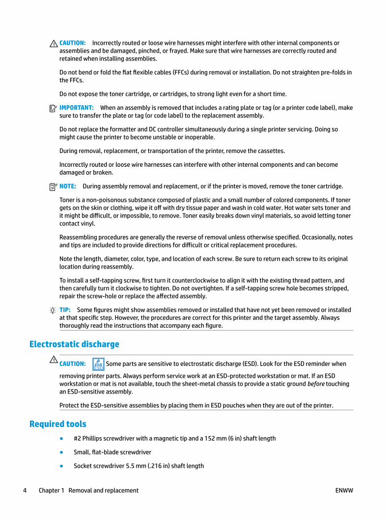
CAUTION: Incorrectly routed or loose wire harnesses might interfere with other internal components or assemblies and be damaged, pinched, or frayed. Make sure that wire harnesses are correctly routed and retained when installing assemblies.
Do not bend or fold the flat flexible cables (FFCs) during removal or installation. Do not straighten pre-folds in the FFCs.
Do not expose the toner cartridge, or cartridges, to strong light even for a short time.
IMPORTANT: When an assembly is removed that includes a rating plate or tag (or a printer code label), make sure to transfer the plate or tag (or code label) to the replacement assembly.
Do not replace the formatter and DC controller simultaneously during a single printer servicing. Doing so might cause the printer to become unstable or inoperable.
During removal, replacement, or transportation of the printer, remove the cassettes.
Incorrectly routed or loose wire harnesses can interfere with other internal components and can become damaged or broken.
NOTE: During assembly removal and replacement, or if the printer is moved, remove the toner cartridge.
Toner is a non-poisonous substance composed of plastic and a small number of colored components. If toner gets on the skin or clothing, wipe it off with dry tissue paper and wash in cold water. Hot water sets toner and it might be difficult, or impossible, to remove. Toner easily breaks down vinyl materials, so avoid letting toner contact vinyl.
Reassembling procedures are generally the reverse of removal unless otherwise specified. Occasionally, notes and tips are included to provide directions for difficult or critical replacement procedures.
Note the length, diameter, color, type, and location of each screw. Be sure to return each screw to its original location during reassembly.
To install a self-tapping screw, first turn it counterclockwise to align it with the existing thread pattern, and then carefully turn it clockwise to tighten. Do not overtighten. If a self-tapping screw hole becomes stripped, repair the screw-hole or replace the affected assembly.
TIP: Some figures might show assemblies removed or installed that have not yet been removed or installed at that specific step. However, the procedures are correct for this printer and the target assembly. Always thoroughly read the instructions that accompany each figure.
Electrostatic discharge
CAUTION: Some parts are sensitive to electrostatic discharge (ESD). Look for the ESD reminder when
removing printer parts. Always perform service work at an ESD-protected workstation or mat. If an ESD workstation or mat is not available, touch the sheet-metal chassis to provide a static ground before touching an ESD-sensitive assembly.
Protect the ESD-sensitive assemblies by placing them in ESD pouches when they are out of the printer.
Required tools● #2 Phillips screwdriver with a magnetic tip and a 152 mm (6 in) shaft length
● Small, flat-blade screwdriver
● Socket screwdriver 5.5 mm (.216 in) shaft length
4 Chapter 1 Removal and replacement ENWW
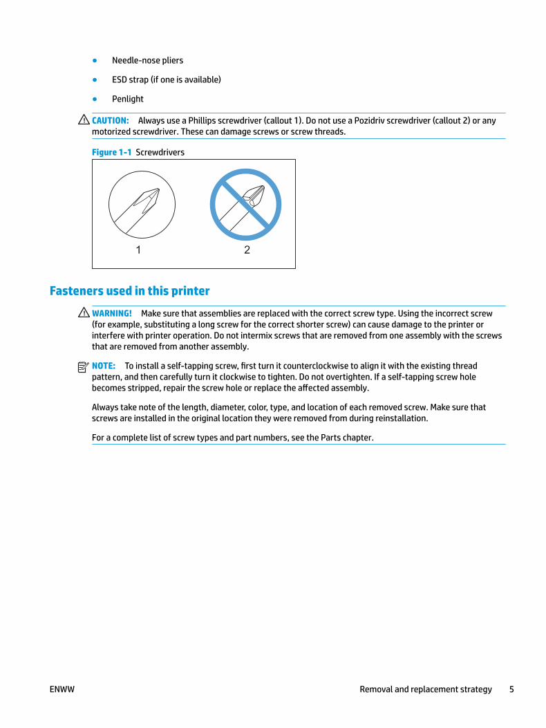
● Needle-nose pliers
● ESD strap (if one is available)
● Penlight
CAUTION: Always use a Phillips screwdriver (callout 1). Do not use a Pozidriv screwdriver (callout 2) or any motorized screwdriver. These can damage screws or screw threads.
Figure 1-1 Screwdrivers
Fasteners used in this printer
WARNING! Make sure that assemblies are replaced with the correct screw type. Using the incorrect screw (for example, substituting a long screw for the correct shorter screw) can cause damage to the printer or interfere with printer operation. Do not intermix screws that are removed from one assembly with the screws that are removed from another assembly.
NOTE: To install a self-tapping screw, first turn it counterclockwise to align it with the existing thread pattern, and then carefully turn it clockwise to tighten. Do not overtighten. If a self-tapping screw hole becomes stripped, repair the screw hole or replace the affected assembly.
Always take note of the length, diameter, color, type, and location of each removed screw. Make sure that screws are installed in the original location they were removed from during reinstallation.
For a complete list of screw types and part numbers, see the Parts chapter.
ENWW Removal and replacement strategy 5

Service approachBefore performing service
● Remove all paper from the product.
● Turn off the power using the power switch.
● Unplug the power cable and interface cable or cables.
● Place the product on an ESD workstation or mat, or use an ESD strap (if one is available). If an ESD workstation, mat, or strap is not available, ground yourself by touching the sheet-metal chassis before touching an ESD-sensitive part.
● Remove the toner cartridge.
● Remove the Tray 2 cassette.
After performing service1. Reinstall the toner cartridge or toner cartridges.
2. Reinstall the trays.
3. Return all paper to the trays.
4. Plug in the power cable and turn on the printer.
5. Perform print-quality tests by printing from a host computer.
Post-service testPerform the following test to verify that the repair or replacement was successful.
Print-quality test
1. Verify that you have completed the necessary reassembly steps.
2. Make sure that the tray contains clean, unmarked paper.
3. Attach the power cord and interface cable or interface cables, and then turn on the product.
4. Verify that the expected startup sounds occur.
5. Print a configuration page, and then verify that the expected printing sounds occur.
6. Print a demo page, and then verify that the print quality is as expected.
7. Send a print job from the host computer, and then verify that the output meets expectations.
8. Clean the outside of the product with a damp cloth.
6 Chapter 1 Removal and replacement ENWW

Removal and replacement proceduresCustomer self-repair (CSR) A parts and assemblies
The CSR level indicates the expected difficulty the customer will experience when removing and replacing an assembly. The CSR A assemblies in this section are easy for the customer to remove and replace.
● RL2-0656-000CN multipurpose tray roller
● RM2-5392-000CN 250-sheet paper input tray
● RM2-5413-000CN optional Tray 3
● RM2-5452-000CN Tray 2 paper pickup roller assembly
● RM2-5741-000CN optional Tray 3 paper pickup roller assembly
● RM2-5397-000CN Tray 2 separation roller assembly
● RM2-5745-000CN optional Tray 3 separation roller assembly
ENWW Removal and replacement procedures 7

RL2-0656-000CN multipurpose tray roller
● Introduction
● Step 1: Remove the roller
● Step 2: Unpack the replacement assembly
● Step 3: Install the roller
Introduction
This document provides the procedures to remove and replace the Multipurpose (MP) tray (Tray 1) roller.
Before performing service
Turn the printer power off
◦ Disconnect the power cable.
WARNING! To avoid damage to the printer, turn the printer off, wait 30 seconds, and then remove the power cable before attempting to service the printer.
Use the table below to identify the correct part number for your printer. To order the part, go to www.hp.com/buy/parts.
MP tray (Tray 1) roller part number
RL2-0655-000CN Roller, MP tray (Tray 1)
Required tools
● No special tools are required to remove this part.
After performing service
Turn the printer power on
◦ Connect the power cable.
◦ Use the power switch to turn the power on.
Post service test
Make sure that the printer initializes to a Ready state.
Print a page from Tray 1 to make sure that the printer is functioning correctly.
Step 1: Remove the roller
The M427/M426 printer is shown in this procedure. However. the instructions are valid for the M403/M402 printers.
1. Press the door-release button, and then open the toner-cartridge door.
8 Chapter 1 Removal and replacement ENWW

Figure 1-2 Open the toner-cartridge door
12
2. Release two tabs between the roller collar and roller, and then rotate the top of the roller out and away from the printer.
TIP: Pushing down on the top of the roller might make it easier to release the tabs.
Figure 1-3 Release two tabs
ENWW Removal and replacement procedures 9

3. Remove the roller.
Figure 1-4 Remove the roller
Step 2: Unpack the replacement assembly
Unpack the replacement part from the packaging.
http://www8.hp.com/us/en/hp-information/environment/product-recycling.html
CAUTION: Do not touch the gray spongy portion of the replacement roller. Skin oils on the roller can cause paper handling problems.
NOTE: HP recommends responsible disposal of the defective part.
Figure 1-5 Recycle and unpack
10 Chapter 1 Removal and replacement ENWW

Step 3: Install the roller
CAUTION: Do not touch the gray spongy portion of the replacement roller. Skin oils on the roller can cause paper handling problems.
The M427/M426 printer is shown in this procedure. However. the instructions are valid for the M403/M402 printers.
1. Position the replacement pickup roller with the pins in the provided slots on the holder, and then rotate the top of the roller up and toward the printer.
Figure 1-6 Install the roller
2. Continue to rotate the top of the roller toward the printer (callout 1), until two tabs (callout 2) snap into place.
Figure 1-7 Engage two tabs
ENWW Removal and replacement procedures 11

3. Close the toner-cartridge door.
Figure 1-8 Close the toner-cartridge door
12 Chapter 1 Removal and replacement ENWW
RM2-5392-000CN 250-sheet paper input tray
● Introduction
● Step 1: Remove Tray 2
● Step 2: Unpack the replacement assembly
● Step 3: Install Tray 2
Introduction
This document provides the procedures to remove and replace Tray 2.
Before performing service
Turn the printer power off
◦ Disconnect the power cable.
WARNING! To avoid damage to the printer, turn the printer off, wait 30 seconds, and then remove the power cable before attempting to service the printer.
Use the table below to identify the correct part number for your printer. To order the part, go to www.hp.com/buy/parts.
Tray 2 part number
RM2-5392-000CN Cassette (Tray 2) assembly
Required tools
● No special tools are required to remove this part.
After performing service
Turn the printer power on
◦ Connect the power cable.
◦ Use the power switch to turn the power on.
Post service test
Make sure that the printer initializes to a Ready state.
Print a configuration page (from Tray 2) to make sure that the printer is functioning correctly.
Step 1: Remove Tray 2
▲ Pull the tray straight out of the printer to remove it.
ENWW Removal and replacement procedures 13

Figure 1-9 Remove the tray
Step 2: Unpack the replacement assembly
Unpack the replacement part from the packaging.
http://www8.hp.com/us/en/hp-information/environment/product-recycling.html
NOTE: HP recommends responsible disposal of the defective part.
Figure 1-10 Recycle and unpack
Step 3: Install Tray 2
▲ Slide the tray straight into the printer to install it.
14 Chapter 1 Removal and replacement ENWW
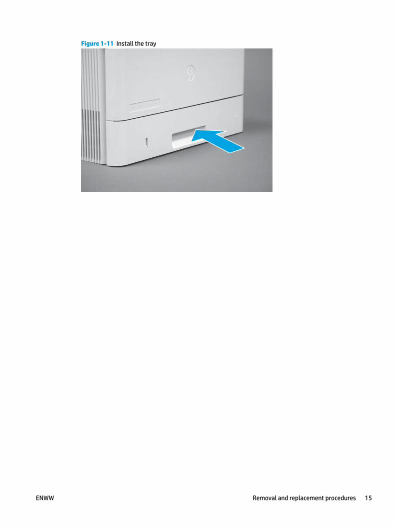
Figure 1-11 Install the tray
ENWW Removal and replacement procedures 15
RM2-5413-000CN optional Tray 3
● Introduction
● Step 1: Remove optional Tray 3
● Step 2: Unpack the replacement assembly
● Step 3: Install optional Tray 3
Introduction
This document provides the procedures to remove and replace the optional Tray 3.
Before performing service
Turn the printer power off
◦ Disconnect the power cable.
WARNING! To avoid damage to the printer, turn the printer off, wait 30 seconds, and then remove the power cable before attempting to service the printer.
Use the table below to identify the correct part number for your printer. To order the part, go to www.hp.com/buy/parts.
Tray 3 part number
RM2-5413-000CN 550-sheet paper feeder cassette (optional Tray 3)
Required tools
● No special tools are required to remove this part.
After performing service
Turn the printer power on
◦ Connect the power cable.
◦ Use the power switch to turn the power on.
Post service test
Make sure that the printer initializes to a Ready state.
Print a page from Tray 3 to make sure that the paper feeder is functioning correctly.
Step 1: Remove optional Tray 3
1. Pull the tray straight out of the printer until it stops.
16 Chapter 1 Removal and replacement ENWW

Figure 1-12 Pull the tray out of the printer
2. Slightly lift up on the front of the tray to release it, and then continue to pull the tray out of the accessory to remove it.
Figure 1-13 Release and remove the tray
Step 2: Unpack the replacement assembly
Unpack the replacement part from the packaging.
http://www8.hp.com/us/en/hp-information/environment/product-recycling.html
NOTE: HP recommends responsible disposal of the defective part.
ENWW Removal and replacement procedures 17

Figure 1-14 Recycle and unpack
Step 3: Install optional Tray 3
1. With the tray at a slight angle, align the sides of the tray with the rails in the accessory, and then partially slide the tray into the accessory.
Figure 1-15 Install the tray
18 Chapter 1 Removal and replacement ENWW

2. Push the tray straight into the accessory to close it.
Figure 1-16 Close the tray
ENWW Removal and replacement procedures 19
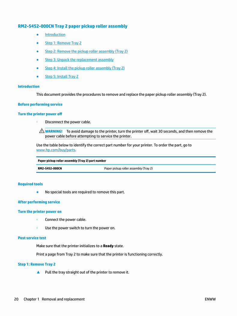
RM2-5452-000CN Tray 2 paper pickup roller assembly
● Introduction
● Step 1: Remove Tray 2
● Step 2: Remove the pickup roller assembly (Tray 2)
● Step 3: Unpack the replacement assembly
● Step 4: Install the pickup roller assembly (Tray 2)
● Step 5: Install Tray 2
Introduction
This document provides the procedures to remove and replace the paper pickup roller assembly (Tray 2).
Before performing service
Turn the printer power off
◦ Disconnect the power cable.
WARNING! To avoid damage to the printer, turn the printer off, wait 30 seconds, and then remove the power cable before attempting to service the printer.
Use the table below to identify the correct part number for your printer. To order the part, go to www.hp.com/buy/parts.
Paper pickup roller assembly (Tray 2) part number
RM2-5452-000CN Paper pickup roller assembly (Tray 2)
Required tools
● No special tools are required to remove this part.
After performing service
Turn the printer power on
◦ Connect the power cable.
◦ Use the power switch to turn the power on.
Post service test
Make sure that the printer initializes to a Ready state.
Print a page from Tray 2 to make sure that the printer is functioning correctly.
Step 1: Remove Tray 2
▲ Pull the tray straight out of the printer to remove it.
20 Chapter 1 Removal and replacement ENWW

Figure 1-17 Remove the tray
Step 2: Remove the pickup roller assembly (Tray 2)
CAUTION: When handling the roller holder, do not touch the gray spongy portion of the rollers. Skin oils on the rollers can cause paper handling problems.
NOTE: The M403/M402 printer is shown in this procedure. However, the procedure is valid for the M427/M426 printers.
1. Carefully rotate the printer backward.
CAUTION: To avoid damage to the rear cassette cover, keep it in the closed position.
Figure 1-18 Tilt the printer backward
ENWW Removal and replacement procedures 21

2. Continue rotate the printer backward until it rests on the rear cover, bottom-side face forward.
CAUTION: M427/M426: The integrated scanner assembly (ISA) is not captive, and can unexpectedly open when the printer is tilted back.
Figure 1-19 Place the printer bottom-side face forward
3. Release one tab (callout 1), and then slide the roller holder toward the left side of the printer to release it.
Figure 1-20 Release one tab
1
22 Chapter 1 Removal and replacement ENWW

4. Remove the roller holder.
Figure 1-21 Remove the roller holder
Step 3: Unpack the replacement assembly
Unpack the replacement part from the packaging.
http://www8.hp.com/us/en/hp-information/environment/product-recycling.html
CAUTION: When handling the roller holder, do not touch the gray spongy portion of the rollers. Skin oils on the rollers can cause paper handling problems.
NOTE: HP recommends responsible disposal of the defective part.
Figure 1-22 Recycle and unpack
ENWW Removal and replacement procedures 23

Step 4: Install the pickup roller assembly (Tray 2)
CAUTION: When handling the roller holder, do not touch the gray spongy portion of the rollers. Skin oils on the rollers can cause paper handling problems.
NOTE: The M403/M402 printer is shown in this procedure. However, the procedure is valid for the M427/M426 printers.
1. Position the roller holder assembly in the printer as shown, and then slide it toward the right side of the printer.
Figure 1-23 Install the roller holder
2. Make sure that the tab snaps into place.
Figure 1-24 Check the tab
24 Chapter 1 Removal and replacement ENWW

3. Carefully rotate the printer forward.
Figure 1-25 Rotate the printer forward
4. Continue rotate the printer forward until it rests in the operational position.
Figure 1-26 Place the printer in the operational position
Step 5: Install Tray 2
▲ Slide the tray straight into the printer to install it.
ENWW Removal and replacement procedures 25

Figure 1-27 Install the tray
26 Chapter 1 Removal and replacement ENWW

RM2-5741-000CN optional Tray 3 paper pickup roller assembly
● Introduction
● Step 1: Remove optional Tray 3
● Step 2: Remove the paper pickup roller assembly (optional Tray 3)
● Step 3: Unpack the replacement assembly
● Step 4: Install the paper pickup roller assembly (optional Tray 3)
● Step 5: Install optional Tray 3
Introduction
This document provides the procedures to remove and replace the paper pickup roller assembly (Tray 3).
Before performing service
Turn the printer power off
◦ Disconnect the power cable.
WARNING! To avoid damage to the printer, turn the printer off, wait 30 seconds, and then remove the power cable before attempting to service the printer.
Use the table below to identify the correct part number for your printer. To order the part, go to www.hp.com/buy/parts.
Paper pickup roller assembly (Tray 3) part number
RM2-5741-000N Paper pickup roller assembly (Tray 3)
Required tools
● No special tools are required to remove this part.
After performing service
Turn the printer power on
◦ Connect the power cable.
◦ Use the power switch to turn the power on.
Post service test
Make sure that the printer initializes to a Ready state.
Print a page from the accessory to make sure that the printer is functioning correctly.
Step 1: Remove optional Tray 3
1. Pull the tray straight out of the printer until it stops.
ENWW Removal and replacement procedures 27
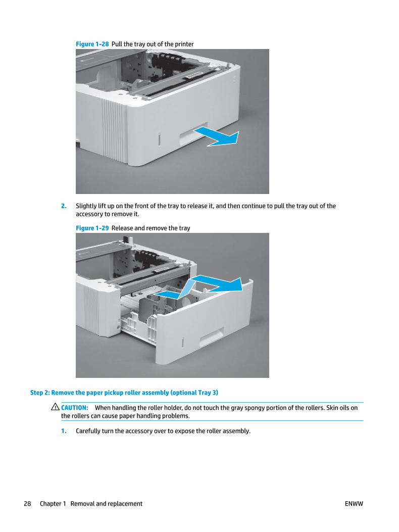
Figure 1-28 Pull the tray out of the printer
2. Slightly lift up on the front of the tray to release it, and then continue to pull the tray out of the accessory to remove it.
Figure 1-29 Release and remove the tray
Step 2: Remove the paper pickup roller assembly (optional Tray 3)
CAUTION: When handling the roller holder, do not touch the gray spongy portion of the rollers. Skin oils on the rollers can cause paper handling problems.
1. Carefully turn the accessory over to expose the roller assembly.
28 Chapter 1 Removal and replacement ENWW
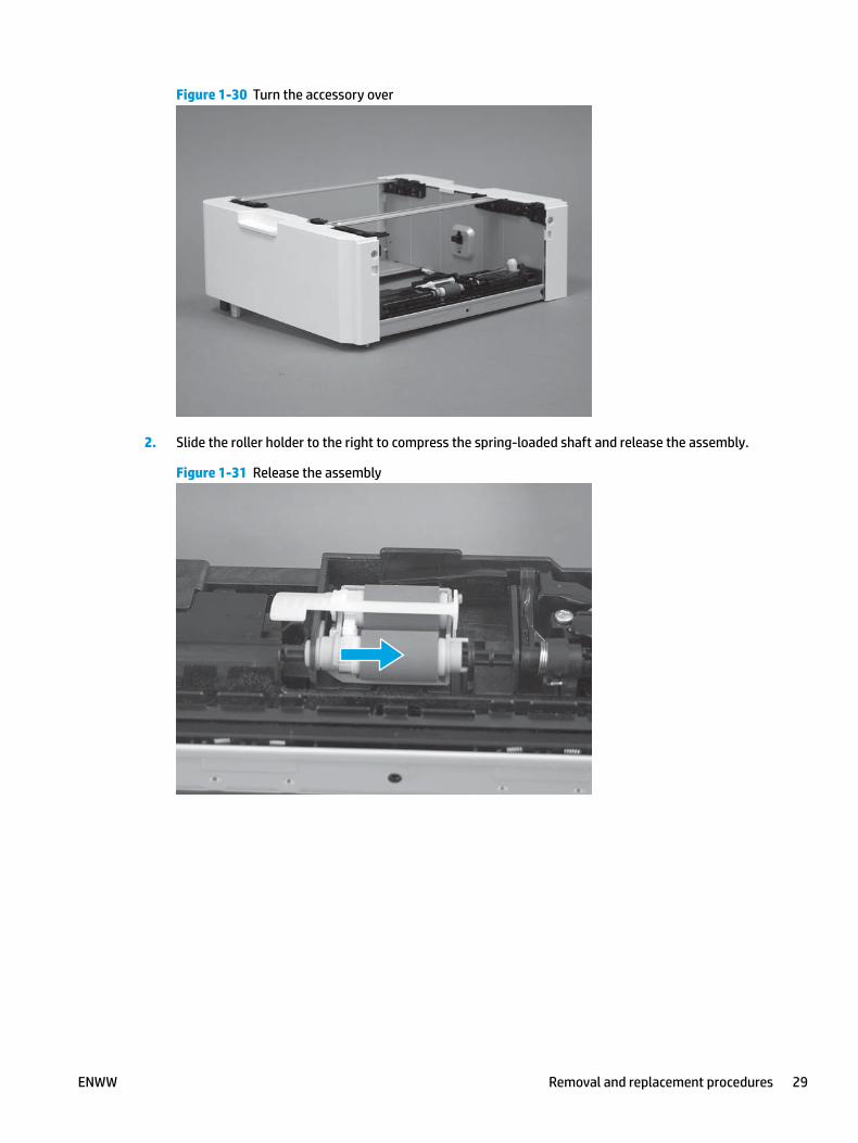
Figure 1-30 Turn the accessory over
2. Slide the roller holder to the right to compress the spring-loaded shaft and release the assembly.
Figure 1-31 Release the assembly
ENWW Removal and replacement procedures 29

3. Rotate the end of the assembly up and away from the accessory.
Figure 1-32 Rotate the assembly up
4. Remove the roller assembly.
Figure 1-33 Remove the assembly
Step 3: Unpack the replacement assembly
Unpack the replacement part from the packaging.
http://www8.hp.com/us/en/hp-information/environment/product-recycling.html
CAUTION: When handling the roller holder, do not touch the gray spongy portion of the rollers. Skin oils on the rollers can cause paper handling problems.
NOTE: HP recommends responsible disposal of the defective part.
30 Chapter 1 Removal and replacement ENWW

Figure 1-34 Recycle and unpack
Step 4: Install the paper pickup roller assembly (optional Tray 3)
CAUTION: When handling the roller holder, do not touch the gray spongy portion of the rollers. Skin oils on the rollers can cause paper handling problems.
1. Install the right end of the assembly on the spring-loaded shaft (callout 1), and then slide it to the right to compress the shaft (callout 2).
IMPORTANT: Make sure that the pin on the back of the holder (callout 3) is inserted in the slot (callout 4) in the lever arm. If the pin is not correctly installed, the accessory will not pick paper.
Figure 1-35 Install the roller assembly
1
23
4
ENWW Removal and replacement procedures 31
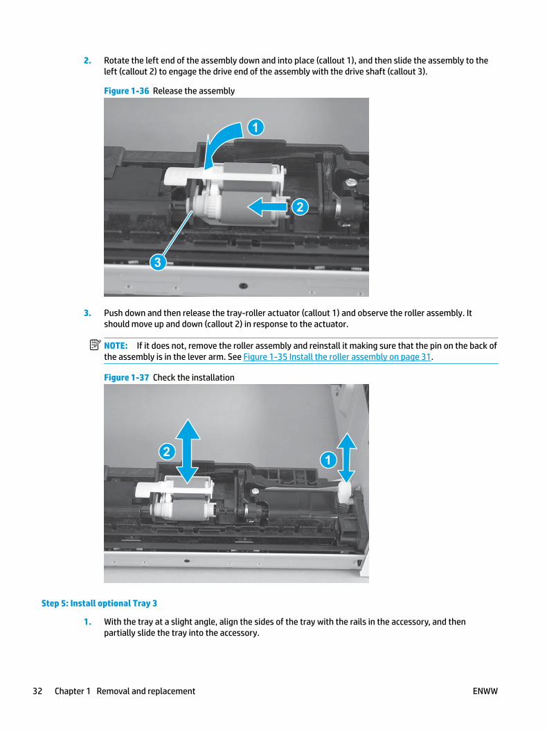
2. Rotate the left end of the assembly down and into place (callout 1), and then slide the assembly to the left (callout 2) to engage the drive end of the assembly with the drive shaft (callout 3).
Figure 1-36 Release the assembly
2
1
3
3. Push down and then release the tray-roller actuator (callout 1) and observe the roller assembly. It should move up and down (callout 2) in response to the actuator.
NOTE: If it does not, remove the roller assembly and reinstall it making sure that the pin on the back of the assembly is in the lever arm. See Figure 1-35 Install the roller assembly on page 31.
Figure 1-37 Check the installation
12
Step 5: Install optional Tray 3
1. With the tray at a slight angle, align the sides of the tray with the rails in the accessory, and then partially slide the tray into the accessory.
32 Chapter 1 Removal and replacement ENWW

Figure 1-38 Install the tray
2. Push the tray straight into the accessory to close it.
Figure 1-39 Close the tray
ENWW Removal and replacement procedures 33

RM2-5397-000CN Tray 2 separation roller assembly
● Introduction
● Step 1: Remove Tray 2
● Step 2: Remove the separation pad roller assembly (Tray 2)
● Step 3: Unpack the replacement assembly
● Step 4: Install the separation pad roller assembly (Tray 2)
● Step 5: Install Tray 2
Introduction
This document provides the procedures to remove and replace the separation roller assembly (Tray 2).
Before performing service
Turn the printer power off
◦ Disconnect the power cable.
WARNING! To avoid damage to the printer, turn the printer off, wait 30 seconds, and then remove the power cable before attempting to service the printer.
Use the table below to identify the correct part number for your printer. To order the part, go to www.hp.com/buy/parts.
Separation roller assembly (Tray 2) part number
RM2-5397-000CN Separation roller assembly (Tray 2)
Required tools
● No special tools are required to install this kit.
After performing service
Turn the printer power on
◦ Connect the power cable.
◦ Use the power switch to turn the power on.
Post service test
Make sure that the printer initializes to a Ready state.
Print a configuration page to make sure that the printer is functioning correctly.
Step 1: Remove Tray 2
▲ Pull the tray straight out of the printer to remove it.
34 Chapter 1 Removal and replacement ENWW

Figure 1-40 Remove the tray
Step 2: Remove the separation pad roller assembly (Tray 2)
1. Press the locking lever (callout 1), and then pull the separation roller assembly straight up to release it.
Figure 1-41 Release the assembly
1
ENWW Removal and replacement procedures 35

2. Remove the assembly.
Figure 1-42 Remove the assembly
Step 3: Unpack the replacement assembly
Unpack the replacement part from the packaging.
http://www8.hp.com/us/en/hp-information/environment/product-recycling.html
NOTE: HP recommends responsible disposal of the defective part.
Figure 1-43 Recycle and unpack
Step 4: Install the separation pad roller assembly (Tray 2)
1. Install the assembly in the slots in the cassette.
36 Chapter 1 Removal and replacement ENWW
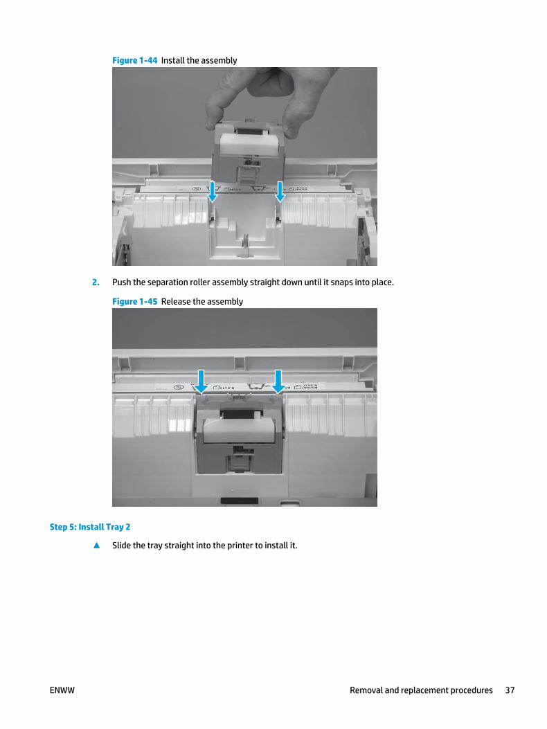
Figure 1-44 Install the assembly
2. Push the separation roller assembly straight down until it snaps into place.
Figure 1-45 Release the assembly
Step 5: Install Tray 2
▲ Slide the tray straight into the printer to install it.
ENWW Removal and replacement procedures 37

Figure 1-46 Install the tray
38 Chapter 1 Removal and replacement ENWW

RM2-5745-000CN optional Tray 3 separation roller assembly
● Introduction
● Step 1: Remove Tray 3
● Step 2: Remove the separation roller assembly (optional Tray 3)
● Step 3: Unpack the replacement assembly
● Step 4: Install the separation roller assembly (optional Tray 3)
● Step 5: Install Tray 3
Introduction
This document provides the procedures to remove and replace the separation roller assembly (500-sheet feeder).
Before performing service
Turn the printer power off
◦ Disconnect the power cable.
WARNING! To avoid damage to the printer, turn the printer off, wait 30 seconds, and then remove the power cable before attempting to service the printer.
Use the table below to identify the correct part number for your printer. To order the part, go to www.hp.com/buy/parts.
Separation roller assembly (550-sheet feeder) part number
RM2-5745-000CN Separation roller assembly (550-sheet feeder)
Required tools
● No special tools are required to install this kit.
After performing service
Turn the printer power on
◦ Connect the power cable.
◦ Use the power switch to turn the power on.
Post service test
Make sure that the printer initializes to a Ready state.
Print a page from the accessory to make sure that the accessory is functioning correctly.
Step 1: Remove Tray 3
1. Pull the tray straight out of the printer until it stops.
ENWW Removal and replacement procedures 39

Figure 1-47 Pull the tray out of the printer
2. Slightly lift up on the front of the tray to release it, and then continue to pull the tray out of the accessory to remove it.
Figure 1-48 Release and remove the tray
Step 2: Remove the separation roller assembly (optional Tray 3)
1. Press the locking lever (callout 1), and then pull the separation roller assembly straight up to release it.
40 Chapter 1 Removal and replacement ENWW
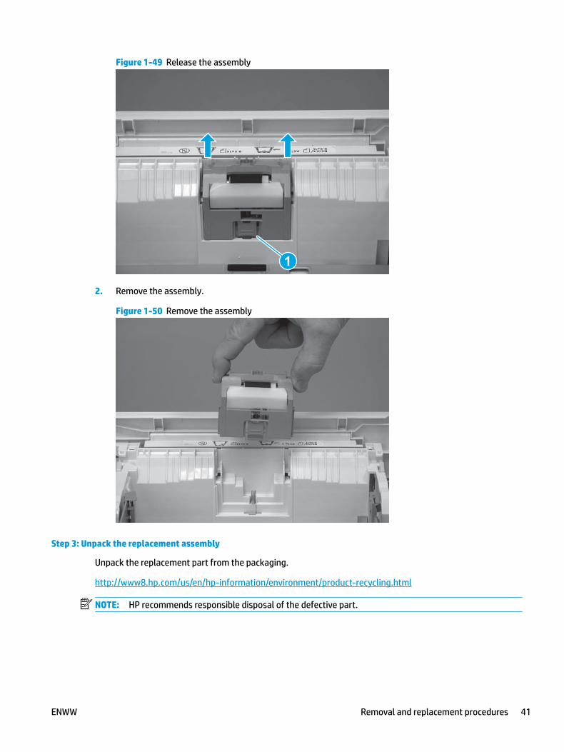
Figure 1-49 Release the assembly
1
2. Remove the assembly.
Figure 1-50 Remove the assembly
Step 3: Unpack the replacement assembly
Unpack the replacement part from the packaging.
http://www8.hp.com/us/en/hp-information/environment/product-recycling.html
NOTE: HP recommends responsible disposal of the defective part.
ENWW Removal and replacement procedures 41

Figure 1-51 Recycle and unpack
Step 4: Install the separation roller assembly (optional Tray 3)
1. Install the assembly in the slots in the cassette.
Figure 1-52 Install the assembly
42 Chapter 1 Removal and replacement ENWW
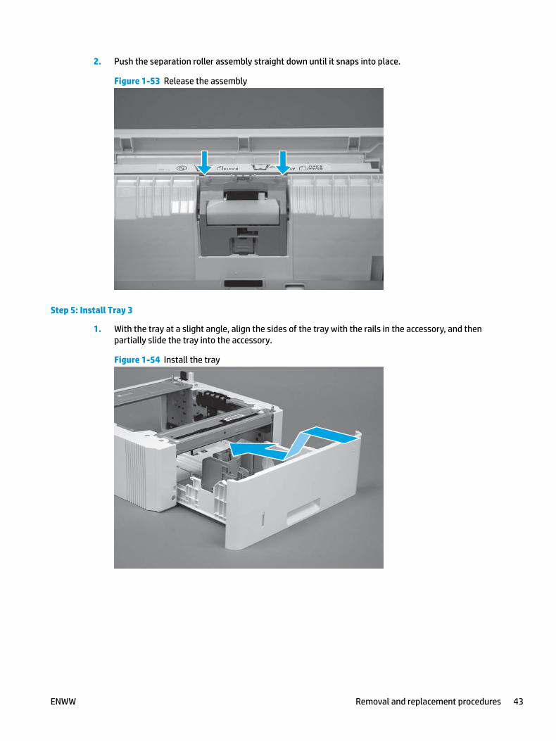
2. Push the separation roller assembly straight down until it snaps into place.
Figure 1-53 Release the assembly
Step 5: Install Tray 3
1. With the tray at a slight angle, align the sides of the tray with the rails in the accessory, and then partially slide the tray into the accessory.
Figure 1-54 Install the tray
ENWW Removal and replacement procedures 43
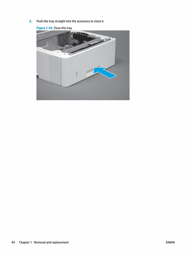
2. Push the tray straight into the accessory to close it.
Figure 1-55 Close the tray
44 Chapter 1 Removal and replacement ENWW
Removal and replacement: External panels, covers, and doors● Removal and replacement: Damper sheets
● Removal and replacement: Rear USB cover
● Removal and replacement: Support shaft
● Removal and replacement: Cartridge door assembly
● Removal and replacement: Pressure-release link
● Removal and replacement: Left cover
● Removal and replacement: Right cover
● Removal and replacement: Rear door assembly
● Removal and replacement: Cassette rear cover
● Removal and replacement: Top cover (M427/M426)
● Removal and replacement: Cable guide (M427/M426)
● Removal and replacement: Top cover (M403/M402)
● Removal and replacement: 2-line LCD operator and indication covers (M403/M402)
● Removal and replacement: Paper delivery tray (output bin)
● Removal and replacement: Integrated scanner assembly (M427/M426)
● Removal and replacement: ISA lift assembly and slider pin (M427/M426)
ENWW Removal and replacement procedures 45

Removal and replacement: Damper sheets
● Introduction
● Step 1: Remove the damper sheets
● Step 2: Unpack the replacement assembly
● Step 3: Install the damper sheets
Introduction
This document provides the procedures to remove and replace the damper sheets.
Before performing service
Turn the printer power off
◦ Disconnect the power cable.
WARNING! To avoid damage to the printer, turn the printer off, wait 30 seconds, and then remove the power cord before attempting to service the printer.
Use the table below to identify the correct part number for your printer. To order the part, go to www.hp.com/buy/parts.
Damper sheets part number
RC2-6075-000CN Sheets, damper (2)
Required tools
● No special tools are needed to remove or install this assembly.
After performing service
Turn the printer power on
◦ Connect the power cable.
◦ Use the power switch to turn the power on.
Post service test
No post service test are available for this assembly.
Step 1: Remove the damper sheets
▲ Remove the damper sheets from the rear cover.
Reinstallation tip: Make sure that all of the residual adhesive is removed from the rear cover damper sheet area. Residual adhesive can cause the replacement sheets to not adhere properly to the door.
46 Chapter 1 Removal and replacement ENWW

Figure 1-56 Remove the damper sheets
Step 2: Unpack the replacement assembly
Unpack the replacement part from the packaging.
http://www8.hp.com/us/en/hp-information/environment/product-recycling.html
NOTE: HP recommends responsible disposal of the defective part.
Figure 1-57 Recycle and unpack
Step 3: Install the damper sheets
▲ Remove the protective backing to expose the adhesive side of the damper sheets, and then install them on the rear cover.
ENWW Removal and replacement procedures 47

Figure 1-58 Install the damper sheets
48 Chapter 1 Removal and replacement ENWW

Removal and replacement: Rear USB cover
● Introduction
● Step 1: Remove the rear USB cover
● Step 2: Unpack the replacement assembly
● Step 3: Install the rear USB cover
Introduction
This document provides the procedures to remove and replace the rear USB cover.
Before performing service
Turn the printer power off
◦ Disconnect the power cable.
WARNING! To avoid damage to the printer, turn the printer off, wait 30 seconds, and then remove the power cable before attempting to service the printer.
Use the table below to identify the correct part number for your printer. To order the part, go to www.hp.com/buy/parts.
Rear USB cover part number
RC4-3298-000CN
RC4-3299-000CN
Rear USB cover, small (M402/M403)
Rear USB cover, small (M426/M427)
Required tools
● No special tools are needed to remove or install this assembly.
After performing service
Turn the printer power on
◦ Connect the power cable.
◦ Use the power switch to turn the power on.
Post service test
No post service test are available for this assembly.
Step 1: Remove the rear USB cover
1. Use a finger to release two tabs (callout 1), and then pull the cover straight off of the printer.
ENWW Removal and replacement procedures 49

Figure 1-59 Pull the cover straight off
1
2. Remove the cover.
NOTE: For network models, also remove the network port cover (not shown; RC4-2907-000CN).
Figure 1-60 Remove the cover
Step 2: Unpack the replacement assembly
Unpack the replacement part from the packaging.
http://www8.hp.com/us/en/hp-information/environment/product-recycling.html
NOTE: HP recommends responsible disposal of the defective part.
50 Chapter 1 Removal and replacement ENWW

Figure 1-61 Recycle and unpack
Step 3: Install the rear USB cover
1. Align the tabs on the cover with the slots in the left cover.
Figure 1-62 Align the tabs on the cover
ENWW Removal and replacement procedures 51

2. Push the cover straight on to the printer to install it.
NOTE: For network models, also install the network port cover (not shown; RC4-2907-000CN).
Figure 1-63 Install the cover
52 Chapter 1 Removal and replacement ENWW

Removal and replacement: Support shaft
● Introduction
● Step 1: Remove the support shaft
● Step 2: Unpack the replacement assembly
● Step 3: Install the support shaft
Introduction
This document provides the procedures to remove and replace the toner-cartridge door support shaft.
Before performing service
Turn the printer power off
◦ Disconnect the power cable.
WARNING! To avoid damage to the printer, turn the printer off, wait 30 seconds, and then remove the power cord before attempting to service the printer.
Use the table below to identify the correct part number for your printer. To order the part, go to www.hp.com/buy/parts.
Support shaft part number
RC4-3002-000CN Shaft, support
Required tools
● Optional: Small flat-blade screwdriver.
After performing service
Turn the printer power on
◦ Connect the power cable.
◦ Use the power switch to turn the power on.
Post service test
Make sure that toner toner-cartridge door correctly opens and closes.
Step 1: Remove the support shaft
1. Release the support shaft (callout 1), and then slide it toward the center of the door (callout 2).
TIP: It might be easier to release the support shaft by using a small flat-blade screwdriver.
ENWW Removal and replacement procedures 53

Figure 1-64 Release the support shaft
12
2. Remove the support shaft.
Figure 1-65 Remove the support shaft
Step 2: Unpack the replacement assembly
Unpack the replacement part from the packaging.
http://www8.hp.com/us/en/hp-information/environment/product-recycling.html
NOTE: HP recommends responsible disposal of the defective part.
54 Chapter 1 Removal and replacement ENWW
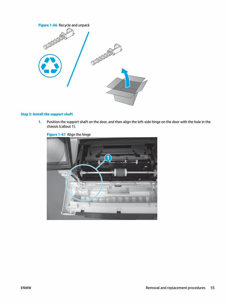
Figure 1-66 Recycle and unpack
Step 3: Install the support shaft
1. Position the support shaft on the door, and then align the left-side hinge on the door with the hole in the chassis (callout 1).
Figure 1-67 Align the hinge
1
ENWW Removal and replacement procedures 55

2. Push the shaft towards the left side of the printer to install it (callout 1).
Reinstallation tip: Make sure that the support shaft is fully installed and correctly orientated (callout 2) so that it will not interfere with the door opening and closing.
Figure 1-68 Install the support shaft
2
1
56 Chapter 1 Removal and replacement ENWW

Removal and replacement: Cartridge door assembly
● Introduction
● Step 1: Remove the cartridge door assembly
● Step 2: Unpack the replacement assembly
● Step 3: Install the cartridge door assembly
Introduction
This document provides the procedures to remove and replace the cartridge door assembly.
Before performing service
Turn the printer power off
◦ Disconnect the power cable.
WARNING! To avoid damage to the printer, turn the printer off, wait 30 seconds, and then remove the power cable before attempting to service the printer.
Use the table below to identify the correct part number for your printer. To order the part, go to www.hp.com/buy/parts.
Cartridge door assembly part number
RM2-5390-000CN
RM2-5436-000CN
Cartridge door assembly (M403/M402 models)
Cartridge door assembly (M403/M402 NFC models)
RM2-5408-000CN
RM2-5435-000CN
Cartridge door assembly (M427/M426 models)
Cartridge door assembly (M427/M426 NFC models)
Required tools
● Small flat-blade screwdriver.
After performing service
Turn the printer power on
◦ Connect the power cable.
◦ Use the power switch to turn the power on.
Post service test
Make sure that the cartridge door assembly correctly opens and closes.
Step 1: Remove the cartridge door assembly
NOTE: If the toner cartridge was not removed prior to servicing the printer, remove it now.
1. Release one tab (callout 1), and then slide shaft (callout 2) in the direction the arrow indicates and remove it.
ENWW Removal and replacement procedures 57

TIP: It might be easier to release the support shaft by using a small flat-blade screwdriver.
Figure 1-69 Release the support shaft
12
2. Release one tab (callout 1), and then slide the guide (callout 2) in the direction the arrow indicates and remove it.
Figure 1-70 Remove the guide
1 2
58 Chapter 1 Removal and replacement ENWW

3. Remove the link arm (callout 1).
Figure 1-71 Remove the link arm
1
4. Slide the cartridge door assembly (callout 1) in the direction the arrow indicates and remove it.
Figure 1-72 Remove the door
1
ENWW Removal and replacement procedures 59
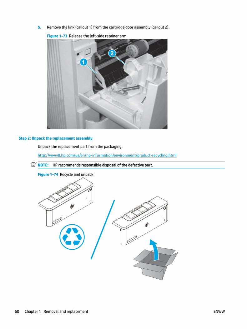
5. Remove the link (callout 1) from the cartridge door assembly (callout 2).
Figure 1-73 Release the left-side retainer arm
21
Step 2: Unpack the replacement assembly
Unpack the replacement part from the packaging.
http://www8.hp.com/us/en/hp-information/environment/product-recycling.html
NOTE: HP recommends responsible disposal of the defective part.
Figure 1-74 Recycle and unpack
60 Chapter 1 Removal and replacement ENWW
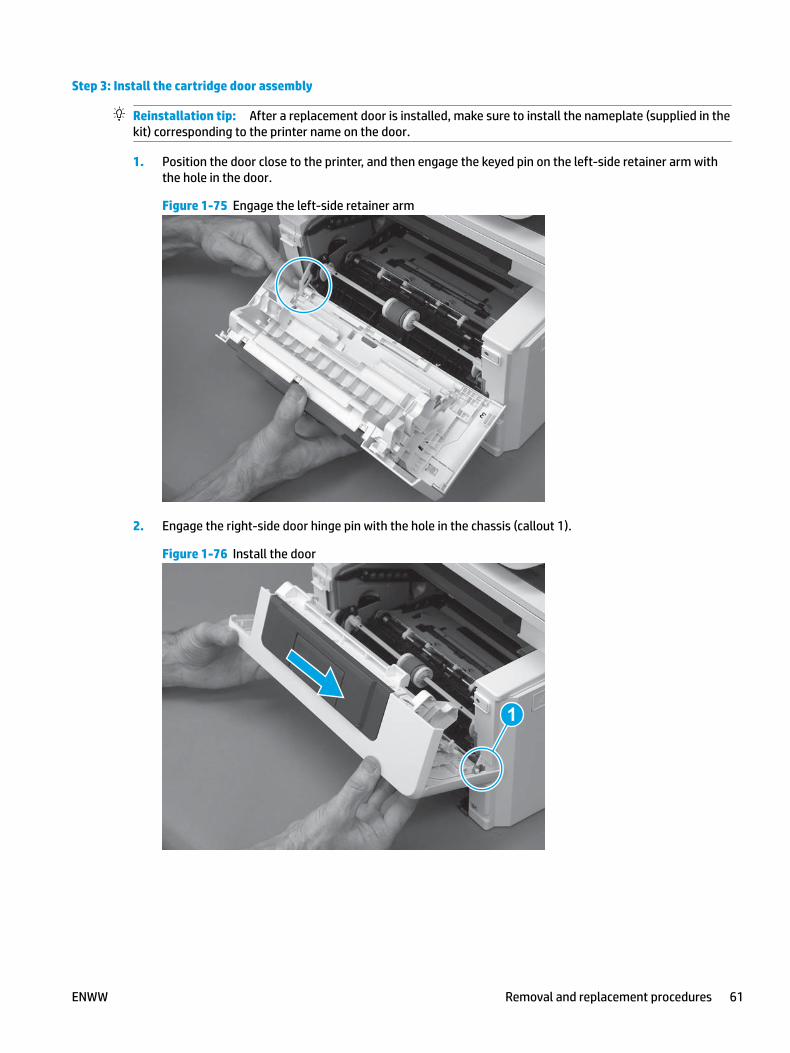
Step 3: Install the cartridge door assembly
Reinstallation tip: After a replacement door is installed, make sure to install the nameplate (supplied in the kit) corresponding to the printer name on the door.
1. Position the door close to the printer, and then engage the keyed pin on the left-side retainer arm with the hole in the door.
Figure 1-75 Engage the left-side retainer arm
2. Engage the right-side door hinge pin with the hole in the chassis (callout 1).
Figure 1-76 Install the door
1
ENWW Removal and replacement procedures 61

3. Install the link (callout 1).
IMPORTANT: Make sure that the link snaps into place on the arm (callout 2). The link actuates the fuser pressure-release mechanism.
Figure 1-77 Install the pressure-release link
1
2
4. Slide the guide into the printer (callout 1), and then make sure that the tab (callout 2) snaps into place to secure the guide to the chassis.
Figure 1-78 Install the guide
1
2
62 Chapter 1 Removal and replacement ENWW

5. Position the shaft on the door, and then align the left-side hinge on the door with the hole in the chassis (callout 1).
Figure 1-79 Align the hinge
1
6. Push the shaft towards the left side of the printer to install it (callout 1).
Reinstallation tip: Make sure that the support shaft is fully installed and correctly orientated (callout 2) so that it will not interfere with the door opening and closing.
Figure 1-80 Install the support shaft
2
1
ENWW Removal and replacement procedures 63

Removal and replacement: Pressure-release link
● Introduction
● Step 1: Remove the cartridge door assembly
● Step 2: Remove the pressure-release link
● Step 3: Unpack the replacement assembly
● Step 4: Install the pressure-release link
● Step 5: Install the cartridge door assembly
Introduction
This document provides the procedures to remove and replace the pressure-release link arm.
Before performing service
Turn the printer power off
◦ Disconnect the power cable.
WARNING! To avoid damage to the printer, turn the printer off, wait 30 seconds, and then remove the power cable before attempting to service the printer.
Use the table below to identify the correct part number for your printer. To order the part, go to www.hp.com/buy/parts.
Pressure-release link part number
RC4-4479-000CN Link, pressure-release link
Required tools
● Small flat-blade screwdriver.
After performing service
Turn the printer power on
◦ Connect the power cable.
◦ Use the power switch to turn the power on.
Post service test
Make sure that the toner-cartridge door correctly opens and closes.
Step 1: Remove the cartridge door assembly
NOTE: If the toner cartridge was not removed prior to servicing the printer, remove it now.
1. Release one tab (callout 1), and then slide shaft (callout 2) in the direction the arrow indicates and remove it.
64 Chapter 1 Removal and replacement ENWW

TIP: It might be easier to release the support shaft by using a small flat-blade screwdriver.
Figure 1-81 Release the support shaft
12
2. Release one tab (callout 1), and then slide the guide (callout 2) in the direction the arrow indicates and remove it.
Figure 1-82 Remove the guide
1 2
ENWW Removal and replacement procedures 65

3. Remove the link arm (callout 1).
Figure 1-83 Remove the link arm
1
4. Slide the cartridge door assembly (callout 1) in the direction the arrow indicates and remove it.
Figure 1-84 Remove the door
1
66 Chapter 1 Removal and replacement ENWW

5. Remove the link (callout 1) from the cartridge door assembly (callout 2).
Figure 1-85 Release the left-side retainer arm
21
Step 2: Remove the pressure-release link
1. Rotate the pressure-release link until the keyed portion of the pin aligns with the slot in the holder.
Figure 1-86 Release the pressure-release link
ENWW Removal and replacement procedures 67

2. Remove the pressure-release link.
Figure 1-87 Remove the pressure-release link
Step 3: Unpack the replacement assembly
Unpack the replacement part from the packaging.
http://www8.hp.com/us/en/hp-information/environment/product-recycling.html
NOTE: HP recommends responsible disposal of the defective part.
Figure 1-88 Recycle and unpack
Step 4: Install the pressure-release link
1. Align the keyed portion of the pin with the slot in the holder, and then install the link.
68 Chapter 1 Removal and replacement ENWW

Figure 1-89 Align the keyed portion of the pin
2. Rotate the pressure-release link to engage it with the door.
Figure 1-90 Install the pressure-release link
Step 5: Install the cartridge door assembly
Reinstallation tip: After a replacement door is installed, make sure to install the nameplate (supplied in the kit) corresponding to the printer name on the door.
1. Position the door close to the printer, and then engage the keyed pin on the left-side retainer arm with the hole in the door.
ENWW Removal and replacement procedures 69

Figure 1-91 Engage the left-side retainer arm
2. Engage the right-side door hinge pin with the hole in the chassis (callout 1).
Figure 1-92 Install the door
1
70 Chapter 1 Removal and replacement ENWW

3. Install the link (callout 1).
IMPORTANT: Make sure that the link snaps into place on the arm (callout 2). The link actuates the fuser pressure-release mechanism.
Figure 1-93 Install the pressure-release link
1
2
4. Slide the guide into the printer (callout 1), and then make sure that the tab (callout 2) snaps into place to secure the guide to the chassis.
Figure 1-94 Install the guide
1
2
ENWW Removal and replacement procedures 71
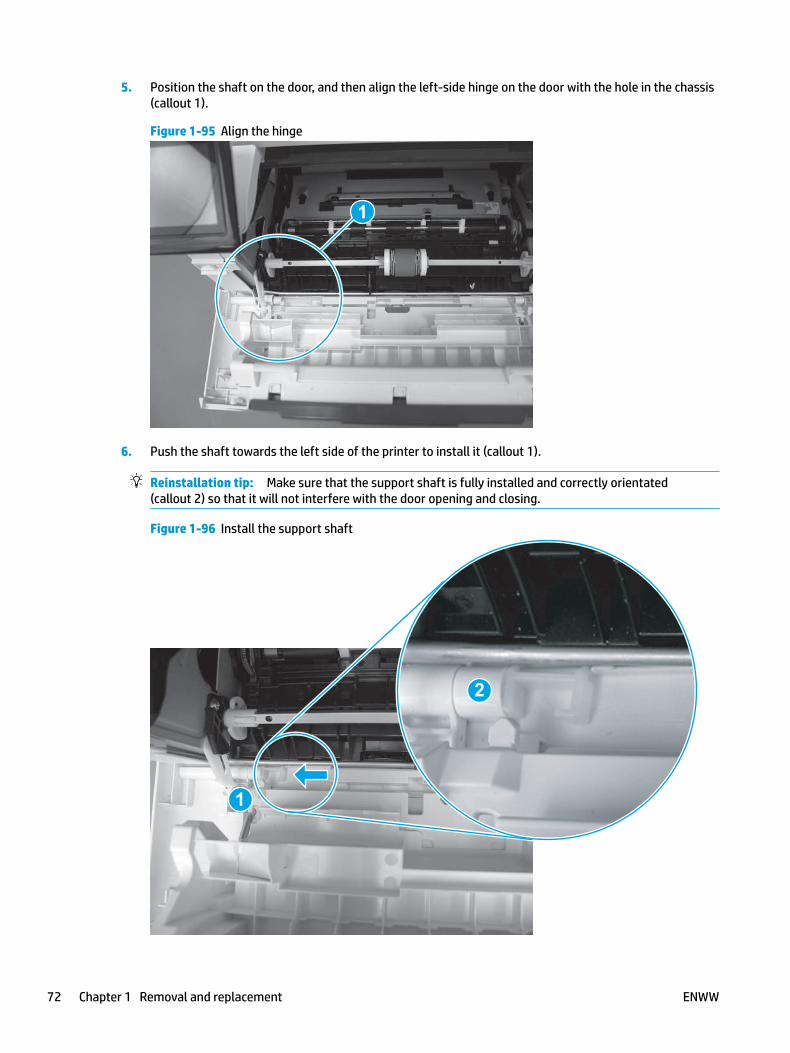
5. Position the shaft on the door, and then align the left-side hinge on the door with the hole in the chassis (callout 1).
Figure 1-95 Align the hinge
1
6. Push the shaft towards the left side of the printer to install it (callout 1).
Reinstallation tip: Make sure that the support shaft is fully installed and correctly orientated (callout 2) so that it will not interfere with the door opening and closing.
Figure 1-96 Install the support shaft
2
1
72 Chapter 1 Removal and replacement ENWW

Removal and replacement: Left cover
● Introduction
● Step 1: Remove the rear USB cover
● Step 2: Remove the rear network cover (M402d and M403d)
● Step 3: Remove Tray 2
● Step 4: Remove the cartridge door assembly
● Step 5: Remove the left cover
● Step 6: Unpack the replacement assembly
● Step 7: Install the left cover
● Step 8: Install the cartridge door assembly
● Step 9: Install Tray 2
● Step 10: Install the rear network cover (M402d and M403d)
● Step 11: Install the rear USB cover
Introduction
This document provides the procedures to remove and replace the left cover.
Before performing service
Turn the printer power off
◦ Disconnect the power cable.
WARNING! To avoid damage to the printer, turn the printer off, wait 30 seconds, and then remove the power cable before attempting to service the printer.
Use the table below to identify the correct part number for your printer. To order the part, go to www.hp.com/buy/parts.
Left cover part number
RL2-0673-000CN Left cover (M403/M402 models)
RL2-0674-000CN Left cover (M427/M426 models)
Required tools
● #2 Phillips screwdriver with a magnetic tip.
ENWW Removal and replacement procedures 73
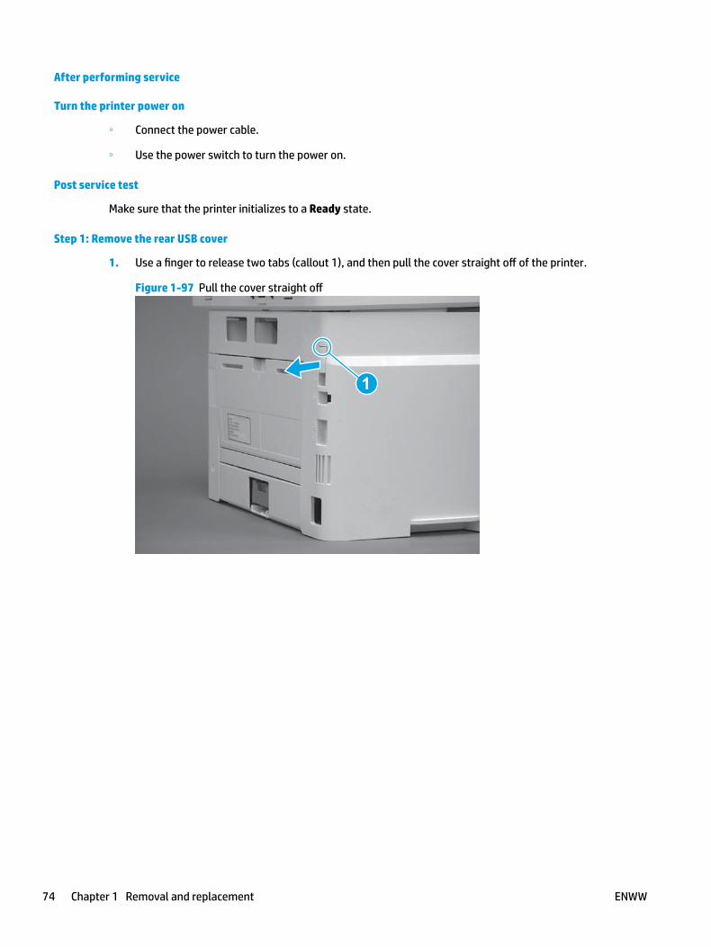
After performing service
Turn the printer power on
◦ Connect the power cable.
◦ Use the power switch to turn the power on.
Post service test
Make sure that the printer initializes to a Ready state.
Step 1: Remove the rear USB cover
1. Use a finger to release two tabs (callout 1), and then pull the cover straight off of the printer.
Figure 1-97 Pull the cover straight off
1
74 Chapter 1 Removal and replacement ENWW
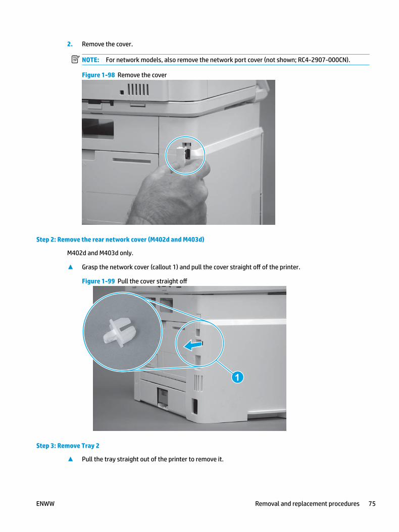
2. Remove the cover.
NOTE: For network models, also remove the network port cover (not shown; RC4-2907-000CN).
Figure 1-98 Remove the cover
Step 2: Remove the rear network cover (M402d and M403d)
M402d and M403d only.
▲ Grasp the network cover (callout 1) and pull the cover straight off of the printer.
Figure 1-99 Pull the cover straight off
1
Step 3: Remove Tray 2
▲ Pull the tray straight out of the printer to remove it.
ENWW Removal and replacement procedures 75

Figure 1-100 Remove the tray
Step 4: Remove the cartridge door assembly
NOTE: If the toner cartridge was not removed prior to servicing the printer, remove it now.
1. Release one tab (callout 1), and then slide shaft (callout 2) in the direction the arrow indicates and remove it.
TIP: It might be easier to release the support shaft by using a small flat-blade screwdriver.
Figure 1-101 Release the support shaft
12
76 Chapter 1 Removal and replacement ENWW
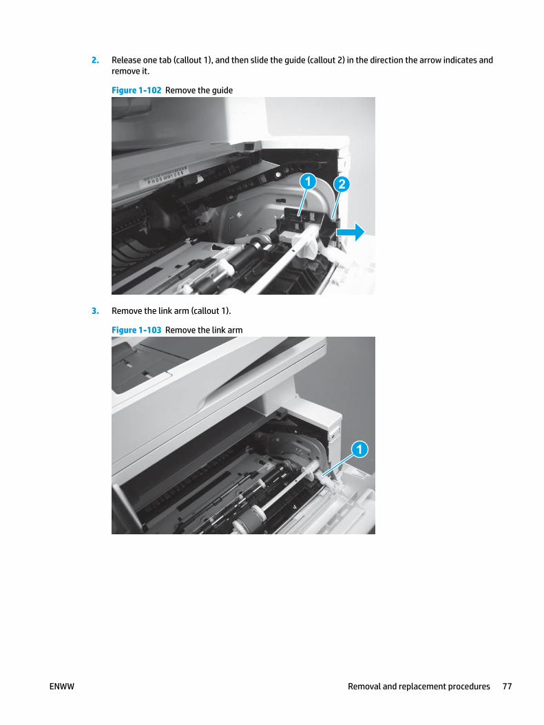
2. Release one tab (callout 1), and then slide the guide (callout 2) in the direction the arrow indicates and remove it.
Figure 1-102 Remove the guide
1 2
3. Remove the link arm (callout 1).
Figure 1-103 Remove the link arm
1
ENWW Removal and replacement procedures 77
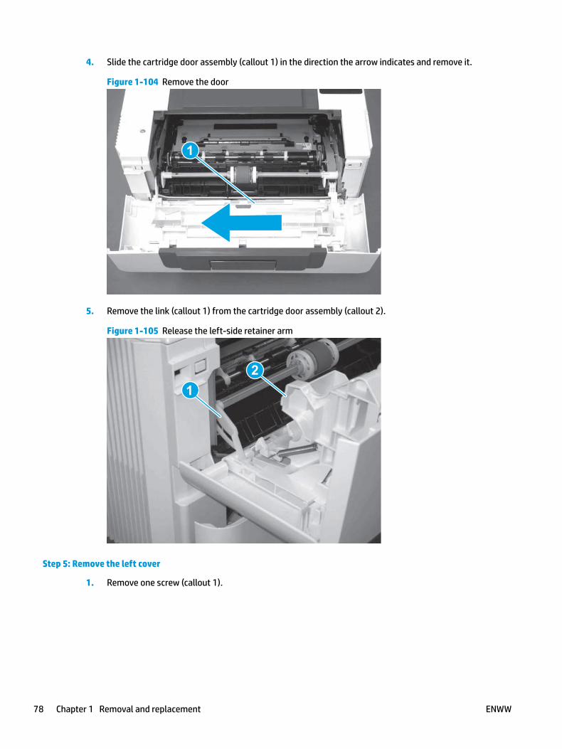
4. Slide the cartridge door assembly (callout 1) in the direction the arrow indicates and remove it.
Figure 1-104 Remove the door
1
5. Remove the link (callout 1) from the cartridge door assembly (callout 2).
Figure 1-105 Release the left-side retainer arm
21
Step 5: Remove the left cover
1. Remove one screw (callout 1).
78 Chapter 1 Removal and replacement ENWW

Figure 1-106 Remove one screw
1 1
2. Open the rear door, release two bosses (callout 1), and then release three tabs (callout 2).
Figure 1-107 Release two bosses and three tabs
1
1
2
2
3. At the front of the printer, do one of the following:
● M403/M402: Release two bosses (callout 1), and then remove the cover (callout 2).
● M427/M426: Release one tab (callout 3), two bosses (callout 4), and then remove the cover (callout 5).
CAUTION: Be careful when releasing the upper bosses on the M427/M426 cover. One portion of the cover (callout 6) is fragile and is easily broken.
ENWW Removal and replacement procedures 79

Figure 1-108 Remove the cover
2
1
3
54 6
Step 6: Unpack the replacement assembly
Unpack the replacement part from the packaging.
http://www8.hp.com/us/en/hp-information/environment/product-recycling.html
NOTE: HP recommends responsible disposal of the defective part.
Figure 1-109 Recycle and unpack
M402/M403
M402/M403
M427/M426M427/M426
Step 7: Install the left cover
1. At the front of the printer, do one of the following:
80 Chapter 1 Removal and replacement ENWW

● M403/M402: Position the cover on the printer ( callout 1), and then engage two bosses (callout 2).
● M427/M426: Position the cover on the printer (callout 3), engage one tab (callout 4), and then engage two bosses (callout 4).
Figure 1-110 Install the cover
1
2
4
35
2. Carefully rotate the rear of the cover onto the printer (callout 1), engage three tabs (callout 2), and then engage two bosses (callout 3).
Figure 1-111 Engage three tabs and two bosses
3
3 11
2
2
3. Install one screw (callout 1).
Figure 1-112 Install one screw
1 1
ENWW Removal and replacement procedures 81
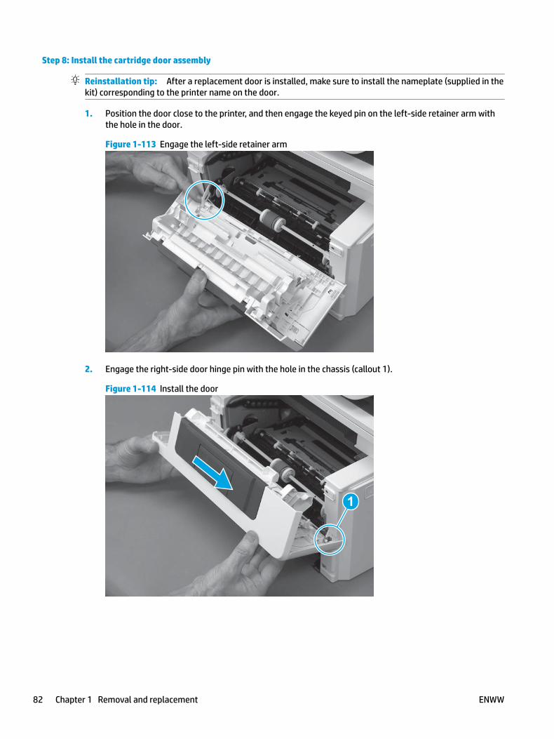
Step 8: Install the cartridge door assembly
Reinstallation tip: After a replacement door is installed, make sure to install the nameplate (supplied in the kit) corresponding to the printer name on the door.
1. Position the door close to the printer, and then engage the keyed pin on the left-side retainer arm with the hole in the door.
Figure 1-113 Engage the left-side retainer arm
2. Engage the right-side door hinge pin with the hole in the chassis (callout 1).
Figure 1-114 Install the door
1
82 Chapter 1 Removal and replacement ENWW

3. Install the link (callout 1).
IMPORTANT: Make sure that the link snaps into place on the arm (callout 2). The link actuates the fuser pressure-release mechanism.
Figure 1-115 Install the pressure-release link
1
2
4. Slide the guide into the printer (callout 1), and then make sure that the tab (callout 2) snaps into place to secure the guide to the chassis.
Figure 1-116 Install the guide
1
2
ENWW Removal and replacement procedures 83

5. Position the shaft on the door, and then align the left-side hinge on the door with the hole in the chassis (callout 1).
Figure 1-117 Align the hinge
1
6. Push the shaft towards the left side of the printer to install it (callout 1).
Reinstallation tip: Make sure that the support shaft is fully installed and correctly orientated (callout 2) so that it will not interfere with the door opening and closing.
Figure 1-118 Install the support shaft
2
1
84 Chapter 1 Removal and replacement ENWW

Step 9: Install Tray 2
▲ Slide the tray straight into the printer to install it.
Figure 1-119 Install the tray
Step 10: Install the rear network cover (M402d and M403d)
M402d and M403d only.
▲ Push the cover straight on to the printer to install it.
Figure 1-120 Install the cover
1
Step 11: Install the rear USB cover
1. Align the tabs on the cover with the slots in the left cover.
ENWW Removal and replacement procedures 85
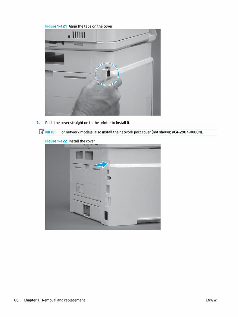
Figure 1-121 Align the tabs on the cover
2. Push the cover straight on to the printer to install it.
NOTE: For network models, also install the network port cover (not shown; RC4-2907-000CN).
Figure 1-122 Install the cover
86 Chapter 1 Removal and replacement ENWW

Removal and replacement: Right cover
● Introduction
● Step 1: Remove Tray 2
● Step 2: Remove the cartridge door assembly
● Step 3: Remove the right cover
● Step 4: Unpack the replacement assembly
● Step 5: Install the right cover
● Step 6: Install the cartridge door assembly
● Step 7: Install Tray 2
Introduction
This document provides the procedures to remove and replace the right cover.
Before performing service
Turn the printer power off
◦ Disconnect the power cable.
WARNING! To avoid damage to the printer, turn the printer off, wait 30 seconds, and then remove the power cable before attempting to service the printer.
Use the table below to identify the correct part number for your printer. To order the part, go to www.hp.com/buy/parts.
Right cover part number
RM2-5434-000CN Right cover
Required tools
● #2 Phillips screwdriver with a magnetic tip.
After performing service
Turn the printer power on
◦ Connect the power cable.
◦ Use the power switch to turn the power on.
Post service test
Make sure that the printer initializes to a Ready state.
Step 1: Remove Tray 2
▲ Pull the tray straight out of the printer to remove it.
ENWW Removal and replacement procedures 87

Figure 1-123 Remove the tray
Step 2: Remove the cartridge door assembly
NOTE: If the toner cartridge was not removed prior to servicing the printer, remove it now.
1. Release one tab (callout 1), and then slide shaft (callout 2) in the direction the arrow indicates and remove it.
TIP: It might be easier to release the support shaft by using a small flat-blade screwdriver.
Figure 1-124 Release the support shaft
12
88 Chapter 1 Removal and replacement ENWW

2. Release one tab (callout 1), and then slide the guide (callout 2) in the direction the arrow indicates and remove it.
Figure 1-125 Remove the guide
1 2
3. Remove the link arm (callout 1).
Figure 1-126 Remove the link arm
1
ENWW Removal and replacement procedures 89

4. Slide the cartridge door assembly (callout 1) in the direction the arrow indicates and remove it.
Figure 1-127 Remove the door
1
5. Remove the link (callout 1) from the cartridge door assembly (callout 2).
Figure 1-128 Release the left-side retainer arm
21
Step 3: Remove the right cover
1. Remove one screw (callout 1).
90 Chapter 1 Removal and replacement ENWW

Figure 1-129 Remove one screw
11
2. At the front of the printer, release two bosses (callout 1), and then release three tabs (callout 2).
Figure 1-130 Release two bosses and three tabs
1 1
2 2
3. Open the rear door, release two bosses (callout 1), and then remove the cover (callout 2).
Figure 1-131 Remove the cover
22
1 1
Step 4: Unpack the replacement assembly
Unpack the replacement part from the packaging.
http://www8.hp.com/us/en/hp-information/environment/product-recycling.html
ENWW Removal and replacement procedures 91

NOTE: HP recommends responsible disposal of the defective part.
Figure 1-132 Recycle and unpack
Step 5: Install the right cover
1. Position the cover (callout 1) on the printer, and then engage two bosses (callout 2).
Figure 1-133 Install the cover
11
2 2
92 Chapter 1 Removal and replacement ENWW

2. Rotate the front of the cover onto the printer (callout 1), engage three (callout 2) tabs, and then engage two bosses (callout 3).
Figure 1-134 Engage two bosses and one tab
1 13 3
2 2
3. Make sure that the power switch (callout 1) and cartridge door assembly button (callout 2) correctly function.
NOTE: Remove, and then reinstall the cover if the switch or button does not correctly function.
Figure 1-135 Check the power switch and cartridge door assembly button
1
1
22
4. Install one screw (callout 1).
Figure 1-136 Install one screw
11
ENWW Removal and replacement procedures 93

Step 6: Install the cartridge door assembly
Reinstallation tip: After a replacement door is installed, make sure to install the nameplate (supplied in the kit) corresponding to the printer name on the door.
1. Position the door close to the printer, and then engage the keyed pin on the left-side retainer arm with the hole in the door.
Figure 1-137 Engage the left-side retainer arm
2. Engage the right-side door hinge pin with the hole in the chassis (callout 1).
Figure 1-138 Install the door
1
94 Chapter 1 Removal and replacement ENWW

3. Install the link (callout 1).
IMPORTANT: Make sure that the link snaps into place on the arm (callout 2). The link actuates the fuser pressure-release mechanism.
Figure 1-139 Install the pressure-release link
1
2
4. Slide the guide into the printer (callout 1), and then make sure that the tab (callout 2) snaps into place to secure the guide to the chassis.
Figure 1-140 Install the guide
1
2
ENWW Removal and replacement procedures 95

5. Position the shaft on the door, and then align the left-side hinge on the door with the hole in the chassis (callout 1).
Figure 1-141 Align the hinge
1
6. Push the shaft towards the left side of the printer to install it (callout 1).
Reinstallation tip: Make sure that the support shaft is fully installed and correctly orientated (callout 2) so that it will not interfere with the door opening and closing.
Figure 1-142 Install the support shaft
2
1
96 Chapter 1 Removal and replacement ENWW

Step 7: Install Tray 2
▲ Slide the tray straight into the printer to install it.
Figure 1-143 Install the tray
ENWW Removal and replacement procedures 97
Removal and replacement: Rear door assembly
NOTE: Only duplex models have a duplex tray assembly installed.
● Introduction
● Step 1: Remove Tray 2
● Step 2: Remove the cartridge door assembly
● Step 3: Remove the left cover
● Step 4: Remove the right cover
● Step 5: Remove the rear door assembly
● Step 6: Unpack the replacement assembly
● Step 7: Install the rear door assembly
● Step 8: Install the right cover
● Step 9: Install the left cover
● Step 10: Install the cartridge door assembly
● Step 11: Install Tray 2
Introduction
This document provides the procedures to remove and replace the rear door assembly.
Before performing service
Turn the printer power off
◦ Disconnect the power cable.
WARNING! To avoid damage to the printer, turn the printer off, wait 30 seconds, and then remove the power cable before attempting to service the printer.
Use the table below to identify the correct part number for your printer. To order the part, go to www.hp.com/buy/parts.
Rear door assembly part number
RM2-5430-000CN
RM2-5405-000CN
Rear door assembly (simplex)
Rear door assembly (duplex)
Required tools
● #2 Phillips screwdriver with a magnetic tip.
98 Chapter 1 Removal and replacement ENWW

After performing service
Turn the printer power on
◦ Connect the power cable.
◦ Use the power switch to turn the power on.
Post service test
Make sure that the printer initializes to a Ready state.
Print a configuration page to make sure that the printer is functioning correctly.
Step 1: Remove Tray 2
▲ Pull the tray straight out of the printer to remove it.
Figure 1-144 Remove the tray
Step 2: Remove the cartridge door assembly
NOTE: If the toner cartridge was not removed prior to servicing the printer, remove it now.
1. Release one tab (callout 1), and then slide shaft (callout 2) in the direction the arrow indicates and remove it.
TIP: It might be easier to release the support shaft by using a small flat-blade screwdriver.
ENWW Removal and replacement procedures 99

Figure 1-145 Release the support shaft
12
2. Release one tab (callout 1), and then slide the guide (callout 2) in the direction the arrow indicates and remove it.
Figure 1-146 Remove the guide
1 2
100 Chapter 1 Removal and replacement ENWW

3. Remove the link arm (callout 1).
Figure 1-147 Remove the link arm
1
4. Slide the cartridge door assembly (callout 1) in the direction the arrow indicates and remove it.
Figure 1-148 Remove the door
1
ENWW Removal and replacement procedures 101

5. Remove the link (callout 1) from the cartridge door assembly (callout 2).
Figure 1-149 Release the left-side retainer arm
21
Step 3: Remove the left cover
1. Remove one screw (callout 1).
Figure 1-150 Remove one screw
1 1
102 Chapter 1 Removal and replacement ENWW

2. Open the rear door, release two bosses (callout 1), and then release three tabs (callout 2).
Figure 1-151 Release two bosses and three tabs
1
1
2
2
3. At the front of the printer, do one of the following:
● M403/M402: Release two bosses (callout 1), and then remove the cover (callout 2).
● M427/M426: Release one tab (callout 3), two bosses (callout 4), and then remove the cover (callout 5).
CAUTION: Be careful when releasing the upper bosses on the M427/M426 cover. One portion of the cover (callout 6) is fragile and is easily broken.
Figure 1-152 Remove the cover
2
1
3
54 6
Step 4: Remove the right cover
1. Remove one screw (callout 1).
ENWW Removal and replacement procedures 103

Figure 1-153 Remove one screw
11
2. At the front of the printer, release two bosses (callout 1), and then release three tabs (callout 2).
Figure 1-154 Release two bosses and three tabs
1 1
2 2
3. Open the rear door, release two bosses (callout 1), and then remove the cover (callout 2).
Figure 1-155 Remove the cover
22
1 1
Step 5: Remove the rear door assembly
1. Duplex models only: Inside the Tray 2 cavity, press the green jam access lever (callout 1), and then lower the duplex feed assembly (callout 2).
104 Chapter 1 Removal and replacement ENWW
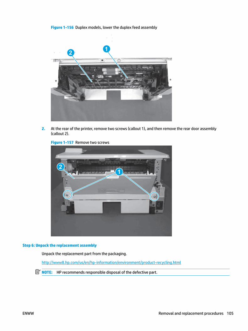
Figure 1-156 Duplex models, lower the duplex feed assembly
12
2. At the rear of the printer, remove two screws (callout 1), and then remove the rear door assembly (callout 2).
Figure 1-157 Remove two screws
12
Step 6: Unpack the replacement assembly
Unpack the replacement part from the packaging.
http://www8.hp.com/us/en/hp-information/environment/product-recycling.html
NOTE: HP recommends responsible disposal of the defective part.
ENWW Removal and replacement procedures 105

Figure 1-158 Recycle and unpack
Simplex model
Duplex model
Duplex model
Simplex model
Step 7: Install the rear door assembly
1. At the rear of the printer, position the assembly so that the two tabs (callout 1) are installed in the slots (callout 2) in the chassis.
NOTE: Duplex models only: Slide the duplex tray into the Tray 2 cavity.
Figure 1-159 Install the rear cover
1
106 Chapter 1 Removal and replacement ENWW
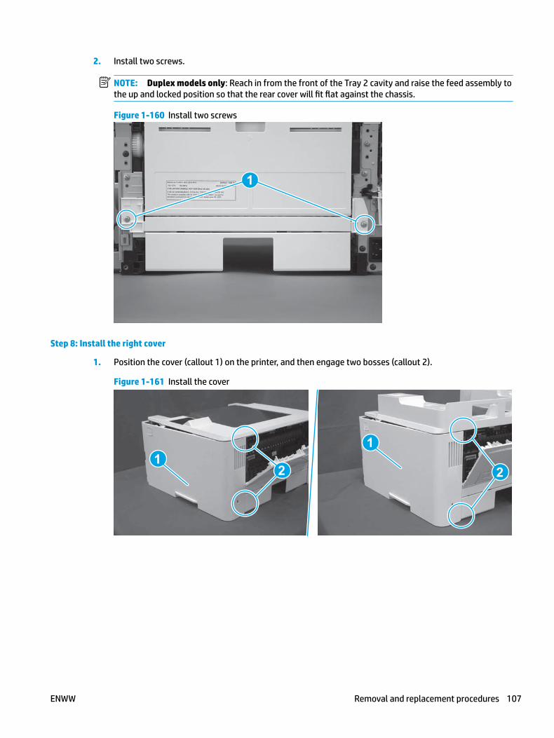
2. Install two screws.
NOTE: Duplex models only: Reach in from the front of the Tray 2 cavity and raise the feed assembly to the up and locked position so that the rear cover will fit flat against the chassis.
Figure 1-160 Install two screws
1
Step 8: Install the right cover
1. Position the cover (callout 1) on the printer, and then engage two bosses (callout 2).
Figure 1-161 Install the cover
11
2 2
ENWW Removal and replacement procedures 107
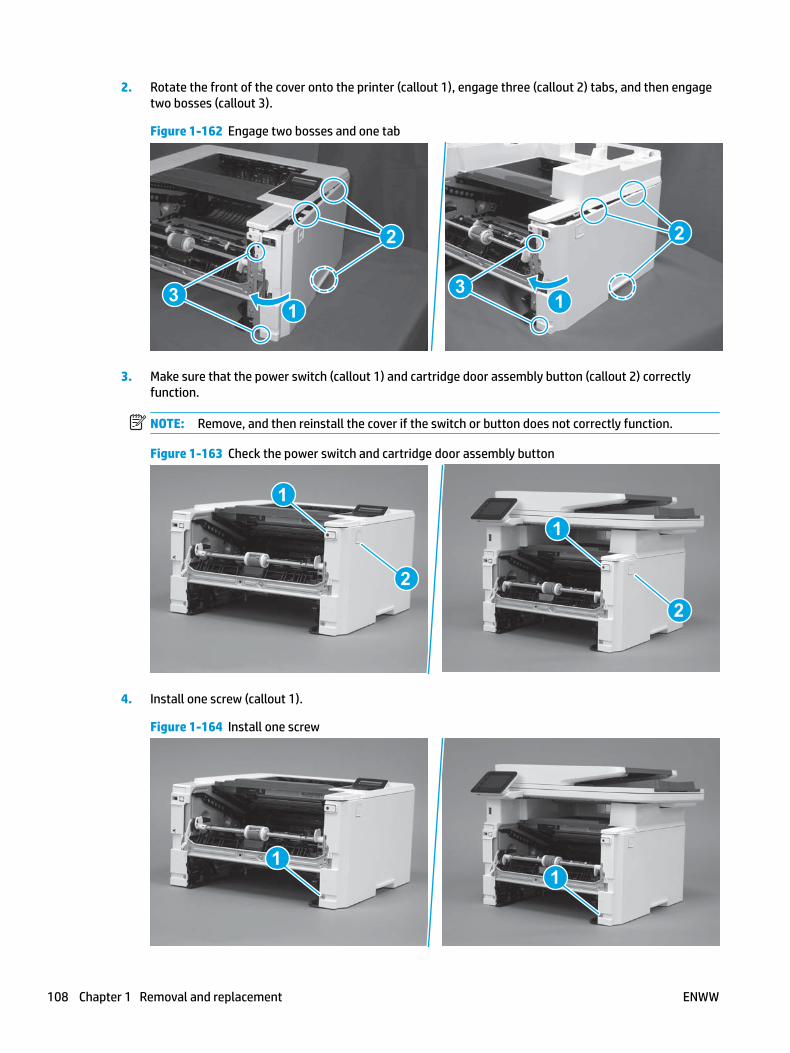
2. Rotate the front of the cover onto the printer (callout 1), engage three (callout 2) tabs, and then engage two bosses (callout 3).
Figure 1-162 Engage two bosses and one tab
1 13 3
2 2
3. Make sure that the power switch (callout 1) and cartridge door assembly button (callout 2) correctly function.
NOTE: Remove, and then reinstall the cover if the switch or button does not correctly function.
Figure 1-163 Check the power switch and cartridge door assembly button
1
1
22
4. Install one screw (callout 1).
Figure 1-164 Install one screw
11
108 Chapter 1 Removal and replacement ENWW
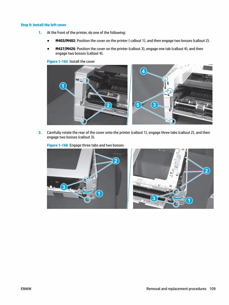
Step 9: Install the left cover
1. At the front of the printer, do one of the following:
● M403/M402: Position the cover on the printer ( callout 1), and then engage two bosses (callout 2).
● M427/M426: Position the cover on the printer (callout 3), engage one tab (callout 4), and then engage two bosses (callout 4).
Figure 1-165 Install the cover
1
2
4
35
2. Carefully rotate the rear of the cover onto the printer (callout 1), engage three tabs (callout 2), and then engage two bosses (callout 3).
Figure 1-166 Engage three tabs and two bosses
3
3 11
2
2
ENWW Removal and replacement procedures 109

3. Install one screw (callout 1).
Figure 1-167 Install one screw
1 1
Step 10: Install the cartridge door assembly
Reinstallation tip: After a replacement door is installed, make sure to install the nameplate (supplied in the kit) corresponding to the printer name on the door.
1. Position the door close to the printer, and then engage the keyed pin on the left-side retainer arm with the hole in the door.
Figure 1-168 Engage the left-side retainer arm
110 Chapter 1 Removal and replacement ENWW

2. Engage the right-side door hinge pin with the hole in the chassis (callout 1).
Figure 1-169 Install the door
1
3. Install the link (callout 1).
IMPORTANT: Make sure that the link snaps into place on the arm (callout 2). The link actuates the fuser pressure-release mechanism.
Figure 1-170 Install the pressure-release link
1
2
ENWW Removal and replacement procedures 111

4. Slide the guide into the printer (callout 1), and then make sure that the tab (callout 2) snaps into place to secure the guide to the chassis.
Figure 1-171 Install the guide
1
2
5. Position the shaft on the door, and then align the left-side hinge on the door with the hole in the chassis (callout 1).
Figure 1-172 Align the hinge
1
112 Chapter 1 Removal and replacement ENWW

6. Push the shaft towards the left side of the printer to install it (callout 1).
Reinstallation tip: Make sure that the support shaft is fully installed and correctly orientated (callout 2) so that it will not interfere with the door opening and closing.
Figure 1-173 Install the support shaft
2
1
Step 11: Install Tray 2
▲ Slide the tray straight into the printer to install it.
Figure 1-174 Install the tray
ENWW Removal and replacement procedures 113

Removal and replacement: Cassette rear cover
● Introduction
● Step 1: Remove Tray 2
● Step 2: Remove the cartridge door assembly
● Step 3: Remove the left cover
● Step 4: Remove the right cover
● Step 5: Remove the rear door assembly
● Step 6: Remove the cassette rear cover
● Step 7: Unpack the replacement assembly
● Step 8: Install the cassette rear door assembly
● Step 9: Install the rear door assembly
● Step 10: Install the right cover
● Step 11: Install the left cover
● Step 12: Install the cartridge door assembly
● Step 13: Install Tray 2
Introduction
This document provides the procedures to remove and replace the cassette rear cover.
Before performing service
Turn the printer power off
◦ Disconnect the power cable.
WARNING! To avoid damage to the printer, turn the printer off, wait 30 seconds, and then remove the power cable before attempting to service the printer.
Use the table below to identify the correct part number for your printer. To order the part, go to www.hp.com/buy/parts.
Cassette rear cover part number
RC4-3082-000CN Cassette rear cover
Required tools
● #2 Phillips screwdriver with a magnetic tip.
114 Chapter 1 Removal and replacement ENWW
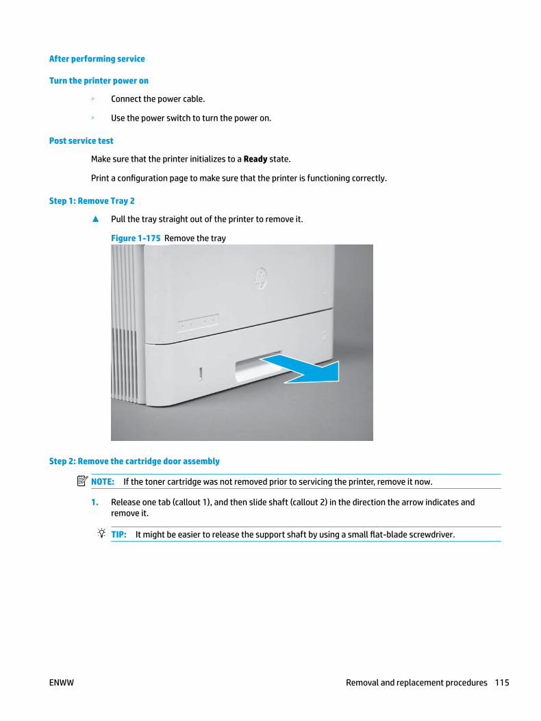
After performing service
Turn the printer power on
◦ Connect the power cable.
◦ Use the power switch to turn the power on.
Post service test
Make sure that the printer initializes to a Ready state.
Print a configuration page to make sure that the printer is functioning correctly.
Step 1: Remove Tray 2
▲ Pull the tray straight out of the printer to remove it.
Figure 1-175 Remove the tray
Step 2: Remove the cartridge door assembly
NOTE: If the toner cartridge was not removed prior to servicing the printer, remove it now.
1. Release one tab (callout 1), and then slide shaft (callout 2) in the direction the arrow indicates and remove it.
TIP: It might be easier to release the support shaft by using a small flat-blade screwdriver.
ENWW Removal and replacement procedures 115

Figure 1-176 Release the support shaft
12
2. Release one tab (callout 1), and then slide the guide (callout 2) in the direction the arrow indicates and remove it.
Figure 1-177 Remove the guide
1 2
116 Chapter 1 Removal and replacement ENWW

3. Remove the link arm (callout 1).
Figure 1-178 Remove the link arm
1
4. Slide the cartridge door assembly (callout 1) in the direction the arrow indicates and remove it.
Figure 1-179 Remove the door
1
ENWW Removal and replacement procedures 117

5. Remove the link (callout 1) from the cartridge door assembly (callout 2).
Figure 1-180 Release the left-side retainer arm
21
Step 3: Remove the left cover
1. Remove one screw (callout 1).
Figure 1-181 Remove one screw
1 1
118 Chapter 1 Removal and replacement ENWW

2. Open the rear door, release two bosses (callout 1), and then release three tabs (callout 2).
Figure 1-182 Release two bosses and three tabs
1
1
2
2
3. At the front of the printer, do one of the following:
● M403/M402: Release two bosses (callout 1), and then remove the cover (callout 2).
● M427/M426: Release one tab (callout 3), two bosses (callout 4), and then remove the cover (callout 5).
CAUTION: Be careful when releasing the upper bosses on the M427/M426 cover. One portion of the cover (callout 6) is fragile and is easily broken.
Figure 1-183 Remove the cover
2
1
3
54 6
Step 4: Remove the right cover
1. Remove one screw (callout 1).
ENWW Removal and replacement procedures 119

Figure 1-184 Remove one screw
11
2. At the front of the printer, release two bosses (callout 1), and then release three tabs (callout 2).
Figure 1-185 Release two bosses and three tabs
1 1
2 2
3. Open the rear door, release two bosses (callout 1), and then remove the cover (callout 2).
Figure 1-186 Remove the cover
22
1 1
Step 5: Remove the rear door assembly
1. Duplex models only: Inside the Tray 2 cavity, press the green jam access lever (callout 1), and then lower the duplex feed assembly (callout 2).
120 Chapter 1 Removal and replacement ENWW

Figure 1-187 Duplex models, lower the duplex feed assembly
12
2. At the rear of the printer, remove two screws (callout 1), and then remove the rear door assembly (callout 2).
Figure 1-188 Remove two screws
12
Step 6: Remove the cassette rear cover
The figures in this procedure show a duplex rear cover assembly. However, the procedure is valid for a simples rear cover.
1. Locate the left-side hinge retainer (callout 1).
ENWW Removal and replacement procedures 121

Figure 1-189 Locate the hinge retainer
2. Carefully flex the cover to release the retainer (callout 1), and the left-side hinge pin (callout 2).
Figure 1-190 Release the retainer and the hinge pin
1
2
122 Chapter 1 Removal and replacement ENWW

3. Remove the cover.
Figure 1-191 Remove the cover
Step 7: Unpack the replacement assembly
Unpack the replacement part from the packaging.
http://www8.hp.com/us/en/hp-information/environment/product-recycling.html
NOTE: HP recommends responsible disposal of the defective part.
Figure 1-192 Recycle and unpack
ENWW Removal and replacement procedures 123

Step 8: Install the cassette rear door assembly
The figures in this procedure show a duplex rear cover assembly. However, the procedure is valid for a simples rear cover.
1. Position the cover on the rear door with the right-side hinge holder on the cover engaged with the right-side hinge pin on the door.
Figure 1-193 Engage the right-side hinge and pin
2. Carefully flex the cover to engage the left-side hinge pin and holder (callout 1), and the retainer (callout 2).
NOTE: When the cover is correctly installed, it moves freely on the hinge pins.
Figure 1-194 Engage the left-side hinge and retainer
1
2
124 Chapter 1 Removal and replacement ENWW

Step 9: Install the rear door assembly
1. At the rear of the printer, position the assembly so that the two tabs (callout 1) are installed in the slots (callout 2) in the chassis.
NOTE: Duplex models only: Slide the duplex tray into the Tray 2 cavity.
Figure 1-195 Install the rear cover
1
2. Install two screws.
NOTE: Duplex models only: Reach in from the front of the Tray 2 cavity and raise the feed assembly to the up and locked position so that the rear cover will fit flat against the chassis.
Figure 1-196 Install two screws
1
Step 10: Install the right cover
1. Position the cover (callout 1) on the printer, and then engage two bosses (callout 2).
ENWW Removal and replacement procedures 125

Figure 1-197 Install the cover
11
2 2
2. Rotate the front of the cover onto the printer (callout 1), engage three (callout 2) tabs, and then engage two bosses (callout 3).
Figure 1-198 Engage two bosses and one tab
1 13 3
2 2
3. Make sure that the power switch (callout 1) and cartridge door assembly button (callout 2) correctly function.
NOTE: Remove, and then reinstall the cover if the switch or button does not correctly function.
Figure 1-199 Check the power switch and cartridge door assembly button
1
1
22
126 Chapter 1 Removal and replacement ENWW

4. Install one screw (callout 1).
Figure 1-200 Install one screw
11
Step 11: Install the left cover
1. At the front of the printer, do one of the following:
● M403/M402: Position the cover on the printer ( callout 1), and then engage two bosses (callout 2).
● M427/M426: Position the cover on the printer (callout 3), engage one tab (callout 4), and then engage two bosses (callout 4).
Figure 1-201 Install the cover
1
2
4
35
ENWW Removal and replacement procedures 127

2. Carefully rotate the rear of the cover onto the printer (callout 1), engage three tabs (callout 2), and then engage two bosses (callout 3).
Figure 1-202 Engage three tabs and two bosses
3
3 11
2
2
3. Install one screw (callout 1).
Figure 1-203 Install one screw
1 1
Step 12: Install the cartridge door assembly
Reinstallation tip: After a replacement door is installed, make sure to install the nameplate (supplied in the kit) corresponding to the printer name on the door.
1. Position the door close to the printer, and then engage the keyed pin on the left-side retainer arm with the hole in the door.
128 Chapter 1 Removal and replacement ENWW

Figure 1-204 Engage the left-side retainer arm
2. Engage the right-side door hinge pin with the hole in the chassis (callout 1).
Figure 1-205 Install the door
1
ENWW Removal and replacement procedures 129

3. Install the link (callout 1).
IMPORTANT: Make sure that the link snaps into place on the arm (callout 2). The link actuates the fuser pressure-release mechanism.
Figure 1-206 Install the pressure-release link
1
2
4. Slide the guide into the printer (callout 1), and then make sure that the tab (callout 2) snaps into place to secure the guide to the chassis.
Figure 1-207 Install the guide
1
2
130 Chapter 1 Removal and replacement ENWW

5. Position the shaft on the door, and then align the left-side hinge on the door with the hole in the chassis (callout 1).
Figure 1-208 Align the hinge
1
6. Push the shaft towards the left side of the printer to install it (callout 1).
Reinstallation tip: Make sure that the support shaft is fully installed and correctly orientated (callout 2) so that it will not interfere with the door opening and closing.
Figure 1-209 Install the support shaft
2
1
ENWW Removal and replacement procedures 131

Step 13: Install Tray 2
▲ Slide the tray straight into the printer to install it.
Figure 1-210 Install the tray
132 Chapter 1 Removal and replacement ENWW

Removal and replacement: Top cover (M427/M426)
● Introduction
● Step 1: Remove Tray 2
● Step 2: Remove the cartridge door assembly
● Step 3: Remove the left cover
● Step 4: Remove the right cover
● Step 5: Remove the integrated scanner assembly (M427/M426)
● Step 6: Remove the control panel (M427/M426)
● Step 7: Remove the top cover (M427/M426)
● Step 8: Unpack the replacement assembly
● Step 9: Remove the cable guide (M427/M426)
● Step 10: Install the cable guide (M427/M426)
● Step 11: Install the top cover (M427/M426)
● Step 12: Install the control panel (M427/M426)
● Step 13: Install the integrated scanner assembly (M427/M246)
● Step 14: Install the right cover
● Step 15: Install the left cover
● Step 16: Install the cartridge door assembly
● Step 17: Install Tray 2
Introduction
This document provides the procedures to remove and replace the top cover (M427/M426).
Before performing service
Turn the printer power off
◦ Disconnect the power cable.
WARNING! To avoid damage to the printer, turn the printer off, wait 30 seconds, and then remove the power cable before attempting to service the printer.
Use the table below to identify the correct part number for your printer. To order the part, go to www.hp.com/buy/parts.
Top cover (M427/M426) part number
RC4-3207-000CN Top cover (M427/M426)
ENWW Removal and replacement procedures 133

Required tools
● #2 Phillips screwdriver with a magnetic tip.
● Small flat-blade screw driver
After performing service
Turn the printer power on
◦ Connect the power cable.
◦ Use the power switch to turn the power on.
Post service test
Make sure that the printer initializes to a Ready state.
Print a configuration page to make sure that the printer is functioning correctly.
Step 1: Remove Tray 2
▲ Pull the tray straight out of the printer to remove it.
Figure 1-211 Remove the tray
Step 2: Remove the cartridge door assembly
NOTE: If the toner cartridge was not removed prior to servicing the printer, remove it now.
1. Release one tab (callout 1), and then slide shaft (callout 2) in the direction the arrow indicates and remove it.
TIP: It might be easier to release the support shaft by using a small flat-blade screwdriver.
134 Chapter 1 Removal and replacement ENWW

Figure 1-212 Release the support shaft
12
2. Release one tab (callout 1), and then slide the guide (callout 2) in the direction the arrow indicates and remove it.
Figure 1-213 Remove the guide
1 2
ENWW Removal and replacement procedures 135

3. Remove the link arm (callout 1).
Figure 1-214 Remove the link arm
1
4. Slide the cartridge door assembly (callout 1) in the direction the arrow indicates and remove it.
Figure 1-215 Remove the door
1
136 Chapter 1 Removal and replacement ENWW

5. Remove the link (callout 1) from the cartridge door assembly (callout 2).
Figure 1-216 Release the left-side retainer arm
21
Step 3: Remove the left cover
1. Remove one screw (callout 1).
Figure 1-217 Remove one screw
1 1
ENWW Removal and replacement procedures 137

2. Open the rear door, release two bosses (callout 1), and then release three tabs (callout 2).
Figure 1-218 Release two bosses and three tabs
1
1
2
2
3. At the front of the printer, do one of the following:
● M403/M402: Release two bosses (callout 1), and then remove the cover (callout 2).
● M427/M426: Release one tab (callout 3), two bosses (callout 4), and then remove the cover (callout 5).
CAUTION: Be careful when releasing the upper bosses on the M427/M426 cover. One portion of the cover (callout 6) is fragile and is easily broken.
Figure 1-219 Remove the cover
2
1
3
54 6
Step 4: Remove the right cover
1. Remove one screw (callout 1).
138 Chapter 1 Removal and replacement ENWW

Figure 1-220 Remove one screw
11
2. At the front of the printer, release two bosses (callout 1), and then release three tabs (callout 2).
Figure 1-221 Release two bosses and three tabs
1 1
2 2
3. Open the rear door, release two bosses (callout 1), and then remove the cover (callout 2).
Figure 1-222 Remove the cover
22
1 1
ENWW Removal and replacement procedures 139

Step 5: Remove the integrated scanner assembly (M427/M426)
NOTE: M427/M426 models only. The integrated scanner assembly (ISA) includes the sub-scanner assembly (SSA) and the automatic document feeder (ADF).
1. Raise the ISA.
Figure 1-223 Raise the ISA
2. Release the ISA flat-flexible cable (FFC) cover (callout 1), and then remove it (callout 2).
Figure 1-224 Remove the ISA FFC cover
12
140 Chapter 1 Removal and replacement ENWW

3. Disconnect three FFCs (callout 1), and then remove the ferrite (callout 2) from the holder.
CAUTION: The ferrite is not captive on the FFC. Do not lose the ferrite while handling the ISA.
Figure 1-225 Disconnect three FFCs
2
1
4. Remove one screw (callout 1).
Figure 1-226 Remove one screw
1
ENWW Removal and replacement procedures 141

5. Pass the ground wire through the opening in the top cover.
Figure 1-227 Pass the wire through the opening
6. Release one tab (callout 1), and then rotate the ISA slider pin (callout 2) towards the front of the printer to release it.
Figure 1-228 Release one tab and rotate the slider pin
1
2
142 Chapter 1 Removal and replacement ENWW

7. Remove the slider pin.
Figure 1-229 Remove the slider pin
8. Rotate the ISA towards the rear of the printer until it stops.
Figure 1-230 Rotate the ISA towards the rear of the printer
ENWW Removal and replacement procedures 143
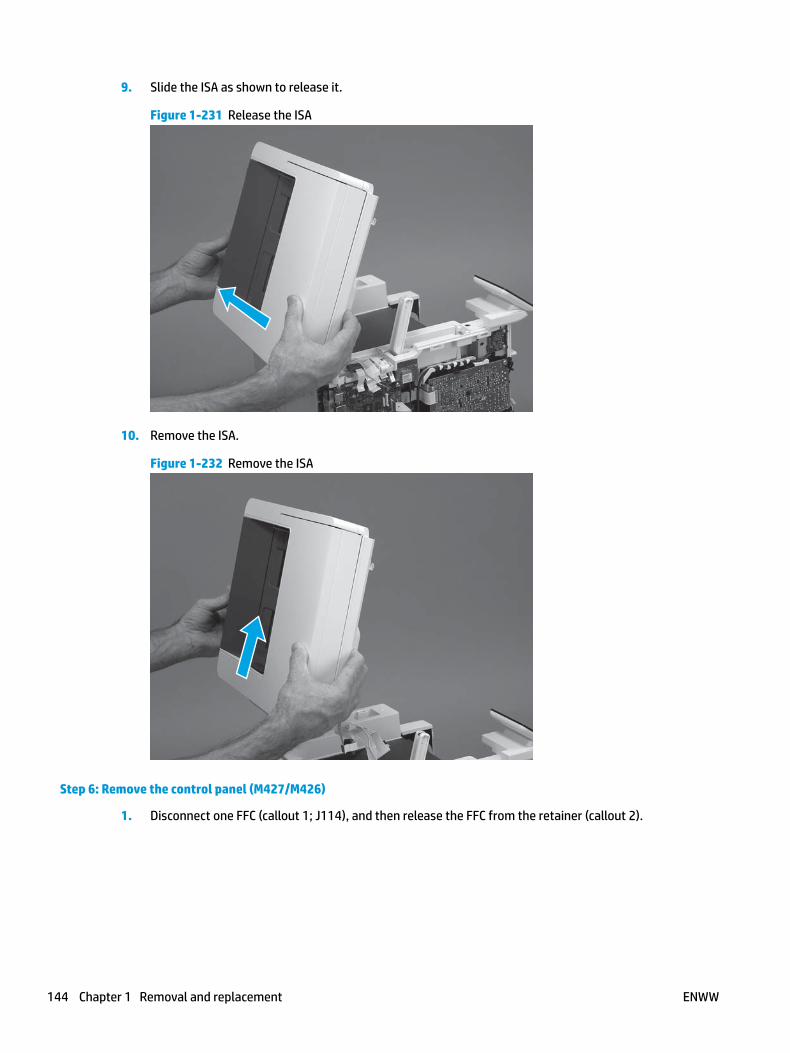
9. Slide the ISA as shown to release it.
Figure 1-231 Release the ISA
10. Remove the ISA.
Figure 1-232 Remove the ISA
Step 6: Remove the control panel (M427/M426)
1. Disconnect one FFC (callout 1; J114), and then release the FFC from the retainer (callout 2).
144 Chapter 1 Removal and replacement ENWW

Figure 1-233 Disconnect one connector
1
2
2. Remove one screw (callout 1).
Figure 1-234 Remove one screw
1
ENWW Removal and replacement procedures 145

3. Use a small flat-blade screwdriver to release two tabs (callout 1) on the control-panel cable cover.
Figure 1-235 Release two tabs
1
4. Remove the control-panel cable cover.
Figure 1-236 Remove the cover
146 Chapter 1 Removal and replacement ENWW

5. Remove one grounding screw (callout 1), and then move the ground cable (callout 2) out of the way.
Figure 1-237 Remove one screw
2
1
6. Move the FFC out of the way, and then remove two screws (callout 1).
Figure 1-238 Remove two screws
1
ENWW Removal and replacement procedures 147
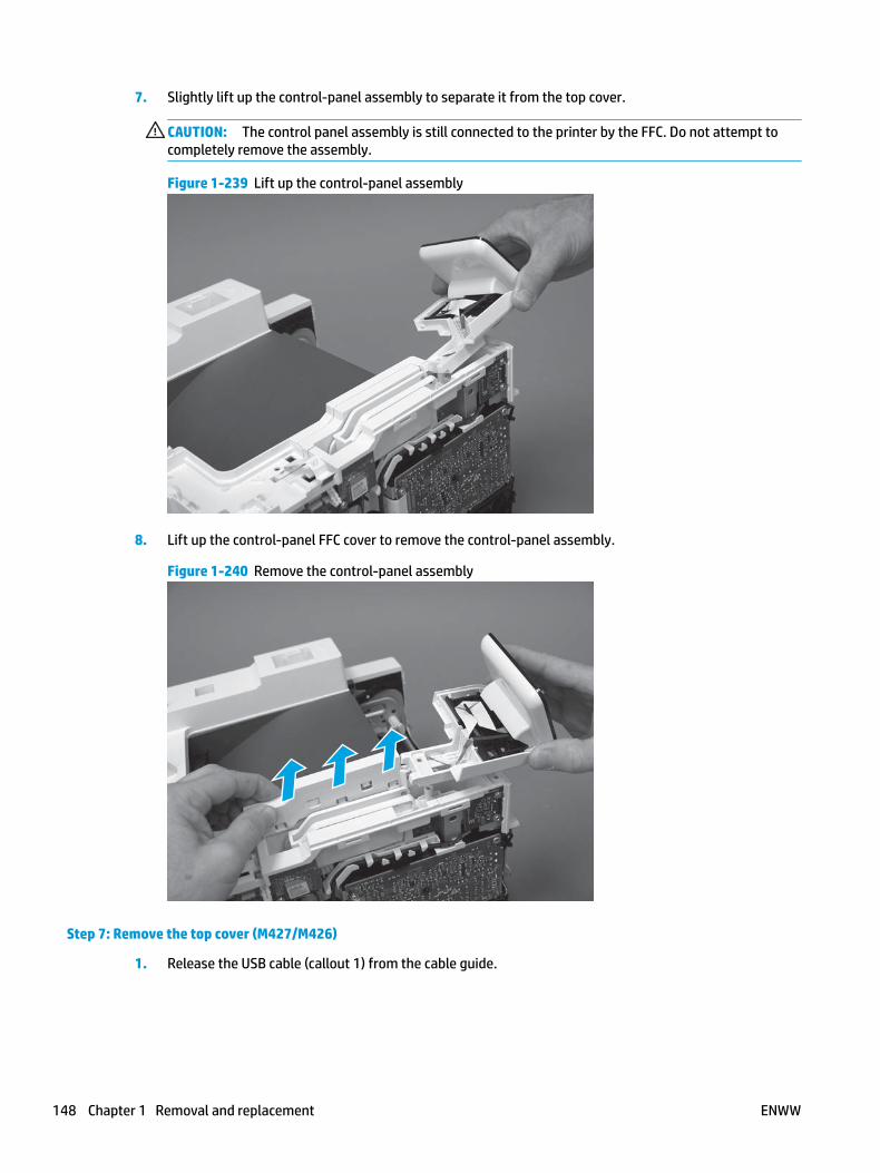
7. Slightly lift up the control-panel assembly to separate it from the top cover.
CAUTION: The control panel assembly is still connected to the printer by the FFC. Do not attempt to completely remove the assembly.
Figure 1-239 Lift up the control-panel assembly
8. Lift up the control-panel FFC cover to remove the control-panel assembly.
Figure 1-240 Remove the control-panel assembly
Step 7: Remove the top cover (M427/M426)
1. Release the USB cable (callout 1) from the cable guide.
148 Chapter 1 Removal and replacement ENWW
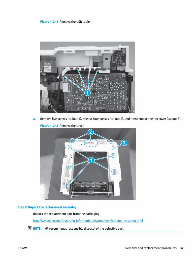
Figure 1-241 Remove the USB cable
1
2. Remove five screws (callout 1), release four bosses (callout 2), and then remove the top cover (callout 3).
Figure 1-242 Remove the cover
3
2
1
Step 8: Unpack the replacement assembly
Unpack the replacement part from the packaging.
http://www8.hp.com/us/en/hp-information/environment/product-recycling.html
NOTE: HP recommends responsible disposal of the defective part.
ENWW Removal and replacement procedures 149

Figure 1-243 Recycle and unpack
Step 9: Remove the cable guide (M427/M426)
1. Turn the top cover over, and then release one tab (callout 1).
Figure 1-244 Release one tab
1
150 Chapter 1 Removal and replacement ENWW

2. Slide the guide as sown to release it.
Figure 1-245 Release the guide
3. Remove the guide.
Figure 1-246 Remove the guide
Step 10: Install the cable guide (M427/M426)
1. Position the guide on the printer with the two tabs (callout 1) in the slots (callout 2) in the chassis.
ENWW Removal and replacement procedures 151

Figure 1-247 Position the guide on the printer
1
2
2. Slide the guide as shown (callout 1) to install it.
Figure 1-248 Install the guide
152 Chapter 1 Removal and replacement ENWW

3. Make sure that the tab (callout 1) snaps into place.
Figure 1-249 Check the guide
1
Step 11: Install the top cover (M427/M426)
1. Position the rear edge of the top cover on the printer.
Figure 1-250 Install the cover
ENWW Removal and replacement procedures 153
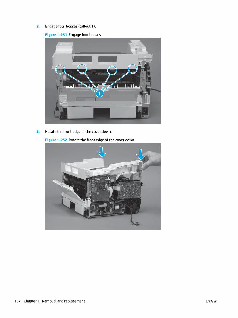
2. Engage four bosses (callout 1).
Figure 1-251 Engage four bosses
1
3. Rotate the front edge of the cover down.
Figure 1-252 Rotate the front edge of the cover down
154 Chapter 1 Removal and replacement ENWW

4. Install the USB cable (callout 1) in the guide.
Figure 1-253 Install the USB PCA
1
5. Install five screws (callout 1).
Figure 1-254 Install five screws
1
Step 12: Install the control panel (M427/M426)
1. Slide the control-panel FFC cover into the slot in the top cover (next to the document feeder support arm) to install it.
ENWW Removal and replacement procedures 155

Figure 1-255 Install the control-panel FFC cover
2. Install the control-panel assembly on the top cover.
Figure 1-256 Install the control-panel assembly
156 Chapter 1 Removal and replacement ENWW

3. Move the FFC out of the way, and then install two screws (callout 1).
Figure 1-257 Install two screws
1
4. Install one grounding screw (callout 1), and then make sure that the ground cable (callout 2) is properly routed.
Figure 1-258 Remove one screw
2
1
ENWW Removal and replacement procedures 157

5. Install the control-panel cable cover.
Figure 1-259 Install the cover
6. Make sure that the two tabs (callout 1) on the cover snap into place.
Figure 1-260 Engage two tabs
1
158 Chapter 1 Removal and replacement ENWW

7. Install one screw (callout 1).
Figure 1-261 Install one screw
1
8. Install the FFC in the retainer (callout 1), and then connect one FFC (callout 1; J114).
Figure 1-262 Connect one connector
1
2
Step 13: Install the integrated scanner assembly (M427/M246)
NOTE: M427/M426 models only. The integrated scanner assembly (ISA) includes the sub-scanner assembly (SSA) and the automatic document feeder (ADF).
1. Position the ISA on the printer.
ENWW Removal and replacement procedures 159

Figure 1-263 Position the ISA on the printer
2. Engage the hinge pins on the ISA with the holders in the top cover (callouts 1/2), and the slide the ISA as shown to engage them
Figure 1-264 Engage the hinge pins with the holders
1
2
160 Chapter 1 Removal and replacement ENWW

3. Rotate the ISA towards the front of the printer until it rests on the ISA lift assembly (callout 1).
Figure 1-265 Rotate the ISA towards the front of the printer
1
4. Pass the ground wire through the opening in the top cover.
Figure 1-266 Pass the wire through the opening
ENWW Removal and replacement procedures 161

5. Install one screw (callout 1).
Figure 1-267 Install one screw
1
6. Install the ISA lift assembly slider pin.
Reinstallation tip: Align the keyed portion of the locking pin with the slot and hole in the support arm.
Figure 1-268 Install the slider pin
162 Chapter 1 Removal and replacement ENWW
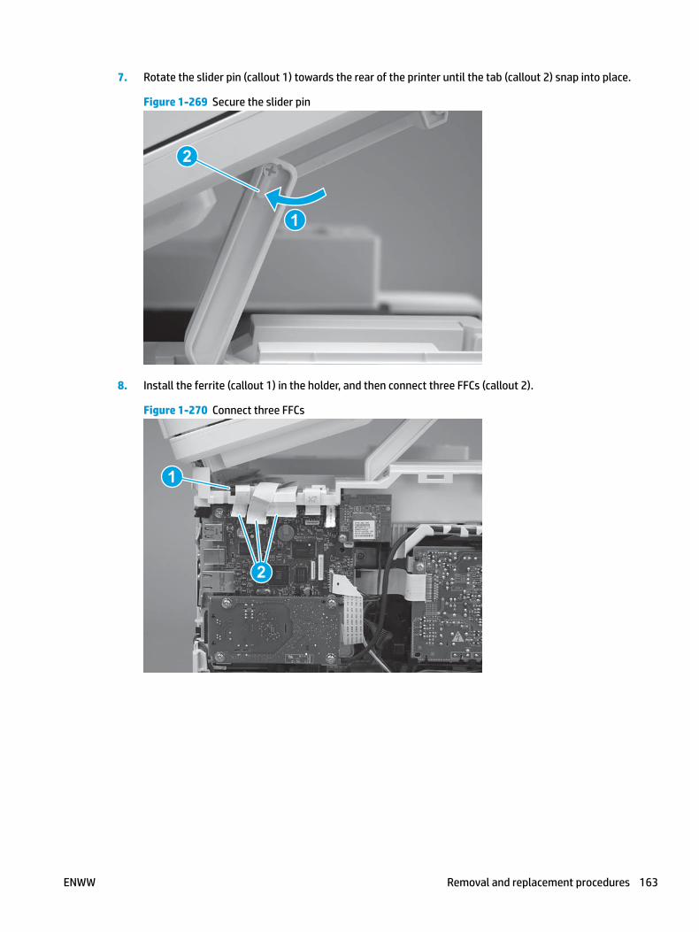
7. Rotate the slider pin (callout 1) towards the rear of the printer until the tab (callout 2) snap into place.
Figure 1-269 Secure the slider pin
2
1
8. Install the ferrite (callout 1) in the holder, and then connect three FFCs (callout 2).
Figure 1-270 Connect three FFCs
1
2
ENWW Removal and replacement procedures 163

9. Position the rear edge of the ISA flat-flexible cable (FFC) cover on the printer (callout 1) , and then rotate it down (callout 2) until it snaps into place.
Figure 1-271 Install the ISA FFC cover
1
2
10. Lower the ISA.
Figure 1-272 Lower the ISA
Step 14: Install the right cover
1. Position the cover (callout 1) on the printer, and then engage two bosses (callout 2).
164 Chapter 1 Removal and replacement ENWW

Figure 1-273 Install the cover
11
2 2
2. Rotate the front of the cover onto the printer (callout 1), engage three (callout 2) tabs, and then engage two bosses (callout 3).
Figure 1-274 Engage two bosses and one tab
1 13 3
2 2
3. Make sure that the power switch (callout 1) and cartridge door assembly button (callout 2) correctly function.
NOTE: Remove, and then reinstall the cover if the switch or button does not correctly function.
Figure 1-275 Check the power switch and cartridge door assembly button
1
1
22
ENWW Removal and replacement procedures 165

4. Install one screw (callout 1).
Figure 1-276 Install one screw
11
Step 15: Install the left cover
1. At the front of the printer, do one of the following:
● M403/M402: Position the cover on the printer ( callout 1), and then engage two bosses (callout 2).
● M427/M426: Position the cover on the printer (callout 3), engage one tab (callout 4), and then engage two bosses (callout 4).
Figure 1-277 Install the cover
1
2
4
35
166 Chapter 1 Removal and replacement ENWW
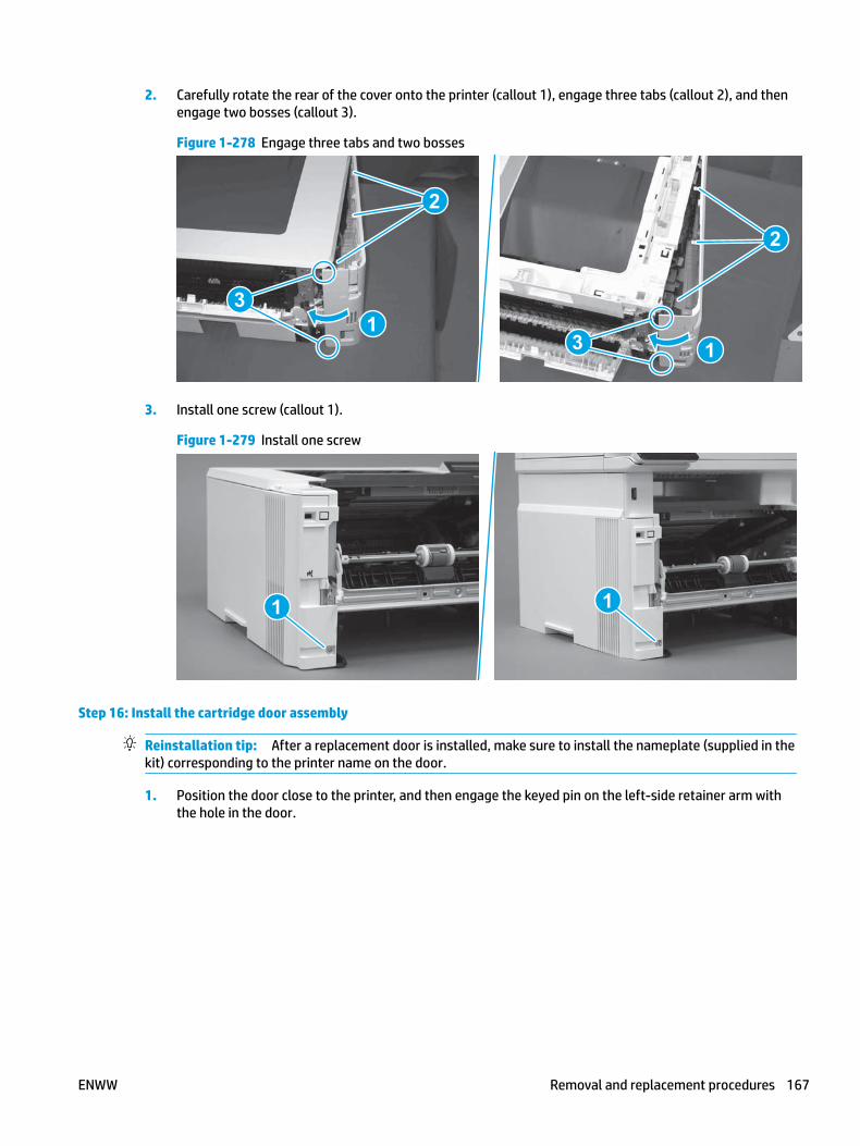
2. Carefully rotate the rear of the cover onto the printer (callout 1), engage three tabs (callout 2), and then engage two bosses (callout 3).
Figure 1-278 Engage three tabs and two bosses
3
3 11
2
2
3. Install one screw (callout 1).
Figure 1-279 Install one screw
1 1
Step 16: Install the cartridge door assembly
Reinstallation tip: After a replacement door is installed, make sure to install the nameplate (supplied in the kit) corresponding to the printer name on the door.
1. Position the door close to the printer, and then engage the keyed pin on the left-side retainer arm with the hole in the door.
ENWW Removal and replacement procedures 167

Figure 1-280 Engage the left-side retainer arm
2. Engage the right-side door hinge pin with the hole in the chassis (callout 1).
Figure 1-281 Install the door
1
168 Chapter 1 Removal and replacement ENWW

3. Install the link (callout 1).
IMPORTANT: Make sure that the link snaps into place on the arm (callout 2). The link actuates the fuser pressure-release mechanism.
Figure 1-282 Install the pressure-release link
1
2
4. Slide the guide into the printer (callout 1), and then make sure that the tab (callout 2) snaps into place to secure the guide to the chassis.
Figure 1-283 Install the guide
1
2
ENWW Removal and replacement procedures 169

5. Position the shaft on the door, and then align the left-side hinge on the door with the hole in the chassis (callout 1).
Figure 1-284 Align the hinge
1
6. Push the shaft towards the left side of the printer to install it (callout 1).
Reinstallation tip: Make sure that the support shaft is fully installed and correctly orientated (callout 2) so that it will not interfere with the door opening and closing.
Figure 1-285 Install the support shaft
2
1
170 Chapter 1 Removal and replacement ENWW

Step 17: Install Tray 2
▲ Slide the tray straight into the printer to install it.
Figure 1-286 Install the tray
ENWW Removal and replacement procedures 171

Removal and replacement: Cable guide (M427/M426)
● Introduction
● Step 1: Remove Tray 2
● Step 2: Remove the cartridge door assembly
● Step 3: Remove the left cover
● Step 4: Remove the right cover
● Step 5: Remove the control panel (M427/M426)
● Step 6: Remove the integrated scanner assembly (M427/M246)
● Step 7: Remove the top cover (M427/M426)
● Step 8: Remove the cable guide (M427/M426)
● Step 9: Unpack the replacement assembly
● Step 10: Install the cable guide (M427/M426)
● Step 11: install the top cover (M427/M426)
● Step 12: Install the integrated scanner assembly (M427/M246)
● Step 13: Install the control panel (M427/M426)
● Step 14: Install the right cover
● Step 15: Install the left cover
● Step 16: Install the cartridge door assembly
● Step 17: Install Tray 2
Introduction
This document provides the procedures to remove and replace the cable guide (M427/M426).
Before performing service
Turn the printer power off
◦ Disconnect the power cable.
WARNING! To avoid damage to the printer, turn the printer off, wait 30 seconds, and then remove the power cable before attempting to service the printer.
Use the table below to identify the correct part number for your printer. To order the part, go to www.hp.com/buy/parts.
Cable guide (M427/M426) part number
RC4-3217-000CN Cable guide (M427/M426)
172 Chapter 1 Removal and replacement ENWW
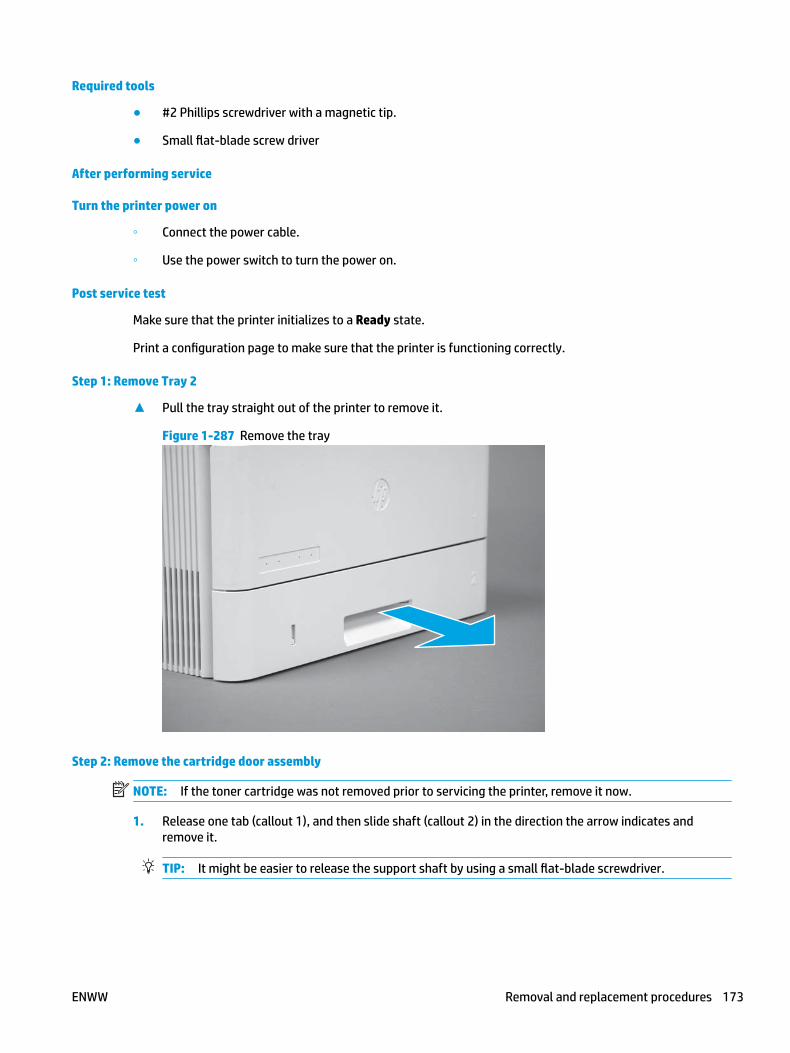
Required tools
● #2 Phillips screwdriver with a magnetic tip.
● Small flat-blade screw driver
After performing service
Turn the printer power on
◦ Connect the power cable.
◦ Use the power switch to turn the power on.
Post service test
Make sure that the printer initializes to a Ready state.
Print a configuration page to make sure that the printer is functioning correctly.
Step 1: Remove Tray 2
▲ Pull the tray straight out of the printer to remove it.
Figure 1-287 Remove the tray
Step 2: Remove the cartridge door assembly
NOTE: If the toner cartridge was not removed prior to servicing the printer, remove it now.
1. Release one tab (callout 1), and then slide shaft (callout 2) in the direction the arrow indicates and remove it.
TIP: It might be easier to release the support shaft by using a small flat-blade screwdriver.
ENWW Removal and replacement procedures 173

Figure 1-288 Release the support shaft
12
2. Release one tab (callout 1), and then slide the guide (callout 2) in the direction the arrow indicates and remove it.
Figure 1-289 Remove the guide
1 2
174 Chapter 1 Removal and replacement ENWW

3. Remove the link arm (callout 1).
Figure 1-290 Remove the link arm
1
4. Slide the cartridge door assembly (callout 1) in the direction the arrow indicates and remove it.
Figure 1-291 Remove the door
1
ENWW Removal and replacement procedures 175

5. Remove the link (callout 1) from the cartridge door assembly (callout 2).
Figure 1-292 Release the left-side retainer arm
21
Step 3: Remove the left cover
1. Remove one screw (callout 1).
Figure 1-293 Remove one screw
1 1
176 Chapter 1 Removal and replacement ENWW

2. Open the rear door, release two bosses (callout 1), and then release three tabs (callout 2).
Figure 1-294 Release two bosses and three tabs
1
1
2
2
3. At the front of the printer, do one of the following:
● M403/M402: Release two bosses (callout 1), and then remove the cover (callout 2).
● M427/M426: Release one tab (callout 3), two bosses (callout 4), and then remove the cover (callout 5).
CAUTION: Be careful when releasing the upper bosses on the M427/M426 cover. One portion of the cover (callout 6) is fragile and is easily broken.
Figure 1-295 Remove the cover
2
1
3
54 6
Step 4: Remove the right cover
1. Remove one screw (callout 1).
ENWW Removal and replacement procedures 177

Figure 1-296 Remove one screw
11
2. At the front of the printer, release two bosses (callout 1), and then release three tabs (callout 2).
Figure 1-297 Release two bosses and three tabs
1 1
2 2
3. Open the rear door, release two bosses (callout 1), and then remove the cover (callout 2).
Figure 1-298 Remove the cover
22
1 1
Step 5: Remove the control panel (M427/M426)
1. Disconnect one FFC (callout 1; J114), and then release the FFC from the retainer (callout 2).
178 Chapter 1 Removal and replacement ENWW

Figure 1-299 Disconnect one connector
1
2
2. Remove one screw (callout 1).
Figure 1-300 Remove one screw
1
ENWW Removal and replacement procedures 179

3. Use a small flat-blade screwdriver to release two tabs (callout 1) on the control-panel cable cover.
Figure 1-301 Release two tabs
1
4. Remove the control-panel cable cover.
Figure 1-302 Remove the cover
180 Chapter 1 Removal and replacement ENWW

5. Remove one grounding screw (callout 1), and then move the ground cable (callout 2) out of the way.
Figure 1-303 Remove one screw
2
1
6. Move the FFC out of the way, and then remove two screws (callout 1).
Figure 1-304 Remove two screws
1
ENWW Removal and replacement procedures 181

7. Slightly lift up the control-panel assembly to separate it from the top cover.
CAUTION: The control panel assembly is still connected to the printer by the FFC. Do not attempt to completely remove the assembly.
Figure 1-305 Lift up the control-panel assembly
8. Lift up the control-panel FFC cover to remove the control-panel assembly.
Figure 1-306 Remove the control-panel assembly
Step 6: Remove the integrated scanner assembly (M427/M246)
NOTE: M427/M426 models only. The integrated scanner assembly (ISA) includes the sub-scanner assembly (SSA) and the automatic document feeder (ADF).
1. Raise the ISA.
182 Chapter 1 Removal and replacement ENWW

Figure 1-307 Raise the ISA
2. Release the ISA flat-flexible cable (FFC) cover (callout 1), and then remove it (callout 2).
Figure 1-308 Remove the ISA FFC cover
12
ENWW Removal and replacement procedures 183

3. Disconnect three FFCs (callout 1), and then remove the ferrite (callout 2) from the holder.
CAUTION: The ferrite is not captive on the FFC. Do not lose the ferrite while handling the ISA.
Figure 1-309 Disconnect three FFCs
2
1
4. Remove one screw (callout 1).
Figure 1-310 Remove one screw
1
184 Chapter 1 Removal and replacement ENWW
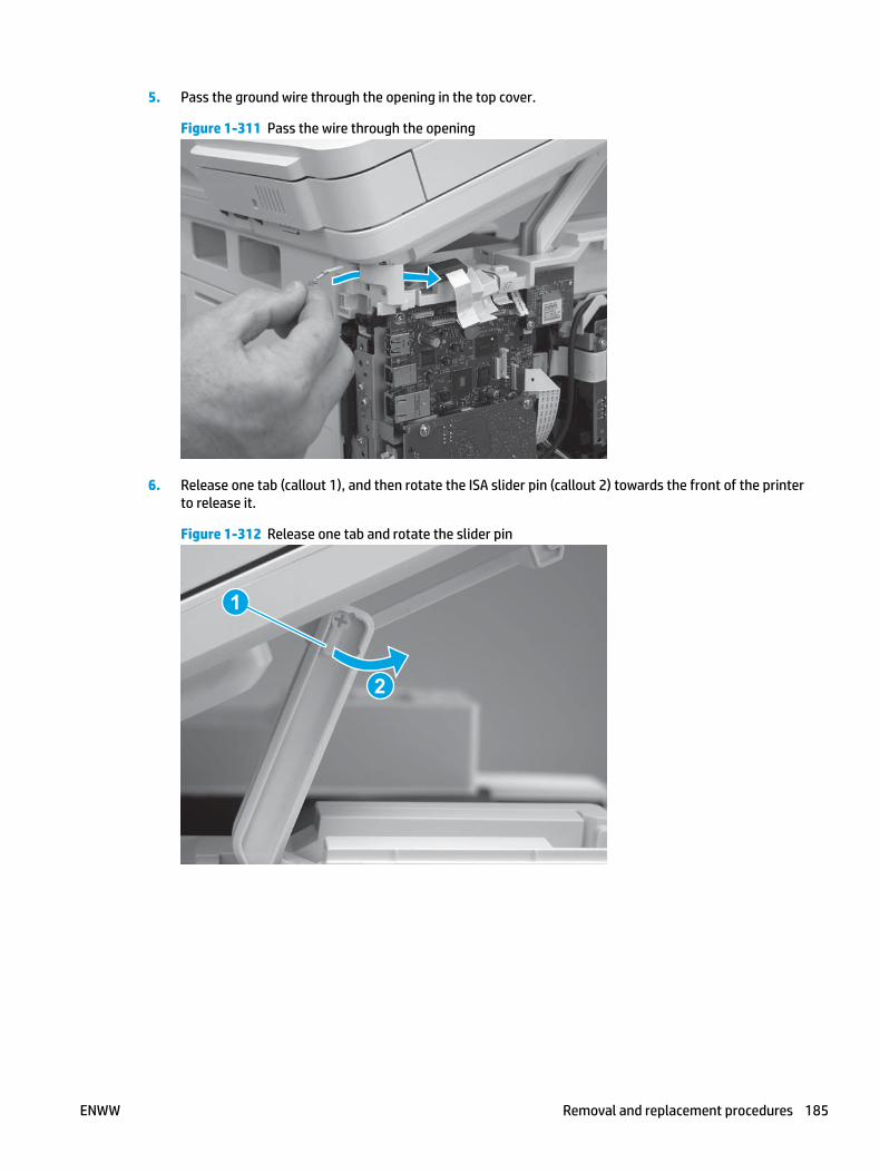
5. Pass the ground wire through the opening in the top cover.
Figure 1-311 Pass the wire through the opening
6. Release one tab (callout 1), and then rotate the ISA slider pin (callout 2) towards the front of the printer to release it.
Figure 1-312 Release one tab and rotate the slider pin
1
2
ENWW Removal and replacement procedures 185

7. Remove the slider pin.
Figure 1-313 Remove the slider pin
8. Rotate the ISA towards the rear of the printer until it stops.
Figure 1-314 Rotate the ISA towards the rear of the printer
186 Chapter 1 Removal and replacement ENWW

9. Slide the ISA as shown to release it.
Figure 1-315 Release the ISA
10. Remove the ISA.
Figure 1-316 Remove the ISA
Step 7: Remove the top cover (M427/M426)
1. Release the USB cable (callout 1) from the cable guide.
ENWW Removal and replacement procedures 187

Figure 1-317 Remove the USB cable
1
2. Remove five screws (callout 1), release four bosses (callout 2), and then remove the top cover (callout 3).
Figure 1-318 Remove the cover
3
2
1
Step 8: Remove the cable guide (M427/M426)
1. Turn the top cover over, and then release one tab (callout 1).
188 Chapter 1 Removal and replacement ENWW

Figure 1-319 Release one tab
1
2. Slide the guide as sown to release it.
Figure 1-320 Release the guide
ENWW Removal and replacement procedures 189

3. Remove the guide.
Figure 1-321 Remove the guide
Step 9: Unpack the replacement assembly
Unpack the replacement part from the packaging.
http://www8.hp.com/us/en/hp-information/environment/product-recycling.html
NOTE: HP recommends responsible disposal of the defective part.
Figure 1-322 Recycle and unpack
Step 10: Install the cable guide (M427/M426)
1. Position the guide on the printer with the two tabs (callout 1) in the slots (callout 2) in the chassis.
190 Chapter 1 Removal and replacement ENWW

Figure 1-323 Position the guide on the printer
1
2
2. Slide the guide as shown (callout 1) to install it.
Figure 1-324 Install the guide
ENWW Removal and replacement procedures 191

3. Make sure that the tab (callout 1) snaps into place.
Figure 1-325 Check the guide
1
Step 11: install the top cover (M427/M426)
1. Position the rear edge of the top cover on the printer.
Figure 1-326 Install the cover
192 Chapter 1 Removal and replacement ENWW

2. Engage four bosses (callout 1).
Figure 1-327 Engage four bosses
1
3. Rotate the front edge of the cover down.
Figure 1-328 Rotate the front edge of the cover down
ENWW Removal and replacement procedures 193

4. Install the USB cable (callout 1) in the guide.
Figure 1-329 Install the USB PCA
1
5. Install five screws (callout 1).
Figure 1-330 Install five screws
1
Step 12: Install the integrated scanner assembly (M427/M246)
NOTE: M427/M426 models only. The integrated scanner assembly (ISA) includes the sub-scanner assembly (SSA) and the automatic document feeder (ADF).
1. Position the ISA on the printer.
194 Chapter 1 Removal and replacement ENWW

Figure 1-331 Position the ISA on the printer
2. Engage the hinge pins on the ISA with the holders in the top cover (callouts 1/2), and the slide the ISA as shown to engage them
Figure 1-332 Engage the hinge pins with the holders
1
2
ENWW Removal and replacement procedures 195

3. Rotate the ISA towards the front of the printer until it rests on the ISA lift assembly (callout 1).
Figure 1-333 Rotate the ISA towards the front of the printer
1
4. Pass the ground wire through the opening in the top cover.
Figure 1-334 Pass the wire through the opening
196 Chapter 1 Removal and replacement ENWW

5. Install one screw (callout 1).
Figure 1-335 Install one screw
1
6. Install the ISA lift assembly slider pin.
Reinstallation tip: Align the keyed portion of the locking pin with the slot and hole in the support arm.
Figure 1-336 Install the slider pin
ENWW Removal and replacement procedures 197

7. Rotate the slider pin (callout 1) towards the rear of the printer until the tab (callout 2) snap into place.
Figure 1-337 Secure the slider pin
2
1
8. Install the ferrite (callout 1) in the holder, and then connect three FFCs (callout 2).
Figure 1-338 Connect three FFCs
1
2
198 Chapter 1 Removal and replacement ENWW

9. Position the rear edge of the ISA flat-flexible cable (FFC) cover on the printer (callout 1) , and then rotate it down (callout 2) until it snaps into place.
Figure 1-339 Install the ISA FFC cover
1
2
10. Lower the ISA.
Figure 1-340 Lower the ISA
Step 13: Install the control panel (M427/M426)
1. Slide the control-panel FFC cover into the slot in the top cover (next to the document feeder support arm) to install it.
ENWW Removal and replacement procedures 199
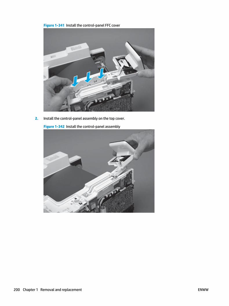
Figure 1-341 Install the control-panel FFC cover
2. Install the control-panel assembly on the top cover.
Figure 1-342 Install the control-panel assembly
200 Chapter 1 Removal and replacement ENWW

3. Move the FFC out of the way, and then install two screws (callout 1).
Figure 1-343 Install two screws
1
4. Install one grounding screw (callout 1), and then make sure that the ground cable (callout 2) is properly routed.
Figure 1-344 Remove one screw
2
1
ENWW Removal and replacement procedures 201

5. Install the control-panel cable cover.
Figure 1-345 Install the cover
6. Make sure that the two tabs (callout 1) on the cover snap into place.
Figure 1-346 Engage two tabs
1
202 Chapter 1 Removal and replacement ENWW

7. Install one screw (callout 1).
Figure 1-347 Install one screw
1
8. Install the FFC in the retainer (callout 1), and then connect one FFC (callout 1; J114).
Figure 1-348 Connect one connector
1
2
Step 14: Install the right cover
1. Position the cover (callout 1) on the printer, and then engage two bosses (callout 2).
ENWW Removal and replacement procedures 203

Figure 1-349 Install the cover
11
2 2
2. Rotate the front of the cover onto the printer (callout 1), engage three (callout 2) tabs, and then engage two bosses (callout 3).
Figure 1-350 Engage two bosses and one tab
1 13 3
2 2
3. Make sure that the power switch (callout 1) and cartridge door assembly button (callout 2) correctly function.
NOTE: Remove, and then reinstall the cover if the switch or button does not correctly function.
Figure 1-351 Check the power switch and cartridge door assembly button
1
1
22
204 Chapter 1 Removal and replacement ENWW

4. Install one screw (callout 1).
Figure 1-352 Install one screw
11
Step 15: Install the left cover
1. At the front of the printer, do one of the following:
● M403/M402: Position the cover on the printer ( callout 1), and then engage two bosses (callout 2).
● M427/M426: Position the cover on the printer (callout 3), engage one tab (callout 4), and then engage two bosses (callout 4).
Figure 1-353 Install the cover
1
2
4
35
ENWW Removal and replacement procedures 205

2. Carefully rotate the rear of the cover onto the printer (callout 1), engage three tabs (callout 2), and then engage two bosses (callout 3).
Figure 1-354 Engage three tabs and two bosses
3
3 11
2
2
3. Install one screw (callout 1).
Figure 1-355 Install one screw
1 1
Step 16: Install the cartridge door assembly
Reinstallation tip: After a replacement door is installed, make sure to install the nameplate (supplied in the kit) corresponding to the printer name on the door.
1. Position the door close to the printer, and then engage the keyed pin on the left-side retainer arm with the hole in the door.
206 Chapter 1 Removal and replacement ENWW
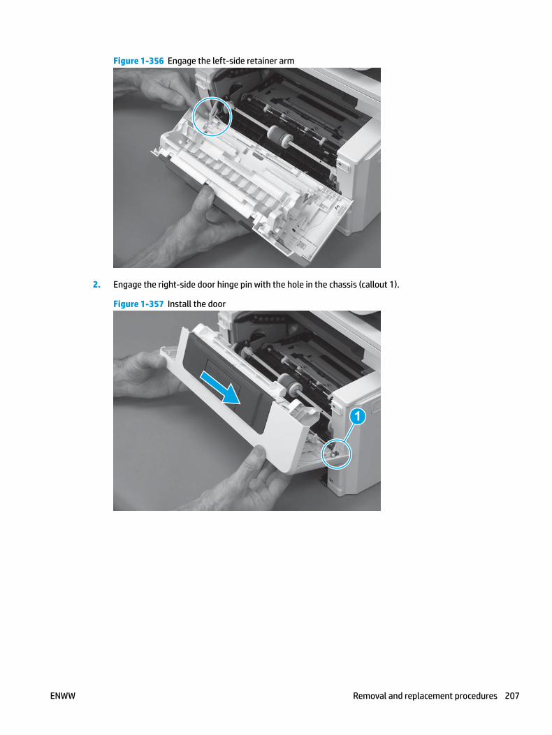
Figure 1-356 Engage the left-side retainer arm
2. Engage the right-side door hinge pin with the hole in the chassis (callout 1).
Figure 1-357 Install the door
1
ENWW Removal and replacement procedures 207

3. Install the link (callout 1).
IMPORTANT: Make sure that the link snaps into place on the arm (callout 2). The link actuates the fuser pressure-release mechanism.
Figure 1-358 Install the pressure-release link
1
2
4. Slide the guide into the printer (callout 1), and then make sure that the tab (callout 2) snaps into place to secure the guide to the chassis.
Figure 1-359 Install the guide
1
2
208 Chapter 1 Removal and replacement ENWW

5. Position the shaft on the door, and then align the left-side hinge on the door with the hole in the chassis (callout 1).
Figure 1-360 Align the hinge
1
6. Push the shaft towards the left side of the printer to install it (callout 1).
Reinstallation tip: Make sure that the support shaft is fully installed and correctly orientated (callout 2) so that it will not interfere with the door opening and closing.
Figure 1-361 Install the support shaft
2
1
ENWW Removal and replacement procedures 209

Step 17: Install Tray 2
▲ Slide the tray straight into the printer to install it.
Figure 1-362 Install the tray
210 Chapter 1 Removal and replacement ENWW
Removal and replacement: Top cover (M403/M402)
● Introduction
● Step 1: Remove Tray 2
● Step 2: Remove the cartridge door assembly
● Step 3: Remove the left cover
● Step 4: Remove the right cover
● Step 5: Remove the top cover (M403/M402)
● Step 6: Remove the 2-line LCD operator and indication covers (M403/M402)
● Step 7: Unpack the replacement assembly
● Step 8: Install the 2-line LCD operator and indication covers (M403/M402)
● Step 9: Install the top cover (M403/M402)
● Step 10: Install the right cover
● Step 11: Install the left cover
● Step 12: Install the cartridge door assembly
● Step 13: Install Tray 2
Introduction
This document provides the procedures to remove and replace the top cover (M403/M402).
Before performing service
Turn the printer power off
◦ Disconnect the power cable.
WARNING! To avoid damage to the printer, turn the printer off, wait 30 seconds, and then remove the power cable before attempting to service the printer.
Use the table below to identify the correct part number for your printer. To order the part, go to www.hp.com/buy/parts.
Top cover (M403/M402) part number
RC4-2956-000CN Top cover (M403/M402)
Required tools
● #2 Phillips screwdriver with a magnetic tip.
ENWW Removal and replacement procedures 211

After performing service
Turn the printer power on
◦ Connect the power cable.
◦ Use the power switch to turn the power on.
Post service test
Make sure that the printer initializes to a Ready state.
Print a configuration page to make sure that the printer is functioning correctly.
Step 1: Remove Tray 2
▲ Pull the tray straight out of the printer to remove it.
Figure 1-363 Remove the tray
Step 2: Remove the cartridge door assembly
NOTE: If the toner cartridge was not removed prior to servicing the printer, remove it now.
1. Release one tab (callout 1), and then slide shaft (callout 2) in the direction the arrow indicates and remove it.
TIP: It might be easier to release the support shaft by using a small flat-blade screwdriver.
212 Chapter 1 Removal and replacement ENWW
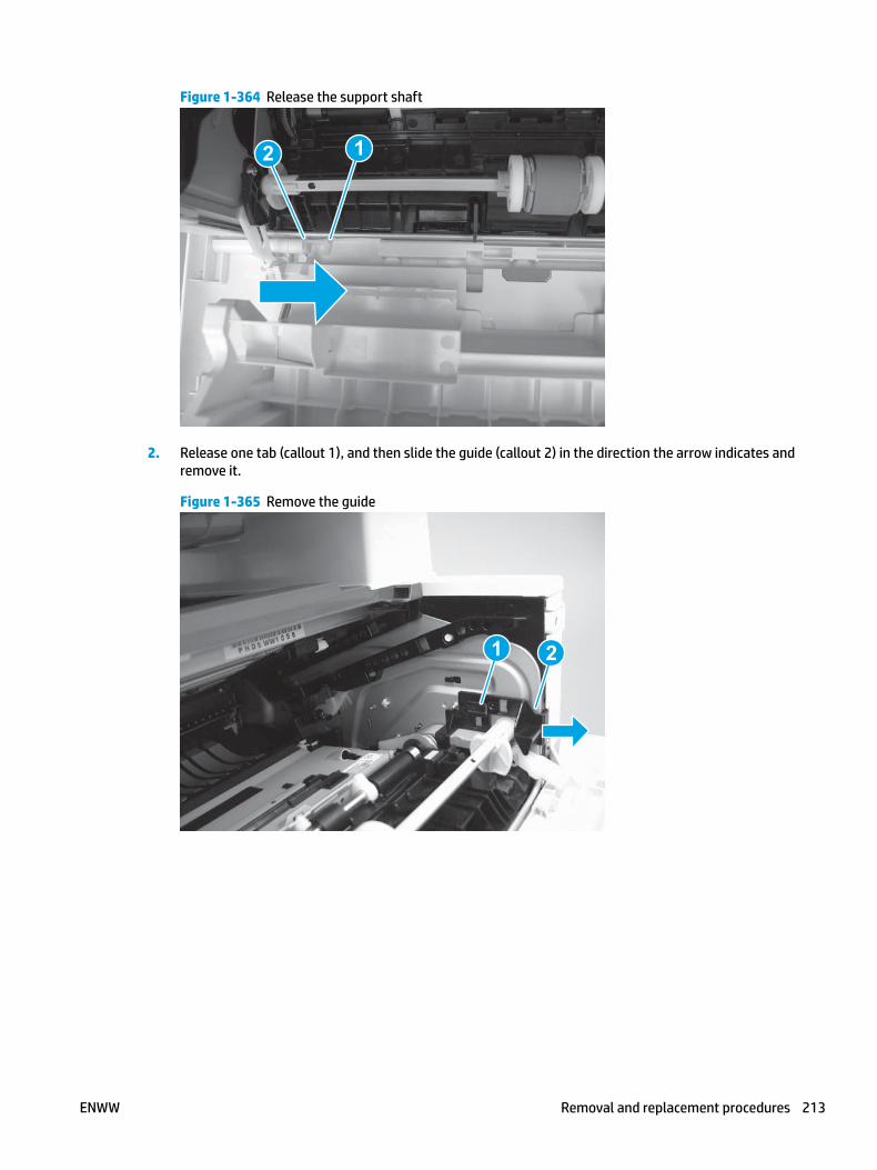
Figure 1-364 Release the support shaft
12
2. Release one tab (callout 1), and then slide the guide (callout 2) in the direction the arrow indicates and remove it.
Figure 1-365 Remove the guide
1 2
ENWW Removal and replacement procedures 213
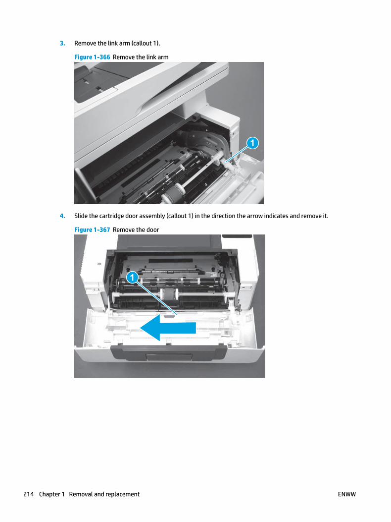
3. Remove the link arm (callout 1).
Figure 1-366 Remove the link arm
1
4. Slide the cartridge door assembly (callout 1) in the direction the arrow indicates and remove it.
Figure 1-367 Remove the door
1
214 Chapter 1 Removal and replacement ENWW

5. Remove the link (callout 1) from the cartridge door assembly (callout 2).
Figure 1-368 Release the left-side retainer arm
21
Step 3: Remove the left cover
1. Remove one screw (callout 1).
Figure 1-369 Remove one screw
1 1
ENWW Removal and replacement procedures 215
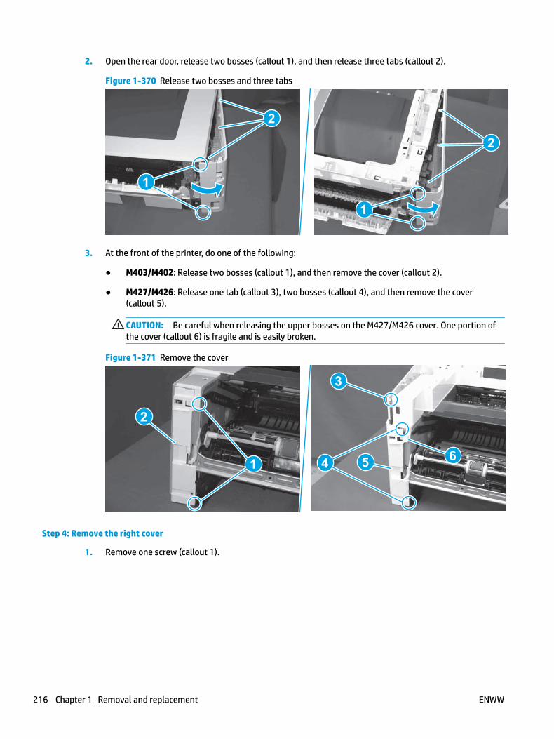
2. Open the rear door, release two bosses (callout 1), and then release three tabs (callout 2).
Figure 1-370 Release two bosses and three tabs
1
1
2
2
3. At the front of the printer, do one of the following:
● M403/M402: Release two bosses (callout 1), and then remove the cover (callout 2).
● M427/M426: Release one tab (callout 3), two bosses (callout 4), and then remove the cover (callout 5).
CAUTION: Be careful when releasing the upper bosses on the M427/M426 cover. One portion of the cover (callout 6) is fragile and is easily broken.
Figure 1-371 Remove the cover
2
1
3
54 6
Step 4: Remove the right cover
1. Remove one screw (callout 1).
216 Chapter 1 Removal and replacement ENWW
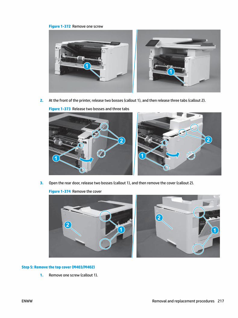
Figure 1-372 Remove one screw
11
2. At the front of the printer, release two bosses (callout 1), and then release three tabs (callout 2).
Figure 1-373 Release two bosses and three tabs
1 1
2 2
3. Open the rear door, release two bosses (callout 1), and then remove the cover (callout 2).
Figure 1-374 Remove the cover
22
1 1
Step 5: Remove the top cover (M403/M402)
1. Remove one screw (callout 1).
ENWW Removal and replacement procedures 217

Figure 1-375 Remove one screw
1
2. At the right side of the printer, release the one boss (callout 1), and then release one tab (callout 2).
Figure 1-376 Release one boss and one tab
21
218 Chapter 1 Removal and replacement ENWW

3. Release four tabs (callout 1), release four bosses (callout 2), and then remove the top cover (callout 3).
TIP: Open the rear door to make releasing the bosses (callout 3) easier.
Figure 1-377 Remove the cover
2
3
1
Step 6: Remove the 2-line LCD operator and indication covers (M403/M402)
1. Rotate the top edge of the operator cover away from the printer to release it.
Figure 1-378 Rotate the top edge of the operator cover
ENWW Removal and replacement procedures 219

2. Remove the operator cover.
Figure 1-379 Remove the cover
3. Turn the top cover over, release two tabs (callout 1), and then remove the indication cover.
Figure 1-380 Remove the cover
1
Step 7: Unpack the replacement assembly
Unpack the replacement part from the packaging.
http://www8.hp.com/us/en/hp-information/environment/product-recycling.html
NOTE: HP recommends responsible disposal of the defective part.
220 Chapter 1 Removal and replacement ENWW

Figure 1-381 Recycle and unpack
Step 8: Install the 2-line LCD operator and indication covers (M403/M402)
1. Position the indication cover on the top cover, and then make sure that the two tabs (callout 1) snap into place.
Figure 1-382 Install the cover
1
ENWW Removal and replacement procedures 221
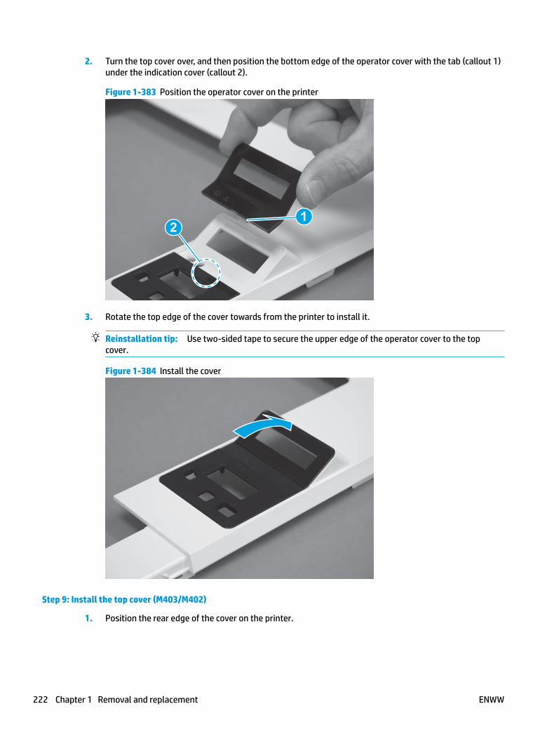
2. Turn the top cover over, and then position the bottom edge of the operator cover with the tab (callout 1) under the indication cover (callout 2).
Figure 1-383 Position the operator cover on the printer
12
3. Rotate the top edge of the cover towards from the printer to install it.
Reinstallation tip: Use two-sided tape to secure the upper edge of the operator cover to the top cover.
Figure 1-384 Install the cover
Step 9: Install the top cover (M403/M402)
1. Position the rear edge of the cover on the printer.
222 Chapter 1 Removal and replacement ENWW

Figure 1-385 Install the cover
2. Engage four bosses (callout 1), rotate the front of the cover down (callout 2) and onto from the printer, and then engage four tabs (callout 3).
Figure 1-386 Engage four bosses and tabs
1
3
2
2
ENWW Removal and replacement procedures 223

3. At the right side of the printer, engage the one boss and one tab (callout 1).
Figure 1-387 Engage one boss and one tab
1
4. Install one screw (callout 1).
Figure 1-388 Install one screw
1
Step 10: Install the right cover
1. Position the cover (callout 1) on the printer, and then engage two bosses (callout 2).
224 Chapter 1 Removal and replacement ENWW

Figure 1-389 Install the cover
11
2 2
2. Rotate the front of the cover onto the printer (callout 1), engage three (callout 2) tabs, and then engage two bosses (callout 3).
Figure 1-390 Engage two bosses and one tab
1 13 3
2 2
3. Make sure that the power switch (callout 1) and cartridge door assembly button (callout 2) correctly function.
NOTE: Remove, and then reinstall the cover if the switch or button does not correctly function.
Figure 1-391 Check the power switch and cartridge door assembly button
1
1
22
ENWW Removal and replacement procedures 225

4. Install one screw (callout 1).
Figure 1-392 Install one screw
11
Step 11: Install the left cover
1. At the front of the printer, do one of the following:
● M403/M402: Position the cover on the printer ( callout 1), and then engage two bosses (callout 2).
● M427/M426: Position the cover on the printer (callout 3), engage one tab (callout 4), and then engage two bosses (callout 4).
Figure 1-393 Install the cover
1
2
4
35
226 Chapter 1 Removal and replacement ENWW

2. Carefully rotate the rear of the cover onto the printer (callout 1), engage three tabs (callout 2), and then engage two bosses (callout 3).
Figure 1-394 Engage three tabs and two bosses
3
3 11
2
2
3. Install one screw (callout 1).
Figure 1-395 Install one screw
1 1
Step 12: Install the cartridge door assembly
Reinstallation tip: After a replacement door is installed, make sure to install the nameplate (supplied in the kit) corresponding to the printer name on the door.
1. Position the door close to the printer, and then engage the keyed pin on the left-side retainer arm with the hole in the door.
ENWW Removal and replacement procedures 227

Figure 1-396 Engage the left-side retainer arm
2. Engage the right-side door hinge pin with the hole in the chassis (callout 1).
Figure 1-397 Install the door
1
228 Chapter 1 Removal and replacement ENWW

3. Install the link (callout 1).
IMPORTANT: Make sure that the link snaps into place on the arm (callout 2). The link actuates the fuser pressure-release mechanism.
Figure 1-398 Install the pressure-release link
1
2
4. Slide the guide into the printer (callout 1), and then make sure that the tab (callout 2) snaps into place to secure the guide to the chassis.
Figure 1-399 Install the guide
1
2
ENWW Removal and replacement procedures 229

5. Position the shaft on the door, and then align the left-side hinge on the door with the hole in the chassis (callout 1).
Figure 1-400 Align the hinge
1
6. Push the shaft towards the left side of the printer to install it (callout 1).
Reinstallation tip: Make sure that the support shaft is fully installed and correctly orientated (callout 2) so that it will not interfere with the door opening and closing.
Figure 1-401 Install the support shaft
2
1
230 Chapter 1 Removal and replacement ENWW

Step 13: Install Tray 2
▲ Slide the tray straight into the printer to install it.
Figure 1-402 Install the tray
ENWW Removal and replacement procedures 231

Removal and replacement: 2-line LCD operator and indication covers (M403/M402)
● Introduction
● Step 1: Remove Tray 2
● Step 2: Remove the cartridge door assembly
● Step 3: Remove the left cover
● Step 4: Remove the right cover
● Step 5: Remove the top cover (M403/M402)
● Step 6: Remove the 2-line LCD operator and indication covers (M403/M402)
● Step 7: Unpack the replacement assembly
● Step 8: Install the 2-line LCD operator and indication covers (M403/M402)
● Step 9: Install the top cover (M403/M402)
● Step 10: Install the right cover
● Step 11: Install the left cover
● Step 12: Install the cartridge door assembly
● Step 13: Install Tray 2
Introduction
This document provides the procedures to remove and replace the 2-line LCD operator and indication covers.
Before performing service
Turn the printer power off
◦ Disconnect the power cable.
WARNING! To avoid damage to the printer, turn the printer off, wait 30 seconds, and then remove the power cable before attempting to service the printer.
Use the table below to identify the correct part number for your printer. To order the part, go to www.hp.com/buy/parts.
2-line LCD operator and indication covers (M403/M402) part number
RC4-3312-000CN
RC4-3322-000CN
2-line LCD operator cover (M403/M402; non-wireless models)
2-line LCD operator cover (M402dw; wireless model)
RL2-0675-000CN 2-line LCD indication cover (M403/M402)
Required tools
● #2 Phillips screwdriver with a magnetic tip.
232 Chapter 1 Removal and replacement ENWW

After performing service
Turn the printer power on
◦ Connect the power cable.
◦ Use the power switch to turn the power on.
Post service test
Make sure that the printer initializes to a Ready state.
Print a configuration page to make sure that the printer is functioning correctly.
Step 1: Remove Tray 2
▲ Pull the tray straight out of the printer to remove it.
Figure 1-403 Remove the tray
Step 2: Remove the cartridge door assembly
NOTE: If the toner cartridge was not removed prior to servicing the printer, remove it now.
1. Release one tab (callout 1), and then slide shaft (callout 2) in the direction the arrow indicates and remove it.
TIP: It might be easier to release the support shaft by using a small flat-blade screwdriver.
ENWW Removal and replacement procedures 233

Figure 1-404 Release the support shaft
12
2. Release one tab (callout 1), and then slide the guide (callout 2) in the direction the arrow indicates and remove it.
Figure 1-405 Remove the guide
1 2
234 Chapter 1 Removal and replacement ENWW

3. Remove the link arm (callout 1).
Figure 1-406 Remove the link arm
1
4. Slide the cartridge door assembly (callout 1) in the direction the arrow indicates and remove it.
Figure 1-407 Remove the door
1
ENWW Removal and replacement procedures 235

5. Remove the link (callout 1) from the cartridge door assembly (callout 2).
Figure 1-408 Release the left-side retainer arm
21
Step 3: Remove the left cover
1. Remove one screw (callout 1).
Figure 1-409 Remove one screw
1 1
236 Chapter 1 Removal and replacement ENWW

2. Open the rear door, release two bosses (callout 1), and then release three tabs (callout 2).
Figure 1-410 Release two bosses and three tabs
1
1
2
2
3. At the front of the printer, do one of the following:
● M403/M402: Release two bosses (callout 1), and then remove the cover (callout 2).
● M427/M426: Release one tab (callout 3), two bosses (callout 4), and then remove the cover (callout 5).
CAUTION: Be careful when releasing the upper bosses on the M427/M426 cover. One portion of the cover (callout 6) is fragile and is easily broken.
Figure 1-411 Remove the cover
2
1
3
54 6
Step 4: Remove the right cover
1. Remove one screw (callout 1).
ENWW Removal and replacement procedures 237

Figure 1-412 Remove one screw
11
2. At the front of the printer, release two bosses (callout 1), and then release three tabs (callout 2).
Figure 1-413 Release two bosses and three tabs
1 1
2 2
3. Open the rear door, release two bosses (callout 1), and then remove the cover (callout 2).
Figure 1-414 Remove the cover
22
1 1
Step 5: Remove the top cover (M403/M402)
1. Remove one screw (callout 1).
238 Chapter 1 Removal and replacement ENWW

Figure 1-415 Remove one screw
1
2. At the right side of the printer, release the one boss (callout 1), and then release one tab (callout 2).
Figure 1-416 Release one boss and one tab
21
ENWW Removal and replacement procedures 239
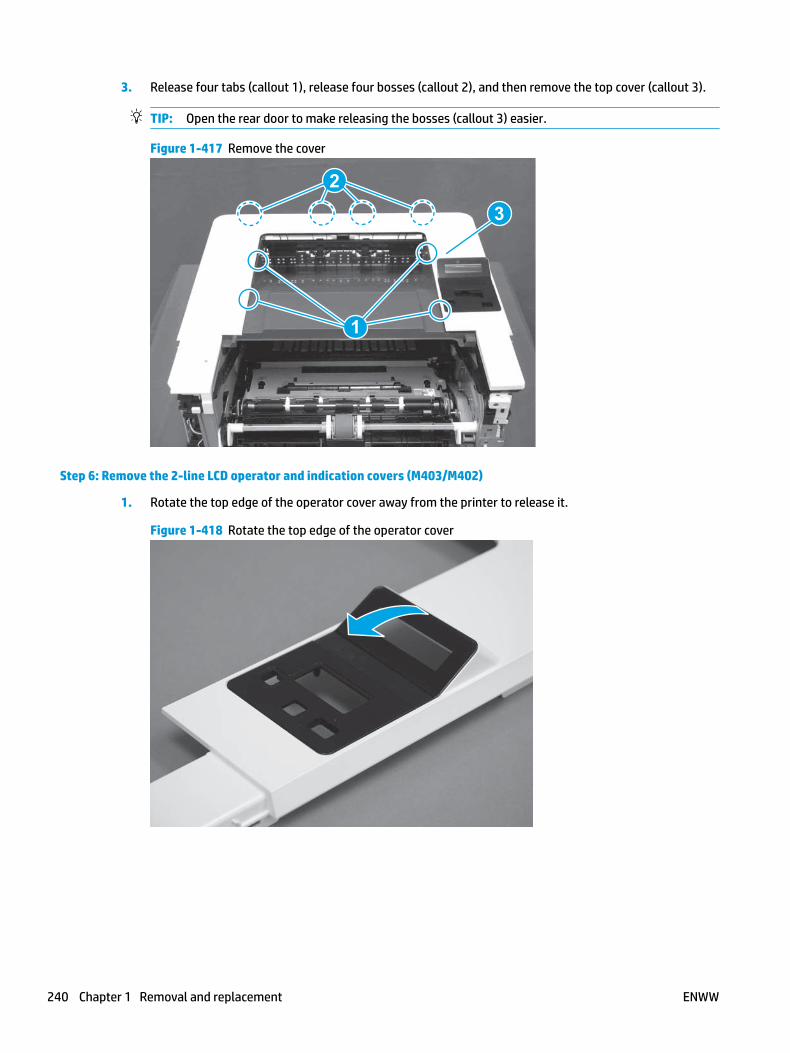
3. Release four tabs (callout 1), release four bosses (callout 2), and then remove the top cover (callout 3).
TIP: Open the rear door to make releasing the bosses (callout 3) easier.
Figure 1-417 Remove the cover
2
3
1
Step 6: Remove the 2-line LCD operator and indication covers (M403/M402)
1. Rotate the top edge of the operator cover away from the printer to release it.
Figure 1-418 Rotate the top edge of the operator cover
240 Chapter 1 Removal and replacement ENWW

2. Remove the operator cover.
Figure 1-419 Remove the cover
3. Turn the top cover over, release two tabs (callout 1), and then remove the indication cover.
Figure 1-420 Remove the cover
1
Step 7: Unpack the replacement assembly
Unpack the replacement part from the packaging.
http://www8.hp.com/us/en/hp-information/environment/product-recycling.html
NOTE: HP recommends responsible disposal of the defective part.
ENWW Removal and replacement procedures 241

Figure 1-421 Recycle and unpack
Step 8: Install the 2-line LCD operator and indication covers (M403/M402)
1. Position the indication cover on the top cover, and then make sure that the two tabs (callout 1) snap into place.
Figure 1-422 Install the cover
1
242 Chapter 1 Removal and replacement ENWW

2. Turn the top cover over, and then position the bottom edge of the operator cover with the tab (callout 1) under the indication cover (callout 2).
Figure 1-423 Position the operator cover on the printer
12
3. Rotate the top edge of the cover towards from the printer to install it.
Reinstallation tip: Use two-sided tape to secure the upper edge of the operator cover to the top cover.
Figure 1-424 Install the cover
Step 9: Install the top cover (M403/M402)
1. Position the rear edge of the cover on the printer.
ENWW Removal and replacement procedures 243

Figure 1-425 Install the cover
2. Engage four bosses (callout 1), rotate the front of the cover down (callout 2) and onto from the printer, and then engage four tabs (callout 3).
Figure 1-426 Engage four bosses and tabs
1
3
2
2
244 Chapter 1 Removal and replacement ENWW

3. At the right side of the printer, engage the one boss and one tab (callout 1).
Figure 1-427 Engage one boss and one tab
1
4. Install one screw (callout 1).
Figure 1-428 Install one screw
1
Step 10: Install the right cover
1. Position the cover (callout 1) on the printer, and then engage two bosses (callout 2).
ENWW Removal and replacement procedures 245

Figure 1-429 Install the cover
11
2 2
2. Rotate the front of the cover onto the printer (callout 1), engage three (callout 2) tabs, and then engage two bosses (callout 3).
Figure 1-430 Engage two bosses and one tab
1 13 3
2 2
3. Make sure that the power switch (callout 1) and cartridge door assembly button (callout 2) correctly function.
NOTE: Remove, and then reinstall the cover if the switch or button does not correctly function.
Figure 1-431 Check the power switch and cartridge door assembly button
1
1
22
246 Chapter 1 Removal and replacement ENWW

4. Install one screw (callout 1).
Figure 1-432 Install one screw
11
Step 11: Install the left cover
1. At the front of the printer, do one of the following:
● M403/M402: Position the cover on the printer ( callout 1), and then engage two bosses (callout 2).
● M427/M426: Position the cover on the printer (callout 3), engage one tab (callout 4), and then engage two bosses (callout 4).
Figure 1-433 Install the cover
1
2
4
35
ENWW Removal and replacement procedures 247

2. Carefully rotate the rear of the cover onto the printer (callout 1), engage three tabs (callout 2), and then engage two bosses (callout 3).
Figure 1-434 Engage three tabs and two bosses
3
3 11
2
2
3. Install one screw (callout 1).
Figure 1-435 Install one screw
1 1
Step 12: Install the cartridge door assembly
Reinstallation tip: After a replacement door is installed, make sure to install the nameplate (supplied in the kit) corresponding to the printer name on the door.
1. Position the door close to the printer, and then engage the keyed pin on the left-side retainer arm with the hole in the door.
248 Chapter 1 Removal and replacement ENWW

Figure 1-436 Engage the left-side retainer arm
2. Engage the right-side door hinge pin with the hole in the chassis (callout 1).
Figure 1-437 Install the door
1
ENWW Removal and replacement procedures 249

3. Install the link (callout 1).
IMPORTANT: Make sure that the link snaps into place on the arm (callout 2). The link actuates the fuser pressure-release mechanism.
Figure 1-438 Install the pressure-release link
1
2
4. Slide the guide into the printer (callout 1), and then make sure that the tab (callout 2) snaps into place to secure the guide to the chassis.
Figure 1-439 Install the guide
1
2
250 Chapter 1 Removal and replacement ENWW

5. Position the shaft on the door, and then align the left-side hinge on the door with the hole in the chassis (callout 1).
Figure 1-440 Align the hinge
1
6. Push the shaft towards the left side of the printer to install it (callout 1).
Reinstallation tip: Make sure that the support shaft is fully installed and correctly orientated (callout 2) so that it will not interfere with the door opening and closing.
Figure 1-441 Install the support shaft
2
1
ENWW Removal and replacement procedures 251

Step 13: Install Tray 2
▲ Slide the tray straight into the printer to install it.
Figure 1-442 Install the tray
252 Chapter 1 Removal and replacement ENWW

Removal and replacement: Paper delivery tray (output bin)
● Introduction
● Step 1: Remove Tray 2
● Step 2: Remove the cartridge door assembly
● Step 3: Remove the left cover
● Step 4: Remove the right cover
● Step 5: Remove the integrated scanner assembly (M427/M246)
● Step 6: Remove the control panel (M427/M246)
● Step 7: Remove the top cover (M427/M426)
● Step 8: Remove the top cover (M403/M402)
● Step 9: Remove the paper delivery tray (output bin)
● Step 10: Unpack the replacement assembly
● Step 11: Install the paper delivery tray (output bin)
● Step 12: Install the top cover (M403/M402)
● Step 13: Install the top cover (M427/M426)
● Step 14: Install the control panel (M427/M246)
● Step 15: Install the integrated scanner assembly (M427/M246)
● Step 16: Install the right cover
● Step 17: Install the left cover
● Step 18: Install the cartridge door assembly
● Step 19: Install Tray 2
Introduction
This document provides the procedures to remove and replace the paper delivery tray (output bin).
Before performing service
Turn the printer power off
◦ Disconnect the power cable.
WARNING! To avoid damage to the printer, turn the printer off, wait 30 seconds, and then remove the power cable before attempting to service the printer.
Use the table below to identify the correct part number for your printer. To order the part, go to www.hp.com/buy/parts.
ENWW Removal and replacement procedures 253

Paper delivery tray (output bin) part number
RC4-3231-000CN Paper delivery tray (output bin)
Required tools
● #2 Phillips screwdriver with a magnetic tip.
● Small flat-blade screwdriver (M427/M426 required; M403/M402 optional)
After performing service
Turn the printer power on
◦ Connect the power cable.
◦ Use the power switch to turn the power on.
Post service test
Make sure that the printer initializes to a Ready state.
Print a configuration page to make sure that the printer is functioning correctly.
Step 1: Remove Tray 2
▲ Pull the tray straight out of the printer to remove it.
Figure 1-443 Remove the tray
254 Chapter 1 Removal and replacement ENWW

Step 2: Remove the cartridge door assembly
NOTE: If the toner cartridge was not removed prior to servicing the printer, remove it now.
1. Release one tab (callout 1), and then slide shaft (callout 2) in the direction the arrow indicates and remove it.
TIP: It might be easier to release the support shaft by using a small flat-blade screwdriver.
Figure 1-444 Release the support shaft
12
2. Release one tab (callout 1), and then slide the guide (callout 2) in the direction the arrow indicates and remove it.
Figure 1-445 Remove the guide
1 2
ENWW Removal and replacement procedures 255

3. Remove the link arm (callout 1).
Figure 1-446 Remove the link arm
1
4. Slide the cartridge door assembly (callout 1) in the direction the arrow indicates and remove it.
Figure 1-447 Remove the door
1
256 Chapter 1 Removal and replacement ENWW

5. Remove the link (callout 1) from the cartridge door assembly (callout 2).
Figure 1-448 Release the left-side retainer arm
21
Step 3: Remove the left cover
1. Remove one screw (callout 1).
Figure 1-449 Remove one screw
1 1
ENWW Removal and replacement procedures 257

2. Open the rear door, release two bosses (callout 1), and then release three tabs (callout 2).
Figure 1-450 Release two bosses and three tabs
1
1
2
2
3. At the front of the printer, do one of the following:
● M403/M402: Release two bosses (callout 1), and then remove the cover (callout 2).
● M427/M426: Release one tab (callout 3), two bosses (callout 4), and then remove the cover (callout 5).
CAUTION: Be careful when releasing the upper bosses on the M427/M426 cover. One portion of the cover (callout 6) is fragile and is easily broken.
Figure 1-451 Remove the cover
2
1
3
54 6
Step 4: Remove the right cover
1. Remove one screw (callout 1).
258 Chapter 1 Removal and replacement ENWW

Figure 1-452 Remove one screw
11
2. At the front of the printer, release two bosses (callout 1), and then release three tabs (callout 2).
Figure 1-453 Release two bosses and three tabs
1 1
2 2
3. Open the rear door, release two bosses (callout 1), and then remove the cover (callout 2).
Figure 1-454 Remove the cover
22
1 1
Step 5: Remove the integrated scanner assembly (M427/M246)
NOTE: The step is for the M427/M426 printer. For the M403/M402, skip this step and go to Step 8: Remove the top cover (M403/M402) on page 269.
ENWW Removal and replacement procedures 259

NOTE: M427/M426 models only. The integrated scanner assembly (ISA) includes the sub-scanner assembly (SSA) and the automatic document feeder (ADF).
1. Raise the ISA.
Figure 1-455 Raise the ISA
2. Release the ISA flat-flexible cable (FFC) cover (callout 1), and then remove it (callout 2).
Figure 1-456 Remove the ISA FFC cover
12
260 Chapter 1 Removal and replacement ENWW

3. Disconnect three FFCs (callout 1), and then remove the ferrite (callout 2) from the holder.
CAUTION: The ferrite is not captive on the FFC. Do not lose the ferrite while handling the ISA.
Figure 1-457 Disconnect three FFCs
2
1
4. Remove one screw (callout 1).
Figure 1-458 Remove one screw
1
ENWW Removal and replacement procedures 261
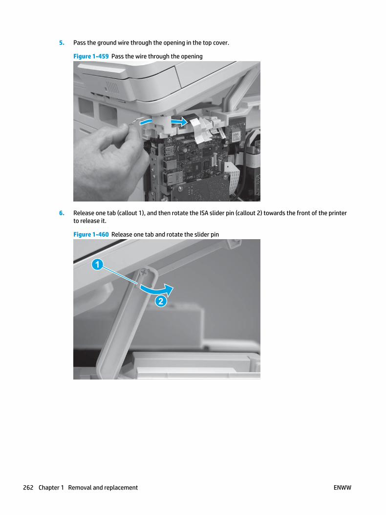
5. Pass the ground wire through the opening in the top cover.
Figure 1-459 Pass the wire through the opening
6. Release one tab (callout 1), and then rotate the ISA slider pin (callout 2) towards the front of the printer to release it.
Figure 1-460 Release one tab and rotate the slider pin
1
2
262 Chapter 1 Removal and replacement ENWW

7. Remove the slider pin.
Figure 1-461 Remove the slider pin
8. Rotate the ISA towards the rear of the printer until it stops.
Figure 1-462 Rotate the ISA towards the rear of the printer
ENWW Removal and replacement procedures 263

9. Slide the ISA as shown to release it.
Figure 1-463 Release the ISA
10. Remove the ISA.
Figure 1-464 Remove the ISA
Step 6: Remove the control panel (M427/M246)
NOTE: The step is for the M427/M426 printer. For the M403/M402, skip this step and go to Step 8: Remove the top cover (M403/M402) on page 269.
1. Disconnect one FFC (callout 1; J114), and then release the FFC from the retainer (callout 2).
264 Chapter 1 Removal and replacement ENWW

Figure 1-465 Disconnect one connector
1
2
2. Remove one screw (callout 1).
Figure 1-466 Remove one screw
1
ENWW Removal and replacement procedures 265
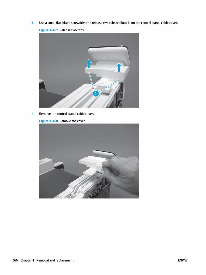
3. Use a small flat-blade screwdriver to release two tabs (callout 1) on the control-panel cable cover.
Figure 1-467 Release two tabs
1
4. Remove the control-panel cable cover.
Figure 1-468 Remove the cover
266 Chapter 1 Removal and replacement ENWW

5. Remove one grounding screw (callout 1), and then move the ground cable (callout 2) out of the way.
Figure 1-469 Remove one screw
2
1
6. Move the FFC out of the way, and then remove two screws (callout 1).
Figure 1-470 Remove two screws
1
ENWW Removal and replacement procedures 267

7. Slightly lift up the control-panel assembly to separate it from the top cover.
CAUTION: The control panel assembly is still connected to the printer by the FFC. Do not attempt to completely remove the assembly.
Figure 1-471 Lift up the control-panel assembly
8. Lift up the control-panel FFC cover to remove the control-panel assembly.
Figure 1-472 Remove the control-panel assembly
Step 7: Remove the top cover (M427/M426)
NOTE: The step is for the M427/M426 printer. For the M403/M402, skip this step and go to Step 8: Remove the top cover (M403/M402) on page 269.
1. Release the USB cable (callout 1) from the cable guide.
268 Chapter 1 Removal and replacement ENWW

Figure 1-473 Remove the USB cable
1
2. Remove five screws (callout 1), release four bosses (callout 2), and then remove the top cover (callout 3).
Figure 1-474 Remove the cover
3
2
1
Step 8: Remove the top cover (M403/M402)
NOTE: The step is for the M403/M402 printer. For the M427/M426, skip this step and go to Step 9: Remove the paper delivery tray (output bin) on page 271.
1. Remove one screw (callout 1).
ENWW Removal and replacement procedures 269
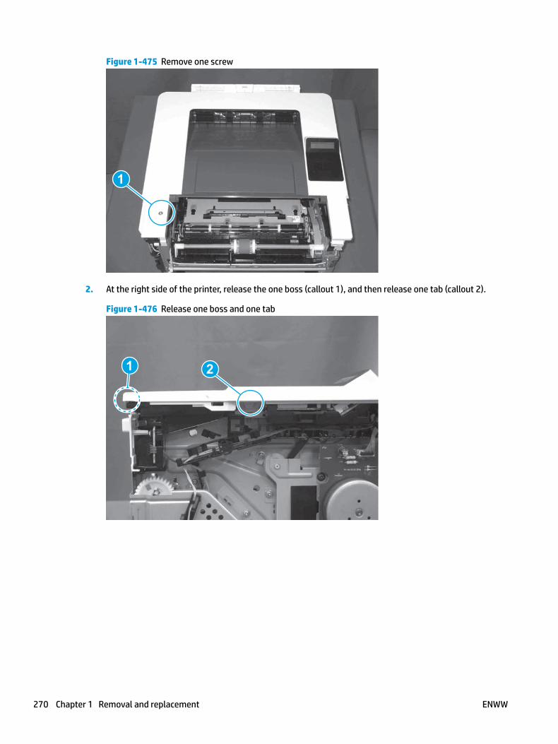
Figure 1-475 Remove one screw
1
2. At the right side of the printer, release the one boss (callout 1), and then release one tab (callout 2).
Figure 1-476 Release one boss and one tab
21
270 Chapter 1 Removal and replacement ENWW

3. Release four tabs (callout 1), release four bosses (callout 2), and then remove the top cover (callout 3).
TIP: Open the rear door to make releasing the bosses (callout 3) easier.
Figure 1-477 Remove the cover
2
3
1
Step 9: Remove the paper delivery tray (output bin)
NOTE: This procedure shows the M403/M402 model, however, the paper delivery tray (output bin) removal is similar for the M427/M426 printer.
▲ Release two bosses (callout 1), release two tabs (callout 2), and then remove the paper delivery tray (output bin; callout 3).
Figure 1-478 Release two tabs
2
1
3
ENWW Removal and replacement procedures 271
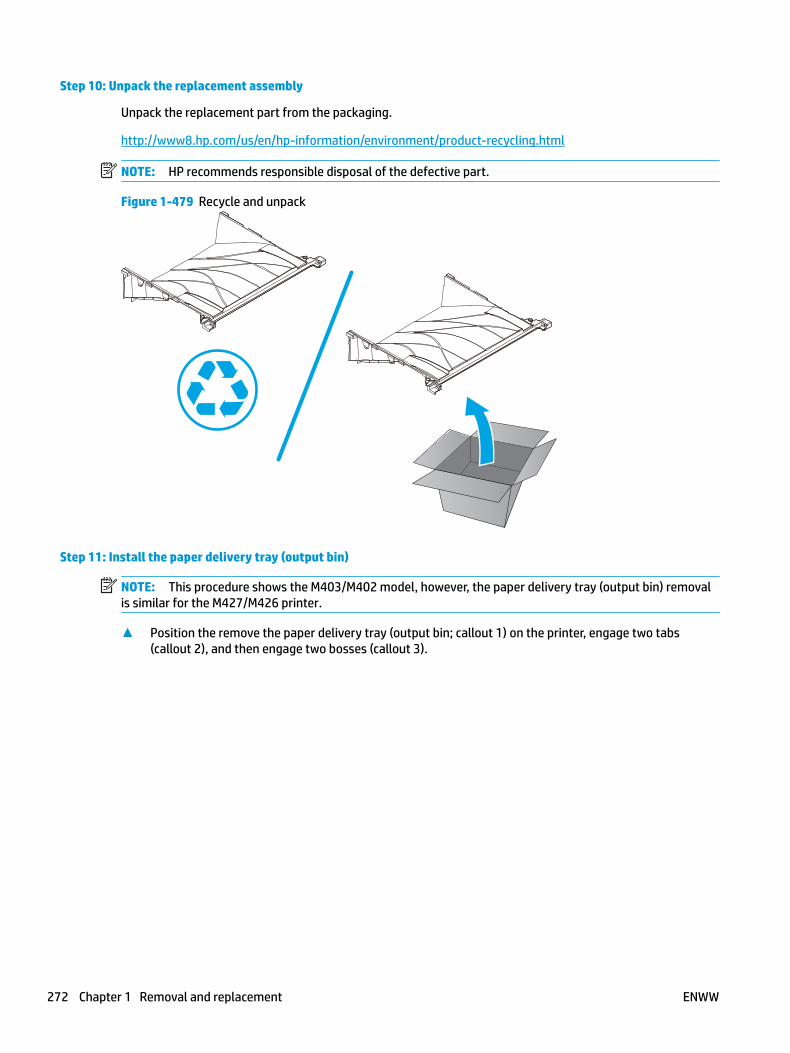
Step 10: Unpack the replacement assembly
Unpack the replacement part from the packaging.
http://www8.hp.com/us/en/hp-information/environment/product-recycling.html
NOTE: HP recommends responsible disposal of the defective part.
Figure 1-479 Recycle and unpack
Step 11: Install the paper delivery tray (output bin)
NOTE: This procedure shows the M403/M402 model, however, the paper delivery tray (output bin) removal is similar for the M427/M426 printer.
▲ Position the remove the paper delivery tray (output bin; callout 1) on the printer, engage two tabs (callout 2), and then engage two bosses (callout 3).
272 Chapter 1 Removal and replacement ENWW

Figure 1-480 Engage two tabs
2
3
1
Step 12: Install the top cover (M403/M402)
NOTE: The step is for the M403/M402 printer. For the M427/M426, skip this step and go to Step 13: Install the top cover (M427/M426) on page 275.
1. Position the rear edge of the cover on the printer.
Figure 1-481 Install the cover
ENWW Removal and replacement procedures 273

2. Engage four bosses (callout 1), rotate the front of the cover down (callout 2) and onto from the printer, and then engage four tabs (callout 3).
Figure 1-482 Engage four bosses and tabs
1
3
2
2
3. At the right side of the printer, engage the one boss and one tab (callout 1).
Figure 1-483 Engage one boss and one tab
1
274 Chapter 1 Removal and replacement ENWW
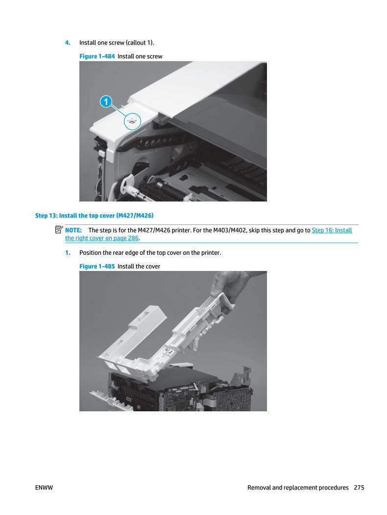
4. Install one screw (callout 1).
Figure 1-484 Install one screw
1
Step 13: Install the top cover (M427/M426)
NOTE: The step is for the M427/M426 printer. For the M403/M402, skip this step and go to Step 16: Install the right cover on page 286.
1. Position the rear edge of the top cover on the printer.
Figure 1-485 Install the cover
ENWW Removal and replacement procedures 275

2. Engage four bosses (callout 1).
Figure 1-486 Engage four bosses
1
3. Rotate the front edge of the cover down.
Figure 1-487 Rotate the front edge of the cover down
276 Chapter 1 Removal and replacement ENWW

4. Install the USB cable (callout 1) in the guide.
Figure 1-488 Install the USB PCA
1
5. Install five screws (callout 1).
Figure 1-489 Install five screws
1
Step 14: Install the control panel (M427/M246)
NOTE: The step is for the M427/M426 printer. For the M403/M402, skip this step and go to Step 16: Install the right cover on page 286.
1. Slide the control-panel FFC cover into the slot in the top cover (next to the document feeder support arm) to install it.
ENWW Removal and replacement procedures 277

Figure 1-490 Install the control-panel FFC cover
2. Install the control-panel assembly on the top cover.
Figure 1-491 Install the control-panel assembly
278 Chapter 1 Removal and replacement ENWW

3. Move the FFC out of the way, and then install two screws (callout 1).
Figure 1-492 Install two screws
1
4. Install one grounding screw (callout 1), and then make sure that the ground cable (callout 2) is properly routed.
Figure 1-493 Remove one screw
2
1
ENWW Removal and replacement procedures 279

5. Install the control-panel cable cover.
Figure 1-494 Install the cover
6. Make sure that the two tabs (callout 1) on the cover snap into place.
Figure 1-495 Engage two tabs
1
280 Chapter 1 Removal and replacement ENWW

7. Install one screw (callout 1).
Figure 1-496 Install one screw
1
8. Install the FFC in the retainer (callout 1), and then connect one FFC (callout 1; J114).
Figure 1-497 Connect one connector
1
2
Step 15: Install the integrated scanner assembly (M427/M246)
NOTE: The step is for the M427/M426 printer. For the M403/M402, skip this step and go to Step 16: Install the right cover on page 286.
NOTE: M427/M426 models only. The integrated scanner assembly (ISA) includes the sub-scanner assembly (SSA) and the automatic document feeder (ADF).
1. Position the ISA on the printer.
ENWW Removal and replacement procedures 281

Figure 1-498 Position the ISA on the printer
2. Engage the hinge pins on the ISA with the holders in the top cover (callouts 1/2), and the slide the ISA as shown to engage them
Figure 1-499 Engage the hinge pins with the holders
1
2
282 Chapter 1 Removal and replacement ENWW

3. Rotate the ISA towards the front of the printer until it rests on the ISA lift assembly (callout 1).
Figure 1-500 Rotate the ISA towards the front of the printer
1
4. Pass the ground wire through the opening in the top cover.
Figure 1-501 Pass the wire through the opening
ENWW Removal and replacement procedures 283

5. Install one screw (callout 1).
Figure 1-502 Install one screw
1
6. Install the ISA lift assembly slider pin.
Reinstallation tip: Align the keyed portion of the locking pin with the slot and hole in the support arm.
Figure 1-503 Install the slider pin
284 Chapter 1 Removal and replacement ENWW

7. Rotate the slider pin (callout 1) towards the rear of the printer until the tab (callout 2) snap into place.
Figure 1-504 Secure the slider pin
2
1
8. Install the ferrite (callout 1) in the holder, and then connect three FFCs (callout 2).
Figure 1-505 Connect three FFCs
1
2
ENWW Removal and replacement procedures 285

9. Position the rear edge of the ISA flat-flexible cable (FFC) cover on the printer (callout 1) , and then rotate it down (callout 2) until it snaps into place.
Figure 1-506 Install the ISA FFC cover
1
2
10. Lower the ISA.
Figure 1-507 Lower the ISA
Step 16: Install the right cover
1. Position the cover (callout 1) on the printer, and then engage two bosses (callout 2).
286 Chapter 1 Removal and replacement ENWW

Figure 1-508 Install the cover
11
2 2
2. Rotate the front of the cover onto the printer (callout 1), engage three (callout 2) tabs, and then engage two bosses (callout 3).
Figure 1-509 Engage two bosses and one tab
1 13 3
2 2
3. Make sure that the power switch (callout 1) and cartridge door assembly button (callout 2) correctly function.
NOTE: Remove, and then reinstall the cover if the switch or button does not correctly function.
Figure 1-510 Check the power switch and cartridge door assembly button
1
1
22
ENWW Removal and replacement procedures 287

4. Install one screw (callout 1).
Figure 1-511 Install one screw
11
Step 17: Install the left cover
1. At the front of the printer, do one of the following:
● M403/M402: Position the cover on the printer ( callout 1), and then engage two bosses (callout 2).
● M427/M426: Position the cover on the printer (callout 3), engage one tab (callout 4), and then engage two bosses (callout 4).
Figure 1-512 Install the cover
1
2
4
35
288 Chapter 1 Removal and replacement ENWW

2. Carefully rotate the rear of the cover onto the printer (callout 1), engage three tabs (callout 2), and then engage two bosses (callout 3).
Figure 1-513 Engage three tabs and two bosses
3
3 11
2
2
3. Install one screw (callout 1).
Figure 1-514 Install one screw
1 1
Step 18: Install the cartridge door assembly
Reinstallation tip: After a replacement door is installed, make sure to install the nameplate (supplied in the kit) corresponding to the printer name on the door.
1. Position the door close to the printer, and then engage the keyed pin on the left-side retainer arm with the hole in the door.
ENWW Removal and replacement procedures 289

Figure 1-515 Engage the left-side retainer arm
2. Engage the right-side door hinge pin with the hole in the chassis (callout 1).
Figure 1-516 Install the door
1
290 Chapter 1 Removal and replacement ENWW

3. Install the link (callout 1).
IMPORTANT: Make sure that the link snaps into place on the arm (callout 2). The link actuates the fuser pressure-release mechanism.
Figure 1-517 Install the pressure-release link
1
2
4. Slide the guide into the printer (callout 1), and then make sure that the tab (callout 2) snaps into place to secure the guide to the chassis.
Figure 1-518 Install the guide
1
2
ENWW Removal and replacement procedures 291

5. Position the shaft on the door, and then align the left-side hinge on the door with the hole in the chassis (callout 1).
Figure 1-519 Align the hinge
1
6. Push the shaft towards the left side of the printer to install it (callout 1).
Reinstallation tip: Make sure that the support shaft is fully installed and correctly orientated (callout 2) so that it will not interfere with the door opening and closing.
Figure 1-520 Install the support shaft
2
1
292 Chapter 1 Removal and replacement ENWW

Step 19: Install Tray 2
▲ Slide the tray straight into the printer to install it.
Figure 1-521 Install the tray
ENWW Removal and replacement procedures 293

Removal and replacement: Integrated scanner assembly (M427/M426)
NOTE: M427/M426 models only. The integrated scanner assembly (ISA) includes the sub-scanner assembly (SSA) and the automatic document feeder (ADF).
● Introduction
● Step 1: Remove Tray 2
● Step 2: Remove the cartridge door assembly
● Step 3: Remove the left cover
● Step 4: Remove the ISA (M427/M426)
● Step 5: Unpack the replacement assembly
● Step 6: Install the ISA (M427/M426)
● Step 7: Install the left cover
● Step 8: Install the cartridge door assembly
● Step 9: Install Tray 2
Introduction
This document provides the procedures to remove and replace the ISA.
Before performing service
Turn the printer power off
◦ Disconnect the power cable.
WARNING! To avoid damage to the printer, turn the printer off, wait 30 seconds, and then remove the power cable before attempting to service the printer.
Use the table below to identify the correct part number for your printer. To order the part, go to www.hp.com/buy/parts.
ISA part number1
C5F98-60110 ADF/scanner assembly, duplex ADF
C5F98-60109 ADF/scanner assembly, simplex ADF
1 The ISA includes the SSA and the ADF.
Required tools
● #2 Phillips screwdriver with a magnetic tip.
294 Chapter 1 Removal and replacement ENWW

After performing service
Turn the printer power on
◦ Connect the power cable.
◦ Use the power switch to turn the power on.
Post service test
Make sure that the printer initializes to a Ready state.
Print a configuration page, and then make a copy using the document feeder to make sure that it is properly functioning.
Step 1: Remove Tray 2
▲ Pull the tray straight out of the printer to remove it.
Figure 1-522 Remove the tray
Step 2: Remove the cartridge door assembly
NOTE: If the toner cartridge was not removed prior to servicing the printer, remove it now.
1. Release one tab (callout 1), and then slide shaft (callout 2) in the direction the arrow indicates and remove it.
TIP: It might be easier to release the support shaft by using a small flat-blade screwdriver.
ENWW Removal and replacement procedures 295

Figure 1-523 Release the support shaft
12
2. Release one tab (callout 1), and then slide the guide (callout 2) in the direction the arrow indicates and remove it.
Figure 1-524 Remove the guide
1 2
296 Chapter 1 Removal and replacement ENWW

3. Remove the link arm (callout 1).
Figure 1-525 Remove the link arm
1
4. Slide the cartridge door assembly (callout 1) in the direction the arrow indicates and remove it.
Figure 1-526 Remove the door
1
ENWW Removal and replacement procedures 297
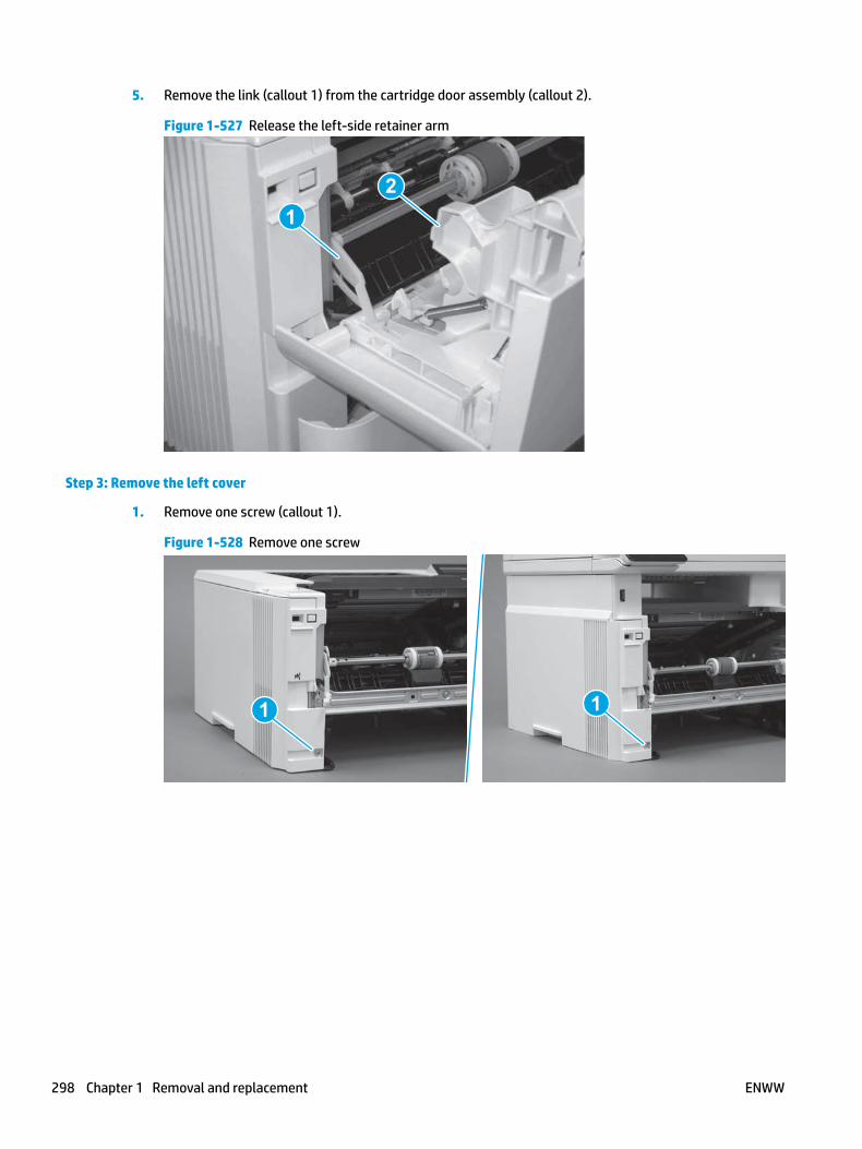
5. Remove the link (callout 1) from the cartridge door assembly (callout 2).
Figure 1-527 Release the left-side retainer arm
21
Step 3: Remove the left cover
1. Remove one screw (callout 1).
Figure 1-528 Remove one screw
1 1
298 Chapter 1 Removal and replacement ENWW

2. Open the rear door, release two bosses (callout 1), and then release three tabs (callout 2).
Figure 1-529 Release two bosses and three tabs
1
1
2
2
3. At the front of the printer, do one of the following:
● M403/M402: Release two bosses (callout 1), and then remove the cover (callout 2).
● M427/M426: Release one tab (callout 3), two bosses (callout 4), and then remove the cover (callout 5).
CAUTION: Be careful when releasing the upper bosses on the M427/M426 cover. One portion of the cover (callout 6) is fragile and is easily broken.
Figure 1-530 Remove the cover
2
1
3
54 6
Step 4: Remove the ISA (M427/M426)
NOTE: M427/M426 models only. The integrated scanner assembly (ISA) includes the sub-scanner assembly (SSA) and the automatic document feeder (ADF).
1. Raise the ISA.
ENWW Removal and replacement procedures 299

Figure 1-531 Raise the ISA
2. Release the ISA flat-flexible cable (FFC) cover (callout 1), and then remove it (callout 2).
Figure 1-532 Remove the ISA FFC cover
12
300 Chapter 1 Removal and replacement ENWW

3. Disconnect three FFCs (callout 1), and then remove the ferrite (callout 2) from the holder.
CAUTION: The ferrite is not captive on the FFC. Do not lose the ferrite while handling the ISA.
Figure 1-533 Disconnect three FFCs
2
1
4. Remove one screw (callout 1).
Figure 1-534 Remove one screw
1
ENWW Removal and replacement procedures 301

5. Pass the ground wire through the opening in the top cover.
Figure 1-535 Pass the wire through the opening
6. Release one tab (callout 1), and then rotate the ISA slider pin (callout 2) towards the front of the printer to release it.
Figure 1-536 Release one tab and rotate the slider pin
1
2
302 Chapter 1 Removal and replacement ENWW
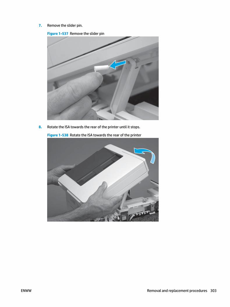
7. Remove the slider pin.
Figure 1-537 Remove the slider pin
8. Rotate the ISA towards the rear of the printer until it stops.
Figure 1-538 Rotate the ISA towards the rear of the printer
ENWW Removal and replacement procedures 303

9. Slide the ISA as shown to release it.
Figure 1-539 Release the ISA
10. Remove the ISA.
Figure 1-540 Remove the ISA
Step 5: Unpack the replacement assembly
Unpack the replacement part from the packaging.
http://www8.hp.com/us/en/hp-information/environment/product-recycling.html
NOTE: HP recommends responsible disposal of the defective part.
304 Chapter 1 Removal and replacement ENWW

Figure 1-541 Recycle and unpack
Step 6: Install the ISA (M427/M426)
NOTE: M427/M426 models only. The integrated scanner assembly (ISA) includes the sub-scanner assembly (SSA) and the automatic document feeder (ADF).
1. Position the ISA on the printer.
Figure 1-542 Position the ISA on the printer
ENWW Removal and replacement procedures 305

2. Engage the hinge pins on the ISA with the holders in the top cover (callouts 1/2), and the slide the ISA as shown to engage them
Figure 1-543 Engage the hinge pins with the holders
1
2
3. Rotate the ISA towards the front of the printer until it rests on the ISA lift assembly (callout 1).
Figure 1-544 Rotate the ISA towards the front of the printer
1
306 Chapter 1 Removal and replacement ENWW
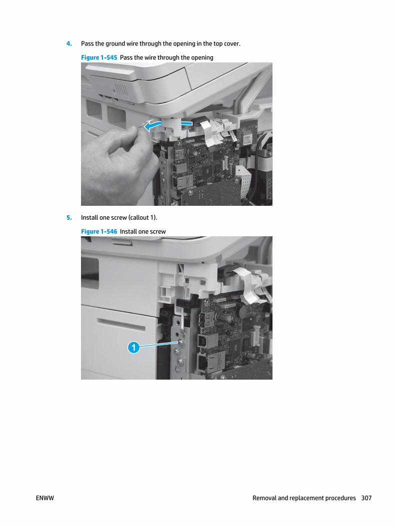
4. Pass the ground wire through the opening in the top cover.
Figure 1-545 Pass the wire through the opening
5. Install one screw (callout 1).
Figure 1-546 Install one screw
1
ENWW Removal and replacement procedures 307

6. Install the ISA lift assembly slider pin.
Reinstallation tip: Align the keyed portion of the locking pin with the slot and hole in the support arm.
Figure 1-547 Install the slider pin
7. Rotate the slider pin (callout 1) towards the rear of the printer until the tab (callout 2) snap into place.
Figure 1-548 Secure the slider pin
2
1
308 Chapter 1 Removal and replacement ENWW

8. Install the ferrite (callout 1) in the holder, and then connect three FFCs (callout 2).
Figure 1-549 Connect three FFCs
1
2
9. Position the rear edge of the ISA flat-flexible cable (FFC) cover on the printer (callout 1) , and then rotate it down (callout 2) until it snaps into place.
Figure 1-550 Install the ISA FFC cover
1
2
ENWW Removal and replacement procedures 309

10. Lower the ISA.
Figure 1-551 Lower the ISA
Step 7: Install the left cover
1. At the front of the printer, do one of the following:
● M403/M402: Position the cover on the printer ( callout 1), and then engage two bosses (callout 2).
● M427/M426: Position the cover on the printer (callout 3), engage one tab (callout 4), and then engage two bosses (callout 4).
Figure 1-552 Install the cover
1
2
4
35
310 Chapter 1 Removal and replacement ENWW

2. Carefully rotate the rear of the cover onto the printer (callout 1), engage three tabs (callout 2), and then engage two bosses (callout 3).
Figure 1-553 Engage three tabs and two bosses
3
3 11
2
2
3. Install one screw (callout 1).
Figure 1-554 Install one screw
1 1
Step 8: Install the cartridge door assembly
Reinstallation tip: After a replacement door is installed, make sure to install the nameplate (supplied in the kit) corresponding to the printer name on the door.
1. Position the door close to the printer, and then engage the keyed pin on the left-side retainer arm with the hole in the door.
ENWW Removal and replacement procedures 311

Figure 1-555 Engage the left-side retainer arm
2. Engage the right-side door hinge pin with the hole in the chassis (callout 1).
Figure 1-556 Install the door
1
312 Chapter 1 Removal and replacement ENWW
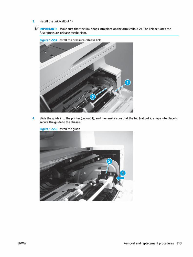
3. Install the link (callout 1).
IMPORTANT: Make sure that the link snaps into place on the arm (callout 2). The link actuates the fuser pressure-release mechanism.
Figure 1-557 Install the pressure-release link
1
2
4. Slide the guide into the printer (callout 1), and then make sure that the tab (callout 2) snaps into place to secure the guide to the chassis.
Figure 1-558 Install the guide
1
2
ENWW Removal and replacement procedures 313

5. Position the shaft on the door, and then align the left-side hinge on the door with the hole in the chassis (callout 1).
Figure 1-559 Align the hinge
1
6. Push the shaft towards the left side of the printer to install it (callout 1).
Reinstallation tip: Make sure that the support shaft is fully installed and correctly orientated (callout 2) so that it will not interfere with the door opening and closing.
Figure 1-560 Install the support shaft
2
1
314 Chapter 1 Removal and replacement ENWW

Step 9: Install Tray 2
▲ Slide the tray straight into the printer to install it.
Figure 1-561 Install the tray
ENWW Removal and replacement procedures 315

Removal and replacement: ISA lift assembly and slider pin (M427/M426)
NOTE: M427/M426 models only.
● Introduction
● Step 1: Remove the slider pin (M427/M426)
● Step 2: Remove the ISA lift assembly (M427/M426)
● Step 3: Unpack the replacement assembly
● Step 4: Install the ISA lift assembly (M427/M426)
● Step 5: Install the slider pin (M427/M426)
Introduction
This document provides the procedures to remove and replace the integrated scanner assembly (ISA) support arm.
Before performing service
Turn the printer power off
◦ Disconnect the power cable.
WARNING! To avoid damage to the printer, turn the printer off, wait 30 seconds, and then remove the power cable before attempting to service the printer.
Use the table below to identify the correct part number for your printer. To order the part, go to www.hp.com/buy/parts.
ISA lift assembly and slider pin
B3Q10-60128
B3Q10-40041
ISA lift assembly
Slider pin, ISA lift assembly
Required tools
● #2 Phillips screwdriver with a magnetic tip.
After performing service
Turn the printer power on
◦ Connect the power cable.
◦ Use the power switch to turn the power on.
Post service test
Make sure that the printer initializes to a Ready state.
Print a configuration page, and then make a copy using the document feeder to make sure that it is properly functioning.
316 Chapter 1 Removal and replacement ENWW

Step 1: Remove the slider pin (M427/M426)
1. Open the ISA, release one tab (callout 1), and then rotate the ISA slider pin (callout 2) towards the front of the printer to release it.
Figure 1-562 Release one tab and rotate the slider pin
1
2
2. Remove the slider pin.
Figure 1-563 Remove the slider pin
Step 2: Remove the ISA lift assembly (M427/M426)
1. Move the ISA out of the way, and then lower the support arm to the closed position.
CAUTION: The ISA hinges are not captive in the top cover mounting bosses. Do not allow the ISA to slip off of the top cover.
ENWW Removal and replacement procedures 317

Figure 1-564 Lower the support arm
2. Before proceeding take note of the following.
CAUTION: The support arm is spring loaded and can unexpectedly spring into the open position. To avoid injury, do not place a finger in the screw well when the support arm is in the closed position.
Figure 1-565 Before proceeding take note
318 Chapter 1 Removal and replacement ENWW

3. Remove one screw (callout 1).
Figure 1-566 Remove one screw
1
4. Remove the support arm.
Figure 1-567 Remove the support arm
Step 3: Unpack the replacement assembly
Unpack the replacement part from the packaging.
http://www8.hp.com/us/en/hp-information/environment/product-recycling.html
NOTE: HP recommends responsible disposal of the defective part.
ENWW Removal and replacement procedures 319

Figure 1-568 Recycle and unpack
Step 4: Install the ISA lift assembly (M427/M426)
1. Support the ISA, align the tab (callout 1) on the lift assembly with the slot in the top cover (callout 2), and then install the lift assembly.
CAUTION: The ISA hinges are not captive in the top cover mounting bosses. Do not allow the ISA to slip off of the top cover.
NOTE: If the replacement lift assembly is in the closed position, place it in the open position.
Figure 1-569 Install the lift assembly
1
2
320 Chapter 1 Removal and replacement ENWW

2. Lower the lift assembly to the closed position.
Figure 1-570 Lower the lift assembly
3. Before proceeding take note of the following.
CAUTION: The lift assembly is spring loaded and can unexpectedly spring into the open position. To avoid injury, do not place a finger in the screw well when the lift assembly is in the closed position.
Figure 1-571 Before proceeding take note
ENWW Removal and replacement procedures 321

4. Install one screw (callout 1).
Figure 1-572 Install one screw
1
Step 5: Install the slider pin (M427/M426)
1. Raise the ISA lift assembly to the open position, engage the ISA with the lift assembly, and then install the slider pin.
Reinstallation tip: Align the keyed portion of the slider pin with the slot and hole in the lift assembly.
Figure 1-573 Install the slider pin
322 Chapter 1 Removal and replacement ENWW

2. Rotate the slider pin (callout 1) towards the rear of the printer until the tab (callout 2) snap into place. Close the ISA.
Figure 1-574 Secure the slider pin
2
1
ENWW Removal and replacement procedures 323

Removal and replacement: Internal parts and assemblies● Removal and replacement: Fuser
● Removal and replacement: Registration assembly
● Removal and replacement: Main motor (M1)
● Removal and replacement: Power switch printed circuit assembly
● Removal and replacement: Fax PCA (M427/M426)
● Removal and replacement: Walkup USB PCA (M427/M426)
● Removal and replacement: Wireless PCA
● Removal and replacement: Formatter PCA
● Removal and replacement: Fan (FM1)
● Removal and replacement: Fan holder (FM1)
● Removal and replacement: Laser scanner assembly
● Removal and replacement: Sheet-metal formatter bracket and formatter PCA
● Removal and replacement: NFC FFC
● Removal and replacement: Control panel FFC, (M403/M402)
● Removal and replacement: Formatter FFC
● Removal and replacement: DC controller
● Removal and replacement: Tag-cable assembly (toner-cartridge memory)
● Removal and replacement: Connecting PCA
● Removal and replacement: Laser scanner FFC
● Removal and replacement: High-voltage power supply
● Removal and replacement: Low-voltage power supply
● Removal and replacement: NFC cover (M427/M426)
● Removal and replacement: NFC PCA
● Removal and replacement: Control-panel assembly (M403/M402)
● Removal and replacement: Control panel (M427/M426) and control panel sub assemblies
324 Chapter 1 Removal and replacement ENWW

Removal and replacement: Fuser
● Introduction
● Step 1: Remove Tray 2
● Step 2: Remove the cartridge door assembly
● Step 3: Remove the left cover
● Step 4: Remove the right cover
● Step 5: Remove the rear door assembly
● Step 6: Remove the fuser
● Step 7: Unpack the replacement assembly
● Step 8: Install the fuser
● Step 9: Install the rear door assembly
● Step 10: Install the right cover
● Step 11: Install the left cover
● Step 12: Install the cartridge door assembly
● Step 13: Install Tray 2
Introduction
This document provides the procedures to remove and replace the fuser.
Before performing service
Turn the printer power off
◦ Disconnect the power cable.
WARNING! To avoid damage to the printer, turn the printer off, wait 30 seconds, and then remove the power cable before attempting to service the printer.
Make sure the correct voltage fuser is installed in the printer.
CAUTION: The fuser is hot. Wait at least 30 minutes after turning the printer off before removing the fuser.
Use the table below to identify the correct part number for your printer. To order the part, go to www.hp.com/buy/parts.
Fuser part number
RM2-5399-000CN
RM2-5425-000CN
Fuser (110V/127V)
Fuser (220V/240V)
ENWW Removal and replacement procedures 325

Required tools
● #2 Phillips screwdriver with a magnetic tip.
After performing service
Turn the printer power on
◦ Connect the power cable.
◦ Use the power switch to turn the power on.
Post service test
Make sure that the printer initializes to a Ready state.
Print a configuration page to make sure that the printer is functioning correctly.
Step 1: Remove Tray 2
▲ Pull the tray straight out of the printer to remove it.
Figure 1-575 Remove the tray
Step 2: Remove the cartridge door assembly
NOTE: If the toner cartridge was not removed prior to servicing the printer, remove it now.
1. Release one tab (callout 1), and then slide shaft (callout 2) in the direction the arrow indicates and remove it.
TIP: It might be easier to release the support shaft by using a small flat-blade screwdriver.
326 Chapter 1 Removal and replacement ENWW

Figure 1-576 Release the support shaft
12
2. Release one tab (callout 1), and then slide the guide (callout 2) in the direction the arrow indicates and remove it.
Figure 1-577 Remove the guide
1 2
ENWW Removal and replacement procedures 327

3. Remove the link arm (callout 1).
Figure 1-578 Remove the link arm
1
4. Slide the cartridge door assembly (callout 1) in the direction the arrow indicates and remove it.
Figure 1-579 Remove the door
1
328 Chapter 1 Removal and replacement ENWW

5. Remove the link (callout 1) from the cartridge door assembly (callout 2).
Figure 1-580 Release the left-side retainer arm
21
Step 3: Remove the left cover
1. Remove one screw (callout 1).
Figure 1-581 Remove one screw
1 1
ENWW Removal and replacement procedures 329

2. Open the rear door, release two bosses (callout 1), and then release three tabs (callout 2).
Figure 1-582 Release two bosses and three tabs
1
1
2
2
3. At the front of the printer, do one of the following:
● M403/M402: Release two bosses (callout 1), and then remove the cover (callout 2).
● M427/M426: Release one tab (callout 3), two bosses (callout 4), and then remove the cover (callout 5).
CAUTION: Be careful when releasing the upper bosses on the M427/M426 cover. One portion of the cover (callout 6) is fragile and is easily broken.
Figure 1-583 Remove the cover
2
1
3
54 6
Step 4: Remove the right cover
1. Remove one screw (callout 1).
330 Chapter 1 Removal and replacement ENWW

Figure 1-584 Remove one screw
11
2. At the front of the printer, release two bosses (callout 1), and then release three tabs (callout 2).
Figure 1-585 Release two bosses and three tabs
1 1
2 2
3. Open the rear door, release two bosses (callout 1), and then remove the cover (callout 2).
Figure 1-586 Remove the cover
22
1 1
Step 5: Remove the rear door assembly
1. Duplex models only: Inside the Tray 2 cavity, press the green jam access lever (callout 1), and then lower the duplex feed assembly (callout 2).
ENWW Removal and replacement procedures 331

Figure 1-587 Duplex models, lower the duplex feed assembly
12
2. At the rear of the printer, remove two screws (callout 1), and then remove the rear door assembly (callout 2).
Figure 1-588 Remove two screws
12
Step 6: Remove the fuser
1. Disconnect one connector (callout 1), and then release the wire harness from the guide (callout 2).
332 Chapter 1 Removal and replacement ENWW
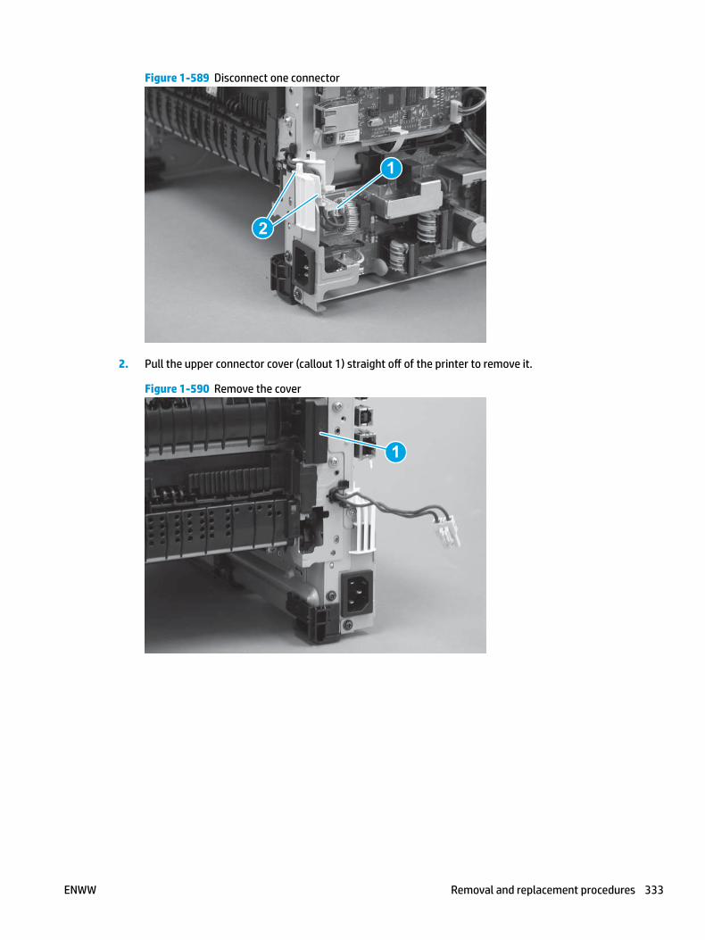
Figure 1-589 Disconnect one connector
2
1
2. Pull the upper connector cover (callout 1) straight off of the printer to remove it.
Figure 1-590 Remove the cover
1
ENWW Removal and replacement procedures 333

3. Disconnect two connectors (callout 1).
Figure 1-591 Disconnect two connectors
1
4. Remove four screws (callout 1).
Figure 1-592 Remove four screws
1
334 Chapter 1 Removal and replacement ENWW

5. Pull the pressure-release link arm as shown to release it from the fuser.
Figure 1-593 Release the pressure-release arm
6. Slide the fuser straight out of the printer.
Figure 1-594 Remove the fuser
Step 7: Unpack the replacement assembly
Unpack the replacement part from the packaging.
http://www8.hp.com/us/en/hp-information/environment/product-recycling.html
NOTE: HP recommends responsible disposal of the defective part.
ENWW Removal and replacement procedures 335

Figure 1-595 Recycle and unpack
Step 8: Install the fuser
1. Slide the fuser straight into the printer.
Figure 1-596 Install the fuser
336 Chapter 1 Removal and replacement ENWW
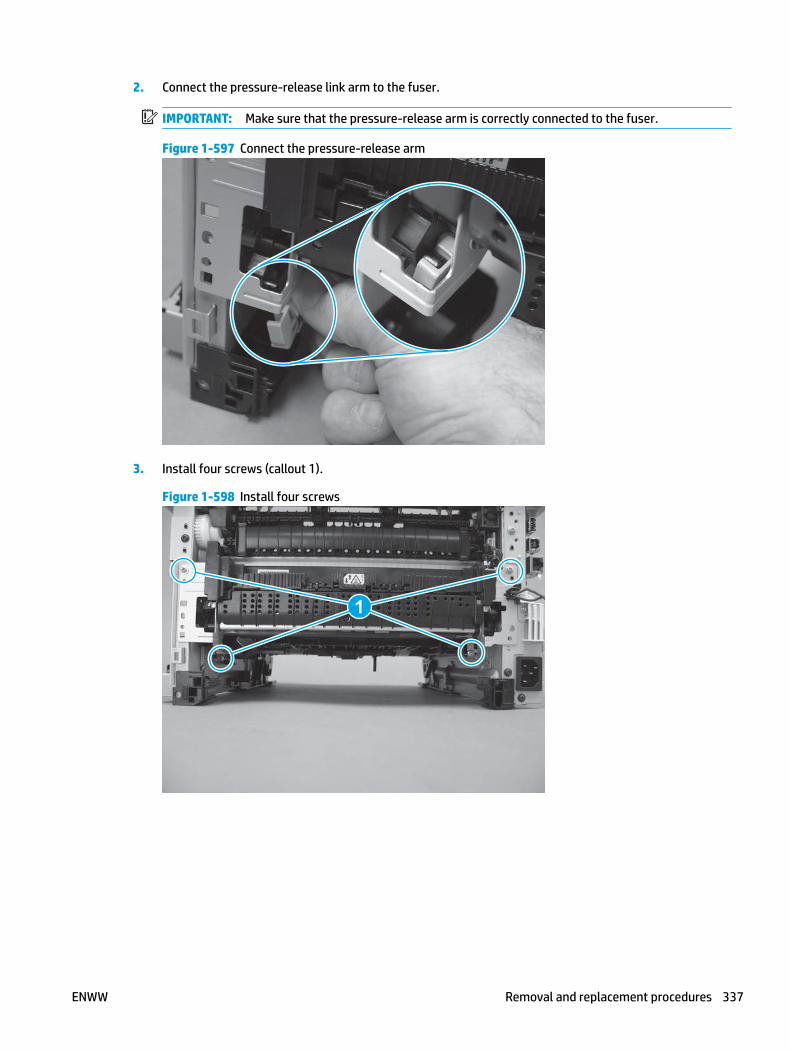
2. Connect the pressure-release link arm to the fuser.
IMPORTANT: Make sure that the pressure-release arm is correctly connected to the fuser.
Figure 1-597 Connect the pressure-release arm
3. Install four screws (callout 1).
Figure 1-598 Install four screws
1
ENWW Removal and replacement procedures 337

4. Connect two connectors (callout 1).
Figure 1-599 Connect two connectors
1
5. Push the upper connector cover (callout 1) straight onto of the printer to install it.
Figure 1-600 Install the cover
1
338 Chapter 1 Removal and replacement ENWW

6. Install the wire harness in the guide (callout 1), and then connect one connector (callout 2).
Figure 1-601 Connect one connector
1
2
Step 9: Install the rear door assembly
1. At the rear of the printer, position the assembly so that the two tabs (callout 1) are installed in the slots (callout 2) in the chassis.
NOTE: Duplex models only: Slide the duplex tray into the Tray 2 cavity.
Figure 1-602 Install the rear cover
1
ENWW Removal and replacement procedures 339

2. Install two screws.
NOTE: Duplex models only: Reach in from the front of the Tray 2 cavity and raise the feed assembly to the up and locked position so that the rear cover will fit flat against the chassis.
Figure 1-603 Install two screws
1
Step 10: Install the right cover
1. Position the cover (callout 1) on the printer, and then engage two bosses (callout 2).
Figure 1-604 Install the cover
11
2 2
340 Chapter 1 Removal and replacement ENWW

2. Rotate the front of the cover onto the printer (callout 1), engage three (callout 2) tabs, and then engage two bosses (callout 3).
Figure 1-605 Engage two bosses and one tab
1 13 3
2 2
3. Make sure that the power switch (callout 1) and cartridge door assembly button (callout 2) correctly function.
NOTE: Remove, and then reinstall the cover if the switch or button does not correctly function.
Figure 1-606 Check the power switch and cartridge door assembly button
1
1
22
4. Install one screw (callout 1).
Figure 1-607 Install one screw
11
ENWW Removal and replacement procedures 341

Step 11: Install the left cover
1. At the front of the printer, do one of the following:
● M403/M402: Position the cover on the printer ( callout 1), and then engage two bosses (callout 2).
● M427/M426: Position the cover on the printer (callout 3), engage one tab (callout 4), and then engage two bosses (callout 4).
Figure 1-608 Install the cover
1
2
4
35
2. Carefully rotate the rear of the cover onto the printer (callout 1), engage three tabs (callout 2), and then engage two bosses (callout 3).
Figure 1-609 Engage three tabs and two bosses
3
3 11
2
2
342 Chapter 1 Removal and replacement ENWW

3. Install one screw (callout 1).
Figure 1-610 Install one screw
1 1
Step 12: Install the cartridge door assembly
Reinstallation tip: After a replacement door is installed, make sure to install the nameplate (supplied in the kit) corresponding to the printer name on the door.
1. Position the door close to the printer, and then engage the keyed pin on the left-side retainer arm with the hole in the door.
Figure 1-611 Engage the left-side retainer arm
ENWW Removal and replacement procedures 343

2. Engage the right-side door hinge pin with the hole in the chassis (callout 1).
Figure 1-612 Install the door
1
3. Install the link (callout 1).
IMPORTANT: Make sure that the link snaps into place on the arm (callout 2). The link actuates the fuser pressure-release mechanism.
Figure 1-613 Install the pressure-release link
1
2
344 Chapter 1 Removal and replacement ENWW

4. Slide the guide into the printer (callout 1), and then make sure that the tab (callout 2) snaps into place to secure the guide to the chassis.
Figure 1-614 Install the guide
1
2
5. Position the shaft on the door, and then align the left-side hinge on the door with the hole in the chassis (callout 1).
Figure 1-615 Align the hinge
1
ENWW Removal and replacement procedures 345

6. Push the shaft towards the left side of the printer to install it (callout 1).
Reinstallation tip: Make sure that the support shaft is fully installed and correctly orientated (callout 2) so that it will not interfere with the door opening and closing.
Figure 1-616 Install the support shaft
2
1
Step 13: Install Tray 2
▲ Slide the tray straight into the printer to install it.
Figure 1-617 Install the tray
346 Chapter 1 Removal and replacement ENWW

Removal and replacement: Registration assembly
● Introduction
● Step 1: Remove Tray 2
● Step 2: Remove the cartridge door assembly
● Step 3: Remove the left cover
● Step 4: Remove the right cover
● Step 5: Remove the rear door assembly
● Step 6: Remove the integrated scanner assembly (M427/M246)
● Step 7: Remove the control panel (M427/M426)
● Step 8: Remove the top cover (M427/M426)
● Step 9: Remove the top cover (M403/M402)
● Step 10: Remove the paper delivery tray (output bin)
● Step 11: Remove the fuser
● Step 12: Remove the registration assembly
● Step 13: Unpack the replacement assembly
● Step 14: Install the registration assembly
● Step 15: Install the fuser
● Step 16: Install the paper delivery tray (output bin)
● Step 17: Install the top cover (M403/M402)
● Step 18: Install the top cover (M427/M426)
● Step 19: Install the control panel (M427/M246)
● Step 20: Install the integrated scanner assembly (M427/M246)
● Step 21: Install the rear door assembly
● Step 22: Install the right cover
● Step 23: Install the left cover
● Step 24: Install the cartridge door assembly
● Step 25: Install Install Tray 2
Introduction
This document provides the procedures to remove and replace the registration assembly.
ENWW Removal and replacement procedures 347

Before performing service
Turn the printer power off
◦ Disconnect the power cable.
WARNING! To avoid damage to the printer, turn the printer off, wait 30 seconds, and then remove the power cable before attempting to service the printer.
Make sure the correct voltage fuser is installed in the printer.
CAUTION: The fuser is hot. Wait at least 30 minutes after turning the printer off before removing the fuser.
Use the table below to identify the correct part number for your printer. To order the part, go to www.hp.com/buy/parts.
Registration assembly part number
RM2-5671-000CN Registration assembly
Required tools
● #2 Phillips screwdriver with a magnetic tip.
After performing service
Turn the printer power on
◦ Connect the power cable.
◦ Use the power switch to turn the power on.
Post service test
Make sure that the printer initializes to a Ready state.
Print a configuration page to make sure that the printer is functioning correctly.
Step 1: Remove Tray 2
▲ Pull the tray straight out of the printer to remove it.
348 Chapter 1 Removal and replacement ENWW

Figure 1-618 Remove the tray
Step 2: Remove the cartridge door assembly
NOTE: If the toner cartridge was not removed prior to servicing the printer, remove it now.
1. Release one tab (callout 1), and then slide shaft (callout 2) in the direction the arrow indicates and remove it.
TIP: It might be easier to release the support shaft by using a small flat-blade screwdriver.
Figure 1-619 Release the support shaft
12
ENWW Removal and replacement procedures 349

2. Release one tab (callout 1), and then slide the guide (callout 2) in the direction the arrow indicates and remove it.
Figure 1-620 Remove the guide
1 2
3. Remove the link arm (callout 1).
Figure 1-621 Remove the link arm
1
350 Chapter 1 Removal and replacement ENWW

4. Slide the cartridge door assembly (callout 1) in the direction the arrow indicates and remove it.
Figure 1-622 Remove the door
1
5. Remove the link (callout 1) from the cartridge door assembly (callout 2).
Figure 1-623 Release the left-side retainer arm
21
Step 3: Remove the left cover
1. Remove one screw (callout 1).
ENWW Removal and replacement procedures 351

Figure 1-624 Remove one screw
1 1
2. Open the rear door, release two bosses (callout 1), and then release three tabs (callout 2).
Figure 1-625 Release two bosses and three tabs
1
1
2
2
3. At the front of the printer, do one of the following:
● M403/M402: Release two bosses (callout 1), and then remove the cover (callout 2).
● M427/M426: Release one tab (callout 3), two bosses (callout 4), and then remove the cover (callout 5).
CAUTION: Be careful when releasing the upper bosses on the M427/M426 cover. One portion of the cover (callout 6) is fragile and is easily broken.
352 Chapter 1 Removal and replacement ENWW

Figure 1-626 Remove the cover
2
1
3
54 6
Step 4: Remove the right cover
1. Remove one screw (callout 1).
Figure 1-627 Remove one screw
11
2. At the front of the printer, release two bosses (callout 1), and then release three tabs (callout 2).
Figure 1-628 Release two bosses and three tabs
1 1
2 2
ENWW Removal and replacement procedures 353

3. Open the rear door, release two bosses (callout 1), and then remove the cover (callout 2).
Figure 1-629 Remove the cover
22
1 1
Step 5: Remove the rear door assembly
1. Duplex models only: Inside the Tray 2 cavity, press the green jam access lever (callout 1), and then lower the duplex feed assembly (callout 2).
Figure 1-630 Duplex models, lower the duplex feed assembly
12
354 Chapter 1 Removal and replacement ENWW

2. At the rear of the printer, remove two screws (callout 1), and then remove the rear door assembly (callout 2).
Figure 1-631 Remove two screws
12
Step 6: Remove the integrated scanner assembly (M427/M246)
NOTE: The step is for the M427/M426 printer. For the M403/M402, skip this step and go to Step 9: Remove the top cover (M403/M402) on page 365.
NOTE: M427/M426 models only. The integrated scanner assembly (ISA) includes the sub-scanner assembly (SSA) and the automatic document feeder (ADF).
1. Raise the ISA.
Figure 1-632 Raise the ISA
ENWW Removal and replacement procedures 355

2. Release the ISA flat-flexible cable (FFC) cover (callout 1), and then remove it (callout 2).
Figure 1-633 Remove the ISA FFC cover
12
3. Disconnect three FFCs (callout 1), and then remove the ferrite (callout 2) from the holder.
CAUTION: The ferrite is not captive on the FFC. Do not lose the ferrite while handling the ISA.
Figure 1-634 Disconnect three FFCs
2
1
356 Chapter 1 Removal and replacement ENWW

4. Remove one screw (callout 1).
Figure 1-635 Remove one screw
1
5. Pass the ground wire through the opening in the top cover.
Figure 1-636 Pass the wire through the opening
ENWW Removal and replacement procedures 357

6. Release one tab (callout 1), and then rotate the ISA slider pin (callout 2) towards the front of the printer to release it.
Figure 1-637 Release one tab and rotate the slider pin
1
2
7. Remove the slider pin.
Figure 1-638 Remove the slider pin
358 Chapter 1 Removal and replacement ENWW

8. Rotate the ISA towards the rear of the printer until it stops.
Figure 1-639 Rotate the ISA towards the rear of the printer
9. Slide the ISA as shown to release it.
Figure 1-640 Release the ISA
ENWW Removal and replacement procedures 359

10. Remove the ISA.
Figure 1-641 Remove the ISA
Step 7: Remove the control panel (M427/M426)
NOTE: The step is for the M427/M426 printer. For the M403/M402, skip this step and go to Step 9: Remove the top cover (M403/M402) on page 365.
1. Disconnect one FFC (callout 1; J114), and then release the FFC from the retainer (callout 2).
Figure 1-642 Disconnect one connector
1
2
360 Chapter 1 Removal and replacement ENWW

2. Remove one screw (callout 1).
Figure 1-643 Remove one screw
1
3. Use a small flat-blade screwdriver to release two tabs (callout 1) on the control-panel cable cover.
Figure 1-644 Release two tabs
1
ENWW Removal and replacement procedures 361

4. Remove the control-panel cable cover.
Figure 1-645 Remove the cover
5. Remove one grounding screw (callout 1), and then move the ground cable (callout 2) out of the way.
Figure 1-646 Remove one screw
2
1
362 Chapter 1 Removal and replacement ENWW
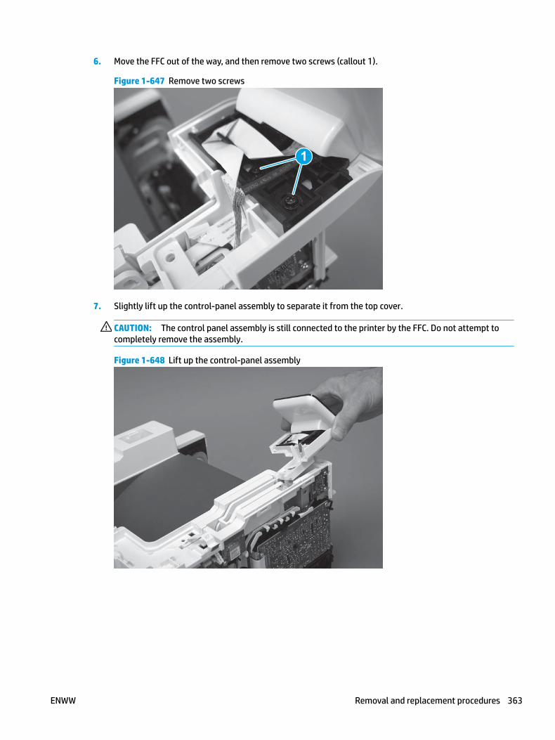
6. Move the FFC out of the way, and then remove two screws (callout 1).
Figure 1-647 Remove two screws
1
7. Slightly lift up the control-panel assembly to separate it from the top cover.
CAUTION: The control panel assembly is still connected to the printer by the FFC. Do not attempt to completely remove the assembly.
Figure 1-648 Lift up the control-panel assembly
ENWW Removal and replacement procedures 363

8. Lift up the control-panel FFC cover to remove the control-panel assembly.
Figure 1-649 Remove the control-panel assembly
Step 8: Remove the top cover (M427/M426)
NOTE: The step is for the M427/M426 printer. For the M403/M402, skip this step and go to Step 9: Remove the top cover (M403/M402) on page 365.
1. Release the USB cable (callout 1) from the cable guide.
Figure 1-650 Remove the USB cable
1
364 Chapter 1 Removal and replacement ENWW

2. Remove five screws (callout 1), release four bosses (callout 2), and then remove the top cover (callout 3).
Figure 1-651 Remove the cover
3
2
1
Step 9: Remove the top cover (M403/M402)
NOTE: The step is for the M403/M402 printer. For the M427/M426, skip this step and go to Step 10: Remove the paper delivery tray (output bin) on page 366.
1. Remove one screw (callout 1).
Figure 1-652 Remove one screw
1
ENWW Removal and replacement procedures 365

2. At the right side of the printer, release the one boss (callout 1), and then release one tab (callout 2).
Figure 1-653 Release one boss and one tab
21
3. Release four tabs (callout 1), release four bosses (callout 2), and then remove the top cover (callout 3).
TIP: Open the rear door to make releasing the bosses (callout 3) easier.
Figure 1-654 Remove the cover
2
3
1
Step 10: Remove the paper delivery tray (output bin)
NOTE: This procedure shows the M403/M402 model, however, the paper delivery tray (output bin) removal is similar for the M427/M426 printer.
▲ Release two bosses (callout 1), release two tabs (callout 2), and then remove the paper delivery tray (output bin; callout 3).
366 Chapter 1 Removal and replacement ENWW

Figure 1-655 Release two tabs
2
1
3
Step 11: Remove the fuser
1. Disconnect one connector (callout 1), and then release the wire harness from the guide (callout 2).
Figure 1-656 Disconnect one connector
2
1
ENWW Removal and replacement procedures 367

2. Pull the upper connector cover (callout 1) straight off of the printer to remove it.
Figure 1-657 Remove the cover
1
3. Disconnect two connectors (callout 1).
Figure 1-658 Disconnect two connectors
1
368 Chapter 1 Removal and replacement ENWW

4. Remove four screws (callout 1).
Figure 1-659 Remove four screws
1
5. Pull the pressure-release link arm as shown to release it from the fuser.
Figure 1-660 Release the pressure-release arm
ENWW Removal and replacement procedures 369

6. Slide the fuser straight out of the printer.
Figure 1-661 Remove the fuser
Step 12: Remove the registration assembly
1. Carefully rotate the printer backward until it rests on the rear side, bottom-side face forward.
CAUTION: The integrated scanner assembly (ISA) on the M427/M426 is not captive and can suddenly open when the printer is tilted backward. Support the ISA when handling the M427/M426 printer.
Figure 1-662 Place the printer bottom-side face forward
370 Chapter 1 Removal and replacement ENWW

2. Remove one screw (callout 1), and then remove the guide (callout 2).
Figure 1-663 Remove one screw and the guide
2
1
3. Move the end of pressure-release link arm out of the way.
NOTE: Doing this makes the other end of the pressure-release arm easier to move out of the way of the later in this procedure.
Figure 1-664 Move the link arm out of the way
ENWW Removal and replacement procedures 371

4. Place the printer with the bottom side down, look inside the toner-cartridge cavity, and then remove two screws (callout 1).
Figure 1-665 Remove two screws
1
5. Move the end of pressure-release link arm (callout 1) out of the way.
Figure 1-666 Move the pressure-release arm out of the way
1
372 Chapter 1 Removal and replacement ENWW

6. Rotate the left end of the registration up and out of the printer (callout 1), and then slide it to the left to release the gear end of the assembly (callout 2).
Figure 1-667 Release the assembly
2
1
7. Remove the assembly.
Figure 1-668 Remove the assembly
Step 13: Unpack the replacement assembly
Unpack the replacement part from the packaging.
http://www8.hp.com/us/en/hp-information/environment/product-recycling.html
NOTE: HP recommends responsible disposal of the defective part.
ENWW Removal and replacement procedures 373
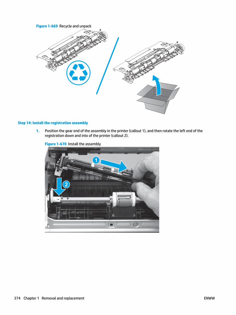
Figure 1-669 Recycle and unpack
Step 14: Install the registration assembly
1. Position the gear end of the assembly in the printer (callout 1), and then rotate the left end of the registration down and into of the printer (callout 2).
Figure 1-670 Install the assembly
1
2
374 Chapter 1 Removal and replacement ENWW

2. Install the end of pressure-release link arm (callout 1).
Figure 1-671 Install the pressure-release arm
1
3. Install two screws (callout 1).
Figure 1-672 Install two screws
1
ENWW Removal and replacement procedures 375

4. Carefully rotate the printer backward until it rests on the rear side, bottom-side face forward.
CAUTION: The integrated scanner assembly (ISA) on the M427/M426 is not captive and can suddenly open when the printer is tilted backward. Support the ISA when handling the M427/M426 printer.
Figure 1-673 Place the printer bottom-side face forward
5. Install the guide (callout 1), and then install one screw (callout 2).
Figure 1-674 Install the guide
1
2
Step 15: Install the fuser
1. Slide the fuser straight into the printer.
376 Chapter 1 Removal and replacement ENWW

Figure 1-675 Install the fuser
2. Connect the pressure-release link arm to the fuser.
IMPORTANT: Make sure that the pressure-release arm is correctly connected to the fuser.
Figure 1-676 Connect the pressure-release arm
ENWW Removal and replacement procedures 377

3. Install four screws (callout 1).
Figure 1-677 Install four screws
1
4. Connect two connectors (callout 1).
Figure 1-678 Connect two connectors
1
378 Chapter 1 Removal and replacement ENWW
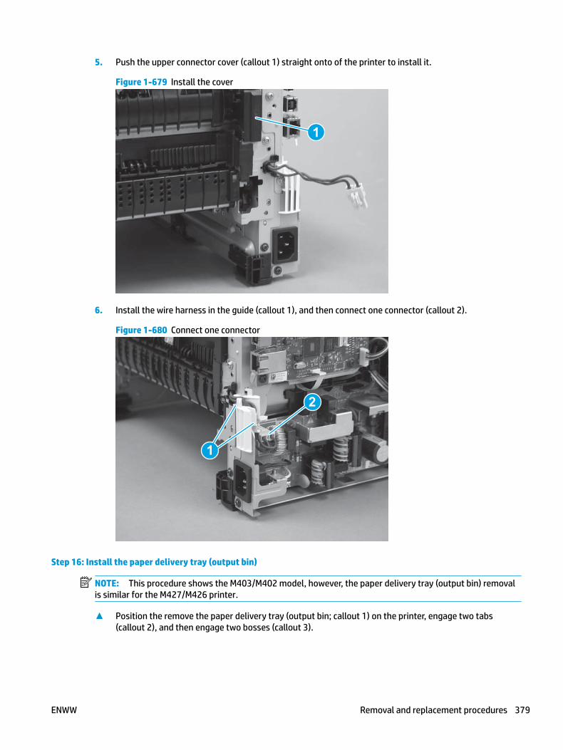
5. Push the upper connector cover (callout 1) straight onto of the printer to install it.
Figure 1-679 Install the cover
1
6. Install the wire harness in the guide (callout 1), and then connect one connector (callout 2).
Figure 1-680 Connect one connector
1
2
Step 16: Install the paper delivery tray (output bin)
NOTE: This procedure shows the M403/M402 model, however, the paper delivery tray (output bin) removal is similar for the M427/M426 printer.
▲ Position the remove the paper delivery tray (output bin; callout 1) on the printer, engage two tabs (callout 2), and then engage two bosses (callout 3).
ENWW Removal and replacement procedures 379

Figure 1-681 Engage two tabs
2
3
1
Step 17: Install the top cover (M403/M402)
NOTE: The step is for the M403/M402 printer. For the M427/M426, skip this step and go to Step 18: Install the top cover (M427/M426) on page 382.
1. Position the rear edge of the cover on the printer.
Figure 1-682 Install the cover
380 Chapter 1 Removal and replacement ENWW

2. Engage four bosses (callout 1), rotate the front of the cover down (callout 2) and onto from the printer, and then engage four tabs (callout 3).
Figure 1-683 Engage four bosses and tabs
1
3
2
2
3. At the right side of the printer, engage the one boss and one tab (callout 1).
Figure 1-684 Engage one boss and one tab
1
ENWW Removal and replacement procedures 381
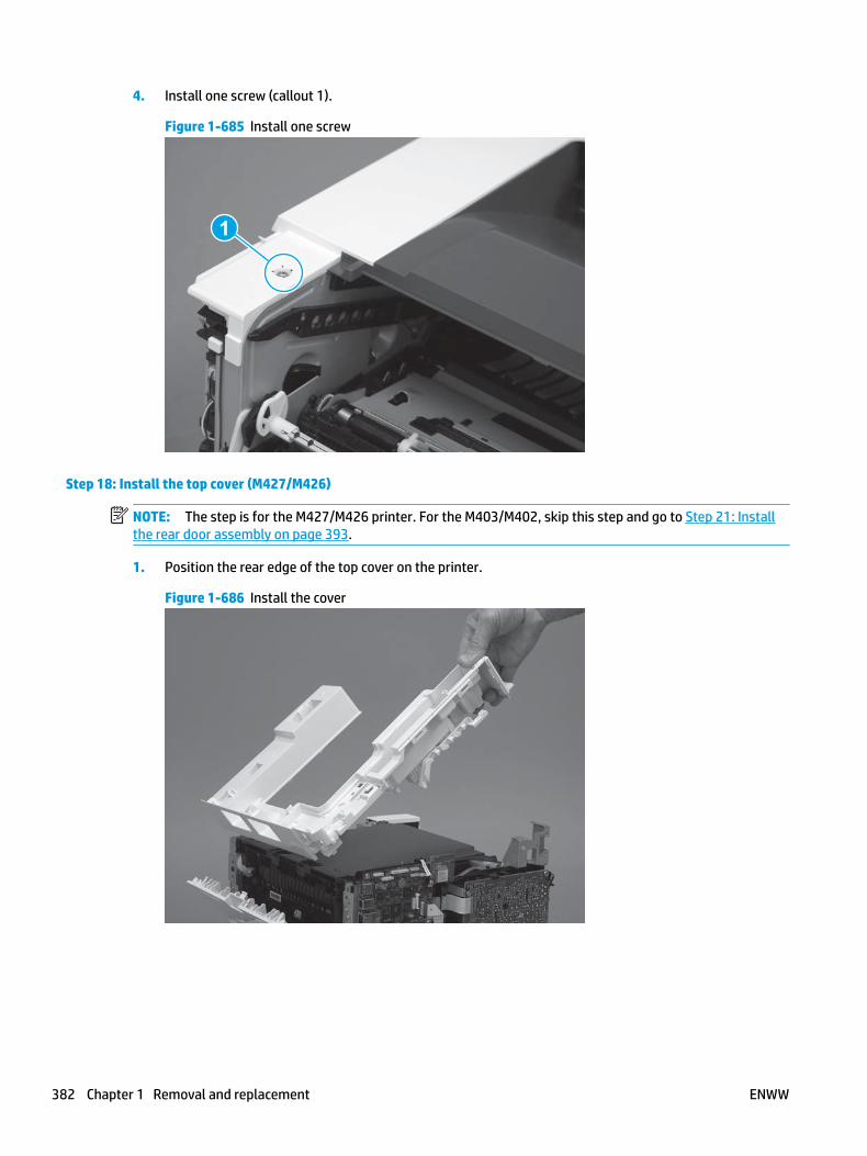
4. Install one screw (callout 1).
Figure 1-685 Install one screw
1
Step 18: Install the top cover (M427/M426)
NOTE: The step is for the M427/M426 printer. For the M403/M402, skip this step and go to Step 21: Install the rear door assembly on page 393.
1. Position the rear edge of the top cover on the printer.
Figure 1-686 Install the cover
382 Chapter 1 Removal and replacement ENWW

2. Engage four bosses (callout 1).
Figure 1-687 Engage four bosses
1
3. Rotate the front edge of the cover down.
Figure 1-688 Rotate the front edge of the cover down
ENWW Removal and replacement procedures 383

4. Install the USB cable (callout 1) in the guide.
Figure 1-689 Install the USB PCA
1
5. Install five screws (callout 1).
Figure 1-690 Install five screws
1
Step 19: Install the control panel (M427/M246)
NOTE: The step is for the M427/M426 printer. For the M403/M402, skip this step and go to Step 21: Install the rear door assembly on page 393.
1. Slide the control-panel FFC cover into the slot in the top cover (next to the document feeder support arm) to install it.
384 Chapter 1 Removal and replacement ENWW
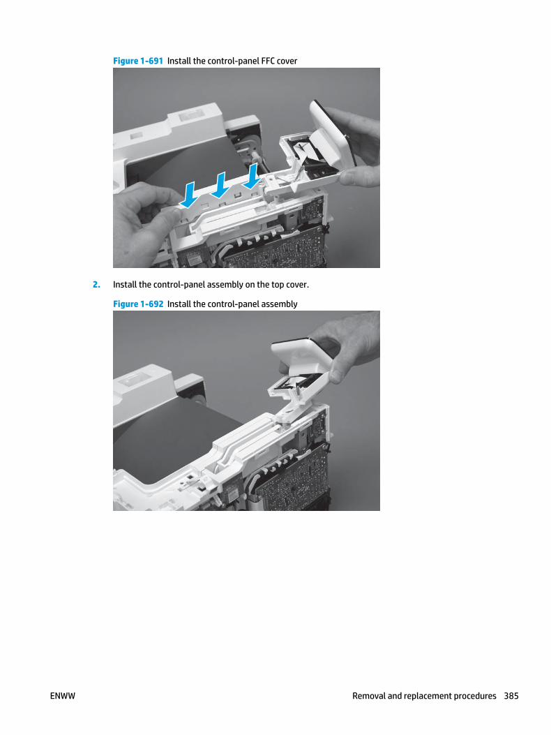
Figure 1-691 Install the control-panel FFC cover
2. Install the control-panel assembly on the top cover.
Figure 1-692 Install the control-panel assembly
ENWW Removal and replacement procedures 385

3. Move the FFC out of the way, and then install two screws (callout 1).
Figure 1-693 Install two screws
1
4. Install one grounding screw (callout 1), and then make sure that the ground cable (callout 2) is properly routed.
Figure 1-694 Remove one screw
2
1
386 Chapter 1 Removal and replacement ENWW

5. Install the control-panel cable cover.
Figure 1-695 Install the cover
6. Make sure that the two tabs (callout 1) on the cover snap into place.
Figure 1-696 Engage two tabs
1
ENWW Removal and replacement procedures 387

7. Install one screw (callout 1).
Figure 1-697 Install one screw
1
8. Install the FFC in the retainer (callout 1), and then connect one FFC (callout 1; J114).
Figure 1-698 Connect one connector
1
2
Step 20: Install the integrated scanner assembly (M427/M246)
NOTE: The step is for the M427/M426 printer. For the M403/M402, skip this step and go to Step 21: Install the rear door assembly on page 393.
NOTE: M427/M426 models only. The integrated scanner assembly (ISA) includes the sub-scanner assembly (SSA) and the automatic document feeder (ADF).
1. Position the ISA on the printer.
388 Chapter 1 Removal and replacement ENWW
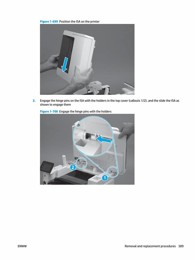
Figure 1-699 Position the ISA on the printer
2. Engage the hinge pins on the ISA with the holders in the top cover (callouts 1/2), and the slide the ISA as shown to engage them
Figure 1-700 Engage the hinge pins with the holders
1
2
ENWW Removal and replacement procedures 389

3. Rotate the ISA towards the front of the printer until it rests on the ISA lift assembly (callout 1).
Figure 1-701 Rotate the ISA towards the front of the printer
1
4. Pass the ground wire through the opening in the top cover.
Figure 1-702 Pass the wire through the opening
390 Chapter 1 Removal and replacement ENWW
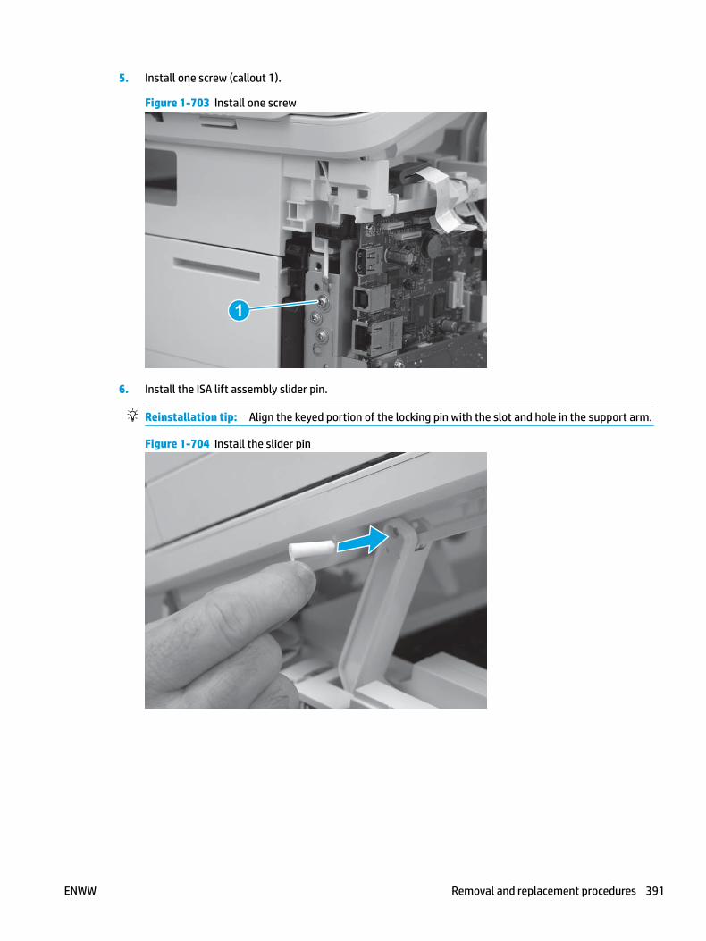
5. Install one screw (callout 1).
Figure 1-703 Install one screw
1
6. Install the ISA lift assembly slider pin.
Reinstallation tip: Align the keyed portion of the locking pin with the slot and hole in the support arm.
Figure 1-704 Install the slider pin
ENWW Removal and replacement procedures 391

7. Rotate the slider pin (callout 1) towards the rear of the printer until the tab (callout 2) snap into place.
Figure 1-705 Secure the slider pin
2
1
8. Install the ferrite (callout 1) in the holder, and then connect three FFCs (callout 2).
Figure 1-706 Connect three FFCs
1
2
392 Chapter 1 Removal and replacement ENWW

9. Position the rear edge of the ISA flat-flexible cable (FFC) cover on the printer (callout 1) , and then rotate it down (callout 2) until it snaps into place.
Figure 1-707 Install the ISA FFC cover
1
2
10. Lower the ISA.
Figure 1-708 Lower the ISA
Step 21: Install the rear door assembly
1. At the rear of the printer, position the assembly so that the two tabs (callout 1) are installed in the slots (callout 2) in the chassis.
NOTE: Duplex models only: Slide the duplex tray into the Tray 2 cavity.
ENWW Removal and replacement procedures 393

Figure 1-709 Install the rear cover
1
2. Install two screws.
NOTE: Duplex models only: Reach in from the front of the Tray 2 cavity and raise the feed assembly to the up and locked position so that the rear cover will fit flat against the chassis.
Figure 1-710 Install two screws
1
Step 22: Install the right cover
1. Position the cover (callout 1) on the printer, and then engage two bosses (callout 2).
394 Chapter 1 Removal and replacement ENWW

Figure 1-711 Install the cover
11
2 2
2. Rotate the front of the cover onto the printer (callout 1), engage three (callout 2) tabs, and then engage two bosses (callout 3).
Figure 1-712 Engage two bosses and one tab
1 13 3
2 2
3. Make sure that the power switch (callout 1) and cartridge door assembly button (callout 2) correctly function.
NOTE: Remove, and then reinstall the cover if the switch or button does not correctly function.
Figure 1-713 Check the power switch and cartridge door assembly button
1
1
22
ENWW Removal and replacement procedures 395

4. Install one screw (callout 1).
Figure 1-714 Install one screw
11
Step 23: Install the left cover
1. At the front of the printer, do one of the following:
● M403/M402: Position the cover on the printer ( callout 1), and then engage two bosses (callout 2).
● M427/M426: Position the cover on the printer (callout 3), engage one tab (callout 4), and then engage two bosses (callout 4).
Figure 1-715 Install the cover
1
2
4
35
396 Chapter 1 Removal and replacement ENWW

2. Carefully rotate the rear of the cover onto the printer (callout 1), engage three tabs (callout 2), and then engage two bosses (callout 3).
Figure 1-716 Engage three tabs and two bosses
3
3 11
2
2
3. Install one screw (callout 1).
Figure 1-717 Install one screw
1 1
Step 24: Install the cartridge door assembly
Reinstallation tip: After a replacement door is installed, make sure to install the nameplate (supplied in the kit) corresponding to the printer name on the door.
1. Position the door close to the printer, and then engage the keyed pin on the left-side retainer arm with the hole in the door.
ENWW Removal and replacement procedures 397

Figure 1-718 Engage the left-side retainer arm
2. Engage the right-side door hinge pin with the hole in the chassis (callout 1).
Figure 1-719 Install the door
1
398 Chapter 1 Removal and replacement ENWW

3. Install the link (callout 1).
IMPORTANT: Make sure that the link snaps into place on the arm (callout 2). The link actuates the fuser pressure-release mechanism.
Figure 1-720 Install the pressure-release link
1
2
4. Slide the guide into the printer (callout 1), and then make sure that the tab (callout 2) snaps into place to secure the guide to the chassis.
Figure 1-721 Install the guide
1
2
ENWW Removal and replacement procedures 399

5. Position the shaft on the door, and then align the left-side hinge on the door with the hole in the chassis (callout 1).
Figure 1-722 Align the hinge
1
6. Push the shaft towards the left side of the printer to install it (callout 1).
Reinstallation tip: Make sure that the support shaft is fully installed and correctly orientated (callout 2) so that it will not interfere with the door opening and closing.
Figure 1-723 Install the support shaft
2
1
400 Chapter 1 Removal and replacement ENWW

Step 25: Install Install Tray 2
▲ Slide the tray straight into the printer to install it.
Figure 1-724 Install the tray
ENWW Removal and replacement procedures 401

Removal and replacement: Main motor (M1)
● Introduction
● Step 1: Remove Tray 2
● Step 2: Remove the cartridge door assembly
● Step 3: Remove the right cover
● Step 4: Remove the main motor (M1)
● Step 5: Unpack the replacement assembly
● Step 6: Install the main motor (M1)
● Step 7: Install the right cover
● Step 8: Install the cartridge door assembly
● Step 9: Install Tray 2
Introduction
This document provides the procedures to remove and replace the main motor (M1).
Before performing service
Turn the printer power off
◦ Disconnect the power cable.
WARNING! To avoid damage to the printer, turn the printer off, wait 30 seconds, and then remove the power cable before attempting to service the printer.
Use the table below to identify the correct part number for your printer. To order the part, go to www.hp.com/buy/parts.
Main motor (M1) part number
RM2-8684-000CN Main motor (M1)
Required tools
● #2 Phillips screwdriver with a magnetic tip.
After performing service
Turn the printer power on
◦ Connect the power cable.
◦ Use the power switch to turn the power on.
Post service test
Make sure that the printer initializes to a Ready state.
402 Chapter 1 Removal and replacement ENWW

Print a configuration page to make sure that the printer is functioning correctly.
Step 1: Remove Tray 2
▲ Pull the tray straight out of the printer to remove it.
Figure 1-725 Remove the tray
Step 2: Remove the cartridge door assembly
NOTE: If the toner cartridge was not removed prior to servicing the printer, remove it now.
1. Release one tab (callout 1), and then slide shaft (callout 2) in the direction the arrow indicates and remove it.
TIP: It might be easier to release the support shaft by using a small flat-blade screwdriver.
Figure 1-726 Release the support shaft
12
ENWW Removal and replacement procedures 403

2. Release one tab (callout 1), and then slide the guide (callout 2) in the direction the arrow indicates and remove it.
Figure 1-727 Remove the guide
1 2
3. Remove the link arm (callout 1).
Figure 1-728 Remove the link arm
1
404 Chapter 1 Removal and replacement ENWW

4. Slide the cartridge door assembly (callout 1) in the direction the arrow indicates and remove it.
Figure 1-729 Remove the door
1
5. Remove the link (callout 1) from the cartridge door assembly (callout 2).
Figure 1-730 Release the left-side retainer arm
21
Step 3: Remove the right cover
1. Remove one screw (callout 1).
ENWW Removal and replacement procedures 405

Figure 1-731 Remove one screw
11
2. At the front of the printer, release two bosses (callout 1), and then release three tabs (callout 2).
Figure 1-732 Release two bosses and three tabs
1 1
2 2
3. Open the rear door, release two bosses (callout 1), and then remove the cover (callout 2).
Figure 1-733 Remove the cover
22
1 1
Step 4: Remove the main motor (M1)
▲ Disconnect one connector (callout 1), remove four screws (callout 2), and the remove the main motor (M1).
406 Chapter 1 Removal and replacement ENWW

Figure 1-734 Remove the motor
2
1
Step 5: Unpack the replacement assembly
Unpack the replacement part from the packaging.
http://www8.hp.com/us/en/hp-information/environment/product-recycling.html
NOTE: HP recommends responsible disposal of the defective part.
Figure 1-735 Recycle and unpack
Step 6: Install the main motor (M1)
▲ Position the motor on the chassis, install four screws in the order shown below (callout 1 to callout 4), and then connect one connector (callout 5).
CAUTION: Make sure that the screws are installed in the order shown below.
ENWW Removal and replacement procedures 407

Figure 1-736 Install the motor
5
12
3
4
Step 7: Install the right cover
1. Position the cover (callout 1) on the printer, and then engage two bosses (callout 2).
Figure 1-737 Install the cover
11
2 2
408 Chapter 1 Removal and replacement ENWW

2. Rotate the front of the cover onto the printer (callout 1), engage three (callout 2) tabs, and then engage two bosses (callout 3).
Figure 1-738 Engage two bosses and one tab
1 13 3
2 2
3. Make sure that the power switch (callout 1) and cartridge door assembly button (callout 2) correctly function.
NOTE: Remove, and then reinstall the cover if the switch or button does not correctly function.
Figure 1-739 Check the power switch and cartridge door assembly button
1
1
22
4. Install one screw (callout 1).
Figure 1-740 Install one screw
11
ENWW Removal and replacement procedures 409

Step 8: Install the cartridge door assembly
Reinstallation tip: After a replacement door is installed, make sure to install the nameplate (supplied in the kit) corresponding to the printer name on the door.
1. Position the door close to the printer, and then engage the keyed pin on the left-side retainer arm with the hole in the door.
Figure 1-741 Engage the left-side retainer arm
2. Engage the right-side door hinge pin with the hole in the chassis (callout 1).
Figure 1-742 Install the door
1
410 Chapter 1 Removal and replacement ENWW

3. Install the link (callout 1).
IMPORTANT: Make sure that the link snaps into place on the arm (callout 2). The link actuates the fuser pressure-release mechanism.
Figure 1-743 Install the pressure-release link
1
2
4. Slide the guide into the printer (callout 1), and then make sure that the tab (callout 2) snaps into place to secure the guide to the chassis.
Figure 1-744 Install the guide
1
2
ENWW Removal and replacement procedures 411

5. Position the shaft on the door, and then align the left-side hinge on the door with the hole in the chassis (callout 1).
Figure 1-745 Align the hinge
1
6. Push the shaft towards the left side of the printer to install it (callout 1).
Reinstallation tip: Make sure that the support shaft is fully installed and correctly orientated (callout 2) so that it will not interfere with the door opening and closing.
Figure 1-746 Install the support shaft
2
1
412 Chapter 1 Removal and replacement ENWW

Step 9: Install Tray 2
▲ Slide the tray straight into the printer to install it.
Figure 1-747 Install the tray
ENWW Removal and replacement procedures 413

Removal and replacement: Power switch printed circuit assembly
● Introduction
● Step 1: Remove Tray 2
● Step 2: Remove the cartridge door assembly
● Step 3: Remove the right cover
● Step 4: Remove the power switch PCA
● Step 5: Unpack the replacement assembly
● Step 6: Install the power switch PCA
● Step 7: Install the right cover
● Step 8: Install the cartridge door assembly
● Step 9: Install Tray 2
Introduction
This document provides the procedures to remove and replace the power switch printed circuit assembly (PCA).
Before performing service
Turn the printer power off
◦ Disconnect the power cable.
WARNING! To avoid damage to the printer, turn the printer off, wait 30 seconds, and then remove the power cable before attempting to service the printer.
Use the table below to identify the correct part number for your printer. To order the part, go to www.hp.com/buy/parts.
Power switch PCA part number
RM2-8506-000CN Power switch PCA
Required tools
● #2 Phillips screwdriver with a magnetic tip.
After performing service
Turn the printer power on
◦ Connect the power cable.
◦ Use the power switch to turn the power on.
414 Chapter 1 Removal and replacement ENWW

Post service test
Use the power switch to turn the printer on, and then off.
Step 1: Remove Tray 2
▲ Pull the tray straight out of the printer to remove it.
Figure 1-748 Remove the tray
Step 2: Remove the cartridge door assembly
NOTE: If the toner cartridge was not removed prior to servicing the printer, remove it now.
1. Release one tab (callout 1), and then slide shaft (callout 2) in the direction the arrow indicates and remove it.
TIP: It might be easier to release the support shaft by using a small flat-blade screwdriver.
ENWW Removal and replacement procedures 415

Figure 1-749 Release the support shaft
12
2. Release one tab (callout 1), and then slide the guide (callout 2) in the direction the arrow indicates and remove it.
Figure 1-750 Remove the guide
1 2
416 Chapter 1 Removal and replacement ENWW

3. Remove the link arm (callout 1).
Figure 1-751 Remove the link arm
1
4. Slide the cartridge door assembly (callout 1) in the direction the arrow indicates and remove it.
Figure 1-752 Remove the door
1
ENWW Removal and replacement procedures 417

5. Remove the link (callout 1) from the cartridge door assembly (callout 2).
Figure 1-753 Release the left-side retainer arm
21
Step 3: Remove the right cover
1. Remove one screw (callout 1).
Figure 1-754 Remove one screw
11
418 Chapter 1 Removal and replacement ENWW

2. At the front of the printer, release two bosses (callout 1), and then release three tabs (callout 2).
Figure 1-755 Release two bosses and three tabs
1 1
2 2
3. Open the rear door, release two bosses (callout 1), and then remove the cover (callout 2).
Figure 1-756 Remove the cover
22
1 1
Step 4: Remove the power switch PCA
1. Release one tab (callout 1).
ENWW Removal and replacement procedures 419

Figure 1-757 Release one tab
1
2. Remove the switch lever.
Figure 1-758 Remove the switch lever
420 Chapter 1 Removal and replacement ENWW

3. Release the wire harness from the guide (callout 1), and then disconnect one connector (callout 2).
Figure 1-759 Disconnect one connector
2
1
4. Release one tab (callout 1), and then remove the power switch PCA.
CAUTION: Do not damage the tab (callout 1) when releasing the it. The tab must snap over the PCA when it is reinstalled.
Figure 1-760 Release one tab and remove the PCA
1
Step 5: Unpack the replacement assembly
Unpack the replacement part from the packaging.
http://www8.hp.com/us/en/hp-information/environment/product-recycling.html
NOTE: HP recommends responsible disposal of the defective part.
ENWW Removal and replacement procedures 421

Figure 1-761 Recycle and unpack
Step 6: Install the power switch PCA
1. Position the PCA in the holder. The PCA must be securely installed in the holder.
IMPORTANT: Make sure of the following:
● The inside edge of the PCA is positioned behind the holder (callout 1).
● The two alignment pins are installed in the holes in the PCA (callout 2).
● The tab on the holder snaps in place over the edge of the PCA (callout 3).
Figure 1-762 Install the PCA
1
2
3
422 Chapter 1 Removal and replacement ENWW

2. Connect one connector (callout 1), and then install the wire harness in the guide (callout 2).
Figure 1-763 Connect one connector and install the wire harness in the guide
1
2
3. Install the switch lever.
Make sure that the switch lever freely moves in and out when pushed, and that it makes proper contact with the monetary switch on the power switch PCA.
Figure 1-764 Install the switch lever
Step 7: Install the right cover
1. Position the cover (callout 1) on the printer, and then engage two bosses (callout 2).
ENWW Removal and replacement procedures 423

Figure 1-765 Install the cover
11
2 2
2. Rotate the front of the cover onto the printer (callout 1), engage three (callout 2) tabs, and then engage two bosses (callout 3).
Figure 1-766 Engage two bosses and one tab
1 13 3
2 2
3. Make sure that the power switch (callout 1) and cartridge door assembly button (callout 2) correctly function.
NOTE: Remove, and then reinstall the cover if the switch or button does not correctly function.
Figure 1-767 Check the power switch and cartridge door assembly button
1
1
22
424 Chapter 1 Removal and replacement ENWW

4. Install one screw (callout 1).
Figure 1-768 Install one screw
11
Step 8: Install the cartridge door assembly
Reinstallation tip: After a replacement door is installed, make sure to install the nameplate (supplied in the kit) corresponding to the printer name on the door.
1. Position the door close to the printer, and then engage the keyed pin on the left-side retainer arm with the hole in the door.
Figure 1-769 Engage the left-side retainer arm
ENWW Removal and replacement procedures 425
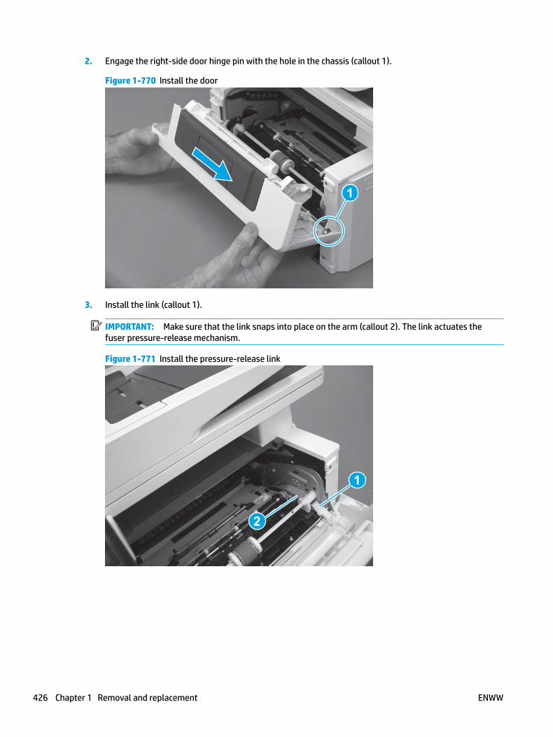
2. Engage the right-side door hinge pin with the hole in the chassis (callout 1).
Figure 1-770 Install the door
1
3. Install the link (callout 1).
IMPORTANT: Make sure that the link snaps into place on the arm (callout 2). The link actuates the fuser pressure-release mechanism.
Figure 1-771 Install the pressure-release link
1
2
426 Chapter 1 Removal and replacement ENWW

4. Slide the guide into the printer (callout 1), and then make sure that the tab (callout 2) snaps into place to secure the guide to the chassis.
Figure 1-772 Install the guide
1
2
5. Position the shaft on the door, and then align the left-side hinge on the door with the hole in the chassis (callout 1).
Figure 1-773 Align the hinge
1
ENWW Removal and replacement procedures 427
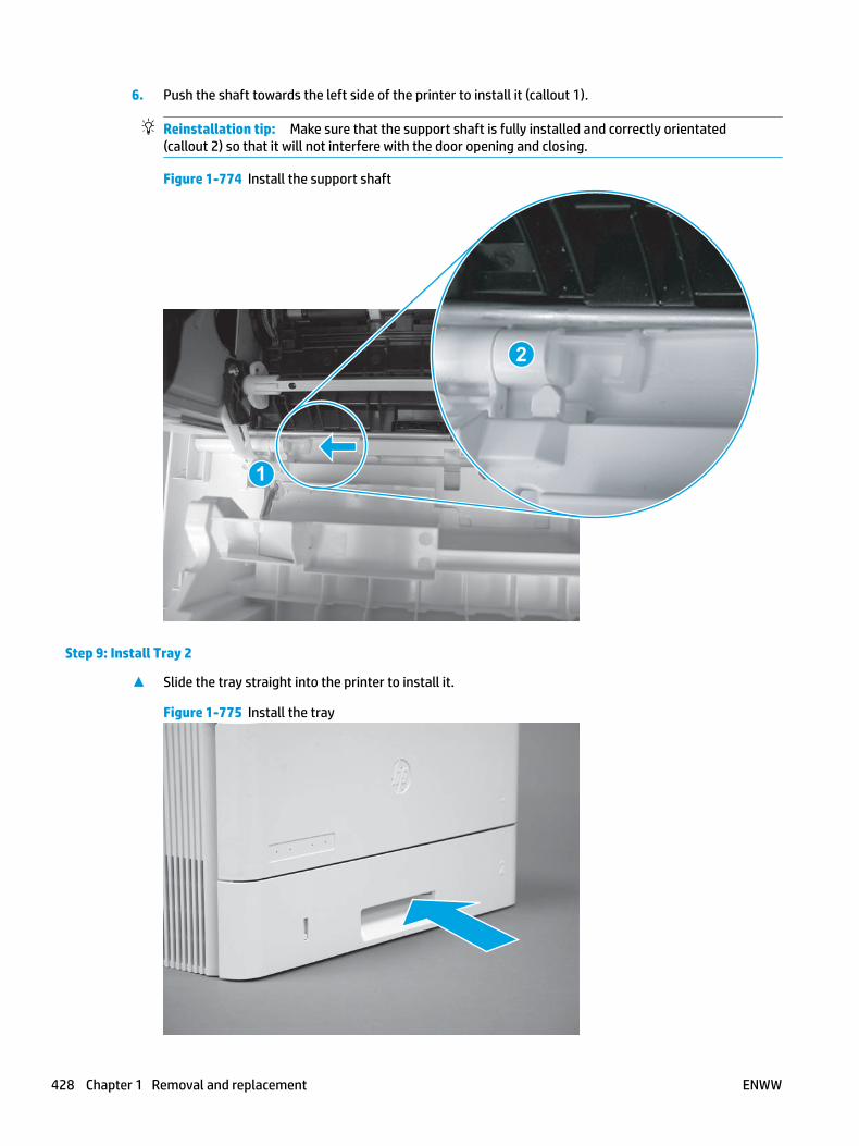
6. Push the shaft towards the left side of the printer to install it (callout 1).
Reinstallation tip: Make sure that the support shaft is fully installed and correctly orientated (callout 2) so that it will not interfere with the door opening and closing.
Figure 1-774 Install the support shaft
2
1
Step 9: Install Tray 2
▲ Slide the tray straight into the printer to install it.
Figure 1-775 Install the tray
428 Chapter 1 Removal and replacement ENWW

Removal and replacement: Fax PCA (M427/M426)
NOTE: Fax models only.
● Introduction
● Step 1: Remove Tray 2
● Step 2: Remove the cartridge door assembly
● Step 3: Remove the left cover
● Step 4: Remove the fax PCA (M427/M426)
● Step 5: Unpack the replacement assembly
● Step 6: Install the fax PCA (M427/M426)
● Step 7: Install the left cover
● Step 8: Install the cartridge door assembly
● Step 9: Install Tray 2
Introduction
This document provides the procedures to remove and replace the fax printed circuit assembly (PCA).
Before performing service
Turn the printer power off
◦ Disconnect the power cable.
WARNING! To avoid damage to the printer, turn the printer off, wait 30 seconds, and then remove the power cable before attempting to service the printer.
Use the table below to identify the correct part number for your printer. To order the part, go to www.hp.com/buy/parts.
Fax PCA part number
CF206-60001
CF207-60001
CF208-60001
Fax PCA1 US/AP
Fax PCA1 Euro
Fax PCA1 Brazil
1 M427/M426 fax models only.
Required tools
● #2 Phillips screwdriver with a magnetic tip.
● Small flat-blade screw driver
ENWW Removal and replacement procedures 429
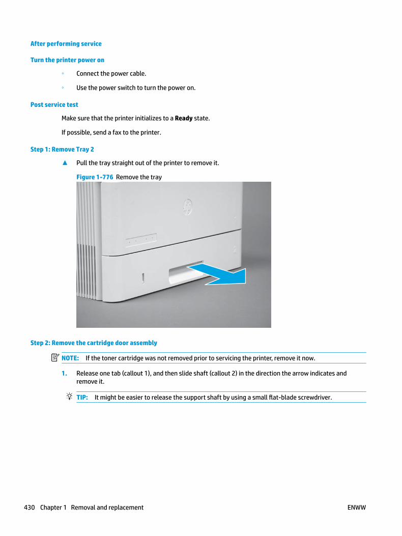
After performing service
Turn the printer power on
◦ Connect the power cable.
◦ Use the power switch to turn the power on.
Post service test
Make sure that the printer initializes to a Ready state.
If possible, send a fax to the printer.
Step 1: Remove Tray 2
▲ Pull the tray straight out of the printer to remove it.
Figure 1-776 Remove the tray
Step 2: Remove the cartridge door assembly
NOTE: If the toner cartridge was not removed prior to servicing the printer, remove it now.
1. Release one tab (callout 1), and then slide shaft (callout 2) in the direction the arrow indicates and remove it.
TIP: It might be easier to release the support shaft by using a small flat-blade screwdriver.
430 Chapter 1 Removal and replacement ENWW

Figure 1-777 Release the support shaft
12
2. Release one tab (callout 1), and then slide the guide (callout 2) in the direction the arrow indicates and remove it.
Figure 1-778 Remove the guide
1 2
ENWW Removal and replacement procedures 431

3. Remove the link arm (callout 1).
Figure 1-779 Remove the link arm
1
4. Slide the cartridge door assembly (callout 1) in the direction the arrow indicates and remove it.
Figure 1-780 Remove the door
1
432 Chapter 1 Removal and replacement ENWW

5. Remove the link (callout 1) from the cartridge door assembly (callout 2).
Figure 1-781 Release the left-side retainer arm
21
Step 3: Remove the left cover
1. Remove one screw (callout 1).
Figure 1-782 Remove one screw
1 1
ENWW Removal and replacement procedures 433

2. Open the rear door, release two bosses (callout 1), and then release three tabs (callout 2).
Figure 1-783 Release two bosses and three tabs
1
1
2
2
3. At the front of the printer, do one of the following:
● M403/M402: Release two bosses (callout 1), and then remove the cover (callout 2).
● M427/M426: Release one tab (callout 3), two bosses (callout 4), and then remove the cover (callout 5).
CAUTION: Be careful when releasing the upper bosses on the M427/M426 cover. One portion of the cover (callout 6) is fragile and is easily broken.
Figure 1-784 Remove the cover
2
1
3
54 6
Step 4: Remove the fax PCA (M427/M426)
1. Remove four screws (callout 1).
434 Chapter 1 Removal and replacement ENWW
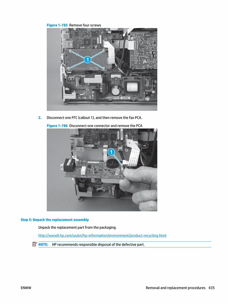
Figure 1-785 Remove four screws
1
2. Disconnect one FFC (callout 1), and then remove the fax PCA.
Figure 1-786 Disconnect one connector and remove the PCA
1
Step 5: Unpack the replacement assembly
Unpack the replacement part from the packaging.
http://www8.hp.com/us/en/hp-information/environment/product-recycling.html
NOTE: HP recommends responsible disposal of the defective part.
ENWW Removal and replacement procedures 435

Figure 1-787 Recycle and unpack
Step 6: Install the fax PCA (M427/M426)
1. Connect one FFC cable (callout 1), and then position the fax PCA on the printer.
Figure 1-788 Connect one connector and install the PCA
1
436 Chapter 1 Removal and replacement ENWW

2. Install four screws (callout 1).
Figure 1-789 Install four screws
1
Step 7: Install the left cover
1. At the front of the printer, do one of the following:
● M403/M402: Position the cover on the printer ( callout 1), and then engage two bosses (callout 2).
● M427/M426: Position the cover on the printer (callout 3), engage one tab (callout 4), and then engage two bosses (callout 4).
Figure 1-790 Install the cover
1
2
4
35
ENWW Removal and replacement procedures 437
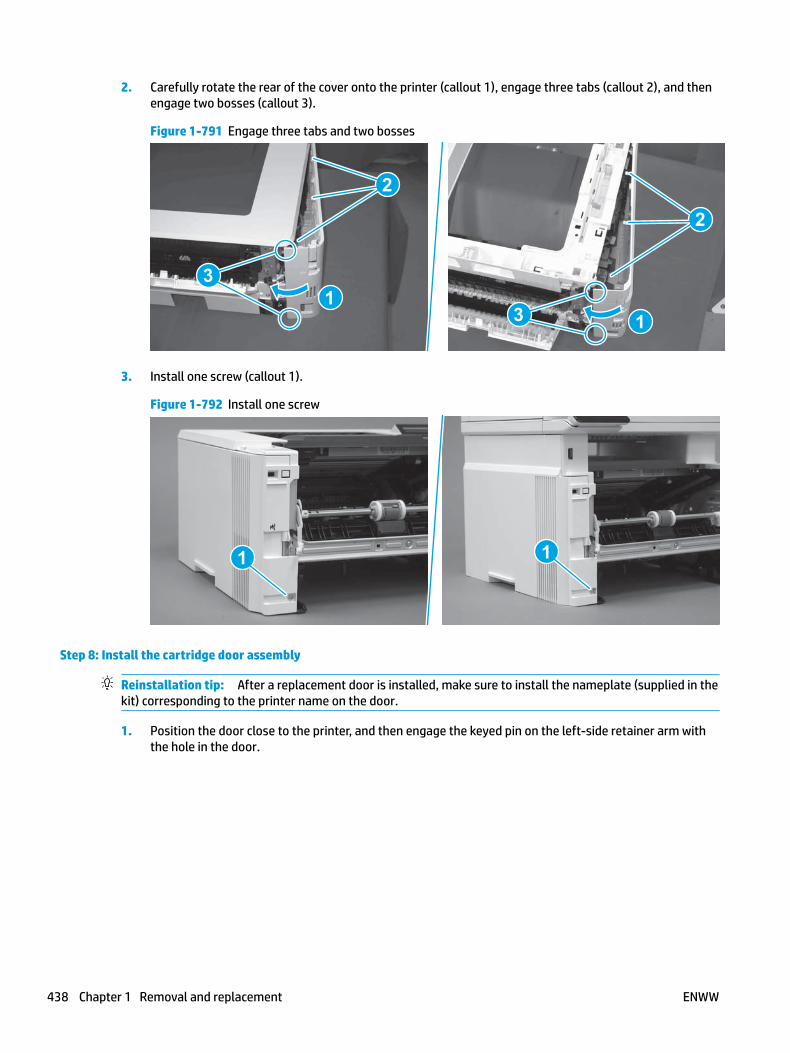
2. Carefully rotate the rear of the cover onto the printer (callout 1), engage three tabs (callout 2), and then engage two bosses (callout 3).
Figure 1-791 Engage three tabs and two bosses
3
3 11
2
2
3. Install one screw (callout 1).
Figure 1-792 Install one screw
1 1
Step 8: Install the cartridge door assembly
Reinstallation tip: After a replacement door is installed, make sure to install the nameplate (supplied in the kit) corresponding to the printer name on the door.
1. Position the door close to the printer, and then engage the keyed pin on the left-side retainer arm with the hole in the door.
438 Chapter 1 Removal and replacement ENWW

Figure 1-793 Engage the left-side retainer arm
2. Engage the right-side door hinge pin with the hole in the chassis (callout 1).
Figure 1-794 Install the door
1
ENWW Removal and replacement procedures 439
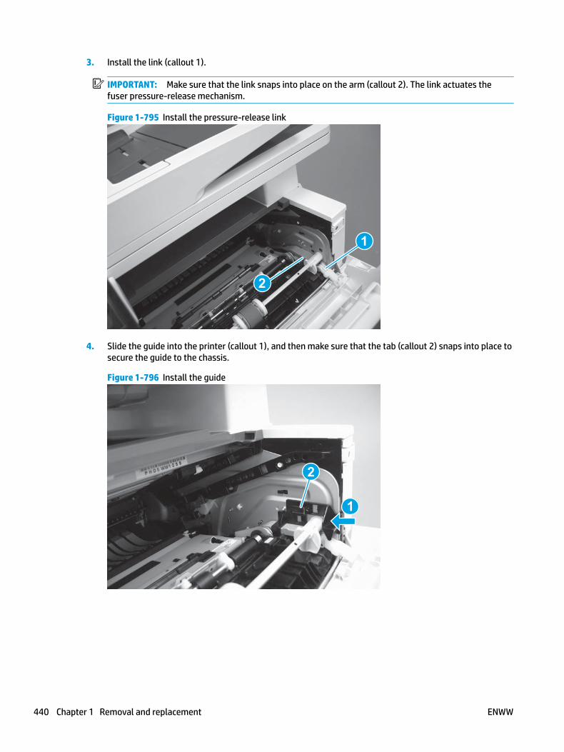
3. Install the link (callout 1).
IMPORTANT: Make sure that the link snaps into place on the arm (callout 2). The link actuates the fuser pressure-release mechanism.
Figure 1-795 Install the pressure-release link
1
2
4. Slide the guide into the printer (callout 1), and then make sure that the tab (callout 2) snaps into place to secure the guide to the chassis.
Figure 1-796 Install the guide
1
2
440 Chapter 1 Removal and replacement ENWW

5. Position the shaft on the door, and then align the left-side hinge on the door with the hole in the chassis (callout 1).
Figure 1-797 Align the hinge
1
6. Push the shaft towards the left side of the printer to install it (callout 1).
Reinstallation tip: Make sure that the support shaft is fully installed and correctly orientated (callout 2) so that it will not interfere with the door opening and closing.
Figure 1-798 Install the support shaft
2
1
ENWW Removal and replacement procedures 441
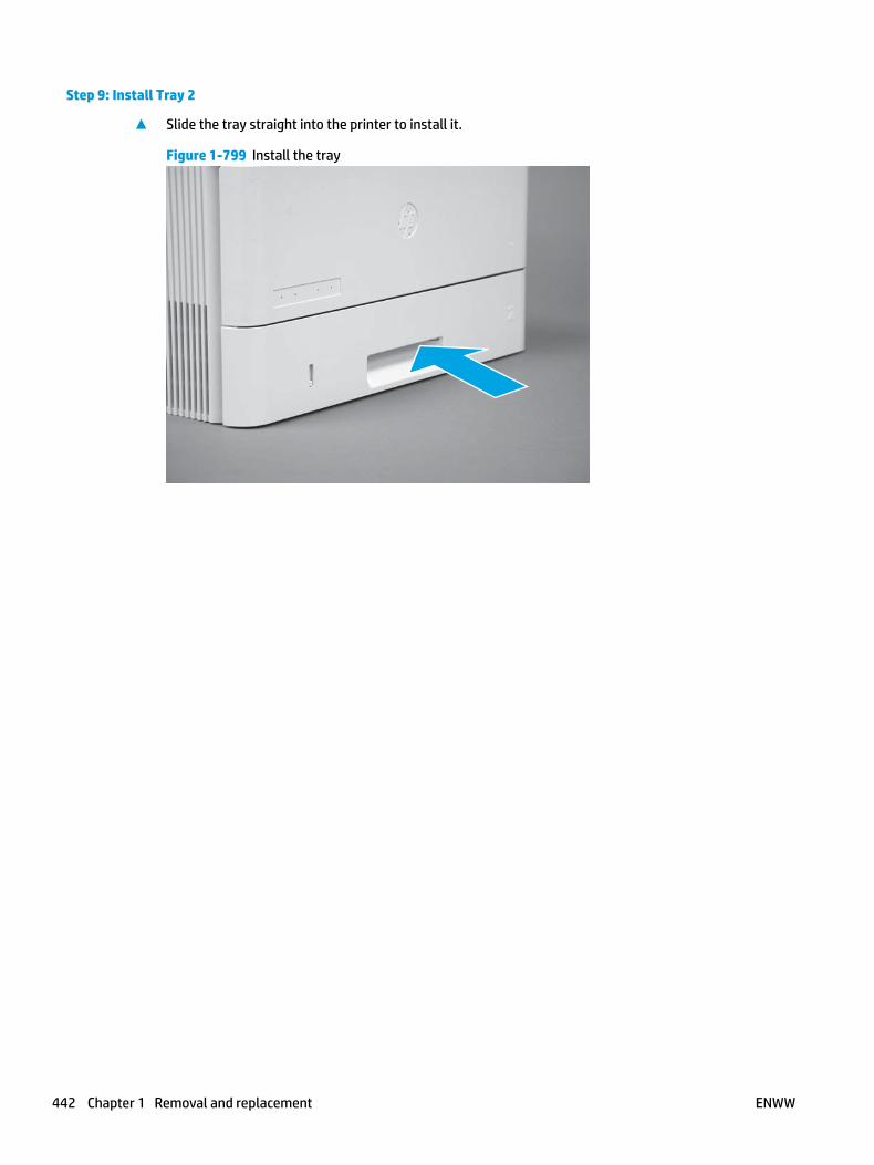
Step 9: Install Tray 2
▲ Slide the tray straight into the printer to install it.
Figure 1-799 Install the tray
442 Chapter 1 Removal and replacement ENWW
Removal and replacement: Walkup USB PCA (M427/M426)
● Introduction
● Step 1: Remove Tray 2
● Step 2: Remove the cartridge door assembly
● Step 3: Remove the left cover
● Step 4: Remove the fax PCA
● Step 5: Remove the walkup USB PCA (M427/M426)
● Step 6: Unpack the replacement assembly
● Step 7: Install the walkup USB PCA (M427/M426)
● Step 8: Install the fax PCA
● Step 9: Install the left cover
● Step 10: Install the cartridge door assembly
● Step 9: Install Tray 2
Introduction
This document provides the procedures to remove and replace the walkup USB PCA.
Before performing service
Turn the printer power off
◦ Disconnect the power cable.
WARNING! To avoid damage to the printer, turn the printer off, wait 30 seconds, and then remove the power cable before attempting to service the printer.
Use the table below to identify the correct part number for your printer. To order the part, go to www.hp.com/buy/parts.
Walkup USB PCA part number
CF368-60001 Walkup USB PCA1
1 M427/M426 only.
Required tools
● #2 Phillips screwdriver with a magnetic tip.
After performing service
Turn the printer power on
◦ Connect the power cable.
◦ Use the power switch to turn the power on.
ENWW Removal and replacement procedures 443

Post service test
Make sure that the printer initializes to a Ready state.
Print a job from the walkup USB PCA.
Step 1: Remove Tray 2
▲ Pull the tray straight out of the printer to remove it.
Figure 1-800 Remove the tray
Step 2: Remove the cartridge door assembly
NOTE: If the toner cartridge was not removed prior to servicing the printer, remove it now.
1. Release one tab (callout 1), and then slide shaft (callout 2) in the direction the arrow indicates and remove it.
TIP: It might be easier to release the support shaft by using a small flat-blade screwdriver.
444 Chapter 1 Removal and replacement ENWW

Figure 1-801 Release the support shaft
12
2. Release one tab (callout 1), and then slide the guide (callout 2) in the direction the arrow indicates and remove it.
Figure 1-802 Remove the guide
1 2
ENWW Removal and replacement procedures 445

3. Remove the link arm (callout 1).
Figure 1-803 Remove the link arm
1
4. Slide the cartridge door assembly (callout 1) in the direction the arrow indicates and remove it.
Figure 1-804 Remove the door
1
446 Chapter 1 Removal and replacement ENWW

5. Remove the link (callout 1) from the cartridge door assembly (callout 2).
Figure 1-805 Release the left-side retainer arm
21
Step 3: Remove the left cover
1. Remove one screw (callout 1).
Figure 1-806 Remove one screw
1 1
ENWW Removal and replacement procedures 447

2. Open the rear door, release two bosses (callout 1), and then release three tabs (callout 2).
Figure 1-807 Release two bosses and three tabs
1
1
2
2
3. At the front of the printer, do one of the following:
● M403/M402: Release two bosses (callout 1), and then remove the cover (callout 2).
● M427/M426: Release one tab (callout 3), two bosses (callout 4), and then remove the cover (callout 5).
CAUTION: Be careful when releasing the upper bosses on the M427/M426 cover. One portion of the cover (callout 6) is fragile and is easily broken.
Figure 1-808 Remove the cover
2
1
3
54 6
Step 4: Remove the fax PCA
NOTE: Fax models only. For all other models, skip this step and go to Step 5: Remove the walkup USB PCA (M427/M426) on page 449.
1. Remove four screws (callout 1).
448 Chapter 1 Removal and replacement ENWW

Figure 1-809 Remove four screws
1
2. Disconnect one FFC (callout 1), and then remove the fax PCA.
Figure 1-810 Disconnect one connector and remove the PCA
1
Step 5: Remove the walkup USB PCA (M427/M426)
1. Disconnect one connector (callout 1), and then release the wire harness from the guide (callout 2).
ENWW Removal and replacement procedures 449
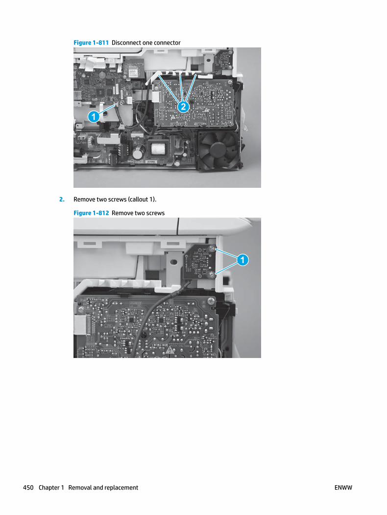
Figure 1-811 Disconnect one connector
12
2. Remove two screws (callout 1).
Figure 1-812 Remove two screws
1
450 Chapter 1 Removal and replacement ENWW
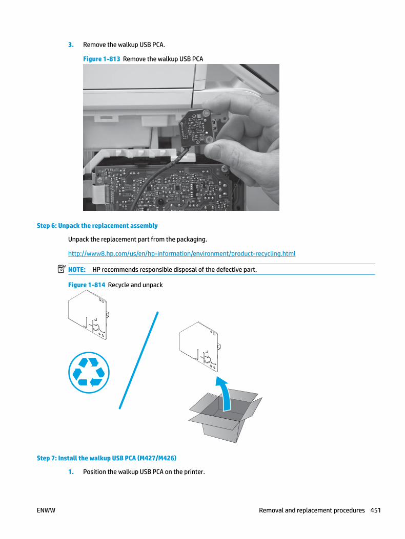
3. Remove the walkup USB PCA.
Figure 1-813 Remove the walkup USB PCA
Step 6: Unpack the replacement assembly
Unpack the replacement part from the packaging.
http://www8.hp.com/us/en/hp-information/environment/product-recycling.html
NOTE: HP recommends responsible disposal of the defective part.
Figure 1-814 Recycle and unpack
Step 7: Install the walkup USB PCA (M427/M426)
1. Position the walkup USB PCA on the printer.
ENWW Removal and replacement procedures 451

Figure 1-815 Install the walkup USB PCA
2. Install two screws (callout 1).
Figure 1-816 Install two screws
1
452 Chapter 1 Removal and replacement ENWW

3. Connect one connector (callout 1), and then install the wire harness in the guide (callout 2).
Figure 1-817 Connect one connector
12
Step 8: Install the fax PCA
NOTE: Fax models only. For all other models, skip this step and go to Step 9: Install the left cover on page 454.
1. Connect one FFC cable (callout 1), and then position the fax PCA on the printer.
Figure 1-818 Connect one connector and install the PCA
1
ENWW Removal and replacement procedures 453

2. Install four screws (callout 1).
Figure 1-819 Install four screws
1
Step 9: Install the left cover
1. At the front of the printer, do one of the following:
● M403/M402: Position the cover on the printer ( callout 1), and then engage two bosses (callout 2).
● M427/M426: Position the cover on the printer (callout 3), engage one tab (callout 4), and then engage two bosses (callout 4).
Figure 1-820 Install the cover
1
2
4
35
454 Chapter 1 Removal and replacement ENWW

2. Carefully rotate the rear of the cover onto the printer (callout 1), engage three tabs (callout 2), and then engage two bosses (callout 3).
Figure 1-821 Engage three tabs and two bosses
3
3 11
2
2
3. Install one screw (callout 1).
Figure 1-822 Install one screw
1 1
Step 10: Install the cartridge door assembly
Reinstallation tip: After a replacement door is installed, make sure to install the nameplate (supplied in the kit) corresponding to the printer name on the door.
1. Position the door close to the printer, and then engage the keyed pin on the left-side retainer arm with the hole in the door.
ENWW Removal and replacement procedures 455

Figure 1-823 Engage the left-side retainer arm
2. Engage the right-side door hinge pin with the hole in the chassis (callout 1).
Figure 1-824 Install the door
1
456 Chapter 1 Removal and replacement ENWW

3. Install the link (callout 1).
IMPORTANT: Make sure that the link snaps into place on the arm (callout 2). The link actuates the fuser pressure-release mechanism.
Figure 1-825 Install the pressure-release link
1
2
4. Slide the guide into the printer (callout 1), and then make sure that the tab (callout 2) snaps into place to secure the guide to the chassis.
Figure 1-826 Install the guide
1
2
ENWW Removal and replacement procedures 457

5. Position the shaft on the door, and then align the left-side hinge on the door with the hole in the chassis (callout 1).
Figure 1-827 Align the hinge
1
6. Push the shaft towards the left side of the printer to install it (callout 1).
Reinstallation tip: Make sure that the support shaft is fully installed and correctly orientated (callout 2) so that it will not interfere with the door opening and closing.
Figure 1-828 Install the support shaft
2
1
458 Chapter 1 Removal and replacement ENWW

Step 9: Install Tray 2
▲ Slide the tray straight into the printer to install it.
Figure 1-829 Install the tray
ENWW Removal and replacement procedures 459

Removal and replacement: Wireless PCA
NOTE: Wireless models only.
● Introduction
● Step 1: Remove Tray 2
● Step 2: Remove the cartridge door assembly
● Step 3: Remove the left cover
● Step 4: Remove the wireless PCA
● Step 5: Unpack the replacement assembly
● Step 6: Install the wireless PCA
● Step 7: Install the left cover
● Step 8: Install the cartridge door assembly
● Step 9: Install Tray 2
Introduction
This document provides the procedures to remove and replace the wireless printed circuit assembly (PCA).
Before performing service
Turn the printer power off
◦ Disconnect the power cable.
WARNING! To avoid damage to the printer, turn the printer off, wait 30 seconds, and then remove the power cable before attempting to service the printer.
Use the table below to identify the correct part number for your printer. To order the part, go to www.hp.com/buy/parts.
Wireless PCA part number
0960-3293 Wireless module1
1 M427/M426 and M403/M402 wireless models only.
Required tools
● #2 Phillips screwdriver with a magnetic tip.
After performing service
Turn the printer power on
◦ Connect the power cable.
◦ Use the power switch to turn the power on.
460 Chapter 1 Removal and replacement ENWW
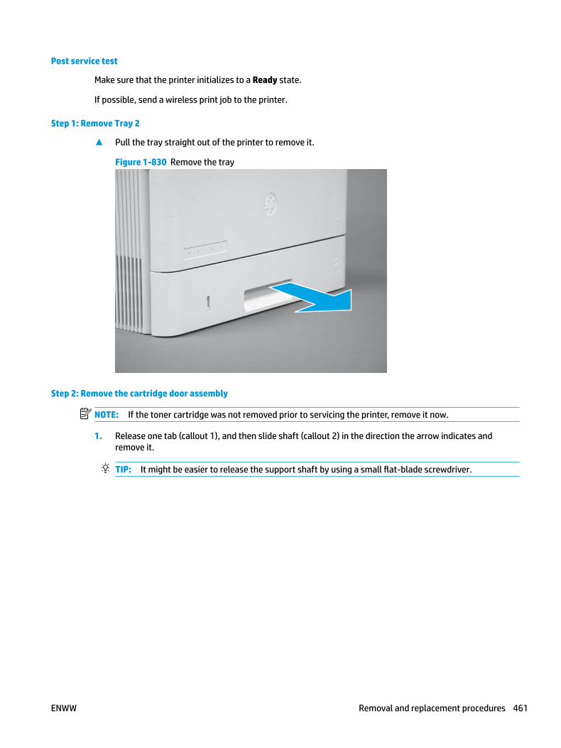
Post service test
Make sure that the printer initializes to a Ready state.
If possible, send a wireless print job to the printer.
Step 1: Remove Tray 2
▲ Pull the tray straight out of the printer to remove it.
Figure 1-830 Remove the tray
Step 2: Remove the cartridge door assembly
NOTE: If the toner cartridge was not removed prior to servicing the printer, remove it now.
1. Release one tab (callout 1), and then slide shaft (callout 2) in the direction the arrow indicates and remove it.
TIP: It might be easier to release the support shaft by using a small flat-blade screwdriver.
ENWW Removal and replacement procedures 461
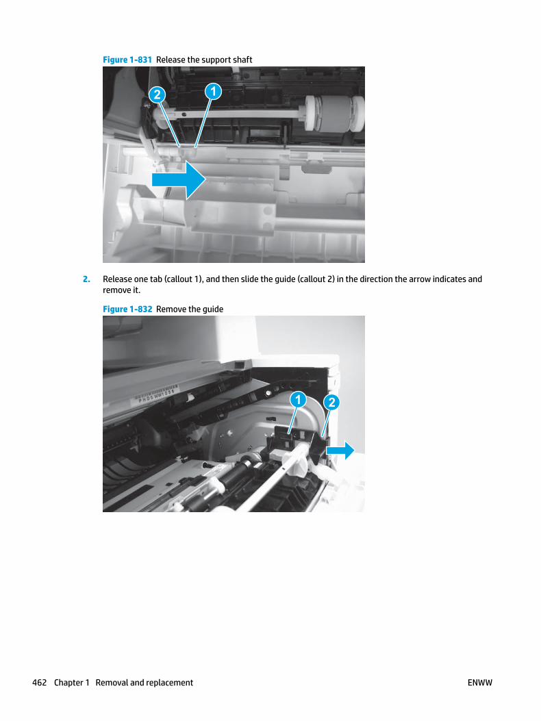
Figure 1-831 Release the support shaft
12
2. Release one tab (callout 1), and then slide the guide (callout 2) in the direction the arrow indicates and remove it.
Figure 1-832 Remove the guide
1 2
462 Chapter 1 Removal and replacement ENWW

3. Remove the link arm (callout 1).
Figure 1-833 Remove the link arm
1
4. Slide the cartridge door assembly (callout 1) in the direction the arrow indicates and remove it.
Figure 1-834 Remove the door
1
ENWW Removal and replacement procedures 463

5. Remove the link (callout 1) from the cartridge door assembly (callout 2).
Figure 1-835 Release the left-side retainer arm
21
Step 3: Remove the left cover
1. Remove one screw (callout 1).
Figure 1-836 Remove one screw
1 1
464 Chapter 1 Removal and replacement ENWW

2. Open the rear door, release two bosses (callout 1), and then release three tabs (callout 2).
Figure 1-837 Release two bosses and three tabs
1
1
2
2
3. At the front of the printer, do one of the following:
● M403/M402: Release two bosses (callout 1), and then remove the cover (callout 2).
● M427/M426: Release one tab (callout 3), two bosses (callout 4), and then remove the cover (callout 5).
CAUTION: Be careful when releasing the upper bosses on the M427/M426 cover. One portion of the cover (callout 6) is fragile and is easily broken.
Figure 1-838 Remove the cover
2
1
3
54 6
Step 4: Remove the wireless PCA
1. Remove one screw (callout 1).
ENWW Removal and replacement procedures 465

Figure 1-839 Remove one screw
1 1
2. Carefully pull the wireless PCA straight off of the formatter PCA to remove it.
Figure 1-840 Remove the wireless PCA
Step 5: Unpack the replacement assembly
Unpack the replacement part from the packaging.
http://www8.hp.com/us/en/hp-information/environment/product-recycling.html
NOTE: HP recommends responsible disposal of the defective part.
466 Chapter 1 Removal and replacement ENWW

Figure 1-841 Recycle and unpack
Step 6: Install the wireless PCA
1. Carefully push the wireless PCA straight onto the formatter PCA to install it.
Figure 1-842 Install the PCA
ENWW Removal and replacement procedures 467

2. Install one screw (callout 1).
Figure 1-843 Install one screw
1 1
Step 7: Install the left cover
1. At the front of the printer, do one of the following:
● M403/M402: Position the cover on the printer ( callout 1), and then engage two bosses (callout 2).
● M427/M426: Position the cover on the printer (callout 3), engage one tab (callout 4), and then engage two bosses (callout 4).
Figure 1-844 Install the cover
1
2
4
35
468 Chapter 1 Removal and replacement ENWW

2. Carefully rotate the rear of the cover onto the printer (callout 1), engage three tabs (callout 2), and then engage two bosses (callout 3).
Figure 1-845 Engage three tabs and two bosses
3
3 11
2
2
3. Install one screw (callout 1).
Figure 1-846 Install one screw
1 1
Step 8: Install the cartridge door assembly
Reinstallation tip: After a replacement door is installed, make sure to install the nameplate (supplied in the kit) corresponding to the printer name on the door.
1. Position the door close to the printer, and then engage the keyed pin on the left-side retainer arm with the hole in the door.
ENWW Removal and replacement procedures 469

Figure 1-847 Engage the left-side retainer arm
2. Engage the right-side door hinge pin with the hole in the chassis (callout 1).
Figure 1-848 Install the door
1
470 Chapter 1 Removal and replacement ENWW

3. Install the link (callout 1).
IMPORTANT: Make sure that the link snaps into place on the arm (callout 2). The link actuates the fuser pressure-release mechanism.
Figure 1-849 Install the pressure-release link
1
2
4. Slide the guide into the printer (callout 1), and then make sure that the tab (callout 2) snaps into place to secure the guide to the chassis.
Figure 1-850 Install the guide
1
2
ENWW Removal and replacement procedures 471

5. Position the shaft on the door, and then align the left-side hinge on the door with the hole in the chassis (callout 1).
Figure 1-851 Align the hinge
1
6. Push the shaft towards the left side of the printer to install it (callout 1).
Reinstallation tip: Make sure that the support shaft is fully installed and correctly orientated (callout 2) so that it will not interfere with the door opening and closing.
Figure 1-852 Install the support shaft
2
1
472 Chapter 1 Removal and replacement ENWW
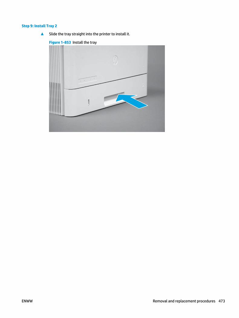
Step 9: Install Tray 2
▲ Slide the tray straight into the printer to install it.
Figure 1-853 Install the tray
ENWW Removal and replacement procedures 473

Removal and replacement: Formatter PCA
● Introduction
● Step 1: Remove Tray 2
● Step 2: Remove the cartridge door assembly
● Step 3: Remove the left cover
● Step 4: Remove the fax PCA
● Step 5: Remove the wireless PCA
● Step 6: Remove the formatter PCA
● Step 7: Unpack the replacement assembly
● Step 8: Install the formatter PCA
● Step 9: Install the wireless PCA
● Step 10: Install the fax PCA
● Step 11: Install the left cover
● Step 12: Install the cartridge door assembly
● Step 13: Install Tray 2
Introduction
This document provides the procedures to remove and replace the formatter PCA.
Before performing service
Turn the printer power off
◦ Disconnect the power cable.
WARNING! To avoid damage to the printer, turn the printer off, wait 30 seconds, and then remove the power cable before attempting to service the printer.
IMPORTANT: Always replace the thermal transfer pad (5851-6550) when the formatter is replaced.
Formatter PCA part numbers
C5F99-60001
C5F98-60001
C5F92-60001
C5F93-60001
C5F94-60001
Formatter PCA (M426dw; M427dw)
Formatter PCA (M426fdn; M426fdw; M427fdn; M427fdw)
Formatter PCA (M402d; M403d)
Formatter PCA (M402n; M402dn; M403n; M403dn)
Formatter PCA (M402dw; M403dw)
474 Chapter 1 Removal and replacement ENWW

Required tools
● #2 Phillips screwdriver with a magnetic tip.
● 5.5 mm (0.22 inch) socket screwdriver.
After performing service
Turn the printer power on
◦ Connect the power cable.
◦ Use the power switch to turn the power on.
Post service test
Make sure that the printer initializes to a Ready state.
Print a configuration page to make sure that the printer is functioning correctly.
Step 1: Remove Tray 2
▲ Pull the tray straight out of the printer to remove it.
Figure 1-854 Remove the tray
Step 2: Remove the cartridge door assembly
NOTE: If the toner cartridge was not removed prior to servicing the printer, remove it now.
1. Release one tab (callout 1), and then slide shaft (callout 2) in the direction the arrow indicates and remove it.
TIP: It might be easier to release the support shaft by using a small flat-blade screwdriver.
ENWW Removal and replacement procedures 475

Figure 1-855 Release the support shaft
12
2. Release one tab (callout 1), and then slide the guide (callout 2) in the direction the arrow indicates and remove it.
Figure 1-856 Remove the guide
1 2
476 Chapter 1 Removal and replacement ENWW

3. Remove the link arm (callout 1).
Figure 1-857 Remove the link arm
1
4. Slide the cartridge door assembly (callout 1) in the direction the arrow indicates and remove it.
Figure 1-858 Remove the door
1
ENWW Removal and replacement procedures 477

5. Remove the link (callout 1) from the cartridge door assembly (callout 2).
Figure 1-859 Release the left-side retainer arm
21
Step 3: Remove the left cover
1. Remove one screw (callout 1).
Figure 1-860 Remove one screw
1 1
478 Chapter 1 Removal and replacement ENWW

2. Open the rear door, release two bosses (callout 1), and then release three tabs (callout 2).
Figure 1-861 Release two bosses and three tabs
1
1
2
2
3. At the front of the printer, do one of the following:
● M403/M402: Release two bosses (callout 1), and then remove the cover (callout 2).
● M427/M426: Release one tab (callout 3), two bosses (callout 4), and then remove the cover (callout 5).
CAUTION: Be careful when releasing the upper bosses on the M427/M426 cover. One portion of the cover (callout 6) is fragile and is easily broken.
Figure 1-862 Remove the cover
2
1
3
54 6
Step 4: Remove the fax PCA
NOTE: Fax models only. For all other models, skip this step and go to Step 5: Remove the wireless PCA on page 480.
1. Remove four screws (callout 1).
ENWW Removal and replacement procedures 479

Figure 1-863 Remove four screws
1
2. Disconnect one FFC (callout 1), and then remove the fax PCA.
Figure 1-864 Disconnect one connector and remove the PCA
1
Step 5: Remove the wireless PCA
NOTE: Wireless models only. For all other models, skip this step and go to Step 6: Remove the formatter PCA on page 481.
1. Remove one screw (callout 1).
480 Chapter 1 Removal and replacement ENWW

Figure 1-865 Remove one screw
1 1
2. Carefully pull the wireless PCA straight off of the formatter PCA to remove it.
Figure 1-866 Remove the wireless PCA
Step 6: Remove the formatter PCA
1. Disconnect all of the connectors and FFCs.
Depending on the M427/M426 model, the following connector locations are empty.
● J6; all models
● J7; all models
● J30; non-wireless models
● J12; non-fax models
● J15; all models
● J17; non-NFC models
● J28; all models
Depending on the M403/M402 model, the following connector locations are empty.
● J6; all models
● J7; all models
● J8; non-wireless models
● J15; all models
● J17; non-NFC models
ENWW Removal and replacement procedures 481
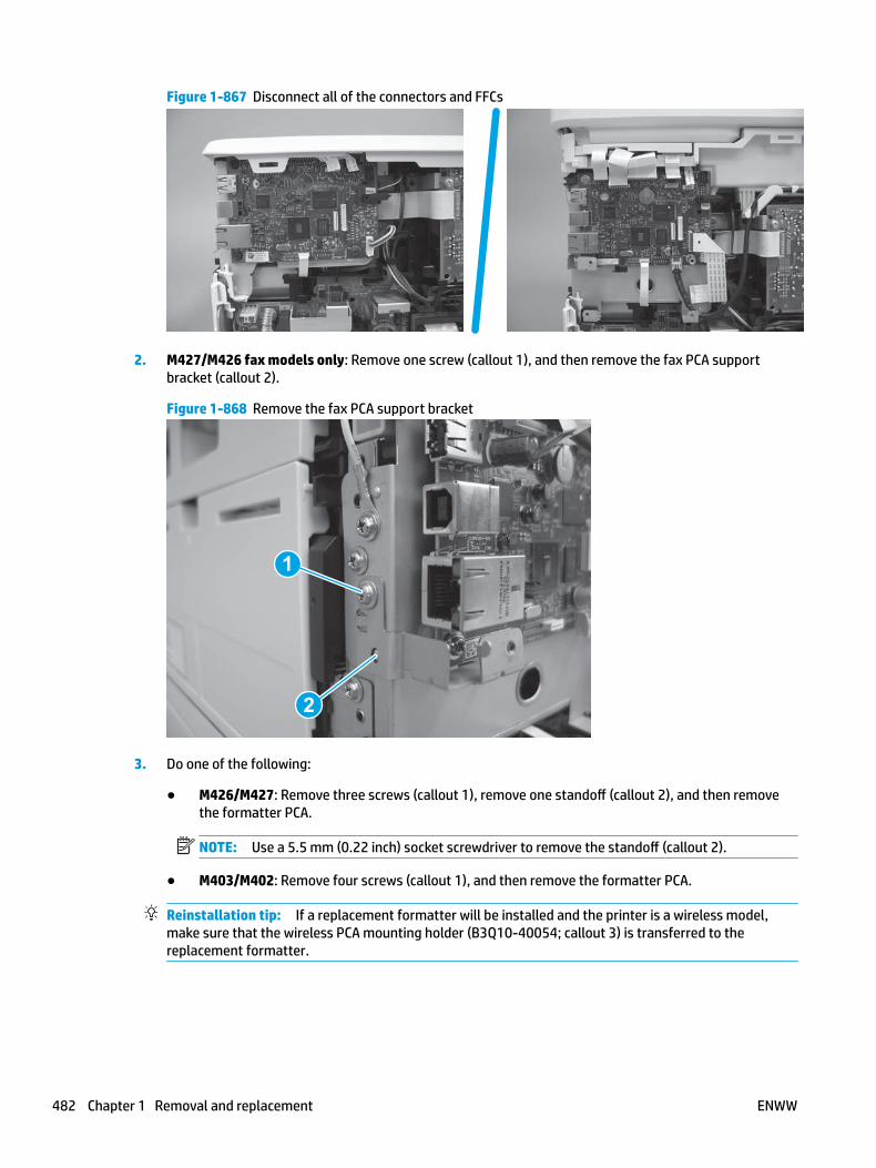
Figure 1-867 Disconnect all of the connectors and FFCs
2. M427/M426 fax models only: Remove one screw (callout 1), and then remove the fax PCA support bracket (callout 2).
Figure 1-868 Remove the fax PCA support bracket
1
2
3. Do one of the following:
● M426/M427: Remove three screws (callout 1), remove one standoff (callout 2), and then remove the formatter PCA.
NOTE: Use a 5.5 mm (0.22 inch) socket screwdriver to remove the standoff (callout 2).
● M403/M402: Remove four screws (callout 1), and then remove the formatter PCA.
Reinstallation tip: If a replacement formatter will be installed and the printer is a wireless model, make sure that the wireless PCA mounting holder (B3Q10-40054; callout 3) is transferred to the replacement formatter.
482 Chapter 1 Removal and replacement ENWW

Figure 1-869 Remove the formatter PCA
2
11
33
Step 7: Unpack the replacement assembly
Unpack the replacement part from the packaging.
http://www8.hp.com/us/en/hp-information/environment/product-recycling.html
NOTE: HP recommends responsible disposal of the defective part.
Figure 1-870 Recycle and unpack
Step 8: Install the formatter PCA
NOTE: If the formatter PCA thermal pad on the back side of the PCA is broken or damaged, replace the pad (5851-6550).
1. Adhere the pad to the sheet-metal bracket (a positioning line is embossed in the bracket).
Do one of the following:
ENWW Removal and replacement procedures 483

● M426/M427: Position the formater PCA on the printer, install three screws (callout 1), and then install one standoff (callout 2).
● M403/M402: Position the formater PCA on the printer, and then install four screws (callout 1).
Reinstallation tip: If a replacement formatter PCA will be installed and the printer is a wireless model, make sure that the wireless PCA mounting holder (callout 3) is transferred to the replacement formatter PCA.
Figure 1-871 Install the formatter PCA
2
11
33
2. M427/M426 fax models only: Position the fax PCA support bracket (callout 1) on the printer, and then install one screw (callout 2).
Figure 1-872 Remove the fax PCA support bracket
2
1
3. Connect all of the connectors and FFCs.
484 Chapter 1 Removal and replacement ENWW

Depending on the M427/M426 model, the following connector locations are empty.
● J6; all models
● J7; all models
● J30; non-wireless models
● J12; non-fax models
● J15; all models
● J17; non-NFC models
● J28; all models
Depending on the M403/M402 model, the following connector locations are empty.
● J6; all models
● J7; all models
● J8; non-wireless models
● J15; all models
● J17; non-NFC models
Figure 1-873 Connect all of the connectors and FFCs
Step 9: Install the wireless PCA
NOTE: Wireless models only. For all other models, skip this step and go to Step 10: Install the fax PCA on page 486.
1. Carefully push the wireless PCA straight onto the formatter PCA to install it.
Figure 1-874 Install the PCA
ENWW Removal and replacement procedures 485

2. Install one screw (callout 1).
Figure 1-875 Install one screw
1 1
Step 10: Install the fax PCA
NOTE: Fax models only. For all other models, skip this step and go to Step 11: Install the left cover on page 487.
1. Connect one FFC cable (callout 1), and then position the fax PCA on the printer.
Figure 1-876 Connect one connector and install the PCA
1
486 Chapter 1 Removal and replacement ENWW

2. Install four screws (callout 1).
Figure 1-877 Install four screws
1
Step 11: Install the left cover
1. At the front of the printer, do one of the following:
● M403/M402: Position the cover on the printer ( callout 1), and then engage two bosses (callout 2).
● M427/M426: Position the cover on the printer (callout 3), engage one tab (callout 4), and then engage two bosses (callout 4).
Figure 1-878 Install the cover
1
2
4
35
ENWW Removal and replacement procedures 487

2. Carefully rotate the rear of the cover onto the printer (callout 1), engage three tabs (callout 2), and then engage two bosses (callout 3).
Figure 1-879 Engage three tabs and two bosses
3
3 11
2
2
3. Install one screw (callout 1).
Figure 1-880 Install one screw
1 1
Step 12: Install the cartridge door assembly
Reinstallation tip: After a replacement door is installed, make sure to install the nameplate (supplied in the kit) corresponding to the printer name on the door.
1. Position the door close to the printer, and then engage the keyed pin on the left-side retainer arm with the hole in the door.
488 Chapter 1 Removal and replacement ENWW

Figure 1-881 Engage the left-side retainer arm
2. Engage the right-side door hinge pin with the hole in the chassis (callout 1).
Figure 1-882 Install the door
1
ENWW Removal and replacement procedures 489

3. Install the link (callout 1).
IMPORTANT: Make sure that the link snaps into place on the arm (callout 2). The link actuates the fuser pressure-release mechanism.
Figure 1-883 Install the pressure-release link
1
2
4. Slide the guide into the printer (callout 1), and then make sure that the tab (callout 2) snaps into place to secure the guide to the chassis.
Figure 1-884 Install the guide
1
2
490 Chapter 1 Removal and replacement ENWW

5. Position the shaft on the door, and then align the left-side hinge on the door with the hole in the chassis (callout 1).
Figure 1-885 Align the hinge
1
6. Push the shaft towards the left side of the printer to install it (callout 1).
Reinstallation tip: Make sure that the support shaft is fully installed and correctly orientated (callout 2) so that it will not interfere with the door opening and closing.
Figure 1-886 Install the support shaft
2
1
ENWW Removal and replacement procedures 491

Step 13: Install Tray 2
▲ Slide the tray straight into the printer to install it.
Figure 1-887 Install the tray
492 Chapter 1 Removal and replacement ENWW

Removal and replacement: Fan (FM1)
● Introduction
● Step 1: Remove Tray 2
● Step 2: Remove the cartridge door assembly
● Step 3: Remove the left cover
● Step 4: Remove the fan (FM1)
● Step 5: Unpack the replacement assembly
● Step 6: Install the fan (FM1)
● Step 7: Install the left cover
● Step 8: Install the cartridge door assembly
● Step 9: Install Tray 2
Introduction
This document provides the procedures to remove and replace the fan (FM1).
Before performing service
Turn the printer power off
◦ Disconnect the power cable.
WARNING! To avoid damage to the printer, turn the printer off, wait 30 seconds, and then remove the power cable before attempting to service the printer.
Use the table below to identify the correct part number for your printer. To order the part, go to www.hp.com/buy/parts.
Fan (FM1) part number
RK2-8068-000CN Fan (FM1)
Required tools
● #2 Phillips screwdriver with a magnetic tip.
After performing service
Turn the printer power on
◦ Connect the power cable.
◦ Use the power switch to turn the power on.
Post service test
Listen for the fan to roatate when the printer power is turned on.
ENWW Removal and replacement procedures 493
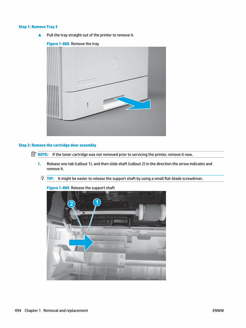
Step 1: Remove Tray 2
▲ Pull the tray straight out of the printer to remove it.
Figure 1-888 Remove the tray
Step 2: Remove the cartridge door assembly
NOTE: If the toner cartridge was not removed prior to servicing the printer, remove it now.
1. Release one tab (callout 1), and then slide shaft (callout 2) in the direction the arrow indicates and remove it.
TIP: It might be easier to release the support shaft by using a small flat-blade screwdriver.
Figure 1-889 Release the support shaft
12
494 Chapter 1 Removal and replacement ENWW

2. Release one tab (callout 1), and then slide the guide (callout 2) in the direction the arrow indicates and remove it.
Figure 1-890 Remove the guide
1 2
3. Remove the link arm (callout 1).
Figure 1-891 Remove the link arm
1
ENWW Removal and replacement procedures 495

4. Slide the cartridge door assembly (callout 1) in the direction the arrow indicates and remove it.
Figure 1-892 Remove the door
1
5. Remove the link (callout 1) from the cartridge door assembly (callout 2).
Figure 1-893 Release the left-side retainer arm
21
Step 3: Remove the left cover
1. Remove one screw (callout 1).
496 Chapter 1 Removal and replacement ENWW

Figure 1-894 Remove one screw
1 1
2. Open the rear door, release two bosses (callout 1), and then release three tabs (callout 2).
Figure 1-895 Release two bosses and three tabs
1
1
2
2
3. At the front of the printer, do one of the following:
● M403/M402: Release two bosses (callout 1), and then remove the cover (callout 2).
● M427/M426: Release one tab (callout 3), two bosses (callout 4), and then remove the cover (callout 5).
CAUTION: Be careful when releasing the upper bosses on the M427/M426 cover. One portion of the cover (callout 6) is fragile and is easily broken.
ENWW Removal and replacement procedures 497
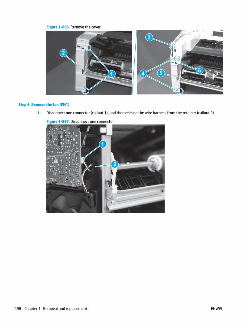
Figure 1-896 Remove the cover
2
1
3
54 6
Step 4: Remove the fan (FM1)
1. Disconnect one connector (callout 1), and then release the wire harness from the retainer (callout 2).
Figure 1-897 Disconnect one connector
1
2
498 Chapter 1 Removal and replacement ENWW

2. Release two tabs (callout 1).
Figure 1-898 Release two tabs
1
3. Remove the fan.
Figure 1-899 Remove the fan
Step 5: Unpack the replacement assembly
Unpack the replacement part from the packaging.
http://www8.hp.com/us/en/hp-information/environment/product-recycling.html
NOTE: HP recommends responsible disposal of the defective part.
ENWW Removal and replacement procedures 499
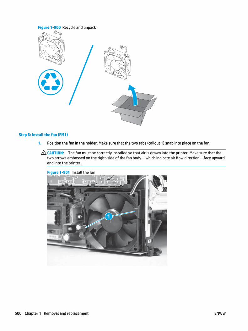
Figure 1-900 Recycle and unpack
Step 6: Install the fan (FM1)
1. Position the fan in the holder. Make sure that the two tabs (callout 1) snap into place on the fan.
CAUTION: The fan must be correctly installed so that air is drawn into the printer. Make sure that the two arrows embossed on the right-side of the fan body—which indicate air flow direction—face upward and into the printer.
Figure 1-901 Install the fan
1
500 Chapter 1 Removal and replacement ENWW

2. Install the wire harness on the retainer (callout 2), and then connect one connector (callout 2).
Figure 1-902 Connect one connector
2
1
Step 7: Install the left cover
1. At the front of the printer, do one of the following:
● M403/M402: Position the cover on the printer ( callout 1), and then engage two bosses (callout 2).
● M427/M426: Position the cover on the printer (callout 3), engage one tab (callout 4), and then engage two bosses (callout 4).
Figure 1-903 Install the cover
1
2
4
35
ENWW Removal and replacement procedures 501

2. Carefully rotate the rear of the cover onto the printer (callout 1), engage three tabs (callout 2), and then engage two bosses (callout 3).
Figure 1-904 Engage three tabs and two bosses
3
3 11
2
2
3. Install one screw (callout 1).
Figure 1-905 Install one screw
1 1
Step 8: Install the cartridge door assembly
Reinstallation tip: After a replacement door is installed, make sure to install the nameplate (supplied in the kit) corresponding to the printer name on the door.
1. Position the door close to the printer, and then engage the keyed pin on the left-side retainer arm with the hole in the door.
502 Chapter 1 Removal and replacement ENWW

Figure 1-906 Engage the left-side retainer arm
2. Engage the right-side door hinge pin with the hole in the chassis (callout 1).
Figure 1-907 Install the door
1
ENWW Removal and replacement procedures 503

3. Install the link (callout 1).
IMPORTANT: Make sure that the link snaps into place on the arm (callout 2). The link actuates the fuser pressure-release mechanism.
Figure 1-908 Install the pressure-release link
1
2
4. Slide the guide into the printer (callout 1), and then make sure that the tab (callout 2) snaps into place to secure the guide to the chassis.
Figure 1-909 Install the guide
1
2
504 Chapter 1 Removal and replacement ENWW

5. Position the shaft on the door, and then align the left-side hinge on the door with the hole in the chassis (callout 1).
Figure 1-910 Align the hinge
1
6. Push the shaft towards the left side of the printer to install it (callout 1).
Reinstallation tip: Make sure that the support shaft is fully installed and correctly orientated (callout 2) so that it will not interfere with the door opening and closing.
Figure 1-911 Install the support shaft
2
1
ENWW Removal and replacement procedures 505

Step 9: Install Tray 2
▲ Slide the tray straight into the printer to install it.
Figure 1-912 Install the tray
506 Chapter 1 Removal and replacement ENWW
Removal and replacement: Fan holder (FM1)
● Introduction
● Step 1: Remove Tray 2
● Step 2: Remove the cartridge door assembly
● Step 3: Remove the left cover
● Step 4: Remove the fan (FM1)
● Step 5: Remove the fan holder (FM1)
● Step 6: Unpack the replacement assembly
● Step 7: Install the fan holder (FM1)
● Step 8: Install the fan (FM1)
● Step 9: Install the left cover
● Step 10: Install the cartridge door assembly
● Step 11: Install Tray 2
Introduction
This document provides the procedures to remove and replace the fan holder (FM1).
Before performing service
Turn the printer power off
◦ Disconnect the power cable.
WARNING! To avoid damage to the printer, turn the printer off, wait 30 seconds, and then remove the power cable before attempting to service the printer.
Use the table below to identify the correct part number for your printer. To order the part, go to www.hp.com/buy/parts.
Fan holder (FM1) part number
RC4-2891-000CN Fan holder (FM1)
Required tools
● #2 Phillips screwdriver with a magnetic tip.
After performing service
Turn the printer power on
◦ Connect the power cable.
◦ Use the power switch to turn the power on.
ENWW Removal and replacement procedures 507
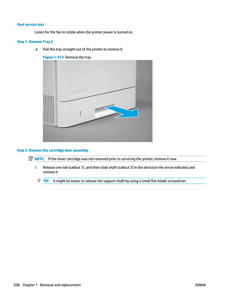
Post service test
Listen for the fan to rotate when the printer power is turned on.
Step 1: Remove Tray 2
▲ Pull the tray straight out of the printer to remove it.
Figure 1-913 Remove the tray
Step 2: Remove the cartridge door assembly
NOTE: If the toner cartridge was not removed prior to servicing the printer, remove it now.
1. Release one tab (callout 1), and then slide shaft (callout 2) in the direction the arrow indicates and remove it.
TIP: It might be easier to release the support shaft by using a small flat-blade screwdriver.
508 Chapter 1 Removal and replacement ENWW

Figure 1-914 Release the support shaft
12
2. Release one tab (callout 1), and then slide the guide (callout 2) in the direction the arrow indicates and remove it.
Figure 1-915 Remove the guide
1 2
ENWW Removal and replacement procedures 509

3. Remove the link arm (callout 1).
Figure 1-916 Remove the link arm
1
4. Slide the cartridge door assembly (callout 1) in the direction the arrow indicates and remove it.
Figure 1-917 Remove the door
1
510 Chapter 1 Removal and replacement ENWW
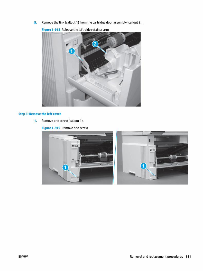
5. Remove the link (callout 1) from the cartridge door assembly (callout 2).
Figure 1-918 Release the left-side retainer arm
21
Step 3: Remove the left cover
1. Remove one screw (callout 1).
Figure 1-919 Remove one screw
1 1
ENWW Removal and replacement procedures 511
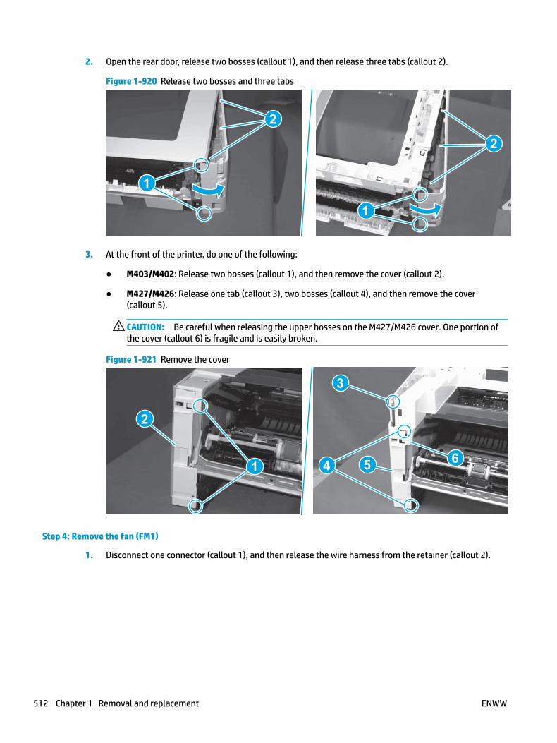
2. Open the rear door, release two bosses (callout 1), and then release three tabs (callout 2).
Figure 1-920 Release two bosses and three tabs
1
1
2
2
3. At the front of the printer, do one of the following:
● M403/M402: Release two bosses (callout 1), and then remove the cover (callout 2).
● M427/M426: Release one tab (callout 3), two bosses (callout 4), and then remove the cover (callout 5).
CAUTION: Be careful when releasing the upper bosses on the M427/M426 cover. One portion of the cover (callout 6) is fragile and is easily broken.
Figure 1-921 Remove the cover
2
1
3
54 6
Step 4: Remove the fan (FM1)
1. Disconnect one connector (callout 1), and then release the wire harness from the retainer (callout 2).
512 Chapter 1 Removal and replacement ENWW
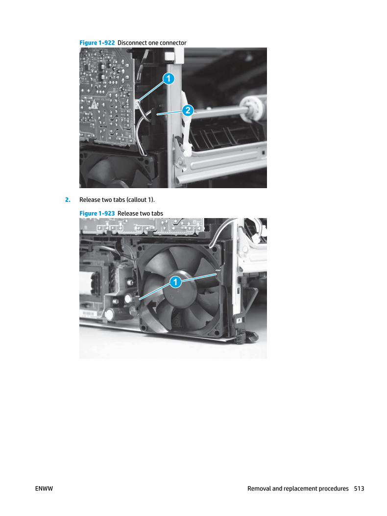
Figure 1-922 Disconnect one connector
1
2
2. Release two tabs (callout 1).
Figure 1-923 Release two tabs
1
ENWW Removal and replacement procedures 513

3. Remove the fan.
Figure 1-924 Remove the fan
Step 5: Remove the fan holder (FM1)
1. Remove one screw (callout 1).
Figure 1-925 Remove one screw
1
514 Chapter 1 Removal and replacement ENWW

2. Release one tab at the top-left side of the fan holder (callout 1), and then rotate the top-left side corner of the holder away from the printer.
Reinstallation tip: Use a flat-blade screwdriver to slightly flex the top of the holder down to make it easier to disengage this tab.
Figure 1-926 Release one tab
1
3. Slightly flex the right side of the holder to release one tab (callout 1), and then rotate the top of the holder away from the printer (callout 2).
Figure 1-927 Release one tab
1
2
ENWW Removal and replacement procedures 515

4. Lift the holder up to release two alignment tabs on the bottom of the holder, and then remove the holder.
Figure 1-928 Remove the holder
Step 6: Unpack the replacement assembly
Unpack the replacement part from the packaging.
http://www8.hp.com/us/en/hp-information/environment/product-recycling.html
NOTE: HP recommends responsible disposal of the defective part.
Figure 1-929 Recycle and unpack
516 Chapter 1 Removal and replacement ENWW

Step 7: Install the fan holder (FM1)
1. Position the bottom edge of the holder on the chassis—engage the two alignment tabs on the bottom of the holder with the slots in the chassis.
Figure 1-930 Install the holder
2. Rotate the top of the holder toward the printer (callout 1), and then engage one tab on the right side of the holder (callout 1).
Figure 1-931 Engage one tab
2
1
ENWW Removal and replacement procedures 517

3. Rotate the top-left side corner of the holder toward the printer, and then engage one tab on the holder (callout 1).
Reinstallation tip: Use a flat-blade screwdriver to slightly flex the top of the holder down to make it easier to engage this tab.
Figure 1-932 Engage one tab
1
4. Install one screw (callout 1).
Figure 1-933 Install one screw
1
Step 8: Install the fan (FM1)
1. Position the fan in the holder. Make sure that the two tabs (callout 1) snap into place on the fan.
CAUTION: The fan must be correctly installed so that air is drawn into the printer. Make sure that the two arrows embossed on the right-side of the fan body—which indicate air flow direction—face upward and into the printer.
518 Chapter 1 Removal and replacement ENWW

Figure 1-934 Install the fan
1
2. Install the wire harness on the retainer (callout 2), and then connect one connector (callout 2).
Figure 1-935 Connect one connector
2
1
Step 9: Install the left cover
1. At the front of the printer, do one of the following:
● M403/M402: Position the cover on the printer ( callout 1), and then engage two bosses (callout 2).
● M427/M426: Position the cover on the printer (callout 3), engage one tab (callout 4), and then engage two bosses (callout 4).
ENWW Removal and replacement procedures 519

Figure 1-936 Install the cover
1
2
4
35
2. Carefully rotate the rear of the cover onto the printer (callout 1), engage three tabs (callout 2), and then engage two bosses (callout 3).
Figure 1-937 Engage three tabs and two bosses
3
3 11
2
2
3. Install one screw (callout 1).
Figure 1-938 Install one screw
1 1
520 Chapter 1 Removal and replacement ENWW

Step 10: Install the cartridge door assembly
Reinstallation tip: After a replacement door is installed, make sure to install the nameplate (supplied in the kit) corresponding to the printer name on the door.
1. Position the door close to the printer, and then engage the keyed pin on the left-side retainer arm with the hole in the door.
Figure 1-939 Engage the left-side retainer arm
2. Engage the right-side door hinge pin with the hole in the chassis (callout 1).
Figure 1-940 Install the door
1
ENWW Removal and replacement procedures 521

3. Install the link (callout 1).
IMPORTANT: Make sure that the link snaps into place on the arm (callout 2). The link actuates the fuser pressure-release mechanism.
Figure 1-941 Install the pressure-release link
1
2
4. Slide the guide into the printer (callout 1), and then make sure that the tab (callout 2) snaps into place to secure the guide to the chassis.
Figure 1-942 Install the guide
1
2
522 Chapter 1 Removal and replacement ENWW

5. Position the shaft on the door, and then align the left-side hinge on the door with the hole in the chassis (callout 1).
Figure 1-943 Align the hinge
1
6. Push the shaft towards the left side of the printer to install it (callout 1).
Reinstallation tip: Make sure that the support shaft is fully installed and correctly orientated (callout 2) so that it will not interfere with the door opening and closing.
Figure 1-944 Install the support shaft
2
1
ENWW Removal and replacement procedures 523

Step 11: Install Tray 2
▲ Slide the tray straight into the printer to install it.
Figure 1-945 Install the tray
524 Chapter 1 Removal and replacement ENWW

Removal and replacement: Laser scanner assembly
● Introduction
● Step 1: Remove Tray 2
● Step 2: Remove the cartridge door assembly
● Step 3: Remove the left cover
● Step 4: Remove the right cover
● Step 5: Remove the integrated scanner assembly (M427/M246)
● Step 6: Remove the control panel (M427/M246)
● Step 7: Remove the top cover (M427/M426)
● Step 8: Remove the top cover (M403/M402)
● Step 9: Remove the paper delivery tray (output bin)
● Step 10: Remove the laser scanner assembly
● Step 11: Unpack the replacement assembly
● Step 12: Install the laser scanner assembly
● Step 13: Install the paper delivery tray (output bin)
● Step 14: Install the top cover (M403/M402)
● Step 15: Install the top cover (M427/M426)
● Step 16: Install the control panel (M427/M246)
● Step 17: Install the integrated scanner assembly (M427/M246)
● Step 18: Install the right cover
● Step 19: Install the left cover
● Step 20: Install the cartridge door assembly
● Step 21: Install Tray 2
Introduction
This document provides the procedures to remove and replace the laser scanner assembly.
Before performing service
Turn the printer power off
◦ Disconnect the power cable.
WARNING! To avoid damage to the printer, turn the printer off, wait 30 seconds, and then remove the power cable before attempting to service the printer.
Use the table below to identify the correct part number for your printer. To order the part, go to www.hp.com/buy/parts.
ENWW Removal and replacement procedures 525

Laser scanner assembly part number
RM2-5528-000CN Laser scanner assembly
Required tools
● #2 Phillips screwdriver with a magnetic tip.
After performing service
Turn the printer power on
◦ Connect the power cable.
◦ Use the power switch to turn the power on.
Post service test
Make sure that the printer initializes to a Ready state.
Print a configuration page to make sure that the printer is functioning correctly.
Step 1: Remove Tray 2
▲ Pull the tray straight out of the printer to remove it.
Figure 1-946 Remove the tray
Step 2: Remove the cartridge door assembly
NOTE: If the toner cartridge was not removed prior to servicing the printer, remove it now.
1. Release one tab (callout 1), and then slide shaft (callout 2) in the direction the arrow indicates and remove it.
TIP: It might be easier to release the support shaft by using a small flat-blade screwdriver.
526 Chapter 1 Removal and replacement ENWW

Figure 1-947 Release the support shaft
12
2. Release one tab (callout 1), and then slide the guide (callout 2) in the direction the arrow indicates and remove it.
Figure 1-948 Remove the guide
1 2
ENWW Removal and replacement procedures 527

3. Remove the link arm (callout 1).
Figure 1-949 Remove the link arm
1
4. Slide the cartridge door assembly (callout 1) in the direction the arrow indicates and remove it.
Figure 1-950 Remove the door
1
528 Chapter 1 Removal and replacement ENWW
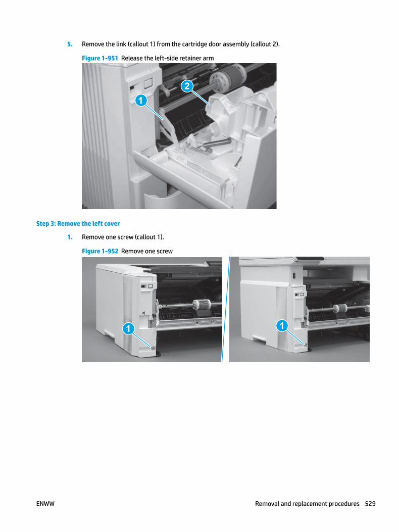
5. Remove the link (callout 1) from the cartridge door assembly (callout 2).
Figure 1-951 Release the left-side retainer arm
21
Step 3: Remove the left cover
1. Remove one screw (callout 1).
Figure 1-952 Remove one screw
1 1
ENWW Removal and replacement procedures 529

2. Open the rear door, release two bosses (callout 1), and then release three tabs (callout 2).
Figure 1-953 Release two bosses and three tabs
1
1
2
2
3. At the front of the printer, do one of the following:
● M403/M402: Release two bosses (callout 1), and then remove the cover (callout 2).
● M427/M426: Release one tab (callout 3), two bosses (callout 4), and then remove the cover (callout 5).
CAUTION: Be careful when releasing the upper bosses on the M427/M426 cover. One portion of the cover (callout 6) is fragile and is easily broken.
Figure 1-954 Remove the cover
2
1
3
54 6
Step 4: Remove the right cover
1. Remove one screw (callout 1).
530 Chapter 1 Removal and replacement ENWW
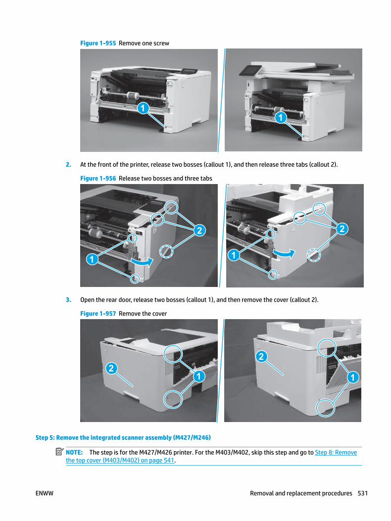
Figure 1-955 Remove one screw
11
2. At the front of the printer, release two bosses (callout 1), and then release three tabs (callout 2).
Figure 1-956 Release two bosses and three tabs
1 1
2 2
3. Open the rear door, release two bosses (callout 1), and then remove the cover (callout 2).
Figure 1-957 Remove the cover
22
1 1
Step 5: Remove the integrated scanner assembly (M427/M246)
NOTE: The step is for the M427/M426 printer. For the M403/M402, skip this step and go to Step 8: Remove the top cover (M403/M402) on page 541.
ENWW Removal and replacement procedures 531

NOTE: M427/M426 models only. The integrated scanner assembly (ISA) includes the sub-scanner assembly (SSA) and the automatic document feeder (ADF).
1. Raise the ISA.
Figure 1-958 Raise the ISA
2. Release the ISA flat-flexible cable (FFC) cover (callout 1), and then remove it (callout 2).
Figure 1-959 Remove the ISA FFC cover
12
532 Chapter 1 Removal and replacement ENWW
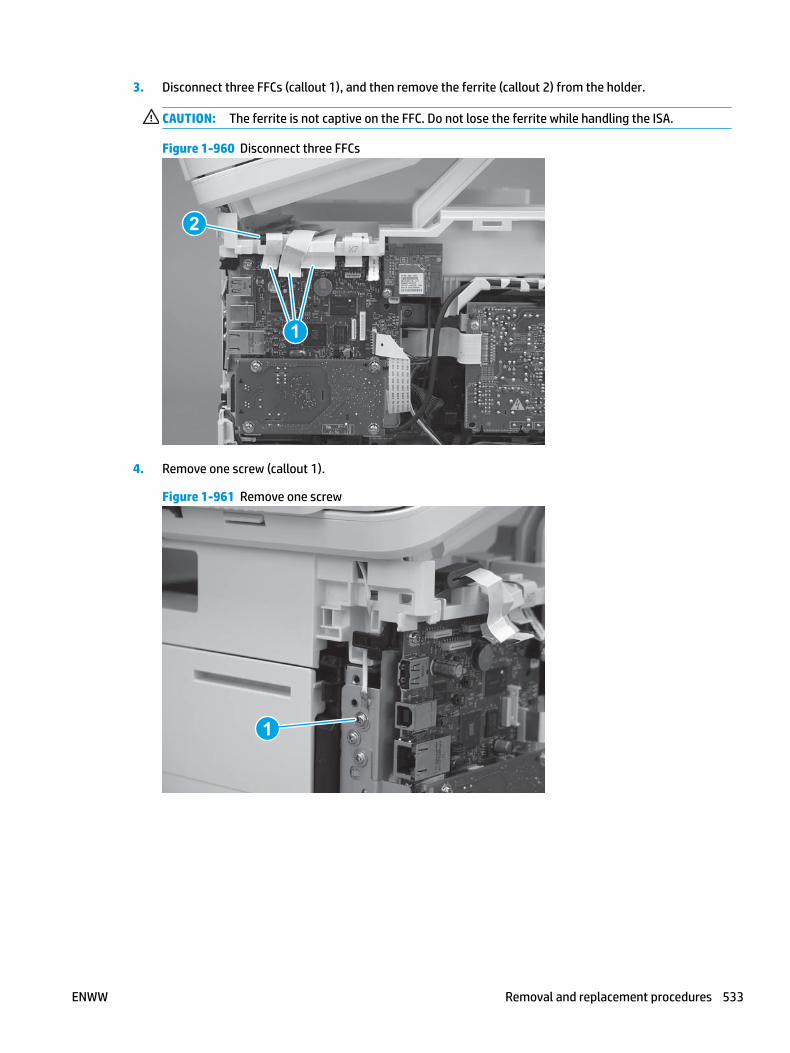
3. Disconnect three FFCs (callout 1), and then remove the ferrite (callout 2) from the holder.
CAUTION: The ferrite is not captive on the FFC. Do not lose the ferrite while handling the ISA.
Figure 1-960 Disconnect three FFCs
2
1
4. Remove one screw (callout 1).
Figure 1-961 Remove one screw
1
ENWW Removal and replacement procedures 533

5. Pass the ground wire through the opening in the top cover.
Figure 1-962 Pass the wire through the opening
6. Release one tab (callout 1), and then rotate the ISA slider pin (callout 2) towards the front of the printer to release it.
Figure 1-963 Release one tab and rotate the slider pin
1
2
534 Chapter 1 Removal and replacement ENWW

7. Remove the slider pin.
Figure 1-964 Remove the slider pin
8. Rotate the ISA towards the rear of the printer until it stops.
Figure 1-965 Rotate the ISA towards the rear of the printer
ENWW Removal and replacement procedures 535

9. Slide the ISA as shown to release it.
Figure 1-966 Release the ISA
10. Remove the ISA.
Figure 1-967 Remove the ISA
Step 6: Remove the control panel (M427/M246)
NOTE: The step is for the M427/M426 printer. For the M403/M402, skip this step and go to Step 8: Remove the top cover (M403/M402) on page 541.
1. Disconnect one FFC (callout 1; J114), and then release the FFC from the retainer (callout 2).
536 Chapter 1 Removal and replacement ENWW

Figure 1-968 Disconnect one connector
1
2
2. Remove one screw (callout 1).
Figure 1-969 Remove one screw
1
ENWW Removal and replacement procedures 537

3. Use a small flat-blade screwdriver to release two tabs (callout 1) on the control-panel cable cover.
Figure 1-970 Release two tabs
1
4. Remove the control-panel cable cover.
Figure 1-971 Remove the cover
538 Chapter 1 Removal and replacement ENWW

5. Remove one grounding screw (callout 1), and then move the ground cable (callout 2) out of the way.
Figure 1-972 Remove one screw
2
1
6. Move the FFC out of the way, and then remove two screws (callout 1).
Figure 1-973 Remove two screws
1
ENWW Removal and replacement procedures 539

7. Slightly lift up the control-panel assembly to separate it from the top cover.
CAUTION: The control panel assembly is still connected to the printer by the FFC. Do not attempt to completely remove the assembly.
Figure 1-974 Lift up the control-panel assembly
8. Lift up the control-panel FFC cover to remove the control-panel assembly.
Figure 1-975 Remove the control-panel assembly
Step 7: Remove the top cover (M427/M426)
NOTE: The step is for the M427/M426 printer. For the M403/M402, skip this step and go to Step 8: Remove the top cover (M403/M402) on page 541.
1. Release the USB cable (callout 1) from the cable guide.
540 Chapter 1 Removal and replacement ENWW

Figure 1-976 Remove the USB cable
1
2. Remove five screws (callout 1), release four bosses (callout 2), and then remove the top cover (callout 3).
Figure 1-977 Remove the cover
3
2
1
Step 8: Remove the top cover (M403/M402)
NOTE: The step is for the M403/M402 printer. For the M427/M426, skip this step and go to Step 9: Remove the paper delivery tray (output bin) on page 543.
1. Remove one screw (callout 1).
ENWW Removal and replacement procedures 541

Figure 1-978 Remove one screw
1
2. At the right side of the printer, release the one boss (callout 1), and then release one tab (callout 2).
Figure 1-979 Release one boss and one tab
21
542 Chapter 1 Removal and replacement ENWW

3. Release four tabs (callout 1), release four bosses (callout 2), and then remove the top cover (callout 3).
TIP: Open the rear door to make releasing the bosses (callout 3) easier.
Figure 1-980 Remove the cover
2
3
1
Step 9: Remove the paper delivery tray (output bin)
NOTE: This procedure shows the M403/M402 model, however, the paper delivery tray (output bin) removal is similar for the M427/M426 printer.
▲ Release two bosses (callout 1), release two tabs (callout 2), and then remove the paper delivery tray (output bin; callout 3).
Figure 1-981 Release two tabs
2
1
3
ENWW Removal and replacement procedures 543

Step 10: Remove the laser scanner assembly
NOTE: The M403/M402 product is shown in this procedure. However, the procedure is valid for the M427/M426 laser scanner assembly.
1. Disconnect one flat-flexible cable (FFC) (callout 1), and one connector (callout 2).
Reinstallation tip: Transfer the antistatic foam pad (callout 2) from the discarded laser/scanner assembly to the replacement assembly.
Figure 1-982 Disconnect one FFC and one connector
1
2
2. Remove four screws (callout 1), and then remove the laser scanner assembly.
Figure 1-983 Remove the laser scanner
1
Step 11: Unpack the replacement assembly
Unpack the replacement part from the packaging.
544 Chapter 1 Removal and replacement ENWW
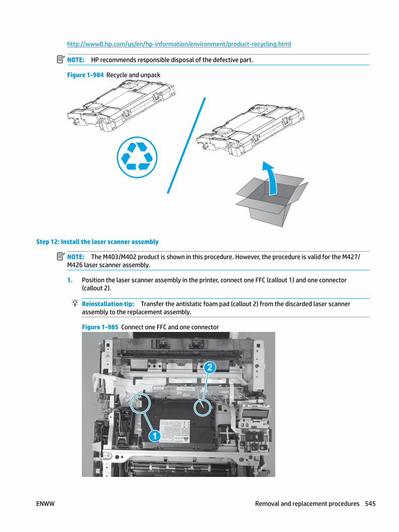
http://www8.hp.com/us/en/hp-information/environment/product-recycling.html
NOTE: HP recommends responsible disposal of the defective part.
Figure 1-984 Recycle and unpack
Step 12: Install the laser scanner assembly
NOTE: The M403/M402 product is shown in this procedure. However, the procedure is valid for the M427/M426 laser scanner assembly.
1. Position the laser scanner assembly in the printer, connect one FFC (callout 1) and one connector (callout 2).
Reinstallation tip: Transfer the antistatic foam pad (callout 2) from the discarded laser scanner assembly to the replacement assembly.
Figure 1-985 Connect one FFC and one connector
1
2
ENWW Removal and replacement procedures 545

2. Install four screws (callout 1).
Figure 1-986 Install the laser scanner
1
Step 13: Install the paper delivery tray (output bin)
NOTE: This procedure shows the M403/M402 model, however, the paper delivery tray (output bin) removal is similar for the M427/M426 printer.
▲ Position the remove the paper delivery tray (output bin; callout 1) on the printer, engage two tabs (callout 2), and then engage two bosses (callout 3).
Figure 1-987 Engage two tabs
2
3
1
Step 14: Install the top cover (M403/M402)
NOTE: The step is for the M403/M402 printer. For the M427/M426, skip this step and go to Step 15: Install the top cover (M427/M426) on page 548.
546 Chapter 1 Removal and replacement ENWW
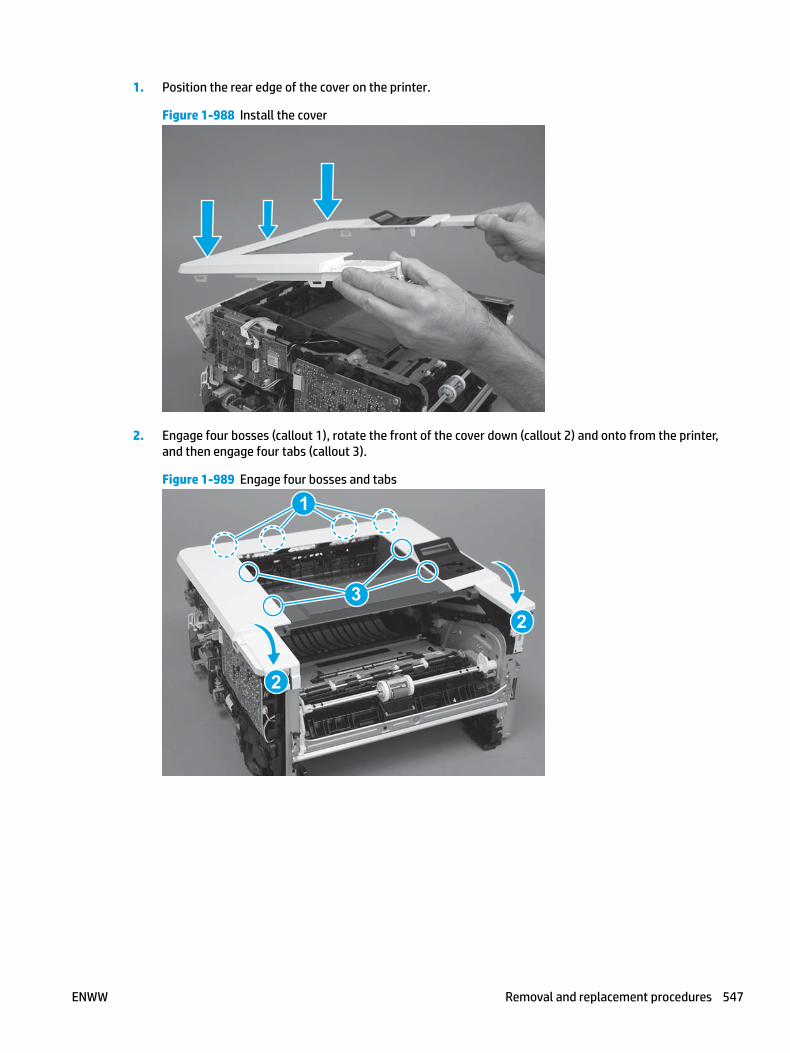
1. Position the rear edge of the cover on the printer.
Figure 1-988 Install the cover
2. Engage four bosses (callout 1), rotate the front of the cover down (callout 2) and onto from the printer, and then engage four tabs (callout 3).
Figure 1-989 Engage four bosses and tabs
1
3
2
2
ENWW Removal and replacement procedures 547

3. At the right side of the printer, engage the one boss and one tab (callout 1).
Figure 1-990 Engage one boss and one tab
1
4. Install one screw (callout 1).
Figure 1-991 Install one screw
1
Step 15: Install the top cover (M427/M426)
NOTE: The step is for the M427/M426 printer. For the M403/M402, skip this step and go to Step 18: Install the right cover on page 560.
1. Position the rear edge of the top cover on the printer.
548 Chapter 1 Removal and replacement ENWW

Figure 1-992 Install the cover
2. Engage four bosses (callout 1).
Figure 1-993 Engage four bosses
1
ENWW Removal and replacement procedures 549
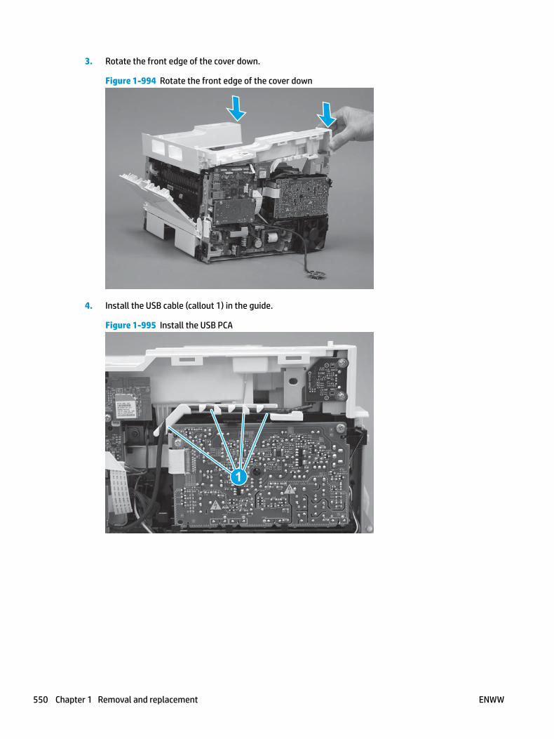
3. Rotate the front edge of the cover down.
Figure 1-994 Rotate the front edge of the cover down
4. Install the USB cable (callout 1) in the guide.
Figure 1-995 Install the USB PCA
1
550 Chapter 1 Removal and replacement ENWW

5. Install five screws (callout 1).
Figure 1-996 Install five screws
1
Step 16: Install the control panel (M427/M246)
NOTE: The step is for the M427/M426 printer. For the M403/M402, skip this step and go to Step 18: Install the right cover on page 560.
1. Slide the control-panel FFC cover into the slot in the top cover (next to the document feeder support arm) to install it.
Figure 1-997 Install the control-panel FFC cover
ENWW Removal and replacement procedures 551

2. Install the control-panel assembly on the top cover.
Figure 1-998 Install the control-panel assembly
3. Move the FFC out of the way, and then install two screws (callout 1).
Figure 1-999 Install two screws
1
552 Chapter 1 Removal and replacement ENWW

4. Install one grounding screw (callout 1), and then make sure that the ground cable (callout 2) is properly routed.
Figure 1-1000 Remove one screw
2
1
5. Install the control-panel cable cover.
Figure 1-1001 Install the cover
ENWW Removal and replacement procedures 553

6. Make sure that the two tabs (callout 1) on the cover snap into place.
Figure 1-1002 Engage two tabs
1
7. Install one screw (callout 1).
Figure 1-1003 Install one screw
1
554 Chapter 1 Removal and replacement ENWW

8. Install the FFC in the retainer (callout 1), and then connect one FFC (callout 1; J114).
Figure 1-1004 Connect one connector
1
2
Step 17: Install the integrated scanner assembly (M427/M246)
NOTE: The step is for the M427/M426 printer. For the M403/M402, skip this step and go to Step 18: Install the right cover on page 560.
NOTE: M427/M426 models only. The integrated scanner assembly (ISA) includes the sub-scanner assembly (SSA) and the automatic document feeder (ADF).
1. Position the ISA on the printer.
Figure 1-1005 Position the ISA on the printer
ENWW Removal and replacement procedures 555

2. Engage the hinge pins on the ISA with the holders in the top cover (callouts 1/2), and the slide the ISA as shown to engage them
Figure 1-1006 Engage the hinge pins with the holders
1
2
3. Rotate the ISA towards the front of the printer until it rests on the ISA lift assembly (callout 1).
Figure 1-1007 Rotate the ISA towards the front of the printer
1
556 Chapter 1 Removal and replacement ENWW

4. Pass the ground wire through the opening in the top cover.
Figure 1-1008 Pass the wire through the opening
5. Install one screw (callout 1).
Figure 1-1009 Install one screw
1
ENWW Removal and replacement procedures 557

6. Install the ISA lift assembly slider pin.
Reinstallation tip: Align the keyed portion of the locking pin with the slot and hole in the support arm.
Figure 1-1010 Install the slider pin
7. Rotate the slider pin (callout 1) towards the rear of the printer until the tab (callout 2) snap into place.
Figure 1-1011 Secure the slider pin
2
1
558 Chapter 1 Removal and replacement ENWW

8. Install the ferrite (callout 1) in the holder, and then connect three FFCs (callout 2).
Figure 1-1012 Connect three FFCs
1
2
9. Position the rear edge of the ISA flat-flexible cable (FFC) cover on the printer (callout 1) , and then rotate it down (callout 2) until it snaps into place.
Figure 1-1013 Install the ISA FFC cover
1
2
ENWW Removal and replacement procedures 559
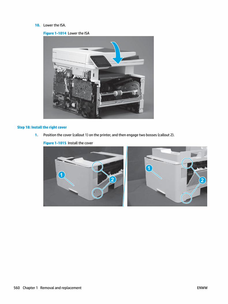
10. Lower the ISA.
Figure 1-1014 Lower the ISA
Step 18: Install the right cover
1. Position the cover (callout 1) on the printer, and then engage two bosses (callout 2).
Figure 1-1015 Install the cover
11
2 2
560 Chapter 1 Removal and replacement ENWW

2. Rotate the front of the cover onto the printer (callout 1), engage three (callout 2) tabs, and then engage two bosses (callout 3).
Figure 1-1016 Engage two bosses and one tab
1 13 3
2 2
3. Make sure that the power switch (callout 1) and cartridge door assembly button (callout 2) correctly function.
NOTE: Remove, and then reinstall the cover if the switch or button does not correctly function.
Figure 1-1017 Check the power switch and cartridge door assembly button
1
1
22
4. Install one screw (callout 1).
Figure 1-1018 Install one screw
11
ENWW Removal and replacement procedures 561

Step 19: Install the left cover
1. At the front of the printer, do one of the following:
● M403/M402: Position the cover on the printer ( callout 1), and then engage two bosses (callout 2).
● M427/M426: Position the cover on the printer (callout 3), engage one tab (callout 4), and then engage two bosses (callout 4).
Figure 1-1019 Install the cover
1
2
4
35
2. Carefully rotate the rear of the cover onto the printer (callout 1), engage three tabs (callout 2), and then engage two bosses (callout 3).
Figure 1-1020 Engage three tabs and two bosses
3
3 11
2
2
562 Chapter 1 Removal and replacement ENWW
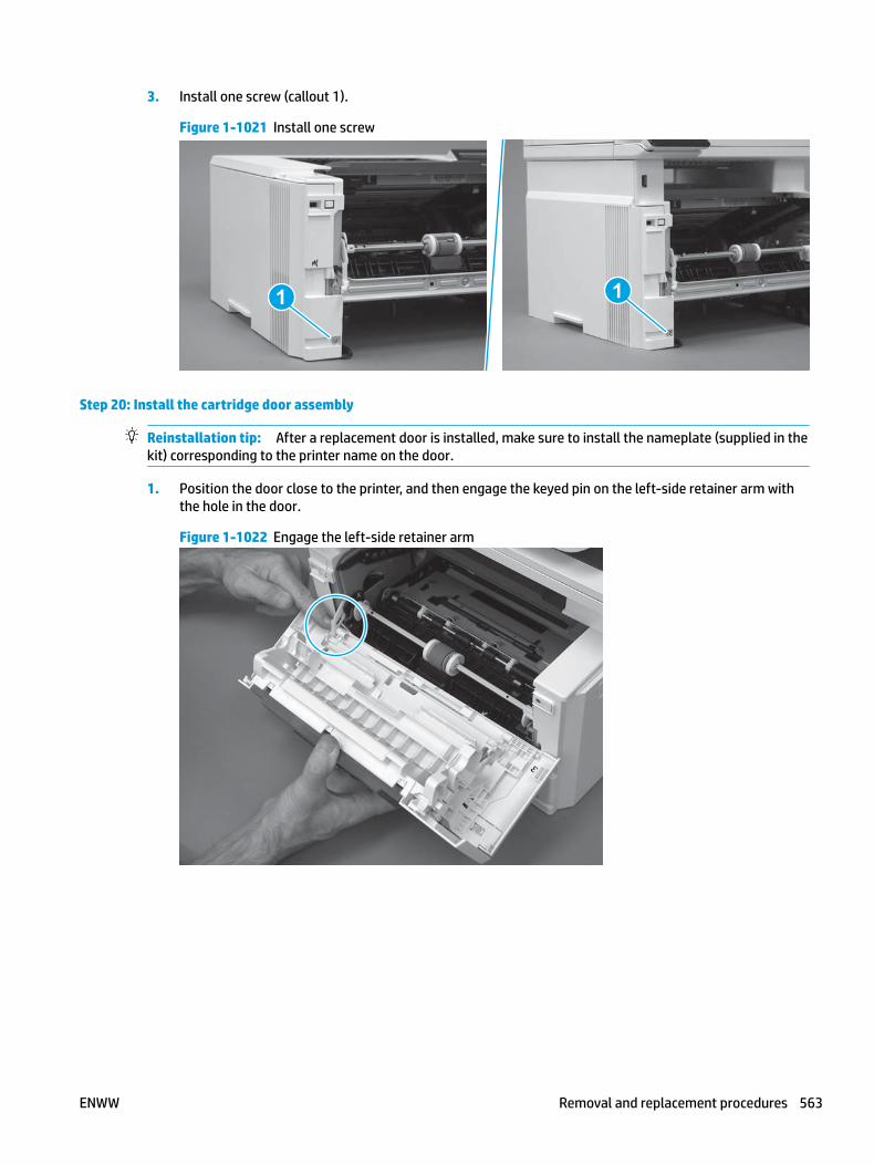
3. Install one screw (callout 1).
Figure 1-1021 Install one screw
1 1
Step 20: Install the cartridge door assembly
Reinstallation tip: After a replacement door is installed, make sure to install the nameplate (supplied in the kit) corresponding to the printer name on the door.
1. Position the door close to the printer, and then engage the keyed pin on the left-side retainer arm with the hole in the door.
Figure 1-1022 Engage the left-side retainer arm
ENWW Removal and replacement procedures 563

2. Engage the right-side door hinge pin with the hole in the chassis (callout 1).
Figure 1-1023 Install the door
1
3. Install the link (callout 1).
IMPORTANT: Make sure that the link snaps into place on the arm (callout 2). The link actuates the fuser pressure-release mechanism.
Figure 1-1024 Install the pressure-release link
1
2
564 Chapter 1 Removal and replacement ENWW

4. Slide the guide into the printer (callout 1), and then make sure that the tab (callout 2) snaps into place to secure the guide to the chassis.
Figure 1-1025 Install the guide
1
2
5. Position the shaft on the door, and then align the left-side hinge on the door with the hole in the chassis (callout 1).
Figure 1-1026 Align the hinge
1
ENWW Removal and replacement procedures 565

6. Push the shaft towards the left side of the printer to install it (callout 1).
Reinstallation tip: Make sure that the support shaft is fully installed and correctly orientated (callout 2) so that it will not interfere with the door opening and closing.
Figure 1-1027 Install the support shaft
2
1
Step 21: Install Tray 2
▲ Slide the tray straight into the printer to install it.
Figure 1-1028 Install the tray
566 Chapter 1 Removal and replacement ENWW

Removal and replacement: Sheet-metal formatter bracket and formatter PCA
● Step 1: Remove Tray 2
● Step 2: Remove the cartridge door assembly
● Step 3: Remove the left cover
● Step 4: Remove the right cover
● Step 5: Remove the integrated scanner assembly (M427/M246)
● Step 6: Remove the control panel (M427/M246)
● Step 7: Remove the top cover (M427/M426)
● Step 8: Remove the top cover (M403/M402)
● Step 9: Remove the sheet-metal formatter bracket and formatter PCA
● Step 10: Install the sheet-metal formatter bracket and formatter PCA
● Step 11: Install the top cover (M403/M402)
● Step 12: Install the top cover (M427/M426)
● Step 13: Install the control panel (M427/M246)
● Step 14: Install the integrated scanner assembly (M427/M246)
● Step 15: Install the right cover
● Step 16: Install the left cover
● Step 17: Install the cartridge door assembly
● Step 18: Install Tray 2
Step 1: Remove Tray 2
▲ Pull the tray straight out of the printer to remove it.
ENWW Removal and replacement procedures 567

Figure 1-1029 Remove the tray
Step 2: Remove the cartridge door assembly
NOTE: If the toner cartridge was not removed prior to servicing the printer, remove it now.
1. Release one tab (callout 1), and then slide shaft (callout 2) in the direction the arrow indicates and remove it.
TIP: It might be easier to release the support shaft by using a small flat-blade screwdriver.
Figure 1-1030 Release the support shaft
12
568 Chapter 1 Removal and replacement ENWW

2. Release one tab (callout 1), and then slide the guide (callout 2) in the direction the arrow indicates and remove it.
Figure 1-1031 Remove the guide
1 2
3. Remove the link arm (callout 1).
Figure 1-1032 Remove the link arm
1
ENWW Removal and replacement procedures 569

4. Slide the cartridge door assembly (callout 1) in the direction the arrow indicates and remove it.
Figure 1-1033 Remove the door
1
5. Remove the link (callout 1) from the cartridge door assembly (callout 2).
Figure 1-1034 Release the left-side retainer arm
21
Step 3: Remove the left cover
1. Remove one screw (callout 1).
570 Chapter 1 Removal and replacement ENWW

Figure 1-1035 Remove one screw
1 1
2. Open the rear door, release two bosses (callout 1), and then release three tabs (callout 2).
Figure 1-1036 Release two bosses and three tabs
1
1
2
2
3. At the front of the printer, do one of the following:
● M403/M402: Release two bosses (callout 1), and then remove the cover (callout 2).
● M427/M426: Release one tab (callout 3), two bosses (callout 4), and then remove the cover (callout 5).
CAUTION: Be careful when releasing the upper bosses on the M427/M426 cover. One portion of the cover (callout 6) is fragile and is easily broken.
ENWW Removal and replacement procedures 571

Figure 1-1037 Remove the cover
2
1
3
54 6
Step 4: Remove the right cover
1. Remove one screw (callout 1).
Figure 1-1038 Remove one screw
11
2. At the front of the printer, release two bosses (callout 1), and then release three tabs (callout 2).
Figure 1-1039 Release two bosses and three tabs
1 1
2 2
572 Chapter 1 Removal and replacement ENWW

3. Open the rear door, release two bosses (callout 1), and then remove the cover (callout 2).
Figure 1-1040 Remove the cover
22
1 1
Step 5: Remove the integrated scanner assembly (M427/M246)
NOTE: The step is for the M427/M426 printer. For the M403/M402, skip this step and go to Step 8: Remove the top cover (M403/M402) on page 583.
NOTE: M427/M426 models only. The integrated scanner assembly (ISA) includes the sub-scanner assembly (SSA) and the automatic document feeder (ADF).
1. Raise the ISA.
Figure 1-1041 Raise the ISA
ENWW Removal and replacement procedures 573

2. Release the ISA flat-flexible cable (FFC) cover (callout 1), and then remove it (callout 2).
Figure 1-1042 Remove the ISA FFC cover
12
3. Disconnect three FFCs (callout 1), and then remove the ferrite (callout 2) from the holder.
CAUTION: The ferrite is not captive on the FFC. Do not lose the ferrite while handling the ISA.
Figure 1-1043 Disconnect three FFCs
2
1
574 Chapter 1 Removal and replacement ENWW

4. Remove one screw (callout 1).
Figure 1-1044 Remove one screw
1
5. Pass the ground wire through the opening in the top cover.
Figure 1-1045 Pass the wire through the opening
ENWW Removal and replacement procedures 575

6. Release one tab (callout 1), and then rotate the ISA slider pin (callout 2) towards the front of the printer to release it.
Figure 1-1046 Release one tab and rotate the slider pin
1
2
7. Remove the slider pin.
Figure 1-1047 Remove the slider pin
576 Chapter 1 Removal and replacement ENWW

8. Rotate the ISA towards the rear of the printer until it stops.
Figure 1-1048 Rotate the ISA towards the rear of the printer
9. Slide the ISA as shown to release it.
Figure 1-1049 Release the ISA
ENWW Removal and replacement procedures 577

10. Remove the ISA.
Figure 1-1050 Remove the ISA
Step 6: Remove the control panel (M427/M246)
NOTE: The step is for the M427/M426 printer. For the M403/M402, skip this step and go to Step 8: Remove the top cover (M403/M402) on page 583.
1. Disconnect one FFC (callout 1; J114), and then release the FFC from the retainer (callout 2).
Figure 1-1051 Disconnect one connector
1
2
578 Chapter 1 Removal and replacement ENWW

2. Remove one screw (callout 1).
Figure 1-1052 Remove one screw
1
3. Use a small flat-blade screwdriver to release two tabs (callout 1) on the control-panel cable cover.
Figure 1-1053 Release two tabs
1
ENWW Removal and replacement procedures 579

4. Remove the control-panel cable cover.
Figure 1-1054 Remove the cover
5. Remove one grounding screw (callout 1), and then move the ground cable (callout 2) out of the way.
Figure 1-1055 Remove one screw
2
1
580 Chapter 1 Removal and replacement ENWW

6. Move the FFC out of the way, and then remove two screws (callout 1).
Figure 1-1056 Remove two screws
1
7. Slightly lift up the control-panel assembly to separate it from the top cover.
CAUTION: The control panel assembly is still connected to the printer by the FFC. Do not attempt to completely remove the assembly.
Figure 1-1057 Lift up the control-panel assembly
ENWW Removal and replacement procedures 581

8. Lift up the control-panel FFC cover to remove the control-panel assembly.
Figure 1-1058 Remove the control-panel assembly
Step 7: Remove the top cover (M427/M426)
NOTE: The step is for the M427/M426 printer. For the M403/M402, skip this step and go to Step 8: Remove the top cover (M403/M402) on page 583.
1. Release the USB cable (callout 1) from the cable guide.
Figure 1-1059 Remove the USB cable
1
582 Chapter 1 Removal and replacement ENWW

2. Remove five screws (callout 1), release four bosses (callout 2), and then remove the top cover (callout 3).
Figure 1-1060 Remove the cover
3
2
1
Step 8: Remove the top cover (M403/M402)
NOTE: The step is for the M403/M402 printer. For the M427/M426, skip this step and go to Step 9: Remove the sheet-metal formatter bracket and formatter PCA on page 584.
1. Remove one screw (callout 1).
Figure 1-1061 Remove one screw
1
ENWW Removal and replacement procedures 583

2. At the right side of the printer, release the one boss (callout 1), and then release one tab (callout 2).
Figure 1-1062 Release one boss and one tab
21
3. Release four tabs (callout 1), release four bosses (callout 2), and then remove the top cover (callout 3).
TIP: Open the rear door to make releasing the bosses (callout 3) easier.
Figure 1-1063 Remove the cover
2
3
1
Step 9: Remove the sheet-metal formatter bracket and formatter PCA
NOTE: Disconnect any remaining formatter PCA FFCs or wire-harness connectors.
1. M427/M426 only: Remove the guide (callout 1).
584 Chapter 1 Removal and replacement ENWW

Figure 1-1064 Remove the guide
1
2. Remove two screws (callout 1).
Figure 1-1065 Remove two screws
11
3. Disconnect one connector (callout 1), and then release the wire harness from the guide (callout 2).
Figure 1-1066 Disconnect one connector
21
21
ENWW Removal and replacement procedures 585

4. Remove the guide (callout 1).
Figure 1-1067 Remove the guide
11
5. Remove three screws (callout 1).
Figure 1-1068 Remove three screws
1 1
6. Remove the sheet-metal bracket and formatter PCA.
Figure 1-1069 Remove the bracket
586 Chapter 1 Removal and replacement ENWW

Step 10: Install the sheet-metal formatter bracket and formatter PCA
NOTE: Do not forget to connect any formatter PCA FFCs or wire-harness connectors that were disconnected when the bracket was removed.
1. Position the sheet-metal bracket and formatter PCA on the printer.
Figure 1-1070 Install the bracket
2. Install three screws (callout 1).
Figure 1-1071 Install three screws
1 1
3. Install the guide (callout 1).
Figure 1-1072 Install the guide
11
ENWW Removal and replacement procedures 587

4. Connect one connector (callout 1), and then install the wire harness in the guide (callout 2).
Figure 1-1073 Connect one connector
21
21
5. Install two screws (callout 1).
Figure 1-1074 Install two screws
11
6. M427/M426 only: Install the guide (callout 1).
Figure 1-1075 Install the guide
1
588 Chapter 1 Removal and replacement ENWW
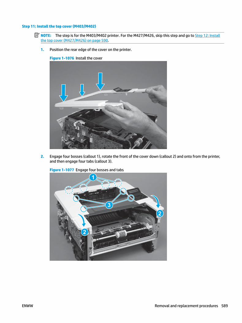
Step 11: Install the top cover (M403/M402)
NOTE: The step is for the M403/M402 printer. For the M427/M426, skip this step and go to Step 12: Install the top cover (M427/M426) on page 590.
1. Position the rear edge of the cover on the printer.
Figure 1-1076 Install the cover
2. Engage four bosses (callout 1), rotate the front of the cover down (callout 2) and onto from the printer, and then engage four tabs (callout 3).
Figure 1-1077 Engage four bosses and tabs
1
3
2
2
ENWW Removal and replacement procedures 589

3. At the right side of the printer, engage the one boss and one tab (callout 1).
Figure 1-1078 Engage one boss and one tab
1
4. Install one screw (callout 1).
Figure 1-1079 Install one screw
1
Step 12: Install the top cover (M427/M426)
NOTE: The step is for the M427/M426 printer. For the M403/M402, skip this step and go to Step 15: Install the right cover on page 602.
1. Position the rear edge of the top cover on the printer.
590 Chapter 1 Removal and replacement ENWW

Figure 1-1080 Install the cover
2. Engage four bosses (callout 1).
Figure 1-1081 Engage four bosses
1
ENWW Removal and replacement procedures 591

3. Rotate the front edge of the cover down.
Figure 1-1082 Rotate the front edge of the cover down
4. Install the USB cable (callout 1) in the guide.
Figure 1-1083 Install the USB PCA
1
592 Chapter 1 Removal and replacement ENWW

5. Install five screws (callout 1).
Figure 1-1084 Install five screws
1
Step 13: Install the control panel (M427/M246)
NOTE: The step is for the M427/M426 printer. For the M403/M402, skip this step and go to Step 15: Install the right cover on page 602.
1. Slide the control-panel FFC cover into the slot in the top cover (next to the document feeder support arm) to install it.
Figure 1-1085 Install the control-panel FFC cover
ENWW Removal and replacement procedures 593
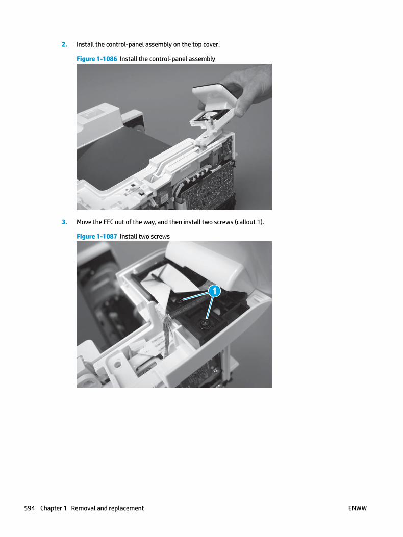
2. Install the control-panel assembly on the top cover.
Figure 1-1086 Install the control-panel assembly
3. Move the FFC out of the way, and then install two screws (callout 1).
Figure 1-1087 Install two screws
1
594 Chapter 1 Removal and replacement ENWW

4. Install one grounding screw (callout 1), and then make sure that the ground cable (callout 2) is properly routed.
Figure 1-1088 Remove one screw
2
1
5. Install the control-panel cable cover.
Figure 1-1089 Install the cover
ENWW Removal and replacement procedures 595

6. Make sure that the two tabs (callout 1) on the cover snap into place.
Figure 1-1090 Engage two tabs
1
7. Install one screw (callout 1).
Figure 1-1091 Install one screw
1
596 Chapter 1 Removal and replacement ENWW

8. Install the FFC in the retainer (callout 1), and then connect one FFC (callout 1; J114).
Figure 1-1092 Connect one connector
1
2
Step 14: Install the integrated scanner assembly (M427/M246)
NOTE: The step is for the M427/M426 printer. For the M403/M402, skip this step and go to Step 15: Install the right cover on page 602.
NOTE: M427/M426 models only. The integrated scanner assembly (ISA) includes the sub-scanner assembly (SSA) and the automatic document feeder (ADF).
1. Position the ISA on the printer.
Figure 1-1093 Position the ISA on the printer
ENWW Removal and replacement procedures 597
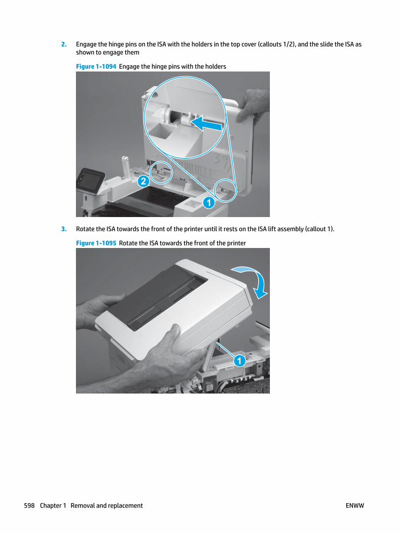
2. Engage the hinge pins on the ISA with the holders in the top cover (callouts 1/2), and the slide the ISA as shown to engage them
Figure 1-1094 Engage the hinge pins with the holders
1
2
3. Rotate the ISA towards the front of the printer until it rests on the ISA lift assembly (callout 1).
Figure 1-1095 Rotate the ISA towards the front of the printer
1
598 Chapter 1 Removal and replacement ENWW

4. Pass the ground wire through the opening in the top cover.
Figure 1-1096 Pass the wire through the opening
5. Install one screw (callout 1).
Figure 1-1097 Install one screw
1
ENWW Removal and replacement procedures 599

6. Install the ISA lift assembly slider pin.
Reinstallation tip: Align the keyed portion of the locking pin with the slot and hole in the support arm.
Figure 1-1098 Install the slider pin
7. Rotate the slider pin (callout 1) towards the rear of the printer until the tab (callout 2) snap into place.
Figure 1-1099 Secure the slider pin
2
1
600 Chapter 1 Removal and replacement ENWW

8. Install the ferrite (callout 1) in the holder, and then connect three FFCs (callout 2).
Figure 1-1100 Connect three FFCs
1
2
9. Position the rear edge of the ISA flat-flexible cable (FFC) cover on the printer (callout 1) , and then rotate it down (callout 2) until it snaps into place.
Figure 1-1101 Install the ISA FFC cover
1
2
ENWW Removal and replacement procedures 601

10. Lower the ISA.
Figure 1-1102 Lower the ISA
Step 15: Install the right cover
1. Position the cover (callout 1) on the printer, and then engage two bosses (callout 2).
Figure 1-1103 Install the cover
11
2 2
602 Chapter 1 Removal and replacement ENWW

2. Rotate the front of the cover onto the printer (callout 1), engage three (callout 2) tabs, and then engage two bosses (callout 3).
Figure 1-1104 Engage two bosses and one tab
1 13 3
2 2
3. Make sure that the power switch (callout 1) and cartridge door assembly button (callout 2) correctly function.
NOTE: Remove, and then reinstall the cover if the switch or button does not correctly function.
Figure 1-1105 Check the power switch and cartridge door assembly button
1
1
22
4. Install one screw (callout 1).
Figure 1-1106 Install one screw
11
ENWW Removal and replacement procedures 603

Step 16: Install the left cover
1. At the front of the printer, do one of the following:
● M403/M402: Position the cover on the printer ( callout 1), and then engage two bosses (callout 2).
● M427/M426: Position the cover on the printer (callout 3), engage one tab (callout 4), and then engage two bosses (callout 4).
Figure 1-1107 Install the cover
1
2
4
35
2. Carefully rotate the rear of the cover onto the printer (callout 1), engage three tabs (callout 2), and then engage two bosses (callout 3).
Figure 1-1108 Engage three tabs and two bosses
3
3 11
2
2
604 Chapter 1 Removal and replacement ENWW

3. Install one screw (callout 1).
Figure 1-1109 Install one screw
1 1
Step 17: Install the cartridge door assembly
Reinstallation tip: After a replacement door is installed, make sure to install the nameplate (supplied in the kit) corresponding to the printer name on the door.
1. Position the door close to the printer, and then engage the keyed pin on the left-side retainer arm with the hole in the door.
Figure 1-1110 Engage the left-side retainer arm
ENWW Removal and replacement procedures 605

2. Engage the right-side door hinge pin with the hole in the chassis (callout 1).
Figure 1-1111 Install the door
1
3. Install the link (callout 1).
IMPORTANT: Make sure that the link snaps into place on the arm (callout 2). The link actuates the fuser pressure-release mechanism.
Figure 1-1112 Install the pressure-release link
1
2
606 Chapter 1 Removal and replacement ENWW

4. Slide the guide into the printer (callout 1), and then make sure that the tab (callout 2) snaps into place to secure the guide to the chassis.
Figure 1-1113 Install the guide
1
2
5. Position the shaft on the door, and then align the left-side hinge on the door with the hole in the chassis (callout 1).
Figure 1-1114 Align the hinge
1
ENWW Removal and replacement procedures 607

6. Push the shaft towards the left side of the printer to install it (callout 1).
Reinstallation tip: Make sure that the support shaft is fully installed and correctly orientated (callout 2) so that it will not interfere with the door opening and closing.
Figure 1-1115 Install the support shaft
2
1
Step 18: Install Tray 2
▲ Slide the tray straight into the printer to install it.
Figure 1-1116 Install the tray
608 Chapter 1 Removal and replacement ENWW

Removal and replacement: NFC FFC
● Introduction
● Step 1: Remove Tray 2
● Step 2: Remove the cartridge door assembly
● Step 3: Remove the left cover
● Step 4: Remove the right cover
● Step 5: Remove the integrated scanner assembly (M427/M246)
● Step 6: Remove the control panel (M427/M246)
● Step 7: Remove the top cover (M427/M426)
● Step 8: Remove the NFC PCA cover (M427/M426)
● Step 9: Remove the top cover (M403/M402)
● Step 10: Remove the paper delivery tray (output bin)
● Step 11: Remove the NFC PCA
● Step 12: Remove the NFC FFC
● Step 13: Unpack the replacement assembly
● Step 14: Install the NFC FFC
● Step 15: Install the NFC PCA
● Step 16: Install the paper delivery tray (output bin)
● Step 17: Install the top cover (M403/M402)
● Step 18: Install the NFC PCA cover (M427/M426)
● Step 19: Install the top cover (M427/M426)
● Step 20: Install the control panel (M427/M246)
● Step 21: Install the integrated scanner assembly (M427/M246)
● Step 22: Install the right cover
● Step 23: Install the left cover
● Step 24: Install the cartridge door assembly
● Step 25: Install Tray 2
Introduction
This document provides the procedures to remove and replace the near field communication (NFC) flat-flexible cable (FFC; M426fdw/M403dn models only).
ENWW Removal and replacement procedures 609

Before performing service
Turn the printer power off
◦ Disconnect the power cable.
WARNING! To avoid damage to the printer, turn the printer off, wait 30 seconds, and then remove the power cable before attempting to service the printer.
Use the table below to identify the correct part number for your printer. To order the part, go to www.hp.com/buy/parts.
NFC FFC part number
RK2-6949-000CN
RK2-6947-000CN
NFC FFC (M427/M426; wireless models)
NFC FFC (M403/M402; wireless models)
Required tools
● #2 Phillips screwdriver with a magnetic tip.
After performing service
Turn the printer power on
◦ Connect the power cable.
◦ Use the power switch to turn the power on.
Post service test
Make sure that the printer initializes to a Ready state.
Print a configuration page to make sure that the printer is functioning correctly.
Step 1: Remove Tray 2
▲ Pull the tray straight out of the printer to remove it.
610 Chapter 1 Removal and replacement ENWW

Figure 1-1117 Remove the tray
Step 2: Remove the cartridge door assembly
NOTE: If the toner cartridge was not removed prior to servicing the printer, remove it now.
1. Release one tab (callout 1), and then slide shaft (callout 2) in the direction the arrow indicates and remove it.
TIP: It might be easier to release the support shaft by using a small flat-blade screwdriver.
Figure 1-1118 Release the support shaft
12
ENWW Removal and replacement procedures 611

2. Release one tab (callout 1), and then slide the guide (callout 2) in the direction the arrow indicates and remove it.
Figure 1-1119 Remove the guide
1 2
3. Remove the link arm (callout 1).
Figure 1-1120 Remove the link arm
1
612 Chapter 1 Removal and replacement ENWW

4. Slide the cartridge door assembly (callout 1) in the direction the arrow indicates and remove it.
Figure 1-1121 Remove the door
1
5. Remove the link (callout 1) from the cartridge door assembly (callout 2).
Figure 1-1122 Release the left-side retainer arm
21
Step 3: Remove the left cover
1. Remove one screw (callout 1).
ENWW Removal and replacement procedures 613

Figure 1-1123 Remove one screw
1 1
2. Open the rear door, release two bosses (callout 1), and then release three tabs (callout 2).
Figure 1-1124 Release two bosses and three tabs
1
1
2
2
3. At the front of the printer, do one of the following:
● M403/M402: Release two bosses (callout 1), and then remove the cover (callout 2).
● M427/M426: Release one tab (callout 3), two bosses (callout 4), and then remove the cover (callout 5).
CAUTION: Be careful when releasing the upper bosses on the M427/M426 cover. One portion of the cover (callout 6) is fragile and is easily broken.
614 Chapter 1 Removal and replacement ENWW

Figure 1-1125 Remove the cover
2
1
3
54 6
Step 4: Remove the right cover
1. Remove one screw (callout 1).
Figure 1-1126 Remove one screw
11
2. At the front of the printer, release two bosses (callout 1), and then release three tabs (callout 2).
Figure 1-1127 Release two bosses and three tabs
1 1
2 2
ENWW Removal and replacement procedures 615
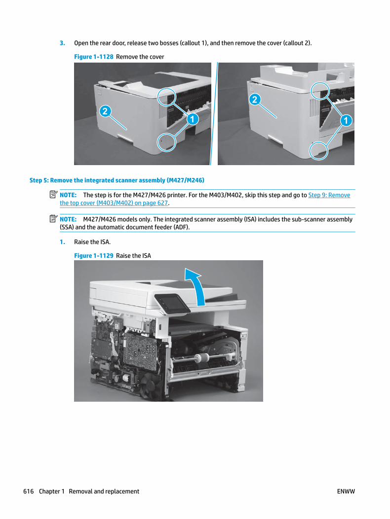
3. Open the rear door, release two bosses (callout 1), and then remove the cover (callout 2).
Figure 1-1128 Remove the cover
22
1 1
Step 5: Remove the integrated scanner assembly (M427/M246)
NOTE: The step is for the M427/M426 printer. For the M403/M402, skip this step and go to Step 9: Remove the top cover (M403/M402) on page 627.
NOTE: M427/M426 models only. The integrated scanner assembly (ISA) includes the sub-scanner assembly (SSA) and the automatic document feeder (ADF).
1. Raise the ISA.
Figure 1-1129 Raise the ISA
616 Chapter 1 Removal and replacement ENWW

2. Release the ISA flat-flexible cable (FFC) cover (callout 1), and then remove it (callout 2).
Figure 1-1130 Remove the ISA FFC cover
12
3. Disconnect three FFCs (callout 1), and then remove the ferrite (callout 2) from the holder.
CAUTION: The ferrite is not captive on the FFC. Do not lose the ferrite while handling the ISA.
Figure 1-1131 Disconnect three FFCs
2
1
ENWW Removal and replacement procedures 617

4. Remove one screw (callout 1).
Figure 1-1132 Remove one screw
1
5. Pass the ground wire through the opening in the top cover.
Figure 1-1133 Pass the wire through the opening
618 Chapter 1 Removal and replacement ENWW

6. Release one tab (callout 1), and then rotate the ISA slider pin (callout 2) towards the front of the printer to release it.
Figure 1-1134 Release one tab and rotate the slider pin
1
2
7. Remove the slider pin.
Figure 1-1135 Remove the slider pin
ENWW Removal and replacement procedures 619

8. Rotate the ISA towards the rear of the printer until it stops.
Figure 1-1136 Rotate the ISA towards the rear of the printer
9. Slide the ISA as shown to release it.
Figure 1-1137 Release the ISA
620 Chapter 1 Removal and replacement ENWW

10. Remove the ISA.
Figure 1-1138 Remove the ISA
Step 6: Remove the control panel (M427/M246)
NOTE: The step is for the M427/M426 printer. For the M403/M402, skip this step and go to Step 9: Remove the top cover (M403/M402) on page 627.
1. Disconnect one FFC (callout 1; J114), and then release the FFC from the retainer (callout 2).
Figure 1-1139 Disconnect one connector
1
2
ENWW Removal and replacement procedures 621

2. Remove one screw (callout 1).
Figure 1-1140 Remove one screw
1
3. Use a small flat-blade screwdriver to release two tabs (callout 1) on the control-panel cable cover.
Figure 1-1141 Release two tabs
1
622 Chapter 1 Removal and replacement ENWW

4. Remove the control-panel cable cover.
Figure 1-1142 Remove the cover
5. Remove one grounding screw (callout 1), and then move the ground cable (callout 2) out of the way.
Figure 1-1143 Remove one screw
2
1
ENWW Removal and replacement procedures 623

6. Move the FFC out of the way, and then remove two screws (callout 1).
Figure 1-1144 Remove two screws
1
7. Slightly lift up the control-panel assembly to separate it from the top cover.
CAUTION: The control panel assembly is still connected to the printer by the FFC. Do not attempt to completely remove the assembly.
Figure 1-1145 Lift up the control-panel assembly
624 Chapter 1 Removal and replacement ENWW

8. Lift up the control-panel FFC cover to remove the control-panel assembly.
Figure 1-1146 Remove the control-panel assembly
Step 7: Remove the top cover (M427/M426)
NOTE: The step is for the M427/M426 printer. For the M403/M402, skip this step and go to Step 9: Remove the top cover (M403/M402) on page 627.
1. Release the USB cable (callout 1) from the cable guide.
Figure 1-1147 Remove the USB cable
1
ENWW Removal and replacement procedures 625

2. Remove five screws (callout 1), release four bosses (callout 2), and then remove the top cover (callout 3).
Figure 1-1148 Remove the cover
3
2
1
Step 8: Remove the NFC PCA cover (M427/M426)
NOTE: The step is for the M427/M426 printer. For the M403/M402, skip this step and go to Step 9: Remove the top cover (M403/M402) on page 627.
▲ Carefully pull up on the NFC cover (callout 1) to remove it.
CAUTION: Do not damage the NFC PCA when removing the cover.
Figure 1-1149 Remove the cover
1
626 Chapter 1 Removal and replacement ENWW

Step 9: Remove the top cover (M403/M402)
NOTE: The step is for the M403/M402 printer. For the M427/M426, skip this step and go to Step 10: Remove the paper delivery tray (output bin) on page 628.
1. Remove one screw (callout 1).
Figure 1-1150 Remove one screw
1
2. At the right side of the printer, release the one boss (callout 1), and then release one tab (callout 2).
Figure 1-1151 Release one boss and one tab
21
ENWW Removal and replacement procedures 627

3. Release four tabs (callout 1), release four bosses (callout 2), and then remove the top cover (callout 3).
TIP: Open the rear door to make releasing the bosses (callout 3) easier.
Figure 1-1152 Remove the cover
2
3
1
Step 10: Remove the paper delivery tray (output bin)
NOTE: This procedure shows the M403/M402 model, however, the paper delivery tray (output bin) removal is similar for the M427/M426 printer.
▲ Release two bosses (callout 1), release two tabs (callout 2), and then remove the paper delivery tray (output bin; callout 3).
Figure 1-1153 Release two tabs
2
1
3
628 Chapter 1 Removal and replacement ENWW

Step 11: Remove the NFC PCA
1. Remove one screw (callout 1).
Figure 1-1154 Remove one screw
1
2. Turn the NFC PCA over to access the bottom side, disconnect one FFC (callout 1), and then remove the NFC PCA.
Figure 1-1155 Remove the NFC PCA
1
Step 12: Remove the NFC FFC
NOTE: The M403/M402 product is shown in this procedure. However, the procedure is valid for the M427/M426 connecting PCA.
1. Release the FFC from the guide (callout 1).
ENWW Removal and replacement procedures 629

Figure 1-1156 Release the FFC from the guide
1
2. Release the FFC from the guide (callout 1).
NOTE: M403/M402 only: The control-panel FFC might need to be moved out of the way to gain access to the NFC FFC.
Figure 1-1157 Release the FFC from the guide
1
630 Chapter 1 Removal and replacement ENWW

3. Disconnect one FFC (callout 1), and then remove the FFC.
Figure 1-1158 Disconnect and remove the FFC
1 1
Step 13: Unpack the replacement assembly
Unpack the replacement part from the packaging.
http://www8.hp.com/us/en/hp-information/environment/product-recycling.html
NOTE: HP recommends responsible disposal of the defective part.
Figure 1-1159 Recycle and unpack
Step 14: Install the NFC FFC
NOTE: The M403/M402 product is shown in this procedure. However, the procedure is valid for the M427/M426 connecting PCA.
1. Connect one FFC (callout 1) to the formatter PCA.
ENWW Removal and replacement procedures 631

Figure 1-1160 Cconnect the FFC
1 1
2. Install the NFC FFC in the guide (callout 1).
NOTE: M403/M402 only: The control-panel FFC might need to be moved out of the way to gain access to the guide.
Figure 1-1161 Install the FFC in the guide
1
632 Chapter 1 Removal and replacement ENWW

3. Install the FFC in the guide (callout 1).
Figure 1-1162 Install the FFC in the guide
1
Step 15: Install the NFC PCA
1. Connect one FFC (callout 1).
Figure 1-1163 Connect one FFC
1
ENWW Removal and replacement procedures 633

2. Position the NFC PCA on the holder.
CAUTION: Make sure that the NFC PCA is correctly positioned on the holder. One corner (callout 1) is under a tab on the holder, and the alignment pins on the holder fit in the hole and slot in the PCA (callout 2).
To avoid damage to the PCA, it must be installed flat on the holder before installing the mounting screw.
Figure 1-1164 Install the NFC PCA
12
3. Install one screw (callout 1).
Figure 1-1165 Install one screw
1
634 Chapter 1 Removal and replacement ENWW

Step 16: Install the paper delivery tray (output bin)
NOTE: This procedure shows the M403/M402 model, however, the paper delivery tray (output bin) removal is similar for the M427/M426 printer.
▲ Position the remove the paper delivery tray (output bin; callout 1) on the printer, engage two tabs (callout 2), and then engage two bosses (callout 3).
Figure 1-1166 Engage two tabs
2
3
1
Step 17: Install the top cover (M403/M402)
NOTE: The step is for the M403/M402 printer. For the M427/M426, skip this step and go to Step 18: Install the NFC PCA cover (M427/M426) on page 637.
1. Position the rear edge of the cover on the printer.
Figure 1-1167 Install the cover
ENWW Removal and replacement procedures 635

2. Engage four bosses (callout 1), rotate the front of the cover down (callout 2) and onto from the printer, and then engage four tabs (callout 3).
Figure 1-1168 Engage four bosses and tabs
1
3
2
2
3. At the right side of the printer, engage the one boss and one tab (callout 1).
Figure 1-1169 Engage one boss and one tab
1
636 Chapter 1 Removal and replacement ENWW

4. Install one screw (callout 1).
Figure 1-1170 Install one screw
1
Step 18: Install the NFC PCA cover (M427/M426)
NOTE: The step is for the (M427/M426) printer. For the M403/M402, skip this step and go to Step 22: Install the right cover on page 649.
▲ Carefully install the NFC cover on the printer.
CAUTION: Do not damage the NFC PCA when installing the cover.
Figure 1-1171 Remove the cover
ENWW Removal and replacement procedures 637

Step 19: Install the top cover (M427/M426)
NOTE: The step is for the M427/M426 printer. For the M403/M402, skip this step and go to Step 22: Install the right cover on page 649.
1. Position the rear edge of the top cover on the printer.
Figure 1-1172 Install the cover
2. Engage four bosses (callout 1).
Figure 1-1173 Engage four bosses
1
638 Chapter 1 Removal and replacement ENWW

3. Rotate the front edge of the cover down.
Figure 1-1174 Rotate the front edge of the cover down
4. Install the USB cable (callout 1) in the guide.
Figure 1-1175 Install the USB PCA
1
ENWW Removal and replacement procedures 639

5. Install five screws (callout 1).
Figure 1-1176 Install five screws
1
Step 20: Install the control panel (M427/M246)
NOTE: The step is for the M427/M426 printer. For the M403/M402, skip this step and go to Step 22: Install the right cover on page 649.
1. Slide the control-panel FFC cover into the slot in the top cover (next to the document feeder support arm) to install it.
Figure 1-1177 Install the control-panel FFC cover
640 Chapter 1 Removal and replacement ENWW

2. Install the control-panel assembly on the top cover.
Figure 1-1178 Install the control-panel assembly
3. Move the FFC out of the way, and then install two screws (callout 1).
Figure 1-1179 Install two screws
1
ENWW Removal and replacement procedures 641

4. Install one grounding screw (callout 1), and then make sure that the ground cable (callout 2) is properly routed.
Figure 1-1180 Remove one screw
2
1
5. Install the control-panel cable cover.
Figure 1-1181 Install the cover
642 Chapter 1 Removal and replacement ENWW

6. Make sure that the two tabs (callout 1) on the cover snap into place.
Figure 1-1182 Engage two tabs
1
7. Install one screw (callout 1).
Figure 1-1183 Install one screw
1
ENWW Removal and replacement procedures 643

8. Install the FFC in the retainer (callout 1), and then connect one FFC (callout 1; J114).
Figure 1-1184 Connect one connector
1
2
Step 21: Install the integrated scanner assembly (M427/M246)
NOTE: The step is for the M427/M426 printer. For the M403/M402, skip this step and go to Step 22: Install the right cover on page 649.
NOTE: M427/M426 models only. The integrated scanner assembly (ISA) includes the sub-scanner assembly (SSA) and the automatic document feeder (ADF).
1. Position the ISA on the printer.
Figure 1-1185 Position the ISA on the printer
644 Chapter 1 Removal and replacement ENWW

2. Engage the hinge pins on the ISA with the holders in the top cover (callouts 1/2), and the slide the ISA as shown to engage them
Figure 1-1186 Engage the hinge pins with the holders
1
2
3. Rotate the ISA towards the front of the printer until it rests on the ISA lift assembly (callout 1).
Figure 1-1187 Rotate the ISA towards the front of the printer
1
ENWW Removal and replacement procedures 645

4. Pass the ground wire through the opening in the top cover.
Figure 1-1188 Pass the wire through the opening
5. Install one screw (callout 1).
Figure 1-1189 Install one screw
1
646 Chapter 1 Removal and replacement ENWW
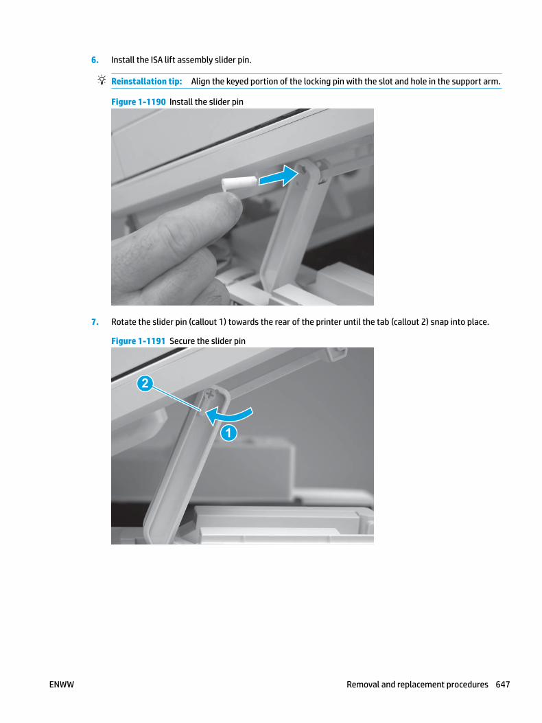
6. Install the ISA lift assembly slider pin.
Reinstallation tip: Align the keyed portion of the locking pin with the slot and hole in the support arm.
Figure 1-1190 Install the slider pin
7. Rotate the slider pin (callout 1) towards the rear of the printer until the tab (callout 2) snap into place.
Figure 1-1191 Secure the slider pin
2
1
ENWW Removal and replacement procedures 647
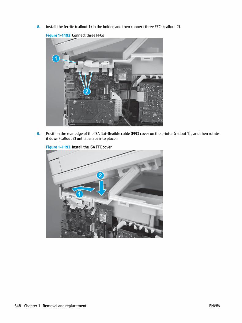
8. Install the ferrite (callout 1) in the holder, and then connect three FFCs (callout 2).
Figure 1-1192 Connect three FFCs
1
2
9. Position the rear edge of the ISA flat-flexible cable (FFC) cover on the printer (callout 1) , and then rotate it down (callout 2) until it snaps into place.
Figure 1-1193 Install the ISA FFC cover
1
2
648 Chapter 1 Removal and replacement ENWW

10. Lower the ISA.
Figure 1-1194 Lower the ISA
Step 22: Install the right cover
1. Position the cover (callout 1) on the printer, and then engage two bosses (callout 2).
Figure 1-1195 Install the cover
11
2 2
ENWW Removal and replacement procedures 649

2. Rotate the front of the cover onto the printer (callout 1), engage three (callout 2) tabs, and then engage two bosses (callout 3).
Figure 1-1196 Engage two bosses and one tab
1 13 3
2 2
3. Make sure that the power switch (callout 1) and cartridge door assembly button (callout 2) correctly function.
NOTE: Remove, and then reinstall the cover if the switch or button does not correctly function.
Figure 1-1197 Check the power switch and cartridge door assembly button
1
1
22
4. Install one screw (callout 1).
Figure 1-1198 Install one screw
11
650 Chapter 1 Removal and replacement ENWW

Step 23: Install the left cover
1. At the front of the printer, do one of the following:
● M403/M402: Position the cover on the printer ( callout 1), and then engage two bosses (callout 2).
● M427/M426: Position the cover on the printer (callout 3), engage one tab (callout 4), and then engage two bosses (callout 4).
Figure 1-1199 Install the cover
1
2
4
35
2. Carefully rotate the rear of the cover onto the printer (callout 1), engage three tabs (callout 2), and then engage two bosses (callout 3).
Figure 1-1200 Engage three tabs and two bosses
3
3 11
2
2
ENWW Removal and replacement procedures 651
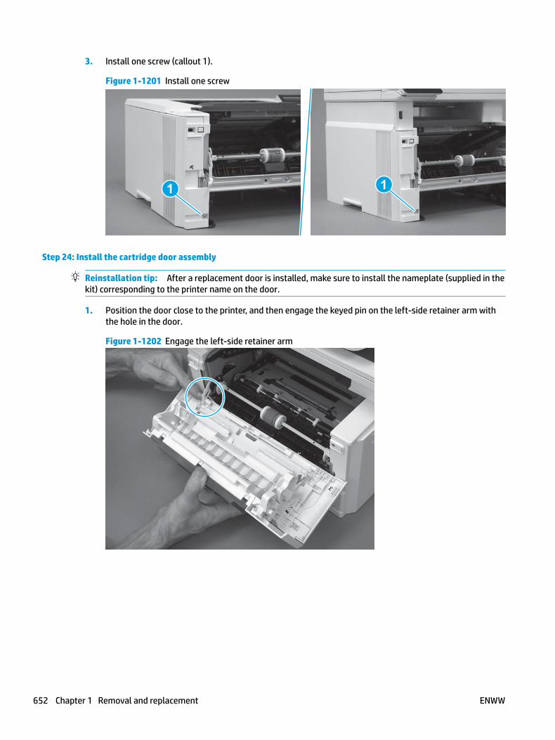
3. Install one screw (callout 1).
Figure 1-1201 Install one screw
1 1
Step 24: Install the cartridge door assembly
Reinstallation tip: After a replacement door is installed, make sure to install the nameplate (supplied in the kit) corresponding to the printer name on the door.
1. Position the door close to the printer, and then engage the keyed pin on the left-side retainer arm with the hole in the door.
Figure 1-1202 Engage the left-side retainer arm
652 Chapter 1 Removal and replacement ENWW

2. Engage the right-side door hinge pin with the hole in the chassis (callout 1).
Figure 1-1203 Install the door
1
3. Install the link (callout 1).
IMPORTANT: Make sure that the link snaps into place on the arm (callout 2). The link actuates the fuser pressure-release mechanism.
Figure 1-1204 Install the pressure-release link
1
2
ENWW Removal and replacement procedures 653

4. Slide the guide into the printer (callout 1), and then make sure that the tab (callout 2) snaps into place to secure the guide to the chassis.
Figure 1-1205 Install the guide
1
2
5. Position the shaft on the door, and then align the left-side hinge on the door with the hole in the chassis (callout 1).
Figure 1-1206 Align the hinge
1
654 Chapter 1 Removal and replacement ENWW

6. Push the shaft towards the left side of the printer to install it (callout 1).
Reinstallation tip: Make sure that the support shaft is fully installed and correctly orientated (callout 2) so that it will not interfere with the door opening and closing.
Figure 1-1207 Install the support shaft
2
1
Step 25: Install Tray 2
▲ Slide the tray straight into the printer to install it.
Figure 1-1208 Install the tray
ENWW Removal and replacement procedures 655
Removal and replacement: Control panel FFC, (M403/M402)
● Introduction
● Step 1: Remove Tray 2
● Step 2: Remove the cartridge door assembly
● Step 3: Remove the left cover
● Step 4: Remove the right cover
● Step 5: Remove the top cover (M403/M402)
● Step 6: Remove the paper delivery tray (output bin)
● Step 7: Remove the control panel FFC
● Step 8: Unpack the replacement assembly
● Step 9: Install the control panel FFC
● Step 10: Install the paper delivery tray (output bin)
● Step 11: Install the top cover (M403/M402)
● Step 12: Install the right cover
● Step 13: Install the left cover
● Step 14: Install the cartridge door assembly
● Step 15: Install Tray 2
Introduction
This document provides the procedures to remove and replace the control panel FFC (M403/M402 only).
Before performing service
Turn the printer power off
◦ Disconnect the power cable.
WARNING! To avoid damage to the printer, turn the printer off, wait 30 seconds, and then remove the power cable before attempting to service the printer.
Use the table below to identify the correct part number for your printer. To order the part, go to www.hp.com/buy/parts.
Control panel FFC (M403/M402) part number
RK2-6943-000CN Control panel FFC (M403/M402)
Required tools
● #2 Phillips screwdriver with a magnetic tip.
656 Chapter 1 Removal and replacement ENWW

After performing service
Turn the printer power on
◦ Connect the power cable.
◦ Use the power switch to turn the power on.
Post service test
Make sure that the printer initializes to a Ready state.
Print a configuration page to make sure that the printer is functioning correctly.
Step 1: Remove Tray 2
▲ Pull the tray straight out of the printer to remove it.
Figure 1-1209 Remove the tray
Step 2: Remove the cartridge door assembly
NOTE: If the toner cartridge was not removed prior to servicing the printer, remove it now.
1. Release one tab (callout 1), and then slide shaft (callout 2) in the direction the arrow indicates and remove it.
TIP: It might be easier to release the support shaft by using a small flat-blade screwdriver.
ENWW Removal and replacement procedures 657

Figure 1-1210 Release the support shaft
12
2. Release one tab (callout 1), and then slide the guide (callout 2) in the direction the arrow indicates and remove it.
Figure 1-1211 Remove the guide
1 2
658 Chapter 1 Removal and replacement ENWW

3. Remove the link arm (callout 1).
Figure 1-1212 Remove the link arm
1
4. Slide the cartridge door assembly (callout 1) in the direction the arrow indicates and remove it.
Figure 1-1213 Remove the door
1
ENWW Removal and replacement procedures 659
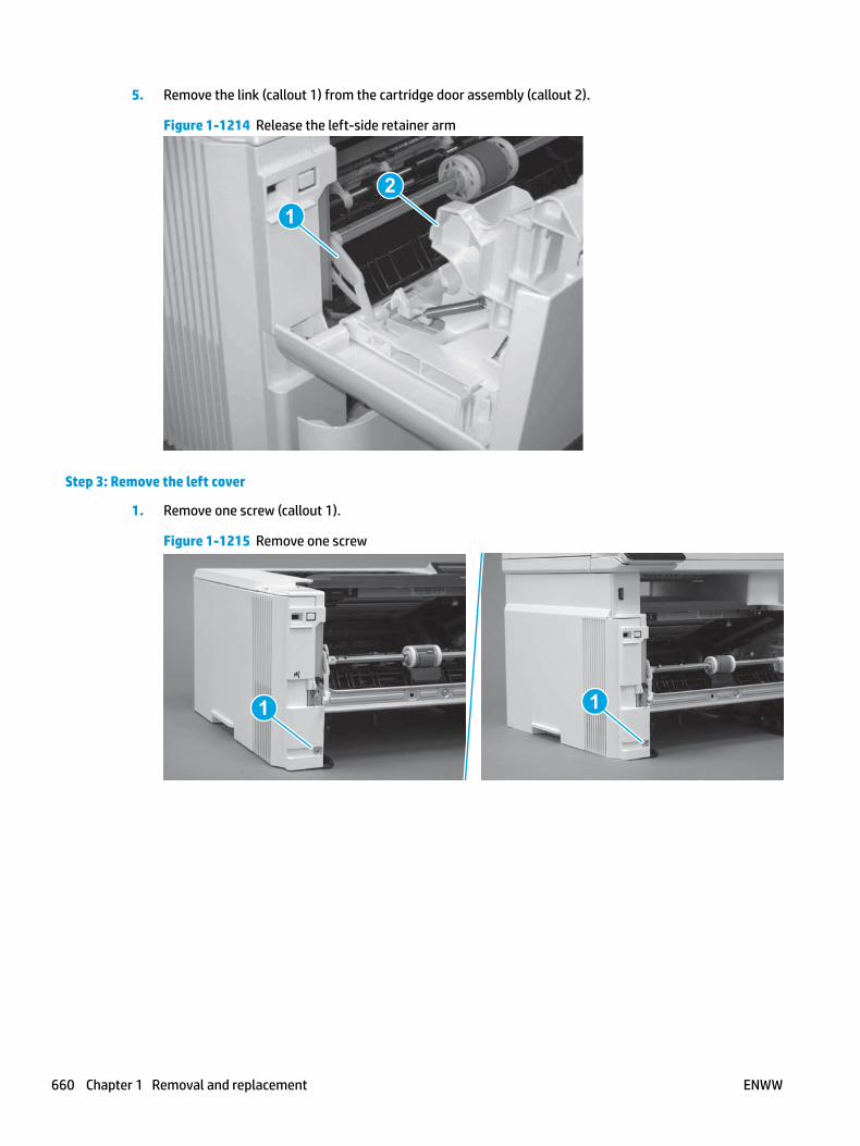
5. Remove the link (callout 1) from the cartridge door assembly (callout 2).
Figure 1-1214 Release the left-side retainer arm
21
Step 3: Remove the left cover
1. Remove one screw (callout 1).
Figure 1-1215 Remove one screw
1 1
660 Chapter 1 Removal and replacement ENWW

2. Open the rear door, release two bosses (callout 1), and then release three tabs (callout 2).
Figure 1-1216 Release two bosses and three tabs
1
1
2
2
3. At the front of the printer, do one of the following:
● M403/M402: Release two bosses (callout 1), and then remove the cover (callout 2).
● M427/M426: Release one tab (callout 3), two bosses (callout 4), and then remove the cover (callout 5).
CAUTION: Be careful when releasing the upper bosses on the M427/M426 cover. One portion of the cover (callout 6) is fragile and is easily broken.
Figure 1-1217 Remove the cover
2
1
3
54 6
Step 4: Remove the right cover
1. Remove one screw (callout 1).
ENWW Removal and replacement procedures 661
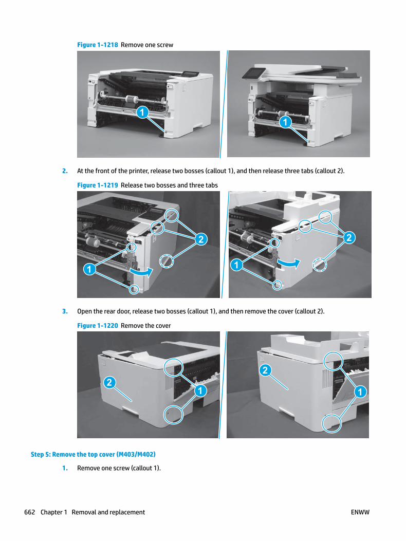
Figure 1-1218 Remove one screw
11
2. At the front of the printer, release two bosses (callout 1), and then release three tabs (callout 2).
Figure 1-1219 Release two bosses and three tabs
1 1
2 2
3. Open the rear door, release two bosses (callout 1), and then remove the cover (callout 2).
Figure 1-1220 Remove the cover
22
1 1
Step 5: Remove the top cover (M403/M402)
1. Remove one screw (callout 1).
662 Chapter 1 Removal and replacement ENWW

Figure 1-1221 Remove one screw
1
2. At the right side of the printer, release the one boss (callout 1), and then release one tab (callout 2).
Figure 1-1222 Release one boss and one tab
21
ENWW Removal and replacement procedures 663

3. Release four tabs (callout 1), release four bosses (callout 2), and then remove the top cover (callout 3).
TIP: Open the rear door to make releasing the bosses (callout 3) easier.
Figure 1-1223 Remove the cover
2
3
1
Step 6: Remove the paper delivery tray (output bin)
NOTE: This procedure shows the M403/M402 model, however, the paper delivery tray (output bin) removal is similar for the M427/M426 printer.
▲ Release two bosses (callout 1), release two tabs (callout 2), and then remove the paper delivery tray (output bin; callout 3).
Figure 1-1224 Release two tabs
2
1
3
664 Chapter 1 Removal and replacement ENWW

Step 7: Remove the control panel FFC
1. Disconnect the FFC from the control panel (callout 1).
Figure 1-1225 Disconnect the FFC
1
2. Release the FFC from the guide (callout 1).
NOTE: The near field communication (NFC) FFC might need to be moved out of the way to gain access to the control panel FFC.
Figure 1-1226 Release the FFC from the guide
1
ENWW Removal and replacement procedures 665
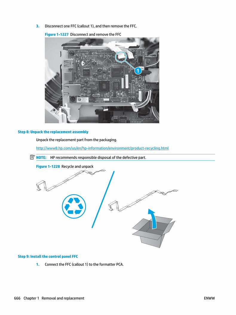
3. Disconnect one FFC (callout 1), and then remove the FFC.
Figure 1-1227 Disconnect and remove the FFC
1
Step 8: Unpack the replacement assembly
Unpack the replacement part from the packaging.
http://www8.hp.com/us/en/hp-information/environment/product-recycling.html
NOTE: HP recommends responsible disposal of the defective part.
Figure 1-1228 Recycle and unpack
Step 9: Install the control panel FFC
1. Connect the FFC (callout 1) to the formatter PCA.
666 Chapter 1 Removal and replacement ENWW
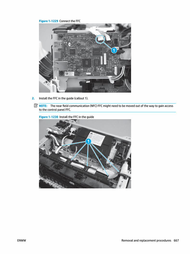
Figure 1-1229 Connect the FFC
1
2. Install the FFC in the guide (callout 1).
NOTE: The near field communication (NFC) FFC might need to be moved out of the way to gain access to the control panel FFC.
Figure 1-1230 Install the FFC in the guide
1
ENWW Removal and replacement procedures 667

3. Connect the FFC to the control panel (callout 1).
Figure 1-1231 Connect the FFC
1
Step 10: Install the paper delivery tray (output bin)
NOTE: This procedure shows the M403/M402 model, however, the paper delivery tray (output bin) removal is similar for the M427/M426 printer.
▲ Position the remove the paper delivery tray (output bin; callout 1) on the printer, engage two tabs (callout 2), and then engage two bosses (callout 3).
Figure 1-1232 Engage two tabs
2
3
1
Step 11: Install the top cover (M403/M402)
1. Position the rear edge of the cover on the printer.
668 Chapter 1 Removal and replacement ENWW

Figure 1-1233 Install the cover
2. Engage four bosses (callout 1), rotate the front of the cover down (callout 2) and onto from the printer, and then engage four tabs (callout 3).
Figure 1-1234 Engage four bosses and tabs
1
3
2
2
ENWW Removal and replacement procedures 669

3. At the right side of the printer, engage the one boss and one tab (callout 1).
Figure 1-1235 Engage one boss and one tab
1
4. Install one screw (callout 1).
Figure 1-1236 Install one screw
1
Step 12: Install the right cover
1. Position the cover (callout 1) on the printer, and then engage two bosses (callout 2).
670 Chapter 1 Removal and replacement ENWW

Figure 1-1237 Install the cover
11
2 2
2. Rotate the front of the cover onto the printer (callout 1), engage three (callout 2) tabs, and then engage two bosses (callout 3).
Figure 1-1238 Engage two bosses and one tab
1 13 3
2 2
3. Make sure that the power switch (callout 1) and cartridge door assembly button (callout 2) correctly function.
NOTE: Remove, and then reinstall the cover if the switch or button does not correctly function.
Figure 1-1239 Check the power switch and cartridge door assembly button
1
1
22
ENWW Removal and replacement procedures 671

4. Install one screw (callout 1).
Figure 1-1240 Install one screw
11
Step 13: Install the left cover
1. At the front of the printer, do one of the following:
● M403/M402: Position the cover on the printer ( callout 1), and then engage two bosses (callout 2).
● M427/M426: Position the cover on the printer (callout 3), engage one tab (callout 4), and then engage two bosses (callout 4).
Figure 1-1241 Install the cover
1
2
4
35
672 Chapter 1 Removal and replacement ENWW

2. Carefully rotate the rear of the cover onto the printer (callout 1), engage three tabs (callout 2), and then engage two bosses (callout 3).
Figure 1-1242 Engage three tabs and two bosses
3
3 11
2
2
3. Install one screw (callout 1).
Figure 1-1243 Install one screw
1 1
Step 14: Install the cartridge door assembly
Reinstallation tip: After a replacement door is installed, make sure to install the nameplate (supplied in the kit) corresponding to the printer name on the door.
1. Position the door close to the printer, and then engage the keyed pin on the left-side retainer arm with the hole in the door.
ENWW Removal and replacement procedures 673
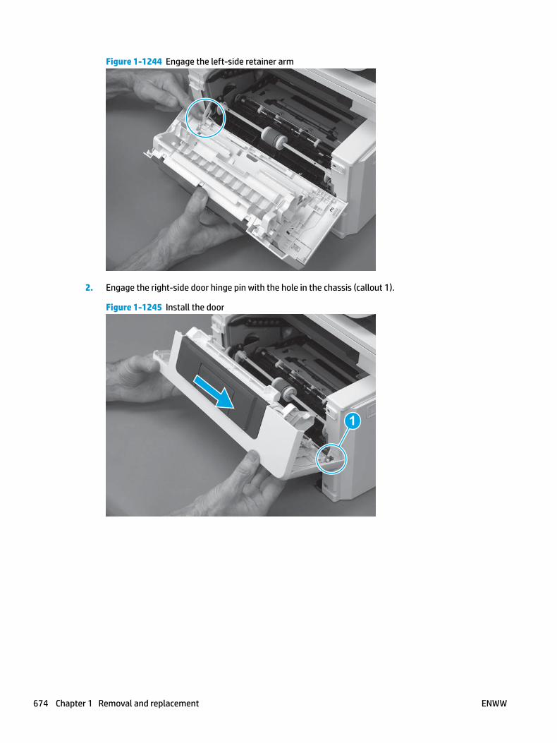
Figure 1-1244 Engage the left-side retainer arm
2. Engage the right-side door hinge pin with the hole in the chassis (callout 1).
Figure 1-1245 Install the door
1
674 Chapter 1 Removal and replacement ENWW

3. Install the link (callout 1).
IMPORTANT: Make sure that the link snaps into place on the arm (callout 2). The link actuates the fuser pressure-release mechanism.
Figure 1-1246 Install the pressure-release link
1
2
4. Slide the guide into the printer (callout 1), and then make sure that the tab (callout 2) snaps into place to secure the guide to the chassis.
Figure 1-1247 Install the guide
1
2
ENWW Removal and replacement procedures 675
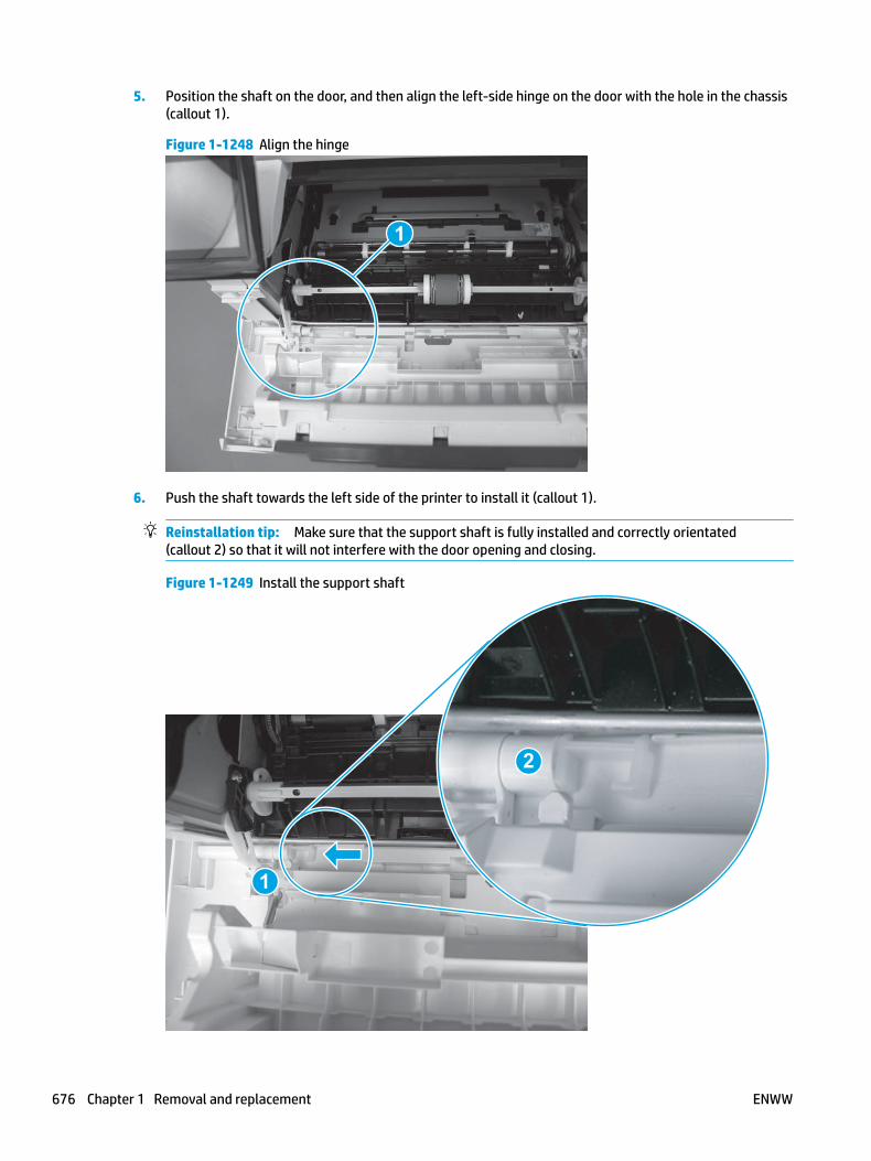
5. Position the shaft on the door, and then align the left-side hinge on the door with the hole in the chassis (callout 1).
Figure 1-1248 Align the hinge
1
6. Push the shaft towards the left side of the printer to install it (callout 1).
Reinstallation tip: Make sure that the support shaft is fully installed and correctly orientated (callout 2) so that it will not interfere with the door opening and closing.
Figure 1-1249 Install the support shaft
2
1
676 Chapter 1 Removal and replacement ENWW

Step 15: Install Tray 2
▲ Slide the tray straight into the printer to install it.
Figure 1-1250 Install the tray
ENWW Removal and replacement procedures 677

Removal and replacement: Formatter FFC
● Introduction
● Step 1: Remove Tray 2
● Step 2: Remove the cartridge door assembly
● Step 3: Remove the left cover
● Step 4: Remove the right cover
● Step 5: Remove the integrated scanner assembly (M427/M246)
● Step 6: Remove the control panel (M427/M246)
● Step 7: Remove the top cover (M427/M426)
● Step 8: Remove the top cover (M403/M402)
● Step 9: Remove the sheet-metal formatter bracket and formatter PCA
● Step 10: Remove the formatter FFC
● Step 11: Unpack the replacement assembly
● Step 12: Install the formatter FFC
● Step 13: Install the sheet-metal formatter bracket and formatter PCA
● Step 14: Install the top cover (M403/M402)
● Step 15: Install the top cover (M427/M426)
● Step 16: Install the control panel (M427/M246)
● Step 17: Install the integrated scanner assembly (M427/M246)
● Step 18: Install the right cover
● Step 19: Install the left cover
● Step 20: Install the cartridge door assembly
● Step 21: Install Tray 2
Introduction
This document provides the procedures to remove and replace the formatter flat-flexible cable (FFC).
Before performing service
Turn the printer power off
◦ Disconnect the power cable.
WARNING! To avoid damage to the printer, turn the printer off, wait 30 seconds, and then remove the power cable before attempting to service the printer.
Use the table below to identify the correct part number for your printer. To order the part, go to www.hp.com/buy/parts.
678 Chapter 1 Removal and replacement ENWW

Formatter FFC part number
RK2-6931-000CN
RK2-6920-000CN
Formatter FFC (M427M426)
Formatter FFC( M403/M402)
Required tools
● #2 Phillips screwdriver with a magnetic tip.
● 5.5 mm (0.22 inch) socket screwdriver.
After performing service
Turn the printer power on
◦ Connect the power cable.
◦ Use the power switch to turn the power on.
Post service test
Make sure that the printer initializes to a Ready state.
Print a configuration page to make sure that the printer is functioning correctly.
Step 1: Remove Tray 2
▲ Pull the tray straight out of the printer to remove it.
Figure 1-1251 Remove the tray
ENWW Removal and replacement procedures 679

Step 2: Remove the cartridge door assembly
NOTE: If the toner cartridge was not removed prior to servicing the printer, remove it now.
1. Release one tab (callout 1), and then slide shaft (callout 2) in the direction the arrow indicates and remove it.
TIP: It might be easier to release the support shaft by using a small flat-blade screwdriver.
Figure 1-1252 Release the support shaft
12
2. Release one tab (callout 1), and then slide the guide (callout 2) in the direction the arrow indicates and remove it.
Figure 1-1253 Remove the guide
1 2
680 Chapter 1 Removal and replacement ENWW
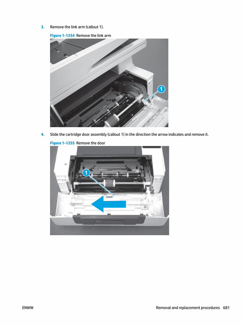
3. Remove the link arm (callout 1).
Figure 1-1254 Remove the link arm
1
4. Slide the cartridge door assembly (callout 1) in the direction the arrow indicates and remove it.
Figure 1-1255 Remove the door
1
ENWW Removal and replacement procedures 681

5. Remove the link (callout 1) from the cartridge door assembly (callout 2).
Figure 1-1256 Release the left-side retainer arm
21
Step 3: Remove the left cover
1. Remove one screw (callout 1).
Figure 1-1257 Remove one screw
1 1
682 Chapter 1 Removal and replacement ENWW

2. Open the rear door, release two bosses (callout 1), and then release three tabs (callout 2).
Figure 1-1258 Release two bosses and three tabs
1
1
2
2
3. At the front of the printer, do one of the following:
● M403/M402: Release two bosses (callout 1), and then remove the cover (callout 2).
● M427/M426: Release one tab (callout 3), two bosses (callout 4), and then remove the cover (callout 5).
CAUTION: Be careful when releasing the upper bosses on the M427/M426 cover. One portion of the cover (callout 6) is fragile and is easily broken.
Figure 1-1259 Remove the cover
2
1
3
54 6
Step 4: Remove the right cover
1. Remove one screw (callout 1).
ENWW Removal and replacement procedures 683

Figure 1-1260 Remove one screw
11
2. At the front of the printer, release two bosses (callout 1), and then release three tabs (callout 2).
Figure 1-1261 Release two bosses and three tabs
1 1
2 2
3. Open the rear door, release two bosses (callout 1), and then remove the cover (callout 2).
Figure 1-1262 Remove the cover
22
1 1
Step 5: Remove the integrated scanner assembly (M427/M246)
NOTE: The step is for the M427/M426 printer. For the M403/M402, skip this step and go to Step 8: Remove the top cover (M403/M402) on page 694.
684 Chapter 1 Removal and replacement ENWW

NOTE: M427/M426 models only. The integrated scanner assembly (ISA) includes the sub-scanner assembly (SSA) and the automatic document feeder (ADF).
1. Raise the ISA.
Figure 1-1263 Raise the ISA
2. Release the ISA flat-flexible cable (FFC) cover (callout 1), and then remove it (callout 2).
Figure 1-1264 Remove the ISA FFC cover
12
ENWW Removal and replacement procedures 685
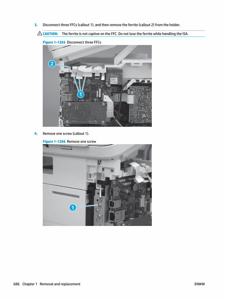
3. Disconnect three FFCs (callout 1), and then remove the ferrite (callout 2) from the holder.
CAUTION: The ferrite is not captive on the FFC. Do not lose the ferrite while handling the ISA.
Figure 1-1265 Disconnect three FFCs
2
1
4. Remove one screw (callout 1).
Figure 1-1266 Remove one screw
1
686 Chapter 1 Removal and replacement ENWW

5. Pass the ground wire through the opening in the top cover.
Figure 1-1267 Pass the wire through the opening
6. Release one tab (callout 1), and then rotate the ISA slider pin (callout 2) towards the front of the printer to release it.
Figure 1-1268 Release one tab and rotate the slider pin
1
2
ENWW Removal and replacement procedures 687

7. Remove the slider pin.
Figure 1-1269 Remove the slider pin
8. Rotate the ISA towards the rear of the printer until it stops.
Figure 1-1270 Rotate the ISA towards the rear of the printer
688 Chapter 1 Removal and replacement ENWW

9. Slide the ISA as shown to release it.
Figure 1-1271 Release the ISA
10. Remove the ISA.
Figure 1-1272 Remove the ISA
Step 6: Remove the control panel (M427/M246)
NOTE: The step is for the M427/M426 printer. For the M403/M402, skip this step and go to Step 8: Remove the top cover (M403/M402) on page 694.
1. Disconnect one FFC (callout 1; J114), and then release the FFC from the retainer (callout 2).
ENWW Removal and replacement procedures 689

Figure 1-1273 Disconnect one connector
1
2
2. Remove one screw (callout 1).
Figure 1-1274 Remove one screw
1
690 Chapter 1 Removal and replacement ENWW
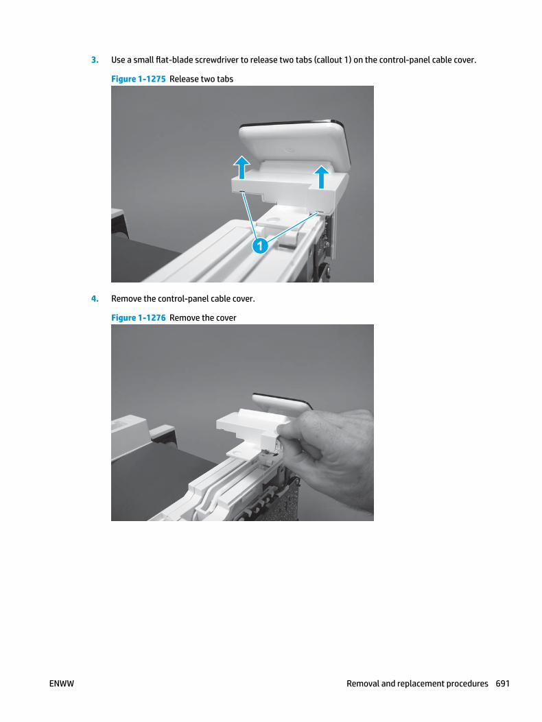
3. Use a small flat-blade screwdriver to release two tabs (callout 1) on the control-panel cable cover.
Figure 1-1275 Release two tabs
1
4. Remove the control-panel cable cover.
Figure 1-1276 Remove the cover
ENWW Removal and replacement procedures 691

5. Remove one grounding screw (callout 1), and then move the ground cable (callout 2) out of the way.
Figure 1-1277 Remove one screw
2
1
6. Move the FFC out of the way, and then remove two screws (callout 1).
Figure 1-1278 Remove two screws
1
692 Chapter 1 Removal and replacement ENWW

7. Slightly lift up the control-panel assembly to separate it from the top cover.
CAUTION: The control panel assembly is still connected to the printer by the FFC. Do not attempt to completely remove the assembly.
Figure 1-1279 Lift up the control-panel assembly
8. Lift up the control-panel FFC cover to remove the control-panel assembly.
Figure 1-1280 Remove the control-panel assembly
Step 7: Remove the top cover (M427/M426)
NOTE: The step is for the M427/M426 printer. For the M403/M402, skip this step and go to Step 8: Remove the top cover (M403/M402) on page 694.
1. Release the USB cable (callout 1) from the cable guide.
ENWW Removal and replacement procedures 693

Figure 1-1281 Remove the USB cable
1
2. Remove five screws (callout 1), release four bosses (callout 2), and then remove the top cover (callout 3).
Figure 1-1282 Remove the cover
3
2
1
Step 8: Remove the top cover (M403/M402)
NOTE: The step is for the M403/M402 printer. For the M427/M426, skip this step and go to Step 9: Remove the sheet-metal formatter bracket and formatter PCA on page 696.
1. Remove one screw (callout 1).
694 Chapter 1 Removal and replacement ENWW

Figure 1-1283 Remove one screw
1
2. At the right side of the printer, release the one boss (callout 1), and then release one tab (callout 2).
Figure 1-1284 Release one boss and one tab
21
ENWW Removal and replacement procedures 695
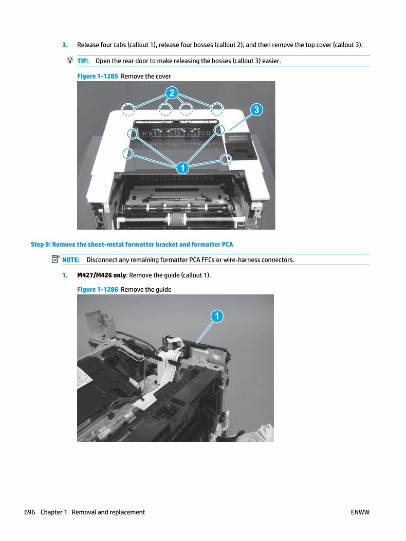
3. Release four tabs (callout 1), release four bosses (callout 2), and then remove the top cover (callout 3).
TIP: Open the rear door to make releasing the bosses (callout 3) easier.
Figure 1-1285 Remove the cover
2
3
1
Step 9: Remove the sheet-metal formatter bracket and formatter PCA
NOTE: Disconnect any remaining formatter PCA FFCs or wire-harness connectors.
1. M427/M426 only: Remove the guide (callout 1).
Figure 1-1286 Remove the guide
1
696 Chapter 1 Removal and replacement ENWW

2. Remove two screws (callout 1).
Figure 1-1287 Remove two screws
11
3. Disconnect one connector (callout 1), and then release the wire harness from the guide (callout 2).
Figure 1-1288 Disconnect one connector
21
21
4. Remove the guide (callout 1).
Figure 1-1289 Remove the guide
11
ENWW Removal and replacement procedures 697
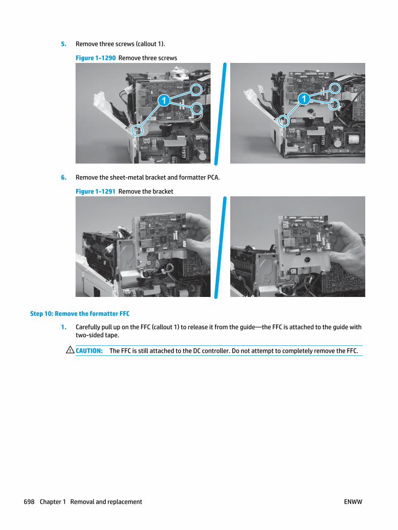
5. Remove three screws (callout 1).
Figure 1-1290 Remove three screws
1 1
6. Remove the sheet-metal bracket and formatter PCA.
Figure 1-1291 Remove the bracket
Step 10: Remove the formatter FFC
1. Carefully pull up on the FFC (callout 1) to release it from the guide—the FFC is attached to the guide with two-sided tape.
CAUTION: The FFC is still attached to the DC controller. Do not attempt to completely remove the FFC.
698 Chapter 1 Removal and replacement ENWW

Figure 1-1292 Release the FFC
2. Disconnect the formatter FFC (callout 1).
IMPORTANT: The FFC connector (callout 2) is a Zero Insertion Force (ZIF) connector that uses a hinged retainer to secure the FFC. The hinged retainer must be opened to release the FFC.
Figure 1-1293 Disconnect the FFC
1
Step 11: Unpack the replacement assembly
Unpack the replacement part from the packaging.
http://www8.hp.com/us/en/hp-information/environment/product-recycling.html
NOTE: HP recommends responsible disposal of the defective part.
ENWW Removal and replacement procedures 699
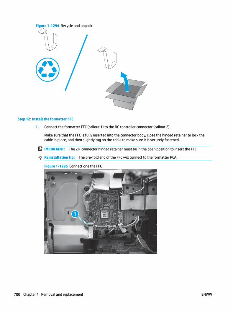
Figure 1-1294 Recycle and unpack
Step 12: Install the formatter FFC
1. Connect the formatter FFC (callout 1) to the DC controller connector (callout 2).
Make sure that the FFC is fully inserted into the connector body, close the hinged retainer to lock the cable in place, and then slightly tug on the cable to make sure it is securely fastened.
IMPORTANT: The ZIF connector hinged retainer must be in the open position to insert the FFC.
Reinstallation tip: The pre-fold end of the FFC will connect to the formatter PCA.
Figure 1-1295 Connect one the FFC
1
700 Chapter 1 Removal and replacement ENWW

2. Carefully push on the FFC (callout 1) to adhere it to the guide.
Reinstallation tip: Use the discarded FFC as a guide to apply a small section of two-sided tape to the replacement FFC.
Figure 1-1296 Adhere the FFC to the guide
Step 13: Install the sheet-metal formatter bracket and formatter PCA
NOTE: Do not forget to connect any formatter PCA FFCs or wire-harness connectors that were disconnected when the bracket was removed.
1. Position the sheet-metal bracket and formatter PCA on the printer.
Figure 1-1297 Install the bracket
ENWW Removal and replacement procedures 701

2. Install three screws (callout 1).
Figure 1-1298 Install three screws
1 1
3. Install the guide (callout 1).
Figure 1-1299 Install the guide
11
4. Connect one connector (callout 1), and then install the wire harness in the guide (callout 2).
Figure 1-1300 Connect one connector
21
21
702 Chapter 1 Removal and replacement ENWW

5. Install two screws (callout 1).
Figure 1-1301 Install two screws
11
6. M427/M426 only: Install the guide (callout 1).
Figure 1-1302 Install the guide
1
Step 14: Install the top cover (M403/M402)
NOTE: The step is for the M403/M402 printer. For the M427/M426, skip this step and go to Step 15: Install the top cover (M427/M426) on page 705.
1. Position the rear edge of the cover on the printer.
ENWW Removal and replacement procedures 703

Figure 1-1303 Install the cover
2. Engage four bosses (callout 1), rotate the front of the cover down (callout 2) and onto from the printer, and then engage four tabs (callout 3).
Figure 1-1304 Engage four bosses and tabs
1
3
2
2
704 Chapter 1 Removal and replacement ENWW

3. At the right side of the printer, engage the one boss and one tab (callout 1).
Figure 1-1305 Engage one boss and one tab
1
4. Install one screw (callout 1).
Figure 1-1306 Install one screw
1
Step 15: Install the top cover (M427/M426)
NOTE: The step is for the M427/M426 printer. For the M403/M402, skip this step and go to Step 18: Install the right cover on page 717.
1. Position the rear edge of the top cover on the printer.
ENWW Removal and replacement procedures 705

Figure 1-1307 Install the cover
2. Engage four bosses (callout 1).
Figure 1-1308 Engage four bosses
1
706 Chapter 1 Removal and replacement ENWW

3. Rotate the front edge of the cover down.
Figure 1-1309 Rotate the front edge of the cover down
4. Install the USB cable (callout 1) in the guide.
Figure 1-1310 Install the USB PCA
1
ENWW Removal and replacement procedures 707

5. Install five screws (callout 1).
Figure 1-1311 Install five screws
1
Step 16: Install the control panel (M427/M246)
NOTE: The step is for the M427/M426 printer. For the M403/M402, skip this step and go to Step 18: Install the right cover on page 717.
1. Slide the control-panel FFC cover into the slot in the top cover (next to the document feeder support arm) to install it.
Figure 1-1312 Install the control-panel FFC cover
708 Chapter 1 Removal and replacement ENWW

2. Install the control-panel assembly on the top cover.
Figure 1-1313 Install the control-panel assembly
3. Move the FFC out of the way, and then install two screws (callout 1).
Figure 1-1314 Install two screws
1
ENWW Removal and replacement procedures 709

4. Install one grounding screw (callout 1), and then make sure that the ground cable (callout 2) is properly routed.
Figure 1-1315 Remove one screw
2
1
5. Install the control-panel cable cover.
Figure 1-1316 Install the cover
710 Chapter 1 Removal and replacement ENWW

6. Make sure that the two tabs (callout 1) on the cover snap into place.
Figure 1-1317 Engage two tabs
1
7. Install one screw (callout 1).
Figure 1-1318 Install one screw
1
ENWW Removal and replacement procedures 711
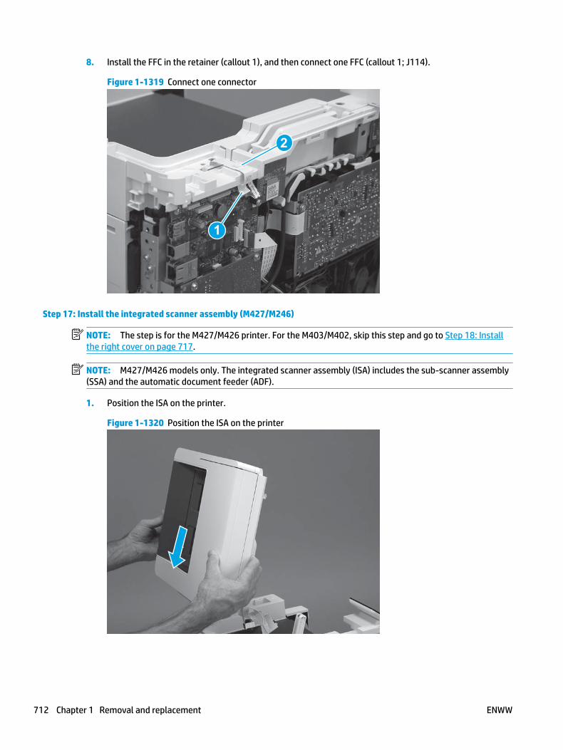
8. Install the FFC in the retainer (callout 1), and then connect one FFC (callout 1; J114).
Figure 1-1319 Connect one connector
1
2
Step 17: Install the integrated scanner assembly (M427/M246)
NOTE: The step is for the M427/M426 printer. For the M403/M402, skip this step and go to Step 18: Install the right cover on page 717.
NOTE: M427/M426 models only. The integrated scanner assembly (ISA) includes the sub-scanner assembly (SSA) and the automatic document feeder (ADF).
1. Position the ISA on the printer.
Figure 1-1320 Position the ISA on the printer
712 Chapter 1 Removal and replacement ENWW

2. Engage the hinge pins on the ISA with the holders in the top cover (callouts 1/2), and the slide the ISA as shown to engage them
Figure 1-1321 Engage the hinge pins with the holders
1
2
3. Rotate the ISA towards the front of the printer until it rests on the ISA lift assembly (callout 1).
Figure 1-1322 Rotate the ISA towards the front of the printer
1
ENWW Removal and replacement procedures 713

4. Pass the ground wire through the opening in the top cover.
Figure 1-1323 Pass the wire through the opening
5. Install one screw (callout 1).
Figure 1-1324 Install one screw
1
714 Chapter 1 Removal and replacement ENWW

6. Install the ISA lift assembly slider pin.
Reinstallation tip: Align the keyed portion of the locking pin with the slot and hole in the support arm.
Figure 1-1325 Install the slider pin
7. Rotate the slider pin (callout 1) towards the rear of the printer until the tab (callout 2) snap into place.
Figure 1-1326 Secure the slider pin
2
1
ENWW Removal and replacement procedures 715

8. Install the ferrite (callout 1) in the holder, and then connect three FFCs (callout 2).
Figure 1-1327 Connect three FFCs
1
2
9. Position the rear edge of the ISA flat-flexible cable (FFC) cover on the printer (callout 1) , and then rotate it down (callout 2) until it snaps into place.
Figure 1-1328 Install the ISA FFC cover
1
2
716 Chapter 1 Removal and replacement ENWW

10. Lower the ISA.
Figure 1-1329 Lower the ISA
Step 18: Install the right cover
1. Position the cover (callout 1) on the printer, and then engage two bosses (callout 2).
Figure 1-1330 Install the cover
11
2 2
ENWW Removal and replacement procedures 717

2. Rotate the front of the cover onto the printer (callout 1), engage three (callout 2) tabs, and then engage two bosses (callout 3).
Figure 1-1331 Engage two bosses and one tab
1 13 3
2 2
3. Make sure that the power switch (callout 1) and cartridge door assembly button (callout 2) correctly function.
NOTE: Remove, and then reinstall the cover if the switch or button does not correctly function.
Figure 1-1332 Check the power switch and cartridge door assembly button
1
1
22
4. Install one screw (callout 1).
Figure 1-1333 Install one screw
11
718 Chapter 1 Removal and replacement ENWW

Step 19: Install the left cover
1. At the front of the printer, do one of the following:
● M403/M402: Position the cover on the printer ( callout 1), and then engage two bosses (callout 2).
● M427/M426: Position the cover on the printer (callout 3), engage one tab (callout 4), and then engage two bosses (callout 4).
Figure 1-1334 Install the cover
1
2
4
35
2. Carefully rotate the rear of the cover onto the printer (callout 1), engage three tabs (callout 2), and then engage two bosses (callout 3).
Figure 1-1335 Engage three tabs and two bosses
3
3 11
2
2
ENWW Removal and replacement procedures 719

3. Install one screw (callout 1).
Figure 1-1336 Install one screw
1 1
Step 20: Install the cartridge door assembly
Reinstallation tip: After a replacement door is installed, make sure to install the nameplate (supplied in the kit) corresponding to the printer name on the door.
1. Position the door close to the printer, and then engage the keyed pin on the left-side retainer arm with the hole in the door.
Figure 1-1337 Engage the left-side retainer arm
720 Chapter 1 Removal and replacement ENWW
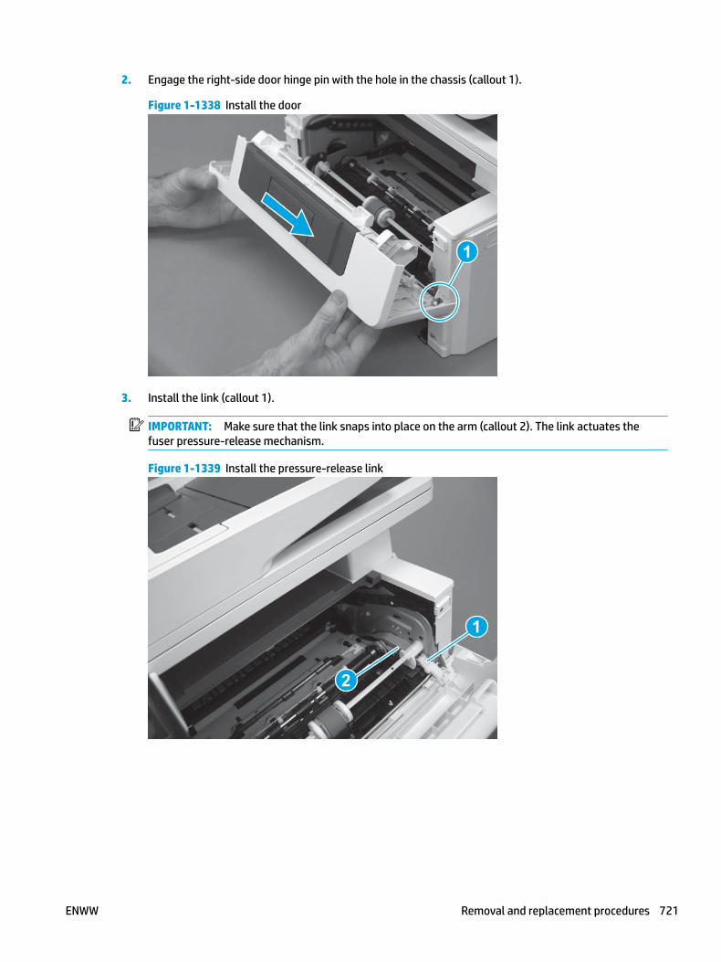
2. Engage the right-side door hinge pin with the hole in the chassis (callout 1).
Figure 1-1338 Install the door
1
3. Install the link (callout 1).
IMPORTANT: Make sure that the link snaps into place on the arm (callout 2). The link actuates the fuser pressure-release mechanism.
Figure 1-1339 Install the pressure-release link
1
2
ENWW Removal and replacement procedures 721
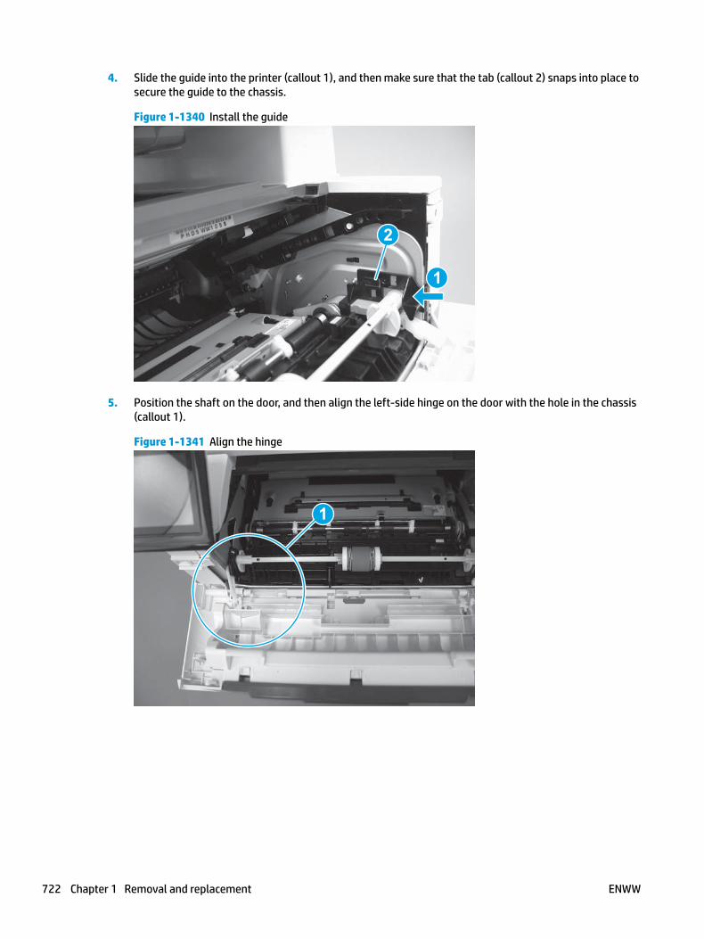
4. Slide the guide into the printer (callout 1), and then make sure that the tab (callout 2) snaps into place to secure the guide to the chassis.
Figure 1-1340 Install the guide
1
2
5. Position the shaft on the door, and then align the left-side hinge on the door with the hole in the chassis (callout 1).
Figure 1-1341 Align the hinge
1
722 Chapter 1 Removal and replacement ENWW

6. Push the shaft towards the left side of the printer to install it (callout 1).
Reinstallation tip: Make sure that the support shaft is fully installed and correctly orientated (callout 2) so that it will not interfere with the door opening and closing.
Figure 1-1342 Install the support shaft
2
1
Step 21: Install Tray 2
▲ Slide the tray straight into the printer to install it.
Figure 1-1343 Install the tray
ENWW Removal and replacement procedures 723

Removal and replacement: DC controller
● Introduction
● Step 1: Remove Tray 2
● Step 2: Remove the cartridge door assembly
● Step 3: Remove the left cover
● Step 4: Remove the right cover
● Step 5: Remove the rear door assembly
● Step 6: Remove the integrated scanner assembly (M427/M246)
● Step 7: Remove the control panel (M427/M246)
● Step 8: Remove the top cover (M427/M426)
● Step 9: Remove the top cover (M403/M402)
● Step 10: Remove the paper delivery tray (output bin)
● Step 11: Remove the sheet-metal formatter bracket and formatter
● Step 12: Remove the DC controller
● Step 13: Unpack the replacement assembly
● Step 14: Install the DC controller
● Step 15: Install the sheet-metal formatter bracket and formatter
● Step 16: Install the paper delivery tray (output bin)
● Step 17: Install the top cover (M403/M402)
● Step 18: Install the top cover (M427/M426)
● Step 19: Install the control panel (M427/M246)
● Step 20: Install the integrated scanner assembly (M427/M246)
● Step 21: Install the rear door assembly
● Step 22: Install the right cover
● Step 23: Install the left cover
● Step 24: Install the cartridge door assembly
● Step 25: Install Tray 2
Introduction
This document provides the procedures to remove and replace the DC controller.
724 Chapter 1 Removal and replacement ENWW
Before performing service
Turn the printer power off
◦ Disconnect the power cable.
WARNING! To avoid damage to the printer, turn the printer off, wait 30 seconds, and then remove the power cable before attempting to service the printer.
Use the table below to identify the correct part number for your printer. To order the part, go to www.hp.com/buy/parts.
DC controller part number
RM2-8680-000CN DC controller
Required tools
● #2 Phillips screwdriver with a magnetic tip.
After performing service
Turn the printer power on
◦ Connect the power cable.
◦ Use the power switch to turn the power on.
Post service test
Make sure that the printer initializes to a Ready state.
Print a configuration page to make sure that the printer is functioning correctly.
Step 1: Remove Tray 2
▲ Pull the tray straight out of the printer to remove it.
ENWW Removal and replacement procedures 725
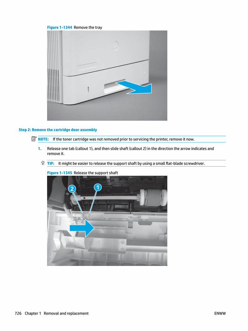
Figure 1-1344 Remove the tray
Step 2: Remove the cartridge door assembly
NOTE: If the toner cartridge was not removed prior to servicing the printer, remove it now.
1. Release one tab (callout 1), and then slide shaft (callout 2) in the direction the arrow indicates and remove it.
TIP: It might be easier to release the support shaft by using a small flat-blade screwdriver.
Figure 1-1345 Release the support shaft
12
726 Chapter 1 Removal and replacement ENWW

2. Release one tab (callout 1), and then slide the guide (callout 2) in the direction the arrow indicates and remove it.
Figure 1-1346 Remove the guide
1 2
3. Remove the link arm (callout 1).
Figure 1-1347 Remove the link arm
1
ENWW Removal and replacement procedures 727

4. Slide the cartridge door assembly (callout 1) in the direction the arrow indicates and remove it.
Figure 1-1348 Remove the door
1
5. Remove the link (callout 1) from the cartridge door assembly (callout 2).
Figure 1-1349 Release the left-side retainer arm
21
Step 3: Remove the left cover
1. Remove one screw (callout 1).
728 Chapter 1 Removal and replacement ENWW

Figure 1-1350 Remove one screw
1 1
2. Open the rear door, release two bosses (callout 1), and then release three tabs (callout 2).
Figure 1-1351 Release two bosses and three tabs
1
1
2
2
3. At the front of the printer, do one of the following:
● M403/M402: Release two bosses (callout 1), and then remove the cover (callout 2).
● M427/M426: Release one tab (callout 3), two bosses (callout 4), and then remove the cover (callout 5).
CAUTION: Be careful when releasing the upper bosses on the M427/M426 cover. One portion of the cover (callout 6) is fragile and is easily broken.
ENWW Removal and replacement procedures 729

Figure 1-1352 Remove the cover
2
1
3
54 6
Step 4: Remove the right cover
1. Remove one screw (callout 1).
Figure 1-1353 Remove one screw
11
2. At the front of the printer, release two bosses (callout 1), and then release three tabs (callout 2).
Figure 1-1354 Release two bosses and three tabs
1 1
2 2
730 Chapter 1 Removal and replacement ENWW

3. Open the rear door, release two bosses (callout 1), and then remove the cover (callout 2).
Figure 1-1355 Remove the cover
22
1 1
Step 5: Remove the rear door assembly
1. Duplex models only: Inside the Tray 2 cavity, press the green jam access lever (callout 1), and then lower the duplex feed assembly (callout 2).
Figure 1-1356 Duplex models, lower the duplex feed assembly
12
ENWW Removal and replacement procedures 731

2. At the rear of the printer, remove two screws (callout 1), and then remove the rear door assembly (callout 2).
Figure 1-1357 Remove two screws
12
Step 6: Remove the integrated scanner assembly (M427/M246)
NOTE: The step is for the M427/M426 printer. For the M403/M402, skip this step and go to Step 9: Remove the top cover (M403/M402) on page 742.
NOTE: M427/M426 models only. The integrated scanner assembly (ISA) includes the sub-scanner assembly (SSA) and the automatic document feeder (ADF).
1. Raise the ISA.
Figure 1-1358 Raise the ISA
732 Chapter 1 Removal and replacement ENWW

2. Release the ISA flat-flexible cable (FFC) cover (callout 1), and then remove it (callout 2).
Figure 1-1359 Remove the ISA FFC cover
12
3. Disconnect three FFCs (callout 1), and then remove the ferrite (callout 2) from the holder.
CAUTION: The ferrite is not captive on the FFC. Do not lose the ferrite while handling the ISA.
Figure 1-1360 Disconnect three FFCs
2
1
ENWW Removal and replacement procedures 733
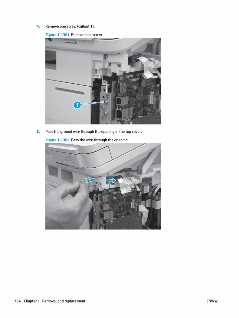
4. Remove one screw (callout 1).
Figure 1-1361 Remove one screw
1
5. Pass the ground wire through the opening in the top cover.
Figure 1-1362 Pass the wire through the opening
734 Chapter 1 Removal and replacement ENWW

6. Release one tab (callout 1), and then rotate the ISA slider pin (callout 2) towards the front of the printer to release it.
Figure 1-1363 Release one tab and rotate the slider pin
1
2
7. Remove the slider pin.
Figure 1-1364 Remove the slider pin
ENWW Removal and replacement procedures 735

8. Rotate the ISA towards the rear of the printer until it stops.
Figure 1-1365 Rotate the ISA towards the rear of the printer
9. Slide the ISA as shown to release it.
Figure 1-1366 Release the ISA
736 Chapter 1 Removal and replacement ENWW

10. Remove the ISA.
Figure 1-1367 Remove the ISA
Step 7: Remove the control panel (M427/M246)
NOTE: The step is for the M427/M426 printer. For the M403/M402, skip this step and go to Step 9: Remove the top cover (M403/M402) on page 742.
1. Disconnect one FFC (callout 1; J114), and then release the FFC from the retainer (callout 2).
Figure 1-1368 Disconnect one connector
1
2
ENWW Removal and replacement procedures 737

2. Remove one screw (callout 1).
Figure 1-1369 Remove one screw
1
3. Use a small flat-blade screwdriver to release two tabs (callout 1) on the control-panel cable cover.
Figure 1-1370 Release two tabs
1
738 Chapter 1 Removal and replacement ENWW
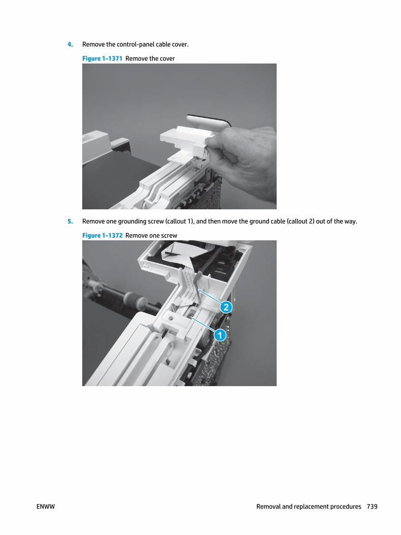
4. Remove the control-panel cable cover.
Figure 1-1371 Remove the cover
5. Remove one grounding screw (callout 1), and then move the ground cable (callout 2) out of the way.
Figure 1-1372 Remove one screw
2
1
ENWW Removal and replacement procedures 739

6. Move the FFC out of the way, and then remove two screws (callout 1).
Figure 1-1373 Remove two screws
1
7. Slightly lift up the control-panel assembly to separate it from the top cover.
CAUTION: The control panel assembly is still connected to the printer by the FFC. Do not attempt to completely remove the assembly.
Figure 1-1374 Lift up the control-panel assembly
740 Chapter 1 Removal and replacement ENWW
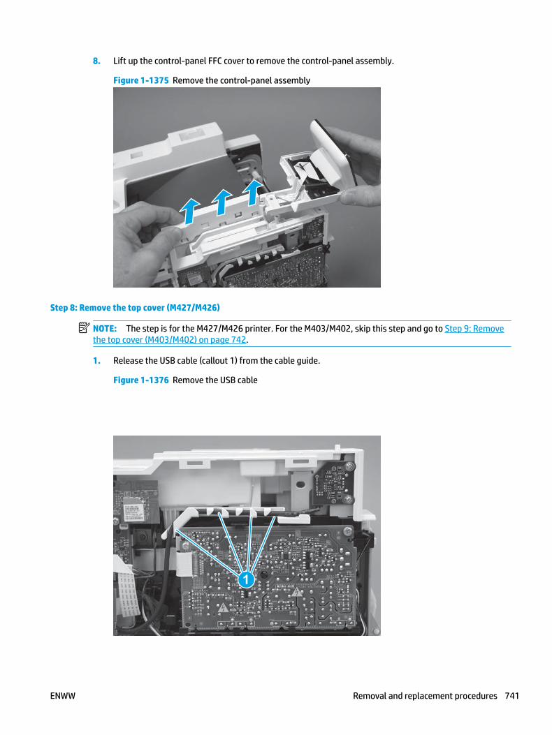
8. Lift up the control-panel FFC cover to remove the control-panel assembly.
Figure 1-1375 Remove the control-panel assembly
Step 8: Remove the top cover (M427/M426)
NOTE: The step is for the M427/M426 printer. For the M403/M402, skip this step and go to Step 9: Remove the top cover (M403/M402) on page 742.
1. Release the USB cable (callout 1) from the cable guide.
Figure 1-1376 Remove the USB cable
1
ENWW Removal and replacement procedures 741

2. Remove five screws (callout 1), release four bosses (callout 2), and then remove the top cover (callout 3).
Figure 1-1377 Remove the cover
3
2
1
Step 9: Remove the top cover (M403/M402)
NOTE: The step is for the M403/M402 printer. For the M427/M426, skip this step and go to Step 10: Remove the paper delivery tray (output bin) on page 743.
1. Remove one screw (callout 1).
Figure 1-1378 Remove one screw
1
742 Chapter 1 Removal and replacement ENWW
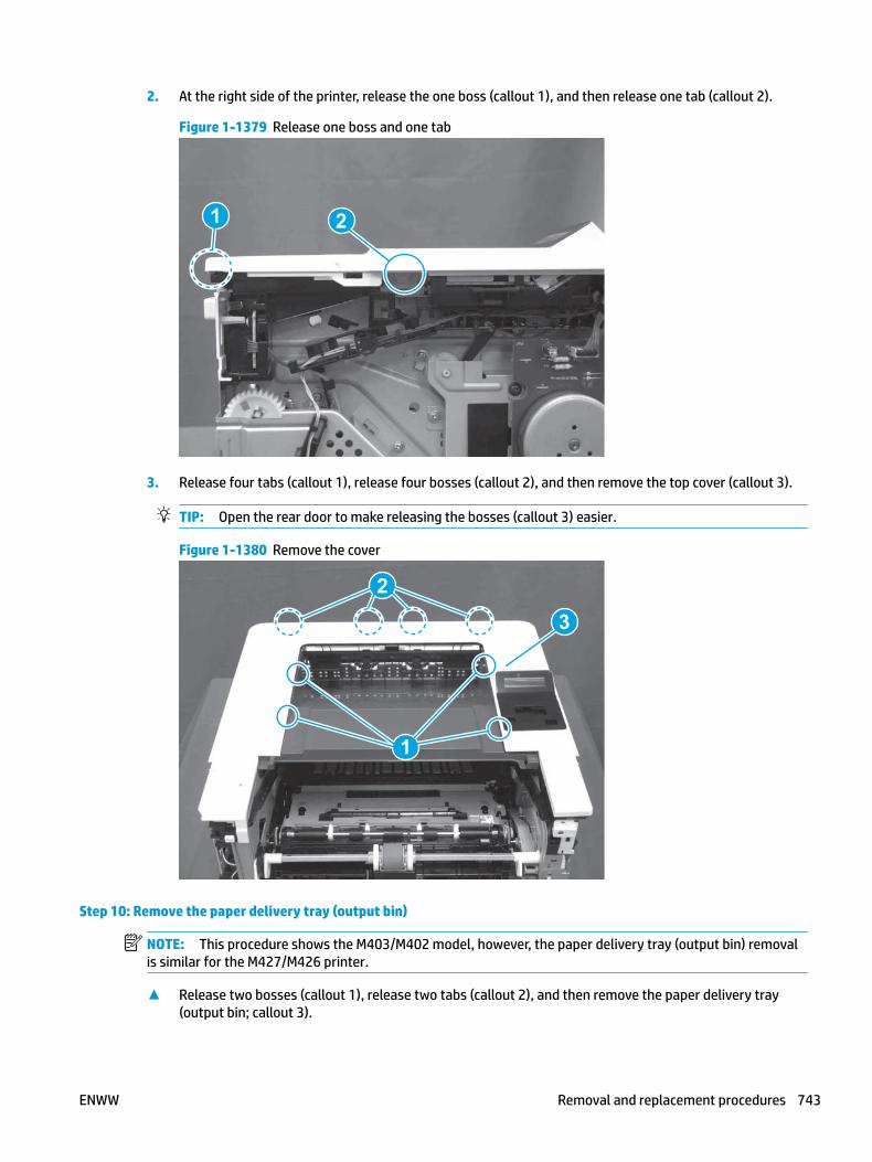
2. At the right side of the printer, release the one boss (callout 1), and then release one tab (callout 2).
Figure 1-1379 Release one boss and one tab
21
3. Release four tabs (callout 1), release four bosses (callout 2), and then remove the top cover (callout 3).
TIP: Open the rear door to make releasing the bosses (callout 3) easier.
Figure 1-1380 Remove the cover
2
3
1
Step 10: Remove the paper delivery tray (output bin)
NOTE: This procedure shows the M403/M402 model, however, the paper delivery tray (output bin) removal is similar for the M427/M426 printer.
▲ Release two bosses (callout 1), release two tabs (callout 2), and then remove the paper delivery tray (output bin; callout 3).
ENWW Removal and replacement procedures 743

Figure 1-1381 Release two tabs
2
1
3
Step 11: Remove the sheet-metal formatter bracket and formatter
NOTE: Disconnect any remaining formatter PCA FFCs or wire-harness connectors.
1. M427/M426 only: Remove the guide (callout 1).
Figure 1-1382 Remove the guide
1
744 Chapter 1 Removal and replacement ENWW

2. Remove two screws (callout 1).
Figure 1-1383 Remove two screws
11
3. Disconnect one connector (callout 1), and then release the wire harness from the guide (callout 2).
Figure 1-1384 Disconnect one connector
21
21
4. Remove the guide (callout 1).
Figure 1-1385 Remove the guide
11
ENWW Removal and replacement procedures 745

5. Remove three screws (callout 1).
Figure 1-1386 Remove three screws
1 1
6. Remove the sheet-metal bracket and formatter PCA.
Figure 1-1387 Remove the bracket
Step 12: Remove the DC controller
1. Disconnect three FFCs (callout 1), and six connectors (callout 2).
IMPORTANT: One FFC (callout 3) is fastened to the guide with two sided tape. This FFC will be removed later in the procedure.
746 Chapter 1 Removal and replacement ENWW

Figure 1-1388 Disconnect three FFCs and six connectors
2
3
1
2. Remove two screws (callout 1).
Figure 1-1389 Remove two screws
1
ENWW Removal and replacement procedures 747

3. Separate the DC controller from the printer.
CAUTION: Carefully pull up on the FFC (callout 1) to release it from the guide, and then remove the DC controller.
Figure 1-1390 Remove the DC controller
1
4. Disconnect one the FFC.
IMPORTANT: The FFC connector is a Zero Insertion Force (ZIF) connector that uses a hinged retainer to secure the FFC. The hinged retainer must be opened to release the FFC.
Do not discard this FFC. It must be installed on the replacement DC controller
Figure 1-1391 Disconnect one the FFC
Step 13: Unpack the replacement assembly
Unpack the replacement part from the packaging.
748 Chapter 1 Removal and replacement ENWW
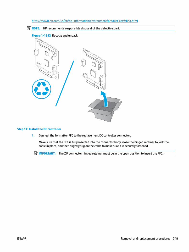
http://www8.hp.com/us/en/hp-information/environment/product-recycling.html
NOTE: HP recommends responsible disposal of the defective part.
Figure 1-1392 Recycle and unpack
Step 14: Install the DC controller
1. Connect the formatter FFC to the replacement DC controller connector.
Make sure that the FFC is fully inserted into the connector body, close the hinged retainer to lock the cable in place, and then slightly tug on the cable to make sure it is securely fastened.
IMPORTANT: The ZIF connector hinged retainer must be in the open position to insert the FFC.
ENWW Removal and replacement procedures 749
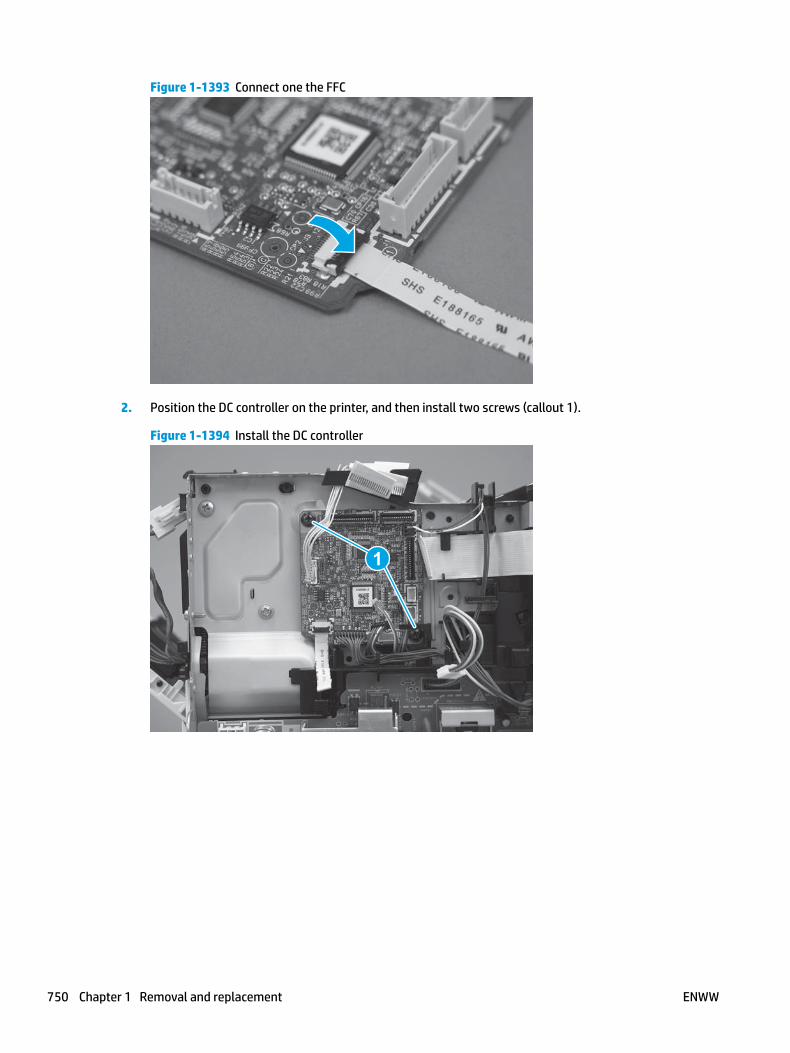
Figure 1-1393 Connect one the FFC
2. Position the DC controller on the printer, and then install two screws (callout 1).
Figure 1-1394 Install the DC controller
1
750 Chapter 1 Removal and replacement ENWW
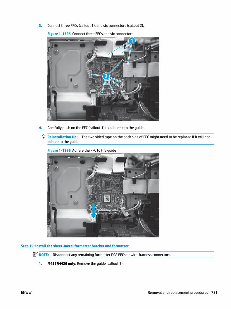
3. Connect three FFCs (callout 1), and six connectors (callout 2).
Figure 1-1395 Connect three FFCs and six connectors
2
1
4. Carefully push on the FFC (callout 1) to adhere it to the guide.
Reinstallation tip: The two sided tape on the back side of FFC might need to be replaced if it will not adhere to the guide.
Figure 1-1396 Adhere the FFC to the guide
Step 15: Install the sheet-metal formatter bracket and formatter
NOTE: Disconnect any remaining formatter PCA FFCs or wire-harness connectors.
1. M427/M426 only: Remove the guide (callout 1).
ENWW Removal and replacement procedures 751

Figure 1-1397 Remove the guide
1
2. Remove two screws (callout 1).
Figure 1-1398 Remove two screws
11
3. Disconnect one connector (callout 1), and then release the wire harness from the guide (callout 2).
Figure 1-1399 Disconnect one connector
21
21
752 Chapter 1 Removal and replacement ENWW

4. Remove the guide (callout 1).
Figure 1-1400 Remove the guide
11
5. Remove three screws (callout 1).
Figure 1-1401 Remove three screws
1 1
6. Remove the sheet-metal bracket and formatter PCA.
Figure 1-1402 Remove the bracket
ENWW Removal and replacement procedures 753

Step 16: Install the paper delivery tray (output bin)
NOTE: This procedure shows the M403/M402 model, however, the paper delivery tray (output bin) removal is similar for the M427/M426 printer.
▲ Position the remove the paper delivery tray (output bin; callout 1) on the printer, engage two tabs (callout 2), and then engage two bosses (callout 3).
Figure 1-1403 Engage two tabs
2
3
1
Step 17: Install the top cover (M403/M402)
NOTE: The step is for the M403/M402 printer. For the M427/M426, skip this step and go to Step 18: Install the top cover (M427/M426) on page 756.
1. Position the rear edge of the cover on the printer.
Figure 1-1404 Install the cover
754 Chapter 1 Removal and replacement ENWW

2. Engage four bosses (callout 1), rotate the front of the cover down (callout 2) and onto from the printer, and then engage four tabs (callout 3).
Figure 1-1405 Engage four bosses and tabs
1
3
2
2
3. At the right side of the printer, engage the one boss and one tab (callout 1).
Figure 1-1406 Engage one boss and one tab
1
ENWW Removal and replacement procedures 755

4. Install one screw (callout 1).
Figure 1-1407 Install one screw
1
Step 18: Install the top cover (M427/M426)
NOTE: The step is for the M427/M426 printer. For the M403/M402, skip this step and go to Step 21: Install the rear door assembly on page 767.
1. Position the rear edge of the top cover on the printer.
Figure 1-1408 Install the cover
756 Chapter 1 Removal and replacement ENWW

2. Engage four bosses (callout 1).
Figure 1-1409 Engage four bosses
1
3. Rotate the front edge of the cover down.
Figure 1-1410 Rotate the front edge of the cover down
ENWW Removal and replacement procedures 757
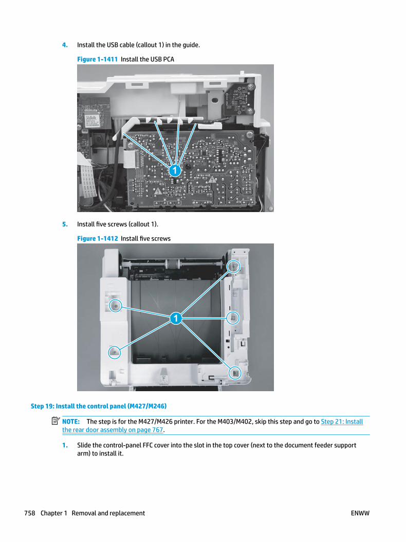
4. Install the USB cable (callout 1) in the guide.
Figure 1-1411 Install the USB PCA
1
5. Install five screws (callout 1).
Figure 1-1412 Install five screws
1
Step 19: Install the control panel (M427/M246)
NOTE: The step is for the M427/M426 printer. For the M403/M402, skip this step and go to Step 21: Install the rear door assembly on page 767.
1. Slide the control-panel FFC cover into the slot in the top cover (next to the document feeder support arm) to install it.
758 Chapter 1 Removal and replacement ENWW

Figure 1-1413 Install the control-panel FFC cover
2. Install the control-panel assembly on the top cover.
Figure 1-1414 Install the control-panel assembly
ENWW Removal and replacement procedures 759
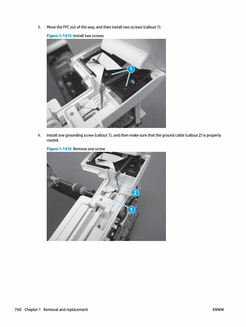
3. Move the FFC out of the way, and then install two screws (callout 1).
Figure 1-1415 Install two screws
1
4. Install one grounding screw (callout 1), and then make sure that the ground cable (callout 2) is properly routed.
Figure 1-1416 Remove one screw
2
1
760 Chapter 1 Removal and replacement ENWW

5. Install the control-panel cable cover.
Figure 1-1417 Install the cover
6. Make sure that the two tabs (callout 1) on the cover snap into place.
Figure 1-1418 Engage two tabs
1
ENWW Removal and replacement procedures 761
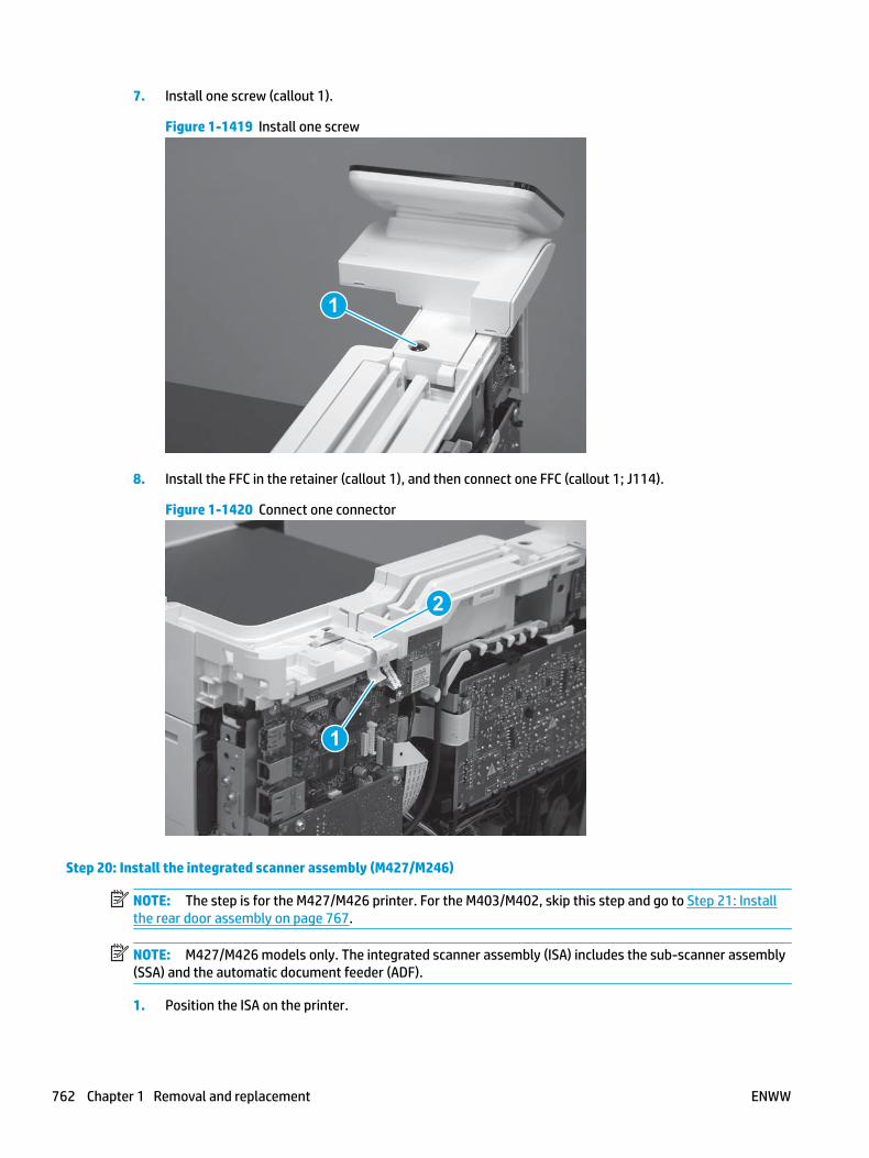
7. Install one screw (callout 1).
Figure 1-1419 Install one screw
1
8. Install the FFC in the retainer (callout 1), and then connect one FFC (callout 1; J114).
Figure 1-1420 Connect one connector
1
2
Step 20: Install the integrated scanner assembly (M427/M246)
NOTE: The step is for the M427/M426 printer. For the M403/M402, skip this step and go to Step 21: Install the rear door assembly on page 767.
NOTE: M427/M426 models only. The integrated scanner assembly (ISA) includes the sub-scanner assembly (SSA) and the automatic document feeder (ADF).
1. Position the ISA on the printer.
762 Chapter 1 Removal and replacement ENWW

Figure 1-1421 Position the ISA on the printer
2. Engage the hinge pins on the ISA with the holders in the top cover (callouts 1/2), and the slide the ISA as shown to engage them
Figure 1-1422 Engage the hinge pins with the holders
1
2
ENWW Removal and replacement procedures 763

3. Rotate the ISA towards the front of the printer until it rests on the ISA lift assembly (callout 1).
Figure 1-1423 Rotate the ISA towards the front of the printer
1
4. Pass the ground wire through the opening in the top cover.
Figure 1-1424 Pass the wire through the opening
764 Chapter 1 Removal and replacement ENWW

5. Install one screw (callout 1).
Figure 1-1425 Install one screw
1
6. Install the ISA lift assembly slider pin.
Reinstallation tip: Align the keyed portion of the locking pin with the slot and hole in the support arm.
Figure 1-1426 Install the slider pin
ENWW Removal and replacement procedures 765

7. Rotate the slider pin (callout 1) towards the rear of the printer until the tab (callout 2) snap into place.
Figure 1-1427 Secure the slider pin
2
1
8. Install the ferrite (callout 1) in the holder, and then connect three FFCs (callout 2).
Figure 1-1428 Connect three FFCs
1
2
766 Chapter 1 Removal and replacement ENWW
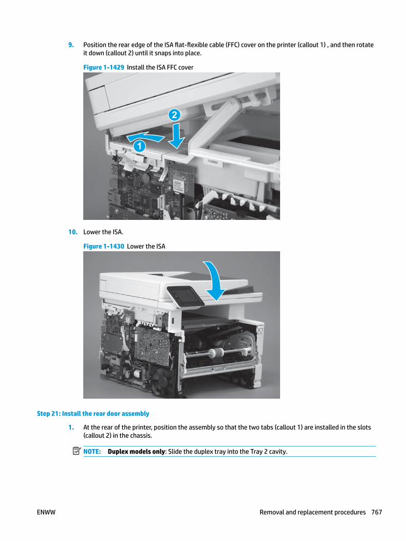
9. Position the rear edge of the ISA flat-flexible cable (FFC) cover on the printer (callout 1) , and then rotate it down (callout 2) until it snaps into place.
Figure 1-1429 Install the ISA FFC cover
1
2
10. Lower the ISA.
Figure 1-1430 Lower the ISA
Step 21: Install the rear door assembly
1. At the rear of the printer, position the assembly so that the two tabs (callout 1) are installed in the slots (callout 2) in the chassis.
NOTE: Duplex models only: Slide the duplex tray into the Tray 2 cavity.
ENWW Removal and replacement procedures 767
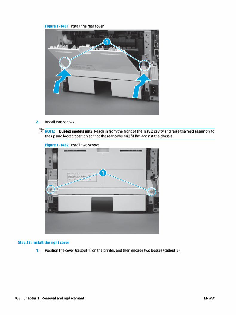
Figure 1-1431 Install the rear cover
1
2. Install two screws.
NOTE: Duplex models only: Reach in from the front of the Tray 2 cavity and raise the feed assembly to the up and locked position so that the rear cover will fit flat against the chassis.
Figure 1-1432 Install two screws
1
Step 22: Install the right cover
1. Position the cover (callout 1) on the printer, and then engage two bosses (callout 2).
768 Chapter 1 Removal and replacement ENWW

Figure 1-1433 Install the cover
11
2 2
2. Rotate the front of the cover onto the printer (callout 1), engage three (callout 2) tabs, and then engage two bosses (callout 3).
Figure 1-1434 Engage two bosses and one tab
1 13 3
2 2
3. Make sure that the power switch (callout 1) and cartridge door assembly button (callout 2) correctly function.
NOTE: Remove, and then reinstall the cover if the switch or button does not correctly function.
Figure 1-1435 Check the power switch and cartridge door assembly button
1
1
22
ENWW Removal and replacement procedures 769

4. Install one screw (callout 1).
Figure 1-1436 Install one screw
11
Step 23: Install the left cover
1. At the front of the printer, do one of the following:
● M403/M402: Position the cover on the printer ( callout 1), and then engage two bosses (callout 2).
● M427/M426: Position the cover on the printer (callout 3), engage one tab (callout 4), and then engage two bosses (callout 4).
Figure 1-1437 Install the cover
1
2
4
35
770 Chapter 1 Removal and replacement ENWW

2. Carefully rotate the rear of the cover onto the printer (callout 1), engage three tabs (callout 2), and then engage two bosses (callout 3).
Figure 1-1438 Engage three tabs and two bosses
3
3 11
2
2
3. Install one screw (callout 1).
Figure 1-1439 Install one screw
1 1
Step 24: Install the cartridge door assembly
Reinstallation tip: After a replacement door is installed, make sure to install the nameplate (supplied in the kit) corresponding to the printer name on the door.
1. Position the door close to the printer, and then engage the keyed pin on the left-side retainer arm with the hole in the door.
ENWW Removal and replacement procedures 771

Figure 1-1440 Engage the left-side retainer arm
2. Engage the right-side door hinge pin with the hole in the chassis (callout 1).
Figure 1-1441 Install the door
1
772 Chapter 1 Removal and replacement ENWW

3. Install the link (callout 1).
IMPORTANT: Make sure that the link snaps into place on the arm (callout 2). The link actuates the fuser pressure-release mechanism.
Figure 1-1442 Install the pressure-release link
1
2
4. Slide the guide into the printer (callout 1), and then make sure that the tab (callout 2) snaps into place to secure the guide to the chassis.
Figure 1-1443 Install the guide
1
2
ENWW Removal and replacement procedures 773

5. Position the shaft on the door, and then align the left-side hinge on the door with the hole in the chassis (callout 1).
Figure 1-1444 Align the hinge
1
6. Push the shaft towards the left side of the printer to install it (callout 1).
Reinstallation tip: Make sure that the support shaft is fully installed and correctly orientated (callout 2) so that it will not interfere with the door opening and closing.
Figure 1-1445 Install the support shaft
2
1
774 Chapter 1 Removal and replacement ENWW

Step 25: Install Tray 2
▲ Slide the tray straight into the printer to install it.
Figure 1-1446 Install the tray
ENWW Removal and replacement procedures 775

Removal and replacement: Tag-cable assembly (toner-cartridge memory)
● Introduction
● Step 1: Remove Tray 2
● Step 2: Remove the cartridge door assembly
● Step 3: Remove the left cover
● Step 4: Remove the right cover
● Step 5: Remove the integrated scanner assembly (M427/M246)
● Step 6: Remove the control panel (M427/M246)
● Step 7: Remove the top cover (M427/M426)
● Step 8: Remove the top cover (M403/M402)
● Step 9: Remove the paper delivery tray (output bin)
● Step 10: Remove the sheet-metal formatter bracket and formatter PCA
● Step 11: Remove the tag-cable assembly (toner-cartridge memory)
● Step 12: Unpack the replacement assembly
● Step 13: Install the tag-cable assembly (toner-cartridge memory)
● Step 14: Install the sheet-metal formatter bracket and formatter PCA
● Step 15: Install the paper delivery tray (output bin)
● Step 16: Install the top cover (M403/M402)
● Step 17: Install the top cover (M427/M426)
● Step 18: Install the control panel (M427/M246)
● Step 19: Install the integrated scanner assembly (M427/M246)
● Step 20: Install the right cover
● Step 21: Install the left cover
● Step 22: Install the cartridge door assembly
● Step 23: Install Tray 2
Introduction
This document provides the procedures to remove and replace the tag-cable assembly (toner-cartridge memory).
Before performing service
Turn the printer power off
◦ Disconnect the power cable.
776 Chapter 1 Removal and replacement ENWW
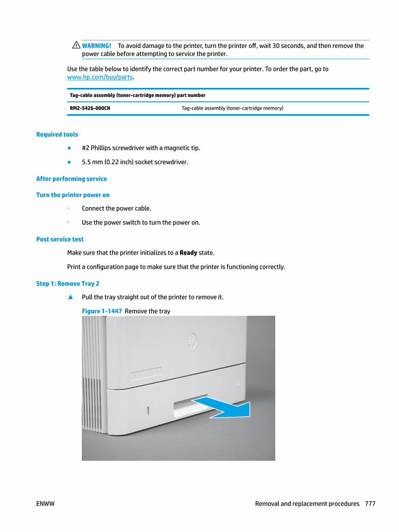
WARNING! To avoid damage to the printer, turn the printer off, wait 30 seconds, and then remove the power cable before attempting to service the printer.
Use the table below to identify the correct part number for your printer. To order the part, go to www.hp.com/buy/parts.
Tag-cable assembly (toner-cartridge memory) part number
RM2-5426-000CN Tag-cable assembly (toner-cartridge memory)
Required tools
● #2 Phillips screwdriver with a magnetic tip.
● 5.5 mm (0.22 inch) socket screwdriver.
After performing service
Turn the printer power on
◦ Connect the power cable.
◦ Use the power switch to turn the power on.
Post service test
Make sure that the printer initializes to a Ready state.
Print a configuration page to make sure that the printer is functioning correctly.
Step 1: Remove Tray 2
▲ Pull the tray straight out of the printer to remove it.
Figure 1-1447 Remove the tray
ENWW Removal and replacement procedures 777

Step 2: Remove the cartridge door assembly
NOTE: If the toner cartridge was not removed prior to servicing the printer, remove it now.
1. Release one tab (callout 1), and then slide shaft (callout 2) in the direction the arrow indicates and remove it.
TIP: It might be easier to release the support shaft by using a small flat-blade screwdriver.
Figure 1-1448 Release the support shaft
12
2. Release one tab (callout 1), and then slide the guide (callout 2) in the direction the arrow indicates and remove it.
Figure 1-1449 Remove the guide
1 2
778 Chapter 1 Removal and replacement ENWW

3. Remove the link arm (callout 1).
Figure 1-1450 Remove the link arm
1
4. Slide the cartridge door assembly (callout 1) in the direction the arrow indicates and remove it.
Figure 1-1451 Remove the door
1
ENWW Removal and replacement procedures 779

5. Remove the link (callout 1) from the cartridge door assembly (callout 2).
Figure 1-1452 Release the left-side retainer arm
21
Step 3: Remove the left cover
1. Remove one screw (callout 1).
Figure 1-1453 Remove one screw
1 1
780 Chapter 1 Removal and replacement ENWW

2. Open the rear door, release two bosses (callout 1), and then release three tabs (callout 2).
Figure 1-1454 Release two bosses and three tabs
1
1
2
2
3. At the front of the printer, do one of the following:
● M403/M402: Release two bosses (callout 1), and then remove the cover (callout 2).
● M427/M426: Release one tab (callout 3), two bosses (callout 4), and then remove the cover (callout 5).
CAUTION: Be careful when releasing the upper bosses on the M427/M426 cover. One portion of the cover (callout 6) is fragile and is easily broken.
Figure 1-1455 Remove the cover
2
1
3
54 6
Step 4: Remove the right cover
1. Remove one screw (callout 1).
ENWW Removal and replacement procedures 781

Figure 1-1456 Remove one screw
11
2. At the front of the printer, release two bosses (callout 1), and then release three tabs (callout 2).
Figure 1-1457 Release two bosses and three tabs
1 1
2 2
3. Open the rear door, release two bosses (callout 1), and then remove the cover (callout 2).
Figure 1-1458 Remove the cover
22
1 1
Step 5: Remove the integrated scanner assembly (M427/M246)
NOTE: The step is for the M427/M426 printer. For the M403/M402, skip this step and go to Step 8: Remove the top cover (M403/M402) on page 792.
782 Chapter 1 Removal and replacement ENWW
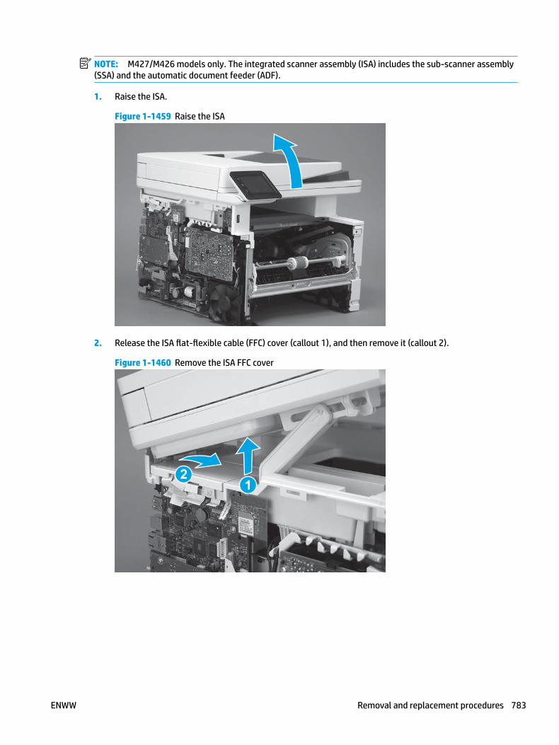
NOTE: M427/M426 models only. The integrated scanner assembly (ISA) includes the sub-scanner assembly (SSA) and the automatic document feeder (ADF).
1. Raise the ISA.
Figure 1-1459 Raise the ISA
2. Release the ISA flat-flexible cable (FFC) cover (callout 1), and then remove it (callout 2).
Figure 1-1460 Remove the ISA FFC cover
12
ENWW Removal and replacement procedures 783

3. Disconnect three FFCs (callout 1), and then remove the ferrite (callout 2) from the holder.
CAUTION: The ferrite is not captive on the FFC. Do not lose the ferrite while handling the ISA.
Figure 1-1461 Disconnect three FFCs
2
1
4. Remove one screw (callout 1).
Figure 1-1462 Remove one screw
1
784 Chapter 1 Removal and replacement ENWW

5. Pass the ground wire through the opening in the top cover.
Figure 1-1463 Pass the wire through the opening
6. Release one tab (callout 1), and then rotate the ISA slider pin (callout 2) towards the front of the printer to release it.
Figure 1-1464 Release one tab and rotate the slider pin
1
2
ENWW Removal and replacement procedures 785
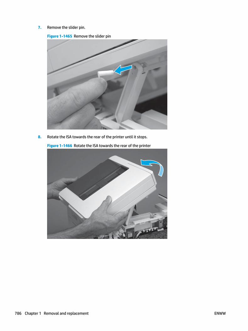
7. Remove the slider pin.
Figure 1-1465 Remove the slider pin
8. Rotate the ISA towards the rear of the printer until it stops.
Figure 1-1466 Rotate the ISA towards the rear of the printer
786 Chapter 1 Removal and replacement ENWW

9. Slide the ISA as shown to release it.
Figure 1-1467 Release the ISA
10. Remove the ISA.
Figure 1-1468 Remove the ISA
Step 6: Remove the control panel (M427/M246)
NOTE: The step is for the M427/M426 printer. For the M403/M402, skip this step and go to Step 8: Remove the top cover (M403/M402) on page 792.
1. Disconnect one FFC (callout 1; J114), and then release the FFC from the retainer (callout 2).
ENWW Removal and replacement procedures 787

Figure 1-1469 Disconnect one connector
1
2
2. Remove one screw (callout 1).
Figure 1-1470 Remove one screw
1
788 Chapter 1 Removal and replacement ENWW

3. Use a small flat-blade screwdriver to release two tabs (callout 1) on the control-panel cable cover.
Figure 1-1471 Release two tabs
1
4. Remove the control-panel cable cover.
Figure 1-1472 Remove the cover
ENWW Removal and replacement procedures 789
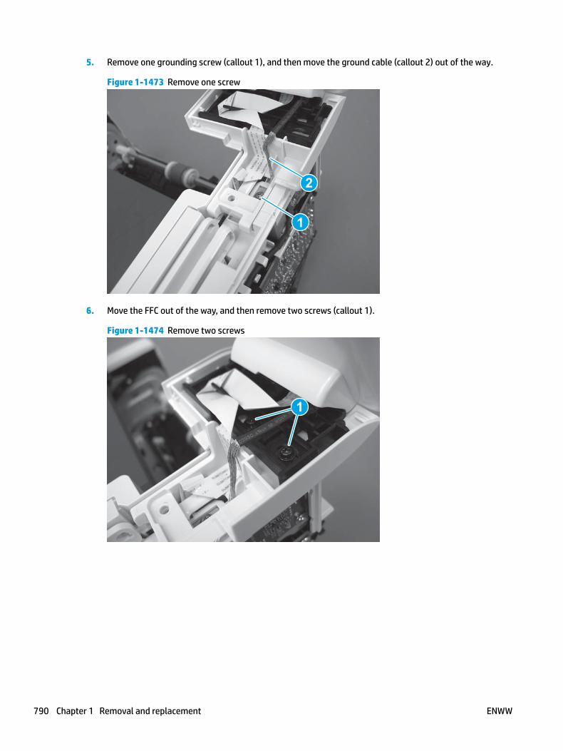
5. Remove one grounding screw (callout 1), and then move the ground cable (callout 2) out of the way.
Figure 1-1473 Remove one screw
2
1
6. Move the FFC out of the way, and then remove two screws (callout 1).
Figure 1-1474 Remove two screws
1
790 Chapter 1 Removal and replacement ENWW

7. Slightly lift up the control-panel assembly to separate it from the top cover.
CAUTION: The control panel assembly is still connected to the printer by the FFC. Do not attempt to completely remove the assembly.
Figure 1-1475 Lift up the control-panel assembly
8. Lift up the control-panel FFC cover to remove the control-panel assembly.
Figure 1-1476 Remove the control-panel assembly
Step 7: Remove the top cover (M427/M426)
NOTE: The step is for the M427/M426 printer. For the M403/M402, skip this step and go to Step 8: Remove the top cover (M403/M402) on page 792.
1. Release the USB cable (callout 1) from the cable guide.
ENWW Removal and replacement procedures 791

Figure 1-1477 Remove the USB cable
1
2. Remove five screws (callout 1), release four bosses (callout 2), and then remove the top cover (callout 3).
Figure 1-1478 Remove the cover
3
2
1
Step 8: Remove the top cover (M403/M402)
NOTE: The step is for the M403/M402 printer. For the M427/M426, skip this step and go to Step 9: Remove the paper delivery tray (output bin) on page 794.
1. Remove one screw (callout 1).
792 Chapter 1 Removal and replacement ENWW

Figure 1-1479 Remove one screw
1
2. At the right side of the printer, release the one boss (callout 1), and then release one tab (callout 2).
Figure 1-1480 Release one boss and one tab
21
ENWW Removal and replacement procedures 793

3. Release four tabs (callout 1), release four bosses (callout 2), and then remove the top cover (callout 3).
TIP: Open the rear door to make releasing the bosses (callout 3) easier.
Figure 1-1481 Remove the cover
2
3
1
Step 9: Remove the paper delivery tray (output bin)
NOTE: This procedure shows the M403/M402 model, however, the paper delivery tray (output bin) removal is similar for the M427/M426 printer.
▲ Release two bosses (callout 1), release two tabs (callout 2), and then remove the paper delivery tray (output bin; callout 3).
Figure 1-1482 Release two tabs
2
1
3
794 Chapter 1 Removal and replacement ENWW

Step 10: Remove the sheet-metal formatter bracket and formatter PCA
NOTE: Disconnect any remaining formatter PCA FFCs or wire-harness connectors.
1. M427/M426 only: Remove the guide (callout 1).
Figure 1-1483 Remove the guide
1
2. Remove two screws (callout 1).
Figure 1-1484 Remove two screws
11
ENWW Removal and replacement procedures 795

3. Disconnect one connector (callout 1), and then release the wire harness from the guide (callout 2).
Figure 1-1485 Disconnect one connector
21
21
4. Remove the guide (callout 1).
Figure 1-1486 Remove the guide
11
5. Remove three screws (callout 1).
Figure 1-1487 Remove three screws
1 1
796 Chapter 1 Removal and replacement ENWW

6. Remove the sheet-metal bracket and formatter PCA.
Figure 1-1488 Remove the bracket
Step 11: Remove the tag-cable assembly (toner-cartridge memory)
1. Disconnect one connector (callout 1), and then release the wire harness from the guide (callout 2).
Figure 1-1489 Disconnect one connector
1
2
ENWW Removal and replacement procedures 797

2. Remove one screw (callout 1).
Figure 1-1490 Remove one screw
1
3. Remove the tag-cable assembly.
Figure 1-1491 Remove the tag-cable assembly
Step 12: Unpack the replacement assembly
Unpack the replacement part from the packaging.
http://www8.hp.com/us/en/hp-information/environment/product-recycling.html
NOTE: HP recommends responsible disposal of the defective part.
798 Chapter 1 Removal and replacement ENWW

Figure 1-1492 Recycle and unpack
Step 13: Install the tag-cable assembly (toner-cartridge memory)
1. Position the assembly on the printer.
IMPORTANT: Make sure that the assembly is flat against the chassis. If the assembly is not correctly installed, it might not make proper contact with the toner cartridge.
Figure 1-1493 Install the assembly
ENWW Removal and replacement procedures 799

2. Install one screw (callout 1).
Figure 1-1494 Install one screw
1
3. Install the wire harness in the guide (callout 1), and then connect one connector (callout 2).
Figure 1-1495 Connect one connector
2
1
Step 14: Install the sheet-metal formatter bracket and formatter PCA
NOTE: Do not forget to connect any formatter PCA FFCs or wire-harness connectors that were disconnected when the bracket was removed.
1. Position the sheet-metal bracket and formatter PCA on the printer.
800 Chapter 1 Removal and replacement ENWW

Figure 1-1496 Install the bracket
2. Install three screws (callout 1).
Figure 1-1497 Install three screws
1 1
3. Install the guide (callout 1).
Figure 1-1498 Install the guide
11
ENWW Removal and replacement procedures 801

4. Connect one connector (callout 1), and then install the wire harness in the guide (callout 2).
Figure 1-1499 Connect one connector
21
21
5. Install two screws (callout 1).
Figure 1-1500 Install two screws
11
6. M427/M426 only: Install the guide (callout 1).
Figure 1-1501 Install the guide
1
802 Chapter 1 Removal and replacement ENWW

Step 15: Install the paper delivery tray (output bin)
NOTE: This procedure shows the M403/M402 model, however, the paper delivery tray (output bin) removal is similar for the M427/M426 printer.
▲ Position the remove the paper delivery tray (output bin; callout 1) on the printer, engage two tabs (callout 2), and then engage two bosses (callout 3).
Figure 1-1502 Engage two tabs
2
3
1
Step 16: Install the top cover (M403/M402)
NOTE: The step is for the M403/M402 printer. For the M427/M426, skip this step and go to Step 17: Install the top cover (M427/M426) on page 805.
1. Position the rear edge of the cover on the printer.
Figure 1-1503 Install the cover
ENWW Removal and replacement procedures 803

2. Engage four bosses (callout 1), rotate the front of the cover down (callout 2) and onto from the printer, and then engage four tabs (callout 3).
Figure 1-1504 Engage four bosses and tabs
1
3
2
2
3. At the right side of the printer, engage the one boss and one tab (callout 1).
Figure 1-1505 Engage one boss and one tab
1
804 Chapter 1 Removal and replacement ENWW

4. Install one screw (callout 1).
Figure 1-1506 Install one screw
1
Step 17: Install the top cover (M427/M426)
NOTE: The step is for the M427/M426 printer. For the M403/M402, skip this step and go to Step 20: Install the right cover on page 816.
1. Position the rear edge of the top cover on the printer.
Figure 1-1507 Install the cover
ENWW Removal and replacement procedures 805

2. Engage four bosses (callout 1).
Figure 1-1508 Engage four bosses
1
3. Rotate the front edge of the cover down.
Figure 1-1509 Rotate the front edge of the cover down
806 Chapter 1 Removal and replacement ENWW

4. Install the USB cable (callout 1) in the guide.
Figure 1-1510 Install the USB PCA
1
5. Install five screws (callout 1).
Figure 1-1511 Install five screws
1
Step 18: Install the control panel (M427/M246)
NOTE: The step is for the M427/M426 printer. For the M403/M402, skip this step and go to Step 20: Install the right cover on page 816.
1. Slide the control-panel FFC cover into the slot in the top cover (next to the document feeder support arm) to install it.
ENWW Removal and replacement procedures 807

Figure 1-1512 Install the control-panel FFC cover
2. Install the control-panel assembly on the top cover.
Figure 1-1513 Install the control-panel assembly
808 Chapter 1 Removal and replacement ENWW

3. Move the FFC out of the way, and then install two screws (callout 1).
Figure 1-1514 Install two screws
1
4. Install one grounding screw (callout 1), and then make sure that the ground cable (callout 2) is properly routed.
Figure 1-1515 Remove one screw
2
1
ENWW Removal and replacement procedures 809
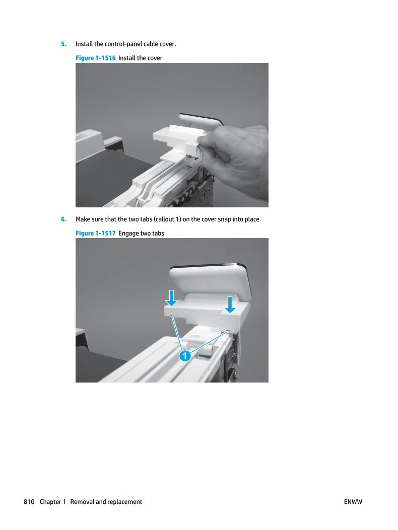
5. Install the control-panel cable cover.
Figure 1-1516 Install the cover
6. Make sure that the two tabs (callout 1) on the cover snap into place.
Figure 1-1517 Engage two tabs
1
810 Chapter 1 Removal and replacement ENWW

7. Install one screw (callout 1).
Figure 1-1518 Install one screw
1
8. Install the FFC in the retainer (callout 1), and then connect one FFC (callout 1; J114).
Figure 1-1519 Connect one connector
1
2
Step 19: Install the integrated scanner assembly (M427/M246)
NOTE: The step is for the M427/M426 printer. For the M403/M402, skip this step and go to Step 20: Install the right cover on page 816.
NOTE: M427/M426 models only. The integrated scanner assembly (ISA) includes the sub-scanner assembly (SSA) and the automatic document feeder (ADF).
1. Position the ISA on the printer.
ENWW Removal and replacement procedures 811

Figure 1-1520 Position the ISA on the printer
2. Engage the hinge pins on the ISA with the holders in the top cover (callouts 1/2), and the slide the ISA as shown to engage them
Figure 1-1521 Engage the hinge pins with the holders
1
2
812 Chapter 1 Removal and replacement ENWW

3. Rotate the ISA towards the front of the printer until it rests on the ISA lift assembly (callout 1).
Figure 1-1522 Rotate the ISA towards the front of the printer
1
4. Pass the ground wire through the opening in the top cover.
Figure 1-1523 Pass the wire through the opening
ENWW Removal and replacement procedures 813

5. Install one screw (callout 1).
Figure 1-1524 Install one screw
1
6. Install the ISA lift assembly slider pin.
Reinstallation tip: Align the keyed portion of the locking pin with the slot and hole in the support arm.
Figure 1-1525 Install the slider pin
814 Chapter 1 Removal and replacement ENWW

7. Rotate the slider pin (callout 1) towards the rear of the printer until the tab (callout 2) snap into place.
Figure 1-1526 Secure the slider pin
2
1
8. Install the ferrite (callout 1) in the holder, and then connect three FFCs (callout 2).
Figure 1-1527 Connect three FFCs
1
2
ENWW Removal and replacement procedures 815
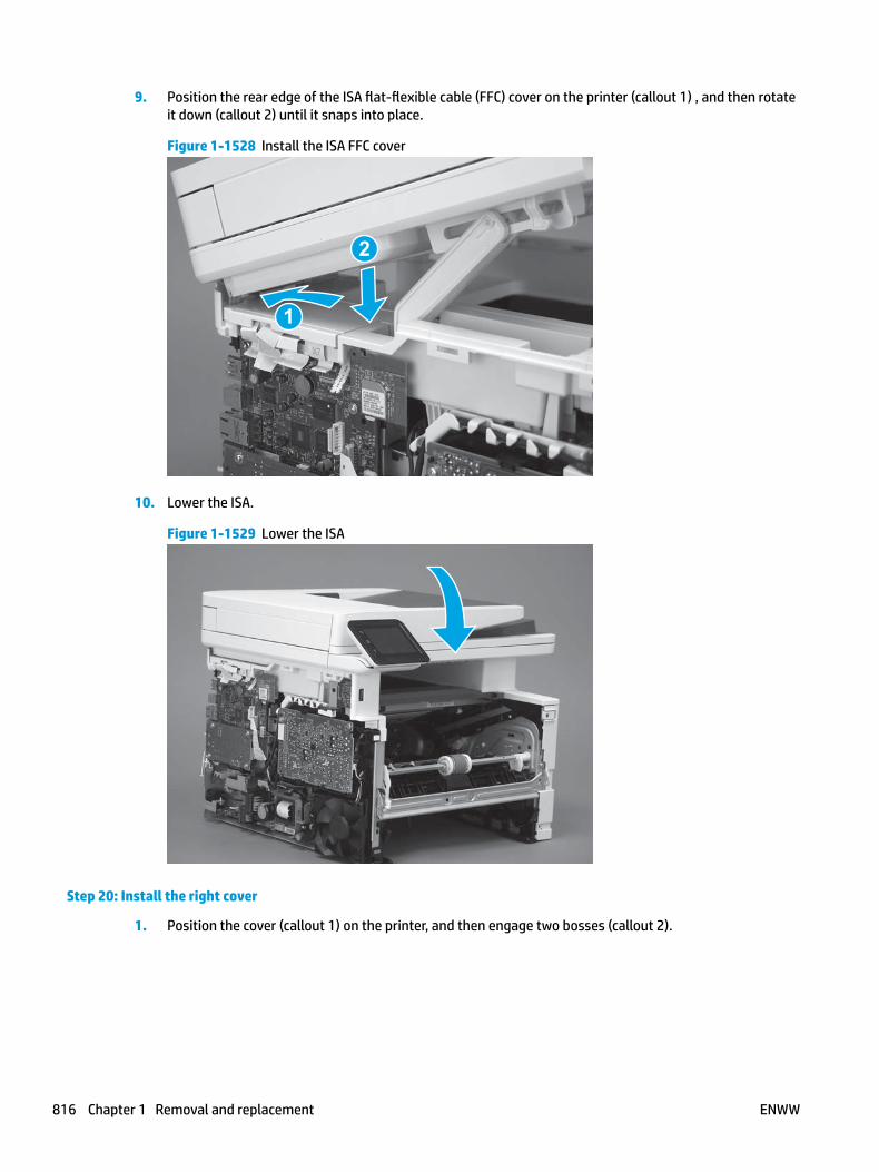
9. Position the rear edge of the ISA flat-flexible cable (FFC) cover on the printer (callout 1) , and then rotate it down (callout 2) until it snaps into place.
Figure 1-1528 Install the ISA FFC cover
1
2
10. Lower the ISA.
Figure 1-1529 Lower the ISA
Step 20: Install the right cover
1. Position the cover (callout 1) on the printer, and then engage two bosses (callout 2).
816 Chapter 1 Removal and replacement ENWW

Figure 1-1530 Install the cover
11
2 2
2. Rotate the front of the cover onto the printer (callout 1), engage three (callout 2) tabs, and then engage two bosses (callout 3).
Figure 1-1531 Engage two bosses and one tab
1 13 3
2 2
3. Make sure that the power switch (callout 1) and cartridge door assembly button (callout 2) correctly function.
NOTE: Remove, and then reinstall the cover if the switch or button does not correctly function.
Figure 1-1532 Check the power switch and cartridge door assembly button
1
1
22
ENWW Removal and replacement procedures 817

4. Install one screw (callout 1).
Figure 1-1533 Install one screw
11
Step 21: Install the left cover
1. At the front of the printer, do one of the following:
● M403/M402: Position the cover on the printer ( callout 1), and then engage two bosses (callout 2).
● M427/M426: Position the cover on the printer (callout 3), engage one tab (callout 4), and then engage two bosses (callout 4).
Figure 1-1534 Install the cover
1
2
4
35
818 Chapter 1 Removal and replacement ENWW
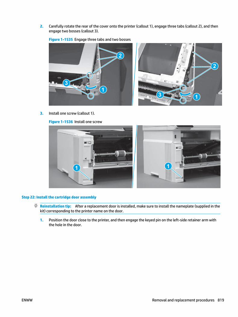
2. Carefully rotate the rear of the cover onto the printer (callout 1), engage three tabs (callout 2), and then engage two bosses (callout 3).
Figure 1-1535 Engage three tabs and two bosses
3
3 11
2
2
3. Install one screw (callout 1).
Figure 1-1536 Install one screw
1 1
Step 22: Install the cartridge door assembly
Reinstallation tip: After a replacement door is installed, make sure to install the nameplate (supplied in the kit) corresponding to the printer name on the door.
1. Position the door close to the printer, and then engage the keyed pin on the left-side retainer arm with the hole in the door.
ENWW Removal and replacement procedures 819

Figure 1-1537 Engage the left-side retainer arm
2. Engage the right-side door hinge pin with the hole in the chassis (callout 1).
Figure 1-1538 Install the door
1
820 Chapter 1 Removal and replacement ENWW

3. Install the link (callout 1).
IMPORTANT: Make sure that the link snaps into place on the arm (callout 2). The link actuates the fuser pressure-release mechanism.
Figure 1-1539 Install the pressure-release link
1
2
4. Slide the guide into the printer (callout 1), and then make sure that the tab (callout 2) snaps into place to secure the guide to the chassis.
Figure 1-1540 Install the guide
1
2
ENWW Removal and replacement procedures 821

5. Position the shaft on the door, and then align the left-side hinge on the door with the hole in the chassis (callout 1).
Figure 1-1541 Align the hinge
1
6. Push the shaft towards the left side of the printer to install it (callout 1).
Reinstallation tip: Make sure that the support shaft is fully installed and correctly orientated (callout 2) so that it will not interfere with the door opening and closing.
Figure 1-1542 Install the support shaft
2
1
822 Chapter 1 Removal and replacement ENWW

Step 23: Install Tray 2
▲ Slide the tray straight into the printer to install it.
Figure 1-1543 Install the tray
ENWW Removal and replacement procedures 823

Removal and replacement: Connecting PCA
● Introduction
● Step 1: Remove Tray 2
● Step 2: Remove the cartridge door assembly
● Step 3: Remove the left cover
● Step 4: Remove the right cover
● Step 5: Remove the integrated scanner assembly (M427/M246)
● Step 6: Remove the control panel (M427/M246)
● Step 7: Remove the top cover (M427/M426)
● Step 8: Remove the top cover (M403/M402)
● Step 9: Remove the paper delivery tray (output bin)
● Step 10: Remove the sheet-metal formatter bracket and formatter PCA
● Step 11: Remove the connecting PCA
● Step 12: Unpack the replacement assembly
● Step 13: Install the connecting PCA
● Step 14: Install the sheet-metal formatter bracket and formatter PCA
● Step 15: Install the paper delivery tray (output bin)
● Step 16: Install the top cover (M403/M402)
● Step 17: Install the top cover (M427/M426)
● Step 18: Install the control panel (M427/M246)
● Step 19: Install the integrated scanner assembly (M427/M246)
● Step 20: Install the right cover
● Step 21: Install the left cover
● Step 22: Install the cartridge door assembly
● Step 23: Install Tray 2
Introduction
This document provides the procedures to remove and replace the connecting printed circuit assembly (PCA).
Before performing service
Turn the printer power off
◦ Disconnect the power cable.
824 Chapter 1 Removal and replacement ENWW

WARNING! To avoid damage to the printer, turn the printer off, wait 30 seconds, and then remove the power cable before attempting to service the printer.
Use the table below to identify the correct part number for your printer. To order the part, go to www.hp.com/buy/parts.
Connecting printed circuit assembly (PCA) part number
RM2-7510-000CN
RM2-8510-000CN
Connecting PCA (duplex models1)
Connecting PCA (simplex models)
1 All M426/M427 printers are duplex models and use the RM2-7510-000CN connecting PCA.
Required tools
● #2 Phillips screwdriver with a magnetic tip.
● 5.5 mm (0.22 inch) socket screwdriver.
After performing service
Turn the printer power on
◦ Connect the power cable.
◦ Use the power switch to turn the power on.
Post service test
Make sure that the printer initializes to a Ready state.
Print a configuration page to make sure that the printer is functioning correctly.
Step 1: Remove Tray 2
▲ Pull the tray straight out of the printer to remove it.
ENWW Removal and replacement procedures 825

Figure 1-1544 Remove the tray
Step 2: Remove the cartridge door assembly
NOTE: If the toner cartridge was not removed prior to servicing the printer, remove it now.
1. Release one tab (callout 1), and then slide shaft (callout 2) in the direction the arrow indicates and remove it.
TIP: It might be easier to release the support shaft by using a small flat-blade screwdriver.
Figure 1-1545 Release the support shaft
12
826 Chapter 1 Removal and replacement ENWW

2. Release one tab (callout 1), and then slide the guide (callout 2) in the direction the arrow indicates and remove it.
Figure 1-1546 Remove the guide
1 2
3. Remove the link arm (callout 1).
Figure 1-1547 Remove the link arm
1
ENWW Removal and replacement procedures 827

4. Slide the cartridge door assembly (callout 1) in the direction the arrow indicates and remove it.
Figure 1-1548 Remove the door
1
5. Remove the link (callout 1) from the cartridge door assembly (callout 2).
Figure 1-1549 Release the left-side retainer arm
21
Step 3: Remove the left cover
1. Remove one screw (callout 1).
828 Chapter 1 Removal and replacement ENWW

Figure 1-1550 Remove one screw
1 1
2. Open the rear door, release two bosses (callout 1), and then release three tabs (callout 2).
Figure 1-1551 Release two bosses and three tabs
1
1
2
2
3. At the front of the printer, do one of the following:
● M403/M402: Release two bosses (callout 1), and then remove the cover (callout 2).
● M427/M426: Release one tab (callout 3), two bosses (callout 4), and then remove the cover (callout 5).
CAUTION: Be careful when releasing the upper bosses on the M427/M426 cover. One portion of the cover (callout 6) is fragile and is easily broken.
ENWW Removal and replacement procedures 829

Figure 1-1552 Remove the cover
2
1
3
54 6
Step 4: Remove the right cover
1. Remove one screw (callout 1).
Figure 1-1553 Remove one screw
11
2. At the front of the printer, release two bosses (callout 1), and then release three tabs (callout 2).
Figure 1-1554 Release two bosses and three tabs
1 1
2 2
830 Chapter 1 Removal and replacement ENWW

3. Open the rear door, release two bosses (callout 1), and then remove the cover (callout 2).
Figure 1-1555 Remove the cover
22
1 1
Step 5: Remove the integrated scanner assembly (M427/M246)
NOTE: The step is for the M427/M426 printer. For the M403/M402, skip this step and go to Step 8: Remove the top cover (M403/M402) on page 841.
NOTE: M427/M426 models only. The integrated scanner assembly (ISA) includes the sub-scanner assembly (SSA) and the automatic document feeder (ADF).
1. Raise the ISA.
Figure 1-1556 Raise the ISA
ENWW Removal and replacement procedures 831

2. Release the ISA flat-flexible cable (FFC) cover (callout 1), and then remove it (callout 2).
Figure 1-1557 Remove the ISA FFC cover
12
3. Disconnect three FFCs (callout 1), and then remove the ferrite (callout 2) from the holder.
CAUTION: The ferrite is not captive on the FFC. Do not lose the ferrite while handling the ISA.
Figure 1-1558 Disconnect three FFCs
2
1
832 Chapter 1 Removal and replacement ENWW

4. Remove one screw (callout 1).
Figure 1-1559 Remove one screw
1
5. Pass the ground wire through the opening in the top cover.
Figure 1-1560 Pass the wire through the opening
ENWW Removal and replacement procedures 833

6. Release one tab (callout 1), and then rotate the ISA slider pin (callout 2) towards the front of the printer to release it.
Figure 1-1561 Release one tab and rotate the slider pin
1
2
7. Remove the slider pin.
Figure 1-1562 Remove the slider pin
834 Chapter 1 Removal and replacement ENWW

8. Rotate the ISA towards the rear of the printer until it stops.
Figure 1-1563 Rotate the ISA towards the rear of the printer
9. Slide the ISA as shown to release it.
Figure 1-1564 Release the ISA
ENWW Removal and replacement procedures 835

10. Remove the ISA.
Figure 1-1565 Remove the ISA
Step 6: Remove the control panel (M427/M246)
NOTE: The step is for the M427/M426 printer. For the M403/M402, skip this step and go to Step 8: Remove the top cover (M403/M402) on page 841.
1. Disconnect one FFC (callout 1; J114), and then release the FFC from the retainer (callout 2).
Figure 1-1566 Disconnect one connector
1
2
836 Chapter 1 Removal and replacement ENWW

2. Remove one screw (callout 1).
Figure 1-1567 Remove one screw
1
3. Use a small flat-blade screwdriver to release two tabs (callout 1) on the control-panel cable cover.
Figure 1-1568 Release two tabs
1
ENWW Removal and replacement procedures 837

4. Remove the control-panel cable cover.
Figure 1-1569 Remove the cover
5. Remove one grounding screw (callout 1), and then move the ground cable (callout 2) out of the way.
Figure 1-1570 Remove one screw
2
1
838 Chapter 1 Removal and replacement ENWW

6. Move the FFC out of the way, and then remove two screws (callout 1).
Figure 1-1571 Remove two screws
1
7. Slightly lift up the control-panel assembly to separate it from the top cover.
CAUTION: The control panel assembly is still connected to the printer by the FFC. Do not attempt to completely remove the assembly.
Figure 1-1572 Lift up the control-panel assembly
ENWW Removal and replacement procedures 839
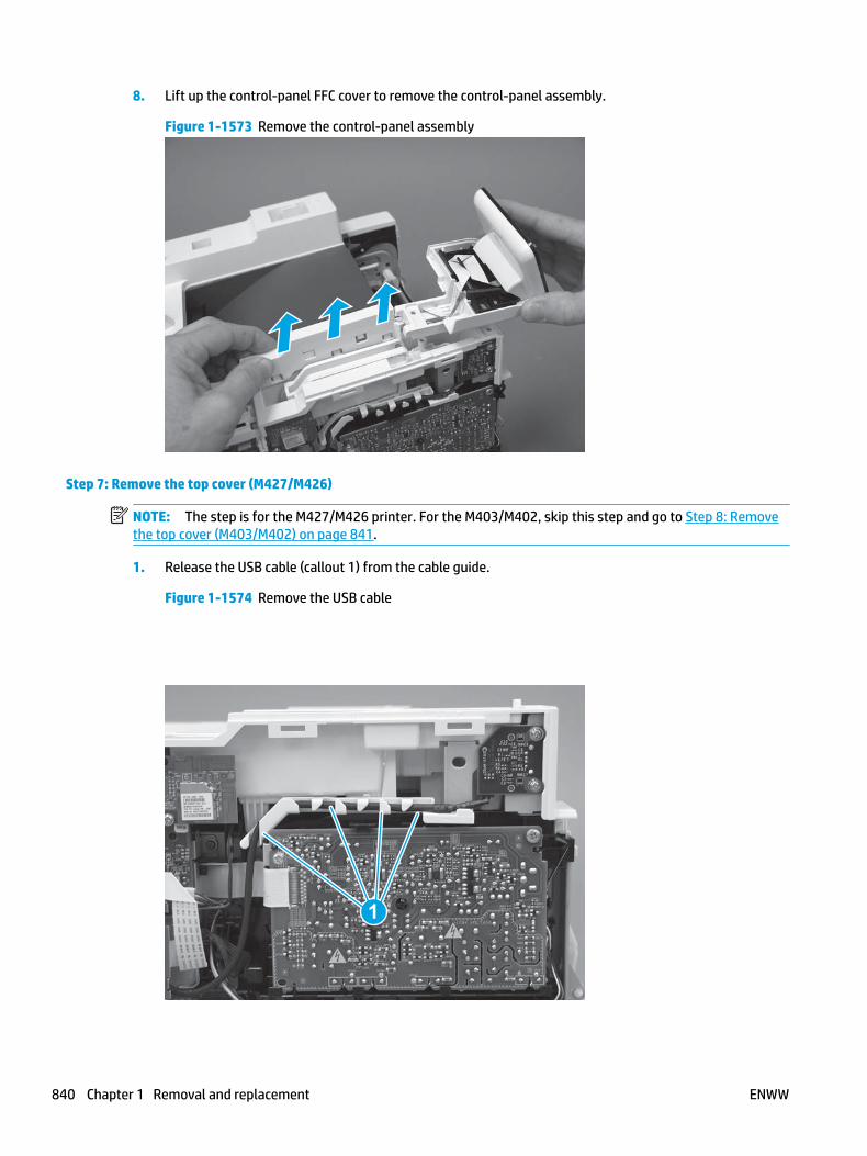
8. Lift up the control-panel FFC cover to remove the control-panel assembly.
Figure 1-1573 Remove the control-panel assembly
Step 7: Remove the top cover (M427/M426)
NOTE: The step is for the M427/M426 printer. For the M403/M402, skip this step and go to Step 8: Remove the top cover (M403/M402) on page 841.
1. Release the USB cable (callout 1) from the cable guide.
Figure 1-1574 Remove the USB cable
1
840 Chapter 1 Removal and replacement ENWW

2. Remove five screws (callout 1), release four bosses (callout 2), and then remove the top cover (callout 3).
Figure 1-1575 Remove the cover
3
2
1
Step 8: Remove the top cover (M403/M402)
NOTE: The step is for the M403/M402 printer. For the M427/M426, skip this step and go to Step 9: Remove the paper delivery tray (output bin) on page 842.
1. Remove one screw (callout 1).
Figure 1-1576 Remove one screw
1
ENWW Removal and replacement procedures 841

2. At the right side of the printer, release the one boss (callout 1), and then release one tab (callout 2).
Figure 1-1577 Release one boss and one tab
21
3. Release four tabs (callout 1), release four bosses (callout 2), and then remove the top cover (callout 3).
TIP: Open the rear door to make releasing the bosses (callout 3) easier.
Figure 1-1578 Remove the cover
2
3
1
Step 9: Remove the paper delivery tray (output bin)
NOTE: This procedure shows the M403/M402 model, however, the paper delivery tray (output bin) removal is similar for the M427/M426 printer.
▲ Release two bosses (callout 1), release two tabs (callout 2), and then remove the paper delivery tray (output bin; callout 3).
842 Chapter 1 Removal and replacement ENWW

Figure 1-1579 Release two tabs
2
1
3
Step 10: Remove the sheet-metal formatter bracket and formatter PCA
NOTE: Disconnect any remaining formatter PCA FFCs or wire-harness connectors.
1. M427/M426 only: Remove the guide (callout 1).
Figure 1-1580 Remove the guide
1
ENWW Removal and replacement procedures 843
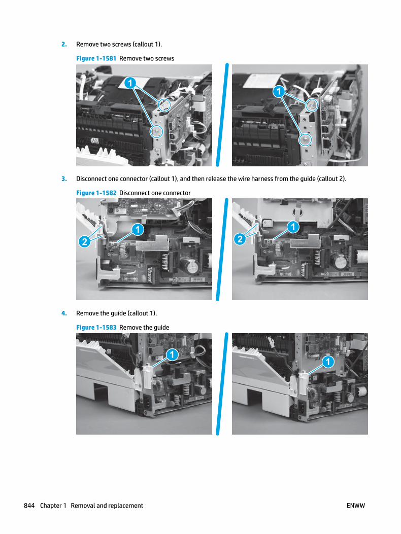
2. Remove two screws (callout 1).
Figure 1-1581 Remove two screws
11
3. Disconnect one connector (callout 1), and then release the wire harness from the guide (callout 2).
Figure 1-1582 Disconnect one connector
21
21
4. Remove the guide (callout 1).
Figure 1-1583 Remove the guide
11
844 Chapter 1 Removal and replacement ENWW

5. Remove three screws (callout 1).
Figure 1-1584 Remove three screws
1 1
6. Remove the sheet-metal bracket and formatter PCA.
Figure 1-1585 Remove the bracket
Step 11: Remove the connecting PCA
1. Disconnect nine connectors (callout 1).
TIP: Some of these connectors might be easier to disconnect if the wire harnesses are removed from the guides.
ENWW Removal and replacement procedures 845

Figure 1-1586 Disconnect nine connectors
1
2. Remove one screw (callout 1).
Figure 1-1587 Remove one screw
1
846 Chapter 1 Removal and replacement ENWW

3. Release two holders (callout 1), and then remove the connecting PCA (callout 2).
Figure 1-1588 Remove the connecting PCA
2
1
Step 12: Unpack the replacement assembly
Unpack the replacement part from the packaging.
http://www8.hp.com/us/en/hp-information/environment/product-recycling.html
NOTE: HP recommends responsible disposal of the defective part.
Figure 1-1589 Recycle and unpack
Step 13: Install the connecting PCA
1. Position the connecting PCA (callout 1) under the two holders (callout 2).
ENWW Removal and replacement procedures 847
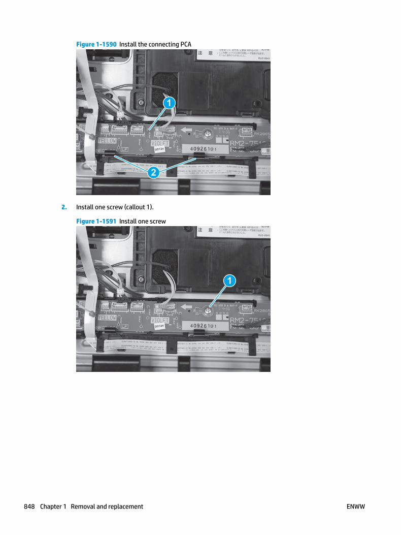
Figure 1-1590 Install the connecting PCA
1
2
2. Install one screw (callout 1).
Figure 1-1591 Install one screw
1
848 Chapter 1 Removal and replacement ENWW

3. Connect nine connectors (callout 1).
Reinstallation tip: If any of the connectors were removed from the guides, make sure that they are reinstalled now.
Figure 1-1592 Connect nine connectors
1
Step 14: Install the sheet-metal formatter bracket and formatter PCA
NOTE: Do not forget to connect any formatter PCA FFCs or wire-harness connectors that were disconnected when the bracket was removed.
1. Position the sheet-metal bracket and formatter PCA on the printer.
Figure 1-1593 Install the bracket
ENWW Removal and replacement procedures 849
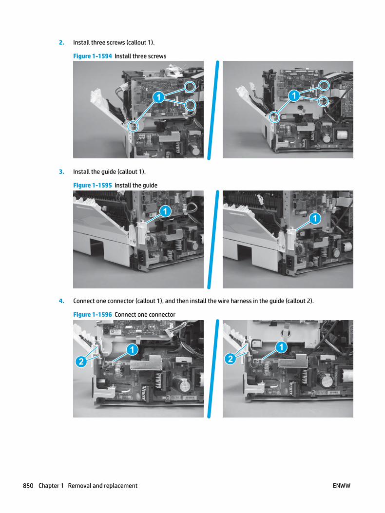
2. Install three screws (callout 1).
Figure 1-1594 Install three screws
1 1
3. Install the guide (callout 1).
Figure 1-1595 Install the guide
11
4. Connect one connector (callout 1), and then install the wire harness in the guide (callout 2).
Figure 1-1596 Connect one connector
21
21
850 Chapter 1 Removal and replacement ENWW

5. Install two screws (callout 1).
Figure 1-1597 Install two screws
11
6. M427/M426 only: Install the guide (callout 1).
Figure 1-1598 Install the guide
1
Step 15: Install the paper delivery tray (output bin)
NOTE: This procedure shows the M403/M402 model, however, the paper delivery tray (output bin) removal is similar for the M427/M426 printer.
▲ Position the remove the paper delivery tray (output bin; callout 1) on the printer, engage two tabs (callout 2), and then engage two bosses (callout 3).
ENWW Removal and replacement procedures 851

Figure 1-1599 Engage two tabs
2
3
1
Step 16: Install the top cover (M403/M402)
NOTE: The step is for the M403/M402 printer. For the M427/M426, skip this step and go to Step 17: Install the top cover (M427/M426) on page 854.
1. Position the rear edge of the cover on the printer.
Figure 1-1600 Install the cover
852 Chapter 1 Removal and replacement ENWW

2. Engage four bosses (callout 1), rotate the front of the cover down (callout 2) and onto from the printer, and then engage four tabs (callout 3).
Figure 1-1601 Engage four bosses and tabs
1
3
2
2
3. At the right side of the printer, engage the one boss and one tab (callout 1).
Figure 1-1602 Engage one boss and one tab
1
ENWW Removal and replacement procedures 853

4. Install one screw (callout 1).
Figure 1-1603 Install one screw
1
Step 17: Install the top cover (M427/M426)
NOTE: The step is for the M427/M426 printer. For the M403/M402, skip this step and go to Step 20: Install the right cover on page 865.
1. Position the rear edge of the top cover on the printer.
Figure 1-1604 Install the cover
854 Chapter 1 Removal and replacement ENWW

2. Engage four bosses (callout 1).
Figure 1-1605 Engage four bosses
1
3. Rotate the front edge of the cover down.
Figure 1-1606 Rotate the front edge of the cover down
ENWW Removal and replacement procedures 855

4. Install the USB cable (callout 1) in the guide.
Figure 1-1607 Install the USB PCA
1
5. Install five screws (callout 1).
Figure 1-1608 Install five screws
1
Step 18: Install the control panel (M427/M246)
NOTE: The step is for the M427/M426 printer. For the M403/M402, skip this step and go to Step 20: Install the right cover on page 865.
1. Slide the control-panel FFC cover into the slot in the top cover (next to the document feeder support arm) to install it.
856 Chapter 1 Removal and replacement ENWW

Figure 1-1609 Install the control-panel FFC cover
2. Install the control-panel assembly on the top cover.
Figure 1-1610 Install the control-panel assembly
ENWW Removal and replacement procedures 857

3. Move the FFC out of the way, and then install two screws (callout 1).
Figure 1-1611 Install two screws
1
4. Install one grounding screw (callout 1), and then make sure that the ground cable (callout 2) is properly routed.
Figure 1-1612 Remove one screw
2
1
858 Chapter 1 Removal and replacement ENWW

5. Install the control-panel cable cover.
Figure 1-1613 Install the cover
6. Make sure that the two tabs (callout 1) on the cover snap into place.
Figure 1-1614 Engage two tabs
1
ENWW Removal and replacement procedures 859

7. Install one screw (callout 1).
Figure 1-1615 Install one screw
1
8. Install the FFC in the retainer (callout 1), and then connect one FFC (callout 1; J114).
Figure 1-1616 Connect one connector
1
2
Step 19: Install the integrated scanner assembly (M427/M246)
NOTE: The step is for the M427/M426 printer. For the M403/M402, skip this step and go to Step 20: Install the right cover on page 865.
NOTE: M427/M426 models only. The integrated scanner assembly (ISA) includes the sub-scanner assembly (SSA) and the automatic document feeder (ADF).
1. Position the ISA on the printer.
860 Chapter 1 Removal and replacement ENWW

Figure 1-1617 Position the ISA on the printer
2. Engage the hinge pins on the ISA with the holders in the top cover (callouts 1/2), and the slide the ISA as shown to engage them
Figure 1-1618 Engage the hinge pins with the holders
1
2
ENWW Removal and replacement procedures 861
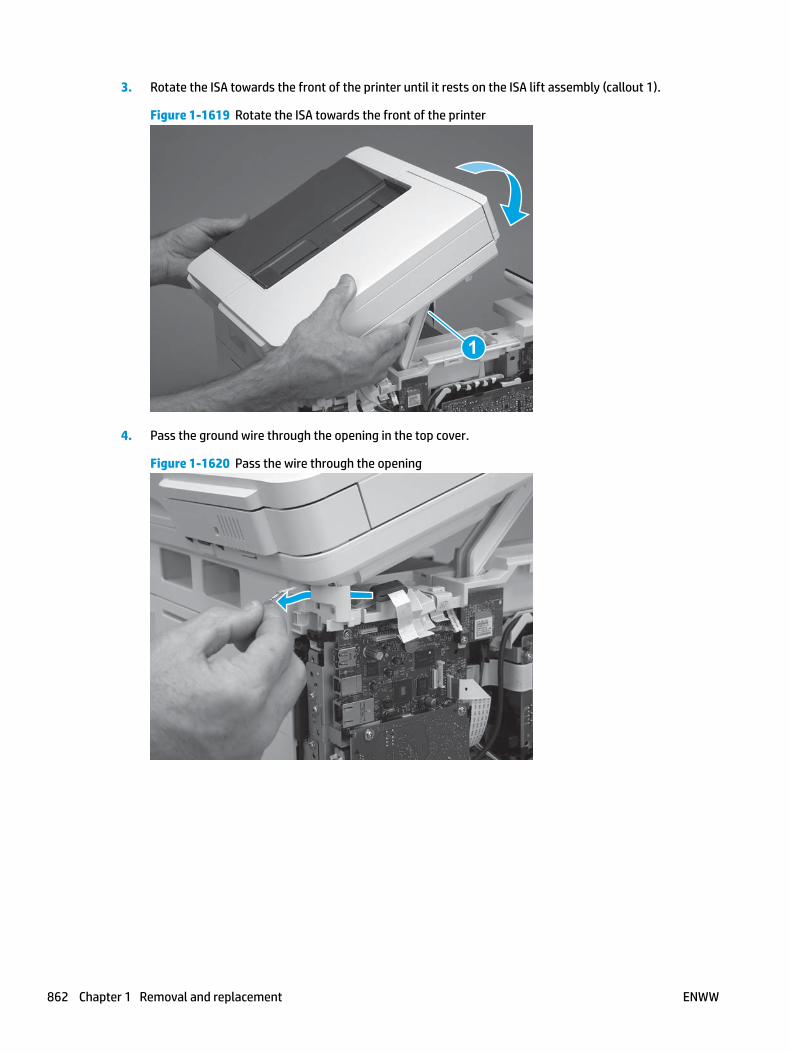
3. Rotate the ISA towards the front of the printer until it rests on the ISA lift assembly (callout 1).
Figure 1-1619 Rotate the ISA towards the front of the printer
1
4. Pass the ground wire through the opening in the top cover.
Figure 1-1620 Pass the wire through the opening
862 Chapter 1 Removal and replacement ENWW

5. Install one screw (callout 1).
Figure 1-1621 Install one screw
1
6. Install the ISA lift assembly slider pin.
Reinstallation tip: Align the keyed portion of the locking pin with the slot and hole in the support arm.
Figure 1-1622 Install the slider pin
ENWW Removal and replacement procedures 863

7. Rotate the slider pin (callout 1) towards the rear of the printer until the tab (callout 2) snap into place.
Figure 1-1623 Secure the slider pin
2
1
8. Install the ferrite (callout 1) in the holder, and then connect three FFCs (callout 2).
Figure 1-1624 Connect three FFCs
1
2
864 Chapter 1 Removal and replacement ENWW

9. Position the rear edge of the ISA flat-flexible cable (FFC) cover on the printer (callout 1) , and then rotate it down (callout 2) until it snaps into place.
Figure 1-1625 Install the ISA FFC cover
1
2
10. Lower the ISA.
Figure 1-1626 Lower the ISA
Step 20: Install the right cover
1. Position the cover (callout 1) on the printer, and then engage two bosses (callout 2).
ENWW Removal and replacement procedures 865

Figure 1-1627 Install the cover
11
2 2
2. Rotate the front of the cover onto the printer (callout 1), engage three (callout 2) tabs, and then engage two bosses (callout 3).
Figure 1-1628 Engage two bosses and one tab
1 13 3
2 2
3. Make sure that the power switch (callout 1) and cartridge door assembly button (callout 2) correctly function.
NOTE: Remove, and then reinstall the cover if the switch or button does not correctly function.
Figure 1-1629 Check the power switch and cartridge door assembly button
1
1
22
866 Chapter 1 Removal and replacement ENWW

4. Install one screw (callout 1).
Figure 1-1630 Install one screw
11
Step 21: Install the left cover
1. At the front of the printer, do one of the following:
● M403/M402: Position the cover on the printer ( callout 1), and then engage two bosses (callout 2).
● M427/M426: Position the cover on the printer (callout 3), engage one tab (callout 4), and then engage two bosses (callout 4).
Figure 1-1631 Install the cover
1
2
4
35
ENWW Removal and replacement procedures 867
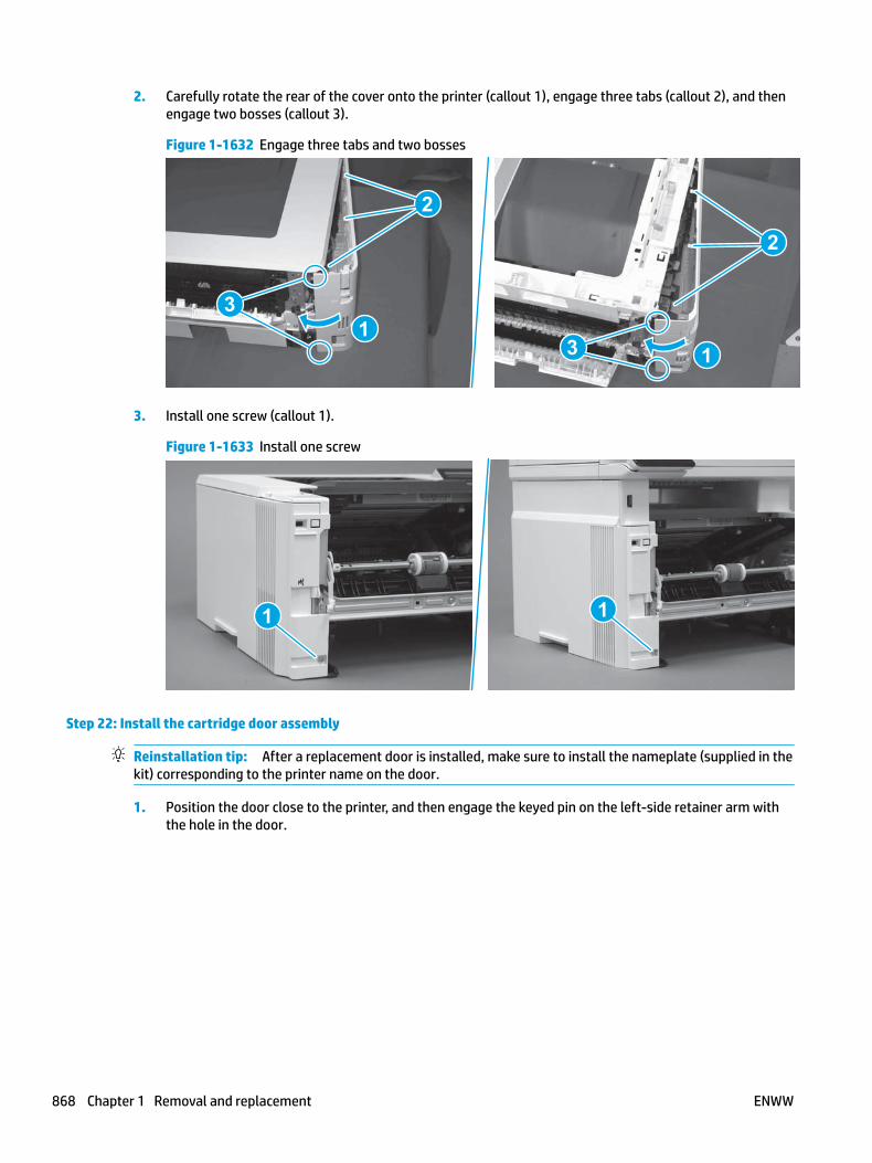
2. Carefully rotate the rear of the cover onto the printer (callout 1), engage three tabs (callout 2), and then engage two bosses (callout 3).
Figure 1-1632 Engage three tabs and two bosses
3
3 11
2
2
3. Install one screw (callout 1).
Figure 1-1633 Install one screw
1 1
Step 22: Install the cartridge door assembly
Reinstallation tip: After a replacement door is installed, make sure to install the nameplate (supplied in the kit) corresponding to the printer name on the door.
1. Position the door close to the printer, and then engage the keyed pin on the left-side retainer arm with the hole in the door.
868 Chapter 1 Removal and replacement ENWW

Figure 1-1634 Engage the left-side retainer arm
2. Engage the right-side door hinge pin with the hole in the chassis (callout 1).
Figure 1-1635 Install the door
1
ENWW Removal and replacement procedures 869

3. Install the link (callout 1).
IMPORTANT: Make sure that the link snaps into place on the arm (callout 2). The link actuates the fuser pressure-release mechanism.
Figure 1-1636 Install the pressure-release link
1
2
4. Slide the guide into the printer (callout 1), and then make sure that the tab (callout 2) snaps into place to secure the guide to the chassis.
Figure 1-1637 Install the guide
1
2
870 Chapter 1 Removal and replacement ENWW

5. Position the shaft on the door, and then align the left-side hinge on the door with the hole in the chassis (callout 1).
Figure 1-1638 Align the hinge
1
6. Push the shaft towards the left side of the printer to install it (callout 1).
Reinstallation tip: Make sure that the support shaft is fully installed and correctly orientated (callout 2) so that it will not interfere with the door opening and closing.
Figure 1-1639 Install the support shaft
2
1
ENWW Removal and replacement procedures 871

Step 23: Install Tray 2
▲ Slide the tray straight into the printer to install it.
Figure 1-1640 Install the tray
872 Chapter 1 Removal and replacement ENWW

Removal and replacement: Laser scanner FFC
● Introduction
● Step 1: Remove Tray 2
● Step 2: Remove the cartridge door assembly
● Step 3: Remove the left cover
● Step 4: Remove the right cover
● Step 5: Remove the integrated scanner assembly (M427/M246)
● Step 6: Remove the control panel (M427/M246)
● Step 7: Remove the top cover (M427/M426)
● Step 8: Remove the top cover (M403/M402)
● Step 9: Remove the paper delivery tray (output bin)
● Step 10: Remove the sheet-metal formatter bracket and formatter PCA
● Step 11: Remove the tag-cable assembly
● Step 12: Remove the laser scanner FFC
● Step 13: Unpack the replacement assembly
● Step 14: Install the laser scanner FFC
● Step 15: Install the tag-cable assembly
● Step 16: Install the sheet-metal formatter bracket and formatter PCA
● Step 17: Install the paper delivery tray (output bin)
● Step 18: Install the top cover (M403/M402)
● Step 19: Install the top cover (M427/M426)
● Step 20: Install the control panel (M427/M246)
● Step 21: Install the integrated scanner assembly (M427/M246)
● Step 22: Install the right cover
● Step 23: Install the left cover
● Step 24: Install the cartridge door assembly
● Step 25: Install Tray 2
Introduction
This document provides the procedures to remove and replace the laser scanner flat-flexible cable (FFC).
ENWW Removal and replacement procedures 873

Before performing service
Turn the printer power off
◦ Disconnect the power cable.
WARNING! To avoid damage to the printer, turn the printer off, wait 30 seconds, and then remove the power cable before attempting to service the printer.
Use the table below to identify the correct part number for your printer. To order the part, go to www.hp.com/buy/parts.
Laser scanner FFC part number
RK2-6919-000CN Laser scanner FFC
Required tools
● #2 Phillips screwdriver with a magnetic tip.
● 5.5 mm (0.22 inch) socket screwdriver.
After performing service
Turn the printer power on
◦ Connect the power cable.
◦ Use the power switch to turn the power on.
Post service test
Make sure that the printer initializes to a Ready state.
Print a configuration page to make sure that the printer is functioning correctly.
Step 1: Remove Tray 2
▲ Pull the tray straight out of the printer to remove it.
874 Chapter 1 Removal and replacement ENWW
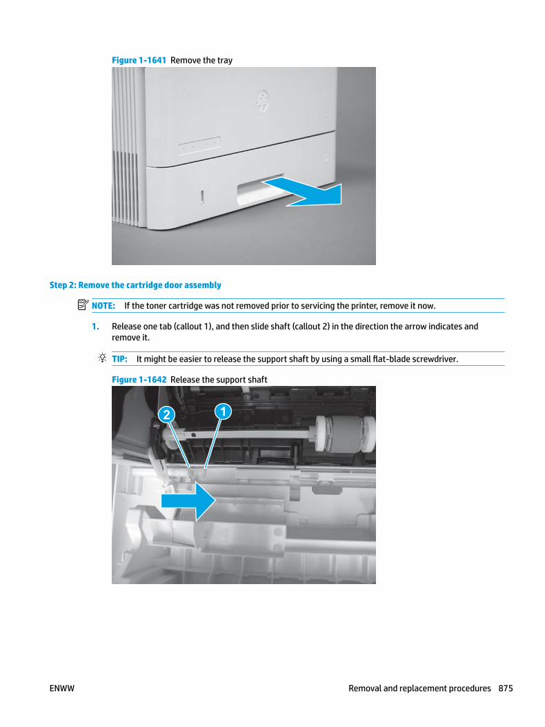
Figure 1-1641 Remove the tray
Step 2: Remove the cartridge door assembly
NOTE: If the toner cartridge was not removed prior to servicing the printer, remove it now.
1. Release one tab (callout 1), and then slide shaft (callout 2) in the direction the arrow indicates and remove it.
TIP: It might be easier to release the support shaft by using a small flat-blade screwdriver.
Figure 1-1642 Release the support shaft
12
ENWW Removal and replacement procedures 875
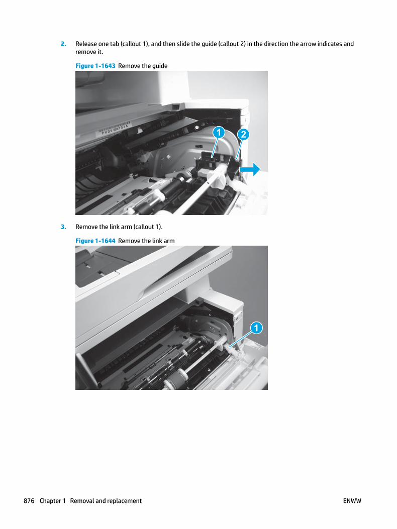
2. Release one tab (callout 1), and then slide the guide (callout 2) in the direction the arrow indicates and remove it.
Figure 1-1643 Remove the guide
1 2
3. Remove the link arm (callout 1).
Figure 1-1644 Remove the link arm
1
876 Chapter 1 Removal and replacement ENWW

4. Slide the cartridge door assembly (callout 1) in the direction the arrow indicates and remove it.
Figure 1-1645 Remove the door
1
5. Remove the link (callout 1) from the cartridge door assembly (callout 2).
Figure 1-1646 Release the left-side retainer arm
21
Step 3: Remove the left cover
1. Remove one screw (callout 1).
ENWW Removal and replacement procedures 877
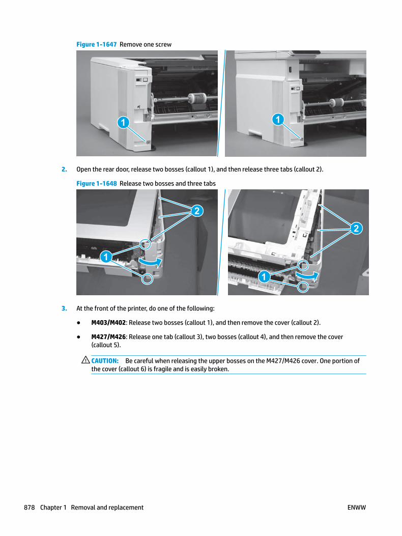
Figure 1-1647 Remove one screw
1 1
2. Open the rear door, release two bosses (callout 1), and then release three tabs (callout 2).
Figure 1-1648 Release two bosses and three tabs
1
1
2
2
3. At the front of the printer, do one of the following:
● M403/M402: Release two bosses (callout 1), and then remove the cover (callout 2).
● M427/M426: Release one tab (callout 3), two bosses (callout 4), and then remove the cover (callout 5).
CAUTION: Be careful when releasing the upper bosses on the M427/M426 cover. One portion of the cover (callout 6) is fragile and is easily broken.
878 Chapter 1 Removal and replacement ENWW

Figure 1-1649 Remove the cover
2
1
3
54 6
Step 4: Remove the right cover
1. Remove one screw (callout 1).
Figure 1-1650 Remove one screw
11
2. At the front of the printer, release two bosses (callout 1), and then release three tabs (callout 2).
Figure 1-1651 Release two bosses and three tabs
1 1
2 2
ENWW Removal and replacement procedures 879

3. Open the rear door, release two bosses (callout 1), and then remove the cover (callout 2).
Figure 1-1652 Remove the cover
22
1 1
Step 5: Remove the integrated scanner assembly (M427/M246)
NOTE: The step is for the M427/M426 printer. For the M403/M402, skip this step and go to Step 8: Remove the top cover (M403/M402) on page 890.
NOTE: M427/M426 models only. The integrated scanner assembly (ISA) includes the sub-scanner assembly (SSA) and the automatic document feeder (ADF).
1. Raise the ISA.
Figure 1-1653 Raise the ISA
880 Chapter 1 Removal and replacement ENWW

2. Release the ISA flat-flexible cable (FFC) cover (callout 1), and then remove it (callout 2).
Figure 1-1654 Remove the ISA FFC cover
12
3. Disconnect three FFCs (callout 1), and then remove the ferrite (callout 2) from the holder.
CAUTION: The ferrite is not captive on the FFC. Do not lose the ferrite while handling the ISA.
Figure 1-1655 Disconnect three FFCs
2
1
ENWW Removal and replacement procedures 881

4. Remove one screw (callout 1).
Figure 1-1656 Remove one screw
1
5. Pass the ground wire through the opening in the top cover.
Figure 1-1657 Pass the wire through the opening
882 Chapter 1 Removal and replacement ENWW

6. Release one tab (callout 1), and then rotate the ISA slider pin (callout 2) towards the front of the printer to release it.
Figure 1-1658 Release one tab and rotate the slider pin
1
2
7. Remove the slider pin.
Figure 1-1659 Remove the slider pin
ENWW Removal and replacement procedures 883

8. Rotate the ISA towards the rear of the printer until it stops.
Figure 1-1660 Rotate the ISA towards the rear of the printer
9. Slide the ISA as shown to release it.
Figure 1-1661 Release the ISA
884 Chapter 1 Removal and replacement ENWW

10. Remove the ISA.
Figure 1-1662 Remove the ISA
Step 6: Remove the control panel (M427/M246)
NOTE: The step is for the M427/M426 printer. For the M403/M402, skip this step and go to Step 8: Remove the top cover (M403/M402) on page 890.
1. Disconnect one FFC (callout 1; J114), and then release the FFC from the retainer (callout 2).
Figure 1-1663 Disconnect one connector
1
2
ENWW Removal and replacement procedures 885

2. Remove one screw (callout 1).
Figure 1-1664 Remove one screw
1
3. Use a small flat-blade screwdriver to release two tabs (callout 1) on the control-panel cable cover.
Figure 1-1665 Release two tabs
1
886 Chapter 1 Removal and replacement ENWW

4. Remove the control-panel cable cover.
Figure 1-1666 Remove the cover
5. Remove one grounding screw (callout 1), and then move the ground cable (callout 2) out of the way.
Figure 1-1667 Remove one screw
2
1
ENWW Removal and replacement procedures 887
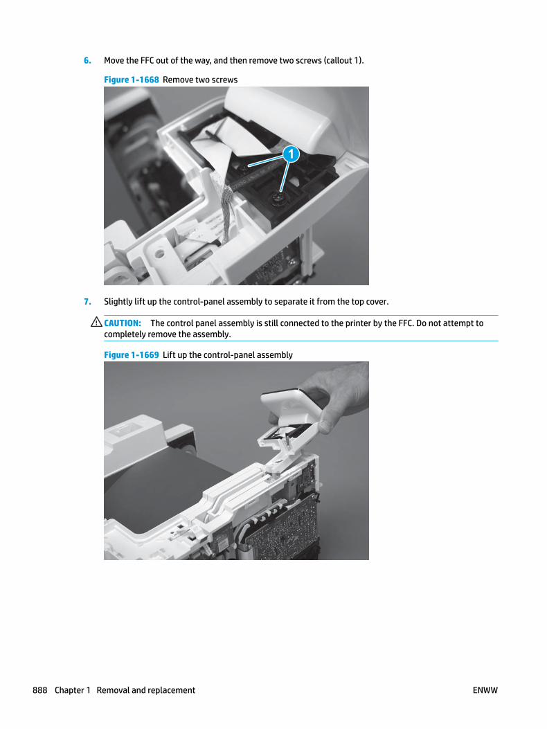
6. Move the FFC out of the way, and then remove two screws (callout 1).
Figure 1-1668 Remove two screws
1
7. Slightly lift up the control-panel assembly to separate it from the top cover.
CAUTION: The control panel assembly is still connected to the printer by the FFC. Do not attempt to completely remove the assembly.
Figure 1-1669 Lift up the control-panel assembly
888 Chapter 1 Removal and replacement ENWW

8. Lift up the control-panel FFC cover to remove the control-panel assembly.
Figure 1-1670 Remove the control-panel assembly
Step 7: Remove the top cover (M427/M426)
NOTE: The step is for the M427/M426 printer. For the M403/M402, skip this step and go to Step 8: Remove the top cover (M403/M402) on page 890.
1. Release the USB cable (callout 1) from the cable guide.
Figure 1-1671 Remove the USB cable
1
ENWW Removal and replacement procedures 889

2. Remove five screws (callout 1), release four bosses (callout 2), and then remove the top cover (callout 3).
Figure 1-1672 Remove the cover
3
2
1
Step 8: Remove the top cover (M403/M402)
NOTE: The step is for the M403/M402 printer. For the M427/M426, skip this step and go to Step 9: Remove the paper delivery tray (output bin) on page 891.
1. Remove one screw (callout 1).
Figure 1-1673 Remove one screw
1
890 Chapter 1 Removal and replacement ENWW

2. At the right side of the printer, release the one boss (callout 1), and then release one tab (callout 2).
Figure 1-1674 Release one boss and one tab
21
3. Release four tabs (callout 1), release four bosses (callout 2), and then remove the top cover (callout 3).
TIP: Open the rear door to make releasing the bosses (callout 3) easier.
Figure 1-1675 Remove the cover
2
3
1
Step 9: Remove the paper delivery tray (output bin)
NOTE: This procedure shows the M403/M402 model, however, the paper delivery tray (output bin) removal is similar for the M427/M426 printer.
▲ Release two bosses (callout 1), release two tabs (callout 2), and then remove the paper delivery tray (output bin; callout 3).
ENWW Removal and replacement procedures 891

Figure 1-1676 Release two tabs
2
1
3
Step 10: Remove the sheet-metal formatter bracket and formatter PCA
NOTE: Disconnect any remaining formatter PCA FFCs or wire-harness connectors.
1. M427/M426 only: Remove the guide (callout 1).
Figure 1-1677 Remove the guide
1
892 Chapter 1 Removal and replacement ENWW

2. Remove two screws (callout 1).
Figure 1-1678 Remove two screws
11
3. Disconnect one connector (callout 1), and then release the wire harness from the guide (callout 2).
Figure 1-1679 Disconnect one connector
21
21
4. Remove the guide (callout 1).
Figure 1-1680 Remove the guide
11
ENWW Removal and replacement procedures 893

5. Remove three screws (callout 1).
Figure 1-1681 Remove three screws
1 1
6. Remove the sheet-metal bracket and formatter PCA.
Figure 1-1682 Remove the bracket
Step 11: Remove the tag-cable assembly
1. Disconnect one connector (callout 1), and then release the wire harness from the guide (callout 2).
894 Chapter 1 Removal and replacement ENWW
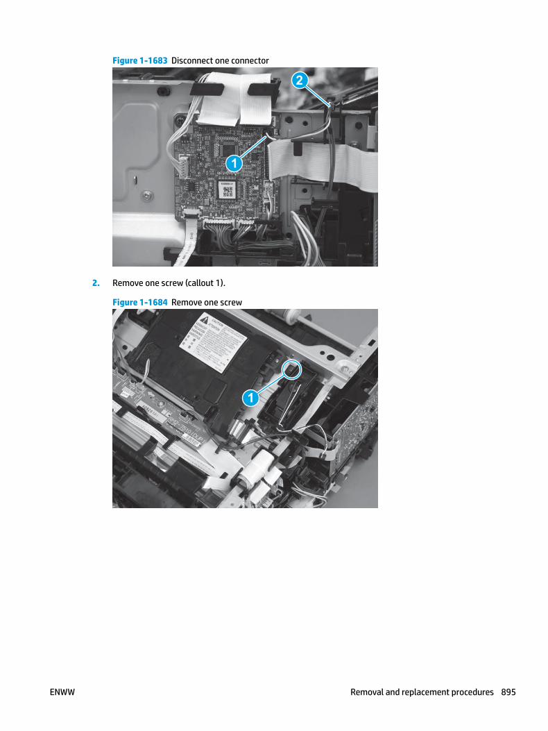
Figure 1-1683 Disconnect one connector
1
2
2. Remove one screw (callout 1).
Figure 1-1684 Remove one screw
1
ENWW Removal and replacement procedures 895

3. Remove the tag-cable assembly.
Figure 1-1685 Remove the tag-cable assembly
Step 12: Remove the laser scanner FFC
1. Disconnect one FFC (callout 1), and then release it from the guide (callout 2).
Figure 1-1686 Disconnect one FFC
1
2
896 Chapter 1 Removal and replacement ENWW

2. Remove one screw (callout 1), and then remove the sheet-metal plate (callout 2).
Figure 1-1687 Remove one screw and the sheet-metal plate
1
2
3. Disconnect one FFC (callout 1).
Figure 1-1688 Disconnect one FFC
1
ENWW Removal and replacement procedures 897

4. Slightly flex the holder (callout 1), and then release the FFC ferrite (callout 2).
Reinstallation tip: Do not fdiscard the ferrite. It will be installed on the replacement FFC.
Figure 1-1689 Release the ferrite
1
2
1
5. Remove the FFC.
Figure 1-1690 Remove the FFC
Step 13: Unpack the replacement assembly
Unpack the replacement part from the packaging.
http://www8.hp.com/us/en/hp-information/environment/product-recycling.html
NOTE: HP recommends responsible disposal of the defective part.
898 Chapter 1 Removal and replacement ENWW

Figure 1-1691 Recycle and unpack
Step 14: Install the laser scanner FFC
1. Install the ferrite on the replacement FFC.
Figure 1-1692 Install the ferrite
ENWW Removal and replacement procedures 899
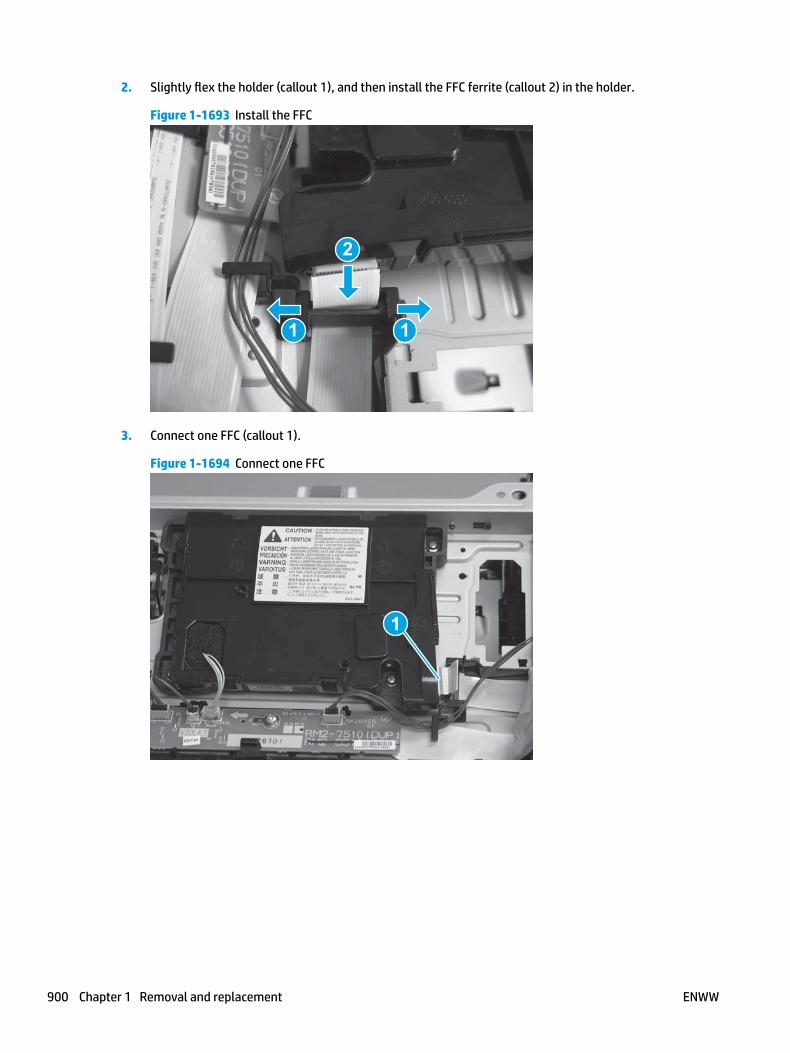
2. Slightly flex the holder (callout 1), and then install the FFC ferrite (callout 2) in the holder.
Figure 1-1693 Install the FFC
1
2
1
3. Connect one FFC (callout 1).
Figure 1-1694 Connect one FFC
1
900 Chapter 1 Removal and replacement ENWW

4. Install the sheet-metal plate (callout 1), and then install one screw (callout 2).
Figure 1-1695 Install the sheet-metal plate and install one screw
2
1
5. Install the FFC in the guide (callout 1, and then connect the FFC (callout 1) to the DC controller.
Figure 1-1696 Connect one FFC
2
1
Step 15: Install the tag-cable assembly
1. Position the assembly on the printer.
IMPORTANT: Make sure that the assembly is flat against the chassis. If the assembly is not correctly installed, it might not make proper contact with the toner cartridge.
ENWW Removal and replacement procedures 901

Figure 1-1697 Install the assembly
2. Install one screw (callout 1).
Figure 1-1698 Install one screw
1
902 Chapter 1 Removal and replacement ENWW
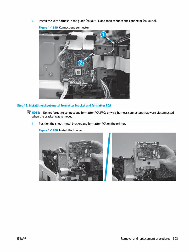
3. Install the wire harness in the guide (callout 1), and then connect one connector (callout 2).
Figure 1-1699 Connect one connector
2
1
Step 16: Install the sheet-metal formatter bracket and formatter PCA
NOTE: Do not forget to connect any formatter PCA FFCs or wire-harness connectors that were disconnected when the bracket was removed.
1. Position the sheet-metal bracket and formatter PCA on the printer.
Figure 1-1700 Install the bracket
ENWW Removal and replacement procedures 903

2. Install three screws (callout 1).
Figure 1-1701 Install three screws
1 1
3. Install the guide (callout 1).
Figure 1-1702 Install the guide
11
4. Connect one connector (callout 1), and then install the wire harness in the guide (callout 2).
Figure 1-1703 Connect one connector
21
21
904 Chapter 1 Removal and replacement ENWW

5. Install two screws (callout 1).
Figure 1-1704 Install two screws
11
6. M427/M426 only: Install the guide (callout 1).
Figure 1-1705 Install the guide
1
Step 17: Install the paper delivery tray (output bin)
NOTE: This procedure shows the M403/M402 model, however, the paper delivery tray (output bin) removal is similar for the M427/M426 printer.
▲ Position the remove the paper delivery tray (output bin; callout 1) on the printer, engage two tabs (callout 2), and then engage two bosses (callout 3).
ENWW Removal and replacement procedures 905

Figure 1-1706 Engage two tabs
2
3
1
Step 18: Install the top cover (M403/M402)
NOTE: The step is for the M403/M402 printer. For the M427/M426, skip this step and go to Step 19: Install the top cover (M427/M426) on page 908.
1. Position the rear edge of the cover on the printer.
Figure 1-1707 Install the cover
906 Chapter 1 Removal and replacement ENWW

2. Engage four bosses (callout 1), rotate the front of the cover down (callout 2) and onto from the printer, and then engage four tabs (callout 3).
Figure 1-1708 Engage four bosses and tabs
1
3
2
2
3. At the right side of the printer, engage the one boss and one tab (callout 1).
Figure 1-1709 Engage one boss and one tab
1
ENWW Removal and replacement procedures 907

4. Install one screw (callout 1).
Figure 1-1710 Install one screw
1
Step 19: Install the top cover (M427/M426)
NOTE: The step is for the M427/M426 printer. For the M403/M402, skip this step and go to Step 22: Install the right cover on page 919.
1. Position the rear edge of the top cover on the printer.
Figure 1-1711 Install the cover
908 Chapter 1 Removal and replacement ENWW
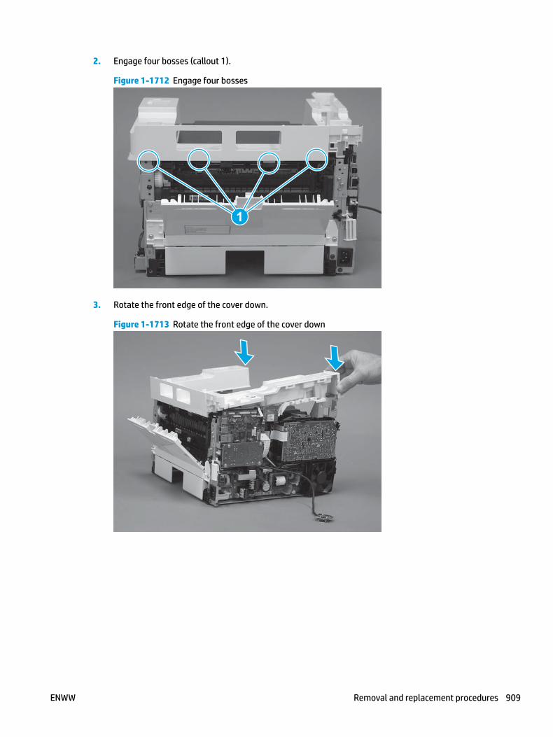
2. Engage four bosses (callout 1).
Figure 1-1712 Engage four bosses
1
3. Rotate the front edge of the cover down.
Figure 1-1713 Rotate the front edge of the cover down
ENWW Removal and replacement procedures 909

4. Install the USB cable (callout 1) in the guide.
Figure 1-1714 Install the USB PCA
1
5. Install five screws (callout 1).
Figure 1-1715 Install five screws
1
Step 20: Install the control panel (M427/M246)
NOTE: The step is for the M427/M426 printer. For the M403/M402, skip this step and go to Step 22: Install the right cover on page 919.
1. Slide the control-panel FFC cover into the slot in the top cover (next to the document feeder support arm) to install it.
910 Chapter 1 Removal and replacement ENWW

Figure 1-1716 Install the control-panel FFC cover
2. Install the control-panel assembly on the top cover.
Figure 1-1717 Install the control-panel assembly
ENWW Removal and replacement procedures 911

3. Move the FFC out of the way, and then install two screws (callout 1).
Figure 1-1718 Install two screws
1
4. Install one grounding screw (callout 1), and then make sure that the ground cable (callout 2) is properly routed.
Figure 1-1719 Remove one screw
2
1
912 Chapter 1 Removal and replacement ENWW

5. Install the control-panel cable cover.
Figure 1-1720 Install the cover
6. Make sure that the two tabs (callout 1) on the cover snap into place.
Figure 1-1721 Engage two tabs
1
ENWW Removal and replacement procedures 913

7. Install one screw (callout 1).
Figure 1-1722 Install one screw
1
8. Install the FFC in the retainer (callout 1), and then connect one FFC (callout 1; J114).
Figure 1-1723 Connect one connector
1
2
Step 21: Install the integrated scanner assembly (M427/M246)
NOTE: The step is for the M427/M426 printer. For the M403/M402, skip this step and go to Step 22: Install the right cover on page 919.
NOTE: M427/M426 models only. The integrated scanner assembly (ISA) includes the sub-scanner assembly (SSA) and the automatic document feeder (ADF).
1. Position the ISA on the printer.
914 Chapter 1 Removal and replacement ENWW

Figure 1-1724 Position the ISA on the printer
2. Engage the hinge pins on the ISA with the holders in the top cover (callouts 1/2), and the slide the ISA as shown to engage them
Figure 1-1725 Engage the hinge pins with the holders
1
2
ENWW Removal and replacement procedures 915

3. Rotate the ISA towards the front of the printer until it rests on the ISA lift assembly (callout 1).
Figure 1-1726 Rotate the ISA towards the front of the printer
1
4. Pass the ground wire through the opening in the top cover.
Figure 1-1727 Pass the wire through the opening
916 Chapter 1 Removal and replacement ENWW

5. Install one screw (callout 1).
Figure 1-1728 Install one screw
1
6. Install the ISA lift assembly slider pin.
Reinstallation tip: Align the keyed portion of the locking pin with the slot and hole in the support arm.
Figure 1-1729 Install the slider pin
ENWW Removal and replacement procedures 917

7. Rotate the slider pin (callout 1) towards the rear of the printer until the tab (callout 2) snap into place.
Figure 1-1730 Secure the slider pin
2
1
8. Install the ferrite (callout 1) in the holder, and then connect three FFCs (callout 2).
Figure 1-1731 Connect three FFCs
1
2
918 Chapter 1 Removal and replacement ENWW

9. Position the rear edge of the ISA flat-flexible cable (FFC) cover on the printer (callout 1) , and then rotate it down (callout 2) until it snaps into place.
Figure 1-1732 Install the ISA FFC cover
1
2
10. Lower the ISA.
Figure 1-1733 Lower the ISA
Step 22: Install the right cover
1. Position the cover (callout 1) on the printer, and then engage two bosses (callout 2).
ENWW Removal and replacement procedures 919
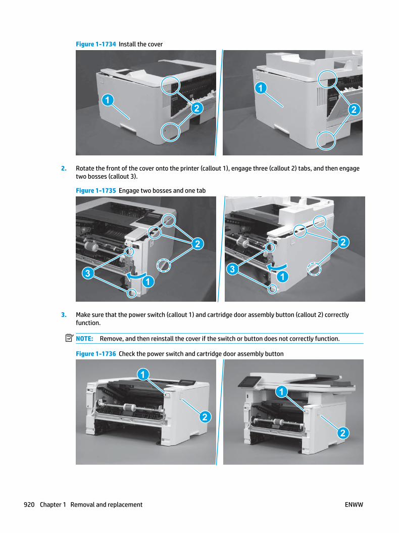
Figure 1-1734 Install the cover
11
2 2
2. Rotate the front of the cover onto the printer (callout 1), engage three (callout 2) tabs, and then engage two bosses (callout 3).
Figure 1-1735 Engage two bosses and one tab
1 13 3
2 2
3. Make sure that the power switch (callout 1) and cartridge door assembly button (callout 2) correctly function.
NOTE: Remove, and then reinstall the cover if the switch or button does not correctly function.
Figure 1-1736 Check the power switch and cartridge door assembly button
1
1
22
920 Chapter 1 Removal and replacement ENWW
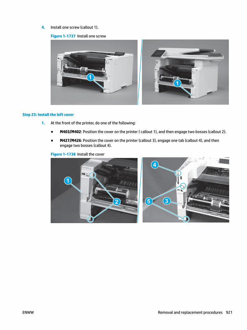
4. Install one screw (callout 1).
Figure 1-1737 Install one screw
11
Step 23: Install the left cover
1. At the front of the printer, do one of the following:
● M403/M402: Position the cover on the printer ( callout 1), and then engage two bosses (callout 2).
● M427/M426: Position the cover on the printer (callout 3), engage one tab (callout 4), and then engage two bosses (callout 4).
Figure 1-1738 Install the cover
1
2
4
35
ENWW Removal and replacement procedures 921

2. Carefully rotate the rear of the cover onto the printer (callout 1), engage three tabs (callout 2), and then engage two bosses (callout 3).
Figure 1-1739 Engage three tabs and two bosses
3
3 11
2
2
3. Install one screw (callout 1).
Figure 1-1740 Install one screw
1 1
Step 24: Install the cartridge door assembly
Reinstallation tip: After a replacement door is installed, make sure to install the nameplate (supplied in the kit) corresponding to the printer name on the door.
1. Position the door close to the printer, and then engage the keyed pin on the left-side retainer arm with the hole in the door.
922 Chapter 1 Removal and replacement ENWW

Figure 1-1741 Engage the left-side retainer arm
2. Engage the right-side door hinge pin with the hole in the chassis (callout 1).
Figure 1-1742 Install the door
1
ENWW Removal and replacement procedures 923

3. Install the link (callout 1).
IMPORTANT: Make sure that the link snaps into place on the arm (callout 2). The link actuates the fuser pressure-release mechanism.
Figure 1-1743 Install the pressure-release link
1
2
4. Slide the guide into the printer (callout 1), and then make sure that the tab (callout 2) snaps into place to secure the guide to the chassis.
Figure 1-1744 Install the guide
1
2
924 Chapter 1 Removal and replacement ENWW

5. Position the shaft on the door, and then align the left-side hinge on the door with the hole in the chassis (callout 1).
Figure 1-1745 Align the hinge
1
6. Push the shaft towards the left side of the printer to install it (callout 1).
Reinstallation tip: Make sure that the support shaft is fully installed and correctly orientated (callout 2) so that it will not interfere with the door opening and closing.
Figure 1-1746 Install the support shaft
2
1
ENWW Removal and replacement procedures 925

Step 25: Install Tray 2
▲ Slide the tray straight into the printer to install it.
Figure 1-1747 Install the tray
926 Chapter 1 Removal and replacement ENWW

Removal and replacement: High-voltage power supply
● Introduction
● Step 1: Remove Tray 2
● Step 2: Remove the cartridge door assembly
● Step 3: Remove the left cover
● Step 4: Remove the right cover
● Step 5: Remove the integrated scanner assembly (M427/M246)
● Step 6: Remove the control panel (M427/M246)
● Step 7: Remove the top cover (M427/M426)
● Step 8: Remove the top cover (M403/M402)
● Step 9: Remove the paper delivery tray (output bin)
● Step 10: Remove the sheet-metal formatter bracket and formatter PCA
● Step 11: Remove the HVPS
● Step 12: Unpack the replacement assembly
● Step 13: Install the HVPS
● Step 14: Install the sheet-metal formatter bracket and formatter PCA
● Step 15: Install the paper delivery tray (output bin)
● Step 16: Install the top cover (M403/M402)
● Step 17: Install the top cover (M427/M426)
● Step 18: Install the control panel (M427/M246)
● Step 19: Install the integrated scanner assembly (M427/M246)
● Step 20: Install the right cover
● Step 21: Install the left cover
● Step 22: Install the cartridge door assembly
● Step 23: Install Tray 2
Introduction
This document provides the procedures to remove and replace the high-voltage power supply (HVPS).
Before performing service
Turn the printer power off
◦ Disconnect the power cable.
ENWW Removal and replacement procedures 927

WARNING! To avoid damage to the printer, turn the printer off, wait 30 seconds, and then remove the power cable before attempting to service the printer.
Use the table below to identify the correct part number for your printer. To order the part, go to www.hp.com/buy/parts.
High-voltage power supply (HVPS) part number
RM2-7508-000CN High-voltage power supply (HVPS)
Required tools
● #2 Phillips screwdriver with a magnetic tip.
After performing service
Turn the printer power on
◦ Connect the power cable.
◦ Use the power switch to turn the power on.
Post service test
Make sure that the printer initializes to a Ready state.
Print a configuration page to make sure that the printer is functioning correctly.
Step 1: Remove Tray 2
▲ Pull the tray straight out of the printer to remove it.
Figure 1-1748 Remove the tray
928 Chapter 1 Removal and replacement ENWW

Step 2: Remove the cartridge door assembly
NOTE: If the toner cartridge was not removed prior to servicing the printer, remove it now.
1. Release one tab (callout 1), and then slide shaft (callout 2) in the direction the arrow indicates and remove it.
TIP: It might be easier to release the support shaft by using a small flat-blade screwdriver.
Figure 1-1749 Release the support shaft
12
2. Release one tab (callout 1), and then slide the guide (callout 2) in the direction the arrow indicates and remove it.
Figure 1-1750 Remove the guide
1 2
ENWW Removal and replacement procedures 929

3. Remove the link arm (callout 1).
Figure 1-1751 Remove the link arm
1
4. Slide the cartridge door assembly (callout 1) in the direction the arrow indicates and remove it.
Figure 1-1752 Remove the door
1
930 Chapter 1 Removal and replacement ENWW

5. Remove the link (callout 1) from the cartridge door assembly (callout 2).
Figure 1-1753 Release the left-side retainer arm
21
Step 3: Remove the left cover
1. Remove one screw (callout 1).
Figure 1-1754 Remove one screw
1 1
ENWW Removal and replacement procedures 931

2. Open the rear door, release two bosses (callout 1), and then release three tabs (callout 2).
Figure 1-1755 Release two bosses and three tabs
1
1
2
2
3. At the front of the printer, do one of the following:
● M403/M402: Release two bosses (callout 1), and then remove the cover (callout 2).
● M427/M426: Release one tab (callout 3), two bosses (callout 4), and then remove the cover (callout 5).
CAUTION: Be careful when releasing the upper bosses on the M427/M426 cover. One portion of the cover (callout 6) is fragile and is easily broken.
Figure 1-1756 Remove the cover
2
1
3
54 6
Step 4: Remove the right cover
1. Remove one screw (callout 1).
932 Chapter 1 Removal and replacement ENWW

Figure 1-1757 Remove one screw
11
2. At the front of the printer, release two bosses (callout 1), and then release three tabs (callout 2).
Figure 1-1758 Release two bosses and three tabs
1 1
2 2
3. Open the rear door, release two bosses (callout 1), and then remove the cover (callout 2).
Figure 1-1759 Remove the cover
22
1 1
Step 5: Remove the integrated scanner assembly (M427/M246)
NOTE: The step is for the M427/M426 printer. For the M403/M402, skip this step and go to Step 8: Remove the top cover (M403/M402) on page 943.
ENWW Removal and replacement procedures 933

NOTE: M427/M426 models only. The integrated scanner assembly (ISA) includes the sub-scanner assembly (SSA) and the automatic document feeder (ADF).
1. Raise the ISA.
Figure 1-1760 Raise the ISA
2. Release the ISA flat-flexible cable (FFC) cover (callout 1), and then remove it (callout 2).
Figure 1-1761 Remove the ISA FFC cover
12
934 Chapter 1 Removal and replacement ENWW

3. Disconnect three FFCs (callout 1), and then remove the ferrite (callout 2) from the holder.
CAUTION: The ferrite is not captive on the FFC. Do not lose the ferrite while handling the ISA.
Figure 1-1762 Disconnect three FFCs
2
1
4. Remove one screw (callout 1).
Figure 1-1763 Remove one screw
1
ENWW Removal and replacement procedures 935

5. Pass the ground wire through the opening in the top cover.
Figure 1-1764 Pass the wire through the opening
6. Release one tab (callout 1), and then rotate the ISA slider pin (callout 2) towards the front of the printer to release it.
Figure 1-1765 Release one tab and rotate the slider pin
1
2
936 Chapter 1 Removal and replacement ENWW

7. Remove the slider pin.
Figure 1-1766 Remove the slider pin
8. Rotate the ISA towards the rear of the printer until it stops.
Figure 1-1767 Rotate the ISA towards the rear of the printer
ENWW Removal and replacement procedures 937

9. Slide the ISA as shown to release it.
Figure 1-1768 Release the ISA
10. Remove the ISA.
Figure 1-1769 Remove the ISA
Step 6: Remove the control panel (M427/M246)
NOTE: The step is for the M427/M426 printer. For the M403/M402, skip this step and go to Step 8: Remove the top cover (M403/M402) on page 943.
1. Disconnect one FFC (callout 1; J114), and then release the FFC from the retainer (callout 2).
938 Chapter 1 Removal and replacement ENWW

Figure 1-1770 Disconnect one connector
1
2
2. Remove one screw (callout 1).
Figure 1-1771 Remove one screw
1
ENWW Removal and replacement procedures 939

3. Use a small flat-blade screwdriver to release two tabs (callout 1) on the control-panel cable cover.
Figure 1-1772 Release two tabs
1
4. Remove the control-panel cable cover.
Figure 1-1773 Remove the cover
940 Chapter 1 Removal and replacement ENWW

5. Remove one grounding screw (callout 1), and then move the ground cable (callout 2) out of the way.
Figure 1-1774 Remove one screw
2
1
6. Move the FFC out of the way, and then remove two screws (callout 1).
Figure 1-1775 Remove two screws
1
ENWW Removal and replacement procedures 941

7. Slightly lift up the control-panel assembly to separate it from the top cover.
CAUTION: The control panel assembly is still connected to the printer by the FFC. Do not attempt to completely remove the assembly.
Figure 1-1776 Lift up the control-panel assembly
8. Lift up the control-panel FFC cover to remove the control-panel assembly.
Figure 1-1777 Remove the control-panel assembly
Step 7: Remove the top cover (M427/M426)
NOTE: The step is for the M427/M426 printer. For the M403/M402, skip this step and go to Step 8: Remove the top cover (M403/M402) on page 943.
1. Release the USB cable (callout 1) from the cable guide.
942 Chapter 1 Removal and replacement ENWW
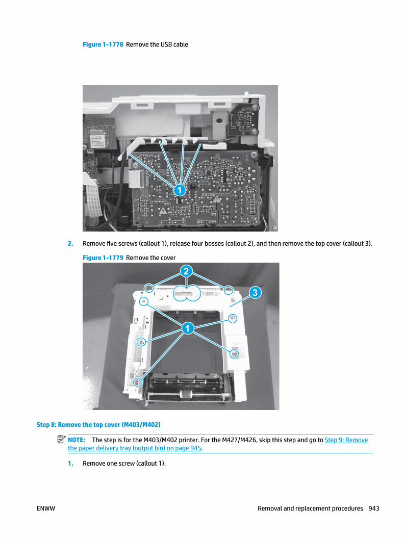
Figure 1-1778 Remove the USB cable
1
2. Remove five screws (callout 1), release four bosses (callout 2), and then remove the top cover (callout 3).
Figure 1-1779 Remove the cover
3
2
1
Step 8: Remove the top cover (M403/M402)
NOTE: The step is for the M403/M402 printer. For the M427/M426, skip this step and go to Step 9: Remove the paper delivery tray (output bin) on page 945.
1. Remove one screw (callout 1).
ENWW Removal and replacement procedures 943

Figure 1-1780 Remove one screw
1
2. At the right side of the printer, release the one boss (callout 1), and then release one tab (callout 2).
Figure 1-1781 Release one boss and one tab
21
944 Chapter 1 Removal and replacement ENWW

3. Release four tabs (callout 1), release four bosses (callout 2), and then remove the top cover (callout 3).
TIP: Open the rear door to make releasing the bosses (callout 3) easier.
Figure 1-1782 Remove the cover
2
3
1
Step 9: Remove the paper delivery tray (output bin)
NOTE: This procedure shows the M403/M402 model, however, the paper delivery tray (output bin) removal is similar for the M427/M426 printer.
▲ Release two bosses (callout 1), release two tabs (callout 2), and then remove the paper delivery tray (output bin; callout 3).
Figure 1-1783 Release two tabs
2
1
3
ENWW Removal and replacement procedures 945
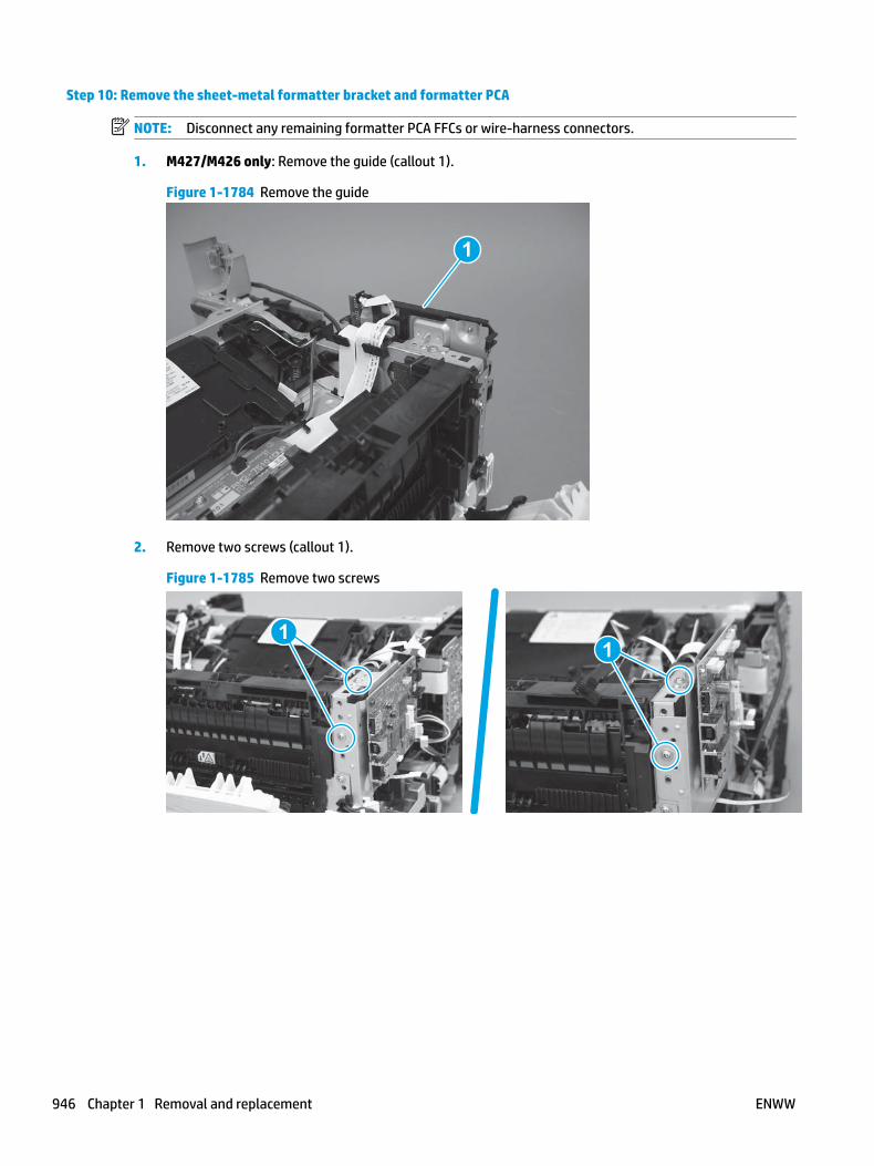
Step 10: Remove the sheet-metal formatter bracket and formatter PCA
NOTE: Disconnect any remaining formatter PCA FFCs or wire-harness connectors.
1. M427/M426 only: Remove the guide (callout 1).
Figure 1-1784 Remove the guide
1
2. Remove two screws (callout 1).
Figure 1-1785 Remove two screws
11
946 Chapter 1 Removal and replacement ENWW

3. Disconnect one connector (callout 1), and then release the wire harness from the guide (callout 2).
Figure 1-1786 Disconnect one connector
21
21
4. Remove the guide (callout 1).
Figure 1-1787 Remove the guide
11
5. Remove three screws (callout 1).
Figure 1-1788 Remove three screws
1 1
ENWW Removal and replacement procedures 947

6. Remove the sheet-metal bracket and formatter PCA.
Figure 1-1789 Remove the bracket
Step 11: Remove the HVPS
1. Disconnect one FFC (callout 1) on the DC controller, and then release it from the guide (callout 2).
Figure 1-1790 Disconnect one FFC
1
2
948 Chapter 1 Removal and replacement ENWW

2. Disconnect one connector (callout 1).
Figure 1-1791 Disconnect one connector
1
3. Remove two screws (callout 1).
Figure 1-1792 Remove two screws
1
ENWW Removal and replacement procedures 949

4. Release one tab (callout 1), and then rotate the top of the HVPS away from the printer.
Figure 1-1793 Release one tab
1
5. Slide the HVPS up and away from the holder to remove it.
Figure 1-1794 Remove the HVPS
Step 12: Unpack the replacement assembly
Unpack the replacement part from the packaging.
http://www8.hp.com/us/en/hp-information/environment/product-recycling.html
NOTE: HP recommends responsible disposal of the defective part.
950 Chapter 1 Removal and replacement ENWW

Figure 1-1795 Recycle and unpack
Step 13: Install the HVPS
1. Position the HVPS in the holder with the bottom edge behind the taps on the holder (callout 1).
NOTE: If the HVPS is not correctly installed, the high-voltage springs will not touch the HVPS contacts and the printer will not properly function.
Figure 1-1796 Position the HVPS in the holder
ENWW Removal and replacement procedures 951

2. Rotate the top of the HVPS toward the printer (callout 1) until the tab (callout 2) snaps into place.
CAUTION: Do not damage the toner-cartridge detection switch lever (callout 3) when installing the HVPS
Figure 1-1797 Engage one tab
1
3. Install two screws (callout 1).
Figure 1-1798 Install two screws
1
952 Chapter 1 Removal and replacement ENWW
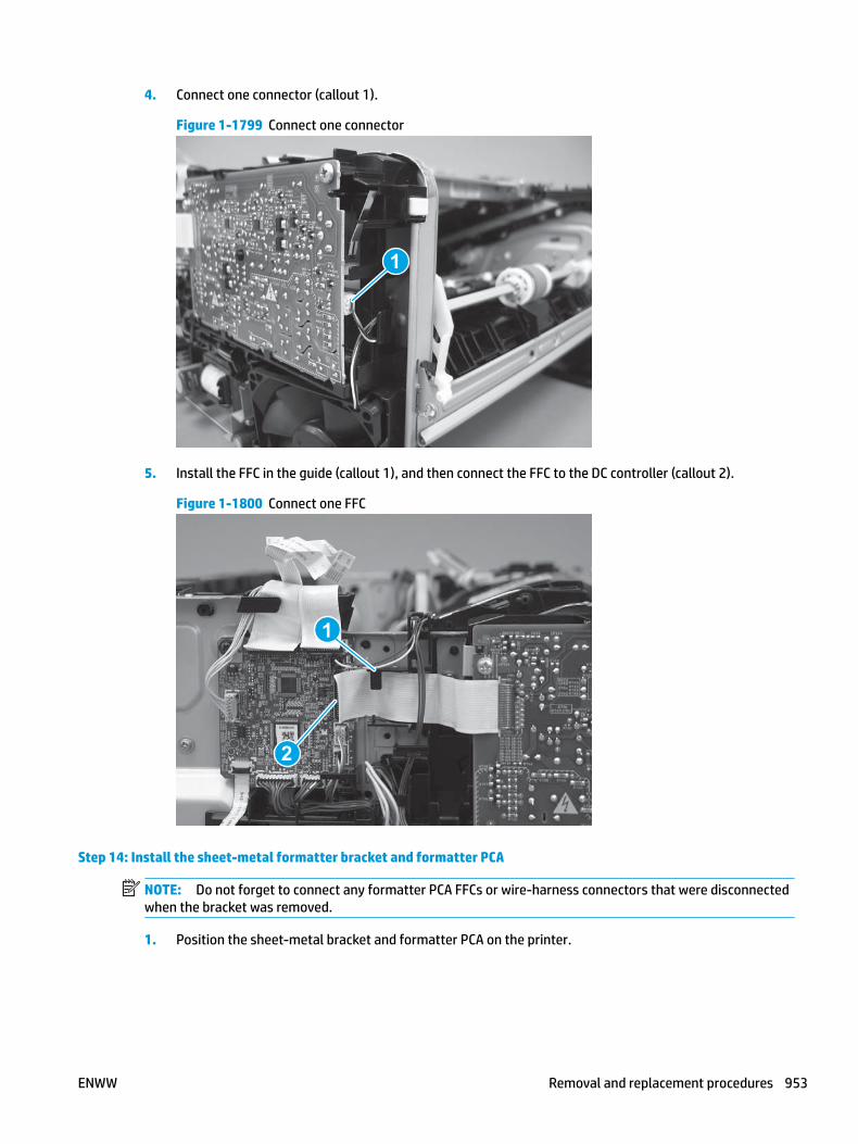
4. Connect one connector (callout 1).
Figure 1-1799 Connect one connector
1
5. Install the FFC in the guide (callout 1), and then connect the FFC to the DC controller (callout 2).
Figure 1-1800 Connect one FFC
2
1
Step 14: Install the sheet-metal formatter bracket and formatter PCA
NOTE: Do not forget to connect any formatter PCA FFCs or wire-harness connectors that were disconnected when the bracket was removed.
1. Position the sheet-metal bracket and formatter PCA on the printer.
ENWW Removal and replacement procedures 953

Figure 1-1801 Install the bracket
2. Install three screws (callout 1).
Figure 1-1802 Install three screws
1 1
3. Install the guide (callout 1).
Figure 1-1803 Install the guide
11
954 Chapter 1 Removal and replacement ENWW

4. Connect one connector (callout 1), and then install the wire harness in the guide (callout 2).
Figure 1-1804 Connect one connector
21
21
5. Install two screws (callout 1).
Figure 1-1805 Install two screws
11
6. M427/M426 only: Install the guide (callout 1).
Figure 1-1806 Install the guide
1
ENWW Removal and replacement procedures 955

Step 15: Install the paper delivery tray (output bin)
NOTE: This procedure shows the M403/M402 model, however, the paper delivery tray (output bin) removal is similar for the M427/M426 printer.
▲ Position the remove the paper delivery tray (output bin; callout 1) on the printer, engage two tabs (callout 2), and then engage two bosses (callout 3).
Figure 1-1807 Engage two tabs
2
3
1
Step 16: Install the top cover (M403/M402)
NOTE: The step is for the M403/M402 printer. For the M427/M426, skip this step and go to Step 17: Install the top cover (M427/M426) on page 958.
1. Position the rear edge of the cover on the printer.
Figure 1-1808 Install the cover
956 Chapter 1 Removal and replacement ENWW

2. Engage four bosses (callout 1), rotate the front of the cover down (callout 2) and onto from the printer, and then engage four tabs (callout 3).
Figure 1-1809 Engage four bosses and tabs
1
3
2
2
3. At the right side of the printer, engage the one boss and one tab (callout 1).
Figure 1-1810 Engage one boss and one tab
1
ENWW Removal and replacement procedures 957
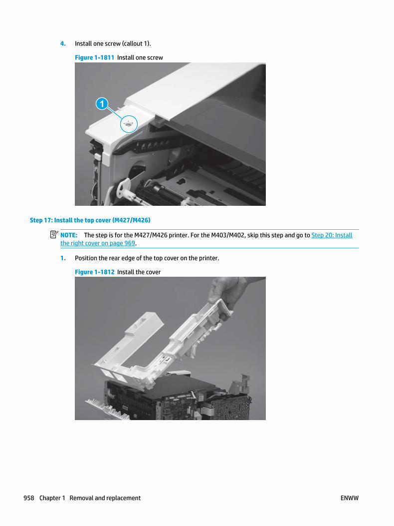
4. Install one screw (callout 1).
Figure 1-1811 Install one screw
1
Step 17: Install the top cover (M427/M426)
NOTE: The step is for the M427/M426 printer. For the M403/M402, skip this step and go to Step 20: Install the right cover on page 969.
1. Position the rear edge of the top cover on the printer.
Figure 1-1812 Install the cover
958 Chapter 1 Removal and replacement ENWW

2. Engage four bosses (callout 1).
Figure 1-1813 Engage four bosses
1
3. Rotate the front edge of the cover down.
Figure 1-1814 Rotate the front edge of the cover down
ENWW Removal and replacement procedures 959

4. Install the USB cable (callout 1) in the guide.
Figure 1-1815 Install the USB PCA
1
5. Install five screws (callout 1).
Figure 1-1816 Install five screws
1
Step 18: Install the control panel (M427/M246)
NOTE: The step is for the M427/M426 printer. For the M403/M402, skip this step and go to Step 20: Install the right cover on page 969.
1. Slide the control-panel FFC cover into the slot in the top cover (next to the document feeder support arm) to install it.
960 Chapter 1 Removal and replacement ENWW

Figure 1-1817 Install the control-panel FFC cover
2. Install the control-panel assembly on the top cover.
Figure 1-1818 Install the control-panel assembly
ENWW Removal and replacement procedures 961

3. Move the FFC out of the way, and then install two screws (callout 1).
Figure 1-1819 Install two screws
1
4. Install one grounding screw (callout 1), and then make sure that the ground cable (callout 2) is properly routed.
Figure 1-1820 Remove one screw
2
1
962 Chapter 1 Removal and replacement ENWW

5. Install the control-panel cable cover.
Figure 1-1821 Install the cover
6. Make sure that the two tabs (callout 1) on the cover snap into place.
Figure 1-1822 Engage two tabs
1
ENWW Removal and replacement procedures 963

7. Install one screw (callout 1).
Figure 1-1823 Install one screw
1
8. Install the FFC in the retainer (callout 1), and then connect one FFC (callout 1; J114).
Figure 1-1824 Connect one connector
1
2
Step 19: Install the integrated scanner assembly (M427/M246)
NOTE: The step is for the M427/M426 printer. For the M403/M402, skip this step and go to Step 20: Install the right cover on page 969.
NOTE: M427/M426 models only. The integrated scanner assembly (ISA) includes the sub-scanner assembly (SSA) and the automatic document feeder (ADF).
1. Position the ISA on the printer.
964 Chapter 1 Removal and replacement ENWW

Figure 1-1825 Position the ISA on the printer
2. Engage the hinge pins on the ISA with the holders in the top cover (callouts 1/2), and the slide the ISA as shown to engage them
Figure 1-1826 Engage the hinge pins with the holders
1
2
ENWW Removal and replacement procedures 965

3. Rotate the ISA towards the front of the printer until it rests on the ISA lift assembly (callout 1).
Figure 1-1827 Rotate the ISA towards the front of the printer
1
4. Pass the ground wire through the opening in the top cover.
Figure 1-1828 Pass the wire through the opening
966 Chapter 1 Removal and replacement ENWW

5. Install one screw (callout 1).
Figure 1-1829 Install one screw
1
6. Install the ISA lift assembly slider pin.
Reinstallation tip: Align the keyed portion of the locking pin with the slot and hole in the support arm.
Figure 1-1830 Install the slider pin
ENWW Removal and replacement procedures 967

7. Rotate the slider pin (callout 1) towards the rear of the printer until the tab (callout 2) snap into place.
Figure 1-1831 Secure the slider pin
2
1
8. Install the ferrite (callout 1) in the holder, and then connect three FFCs (callout 2).
Figure 1-1832 Connect three FFCs
1
2
968 Chapter 1 Removal and replacement ENWW

9. Position the rear edge of the ISA flat-flexible cable (FFC) cover on the printer (callout 1) , and then rotate it down (callout 2) until it snaps into place.
Figure 1-1833 Install the ISA FFC cover
1
2
10. Lower the ISA.
Figure 1-1834 Lower the ISA
Step 20: Install the right cover
1. Position the cover (callout 1) on the printer, and then engage two bosses (callout 2).
ENWW Removal and replacement procedures 969

Figure 1-1835 Install the cover
11
2 2
2. Rotate the front of the cover onto the printer (callout 1), engage three (callout 2) tabs, and then engage two bosses (callout 3).
Figure 1-1836 Engage two bosses and one tab
1 13 3
2 2
3. Make sure that the power switch (callout 1) and cartridge door assembly button (callout 2) correctly function.
NOTE: Remove, and then reinstall the cover if the switch or button does not correctly function.
Figure 1-1837 Check the power switch and cartridge door assembly button
1
1
22
970 Chapter 1 Removal and replacement ENWW

4. Install one screw (callout 1).
Figure 1-1838 Install one screw
11
Step 21: Install the left cover
1. At the front of the printer, do one of the following:
● M403/M402: Position the cover on the printer ( callout 1), and then engage two bosses (callout 2).
● M427/M426: Position the cover on the printer (callout 3), engage one tab (callout 4), and then engage two bosses (callout 4).
Figure 1-1839 Install the cover
1
2
4
35
ENWW Removal and replacement procedures 971

2. Carefully rotate the rear of the cover onto the printer (callout 1), engage three tabs (callout 2), and then engage two bosses (callout 3).
Figure 1-1840 Engage three tabs and two bosses
3
3 11
2
2
3. Install one screw (callout 1).
Figure 1-1841 Install one screw
1 1
Step 22: Install the cartridge door assembly
Reinstallation tip: After a replacement door is installed, make sure to install the nameplate (supplied in the kit) corresponding to the printer name on the door.
1. Position the door close to the printer, and then engage the keyed pin on the left-side retainer arm with the hole in the door.
972 Chapter 1 Removal and replacement ENWW

Figure 1-1842 Engage the left-side retainer arm
2. Engage the right-side door hinge pin with the hole in the chassis (callout 1).
Figure 1-1843 Install the door
1
ENWW Removal and replacement procedures 973

3. Install the link (callout 1).
IMPORTANT: Make sure that the link snaps into place on the arm (callout 2). The link actuates the fuser pressure-release mechanism.
Figure 1-1844 Install the pressure-release link
1
2
4. Slide the guide into the printer (callout 1), and then make sure that the tab (callout 2) snaps into place to secure the guide to the chassis.
Figure 1-1845 Install the guide
1
2
974 Chapter 1 Removal and replacement ENWW
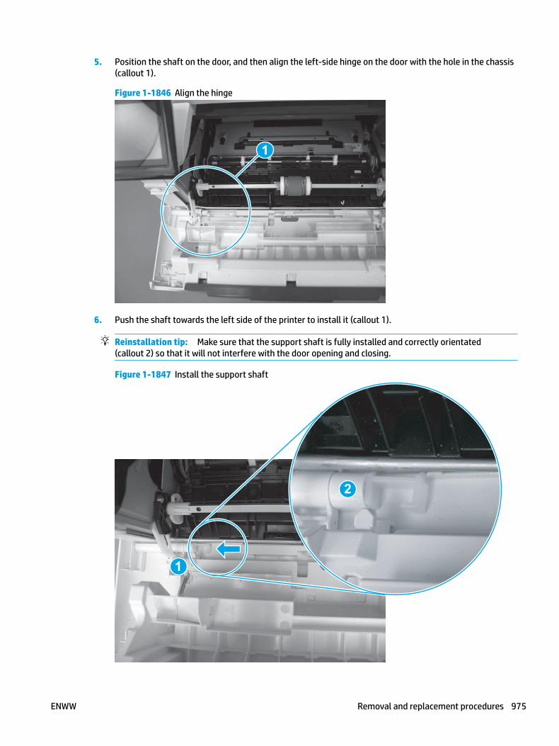
5. Position the shaft on the door, and then align the left-side hinge on the door with the hole in the chassis (callout 1).
Figure 1-1846 Align the hinge
1
6. Push the shaft towards the left side of the printer to install it (callout 1).
Reinstallation tip: Make sure that the support shaft is fully installed and correctly orientated (callout 2) so that it will not interfere with the door opening and closing.
Figure 1-1847 Install the support shaft
2
1
ENWW Removal and replacement procedures 975

Step 23: Install Tray 2
▲ Slide the tray straight into the printer to install it.
Figure 1-1848 Install the tray
976 Chapter 1 Removal and replacement ENWW

Removal and replacement: Low-voltage power supply
● Introduction
● Step 1: Remove Tray 2
● Step 2: Remove the cartridge door assembly
● Step 3: Remove the left cover
● Step 4: Remove the right cover
● Step 5: Remove the integrated scanner assembly (M427/M246)
● Step 6: Remove the control panel (M427/M246)
● Step 7: Remove the top cover (M427/M426)
● Step 8: Remove the top cover (M403/M402)
● Step 9: Remove the paper delivery tray (output bin)
● Step 10: Remove the fan (FM1)
● Step 11: Remove the sheet-metal formatter bracket and formatter PCA
● Step 12: Remove the LVPS
● Step 13: Unpack the replacement assembly
● Step 14: Install the LVPS
● Step 15: Install the sheet-metal formatter bracket and formatter PCA
● Step 16: Install the fan (FM1)
● Step 17: Install the paper delivery tray (output bin)
● Step 18: Install the top cover (M403/M402)
● Step 19: Install the top cover (M427/M426)
● Step 20: Install the control panel (M427/M246)
● Step 21: Install the integrated scanner assembly (M427/M246)
● Step 23: Install the right cover
● Step 24: Install the left cover
● Step 25: Install the cartridge door assembly
● Step 26: Install Tray 2
Introduction
This document provides the procedures to remove and replace the low-voltage power supply (LVPS).
ENWW Removal and replacement procedures 977

Before performing service
Turn the printer power off
◦ Disconnect the power cable.
WARNING! To avoid damage to the printer, turn the printer off, wait 30 seconds, and then remove the power cable before attempting to service the printer.
Use the table below to identify the correct part number for your printer. To order the part, go to www.hp.com/buy/parts.
Low-voltage power supply (LVPS) part number
RM2-8518-000CN
RM2-8519-000CN
RM2-8516-000CN
RM2-8517-000CN
Low-voltage power supply (M427/M426; 110V-127V)
Low-voltage power supply (M427/M426; 220V-240V)
Low-voltage power supply (M403/M402; 110V-127V)
Low-voltage power supply (M403/M402; 220V-240V)
Required tools
● #2 Phillips screwdriver with a magnetic tip.
After performing service
Turn the printer power on
◦ Connect the power cable.
◦ Use the power switch to turn the power on.
Post service test
Make sure that the printer initializes to a Ready state.
Print a configuration page to make sure that the printer is functioning correctly.
Step 1: Remove Tray 2
▲ Pull the tray straight out of the printer to remove it.
978 Chapter 1 Removal and replacement ENWW

Figure 1-1849 Remove the tray
Step 2: Remove the cartridge door assembly
NOTE: If the toner cartridge was not removed prior to servicing the printer, remove it now.
1. Release one tab (callout 1), and then slide shaft (callout 2) in the direction the arrow indicates and remove it.
TIP: It might be easier to release the support shaft by using a small flat-blade screwdriver.
Figure 1-1850 Release the support shaft
12
ENWW Removal and replacement procedures 979

2. Release one tab (callout 1), and then slide the guide (callout 2) in the direction the arrow indicates and remove it.
Figure 1-1851 Remove the guide
1 2
3. Remove the link arm (callout 1).
Figure 1-1852 Remove the link arm
1
980 Chapter 1 Removal and replacement ENWW
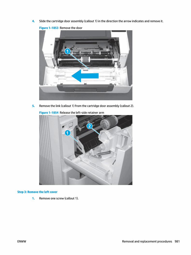
4. Slide the cartridge door assembly (callout 1) in the direction the arrow indicates and remove it.
Figure 1-1853 Remove the door
1
5. Remove the link (callout 1) from the cartridge door assembly (callout 2).
Figure 1-1854 Release the left-side retainer arm
21
Step 3: Remove the left cover
1. Remove one screw (callout 1).
ENWW Removal and replacement procedures 981

Figure 1-1855 Remove one screw
1 1
2. Open the rear door, release two bosses (callout 1), and then release three tabs (callout 2).
Figure 1-1856 Release two bosses and three tabs
1
1
2
2
3. At the front of the printer, do one of the following:
● M403/M402: Release two bosses (callout 1), and then remove the cover (callout 2).
● M427/M426: Release one tab (callout 3), two bosses (callout 4), and then remove the cover (callout 5).
CAUTION: Be careful when releasing the upper bosses on the M427/M426 cover. One portion of the cover (callout 6) is fragile and is easily broken.
982 Chapter 1 Removal and replacement ENWW

Figure 1-1857 Remove the cover
2
1
3
54 6
Step 4: Remove the right cover
1. Remove one screw (callout 1).
Figure 1-1858 Remove one screw
11
2. At the front of the printer, release two bosses (callout 1), and then release three tabs (callout 2).
Figure 1-1859 Release two bosses and three tabs
1 1
2 2
ENWW Removal and replacement procedures 983

3. Open the rear door, release two bosses (callout 1), and then remove the cover (callout 2).
Figure 1-1860 Remove the cover
22
1 1
Step 5: Remove the integrated scanner assembly (M427/M246)
NOTE: The step is for the M427/M426 printer. For the M403/M402, skip this step and go to Step 8: Remove the top cover (M403/M402) on page 994.
NOTE: M427/M426 models only. The integrated scanner assembly (ISA) includes the sub-scanner assembly (SSA) and the automatic document feeder (ADF).
1. Raise the ISA.
Figure 1-1861 Raise the ISA
984 Chapter 1 Removal and replacement ENWW

2. Release the ISA flat-flexible cable (FFC) cover (callout 1), and then remove it (callout 2).
Figure 1-1862 Remove the ISA FFC cover
12
3. Disconnect three FFCs (callout 1), and then remove the ferrite (callout 2) from the holder.
CAUTION: The ferrite is not captive on the FFC. Do not lose the ferrite while handling the ISA.
Figure 1-1863 Disconnect three FFCs
2
1
ENWW Removal and replacement procedures 985

4. Remove one screw (callout 1).
Figure 1-1864 Remove one screw
1
5. Pass the ground wire through the opening in the top cover.
Figure 1-1865 Pass the wire through the opening
986 Chapter 1 Removal and replacement ENWW

6. Release one tab (callout 1), and then rotate the ISA slider pin (callout 2) towards the front of the printer to release it.
Figure 1-1866 Release one tab and rotate the slider pin
1
2
7. Remove the slider pin.
Figure 1-1867 Remove the slider pin
ENWW Removal and replacement procedures 987

8. Rotate the ISA towards the rear of the printer until it stops.
Figure 1-1868 Rotate the ISA towards the rear of the printer
9. Slide the ISA as shown to release it.
Figure 1-1869 Release the ISA
988 Chapter 1 Removal and replacement ENWW
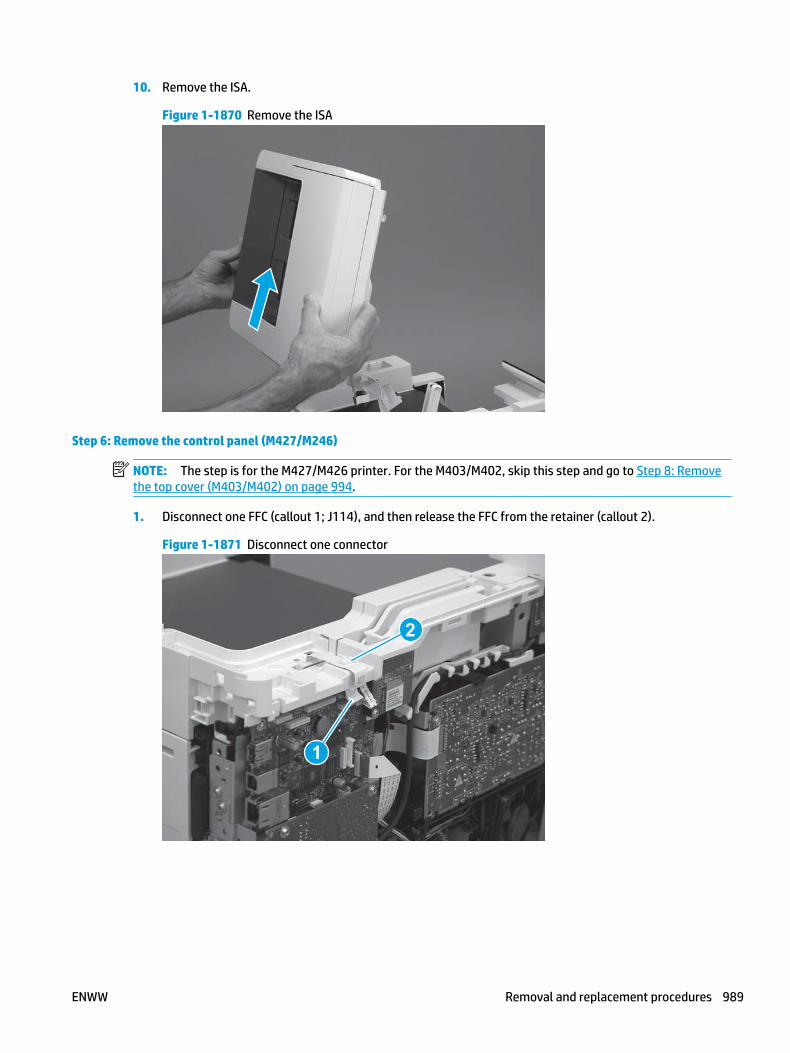
10. Remove the ISA.
Figure 1-1870 Remove the ISA
Step 6: Remove the control panel (M427/M246)
NOTE: The step is for the M427/M426 printer. For the M403/M402, skip this step and go to Step 8: Remove the top cover (M403/M402) on page 994.
1. Disconnect one FFC (callout 1; J114), and then release the FFC from the retainer (callout 2).
Figure 1-1871 Disconnect one connector
1
2
ENWW Removal and replacement procedures 989

2. Remove one screw (callout 1).
Figure 1-1872 Remove one screw
1
3. Use a small flat-blade screwdriver to release two tabs (callout 1) on the control-panel cable cover.
Figure 1-1873 Release two tabs
1
990 Chapter 1 Removal and replacement ENWW

4. Remove the control-panel cable cover.
Figure 1-1874 Remove the cover
5. Remove one grounding screw (callout 1), and then move the ground cable (callout 2) out of the way.
Figure 1-1875 Remove one screw
2
1
ENWW Removal and replacement procedures 991

6. Move the FFC out of the way, and then remove two screws (callout 1).
Figure 1-1876 Remove two screws
1
7. Slightly lift up the control-panel assembly to separate it from the top cover.
CAUTION: The control panel assembly is still connected to the printer by the FFC. Do not attempt to completely remove the assembly.
Figure 1-1877 Lift up the control-panel assembly
992 Chapter 1 Removal and replacement ENWW

8. Lift up the control-panel FFC cover to remove the control-panel assembly.
Figure 1-1878 Remove the control-panel assembly
Step 7: Remove the top cover (M427/M426)
NOTE: The step is for the M427/M426 printer. For the M403/M402, skip this step and go to Step 8: Remove the top cover (M403/M402) on page 994.
1. Release the USB cable (callout 1) from the cable guide.
Figure 1-1879 Remove the USB cable
1
ENWW Removal and replacement procedures 993

2. Remove five screws (callout 1), release four bosses (callout 2), and then remove the top cover (callout 3).
Figure 1-1880 Remove the cover
3
2
1
Step 8: Remove the top cover (M403/M402)
NOTE: The step is for the M403/M402 printer. For the M427/M426, skip this step and go to Step 9: Remove the paper delivery tray (output bin) on page 995.
1. Remove one screw (callout 1).
Figure 1-1881 Remove one screw
1
994 Chapter 1 Removal and replacement ENWW

2. At the right side of the printer, release the one boss (callout 1), and then release one tab (callout 2).
Figure 1-1882 Release one boss and one tab
21
3. Release four tabs (callout 1), release four bosses (callout 2), and then remove the top cover (callout 3).
TIP: Open the rear door to make releasing the bosses (callout 3) easier.
Figure 1-1883 Remove the cover
2
3
1
Step 9: Remove the paper delivery tray (output bin)
NOTE: This procedure shows the M403/M402 model, however, the paper delivery tray (output bin) removal is similar for the M427/M426 printer.
▲ Release two bosses (callout 1), release two tabs (callout 2), and then remove the paper delivery tray (output bin; callout 3).
ENWW Removal and replacement procedures 995
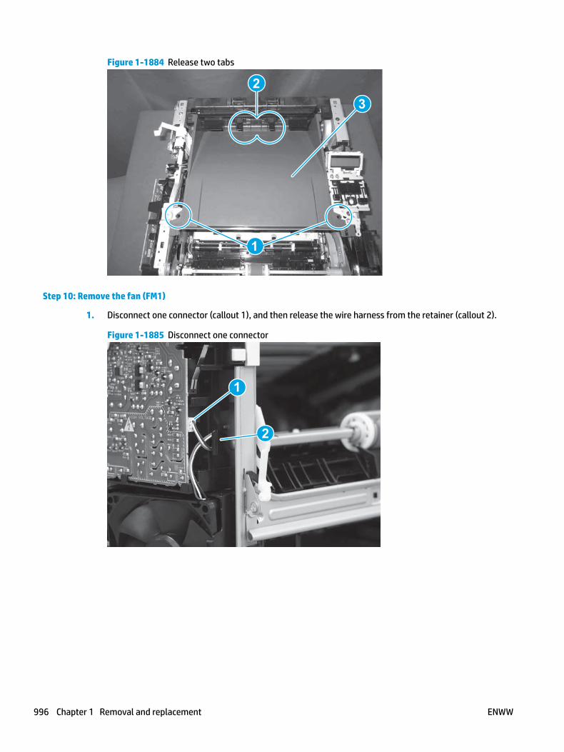
Figure 1-1884 Release two tabs
2
1
3
Step 10: Remove the fan (FM1)
1. Disconnect one connector (callout 1), and then release the wire harness from the retainer (callout 2).
Figure 1-1885 Disconnect one connector
1
2
996 Chapter 1 Removal and replacement ENWW
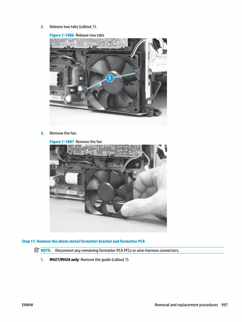
2. Release two tabs (callout 1).
Figure 1-1886 Release two tabs
1
3. Remove the fan.
Figure 1-1887 Remove the fan
Step 11: Remove the sheet-metal formatter bracket and formatter PCA
NOTE: Disconnect any remaining formatter PCA FFCs or wire-harness connectors.
1. M427/M426 only: Remove the guide (callout 1).
ENWW Removal and replacement procedures 997

Figure 1-1888 Remove the guide
1
2. Remove two screws (callout 1).
Figure 1-1889 Remove two screws
11
3. Disconnect one connector (callout 1), and then release the wire harness from the guide (callout 2).
Figure 1-1890 Disconnect one connector
21
21
998 Chapter 1 Removal and replacement ENWW
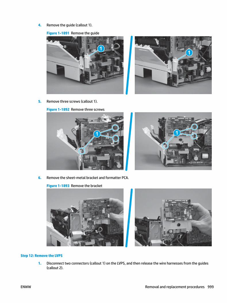
4. Remove the guide (callout 1).
Figure 1-1891 Remove the guide
11
5. Remove three screws (callout 1).
Figure 1-1892 Remove three screws
1 1
6. Remove the sheet-metal bracket and formatter PCA.
Figure 1-1893 Remove the bracket
Step 12: Remove the LVPS
1. Disconnect two connectors (callout 1) on the LVPS, and then release the wire harnesses from the guides (callout 2).
ENWW Removal and replacement procedures 999

Figure 1-1894 Disconnect two connectors
2
1
2. Remove one screw (callout 1).
Figure 1-1895 Remove one screw
1
1000 Chapter 1 Removal and replacement ENWW

3. Release one tab at the top-left side of the fan holder (callout 1), and then rotate the top-left side corner of the holder away from the printer.
Reinstallation tip: Use a flat-blade screwdriver to slightly flex the top of the holder down to make it easier to disengage this tab.
Figure 1-1896 Release one tab
1
4. Slightly flex the right side of the holder to release one tab (callout 1), and then rotate the top of the holder away from the printer (callout 2).
Figure 1-1897 Release one tab
1
2
ENWW Removal and replacement procedures 1001

5. Lift the holder up to release two alignment tabs on the bottom of the holder, and then remove the holder.
Figure 1-1898 Remove the holder
6. Remove two screws (callout 1).
Figure 1-1899 Remove two screws
1
1002 Chapter 1 Removal and replacement ENWW

7. Remove three screws (callout 1).
Figure 1-1900 Remove three screws
1
8. Rotate the bottom of the LVPS away from the printer, and then remove the LVPS.
Figure 1-1901 Remove the LVPS
Step 13: Unpack the replacement assembly
Unpack the replacement part from the packaging.
http://www8.hp.com/us/en/hp-information/environment/product-recycling.html
NOTE: HP recommends responsible disposal of the defective part.
ENWW Removal and replacement procedures 1003

Figure 1-1902 Recycle and unpack
Step 14: Install the LVPS
1. Position the top of LVPS in the printer, and then rotate the bottom toward the printer to install the LVPS.
Figure 1-1903 Install the LVPS
1004 Chapter 1 Removal and replacement ENWW
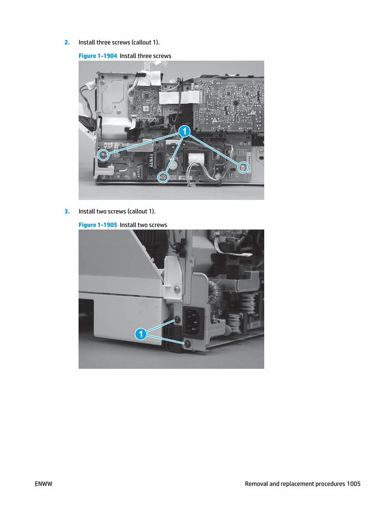
2. Install three screws (callout 1).
Figure 1-1904 Install three screws
1
3. Install two screws (callout 1).
Figure 1-1905 Install two screws
1
ENWW Removal and replacement procedures 1005

4. Position the bottom edge of the holder on the chassis—engage the two alignment tabs on the bottom of the holder with the slots in the chassis.
Figure 1-1906 Install the holder
5. Rotate the top of the holder toward the printer (callout 1), and then engage one tab on the right side of the holder (callout 1).
Figure 1-1907 Engage one tab
2
1
1006 Chapter 1 Removal and replacement ENWW

6. Rotate the top-left side corner of the holder toward the printer, and then engage one tab on the holder (callout 1).
Reinstallation tip: Use a flat-blade screwdriver to slightly flex the top of the holder down to make it easier to engage this tab.
Figure 1-1908 Engage one tab
1
7. Install one screw (callout 1).
Figure 1-1909 Install one screw
1
ENWW Removal and replacement procedures 1007

8. Install the wire harnesses in the guides (callout 1), and then connect two connectors (callout 2).
Figure 1-1910 Connect two connectors
1
2
Step 15: Install the sheet-metal formatter bracket and formatter PCA
NOTE: Do not forget to connect any formatter PCA FFCs or wire-harness connectors that were disconnected when the bracket was removed.
1. Position the sheet-metal bracket and formatter PCA on the printer.
Figure 1-1911 Install the bracket
1008 Chapter 1 Removal and replacement ENWW

2. Install three screws (callout 1).
Figure 1-1912 Install three screws
1 1
3. Install the guide (callout 1).
Figure 1-1913 Install the guide
11
4. Connect one connector (callout 1), and then install the wire harness in the guide (callout 2).
Figure 1-1914 Connect one connector
21
21
ENWW Removal and replacement procedures 1009

5. Install two screws (callout 1).
Figure 1-1915 Install two screws
11
6. M427/M426 only: Install the guide (callout 1).
Figure 1-1916 Install the guide
1
Step 16: Install the fan (FM1)
1. Position the fan in the holder. Make sure that the two tabs (callout 1) snap into place on the fan.
CAUTION: The fan must be correctly installed so that air is drawn into the printer. Make sure that the two arrows embossed on the right-side of the fan body—which indicate air flow direction—face upward and into the printer.
1010 Chapter 1 Removal and replacement ENWW

Figure 1-1917 Install the fan
1
2. Install the wire harness on the retainer (callout 2), and then connect one connector (callout 2).
Figure 1-1918 Connect one connector
2
1
Step 17: Install the paper delivery tray (output bin)
NOTE: This procedure shows the M403/M402 model, however, the paper delivery tray (output bin) removal is similar for the M427/M426 printer.
▲ Position the remove the paper delivery tray (output bin; callout 1) on the printer, engage two tabs (callout 2), and then engage two bosses (callout 3).
ENWW Removal and replacement procedures 1011
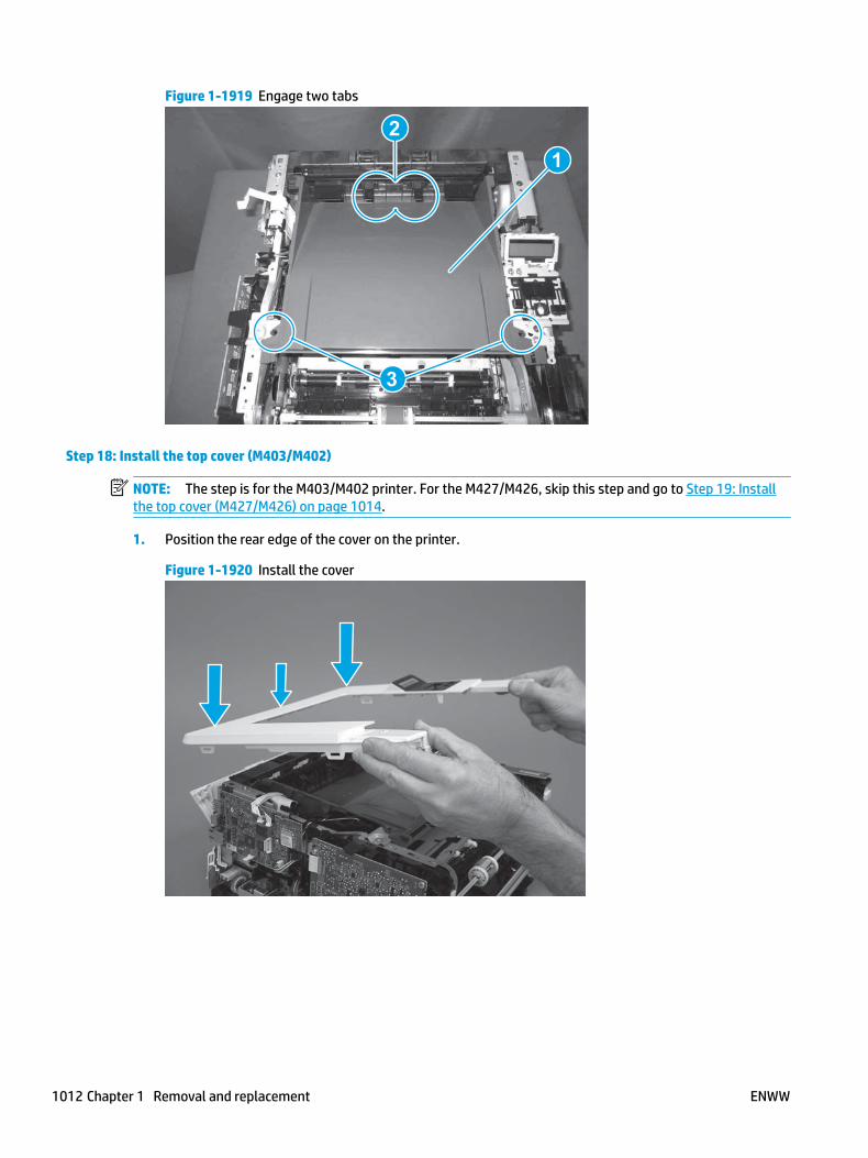
Figure 1-1919 Engage two tabs
2
3
1
Step 18: Install the top cover (M403/M402)
NOTE: The step is for the M403/M402 printer. For the M427/M426, skip this step and go to Step 19: Install the top cover (M427/M426) on page 1014.
1. Position the rear edge of the cover on the printer.
Figure 1-1920 Install the cover
1012 Chapter 1 Removal and replacement ENWW
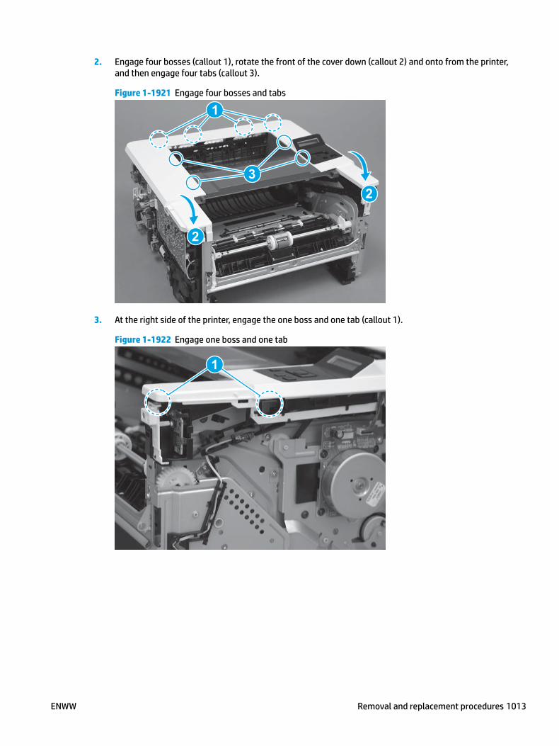
2. Engage four bosses (callout 1), rotate the front of the cover down (callout 2) and onto from the printer, and then engage four tabs (callout 3).
Figure 1-1921 Engage four bosses and tabs
1
3
2
2
3. At the right side of the printer, engage the one boss and one tab (callout 1).
Figure 1-1922 Engage one boss and one tab
1
ENWW Removal and replacement procedures 1013

4. Install one screw (callout 1).
Figure 1-1923 Install one screw
1
Step 19: Install the top cover (M427/M426)
NOTE: The step is for the M427/M426 printer. For the M403/M402, skip this step and go to Step 23: Install the right cover on page 1025.
1. Position the rear edge of the top cover on the printer.
Figure 1-1924 Install the cover
1014 Chapter 1 Removal and replacement ENWW

2. Engage four bosses (callout 1).
Figure 1-1925 Engage four bosses
1
3. Rotate the front edge of the cover down.
Figure 1-1926 Rotate the front edge of the cover down
ENWW Removal and replacement procedures 1015

4. Install the USB cable (callout 1) in the guide.
Figure 1-1927 Install the USB PCA
1
5. Install five screws (callout 1).
Figure 1-1928 Install five screws
1
Step 20: Install the control panel (M427/M246)
NOTE: The step is for the M427/M426 printer. For the M403/M402, skip this step and go to Step 23: Install the right cover on page 1025.
1. Slide the control-panel FFC cover into the slot in the top cover (next to the document feeder support arm) to install it.
1016 Chapter 1 Removal and replacement ENWW

Figure 1-1929 Install the control-panel FFC cover
2. Install the control-panel assembly on the top cover.
Figure 1-1930 Install the control-panel assembly
ENWW Removal and replacement procedures 1017

3. Move the FFC out of the way, and then install two screws (callout 1).
Figure 1-1931 Install two screws
1
4. Install one grounding screw (callout 1), and then make sure that the ground cable (callout 2) is properly routed.
Figure 1-1932 Remove one screw
2
1
1018 Chapter 1 Removal and replacement ENWW
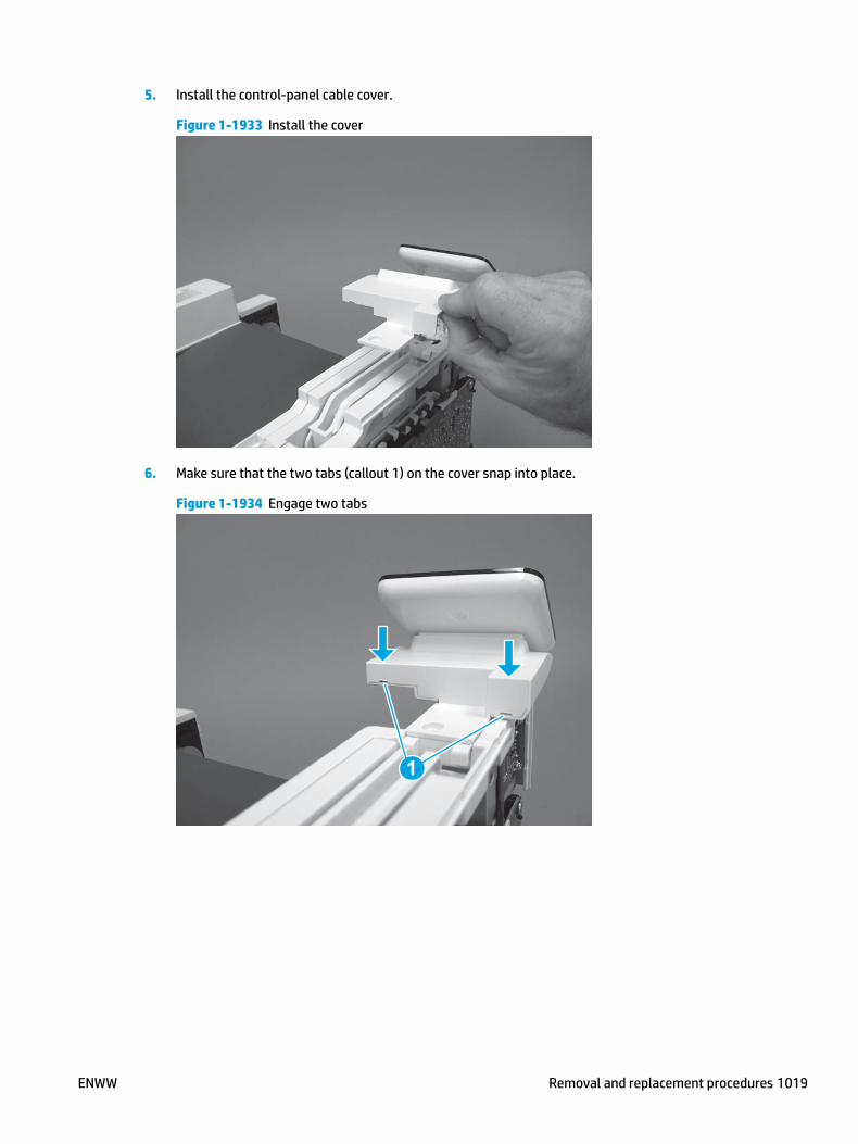
5. Install the control-panel cable cover.
Figure 1-1933 Install the cover
6. Make sure that the two tabs (callout 1) on the cover snap into place.
Figure 1-1934 Engage two tabs
1
ENWW Removal and replacement procedures 1019

7. Install one screw (callout 1).
Figure 1-1935 Install one screw
1
8. Install the FFC in the retainer (callout 1), and then connect one FFC (callout 1; J114).
Figure 1-1936 Connect one connector
1
2
Step 21: Install the integrated scanner assembly (M427/M246)
NOTE: The step is for the M427/M426 printer. For the M403/M402, skip this step and go to Step 23: Install the right cover on page 1025.
NOTE: M427/M426 models only. The integrated scanner assembly (ISA) includes the sub-scanner assembly (SSA) and the automatic document feeder (ADF).
1. Position the ISA on the printer.
1020 Chapter 1 Removal and replacement ENWW

Figure 1-1937 Position the ISA on the printer
2. Engage the hinge pins on the ISA with the holders in the top cover (callouts 1/2), and the slide the ISA as shown to engage them
Figure 1-1938 Engage the hinge pins with the holders
1
2
ENWW Removal and replacement procedures 1021

3. Rotate the ISA towards the front of the printer until it rests on the ISA lift assembly (callout 1).
Figure 1-1939 Rotate the ISA towards the front of the printer
1
4. Pass the ground wire through the opening in the top cover.
Figure 1-1940 Pass the wire through the opening
1022 Chapter 1 Removal and replacement ENWW

5. Install one screw (callout 1).
Figure 1-1941 Install one screw
1
6. Install the ISA lift assembly slider pin.
Reinstallation tip: Align the keyed portion of the locking pin with the slot and hole in the support arm.
Figure 1-1942 Install the slider pin
ENWW Removal and replacement procedures 1023

7. Rotate the slider pin (callout 1) towards the rear of the printer until the tab (callout 2) snap into place.
Figure 1-1943 Secure the slider pin
2
1
8. Install the ferrite (callout 1) in the holder, and then connect three FFCs (callout 2).
Figure 1-1944 Connect three FFCs
1
2
1024 Chapter 1 Removal and replacement ENWW
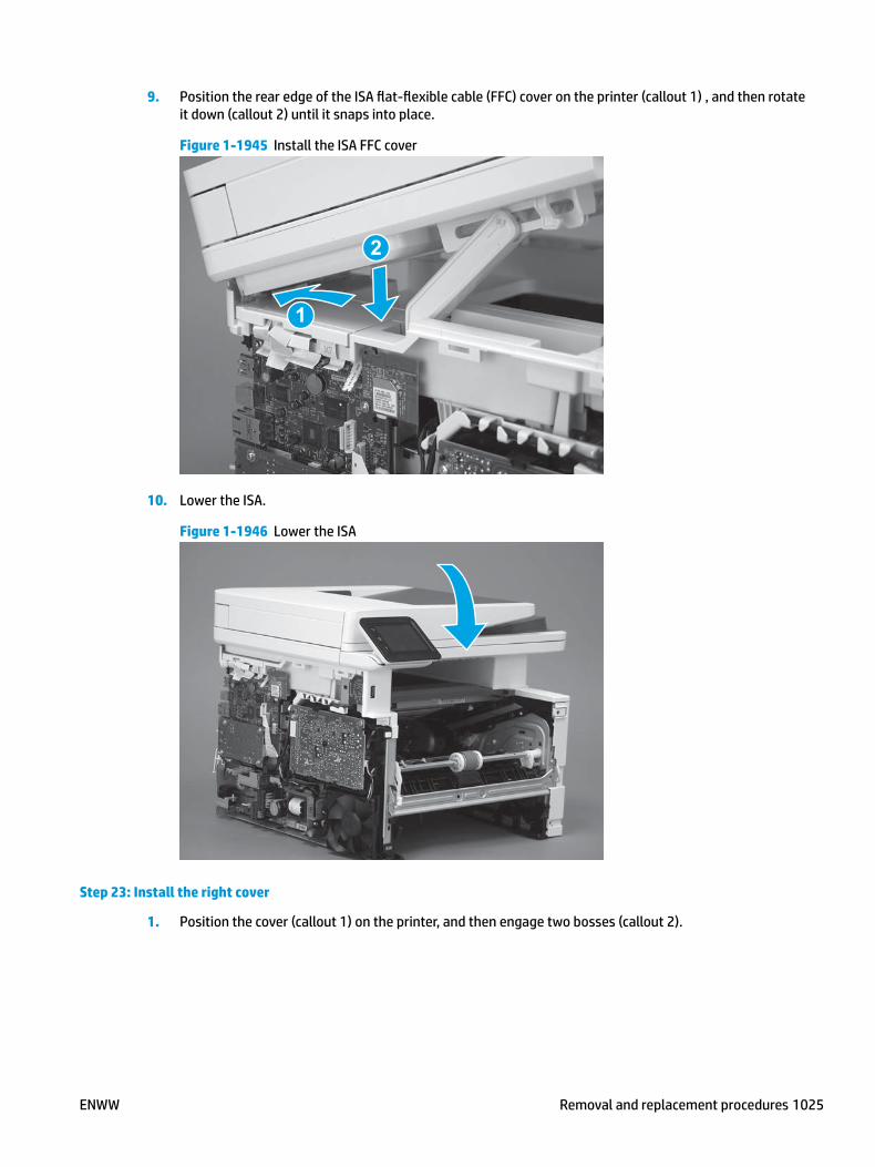
9. Position the rear edge of the ISA flat-flexible cable (FFC) cover on the printer (callout 1) , and then rotate it down (callout 2) until it snaps into place.
Figure 1-1945 Install the ISA FFC cover
1
2
10. Lower the ISA.
Figure 1-1946 Lower the ISA
Step 23: Install the right cover
1. Position the cover (callout 1) on the printer, and then engage two bosses (callout 2).
ENWW Removal and replacement procedures 1025

Figure 1-1947 Install the cover
11
2 2
2. Rotate the front of the cover onto the printer (callout 1), engage three (callout 2) tabs, and then engage two bosses (callout 3).
Figure 1-1948 Engage two bosses and one tab
1 13 3
2 2
3. Make sure that the power switch (callout 1) and cartridge door assembly button (callout 2) correctly function.
NOTE: Remove, and then reinstall the cover if the switch or button does not correctly function.
Figure 1-1949 Check the power switch and cartridge door assembly button
1
1
22
1026 Chapter 1 Removal and replacement ENWW

4. Install one screw (callout 1).
Figure 1-1950 Install one screw
11
Step 24: Install the left cover
1. At the front of the printer, do one of the following:
● M403/M402: Position the cover on the printer ( callout 1), and then engage two bosses (callout 2).
● M427/M426: Position the cover on the printer (callout 3), engage one tab (callout 4), and then engage two bosses (callout 4).
Figure 1-1951 Install the cover
1
2
4
35
ENWW Removal and replacement procedures 1027

2. Carefully rotate the rear of the cover onto the printer (callout 1), engage three tabs (callout 2), and then engage two bosses (callout 3).
Figure 1-1952 Engage three tabs and two bosses
3
3 11
2
2
3. Install one screw (callout 1).
Figure 1-1953 Install one screw
1 1
Step 25: Install the cartridge door assembly
Reinstallation tip: After a replacement door is installed, make sure to install the nameplate (supplied in the kit) corresponding to the printer name on the door.
1. Position the door close to the printer, and then engage the keyed pin on the left-side retainer arm with the hole in the door.
1028 Chapter 1 Removal and replacement ENWW

Figure 1-1954 Engage the left-side retainer arm
2. Engage the right-side door hinge pin with the hole in the chassis (callout 1).
Figure 1-1955 Install the door
1
ENWW Removal and replacement procedures 1029

3. Install the link (callout 1).
IMPORTANT: Make sure that the link snaps into place on the arm (callout 2). The link actuates the fuser pressure-release mechanism.
Figure 1-1956 Install the pressure-release link
1
2
4. Slide the guide into the printer (callout 1), and then make sure that the tab (callout 2) snaps into place to secure the guide to the chassis.
Figure 1-1957 Install the guide
1
2
1030 Chapter 1 Removal and replacement ENWW

5. Position the shaft on the door, and then align the left-side hinge on the door with the hole in the chassis (callout 1).
Figure 1-1958 Align the hinge
1
6. Push the shaft towards the left side of the printer to install it (callout 1).
Reinstallation tip: Make sure that the support shaft is fully installed and correctly orientated (callout 2) so that it will not interfere with the door opening and closing.
Figure 1-1959 Install the support shaft
2
1
ENWW Removal and replacement procedures 1031

Step 26: Install Tray 2
▲ Slide the tray straight into the printer to install it.
Figure 1-1960 Install the tray
1032 Chapter 1 Removal and replacement ENWW

Removal and replacement: NFC cover (M427/M426)
NOTE: M427/M426 models only.
● Introduction
● Step 1: Remove Tray 2
● Step 2: Remove the cartridge door assembly
● Step 3: Remove the left cover
● Step 4: Remove the right cover
● Step 6: Remove the integrated scanner assembly (M427/M246)
● Step 5: Remove the control panel (M427/M426)
● Step 7: Remove the top cover (M427/M426)
● Step 8: Remove the NFC cover (M427/M426)
● Step 9: Unpack the replacement assembly
● Step 10: Install the NFC cover (M427/M426)
● Step 11: Install the top cover (M427/M426)
● Step 12: install the control panel (M427/M426)
● Step 12: Install the integrated scanner assembly (M427/M246)
● Step 13: Install the right cover
● Step 14: Install the left cover
● Step 15: Remove the cartridge door assembly
● Step 16: Install Tray 2
Introduction
This document provides the procedures to remove and replace the near field communication (NFC) cover.
Before performing service
Turn the printer power off
◦ Disconnect the power cable.
WARNING! To avoid damage to the printer, turn the printer off, wait 30 seconds, and then remove the power cable before attempting to service the printer.
Use the table below to identify the correct part number for your printer. To order the part, go to www.hp.com/buy/parts.
NFC cover part number
RC4-2961-000CN NFC cover
ENWW Removal and replacement procedures 1033

Required tools
● #2 Phillips screwdriver with a magnetic tip.
After performing service
Turn the printer power on
◦ Connect the power cable.
◦ Use the power switch to turn the power on.
Post service test
Make sure that the printer initializes to a Ready state.
Us a NFC enabled device to print a job from the printer.
Step 1: Remove Tray 2
▲ Pull the tray straight out of the printer to remove it.
Figure 1-1961 Remove the tray
Step 2: Remove the cartridge door assembly
NOTE: If the toner cartridge was not removed prior to servicing the printer, remove it now.
1. Release one tab (callout 1), and then slide shaft (callout 2) in the direction the arrow indicates and remove it.
TIP: It might be easier to release the support shaft by using a small flat-blade screwdriver.
1034 Chapter 1 Removal and replacement ENWW

Figure 1-1962 Release the support shaft
12
2. Release one tab (callout 1), and then slide the guide (callout 2) in the direction the arrow indicates and remove it.
Figure 1-1963 Remove the guide
1 2
ENWW Removal and replacement procedures 1035

3. Remove the link arm (callout 1).
Figure 1-1964 Remove the link arm
1
4. Slide the cartridge door assembly (callout 1) in the direction the arrow indicates and remove it.
Figure 1-1965 Remove the door
1
1036 Chapter 1 Removal and replacement ENWW

5. Remove the link (callout 1) from the cartridge door assembly (callout 2).
Figure 1-1966 Release the left-side retainer arm
21
Step 3: Remove the left cover
1. Remove one screw (callout 1).
Figure 1-1967 Remove one screw
1 1
ENWW Removal and replacement procedures 1037

2. Open the rear door, release two bosses (callout 1), and then release three tabs (callout 2).
Figure 1-1968 Release two bosses and three tabs
1
1
2
2
3. At the front of the printer, do one of the following:
● M403/M402: Release two bosses (callout 1), and then remove the cover (callout 2).
● M427/M426: Release one tab (callout 3), two bosses (callout 4), and then remove the cover (callout 5).
CAUTION: Be careful when releasing the upper bosses on the M427/M426 cover. One portion of the cover (callout 6) is fragile and is easily broken.
Figure 1-1969 Remove the cover
2
1
3
54 6
Step 4: Remove the right cover
1. Remove one screw (callout 1).
1038 Chapter 1 Removal and replacement ENWW

Figure 1-1970 Remove one screw
11
2. At the front of the printer, release two bosses (callout 1), and then release three tabs (callout 2).
Figure 1-1971 Release two bosses and three tabs
1 1
2 2
3. Open the rear door, release two bosses (callout 1), and then remove the cover (callout 2).
Figure 1-1972 Remove the cover
22
1 1
ENWW Removal and replacement procedures 1039

Step 6: Remove the integrated scanner assembly (M427/M246)
NOTE: M427/M426 models only. The integrated scanner assembly (ISA) includes the sub-scanner assembly (SSA) and the automatic document feeder (ADF).
1. Raise the ISA.
Figure 1-1973 Raise the ISA
2. Release the ISA flat-flexible cable (FFC) cover (callout 1), and then remove it (callout 2).
Figure 1-1974 Remove the ISA FFC cover
12
1040 Chapter 1 Removal and replacement ENWW

3. Disconnect three FFCs (callout 1), and then remove the ferrite (callout 2) from the holder.
CAUTION: The ferrite is not captive on the FFC. Do not lose the ferrite while handling the ISA.
Figure 1-1975 Disconnect three FFCs
2
1
4. Remove one screw (callout 1).
Figure 1-1976 Remove one screw
1
ENWW Removal and replacement procedures 1041

5. Pass the ground wire through the opening in the top cover.
Figure 1-1977 Pass the wire through the opening
6. Release one tab (callout 1), and then rotate the ISA slider pin (callout 2) towards the front of the printer to release it.
Figure 1-1978 Release one tab and rotate the slider pin
1
2
1042 Chapter 1 Removal and replacement ENWW

7. Remove the slider pin.
Figure 1-1979 Remove the slider pin
8. Rotate the ISA towards the rear of the printer until it stops.
Figure 1-1980 Rotate the ISA towards the rear of the printer
ENWW Removal and replacement procedures 1043

9. Slide the ISA as shown to release it.
Figure 1-1981 Release the ISA
10. Remove the ISA.
Figure 1-1982 Remove the ISA
Step 5: Remove the control panel (M427/M426)
1. Disconnect one FFC (callout 1; J114), and then release the FFC from the retainer (callout 2).
1044 Chapter 1 Removal and replacement ENWW

Figure 1-1983 Disconnect one connector
1
2
2. Remove one screw (callout 1).
Figure 1-1984 Remove one screw
1
ENWW Removal and replacement procedures 1045

3. Use a small flat-blade screwdriver to release two tabs (callout 1) on the control-panel cable cover.
Figure 1-1985 Release two tabs
1
4. Remove the control-panel cable cover.
Figure 1-1986 Remove the cover
1046 Chapter 1 Removal and replacement ENWW

5. Remove one grounding screw (callout 1), and then move the ground cable (callout 2) out of the way.
Figure 1-1987 Remove one screw
2
1
6. Move the FFC out of the way, and then remove two screws (callout 1).
Figure 1-1988 Remove two screws
1
ENWW Removal and replacement procedures 1047

7. Slightly lift up the control-panel assembly to separate it from the top cover.
CAUTION: The control panel assembly is still connected to the printer by the FFC. Do not attempt to completely remove the assembly.
Figure 1-1989 Lift up the control-panel assembly
8. Lift up the control-panel FFC cover to remove the control-panel assembly.
Figure 1-1990 Remove the control-panel assembly
Step 7: Remove the top cover (M427/M426)
1. Release the USB cable (callout 1) from the cable guide.
1048 Chapter 1 Removal and replacement ENWW
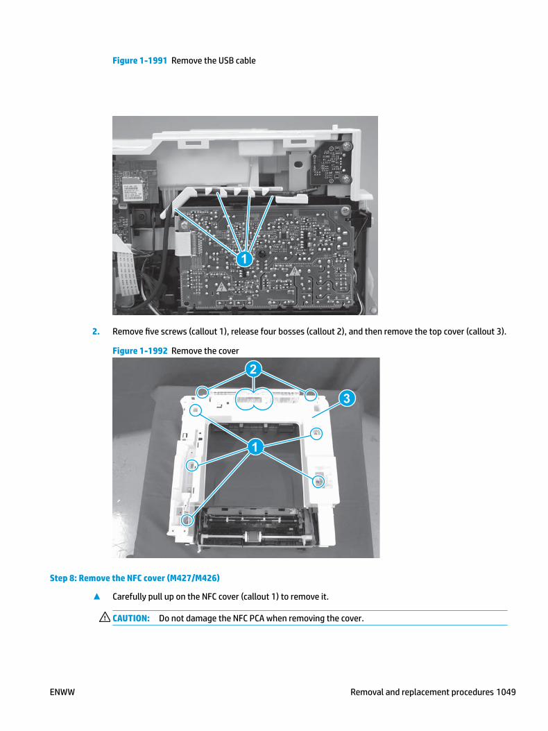
Figure 1-1991 Remove the USB cable
1
2. Remove five screws (callout 1), release four bosses (callout 2), and then remove the top cover (callout 3).
Figure 1-1992 Remove the cover
3
2
1
Step 8: Remove the NFC cover (M427/M426)
▲ Carefully pull up on the NFC cover (callout 1) to remove it.
CAUTION: Do not damage the NFC PCA when removing the cover.
ENWW Removal and replacement procedures 1049

Figure 1-1993 Remove the cover
1
Step 9: Unpack the replacement assembly
Unpack the replacement part from the packaging.
http://www8.hp.com/us/en/hp-information/environment/product-recycling.html
NOTE: HP recommends responsible disposal of the defective part.
Figure 1-1994 Recycle and unpack
Step 10: Install the NFC cover (M427/M426)
▲ Carefully install the NFC cover on the printer.
CAUTION: Do not damage the NFC PCA when installing the cover.
1050 Chapter 1 Removal and replacement ENWW

Figure 1-1995 Remove the cover
Step 11: Install the top cover (M427/M426)
1. Position the rear edge of the top cover on the printer.
Figure 1-1996 Install the cover
ENWW Removal and replacement procedures 1051

2. Engage four bosses (callout 1).
Figure 1-1997 Engage four bosses
1
3. Rotate the front edge of the cover down.
Figure 1-1998 Rotate the front edge of the cover down
1052 Chapter 1 Removal and replacement ENWW
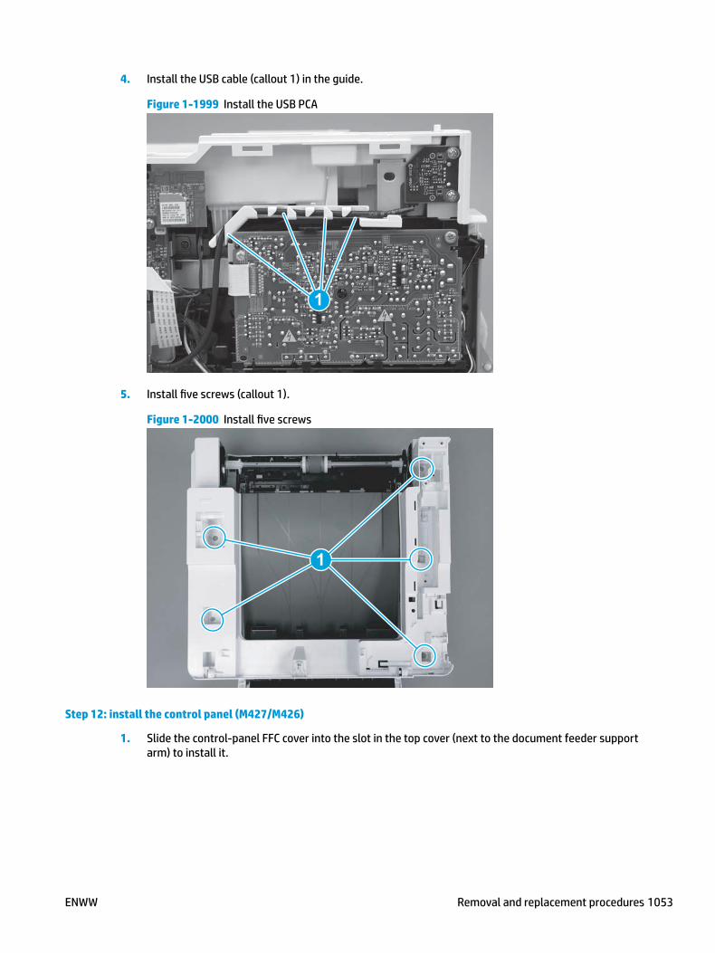
4. Install the USB cable (callout 1) in the guide.
Figure 1-1999 Install the USB PCA
1
5. Install five screws (callout 1).
Figure 1-2000 Install five screws
1
Step 12: install the control panel (M427/M426)
1. Slide the control-panel FFC cover into the slot in the top cover (next to the document feeder support arm) to install it.
ENWW Removal and replacement procedures 1053

Figure 1-2001 Install the control-panel FFC cover
2. Install the control-panel assembly on the top cover.
Figure 1-2002 Install the control-panel assembly
1054 Chapter 1 Removal and replacement ENWW
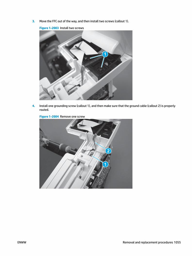
3. Move the FFC out of the way, and then install two screws (callout 1).
Figure 1-2003 Install two screws
1
4. Install one grounding screw (callout 1), and then make sure that the ground cable (callout 2) is properly routed.
Figure 1-2004 Remove one screw
2
1
ENWW Removal and replacement procedures 1055

5. Install the control-panel cable cover.
Figure 1-2005 Install the cover
6. Make sure that the two tabs (callout 1) on the cover snap into place.
Figure 1-2006 Engage two tabs
1
1056 Chapter 1 Removal and replacement ENWW

7. Install one screw (callout 1).
Figure 1-2007 Install one screw
1
8. Install the FFC in the retainer (callout 1), and then connect one FFC (callout 1; J114).
Figure 1-2008 Connect one connector
1
2
Step 12: Install the integrated scanner assembly (M427/M246)
NOTE: M427/M426 models only. The integrated scanner assembly (ISA) includes the sub-scanner assembly (SSA) and the automatic document feeder (ADF).
1. Position the ISA on the printer.
ENWW Removal and replacement procedures 1057

Figure 1-2009 Position the ISA on the printer
2. Engage the hinge pins on the ISA with the holders in the top cover (callouts 1/2), and the slide the ISA as shown to engage them
Figure 1-2010 Engage the hinge pins with the holders
1
2
1058 Chapter 1 Removal and replacement ENWW

3. Rotate the ISA towards the front of the printer until it rests on the ISA lift assembly (callout 1).
Figure 1-2011 Rotate the ISA towards the front of the printer
1
4. Pass the ground wire through the opening in the top cover.
Figure 1-2012 Pass the wire through the opening
ENWW Removal and replacement procedures 1059

5. Install one screw (callout 1).
Figure 1-2013 Install one screw
1
6. Install the ISA lift assembly slider pin.
Reinstallation tip: Align the keyed portion of the locking pin with the slot and hole in the support arm.
Figure 1-2014 Install the slider pin
1060 Chapter 1 Removal and replacement ENWW

7. Rotate the slider pin (callout 1) towards the rear of the printer until the tab (callout 2) snap into place.
Figure 1-2015 Secure the slider pin
2
1
8. Install the ferrite (callout 1) in the holder, and then connect three FFCs (callout 2).
Figure 1-2016 Connect three FFCs
1
2
ENWW Removal and replacement procedures 1061

9. Position the rear edge of the ISA flat-flexible cable (FFC) cover on the printer (callout 1) , and then rotate it down (callout 2) until it snaps into place.
Figure 1-2017 Install the ISA FFC cover
1
2
10. Lower the ISA.
Figure 1-2018 Lower the ISA
Step 13: Install the right cover
1. Position the cover (callout 1) on the printer, and then engage two bosses (callout 2).
1062 Chapter 1 Removal and replacement ENWW
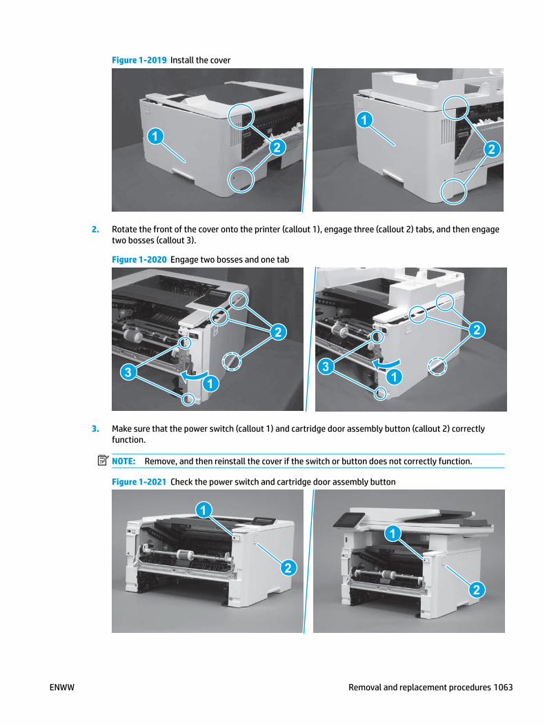
Figure 1-2019 Install the cover
11
2 2
2. Rotate the front of the cover onto the printer (callout 1), engage three (callout 2) tabs, and then engage two bosses (callout 3).
Figure 1-2020 Engage two bosses and one tab
1 13 3
2 2
3. Make sure that the power switch (callout 1) and cartridge door assembly button (callout 2) correctly function.
NOTE: Remove, and then reinstall the cover if the switch or button does not correctly function.
Figure 1-2021 Check the power switch and cartridge door assembly button
1
1
22
ENWW Removal and replacement procedures 1063
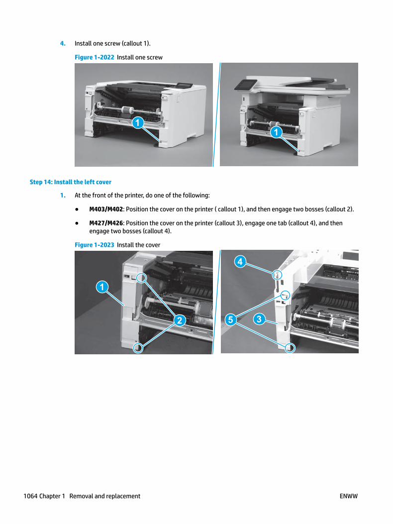
4. Install one screw (callout 1).
Figure 1-2022 Install one screw
11
Step 14: Install the left cover
1. At the front of the printer, do one of the following:
● M403/M402: Position the cover on the printer ( callout 1), and then engage two bosses (callout 2).
● M427/M426: Position the cover on the printer (callout 3), engage one tab (callout 4), and then engage two bosses (callout 4).
Figure 1-2023 Install the cover
1
2
4
35
1064 Chapter 1 Removal and replacement ENWW

2. Carefully rotate the rear of the cover onto the printer (callout 1), engage three tabs (callout 2), and then engage two bosses (callout 3).
Figure 1-2024 Engage three tabs and two bosses
3
3 11
2
2
3. Install one screw (callout 1).
Figure 1-2025 Install one screw
1 1
Step 15: Remove the cartridge door assembly
Reinstallation tip: After a replacement door is installed, make sure to install the nameplate (supplied in the kit) corresponding to the printer name on the door.
1. Position the door close to the printer, and then engage the keyed pin on the left-side retainer arm with the hole in the door.
ENWW Removal and replacement procedures 1065

Figure 1-2026 Engage the left-side retainer arm
2. Engage the right-side door hinge pin with the hole in the chassis (callout 1).
Figure 1-2027 Install the door
1
1066 Chapter 1 Removal and replacement ENWW

3. Install the link (callout 1).
IMPORTANT: Make sure that the link snaps into place on the arm (callout 2). The link actuates the fuser pressure-release mechanism.
Figure 1-2028 Install the pressure-release link
1
2
4. Slide the guide into the printer (callout 1), and then make sure that the tab (callout 2) snaps into place to secure the guide to the chassis.
Figure 1-2029 Install the guide
1
2
ENWW Removal and replacement procedures 1067

5. Position the shaft on the door, and then align the left-side hinge on the door with the hole in the chassis (callout 1).
Figure 1-2030 Align the hinge
1
6. Push the shaft towards the left side of the printer to install it (callout 1).
Reinstallation tip: Make sure that the support shaft is fully installed and correctly orientated (callout 2) so that it will not interfere with the door opening and closing.
Figure 1-2031 Install the support shaft
2
1
1068 Chapter 1 Removal and replacement ENWW

Step 16: Install Tray 2
▲ Slide the tray straight into the printer to install it.
Figure 1-2032 Install the tray
ENWW Removal and replacement procedures 1069

Removal and replacement: NFC PCA
NOTE: M427fdw/M426fdw/M402dw/M403dw models only.
● Introduction
● Step 1: Remove Tray 2
● Step 2: Remove the cartridge door assembly
● Step 3: Remove the left cover
● Step 4: Remove the right cover
● Step 5: Remove the integrated scanner assembly (M427/M246)
● Step 6: Remove the control panel (M427/M426)
● Step 7: Remove the top cover (M427/M426)
● Step 8: Remove the NFC cover (M427/M426)
● Step 9: Remove the top cover (M403/M402)
● Step 10: Remove the NFC PCA
● Step 11: Unpack the replacement assembly
● Step 12: Install the NFC PCA
● Step 13: Install the top cover (M403/M402)
● Step 14: Install the NFC cover (M427/M426)
● Step 15: Install the top cover (M427/M426)
● Step 16: Install the control panel (M427/M426)
● Step 17: Install the integrated scanner assembly (M427/M246)
● Step 18: Install the right cover
● Step 19: Install the left cover
● Step 20: Remove the cartridge door assembly
● Step 21: Install Tray 2
Introduction
This document provides the procedures to remove and replace the near field communication (NFC) printed circuit assembly (PCA; M426fdw/M403dn models only).
Before performing service
Turn the printer power off
◦ Disconnect the power cable.
1070 Chapter 1 Removal and replacement ENWW

WARNING! To avoid damage to the printer, turn the printer off, wait 30 seconds, and then remove the power cable before attempting to service the printer.
Use the table below to identify the correct part number for your printer. To order the part, go to www.hp.com/buy/parts.
NFC PCA part number
B4K93-60001 NFC PCA1
1 M427fdw/M426fdw/M402dw/M403dw models only.
Required tools
● #2 Phillips screwdriver with a magnetic tip.
After performing service
Turn the printer power on
◦ Connect the power cable.
◦ Use the power switch to turn the power on.
Post service test
Make sure that the printer initializes to a Ready state.
Use a NFC enabled device to print a job from the printer.
Step 1: Remove Tray 2
▲ Pull the tray straight out of the printer to remove it.
Figure 1-2033 Remove the tray
ENWW Removal and replacement procedures 1071

Step 2: Remove the cartridge door assembly
NOTE: If the toner cartridge was not removed prior to servicing the printer, remove it now.
1. Release one tab (callout 1), and then slide shaft (callout 2) in the direction the arrow indicates and remove it.
TIP: It might be easier to release the support shaft by using a small flat-blade screwdriver.
Figure 1-2034 Release the support shaft
12
2. Release one tab (callout 1), and then slide the guide (callout 2) in the direction the arrow indicates and remove it.
Figure 1-2035 Remove the guide
1 2
1072 Chapter 1 Removal and replacement ENWW

3. Remove the link arm (callout 1).
Figure 1-2036 Remove the link arm
1
4. Slide the cartridge door assembly (callout 1) in the direction the arrow indicates and remove it.
Figure 1-2037 Remove the door
1
ENWW Removal and replacement procedures 1073

5. Remove the link (callout 1) from the cartridge door assembly (callout 2).
Figure 1-2038 Release the left-side retainer arm
21
Step 3: Remove the left cover
1. Remove one screw (callout 1).
Figure 1-2039 Remove one screw
1 1
1074 Chapter 1 Removal and replacement ENWW
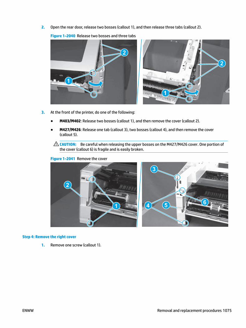
2. Open the rear door, release two bosses (callout 1), and then release three tabs (callout 2).
Figure 1-2040 Release two bosses and three tabs
1
1
2
2
3. At the front of the printer, do one of the following:
● M403/M402: Release two bosses (callout 1), and then remove the cover (callout 2).
● M427/M426: Release one tab (callout 3), two bosses (callout 4), and then remove the cover (callout 5).
CAUTION: Be careful when releasing the upper bosses on the M427/M426 cover. One portion of the cover (callout 6) is fragile and is easily broken.
Figure 1-2041 Remove the cover
2
1
3
54 6
Step 4: Remove the right cover
1. Remove one screw (callout 1).
ENWW Removal and replacement procedures 1075

Figure 1-2042 Remove one screw
11
2. At the front of the printer, release two bosses (callout 1), and then release three tabs (callout 2).
Figure 1-2043 Release two bosses and three tabs
1 1
2 2
3. Open the rear door, release two bosses (callout 1), and then remove the cover (callout 2).
Figure 1-2044 Remove the cover
22
1 1
Step 5: Remove the integrated scanner assembly (M427/M246)
NOTE: The step is for the M427/M426 printer. For the M403/M402, skip this step and go to Step 9: Remove the top cover (M403/M402) on page 1087.
1076 Chapter 1 Removal and replacement ENWW

NOTE: M427/M426 models only. The integrated scanner assembly (ISA) includes the sub-scanner assembly (SSA) and the automatic document feeder (ADF).
1. Raise the ISA.
Figure 1-2045 Raise the ISA
2. Release the ISA flat-flexible cable (FFC) cover (callout 1), and then remove it (callout 2).
Figure 1-2046 Remove the ISA FFC cover
12
ENWW Removal and replacement procedures 1077

3. Disconnect three FFCs (callout 1), and then remove the ferrite (callout 2) from the holder.
CAUTION: The ferrite is not captive on the FFC. Do not lose the ferrite while handling the ISA.
Figure 1-2047 Disconnect three FFCs
2
1
4. Remove one screw (callout 1).
Figure 1-2048 Remove one screw
1
1078 Chapter 1 Removal and replacement ENWW

5. Pass the ground wire through the opening in the top cover.
Figure 1-2049 Pass the wire through the opening
6. Release one tab (callout 1), and then rotate the ISA slider pin (callout 2) towards the front of the printer to release it.
Figure 1-2050 Release one tab and rotate the slider pin
1
2
ENWW Removal and replacement procedures 1079

7. Remove the slider pin.
Figure 1-2051 Remove the slider pin
8. Rotate the ISA towards the rear of the printer until it stops.
Figure 1-2052 Rotate the ISA towards the rear of the printer
1080 Chapter 1 Removal and replacement ENWW

9. Slide the ISA as shown to release it.
Figure 1-2053 Release the ISA
10. Remove the ISA.
Figure 1-2054 Remove the ISA
Step 6: Remove the control panel (M427/M426)
NOTE: The step is for the M427/M426 printer. For the M403/M402, skip this step and go to Step 9: Remove the top cover (M403/M402) on page 1087.
1. Disconnect one FFC (callout 1; J114), and then release the FFC from the retainer (callout 2).
ENWW Removal and replacement procedures 1081

Figure 1-2055 Disconnect one connector
1
2
2. Remove one screw (callout 1).
Figure 1-2056 Remove one screw
1
1082 Chapter 1 Removal and replacement ENWW

3. Use a small flat-blade screwdriver to release two tabs (callout 1) on the control-panel cable cover.
Figure 1-2057 Release two tabs
1
4. Remove the control-panel cable cover.
Figure 1-2058 Remove the cover
ENWW Removal and replacement procedures 1083

5. Remove one grounding screw (callout 1), and then move the ground cable (callout 2) out of the way.
Figure 1-2059 Remove one screw
2
1
6. Move the FFC out of the way, and then remove two screws (callout 1).
Figure 1-2060 Remove two screws
1
1084 Chapter 1 Removal and replacement ENWW

7. Slightly lift up the control-panel assembly to separate it from the top cover.
CAUTION: The control panel assembly is still connected to the printer by the FFC. Do not attempt to completely remove the assembly.
Figure 1-2061 Lift up the control-panel assembly
8. Lift up the control-panel FFC cover to remove the control-panel assembly.
Figure 1-2062 Remove the control-panel assembly
Step 7: Remove the top cover (M427/M426)
NOTE: The step is for the M427/M426 printer. For the M403/M402, skip this step and go to Step 9: Remove the top cover (M403/M402) on page 1087.
1. Release the USB cable (callout 1) from the cable guide.
ENWW Removal and replacement procedures 1085

Figure 1-2063 Remove the USB cable
1
2. Remove five screws (callout 1), release four bosses (callout 2), and then remove the top cover (callout 3).
Figure 1-2064 Remove the cover
3
2
1
Step 8: Remove the NFC cover (M427/M426)
NOTE: The step is for the M427/M426 printer. For the M403/M402, skip this step and go to Step 9: Remove the top cover (M403/M402) on page 1087.
▲ Carefully pull up on the NFC cover (callout 1) to remove it.
CAUTION: Do not damage the NFC PCA when removing the cover.
1086 Chapter 1 Removal and replacement ENWW

Figure 1-2065 Remove the cover
1
Step 9: Remove the top cover (M403/M402)
NOTE: The step is for the M403/M402 printer. For the M427/M426, skip this step and go to Step 10: Remove the NFC PCA on page 1088.
1. Remove one screw (callout 1).
Figure 1-2066 Remove one screw
1
ENWW Removal and replacement procedures 1087

2. At the right side of the printer, release the one boss (callout 1), and then release one tab (callout 2).
Figure 1-2067 Release one boss and one tab
21
3. Release four tabs (callout 1), release four bosses (callout 2), and then remove the top cover (callout 3).
TIP: Open the rear door to make releasing the bosses (callout 3) easier.
Figure 1-2068 Remove the cover
2
3
1
Step 10: Remove the NFC PCA
NOTE: M427fdw/M426fdw/M402dw/M403dw models only.
The M403 printer is shown in this procedure. However, the procedure is valid for the M427/M426/M402 printers.
1. Remove one screw (callout 1).
1088 Chapter 1 Removal and replacement ENWW

Figure 1-2069 Remove one screw
1
2. Turn the NFC PCA over to access the bottom side, disconnect one FFC (callout 1), and then remove the NFC PCA.
Figure 1-2070 Remove the NFC PCA
1
Step 11: Unpack the replacement assembly
Unpack the replacement part from the packaging.
http://www8.hp.com/us/en/hp-information/environment/product-recycling.html
NOTE: HP recommends responsible disposal of the defective part.
ENWW Removal and replacement procedures 1089

Figure 1-2071 Recycle and unpack
Step 12: Install the NFC PCA
NOTE: M427fdw/M426fdw/M402dw/M403dw models only.
The M403dw printer is shown in this procedure. However, the procedure is valid for the M427/M426/M402 printers.
1. Connect one FFC (callout 1).
Figure 1-2072 Connect one FFC
1
1090 Chapter 1 Removal and replacement ENWW

2. Position the NFC PCA on the holder.
CAUTION: Make sure that the NFC PCA is correctly positioned on the holder. One corner (callout 1) is under a tab on the holder, and the alignment pins on the holder fit in the hole and slot in the PCA (callout 2).
To avoid damage to the PCA, it must be installed flat on the holder before installing the mounting screw.
Figure 1-2073 Install the NFC PCA
12
3. Install one screw (callout 1).
Figure 1-2074 Install one screw
1
Step 13: Install the top cover (M403/M402)
NOTE: The step is for the M403/M402 printer. For the M427/M426, skip this step and go to Step 18: Install the right cover on page 1105.
ENWW Removal and replacement procedures 1091

1. Position the rear edge of the cover on the printer.
Figure 1-2075 Install the cover
2. Engage four bosses (callout 1), rotate the front of the cover down (callout 2) and onto from the printer, and then engage four tabs (callout 3).
Figure 1-2076 Engage four bosses and tabs
1
3
2
2
1092 Chapter 1 Removal and replacement ENWW
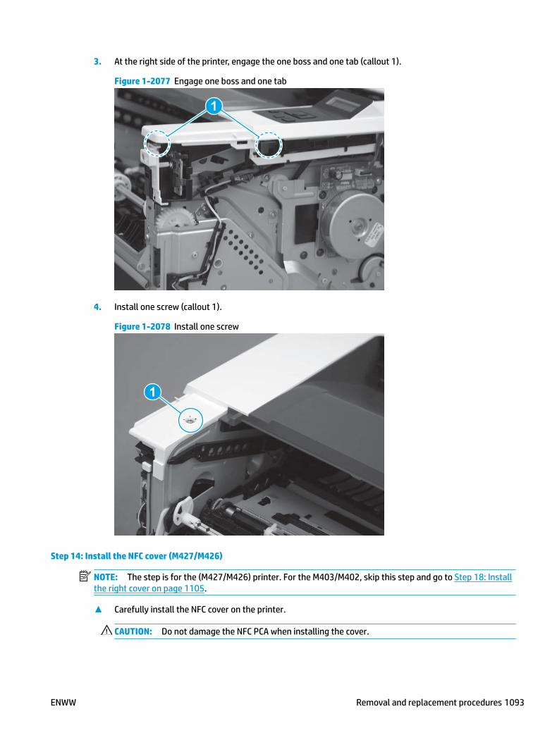
3. At the right side of the printer, engage the one boss and one tab (callout 1).
Figure 1-2077 Engage one boss and one tab
1
4. Install one screw (callout 1).
Figure 1-2078 Install one screw
1
Step 14: Install the NFC cover (M427/M426)
NOTE: The step is for the (M427/M426) printer. For the M403/M402, skip this step and go to Step 18: Install the right cover on page 1105.
▲ Carefully install the NFC cover on the printer.
CAUTION: Do not damage the NFC PCA when installing the cover.
ENWW Removal and replacement procedures 1093

Figure 1-2079 Remove the cover
Step 15: Install the top cover (M427/M426)
NOTE: The step is for the M427/M426 printer. For the M403/M402, skip this step and go to Step 18: Install the right cover on page 1105.
1. Position the rear edge of the top cover on the printer.
Figure 1-2080 Install the cover
1094 Chapter 1 Removal and replacement ENWW

2. Engage four bosses (callout 1).
Figure 1-2081 Engage four bosses
1
3. Rotate the front edge of the cover down.
Figure 1-2082 Rotate the front edge of the cover down
ENWW Removal and replacement procedures 1095

4. Install the USB cable (callout 1) in the guide.
Figure 1-2083 Install the USB PCA
1
5. Install five screws (callout 1).
Figure 1-2084 Install five screws
1
Step 16: Install the control panel (M427/M426)
NOTE: The step is for the M427/M426 printer. For the M403/M402, skip this step and go to Step 18: Install the right cover on page 1105.
1. Slide the control-panel FFC cover into the slot in the top cover (next to the document feeder support arm) to install it.
1096 Chapter 1 Removal and replacement ENWW

Figure 1-2085 Install the control-panel FFC cover
2. Install the control-panel assembly on the top cover.
Figure 1-2086 Install the control-panel assembly
ENWW Removal and replacement procedures 1097

3. Move the FFC out of the way, and then install two screws (callout 1).
Figure 1-2087 Install two screws
1
4. Install one grounding screw (callout 1), and then make sure that the ground cable (callout 2) is properly routed.
Figure 1-2088 Remove one screw
2
1
1098 Chapter 1 Removal and replacement ENWW

5. Install the control-panel cable cover.
Figure 1-2089 Install the cover
6. Make sure that the two tabs (callout 1) on the cover snap into place.
Figure 1-2090 Engage two tabs
1
ENWW Removal and replacement procedures 1099
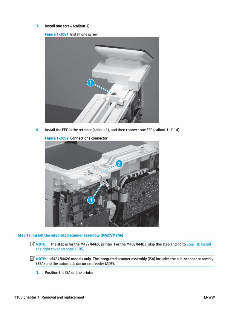
7. Install one screw (callout 1).
Figure 1-2091 Install one screw
1
8. Install the FFC in the retainer (callout 1), and then connect one FFC (callout 1; J114).
Figure 1-2092 Connect one connector
1
2
Step 17: Install the integrated scanner assembly (M427/M246)
NOTE: The step is for the M427/M426 printer. For the M403/M402, skip this step and go to Step 18: Install the right cover on page 1105.
NOTE: M427/M426 models only. The integrated scanner assembly (ISA) includes the sub-scanner assembly (SSA) and the automatic document feeder (ADF).
1. Position the ISA on the printer.
1100 Chapter 1 Removal and replacement ENWW

Figure 1-2093 Position the ISA on the printer
2. Engage the hinge pins on the ISA with the holders in the top cover (callouts 1/2), and the slide the ISA as shown to engage them
Figure 1-2094 Engage the hinge pins with the holders
1
2
ENWW Removal and replacement procedures 1101

3. Rotate the ISA towards the front of the printer until it rests on the ISA lift assembly (callout 1).
Figure 1-2095 Rotate the ISA towards the front of the printer
1
4. Pass the ground wire through the opening in the top cover.
Figure 1-2096 Pass the wire through the opening
1102 Chapter 1 Removal and replacement ENWW

5. Install one screw (callout 1).
Figure 1-2097 Install one screw
1
6. Install the ISA lift assembly slider pin.
Reinstallation tip: Align the keyed portion of the locking pin with the slot and hole in the support arm.
Figure 1-2098 Install the slider pin
ENWW Removal and replacement procedures 1103

7. Rotate the slider pin (callout 1) towards the rear of the printer until the tab (callout 2) snap into place.
Figure 1-2099 Secure the slider pin
2
1
8. Install the ferrite (callout 1) in the holder, and then connect three FFCs (callout 2).
Figure 1-2100 Connect three FFCs
1
2
1104 Chapter 1 Removal and replacement ENWW

9. Position the rear edge of the ISA flat-flexible cable (FFC) cover on the printer (callout 1) , and then rotate it down (callout 2) until it snaps into place.
Figure 1-2101 Install the ISA FFC cover
1
2
10. Lower the ISA.
Figure 1-2102 Lower the ISA
Step 18: Install the right cover
1. Position the cover (callout 1) on the printer, and then engage two bosses (callout 2).
ENWW Removal and replacement procedures 1105

Figure 1-2103 Install the cover
11
2 2
2. Rotate the front of the cover onto the printer (callout 1), engage three (callout 2) tabs, and then engage two bosses (callout 3).
Figure 1-2104 Engage two bosses and one tab
1 13 3
2 2
3. Make sure that the power switch (callout 1) and cartridge door assembly button (callout 2) correctly function.
NOTE: Remove, and then reinstall the cover if the switch or button does not correctly function.
Figure 1-2105 Check the power switch and cartridge door assembly button
1
1
22
1106 Chapter 1 Removal and replacement ENWW

4. Install one screw (callout 1).
Figure 1-2106 Install one screw
11
Step 19: Install the left cover
1. At the front of the printer, do one of the following:
● M403/M402: Position the cover on the printer ( callout 1), and then engage two bosses (callout 2).
● M427/M426: Position the cover on the printer (callout 3), engage one tab (callout 4), and then engage two bosses (callout 4).
Figure 1-2107 Install the cover
1
2
4
35
ENWW Removal and replacement procedures 1107

2. Carefully rotate the rear of the cover onto the printer (callout 1), engage three tabs (callout 2), and then engage two bosses (callout 3).
Figure 1-2108 Engage three tabs and two bosses
3
3 11
2
2
3. Install one screw (callout 1).
Figure 1-2109 Install one screw
1 1
Step 20: Remove the cartridge door assembly
Reinstallation tip: After a replacement door is installed, make sure to install the nameplate (supplied in the kit) corresponding to the printer name on the door.
1. Position the door close to the printer, and then engage the keyed pin on the left-side retainer arm with the hole in the door.
1108 Chapter 1 Removal and replacement ENWW

Figure 1-2110 Engage the left-side retainer arm
2. Engage the right-side door hinge pin with the hole in the chassis (callout 1).
Figure 1-2111 Install the door
1
ENWW Removal and replacement procedures 1109

3. Install the link (callout 1).
IMPORTANT: Make sure that the link snaps into place on the arm (callout 2). The link actuates the fuser pressure-release mechanism.
Figure 1-2112 Install the pressure-release link
1
2
4. Slide the guide into the printer (callout 1), and then make sure that the tab (callout 2) snaps into place to secure the guide to the chassis.
Figure 1-2113 Install the guide
1
2
1110 Chapter 1 Removal and replacement ENWW

5. Position the shaft on the door, and then align the left-side hinge on the door with the hole in the chassis (callout 1).
Figure 1-2114 Align the hinge
1
6. Push the shaft towards the left side of the printer to install it (callout 1).
Reinstallation tip: Make sure that the support shaft is fully installed and correctly orientated (callout 2) so that it will not interfere with the door opening and closing.
Figure 1-2115 Install the support shaft
2
1
ENWW Removal and replacement procedures 1111

Step 21: Install Tray 2
▲ Slide the tray straight into the printer to install it.
Figure 1-2116 Install the tray
1112 Chapter 1 Removal and replacement ENWW
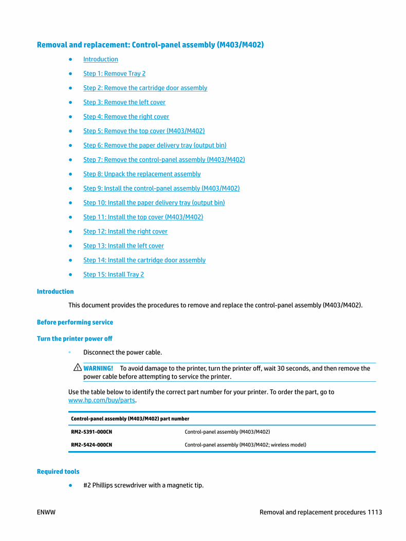
Removal and replacement: Control-panel assembly (M403/M402)
● Introduction
● Step 1: Remove Tray 2
● Step 2: Remove the cartridge door assembly
● Step 3: Remove the left cover
● Step 4: Remove the right cover
● Step 5: Remove the top cover (M403/M402)
● Step 6: Remove the paper delivery tray (output bin)
● Step 7: Remove the control-panel assembly (M403/M402)
● Step 8: Unpack the replacement assembly
● Step 9: Install the control-panel assembly (M403/M402)
● Step 10: Install the paper delivery tray (output bin)
● Step 11: Install the top cover (M403/M402)
● Step 12: Install the right cover
● Step 13: Install the left cover
● Step 14: Install the cartridge door assembly
● Step 15: Install Tray 2
Introduction
This document provides the procedures to remove and replace the control-panel assembly (M403/M402).
Before performing service
Turn the printer power off
◦ Disconnect the power cable.
WARNING! To avoid damage to the printer, turn the printer off, wait 30 seconds, and then remove the power cable before attempting to service the printer.
Use the table below to identify the correct part number for your printer. To order the part, go to www.hp.com/buy/parts.
Control-panel assembly (M403/M402) part number
RM2-5391-000CN
RM2-5424-000CN
Control-panel assembly (M403/M402)
Control-panel assembly (M403/M402; wireless model)
Required tools
● #2 Phillips screwdriver with a magnetic tip.
ENWW Removal and replacement procedures 1113

After performing service
Turn the printer power on
◦ Connect the power cable.
◦ Use the power switch to turn the power on.
Post service test
Make sure that the printer initializes to a Ready state.
Print a configuration page to make sure that the printer is functioning correctly.
Step 1: Remove Tray 2
▲ Pull the tray straight out of the printer to remove it.
Figure 1-2117 Remove the tray
Step 2: Remove the cartridge door assembly
NOTE: If the toner cartridge was not removed prior to servicing the printer, remove it now.
1. Release one tab (callout 1), and then slide shaft (callout 2) in the direction the arrow indicates and remove it.
TIP: It might be easier to release the support shaft by using a small flat-blade screwdriver.
1114 Chapter 1 Removal and replacement ENWW

Figure 1-2118 Release the support shaft
12
2. Release one tab (callout 1), and then slide the guide (callout 2) in the direction the arrow indicates and remove it.
Figure 1-2119 Remove the guide
1 2
ENWW Removal and replacement procedures 1115

3. Remove the link arm (callout 1).
Figure 1-2120 Remove the link arm
1
4. Slide the cartridge door assembly (callout 1) in the direction the arrow indicates and remove it.
Figure 1-2121 Remove the door
1
1116 Chapter 1 Removal and replacement ENWW

5. Remove the link (callout 1) from the cartridge door assembly (callout 2).
Figure 1-2122 Release the left-side retainer arm
21
Step 3: Remove the left cover
1. Remove one screw (callout 1).
Figure 1-2123 Remove one screw
1 1
ENWW Removal and replacement procedures 1117

2. Open the rear door, release two bosses (callout 1), and then release three tabs (callout 2).
Figure 1-2124 Release two bosses and three tabs
1
1
2
2
3. At the front of the printer, do one of the following:
● M403/M402: Release two bosses (callout 1), and then remove the cover (callout 2).
● M427/M426: Release one tab (callout 3), two bosses (callout 4), and then remove the cover (callout 5).
CAUTION: Be careful when releasing the upper bosses on the M427/M426 cover. One portion of the cover (callout 6) is fragile and is easily broken.
Figure 1-2125 Remove the cover
2
1
3
54 6
Step 4: Remove the right cover
1. Remove one screw (callout 1).
1118 Chapter 1 Removal and replacement ENWW

Figure 1-2126 Remove one screw
11
2. At the front of the printer, release two bosses (callout 1), and then release three tabs (callout 2).
Figure 1-2127 Release two bosses and three tabs
1 1
2 2
3. Open the rear door, release two bosses (callout 1), and then remove the cover (callout 2).
Figure 1-2128 Remove the cover
22
1 1
Step 5: Remove the top cover (M403/M402)
1. Remove one screw (callout 1).
ENWW Removal and replacement procedures 1119

Figure 1-2129 Remove one screw
1
2. At the right side of the printer, release the one boss (callout 1), and then release one tab (callout 2).
Figure 1-2130 Release one boss and one tab
21
1120 Chapter 1 Removal and replacement ENWW
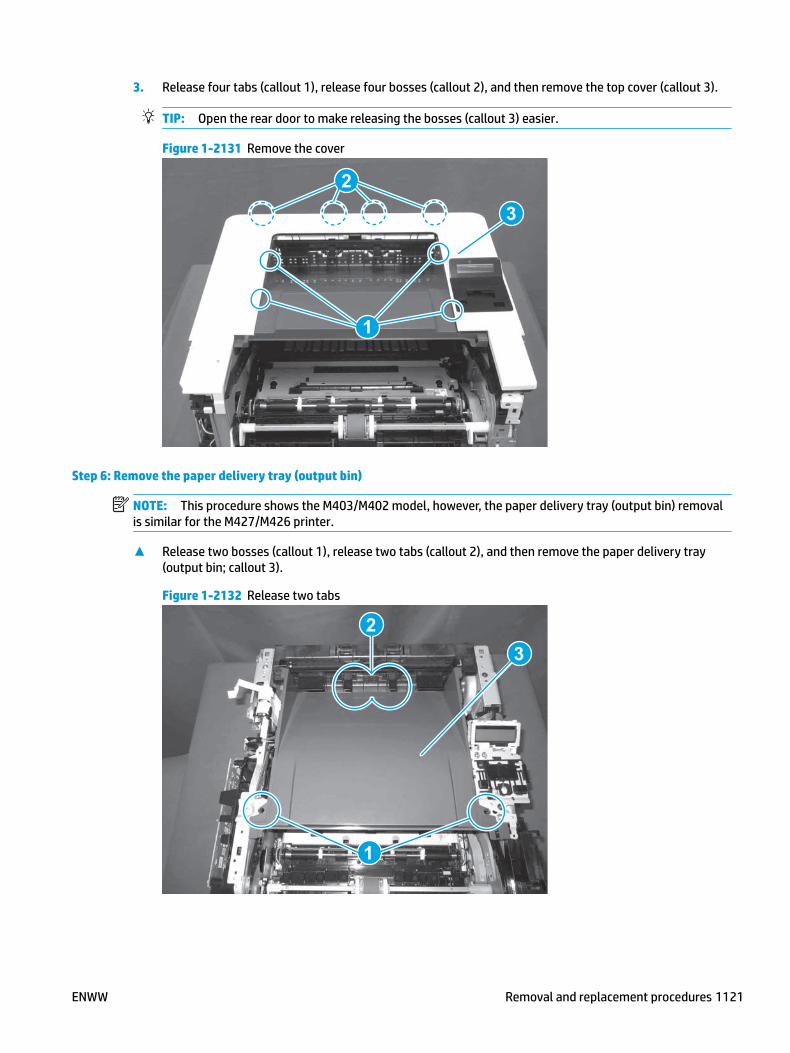
3. Release four tabs (callout 1), release four bosses (callout 2), and then remove the top cover (callout 3).
TIP: Open the rear door to make releasing the bosses (callout 3) easier.
Figure 1-2131 Remove the cover
2
3
1
Step 6: Remove the paper delivery tray (output bin)
NOTE: This procedure shows the M403/M402 model, however, the paper delivery tray (output bin) removal is similar for the M427/M426 printer.
▲ Release two bosses (callout 1), release two tabs (callout 2), and then remove the paper delivery tray (output bin; callout 3).
Figure 1-2132 Release two tabs
2
1
3
ENWW Removal and replacement procedures 1121

Step 7: Remove the control-panel assembly (M403/M402)
1. Disconnect one FFC (callout 1).
Figure 1-2133 Disconnect one FFC
1
2. Remove one screw (callout 1), and then remove the control panel.
Figure 1-2134 Remove one screw and the control panel
1
Step 8: Unpack the replacement assembly
Unpack the replacement part from the packaging.
http://www8.hp.com/us/en/hp-information/environment/product-recycling.html
NOTE: HP recommends responsible disposal of the defective part.
1122 Chapter 1 Removal and replacement ENWW

Figure 1-2135 Recycle and unpack
Step 9: Install the control-panel assembly (M403/M402)
1. Position the control panel on the chassis, and then install one screw (callout 1).
Figure 1-2136 Install the control panel and one screw
1
ENWW Removal and replacement procedures 1123

2. Connect one FFC (callout 1).
Figure 1-2137 Connect one FFC
1
Step 10: Install the paper delivery tray (output bin)
NOTE: This procedure shows the M403/M402 model, however, the paper delivery tray (output bin) removal is similar for the M427/M426 printer.
▲ Position the remove the paper delivery tray (output bin; callout 1) on the printer, engage two tabs (callout 2), and then engage two bosses (callout 3).
Figure 1-2138 Engage two tabs
2
3
1
Step 11: Install the top cover (M403/M402)
1. Position the rear edge of the cover on the printer.
1124 Chapter 1 Removal and replacement ENWW

Figure 1-2139 Install the cover
2. Engage four bosses (callout 1), rotate the front of the cover down (callout 2) and onto from the printer, and then engage four tabs (callout 3).
Figure 1-2140 Engage four bosses and tabs
1
3
2
2
ENWW Removal and replacement procedures 1125

3. At the right side of the printer, engage the one boss and one tab (callout 1).
Figure 1-2141 Engage one boss and one tab
1
4. Install one screw (callout 1).
Figure 1-2142 Install one screw
1
Step 12: Install the right cover
1. Position the cover (callout 1) on the printer, and then engage two bosses (callout 2).
1126 Chapter 1 Removal and replacement ENWW

Figure 1-2143 Install the cover
11
2 2
2. Rotate the front of the cover onto the printer (callout 1), engage three (callout 2) tabs, and then engage two bosses (callout 3).
Figure 1-2144 Engage two bosses and one tab
1 13 3
2 2
3. Make sure that the power switch (callout 1) and cartridge door assembly button (callout 2) correctly function.
NOTE: Remove, and then reinstall the cover if the switch or button does not correctly function.
Figure 1-2145 Check the power switch and cartridge door assembly button
1
1
22
ENWW Removal and replacement procedures 1127

4. Install one screw (callout 1).
Figure 1-2146 Install one screw
11
Step 13: Install the left cover
1. At the front of the printer, do one of the following:
● M403/M402: Position the cover on the printer ( callout 1), and then engage two bosses (callout 2).
● M427/M426: Position the cover on the printer (callout 3), engage one tab (callout 4), and then engage two bosses (callout 4).
Figure 1-2147 Install the cover
1
2
4
35
1128 Chapter 1 Removal and replacement ENWW

2. Carefully rotate the rear of the cover onto the printer (callout 1), engage three tabs (callout 2), and then engage two bosses (callout 3).
Figure 1-2148 Engage three tabs and two bosses
3
3 11
2
2
3. Install one screw (callout 1).
Figure 1-2149 Install one screw
1 1
Step 14: Install the cartridge door assembly
Reinstallation tip: After a replacement door is installed, make sure to install the nameplate (supplied in the kit) corresponding to the printer name on the door.
1. Position the door close to the printer, and then engage the keyed pin on the left-side retainer arm with the hole in the door.
ENWW Removal and replacement procedures 1129

Figure 1-2150 Engage the left-side retainer arm
2. Engage the right-side door hinge pin with the hole in the chassis (callout 1).
Figure 1-2151 Install the door
1
1130 Chapter 1 Removal and replacement ENWW

3. Install the link (callout 1).
IMPORTANT: Make sure that the link snaps into place on the arm (callout 2). The link actuates the fuser pressure-release mechanism.
Figure 1-2152 Install the pressure-release link
1
2
4. Slide the guide into the printer (callout 1), and then make sure that the tab (callout 2) snaps into place to secure the guide to the chassis.
Figure 1-2153 Install the guide
1
2
ENWW Removal and replacement procedures 1131

5. Position the shaft on the door, and then align the left-side hinge on the door with the hole in the chassis (callout 1).
Figure 1-2154 Align the hinge
1
6. Push the shaft towards the left side of the printer to install it (callout 1).
Reinstallation tip: Make sure that the support shaft is fully installed and correctly orientated (callout 2) so that it will not interfere with the door opening and closing.
Figure 1-2155 Install the support shaft
2
1
1132 Chapter 1 Removal and replacement ENWW

Step 15: Install Tray 2
▲ Slide the tray straight into the printer to install it.
Figure 1-2156 Install the tray
ENWW Removal and replacement procedures 1133

Removal and replacement: Control panel (M427/M426) and control panel sub assemblies
● Introduction
● Step 1: Remove the control panel mount cover (M427/M426)
● Step 2: Remove the control panel (M427/M426)
● Step 3: Remove the control panel mount base (M427/M426)
● Step 4: Remove the control panel mount chassis assembly (M427/M426)
● Step 5: Remove Tray 2
● Step 6: Remove the cartridge door assembly
● Step 7: Remove the left cover
● Step 8: Remove the control panel 22-pin FFC (M427/M426)
● Step 9: Unpack the replacement assembly
● Step 10: Install the control panel 22-pin FFC (M427/M426)
● Step 11: Install the left cover
● Step 12: Install the cartridge door assembly
● Step 13: Install Tray 2
● Step 14: Install the control panel mount chassis assembly (M427/M426)
● Step 15: Install the control panel mount base (M427/M426)
● Step 16: Install the control panel (M427/M426)
● Step 17: Install the control panel mount cover (M427/M426)
Introduction
This document provides the procedures to remove and replace the M427/M426 control panel, control panel mount cover, control panel base, control panel mount chassis assembly, and the control panel 22–pin flat flexable cable (FFC).
Before performing service
Turn the printer power off
◦ Disconnect the power cable.
WARNING! To avoid damage to the printer, turn the printer off, wait 30 seconds, and then remove the power cable before attempting to service the printer.
Use the table below to identify the correct part number for your printer. To order the part, go to www.hp.com/buy/parts.
1134 Chapter 1 Removal and replacement ENWW

Control panel (M427/M426) part numbers
B3Q10-60139
B3Q10-40056
B3Q11-40002
B3Q11-40001
B3Q10-60145
C5F98-60104
Control panel (M427/M426; 76.2 mm (3.0 in))
Cover, back control panel (M427/M426)
Control panel mount cover (M427/M426)
Control panel mount base (M427/M426)
Control panel mount chassis (M427/M426)
Control panel 22-pin FFC (M427/M426)
NOTE: If the control panel is damaged, order the following parts and assemble them together.
● B3Q10-60139
● B3Q10-40056
Required tools
● #2 Phillips screwdriver with a magnetic tip.
After performing service
Turn the printer power on
◦ Connect the power cable.
◦ Use the power switch to turn the power on.
Post service test
Make sure that the printer initializes to a Ready state.
Navigate the control-panel menus to make sure that the control panel is correctly functioning.
TIP: If the control panel is not functioning, check the FFC connections at the formatter and control panel. See Step 10: Install the control panel 22-pin FFC (M427/M426) on page 1150 and Step 16: Install the control panel (M427/M426) on page 1159.
Step 1: Remove the control panel mount cover (M427/M426)
1. Open the integrated scanner assembly (ISA).
NOTE: If the control panel is not fully tilted forward, tilt it forward now until it stops.
ENWW Removal and replacement procedures 1135

Figure 1-2157 Open the ISA
2. Remove one screw (callout 1).
Figure 1-2158 Remove one screw
1
1136 Chapter 1 Removal and replacement ENWW
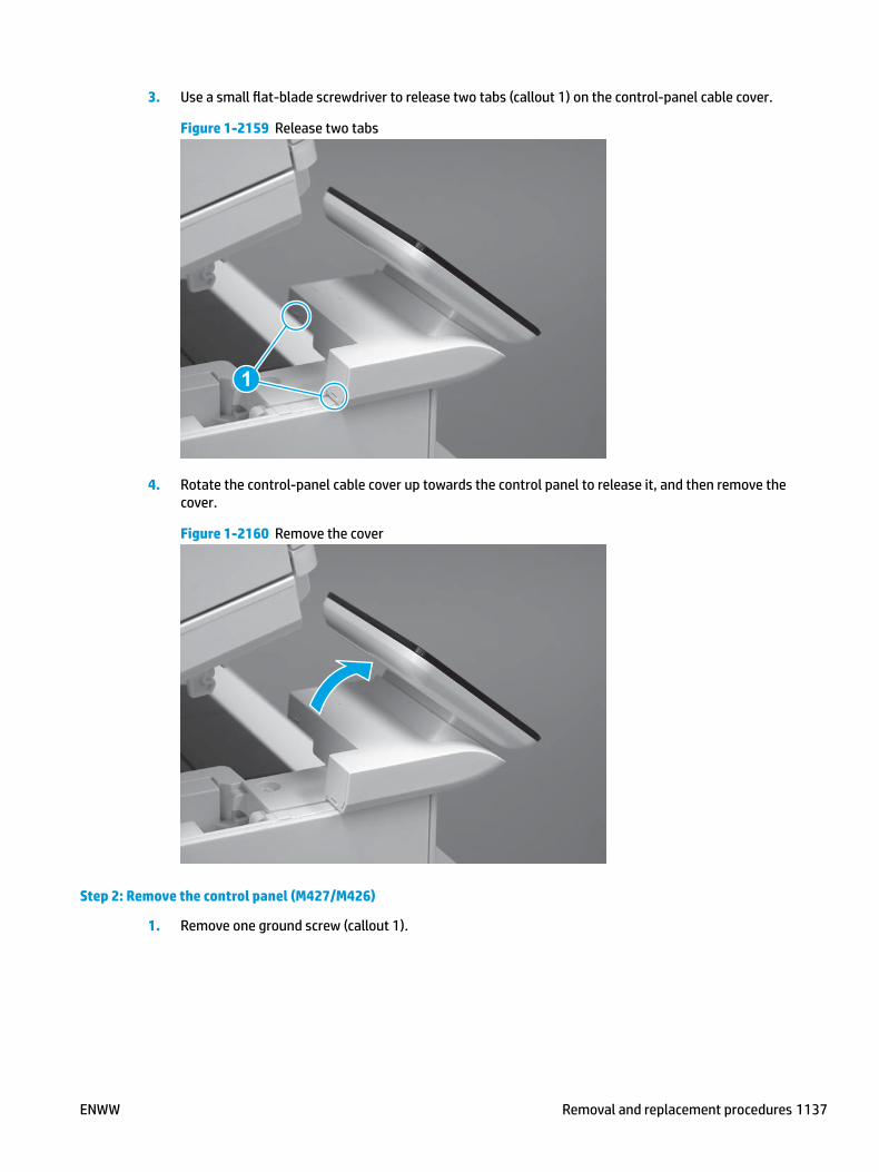
3. Use a small flat-blade screwdriver to release two tabs (callout 1) on the control-panel cable cover.
Figure 1-2159 Release two tabs
1
4. Rotate the control-panel cable cover up towards the control panel to release it, and then remove the cover.
Figure 1-2160 Remove the cover
Step 2: Remove the control panel (M427/M426)
1. Remove one ground screw (callout 1).
ENWW Removal and replacement procedures 1137

Figure 1-2161 Remove one screw
1
2. Gently tilt the control panel farther forward about 3.18 mm (.125 in).
CAUTION: Do not use excessive force. The black-plastic mounting retainer (callout 1) for the control-panel hinge pin is easily broken
Figure 1-2162 Tilt the control panel farther forward
1
1138 Chapter 1 Removal and replacement ENWW

3. Slightly shift the control panel in the direction of the arrow about 6.35 mm (.25 in) to remove it.
CAUTION: Do not twist the control panel. The black-plastic mounting retainer (callout 1) for the control-panel hinge pin is easily broken
Figure 1-2163 Release the control panel
1
4. Separate the control panel from the printer.
CAUTION: The control panel is still connected to the mounting printer by a FFC. Do not attempt to completely remove the control panel.
Figure 1-2164 Separate the control panel from the printer
ENWW Removal and replacement procedures 1139

5. Open the hinged latch to release the FFC, and then remove the control panel.
CAUTION: Be careful. Do not dislodge the latch from the connector.
Figure 1-2165 Release the FFC and remove the control panel
Step 3: Remove the control panel mount base (M427/M426)
1. Remove two screws (callout 1).
Figure 1-2166 Remove two screws
1
1140 Chapter 1 Removal and replacement ENWW

2. Release the FFC from the retainer (callout 1), and then gently remove the FFC from mount base (callout 2).
CAUTION: The FFC is adhered to the mount base with two-sided tape (callout 2). Do not damage the FFC when removing it from the mount base.
Figure 1-2167 Remove the FFC
1
2
3. Remove the control panel mount base.
Figure 1-2168 Release the control panel mount base
Step 4: Remove the control panel mount chassis assembly (M427/M426)
1. Slide the mount chassis assembly as shown (callout 1) to release it from four bosses (callout 2).
ENWW Removal and replacement procedures 1141
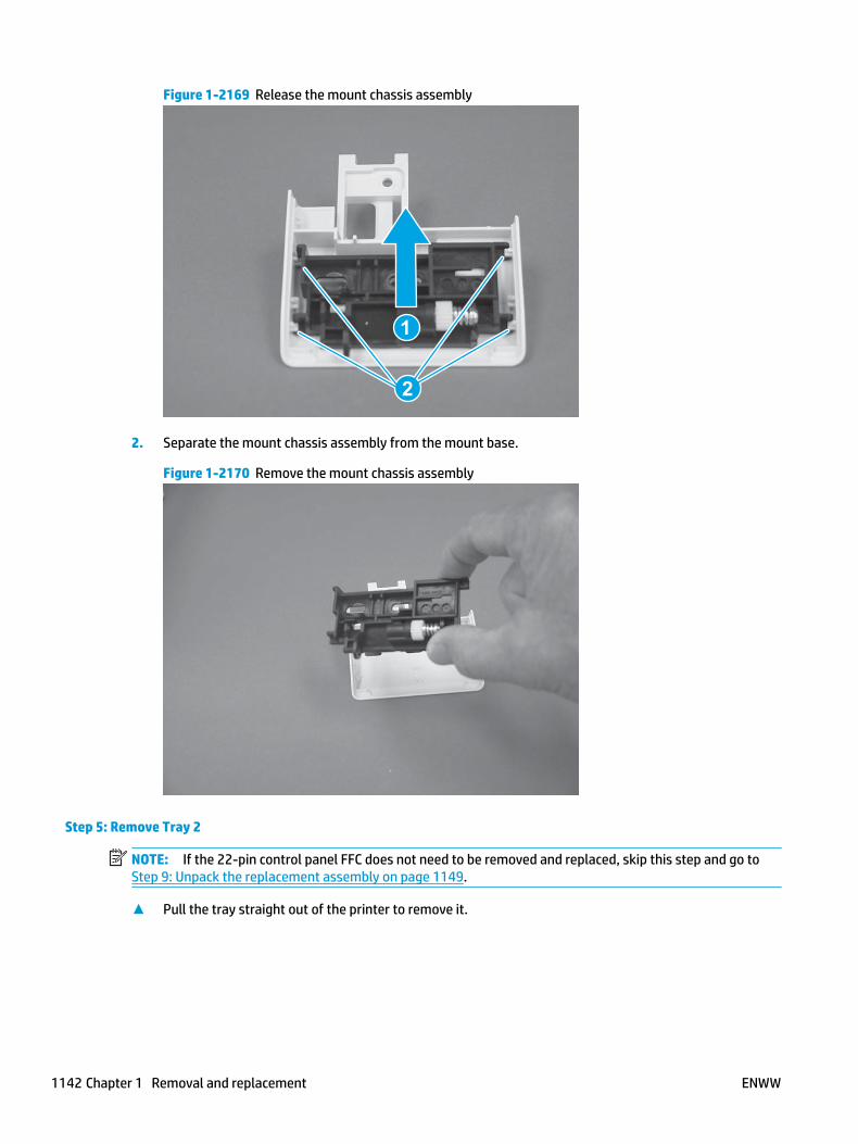
Figure 1-2169 Release the mount chassis assembly
1
2
2. Separate the mount chassis assembly from the mount base.
Figure 1-2170 Remove the mount chassis assembly
Step 5: Remove Tray 2
NOTE: If the 22-pin control panel FFC does not need to be removed and replaced, skip this step and go to Step 9: Unpack the replacement assembly on page 1149.
▲ Pull the tray straight out of the printer to remove it.
1142 Chapter 1 Removal and replacement ENWW
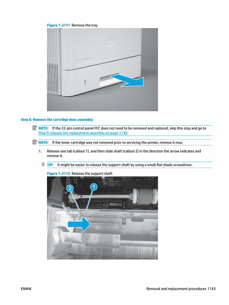
Figure 1-2171 Remove the tray
Step 6: Remove the cartridge door assembly
NOTE: If the 22-pin control panel FFC does not need to be removed and replaced, skip this step and go to Step 9: Unpack the replacement assembly on page 1149.
NOTE: If the toner cartridge was not removed prior to servicing the printer, remove it now.
1. Release one tab (callout 1), and then slide shaft (callout 2) in the direction the arrow indicates and remove it.
TIP: It might be easier to release the support shaft by using a small flat-blade screwdriver.
Figure 1-2172 Release the support shaft
12
ENWW Removal and replacement procedures 1143

2. Release one tab (callout 1), and then slide the guide (callout 2) in the direction the arrow indicates and remove it.
Figure 1-2173 Remove the guide
1 2
3. Remove the link arm (callout 1).
Figure 1-2174 Remove the link arm
1
1144 Chapter 1 Removal and replacement ENWW
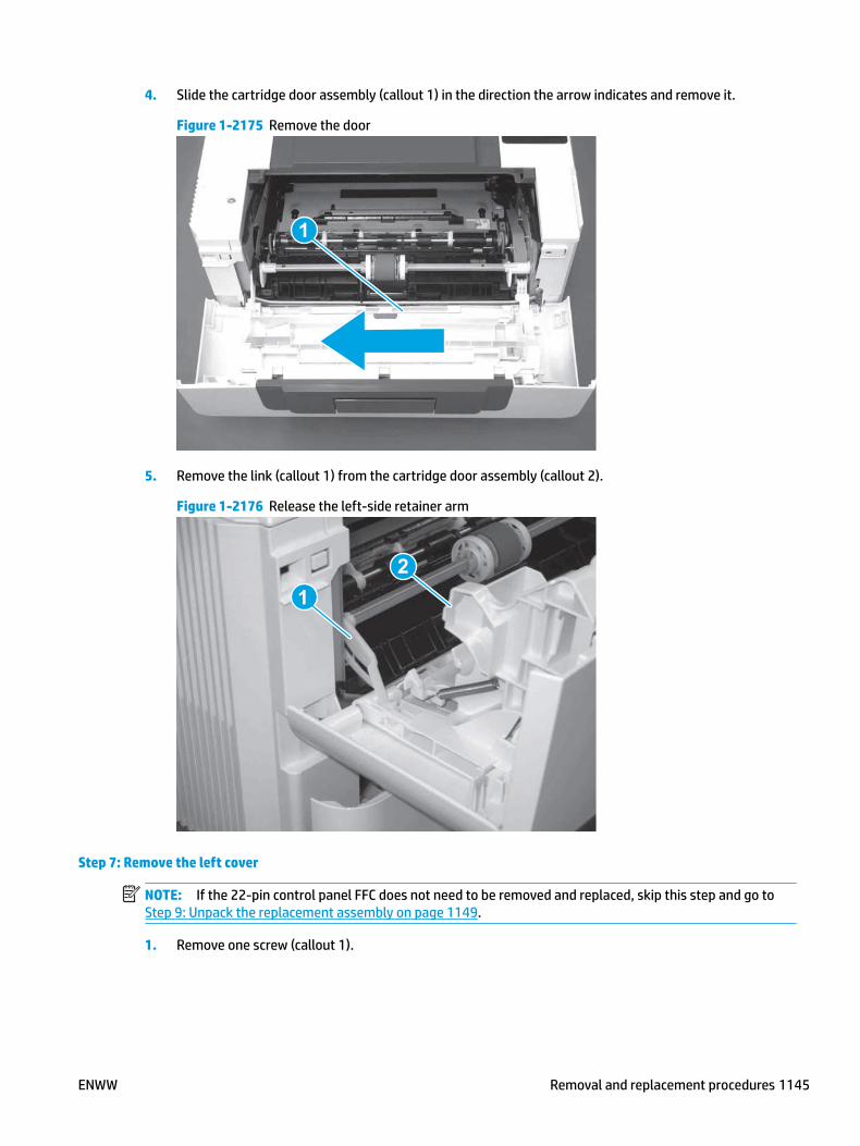
4. Slide the cartridge door assembly (callout 1) in the direction the arrow indicates and remove it.
Figure 1-2175 Remove the door
1
5. Remove the link (callout 1) from the cartridge door assembly (callout 2).
Figure 1-2176 Release the left-side retainer arm
21
Step 7: Remove the left cover
NOTE: If the 22-pin control panel FFC does not need to be removed and replaced, skip this step and go to Step 9: Unpack the replacement assembly on page 1149.
1. Remove one screw (callout 1).
ENWW Removal and replacement procedures 1145

Figure 1-2177 Remove one screw
1 1
2. Open the rear door, release two bosses (callout 1), and then release three tabs (callout 2).
Figure 1-2178 Release two bosses and three tabs
1
1
2
2
3. At the front of the printer, do one of the following:
● M403/M402: Release two bosses (callout 1), and then remove the cover (callout 2).
● M427/M426: Release one tab (callout 3), two bosses (callout 4), and then remove the cover (callout 5).
CAUTION: Be careful when releasing the upper bosses on the M427/M426 cover. One portion of the cover (callout 6) is fragile and is easily broken.
1146 Chapter 1 Removal and replacement ENWW
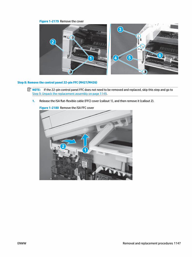
Figure 1-2179 Remove the cover
2
1
3
54 6
Step 8: Remove the control panel 22-pin FFC (M427/M426)
NOTE: If the 22-pin control panel FFC does not need to be removed and replaced, skip this step and go to Step 9: Unpack the replacement assembly on page 1149.
1. Release the ISA flat-flexible cable (FFC) cover (callout 1), and then remove it (callout 2).
Figure 1-2180 Remove the ISA FFC cover
12
ENWW Removal and replacement procedures 1147

2. Disconnect one FFC (callout 1).
Figure 1-2181 Disconnect one FFC
1
3. Lift up the control-panel FFC cover to release it.
Figure 1-2182 Release the control-panel FFC cover
1148 Chapter 1 Removal and replacement ENWW
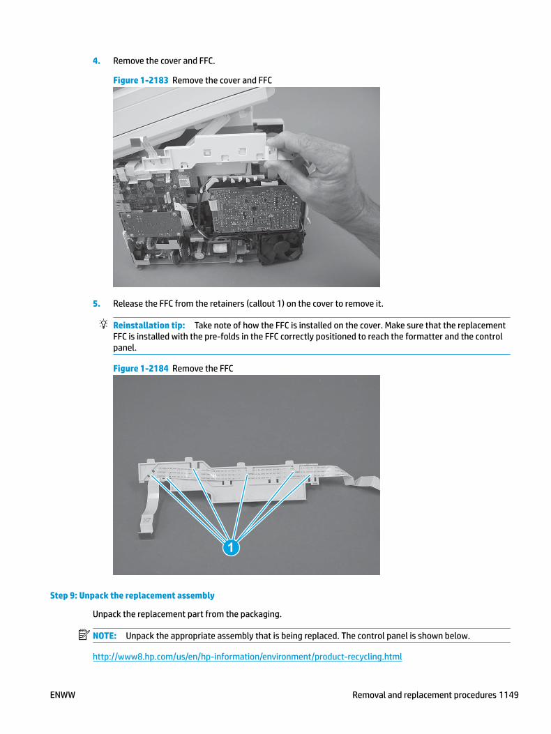
4. Remove the cover and FFC.
Figure 1-2183 Remove the cover and FFC
5. Release the FFC from the retainers (callout 1) on the cover to remove it.
Reinstallation tip: Take note of how the FFC is installed on the cover. Make sure that the replacement FFC is installed with the pre-folds in the FFC correctly positioned to reach the formatter and the control panel.
Figure 1-2184 Remove the FFC
1
Step 9: Unpack the replacement assembly
Unpack the replacement part from the packaging.
NOTE: Unpack the appropriate assembly that is being replaced. The control panel is shown below.
http://www8.hp.com/us/en/hp-information/environment/product-recycling.html
ENWW Removal and replacement procedures 1149

NOTE: HP recommends responsible disposal of the defective part.
Figure 1-2185 Recycle and unpack
Step 10: Install the control panel 22-pin FFC (M427/M426)
NOTE: If the 22-pin control panel FFC does not need to be removed and replaced, skip this step and go to Step 14: Install the control panel mount chassis assembly (M427/M426) on page 1157.
1. Install the FFC in the retainers (callout 1) on the control-panel FFC.
Reinstallation tip: Make sure that the replacement FFC is installed with the pre-folds in the FFC correctly positioned to reach the formatter and the control panel.
Figure 1-2186 Install the FFC on the cover
1
1150 Chapter 1 Removal and replacement ENWW

2. Position the cover on the printer, and then push down to install it.
Figure 1-2187 Install the cover
3. Connect one FFC (callout 1).
Figure 1-2188 Connect one FFC
1
ENWW Removal and replacement procedures 1151

4. Position the rear edge of the ISA flat-flexible cable (FFC) cover on the printer (callout 1) , and then rotate it down (callout 2) until it snaps into place.
Figure 1-2189 Install the ISA FFC cover
1
2
Step 11: Install the left cover
NOTE: If the 22-pin control panel FFC was not replaced, skip this step and go to Step 14: Install the control panel mount chassis assembly (M427/M426) on page 1157.
1. At the front of the printer, do one of the following:
● M403/M402: Position the cover on the printer ( callout 1), and then engage two bosses (callout 2).
● M427/M426: Position the cover on the printer (callout 3), engage one tab (callout 4), and then engage two bosses (callout 4).
Figure 1-2190 Install the cover
1
2
4
35
1152 Chapter 1 Removal and replacement ENWW
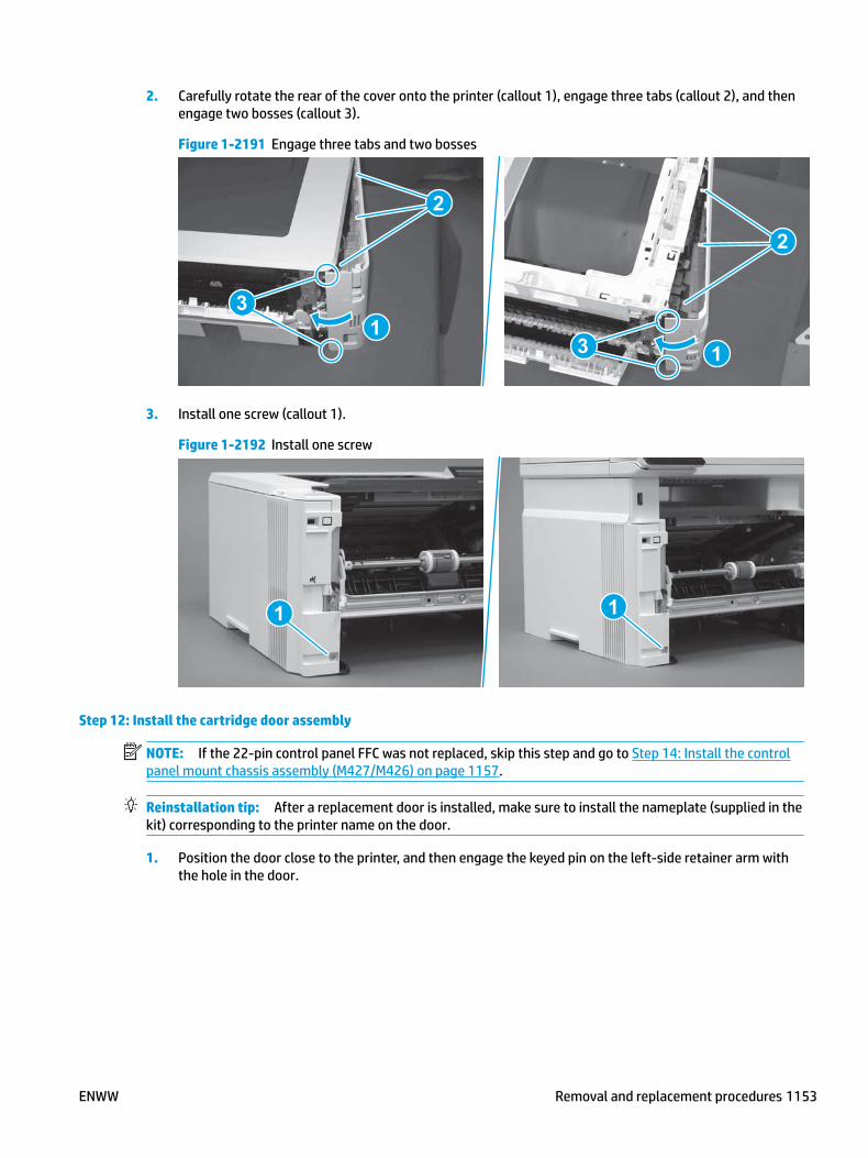
2. Carefully rotate the rear of the cover onto the printer (callout 1), engage three tabs (callout 2), and then engage two bosses (callout 3).
Figure 1-2191 Engage three tabs and two bosses
3
3 11
2
2
3. Install one screw (callout 1).
Figure 1-2192 Install one screw
1 1
Step 12: Install the cartridge door assembly
NOTE: If the 22-pin control panel FFC was not replaced, skip this step and go to Step 14: Install the control panel mount chassis assembly (M427/M426) on page 1157.
Reinstallation tip: After a replacement door is installed, make sure to install the nameplate (supplied in the kit) corresponding to the printer name on the door.
1. Position the door close to the printer, and then engage the keyed pin on the left-side retainer arm with the hole in the door.
ENWW Removal and replacement procedures 1153

Figure 1-2193 Engage the left-side retainer arm
2. Engage the right-side door hinge pin with the hole in the chassis (callout 1).
Figure 1-2194 Install the door
1
1154 Chapter 1 Removal and replacement ENWW

3. Install the link (callout 1).
IMPORTANT: Make sure that the link snaps into place on the arm (callout 2). The link actuates the fuser pressure-release mechanism.
Figure 1-2195 Install the pressure-release link
1
2
4. Slide the guide into the printer (callout 1), and then make sure that the tab (callout 2) snaps into place to secure the guide to the chassis.
Figure 1-2196 Install the guide
1
2
ENWW Removal and replacement procedures 1155

5. Position the shaft on the door, and then align the left-side hinge on the door with the hole in the chassis (callout 1).
Figure 1-2197 Align the hinge
1
6. Push the shaft towards the left side of the printer to install it (callout 1).
Reinstallation tip: Make sure that the support shaft is fully installed and correctly orientated (callout 2) so that it will not interfere with the door opening and closing.
Figure 1-2198 Install the support shaft
2
1
1156 Chapter 1 Removal and replacement ENWW

Step 13: Install Tray 2
NOTE: If the 22-pin control panel FFC was not replaced, skip this step and go to Step 14: Install the control panel mount chassis assembly (M427/M426) on page 1157.
▲ Slide the tray straight into the printer to install it.
Figure 1-2199 Install the tray
Step 14: Install the control panel mount chassis assembly (M427/M426)
1. Position the mount chassis assembly on the mount base.
Figure 1-2200 Install the mount chassis assembly
ENWW Removal and replacement procedures 1157
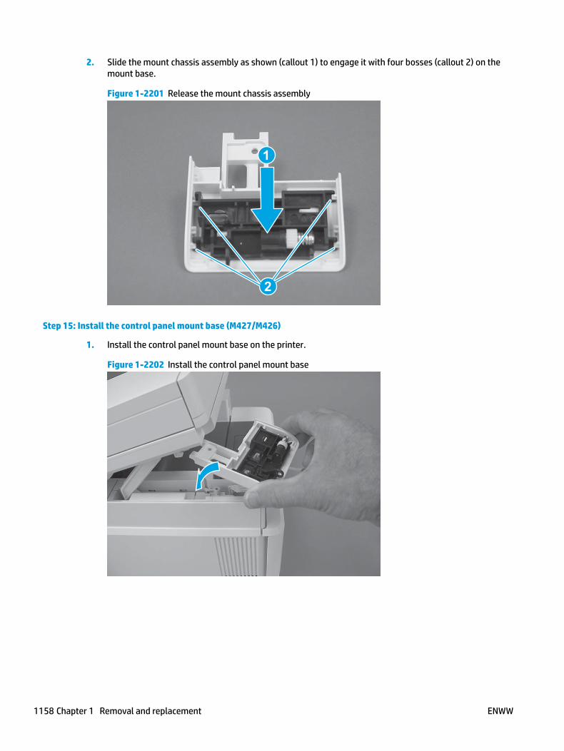
2. Slide the mount chassis assembly as shown (callout 1) to engage it with four bosses (callout 2) on the mount base.
Figure 1-2201 Release the mount chassis assembly
1
2
Step 15: Install the control panel mount base (M427/M426)
1. Install the control panel mount base on the printer.
Figure 1-2202 Install the control panel mount base
1158 Chapter 1 Removal and replacement ENWW
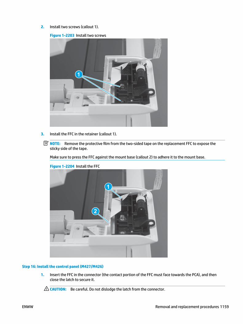
2. Install two screws (callout 1).
Figure 1-2203 Install two screws
1
3. Install the FFC in the retainer (callout 1).
NOTE: Remove the protective film from the two-sided tape on the replacement FFC to expose the sticky side of the tape.
Make sure to press the FFC against the mount base (callout 2) to adhere it to the mount base.
Figure 1-2204 Install the FFC
1
2
Step 16: Install the control panel (M427/M426)
1. Insert the FFC in the connector (the contact portion of the FFC must face towards the PCA), and then close the latch to secure it.
CAUTION: Be careful. Do not dislodge the latch from the connector.
ENWW Removal and replacement procedures 1159

Reinstallation tip: Gently pull on the FFC to make sure it is fully seated and secured by the latch on the connector. Do not forcibly pull on the FFC, a gentle tug is all that is required.
Figure 1-2205 Connect the FFC
2. Align the control-panel hinge pins (callout 1) with the mounting retainers (callout 2) on the printer.
Figure 1-2206 Align the control-panel hinge pins
2
1
1160 Chapter 1 Removal and replacement ENWW

3. Slightly shift the control panel in the direction of the arrow about 6.35 mm (.25 in) to engage the hinge pins.
CAUTION: Do not twist the control panel. The black-plastic mounting retainer (callout 1) for the control-panel hinge pin is easily broken
Figure 1-2207 Engage the control panel
1
ENWW Removal and replacement procedures 1161
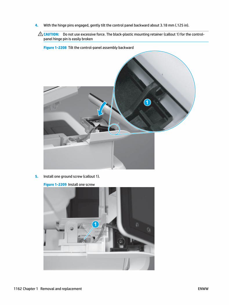
4. With the hinge pins engaged, gently tilt the control panel backward about 3.18 mm (.125 in).
CAUTION: Do not use excessive force. The black-plastic mounting retainer (callout 1) for the control-panel hinge pin is easily broken
Figure 1-2208 Tilt the control-panel assembly backward
1
5. Install one ground screw (callout 1).
Figure 1-2209 Install one screw
1
1162 Chapter 1 Removal and replacement ENWW

Step 17: Install the control panel mount cover (M427/M426)
1. Position the front edge of the control-panel cable cover at the base of the control panel (callout 1), and then rotate it down to install it (callout 2).
Figure 1-2210 Install the control-panel cable cover
1
2
2. Make sure that the two tabs (callout 1) on the cover snap into place.
Figure 1-2211 Check two tabs
1
ENWW Removal and replacement procedures 1163

3. Install one screw (callout 1).
Figure 1-2212 Install one screw
1
4. Close the ISA.
Figure 1-2213 Close the ISA
1164 Chapter 1 Removal and replacement ENWW

Removal and replacement: Trays● Removal and replacement: Tray 2
Removal and replacement: Tray 2
● RM2-5392-000CN 250-sheet paper input tray
● RM2-5452-000CN Tray 2 paper pickup roller assembly
● RM2-5397-000CN Tray 2 separation roller assembly
ENWW Removal and replacement procedures 1165
RM2-5392-000CN 250-sheet paper input tray
● Introduction
● Step 1: Remove Tray 2
● Step 2: Unpack the replacement assembly
● Step 3: Install Tray 2
Introduction
This document provides the procedures to remove and replace Tray 2.
Before performing service
Turn the printer power off
◦ Disconnect the power cable.
WARNING! To avoid damage to the printer, turn the printer off, wait 30 seconds, and then remove the power cable before attempting to service the printer.
Use the table below to identify the correct part number for your printer. To order the part, go to www.hp.com/buy/parts.
Tray 2 part number
RM2-5392-000CN Cassette (Tray 2) assembly
Required tools
● No special tools are required to remove this part.
After performing service
Turn the printer power on
◦ Connect the power cable.
◦ Use the power switch to turn the power on.
Post service test
Make sure that the printer initializes to a Ready state.
Print a configuration page (from Tray 2) to make sure that the printer is functioning correctly.
Step 1: Remove Tray 2
▲ Pull the tray straight out of the printer to remove it.
1166 Chapter 1 Removal and replacement ENWW

Figure 1-2214 Remove the tray
Step 2: Unpack the replacement assembly
Unpack the replacement part from the packaging.
http://www8.hp.com/us/en/hp-information/environment/product-recycling.html
NOTE: HP recommends responsible disposal of the defective part.
Figure 1-2215 Recycle and unpack
Step 3: Install Tray 2
▲ Slide the tray straight into the printer to install it.
ENWW Removal and replacement procedures 1167

Figure 1-2216 Install the tray
RM2-5452-000CN Tray 2 paper pickup roller assembly
● Introduction
● Step 1: Remove Tray 2
● Step 2: Remove the pickup roller assembly (Tray 2)
● Step 3: Unpack the replacement assembly
● Step 4: Install the pickup roller assembly (Tray 2)
● Step 5: Install Tray 2
Introduction
This document provides the procedures to remove and replace the paper pickup roller assembly (Tray 2).
Before performing service
Turn the printer power off
◦ Disconnect the power cable.
WARNING! To avoid damage to the printer, turn the printer off, wait 30 seconds, and then remove the power cable before attempting to service the printer.
Use the table below to identify the correct part number for your printer. To order the part, go to www.hp.com/buy/parts.
Paper pickup roller assembly (Tray 2) part number
RM2-5452-000CN Paper pickup roller assembly (Tray 2)
1168 Chapter 1 Removal and replacement ENWW

Required tools
● No special tools are required to remove this part.
After performing service
Turn the printer power on
◦ Connect the power cable.
◦ Use the power switch to turn the power on.
Post service test
Make sure that the printer initializes to a Ready state.
Print a page from Tray 2 to make sure that the printer is functioning correctly.
Step 1: Remove Tray 2
▲ Pull the tray straight out of the printer to remove it.
Figure 1-2217 Remove the tray
Step 2: Remove the pickup roller assembly (Tray 2)
CAUTION: When handling the roller holder, do not touch the gray spongy portion of the rollers. Skin oils on the rollers can cause paper handling problems.
NOTE: The M403/M402 printer is shown in this procedure. However, the procedure is valid for the M427/M426 printers.
1. Carefully rotate the printer backward.
CAUTION: To avoid damage to the rear cassette cover, keep it in the closed position.
ENWW Removal and replacement procedures 1169

Figure 1-2218 Tilt the printer backward
2. Continue rotate the printer backward until it rests on the rear cover, bottom-side face forward.
CAUTION: M427/M426: The integrated scanner assembly (ISA) is not captive, and can unexpectedly open when the printer is tilted back.
Figure 1-2219 Place the printer bottom-side face forward
1170 Chapter 1 Removal and replacement ENWW

3. Release one tab (callout 1), and then slide the roller holder toward the left side of the printer to release it.
Figure 1-2220 Release one tab
1
4. Remove the roller holder.
Figure 1-2221 Remove the roller holder
Step 3: Unpack the replacement assembly
Unpack the replacement part from the packaging.
http://www8.hp.com/us/en/hp-information/environment/product-recycling.html
CAUTION: When handling the roller holder, do not touch the gray spongy portion of the rollers. Skin oils on the rollers can cause paper handling problems.
NOTE: HP recommends responsible disposal of the defective part.
ENWW Removal and replacement procedures 1171

Figure 1-2222 Recycle and unpack
Step 4: Install the pickup roller assembly (Tray 2)
CAUTION: When handling the roller holder, do not touch the gray spongy portion of the rollers. Skin oils on the rollers can cause paper handling problems.
NOTE: The M403/M402 printer is shown in this procedure. However, the procedure is valid for the M427/M426 printers.
1. Position the roller holder assembly in the printer as shown, and then slide it toward the right side of the printer.
Figure 1-2223 Install the roller holder
1172 Chapter 1 Removal and replacement ENWW

2. Make sure that the tab snaps into place.
Figure 1-2224 Check the tab
3. Carefully rotate the printer forward.
Figure 1-2225 Rotate the printer forward
ENWW Removal and replacement procedures 1173

4. Continue rotate the printer forward until it rests in the operational position.
Figure 1-2226 Place the printer in the operational position
Step 5: Install Tray 2
▲ Slide the tray straight into the printer to install it.
Figure 1-2227 Install the tray
1174 Chapter 1 Removal and replacement ENWW

RM2-5397-000CN Tray 2 separation roller assembly
● Introduction
● Step 1: Remove Tray 2
● Step 2: Remove the separation pad roller assembly (Tray 2))
● Step 3: Unpack the replacement assembly
● Step 4: Install the separation pad roller assembly (Tray 2)
● Step 5: Install Tray 2
Introduction
This document provides the procedures to remove and replace the separation roller assembly (Tray 2).
Before performing service
Turn the printer power off
◦ Disconnect the power cable.
WARNING! To avoid damage to the printer, turn the printer off, wait 30 seconds, and then remove the power cable before attempting to service the printer.
Use the table below to identify the correct part number for your printer. To order the part, go to www.hp.com/buy/parts.
Separation roller assembly (Tray 2) part number
RM2-5397-000CN Separation roller assembly (Tray 2)
Required tools
● No special tools are required to install this kit.
After performing service
Turn the printer power on
◦ Connect the power cable.
◦ Use the power switch to turn the power on.
Post service test
Make sure that the printer initializes to a Ready state.
Print a configuration page to make sure that the printer is functioning correctly.
Step 1: Remove Tray 2
▲ Pull the tray straight out of the printer to remove it.
ENWW Removal and replacement procedures 1175

Figure 1-2228 Remove the tray
Step 2: Remove the separation pad roller assembly (Tray 2))
1. Pull the separation pad assembly straight up to release it.
Figure 1-2229 Release the assembly
1
1176 Chapter 1 Removal and replacement ENWW

2. Remove the assembly.
Figure 1-2230 Remove the assembly
Step 3: Unpack the replacement assembly
Unpack the replacement part from the packaging.
http://www8.hp.com/us/en/hp-information/environment/product-recycling.html
NOTE: HP recommends responsible disposal of the defective part.
Figure 1-2231 Recycle and unpack
Step 4: Install the separation pad roller assembly (Tray 2)
1. Install the assembly in the slot in the cassette.
ENWW Removal and replacement procedures 1177

Figure 1-2232 Install the assembly
2. Push the separation pad assembly straight down until it snaps into place.
Figure 1-2233 Release the assembly
Step 5: Install Tray 2
▲ Slide the tray straight into the printer to install it.
1178 Chapter 1 Removal and replacement ENWW
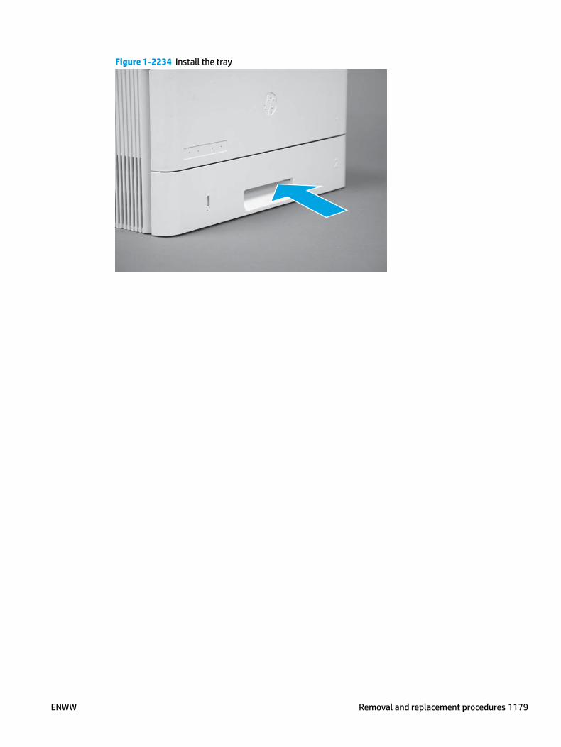
Figure 1-2234 Install the tray
ENWW Removal and replacement procedures 1179

Removal and replacement: Accessories● 550-sheet paper feeder
550-sheet paper feeder
NOTE: HP recommends removing the accessory from the product before servicing them.
● C5F97-69001 optional 550-sheet paper feeder
● RM2-5413-000CN optional Tray 3
● RM2-5741-000CN optional Tray 3 paper pickup roller assembly
● RM2-5745-000CN optional Tray 3 separation roller assembly
1180 Chapter 1 Removal and replacement ENWW

C5F97-69001 optional 550-sheet paper feeder
● Introduction
● Step 1: Remove the optional 550-sheet feeder Tray 3
● Step 2: Unpack the replacement optional paper feeder
● Step 3: Install the optional 550-sheet feeder Tray 3
Introduction
This document provides the procedures to remove and replace the optional 550-sheet paper feeder.
Before performing service
Turn the printer power off
◦ Disconnect the power cable.
WARNING! To avoid damage to the printer, turn the printer off, wait 30 seconds, and then remove the power cable before attempting to service the printer.
Use the table below to identify the correct part number for your printer. To order the part, go to www.hp.com/buy/parts.
Optional 550-sheet paper feeder part number
C5F697–69001 Optional 550-sheet paper feeder (optional Tray 3)
Required tools
● No special tools are required to remove this part.
After performing service
Turn the printer power on
◦ Connect the power cable.
◦ Use the power switch to turn the power on.
Post service test
Make sure that the printer initializes to a Ready state.
Print a page from the optional Tray 3 to make sure that the paper feeder is functioning correctly.
Step 1: Remove the optional 550-sheet feeder Tray 3
▲ Carefully lift the printer off of the paper feeder assembly.
ENWW Removal and replacement procedures 1181

Figure 1-2235 Remove the printer
3
2
1
Step 2: Unpack the replacement optional paper feeder
Unpack the replacement part from the packaging.
http://www8.hp.com/us/en/hp-information/environment/product-recycling.html
NOTE: HP recommends responsible disposal of the defective part.
Figure 1-2236 Recycle and unpack
3
3
1182 Chapter 1 Removal and replacement ENWW

Step 3: Install the optional 550-sheet feeder Tray 3
1. Remove the orange shipping tape.
Figure 1-2237 Remove shipping tape
3
2. Carefully place the printer on the paper feeder assembly.
Figure 1-2238 Install the printer
3
2
1
ENWW Removal and replacement procedures 1183

3. Pull Tray 3 out of the paper feeder assembly to remove it.
Figure 1-2239 Remove Tray 3
2
1
RD
3
4. Adjust the Tray 3 sliding paper guides.
Figure 1-2240 Adjust the paper guides
3
1184 Chapter 1 Removal and replacement ENWW

5. Load paper in Tray 3.
Figure 1-2241 Load paper
33
6. Slide Tray 3 into the paper feeder assembly to install it.
Figure 1-2242 Install
ENWW Removal and replacement procedures 1185

RM2-5413-000CN optional Tray 3
● Introduction
● Step 1: Remove optional Tray 3
● Step 2: Unpack the replacement assembly
● Step 3: Install optional Tray 3
Introduction
This document provides the procedures to remove and replace the optional Tray 3.
Before performing service
Turn the printer power off
◦ Disconnect the power cable.
WARNING! To avoid damage to the printer, turn the printer off, wait 30 seconds, and then remove the power cable before attempting to service the printer.
Use the table below to identify the correct part number for your printer. To order the part, go to www.hp.com/buy/parts.
Tray 3 part number
RM2-5413-000CN 550-sheet paper feeder cassette (optional Tray 3)
Required tools
● No special tools are required to remove this part.
After performing service
Turn the printer power on
◦ Connect the power cable.
◦ Use the power switch to turn the power on.
Post service test
Make sure that the printer initializes to a Ready state.
Print a page from Tray 3 to make sure that the paper feeder is functioning correctly.
Step 1: Remove optional Tray 3
1. Pull the tray straight out of the printer until it stops.
1186 Chapter 1 Removal and replacement ENWW

Figure 1-2243 Pull the tray out of the printer
2. Slightly lift up on the front of the tray to release it, and then continue to pull the tray out of the accessory to remove it.
Figure 1-2244 Release and remove the tray
Step 2: Unpack the replacement assembly
Unpack the replacement part from the packaging.
http://www8.hp.com/us/en/hp-information/environment/product-recycling.html
NOTE: HP recommends responsible disposal of the defective part.
ENWW Removal and replacement procedures 1187

Figure 1-2245 Recycle and unpack
Step 3: Install optional Tray 3
1. With the tray at a slight angle, align the sides of the tray with the rails in the accessory, and then partially slide the tray into the accessory.
Figure 1-2246 Install the tray
1188 Chapter 1 Removal and replacement ENWW

2. Push the tray straight into the accessory to close it.
Figure 1-2247 Close the tray
ENWW Removal and replacement procedures 1189

RM2-5741-000CN optional Tray 3 paper pickup roller assembly
● Introduction
● Step 1: Remove optional Tray 3
● Step 2: Remove the paper pickup roller assembly (Tray 3)
● Step 3: Unpack the replacement assembly
● Step 4: Install the paper pickup roller assembly (Tray 3)
● Step 5: Install optional Tray 3
Introduction
This document provides the procedures to remove and replace the paper pickup roller assembly (Tray 3).
Before performing service
Turn the printer power off
◦ Disconnect the power cable.
WARNING! To avoid damage to the printer, turn the printer off, wait 30 seconds, and then remove the power cable before attempting to service the printer.
Use the table below to identify the correct part number for your printer. To order the part, go to www.hp.com/buy/parts.
Paper pickup roller assembly (Tray 3) part number
RM2-5741-000N Paper pickup roller assembly (Tray 3)
Required tools
● No special tools are required to remove this part.
After performing service
Turn the printer power on
◦ Connect the power cable.
◦ Use the power switch to turn the power on.
Post service test
Make sure that the printer initializes to a Ready state.
Print a page from the accessory to make sure that the printer is functioning correctly.
Step 1: Remove optional Tray 3
1. Pull the tray straight out of the printer until it stops.
1190 Chapter 1 Removal and replacement ENWW
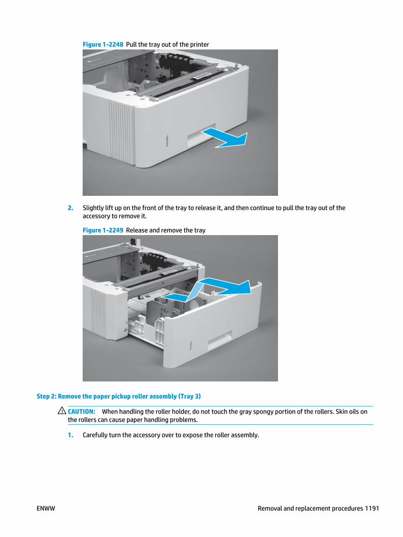
Figure 1-2248 Pull the tray out of the printer
2. Slightly lift up on the front of the tray to release it, and then continue to pull the tray out of the accessory to remove it.
Figure 1-2249 Release and remove the tray
Step 2: Remove the paper pickup roller assembly (Tray 3)
CAUTION: When handling the roller holder, do not touch the gray spongy portion of the rollers. Skin oils on the rollers can cause paper handling problems.
1. Carefully turn the accessory over to expose the roller assembly.
ENWW Removal and replacement procedures 1191

Figure 1-2250 Turn the accessory over
2. Slide the roller holder to the right to compress the spring-loaded shaft and release the assembly.
Figure 1-2251 Release the assembly
1192 Chapter 1 Removal and replacement ENWW
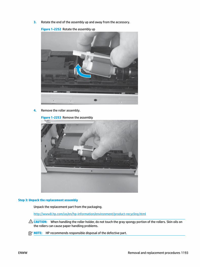
3. Rotate the end of the assembly up and away from the accessory.
Figure 1-2252 Rotate the assembly up
4. Remove the roller assembly.
Figure 1-2253 Remove the assembly
Step 3: Unpack the replacement assembly
Unpack the replacement part from the packaging.
http://www8.hp.com/us/en/hp-information/environment/product-recycling.html
CAUTION: When handling the roller holder, do not touch the gray spongy portion of the rollers. Skin oils on the rollers can cause paper handling problems.
NOTE: HP recommends responsible disposal of the defective part.
ENWW Removal and replacement procedures 1193

Figure 1-2254 Recycle and unpack
Step 4: Install the paper pickup roller assembly (Tray 3)
CAUTION: When handling the roller holder, do not touch the gray spongy portion of the rollers. Skin oils on the rollers can cause paper handling problems.
1. Install the right end of the assembly on the spring-loaded shaft (callout 1), and then slide it to the right to compress the shaft (callout 2).
IMPORTANT: Make sure that the pin on the back of the holder (callout 3) is inserted in the slot (callout 4) in the lever arm. If the pin is not correctly installed, the accessory will not pick paper.
Figure 1-2255 Install the roller assembly
1
23
4
1194 Chapter 1 Removal and replacement ENWW

2. Rotate the left end of the assembly down and into place (callout 1), and then slide the assembly to the left (callout 2) to engage the drive end of the assembly with the drive shaft (callout 3).
Figure 1-2256 Release the assembly
2
1
3
3. Push down and then release the tray-roller actuator (callout 1) and observe the roller assembly. It should move up and down (callout 2) in response to the actuator.
NOTE: If it does not, remove the roller assembly and reinstall it making sure that the pin on the back of the assembly is in the lever arm. See Figure 1-35 Install the roller assembly on page 31.
Figure 1-2257 Check the installation
12
Step 5: Install optional Tray 3
1. With the tray at a slight angle, align the sides of the tray with the rails in the accessory, and then partially slide the tray into the accessory.
ENWW Removal and replacement procedures 1195

Figure 1-2258 Install the tray
2. Push the tray straight into the accessory to close it.
Figure 1-2259 Close the tray
1196 Chapter 1 Removal and replacement ENWW
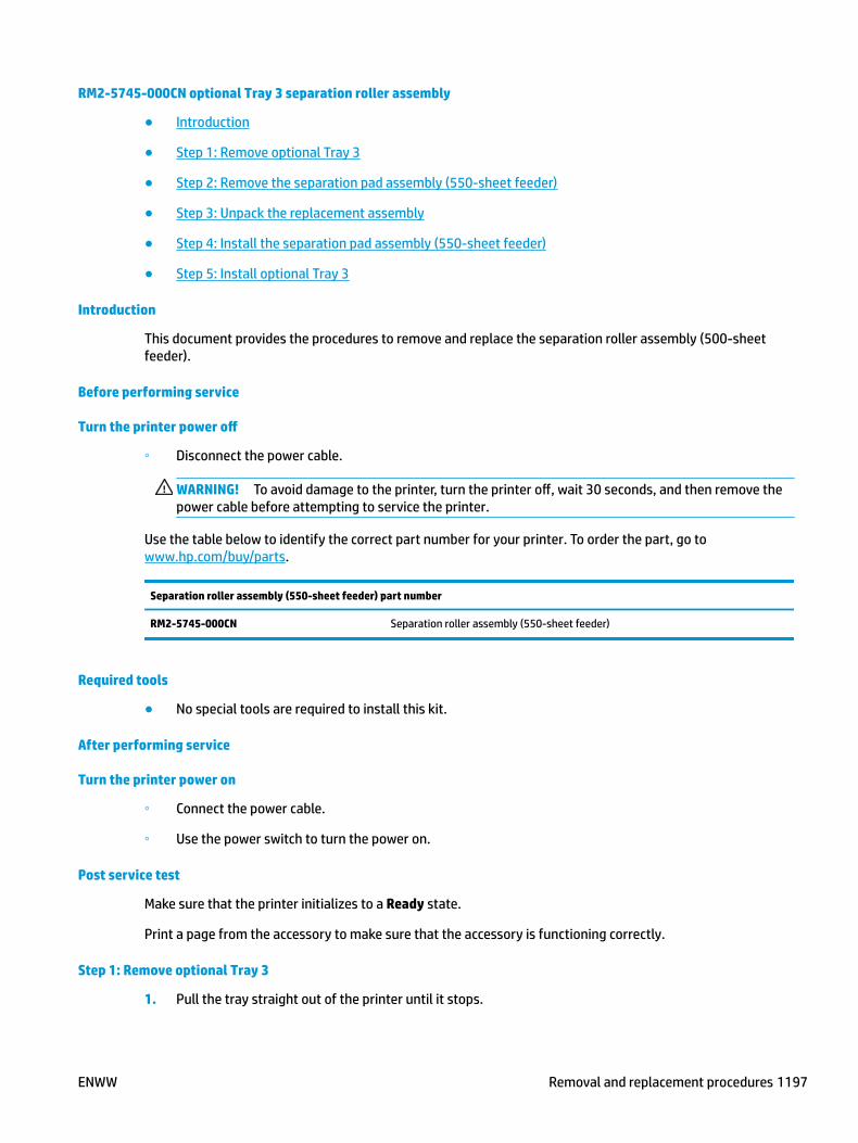
RM2-5745-000CN optional Tray 3 separation roller assembly
● Introduction
● Step 1: Remove optional Tray 3
● Step 2: Remove the separation pad assembly (550-sheet feeder)
● Step 3: Unpack the replacement assembly
● Step 4: Install the separation pad assembly (550-sheet feeder)
● Step 5: Install optional Tray 3
Introduction
This document provides the procedures to remove and replace the separation roller assembly (500-sheet feeder).
Before performing service
Turn the printer power off
◦ Disconnect the power cable.
WARNING! To avoid damage to the printer, turn the printer off, wait 30 seconds, and then remove the power cable before attempting to service the printer.
Use the table below to identify the correct part number for your printer. To order the part, go to www.hp.com/buy/parts.
Separation roller assembly (550-sheet feeder) part number
RM2-5745-000CN Separation roller assembly (550-sheet feeder)
Required tools
● No special tools are required to install this kit.
After performing service
Turn the printer power on
◦ Connect the power cable.
◦ Use the power switch to turn the power on.
Post service test
Make sure that the printer initializes to a Ready state.
Print a page from the accessory to make sure that the accessory is functioning correctly.
Step 1: Remove optional Tray 3
1. Pull the tray straight out of the printer until it stops.
ENWW Removal and replacement procedures 1197

Figure 1-2260 Pull the tray out of the printer
2. Slightly lift up on the front of the tray to release it, and then continue to pull the tray out of the accessory to remove it.
Figure 1-2261 Release and remove the tray
Step 2: Remove the separation pad assembly (550-sheet feeder)
1. Press the locking lever (callout 1), and then pull the separation roller assembly straight up to release it.
1198 Chapter 1 Removal and replacement ENWW

Figure 1-2262 Release the assembly
1
2. Remove the assembly.
Figure 1-2263 Remove the assembly
Step 3: Unpack the replacement assembly
Unpack the replacement part from the packaging.
http://www8.hp.com/us/en/hp-information/environment/product-recycling.html
NOTE: HP recommends responsible disposal of the defective part.
ENWW Removal and replacement procedures 1199

Figure 1-2264 Recycle and unpack
Step 4: Install the separation pad assembly (550-sheet feeder)
1. Install the assembly in the slots in the cassette.
Figure 1-2265 Install the assembly
1200 Chapter 1 Removal and replacement ENWW

2. Push the separation roller assembly straight down until it snaps into place.
Figure 1-2266 Release the assembly
Step 5: Install optional Tray 3
1. With the tray at a slight angle, align the sides of the tray with the rails in the accessory, and then partially slide the tray into the accessory.
Figure 1-2267 Install the tray
ENWW Removal and replacement procedures 1201

2. Push the tray straight into the accessory to close it.
Figure 1-2268 Close the tray
1202 Chapter 1 Removal and replacement ENWW

2 Parts and diagrams
● For additional service and support
● Order parts, accessories, and supplies
● How to use the parts lists and diagrams
● Document feeder and image scanner
● Covers, printer base
● Internal components, printer base
● 550-sheet paper feeder
● Alphabetical parts list
● Numerical parts list
ENWW 1203

For additional service and supportHP service personnel, go to the Service Access Work Bench (SAW) at http://h41302.www4.hp.com/km/saw/home.do.
Channel partners, go to HP Channel Services Network (CSN) at https://h30125.www3.hp.com/hpcsn.
● To access HP PartSurfer information from any mobile device, go to http://partsurfermobile.hp.com/ or scan the Quick Response (QR) code below.
● Install and configure
● Printer specifications
● Up-to-date control panel message (CPMD) troubleshooting
● Solutions for printer issues and emerging issues
● Remove and replace part instructions and videos
● Service advisories
● Warranty and regulatory information
1204 Chapter 2 Parts and diagrams ENWW

Order parts, accessories, and suppliesOrdering
Order supplies and paper www.hp.com/go/suresupply
Order genuine HP parts or accessories www.hp.com/buy/parts
or
partsurfer.hp.com
Order through service or support providers Contact an HP-authorized service or support provider.
Order using the HP Embedded Web Server (EWS) To access, in a supported Web browser on your computer, enter the printer IP address or host name in the address/URL field. The EWS contains a link to the HP SureSupply Web site, which provides options for purchasing Original HP supplies.
Orderable partsNot all of the parts shown in the diagrams in this chapter can be ordered. Refer to the table following the diagram or the parts lists at the end of this chapter to determine if a part is orderable.
SuppliesFollowing are the part numbers for the supplies available for the printers.
Table 2-1 Supplies
Item Description Cartridge number Part number
Supplies
HP 26A Black Original LaserJet Toner Cartridge
NOTE: M402 and M426 models only
Standard-capacity replacement black toner cartridge
26A CF226A
HP 28A Black Original LaserJet Toner Cartridge
NOTE: M403 and M427 models only
Standard-capacity replacement black toner cartridge
28A CF228A
HP 26X High Yield Black Original LaserJet Toner Cartridge
NOTE: M402 and M426 models only
High-capacity replacement black toner cartridge
26X CF226X
HP 28X High Yield Black Original LaserJet Toner Cartridge)
NOTE: M403 and M427 models only
High-capacity replacement black toner cartridge
28X CF228X
ENWW Order parts, accessories, and supplies 1205

AccessoriesFollowing are the part numbers for the accessories available for the printer.
Table 2-2 Accessories
Item Part number
550-sheet paper feeder (optional Tray 3) C5F97-69001
Customer self-repair partsCustomer Self-Repair (CSR) parts are available for many HP LaserJet printers to reduce repair time. More information about the CSR program and benefits can be found at www.hp.com/go/csr-support and www.hp.com/go/csr-faq.
Genuine HP replacement parts can be ordered at www.hp.com/buy/parts or by contacting an HP-authorized service or support provider. When ordering, one of the following will be needed: part number, serial number (found on back of printer), printer number, or printer name.
● Parts listed as Mandatory self-replacement are to be installed by customers, unless you are willing to pay HP service personnel to perform the repair. For these parts, on-site or return-to-depot support is not provided under the HP printer warranty.
● Parts listed as Optional self-replacement can be installed by HP service personnel at your request for no additional charge during the printer warranty period.
Item Description Self-replacement options
Part number
250-sheet paper input tray Replacement cassette for Tray 2 Mandatory RM2-5392-000CN
Optional 550-sheet accessory tray Replacement cassette for Tray 3 Mandatory RM2-5413-000CN
Tray 2 separation roller assembly Tray 2 separation roller Mandatory RM2-5397-000CN
Optional Tray 3 separation roller assembly Optional Tray 3 separation roller Mandatory RM2-5745-000CN
Multipurpose roller Multipurpose roller Mandatory RL2-0656-000CN
Tray 2 paper pickup roller assembly Tray 2 pickup roller Mandatory RM2-5452-000CN
Optional Tray 3 paper pickup roller assembly Optional Tray 3 pickup roller Mandatory RM2-5741-000CN
1206 Chapter 2 Parts and diagrams ENWW

How to use the parts lists and diagramsThe figures in this chapter show the major subassemblies in the printer and their component parts. A parts list table follows each exploded view assembly diagram. Each table lists the item number, the associated part number, and the description of each part. If a part is not listed in the table, then it is not a field replacement unit (FRU).
CAUTION: Be sure to order the correct part. When looking for part numbers for electrical components, pay careful attention to the voltage that is listed in the description column. Doing so will ensure that the part number selected is for the correct model.
NOTE: In this manual, the abbreviation “PCA” stands for “printed circuit-board assembly.” Components described as a PCA might consist of a single circuit board or a circuit board plus other parts, such as cables and sensors.
ENWW How to use the parts lists and diagrams 1207

Document feeder and image scannerNOTE: Parts listed in this section are for the M426 and M427 printers.
Main assembliesFigure 2-1 Main assemblies (document feeder and image scanner)
2
3
45
1 6
1208 Chapter 2 Parts and diagrams ENWW

Table 2-3 Main assemblies (document feeder and image scanner)
Ref Description Part number Qty
1 Document feeder and image scanner assembly (simplex models M426/M427)
C5F98-60109 1
1 Document feeder and image scanner assembly (duplex models M426/M427)
C5F98-60110 1
2 ADF separation pad B3Q10-40080 1
3 Support, ADF separation pad B3Q10-40079 1
Not shown Spring, ADF separation pad (under the separation pad) B3Q10-00019 1
4 Shaft, ADF pick extension B3Q10-40081 1
5 ADF pick roller assembly B3Q10-60105 1
6 Cover, ADF outer B3Q10-40013 1
Not shown Cover, ADF inner (under the out cover) B3Q10-40012 1
Not shown Ferrite ISA (M426fdn; M426fdw; M427fdn; M427fdw) 9170-2664 1
Not shown Ferrite, ISA 9170-2437 1
Not shown Ferrite, motor 9170-2659 1
Not shown Cover, FFC C5F98-40002 1
Not shown Cover, core C5F98-40003 1
Not shown ISA lift B3Q10-60128 1
Not shown Slider pin, ISA lift B3Q10-40041 1
ENWW Document feeder and image scanner 1209

Covers, printer baseCovers, M402 and M403
Figure 2-2 Covers, M402 and M403
Simplex model
Duplex model
Exceptnetwork models
ZSee Internal assemblies (2 of 2)
A02
A01
A0116
161
1
26
9
4
13
5
15
8
177
14
310
1112
1210 Chapter 2 Parts and diagrams ENWW
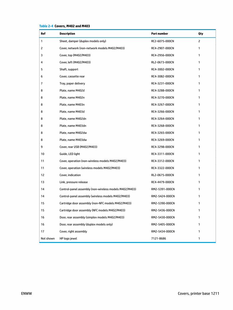
Table 2-4 Covers, M402 and M403
Ref Description Part number Qty
1 Sheet, damper (duplex models only) RC2-6075-000CN 2
2 Cover, network (non-network models M402/M403) RC4-2907-000CN 1
3 Cover, top (M402/M403) RC4-2956-000CN 1
4 Cover, left (M402/M403) RL2-0673-000CN 1
5 Shaft, support RC4-3002-000CN 1
6 Cover, cassette rear RC4-3082-000CN 1
7 Tray, paper delivery RC4-3231-000CN 1
8 Plate, name M402d RC4-3288-000CN 1
8 Plate, name M402n RC4-3270-000CN 1
8 Plate, name M403n RC4-3267-000CN 1
8 Plate, name M403d RC4-3266-000CN 1
8 Plate, name M402dn RC4-3264-000CN 1
8 Plate, name M403dn RC4-3268-000CN 1
8 Plate, name M402dw RC4-3265-000CN 1
8 Plate, name M403dw RC4-3269-000CN 1
9 Cover, rear USB (M402/M403) RC4-3298-000CN 1
10 Guide, LED light RC4-3311-000CN 1
11 Cover, operation (non-wireless models M402/M403) RC4-3312-000CN 1
11 Cover, operation (wireless models M402/M403) RC4-3322-000CN 1
12 Cover, indication RL2-0675-000CN 1
13 Link, pressure release RC4-4479-000CN 1
14 Control-panel assembly (non-wireless models M402/M403) RM2-5391-000CN 1
14 Control-panel assembly (wireless models M402/M403) RM2-5424-000CN 1
15 Cartridge door assembly (non-NFC models M402/M403) RM2-5390-000CN 1
15 Cartridge door assembly (NFC models M402/M403) RM2-5436-000CN 1
16 Door, rear assembly (simplex models M402/M403) RM2-5430-000CN 1
16 Door, rear assembly (duplex models only) RM2-5405-000CN 1
17 Cover, right assembly RM2-5434-000CN 1
Not shown HP logo jewel 7121-8686 1
ENWW Covers, printer base 1211

Covers, M426 and M427Figure 2-3 Covers, M426 and M427
A02
A01
4
7
12
6
11
9
2
5
3
8
10
1
1
13
1212 Chapter 2 Parts and diagrams ENWW
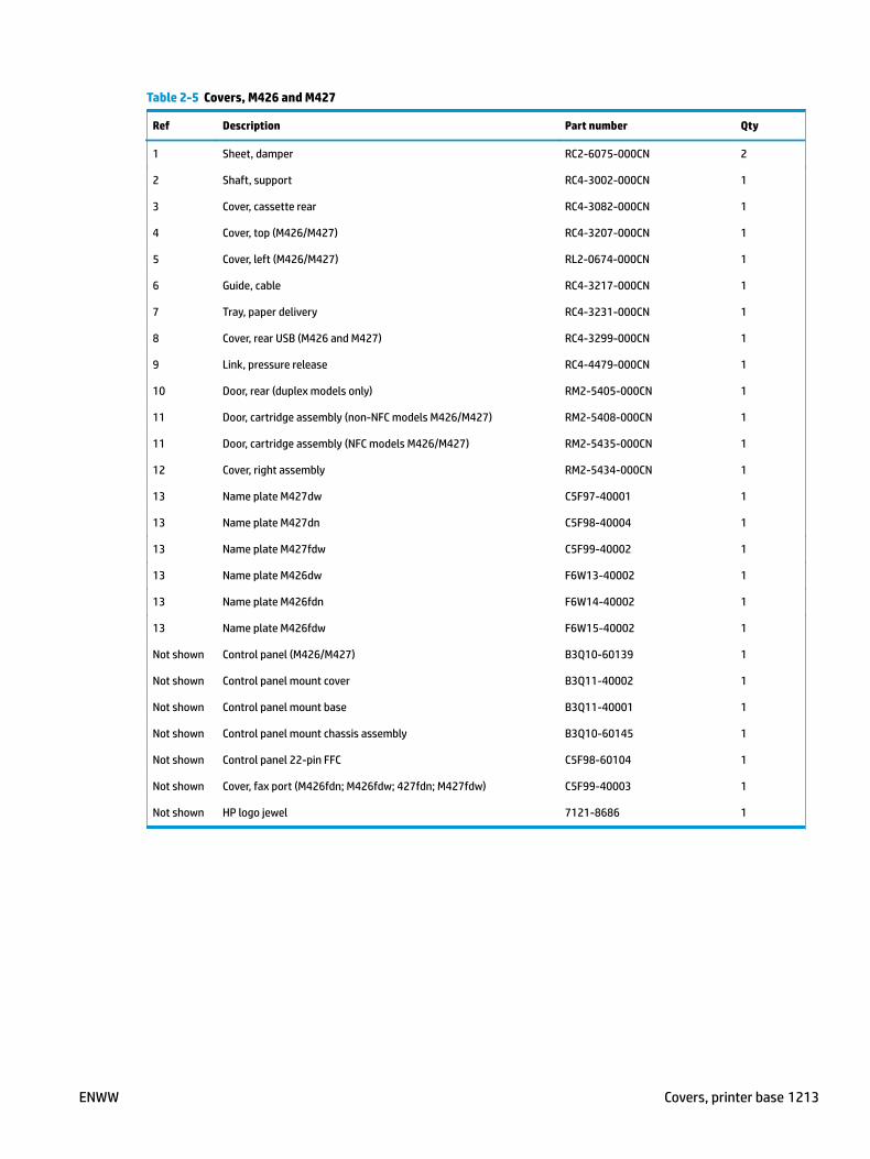
Table 2-5 Covers, M426 and M427
Ref Description Part number Qty
1 Sheet, damper RC2-6075-000CN 2
2 Shaft, support RC4-3002-000CN 1
3 Cover, cassette rear RC4-3082-000CN 1
4 Cover, top (M426/M427) RC4-3207-000CN 1
5 Cover, left (M426/M427) RL2-0674-000CN 1
6 Guide, cable RC4-3217-000CN 1
7 Tray, paper delivery RC4-3231-000CN 1
8 Cover, rear USB (M426 and M427) RC4-3299-000CN 1
9 Link, pressure release RC4-4479-000CN 1
10 Door, rear (duplex models only) RM2-5405-000CN 1
11 Door, cartridge assembly (non-NFC models M426/M427) RM2-5408-000CN 1
11 Door, cartridge assembly (NFC models M426/M427) RM2-5435-000CN 1
12 Cover, right assembly RM2-5434-000CN 1
13 Name plate M427dw C5F97-40001 1
13 Name plate M427dn C5F98-40004 1
13 Name plate M427fdw C5F99-40002 1
13 Name plate M426dw F6W13-40002 1
13 Name plate M426fdn F6W14-40002 1
13 Name plate M426fdw F6W15-40002 1
Not shown Control panel (M426/M427) B3Q10-60139 1
Not shown Control panel mount cover B3Q11-40002 1
Not shown Control panel mount base B3Q11-40001 1
Not shown Control panel mount chassis assembly B3Q10-60145 1
Not shown Control panel 22-pin FFC C5F98-60104 1
Not shown Cover, fax port (M426fdn; M426fdw; 427fdn; M427fdw) C5F99-40003 1
Not shown HP logo jewel 7121-8686 1
ENWW Covers, printer base 1213

Internal components, printer baseInternal components, printer base (1 of 3)
Figure 2-4 Internal components, printer base (1 of 5)
M426/M427 M402/M403
Wireless modelsM426/M427
M402/M403
(J10)
(J811)
(J4)
(J691)
(J103)
(J203)
(J106)
(J1)
(J201)
(J1302S)(J1302A)
(J3)
(FM1)(J301)
(J2)(J501)
(J105)
(J802)
(J505)
(J504)
(J503)
(J506)
A01
A02
A03
A05
A06
A07
A08
A09
A10
A11
A12
A13A14
A20
A20
A21
A22
A23
A24
A25
A26
A27
A28
A29
A29
A30
A30
A30
A30
A31
A31
A31
A31
A32A15
A16
A17A18
A19
A33
A34
A34
A14
5
2
7
4
6
10
1
3
8
9
1111
A04
1214 Chapter 2 Parts and diagrams ENWW
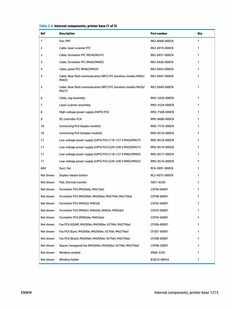
Table 2-6 Internal components, printer base (1 of 3)
Ref Description Part number Qty
1 Fan, FM1 RK2-8068-000CN 1
2 Cable, laser-scanner FFC RK2-6919-000CN 1
3 Cable, formatter FFC (M246/M247) RK2-6931-000CN 1
3 Cable, formatter FFC (M402/M403) RK2-6920-000CN 1
4 Cable, panel FFC (M402/M403) RK2-6943-000CN 1
5 Cable, Near field communication (NFC) FFC (wireless models M402/M403)
RK2-6947-000CN 1
5 Cable, Near field communication (NFC) FFC (wireless models M426/M427)
RK2-6949-000CN 1
6 Cable, tag assembly RM2-5426-000CN 1
7 Laser-scanner assembly RM2-5528-000CN 1
8 High-voltage power supply (HVPS) PCA RM2-7508-000CN 1
9 DC controller PCA RM2-8680-000CN 1
10 Connecting PCA (duplex models) RM2-7510-000CN 1
10 Connecting PCA (simplex models) RM2-8510-000CN 1
11 Low-voltage power supply (LVPS) PCA (110–127 V M426/M427) RM2-8518-000CN 1
11 Low-voltage power supply (LVPS) PCA (220–240 V M426/M427) RM2-8519-000CN 1
11 Low-voltage power supply (LVPS) PCA (110–127 V M402/M403) RM2-8517-000CN 1
11 Low-voltage power supply (LVPS) PCA (220–240 V M402/M403) RM2-8516-000CN 1
A04 Duct, fan RC4-2891-000CN 1
Not shown Duplex release button RC2-6075-000CN 1
Not shown Pad, thermal transfer 5851-6550 1
Not shown Formatter PCA (M426dw; M427dw) C5F99-60001 1
Not shown Formatter PCA (M426fdn; M426fdw; M427fdn; M427fdw) C5F98-60001 1
Not shown Formatter PCA (M402d; M403d) C5F92-60001 1
Not shown Formatter PCA (M402n; M402dn; M403n; M403dn) C5F93-60001 1
Not shown Formatter PCA (M402dw; M403dw) C5F94-60001 1
Not shown Fax PCA (US/AP; M426fdn; M426fdw; 427fdn; M427fdw) CF206-60001 1
Not shown Fax PCA (Euro; M426fdn; M426fdw; 427fdn; M427fdw) CF207-60001 1
Not shown Fax PCA (Brazil; M426fdn; M426fdw; 427fdn; M427fdw) CF208-60001 1
Not shown Spacer, hexagonal fax (M426fdn; M426fdw; 427fdn; M427fdw) C5F98-20001 1
Not shown Wireless module 0960-3293 1
Not shown Wireless holder B3Q10-40054 1
ENWW Internal components, printer base 1215

Internal components, printer base (2 of 3)Figure 2-5 Internal components, printer base (2 of 3)
M426/M427
M426/M427
(M1)(J102)
(J705)
(J102)
(J110)(J13)
(J405)
(J6)
(J701)
(J109)
(J406)(J407)
Z
See Covers,M402 and M403
A02
A06
A07
A11
A14
A15
A01
A03
A04
A05
A12
A08A09
A10
A13
A16
4
5
1
6
2
3
1216 Chapter 2 Parts and diagrams ENWW

Table 2-7 Internal components, printer base (2 of 3)
Ref Description Part number Qty
1 Cover, Near field communication (NFC) (M426/M427) RC4-2961-000CN 1
2 Cassette (Tray 2) assembly RM2-5392-000CN 1
3 Roller, separation assembly RM2-5397-000CN 1
4 Fixing (fuser) assembly (110-127 V) RM2-5399-000CN 1
4 Fixing (fuser) assembly (220-240 V) RM2-5425-000CN 1
5 Main motor assembly RM2-8684-000CN 1
6 Switch, power PCA RM2-8506-000CN 1
Not shown Ferrite, motor 9170-2659 1
Not shown Walkup USB PCA (M426/M427) CF368-60001 1
Not shown Cable, walkup USB (M426/M427) C5F98-60105 1
Not shown NFC module B4K93-60001 1
ENWW Internal components, printer base 1217

Internal components, printer base (3 of 3)Figure 2-6 Internal components, printer base (3 of 3)
Duplex models
A01
A02
A03
A04
A05
A08
A08
A07
A06
1
2
3
4
6
8
7
5
1218 Chapter 2 Parts and diagrams ENWW

Table 2-8 Internal components, printer base (3 of 3)
Ref Description Part number Qty
1 Roller, transfer RM1-4023-000CN 1
2 Roller, paper pickup assembly RM2-5452-000CN 1
3 Holder, transfer roller right RC4-3133-000CN 1
4 Holder, transfer roller left RC4-3134-000CN 1
5 Roller, multi-purpose (Tray 1) RL2-0656-000CN 1
6 Pad, multi-purpose (Tray 1) separation RL2-0657-000CN 1
7 Spring, compression RU8-2935-000CN 1
8 Registration assembly RM2-5671-000CN 1
ENWW Internal components, printer base 1219

550-sheet paper feederCovers, 550-sheet paper feeder
Figure 2-7 Covers, 550-sheet paper feeder
A01
A01
31
2
4
1220 Chapter 2 Parts and diagrams ENWW

Table 2-9 Covers, 550-sheet paper feeder
Ref Description Part number Qty
4 Paper feeder, 550-sheet assembly (whole unit) C5F97–69001 1
ENWW 550-sheet paper feeder 1221

Main body, 550-sheet paper feederFigure 2-8 Main body, 550-sheet paper feeder
(J691)
(J600)
(J604)(J605)
(J601)
(SW2)
A01
A03
A04
A05
A06
A07
A08
A09
A10
A11
A12
A13
A14
A15
A16
A02
A02A16
A16
A16
A171
3
7
5
8
2
9
6
4
1222 Chapter 2 Parts and diagrams ENWW

Table 2-10 Main body, 550-sheet paper feeder
Ref Description Part number Qty
6 Cassette assembly (550-sheet feeder) RM2-5413-000CN 1
7 Roller, paper pickup assembly (550-sheet feeder) RM2-5741-000CN 1
8 Roller, separation assembly (550-sheet feeder) RM2-5745-000CN 1
ENWW 550-sheet paper feeder 1223
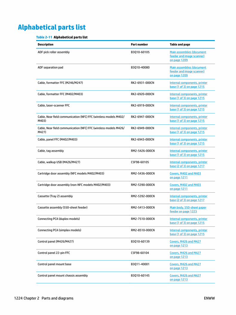
Alphabetical parts listTable 2-11 Alphabetical parts list
Description Part number Table and page
ADF pick roller assembly B3Q10-60105 Main assemblies (document feeder and image scanner) on page 1209
ADF separation pad B3Q10-40080 Main assemblies (document feeder and image scanner) on page 1209
Cable, formatter FFC (M246/M247) RK2-6931-000CN Internal components, printer base (1 of 3) on page 1215
Cable, formatter FFC (M402/M403) RK2-6920-000CN Internal components, printer base (1 of 3) on page 1215
Cable, laser-scanner FFC RK2-6919-000CN Internal components, printer base (1 of 3) on page 1215
Cable, Near field communication (NFC) FFC (wireless models M402/M403)
RK2-6947-000CN Internal components, printer base (1 of 3) on page 1215
Cable, Near field communication (NFC) FFC (wireless models M426/M427)
RK2-6949-000CN Internal components, printer base (1 of 3) on page 1215
Cable, panel FFC (M402/M403) RK2-6943-000CN Internal components, printer base (1 of 3) on page 1215
Cable, tag assembly RM2-5426-000CN Internal components, printer base (1 of 3) on page 1215
Cable, walkup USB (M426/M427) C5F98-60105 Internal components, printer base (2 of 3) on page 1217
Cartridge door assembly (NFC models M402/M403) RM2-5436-000CN Covers, M402 and M403 on page 1211
Cartridge door assembly (non-NFC models M402/M403) RM2-5390-000CN Covers, M402 and M403 on page 1211
Cassette (Tray 2) assembly RM2-5392-000CN Internal components, printer base (2 of 3) on page 1217
Cassette assembly (550-sheet feeder) RM2-5413-000CN Main body, 550-sheet paper feeder on page 1223
Connecting PCA (duplex models) RM2-7510-000CN Internal components, printer base (1 of 3) on page 1215
Connecting PCA (simplex models) RM2-8510-000CN Internal components, printer base (1 of 3) on page 1215
Control panel (M426/M427) B3Q10-60139 Covers, M426 and M427 on page 1213
Control panel 22-pin FFC C5F98-60104 Covers, M426 and M427 on page 1213
Control panel mount base B3Q11-40001 Covers, M426 and M427 on page 1213
Control panel mount chassis assembly B3Q10-60145 Covers, M426 and M427 on page 1213
1224 Chapter 2 Parts and diagrams ENWW
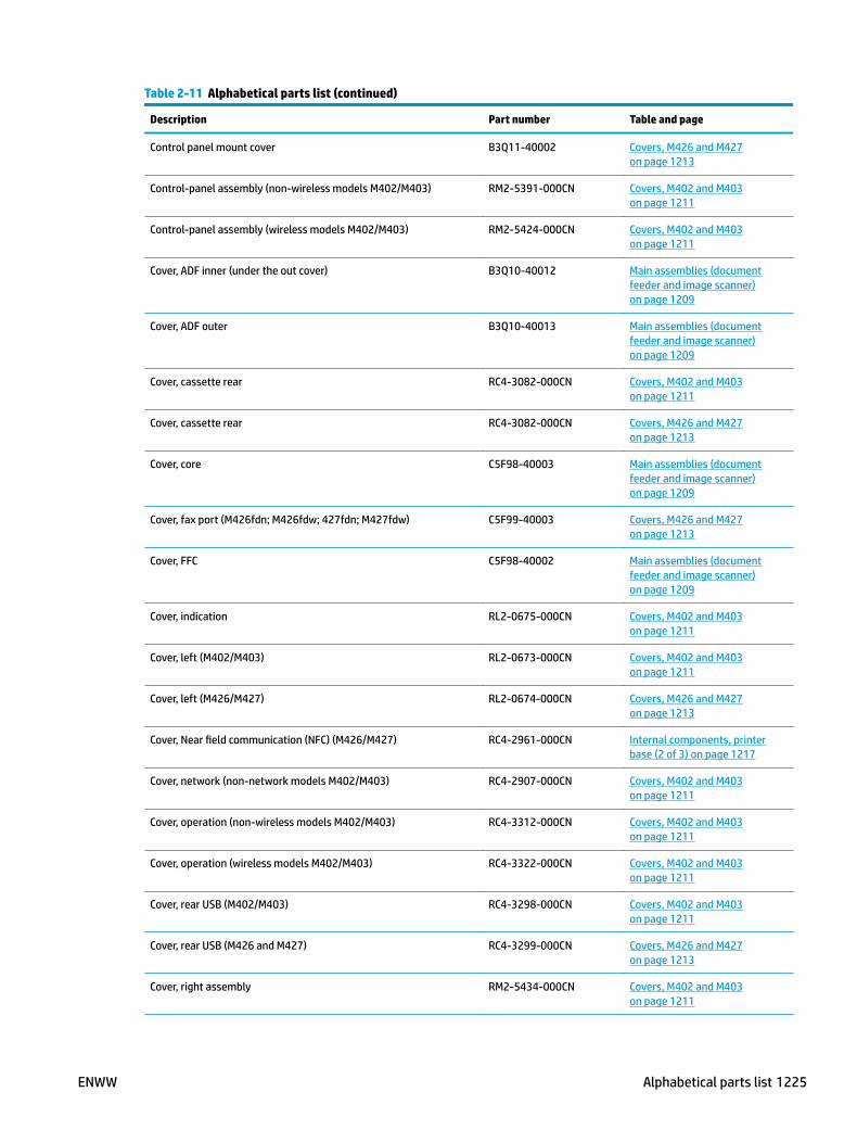
Table 2-11 Alphabetical parts list (continued)
Description Part number Table and page
Control panel mount cover B3Q11-40002 Covers, M426 and M427 on page 1213
Control-panel assembly (non-wireless models M402/M403) RM2-5391-000CN Covers, M402 and M403 on page 1211
Control-panel assembly (wireless models M402/M403) RM2-5424-000CN Covers, M402 and M403 on page 1211
Cover, ADF inner (under the out cover) B3Q10-40012 Main assemblies (document feeder and image scanner) on page 1209
Cover, ADF outer B3Q10-40013 Main assemblies (document feeder and image scanner) on page 1209
Cover, cassette rear RC4-3082-000CN Covers, M402 and M403 on page 1211
Cover, cassette rear RC4-3082-000CN Covers, M426 and M427 on page 1213
Cover, core C5F98-40003 Main assemblies (document feeder and image scanner) on page 1209
Cover, fax port (M426fdn; M426fdw; 427fdn; M427fdw) C5F99-40003 Covers, M426 and M427 on page 1213
Cover, FFC C5F98-40002 Main assemblies (document feeder and image scanner) on page 1209
Cover, indication RL2-0675-000CN Covers, M402 and M403 on page 1211
Cover, left (M402/M403) RL2-0673-000CN Covers, M402 and M403 on page 1211
Cover, left (M426/M427) RL2-0674-000CN Covers, M426 and M427 on page 1213
Cover, Near field communication (NFC) (M426/M427) RC4-2961-000CN Internal components, printer base (2 of 3) on page 1217
Cover, network (non-network models M402/M403) RC4-2907-000CN Covers, M402 and M403 on page 1211
Cover, operation (non-wireless models M402/M403) RC4-3312-000CN Covers, M402 and M403 on page 1211
Cover, operation (wireless models M402/M403) RC4-3322-000CN Covers, M402 and M403 on page 1211
Cover, rear USB (M402/M403) RC4-3298-000CN Covers, M402 and M403 on page 1211
Cover, rear USB (M426 and M427) RC4-3299-000CN Covers, M426 and M427 on page 1213
Cover, right assembly RM2-5434-000CN Covers, M402 and M403 on page 1211
ENWW Alphabetical parts list 1225
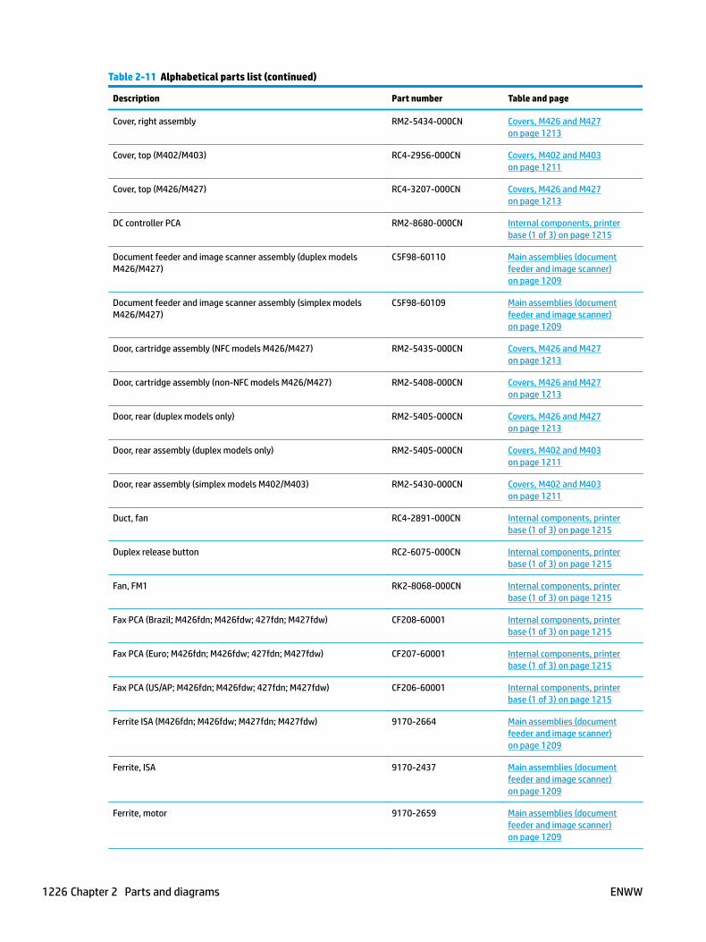
Table 2-11 Alphabetical parts list (continued)
Description Part number Table and page
Cover, right assembly RM2-5434-000CN Covers, M426 and M427 on page 1213
Cover, top (M402/M403) RC4-2956-000CN Covers, M402 and M403 on page 1211
Cover, top (M426/M427) RC4-3207-000CN Covers, M426 and M427 on page 1213
DC controller PCA RM2-8680-000CN Internal components, printer base (1 of 3) on page 1215
Document feeder and image scanner assembly (duplex models M426/M427)
C5F98-60110 Main assemblies (document feeder and image scanner) on page 1209
Document feeder and image scanner assembly (simplex models M426/M427)
C5F98-60109 Main assemblies (document feeder and image scanner) on page 1209
Door, cartridge assembly (NFC models M426/M427) RM2-5435-000CN Covers, M426 and M427 on page 1213
Door, cartridge assembly (non-NFC models M426/M427) RM2-5408-000CN Covers, M426 and M427 on page 1213
Door, rear (duplex models only) RM2-5405-000CN Covers, M426 and M427 on page 1213
Door, rear assembly (duplex models only) RM2-5405-000CN Covers, M402 and M403 on page 1211
Door, rear assembly (simplex models M402/M403) RM2-5430-000CN Covers, M402 and M403 on page 1211
Duct, fan RC4-2891-000CN Internal components, printer base (1 of 3) on page 1215
Duplex release button RC2-6075-000CN Internal components, printer base (1 of 3) on page 1215
Fan, FM1 RK2-8068-000CN Internal components, printer base (1 of 3) on page 1215
Fax PCA (Brazil; M426fdn; M426fdw; 427fdn; M427fdw) CF208-60001 Internal components, printer base (1 of 3) on page 1215
Fax PCA (Euro; M426fdn; M426fdw; 427fdn; M427fdw) CF207-60001 Internal components, printer base (1 of 3) on page 1215
Fax PCA (US/AP; M426fdn; M426fdw; 427fdn; M427fdw) CF206-60001 Internal components, printer base (1 of 3) on page 1215
Ferrite ISA (M426fdn; M426fdw; M427fdn; M427fdw) 9170-2664 Main assemblies (document feeder and image scanner) on page 1209
Ferrite, ISA 9170-2437 Main assemblies (document feeder and image scanner) on page 1209
Ferrite, motor 9170-2659 Main assemblies (document feeder and image scanner) on page 1209
1226 Chapter 2 Parts and diagrams ENWW

Table 2-11 Alphabetical parts list (continued)
Description Part number Table and page
Ferrite, motor 9170-2659 Internal components, printer base (2 of 3) on page 1217
Fixing (fuser) assembly (110-127 V) RM2-5399-000CN Internal components, printer base (2 of 3) on page 1217
Fixing (fuser) assembly (220-240 V) RM2-5425-000CN Internal components, printer base (2 of 3) on page 1217
Formatter PCA (M402d; M403d) C5F92-60001 Internal components, printer base (1 of 3) on page 1215
Formatter PCA (M402dw; M403dw) C5F94-60001 Internal components, printer base (1 of 3) on page 1215
Formatter PCA (M402n; M402dn; M403n; M403dn) C5F93-60001 Internal components, printer base (1 of 3) on page 1215
Formatter PCA (M426dw; M427dw) C5F99-60001 Internal components, printer base (1 of 3) on page 1215
Formatter PCA (M426fdn; M426fdw; M427fdn; M427fdw) C5F98-60001 Internal components, printer base (1 of 3) on page 1215
Guide, cable RC4-3217-000CN Covers, M426 and M427 on page 1213
Guide, LED light RC4-3311-000CN Covers, M402 and M403 on page 1211
High-voltage power supply (HVPS) PCA RM2-7508-000CN Internal components, printer base (1 of 3) on page 1215
Holder, transfer roller left RC4-3134-000CN Internal components, printer base (3 of 3) on page 1219
Holder, transfer roller right RC4-3133-000CN Internal components, printer base (3 of 3) on page 1219
HP logo jewel 7121-8686 Covers, M402 and M403 on page 1211
HP logo jewel 7121-8686 Covers, M426 and M427 on page 1213
ISA lift B3Q10-60128 Main assemblies (document feeder and image scanner) on page 1209
Laser-scanner assembly RM2-5528-000CN Internal components, printer base (1 of 3) on page 1215
Link, pressure release RC4-4479-000CN Covers, M402 and M403 on page 1211
Link, pressure release RC4-4479-000CN Covers, M426 and M427 on page 1213
Low-voltage power supply (LVPS) PCA (110–127 V M402/M403) RM2-8517-000CN Internal components, printer base (1 of 3) on page 1215
Low-voltage power supply (LVPS) PCA (110–127 V M426/M427) RM2-8518-000CN Internal components, printer base (1 of 3) on page 1215
ENWW Alphabetical parts list 1227
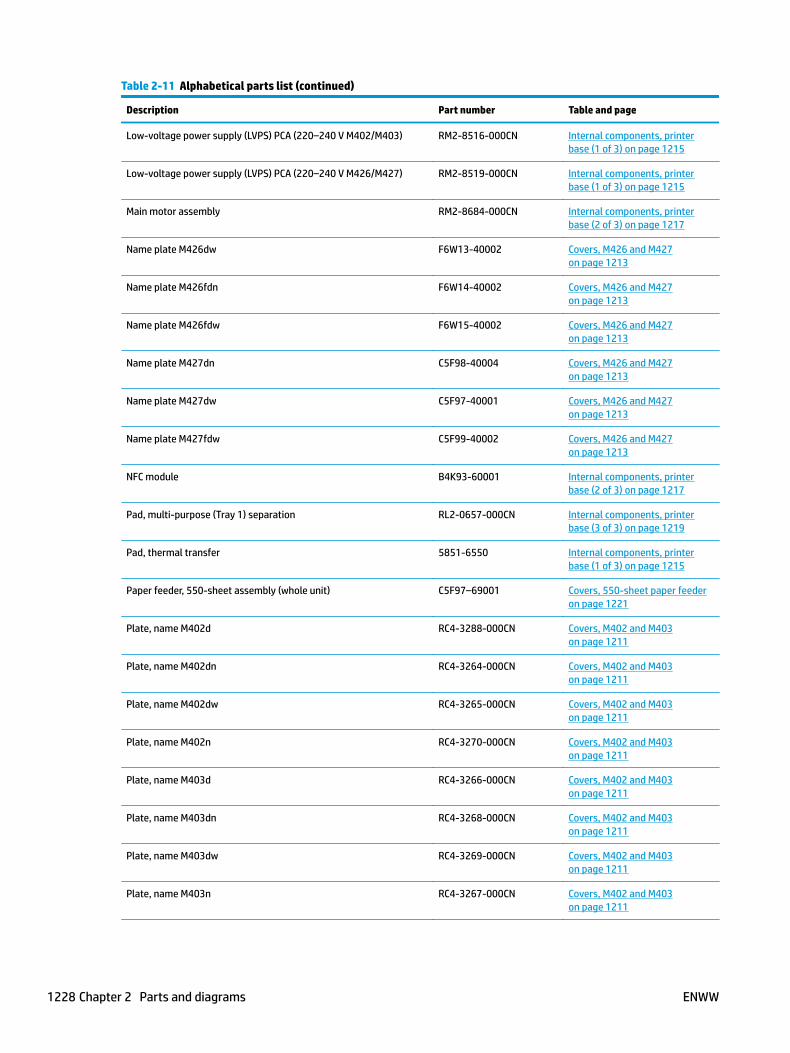
Table 2-11 Alphabetical parts list (continued)
Description Part number Table and page
Low-voltage power supply (LVPS) PCA (220–240 V M402/M403) RM2-8516-000CN Internal components, printer base (1 of 3) on page 1215
Low-voltage power supply (LVPS) PCA (220–240 V M426/M427) RM2-8519-000CN Internal components, printer base (1 of 3) on page 1215
Main motor assembly RM2-8684-000CN Internal components, printer base (2 of 3) on page 1217
Name plate M426dw F6W13-40002 Covers, M426 and M427 on page 1213
Name plate M426fdn F6W14-40002 Covers, M426 and M427 on page 1213
Name plate M426fdw F6W15-40002 Covers, M426 and M427 on page 1213
Name plate M427dn C5F98-40004 Covers, M426 and M427 on page 1213
Name plate M427dw C5F97-40001 Covers, M426 and M427 on page 1213
Name plate M427fdw C5F99-40002 Covers, M426 and M427 on page 1213
NFC module B4K93-60001 Internal components, printer base (2 of 3) on page 1217
Pad, multi-purpose (Tray 1) separation RL2-0657-000CN Internal components, printer base (3 of 3) on page 1219
Pad, thermal transfer 5851-6550 Internal components, printer base (1 of 3) on page 1215
Paper feeder, 550-sheet assembly (whole unit) C5F97–69001 Covers, 550-sheet paper feeder on page 1221
Plate, name M402d RC4-3288-000CN Covers, M402 and M403 on page 1211
Plate, name M402dn RC4-3264-000CN Covers, M402 and M403 on page 1211
Plate, name M402dw RC4-3265-000CN Covers, M402 and M403 on page 1211
Plate, name M402n RC4-3270-000CN Covers, M402 and M403 on page 1211
Plate, name M403d RC4-3266-000CN Covers, M402 and M403 on page 1211
Plate, name M403dn RC4-3268-000CN Covers, M402 and M403 on page 1211
Plate, name M403dw RC4-3269-000CN Covers, M402 and M403 on page 1211
Plate, name M403n RC4-3267-000CN Covers, M402 and M403 on page 1211
1228 Chapter 2 Parts and diagrams ENWW
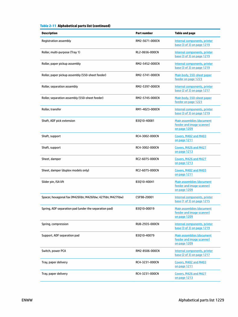
Table 2-11 Alphabetical parts list (continued)
Description Part number Table and page
Registration assembly RM2-5671-000CN Internal components, printer base (3 of 3) on page 1219
Roller, multi-purpose (Tray 1) RL2-0656-000CN Internal components, printer base (3 of 3) on page 1219
Roller, paper pickup assembly RM2-5452-000CN Internal components, printer base (3 of 3) on page 1219
Roller, paper pickup assembly (550-sheet feeder) RM2-5741-000CN Main body, 550-sheet paper feeder on page 1223
Roller, separation assembly RM2-5397-000CN Internal components, printer base (2 of 3) on page 1217
Roller, separation assembly (550-sheet feeder) RM2-5745-000CN Main body, 550-sheet paper feeder on page 1223
Roller, transfer RM1-4023-000CN Internal components, printer base (3 of 3) on page 1219
Shaft, ADF pick extension B3Q10-40081 Main assemblies (document feeder and image scanner) on page 1209
Shaft, support RC4-3002-000CN Covers, M402 and M403 on page 1211
Shaft, support RC4-3002-000CN Covers, M426 and M427 on page 1213
Sheet, damper RC2-6075-000CN Covers, M426 and M427 on page 1213
Sheet, damper (duplex models only) RC2-6075-000CN Covers, M402 and M403 on page 1211
Slider pin, ISA lift B3Q10-40041 Main assemblies (document feeder and image scanner) on page 1209
Spacer, hexagonal fax (M426fdn; M426fdw; 427fdn; M427fdw) C5F98-20001 Internal components, printer base (1 of 3) on page 1215
Spring, ADF separation pad (under the separation pad) B3Q10-00019 Main assemblies (document feeder and image scanner) on page 1209
Spring, compression RU8-2935-000CN Internal components, printer base (3 of 3) on page 1219
Support, ADF separation pad B3Q10-40079 Main assemblies (document feeder and image scanner) on page 1209
Switch, power PCA RM2-8506-000CN Internal components, printer base (2 of 3) on page 1217
Tray, paper delivery RC4-3231-000CN Covers, M402 and M403 on page 1211
Tray, paper delivery RC4-3231-000CN Covers, M426 and M427 on page 1213
ENWW Alphabetical parts list 1229

Table 2-11 Alphabetical parts list (continued)
Description Part number Table and page
Walkup USB PCA (M426/M427) CF368-60001 Internal components, printer base (2 of 3) on page 1217
Wireless holder B3Q10-40054 Internal components, printer base (1 of 3) on page 1215
Wireless module 0960-3293 Internal components, printer base (1 of 3) on page 1215
1230 Chapter 2 Parts and diagrams ENWW
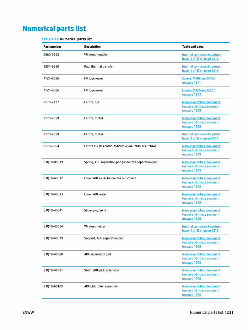
Numerical parts listTable 2-12 Numerical parts list
Part number Description Table and page
0960-3293 Wireless module Internal components, printer base (1 of 3) on page 1215
5851-6550 Pad, thermal transfer Internal components, printer base (1 of 3) on page 1215
7121-8686 HP logo jewel Covers, M402 and M403 on page 1211
7121-8686 HP logo jewel Covers, M426 and M427 on page 1213
9170-2437 Ferrite, ISA Main assemblies (document feeder and image scanner) on page 1209
9170-2659 Ferrite, motor Main assemblies (document feeder and image scanner) on page 1209
9170-2659 Ferrite, motor Internal components, printer base (2 of 3) on page 1217
9170-2664 Ferrite ISA (M426fdn; M426fdw; M427fdn; M427fdw) Main assemblies (document feeder and image scanner) on page 1209
B3Q10-00019 Spring, ADF separation pad (under the separation pad) Main assemblies (document feeder and image scanner) on page 1209
B3Q10-40012 Cover, ADF inner (under the out cover) Main assemblies (document feeder and image scanner) on page 1209
B3Q10-40013 Cover, ADF outer Main assemblies (document feeder and image scanner) on page 1209
B3Q10-40041 Slider pin, ISA lift Main assemblies (document feeder and image scanner) on page 1209
B3Q10-40054 Wireless holder Internal components, printer base (1 of 3) on page 1215
B3Q10-40079 Support, ADF separation pad Main assemblies (document feeder and image scanner) on page 1209
B3Q10-40080 ADF separation pad Main assemblies (document feeder and image scanner) on page 1209
B3Q10-40081 Shaft, ADF pick extension Main assemblies (document feeder and image scanner) on page 1209
B3Q10-60105 ADF pick roller assembly Main assemblies (document feeder and image scanner) on page 1209
ENWW Numerical parts list 1231
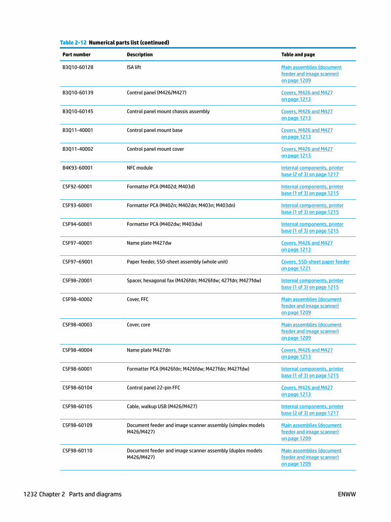
Table 2-12 Numerical parts list (continued)
Part number Description Table and page
B3Q10-60128 ISA lift Main assemblies (document feeder and image scanner) on page 1209
B3Q10-60139 Control panel (M426/M427) Covers, M426 and M427 on page 1213
B3Q10-60145 Control panel mount chassis assembly Covers, M426 and M427 on page 1213
B3Q11-40001 Control panel mount base Covers, M426 and M427 on page 1213
B3Q11-40002 Control panel mount cover Covers, M426 and M427 on page 1213
B4K93-60001 NFC module Internal components, printer base (2 of 3) on page 1217
C5F92-60001 Formatter PCA (M402d; M403d) Internal components, printer base (1 of 3) on page 1215
C5F93-60001 Formatter PCA (M402n; M402dn; M403n; M403dn) Internal components, printer base (1 of 3) on page 1215
C5F94-60001 Formatter PCA (M402dw; M403dw) Internal components, printer base (1 of 3) on page 1215
C5F97-40001 Name plate M427dw Covers, M426 and M427 on page 1213
C5F97–69001 Paper feeder, 550-sheet assembly (whole unit) Covers, 550-sheet paper feeder on page 1221
C5F98-20001 Spacer, hexagonal fax (M426fdn; M426fdw; 427fdn; M427fdw) Internal components, printer base (1 of 3) on page 1215
C5F98-40002 Cover, FFC Main assemblies (document feeder and image scanner) on page 1209
C5F98-40003 Cover, core Main assemblies (document feeder and image scanner) on page 1209
C5F98-40004 Name plate M427dn Covers, M426 and M427 on page 1213
C5F98-60001 Formatter PCA (M426fdn; M426fdw; M427fdn; M427fdw) Internal components, printer base (1 of 3) on page 1215
C5F98-60104 Control panel 22-pin FFC Covers, M426 and M427 on page 1213
C5F98-60105 Cable, walkup USB (M426/M427) Internal components, printer base (2 of 3) on page 1217
C5F98-60109 Document feeder and image scanner assembly (simplex models M426/M427)
Main assemblies (document feeder and image scanner) on page 1209
C5F98-60110 Document feeder and image scanner assembly (duplex models M426/M427)
Main assemblies (document feeder and image scanner) on page 1209
1232 Chapter 2 Parts and diagrams ENWW

Table 2-12 Numerical parts list (continued)
Part number Description Table and page
C5F99-40002 Name plate M427fdw Covers, M426 and M427 on page 1213
C5F99-40003 Cover, fax port (M426fdn; M426fdw; 427fdn; M427fdw) Covers, M426 and M427 on page 1213
C5F99-60001 Formatter PCA (M426dw; M427dw) Internal components, printer base (1 of 3) on page 1215
CF206-60001 Fax PCA (US/AP; M426fdn; M426fdw; 427fdn; M427fdw) Internal components, printer base (1 of 3) on page 1215
CF207-60001 Fax PCA (Euro; M426fdn; M426fdw; 427fdn; M427fdw) Internal components, printer base (1 of 3) on page 1215
CF208-60001 Fax PCA (Brazil; M426fdn; M426fdw; 427fdn; M427fdw) Internal components, printer base (1 of 3) on page 1215
CF368-60001 Walkup USB PCA (M426/M427) Internal components, printer base (2 of 3) on page 1217
F6W13-40002 Name plate M426dw Covers, M426 and M427 on page 1213
F6W14-40002 Name plate M426fdn Covers, M426 and M427 on page 1213
F6W15-40002 Name plate M426fdw Covers, M426 and M427 on page 1213
RC2-6075-000CN Sheet, damper (duplex models only) Covers, M402 and M403 on page 1211
RC2-6075-000CN Sheet, damper Covers, M426 and M427 on page 1213
RC2-6075-000CN Duplex release button Internal components, printer base (1 of 3) on page 1215
RC4-2891-000CN Duct, fan Internal components, printer base (1 of 3) on page 1215
RC4-2907-000CN Cover, network (non-network models M402/M403) Covers, M402 and M403 on page 1211
RC4-2956-000CN Cover, top (M402/M403) Covers, M402 and M403 on page 1211
RC4-2961-000CN Cover, Near field communication (NFC) (M426/M427) Internal components, printer base (2 of 3) on page 1217
RC4-3002-000CN Shaft, support Covers, M402 and M403 on page 1211
RC4-3002-000CN Shaft, support Covers, M426 and M427 on page 1213
RC4-3082-000CN Cover, cassette rear Covers, M402 and M403 on page 1211
RC4-3082-000CN Cover, cassette rear Covers, M426 and M427 on page 1213
ENWW Numerical parts list 1233
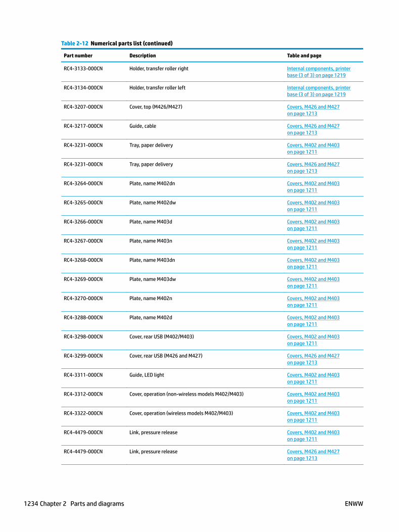
Table 2-12 Numerical parts list (continued)
Part number Description Table and page
RC4-3133-000CN Holder, transfer roller right Internal components, printer base (3 of 3) on page 1219
RC4-3134-000CN Holder, transfer roller left Internal components, printer base (3 of 3) on page 1219
RC4-3207-000CN Cover, top (M426/M427) Covers, M426 and M427 on page 1213
RC4-3217-000CN Guide, cable Covers, M426 and M427 on page 1213
RC4-3231-000CN Tray, paper delivery Covers, M402 and M403 on page 1211
RC4-3231-000CN Tray, paper delivery Covers, M426 and M427 on page 1213
RC4-3264-000CN Plate, name M402dn Covers, M402 and M403 on page 1211
RC4-3265-000CN Plate, name M402dw Covers, M402 and M403 on page 1211
RC4-3266-000CN Plate, name M403d Covers, M402 and M403 on page 1211
RC4-3267-000CN Plate, name M403n Covers, M402 and M403 on page 1211
RC4-3268-000CN Plate, name M403dn Covers, M402 and M403 on page 1211
RC4-3269-000CN Plate, name M403dw Covers, M402 and M403 on page 1211
RC4-3270-000CN Plate, name M402n Covers, M402 and M403 on page 1211
RC4-3288-000CN Plate, name M402d Covers, M402 and M403 on page 1211
RC4-3298-000CN Cover, rear USB (M402/M403) Covers, M402 and M403 on page 1211
RC4-3299-000CN Cover, rear USB (M426 and M427) Covers, M426 and M427 on page 1213
RC4-3311-000CN Guide, LED light Covers, M402 and M403 on page 1211
RC4-3312-000CN Cover, operation (non-wireless models M402/M403) Covers, M402 and M403 on page 1211
RC4-3322-000CN Cover, operation (wireless models M402/M403) Covers, M402 and M403 on page 1211
RC4-4479-000CN Link, pressure release Covers, M402 and M403 on page 1211
RC4-4479-000CN Link, pressure release Covers, M426 and M427 on page 1213
1234 Chapter 2 Parts and diagrams ENWW

Table 2-12 Numerical parts list (continued)
Part number Description Table and page
RK2-6919-000CN Cable, laser-scanner FFC Internal components, printer base (1 of 3) on page 1215
RK2-6920-000CN Cable, formatter FFC (M402/M403) Internal components, printer base (1 of 3) on page 1215
RK2-6931-000CN Cable, formatter FFC (M246/M247) Internal components, printer base (1 of 3) on page 1215
RK2-6943-000CN Cable, panel FFC (M402/M403) Internal components, printer base (1 of 3) on page 1215
RK2-6947-000CN Cable, Near field communication (NFC) FFC (wireless models M402/M403)
Internal components, printer base (1 of 3) on page 1215
RK2-6949-000CN Cable, Near field communication (NFC) FFC (wireless models M426/M427)
Internal components, printer base (1 of 3) on page 1215
RK2-8068-000CN Fan, FM1 Internal components, printer base (1 of 3) on page 1215
RL2-0656-000CN Roller, multi-purpose (Tray 1) Internal components, printer base (3 of 3) on page 1219
RL2-0657-000CN Pad, multi-purpose (Tray 1) separation Internal components, printer base (3 of 3) on page 1219
RL2-0673-000CN Cover, left (M402/M403) Covers, M402 and M403 on page 1211
RL2-0674-000CN Cover, left (M426/M427) Covers, M426 and M427 on page 1213
RL2-0675-000CN Cover, indication Covers, M402 and M403 on page 1211
RM1-4023-000CN Roller, transfer Internal components, printer base (3 of 3) on page 1219
RM2-5390-000CN Cartridge door assembly (non-NFC models M402/M403) Covers, M402 and M403 on page 1211
RM2-5391-000CN Control-panel assembly (non-wireless models M402/M403) Covers, M402 and M403 on page 1211
RM2-5392-000CN Cassette (Tray 2) assembly Internal components, printer base (2 of 3) on page 1217
RM2-5397-000CN Roller, separation assembly Internal components, printer base (2 of 3) on page 1217
RM2-5399-000CN Fixing (fuser) assembly (110-127 V) Internal components, printer base (2 of 3) on page 1217
RM2-5405-000CN Door, rear assembly (duplex models only) Covers, M402 and M403 on page 1211
RM2-5405-000CN Door, rear (duplex models only) Covers, M426 and M427 on page 1213
RM2-5408-000CN Door, cartridge assembly (non-NFC models M426/M427) Covers, M426 and M427 on page 1213
ENWW Numerical parts list 1235

Table 2-12 Numerical parts list (continued)
Part number Description Table and page
RM2-5413-000CN Cassette assembly (550-sheet feeder) Main body, 550-sheet paper feeder on page 1223
RM2-5424-000CN Control-panel assembly (wireless models M402/M403) Covers, M402 and M403 on page 1211
RM2-5425-000CN Fixing (fuser) assembly (220-240 V) Internal components, printer base (2 of 3) on page 1217
RM2-5426-000CN Cable, tag assembly Internal components, printer base (1 of 3) on page 1215
RM2-5430-000CN Door, rear assembly (simplex models M402/M403) Covers, M402 and M403 on page 1211
RM2-5434-000CN Cover, right assembly Covers, M402 and M403 on page 1211
RM2-5434-000CN Cover, right assembly Covers, M426 and M427 on page 1213
RM2-5435-000CN Door, cartridge assembly (NFC models M426/M427) Covers, M426 and M427 on page 1213
RM2-5436-000CN Cartridge door assembly (NFC models M402/M403) Covers, M402 and M403 on page 1211
RM2-5452-000CN Roller, paper pickup assembly Internal components, printer base (3 of 3) on page 1219
RM2-5528-000CN Laser-scanner assembly Internal components, printer base (1 of 3) on page 1215
RM2-5671-000CN Registration assembly Internal components, printer base (3 of 3) on page 1219
RM2-5741-000CN Roller, paper pickup assembly (550-sheet feeder) Main body, 550-sheet paper feeder on page 1223
RM2-5745-000CN Roller, separation assembly (550-sheet feeder) Main body, 550-sheet paper feeder on page 1223
RM2-7508-000CN High-voltage power supply (HVPS) PCA Internal components, printer base (1 of 3) on page 1215
RM2-7510-000CN Connecting PCA (duplex models) Internal components, printer base (1 of 3) on page 1215
RM2-8506-000CN Switch, power PCA Internal components, printer base (2 of 3) on page 1217
RM2-8510-000CN Connecting PCA (simplex models) Internal components, printer base (1 of 3) on page 1215
RM2-8516-000CN Low-voltage power supply (LVPS) PCA (220–240 V M402/M403) Internal components, printer base (1 of 3) on page 1215
RM2-8517-000CN Low-voltage power supply (LVPS) PCA (110–127 V M402/M403) Internal components, printer base (1 of 3) on page 1215
RM2-8518-000CN Low-voltage power supply (LVPS) PCA (110–127 V M426/M427) Internal components, printer base (1 of 3) on page 1215
1236 Chapter 2 Parts and diagrams ENWW
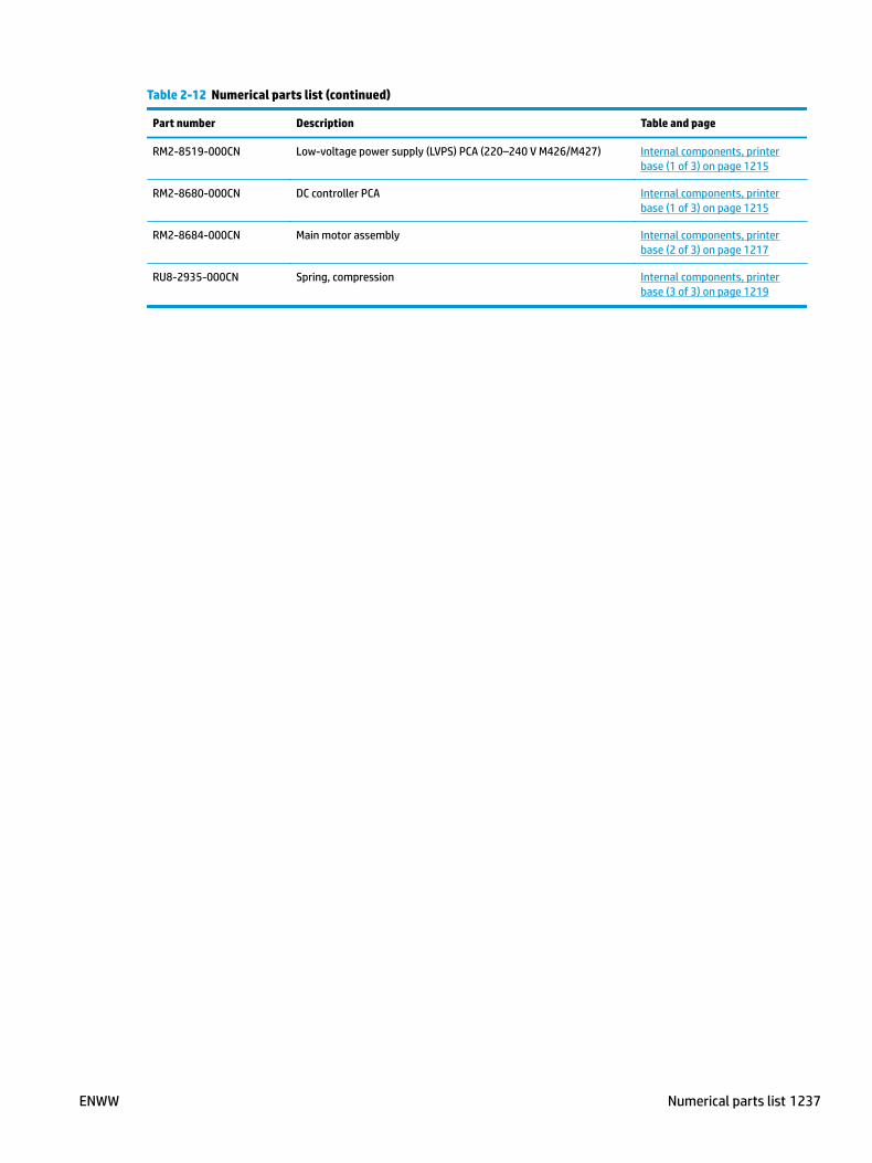
Table 2-12 Numerical parts list (continued)
Part number Description Table and page
RM2-8519-000CN Low-voltage power supply (LVPS) PCA (220–240 V M426/M427) Internal components, printer base (1 of 3) on page 1215
RM2-8680-000CN DC controller PCA Internal components, printer base (1 of 3) on page 1215
RM2-8684-000CN Main motor assembly Internal components, printer base (2 of 3) on page 1217
RU8-2935-000CN Spring, compression Internal components, printer base (3 of 3) on page 1219
ENWW Numerical parts list 1237

1238 Chapter 2 Parts and diagrams ENWW

Index
Symbols/Numerics2-line LCD operator and indication
covers (M403/M402)removing and replacing 232
2-line LCD operator and indication covers (M403/M402), removing and replacing 232
500-sheet feederparts lists and diagrams 1220
550-sheet paper feederremoving and replacing 1181
550-sheet paper feeder, removing and replacing 1181
Aaccessories
part numbers 1206after-service checklist 6
Ccable guide (M427/M426)
removing and replacing 172cable guide (M427/M426), removing
and replacing 172cartridge-door assembly
removing and replacing 57cartridge-door assembly, removing
and replacing 57cartridges
ordering 1205part numbers 1205
cassette rear coverremoving and replacing 114
cassette rear cover, removing and replacing 114
cautions iiichecklists
preservice 6
connecting PCAremoving and replacing 824
connecting PCA, removing and replacing 824
control panel (M427/M426)removing and replacing 1134
control panel 22-pin FFC (M427/M426)
removing and replacing 1134control panel and control panel 22-
pin FFC (M427/M426), removing and replacing 1134
control panel and control panel sub assemblies (M427/M426), removing and replacing 1134
control panel FFC (M403/M402)removing and replacing 656
control panel FFC (M403/M402), removing and replacing 656
control panel mount base (M427/M426)
removing and replacing 1134control panel mount base (M427/
M426), removing and replacing1134
control panel mount chassis assembly (M427/M426)
removing and replacing 1134control panel mount chassis
assembly (M427/M426), removing and replacing 1134
control panel mount cover (M427/M426)
removing and replacing 1134control panel mount cover (M427/
M426), removing and replacing1134
conventions, document iii
cover NFCremoving and replacing 1033
cover NFC, removing and replacing1033
covers, printer baseparts lists and diagrams 1210
Ddamper sheets
removing and replacing 46damper sheets, removing and
replacing 46DC controller
removing and replacing 724DC controller, removing and
replacing 724document conventions iiidocument feeder
parts lists and diagrams 1208document feeder and image scanner
parts lists and diagrams 1208
Eelectrostatic discharge (ESD) 4ESD electrostatic discharge (ESD) 4
Ffan (FM1)
removing and replacing 493fan (FM1), removing and replacing
493fan holder (FM1)
removing and replacing 507fan holder (FM1), removing and
replacing 507fax PCA
removing and replacing 429FCC NFC
removing and replacing 609
ENWW Index 1239

FCC NFC , removing and replacing609
FFC control panel (M403/M402)removing and replacing 656
FFC control panel (M403/M402), removing and replacing 656
FFC laser scannerremoving and replacing 873
FFC laser scanner, removing and replacing 873
FFC, formatterremoving and replacing 678
FFC, formatter, removing and replacing 678
field-replaceable units (FRUs)replacing 3
flat-flexible cable, control panel (M403/M402)
removing and replacing 656flat-flexible cable, control panel
(M403/M402), removing and replacing 656
flat-flexible cable, formatterremoving and replacing 678
flat-flexible cable, formatter, removing and replacing 678
flat-flexible cable, laser scannerremoving and replacing 873
flat-flexible cable, laser scanner, removing and replacing 873
flat-flexible cable, near field communication
removing and replacing 609flat-flexible cable, removing and
replacing 609formatter FFC
removing and replacing 678formatter FFC, removing and
replacing 678formatter PCA
removing and replacing 474formatter PCA, removing and
replacing 474FRUs (field-replaceable units)
replacing 3fuser
removing and replacing 325fuser, removing and replacing 325
Hhigh-voltage power supply
removing and replacing 927high-voltage power supply, removing
and replacing 927holder fan (FM1)
removing and replacing 507holder fan (FM1), removing and
replacing 507HVPS
removing and replacing 927HVPS, removing and replacing 927
II/O cover
removing and replacing 49I/O cover, removing and replacing
49image scanner
parts lists and diagrams 1208input/output cover
removing and replacing 49input/output cover, removing and
replacing 49installation 5
screws 5See also replacing parts
integrated scanner assembly (M427/M426)
removing and replacing 294integrated scanner assembly (M427/
M426), removing and replacing294
internal components, printerparts lists and diagrams 1214
ISAremoving and replacing 294
ISA (M427/M426), removing and replacing 294
ISA lift assembly and slider pinremoving and replacing 316
ISA lift assembly and slider pin (M427/M426)
removing and replacing 316ISA lift assembly and slider pin
(M427/M426), removing and replacing 316
Llaser scanner
warnings for servicing 3laser scanner assembly
removing and replacing 525laser scanner assembly, removing
and replacing 525laser scanner FFC
removing and replacing 873laser scanner FFC, removing and
replacing 873left cover
removing and replacing 73left cover, removing and replacing
73low-voltage power supply
removing and replacing 977low-voltage power supply, removing
and replacing 977LVPS
removing and replacing 977LVPS, removing and replacing 977
Mmain motor (M1)
removing and replacing 402main motor (M1), removing and
replacing 402maintenance kits
part numbers 1206multipurpose tray (Tray 1) roller
removing and replacing 8multipurpose tray (Tray 1) roller,
removing and replacing 8
Nnear field communication PCA
removing and replacing 1070near field communication PCA cover
removing and replacing 1033near field communication PCA cover,
removing and replacing 1033near field communication PCA,
removing and replacing 1070NFC
removing and replacing 1070NFC FCC, removing and replacing
609NFC, removing and replacing 1070notes iii
1240 Index ENWW

Ooptional Tray 3 paper paper pickup
roller assembly (Tray 3), removing and replacing 27, 1190
orderingtoner cartridges and
accessories 1205output bin
removing and replacing 253output bin, removing and replacing
253
Ppaper delivery tray (output bin)
removing and replacing 253paper delivery tray (output bin),
removing and replacing 253paper pickup roller assembly (Tray 2)
removing and replacing 20, 1168
paper pickup roller assembly (Tray 2), removing and replacing 20, 1168
paper pickup roller assembly (Tray 3)removing and replacing 27,
1190paper pickup roller assembly (Tray 3),
removing and replacing 27, 1190part numbers
accessories 1206replacement parts 1206staple cartridges 1206supplies 1206toner cartridge 1206toner cartridges 1205
parts lists and diagrams 1203500-sheet feeder 1220covers, printer base 1210document feeder and image
scanner 1208internal components, printer
1214using 1207
PCA connectingremoving and replacing 824
PCA connecting, removing and replacing 824
PCA power switchremoving and replacing 414
PCA power switch, removing and replacing 414
post-service tests 6power switch printed circuit assembly
removing and replacing 414power switch printed circuit
assembly, removing and replacing 414
preservice checklist 6pressure-release link
removing and replacing 64pressure-release link, removing and
replacing 64print quality
test 6
Rrear door assembly
removing and replacing 98rear door assembly, removing and
replacing 98registration assembly
removing and replacing 347registration assembly, removing and
replacing 347removal strategy
removing and replacing 3removing and replacing
2-line LCD operator and indication covers (M403/M402) 232
550-sheet paper feeder 1181cable guide (M427/M426) 172cartridge-door assembly 57cassette rear cover 114connecting PCA 824control panel and control panel
sub assemblies (M427/M426)1134
control panel FFC (M403/M402)656
cover NFC 1033damper sheets 46DC controller 724fan (FM1) 493fan holder (FM1) 507fax PCA 429FFC control panel (M403/M402)
656FFC laser scanner 873FFC, formatter 678flat-flexible cable, control panel
(M403/M402) 656
flat-flexible cable, formatter678
flat-flexible cable, laser scanner 873
flat-flexible cable, near field communication 609
formatter FFC 678formatter PCA 474fuser 325high-voltage power supply 927HVPS 927I/O cover 49input/output cover 49integrated scanner assembly
(M427/M426) 294ISA (M427/M426) 294ISA lift assembly and slider pin
(M427/M426) 316laser scanner assembly 525laser scanner FFC 873left cover 73low-voltage power supply 977LVPS 977main motor (M1) 402multipurpose tray (Tray 1) roller
8near field communication PCA
1070near field communication PCA
cover 1033NFC 1070NFC FCC 609output bin 253paper delivery tray (output bin)
253paper pickup roller assembly
(Tray 2) 20, 1168paper pickup roller assembly (Tray
3) 27, 1190PCA connecting 824PCA power switch 414power switch printed circuit
assembly 414pressure-release link 64rear door assembly 98registration assembly 347right cover 87roller MP tray (Tray 1) 8separation roller assembly (Tray
2) 34, 1175
ENWW Index 1241

separation roller assembly (Tray 3) 39, 1197
sheet-metal formatter bracket and formatter PCA 567
support shaft 53tag-cable assembly (toner-
cartridge memory) 776toner-cartridge memory (tag-
cable assembly) 776top cover (M403/M402) 211top cover (M427/M426) 133Tray 1 roller 8Tray 2 13, 1165, 1166Tray 2 paper pickup roller
assembly 20, 1168Tray 3 16, 1186walkup USB PCA 443wireless PCA 460
removing partsafter-service checklist 6checklists 6tools, required 4
replacement partspart numbers 1206
replacingparts 3
replacing partsabout 3after-service checklist 6screws 5tools, required 4
right coverremoving and replacing 87
right cover, removing and replacing87
roller MP tray (Tray 1)removing and replacing 8
roller MP tray (Tray 1), removing and replacing 8
Sscrewdrivers, required 4screws
installing 5replacing 4types of 5
separation roller assembly (Tray 2)removing and replacing 34,
1175
separation roller assembly (Tray 2), removing and replacing 34, 1175
separation roller assembly (Tray 3)removing and replacing 39,
1197separation roller assembly (Tray 3),
removing and replacing 39, 1197service and support information v,
2, 1204service approach
removing and replacing 6sheet-metal formatter bracket and
formatter PCAremoving and replacing 567
sheet-metal formatter bracket and formatter PCA, removing and replacing 567
staple cartridgespart numbers 1206
static, precautions for 4supplies
part numbers 1206support shaft
removing and replacing 53support shaft, removing and
replacing 53
Ttag-cable assembly (toner-cartridge
memory)removing and replacing 776
tag-cable assembly (toner-cartridge memory), removing and replacing776
testspost-service 6print-quality 6
tips iiitoner cartridge
part numbers 1206toner cartridges
ordering 1205part numbers 1205
toner-cartridge memory (tag-cable assembly)
removing and replacing 776toner-cartridge memory (tag-cable
assembly), removing and replacing 776
tools, required 4
top cover (M403/M402)removing and replacing 211
top cover (M403/M402), removing and replacing 211
top cover (M427/M426)removing and replacing 133
top cover (M427/M426), removing and replacing 133
Tray 1 rollerremoving and replacing 8
Tray 1 roller, removing and replacing 8
Tray 2removing and replacing 13,
1165, 1166Tray 2 paper pickup roller assembly
removing and replacing 20, 1168
Tray 2 paper pickup roller assembly, removing and replacing 20, 1168
Tray 2, removing and replacing 13, 1165, 1166
Tray 3removing and replacing 16,
1186Tray 3, removing and replacing 16,
1186
Wwalkup USB PCA
removing and replacing 443warnings iiiwireless PCA
removing and replacing 460
1242 Index ENWW