HP LaserJet Enterprise MFP M630 Troubleshooting Manual
512
Troubleshooting Manual LaserJet Enterprise MFP M630 www.hp.com/support/ljMFPM630 For product repair and part number information, see the Repair Manual. M630z M630f M630dn M630h
-
Upload
khangminh22 -
Category
Documents
-
view
0 -
download
0
Transcript of HP LaserJet Enterprise MFP M630 Troubleshooting Manual

Troubleshooting Manual
LaserJet Enterprise MFP M630
www.hp.com/support/ljMFPM630For product repair and part numberinformation, see the Repair Manual.
M630zM630fM630dnM630h


HP LaserJet Enterprise M630
Troubleshooting Manual

Copyright and License
© 2014 Copyright Hewlett-PackardDevelopment Company, L.P.
Reproduction, adaptation, or translationwithout prior written permission is prohibited,except as allowed under the copyright laws.
The information contained herein is subject tochange without notice.
The only warranties for HP products andservices are set forth in the express warrantystatements accompanying such products andservices. Nothing herein should be construedas constituting an additional warranty. HP shallnot be liable for technical or editorial errors oromissions contained herein.
Edition 1, 9/2014

Conventions used in this guideTIP: Helpful hints or shortcuts.
Reinstallation tip: Reinstallation helpful hints, shortcuts, or considerations.
NOTE: Information that explains a concept or how to complete a task.
IMPORTANT: Information that help the user to avoid potential product error conditions.
CAUTION: Procedures that the user must follow to avoid losing data or damaging the product.
WARNING! Procedures that the user must follow to avoid personal injury, catastrophic loss of data, orextensive damage to the product.
ENWW iii

iv Conventions used in this guide ENWW

Table of contents
1 Theory of operation ....................................................................................................................................... 1
Basic operation ...................................................................................................................................................... 2Sequence of operation (product) ........................................................................................................ 4Sequence of operation (scanner) ........................................................................................................ 5
Formatter-control system ..................................................................................................................................... 6Formatter hardware ............................................................................................................................ 6
Sleep mode ....................................................................................................................... 6Input/output (I/O) ............................................................................................................. 8CPU .................................................................................................................................... 8Memory ............................................................................................................................. 8
Random access memory (RAM) ...................................................................... 8Firmware ........................................................................................................................... 8Nonvolatile random access memory (NVRAM) ................................................................. 8Image Resolution Enhancement technology ................................................................... 8HP Memory Enhancement technology ............................................................................. 9Printer job language (PJL) ................................................................................................. 9Printer management language (PML) .............................................................................. 9
Control panel ....................................................................................................................................... 9Scanner interface ................................................................................................................................ 9
Engine-control system ........................................................................................................................................ 10DC controller ...................................................................................................................................... 11
Motors ............................................................................................................................. 12Fans ................................................................................................................................. 13High-voltage power supply ............................................................................................ 14Low-voltage power supply ............................................................................................. 15
Overcurrent/overvoltage protection ........................................................... 16Voltage detection ......................................................................................... 16Safety ............................................................................................................ 16Sleep (power save) mode ............................................................................. 17Low-voltage power supply functions .......................................................... 17
Fuser control ................................................................................................................... 18Fuser temperature control ........................................................................... 19
ENWW v

Fuser sleeve temperature protection .......................................................... 20Fuser failure detection ................................................................................. 20Pressure roller cleaning ............................................................................... 21Ambient-temperature detection ................................................................. 21
Laser/scanner system ......................................................................................................................................... 22Laser/scanner failure ........................................................................................................................ 23Safety ................................................................................................................................................ 23
Image-formation system .................................................................................................................................... 24Electrophotographic process ............................................................................................................ 26
Step 1: Primary charge (conditioning) ............................................................................ 27Step 2: Laser-beam exposure (writing) .......................................................................... 27Step 3: Developing .......................................................................................................... 28Step 4: Transfer .............................................................................................................. 28Step 5: Separation .......................................................................................................... 29Step 6: Fusing .................................................................................................................. 29Step 7: Drum cleaning ..................................................................................................... 30
Toner cartridge .................................................................................................................................. 31Memory chip .................................................................................................................... 31Cartridge presence and life detection ............................................................................ 31
Pickup, feed, and delivery system ...................................................................................................................... 33Pickup-and-feed block ...................................................................................................................... 38
Tray 2 pickup ................................................................................................................... 39Tray 2 paper-size detection and tray-present detection ............................ 40
Tray 1 pickup ................................................................................................................... 43Tray 1 paper-presence detection ................................................................. 44
Feed speed control ......................................................................................................... 44Skew-feed prevention .................................................................................................... 45Paper-length detection .................................................................................................. 46Paper-width detection .................................................................................................... 46
Fusing, reverse, and delivery block .................................................................................................. 47Fusing .............................................................................................................................. 47Pressure roller pressurization and depressurization control ....................................... 48Reverse and delivery control .......................................................................................... 49
Face-down delivery ...................................................................................... 50Face-up delivery ........................................................................................... 51Output bin paper-full detection ................................................................... 52
Duplex block ...................................................................................................................................... 53Duplex side registration adjustment operation ............................................................. 53
Jam detection .................................................................................................................................... 55Optional paper feeders ........................................................................................................................................ 59
Paper-feeder pickup and feed components ..................................................................................... 62
vi ENWW

1x500-sheet paper feeder signal flow and component locations ................................ 621x500-sheet paper feeder with cabinet signal flow and component locations ........... 632,500-sheet high-capacity paper feeder signal flow and component locations .......... 65
Paper-size detection and tray-presence detection ......................................................................... 67Paper feeder tray lift operation ........................................................................................................ 68
Trays 3 and 4 lift operation ............................................................................................ 68Tray 5 lift operation ........................................................................................................ 69
Paper feeder jam detection .............................................................................................................. 70Scanning/image capture system ........................................................................................................................ 73
Scanner .............................................................................................................................................. 73Document feed system ..................................................................................................................... 73
Sensors in the document feeder .................................................................................... 73Document feeder paper path ......................................................................................... 75Document feeder simplex operation ............................................................................. 75Document feeder e-duplex operation ............................................................................ 76Front-side and back-side background selector ............................................................. 77Deskew operation ........................................................................................................... 78Document feeder hinges ................................................................................................ 79
Stapling mailbox .................................................................................................................................................. 81Motor control ..................................................................................................................................... 83
Failure detection ............................................................................................................. 84Delivery operation .......................................................................................................... 84
Staple operation ........................................................................................... 86Stapler .......................................................................................................... 91Output bin 3 lift operation ........................................................................... 92
Stacker mode .................................................................................................................................... 93Mailbox/job separator mode ............................................................................................................ 93Jam detection .................................................................................................................................... 94Automatic delivery ............................................................................................................................ 96
2 Solve problems ........................................................................................................................................... 97
Solve problems checklist ..................................................................................................................................... 98Menu map .......................................................................................................................................................... 101Current settings pages ...................................................................................................................................... 101Event log ............................................................................................................................................................ 101Pre-boot menu options ..................................................................................................................................... 103
Remote Admin ................................................................................................................................. 110Required software and network connection ................................................................ 110
Telnet client ................................................................................................ 111Network connection ................................................................................... 112
Connect a remote connection ...................................................................................... 112
ENWW vii

Disconnect a remote connection .................................................................................. 117Troubleshooting process .................................................................................................................................. 119
Determine the problem source ....................................................................................................... 119Troubleshooting flowchart .......................................................................................... 119
Power subsystem ............................................................................................................................ 120Power-on checks .......................................................................................................... 120
Power-on troubleshooting overview ......................................................... 120Scanning subsystem ....................................................................................................................... 124Control panel checks ....................................................................................................................... 124
Control panel diagnostic flowcharts ............................................................................ 127Touchscreen black, white, or dim (no image) ............................................ 128Touchscreen is slow to respond or requires multiple presses torespond ....................................................................................................... 129Touchscreen has an unresponsive zone .................................................... 130No control panel sound .............................................................................. 131Home button is unresponsive .................................................................... 132Hardware integration pocket (HIP) is not functioning (control panelfunctional) .................................................................................................. 133
Tools for troubleshooting ................................................................................................................................. 134Individual component diagnostics .................................................................................................. 134
LED diagnostics ............................................................................................................. 134Understand lights on the formatter .......................................................... 134
Engine diagnostics ........................................................................................................ 139Defeating interlocks ................................................................................... 139Disable cartridge check .............................................................................. 140Engine test button ...................................................................................... 140
Paper path test ............................................................................................................. 141Paper path sensors test ............................................................................................... 141Manual sensor tests and tray/bin sensor tests ........................................................... 143
Manual sensor tests ................................................................................... 143Tray/bin manual sensor test ...................................................................... 148
Print/stop test .............................................................................................................. 150Component tests .......................................................................................................... 150
Component test (special-mode test) ......................................................... 150Scanner tests ................................................................................................................ 153
Scanner tests .............................................................................................. 153Diagrams ......................................................................................................................................... 155
Block diagrams ............................................................................................................. 155Sensors ....................................................................................................... 155Switches (product base) ............................................................................. 159Solenoids (product base) ........................................................................... 160
viii ENWW

Clutch (product base) ................................................................................. 161Motors ......................................................................................................... 162Fans (product base) .................................................................................... 166Main assemblies ......................................................................................... 167Main PCAs (product base) ........................................................................... 174Rollers (product base) ................................................................................ 175
DC controller connections ............................................................................................ 176Scanner controller board (SBC) connectors ................................................................. 1781x500-sheet feeder, 1x500-sheet feeder with cabinet, and 2,500-sheet high-capacity feeder connectors .......................................................................................... 179Stapling mailbox connectors ........................................................................................ 180General timing chart ..................................................................................................... 182General circuit diagrams ............................................................................................... 184
Internal print-quality test pages .................................................................................................... 189Print quality troubleshooting pages ............................................................................ 189Fuser test page ............................................................................................................. 192Cleaning page ............................................................................................................... 193
Enable and configure auto cleaning .......................................................... 193Print configuration page ............................................................................................... 194
Configuration page ..................................................................................... 194HP embedded Jetdirect page ..................................................................... 196Finding important information on the configuration pages ..................... 197
Print quality troubleshooting tools ................................................................................................ 198Print quality troubleshooting tools: repetitive defects ruler ...................................... 198
Control-panel menus ...................................................................................................................... 199Administration menu .................................................................................................... 199
Reports menu ............................................................................................. 199General Settings menu ............................................................................... 201Copy Settings menu ................................................................................... 206Scan/Digital Send Settings menu .............................................................. 214Fax Settings menu (fax models only) ........................................................ 224General Print Settings menu ...................................................................... 234Default Print Options menu ....................................................................... 237Display Settings menu ............................................................................... 239Manage Supplies menu .............................................................................. 241Manage Trays menu ................................................................................... 244Network Settings menu ............................................................................. 246Troubleshooting menu ............................................................................... 257
Device Maintenance menu ............................................................................................ 259Backup/Restore menu ............................................................................... 259Calibration/Cleaning menu ........................................................................ 260
ENWW ix

USB Firmware Upgrade menu .................................................................... 262Service menu .............................................................................................. 262
Control panel message document (CPMD) ..................................................................................... 263Control-panel message types ...................................................................................... 263Control-panel messages and event log entries ........................................................... 263
10.XX.YZ Error Messages ........................................................................... 26311.XX.YZ Error Messages ........................................................................... 26613.XX.YZ Error Messages ........................................................................... 26713.XX.YZ Error Messages ........................................................................... 29330.XX.YZ Error Messages ........................................................................... 29331.XX.YZ Error Messages ........................................................................... 30032.XX.YX and 33.XX.YZ Error Messages .................................................... 30640.XX.YZ Error Messages ........................................................................... 31241.XX.YZ Error Messages ........................................................................... 31442.XX.YZ Error Messages ........................................................................... 32144.XX.XX Error Messages ........................................................................... 32147.XX.XX Error Messages ........................................................................... 32348.XX.YY Error Messages ........................................................................... 32549.XX.YY Error Messages ........................................................................... 32650.WX.YZ Error Messages .......................................................................... 32651.XX.YZ, 52.XX.YZ Error Messages .......................................................... 32854.XX.YZ Error Messages ........................................................................... 32955.XX.YZ, 56.XX.YZ Error Messages .......................................................... 33057.XX.YZ Error Messages ........................................................................... 33158.XX.YZ Error Messages ........................................................................... 33359.XX.YZ Error Messages ........................................................................... 33560.00.0Y, 62.00.00 Error Messages .......................................................... 33765.X0.AZ Error Messages ........................................................................... 33966.WX.YZ Error Messages .......................................................................... 33970.XX.YY Error Messages ........................................................................... 34380.XX.YY, 82.XX.YY Error Messages .......................................................... 34398.0X.0Y Error Messages ........................................................................... 34499.XX.YY Error Messages ........................................................................... 345Alpha Error Messages ................................................................................. 352
Control panel: event log messages ................................................................................................ 386Print or view an event log ............................................................................................. 387Clear the event log ........................................................................................................ 387
Clear jams .......................................................................................................................................................... 388Jam sensor locations ...................................................................................................................... 388
Paper path sensor locations ......................................................................................... 388Jam locations .................................................................................................................................. 392
x ENWW

Auto-navigation for clearing jams .................................................................................................. 392Experiencing frequent or recurring paper jams? ............................................................................ 392Clear jams in the document feeder ................................................................................................. 394Clear jams in Tray 1 ......................................................................................................................... 398Clear jams in Tray 2, 3, or 4 ............................................................................................................. 401Clear jams in the 1,500-sheet high-capacity input tray (Tray 5) ................................................... 403Clear jams in the right door ............................................................................................................. 406Clear jams in the lower-right door .................................................................................................. 407Clear jams in the duplexer and fuser .............................................................................................. 408Clear jams under the top cover and in the registration area ......................................................... 413Clear jams in the output bin ............................................................................................................ 416Clear jams in the stapling mailbox accessory ................................................................................ 417Clear staple jams in the stapling mailbox accessory ..................................................................... 419Change jam recovery ....................................................................................................................... 423
Paper feeds incorrectly or becomes jammed ................................................................................................... 424The product does not pick up paper ............................................................................................... 424The product picks up multiple sheets of paper .............................................................................. 424The document feeder jams, skews, or picks up multiple sheets of paper .................................... 425Prevent paper jams ......................................................................................................................... 425
Use manual print modes ................................................................................................................................... 426Solve image quality problems .......................................................................................................................... 429
Image defects table ........................................................................................................................ 429Clean the product .............................................................................................................................................. 439
Print a cleaning page ...................................................................................................................... 439Check the scanner glass for dirt or smudges ................................................................................. 440Clean the pickup rollers and separation pad in the document feeder ........................................... 442Clean the pickup, feed, and separation rollers in the 1x500-sheet paper-feeder and 1x500-sheet paper-feeder with storage cabinet ...................................................................................... 444Clean the pickup, feed, and separation rollers in the 2,500-sheet high-capacity feeder (HCI) .... 445
Solve performance problems ............................................................................................................................ 446Solve connectivity problems ............................................................................................................................. 447
Solve USB connection problems ..................................................................................................... 447Solve wired network problems ....................................................................................................... 447
Poor physical connection ............................................................................................. 447The computer is using the incorrect IP address for the product ................................. 447The computer is unable to communicate with the product ........................................ 448The product is using incorrect link and duplex settings for the network ................... 448New software programs might be causing compatibility problems ........................... 448The computer or workstation might be set up incorrectly .......................................... 448The product is disabled, or other network settings are incorrect ............................... 448
Service mode functions ..................................................................................................................................... 449
ENWW xi

Service menu ................................................................................................................................... 449Product resets ................................................................................................................................. 452
Restore factory-set defaults ........................................................................................ 452Restore the service ID ................................................................................................... 453Product cold reset ........................................................................................................ 453
Format Disk and Partial Clean functions ........................................................................................ 454Active and repository firmware locations .................................................................... 454Partial Clean .................................................................................................................. 454
Execute a Partial Clean ............................................................................... 455Format Disk ................................................................................................................... 455
Execute a Format Disk ................................................................................ 456Solve fax problems ............................................................................................................................................ 457
Checklist for solving fax problems ................................................................................................. 457What type of phone line are you using? ....................................................................... 457Are you using a surge-protection device? .................................................................... 457Are you using a phone company voice-messaging service or an answeringmachine? ....................................................................................................................... 457Does your phone line have a call-waiting feature? ..................................................... 457Check fax accessory status .......................................................................................... 458
General fax problems ...................................................................................................................... 459The fax failed to send ................................................................................................... 459An Out of Memory status message displays on the product control panel ................ 459Print quality of a photo is poor or prints as a gray box ............................................... 459You touched the Stop button to cancel a fax, but the fax was still sent ..................... 459No fax address book button displays ........................................................................... 459Not able to locate the Fax settings in HP Web Jetadmin ............................................. 459The header is appended to the top of the page when the overlay option is enabled 459A mix of names and numbers is in the recipients box ................................................. 459A one-page fax prints as two pages ............................................................................. 460A document stops in the document feeder in the middle of faxing ............................ 460The volume for sounds coming from the fax accessory is too high or too low .......... 460
Use Fax over VoIP networks ........................................................................................................... 460Problems with receiving faxes ........................................................................................................ 461Problems with sending faxes ......................................................................................................... 463Fax error messages on the product control panel ......................................................................... 464
Send-fax messages ...................................................................................................... 465Receive-fax messages .................................................................................................. 466
Service settings ............................................................................................................................... 467Settings in the Troubleshooting menu ........................................................................ 467
Firmware upgrades ........................................................................................................................................... 468Determine the installed revision of firmware ................................................................................ 469
xii ENWW

Perform a firmware upgrade .......................................................................................................... 470HP Embedded Web Server ............................................................................................ 470USB flash drive (Pre-boot menu) ................................................................................. 470USB flash drive (control-panel menu) .......................................................................... 471
Appendix A Product specifications ................................................................................................................. 473
Product dimensions ........................................................................................................................................... 474Product space requirements ............................................................................................................................. 475Power consumption, electrical specifications, and acoustic emissions .......................................................... 476Environmental specifications ............................................................................................................................ 476Certificate of Volatility ...................................................................................................................................... 477
Index ........................................................................................................................................................... 479
ENWW xiii

xiv ENWW

List of tables
Table 1-1 Sequence of operation (product) ......................................................................................................................... 4Table 1-2 Sequence of operation (scanner) ......................................................................................................................... 5Table 1-3 Formatter hardware components ....................................................................................................................... 6Table 1-4 Motors ................................................................................................................................................................ 12Table 1-5 Fans .................................................................................................................................................................... 13Table 1-6 Converted DC voltages ....................................................................................................................................... 16Table 1-7 Low-voltage power supply functions ................................................................................................................ 17Table 1-8 Fuser components ............................................................................................................................................. 18Table 1-9 Sensors ............................................................................................................................................................... 34Table 1-10 Motors, clutch, and solenoids .......................................................................................................................... 35Table 1-11 Switches ........................................................................................................................................................... 36Table 1-12 Tray 2 media-size detection switch components ........................................................................................... 40Table 1-13 Feed speed control ........................................................................................................................................... 44Table 1-14 Paper-width detection ..................................................................................................................................... 46Table 1-15 Jams that the product detects ......................................................................................................................... 56Table 1-16 Pickup and feed components (1x500-sheet paper feeder) ............................................................................ 62Table 1-17 Pickup and feed components (1x500-sheet paper feeder with cabinet) ....................................................... 64Table 1-18 Pickup and feed components (2,500-sheet high-capacity paper feeder) ...................................................... 66Table 1-19 Paper-size detection and tray-presence detection (1 x 500-sheet paper feeder and 1x500-sheetpaper feeder with cabinet) ..................................................................................................................................................... 67Table 1-20 Paper-size detection and tray-presence detection (2,500-sheet high-capacity paper feeder) ................... 67Table 1-21 Document feeder sensors ................................................................................................................................ 74Table 1-22 Document feeder paper path ........................................................................................................................... 75Table 1-23 Document feeder deskew features ................................................................................................................. 78Table 1-24 Motor control (stapling mailbox) ..................................................................................................................... 83Table 1-25 Delivery components (stapling mailbox) ........................................................................................................ 85Table 2-1 Pre-boot menu options (1 of 7) ....................................................................................................................... 103Table 2-2 Pre-boot menu options (2 of 7) ....................................................................................................................... 104Table 2-3 Pre-boot menu options (3 of 7) ....................................................................................................................... 105Table 2-4 Pre-boot menu options (4 of 7) ....................................................................................................................... 106Table 2-5 Pre-boot menu options (5 of 7) ....................................................................................................................... 107Table 2-6 Pre-boot menu options (6 of 7) ....................................................................................................................... 108
ENWW xv

Table 2-7 Pre-boot menu options (7 of 7) ....................................................................................................................... 109Table 2-8 Troubleshooting flowchart .............................................................................................................................. 119Table 2-9 Control panel diagnostic functions .................................................................................................................. 124Table 2-10 Connectivity LED, product initialization ........................................................................................................ 135Table 2-11 Connectivity LED, product operational .......................................................................................................... 137Table 2-12 Paper-path sensors diagnostic tests ............................................................................................................ 141Table 2-13 Manual sensor diagnostic tests ..................................................................................................................... 144Table 2-14 Tray/bin manual sensors ............................................................................................................................... 148Table 2-15 Component test details ................................................................................................................................. 151Table 2-16 Sensors (product base) .................................................................................................................................. 155Table 2-17 Sensors (1x500-sheet paper feeder and 1x500-sheet paper feeder with cabinet) .................................... 156Table 2-18 Sensors (2,500-sheet high-capacity feeder) (HCI) ........................................................................................ 157Table 2-19 Sensors (SSMBM) ........................................................................................................................................... 158Table 2-20 Switches (product base) ................................................................................................................................ 159Table 2-21 Solenoids (product base) ............................................................................................................................... 160Table 2-22 Clutch (product base) ..................................................................................................................................... 161Table 2-23 Motors (product base) ................................................................................................................................... 162Table 2-24 Motors (1 x 500-sheet paper feeder) ............................................................................................................ 163Table 2-25 Motors (1x500-sheet and 3 x 500-sheet paper deck) .................................................................................. 163Table 2-26 Motors (1x500-sheet and 3 x 500-sheet paper deck) .................................................................................. 164Table 2-27 Motors (SSMBM) ............................................................................................................................................. 165Table 2-28 Fans (product base) ....................................................................................................................................... 166Table 2-29 Main assemblies (product base; 1 of 2) ......................................................................................................... 167Table 2-30 Main assemblies (product base; 2 of 2) ......................................................................................................... 168Table 2-31 Main assemblies (1 x 500-sheet paper feeder) ............................................................................................. 169Table 2-32 Main assemblies (1x500-sheet paper feeder with cabinet) ......................................................................... 170Table 2-33 Main assemblies (2,500-sheet high-capacity feeder) (HCI) .......................................................................... 171Table 2-34 Main assemblies (SSMBM; 1 of 2) .................................................................................................................. 172Table 2-35 Main assemblies (SSMBM; 2 of 2) .................................................................................................................. 173Table 2-36 Main PCAs (product base) .............................................................................................................................. 174Table 2-37 Rollers (product base) ................................................................................................................................... 175Table 2-38 DC controller connectors ............................................................................................................................... 176Table 2-39 Scanner controller board (SCB) connectors .................................................................................................. 178Table 2-40 1x500-sheet feeder, 1x500-sheet feeder with cabinet, and 2,500-sheet high-capacity feederconnectors ........................................................................................................................................................................... 179Table 2-41 Stapling mailbox connectors ......................................................................................................................... 180Table 2-42 Important information on the configuration pages ...................................................................................... 197Table 2-43 Reports menu ................................................................................................................................................. 199Table 2-44 General Settings menu .................................................................................................................................. 201Table 2-45 Copy Settings menu ....................................................................................................................................... 206Table 2-46 Scan/Digital Send Settings menu .................................................................................................................. 214
xvi ENWW

Table 2-47 Fax Settings menu (fax models only) ............................................................................................................ 224Table 2-48 General Print Settings menu ......................................................................................................................... 234Table 2-49 Default Print Options menu ........................................................................................................................... 237Table 2-50 Display Settings menu ................................................................................................................................... 239Table 2-51 Manage Supplies menu .................................................................................................................................. 241Table 2-52 Manage Trays menu ....................................................................................................................................... 244Table 2-53 Network Settings menu ................................................................................................................................. 246Table 2-54 Embedded Jetdirect Menu ............................................................................................................................. 246Table 2-55 Troubleshooting menu .................................................................................................................................. 257Table 2-56 Backup/Restore menu ................................................................................................................................... 260Table 2-57 Calibration/Cleaning menu ............................................................................................................................ 260Table 2-58 Sample event log page .................................................................................................................................. 386Table 2-59 Sensors (product base) .................................................................................................................................. 388Table 2-60 1x500-sheet paper-feeder and 1x500-sheet paper-feeder with storage cabinet sensors andswitches1 .............................................................................................................................................................................. 389Table 2-61 2,500-sheet high-capacity feeder (HCI) sensors and switches .................................................................... 390Table 2-62 3-bin stapling mailbox accessory sensors .................................................................................................... 391
Table 2-63 Print modes1 under the Adjust Paper Types submenu ................................................................................. 427
Table 2-64 Print modes under the Optimize submenu ................................................................................................... 427Table 2-65 Image defects table ....................................................................................................................................... 429Table 2-66 Solve performance problems ........................................................................................................................ 446Table 2-67 Send-fax messages ....................................................................................................................................... 465Table 2-68 Receive-fax messages ................................................................................................................................... 466Table A-1 Physical specifications ..................................................................................................................................... 474Table A-2 Accessory dimensions ...................................................................................................................................... 474Table A-3 Product space requirements ........................................................................................................................... 475Table A-4 Operating-environment specifications ........................................................................................................... 476
ENWW xvii

xviii ENWW

List of figures
Figure 1-1 Relationship between the main product systems .............................................................................................. 2Figure 1-2 System block diagram ........................................................................................................................................ 3Figure 1-3 Engine control system block diagram .............................................................................................................. 10Figure 1-4 DC controller block diagram ............................................................................................................................. 11Figure 1-5 Motors ............................................................................................................................................................... 12Figure 1-6 Fans ................................................................................................................................................................... 13Figure 1-7 High-voltage power supply .............................................................................................................................. 14Figure 1-8 Low-voltage power supply circuit .................................................................................................................... 15Figure 1-9 Fuser components ............................................................................................................................................ 18Figure 1-10 Fuser circuit ..................................................................................................................................................... 19Figure 1-11 Laser/scanner ................................................................................................................................................. 22Figure 1-12 Image-formation system components .......................................................................................................... 24Figure 1-13 Image-formation system motor control ........................................................................................................ 25Figure 1-14 Stages of image-formation ............................................................................................................................ 26Figure 1-15 1. Primary charge (conditioning) .................................................................................................................... 27Figure 1-16 2. Laser-beam exposure (writing) .................................................................................................................. 27Figure 1-17 3. Developing .................................................................................................................................................. 28Figure 1-18 4. Transfer ....................................................................................................................................................... 28Figure 1-19 5. Separation ................................................................................................................................................... 29Figure 1-20 6. Fusing .......................................................................................................................................................... 29Figure 1-21 7. Drum cleaning ............................................................................................................................................. 30Figure 1-22 Toner Cartridge ............................................................................................................................................... 31Figure 1-23 Pickup, feed, and delivery system .................................................................................................................. 33Figure 1-24 Sensor locations ............................................................................................................................................. 34Figure 1-25 Motor, clutch, and solenoid locations ............................................................................................................ 35Figure 1-26 Switch locations .............................................................................................................................................. 36Figure 1-27 Pickup-and-feed block ................................................................................................................................... 38Figure 1-28 Tray 2 pickup ................................................................................................................................................... 39Figure 1-29 Tray 2 lift operation ........................................................................................................................................ 41Figure 1-30 Multiple-feed prevention ................................................................................................................................ 42Figure 1-31 Tray 1 pickup ................................................................................................................................................... 43Figure 1-32 Skew-feed prevention .................................................................................................................................... 45
ENWW xix

Figure 1-33 Fusing, reverse, and delivery block ................................................................................................................ 47Figure 1-34 Pressure roller pressurization and depressurization control ....................................................................... 48Figure 1-35 Reverse and delivery control .......................................................................................................................... 49Figure 1-36 Face-down delivery ........................................................................................................................................ 50Figure 1-37 Face-up delivery ............................................................................................................................................. 51Figure 1-38 Output bin paper-full detection ..................................................................................................................... 52Figure 1-39 Duplex block ................................................................................................................................................... 53Figure 1-40 Duplex side registration adjustment operation ............................................................................................. 54Figure 1-41 Jam detection sensors .................................................................................................................................... 56Figure 1-42 1x500-sheet paper feeder ............................................................................................................................. 59Figure 1-43 1x500-sheet paper feeder with cabinet ........................................................................................................ 60Figure 1-44 2,500-sheet high-capacity paper feeder ....................................................................................................... 61Figure 1-45 Signal flow for the 1x500-sheet paper feeder controller ............................................................................. 62Figure 1-46 Pickup and feed components (1x500-sheet paper feeder) ........................................................................... 62Figure 1-47 Signal flow for the 1x500 paper feeder with cabinet controller ................................................................... 63Figure 1-48 Pickup and feed components (1x500-sheet paper feeder with cabinet) ...................................................... 64Figure 1-49 Signal flow for the 2,500-sheet high-capacity paper feeder controller ....................................................... 65Figure 1-50 Pickup and feed components (2,500-sheet high-capacity paper feeder) .................................................... 65Figure 1-51 Trays 3 and 4 paper feeder lift operation ...................................................................................................... 68Figure 1-52 Tray 5 paper feeder lift operation .................................................................................................................. 69Figure 1-53 1x500-sheet paper feeder media feed sensor .............................................................................................. 70Figure 1-54 1x500-sheet paper feeder with cabinet media feed sensor ......................................................................... 71Figure 1-55 2,500-sheet high-capacity paper feeder media feed sensors ...................................................................... 72Figure 1-56 Document feeder sensors .............................................................................................................................. 74Figure 1-57 Document feeder paper path ......................................................................................................................... 75Figure 1-58 Document feeder deskew features ................................................................................................................ 78Figure 1-59 Document feeder open (book mode) ............................................................................................................. 79Figure 1-60 Document feeder open (60º to 80º) ............................................................................................................... 80Figure 1-61 Stapling mailbox ............................................................................................................................................. 81Figure 1-62 Signal flow for the stapling mailbox .............................................................................................................. 82Figure 1-63 Stapling mailbox motors ................................................................................................................................ 83Figure 1-64 Delivery components (stapling mailbox) ....................................................................................................... 85Figure 1-65 Stapling mailbox stapler operation ................................................................................................................ 87Figure 1-66 Stapling mailbox stapler operation ................................................................................................................ 88Figure 1-67 Stapling mailbox stapler operation ................................................................................................................ 89Figure 1-68 Stapling mailbox stapler operation ................................................................................................................ 90Figure 1-69 Stapling mailbox sensors for the stapler ....................................................................................................... 91Figure 1-70 Stapling mailbox sensors for output bin 3 lift operation .............................................................................. 92Figure 1-71 Stapling mailbox sensors for stacker mode .................................................................................................. 93Figure 1-72 Stapling mailbox sensors for mailbox/jam separation ................................................................................. 94Figure 1-73 Stapling mailbox sensors for jam detection .................................................................................................. 95
xx ENWW
Figure 2-1 Open the Control Panel ................................................................................................................................... 111Figure 2-2 Turn Windows features on or off .................................................................................................................... 111Figure 2-3 Enable the telnet client feature ..................................................................................................................... 112Figure 2-4 Select the +3:Administrator item ................................................................................................................... 113Figure 2-5 Select the +A:Remote Admin item ................................................................................................................. 113Figure 2-6 Select the 1:Start Telnet item ........................................................................................................................ 113Figure 2-7 Telnet connecting message ............................................................................................................................ 113Figure 2-8 Telnet error message ..................................................................................................................................... 114Figure 2-9 Telnet server function initialized ................................................................................................................... 114Figure 2-10 Open a command window ............................................................................................................................ 115Figure 2-11 Start a telnet session .................................................................................................................................... 115Figure 2-12 Establish a telnet connection ....................................................................................................................... 115Figure 2-13 Enter the PIN ................................................................................................................................................. 116Figure 2-14 Remote Admin window ................................................................................................................................. 116Figure 2-15 Access the administrator menu ................................................................................................................... 117Figure 2-16 Access the remote admin menu ................................................................................................................... 117Figure 2-17 Terminate the telnet connection ................................................................................................................. 118Figure 2-18 Touchscreen blank, white, or dim (no image) .............................................................................................. 128Figure 2-19 Touchscreen is slow to respond or requires multiple presses to respond ................................................. 129Figure 2-20 Touchscreen has an unresponsive zone ...................................................................................................... 130Figure 2-21 No control panel sound ................................................................................................................................ 131Figure 2-22 Home button is unresponsive ...................................................................................................................... 132Figure 2-23 Hardware integration pocket (HIP) is not functioning (control panel functional) ...................................... 133Figure 2-24 Defeating interlocks ..................................................................................................................................... 139Figure 2-25 Engine test button ........................................................................................................................................ 140Figure 2-26 Sensors (product base) ................................................................................................................................. 155Figure 2-27 Sensors (1x500-sheet paper feeder and 1x500-sheet paper feeder with cabinet) ................................... 156Figure 2-28 Sensors (2,500-sheet high-capacity feeder) (HCI) ...................................................................................... 157Figure 2-29 Sensors (SSMBM) .......................................................................................................................................... 158Figure 2-30 Switches (product base) ............................................................................................................................... 159Figure 2-31 Solenoids (product base) .............................................................................................................................. 160Figure 2-32 Clutch (product base) ................................................................................................................................... 161Figure 2-33 Motors (product base) .................................................................................................................................. 162Figure 2-34 Motors (1 x 500-sheet paper feeder) ........................................................................................................... 163Figure 2-35 Motors (1x500-sheet paper feeder) ............................................................................................................ 163Figure 2-36 Motors (2,500-sheet high-capacity feeder) (HCI) ........................................................................................ 164Figure 2-37 Motors (SSMBM) ............................................................................................................................................ 165Figure 2-38 Fans (product base) ...................................................................................................................................... 166Figure 2-39 Main assemblies (product base; 1 of 2) ....................................................................................................... 167Figure 2-40 Main assemblies (product base; 2 of 2) ....................................................................................................... 168Figure 2-41 Main assemblies (1x500-sheet paper feeder) ............................................................................................. 169
ENWW xxi

Figure 2-42 Main assemblies (1x 500-sheet paper feeder with cabinet) ....................................................................... 170Figure 2-43 Main assemblies (2,500-sheet high-capacity feeder) (HCI) ........................................................................ 171Figure 2-44 Main assemblies (SSMBM; 1 of 2) ................................................................................................................. 172Figure 2-45 Main assemblies (SSMBM; 2 of 2) ................................................................................................................. 173Figure 2-46 Main PCAs (product base) ............................................................................................................................. 174Figure 2-47 Rollers (product base) .................................................................................................................................. 175Figure 2-48 DC controller PCA connectors ....................................................................................................................... 176Figure 2-49 Scanner controller board (SCB) connectors ................................................................................................. 178Figure 2-50 1x500-sheet feeder, 1x500-sheet feeder with cabinet, and 2,500-sheet high-capacity feederconnectors ........................................................................................................................................................................... 179Figure 2-51 Stapling mailbox connectors ........................................................................................................................ 180Figure 2-52 General timing chart (1 of 2) ........................................................................................................................ 182Figure 2-53 General timing chart (2 of 2) ........................................................................................................................ 183Figure 2-54 General circuit diagram (product base) (1 of 2) ........................................................................................... 184Figure 2-55 General circuit diagram (product base) (2 of 2) ........................................................................................... 185Figure 2-56 General circuit diagram 1x500-sheet feeder, 1x500-sheet feeder with cabinet, and 2,500-sheethigh-capacity feeder (HCI) ................................................................................................................................................... 186Figure 2-57 General circuit diagram for the stapling mailbox ........................................................................................ 187Figure 2-58 General circuit diagram for the envelope feeder ......................................................................................... 188Figure 2-59 Print-quality troubleshooting procedure page ........................................................................................... 190Figure 2-60 Black print-quality troubleshooting page .................................................................................................... 191Figure 2-61 Configuration page ....................................................................................................................................... 195Figure 2-62 HP embedded Jetdirect page ....................................................................................................................... 196Figure 2-63 Removing paper Stuck in Duplex re-feed path. ........................................................................................... 280Figure 2-64 Jam detection sensors .................................................................................................................................. 281Figure 2-65 Opening to the registration assembly ......................................................................................................... 282Figure 2-66 Paper feed assembly belt ............................................................................................................................. 288Figure 2-67 Sample event log .......................................................................................................................................... 386Figure 2-68 Sensors (product base) ................................................................................................................................. 388Figure 2-69 1x500-sheet paper-feeder and 1x500-sheet paper-feeder with storage cabinet sensors andswitches1 .............................................................................................................................................................................. 389Figure 2-70 2,500-sheet high-capacity feeder (HCI) sensors and switches ................................................................... 390Figure 2-71 Stapling mailbox sensors ............................................................................................................................. 391Figure A-1 Product space requirements .......................................................................................................................... 475Figure A-2 Certificate of Volatility 1 of 2) ........................................................................................................................ 477Figure A-3 Certificate of Volatility (2 of 2) ....................................................................................................................... 478
xxii ENWW

1 Theory of operation
● Basic operation
● Formatter-control system
● Engine-control system
● Laser/scanner system
● Image-formation system
● Pickup, feed, and delivery system
● Optional paper feeders
● Scanning/image capture system
● Stapling mailbox
ENWW 1

Basic operationThe product routes all high-level processes through the formatter, which stores font information, processesthe print image, and communicates with the host computer.
The basic product operation comprises the following systems:
● The engine-control system, which includes the power supply and the DC controller
● The laser/scanner system, which forms the latent image on the photosensitive drum
● The image-formation system, which transfers a toner image onto the paper
● The pickup-and-feed system, which uses a system of rollers and belts to transport the paper throughthe product
● The option system, which controls the optional paper feeders
● The scanner system, which scans data and sends it to the formatter for copying or for sending to email
Figure 1-1 Relationship between the main product systems
PICKUP-AND-FEED SYSTEM
LASER/SCANNER SYSTEM
ENGINE CONTROLSYSTEM
IMAGE-FORMATION SYSTEM
OPTION
SCANNER
PICKUP-AND-FEED SYSTEM
LASER/SCANNER SYSTEM
ENGINE CONTROLSYSTEM
IMAGE-FORMATION SYSTEM
OPTION
SCANNER
The interconnect board (ICB) provides connections from the formatter to the following components:
● DC controller (DCC)
● Scanner control board (SCB)
● Control panel, easy-access USB port, and USB hardware integration pocket through a USB cable
The formatter receives +5 volts from the low-voltage power supply (LVPS).
The document feeder/scanner receives +24 volts from the scanner power supply, which is powered by an ACline from the LVPS.
2 Chapter 1 Theory of operation ENWW

The stapling mailbox receives +24 volts from the LVPS through a line in the JetLink cable connecting thestapling mailbox to the product.
Figure 1-2 System block diagram
A4 Carriage
DC MotorDriver& P/S
Timing
LVD
S
LED
Timing
LVD
S
LED
Timing
LVD
S
LED
A4
E-D
uple
xC
ISS
CA
NN
ER
MO
DU
LE
Timing
LVD
S
LED
SCANNER FFC
E-Duplex FFC
Scanner Signals: 4 Diff Data Pairs &4 Diff Clock Pairs
E-Duplex Signals: 4 Diff Data Pairs &4 Diff Clock Pairs
DC MotorDriver& P/S
+5V
ScannerTub
FB DC Motor SensorsJ2
SAT ADFAsset
Sensors& LEDs
ADF DC Motors
J18
J19
J17
24V
Eng
ine
FFC
Form
atte
r+5V
US
B/M
S+ 5
V
FormatterPower Circuits
MICCI-2 channel E
ADF & FB SENSORS
ULTASONIC PICK SIGNALS
FLATBED SENSORS
FLATBED MOTORCONTROL
ADF SENSORS
ADF MOTOR CONTROL
FormatterEngine ICB
Scanner ICB
Engine
UPSCIRCUIT
USB & Mass Storage +5V
Formatter +5V
X16 PCI-e Connector
+5VSW
ASICUSB Data Lines
nENG_ON
3.3V Standby
Scanner
+6.5V
LEDDriver
TimingGenerator(x3 or x4)
LEDDriver
Timing
LVD
S
LED
Timing
LVD
S
LED
Timing
LVD
S
LED
Timing
LVD
S
LED
+3.3V AUX
+3.3V AUX
CAN I/F
NuBus
Video I/F
NVRAM
NVRAM
I2C I/F
ControlPanel
Assembly
Control Panel Assembly ContainsWalkup USB, HIP Module and
KEYS
USB Switch Control
PCI-express Lines
“Sideband” 12X1 Wire bundleHDMIDataCable
MICCI-2 channel E
MICCI-2 channel A/B
MICCI-2 channel C
+3.3V
24V to 32Vbooster
+32V
+3.3VUSW
36-pin
iPass2
36-pin
iPass1
20-Pin
12-pin SBHDMI
MICCI2 signals
ENWW Basic operation 3

Sequence of operation (product)A microprocessor on the DC controller controls the operating sequence of the product. The tables in thissection describe the basic operating sequence, from when the product power is turned on until the finalprinted page is delivered to an output bin.
Table 1-1 Sequence of operation (product)
Period Duration Description
Waiting From the time the power is turned on, the door isclosed, or the product exits Sleep mode until theproduct is ready for printing
● Detects the toner cartridge
● Cleans the transfer roller
● Heats the fuser sleeve in the fuser
● Pressurizes the pressure roller in the fuser
Standby From the end of the waiting sequence or the end ofthe last rotation until the formatter receives aprint command or the product is turned off
● The product is in the Ready state.
● The product enters Sleep mode if the Sleep command isreceived from the formatter.
Initial rotation From the time the formatter receives a printcommand until the paper enters the paper path
● Stabilizes the photosensitive drum to prepare forprinting
● Prepares the laser/scanner unit
Print From the time the first sheet of paper enters thepaper path until the last sheet has passed throughthe fuser
● Forms the image on the photosensitive drum
● Transfers the toner to the paper
● Fuses the toner image onto the paper
Last rotation From the time the last sheet of paper exits thefuser until the motors stop rotating
● Moves the last printed sheet into the output bin
● Cleans the transfer roller
● Stops the high-voltage power supply
● Stops the laser/scanner unit
● If the product receives another print command, theproduct returns to the initial rotation period when thelast rotation is complete.
● If the product does not receive another print command,the product returns to the standby period.
4 Chapter 1 Theory of operation ENWW

Sequence of operation (scanner)Table 1-2 Sequence of operation (scanner)
Period Duration Description
Power on When the product is turned on ● Scanner motors rotate
● Product checks the status of all the sensors
● Scanner lamp illuminates
● Optical scan head moves from its home position
● Scanner calibrates
● Optical scan head returns to its home position
Initialization From the end of the power-on period until theproduct is ready to scan or copy
● Scanner and document feeder initialization complete
● Scanner calibrates
● Document feeder checks for paper in the input tray
Standby From the end of the initialization period until arequest for a scan
● The product enters Sleep mode if the Sleep command isreceived from the formatter.
● Scan carriage rests in its home position
Scan From the time immediately following a request fora scan until the scan is complete
● Scanner turns on
● Scan start position adjusted
● Scan performed
● Data sent to the formatter
ENWW Basic operation 5

Formatter-control systemThe formatter performs the following functions:
● Controls Sleep mode
● Receives and processes print data from the various product interfaces
● Monitors control-panel functions and relays product-status information (through the control panel andthe network or the bidirectional interface)
● Develops and coordinates data placement and timing with the DC controller
● Stores font information
● Communicates with the host computer through the network or the bidirectional interface
The formatter receives a print job from the network or the bidirectional interface and separates it into imageinformation and instructions that control the printing process. The DC controller synchronizes the image-formation system with the paper-input and -output systems, and then signals the formatter to send theprint-image data.
The formatter also provides the electrical interface and mounting locations for one memory DIMM, the harddisk drive or solid state module memory device, and the optional analog fax accessory.
Formatter hardwareThe formatter system includes the following components.
Table 1-3 Formatter hardware components
Component Function
Microprocessor Stores fonts and microprocessor control programs
Random access memory (RAM) Stores printing and font information and temporarily stores print-image data before sending it tothe product. RAM data is lost when the product is turned off.
Nonvolatile random accessmemory (NVRAM)
Stores configuration information. NVRAM data is saved when the product is turned off.
USB Sends and receives data through a USB type B interface connector (connected to the hostcomputer)
Hard-disk drive (HDD)
Solid-state module (SSM)
Stores the firmware. A remote firmware upgrade process overwrites and upgrades the firmwareon the HDD or SSM.
Real time clock The Wake-up time feature uses this clock. It includes a battery to supply power when the productis turned off.
HP Jetdirect Inside (JDI) JDI is an Ethernet interface that is part of the formatter.
Sleep mode
NOTE: In the General Settings menu (a submenu of the Administration menu), this item is termed SleepTimer Settings.
6 Chapter 1 Theory of operation ENWW

This feature conserves power after the product has been idle for an adjustable period of time. When theproduct is in Sleep mode, the product retains all settings, downloaded fonts, and macros. The default settingis for Sleep mode to be enabled, and the product enters Sleep mode after a 30-minute idle time.
The product firmware uses a combination of timers and Sleep settings to control when the product enters adifferent state as well as what states the product will enter. The available states are listed below, indescending order, from using the most power to using the least power:
● Active: The product control panel is fully illuminated. The power button light is illuminated.
● Shallow suspend: The product control panel is dim and the content is grayed out, but is still readable.The power button light is illuminated.
● Suspend: The product control panel is off (blacked out). The power button light blinks once every threeseconds.
● Deep suspend: The product control panel is off (blacked out). The power button light blinks once everythree seconds. The control panel and power button appearance is the same in this state as the suspendstate. However, the product is drawing less than 1 watt of power in the deep suspend state (as opposedto 6 watts of power in the suspend state).
● Off: This state is entered by pressing the power button or removing power from the product. The powerbutton light is not illuminated.
The product exits Sleep mode and enters the warm-up cycle when any of the following events occur:
● The product receives a print job, valid data, or a PML or PJL command.
● A control-panel button is pressed or the touchscreen is touched.
● A cover or door is opened.
● The engine-test switch is pressed.
● A paper tray, other than Tray 1, is opened.
NOTE: If the product is in the deep suspend state, opening a paper tray will not cause the product toexit Sleep mode.
NOTE: Product error messages override the Sleep message. The product enters Sleep mode at theappropriate time, but the error message continues to appear.
TIP: When the product is in Sleep mode, the sub-power supply is off and the low-voltage power supply ison. The scanner cannot be used when the product is in Sleep mode.
ENWW Formatter-control system 7

Input/output (I/O)
The product has three I/O interfaces:
● Hi-Speed USB 2.0
● 10/100/1000 Ethernet LAN connection with IPv4 and IPv6
● Easy-access USB printing (no computer required)
CPU
The formatter incorporates an 800 MHz processor.
Memory
This section describes the product random access memory (RAM).
Random access memory (RAM)
RAM on the formatter contains the page, I/O buffers, and the font storage area. It stores printing and fontinformation received from the host system, and can also serve to temporarily store a full page of print-imagedata before the data is sent to the product. The contents of RAM are lost when the product is turned off.
NOTE: If the product encounters a problem when managing available memory, a clearable warningmessage displays on the control-panel display.
Firmware
The hard-disk drive (HDD) or solid-state module (SSM) store the firmware. A remote firmware upgradeprocess overwrites and upgrades the firmware on the HDD or SSM.
Nonvolatile random access memory (NVRAM)
NVRAM on the formatter stores product and user configuration settings. The contents of NVRAM are retainedwhen the product is turned off or disconnected.
Image Resolution Enhancement technology
NOTE: Resolution Enhancement technology (REt) settings that are sent from software programs or productdrivers override the control-panel settings.
The formatter contains circuitry for REt, which modifies the standard video dot data on its way to the DCcontroller to produce “smoothed” line edges. REt can be turned on or off from the control panel or from somesoftware programs. The default setting is on.
REt produces print output with smooth angles, curves, and edges. All print resolutions, including FastRes1200, benefit from using REt.
● ProRes 1200: produces 1200 dpi printing for the best quality in-line art and graphic images.
● FastRes 1200: produces 1200 dpi print quality for fast, high-quality printing of business text andgraphics.
8 Chapter 1 Theory of operation ENWW

HP Memory Enhancement technology
The HP Memory Enhancement technology (MEt) effectively doubles the amount of standard memory througha variety of font- and data-compression methods.
NOTE: MEt is available only in when printing in printer command language (PCL) mode. It is not functionalwhen printing in PostScript (PS) mode.
Printer job language (PJL)
PJL is an integral part of product configuration, in addition to the standard printer command language (PCL)and PostScript (PS). With standard cabling, the product can use PJL to perform a variety of functions, such asthese:
● Two-way communication with the host computer through a network connection or a USB deviceport: The product can inform the host about the control-panel settings, and the control-panel settingscan be changed from the host.
● Dynamic I/O switching: The product uses this switching to be configured with a host on each I/O. Theproduct can receive data from more than one I/O simultaneously, until the I/O buffer is full. This canoccur even when the product is offline.
● Context-sensitive switching: The product can automatically recognize the personality (PS or PCL) ofeach job and configure itself to serve that personality.
● Isolation of print environment settings from one print job to the next: For example, if a print job issent to the product in landscape mode, the subsequent print jobs print in landscape only if they areformatted for landscape printing.
Printer management language (PML)
PML allows remote configuration of the product and status read-back from the product through the I/Oports.
Control panelThe control panel is a 20.3 cm (8 in) full-color SVGA with capacitive touchscreen and adjustable viewingangle. It includes an easy-access USB port for walk-up printing and a hardware integration pocket for third-party USB devices, such as card readers.
The control panel has a diagnostic mode to allow testing of the touchscreen, Home button, and speaker. Thecontrol panel does not require calibration.
The M630z model has a QWERTY retractable keyboard beneath the control panel. The keys are mapped to aspecific language in the same way the virtual keyboard on the product control panel is mapped. Selecting adifferent keyboard layout for the virtual keyboard remaps the keys on the physical keyboard to match thenew settings.
Scanner interfaceThe formatter receives data from the scanner to produce copies and to send scanned data in email format.
ENWW Formatter-control system 9

Engine-control systemThe engine-control system receives commands from the formatter and interacts with the other mainsystems to coordinate all product functions. The engine-control system consists of the followingcomponents:
● DC controller
● Low-voltage power supply (LVPS)
● High-voltage power supply (HVPS)
● Fuser control
This system controls the laser/scanner, image-formation, and pickup-and-feed systems. The microprocessoron the DC controller controls the operating sequence of the product.
Figure 1-3 Engine control system block diagram
Engine-control system
DC controller
High-voltage power supply
Low-voltage power supply
Formatter
Laser/scanner system
Image-formation system
Pickup, feed and deliverysystem
Fuser controlScanner
Option
Engine-control system
DC controller
High-voltage power supply
Low-voltage power supplytt
Formatter
Laser/scanner system
Image-formation system
Pickup, feed and deliverysystem
Fuser controlScanner
Option
10 Chapter 1 Theory of operation ENWW

DC controllerThe DC controller controls the operation of the product and its components. The DC controller starts theproduct operation when the product power is turned on and the power supply sends DC voltage to the DCcontroller. After the product enters the standby period, the DC controller sends out various signals to operatemotors, solenoids, and other product components based on the print command and image data that the hostcomputer sends.
Figure 1-4 DC controller block diagram
Fuser
Transfer roller
Cartridge
High-voltagepower supply DC controller
Low-voltagepower supply
Motor
Fan
Solenoid
Photointerrupter
Sensor
Clutch
Switch
Accessory
Laser scanner ass’yICB
Control panel
Image scanner
Formatter Duplex unit
Fuser
Transfer roller
Cartridge
High-voltagepower supply DC controller
Low-voltagepower supply
Motor
Fan
Solenoid
Photointerrupter
Sensor
Clutch
Switch
Accessory
Laser scanner ass’yICB
Control panel
Image scanner
Formatter Duplex unit
ENWW Engine-control system 11

Motors
The product has nine motors. The motors drive the components in the paper-feed and image-formationsystems.
The DC controller monitors the feed motor, drum motor, and fuser motor to determine motor failure. The DCcontroller does not detect motor failure in the intermediate reverse assembly motor, the reverse assemblymotor, the delivery motor, or the duplex re-pickup motor. Therefore, a jam occurs when one of these motorsfails.
Figure 1-5 MotorsM104
M106M105
M101
M102
M299
M103
M107M108
Table 1-4 Motors
Name Purpose
Feed motor (M101) Drives the following rollers: Tray 1 pickup roller, Tray 2 pickup roller, feed roller, androllers for the optional paper feeders
Drum motor (M102) Drives the transfer-charging roller, photosensitive drum, and developing cylinder
Cassette lifter motor (M103) Moves the lifting plate
Intermediate reverse assembly motor(M104)
Drives the intermediate reverse assembly roller
Reverse assembly motor (M105) Drives the reverse assembly roller
Delivery motor (M106) Drives the intermediate delivery roller and the delivery roller
Duplex re-pickup motor (M107) Drives the duplex feed roller
Scanner motor (M108) Drives the scanner mirror
Fuser motor (M299) Drives the pressure roller and fuser delivery roller; pressurizes or releases the pressureroller
12 Chapter 1 Theory of operation ENWW
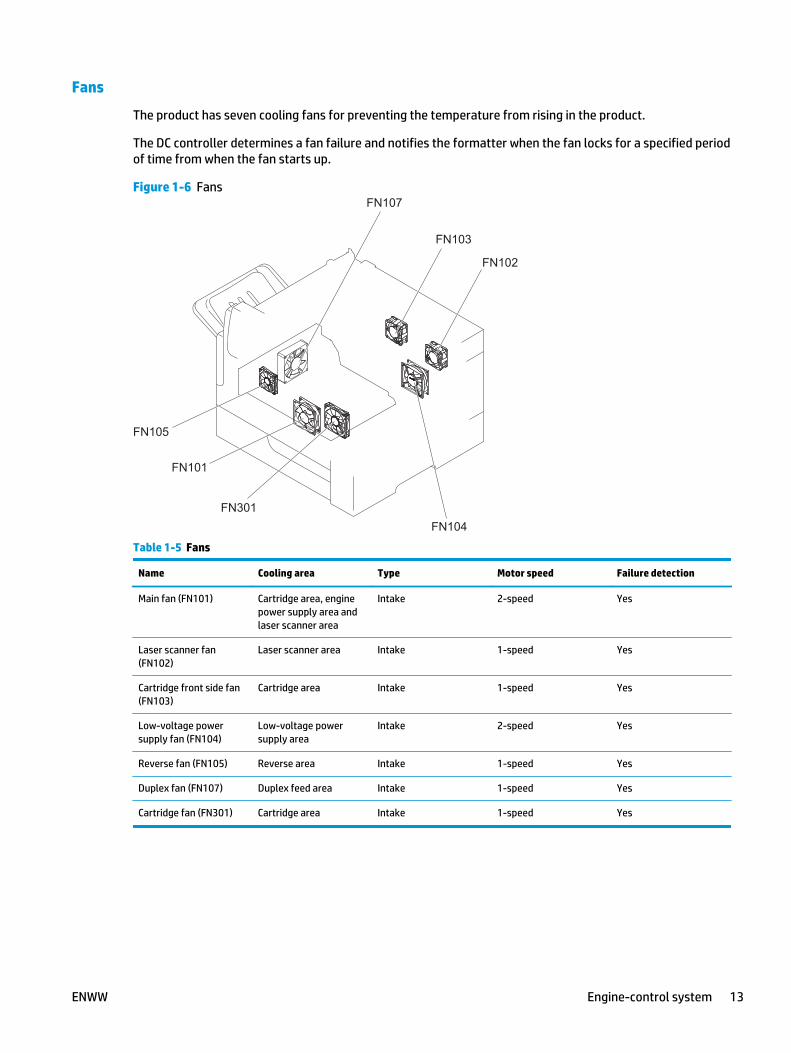
Fans
The product has seven cooling fans for preventing the temperature from rising in the product.
The DC controller determines a fan failure and notifies the formatter when the fan locks for a specified periodof time from when the fan starts up.
Figure 1-6 Fans
FN105
FN101
FN301FN104
FN102
FN103
FN107
Table 1-5 Fans
Name Cooling area Type Motor speed Failure detection
Main fan (FN101) Cartridge area, enginepower supply area andlaser scanner area
Intake 2-speed Yes
Laser scanner fan(FN102)
Laser scanner area Intake 1-speed Yes
Cartridge front side fan(FN103)
Cartridge area Intake 1-speed Yes
Low-voltage powersupply fan (FN104)
Low-voltage powersupply area
Intake 2-speed Yes
Reverse fan (FN105) Reverse area Intake 1-speed Yes
Duplex fan (FN107) Duplex feed area Intake 1-speed Yes
Cartridge fan (FN301) Cartridge area Intake 1-speed Yes
ENWW Engine-control system 13

High-voltage power supply
The high-voltage power supply applies biases to the following components:
● Primary charging roller
● Developing roller
● Transfer roller
● Fuser sleeve
● Pressure roller
Figure 1-7 High-voltage power supply
To primary charging roller
To developing roller
Primarycharging bias
circuit
Developingbias circuit
FuserFuser sleeve
Transfer biascircuit
Fuserbias circuit
DC controller
Photosensitive drum
Transfer roller
Engine power supply
Cartridge
Pressure roller
To primary charging rolleo r
To developing rolleo r
Primarycharging bias
circuitii
Developingbias circuit
FuserFuser sleeve
Transfer biasTTcircuitii
Fuserbias circuit
DC controller
Photosensitive drum
Transfer rolleTT r
Engine power supply
Cartridge
Pressure roller
The primary charging bias is used to charge the surface of the photosensitive drum evenly to prepare forimage formation. The primary charging bias circuit generates the bias.
The developing bias is used to adhere toner to an electrostatic latent image formed on the photosensitivedrum. The developing bias circuit generates the bias.
The transfer bias is used to transfer the toner from the photosensitive drum onto the paper. The transfer biascircuit generates the bias.
The fuser bias is used to stabilize the paper feed and improve the print quality. The fuser bias circuitgenerates the bias.
14 Chapter 1 Theory of operation ENWW

Low-voltage power supply
The low-voltage power supply converts the AC power from the power source into the DC voltage that theproduct components use.
Figure 1-8 Low-voltage power supply circuit
AC power DC controller
FuseFU1 Power switch
SW1061Fuser
FuseFU2
Zerocrosscircuit
Switchcircuit
Rectifyingcircuit
Protectioncircuit
+5Vgeneration
circuit
Rectifyingcircuit
+24Vgeneration
circuit
Protectioncircuit
+3.3VA
/SOFTSWSNS
/ZEROX
PSREM24V
+24VA
+24VB
/AC200
PFC-Z PWRRMT
+24VB
+24VB
+24VB
+24VA
InterlockswitchSW101
Protectioncircuit
+3.3Vgeneration
circuit
+5VA
WAKE_ENG
ICB
Formatter
Enginepower supply
+3.3VA
Switchcircuit
+24VC
Switchcircuit
+3.3VB
WAKE_VC
+3.3VB
Low-voltage power supply
PWR_SAVE
The low-voltage power supply converts the AC power into three DC voltages, which it then subdivides, asdescribed in the following table.
ENWW Engine-control system 15

Table 1-6 Converted DC voltages
DC voltage Behavior
+24V
+24VA Stopped when the product is turned off or is in Sleep mode
+24VB Interrupted when the cartridge door opens
+24VC Interrupted when the product detects no fuser installed
+5V +5VA Constantly supplied
+3.3V+3.3VA Constantly supplied
+3.3VB Stopped when the product is turned off or is in Sleep mode
Overcurrent/overvoltage protection
The low-voltage power supply automatically stops supplying the DC voltage to the product componentswhenever it detects excessive current or abnormal voltage. The low-voltage power supply has a protectivecircuit against overcurrent and overvoltage to prevent failures in the power supply circuit.
CAUTION: If DC voltage is not being supplied from the low-voltage power supply, the protective functionmight be running. In this case, turn the power switch off and unplug the power cord.
Do not turn the power switch on until the root cause is found and corrected.
If the protective function is active, the DC controller notifies the formatter of a low-voltage power supplyfailure. In addition, the low-voltage power supply has two fuses (FU1 and FU2) to protect against over-current. If over-current flows into the AC line, the fuses stop the AC power.
Voltage detection
The product detects the power supply voltage that is connected to the product. The DC controller monitorsthe POWERSUPPLY VOLTAGE (/AC200) signal and detects power supply voltage, whether 100 volts or 200volts, to control the fuser operation. The DC controller determines a low-voltage power supply failure andnotifies the formatter when the power supply voltage is out of a specified range.
Safety
For personal safety, the product interrupts +24VB power when the interlock switch is turned off. As a result,the DC voltage to the following components stops. See Table 1-6 Converted DC voltages on page 16.
● Low-voltage power supply
● High-voltage power supply
● Fuser motor (M299)
● Laser scanner fan (FN102)
● Cartridge front-side fan (FN103)
● Reverse fan (FN105)
● Cartridge fan (FN301)
16 Chapter 1 Theory of operation ENWW

WARNING! The remote switch control circuit turns the product power on or off such that AC power flowseven when the power switch is turned off. Unplug the power cord before disassembling the product.
Sleep (power save) mode
Sleep mode conserves energy by stopping the power to several components when the product is idle. The DCcontroller determines a low-voltage power supply failure and notifies the formatter if the power supply of+24 volts is lower than a specified value when the product exits Sleep mode and enters the standby period.
Low-voltage power supply functions
The product has the following low-voltage power supply functions.
Table 1-7 Low-voltage power supply functions
Function Supported feature
Sleep mode Yes
Power supply voltage detection Yes
Automatic power OFF No
Automatic power ON/OFF No
Active OFF Yes
Inactive OFF Yes
Network mode No
Power switch illumination Yes
Low-voltage power supply failure detection Yes
ENWW Engine-control system 17

Fuser control
The fuser heater control circuit and the fuser heater safety circuit control the fuser temperature according tocommands from the DC controller. The product uses an on-demand fusing method.
Figure 1-9 Fuser components
Fuser heater safetycircuit
Low-voltage power supply
TH1
TP1
H1, H2
DC controller
Fuser heater controlcircuit
TH2
FUSER TEMPERATURE signal
FUSER HEATER CONTROL signal
Pressure roller
Fuser sleeve
Fuser heater safetycircuitii
Low-voltage power suppltt y
TH1
TP1
H1, H2
DC controller
Fuser heater controlcircuit
TH2
FUSER TEMPERATURE signalAA
FUSER HEATER CONTROLAA signalL
Pressure roller
Fuser sleeve
Table 1-8 Fuser components
Component name Function
H1 Fuser main heater Heats the fuser sleeve
H2 Fuser sub-heater Heats the fuser sleeve
TH1 Main thermistor Detects the temperature at the center of the fuser heater(contact type)
TH2 Sub-thermistor Detects the temperature on one end of the fuser heater (contacttype)
TP1 Thermoswitch Prevents an abnormal temperature rise of the fuser heater(contact type)
18 Chapter 1 Theory of operation ENWW

Fuser temperature control
The fuser temperature control maintains the temperature of the fuser heater at its targeted temperature.
The DC controller detects the fuser temperature by monitoring the FUSER TEMPERATURE (FSRTH1 andFSRTH2) signals. The DC controller outputs the FUSER HEATER CONTROL (FSRD1 and FSRD2) signals, so thatthe fuser heater control circuit controls the fuser heater accordingly.
Figure 1-10 Fuser circuit
FSRTH1
FSRD1
FSRTH2
/FSRARI
/AC200
DC controller
/RLD
/ZEROX
CURRMS
FSRSAFE
JP1001
RL101
Fuser control
H1, H2
TH1TP1
Pressure roller
TH2
FSRD2
100V: Open200V: Close
Zerocrosscircuit
Relay controlcircuit
Currentdetection
circuit
Fuser heatercontrol circuit
Fuser heatersafety circuitRL102
AC input
Fuser sleeve ass’y
Fuser
Low-voltage power supply (LPU)
Engine power supply (EPU)
FSRTH1RR
FSRD1
FSRTH2RR
/FSRARI
/AC200
DC controller
/RLD
/ZEROX
CURRMS
FSRSAFE
JP1001
RL101
Fuser control
H1, H2
TH1TP1
Pressure roller
TH2
FSRD2
100V: OpenVV200V: CloseVV
Zerocrosscircuitii
Relay controlcircuitii
Currentdetection
circuitii
Fuser heatercontrol circuit
Fuser heatersafety circuitRL102
AC input
Fuser sleeve ass’y
Fuser
Low-voltage power supply (LPU)tt
Engine power supply (EPU)
ENWW Engine-control system 19

Fuser sleeve temperature protection
Fuser heater protection is a feature that detects excessive temperatures in the fuser and interrupts thepower supply to the fuser heater.
The following three protective components prevent the fuser heater from reaching excessive temperatures:
● DC controller: The DC controller monitors the detected temperature of the thermistors. The DCcontroller deactivates the FUSER HEATER CONTROL signal and releases the relays (RL101 and RL102) tointerrupt power supply to the fuser heater when it detects an excessive temperature.
● Fuser heater safety circuit: The fuser heater safety circuit monitors the detected temperature of thethermistors. The fuser heater safety circuit deactivates the FUSER HEATER CONTROL signal andreleases the relays (RL101 and RL102) to interrupt power supply to the fuser heater when it detects anexcessive temperature.
● Thermoswitch: If the temperature of the fuser heater is abnormally high, the contact of thethermoswitch breaks to interrupt power supply to the fuser heater.
Fuser failure detection
The DC controller determines if the fuser functions properly. The DC controller determines a fuser failure,interrupts power supply to the fuser heater, and notifies the formatter of a failure status when it encountersany of following conditions:
● Abnormal temperature rise
◦ The main thermistor does not detect 15°C (59°F) or higher within a specified period of time fromwhen the fuser heater is turned on.
◦ The main thermistor does not detect 100°C (212°F) or higher within a specified period of time fromwhen the fuser heater is turned on.
◦ The main thermistor does not detect targeted temperature minus 5°C (41°F) within a specifiedperiod of time from when the fuser heater is turned on.
● Abnormally low temperature
◦ The main thermistor detects 49°C (120.2°F) or lower continuously for a specified period of timeafter it once detects 100°C (212°F) or higher.
◦ The main thermistor detects targeted temperature minus specified degrees or lower continuouslyfor a specified period of time after the TOP signal for the first page is output.
◦ The sub-thermistor detects 49°C (120.2°F) or lower continuously for a specified period of timeafter it once detects 100°C (212°F) or higher.
● Abnormally high temperature
◦ The main thermistor detects 255°C (491°F) or higher.
◦ The sub-thermistor detects 285°C (545°F)or higher.
● Frequency detection circuit failure
◦ The ZEROCROSS signal is not detected within a specified period of time after the product is turnedon.
● Fuser-presence detection
20 Chapter 1 Theory of operation ENWW

The DC controller determines if the fuser is installed in the product and notifies the formatter when itdetects the fuser is absent. The DC controller detects fuser presence from the FUSER PRESENCE (/FUSERARI) signal when any of the following occurs:
◦ The product is turned on.
◦ The door is closed.
Pressure roller cleaning
The formatter periodically initiates the pressure roller cleaning function to clear the toner accumulated onthe pressure roller surface by transferring it to a piece of paper. Following is the operational sequence ofpressure roller cleaning:
1. The DC controller initiates picking a sheet of paper from the designated input source when it receivesthe cleaning command from the formatter.
2. The fuser motor repeatedly drives-and-stops at a specified interval when the trailing edge of the paperpasses through the transfer roller. The fuser heater is turned on-and-off at the same time.
3. The fuser fuses the toner adhered to the pressure roller surface onto the paper; thus, cleaning thepressure roller.
4. The paper with the fused toner exits the product.
Ambient-temperature detection
The product contains an environmental sensor (TH3) that measures the air temperature of the surroundingenvironment. The product automatically adjusts the temperature settings in the fuser to adjust for changesin the ambient temperature.
ENWW Engine-control system 21

Laser/scanner systemThe DC controller controls the laser scanner system according to commands from the formatter. The DCcontroller controls the internal components in the laser scanner system to form a latent electrostatic imageon the photosensitive drum according to the VIDEO signals.
The following are the main components of the laser scanner system:
● Laser assembly
● Scanner motor assembly
● Beam Detect (BD) sensor
● Scanning mirror
● BD mirror
Figure 1-11 Laser/scanner
DC controller
Photosensitive drum
Scanning mirror
BD sensor
Laser ass’y
Scanner motor ass’y
BD mirror
DC controller
Photosensitive drum
Scanning mirror
BD sensor
Laser ass’y
Scanner motor ass’y
BD mirror
22 Chapter 1 Theory of operation ENWW

Laser/scanner failureThe DC controller determines an optical unit failure and notifies the formatter of the error status when any ofthe following occurs:
● Beam Detect (BD) failure: The BD signal is not detected within a specified period of time from when thelaser/scanner starts. Or, a specified BD interval is not detected within a specified period of time fromwhen the laser/scanner is ready.
● Laser/scanner motor startup failure: The scanner motor does not reach a specified rotation frequencywithin a specified period of time from when the laser/scanner starts up.
● Laser/scanner motor abnormal rotation: The laser/scanner motor does not reach a specifiedrotational frequency within a specified period of time during a print operation.
SafetyThe laser/scanner assembly has a mechanical laser shutter. For the safety of users and service technicians,the laser shutter interrupts the optical path of the laser/scanner assembly when the top door is opened(SW101).
ENWW Laser/scanner system 23

Image-formation systemThe DC controller controls the image-formation system according to commands from the formatter. The DCcontroller controls the internal components of the image-formation system to form the toner image on thephotosensitive drum surface, transfer the image to the paper, and then fuse it to the paper.
The following are the main components of the image-formation system:
● Toner cartridge
● Transfer roller
● Fuser
● Laser/scanner assembly
● Engine power supply
Figure 1-12 Image-formation system components
Engine power supply
DC controller
Laser scanner ass’yToner
Transfer rollerFuser
Cartridge
Image scanner
Engine power supply
DC controller
Laser scanner ass’yToner
Transfer rolleTT rFuser
Cartridge
Image scanner
The DC controller rotates the drum motor to drive the following components:
● Photosensitive drum
● Developing roller
24 Chapter 1 Theory of operation ENWW

● Primary charging roller (follows the photosensitive drum)
● Transfer roller (follows the photosensitive drum)
The DC controller rotates the fuser motor to drive the following components:
● Pressure roller
● Fuser sleeve (follows the pressure roller)
Figure 1-13 Image-formation system motor control
DC controller
Developing roller
Primary charging roller
Cartridge
Transfer roller
Drum motor
Photosensitive drum
Fuser
Pressure roller
Fuser sleeve
Fuser motor
Toner
Image scanner
DC controller
Developing roller
Primary charging roller
Cartridge
Transfer rolleTT r
Drum motor
Photosensitive drum
Fuser
Pressure roller
Fuser sleeve
Fuser motor
Toner
Image scanner
ENWW Image-formation system 25

Electrophotographic processFollowing are the stages of the electrophotographic process (image formation):
Figure 1-14 Stages of image-formation
2. Laser beam exposure
3. Developing
4. Transfer5. Separation6. Fusing
Electrostatic latent image formation block
Cleaning block
Fusing blockTransfer block
Paper path
Developing block
Direction of drum rotation
Paper deliveryRegistration Tray 1 pickup
Paper pickup
7. Drum cleaning
8. Drum charge elimination
1. Primary charge
2. Laser beam exposure
3. Developing
4. Transferr5. Separation6. Fusing
Electrostatic latent image formation block
Cleaning block
Fusing blockTransfer block
Paper path
Developing block
Direction of drum rotation
Paper deliveryRegistration Tray 1 pickup
Paper pickup
7. Drum cleaning
8. Drum charge elimination
1. Primary charge
26 Chapter 1 Theory of operation ENWW

Step 1: Primary charge (conditioning)
The primary-charging roller in the toner cartridge applies a uniform negative charge to the surface of thedrum. The primary-charging roller is made of conductive rubber. An AC bias applied to the roller erases anyresidual charges from any previous image. The charging roller applies a negative DC bias to create a uniformnegative potential on the drum surface.
Figure 1-15 1. Primary charge (conditioning)
Primary charging bias
Photosensitive drum
Primary charging roller
Primary charging bias
Photosensitive drum
Primary charging roller
Step 2: Laser-beam exposure (writing)
Two laser diodes project laser beams onto a rotating scanning mirror. As the mirror rotates, the beamsreflect off of the mirror, first through a set of focusing lenses, then off a mirror, and finally through a slot inthe top of the toner cartridge, and onto the photosensitive drum. The twin beams sweep the drum from leftto right, discharging the negative potential wherever the beams strike the surface. This creates a latentelectrostatic image, which later is developed into a visible image.
Figure 1-16 2. Laser-beam exposure (writing)
Laser beam
Photosensitive drum
Laser beam
Photosensitive drum
ENWW Image-formation system 27

Step 3: Developing
At this stage of the process, the latent electrostatic image is present on the drum. The toner particles obtaina negative surface charge by rubbing against the developing cylinder, which is connected to a negative DCsupply. The discharged (exposed, grounded) areas of the drum attract the negatively charged toner, and thenegatively charged (unexposed) areas repel the toner.
Figure 1-17 3. Developing
Developer blade
Photosensitive drum
Developing roller
Developing bias
Developer blade
Photosensitive drum
Developing roller
Developing bias
Step 4: Transfer
During the transfer process, the toner image on the drum surface transfers to the paper. The transfercharging roller applies a positive charge to the back of the paper, which attracts the negatively charged toneron the drum surface to the paper.
Figure 1-18 4. Transfer
PaperTransfer roller
Photosensitivedrum
Transfer bias
PaperTransfer rolleTT r
Photosensitivedrum
Transfer biasTT
28 Chapter 1 Theory of operation ENWW

Step 5: Separation
During the separating process, the paper separates from the drum. To stabilize the feed system and toprevent dropouts on the printed image at low temperature and humidity, the static-charge eliminatorreduces the charge on the back of the paper.
Figure 1-19 5. Separation
Transfer roller
Photosensitivedrum
Static charge eliminatorPaper
Transfer rolleTT r
Photosensitivedrum
Static charge eliminatorttPaper
Step 6: Fusing
During the fusing process, heat and pressure fuse the toner to the paper in order to produce a permanentimage. The paper passes between a heated fuser element and a soft pressure roller. This melts the toner andpresses it into the paper.
Figure 1-20 6. Fusing
Brush
Fuser bias Fuser bias
TonerFuser sleeve
Fuser heater
Pressure roller
Paper
Brush
Fuser bias Fuser bias
TonerTTFuser sleeve
Fuser heater
Pressure roller
Paper
ENWW Image-formation system 29
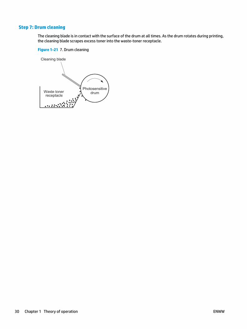
Step 7: Drum cleaning
The cleaning blade is in contact with the surface of the drum at all times. As the drum rotates during printing,the cleaning blade scrapes excess toner into the waste-toner receptacle.
Figure 1-21 7. Drum cleaning
Waste tonerPhotosensitive
drum
Cleaning blade
receptacleWaste toner
Photosensitivedrum
Cleaning blade
receptacle
30 Chapter 1 Theory of operation ENWW

Toner cartridgeThe toner cartridge consists of a reservoir of toner and the following components:
● Photosensitive drum
● Developing roller
● Primary charging roller
● Memory chip
Figure 1-22 Toner Cartridge
Primarycharging
roller
Engine power supply
DC controller
PS115Cartridge sensor Developing roller
Cartridge
Photosensitive drum
Drum motor
Memory chip
Primarycharging
roller
Engine power supply
DC controller
PS115Cartridge sensor Developing roller
Cartridge
Photosensitive drum
Drum motor
Memory chip
Memory chip
The memory chip is non-volatile memory that stores information about the usage of the toner cartridge. Theproduct reads and writes the data in the memory chip.
The DC controller determines a memory chip error and notifies the formatter when it fails to either read fromor write to the memory chip.
Cartridge presence and life detection
The DC controller performs the following functions related to both detecting the presence of the tonercartridge and determining the remaining life of the cartridge:
● Cartridge presence detection: The DC controller detects the presence of the cartridge by monitoringthe cartridge sensor (PS115) when both of the following occur:
ENWW Image-formation system 31

◦ The product is turned on.
◦ The door is closed.
The DC controller notifies the formatter when it detects the cartridge is missing.
● Toner level detection: The DC controller detects the remaining toner in the cartridge according to theTONER LEVEL signal, and then notifies the formatter of the remaining toner level.
● Cartridge life detection: The DC controller detects the cartridge life by monitoring the total operatingtime or remaining toner level of the toner cartridge. The DC controller determines a cartridge is at theend of life and notifies the formatter when total operating time of the cartridge reaches a specifiedperiod of time or the cartridge runs out of toner.
32 Chapter 1 Theory of operation ENWW

Pickup, feed, and delivery systemThe DC controller controls the pickup, feed, and delivery system according to commands from the formatter.This system consists of three parts:
● The pickup-and-feed block encompasses the paper path from each tray to the fuser entrance.
● The fusing, reverse, and delivery block encompasses the paper path from the fuser entrance to theoutput device.
● The duplex block emcompasses the paper path to reverse the paper in the duplex reverse area for two-sided printing
Figure 1-23 Pickup, feed, and delivery system
Simplex paper path
DC controller
Fusing, switchback, and delivery block
Pickup-and-feed block
Duplex block
Duplex paper path Simplex paper path
DC controller
Fusing, switchback, and delivery block
Pickup-and-feed block
Duplex block
Duplex paper path
Fusing, reverse, and delivery block
ENWW Pickup, feed, and delivery system 33

Figure 1-24 Sensor locations
PS114
PS101
PS107PS907
PS699PS113PS109
PS700
PS111PS112
PS110PS104
PS103
PS108
PS106
SW102
PS102
Table 1-9 Sensors
Abbreviation Component Replacement part number
PS101 Tray 2 media out sensor Paper pickup assembly (RM1-5919-000CN)
PS102 Pre-feed sensor Part not available
PS103 TOP sensor Part not available
PS104 Output bin media-full sensor Part not available
PS106 Media width sensor 1 Part not available
PS107 Tray 2 media stack surface sensor 1 Paper pickup assembly (RM1-5919-000CN)
PS108 Media width sensor 2 Part not available
PS109 Duplex side registration sensor Duplex assembly kit (B3G84-67903)
PS110 Reverse sensor Reverse assembly (RM2-5799-000CN)
PS111 Reverse jam sensor Reverse assembly (RM2-5799-000CN)
PS112 Delivery sensor Reverse assembly (RM2-5799-000CN)
PS113 Duplex re-pickup sensor Duplex assembly kit (B3G84-67903)
PS114 Tray 1 media out sensor MP (Tray 1) pickup assembly (RM2-5822-000CN)
PS115 Cartridge sensor Cartridge sensor assembly (RM1-8323-000CN )
PS699 Fuser pressure release sensor Fuser replacement kit, 110V (B3M77-67903)
Fuser replacement kit, 220V (B3M78-67903)
PS700 Fuser delivery sensor Fuser replacement kit, 110V (B3M77-67903)
Fuser replacement kit, 220V (B3M78-67903)
34 Chapter 1 Theory of operation ENWW

Table 1-9 Sensors (continued)
Abbreviation Component Replacement part number
PS907 Tray 2 media stack surface sensor 2 Paper pickup assembly (RM1-5919-000CN)
SW102 Tray 2 media size switch Size detect cable (RM1-7179-000CN)
Figure 1-25 Motor, clutch, and solenoid locations
M105M104M106 SL106SL105
M299
M107
SL102
SL101 CL101
M101M103
M102
Cam
Face-up flapper
Lifter
Tray pickup arm
Reverse rollerdisengagement arm
Fuser pressurerelease cam
Side registration guide
M105M104M106 SL106SL105
M299
M107
SL102
SL101 CL101
M101M103
M102
Cam
Face-up flapper
Lifterff
Tray pickup arm
Reverse rollerdisengagement arm
Fuser pressurerelease cam
Side registration guide
Table 1-10 Motors, clutch, and solenoids
Abbreviation Component Replacement part number
CL101 Media feed clutch Paper feed roller assembly (RM1-8411-010CN)
M101 Feed motor Feed motor assembly (RM2-5942-000CN)
M102 Drum motor Drum motor assembly (RM1-8358-000CN)
M103 Tray 2 lifter motor Lifter assembly (RM1-5914-000CN)
M104 Intermediate reverse assembly motor Reverse assembly (RM2-5799-000CN)
M105 Reverse motor Reverse assembly (RM2-5799-000CN)
M106 Delivery motor Reverse assembly (RM2-5799-000CN)
ENWW Pickup, feed, and delivery system 35

Table 1-10 Motors, clutch, and solenoids (continued)
Abbreviation Component Replacement part number
M107 Duplex re-pickup motor Duplex assembly kit (B3G84-67903)
M108 Scanner motor (not shown) Laser/scanner assembly (RM1-8406-000CN)
M299 Fuser motor Fuser motor assembly (RM1-5051-020CN)
SL101 Tray 2 pickup solenoid Paper pickup assembly (RM1-5919-000CN)
SL102 Tray 1 pickup solenoid MP (Tray 1) pickup assembly (RM2-5822-000CN)
SL105 Face-up solenoid Reverse assembly (RM2-5799-000CN)
SL106 Reverse roller disengagement solenoid Reverse assembly (RM2-5799-000CN)
Figure 1-26 Switch locations
SW105
SW103
SW104
SW1
SW102
SW101SW700
SW105
SW103
4SW1044
SW1
SW102
SW101SW700
Table 1-11 Switches
Abbreviation Component Replacement part number
SW1061 Power switch Power switch assembly (RM2-5818-000CN)
SW101 Interlock switch Door switch cable assembly (RM2-7478-000CN)
SW102 Tray 2 media size switch Part not available
36 Chapter 1 Theory of operation ENWW

Table 1-11 Switches (continued)
Abbreviation Component Replacement part number
SW103 Face-up bin detection switch Part not available
SW104 Output accessory detection switch Push button switch assembly (RM1-7374-000CN)
SW105 Tray 2 door open detection switch Right door sensor assembly (RM1-1045-000CN)
SW106 Cartridge door open detection switch (not shown) Door sensor cable assembly (RM2-7476-000CN)
SW700 Test-print switch DC controller PCA assembly (RM2-7458-000CN)
ENWW Pickup, feed, and delivery system 37

Pickup-and-feed blockThe pickup-and-feed block picks one sheet of paper from the tray and feeds it into the fuser.
Figure 1-27 Pickup-and-feed block
Tray 2
Tray 1
Tray 2
Tray 1
38 Chapter 1 Theory of operation ENWW

Tray 2 pickup
The operational sequence of picking one sheet of paper from Tray 2 is as follows:
1. The DC controller rotates the feed motor when it receives a print command from the formatter.
2. The Tray 2 pickup roller, Tray 2 feed roller, and Tray 2 separation roller rotate.
3. The Tray 2 pickup solenoid drives at a specified timing.
4. The Tray 2 pickup cam rotates.
5. As the Tray 2 pickup arm lowers, the Tray 2 pickup roller touches the surface of the top sheet of paper.
6. The Tray 2 separation roller removes any multiply-fed sheets.
7. One sheet of paper feeds into the product.
Figure 1-28 Tray 2 pickup
DC controller
1: The Tray 2 pickup cam rotates2: The Tray 2 pickup arm lowers.
3: The Tray 2 pickup roller picks up the paper.
1
2
3
M101
SL101
Tray 2 separation roller
Tray 2 feed roller
Tray 2 pickup cam
Tray 2 pickup arm
Tray 2 pickup roller
Feed motor
Tray 2 pickup solenoid
Lifting plate
DC controller
1:The Tray 2 pickup cam rotates2:The Tray 2 pickup arm lowers.
3:The Tray 2 pickup roller picks up the paperee
1
2
3
M101
SL101
Tray 2 separation roller
Tray 2 feed roller
Tray 2 pickup cam
Tray 2 pickup arm
Tray 2 pickup roller
Feed motor
Tray 2 pickup solenoid
Lifting plate
ENWW Pickup, feed, and delivery system 39

Tray 2 paper-size detection and tray-present detection
The DC controller determines the size of the paper loaded in Tray 2 and also whether the tray is installed inthe product by monitoring the Tray 2 media size switch. The DC controller notifies the formatter when thedetected paper size does not match the size specified by the formatter or if the tray is absent.
The Tray 2 media size switch contains three sub-switches. The DC controller detects the size of the paper andthe presence of the tray based on the combination of the switches.
Table 1-12 Tray 2 media-size detection switch components
Tray presence or media size Top switch Center switch Bottom switch
A4 On Off Off
Letter Off On Off
B5 Off On On
A5 Off Off On
Executive On Off On
Legal On On Off
Custom size On On On
No tray Off Off Off
40 Chapter 1 Theory of operation ENWW

Tray 2 lift operation
The Tray 2 lift operation keeps the paper stack surface at the correct pickup position.
The DC controller detects the position of the stack surface by monitoring the Tray 2 media stack surfacesensors under the following conditions:
● When the product is turned on
● When the tray is inserted
● When the paper stack surface in the tray lowers
Figure 1-29 Tray 2 lift operation
DC controller
Tray lifter motor
Tray media presence sensor lever
Tray media stack surface sensor lever
Lifting plate
Tray mediapresence sensor
Tray mediastack surface sensor 1
Lifter
Tray mediastack surface sensor 2
DC controller
Tray lifter motor
Tray media presence sensor lever
Tray media stack surface sensor lever
Lifting plate
Tray mediapresence sensor
Tray mediastack surface sensor tt 1
Lifterff
Tray mediastack surface sensor tt 2
The sequence of the Tray 2 lift operation is as follows:
1. The DC controller rotates the Tray 2 lifter motor.
2. The lifter moves up.
3. The tray lifter motor stops when the tray media stack surface sensor 2 detects the paper stack surface.
4. The tray lifter motor rotates again when the tray media stack surface sensor 1 detects that the paperstack surface lowers.
NOTE: The DC controller determines a tray lifter motor failure and notifies the formatter if the traymedia stack surface sensor 1 or sensor 2 does not detect the paper stack surface within a specifiedperiod of time after the tray lifter motor starts rotating.
Tray 2 paper-presence detection
The DC controller detects the presence of paper in Tray 2 by monitoring the Tray 2 media presence sensor.When this sensor does not detect paper in the tray, the DC controller notifies the formatter.
ENWW Pickup, feed, and delivery system 41

Tray 2 multiple-feed prevention
In Tray 2, the separation roller prevents multiple sheets of paper from entering the paper path. The Tray 2pickup roller drives the separation roller through a sheet of paper.
The rotation of the Tray 2 feed roller through the sheet drives the separation roller. Because the feed roller isequipped with a torque limiter, only one sheet feeds into the product.
The low friction force between the sheets weakens the driving force from the Tray 2 feed roller. Therefore,the separation roller is driven by its own driving force and holds back any multiply-fed sheets from thecassette.
Figure 1-30 Multiple-feed prevention
<Multiple-feed><Normal-feed>
Tray 2 separation roller followsthe Tray 2 feed roller
Driving force from the feed motorPaper
Tray 2 pickup roller
Tray 2 separation roller
Tray 2 feed roller
<Multiple-feed><Normal-feed>
Tray 2 separation roller followsthe Tray 2 feed roller
Driving force from the feed motorPaper
Tray 2 pickup roller
Tray 2 separation roller
Tray 2 feed roller
42 Chapter 1 Theory of operation ENWW
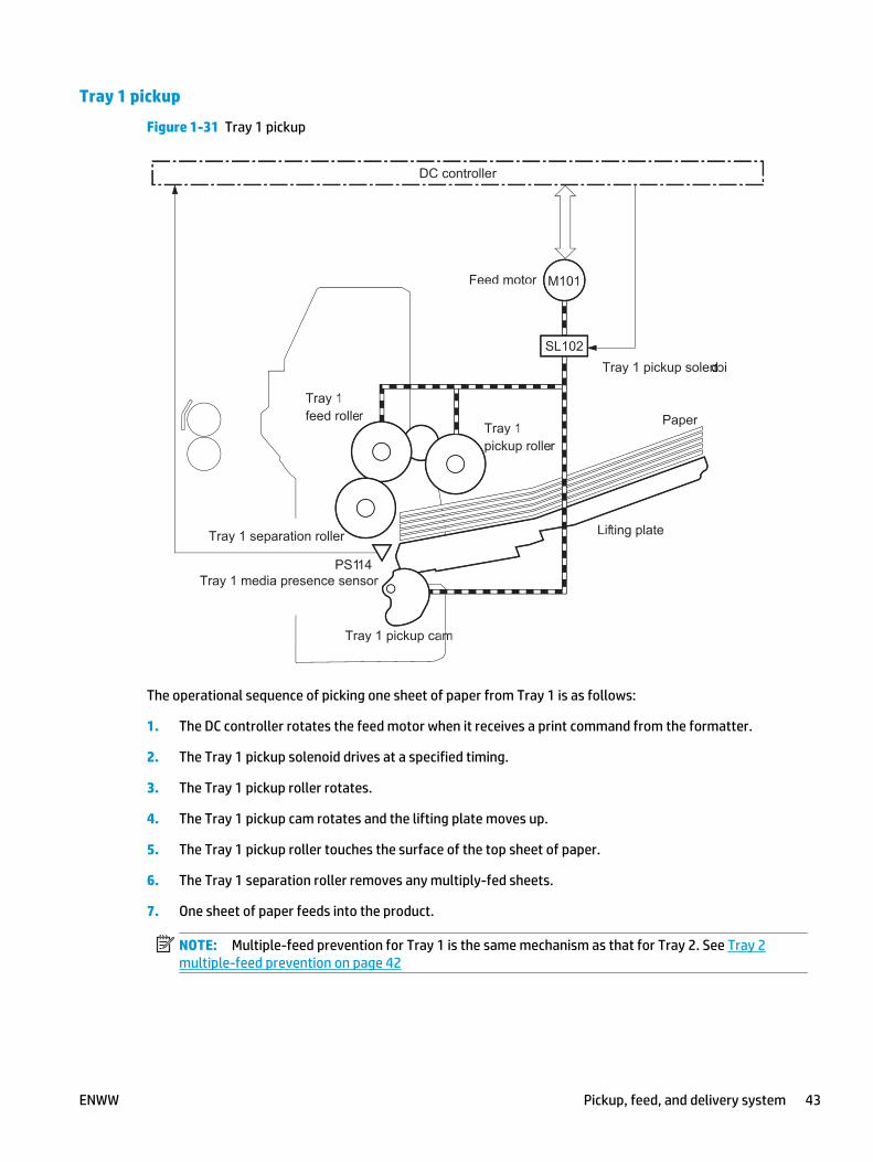
Tray 1 pickup
Figure 1-31 Tray 1 pickup
DC controller
M101
SL102
PS114
Lifting plate
Tray 1pickup roller
Tray 1 separation roller
Feed motor
Tray 1 pickup solenoid
Tray 1 media presence sensor
PaperTray 1feed roller
Tray 1 pickup cam
DC controller
M101
SL102
PS114
Lifting plateff
Tray 1pickup roller
Tray 1 separation roller
Feed motor
Tray 1 pickup solenoinono
rTray 1 media presence sensor
PaperTray 1feed roller
ammTray 1 pickup ca
The operational sequence of picking one sheet of paper from Tray 1 is as follows:
1. The DC controller rotates the feed motor when it receives a print command from the formatter.
2. The Tray 1 pickup solenoid drives at a specified timing.
3. The Tray 1 pickup roller rotates.
4. The Tray 1 pickup cam rotates and the lifting plate moves up.
5. The Tray 1 pickup roller touches the surface of the top sheet of paper.
6. The Tray 1 separation roller removes any multiply-fed sheets.
7. One sheet of paper feeds into the product.
NOTE: Multiple-feed prevention for Tray 1 is the same mechanism as that for Tray 2. See Tray 2multiple-feed prevention on page 42
ENWW Pickup, feed, and delivery system 43

Tray 1 paper-presence detection
The DC controller detects the presence of paper in Tray 1 by monitoring the Tray 1 media presence sensorduring the initial rotation period when the product is turned on or when the product exits Sleep mode.
Feed speed control
The feed speed control adjusts the feed speed to improve the print quality depending upon the paper type.The DC controller feeds the paper at a specified speed, depending on the print mode designated by theformatter.
Table 1-13 Feed speed control
Print mode Feed speed
Legal / Letter / A4 Executive / B5 / A5 / Any custom
Auto NA NA
Normal 1/1, 1/2 1/2
Heavy media 1 1/1, 1/2 1/2
Heavy media 2 1/2 1/2
Light media 2 1/1, 1/2 1/2
OHT 1/2 1/2
44 Chapter 1 Theory of operation ENWW

Skew-feed prevention
The product can straighten the paper without slowing the feed operation. The operational sequence of skew-feed prevention is as follows:
1. The leading edge of paper strikes the registration shutter, and the leading edge aligns with the shutter.
2. As the feed rollers keep pushing the paper, the paper warps.
3. When the force is great enough, the registration shutter opens, and the paper passes through andstraightens.
Figure 1-32 Skew-feed prevention
Registration shutter
Paper
Registration shutter
Paper
Registration shutter
Paper
Registration shutter
Paper
ENWW Pickup, feed, and delivery system 45

Paper-length detection
The DC controller determines the paper length by measuring the time between when the leading edge of thepaper reaches the TOP sensor and when the trailing edge passes through.
The DC controller determines a paper size mismatch and notifies the formatter in one of the followingconditions:
● The detected paper size is different from the size designated by the formatter.
● The detected paper size is different from the size detected by the Tray 2 media size switch (only whenprinting from Tray 2).
Paper-width detection
The DC controller determines the paper width by analyzing the combination of media width sensor readings.
The DC controller determines a paper size mismatch and notifies the formatter in one of the followingconditions:
● The detected paper size is different from the size designated by the formatter.
● The detected paper size is different from the size detected by the Tray 2 media size switch (only whenprinting from Tray 2).
Table 1-14 Paper-width detection
Media width sensor 1 (PS106) Media width sensor 2 (PS108) Detection
ON ON Regular size
A4, Letter and Legal
OFF OFF Small size
Executive, B5 and A5
OFF ON Detected on right side
ON OFF Detected on left side
46 Chapter 1 Theory of operation ENWW
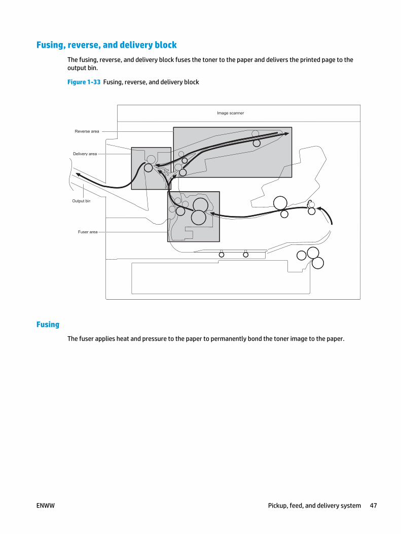
Fusing, reverse, and delivery blockThe fusing, reverse, and delivery block fuses the toner to the paper and delivers the printed page to theoutput bin.
Figure 1-33 Fusing, reverse, and delivery block
Fuser area
Delivery area
Switchback area
Output bin
Image scanner
Fuser area
Delivery area
Switchback area
Output bin
Image scanner
Reverse area
Fusing
The fuser applies heat and pressure to the paper to permanently bond the toner image to the paper.
ENWW Pickup, feed, and delivery system 47

Pressure roller pressurization and depressurization control
Pressure roller pressurization and depressurization control is a feature to pressurize the pressure roller onlywhen required for preventing a deformation of the roller and to facilitate clearing jams.
The product ships from the factory with the pressure roller released. The DC controller also releases thepressure roller when a jam is detected.
Figure 1-34 Pressure roller pressurization and depressurization control
DC controller
Fuser pressure release sensor
<Pressurized> <Depressurized>
PS699
M299
Pressure roller
Fuser pressurerelease cam
Fuser motor
Fuser sleeve
DC controller
Fuser pressure release sensor
<Pressurized> <Depressurized>
PS699
M299
Pressure roller
Fuser pressurerelease cam
Fuser motor
Fuser sleeve
The operational sequence of the pressure roller pressurization and depressurization control is as follows:
1. The DC controller reverses the fuser motor.
2. The fuser pressure release cam rotates.
3. The pressure roller is pressurized or depressurized against the fuser sleeve, depending on the positionof the fuser pressure release cam.
NOTE: The DC controller determines a fuser pressure release mechanism failure and notifies theformatter if the fuser pressure release sensor does not detect the depressurized condition within aspecified period of time from when the fuser motor starts reverse rotation.
48 Chapter 1 Theory of operation ENWW

Reverse and delivery control
After the toner is fused to the paper, the paper enters the reversing/delivery unit. The product can deliver thepaper to the output bin either face-up or face-down, depending on instructions from the formatter.
Figure 1-35 Reverse and delivery control
M105M104
M106
SL106
Face-down paper path
PS700
PS111PS112
PS110
Image scanner
Switchback area
Fuser
Switchback roller disengagement arm
Output bin
Delivery motor
Intermediate switchback motor
Switchback motor
Switchback rollerdisengagement solenoid
PS110: Switchback sensorPS111: Switchback jam sensorPS112: Delivery sensorPS700: Fuser output sensor
Intermediate switchback roller
Switchback lower roller
Switchback upper roller
Intermediatedelivery roller
Delivery roller
Face-up paper path
M105M104
M106
SL106
Face-down paper path
PPS700P
PS111SSPS112
PS110
Image scanner
Switchback area
Fuser
Switchback roller disengagement arm
Output bin
Delivery motor
Intermediate switchback motor
rSwitchback motor
Switchback rollerdisengagement solenoid
PS110: Switchback sensorPS111: Switchback jam sensorPS112: Delivery sensorPS700: Fuser output sensor
Intermediate switchback roller
Switchback lower roller
Switchback upper roller
Intermediatedelivery roller
Delivery roller
Face-up paper path
ENWW Pickup, feed, and delivery system 49

Face-down delivery
To stack pages of a multiple-page print job in the correct order, the pages must be flipped over in thereversing unit before they are delivered face-down to the output bin.
Figure 1-36 Face-down delivery
Face-down paper path
Image scanner
Intermediate delivery roller
Switchback roller disengagement arm
Fuser
Switchback area
Output bin
Delivery roller
Intermediate switchback roller
Switchback lower roller
Switchback upper roller
Face-down paper path
Image scanner
Intermediate delivery roller
Switchback roller disengagement arm
Fuser
Switchback area
Output bin
Delivery roller
Intermediate switchback roller
Switchback lower roller
Switchback upper roller
50 Chapter 1 Theory of operation ENWW

Face-up delivery
When the paper is delivered face-up, the face-up solenoid (SL105) activates the face-up deflector to preventthe paper from entering the reversing unit.
Figure 1-37 Face-up delivery
Face-up paper path
Image scanner
Delivery roller
Face-up flapper
Fuser
Output bin
Face-up paper path
Image scanner
Delivery roller
Face-up flapper
Fuser
Output bin
ENWW Pickup, feed, and delivery system 51

Output bin paper-full detection
The DC controller detects whether the output bin is full by monitoring the output-bin media-full sensor.
Figure 1-38 Output bin paper-full detection
Face-down paper pathFace-up paper path
DC controller
Output-bin media-full sensorPrinted paperPS104
Output bin
Output-bin media-fullsensor lever
Face-down paper pathFace-up paper path
DC controller
Output-bin media-full sensorPrinted paperPS104
Output bin
Output-bin media-fullsensor lever
52 Chapter 1 Theory of operation ENWW
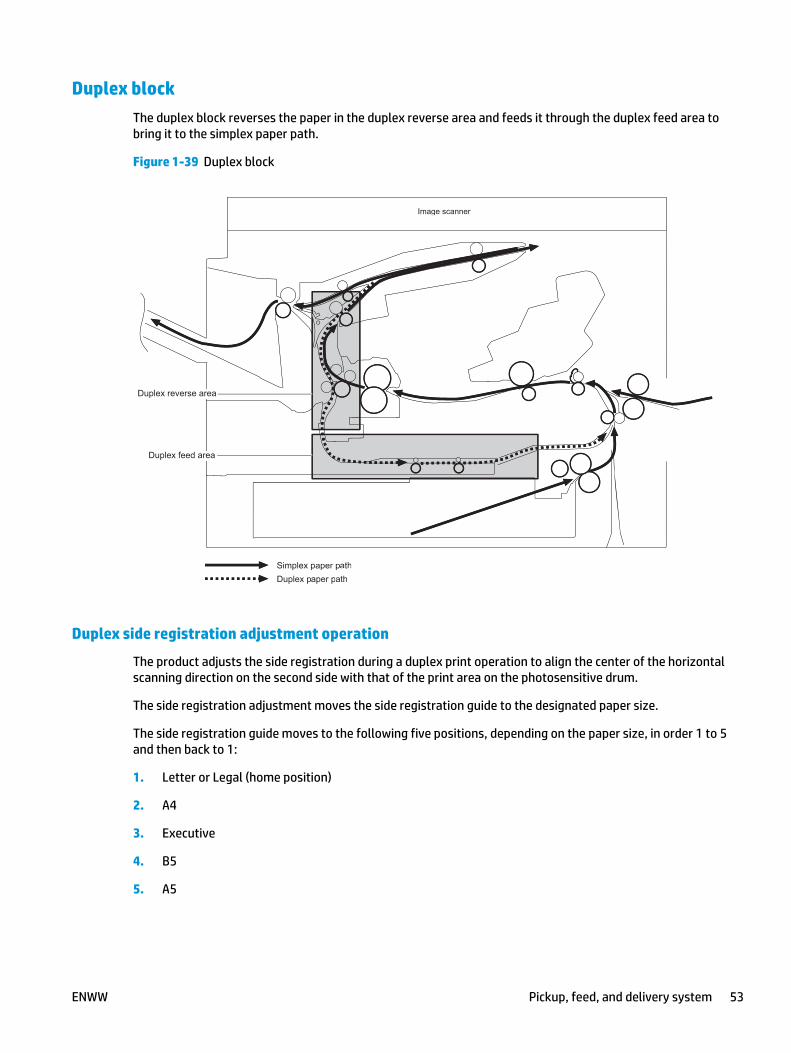
Duplex blockThe duplex block reverses the paper in the duplex reverse area and feeds it through the duplex feed area tobring it to the simplex paper path.
Figure 1-39 Duplex block
Duplex feed area
Simplex paper pathDuplex paper path
Duplex reverse area
Image scanner
Duplex feed area
Simplex paper pathDuplex paper path
Duplex reverse area
Image scanner
Duplex side registration adjustment operation
The product adjusts the side registration during a duplex print operation to align the center of the horizontalscanning direction on the second side with that of the print area on the photosensitive drum.
The side registration adjustment moves the side registration guide to the designated paper size.
The side registration guide moves to the following five positions, depending on the paper size, in order 1 to 5and then back to 1:
1. Letter or Legal (home position)
2. A4
3. Executive
4. B5
5. A5
ENWW Pickup, feed, and delivery system 53

Figure 1-40 Duplex side registration adjustment operation
Duplex side registration sensorPS109
CCW
Duplex re-pickup motor
Duplex side registrationguide drive cam
Duplex side registration guide
123
45
1
234
5
M107
Duplex side registration sensorPS109
CCW
Duplex re-pickup motor
Duplex side registrationguide drive cam
Duplex side registration guide
123
45
1
234
5
M107
The operational sequence of the side registration adjustment is as follows:
1. The DC controller reverses the duplex re-pickup motor (M107).
2. The side registration guide drive cam rotates and the duplex side registration sensor (PS109) detectsthe home position of the duplex side registration guide.
3. The side registration guide moves, depending upon the paper size.
4. The DC controller stops the duplex re-pickup motor and completes the side registration guidemovement.
NOTE: The DC controller determines a duplex side registration guide failure and notifies the formatterwhen the duplex side registration sensor does not detect the home position of the duplex sideregistration guide after the duplex side registration guide drive cam rotates twice.
54 Chapter 1 Theory of operation ENWW

Jam detectionNOTE: The product senses a jam condition when paper in the paper path does not trigger the requiredsensor or sensors within a specific amount of time.
TIP: For information about individual sensor tests, see the manual sensor test and tray/bin sensor testsections of the troubleshooting manual.
The product uses the following sensors to detect the presence of paper and to check whether paper isfeeding correctly or has jammed:
● Pre-feed sensor (PS102)
● Top-of-page (TOP) sensor (PS103)
● Media width sensor 1 (PS106)
● Media width sensor 2 (PS108)
● Reverse sensor (PS110)
● Reverse jam sensor (PS111)
● Paper-delivery sensor (PS112)
● Duplex re-pickup sensor (PS113)
● Fuser-delivery sensor (PS700)
● Tray 3 media feed sensor (SR4) (for 1x500 sheet paper feeder, 1x500 sheet paper feeder with cabinet,and 2,500-sheet high-capacity paper feeder)
● Tray 4 media feed sensor (SR8) (for 2,500-sheet high-capacity paper feeder)
● Tray 5 media feed sensor (SR12) (for 2,500-sheet high-capacity paper feeder)
The DC controller checks for jams by timing the paper as it moves past these sensors. If the paper does notpass the sensor in a specific period of time, the DC controller stops the transport process (the motors areturned off and the rollers no longer rotate) and a jam message displays on the control panel.
ENWW Pickup, feed, and delivery system 55

Figure 1-41 Jam detection sensors
PS102PS113
PS700
PS111PS112
PS110
PS103
PS108
PS106
Simplex paper pathDuplex paper path
SR4
SR8
SR12
PS102PS113
PS700
PS111PS112
PS110
PS103
PS108
PS106
Simplex paper pathDuplex paper path
SR4
SR8
SR12
Table 1-15 Jams that the product detects
Jam Description
Pickup delay jam One of the following conditions is true:
● Tray 1, duplex accessory, or envelope feeder
56 Chapter 1 Theory of operation ENWW

Table 1-15 Jams that the product detects (continued)
Jam Description
◦ The TOP sensor does not detect the leading edge of the paper within a specified period oftime after the pickup operation starts.
● Tray 2
◦ The pre-feed sensor does not detect the leading edge of the paper within a specifiedperiod of time from when a pickup operation starts.
◦ The TOP sensor does not detect the leading edge of the paper within a specified period oftime from when the pre-feed sensor detects the leading edge.
● Trays 4 or 5
◦ The Tray 3 media-feed sensor does not detect the leading edge of the paper within aspecified period from when the Tray 4 or 5 media-feed sensor detects the leading edge.
● Trays 3, 4, or 5
◦ The Tray 3, 4, or 5 media feed sensor does not detect the leading edge of the paperwithin a specified period of time after the pickup operation starts.
◦ The TOP sensor does not detect the leading edge of paper within a specified period oftime from when the media feed clutch is turned on.
NOTE: The product attempts to pick up the paper several times before determining that a jamexists. The number of pickup attempts depends on the source (for example, four attempts occur ifTray 1 is the source).
Pickup stationary jam One of the following conditions is true:
● The TOP sensor does not detect the trailing edge of the paper within a specified period of timefrom when it detects the leading edge.
● Both media width sensors 1 and 2 do not detect the trailing edge of the paper within aspecified period of time from when the TOP sensor detects the trailing edge.
● Trays 4 or 5
◦ The Tray 3 media-feed sensor does not detect the trailing edge of paper within aspecified period from when it detects the leading edge.
● Trays 3, 4, or 5
◦ The Tray 3, 4, or 5 media feed sensor does not detect the trailing edge of the paperwithin a specified period of time from when it detects the leading edge.
Fuser delivery delay jam One of the following conditions is true:
● The fuser delivery sensor does not detect the leading edge of the paper within a specifiedperiod of time after the TOP sensor detects the leading edge.
● The reverse assembly jam sensor does not detect the leading edge of the paper within aspecified period of time from when the fuser delivery sensor detects the leading edge.
● For face-down delivery, the delivery sensor does not detect the leading edge of the paperwithin a specified period of time from when a paper reverse operation starts in the reversearea.
● For face-up delivery, the delivery sensor does not detect the leading edge of the paper withina specified period of time from when the fuser delivery sensor detects the leading edge.
ENWW Pickup, feed, and delivery system 57

Table 1-15 Jams that the product detects (continued)
Jam Description
Fuser delivery stationary jam One of the following conditions is true:
● The fuser delivery sensor does not detect the trailing edge of the paper within a specifiedperiod of time after the TOP sensor detects the trailing edge.
● The reverse assembly jam sensor does not detect the trailing edge of the paper within aspecified period of time from when the fuser delivery sensor detects the trailing edge.
● For face-down delivery, the delivery sensor does not detect the trailing edge of the paperwithin a specified period of time from when a paper reverse operation starts in the reverseassembly area.
● For face-up delivery, the delivery sensor does not detect the trailing edge of the paper within aspecified period of time from when the fuser delivery sensor detects the leading edge.
Duplex re-pickup delay jam The duplex re-pickup sensor does not detect the leading edge of the paper within a specified periodof time from when a duplex reverse operation starts.
Wrapping jam After detecting the leading edge of the paper, the fuser delivery sensor detects the absence ofpaper, and it has not yet detected the trailing edge.
Residual paper jam One of the following sensors detects paper presence when the product is turned on, when the dooris closed or when the product exits Sleep mode. The product automatically clears the residualpaper.
● TOP sensor
● Media width sensor 1
● Media width sensor 2
● Fuser delivery sensor
● Tray 3 media-feed sensor
● Tray 4 media-feed sensor
● Tray 5 media-feed sensor
Door open jam The product detects that a door is open while paper is moving through the product.
58 Chapter 1 Theory of operation ENWW

Optional paper feedersThree types of optional paper feeders are available for the product:
● 1x500-sheet paper feeder
● 1x500-sheet paper feeder with cabinet
● 2,500-sheet high-capacity paper feeder
The following figures show the product positioned on these paper feeders and the paper path associatedwith each one.
Figure 1-42 1x500-sheet paper feeder
Simplex paper path
Duplex paper path
Simplex paper path
Duplex paper pp ath
ENWW Optional paper feeders 59

Figure 1-43 1x500-sheet paper feeder with cabinet
Simplex paper path
Duplex paper path
Simplex paper path
Duplex paper path
60 Chapter 1 Theory of operation ENWW

Figure 1-44 2,500-sheet high-capacity paper feeder
Simplex paper pathDuplex paper pathSimplex paper pathDuplex paper path
ENWW Optional paper feeders 61

Paper-feeder pickup and feed components
The following figures and tables show the signal flow in the paper feeder controller and the location of themotors, sensors, and solenoids located in the paper feeders.
1x500-sheet paper feeder signal flow and component locations
Figure 1-45 Signal flow for the 1x500-sheet paper feeder controller
Motor
Solenoid
Photointerrupter
DC controller
Switch
+24V
Paper feeder
+3.3V +24V
Paper feeder controller
+3.3Vgeneration
circuit
Motor
Solenoid
Photointerrupter
DC controller
Switch
+24V
Paper feeder
+3.3V +24V
Paper feeder controller
+3.3Vgeneration
circuitii
Figure 1-46 Pickup and feed components (1x500-sheet paper feeder)
SL1
SR4
SW2
M1
SR3 SR1
SR2Pickup arm
M101
SL1
SR4
SW2
M1
SR3 SR1
SR2Pickup arm
M101
Table 1-16 Pickup and feed components (1x500-sheet paper feeder)
Abbreviation Component Replacement part number
M101 Feed motor Feed motor assembly (RM2-5942-000CN)
M1 Paper feeder tray lifter motor Lifter assembly (RM1-5914-000CN)
62 Chapter 1 Theory of operation ENWW

Table 1-16 Pickup and feed components (1x500-sheet paper feeder) (continued)
Abbreviation Component Replacement part number
SL1 Paper feeder tray pickup solenoid Paper pickup assembly (RM2-0341-000CN)
SR1 Paper feeder tray media stack surface sensor 1 Paper feed roller assembly (RM1-8411-010CN)
SR2 Paper feeder tray media stack surface sensor 2 Paper feed roller assembly (RM1-8411-010CN)
SR3 Paper feeder tray media out sensor Paper pickup assembly (RM2-0341-000CN)
SR4 Paper feeder tray media feed sensor Paper pickup assembly (RM2-0341-000CN)
SW2 Paper feeder tray media size switch Part not available
1x500-sheet paper feeder with cabinet signal flow and component locations
Figure 1-47 Signal flow for the 1x500 paper feeder with cabinet controller
Motor
Solenoid
Photointerrupter
DC controller
Switch
+24V
Paper feeder with cabinet
+3.3V +24V
Paper feeder with cabinet controller
+3.3Vgeneration
circuit
Motor
Solenoidii
Photointerrupter
DC controller
Switch
+24V
Paper feeder with cabinet
+3.3V +24V
Paper feeder with cabinet controller
+3.3Vgeneration
circuitii
ENWW Optional paper feeders 63

Figure 1-48 Pickup and feed components (1x500-sheet paper feeder with cabinet)
SL1
SR4
SW2
M1
Pickup arm
SR3 SR1
SR2
M101
SL1
SR4
SW2
M1
Pickup arm
SR3 SR1
SR2
M101
Table 1-17 Pickup and feed components (1x500-sheet paper feeder with cabinet)
Abbreviation Component Replacement part number
M101 Feed motor Feed motor assembly (RM2-5942-000CN)
M1 Paper feeder with cabinet lifter motor Lifter assembly (RM1-5914-000CN)
SL1 Paper feeder with cabinet pickup solenoid Paper pickup assembly (RM2-0341-000CN)
SR1 Paper feeder with cabinet media stack surfacesensor 1
Paper feed roller assembly (RM1-8411-010CN)
SR2 Paper feeder with cabinet media stack surfacesensor 2
Paper feed roller assembly (RM1-8411-010CN)
SR3 Paper feeder with cabinet media out sensor Paper pickup assembly (RM2-0341-000CN)
SR4 Paper feeder with cabinet media feed sensor Paper pickup assembly (RM2-0341-000CN)
SW2 Paper feeder with cabinet media size switch Part not available
64 Chapter 1 Theory of operation ENWW

2,500-sheet high-capacity paper feeder signal flow and component locations
Figure 1-49 Signal flow for the 2,500-sheet high-capacity paper feeder controller
DC controller HCI controller
Motor
Photointerrupter
Solenoid
Switch
2,500-sheet paper feeder
+24VA
DC controller HCI controller
Motor
Photointerrupter
Solenoid
Switch
2,500-sheet paper feeder
+24VA
Figure 1-50 Pickup and feed components (2,500-sheet high-capacity paper feeder)
M1
M3
M4
SL1
SL2
SL3
M101
SW2
SR4
SR8
SR12
SR1, SR2, SR3
SR5, SR6, SR7
SR9SR10SR11
SW3
SW4
Tray
Wire
Pulley
Lifting plate
Tray 3
Tray 4
Tray 5
Lifter
LifterM1
M3
M4
SL1
SL2
SL3
M101
SW2
SR4
SR8
SR12
SR1, SR2, SR3SR1 SR2 SR3
SR5, SR6, SR7SR5, SR6, SR7
SR9SR10SR11
SW3
SW4
Tray
Wire
Pulley
Lifting plate
Tray 33
Tray 44
Tray 55
Lifter
LifterLifter
ENWW Optional paper feeders 65

Table 1-18 Pickup and feed components (2,500-sheet high-capacity paper feeder)
Abbreviation Component name Replacement part number
M101 Feed motor Feed motor assembly (RM2-5942-000CN)
M1 Tray 3 lifter motor Lifter assembly (RM1-5914-000CN)
M3 Tray 4 lifter motor Lifter assembly (RM1-5914-000CN)
M4 Tray 5 lifter motor Lifter drive assembly (RM2-0346-000CN)
SL1 Tray 3 pickup solenoid Paper pickup assembly (RM2-0341-000CN)
SL2 Tray 4 pickup solenoid Lifter assembly (RM1-5914-000CN)
SL3 Tray 5 pickup solenoid Lifter assembly (RM1-5914-000CN)
SW1 Right door open detection switch Part not available
SW2 Tray 3 media-size switch Lifter base assembly (RM1-5913-000CN)
SW3 Tray 4 media-size switch Lifter base assembly (RM1-5913-000CN)
SW4 Tray 5 media-size switch Tray size sensor assembly (RM2-0350-000CN)
SR1 Tray 3 media-surface sensor 1 Paper pickup assembly (RM2-0341-000CN)
SR2 Tray 3 media-surface sensor 2 Paper pickup assembly (RM2-0341-000CN)
SR3 Tray 3 media-presence sensor Paper pickup assembly (RM2-0341-000CN)
SR4 Tray 3 media-feed sensor Paper pickup assembly (RM2-0341-000CN)
SR5 Tray 4 media-surface sensor 1 Paper pickup assembly (RM2-0341-000CN)
SR6 Tray 4 media-surface sensor 2 Paper pickup assembly (RM2-0341-000CN)
SR7 Tray 4 media-presence sensor Paper pickup assembly (RM2-0341-000CN)
SR8 Tray 4 media-feed sensor Paper pickup assembly (RM2-0341-000CN)
SR9 Tray 5 media-surface sensor 1 Paper pickup assembly (RM2-0341-000CN)
SR10 Tray 5 media-surface sensor 2 Paper pickup assembly (RM2-0341-000CN)
SR11 Tray 5 media-presence sensor Paper pickup assembly (RM2-0341-000CN)
SR12 Tray 5 media-feed sensor Paper pickup assembly (RM2-0341-000CN)
66 Chapter 1 Theory of operation ENWW

Paper-size detection and tray-presence detectionThe paper feeder controller in both the 1 x 500-sheet paper feeder and 1x500-sheet paper feeder withcabinet detects the size of paper loaded in Tray 3 and the presence of Tray 3 using the media size switch.Each media-size switch contains three sub-switches. The paper feeder controller detects the size of paperand the presence of the tray according to the combination of the sub-switches and notifies the formatterthrough the DC controller.
Table 1-19 Paper-size detection and tray-presence detection (1 x 500-sheet paper feeder and 1x500-sheet paperfeeder with cabinet)
Tray presence or media size Top switch Center switch Bottom switch
A4 On Off Off
Letter Off On Off
B5 Off On On
A5 Off Off On
Executive On Off On
Legal On On Off
Custom size On On On
No tray Off Off Off
The HCI controller detects the size of the paper loaded in the trays and the presence of the trays in the 2,500-sheet high-capacity paper feeder by monitoring the media-size switches. Each media-size switch containsthree sub-switches. The HCI controller detects the size of paper and the presence of the tray according to thecombination of the sub-switches and notifies the formatter through the DC controller. During Sleep mode,the HCI controller only detects the presence of the tray.
Table 1-20 Paper-size detection and tray-presence detection (2,500-sheet high-capacity paper feeder)
Paper size Paper-size switch SW2, SW3 (Trays 3 and 4) Paper-size switch SW4 (Tray 5)
Top Center Bottom Top Center Bottom
No tray Off Off Off Off Off Off
A5 On On Off N/A N/A N/A
B5 Off On On N/A N/A N/A
Executive On Off On N/A N/A N/A
Letter Off On Off Off On On
A4 On Off Off On Off On
Legal On On Off Off Off On
Custom size On On On Any combination of switches not shown above
ENWW Optional paper feeders 67

Paper feeder tray lift operationThe paper feeders keep the paper stack surface at the correct pickup position. The tray lift operation occursunder the following conditions:
The paper feeder controller detects the position of the stack surface by monitoring the paper feeder mediastack surface sensors under the following conditions:
● When the product is turned on
● When a tray is inserted
● When the paper stack surface in the tray lowers
Trays 3 and 4 lift operation
The sequence of the paper feeder lift operation for Trays 3 and 4 is as follows:
1. The paper feeder controller rotates the tray lifter motor.
2. The lifter moves up.
3. The tray lifter motor stops when the tray media stack surface sensor 2 detects the paper stack surface.
4. The tray lifter motor rotates again when the tray media stack surface sensor 1 detects that the paperstack surface lowers.
NOTE: The paper feeder controller determines a tray lifter motor failure and notifies the formatterthrough the DC controller if the tray media stack surface sensor 1 or sensor 2 does not detect the paperstack surface within a specified period of time after the tray lifter motor starts rotating.
Figure 1-51 Trays 3 and 4 paper feeder lift operation
DC controller
Tray lifter motor
Tray media presence sensor lever
Tray media stack surface sensor lever
Lifting plate
Tray mediapresence sensor
Tray mediastack surface sensor 1
Lifter
Tray mediastack surface sensor 2
DC controller
Tray lifter motor
Tray media presence sensor lever
Tray media stack surface sensor lever
Lifting plate
Tray mediapresence sensor
Tray mediastack surface sensor tt 1
Lifterff
Tray mediastack surface sensor tt 2
68 Chapter 1 Theory of operation ENWW

Tray 5 lift operation
The sequence of the paper feeder lift operation for Tray 5 is as follows:
1. The paper feeder controller rotates the tray lifter motor.
2. The lifter motor activates the pulley, which coils the wire connected to the lift plate, and raises the liftplate.
3. The tray lifter motor stops when the tray media stack surface sensor 2 detects the paper stack surface.
4. The tray lifter motor rotates again when the tray media stack surface sensor 1 detects that the paperstack surface lowers.
NOTE: The paper feeder controller determines a tray lifter motor failure and notifies the formatterthrough the DC controller if the tray media stack surface sensor 1 or sensor 2 does not detect the paperstack surface within a specified period of time after the tray lifter motor starts rotating.
Figure 1-52 Tray 5 paper feeder lift operation
Wire
Pulley
DC controller
Tray lifter motor
Tray mediapresence sensor
Tray mediastack surface sensor 1
Tray mediastack surface sensor 2
Tray media stack surface sensor lever
Tray media presencesensor lever
Liting plate
Wire
Pulley
DC controller
Tray lifter motor
Tray mediapresence sensor
Tray mediastack surface sensor 1
Tray mediastack surface sensor 2
Tray media stack surface sensor lever
Tray media presencesensor lever
Liting plate
ENWW Optional paper feeders 69

Paper feeder jam detectionThe following figures show the location of paper presence sensors in the paper feeders that detect thepresence of paper and determine whether the paper is being fed correctly or has jammed. The 1x500-sheetpaper feeder and 1x500-sheet paper feeder with cabinet use the Tray 3 paper presence sensor (SR4). The2,500-sheet high-capacity paper feeder uses the following sensors
● Tray 3 media-feed sensor (SR4)
● Tray 4 media-feed sensor (SR8)
● Tray 5 media-feed sensor (SR12)
See Table 1-15 Jams that the product detects on page 56 for descriptions of jams detected by these sensors.
Figure 1-53 1x500-sheet paper feeder media feed sensor
SR4SR4SR4
70 Chapter 1 Theory of operation ENWW
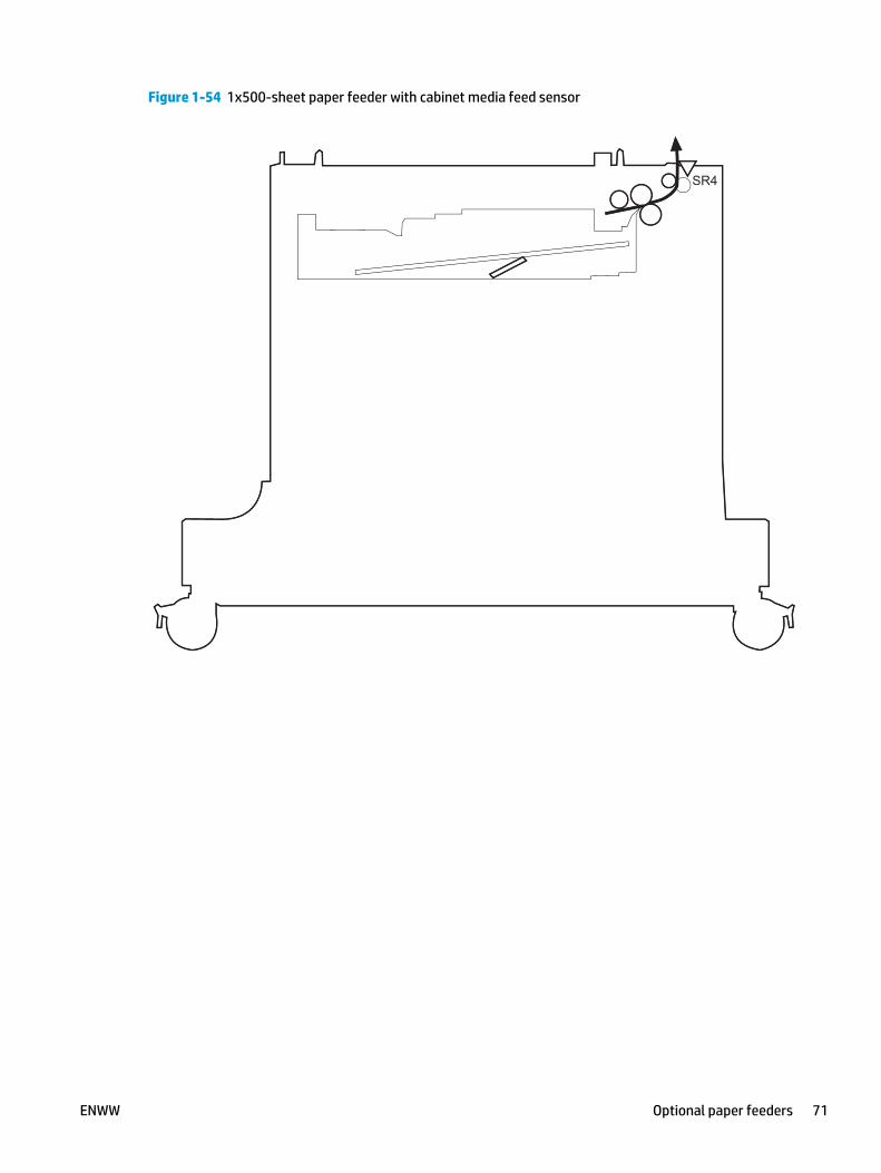
Figure 1-54 1x500-sheet paper feeder with cabinet media feed sensor
SR4SR4
ENWW Optional paper feeders 71

Figure 1-55 2,500-sheet high-capacity paper feeder media feed sensors
SR4
SR8
SR12
SR4
SR8
SR12
72 Chapter 1 Theory of operation ENWW

Scanning/image capture system NOTE: Figures in this section might look slightly different from your product, but they are correct for theM630. All the information provided in this section is correct for this product.
ScannerThe scanner is a carriage-type platen scanner which includes the frame, glass, scan module, and a scannercontrol board (SCB). The scanner has a sensor to detect legal-sized media and a switch to indicate when thedocument feeder is opened.
The document feeder and control panel are attached to the scanner. If the scanner fails, it can be replaced asa whole unit. The scanner replacement part does not include the document feeder, control panel, or SCB.
Document feed systemThis section describes the following:
● Sensors in the document feeder
● Document feeder paper path
● Simplex single-pass scanning
● Electronic duplexing (e-duplex) single-pass scanning
● Front-side and back-side background selector
● Deskew operation
● Document feeder hinges
The product supports single-pass electronic duplexing (e-duplex) copy jobs. Two separate scan modules scanthe front-side and back-side of an e-duplex copy job page in a single pass through the document feeder.
For specific copy jobs, a background selector changes the reflective platen from a white strip to a black stripfor page edge-to-edge recognition.
Sensors in the document feeder
The document feeder contains the following sensors:
● ADF paper present sensor: Detects whether a document is present in the document feeder. If paper ispresent in the document feeder when copies are made, the product scans the document using thedocument feeder. If no paper is present when copies are made, the product scans the document usingthe scanner glass.
● ADF Y (length) sensor: Detects whether a legal-size original is present in the document feeder.
● ADF jam cover sensor: Detects whether the document feeder cover is open or closed.
● ADF paper path deskew sensor: Detects the top of the page as it enters the deskew rollers.
● ADF paper path pick success sensor: Detects a successful one page feed from the document feedertray.
NOTE: This sensor uses ultrasonic sound to detect a mutli-page paper feed.
ENWW Scanning/image capture system 73

● Paper path sensor 1: Detects the top of the page as it approaches the front-side scan module(document feeder glass).
● Paper path sensor 2: Detects the top of the page as it approaches the back-side scan module during e-duplex copy jobs.
Figure 1-56 Document feeder sensors
74 2 13
5 6
74 2 13
5 6
Table 1-21 Document feeder sensors
Item Description
1 ADF Y (length) sensor
2 ADF paper present sensor
3 ADF paper path pick success sensor
4 Paper path sensor 1
NOTE: For an e-duplex copy job, this sensor is used to activate the front-side scan module (in the scannerbase) and the front-side background selector (in the document feeder), if needed.
5 ADF paper path deskew sensor
6 Paper path sensor 2
NOTE: For an e-duplex copy job, this sensor is used to activate the back-side scan module and the back-sidebackground selector, if needed. These components are in the document feeder.
7 ADF jam cover sensor (open the jam access cover and insert a folded piece of paper to activate the flag)
74 Chapter 1 Theory of operation ENWW
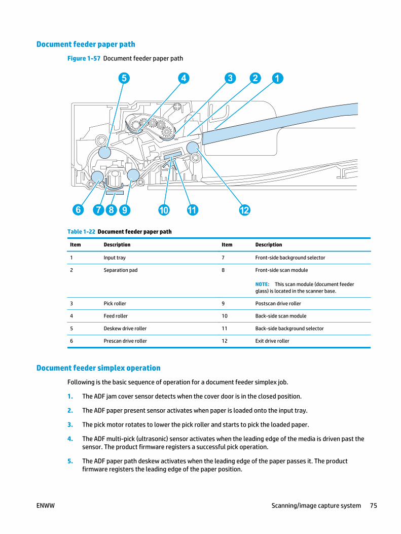
Document feeder paper path
Figure 1-57 Document feeder paper path
5 4 3 12
6 7 8 9 1210
1
11
5 4 3 2
6 7 8 9 1210
1
111
Table 1-22 Document feeder paper path
Item Description Item Description
1 Input tray 7 Front-side background selector
2 Separation pad 8 Front-side scan module
NOTE: This scan module (document feederglass) is located in the scanner base.
3 Pick roller 9 Postscan drive roller
4 Feed roller 10 Back-side scan module
5 Deskew drive roller 11 Back-side background selector
6 Prescan drive roller 12 Exit drive roller
Document feeder simplex operation
Following is the basic sequence of operation for a document feeder simplex job.
1. The ADF jam cover sensor detects when the cover door is in the closed position.
2. The ADF paper present sensor activates when paper is loaded onto the input tray.
3. The pick motor rotates to lower the pick roller and starts to pick the loaded paper.
4. The ADF multi-pick (ultrasonic) sensor activates when the leading edge of the media is driven past thesensor. The product firmware registers a successful pick operation.
5. The ADF paper path deskew activates when the leading edge of the paper passes it. The productfirmware registers the leading edge of the paper position.
ENWW Scanning/image capture system 75

6. The leading edge of the paper drives into the nip point of the deskew drive roller and the deskew pinchrollers. This creates a buckle of paper by the nip point for pick-skew correction.
7. The deskew motor rotates the deskew drive roller to pull the paper into the prescan drive roller.
8. The pick motor stops turning and allows both the pick and feed roller to turn freely while the paper ispulled in by the deskew drive roller.
9. The feed motor rotates to drive the paper into the prescan front-side sensor. The firmware registers theleading edge position of the paper as the multi-pick sensor activates.
NOTE: If the copy job requires a reflective platen change, the front-side background selectoractivates.
10. The feed motor continues to rotate and drive the leading edge of the paper through the preset distancefrom the multi-pick sensor to the front-side scan zone. The scanner begins the scanning and dataretrieval process.
11. The ADF multi-pick (ultrasonic) sensor deactivates when the trailing edge of the paper passes thesensor. The firmware registers the trailing edge of the paper position.
12. The feed motor continues to rotate and drive the trailing edge of the paper through the preset distancefrom the ADF multi-pick (ultrasonic) sensor to the front-side scan zone. The scanner ends the scanningand data retrieval process.
13. The feed motor continues to rotate and ejects the trailing edge of the paper into the output bin.
14. One of the following occurs:
● If the copy job is complete, the ADF paper present sensor deactivates. The feed motor reversesrotation to raise the pick roller.
● If the copy job is not complete, the ADF paper present sensor is active. The product firmwaredetects additional pages in the input tray and the process repeats.
Document feeder e-duplex operation
Following is the basic sequence of operation for an e-duplex job.
NOTE: For an e-duplex copy job, the background scan operation begins immediately after the simplexsequence of operation ends.
1. The feed motor continues to drive the paper until the leading edge activates the prescan back-sidesensor. The product firmware registers the position of the leading edge of the paper.
NOTE: If the copy job requires a reflective platen change, the back-side background selector activates.
2. The feed motor continues to rotate to drive the leading edge of the paper through the preset distancefrom prescan back-side sensor to the back-side background selector scan zone. The back-sidebackground scan module begins scanning and retrieval of the data.
3. The prescan back-side sensor deactivates when the trailing edge of the paper passes it. The productfirmware registers the trailing edge of the paper position.
4. The feed motor continues to rotate to drive the trailing edge of the paper edge past the back-sidebackground selector scan zone.
76 Chapter 1 Theory of operation ENWW

5. The feed motor continues to rotate and ejects the trailing edge of the paper into the output bin.
6. One of the following occurs:
● If the copy job is complete, the ADF paper present sensor deactivates. The feed motor reversesrotation to raise the pick roller.
● If the copy job is not complete, the ADF paper present sensor is active. The product firmwaredetects additional pages in the input tray and the process repeats.
Front-side and back-side background selector
NOTE: The product automatically controls the operation of the front-side and back-side backgroundselectors.
The background selectors change the reflective surface behind a duplex or simplex scanned page from whiteto black. Doing so allows the firmware to recognize the edges of a scanned page by passing it over a blackbackground.
The product uses the background selectors for specific scan jobs. Scan jobs like optical character recognition(OCR) and scan-to-folder require a black reflective background so that the firmware can correctly scan thepage from edge-to-edge.
The front-side background selector is a non-removable component of the document feeder. The back-sidebackground selector assembly is located under the document feeder input tray and is removable to allowaccess for cleaning the back-side scan module glass.
ENWW Scanning/image capture system 77

Deskew operation
Sliding side guides on the input tray make sure that the paper stack is correctly aligned at the center of theinput tray when paper is loaded in the tray. The correct position of the loaded paper is parallel with thedirection of travel into the document feeder paper path.
The document feeder further reduces paper skew due to improper loading of paper in the input tray bybuckling the paper to create a paper buffer.
The document feeder aligns the leading edge of the paper parallel with the deskew drive rollers before it isdriven further into the document feeder paper path.
The stack-height limiter prevents incorrect insertion of the paper and limits the maximum amount (stackingheight) of media that can be loaded on the input tray.
Figure 1-58 Document feeder deskew features
2
1
Table 1-23 Document feeder deskew features
Item Description
1 Sliding side guides
2 Stack-height limiter
78 Chapter 1 Theory of operation ENWW

Document feeder hinges
The document feeder hinges allow positioning the assembly vertically above the scanner glass toaccommodate the placement of books and other objects up to 40 mm (1.57 in) in height on the scanner glass.The document feeder still closes (the bottom of the ADF is kept parallel to the scanner glass) and allows theproduct to operate.
The document feeder hinges provide height adjustment of at least 40 mm (1.57 in) when a maximumdownward force of 5 kg (11 lb) is applied at the front edge of the assembly, with the fulcrum (such as thespine of a book) centered on the scanner glass and parallel to its long axis.
The document feeder will withstand a downward force of at least 15 kg (33 lb) applied at the front edgecenter of the assembly—when the fulcrum (such as the spine of a book) is located anywhere on the scannerglass and parallel to its long axis—without breaking, deforming, detaching or experiencing performancedegradation.
The document feeder hinges support the assembly in the open position and prevent the document feederfrom suddenly closing in a damaging or loud manner.
The hinges can hold the document feeder static in all positions higher than 100 mm (3.93 in) (measured atthe front of the assembly). Less than 2.3 kg (5 lb) of force is required to open or close the document feeder.
The hinges allow the document feeder to open to an angle of between 60º and 80º from the horizontalposition (this angle will not allow the product to tip over).
Figure 1-59 Document feeder open (book mode)
ENWW Scanning/image capture system 79

Figure 1-60 Document feeder open (60º to 80º)
80 Chapter 1 Theory of operation ENWW
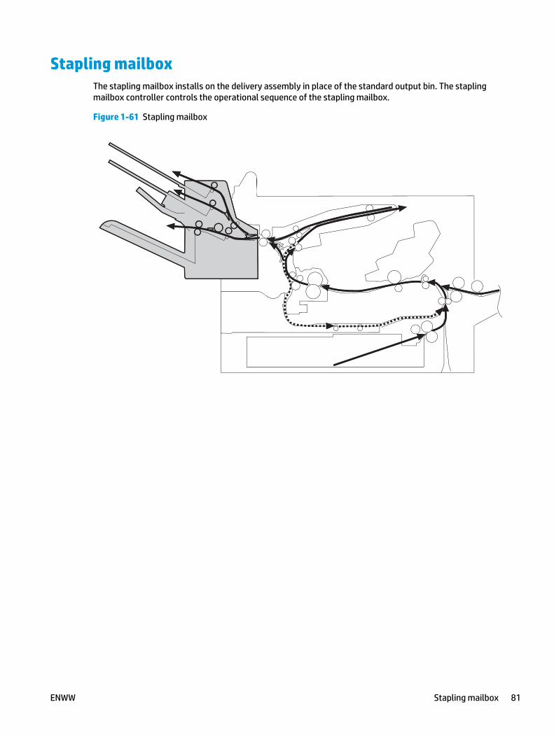
Stapling mailboxThe stapling mailbox installs on the delivery assembly in place of the standard output bin. The staplingmailbox controller controls the operational sequence of the stapling mailbox.
Figure 1-61 Stapling mailbox
ENWW Stapling mailbox 81

Figure 1-62 Signal flow for the stapling mailbox
Motor
Solenoid
Photointerrupter
DC controller
Switch
+24V
Stapling mailbox
+24V+5V
Formatter
+5Vgeneration
circuit
Stapling mailbox controller
Motor
Solenoid
Photointerrupter
DC controller
Switch
+24V
Stapling mailbox
+24V+5V
Formatter
+5Vgeneration
circuit
Stapling mailbox controller
82 Chapter 1 Theory of operation ENWW

Motor controlFigure 1-63 Stapling mailbox motors
M1
M5
M4
M3
M6M1
M5
M4
M3
M6
The stapling mailbox has five motors for paper feed, paper delivery, and staple operation.
Table 1-24 Motor control (stapling mailbox)
Component Drives Failure detection
Stapler motor M1 Stapler Yes
Jogger motor M3 Jogger guide Yes
Paddle motor M4 Alignment roller, disengagement of thealignment roller, and disengagement ofthe output bin 3 lower delivery roller
Yes
Stapling mailbox feed motor M5 Stapling mailbox feed roller, staplingmailbox delivery roller, output bin 3 upperdelivery roller, and the output bin 3 lowerdelivery roller
No
When the motor fails, a jamoccurs.
Stapling mailbox lifter motor M6 Output bin 3 Yes
ENWW Stapling mailbox 83

Failure detection
The stapling mailbox controller detects a motor failure by monitoring a part related to the motor. If thecontroller determines a motor failure or motor-related part failure, it notifies the formatter when itencounters the following conditions:
● Stapler motor: The stapler sensor is not sensed for a specified period of time after the stapler motorstarts rotating.
● Jogger motor: The jogger sensor is not sensed for a specified period of time after the jogger motorstarts rotating.
● Paddle motor: The output bin 3 upper delivery roller sensor is not sensed for a specified period of timeafter the paddle motor rotates. The alignment roller sensor is not sensed for a specified period of timeafter the paddle motor reverses.
● Stapling mailbox lifter motor: The output bin 3 higher limit sensor or output bin 3 media full sensor isnot sensed for a specified period of time after the stapling mailbox lifter motor rotates. The output bin3 higher limit sensor, output bin 3 lower limit sensor, or output bin 3 media full sensor is not sensed fora specified period of time from when the stapling mailbox lifter motor reverses.
Delivery operation
The stapling mailbox has two modes.
● Stacker mode: The printed page is delivered to output bin 3 first and then delivered to the subsequentoutput bins.
● Mailbox/job separator mode: The printed page is delivered to the specified output bin for each printjob.
Stapling is available for both modes. All stapled jobs are delivered to the lower bin.
NOTE: The figure below does not show the location of the stapler motor, stapler sensor, staple presencesensor and staple ready sensor because they are contained in the stapler assembly.
84 Chapter 1 Theory of operation ENWW

Figure 1-64 Delivery components (stapling mailbox)
PS2504
PS2601
PS2602
PS2501
PS2503PS2502
SR1
SR7 SR4
SR5
SR2
SR6
SR3
M5
SL1
M4
SL2
M6
M3
SW1
SL3
Output bin 1
Output bin 2
Output bin 3
Jogger guide
PS2504
PS2601
PS2602
PS25011
33PS25033PS2502PS2 02
SR1SR1
SSR7S SR4SR4
SR5
SSR2S
SR6
SRR3R3
M5
SL1
M4
SL2
M6
M3
SW1
SL3
Output bin 1
Output bin 2
Output bin 3
Jogger guide
Table 1-25 Delivery components (stapling mailbox)
Abbreviation Component Replacement part number
M1 Stapler motor Stapler assembly (RM1-5166-000CN)
M3 Jogger motor Jog assembly (RM2-5235-000CN)
M4 Paddle motor Part not available
M5 Stapling mailbox feed motor Part not available
M6 Stapling mailbox lifter motor Output bin 3 drive assembly (RM1-5156-000CN)
SL1 Stamp solenoid Stamp solenoid assembly (RM1-6664-000CN)
SL2 Inlet solenoid Entrance solenoid assembly (RM1-6663-000CN)
SL3 Output bin solenoid Bin solenoid assembly (RM1-5896-000CN)
SR1 Output bin 3 delivery sensor Bin sensor PCA assembly (RM1-5894-000CN)
SR2 Stapling mailbox media feed sensor 1 Paper feed guide assembly (RM1-5173-000CN)
SR3 Output bin 3 media full sensor Bin sensor PCA assembly (RM1-5894-000CN)
SR4 Alignment roller sensor Stage top subassembly (RM1-7437-010CN)
SR5 Stapling mailbox media feed sensor 2 Stapler assembly (RM1-5166-000CN)
SR6 Jogger sensor Jog assembly (RM2-5235-000CN)
SR7 Output bin 3 upper delivery roller sensor Part not available
PS2501 Output bin 1 media presence sensor Bin sensor PCA assembly (RM1-5894-000CN)
ENWW Stapling mailbox 85

Table 1-25 Delivery components (stapling mailbox) (continued)
Abbreviation Component Replacement part number
PS2502 Output bin 2 media full sensor Bin sensor PCA assembly (RM1-5894-000CN)
PS2503 Output bin 2 media presence sensor Bin sensor PCA assembly (RM1-5894-000CN)
PS2504 Output bin 1 media full sensor Bin sensor PCA assembly (RM1-5894-000CN)
PS2601 Output bin 3 higher limit sensor Stage assembly (RM1-5159-000CN)
PS2602 Output bin 3 lower limit sensor Stage assembly (RM1-5159-000CN)
PH0I1 Stapler sensor (not shown) Stapler assembly (RM1-5166-000CN)
PH0I3 Staple presence sensor (not shown) Stapler assembly (RM1-5166-000CN)
PH0I2 Staple ready sensor (not shown) Stapler assembly (RM1-5166-000CN)
SW1 Stapling mailbox door switch (not shown) Part not available
Staple operation
The staple operation staples 2 to 30 sheets of printed pages together into one set and then delivers it tooutput bin 3. This staple operation is available for both stacker mode and mailbox/job separator mode.
The staple sequence is as follows:
1. The stapling mailbox controller rotates the paddle motor to disengage the output bin 3 upper deliveryroller from the output bin 3 lower delivery roller.
86 Chapter 1 Theory of operation ENWW

2. The stapling mailbox feeds the printed page from the product to the staple tray.
Figure 1-65 Stapling mailbox stapler operation
SR7
M5
M4
Output bin 3 upper delivery roller
Staple tray
feed roller 2
Output bin 3 lower delivery roller
Stapling mailboxfeed motor
Paddle motor
Output bin 3 delivery roller sensor
Stapling mailbox
SR7SR7SR7
M5
M4
Output bin 3 upper delivery roller
Staple traytt
feed roller 2
Output bin 3 lower delivery roller
Stapling mailboxfeed motor
Paddle motorP ddlP ddl tPaddle mPaddle mo
Output bin 3 delivery roller sensor
Stapling mailbox
The stapling mailbox controller determines an output bin 3 upper delivery roller failure and notifies theformatter through the DC controller when it does not detect the output bin 3 upper delivery rollersensor for a specified period of time after the paddle motor starts rotating.
ENWW Stapling mailbox 87

3. The stapling mailbox aligns the printed page on the staple tray. For horizontal alignment, the joggermotor rotates and moves the jogger guide. For vertical alignment, the paddle motor reverses and thealignment roller pushes the page.
Figure 1-66 Stapling mailbox stapler operation
SR4
SR6
M4M3
Alignment roller
Paddle motor
Jogger sensor
Jogger guide
Jogger motor
Staple tray
Alignment roller sensor
SR4S
SR6
M4M3
Alignment roller
ormotomotoPaddle mPaddle m
rJogger sensor
Jogger guide
Jogger motorJogger motor
Staple traytt
Alignment roller sensorAlignment roller sensor
The controller determines a paddle motor failure and notifies the formatter through the DC controllerwhen it does not detect the alignment roller sensor for a specified period of time after the paddle motorstarts rotating.
4. After alignment, the stamp solenoid drives and the stamp holds the page.
5. Steps 1 to 4 repeat for a specified number of pages.
88 Chapter 1 Theory of operation ENWW

6. After all of the pages are aligned, the stapling mailbox stapes the pages together while they are beingheld by the stamp.
Figure 1-67 Stapling mailbox stapler operation
SL1Stamp
Stamp solenoid
Staple tray
SL1Stamp
Stamp solenoitt d
Staple traytt
7. The paddle motor rotates, and the output bin 3 upper delivery roller touches the stapled pages.
8. The stapling mailbox feed motor rotates the output bin 3 upper delivery roller and the output bin 3lower delivery roller. Then, the stapling mailbox delivers the set of printed-pages to output bin 3.
ENWW Stapling mailbox 89

9. The stapling mailbox feed motor starts rotating while the jogger motor reverses and the jogger guidemoves to its home position.
Figure 1-68 Stapling mailbox stapler operation
PS2602
SR3
M4
M5
M6
M3Paddle motor
Output bin 3 upper delivery rollerOutput bin 3 lower delivery roller
Stapling mailbox feed motor
Output bin 3
Output bin 3 lower limit sensor
Jogger guide
Jogger motor
Stapling mailboxlifter motor
Output bin 3 media full sensor
PS2602
SSR3SR3
M4
M5
M6
M3motormotomotoPaddle mm
Output bin 3 upper delivery rollerOutput bin 3 lower delivery roller
Stapling mailbox feed motor
Output bin 3
rOutput bin 3 lower limit sensor
Jogger guide
Jogger motorJogger motor
Stapling mailboxlifter motor
rOutput bin 3 media full sensor
The output bin 3 media full sensor detects whether the bin is full. The stapling mailbox controllerdetermines that the paper stack surface is high and reverses the stapling mailbox lifter motor to loweroutput bin 3 when the output bin 3 media full sensor is on for a specified period of time. If the outputbin 3 lower limit sensor activates at this time, the stapling mailbox controller determines an output bin3 media full and notifies the formatter through the DC controller.
The stapling mailbox controller determines a jogger motor failure and notifies the formatter throughthe DC controller when it does not detect the jogger sensor for a specified period of time after thejogger motor starts rotating.
90 Chapter 1 Theory of operation ENWW

Stapler
The stapler consists of the staple cartridge and the stapler assembly. The staple cartridge holds up to 5,000staples. The staple presence sensor detects the presence of staples. The staple ready sensor detectswhether the stapler is in the correct position to staple. The stapler assembly contains the stapler motor.When the stapling mailbox controller rotates the stapler motor, the staple arm lowers and the stapleoperation begins. The stapler sensor detects the position of the staple arm.
Figure 1-69 Stapling mailbox sensors for the stapler
M1
StapleStaple ass’y
Staple arm Staple cartridge
Stapling mailbox controller
Stapler sensor
Staple presence sensor
Staple ready sensor Stapler motor
M1
StapleStaple ass’tt y
Staple arm Staple cartridge
Stapling mailbox controller
Stapler sensor
Staple presence sensor
Staple ready sensor Stapler motor
The stapling mailbox controller determines a stapler motor failure and notifies the formatter through the DCcontroller when it does not detect the stapler sensor for a specified period of time after the stapler motorstarts rotating. The stapling mailbox controller determines a stapler jam and notifies the formatter throughthe DC controller if it senses the stapler sensor after a specified period of time from when the stapler motorstarts rotating. It also detects if the stapler sensor recovers within a specified period of time from when thestapler motor is reversed.
ENWW Stapling mailbox 91

Output bin 3 lift operation
Figure 1-70 Stapling mailbox sensors for output bin 3 lift operation
M6
PS2601
SR3
PS2602
Stapling mailboxlifter motor
Output bin 3 media full sensor
Output bin 3
Output bin 3 lower limit sensor
Output bin 3 higher limit sensor
M6
PS2601
SR3
PS2602
Stapling mailboxlifter motor
rOutput bin 3 media full sensor
Output bin 3
rOutput bin 3 lower limit sensor
Output bin 3 higher limit sensorOutput bin 3 higher limit sensor
The operational sequence of the output bin 3 lift operation is as follows:
1. The stapling mailbox lifter motor rotates if both the output bin 3 higher limit sensor and the output bin3 media full sensor are off when the product is turned on until the following conditions occur:
● The output bin 3 higher limit sensor detects the output bin 3.
● The output bin 3 media full sensor detects paper.
The stapling mailbox lifter motor reverses to lower output bin 3 to a specified level if either of thefollowing occur:
● The output bin 3 higher limit sensor or the output bin 3 media full sensor is on.
● Both the output bin 3 higher limit sensor and the output bin 3 media full sensor are on when theproduct is turned on.
2. When the printed pages are stacked in output bin 3, and the output bin 3 media full sensor detects thepaper, the stapling mailbox lifter motor reverses to lower output bin 3 to a specified level.
3. The stapling mailbox controller notifies the formatter through the DC controller when the output bin 3media full sensor detects paper. Output bin 3 lowers to the position of the output bin 3 lower limitsensor.
The stapling mailbox controller determines a stapling mailbox lifter motor failure. The controller notifies theformatter through the DC controller when it encounters the following conditions after the stapling mailboxlifter motor starts rotating:
● Output bin 3 does not reach the output bin 3 higher limit sensor within a specified period of time.
● The output bin 3 media full sensor does not detect paper.
92 Chapter 1 Theory of operation ENWW

The stapling mailbox controller also detects a stapling mailbox lifter motor failure and notifies the formatterthrough the DC controller when the following sensors are not sensed after the stapling mailbox lifter motorreverses:
● Output bin 3 higher limit sensor
● Output bin 3 lower limit sensor
● Output bin 3 media full sensor
Stacker modeStacker mode does not designate an output bin. It attempts to deliver the printed page to output bin 3 first.When the output bin 3 media full sensor detects that output bin 3 is full, the stapling mailbox delivers tooutput bin 2. When the output bin 2 media full sensor detects that output bin 2 is full, the stapling mailboxdelivers to output bin 1.
Figure 1-71 Stapling mailbox sensors for stacker mode
SR3
PS2504
PS2502
Output bin 3 media full sensor
Output bin 3
Output bin 2
Output bin 1
Output bin 2 media full sensor
Output bin 1 media full sensor
SR3
PS2504PS2504
PS2502
Output bin 3 media full rsensor
Output bin 3
Output bin 2
Output bin 1
Output bin 2 media full sensor
Output bin 1 media full sensor
The stapling mailbox controller determines if the stapling mailbox is full and notifies the formatter throughthe DC controller when it encounters one of the following conditions:
● The output bin 1 media full sensor is detected.
● The staple operation is designated when output bin 3 is full.
Mailbox/job separator modeThe mailbox/job separator mode delivers the printed page to the designated bin for each print job.
ENWW Stapling mailbox 93

Figure 1-72 Stapling mailbox sensors for mailbox/jam separation
SR3
PS2504
PS2502
Output bin 3
Output bin 2
Output bin 1
Output bin 3 media full sensor
Output bin 1 media full sensor
Output bin 2 media full sensor
SR3
PS2504PS2504
PS2502
Output bin 3
Output bin 2
Output bin 1
Output bin 3 media full sensor
Output bin 1 media full sensorr
Output bin 2 media full sensorr
The stapling mailbox controller determines if the stapling mailbox is full and notifies the formatter throughthe DC controller when it encounters the following condition:
● The designated output bin media full sensor is detected.
● The staple operation is designated when output bin 3 is full of paper.
Jam detectionThe stapling mailbox uses the following sensors to detect the presence of paper and to check whether paperis being fed correctly or has jammed:
● Output bin 3 delivery sensor (SR1)
● Stapling mailbox media feed sensor 1 (SR2)
● Stapling mailbox media feed sensor 2 (SR5)
94 Chapter 1 Theory of operation ENWW

Figure 1-73 Stapling mailbox sensors for jam detection
SR1
SR5
SR2
SR1
SR5
SR2
The stapling mailbox detects the following jams:
● Stapling mailbox feed delay jam 1: The stapling mailbox media feed sensor 1 does not detect theleading edge of paper within a specified period of time after the fuser delivery sensor in the productdetects the leading edge.
● Stapling mailbox feed delay jam 2: The stapling mailbox media feed sensor 2 does not detect theleading edge of paper within a specified period of time after the fuser delivery sensor in the productdetects the leading edge.
● Stapling mailbox feed stationary jam 1: The stapling mailbox media feed sensor 1 does not detect thetrailing edge of paper within a specified period of time after it detects the leading edge.
● Stapling mailbox feed stationary jam 2: The stapling mailbox media feed sensor 2 does not detect thetrailing edge of paper within a specified period of time after it detects the leading edge.
● Stapling mailbox feed stationary jam 3: The output bin 3 delivery sensor does not detect the trailingedge of paper within a specified period of time from when the stapling mailbox feed motor startsrotating after a staple operation.
● Stapling mailbox residual paper jam: Any one of the following sensors detects a presence of paper fora specified period of time during an automatic delivery operation:
◦ Output bin 3 delivery sensor
◦ Stapling mailbox media feed sensor 1
◦ Stapling mailbox media feed sensor 2
ENWW Stapling mailbox 95

Automatic deliveryThe stapling mailbox automatically clears the paper if any one of the following sensors detects residualpaper during the initial sequence after the stapling mailbox is turned on or after the door is closed.
● Output bin 3 delivery sensor
● Stapling mailbox media feed sensor 1
● Stapling mailbox media feed sensor 2
96 Chapter 1 Theory of operation ENWW

2 Solve problems
● Solve problems checklist
● Menu map
● Current settings pages
● Event log
● Pre-boot menu options
● Troubleshooting process
● Tools for troubleshooting
● Clear jams
● Paper feeds incorrectly or becomes jammed
● Use manual print modes
● Solve image quality problems
● Clean the product
● Solve performance problems
● Solve connectivity problems
● Service mode functions
● Solve fax problems
● Firmware upgrades
ENWW 97

Solve problems checklistIf the product is not correctly functioning, complete the steps (in the order given) in the following checklist. Ifthe product fails a checklist step, follow the corresponding troubleshooting suggestions for that step. If achecklist step resolves the problem, skip the remaining checklist items.
1. If the control panel is blank or black, check the following before proceeding:
❑ Check the power cable.
❑ Check that the power is turned on.
❑ Make sure that the line voltage is correct for the product power configuration. (See the label thatis on the back of the product for voltage requirements.) If a power strip is in use, and its voltage isnot within specifications, connect the product directly into the electrical outlet. If it is alreadyconnected into the outlet, try a different outlet.
If the control panel is not responding to touch, or if it appears black or blank, look for the followingconditions.
NOTE: The following conditions indicate that the product has froze while in Sleep mode (opening adoor or tapping the control panel causes the product to wake up it it is in Sleep mode).
● The control-panel home button LED is illuminated.
● The power-switch LED flashes once every three to five seconds.
● The product does not exit Sleep mode when a page is placed in the document feeder.
● The product does not exit Sleep mode when the document feeder is opened to place a page on the scanner flatbed.
a. Try upgrading the firmware. If the firmware upgrade fails to resolve the problem, and the productstill freezes while in Sleep mode, elevate the case after collecting the following info:
● Try printing to the product from a host computer. Does the product print a page?
● Is the product HP Embedded Web Server (EWS) accessible?
● Turn the product power off, and then on again. Save the product diagnostic file.
b. If the product did not freeze while in Sleep mode, verify that the control panel is correctlyfunctioning by accessing the control panel diagnostics (see the Control-panel checks section of theproduct problem solving manual).
If the control panel does not respond to the diagnostic button, try the following:
● Turn the product power off.
● Reseat the cable connections on the bottom of the control-panel assembly.
● Remove, and then reseat the formatter.
● Turn the product power on, and then check for functionality of the control-panel.
98 Chapter 2 Solve problems ENWW

c. Verify that the formatter is firmly seated. Check the contol-panel cables and connectors at bothends of the cables.
d. If the error persists, replace the control-panel assembly.
2. The control panel should indicate a Ready, Paused, or Sleep mode on status. If an error messagedisplays, resolve the error.
● Use the Power-on checks section in the product troubleshooting service manual to solve theproblem.
3. For network connection errors, check the cables.
a. Check the network cable connections between the product and the computer or network port.Make sure that the connections are secure.
b. Make sure that the cables are not faulty by trying different cables, if possible.
c. Check the network connection.
4. Print a configuration page. If the product is connected to a network, an HP Jetdirect page also prints.
a. From the Home screen on the product control panel, scroll to and touch the Administration button.
b. Open the following menus:
● Reports
● Configuration/Status Pages
● Configuration Page
c. Touch the Print button to print the page.
● If the pages do not print, check that at least one tray contains paper.
TIP: Make sure that the selected paper size and type meet HP specifications. Also open theTrays menu on the product control panel and verify that the tray is configured correctly forthe paper type and size.
● If the page jams in the product, follow the instructions on the control panel to clear the jam.
● If the page does not print correctly, the problem is with the product hardware.
● If the page prints correctly, the product hardware is working. The problem is with the hostcomputer, with the print driver, or with the program.
5. Print a supplies status page and then check that the maintenance items below are not at their end-of-life.
TIP: If a maintenance item needs to be replaced, order the part number provided below.
a. From the Home screen on the product control panel, scroll to and touch the Administration button.
b. Open the following menus:
ENWW Solve problems checklist 99

● Reports
● Configuration/Status Pages
● Supplies Status Page
c. Touch the Print button to print the page, and then check the following maintenance items:
NOTE: HP long-life consumables and maintenance kit life specifications are estimations. Actualindividual life/yield during normal use varies depending on usage, environment, media, and otherfactors. Estimated life is not an implied guarantee or warrantable.
● 110V or 220V maintenance kit (includes the fuser, transfer roller, and the Tray 2 - Tray 5 feedand separation rollers; estimated life: 225,000 pages
◦ B3M77A (110V)
◦ B3M78A (22V)
● Fuser kit; estimated life: 225,000 pages
◦ B3M77-67903 (110V)
◦ B3M78-67903 (220V)
● ADF maintenance kit; estimated life: 100,000 pages
◦ L2725A
6. Verify that the correct print driver for this product is installed. Check the program to make sure that theprint driver for this product is used. The print driver is on the CD that came with the product, or can bedownloaded from this Web site: www.hp.com/support/ljMFPM630.
7. Print a short document from a different program that has worked in the past. If this solution works, theproblem is with the program. If this solution does not work (the document does not print), completethese steps:
a. Try printing the job from another computer that has the product software installed.
b. If the product is connected to the network, connect the product directly to a host computer with aUSB cable. Redirect the product to the correct port, or reinstall the software (make sure to selectthe new connection type).
100 Chapter 2 Solve problems ENWW

Menu mapTo more easily navigate individual settings, print a report of the complete Administration menu.
1. From the Home screen on the product control panel, scroll to and touch the Administration button.
2. Open the following menus:
● Reports
● Configuration/Status Pages
3. Select the Administration Menu Map option.
4. Touch the Print button to print the report.
Current settings pagesPrinting the current settings pages provides a map of the user configurable settings that might be helpful inthe troubleshooting process.
1. From the Home screen on the product control panel, scroll to and touch the Administration button.
2. Open the following menus:
● Reports
● Configuration/Status Pages
3. Select the Current Settings Page option.
4. Touch the Print button to print the report.
Event logPrinting the event log might be helpful in the troubleshooting process. For more information, see theInterpret control-panel messages and event log entries section in the product troubleshooting manual.
Print or view the event log from the Administration menu
1. From the Home screen on the product control panel, scroll to and touch the Administration button.
2. Open the following menus:
● Troubleshooting
● Event Log
3. The event log displays on the screen. To print it, touch the Print button.
Print or view the event log from the Service menu
1. From the Home screen on the product control panel, scroll to and touch the Device Maintenance button.
2. Open the Service menu.
3. On the sign-in screen, select the Service Access Code option from the drop-down list.
ENWW Menu map 101

4. Enter the following service access code for the product:
● 09063014
5. Touch the Print Event Log or View Event Log item.
Clear the event log
1. From the Home screen on the product control panel, scroll to and touch the Device Maintenance button.
2. Open the Service menu.
3. On the sign-in screen, select the Service Access Code option from the drop-down list.
4. Enter the following service access code for the product:
● 09063014
5. Select the Clear Event Log item, and then touch the OK button.
102 Chapter 2 Solve problems ENWW

Pre-boot menu optionsThe Pre-boot menus are avaialble prior to the product initializing.
CAUTION: The Format Disk option performs a disk initialization for the entire disk. The operating system,firmware files, and third party files (among other files) will be completely lost. HP does not recommend thisaction.
TIP: The Pre-boot menu can be remotely accessed by using a telnet network protocol to establish aadministration connection to the product. See Remote Admin on page 110.
Open the Pre-boot menu using the product control panel
1. Turn the product on.
2. The HP logo displays on the product control panel. When a "1/8" with an underscore displays below theHP logo, touch the logo to open the Pre-boot menu.
3. Use the arrow buttons on the touchscreen to navigate the Pre-boot menu.
4. Touch the OK button to select a menu item.
Cold reset using the Pre-boot menu from the product control panel
CAUTION: This procedure resets all product configurations and settings to factory defaults (customerconfigurations and settings are lost).
1. Turn the product on.
2. The HP logo displays on the product control panel. When a "1/8" with an underscore displays below theHP logo, touch the logo to open the Pre-boot menu.
3. Use the down arrow button to highlight the +3:Administrator item, and then touch the OK button.
4. Use the down arrow button to highlight the +8:Startup Options item, and then touch the OK button.
5. Use the down arrow button to highlight the 2 Cold Reset item, and then touch the OK button to selectit.
6. Touch the Home button to return to the main Pre-boot menu and highlight the 1:Continue item, andthen touch the OK button.
NOTE: The product will initialize.
Table 2-1 Pre-boot menu options (1 of 7)
Menu option First level Second level Third level Description
Continue Selecting the Continue item exits the Pre-boot menu andcontinues the normal boot process.
If a selection is not made in the initial menu within 30 seconds,the product returns to a normal boot (the same as selectingContinue).
If the user navigates to another menu, the timeout does notapply.
Sign In Enter the administrator PIN or service PIN if one is required toopen the Pre-boot menu.
ENWW Pre-boot menu options 103
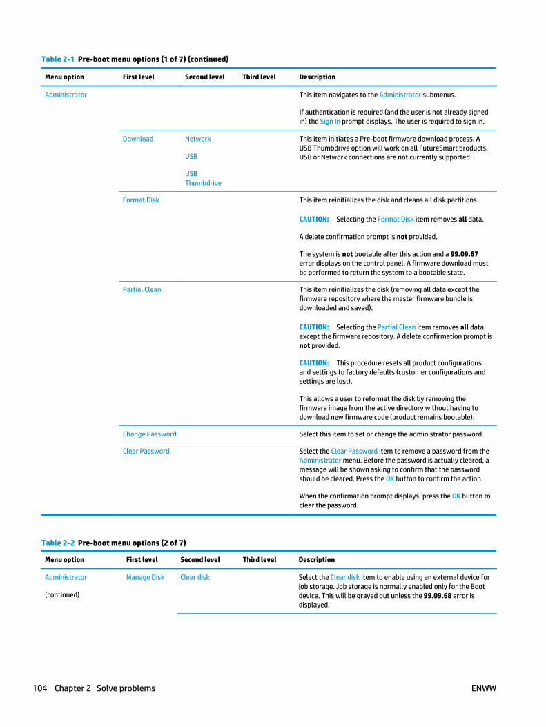
Table 2-1 Pre-boot menu options (1 of 7) (continued)
Menu option First level Second level Third level Description
Administrator This item navigates to the Administrator submenus.
If authentication is required (and the user is not already signedin) the Sign In prompt displays. The user is required to sign in.
Download Network
USB
USBThumbdrive
This item initiates a Pre-boot firmware download process. AUSB Thumbdrive option will work on all FutureSmart products.USB or Network connections are not currently supported.
Format Disk This item reinitializes the disk and cleans all disk partitions.
CAUTION: Selecting the Format Disk item removes all data.
A delete confirmation prompt is not provided.
The system is not bootable after this action and a 99.09.67error displays on the control panel. A firmware download mustbe performed to return the system to a bootable state.
Partial Clean This item reinitializes the disk (removing all data except thefirmware repository where the master firmware bundle isdownloaded and saved).
CAUTION: Selecting the Partial Clean item removes all dataexcept the firmware repository. A delete confirmation prompt isnot provided.
CAUTION: This procedure resets all product configurationsand settings to factory defaults (customer configurations andsettings are lost).
This allows a user to reformat the disk by removing thefirmware image from the active directory without having todownload new firmware code (product remains bootable).
Change Password Select this item to set or change the administrator password.
Clear Password Select the Clear Password item to remove a password from theAdministrator menu. Before the password is actually cleared, amessage will be shown asking to confirm that the passwordshould be cleared. Press the OK button to confirm the action.
When the confirmation prompt displays, press the OK button toclear the password.
Table 2-2 Pre-boot menu options (2 of 7)
Menu option First level Second level Third level Description
Administrator
(continued)
Manage Disk Clear disk Select the Clear disk item to enable using an external device forjob storage. Job storage is normally enabled only for the Bootdevice. This will be grayed out unless the 99.09.68 error isdisplayed.
104 Chapter 2 Solve problems ENWW
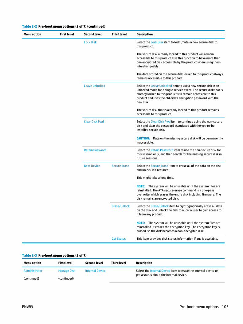
Table 2-2 Pre-boot menu options (2 of 7) (continued)
Menu option First level Second level Third level Description
Lock Disk Select the Lock Disk item to lock (mate) a new secure disk tothis product.
The secure disk already locked to this product will remainaccessible to this product. Use this function to have more thanone encrypted disk accessible by the product when using theminterchangeably.
The data stored on the secure disk locked to this product alwaysremains accessible to this product.
Leave Unlocked Select the Leave Unlocked item to use a new secure disk in anunlocked mode for a single service event. The secure disk that isalready locked to this product will remain accessible to thisproduct and uses the old disk's encryption password with thenew disk.
The secure disk that is already locked to this product remainsaccessible to this product.
Clear Disk Pwd Select the Clear Disk Pwd item to continue using the non-securedisk and clear the password associated with the yet-to-beinstalled secure disk.
CAUTION: Data on the missing secure disk will be permanentlyinaccessible.
Retain Password Select the Retain Password item to use the non-secure disk forthis session only, and then search for the missing secure disk infuture sessions.
Boot Device Secure Erase Select the Secure Erase item to erase all of the data on the diskand unlock it if required.
This might take a long time.
NOTE: The system will be unusable until the system files arereinstalled. The ATA secure-erase command is a one-passoverwrite, which erases the entire disk including firmware. Thedisk remains an encrypted disk.
Erase/Unlock Select the Erase/Unlock item to cryptographically erase all dataon the disk and unlock the disk to allow a user to gain access toit from any product.
NOTE: The system will be unusable until the system files arereinstalled. It erases the encryption key. The encryption key iserased, so the disk becomes a non-encrypted disk.
Get Status This item provides disk status information if any is available.
Table 2-3 Pre-boot menu options (3 of 7)
Menu option First level Second level Third level Description
Administrator
(continued)
Manage Disk
(continued)
Internal Device Select the Internal Device item to erase the internal device orget a status about the internal device.
ENWW Pre-boot menu options 105

Table 2-3 Pre-boot menu options (3 of 7) (continued)
Menu option First level Second level Third level Description
Secure Erase Select the Secure Erase item to erase all of the data on the diskand unlock it if required.
This might take a long time.
NOTE: The system will be unusable until the system files arereinstalled. The ATA secure-erase command erases the entiredisk, including firmware. The disk remains an encrypted disk.
Erase/Unlock Select the Erase/Unlock item to cryptographically erase all ofthe data on disk and unlock the disk to allow the user to gainaccess to it from any product.
NOTE: The system will be unusable until the system files arereinstalled. The HP High Performance Secure Hard Disk iserased.
Get Status This item provides disk status information if any is available.
External Device Select the External Device item to erase the external device orget status about the external device.
Secure Erase Select the Secure Erase item to erase all of the data on the diskand unlock it if required.
This might take a long time.
NOTE: The system will be unusable until the system files arereinstalled.
The ATA secure-erase command erases the entire disk, includingfirmware. The disk remains an encrypted disk.
Erase/Unlock Select the Erase/Unlock item to cryptographically erase all ofthe data on disk and unlock the disk to allow a user to gainaccess to it from any product.
NOTE: The system will be unusable until the system files arereinstalled. The encryption key is erased, so the disk becomes anon-encrypted disk.
Get Status This item provides disk status information if any is available.
Table 2-4 Pre-boot menu options (4 of 7)
Menu option First level Second level Third level Description
Administrator
(continued)
Configure LAN
NOTE: Thisconfiguration isonly active whenthe Pre-bootmenu is open.
IP Mode [DHCP] The network can be configured to obtain the network settingsfrom a DHCP server or as static.
Use this item for automatic IP address acquisition from the DHCPserver.
IP Mode[STATIC]
Use this item to manually assign the network addresses.
IP Address Use this item to manually enter the IP addresses.
Subnet Mask Use this item to manually enter the subnet mask.
106 Chapter 2 Solve problems ENWW

Table 2-4 Pre-boot menu options (4 of 7) (continued)
Menu option First level Second level Third level Description
DefaultGateway
Use this item to manually enter the default gateway.
Save Select the Save item to save the manual settings.
Table 2-5 Pre-boot menu options (5 of 7)
Menu option First level Second level Third level Description
Administrator
(continued)
Startup Options Select the Startup Options item to specify options that can be setfor the next time the product is turned on and initializes to theReady state.
Show Revision Not currently functional: Select the Show Revision item to allowthe product to initialize and show the firmware version when theproduct reaches the Ready state.
Once the product power is turned on the next time, the ShowRevision item is unchecked so that the firmware revision is notshown.
Cold Reset Select the Cold Reset item to clear the IP address and all customersettings. (This item also returns all settings to factory defaults.)
NOTE: Items in the Service menu are not reset.
Skip Disk Load Select the Skip Disk Load item to disable installed third-partyapplications.
Skip Cal Select the Skip Cal item to skip the product calibration for the verynext power-initialization cycle only.
Lock Service CAUTION: Select the Lock Service item to lock the Service menuaccess (both in the Pre-boot menu and the Device Maintenancemenu).
Service personnel must have the administrator remove the LockService setting before they can open the Service menu.
Skip FSCK Select the Skip FSCK item to disable Chkdisk/ScanVolume duringstartup.
Administrator
(continued)
Startup Options
(continued)
First Power Not currently functional: This item allows the product to initializeas if it is the first time it has been turned on.
For example, the user is prompted to configure first-time settingslike date/time, language, and other settings.
Select this item so that it is enabled for the next time the productpower is turned on.
When the product power is turned on the next time, this item isunchecked so that the pre-configured settings are used duringconfiguration, and the first-time setting prompt is not used.
ENWW Pre-boot menu options 107

Table 2-5 Pre-boot menu options (5 of 7) (continued)
Menu option First level Second level Third level Description
EmbeddedJetdirect Off
Select the Embedded Jetdirect Off item to disable the embeddedHP Jetdirect.
By default this item is unchecked so that HP Jetdirect is alwaysenabled.
WiFi Accessory Select the WiFi Accessory item to enable the wireless accessory.
Table 2-6 Pre-boot menu options (6 of 7)
Menu option First level Second level Third level Description
Administrator
(continued)
Diagnostics Diagnostic items are useful to diagnose hardware componentsand their interface connections. Use these items totroubleshoot specific hardware components, and the interfacebetween them and other components.
Memory Do Not Run Use the Do Not Run item to exclude the Memory diagnosticwhen executing multiple diagnostics.
Short Use the Short item to select a brief memory test.
NOTE: This test requires about four minutes to execute.
Long Use the Long item to select an extended memory test.
NOTE: This test requires about twenty minutes to execute.
Disk Do Not Run Use the Do Not Run item to exclude the Disk diagnostic whenexecuting multiple diagnostics.
Short Use the Short item to select a brief firmware self-test.
NOTE: This test requires about two or three minutes toexecute.
Long Use the Long item to select an extended firmware self-test.
NOTE: This test requires about sixty minutes to execute.
Optimized Use the Optimized item to select a test that checks the activesectors on the disk.
NOTE: This test requires about thirty minutes to execute.
Raw Use the Raw item to select a test that checks every sector onthe disk.
NOTE: This test requires about fifty minutes to execute.
Smart Use the Smart item to select a very brief test that checks thedrive self-monitoring analysis and reporting technology(SMART) status—the drive detects and reports reliabilityindicators to help anticipate disk failures (SMART status).
ICB Connection Use the ICB item to select a test that checks the communicationbetween the formatter and interconnect board (ICB).
CPB Use the CPB item to verify the integrity of the copy processorboard (CPB) and the formatter PCA connections.
108 Chapter 2 Solve problems ENWW

Table 2-6 Pre-boot menu options (6 of 7) (continued)
Menu option First level Second level Third level Description
Interconnect Use the Interconnect item to verify the integrity of theinterconnect PCA (ICB) and its connections.
Run Selected Select the Run Selected item to execute a selected test.
NOTE: If more than one test is selected, they are executed insequence.
Table 2-7 Pre-boot menu options (7 of 7)
Menu option First level Second level Third level Description
Administrator
(continued)
Remote Admin Start Telnet The Remote Admin item allows a service technician toaccess to the product Pre-boot menu remotely, and tonavigate the menu selections from a remote location.
IMPORTANT: A Remote Admin connection must beinitiated by a person that is physically present at theproduct.
This person will also need to provide a randomlygenerated PIN to the remote service technician.
NOTE: For more information about using the RemoteAdmin function, see Remote Admin on page 110.
Stop Telnet
Refresh IP
System Triage Copy Logs If the device will not boot to the Ready state, or thediagnostic log feature found in the Troubleshootingmenu is not accessible, then use the System Triage itemto copy the diagnostic logs to a USB flash drive at thenext product start up.
The files can then be sent to HP to help diagnose theproblem.
Change Svc PWD Use this item to change the Service menu personalidentification number (PIN).
Reset Svc PWD If the Service menu personal identification number (PIN)has been changed, use this item to reset it to the originalPIN.
Service Tools This item requires the service access code. If the productdoes not reach the Ready state, use this item to print theerror logs. The logs can be copied to a USB storageaccessory when the product is initialized. Send these filesto HP to help troubleshoot the cause of the problem.
Reset Password Use this item to reset the Pre-boot administratorpassword.
Subsystems For manufacturing use only. Do not change these values.
Developer Tools Netexec
ENWW Pre-boot menu options 109

Remote AdminThe Remote Admin feature allows remote access the product Pre-boot menu (BIOS environment). Theproduct functions as a telnet server which uses the telnet networking protocol to transmit text data. Anycomputer (with telnet installed and enabled) can function as the telnet client to remotely display and interactwith the Pre-boot menu.
IMPORTANT: While the Remote Admin function allows remote access the Pre-boot menu, for securityreasons the Remote Admin connection must be initiated by a person that is physically present at the product.
This section describes the following Remote Admin items.
● Required software and network connection
● Connect a remote connection
● Disconnect a remote connection
Required software and network connection
Before using the Remote Admin feature, make sure that the telnet network protocol is installed, andenabled, on the remote telnet client computer.
NOTE: This section describes enabling and configuring the telnet feature for computers using a Windows®operating system.
HP recommends that the telnet client computer be a Windows based system, however, there are otheroperating systems that support the telnet network protocol. For information about enabling and configuringthe telnet network protocol for other operating systems, see the owner's manual for that operating system.
110 Chapter 2 Solve problems ENWW

Telnet client
Enable the Windows telnet client
All computers using the Windows operating system have the telnet client installed, however, the telnet clientfunction might not be enabled by default.
NOTE: The figures and menus in this section are for the Windows 7 Enterprise® operating system. Screensand menu selections might vary slightly for other operating systems.
1. Use the Start menu to open the Control Panel, and then click the Programs item to select it.
Figure 2-1 Open the Control Panel
2. Click the Turn Windows features on or off item to select it.
Figure 2-2 Turn Windows features on or off
ENWW Pre-boot menu options 111
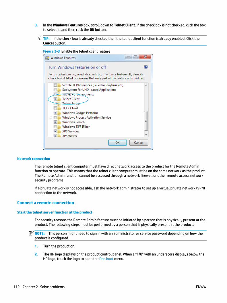
3. In the Windows Features box, scroll down to Telnet Client. If the check box is not checked, click the boxto select it, and then click the OK button.
TIP: If the check box is already checked then the telnet client function is already enabled. Click theCancel button.
Figure 2-3 Enable the telnet client feature
Network connection
The remote telnet client computer must have direct network access to the product for the Remote Adminfunction to operate. This means that the telnet client computer must be on the same network as the product.The Remote Admin function cannot be accessed through a network firewall or other remote access networksecurity programs.
If a private network is not accessible, ask the network administrator to set up a virtual private network (VPN)connection to the network.
Connect a remote connection
Start the telnet server function at the product
For security reasons the Remote Admin feature must be initiated by a person that is physically present at theproduct. The following steps must be performed by a person that is physically present at the product.
NOTE: This person might need to sign in with an administrator or service password depending on how theproduct is configured.
1. Turn the product on.
2. The HP logo displays on the product control panel. When a "1/8" with an underscore displays below theHP logo, touch the logo to open the Pre-boot menu.
112 Chapter 2 Solve problems ENWW

3. Use the arrow buttons on the touchscreen to scroll down and highlight the +3:Administrator item, andthen touch the OK button to select it.
Figure 2-4 Select the +3:Administrator item
4. Use the arrow buttons on the touchscreen to scroll down and highlight the +A:Remote Admin item, andthen touch the OK button to select it.
Figure 2-5 Select the +A:Remote Admin item
5. Use the arrow buttons on the touchscreen to scroll down and highlight the 1:Start Telnet item, andthen touch the OK button to select it.
Figure 2-6 Select the 1:Start Telnet item
6. Do one of the following
● If a connecting message displays briefly, go to step 7.
Figure 2-7 Telnet connecting message
● If an error message displays, use the steps below to identify the problem.
ENWW Pre-boot menu options 113

Figure 2-8 Telnet error message
a. The product network cable is not correctly connected.
b. The BIOS LAN settings are incorrect.
● The product should be configured to use a static IP address, but is configured to useDHCP instead.
● The product is configured to use a static IP address, but the IP address is incorrect.
c. The product is correctly configured to use DHCP, but the DHCP server is not turned on or ismalfunctioning.
7. When the product telnet server function is initialized, the following screen appears. Use the informationon this screen to connect the remote telnet client computer to the product.
NOTE: The product is now ready to receive remote telenet client commands.
● IP: The static or dynamically allocated IP address for the product.
● Port: The standard telnet port (23).
● Pin: A randomly generated 4-digit personal identification number (PIN).
Figure 2-9 Telnet server function initialized
Start the telnet client function at the remote computer
The following steps establish a Remote Admin connection from a remote computer to the product.
1. From the Start menu click Run to open a dialog box, type cmd in the Open field, and then click the OKbutton to open a Windows command window.
114 Chapter 2 Solve problems ENWW

Figure 2-10 Open a command window
1
2
2. From any displayed directory, type telnet at the prompt, and then press the Enter key.
Figure 2-11 Start a telnet session
3. Type o <IP ADDRESS> at the telnet prompt, and then press the Enter key.
NOTE: For <IP ADDRESS>, substitute the IP address that was displayed in step 7 in Start the telnetserver function at the product on page 112.
TIP: If the telnet connection fails to establish a connection, the product is probably behind a firewallor on a different network that the remote telnet client computer. See Network connection on page 112.
Figure 2-12 Establish a telnet connection
ENWW Pre-boot menu options 115

4. Type the PIN that was displayed in step 7 in Start the telnet server function at the product on page 112at the prompt, and then press the Enter key.
IMPORTANT: Make sure to type the PIN correctly. After five incorrect PIN entries, the productterminates the Remote Admin connection. The Remote Admin feature must be re-initiated at theproduct. See Start the telnet server function at the product on page 112.
Figure 2-13 Enter the PIN
5. The following screen displays when the correct PIN is entered and the Remote Admin connection issuccessful. For information about the Pre-boot menu and options, see Pre-boot menu optionson page 103.
NOTE: Because a Remote Admin connection is an unsecure telnet network protocol connection, thefollowing Pre-boot menu items are disabled for the remote telnet client computer.
● The +3:Administrator menu 4:Change Password item.
● The +3:Administrator menu 5:Clear Password item.
● The +3:Administrator menu 6:Disk Manage item.
Figure 2-14 Remote Admin window
116 Chapter 2 Solve problems ENWW

Disconnect a remote connection
The Remote Admin connection can be terminated from the product control panel or the remote telnet clientcomputer.
NOTE: The following procedure describes terminating a Remote Admin connection from the remote telnetclient computer.
1. From the Pre-boot main menu, use the arrow buttons on the keybaord to scroll down to the+3:Administrator item, and then press the Enter key.
Figure 2-15 Access the administrator menu
2. Use the arrow buttons on the keybaord to scroll down to the +A:Rmote Admin item, and then press theEnter key.
Figure 2-16 Access the remote admin menu
3. Use the arrow buttons on the keybaord to scroll down to the 2:Stop Telnet item, and then press theEnter key. The Remote Admin connection between the product and the remote telnet client computerterminates.
IMPORTANT: The product remains in the Pre-boot menu. Have the person that is physically present atthe product do the following:
● Touch the Home button to return to the main Pre-boot menu and highlight the 1:Continue item,and then touch the OK button. The product will continue to initialize.
ENWW Pre-boot menu options 117

Figure 2-17 Terminate the telnet connection
118 Chapter 2 Solve problems ENWW

Troubleshooting processDetermine the problem source
When the product malfunctions or encounters an unexpected situation, the product control panel alerts theuser to the situation. This section contains a pre-troubleshooting checklist to filter out many possible causesof the problem. Use the troubleshooting flowchart to help diagnose the root cause of the problem. Theremainder of this chapter provides steps for correcting problems.
● Use the troubleshooting flowchart to pinpoint the root cause of hardware malfunctions. The flowchartprovides guides to the section of this chapter that contain steps to correct the malfunction.
Before beginning any troubleshooting procedure, check the following issues:
● Are supply items within their rated life?
● Does the configuration page reveal any configuration errors?
NOTE: The customer is responsible for checking supplies and for using supplies that are in good condition.
Troubleshooting flowchart
This flowchart highlights the general processes to follow to quickly isolate and solve product hardwareproblems.
Each row depicts a major troubleshooting step. Follow a “yes” answer to a question to proceed to the nextmajor step. A “no” answer indicates that more testing is needed. Go to the appropriate section in this chapter,and follow the instructions there. After completing the instructions, go to the next major step in thistroubleshooting flowchart.
Table 2-8 Troubleshooting flowchart
1
Power on
Is the product on and does a readable messagedisplay?
Follow the power-on troubleshooting checks. See Power subsystemon page 120.
After the control panel display is functional, see step 2.Yes No
2
Control panelmessages
Does the message Ready display on the controlpanel?
After the errors have been corrected, go to step 3.
Yes No
3
Event log
Open the Troubleshooting menu and print anevent log to see the history of errors with thisproduct.
Does the event log print?
If the event log does not print, check for error messages.
If paper jams inside the product, see the jams section of the productservice manual.
If error messages display on the control panel when trying to print anevent log, see the control panel message section of the producttroubleshooting service manual.
After successfully printing and evaluating the event log, see step 4.
Yes No
4
Information pages
Open the Reports menu and print theconfiguration pages to verify that all theaccessories are installed.
Are all the accessories installed?
If accessories that are installed are not listed on the configurationpage, remove the accessory and reinstall it.
After evaluating the configuration pages, see step 5.
Yes No
ENWW Troubleshooting process 119

Table 2-8 Troubleshooting flowchart (continued)
5
Print quality
Does the print quality meet the customer'srequirements?
Compare the images with the sample defects in the image defecttables. See the images defects table in the product service manual.
After the print quality is acceptable, see step 6.Yes No
6
Interface
Can the customer print successfully from thehost computer?
Verify that all I/O cables are connected correctly and that a validIP address is listed on the HP Jetdirect configuration page.
If error messages display on the control panel when trying to print anevent log, see the control-panel message section of the producttroubleshooting service manual.
When the customer can print from the host computer, this is the end ofthe troubleshooting process.
Yes. This is the end ofthe troubleshootingprocess.
No
Power subsystem
Power-on checks
The basic product functions should start up when the product is connected into an electrical outlet and thepower switch is pushed to the on position. If the product does not start, use the information in this section toisolate and solve the problem.
If the control panel display remains blank, random patterns display, or asterisks remain on the control paneldisplay, perform power-on checks to find the cause of the problem.
Power-on troubleshooting overview
During normal operation, a cooling fan begins to spin briefly after the product power is turned on. Place ahand over the vents in the rear cover, near the formatter. When the fan is correctly operating, air passing outof the product is felt. Lean close to the product to hear the fan operating. If the fan is operating, the dc side ofthe power supply is functioning.
After the fan is operating, the main motor turns on (unless the top cover is open, a jam condition is sensed, orthe paper-path sensors are damaged). Visually and audibly determine that the main motor is turned on.
If the fan and main motor are operating correctly, the next troubleshooting step is to isolate print engine,formatter, and control panel problems. Perform an engine test. If the formatter is damaged, it mightinterfere with the engine test. If the engine-test page does not print, try removing the formatter, and thenperforming the engine test again. If the engine test is then successful, the problem is almost certainly withthe formatter, the control panel, or the cable that connects them.
Troubleshooting power on problems
1. Verify that power is available to the product. If the product is plugged into a surge protector oruniterruptible power supply (UPS), remove it, and then plug the product directly into a known operatingwall receptacle (make sure that the wall receptacle provides the correct voltage and current for theproduct).
Unplug any other devices on the same circuit that the product is using.
2. Try another known operating wall receptacle and a different power cord.
120 Chapter 2 Solve problems ENWW

3. Listen for startup noises (fans and motors) and illuminated lights on the control panel.
NOTE: Operational fans, motors, and control-panel lights indicate the following:
● AC power is present at the product.
● The low-voltage power supply (LVPS) is providing either or both 24 Vdc and 5 Vdc voltages.
● The DC controller microprocessor is functioning.
4. If startup noises are not heard, check the following:
a. Turn the product off, and then remove the formatter.
b. Turn the product on, and then listen for startup noises. If normal startup noises are heard, go tostep 5.
NOTE: The control panel will be blank with the formatter removed.
c. Turn the product off, and then remove any installed accessories (for example, envelope feeders,paper feeders, or output accessories).
Turn the product on, and then listen for startup noises. If normal startup noises are heard, theproblem might be with one of the accessories.
d. If normal startup noises and lights are still not present, replace the LVPS.
e. If after replacing the LVPS normal startup noises are still not heard, replace the DC controller.
f. If after replacing the DC controller normal startup noises are still not heard, replace the HVPS.
NOTE: If the error persists after replacing these assemblies, escalate the problem to the GlobalBusiness Unit (GBU).
5. Try printing an engine test page.
a. Use a small pointed object to depress the test-page switch located on the rear of the product.
NOTE: The test page can only use Tray 2 as the paper source, so make sure that paper is loadedin Tray 2.
ENWW Troubleshooting process 121

b. If the engine test page prints, the print engine is operating normally (a failed engine test printpage does not necessarily indicate that the print engine or DC controller is defective).
NOTE: If the engine test page does not print, turn the product off, remove the formatter, andthen try the engine test again. If the page prints, the problem might be the formatter.
Troubleshooting a blank control panel
A blank control panel display can be caused by by one or more of the following:
● No power to the product.
● Power supply has tripped (over-current/over-voltage/temperature issue).
● Formatter not fully seated.
TIP: The three LEDs on the formatter indicate that the product is functioning correctly.
HP recommends fully troubleshooting the formatter and control panel before replacing either assembly. Use the connectivityLED to troubleshoot formatter and control panel errors to avoid unnecessarily replacing these assemblies. See the LEDdiagnostics section in the product troubleshooting manual.
● Faulty component installed on the formatter (for example, memory DIMM or disk drive).
● Control panel connector not fully seated.
● Faulty formatter.
● Faulty DC controller.
● Faulty control panel.
1. Verify that power is available to the product. If the product is plugged into a surge protector oruniterruptible power supply (UPS), remove it, and then plug the product directly into a known operatingwall receptacle (make sure that the wall receptacle provides the correct voltage and current for theproduct).
2. Make sure that the power switch is in the on position.
122 Chapter 2 Solve problems ENWW

3. Make sure that the fan runs briefly, which indicates that the power supply is operational.
4. Make sure that the control-panel display wire harness is connected.
5. Make sure that the formatter is seated and operating correctly. Turn off the product and remove theformatter. Reinstall the formatter, make sure the power switch is in the on position, and then verify thatthe heartbeat LED is blinking and that the connectivity LED is illuminated.
6. Remove any external solutions, and then try to turn the product on again.
7. If the control panel display is blank, but the main cooling fan runs briefly after the product power isturned on, try printing an engine-test page to determine whether the problem is with the control-paneldisplay, formatter, or other product assemblies.
a. Remove the formatter.
b. Use a small pointed object to depress the test-page switch located on the rear of the product.
NOTE: The test page can only use Tray 2 as the paper source, so make sure that paper is loadedin Tray 2.
c. If the engine test page prints, the print engine is operating normally (a failed engine test printpage does not necessarily indicate that the print engine or DC controller is defective).
d. Use the control-panel diagnostics to test the control panel. See the Control panel checks section inthe product troubleshooting manual. If the error persists, proceed to step 8.
8. If the print engine appears to be correctly operating (the engine test page successfully printed) and thecontrol panel is still blank, replace the low-voltage power supply (LVPS)
9. If after replacing the LVPS normal startup noises and lights are still not present, replace the DCcontroller.
NOTE: If the error persists after replacing these assemblies, escalate the problem to the GlobalBusiness Unit (GBU).
ENWW Troubleshooting process 123
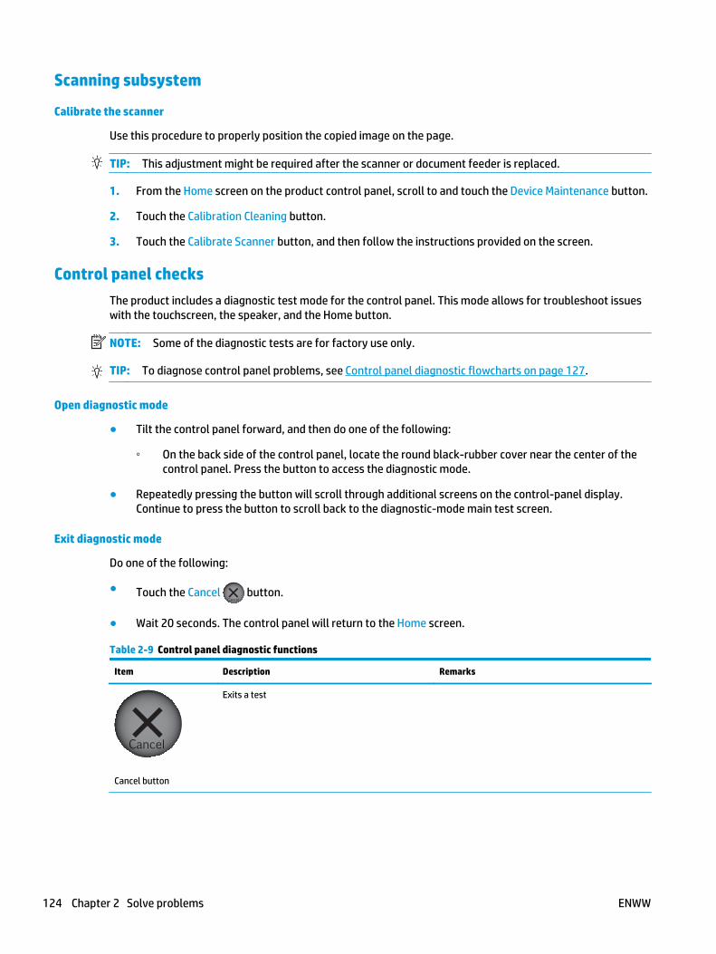
Scanning subsystem
Calibrate the scanner
Use this procedure to properly position the copied image on the page.
TIP: This adjustment might be required after the scanner or document feeder is replaced.
1. From the Home screen on the product control panel, scroll to and touch the Device Maintenance button.
2. Touch the Calibration Cleaning button.
3. Touch the Calibrate Scanner button, and then follow the instructions provided on the screen.
Control panel checksThe product includes a diagnostic test mode for the control panel. This mode allows for troubleshoot issueswith the touchscreen, the speaker, and the Home button.
NOTE: Some of the diagnostic tests are for factory use only.
TIP: To diagnose control panel problems, see Control panel diagnostic flowcharts on page 127.
Open diagnostic mode
● Tilt the control panel forward, and then do one of the following:
◦ On the back side of the control panel, locate the round black-rubber cover near the center of thecontrol panel. Press the button to access the diagnostic mode.
● Repeatedly pressing the button will scroll through additional screens on the control-panel display.Continue to press the button to scroll back to the diagnostic-mode main test screen.
Exit diagnostic mode
Do one of the following:
● Touch the Cancel button.
● Wait 20 seconds. The control panel will return to the Home screen.
Table 2-9 Control panel diagnostic functions
Item Description Remarks
Cancel button
Exits a test
124 Chapter 2 Solve problems ENWW

Table 2-9 Control panel diagnostic functions (continued)
Item Description Remarks
Keypad
Selects test settings in some of the test windows
Red-grid touch test
Verifies that all areas respond to a touch Use this item to check the accuracy of the touchscreen.
Use a finger or 3 mm (.118 in) conductive stylus totrace between the grid lines to check the accuracyof the touchscreen calibration.
NOTE: The gap between the grid lines is 6 mm (.236 in).
When the screen is touched, a line or a dot displayson the screen (the X and Y coordinates of theposition on the screen are also displayed).
Calibration touch test
Checks calibration Use this item to determine if the touchscreencalibration is within the acceptable range.
When selected, ten target points (and the X and Ycoordinates of the position of the target point)display on the screen.
Touching a target causes the X and Y coordinate ofthat target to appear in the middle of thetouchscreen (above the cancel button).
NOTE: The product automatically calibrates thetouchscreen. A manual touchscreen calibrationprocedure is not available for this product.
Touchscreen LED displaytest
Selects a test pattern to view on the display. Use this item to identify touchscreen LED displayproblems.
1. Touch the icon.
2. Touch the up or down arrow buttons toscroll though touchscreen LED display testscreens.
Speaker test
Tests sounds Use this item to test audio functionality.
1. Touching this item causes the speaker to emita tone.
2. Touch the 2 button on the keypad, and thentouch this item to cause the speaker to emit amore complex tone.
ENWW Troubleshooting process 125

Table 2-9 Control panel diagnostic functions (continued)
Item Description Remarks
Firmware information
Shows the firmware version Touch this item to display the control panelfirmware version and firmware build date.
Factory use only
Keyboard test
Tests the product keyboard
NOTE: For products with a keyboard feature only.
When this item is selected, pressing a button on thekeyboard causes the corresponding character toappear on the control-panel display.
1. Touch the icon.
2. Press a button on the keyboard. Thecorresponding character should appear on thecontrol-panel display.
Backlight test
Adjusts the backlight Use this item to adjust the brightness of thecontrol-panel display.
1. Touch the icon.
2. Touch the up or down arrow buttons toadjust the backlight level.
Ambient-light sensortest
Checks the ambient light sensor Use this item to test the ambient-light sensorfunctionality.
1. Touch the icon.
2. Shine a flashlight at the control panel to theleft of, and down about 25.4 mm (1 in,) fromthe Home button.
3. The numbers displayed below the icon shouldbe any value other than zero.
Home button test
Tests the Home button Use this item to test the Home button LED andswitch functionality.
1. Touch the icon.
2. Press the Home button on the right side of thecontrol panel. The LED icon on the control-panel display illuminates if the button LED andswitch are correctly functioning.
126 Chapter 2 Solve problems ENWW

Control panel diagnostic flowcharts
TIP: Tilt the control panel forward. On the back side of the control panel, press the round black-rubbercover near the center of the control panel to access the diagnostic mode.
Use the flowcharts in this section to troubleshoot the following control panel problems.
● Touchscreen is blank, white, or dim (no image).
● Touchscreen is slow to respond or requires multiple presses to respond.
● Touchscreen has an unresponsive zone.
● No control panel sound.
● Home button is unresponsive.
● Hardware integration pocket (HIP) is not functioning (control panel functional).
ENWW Troubleshooting process 127

Touchscreen black, white, or dim (no image)
Figure 2-18 Touchscreen blank, white, or dim (no image)
N
N
Y
N
N
Y
Y
N
Y
Y
N
Y
Touch the display or Home buttonto exit sleep mode. Make sure that
the product is plugged in andthe power is turned on.
Black display(no backlight
or image)
White display(no image)
Dim display(no image)
Is the Home buttonilluminated
(bright white)?
Open thediagnostic function.
Does an imageappear on thecontrol panel?
Does the displayturn on?
Problem solved.
Are the formatterLEDs functioning?
Turn the product power off.Remove and reseat the formatter.
Troubleshoot the formatter.Do not replace the control panel.
Turn the product power off.Inspect and reseat thecontrol panel cables.
Remove and reseat theformatter.
Make sure that theformatter LEDs function.
Problem fixed?
Replace thecontrol panel.
Do not replace the control panel.Turn the product power off.
Remove and reseat the formatter.If the error persists,
troubleshoot the formatter.
Is the backlightadjustable?
Open thediagnostic function.
Perform thebacklight test.
Is the product in brightsunlight?
If yes, move theproduct to a
different location.
128 Chapter 2 Solve problems ENWW

Touchscreen is slow to respond or requires multiple presses to respond
TIP: Use the red-grid touch test to verify that all areas of the touchscreen are correctly functioning. SeeTable 2-9 Control panel diagnostic functions on page 124.
Figure 2-19 Touchscreen is slow to respond or requires multiple presses to respond
Touchscreen slow torespond or requires
multiple pressesto respond
Not a control-panel problem.Do not replace the control panel.
Troubleshoot firmware orsoftware application problems.
ENWW Troubleshooting process 129

Touchscreen has an unresponsive zone
Figure 2-20 Touchscreen has an unresponsive zone
N
Y
N
Y
N
Y
Touchscreenhas an
unresponsivezone
Is the area of thetouchscreen you are touching
greyed out (intentionallydeactivated)?
Does the previouslyinactive area respond
to a touch?
Open thediagnostic function.
Perform thered-grid touch test.
Turn the productpower off,and thenon again.
Does the previouslyinactive area respond
to a touch?
Replace thecontrol panel.
Do not replace thecontrol panel.
130 Chapter 2 Solve problems ENWW
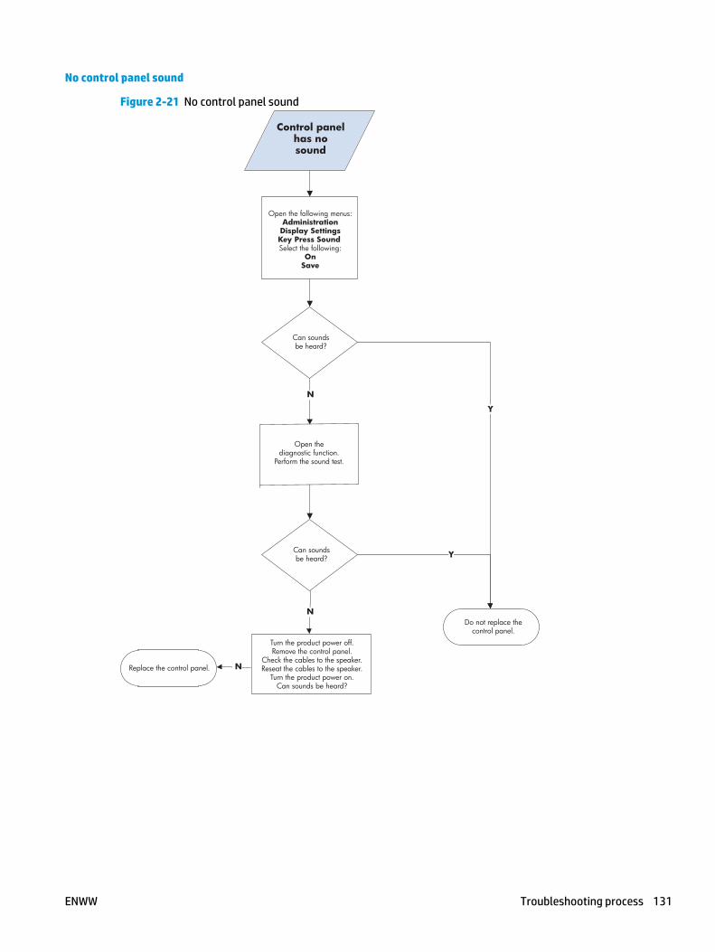
No control panel sound
Figure 2-21 No control panel sound
N
N
Y
Y
Control panelhas nosound
Turn the product power off.Remove the control panel.
Check the cables to the speaker.Reseat the cables to the speaker.
Turn the product power on.Can sounds be heard?
Can soundsbe heard?
Can soundsbe heard?
Replace the control panel.
Open the following menus:AdministrationDisplay SettingsKey Press Sound Select the following:
OnSave
N
Do not replace thecontrol panel.
Open thediagnostic function.
Perform the sound test.
ENWW Troubleshooting process 131

Home button is unresponsive
Figure 2-22 Home button is unresponsive
Y
N
N
Y
Home buttonunresponsive
Open thediagnostic function.Perform the Home
button test.
Does the virtual LEDilluminate green when
the Home button is pressed?
Turn the product power off,and then on again.
Open thediagnostic function.
Perform theHome button test.
Does the virtual LEDilluminate green when
the Home button is pressed?
Replace thecontrol panel.
Do not replace thecontrol panel.
132 Chapter 2 Solve problems ENWW

Hardware integration pocket (HIP) is not functioning (control panel functional)
Figure 2-23 Hardware integration pocket (HIP) is not functioning (control panel functional)
Hardware integrationpocket (HIP)
not functional(control panel
functional)
Check that all installed hardware integrationpocket devices are within HP specifications.The control panel provides only 0.5 Amps to
the port. If an installed device attempts to drawmore power than is provided, the port is
automatically disabled. Troubleshoot third-party devices with the device manufacturer.
ENWW Troubleshooting process 133

Tools for troubleshootingThe section describes the tools that can help solve problems with the product.
Individual component diagnostics
LED diagnostics
LED, engine, and individual diagnostics can identify and troubleshoot product problems.
Understand lights on the formatter
Three LEDs on the formatter indicate that the product is functioning correctly.
21
3
1 Heartbeat LED
2 Connectivity LED
3 HP Jetdirect LEDs
Connectivity LED
The connectivity LED provides information about product operation. If a product error occurs, the formatterdisplays a message on the control-panel display. However, error situations can occur causing the formatter-to-control panel communication to be interrupted.
NOTE: HP recommends fully troubleshooting the formatter and control panel before replacing eitherassembly. Use the connectivity LED to troubleshoot formatter and control panel errors to avoidunnecessarily replacing these assemblies.
134 Chapter 2 Solve problems ENWW

Formatter-to-control panel communication interruptions
● The firmware does not fully initialize and configure the control panel interface.
● The control panel is not functioning (either a failed assembly or power problem).
● Interface cabling between the formatter and control panel is damaged or disconnected.
TIP: If the connectivity LED is illuminated—by an error condition or normal operation—the formatter isfully seated and the power is on. The pins for the LED circuit in the formatter connector are recessed so thatthis LED will not illuminate unless the formatter is fully seated.
The heartbeat LED operates according to the product state. When the product is initializing, see ConnectivityLED, product initialization on page 135. When the product is in Ready mode, see Connectivity LED, productoperational on page 137.
Connectivity LED, product initialization
The following table describes the connectivity LED operation while the product is executing the firmwareboot process.
NOTE: When the initialization process completes, the connectivity LED should be illuminated solid green.
If after initialization, the connectivity LED is not solid green, see Connectivity LED, product operationalon page 137.
Table 2-10 Connectivity LED, product initialization
Product initializing state Connectivity LED, normal state Connectivity LED, error state
No power (power cabledisconnected or powerswitch off)
Off Not applicable
Power on (immediatelyafter the power switchpressed)
Red, solid
● Duration should be 1 second or less
Red, solid
● Firmware error; problem finding hardwareand booting the serial peripheral interfaceflash memory
◦ Boot process halted
Replace the formatter.
Serial peripheralinterface (SPI) flashmemory boot
Green, solid Red, solid
● Firmware error; problem corrupt or missingSPI flash memory
◦ Boot process halted
Replace the formatter.
HW checks on boardDRAM
Green, solid Red, solid
● Power on self check failure
◦ Boot process halted
Replace the formatter.
ENWW Tools for troubleshooting 135
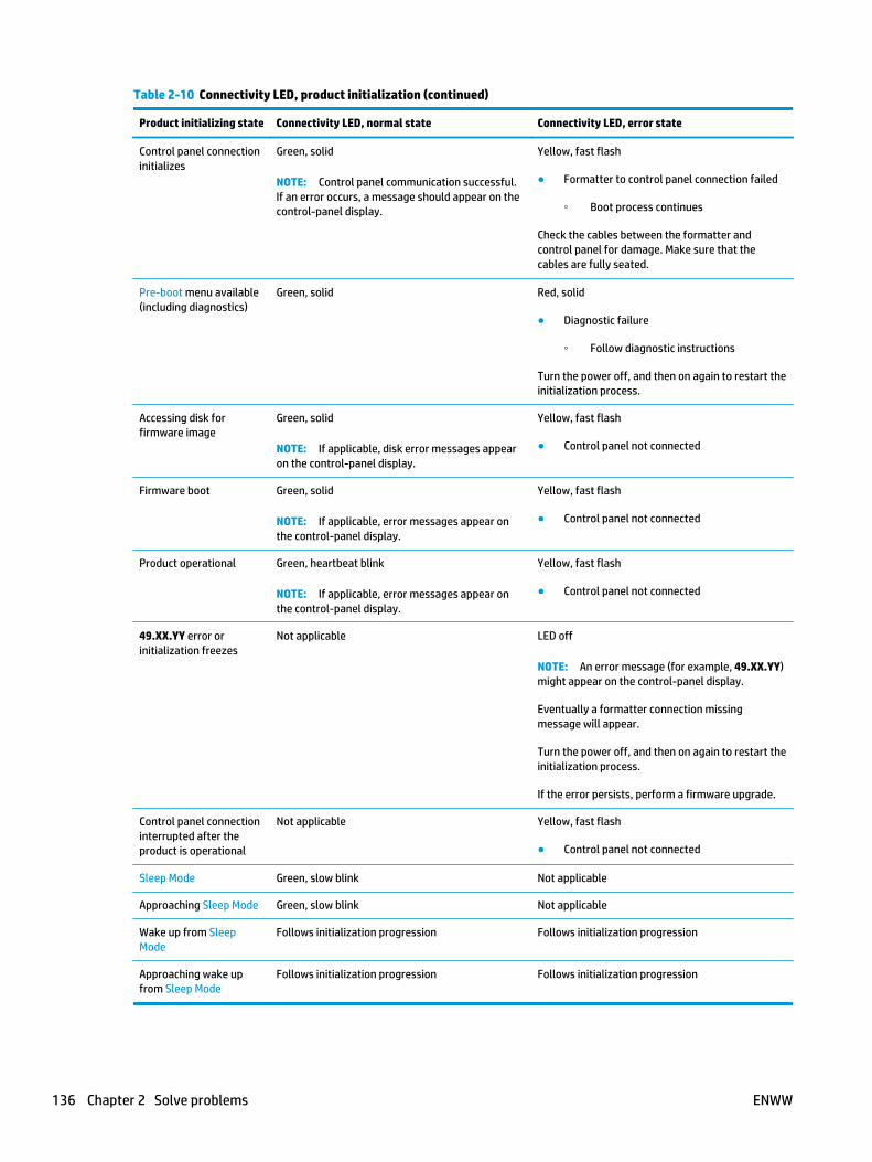
Table 2-10 Connectivity LED, product initialization (continued)
Product initializing state Connectivity LED, normal state Connectivity LED, error state
Control panel connectioninitializes
Green, solid
NOTE: Control panel communication successful.If an error occurs, a message should appear on thecontrol-panel display.
Yellow, fast flash
● Formatter to control panel connection failed
◦ Boot process continues
Check the cables between the formatter andcontrol panel for damage. Make sure that thecables are fully seated.
Pre-boot menu available(including diagnostics)
Green, solid Red, solid
● Diagnostic failure
◦ Follow diagnostic instructions
Turn the power off, and then on again to restart theinitialization process.
Accessing disk forfirmware image
Green, solid
NOTE: If applicable, disk error messages appearon the control-panel display.
Yellow, fast flash
● Control panel not connected
Firmware boot Green, solid
NOTE: If applicable, error messages appear onthe control-panel display.
Yellow, fast flash
● Control panel not connected
Product operational Green, heartbeat blink
NOTE: If applicable, error messages appear onthe control-panel display.
Yellow, fast flash
● Control panel not connected
49.XX.YY error orinitialization freezes
Not applicable LED off
NOTE: An error message (for example, 49.XX.YY)might appear on the control-panel display.
Eventually a formatter connection missingmessage will appear.
Turn the power off, and then on again to restart theinitialization process.
If the error persists, perform a firmware upgrade.
Control panel connectioninterrupted after theproduct is operational
Not applicable Yellow, fast flash
● Control panel not connected
Sleep Mode Green, slow blink Not applicable
Approaching Sleep Mode Green, slow blink Not applicable
Wake up from SleepMode
Follows initialization progression Follows initialization progression
Approaching wake upfrom Sleep Mode
Follows initialization progression Follows initialization progression
136 Chapter 2 Solve problems ENWW

Connectivity LED, product operational
The following table describes the connectivity operation when the product completes the firmware bootprocess and is in the Ready state.
Table 2-11 Connectivity LED, product operational
LED color Description
Green ● Normal operation
◦ Formatter is operating normally
◦ Firmware is operating normally
◦ Control panel is connected
Yellow ● Formatter cannot connect to the control panel
◦ Check control panel connections
◦ Verify control panel functionality
Red ● Formatter error or failure
◦ Serial peripheral interface (SPI) flash memory boot error
◦ Power on self test (formatter) failed
◦ Diagnostic (formatter) failed
Off TIP: The connectivity LED is off if the power cable is disconnected, the product power switch is in theoff position, or the product is in Sleep Mode.
● Firmware or system freeze
◦ Check control panel for an error message
◦ Control panel failure
NOTE: This condition is not usually caused by a formatter failure. Turn the power off, and then onagain. If the error persists, perform a firmware upgrade.
Heartbeat LED
The heartbeat LED indicates that the formatter is functioning correctly. While the product is initializing afterit is turned on, the LED blinks rapidly, and then turns off. When the product has finished the initializationsequence, the heartbeat LED pulses on and off.
HP Jetdirect LEDs
The embedded HP Jetdirect print server has two LEDs. The yellow LED indicates network activity, and thegreen LED indicates the link status. A blinking yellow LED indicates network traffic. If the green LED is off, alink has failed.
For link failures, check all the network cable connections. In addition, try to manually configure the linksettings on the embedded print server by using the product control-panel menus.
1. From the Home screen on the product control panel, scroll to and touch the Administration button.
2. Open the following menus:
ENWW Tools for troubleshooting 137

● Network Settings
● Embedded Jetdirect Menu
● Link Speed
3. Select the appropriate link speed, and then touch the OK button.
138 Chapter 2 Solve problems ENWW

Engine diagnostics
The product contains extensive internal engine diagnostics that help in troubleshooting print quality, paperpath, noise, assembly, and timing issues.
Defeating interlocks
Different tests can be used to isolate different types of issues. For assembly or noise isolation, run thediagnostic test when the top cover is open. To operate the product with the cover open, the top cover switchlevers must be depressed to simulate a closed-cover position.
WARNING! Be careful when performing product diagnostics to avoid risk of injury. Only trained servicepersonnel should open and run the diagnostics with the covers removed. Never touch any of the powersupplies when the product is turned on.
1. Open the top cover.
2. Insert a folded piece of paper into each slot to defeat the top switches.
TIP: Fold a stiff piece of paper, for example a business card or index card, into a 10 mm (.375 in) stripwith a bend at the end, and insert the strip into the openings under the top cover logic switches.
Figure 2-24 Defeating interlocks
ENWW Tools for troubleshooting 139

Disable cartridge check
Use this diagnostic test to print internal pages or send an external job to the product when the tonercartridge is removed or exchanged. Supply errors are ignored while the product is in this mode. When theproduct is in this mode, access the troubleshooting menus and print internal pages (the print quality pageswill be the most useful). This test can be used to isolate problems, such as noise, and to isolate print-qualityproblems that are related to the toner cartridge.
NOTE: Do not remove or exchange the toner cartridge until after beginning the disable cartridge checkdiagnostic.
1. From the Home screen on the product control panel, scroll to and touch the Administration button.
2. Open the following menus:
● Troubleshooting
● Diagnostic Tests
● Disable Cartridge Check
Engine test button
To verify that the product engine is functioning, print an engine test page. Use a small pointed object todepress the test-page switch located on the rear of the product. The test page should have a series of linesthat are parallel to the short end of the page. The test page can use only Tray 2 as the paper source, so makesure that paper is loaded in Tray 2.
Figure 2-25 Engine test button
140 Chapter 2 Solve problems ENWW

Paper path test
This diagnostic test generates one or more test pages. Use these pages to isolate the cause of jams.
To isolate a problem, specify which input tray to use, specify whether to use the duplex path, and specify thenumber of copies to print. Multiple copies can be printed to help isolate intermittent problems. The followingoptions become available after beginning the diagnostic feature:
● Print Test Page: Run the paper-path test from the default settings: Tray 2, no duplex, and one copy. Tospecify other settings, scroll down the menu, and select the setting, and then scroll back up and selectPrint Test Page to start the test.
● Source Tray: Select Tray 1, Tray 2, or the optional tray.
● Test Duplex Path: Enable or disable two-sided printing.
● Number of Copies: Set the numbers of copies to be printed; the choices are 1,10, 50, 100, or 500.
1. From the Home screen on the product control panel, scroll to and touch the Administration button.
2. Open the following menus:
● Troubleshooting
● Diagnostic Tests
● Paper Path Test
3. Select the paper-path test options for the test.
Paper path sensors test
This test displays the status of each paper-path sensor and allows viewing of sensor status while printinginternal pages.
1. From the Home screen on the product control panel, scroll to and touch the Administration button.
2. Open the following menus:
● Troubleshooting
● Diagnostic Tests
● Paper Path Sensors
NOTE: Exiting the Paper path sensors menu and then reentering the test will clear the test values from theprevious test.
The menu list of sensors and motors for the Paper path sensors test varies depending on which optionalaccessories are installed.
Table 2-12 Paper-path sensors diagnostic tests
Sensor name Sensor/Switch number Replacement part number Descriptions
Tray 3 Feed sensor1 SR4 RM2-0341-000CN Paper pickup assembly
Tray 4 Feed sensor1 SR8 RM2-0341-000CN Paper pickup assembly
Tray 5 Feed sensor1 SR12 RM2-0341-000CN Paper pickup assembly
ENWW Tools for troubleshooting 141

Table 2-12 Paper-path sensors diagnostic tests (continued)
Sensor name Sensor/Switch number Replacement part number Descriptions
Pre-feed Sensor PS102 Not orderable NA
TOP sensor (top-of-page) PS103 Not orderable NA
Paper Width 1 PS106 Not orderable NA
Paper Width 2 PS108 Not orderable NA
Fuser delivery sensor PS700 RM2-5795-000CN (110V; servicepart)
B3M77-67903 (110V;replacement kit)
RM2-5796-000CN (220V; servicepart)
B3M78-67903 (220V;replacement kit)
Fuser
Interlock sensors SW101
SW106
RM2-7478-000CN
RM2-7476-000CN
Door switch cable assembly(SW101)
Door sensor cable assembly
NOTE: These assembliesinclude the switchs.
Intermediate Switch (reversesensor)
PS110 RM2-5799-000CN Reverse assembly
Inverter Media Stay (reversejam sensor)
PS111 RM2-5799-000CN Reverse assembly
Duplex refeed sensor PS113B3G84-67903
Duplex assembly kit
Output sensor (delivery sensor) PS112 RM2-5799-000CN Reverse assembly
Output bin full sensor PS104 Not orderable NA
1 Only appears if optional input accessories are installed.
142 Chapter 2 Solve problems ENWW

Manual sensor tests and tray/bin sensor tests
NOTE: Some of the figures in this section might look different than the M630 product. However, theprocedures in this section are correct for the product.
Use these diagnostic tests to manually test the product sensors, switches.
Manual sensor tests
The table in this section lists the sensors and switches available in the Manual Sensor Test.
Use the manual sensor test
The Manual Sensor Test screen shows the sensor number, sensor name, sensor state (active or inactive), andthe number of times the sensor has been toggled (activated).
1. From the Home screen on the product control panel, scroll to and touch the Administration button.
2. Open the following menus:
● Troubleshooting
● Diagnostic Tests
● Manual Sensor Test
3. Touch the sensor number and name on the Manual Sensor Test screen to display a sensor locationgraphic on the control-panel display.
4. Activate the desired sensor, and then check the control-panel display to verify the sensor state (activeor inactive).
● The State virtual LED next to the sensor number and sensor name illuminates green when thesensor is active.
● The Toggle virtual LED next to the sensor number and sensor name illuminates green after thesensor is activated and increments by one each time the sensor is interrupted (activated ordeactivated).
For example, opening the front door increments the PS14 Front door Toggle item count two times—once when the door is opened, and once when the door is closed.
5. Touch the Reset Sensors button to reset the Toggle count item.
-or-
Touch the Cancel button to exit the Manual Sensor Test screen and return to the Diagnostic Tests menu.
ENWW Tools for troubleshooting 143

Table 2-13 Manual sensor diagnostic tests
Sensor or switch location Sensor or switch Replacement Part number Description
SW1 Right Upper Door Not orederable NA
SW106 Cartridge Door RM2-7476-000CN Door sensor cable assembly
PS102 Pre-feed Sensor Not orderable NA
PS103 Top sensor Not orderable NA
144 Chapter 2 Solve problems ENWW

Table 2-13 Manual sensor diagnostic tests (continued)
Sensor or switch location Sensor or switch Replacement Part number Description
PS106 Paper Width 1 Not orderable NA
PS108 Paper Width 2 Not orderable NA
PS700 Fuser output sensor RM2-5795-000CN (110V;service part)
B3M77-67903 (110V;replacement kit)
RM2-5796-000CN (220V;service part)
B3M78-67903 (220V;replacement kit)
Fuser
SW101 Interlock sensor RM2-7478-000CN Door switch cable assembly(SW101)
NOTE: This assembly includesthe switch.
ENWW Tools for troubleshooting 145
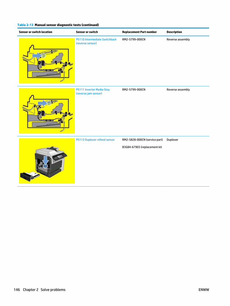
Table 2-13 Manual sensor diagnostic tests (continued)
Sensor or switch location Sensor or switch Replacement Part number Description
PS110 Intermediate Switchback(reverse sensor)
RM2-5799-000CN Reverse assembly
PS111 Inverter Media Stay(reverse jam sensor)
RM2-5799-000CN Reverse assembly
PS113 Duplexer refeed sensor RM2-5828-000CN (service part)
B3G84-67903 (replacement kit
Duplexer
146 Chapter 2 Solve problems ENWW

Table 2-13 Manual sensor diagnostic tests (continued)
Sensor or switch location Sensor or switch Replacement Part number Description
PS112 Output sensor (deliverysensor)
RM2-5799-000CN Reverse assembly
PS104 Output bin full sensor Not orderable NA
ENWW Tools for troubleshooting 147
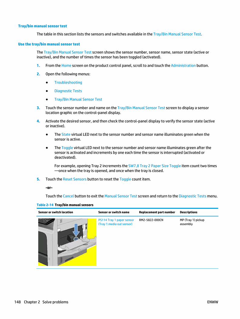
Tray/bin manual sensor test
The table in this section lists the sensors and switches available in the Tray/Bin Manual Sensor Test.
Use the tray/bin manual sensor test
The Tray/Bin Manual Sensor Test screen shows the sensor number, sensor name, sensor state (active orinactive), and the number of times the sensor has been toggled (activated).
1. From the Home screen on the product control panel, scroll to and touch the Administration button.
2. Open the following menus:
● Troubleshooting
● Diagnostic Tests
● Tray/Bin Manual Sensor Test
3. Touch the sensor number and name on the Tray/Bin Manual Sensor Test screen to display a sensorlocation graphic on the control-panel display.
4. Activate the desired sensor, and then check the control-panel display to verify the sensor state (activeor inactive).
● The State virtual LED next to the sensor number and sensor name illuminates green when thesensor is active.
● The Toggle virtual LED next to the sensor number and sensor name illuminates green after thesensor is activated and increments by one each time the sensor is interrupted (activated ordeactivated).
For example, opening Tray 2 increments the SW7,8 Tray 2 Paper Size Toggle item count two times—once when the tray is opened, and once when the tray is closed.
5. Touch the Reset Sensors button to reset the Toggle count item.
-or-
Touch the Cancel button to exit the Manual Sensor Test screen and return to the Diagnostic Tests menu.
Table 2-14 Tray/bin manual sensors
Sensor or switch location Sensor or switch name Replacement part number Descriptions
PS114 Tray 1 paper sensor(Tray 1 media out sensor)
RM2-5822-000CN MP (Tray 1) pickupassembly
148 Chapter 2 Solve problems ENWW

Table 2-14 Tray/bin manual sensors (continued)
Sensor or switch location Sensor or switch name Replacement part number Descriptions
PS101 Tray 2 paper sensor(Tray 2 media out sensor)
RM1-5919-000CN Paper pickup assembly
PS107, PS907 Tray 2 papersurface (Tray 2 media stacksurface sensor 1 and Tray 2media stack surface sensor2)
RM1-5919-000CN Paper pickup assembly
SW102 Tray 2 paper size RM1-7179-000CN Size detect cable
PS104 Output bin fullsensor
Not orderable NA
ENWW Tools for troubleshooting 149

Print/stop test
Use this diagnostic test to isolate the cause of problems such as image-formation defects and jams withinthe engine. During this test, stop the paper anywhere along the product paper path. The test can beprogrammed to stop printing internal pages or an external print job when the paper reaches a certainposition. The test can also be programmed to stop from 0 to 60,000 ms. If the timer is set to a value that isgreater than the job-print time, the product can recover in one of two ways.
1. From the Home screen on the product control panel, scroll to and touch the Administration button.
2. Open the following menus:
● Troubleshooting
● Diagnostic Tests
● Print/Stop Test
3. Enter a range, and then touch the OK button.
● After the print job is completed press OK button to return to the Troubleshooting menu before the timertimes out.
● After the timer times out, touch the Stop button. Activate the door switch to restart the engine andreturn it to a normal state.
NOTE: Do not try to perform a print/stop test while the product is calibrating, because restarting theproduct might be necessary. If a jam message displays on the control panel during testing, activate the topcover switch.
Component tests
Use the procedure below to test various product mechanical and electromechanical assemblies.
Component test (special-mode test)
This test activates individual parts independently to isolate problems.
Each component test can be performed once or repeatedly. If the Repeat option is enabled from the drop-down menu, the test cycles the component on and off. This process continues for two minutes, and then thetest terminates.
NOTE: The front or side door interlocks must be defeated to run the component tests. Some tests mightrequire that the ITB and toner cartridges be removed. A control-panel display prompt appears indicateremoving some, or all of the cartridges, during certain tests.
1. From the Home screen on the product control panel, scroll to and touch the Administration button.
2. Open the following menus:
● Troubleshooting
● Diagnostic Tests
● Component Test
3. Select the component test options for the test.
150 Chapter 2 Solve problems ENWW

Table 2-15 Component test details
Component test Item tested Replacement part number Comments
Feed motor M101 RM2-5942-000CN
Feed motor assembly
Activates the specified motor for 10 seconds.
Drum motor M102 RM1-8358-000CN
Drum motor assembly
Activates the specified motor at a specificspeed for 10 seconds.
Fuser motor M299 RM1-5051-020CN
Fixing motor assembly
Activates the specified motor for 10 seconds.
Cassette lifter motor M103 RM1-5914-000CN
Lifter assembly
Activates the specified motor for 10 seconds.
Merge motor M104 RM2-5942-000CN
Merge motor assembly
Activates the specified motor for 10 seconds.
Intermediate switchbackmotor (reverse motor)
M105 RM2-5799-000CN
Reverse assembly
Activates the specified motor for 10 seconds.
Duplexer Reverse Motor M107 RM2-5828-000CN (service part)
B3G84-67903 (replacement kit
Duplexer
Activates the specified motor at a specificspeed for 10 seconds.
Output motor (deliverymotor)
M106 RM2-5799-000CN
Reverse assembly
Activates the specified motor at a specificspeed for 10 seconds.
Duplex Refeed Motor M107 RM2-5828-000CN (service part)
B3G84-67903 (replacement kit
Duplexer
Activates the specified motor at a specificspeed for 10 seconds.
Tray 1 Pickup Solenoid SL102 RM2-5822-000CN
MP (Tray 1) pickup assembly
Activates the specified solenoid for 10 seconds.
Activates the specified items at a specific speedfor 10 seconds.
Tray 2 Pickup Solenoid SL101 RM1-5919-000CN
Paper pickup assembly
Activates the specified solenoid for 10 seconds.
Feed Roller Clutch CL101 RM1-8411-010CN
Paper feed roller assembly
Activates the specified clutch for 10 seconds.
Face-Up Face-Downsolenoid
SL105 RM2-5799-000CN
Reverse assembly
Activates the specified solenoid for 10 seconds.
Switchback (reverse)Alienation Solenoid
SL106 RM2-5799-000CN
Reverse assembly
Activates the specified solenoid for 10 seconds.
ENWW Tools for troubleshooting 151

Table 2-15 Component test details (continued)
Component test Item tested Replacement part number Comments
Laser Scanner Motor M108 RM1-8406-000CN
Laser scanner assembly
Activates the specified motor for 10 seconds.
Repeat Not applicable Not applicable Choose Off to execute the test once.
Choose On to execute the test continuously.
152 Chapter 2 Solve problems ENWW

Scanner tests
Use these diagnostic tests to manually test the document feeder and scanner sensors.
Scanner tests
This section lists the sensors available in the Scanner Tests.
Document feeder and image scanner sensor replacement parts
If a document feeder or image scanner sensor fails, replace the following assemblies:
● Document feeder sensors
◦ Document feeder whole unit kit; B3G86-67901
NOTE: Includes the white foam backing kit.
◦ Image scanner whole unit kit; B3G86-67905
NOTE: Includes the white foam backingkit.
Use the scanner tests
The Scanner Tests screen shows the sensor name, sensor state (active or inactive), and the number of timesthe sensor has been toggled (activated).
1. From the Home screen on the product control panel, scroll to and touch the Administration button.
2. Open the following menus:
● Troubleshooting
● Diagnostic Tests
● Scanner Tests
● Sensors
3. Touch the sensor name on the Scanner Tests screen to display a sensor location graphic on the control-panel display.
4. Activate the desired sensor, and then check the control-panel display to verify the sensor state (activeor inactive).
● The State virtual LED next to the sensor number and sensor name illuminates green when thesensor is active.
● The Toggle virtual LED next to the sensor number and sensor name illuminates green after thesensor is activated and increments by one each time the sensor is interrupted (activated ordeactivated).
For example, opening the flatbed cover increments the Flatbed cover Toggle item count two times—once when the door is opened, and once when the door is closed.
5. Touch the Reset Sensors button to reset the Toggle count item.
-or-
ENWW Tools for troubleshooting 153

Touch the Cancel button to exit the Scanner Tests screen, and then touch the Cancel button again toreturn to the Diagnostic Tests menu.
Scanner tests sensors
● ADF paper present
● ADF Y (length)
● ADF jam cover
● ADF paper path deskew
● ADF paper path pick success
● Paper path sensor 1(unreachable)
● Paper path sensor 2 (unreachable)
● Flatbed Y (length)
● Flatbed cover
154 Chapter 2 Solve problems ENWW

DiagramsUse the diagrams in this section to identify product components.
Block diagrams
Sensors
Sensors (product base)
Figure 2-26 Sensors (product base)
Table 2-16 Sensors (product base)
Sensor Description Sensor Description
PS101 Cassette media out sensor PS111 Switchback jam sensor
PS102 Pre-feed sensor PS112 Delivery sensor
PS103 TOP sensor PS113 Duplex re-pickup sensor
PS104 Output-bin media-full sensor PS114 MP tray media-out sensor
PS106 Media width 1 sensor PS115 Cartridge sensor
PS107 Cassette media stack surface 1 sensor PS699 Fuser pressure release sensor
PS108 Media width 2 sensor PS700 Fuser output sensor
PS109 Duplex side registration sensor PS907 Cassette media stack surface 2 sensor
PS110 Switchback sensor
ENWW Tools for troubleshooting 155

Sensors (1x500-sheet paper feeder and 1x500-sheet paper feeder with cabinet)
NOTE: The diagram shows the 1x500-sheet paper feeder with cabinet. The sensors are the same for the1x500-sheet paper feeder.
Figure 2-27 Sensors (1x500-sheet paper feeder and 1x500-sheet paper feeder with cabinet)
SL1
SR4
SW2
M2
M1
Pickup arm
SR3SR1
SR2
Table 2-17 Sensors (1x500-sheet paper feeder and 1x500-sheet paper feeder with cabinet)
Sensor Description
SR1 Tray 3 paper surface sensor 1
SR2 Tray 3 paper surface sensor 2
SR3 Tray 3 paper presence sensor
SR4 Tray 3 paper present sensor
SW2 Tray 3 paper size switches
156 Chapter 2 Solve problems ENWW

Sensors (2,500-sheet high-capacity feeder) (HCI)
Figure 2-28 Sensors (2,500-sheet high-capacity feeder) (HCI)
M1
M3
M4
SL1
SL2
SL3
M101
SW2
SR4
SR8
SR12
SR1, SR2, SR3
SR5, SR6, SR7
SR9SR10SR11
SW3
SW4
Tray
Wire
Pulley
Lifting plate
Tray 3
Tray 4
Tray 5
Lifter
Lifter
Table 2-18 Sensors (2,500-sheet high-capacity feeder) (HCI)
Sensor Description Sensor Description
SW1 Right door open detection switch SR5 Tray 4 media stack surface sensor 1
SW2 Tray 3 media size switch SR6 Tray 4 media stack surface sensor 2
SW3 Tray 4 media size switch SR7 Tray 4 media out sensor
SW4 Tray 5media size switch SR8 Tray 4 media feed sensor
SR1 Tray 3 media stack surface sensor 1 SR9 Tray 5 media stack surface sensor 1
SR2 Tray 3media stack surface sensor 2 SR10 Tray 5 media stack surface sensor 2
SR3 Tray 3 media out sensor SR11 Tray 5 media out sensor
SR4 Tray 3media feed sensor SR12 Tray 5 media feed sensor
ENWW Tools for troubleshooting 157

Sensors (stapling mailbox)
Figure 2-29 Sensors (SSMBM)
SR1
SR5
SR2
Table 2-19 Sensors (SSMBM)
Sensor Description
SR1 Output bin 3 delivery sensor
SR2 Staple stacker multi-bin mailbox media feed sensor 1
SR5 Staple stacker multi-bin mailbox media feed sensor 2
158 Chapter 2 Solve problems ENWW

Switches (product base)
Figure 2-30 Switches (product base)
Table 2-20 Switches (product base)
Item Description Item Description
SW1 Power switch SW104 Output accessory detection switch
SW101 Interlock switch SW105 Cassette door-open-detection switch
SW102 Cassette media size switch SW700 Test-print switch
SW103 Face-up bin detection switch
ENWW Tools for troubleshooting 159

Solenoids (product base)
Figure 2-31 Solenoids (product base)
Table 2-21 Solenoids (product base)
Item Description
SL101 Cassette pickup solenoid
SL102 MP tray pickup solenoidh
SL105 Face-up solenoid
SL106 Switchback roller disengagement solenoid
160 Chapter 2 Solve problems ENWW

Clutch (product base)
Figure 2-32 Clutch (product base)
Table 2-22 Clutch (product base)
Item Description
CL101 Media feed clutch
ENWW Tools for troubleshooting 161

Motors
Motors (product base)
Figure 2-33 Motors (product base)M104
M106M105
M101
M102
M299
M103
M107M108
Table 2-23 Motors (product base)
Item Component Component driven
M101 Feed motor Cassette pickup roller, MP tray pickup roller, feed roller and rollers for the inputaccessory
M102 Drum motor Photosensitive drum, primary charging roller and transfer roller
M103 Cassette lifter motor Lifter for the cassette
M104 Intermediate switchbackmotor
Intermediate switchback roller
M105 Switchback motor Switchback roller
M106 Delivery motor Intermediate feed roller and delivery roller
M107 Duplex re-pickup motor Duplex feed roller
M108 Laser/scanner motor Scanner mirror
M299 Fuser motor Pressure roller and fuser delivery roller Pressurizes or releases the pressureroller
162 Chapter 2 Solve problems ENWW

Motors (1 x 500-sheet paper feeder)
Figure 2-34 Motors (1 x 500-sheet paper feeder)
M1
Table 2-24 Motors (1 x 500-sheet paper feeder)
Item Component Component driven
M1 Paper feeder cassette liftermotor
Lifter of the paper feeder cassette
Motors (1x500-sheet paper deck with cabinet)
Figure 2-35 Motors (1x500-sheet paper feeder)
M1
Table 2-25 Motors (1x500-sheet and 3 x 500-sheet paper deck)
Item Component Component driven
M1 Paper feeder Tray 3 liftermotor
Lifter of the paper feeder Tray 3
ENWW Tools for troubleshooting 163

Motors (2,500-sheet high-capacity feeder) (HCI)
Figure 2-36 Motors (2,500-sheet high-capacity feeder) (HCI)
M1
M3
M4
SL1
SL2
SL3
M101
SW2
SR4
SR8
SR12
SR1, SR2, SR3
SR5, SR6, SR7
SR9SR10SR11
SW3
SW4
Tray
Wire
Pulley
Lifting plate
Tray 3
Tray 4
Tray 5
Lifter
Lifter
Table 2-26 Motors (1x500-sheet and 3 x 500-sheet paper deck)
Item Component Component driven
M1 Paper feeder Tray 3 liftermotor
Lifter of the paper feeder Tray 3
M2 Paper feeder Tray 4 liftermotor
Lifter of the paper feeder Tray 4
M3 Paper feeder Tray 5liftermotor
Lifter of the paper feeder Tray 5
164 Chapter 2 Solve problems ENWW

Motors (stapling mailbox)
Figure 2-37 Motors (SSMBM)
M1
M5
M4
M3
M6
Table 2-27 Motors (SSMBM)
Item Component Component driven
M1 Stapler motor Stapler
M3 Jogger motor Jogger guide
M4 Paddle motor Alignment roller
Dis/engagement of the alignment roller
Dis/engagement of the output bin 3 upper delivery roller
M5 Staple stacker multi-binmailbox feed motor
Staple stacker multi-bin mailbox feed roller, staple stacker multi-bin mailboxdelivery roller, output bin 3 upper delivery roller and output bin 3 lower deliveryroller
M6 Staple stacker multi-binmailbox lifter motor
Output bin 3
ENWW Tools for troubleshooting 165

Fans (product base)
Figure 2-38 Fans (product base)
FN105
FN101
FN301FN104
FN102
FN103
FN107
Table 2-28 Fans (product base)
Item Component Cooling area Type Speed
FN101 Main fan Cartridge area, engine power supply area and laser/scanner area Intake Full/half
FN102 Laser/scannerfan
Laser/scanner area Intake Full
FN103 Cartridge frontside fan
Cartridge area Intake Full
FN104 Low-voltagepower supplyfan
Low-voltage power supply area Intake Full/half
FN105 Switchback fan Switchback area Intake Full
FN107 Duplex fan Duplex feed area Intake Full
FN301 Cartridge fan Cartridge area Intake Full
166 Chapter 2 Solve problems ENWW
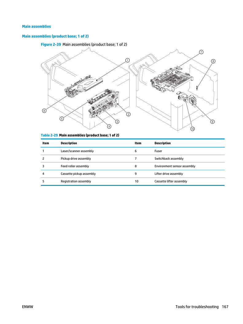
Main assemblies
Main assemblies (product base; 1 of 2)
Figure 2-39 Main assemblies (product base; 1 of 2)
1
2
3
4
5
6
7
8
10
9
Table 2-29 Main assemblies (product base; 1 of 2)
Item Description Item Description
1 Laser/scanner assembly 6 Fuser
2 Pickup drive assembly 7 Switchback assembly
3 Feed roller assembly 8 Environment sensor assembly
4 Cassette pickup assembly 9 Lifter drive assembly
5 Registration assembly 10 Cassette lifter assembly
ENWW Tools for troubleshooting 167

Main assemblies (product base; 2 of 2)
Figure 2-40 Main assemblies (product base; 2 of 2)
1112
13
14
Table 2-30 Main assemblies (product base; 2 of 2)
Item Description Item Description
11 Laser/scanner assembly 13 Fuser
12 Pickup drive assembly 14 Switchback assembly
168 Chapter 2 Solve problems ENWW

Main assemblies (1x500-sheet paper feeder)
Figure 2-41 Main assemblies (1x500-sheet paper feeder)
Table 2-31 Main assemblies (1 x 500-sheet paper feeder)
Item Description Item Description
1 Paper feeder controller PCA 5 Paper feeder feed roller
2 Paper feeder pickup assembly 6 Paper feeder separation roller
3 Paper feeder lifter assembly 7 Paper feeder pickup roller
4 Paper feeder lifter drive assembly
ENWW Tools for troubleshooting 169

Main assemblies (1x500-sheet paper feeder with cabinet)
Figure 2-42 Main assemblies (1x 500-sheet paper feeder with cabinet)
Table 2-32 Main assemblies (1x500-sheet paper feeder with cabinet)
Item Description Item Description
1 Paper deck lifter drive assembly 5 Paper deck cassette pickup roller
2 Paper deck cassette feed roller 6 Paper deck pickup assembly
3 Paper deck cassette separation roller 7 Paper deck controller PCA
4 Paper deck lifter assembly
170 Chapter 2 Solve problems ENWW

Main assemblies (2,500-sheet high-capacity feeder) (HCI)
Figure 2-43 Main assemblies (2,500-sheet high-capacity feeder) (HCI)
Table 2-33 Main assemblies (2,500-sheet high-capacity feeder) (HCI)
Item Description Item Description
1 Tray 3 pickup assembly 5 Tray 4 lifter drive assembly
2 Tray 4 pickup assembly 6 Tray 5 lifter drive assembly
3 Tray 5 pickup assembly 7 Tray 4 lifter assembly
4 Tray 3 lifter drive assembly 8 Tray 5 lifter assembly
ENWW Tools for troubleshooting 171

Main assemblies (stapling mailbox; 1 of 2)
Figure 2-44 Main assemblies (SSMBM; 1 of 2)
Table 2-34 Main assemblies (SSMBM; 1 of 2)
Item Description Item Description
1 Jogger assembly 5 Output bin solenoid
2 Paddle motor 6 Stage top assembly
3 Staple stacker multi-bin mailbox feed motor 7 Inlet solenoid
4 Output bin 3 drive assembly
172 Chapter 2 Solve problems ENWW

Main assemblies (stapling mailbox; 2 of 2)
Figure 2-45 Main assemblies (SSMBM; 2 of 2)
Table 2-35 Main assemblies (SSMBM; 2 of 2)
Item Description
1 Output bin sensor PCA
2 Stage assembly
3 Multi-bin mailbox output bin assembly
4 Staple stacker multi-bin mailbox controller PCA
5 Stamp solenoid
6 Stapler assembly
ENWW Tools for troubleshooting 173

Main PCAs (product base)
Figure 2-46 Main PCAs (product base)
Table 2-36 Main PCAs (product base)
Item Description Item Description
1 Low-voltage power supply assembly 4 Engine power supply assembly
2 Interconnect board (ICB) 5 Switchback connector PCA
3 DC controller 6 Duplex connector PCA
174 Chapter 2 Solve problems ENWW

Rollers (product base)
Figure 2-47 Rollers (product base)
Table 2-37 Rollers (product base)
Item Description Item Description
1 MP tray pickup roller 5 Cassette feed roller
2 MP tray feed roller 6 Cassette pickup roller
3 MP tray separation roller 7 Transfer roller
4 Cassette separation roller
ENWW Tools for troubleshooting 175

DC controller connections
Each of the connections on the DC controller PCA is indicated in the following figure.
Figure 2-48 DC controller PCA connectors
Table 2-38 DC controller connectors
Item Description Item Description
J13 Cartridge door open detection switch (SW106) J79 Cartridge front-side fan (FN103)
J40 Merge motor (M104)
Switchback (reverse) motor (M105)
Delivery motor (M106)
J80 Empty
176 Chapter 2 Solve problems ENWW

Table 2-38 DC controller connectors (continued)
Item Description Item Description
J41 Switchback (reverse) jam sensor (PS111)
Face-up solenoid (SL105)
Switchback (reverse) roller disengagement solenoid(SL106)
Switchback (reverse) sensor (PS110)
Delivery sensor (PS112)
J81 MP (Tray 1) media out switch (PS114)
J42 Environmental sensor (TH3)
LVPS fan (FN104)
J82 Fuser pressure release sensor (PS699)
Fuser output sensor (PS700)
Main thermistor (TH1)
Sub thermistor (TH2)
J43 Face up bin detection switch (SW103)
Switchback fan (FN105)
J83 Envelope feeder
J45 Image scanner assembly J84 Duplex repick motor (M107)
Duplex Fan (FN107)
Duplex side registration sensor (PS109)
Duplex repick sensor (PS113)
J50 Cartridge sensor (PS115) J85 HVPS
J51 Output accessory detection switch (SW104) J86 Scanner motor (M108)
J53 LVPS J87 Drum motor (M102)
J54 LVPS J88 Paper feeder or HCI
J59 Empty J89 Fuser motor (M299)
J71 MP (Tray 1) pickup solenoid (SL102) J90 Stapling mailbox
J72 Cassette (Tray 2) media size switch (SW102) J91 Feed motor (M101)
J73 Cassette (Tray 2) lifter motor (M103) J92 Cassette (Tray 2) pickup solenoid (SL101)
Cassette (Tray 2) media out sensor (PS101)
Cassette (Tray 2) media stack surface 1 sensor(PS107)
Cassette (Tray 2) media stack surface 2 sensor(PS907)
J74 Memory tag (E-label; TG101) J93 Laser scanner
ENWW Tools for troubleshooting 177

Table 2-38 DC controller connectors (continued)
Item Description Item Description
J75 Laser scanner fan (FN102) J94 Prefeed sensor (PS102)
TOP sensor (PS103)
Media width sensor 1 (PS106)
Media width sensor 2 (PS108)
Power switch (SW1061)
Cassette (Tray 2) door open switch (SW105)
J76 Output bin full sensor (PS104) J95 HVPS
J77 Media feed clutch (CL101) J96 HVPS
J78 Interlock switch (SW101) J97 ICB
Scanner controller board (SBC) connectors
Figure 2-49 Scanner controller board (SCB) connectors
56
1 2 3
4
7
Table 2-39 Scanner controller board (SCB) connectors
Item Description Item Description
1 Document feeder sensors 5 Image scanner (A4)
2 Document feeder motors 6 Backside background selector
3 Document feeder 7 Formatter
4 Power (LVPS)
178 Chapter 2 Solve problems ENWW
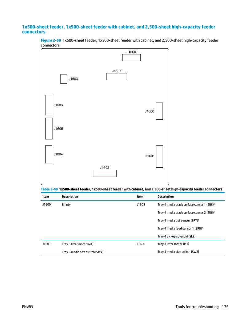
1x500-sheet feeder, 1x500-sheet feeder with cabinet, and 2,500-sheet high-capacity feederconnectors
Figure 2-50 1x500-sheet feeder, 1x500-sheet feeder with cabinet, and 2,500-sheet high-capacity feederconnectors
Table 2-40 1x500-sheet feeder, 1x500-sheet feeder with cabinet, and 2,500-sheet high-capacity feeder connectors
Item Description Item Description
J1600 Empty J1605 Tray 4 media stack surface sensor 1 (SR5)1
Tray 4 media stack surface sensor 2 (SR6)1
Tray 4 media out sensor (SR7)1
Tray 4 media feed sensor 1 (SR8)1
Tray 4 pickup solenoid (SL2)1
J1601 Tray 5 lifter motor (M4)1
Tray 5 media size switch (SW4)1
J1606 Tray 3 lifter motor (M1)
Tray 3 media size switch (SW2)
ENWW Tools for troubleshooting 179

Table 2-40 1x500-sheet feeder, 1x500-sheet feeder with cabinet, and 2,500-sheet high-capacity feeder connectors(continued)
Item Description Item Description
J1602 Tray 5 media stack surface sensor 1 (SR9)1
Tray 5 media stack surface sensor 2 (SR10)1
Tray 5 media out sensor (SR11)1
Tray 5 media feed sensor 1 (SR12)1
Tray 5 pickup solenoid (SL3)1
J1607 Tray 3 media stack surface sensor 1 (SR1)
Tray 3 media stack surface sensor 2 (SR2)
Tray 3 media out sensor (SR3)1
Tray 3 media feed sensor 1 (SR4)
Tray 3 pickup solenoid (SL1)
J1603 Right door open detection switch (SW1)1 J1608 DC controller PCA
J1604 Tray 4 lifter motor (M3)1
Tray 4 media size switch (SW3)1
1 2,500-sheet high-capacity feeder (HCI) only.
Stapling mailbox connectors
Figure 2-51 Stapling mailbox connectors
Table 2-41 Stapling mailbox connectors
Item Description Item Description
J450 DC controller PCA J459 Jogger motor (M3)
J451 Output bin 3 delivery sensor (SR1)
Stapling mailbox media feed sensor 1 (SR2)
J460 Empty
J452 Output bin 1 media presence sensor (PS2501)
Output bin 2 media-full sensor (PS2502)
Output bin 2 media presence sensor (PS2503)
Output bin 1 media-full sensor (PS2504)
J461 Stapling mailbox feed motor (M5)
180 Chapter 2 Solve problems ENWW

Table 2-41 Stapling mailbox connectors (continued)
Item Description Item Description
J453 Output bin 3 media-full sensor (SR3)
Alignment roller sensor (SR4)
SSMBM media feed sensor 2 (SR5)
Jogger sensor (SR6)
Output bin 3 upper delivery roller sensor (SR7)
J462 Stamp solenoid (SL1)
Inlet solenoid (SL2)
J454 Output bin 3 upper limit sensor (PS2601)
Output bin 3 lower limit sensor (PS2602)
J463 Stapler sensor (PH011)
Staple out sensor (PH013)
Staple ready sensor (PH012)
J455 SSMBM lifter motor (M6) J464 Stapler motor (M1)
J456 Output bin solenoid (SL3) J465 SSMBM door open detection switch (SW1)
J458 Paddle motor (M4)
ENWW Tools for troubleshooting 181

General timing chart
Figure 2-52 General timing chart (1 of 2)
4TO
P si
gnal
(/TO
P)
2Pr
int r
eser
vatio
n co
mm
and
(EEC
50)
3Pr
int s
tart
com
man
d (E
EC12
)
YBTSRTSL
TNI
RPRT
NITIA
Wnoitarep
O
1In
itial
ize
cont
rol c
omm
and
(EEC
52)
STBY
Pow
er s
witc
h O
N
10Fe
ed m
otor
(M10
1)
11M
edia
feed
clu
tch
(CL1
01)
12C
asse
ttepi
ckup
sole
noid
(SL1
01)
7Fu
ser h
eate
r (H
1/H
2)
8Fu
ser m
otor
(M29
9)
9D
rum
mot
or (M
102)
5Sc
anne
r mot
or (M
108)
6La
ser
Pow
er s
witc
h O
N
19D
eliv
ery
sens
or (P
S112
)
16Fu
ser o
utpu
t sen
sor (
PS
700)
17Sw
itchb
ack
sens
or (P
S110
)
18Sw
itchb
ack
jam
sen
sor (
PS11
1)
13Pr
e-fe
ed s
enso
r (P
S102
)
14TO
P se
nsor
(PS
103)
15M
edia
wid
th s
enso
r 1/2
(PS1
06/P
S108
)
12C
asse
tte p
icku
p so
leno
id (S
L101
)
Pow
er s
witc
h O
N
25Sw
itchb
ack
mot
or (M
105)
22Fa
ce-u
p so
leno
id (S
L105
)
23Sw
itchb
ack
rolle
r dis
enga
gem
ent
sole
noid
(SL1
06)
24In
term
edia
te s
witc
hbac
k m
otor
(M10
4)
20M
EDIA
DEL
IVER
Y si
gnal
(/EN
G_P
DLV
)
21SP
EED
UP
sign
al (S
PD_U
P)Pow
er s
witc
h O
N
182 Chapter 2 Solve problems ENWW

Figure 2-53 General timing chart (2 of 2)
YBTSRTSL
TNI
RPRT
NITIA
Wnoitarep
OST
BY
Pow
er s
witc
h O
N
28Pr
imar
y ch
argi
ng b
ias
(DC
)
29D
evel
opin
g bi
as
26D
eliv
ery
mot
or (M
106)
27Pr
imar
y ch
argi
ng b
ias
(AC
)
37D
uple
xfa
n(F
N10
7)
34C
artri
dge
front
sid
e fa
n (F
N10
3)
35Lo
w-v
olta
ge p
ower
sup
ply
fan
(FN
104)
36Sw
itchb
ack
fan
(FN
105)
31Fu
ser b
ias
32M
ain
fan
(FN
101)
33La
ser s
cann
er fa
n (F
N10
2)
30Tr
ansf
er c
harg
ing
bias
4037D
uple
x fa
n (F
N10
7)
38C
artri
dge
fan
(FN
301)
39
ENWW Tools for troubleshooting 183

General circuit diagrams
Figure 2-54 General circuit diagram (product base) (1 of 2)
A
65
43
21
BCD
FSRSAFE
FPRSNS
FSRTH2
FSRTHG2
/RLD
/ZEROX
CURRMS
PFC-Z_PWRRMT
CURDIS
FSRD1
FSRD2
ENG_TEST
J53
J92
/CSTSNS
GND
/PLVLSNS
/PLVL2SNS
24VA
/CSTSL
NC
3.3VB
/CSTSIZE1
GND
/CSTSIZE0
/CSTSIZE2
J72
/LMON
24VA
J73
M10
3
J73D
HJ7
3D J73L
SW
102
J120
LHJ1
20L
J120
D
J122
PS
101
PS
907
PS
107
SL1
01
J92L
HJ9
2LJ7
2LH
J72LJ72D
PS
108
PS
106
J112
J108
J138
SW
105
PS
103
J111
J228
PS
102
SW
PC
A
J106
1
J123
J80
GND
MD2
MD0
IOTTXD
IOTRXD
+3.3V
J89
M29
9
J221
J187
M10
2
GND
J91
J87
M10
1
SL1
02SW
106
J71
J13
J74
PS
115
PS
114
J884
J76
J50
PS
104
J176
J81
CL1
01
J92D
J82
J3
J54
J4J5
HEATERC
HEATER1
HEATER2
J11
J10
FPR
SN
S
GN
D
FPR
SN
SD
R
FSR
THG
2
FSR
TH2
J62
J128
DD
W
J128
LDW
J134
M
J613
4FJ613
5
J66
J64
FN10
1
FN30
1
MFLK
GND
GND
NC
DF2DR
MFDRV
3RDFLK
100V
200V
J30
TB01
20
TB01
21
TB12
0
TB12
1
J95
FN10
4
FN10
3FN
102
FN10
5
SW
103
J128
J142
3DH
J142
3DJ1
423L
J43
J79
J75
TH1
TH2
J778
LJ1
31L
J131
DH
J131
D
J929
PS
699
PS
700
J778
DJ7
78D
H
WIDTHDR
GND
/WIDTHSNS
TOPDR
GND
/TOPSNS
WIDTH2DR
GND
/WIDTH2SNS
PREDR
GND
/PRESNS
GND
CSTDRSNS
3.3VA
LED
GND
/SOFTSWSNS
DCDCOVP
PWR_SAVE
3.3VB
GND
24VB
GND
GND
GND
CRGDR
CRGSNS
GND
FULDR
FULSNS
GND
24VB
PRDCPWM
DVACPWM
DVDCPWM
PRACCK
PRACPWM
HVTCK
TRNCK
PRDCCK
TRAD
TRPWM
TRPCK
TNRSP1
TNRSP2
24VB
GND
MPDR
/MPSNS
DVACCLK
GND
GND
24VA
24VA
J85
GN
D
GN
D
RE
VFD
R
RE
VFL
K
FUTR
AY
SN
S
NC
J78
MFL
K
DF2
DR
3RD
FLK
/AC
200
3.3V
B
MFD
RV
LPR
OTE
CT
GN
D
PS
RE
M24
V
GN
D
J96
J31
TB31
TB32
TB33
TB34
GND
/BDI
GND
/SMACC
/SMDEC
24VA
3.3VB
GND
DELARI
J51S
W10
4
J161
ENVTMPG
CNT2
CNT1
CNT0
PDOUT
NC
LPPWM
LPUFLK
ENVTMP
+3.3VB
GND
NC
LPUFDR
VDO1
/VDO1
VDO2
/VDO2
J42
GND
J198 J198DH
J145
J86D
HJ86L
J86D
J144
J143
J01J1
TB1
TB2
PFC
H
PFC
L
PFC
H
PFC
L
J136
FJ1
36M
J128
LBJ1
28LA
J128
LWH
J128
DA
J128
DW
H
J128
DB
J128
FA_B
US
[0:6
]
J128
FB_B
US
[0:6
]
J128
MB
_BU
S[0
:6]
J128
MA
_BU
S[0
:6]
DELSNS
GND
DELDR
FSRTH1GND
FSRTH1
FUSERARI
GND
GND
GND
FMREV
GND
/FMFG
/FMDEC
/FMACC
24VC
24VC
24VC
GND
24VA
24VA
/DMFG
/DMDEC
/DMACC
GND
GND
GND
/MMACC
/MMDEC
/MMFG
24VA
24VA
J191
SW
101
24VA
24VB
2NDFLK
GND
4THFLK
GND
DF2DR
REVFDR
J199
D
J199DH
J93
FILM
BIA
S
KA
ATU
BIA
S
TRG
UID
EB
IAS
MT1
3
FG
J150
INL1
01
P1
J129
J137
H1
H2
TB61
81
2
211
2
1 2
21
11
CO
ILA
CO
ILB
TG10
1
213
24V
A NC
/TR
CL
21
3.3V
A
DO
OP
EN
SN
S
/MP
SL
24V
A
J94
Engi
ne p
ower
sup
ply
PCA
(EPU
)
SW
700
TB21
TB23
TB20
J86
TH3
SL
SL
TP
A6
B6
B6
A6
CL
MM
M
M
54
69
1110
87
1213
12
313
1211
109
82
34
56
17
45
67
89
12
310
111110
98
23
45
61
7
12
332
1
43
211
23
4 12
34
56
7 12
34
56
7 12
34
56
7
65
43
21
7
12
34
56
41
23
56
12
3
32
12
13
412
34
32
1
12
321
1 2 3
123
2 112
2 1
1 2 3 4 5
2 5431
23
12
31 2
1
76
53
21
4
12
34
56
78
12
34
56
776
54
32
11
23
45
67
887
12
34
56
12
34
56
78
76
53
21
4
1 2
2 1
12
12
2 1
2 1
1 2
1 21 2 31 2 3
34
56
89
12
107
109
82
34
56
17
98
76
54
32
110
109
82
34
56
17
32
1 12
3 12
3 32
1
32
1 12
3 12
31
23
31
21
23 1
23
12
3
12
34
12
34
21
31
23
32
12
13
21
211
2
1817
1615
1413
1211
109
82
34
56
17
65
34
711
1213
98
101
1415
1617
182
32
1
32
1
32
1
12
121
21
23
45 1
23
45
12
341
23
4
12
341
23
41
23
41
23
45
67
8
27
43
15
68
12
12 1
2 12
21
34
56
7
12
34
56
7
97
810
1112
21
34
56
1211
109
82
34
56
17
56
21
34
12
34
56
98
65
34
710
1112
1314
1516
21
1817
1817
1615
1413
1211
109
82
34
56
17
12
34
23
41
653 42 71 98 10
10982 3 4 5 61 7
10 9 8 23456 17
6 5 34 27 19 810
211
2
32
13
21
32
112
31
23
4
12
34
122
1
21
12
31
23
24
13
12
34
32
1
12
34
56
78
45
67
23
81
12
344
32
11
23
45
6
45
61
23
1 221
212 31
1 2 3
1716
1514
1312
1110
98
76
54
32
118 18
1716
1514
1312
1110
98
23
45
61
7
2 12 1
12
3
23
1
12
32
13
21
32
13
21
3
6
5
4
2
1
1
2
3
4
5
6
12
21
12
2
1
1
5
3
2
6 4
6
4
3
5
12345
12345
12
12
11
56
41
233
21
46
5
21
12
34
65
21
HN1 3
32
1
Low
-vol
tege
pow
er s
uppl
y PC
A (L
PU)
DC
con
trol
ler P
CA
FUSE
R U
NIT
Lase
r PC
A
Sca
nner
mot
or
BD
sen
sor
LASE
R S
CA
NN
ER U
NIT
21
43
SW
1061
21
LED
1061
J77
184 Chapter 2 Solve problems ENWW

Figure 2-55 General circuit diagram (product base) (2 of 2)
A
65
43
21
BCD24VA
24VA
PWRON
GND
GND
CAN-L
CAN-H
SPD_UP
24VA
GND
DELARI
J467
J450
D
DELARI
CAN-H
CAN-L
GND
GND
GND
PWRON
SPD_UP
24VA
24VA
24VA
J90
J106
D
J106
L
J118
D
J118
DA
J118
DB
GND
OPSCLK
OPSIN
OPSOUT
24VA
J40
MJCT_OUT1
MJCT_OUT2
MJCT_OUT3
MJCT_OUT4
MDEL_OUT4
MDEL_OUT3
MDEL_OUT2
MDEL_OUT1
MREV_OUT4
MREV_OUT3
MREV_OUT2
MREV_OUT1
J140
2
J142
1D
J142
1DH
J142
1L
J140
1
J142
0DJ1
420D
H
J142
0L
J41
REVDR
GND
TAIRYUDR
REVSNS
TAIRYUSNS
DEL2DR
DEL2SNS
/FU_SL
/RRS_SL
24VA
24VA
GND
24VA
OP_CLK
OP_STS
OP_CMD
J83
FL_CLK
FL_DATA
FL_MODE
IOT_TXD
GND
IOT_RXD
SUBRST
3.3VB
GND
DUPFDR
GND
PCKSNS
REJISNS
DUPARI
DUPFLK
MDUP_OUT1
MDUP_OUT2
MDUP_OUT3
MDUP_OUT4
N.C.
3.3VB
J84
J156
DJ1
56D
H
J156
L
J154
M10
7FN
107
J159
J142
PS
113
PS
109
GND
PCKSNS
3.3R
REJISNS
GND
3.3R
J153
J152
DU
P P
CA
J151
J151
LA
J151
L
J151
D
J151
LB
J151
DB
J350
4
J59
MREV_OUT1
MREV_OUT2
MREV_OUT3
MREV_OUT4
MJCT_OUT1
MJCT_OUT2
MJCT_OUT3
MJCT_OUT4
MDEL_OUT1
MDEL_OUT2
MDEL_OUT3
MDEL_OUT4
FUSOL
GND
REVSNS
TAIRYUDR
GND
TAIRYUSNS
DEL2DR
GND
DEL2SNS
RESOL
REVDR
24VA
24VA
J140
3
J125
J126
J127
PS
112
PS
111
PS
110
SL1
05S
L106
M10
5M
104
M10
6
J140
6J1
407
J140
8J1
409
J140
5
CA
RD
ED
GE
CO
NN
EC
TOR
164
pin
TB30
3
TB30
4
TB30
2
TB30
1
GN
D
+5V
+5V
GN
D
GN
D
+5V
+5V
GN
D
J350
1
J105
DJ1
05D
BJ1
05D
A
J105
LAJ1
05LB
J160
8
J105
L
CMD
STS
CLK
/OPCSTWAKE
24VA
GND
J45
24VA
GND
OP_CLK
OP_STS
OP_CMD
/OPCSTWAKE
24VAGND
J700
J45D
J45L
J88
J97
J350
8
J350
2
J350
9
J350
6
J350
7
J350
5
J200
2
5VA
GN
D
/VC
RS
ET
WA
KE
EN
G
WA
KE
VC
/TO
P
GN
D
CLE
O
CLE
I
GN
D
/BD
O
GN
D
GN
D
CA
N-L
CA
N-H
GN
D
PW
RO
N
EN
G_T
ES
T
5VC
CTR
L
3.3V
A
5VA
VD
O1
/VD
O1
/VD
O2
VD
O2
Sid
eBan
d
US
B
A ty
pe
4pin
US
B C
AB
LE
Type
A to
min
i B
US
B
(5pi
n)
min
i B
PA
NE
L
HIP
US
B
ICB
Rig
ht k
ey
36pi
n
I-Pas
s
I-Pas
s
36pi
n
Left
key
i-Grid
20pi
n
i-Grid
20pi
n
Rig
ht k
ey
36pi
n
I-Pas
s
Left
key
36pi
n
I-Pas
s
MT1
09FT5
SL
MM
MS
L
M
81
23
45
67
915
1413
1211
10
1514
1312
1110
98
23
45
61
7
65
34
27
19
810
111110
98
23
45
61
7
1110
98
23
45
61
7
65
34
27
19
810
11
12
34
5
12
34
5
J906
1
J905
M
J901
J905
32
14
32
1
12
34
12
3
1
1211
109
82
34
56
17
116
53
42
71
98
1012
54
32
112
34
5
86
53
47
21
98
63
42
710
111
512
131312
1110
98
23
45
61
7
12
34
56
J151
DA
12
34
56
781
23
32
1
32
1
12
341
23
4
12
31
23
12
31
23
32
112
31
23 3
21
54
32
1 12
34
5
12
34
56
12
34
56
78
1110
98
23
45
61
7
65
34
27
19
810
11
1110
98
23
45
61
7
1110
98
23
45
61
7
1211
109
82
34
56
17
1211
109
82
34
56
17
1211
109
82
34
56
17
1112
65
34
27
19
810
1110
98
23
45
61
7
12
34
56
78
910
11
98
23
45
61
7
65
34
27
19
8
32
13
21
32
11
23
12
31
23
12
12
12
34
34
21
12
34
12
34
12
34
34
21
12
34
553
42
1 12
34
211
22
112
1 2 3 4
2 3 41
12
34
56
12
31
23
4
12
31
23
4
12
34
566
53
42
12
112
21 21
2 1
2 1
1210 11 13 14 15 16 17 18 19 20987654321 21 22 23 24 25
2425 23 22 21 20 19 18 17 16 15 14 13 12 11 10 9 8 7 6 5 4 3 2 1
121181 2 3 4 5 6 7 9 10
1210 11987654321
1210 119876543211211101 2 5 987643
Low
-vol
tege
po
wer
sup
ply
PCA
(LPU
)
DC
con
trol
ler P
CA
IMA
GE
SCA
NN
ER
HU
B B
OA
RD
Form
atte
r
Stap
le s
tack
er
mul
ti-bi
n m
ailb
ox
(acc
esso
ry)
Enve
lope
feed
er (a
cces
sory
)
Switc
hbac
k in
term
edia
te P
CA
500-
shee
t pap
er fe
eder
, 1x
500-
shee
t pap
er d
eck
or2,
500-
shee
t pap
er d
eck
(acc
esso
ry)
Dup
lex
unit
ENWW Tools for troubleshooting 185
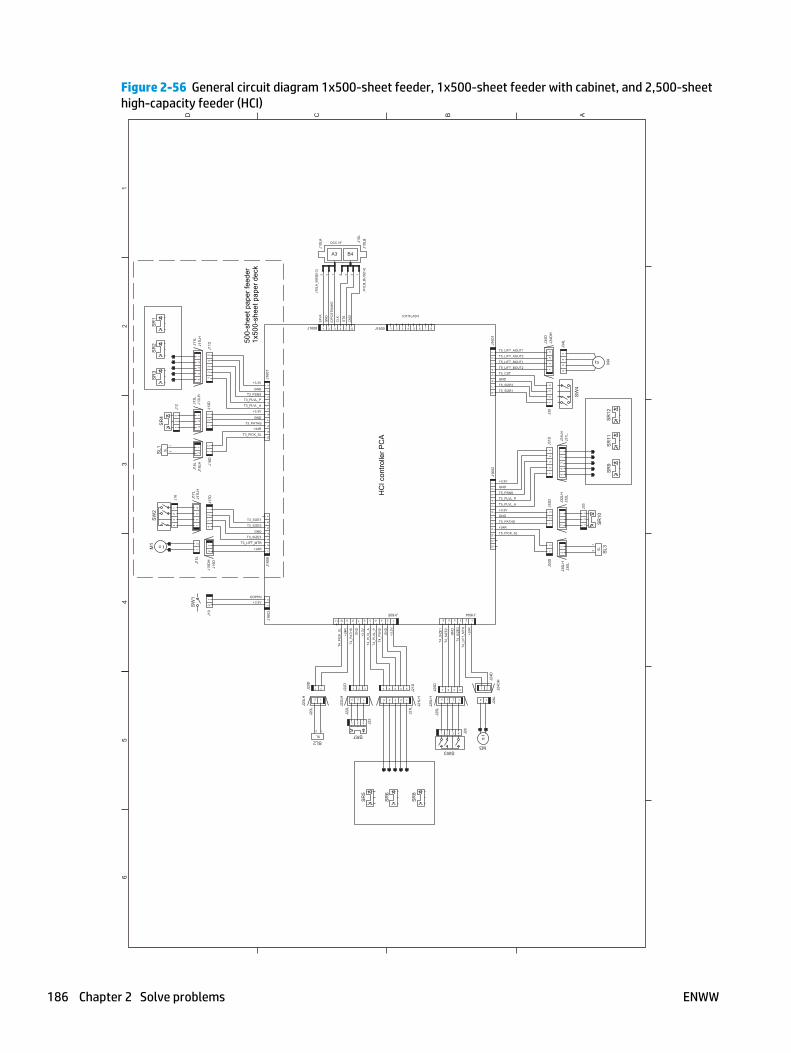
Figure 2-56 General circuit diagram 1x500-sheet feeder, 1x500-sheet feeder with cabinet, and 2,500-sheethigh-capacity feeder (HCI)
A
65
43
21
BCD
J160
3J1
606
+3.3V
DOPEN
J19
J15D
HJ1
5D
T3_SIZE2
GND
T3_SIZE3
T3_LIFT_MTR
+24R
T3_SIZE1
21
12
34
56
7
J15L
12
21
21
34
12
J17L
HJ1
7L
J16
12
J17D
43
43
21
J18L
J18L
H J18D
SL
M
SL
M
SL
M
B4A3
DCC I/F
IOT/FLASH
GND
T3_PSNS
T3_PLVL_P
T3_PLVL_A
GND
T3_PATHS
T4_P
ICK
_SL
T4_P
ATH
S
T4_P
LVL_
A
T4_P
LVL_
P
GN
D
GND
T5_PSNS
T5_PLVL_P
T5_PLVL_A
GND
T5_PATHS
T5_PICK_SL
GND
T5_SIZE2
T5_SIZE1
T5_LIFT_AOUT1
T5_LIFT_AOUT2
T5_LIFT_BOUT1
T5_LIFT_BOUT2
T5_CST
T4_L
IFT_
MTR
T4_S
IZE
3
T4_P
SN
S
GN
D
GN
D
T3_PICK_SL
CLK STS
CM
D
+3.3V
+3.3V
+24R
+3.3
V
+3.3
V
+24R
+24R
+3.3V
+3.3V
+24R
24V
A
GN
D
/OP
CS
TWA
KE
T4_S
IZE
2
T4_S
IZE
1
21
J30D
12
3J3
2D
12
J24L
J21L
H
1 2 3 4 5 J21D
J22L
H
321J22D
1 2J20D
21
12
3J1
3D5
43
21
J11D
12
34
5
J31L
12
J30L
12
12
34
5J1
1L
2 1
J20L
5 4 3 2 1
J21L
21
J24D
123456
J1604
J10L
A J10L
J10L
B
J10L
A_B
US
[0:3
]
1211
109
82
34
56
17
J160
21
23
45
67
8J1
601
1 2 3 4 5 6J1608
109
82
34
56
17
J160
7
J10L
B_B
US
[0:4
]
4 3 2 123 1
12
34
J35
54
32
1J3
1D J31L
H
J20L
H
J11L
H
32
1
J32L
32
1J3
3
J30L
H
123
J22L
1 2 3 J23
J13L
H
J25L
H
J24D
H
J34D
H1
23
4J3
4D
12
34
J34L
11 10 9 8 23456 17
J1605
2 1
4321J25D
1234
J25L
J32L
H
12
1 2 3 4 5 6 7 8J1600
32
1J1
2
32
1J1
3L
1 2 3 4 J26
12
SW
4
M4
SR
11S
R9
SR
12S
L3S
R10
M3SW3
SR
8
SR
6
SR
5
SR7SL2
SW
1
M1
SW
2S
L1S
R4
SR
2S
R3
SR
1
500-
shee
t pap
er fe
eder
1x50
0-sh
eet p
aper
dec
k
HC
I con
trolle
r PC
A
186 Chapter 2 Solve problems ENWW

Figure 2-57 General circuit diagram for the stapling mailbox
A
65
43
21
BCD
SL
SL
MS
L
MM
M
M
J466
DJ4
66D
H
J466
L
GND
+5V
GND
+5V
GND
+5V
GND
+5V
GND
+5V
GND
GND
GND
BIN2_PAP_SNS
BIN2_FULL_SNS
BIN1_PAP_SNS
BIN1_FULL_SNS
+5V
SWNG_HP_SNS
/JOG_HP_SNS
/MBM_IN_SNS
PDL_HP_SNS
/BIN3_FULL_SNS
GND
+5V
EXIT_SNS
GND
+5V
GND
LOWER_LIMIT_SNS
UPPER_LIMIT_SNS
+5V
LIFT_AND
LIFT_AD
+24R
BIN_SL
JOG_BND
JOG_BD
JOG_AND
JOG_AD
PDL_BND
PDL_BD
PDL_AND
PDL_AD
GND
FLASH_ACT1
RCT
+5V
/FLASH_ACT0
FLASH_DAT_IN
FLASH_MD2
FLASH_CLK_IN
/FLASH_MD0
FLASH_DAT_OUT
GND
+24R
STMP_SL
+24R
ENTR_FLP_SL
FD_BND
FD_BD
FD_AND
FD_ADM
TR+
MTR
+
MTR
-
MTR
-
GN
D
ST_
LOW
ST_
RD
Y
ST_
HP
+5V
+24U
+24VA
/ENTR_SNS
12
34
56
78
J452
1 2 3 4
J4541
2J1
20D
J120
DH
12
J119
DJ1
19D
H
12
J119
L1
2J1
20L
12
J455
23 1
J465
12
3
J456
SR
2S
R1
SR
7
SR
6
SR
5
SR
4
SR
3
1 2 3 4
M1
23
41 J459
12345
J463234 1
J464
12
34
J462
1514
1312
1110
98
23
45
61
7J4
53
23
41
23
41
21
M6
12
34M
3
12
34
M4
12
J121
L
12SL3
J121
DH
12
3J1
15
12
J121
D
1110
98
23
45
61
7
J460
12
34
5
J458
12
3J1
14L
12
3
J114
D
12
34
56
78
J490
12
3
J102
23
45
1J4
61
12
3
J111
12
3
J112
12
3
J113
12
34M
5
12
3
J110
12
3
J109
12
34
56
J451
12
SL2
12
SL1
21
SW
1
2 3 41J105
1 2 3 4 5J106
J114
DH
PS
2501
PS
2502
PS
2504
PS
2503
PS
2601
PS
2602
Staple presence sensor
Staple ready sensor
Stapler sensor
GND
GND
+24V
+24V
+24V
GND
CAN-L
PWRON
CAN-H
/SP_UP
DELARI1110
98
23
45
61
7J4
67
SS
MB
M c
ontro
ller P
CA
Sta
ple
ass’
y
To D
C c
ontro
ller P
CA
Cur
l Cab
le
ENWW Tools for troubleshooting 187

Figure 2-58 General circuit diagram for the envelope feeder
A
65
43
21
BCD
M
[IOT]
GND
24V
STS
CMD
CLK
*A
*B
A
B
CPU
GND
3.3V
12
34
M18
00
J185
6
FT18
00
23
45
1
J180
4
4
PS
1800
MT1
800
23
41
J180
2
32
1
PS
1802
12
34
J185
22
31
J185
42
34
1
J185
5
J180
1
12
3J1
850
12
3
J180
012
3
Env
elop
e fe
eder
driv
er P
CA
To D
C c
ontro
ller P
CA
188 Chapter 2 Solve problems ENWW

Internal print-quality test pages
Print quality troubleshooting pages
Use the print quality troubleshooting pages to help diagnose and solve print-quality problems.
NOTE: To get further assistance in print quality troubleshooting, go to www.hp.com/support/ljMFPM630and select PQ Troubleshooting Tools.
1. From the Home screen on the product control panel, scroll to and touch the Administration button.
2. Open the following menus:
● Troubleshooting
● Print Quality Pages
● Print PQ Troubleshooting Page
3. Touch the Print button. The product prints a print-quality troubleshooting procedure page and a blackprint-quality troubleshooting page.
Follow the instructions on the print-quality troubleshooting procedure page.
ENWW Tools for troubleshooting 189

Figure 2-59 Print-quality troubleshooting procedure page
HP LaserJet M630
190 Chapter 2 Solve problems ENWW

Figure 2-60 Black print-quality troubleshooting page
Grids The grids are in inches and millimeters. They are labeled withletters and numbers so that defects can be described by positionand by distance between repeats.
Grey scale ramp patches Used to detect offset for the OPC or developer in the tonercartridge or offset in the fuser.
ENWW Tools for troubleshooting 191

Fuser test page
Use the fuser test page to evaluate problems with fuser print quality.
1. From the Home screen on the product control panel, scroll to and touch the Administration button.
2. Open the following menus:
● Troubleshooting
● Print Quality Pages
● Fuser Test Page
3. Touch the Print button.
192 Chapter 2 Solve problems ENWW

Cleaning page
1. From the Home screen on the product control panel, scroll to and touch the Device Maintenance button.
2. Open the following menus:
● Calibration/Cleaning
● Cleaning Page
3. Touch the Print button to print the page.
4. The cleaning process can take several minutes. When it is finished, discard the printed page.
Enable and configure auto cleaning
Use the procedure in this section to enable and configure the automatic cleaning function.
To enable the auto cleaning function
1. From the Home screen on the product control panel, scroll to and touch the Device Maintenance button.
2. Open the following menus:
● Calibration/Cleaning
● Auto Cleaning
3. Select the Enable item, and then touch the Save button.
To configure the auto cleaning function
1. From the Home screen on the product control panel, scroll to and touch the Device Maintenance button.
2. Open the following menus:
● Calibration/Cleaning
3. Open one the following menus:
● Cleaning Interval
Default setting: 1000 pages
● Auto Cleaning Size
Default setting: Letter
4. After selection an option item, touch the Save button
ENWW Tools for troubleshooting 193

Print configuration page
Up to three pages print when you print a configuration page. In addition to the main configuration page, theHP embedded Jetdirect configuration pages print.
Configuration page
Use the configuration page to view current product settings, to help troubleshoot product problems, or toverify installation of optional accessories, such as memory (DIMMs), paper trays, and product languages.
1. From the Home screen on the product control panel, scroll to and touch the Administration button.
2. Open the following menus:
● Reports
● Configuration/Status Pages
3. Touch Configuration Page to select it.
4. Touch the View button to view the information on the control panel, or touch the Print button to printthe pages.
194 Chapter 2 Solve problems ENWW

Figure 2-61 Configuration page
5
6
1
2
3
4
7
HP LaserJet M630
1 Device information
2 Installed personalities and options
3 HP Web services
4 Memory
5 Event log
6 Security
7 Paper trays and options
ENWW Tools for troubleshooting 195

HP embedded Jetdirect page
The second configuration page is the HP embedded Jetdirect page, which contains the following information:
Always make sure the status line under the general information line indicates: I/O Card Ready.
Figure 2-62 HP embedded Jetdirect page
5
6
1
2
3
4
HP LaserJet M630
1 General Information indicates the product status, model number, hardware firmware version, port select, port configuration,auto negotiation, manufacturing identification, and manufactured date.
2 Security Settings information
3 Network Statistics indicates the total packets received, unicast packets received, bad packets received, framing errorsreceived, total packets transmitted, unsendable packets, transmit collisions, and transmit late collisions.
4 TCP/IP information, including the IP address
5 IPv4 information
6 IPv6 information
196 Chapter 2 Solve problems ENWW

Finding important information on the configuration pages
Certain information, such as the firmware date codes, the IP address, and the email gateways, is especiallyhelpful while servicing the product. This information is on the various configuration pages.
Table 2-42 Important information on the configuration pages
Type of information Specific information Configuration page
Firmware date codes
When you use the remote firmware upgradeprocedure, all of these firmware componentsare upgraded.
DC controller Look on the main configuration page,under “Device Information.”
Firmware datecode Look on the main configuration page,under “Device Information.”
HP embedded Jetdirect firmware version Look on the HP embedded Jetdirectpage, under “General Information.”
Accessories and internal storage
All optional devices that are installed on theproduct should be listed on the mainconfiguration page.
In addition, separate pages print for theoptional paper handling devices and the faxaccessory. These pages list more-detailedinformation for those devices.
Embedded HP Jetdirect Look on the main configuration page,under “Installed Personalities andOptions.” Shows model and ID.
Total RAM Look on the main configuration page,under “Memory.”
Duplex unit Look on the main configuration page,under “Paper Trays and Options.”
Finishing accessories Installed finishing accessory type Look on the main configuration page,under “Paper Trays and Options.”
Engine cycles and event logs
Total page counts and maintenance kit countsare important for ongoing productmaintenance.
The configuration page lists only the threemost recent errors. To see a list of the 50 mostrecent errors, print an event log from theDiagnostics menu.
Engine cycles Look on the main configuration page,under “Device Information.”
Maintenance Kit Interval:
and
Pages Since Last Maintenance:
Number of pages before the productprompts the user to install amaintenance kit.
Number of pages since a maintenancekit was installed.
Look on the main configuration page,under “Device Information.”
Document Feeder Kit Interval:
and
Pages Since Last Doc Feeder Maintenance:
Number of pages before the productprompts the user to install a documentfeeder maintenance kit.
Number of pages since a documentfeeder maintenance kit was installed.
Look on the main configuration page,under “Device Information.”
Event-log information Event-log information Look on the main configuration page,under “Event Log.”
ENWW Tools for troubleshooting 197

Print quality troubleshooting tools
Print quality troubleshooting tools: repetitive defects ruler
Use a ruler to measure occurrences of repetitive image defects to help solve image-quality problems. Placethe ruler next to the first occurrence of the defect on the page. Find the distance between identical defectsand use the table below to identify the component that is causing the defect.
NOTE: Do not use solvents or oils to clean rollers. Instead, rub the roller with lint-free paper. If dirt isdifficult to remove, rub the roller with lint-free paper that has been dampened with water.
Distance between defects Product components that cause the defect
38 mm (1.45 in.) Primary charging roller1
47 mm (1.85 in.) Transfer roller
50 mm (1.97 in.) Feed roller
Pre-registration roller
63 mm (2.48 in.) Tray 1 pickup roller
Developing roller
79 mm (3.11 in.) Tray 1 feed roller
Tray 1 separation roller
Tray 2 pickup roller
Tray 2 feed roller
Tray 2 separation roller
94 mm
94 mm (3.70 in.)
Photosensitive drum (toner cartridge)1
Fuser sleeve assembly
Pressure roller
1 The primary charging roller and photosensitive drum cannot be cleaned because they are internal assemblies in the toner cartridge.If one of these assemblies is causing the defect, replace the toner cartridge.
198 Chapter 2 Solve problems ENWW

Control-panel menus
Administration menu
You can perform basic product setup by using the Administration menu. Use the HP Embedded Web Serverfor more advanced product setup. To open the HP Embedded Web Server, enter the product IP address orhost name in the address bar of a Web browser.
Reports menu
To display: At the product control panel, select the Administration menu, and then select the Reports menu.
Table 2-43 Reports menu
First level Second level Values Description
Configuration/Status Pages Administration Menu Map Print
View
Shows a map of the entireAdministration menu and theselected values for each setting.
Current Settings Page Print
View
Print a summary of the currentsettings for the product. Thismight be helpful if you plan tomake changes and need a recordof the present configuration.
Configuration Page Print
View
Shows the product settings andinstalled accessories.
How to Connect Page Print
View
Shows network connectioninformation.
Supplies Status Page Print
View
Shows the approximate remaininglife for the supplies; reportsstatistics on total number of pagesand jobs processed, serial number,page counts, and maintenanceinformation.
HP provides approximations of theremaining life for the supplies as acustomer convenience. The actualremaining supply levels might bedifferent than the approximationsprovided.
Usage Page Print
View
Shows a count of all paper sizesthat have passed through theproduct; lists whether they weresimplex, duplex, monochrome, orcolor; and reports the page count.
File Directory Page Print
View
Shows the file name and foldername for files that are stored inthe product memory.
Web Services Status Page Print
View
Shows the detected Web Servicesfor the product.
Fax Reports (Fax models only) Fax Activity Log Print
View
Contains a list of the faxes thathave been sent from or received bythis product.
ENWW Tools for troubleshooting 199

Table 2-43 Reports menu (continued)
First level Second level Values Description
Billing Codes Report Print
View
Provides a list of billing codes thathave been used for outgoing faxes.This report shows how many sentfaxes were billed to each code.
Blocked Fax List Print
View
A list of phone numbers that areblocked from sending faxes to thisproduct.
Speed Dial List Print
View
Shows the speed dials that havebeen set up for this product.
Fax Call Report Print
View
A detailed report of the last faxoperation, either sent or received.
Other Pages PCL Font List Print Prints the available PCL fonts.
PS Font List Print Prints the available PS fonts.
200 Chapter 2 Solve problems ENWW

General Settings menu
To display: At the product control panel, select the Administration menu, and then select the GeneralSettings menu.
In the following table, asterisks (*) indicate the factory default setting.
Table 2-44 General Settings menu
First level Second level Third level Fourth level Values Description
Date/Time Settings Date/Time Format Date Format DD/MMM/YYYY
MMM/DD/YYYY
YYYY/MMM/DD
Use the Date/TimeSettings menu tospecify the date andtime and to configuredate/time settings.
Time Format 12 hour (AM/PM)
24 hours
Select the format thatthe product uses toshow the date andtime, for example 12-hour format or 24-hour format.
Date/Time Time Zone Select the time zone froma list.
Date Select the date from apop-up calendar.
Time Select the time from apop-up keypad.
Adjust for DaylightSavings
Checkbox If you are in an areathat uses daylightsavings time, selectthe Adjust for DaylightSavings box.
Energy Settings Sleep Schedule A list of scheduledevents displays.
+ (Add)
Edit
Delete
Use to configure theproduct toautomatically wake upor go to sleep atspecific times onspecific days. Usingthis feature savesenergy.
NOTE: You mustconfigure the date andtime settings beforeyou can use thisfeature.
Event Type Wake
Sleep
Select whether to addor edit a Wake eventor a Sleep event, andthen select the timeand the days for thewake or sleep event.
Event Time
Event Days Select days of the weekfrom a list.
ENWW Tools for troubleshooting 201

Table 2-44 General Settings menu (continued)
First level Second level Third level Fourth level Values Description
Sleep Timer Settings Sleep Mode/Auto OffAfter
Range: 1 to 120 minutes
Default = 60 minutes
Set the number ofminutes after whichthe product entersSleep or Auto Offmode. Use the arrowbuttons on the controlpanel to increase ordecrease the numberof minutes.
Wake/Auto On toThese Events
All Events*
Network port
Power button only
Print Quality Image Registration Adjust Tray <X> Print Test Page Shift the marginalignment to centerthe image on the pagefrom top to bottomand from left to right.You can also align theimage on the frontwith the image printedon the back.
Use the Adjust Tray<X> menu to adjustthe registrationsettings for each tray.Before adjusting thesevalues, print aregistration test page.It provides alignmentguides in the X and Ydirections so you candetermine whichadjustments arenecessary. You canadjust values for X1Shift, X2 Shift, Y1Shift, and Y2 Shift.
Use the Print TestPage option to print apage to test the imageregistration. Itprovides alignmentguides in the X and Ydirections so you candetermine whichadjustments arenecessary.
202 Chapter 2 Solve problems ENWW

Table 2-44 General Settings menu (continued)
First level Second level Third level Fourth level Values Description
X1 Shift
Y1 Shift
X2 Shift
Y2 Shift
-5.00 mm to 5.00 mm The direction that isperpendicular to theway the paper passesthrough the product isreferred to as X. This isalso known as thescan direction. X1 isthe scan direction for asingle-sided page orfor the second side ofa two-sided page. X2is the scan directionfor the first side of atwo-sided page.
The direction that thepaper feeds throughthe product is referredto as Y. Y1 is the feeddirection for a single-sided page or for thesecond side of a two-sided page. Y2 is thefeed direction for thefirst side of a two-sided page.
Optimize Line Detail Normal*
Alternate 1
Off
Use this setting if youhave scattered lines inprinted pages.
Restore Optimize Use to return all thesettings in theOptimize menu to thefactory-defaultvalues.
Resolution 300 x 300 dpi*
600 x 600 dpi*
FastRes 1200
ProRes 1200
Sets the resolution atwhich the productprints.
REt On
Off
Use this setting toenable or disableResolutionEnhancementtechnology (REt),which producessmoother angles,curves, and edges.
Economode On
Off
Use this setting toenable or disable theEconomode feature,which conservestoner.
ENWW Tools for troubleshooting 203

Table 2-44 General Settings menu (continued)
First level Second level Third level Fourth level Values Description
Toner density Lighter print (M830)
Darker print (M830)
Range: 1 to 5 (M806;default: 3)
Jam Recovery Auto*
Off
On
This product providesa jam recovery featurethat reprints jammedpages. Select one ofthe following options:
Auto: The productattempts to reprintjammed pages whensufficient memory isavailable. This is thedefault setting.
Off: The product doesnot attempt to reprintjammed pages.Because no memory isused to store the mostrecent pages,performance isoptimal.
NOTE: When usingthis option, if theproduct runs out ofpaper and the job isbeing printed on bothsides, some pages canbe lost.
On: The productalways reprintsjammed pages.Additional memory isallocated to store thelast few pages printed.This might causeoverall performanceto suffer.
Auto Recovery Enabled
Disabled*
The product attemptsto reprint jammedpages when sufficientmemory is available.This is the defaultsetting.
Manage Stored Jobs General Stored JobSettings
Job Name*
Date
Default Folder Name
List the jobs eitheralphabetically orchronologically, andselect a default folderfor stored jobs.
204 Chapter 2 Solve problems ENWW

Table 2-44 General Settings menu (continued)
First level Second level Third level Fourth level Values Description
Temporary Stored JobSettings
Retain TemporaryJobs After Reboot
Do not retain
Personal job only
All temporary jobs
Select how temporayjobs are treated whenthe power is turnedoff, and then on again
Delete TemporaryJobs After:
Off*
1 hour
4 hours
1 day
1 week
Select if, or for howlong, temporary jobsare stored.
Temporary JobStorage Limit
1 to 300 jobs Select the maximumnumber of stored jobsallowed.
Enable Retrieve fromUSB
Enabled
Disabled*
Enables the product toopen a file from a USBdrive.
Hold Off Print Job Enabled*
Disabled
Enable this feature ifyou want to preventprint jobs fromstarting while a user isinitiating a copy jobfrom the controlpanel. Held print jobsstart printing after thecopy job is finished,provided that no othercopy job is in the printqueue.
Restore FactorySettings
Use to restore allproduct settings totheir factory defaults.
ENWW Tools for troubleshooting 205

Copy Settings menu
To display: At the product control panel, select the Administration menu, and then select the Copy Settingsmenu.
In the following table, asterisks (*) indicate the factory default setting.
Table 2-45 Copy Settings menu
First level Second level Third level Values Description
Copies 1–9999
Default = 1
Configure the defaultoptions for copy jobs. If theuser does not specify thejob options when creatingthe job, the default optionsare used.
Sides 1-sided original, 1-sidedoutput*
2-sided original, 2-sidedoutput
1-sided original, 2-sidedoutput
2-sided original, 1-sidedoutput
Use to indicate whether theoriginal document isprinted on one or bothsides, and whether thecopies should be printed onone or both sides. Forexample, select 1-sidedoriginal, 2- sided outputwhen the original is printedon one side, but you wantto make two-sided copies.
Orientation Portrait* Specify portrait orlandscape orientation andselect the way the secondsides are printed.
Portrait orientation meansthe short edge of the pageis along the top.
Landscape Landscape orientationmeans the long edge of thepage is along the top.
206 Chapter 2 Solve problems ENWW

Table 2-45 Copy Settings menu (continued)
First level Second level Third level Values Description
2-Sided Format Book-style
Flip-style
Book-style original; Flip-style copy
Flip-style original; Book-style copy
If you are making two-sided copies, select a 2-sided format option.
Book-style: The back sideof the original is printedright-side-up, and the backside of the copy is printedthe same way. Use thisoption for originals andcopies that are bound alongthe left edge.
Flip-style: The back side ofthe original is printedupside-down, and the backside of the copy is printedthe same way. Use thisoption for originals andcopies that are to be boundalong the top edge.
Book-style original; Flip-style copy: The back side ofthe original is printed right-side-up, but the back sideof the copy is printedupside-down. Use thisoption when the original isbound along the left edge,but you want the copies tobe bound along the topedge.
Flip-style original; Book-style copy: The back side ofthe original is printedupside-down, but the backside of the copy is printedright-side-up. Use thisoption when the original isbound along the top edge,but you want the copies tobe bound along the leftedge.
ENWW Tools for troubleshooting 207

Table 2-45 Copy Settings menu (continued)
First level Second level Third level Values Description
Collate
or
Staple/Collate
NOTE: The Staple/Collateitem is displayed if the 3-bin stapling mailboxaccessory is installed.
Collate on (Sets in pageorder)*
Collate off (Pages grouped)
None
Top Left
Top Right
NOTE: The staplepositions are displayed ifthe 3- bin stapling mailboxaccessory is installed.
If you are making morethan one copy, select theCollate on (Sets in pageorder) option to assemblethe pages in the correctorder in each set of copies.
Select the Collate off(Pages grouped) option togroup the same pagestogether. For example, ifyou are making five copiesof an original documentthat has two pages, all fivefirst pages would begrouped together and allfive second pages would begrouped together.
Use the Staple/Collate itemto set the default stapleposition.
Reduce/Enlarge Schedule Auto*
100%
75%
50%
125%
150%
200%
Range X-Y (25-400%)
Use to scale the size of thedocument up or down.Select one of thepredefined percentages, orselect the Schedule fieldand type a percentagebetween 25 and 400. TheAuto option automaticallyscales the image to fit thepaper size in the tray.
NOTE: To reduce theimage, select a scalingpercentage that is less than100. To enlarge the image,select a scaling percentagethat is greater than 100.
Auto Include Margins The product reduces theimage slightly to fit theentire scanned imagewithin the printable area onthe page.
Paper Selection Manually feed
Automatically select
Tray 1: Any Type, Any Size
Tray 2: Plain, Letter(8.5x11)
For the best image quality,select the appropriatepaper type from the controlpanel menu or from theprint driver.
208 Chapter 2 Solve problems ENWW

Table 2-45 Copy Settings menu (continued)
First level Second level Third level Values Description
Image Adjustment Darkness Select a value using theslide bar, or touchAutomatic.
Use to improve the overallquality of the copy.
Adjust the Darkness settingto increase or decrease theamount of white and blackin the colors.
Contrast Select a value using theslide bar, or touchAutomatic.
Adjust the Contrast settingto increase or decrease thedifference between thelightest and darkest coloron the page.
Background Cleanup Select a value using theslide bar, or touchAutomatic.
Adjust the BackgroundCleanup setting if you arehaving trouble copying afaint image.
Sharpness Select a value using theslide bar, or touchAutomatic.
Adjust the Sharpnesssetting to clarify or softenthe image. For example,increasing the sharpnesscould make text appearcrisper, but decreasing itcould make photographsappear smoother.
Default Select this to make theselected Image Adjustmentsetting the default value.
Content Orientation Orientation Portrait*
Landscape
For some features to workcorrectly, you must specifythe way the content of theoriginal document is placedon the page. Portraitorientation means theshort edge of the page isalong the top. Landscapeorientation means the longedge of the page is alongthe top.
ENWW Tools for troubleshooting 209

Table 2-45 Copy Settings menu (continued)
First level Second level Third level Values Description
2-Sided Format Book-style
Flip-style
Book-style original; Flip-style copy
Flip-style original; Book-style copy
If you are making two-sided copies, select a 2-sided format option.
Book-style: The back sideof the original is printedright-side-up, and the backside of the copy is printedthe same way. Use thisoption for originals andcopies that are bound alongthe left edge.
Flip-style: The back side ofthe original is printedupside-down, and the backside of the copy is printedthe same way. Use thisoption for originals andcopies that are to be boundalong the top edge.
Book-style original; Flip-style copy: The back side ofthe original is printed right-side-up, but the back sideof the copy is printedupside-down. Use thisoption when the original isbound along the left edge,but you want the copies tobe bound along the topedge.
Flip-style original; Book-style copy: The back side ofthe original is printedupside-down, but the backside of the copy is printedright-side-up. Use thisoption when the original isbound along the top edge,but you want the copies tobe bound along the leftedge.
Optimize Text/Picture Manually adjust*
Optimize For slider
Manually adjust: Use tomanually optimize thesetting for each document.
Use this setting to optimizethe output for a particulartype of content.
210 Chapter 2 Solve problems ENWW

Table 2-45 Copy Settings menu (continued)
First level Second level Third level Values Description
Text
Printed picture
Photograph
Printed picture: Use for linedrawings and preprintedimages, such as magazineclippings or pages frombooks. If you see bands ofirregular intensity oncopies, try selecting thePrinted picture setting toimprove the quality.
Photograph: Use forphotographic prints.
Pages per Sheet One (1)
Two (2)
Four (4)
Copies multiple pages ontoone sheet of paper.
NOTE: Before using thisscreen, use the ContentOrientation screen todescribe the originaldocument orientation.
Page Order Right, then down
Down, then right
If you are printing fourpages per sheet, select thepage order. To print thepages in rows, select theRight, then down option. Toprint the pages in columns,select the Down, then rightoption.
Add Page Borders If you are printing two ormore pages per sheet andyou want to print a borderaround each page, selectthe Add Page Bordersoption.
Original Size Select from a list of sizesthat the product supports.
Describes the page size ofthe original document.
Booklet Booklet Format Use to copy two or morepages onto one sheet ofpaper so you can fold thesheets in the center to forma booklet. The productarranges the pages in thecorrect order. For example,if the original documenthas eight pages, theproduct prints pages 1 and8 on the same sheet.
Original Size Select from a list of sizesthat the product supports.
Describes the page size ofthe original document.
ENWW Tools for troubleshooting 211

Table 2-45 Copy Settings menu (continued)
First level Second level Third level Values Description
Sides 1-sided original, 1-sidedoutput
2-sided original, 2-sidedoutput
1-sided original, 2-sidedoutput
2-sided original, 1-sidedoutput
Select the original andoutput job sides
Orientation Portrait*
Landscape
For some features to workcorrectly, you must specifythe way the content of theoriginal document is placedon the page. Portraitorientation means theshort edge of the page isalong the top. Landscapeorientation means the longedge of the page is alongthe top.
Borders on Each Page To print a border aroundeach page, select theBorders on Each Pageoption.
Edge-to-Edge Normal (recommended)*
Edge-to-Edge output
Use to avoid shadows thatcan appear along the edgesof copies when the originaldocument is printed closeto the edges. Combine withthe Reduce/Enlarge featureto ensure that the entirepage is printed on thecopies. When the Edge-to-Edge feature is turned on,the product minimizesmargins and prints as closeto the edge of the paper aspossible.
Job Build Job Build off*
Job Build on
Use to combine severaloriginal documents intoone job. Also use thisfeature to scan an originaldocument that has morepages than the documentfeeder can accommodate atone time. The producttemporarily saves all thescanned images. After youhave scanned all the pagesfor the job, touch the Finishoption to finish the job.
212 Chapter 2 Solve problems ENWW

Table 2-45 Copy Settings menu (continued)
First level Second level Third level Values Description
2-sided ID scan ID scan off*
ID scan on
2-sided ID scan allowsscanning of both sides ofan identification card,placing both images on oneside of the printed page.
Book Mode Book Mode off*
Book Mode on
Use Book Mode to scanpages from a book. Chooseadditional options whenBook Mode on is selected.
ENWW Tools for troubleshooting 213

Scan/Digital Send Settings menu
To display: At the product control panel, select the Administration menu, and then select the Scan/DigitalSend Settings menu.
In the following table, asterisks (*) indicate the factory default setting.
Table 2-46 Scan/Digital Send Settings menu
First level Second level Third level Fourth level Values Description
E-mail Settings
Default Save toNetwork FolderOptions
Default Save to USBOptions
NOTE: The sameoptions are availablefor each of thesefeatures, exceptwhere noted.
E-mail Setup
NOTE: EmailSettings only
E-mail Setup Wizard Use to configuresettings that apply tosending documentsthrough email orsaving documents to afolder on the networkor on a USB multi-drive.
The E-mail SetupWizard featureconfigures theproduct to sendscanned images asemail attachments. Toopen the product HPEmbedded Web Serverand set up the emailnotification server,enter the product IPaddress into a Webbrowser.
214 Chapter 2 Solve problems ENWW

Table 2-46 Scan/Digital Send Settings menu (continued)
First level Second level Third level Fourth level Values Description
Default Job Options Image Preview Make optional*
Require preview
Disable preview
Defines the defaultjob options for eachfunction. If you do notspecify the job optionswhen creating the job,the default optionsare used. Forcomplete setup, go tothe HP EmbeddedWeb Server by typingthe IP address of theproduct into a Webbrowser.
Use the ImagePreview feature toscan a document anddisplay a previewbefore completing thejob. Select whetherthis feature isavailable on theproduct.
Make optional: Thefeature is optional,depending on the userwho is signed in.
Require previewPreviews are requiredfor all users.
Disable preview:Previews are disabledfor all users.
Default File Name The product is shippedwith a factory defaultfile name of [Untitled]for any scanned filesthat are sent or saved.Use this feature tospecify a differentdefault file name. Ifyou are saving a file toa network folder orUSB storage productand a file with thedefault file namealready exists, anumber is appendedto the file name, forexample,[Untitled]001.
ENWW Tools for troubleshooting 215

Table 2-46 Scan/Digital Send Settings menu (continued)
First level Second level Third level Fourth level Values Description
Document File Type Select from a list offile types.
PDF provides the bestoverall image and textquality.
JPEG is a good choicefor most graphics.Most computers havea browser that canview .JPEG files. Thisfile type produces onefile per page.
TIFF is a standard fileformat that manygraphics programssupport. This file typeproduces one file perpage.
MTIFF: stands formulti-page TIFF. Thisfile type savesmultiple scannedpages in a single file.
XPS (XML PaperSpecification) createsan XAML file thatpreserves the originalformatting of thedocument andsupports colorgraphics andembedded fonts.
NOTE: OCR file typesare not supported onthis product unlessattached to DSS.
216 Chapter 2 Solve problems ENWW
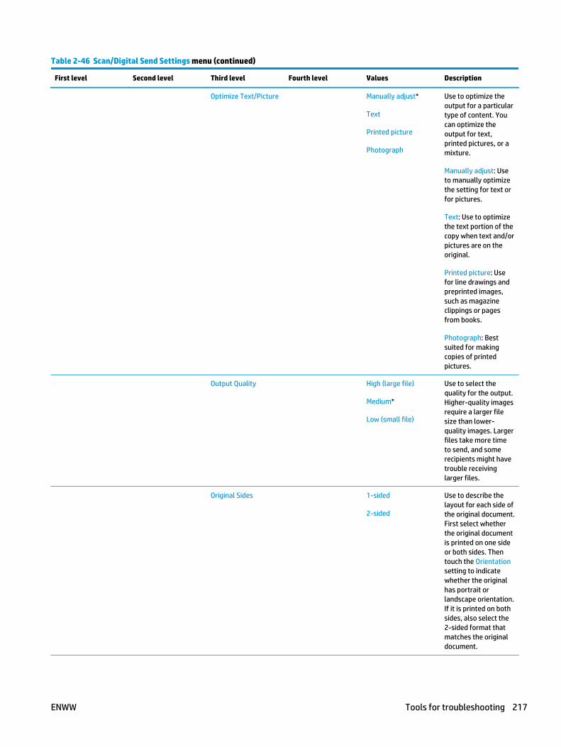
Table 2-46 Scan/Digital Send Settings menu (continued)
First level Second level Third level Fourth level Values Description
Optimize Text/Picture Manually adjust*
Text
Printed picture
Photograph
Use to optimize theoutput for a particulartype of content. Youcan optimize theoutput for text,printed pictures, or amixture.
Manually adjust: Useto manually optimizethe setting for text orfor pictures.
Text: Use to optimizethe text portion of thecopy when text and/orpictures are on theoriginal.
Printed picture: Usefor line drawings andpreprinted images,such as magazineclippings or pagesfrom books.
Photograph: Bestsuited for makingcopies of printedpictures.
Output Quality High (large file)
Medium*
Low (small file)
Use to select thequality for the output.Higher-quality imagesrequire a larger filesize than lower-quality images. Largerfiles take more timeto send, and somerecipients might havetrouble receivinglarger files.
Original Sides 1-sided
2-sided
Use to describe thelayout for each side ofthe original document.First select whetherthe original documentis printed on one sideor both sides. Thentouch the Orientationsetting to indicatewhether the originalhas portrait orlandscape orientation.If it is printed on bothsides, also select the2-sided format thatmatches the originaldocument.
ENWW Tools for troubleshooting 217

Table 2-46 Scan/Digital Send Settings menu (continued)
First level Second level Third level Fourth level Values Description
Orientation Automatically detect
Portrait*
Landscape
For some features towork correctly, youmust specify the waythe content of theoriginal document isplaced on the page.Portrait orientationmeans the short edgeof the page is alongthe top. Landscapeorientation means thelong edge of the pageis along the top. In theOrientation area,select whether theoriginal document hasa portrait orlandscape orientation.
2-Sided Format Book-style
Flip-style
Book-style: The backside of the original isprinted right-side-up,and the back side ofthe copy is printed thesame way. Use thisoption for originalsand copies that arebound along the leftedge.
Flip-style: The backside of the original isprinted upside-down,and the back side ofthe copy is printed thesame way. Use thisoption for originalsand copies that are tobe bound along thetop edge.
218 Chapter 2 Solve problems ENWW

Table 2-46 Scan/Digital Send Settings menu (continued)
First level Second level Third level Fourth level Values Description
Resolution 400 dpi
300 dpi
200 dpi
150 dpi*
75 dpi
Sets the resolution forsent documents.Higher resolutionimages have moredots per inch (dpi), sothey show moredetail. Lowerresolution imageshave fewer dots perinch and show lessdetail, but the file sizeis smaller. Some filetypes, for example afile that will beprocessed with OCR,require a specificresolution. Whenthese file types areselected, theResolution settingmight automaticallychange to a validvalue.
Content Orientation Orientation Auto Detect
Portrait*
Landscape
For some features towork correctly, youmust specify the waythe content of theoriginal document isplaced on the page.Portrait orientationmeans the short edgeof the page is alongthe top. Landscapeorientation means thelong edge of the pageis along the top. In theOrientation area,select whether theoriginal document hasa portrait orlandscape orientation.
2-Sided Format Book-style*
Flip-style
Use to configure thedefault style for 2-sided print jobs. If theBook-style option isselected, the backside of the page isprinted the right wayup. This option is forprint jobs that arebound along the leftedge. If the Flip-styleoption is selected, theback side of the pageis printed upside-down. This option isfor print jobs that arebound along the topedge.
ENWW Tools for troubleshooting 219

Table 2-46 Scan/Digital Send Settings menu (continued)
First level Second level Third level Fourth level Values Description
Color/Black Automatically detect*
Color
Black/Gray
Black
Use to enable ordisable colorscanning.
Automatically detect:Automatically scansdocuments in color ifat least one page hascolor.
Color: Scansdocuments in color.
Black/Gray: Scansdocuments ingrayscale.
Black: Scansdocuments in blackand white with acompressed file size.
Original Size Selelct from a list ofsupported sizes.
Use to describe thepage size of theoriginal document.
Notification Do not notify*
Notify when jobcompletes
Notify only if job fails
Configure to receivenotification about thestatus of a sentdocument.
Do not notify: Turnsoff this feature.
Notify when jobcompletes: Select toreceive notificationfor this job only.
Notify only if job fails:Select to receivenotification only if thejob is not sentsuccessfully.
Print: Select to printthe notification at thisproduct.
Include Thumbnail NOTE: Whensending an analog fax,select IncludeThumbnail to receivea thumbnail image ofthe first page of thefax in yournotification.
220 Chapter 2 Solve problems ENWW

Table 2-46 Scan/Digital Send Settings menu (continued)
First level Second level Third level Fourth level Values Description
Notification E-mailaddress
E-mail: Select toreceive thenotification in anemail. Touch the textbox following EmailAddress, and thentype the emailaddress for thenotification.
Image Adjustment Darkness Use to improve theoverall quality of thecopy.
Adjust the Darknesssetting to increase ordecrease the amountof white and black inthe colors.
Contrast Adjust the Contrastsetting to increase ordecrease thedifference betweenthe lightest anddarkest color on thepage.
Background Cleanup Adjust the BackgroundCleanup setting if youare having troublecopying a faint image.
Sharpness Adjust the Sharpnesssetting to clarify orsoften the image. Forexample, increasingthe sharpness couldmake text appearcrisper, butdecreasing it couldmake photographsappear smoother.
Automatic Tone
Default Select this to makethe selected ImageAdjustment settingthe default value.
ENWW Tools for troubleshooting 221

Table 2-46 Scan/Digital Send Settings menu (continued)
First level Second level Third level Fourth level Values Description
Job Build Job Build off*
Job Build on
Use to combineseveral originaldocuments into onejob. Also use to scanan original documentthat has more pagesthan the documentfeeder canaccommodate at onetime. The producttemporarily saves allthe scanned images.After you havescanned all the pagesfor the job, touchFinish to finish the job.
Cropping Options Do not crop*
Crop to content
Use this menu item toautomatically crop thescan for digitalsending. Use the Cropto content option toscan the smallestpossible area that hasdetectable content.
Erase Edges Use Inches
Back side erase
Front side erase
Use this menu item toremove blemishes,such as dark bordersor staple marks, bycleaning the specifiededges of the scannedimage. In each of thetext boxes enter themeasurements, inmillimeters or inches,for how much of thetop edge, bottomedge, left edge, andright edge to clean.
Blank PageSuppression
Disabled*
Enabled
Use to prevent blankpages in the originaldocument from beingincluded in the outputdocument.
Save to NetworkFolder Settings
Default Job Options use these menus toselect the defaultoptions for jobs thatare saved to anetwork location.
Save to USB Settings Default Job Options use these menus toselect the defaultoptions for job thatare saved to a USBflash drive.
222 Chapter 2 Solve problems ENWW

Table 2-46 Scan/Digital Send Settings menu (continued)
First level Second level Third level Fourth level Values Description
Digital Send ServiceSetup
Allow Usage of DigitalSending Software(DSS) Server
Enabled*
Disabled
Configure how theproduct interacts withthe HP Digital SendingSoftware (DSS) server.HP DSS handles digitalsending tasks, such asfaxing, emailing, andsending scanneddocuments to anetwork folder or USBstorage device.
Use the Allow Usageof Digital SendingSoftware (DSS) Serveroption to configurethe product to use HPDSS.
Allow Transfer to NewDigital SendingSoftware (DSS) Server
Enabled*
Disabled
Use the AllowTransfer to NewDigital SendingSoftware (DSS) Serveroption to specifywhether DSSmanagement of aproduct istransferable to adifferent DSS.
ENWW Tools for troubleshooting 223

Fax Settings menu (fax models only)
To display: At the product control panel, select the Administration menu, and then select the Fax Settingsmenu.
In the following table, asterisks (*) indicate the factory default setting.
Table 2-47 Fax Settings menu (fax models only)
Second level Third level Fourth level Values Description
Fax Send Setup Fax Setup Wizard Configure settings forsending faxes from theproduct.
Use the Fax Setup Wizardfeature to set up optionsfor faxing.
NOTE: To set up LAN faxor Internet fax, use the HPEmbedded Web Server. Toopen the HP EmbeddedWeb Server, type theproduct network addressinto a Web browser. Toconfigure the fax features,select the Fax tab.
Fax Dialing Settings Fax Dial Volume Off
Low*
High
These settings control howthe fax modem dials theoutgoing fax number whenfaxes are sent.
Dialing Mode Tone*
Pulse
Redial Interval 1 – 5 Minutes
Default = 5 minutes
Fax Send Speed Fast*
Medium
Slow
Dialing Prefix
Detect Dial Tone
Redial on Error Range: 0 – 9
Default = 2
Redial on No Answer Range: 0 – 2
Default = 0
Redial on Busy Range: 0 – 9
Default = 3
224 Chapter 2 Solve problems ENWW
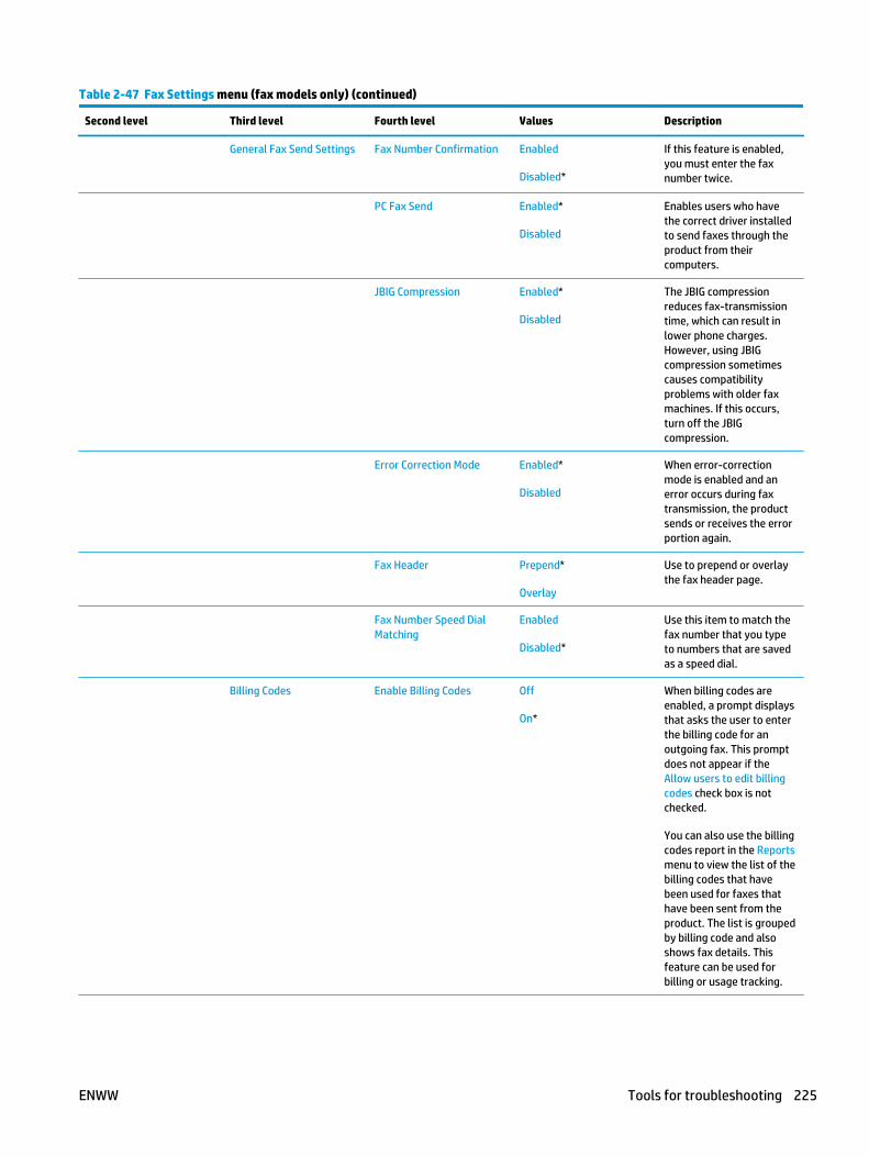
Table 2-47 Fax Settings menu (fax models only) (continued)
Second level Third level Fourth level Values Description
General Fax Send Settings Fax Number Confirmation Enabled
Disabled*
If this feature is enabled,you must enter the faxnumber twice.
PC Fax Send Enabled*
Disabled
Enables users who havethe correct driver installedto send faxes through theproduct from theircomputers.
JBIG Compression Enabled*
Disabled
The JBIG compressionreduces fax-transmissiontime, which can result inlower phone charges.However, using JBIGcompression sometimescauses compatibilityproblems with older faxmachines. If this occurs,turn off the JBIGcompression.
Error Correction Mode Enabled*
Disabled
When error-correctionmode is enabled and anerror occurs during faxtransmission, the productsends or receives the errorportion again.
Fax Header Prepend*
Overlay
Use to prepend or overlaythe fax header page.
Fax Number Speed DialMatching
Enabled
Disabled*
Use this item to match thefax number that you typeto numbers that are savedas a speed dial.
Billing Codes Enable Billing Codes Off
On*
When billing codes areenabled, a prompt displaysthat asks the user to enterthe billing code for anoutgoing fax. This promptdoes not appear if theAllow users to edit billingcodes check box is notchecked.
You can also use the billingcodes report in the Reportsmenu to view the list of thebilling codes that havebeen used for faxes thathave been sent from theproduct. The list is groupedby billing code and alsoshows fax details. Thisfeature can be used forbilling or usage tracking.
ENWW Tools for troubleshooting 225
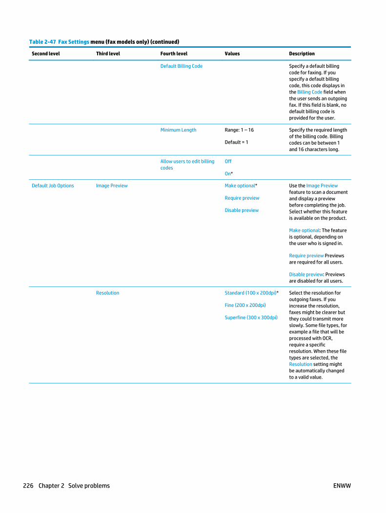
Table 2-47 Fax Settings menu (fax models only) (continued)
Second level Third level Fourth level Values Description
Default Billing Code Specify a default billingcode for faxing. If youspecify a default billingcode, this code displays inthe Billing Code field whenthe user sends an outgoingfax. If this field is blank, nodefault billing code isprovided for the user.
Minimum Length Range: 1 – 16
Default = 1
Specify the required lengthof the billing code. Billingcodes can be between 1and 16 characters long.
Allow users to edit billingcodes
Off
On*
Default Job Options Image Preview Make optional*
Require preview
Disable preview
Use the Image Previewfeature to scan a documentand display a previewbefore completing the job.Select whether this featureis available on the product.
Make optional: The featureis optional, depending onthe user who is signed in.
Require preview Previewsare required for all users.
Disable preview: Previewsare disabled for all users.
Resolution Standard (100 x 200dpi)*
Fine (200 x 200dpi)
Superfine (300 x 300dpi)
Select the resolution foroutgoing faxes. If youincrease the resolution,faxes might be clearer butthey could transmit moreslowly. Some file types, forexample a file that will beprocessed with OCR,require a specificresolution. When these filetypes are selected, theResolution setting mightbe automatically changedto a valid value.
226 Chapter 2 Solve problems ENWW

Table 2-47 Fax Settings menu (fax models only) (continued)
Second level Third level Fourth level Values Description
Original Sides 1-sided*
2-sided
Use to describe the layoutfor each side of the originaldocument. First selectwhether the originaldocument is printed on oneside or both sides. Thentouch the Orientationsetting to indicate whetherthe original has portrait orlandscape orientation. If itis printed on both sides,also select the 2-sidedformat that matches theoriginal document.
Orientation Portrait*
Landscape
For some features to workcorrectly, you must specifythe way the content of theoriginal document is placedon the page.
Portrait: This settingmeans the short edge ofthe page is along the top.
Landscape: This settingmeans the long edge of thepage is along the top.
2-Sided Format Book-style*
Flip-style
Book-style: The back sideof the original is printedright-side-up, and the backside of the copy is printedthe same way. Use thisoption for originals andcopies that are boundalong the left edge.
Flip-style: The back side ofthe original is printedupside-down, and the backside of the copy is printedthe same way. Use thisoption for originals andcopies that are to be boundalong the top edge.
ENWW Tools for troubleshooting 227

Table 2-47 Fax Settings menu (fax models only) (continued)
Second level Third level Fourth level Values Description
Notification Do not notify*
Notify when job completes
Notify only if job fails
Use to receive notificationabout the status of a sentdocument.
Do not notify: Turns off thisfeature.
Notify when job completes:Select to receivenotification for this jobonly.
Notify only if job fails:Select to receivenotification only if the jobis not sent successfully.
Print: Select to print thenotification at this product.
E-mail: Select to receivethe notification in an email.Touch the text boxfollowing Email Address,and then enter the emailaddress for thenotification.
Include Thumbnail When sending an analogfax, select IncludeThumbnail to receive athumbnail image of thefirst page of the fax in yournotification.
Notification E-mail address Provide the email addressthat will receivenotifications.
Content Orientation Orientation Portrait*
Landscape
For some features to workcorrectly, you must specifythe way the content of theoriginal document is placedon the page.
Portrait: This settingmeans the short edge ofthe page is along the top.
Landscape: This settingmeans the long edge of thepage is along the top.
228 Chapter 2 Solve problems ENWW

Table 2-47 Fax Settings menu (fax models only) (continued)
Second level Third level Fourth level Values Description
2-Sided Format Book-style*
Flip-style
Use to configure thedefault style for 2-sidedprint jobs. If the Book-styleoption is selected, the backside of the page is printedthe right way up. Thisoption is for print jobs thatare bound along the leftedge. If the Flip-styleoption is selected, the backside of the page is printedupside-down. This option isfor print jobs that arebound along the top edge.
Original Size Select from a list of sizesthat the product supports.
Use to describe the pagesize of the originaldocument.
Image Adjustment Darkness Use to improve the overallquality of the copy.
Adjust the Darkness settingto increase or decrease theamount of white and blackin the colors.
Contrast Adjust the Contrast settingto increase or decrease thedifference between thelightest and darkest coloron the page.
Background Cleanup Adjust the BackgroundCleanup setting if you arehaving trouble copying afaint image.
Sharpness Adjust the Sharpnesssetting to clarify or softenthe image. For example,increasing the sharpnesscould make text appearcrisper, but decreasing itcould make photographsappear smoother.
Automatic Tone The product automaticallyadjusts the Darkness,Contrast, and BackgroundCleanup settings to themost appropriate for thescanned document.
Default Select this to make theselected Image Adjustmentsetting the default value.
ENWW Tools for troubleshooting 229

Table 2-47 Fax Settings menu (fax models only) (continued)
Second level Third level Fourth level Values Description
Optimize Text/Picture Manually adjust* Optimize For
Text
Printed picture
Photograph
Optimizes the output for aparticular type of content.You can optimize theoutput for text, printedpictures, or a mixture.
Manually adjust: Use tomanually optimize thesetting for text or forpictures.
Text: Use to optimize thetext portion of the copywhere text and/or picturesare on the original.
Printed picture: Use for linedrawings and preprintedimages, such as magazineclippings or pages frombooks.
Photograph: Best suited formaking copies of printedpictures.
Job Build Job Build off*
Job Build on
Use to divide a complex jobinto smaller segments. Thisis useful when you arecopying or scanning anoriginal document that hasmore pages than thedocument feeder can hold,or when you want tocombine pages that havedifferent sizes into one job.You can use either theglass or the documentfeeder to scan the originaldocuments.
Blank Page Suppression Disabled*
Enabled
Prevents blank pages in theoriginal document frombeing included in theoutput document.
Fax Receive Setup Ringer Volume Off
Low*
High
Use to configure settingsfor receiving faxes.
Rings To Answer Range: 1–6
Default = 1
Fax Send Speed Fast*
Medium
Slow
230 Chapter 2 Solve problems ENWW

Table 2-47 Fax Settings menu (fax models only) (continued)
Second level Third level Fourth level Values Description
Ring Interval Range: 220–600 ms
Default = 600 ms
Ring Frequency Range: 1–200
Default = 68hz
Fax Printing Schedule Always store faxes
Always print faxes*
Use Fax Printing Schedule
If you have concerns aboutthe security of privatefaxes, use this feature tostore faxes rather thanhaving them automaticallyprint. Select Incoming FaxOptions, and then you canchoose to always storefaxes, always print them,or you can set up aschedule for each day ofthe week.
Schedule
Touch this to set up a faxprinting schedule if youselected the Use FaxPrinting Schedule option.
Add (plus sign)
Edit
Delete
Print incoming faxes
Store incoming faxes
Time
Event Days
If you are using a faxprinting schedule, use thismenu to configure when toprint faxes.
ENWW Tools for troubleshooting 231

Table 2-47 Fax Settings menu (fax models only) (continued)
Second level Third level Fourth level Values Description
Blocked Fax Numbers Fax Number to Block The blocked fax list cancontain up to 30 numbers.When the product receivesa call from one of theblocked fax numbers, itdeletes the incoming fax. Italso logs the blocked fax inthe activity log along withjob-accountinginformation.
Add blocked numbers:Enter a fax number into theFax Number to Block field,and then touch the arrowbutton to add a newnumber to the blocked faxlist.
To remove blockednumbers: Select a numberand touch the Deletebutton to delete it from theblocked fax list.
To clear all blockednumbers: Touch the DeleteAll button to clear all of thenumbers from the blockedfax list.
You can also use theBlocked Fax List report inthe Information menu toview the list of the faxnumbers that have beenblocked on this product.
Default Job Options Notification Do not notify*
Notify when job completes
Notify only if job fails
Configure to receivenotification about thestatus of a sent document.
Do not notify: Turns off thisfeature.
Notify when job completes:Select to receivenotification for this jobonly.
Notify only if job fails:Select to receivenotification only if the jobis not sent successfully.
E-mail*
E-mail: Select to receivethe notification in an email.Touch the text boxfollowing Email Addess,and then enter the emailaddress for thenotification.
232 Chapter 2 Solve problems ENWW

Table 2-47 Fax Settings menu (fax models only) (continued)
Second level Third level Fourth level Values Description
Include Thumbnail NOTE: When sending ananalog fax, select IncludeThumbnail to receive athumbnail image of thefirst page of the fax in yournotification.
Notification E-mail address
Stamp Received Faxes Enabled
Disabled*
Use this option to add thedate, time, sender’s phonenumber, and page numberto each page of the faxesthat this product receives.
Fit to Page Enabled*
Disabled
Use to shrink faxes that arelarger than Letter-size orA4-size so that they can fitonto a Letter-size or A4-size page. If this feature setto Disabled, faxes largerthan Letter or A4 will flowacross multiple pages.
Paper Selection Automatic*
Select from a list of thetrays.
Sides 1-sided*
2-sided
Use to describe the layoutfor each side of the originaldocument. First selectwhether the originaldocument is printed on oneside or both sides. Thentouch the Orientationsetting to indicate whetherthe original has portrait orlandscape orientation. If itis printed on both sides,also select the 2-sidedformat that matches theoriginal document.
Enable Billing Codes Disabled*
Enabled
Use to forward receivedfaxes to another faxmachine.
Type of Fax Job to Forward All faxes
Sent faxes
Received faxes
Fax Forwarding Number
Clear Fax Activity Log Clears all events from theFax Activity Log list.
ENWW Tools for troubleshooting 233

General Print Settings menu
To display: At the product control panel, select the Administration menu, and then select the General PrintSettings menu.
In the following table, asterisks (*) indicate the factory default setting.
Table 2-48 General Print Settings menu
First level Second level Values Description
Manual Feed Enabled
Disabled*
Use to enable or disable themanual-feed feature, which allowsthe user to feed paper into theproduct by hand. When this featureis enabled, the user can selectmanual feed from the controlpanel as the paper source for a job.If a tray is not specified as part of ajob, manual feed is selected.
Courier Font Regular*
Dark
Select which version of the Courierfont you want to use. The factorydefault setting is Regular, whichuses an average stroke width. TheDark setting can be used if aheavier Courier font is needed.
Wide A4 Enabled
Disabled*
Changes the printable area of A4-size paper. If you enable thisoption, eighty 10-pitch characterscan be printed on a single line ofA4 paper.
Print PS Errors Enabled
Disabled*
Use this feature to select whethera PostScript (PS) error page isprinted when the productencounters a PS error.
Print PDF Errors Enabled
Disabled*
Selects whether a PDF error pageis printed when the productencounters a PDF error.
Personality Auto*
PCL
POSTSCRIPT
Configures the default printlanguage or personality for theproduct. Normally you should notchange the product language. Ifyou change the setting to a specificproduct language, the productdoes not automatically switchfrom one language to anotherunless specific softwarecommands are sent to it.
PCL Form Length Range: 5 – 128
Default = 60
Controls the PCL print-commandoptions. PCL is a set of productcommands that Hewlett-Packarddeveloped to provide access toproduct features.
Use the Form Length feature toselect the user-soft defaultvertical form length.
234 Chapter 2 Solve problems ENWW

Table 2-48 General Print Settings menu (continued)
First level Second level Values Description
Orientation Portrait*
Landscape
Select the orientation that is mostoften used for copy or scanoriginals. Select the Portrait optionif the short edge is at the top orselect the Landscape option if thelong edge is at the top.
Font Source Internal* Selects the font source for theuser-soft default font. The list ofavailable options varies dependingon the installed product options.
Font Number Range: 0 – 110
Default = 0
Specifies the font number for theuser-soft default font using thesource that is specified in the FontSource menu. The product assignsa number to each font and lists iton the PCL font list. The fontnumber displays in the Font #column of the printout.
Font Pitch Range: 0.44 – 99.99
Default = 10
If the Font Source option and theFont Number setting indicate acontour font, then use this featureto select a default pitch (for afixed-spaced font).
Font Point Size Range: 4.00 – 999.75
Default = 12.00
If the Font Source option and theFont Number setting indicate acontour font, then use this featureto select a default point size (for aproportional-spaced font).
Symbol Set Select from a list of symbol sets. Select any one of several availablesymbol sets from the controlpanel. A symbol set is a uniquegrouping of all the characters in afont. The factory default value forthis option is PC-8. Either PC-8 orPC-850 are recommended for line-draw characters.
Append CR to LF No*
Yes
Configure whether a carriagereturn (CR) is appended to eachline feed (LF) encountered inbackwards-compatible PCL jobs(pure text, no job control). SelectYes to append the carriage return.The default setting is No. Someenvironments, such as UNIX,indicate a new line by using onlythe line-feed control code. Thisoption allows the user to appendthe required carriage return toeach line feed.
ENWW Tools for troubleshooting 235

Table 2-48 General Print Settings menu (continued)
First level Second level Values Description
Suppress Blank Pages No*
Yes
This option is for users who aregenerating their own PCL, whichcould include extra form feeds thatwould cause blank pages to beprinted. When the Yes option isselected, form feeds are ignored ifthe page is blank.
Media Source Mapping Standard*
Classic
Use to select and maintain inputtrays by number when you are notusing the product driver, or whenthe software program has nooption for tray selection. Thefollowing options are available:
Standard: Tray numbering is basedon newer HP LaserJet models.
Classic: Tray numbering is basedon HP LaserJet 4 and older models.
236 Chapter 2 Solve problems ENWW

Default Print Options menu
To display: At the product control panel, select the Administration menu, and then select the Default PrintOptions menu.
In the following table, asterisks (*) indicate the factory default setting.
Table 2-49 Default Print Options menu
First level Second level Values Description
Number of Copies Range: 1–32000
Default = 1
Sets the default number of copiesfor a copy job. This default applieswhen the Copy function or theQuick Copy function is initiatedfrom the product Home screen.
Default Paper Size Select from a list of sizes that theproduct supports.
Configures the default paper sizeused for print jobs.
Default Custom Paper Size X Dimension Range: 3–8.5 inches
Default = 8.5 inches
Configures the default paper sizethat is used when the user selectsCustom as the paper size for aprint job.
Y Dimension Range: 5–14 inches
Default = 14 inches
Use Inches Enabled*
Disabled
Paper Path Automatic*
Face-up (straightest path)
Face-down (correct order)
Use this item to select theapproriate paper path through theproduct for the print job.
Sides 1-sided*
2-sided
Use to indicate whether theoriginal document is printed onone or both sides, and whether thecopies should be printed on one orboth sides. For example, select the1-sided original, 2-sided outputoption when the original is printedon one side, but you want to maketwo-sided copies.
Select the Orientation setting tospecify portrait or landscapeorientation and to select the waythe second sides are printed.
ENWW Tools for troubleshooting 237

Table 2-49 Default Print Options menu (continued)
First level Second level Values Description
2-Sided Format Book-style*
Flip-style
Configures the default style for 2-sided print jobs. If the Book-styleoption is selected, the back side ofthe page is printed the right wayup. This option is for print jobs thatare bound along the left edge. Ifthe Flip-style option is selected,the back side of the page is printedupside-down. This option is forprint jobs that are bound along thetop edge.
Edge-to-Edge Normal (recommended)*
Edge-to-Edge output
Use to avoid shadows that canappear along the edges of copieswhen the original document isprinted close to the edges.
238 Chapter 2 Solve problems ENWW

Display Settings menu
To display: At the product control panel, select the Administration menu, and then select the DisplaySettings menu.
In the following table, asterisks (*) indicate the factory default setting.
Table 2-50 Display Settings menu
First level Second level Values Description
Display Brightness Range: -10 to 10
The default value is 0.
Use to specify the intensity of theLCD control-panel display.
Key Press Sound On*
Off
Use to specify whether you hear asound when you touch the screenor press buttons on the controlpanel.
Language Settings Language Select from a list of languages thatthe product supports.
Use to select a different languagefor control-panel messages andspecify the default keyboardlayout. When you select a newlanguage, the keyboard layoutautomatically changes to matchthe factory default for the selectedlanguage.
Keyboard Layout Each language has a defaultkeyboard layout. To change it,select from a list of layouts.
Select the default keyboard layoutthat matches the language youwant to use.
How to Connect Button Display*
Hide
Use this menu item to display orhide the How to Connect Button onthe Home screen.
Date and Time Show Date and Time*
Hide Date and Time
Select whether to display or hidethe date and time on the controlpanel Home screen.
Inactivity Timeout Range: 10 – 300 seconds
Default = 60 seconds
Specifies the amount of time thatelapses between any activity onthe control panel and when theproduct resets to the defaultsettings. When the timeoutexpires, the control-panel displayreturns to the Home menu, andany user signed in to the product issigned out.
ENWW Tools for troubleshooting 239

Table 2-50 Display Settings menu (continued)
First level Second level Values Description
Clearable Warnings On
Job*
Use this feature to set the periodthat a clearable warning displayson the control panel. If the Onsetting is selected, clearablewarnings appear until theClearable Warnings button ispressed. If theJob setting isselected, clearable warnings stayon the display during the job thatgenerated the warning anddisappear from the display whenthe next job starts.
Continuable Events Auto-continue (10 seconds)*
Touch OK to continue
Use this option to configure theproduct behavior when the productencounters certain errors. If theAuto-continue (10 seconds) optionis selected, the job will continueafter 10 seconds. If theTouch OK tocontinue option is selected, the jobwill stop and require the user topress the OK button beforecontinuing.
240 Chapter 2 Solve problems ENWW

Manage Supplies menu
To display: At the product control panel, select the Administration menu, and then select the ManageSupplies menu.
In the following table, asterisks (*) indicate the factory default setting.
Table 2-51 Manage Supplies menu
First level Second level Third level Fourth level Values Description
Supplies Status Print
View
Supply Settings Black Cartridge Low ThresholdSettings
1-100%
Default = 10%
Set the estimatedpercentage at whichthe product notifiesyou when the tonercartridge is very low.
Very Low Settings Stop
Prompt to continue*
Continue
Specifies how theproduct notifies youwhen the tonercartridge is very low.
Stop: The productstops until you replacethe toner cartridge.
Prompt to continue:The product stops andprompts you to replacethe toner cartridge.You can acknowledgethe prompt andcontinue printing.
Continue: The productalerts you that a tonercartridge is very low,but it continuesprinting.
Document Feeder Kit Low ThresholdSettings
1-100%
Default = 10%
Set the percentage atwhich the productnotifies you when adocument feeder kit isneeded.
ENWW Tools for troubleshooting 241

Table 2-51 Manage Supplies menu (continued)
First level Second level Third level Fourth level Values Description
Very Low Settings Stop
Prompt to continue*
Continue
Configure how theproduct respondswhen the documentfeeder kit is reachingthe end of itsestimated life.
Stop: The productstops until you replacethe document feederkit.
Prompt to continue:The product stops andprompts you to replacethe document feederkit. You canacknowledge theprompt and continueprinting
Continue: The productalerts you that thedocument feeder kit isvery low, but itcontinues printing.
Maintenance Kit Low ThresholdSettings
1-100%
Default = 10%
Set the percentage atwhich the productnotifies you when themaintenance kit isneeded.
Very Low Settings Stop
Prompt to continue*
Continue
Configure how theproduct respondswhen the maintenancekit is reaching the endof its estimated life.
Stop: The productstops until you replacethe maintenance kit.
Prompt to continue:The product stops andprompts you to replacethe maintnenace kit.You can acknowledgethe prompt andcontinue printing
Continue: The productalerts you that themaintnenace kit is verylow, but it continuesprinting.
242 Chapter 2 Solve problems ENWW

Table 2-51 Manage Supplies menu (continued)
First level Second level Third level Fourth level Values Description
Store Usage Data On supplies
Not on supplies
The Store Usage Datamenu provides a wayto suppress the tonercartridges from storingmost of theinformation gatheredexclusively for thepurpose ofunderstanding theusage of the product.Select the On suppliessetting to store thedata on the tonercartridge memory chip.Select the Not onsupplies setting tosuppress theinformation from beingstored on the memorychip.
Supply Messages Low Message On*
Off
Use to configurewhether a messagedisplays on the controlpanel when suppliesare getting low, buthave not yet reachedthe low threshold.
Reset Supplies New Document FeederKit
New Maintenance Kit
Reset
Cancel
Select this option ifyou have installed anew document feederkit or preventativemaintenance kit.
ENWW Tools for troubleshooting 243

Manage Trays menu
To display: At the product control panel, select the Administration menu, and then select the Manage Traysmenu.
In the following table, asterisks (*) indicate the factory default setting.
Table 2-52 Manage Trays menu
First level Values Description
Use Requested Tray Exclusively*
First
Controls how the product handles jobs thathave specified a specific input tray. Two optionsare available:
Exclusively: The product never selects adifferent tray when the user has indicated thata specific tray should be used, even if that trayis empty.
First: The product pulls from another tray if thespecified tray is empty, even though the userspecifically indicated a tray for the job.
Manually Feed Prompt Always*
Unless loaded
Indicate whether a prompt should appear whenthe type or size for a job does not match thespecified tray and the product pulls from themultipurpose tray instead. Two options areavailable:
Always: A prompt always displays before usingthe multipurpose tray.
Unless loaded: A message displays only if themultipurpose tray is empty.
Size/Type Prompt Display*
Do not display
Controls whether the tray configurationmessage displays whenever a tray is closed.Two options are available:
Display: Shows the tray configuration messagewhen a tray is closed. The user is able toconfigure the tray settings directly from thismessage.
Do not display: Prevents the tray configurationmessage from automatically appearing.
Use Another Tray Enabled*
Disabled
Use to turn on or off the control-panel promptto select another tray when the specified tray isempty. Two options are available:
Enabled: When this option is selected, the useris prompted either to add paper to the selectedtray or to choose a different tray.
Disabled: When this option is selected, the useris not given the option of selecting a differenttray. The product prompts the user to addpaper to the tray that was initially selected.
244 Chapter 2 Solve problems ENWW

Table 2-52 Manage Trays menu (continued)
First level Values Description
Alternative Letterhead Mode Disabled*
Enabled
Use to load letterhead or preprinted paper intothe tray the same way for all print jobs,whether you are printing to one side of thesheet or to both sides of the sheet. When thisoption is selected, load the paper as you wouldfor printing on both sides. See the userdocumentation that came with the product forinstructions about loading letterhead forprinting on both sides. When this option isselected, the product speed slows to the speedrequired for printing on both sides.
Duplex Blank Pages Auto*
Yes
Control how the product handles two-sidedjobs (duplexing). Two options are available:
Auto: Enables Smart Duplexing, which instructsthe product not to process blank pages.
Yes: Disables Smart Duplexing and forces theduplexer to flip the sheet of paper even if it isprinted on only one side. This might bepreferable for certain jobs that use paper typessuch as letterhead or prepunched paper.
Image rotation Left to right
Alternate
Select to rotate the print job on the page.
Override A4/Letter Yes*
No
Prints on letter-size paper when an A4 job issent but no A4-size paper is loaded in theproduct (or to print on A4 paper when a letter-size job is sent but no letter-size paper isloaded). This option will also override A3 withledger-size paper and ledger with A3-sizepaper.
ENWW Tools for troubleshooting 245

Network Settings menu
To display: At the product control panel, select the Administration menu, and then select the NetworkSettings menu.
In the following table, asterisks (*) indicate the factory default setting.
Table 2-53 Network Settings menu
First level Values Description
IO Timeout Range: 5 – 300 sec
Default = 15
Use to set the I/O timeout period in seconds. I/Otimeout refers to the elapsed time before aprint job fails. If the stream of data that theproduct receives for a print job getsinterrupted, this setting indicates how long theproduct will wait before it reports that the jobhas failed.
Embedded Jetdirect Menu See Table 2-54 Embedded Jetdirect Menuon page 246 for details. These menus have thesame structure. If an additional HP Jetdirectnetwork card is installed in the EIO slot, thenboth menus are available.
Table 2-54 Embedded Jetdirect Menu
First level Second level Third level Fourth level Values Description
Information Print Sec Report Yes
No*
Yes: Prints a page thatcontains the currentsecurity settings onthe HP Jetdirect printserver.
No: A security settingspage is not printed.
TCP/IP Enable On*
Off
On: Enable the TCP/IPprotocol.
Off: Disable the TCP/IPprotocol.
Host Name Use the arrow buttonsto edit the host name.
NPIXXXXXX*
An alphanumericstring, up to 32characters, used toidentify the product.This name is listed onthe HP Jetdirectconfiguration page.The default host nameis NPIxxxxxx, wherexxxxxx is the last sixdigits of the LANhardware (MAC)address.
246 Chapter 2 Solve problems ENWW
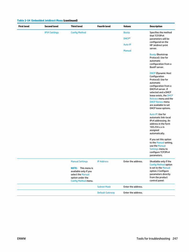
Table 2-54 Embedded Jetdirect Menu (continued)
First level Second level Third level Fourth level Values Description
IPV4 Settings Config Method Bootp
DHCP*
Auto IP
Manual
Specifies the methodthat TCP/IPv4parameters will beconfigured on theHP Jetdirect printserver.
Bootp (BootstrapProtocol): Use forautomaticconfiguration from aBootP server.
DHCP (Dynamic HostConfigurationProtocol): Use forautomaticconfiguration from aDHCPv4 server. Ifselected and a DHCPlease exists, the DHCPRelease menu and theDHCP Renew menuare available to setDHCP lease options.
Auto IP: Use forautomatic link-localIPv4 addressing. Anaddress in the form169.254.x.x isassignedautomatically.
If you set this optionto the Manual setting,use the ManualSettings menu toconfigure TCP/IPv4parameters.
Manual Settings
NOTE: This menu isavailable only if youselect the Manualoption under theConfig Method menu.
IP Address Enter the address. (Available only if theConfig Method optionis set to the Manualoption.) Configureparameters directlyfrom the productcontrol panel:
Subnet Mask Enter the address.
Default Gateway Enter the address.
ENWW Tools for troubleshooting 247

Table 2-54 Embedded Jetdirect Menu (continued)
First level Second level Third level Fourth level Values Description
Default IP Auto IP*
Legacy
Specify the IP addressto default to when theprint server is unableto obtain an IPaddress from thenetwork during aforced TCP/IPreconfiguration (forexample, whenmanually configuredto use BootP orDHCP).
NOTE: This featureassigns a static IPaddress that mightinterfere with amanaged network.
Auto IP: A link-local IPaddress 169.254.x.x isset.
Legacy: The address192.0.0.192 is set,consistent with olderHP Jetdirect products.
Primary DNS Range: 0 – 255
Default =xxx.xxx.xx.xx
Specify the IP address(n.n.n.n) of a PrimaryDomain Name System(DNS) Server.
Secondary DNS Range: 0 – 255
Default = 0.0.0.0
Specify the IP address(n.n.n.n) of aSecondary DNSServer.
IPV6 Settings Enable Off
On*
Use this item toenable or disable IPv6operation on the printserver.
Off: IPv6 is disabled.
On: IPv6 is enabled.
Address Manual Settings Enable
Address
Use this item toenable and manuallyconfigure a TCP/IPv6address.
248 Chapter 2 Solve problems ENWW

Table 2-54 Embedded Jetdirect Menu (continued)
First level Second level Third level Fourth level Values Description
DHCPV6 Policy Router Specified
Router Unavailable*
Always
Router Specified: Thestateful auto-configuration methodto be used by the printserver is determinedby a router. The routerspecifies whether theprint server obtains itsaddress, itsconfigurationinformation, or bothfrom a DHCPv6 server.
Router Unavailable: Ifa router is notavailable, the printserver should attemptto obtain its statefulconfiguration from aDHCPv6 server.
Always: Whether arouter is available, theprint server alwaysattempts to obtain itsstateful configurationfrom a DHCPv6 server.
Primary DNS
Secondary DNS
Proxy Server Select from a providedlist.
Specifies the proxyserver to be used byembeddedapplications in theproduct. A proxyserver is typicallyused by networkclients for Internetaccess. It caches Webpages, and provides adegree of Internetsecurity, for thoseclients.
To specify a proxyserver, enter its IPv4address or fully-qualified domainname. The name canbe up to 255 octets.
For some networks,you might need tocontact your InternetService Provider (ISP)for the proxy serveraddress.
ENWW Tools for troubleshooting 249

Table 2-54 Embedded Jetdirect Menu (continued)
First level Second level Third level Fourth level Values Description
Proxy Port Default = 00080 Enter the port numberused by the proxyserver for clientsupport. The portnumber identifies theport reserved forproxy activity on yournetwork, and can be avalue from 0 to65535.
Idle Timeout Default = 0270 The time period, inseconds, after whichan idle TCP print dataconnection is closed(default is 270seconds, 0 disablesthe timeout).
Security Secure Web HTTPS Required*
HTTPS Optional
For configurationmanagement, specifywhether the HPEmbedded Web Serverwill acceptcommunications usingHTTPS (Secure HTTP)only, or both HTTPand HTTPS.
HTTPS Required: Forsecure, encryptedcommunications, onlyHTTPS access isaccepted. The printserver will appear as asecure site.
IPSEC Keep
Disable*
Specify the IPSecstatus on the printserver.
Keep: IPSec statusremains the same ascurrently configured.
Disable: IPSecoperation on the printserver is disabled.
802.1X Reset
Keep*
Specify whether the802.1X settings onthe print server arereset to the factorydefaults.
Reset: The 802.1Xsettings are reset tothe factory defaults.
Keep: The current802.1X settings aremaintained.
250 Chapter 2 Solve problems ENWW

Table 2-54 Embedded Jetdirect Menu (continued)
First level Second level Third level Fourth level Values Description
Reset Security Yes
No*
Specify whether thecurrent securitysettings on the printserver will be saved orreset to factorydefaults.
Yes: Security settingsare reset to factorydefaults.
No: The currentsecurity settings aremaintained.
Diagnostics Embedded Tests LAN HW Test Yes
No*
Provides tests to helpdiagnose networkhardware or TCP/IPnetwork connectionproblems.
Embedded tests helpto identify whether anetwork fault isinternal or external tothe product. Use anembedded test tocheck hardware andcommunication pathson the print server.After you select andenable a test and setthe execution time,you must select theExecute option toinitiate the test.
Depending on theexecution time, aselected test runscontinuously untileither the product isturned off, or an erroroccurs and adiagnostic page isprinted.
CAUTION: Runningthis embedded testwill erase your TCP/IPconfiguration.
This test performs aninternal loopback test.An internal loopbacktest will send andreceive packets onlyon the internalnetwork hardware.There are no externaltransmissions on yournetwork.
ENWW Tools for troubleshooting 251

Table 2-54 Embedded Jetdirect Menu (continued)
First level Second level Third level Fourth level Values Description
HTTP Test Yes
No*
This test checksoperation of HTTP byretrieving predefinedpages from theproduct, and tests theHP Embedded WebServer.
Select the Yes optionto choose this test, orthe No option to notchoose it.
SNMP Test Yes
No*
This test checksoperation of SNMPcommunications byaccessing predefinedSNMP objects on theproduct.
Select the Yes optionto choose this test, orthe No option to notchoose it.
Data Path Test Yes
No*
This test helps toidentify data path andcorruption problemson an HP postscriptlevel 3 emulationproduct. It sends apredefined PS file tothe product, However,the test is paperless;the file will not print.
Select the Yes optionto choose this test, orthe No option to notchoose it.
Select All Tests Yes
No*
Use this item to selectall availableembedded tests.
Select the Yes optionto choose all tests.Select the No optionto select individualtests.
252 Chapter 2 Solve problems ENWW

Table 2-54 Embedded Jetdirect Menu (continued)
First level Second level Third level Fourth level Values Description
Execution Time [H] Range: 1 – 24 hours
Default = 1 hour
Specify the length oftime (in hours) that anembedded test will berun. If you select zero(0), the test runsindefinitely until anerror occurs or theproduct is turned off.
Data gathered fromthe HTTP, SNMP, andData Path tests isprinted after the testshave completed.
Execute No*
Yes
No: Do not initiate theselected tests.
Yes: Initiate theselected tests.
Ping Test Dest Type IPv4
IPv6
This test is used tocheck networkcommunications. Thistest sends link-levelpackets to a remotenetwork host, thenwaits for anappropriate response.To run a ping test, setthe following items:
Dest Type
Specify whether thetarget product is anIPv4 or IPv6 node.
Dest IPv4 Range: 0 – 255
Default = 127.0.0.1
Enter the IPv4address.
Dest IPv6 Select from a providedlist.
Default = : : 1
Enter the IPv6address.
Packet Size Default = 64 Specify the size ofeach packet, in bytes,to be sent to theremote host. Theminimum is 64(default) and themaximum is 2048.
Timeout Default = 001 Specify the length oftime, in seconds, towait for a responsefrom the remote host.The maximum is 100.
ENWW Tools for troubleshooting 253

Table 2-54 Embedded Jetdirect Menu (continued)
First level Second level Third level Fourth level Values Description
Count Default = 004 Specify the number ofping test packets tosend for this test.Select a value from 0to 100. To configurethe test to runcontinuously, select 0.
Print Results Yes
No*
Execute Yes
No*
No: Do not initiate theselected tests.
Yes: Initiate theselected tests.
Ping Results Packets Sent Default = 00000 Shows the number ofpackets (0 - 65535)sent to the remotehost since the mostrecent test wasinitiated orcompleted..
Packets Received Default = 00000 Shows the number ofpackets (0 - 65535)received from theremote host since themost recent test wasinitiated orcompleted. Thedefault is 0.
Percent Lost Default = 000 Shows the percent (0to 100) of ping testpackets that weresent with no responsefrom the remote hostsince the most recenttest was initiated orcompleted.
RTT Min Default = 0000 Shows the minimumdetected roundtrip-time (RTT), from 0 to4096 milliseconds, forpacket transmissionand response.
RTT Max Default = 0000 Shows the maximumdetected roundtrip-time (RTT), from 0 to4096 milliseconds, forpacket transmissionand response.
254 Chapter 2 Solve problems ENWW

Table 2-54 Embedded Jetdirect Menu (continued)
First level Second level Third level Fourth level Values Description
RTT Average Default = 0000 Shows the averageround-trip-time (RTT),from 0 to 4096milliseconds, forpacket transmissionand response.
Ping In Progress Yes
No*
Shows whether a pingtest is in progress. YesIndicates a test inprogress. No Indicatesthat a test completedor was not run.
Refresh Yes
No*
When viewing the pingtest results, this itemupgrades the ping testdata with currentresults. Select the Yesoption to upgrade thedata, or the No optionto maintain theexisting data.However, a refreshautomatically occurswhen the menu timesout or you manuallyreturn to the mainmenu.
ENWW Tools for troubleshooting 255

Table 2-54 Embedded Jetdirect Menu (continued)
First level Second level Third level Fourth level Values Description
Link Speed Auto* The link speed andcommunication modeof the print servermust match thenetwork. Theavailable settingsdepend on theproduct and installedprint server. Selectone of the followinglink configurationsettings:
CAUTION: If youchange the linksetting, networkcommunications withthe print server andnetwork productmight be lost.
The print server usesauto-negotiation toconfigure itself withthe highest link speedand communicationmode allowed. Ifauto-negotiation fails,either the 100TX Halffeature or the 10THalf feature is setdepending on thedetected link speed ofthe hub/switch port.(A 1000T half-duplexselection is notsupported.)
10T Half 10 Mbps, half-duplexoperation.
10T Full 10 Mbps, full-duplexoperation.
10T Auto 100 Mbps, half-duplexoperation.
100TX Half 100 Mbps, full-duplexoperation.
100TX Full Limits auto-negotiation to amaximum link speedof 100 Mbps.
100TX Auto 1000 Mbps, full-duplex operation.
256 Chapter 2 Solve problems ENWW

Troubleshooting menu
To display: At the product control panel, select the Administration menu, and then select theTroubleshooting menu.
In the following table, asterisks (*) indicate the factory default setting.
Table 2-55 Troubleshooting menu
First level Second level Third level Fourth level Values Description
Event Log Print Use to print a list ofthe 1,000 most recentevents in the EventLog. For each event,the printed log showsthe error number,page count, errorcode, and descriptionor personality.
Paper Path Page Print Shows informationabout pages that havebeen printed.
Fax
Fax models only
Fax T.30 Trace Print T.30 Report Print Use to print orconfigure the fax T.30trace report. T.30 isthe standard thatspecifieshandshaking,protocols, and errorcorrection betweenfax machines.
When to Print Report Never automaticallyprint*
Print after every fax
Print only after faxsend jobs
Print after any faxerror
Print only after faxsend errors
Print only after faxreceive errors
Configure the T.30report to print aftercertain events. Youcan choose to printthe report after everyfax job, every fax jobsent, every fax jobreceived, every senderror, or every receiveerror.
Fax V.34 Normal*
Off
Use to disable V.34modulations if severalfax failures haveoccurred or if phoneline conditions requireit.
Fax Speaker Mode Normal*
Diagnostic
Used by a technicianto evaluate anddiagnose fax issuesby listening to thesounds of faxmodulations.
ENWW Tools for troubleshooting 257

Table 2-55 Troubleshooting menu (continued)
First level Second level Third level Fourth level Values Description
Fax Log Entries On
Off*
The standard fax logincludes basicinformation such asthe time and whetherthe fax wassuccessful. Thedetailed fax logshows theintermediate resultsof the redial processnot shown in thestandard fax log.
Print Quality Pages Print PQTroubleshooting pages
Print Use to print pagesthat help you resolveproblems with printquality.Print Fuser Test Page Print
Diagnostic Tests Disable Cartridge Check Disables the tonercartridge.
Paper Path Sensors Select from a list ofthe product sensors.
Initiates a test of thepaper path sensors.
Paper Path Test Print Test Page
Source Tray Select from a list ofthe available trays.
Generates a test pagefor testing paperhandling features.You can define thepath that is used forthe test in order totest specific paperpaths.
Test Duplex Path Off*
On
Number of Copies Range: 1–500
Default = 1
Sets the defaultnumber of copies fora copy job. Thisdefault applies whenthe Copy or QuickCopy function isinitiated from theproduct Home screen.The factory defaultsetting is 1.
Manual Sensor Test Select from a list ofavailablecomponents.
Reset Sensors
Test the productsensors and switchesfor correct operation.Each sensor isdisplayed on thecontrol-panel screen,along with its status.Manually trip eachsensor and watch forit to change on thescreen. Press the Stopbutton to abort thetest.
258 Chapter 2 Solve problems ENWW

Table 2-55 Troubleshooting menu (continued)
First level Second level Third level Fourth level Values Description
Tray/Bin ManualSensor Test
Select from a list ofavailablecomponents.
Reset Sensors
Test the sensors inthe trays and bins forcorrect operation.Each sensor isdisplayed on thecontrol-panel screen,along with its status.Manually trip eachsensor and watch forit to change on thescreen. Press the Stopbutton to abort thetest.
Component Test Select from a list ofavailablecomponents.
Use to exerciseindividual partsindependently toisolate noise, leaking,or other issues. Tostart the test, selectone of thecomponents. The testwill run the number oftimes specified by theRepeat option. Youmight be prompted toremove parts fromthe product duringthe test. Press theStop button to abortthe test.
Continuous Scan 2-sided
Scanner Tests Sensors
Retrieve DiagnosticData
Create device data file
Create zipped debuginformation file
Include crash dumpfiles
Clean up debuginformation
Send to E-mail
Export to USB
Create files thatcontain informationabout the productthat can help identifythe cause ofproblems.
Generate Debug Data Start
Device Maintenance menu
Backup/Restore menu
To display: At the product control panel, select the Device Maintenance menu, and then select the Backup/Restore menu.
ENWW Tools for troubleshooting 259

In the following table, asterisks (*) indicate the factory default setting.
Table 2-56 Backup/Restore menu
First level Second level Third level Values Description
Backup Data Enable Scheduled Backups Backup Time Enter a time
Days Between Backups Enter the number of days
Backup Now
Export Last Backup
Restore Data Insert a USB drive thatcontains the backup file.
Calibration/Cleaning menu
To display: At the product control panel, select the Device Maintenance menu, and then select theCalibration/Cleaning menu.
In the following table, asterisks (*) indicate the factory default setting.
Table 2-57 Calibration/Cleaning menu
First level Second level Values Description
Calibration/Cleaning Cleaning Settings Auto Cleaning Off*
On
Use to select the AutoCleaning menu or theCleaning Interval menu.
Cleaning Interval Select from a list ofcleaning intervals.
Use to set the intervalwhen the cleaning pageshould be printed. Theinterval is measured by thenumber of pages printed.
Cleaning Size Select from a list ofsupport sizes.
Select the paper size to usefor the cleaning page.
Cleaning Page Print Use to process the cleaningpage that was created byusing the Create CleaningPage menu. The processtakes up to 1.5 minutes.
Calibrate Scanner Touch Next to calibrate thedevice scanner. Messageson the control-paneldisplay will lead youthrough the calibrationprocess.
Clean Rollers Reset
Cancel
Maintenance Historyscreen is view only. Thereare two options: the Resetoption to reset the pagecount, or the Cancel optionto go back to the previousscreen.
260 Chapter 2 Solve problems ENWW

Table 2-57 Calibration/Cleaning menu (continued)
First level Second level Values Description
Clean Document FeederSettings
Low Threshold Settings Range: 0 – 100%
Default = 10%
Configure cleaning settingsfor the document feeder.
Very Low Settings Stop
Prompt to continue*
Continue
USB Firmware Upgrade Follow the onscreenprompts to upgrade thefirmware using a USB flashdevice.
HP FutureSmart Level Change
Cancel
Use this item to change theHP FutureSmart version.
CAUTION: EachFutureSmart level includeschanges to existingfunctionality and a set ofnew features.
ENWW Tools for troubleshooting 261

USB Firmware Upgrade menu
To display: At the product control panel, select the Device Maintenance menu, and then select the USBFirmware Upgrade menu.
Insert a USB storage device with a firmware upgrade bundle into the USB port, and follow the on-screeninstructions.
Service menu
To display: At the product control panel, select the Device Maintenance menu, and then select the Servicemenu.
The Service menu is locked and requires a PIN for access. This menu is intended for use by authorized servicepersonnel. See the Service mode function section in the product troubleshooting manual.
262 Chapter 2 Solve problems ENWW

Control panel message document (CPMD)
Control-panel message types
The control-panel messages and event code entries indicate the current product status or situations thatmight require action.
NOTE: Event log errors do not appear on the control-panel display. Open the event log to view or print theevent log errors.
A control-panel message displays temporarily and might require the user to acknowledge the message bytouching the OK button to resume printing or by touching the Stop button to cancel the job. With certainmessages, the job might not finish printing or the print quality might be affected. If the message is related toprinting and the auto-continue feature is on, the product will attempt to resume printing after the messagehas appeared for 10 seconds without acknowledgement.
For some messages, restarting the product might fix the problem. If a critical error persists, the productmight require service.
Control-panel messages and event log entries
NOTE: Some of the messages in the following sections only appear in the event log.
TIP: Some control-panel messages and event log entries refer to a specific product sensor or switch in therecommended action to solve the problem. See the diagrams in the clear jams section of the producttroubleshooting manual for sensor and switch locations.
10.XX.YZ Error Messages
10.00.00, 10.00.10 Supply memory error
Description
The product cannot read or write to at least one print cartridge memory tag or a memory tag is missing fromthe print cartridge.
Memory error (Y = 0)
● 10.00.00 (event code)
Black print cartridge
Memory tag missing (Y = 1)
● 10.00.10 (event code)
Black print cartridge
Recommended action
1. Remove, and then reinstall the indicated print cartridge.
2. If the error reappears, turn the power off, and then on.
3. Check the cartridge memory tag. If it is damaged, replace the cartridge.
4. If the error persists, replace the indicated print cartridge.
ENWW Tools for troubleshooting 263
10.23.5X Fuser Kit Reset
Description
● 10.23.50 (event code)
The fuser kit life was reset above the order threshold.
● 10.23.51 (event code)
The fuser kit life was reset above the replace threshold.
● 10.23.52 (event code)
The fuser kit life was reset above the reset threshold.
Recommended action
No action necessary.
10.23.70 Printing Past Very Low
Description
The product indicates when fuser kit is very low. The actual remaining fuse kit life might vary.
You do not need to replace the fuser yet unless print quality is unacceptable.
NOTE: After an HP supply has reached the very low threshold, the HP premium protection warranty ends.
Recommended action
If print quality is no longer acceptable, replace the fuser kit. See the parts chapter in the service manual forthe fuser kit part number.
NOTE: Advise the customer that HP recommends that they have replacement supplies available to installwhen the print quality is no longer acceptable.
10.XX.33 Used Supply In Use
Description
The print cartridge is used.
● 10.00.33 (event code)
Black print cartridge
Recommended action
If you believe this is a genuine HP supply, go to www.hp.com/go/anticounterfeit.
NOTE: Using a cartridge that is near its end-of-life can cause this event code.
10.XX.34 Used Supply In Use
Description
The print cartridge is used.
264 Chapter 2 Solve problems ENWW

● 10.00.34 (event code)
Black print cartridge
Recommended action
If you believe this is a genuine HP supply, go to www.hp.com/go/anticounterfeit.
NOTE: Removing a cartridge from one product and then installing it in a different product (for testingfunctionality) will cause this event code.
10.XX.40 Genuine HP Supplies Installed
Description
A genuine HP print cartridge has been installed.
● 10.00.40 (event code)
Black print cartridge
Recommended action
No action necessary.
10.XX.41 Unsupported Supply In Use
Description
The installed print cartridge is for a different product.
● 10.00.41 (event code)
Black print cartridge
Recommended action
Remove the print cartridge, and then install the correct cartridge for this product.
TIP: See the parts chapter in the service manual for the correct cartridge part number.
10.XX.70 Printing past very low
Description
The product indicates when a supply level is very low. The actual remaining print cartridge life might vary.
You do not need to replace the print cartridge at this time unless print quality is no longer acceptable.
NOTE: After an HP supply has reached the very low threshold, the HP premium protection warranty ends.
● 10.00.70 (event code)
Black print cartridge
Recommended action
If print quality is no longer acceptable, replace the print cartridge. See the parts chapter in the service manualfor the correct cartridge part number.
ENWW Tools for troubleshooting 265

TIP: Advise the customer that HP recommends that they have replacement supplies available to installwhen the print quality is no longer acceptable.
10.YY.15 Install <supply>
Description
The indicated supply has been removed or installed incorrectly.
● 10.00.70 (event code)
Black print cartridge
● 10.23.15 (event code)
Fuser kit
Recommended action
Replace or install the indicated supply.
See the parts chapter in the service manual for the correct supply or kit part number.
10.YY.35 Incompatible <supply>
Description
The indicated supply is not compatible with this product.
● 10.00.35 (event code)
Black print cartridge
● 10.23.35 (event code)
Fuser kit
Recommended action
CAUTION: The fuser might be hot. Be careful when removing the fuser.
Install a supply that is designed for this product.
See the parts chapter in the service manual for the correct supply part number.
11.XX.YZ Error Messages
11.00.01 or 11.00.02 Internal clock error
Description
The product real time clock has experienced an error.
01=dead clock
02=dead real time clock
266 Chapter 2 Solve problems ENWW

Recommended action
1. Whenever the product is turned off and then turned on again, set the time and date on the controlpanel.
2. If the error persists, you might need to replace the formatter.
13.XX.YZ Error Messages
13.XX -Manual sensor test for troubleshooting-
Description
Manual sensor test
Recommended action
1. From the Home screen, scroll to and touch the Administration button.
2. Touch the Troubleshooting button, and then touch the Diagnostic Tests button.
3. Touch the Manual Sensor Test button.
4. Activate a switch or sensor, and then watch the control-panel display for the switch or sensor state tochange from green to clear or clear to green. It might take a few seconds to change.
Manual Sensor Test screen
Sensor or switch and number
● Right Lower Door ----------------------- SW1
● Right Upper Door ----------------------- SW105
● Cartridge door (top cover) ---------—- SW101
● Tray 5 Feed --------------—--------------- SR12
● Tray 4 Feed -------------—---------------- SR8
● Tray 3 Feed -----------------------—------ SR4
● Pre-feed ------------------------------—--- PS102
● TOP --------------------------—------------- PS103
● Paper width 1 ---------------------—----- PS106
● Paper width 2 -----------------------—--- PS107
ENWW Tools for troubleshooting 267

● Fuser output ------------------------—--- PS700
● Intermediate Switchback ------—---- PS110
● Inverter media Stay ------------—----- PS111
● Duplexer Refeed ---------------—------ PS113
● Output ---------------------------—-------- PS112
● Output bin Full ----------------------—- PS104
13.80.Ax Jam inside left cover
Description
Paper jam in stapler/stacker input feed sensor SR5
● 13.80.A1
Stopped going to Bin 1
● 13.80.A2
Stopped going to Bin 2
Recommended action
1. Follow the on screen instructions to locate and remove the paper or obstruction.
2. Inspect the paper path and remove any obstructions.
3. Remove and reattach output accessory.
4. Verify that the input sensor (SR5) responds correctly.
5. Replace Output Accessory.
13.84.A4 Jam inside left cover
Description
A jam exists in the lower bin area.
Recommended action
1. Follow the on screen instructions to locate and remove the paper or obstruction.
2. Inspect the paper path and remove any obstructions.
3. Remove and reattach output accessory.
4. Verify that the input sensor (SR5) responds correctly.
5. Replace Output Accessory.
13.85.Ax Jam inside left cover
Description
A jam exists in the accessory output bin area.
268 Chapter 2 Solve problems ENWW

● 13.80.A1
Output Bin 1
● 13.80.A2
Output Bin 2
● 13.80.A3
Output Bin 3
● 13.80.A4
Lower Output Bin
Recommended action
1. Follow the on screen instructions to locate and remove the paper or obstruction.
2. Inspect the paper path and remove any obstructions.
3. Remove and reattach output accessory.
4. Verify that the input sensor (SR5) responds correctly.
5. Replace Output Accessory.
13.A1.D1 Jam in Tray 1
Description
Paper Delay Jam in Tray 1.
This jam occurs when the paper does not reach the TOP sensor (Registration sensor) (PS-103) in designatedamount of time after the start of paper pick-up from Tray 1.
This is a no-pick jam from tray 1 (MP Tray).
Recommended action
1. Clear the jam in the area indicated.
2. Make sure that the MP tray paper guides are set to the correct paper size in the tray, and that the paperis not overload above the marking shown on the tray side guide
3. Check the Tray 1 pickup and feed rollers for wear, damage or paper dusk. Clean or replace the rollers asneeded.
4. Perform a test print job, do the rollers turn and feed paper when the product tries to print from Tray 1?
● IF YES:
Test the feed sensor using the sensor test under the- Administration - Troubleshooting -Diagnostic Tests menu to verify that the sensor is functioning properly.
● IF NO:
Run the Tray 1 pickup/feed motor drive test under the – Administration - Troubleshooting -Diagnostic Tests- menu to verify that the feed motor is functioning properly
ENWW Tools for troubleshooting 269

If the test fails or if there is an abnormal noise replace the MP (Tray 1) pickup assembly.
13.A1.FF Paper Jam
Description
Residual paper Jam in tray 1.
This jam occurs when residual paper is detected at the (Registration sensor) (PS103) at power on.
Recommended action
1. Clear the jam in the area indicated.
2. Close the door to allow the product to attempt to clear the jam.
3. Make sure sensor PS103 flag moves smoothly and that sensor is not damaged. If the flag is damagedreplace the MP tray assembly.
4. Test the feed sensor using the sensor test under the - Administration - Troubleshooting - DiagnosticTests menu to verify that the sensor is functioning properly.
5. If tray 1 does not function properly, replace the MP (Tray 1) pickup assembly.
13.A2.A2 Jam in tray 2
Description
Paper Stay Jam tray 2
This jam occurs when the Prefeed sensor (PS102) does not detect the trailing edge of the paper within aspecified period of time from when the sensor detected the leading edge.
Recommended action
1. Open tray, remove any jammed paper, and then close the tray.
2. Open and close the right door and clear any paper found to allow the product to attempt to clear thejam.
3. Make sure that the tray width and length guides are set to the correct paper size being installed into thetray and that the tray is not over filled above fill mark on the tray.
4. Avoid loading paper that is damaged (ex. bent, torn, dusty, wrinkled, and curled) and or that is out ofspecification for the tray and product.
5. Verify that the Tray 2 pickup, feed, and separation rollers are correctly installed and that they are notworn or damaged. Clean or replace the rollers as needed.
6. Use the component tests to run the Tray 2 pickup/feed motor drive test. If the motor is not functioningproperly, replace the pickup assembly.
7. Use the manual sensor tests to toggle the Prefeed sensor PS102. If the sensor is not functioningproperly.
8. Check the connectors at the sensor and feed motor, and the DC controller PCA.
9. If the error persists, replace the paper pickup assembly.
270 Chapter 2 Solve problems ENWW

13.A2.D2 Jam in tray 2
Description
Paper Delay Jam from tray 2
This jam occurs when the paper does not reach the Prefeed sensor (PS102) in designated amount of timeafter the start of paper pick-up from Tray 2.
This is a no-pick jam from tray 2.
Recommended action
1. Open tray, remove any jammed paper, and then close the tray.
2. Open and close the right door and clear any paper found to allow the product to attempt to clear thejam.
3. Make sure that the tray width and length guides are set to the correct paper size being installed into thetray and that the tray is not over filled above fill mark on the tray.
4. Avoid loading paper that is damaged (ex. bent, torn, dusty, wrinkled, and curled) and or that is out ofspecification for the tray and product.
5. Verify that the Tray 2 pickup, feed, and separation rollers are correctly installed and that they are notworn or damaged. Clean or replace the rollers as needed.
6. Use the component tests to run the Tray 2 pickup/feed motor drive test. If the motor is not functioningproperly, replace the pickup assembly.
7. Use the manual sensor tests to toggle the Prefeed sensor PS102. If the sensor is not functioningproperly.
8. Check the connectors at the sensor and feed motor, and the DC controller PCA.
9. If the error persists, replace the paper pickup assembly.
13.A2.FF
Description
Residual Media Jam in Tray 2
This jam occurs when residual media is detected at the prefeed sensor (PS102).
Recommended action
1. Open Tray 2, remove any jammed paper, and then close the tray.
2. Open and close the upper right door to allow the product to attempt to clear the jam.
3. Make sure that the Tray 2 pickup, feed, and separation roller are installed correctly and show nodamage or wear.
4. Clean or replace the pickup/feed rollers as needed.
5. Check the connectors at the sensor, feed motor, and the DC controller PCA.
6. Open the following menus:
ENWW Tools for troubleshooting 271

● Administration
● Troubleshooting
● Diagnostic Tests
7. Test PS102 using the Tray/Bin Manual sensor test to verify that the sensors are functioning correctly.
8. Run the Tray 2 pickup/feed motor drive test to verify that the feed motor is functioning correctly (listenfor the motor to activate). If it is not, replace the pickup assembly.
9. If the error persists, replace the paper pickup assembly.
13.A3.A3 Jam in tray 3
Description
Paper Stay Jam In Tray 3.
This jam occurs when the Tray feed sensor (SR4) does not detect the trailing edge of the paper within aspecified period of time from when the sensor detected the leading edge.
Recommended action
1. Open tray, remove any jammed paper, and then close the tray.
2. Open and close any door on the product to allow the product to attempt to clear the jam.
3. Make sure that the tray width and length guides are set to the correct paper size being installed into thetray and that the tray is not over filled above fill mark on tray.
4. Avoid loading paper that is damaged (ex. bent, torn, dusty, wrinkled, and curled) and or out ofspecification for the product.
5. Verify that the Tray 3 pickup, feed, and separation rollers are correctly installed and that they are notworn or damaged. Clean or replace the rollers as needed.
6. Use the component tests to run the Tray 3 pickup/feed motor drive test. If the motor is not functioningproperly, replace the Pick up Motor.
7. Use the manual sensor tests to toggle SR4. If the sensor is not functioning properly, replace the Tray 3Pick up Assembly.
8. Check the following connectors for Tray 3 on the HCI controller and assembly. (J13, J408 Media feedsensor) (J18, J408 Pick up assembly (J14, J409 Pick up motor)
9. If the error persists, replace the Tray 3 paper pickup assembly.
13.A3.D3 Jam in tray 3
Description
Paper Delay Jam In Tray 3.
This jam occurs when the paper does not reach the Tray 3 feed sensor (SR4) in designated amount of timeafter the start of paper pick-up from Tray 3.
This is a no-pick jam from tray 3.
272 Chapter 2 Solve problems ENWW

Recommended action
1. Open tray, remove any jammed paper, and then close the tray.
2. Open and close any door on the product to allow the product to attempt to clear the jam.
3. Make sure that the tray width and length guides are set to the correct paper size being installed into thetray and that the tray is not over filled above fill mark on tray.
4. Avoid loading paper that is damaged (ex. bent, torn, dusty, wrinkled, and curled) and or out ofspecification for the product.
5. Verify that the Tray 3 pickup, feed, and separation rollers are correctly installed and that they are notworn or damaged. Clean or replace the rollers as needed.
6. Use the component tests to run the Tray 3 pickup/feed motor drive test. If the motor is not functioningproperly, replace the Pick up Motor.
7. Use the manual sensor tests to toggle SR4. If the sensor is not functioning properly, replace the Tray 3Pick up Assembly.
8. Check the following connectors for Tray 3 on the HCI controller and assembly. (J13, J408 Media feedsensor) (J18, J408 Pick up assembly (J14, J409 Pick up motor)
9. If the error persists, replace the Tray 3 paper pickup assembly.
13.A3.FF Paper Jam
Description
Residual paper jam in Tray 3.
This jam occurs when residual paper is detected at the Tray 3 feed sensor (SR4) at power on.
Recommended action
1. Open the tray, and right door and remove any jammed paper, and then close the tray.
2. Open and close any door on the product to allow the product to attempt to clear the jam.
3. Make sure that the tray width and length guides are set to the correct paper size being installed into thetray and that the tray is not over filled above fill mark on tray.
4. Verify that the Tray 3 pickup, feed, and separation rollers are correctly installed and that they are notworn or damaged. Clean or replace the rollers as needed.
5. Use the manual sensor tests to toggle SR4. If the sensor is not functioning properly, replace the Tray 3Pick up Assembly.
6. Check the following connectors for Tray 3 on the HCI controller and assembly. (J13, J408 Media feedsensor) (J18, J408 Pick up assembly (J14, J409 Pick up motor)
7. If the error persists, replace the Tray 3 paper pickup assembly.
13.A4.A4 Jam in tray 4
Description
Paper Stay Jam In Tray 4.
ENWW Tools for troubleshooting 273

This jam occurs when the paper does not reach the Tray 4 feed sensor (SR8) in designated amount of timeafter the start of paper pick up from Tray 4.
Recommended action
1. Open the tray, remove any jammed paper, and then close the tray.
2. Open and close any door on the product to allow the product to attempt to clear the jam.
3. Make sure that the tray width and length guides are set to the correct paper being installed into thetray, and that the tray is not over filled above fill mark on tray.
4. Avoid loading paper that is damaged (ex. bent, torn, dusty, wrinkled, and curled) and or out ofspecification.
5. Verify that the Tray 4 pickup, feed, and separation rollers are correctly installed and that they are notworn or damaged. Clean or replace the rollers as needed.
6. Use the component tests to run the Tray 4 pickup/feed motor drive test. If the motor is not functioningproperly, replace the Pick up Motor.
7. Use the manual sensor tests to toggle SR8. If the sensor is not functioning properly, replace the Tray 4pick up assembly.
8. Check the following connectors for Tray 4 on the HCI controller and assembly. (J22, J406 Media feedsensor) (J20 J406 Pick up assembly) (J14, J409 Pick up motor)
9. If the error persists, replace the Tray 4 paper pickup assembly.
13.A4.D4 Jam in tray 4
Description
Paper Delay Jam In Tray 4.
This jam occurs when the paper does not reach the Tray 4 feed sensor (SR8) in designated amount of timeafter the start of paper pick-up from Tray 4.
This is a no-pick jam from tray 4.
Recommended action
1. Open the tray, remove any jammed paper, and then close the tray.
2. Open and close any door on the product to allow the product to attempt to clear the jam.
3. Make sure that the tray width and length guides are set to the correct paper being installed into thetray, and that the tray is not over filled above fill mark on tray.
4. Avoid loading paper that is damaged (ex. bent, torn, dusty, wrinkled, and curled) and or out ofspecification.
5. Verify that the Tray 4 pickup, feed, and separation rollers are correctly installed and that they are notworn or damaged. Clean or replace the rollers as needed.
6. Use the component tests to run the Tray 4 pickup/feed motor drive test. If the motor is not functioningproperly, replace the Pick up Motor.
7. Use the manual sensor tests to toggle SR8. If the sensor is not functioning properly, replace the Tray 4pick up assembly.
274 Chapter 2 Solve problems ENWW

8. Check the following connectors for Tray 4 on the HCI controller and assembly. (J22, J406 Media feedsensor) (J20 J406 Pick up assembly) (J14, J409 Pick up motor)
9. If the error persists, replace the Tray 4 paper pickup assembly.
13.A4.FF Paper Jam
Description
Residual paper jam in Tray 4.
This jam occurs when residual paper is detected at the Tray 4 feed sensor (SR8) at power on.
Recommended action
1. Open Tray, and right door and remove any jammed paper, and then close the tray.
2. Open and close any door on the product to allow the product to attempt to clear the jam.
3. Make sure that the tray width and length guides are set to the correct paper size being installed into thetray and that the tray is not over filled above fill mark on tray.
4. Verify that the Tray 4 pickup, feed, and separation rollers are correctly installed and that they are notworn or damaged. Clean or replace the rollers as needed.
5. Use the component tests to run the Tray 4 pickup/feed motor drive test. If the motor is not functioningproperly, replace the Pick up motor.
6. Use the manual sensor tests to toggle SR8. If the sensor is not functioning properly, replace the Tray 4pick up assembly.
7. Check the connectors for Tray 4 on the HCI controller and assembly. (J22, J406 Media feed sensor) (J20J406 Pick up assembly)
8. If the error persists, replace the Tray 4 paper pickup assembly.
13.A5.A5 Jam in tray 5
Description
Paper Stay Jam In Tray 5.
This jam occurs when the paper does not reach the Tray 5 feed sensor (SR12) in designated amount of timeafter the start of paper pick up from Tray 5.
Recommended action
1. Open the tray, remove any jammed paper, and then close the tray.
2. Open and close any door on the product to allow the product to attempt to clear the jam.
3. Make sure that the tray width and length guides are set to the correct paper size being installed into thetray and that the tray is not over filled above fill mark on tray.
4. Avoid loading paper that is damaged (ex. bent, torn, dusty, wrinkled, and curled) and or out ofspecification
5. Verify that the Tray 5 pickup, feed, and separation rollers are correctly installed and that they are notworn or damaged. Clean or replace the rollers as needed.
ENWW Tools for troubleshooting 275

6. Use the component tests to run the Tray 5 pickup/feed motor drive test. If the motor is not functioningproperly, replace the Pick up Motor.
7. Use the manual sensor tests to toggle SR12. If the sensor is not functioning properly, replace the Tray 5pick up assembly.
8. Check the connectors for Tray 5 on the HCI controller and assembly. (J32, J403 Media feed sensor) (J30,J403 Pick up assembly) (J14, J409 Pick up motor)
9. If the error persists, replace the Tray 5 paper pickup assembly.
13.A5.D5 Jam in tray 5
Description
Paper Delay Jam In Tray 5.
This jam occurs when the paper does not reach the Tray 5 feed sensor (SR12) in designated amount of timeafter the start of paper pick-up from Tray 5.
This is a no-pick jam from tray 5.
Recommended action
1. Open the tray, remove any jammed paper, and then close the tray.
2. Open and close any door on the product to allow the product to attempt to clear the jam.
3. Make sure that the tray width and length guides are set to the correct paper size being installed into thetray and that the tray is not over filled above fill mark on tray.
4. Avoid loading paper that is damaged (ex. bent, torn, dusty, wrinkled, and curled) and or out ofspecification
5. Verify that the Tray 5 pickup, feed, and separation rollers are correctly installed and that they are notworn or damaged. Clean or replace the rollers as needed.
6. Use the component tests to run the Tray 5 pickup/feed motor drive test. If the motor is not functioningproperly, replace the Pick up Motor.
7. Use the manual sensor tests to toggle SR12. If the sensor is not functioning properly, replace the Tray 5pick up assembly.
8. Check the connectors for Tray 5 on the HCI controller and assembly. (J32, J403 Media feed sensor) (J30,J403 Pick up assembly) (J14, J409 Pick up motor)
9. If the error persists, replace the Tray 5 paper pickup assembly.
13.A5.FF Paper Jam
Description
Residual paper jam in Tray 5.
This jam occurs when residual paper is detected at the Tray 5 feed sensor (SR12) at power on.
276 Chapter 2 Solve problems ENWW

Recommended action
1. Open the tray, and right door and remove any jammed paper, and then close the tray.
2. Open and close any door on the product to allow the product to attempt to clear the jam.
3. Make sure that the tray width and length guides are set to the correct paper size being installed into thetray and that the tray is not over filled above fill mark on tray.
4. Verify that the Tray 5 pickup, feed, and separation rollers are correctly installed and that they are notworn or damaged. Clean or replace the rollers as needed.
5. Use the manual sensor tests to toggle SR12. If the sensor is not functioning properly, replace the Tray 5pick up assembly.
6. Check the connectors for Tray 5 on the HCI controller and assembly (J32, J403 Media feed sensor) (J30,J403 Pick up assembly)
7. If the error persists, replace the Tray 5 paper pickup assembly.
13.AA.EE Paper Jam
Description
HCI Door Open Jam.
This jam occurs when the HCI right door (SW1) is opened during printing.
Recommended action
1. Close the lower right door to allow the product to attempt to clear the jam.
2. Test SW1 using the manual sensor switch test under the – Administration- Troubleshooting- DiagnosticTests- menu to verify that the switch is functioning properly.
3. Replace the SW1 sensor assembly.
13.Ax.EE
Description
This jam occurs when a door is opened during printing.
● 13.AB.EE (event code)
HCI door open
● 13.BB.EE (event code)
Right door open
Recommended action
Make sure that the doors are fully closed.
Test sensor using the manual sensor switch test under the – Administration- Troubleshooting- DiagnosticTests- menu to verify that the switch is functioning properly.
ENWW Tools for troubleshooting 277

13.B2.Az Paper Jam
Description
Paper stopped at the registration jam, from the tray indicated.
This jam occurs when the paper is present longer than "the expected paper length plus 50mm or more” whendetected at the registration sensor PS103.
● 13.B2.A1 = Tray 1
● 13.B2.A2 = Tray 2
● 13.B2.A3 = Tray 3
● 13.B2.A4 = Tray 4
● 13.B2.A5 = Tray 5
● 13.B2.AD = Duplexer
Recommended action
1. Open the top cover and clear the jam in the indicated area. Inspect the paper path and make sure thatno paper is blocking the paper path.
2. Make sure that the tray width and length guides are set to the correct paper size being installed into thetray and that the tray is not over filled above fill mark on tray.
3. Test TOP sensor/Registration Sensor (PS103) using the manual sensor test under the following:
Administration
Troubleshooting
Diagnostic Test
Manual Sensor Test
elevate the case following your standard support process.
4. If the sensor is functioning properly, run a few pages to check where the leading edge of the paperactually stops.
5. Check the area where the leading edge of the paper has stopped for blockage or damage. Remove anyobstructions that are found.
13.B2.Bz Jam in top cover
Description
Multifeed jam at registration sensor (Top Sensor) PS103
● 13.B2.B1
278 Chapter 2 Solve problems ENWW

This jam occurs when a multifeed is detected at the Registration sensor PS103 when printing from theTray 1.
● 13.B2.B2
This jam occurs when a multifeed is detected at the Registration sensor PS103 when printing from theTray 2.
● 13.B2.B3
This jam occurs when the media is present longer than "the expected media length plus 50mm" or moreis detected at the Registration sensor PS103 when printing from the Tray 3.
● 13.B2.B4
This jam occurs when a multifeed is detected at the Registration sensor PS103 when printing from theTray 4.
● 13.B2.B5
This jam occurs when a multifeed is detected at the Registration sensor PS103 when printing from theTray 5.
● 13.B2.AD
This jam occurs when a multifeed is detected at the Registration sensor PS103 when printing from theDuplexer.
Recommended action
Multifeeds are a media or tray pickup issue. Perform the following steps
1. Open top cover and clear the jam in the indicated area. Inspect the paper path and ensure no paperblocking the paper path.
2. Make sure that the tray width and length guides are set to the correct paper size being installed into thetray and that the tray is not over filled above fill mark on tray
3. Make sure the type and quality of the media that you are using meet HP specifications.
4. Make sure that the Tray pickup, feed, and separation roller are installed correctly and show no damageor wear.
5. Clean or replace the pickup/feed rollers as needed.
6. Check the paper tray for damage and replace tray as needed..
13.B2.DD Jam in duplexer
Description
Paper Delay Jam at Registration Top
This is a paper delay jam at registration sensor PS103 from the duplexer re-feed..
Recommended action
1. Open top cover and right door and inspect the paper path and ensure no paper blocking the paper path.
2. Make sure that the tray width and length guides are set to the correct paper size being installed into thetray and that the tray is not over filled above fill mark on tray.
ENWW Tools for troubleshooting 279

3. Verify that the media meets HP media specifications.
4. Remove the duplexer and remove any media or obstructions found.
NOTE: Make sure and check Duplexer re-feed path for media and obstructions indicated in the followimage.
Figure 2-63 Removing paper Stuck in Duplex re-feed path.
This area is above tray 2 pickup roller assembly. The arrow indicates duplex refeed path.
5. If issue remains, replace the duplexer
13.B2.Dz Jam in top cover
Description
Paper Delay Jam at Registration Top
Paper Delay jam at Registration area’s TOP sensor (PS103) (Late arriving at sensor)
13.B2.Dz (“z” being the tray which the paper was fed from: Tray 1-6) An error code appears on the controlpanel as 13.B2.D(1-6). Paper Jam.
● 13.B2.D1
This jam occurs when the paper is picked from Tray 1 and SP103 is not triggered.
● 13.B2.D2
This jam occurs when the paper is picked from Tray 2 and PS102 is triggered, but PS103 is not triggered.
● 13.B2.D3:
This jam occurs when the paper is picked from Tray 3 and SR4 is triggered, but PS103 is not triggered.
● 13.B2.D4:
This jam occurs when the paper is picked from Tray 5 and SR8 is triggered, but PS103 is not triggered.
● 13.B2.D5:
280 Chapter 2 Solve problems ENWW

This jam occurs when the paper is picked from Tray 5 and SR12 is triggered, but PS103 is not triggered.
● Figure 2-64 Jam detection sensors
1
2
Call Out 1 — PS103 Top Sensor
Call Out 2 — PS102 Prefeed Sensor
NOTE: PS102 and PS103 are not replaceable or removable.
Recommended action
If paper was fed from Tray 1 (MP) (13.B2.D1): Probable cause is a tray 1 misfeed (mispick). Replace Tray 1feed rollers and make sure paper is properly identified in control panel.
If paper was fed from Trays 2-5 or the duplexer:
The error indicates that the paper did activate PS102 (Prefeed Sensor) but did not reach PS103 (TOP Sensor).
Before beginning repair:
IF printer is found still signaling error:
● Before opening the printer, do a control panel test (See “Manual Sensor test” section in this document)to see what sensors are activated and write them down. (Especially note the states of PS101, PS102,PS103, PS107, and PS907).
● Note locations or any paper found in paper path and especially those found just before or after PS103 inthe registration area.
Run a set of internal pages:
ENWW Tools for troubleshooting 281
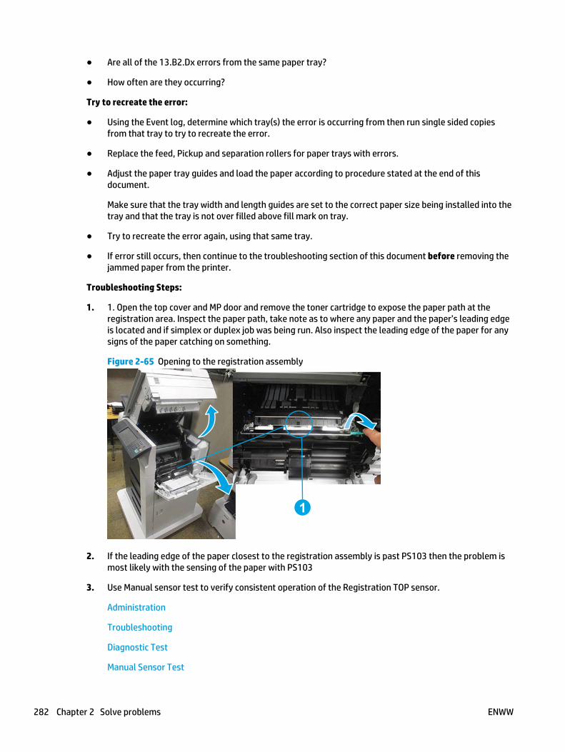
● Are all of the 13.B2.Dx errors from the same paper tray?
● How often are they occurring?
Try to recreate the error:
● Using the Event log, determine which tray(s) the error is occurring from then run single sided copiesfrom that tray to try to recreate the error.
● Replace the feed, Pickup and separation rollers for paper trays with errors.
● Adjust the paper tray guides and load the paper according to procedure stated at the end of thisdocument.
Make sure that the tray width and length guides are set to the correct paper size being installed into thetray and that the tray is not over filled above fill mark on tray.
● Try to recreate the error again, using that same tray.
● If error still occurs, then continue to the troubleshooting section of this document before removing thejammed paper from the printer.
Troubleshooting Steps:
1. 1. Open the top cover and MP door and remove the toner cartridge to expose the paper path at theregistration area. Inspect the paper path, take note as to where any paper and the paper’s leading edgeis located and if simplex or duplex job was being run. Also inspect the leading edge of the paper for anysigns of the paper catching on something.
Figure 2-65 Opening to the registration assembly
1
2. If the leading edge of the paper closest to the registration assembly is past PS103 then the problem ismost likely with the sensing of the paper with PS103
3. Use Manual sensor test to verify consistent operation of the Registration TOP sensor.
Administration
Troubleshooting
Diagnostic Test
Manual Sensor Test
282 Chapter 2 Solve problems ENWW

Scroll down until PS103 TOP is displayed
When activating PS103 sensor, watch the control panel display for the sensor state to change fromgreen to clear or clear to green. I might take a few seconds to change as you toggle sensor flag.
Manually activating PS103
● Open the top cover, and then remove the print cartridge. Raise the registration plate and with asmall flat blade screwdriver carefully activate the sensor flag while looking at the control panelfor a response from the switch.
IMPORTANT: Test the sensor at least 20 times or more since the error is probably intermittent.
NOTE: The sensor flag is up against the set of white rollers and is very hard to see. You will needto swing the guide plate that is part of the white roller assembly out of the way to get to thesensor flag.
Manual Sensor test PASSES:
If Manual test to PS103 passes (Also test PS101, PS107,PS907 in tray 2 feed area or related sensors intray indicated in error)
a. Clean PS103 by using can of compressed air with the blow straw attached for pinpoint cleaning,insert blow straw into the sensor flag opening and blow a couple of short bursts of air at differentangles onto the sensor. Then retest PS103 sensor. (This is done because of the error most likelybeing an intermittent error and you need to make sure that the sensor is clean)
b. Test- Run 200 single sided page test from tray that was associated with error.
c. Check if the pre-registration roller is dirty, worn or deformed. Clean the pre-registration roller ifdirty. Replace the roller if it is worn or deformed.
d. Check the registration assembly. Verify the spring of the registration is in correct position. Replacethe registration assembly if the registration shutter is scarred or worn.
e. Replace the Feed Roller Assembly, clean PS102 using can of compressed air while replacing FeedRoller Assembly and it is exposed. Also replace the Paper Pickup Assembly for the tray that theerror is associated with only.
ENWW Tools for troubleshooting 283

Manual Sensor test FAILS:
a. Disconnect and reconnect the PS103 connector (J94) on the DC controller PCA and check the wiringfor any damage and retest the sensor.
b. If manual sensor test fails again, clean PS103 by using can of compressed air with the blow strawattached for pinpoint cleaning, insert blow straw into the sensor flag opening and blow a couple ofshort bursts of air at different angles onto the sensor. Then retest PS103 sensor.
c. If still no response, replace the DC Controller and retest PS103.
d. If still no response from PS103, replace the printer. (PS103 is not orderable or removable.)
NOTE: Only the base product needs to be replaced. Installed accessories or optional devices canbe transferred to the replacement base product.
13.B2.FF Paper Jam
Description
Residual paper jam in the registration area.
This jam occurs when residual paper is detected at the registration sensor (PS103) at power on.
Recommended action
1. Open the top cover and clear the jam in the indicated area. Inspect the paper path and make sure nopaper is blocking the paper path.
2. Make sure that the tray width and length guides are set to the correct paper size being installed into thetray and that the tray is not over filled above fill mark on tray.
3. Test printer from other trays to verify functionality and if issue is specific to a one specific tray.
4. Try flossing the printer through the jam access door.
● Place paper in access door.
● Turn off then back on printer.
● Watch for Page to be pulled into printer and fed through paper path.
5. Verify if print job was being duplexed.
6. Check if the pre-registration roller is dirty, worn or deformed. Clean the pre-registration roller if dirty.Replace the roller if it is worn or deformed.
7. Check the registration assembly. Verify the spring of the registration is in correct position. Replace theregistration assembly if the registration shutter is scarred or worn.
8. Check and reconnect the connector (J94) on the DC controller PCA.
13.B9.Az Fuser Jam
Description
Fuser delivery stay.
This jam occurs when the fuser delivery sensor (PS700) does not detect the trailing edge of the paper within aspecified period of time from when the sensor detected the leading edge.
284 Chapter 2 Solve problems ENWW

This jam code might be caused by:
● An accordion jam at the fuser exit, something blocking the paper before the output rollers.
● The output bin rollers not turning, there is very little distance from the fuser exit and the output bin
● A sticky fuser exit flag, if it stuck or even delayed momentarily in the activated position.
● Issues with the duplexer — Error occusr only on Duplex jobs, Simplex jobs will print OK.
● 13.B9.A1
The fuser is printing in Auto-Sense mode Normal.
● 13.B9.A2
The fuser is printing in fuser mode Normal.
● 13.B9.A3
The fuser is printing in fuser mode Light 1 or Light 2.
● 13.B9.A4
The fuser is printing in fuser mode Heavy 1.
● 13.B9.A5
The fuser is printing in fuser mode Heavy 2.
● 13.B9.A6
The fuser is printing in fuser mode Heavy 3.
● 13.B9.A7
The fuser is printing in fuser mode Glossy media 1.
● 13.B9.A8
The fuser is printing in fuser mode Glossy media 2
● 13.B9.A9
The fuser is printing in fuser mode Glossy media 3.
● 13.B9.AB
The fuser is printing in fuser mode Transparency.
● 13.B9.AC
The fuser is printing in fuser mode Label.
● 13.B9.AD
The fuser is printing in fuser mode Envelope 1 or Envelope 2.
Recommended action
CAUTION: Use caution when handling the fuser. The fuser might be hot when the product is operating.
ENWW Tools for troubleshooting 285

1. Open the output door, and then clear any jammed paper.
2. Remove any jammed paper from the device. Thoroughly inspect the area the jam occurred and clear allpaper from the paper path.
3. Make sure that the paper meets HP specifications.
4. Ensure the Toner Cartridge and Transfer Roller are seated properly.
5. Remove the fuser, and then clear any jammed paper.
6. Verify there is no debris from a previous jam stuck in the fuser or rollers leading into or exiting thefuser.
7. Verify that the fuser exit flag (PS700) moves freely and is not damaged.
8. Run the sensor test and confirm the fuser exit flag is functioning properly.
9. Replace the fuser.
13.B9.Bz Jam in fuser
Description
This jam occurs when a near complete overlap (less than 5 to 15 mm of non-overlap) multi-feed jam isdetected.
● 13.B9.B1
Multi-Feed jam is detected when printing from Tray 1.
● 13.B9.B2
Multi-Feed jam is detected when printing from Tray 2.
● 13.B9.B3
Multi-Feed jam is detected when printing from Tray 3.
● 13.B9.B4
Multi-Feed jam is detected when printing from Tray 4.
● 13.B9.B5
Multi-Feed jam is detected when printing from Tray 5.
Recommended action
1. Remove any jammed paper from the device.
2. Make sure paper meets HP specifications and is loaded in trays correctly.
3. Make sure that the tray width and length guides are set to the correct paper size being installed into thetray and that the tray is not over filled above fill mark on tray.
4. Verify that the tray pickup, feed, and separation rollers are correctly installed and that they are notworn or damaged.
5. Clean or replace the pickup/feed rollers as needed
286 Chapter 2 Solve problems ENWW

13.B9.Dz Jam in fuser
Description
Fuser delivery delay jam.
This jam occurs when the paper does not reach the fuser output sensor (PS700) in designated amount of timeafter the Registration sensor (PS103) sensed the leading edge when printing.
Z = Tray Printing from.
● 13.B9.D1
Fuser delivery delay jam when printing from Tray 1.
● 13.B9.D2
Fuser delivery delay jam when printing from Tray 2.
● 13.B9.D3
Fuser delivery delay jam when printing from Tray 3.
● 13.B9.D4
Fuser delivery delay jam when printing from Tray 4.
● 13.B9.D5
Fuser delivery delay jam when printing from Tray 5.
● 13.B9.DD
Fuser delivery delay jam when printing from Duplexer.
Recommended action
1. Open rear output bin and check for media or obstructions.
2. Remove any jammed paper from the device. Thoroughly inspect the area the jam occurred and clear allpaper from the paper path.
Paper stopped before fuser:
1. Check the registration area for any blockage, lift registration flap and look for a bit of paper or anyblockage.
2. Verify where the leading edge of the paper is when the jam occurs.
3. Verify that the transfer roller is seated properly and not worn or deformed. Replaced it if necessary.
4. If Paper is stopped below toner cartridge in the registration assy, preform manual sensor test on PS103.
5. Make sure the sensor moves freelty and is not damaged. If sensor does not function elevate the issuefollowing your standard support process.
6. Check Media path between transfer and fuser.
ENWW Tools for troubleshooting 287

7. Check the Paper Feed Assembly for damage or loose belts (see following image)
Figure 2-66 Paper feed assembly belt
8. If belt is extremely loose and will not stayed centered when printing, replacing the Paper FeedAssembly.
Paper stopped in or at fuser
CAUTION: Use caution when handling the fuser. The fuser might be hot when the product is operating.
1. Remove the fuser and inspect the fuser sleeve, pressure roller and delivery roller for blockage and/ordamage. Replace fuser as needed.
2. Test fuser delivery sensor (PS700) using the manual sensor test in the Administration, Troubleshooting,Diagnostic Testsmenu to verify that the sensor is functioning properly. If the sensor fails the test,replace the fuser.
3. Run the Fuser motor drive test under the Administration,Troubleshooting, Diagnostic Tests, ComponentTest menu to verify that the fuser drive and gears are functioning properly. If they are not, replace thefuser drive assembly.
13.B9.FF
Description
Residual paper jam fuser output sensor.
This jam occurs when residual paper is detected at the fuser output sensor (PS700) at power on.
Recommended action
1. Open output door and clear the jam in the indicated area.
2. Close the door so that the product attempts to clear the paper path.
3. Test Fuser Delivery sensor (SP700) using the Tray/Bin manual sensor test in the Administration,Troubleshooting, Diagnostic Tests menu to verify that the sensor is functioning properly, replace fuserif the sensor fails the test.
288 Chapter 2 Solve problems ENWW

13.C3.Az
Description
Media stay jam Engine Switch Back area, Paper Delivery sensor. Paper present at PS112 after specified timelimit.
Z = Fuser Mode
● 13.C3.A1
The fuser is printing in fuser mode Auto Sense special case distinguished from "typed" Normal.
● 13.C3.A2
The fuser is printing in fuser mode Normal.
● 13.C3.A3
The fuser is printing in fuser mode Light 1 or Light 2 (see the event log secondary jam informationdigits for specific mode).
● 13.C3.A4
The fuser is printing in fuser mode Heavy 1.
● 13.C3.A5
The fuser is printing in fuser mode Heavy 2.
● 13.C3.A6
The fuser is printing in fuser mode Heavy media 3.
● 13.C3.A7
The fuser is printing in fuser mode Glossy media 1.
● 13.C3.A8
The fuser is printing in fuser mode Glossy media 2.
● 13.C3.A9
The fuser is printing in fuser mode Glossy media 3.
● 13.C3.AB
The fuser is printing in fuser mode Transparency.
● 13.C3.AC
The fuser is printing in fuser mode Label.
Recommended action
1. Follow the on screen instructions to locate and remove the paper or obstruction.
2. Make sure the type and quality of the media that you are using meet HP specifications.
ENWW Tools for troubleshooting 289

3. Inspect the paper path and remove any obstructions.
4. If issue persists replace Reversing assembly.
13.C3.Dz
Description
Media Delay jam Engine Switch Back area, Paper Delivery sensor. Paper present at PS112 after specified timelimit.
Z = Fuser Mode
● 13.C3.D1
The fuser is printing in fuser mode Auto Sense special case distinguished from "typed" Normal.
● 13.C3.D2
The fuser is printing in fuser mode Normal.
● 13.C3.D3
The fuser is printing in fuser mode Light 1 or Light 2 (see the event log secondary jam informationdigits for specific mode).
● 13.C3.D4
The fuser is printing in fuser mode Heavy 1.
● 13.C3.D5
The fuser is printing in fuser mode Heavy 2.
● 13.C3.D6
The fuser is printing in fuser mode Heavy media 3.
● 13.C3.D7
The fuser is printing in fuser mode Glossy media 1.
● 13.C3.D8
The fuser is printing in fuser mode Glossy media 2.
● 13.C3.D9
The fuser is printing in fuser mode Glossy media 3.
● 13.C3.DB
The fuser is printing in fuser mode Transparency.
● 13.C3.DC
The fuser is printing in fuser mode Label.
290 Chapter 2 Solve problems ENWW

Recommended action
1. Follow the on screen instructions to locate and remove the paper or obstruction.
2. Make sure the type and quality of the media that you are using meet HP specifications.
3. Inspect the paper path and remove any obstructions.
4. If issue persists replace Reversing assembly.
13.D3.Dz
Description
Jam in Duplexer
This jam occurs when the media does not reach the Duplex re-feed sensor (PS113) in designated amount oftime.
Z = Fuser Mode
● 13.D3.D1
The fuser is printing in fuser mode Auto Sense special case distinguished from "typed" Normal.
● 13.D3.D2
The fuser is printing in fuser mode Normal.
● 13.D3.D3
The fuser is printing in fuser mode Light 1 or Light 2 (see the event log secondary jam informationdigits for specific mode).
● 13.D3.D4
The fuser is printing in fuser mode Heavy 1.
● 13.D1.D5
The fuser is printing in fuser mode Heavy 2.
● 13.D3.D6
The fuser is printing in fuser mode Heavy media 3.
● 13.D3.D7
The fuser is printing in fuser mode Glossy media 1.
● 13.D3.D8
The fuser is printing in fuser mode Glossy media 2.
● 13.D3.D9
The fuser is printing in fuser mode Glossy media 3.
● 13.D3.DB
ENWW Tools for troubleshooting 291

The fuser is printing in fuser mode Transparency.
● 13.D1.DC
The fuser is printing in fuser mode Label.
Recommended action
1. Follow the on screen instructions to locate and remove the paper or obstruction.
2. Ensure the type and quality of the media that you are using meet HP specifications.
3. Make sure that customer is using HP Genuine cartridge and test this printer with another working ornew cartridge.
4. Test duplexing from multiple trays to see if issue is TRAY specific or not.
5. Perform the continuous test in simplex mode at least 50 pages to make sure that issue is occurringwhile printing duplex printing only.
6. Remove the duplexer and clean the printer duplex path properly for any debris or dust.
7. Check and Clean the status charge eliminator. (Next to transfer roller).
8. Where is the leading and trailing edge of the paper during the error state?
● Stuck in switchback assembly?
● Stopped at input of Duplexer?
STUCK in switchback assembly:
Check assembly for blockage.
1. Check sensor in assembly using sensor test.
2. If faulty or issue with switchback assembly, Replace the assembly
Stopped at Duplexer:
1. Make sure the duplex re-feed sensor PS113 is clear of paper and is not damaged.
2. Check to ensure the duplex re-feed motor M107 is functioning properly (Use component test to checkduplexer re-feed motor function)
3. If either of these tests fail replace the Duplexing unit.
13.FF.FF
Description
A power on residual paper jam has occurred (sensor).
Recommended action
1. Follow the on screen instructions to locate and remove the paper or obstruction.
2. Inspect the paper path and remove any obstructions.
3. Use the Manual sensors test or Tray/Bin manual sensors test to isolate a faulty door switch or sensor.
292 Chapter 2 Solve problems ENWW

13.XX.YZ Error Messages
20.00.00 Insufficient memory <device>
Description
Event log message 20.00.00.
The product does not have enough memory to print the page.
The product received more data than can fit in the available memory. You might have tried to transfer toomany macros, soft fonts, or complex graphics.
Recommended action
Touch the OK button to print the transferred data. Some data might be lost. Reduce the page complexity oradd product memory.
21.00.00 Page Too Complex Event log error message 21.00.00.
Description
The product displays this message to indicate that the page decompression process was too slow for theproduct.
Recommended action
Touch the OK button to continue. There may be some data loss on the page that was being formatted whenthe error occurred.
30.XX.YZ Error Messages
30.01.01
Description
The flatbed cover sensor was interrupted.
The scanner flatbed cover is open.
Message appears only in the event log and is not posted on the control panel.
The control panel will read Flatbed Cover Open.
Recommended action
No action required.
This error message should automatically clear.
If the error persists, open the scanner tests to test the flatbed cover sensor.
1. If the cover is closed, check the cover sensor at the right rear of the scanner for correct mechanicalfunctionality, using the scanner sensor test in the Administration / Troubleshooting / Diagnostics /ScannerTests Menu.
2. Check the connectors on the scanner control board (SCB) for loose connections.
3. Replace the lid-sensor assembly.
ENWW Tools for troubleshooting 293

4. Replace the scanner control board (SCB).
5. Replace the image scanner assembly.
30.01.06
Description
Scanner fan error.
Recommended action
1. Turn the product off, and then on again.
2. During the MFP initialization sequence, listen to the fan to determine if it is operating.
3. If the error persists, turn the product off, and then check the fan wire-harness connectors.
4. If the fan is not operating, replace the fan.
5. If the error persists, replace the Scan Control Board (SCB).
NOTE: You might want to provide both parts the fan and the SCB to the on-site technician.
Have the technician verify that the connector on the scanner controller PCB is firmly seated. Also, makesure that the connection for the fan in the base of the scanner assembly is firmly seated.
30.01.08 Home position error
Description
The scanner optic failed to return to the home position.
Recommended action
1. Turn the product off, and then on again.
2. Observe the movement of the optics assembly.
3. If the error persists, run the scanner motor test under component test. Administration /Troubleshooting / Scanner tests / Flatbed motor test.
4. If issue still remains and firmware has been upgraded replace scanner control board (SCB).
5. If the error persists, replace the image scanner assembly (ISA).
30.01.14 Scan system EEPROM error
Description
Scanner control board (SCB) EEPROM error.
Recommended action
1. Turn the product off, and then on again.
2. Make sure all connectors on the scanner control board (SCB) are seated fully.
3. Make sure the product has the latest scanner control board (SCB) firmware version.
4. Replace the scanner control board (SCB).
294 Chapter 2 Solve problems ENWW

30.01.15 Scanner error
Description
Scanner did not initialize (internal error).
The scanner failed to be initialized due to an internal error.
Recommended action
1. Turn the product off, and then on again.
2. Make sure that all covers are installed correctly and that the document feeder and document feeder jamcover are closed.
3. Check all sensors on the scanner to make sure they are not blocked.
4. Look through the vents on back of scanner to see if the GREEN LEDs on the scanner control board (SCB)are illuminated.
5. Check all connections for scanner control board (SCB) to print engine.
6. Replace the scanner control board (SCB).
30.01.18 Scanner Error
Description
Scanner internal optical sensor error.
Recommended action
1. Turn the product off, and then on again.
2. Make sure that all the connectors on the scanner control board (SCB) are seated fully.
3. Make sure that the product has the latest scanner control board (SCB) firmware version.
4. Replace the scanner control board (SCB).
5. If the error persists, replace the image scanner assembly (ISA).
30.01.19 Scanner lamp error
Description
Scanner internal lamp sensor error.
Recommended action
1. Turn the product off, and then on again.
2. Verify that the scanner lamp turns on and off approximately 12 seconds after the product is turned on.
3. Test the lower lamp using the scanner test located in the Diagnostics menu.
4. Re-seat the interconnect cables between the optical carriage and the scanner control board (SCB).
5. Replace the image scanner assembly (ISA).
ENWW Tools for troubleshooting 295

30.01.30 or 30.01.32
Description
HP image ASIC error.
Recommended action
1. Turn the product off, and then on again.
2. Check the connections on the scanner control board (SCB).
3. Replace the scanner control board (SCB).
30.01.36 Upgrade Error try downloading upgrade again
Description
Scanner firmware upgrade error.
Recommended action
1. Re-send the scanner firmware upgrade.
2. If the error persists, replace the scanner control board (SCB).
30.01.41 Scanner error
Description
The formatter lost connections with the scanner control board (SCB) or communication was corrupted.
Recommended action
1. Turn the product off, and then on.
2. Remove and then re-seat the formatter.
3. Upgrade the firmware.
4. Verify that all cables are connected to the product and to the interconnect board, and scanner controlboard (SCB).
5. Verify that the scanner control board (SCB) has power.
6. Replace the scanner control board (SCB).
7. Replace the formatter.
30.01.42 Scanner error
Description
Internal product communication error.
Recommended action
1. Turn the product off, and then on again.
2. If the error persists, turn the product off, and then check the scanner control board (SCB) connectors.
296 Chapter 2 Solve problems ENWW

3. If this error occurs after a formatter, fax card or hard disk has been replaced, check that the formatter isfully seated and the connectivity LED (smile face icon on the formatter) is illuminated. Check the faxcard for proper seating on the formatter. (If fax card is not properly seated it can prevent the formatterfrom seating properly in the product..
4. If the error persists, replace the scanner control board (SCB).
30.01.43 Scanner memory failure
Description
Scan memory error.
Recommended action
1. Turn the product off, and then on again.
2. If the error persists, turn the product off, and then re-seat the formatter.
3. If the error persists, replace the formatter.
30.01.44
Description
Copy processor board (CPB) / Scanner control board (SCB) communication error.
Recommended action
1. Turn the product off, and then on again.
2. If the error persists, turn the product off, and then check the scanner cable.
3. Upgrade the firmware.
4. If the error persists, turn the product off, and then re-seat the formatter.
5. If the error persists, replace the scanner control board (SCB) or the formatter.
30.01.45
Description
Internal Copy processor board (CPB) communication error.
CPB code assertion error for the copy processor board firmware.
Recommended action
1. Turn the product off, and then on again.
2. If the error persists, turn the product off, and then remove and then re-seat the formatter.
3. Upgrade the firmware.
4. If the error persists, replace the scanner control board (SCB).
5. If the error persists, replace the formatter.
ENWW Tools for troubleshooting 297

30.01.46 Scanner Error
Description
The firmware cannot find the copy processor board.
Recommended action
1. Turn the product off, and then on again.
2. f the error persists, turn the product off, and then remove and then re-seat the formatter.
3. If the error persists, replace the scanner control board (SCB).
30.01.48 Scanner error
Description
Scanner error.
Scanner power is not connected.
Recommended action
1. Turn the product off, and then on again.
2. If the error persists, turn the product off, and then check the scanner wire-harness connectors and thescanner power supply fan.
3. If the error persists, replace image scanner assembly.
30.01.49
Description
Scanner inverter fan error.
Recommended action
1. Turn the product off, and then on again.
2. If the error persists, turn the product off, and then check the scanner wire-harness connectors and thescanner power supply fan.
3. If the error persists, replace the scanner power supply, the scanner power supply fan, or the SCB.
30.01.50 Scanner error
Description
Internal scanner control board (SCB) error.
Recommended action
1. Turn the product off, and then on again.
2. Upgrade the firmware.
3. If the error persists, replace the scanner control board (SCB).
298 Chapter 2 Solve problems ENWW

30.03.14
Description
A non-fatal error has occurred.
A scanner EEPROM (NVM) error has occurred.
Recommended action
This is an informational message, and no action is required.
30.03.20
Description
The copy processor board firmware cannot communicate with the PCA on the optical assembly.
Recommended action
1. Turn the product off, and then on again.
2. Verify that the FFCs between scanner and the scanner control board (SCB) are connected.
3. Replace the image scanner assembly.
30.03.22 Scanner failure
Description
Front side illumination calibration failure.
The scan module cannot see the illumination module, or marginal illumination.
The optical assembly may not be parked under the calibration strip.
Recommended action
1. Turn the product off, and then on again.
2. Upgrade the firmware.
3. Check the event log for other scanner errors, and then resolve those errors.
4. Check the scan module FFC connection.
5. Replace the image scanner assembly.
30.03.23 Scanner failure
Description
Flatbed alignment calibration error.
Recommended action
1. Turn the product off, and then on again.
2. Upgrade the firmware.
3. Replace the image scanner assembly.
ENWW Tools for troubleshooting 299

30.03.30 Scanner Failure
Description
Flatbed motor shutdown.
The scanner control board (SCB) cannot communicate with the flatbed scanner motor.
Recommended action
1. Turn the product off, and then on again. As the product turns on, verify that the scan head moves.
2. Verify that the drive belt is in the correct position.
3. Run diagnostics on the flatbed scanner to see if the scan bar moves.
4. Check the cable connection to the scanner control board (SCB).
5. Replace the image scanner assembly.
30.03.45 Scanner Error To continue turn off then on
Description
Scanner control board (SCB) firmware assertion failure. SCB firmware assert controls the scan head motor.
Recommended action
1. Turn the product off, and then on again.
2. Upgrade the firmware.
3. Replace the scanner control board (SCB).
4. Replace the image scanner assembly.
31.XX.YZ Error Messages
31.01.47 Document feeder not detected
Description
The document feeder was not detected, the document feeder might not be connected. The flatbed glass isstill available for scanning.
Recommended action
1. Turn the product off and then on.
2. If error persists, replace document feeder.
NOTE: Before replacing the document feeder, technicians should verify that the connections between thedocument feeder and the product are fully seated.
31.03.14
Description
Backside scanner EEPROM (NVM) error.
A non-fatal error has occurred.
300 Chapter 2 Solve problems ENWW

Recommended action
No action required.
31.03.20 backside scanner not detected
Description
Backside scanner not detected.
Recommended action
1. Turn the product off, and then on.
2. Verify the cables between scanner and scanner control board (SCB) are connected.
3. Replace the document feeder assembly.
31.03.22 Scanner calibration failure
Description
Backside illumination calibration failure.
Recommended action
1. Turn the product off, and then on.
2. Upgrade the firmware.
3. Verify the cables between scanner and scanner control board (SCB) are connected.
4. Replace the document feeder assembly.
31.03.30 Document feeder pick motor error
Description
The document feeder pick motor is not turning.
Recommended action
1. Verify that the paper meets the product specifications.
2. Make sure that the input tray is not overloaded and the tray guides are properly aligned to both edgesof the paper.
3. Check the event log for document feeder errors, and then resolve any errors first.
4. Open and close the top cover to see if the pick motor turns without posting this error. If the motor turns,then the motor is good.
5. Verify that the motor cables are connected.
6. Re-seat the document feeder to the scanner control board (SCB).
7. Replace the document feeder.
ENWW Tools for troubleshooting 301

31.03.31 Document feeder motor stall
Description
The document feeder feed motor is not turning.
Recommended action
1. Verify that the paper meets the product specifications.
2. Make sure that the input tray is not overloaded and the tray guides are properly aligned to both edgesof the paper.
3. Check the event log for document feeder errors, and then resolve those errors first.
4. Verify that the motor cables are connected.
5. Re-seat the document feeder to the scanner control board (SCB).
6. Replace the document feeder assembly.
31.03.32
Description
The document feeder de-skew motor is not turning.
Recommended action
1. Verify that the paper meets the product specifications.
2. Make sure that the input tray is not overloaded.
3. Check the event log for document feeder errors, and then resolve any errors first.
4. Verify that the motor cables are connected.
5. Re-seat the document feeder to scanner control board (SCB) cables.
6. Replace the document feeder assembly.
31.03.33 Backside scanner calibration area dirty
Description
The white area used for backside scanner calibration is dirty.
Recommended action
1. Remove the white backing and clean it.
2. Clean the backside scanner glass.
3. If issue remains replace the document feeder assembly.
31.03.34 Background missing
Description
The removable white backing for the backside scanner is either missing or not fully snapped into place.
302 Chapter 2 Solve problems ENWW

Recommended action
1. Remove the white backing and clean it.
2. Clean the backside scanner glass.
3. If issue remains replace the document feeder assembly.
No action necessary.
31.13.00 Document feeder multi-pick error
Description
A multiple pick error was reported by the document feeder assembly.
Recommended action
1. Open the document feeder cover, pull all the sheets back into the tray and then resume the job.
2. Verify that the paper meets the product specifications.
3. Make sure that the input tray is not overloaded and the tray guides are properly aligned to both edgesof the paper.
4. Check and clean the rollers and separation pad, and test the registration sensor. If needed, replacepickup roller assembly, separation pad.
5. Verify that the motor cables are connected.
6. Re-seat the document feeder to the scanner control board (SCB).
7. Replace the document feeder.
31.13.01
Description
document feeder job error, pick error.
Paper pick was initiated, but the page didn't did not make it to the pick success sensor.
Recommended action
1. Open the document feeder lid, pull sheets back into input tray, and then resume the job.
2. Check the paper guides and make sure that they are set to the correct paper width.
3. Make sure that the input tray is not overloaded and the tray guides are properly aligned to both edgesof the paper.
4. Check the document feeder page count for roller life.
5. Verify that the paper meets the product specifications.
6. Clean the document feeder pick and feeder rollers and clean separation pad, if worn or damage replaceroller kit.
7. Open the following menus:
ENWW Tools for troubleshooting 303
● Administration
● Troubleshooting
● Diagnostic Tests
● Scanner Tests
8. Actuate the pick-success sensor. If the sensor does not show functionality when tested, replace thedocument feeder.
9. If sensor is not available for replacement or does not resolve issue, replace the document feederassembly.
31.13.02
Description
Document feeder job error, feed jam.
The paper passed the pick success sensor, and then jammed in the document feeder paper path.
Recommended action
1. Clear the paper path and try feeding the page again.
2. Verify that the paper meets the product specifications.
3. Check the paper guides and make sure that they are set to the correct paper width.
4. Verify that the paper path is clear.
5. Clean the document feeder pick and feeder rollers and clean Separation pad. If worn or damage replaceroller kit.
6. Open the following menus:
● Administration
● Troubleshooting
● Diagnostic Tests
● Scanner Tests
7. Actuate the pick-success sensor. If the sensor does not show functionality when tested, replace thedocument feeder.
8. If sensor is not available for replacement or does not resolve issue replace the document feederassembly.
31.13.13
Description
The document feeder jam access door is open.
304 Chapter 2 Solve problems ENWW

Recommended action
1. Verify that the jam access cover is closed.
2. Verify that the flag is not broken off.
3. Open the following menus:
● Administration
● Troubleshooting
● Diagnostic Tests
● Scanner Tests
4. Actuate the pick-success sensor. If the sensor does not show functionality when tested, replace thedocument feeder.
5. If the sensor is not available for replacement or does not resolve issue replace the document feederassembly.
31.13.14
Description
Document feeder job error: over current.
This is a feed jam in the document feeder, and the motor is not turning.
Recommended action
1. Verify that the paper meets the product specifications.
2. Make sure that the document feeder input tray is not overloaded.
3. Check the event log for document feeder errors, and then resolve those errors first.
4. Open and close the top cover to see if the pick motor turns without posting this error. If there is noerror, then the motor is good.
5. Verify that the motor cables are connected.
6. Re-seat the document feeder to the scanner control board (SCB).
7. Replace the document feeder.
31.13.15
Description
This is a duplex re-feed jam in the document feeder.
The paper jam occurs on the backside copy. The duplex re-feed does not make it to the deskew sensor.
Recommended action
1. Remove the jammed paper.
2. Verify that there is nothing in the paper path of the duplex re-feed area.
ENWW Tools for troubleshooting 305

3. Retry the copy job.
4. Replace the document feeder assembly.
32.XX.YX and 33.XX.YZ Error Messages
32.08.A1, 32.08.A2, 32.08.A3
Description
32.08.A1 (event code)
Shutdown event-boot after abnormal shutdown.
32.08.A2 (event code)
Boot from normal shutdown event.
32.08.A3 (event code)
Regular boot event.
Recommended action
No action necessary.
32.1C.XX
Description
32.1C.05 (event code)
The restore job ticket was submitted with invalid credentials.
32.1C.06 (event code)
The backup job ticket was submitted with invalid credentials.
32.1C.07 (event code)
Backup restore permissions error.
There was an error during the creation, read, or write of the restore file.
32.1C.08 (event code)
Not enough disk space to perform backup/restore or network share issue.
There was an error during the creation, read, or write of the backup file.
32.1C.09 (event code)
Tried to restore a backup file that was not valid for this product.
The data in the backup file specified in the restore job ticket is no longer valid due to a corruption of the dataor no loner present.
32.1C.0A (event code)
Backup file is invalid
306 Chapter 2 Solve problems ENWW

The data in the backup file specified in the restore job ticket is no longer valid due to a corruption of the dataor no loner present.
32.1C.0D (event code)
Backup/restore failed, auto-reboot failed, or the product might be busy.
32.1C.11 (event code)
Backup/restore timeout while communicating with the engine.
The backup was aborted because the product is busy.
32.1C.13 (event code) and 32.1C.14 (event code)
Not enough space exists to perform the backup.
The backup was aborted because the disk is at a critical level or full.
Scheduled backup failure.
32.1C.15 (event code)
Restore aborted because the backup file was created by a previous version of firmware no longer supportedby the feature.
32.1C.2E (event code)
The restore was aborted because the product is busy.
32.1C.2F (event code)
Reset failure.
32.1C.40 (event code)
The backup operation completed successfully (informational).
32.1C.41 (event code)
The backup operation encountered an error (informational).
32.1C.42 (event code)
The backup operation completed, but with a warning message (informational).
32.1C.43 (event code)
A component in the backup file is not supported by the current version of firmware and will not be restored(informational).
32.1C.44 (event code)
A component in the backup file is not transferable to another product and will not be restored(informational).
32.1C.45 (event code)
Some data was not included in the backup file (informational).
32.1C.46 (event code)
ENWW Tools for troubleshooting 307

An expected component could not be found and was thus not backed up. Because components should beknown on backups, this code is a warning (informational).
32.1C.47 (event code)
Some data was not restored from the backup file (informational).
32.1C.48 (event code)
The backup job ticket was submitted using an invalid network path.
32.1C.49 (event code)
The backup job ticket was submitted with a bad encryption.
32.1C.4A (event code)
An error occurred when creating the temporary directories used to store the backup files in transition to andfrom the compressed (ZIP) file.
32.1C.56 (event code)
Reset aborted. Backup/restore in progress (informational).
32.1C.57 (event code)
Reset aborted (informational).
32.1C.58 (event code)
Unknown reset error (informational).
32.1C.60 (event code)
The restore operation completed successfully (informational).
32.1C.61 (event code)
The restore operation encountered an error.
32.1C.62 (event code)
The restore operation completed, but with a warning message.
32.1C.68 (event code)
The restore job ticket was submitted using an invalid network path.
32.1C.69 (event code)
The restore job ticket was submitted with a bad encryption personal identification number (PIN).
32.1C.6A (event code)
An error occurred when creating the temporary directories used to store the restore files in transition to andfrom the compressed (ZIP) file.
32.1C.6D (event code)
An unusual error occurred when running the restore.
308 Chapter 2 Solve problems ENWW

Recommended action
32.1C.05 (event code)
Verify the credentials that were submitted. Check the domain, user name, and password.
32.1C.06 (event code)
Verify the credentials that were submitted. Check the domain, user name, and password.
32.1C.07 (event code)
Retry the job.
32.1C.08 (event code)
● Retry the job.
● Remove stored jobs and retry.
● Use a larger capacity storage device.
● Check the network share.
Remove any stored jobs, and then retry.
If the error persists, try using a larger capacity storage device and check the network share settings.
32.1C.09 (event code)
Use a valid backup file.
32.1C.0A (event code)
Use a valid backup file.
Reboot, and then observe the state of the product.
If the error persists, perform a partition clean from the Preboot menu.
32.1C.0D (event code)
Reboot, and then retry the backup/restore.
32.1C.11 (event code)
Wait until the product is idle, and then try again.
32.1C.13 (event code) and 32.1C.14 (event code)
Free up disk space, and then try again.
32.1C.15 (event code)
- Use the current backup file.
32.1C.2E (event code)
Wait until the product is idle, and then try again.
Turn the product off then on, and then retry.
ENWW Tools for troubleshooting 309

32.1C.2F (event code)
Turn the product off then on, and then retry.
32.1C.40 (event code)
No action necessary.
32.1C.41 (event code)
No action necessary.
32.1C.42 (event code)
No action necessary.
32.1C.43 (event code)
No action necessary.
32.1C.44 (event code)
No action necessary.
32.1C.45 (event code)
No action necessary.
32.1C.46 (event code)
No action necessary.
32.1C.47 (event code)
No action necessary.
32.1C.48 (event code)
Check that a share was provided as part of the network path (not blank).
Check that the server and the share exists.
Check that the user has permission to access the share on the provided server.
32.1C.49 (event code)
Verify that the encryption personal identification number (PIN) meets the restrictions for the product.
32.1C.4A (event code)
Retry the job.
If this does not resolve the issue, turn the product off then on again and retry the job.
If the error persists, perform a Partial Clean using the Preboot menu.
32.1C.56 (event code)
No action necessary.
32.1C.57 (event code)
310 Chapter 2 Solve problems ENWW

No action necessary.
32.1C.58 (event code)
No action necessary.
32.1C.60 (event code)
No action necessary.
32.1C.61 (event code)
Review the error log to see specific details about the failure.
32.1C.62 (event code)
Review the error log to see specific details about the failure.
32.1C.68 (event code)
Check that a share was provided as part of the network path (not blank).
Check that the server and the share exist.
Check that the user has permission to access the share on the provided server.
Check that the path includes the compressed (ZIP) file name as part of the path.
32.1C.69 (event code)
Verify the encryption personal identification number (PIN) is the same PIN used to encrypt the backup file.
32.1C.6A (event code)
Retry the job.
32.1C.6D (event code)
Retry the job.
33.01.XX
Description
● 33.01.01 (event code)
A restore process has occurred.
● 33.01.02 (event code)
A save process has occurred.
● 33.01.03 (event code)
Save recover functionality OK after previously being disabled.
Recommended action
No action necessary.
ENWW Tools for troubleshooting 311

33.02.01 Used board/disk installed
Description
Used board disk installed.
An encrypted board or disk with existing data previously locked to a different product has replaced theoriginal. If you continue, data is permanently lost.
Recommended action
1. Reinstall the used board or disk back into its original product.
2. To save the data on the board or disk, turn the product off. replace the board or disk with another boardor disk.
3. To delete the data on the board or disk and continue, touch the OK button.
33.03.03 Incompatible formater installed.
Description
This is and EFI BIOS event to prevent booting with the wrong formatter installed.
Recommended action
Turn the product off, and then install the correct formatter in the product.
NOTE: If it is believed that this formatter is the correct part number and model for this product, install areplacement formatter, and then return the formatter in question to HP for evaluation.
33.03.XX
Description
● 33.02.01 (event code)
Save recover engine storage ID unexpected length.
● 33.03.02 (event code)
Data size mismatch unable to recover DCC MVRAM.
Recommended action
Turn the product off, and then on again.
If the error persists, replace the image control board (ICB) and return to HP for evaluation.
40.XX.YZ Error Messages
40.00.01 USB I/O buffer overflow To continue, touch “OK”
Description
The USB buffer has overflowed.
312 Chapter 2 Solve problems ENWW

Recommended action
1. Touch the OK button to print the transferred date (some data might be lost).
2. Check the host configuration.
40.00.02 Embedded I/O buffer overflow To continue, touch “OK”
Description
The product has experienced a JetDirect buffer overflow.
Recommended action
1. Touch the OK button to print the transferred date (some data might be lost).
2. Check the host configuration.
40.00.03 EIO <X> buffer overflow To continue, touch “OK”
Description
Too much data was sent to the EIO card in the specified slot (x). An incorrect communications protocol mightbe in use.
Recommended action
Touch the OK button to print the transferred date (some data might be lost).
40.00.04 EIO <X> bad transmission To continue, touch “OK”
Description
The connection between the product and the USB device has been broken.
Recommended action
1. Touch the OK button to clear the error message and continue printing.
2. Remove, and then reinstall the USB device.
40.00.05 Embedded I/O bad transmission To continue, touch “OK”
Description
The USB device has been removed.
Recommended action
1. Touch the OK button to clear the error message (data will be lost).
2. Install the USB device.
40.08.0X USB storage accessory removed
Description
X = 0 or ;1 information code.
Secure file erase is enabled.
ENWW Tools for troubleshooting 313

Recommended action
No action necessary.
40.0X.05 USB storage accessory removed
Description
X = 1, 2, 3, 5, or 6; information code.
The USB storage accessory was removed.
Recommended action
No action necessary.
41.XX.YZ Error Messages
41.01.YZ
Description
Event log error message: 41.01.YZ.
An unknown misprint error occurred on the product.
Y = Type, Z = Tray
● Y = 0: Photo Media (1, 2, or 3)
● Y = 1: Auto Sense (Normal)
● Y = 2: Normal (typed not from Auto Sense)
● Y = 3: Light media 1, 2, or 3 mode
● Y = 4: Heavy media 1
● Y = 5: Heavy media 2
● Y = 6: Heavy media 3
● Y = 7: Glossy media 1
● Y = 8: Glossy media 2
● Y = 9: Glossy media 3
● Y = A: Glossy film
● Y = B: OHT
● Y = C: Label
● Y = D: Envelope 1, 2, or 3 mode
● Y = E: Rough
● Y = F: Other mode
314 Chapter 2 Solve problems ENWW

● Z = 0: From unknown tray
● Z = 1: From Tray 1
● Z = 2: From Tray 2
● Z = 3: From Tray 3
● Z = 4: From Tray 4
● Z = 5: From Tray 5
● Z = 6: From Tray 6
● Z = 7: From Tray 7
● Z = 8: From Tray 8
● Z = 9: From Tray 9
● Z = D: From duplex
Recommended action
1. Touch OK to clear the error.
2. If the error is not cleared, Turn the product off, and then on again.
3. If the error returns, check the wire harness from the laser scanner to the DC controller.
4. If the error persists, replace the laser/scanner assembly.
5. Replace the DC controller.
41.02.00 Error
Description
A beam detected misprint error occurred.
Recommended action
1. To clear the error message, touch OK.
2. If the error persists, turn the product off, and then on again.
3. If the error returns, check the wire harness from the laser/scanners to the DC controller.
4. If the error persists, replace the laser/scanner assembly.
41.03.FZ Unknown Misprint Error
Description
This is a general misprint error. Either media is loaded off-center with the side guides in the tray or a mediawidth sensor failure occurred from an unknown tray. The error will be one of the following:
● 41.03.F0
● 41.03.F1
● 41.03.F2
ENWW Tools for troubleshooting 315

● 41.03.F3
● 41.03.F4
● 41.03.F5
● 41.03.FD
Recommended action
1. Reload the tray, verifying that the guides in the tray are flush with the loaded media in the tray.
2. Try the print job again.
Watch the mechanism to see if it is functioning correctly. If the linkage is broken, replace the paper tray.
3. If the error persists, print a Configuration Page and note the paper size for the tray in question.
● If the size is not reported correctly, run the tray size sensor test in the Diagnostic menu.
● If the tray size sensors test as GOOD, replace the paper tray.
● If the tray size sensors test as BAD, check the cable connections between the tray size sensor andthe DC Controller.
If the cable connections are plugged in correctly and the cables are not compromised, replace thecorrect component that contains the tray size sensing switches.
41.03.YZ Unexpected size in tray <X>
Description
The product detected a different paper size than expected.
Y = Type, Z = Tray
● Y = 0 Size mismatch. Detected media is longer or shorter than expected.
● Y = A Size mismatch. Detected media too long.
● Y = B Size mismatch. Detected media too short.
● Y = C Size mismatch. Inter-page gap error.
● Z = D Source is the duplexer.
● Z = E Source is the envelope feeder.
● Z = 1 Source is Tray 1.
● Z = 2 Source is Tray 2.
● Z = 3 Source is Tray 3.
● Z = 4 Source is Tray 4.
● Z = 5 Source is Tray 5.
316 Chapter 2 Solve problems ENWW

Recommended action
1. Touch OK to use another tray.
2. Print a configuration page to verify the size and type to which the trays are set.
3. Make sure that the tray is loaded with the correct paper size and that the sliding paper guides arecorrectly adjusted to the correct paper size.
4. Verify that the error is not occurring as a result of an unexpected paper size trigger caused by a multi-page feed.
5. Verify that the Toner cartridge and the transfer roller are seated properly.
6. Use the Tray/Bin manual sensor test to verify that the cassette media switch is correctly functioning.
7. Check paper path sensors for proper operation and that they do not stick at all. Replace any damagedsensor or assembly.
8. Reconnect the connectors for the media sensor, intermediate-transfer belt, and the DC controller PCA.
9. Test registration assembly motor and clutch. If not function properly replace the registration assembly.If the error persists, replace the lifter assembly.
41.04.YZ Printer Error
Description
An unknown misprint error occurred on the product.
Y = Type, Z = Tray
● Y = 0: Photo Media (1, 2, or 3)
● Y = 1: Auto Sense (Normal)
● Y = 2: Normal (typed not from Auto Sense)
● Y = 3: Light media 1, 2, or 3 mode
● Y = 4: Heavy media 1
● Y = 5: Heavy media 2
● Y = 6: Heavy media 3
● Y = 7: Glossy media 1
● Y = 8: Glossy media 2
● Y = 9: Glossy media 3
● Y = A: Glossy film
● Y = B: OHT
● Y = C: Label
● Y = D: Envelope 1, 2, or 3 mode
ENWW Tools for troubleshooting 317

● Y = E: Rough
● Y = F: Other mode
● Z = D Source is the duplexer.
● Z = 0 Source is the envelope feeder.
● Z = 1 Source is Tray 1.
● Z = 2 Source is Tray 2.
● Z = 3 Source is Tray 3.
● Z = 4 Source is Tray 4.
● Z = 5 Source is Tray 5.
Recommended action
1. Touch OK to clear the error .
2. If error does not clear, turn the product off, and then on again.
3. Swap out or re-seat each toner cartridge to test it.
4. Check the toner cartridges before replacing any other parts (HP original?, connectors, etc.).
5. Re-seat the connections to the laser/scanner and the DC controller.
6. If the error persists, replace the affected laser/scanner.
7. Replace the DC controller.
41.05.YZ Unexpected type in tray <X>
Description
The product can detect the type of paper in the paper path, and it adjusts the print mode accordingly.
The product uses two types of media sensors:
● Reflection: Detects the glossiness of the paper.
● Transmission: Detects the thickness of the paper.
Tray X is loaded with a media type (transparencies, envelopes, etc.) that is different than what they tray isconfigured to use.
Y = Expected type, Z = Detected type
● Y = 0: Photo Media (1, 2, or 3)
● Y = 1: Auto Sense (Normal)
● Y = 2: Normal (typed not from Auto Sense)
● Y = 3: Light media 1, 2, or 3 mode
● Y = 4: Heavy media 1
● Y = 5: Heavy media 2
318 Chapter 2 Solve problems ENWW

● Y = 6: Heavy media 3
● Y = 7: Glossy media 1
● Y = 8: Glossy media 2
● Y = 9: Glossy media 3
● Y = A: Glossy film
● Y = B: OHT
● Y = C: Label
● Y = D: Envelope 1, 2, or 3 mode
● Y = E: Rough
● Y = F: Other mode
● Z = 0: Photo Media (1, 2, or 3)
● Z = 1: Auto Sense (Normal)
● Z = 2: Normal (typed not from Auto Sense)
● Z = 3: Light media 1, 2, or 3 mode
● Z = 4: Heavy media 1
● Z = 5: Heavy media 2
● Z = 6: Heavy media 3
● Z = 7: Glossy media 1
● Z = 8: Glossy media 2
● Z = 9: Glossy media 3
● Z = A: Glossy film
● Z = B: OHT
● Z = C: Label
● Z = D: Envelope 1, 2, or 3 mode
● Z = E: Rough
● Z = F: Other mode
Recommended action
1. Load the tray with the size and type of paper indicated, or use another tray if available.
2. If this message displays and the tray is loaded with the correct paper type, check the print driversettings to make sure they match the tray type settings.
3. Check all application and product settings to make sure that the Type setting is correct.
ENWW Tools for troubleshooting 319

41.XX.YZ Error To continue, touch “OK”
Description
This section covers all other errors of the form 41.XX.YZ not covered in the previous sections.
A product error has occurred.
XX = error type
Y = fuser mode
Z = input tray
● XX = 02 Beam detect misprint
● XX = 09 Sub thermistor abnormally high
● XX = 10 Pickup failure.
● XX = 11 Illegal Duplex.
● XX = 18 Scan line inclination adjustment
● XX = 20 Image drum HV
● Y = 0: Photo Media (1, 2, or 3)
● Y = 1: Auto Sense (Normal)
● Y = 2: Normal (typed not from Auto Sense)
● Y = 3: Light media 1, 2, or 3 mode
● Y = 4: Heavy media 1
● Y = 5: Heavy media 2
● Y = 6: Heavy media 3
● Y = 7: Glossy media 1
● Y = 8: Glossy media 2
● Y = 9: Glossy media 3
● Y = A: Glossy film
● Y = B: OHT
● Y = C: Label
● Y = D: Envelope 1, 2, or 3 mode
● Y = E: Rough
● Y = F: Other mode
● Z = 0 Envelope feeder
● Z = 1 Tray 1
320 Chapter 2 Solve problems ENWW

● Z = 2 Tray 2
● Z = 3 Tray 3
● Z = 4 Tray 4
● Z = 5 Tray 5
● Z = 6 Tray 6
● D Duplexer
Recommended action
1. To clear the message, touch the OK button.
2. If the message displays again, turn the product off, and then on again.
3. If the error persists, replace the DC Controller PCA.
42.XX.YZ Error Messages
42.XX.YZ
Description
Internal system failure
Recommended action
1. Turn the product off then on, and retry.
2. If the error persists, clear the firmware image from the active partition by using the Partial Clean item inthe Preboot menu.
44.XX.XX Error Messages
44.01.XX Error Event log message
Description
A digital send error has occurred.
Recommended action
No action necessary. This error message should automatically clear.
Try to send the job again.
If error does not clear or returns:
● Use optimal resolution and image quality settings.
● wait till all the digital send jobs have been processed.
● Reboot and retry job.
● Verify if there is an attachment limit on the email.
● Verify network connectivity, SMTP gateways, access to folder share.
ENWW Tools for troubleshooting 321

44.03.XX Error Event log message
Description
A digital send error has occurred.
Recommended action
Try to send the job again.
If error does not clear or returns:
● Use optimal resolution and image quality settings.
● wait till all the digital send jobs have been processed.
● Reboot and retry job.
● Verify if there is an attachment limit on the email.
● Verify network connectivity, SMTP gateways, access to folder share.
44.10.XX Error Event log message
Description
A send to e-mail error has occurred.
Recommended action
No action necessary.
44.34.XX Error Event log message
Description
A fax error has occurred.
Recommended action
1. Try to send the job again.
2. Check the fax settings to make sure they are set to the proper settings for the environment.
3. If the issue persists, see document - “Solve fax problems", for additional fax troubleshootinginformation.
44.92.XX Error Event log message
Description
A fax error has occurred.
Recommended action
1. Try to send the job again.
2. Check the fax settings to make sure they are set to the proper settings for the environment.
3. If the issue persists, see document - “Solve fax problem” for additional fax troubleshootinginformation.
322 Chapter 2 Solve problems ENWW

47.XX.XX Error Messages
47.00.XX
Description
Back channel internal error.
Recommended action
1. Turn the product off, and then on again.
2. Resend the print job.
3. If the error persists, clear the active partition by using the Partial Clean item in the Preboot menu.
47.01.XX
Description
Image transformer internal error.
Recommended action
1. Turn the product off, and then on again.
2. Resend the print job.
3. If the error persists, clear the active partition by using the Partial Clean item in the Preboot menu.
47.02.XX
Description
Job parser internal error.
Recommended action
1. Turn the product off, and then on again.
2. Resend the print job.
3. If the error persists, clear the active partition by using the Partial Clean item in the Preboot menu.
47.03.XX
Description
Print job internal error.
Recommended action
1. Turn the product off, and then on again.
2. Resend the print job.
3. If the error persists, clear the active partition by using the Partial Clean item in the Preboot menu.
ENWW Tools for troubleshooting 323

47.04.XX
Description
Print spooler 9100 internal error.
Recommended action
1. Turn the product off, and then on again.
2. Resend the print job.
3. If the error persists, clear the active partition by using the Partial Clean item in the Preboot menu.
47.05.00
Description
Print spooler framework internal error.
Recommended action
1. Turn the product off, and then on again.
2. Resend the print job.
3. If the error persists, clear the active partition by using the Partial Clean item in the Preboot menu.
47.06.XX
Description
Print application internal error.
Recommended action
1. Turn the product off, and then on again.
2. Resend the print job.
3. If the error persists, clear the active partition by using the Partial Clean item in the Preboot menu.
47.WX.YZ Printer Calibration Failed To continue, touch “OK”
Description
The device is unable to access or implement one of the image patterns files.
Y = Calibration type, Z = Event
● 47.FC.00 (event code) Color plane registration (CPR) Image not found at system initialization
● 47.FC.01 (event code) CPR Store Image failure
● 47.FC.02 (event code) CPR Image not found
● 47.FC.03 (event code) CPR Print engine execution failure
● 47.FC.10 (event code) Consecutive Dmax Dhalf Image not found at system initialization
● 47.FC.11 (event code) Consecutive Dmax Dhalf Store image failure
324 Chapter 2 Solve problems ENWW

● 47.FC.12 (event code) Consecutive Dmax Dhalf Image not found
● 47.FC.13 (event code) Consecutive Dmax Dhalf Print engine execution failure
● 47.FC.20 (event code) Error Diffusion Image not found at system initialization
● 47.FC.21 (event code) Error Diffusion Store image failure
● 47.FC.22 (event code) Error Diffusion Image not found
● 47.FC.23 Error Diffusion Print engine execution failure
● 47.FC.30 0 (event code) Drum Speed Adjustment Image not found at system initialization
● 47.FC.31 (event code) Drum Speed Adjustment Store image failure
● 47.FC.32 (event code) Drum Speed Adjustment Image not found
● 47.FC.33 (event code) Drum Speed Adjustment Print engine execution failure
● 47.FC.40 (event code) Pulse Width Modulation Image not found at system initialization
● 47.FC.41 (event code) Pulse Width Modulation Store image failure
● 47.FC.42 (event code) Pulse Width Modulation Image not found
● 47.FC.43 (event code) Pulse Width Modulation Print engine execution failure
Recommended action
1. Turn the product off, and then on again.
2. If the error persists over multiple power cycles frequently and consistently on a unit then do thefollowing.
● In the Administration/Troubleshooting/Diagnostics, run the hard disk tests to validate health ofthe device. Fix any issue found with the mass storage device
3. If the error persists, reload the firmware.
4. If the error persists, clear the active partition by using the Partial Clean item in the Preboot menu thenreload the firmware.
48.XX.YY Error Messages
48.XX.YY
Description
A job framework internal error has occurred.
Recommended action
1. No action should be necessary.
2. If the error persists, upgrade the product firmware.
3. If the issue persists, continue troubleshooting with the flowcharts for either Intermittent or Persistent49 error troubleshooting (whichever is appropriate) in document c03122817, “HP LaserJet FutureSmartDevices - 49 Error Troubleshooting (Persistent and Intermittent)”.
ENWW Tools for troubleshooting 325

49.XX.YY Error Messages
49.XX.YY Error To continue turn off then on
Description
A firmware error occurred. Corrupted print jobs, software application issues, non-product specific printdrivers, poor quality USB or network cables, bad network connections or incorrect configurations, invalidfirmware operations, or unsupported accessories can cause this error.
Recommended action
1. Turn the product off, and then on.
2. If the error persists, check the following:
● The error might be caused by a network connectivity problem, such as a bad interface cable, a badUSB port, or an invalid network configuration setting.
● The error might be caused by the print job, due to an invalid print driver, a problem with thesoftware application, or a problem with the file being printed.
● Upgrading the product firmware might help resolve the error. See the product user guide for moreinformation.
When a 49 error occurs, the user sees a 49.XXXX message on the control panel (where XXXX is replaced by acombination of letters and numbers). A 49 error might happen at any time for multiple reasons. Althoughsome types of 49 errors can be caused by hardware failures, it is more common for 49 errors to be caused byprinting a specific document or performing some task on the product.
49 errors most often occur when a product is asked to perform an action that the product firmware is notcapable of and might not have been designed to comply with, such as:
● Printing files with unsupported programming commands
● A unique combination of user environment and user interactions with the product
● Interfacing with a third-party solution that was not designed to work with the product
● Specific timing, network traffic, or concurrent processing of jobs
Each of these interactions could cause the product firmware to initiate an action that the product cannotaccomplish. In situations like this, the product might present the error if it has no other option. When theseerrors occur, the only way to recover is to turn the product's power off and back on.
NOTE: LaserJet formatter PCAs are rarely the root cause of 49 service errors. Please do not replace theformatter or flash unless troubleshooting has identified the formatter as the root cause.
If the error persists, continue troubleshooting with the flowcharts for either Intermittent or Persistent 49error troubleshooting (whichever is appropriate) in document c03122817, “HP LaserJet FutureSmart Devices- 49 Error Troubleshooting (Persistent and Intermittent)”.
50.WX.YZ Error Messages
50.WX.YZ Fuser error To continue turn off then on
Description
The fuser has experienced an error.
326 Chapter 2 Solve problems ENWW

W = fuser error code, X = fuser mode, Y = previous printer sleep state, Z = next printer sleep state
Recommended action
W = 1 or W = 2
Low fuser temperature 1 or fuser warm-up failure
1. Reinstall the fuser. Check the connector (J128) between the fuser and the product. If it is damaged,replace the fuser.
2. W = 1: Reconnect the connector (J82) on the DC controller PCA.
-or-
W = 2: Reconnect the connectors (J53, J54 and J82) on the DC controller PCA.
3. Replace the fuser.
4. W = 2: Reconnect the connector (J62) on the low-voltage power supply PCA.
5. If the error persists, replace the low-voltage power supply.
W = 3
High fuser temperature 1
1. Reinstall the fuser. Check the connector (J128) between the fuser and the product. If it is damaged,replace the fuser.
2. Reconnect the connector (J82) on the DC controller PCA.
3. Replace the fuser.
4. If the error persists, replace the low-voltage power supply.
W = 4
Drive circuit fault
1. Check the power source. Make sure the power source meets product requirements.
NOTE: If the power source does not meet the power frequency requirement of 40 to 70Hz, the fusertemperature control does not work properly and causes this error.
2. Reconnect the connector (J53) on the DC controller PCA.
3. If the error persists, replace the low-voltage power supply.
W = 7
Fuser pressure-release mechanism failure
1. Reinstall the fuser. Check the connector (J128) between the fuser and the product. If it is damaged,replace the fuser.
2. Check the fuser pressure-release sensor flag. If it is damaged, replace the fuser.
3. Reconnect the connector (J221) of the fuser motor and the connector (J89) on the DC controller PCA.
ENWW Tools for troubleshooting 327

4. Use the fuser motor (M299) drive test in the component test to verify that the fuser motor is properlyfunctioning. If it is not, replace the fuser motor.
5. Replace the fuser.
W = 8
Low fuser temperature 2
1. Reinstall the fuser. Check the connector (J128) between the fuser and the product. If it is damaged,replace the fuser.
2. Reconnect the connector (J54) on the DC controller PCA.
3. Replace the fuser.
4. Reconnect the connector (J62) on the low-voltage power supply PCA.
5. If the error persists, replace the low-voltage power supply.
W = 9
High fuser temperature 2
1. Reinstall the fuser. Check the connector (J128) between the fuser and the product. If it is damaged,replace the fuser.
2. Reconnect the connector (J54) on the DC controller PCA.
3. Replace the fuser.
4. Reconnect the connector (J62) on the low-voltage power supply PCA.
5. If the error persists, replace the low-voltage power supply.
51.XX.YZ, 52.XX.YZ Error Messages
51.00.10 Beam detect error
Description
A printer beam detect error occurred in the laser scanner.
Recommended action
1. Turn the product off, and then on.
2. If the error persists, replace the laser/scanner and Laser scanner cable.
On-site technician perform the following before replacing parts.
1. Reconnect connector (J145) on the laser/scanner.
2. Reconnect connectors (J86 and J93) on the DC controller.
3. If the error persists, replace the laser/scanner and Laser scanner cable.
328 Chapter 2 Solve problems ENWW

51.00.19 / 51.00.20 Laser Scanner Error - Laser malfunction
Description
A printer laser scanner error occurred.
Recommended action
1. Turn the product off, and then on.
2. If the error persists, replace the laser/scanner and Laser scanner cable.
On-site technician perform the following before replacing parts.
1. Reconnect connector (J145) on the laser/scanner.
2. Reconnect connectors (J86 and J93) on the DC controller.
3. If the error persists, replace the laser/scanner and Laser scanner cable.
52.00.00/52.00.20 Scanner Startup/Rotation error
Description
A printer laser scanner startup (52.00.00) or rotation (52.00.20) error occurred.
Recommended action
1. Turn the product off, and then on.
2. Use the scanner motor (M108) drive test in the component test to verify that the scanner motor isproperly functioning.
Listen for a high pitched whine from the motor. If laser scanner motor is not functioning, replace thelaser scanner.
On-site technician perform the following before replacing parts.
1. Reconnect connector (J145) on the laser/scanner.
2. Reconnect connectors (J86 and J93) on the DC controller.
3. If the error persists, replace the laser/scanner.
54.XX.YZ Error Messages
54.00.03 (EVENT LOG ONLY)
Description
Environmental sensor abnormality warning; Environmental sensor (TH3) failure
Recommended action
1. Turn the product off, and then on.
2. If the environment sensor (TH3) has been removed or replaced, check the connector (J199) on theenvironment sensor and the connector (J42) on the DC controller PCA.
3. If the error persists, replace the environment sensor cable assembly.
ENWW Tools for troubleshooting 329

54.06.21 (EVENT LOG ONLY)
Description
Primary laser/scanner beam detect abnormality
Recommended action
1. Turn the product off, and then on.
2. If the product has had parts removed or replace, check the connector (J86) on the DC controller PCA.
3. If the error persists, replace the laser/scanner assembly.
55.XX.YZ, 56.XX.YZ Error Messages
55.00.01, 55.00.03 or 55.00.04 DC Controller Error
Description
The communication link between the formatter and DC controller was lost.
● 55.00.01–DC controller memory error.
● 55.00.03-DC controller no engine response
● 55.00.04-DC controller communications time out
Recommended action
Turn the product off and then on.
Verify that the all connectors on the DC controller are seated correctly.
If the error persists, replace the DC controller.
55.00.05 Engine Firmware RFU Error
Description
The firmware upgrade failed.
Recommended action
Turn the product off and then on.
If issue remains re-send upgrade.
55.01.06, 55.02.06 DC controller error To continue turn off then on
Description
NVRAM memory warning
● 55.01.06 (event code)
NVRAM memory data error warning
● 55.02.06 (event code)
NVRAM memory access error warning
330 Chapter 2 Solve problems ENWW

Recommended action
Turn the product off, then on.
If the error persists, replace the DC controller PCA.
56.00.01 Illegal Input Printer Error
Description
The product experienced an illegal input.
Recommended action
Turn the product off, then on.
Remove any third-party hardware and test again
56.00.YY
Description
The product experienced a communication error with the optional paper trays.
Recommended action
1. Turn the product off, then on.
2. If the error persists, reseat the optional paper trays (1 x 500-sheet feeder and/or 3 x 500-sheet feeder).
3. Check the input connectors for damage. If a connector is damaged, replace the connector.
57.XX.YZ Error Messages
NOTE: Use the wiring diagram to trace back where the fan gets its supply voltage.
The connectors are supplied in the troubleshooting steps. If after following the steps provided the issue isnot resolved it may be a voltage source issue from the DC Controller or LVPS. Depending which FAN is failingone of these parts may need to be replaced as a following step.
57.00.01 Main fan (FN101) failure
Description
The product experienced a Main fan (FN101) failure.
Recommended action
Turn the product off, then on.
Listen for fan noise at the back corner of the product. If no noise is heard, replace the main fan (FN101).
If this part has been removed or replace, check the connector (J95) on the DC controller PCA and theconnector (J64) on the low-voltage power supply assembly.
57.00.02 Laser/scanner fan (FN102) failure
Description
The product has experienced a Laser/scanner fan (FN102) failure.
ENWW Tools for troubleshooting 331

Recommended action
1. Turn the product off, then on.
2. If this part has been removed or replace, check the connector (J75) on the DC controller PCA.
3. If the error persists, replace the laser/scanner fan (FN102).
57.00.03 Cartridge fan failure (FM301)
Description
The product has experienced a cartridge fan (FM301) error.
Recommended action
1. Turn the product off, then on.
2. Listen for fan noise at the middle back of the product. If no noise is heard, replace the cartridge front-side fan (FM103).
3. If this part has been removed or replace, check the connector (J79) on the DC controller PCA.
4. If the error persists, replace the cartridge front-side fan (FM103).
57.00.05 Switchback fan (FM105) failure
Description
The product has experienced an Switchback fan (FM105) failure.
Recommended action
1. Turn the product off, then on.
2. Listen for fan noise at the front-left side of the product. If no noise is heard, replace the switchback fan(FM105).
3. If this part has been removed or replace, check the connector (J43) on the DC controller PCA.
4. Reconnect the intermediate connector (J1423) on the switchback fan.
5. If the error persists, replace the switchback fan (FM105).
57.00.06 Low-voltage power supply fan (FM104) failure
Description
The product has experienced a Low-voltage power supply fan (FM104) failure.
Recommended action
1. Turn the product off, then on.
2. While the product starts up, listen for fan noise at the middle back of the product. If no noise is heard,replace the LVPS fan (FM104).
3. If this part has been removed or replace, check the connector (J42) on the DC controller PCA.
332 Chapter 2 Solve problems ENWW

4. Check the connector (J198) on the low-voltage power supply fan.
5. If the error persists, replace the LVPS fan (FM104).
57.00.07 Duplex fan (FM107) failure
Description
The product has experienced an Duplex fan (FM107) failure.
Recommended action
1. Turn the product off, then on.
2. While the product starts up, listen for fan noise at the left side of the product. If no noise is heard,replace the duplex fan (FM107).
3. If this part has been removed or replace, check the connector (J84) on the DC controller PCA.
4. If the error persists, replace the duplexer.
5. If the error persists, replace the DC Controller.
58.XX.YZ Error Messages
58.00.02 Error
Description
Environmental sensor (TH3) failure.
Recommended action
1. Turn the product off and then back on.
2. If this part has been removed or replace, check the connector (J42) on the DC controller PCA.
3. Reconnect the intermediate connector (J199) on the environmental sensor.
4. If the error persists, replace the environmental sensor (TH3).
58.00.03 Error
Description
DC controller CPU failure.
Recommended action
1. Turn the product off and then back on.
2. Check all of the connectors on the DC controller PCA.
3. If the error persists, replace the DC controller PCA.
58.00.04 Error
Description
The product experienced a low voltage power supply unit malfunction.
ENWW Tools for troubleshooting 333
Recommended action
1. Turn the product off and then back on.
NOTE: This error might be caused by source power related issues.
Determine if the area where the product is located has experienced brown outs or is subject to powerquality issues.
2. Ensure product is plug into dedicated power outlet.
3. If error persists, replace the Low Voltage Power Supply (LVPS).
58.01.04 Error
Description
24V power supply error during operation.
During regular printing operation the 24V power supply experienced an error.
Recommended action
1. Turn the product off and then back on.
NOTE: This error might be caused by source power related issues.
Determine if the area where the product is located has experienced brown outs or is subject to powerquality issues.
2. Ensure product is plug into dedicated power outlet.
3. If error persists, replace the Low Voltage Power Supply (LVPS).
58.02.04 Error
Description
24V power supply error during boot or wake.
During product power on or when waking from sleep mode, the printer experienced an error with the 24Vpower supply.
Recommended action
1. Turn the product off and then back on.
NOTE: This error might be caused by source power related issues.
Determine if the area where the product is located has experienced brown outs or is subject to powerquality issues.
2. Ensure product is plug into dedicated power outlet.
3. If error persists, replace the Low Voltage Power Supply (LVPS).
334 Chapter 2 Solve problems ENWW

59.XX.YZ Error Messages
59.00.00 or 59.00.10 Error To continue turn off then on
Description
Feed motor (M101) failure (start-up or rotational).
Recommended action
1. Use the feed motor (M101) drive test in the Component test to verify that the motor is properlyfunctioning. If is not, replace the feed motor (M101).
2. If the product has been serviced, check the connector (J191) on the feed motor and the connector (J91)on the DC controller PCA.
3. Replace the feed motor (M101).
59.00.30 or 59.00.40 Error To continue turn off then on
Description
Fuser motor (M299) failure (start-up or rotational).
Recommended action
1. Use the fuser motor (M299) drive test in the Component test to verify that the motor is properlyfunctioning. If it is not, replace the fuser motor (M299).
2. Reconnect the connector (J221) on the feed motor and the connector (J89) on the DC controller PCA.
3. Replace the fuser motor (M299).
59.05.50 59.05.60 Error To continue turn off then on
Description
A motor startup error has occurred Drum motor (M102).
Recommended action
1. Use the drum motor (M102) drive test in the Component test to verify that the motor is properlyfunctioning. If it is not, replace the drum motor.
2. If the product has been serviced, check the connector (J187) on the ITB motor and the connector (J87)on the DC controller PCA.
3. Replace the Drum motor (M102)
59.A2.02 Error
Description
Media input source 2 lifter motor malfunction (M103).
ENWW Tools for troubleshooting 335

Recommended action
1. Use the Tray/Bin manual sensor test to verify that the Tray 2 paper (PS107 and PS907) surface sensorsare properly functioning.
2. If this part has been removed or replace, check the connector (J73 and J94) on the on the DC controllerPCA.
3. If the error persists, replace the lifter drive assembly (Tray 2).
59.A3.03 Error
Description
Media input source 3 lifter motor malfunction (M1).
Recommended action
Use the following to troubleshoot the error:
1x500-sheet/3x500-sheet paper deck:
1. Use the Tray/Bin manual sensor test to verify that the Tray 3 paper (SR1 and SR2) surface sensors areproperly functioning.
2. If this part has been removed or replace, check the connector (1606 and 1607) on the on the paperfeeder controller PCA.
3. If the error persists, replace the lifter drive assembly (Tray 3).
59.A4.04 Error
Description
Media input source 4 lifter motor malfunction (M3).
3x500 sheet paper deck only.
Recommended action
1. Use the Tray/Bin manual sensor test to verify that the Tray 4 paper (SR5 and SR8) surface sensors areproperly functioning.
2. If this part has been removed or replace, check the connector (1604 and 1605) on the on the sheetfeeder controller PCA.
3. If the error persists, replace the lifter drive assembly (Tray 4).
59.A5.05 Error
Description
Media input source 5 lifter motor malfunction (M4).
3x500 sheet paper deck only.
336 Chapter 2 Solve problems ENWW

Recommended action
1. Use the Tray/Bin manual sensor test to verify that the Tray 5 paper (SR9 and SR12) surface sensors areproperly functioning.
2. If this part has been removed or replace, check the connector (1601 and 1602) on the on the sheetfeeder controller PCA.
3. If the error persists, replace the lifter drive assembly (Tray 5).
60.00.0Y, 62.00.00 Error Messages
60.00.02 Tray 2 lifting error
Description
Tray 2 lifting error. Tray 2 did not raise to the paper surface sensor in the required amount of time.
Recommended action
1. Remove the tray and manually rotate the gear on the rear of the tray to make sure that the liftmechanism is working.
2. With the tray removed, pressing any of the paper size switches will cause the tray lift motor to run. Ifthe motor does not work, replace the lifter assembly.
3. Use the Tray/Bin manual sensor test to verify that the Tray 2 paper (PS107 and PS907) surface sensorsare properly functioning.
4. If this part has been removed or replace, check the connector (J73 and J94) on the on the DC controllerPCA.
5. If the error persists, replace the lifter drive assembly (Tray 2).
60.00.03 Tray 3 lifting error
Description
Tray 3 lifting error. Tray 3 did not raise to the paper surface sensor in the required amount of time.
Recommended action
1. Remove the tray and manually rotate the gear on the rear of the tray to make sure that the liftmechanism is working.
2. With the tray removed, pressing any of the paper size switches will cause the tray lift motor to run. Ifthe motor does not work, replace the lifter assembly.
3. Use the Tray/Bin manual sensor test to verify that the Tray 3 paper (SR1 and SR2) surface sensors areproperly functioning.
4. If this part has been removed or replace, check the connector (1606 and 1607) on the on the paperfeeder controller PCA.
5. If the error persists, replace the lifter drive assembly (Tray 3).
ENWW Tools for troubleshooting 337

60.00.04 Tray 4 lifting error
Description
Tray 4 lifting error. Tray 4 did not raise to the paper surface sensor in the required amount of time.
Recommended action
1. Remove the tray and manually rotate the gear on the rear of the tray to make sure that the liftmechanism is working.
2. With the tray removed, pressing any of the paper size switches will cause the tray lift motor to run. Ifthe motor does not work, replace the lifter assembly.
3. Use the Tray/Bin manual sensor test to verify that the Tray 3 paper (SR5 and SR6) surface sensors areproperly functioning.
4. If this part has been removed or replace, check the connector (1604 and 1605) on the on the paperfeeder controller PCA.
5. If the error persists, replace the lifter drive assembly (Tray 4).
60.00.05 Tray 5 lifting error
Description
Tray 5 lifting error. Tray 5 did not raise to the paper surface sensor in the required amount of time.
Recommended action
1. Remove the tray and manually rotate the gear on the rear of the tray to make sure that the liftmechanism is working.
2. With the tray removed, pressing any of the paper size switches will cause the tray lift motor to run. Ifthe motor does not work, replace the lifter assembly.
3. Use the Tray/Bin manual sensor test to verify that the Tray 3 paper (SR8 and SR9) surface sensors areproperly functioning.
4. If this part has been removed or replace, check the connector (1601 and 1602) on the on the paperfeeder controller PCA.
5. If the error persists, replace the lifter drive assembly (Tray 5).
62.00.00 No system To continue turn off then on
Description
The product experienced an internal system failure.
Recommended action
1. Turn the product off, then on.
2. If the error persists, reload the firmware. If the error still persists, perform a firmware upgrade.
3. If the firmware upgrade does not resolve the problem, replace the hard disk.
338 Chapter 2 Solve problems ENWW

65.X0.AZ Error Messages
65.80.A0, 65.80.A1: Output accessory Failure
Description
Output accessory disconnected.
An external paper handling accessory connection has been interrupted.
Recommended action
1. Turn the product off.
2. Make sure that the communication cable from the finisher to the engine is installed correctly.
3. Make sure that all packing materials have been removed from the paper handling accessory.
4. Check the paper path for obstructions, or jammed paper.
5. Turn the product on. If the error persists, replace the accessory.
66.WX.YZ Error Messages
66.00.20
Description
Over Current Error.
This is an output device failure related message.
Recommended action
1. Turn the product off, and then on.
2. Make sure that the finisher is connected correctly.
3. If the error persists, replace the Stapler/Stacker Unit.
66.00.40
Description
NVRAM Error.
This is a finisher control board NVRAM error. The checksum for the finisher stacker controller PCA has anerror when the power is turned on.
Recommended action
1. Turn the product off, and then on.
2. Make sure that the finisher is connected correctly.
3. If the error persists, replace the Stapler/Stacker Unit.
ENWW Tools for troubleshooting 339

66.00.50
Description
This is a CAN-CPU sequence error.
Recommended action
1. Turn the product off, and then on.
2. Make sure that the finisher is connected correctly.
3. If the error persists, replace the Stapler/Stacker Unit.
66.00.77
Description
This is a device communication error.
The communication between the print engine and the finisher has been interrupted or lost.
Recommended action
1. Turn the product off, and then on.
2. Make sure that the finisher is connected correctly.
3. If the error persists, replace the Stapler/Stacker Unit.
66.00.79
Description
This is a JetLink communication error.
The product has lost JetLink communication with the output device.
Recommended action
1. Turn off the product, and then disconnect the finisher.
2. Inspect and reconnect the JetLink cable (power and communication cable) from the finisher to theproduct.
3. Reconnect the finisher to the product.
4. Turn the product on.
5. If the error persists, replace the stacker controller PCA or the Stapler/Stacker Unit.
66.80.YY Stapler/Stacker failure
Description
An external paper handling accessory error has occurred.
● 66.80.01 (event code)
340 Chapter 2 Solve problems ENWW

Y-align malfunction
● 66.80.02 (event code)
Jogger malfunction
● 66.80.03 (event code)
Stapler malfunction
● 66.80.21 (event code)
Lift up malfunction
● 66.80.22 (event code)
Lift down malfunction
● 66.80.23 (event code)
Lift sensor malfunction
● 66.80.33 (event code)
Output roller malfunction
● 66.80.35 (event code)
Self priming malfunction
● 66.80.51 (event code)
System error (FW error)
● 66.80.55 (event code)
System error 5 (FW error)
● 66.80.56 (event code)
System error 6 (FW error)
● 66.80.57 (event code)
System error 7 (FW error)
● 66.80.58 (event code)
System error 8 (FW error)
● 66.80.59 (event code)
System error 9 (FW error)
● 66.80.60 (event code)
System error 10 (FW error)
● 66.80.61 (event code)
System error 11 (FW error)
ENWW Tools for troubleshooting 341

● 66.80.62 (event code)
System error 12 (FW error)
● 66.80.63 (event code)
System error 13 (FW error)
● 66.80.64 (event code)
System error 14 (FW error)
● 66.80.65 (event code)
System error 15 (FW error)
● 66.80.70 (event code)
Page-info in flush
● 66.80.71 (event code)
Flush request in PDLV
● 66.80.72 (event code)
Delivery notice error
● 66.80.73 (event code)
Flush request in checking paper path
● 66.80.74 (event code)
Checking paper path start in PDLV
● 66.80.75 (event code)
Flush request in flush
● 66.80.76 (event code)
Non-flush complete
Recommended action
1. Turn off the product, and then disconnect the finisher.
2. Inspect and reconnect the JetLink cable (power and communication cable) from the finisher to theproduct.
3. Inspect the finisher for paper jams.
4. Reconnect the finisher to the product.
5. Turn the product on.
6. If the error persists, replace the Stapler/Stacker Unit.
342 Chapter 2 Solve problems ENWW

70.XX.YY Error Messages
70.00.00 Error To continue turn off then on
Description
DC controller failure.
Recommended action
1. Turn the product off, and then on.
2. If the error persists, replace the DC controller.
3.
80.XX.YY, 82.XX.YY Error Messages
80.0X.YY Embedded Jetdirect Error
Description
An Embedded HP JetDirect print server critical error has occurred.
● 80.01.80: (event log) No heartbeat
● 80.01.81: (event log) Reclaim timeout
● 80.01.82: (event log) Invalid data length
● 80.01.8B: (event log) Invalid max outstanding packet header field
● 80.01.8C: (event log) Invalid channel mapping response
● 80.03.01: (event log) No PGP buffers
● 80.03.02: (event log) Channel table full
● 80.03.03: (event log) Producer index not reset
● 80.03.04: (event log) Consumer index not reset
● 80.03.05: (event log) Queue position size too small
● 80.03.06: (event log) Transport overflow
● 80.03.07: (event log) No overflow packets
● 80.03.08: (event log) Invalid identify response
● 80.03.09: (event log) Invalid channel map return status
● 80.03.10: (event log) Invalid reclaim return status
● 80.03.12: (event log) Datagram invalid buffer
● 80.03.13: (event log) Max stream channels
● 80.03.14: (event log) Max datagram channels
● 80.03.15: (event log) Card reset failed
ENWW Tools for troubleshooting 343

● 80.03.16: (event log) Self-test failure
● 80.03.17: (event log) Unknown PGP packet
● 80.03.18: (event log) Duplicate I/O channel
Recommended action
1. Turn the product off, and then on.
2. Remove the RJ45 cable.
3. Turn the product off, and then on.
4. Reconnect the RJ45 cable.
5. If the error persists, replace the formatter.
82.73.46, 82.73.47
Description
A hard disk or compact flash disk cleaning failed. This error is usually caused by a failure of the diskhardware.
Recommended action
1. Turn the product off, and then on.
2. Use the Clean Disk item in the Preboot menu.
3. Reload the firmware.
98.0X.0Y Error Messages
98.00.01 or 98.01.00 Corrupt data in firmware volume
Description
Data corrupt has occurred in the firmware volume.
Recommended action
1. Turn the product off, and then on.
2. Use the Clean Disk item in the Preboot menu.
3. Reload the firmware.
98.00.02 Corrupt data in the solutions volume
Description
Data corrupt has occurred in the solutions volume.
344 Chapter 2 Solve problems ENWW

Recommended action
1. Turn the product off, and then on.
2. Use the Clean Disk item in the Preboot menu.
3. Reload the firmware.
98.00.03 Corrupt data in the configuration volume
Description
Data corrupt has occurred in the configuration volume.
Recommended action
1. Turn the product off, and then on.
2. Download the firmware again, and then attempt the upgrade again.
3. Use the Clean Disk item in the Preboot menu.
4. Reload the firmware.
98.00.04 Corrupt data in the job data volume
Description
Data corrupt has occurred in the job data volume.
Recommended action
1. Turn the product off, and then on.
2. Rerun the file erase function.
99.XX.YY Error Messages
99.00.01 Upgrade not performed file is corrupt
Description
A remote firmware upgrade (RFU) was not performed.
This is a CRC error in the firmware image (bad image).
Recommended action
Download the RFU file, and then attempt the upgrade again.
99.00.02 Upgrade not performed timeout during receive
Description
A remote firmware upgrade (RFU) was not performed.
The issue is an I/O timeout when reading the header number and size. It indicates a problem with the networkenvironment, not the product.
ENWW Tools for troubleshooting 345

Recommended action
The most common cause is an issue with the network environment.
Make sure that there is a good network connection to the product, and then attempt the firmware upgradeagain, or upgrade using the USB walk-up port.
99.00.03 Upgrade not performed error writing to disk
Description
A remote firmware upgrade (RFU) was not performed.
This is a disk error. It might indicate a problem or a hard disk failure. It might be necessary to check theconnection to the hard disk or replace the hard disk.
Recommended action
1. Download the RFU file, and then attempt the upgrade again.
2. If the error persists, run the Clean Disk process from the Preboot menu.
You will need to download the firmware from the Preboot menu.
3. If the error persists, replace the hard disk.
99.00.04 Upgrade not performed timeout during receive
Description
A remote firmware upgrade (RFU) was not performed.
The issue is an I/O timeout when reading the header.
Recommended action
The most common cause is an issue with the network environment.
Make sure that there is a good network connection to the product, and then attempt the firmware upgradeagain, or upgrade using the USB walk-up port.
99.00.05 Upgrade not performed timeout during receive
Description
A remote firmware upgrade (RFU) was not performed.
The issue is an I/O timeout when reading image data.
Recommended action
The most common cause is an issue with the network environment.
Make sure that there is a good network connection to the product, and then attempt the firmware upgradeagain, or upgrade using the USB walk-up port.
99.00.06 Upgrade not performed error reading upgrade
Description
A remote firmware upgrade (RFU) was not performed.
346 Chapter 2 Solve problems ENWW

The issue is an unexpected read error when reading the header number and size.
Recommended action
1. Download the RFU file, and then attempt the upgrade again.
2. If the error persists, replace the hard disk.
99.00.07 Upgrade not performed error reading upgrade
Description
A remote firmware upgrade (RFU) was not performed.
The issue is an unexpected read error when reading the rest of the header.
Recommended action
1. Download the RFU file, and then attempt the upgrade again.
2. If the error persists, replace the hard disk.
99.00.08 Upgrade not performed error reading upgrade
Description
A remote firmware upgrade (RFU) was not performed.
The issue is an unexpected read error when reading image data.
Recommended action
1. Download the RFU file, and then attempt the upgrade again.
2. If the error persists, replace the hard disk.
99.00.09 Upgrade canceled by user
Description
A remote firmware upgrade (RFU) was not performed.
The RFU was canceled by the user.
Recommended action
Resend the RFU.
99.00.10 Upgrade canceled by user
Description
A remote firmware upgrade (RFU) was not performed.
The RFU was canceled by the user when reading the header number and size.
Recommended action
Resend the RFU.
ENWW Tools for troubleshooting 347

99.00.11 Upgrade canceled by user
Description
A remote firmware upgrade (RFU) was not performed.
The RFU was canceled by the user when reading the rest of the header.
Recommended action
Resend the RFU.
99.00.12 Upgrade not performed the file is invalid
Description
A remote firmware upgrade (RFU) was not performed.
The header number is 1, but the header size does not match version 1 size.
Recommended action
Download the RFU file again.
Make sure that you download the file for the correct product model, and then resend the RFU.
99.00.13 Upgrade not performed the file is invalid
Description
A remote firmware upgrade (RFU) was not performed.
The header number is 2, but the header size does not match version 2 size.
Recommended action
Download the RFU file again.
Make sure that you download the file for the correct product model, and then resend the RFU.
99.00.14 Upgrade not performed the file is invalid
Description
A remote firmware upgrade (RFU) was not performed.
The file is invalid.
Recommended action
Download the RFU file again.
Make sure that you download the file for the correct product model, and then resend the RFU.
99.00.2X
Description
There is a compatibility issue with the firmware. The specific message varies depending on the cause, but thesolution for each message is the same.
348 Chapter 2 Solve problems ENWW

● 99.00.20 (event log)
The bundle is not for this product.
● 99.00.21 (event log)
The bundle is not signed with the correct signature, or the signature is invalid.
● 99.00.22 (event log)
The bundle header version is not supported by this firmware.
● 99.00.23 (event log)
The package header version is not supported by this firmware.
● 99.00.24 (event log)
The format of the bundle is invalid.
● 99.00.25 (event log)
The format of the package is invalid.
● 99.00.26 (event log)
A CRC32 check did not pass.
● 99.00.27 (event log)
An I/O error occurred while downloading the bundle.
Recommended action
Download the correct firmware file from www.hp.com, and then resend the firmware upgrade.
99.00.27 only:
1. Turn the product off, and then on.
2. Resend the firmware upgrade.
3. If the error persists, try installing the upgrade by another method (USB or Embedded Web Server).
99.01.XX
Description
A firmware install error has occurred. The specific message varies depending on the cause, but the solutionfor each message is the same.
● 99.01.00
● 99.01.10
● 99.01.20
● 99.01.21
Recommended action
Reload the firmware.
ENWW Tools for troubleshooting 349

99.02.01
Description
Firmware installation was successful.
Recommended action
No action necessary.
99.02.09
Description
Firmware upgrade cancelled by user.
Recommended action
No action necessary.
99.09.60 Unsupported disk
Description
This is a Preboot menu error.
The hard disk currently installed is not recognized or supported by the product.
Recommended action
Install the correct hard disk for this product.
99.09.61 Unsupported disk
Description
This is a Preboot menu error.
The installed disk is installed in a product configured for an encrypted hard disk..
Recommended action
Access the Preboot menu, and then select Lock Disk to lock the disk.
99.09.62 Unknown disk
Description
This error indicates that there is an encryption mismatch between the HDD and the formatter. This typicallyhappens because an HDD was swapped into a device from another device.
Recommended action
Install a new disk or use the Preboot menu unlock the disk.
If a disk is to be reused in a different product, execute the Clean Disk procedure from the Preboot, and thenreload the firmware and lock the disk.
350 Chapter 2 Solve problems ENWW

99.09.63 Incorrect disk
Description
This error indicates that the expected encrypted HDD is not present.
This is expected behavior when installing a new HDD in a device where the previous HDD was encrypted.
Recommended action
Follow the procedure to load firmware on a new hard disk, and then lock the disk to this product.
99.09.64 Disk malfunction
Description
A fatal hard disk failure has occurred.
Recommended action
Replace the hard disk.
99.09.65 Disk data error
Description
Disk data corruption has occurred.
Recommended action
Use the Clean Disk procedure from the Preboot menu, and then resend the RFU.
99.09.66 No disk installed
Description
A disk drive is not installed in the product.
Recommended action
1. Install a compatible hard disk drive.
2. If a compatible hard disk is installed, reseat the hard disk to make sure that it is connected correctly.
3. If the error persists, replace the hard disk drive.
99.09.67 Disk is not bootable please download firmware
Description
This is an error indicating that there is no firmware installed on the disk. This is usually the result of installinga new disk or performing a Clean Disk operation from the Preboot menu.
Recommended action
1. Press any button to continue to the main Preboot menu.
2. Press the Help button to see the help text for the error.
3. Select the Administration menu.
ENWW Tools for troubleshooting 351

NOTE: If there is a password assigned to the Administrator, a prompt to enter the product displays.Enter the password to proceed.
4. Select the Download item, and then download the latest firmware.
The user can now download a new firmware bundle to the product.
99.09.67 Disk is not bootable please download firmware
Description
This is an error indicating that there is no firmware installed on the disk. This is usually the result of installinga new disk or performing a Clean Disk operation from the Preboot menu.
Recommended action
1. Press any button to continue to the main Preboot menu.
2. Press the Help button to see the help text for the error.
3. Select the Administration menu.
NOTE: If there is a password assigned to the Administrator, a prompt to enter the product displays.Enter the password to proceed.
4. Select the Download item, and then download the latest firmware.
The user can now download a new firmware bundle to the product.
99.XX.YY
Description
A message of this form indicates a firmware installation error.
Recommended action
Reload the firmware.
Alpha Error Messages
Accept bad signature
Description
The product is performing a remote firmware upgrade, and the code signature is invalid.
Event Log will list 99.00.28.
Recommended action
Download the RFU file again. Make sure that you download the file for the correct product model. Attemptthe firmware upgrade again.
ADF not detected
Description
The ADF was not detected when the product initialized.
352 Chapter 2 Solve problems ENWW

Recommended action
Make sure that the document feeder cables are connected and fully seated.
Authentication required
Description
A user name and password are required.
Recommended action
Type the user name and password, or contact the network administrator.
Bad optional tray connection
Description
The optional tray is not connected, not connected correctly, or a connection is not working correctly.
Recommended action
1. Turn the product off.
2. Remove and then reinstall the optional tray.
3. Remove the tray and inspect the connectors on the tray and product for damage. If either of them arebroken, have bent pins, or otherwise appear damaged, replace them.
4. Carefully reposition product base onto the optional tray. HP recommends that two people lift theproduct.
5. If the problem continues, replace the connector for the tray.
Binname full
Description
The specified output bin is full.
Recommended action
▲ Empty the bin to continue printing.
Calibration reset pending
Description
A calibration reset occurs when all jobs are processed.
Recommended action
▲ To begin the reset sooner, cancel all jobs by pressing the Stop button.
Canceling...<jobname>
Description
The product is canceling the current job <jobname>.
ENWW Tools for troubleshooting 353

Recommended action
No action necessary.
Cartridge low
Description
This message appears even though the print cartridge is new.
Recommended action
1. Remove, and then reinstall the print cartridge.
2. Make sure a genuine HP supply is used.
3. If the error persists, replace the print cartridge.
Cartridge Memory Abnormal
Description
This message appears even though the print cartridge is new.
Recommended action
1. Remove, and then reinstall the print cartridge.
2. Reconnect connector (J74) on the DC controller PCA.
3. If the error persists, replace the print cartridge.
Cartridge out
Description
This message appears even though the print cartridge is new.
Recommended action
1. Remove, and then reinstall the print cartridge.
2. Make sure a genuine HP supply is used.
3. If the error persists, replace the print cartridge.
Checking engine
Description
The product is conducting an internal test.
Recommended action
No action necessary.
Checking paper path
Description
The product is checking for possible paper jams.
354 Chapter 2 Solve problems ENWW

Recommended action
No action necessary.
Chosen personality not available To continue, touch “OK”
Description
A print job requested a product language (personality) that is not available for this product. The job will notprint and will be cleared from memory.
Recommended action
Print the job by using a print driver for a different language, or add the requested language to the product (ifpossible). To see a list of available personalities, print a configuration page.
Cleaning disk <X> complete Do not power off
Description
A storage device is being sanitized or cleaned.
Recommended action
Do not turn off the product. The product's functions are unavailable. The product will automatically restartwhen finished.
Cleaning....
Description
The product is performing an automatic cleaning cycle. Printing will continue after the cleaning is complete.
Recommended action
This process can take a few minutes, do not stop or open printer.
No action necessary.
Clearing activity log
Description
This message is displayed while the activity log is cleared. The product exits the menus when the log hasbeen cleared.
Recommended action
No action necessary.
Clearing event log
Description
This message is displayed while the event log is cleared. The product exits the menus when the event log hasbeen cleared.
Recommended action
No action necessary.
ENWW Tools for troubleshooting 355

Clearing paper path
Description
The product is attempting to eject jammed paper.
paper is detected in the paper path. The product will attempt to eject it.
Recommended action
No action necessary. Check the progress at the bottom of the control panel display.
If a jam is not cleared, remove the paper.
Close lower right door
Description
The 3 x 500-sheet optional paper feeder right door is open.
Recommended action
1. Close the door.
2. Use the lower-right door switch (SW1) test in the Manual sensor test to verify that the switch is properlyfunctioning. If the switch fails the test, replace the switch.
3. Check the sensor flag on the lower-right door assembly. If it is damaged, replace the door assembly.
Close lower right upper cover
Description
This message appears even though the right upper cover is closed.
Recommended action
1. Close the right upper cover.
2. Use the right upper cover switch (SW105) test in the Manual sensor test to verify that the switch isproperly functioning. If the switch fails the test, replace the switch.
3. Reconnect the connector (J94) on the DC controller PCA.
4. If the problem persists, replace the right upper cover switch (SW105).
Close stapler/stacker multi bin mailbox door
Description
This message appears even though the stapler/stacker multi bin mailbox door is closed.
Recommended action
1. Check the stapler/stacker door sensor flag. If the flag is damaged, replace the sensor flag.
2. Reconnect the connector (J465) on the stapler/stacker controller PCA.
356 Chapter 2 Solve problems ENWW

Close top cover
Description
This message appears even though the top cover is closed.
Recommended action
1. Use the cartridge door (top cover) switch (SW101) test in the Manual sensor test to verify that theswitch is properly functioning. If the switch fails the test, replace the switch.
2. Reconnect the connector (J78) on the DC controller PCA.
3. If the problem persists, replace the cartridge door (top cover) switch (SW101).
Communication lost message appears on the control panel in five different languages
Description
A Communication Lost message appears on the control panel in five different languages.
The communication path from the control panel to the formatter includes the Control Panel, USB cable,image control board (ICB), and the formatter.
Recommended action
1. Power down the product and re-seat the formatter.
2. Re-seat the USB cable connection at the rear of the control panel (swing the control panel up 90degrees for better access).
3. Turn the product off and then back on again.
4. Does the message reappear in 20 - 30 seconds?
5. If YES:
Check the Heartbeat LED on the formatter (is it flashing?).
If the Heartbeat LED is NOT flashing, replace the formatter.
If the formatter Heartbeat LED is flashing, then the Communication Lost message could also be causedby:
● Bad USB connection at the ICB
● Bad Control Panel
● Bad ICB
6. If the error persists after replacing the formatter, or formatter is good, the control panel USB cablemight not be seated properly at the ICB connection on top of the engine.
Cooling device
Description
The product is cooling.
ENWW Tools for troubleshooting 357

Recommended action
No action is necessary.
Data received
Description
The product is waiting for more data to continue the print job. To print the remaining data, touch the Clearbutton. To close the dialog and wait for the command to print the last page, touch the OK button.
Recommended action
No action necessary.
Data received To print last page press “OK”
Description
The product is waiting for the command to print the last page.
Recommended action
Touch the OK button to print the last page of the job.
Digital send communication error
Description
A digital send job failed and cannot be delivered.
Recommended action
Try to send the job again.
Document feeder pick error
Description
31.01.03 (event code)
A document feeder pick error occurred.
Recommended action
The document feeder rollers might be dirty or damaged. Clean or replace the rollers.
EIO <X> disk initializing
Description
The specified EIO disk device is initializing.
Recommended action
No action necessary.
358 Chapter 2 Solve problems ENWW
EIO <X> disk not functional
Description
Event log message 82.01.YY, 82.02.YY.
The specified EIO disk device is initializing. For example, if X = 1, the disk in slot 1 is not functional.
Recommended action
1. Turn the product off, and then on again.
2. If the error persists, turn the product off, and then remove and reinstall the disk.
EIO <X> disk spinning up
Description
The EIO disk in slot <X> is spinning up its platter. Jobs that require disk access must wait.
For example, if X = 1, the disk in slot 1 is spinning up.
Recommended action
No action necessary.
EIO device failure
Description
The EIO device file system must be initialized before it can be used.
Recommended action
Initialize the EIO file system.
EIO device failure To clear touch “OK”
Description
The specified device failed.
Recommended action
Touch the OK button to clear the message.
EIO file operation failed
Description
A PJL file system command attempted to perform an illogical operation, such as downloading a file to adirectory that does not exist.
Recommended action
Touch the OK button to clear the message.
ENWW Tools for troubleshooting 359

EIO file system is full
Description
A PJL file system command attempted to write data to the disk but was unsuccessful due to the disk beingfull.
Recommended action
Touch the OK button to clear the message.
EIO is write protected
Description
The device is protected and no new files can be written to it.
Recommended action
Touch the OK button to clear the message.
EIO not initialized
Description
The EIO disk file system must be initialized before it can be used.
Recommended action
Use the HP Embedded Web Server or HP Web Jetadmin to initialize the component.
Event log is empty
Description
No product events are in the log.
Recommended action
No action necessary.
Expected drive missing
Description
The product cannot find the encrypted hard drive.
Recommended action
Install the encrypted hard drive.
External device initializing
Description
An external device is initializing.
Recommended action
No action necessary.
360 Chapter 2 Solve problems ENWW

Fax is disabled — ignoring call
Description
The product received a call, but the fax feature was not configured with the required settings (country/region, date/time, company name, fax number, etc.).
Recommended action
Use the Administration menu to configure the required fax settings.
Flatbed cover open or Close Flatbed cover
Description
The platen glass cover is open or the open/closed sensor is not functioning correctly.
Recommended action
1. Close the flatbed cover.
2. If the error persists, perform a Sensors diagnostic in the Diagnostics menu on the product control panelto test the flatbed open/closed sensor.
3. Clean, adjust, or replace the sensor as needed.
Fuser Kit low
Description
10.23.60 (event code)
The product indicates when a supply is low.
Recommended action
Replace the fuser.
After replacing the fuser, reset the fuser page counter by selecting New Fuser Kit in the Reset Supplies sub-menu.
Fuser Kit very low To continue, touch “OK”
Description
10.23.70 (event code)
The product indicates when a supply is very low.
After an HP supply has reached the very low threshold, the HP premium protection warranty for that supplyhas ended.
Recommended action
Replace the fuser.
After replacing the fuser, reset the fuser page counter by selecting New Fuser Kit in the Reset Supplies sub-menu.
ENWW Tools for troubleshooting 361

Gateways failed
Description
There is an incorrect gateways configuration.
Recommended action
Use the EIO <X> Jetdirect menu to configure the default gateway.
Genuine HP supply installed
Description
10.00.40 (event code) - Black print cartridge
A new genuine HP toner cartridge has been installed.
Recommended action
Touch the Hide button to remove this message.
HP Secure hard drive disabled
Description
The HP high-performance hard disk is disabled, or the product does not recognize the hard disk.
After an encrypted hard disk is paired with a specific product, it cannot be used in another product unless it isre-initialized.
NOTE: After the encrypted hard disk is paired to the product, all other hard disks are disabled.
Recommended action
Remove the drive or use the HP Embedded Web Server for more information.
1. Open the embedded Web server by typing the product IP address into a Web browser.
2. Select the Digital Sending tab.
3. Select the Security link from the left navigation menu, and open the Hard Disk and Mass StorageSecurity Settings section.
4. The following options are available.
● Disk Init : This option does not affect the disk encryption status.
● NVram Init : This option does not affect the disk encryption status.
● Disable Hard Disk Encryption and Reboot : This option completely erases the hard disk includingall stored jobs, digital-send settings, and authentication settings. All pre-loaded fonts, after-market fonts, and other programs must be reloaded.
● Reinitialize Hard Disk : This option has the same effect as the Disable Hard Disk Encryption andReboot , but it does not restart the product.
362 Chapter 2 Solve problems ENWW

Incompatible <Supply>
Description
The indicated supply is not compatible with this product.
● 10.00.35: (event code) Black toner cartridge
● 10.23.35: (event code) Fuser kit
Recommended action
Replace the supply with one that is designed for this product.
Incompatible supplies
Description
Print cartridges or other supply items are installed that were not designed for this product. The productcannot print with these supplies installed.
Event codes are supply specific.
Recommended action
Touch the OK button to identify the incompatible supplies.
Replace the supplies with those that are designed for this product.
Initializing
Description
The product is starting.
Recommended action
No action necessary.
Initializing scanner Please wait
Description
The product is waiting for the scanner to initialize.
Recommended action
No action necessary. Wait until the Ready message appears on the display.
Install fuser unit
Description
10.23.15: (event code) Fuser Kit
The fuser has been removed or installed incorrectly.
Recommended action
WARNING! The fuser can be hot while the product is in use. Turn the product off, and then wait for the fuserto cool before handling it.
ENWW Tools for troubleshooting 363

1. Remove the output bin or stapler/stacker.
2. Remove the fuser entrance guide.
3. Remove the fuser then reinstall it.
4. IF message remains, replace the fuser.
Replace or reinstall the print cartridge correctly to continue printing.
Install Supplies
Description
More than one supply is missing or is installed incorrectly.
● 10.00.15 (event code): Black print cartridge
● 10.23.15 (event code): Fuser kit
Recommended action
Touch the OK button to identify which supplies need to be replaced.
Touch the OK button a second time for more information about the specific supply.
Insert the supply item or make sure the installed supply item is fully seated.
Internal disk device failure To clear touch “OK”
Description
82.0X.YY (event code)
The internal disk failed.
Recommended action
1. Touch the OK button to clear the error.
2. If the error persists, turn off the product, and then remove and reinstall the hard drive.
3. Turn on the product.
4. If the error persists, replace the internal hard drive.
Internal disk file operation failed
Description
A PJL system command attempted to perform an invalid operation, such as downloading a file to anonexistent directory.
Recommended action
Touch the OK button to clear the error.
364 Chapter 2 Solve problems ENWW

Internal disk file system is full
Description
A PJL system command attempted to write data to the internal disk, but failed because the disk is full.
Recommended action
Touch the OK button to clear the error.
Internal disk is write protected
Description
The internal disk is write protected and no new files can be written to it.
Recommended action
Touch the OK button to clear the error.
Internal disk not found
Description
The internal disk was not found at start up.
Recommended action
Turn the product off, and then on.
Internal disk not functional
Description
82.0X.YY (event code)
The internal hard drive is not functioning properly.
Recommended action
1. Turn off the product, and then remove and reinstall the hard drive.
2. Turn on the product.
3. If the error persists, replace the internal hard drive.
Internal disk not initialized
Description
The file system on the internal disk must be initialized before it can be used.
Recommended action
Initialize the file system on the internal disk.
Internal disk spinning up
Description
The internal disk device is spinning up its platter. Jobs that require disk access must wait.
ENWW Tools for troubleshooting 365

Recommended action
No action necessary.
Jam in document feeder
Description
31.01.02 (event code)
A document feeder jam has occurred.
Recommended action
Clear the jam. See the clear jams section in the product troubleshooting service manual.
Job not stapled due to mixed sizes
Description
This message displays when the job to staple has more than one paper size (paper width).
Recommended action
Paper with different widths cannot be stapled. Use the same width paper for the entire print job.
Load Tray <X>: [Type], [Size] To use another tray, press “OK”
Description
This message displays when the indicated tray is selected, but is not loaded, and other paper trays areavailable for use.
It also displays when the tray is configured for a different paper type or size than the print job requires.
Recommended action
1. Load the correct paper in the tray.
2. If prompted, confirm the size and type of paper loaded.
3. Otherwise, press the OK button to select another tray.
4. If error persists, use the cassette paper present sensor test in the Tray/bin manual sensor test to verifythat the sensor is functioning correctly.
5. Make sure that the sensor flag on the paper presence sensor is not damaged and moves freely.
6. Reconnect the corresponding connector.
● MP tray: connector (J191) on the MP tray media feed sensor and the connector (J91) on the DCcontroller PCA.
● Printer cassette: connectors (J22) on the cassette media feed sensor and the connector (J1605) onthe DC controller PCA.
● 1 X 500-sheet paper feeder cassette: connector (J32) on the paper feeder cassette media feedsensor and the connector (J1602) on the paper feeder controller PCA.
● Paper deck cassette 1: connector (J32) on the paper deck cassette 1 media feed sensor andconnector (J1602) on the paper deck controller PCA 1
366 Chapter 2 Solve problems ENWW

● Paper deck cassette 2: connector (J13) on the paper deck cassette 2 media feed sensor andconnector (J1607) on the paper deck controller PCA 2.
● Paper deck cassette 3: connector (J13) on the paper deck cassette 3 media feed sensor andconnector (J607) on the paper deck controller PCA 3.
Loading program <XX>
Description
Programs and fonts can be stored on the product’s file system and are loaded into RAM when the product isturned on. The number <XX> specifies a sequence number indicating the current program being loaded.
Recommended action
No action necessary.
NOTE: Do not turn the product off.
Manually feed output stack Then touch "OK" to print second side
Description
The first side of a manual duplex job printed and the product is waiting for the user to insert the output stackto complete the second side. For the normal Manually Feed message, printing continues automatically whenthe paper is reinserted. With this message, printing stops until the user touches the OK button, which allowstime for straightening the output stack.
Recommended action
1. Maintaining the same orientation, remove the pages from the output bin.
2. Flip the document printed side up.
3. Load the document in Tray 1.
4. Touch the OK button to print the second side of the job.
Manually feed: <Type><Size> To use another tray, press “OK”
Description
This message displays when manual feed is selected, Tray 1 is loaded, and other trays are available.
Recommended action
1. Load tray with the requested paper.
2. If paper is already in tray, press the Help button to exit the message, and then press the OK button toprint.
3. To use another tray, clear paper from Tray 1, press the Help button to exit the message, and then pressthe OK button.
Moving solenoid and motor
Description
The solenoid and a motor are moving as part of a component test.
ENWW Tools for troubleshooting 367

Recommended action
No action necessary.
To exit, press the Stop button .
Moving solenoid To exit press
Description
The solenoid is moving as part of a component test.
Recommended action
No action necessary.
To exit, press the Stop button
No job to cancel
Description
The user pressed the Stop button , but the product is not actively processing any jobs.
Recommended action
No action necessary.
Non HP Supply Installed
Description
10.99.31 (event code)
A non-HP supply is detected.
This message is displayed for about 6 seconds when a new non HP supply is installed.
The product does not provide supply status messages for non-HP supplies.
Recommended action
Press OK to continue.
If you believe you purchased a genuine HP supply, go to www.hp.com/go/anticounterfeit.
Output Bin Full
Description
The Output Bin Full message displays when the output bin is full and paper must be removed before printingcan continue.
Recommended action
If this message appears even though the output bin is not full.
368 Chapter 2 Solve problems ENWW

1. Make sure that the output bin sensor flag is not damaged and can move freely. If the flag is damaged,replace the flag.
2. Use the output bin full sensor (PS104) test in the Manual sensor test to test the sensor. If it does notrespond, replace the output bin full sensor (PS104).
Paused. Press to Resume
Description
This message displays when the product is paused and shows the job queue. The product is paused, andthere are no error messages pending at the display. The I/O continues receiving data until memory is full.
Recommended action
Press the Stop button
Performing Paper Path Test
Description
The product is performing a paper-path test.
Recommended action
No action necessary.
Please wait...
Description
The product is in the process of clearing data.
Recommended action
No action necessary.
Printing Configuration
Description
The product is printing the Configuration page.
Recommended action
No action necessary.
Printing Demo Page
Description
The demo page is being generated. The product will return to the Ready state when the page is complete.
Recommended action
No action necessary.
ENWW Tools for troubleshooting 369

Printing engine test
Description
The product is printing an engine Test page.
Recommended action
No action necessary.
Printing Event Log
Description
The product is printing the Event Log page.
Recommended action
No action necessary.
Printing File Directory
Description
The product is printing the File Directory pages.
Recommended action
No action necessary.
Printing Font List
Description
The product is printing the Font List pages.
Recommended action
No action necessary.
Printing Help Page
Description
The product is printing the Help page.
Recommended action
No action necessary.
Printing Menu Map
Description
The product is printing the Menu Map pages.
Recommended action
No action necessary.
370 Chapter 2 Solve problems ENWW

Printing stopped To continue, touch “OK”
Description
The product displays this message when a print/stop test is run and the time expires.
Recommended action
Touch the OK button to continue.
Printing Supplies Status Page
Description
The product is printing the Supplies Status page.
Recommended action
No action necessary.
Printing Usage Page
Description
The product is printing the Usage page.
Recommended action
No action necessary.
Processing
Description
The product is currently processing a job, but is not yet picking pages. When paper motion begins, thismessage is replaced by a message that indicates the tray the job is using.
Recommended action
No action necessary.
Processing duplex job....Do not grab paper until job completes
Description
The product is processing a duplexed job.
Paper temporarily comes into the output bin while printing a duplex job.
CAUTION: Do not grab paper as it temporarily comes into the output bin. The message disappears when thejob is finished.
Recommended action
No action necessary.
ENWW Tools for troubleshooting 371

Processing job from tray <X>...Do not grab paper until job completes
Description
The product is processing a job from the tray indicated.
Recommended action
No action necessary.
Processing...copy <X> of <Y>
Description
The product is currently processing or printing collated copies. The message indicates that copy number <X>of total copies <Y> is currently being processed.
Recommended action
No action necessary.
RAM disk device failure To clear touch “OK”
Description
The specified device failed.
Recommended action
Touch the OK button to clear the error.
RAM disk file operation failed To clear touch “OK”
Description
A PJL command was received that attempted to perform an invalid operation, such as downloading a file to anonexistent directory.
Recommended action
Touch the OK button to clear the error.
RAM disk file system is full To clear touch “OK”
Description
The hard disk is full.
Recommended action
Touch the OK button to clear the error.
RAM disk is write protected To clear touch “OK”
Description
The RAM device is write protected and no new files can be written to it.
Recommended action
Touch the OK button to clear the error.
372 Chapter 2 Solve problems ENWW

RAM disk not initialized
Description
The file system on the RAM disk must be initialized before it can be used.
Recommended action
Initialize the file system on the RAM disk.
Ready
Description
The product is online and ready for data. No status or product attendance messages are pending at thedisplay.
Recommended action
No action necessary.
Ready <IP Address>
Description
The product is online and ready for data. No status or product attendance messages are pending at thedisplay. The product IP address displays.
Recommended action
No action necessary.
Reattach output bin
Description
This message displays when the standard output bin is detached at power-up or optional output bin (stapler/stacker) and does not have the Jetlink cable attached at power-up.
Recommended action
Touch the Hide button to remove this message.
Receiving Upgrade
Description
The product is receiving a firmware upgrade.
Recommended action
Do not turn the product off until it reaches the Ready state.
Remove print cartridge
Description
The product is testing the print-cartridge motor.
ENWW Tools for troubleshooting 373

Recommended action
To perform the test, remove the print cartridge from the product.
To cancel, press the Stop button.
Remove USB accessory
Description
This message displays when an unsupported USB device is inserted into a host USB port on the product.
Recommended action
Remove the unsupported USB device.
Replace <Supply>
Description
This alert displays only if the product is configured to stop when a supply reaches the very low threshold. Theproduct indicates when a supply level is at its estimated end of life. The actual life remaining might bedifferent than estimated.
The supply does not need to be replaced now unless the print quality is no longer acceptable.
HP recommends that the customer have a replacement supply available to install when print quality is nolonger acceptable.
The product can be configured to stop when the supply level is very low. The supply might still be able toproduce acceptable print quality.
NOTE: When an HP supply has reached its approximated end of life, the HP Premium Protection Warrantyon that supply ends.
● 10.00.70 : (event code) Black toner cartridge
10.23.70 (event code) Fuser Kit
Recommended action
Replace the specified supply.
Or, configure the product to continue printing using the Manage Supplies menu on the product control panel.
Replace Supplies
Description
This alert displays only if the product is configured to stop when a supply reaches the very low threshold. Theproduct indicates when a supply level is at its estimated end of life. The actual life remaining might bedifferent than estimated.
The supply does not need to be replaced now unless the print quality is no longer acceptable.
HP recommends that the customer have a replacement supply available to install when print quality is nolonger acceptable.
The product can be configured to stop when the supply level is very low. The supply might still be able toproduce acceptable print quality.
374 Chapter 2 Solve problems ENWW

NOTE: When an HP supply has reached its approximated end of life, the HP Premium Protection Warrantyon that supply ends.
● 10.00.70 : (event code) Black toner cartridge
10.23.70 (event code) Fuser Kit
Recommended action
Replace the specified supply.
Or, configure the product to continue printing using the Manage Supplies menu on the product control panel.
Resend external accessory firmware
Description
An external accessory requires a firmware upgrade. Printing can continue, but jams might occur if the jobuses the external accessory.
Recommended action
Perform a firmware upgrade.
Resend Upgrade
Description
A firmware upgrade did not complete successfully.
Recommended action
Upgrade the firmware again.
Restore Factory Settings
Description
The product is restoring factory settings.
Recommended action
No action necessary.
RFU Load Error Send full RFU on <X> Port
Description
The product displays this message before the firmware is loaded at initialization when an error has occurredduring a firmware upgrade.
Recommended action
Resend the firmware upgrade.
ROM disk device failed To clear touch “OK”
Description
The specified device failed.
ENWW Tools for troubleshooting 375

Recommended action
Touch the OK button to clear the error.
ROM disk file operation failed To clear touch “OK”
Description
A PJL command was received that attempted to perform an invalid operation, such as downloading a file to anonexistent directory.
Recommended action
Touch the OK button to clear the error.
ROM disk file system is full To clear touch “OK”
Description
The hard disk is full.
Recommended action
Touch the OK button to clear the error.
ROM disk is write protected To clear touch “OK”
Description
The ROM device is write protected and no new files can be written to it.
Recommended action
Touch the OK button to clear the error.
ROM disk not initialized To clear touch “OK”
Description
The file system on the ROM disk must be initialized before it can be used.
Recommended action
Initialize the file system on the ROM disk.
Rotating Motor
Description
This message displays during the execution of a component test and the component that is moving is a singlemotor.
Recommended action
Touch the Hide button to remove this message.
376 Chapter 2 Solve problems ENWW

Sanitizing disk <X> complete Do Not power off
Description
The hard disk is being cleaned.
Recommended action
Contact the network administrator.
Size mismatch in Tray <X>
Description
The paper in the listed tray does not match the size specified for that tray.
Recommended action
1. Load the correct paper.
2. Make sure that the paper is positioned correctly.
3. Close the tray, and then make sure that the control panel lists the correct size and type for the specifiedtray.
4. If necessary, use the control panel menus to reconfigure the size and type settings for the specifiedtray.
5. If this message appears even though the correct size paper is loaded in the correct paper tray performthe following.
● Use the Tray size switch test in the Tray/Bin manual sensor test to test the switch. If it does notrespond, replace the lifter drive assembly.
● Reconnect tray connectors on the media size switch, and then reconnect connector on the DCcontroller to tray.
● If the error persists, replace the lifter drive assembly.
Sleep mode on
Description
The product is in sleep mode. Pressing a control panel button, receiving of a print job, or an error conditionclears this message.
Recommended action
No action necessary.
Staple Cartridge low
Description
The product indicates when a supply level is low. 20 to 50 staples remain in the cartridge.
Recommended action
Replace the staple cartridge.
ENWW Tools for troubleshooting 377

Staple Cartridge very low
Description
The product staple cartridge is at end of life
NOTE: After an HP supply has reached the very low threshold, the HP premium protection warranty ends.
Recommended action
Replace the staple cartridge.
Stapler/Stacker staple jam
Description
13.89.33 (Event code)
Recommended action
Clear the jam. See the clear jams section in the service manual.
See 13.89.XX jam message troubleshooting for more steps.
Supplies low
Description
Multiple supplies on the product have reached the user defined low threshold.
Recommended action
Replace the supply when print quality is no longer acceptable.
Supply Memory Warning
Description
The product cannot read or write to the e-label or the e-label is missing.
Recommended action
No action necessary.
The unit has corrupt data
Description
Data corruption has occurred in the firmware volume.
● 98.00.01: Corrupt data in the firmware volume
● 98.00.02: Corrupt data in the solutions volume
● 98.00.03: Corrupt data in the configuration volume
● 98.00.04: Corrupt data in the job data volume
Recommended action
For 98.00.01, 98.00.02, and 98.00.03, perform the following steps:
378 Chapter 2 Solve problems ENWW

1. Turn the product off, and then on again.
2. Use the Clean Disk item in the Preboot menu.
3. Reload the firmware.
For 98.00.04, perform the following steps:
1. Turn the product off, and then on again.
2. Execute the file erase function.
Too many jobs in queue
Description
This message displays when the user selects a USB file to print, and 100 files are already in the print queue.
Recommended action
To select another file, touch the OK button.
Too many pages in job to staple
Description
The job contains more pages than can be stapled.
Recommended action
Send the job to the stacker bin or make the job page count smaller.
Tray <X> [type] [size]
Description
The paper in the specified tray is detected as the specified size and type.
The custom switch was not changed.
Recommended action
If the paper is a custom size or type, change the custom-size switch on the tray as necessary.
Tray <X> empty: [Type], [Size]
Description
The specified tray is empty and the current job does not need this tray to print.
● X = 1: Tray 1
● X = 2: Tray 2
● X = 3: Tray 3
● X = 4: Tray 4
● X = 5: Tray 5
ENWW Tools for troubleshooting 379
Recommended action
Refill the tray at a convenient time.
NOTE: This could be a false message. If the tray is loaded without removing the shipping lock, the productdoes not sense that the paper is loaded. Remove the shipping lock, and then load the tray.
Tray <X> lifting
Description
The product is in the process of lifting paper in the indicated tray.
● X = 2: Tray 2
● X = 3: Tray 3
● X = 4: Tray 4
● X = 5: Tray 5
Recommended action
No action necessary.
Tray <X> open
Description
The specified tray is open or not closed completely.
● X = 2: Tray 2
● X = 3: Tray 3
● X = 4: Tray 4
● X = 5: Tray 5
Recommended action
1. Close the tray.
2. If this message displays after the lifter drive assembly was removed or replaced, make sure that theconnector of the assembly is connected correctly and fully seated.
3. If the error persists, use the Media size switches (SW102, SW2 , SW3, ) test in the Tray/Bin manualsensor test to test the switches. If they do not respond, replace associated the lifter drive assembly.
4. If the switches do not respond, replace the associated lifter drive assembly.
Tray <X> overfilled
Description
The tray is filled above the stack-height mark.
● X = 2: Tray 2
● X = 3: Tray 3
380 Chapter 2 Solve problems ENWW

● X = 4: Tray 4
● X = 5: Tray 5
The overfilled condition is sensed by the stack surface sensor when the tray is first closed. If the stacksurface sensor does not move down (because the tray is too full), the overfilled message will be displayedand the tray will not be available for printing.
Recommended action
1. Open the tray and remove paper until the tray filled indicators can be seen.
2. Close the tray.
3. If the issue persists after removing paper from the tray, replace Paper Pickup Assembly.
NOTE: Before replacing the Paper Pickup Assembly perform the following steps.
a. Perform a tray bin sensor test for the paper stack sensor of the tray in question.
(Example) Perform a manual sensor test for SR24 tray 2 paper surface sensor.
This test requires the activation of the tray closed lever which releases the sensor arms for thepaper surface sensors.
b. Verify that all connections from the DC Controller to the Paper pickup assembly and Lifting driveassembly are fully seated and connected. A loose or missing connection can cause this error.
c. If this message appears after lifter drive assembly was removed or replaced, make sure that theconnector on the assembly is correctly connected and fully seated.
d. If the error persists, replace the paper pickup assembly.
Type mismatch Tray <X>
Description
The specified tray contains a paper type that does not match the configured type.
Recommended action
The specified tray will not be used until this condition is addressed. Printing can continue from other trays.
1. Load the correct paper in the specified tray.
2. On the product control, make sure that the type loaded in the tray matches the specified setting for thetray.
Unsupported drive installed To continue, touch “OK”
Description
A non-supported hard drive has been installed. The drive is unusable by this product.
ENWW Tools for troubleshooting 381

Recommended action
1. Turn the product off.
2. Remove the hard drive.
3. Turn the product on.
Unsupported supply in use OR Unsupported supply installed To continue, touch “OK”
Description
The product has one or more HP genuine supplies, designed for a different product, in use.
● 10.00.41 (event code): Black print cartridge
Recommended action
Install the correct supplies for this product. See the parts chapter in the service manual for supply partnumbers.
Unsupported tray configuration
Description
The product has too many optional trays installed.
Recommended action
Turn the product off, remove the unsupported trays, and then turn the product on.
Unsupported USB accessory detected Remove USB accessory
Description
A non-supported USB accessory has been connected.
Recommended action
Turn the product off, remove the USB accessory, and then turn the product on.
Upgrade Error
Description
30.01.36 (event code)
There was a scanner control board (SCB) upgrade error.
Recommended action
1. Turn the product off, and then on.
2. Resend the upgrade.
3. If the error persists, replace the SCB.
382 Chapter 2 Solve problems ENWW

USB accessory not functional
Description
A parameter in the USB accessory is not functioning correctly.
Recommended action
1. Turn the product off.
2. Remove the USB accessory.
3. Insert a replacement USB accessory.
4. Turn the product on.
USB hubs are not fully supported Some operations may not work properly
Description
Some USB hubs require more power than the product has available.
Recommended action
Remove the USB hub.
USB is write protected To clear touch “OK”
Description
The USB device is write protected and no new files can be written to it.
Recommended action
Touch the OK button to clear the error.
USB needs too much power
Description
Power requirements for the USB device attached to the product are beyond supported limits.
Recommended action
1. Remove the USB device.
2. Turn the product off, and then on.
3. Try a similar accessory that has its own power supply or requires less power.
USB needs too much power Remove USB and Then Turn Off then On
Description
A USB accessory is drawing too much electrical current. Printing cannot continue.
Recommended action
1. Turn the product off.
2. Remove the USB accessory.
ENWW Tools for troubleshooting 383

3. Turn the product on.
4. Try a similar USB accessory that has its own power supply or requires less power.
USB not initialized
Description
The file system on the USB device must be initialized before it can be used.
Recommended action
Use the HP Embedded Web Server or HP Web Jetadmin to initialize the USB device.
USB storage accessory removed Clearing any associated data
Description
This message displays for about 6 seconds after a USB device is removed.
Recommended action
Touch the Hide button to remove this message.
USB storage device failure To clear touch “OK”
Description
The specified device failed.
Recommended action
Touch the OK button to clear this error.
USB storage file operation failed To clear touch “OK”
Description
A PJL file system command was received that attempted to perform an invalid operation, such asdownloading a file to a nonexistent directory.
Recommended action
Touch the OK button to clear this error.
USB storage file system is full To clear touch “OK”
Description
The file system on the installed USB device is full.
Recommended action
Touch the OK button to clear this error.
Used supply installed To continue, touch “OK” OR Used supply in use Description
Description
The toner cartridges or supplies has been previously used.
384 Chapter 2 Solve problems ENWW

Recommended action
If you believe you purchased a genuine HP supply, go to www.hp.com/go/anticounterfeit.
Verifying, Please Wait
Description
This message displays when the product is retrieving a print job from device memory, but can cause theproduct control panel to lock up.
The user enter the Retrieve from Device Memory menu to print a job. After selecting the desired print jobs,Verifying, Please Wait displays on the control panel. The status bar will move for a moment, and then lockup. Typically, if the user waits a few minutes, the error will clear and the job will print.
In rare cases, the message will lock up permanently and force the user to power cycle the product.
The event log might show the following errors as a result of power cycling the product during lockup:
● 48.05.05
● 98.03.11
Recommended action
Turn the product off and then on again.
Make sure the firmware is the latest revision.
Waiting for Tray <X> to lift
Description
The specified tray is in the process of lifting paper to the top of the tray (so it can feed correctly).
Recommended action
No action necessary.
Windows Login Required to Use this Feature
Description
Windows login is required for the selected feature or job.
Recommended action
Enter the necessary Windows login information.
ENWW Tools for troubleshooting 385

Control panel: event log messagesSee the control-panel message and event-log entries section of the product troubleshooting manual forevent-log entry descriptions and solutions. The event log shows the last 50 events in descending order.
Figure 2-67 Sample event log
5 6
1
23 4 87
HP LaserJet MFP M630
Table 2-58 Sample event log page
Item Description Item Description
1 Product information 5 Event log code
2 Event number 6 Firmware version number
3 Date and time 7 Description of personality
4 Engine cycles 8 Consecutive Repeats
386 Chapter 2 Solve problems ENWW

Print or view an event log
NOTE: The event log in using the Administration menu shows only a subset of events. For a complete eventlog, use the Service menu.
Print or view the event log from the Administration menu
1. From the Home screen on the product control panel, scroll to and touch the Administration button.
2. Open the following menus:
● Troubleshooting
● Event Log
3. The event log displays on the screen. To print it, touch the Print button.
Print or view the event log from the Service menu
1. From the Home screen on the product control panel, scroll to and touch the Device Maintenance button.
2. Open the Service menu.
3. On the sign-in screen, select the Service Access Code option from the drop-down list.
4. Enter the following service access code for the product:
● 09063014
5. Touch the Print Event Log or View Event Log item.
Clear the event log
1. From the Home screen on the product control panel, scroll to and touch the Device Maintenance button.
2. Open the Service menu.
3. On the sign-in screen, select the Service Access Code option from the drop-down list.
4. Enter the following service access code for the product:
● 09063014
5. Select the Clear Event Log item, and then touch the OK button.
ENWW Tools for troubleshooting 387

Clear jamsJam sensor locations
Use the figures below to identify the locations of sensors or switches where reoccurring jams are found.
Paper path sensor locations
Use the diagrams in this section to locate the paper path sensors in the product.
Figure 2-68 Sensors (product base)
Table 2-59 Sensors (product base)
Sensor Description Sensor Description
PS101 Cassette media out sensor PS111 Switchback jam sensor
PS102 Pre-feed sensor PS112 Delivery sensor
PS103 TOP sensor PS113 Duplex re-pickup sensor
PS104 Output-bin media-full sensor PS114 MP tray media-out sensor
PS106 Media width 1 sensor PS115 Cartridge sensor
PS107 Cassette media stack surface 1 sensor PS699 Fuser pressure release sensor
PS108 Media width 2 sensor PS700 Fuser output sensor
PS109 Duplex side registration sensor PS907 Cassette media stack surface 2 sensor
PS110 Switchback sensor
388 Chapter 2 Solve problems ENWW

Figure 2-69 1x500-sheet paper-feeder and 1x500-sheet paper-feeder with storage cabinet sensors andswitches1
SL1
SR4
SW2
M2
M1
Pickup arm
SR3SR1
SR2
Table 2-60 1x500-sheet paper-feeder and 1x500-sheet paper-feeder with storage cabinet sensors and switches1
Item Description
SR1 Tray 3 paper surface sensor 1
SR2 Tray 3 paper surface sensor 2
SR3 Tray 3 paper presence sensor
SR4 Tray 3 paper present sensor
SW2 Tray 3 paper size switches
1 The diagram shows the 1x500-sheet paper feeder with cabinet. The sensors are the same for the 1x500-sheet paper feeder.
ENWW Clear jams 389

Figure 2-70 2,500-sheet high-capacity feeder (HCI) sensors and switches
M1
M3
M4
SL1
SL2
SL3
M101
SW2
SR4
SR8
SR12
SR1, SR2, SR3
SR5, SR6, SR7
SR9SR10SR11
SW3
SW4
Tray
Wire
Pulley
Lifting plate
Tray 3
Tray 4
Tray 5
Lifter
Lifter
Table 2-61 2,500-sheet high-capacity feeder (HCI) sensors and switches
Sensor Description Sensor Description
SW1 Right door open detection switch SR5 Tray 4 media stack surface sensor 1
SW2 Tray 3 media size switch SR6 Tray 4 media stack surface sensor 2
SW3 Tray 4 media size switch SR7 Tray 4 media out sensor
SW4 Tray 5media size switch SR8 Tray 4 media feed sensor
SR1 Tray 3 media stack surface sensor 1 SR9 Tray 5 media stack surface sensor 1
SR2 Tray 3media stack surface sensor 2 SR10 Tray 5 media stack surface sensor 2
SR3 Tray 3 media out sensor SR11 Tray 5 media out sensor
SR4 Tray 3media feed sensor SR12 Tray 5 media feed sensor
390 Chapter 2 Solve problems ENWW

Figure 2-71 Stapling mailbox sensors
SR1
SR5
SR2
Table 2-62 3-bin stapling mailbox accessory sensors
Sensor Description
SR1 Output bin 3 delivery sensor
SR2 Staple stacker multi-bin mailbox media feed sensor 1
SR5 Staple stacker multi-bin mailbox media feed sensor 2
ENWW Clear jams 391

Jam locations
1
2
3
4
5
8
7
6
1 Document feeder See Clear jams in the document feeder on page 394.
2 Top cover area See Clear jams under the top cover and in the registrationarea on page 413.
3 Tray 1 See Clear jams in Tray 1 on page 398.
4 Right door See Clear jams in the right door on page 406.
5 Lower right door See Clear jams in the lower-right door on page 407.
6 Trays 2–5 See Clear jams in Tray 2, 3, or 4 on page 401 and Clearjams in the 1,500-sheet high-capacity input tray (Tray 5)on page 403.
7 Duplexer and fuser See Clear jams in the duplexer and fuser on page 408.
8 Output bin (M630dn, M630f)
Stapling mailbox (M630z)
See Clear jams in the output bin on page 416, Clear jams inthe stapling mailbox accessory on page 417, and Clearstaple jams in the stapling mailbox accessory on page 419.
Auto-navigation for clearing jamsThe auto-navigation feature assists you in clearing jams by providing step-by-step instructions on thecontrol panel. When you complete a step, the product displays instructions for the next step until you havecompleted all steps in the procedure.
Experiencing frequent or recurring paper jams?To reduce the number of paper jams, try these solutions.
1. Use only paper that meets HP specifications for this product.
2. Use paper that is not wrinkled, folded, or damaged. If necessary, use paper from a different package.
3. Use paper that has not previously been printed or copied on.
4. Make sure the tray is not overfilled. If it is, remove the entire stack of paper from the tray, straightenthe stack, and then return some of the paper to the tray.
392 Chapter 2 Solve problems ENWW

5. Make sure the paper guides in the tray are adjusted correctly for the size of paper. Adjust the guides sothey are touching the paper stack without bending it.
6. Make sure that the tray is fully inserted in the product.
7. If you are printing on heavy, embossed, or perforated paper, use the manual feed feature and feedsheets one at a time.
8. From the Home screen on the product control panel, scroll to and touch the Trays button. Verify that thetray is configured correctly for the paper type and size.
9. Make sure the printing environment is within recommended specifications.
ENWW Clear jams 393

Clear jams in the document feederThe following information describes how to clear paper jams in the document feeder. When a jam occurs, thecontrol panel displays an animation that assists in clearing the jam.
1. Lift the latch to release the document-feeder cover.
2. Open the document-feeder cover.
3. Lift the jam-access door, and remove any jammed paper.
If necessary, rotate the green wheel at the front of thedocument feeder to remove jammed paper.
394 Chapter 2 Solve problems ENWW

4. Press on the door next to the document-feeder rollers tomake sure it is closed completely.
TIP: If the product is experiencing continuous documentfeeder jams, make sure that the document-feeder rollers arecorrectly installed. The rollers snap into place. Make sure thatthey are securely held in place.
5. Lift the document-feeder input tray.
6. Squeeze inward on the two slots at each end of the backside-background selector assembly.
ENWW Clear jams 395

7. Remove the backside-background selector assembly bypulling it out.
8. Remove any jammed paper.
9. Reinstall the backside-background selector assembly bysliding it in until it locks into place.
396 Chapter 2 Solve problems ENWW

10. Lower the document-feeder input tray.
11. Close the document-feeder cover.
NOTE: To avoid jams, make sure the guides in the document-feeder input tray are adjusted tightly againstthe document. Remove all staples and paper clips from original documents.
Original documents that are printed on heavy, glossy paper can jam more frequently than originals that areprinted on plain paper.
ENWW Clear jams 397

Clear jams in Tray 1The following information describes how to clear a paper jam in Tray 1. When a jam occurs, the control paneldisplays an animation that assists in clearing the jam.
1. If jammed paper is visible in Tray 1, clear the jam by gentlypulling the paper straight out. Touch the OK button to clearthe message.
2. If the paper is difficult to remove, first remove the envelope-feeder cover (or the optional envelope feeder, if it isinstalled), and then try pulling the paper straight out.
3. If the paper is difficult to remove, or if no jammed paper isvisible in Tray 1, lift the top-cover-release latch and open thetop cover.
398 Chapter 2 Solve problems ENWW

4. Remove the toner cartridge.
5. At the front of the registration roller, lift the small green tabto raise the plastic roller shield, and then pull any jammedpaper straight out.
6. At the back of the roller, use the longer green tab to raise themetal shield, and then pull any jammed paper straight out.
ENWW Clear jams 399

7. Install the toner cartridge.
8. Close the top cover.
9. Insert the envelope-feeder cover and close Tray 1 (or reinstallthe optional envelope feeder).
400 Chapter 2 Solve problems ENWW
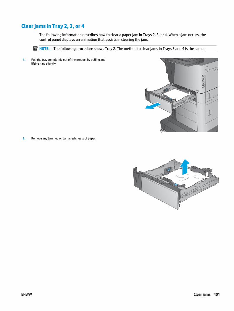
Clear jams in Tray 2, 3, or 4The following information describes how to clear a paper jam in Trays 2, 3, or 4. When a jam occurs, thecontrol panel displays an animation that assists in clearing the jam.
NOTE: The following procedure shows Tray 2. The method to clear jams in Trays 3 and 4 is the same.
1. Pull the tray completely out of the product by pulling andlifting it up slightly.
2. Remove any jammed or damaged sheets of paper.
ENWW Clear jams 401

3. Remove any paper from the feed rollers inside the product.
4. Reinsert and close the tray.
402 Chapter 2 Solve problems ENWW

Clear jams in the 1,500-sheet high-capacity input tray (Tray 5) The following information describes how to clear a paper jam in the 1,500-sheet high-capacity tray (Tray 5).When a jam occurs, the control panel displays an animation that assists in clearing the jam.
1. Open the 1,500-sheet high-capacity input tray.
2. Remove and discard any damaged sheets.
3. Remove the paper from the tray.
ENWW Clear jams 403

4. Lift the tray up and then pull it straight out to remove it.
5. If jammed paper is in the feed area, pull it down to remove it.
404 Chapter 2 Solve problems ENWW

6. Reinstall the tray, and then load full reams of paper into thetray. The tray holds 1,500 sheets of paper.
NOTE: For best results, load full reams of paper. Avoiddividing reams into smaller sections.
7. Close the tray.
ENWW Clear jams 405
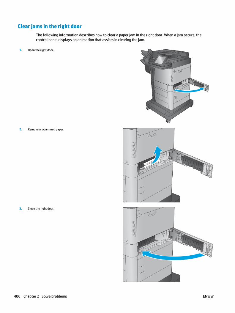
Clear jams in the right door The following information describes how to clear a paper jam in the right door. When a jam occurs, thecontrol panel displays an animation that assists in clearing the jam.
1. Open the right door.
2. Remove any jammed paper.
3. Close the right door.
406 Chapter 2 Solve problems ENWW

Clear jams in the lower-right door The following information describes how to clear a paper jam in the lower-right door. When a jam occurs, thecontrol panel displays an animation that assists in clearing the jam.
1. Open the lower-right door.
2. Remove any jammed paper.
3. Close the lower-right door.
ENWW Clear jams 407

Clear jams in the duplexer and fuser The following information describes how to clear a paper jam in the duplexer or fuser area. When a jamoccurs, the control panel displays an animation that assists in clearing the jam.
1. M630dn and M630f: Pull the output bin and bezel straightout, and then lift up to remove them.
2. M630z (or other models if the stapling mailbox is installed):Press the button to release the stapling mailbox, and removeit from the product.
CAUTION: Do not disconnect the connector. The cord is longenough to set the stapling mailbox on the floor. If theconnector is disconnected, reconnect it and restart theproduct after clearing the jam so the product recognizes theaccessory.
408 Chapter 2 Solve problems ENWW

3. Slide the duplexer away from the product to remove it.
4. If paper is jammed in the duplexer, carefully remove thepaper.
5. Carefully flex the left-hand side of the fuser-entrance guideto release it, and then rotate the guide out and away from theproduct to remove it.
ENWW Clear jams 409

6. Squeeze the two blue tabs on the fuser to release it, slightlylift it up and then pull the fuser straight out of the product toremove it.
CAUTION: The fuser can be hot while the product is in use.
7. Clear the jam by carefully pulling the paper straight out.
8. Push the fuser straight into the product until it snaps intoplace.
410 Chapter 2 Solve problems ENWW
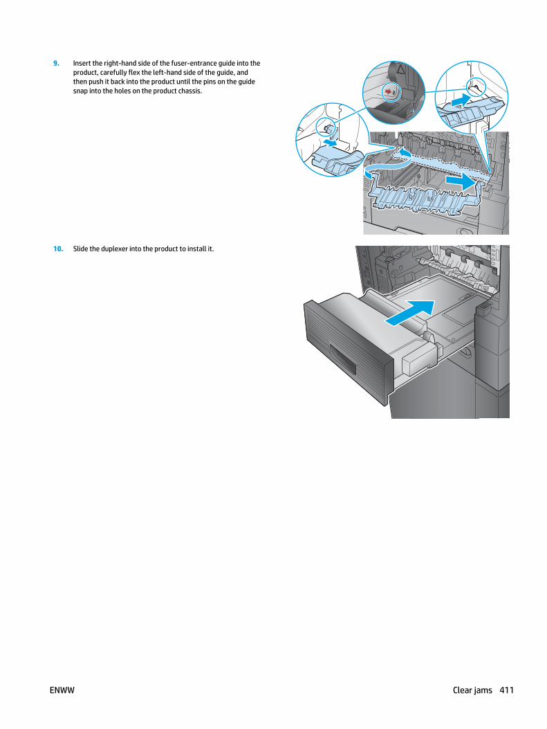
9. Insert the right-hand side of the fuser-entrance guide into theproduct, carefully flex the left-hand side of the guide, andthen push it back into the product until the pins on the guidesnap into the holes on the product chassis.
10. Slide the duplexer into the product to install it.
ENWW Clear jams 411

11. M630dn and M630f: Install the output bin and bezel.
12. M630z (and other models if the stapling mailbox isinstalled): Align the stapling mailbox with the tracks in theproduct, and slide it into the product.
412 Chapter 2 Solve problems ENWW

Clear jams under the top cover and in the registration areaThe following information describes how to clear a paper jam under the top cover. When a jam occurs, thecontrol panel displays an animation that assists in clearing the jam.
1. Open Tray 1 and remove the the envelope-feeder cover (orremove the optional envelope feeder, if it is installed).
2. Lift the top-cover-release latch and open the top cover.
ENWW Clear jams 413

3. Remove the toner cartridge.
4. At the front of the registration roller, lift the small green tabto raise the plastic roller shield, and then pull any jammedpaper straight out.
5. At the back of the roller, use the longer green tab to raise themetal shield, and then pull any jammed paper straight out.
414 Chapter 2 Solve problems ENWW

6. Install the toner cartridge.
7. Close the top cover.
8. Insert the envelope-feeder cover.
ENWW Clear jams 415

Clear jams in the output bin The following information describes how to clear a paper jam in the output bin. When a jam occurs, thecontrol panel displays an animation that assists in clearing the jam.
1. M630dn and M630f: If paper is visible in the output bin, graspthe leading edge and remove it.
2. M630z: Remove any jammed paper from the mailbox bins.
416 Chapter 2 Solve problems ENWW

Clear jams in the stapling mailbox accessory The following information describes how to clear a paper jam in the stapling mailbox accessory. When a jamoccurs, the control panel displays an animation that assists in clearing the jam.
1. Remove any jammed paper from the mailbox bins.
2. Press the button to release the stapling mailbox, and slide itaway from the product.
ENWW Clear jams 417

3. If jammed paper is visible underneath the paper guide, pull itstraight out.
4. Open the jam-access door. If jammed paper is visible insidethe jam-access door, pull it straight up to remove it.
5. Attach the stapling mailbox.
418 Chapter 2 Solve problems ENWW

Clear staple jams in the stapling mailbox accessory The following information describes how to clear a staple jam in the stapling mailbox accessory. When a jamoccurs, the control panel displays an animation that assists in clearing the jam.
1. Press the button to release the stapling mailbox, and slide itaway from the product.
2. Press the latch to release the stapler door.
ENWW Clear jams 419

3. Open the stapler door.
4. Lift the green tab on the staple cartridge up, and then pull thestaple cartridge straight out.
5. Lift up on the small lever at the back of the staple cartridge.
420 Chapter 2 Solve problems ENWW

6. Remove the jammed staples.
7. Close the lever at the back of the staple cartridge. Be surethat it snaps into place.
8. Insert the staple cartridge into the stapler and push down onthe green handle until it snaps into place.
ENWW Clear jams 421
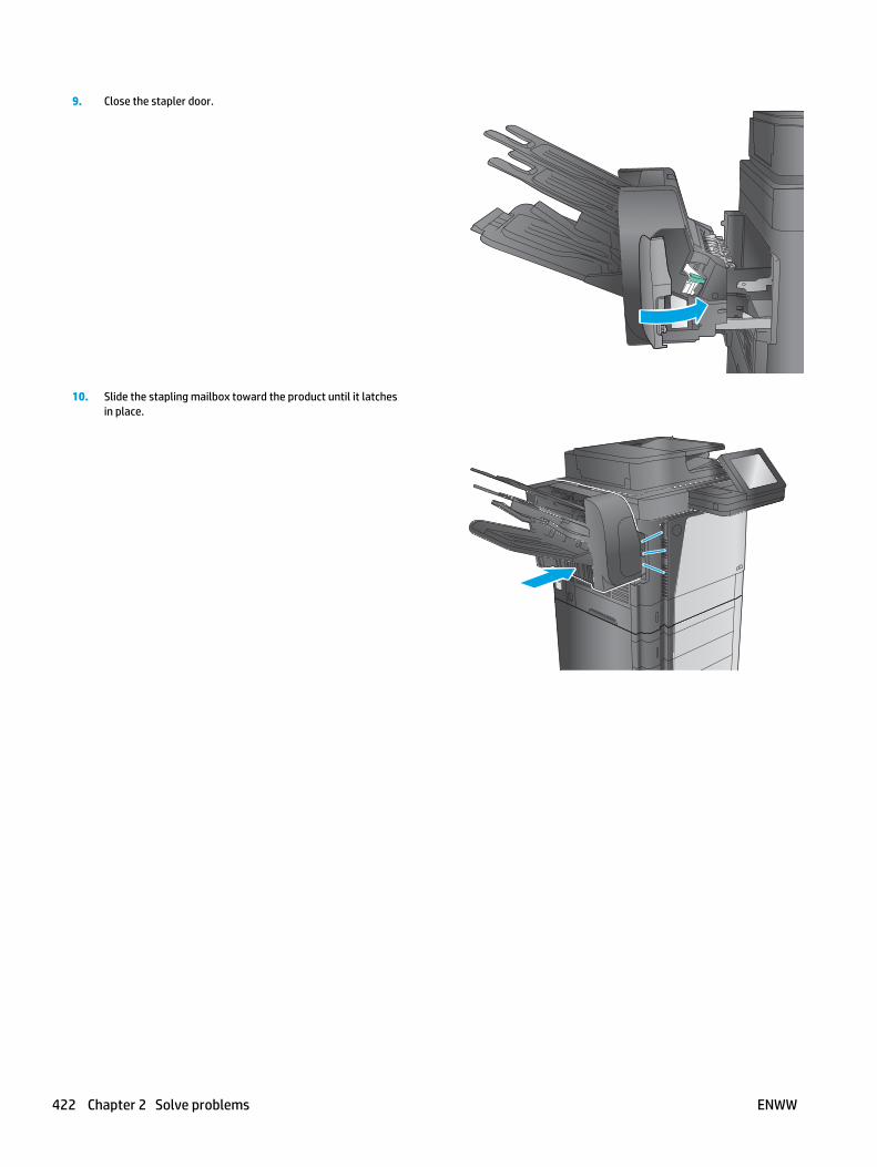
9. Close the stapler door.
10. Slide the stapling mailbox toward the product until it latchesin place.
422 Chapter 2 Solve problems ENWW

Change jam recoveryThis product provides a jam recovery feature that reprints jammed pages.
1. From the Home screen on the product control panel, scroll to and touch the Administration button.
2. Open the General Settings menu, and then open the Jam Recovery menu.
3. Select one of the following options:
● Auto — The product attempts to reprint jammed pages when sufficient memory is available. Thisis the default setting.
● Off — The product does not attempt to reprint jammed pages. Because no memory is used tostore the most recent pages, performance is optimal.
NOTE: Some pages can be lost if the product runs out of paper while printing a duplex job withJam Recovery set to Off.
● On — The product always reprints jammed pages. Additional memory is allocated to store the lastfew pages printed.
ENWW Clear jams 423

Paper feeds incorrectly or becomes jammed● The product does not pick up paper
● The product picks up multiple sheets of paper
● The document feeder jams, skews, or picks up multiple sheets of paper
● Prevent paper jams
The product does not pick up paperIf the product does not pick up paper from the tray, try these solutions.
NOTE: Tray 1 and Tray 2 are optimal for paper pickup when using special paper or media other than 20lbplain paper. For Tray 1 and Tray 2 the product increases the number of attempts to pickup a page, whichincreases the reliability of successfully picking the page from the tray and decreases the possibility of a mis-pick jam.
HP recommends using Tray 1 or Tray 2 if the product is experiencing excessive or reoccurring jams from traysother than Tray 1 and Tray 2, or for print jobs that require media other than 20lb plain paper.
1. Open the product and remove any jammed sheets of paper.
2. Load the tray with the correct size of paper for the job.
3. Make sure the paper size and type are set correctly on the product control panel.
4. Make sure the paper guides in the tray are adjusted correctly for the size of paper. Adjust the guides tothe appropriate indentation in the tray.
5. Check the product control panel to see if the product is waiting for an acknowledgment to the feed thepaper manually prompt. Load paper, and continue.
6. The rollers above the tray might be contaminated. Clean the rollers with a lint-free cloth dampenedwith warm water.
The product picks up multiple sheets of paperIf the product picks up multiple sheets of paper from the tray, try these solutions.
1. Remove the stack of paper from the tray and flex it, rotate it 180 degrees, and flip it over. Do not fanthe paper. Return the stack of paper to the tray.
2. Use only paper that meets HP specifications for this product.
3. Use paper that is not wrinkled, folded, or damaged. If necessary, use paper from a different package.
4. Make sure the tray is not overfilled. If it is, remove the entire stack of paper from the tray, straightenthe stack, and then return some of the paper to the tray.
5. Make sure the paper guides in the tray are adjusted correctly for the size of paper. Adjust the guides tothe appropriate indentation in the tray.
6. Make sure the printing environment is within recommended specifications.
424 Chapter 2 Solve problems ENWW

The document feeder jams, skews, or picks up multiple sheets of paper● The original might have something on it, such as staples or self-adhesive notes, that must be removed.
● Check that all rollers are in place and that the roller-access cover inside the document feeder is closed.
● Make sure that the top document-feeder cover is closed.
● The pages might not be placed correctly. Straighten the pages and adjust the paper guides to center thestack.
● The paper guides must be touching the sides of the paper stack to work correctly. Make sure that thepaper stack is straight and the guides are against the paper stack.
● The document feeder input tray or output bin might contain more than the maximum number of pages.Make sure the paper stack fits below the guides in the input tray, and remove pages from the outputbin.
● Verify that there are no pieces of paper, staples, paper clips, or other debris in the paper path.
● Clean the document-feeder rollers and the separation pad. Use compressed air or a clean, lint-free clothmoistened with warm water. If misfeeds still occur, replace the rollers.
● From the Home screen on the product control panel, scroll to and touch the Supplies button. Check thestatus of the document-feeder kit, and replace it if necessary.
Prevent paper jamsTo reduce the number of paper jams, try these solutions.
1. Use only paper that meets HP specifications for this product.
2. Use paper that is not wrinkled, folded, or damaged. If necessary, use paper from a different package.
3. Use paper that has not previously been printed or copied on.
4. Make sure the tray is not overfilled. If it is, remove the entire stack of paper from the tray, straightenthe stack, and then return some of the paper to the tray.
5. Make sure the paper guides in the tray are adjusted correctly for the size of paper. Adjust the guides sothey are touching the paper stack without bending it.
6. Make sure that the tray is fully inserted in the product.
7. When printing on heavy, embossed, or perforated paper, use the manual feed feature and feed sheetsone at a time.
8. From the Home screen on the product control panel, scroll to and touch the Trays button. Verify that thetray is configured correctly for the paper type and size.
9. Make sure the printing environment is within recommended specifications.
ENWW Paper feeds incorrectly or becomes jammed 425

Use manual print modesTry the following manual print modes to see if they solve the image-quality problems.
NOTE: Tray 1 and Tray 2 are optimal for paper pickup when using special paper or media other than 20lbplain paper. For Tray 1 and Tray 2 the product increases the number of attempts to pickup a page, whichincreases the reliability of successfully picking the page from the tray and decreases the possibility of a mis-pick jam.
HP recommends using Tray 1 or Tray 2 if the product is experiencing excessive or reoccurring jams from traysother than Tray 1 and Tray 2, or for print jobs that require media other than 20lb plain paper.
Select a manual print mode
1. From the Home screen on the product control panel, scroll to and touch the Administration button.
2. Open the following menus:
● General Settings
● Print Quality
● Adjust Paper Types or Optimize
3. Select a paper type, and then select the mode to adjust.
4. Select a value for the mode, and then touch the Save button.
426 Chapter 2 Solve problems ENWW

Table 2-63 Print modes1 under the Adjust Paper Types submenu
Print Mode● Plain
● HP EcoSMART Lite2
● Light
● Bond
● Recycled
● Heavy 111-130g
● Extra Heavy 131-175g
● Cardstock
● Transparency
● Labels
● Letter Head
● Envelope
● Heavy Envelope
● Preprinted
● Prepunched
● Colored
● Rough
● Heavy Rough
● UserType1 to N3
● Restore Modes
1 Not all print modes are available for all paper types.2 Only available in resistance, humidity, and paper curl modes (not available in print mode).3 User types are not shown in the menu until they are enabled by using the HP Embedded Web Server or Web JetAdmin.
Table 2-64 Print modes under the Optimize submenu
Resistance Mode Use this mode when the product is installed in low humidityenvironment and image defects result when using high-resistivitypaper.
High Humidity Mode Use this mode when the product is installed in a high humidityenvironment and lower density images occur.
Curl Mode Use this mode when the media curls and jams in the tonercartridge. Typically, this occurs when light weight short grainmedia is used.
Low Speed Mode Use this item when smears and/or spots—image defect mottle—appear on the printed page.
Quiet Mode Use this item if the product is producing too much noise.
ENWW Use manual print modes 427

Table 2-64 Print modes under the Optimize submenu (continued)
Line Detail Use this item when a toner explosion image defect occurs. Thedefault setting is Normal.
Use the Alternate setting if the defect occurs because of poorquality paper, or the product is installed in a high humidityenvironment.
Restore Optimize Use Restore Optimize to reset the menu defaults.
428 Chapter 2 Solve problems ENWW

Solve image quality problemsOften print-quality problems can be resolved easily by making sure that the product is well-maintained,using paper that meets HP specifications, or running a cleaning page.
Image defects tableThe following examples depict letter-size paper that has passed through the product short-edge first. Theseexamples illustrate problems that would affect all the printed pages, whether they are printed in color or inblack only.
Table 2-65 Image defects table
Problem Sample Cause Solution
Print is light or faded on entirepage.
Poor contact exists between thetransfer roller and its shaft.
Clean the contact. If the problemremains after cleaning, check thecontact for damage. Replace anydeformed or damaged parts.
Image is too dark. Poor contact exists in theprimary charging bias ordeveloping bias contactsbetween the toner cartridge andthe product.
Clean each toner cartridge contact. Ifthe problem remains after cleaning,check the contacts for damage.Replace any deformed or damagedparts. Replace the toner cartridge.
Page is blank. Poor developing bias contactexists with the cartridge.
Clean the contact. If the problemremains after cleaning, check thecontact for damage. Replace anydeformed or damaged parts.
The laser shutter open-closeprojection part of the cartridgeis damaged.
Replace the toner cartridge.
The laser shutter arm and thelaser shutter aremalfunctioning or damaged.
If the laser shutter arm or the lasershutter does not move smoothly or ifany part is damaged, replace anydefective part.
The laser/scanner is defective. Replace the laser/scanner.
ENWW Solve image quality problems 429

Table 2-65 Image defects table (continued)
Problem Sample Cause Solution
The page all black. Poor contact exists in theprimary charging bias ordeveloping bias contactsbetween the toner cartridge andthe product.
Clean each contact. If the problemremains after cleaning, check thecontacts for damage. Replace anydeformed or damaged parts. Replacethe toner cartridge.
The primary charging roller isdefective.
Replace the toner cartridge.
White spots appear in an image Poor contact exists in the staticcharge eliminator.
Clean the contact.
The transfer roller is deformedor has deteriorated.
Replace the transfer roller.
Poor contact exists between thetransfer roller and its shaft.
Clean the contact.
The back of the page is dirty. The paper is dirty. Use clean paper that meets HPspecifications and that has beenstored properly.
Dirt on the leading edge of thepage might signify that dirtexists on the cassette pickuproller.
Clean the cassette pickup roller. If thedirt does not come off, replace theroller.
Repetitive defects mightindicate that dirt exists on thecassette feed roller, feed roller,Tray1 separation roller, pre-registration roller, transferroller, or pressure roller.
Use the repetitive defects ruler toidentify the dirty roller and then cleanit. If the dirt does not come off,replace the roller.
The feed belt, feed guide, orfuser inlet guide is dirty.
Clean the dirty part.
430 Chapter 2 Solve problems ENWW

Table 2-65 Image defects table (continued)
Problem Sample Cause Solution
Vertical streaks or bands appearon the page.
Scratches are present on thecircumference of thephotosensitive drum.
Replace the toner cartridge.
The fuser inlet guide is dirty. Clean the fuser inlet guide.
Scratches on the fuser sleeve. Remove the cause of the scratches,and then replace the fuser.
Horizontal lines or bands appearon the page.
Horizontal scratches on thephotosensitive drum.
Replace the toner cartridge.
The fuser sleeve is dirty,deformed or worn.
Replace the fuser.
The front of the page is dirty. Dirt on leading edge of image(MP tray pickup roller).
Clean the MP tray pickup roller. If thedirt does not come off, replace theroller.
Repetitive dirt (cassetteseparation roller, feed roller,MP tray feed roller, pre-registration roller, fuser sleeveor cartridge).
Use the repetitive defects ruler toidentify the dirty roller. Clean the dirtypart. If the dirt does not come off,replace the corresponding part.
The delivery roller is dirty. Clean the delivery roller.
ENWW Solve image quality problems 431

Table 2-65 Image defects table (continued)
Problem Sample Cause Solution
Dropouts appear. The transfer roller is dirty,deformedor has deteriorated.
Replace the transfer roller.
Poor toner sensor contactexists with the cartridge.
Clean the contact.
The photosensitive drum,primary charging roller,developing roller or tonersensor is defective.
Replace the toner cartridge.
Scratches or foreign substanceon the fuser sleeve.
Replace the fuser.
Vertical white lines appear in aparticular color.
Scratches exist on thecircumference of thephotosensitive drum.
Replace the toner cartridge.
The developing roller isdefective.
Dirt is adhering to the laserbeam window.
Clean the laser beam window.
Foreign substance adheres tothe fuser inlet guide or theguide is dirty.
Clean the fuser inlet guide.
Scratches or foreign substanceon the fuser sleeve.
Replace the fuser.
The laser/scanner-unit mirror isdirty.
Replace the laser/scanner.
A horizontal white line appears onthe page.
Horizontal scratches arepresent on the photosensitivedrum.
Replace the toner cartridge.
The fuser sleeve is defective. Replace the fuser.
432 Chapter 2 Solve problems ENWW

Table 2-65 Image defects table (continued)
Problem Sample Cause Solution
The toner is not fully fused to thepaper.
The pressure roller is dirty. Perform the pressure roller cleaningprocedure. If the dirt does not comeoff, replace the pressure roller.
The fuser roller or pressureroller is scarred or deformed.
Replace the fuser.
The printed page containsmisformed characters.
A poor connection exists on thelaser/scanner assembly.
Reconnect the following laser/scannerassembly connectors: J143, J144, andJ145.
A poor connection exists on theDC controller PCA.
Reconnect the following DC controllerPCA connectors: J86 and J93.
The laser/scanner unit isdefective.
Replace the laser/scanner.
The printed page containswrinkles or creases.
The roller or paper feed guide isdirty.
Clean any dirty components.
A feed roller is deformed or hasdeteriorated.
Replace any deformed or deterioratedrollers.
The paper feed guide isdamaged.
Replace the paper-feed-guide unit.
Repetitive horizontal lines A roller is dirty. See repetitive image defect ruler.Clean the indicated roller. If thecontaminate does not come off,replace the appropriate roller orassembly.
ENWW Solve image quality problems 433

Table 2-65 Image defects table (continued)
Problem Sample Cause Solution
Pages have flecks of toner Residual toner exists in thepaper path.
Execute a cleaning page to clean thecontaminants off the fuser. Thecleaning page might need to be runseveral time to clean the fuser. Do notreplace the fuser.
NOTE: Cleaning the fuser with HPTough Paper provides better resultsthan with plain paper. You might needto execute the cleaning processseveral times to remove allcontaminants on the fuser.
Pages have flecks of toner downthe right side
The fuser is dirty. Clean the fuser. If the error persists,replace the fuser.
Streaks on document feeder scans
Dark or light streak from leadingedge to trailing edge on pagesscanned through the ADF.
The ADF glass (small glass tothe left of the flatbed glass) iscontaminated.
Clean the glass with a waterdampened lint-free cloth.
TIP: Align a printed page with thestreak on it with the glass, to help findthe location of the contamination.
Toner smears appear on thepaper.
The product has residual paper. Remove the residual paper.
The fuser inlet guide is dirty. Clean the fuser inlet guide.
434 Chapter 2 Solve problems ENWW

Table 2-65 Image defects table (continued)
Problem Sample Cause Solution
Text or graphics are skewed on theprinted page when the documentfeeder is used for the print job.
TIP: Make sure that the originalimage is not skewed.
The document feeder guidesare not set correctly, pressedagainst the original.
Make sure that the side guides arecorrectly set against the page.
If the error persists and the defect isisolated to the document feeder,replace the document feeder.
The scanner needs to becalibrated.
1. From the Home screen on thecontrol panel, scroll to and touchthe Device Maintenance button.
2. Open the following menus:
● Calibration/Cleaning
● Calibrate Scanner
3. Touch the Next button to startthe calibration process. Followthe on-screen prompts.
4. Wait while the product calibratesthe scanner.
5. If the error persists and thedefect is isolated to the scanner,replace the scanner.
Text or graphics are skewed on theprinted page.
The registration shutter springis unhooked.
Check the spring and place it in thecorrect position.
The registration shutter springis deformed.
Replace the transfer assembly.
ENWW Solve image quality problems 435

Table 2-65 Image defects table (continued)
Problem Sample Cause Solution
Spots on a document feeder orflatbed scan.
All scans from the documentfeeder or the flatbed glass printhave random dark or light spots.Every page has spots in the sameplace.
The document feeder glass orflatbed glass is contaminated.
Clean the document feeder glass orflatbed glass with a water dampenedlint-free cloth.
Missing trailing edge of ADF scans. The image in the print job isskewed.
Make sure that the image is properlyplaced on the page before the job iscopied.
The copy image might begetting stopped early due tostatic interfering with the ADFpaper path deskew sensor inthe ADF.
TIP: The page does not jam,but is skewed when printed.
Replace the document feeder.
436 Chapter 2 Solve problems ENWW

Table 2-65 Image defects table (continued)
Problem Sample Cause Solution
Smeared toner or water-likemarks.
Randomly-shaped smears thatmeander, but are mostly in thefeed direction. The smearsresemble a mark made by waterdroplets. They might be describedas looking like a snail or slug markon the page.
Printing in a high temperature/high humidity environment and/or with paper which has beenexposed to a high temperature/high humidity environment.
Paper acclimated to this type ofenvironment has a highmoisture content, which cancause the paper to curl as itenters the fuser.
Replace the paper with a unopenedpackage of paper that is acclimated tothe environment where the product isoperating.
Printing the job using different paper(75 g/m2 or heavier).
If the error persists, the product mightneed to be moved to an area of lowertemperature/humidity.
Shifted or cut-off scans.
Images copied or scanned areshifted, in some case the shiftmight be enough for part of theimage to be cut off. In thisexample, the image at the top ofthe page is missing.
The document feeder guidesare not set correctly, pressedagainst the original.
Make sure that the side guides arecorrectly set against the page.
If the error persists and the defect isisolated to the document feeder,replace the document feeder.
The scanner needs to becalibrated.
1. From the Home screen on thecontrol panel, scroll to and touchthe Device Maintenance button.
2. Open the following menus:
● Calibration/Cleaning
● Calibrate Scanner
3. Touch the Next button to startthe calibration process. Followthe on-screen prompts.
4. Wait while the product calibratesthe scanner.
5. If the error persists and thedefect is isolated to the scanner,replace the scanner.
ENWW Solve image quality problems 437

Table 2-65 Image defects table (continued)
Problem Sample Cause Solution
Bubble or cloud print.
Customers might describe animage quality defect thatresembles bubbles. This defecttypically starts near the edges ofthe pages, but in severe cases itmight cover most or all the page.
Bubble print is most oftenrelated to poor grounding of thetoner cartridge and is typicallycaused by damaged groundingcontacts.
1. Inspect the grounding contactsinside the product. Look fordamaged, loose, misaligned,contaminated, or obstructedcontacts. Clean contaminatedcontacts. If possible, repair bentor mis aligned contacts.
2. Verify that the groundingcontacts or springs are properlypositioned such that they makepositive contact with thegrounding point on the cartridge.
3. Inspect the cartridge itself tomake sure that the groundingpoints are not damaged,contaminated or obstructed. Ifdamaged, replace the cartridge.
4. If another cartridge is available,test the product using thatcartridge.
5. If the error persists, escalate theproblem to the Global BusinessUnit.
Tire Tracks. This defect typically occurswhen the toner cartridge has farexceeded its rated life.
Replace the toner cartridge.
438 Chapter 2 Solve problems ENWW

Clean the productOver time, particles of toner and paper accumulate inside the product. This can cause print-quality problemsduring printing. Cleaning the product eliminates or reduces these problems.
Clean the paper path and toner-cartridge areas every time that the toner cartridge is changed or wheneverprint-quality problems occur. As much as possible, keep the product free from dust and debris.
To clean the product exterior, use a soft, water-moistened cloth.
Print a cleaning pagePrint a cleaning page to remove dust and excess toner from the fuser if you are having any of the followingproblems:
● Specks of toner are on the printed pages.
● Toner is smearing on the printed pages.
● Repeated marks occur on the printed pages.
Use the following procedure to print a cleaning page.
1. From the Home screen on the product control panel, scroll to and touch the Device Maintenance button.
2. Open the following menus:
● Calibration/Cleaning
● Cleaning Page
3. Touch the Print button to print the page.
4. The cleaning process can take several minutes. When it is finished, discard the printed page.
ENWW Clean the product 439

Check the scanner glass for dirt or smudgesOver time, specks of debris might collect on the scanner glass and white plastic backing which can affectperformance. Use the following procedure to clean the scanner glass and white plastic backing.
1. Press the power button to turn off the product, and thendisconnect the power cable from the electrical outlet.
2. Open the scanner lid. Align paper that has copy defects withthe scanner glass to identify the locations of dirt or smudges.
3. Clean the scanner glass, the document feeder strips, and thewhite plastic backing with a soft cloth or sponge that hasbeen moistened with nonabrasive glass cleaner.
CAUTION: Do not use abrasives, acetone, benzene,ammonia, ethyl alcohol, or carbon tetrachloride on any partof the product; these can damage the product. Do not placeliquids directly on the glass or platen. They might seep anddamage the product.
NOTE: If the product is experiencing streaks on copies whenusing the document feeder, be sure to clean the small strip ofglass on the left side of the scanner.
TIP: See this English-language video for a demonstration ofhow to identify and clean debris that causes streaks oncopies: www.youtube.com/watch?v=CGn7FJvH8sE.
440 Chapter 2 Solve problems ENWW

4. Dry the glass and white plastic parts with a chamois or acellulose sponge to prevent spotting.
5. Connect the power cable to an outlet, and then press thepower button to turn the product on.
ENWW Clean the product 441

Clean the pickup rollers and separation pad in the document feeder
1. Lift the document-feeder latch.
2. Open the document-feeder cover.
442 Chapter 2 Solve problems ENWW

3. Remove any visible lint or dust from each of the feed rollersand the separation pad using compressed air or a clean lint-free cloth moistened with warm water.
NOTE: Lift up the roller assembly to access and clean thesecond roller.
4. Close the document-feeder cover.
If the error persists, install a document feeder roller kit(L2718A).
ENWW Clean the product 443

Clean the pickup, feed, and separation rollers in the 1x500-sheet paper-feeder and1x500-sheet paper-feeder with storage cabinet
NOTE: The 1x500-sheet paper-feeder with storage cabinet is shown below, hawever, the rollers are in thesame location in the 1x500-sheet paper-feeder.
Remove the tray and locate the rollers in the feeder.
● Pickup roller (callout 1)
● Feed roller (callout 2)
● Separation roller (callout 3)
Remove any visible lint or dust from each of the rollers using compressed air or a clean lint-free clothmoistened with warm water.
12
3
444 Chapter 2 Solve problems ENWW

Clean the pickup, feed, and separation rollers in the 2,500-sheet high-capacityfeeder (HCI)
Remove the trays and locate the rollers in the feeder.
TIP: There is one set of rollers for each tray.
● Pickup rollers (callout 1)
● Feed rollers (callout 2)
● Separation rollers (callout 3)
Remove any visible lint or dust from each of the rollers using compressed air or a clean lint-free clothmoistened with warm water.
1 23
ENWW Clean the product 445

Solve performance problemsNOTE: Tray 1 and Tray 2 are optimal for paper pickup when using special paper or media other than 20lbplain paper. For Tray 1 and Tray 2 the product increases the number of attempts to pickup a page, whichincreases the reliability of successfully picking the page from the tray and decreases the possibility of a mis-pick jam.
HP recommends using Tray 1 or Tray 2 if the product is experiencing excessive or reoccurring jams from traysother than Tray 1 and Tray 2, or for print jobs that require media other than 20lb plain paper.
Table 2-66 Solve performance problems
Problem Cause Solution
Pages print but are totally blank. The document might contain blank pages. Check the original document to see ifcontent is present on all of the pages.
The product might be malfunctioning. To check the product, print a Configurationpage.
Pages print very slowly. Heavier paper types can slow the print job. Print on a different type of paper.
Complex pages can print slowly. Proper fusing might require a slower printspeed to ensure the best print quality.
Large batches, narrow paper, and specialpaper such as gloss, transparency,cardstock, and HP Tough Paper can slowthe print job.
Print in smaller batches, on a differenttype of paper, or on a different size ofpaper.
Pages did not print. The product might not be pulling papercorrectly.
Make sure paper is loaded in the traycorrectly.
The paper is jamming in the product. Clear the jam.
The USB cable might be defective orincorrectly connected.
● Disconnect the USB cable at bothends and reconnect it.
● Try printing a job that has printed inthe past.
● Try using a different USB cable.
Other devices are running on the hostcomputer.
The product might not share a USB port. Ifan external hard drive or networkswitchbox is connected to the same port asthe product, the other device might beinterfering with the product. To connectand use the product, disconnect the otherdevice or use two USB ports on the hostcomputer.
446 Chapter 2 Solve problems ENWW

Solve connectivity problemsSolve USB connection problems
If you have connected the product directly to a computer, check the cable.
● Verify that the cable is connected to the computer and to the product.
● Verify that the cable is not longer than 2 m (6.65 ft). Try using a shorter cable.
● Verify that the cable is working correctly by connecting it to another product. Replace the cable ifnecessary.
Solve wired network problemsCheck the following items to verify that the product is communicating with the network. Before beginning,print a configuration page from the product control panel and locate the product IP address that is listed onthis page.
● Poor physical connection
● The computer is using the incorrect IP address for the product
● The computer is unable to communicate with the product
● The product is using incorrect link and duplex settings for the network
● New software programs might be causing compatibility problems
● The computer or workstation might be set up incorrectly
● The product is disabled, or other network settings are incorrect
NOTE: HP does not support peer-to-peer networking, as the feature is a function of Microsoft operatingsystems and not of the HP print drivers. For more information, go to Microsoft at www.microsoft.com.
Poor physical connection
1. Verify that the product is attached to the correct network port using a cable of the correct length.
2. Verify that cable connections are secure.
3. Look at the network port connection on the back of the product, and verify that the amber activity lightand the green link-status light are lit.
4. If the problem continues, try a different cable or port on the hub.
The computer is using the incorrect IP address for the product
1. Open the printer properties and click the Ports tab. Verify that the current IP address for the product isselected. The product IP address is listed on the product configuration page.
2. If you installed the product using the HP standard TCP/IP port, select the box labeled Always print tothis printer, even if its IP address changes.
ENWW Solve connectivity problems 447

3. If you installed the product using a Microsoft standard TCP/IP port, use the hostname instead of the IPaddress.
4. If the IP address is correct, delete the product and then add it again.
The computer is unable to communicate with the product
1. Test network communication by pinging the network.
a. Open a command-line prompt on your computer. For Windows, click Start, click Run, type cmd,and then press Enter.
b. Type ping followed by the IP address for your product.
For Mac OS X, open the Network Utility, and then supply the IP address in the correct field in thePing pane.
c. If the window displays round-trip times, the network is working.
2. If the ping command failed, verify that the network hubs are on, and then verify that the networksettings, the product, and the computer are all configured for the same network.
The product is using incorrect link and duplex settings for the network
Hewlett-Packard recommends leaving these settings in automatic mode (the default setting). If you changethese settings, you must also change them for your network.
New software programs might be causing compatibility problems
Verify that any new software programs are correctly installed and that they use the correct print driver.
The computer or workstation might be set up incorrectly
1. Check the network drivers, print drivers, and the network redirection settings.
2. Verify that the operating system is configured correctly.
The product is disabled, or other network settings are incorrect
1. Review the configuration page to check the status of the network protocol. Enable it if necessary.
2. Reconfigure the network settings if necessary.
448 Chapter 2 Solve problems ENWW
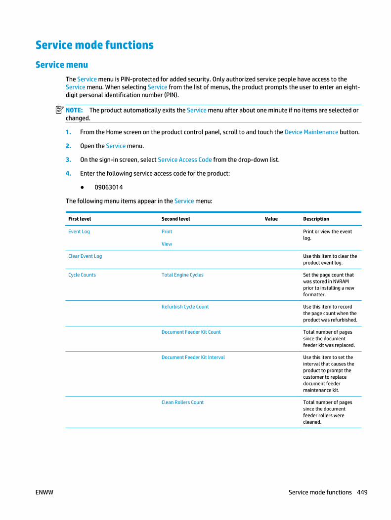
Service mode functionsService menu
The Service menu is PIN-protected for added security. Only authorized service people have access to theService menu. When selecting Service from the list of menus, the product prompts the user to enter an eight-digit personal identification number (PIN).
NOTE: The product automatically exits the Service menu after about one minute if no items are selected orchanged.
1. From the Home screen on the product control panel, scroll to and touch the Device Maintenance button.
2. Open the Service menu.
3. On the sign-in screen, select Service Access Code from the drop-down list.
4. Enter the following service access code for the product:
● 09063014
The following menu items appear in the Service menu:
First level Second level Value Description
Event Log Print
View
Print or view the eventlog.
Clear Event Log Use this item to clear theproduct event log.
Cycle Counts Total Engine Cycles Set the page count thatwas stored in NVRAMprior to installing a newformatter.
Refurbish Cycle Count Use this item to recordthe page count when theproduct was refurbished.
Document Feeder Kit Count Total number of pagessince the documentfeeder kit was replaced.
Document Feeder Kit Interval Use this item to set theinterval that causes theproduct to prompt thecustomer to replacedocument feedermaintenance kit.
Clean Rollers Count Total number of pagessince the documentfeeder rollers werecleaned.
ENWW Service mode functions 449

First level Second level Value Description
Clean Rollers Interval Use this item to set theinterval that causes theproduct to prompt thecustomer to clean thedocument feeder rollersand separation pad.
ADF Count Set the total pages fedthrough the documentfeeder.
Flatbed Count Set the total pagesscanned from theflatbed.
ADF Simplex Count Set the total single-sidedpages fed through thedocument feeder.
ADF Duplex Count Set the total two-sidedpages fed through thedocument feeder.
Copy Scan Count Set the total copy pagesthat have been scanned.
Send Scan Count Set the number ofscanned pages sent toemail.
Fax Scan Count
NOTE: FAX models only.
Set the number ofscanned pages that havebeen faxed.
Copy Pages Count Set the number ofscanned pages that havebeen printed.
Scanner Settings ADF Settings Leading edgefront
Leading edgeback
Trailing edgefront
Trailing edgeback
Left side front
Left side back
Set the calibrationvalues.
WARNING! Do notchange these valuesunless instructed to doso.
Glass Settings Leading edgeglass
Left Side Glass
Serial Number Set the serial number.
450 Chapter 2 Solve problems ENWW

First level Second level Value Description
Service ID Use this item to show thedate that the productwas first used on thecontrol panel. Thiseliminates the need forusers to keep paperreceipts for proof ofwarranty.
Cold Reset Paper When you perform a coldreset, the paper size thatis stored in NVRAM isreset to the defaultfactory setting. If youreplace a formatterboard in a country/regionthat uses A4 as thestandard paper size, usethis menu to reset thedefault paper size to A4.LETTER and A4 are theonly available values.
Low Alerts Enable
Disable
Reset low alert levels:
● Reset to level 1
● Reset to level 2
● Reset to level 3
● Set to non-HPmanaged mode
New Registration Roller Yes
No
Reset the counter for theregistration roller afterreplacing the registrationassembly.
Media Sensor Value Use this item to recordthe media sensor valuefound on a replacementpaper pickup assembly.
PTT Test Mode
NOTE: FAX models only.
Test the internal modemfor the analog faxaccessory.
Hook Operations Off Hook
On Hook
Generate Random Data Select a valuefrom the list.
Generate DTMF Tone Burst Select a valuefrom the list.
Generate DTMF Continuous Tone Select a valuefrom the list.
Generate Pulse Burst Select a valuefrom the list.
ENWW Service mode functions 451

First level Second level Value Description
Generate Tone Dial Number Enter dialnumber.
Generate Pulse Dial Number Enter dialnumber.
Generate Single Modem Tone Range: 1100–2100 Hz
Default = 2100Hz
Line Measurements
Fax Transmit Signal Loss
Test Support Continuous Scan 2-sided
Save to Disk
Continuous Copy 2-sided
Save to Disk
Raw Scan 2-sided
MechanicalCalibration
Continuous Print from USB
Automatic Calibrations Disabled
Enabled*
Runtime Configuration MercStine
Standard
StandardEIC
Workflow
WorkflowEIC
Reconfigure
Product resets
Restore factory-set defaults
1. From the Home screen on the product control panel, scroll to and touch the Administration button.
2. Open the following menus:
● General Settings
● Restore Factory Settings
3. A verification message advises that completing the reset function might result in loss of data. Touch theReset button to complete the process.
452 Chapter 2 Solve problems ENWW

NOTE: The product restarts automatically after the reset operation completes.
Restore the service ID
Restore the service ID
When replacing the formatter, the date is lost. Use this menu item to reset the date to the original date thatthe product was first used. The date format is YYDDD. Use the following formula to calculate the dates:
1. To calculate YY, subtract 1990 from the calendar year. For instance, if the product was first used in2002, calculate YY as follows: 2002 - 1990 = 12. YY = 12.
2. Subtract 1 from 10 (October is the tenth month of the year): 10 - 1 = 9.
● Multiply 9 by 30: 9 x 30 = 270 or add 17 to 270: 270 + 17 = 287. Thus, DDD = 287.
Convert the service ID to an actual date
Use the product Service ID number to determine whether the product is still under warranty. Use thefollowing formula to convert the Service ID into the installation date as follows:
1. Add 1990 to YY to get the actual year that the product was installed.
2. Divide DDD by 30. If there is a remainder, add 1 to the result. This is the month.
3. The remainder from the calculation in step 2 is the date.
Using the Service ID 12287 as an example, the date conversion is as follows:
1. 12 + 1990 = 2002, so the year is 2002.
2. 287 divided by 30 = 9 with a remainder of 17. Because there is a remainder, add 1 to 9 to get 10, whichrepresents October.
3. The remainder in step 2 is 17, so that is the date.
4. The complete date is 17-October-2002.
NOTE: A six-day grace period is built into the date system.
Product cold reset
Cold reset using the Pre-boot menu
1. Turn the product on.
2. The HP logo displays on the product control panel. When an underscore displays below the HP logo,touch the logo to open the Pre-boot menu.
3. Use the down arrow button to highlight Administrator, and then touch the OK button.
4. Use the down arrow button to highlight Startup Options item, and then touch the OK button.
5. Use the down arrow button to highlight the Cold Reset item, and then touch the OK button.
6. Touch the Home button to highlight Continue, and then touch the OK button.
NOTE: The product will initialize.
ENWW Service mode functions 453

Format Disk and Partial Clean functions
Active and repository firmware locations
The firmware bundle consists of multiple parts. The main components are the Windows CE Operating Systemand the product/peripheral firmware files.
There are two locations/partitions on the hard drive where the firmware components are stored:
● The Active, where the operating system and firmware currently are executing.
● The Repository, the recovery location.
If the Active location is damaged, or a Partial Clean was performed, the product automatically copies over theOS and firmware files from the Repository location and the product recovers.
If both the Active and Repository locations are damaged, or a Format Disk was performed, then bothlocations are gone and the error message 99.09.67 displays on the control-panel display. The user mustupload the firmware to the product in order for it to function again.
CAUTION: The Format Disk option performs a disk initialization for the entire disk. The operating system,firmware files, and third party files (among other files) will be completely lost. HP does not recommend thisaction.
Partial Clean
The Partial Clean option erases all partitions and data on the disk drive, except for the firmware repositorywhere a backup copy of the firmware file is stored. This allows the disk drive to be reformatted withouthaving to download a firmware upgrade file to return the product to a bootable state.
Characteristics of a Partial Clean
● Customer-defined settings, third-party solutions, firmware files, and the operating system are deleted.
● Rebooting the product restores the firmware files from the Repository location, but does not restoreany customer-defined settings.
● For previous HP products, a Hard Disk Initialization is similar to executing the Partial Clean function forthis product.
CAUTION: HP recommends backing-up product configuration data before executing a Partial Clean to retaincustomer-defined settings (if needed). See the Backup/Restore item in the Device Maintenance menu.
Reasons for performing Partial Clean
● The product continually boots up in an error state.
NOTE: Try clearing the error prior to executing a Partial Clean.
● The product will not respond to commands from the control panel.
● Executing the Partial Clean function is helpful for troubleshooting hard disk problems.
● To reset the product by deleting all solutions and customer-defined settings.
● The product default settings are not properly working.
454 Chapter 2 Solve problems ENWW

Execute a Partial Clean
1. Turn the product on.
2. The HP logo displays on the product control panel. When a "1/8" with an underscore displays below theHP logo, touch the logo to open the Pre-boot menu.
3. Use the down arrow button to highlight the +3:Administrator item, and then touch the OK button.
4. Use the down arrow button to highlight Partial Clean and then touch the OK button.
5. Touch the OK button again.
6. Touch the Home button to highlight Continue, and then touch the OK button.
NOTE: The product initializes.
Format Disk
The Format Disk option erases the entire disk drive.
CAUTION: After executing a Format Disk option, the product is not bootable.
Characteristics of a Format Disk
● Customer-defined settings, third-party solutions, firmware files, and the operating system are deleted.
NOTE: Rebooting the product does not restore the firmware files.
● Rebooting the product restores the firmware files from the Repository location, but does not restoreany customer-defined settings.
● After executing the Format Disk function, the message 99.09.67 displays on the control panel.
● After executing the Format Disk function, the product firmware must be reloaded.
CAUTION: HP recommends not using the Format Disk option unless an error occurs and the solution in theproduct service manual recommends this solution. After executing the Format Disk function, the product isunusable.
HP recommends backing-up product configuration data before executing a Format Disk toretain customer-defined settings (if needed). See the Backup/Restore item in the Device Maintenance menu.
Reasons for performing Format Disk
● The product continually boots up in an error state.
NOTE: Try clearing the error prior to executing a Format Disk.
● The product will not respond to commands from the control panel.
● Executing the Format Disk function is helpful for troubleshooting hard disk problems.
● To reset the product by deleting all solutions and customer-defined settings.
ENWW Service mode functions 455

Execute a Format Disk
1. Turn the product on.
2. The HP logo displays on the product control panel. When a "1/8" with an underscore displays below theHP logo, touch the logo to open the Pre-boot menu.
3. Use the down arrow button to highlight the +3:Administrator item, and then touch the OK button.
4. Use the down arrow button to highlight Format Disk, and then touch the OK button.
5. Touch the OK button again.
NOTE: When the Format Disk operation is complete, reload the product firmware.
456 Chapter 2 Solve problems ENWW

Solve fax problemsChecklist for solving fax problems
Use the following checklist to help identify the cause of any fax-related problems you encounter:
● Are you using the fax cable supplied with the fax accessory? This fax accessory has been tested withthe supplied fax cable to meet RJ11 and functional specifications. Do not substitute another fax cable;the analog-fax accessory requires an analog-fax cable. It also requires an analog phone connection.
● Is the fax/phone line connector seated in the outlet on the fax accessory? Make sure that the phonejack is correctly seated in the outlet. Insert the connector into the outlet until it "clicks."
NOTE: Verify that the phone jack is connected to the fax port rather than to the network port. Theports are similar.
● Is the phone wall jack working properly? Verify that a dial tone exists by attaching a phone to the walljack. Can you hear a dial tone, and can you make or receive a phone call?
What type of phone line are you using?
● Dedicated line: A standard analog fax/phone line assigned to receive or send faxes.
NOTE: The phone line should be for product fax use only and not shared with other types of telephonedevices. Examples include alarm systems that use the phone line for notifications to a monitoringcompany.
● PBX system: A business-environment phone system. Standard home phones and the fax accessory usean analog phone signal. Some PBX systems are digital and might not be compatible with the faxaccessory. You might need an interfacing Analog Telephone Adapter (ATA) to connect the fax machineto digital PBX systems.
● Roll-over lines: A phone system feature where a new call "rolls over" to the next available line whenthe first incoming line is busy. Try attaching the product to the first incoming phone line. The faxaccessory answers the phone after it rings the number of times set in the rings-to-answer setting.
Are you using a surge-protection device?
A surge-protection device can be used between the wall jack and the fax accessory to protect the faxaccessory against electrical power passed through the phone lines. These devices can cause some faxcommunication problems by degrading the quality of the phone signal. If you are having problems sending orreceiving faxes and are using one of these devices, connect the product directly to the phone jack on the wallto determine whether the problem is with the surge-protection device.
Are you using a phone company voice-messaging service or an answering machine?
If the rings-to-answer setting for the messaging service is lower than the rings-to-answer setting for the faxaccessory, the messaging service answers the call, and the fax accessory cannot receive faxes. If the rings-to-answer setting for the fax accessory is lower than that of the messaging service, the fax accessoryanswers all calls.
Does your phone line have a call-waiting feature?
If the fax telephone line has an activated call-waiting feature, a call-waiting notice can interrupt a fax call inprogress, which causes a communication error. Ensure that a call-waiting feature is not active on the faxtelephone line.
ENWW Solve fax problems 457

Check fax accessory status
If the analog-fax accessory does not appear to be functioning, print a Configuration Page report to check thestatus.
1. From the Home screen, scroll to and touch the Administration button.
2. Open the following menus:
● Reports
● Configuration/Status Pages
● Configuration Page
3. Touch the Print button to print the report, or touch the View button to view the report on the screen.The report consists of several pages.
NOTE: The product IP address or host name is listed on the Jetdirect Page.
On the Fax Accessory Page of the Configuration Page, under the Hardware Information heading, check theModem Status. The following table identifies the status conditions and possible solutions.
NOTE: If the Fax Accessory Page does not print, there might be a problem with the analog fax accessory. Ifyou are using LAN fax or Internet fax, those configurations could be disabling the feature.
Operational / Enabled1 The analog-fax accessory is installed and ready.
Operational / Disabled1 The fax accessory is installed, but you have not configured therequired fax settings yet.
The fax accessory is installed and operational; however, theHP Digital Sending utility has either disabled the product faxfeature or has enabled LAN fax. When LAN fax is enabled, theanalog-fax feature is disabled. Only one fax feature, either LANfax or analog fax, can be enabled at a time.
NOTE: If LAN fax is enabled, the Fax feature is unavailable onthe product control panel.
Non-Operational / Enabled/Disabled1 The product has detected a firmware failure. Upgrade thefirmware.
Damaged / Enabled/Disabled1 The fax accessory has failed. Reseat the fax accessory card andcheck for bent pins. If the status is still DAMAGED, replace theanalog-fax accessory card.
1 ENABLED indicates that the analog-fax accessory is enabled and turned on; DISABLED indicates that LAN fax is enabled (analog fax isturned off).
458 Chapter 2 Solve problems ENWW
General fax problemsThe following are some common fax problems.
The fax failed to send
JBIG is enabled, and the receiving fax machine does not have JBIG capability.
Turn off the JBIG setting.
An Out of Memory status message displays on the product control panel
The product storage disk is full.
Delete some stored jobs from the disk. From the Home screen on the product control panel, touch theRetrieve from Device Memory button. Open the list of stored jobs or stored faxes. Select a job to delete, andthen touch the Delete button.
Print quality of a photo is poor or prints as a gray box
You are using the wrong page-content setting or the wrong resolution setting.
Try setting the Optimize Text/Picture option to Photograph setting.
You touched the Stop button to cancel a fax, but the fax was still sent
If the job is too far along in the sending process, you cannot cancel the job.
This is normal operation.
No fax address book button displays
The fax address book feature has not been enabled.
Use the HP MFP Digital Sending Software Configuration utility to enable the fax address book feature.
Not able to locate the Fax settings in HP Web Jetadmin
Fax settings in HP Web Jetadmin are located under the device's status page drop-down menu.
Select Digital Sending and Fax from the drop-down menu.
The header is appended to the top of the page when the overlay option is enabled
For all forwarded faxes, the product appends the overlay header to the top of a page.
This is normal operation.
A mix of names and numbers is in the recipients box
Names and numbers can both display, depending on where they are from. The fax address book lists names,and all other databases list numbers.
This is normal operation.
ENWW Solve fax problems 459

A one-page fax prints as two pages
The fax header is being appended to the top of the fax, pushing text to a second page.
To print a one page fax on one page, set the overlay header to overlay mode, or adjust the fit-to-pagesetting.
A document stops in the document feeder in the middle of faxing
A jam is in the document feeder.
Clear the jam, and send the fax again.
The volume for sounds coming from the fax accessory is too high or too low
The volume setting needs to be adjusted.
Adjust the volume in the Fax Send Settings menu and the Fax Receive Settings menu.
Use Fax over VoIP networksVoIP technology converts the analog phone signal into digital bits. These are then assembled into packetswhich travel on the Internet. The packets are converted and transmitted back to analog signals at or near thedestination.
Transmission of information on the Internet is digital instead of analog. Therefore, there are differentconstraints on the fax transmission that might require different fax settings than the analog Public SwitchedTelephone Network (PSTN). Fax is very dependent upon timing and signal quality, so a fax transmission ismore sensitive to a VoIP environment.
The following are suggested changes in settings for the HP LaserJet Analog Fax Accessory 500 when it is connectedto a VoIP service:
● Begin with the fax speed set in Medium (V.17). This might be helpful in environments where a new VoIPnetworks is in use.
● If numerous errors or retries occur with the fax speed set to Fast, set it to Medium (V.17).
● If errors and retries persist, set the fax speed to Slow (V.29) because some VoIP systems cannot handlethe higher signal rates associated with fax.
● In rare cases, if errors persist, turn off ECM on the product. The image quality might decrease. Ensurethat the image quality is acceptable with ECM off before using this setting.
● If the preceding setting changes have not improved the VoIP fax reliability, contact your VoIP providerfor help.
460 Chapter 2 Solve problems ENWW

Problems with receiving faxes
Problem Cause Solution
Incoming fax calls are not being answeredby the fax accessory (no fax detected).
The rings-to-answer setting might not beset correctly.
Check the rings-to-answer setting.
The fax cable might not be connectedcorrectly, or the fax cable is not working.
Check the installation. Make sure to usethe fax cable that came with the product orwith the fax accessory.
The phone line might not be working. Disconnect the fax accessory from thephone jack, and then connect a phone. Tryto make a phone call to ensure the phoneline is working.
If a PBX systemis in use, the ring signalsmight not be configured correctly.
Check the ring-signal configuration on thePBX system.
A voice-messaging service might beinterfering with incoming faxes.
Do one of the following:
● Use a phone line dedicated to faxcalls.
● Decrease the rings-to-answer for thefax accessory to a number less thanthe rings-to-answer for the voicemail.
● If the error persists, contact yourGlobal Business Unit (GBU) foralternative workarounds to thisproblem.
Faxes are being received very slowly. The product might be receiving a complexfax, such as one with many graphics.
Complex faxes take longer to transmit.
The sending fax machine might have aslow modem speed.
The fax accessory only receives the fax atthe fastest modem speed the sending faxmachine can use. Wait for the faxtransmission to complete.
The resolution at which the fax was sent oris being received is very high. A higherresolution typically results in betterquality, but also requires a longertransmission time.
Ask the sender to decrease the resolutionand resend the fax.
If there is a poor phone-line connection,the fax accessory and the sending faxmachine slow down the transmission toadjust for errors.
Ask the sender to resend the fax. Ask thephone company to check the phone line.
Faxes are not printing on the product. No paper is in the input tray. Load paper. Any faxes received while theinput tray is empty are stored and willprint after the tray has paper.
The Fax Printing Schedule feature is in use. Faxes print according to the schedule. Toprint faxes immediately, disable the FaxPrinting Schedule feature.
The product is either low on toner or hasrun out of toner.
If configured, the product stops printing assoon as it is low on toner or runs out oftoner. Any faxes received are stored inmemory and print after the toner has beenreplaced.
ENWW Solve fax problems 461

Problem Cause Solution
The incoming call might be a voice call. Incoming voice calls usually show up in thecall report as a No Fax Detected error.Because these are voice calls and not a faxerror, no action is necessary.
The incoming fax was interrupted. Verify that the fax telephone line does nothave an activated call-waiting feature. Acall-waiting notice can interrupt a fax callin progress, which causes acommunication error.
The Fax Printing Schedule feature is set tothe Always store faxes option.
Change the Fax Printing Schedule settingto the Always print faxes option.
462 Chapter 2 Solve problems ENWW

Problems with sending faxes
Problem Cause Solution
Faxes are transmitting very slowly. The product might be sending a complexfax, such as one with many graphics.
Complex faxes take longer to transmit.
The receiving fax machine might have aslow modem speed.
The fax accessory only sends the fax at thefastest modem speed the receiving faxmachine can use. Wait for the faxtransmission to complete.
The resolution at which the fax was sent oris being received is very high. A higherresolution typically results in betterquality, but also requires a longertransmission time.
Decrease the resolution and change theOptimize Text/Picture option.
If there is a poor phone-line connection,the fax accessory and the receiving faxmachine slow down the transmission toadjust for errors.
Cancel and resend the fax. Ask the phonecompany to check the phone line.
The document might have a graybackground, which can increase faxtransmission time.
Use the Image Adjustment feature to cleanup the background shading.
Faxes quit during sending. The receiving fax machine might bemalfunctioning.
Try sending to another fax machine.
The phone line might not be working. Disconnect the fax accessory from thephone jack, and connect a phone. Try tomake a phone call to ensure the phone lineis working.
The phone line might be noisy or poorquality.
Try using a slower fax speed to improvethe reliability of transmission. Use the FaxDialing Settings menu to set the fax speedfor sending faxes.
A call-waiting feature might be active. Verify that the fax telephone line does nothave an activated call-waiting feature. Acall-waiting notice can interrupt a fax callin progress, which causes acommunication error.
The fax accessory is receiving faxes but isnot sending them.
If the fax accessory is on a PBX system, thePBX system might be generating a dialtone the fax accessory cannot detect.
Disable the detect-dial-tone setting.
There might be a poor phone connection. Try again later.
The receiving fax machine might bemalfunctioning.
Try sending to another fax machine.
The phone line might not be working. Disconnect the fax accessory from thephone jack, and connect a phone. Try tomake a phone call to ensure the phone lineis working.
Outgoing fax calls keep dialing. The fax accessory automatically redials afax number if the Redial on Busy option ison or if the Redial on No Answer option ison.
This is normal operation. To prevent thefax from resending, set the Redial on Busyoption to 0, set the Redial on No Answeroption to 0, and set the Redial on Erroroption to 0.
ENWW Solve fax problems 463

Problem Cause Solution
Sent faxes are not arriving at the receivingfax machine.
The receiving fax machine might be turnedoff or might have an error condition, suchas being out of paper.
Ask the recipient to make sure the faxmachine is turned on and ready to receivefaxes.
A fax might be in memory because it iswaiting to redial a busy number, or thereare other jobs ahead of it waiting to besent.
If a fax job is in memory for either of thesereasons, an entry for the job displays inthe fax log. Print the fax activity log, andcheck the Result column for jobs with aPending designation.
Fax error messages on the product control panelIf the fax process is interrupted or an error occurs during a fax transmission or reception, a two-part status/error description is generated by the fax subsystem on the product. Normal or successful faxes also generatemessages indicating success. The message information consists of a text description and a numeric code (afew messages do not include numeric codes). Only the text part of the message is displayed on the productcontrol panel; however, both the text message and numeric code are listed in the Fax Activity Report, Fax CallReport, and the Fax T.30 Trace. The numeric code is shown in parentheses after the text part of the messagein the reports.
The fax modem generates the numeric code. Usually a numeric code of (0) indicates a normal modemresponse. Some messages always display a numeric code of (0), other messages can have a range of numericcodes, and a few messages have no numeric code. Usually a numeric code of (0) indicates an error was notassociated with the fax modem, but occurred in another part of the fax system or other product sytem suchas the printing system. Non-zero error codes give further detail into the particular action or process that themodem is executing, and they do not necessarily indicate that there is a problem with the modem.
Persistent error messages with numeric codes different than those listed here require assistance of customersupport. Print a Fax T.30 Trace report before contacting customer support to help identify the problem. Thisreport contains details of the last fax call.
1. From the Home screen on the product control panel, scroll to and touch the Administration button.
2. Open the following menus:
● Troubleshooting
● Fax
● Fax T.30 Trace
3. Select the Print T.30 Report option to print the report.
464 Chapter 2 Solve problems ENWW

Send-fax messages
Table 2-67 Send-fax messages
Message Error No. Description Action
Cancelled 0 Someone cancelled the fax at theproduct control panel.
None.
Success n/a The fax was sent successfully. None.
Fail Busy 0 The receiving fax machine is busy. The fax will be retiredautomatically (if configured),otherwise try resending fax later.
No Answer 0 or 17 The receiving fax machine is notanswering the call, or a personanswered the call.
The receiving fax machine mightbe disconnected or turned off;contact the receiver to check themachine. Try resending.
No Dial 0 No dial tone is detected whensending the fax.
Verify the phone line is active; setthe sending fax to "not" to detect adial tone.
Failed Any The fax might be corrupted or notsent.
Try resending fax.
Failed 0 Incompatible page width, or pagehad too many bad lines.
Try resending fax; if the errorpersists, contact service.
Failed 17 or 36 Lost telephone connectionbetween sender and receiver. Theissue might be due to voice callsinterrupting the fax, or a personanswering the call.
Try resending the fax.
Failed or Communication Error Any besides 17 or 36 General communications issuewhere the fax transmission wasinterrupted or did not proceed asexpected.
Try resending fax; if the errorpersists, contact support.
Space Fail 0 Unable to read or write the faximage file to disk; could be corruptproduct disk or no space availableon the product's disk.
Try resending fax; if the errorpersists, contact support.
Memory Error 0 Out of memory on product. If the error persists, delete itemsfrom the product memory, such asstored jobs or saved faxes.
Power Failure 0 A power failure occurred on thesending fax product during the faxtransmission.
Try resending the fax.
ENWW Solve fax problems 465

Receive-fax messages
Table 2-68 Receive-fax messages
Message Error No. Description Action
Success n/a The fax transmission wassuccessful.
None.
Blocked n/a The receiving fax machine is usingthe blocked-number feature and isblocking this fax.
None.
Failed Any The fax might be corrupted or notsent.
Ask the sender to resend the fax; ifthe error persists, contact support.
Failed 0 Incompatible page width or pagehad too many bad lines.
Ask the sender to resend the fax; ifthe error persists, contact support.
Failed 17, 36 Lost telephone connection orinterruption between sender/receiver.
Ask the sender to resend the fax (ifthe sending machine does notautomatically retry).
Failed Any besides 17 or 36 General communications issuewhere the fax transmission wasinterrupted or did not proceed asexpected.
Ask the sender to resend the fax; ifthe error persists, contact support.
Space Fail 0 Unable to read or write image fileto disk; could be corrupt productdisk or no space on disk.
Ask the sender to resend the fax; ifthe error persists, contact support.
Memory Error 0 Out of memory on product. If the error persists, delete itemsfrom the product memory, such asstored jobs or saved faxes.
Print Fail 0 The received image file cannot bedecoded.
Ask the sender to resend the fax;enable Error Correction Mode if it isnot already enabled.
Power Failure 0 A power failure occurred duringthe fax reception.
Ask the sender to resend the fax.
No Fax Detected 17, 36 A voice call was made to the fax. None
466 Chapter 2 Solve problems ENWW

Service settingsThese items in the control-panel menus are intended to be used when an HP service representative isassisting you.
Settings in the Troubleshooting menu
1. From the Home screen on the product control panel, scroll to and touch the Administration button.
2. Open the following menus:
● Troubleshooting
● Fax
Fax T.30 Trace This is a printed report of all the communications between the sending and receiving faxmachines for the last Fax transmission or reception. The report contains detailed errorcodes and other information that might be useful in troubleshooting a particularproblem related to sending or receiving a fax. Print this report before contacting HPcustomer support.
Fax V.34 This setting controls the modem's method of transmission. The Normal setting allowsthe modem to select any of the supported fax speeds up to 33,600 bps. The Off settingsets the fax speed to 14,400 bps or lower, depending on the speed settings for sendingand receiving.
Fax Speaker Mode In Normal mode, the modem speaker is turned on during dialing, through the initialconnection, and then it turns off. In Diagnostic mode, the speaker is turned on andremains on for all fax communications until the setting is returned to Normal mode.
Fax Log Entries The Standard fax log includes basic information such as the time and whether the faxwas successful. The Detailed fax log shows the intermediate results of the redial processnot shown in the Standard fax log.
ENWW Solve fax problems 467

Firmware upgradesTo download the most recent firmware upgrade for the product, go to:
● In the US, go to www.hp.com/support/ljMFPM630 . Click Drivers & Software.
● Outside the US, follow these steps:
1. Go to www.hp.com/support.
2. Click the appropriate country/region link.
3. Click Drivers & Downloads.
4. In the Find my product field, enter the product name (HP LaserJet Enterprise MFP M630), and thenselect Go.
TIP: Click on the How do I find my product name/number? link to see a short video onidentifying the product name and number.
5. Click the product name link to go to the product support page.
If more than on link appears, scroll to, and then click on the correct link for the product model.
6. Click the DRIVERS, SOFTWARE & FIRMWARE link.
7. From the Select your product's operating system list, click the Cross operating system (BIOS,Firmware, Diagnostics, etc.) link.
8. From the Downloads list, find the firmware bundle, and then click the DOWNLOAD button.
TIP: For more information about a listed firmware bundle, click the on firmware bundle's namein the list to go to the firmware bundles description page (the firmware bundle is downloadablefrom this page).
468 Chapter 2 Solve problems ENWW

Determine the installed revision of firmwarePrint a configuration page to determine the installed revision of firmware.
1. From the Home screen on the product control panel, scroll to and touch the Administration button.
2. Open the following menus:
● Reports
● Configuration/Status Pages
3. Select the Configuration Page item, and then touch the Print button.
4. On the configuration page, look in the section marked Device Information for the firmware datecodeand firmware revision.
Firmware datecode and firmware revision examples
● 20140408 (firmware datecode)
● 2357348 470111 (firmware revision)
ENWW Firmware upgrades 469
Perform a firmware upgradeThe firmware bundle is a .bdl file. This file requires an interactive upgrade method. The traditional FTP, LPRor Port 9100 methods of upgrading are not available. Use one of the following methods to upgrade thefirmware for this product.
HP Embedded Web Server
NOTE: The product should be at the Ready state.
The firmware update might take 10 minutes or longer based on the input/output (I/O) transfer rates and thetime it takes for the product to reinitialize.
1. Open an Internet browser window.
2. Enter the product IP address in the URL line.
3. Select the Firmware Upgrade link from the General tab or from the Troubleshooting tab.
4. Browse to the location that the firmware upgrade file was downloaded to, and then select the firmwarefile—the file has a .bdl file extension. Select the Install button to perform the upgrade.
NOTE: Do not close the browser window OR interrupt communication until the HP Embedded WebServer (EWS) displays the confirmation page.
5. Select Restart Now from the EWS confirmation page, or turn the product off, and then on again usingthe power switch.
6. After the product reinitializes, print a configuration page and verify that the latest firmware version hasbeen installed.
USB flash drive (Pre-boot menu)
IMPORTANT: Only use this method of performing a firmware upgrade if the product cannot initialize to theReady state.
1. Copy the .bdl file to a portable USB flash drive.
2. Turn the product on.
3. The HP logo displays on the product control panel. When a "1/8" with an underscore displays below theHP logo, touch the logo to open the Pre-boot menu.
4. Touch the down arrow button to highlight Administrator, and then touch the OK button.
5. Touch the down arrow button to highlight Download, and then touch the OK button.
6. Insert the USB flash drive with the .bdl file on it.
NOTE: If the error message No USB Thumbdrive Files Found displays on the control-panel display, tryusing a different portable storage device.
7. Touch the down arrow button to highlight USB Thumbdrive, and then touch the OK button.
8. Touch the down arrow button to highlight the .bdl file, and then touch the 6 button.
NOTE: The upgrade process can take 10 minutes or longer to complete.
470 Chapter 2 Solve problems ENWW

TIP: If there is more than one .bdl file on the storage device, make sure to select the correct file forthis product.
9. When the message Complete displays on the control-panel display, touch the back arrow buttonseveral times until the message Continue displays.
10. Touch the OK button to begin the upgrade. When the upgrade is complete, the product will initialize tothe Ready state.
11. When the upgrade process is complete, print a configuration page and verify that the upgrade firmwareversion was installed.
USB flash drive (control-panel menu)
NOTE: USB flash drives that are not using a FAT32 format, or do not have a CD formatted partition, mightnot be recognized by the product. If the product does not recognize a USB flash drive, try using a differentUSB flash drive.
TIP: The USB port on the product must be enabled. If it is disabled, use the Enable Retrieve from USB itemin the General Settings menu to enable it.
1. Copy the .bdl file to a portable USB flash drive.
2. Turn the product on, and then wait until it reaches the Ready state.
3. From the Home screen on the product control panel, scroll to and touch the Device Maintenance button.
4. Touch the USB Firmware Upgrade button.
5. Insert the portable USB storage device with the .bdl file on it into the USB port on the front of theproduct.
6. Touch the .bdl file, and then touch the Upgrade button.
TIP: If there is more than one .bdl file on the storage device, make sure to select the correct file forthis product.
7. Select one of the following options:
● Upgrade
NOTE: The upgrade process can take 10 minutes or longer to complete.
● Re-install
● Downgrade
8. When the upgrade is complete, the product will initialize to the Ready state. Print a configuration pageand verify that the upgrade firmware version was installed.
ENWW Firmware upgrades 471

472 Chapter 2 Solve problems ENWW

A Product specifications
● Product dimensions
● Product space requirements
● Power consumption, electrical specifications, and acoustic emissions
● Environmental specifications
● Certificate of Volatility
ENWW 473

Product dimensionsTable A-1 Physical specifications
Height Depth Width Weight
457 mm (17.99 in) 510 mm (20.08 in) 742 mm (20.21 in) 37.45 kg (82.45 lb)
Table A-2 Accessory dimensions
Product Height Depth Width Weight
1x500 sheet feeder 102 mm (4.0 in) 527 mm (20.8 in) 508 mm (20.0 in) 8.1 kg (17.8 lb)
1x500 sheet feederwith cabinet
546 mm (21.5 in) 676 mm (26.6 in) 660 mm (26.0 in) 21.4 kg (47.1 lb)
2,500-sheet high-capacity input tray
546 mm (21.5 in) 676 mm (26.6 in) 640 mm (26.0 in) 30.5 kg (67.0 lb)
3-bin staplingmailbox (M680)
368 mm (14.5 in) 400 mm (15.8 in) 445 mm (17.5 in) 8.0 kg (17.6 lb)
474 Appendix A Product specifications ENWW
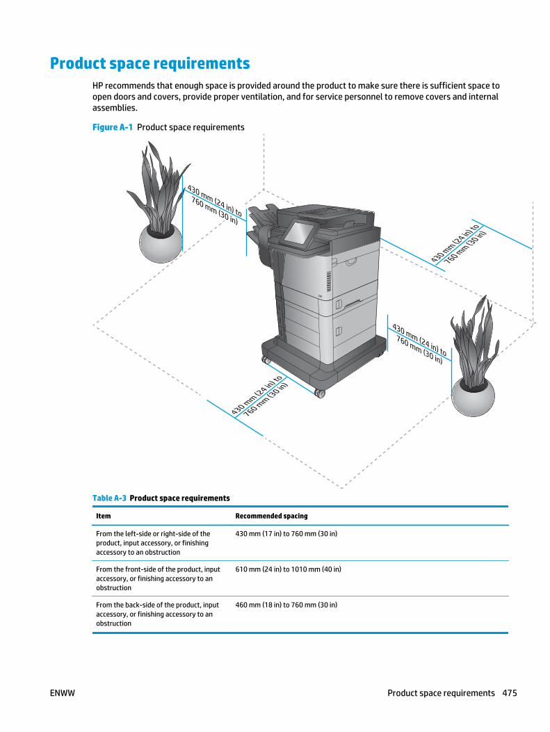
Product space requirementsHP recommends that enough space is provided around the product to make sure there is sufficient space toopen doors and covers, provide proper ventilation, and for service personnel to remove covers and internalassemblies.
Figure A-1 Product space requirements
430 mm (24 in) to
760 mm (30 in)
430 mm (24 in) to
760 mm (30 in)
430 mm (24 in) to
760 mm (30 in)
430 mm (24 in) to
760 mm (30 in)
Table A-3 Product space requirements
Item Recommended spacing
From the left-side or right-side of theproduct, input accessory, or finishingaccessory to an obstruction
430 mm (17 in) to 760 mm (30 in)
From the front-side of the product, inputaccessory, or finishing accessory to anobstruction
610 mm (24 in) to 1010 mm (40 in)
From the back-side of the product, inputaccessory, or finishing accessory to anobstruction
460 mm (18 in) to 760 mm (30 in)
ENWW Product space requirements 475

Power consumption, electrical specifications, and acousticemissions
For more information, go to www.hp.com/support/ljMFPM630. In the left-hand side navigation bar selectLearn and Use, and then select Specifications.
CAUTION: Power requirements are based on the country/region where the product is sold. Do not convertoperating voltages. This will damage the product and void the product warranty.
Environmental specificationsTable A-4 Operating-environment specifications
Environment Recommended Allowed
Temperature 7.5° to 32.5°C (45.5° to 90.5°F) 15° to 30°C (59° to 86°F)
Relative humidity 5% to 90% relative humidity (RH) 10% to 80% RH
Altitude Not applicable 0 to 3048 m (0 to 10,000 ft)
476 Appendix A Product specifications ENWW

Certificate of VolatilityFigure A-2 Certificate of Volatility 1 of 2)
Hewlett-Packard Certificate of VolatilityModel: Part Number: Address:HP LaserJet Enterprise MFP M630
M630 – B3G84A Hewlett Packard Company11311 Chinden BlvdBoise, ID 83714
Volatile MemoryDoes the device contain volatile memory (Memory whose contents are lost when power is removed)?
Yes No If Yes please describe the type, size, function, and steps to clear the memory belowType (SRAM, DRAM, etc): Size: User Modifiable: Function: Steps to clear memory:DDR2 - DRAM 1.5 GB Yes No Video buffer, image buffer and
system memoryWhen the printer is powered off, the memory is erased.
Type (SRAM, DRAM, etc): Size: User Modifiable: Function: Steps to clear memory:Yes No
Type (SRAM, DRAM, etc): Size: User Modifiable: Function: Steps to clear memory:Yes No
Non-Volatile MemoryDoes the device contain non-volatile memory (Memory whose contents are retained when power is removed)?
Yes No If Yes please describe the type, size, function, and steps to clear the memory belowType (Flash, EEPROM, etc): Size: User Modifiable: Function: Steps to clear memory:Formatter SPI Flash 4 MB Yes No BIOS Firmware updateType (Flash, EEPROM, etc): Size: User Modifiable: Function: Steps to clear memory:
Yes No
Type (Flash, EEPROM, etc): Size: User Modifiable: Function: Steps to clear memory:None Yes No
Mass StorageDoes the device contain mass storage memory (Hard Disk Drive, Tape Backup)?
Yes No If Yes please describe the type, size, function, and steps to clear the memory belowType (HDD, Tape, etc): Size: User Modifiable: Function: Steps to clear memory:Hard-disk drive (HDD) 320 GB Yes No Firmware and user data Firmware update
Type (HDD, Tape, etc): Size: User Modifiable: Function: Steps to clear memory:Solid State Storage Device (SSD)
8 MB Yes No Firmware and user data Firmware update
ENWW Certificate of Volatility 477

Figure A-3 Certificate of Volatility (2 of 2)USB
Does the item accept USB input and if so, for what purpose (i.e Print Jobs, device firmware updates, scan upload)?Yes No If Yes please describe below
User can do scan to USB, walkup port print and firmware upgrade through USB walkup portCan any data other than scan upload be sent to the USB device)?
Yes No If Yes please describe belowSystem diagnostic information can also be downloaded to USB drive
RF/RFIDDoes the item use RF or RFID for receive or transmit of any data including remote diagnostics. (e.g. Cellular phone, Bluetooth) Yes No If Yes please describe belowPurpose: Frequency: Bandwidth: Modulation: Effective Radiate Power (ERP): Specifications:
Other Transmission CapabilitiesDoes the device employ any other methods of non-wired access to transmit or receive any data whatsoever (e.g. anything other than standard hard wired TCP/IP, direct USB, or parallel connections)? Yes No If Yes please describe below:Purpose: Frequency: Bandwidth: Modulation: Effective Radiate Power (ERP): Specifications:
Other CapabilitiesDoes the device employ any other method of communications such as a Modem to transmit or receive any data whatsoever? Yes No If Yes please describe below:Purpose: Fax modem for receipt and sending of faxesSpecifications:
Author InformationName: Title: Email: Business Unit:
Technical Marketing Engineer
IPG
Date Prepared: 06-24-14
478 Appendix A Product specifications ENWW

Index
Symbols/Numerics1x500-sheet feeder, 1x500-sheet
feeder with cabinet, and 2,500-sheet high-capacity feeder
connectors, diagrams 1791x500-sheet paper feeder
location 59media feed sensors 70paper jam detection 70signal flow and component
locations 621X500-sheet paper feeder rollers
cleaning 4441x500-sheet paper feeder with
cabinetlocation 60media feed sensors 71paper jam detection 70signal flow and component
locations 632,500-sheet high-capacity feeder
(HCI) rollerscleaning 445
2,500-sheet high-capacity paperfeeder
location 61media feed sensors 72paper jam detection 70signal flow and component
locations 65
Aaccessories 197acoustic specifications 476automatic delivery
stapling mailbox 96
Bbands, troubleshooting 431
basic product operation 2blank pages
troubleshooting 446blank pages, troubleshooting 429block diagram, system 3
Ccables
USB, troubleshooting 446cautions iiicentral processing unit 8certificate of volatility 477characters, troubleshooting 433checklist
problems 98circuit diagrams 184clean the paper path
cleaning page printing 193cleaning
paper path 439pressure roller 21product 439rollers 442, 444, 445scanner glass 440
cleaning page 260clutch
identification 0location 35
clutch (product base)block diagram 161
cold reset 451component test
special mode test 150components
diagnostic tests 150configuration page 134configuration pages
information 197printing 194
connectionsDC controller 176
connectivity LED 137connectors
1x500-sheet feeder, 1x500-sheetfeeder with cabinet, and 2,500-sheet high-capacity feeder179
scanner controller board (SBC)178
stapling mailbox 180control panel
Administration menu 199Backup/Restore menu 259Calibrate/Cleaning menu 260connections diagram 176Copy Settings menu 206Display Settings menu 239fax Settings menu (fax models
only) 224General Settings menu 201Manage Supplies menu 241Manage Trays menu 244messages, types of 263Network Settings menu 246Print Options menu 237Print Settings menu 234Reports menu 199Scan/Digital Send Settings
menu 214Service menu 262specifications 9troubleshooting menu 257USB Firmware Upgrade menu
262control panel diagnostic flowcharts
127control-panel menus 199conventions, document iii
ENWW Index 479

copyimprove quality 440
copyingquality, troubleshooting 429
counts 449copy scan 450document feeder 450document feeder duplex 450document feeder simplex 450flatbed cycle 450page, reset 449refurbish cycle 449reset after replacing formatter
449send scan 450See also pages counts
CPU 8creases, troubleshooting 433current settings pages 101
Ddark image, troubleshooting 429date
product first used 451DC controller
connections, diagrams 176functions 11operation 11voltage detection 16
defeatinginterlocks 139
defects, repeating 198delivery operation
stapling mailbox 84demo page 134deskew operation 78determine problem source 119determine the installed revision of
firmware 469developing stage 28diagnostics
component 150engine 139LED 134networks 251
diagramsblock 155circuit 184clutch (product base) 161DC controller connections 176
fans (product base) 166main assemblies 167main assemblies (1x500-sheet
paper feeder with cabinet) 170main assemblies (1x500-sheet
paper feeder) 169main assemblies (2,500-sheet
high-capacity feeder) (HCI)171
main assemblies (product base)167
main assemblies (staplingmailbox) 172
main assemblies PCAs 174main PCAs (product base) 174motors 162motors (1 x 500-sheet paper
feeder) 163motors (1x500-sheet paper
feeder with cabinet) 163motors (2,500-sheet high-
capacity feeder) (HCI) 164motors (product base) 162motors (stapling mailbox) 165rollers 175rollers (product base) 175sensors (1x500-sheet paper
feeder and 1x500-sheet paperfeeder with cabinet) 156
sensors (2,500-sheet high-capacity feeder) (HCI) 157
sensors (product base) 155sensors (SSMBM) 158solenoids (product base) 160switches (product base) 159timing 182
document conventions iiidocument feed system 73document feeder
books, copying 79e-duplex operation 76front-side and back-side
background selecto 77hinges 79jams 394paper path 75paper-feeding problems 425sensors 73simplex operation 75
document feeder countdocument feeder pages 449
document feeder interval 449document feeder paper path 75document feeder rollers
cleaning 442drum cleaning stage 30duplex printing accessory
connections diagram 176duplexer
clearing jams 408duplexing
operations 53side registration adjustment
operation 53
Eelectrical specifications 476electrophotographic process 26embedded web server 470engine
diagnostics 139test page 140
engine power supplyconnections diagram 176
engine-control systemcomponents 10functions 10operation 10
envelope feederconnections diagram 176
EP process 26error messages
types of 263event log 101, 134
clear 102, 387, 449information 197print 387view 387
event-log messages 386
Ffaded print 429failure detection
laser/scanner 23stapling mailbox 84
fansconnections diagram 176locations 13operation 13
480 Index ENWW

fans (product base)block diagram 166
faxfeeding problems 459
feeding problems 459firmware
date codes 197formatter 8version information 196
firmware, downloading new 468flowcharts
troubleshooting 119formatter
connections diagram 176control system 6CPU 8firmware 8hardware 6hardware components 6input/output 8memory 8nonvolatile random access
memory (NVRAM) 8NVRAM 8random access memory (RAM) 8resets after replacing 449Resolution Enhancement
technology (REt) 8scanner interface 9
formatter lights 134formatter-control system
functions 6operation 6
fuserclearing jams 408components 18connections diagram 176failure detection 20heater protection 20temperature control 19
fuser circuit 19fuser failure detection 20fuser-control circuit 18fuses, overcurrent/overvoltage
protection 16fusing
description 47fusing stage 29
Hhardware
formatter 6hardware integration pocket (HIP) is
not functionin 133high-voltage power supply (HVPS)
14home button is unresponsive 132horizontal lines, troubleshooting
431HP embedded Jetdirect page 196HP Jetdirect print server
configuration page 196lights 134
Iimage capture system 73image formation, stages 26
developing 28drum cleaning 30fusing 29laser-beam exposure (writing)
27primary charge (conditioning)
27separation 29transfer 28
image quality issuesexamples and solutions 429
image-formation systemcomponents 24motor control 25operation 24
imaging drumsdiagnostic test 140
individual component disagnostics134
input/outputformatter 8
installationdate calculation 451
interlocksdefeating 139
interpret control-panel messagesand event log entries 263
IPv4 information 196IPv6 information 196
Jjam detection
stapling mailbox 94jams
1,500-sheet high-capacity inputtray (Tray 5) 403
auto-navigation 392causes of 392, 425detection in paper feeder 70detection operations 55diagnostic test for 141document feeder 394duplexer 408fuser 408locations 392lower-right door 407output bin 416recovery 423right door 406sensor locations 388sensors 388sensors and switches 1x500-
sheet feeders 389sensors and switches HCI 390sensors mailbox 391staples in the stapling mailbox
accessory 419stapling mailbox accessory 417top cover 413Tray 1 398Tray 2, 3, and 4 401
Jetdirect print server 196lights 134
Llaser-beam exposure (writing)
stage 27laser/scanner
failure detection 23safety 23
laser/scanner assemblyconnections diagram 176
laser/scanner systemcomponents 22functions 22operation 22
LEDs. See lightslight print, troubleshooting 429
ENWW Index 481

lightsformatter 134troubleshooting with 134
lines, troubleshooting 431link speed settings 256loose toner, troubleshooting 433low-voltage power supply (LVPS)
15converted DC voltages 16functions 17
low-voltage power supply circuit 15lower-right door
clear jams 407
Mmailbox/job separator mode
stapling mailbox 93main assemblies (1x500-sheet paper
feeder with cabinet)block diagram 170
main assemblies (1x500-sheet paperfeeder)
block diagram 169main assemblies (2,500-sheet high-
capacity feeder) (HCI)block diagram 171
main assemblies (product base)block diagram 167
main assemblies (stapling mailbox)block diagram 172
main PCAs (product base)block diagram 174
main product systemsrelationship between 2
manual print modes 426media size detection components
Tray 2 40memory
formatter 8information 194nonvolative random access
memory (NVRAM) 8random access meory (RAM) 8types 8
memory chiptoner cartridge 31
Memory Enhancement technology(MEt) 9
menu map 101
messagestypes of 263
modem speed 461motor control
stapling mailbox 83motors
connections diagram 176identification 0locations 12, 35operation 12
motors (1 x 500-sheet paper feeder)block diagram 163
motors (1x500-sheet paper feederwith cabinet)
block diagram 163motors (2,500-sheet high-capacity
feeder) (HCI)block diagram 164
motors (product base)block diagram 162
motors (stapling mailbox)block diagram 165
Nnetworks
diagnostics 251HP embedded Jetdirect
configuration page 196link speed settings 256
no control panel sound 131nonvolatile random access memory
(NVRAM) 8notes iiiNVRAM 8
Ooperation
engine-control system 10fans 13image formation system 24laser/scanner system 22motors 12pickup, feed, and delivery
system 33pickup-and-feed block 38power supply, high-voltage 14power supply, low-voltage 15sequence of (product) 4sequence of (scanner) 5Sleep mode 6
operationsjam detection 55scanner 73temperature detection 21
output binclear jams 416
output bin 3 lift operationstapling mailbox 92
output bin paper-full detection 52overcurrent/overvoltage
protection 16
Ppages
blank 446not printing 446printing slowly 446
pages count 449reset 449See also counts
paperdefault size reset 451jam detection 70jams 392, 425size detection 67stop in path for testing 150tray-presence detection 67wrinkled 433
paper deliveryface-down 50face-up 51
paper feed speed control 44paper feeder
jam detection 70optional 1 x 500-sheet 59optional 1 x 500-sheet with
cabinet 59optional 2,500-sheet high-
capacity 59pickup and feed components 62tray lift operation 68
paper jamsdetection 56document feeder 394locations 392lower-right door 407output bin 416right door 406stapling mailbox accessory 417top cover 413
482 Index ENWW

Tray 1 398Tray 2, 3, and 4 401Tray 5 403
paper pathdiagnostic test 141stop movement for testing 150
paper pickup problemssolving 424
paper-length detection 46paper-path
test, sensors 141paper-width detection 46password
Service menu PIN 449PBX systems troubleshooting 463phone lines troubleshooting 463physical specifications 474pickup, feed, and delivery
paper-feeder 62pickup, feed, and delivery system
operation 33pickup-and-feed block
operation 38PJL (product job language)
functions 9PML (printer management
language) 9power
consumption 476power subsystem 120power supply
connections diagram 176overcurrent/overvoltage
protection 16safety 16troubleshooting 120
power supply, high-voltageoperation 14
power supply, low-voltagefunctions 17operation 15
power-on troubleshootingoverview 120
power-save mode. See sleep modepre-boot menu options 103pressure roller
pressurization anddepressurization control 48
pressure roller cleaning 21
primary charge (conditioning)stage 27
print qualitybuilt-in troubleshooting pages
189manual print modes 426test pages 189troubleshooting 429
print quality troubleshooting 198Print Test Page 202printer management language
(PML) 9printing
modes, manual 426stop for testing 150troubleshooting 446
problem-solvingevent-log messages 386messages, types of 263networks 251
Process Cleaning Page 260processor 8product cold reset 453product job language (PJL)
functions 9product resets 452product sequence of operation 4product space requirements 475
Qquality. See print quality
RRAM 8random access memory (RAM) 8repeating defects, troubleshooting
198repetitive defects ruler 198resolution
troubleshooting quality 429Resolution Enhancement technology
(REt) 8restore factory settings 452restore the service ID 453reverse and delivery control 49reversing assembly
operations 47right door
clear jams 406
Rollers (product base)block diagram 175
ruler, repetitive defect 198
Ssafety
laser/scanner 23safety, power supply 16scanner
operations 73sequence of operation 5tests 153
scanner controller board (SBC)connectors, diagrams 178
scanner glasscleaning 440
scanner interfaceformatter 9
scanner sequence of operation 5scanner settings 450scanning/image capture system 73security settings information 196sensors
ADF 73connections diagram 176diagnostic tests 141fuser-control circuits 18identification 0jam detection 55locations 34temperature detection 21tests, manual 143tests, manual tray/bin 148
sensors (1x500-sheet paper feederand 1x500-sheet paper feeder withcabinet)
block diagram 156sensors (2,500-sheet high-capacity
feeder) (HCI)block diagram 157
sensors (product base)block diagram 155
sensors (SSMBM)block diagram 158
separation stage 29sequence of operation, product 4sequence of operation, scanner 5serial number 450
ENWW Index 483

Service IDconvert to date 451restore 451
Service menu options 449service mode functions 449service settings 467settings
restore factory 452size specifications, product 474skew
prevention operations 45Sleep (power save) mode 17Sleep mode
operation 6sleep settings 6slow fax reception 461slow fax transmission 463solenoids
identification 0locations 35
solenoids (product base)block diagram 160
solve connectivity problems 447solve performance problems 446solve problems 97solving
direct-connect problems 447space requiremnts, product 475specifications
electrical and acoustic 476physical 474space requirments 475
stacker modestapling mailbox 93
stages, image formation 26staple jams
stapling mailbox accessory 419staple operation
stapling mailbox 86stapler
stapling mailbox 91stapling mailbox 81
automatic delivery 96connectors, diagrams 180delivery operation 84failure detection 84jam detection 94mailbox/job separator mode 93motor control 83optional, operations 81
output bin 3 lift operation 92stacker mode 93staple operation 86stapler 91
stapling mailbox accessoryclear jams 417clear staple jams 419
statusmessages, types of 263
status page 134status, fax accessory page 458stop printing for test 150streaks, troubleshooting 431switches
connections diagram 176identification 0location 36paper feeder 67
switches (product base)block diagram 159
system block diagram 3systems
main product 2
TT.30 Trace report 467TCP/IP information 196temperature
detection sensor 21fuser sleeve temperature
protection 20fuser-control circuits 18
temperature control, fuser 19tests
component tests list anddescriptions 151
disable cartridge check 140engine 140manual sensor and tray bin
sensor 143networks 251paper path 141paper-path sensors 141print/stop 150scanner 153scanner tests 153tray/bin manual sensor 148
text, troubleshooting 433timing chart 182tips iii
tonerloose, troubleshooting 433
toner cartridgecartridge life detection 31cartridge presence detection 31components 31memory chip 31toner level detection 31
toner cartridgesdiagnostic test 140
top coverjams 413
touchscreen blank, white, or dim (noimage) 128
touchscreen has an unresponsivezone 130
touchscreen is slow to respond 129transfer stage 28tray
lift operation 68presence detection 67
Tray 1jams 398paper pickup operation 43paper presence detection 44
Tray 2jams 401media-size detection
components 40multiple-feed prevention 42paper pickup operation 39paper presence detection 41paper size detection 40tray lift operation 41tray-present detection 40
Tray 3jams 401tray lift operation 68
Tray 4jams 401tray lift operation 68
Tray 5paper jams 403tray lift operation 69
tray selection - use requested tray244
traysjam detection 55
troubleshooting 97blank pages 446
484 Index ENWW

checklist 98clean the paper path 193configuration page 134configuration pages 194control panel checks 124demo page 134direct-connect problems 447event log 134flowchart 119jams 388, 392, 425lights, using 134lines, printed pages 431network problems 447pages not printing 446pages printing slowly 446paper feed problems 424PBX systems 463power 120print quality 189print quality issues 429process 119repeating defects 198reports and tools 134scanner calibration 124scanning subsystem 124slow fax reception 461slow fax transmission 463status page 134text 433USB cables 446wired network 447wrinkles 433
Uunderstand lights on the formatter
formatter lights 134understand the lights on the
formatterconnectivity LED 134connectivity LED, product 135connectivity LED, product
operating 137heartbeat LED 137HP Jetdirect LEDs 137
upgrade firmware 470upgrades, downloading product
firmware 468
USB flash drivefirmware upgrade, control
panel 471firmware upgrade, pre-boot
menu 470USB port
troubleshooting 446Use Requested Tray 244
Vvertical lines, troubleshooting 431VoIP 460voltage detection
DC controller 16
Wwarnings iiiwarranty date information 451white spots, troubleshooting 430wrinkles, troubleshooting 433
ENWW Index 485

486 Index ENWW


© 2014 Hewlett-Packard Development Company, L.P.
www.hp.com