COMPUTER PROBLEMS AND TROUBLESHOOTING
156
1 | Page COMPUTER PROBLEMS AND TROUBLESHOOTING Unit- 1 Troubleshooting Computer –Definition - Tools - Troubleshooting Display Problem- HDD problem- CDROM problem- FDD problem- Sound problem -.- Troubleshooting Systems -Troubleshooting Keyboard Problem- Mouse Problem- Sound Problem- Printer Problem- and Modem - Networking. Unit- 2 Concept-Definition- Requirements Network- Different types Network- peer to peer and server based-Networking Concept- Media –Definition- Bandwidth- Bounded and Unbounded media- media types Coaxial- Twisted Pair - Fiber Optic- Benefits and Limitations each type media. Unit 3 Visual Identification - Inspection Fault Area- Check for Loose Connections- Check whether power supply is ON and OK. Hardware – I-O Slots Troubleshooting – ISA- PCMCIA PCI- AGP- Basic Troubleshooting in Motherboard- Troubleshooting in Visual Display Unit- Switch Mode power Supply – SMPS. Unit 4 Troubleshooting in 8259 - Programmable Interrupt Controller- Interrupt Assigned - Device- DMA – Direct Memory Access- Uninterrupted Power Supply- Online Uninterrupted Power Supply-OFFline Uninterrupted Power Supply- Troubleshooting in Audio – Loudspeaker- Headset -Troubleshooting in Chip Level Services Troubleshooting in AMD and INTEL Processor Lineups Latest - Processor Technologies Construction and Operation Hard Disk - Hard Disk Platters and Media – SUBSTRATE - Magnetic Media - Head Actuator- Unit 5 Keyboard – Membrane- Hall Effect- Mechanical Switch - Dome Switch - Mouse – UPS – Printer – Scanner- Troubleshooting in Managing Printers- Troubleshooting in Managing Documents- and Printers- Understanding printer Administration- Accessing Printer- Setting Printer Permission to Control Access - System Assembling in Hardware- Network Troubleshooting- Windows Troubleshooting- LAN- MAN and WAN Troubleshooting- Configure TCP-IP Troubleshooting
-
Upload
khangminh22 -
Category
Documents
-
view
2 -
download
0
Transcript of COMPUTER PROBLEMS AND TROUBLESHOOTING

1 | P a g e
COMPUTER PROBLEMS AND TROUBLESHOOTING
Unit- 1
Troubleshooting Computer –Definition - Tools - Troubleshooting Display Problem- HDD
problem- CDROM problem- FDD problem- Sound problem -.- Troubleshooting Systems
-Troubleshooting Keyboard Problem- Mouse Problem- Sound Problem- Printer
Problem- and Modem - Networking.
Unit- 2
Concept-Definition- Requirements Network- Different types Network- peer to peer and
server based-Networking Concept- Media –Definition- Bandwidth- Bounded and
Unbounded media- media types Coaxial- Twisted Pair - Fiber Optic- Benefits and
Limitations each type media.
Unit 3
Visual Identification - Inspection Fault Area- Check for Loose Connections- Check
whether power supply is ON and OK. Hardware – I-O Slots Troubleshooting – ISA-
PCMCIA PCI- AGP- Basic Troubleshooting in Motherboard- Troubleshooting in Visual
Display Unit- Switch Mode power Supply – SMPS.
Unit 4
Troubleshooting in 8259 - Programmable Interrupt Controller- Interrupt Assigned -
Device- DMA – Direct Memory Access- Uninterrupted Power Supply- Online
Uninterrupted Power Supply-OFFline Uninterrupted Power Supply- Troubleshooting in
Audio – Loudspeaker- Headset -Troubleshooting in Chip Level Services
Troubleshooting in AMD and INTEL Processor Lineups Latest - Processor Technologies
Construction and Operation Hard Disk - Hard Disk Platters and Media – SUBSTRATE -
Magnetic Media - Head Actuator-
Unit 5
Keyboard – Membrane- Hall Effect- Mechanical Switch - Dome Switch - Mouse – UPS
– Printer – Scanner- Troubleshooting in Managing Printers- Troubleshooting in
Managing Documents- and Printers- Understanding printer Administration- Accessing
Printer- Setting Printer Permission to Control Access - System Assembling in Hardware-
Network Troubleshooting- Windows Troubleshooting- LAN- MAN and WAN
Troubleshooting- Configure TCP-IP Troubleshooting

2 | P a g e
Unit – 1
Troubleshooting Computer –Definition
Troubleshooting is the process of diagnosing the source of a problem. It is used to fix
problems with hardware, software, and many other products. The basic theory of
troubleshooting is that you start with the most general (and often most obvious) possible
problems, and then narrow it down to more specific issues.
Many product manuals have a "Troubleshooting" section in the back of the manual. This
section contains a list of potential problems, which are often phrased in the form of a
question. For example, if your your computer's monitor is not producing an image, you
may be asked to answer the following troubleshooting questions:
1. Is the monitor plugged in to a power source?
2. Is the monitor turned on?
3. Is the monitor cable plugged into the computer?
4. Is the computer turned on?
5. Is the computer awake from sleep mode?
If the answers to all the above questions are Yes, there may be some additional
questions such as:
1. Does your computer have a supporting video card?
2. Have you installed the necessary video card drivers?
3. Is the monitor resolution set properly?
Typically, each of these questions will be followed by specific advice, whether the
answer is Yes or No. Sometimes, this advice is presented as a flowchart diagram. This
means each question is followed by a series of other questions, depending on the
answer. However, in many cases, only single solutions are provided for each question.
Troubleshooting is something we all have to do at some point, though some of us have
to troubleshoot product problems more often than others. The good news is that, the
more you do it, the more you learn and the better you get at fixing problems. Since
many products have similar troubleshooting steps, you may find that after awhile, you
don't even need the manual to find solutions to the problems you encounter.

3 | P a g e
Tools
The following tools will assist you in troubleshooting hardware and software issues.
• ActiveX - Troubleshoot ActiveX issues
• Boot - Troubleshoot booting issues
• CD-ROM, DVD-ROM, DVD-R, DVD+R - Troubleshoot issues with various CD-
ROM and DVD drives
• Deleting upper and lower filters - If you are having trouble with the CD-ROM
drive, this may help
• Email - Troubleshoot email issues
• Floppy - Troubleshoot floppy drive
• Hard Drive - Troubleshoot hard drive not seen in Bios
• Hardware issues - Troubleshoot hardware issues
• Internet - Troubleshoot issues with internet and connection
• Keyboard - Troubleshoot issues with the keyboard
• Memory - Troubleshoot memory issues
• Modem - Troubleshoot issues with your modem
• Microsoft Office - Troubleshoot Microsoft Office issues
• Network - Troubleshoot issues with network
• No disk - Troubleshoot no disk error
• Noise - Troubleshoot noise issues
• No Post - Troubleshoot Computer not booting
• Printers - Troubleshoot printer issues
• Questions - Questions to ask when troubleshooting
• Shuts off - Troubleshoot why the system shuts off
• Software - Troubleshoot issues with software
• Sound - Troubleshoot issues with sound.

4 | P a g e
• Spyware/Virus - Troubleshoot spyware and virus issues
Troubleshooting Display Problems
Troubleshooting CRT monitors versus FPDs begins with similar steps, but diverges due
to the differing natures of the two display types. The first troubleshooting steps are
similar for either display type: power down the system and display and then power them
back up; make sure the power cable is connected and that the outlet has power; verify
that the signal cable is connected firmly to both video adapter and display and that there
are no bent pins; verify that the video adapter is configured properly for the display; try
the problem display on a known-good system, or try a known-good display on the
problem system; and so on. Once you've tried the "obvious" troubleshooting steps, if the
problem persists, the next steps you take depend on the type of display. The following
sections cover basic troubleshooting for CRT monitors and FPDs.
Troubleshooting CRT Monitors
Monitors seldom fail outright without obvious signs, such as a loud snap or a strong
odor of burning electrical components. Most monitor problems are really problems with
the power, video adapter, cable, or hardware/software settings. To eliminate the monitor
as a possible cause, connect the suspect monitor to a known-good system, or connect
a known-good monitor to the suspect system.
If the monitor is the problem, it is often not worth repairing. If the monitor is out of
warranty, parts and labor may cost more than buying a new monitor, which also gives
you better specs and a warranty. About the only monitors we'd even consider repairing
out of warranty are high-end 19-inch and 21-inch models, and even there the
economics are dubious.
Even if the monitor is in warranty, the shipping costs may exceed the value of the
monitor. For example, shipping a monitor both ways can easily cost $75 or more. If that
monitor is a year-old 17-inch model, you're probably better off spending $150 on a new
17-inch monitor than paying $75 to fix the old one. Monitors have many components, all
of which age together. Fixing one is no guarantee that another won't fail shortly. In fact,
that happens more often than not in our experience.
Never disassemble a monitor. At best, you'll likely destroy the monitor. At worst, it may
destroy you. Like televisions, monitors use extremely high voltages internally, and have
large capacitors that store that energy for days or even weeks after the monitor is
unplugged. Robert once literally burned a screwdriver in half when working inside a
color television that had been unplugged for several days. Also, the large, fragile tube

5 | P a g e
may implode, scattering glass fragments like a hand grenade. People who repair
monitors and televisions for a living treat them with great respect, and so should you. If
you must repair a monitor, take it to someone who knows what he is doing. You have
been warned.
Here are some common monitor problems:
Monitor displays no image
Check the obvious things first. Verify the monitor is plugged in (and that the receptacle
has power), the video cable is connected to the video card, the computer and monitor
are turned on, and the brightness and contrast settings are set to the middle of their
range. If none of these steps solves the problem, your monitor, video card, or video
cable may be bad. Check the suspect monitor on a known-good system or a known-
good monitor on the problem system.
If you have ACPI or APM power management enabled, it may be causing the problem.
Some systems simply refuse to wake up once power management puts them to sleep.
We have seen such systems survive a hardware reset without restoring power to the
monitor. To verify this problem, turn off power to the system and monitor and then turn
them back on. If the monitor then displays an image, check the power management
settings in your BIOS and operating system and disable them if necessary.
Monitor displays only a thin horizontal line or a pinpoint at the center
This is a hardware problem. The flyback transformer or high-voltage circuitry is failing or
has failed. Take the monitor to be repaired, or replace it.
Monitor flashes one color intermittently, even when the screen is blanked
This is a hardware problem with one of the electron guns. Take the monitor to be
repaired, or replace it. This problem may also manifest as a strong color cast during
normal operation that is not correctable using the normal color balance controls.
Monitor snaps, crackles, or pops when powered up, or emits a strong electrical odor
Catastrophic monitor failure is imminent. The noises are caused by high-voltage arcing,
and the smell is caused by burning insulation. Unplug the monitor from the wall before it
catches fire, literally.
Monitor emits a very high-pitched squeal
There are two likely causes. First, you may be driving the monitor beyond its design
limits. Some monitors display a usable image at resolutions and/or refresh rates higher
than they are designed to use, but under such abuse the expected life of the monitor is

6 | P a g e
shortened dramatically, perhaps to minutes. To correct this problem, change video
settings to values that are within the monitor's design specifications. Second, the power
receptacle may be supplying voltage lower than the monitor requires. To correct this
problem, connect the monitor to a different circuit or to a UPS or power conditioner that
supplies standard voltage regardless of input voltage.
Monitor displays some colors incorrectly or not at all
This is usually a minor hardware problem. The most likely cause is that the signal cable
is not connected tightly to the monitor and/or video card, causing some pins to make
contact intermittently or not at all. Verify that no pins are loose, bent, or missing on the
cable or the connectors on the monitor and video card, and then tighten the cable at
both ends. If that doesn't fix the problem, open the computer, remove the video card,
and reseat it fully.
Another possible cause is that some hardware DVD decoder cards "steal" one color
(usually magenta) and use it to map the DVD video signal onto the standard video
signal. Short of replacing the DVD decoder card with another model that doesn't do this,
the options are to live with the problem or to connect the monitor directly to the video
card for normal operations and connect the monitor to the DVD decoder card only when
you want to watch a DVD. Alternatively, consider removing the DVD decoder card. If
your current video adapter includes hardware DVD support, or if you upgrade to such
an adapter, you don't need a DVD decoder card.
Image rolls or a horizontal line scrolls constantly down the screen
The most likely cause is that the monitor is receiving inadequate power. Connect it to a
different circuit or to a backup power supply that provides correct voltage regardless of
fluctuations in main voltage.
Image flickers
The most likely cause is that the refresh rate is set too low. Change the refresh rate to
at least 75 Hz. Flicker also results from interaction with fluorescent lights, which operate
on 60 Hz AC and can heterodyne visually with the monitor. This can occur at 60 Hz
(which is far too low a refresh rate anyway), but can also occur at 120 Hz. If you're
running at 120 Hz refresh and experience flicker, either use incandescent lighting or
reset the refresh rate to something other than 120 Hz.

7 | P a g e
Image is scrambled
The video card settings are likely outside the range supported by the monitor,
particularly if you have just installed the monitor or have just changed video settings. To
verify this, restart the system in VGA mode. If the system displays a VGA image
properly, change your display settings to something supported by the monitor.
Image displays rectilinearly, but is incorrectly sized or aligned on screen
Most modern monitors can display signals at many different scan frequencies, but this
doesn't mean that the monitor will necessarily automatically display different signals at
full screen and properly aligned. Use the monitor controls to adjust the size and
alignment of the image.
Image displays other than rectilinearly (trapezoid, parallelogram, barrel, or pincushion)
Depending on the monitor, video card, and video settings, this may be normal behavior,
adjustable using the monitor controls. If the distortion is beyond the ability of the
controls to correct, the problem may be with the video card, the monitor, or the driver.
First try changing video settings. If the problem persists at several settings, move that
monitor to a different system (or use a different video card) to determine whether the
problem is caused by the monitor or video card. Repair or replace the faulty component.
Image wavers or shimmers periodically or constantly
This is usually caused by RF interference from another electrical or electronic device,
particularly one that contains a motor. Make sure such devices are at least 3 feet from
the monitor. Note that such interference can sometimes penetrate typical residential and
office walls, so if the monitor is close to a wall, check the other side. Such image
problems can also be caused by interference carried by the power line or by voltage
variations in the AC power supply. To eliminate interference, plug the monitor into a
surge protector. Better still, plug it into a UPS or power conditioner that supplies clean
power at constant voltage.
Colors are "off" or smearing appears in some areas
The monitor may need to be degaussed. A monitor that sits in one position for months
or years can be affected even by the Earth's very weak magnetic field, causing
distortion and other display problems. Exposing a monitor to a strong magnetic field,
such as unshielded speakers, can cause more-extreme image problems. Many modern
monitors degauss themselves automatically each time you cycle the power, but some
have a manual degauss button that you must remember to use. If your monitor has a
manual degauss button, use it every month or two. The degaussing circuitry in some
monitors has limited power. We have seen monitors that were accidentally exposed to

8 | P a g e
strong magnetic fields, resulting in a badly distorted image. Built-in degaussing did little
or nothing. In that case, you can sometimes fix the problem by using a separate
degaussing coil, available at Radio Shack and similar stores for a few dollars. We have,
however, seen monitors that were so badly "magnet-burned" that even a standalone
degaussing coil could not completely eliminate the problem. The moral is, keep
magnets away from your monitor, including those in speakers that are not video-
shielded.
Flat-Panel Displays
If you've tried the basic troubleshooting steps and your FPD still doesn't work properly,
you may have one or more of the following problems:
No image
If your FPD displays no image at all and you are certain that it is receiving power and
video signals, first adjust the brightness and contrast settings to higher values. If that
doesn't work, turn off the system and FPD, disconnect the FPD signal cable from the
computer, and turn on the FPD by itself. It should display some sort of initialization
screen, if only perhaps a "No video signal" message. If nothing lights up and no
message is displayed, contact technical support for your FPD manufacturer.
Screen flickers
Unlike CRTs, where increasing the refresh rate always reduces flicker, FPDs have an
optimal refresh rate that may be lower than the highest refresh rate supported. For
example, a 15-inch FPD operating in analog mode may support 60 Hz and 75 Hz
refresh. Although it sounds counterintuitive to anyone whose experience has been with
CRTs, reducing the refresh rate from 75 Hz to 60 Hz may improve image stability.
Check the manual to determine the optimum refresh rate for your FPD, and set your
video adapter to use that rate.
The screen is very unstable
First, try setting the optimal refresh rate as described earlier. If that doesn't solve the
problem and you are using an analog interface, there are several possible causes, most
of which are due to poor synchronization between the video adapter clock and the
display clock, or to phase problems. If your FPD has an auto-adjust, auto-setup, or
auto-synchronize option, try using that first. If it doesn't, try adjusting the phase and/or
clock settings manually until you have a usable image. If you are using an extension or
longer than standard video cable, try connecting the standard video cable that was
supplied with the display. Long analog video cables exacerbate sync problems. Also, if
you are using a (KVM) switch, particularly a manual model, try instead connecting the

9 | P a g e
FPD directly to the video adapter. Many FPDs are difficult or impossible to synchronize
if you use a KVM switch. If you are unable to achieve proper synchronization, try
connecting the FPD to a different computer. If you are unable to achieve
synchronization on the second computer, the FPD may be defective. Finally, note that
some video adapter models simply don't function well with some FPD models.
Poor image
If the screen is displaying a full, stable image, but that image is of poor quality, first
verify that the display is not connected through a KVM switch or using an extension
cable. If it isn't, connect the display directly to the video adapter using the standard
cable. If that is already the case, adjust the brightness, contrast, and focus controls. If
you are unable to get a proper image using these controls, the problem is most likely a
clock or phase mismatch, which you can cure by taking the steps described in the
preceding item.
The best way to adjust Clock and Phase is to use auto-adjust first. If this does not solve
the problem, go to the Windows Start menu and select Shutdown. When the screen
goes gray and the Windows Shutdown dialog appears, leave that dialog on screen, but
ignore it. Use the gray screen to adjust Clock and Phase manually. Any problems with
Clock and Phase and any changes you make to the Clock and Phase settings are very
apparent on the gray screen. Although we have never run an FPD under Linux, our
editor wonders if the unadorned X server (no window manager) might serve the same
purpose. It displays a crosshatch pattern; if you are at the text console, you can
generally start it just by running the command X and exit it with Ctrl-Alt-Backspace.
Always adjust Clock first. Clock is usually not a problem if you have used the auto-
adjust feature of your monitor, but if you do have Clock problems, they will be evident as
large vertical bars on your screen. Tweak the Clock setting until those bars disappear.
Then adjust Phase. Phase problems are evident as thin black lines running horizontally
across the screen. Adjust Phase until the lines disappear or are minimized.
Not all video cards synchronize perfectly with flat panels. The gray Shutdown screen
exaggerates the problem, so do not worry if very tiny movements are visible after you've
adjusted Clock and Phase as well as possible. After you've set the Clock and Phase
controls for the best image possible on the gray screen, cancel the Shutdown and the
image should be optimized.
Signal out of range message
Your video card is supplying a video signal at a bandwidth that is above or below the
ability of your FPD to display. Reset your video parameters to be within the range

10 | P a g e
supported by the FPD. If necessary, temporarily connect a different display or start
Windows in Safe Mode and choose standard VGA in order to change video settings.
Text or lines are shadowed or blocky
This generally occurs when you run an FPD at other than its native resolution. For
example, if you have a 15-inch 1024 x 768 FPD but have your display adapter set to
800 x 600, your FPD will attempt to display those 800 x 600 pixels at full screen size,
which physically corresponds to 1024 x 768 pixels. The extrapolation necessary to fill
the screen with the smaller image results in artifacts such as blocky or poorly rendered
text, jaggy lines, and so on. Either set your video adapter to display the native resolution
of the FPD, or set your FPD to display the lower-resolution image using less than the
entire screen.
Some pixels are always on or always off
This is a characteristic of today's FPDs. Other than by pure chance, any FPD you buy
will have some small number of defective pixels. Manufacturers set a threshold number
below which they consider the display acceptable. That number varies with the
manufacturer, the model, and the size of the display, but is typically in the range of five
to 10 pixels. Nothing can be done to fix the problem. The manufacturer will not replace
the FPD under warranty unless the number of defective pixels exceeds the threshold
number. This is simply something you have to learn to live with if you want to use an
FPD.
A persistent after-image exists
Again, this is a characteristic of current FPDs. The after-image occurs when the display
has had the same image in one place for a long time. The after-image may persist even
after you turn off the display. More-expensive models are less prone to this problem
than entry-level models, but all FPDs exhibit the problem to some extent. It is simply
another characteristic of FPDs that you must learn to live with.
Moving images blur, smear, or ghost
The transistor-based pixels in an FPD respond less quickly than the phosphors in a
CRT. The least-expensive FPDs exhibit this problem even with relatively slow image
movement, as when you drag a window. Better FPDs handle moderately fast image
movement without ghosting, but exhibit the problem on fast-motion video, such as DVD
movies. The best FPDs can handle even fast-motion video reasonably well, although no
FPD handles it as well as a CRT. The only real solution to this problem is to upgrade
your FPD to a model with faster rise/fall times. The fastest currently available FPDs
have 15 ms rise/fall times, which are adequate for anything short of 3D gaming.

11 | P a g e
Dim image
Use the brightness control to increase image brightness. If you have set brightness to
maximum and the image is still too dim, contact the display manufacturer. The CCRTs
used to backlight the screen have a finite lifetime and may begin to dim as they near the
end of their life.
Image is only partially backlit
One or more of the CCRTs that provide the backlight have failed. Contact the display
manufacturer.
Horizontal or vertical lines appear
If one or multiple horizontal and/or vertical lines appear on the display, first power-reset
the computer and display. If the lines persist, run the auto-setup function of your display.
If that does not solve the problem, power down the system and display, remove the
video cable, and verify that the video plugs and jacks on both computer and display
ends do not have broken or bent pins. Even if all appears correct, try a different video
cable. If the problem persists, contact the display manufacturer.
HDD Problem
PC Troubleshooting the Hard Disk Drive
How to troubleshoot a Windows PC Hard Disk Drive
• Check the BIOS and see if the hard disk drive is being detected.
• Reset the BIOS (Re-boot and tap the F2 Key, Press F9 (Default Settings), Press
F10 (Save and Exit)
• Check for floppy disk in floppy disk drive and remove and reboot. This would be a
message stating "NON-SYSTEM DISK FOUND".
• Check for error message - SMART FAILURE - HDD Controller Diagnostics
• Check error messages in Event Viewer. Start / Settings / Control Panel /
Administrative Tools / Computer Management (or Event Viewer)
• Diagnostics - SCANDISK / CHKDSK
• Defragment your hard drive
• For Notebooks - reseat the hard drive and also try a hard reset

12 | P a g e
• For Desktops - check the IDE or SCSI wiring to the hard drive
• Check for noises - grinding noise => new hard drive required
• Data Recovery for Notebooks - use a 44 pin to IDE connector and attach to
another computer and employ the other computer's operating system to view the
damaged hard drive as another drive letter. Copy data onto good drive. Replace
bad drive drive and then restore data onto good hard drive.
• Data Recovery for Desktops - connect the hard drive to anothercomputer and
employ the other computer's operating system to view the damaged hard drive
as another drive letter. Copy data onto good drive. Replace bad drive drive and
then restore data onto good hard drive.
CDROM problem
CD ROMs do show common errors and compatibility issues with windows. Unless
corrected, a faulty CD ROM can lead to a system crash. If your PC shows problems
accessing the CD ROM drive and CD ROM is not detected, the first thing you would
recheck are the physical connections of the drive. Make sure the drive has power. Then
check that the data cable is connected properly. In spite of the reassessment, if the PC
is still showing errors, then you may have to check with the issues related to software.
Problems seen in a SCSI CD-ROM drive:
• You would need to confirm that the working of the SCSI bus has been
terminated, without causing system failure. The manufacturer provides a process
terminator tool with an SCSI bus, to facilitate an emergency stop to the last
connected SCSI device. The certification for the SCSI adapter offers more
information about the termination process.
• You would need to authenticate the CD-ROM SCSI ID. The CD-ROM SCSI ID is
automatically configured to SCSI ID of two or higher. The ID assigned to the
SCSI components are unique, thus you need to ensure that the configuration file
of the CD-ROM drive does not include a common SCSI ID that is assigned to
another device.
• In the presence of printer components, set the SCSI ID of the SCSI controller to
SCSI ID 7. Reaffirm that settings of the adapters are accurately setup to differ
from the SCSI controller settings. Recheck the error messages and the error logs

13 | P a g e
of the Microsoft Windows Event Viewer for regarding the working and debugging
of the CD-ROM drive or SCSI controller.
Problems seen in an IDE CD-ROM drive
A device driver for the IDE controller should be present on the PC. To ensure this, you
would need to follow these steps:
• For an IDE channel, you can set the IDE controller to Master, Slave, or Cable
Select (CS - rarely used). If there is a single device on the IDE channel, then the
drive will be set to Master. After assigning an IDE status, it is necessary to read
the product documentation of your CD-ROM drive to download the
recommended device drivers.
• In the Device Manager, Ensure that the downloaded device driver matches the
device driver that is auto-installed. If the device driver does not show similarity,
then you can troubleshoot the manufacturer of the CD-ROM drive to obtain a
device driver. Every manufacturer produces a driver programmed for the IDE
controller that the CD-ROM drive is attached to.
• If the drivers are still unavailable, you can install the IDE controller driver included
with Windows XP. These drivers are permanently compatible with IDE CD-ROM
drives and are ATAPI compliant. Follow the instructions that appear on the
screen to update the driver.
FDD problem
Bad floppy diskette
Verify that the floppy diskette that you are attempting to read from is not write protected
or bad. Verify that the diskette is not write protected by sliding the tab into the position
not allowing light to shine through it. If you do not have a tab place tape over this hole.
Because of the technology of floppy diskette drives, it is likely for a floppy diskettes to
easily become bad. Verify that other floppy diskettes are not exhibiting the same issue.
If other floppies work it is likely that you may have a bad floppy diskette.

14 | P a g e
Not setup in CMOS
Verify that the floppy drive is properly setup in CMOS Setup. If the floppy drive is not
setup properly you may experience read / write errors or the floppy may not work at all.
Most computers need to have the floppy setup as a 3.5, 1.44MB.
Confliction with other hardware
If you have recently physically installed any new hardware such as a tape drive or other
backup medium, temporarily disconnect that new hardware to ensure that it is not the
cause of your floppy drive not working.
Not connected properly
• Power down, unplug, and open computer, being aware of ESD and its potential
dangers.
• Verify that the floppy connection is connected to the motherboard FDD
connector. If it appears to be connected, disconnect and reconnect cable to verify
cable is seated properly.
• Verify that the floppy cable coming from the motherboard is connected to the
back of the floppy drive. If connected, disconnect and connect the floppy drive
cable to verify seated properly.
• Verify that a power connection is also connected to the back of the floppy drive.
• If your floppy cable has more than one connection, verify that you have
connected the floppy to the appropriate connection. The above picture illustrates
what drive should be connected where.
Bad drivers
If you are not able to read or write to a floppy diskette from Windows, verify that the
computer is not exhibiting floppy drivers issues by testing the floppy drive from MS-
DOS.
If you are running Windows 3.x click File and click Exit Windows to get to an MS-DOS
prompt.
If you are running Windows 95, Windows 98, Windows ME, Windows NT, Windows
2000, or Windows 2000 click Start / Shutdown and restart the computer to a MS-DOS
prompt.
Once at the prompt, place a diskette into the floppy disk drive and type format a: if you
get:

15 | P a g e
Invalid media or Track 0 Bad = Try formatting another floppy disk.
Write Protect Error = Ensure that the disk is not write protected by removing the floppy
disk and insuring that you cannot see through both holes; if you can, move the tab in the
left hand side down (looking from the back of the floppy) and try again. If the disk is not
write protected try another floppy disk.
Invalid drive specification = Verify that you floppy drive is setup properly in CMOS
Setup.
If the floppy disk drive formats properly in MS-DOS but does not format in Windows, it is
likely that Windows or a program within Windows is preventing the floppy drive from
working. End task all running TSRs and background programs. If you continue to
experience the same issues we recommend that Windows be reinstalled.
Bad hardware
If you continue to experience issues after following the above steps it is likely that
hardware within the computer is bad. Replace the following hardware in the computer in
the below order.
1. Replace the floppy data cable that connects the computer floppy drive to the
motherboard \ I/O board.
2. Replace the floppy if the floppy data cable did not resolve your issues.
3. Replace or request that the motherboard \ I/O board be replaced.
Troubleshooting Systems
Troubleshooting Keyboard Problem
If you are having an issue with a keyboard, try the following
1. Was any liquid spilled on the keyboard? If so, you may have to replace the
keyboard.
2. A key could be stuck. Unplug it from the computer and press every key on the
keyboard to see if it gets unstuck. Also sometimes an object can get under a key
and this should fix that issue.
3. When you type the letters are not moved over but instead are replaced.
4. Set the BIOS to default and clear NVRAM
16 | P a g e
5. If the keyboard is USB, make sure the USB features in the BIOS is enabled.
6. Make sure the keyboard is plugged into the correct port. Today most PS2 ports
are color coded (not all systems though). Purple is keyboard and Green is
mouse. Some systems will not allow the keyboard to be plugged into the mouse
port and some systems will allow you to plug the keyboard in the mouse port. If
you have it in the mouse port and the keyboard is not working, that could be the
cause.
7. If you do have it in the correct port, swap ports with the mouse. If your system will
allow the ports to be swapped, you can see if the mouse works in the keyboard
port and if the keyboard works in the mouse port. If they do then the motherboard
is bad.
8. Try the keyboard on another system. If it works there then the problem is
somewhere on the system. If the problem occurs there than the keyboard is bad.
9. Try the keyboard in DOS. If it occurs in DOS than the issue is in Windows and it
is a software issue.
10. Install the latest driver for the keyboard. Go to the website of the keyboard and
see if there is a driver for it.
11. Check the settings of the keyboard in control panel Go to control panel (This link
will open in a different window)
12. If you are using a program for your keyboard (such as touchpad software),
Uninstall it and see if the default keyboard driver works fine. If it does work ok
with it uninstalled, reinstall the software and see if the problem comes back. If it
does, then there is either a problem with the software or a setting needs to be
changed in the software.
13. If you cannot wake the system up with the keyboard, the issue may be a setting
14. Try the keyboard without the PCI cards.
15. If the keyboard works, then put one PCI card in till the problem comes back.
16. If the problem you are having is the wrong character appears, click here for help
with this issue.
17. If you are still unable to figure out the cause of your keyboard problems try a
different hard drive.
18. Try the Software Troubleshooter

17 | P a g e
19. If you are still having the issue and you have ruled out the keyboard as the
cause, then the cause is either hard drive or motherboard. If you have reinstalled
your operating system or tried another hard drive then the issue is with your
motherboard and it will need to be replaced.
Sound Problem
To troubleshoot a no sound issue, follow the following steps
1. Check Device Manager for any bangs
2. Check to make sure volume is not muted and the volume is up.
3. Make sure your speakers are connected correctly. (sometimes people will
mistaken the wrong connector on the sound card and this can cause no sound)
4. Make sure the speakers are turned on and the volume is up.
5. Try the speakers on a stereo to see if they work or try another set of speakers.
(Do not try the headphone jack on the CD-ROM. Their is some computers that
the headphone jack doesn't work on).
6. Make sure sound is selected in sound and multimedia
7. If you have no sound icon by the clock, click here for help with this issue.
8. Try limiting MSCONFIG
9. You can try doing a System Restore
10. Remove Multimedia from Add/Remove Programs in Control Panel
11. Go to sound Icon in Control panel and remove Audio Codecs.
12. Remove sound from Add/Remove Programs
13. Make sure sound devices are deleted in Device manager. If they are there then
delete them.
14. Boot to Safe mode
15. When you’re in Safe Mode, see if there is any Ghost drivers in Device manager.
(If there is, try to delete them. It may or may not let you delete them.)
16. Boot to the BIOS. Try setting BIOS to default and clear NVRAM. Click here for
info on setting the BIOS.

18 | P a g e
17. Some motherboards will let you set it to Maintenance Mode. Please consult your
manual or manufacturer on assistance on that procedure.
18. Reinstall sound card drivers.
19. Reseat the sound card in the computer.
20. Try a modem or another PCI card you know works in the slot that the sound card
was in.
21. Try removing all PCI cards except for the sound card. Sometimes another PCI
card can conflict with another card.
22. If you have another system with a sound card, you can try that sound card on this
system and try this sound card with that system.
23. If you have a CD that has Diagnostics on it (most manufacturers have diags on
their disk. Contact the manufacturer for information on running the diags.) If you
have sound running diags in DOS, your sound card works and it is a software
issue.
24. Use Software Troubleshooter to troubleshoot your system.
25. If you have verified that all hardware is working, then it is a software issue. Try
running a repair of Windows. (Click the operating system for instructions) NOTE:
This can harm your data. Safe any files you don't want to loose before following
this step! Windows XP
26. If you are still having trouble with the sound, you may want to contact the
computer manufacturer or the manufacturer of the sound card. They have more
information on the system or sound card than I would.
27. If you have tried everything and still have no sound, you may want to save your
personal files and do a reinstall of the operating system. Click the links for
instructions on reinstalling the OS. Reinstall OS
Printer Problem
If you are having an issue with installing a printer or getting other issues dealing with a
printer or printer setup on the computer, try this troubleshooter. If a step doesn't apply,
skip to next step
1. Turn computer off
2. Turn printer off

19 | P a g e
3. Disconnect power to printer for 2 minutes
4. Turn printer back on
5. Wait one minute
6. Make sure all connections are good
7. If your printer has both parallel and USB connectors, only have one of the two
connected and not both. The USB is faster. (most new systems do not have
parallel connections)
8. Turn computer back on
9. Make sure the printer has ink
10. Is the printer networked? If so is it connected to the network via computer or
router. If it is connected via a computer and the computer is off, the other
systems will not see it.
11. Make sure the dependencies to the print spool is started
12. Check the manufacturer of the printer to see if there is a newer driver for the
printer.
13. Check the manufacturer for any patches or issues with the printer
14. "Spooler subsystem app has encountered a problem and needs to close" and
"Operation could not be completed" error messages Click here for help with this.
15. Check Device Manager for bangs. (A bang is a !, X or ? next to the device. The
!, X or ? indicates an issue)
16. Boot to Safe mode and check for bangs in Device Manager.
17. Limit MSCONFIG and check for a virus. (Windows 98, ME, and Windows XP)
(Be sure to return MSCONFIG to original state after troubleshooting unless you
want to leave it that way)
18. Check hardware Problems for any possible hardware issues that may apply to
your issue.
19. Check Software Problems for any possible software issues that may apply to
your issue.
20. Set BIOS to default and clear NVRAM (Check your computer manual or
manufacturer for instructions. Each system is different on this)

20 | P a g e
21. If you have an error message, do a search for it at Google.com and at the
knowledge base of Microsoft.com.
22. Try the printer on another system to see if it is the printer or the computer.
23. Look at How to use windows for further information on printers
24. Use the Software Troubleshooter to further troubleshoot the issue
Modem Problem
If you are having trouble using your modem, here is some steps you can try. (The
hyperlinks will take you to a page to give you directions how to maneuver around that
section) If first step doesn't fix the issue then move on to the next.
1. Before troubleshooting there is specific questions you need to answer Click here
for the questions.
2. Check the phone connection. Sometimes the phone line can become loose. Also
most modems have two jacks. Make sure the phone line is in the correct jack.
3. Disconnect the phone line from the computer and hook it to a phone. See if you
get a dial tone.
4. Connect the phone line back to the computer and attach a phone to the modem.
See if you have dial tone through the computer.
5. If the computer is hooked to a splitter or through another device, try connecting it
directly to the wall.
6. Connect the system to another wall jack to see if it is that jack.
7. Try removing all phones on the line and see if it connects. A bad phone can
interfere with the connection.
8. Check device manager for bangs
9. Try limiting MSCONFIG
10. If you know the last day that it worked and have Windows Me or Windows XP,
you can try a system restore.
11. Try deleting Telephon.ini and running tapiini.exe.
12. Try a repair of Internet Explorer.

21 | P a g e
13. Remove modem from Windows.
14. Boot to Safe mode and make sure the modem is not listed in the device manager
in safe mode. If it is then delete it.
15. Set BIOS to default clear nvram.
16. Reinstall modem driver.
17. Try the modem in a different PCI slot (remove all other PCI cards such as sound
card, network card etc except for the video card.)
18. If your sound card is working try it in the slot that the modem was in. This will tell
you if the slot on the motherboard is working.
19. Try using HyperTerminal to see if it will connect to a bulletin board.
20. Try another modem that you know works. If that don't work then it is a software
issue.
21. If you have Windows XP, you can try a repair of windows.
22. Try the Software Troubleshooter.
23. Reinstall the operating system Reinstall OS
Networking Problem
If you are having a problem with your network, use this troubleshooter.
1. Before troubleshooting there is specific questions you need to answer Click here
for the questions.
2. Make sure you are using the correct cables. There is crossover cables, straight
cables, and other types of cables. If you use the wrong type, it will prevent the
network from working.
3. Make sure the cables are plugged into the router correctly.
4. Try other cables to see if the cable is bad.
5. If you have another system, try that system to see if it is the computer or a
problem outside of the computer.
6. Try a different port on the router.
7. Make sure the router is configured properly

22 | P a g e
8. Make sure the DSL/Cable modem is configured properly. (some use PPOE and
require a special setup for it to work with a router. Consult the manufacturer on
how to set it up)
9. Make sure your network card is installed properly. (If it built into the motherboard,
then just make sure the driver is installed correctly for it)
10. If you are connecting your system via wired and not wireless, make sure you
have a link light lit on the network card where the cable is plugged in (if you don't
have the light then you have a hardware issue somewhere)
11. Click here for the differences in wired and wireless
12. Make sure the workgroup name matches on all systems
13. Make sure the Full computer name is different on each system.
14. Be sure a file is shared on each system.
15. Run the Network Wizard (Windows XP)
16. Run Windows Update
17. If you are using wireless, make sure the wireless is setup correctly. Click here for
assistance with this.
18. See if you can ping
19. Try a repair of the connection (Windows XP only)
20. Deleting Winsock may fix the issue (Windows XP only) (manual method)
21. Download tool to fix Winsock. (Windows XP only) (using tool)
22. Use the Software Troubleshooter page to troubleshoot software.

23 | P a g e
Unit – 2
Requirements Network
Network Requirements
An Exalogic machine includes compute nodes, Sun ZFS Storage 7320 appliance, as
well as equipment to connect the compute nodes to your network. The network
connections allow the servers to be administered remotely, enable clients to connect to
the compute nodes, and enable client access to the storage appliance.
Each compute node consists of the following network components and interfaces:
• 4 embedded Gigabit Ethernet ports (On Oracle Linux: NET0, NET1, NET2, and
NET3, on Oracle Solaris: igb0, igb1, igb2, igb3)
Note:
Only NET0 or igb0 is connected and used.
• 1 dual-port QDR InfiniBand Host Channel Adapter (ib0 and ib1 for Oracle Linux,
and ibp0 and ibp1 for Oracle Solaris)
• 1 Ethernet port for Sun Integrated Lights Out Manager remote management
(ILOM)
Note:
This port is not connected or used.
The Sun ZFS Storage 7320 appliance consists of the following network components
and interfaces:
• 4 embedded Gigabit Ethernet ports (On Oracle Linux: NET0, NET1, NET2, and
NET3, on Oracle Solaris: igb0, igb1, igb2, igb3) per server head - a total of 8
embedded Gigabit Ethernet ports
Note:
These ports are pre-wired in the Exalogic machine at the time of manufacturing. Do not touch or
modify the ports.
• 1 dual-port QDR InfiniBand Host Channel Adapters (ib0 and ib1 for Oracle Linux,
and ibp0 and ibp1 for Oracle Solaris) per server head - a total of 2 adapters
• 4 Ethernet ports on each server head for Sun Integrated Lights Out Manager
remote management (ILOM). However, sideband management is used. The

24 | P a g e
ETH0 and ETH1 interfaces are used for active/passive clustering support. The
dedicated ILOM port is not used due to sideband.
The Cisco Catalyst 4948 Ethernet switch supplied with the Exalogic machine is
minimally configured during installation. The minimal configuration disables IP routing,
and sets the following:
• Host name
• IP address
• Subnet mask
• Default gateway
• Domain name
• Domain Name Server
• NTP server
• Time
• Time zone
Additional configuration, such as defining multiple virtual local area networks (VLANs) or
enabling routing, may be required for the switch to operate properly in your environment
and is beyond the scope of the installation service.
To deploy the Exalogic machine, ensure that you meet the minimum network
requirements. There are up to five networks for an Exalogic machine. Each network
must be on a distinct and separate subnet from the others. The network descriptions are
as follows:
• Management network: This required network connects to your existing
management network, and is used for administrative work for all components of
the Exalogic machine. It connects ILOM, compute nodes, server heads in the
storage appliance, switches connected to the Ethernet switch in the Exalogic
machine rack. This management network is in a single subnet. ILOM connectivity
uses the NET0 (on Oracle Solaris, igb0) sideband interface.
For multi-rack configurations, you may have any of the following:
o A single subnet per configuration
o A single subnet per rack in the multi-rack configuration

25 | P a g e
o Multiple subnets per configuration
Oracle recommends that you configure a single subnet per configuration.
With sideband management, only the NET0 (on Oracle Solaris, igb0) interface of each
compute node is physically connected to the Ethernet switch on the rack. For the server
heads in the Sun ZFS Storage 7320 appliance, NET0 and NET1 interfaces (on Oracle
Solaris, igb0 and igb1) are physically connected to support active-passive clustering.
Note:
Do not use the management network interface (NET0 on Oracle Linux, and igb0 on Oracle
Solaris) on compute nodes for client or application network traffic. Cabling or configuration
changes to these interfaces on Exalogic compute nodes is not permitted.
• InfiniBand private network: This required network connects the compute nodes
and the Sun ZFS Storage 7320 appliance through the BOND0 interface to the
InfiniBand switches/gateways on the Exalogic rack. It is the default IP over
InfiniBand (IPoIB) subnet created automatically during the initial configuration of
the Exalogic machine.
Note:
This network is either based on the default InfiniBand partition or based on a partition allocated
for the Exalogic machine. A single default partition is defined at the rack level. For more
information, see
• Client access network: This required network connects the compute nodes to
your existing client network through the BOND1 interface and is used for client
access to the compute nodes. Each Exalogic compute node has a single default
client access (edge network) to an external 10 Gb Ethernet network through a
Sun Network QDR InfiniBand Gateway Switch.
The logical network interface of each compute node for client access network
connectivity is bonded. Bond1 consists of 2 vNICs (Ethernet over IB vNICs). Each vNIC
is mapped to a separate Sun Network QDR InfiniBand Gateway Switch for high
availability (HA) and each host EoIB vNIC is associated with a different HCA IB port (On
Oracle Linux, vNIC0 -> ib0, vNIC1 -> ib1; on Oracle Solaris, vNIC0 -> ibp0, vNIC1 ->
ibp1).
• Additional networks (optional): Each Sun Network QDR InfiniBand Gateway
Switch has eight 10 Gb Ethernet ports. The number of ports used in Exalogic
deployment depends on your specific bandwidth requirements (how many 10 Gb
ports can be shared per compute node) and on your specific LAN/VLAN
connection requirements. A group of 16 compute nodes connects 2 Sun Network
26 | P a g e
QDR InfiniBand Gateway Switches in an active-passive bond. Each compute
node is connected to two separate Sun Network QDR InfiniBand Gateway
Switches for HA.
Note that each compute node requires a bond for each external network (physical
network or VLAN).
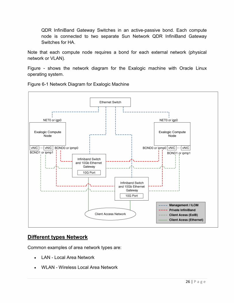
Figure - shows the network diagram for the Exalogic machine with Oracle Linux
operating system.
Figure 6-1 Network Diagram for Exalogic Machine
Different types Network
Common examples of area network types are:
• LAN - Local Area Network
• WLAN - Wireless Local Area Network

27 | P a g e
• WAN - Wide Area Network
• MAN - Metropolitan Area Network
• SAN - Storage Area Network, System Area Network, Server Area Network, or
sometimes Small Area Network
• CAN - Campus Area Network, Controller Area Network, or sometimes Cluster
Area Network
• PAN - Personal Area Network
• DAN - Desk Area Network
LAN and WAN were the original categories of area networks, while the others have
gradually emerged over many years of technology evolution.
Peer to peer and server based- Networking Concept
Peer-to-peer Networks
Overview of Peer-to-peer Networks
Nearly all Operating Systems come with the ability to act as some kind of a server to
share resources. You can setup different computers to allow others to use its
peripherals such as printers or CDROM drives, and other computers to allow others to
read or write to its hard disk allowing sharing of files, while other computers may allow
access to its Internet connection. When you allow workstation computers to become
servers and share things in this manner, it is called a Peer-to-peer network.
An Example of a Peer-to-peer Network
I will use a small office as an example of a Peer-to-Peer network.
In this small business office, the secretary uses the best computer, and has the most
drive space, she also has a fast laser printer connected to her computer. The
accountant has a mediocre computer that has a color ink jet printer. The owner has a
good computer with a zip drive to take work home. All of these computers are
networked together, with no central server.
The secretary uses the zip drive through the network to backup important documents,
and also uses the ink jet printer on the accountant's computer to print out fliers. The
accountant uses the laser printer on the secretary's computer to print out checks,
accesses some important documents on the secretary's computer, and backs up the
accounting data on the zip drive on the owners computer. The owner uses both printers

28 | P a g e
on the other computers, and accesses important documents on the secretary's
computer. All of the computers share Internet access through the secretary's computer.
All of this gets done with no passwords or user names since all the shared devices use
no access control, or other type of security measure. Also in order for the accountant's
computer and the owner's computer to be able to read the companies important
documents, the secretary's computer must be turned on first.
The Benefits of a Peer-to-peer Network
Peer-to-peer networks are very cheap to implement because more than likely the
Operating System software you have installed on your computers should have the
ability to share items with other computers on the network, even though the feature may
be limited. Nearly all of the most popular desktop Operating Systems have this feature,
including Microsoft Windows and Apple's Mac OS, as well as Unix like OS es, such as
Linux and the BSD s. So the only cost will be the networking hardware (cards, wiring,
hubs or switches), and the labor to configure the workstations for this type of network
sharing.
The Downsides of a Peer-to-peer Network
Even though a peer-to-peer network is very cost effective up front, there are a number
of downsides you must consider before implementing this type of network.
Without a central server, it is very difficult, or nearly impossible to secure this type of
network in any way. You can implement passwords on each different network share, but
in order for the network to usable, the exact same username and password must be
entered into each computer acting as a server. Thus, to change a password for a user
could literally take hours of work, especially if the network consists of computers located
in different buildings or different floors. Because of this, what usually happens with peer-
to-peer networks is that passwords are implemented to begin with, but after time, either
everyone starts using the exact same username and password, or the passwords end
up becoming blank, or the network shares are configured to allow anyone access
without a username or password. In any of these cases, security is pretty much non-
existent, which can become a huge problem, especially if your network has access to
the Internet.
On a peer-to-peer network, it is also very difficult to implement a good backup system
because important documents tend to be stored on different hard disks on different
computers. If you do manage to implement a good backup policy, chances are great
that after a while some very important documents will not get archived because
someone "accidentally" saved them to the wrong location on the network.

29 | P a g e
Peer-to-peer networks also tend to become very costly over time. Since each computer
that shares anything to the other computers is a psuedo server, it must be constantly
on, and configured correctly. So instead of maintaining a small handful of servers, you
must maintain all of the workstations as servers, and as such any downtime with any
computer on the network could cause considerable loss of labor or information. The
following diagram illustrates all the theoretical connections that are needed for a peer-
to-peer network to operate with just 5 computers. Note that this illustration does not
represent physical network connections, but the theoretical network connections the
operating system needs to operate the network properly.
The computer operators of a peer-to-peer network must also be well acquainted with
the intricacies of running a computer in order for them to be able to do any work with the
network. The users must be able to locate the different shares on the network, and be
experienced enough to work through small problems, such as password problems or
network mapping problems. As a side note, I have been in offices that used such
complex drive mappings on a peer-to-peer network that they had a checklist showing
which computers to turn in a certain order for the network to work properly.
Final Words on Peer-to-peer Networks
Peer-to-peer networks can be implemented with very little investment costs, but in order
for the network to work properly, the users must be very experienced with computers,
and strict guidelines must be implemented and followed in order for the data to remain
secure and archived properly. In my experience, peer-to-peer networks tend to become

30 | P a g e
more of a headache instead of a help after about 6 computers, especially if your
company has a moderate employee turnover.
Client-Server Networks
Overview of a Client-Server Network
The Client-Server network model usually consists of one or more server computers that
provide services and information to a number of workstation computers. These services
can consist of many different roles, including: file services, web services, email services,
domain name lookup services, document version system services, Internet sharing
services, etc. A great example of the Client-Server network model is actually the World
Wide Internet. On the Internet clients, or computer with web browsers, access web sites
that are hosted on servers.
This model differs from the Peer-to-peer network model in that the servers usually do
not dually act as a workstation, and the workstations usually do not act as servers, and
if they do act as a server, they should be configured to allow the central servers to
provide access restrictions on the shares they provide the network.
An Example of a Client-Server Network
I will use a mid-size business with a network of 20 computers as an example.
The network is setup with a main file server, that also stores all the users email. Every
night the main file server is backed up to a secondary file server that is located in an
adjacent building. The network also has a network firewall computer that serves an
Internet connection to the network, and forwards all email to the file server. The file
server has different shares for each department so only people in that department has
access to the files, and also has a companywide share that everyone in the company
has access to the files. Each user also has a home directory on the main file server for
personal documents that no one else can access. The network also has two large laser
printers and a commercial color laser printer, all the printers are connected to the main
file server through a jet direct interface.
The client computers all map a drive letter (L:) to the company wide share, and also
map a drive letter (M:) to the department share, and the clients can print to whichever
printer they need to. The drive mappings occur during a login script that is ran when the
client computer logs in to the network. Each department has at least one zip drive on its
computers which is shared for backups and convenience. Each employee has a
separate email account, and all email messages reside on the main file server, so if any
of the workstation computers goes down, the emails are still intact.

31 | P a g e
The Benefits of a Client-Server Network
The Client-Server network model offers many benefits that stems from the fact that only
a single computer, or group of computers are the central repository for all the
networking services that you may need.
Security is relatively easy to implement with this type of network model, since you can
setup a single server computer to handle all information requests or login requests for
the entire network, thus you only need one username and password for each user on
the network. So if you ever need to change a password, you only need to change it at
the server and the password would be changed for the entire network.
Information control is also fundamentally easier with this type of network model because
you can have individual server computers store all the important documents of you
company on a single store. In doing this you gain the ability to easily archive all the
companies documents, as well as provide a secure, easy to access network store for all
of your users, reducing the possibility of misplaced documents on your network. Other
information can also be controlled by individual servers, such as all of the company's
email and contact lists can be stored on a single mail server, or all of the company's
policies and public documents can be store on an internal web server or ftp server.
With the Client-Server network model, each workstation only really needs to have one
theoretical connection on the network, and that connection is to the main server as
illustrated in the image below. Because of this, the maintenance cost for the network
drops. Also, since all the important information of the network actually resides on the
servers, the workstation maintenance also drops since the users can access any
information they need through any workstation, and a faulty workstation computer will
have very little effect on the usefulness of the network. I actually have setup networks
where the workstation computers are backed up to an image on a central server, so if a
workstation goes down, a technician can restore the image and have the workstation
back up literally within minutes.

32 | P a g e
There are numerous other benefits to this type of network, most stem from the fact that
you consolidate information or security to a single computer, or groups of computers.
Once this is done, adding other services to the network is both easier and more secure.
The Downsides of a Client-Server Network
Even though the Client-Server type of network has many advantages, there are some
disadvantages that you should be aware of.
The cost of this type of network is relatively high up front, not only must you purchase
the server hardware, but most server software is very expensive, especially for larger
networks since some software companies charge more for each client computer that will
connect to the main server (although there are cheaper alternatives). Once the network
is in place however, it is relatively easy to justify the cost since the overall cost to
maintain the network becomes less expensive.
Another downside to consider is the possibility of the main server having problems. How
fast must you have the network working again? If you need 24x7 operability, you should
allow in your budget a second "redundant" server, so if the main server goes down, the
redundant server will step in and provide services until the primary server is back up
again. An experienced administrator should be able to setup redundant servers that will
assume control of failing servers without user intervention.
Final Words on Client-Server Networks
The Client-Server network model provides important services to the network safely and
securely, it also allows the convenience of allowing the users to work on their own

33 | P a g e
workstation machine. However, this network model can be very expensive, not only
because the software can be expensive, but you also must provide adequate hardware
for both the servers and the individual workstation machines, which can become very
expensive with revolving hardware updates.
If you have the funds to implement this type of network, the return on the investment is
great, and you will have the knowledge that your network is well secured and archived.
Application-Server Networks
Overview of Application-Server Networks
The final network type that I am going to cover is the Application Server based
Networks, sometimes called Terminal Server based. The idea behind this type of
network is that you basically have one high-end server or mainframe, and all the
network clients are "dumb terminals", meaning that none of the processing is actually
done on the terminals, instead the only job the terminals have is to provide input and
show the display on the monitor.
Most people equate application servers to the very old text-only terminals with no
pointing devices. Today application servers are very modern, and most people running
on a "dumb terminal" will think they are working on a modern standalone computer.
An Example of an Application-Server Network
I will use a Metropolitan Library located in a three story building, with 20 terminal
computers on each floor as an example.
Each floor has its own Application Server running a version of Linux. Each application
server has basic user applications, such as Internet Browser, Word Processor,
Spreadsheet Program, Email Application, Image Manipulation Program, as well as all
the basic applications you should find on a computer. Each Application Server serves
applications to 20 different terminals, which are older donated computers. Each terminal
has the ability to run all of the above applications, print to any of the printers on each
floor and has access to the main card catalog through a web-based interface.
If one of the Application Servers goes down, the network is configured so that the
terminals will log into one of the other floors servers until the computer is repaired. If a
terminal goes down, a replacement terminal can be installed with no downtime for the
entire network, with no information loss.
All the Application Servers also share a single /home directory from a separate File
Server, which allows the library the ability to offer an individual login name, email
account and individual storage for a small charge. Along with the login name, email

34 | P a g e
account and storage, the patron also has the ability to access any files he may have
saved on the file server through a secure FTP server.
The Application Servers would cost the library roughly a total of $6000 ($2000 for each
of them), the firewall costs $200, the file server $1000, (all including setup fees) and all
of the terminal servers were old donated computers. In total the library offers to the
public 60 different terminals, individual email accounts, and limited individual Internet
storage, all for a total cost of $7,200 (not including network wiring) or $120 for each
terminal, including software.
Benefits of Application-Server Networks
The biggest benefit that this type of network provides is cost. It is very cheap to
implement and maintain an Application Server based network. The only high end
component you need is a high quality server computer with lots and lots of memory. As
for the terminals, they can be purchased very cheaply, or one could even use old 486
and Pentium computers and not notice any slowdown.
The maintenance of this type of network is also very low cost, since you basically only
need to maintain the one or two servers that provide the applications. Also, to lower the
cost even more, you can install and use commodity software, such as Linux or BSD
Unix, which can be obtained with little or no cost.
The Downsides of Application-Server Networks
The downside to running all of the clients on one server is, of course, what happens
when the server goes down. This of course is a huge disadvantage, but one that can be
overcome with installing a second or even third Application Server to the network.
Which would also spread out the connections across the servers, so that the

35 | P a g e
performance would not diminish as much when more and more users access the
servers.
Another downside is the fact that most Proprietary Software packages are licensed, and
most will not allow you to run the software on Application Servers without a substantial
monetary investment. You can combat this cost by sticking with Open Source variants
of commodity software, such as Word Processors, Web Browsers and Email
Applications, and use standalone computers for the specialized software such as
accounting software.
Final Words on Application-Server Networks
Even though not every software package will allow you to run it off of an Application
Server, the price benefits can be astounding when this type of network is Implemented.
If you need to provide public access to computers, or have separate departments that
only need to use word processing, spreadsheets, and email, an Application Server
could literally save you tens of thousands of dollars, even on a smaller network of 10-20
computers.
Media –Definition
In general, "media" refers to various means of communication. For example, television,
radio, and the newspaper are different types of media. The term can also be used as a
collective noun for the press or news reporting agencies. In the computer world, "media"
is also used as a collective noun, but refers to different types of data storage options.
Computer media can be hard drives, removable drives (such as Zip disks), CD-ROM or
CD-R discs, DVDs, flash memory, USB drives, and yes, floppy disks. For example, if
you want to bring your pictures from your digital camera into a photo processing store,
they might ask you what kind of media your pictures are stored on. Are they on the flash
memory card inside your camera or are they on a CD or USB drive? For this and many
other reasons, it is helpful to have a basic understanding of what the different types of
media are.
Bandwidth
1) In computer networks, bandwidth is often used as a synonym for data transfer rate -
the amount of data that can be carried from one point to another in a given time period
(usually a second). This kind of bandwidth is usually expressed in bits (of data) per
second (bps). Occasionally, it's expressed as bytes per second (Bps). A modem that
works at 57,600 bps hastwice the bandwidth of a modem that works at 28,800 bps. In
general, a link with a high bandwidth is one that may be able to carry enough
information to sustain the succession of images in a video presentation.
36 | P a g e
It should be remembered that a real communications path usually consists of a
succession of links, each with its own bandwidth. If one of these is much slower than
the rest, it is said to be a bandwidth bottleneck.
2) In electronic communication, bandwidth is the width of the range (or band) of
frequencies that an electronic signal uses on a given transmission medium. In this
usage, bandwidth is expressed in terms of the difference between the highest-frequency
signal component and the lowest-frequency signal component. Since the frequency of a
signal is measured in hertz (the number of cycles of change per second), a given
bandwidth is the difference in hertz between the highest frequency the signal uses and
the lowest frequency it uses. A typical voice signal has a bandwidth of approximately
three kilohertz (3 kHz); an analog television (TV) broadcast video signal has a
bandwidth of six megahertz (6 MHz) -- some 2,000 times as wide as the voice signal.
BOUNDED MEDIA
Bounded media are the physical links through which signals are confined to narrow
path. These are also called guide media. Bounded media are made up o a external
conductor (Usually Copper) bounded by jacket material. Bounded media are great for
LABS because they offer high speed, good security and low cast. However, some time
they cannot be used due distance communication.
Media types
Three common types of bounded media are used of the data transmission. These are
• Coaxial Cable
• Twisted Pairs Cable
• Fiber Optics Cable
COAXIAL CABLE:
Coaxial cable is very common & widely used commutation media. For example TV wire
is usually coaxial.
Coaxial cable gets its name because it contains two conductors that are parallel to each
other. The center conductor in the cable is usually copper. The copper can be either a
solid wire or stranded martial.
Outside this central Conductor is a non-conductive material. It is usually white, plastic
material used to separate the inner Conductor form the outer Conductor. The other
Conductor is a fine mesh made from Copper. It is used to help shield the cable form
EMI.

37 | P a g e
Outside the copper mesh is the final protective cover. (as shown in Fig)
The actual data travels through the center conductor in the cable. EMI interference is
caught by outer copper mesh. There are different types of coaxial cable vary by gauge
& impedance.
Gauge is the measure of the cable thickness. It is measured by the Radio grade
measurement, or RG number. The high the RG number, the thinner the central
conductor core, the lower the number the thicker the core.
Here the most common coaxial standards.
• 50-Ohm RG-7 or RG-11 : used with thick Ethernet.
• 50-Ohm RG-58 : used with thin Ethernet
• 75-Ohm RG-59 : used with cable television
• 93-Ohm RG-62 : used with ARCNET.
CHARACTERISTICS OF COAXIAL CABLE
• Low cost
• Easy to install
• Up to 10Mbps capacity
• Medium immunity form EMI
• Medium of attenuation
ADVANTAGES COAXIAL CABLE
• Inexpensive
• Easy to wire
• Easy to expand
• Moderate level of EMI immunity
DISADVANTAGE COAXIAL CABLE
• Single cable failure can take down an entire network

38 | P a g e
STP
UTP
Twisted Pair Cable
The most popular network cabling is Twisted pair. It is light weight, easy to install,
inexpensive and support many different types of network. It also supports the speed of
100 mps. Twisted pair cabling is made of pairs of solid or stranded copper twisted along
each other. The twists are done to reduce vulnerably to EMI and cross talk. The number
of pairs in the cable depends on the type. The copper core is usually 22-AWG or 24-
AWG, as measured on the American wire gauge standard. There are two types of
twisted pairs cabling
1. Unshielded twisted pair (UTP)
2. Shielded twisted pair (STP)
1. Unshielded twisted pair (UTP)
UTP is more common. It can be either voice grade or data grade depending on the
condition. UTP cable normally has an impedance of 100 ohm. UTP cost less than STP
and easily available due to its many use. There are five levels of data cabling
Category 1
These are used in telephone lines and low speed data cable.
Category 2
These cables can support up to 4 mps implementation.

39 | P a g e
Category 3
These cable supports up to 16 mps and are mostly used in 10 mps.
Category 4
These are used for large distance and high speed. It can support 20mps.
Category 5
This is the highest rating for UTP cable and can support up to 100mps.
UTP cables consist of 2 or 4 pairs of twisted cable. Cable with 2 pair use RJ-11
connector and 4 pair cable use RJ-45 connector.
Characteristics of UTP
• low cost
• easy to install
• High speed capacity
• High attenuation
• Effective to EMI
• 100 meter limit
Advantages of UTP
• Easy installation
• Capable of high speed for LAN
• Low cost
Disadvantages of UTP
• Short distance due to attenuation
2. Shielded twisted pair (STP)
It is similar to UTP but has a mesh shielding that’s protects it from EMI which allows for
higher transmission rate.
IBM has defined category for STP cable.

40 | P a g e
Type 1
STP features two pairs of 22-AWG
Type 2
This type include type 1 with 4 telephone pairs
Type 6
This type feature two pairs of standard shielded 26-AWG
Type 7
This type of STP consist of 1 pair of standard shielded 26-AWG
Type 9
This type consist of shielded 26-AWG wire
Characteristics of STP
• Medium cost
• Easy to install
• Higher capacity than UTP
• Higher attenuation, but same as UTP
• Medium immunity from EMI
• 100 meter limit
Advantages of STP:
• Shielded
• Faster than UTP and coaxial
Disadvantages of STP:
• More expensive than UTP and coaxial
• More difficult installation
• High attenuation rate
41 | P a g e
Fiber Optics
Fiber optic cable uses electrical signals to transmit data. It uses light. In fiber optic cable
light only moves in one direction for two way communication to take place a second
connection must be made between the two devices. It is actually two stands of cable.
Each stand is responsible for one direction of communication. A laser at one device
sends pulse of light through this cable to other device. These pulses translated into “1’s”
and “0’s” at the other end.
In the center of fiber cable is a glass stand or core. The light from the laser moves
through this glass to the other device around the internal core is a reflective material
known as CLADDING. No light escapes the glass core because of this reflective
cladding.
Fiber optic cable has bandwidth more than 2 gbps (Gigabytes per Second)
Characteristics Of Fiber Optic Cable:
• Expensive
• Very hard to install
• Capable of extremely high speed
• Extremely low attenuation
• No EMI interference
Advantages Of Fiber Optic Cable:
• Fast
• Low attenuation
• No EMI interference
Disadvantages Fiber Optics:
• Very costly
• Hard to install
42 | P a g e
Unbounded media
Unbounded / Unguided media or wireless media doesn't use any physical connectors
between the two devices communicating. Usually the transmission is send through the
atmosphere but sometime it can be just across the rule. Wireless media is used when a
physical obstruction or distance blocks are used with normal cable media. The three
types of wireless media are:
• RADIO WAVES
• MICRO WAVES
• INFRARED WAVES
1. RADIO WAVES
It has frequency between 10 K Hz to 1 G Hz. Radio waves has the following types.
• Short waves
• VHF (Very High Frequency)
• UHF (Ultra High Frequency)
SHORT WAVES
There are different types of antennas used for radio waves. Radio waves transmission
can be divided into following categories.
• LOW POWER, SINGLE FREQUENCY.
• HIGH POWER, SINGLE FREQUENCY
1. LOW POWER , SINGLE FREQUENCY:-
As the name shows this system transmits from one frequency and has low power out.
The normal operating ranges on these devices are 20 to 25 meter.
CHARACTERISTICS LOW POWER, SINGLE FREQUENCY
• Low cost
• Simple installation with pre-configured
• 1 M bps to 10 M bps capacity
• High attenuation

43 | P a g e
• Low immunity to EMI
2. HIGH POWER, SINGLE FREQUENCY:-
This is similar to low power single frequency. These devices can communicate over
greater distances.
CHARACTERISTICS HIGH POWER, SINGLE FREQUENCY:-
• Moderate cost
• Easier to install than low power single frequency
• 1 Mbps to 10 Mbps of capacity
• Low attenuation for long distances
• Low immunity to EMI

44 | P a g e
Unit – 3
Visual Identification
V.I. (Visual Identification) is the fastest and most reliable method of Type identification
of today. It works on the principle that an inner process will always manifest itself
through its outer boundaries - a sack with a brick will have a different shape than a sack
with a football (Fig).
Analogously, mental processes inside the human head will have their manifestation
through the face, the eyes and the appearance of an individual. Since the major part of
one's mental activity is carried out according to their Type, there is a significant
correlation between the type and the look of a person. In other words, people of the
same Type look similar.
In the same way people can tell women from men by their looks, it is also possible to
distinguish between the Psychological Types of people. Each Type has peculiar
features in their appearance and it is possible to recognize and identify those features.
There are groups of people within the same Type that share similar looks. This leads to
a number of different looks that can be associated with the same Type.
The looks have to be memorized and they often include behavioral peculiarities as well
as facial features. The ability to recognize the look often depends on personal qualities,
meaning that some people are better at V.I. than others. If the looks have been
associated with wrong types, it may cause problems with correct Type identification in
the future. Here are some examples:
Type #1 Type #2

45 | P a g e
Type #3 Type #4
Type #1 shares a common look with Type #2 in the same way as Type #3 shares it with
Type #4. Although Types #1 and #2 look different from Types #3 and #4, they all share
looks peculiar to the Logical-Sensory Introvert - ISTj. The "Types and celebrities" page
also contains several good examples of how people of the same Type can share similar
looks.
People of the same Type with similar looks very rarely look very similar. Because of
this, every newly memorized face contains a "key" quality that has potential to "unlock"
several other unknown faces. Here are some examples:
Type #5 Type #6
Type #5 has some similarities with Types #1, #2, #3 and #4, whereas Type #6 has
these similarities only with Types #3 and #4.
In conclusion, V.I. is most effective when used in conjunction with proper functional
analysis, but as any other methods of Type identification, V.I. is also not infallible. As
mentioned before, it is very important to make the right associations Type => Face on
the earlier stages of working with V.I. and correct functional analysis can help to do so.
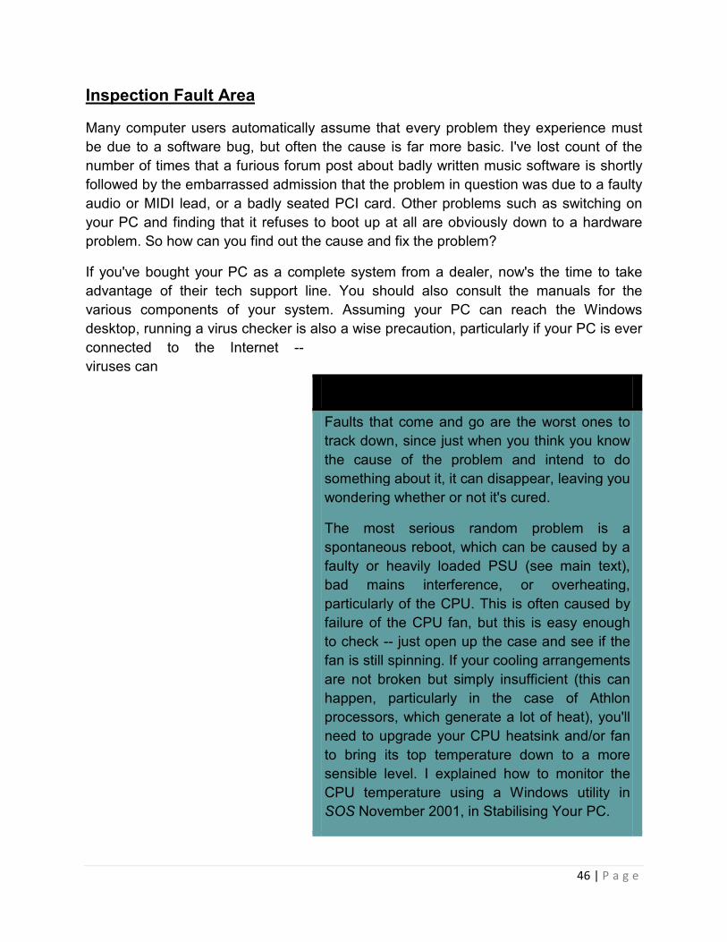
46 | P a g e
Inspection Fault Area
Many computer users automatically assume that every problem they experience must
be due to a software bug, but often the cause is far more basic. I've lost count of the
number of times that a furious forum post about badly written music software is shortly
followed by the embarrassed admission that the problem in question was due to a faulty
audio or MIDI lead, or a badly seated PCI card. Other problems such as switching on
your PC and finding that it refuses to boot up at all are obviously down to a hardware
problem. So how can you find out the cause and fix the problem?
If you've bought your PC as a complete system from a dealer, now's the time to take
advantage of their tech support line. You should also consult the manuals for the
various components of your system. Assuming your PC can reach the Windows
desktop, running a virus checker is also a wise precaution, particularly if your PC is ever
connected to the Internet --
viruses can
Intermittent Hardware Problems
Faults that come and go are the worst ones to
track down, since just when you think you know
the cause of the problem and intend to do
something about it, it can disappear, leaving you
wondering whether or not it's cured.
The most serious random problem is a
spontaneous reboot, which can be caused by a
faulty or heavily loaded PSU (see main text),
bad mains interference, or overheating,
particularly of the CPU. This is often caused by
failure of the CPU fan, but this is easy enough
to check -- just open up the case and see if the
fan is still spinning. If your cooling arrangements
are not broken but simply insufficient (this can
happen, particularly in the case of Athlon
processors, which generate a lot of heat), you'll
need to upgrade your CPU heatsink and/or fan
to bring its top temperature down to a more
sensible level. I explained how to monitor the
CPU temperature using a Windows utility in
SOS November 2001, in Stabilising Your PC.

47 | P a g e
Sadly, some spontaneous reboots can also be
caused by software, sometimes due to a bug, or
perhaps a virus, but also where software-based
anti-piracy protection has been implemented,
since this may work 'outside' Windows at a fairly
low level. Hardware-based protection such as
dongles may also occasionally cause such
problems due to a bad connection, although in
my experience this is rare. However, if software
protection is the cause of a random reboot, one
giveaway is that it normally only occurs when
running the particular piece of software in
question.
Many random clicks and pops when recording
or playing back audio are also due to software
problems, such as incorrect soundcard driver
settings, buggy soundcard drivers, badly set up
PCs and background tasks, but they can also
be caused by a variety of intermittent hardware
problems. These include mains spikes, faulty
connecting leads, PCI graphic cards that 'hog
the buss', and bad connections on expansion
cards. If you suspect the latter, switch off your
PC and check that all your expansion cards are
seated firmly in their slots. Often the best way to
do this is to loosen the backplate screw, rock
the card to lift it slightly, and then push it down
again. Remember to tighten the backplate
screw well, as this provides a good earth point
to the chassis that will minimise hum levels, as
well as reduce background noises, such as
those you sometimes get when moving the
mouse or opening new windows.
Next, check that the internal cables are all
secure, using a similar technique. Make sure
you include IDE cables, the floppy drive cable,
and all the connections between the front panel
switches and LED indicators -- this may resolve

48 | P a g e
cause various symptoms that mimic hardware problems, such as spontaneous reboots,
system and application crashes, random glitches on the screen, corrupted hard disk
data, disappearing partitions, system slowdowns, and hard drives that won't boot.
However, your computer is most likely to go wrong when you've just changed
something, for instance when you've installed a new stick of RAM, a soundcard, hard
drive, or a new CPU. Even though this may work perfectly well, you may have disturbed
one of the cables inside your PC at the same time, giving you a completely unrelated
problem; or if you've been overclocking your CPU, it may stop working when a new PCI
card is installed.
Don't be tempted to upgrade several components at once. It may seem easier to do it
this way, while you have the cover off and the leads spread all over the floor, but if the
computer doesn't work when you first switch on, the cause of the problem will be less
obvious. So, install one upgrade and check out your PC for an hour or two, and when
you're happy that it's working OK, install the next upgrade, and so on.
Similarly, don't be tempted to carry out several fixes at once. The chances are that the
problem is due to a single cause, and the way to track this down is to slowly eliminate
the alternatives, one at a time, until you find the culprit. Make sure you take some notes
on what you've tried, as well as writing down the exact wording of any error messages
that appear, since these will help you in your search.
The worst problems to track down are intermittent ones, since they have the annoying
habit of disappearing as soon as you try to solve them. In this case, write down what
you were doing whenever the problem happens, and you may notice a common factor.
I've suggested some things to try out in the Intermittent Hardware Problems box.
Power Supplies
If your PC won't boot up, you need to establish how far it's getting before the problem
occurs. If you see messages on the screen
a hard drive problem or random reboot.

49 | P a g e
then your power supply is probably working OK. If,
on the other hand, no LEDs illuminate on the PC's
front panel, and you can't hear your hard drives or
cooling fans spin up, you may have a problem with
your mains supply, or a faulty or dead computer
PSU (Power Supply Unit). Faulty power supplies
can also cause random reboots: these can also
mean that your power supply is working properly
but is under such a heavy load that occasionally
the voltages sag a bit, or even collapse. This may
also occur if the mains voltage ever sags (a
brownout), but you should be able to spot this fairly easily, as your studio lights will
probably dim at the same time.
If you've recently added yet another hard drive and find that when you switch on, the
drive LED lights up but your computer won't boot, it's probably time to fit a beefier
supply, which should ensure that your system becomes stable once more. It seems
generally accepted that a 250 Watt PSU is probably sufficient if you're only running a
single hard drive and 128Mb of RAM, but for most of us a 300 Watt or larger capacity is
far more sensible. This should be perfectly sufficient to power a fast Athlon or Pentium
4, a couple of hard drives, CD-R/W, DVD, and several parasitically powered USB
devices.
One other PSU issue that's of particular interest to musicians is fan noise. Although we
all want quiet PCs, it's vital that the cooling fans in the PSU and on the CPU carry on
working properly. If you ever hear any
squealing n
Static Precautions
The only safety precaution many
musicians take before plunging their
hands inside the PC is to unplug it from
the mains, but this can actually
increase the chance of semiconductors
including motherboard components,
expansion cards, RAM and CPUs
being destroyed by electrostatic
discharge. Before installing new
components, you should always Shut
Down the PC normally, but then switch
it off using the rear-panel switch, since

50 | P a g e
oises, it may mean that one of your fans is
about to fail, and needs replacing. If on the
other hand your PC suddenly seems
unusually quiet, don't assume your prayers
have been answered -- one of your fans
may have failed, and will need replacing
immediately before anything expensive
overheats.
BIOS Beep Codes
If the power supply is working, booting your
PC will light the front panel-power LED and
let the BIOS perform a Power-On Self-
Test, or POST. This initialises system
hardware, tests RAM, the keyboard, serial
and parallel ports, initialises the floppy
drive and hard disk controller, and
diagnoses any basic problems. If none are
found, you'll get one short beep from the
internal PC speaker. A combination of long
or short beeps signifies a problem, and in
most cases your PC will refuse to carry on. Although many 'beep codes' are similar from
motherboard to motherboard, you really need to refer to the manual to find out what
each sequence of beeps signifies.
Many POST-related problems occur after installing a new CPU, a PCI or AGP
expansion card, or after inserting extra RAM (see Static Precautions box). If your
problem appears after a CPU install, check that the new CPU is correctly fitted in its
socket, check the motherboard jumper settings and the BIOS settings for CPU clock
frequency, multiplier, and front side buss.
With any expansion card, the most important thing to check is that it's seated correctly
in its slot, and that the backplate is firmly screwed down, since this establishes a good
earth connection. Graphic
otherwise the motherboard may still be
in suspend or soft-off mode, and not
completely powered down (some
motherboards have an onboard LED to
indicate this). Unless you're working
near the PSU, where there are mains
voltages, it's probably safer to leave
your PC plugged in so that it remains
earthed, and then you can grab hold of
any convenient piece of PC metalwork
to ground yourself before you remove
your new components from their
antistatic packaging. You can also buy
very cheap disposable wrist straps that
clip to grounded metalwork, so you
don't build up any static. Always hold
components by the edges, and try to
avoid touching the edge connectors
and components directly.

51 | P a g e
s cards tend to be extremely
reliable, but if yours isn't
securely bolted into place, you
may not be able to boot your
PC. One long beep followed by
two short ones normally signifies
that the graphics card is not
properly seated, faulty, or
missing, while one long followed
by three short beeps is similar
except that it may also indicate
faulty video RAM.
Continuous beeps indicate that
no RAM has been found,
although if you've fitted an extra
stick or two, the chances are that the original RAM will still work, in which case you
need to check on the bootup screen that the new stick has been recognised, or by
looking at the Performance page of Control Panel's System applet, which displays the
amount of RAM along with various other parameters. After installing more RAM, it's also
wise to run a DOS-based utility such as GoldMemory (www.mtsoftware.cz), mentioned
in SOS November 2001, which will identify any incompatibility between your RAM and
motherboard, an incorrect RAM setting in your BIOS, and log any memory failure during
its continuous testing of every byte until you stop it.
If beep codes suggest that your PC keyboard is faulty, this will nearly always be a
connection problem (try reinserting the lead), although some machines may give an
error if a key is pressed when you boot the PC, so don't lean on it or leave things resting
on top. If you ever spill a drink on your PC keyboard, switch off immediately, disconnect
it, and hold it over a bath or sink until the liquid has drained away. Then rinse it out with
clean water (ideally distilled water), and leave it to dry out thoroughly for a day or two.
Alternatively, with keyboards now starting at £10, it may be easier to replace it
Check for Loose Connections
General Problems Related to Loose Connections
Explanation: It is suspected that there may be a loose connection, shorted component,
loose memory modules, or other physical problems within the PC.
Diagnosis: Any time that the PC is opened up, worked on, or moved, there is the
chance that a cable or component has come loose, that something has been moved
and is now where it should not be, and so forth. Loose components and similar physical
Fitting the most appropriate internal leads is important,
as is ensuring that they are of the correct length,
and are pushed firmly home.

52 | P a g e
problems can cause a host of bizarre situations that may seem to imply failures of
unrelated components. For example, I once had a floppy drive stop working after I
upgraded my system RAM; it turned out I had loosened the floppy drive cable, whose
connector was directly above the SIMM sockets on the motherboard.
Recommendation: At any time that you suspect that a physical connection problem may
be responsible for erratic system behavior, turn off the PC and disconnect the power
cord from the power supply. Then go through this checklist:
• Make sure that there are no loose screws or other components inside the case.
These can cause shorts and other serious problems with the PC.
• Examine the inside of the box for any cables or wires that are very tight. A cable
that has too little slack on it is a prime candidate for being loosened accidentally,
or even being damaged. A cable pulled out by accident can also damage one of
the devices it is connected to. Make sure no cables are being pinched or twisted
harshly. Check any taut cables for damage or loosened connectors. If possible,
rearrange component locations to loosen the cables up.
• Ensure that there is no physical interference with devices that have moving parts.
Some common problems include: cables getting in the way of the CPU fan,
causing it to not run or to make noise; cables being pushed inside the
mechanisms of floppy disks; drives that are mounted too close to each other that
may interfere with each other; cables being pinched between components;
cables or wires getting in the way of the power supply fan or intake vents; and
expansion cards interfering with motherboard components.
• Check the mounting of the motherboard. It should not be possible for the
motherboard to contact the case in any way. Lightly press down on the
expansion slot area of the board to test how much it flexes under the pressure of
inserting expansion cards. If the board flexes a great deal or contacts the case
under this circumstance, it is not properly supported.
• Make sure that any screws that have been used to mount the motherboard are
touching only the metal pads designed for them on the motherboard. If there is
any chance of the head of a screw contacting a wire on the board, the screw
should have a paper insulating washer inserted under it. Make sure that there are
no "extra" metal standoffs contacting the underside of the board.
• For a system with the power button on the front, examine the 4-wire electrical
cable running from the power supply to the front of the case. Make sure it is not
damaged, twisted or pinched. Ensure that there are no loose or bared wires.

53 | P a g e
• Double-check all connections between the LEDs and switches on the case, and
the motherboard. Ensure that none have been pulled loose. If they have,
reconnect them, making sure to do so the right way.
• Double-check the power connections from the power supply. Make sure the
connector(s) to the motherboard are inserted properly and have not come loose.
Check the connections to all the drives in the system and the CPU fan, if
applicable. Make sure any unused four-wire power connectors are tucked away
and not touching anything.
• Double-check all the data cable connections to the motherboard, and to the
devices they go to as well. Make sure the hard disk, floppy disk, serial port,
parallel port, and other connections are all securely in place. Look carefully,
because it is easy for these cables to become partially disconnected, which
causes all kinds of very bizarre behavior. Make sure that cables connected to
headers on the motherboard are connected correctly and aren't "off by one" pin.
Make sure that the correct IDE port is being used on the motherboard for the
hard disk.
• Examine the processor. Make sure the fan is securely on it. Make sure that it is
not loose in the socket/slot; it should be inserted all the way into it. You may want
to loosen and reinsert the processor.
• Examine the memory SIMMs or DIMMs. Ensure that they are all seated correctly.
Gently rock them to make sure they are secure. You may want try removing and
reinserting the memory if you suspect a problem related to it.
• Ensure that all expansion cards are seated fully into their slots and are not
interfering with any part of the motherboard.
Check whether power supply is ON and OK
How to Troubleshoot a Bad or Faulty Power Supply (PSU)
o WARNING: Power Supplies contain internal components that can store an
electrical charge. Never attempt to repair the internal components of a
Power Supply as you risk personal injury and also void the warranty on
the PSU.
01. Check that the AC Power Cable is Connected Firmly to the Wall Outlet and PSU.
The PSU can commonly be stiff when connecting the AC power cable so make sure the
cable and power supply are making good contact with one another.

54 | P a g e
02. Check the AC Outlet that the Power Supply is Plugged Into.
If it is a wall outlet, ask yourself if it is controlled by a wall switch. If so is the switch
turned on?
If you are using a power strip or surge protector check to make sure the power switch is
set to “On”. There will usually be a little red light that indicates this on a decent power
strip or surge protector.
03. Check the On/Off switch on the Power Supply itself.
Most new power supplies all have an On/Off switch. This is a little black switch on the
back of the power supply that has a one and a zero on it. (It may look like an I / O on the
switch).
Make sure this switch is set to “On”. If the switch is set to one (1) this indicates that the
power supply is turned “On”. If it is set to zero (0) it means the PSU is currently switched
off. Make sure the switch is set to the one (1) position.
04. Check the Voltage Switch on the Power Supply.
On most new Power Supplies there is a red switch on the back that indicates voltage.
This can be set to either 115V or 230V.
In the USA all our households use 115V from the wall AC outlets for standard
appliances. If you are in the US make sure your Power Supply is set to 115V. If you are
from Europe I believe your PSU needs to be set to 230V.

55 | P a g e
05. Check the 20/24 Pin ATX Power Connector and 4 Pin ATX Power Connector
Most motherboards require that you connect two Power Leads from a Power Supply to
power your motherboard.
The main power lead is the 20/24 Pin ATX power connection which plugs in near the
memory slots on your motherboard. The secondary power lead that is required is the 4
pin ATX power connection.
Make sure both of these leads are plugged in securely to your motherboard. You should
feel a small click when they are properly inserted.
It is not uncommon for a lead to feel stiff and not go in all the way. To ensure that the
ATX power leads are firmly connected disconnect each on and reconnect them to the
motherboard.
06. Use Observations on the Power Supply to Determine if it’s Faulty.
1. If your motherboard has a power LED on it, is this light turned on. (The
motherboard power LED will normally glow even when the system is powered
down.) If it is glowing this confirms the board is receiving power from the PSU
and the problem may lie elsewhere.
2. Can you see or hear the fan inside the power supply spin when you try to power
on the system. If you do not see or hear it spinning this can be a sign of a bad
power supply.
3. Did the power supply make any crackling or popping noises when you tried to
start the system? If so, this is a sign that a component inside the power supply
has failed.

56 | P a g e
4. Did you see a spark or smoke come out of the power supply? If so this is another
sign that a component inside the Power Supply has failed.
5. Does the power supply smell like burning electrical components. If so this is
another sign of component failure inside the power supply.
07. Use another Power Supply for Testing
If you have performed all of the above steps and have still not been able to determine if
your issues are a result of a bad power supply use an extra power supply (if applicable)
or a PSU from another system and try to start your system with the secondary Power
Supply.
If it powers on with the other power supply you have determined your original Power
Supply is bad or faulty.
PCMCIA
PC Card (originally PCMCIA Card for Personal Computer Memory Card International
Association) is the form factor of a peripheral interface designed for laptopcomputers.
The PC Card standard (as well as its successor ExpressCard) was defined and
developed by the Personal Computer Memory Card International Association (PCMCIA)
which itself was created by a number of computer industry companies in the United
States to offer a standard for memory-expansion cards that would compete with
the JEIDA memory cardstandard developed in Japan. It was invented by Jacob D.
Holm in 1986, and in 1991 the two standards merged as JEIDA 4.1 or PCMCIA 2.0 (PC
Card).
PC Card was originally designed for computer storage expansion, but the existence of a
usable general standard for notebook peripherals led to many kinds of devices being
made available in this form. Typical devices included network cards, modems, and hard
disks. The cards were also used in early digital SLR cameras, such as the Kodak DCS
300 series. The original use, as storage expansion, is no longer common.
Many notebooks in the 1990s had two adjacent type-II slots, which allowed installation
of two type-II cards or one, double-thickness, type-III card. The PC card port has been
superseded by the faster ExpressCard interface, but some modern portable computers
still use them.

57 | P a g e
PCI
Troubleshoot PCI Slots
In most modern computers, the motherboard has several Peripheral Component
Interconnect (PCI) slots. You can insert PCI cards into these slots to expand your
computer's basic capabilities. For example, you can add a graphics card or audio card
to you PC, which will allow your system to process video or audio output more
effectively than its built-in components. Sometimes, you may encounter problems with
your PCI slots. The easiest way to see if the problem is with the peripheral card or the
PCI slot is to switch the card to a new slot.
1. Uninstall Software/Deactivate Computer
o 1 Go to "Start," "Control Panel" and "Uninstall a Program." The "Uninstall
or Change a program" window opens.
o 2 Locate the name of the controlling software and select it. Click the
"Uninstall/Change" button at the top of the window. Windows will open the
software's uninstall wizard. Follow its instructions.
o 3 Deactivate the computer.
o 4 Remove the power cord from the power supply.
2. Move the Card to a New Slot
o 1 Open the computer case.
o 2 Remove any connectors from the back of the case (for example, audio
or video cables and screws).
o 3 Grip the PCI card firmly and remove it from the slot.
58 | P a g e
o 4 Insert the PCI card into a new PCI slot. It may be difficult, but do not try
to force the card into the PCI slot.
o 5 Secure the PCI card with its screw.
o 6 Close the computer cover.
o 7 Plug in any cables you removed from the PCI card when you moved it.
o 8 Plug in the computer's power cord.
o 9 Activate the computer.
3. Reinstall Drivers
o 1 Stop Windows from installing drivers. To do so, click the "Cancel" button
when the "Searching for or Installing drivers" dialog message opens.
o 2 Insert the driver software CD into the CD/DVD ROM drive.
o 3 Follow the steps on the installation wizard.
o 4 Determine if the PCI card works properly. If it does, then the slot is
defective. Contact the manufacturer for support. If the PCI card still does
not work properly, then the problem may be with the PCI card itself.
Contact the card manufacturer for support.
AGP
Troubleshooting AGP
The AGP expansion slot was introduced to overcome the speed lim-itations of PCI on
the graphics sub-system. The AGP slot is a modified version of the 66 MHz 32-bit PCI
Slot. If AGP is disabled, the slot reverts to being a PCI slot. Initially, AGP 1x and 2x
provided twice and four times the speed of PCI respectively. AGP 2.0 introduced Fast
Writes and a 4x speed while reducing the signalling voltage. With AGP 3.0, the speed
got pushed up to 8x and further reduced the signalling voltage.On most computers,
AGP works without a hitch. However, a significant number of PCs face problems with
the AGP port.

59 | P a g e
Problems with instability:
Typical symptoms include random crashes in 3D mode, instantaneous crashes or
hangs when entering 3D mode, image corruption, monitor blanking, computer freezes,
and just about every other symptom that you might face with a video card.
Causes of the instability:
There are two main sources of instability. First, there could be an incompatibility
between the AGP card and the slot on the motherboard. Second, AGP instability will
also be noticed on cards and motherboards configured for 8x speeds. Sometimes, at
this speed, the data transfer rate of 2133 MBps becomes too fast for the rest of the
system to handle. The motherboard is a complex knit of multiple components, talking to
each other at varying speeds. When the CPU, RAM, PSU and other components are all
perfectly matched and adjusted, AGP should work just fine. Any weakness in any of the
links in this chain and problems are bound to show up. If you are facing reliability and
stability problems with your system and you have narrowed it down to the AGP port, the
solution is to verify card and motherboard compatibility and/or slowdown AGP and see if
that solves the problems. In rare cases, you might also face a memory resource conflict.
Solutions Incompatibility:
The AGP card communicates with the AGP motherboard using a ‘signalling voltage’
that varies according to the version. AGP 1.0 uses 3.3 volts, AGP 2.0 uses 1.5 volts,
and AGP 3.0 uses0.8 volts. Depending on the AGP version supported, the AGP card
has one or two slots. 3.3 volts uses one type of slot, while 1.5 and 0.8 volts use the
same type of slot. According to the official AGP 3.0 specifications, AGP cards have
been categorized as in the table on the next page (AGP Card Specifications).
The above are Intel’s official names for the cards allowed by the specification.
Manufacturers, however, are not so consistent, and you might find various kinds of
names describing their cards. Souse the table on the next page to figure out what kind
of AGP card you have. Similarly, AGP slots on the motherboard also have official
specifications as in the second table ( AGP Slot Specifications)
Basic Troubleshooting in Motherboard
A.)GENERAL TESTING TIPS.
Before you begin, download a few of our Diagnostic Software Tools to pinpoint possible
problem areas in your PC. Ideally, troubleshooting is best accomplished with duplicate
parts from a used computer enabling "test" swapping of peripheral
devices/cards/chips/cables. In general, it is best to troubleshoot on systems that have
been leaned-out. Remove unnecessary peripherals (soundcard, modem, harddisk, etc.)

60 | P a g e
to check the unworking device in as much isolation as possible. Also, when swapping
devices, don't forget the power supply. Power incompetency (watts and volts) can cause
intermittent problems at all levels, but especially with UARTS and HD's.
Inspect the motherboard for loose components. A loose or missing CPU, BIOS chip,
Crystal Oscillator, or Chipset chip will cause the motherboard not to function. Also check
for loose or missing jumper caps, missing or loose memory chips (cache and SIMM's or
DIMM's). To possibly save you hours of frustration i'll mention this here, check the BIOS
Setup settings. 60% of the time this is the cause of many system failures. A quick fix is
to restore the BIOS Defaults. Next, eliminate the possibility of interference by a bad or
improperly set up I/O card by removing all cards except the video adapter. The system
should at least power up and wait for a drive time-out. Insert the cards back into the
system one at a time until the problem happens again. When the system does nothing,
the problem will be with the last expansion card that was put in.
B.)RESETTING CMOS.
Did you recently 'flash' your computers BIOS, and needed to change a jumper to do so?
Perhaps you left the jumper in the 'flash' position which could cause the CMOS to be
erased.
If you require the CMOS Reset and don't have the proper jumper settings try these
methods: Our Help Desk receives so many requests on Clearing BIOS/CMOS
Passwords that we've put together a standard text outlining the various solutions.
C.)NO POWER.
Switching power supplies (the most common used PC's), cannot be adequately field-
tested with V/OHM meters. Remember: for most switching power supplies to work, a
FLOPPY and at least 1 meg of memory must be present on the motherboard. If the
necessary components are present on the motherboard and there is no power:
1) check the power cable to the wall and that the wall socket is working. (You'd be
surprised!)
2) swap power supply with one that is known to work.
2)
3) if the system still doesn't work, check for fuses on the motherboard. If there
are none, you must replace the motherboard.

61 | P a g e
D.)PERIPHERAL WON'T WORK.
Peripherals are any devices that are connected to the motherboard, including I/O
boards, RS232/UART devices (including mice and modems), floppies and fixed-disks,
video cards, etc. On modern boards, many peripherals are integrated into the
motherboard, meaning, if one peripheral fails, effectually the motherboard has to be
replaced.* On older boards, peripherals were added via daughter boards.
*some MB CMOS's allow for disabling on-board devices, which may be an option for not
replacing the motherboard -- though, in practicality, some peripheral boards can cost as
much, if not more, than the motherboard. Also, failure of on-board devices may signal a
cascading failure to other components.
1. New peripheral?
a) Check the MB BIOS documentation/setup to ensure that the BIOS supports the
device and that the MB is correctly configured for the device.
(Note>> when in doubt, reset CMOS to DEFAULT VALUES. These are ) (optimized for
the most generalized settings that avoid some of) (the conflicts that result from improper
'tweaking'.
)
b) Check cable attachments & orientation (don't just look, reattach!)
c) If that doesn't work, double-check jumper/PnP (including software and/or MB BIOS
set) settings on the device.
d) If that doesn't work, try another peripheral of same brand & model that is known to
work.
e) If the swap peripheral works, the original peripheral is most likely the problem. (You
can verify this by testing the non-working peripheral on a test MB of the same make &
bios.)
f) If the swap periphal doesn't on the MB, verify the functionality of the first peripheral on
a test machine. If the first peripheral works on another machine AND IF the set-up of the
motherboard BIOS is verified AND IF all potentially conflicting peripherals have been
removed OR verified to not be in conflict, the motherboard is suspect. (However, see #D
below.)
g) At this point, recheck MB or BIOS documentation to see if there are known bugs with
the peripheral AND to verify any MB or peripheral jumper settings that are necessary for

62 | P a g e
the particular peripheral to work. Also, try a different peripheral of the same kind but a
different make to see if it works. If it does not, swap the motherboard. (However, see #D
below.)
2. Peripheral that worked before?
a) If the hood has been opened (or even if it has not), check the orientation and/or
seating of the cables. Cables sometimes 'shake' loose or are accidentally pulled
out by end-users, who then misalign or do not reattach them.
b) If that doesn't work, try the peripheral in another machine of the same make &
bios that is known to work. If the peripheral still doesn't work, the peripheral is
most likely the problem. (This can be verified by swapping-in a working
peripheral of the same make and model AND that is configured the same as the
one that is not working. If it works, then the first peripheral is the problem.)
b)
c) If the peripheral works on another machine, double-check other peripherals
and/or potential conflicts on the MB, including the power supply. If none can be
found, suspect the MB.
d) At this point, recheck MB or BIOS documentation to see if there are known
bugs with the peripheral AND to verify any jumper settings that might be
necessary for the particular peripheral. Also, try another peripheral of the same
kind but a different make to see if it works. If not, swap the motherboard!
E.) OTHER INDICATIONS OF A PROBLEM MOTHERBOARD.
1. CLOCK that won't keep correct time. >>Be sure to check/change the battery.
2. CMOS that won't hold configuration information. >>Again, check/change the battery.
Note about batteries and CMOS: in theory, CMOS should retain configuration
information even if the system battery is removed or dies. In practice, some systems
rely on the battery to hold this information. On these systems, a machine that is not
powered-up for a week or two may report improper BIOS configuration. To check this
kind of system, change the battery, power-up and run the system for several hours. If
the CMOS is working, the information should be retained with the system off for more
than 24 hours.

63 | P a g e
F.)BAD MOTHERBOARD OR OBSOLETE BIOS?
1. If the motherboard cannot configure to a particular peripheral, don't automatically
assume a bad motherboard, even if the peripheral checks out on another machine --
especially if the other machine has a different BIOS revision. Check with the board
manufacturer to see if a BIOS upgrade is available. Many BIOS upgrades can be made
right on the MB with a FLASH RAM program provided by the board maker. See our
BIOS page for more information.
Troubleshooting the Visual Display Unit (VDU)
Problem Possible Causes Remedies
First line of display not
on the top line of the
screen
Alignment problem Use the V-shift control to adjust
the display
Display not covering the
whole screen but is
compressed in the
center of the screen
Alignment problem Use the H-shift control to adjust
the display
Display not stable Power supply
fluctuations
Change power supply point
Interference from other
devices, such as an
electric heater, vacuum
cleaner, etc.
Shut off these devices or shift the
computer to a different location
Display suddenly
vanishes and reappears
Loose contact in VDU
socket
Check and replace if necessary
Bad connections within
the system
Call engineer

64 | P a g e
No display Bad cable Change cable
Brightness
maladjustment
Adjust brightness to maximum
Bad monitor or system
problem
Call engineer
Bad or no color Monitor maladjustment Adjust monitor controls
Color signals are not
proper
Call engineer
Switching-mode power supply, SMPS
A switched-mode power supply (switching-mode power supply, SMPS, or simply
switcher) is an electronic power supply that incorporates a switching regulator in order
to be highly efficient in the conversion of electrical power. Like other types of power
supplies, an SMPS transfer’s power from a source like the electrical power grid to a load
(e.g., a personal computer) while converting voltage and current characteristics. An
SMPS is usually employed to efficiently provide a regulated output voltage, typically at a
level different from the input voltage. Unlike a linear power supply, the pass transistor of
a switching mode supply continually switches between low-dissipation full-on and full-off
states and spends very little time in the high dissipation transitions (which minimizes
wasted energy). Ideally, a switched-mode power supply dissipates no power. Voltage
regulation is achieved by varying the ratio of on-to-off time. In contrast, a linear power
supply regulates the output voltage by continually dissipating power in the pass
transistor. This higher power conversion efficiency is an important advantage of a
switched-mode power supply. Switched-mode power supplies may also be substantially
smaller and lighter than a linear supply.
Switching regulators are used as replacements for the linear regulators when higher
efficiency, smaller size or lighter weight are required. They are, however, more
complicated, their switching currents can cause electrical noise problems if not carefully
suppressed, and simple designs may have a poor power factor.
65 | P a g e
Unit – 4
Troubleshooting in 8259
Programmable Interrupt Controller
The 8259 Microcontroller family is a set of Programmable Interrupt Controller (PIC)
Integrated Circuits (ICs). Look back again at Tutorial 7... Under the Processor
Architecture section, Notice that the processor has its own internal PIC Microcontroller.
This is very important to note.
Do to limitations in the circuit design, a PIC only supports 8 IRQ's. This is a big
limitation. As additional devices were created, IBM quickly realized that this limitation is
very bad. Because of this, Most motherboards contain a secondary (Slave) PIC
microcontroller to work with the primary PIC inside the processor. Today, this is very
common. A single PIC can be "cascaded" (capable of working with) another PIC. This
makes it possible to support more IRQ's with additional PICs.
The More PIC's supported, the more IRQ's can be handled. They can be cascaded to
support up to 64 IRQ's. Cool?
Remember: Most computers have 2 PIC's, 1 inside the processor, and 1 on the
motherboard. Some systems may not have this.
Remember: Each PIC can only support up to 8 IRQ's.
Remember: Each PIC can communicate with each other, allowing up to 64 IRQ's
depending on the number of PIC's.
DMA - Direct memory access
Direct memory access (DMA) is a feature of modern computers that allows certain
hardware subsystems within the computer to access system memory independently of
the central processing unit (CPU).
Without DMA, when the CPU is using programmed input/output, it is typically fully
occupied for the entire duration of the read or write operation, and is thus unavailable to
perform other work. With DMA, the CPU initiates the transfer, does other operations
while the transfer is in progress, and receives an interrupt from the DMA controller when
the operation is done. This feature is useful any time the CPU cannot keep up with the
rate of data transfer, or where the CPU needs to perform useful work while waiting for a
relatively slow I/O data transfer. Many hardware systems use DMA, including disk drive
controllers, graphics cards, network cards and sound cards. DMA is also used for intra-
chip data transfer in multi-core processors. Computers that have DMA channels can

66 | P a g e
transfer data to and from devices with much less CPU overhead than computers without
a DMA channel. Similarly, a processing element inside a multi-core processor can
transfer data to and from its local memory without occupying its processor time, allowing
computation and data transfer to proceed in parallel.
DMA can also be used for "memory to memory" copying or moving of data within
memory. DMA can offload expensive memory operations, such as large copies or
scatter-gather operations, from the CPU to a dedicated DMA engine. Intel includes such
engines on high-end servers, called I/O Acceleration Technology (I/OAT).
Uninterruptible power supply
An uninterruptible power supply, also uninterruptible power source, UPS or
battery/flywheel backup is an electrical apparatus that provides emergency power to a
load when the input power source, typically mains power, fails. A UPS differs from an
auxiliary or emergency power system or standby generator in that it will provide
instantaneous or near-instantaneous protection from input power interruptions by
means of one or more attached batteries and associated electronic circuitry for low
power users, and or by means of diesel generators and flywheels for high power users.
The on-battery runtime of most uninterruptible power sources is relatively short—5–15
minutes being typical for smaller units—but sufficient to allow time to bring an auxiliary
power source on line, or to properly shut down the protected equipment.
While not limited to protecting any particular type of equipment, a UPS is typically used
to protect computers, data centers, telecommunication equipment or other electrical
equipment where an unexpected power disruption could cause injuries, fatalities,
serious business disruption or data loss. UPS units range in size from units designed to
protect a single computer without a video monitor (around 200 VA rating) to large units
powering entire data centers, buildings, or even cities.[1
Online Uninterrupted Power Supply
The online UPS, sometimes called a true UPS, is the best type you can buy.
Paradoxically, it is both very similar to, and totally opposite to, the least-expensive type,
the standby UPS. It is very similar to it in that it has the same two power sources, and a
transfer switch that selects between them. It is the exact opposite from the standby UPS
because it has reversed its sources: in the online UPS the primary power source is the
UPS's battery, and utility power is the secondary power source!

67 | P a g e
Block schematic of an online ("true") UPS. You will notice if you look at the schematic
for the standby UPS that it is identical, except that the primary and secondary power
paths have been exchanged, and here the battery is the primary power source.
Of course, while seeming small, this change is a very significant one. Under normal
operation the online UPS is always running off the battery, using its inverter, while the
line power runs the battery charger. For this reason, this type of UPS is sometimes also
called a double-conversion or double-conversion online UPS. This design means that
there is no transfer time in the event of a power failure--if the power goes out, the
inverter (and its load) keeps chugging along and only the battery charger fails. A
computer powered by an online UPS responds to a power failure in the same way that a
plugged-in laptop PC does: it keeps running without interruption, and all that happens is
that the battery starts to run down because there is no line power to charge it.
You may ask yourself, why bother having the secondary power path (the dashed line in
the diagram above) if you are always running off the battery anyway? The reason is that
this provides backup in the event that the inverter fails or stutters due to some sort of
internal problem. While unusual, this can happen, and if it does, the unit will switch to
the filtered, surge-suppressed line power. In this event, the matter of transfer time
comes into play again, just as it does when a standby UPS reacts to a power failure. Of
course, power failures are much more common than inverter failures.
There is another key advantage to having the equipment running off the battery most of
the time: the double-conversion process totally isolates the output power from the input
power. Any nasty surprises coming from the wall affect only the battery charger, and not
the output loads.
Even though it may appear from the schematic diagrams that the online UPS and
standby UPS have the same components inside, this is not the case. The distinction is
that there is a big difference between designing chargers and inverters that are normally
sitting around doing nothing and only run say once a month for a few minutes, and
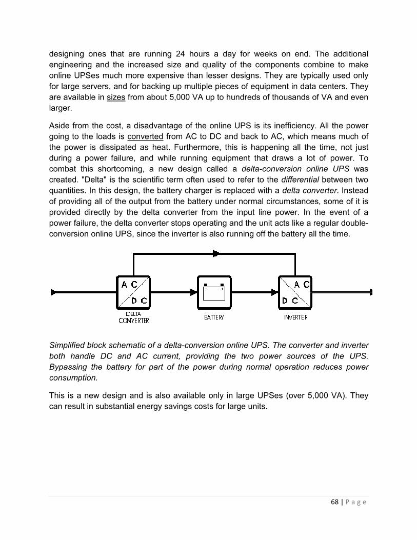
68 | P a g e
designing ones that are running 24 hours a day for weeks on end. The additional
engineering and the increased size and quality of the components combine to make
online UPSes much more expensive than lesser designs. They are typically used only
for large servers, and for backing up multiple pieces of equipment in data centers. They
are available in sizes from about 5,000 VA up to hundreds of thousands of VA and even
larger.
Aside from the cost, a disadvantage of the online UPS is its inefficiency. All the power
going to the loads is converted from AC to DC and back to AC, which means much of
the power is dissipated as heat. Furthermore, this is happening all the time, not just
during a power failure, and while running equipment that draws a lot of power. To
combat this shortcoming, a new design called a delta-conversion online UPS was
created. "Delta" is the scientific term often used to refer to the differential between two
quantities. In this design, the battery charger is replaced with a delta converter. Instead
of providing all of the output from the battery under normal circumstances, some of it is
provided directly by the delta converter from the input line power. In the event of a
power failure, the delta converter stops operating and the unit acts like a regular double-
conversion online UPS, since the inverter is also running off the battery all the time.
Simplified block schematic of a delta-conversion online UPS. The converter and inverter
both handle DC and AC current, providing the two power sources of the UPS.
Bypassing the battery for part of the power during normal operation reduces power
consumption.
This is a new design and is also available only in large UPSes (over 5,000 VA). They
can result in substantial energy savings costs for large units.

Off line Uninterrupted Power Supply
Offline / standby UPS. Typical protection time: 0
Usually not available
The offline / standby UPS (SPS) offers only the most basic features, providing surge
protection and battery backup. The protected equipment is normally connected directly
to incoming utility power. When the incoming voltage falls below a predetermined level
the SPS turns on its internal DC
storage battery. The SPS then mechanically switches the connected equipment on to its
DC-AC inverter output. The switchover time can be as long as 25 milliseconds
depending on the amount of time it takes the standby UPS to detect the lost utility
voltage. The UPS will be designed to power certain equipment, such as a personal
computer, without any objectionable dip or brownout to that device.
Audio Troubleshooting
System working properly:
This diagram shows that the signal from the output of the radio to the speakers is OK.
Both channels have output.
Off line Uninterrupted Power Supply
Offline / standby UPS. Typical protection time: 0–20 minutes. Capacity expansion:
The offline / standby UPS (SPS) offers only the most basic features, providing surge
battery backup. The protected equipment is normally connected directly
to incoming utility power. When the incoming voltage falls below a predetermined level
the SPS turns on its internal DC-AC inverter circuitry, which is powered from an internal
battery. The SPS then mechanically switches the connected equipment on to its
AC inverter output. The switchover time can be as long as 25 milliseconds
depending on the amount of time it takes the standby UPS to detect the lost utility
will be designed to power certain equipment, such as a personal
computer, without any objectionable dip or brownout to that device.
Audio Troubleshooting
This diagram shows that the signal from the output of the radio to the speakers is OK.
69 | P a g e
20 minutes. Capacity expansion:
The offline / standby UPS (SPS) offers only the most basic features, providing surge
battery backup. The protected equipment is normally connected directly
to incoming utility power. When the incoming voltage falls below a predetermined level
AC inverter circuitry, which is powered from an internal
battery. The SPS then mechanically switches the connected equipment on to its
AC inverter output. The switchover time can be as long as 25 milliseconds
depending on the amount of time it takes the standby UPS to detect the lost utility
will be designed to power certain equipment, such as a personal
This diagram shows that the signal from the output of the radio to the speakers is OK.

70 | P a g e
One channel has no output:
In this diagram, you see that something is wrong with the left channel of the radio.
Drag your mouse over the picture below. You'll see how the RCA cables are reversed at
the head unit. This means that the right signal line is now connected to the defective
channel of the HU. You can see that the output, at the speakers, has now switched
sides. This is because the green signal line is now connected to the good channel of the
HU. Click on the image to optimize its position.

71 | P a g e
Unknown break in the signal line:
Until now, you were shown where the signal line was broken. In your vehicle, it is
unlikely that there will be Xs and checks on all of the signal lines. To prevent damage to
your amplifiers and/or speakers, I strongly recommend turning the amplifier off before
plugging or unplugging the RCAs. Failure to do so may let the smoke out of your
amplifier rendering it useless.
Method #1:
If you have a double female RCA coupler (barrel connector), this is one of the simplest
ways of troubleshooting an audio problem.

72 | P a g e
If one audio channel is not working properly and you suspect that that the problem may
be in you crossover or any other audio component, you can simply insert the barrel
connector in place of the suspect piece of audio equipment. If the formerly dead
channel now plays, you know that the bypassed piece of equipment was the problem.
Since the crossover has outputs going to multiple amplifiers, you will have to plug each
amplifier into the barrel connector individually.
Method #2:
If you believe that the RCA cable running from the head unit to the rear of the vehicle is
defective, you can get a long patch cable and run it outside of the vehicle. This will allow
you to quickly determine whether the cable is bad without having to route it under the
carpet. I know that running it outside of the vehicle might be obvious to some people but
I thought I'd mention it anyway.
Method #3:
In this diagram, you can see that one channel is out. The problem could be caused by
any one of the components (head unit, RCA cables, crossover, amplifier, speaker wires
or speakers). If you hold the cursor over one of the links (at the left of the diagram), the
image will change from the diagram with the original problem to a diagram showing how
the symptoms change (or don't change) depending on the action taken in the new
diagram. When you move the cursor off of the link, the image goes back to the original
image so you can see how each step (or action) affects the original problem. You may
have to hold the mouse cursor over each 'step' for a few seconds until the new image
loads completely.

73 | P a g e
Checking RCA cables:
When there is a question of whether a piece of electronic equipment or a set of RCA
cables is bad, you should do the following. Unplug BOTH of the connectors on BOTH
ends of the cable. It is now completely disconnected from everything. Take ONE side of
the jacks (left OR right) and use it to do this test. We will start with the right side of the
RCA cable. Plug the right side of the cable into the right side of both pieces of
equipment (the crossover and the amp in this situation). If the right side of the amplifier
starts to play, then you know the right side of the RCA cable is good. Move the cable
around a little on both ends to make sure that the cable is not intermittently defective. If
the sound doesn't cut out, we will assume that the right side of the cable is indeed OK. If
the sound cuts out or does not come through, try using the other channel of the RCA
cables. Now move the RCA cable connector from the right channel of the amplifier to
the left channel of the amplifier. If the left channel of the amplifier now plays, you know
that both channels of the amplifier are OK. Now move the RCA cable connector from
the right channel of the crossover to the left channel of the crossover. If the audio plays
through again, we know that both channels of the amplifier and both channels of the
crossover are OK. If the audio does not play through, the left channel of the crossover
or something in the left channel's signal line before the crossover is defective. Now
repeat the process with the left side of the RCA cable. If the left channel of the cable is

74 | P a g e
bad, it will not pass all of the tests as it did with the right side. Of course you could also
check the RCA cable with an ohm meter if you have one available.
Meter readings
The demo below shows how the meter will read with the leads shorted (touching) or
open (not touching).
Drag your mouse over the diagram below. If the shield connection of the cable is good,
the meter will read the same as if the meter leads were held together. If the shield
connection is defective, the meter will read the same as when the leads are open (not
touching to anything). Do the same thing for the center conductor. You will also have to
check the other channel of the RCA cable. If you check from the shield to the center
conductor, the meter should show open.

75 | P a g e
ENGINENOISE
(alternator whine)
These are general rules or tips which will prevent or reduce the problems with engine
noise.

76 | P a g e
1. Run the patch cords on the opposite side of the vehicle from the main power and remote output wires.
2. Make sure that all of the audio components are well grounded to an area that has has been cleared of all paint, primer and other protective coatings.
3. Don't use the factory wiring for the head unit's (HU) ground connection. Ground the HU to the chassis (body) of the vehicle. If the HU isn't mounted directly to a solid, GROUNDED metal structure, ground the case of the HU to the same point that the HU's ground wire is connected.
4. Do not extend the ground wires of any component unless it's absolutely necessary. If the device's manufacturer designed a high quality input circuit, extending the ground wire will only cause more problems. If all else fails, and you have one audio component which is allowing noise to enter the system, you can then try different grounding points to see if they make a difference.
5. If the insulation on the patch cord is damaged and is allowed to touch to ground, it will likely allow noise to enter the audio signal path. If the patch cord is pinched under the back seat or where it crosses over any sharp metal (where it enters the trunk) it will cause noise problems.
6. As you already know, an amplifier's speaker output generally has one speaker wire with the audio signal and another (the reference) which is connected to the audio ground inside of the amplifier. If the reference is allowed to come in contact with ground (in the door or back deck of the vehicle), a ground loop may be created allowing noise to enter the system. This is not very common but it has happened.
7. Set the amplifier's gain controls properly. Setting the gains too high will only make a problem with noise worse.
NOTE:
DO NOT make any connection (RCA or otherwise) with the system switched on. Doing
so may cause damage to speakers or amplifiers.
The image below is a normal system with a head unit, equalizer, crossover and 2
amplifers.

77 | P a g e
The first step is to bypass all components and connect the head unit directly to the high
frequency amplifier. The high frequency amplifier should be used because the tweeters
connected to the amplifier will best reproduce the frequencies that are associated with
alternator whine. If the noise goes away with only the HU and high frequency amplifier
connected, it is a fairly safe assumption that these two components are OK. You can
also connect the head unit directly to the low frequency amplifier to see if the noise
returns (although the noise may be hard to hear since woofers don't reproduce the
higher frequencies very well). If there is noise with only one of the amplifiers, the
problem probably lies within the noisy amplifier. If the noise is present with both
amplifiers, there may be something wrong with the head unit.

78 | P a g e
Testing the HU's shield ground connection:
If you want to check the shield ground, use an ohm meter and make sure that there is
continuity between the case of the HU and the RCA shield. Make sure that the RCA
cables are disconnected from the RCA jacks on the HU. There should be less than 1
ohm between the RCA output shields (the shiny outside part of the connector) and the
case of the HU. If the resistance is more than a few ohms, you may want to have a
QUALIFIED technician check it out. This is only for a HU with Unbalanced preamp
outputs. If you find that the shield connection is defective, it was likely damaged when a
12 volt power source was allowed to come in contact with the shield at some point in the
system.

79 | P a g e
The next step is to start inserting the rest of the audio components (one at a time). If
you insert a component, and the noise returns, bypass it again to make sure that the
system is again noise free. If you have more components that you have not yet inserted
, insert them one at a time so that there is no more than one component inbetween the
HU and the amplifier. If one component allows noise to enter the system whenever it is
in the signal path, have it tested by a qualified technician.

80 | P a g e
After checking all of the components (individually), try reconnecting the head unit to the
crossover but leave all other processors out of the line. Connect the crossover to the
amplifiers. If there is no noise when the high frequency amplifier (alone) is connected to
the crossover but the noise returns when both amplifiers are connected to the
crossover, one of the amplifiers may not have enough electrical isolation from the
chassis ground. The isolation from chassis ground is determined by the design of the
amplifier's input circuit. If one amplifier is causing a problem, you may need to use a
ground loop isolator to break the DC ground connection. Inserting the isolator between
the output of the crossover and one of the amplifiers should significantly reduce or
eliminate the noise.
DO NOT make any connection (RCA or otherwise) with the system switched on. Doing
so may cause damage to speakers or amplifiers.
The image below is a normal system with a head unit, equalizer, crossover and 2
amplifers.

81 | P a g e
The first step is to bypass all components and connect the head unit directly to the high
frequency amplifier. The high frequency amplifier should be used because the tweeters
connected to the amplifier will best reproduce the frequencies that are associated with
alternator whine. If the noise goes away with only the HU and high frequency amplifier
connected, it is a fairly safe assumption that these two components are OK. You can
also connect the head unit directly to the low frequency amplifier to see if the noise
returns (although the noise may be hard to hear since woofers don't reproduce the
higher frequencies very well). If there is noise with only one of the amplifiers, the
problem probably lies within the noisy amplifier. If the noise is present with both
amplifiers, there may be something wrong with the head unit.

82 | P a g e
Testing the HU's shield ground connection:
If you want to check the shield ground, use an ohm meter and make sure that there is
continuity between the case of the HU and the RCA shield. Make sure that the RCA
cables are disconnected from the RCA jacks on the HU. There should be less than 1
ohm between the RCA output shields (the shiny outside part of the connector) and the
case of the HU. If the resistance is more than a few ohms, you may want to have a
QUALIFIED technician check it out. This is only for a HU with Unbalanced preamp
outputs. If you find that the shield connection is defective, it was likely damaged when a
12 volt power source was allowed to come in contact with the shield at some point in the
system.

83 | P a g e
The next step is to start inserting the rest of the audio components (one at a time). If
you insert a component, and the noise returns, bypass it again to make sure that the
system is again noise free. If you have more components that you have not yet inserted
, insert them one at a time so that there is no more than one component inbetween the
HU and the amplifier. If one component allows noise to enter the system whenever it is
in the signal path, have it tested by a qualified technician.

84 | P a g e
After checking all of the components (individually), try reconnecting the head unit to the
crossover but leave all other processors out of the line. Connect the crossover to the
amplifiers. If there is no noise when the high frequency amplifier (alone) is connected to
the crossover but the noise returns when both amplifiers are connected to the
crossover, one of the amplifiers may not have enough electrical isolation from the
chassis ground. The isolation from chassis ground is determined by the design of the
amplifier's input circuit. If one amplifier is causing a problem, you may need to use a
ground loop isolator to break the DC ground connection. Inserting the isolator between
the output of the crossover and one of the amplifiers should significantly reduce or
eliminate the noise.
Loudspeaker
Speakers-Troubleshooting
Specific Problems -
• No Power
85 | P a g e
1. Check the connection to the wall outlet. Most speakers and subwoofers
have a light showing there is power when they are turned on.
2. Check to see if your subwoofer has a fuse, and if it does check the fuse to
make sure it is ok.
• One or two of the speakers do not work
1. Check to make sure they are getting power
2. Check the connections from the back of the computer to the speakers.
The speakers should connect to the line-out jack on the back of the
computer.
• Crackling Sound
1. Check the cables and make sure they are firmly connected between line-
out plug on the back of the computer and the speakers. If you have
powered speakers and connect them to the "speaker out" connector you
can get Crackling.
2. Also, check the volume control in Windows and make sure that it is not set
more than half-way
• Radio Feedback
1. Move the speakers in a different location or rotate them to see if it helps.
2. Buy cables that have better shielding.
• Static Noise
o Make sure you are using the Line-out plug on the back of the computer.
Popping Sounds
0. Check All speaker cables for proper connections.
1. Move the speaker wires away from other cables.
2. Plug the speaker AC adapter into a different outlet
3. Buy a pack of ferrite beads that attach to your speaker wires which filter
out noise
• Popping with Creative Labs Sound Blaster Live and Windows 98.
This problem happens when you are using a VIA motherboard with either Apollo

86 | P a g e
VP3(VT82C597) or Apollo MVP3(VT82C598) system controller chipset with a
VIA IDE Bus master driver version 2.1.33 update. To remove the
popping/cracking sound, follow these steps:
1. Run SETUP.EXE of the VIA IDE Bus master driver version 2.1.33 again.
2. Select the Enable/Disable (Ultra) DMA option instead, and then press the
NEXT button.
3. Unselect/uncheck the available devices, and then press the NEXT button.
4. Reboot the system Please check http://www.viatech.com for updates on
your motherboard.
• Short Bursts of sound while playing wave files with Sound Blaster Live
This problem happens when you are using a VIA motherboard with the Apollo
VP3(VT82C597) or Apollo MVP3(VT82C598) system controller chipset, it causes
repeated buffer during a wave playback on Windows 98(Version 4.10.1998). To
resolve this problem: 1. Run the VIA PCI IRQ Miniport driver version 1.3a setup
program. This program can be obtained from the VIA website technical support
at http://www.via.com.tw 2. Reboot the system Please check
http://www.viatech.com for updates on your motherboard.
• The SB16 Emulation is causing and Interrupt (IRQ) conflict on my PC. How can I
disable this device?
1. Click Start, point to Settings, and click Control Panel. 2. Double click the System
icon, then click the Device Manager tab. 3. Click the plus sign (+) next to Creative
Miscellaneous Devices, unless the device category is already expanded with a
minus sign (-). 4. Click Creative SB Live! SB16 Emulation to highlight it, then click
Properties. 5. Put a check-mark in box that says Disable This Device In This
Hardware Profile. 6. Click OK, OK again, and then Close. Note that this will disable
your sound device in MS-DOS mode.
Troubleshooting in Headsets
Probable Causes
1) Mute switch on.
The mute control only affects the microphone (outgoing) transmit.
It does not mute headphone receive (incoming) sounds.

87 | P a g e
2) Loose USB connection.
3) Microphone not selected as USB Audio Device and "use only preferred device" box
not checked.
4) PerSono mic volume all the way down.
5) Incorrect microphone placement.
6) You could have exceeded the allocated power on your USB port, rendering the
microphone inactive.
Solution(s):
1) Make sure that the mute switch is off. If the red light is illuminated on the inline
controls, the mute is activated.
2) Re-connect your headphone USB cable to your computer. Wait 15 seconds for your
computer to recognize the USB connection.
3)
• a.) Click Start, point to Settings, point to Control Panel and click Multimedia.
("Sound and Multimedia" if using ME or 2000)
• b.) Under the Audio tab, in the area labeled Record, ensure that USB Audio
Device is selected as the Preferred Device.
• c.) At the bottom of this window make sure that the "use only preferred device"
box is checked.
4)
• a.) Double-click the PerSono icon.
• b.) Make sure the Mute Microphone button in the upper-left corner does not have
a cross trough it. Also make sure the inline mute switch is not red.
• c.) Click the Microphone tab, to adjust the level, use the Microphone Volume
control that is just above the Microphone Test button.
5) Adjust the microphone to the corner of your mouth.
6) Disconnect the headset then reconnect to see if this reactivates the microphone. If
you attempt to use the mic again and it fails, then you have a possible insufficient USB
power supply. Click here for more information about USB power supply problems.

88 | P a g e
Please note:
The mute control only affects the microphone (outgoing) transmit.
It does not mute headphone receive (incoming) sounds.
Troubleshooting in AMD and INTEL Processor Lineups Latest
Issue
Troubleshooting I-Errors and Machine Checks on Intel and AMD blades.
Affected configurations
The system may be any of the following IBM servers:
• BladeCenter Chassis, type 7967, any model
• BladeCenter Chassis, type 8677, any model
• BladeCenter H, type 8852, any model
• BladeCenter HS20, type 1883, any model
• BladeCenter HS20, type 1884, any model
• BladeCenter HS20, type 7981, any model
• BladeCenter HS20, type 8678, any model
• BladeCenter HS20, type 8832, any model
• BladeCenter HS20, type 8843, any model
• BladeCenter HS21, type 8853, any model
• BladeCenter HS40, type 8839, any model
• BladeCenter JS20, type 8842, any model
• BladeCenter JS21, type 8844, any model
• BladeCenter LS20, type 8850, any model
• BladeCenter LS21, type 7971, any model
• BladeCenter LS41, type 7972, any model
• BladeCenter QS20, type 0200, any model

89 | P a g e
• BladeCenter T, type 8720, any model
• BladeCenter T, type 8730, any model
This tip is not option specific.
This tip is not software specific.
Additional information
For I-Errors and machine checks on Intel CPUs:
An I-Error is a generic error created by the Intel CPU. The error occurs when the CPU
sees an error anywhere on the system. This does necessarily mean that the CPU
caused the error. In general, the root cause of the error is one of the following (ordered
roughly by frequency they have been seen in the field):
1. I/O Device Drivers
2. Hard disk drive failure
3. PCI device time-outs
4. Unterminated SCSI bus
5. Real CPU internal failure
6. Power supply issues
Most CPU I-Errors (>99%) are the result of a fault outside of the CPU, usually a non-
responding I/O device. When a real CPU Internal hardware fault occurs, it will be
flagged by the LightPath function of the blade and light the appropriate CPU fault LED.
BIOS will read the CPU?s Machine Check registers and pass the contents to the
Management Module (MM) via the BMC (if a fault was detected). BIOS will also look at
the I/O stalled bit and inform the BMC of its results. The BIOS and BMC will execute an
"I-Error" algorithm to better fault isolate and restart the system at the detection and a
CPU I-Error. If the CPU fault LED is not on, do not replace the CPU.
When an I-Error occurs, the MM Event log should contain data that appears as follows:
13 ERR BLADE_01 03/10/04 14:13:02 (SN#ZJ1TS1234567) PFA
Alert, see preceding error in system error log.
14 ERR BLADE_01 03/10/04 14:13:02 (SN#ZJ1TS1234567)
00151200 MCA: Unrecoverable Error Detected Proc=1

90 | P a g e
15 INFO BLADE_01 03/10/04 14:13:01 (SN#ZJ1TS1234567)
00151352 MachineCheck Data Status:A2000000 8C010400
Notice that after "Status:", there are 16 hex numbers. If the third hexadecimal character
from the right (in this case, the number "4"), has a value of 4, 5, 6, 7, c, d, e or f, the
CPU is announcing that it stopped because an I/O stream that it needs has stalled. In
this case, the CPU is working correctly, but some other device has caused an issue.
If the "Status:" value above does not indicate an I/O stall, replace the processor. If it
indicates an I/O stall, take the following steps to isolate the source of the stall:
1. Check operating system logs for hard disk drive errors. If there are hard disk
drive errors at the time of the I/O timeout, compare the time stamp of the
operating system log and the time stamp of the Management Module log. If they
are at the same time then it is possible that the fault was caused by the hard disk
drive. hard disk drive failures have been seen to cause an I/O fault and generate
the errors above.
2. Check the on-board Ethernet, Ethernet daughter cards, and Fibre daughter
cards, if they are at the current level of firmware and using the latest device
drivers. Ensure that the blade is running the current BIOS and Service Processor
code, since some blades have had BIOS fixes for I-Errors.
3. Reseat any daughter cards installed, and Blade Storage Expansion unit, if
installed.
4. Ensure that if there is not a Blade Storage Expansion (BSE) unit installed, that
the BSE terminator that ships from the factory is installed.
5. Run the Diagnostics.
6. Try to understand what is being stressed when the failure occurs. If the failure
occurs only with doing heavy I/O over an option card, then replaing the option
card may be the next step, if the previous steps have not resolved the issue.
7. If you have done the previous steps and are still seeing an I/O timeout as
indicated by the MachineCheck in the MM log, open up a case with the support
center. Document what was going on with the system at the time of failure, for
example, high network traffic, database indexing, idle, etc.
8. Ensure that all of the blades firmware is at the latest level.

91 | P a g e
For Machine Checks on AMD blades:
In the AMD architecture, errors are handled in a machine check mechanism internal to
the processor. These errors can be either recoverable or non-recoverable and have
multiple sources. The source of the machine check can be internal to the processor
such as parity or ECC errors in caches and TLB's, ECC or chipkill errors from main
memory DRAM, or external bus errors. Machine checks that are not recoverable trigger
a machine check exception (MCE). These are often uncorrectable memory errors, but
also may rarely be fatal errors internal to the processor or on the HyperTransport bus.
Due to the HyperTransport interconnection links used in Opteron processor-based
systems, an error reporting state called "Sync Flood" is used to halt the system. Once in
this state, the system must get a reset to reboot and begin operation again.
Below is an example of an uncorrectable memory error on an AMD blade server
reported in the MM log. In the case of uncorrectable errors, the failing bank (usually a
pair) of DIMM's are disabled, since it cannot be determined which particular DIMM
actually failed with this memory controller. Both DIMM's are to then be replaced with
new DIMM's (not swapped) and then the disabled memory bank can be enabled in
POST BIOS CMOS settings (press F1 during bootup).
9 I BLADE_07 08/24/06, 17:40:53 (id14c2n07) Power unit power
off event received
10 E BLADE_07 08/24/06, 17:38:25 (id14c2n07) POSTBIOS: 289
DIMM D02 is Affected
11 E BLADE_07 08/24/06, 17:38:25 (id14c2n07) POSTBIOS: 289
DIMM D01 is Affected
The blades LED lightpath should also light the two LED associated with the DIMM's
identified in the MM logs. Other error types (e.g. a CPU failure) will be documented in
the MM Event Log and the appropriate lightpath LEDs will be lit.
Processor Technology
Processor Technology Corporation was a microcomputer company founded by Bob
Marsh and Gary Ingram in April 1975. Its best known product is the Sol-20 computer.
History
Bob Marsh, Lee Felsenstein and Gordon French started designing the Sol-20 between
April and July 1975. The Sol-20 utilized the Intel 8080 8-bit microprocessor chip,
92 | P a g e
running at 2 MHz. A major difference between the Sol-20 and most other machines of
the era was its built-in video driver, which allowed it to be attached to a composite
monitor for display. The Sol-20 consisted of a main motherboard (PCB) mounted at the
bottom of the case, and a five slot S-100 bus card cage. The main PCB consisted of the
CPU, memory, video display, I/O circuits. Inside the case included power supply, fan,
and keyboard. The case was painted 'IBM blue' and the sides of case were made of
solid oiled walnut salvaged from a gun stock manufacturer.
Processor Technology manufactured approximately 10,000 Sol-20 personal computers
between 1977 and 1979. All Processor Technology products were available either fully
assembled, or as electronic kits. Processor Technology also sold software on Cassette
tape. One side of the tape was recorded in CUTS format, and the other side was
Kansas City standard format. Gary Ingram and Steven Dompier wrote the original
software utilities. Lee Felsenstein wrote the original user manuals as a contractor.
Making Standards
Processor Technology also designed several S-100 bus boards. The boards were
meant to be compatible with the circuits of Sol-20.
Most notable was the VDM-1. The Video Display Module 1 was the original video
display interface for S-100 bus systems, The board generates sixteen 64-character lines
of upper and lower case typeface on any standard composite video monitor or a
modified TV set. Utilizing a 1,024 byte (1K) segment of system memory, the VDM-1
provided memory-mapped I/O for high performance, and also included hardware
support for scrolling. The VDM-1 Video Board was a great improvement over using a
teletype machine or a serial attached terminals, and was popular for owners of other S-
100 bus systems such as the IMSAI 8080.
Another popular product was the CUTS Tape I/O Interface S-100 board. The CUTS
board offered standard interface for saving and reading data from cassette tape,
supporting both the Kansas City standard format, as well as their own custom CUTS
format. Lee Felsenstein was key participant of the development of Kansas City standard
format, the first cross-system data transfer standard for microcomputers.

93 | P a g e
Products
Processor Technology Sol-20 Computer designed by Lee Felsenstein
• Computers
o SOL-20 — available as fully assembled or as kit form
• S-100 bus boards
o VDM-1 — Video Display Module Board
o 3P+S — Input/output Module 3 Parallel plus 1 Serial Board
o 4KRA — 4K Static Memory Board
o 8KRA — 8K Static Memory Board
o 16KRA — 16K DRAM memory board
o 32KRA-1 — 32K DRAM memory board
o CUTS — Tape I/O Interface Board, CUTS format and Kansas City
standard format
o 2KRO — EPROM memory board
• Software
o SOLOS — Operating System
o CUTER — Monitor program and cassette tape loader.
o ASSM — 8080 Assembler
o BASIC/5 — 5K BASIC programming language

94 | P a g e
o Extended Cassette Basic (8K) — BASIC Interpreter
o ALS-8
o EDIT — 8080 Editor
o 8080 Chess — Chess Game
o TREK-80 — Star Trek Themed Game
o GamePack 1 — Collection of Games - Volume 1
o GamePack 2 — Collection of Games - Volume 2
Construction and Operation of the Hard Disk
To many people, a hard disk is a "black box" of sorts--it is thought of as just a small
device that "somehow" stores data. There is nothing wrong with this approach of
course, as long as all you care about is that it stores data. If you use your hard disk as
more than just a place to "keep stuff", then you want to know more about your hard disk.
It is hard to really understand the factors that affect performance, reliability and
interfacing without knowing how the drive works internally. Fortunately, most hard disks
are basically the same on the inside. While the technology evolves, many of the basics
are unchanged from the first PC hard disks in the early 1980s.

95 | P a g e
Photograph of a modern SCSI hard disk, with major components annotated.
The logic board is underneath the unit and not visible from this angle.
In this section we dive into the guts of the hard disk and discover what makes it tick. We
look at the various key components, discuss how the hard disk is put together, and
explore the various important technologies and how they work together to let you read
and write data to the hard disk. My goal is to go beyond the basics, and help you really
understand the design decisions and tradeoffs made by hard disk engineers, and the
ways that new technologies are being employed to increase capacity and improve
performance.
Hard Disk Platters and Media
Every hard disk contains one or more flat disks that are used to actually hold the data in
the drive. These disks are called platters (sometimes also "disks" or "discs"). They are
composed of two main substances: a substrate material that forms the bulk of the

96 | P a g e
platter and gives it structure and rigidity, and a magnetic media coating which actually
holds the magnetic impulses that represent the data. Hard disks get their name from the
rigidity of the platters used, as compared to floppy disks and other media which use
flexible "platters" (actually, they aren't usually even called platters when the material is
flexible.)
The platters are "where the action is"--this is where the data itself is recorded. For this
reason the quality of the platters and particularly, their media coating, is critical. The
surfaces of each platter are precision machined and treated to remove any
imperfections, and the hard disk itself is assembled in a clean room to reduce the
chances of any dirt or contamination getting onto the platters.
Platter Substrate Materials
The magnetic patterns that comprise your data are recorded in a very thin media layer
on the surfaces of the hard disk's platters; the bulk of the material of the platter is called
the substrate and does nothing but support the media layer. To be suitable, a substrate
material must be rigid, easy to work with, lightweight, stable, magnetically inert,
inexpensive and readily available. The most commonly used material for making
platters has traditionally been an aluminum alloy, which meets all of these criteria.
Due to the way the platters spin with the read/write heads floating just above them, the
platters must be extremely smooth and flat. With older, slower spindle drives and
relatively high fly heights, the uniformity of the platter surface was less of an issue. Now,
as technology advances, the gap between the heads and the platter is decreasing, and
the speed that the platters spin at is increasing, creating more demands on the platter
material itself. Uneven platter surfaces on hard disks running at faster speeds with
heads closer to the surface are more apt to lead to head crashes. For this reason many
drive makers began several years ago to look at alternatives to aluminum, such as
glass, glass composites, and magnesium alloys.

97 | P a g e
Hard disk platters are very smooth, right? Well, not to a scanning electron microscope!
The image on the left is of the surface of an aluminum alloy platter; the one on the right
is a glass platter. The images speak for themselves. The scale is in microns..
It now is looking increasingly likely that glass and composites made with glass will be
the next standard for the platter substrate. IBM has been shipping drives with glass
platters for several years and in 2000 is introducing them into the IDE/ATA consumer
drive market. Compared to aluminum platters, glass platters have several advantages:
• Better Quality: The first and most important reason for going to glass is probably
that glass platters can be made much smoother and flatter than aluminum,
improving the reliability of the hard disk and making low flying heights and faster
spindle speeds more feasible.
• Improved Rigidity: Another important consideration is that glass is more rigid than
aluminum for the same weight of material. Improved rigidity, one of the reasons
why platter sizes are also shrinking in size, is important for reducing noise and
vibration with drives that spin at high speed.
• Thinner Platters: The enhanced rigidity of glass also allows platters to be made
thinner than with aluminum, allowing more platters to be packed into the same
drive dimensions. Thinner platters also weigh less, reducing spindle motor
requirements and reducing start time when the drive is at rest.
• Thermal Stability: When heated, glass expands much less than does aluminum.
With some hard disk platters now containing 35,000 tracks per inch or more,
even a small amount of expansion can causes these tracks to "move around".

98 | P a g e
The drive's servo mechanism compensates for expansion and contraction, but it
is still preferable to use materials that move as little as possible because this
reduces the amount of adjusting the hard drive has to do, improving
performance.
One obvious disadvantage of glass compared to aluminum is fragility, particularly when
made very thin. For this reason some companies are experimenting with glass/ceramic
composites. One of these is a Dow Corning product called MemCor, which is a glass
made with ceramic inserts to reduce the likelihood of cracking. Sometimes these
composites are just called "glass", much the way aluminum alloy platters, which usually
contain other metals, are just called "aluminum".
Magnetic Media
The substrate material of which the platters are made forms the base upon which the
actual recording media is deposited. The media layer is a very thin coating of magnetic
material which is where the actual data is stored; it is typically only a few millionths of an
inch in thickness.
Older hard disks used oxide media. "Oxide" really means iron oxide--rust. Of course no
high-tech company wants to say they use rust in their products, so they instead say
something like "high-performance oxide media layer". :^) But in fact that's basically what
oxide media is, particles of rust attached to the surface of the platter substrate using a
binding agent. You can actually see this if you look at the surface of an older hard disk
platter: it has the characteristic light brown color. This type of media is similar to what is
used in audio cassette tape (which has a similar color.)
Oxide media is inexpensive to use, but also has several important shortcomings. The
first is that it is a soft material, and easily damaged from contact by a read/write head.
The second is that it is only useful for relatively low-density storage. It worked fine for
older hard disks with relatively low data density, but as manufacturers sought to pack
more and more data into the same space, oxide was not up to the task: the oxide
particles became too large for the small magnetic fields of newer designs.
Today's hard disks use thin film media. As the name suggests, thin film media consists
of a very thin layer of magnetic material applied to the surface of the platters. (While
oxide media certainly isn't thick by any reasonable use of the word, it was much thicker
than this new media material; hence the name "thin film".) Special manufacturing
techniques are employed to deposit the media material on the platters. One method is
electroplating, which deposits the material on the platters using a process similar to that
used in electroplating jewelry. Another is sputtering, which uses a vapor-deposition
process borrowed from the manufacture of semiconductors to deposit an extremely thin
layer of magnetic material on the surface. Sputtered platters have the advantage of a

99 | P a g e
more uniform and flat surface than plating. Due to the increased need for high quality on
newer drives, sputtering is the primary method used on new disk drives, despite its
higher cost.
Compared to oxide media, thin film media is much more uniform and smooth. It also has
greatly superior magnetic properties, allowing it to hold much more data in the same
amount of space. Finally, it's a much harder and more durable material than oxide, and
therefore much less susceptible to damage.
A thin film 5.25" platter (above) next to an oxide 5.25" platter (below).
Thin film platters are actually reflective; taking photographs of them
is like trying to take a picture of a mirror! This is one reason why
companies always display internal hard disk pictures at an angle.
After applying the magnetic media, the surface of each platter is usually covered with a
thin, protective, layer made of carbon. On top of this is added a super-thin lubricating
layer. These material are used to protect the disk from damage caused by accidental
contact from the heads or other foreign matter that might get into the drive.
IBM's researchers are now working on a fascinating, experimental new substance that
may replace thin film media in the years ahead. Rather than sputtering a metallic film
onto the surface, a chemical solution containing organic molecules and particles of iron
and platinum is applied to the platters. The solution is spread out and heated. When this
is done, the iron and platinum particles arrange themselves naturally into a grid of
crystals, with each crystal able to hold a magnetic charge. IBM is calling this structure a
"nanocrystal superlattice". This technology has the potential to increase the areal
density capability of the recording media of hard disks by as much as 10 or even 100

100 | P a g e
times! Of course it is years away, and will need to be matched by advances in other
areas of the hard disk (particularly read/write head capabilities) but it is still pretty
amazing and shows that magnetic storage still has a long way to go before it runs out of
room for improvement.
Head Actuator
The head actuator is the device that physically positions the read/write heads over the
correct track on the surface of the disk. Floppy disks generally contain 80 tracks per
side. The actuator is driven by a stepper motor. As the stepper motor turns it moves
through various stop positions, and in doing so, moves the heads in and out one or
more position. Each one of these positions defines a track on the surface of the disk.
Stepper motors were originally used for the actuators for hard disks as well, but were
replaced by voice coils due to problems with reliability and speed. Since the stepper
motor uses pre-defined track placements, thermal expansion in hard disks can cause
errors in older hard disks that use stepper motor actuators, when the disk platters
expand and move the tracks to a place different than where the heads are expecting
them. This is not an issue for floppy disks because of their much lower track density,
plus the fact that thermal expansion isn't nearly as big of an issue for floppies.
Over time, however, a floppy disk can develop difficulties if the track positioning of the
actuator drifts from what is normal. This is called a head alignment problem. When the
heads become misaligned, you may notice that disks will work if formatted, written and
then read in the same drive, but not if moved from one drive to another. This is because
the formatting of the floppy is what defines where the data is placed. Misalignment can
be solved by having the heads on the floppy disk realigned. This was a common
practice when floppy drives cost $500; now that a new disk costs around $30 maximum,
nobody realigns regular floppy disk drives, since the realignment labor costs more than
a new drive.
The head actuators on a floppy disk are very slow, compared to hard disks, which
makes their seek time much higher. While a hard disk's actuator can move from the
innermost to outermost tracks (full-stroke seek) in about 20 milliseconds, a floppy disk
will typically take 10 times that amount of time or more. This is one reason why floppy
disks are much slower than hard disks.

101 | P a g e
Unit – 5
Keyboards
Keyboards form part of the computer user interface and a keyboard problem can be
very annoying. Some of the common keyboard problems are
a. Some keys work, while other keys don't
b. A key comes out or is stuck
c. No character appears on the screen when entered on the keyboard
d. Keyboard test failure appears during startup or a series of beeps are heard when the
computer is started
e. A character/letter repeat itself too fast when you place your finger on a key.
f. discolouration or fading. etc
How to fix Keyboard problems:
1. Due to wear and tear, the keys for certain characters on a keyboard will wear out.
This happens for more commonly used characters. If the problem is due to loose or
improper contact, you can try to fix the key back. If this does not work, you can replace
the key with a new key purchased from a computer store. Love your keyboard by
handling it gentle.
2. Sometimes the keyboard drivers can get corrupted. You need to change them or test
the driver.
Go to My Computer :::>Hardware:::>Device Manager and uninstall the keyboard. For
windowsXP Start:::>Control panel:::>Keyboard:::>Hardware:::> uninstall keyboard.
Restart the computer, the keyboard should get reinstalled automatically.The keyboard
should start working again. If not so get keyboard drivers by updating windows or
manufacturer web site.
Always use computer or antivirus protection - run a free computer antivirus scan or any
other anti-virus since virus can corrupt system files. get one now!
3. Try to swap the keyboard with another keyboard which works properly on another
computer. If the alternate keyboard has the same problem, there may be a problem with
the keyboard circuit on motherboard.

102 | P a g e
If the alternate keyboard works properly, check if the keyboard cable is properly
connected, whether wires in the keyboard cable are connected properly.
4. Open out the keyboard and check if the keyboard fuse is working. If the fuse has
blown, replace it with another fuse of the same rating and size.
5. If you spill water or any liquid on the keyboard, switch off the computer immediately.
Unplug the keyboard, turn the keyboard upside down and keep it out for drying either in
the sun or under a fan. If some other sticky fluid has been spilled on the keyboard, use
a moist cotton swab or ear bud to clean computer or wipe away the fluid. Only when it
is completely dry, (it will take a minimum of 24 hours depending on the weather),
connect the keyboard back to your computer.
6. For USB keyboard change the USB ports or unplug the keyboard from the USB port
then plug it back until it responds or detected. Usually the keyboard led(indicator)
lighting up should show a successful connection.
7. Set the speed of character repeatation. For windowsXP Start:::>Control
panel:::>Keyboard:::>Speed:::>make adjustments.
8. Set the blinking rate of cursor. For windowsXP Start:::>Control
panel:::>Keyboard:::>Speed:::>make adjustments.
9. Go for a typing course or tutorial on how to use keboard features.
10. For discolouration or fading of white keyboard. Use good computer cleaners,soft
cloth, whiteners or vinegar mixed with water to keep the original white colour or clean.
don't use bleach or rough material to clean. disconnect the power supply. switching to
good black keyboard can comfort you.
Membrane
A membrane keyboard is a computer keyboard whose "keys" are not separate, moving
parts, as with the majority of other keyboards, but rather arepressure pads that have
only outlines and symbols printed on a flat, flexible surface. Very little, if any, tactile
feedback is felt when using such a keyboard, and error-free blind typing is difficult.
Membrane keyboards, which work by electrical contact between the keyboard surface
and the underlying circuits when keytop areas are pressed, were used with some early
1980s home computers, and have been much used in consumer electronics devices.
The keyboards are very inexpensive to mass produce, and are more resistant against
dirt and liquids than most other keyboards, but due to the low or non-existent amount of
tactile feedback provided, most people have difficulty typing with them, especially when

103 | P a g e
large numbers of characters need to be typed. Chiclet keyboards were a slight
improvement, at least allowing individual keys to be felt to some extent.
Aside from early hobbyist/kit/home computers and some video game consoles,
membrane-based QWERTY keyboards are used in some industrial computer systems,
and are also found as portable, even "rollable-collapsible" designs for PDAs and other
pocket computing devices. Smaller, specialised membrane keyboards, typically
numeric-and-a-few-control-keys only, have been used in access control systems (for
buildings and restricted areas), simple handheld calculators, domestic remote
control keypads, microwave ovens, and other similar devices where the amount of
typing is relatively small or infrequent, such as cell phones.
Modern PC keyboards are essentially a membrane keyboard mechanism covered with
an array of dome switches which give positive tactile feedback.
Hall-effect keyboard
Hall effect keyboards use magnets and Hall effect sensors instead of an actual switch.
When a key is depressed, it moves a magnet, which is detected by the solid-state
sensor. These keyboards are extremely reliable, and are able to accept millions of
keystrokes before failing. They are used for ultra-high reliability applications, in locations
like nuclear powerplants or aircraft cockpits. They are also sometimes used in industrial
environments. These keyboards can be easily made totally waterproof. They also resist
large amounts of dust and contaminants. Because a magnet and sensor is required for
each key, as well as custom control electronics, they are very expensive.
Mechanical-switch keyboard
Mechanical-switch keyboards use real switches underneath every key. Depending on
the construction of the switch, such keyboards have varying response and travel times.
Notable keyboards utilizing this technology are the Apple Extended Keyboard (the
original or the "II"), as well as its modern imitator, the Matias Tactile Pro. These two
keyboards use ALPS switches. On PCs, the OmniKey series from Northgate
Computers was popular, and the line is now carried by Creative Vision
Technologies under the Avant brand.
Dome-switch keyboard
Dome-switch keyboards are a hybrid of flat-panel membrane and mechanical
keyboards. They bring two circuit board traces together under a rubber or silicone
keypad using either metal "dome" switches or polyester formed domes. The metal dome
switches are formed pieces of stainless steel that, when compressed, give the user a
crisp, positive tactile feedback. These metal types of dome switches are very common,

104 | P a g e
are usually reliable to over 5 million cycles, and can be plated in either nickel, silver or
gold. The rubber dome switches, most commonly referred to as polydomes, are formed
polyester domes where the inside bubble is coated in graphite. While polydomes are
typically cheaper than metal domes, they lack the crisp snap of the metal domes, and
usually have a lower life specification. Polydomes are considered very quiet, but purists
tend to find them "mushy" because the collapsing dome does not provide as much
positive response as metal domes. For either metal or polydomes, when a key is
pressed, it collapses the dome, which connects the two circuit traces and completes the
connection to enter the character. The pattern on the PC board is often gold-plated.
Both are common switch technologies used in mass market keyboards today. This type
of switch technology happens to be most commonly used in handheld controllers,
mobile phones, automotive, consumer electronics and medical devices. Dome-switch
keyboards are also called direct-switch keyboards.
Mouse
Troubleshooting Mouse Problems
Most problems with mice are related either to its port connection, the mouse driver, the
trackball in a trackball mouse or a trackball unit, and the operation of the mouse
buttons.
In newer systems, the mouse is typically connected to the USB port or the dedicated
PS/2 mouse port on the back of the unit. In ATX systems, the keyboard and mouse
have been given the same six-pin mini-DIN connector and, unfortunately, they do not
work interchangeably. Although plugging the mouse into the keyboard connector should
not cause any physical damage, it does cause problems with getting the system to
work. These connections tend to be color-coded so you can check to ensure the mouse
is connected to the green connector.
For PnP-compatible mice, installation and configuration has become a fairly routine
process. Connect the mouse to the PS/2 mouse port and let the system autodetect it
and install the basic Windows mouse drivers.
However, specialty mice—including USB-connected mice, wireless mice, and infrared
mice—along with other pointing devices might require special drivers that are supplied
by the manufacturer and loaded from the disk or disc that accompanies the device.
Older serial mice used one of the PC's serial ports as their interface. These ports had to
be properly configured for the serial mouse to work properly.
When a trackball mouse is moved across the table, the trackball picks up dirt or lint,
which can hinder the movement of the trackball, typically evident by the cursor

105 | P a g e
periodically freezing and jumping onscreen. On most mice, you can remove the
trackball from the mouse by a latching mechanism on its bottom. Twisting the latch
counterclockwise enables you to remove the trackball. Then, you can clean dirt out of
the mouse.
The other mechanical part of the mouse is its buttons. These items can wear out under
normal use. When they do, the mouse should simply be replaced. However, before
doing so, check the Properties of the mouse in the operating system to ensure that the
button functions have not been altered. It would be a shame to throw away a perfectly
good mouse because it had been set up for left-hand use in the operating system.
Mouse Hardware Checks
The hardware check for the mouse involves isolating it from its host port. Simply replace
the mouse to test its electronics. If the replacement mouse works, the original mouse is
probably defective. If its electronics are not working properly, few options are available
for actually servicing a mouse. It might need a cleaning, or a new trackball. However,
the low cost of a typical mouse generally makes it a throwaway item if simple cleaning
does not fix it.
If the new mouse does not work either, chances are good that the mouse's electronics
are working properly. In this case, the mouse driver or the port hardware must be the
cause of the problem. If the driver is correct for the mouse, the port hardware and
CMOS configuration must be checked.
The system board typically contains all of the port hardware electronics and support so
it must be replaced to restore the port/mouse operation at that port. However, if the
system board mouse port is defective, another option is to install a mouse that uses a
different type of port (for example, use a USB mouse to replace the PS/2 mouse).
Mouse Configuration Checks
When a mouse does not work in a Windows system, restart it and move into safe mode
by pressing the F5 function key while the "Starting Windows" message is displayed.
This starts the operating system with the most basic mouse driver available. If the
mouse does not operate in safe mode, you must check the mouse hardware and the
port to which the mouse is connected.
If the mouse works in safe mode, the problem exists with the driver you are trying to use
with it. It might be corrupt or it could be having a conflict with some other driver. To
check the driver, consult Device Manager. If Device Manager shows a conflict with the
mouse, remove the driver and allow the system's PnP process to reinstall it.

106 | P a g e
If the correct driver for the installed mouse is not available, you must install one from the
manufacturer. This typically involves placing the manufacturer's driver disk or disc in the
appropriate drive and loading the driver using the Update Driver (requires disk from
original equipment manufacturer [OEM]) option on the Device Manager Mouse
Properties page. If the OEM driver fails to operate the mouse in Windows, you should
contact the mouse manufacturer for an updated Windows driver
UPS
An uninterruptible power supply, also uninterruptible power
source, UPSor battery/flywheel backup, is an electrical apparatus that provides
emergency power to a load when the input power source, typically mains power, fails. A
UPS differs from an auxiliary or emergency power system or standby generator in that it
will provide instantaneous or near-instantaneous protection from input power
interruptions by means of one or more attached batteries and associated electronic
circuitry for low power users, and or by means of diesel generators and flywheels for
high power users. The on-battery runtime of most uninterruptible power sources is
relatively short—5–15 minutes being typical for smaller units—but sufficient to allow
time to bring an auxiliary power source on line, or to properly shut down the protected
equipment.
While not limited to protecting any particular type of equipment, a UPS is typically used
to protect computers, data centers, telecommunication equipment or other electrical
equipment where an unexpected power disruption could cause injuries, fatalities,
serious business disruption or data loss. UPS units range in size from units designed to
protect a single computer without a video monitor (around 200 VA rating) to large units
powering entire data centers, buildings, or even cities.
Troubleshooting the PowerMind (PML) Series UPS
The Trouble Shooting Chart covers most of the difficulties that you may encounter
under normal working conditions. If the UPS fails to operate properly, please review
the following checks before calling the repair center.
1. Is the UPS plugged into a correctly working outlet?
2. Is the line voltage within the rating specified?
3. Has the fuse on the back panel on model PML600, PML600/2, PML900, PML1250
blown? Has the circuit protector tripped on the PML900/2, PML1250/2, PML1650,
PML1650/2, PML2000 or PML2000/2?

107 | P a g e
Symptom Possible Cause What to do
UPS can not turn on and there is no alarm
UPS rear panel main switch in off position
Fuse open
No incoming utility line or abnormal input frequency
Turn on switch
Replace fuse
Check input power and wall socket
UPS can not turn on and alarm sounds continuously
Too low or high input frequency
Too low or high input line voltage
Test input frequency
Check input line voltage
Battery mode light is on when incoming line is thought to be normal
No incoming line, very low or very high line voltage
Fuse open or circuit protector tripped
Check wall socket and test input line voltage
Replace fuse or reset circuit protector
Fault light is on and alarm sounds continuously
UPS failure Call for service
Backup time is less than rated
Battery is not fully charged Dead battery charger failure
Recharge the battery for at least 6 hours. Re-test the backup time. If problem remains, call for service.
Battery Mode and Battery Low/Weak lights are on and alarm sounds periodically
UPS is in battery mode when input line fails Battery is near end of discharge
Check input power and wall socket
Overload light is on and alarm sounds continuously
>Weak battery Recharge battery for 4 hours and press the test button again, if the light keeps on flashing, call for service.
Printer
Printer is a peripheral which produces a text or graphics of documents stored in
electronic form, usually on physical print media such as paper or transparencies. Many
printers are primarily used as local peripherals, and are attached by a printer cable or, in

108 | P a g e
most new printers, a USB cable to a computer which serves as a document source.
Some printers, commonly known as network printers, have built-in network interfaces,
typically wireless or Ethernet based, and can serve as a hard copy device for any user
on the network. Individual printers are often designed to support both local and network
connected users at the same time. In addition, a few modern printers can directly
interface to electronic media such as memory cards, or to image capture devices such
as digital cameras and scanners; some printers are combined with scanners
or fax machines in a single unit, and can function as photocopiers. Printers that include
non-printing features are sometimes called multifunction printers (MFP), multi-function
devices (MFD), or all-in-one (AIO) printers. Most MFPs include printing, scanning, and
copying among their many features.
Consumer and some commercial printers are designed for low-volume, short-
turnaround print jobs; requiring virtually no setup time to achieve a hard copy of a given
document. However, printers are generally slow devices (30 pages per minute is
considered fast; and many inexpensive consumer printers are far slower than that), and
the cost per page is actually relatively high. However, this is offset by the on-demand
convenience and project management costs being more controllable compared to an
out-sourced solution. The printing press remains the machine of choice for high-volume,
professional publishing. However, as printers have improved in quality and
performance, many jobs which used to be done by professional print shops are now
done by users on local printers; see desktop publishing. Local printers are also
increasingly taking over the process of photofinishing as digital photo printers become
commonplace. The world's first computer printer was a 19th century mechanically
driven apparatus invented by Charles Babbage for his Difference Engine.[1]
A virtual printer is a piece of computer software whose user interface
and API resembles that of a printer driver, but which is not connected with a physical
computer printer.
Scanner
image scanner—often abbreviated to just scanner—is a device that optically scans
images, printed text, handwriting, or an object, and converts it to a digital image.
Common examples found in offices are variations of the desktop (or flatbed)
scanner where the document is placed on a glass window for scanning. Hand-held
scanners, where the device is moved by hand, have evolved from text scanning
"wands" to 3D scanners used for industrial design, reverse engineering, test and
measurement, orthotics, gaming and other applications. Mechanically driven scanners
that move the document are typically used for large-format documents, where a flatbed
design would be impractical.

109 | P a g e
Modern scanners typically use a charge-coupled device (CCD) or a Contact Image
Sensor (CIS) as the image sensor, whereas older drum scanners use
a photomultiplier tube as the image sensor. A rotary scanner, used for high-speed
document scanning, is another type of drum scanner, using a CCD array instead of a
photomultiplier. Other types of scanners are planetary scanners, which take
photographs of books and documents, and 3D scanners, for producing three-
dimensional models of objects.
Another category of scanner is digital camera scanners, which are based on the
concept ofreprographic cameras. Due to increasing resolution and new features such as
anti-shake, digital cameras have become an attractive alternative to regular scanners.
While still having disadvantages compared to traditional scanners (such as distortion,
reflections, shadows, low contrast), digital cameras offer advantages such as speed,
portability and gentle digitizing of thick documents without damaging the book spine.
New scanning technologies are combining 3D scanners with digital cameras to create
full-color, photo-realistic 3D models of objects.[citation needed]
In the biomedical research area, detection devices for DNA microarrays are called
scanners as well. These scanners are high-resolution systems (up to 1 µm/ pixel),
similar to microscopes. The detection is done via CCD or a photomultiplier tube (PMT).
Troubleshoot printer problems
Here are solutions to common problems with printers. For a step-by-step tutorial to help
you identify and fix common printer problems, go to Printer problems in Windows.
You can also try running a troubleshooter to diagnose and fix common printing
problems.
To run a printing troubleshooter
1. Click this button:
Fix this problem
2. In the File Download dialog box, click Run, and then follow the steps in the
wizard.
Hide all
My printer doesn't print.
This is a difficult problem to diagnose because there are many printers on the market
and numerous reasons why one might not print.

110 | P a g e
First, make sure your printer is powered up and connected to your Windows computer
according to the manufacturer's instructions.
Next, try updating the printer driver on your computer. Printer problems sometimes stem
from out-of-date driver software, and can be solved by installing, or reinstalling, the
latest driver.
To find the latest driver for your printer, first check Windows Update, which is designed
to detect the hardware connected to your computer and automatically notify you when
new drivers are available:
1. Open Windows Update by clicking the Start button , clicking All Programs, and
then clicking Windows Update.
2. In the left pane, click Check for updates, and then wait while Windows looks for
the latest updates for your computer.
3. If any updates are found, click Install updates. If you are prompted for an
administrator password or confirmation, type the password or provide
confirmation.
If you don't see an updated printer driver listed, it's still possible that one exists: Your
printer manufacturer may not have provided it to Microsoft yet.
Most printer manufacturers offer up-to-date drivers on the support sections of their
websites. Drivers are typically organized by Windows edition and printer model. Once
you find the proper driver, download and install it according to the manufacturer's
instructions. For more help, see Update a driver for hardware that isn't working properly.
If your printer still doesn't print, consult the support section of your printer
manufacturer's website for model-specific troubleshooting tips.
See an error message about "spooler" problems, or the printer is printing more slowly
than usual.
A print spooler is software that temporarily stores print jobs on the computer hard disk
or in memory until the printer is ready to print them. If you've been waiting an unusually
long time for a document to print, or if you see an error message about the print spooler,
spooler subsystem, or spooler resources, you might need to change and then restart
the Print Spooler service on your computer.
To do this, we recommend that you save your work, and then restart the computer to
restart the Print Spooler service. If you don't want to restart the computer, try these
steps instead.

111 | P a g e
To change or restart the Print Spooler service
You must be logged on as an administrator to perform these steps.
1. Open Administrative Tools by clicking the Start button , clicking Control Panel,
clicking System and Maintenance, and then clicking Administrative Tools.
2. Double-click Services. If you are prompted for an administrator password or
confirmation, type the password or provide confirmation.
3. Right-click the Print Spooler service, and then click Properties.
4. On the General tab, next to Startup type, make sure that Automatic is selected.
5. If the service is not already running, under Service status, click Start, and then
click OK. If you are prompted for an administrator password or confirmation, type
the password or provide confirmation.
The printer only prints part of a page, prints blurry ink, or prints faded or
inaccurate colors.
You might need to replace an ink or toner cartridge. Check the status information in the
print queue for low ink or toner messages. If the printer has a status or display area, you
can also check for low ink or toner messages on the printer itself. For more information,
see Change an ink or toner cartridge and View the print queue.
The printer is out of paper.
Reload the paper tray or, if the printer has more than one tray, make sure that you
reload the tray that contains the paper size you selected. To see how to load printer
paper for your printer, refer to the information that came with the printer. Some printers
also provide steps in a status or display area on the printer itself.
If you add paper but still receive an out-of-paper message, check the print options for
the document to see if you've selected the correct paper tray or source.
Paper is caught in the printer (paper jam).
To prevent damage to the printer, check the information that came with the printer to
see how to remove paper jams. Depending on the printer and where the problem
occurred, you might want to try one of these options:
• Go to the printer, check for messages in the status or display area on the printer
that might tell you where the problem occurred, and then complete any steps
provided to remove the paper jam. If the printer does not display information
about the problem, check the information that came with the printer. If the printer

112 | P a g e
is connected to a network domain, contact a system administrator or your
company support desk for assistance.
• Some printers offer a button that you can press and hold, or another paper feed
option that you can use to try to extract paper without damaging the printer.
• You might need to open the printer casing and remove the paper that is causing
the problem. Before you do, check the information that came with the printer to
see if you should turn off the printer or take other steps to prevent injury to
yourself or damage to the printer.
You should also check if opening the printer casing will void the warranty or any repair
agreements that you've purchased or that came with the printer. For information about
agreements, check the retail and manufacturer information that came with the printer.
Understanding Printer Administration
Managing Printers
Managing printers is one of the most important aspects of printer administration, and it
includes the following tasks:
• Assigning forms to paper trays
• Setting a separator page
• Pausing, resuming, and canceling documents on a printer
• Redirecting documents
• Taking ownership of a printer
Managing Documents
A second major aspect of printer administration is managing documents, which includes
the following tasks:
• Pausing and resuming a document
• Setting notification, priority, and printing time
• Deleting a document

113 | P a g e
Troubleshooting Printers
Troubleshooting printers, which means identifying and resolving all printer problems, is
a third major aspect of printer administration. The types of problems you need to
troubleshoot include the following:
• Printers that are off or offline
• Printers that are out of paper or out of ink
• Users who cannot print or cannot print correctly
• Users who cannot access a printer
Performing Tasks That Require the Manage Printers Permission
The following tasks involved with administering printers require the Manage Printers
permission:
• Adding and removing printers
• Sharing printers
• Taking ownership of a printer
• Changing printer properties or permissions
By default, members of the Administrators and Power Users groups have the Manage
Printers permission for all printers.
Accessing Printers
You can access printers for administration using the Printers And Faxes window.
Windows XP Professional has an improved user interface to make it easier for you to
perform daily tasks. When you select a printer icon, many of the common printer
management and document management tasks are listed for you, as shown in Figure

114 | P a g e
Figure- Managing printers and documents using the Printers And Faxes window
These tasks, as well as some additional printer management and document
management tasks, are covered in later lessons in this chapter.
To access printers using the Printers And Faxes window, complete the following steps:
1. Click Start, and then click Control Panel.
2. In the Control Panel window, click Printers And Other Hardware, and then click
Printers And Faxes.
3. In the Printers And Faxes window, select the appropriate printer icon.
4. After you have selected a printer icon, you can also use the File menu to manage
printers and documents.
o Click Open to open the printer window to perform document management
tasks.
o Click Properties to open the Properties dialog box to perform printer
management tasks such as changing printer permissions or editing Active
Directory service information about the printer.
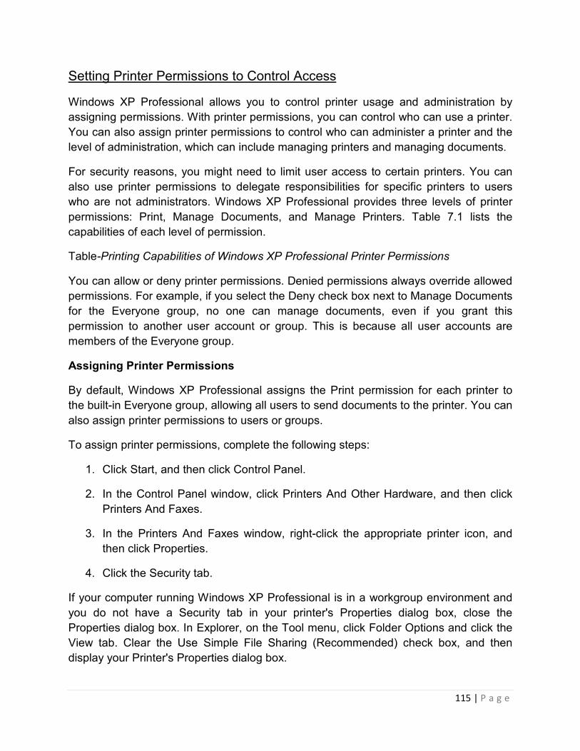
115 | P a g e
Setting Printer Permissions to Control Access
Windows XP Professional allows you to control printer usage and administration by
assigning permissions. With printer permissions, you can control who can use a printer.
You can also assign printer permissions to control who can administer a printer and the
level of administration, which can include managing printers and managing documents.
For security reasons, you might need to limit user access to certain printers. You can
also use printer permissions to delegate responsibilities for specific printers to users
who are not administrators. Windows XP Professional provides three levels of printer
permissions: Print, Manage Documents, and Manage Printers. Table 7.1 lists the
capabilities of each level of permission.
Table-Printing Capabilities of Windows XP Professional Printer Permissions
You can allow or deny printer permissions. Denied permissions always override allowed
permissions. For example, if you select the Deny check box next to Manage Documents
for the Everyone group, no one can manage documents, even if you grant this
permission to another user account or group. This is because all user accounts are
members of the Everyone group.
Assigning Printer Permissions
By default, Windows XP Professional assigns the Print permission for each printer to
the built-in Everyone group, allowing all users to send documents to the printer. You can
also assign printer permissions to users or groups.
To assign printer permissions, complete the following steps:
1. Click Start, and then click Control Panel.
2. In the Control Panel window, click Printers And Other Hardware, and then click
Printers And Faxes.
3. In the Printers And Faxes window, right-click the appropriate printer icon, and
then click Properties.
4. Click the Security tab.
If your computer running Windows XP Professional is in a workgroup environment and
you do not have a Security tab in your printer's Properties dialog box, close the
Properties dialog box. In Explorer, on the Tool menu, click Folder Options and click the
View tab. Clear the Use Simple File Sharing (Recommended) check box, and then
display your Printer's Properties dialog box.
116 | P a g e
5. In the Security tab, click Add.
6. In the Select Users, Groups, Or Computers dialog box, select the appropriate
user account or group, and then click Add. Repeat this step for all users or
groups that you are adding.
7. Click OK.
8. In the Security tab, shown in Figure 7.2, select a user account or group, and then
do one of the following:
o Click the permissions in the bottom part of the dialog box that you want to
assign.
o Click Advanced and assign additional printer permissions that do not fit
into the predefined permissions in the Security tab, and then click OK.
The bottom part of the dialog box shows the permissions granted to the user or group
selected in the upper part.
9. Click OK to close the Properties dialog box.

117 | P a g e
Figure-Assigning printer permissions
Modifying Printer Permissions
You can change the default printer permissions that Windows XP Professional
assigned, or that you previously assigned for any user or group.
To modify printer permissions, complete the following steps:
1. In the Printers And Faxes window, right-click the appropriate printer icon, and
then click Properties.
2. In the Security tab of the Properties dialog box for the printer, select the
appropriate user account or group, and then do one of the following:
o Click the permissions that you want to change for the user or group.
o Click Advanced to modify additional printer permissions that do not fit into
the predefined permissions in the Security tab.

118 | P a g e
3. Click OK.
Troubleshooting in Managing Printers
Assigning Forms to Paper Trays
If a printer has multiple trays that regularly hold different paper sizes, you can assign a
form to a specific tray. A form defines a paper size. Users can then select the paper size
from within their application. When the user prints, Windows XP Professional
automatically routes the print job to the paper tray that holds the correct form. Examples
of forms include the following: Legal, A4, Envelopes #10, and Letter Small.
To assign a form to a paper tray, complete the following steps:
1. Click Start, and then click Control Panel.
2. In the Control Panel window, click Printers And Other Hardware, and then
click Printers And Faxes.
3. In the Printers And Faxes window, right-click the icon of the appropriate printer,
and then click Properties.
4. In the printer's Properties dialog box, click the Device Settings tab.
5. In the box next to each paper tray, click the form for the paper type for the tray,
as shown in Figure 7.3.
6. Click OK.

119 | P a g e
Figure 7.3 Setting forms for a printer
After you have set up a paper tray, users specify the paper size from within applications.
Windows XP Professional knowsin which paper tray the form is located.
Setting a Separator Page
A separator page is a file that contains print device commands. Separator pages have
two functions:
• To identify and separate printed documents.
• To switch print devices between print modes. Some print devices can switch
between print modes that take advantage of different device features. You can
use separator pages to specify the correct page description language. For
example, you can specify PostScript or Printer Control Language (PCL) for a
print device that can switch between different print modes but cannot
automatically detect which language a print job uses.

120 | P a g e
Windows XP Professional includes four separator page files, which are
located in the %systemroot%\System32 folder. Table 7.2 lists the filename and
describes the function for each of the included separator page files.
Table 7.2??Separator Page Files
When you have decided to use a separator page and have chosen an appropriate one,
use the Advanced tab in the printer's Properties dialog box to have the separator page
printed at the beginning of each print job.
To set up a separator page, complete the following steps:
1. In the Advanced tab in the Properties dialog box for the printer (see Figure 7.4),
click Separator Page.
Figure 7.4??The Advanced tab for a printer's Properties dialog box
2. In the Separator Page dialog box, type the name of the separator page file.
To browse for a separator file, click Browse.

121 | P a g e
3. Click OK to close the Separator Page box, and then click OK again to close the
printer's Properties dialog box.
Pausing, Resuming, and Canceling Documents
Pausing and resuming a printer or canceling all documents on a printer might be
necessary if there is a printing problem.
To pause or cancel all documents, right-click the icon for the printer in the Printers And
Faxes window, and then click the appropriate command. To resume printing on a
printer, right-click the printer and click Resume Printing.
Table 7.3 describes the tasks that you might perform when you manage printers, how to
perform the tasks, and examples of situations in which you might perform these tasks.
Table 7.3??Managing Printers Tasks
You can also pause a printer by taking the printer offline. To take a printer offline, open
the printer window, and on the Printer menu, click Use Printer Offline.
Redirecting Documents to a Different Printer
You can redirect documents to a different printer. For example, if a printer is not
working, you should redirect the documents so that users do not need to resubmit them.
You can redirect all print jobs for a printer, but you cannot redirect specific documents.
The new printer must use the same printer driver as the current printer.
To redirect documents to a different printer, complete the following steps:
1. Open the Printers And Faxes window, right-click the printer, and then click
Properties.
2. In the Properties dialog box, click the Ports tab.
3. Click Add Port.
4. In the Available Port Types list, click Local Port, and then click New Port.
5. In the Port Name dialog box, in the Enter A Port Name text box, type the
Universal Naming Convention (UNC) name for the printer to which you are
redirecting documents (for example, \\prntsrv6\HPCLJ4550), as shown in Figure
7.5.

122 | P a g e
Figure 7.5??Redirecting documents to another printer
6. Click OK to accept the change and close the Port Name dialog box.
7. Click Close to close the Printer Ports dialog box.
8. Click OK to close the printer's Properties dialog box.
If another printer is available for the current print server, you can redirect the documents
to that printer. To redirect documents to another local or network printer that uses the
same printer driver, select the appropriate port on the print server and cancel the
selection of the current port.
Taking Ownership of a Printer
There might be times when the owner of a printer can no longer manage that printer
and you need to take ownership. Taking ownership of a printer enables you to change
administrative responsibility for it. By default, the user who installed the printer owns it. If
that user can no longer administer the printer, you should take ownership of it-for
example, if the current owner leaves the company.

123 | P a g e
The following users can take ownership of a printer:
• A user or a member of a group who has the Manage Printers permission for the
printer.
• Members of the Administrators and Power Users groups. By default these groups
have the Manage Printers permission, which allows them to take ownership.
To take ownership of a printer, complete the following steps:
1. In the Properties dialog box for the printer, click the Security tab, and then click
Advanced.
2. In the Advanced Security Settings dialog box, click the Owner tab, and then click
your user account under Change Owner To, as shown in Figure 7.6.
Figure 7.6??Taking ownership of a printer

124 | P a g e
3. Click OK to change ownership and to close the Advanced Security Settings
dialog box.
4. Click OK to close the Properties dialog box for the printer.
Practice: Managing Printers
In this practice you perform three tasks that are part of managing printers. In the first
exercise, you assign forms to paper trays. In the second exercise, you set up a
separator page. In the third exercise you learn how to take ownership of a printer.
Exercise 1: Assigning Forms to Paper Trays
In this exercise, you assign a paper type (form) to a paper tray so that when users print
to a specified form, the print job is automatically routed to and adjusted for the correct
tray.
To assign forms to paper trays
1. Log on as the user you created during installation or any user that is a member of
the Administrators group.
2. Click Start, and then click Control Panel.
3. In the Control Panel window, click Printers And Other Hardware, and then
click Printers And Faxes.
4. Right-click the icon of your printer, and then click Properties.
If you do not have a printer installed, see Exercise 1: Adding and Sharing a
Printer in Chapter 6, "Setting Up, Configuring, and Troubleshooting Common Setup and
Configuration Problems for Network Printers."
5. In the Properties dialog box, click the Device Settings tab.
Some of the selections might be labeled Not Available because they depend on options
that are not installed.
6. Click Tray 2, and then select Legal.
Whenever a user prints on legal size paper, Windows XP Professional instructs the
printer to use paper from Tray 2.

125 | P a g e
7. Click Apply and leave the Properties dialog box open for the next exercise.
Exercise 2: Setting Up Separator Pages
In this exercise, you set up a separator page to print between documents. You use the
SYSPRINT.SEP separator page that ships with Windows XP Professional. This
separator page includes the user's name and the date and time that the document was
printed.
To set up a separator page
1. Click the Advanced tab of the Properties dialog box.
2. In the Advanced tab, click Separator Page.
3. In the Separator Page dialog box, click Browse.
Windows XP Professional displays a Separator Page dialog box that lists the contents
of the System32 folder, which contains the separator pages that ship with Windows XP
Professional. This dialog box also allows you to search inadditional folders.
4. Select SYSPRINT.SEP, and then click Open.
Windows XP Professional displays the Separator Page dialog box with the full path to
the SYSPRINT.SEP separator page specified.
5. Click OK.
Windows XP Professional is now set to print a separator page between print jobs.
6. Leave the Properties dialog box open for the next exercise.
Exercise 3: Taking Ownership of a Printer
In this exercise, you practice taking ownership of a printer.
To take ownership of a printer
1. Click the Security tab of the Properties dialog box.
2. In the Security tab, click Advanced.
The Advanced Security Settings For HP Color LaserJet 4550 dialog box is displayed.
3. Click the Owner tab.
4. To take ownership of the printer, select another user in the Name box.

126 | P a g e
5. If you actually wanted to take ownership you would click Apply, but for the
purposes of this exercise, click Cancel and leave the ownership unchanged.
6. Click OK to close the Properties dialog box.
7. Click File and then click Close to close the Printers And Faxes window.
8. Log off Windows XP Professional.
Troubleshooting in Managing Documents
Pausing, Restarting, and Canceling a Document
If there is a printing problem with a specific document, you can pause and resume
printing of that document. Additionally, you can restart or cancel a document. You must
have the Manage Documents permission for the appropriate printer to perform these
actions. Because the creator of a document has the default permissions to manage that
document, users can perform any of these actions on their own documents.
To manage a document, right-click the icon representing the printer for the document in
the Printers And Faxes window, and then click Open. Select the appropriate documents,
click the Document menu, and then click the appropriate command to pause, resume,
and restart from the beginning, or cancel a document, as shown in Figure 7.7.
Figure??Managing documents
Table 7.4 describes the tasks that you might perform when you manage individual
documents, how to perform the tasks, and examples of situations in which you might
perform them.
Table??Managing Document Tasks

127 | P a g e
Setting Notification, Priority, and Printing Time
You can control print jobs by setting the notification, priority, and printing time. To
perform these document management tasks, you must have the Manage Documents
permission for the appropriate printer.
You can set the notification, priority, and printing time for a document in the General tab
of the Properties dialog box for the document, as shown in Figure 7.8. To open the
Properties dialog box for one or more documents, first select the documents in the
Printer window, click Document on the Printer window menu bar, and then click
Properties.
Figure ??Setting notification, priority, and printing time for a document
Table 7.5 describes the tasks that you might perform when you control print jobs, how to
perform the tasks, and examples of situations in which you might perform them.
Table??Setting a Notification, Changing Priority, and Scheduling Print Times

128 | P a g e
Practice:?Managing Documents
In this practice, you manage documents by printing a document, setting a notification for
a document, changing the priority for a document, and then canceling a document.
To verify that a printer is offline
1. Log on as the user you created during installation or any user that is a member of
the Administrators group.
2. Click Start and then click Control Panel.
3. In the Control Panel window, click Printers And Other Hardware, and click
Printers And Faxes.
4. In the Printers And Faxes window, click the printer icon.
5. Do one of the following to verify that the printer is offline:
o On the File menu, verify that the Use Printer Online option is listed
because that indicates that the printer is currently offline.
o Right-click the printer icon and verify that the Use Printer Online command
is listed because that indicates that the printer is currently offline.
o If the Printers And Faxes window is displayed in Web view, verify that Use
Printer Offline is displayed in the left portion of the window.
6. Verify that a check mark appears above the printer icon indicating that it is the
default printer.
7. Minimize the Printers And Faxes window.
Keep the printer offline to keep it from trying to print. This eliminates error messages in
later exercises when documents are spooled.
To print a document
1. Click Start, point to All Programs, point to Accessories, and then click WordPad.
2. Type How big is big? and then, on the File menu, click Save.
3. In the File Name text box, type BIG, and then click Save.

129 | P a g e
4. Click File and then click Print.
The Print dialog box appears. Notice that the file will be printed on the HP Color
LaserJet 4550 PS printer.
5. Click Print, and then close WordPad.
To set a notification
1. Restore the Printers And Faxes window.
2. Double-click HP Color LaserJet 4550 PS.
3. In the Printer window, select BIG, and then, on the Document menu, click
Properties.
Windows XP Professional displays the BIG Document Properties dialog box with the
General tab active.
Which user is specified in the Notify text box? Why?
4. In the Notify text box, type Fred and then click Apply.
You set the notification to go to Fred.
To increase the priority of a document
1. In the BIG Document Properties dialog box, in the General tab, notice the default
priority.
What is the current priority? Is it the lowest or highest priority?
2. In the Priority box, move the slider to the right to increase the priority of the
document to 38, and then click OK.
Nothing changes visibly in the HP Color LaserJet 4550 PS - Use Printer Offline window.
To cancel a document
1. Select BIG in the Printer window document list.
2. On the Document menu, click Cancel.
Notice that the Status column changes to Deleting. BIG is removed from the document
list.
You can also cancel a document by pressing the Delete key.

130 | P a g e
3. Close the Printer window, and then close the Printers And Faxes window.
System Assembling in Hardware
An Overview of Steps Involved
First, let's take a look at the various steps to putting together a PC.
• Opening the empty case;
• Preparing to fit the components;
• Fitting the motherboard;
• Fitting the RAM, processor, and cooler;
• Installing the graphics card and sound card;
• Fitting the hard disk and floppy drive;
• Installing the floppy and CD-ROM drives;
• Connecting the ribbon cables;
• Powering the drives and motherboard;
• Connecting the cables for the case front panel;
• Final check.
The above list is intended to be used as a general guide. In practice, you can vary the
actual order of assembly to some degree. We use a tower case in our demonstration
because it makes for clearer illustrations. The same assembly principles apply for midi
and mini cases.
The case we use has a slide-out tray for the motherboard and the expansion cards.
There are a variety of case designs on the market, and we've discussed this in depth in
an earlier article, entitled How To Select The Right Case . Take time to familiarize
yourself with the case before installing any components in order to avoid having to
remove some of them later!

131 | P a g e
Opening The Empty Case
Empty case with motherboard tray withdrawn.
Our tower case is built to ATX specification and includes a 300-watt power supply. Two
side panels can be individually removed after undoing the screws. Some other cases
have a one-piece outer cover in the shape of an upside down 'U.' No matter how the
case is constructed, you can normally gain access to the interior of the PC-to-be from
both sides.
The price of a case is a good indicator of its modularity and build quality. Cheaper cases
often force you to assemble the PC in a specific order, are made of softer and/ or
thinner metal, and may contain sharp edges. Expensive cases provide clever design
features, a more solid construction, better finish, and are often fitted with more capable
power supplies.
When you have opened the case by removing the side panels, you will see what
accessories the case manufacture has supplied. A power cord and screws should
always be included, and you will also often find a set of case feet.
Preparing To Fit The Components

132 | P a g e
Overview of all components (from left to right and top to bottom): network adapter card;
floppy disk drive; CD-ROM drive; sound card; hard disk; ribbon cable; graphics card;
RAM; CPU cooler; and, motherboard.
Let's take another look at the photo. The inclusion of a component from a particular
manufacturer does not imply a recommendation on our part. We use them to illustrate
the installation procedure of similar components. The choice of components is entirely
up to you. You can always find reviews of the latest products on the Tom's Hardware
site, together with articles on the latest developments and product recommendations.
Fitting The Motherboard
Empty tray with six motherboard spacers.
Our case has a slide-out tray, which provides a very elegant way to install the
motherboard and all of its components. Cheaper cases will have a mounting plate fixed
permanently to the case. If you have this type, you should first lay the case on its side.
Next, screw in the spacer mounts for fixing the motherboard. The photo shows six
spacers already fitted to the mounting plate. There are usually more holes drilled in the
mounting plate than you actually need. There are standard locations for these holes on
the mounting plate, which correspond to the holes on the motherboard. How many of
these are actually used depends on the board manufacturer. Cases are normally
designed to accept any motherboard. Compare the available holes with the ones on
your motherboard to determine where to fit the threaded spacers.
Spaced well away from the metal - the motherboard on the mounting plate.

133 | P a g e
Mounting The Cooler
A cooler made of copper is recommended, since this material is a very efficient heat
conductor. You should know your processor's socket type when buying a cooler. You
have a choice of two types of cooler - one suitable for both Socket A/462 and Socket
370, or one just for Socket 423 (Pentium 4).
Make sure that the cooler is in the correct position. Here is the cooler about to be
connected with the socket.
Clips fix the cooler to the socket. This applies to Socket A/462 (AMD) and Socket 370
(Pentium III and C3)
Plenty of air flow. Here is the power connection for the cooler's fan.
You may have wondered why the connector lead for the fan has three wires. Two of
these carry the power; the third is used for monitoring the speed of the fan. Therefore,
the BIOS is always aware of the speed at which the fan is running.
Minor Differences With The Pentium 4 System
Socket 370 (Intel Pentium III or Via C3), Socket A/462, and Socket 7 all use the same
method of mounting the cooler. However, Socket 478-based Pentium 4 systems are

134 | P a g e
slightly different. Intel specifies that motherboard manufacturers should provide a plastic
guide rail to ensure that the cooler is always mounted flat to the surface of the
processor. Also, the cooler is not locked down with clips but with a snap-in system, as
shown in the following pictures.
Pentium 4 motherboards have a socket with 478 pins and a guide for the CPU cooler.
Attaching a Pentium 4 cooler
Installing The RAM
The RAM must be suitable for the motherboard. There are currently three types of RAM
available: SDRAM, DDR SDRAM and RDRAM. The motherboard's chipset determines
which type of RAM may be used. You will find the specification on the motherboard's
box or in the motherboard manual.
Installing RAM. A notch at the bottom of the memory module ensures that the RAM is
fitted correctly. The notch is located in different places on SDRAM, DDR SDRAM and
RDRAM.
DIMM memory modules have a notch underneath that lines up with a key on the
memory slots. Although it is not possible to insert the modules the wrong way, you
should line up the RAM with its slot before installing it. Then, carefully press the module
into the slot. Caution is recommended, as too much pressure may damage certain

135 | P a g e
tracks on the motherboard. It is best to push one side down first, and then the other.
The notch will snap into its key as soon as one side is seated correctly. To make sure it
is seated correctly, you can always take the memory module out again. Releasing the
clips will pop the module out of its socket. Then, you can just lift it out.
Passed the first hurdle. Motherboard with processor, cooler and memory.
Graphics, Sound And Network
In place - sound card (left) and graphics card (center) in white PCI slots. There is room
for a network card, if required.
Nowadays, graphics cards are usually fitted in the AGP slots provided specifically for
this purpose. These are brown in color, in contrast to the PCI slots, and are generally
located in the center of the motherboard. PCI graphics cards are rarely used. Now,
select a PCI slot for each of your other plug-in cards, including the sound card. Before
fitting an expansion card, remove the appropriate slot insert from the back panel of the
case (or of the motherboard tray). As a rule, you need to undo a screw to do this,
although sometimes convenient plastic clips are used. The insert may also form part of
the back panel.
Choosing a location for a PCI card will not usually be a problem on a simple system. In
our experience, however, selecting an appropriate PCI slot can sometimes be
problematic with some brands of motherboard. For example, IRQs can be reserved
twice or even three times over. Resource conflicts can make it difficult for the operating
system and motherboard to work together properly. This can often be solved by moving

136 | P a g e
the offending PCI card to another slot or by manually reassigning IRQs. The other
reason is more practical. If you see a large heat sink on a plug-in card, perhaps even
with a fan on top, the chip underneath will be producing a lot of heat that has to be
removed. There is only one reason we did not fit the sound card next to the graphics
card: we wanted to keep some space between the cards in order to prevent heat
buildup.
Installing The Hard Disk And Floppy
We assume that you have already configured your hard disk the way you want it -
single, master, or slave. The photo below shows the hard disk already fitted. As you can
see, we can look right through the case here. If we had slid the motherboard tray back
into position, it would have been impossible to screw the hard disk in from the left.
At the moment, we still have good access to the hard disk (bottom) and the floppy drive
(top). You can see the screws for the drive on the side.
Use two screws per side on each drive. We would like to touch briefly on the topic of
drive cooling, as it is quite important with the current 7,200 rpm drives. Hard disks
running at 7,200 rpm can quickly reach temperatures in excess of 50°C. You should,
therefore, always leave some space above them to prevent heat buildup. The power
supply fan is normally powerful enough to provide adequate air circulation inside the
case.
Installing The CD-ROM Drive
Installing a CD-ROM drive is similar to installing a hard disk. First, check that the jumper
configuration is correct.

137 | P a g e
CD Drive In Drive Cage.
You only get to see the metal below the decorative plastic front panel when installing
your system; the case metal is actually hidden by plastic panels. The entire front
section, or at least the part where the drives will be installed, is manufactured from a
single, large piece of metal, in which the drive holes are then punched. For some years
now, the CE norm for cases has specified this kind of metal panel, as only metal can
reduce electromagnetic emissions - the processor usually being the worst offender in
this area.
In practice, there are two options. If the metal knockouts are pre-stamped, you have to
either take them out using metal cutters, or knock them out using force. If you have a
high quality computer case, you can remove and replace these metal panels whenever
you like. Check carefully to see if there is an easy way to remove these panels that will
reduce the chances of your accidentally damaging one or more of them.
When we have opened up the hole, we can feed the CD-ROM drive in and screw it into
place. You will need the fine-threaded type screws. Always use four screws. Be careful
not to over-tighten the screws, as excess pressure can put a strain on the case that
could lead to twisting. The faster a drive's rotational speed, the more serious the effect.
Tighten the screws only enough to ensure that the drive is secure. Heat is a
consideration with CD-ROM drives, as it is with disk drives.
Connecting The Ribbon Cables
Your PC should now look similar to the one in our photograph. All key components,
such as the motherboard, processor, RAM, graphics card, sound card, hard disk, CD-
ROM and floppy, have been installed. Now it is time to connect the cables.
PC still without the cables
As you will be aware after reading Part 1, there are two main cable types: the 34-pin
cable for the floppy drive and the 40-pin IDE cable (with 80 wires) for the hard disk and
CD-ROM. Cables are always color-coded to show pin 1. Most drives also provide some
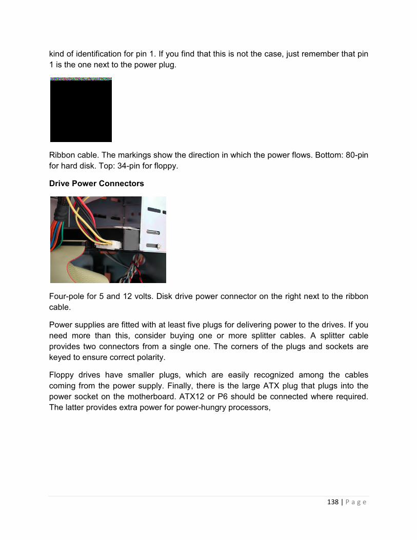
138 | P a g e
kind of identification for pin 1. If you find that this is not the case, just remember that pin
1 is the one next to the power plug.
Ribbon cable. The markings show the direction in which the power flows. Bottom: 80-pin
for hard disk. Top: 34-pin for floppy.
Drive Power Connectors
Four-pole for 5 and 12 volts. Disk drive power connector on the right next to the ribbon
cable.
Power supplies are fitted with at least five plugs for delivering power to the drives. If you
need more than this, consider buying one or more splitter cables. A splitter cable
provides two connectors from a single one. The corners of the plugs and sockets are
keyed to ensure correct polarity.
Floppy drives have smaller plugs, which are easily recognized among the cables
coming from the power supply. Finally, there is the large ATX plug that plugs into the
power socket on the motherboard. ATX12 or P6 should be connected where required.
The latter provides extra power for power-hungry processors,

139 | P a g e
Front Panel Connections
Front panel connections: HDD LED (hard disk light), power (on/ off) switch and RESET
switch in the top row. Below: mini speaker.
All motherboards group the pins that provide front panel functions at the bottom right of
the board. You should find these described in the handbook that came with your
motherboard. The abbreviations printed on the board itself are not particularly helpful for
beginners, who may find the following short explanation of the abbreviations useful.
• SP, SPK, or SPEAK: the loudspeaker output. It has four pins.
• RS, RE, RST or RESET: connect the two-pin Reset cable here.
• PWR, PW, PW SW, PS or Power SW: power switch, the PC's on/ off switch. The
plug is two-pin.
• PW LED, PWR LED or Power LED: the light-emitting diode on the front panel of
the case illuminates when the computer is switched on. It is a two-pin cable.
• HD, HDD LED: these two pins connect to the cable for the hard disk activity LED.
Don't worry about polarity. The Reset and On/ Off switch will work no matter how they
are connected, but the LEDs will not light up if they are connected in reverse polarity. If
you can hear disk activity but the LED does not light, simply reverse the plug.
Final Check
Congratulations - you've done it! You have fitted and connected all components. Before
you boot your new computer for the first time, recheck everything. It is very easy to
overlook something obvious.
Consider the following:
• Motherboard jumper configuration: are the settings for the processor correct?
• Drive jumper settings: master/ slave correct?

140 | P a g e
• Are the processor, RAM modules and plug-in cards firmly seated in their
sockets?
• Did you plug all the cables in? Do they all fit snugly?
• Have you tightened all the screws on the plug-in cards or fitted the clips?
• Are the drives secure?
• Have you connected the power cables to all drives?
Once you have checked all of the above, you can start your PC and install your
operating system.
To troubleshoot network problems, the first question you should ask is, “Has this piece
of equipment or has this part of network ever worked properly before?” If the answer is
yes, then the next question should be, “Since then, what has changed?” You will solve
the problem more efficiently if you are systematic and organized in your network
troubleshooting approach and maintenance work. It will always help to do some
homework - plan before you proceed.
Network Troubleshooting
How to Start Network Troubleshooting?
Knowing what to look for is absolutely essential in network troubleshooting. To do so, go
through the list of questions or check list below, which will help you to narrow down your
problem.
1) How many users are affected by the network problem? One or more?
2) Were the users affected all at once or randomly affected?
3) Is only one computer down or is the entire network down?
4) Does this problem occur all the time, or does it only happen during certain hours of
the day?
5) Does this problem affect only one application, a few or all the applications?
6) Does this problem resemble any past problems?
7) Have you added any new user(s) to the network?
8) Have you added any new equipment to the network?

141 | P a g e
9) Are any vendor products involved in this problem? If yes, who are the vendors?
10) Does this problem occur among components such as hubs, disk drives, application
software, cards or network operating software?
11) Has anyone attempted to solve this problem?
12) Have you check the network adaptor card? Is it working?
13) Is the amount of traffic or network load normal?
14) Is there any error message in the network log files?
15) Can the computer having the problem function as a standalone computer without
connection to the network?
16) Is there any network port being segmented?
17) Is the problem affected coming from the certain segment of the network?
Cabling Problems
If you suspect a problem with cabling, check the following items :
1) Missing or loose cable connection
2) Frayed or broken cable connection
3) Crimped or bent cable
4) Correct cable length
5) Correct resistance (ohms)
6) Network adapter card specifications
7) Location of cable routing – Cable routed near a transformer, larger electric motor,
or air conditioner may cause electromagnetic interference.
8) Correct termination of network (for e.g. for bus topologies)
9) Some intelligent hubs come with management facility, please remember to refer to
the technical manual for proper installation procedure and settings

142 | P a g e
10) If you fabricate the cable on your own, ensure you use the correct pin termination
on the plug. For RJ45 or category 5 & 6 cable, watch out for "straight through" and
"crossover" (cross-pinned) when making the patch cord,
Problems with Network Adapter Cards
If you suspect there are problems with network adapter cards or network interface card
(NIC), check the following:
1) Do the settings of your network adapter card match with the network operation
system software settings?
2) Are there any I/O address conflicts in the problematic computer?
3) Are there any interrupt conflicts in the computer?
4) Are there any memory conflicts or memory insufficiency problem in the computer?
5) If you have more than one network adapter in a computer, are there any setting
conflicts among them?
6) Is there any address conflict in the network, for e.g. duplicate TCP/IP address
assigned ?
7) Are you using the correct interface (RJ45, BNC or AUI )?
8) If the port is not auto negotiable for speed, is the network speed set correctly?
9) Is the correct type of network card used for the network?
10) Are the type and signalling speed correctly set? (In some network setup, there is
a life beat signal to check the network status)
Problem with Network Card Driver
Check the following to isolate the problem with network card driver:
1) Has anyone replaced any network card?
2) Is the old driver being used with the new hardware?
3) Has anyone formatted the hard disk and installed new operating system? If yes,
network card driver may need to be installed again.

143 | P a g e
Problems with Network Operations
Check the following for network operations problems :
1) Check the hardware in your server to ensure that
a) it is on the Microsoft Hardware Compatibility List (HCL), or Linux Compatibility
List (LinuxHCL) depending on the operating system used
b) Correct and the most current drivers are installed
c) it has sufficient memory for network operation
d) it has sufficient hard disk space for storage and virtual memory
e) it has sufficient CPU processing memory to run the applications
2) Check to ensure all the network bindings are correct.
3) Ensure network protocol installed matches the protocol already in use on the
network
4) Check your client computer to ensure proper software installation
5) Have the users received proper training on how to operate the network
application? Are they using the correct procedures to run or does maintenance work on
the server and client ?
6) Is there any license issue or limitation for the network application software?
Problems with Client-Server Computing
If you have a client-server setup, check the following for possible problem:
1) Is the application software properly installed, configured and working?
2) Is the client software properly installed?
3) Are there any bug fixes or patches required for this version of software? Your
problem may be due to the uninstalled bug fix or patch.
4) Does the server have sufficient RAM, space on shared hard disk and processing
power to run the particular network application?

144 | P a g e
Problems with Wide Area Network Communications
You can troubleshoot a Wide Area Network (WAN) the same way you do a local area
network (LAN), as given above. There are some specific consideration for WAN, and
normally they require assistance of vendors or service providers. Here is the checklist
to WAN troubleshooting :
1) Is the power supply to the following network components turned on ?
- Router
- Gateway
- Firewall
- Repeater
- Bridge
- Modem
2) For the components above, check the following :
- Are the cables properly connected and are in good condition?
- Is the component compatible with the communications medium and the
communication device at the other end of the link?
- Is the software properly configured and matched the configuration of the
connected communication equipment on the other end?

145 | P a g e
- Is the software installed on both sides of the link compatible and of the same
version?
- Is there any license issue or limitation for the software installed on both sides?
3) Did any vendor replace, add or remove any hardware or software from the WAN
lately?
Working with Vendor
After you have attempted to solve the network problem but to no avail, you may need to
consider contacting your network vendor for technical support. To speed up the work, it
is recommended that you do some preparation work before contacting the vendor’s
technical support staff. Keeping a record of the following will be helpful:
1) Jot down what happened before the network problem came up
2) Make a list of any modifications to software or hardware made immediately before
the problem occur
3) Make a print screen or write down any error messages that appear on the screen
4) Recall and write down what application or task was running when the problem appear
5) Prepare to retrieve and present all the relevant network documentation
Microsoft Windows XP troubleshooting.
This document has been created as a location of general steps that can be taken to
help you with problems you may be experiencing with Microsoft Windows XP that are
either general problems or problems not documented elsewhere in the Computer Hope
database.
Below are some reasons why a user may follow the steps in this document.
1. Unknown or undocumented problem with computer running Microsoft Windows
XP.
2. Performance issues with the computer, for example, the computer running
slowly.
3. Users who wish to run maintenance on the computer or potentially speed up the
computer.
4. Users looking for steps to help resolve an issue or that may help locate the cause
of an issue.

146 | P a g e
Users may find explicitly documented questions and answers on our Windows XP Q&A
page. Additional information about Windows XP can also be found on our Windows XP
main page.
Solutions
Error messages encountered during boot before Windows loads
Before following the below steps, make sure that the error you are encountering is not
already documented on Computer Hope by performing a quick search for the error and
by looking through ourWindows XP Q&A page.
1. Ensure that your computer BIOS settings are correctly configured to the
hardware that is installed in your computer. Improper settings in the BIOS may
cause various errors when first booting an IBM compatible computer. These
errors often occur as the computer is first booting and may stop the load process
of the computer.
Error messages while Windows is loading
Errors that occur while Windows XP is loading or prevent Windows XP from loading are
likely being caused by a configuration error in the registry.
1. If you have recently changed or installed something that could have caused
Normal Windows to stop loading, try loading the last known good configuration.
2. If you are unable to get into Normal Windows and believe that removing or
uninstalling a program or changing a setting may help enable you to get into
Windows, boot the computer into Windows XP Safe Mode.
3. If your computer has worked fine in the past but recently has been experiencing
the issue you're encountering, run the System Restore option to restore the
computer to an earlier date.
Other error messages that occur while Windows is loading or after Windows is loaded
Errors that have occurred while Windows is loading or after Windows has completed
loading are often caused by a program that is automatically loading each time Windows
is loading, problem or misconfiguration of a hardware device, or computer virus.
1. If errors occur but Microsoft Windows still loads, verify no issues or conflicts exist
in Device Manager. If errors are found, read through our Device Manager page
for steps on resolving issues.
147 | P a g e
2. Ensure that if programs are loading automatically, the errors are not associated
with these programs. Many times utilities such as virus programs may load when
Windows first starts and cause errors. If you believe that your startup errors are
associated with another program, refer to our basic software troubleshooting.
3. Make sure Windows XP is up to date.
4. If your computer has a virus protection program installed, make sure it is up-to-
date and that no viruses are being detected. If your computer does not have a
virus protection program, you may wish to consider installing an anti-virus
program to make sure no viruses are causing your problems.
5. If your computer has worked fine in the past but recently has been experiencing
this issue, run the System Restore option to restore the computer to an earlier
date.
Other error messages
If you are experiencing other error messages, it is likely these errors are being caused
by the software program you are running and a hardware device you are attempting to
utilize. It is recommended you see the basic troubleshooting section for your hardware
device or software program.
Computer running slowly
1. Make sure your computer has at least 500MB of free hard disk drive space. If
your computer has less than 500MB free, it may cause the computer to operate
more slowly. Try regaining hard disk drive space.
2. Run Microsoft Scandisk and Defrag on the computer. Additional information and
help with these commands can be found on ourscandisk page and our defrag
page.
3. Close any programs that are running in the background or disable background
programs from automatically loading each time your computer boots. Information
about doing this can be found indocument CHTSR.
4. Click Start, Search, and click For Files or Folders. In the search window, search
for files named *.tmp and make sure you are searching or looking in the local C:
drive. Once search has completed, delete any files found.
5. Ensure that no errors or conflicts exist in the Device Manager.
6. Make sure Windows XP is up-to-date by checking Microsoft Windows update
page.

148 | P a g e
7. Delete all files in your Windows Prefetch directory. These files can lower overall
system resources if loading programs no longer being used. See
the prefetch definition for additional information about prefetch.
8. Verify your computer has the latest drivers for the hardware devices installed in
your computer.
9. If your computer has a virus protection program installed, make sure it is up to
date and that no viruses are being detected. If your computer does not have a
virus protection program, you may wish to consider installing a program to make
sure no viruses are causing your problems. Information about updating your
antivirus program can be found on document CH000533 and information about
what antivirus programs are available can be found ondocument CH000514.
10. If your computer has worked fine in the past but recently has been experiencing
this issue, run the System Restore option to restore the computer to an earlier
date. Information about how to do this can be found on document CH000589.
Issue with hardware device
If you are having difficulties with a hardware device, see the basic troubleshooting
section for steps that can be taken to help resolve your hardware issues.
Troubleshooting the LAN is part of the job of a technical support provider/network
administrator. In your role as a troubleshooter, you should:
• Encourage the users on your network to come to you when they experience
network difficulties.
• Learn simple troubleshooting techniques to try before you call the NOC.
• Learn how to gather information that will be helpful and useful to the NOC when
you do need to submit a Problem Report.
The rest of this page discusses some common problems and solutions to them. You
should run through these solutions before calling the NOC for help. If you don't have
any success fixing your network problem, you will need to submit a Problem Report to
the Network Operations Center.
Some common problems are listed below, click on the problem to view possible
solutions:
� Troubleshooting Guide for Macintosh Computers on Ethernet Networks
• Devices are displayed in the Chooser, but you have no IP access.

149 | P a g e
• No devices are displayed in the Chooser and there is no IP access.
• No devices are displayed in the Chooser and you have IP access.
• Single user has devices but cannot connect to any IP services (CornellC,
POPMail, CUinfo,
etc.).
• Single user has no devices and no IP connectivity.
• Multiple users have devices but no connectivity to a specific IP service
(e.g. COLTS).
• Multiple users have no devices and no IP connectivity, but local resources
such as printers and file servers are available.
• Multiple users have no devices and no IP connectivity, and local resources
such as printers and file servers are not available.
• Printer or file server not accessible.
� Troubleshooting Guide for PCs on Ethernet Networks
• Cannot find Novell server.
• Cannot connect to host or no ARP response from router.
• Error message when connecting to TCP/IP application.
• Error connecting to a host computer.
• Printer or file server not accessible.
Troubleshooting in LAN
The monitoring of LAN is accomplished by general network sniffers or network
management computer and the various LAN troubleshooting is provided by the protocol
analyzer and it provides solution over IP/TCP networks.
The troubleshooting in LAN/IP/TCP will always be tricky and the procedure includes
finding computer IP address, faulty LAN cards, cabling problems, low service
performance, DNS/DHCP problems, and security issues, overloading of network
servers, proxy server’s settings, and some of the applications in software.

150 | P a g e
The LAN problem is raised due to the above mentioned reasons and it the Network
administrator responsibility to have quiet good knowledge of infrastructure of LAN,
software, user access rights, network hardware and some of network configurations.
The user has to make the inventory of all resources of LAN such as network hardware,
software installed.
The following tips helps the user in troubleshooting and diagnosing the LAN problem
which occur frequently
Connectivity issues:
• The user has to make sure that in all computers in his LAN same associated subnet
masks and same class IP address is used.
• On every individual computer accurate gate address has to be provided.
• At both end i.e. one end in LAN card and other end in HUB/Switch network cable has
to be tightly plugged.
• The user has to make sure that lights are switched on in LAN card and it is in working
condition.
• To verify the connectivity with another computer PING command has to be used at the
command prompt.
• The user has to make sure that firewall is not blocking outgoing traffic.
The procedure as follows
• At command prompt user has to ping 100.100.100.1 and press enter as it is the IP
address of other computer.
• The driver of the NIC adapter has to be reinstalled if there is connectivity issue with
particular computer and still if any problem is found NIC adapter has to be changed and
it has to be reconfigured.
• The network cable from computer to HUB/Switch has to be checked if the connectivity
problem is not resolved.
Security:
If no proper security such as policies, antivirus programs, and security methods have
not been implemented security issues are more likely to occur.
Some of the tips user has to follow to maintain the security in LAN.
• The updated spyware program and antivirus should regularly scan the network server

151 | P a g e
and the entire computer.
• The user has to block the notorious applications in the proxy server which causes
security issues and specific rules for the internet access have to be defined.
• Security policies have to be implemented.
• The user has to limit the access to network resources by using encryption methods
and strong passwords.
• Operating system has to be updated and latest services pack should be installed.
• The user has to implement firewall such that it will save the computer from
unauthorized users.
Performance:
The performance of the network depends based on the installed applications. Low
physical memory, anti spyware free systems, windows registry errors, faulty or low
hardware, unnecessary shortcuts to networks will access server in network
management and server for same resource.
• User has to remove recent files, browser’s history, clear cookies and some of
temporary files.
• The physical memory (RAM) has to be increased.
• The browsing speed can be increased if unnecessary shortcut is removed.
• Proxy server, print server, Gateway computer and File server has to be separately
configured for minimum load on individual server.
• LAN cards which supports 10/100 mbps of speed has to be installed and in LAN
switch has to be used instead of Hub.
WAN Troubleshooting.
There are much solution and the product which are available in small business and
enterprises.
Through dial up connections WAN links are built, circuit switching, dedicated
connections, dial up connections, packet switching and other WAN technologies is also
connected through dial up connections.
TCP/IP stack is built in and it is the basic troubleshooting for every network and it is
done through every utility which is available.
“PING” command is the one which is used in the first step of troubleshooting and the
procedure is as follows

152 | P a g e
Step 1) Go to run>
Step 2) Type CMD>
Step 3) Press enter>
Step 4) Go to command prompt option and type ping [IP address]
Step 5) Here IP address is 32 bit numeric address of source computer like 10.11.10.1
figure
figure

153 | P a g e
figure
figure
If the user get reply from remote computer it suggest that physical connection between
computers is quite good and message such as “Request Time Out” means that there is
Physical connectivity problem.
Devices such as router, LAN card, firewall, server crash down, bandwidth, network
congestions has the common troubleshooting problem and it has the faulty network.
The finding of the important cause for the problem in WAN and it can be found by using
the troubleshooting tools. In isolation of the problem managed service and usage of the
right tool is very important.
The tool helps in finding out the root cause of the applications such as firewall, router,
switch, carrier network infrastructure or just the man made errors.
In the modern world there are advanced technology and products which are used in
troubleshooting and determining of WAN performance.
The some of the basic troubleshooting tips which helps in determining of WAN network.

154 | P a g e
• The user should make sure that settings in network card are correct in every
computer.
• The cables on the router should be tightly plugged.
• The WAN IP address of the remote router should be pinged.
• The router should be turned off for 30 seconds and later it should be turned on.
• The network device such as switch, router should be turned on both sides and it
should be in working condition.
• The user should check the bandwidth and the bandwidth allocation of each remote
site.
• The techniques such as signaling, framing, loop testing, clocking and signal encoding
has to be applied.
• The user has to check for the large sums of unrelated data which is sent by
unauthorized users.
• The legitimate WAN problem has to be checked with the help of WAN troubleshooting
tools.
• The network congestion problem occurs due to bandwidth problem or due to
distributed application.
• The user has to make sure to check for NIC problem in computer.
• The firewall hardware and software has to be configured properly.
Some of the tools which are used in monitoring and Troubleshooting of tools are
• Super Agent
• Report Analyzer
• Net Watch
• Opt view
• Net Volant
By using the above tool it will be easy for the user for troubleshooting in WAN.
Configure TCP-IP Troubleshooting
TCP/IP is a wonderful protocol suite; it comprises almost all of the functionality and the
core services that make possible for the Internet and its applications. However, with
great power come many problems; so, knowledge of TCP/IP troubleshooting will be
necessary in your networking-related career and especially in your ability to pass the
Network+ exam. In fact, you will probably encounter around four or five questions on
TCP/IP troubleshooting alone on the Network+ exam.
Your knowledge of TCP/IP troubleshooting depends on your command of TCP/IP tool

155 | P a g e
usage. Many of the following tools are used in typical troubleshooting operations, and
almost all of them can be used to either identify or eliminate a potential problem in a
troubleshooting situation. We will go over general network troubleshooting in more detail
in later articles.
To give an example of the way TCP/IP troubleshooting tools can help, consider the
common tool “ping.” Ping operates over the ICMP protocol (using ICMP Echo Request
and Echo response) to attempt to contact a host given some kind of unique identifier
(hostname, domain, IP, etc.). If it is successful, it will return a reply from that IP address;
if it is unsuccessful, it will inform you that the “destination could not be reached.” Why is
this useful? Suppose you are trying to determine why you are unable to access the
company’s remote email server through “Outlook.” The problem could stem from a
number of issues, including
� The computer is not properly configured for the internal network (media
problems, TCP/IP configuration issues, router is down, etc.)
� The Internet connection is down
� There is an issue in connecting to the email server at the Application or
Connection layers (maybe he is connecting to the wrong port, NAT issues, email
server is rejecting connections)
� The remote host is down or is unavailable in general (IP connection issues)
Obviously, these are only four of many possibilities, but they are four possibilities that
can be further investigated through Ping. For example, to ping your router would
indicate to you if your router or network connection is down, or if the problem lies at the
remote host level. This kind of “step-by-step, process of elimination” process is how
most troubleshooting takes place. Some other tools include:
� Tracert: Traces the connection path to a remote host, step-by-step. Allows you to
see where the connection “is lost” – for example, sometimes a connection to a
remote host may stop at an ISP router, at which point you can determine that the
issue is a WAN problem.
� Netstat: Depending on the parameters, gives varying degrees of information
about TCP/IP connections and protocols. Examples include information such as
all connections and listening ports, routing table etc
� Ipconfig: Displays IP configuration information with the switch (/all), which
includes IP address, subnet mask, and default gateway. Ipconfig can also be
used to force a DHCP release or renew operation, using the switches /release
and /renew
156 | P a g e
� ifconfig: Displays IP configuration information in a UNIX
environment. ifconfig interface_name can also be used to display the IP
configuration information for a specific interface
� Winipcfg - the GUI-based Windows 9x-era ipconfig tool
� ARP – Returns the MAC address that maps from a given IP address
� RARP – Returns the IP address that maps to a given MAC address
� Nslookup – Used to troubleshoot DNS issues; can be used to find an IP given a
DNS name
There are of course other TCP/IP tools, but they will be covered in other sections (i.e.
NetBios). The most important things to remember about the above TCP/IP tools are not
the details of their functionality, but rather, remember the troubleshooting operations
that they are associated with. For example, if you read about some sort of DNS issue,
you should immediately think Nslookup before considering other tools.