hp color LaserJet 3500/3550 and 3700 series printer - Laser ...
598
hp color LaserJet 3500/3550 and 3700 series printer service
-
Upload
khangminh22 -
Category
Documents
-
view
0 -
download
0
Transcript of hp color LaserJet 3500/3550 and 3700 series printer - Laser ...
hp color LaserJet3500/3550 and 3700
series printerservice

HP Color LaserJet 3500/3550 and 3700series printers
Service Manual

© 2004 Copyright Hewlett-PackardDevelopment Company, L.P.
Reproduction, adaptation or translationwithout prior written permission isprohibited, except as allowed under thecopyright laws.
Part number: Q5990-90939
Edition 1, 10/2004
The information contained herein is subjectto change without notice.
The only warranties for HP products andservices are set forth in the expresswarranty statements accompanying suchproducts and services. Nothing hereinshould be construed as constituting anadditional warranty. HP shall not be liablefor technical or editorial errors or omissionscontained herein.
Trademark Credits
Microsoft® is a U.S. registered trademarkof Microsoft Corporation.
MS-DOS® is a U.S. registered trademarkof the Microsoft Corporation.
*Pantone®, Inc.'s check-standardtrademark for color.
PostScript® is a trademark of AdobeSystems Incorporated.
TrueTypeTM is a U.S. trademark of AppleComputer, Inc.
UNIX® is a registered trademark of TheOpen Group.
Windows, MS Windows, and Windows NTare U.S. registered trademarks of MicrosoftCorporation.

Conventions
This manual uses the following conventions:
Color is used to emphasize items that are important to the material under discussion.
Bold is used for menu items to click and for emphasis, particularly in situations where italictype would be confusing.
Italic type is used to indicate related documents or emphasis.
DISPLAY type indicates text as seen on the printer control panel display.
Commands you use on a computer keyboard or on the printer control panel are shown inKeycap. Two examples are MENU and STOP.
COURIER type indicates text that you type on a computer keyboard exactly as shown.
NOTE Notes contain important information set off from the text.
CAUTION Caution messages alert you to the possibility of damage to equipment or loss of data.
WARNING! Warning messages alert you to the possibility of personal injury.
ENWW Conventions iii

iv ENWW

Table of contents
1 Printer descriptionChapter contents .......................................................................................................................1Printer configurations ................................................................................................................3
HP Color LaserJet 3500/3550 printer .................................................................................3HP Color LaserJet 3500n/3550n printer .............................................................................3HP Color LaserJet 3700 printer ..........................................................................................4HP Color LaserJet 3700n printer ........................................................................................4HP Color LaserJet 3700dn printer ......................................................................................5HP Color LaserJet 3700dtn printer .....................................................................................5
Printer features ..........................................................................................................................6Printer assemblies .....................................................................................................................9
Front and rear features .......................................................................................................9Site requirements ....................................................................................................................11
Space requirements .........................................................................................................11Electrical specifications ....................................................................................................12Environmental specifications ............................................................................................13
Printer specifications ...............................................................................................................15Duty cycle .........................................................................................................................15
Print media specifications .......................................................................................................16Supported media weights and sizes .................................................................................16
Hewlett-Packard warranty statement ......................................................................................19HP's Premium Protection Print Cartridge Warranty Limited Warranty Statement ..................20Premium Protection Warranty Color LaserJet Image Fuser Kit and Image Transfer
Kit Limited Warranty Statement ...........................................................................................21Identification ............................................................................................................................22
Model and serial numbers ................................................................................................22Power and regulatory information ....................................................................................22
Selecting paper .......................................................................................................................24Paper to avoid ...................................................................................................................24Paper that can damage the printer ...................................................................................24
Printing on special media ........................................................................................................26Transparencies .................................................................................................................26Glossy paper .....................................................................................................................26Colored paper ...................................................................................................................26Envelopes .........................................................................................................................27Labels ...............................................................................................................................27Heavy paper .....................................................................................................................28HP LaserJet Tough paper ................................................................................................28Preprinted forms and letterhead .......................................................................................28Recycled paper .................................................................................................................29Media weight .....................................................................................................................29
Environmental product stewardship program .........................................................................31Protecting the environment ...............................................................................................31
Declaration of Conformities .....................................................................................................34Safety statements ...................................................................................................................37
Laser safety statement .....................................................................................................37
ENWW Conventions v

Canadian DOC regulations ...............................................................................................37EMI statement (Korea) .....................................................................................................37VCCI statement (Japan) ...................................................................................................37Laser statement for Finland ..............................................................................................38
FCC Regulations .....................................................................................................................39
2 Service approachChapter contents .....................................................................................................................41Search approach .....................................................................................................................42Parts and supplies ...................................................................................................................43
Ordering parts ...................................................................................................................43Ordering supplies ..............................................................................................................43Exchange program ...........................................................................................................44Supplies ............................................................................................................................44World Wide Web ...............................................................................................................44HP service parts information CD-ROM ............................................................................44HP support assistant CD-ROM ........................................................................................44Customer care reseller sales and service support center ................................................44Ordering related documentation and software .................................................................45
HP maintenance agreements .................................................................................................46On-site service agreements ..............................................................................................46
3 Installation and configurationChapter contents .....................................................................................................................47Checking the package contents ..............................................................................................48Unpacking the printer ..............................................................................................................50Installing the print cartridge .....................................................................................................55Loading paper into Tray 3 (optional) .......................................................................................57Loading paper into Tray 2 .......................................................................................................59Loading paper into Tray 1 (optional procedure) ......................................................................61Connecting power ...................................................................................................................62Installing a new control panel overlay (optional) .....................................................................63Testing the printer operation ...................................................................................................64Using PowerSave Time ...........................................................................................................65
To set PowerSave Time ...................................................................................................65To disable/enable PowerSave ..........................................................................................65
USB configuration ...................................................................................................................66Connecting the USB cable ...............................................................................................66
Parallel configuration (HP Color LaserJet 3700 series printer only) .......................................67Network configuration .............................................................................................................68Enhanced I/O (EIO) configuration (HP color LaserJet 3700 series printer only) ....................69
HP Jetdirect print servers .................................................................................................69Available enhanced I/O interfaces ....................................................................................69NetWare networks ............................................................................................................70Windows and Windows NT networks ...............................................................................70AppleTalk networks ..........................................................................................................70UNIX/Linux networks ........................................................................................................70
Printer software .......................................................................................................................71Printer drivers ...................................................................................................................71Software for networks .......................................................................................................72Utilities ..............................................................................................................................73
Setting security on the printer .................................................................................................76Locking the control panel ..................................................................................................76Using an ASCII PJL escape sequence to set security .....................................................77
Printer memory for the HP Color LaserJet 3700 series printer ...............................................78
vi ENWW

Installing memory and font DIMMs .........................................................................................79Enabling memory ..............................................................................................................83Enabling the language font DIMM (HP color LaserJet 3700 only) ...................................83Checking DIMM installation (HP color LaserJet 3700 only) .............................................84
Installing an HP Jetdirect print server card in the HP color LaserJet 3700 series printer ......85To install the HP Jetdirect print server card .....................................................................85
Installing an HP Jetdirect en3700 external print server ..........................................................88
4 Printer maintenanceChapter contents .....................................................................................................................91Cleaning the printer and accessories ......................................................................................92
Cleaning spilled toner .......................................................................................................92Managing supplies ..................................................................................................................94
Supplies life ......................................................................................................................94Approximate replacement intervals for supplies for the HP Color LaserJet 3500
series printer ..................................................................................................................94Approximate replacement intervals for supplies for the HP Color LaserJet
3550/3700 series printer ................................................................................................94Locating supplies and parts ....................................................................................................96Replacing supply items ...........................................................................................................97
Replacing the transfer unit ................................................................................................99Replacing the fuser and pickup roller .............................................................................103
5 Theory of operationChapter contents ...................................................................................................................113Basic operation .....................................................................................................................114
Operation sequence .......................................................................................................114Power-on sequences ......................................................................................................116
Engine control system ...........................................................................................................119DC controller PCB ..........................................................................................................119Low-voltage power supply circuit ...................................................................................126Low-voltage power supply circuit ...................................................................................131
Laser/scanner system ...........................................................................................................139Laser control ...................................................................................................................140Scanner motor control ....................................................................................................144
Image formation system ........................................................................................................146Print process ...................................................................................................................147Developing section .........................................................................................................156Cartridge cleaning control ...............................................................................................163Transfer section ..............................................................................................................164ITB cleaning control ........................................................................................................167Waste toner full detection ...............................................................................................167Transfer (ITB) unit detection ...........................................................................................168Transfer unit life detection ..............................................................................................169ITB self-aligning mechanism ..........................................................................................170Primary transfer roller engaging/disengaging control ....................................................171Secondary transfer roller engaging/disengaging control ................................................172Secondary transfer roller engaging/disengaging detection ............................................173Color misregistration control ...........................................................................................174Image stabilization control ..............................................................................................177
Pickup/feed system ...............................................................................................................182Pickup/feed unit ..............................................................................................................184Fuser/delivery unit ..........................................................................................................189Duplexing feed unit (HP 3700 printer only) ....................................................................192Jam detection .................................................................................................................195
ENWW Conventions vii

Paper feeder ..........................................................................................................................197Pickup/delivery sequence ...............................................................................................198Paper jam detection ........................................................................................................199
6 Removal and replacementChapter contents ...................................................................................................................201Introduction ............................................................................................................................204
Removal and replacement strategy ................................................................................204Repair notices .................................................................................................................204Caution regarding electrostatic discharge (ESD) ...........................................................204Required tools .................................................................................................................204Types of screws ..............................................................................................................205
Supplies .................................................................................................................................207Print cartridges and transfer unit ....................................................................................208
Covers ...................................................................................................................................209Front door removal .........................................................................................................209Left cover removal ..........................................................................................................210Left front cover removal ..................................................................................................211Right cover removal ........................................................................................................213Top cover removal ..........................................................................................................214Upper rear door removal ................................................................................................214Rear cover removal ........................................................................................................215Lower rear door (rear output bin) removal .....................................................................215Tray 1 (multipurpose) removal .......................................................................................216
Main Assemblies ...................................................................................................................217Transfer unit removal ......................................................................................................218Print cartridge removal ...................................................................................................219Fuser removal .................................................................................................................220Face-down delivery assembly removal ..........................................................................221Laser/scanner assembly removal ...................................................................................222Image drive assembly removal .......................................................................................223Developing engaging drive assembly removal ...............................................................225Pick-up/feed assembly removal .....................................................................................225
Main assembly parts .............................................................................................................236Tray 1 pick-up roller removal ..........................................................................................237Tray 1 separation pad removal .......................................................................................237Tray 2 pick-up roller removal ..........................................................................................238Tray 2 separation pad removal .......................................................................................238Secondary transfer charging roller removal ...................................................................239Fuser sleeve unit removal ..............................................................................................239Pressure roller removal ..................................................................................................239Main thermistor/sub-thermistor removal .........................................................................239Thermoswitch removal ...................................................................................................239Feed guide unit removal .................................................................................................240Swing guide removal, right .............................................................................................242Swing guide removal, left ...............................................................................................245
Switches ................................................................................................................................250Door Switch (SW1) removal ...........................................................................................250Test print switch (SW1001) removal ..............................................................................251Power switch (SW3001) removal ...................................................................................251
Sensors .................................................................................................................................252Tray 1 (multipurpose tray) paper sensor (PS1) removal ................................................253Tray 2 (cassette) paper sensor (PS2) removal ..............................................................253Registration paper sensor (PS4) removal ......................................................................254Media sensor (PS5) removal ..........................................................................................255
viii ENWW
Fuser front paper sensor (PS6) removal ........................................................................256Fuser delivery paper sensor (PS7) removal ...................................................................256Face-down delivery paper sensor (PS8) removal ..........................................................257Reversed paper sensor (PS9) removal (HP 3700 only) .................................................257Duplex feed delivery paper sensor (PS10) removal (HP 3700 only) .............................258Rear output bin paper sensor (PS11) removal ...............................................................259Color misregistration sensor (PS12) removal ................................................................260Waste toner level sensor (PS13) removal ......................................................................260Developing engaging sensor (PS14) removal ................................................................261Environment sensor (PS15) removal .............................................................................261Secondary transfer roller engaging sensor (PS16) removal ..........................................262
Solenoids and Clutches ........................................................................................................263Tray 1 (multipurpose tray) pick-up solenoid (SL1) removal ...........................................263Tray 2 pick-up solenoid (SL2) removal ...........................................................................264Secondary transfer roller engaging solenoid (SL4) removal ..........................................265Duplex feed solenoid (SL5) removal (HP 3700 only) .....................................................266Registration clutch (CL1) removal ..................................................................................266Black (K) development clutch (CL2 - image drive) removal ...........................................267Developing engaging drive clutch (CL3) removal ..........................................................268
Motor and fans ......................................................................................................................269Feed motor (M1) removal ...............................................................................................269Delivery motor (M2) removal ..........................................................................................271Drum motor (M3) removal ..............................................................................................271Developing motor (M4) removal .....................................................................................273Primary transfer roller engaging motor (M5) removal ....................................................274Exhaust fan (FAN1) removal ..........................................................................................277
Circuit Boards ........................................................................................................................278DC controller PCB removal ............................................................................................278Formatter PCB removal ..................................................................................................279High-voltage power supply PCB removal .......................................................................281Low-voltage power supply PCB removal .......................................................................285Memory controller PCB removal ....................................................................................286Control Panel PCB removal ............................................................................................287
Miscellaneous parts ..............................................................................................................288Swing rod guide, left removal .........................................................................................288Swing rod/lock guide, right removal ...............................................................................288Transfer contact assembly removal ...............................................................................288Developing contact assembly .........................................................................................288
Tray 2 (cassette) parts removal ............................................................................................291Tray 2 (cassette) .............................................................................................................291Cassette (Tray 2) guide, right, removal ..........................................................................291
500-Sheet paper feeder (Tray 3) covers ...............................................................................296Front cover removal - 500-sheet paper feeder ...............................................................296Right cover removal - 500-sheet paper feeder ...............................................................297Left cover removal - 500-sheet paper feeder .................................................................297
500-Sheet paper feeder internal parts ..................................................................................298Pick-up roller removal - 500-sheet paper feeder ............................................................298Separation pad removal - 500-sheet paper feeder ........................................................299Pick-up drive unit removal - 500-sheet paper feeder .....................................................299
500-Sheet paper feeder sensor/solenoid/motor/PCB ...........................................................300500-Sheet paper feeder PCB removal - 500-sheet feeder ............................................300Pick-up clutch (CL4) removal - 500-sheet feeder ...........................................................301Pick-up solenoid (SL3) removal - 500-sheet feeder .......................................................301Paper sensor (PS3) removal - 500-sheet feeder ...........................................................302
ENWW Conventions ix

7 TroubleshootingChapter contents ...................................................................................................................303Introduction ............................................................................................................................306Troubleshooting process .......................................................................................................307
Pre-troubleshooting checklist .........................................................................................307Troubleshooting flowchart ..............................................................................................308Troubleshooting power-on ..............................................................................................310
Printer error troubleshooting .................................................................................................312Status messages ............................................................................................................312Warning messages .........................................................................................................312Error messages ..............................................................................................................312Critical error messages ...................................................................................................312Alphabetical printer messages .......................................................................................312Numerical printer messages ...........................................................................................327
Replacement parts configuration ..........................................................................................352Formatter and DC Controller replaced at the same time ...............................................352Formatter (New) replacement configuration ...................................................................352Formatter (previously installed in another printer) replacement configuration ...............353DC Controller (New) replacement configuration ............................................................353DC Controller (previously installed in another printer) replacement configuration ........354Media sensor (PS5) replacement configuration .............................................................354Color Misregistration Sensor (PS12) replacement configuration ...................................355Laser/scanner Assembly replacement configuration .....................................................355Fuser replacement configuration ....................................................................................355Transfer unit (ITB assembly) replacement configuration ...............................................355
Paper path troubleshooting ...................................................................................................356Paper path jam areas .....................................................................................................357Paper jam error message ...............................................................................................357Paper path areas jam troubleshooting ...........................................................................360Paper jam recovery feature ............................................................................................377Avoiding paper jams .......................................................................................................377General paper path troubleshooting ...............................................................................379Persistent jams ...............................................................................................................380
Image formation troubleshooting ..........................................................................................381Print quality problems associated with media ................................................................381Overhead transparency defect .......................................................................................381Print quality problems associated with the environment ................................................382Print quality problems associated with paper jams ........................................................382Print quality problems associated with toner buildup .....................................................382Print quality troubleshooting pages ................................................................................383Calibrating the printer .....................................................................................................383
Using Color ...........................................................................................................................384HP ImageREt 2400 .........................................................................................................384Paper selection ...............................................................................................................384Color options (available for the HP Color LaserJet 3700 series printer) ........................384Standard red-green-blue (sRGB) ...................................................................................384Printing in four-colors [CMYK (available for the HP Color LaserJet 3700 series
printer) .........................................................................................................................385CMYK ink set emulation (PostScript only) .....................................................................385
Managing color ......................................................................................................................386Print in Grayscale ...........................................................................................................386Automatic or manual color adjustment ...........................................................................386Manual color options ......................................................................................................386
Matching colors .....................................................................................................................388Swatch book color matching (HP Color LaserJet 3700 series printer only) ...................388Adjusting color balance ..................................................................................................389
x ENWW

Image defects ........................................................................................................................390Light image ....................................................................................................................391Light color .......................................................................................................................392Dark image ...................................................................................................................392Dark color .......................................................................................................................393Completely blank image .................................................................................................393All black or solid color ....................................................................................................393Dots in vertical lines .......................................................................................................394Dirt on back of paper ......................................................................................................394Dirt on front of paper .......................................................................................................394Vertical lines ..................................................................................................................395White vertical lines ..........................................................................................................395Horizontal line .................................................................................................................396White horizontal line .......................................................................................................396Color missing ..................................................................................................................397Blank spots .....................................................................................................................397Poor fusing ....................................................................................................................397Image distortion ..............................................................................................................398Color misregistration .......................................................................................................398Smearing ........................................................................................................................399Misplaced image .............................................................................................................399Reversed color ................................................................................................................400Snail tracks .....................................................................................................................400
Repetitive defects troubleshooting ........................................................................................401Interface troubleshooting ......................................................................................................403
Communications checks .................................................................................................403EIO troubleshooting ........................................................................................................403AUTOEXEC.BAT standard configurations .....................................................................404Printer Job Language (PJL) commands .........................................................................404@PJL COMMENT ..........................................................................................................405@PJL INFO CONFIG .....................................................................................................405@PJL INFO ID ................................................................................................................405@PJL INFO USTATUS ..................................................................................................405@PJL INFO PAGECOUNT ............................................................................................405@PJL JOB ......................................................................................................................406@PJL EOJ ......................................................................................................................406@PJL ECHO ...................................................................................................................406@PJL USTATUS JOB=ON/OFF ....................................................................................406@PJL USTATUSOFF .....................................................................................................406
Control panel troubleshooting ...............................................................................................407Printing a menu map ......................................................................................................407Information menu ............................................................................................................407Paper handling menu .....................................................................................................408Configure device menu ...................................................................................................409Print quality menu ...........................................................................................................411System setup menu ........................................................................................................414I/O menu .........................................................................................................................418Resets menu ...................................................................................................................419Diagnostics menu ...........................................................................................................419Service menu ..................................................................................................................420
Tools for troubleshooting ......................................................................................................422Embedded Web server (HP Color LaserJet 3700 series printer only) ...........................422HP Toolbox .....................................................................................................................424Printer configuration page ..............................................................................................428Supplies status page ......................................................................................................429Usage page (HP 3700 only) ...........................................................................................430
ENWW Conventions xi

Event log .........................................................................................................................431Diagnostics ............................................................................................................................433
Diagnostics flowchart ......................................................................................................433Engine diagnostics .........................................................................................................434
Diagnostics from the Control Panel ......................................................................................436Printer display menu .......................................................................................................436Diagnostics test menu ....................................................................................................436Paper Path Test ..............................................................................................................439Component Test – special mode test .............................................................................439Print/Stop Test ................................................................................................................442Information menu ............................................................................................................443Configure device menu/printing menu ............................................................................443Configure device menu/resets menu ..............................................................................443Configure device menu/print quality menu .....................................................................443
Test pages .............................................................................................................................445Engine test page .............................................................................................................445Formatter test page ........................................................................................................445
Engine resets ........................................................................................................................446Cold reset .......................................................................................................................446NVRAM initialization .......................................................................................................446Calibration bypass ..........................................................................................................447Calibrate Now .................................................................................................................447
Service menu ........................................................................................................................448Accessing the Service menu ..........................................................................................448
Diagrams ...............................................................................................................................450Main parts .......................................................................................................................451Switches .........................................................................................................................452Sensors ...........................................................................................................................453Solenoids and clutches ...................................................................................................454Motors and fans ..............................................................................................................455PCBs ...............................................................................................................................456Connector locations ........................................................................................................458500-sheet paper feeder connectors ...............................................................................462General circuit diagram ..................................................................................................463
8 Parts and diagramsChapter contents ...................................................................................................................465Introduction ............................................................................................................................466Ordering parts .......................................................................................................................467
Supplies and accessories ...............................................................................................467Replacement parts configuration ....................................................................................473
Illustrations and parts lists .....................................................................................................478Alphabetical parts list.............................................................................................................538Numerical parts list.................................................................................................................551
Index
xii ENWW
List of tables
Table 1-1. Features ............................................................................................................6Table 1-2. Electrical specifications ...................................................................................12Table 1-3. Power consumption for 110 and 220-volt (average in watts)1 ........................12Table 1-4. Environmental specifications ..........................................................................13Table 1-5. Supply storage requirements ..........................................................................13Table 1-6. Physical dimensions ........................................................................................15Table 1-7. Acoustic emissions ..........................................................................................15Table 1-8. Tray 1 paper sizes1 .........................................................................................16Table 1-9. Tray 2 paper sizes1 .........................................................................................17Table 1-10. Tray 3 paper sizes1 .........................................................................................17Table 1-11. Automatic two-sided printer (available on some models of the
HP Color LaserJet 3700 series printer)1 .........................................................17Table 1-12. Model names and numbers ............................................................................22Table 1-13. Weight equivalence table ................................................................................29Table 2-1. Related documentation and software .............................................................45Table 3-1. Printer drivers for the HP Color LaserJet 3500/3550 series printer ................71Table 3-2. Printer drivers for the HP Color LaserJet 3700 series printer .........................72Table 3-3. Other software applications ............................................................................75Table 3-4. Printer security levels ......................................................................................76Table 4-1. Cleaning the printer .........................................................................................92Table 4-2. Approximate replacement intervals .................................................................94Table 4-3. Approximate replacement intervals .................................................................95Table 5-1. Basic operation sequence .............................................................................115Table 5-2. Motor Functions ............................................................................................122Table 5-3. Function of solenoids ....................................................................................123Table 5-4. Function of clutches ......................................................................................123Table 5-5. Print media and feed speeds ........................................................................187Table 5-6. Conditions of available duplex feed ..............................................................195Table 6-1. Common fasteners ........................................................................................205Table 6-2. Approximate replacement intervals for print cartridges ................................207Table 6-3. Approximate replacement intervals for supply items ....................................207Table 7-1. Pre-troubleshooting checklist ........................................................................307Table 7-2. Alphabetical printer messages ......................................................................313Table 7-3. Numerical printer messages .........................................................................328Table 7-4. Error messages and associated jam locations .............................................358Table 7-5. Causes for multiple pages feeding ................................................................360Table 7-6. Causes for jams in the Tray 1 pick-up area ..................................................360Table 7-7. Causes for jams in the Tray 2 area ...............................................................361Table 7-8. Causes for jams in the fuser/face-down delivery area ..................................361Table 7-9. Transfer/feed area .........................................................................................362Table 7-10. Causes for wrinkled or folded paper (paper path entrance) .........................368Table 7-11. Causes for wrinkled or folded paper (paper path exit) ..................................368Table 7-12. Causes for skewed paper .............................................................................368Table 7-13. Causes for jams in the duplex area (HP 3700 (only) ....................................369Table 7-14. Fuser/face-down delivery area ......................................................................370Table 7-15. Common causes of paper jams ....................................................................378
ENWW Conventions xiii

Table 7-16. Image defects ................................................................................................390Table 7-17. Causes for light images .................................................................................391Table 7-18. Causes for one color printing light ................................................................392Table 7-19. Causes for dark images ................................................................................392Table 7-20. Causes for one color printing dark ................................................................393Table 7-21. Causes for a completely blank image ...........................................................393Table 7-22. Causes for an all black or solid colored image .............................................393Table 7-23. Causes for vertical lines of white dots ..........................................................394Table 7-24. Causes for dirt on the back of the paper .......................................................394Table 7-25. Causes for dirt on the front of the paper .......................................................395Table 7-26. Causes for vertical lines ................................................................................395Table 7-27. Causes for white vertical lines ......................................................................395Table 7-28. Causes for horizontal line .............................................................................396Table 7-29. Causes for white horizonal lines ...................................................................396Table 7-30. Causes for a missing color ............................................................................397Table 7-31. Causes for blank spots ..................................................................................397Table 7-32. Causes for poor fusing ..................................................................................397Table 7-33. Causes for distortion or blurring ....................................................................398Table 7-34. Causes for smearing .....................................................................................398Table 7-35. Causes for smearing .....................................................................................399Table 7-36. Causes for a misplaced image ......................................................................399Table 7-37. Causes for reversed color .............................................................................400Table 7-38. Causes for reversed color .............................................................................400Table 7-39. Repetitive defect cause .................................................................................401Table 7-40. Communications check .................................................................................403Table 7-41. Information menu ..........................................................................................408Table 7-42. Paper handling menu ....................................................................................408Table 7-43. Printing menu ................................................................................................409Table 7-44. Print quality menu .........................................................................................412Table 7-45. System setup submenu .................................................................................415Table 7-46. I/O submenu ..................................................................................................418Table 7-47. Resets submenu ...........................................................................................419Table 7-48. Diagnostics menu ..........................................................................................419Table 7-49. Service menu ................................................................................................420Table 7-50. Paper path and manual sensor test control panel information .....................438Table 8-1. Supplies and accessories .............................................................................467Table 8-2. Common fasteners ........................................................................................472Table 8-3. PCB locations ................................................................................................481Table 8-4. Paper feeder PCB Assembly Location diagram ...........................................483Table 8-5. External covers and panels ...........................................................................485Table 8-6. Front door assembly .....................................................................................487Table 8-7. Internal components (1 of 4) .........................................................................489Table 8-8. Internal components (2 of 4) .........................................................................491Table 8-9. Internal components (3 of 4) .........................................................................495Table 8-10. Internal components (4 of 4) .........................................................................497Table 8-11. Center Frame Assembly ...............................................................................499Table 8-12. Main Right Side Plate Assembly / Motors .....................................................501Table 8-13. Main Left Side Plate Assembly .....................................................................505Table 8-14. Image drive assembly ...................................................................................511Table 8-15. Developing Disengaging Assembly ..............................................................513Table 8-16. Tray 2 (cassette) ...........................................................................................515Table 8-17. Pick-up/Feed assembly .................................................................................519Table 8-18. Tray 2 (cassette) pick-up assembly ..............................................................521Table 8-19. Face-down delivery assembly .......................................................................523Table 8-20. Transfer unit ..................................................................................................525Table 8-21. Right Swing Frame Assembly .......................................................................527
xiv ENWW

Table 8-22. Left swing frame assembly ...........................................................................529Table 8-23. Fuser assembly .............................................................................................531Table 8-24. 500-Sheet paper feeder main body ..............................................................533Table 8-25. 500-Sheet paper feeder paper pick-up drive assembly ................................535Table 8-26. 500-Sheet paper feeder tray (Tray 3) ...........................................................537Table 8-27. Alphabetical parts list.....................................................................................538Table 8-28. Numerical parts list.........................................................................................551
ENWW Conventions xv

xvi ENWW
List of figures
Figure 1-1. HP Color LaserJet 3500/3550 printer ...............................................................3Figure 1-2. HP Color LaserJet 3500n/3550n printer ...........................................................3Figure 1-3. HP Color LaserJet 3700 printer ........................................................................4Figure 1-4. HP Color LaserJet 3700n printer ......................................................................4Figure 1-5. HP Color LaserJet 3700dn printer ....................................................................5Figure 1-6. HP Color LaserJet 3700dtn printer ...................................................................5Figure 1-7. Front view, HP Color LaserJet 3500/3550 and 3700 series printers
(shown with additional 500-sheet paper feeder) ...............................................9Figure 1-8. Rear view, HP Color LaserJet 3500/3550 and 3700 series printers
(shown with additional 500-sheet paper feeder) .............................................10Figure 1-9. Space requirements for the HP Color LaserJet 3500/3550 series printer ......11Figure 1-10. Space requirements for the HP Color LaserJet 3700 series printer
with optional Tray 3 .........................................................................................12Figure 1-11. Serial number information ...............................................................................22Figure 1-12. Sample label ....................................................................................................23Figure 1-13. EMI statement for Korea .................................................................................37Figure 1-14. VCCI statement for Japan ...............................................................................37Figure 3-1. HP Color LaserJet 3500/3550 printer package contents ................................48Figure 3-2. Additional contents shipped with the HP Color LaserJet 3500n/3550n
printer ..............................................................................................................48Figure 3-3. HP Color LaserJet 3700, 3700n, or 3700dn printer package contents ..........49Figure 3-4. HP Color LaserJet 3700dtn printer package contents ....................................49Figure 3-5. USB connection ..............................................................................................66Figure 3-6. Parallel port connection ...................................................................................67Figure 4-1. Toner specks ...................................................................................................93Figure 4-2. Toner smearing ...............................................................................................93Figure 4-3. Supply item and part locations ........................................................................96Figure 5-1. Basic system operation .................................................................................114Figure 5-2. Power-on sequence ......................................................................................116Figure 5-3. Timing diagram .............................................................................................118Figure 5-4. Engine control system ...................................................................................119Figure 5-5. DC controller circuit .......................................................................................120Figure 5-6. Motor locations ..............................................................................................123Figure 5-7. Solenoid and clutch locations .......................................................................124Figure 5-8. Drum motor control circuit .............................................................................124Figure 5-9. Developing motor control circuit ....................................................................125Figure 5-10. Fan control circuit ..........................................................................................125Figure 5-11. Low-voltage power supply circuit ..................................................................126Figure 5-12. Ceramic heater fusing method ......................................................................127Figure 5-13. Heater temperature control circuit .................................................................128Figure 5-14. Low-voltage power supply circuit ..................................................................131Figure 5-15. High-voltage power supply circuit .................................................................133Figure 5-16. Video interface ..............................................................................................135Figure 5-17. Video interface signals ..................................................................................136Figure 5-18. Output timing of the VIDEO signal in response to the /TOP signal ..............137Figure 5-19. Output timing of the VIDEO signal synchronized with the /BD signal ..........138
ENWW Conventions xvii

Figure 5-20. Laser/scanner unit .........................................................................................139Figure 5-21. Laser control block diagram ..........................................................................141Figure 5-22. Image mask control .......................................................................................143Figure 5-23. Scanner motor control ...................................................................................144Figure 5-24. Image formation system ................................................................................146Figure 5-25. Image formation system (signal paths) .........................................................147Figure 5-26. Print process diagram ...................................................................................149Figure 5-27. Electrostatic latent image formation ..............................................................150Figure 5-28. Primary charging ...........................................................................................150Figure 5-29. Laser beam exposure ...................................................................................151Figure 5-30. Image development .......................................................................................152Figure 5-31. Potential difference between the developing cylinder and the exposed
area ...............................................................................................................152Figure 5-32. Primary transfer .............................................................................................153Figure 5-33. Secondary transfer ........................................................................................153Figure 5-34. Separation .....................................................................................................154Figure 5-35. Fusing ............................................................................................................155Figure 5-36. ITB cleaning ..................................................................................................155Figure 5-37. Drum cleaning ...............................................................................................156Figure 5-38. Cartridge diagram .........................................................................................157Figure 5-39. Developing engaging/disengaging unit .........................................................159Figure 5-40. Memory tag control .......................................................................................160Figure 5-41. Cartridge presence detection ........................................................................161Figure 5-42. Toner level detection .....................................................................................162Figure 5-43. Transfer section diagram ..............................................................................164Figure 5-44. Transfer section ............................................................................................166Figure 5-45. ITB cleaning control ......................................................................................167Figure 5-46. Waste toner full detection .............................................................................168Figure 5-47. Transfer unit detection ..................................................................................169Figure 5-48. Transfer unit life detection control .................................................................169Figure 5-49. ITB self-aligning mechanism .........................................................................171Figure 5-50. Primary transfer roller engaging/disengaging control ...................................172Figure 5-51. Secondary transfer roller engaging/disengaging control ..............................173Figure 5-52. Secondary transfer roller engaging/disengaging detection ..........................174Figure 5-53. Color misregistration control .........................................................................176Figure 5-54. Color misregistration detection .....................................................................177Figure 5-55. Image stabilization control ............................................................................178Figure 5-56. Image density detection ................................................................................180Figure 5-57. Pickup/feed system .......................................................................................183Figure 5-58. Pickup/feed system blocks ............................................................................184Figure 5-59. Pickup/delivery unit block ..............................................................................186Figure 5-60. Skew control mechanism ..............................................................................188Figure 5-61. Media detection .............................................................................................189Figure 5-62. Fuser/delivery unit .........................................................................................191Figure 5-63. Duplexing unit ...............................................................................................193Figure 5-64. Reverse control .............................................................................................194Figure 5-65. Paper feeder .................................................................................................197Figure 5-66. Paper feeder PCB signal flow .......................................................................198Figure 5-67. Pickup/delivery sequence .............................................................................199Figure 6-1. Phillips and Posidrive screwdriver comparison .............................................205Figure 6-2. Cover locations .............................................................................................209Figure 6-3. Front door removal (1 of 2) ...........................................................................210Figure 6-4. Front door removal (2 of 2) ...........................................................................210Figure 6-5. Left cover removal .........................................................................................211Figure 6-6. Left front cover removal (1 of 3) ....................................................................211Figure 6-7. Left front cover removal (2 of 4) ....................................................................212
xviii ENWW
Figure 6-8. Left front cover removal (2 of 3) ....................................................................212Figure 6-9. Left front cover removal (3 of 3) ....................................................................213Figure 6-10. Right cover removal ......................................................................................213Figure 6-11. Top cover removal ........................................................................................214Figure 6-12. Upper rear door removal ...............................................................................214Figure 6-13. Rear cover removal .......................................................................................215Figure 6-14. Lower rear door removal ...............................................................................215Figure 6-15. Tray 1 removal ..............................................................................................216Figure 6-16. Main internal assemblies ...............................................................................217Figure 6-17. Transfer unit removal ....................................................................................219Figure 6-18. Transfer unit installation ................................................................................219Figure 6-19. Print cartridge removal ..................................................................................220Figure 6-20. Fuser removal ...............................................................................................221Figure 6-21. Face-down delivery assembly removal .........................................................222Figure 6-22. Laser/scanner assembly removal .................................................................223Figure 6-23. Image drive assembly removal .....................................................................224Figure 6-24. Developing engaging drive assembly removal .............................................225Figure 6-25. Pick-up/feed assembly removal (1 of 13) .....................................................226Figure 6-26. Pick-up/feed assembly removal (2 of 13) .....................................................226Figure 6-27. Pick-up/feed assembly removal (3 of 13) .....................................................227Figure 6-28. Right swing rod arm reassembly ...................................................................227Figure 6-29. Pick-up/feed assembly removal (4 of 13) .....................................................228Figure 6-30. Pick-up/feed engaging rack assembly replacement (1 of 2) .........................229Figure 6-31. Pick-up/feed engaging rack assembly replacement (2 of 2) .........................229Figure 6-32. Print cartridge engaging pins replacement ...................................................229Figure 6-33. Pick-up/feed assembly removal (5 of 13) .....................................................230Figure 6-34. Pick-up/feed assembly removal (6 of 13) .....................................................231Figure 6-35. Gear plate gear locations replacement .........................................................231Figure 6-36. Pick-up/feed assembly removal (7 of 13) .....................................................232Figure 6-37. Pick-up/feed assembly removal (8 of 13) .....................................................232Figure 6-38. Pick-up/feed assembly removal (9 of 13) .....................................................233Figure 6-39. Pick-up/feed assembly removal (10 of 13) ...................................................233Figure 6-40. Pick-up/feed assembly removal (11 of 13) ...................................................234Figure 6-41. Pick-up/feed assembly removal (12 of 13) ...................................................234Figure 6-42. Pick-up/feed assembly removal (13 of 13) ...................................................235Figure 6-43. Main assemblies parts location .....................................................................236Figure 6-44. Tray 1 pick-up roller removal ........................................................................237Figure 6-45. Tray 1 separation pad removal .....................................................................237Figure 6-46. Tray 2 pick-up roller removal ........................................................................238Figure 6-47. Tray 2 separation pad removal .....................................................................238Figure 6-48. Secondary transfer charging roller removal ..................................................239Figure 6-49. Feed guide unit removal (1 of 2) ...................................................................240Figure 6-50. Feed guide removal (2 of 2) ..........................................................................241Figure 6-51. Feed guide/printer drive shaft connection .....................................................241Figure 6-52. Feed guide unit tab locations ........................................................................241Figure 6-53. Right swing guide removal (1 of 4) ...............................................................242Figure 6-54. Right swing guide removal (2 of 4) ...............................................................242Figure 6-55. Right swing guide removal (3 of 4) ...............................................................243Figure 6-56. Right swing guide removal (4 of 4) ...............................................................243Figure 6-57. Swing guide shaft removal ............................................................................244Figure 6-58. Developing (drum) lock arm position for swing guide installation .................244Figure 6-59. Left swing guide removal (1 of 6) ..................................................................245Figure 6-60. Left swing guide removal (2 of 6) ..................................................................246Figure 6-61. Left swing guide removal (3 of 6) ..................................................................246Figure 6-62. Left swing guide removal (4 of 6) ..................................................................247Figure 6-63. Left swing guide removal (5 of 6) ..................................................................247
ENWW Conventions xix
Figure 6-64. Left swing guide removal (6 of 6) ..................................................................248Figure 6-65. Left swing guide replacement .......................................................................249Figure 6-66. Switch locations ............................................................................................250Figure 6-67. Door switch removal ......................................................................................250Figure 6-68. Sensor locations ............................................................................................252Figure 6-69. Tray 2 paper sensor removal (1 of 3) ............................................................253Figure 6-70. Tray 2 paper sensor removal (2 of 3) ............................................................253Figure 6-71. Tray paper sensor removal (3 of 3) ...............................................................254Figure 6-72. Registration paper sensor removal (1 of 2) ..................................................254Figure 6-73. Registration paper sensor removal (2 of 2) ..................................................255Figure 6-74. Media sensor removal ...................................................................................255Figure 6-75. Fuser front paper sensor (PS6) removal ......................................................256Figure 6-76. Fuser delivery paper sensor removal (1 of 2) ...............................................256Figure 6-77. Fuser delivery paper sensor removal (2 of 2) ...............................................257Figure 6-78. Face-down (output bin) delivery paper sensor removal ...............................257Figure 6-79. Reversed paper sensor removal (1 of 2) ......................................................258Figure 6-80. Reversed paper sensor removal (2 of 2) ......................................................258Figure 6-81. Duplex feed delivery paper sensor removal .................................................259Figure 6-82. Rear output bin paper sensor removal .........................................................259Figure 6-83. Color misregistration sensor removal ...........................................................260Figure 6-84. Waste toner level sensor removal .................................................................261Figure 6-85. Developing engaging sensor removal ..........................................................261Figure 6-86. Environmental sensor removal .....................................................................262Figure 6-87. Secondary transfer roller engaging sensor removal .....................................262Figure 6-88. Solenoid and clutch locations .......................................................................263Figure 6-89. Tray 1 pick-up solenoid removal ...................................................................264Figure 6-90. Tray 2 pick-up solenoid removal (1 of 2) ......................................................264Figure 6-91. Tray 2 pick-up solenoid removal (2 of 2) ......................................................265Figure 6-92. Secondary transfer roller engaging solenoid removal (1 of 2) ......................265Figure 6-93. Secondary transfer roller engaging solenoid removal (2 of 2) ......................266Figure 6-94. Duplex feed solenoid removal .......................................................................266Figure 6-95. Registration clutch removal (1 of 2) ..............................................................267Figure 6-96. Registration clutch removal (2 of 2) ..............................................................267Figure 6-97. Black development clutch removal (2 of 2) ...................................................268Figure 6-98. Developing engaging drive clutch removal ...................................................268Figure 6-99. Motor and fan locations .................................................................................269Figure 6-100. Feed motor removal (1 of 3) .........................................................................270Figure 6-101. Feed motor removal (2 of 3) .........................................................................270Figure 6-102. Feed motor removal (3 of 3) .........................................................................271Figure 6-103. Delivery motor removal .................................................................................271Figure 6-104. Drum motor removal (1 of 3) .........................................................................272Figure 6-105. Drum motor removal (2 of 3) .........................................................................272Figure 6-106. Drum motor removal (3 of 3) .........................................................................273Figure 6-107. Developing motor removal (1 of 3) ................................................................273Figure 6-108. Developing motor removal (2 of 3) ................................................................274Figure 6-109. Developing motor removal (3 of 3) ................................................................274Figure 6-110. Primary transfer roller engaging motor removal (1 of 4) ...............................275Figure 6-111. Primary transfer roller engaging motor removal (2 of 4) ...............................276Figure 6-112. Transfer roller engaging motor removal (3 of 4) ...........................................276Figure 6-113. Transfer roller engaging motor (4 of 4) .........................................................277Figure 6-114. Fan removal ..................................................................................................277Figure 6-115. Circuit board locations ...................................................................................278Figure 6-116. DC controller PCB removal ...........................................................................279Figure 6-117. Formatter PCB (HP 3500/3550) removal (1 of 2) .........................................280Figure 6-118. Formatter PCB (HP 3500/3500) removal (2 of 2) .........................................280Figure 6-119. Formatter PCB (HP 3700) removal (1 of 2) ..................................................281
xx ENWW

Figure 6-120. Formatter PCB (HP 3700) removal (2 of 2) ..................................................281Figure 6-121. HP 3500/3550 and HP 3700 .........................................................................282Figure 6-122. High-voltage power supply PCB removal (1 of 5) .........................................282Figure 6-123. High-voltage power supply PCB removal (2 of 5) .........................................283Figure 6-124. High-voltage power supply PCB removal (3 or 5) .........................................283Figure 6-125. High-voltage power supply PCB removal (4 of 5) .........................................284Figure 6-126. High-voltage power supply PCB removal (5 of 5) .........................................284Figure 6-127. Low voltage power supply PCB removal (1 of 2) ..........................................285Figure 6-128. Left front cover removal (2 of 4) ....................................................................285Figure 6-129. Low voltage power supply PCB removal (2 of 2) ..........................................286Figure 6-130. Memory controller PCB removal (1 of 2) ......................................................286Figure 6-131. Memory controller PCB removal (2 of 2) ......................................................287Figure 6-132. Control panel PCB removal ..........................................................................287Figure 6-133. Developing contact assembly removal (1 of 3) .............................................289Figure 6-134. Developing contact assembly removal (2 of 3) .............................................289Figure 6-135. Developing contact assembly removal (3 of 3) .............................................290Figure 6-136. Right Tray 2 guide removal (1 of 6) ..............................................................291Figure 6-137. Right Tray 2 guide removal (2 of 6) ..............................................................292Figure 6-138. Right Tray 2 guide removal (3 of 6) ..............................................................292Figure 6-139. Right Tray 2 guide removal (4 of 6) ..............................................................293Figure 6-140. Right Tray 2 guide removal (5 of 6) ..............................................................293Figure 6-141. Right tray guide removal (6 of 6) ...................................................................294Figure 6-142. Right Tray 2 guide removal (1 of 3) ..............................................................294Figure 6-143. Right Tray 2 guide removal (2 of 3) ..............................................................295Figure 6-144. Right Tray 2 guide removal (3 of 3) ..............................................................295Figure 6-145. 500-Sheet feeder cover locations .................................................................296Figure 6-146. 500-Sheet paper feeder front cover removal ................................................296Figure 6-147. 500-sheet paper feeder right cover removal .................................................297Figure 6-148. 500-sheet paper feeder left cover removal ...................................................297Figure 6-149. 500-Sheet paper feeder pick-up roller removal ............................................298Figure 6-150. 500-sheet paper feeder separation pad removal ..........................................299Figure 6-151. 500-Sheet paper feeder pick-up drive unit removal ......................................299Figure 6-152. 500-Sheet paper feeder sensor/solenoid/motor/PCB locations ...................300Figure 6-153. 500-Sheet paper feeder PCB removal ..........................................................300Figure 6-154. 500-Sheet paper feeder pick-up clutch removal ...........................................301Figure 6-155. 500-Sheet paper feeder pick-up solenoid removal .......................................301Figure 6-156. 500-Sheet paper feeder front frame removal (1 of 3) ...................................302Figure 6-157. 500-Sheet feeder paper sensor removal (2 of 3) ..........................................302Figure 6-158. 500-Sheet feeder paper sensor removal (3 of 3) ..........................................302Figure 7-1. Jam area locations and sensor positions ......................................................357Figure 7-2. Printer front door ...........................................................................................364Figure 7-3. Left side of front door ....................................................................................367Figure 7-4. Repetitive defects ruler .................................................................................402Figure 7-5. Configuration page ........................................................................................404Figure 7-6. Printer menu map (HP 3700 shown) .............................................................407Figure 7-7. Printer configuration page .............................................................................428Figure 7-8. EIO page .......................................................................................................429Figure 7-9. Supplies status page .....................................................................................430Figure 7-10. Usage page ...................................................................................................431Figure 7-11. Event log .......................................................................................................432Figure 7-12. Diagnostics flowchart ....................................................................................433Figure 7-13. Formatter LED ...............................................................................................434Figure 7-14. Location of sensors .......................................................................................437Figure 7-15. Location of motors and fans ..........................................................................440Figure 7-16. Location of solenoids and clutches ...............................................................441Figure 7-17. Test page switch ...........................................................................................445
ENWW Conventions xxi
Figure 7-18. Location of main parts ...................................................................................451Figure 7-19. Location of switches ......................................................................................452Figure 7-20. Location of sensors .......................................................................................453Figure 7-21. Location of solenoids and clutches ...............................................................454Figure 7-22. Location of motors and fans ..........................................................................455Figure 7-23. PCB locations ................................................................................................456Figure 7-24. Location of DC controller PCB connectors (HP 3700) ..................................457Figure 7-25. Location of DC controller PCB connectors (HP 3500/3550) .........................457Figure 7-26. Connector locations for the HP Color LaserJet 3700 printer (1 of 2) ...........458Figure 7-27. Connector locations for the HP Color LaserJet 3700 printer (2 of 2) ...........459Figure 7-28. Connector locations for the HP Color LaserJet 3500/3550 printer (1 of 2) . .460Figure 7-29. Connector locations for the HP Color LaserJet 3500/3550 printer (2 of 2) . .461Figure 7-30. Connector locations for the 500-sheet paper feeder ....................................462Figure 7-31. General circuit diagram (1 of 2) ....................................................................463Figure 7-32. General circuit diagram (2 of 2) ....................................................................464Figure 8-1. Main parts (1 of 3) .........................................................................................478Figure 8-2. Main parts (2 of 3) .........................................................................................479Figure 8-3. Main parts (3 of 3) 500-sheet paper feeder ..................................................480Figure 8-4. PCB locations (1 of 2) ...................................................................................480Figure 8-5. Paper Feeder PCB Assembly Location Diagram (2 of 2) R90 - 1 ................482Figure 8-6. External covers and panels ...........................................................................484Figure 8-7. Front door assembly .....................................................................................486Figure 8-8. Internal components (1 of 4) .........................................................................488Figure 8-9. Internal components (2 of 4) .........................................................................490Figure 8-10. Internal components (3 of 4) .........................................................................494Figure 8-11. Internal components (4 of 4) .........................................................................496Figure 8-12. Center frame assembly .................................................................................498Figure 8-13. Main Right Side Plate Assembly / Motors .....................................................500Figure 8-14. Main Left Side Plate Assembly .....................................................................504Figure 8-15. Lower Frame Assembly - HP 3700 and HP 3500/3550 (1 of 2) ...................506Figure 8-16. Lower Frame Assembly - HP 3700 and HP 3500/3550 (2 of 2) ...................508Figure 8-17. Image Drive Assembly ..................................................................................510Figure 8-18. Developing Disengaging Assembly ..............................................................512Figure 8-19. Tray 2 (cassette) ...........................................................................................514Figure 8-20. Pick-up/Feed assembly (1 of 2) ....................................................................516Figure 8-21. Pick-up/Feed assembly (2 of 2) ....................................................................518Figure 8-22. Tray 2 (cassette) pick-up assembly ..............................................................520Figure 8-23. Face-down delivery assembly .......................................................................522Figure 8-24. Transfer Unit ..................................................................................................524Figure 8-25. Right Swing Frame Assembly .......................................................................526Figure 8-26. Left Swing Frame Assembly .........................................................................528Figure 8-27. Fuser .............................................................................................................530Figure 8-28. 500-Sheet paper feeder main body ..............................................................532Figure 8-29. 500-Sheet paper feeder paper pick-up drive assembly ................................534Figure 8-30. 500-Sheet paper feeder tray (Tray 3) ...........................................................536
xxii ENWW

1 Printer description
Chapter contents
This chapter contains the following sections.
Chapter contents .......................................................................................................................1Printer configurations ................................................................................................................3
HP Color LaserJet 3500/3550 printer .................................................................................3HP Color LaserJet 3500n/3550n printer .............................................................................3HP Color LaserJet 3700 printer ..........................................................................................4HP Color LaserJet 3700n printer ........................................................................................4HP Color LaserJet 3700dn printer ......................................................................................5HP Color LaserJet 3700dtn printer .....................................................................................5
Printer features ..........................................................................................................................6Printer assemblies .....................................................................................................................9
Front and rear features .......................................................................................................9Site requirements ....................................................................................................................11
Space requirements .........................................................................................................11Electrical specifications ....................................................................................................12Environmental specifications ............................................................................................13
Printer specifications ...............................................................................................................15Duty cycle .........................................................................................................................15
Print media specifications .......................................................................................................16Supported media weights and sizes .................................................................................16
Hewlett-Packard warranty statement ......................................................................................19HP's Premium Protection Print Cartridge Warranty Limited Warranty Statement ..................20Premium Protection Warranty Color LaserJet Image Fuser Kit and Image Transfer
Kit Limited Warranty Statement ...........................................................................................21Identification ............................................................................................................................22
Model and serial numbers ................................................................................................22Power and regulatory information ....................................................................................22
Selecting paper .......................................................................................................................24Paper to avoid ...................................................................................................................24Paper that can damage the printer ...................................................................................24
Printing on special media ........................................................................................................26Transparencies .................................................................................................................26Glossy paper .....................................................................................................................26Colored paper ...................................................................................................................26Envelopes .........................................................................................................................27Labels ...............................................................................................................................27Heavy paper .....................................................................................................................28HP LaserJet Tough paper ................................................................................................28Preprinted forms and letterhead .......................................................................................28Recycled paper .................................................................................................................29
ENWW Chapter contents 1

Media weight .....................................................................................................................29Environmental product stewardship program .........................................................................31
Protecting the environment ...............................................................................................31Declaration of Conformities .....................................................................................................34Safety statements ...................................................................................................................37
Laser safety statement .....................................................................................................37Canadian DOC regulations ...............................................................................................37EMI statement (Korea) .....................................................................................................37VCCI statement (Japan) ...................................................................................................37Laser statement for Finland ..............................................................................................38
FCC Regulations .....................................................................................................................39
2 Chapter 1 Printer description ENWW

Printer configurations
HP Color LaserJet 3500/3550 printer
Figure 1-1. HP Color LaserJet 3500/3550 printer
The HP Color LaserJet 3500 printer is a four-color laser printer that prints 12 pages perminute (ppm) in both monochrome (black and white) and color. The HP Color LaserJet 3550printer prints 16 pages per minute (ppm) in both monochrome (black and white) and color.
Trays. The printer comes with a multipurpose tray (Tray 1) that holds up to 100 sheets ofvarious paper types and sizes or 10 envelopes, and a 250-sheet paper feeder (Tray 2) thatsupports various paper sizes. It supports an optional 500-sheet paper feeder (Tray 3). SeePrint media specifications for more information.
Connectivity. The printer provides a high-speed Universal Serial Port (USB) 2.0 port forconnectivity.
Memory. The printer contains 64 megabytes (MB) of synchronous dynamic random accessmemory (SDRAM).
HP Color LaserJet 3500n/3550n printer
Figure 1-2. HP Color LaserJet 3500n/3550n printer
The HP Color LaserJet 3500n/3550n printer includes the features of the HP Color LaserJet3500/3550 printer, plus an HP Jetdirect en3700 external print server for easy connectivity to10/100base-T networks.
ENWW Printer configurations 3
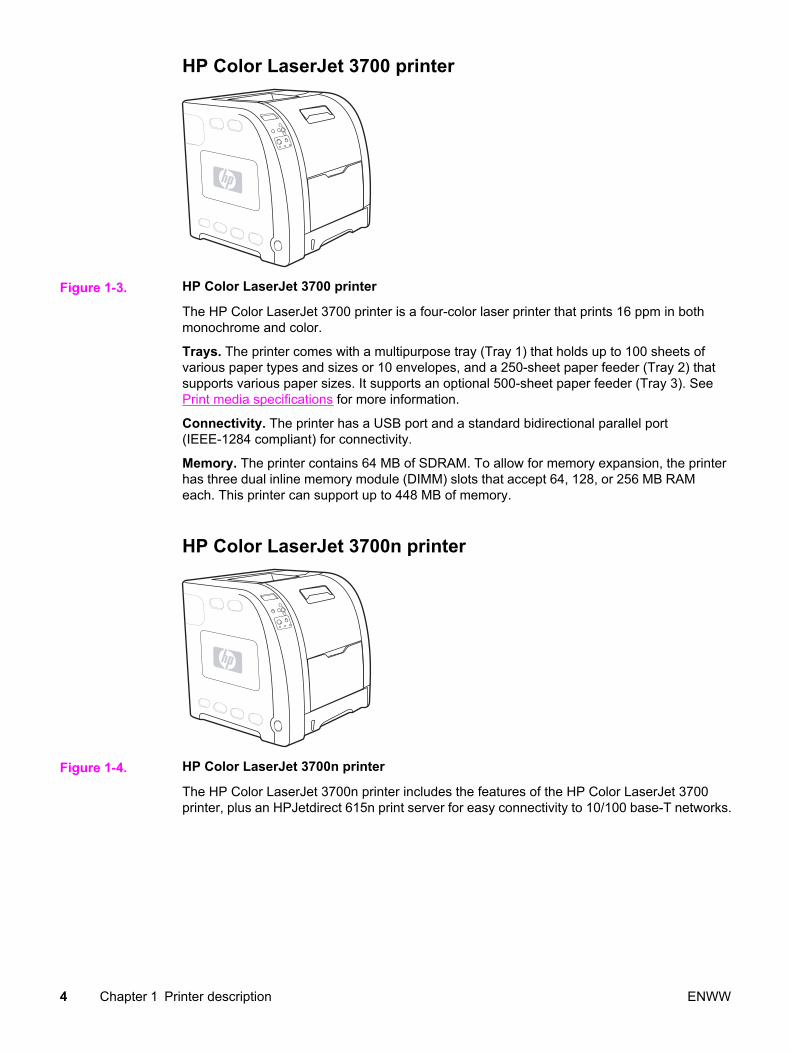
HP Color LaserJet 3700 printer
Figure 1-3. HP Color LaserJet 3700 printer
The HP Color LaserJet 3700 printer is a four-color laser printer that prints 16 ppm in bothmonochrome and color.
Trays. The printer comes with a multipurpose tray (Tray 1) that holds up to 100 sheets ofvarious paper types and sizes or 10 envelopes, and a 250-sheet paper feeder (Tray 2) thatsupports various paper sizes. It supports an optional 500-sheet paper feeder (Tray 3). SeePrint media specifications for more information.
Connectivity. The printer has a USB port and a standard bidirectional parallel port(IEEE-1284 compliant) for connectivity.
Memory. The printer contains 64 MB of SDRAM. To allow for memory expansion, the printerhas three dual inline memory module (DIMM) slots that accept 64, 128, or 256 MB RAMeach. This printer can support up to 448 MB of memory.
HP Color LaserJet 3700n printer
Figure 1-4. HP Color LaserJet 3700n printer
The HP Color LaserJet 3700n printer includes the features of the HP Color LaserJet 3700printer, plus an HPJetdirect 615n print server for easy connectivity to 10/100 base-T networks.
4 Chapter 1 Printer description ENWW
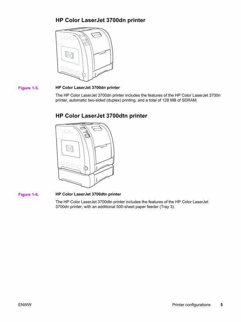
HP Color LaserJet 3700dn printer
Figure 1-5. HP Color LaserJet 3700dn printer
The HP Color LaserJet 3700dn printer includes the features of the HP Color LaserJet 3700nprinter, automatic two-sided (duplex) printing, and a total of 128 MB of SDRAM.
HP Color LaserJet 3700dtn printer
Figure 1-6. HP Color LaserJet 3700dtn printer
The HP Color LaserJet 3700dtn printer includes the features of the HP Color LaserJet3700dn printer, with an additional 500-sheet paper feeder (Tray 3).
ENWW Printer configurations 5
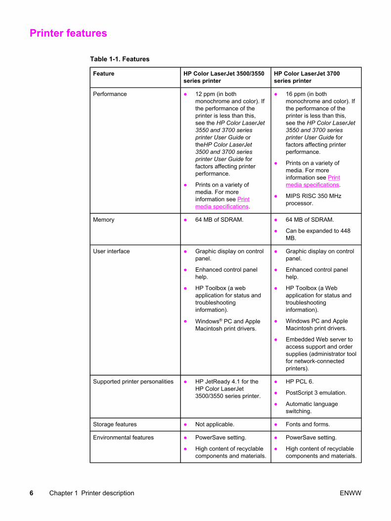
Printer features
Table 1-1. Features
Feature HP Color LaserJet 3500/3550series printer
HP Color LaserJet 3700series printer
Performance ● 12 ppm (in bothmonochrome and color). Ifthe performance of theprinter is less than this,see the HP Color LaserJet3550 and 3700 seriesprinter User Guide ortheHP Color LaserJet3500 and 3700 seriesprinter User Guide forfactors affecting printerperformance.
● Prints on a variety ofmedia. For moreinformation see Printmedia specifications.
● 16 ppm (in bothmonochrome and color). Ifthe performance of theprinter is less than this,see the HP Color LaserJet3550 and 3700 seriesprinter User Guide forfactors affecting printerperformance.
● Prints on a variety ofmedia. For moreinformation see Printmedia specifications.
● MIPS RISC 350 MHzprocessor.
Memory ● 64 MB of SDRAM. ● 64 MB of SDRAM.
● Can be expanded to 448MB.
User interface ● Graphic display on controlpanel.
● Enhanced control panelhelp.
● HP Toolbox (a webapplication for status andtroubleshootinginformation).
● Windows® PC and AppleMacintosh print drivers.
● Graphic display on controlpanel.
● Enhanced control panelhelp.
● HP Toolbox (a Webapplication for status andtroubleshootinginformation).
● Windows PC and AppleMacintosh print drivers.
● Embedded Web server toaccess support and ordersupplies (administrator toolfor network-connectedprinters).
Supported printer personalities ● HP JetReady 4.1 for theHP Color LaserJet3500/3550 series printer.
● HP PCL 6.
● PostScript 3 emulation.
● Automatic languageswitching.
Storage features ● Not applicable. ● Fonts and forms.
Environmental features ● PowerSave setting.
● High content of recyclablecomponents and materials.
● PowerSave setting.
● High content of recyclablecomponents and materials.
6 Chapter 1 Printer description ENWW

Feature HP Color LaserJet 3500/3550series printer
HP Color LaserJet 3700series printer
Fonts ● Not applicable. ● 80 internal fonts availablefor both PCL andPostScript emulation.
● 80 printer-matching screenfonts in TrueTypeTM formatavailable with the softwaresolution.
Paper handling ● Prints on paper from 76 x127 mm (3 x 5 inches) upto 215 x 355 mm (8.5 x14 inches).
● Prints on paper withweights from 60 g/m2 to163 g/m2 (16 to 43 lb bond).
● Prints on a wide range ofmedia types includingglossy, heavy, labels, film,overhead transparencies,and envelopes.
● Multiple gloss levels.
● A 250-sheet paper feeder(Tray 2) that supportsletter, legal, executive,executive (JIS), A4, A5, B5(JIS), B5 (ISO), and 216 x330 mm (8.5 x 13 inches)paper sizes.
● Optional 500-sheet paperfeeder that supports letterand A4 paper sizes(Tray 3). For moreinformation see Printmedia specifications.
● A 150-sheet, face-down,output bin (top) and a 25-sheet, face-up, output bin(rear).
● Prints on paper from 76 x127 mm (3 x 5 inches) upto 215 x 355 mm (8.5 x14 inches).
● Prints on paper withweights from 60 g/m2 to163 g/m2 (16 to 43 lb bond).
● Prints on a wide range ofmedia types includingglossy, heavy, labels, film,overhead transparencies,and envelopes.
● Multiple gloss levels.
● A 250-sheet paper feeder(Tray 2) that supportsletter, legal, executive,executive (JIS), A4, A5, B5(JIS), B5 (ISO), and 216 x330 mm (8.5 x 13 inches)paper sizes.
● Optional 500-sheet paperfeeder that supports letterand A4 paper sizes;standard on the HP ColorLaserJet 3700dtn printer(Tray 3). For moreinformation see Printmedia specifications.
● A 150-sheet, face-down,output bin (top) and a 25-sheet, face-up, output bin(rear).
● Automatic two-sidedprinting on HP ColorLaserJet 3700dn and3700dtn printers.
Accessories ● Optional 500-sheet paperfeeder that supports letterand A4 paper sizes(Tray 3).
● Optional 500-sheet paperfeeder (Tray 3) thatsupports letter and A4paper sizes; standard onthe HP Color LaserJet3700dtn printer (Tray 3).
● DIMM.
● Optional flash DIMM.
Table 1-1. Features (continued)
ENWW Printer features 7
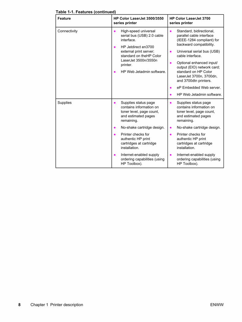
Feature HP Color LaserJet 3500/3550series printer
HP Color LaserJet 3700series printer
Connectivity ● High-speed universalserial bus (USB) 2.0 cableinterface.
● HP Jetdirect en3700external print server;standard on theHP ColorLaserJet 3500n/3550nprinter.
● HP Web Jetadmin software.
● Standard, bidirectional,parallel cable interface(IEEE-1284 compliant) forbackward compatibility.
● Universal serial bus (USB)cable interface.
● Optional enhanced input/output (EIO) network card;standard on HP ColorLaserJet 3700n, 3700dn,and 3700dtn printers.
● eP Embedded Web server.
● HP Web Jetadmin software.
Supplies ● Supplies status pagecontains information ontoner level, page count,and estimated pagesremaining.
● No-shake cartridge design.
● Printer checks forauthentic HP printcartridges at cartridgeinstallation.
● Internet-enabled supplyordering capabilities (usingHP Toolbox).
● Supplies status pagecontains information ontoner level, page count,and estimated pagesremaining.
● No-shake cartridge design.
● Printer checks forauthentic HP printcartridges at cartridgeinstallation.
● Internet-enabled supplyordering capabilities (usingHP Toolbox).
Table 1-1. Features (continued)
8 Chapter 1 Printer description ENWW
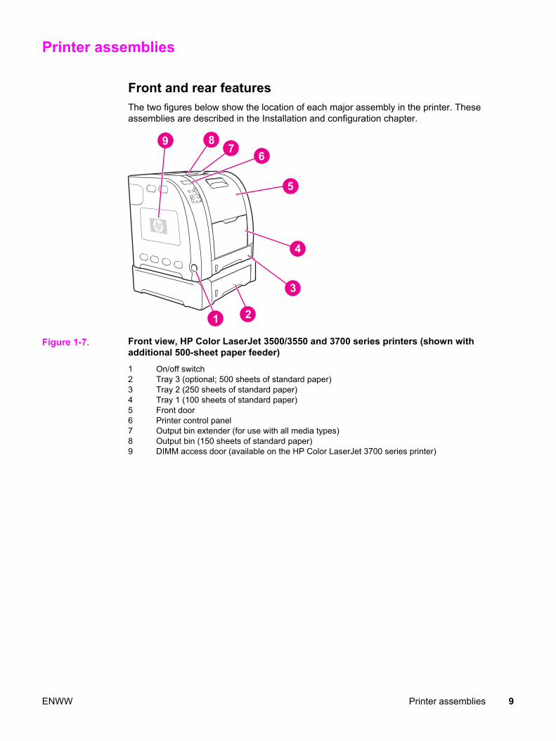
Printer assemblies
Front and rear featuresThe two figures below show the location of each major assembly in the printer. Theseassemblies are described in the Installation and configuration chapter.
Figure 1-7. Front view, HP Color LaserJet 3500/3550 and 3700 series printers (shown withadditional 500-sheet paper feeder)1 On/off switch 2 Tray 3 (optional; 500 sheets of standard paper)3 Tray 2 (250 sheets of standard paper)4 Tray 1 (100 sheets of standard paper)5 Front door6 Printer control panel7 Output bin extender (for use with all media types)8 Output bin (150 sheets of standard paper)9 DIMM access door (available on the HP Color LaserJet 3700 series printer)
ENWW Printer assemblies 9

Figure 1-8. Rear view, HP Color LaserJet 3500/3550 and 3700 series printers (shown withadditional 500-sheet paper feeder)1 Upper rear door2 Parallel connection (available on the HP Color LaserJet 3700 series printer)3 Lower rear door (rear output bin) (25 sheets of standard paper)4 USB connection5 Power connection6 Tray 3 (optional)7 On/off switch8 EIO connection (available on the HP Color LaserJet 3700 series printer)9 DIMM access door (available on the HP Color LaserJet 3700 series printer)
10 Chapter 1 Printer description ENWW

Site requirements
The printer must be kept in a proper location to maintain the performance level that hasbeen set at the factory. In particular, be sure that the environment adheres to thespecifications listed in this chapter.
Below are recommendations for the printer location and placement.
Make sure the printer has the following:
● a well-ventilated, dust-free area
● a hard, level surface (not more than a 2° angle) that can support approximately 43.4 kg(95.5 lbs)
● a level surface that supports all four corners of the 500-sheet paper feeder
● constant temperature and humidity. (Do not install near water sources, humidifiers, airconditioners, refrigerators, or other major appliances.)
Make sure to keep the printer away from the following:
● direct sunlight, dust, open flames, or water
● direct flow of exhaust from air ventilation systems
● magnets and devices that emit a magnetic field
● areas subject to vibration
● walls or other objects (There must be enough space around the printer for proper accessand ventilation. See the figures Figure 1-9. Space requirements for the HP ColorLaserJet 3500/3550 series printer and Figure 1-10. Space requirements for the HP ColorLaserJet 3700 series printer with optional Tray 3, on the following pages.)
Space requirementsThe printer must have the following amounts of space above and around it.
Figure 1-9. Space requirements for the HP Color LaserJet 3500/3550 series printer
1 Height: 722 mm (28.4 in.)2 Depth: 1480 mm (58.3 in.)3 Width: 699.5 mm (27.6 in.)
ENWW Site requirements 11
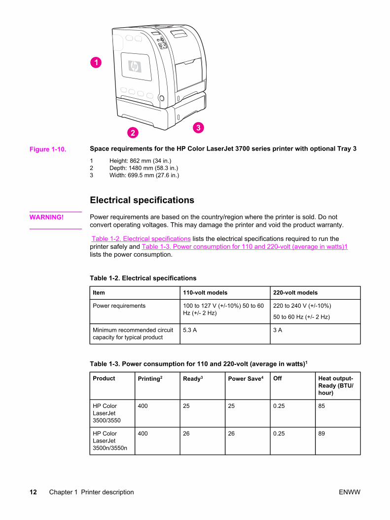
Figure 1-10. Space requirements for the HP Color LaserJet 3700 series printer with optional Tray 3
1 Height: 862 mm (34 in.)2 Depth: 1480 mm (58.3 in.)3 Width: 699.5 mm (27.6 in.)
Electrical specifications
WARNING! Power requirements are based on the country/region where the printer is sold. Do notconvert operating voltages. This may damage the printer and void the product warranty.
Table 1-2. Electrical specifications lists the electrical specifications required to run theprinter safely and Table 1-3. Power consumption for 110 and 220-volt (average in watts)1lists the power consumption.
Table 1-2. Electrical specifications
Item 110-volt models 220-volt models
Power requirements 100 to 127 V (+/-10%) 50 to 60Hz (+/- 2 Hz)
220 to 240 V (+/-10%)
50 to 60 Hz (+/- 2 Hz)
Minimum recommended circuitcapacity for typical product
5.3 A 3 A
Table 1-3. Power consumption for 110 and 220-volt (average in watts)1
Product Printing2 Ready3 Power Save4 Off Heat output-Ready (BTU/hour)
HP ColorLaserJet3500/3550
400 25 25 0.25 85
HP ColorLaserJet3500n/3550n
400 26 26 0.25 89
12 Chapter 1 Printer description ENWW
Product Printing2 Ready3 Power Save4 Off Heat output-Ready (BTU/hour)
HP ColorLaserJet 3700
400 25 25 0.25 85
HP ColorLaserJet3700n
400 26 26 0.25 89
HP ColorLaserJet3700dn
400 26 26 0.25 89
HP ColorLaserJet3700dtn
400 26 26 0.25 89
1The power consumptions reported are the highest values measured for color andmonochrome printing using standard voltages.2The printing speed is 16 ppm for letter-size media and 16 ppm for A4-size media.3The default activation time from Ready mode to PowerSave is 30 minutes.4The recovery time from PowerSave to the start of printing is 12 minutes.
NOTE These values are subject to change. For current information, see http://www.hp.com/support/clj3500 for the HP Color LaserJet 3500 series printer, http://www.hp.com/support/clj3550 forthe HP Color LaserJet 3550 series printer, or http://www.hp.com/support/clj3700 for theHP Color LaserJet 3700 series printer.
Environmental specificationsKeep the printer within the environmental conditions shown in Table 1-4. Environmentalspecifications for optimum performance.
Table 1-4. Environmental specifications
Environment Recommended Allowed
Temperature 17° to 25°C (62.6° to 77°F) 10° to 27°C (50° to 81°F)
Humidity 20% to 60% RH 10% to 70% RH
Altitude Not applicable 0 to 2600 m (0 to 8530 ft)
Supply storage requirementsThe life of supplies is greatly affected by their storage environment. Use Supply storagerequirements to determine the shelf life of stored supplies.
Table 1-5. Supply storage requirements
Item Storage time Storage condition
Temperature Normal (maximum of 2.5 years) 0° to 35° C (32° to 95° F)
Table 1-3. Power consumption for 110 and 220-volt (average in watts)1 (continued)
ENWW Site requirements 13

Severe (maximum of 18 days)
Severe (maximum of 18 days)
High: 35° to 40° C (95° to 104°F)
Low: 0° to -20° C (32° to -4° F)
Maximum temperature changerate
40° to 15° C (104° to 59° F)within 3 minutes
-20° to 25° C (-4° to 77° F)within 3 minutes
Humidity Normal (maximum of 2.5 years) 35% to 85% RH
Severe (maximum of 18 days) High: 85% to 95% RH
Low: 10% to 35% RH
Atmospheric pressure 460 to 760 mm Hg (18.1 to29.9 in Hg)
Storage time1 2.5 years1The average storage time includes use time. Use cartridges within 2.5 years of the datecode on the cartridge.
Table 1-5. Supply storage requirements (continued)
14 Chapter 1 Printer description ENWW

Printer specifications
Table 1-6. Physical dimensions
Product Height Depth Width Weight
HP ColorLaserJet3500/3550 serieswith printcartridges
467 mm(18.4 in)
447 mm(17.6 in)
499.5 mm(19.67 in)
36.6 kg(80.52 lbs)
HP ColorLaserJet3500/3550 seriesprinter with printcartridges andoptional Tray 3
603 mm(23.8 in)
447 mm(17.6 in)
499.5 mm(19.67 in)
42 kg(92.4 lbs)
HP ColorLaserJet 3700series printer withprint cartridges
467 mm(18.4 in)
447 mm(17.6 in)
499.5 mm(19.67 in)
37.8 kg(83.16 lbs)
HP ColorLaserJet 3700series printer withprint cartridgesand optionalTray 3
603 mm(23.8 in)
447 mm(17.6 in)
499.5 mm(19.67 in)
43.4 kg(95.48 lbs)
HP Jetdirecten3700 externalprint server
35 mm(1.4 in)
131 mm(5.2 in)
102 mm(4 in)
0.159 kg(0.35 lbs)
Table 1-7. Acoustic emissions
Activity level Operator (<1m) Bystander (1m) Sound power
Active LpAm64 dB (A) LpAm49 dB (A) LWAd6.4 Bels (A)
Idle LpAm55 dB (A) LpAm40 dB (A) LWAd5.6 Bels (A)
Powersave LpAmN/A dB (A) LpAmN/A dB (A) LWAdN/A Bels (A)
NOTE These values are subject to change. For current information, see http://www.hp.com/support/clj3500 for the HP Color LaserJet 3500 series printer, http://www.hp.com/support/clj3550 forthe HP Color LaserJet 3550 series printer, or http://www.hp.com/support/clj3700 for theHP Color LaserJet 3700 series printer.
Duty cycleThe HP Color LaserJet 3500 series printer maximum duty cycle is 45,000 pages per month.Maximum duty cycle for the HP Color LaserJet 3550 series printer and HP Color LaserJet3700 series printer is 55,000 pages per month.
ENWW Printer specifications 15
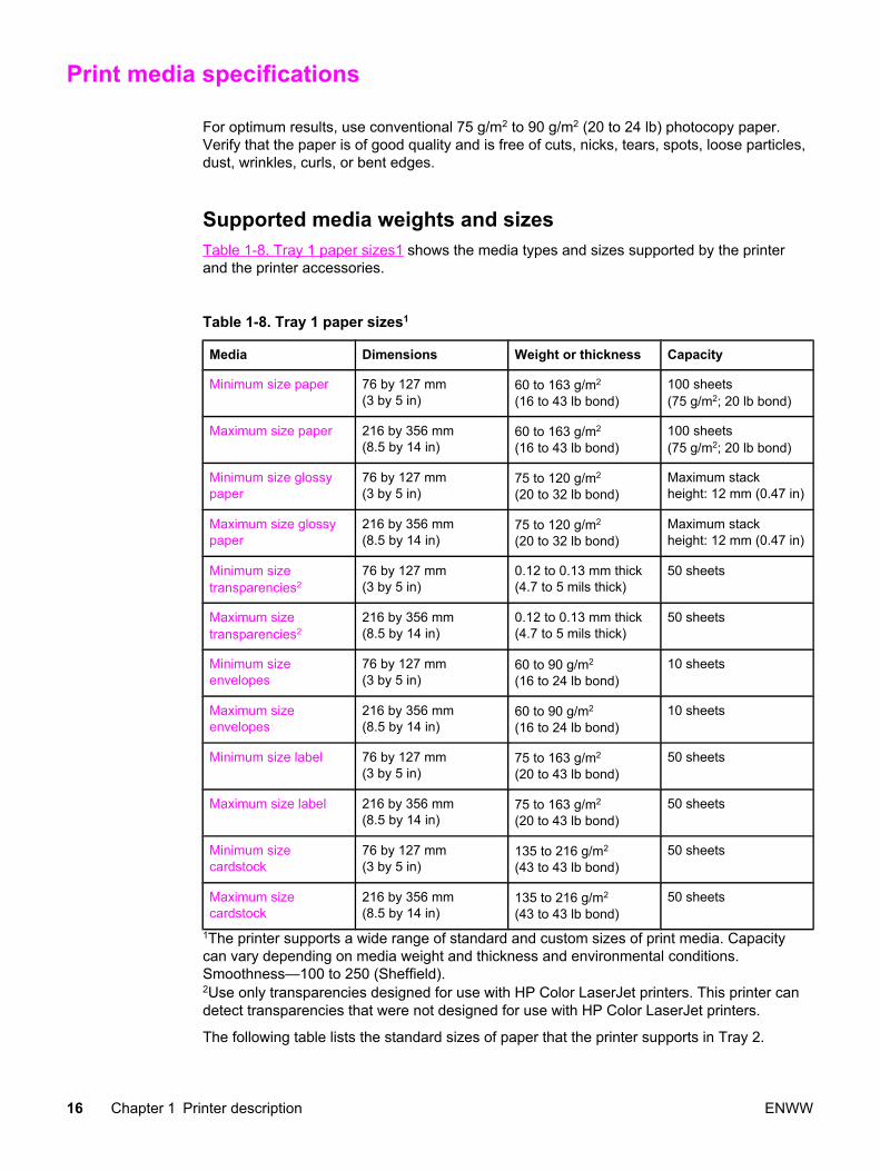
Print media specifications
For optimum results, use conventional 75 g/m2 to 90 g/m2 (20 to 24 lb) photocopy paper.Verify that the paper is of good quality and is free of cuts, nicks, tears, spots, loose particles,dust, wrinkles, curls, or bent edges.
Supported media weights and sizesTable 1-8. Tray 1 paper sizes1 shows the media types and sizes supported by the printerand the printer accessories.
Table 1-8. Tray 1 paper sizes1
Media Dimensions Weight or thickness Capacity
Minimum size paper 76 by 127 mm(3 by 5 in)
60 to 163 g/m2
(16 to 43 lb bond)100 sheets(75 g/m2; 20 lb bond)
Maximum size paper 216 by 356 mm(8.5 by 14 in)
60 to 163 g/m2
(16 to 43 lb bond)100 sheets(75 g/m2; 20 lb bond)
Minimum size glossypaper
76 by 127 mm(3 by 5 in)
75 to 120 g/m2
(20 to 32 lb bond)Maximum stackheight: 12 mm (0.47 in)
Maximum size glossypaper
216 by 356 mm(8.5 by 14 in)
75 to 120 g/m2
(20 to 32 lb bond)Maximum stackheight: 12 mm (0.47 in)
Minimum sizetransparencies2
76 by 127 mm(3 by 5 in)
0.12 to 0.13 mm thick(4.7 to 5 mils thick)
50 sheets
Maximum sizetransparencies2
216 by 356 mm(8.5 by 14 in)
0.12 to 0.13 mm thick(4.7 to 5 mils thick)
50 sheets
Minimum sizeenvelopes
76 by 127 mm(3 by 5 in)
60 to 90 g/m2
(16 to 24 lb bond)10 sheets
Maximum sizeenvelopes
216 by 356 mm(8.5 by 14 in)
60 to 90 g/m2
(16 to 24 lb bond)10 sheets
Minimum size label 76 by 127 mm(3 by 5 in)
75 to 163 g/m2
(20 to 43 lb bond)50 sheets
Maximum size label 216 by 356 mm(8.5 by 14 in)
75 to 163 g/m2
(20 to 43 lb bond)50 sheets
Minimum sizecardstock
76 by 127 mm(3 by 5 in)
135 to 216 g/m2
(43 to 43 lb bond)50 sheets
Maximum sizecardstock
216 by 356 mm(8.5 by 14 in)
135 to 216 g/m2
(43 to 43 lb bond)50 sheets
1The printer supports a wide range of standard and custom sizes of print media. Capacitycan vary depending on media weight and thickness and environmental conditions.Smoothness—100 to 250 (Sheffield).2Use only transparencies designed for use with HP Color LaserJet printers. This printer candetect transparencies that were not designed for use with HP Color LaserJet printers.
The following table lists the standard sizes of paper that the printer supports in Tray 2.
16 Chapter 1 Printer description ENWW

Table 1-9. Tray 2 paper sizes1
Media Dimensions Weight or thickness Capacity
Letter 216 by 279 mm(8.5 by 11 in)
60 to 105 g/m2
(16 to 28 lb bond)250 sheets(75 g/m2; 20 lb bond)
Legal 216 by 356 mm(8.5 by 14 in)
60 to 105 g/m2
(16 to 28 lb bond)250 sheets(75 g/m2; 20 lb bond)
Executive 184 by 267 mm(7.3 by 10.5 in)
60 to 105 g/m2
(16 to 28 lb bond)250 sheets(75 g/m2; 20 lb bond)
Executive (JIS) 216 by 330 mm(8.5 by 13 in)
60 to 105 g/m2
(16 to 28 lb bond)250 sheets(75 g/m2; 20 lb bond)
A4 210 by 297 mm(8.3 by 11.7 in)
60 to 105 g/m2
(16 to 28 lb bond)250 sheets(75 g/m2; 20 lb bond)
A5 148 by 210 mm(5.8 by 8.3 in)
60 to 105 g/m2
(16 to 28 lb bond)250 sheets(75 g/m2; 20 lb bond)
B5 (JIS) 182 by 257 mm(7.2 by 10.1 in)
60 to 105 g/m2
(16 to 28 lb bond)250 sheets(75 g/m2; 20 lb bond)
B5 (ISO) 176 by 250 mm(6.9 by 9.8 in)
60 to 105 g/m2
(16 to 28 lb bond)250 sheets(75 g/m2; 20 lb bond)
1Capacity can vary depending on media weight and thickness, and environmental conditions.
The following table lists the standard sizes of paper that the printer supports in Tray 3.
Table 1-10. Tray 3 paper sizes1
Media Dimensions Weight or thickness Capacity
Letter 216 by 279 mm(8.5 by 11 in)
60 to 105 g/m2
(16 to 28 lb bond)500 sheets(75 g/m2; 20 lb bond)
A4 210 by 297 mm(8.3 by 11.7 in)
60 to 105 g/m2
(16 to 28 lb bond)500 sheets(75 g/m2; 20 lb bond)
1Capacity can vary depending on media weight and thickness, and environmental conditions.
Table 1-11. Automatic two-sided printer (available on some models of the HP ColorLaserJet 3700 series printer)1
Media Dimensions Weight or thickness Capacity
Letter 216 by 279 mm(8.5 by 11 in)
60 to 105 g/m2
(16 to 28 lb bond)unlimited sheets sheets
Legal 216 by 356 mm(8.5 by 14 in)
60 to 105 g/m2
(16 to 28 lb bond)unlimited sheets sheets
A4 210 by 297 mm(8.3 by 11.7 in)
60 to 105 g/m2
(16 to 28 lb bond)unlimited sheets sheets
1The printer automatically prints on paper weights up to 163 gm2 (43 lb bond). However,automatic two-sided printing on weights above the maximum value noted in this table canproduce unexpected results.
ENWW Print media specifications 17

Manual two-sided printing. Any of the supported paper sizes and types listed for printingfrom Tray 1 can be manually duplexed. See the two-sided (duplex) printing section in theHP Color LaserJet 3550 and 3700 series printer User Guide for more information.
18 Chapter 1 Printer description ENWW

Hewlett-Packard warranty statement
HP PRODUCTHP Color LaserJet 3500, 3500n, 3550, 3550n, 3700,3700n, 3700dn, and 3700dtn printers
DURATION OF LIMITED WARRANTYOne-year limited warranty
HP warrants to you, the end-user customer, that HP hardware and accessories will be free from defects inmaterials and workmanship after the date of purchase, for the period specified above. If HP receives notice ofsuch defects during the warranty period, HP will, at its option, either repair or replace products which prove to bedefective. Replacement products may be either new or equivalent in performance to new.
HP warrants to you that HP software will not fail to execute its programming instructions after the date ofpurchase, for the period specified above, due to defects in material and workmanship when properly installed andused. If HP receives notice of such defects during the warranty period, HP will replace software which does notexecute its programming instructions due to such defects.
HP does not warrant that the operation of HP products will be uninterrupted or error free. If HP is unable, within areasonable time, to repair or replace any product to a condition as warranted, you will be entitled to a refund ofthe purchase price upon prompt return of the product.
HP products may contain remanufactured parts equivalent to new in performance or may have been subject toincidental use.
Warranty does not apply to defects resulting from (a) improper or inadequate maintenance or calibration, (b)software, interfacing, parts or supplies not supplied by HP, (c) unauthorized modification or misuse, (d) operationoutside of the published environmental specifications for the product, or (e) improper site preparation ormaintenance.
TO THE EXTENT ALLOWED BY LOCAL LAW, THE ABOVE WARRANTIES ARE EXCLUSIVE AND NO OTHERWARRANTY OR CONDITION, WHETHER WRITTEN OR ORAL, IS EXPRESSED OR IMPLIED ANDHP SPECIFICALLY DISCLAIMS ANY IMPLIED WARRANTIES OR CONDITIONS OF MERCHANTABILITY,SATISFACTORY QUALITY, AND FITNESS FOR A PARTICULAR PURPOSE. Some countries/regions, states orprovinces do not allow limitations on the duration of an implied warranty, so the above limitation or exclusionmight not apply to you. This warranty gives you specific legal rights and you might also have other rights that varyfrom country/region to country/region, state to state, or province to province. HP’s limited warranty is valid in anycountry/region or locality where HP has a support presence for this product and where HP has marketed thisproduct. The level of warranty service you receive may vary according to local standards. HP will not alter form, fitor function of the product to make it operate in a country/region for which it was never intended to function forlegal or regulatory reasons.
TO THE EXTENT ALLOWED BY LOCAL LAW, THE REMEDIES IN THIS WARRANTY STATEMENT AREYOUR SOLE AND EXCLUSIVE REMEDIES. EXCEPT AS INDICATED ABOVE, IN NO EVENT WILL HP OR ITSSUPPLIERS BE LIABLE FOR LOSS OF DATA OR FOR DIRECT, SPECIAL, INCIDENTAL, CONSEQUENTIAL(INCLUDING LOST PROFIT OR DATA), OR OTHER DAMAGE, WHETHER BASED IN CONTRACT, TORT, OROTHERWISE. Some countries/regions, states or provinces do not allow the exclusion or limitation of incidental orconsequential damages, so the above limitation or exclusion may not apply to you.
THE WARRANTY TERMS CONTAINED IN THIS STATEMENT, EXCEPT TO THE EXTENT LAWFULLYPERMITTED, DO NOT EXCLUDE, RESTRICT OR MODIFY AND ARE IN ADDITION TO THE MANDATORYSTATUTORY RIGHTS APPLICABLE TO THE SALE OF THIS PRODUCT TO YOU.
ENWW Hewlett-Packard warranty statement 19

HP's Premium Protection Print Cartridge Warranty LimitedWarranty Statement
This HP Print Cartridge is warranted to be free from defects in materials and workmanship.
This warranty does not apply to print cartridges that (a) have been refilled, refurbished,remanufactured or tampered with in any way, (b) experience problems resulting frommisuse, improper storage, or operation outside of the published environmental specificationsfor the printer product or (c) exhibit wear from ordinary use.
To obtain warranty service, please return the product to place of purchase (with a writtendescription of the problem and print samples) or contact HP customer support. At HP'soption, HP will either replace products that prove to be defective or refund your purchaseprice.
TO THE EXTENT ALLOWED BY LOCAL LAW, THE ABOVE WARRANT Y IS EXCLUSIVEAND NO OTHER WARRANTY OR CONDITION, WHETHER WRITTEN OR ORAL, ISEXPRESSED OR IMPLIED AND HP SPECIFICALLY DISCLAIMS ANY IMPLIEDWARRANTIES OR CONDITIONS OF MERCHANTABILITY, SATISFACTORY QUALITY,AND FITNESS FOR A PARTICULAR PURPOSE.
TO THE EXTENT ALLOWED BY LOCAL LAW, IN NO EVENT WILL HP OR ITSSUPPLIERS BE LIABLE FOR DIRECT, SPECIAL, INCIDENTAL, CONSEQUENTIAL(INCLUDING LOST PROFIT OR DATA), OR OTHER DAMAGE, WHETHER BASED INCONTRACT, TORT, OR OTHERWISE
THE WARRANTY TERMS CONTAINED IN THIS STATEMENT, EXCEPT TO THE EXTENTLAWFULLY PERMITTED, DO NOT EXCLUDE, RESTRICT OR MODIFY AND ARE INADDITION TO THE MANDATORY STATUTORY RIGHTS APPLICABLE TO THE SALE OFTHIS PRODUCT TO YOU.
20 Chapter 1 Printer description ENWW

Premium Protection Warranty Color LaserJet Image Fuser Kit andImage Transfer Kit Limited Warranty Statement
This HP product is warranted to be free from defects in materials and workmanship until theprinter provides a low-life indicator on the control panel.
This warranty does not apply to products that (a) have been refurbished, remanufactured ortampered with in any way, (b) experience problems resulting from misuse, improper storage,or operation outside of the published environmental specifications for the printer product or(c) exhibit wear from ordinary use.
To obtain warranty service, please return the product to place of purchase (with a writtendescription of the problem) or contact HP customer support. At HP's option, HP will eitherreplace products that prove to be defective or refund your purchase price.
TO THE EXTENT ALLOWED BY LOCAL LAW, THE ABOVE WARRANTY IS EXCLUSIVEAND NO OTHER WARRANTY OR CONDITION, WHETHER WRITTEN OR ORAL, ISEXPRESSED OR IMPLIED AND HP SPECIFICALLY DISCLAIMS ANY IMPLIEDWARRANTIES OR CONDITIONS OF MERCHANTABILITY, SATISFACTORY QUALITY,AND FITNESS FOR A PARTICULAR PURPOSE.
TO THE EXTENT ALLOWED BY LOCAL LAW, IN NO EVENT WILL HP OR ITSSUPPLIERS BE LIABLE FOR DIRECT, SPECIAL, INCIDENTAL, CONSEQUENTIAL(INCLUDING LOST PROFIT OR DATA), OR OTHER DAMAGE, WHETHER BASED INCONTRACT, TORT, OR OTHERWISE
THE WARRANTY TERMS CONTAINED IN THIS STATEMENT, EXCEPT TO THE EXTENTLAWFULLY PERMITTED, DO NOT EXCLUDE, RESTRICT OR MODIFY AND ARE INADDITION TO THE MANDATORY STATUTORY RIGHTS APPLICABLE TO THE SALE OFTHIS PRODUCT TO YOU.
ENWWPremium Protection Warranty Color LaserJet Image Fuser Kit and Image Transfer Kit
Limited Warranty Statement 21

Identification
HP's Product Stewardship program monitors product design to help protect the environment.
Model and serial numbersThe model number and serial numbers are listed on identification labels located on the rearof the printer. The model number is alphanumeric, such as Q5990A for the HP ColorLaserJet 3550 printer. The serial number contains information about the country/region oforigin, the printer version, production code, and the production number of the printer (seeFigure 1-11. Serial number information).
Figure 1-11. Serial number information
Table 1-12. Model names and numbers
Model name Model number
HP Color LaserJet 3500 Q1319A
HP Color LaserJet 3500n Q1320A
HP Color LaserJet 3550 Q5990A
HP Color LaserJet 3550n Q5991A
HP Color LaserJet 3700 Q1321A
HP Color LaserJet 3700n Q1322A
HP Color LaserJet 3700dn Q1323A
HP Color LaserJet 3700dtn Q1324A
Power and regulatory informationThe identification label on the rear of the printer also contains power rating and regulatoryinformation as shown in Figure 1-12. Sample label.
22 Chapter 1 Printer description ENWW

CAUTION Converting the voltage on the printer can damage the printer. Do not use any voltage otherthan the operating voltage. Any attempt to convert operating voltages will void the productwarranty (for example, attempting to change a 110V printer to a 220V printer).
Figure 1-12. Sample label
ENWW Identification 23

Selecting paper
You can use many types of paper and other print media with this printer. This sectionprovides guidelines and specifications for selecting and using different print media.
Before purchasing any paper or specialized forms in quantity, verify that your paper supplierobtains and understands the print media requirements specified in the HP LaserJet PrinterFamily Print Media Specification Guide.
See the HP Color LaserJet 3550 and 3700 series printer User Guide or HP LaserJet PrinterFamily Print Media Specification Guide for ordering information. To download a copy of theHP LaserJet Printer Family Print Media Specification Guide go to http://www.hp.com/support/clj3500 for the HP Color LaserJet 3500 series, to http://www.hp.com/support/clj3500 for theHP Color LaserJet 3550 series and to http://www.hp.com/support/clj3700 for the HP ColorLaserJet 3700 series, and then select manuals.
It is possible that paper could meet all of the guidelines in this chapter or the HP LaserJetPrinter Family Print Media Specification Guide and still not print satisfactorily. This may bedue to abnormal characteristics of the printing environment or to other variables over whichHewlett-Packard has no control (for example, extremes in temperature and humidity).
Hewlett-Packard recommends testing any paper before buying it in large quantities.
CAUTION Using paper that does not conform to the specifications listed here or in the print mediaguide can cause problems that require service. This service is not covered by the Hewlett-Packard warranty or service agreements.
Paper to avoidThe printer can handle many types of paper. Use of paper outside the printer specificationswill cause a loss of print quality and will increase the chance of paper jams.
● Do not use paper that is too rough.
● Do not use paper with cutouts or perforations, other than standard 3-hole punched paper.
● Do not use multipart forms.
● Do not use paper that has already been printed on, or that has been fed through aphotocopier.
● Do not use paper with a watermark if you are printing solid patterns.
Paper that can damage the printerIn rare circumstances, paper can damage the printer. The following paper must be avoidedto prevent possible damage to the printer:
● Do not use paper with staples attached.
● Do not use transparencies designed for Inkjet printers or other low-temperature printers,or transparencies designed for monochrome printing. Use only transparencies that arespecified for use with HP Color LaserJet printers.
● Do not use photo paper intended for Inkjet printers.
24 Chapter 1 Printer description ENWW

● Do not use paper that is embossed or coated, and that is not designed for thetemperatures of the HP Color LaserJet 3500/3550 and 3700 series printer image fusers.Select paper that can tolerate temperatures of 190°C (374°F) for 0.1 second.HP produces a selection of paper that is designed for the HP Color LaserJet 3500/3550and 3700 series printer.
● Do not use letterhead paper with low-temperature dyes or thermography. Preprintedforms or letterhead must use inks that can tolerate temperatures of 190°C (374°F) for0.1 second.
● Do not use any media that produces hazardous emissions, or that melts, offsets, ordiscolors when exposed to 190°C (374°F) for 0.1 second.
ENWW Selecting paper 25

Printing on special media
Use these guidelines when printing on special types of media.
TransparenciesWhen printing on transparencies, use the following guidelines:
● Handle transparencies using the edges. Oils from your fingers deposited on thetransparency can cause print quality problems.
● Use only overhead transparencies recommended for use in this printer. Hewlett-Packardrecommends using HP Color LaserJet Transparencies with this printer. HP products aredesigned to work together for optimum printing results.
● In either the software application or the printer driver, select TRANSPARENCY as themedia type, or print from a tray that is configured for transparencies.
CAUTION Transparencies not designed for LaserJet printing will melt in the printer, causing damage tothe printer. Do not use transparencies designed for monochrome printing.
Glossy paperWhen printing on glossy paper, use the following guidelines:
● In either the software application or the driver, select Glossy as the media type, or printfrom a tray that is configured for glossy paper.
Select Glossy for media weights up to 105 g/m2 (28 lb bond). Select Heavy Glossy formedia weights up to 120 g/m2 (32 lb bond).
● Because these settings will affect all print jobs, it is important to return the printer to itsoriginal settings once the job has printed.
NOTE Hewlett-Packard recommends using HP Color LaserJet Soft Gloss paper with this printer.HP products are designed to work together for optimum printing results. If HP Color LaserJetSoft Gloss paper is not used with this printer, print quality may be compromised.
Colored paperWhen printing on colored paper, use the following guidelines:
● Colored paper should be of the same high quality as white xerographic paper.
● Pigments used must be able to withstand the printer fusing temperature of 190°C (374°F) for 0.1 second without deterioration.
● Do not use paper with a colored coating that was added after the paper was produced.
● The printer creates colors by printing patterns of dots, overlaying and varying theirspacing to produce various colors. Varying the shade or color of the paper will affect theshades of the printed colors.
26 Chapter 1 Printer description ENWW
Envelopes
NOTE Envelopes can be printed only from Tray 1. Set the tray media size to the specific envelopesize.
Adhere to the following guidelines to help ensure proper printing on envelopes and to helpprevent printer jams:
● Do not load more than ten envelopes into Tray 1.
● The weight rating of envelopes should not exceed 90 g/m2 (24 lb bond).
● Envelopes should be flat.
● Do not use envelopes with windows or clasps.
● Envelopes must not be wrinkled, nicked, or otherwise damaged.
● Envelopes with peel-off adhesive strips must use adhesives that can withstand the heatand pressures of the printer fusing process.
● Envelopes should be loaded face-down with the top of the envelope to the left, and theshort edge feeding into the printer first.
NOTE In high-humidity environments, envelopes should be printed long-edge first to prevent themfrom sealing during printing. For long-edge printing, envelopes should be loaded long edgefirst, face down. See the Printing envelopes from the Tray 1 section in the HP Color LaserJet3550 and 3700 series printer User Guide to change the printer driver envelope orientation.
Labels
NOTE In either the application or the printer driver, selectLabels as the media type, or configureTray 1 for labels.
When printing labels, use the following guidelines:
● Verify that the label adhesive material can tolerate temperatures of 190°C (374°F) for0.1 second.
● Verify that there is no exposed adhesive material between the labels. Exposed areascan cause labels to peel off during printing, which can cause paper jams. Exposedadhesive can also cause damage to printer components.
● Do not re-feed a sheet of labels.
● Verify that labels lie flat.
● Do not use labels that are wrinkled, bubbled, or otherwise damaged.
ENWW Printing on special media 27

Heavy paperWhen printing on heavy paper, use the following guidelines:
● Any tray will print most heavy media that does not exceed 105 g/m2 (28 lb bond).
● Use cardstock only in Tray 1 (135 g/m2to 216 g/m2; 50 to 80 lb cover).
● In either the software application or the printer driver, select HEAVY (106 g/m2 to 163 g/m2; 28 to 43 lb bond) or CARDSTOCK (135 g/m2 to 216 g/m2; 50 to 80 lb cover) as themedia type, or print from a tray that is configured for heavy paper. Because this settingaffects all print jobs, it is important to return the printer back to its original settings oncethe job has printed.
CAUTION In general, do not use paper that is heavier than the media specification recommended forthis printer. Doing so can cause misfeeds, paper jams, reduced print quality, and excessivemechanical wear.
HP LaserJet Tough paperWhen printing on HP LaserJet Tough paper, use the following guidelines:
● Handle HP LaserJet Tough paper only by the edges. Oils from your fingers deposited onHP LaserJet Tough paper can cause print quality problems.
● Use only HP LaserJet Tough paper with this printer. HP products are designed to worktogether for optimum printing results.
● In either the software application or the printer driver, select TOUGH PAPER as themedia type, or print from a tray that is configured for HP LaserJet Tough paper.
Preprinted forms and letterheadWhen printing on preprinted forms and letterhead, use the following guidelines:
● Forms and letterhead must be printed with heat-resistant inks that will not melt, vaporize,or release hazardous emissions when subjected to the printer fusing temperature ofapproximately 190°C (374°F) for 0.1 second.
● Inks must be non-flammable and should not adversely affect any printer rollers.
● Forms and letterhead should be sealed in a moisture-proof wrapping to prevent changesduring storage.
● Before loading preprinted paper such as forms and letterhead, verify that the ink on thepaper is dry. During the fusing process, wet ink can come off preprinted paper.
● When duplex printing on the HP Color LaserJet 3700 series printer, load preprintedforms and letterhead into Tray 2 and Tray 3 first side up, top edge toward the back of thetray. To load preprinted forms and letterhead into Tray 1, load them with the first sidedown, bottom edge in first.
● When simplex (one-sided) printing, load preprinted forms and letterhead into Tray 2 andTray 3 face-up with the top edge of the page to the left. To load preprinted forms andletterhead into Tray 1, place them in the tray with the side to be printed facing up, andtop, short edge in first.
28 Chapter 1 Printer description ENWW

Recycled paperThis printer supports the use of recycled paper. Recycled paper must meet the samespecifications as standard paper. See the HP LaserJet Printer Family Print MediaSpecification Guide. Hewlett-Packard recommends that recycled paper contain no more thanfive percent ground wood.
Media weightTable 1-13. Weight equivalence table shows equivalent weights for different grades ofpaper. A boldface type value indicates a commonly available standard weight for that grade.
NOTE Text and book grades marked with an asterisk (*) actually calculate to 51, 61, 71, and 81 butare rounded to standard book or text weights of 50, 60, 70, and 80.
Table 1-13. Weight equivalence table
Bond weight
(17 x 22 in.)
Text/Bookweight
(25 x 38 in.)
Coverweight (20x 26 in.)
Bristolweight
(22.5 x
28.5 in.)
Index weight
(25.5 x
30.5 in.)
Tag weight
(24 x 36 in.)
Metric
weight
16# 41# 22# 27# 33# 37# 60 g/m2
17# 43# 24# 29# 35# 39# 64 g/m2
20# 50# * 28# 34# 42# 46# 75 g/m2
21# 54# 30# 36# 44# 49# 80 g/m2
24# 60# * 33# 41# 50# 55# 90 g/m2
27# 68# 37# 45# 55# 61# 100 g/m2
28# 70# * 39# 49# 58# 65# 105 g/m2
29# 74# 41# 50# 61# 68# 110 g/m2
32# 80# * 44# 55# 67# 74# 120 g/m2
36# 90# 50# 62# 75# 83# 135 g/m2
39# 100# 55# 67# 82# 91# 148 g/m2
40# 101# 55# 68# 83# 92# 150 g/m2
43# 110# 60# 74# 90# 100# 163 g/m2
45# 115# 63# 77# 94# 104# 170 g/m2
47# 119# 65# 80# 97# 108# 176 g/m2
51# 128# 70# 86# 105# 117# 190 g/m2
53# 134# 74# 90# 110# 122# 199 g/m2
54# 137# 75# 93# 113# 125# 203 g/m2
58# 146# 80# 98# 120# 133# 216 g/m2
ENWW Printing on special media 29

65# 165# 90# 111# 135# 150# 244 g/m2
66# 169# 92# 114# 138# 154# 250 g/m2
67# 171# 94# 115# 140# 155# 253 g/m2
70# 178# 98# 120# 146# 162# 264 g/m2
72# 183# 100# 123# 150# 166# 271 g/m2
Table 1-13. Weight equivalence table (continued)
30 Chapter 1 Printer description ENWW

Environmental product stewardship program
Environmental protection for this product is described in this section.
Protecting the environmentHewlett-Packard Company is committed to providing quality products in an environmentallysound manner. This product has been designed with several attributes to minimize impactson the environment.
Ozone productionThis product generates no appreciable ozone gas (O3).
Power ConsumptionPower usage drops significantly while in PowerSave mode, which saves natural resourcesand saves money without affecting the high performance of this product. This productqualifies for ENERGY STAR® (Version 3.0), which is a voluntary program to encourage thedevelopment of energy-efficient office products.
Paper useENERGY STAR® is a U.S. registered mark. As an ENERGY STAR partner, Hewlett-Packard Company has determined that this product meets ENERGY STAR Guidelines forenergy efficiency. For more information, see http://www.energystar.gov/.
Toner consumptionAPPROVED mode uses significantly less toner, which might extend the life of the printcartridge.
Paper useThis product’s optional, automatic, two-sided printing feature (duplex printing) can reducepaper usage and the resulting demands on natural resources.
NOTE The HP Color LaserJet 3550, 3550n, 3700, and 3700n printers support the manual duplexfeature.
PlasticsPlastic parts over 25 grams are marked according to international standards that enhancethe ability to identify plastics for recycling purposes at the end of the product’s life.
ENWW Environmental product stewardship program 31

HP LaserJet printing suppliesIn many countries/regions, this product’s printing supplies (for example, print cartridges) canbe returned to HP through the HP Printing Supplies Returns and Recycling Program. Aneasy-to-use and free takeback program is available in more than 30 countries/regions. Multi-lingual program information and instructions are included in every new HP LaserJetprintcartridge and supplies package.
HP printing supplies returns and recycling program informationSince 1992, HP has offered HP LaserJet supplies return and recycling free of charge in 86%of the world market where HP LaserJet supplies are sold. Postage-paid and pre-addressedlabels are included within the instruction guide in most HP LaserJet print cartridge boxes.Labels and bulk boxes are also available through the Website: http://www.hp.com/recycle.
More than 10 million HP LaserJet print cartridges were recycled globally in 2002 through theHP Planet Partners supplies recycling program. This record number represents 26 millionpounds of print cartridge materials diverted from landfills. Worldwide, HP recycled anaverage of 80% of the print cartridge by weight consisting primarily of plastic and metals.Plastics and metals are used to make new products such as HP products, plastic trays andspools. The remaining materials are disposed of in an environmentally responsible manner.
● U.S. returns. For more environmentally responsible return of used cartridges andsupplies, HP encourages the use of bulk returns. Simply bundle two or more cartridgestogether and use the single, pre-paid, and pre-addressed UPS label that is supplied inthe package. For more information in the U.S., call 1-800-340-2445 or visit theHP Website at http://www.hp.com/recycle.
● Non-U.S. returns. Non-U.S. customers should visit the http://www.hp.com/recycleWebsite for further information regarding availability of the HP Supplies Returns andRecycling Program.
PaperMaterial Safety Data Sheets (MSDS) for supplies containing chemical substances (forexample, toner) can be obtained by contacting the HP Website at http://www.hp.com/go/msdshttp://www.hp.com/hpinfo/community/environment/productinfo/safety.
Material restrictionsThis HP product does not contain batteries.
This HP product does not contain added mercury.
This product contains lead in solder that could require special handling at end-of-life.
For recycling information, see http://www.hp.com/recycle, contact your local authorities, orgo to the Electronics Industries Alliance Website http://www.eiae.org.
Material Safety Data Sheet (MSDS)Material Safety Data Sheets (MSDS) for supplies containing chemical substances (forexample, toner) can be obtained by accessing the HP LaserJet Supplies Website athttp://www.hp.com/hpinfo/community/environment/productinfo/safety.htm.
32 Chapter 1 Printer description ENWW

Extended warrantyHP SupportPack provides coverage for the HP hardware product and all HP-suppliedinternal components. The hardware maintenance covers a three-year period from date of theHP product purchase. The customer must purchase the HP SupportPack within 90 days ofthe HP product purchase. For more information, contact the HP Customer Care Service andHP Customer Support group. See Hewlett-Packard warranty statement.
For more informationOn HP environmental programs, including:
● Product environmental profile sheet for this and many related HP products
● HP’s commitment to the environment
● HP’s environmental management system
● HP’s end-of-life product return and recycling program
● Material Safety Data Sheets
See http://www.hp.com/go/environment or http://www.hp.com/hpinfo/community/environment/productinfo/safety.
ENWW Environmental product stewardship program 33

Declaration of Conformities
Declaration of Conformityaccording to ISO/IEC Guide 22 and EN 45014
Manufacturer’s Name: Hewlett-Packard CompanyManufacturer's Address: 11311 Chinden Boulevard
Boise, Idaho 83714-1021, USA
declares, that the product
Product Name: HP Color LaserJet 3500HP Color LaserJet 3550
Regulatory Model Number:3) BOISB-0302-01Product Options: All
conforms to the following Product Specifications:
SAFETY: IEC 60950:1999 / EN60950: 2000IEC 60825-1:1993 + A1:1997 +A2:2001 / EN 60825-1:1994 + A11:1996 +A2:2001 (Class 1 Laser/LED Product)GB4943-2001
EMC : CISPR 22:1997 / EN 55022:1998 Class B1)
EN 61000-3-2:2000EN 61000-3-3:1995\A1EN 55024:1998FCC Title 47 CFR, Part 15 Class B2) / ICES-003, Issue 4GB9254-1998, GB17625.1-2003
Supplementary Information:
The product herewith complies with the requirements of the EMC Directive 89/336/EEC and the Low Voltage Directive 73/23/EEC, and carriesthe CE-Marking accordingly.
1) The product was tested in a typical configuration with Hewlett-Packard Personal Computer Systems.
2) This Device complies with Part 15 of the FCC Rules. Operation is subject to the following two Conditions: (1) this device may not causeharmful interference, and (2) this device must accept any interference received, including interference that may cause undesired operation.
3) For regulatory purposes, this product is assigned a Regulatory model number. This number should not be confused with the product namesor the product numbers.
Boise, Idaho 83713, USA
1 August 2004
For Regulatory Topics Only:
Australia Contact: Product Regulations Manager, Hewlett-Packard Australia Ltd., 31-41 Joseph Street, Blackburn, Victoria 3130, Australia
European Contact Your Local Hewlett-Packard Sales and Service Office or Hewlett-Packard Gmbh, Department HQ-TRE / StandardsEurope, Herrenberger Straße 140, Böblingen, D-71034, Germany (FAX+49-7031-14-3143)
USA Contact Product Regulations Manager, Hewlett-Packard Company, PO Box 15, Mail Stop 160, Boise, ID 83707-0015, USA(Phone: 208-396-6000)
34 Chapter 1 Printer description ENWW

Declaration of Conformityaccording to ISO/IEC Guide 22 and EN 45014
Manufacturer’s Name: Hewlett-Packard CompanyManufacturer's Address: 11311 Chinden Boulevard
Boise, Idaho 83714-1021, USA
declares, that the product
Product Name: HP Color LaserJet 3700/3700n/3700dn/3700dtnRegulatory Model Number4) BOISB-0302-00
IncludingQ2486A - Optional 500-Sheet Input Tray
Product Options: All
conforms to the following Product Specifications:
SAFETY: IEC 60950:1999 / EN60950: 2000IEC 60825-1:1993 + A1:1997 +A2:2001 / EN 60825-1:1994 +A11:1996 + A2:2001 (Class 1 Laser/LED Product) /GB4943-2001
EMC : CISPR 22:1997 / EN 55022:1998 Class B1), 3)
EN 61000-3-2:2000EN 61000-3-3:1995\A1EN 55024:1998FCC Title 47 CFR, Part 15 Class B2) / ICES-003, Issue 4/ GB9254-1998, GB17625.1-2003
Supplementary Information:
The product herewith complies with the requirements of the EMC Directive 89/336/EEC and the Low Voltage Directive 73/23/EEC, and carriesthe CE-Marking accordingly.
1) The product was tested in a typical configuration with Hewlett-Packard Personal Computer Systems.
2) This Device complies with Part 15 of the FCC Rules. Operation is subject to the following two Conditions: (1) this device may not causeharmful interference, and (2) this device must accept any interference received, including interference that may cause undesired operation.
3) The product includes LAN (Local Area Network) options. When the interface cable is attached to LAN connectors, the product meets therequirements of EN55022 Class A, in which case the following applies: “Warning – This is a class A product. In a domestic environment thisproduct may cause radio interference in which case the user may be required to take adequate measures”.
4) For regulatory purposes, this product is assigned a Regulatory model number. This number should not be confused with the marketingnames (HP Color LaserJet 3700 series) or the product numbers (Q1321A, Q1322A, Q1323A, Q1324A).
Boise, Idaho 83713, USA
1 August 2004
For Regulatory Topics Only:
Australia Contact: Product Regulations Manager, Hewlett-Packard Australia Ltd., 31-41 Joseph Street, Blackburn, Victoria 3130, Australia
European Contact Your Local Hewlett-Packard Sales and Service Office or Hewlett-Packard Gmbh, Department HQ-TRE / StandardsEurope, Herrenberger Straße 140, Böblingen, D-71034, Germany (FAX+49-7031-14-3143)
USA Contact Product Regulations Manager, Hewlett-Packard Company, PO Box 15, Mail Stop 160, Boise, ID 83707-0015, USA(Phone: 208-396-6000)
ENWW Declaration of Conformities 35

Declaration of Conformityaccording to ISO/IEC Guide 22 and EN 45014
Manufacturer’s Name: Hewlett-Packard CompanyManufacturer's Address: 8000 Foothills Blvd.
Roseville, California 95747-5677, USA
declares, that the product
Product Name: Jetdirect en3700 External print serverRegulatory Model Number2) RSVLD--0101
Model number, J7942A
conforms to the following Product Specifications:
SAFETY: IEC 60950: 1999 3rd Edition / EN 60950: 2000IEC 60825-1: 1993 +A1:1997 +A2:2001 / EN 60825-1: 1994 +A11:1996 +A2:2001 Class 1 (Laser/LED)GB 4943: 1995
EMC : EN 55022: 1998 Class B1)
FCC Title 47 CFR, Part 15 Class BICES-003 Issue 4: 2004EN 55024: 1998 +A1 2001 + A2: 2003EN 61000-3-2: 2000EN 61000-3-3 +A1: 2001GB 9254: 1998
Supplementary Information:
1) The product herewith complies with the requirements of the Low Voltage Directive 73/23/EEC and the EMC Directive 89/336/EEC andcarries the CE marking accordingly.
2) For regulatory purposes this product is assigned a regulatory model number. This number should not be confused with the product name orproduct number(s).
This product was tested in typical configurations with Hewlett-Packard Co. products.
Roseville, California 95747, USA
24 March 2004
For Regulatory Topics Only:
European Contact Your Local Hewlett-Packard Sales and Service Office or Hewlett-Packard Gmbh, Department HQ-TRE / StandardsEurope, Herrenberger Straße 140, Böblingen, D-71034, Germany (FAX+49-7031-14-3143)
USA Contact Hewlett Packard Co. Corporate Product Regulations Manager, 3000 Hanover Street, Palo Alto, CA 94304, USA(Phone 650-857-1501)
36 Chapter 1 Printer description ENWW
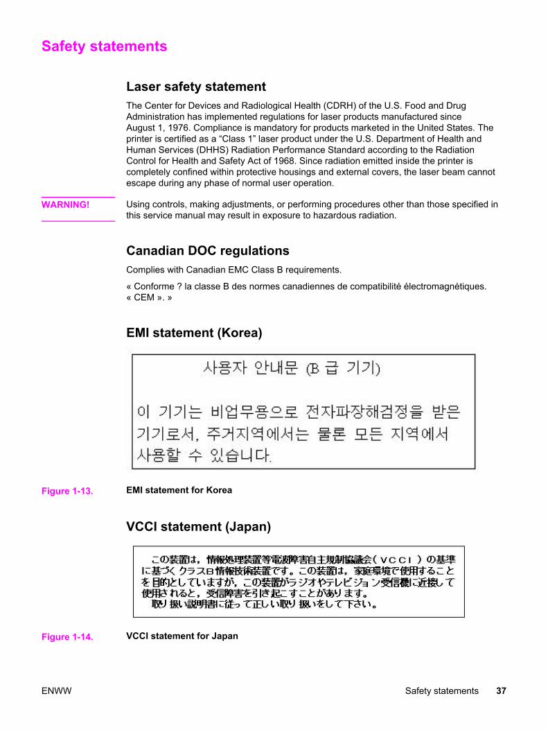
Safety statements
Laser safety statementThe Center for Devices and Radiological Health (CDRH) of the U.S. Food and DrugAdministration has implemented regulations for laser products manufactured sinceAugust 1, 1976. Compliance is mandatory for products marketed in the United States. Theprinter is certified as a “Class 1” laser product under the U.S. Department of Health andHuman Services (DHHS) Radiation Performance Standard according to the RadiationControl for Health and Safety Act of 1968. Since radiation emitted inside the printer iscompletely confined within protective housings and external covers, the laser beam cannotescape during any phase of normal user operation.
WARNING! Using controls, making adjustments, or performing procedures other than those specified inthis service manual may result in exposure to hazardous radiation.
Canadian DOC regulationsComplies with Canadian EMC Class B requirements.
« Conforme ? la classe B des normes canadiennes de compatibilité électromagnétiques.« CEM ». »
EMI statement (Korea)
Figure 1-13. EMI statement for Korea
VCCI statement (Japan)
Figure 1-14. VCCI statement for Japan
ENWW Safety statements 37

Laser statement for FinlandLuokan 1 laserlaiteKlass 1 Laser ApparatHP Color LaserJet 3550, 3550n, 3700, 3700n, 3700dn, 3700dtn, laserkirjoitin on käyttäjänkannalta turvallinen luokan 1 laserlaite. Normaalissa käytössä kirjoittimen suojakotelointiestää lasersäteen pääsyn laitteen ulkopuolelle. Laitteen turvallisuusluokka on määritettystandardin EN 60825-1 (1994) mukaisesti.VAROITUS !Laitteen käyttäminen muulla kuin käyttöohjeessa mainitulla tavalla saattaa altistaa käyttäjänturvallisuusluokan 1 ylittävälle näkymättömälle lasersäteilylle.VARNING !Om apparaten används p? annat sätt än i bruksanvisning specificerats, kan användarenutsättas för osynlig laserstr?lning, som överskrider gränsen för laserklass 1.HUOLTOHP Color LaserJet 3500, 3500n, 3550, 3550n, 3700, 3700n, 3700dn, 3700dtn -kirjoittimensisällä ei ole käyttäjän huollettavissa olevia kohteita. Laitteen saa avata ja huoltaaainoastaan sen huoltamiseen koulutettu henkilö. Tällaiseksi huoltotoimenpiteeksi ei katsotaväriainekasetin vaihtamista, paperiradan puhdistusta tai muita käyttäjän käsikirjassalueteltuja, käyttäjän tehtäväksi tarkoitettuja ylläpitotoimia, jotka voidaan suorittaa ilmanerikoistyökaluja.VARO !Mikäli kirjoittimen suojakotelo avataan, olet alttiina näkymättömällelasersäteilylle laitteenollessa toiminnassa. Älä katso säteeseen.VARNING !Om laserprinterns skyddshölje öppnas d? apparaten är i funktion, utsättas användaren förosynlig laserstr?lning. Betrakta ej str?len. Tiedot laitteessa käytettävän laserdiodinsäteilyominaisuuksista: Aallonpituus 775-795 nm Teho 5 m W Luokan 3B laser.
38 Chapter 1 Printer description ENWW
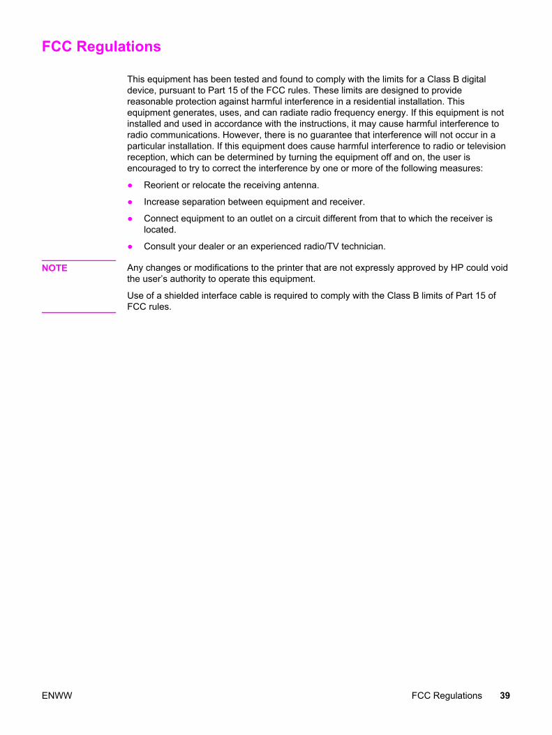
FCC Regulations
This equipment has been tested and found to comply with the limits for a Class B digitaldevice, pursuant to Part 15 of the FCC rules. These limits are designed to providereasonable protection against harmful interference in a residential installation. Thisequipment generates, uses, and can radiate radio frequency energy. If this equipment is notinstalled and used in accordance with the instructions, it may cause harmful interference toradio communications. However, there is no guarantee that interference will not occur in aparticular installation. If this equipment does cause harmful interference to radio or televisionreception, which can be determined by turning the equipment off and on, the user isencouraged to try to correct the interference by one or more of the following measures:
● Reorient or relocate the receiving antenna.
● Increase separation between equipment and receiver.
● Connect equipment to an outlet on a circuit different from that to which the receiver islocated.
● Consult your dealer or an experienced radio/TV technician.
NOTE Any changes or modifications to the printer that are not expressly approved by HP could voidthe user’s authority to operate this equipment.
Use of a shielded interface cable is required to comply with the Class B limits of Part 15 ofFCC rules.
ENWW FCC Regulations 39

40 Chapter 1 Printer description ENWW
2 Service approach
Chapter contents
This chapter contains the following sections.
Chapter contents .....................................................................................................................41Search approach .....................................................................................................................42Parts and supplies ...................................................................................................................43
Ordering parts ...................................................................................................................43Ordering supplies ..............................................................................................................43Exchange program ...........................................................................................................44Supplies ............................................................................................................................44World Wide Web ...............................................................................................................44HP service parts information CD-ROM ............................................................................44HP support assistant CD-ROM ........................................................................................44Customer care reseller sales and service support center ................................................44Ordering related documentation and software .................................................................45
HP maintenance agreements .................................................................................................46On-site service agreements ..............................................................................................46
ENWW Chapter contents 41

Search approach
Printer repair normally begins by using the printer internal diagnostics and the three-stepprocess below.
1. Isolate the problem to the major system (for example, the host computer, the network orserver, or the printer system).
2. Determine if the problem is located in an accessory or in the printer engine.
3. Troubleshoot the problem.
Once a faulty part is located, the printer can usually be repaired at the assembly level byreplacing field-replaceable units (FRUs). Some mechanical assemblies might need to berepaired at the subassembly level. Hewlett-Packard does not support replacement ofcomponents on the printer circuit assembles.
42 Chapter 2 Service approach ENWW
Parts and supplies
This section identifies parts and supplies ordering information and how to obtain HPassistance.
Ordering partsField-replaceable and accessory part numbers are found in chapter 8 of this manual. Orderreplacement parts from Hewlett-Packard Customer Support-Americas (HPCS-A) or Hewlett-Packard Customer Support-Europe (HPCS-E).
NOTE Use only accessories specifically designed for this printer. Accessories can be ordered froman authorized service or support provider. See Ordering related documentation and softwarelater in this chapter and Ordering parts in chapter 8 for additional ordering information.
By phone:Hewlett-Packard Customer Support-Americas (HPCS-A) (800) 227-8164 (U.S. only)
Hewlett-Packard Customer Support-Europe (HPCS-E) (49) (70) 311 4225 (3)
By Internet:Hewlett-Packard Parts Direct http://partsdirect.hp.com
By mail:
Hewlett-Packard Company
HPCS-A
8050 Foothills Blvd.
Roseville, CA 95678
Hewlett-Packard Company
HPCS-E
Wolf-Hirth Straße 33
D-7030 Böblingen, Germany
Ordering suppliesOrder supplies directly from Hewlett-Packard. The phone numbers for ordering supplies are:
● U.S. HP Shopping (home) 1-888-999-4747
● U.S. Small/Medium Business store 1-800-888-0262
● Canada (800) 387-3154; Toronto (416) 671-8383
● United Kingdom (07) (34) 441 212
● Other local phone numbers may also be available
ENWW Parts and supplies 43

Exchange programHP offers remanufactured assemblies for some parts. These are identified in chapter 8 andcan be ordered from Hewlett-Packard Customer Support-Americas (HPCS-A) or Hewlett-Packard Customer Support-Europe (HPCS-E).
SuppliesPaper and print cartridges can be ordered directly from Hewlett-Packard. See chapter 8 forordering information.
World Wide WebPrinter drivers, updated HP printer software, and product and support information can beobtained from the following website:
In the U.S.: http://www.hp.com/support/clj3500 or http://www.hp.com/support/clj3700
Printer drivers may be obtained from the following websites:
In China: http://www.hp.com.cn/support/clj3500 or ftp://www.hp.com.cn/support/clj3700
In Japan: ftp://www.jpn.hp.com/support/clj3500 or ftp://www.jpn.hp.com/support/clj3700
In Korea: http://www.hp.co.kr/support/clj3500 or http://www.hp.co.kr/support/clj3700
In Taiwan: http://www.hp.com.tw/support/clj3500 or http://www.hp.com.tw/support/clj3700 orthe local driver website: http://www.dds.com.tw
HP service parts information CD-ROMThis powerful, CD-ROM-based parts information tool is designed to give users fast, easyaccess to parts information such as pricing and recommended stocking lists for a wide rangeof HP products. To subscribe to this quarterly service in the U.S. or Canada, call(800) 336-5987. In Asia Pacific, call (65) 740-4484. Parts identification and pricinginformation can also be checked via the World Wide Web at http://www.hp.com/go/partsinfo.
HP support assistant CD-ROM This support tool offers a comprehensive online information system designed to providetechnical and product information about HP products. To subscribe to the quarterly service inthe U.S. or Canada, call (800) 457-1762. In Hong Kong SAR, Indonesia, Malaysia, orSingapore, call Mentor Media at (65) 740-4477.
Customer care reseller sales and service support centerThe Customer Care Reseller Sales and Support Center is available to assist resellers andservice technicians. To reach this support center, call (1) (800) 544-9976.
HP authorized resellers and supportTo locate authorized HP resellers and support, call (800) 243-9816 in the U.S. or (800)387-3867 in Canada.
44 Chapter 2 Service approach ENWW
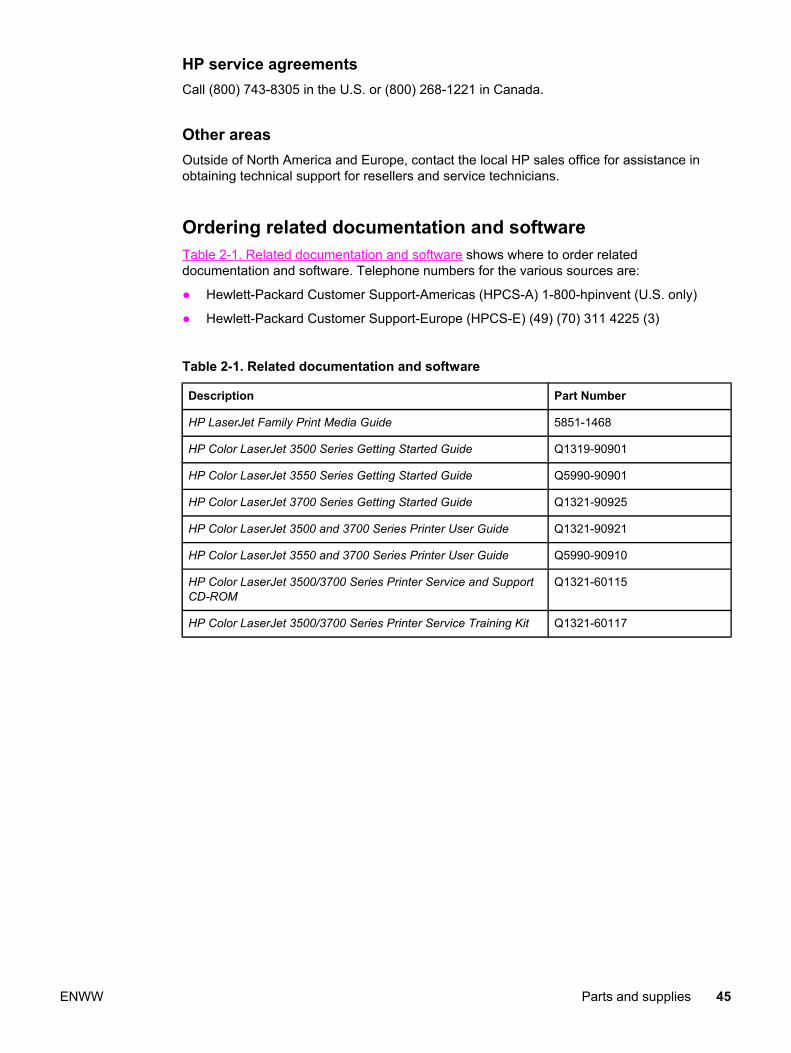
HP service agreementsCall (800) 743-8305 in the U.S. or (800) 268-1221 in Canada.
Other areasOutside of North America and Europe, contact the local HP sales office for assistance inobtaining technical support for resellers and service technicians.
Ordering related documentation and softwareTable 2-1. Related documentation and software shows where to order relateddocumentation and software. Telephone numbers for the various sources are:
● Hewlett-Packard Customer Support-Americas (HPCS-A) 1-800-hpinvent (U.S. only)
● Hewlett-Packard Customer Support-Europe (HPCS-E) (49) (70) 311 4225 (3)
Table 2-1. Related documentation and software
Description Part Number
HP LaserJet Family Print Media Guide 5851-1468
HP Color LaserJet 3500 Series Getting Started Guide Q1319-90901
HP Color LaserJet 3550 Series Getting Started Guide Q5990-90901
HP Color LaserJet 3700 Series Getting Started Guide Q1321-90925
HP Color LaserJet 3500 and 3700 Series Printer User Guide Q1321-90921
HP Color LaserJet 3550 and 3700 Series Printer User Guide Q5990-90910
HP Color LaserJet 3500/3700 Series Printer Service and SupportCD-ROM
Q1321-60115
HP Color LaserJet 3500/3700 Series Printer Service Training Kit Q1321-60117
ENWW Parts and supplies 45

HP maintenance agreements
HP has several types of maintenance agreements that meet a wide range of support needs.Maintenance agreements are not part of the standard warranty. Support services may varyby area. Check with your local HP dealer to determine the services available to you.
On-site service agreementsTo provide you with the level of support best suited to your needs, HP has on-site serviceagreements with a selection of response times.
Next-day on-site serviceThis agreement provides support by the next working day following a service request.Extended coverage hours and extended travel beyond HP’s designated service zones areavailable on most on-site agreements (for additional charges).
Weekly (volume) on-site serviceThis agreement provides scheduled weekly on-site visits for organizations with manyHP products. This agreement is designated for sites using 25 or more workstation products,including printers, plotters, computers, and disk drives.
Extended warrantyHP Carepak provides coverage for the HP hardware product and all HP-supplied internalcomponents. The hardware maintenance covers a one- to three-year period from date of theHP product purchase. For more information, contact the HP Customer Care Service andSupport group.
46 Chapter 2 Service approach ENWW

3 Installation and configuration
Chapter contents
This chapter contains the following sections:
Chapter contents .....................................................................................................................47Checking the package contents ..............................................................................................48Unpacking the printer ..............................................................................................................50Installing the print cartridge .....................................................................................................55Loading paper into Tray 3 (optional) .......................................................................................57Loading paper into Tray 2 .......................................................................................................59Loading paper into Tray 1 (optional procedure) ......................................................................61Connecting power ...................................................................................................................62Installing a new control panel overlay (optional) .....................................................................63Testing the printer operation ...................................................................................................64Using PowerSave Time ...........................................................................................................65
To set PowerSave Time ...................................................................................................65To disable/enable PowerSave ..........................................................................................65
USB configuration ...................................................................................................................66Connecting the USB cable ...............................................................................................66
Parallel configuration (HP Color LaserJet 3700 series printer only) .......................................67Network configuration .............................................................................................................68Enhanced I/O (EIO) configuration (HP color LaserJet 3700 series printer only) ....................69
HP Jetdirect print servers .................................................................................................69Available enhanced I/O interfaces ....................................................................................69NetWare networks ............................................................................................................70Windows and Windows NT networks ...............................................................................70AppleTalk networks ..........................................................................................................70UNIX/Linux networks ........................................................................................................70
Printer software .......................................................................................................................71Printer drivers ...................................................................................................................71Software for networks .......................................................................................................72Utilities ..............................................................................................................................73
Setting security on the printer .................................................................................................76Locking the control panel ..................................................................................................76Using an ASCII PJL escape sequence to set security .....................................................77
Printer memory for the HP Color LaserJet 3700 series printer ...............................................78Installing memory and font DIMMs .........................................................................................79
Enabling memory ..............................................................................................................83Enabling the language font DIMM (HP color LaserJet 3700 only) ...................................83Checking DIMM installation (HP color LaserJet 3700 only) .............................................84
Installing an HP Jetdirect print server card in the HP color LaserJet 3700 series printer ......85To install the HP Jetdirect print server card .....................................................................85
Installing an HP Jetdirect en3700 external print server ..........................................................88
ENWW Chapter contents 47

Checking the package contents
Figure 3-1. HP Color LaserJet 3500/3550 printer package contents
1 HP Color LaserJet 3500/35502 USB cable3 Power cable4 Four print cartridges5 CD-ROM (the CD-ROM contains the user guide)6 Control panel overlay7 Getting started guide
Figure 3-2. Additional contents shipped with the HP Color LaserJet 3500n/3550n printer
1 HP Jetdirect en3700 external print server (3500n/3550n only)2 Power cable
48 Chapter 3 Installation and configuration ENWW

NOTE The items listed here are for the external print server connection.
Figure 3-3. HP Color LaserJet 3700, 3700n, or 3700dn printer package contents
1 HP Color LaserJet 3700, 3700n, or 3700dn2 Power cable3 Four print cartridges4 CD-ROM (the CD-ROM contains the user guide)5 Control panel overlay6 Getting started guide
Figure 3-4. HP Color LaserJet 3700dtn printer package contents
1 HP Color LaserJet 3700dtn2 Tray 3 (500-sheet paper feeder tray)3 Power cable4 Four print cartridges5 CD-ROM (the CD-ROM contains the user guide)6 Control panel overlay7 Getting started guide
NOTE Parallel and USB cables are not included with HP Color LaserJet 3700 series printers. Usean IEEE 1284-compliant, parallel cable or a standard, 2-meter USB cable.
ENWW Checking the package contents 49

Unpacking the printer
NOTE Save all the packing materials in case you need to repack and transport the printer at a laterdate.
WARNING! The printer weighs approximately 33.5 kg (73.3 lbs). HP recommends having two or morepeople lift or move the printer.
1. Prepare the location by selecting a sturdy, level surface in a well-ventilated, dust-freearea. Make sure there is enough space around the printer so that the air vents on the leftside and rear of the printer are not blocked.
CAUTION Do not place the printer in direct sunlight or in an area that has abrupt temperature andhumidity changes.
Recommended ranges: 17° to 25°C (62.6° to 77°F) and 20 to 60 percent relative humidity.
NOTE If the printer has an optional 500-sheet paper feeder, it is packaged on top of the printer. Liftthe 500-sheet paper feeder from the package, and place it in the prepared location.
50 Chapter 3 Installation and configuration ENWW
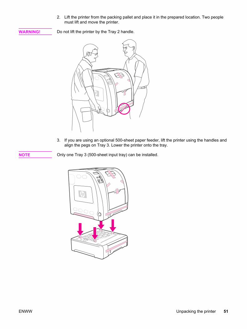
2. Lift the printer from the packing pallet and place it in the prepared location. Two peoplemust lift and move the printer.
WARNING! Do not lift the printer by the Tray 2 handle.
3. If you are using an optional 500-sheet paper feeder, lift the printer using the handles andalign the pegs on Tray 3. Lower the printer onto the tray.
NOTE Only one Tray 3 (500-sheet input tray) can be installed.
ENWW Unpacking the printer 51
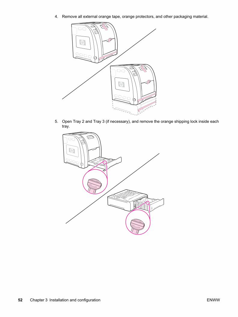
4. Remove all external orange tape, orange protectors, and other packaging material.
5. Open Tray 2 and Tray 3 (if necessary), and remove the orange shipping lock inside eachtray.
52 Chapter 3 Installation and configuration ENWW

6. Open the lower rear door, and make sure that the two blue pressure release leveractuators are in the upright position. The two release levers are located on the left andright side of the lower rear door.
7. Close the lower rear door.
8. Lift the front door handle, and pull down the front door.
NOTE When you open the front door, you will hear components clicking.
CAUTION Do not place anything on the transfer unit. Do not touch the top of the transfer unit or thecontacts on the left side of the transfer unit.
ENWW Unpacking the printer 53

9. Remove the orange tape and orange shipping locks on the rear, left, and right sides ofthe transfer unit. Remove any remaining tape from the printer.
54 Chapter 3 Installation and configuration ENWW

Installing the print cartridge
1. Remove a new print cartridge from the bag.
2. Grasp both sides of the print cartridge and distribute the toner by gently rocking thecartridge from side to side.
3. Remove and discard the orange shipping tape and the shipping locks from the new printcartridge.
NOTE Discard the shipping tape and the shipping locks according to local regulations.
ENWW Installing the print cartridge 55

4. Locate the color slot for the print cartridge.
5. Align the print cartridge with the tracks inside the printer and, using the handle, insert thecartridge. Repeat this procedure for the remaining three cartridges.
6. Firmly close the front door.
56 Chapter 3 Installation and configuration ENWW
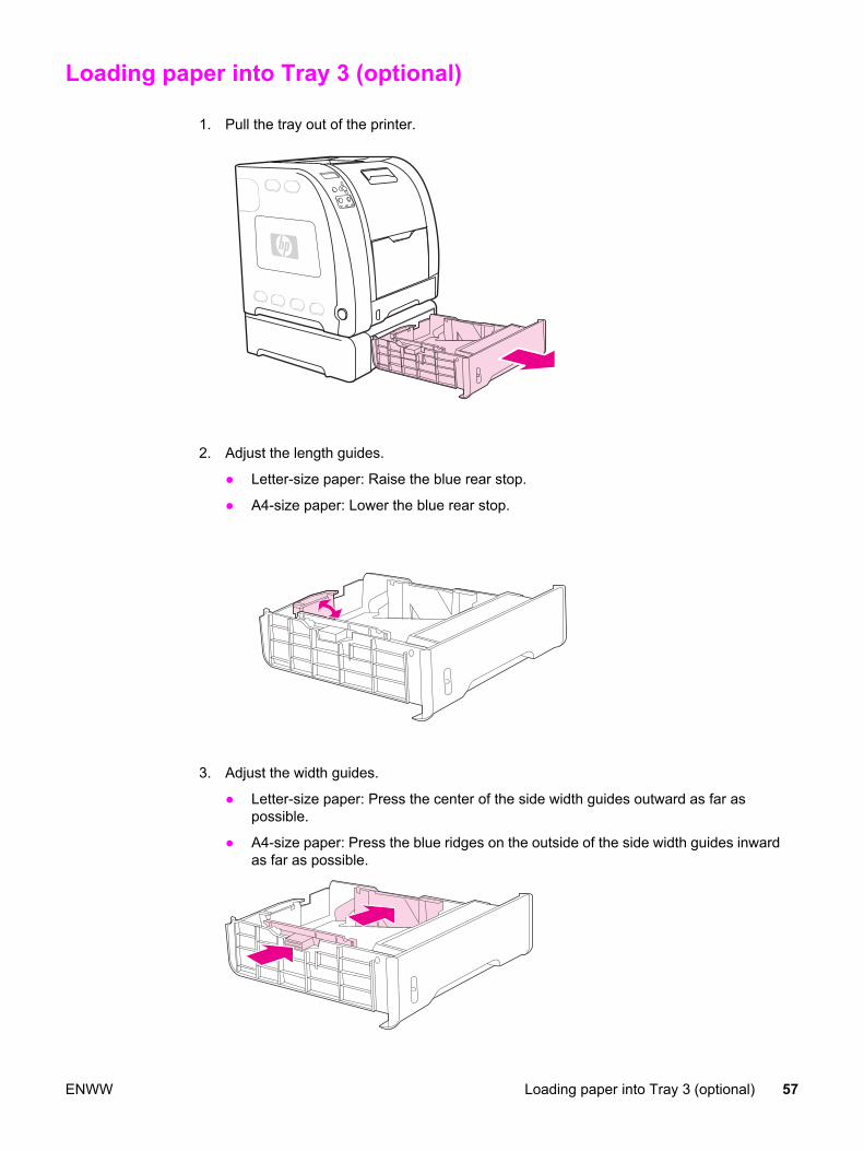
Loading paper into Tray 3 (optional)
1. Pull the tray out of the printer.
2. Adjust the length guides.
● Letter-size paper: Raise the blue rear stop.
● A4-size paper: Lower the blue rear stop.
3. Adjust the width guides.
● Letter-size paper: Press the center of the side width guides outward as far aspossible.
● A4-size paper: Press the blue ridges on the outside of the side width guides inwardas far as possible.
ENWW Loading paper into Tray 3 (optional) 57

4. Load the paper into the tray. If this is special paper, such as letterhead, load it with theside to be printed down and the top edge toward the front of the tray.
NOTE Do not fan paper before loading.
5. Make sure the stack of paper is flat in the tray at all four corners, and keep it below theheight tabs.
6. Slide the tray back into the printer.
58 Chapter 3 Installation and configuration ENWW

Loading paper into Tray 2
1. Pull Tray 2 out of the printer.
2. Move the side width guides until the blue arrows on the width guides point to the size ofpaper you are loading.
3. On the back of the tray, press the blue ridges and slide the length guides until the arrowsymbol points to the paper size you are loading.
ENWW Loading paper into Tray 2 59

4. Load the paper into the tray. If this is special paper, such as letterhead, load it with theside to be printed down and the top edge toward the front of the tray.
NOTE Do not fan the paper before loading.
5. Push down on the stack of paper to lock the metal lift plate into place. Make sure thatthe stack of paper is flat and that the paper is below the height tabs.
6. Slide the tray back into the printer. Raise the output bin extension.
60 Chapter 3 Installation and configuration ENWW

Loading paper into Tray 1 (optional procedure)
1. Open Tray 1, and raise the output bin extension.
NOTE If printing special media, such as envelopes, use Tray 1.
2. Slide out the tray extender and, if necessary, open the additional tray extender.
3. Slide the width guides slightly wider than the print media. Remove any unused printmedia, and close the tray when finished printing.
?
ENWW Loading paper into Tray 1 (optional procedure) 61

Connecting power
1. Connect the AC power cord to the printer and to a power outlet.
NOTE Do not connect the printer to the computer or to the network at this time.
2. Turn the printer on. After a minimum of two minutes, the green ready light turns on.
62 Chapter 3 Installation and configuration ENWW
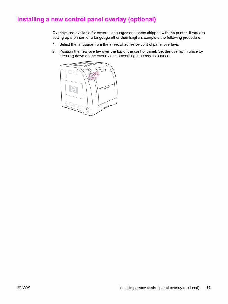
Installing a new control panel overlay (optional)
Overlays are available for several languages and come shipped with the printer. If you aresetting up a printer for a language other than English, complete the following procedure.
1. Select the language from the sheet of adhesive control panel overlays.
2. Position the new overlay over the top of the control panel. Set the overlay in place bypressing down on the overlay and smoothing it across its surface.
ENWW Installing a new control panel overlay (optional) 63

Testing the printer operation
Print a demo page to ensure the printer is working properly.
1. Press MENU to enter the MENUS.
2. Press to highlight Information.
3. Press to select Information.
4. Press to highlight PRINT DEMO.
5. Press to select PRINT CONFIGURATION.
After printing the demo page, the printer control panel displays the Ready message.
64 Chapter 3 Installation and configuration ENWW

Using PowerSave Time
The adjustable PowerSave Time feature reduces power consumption when the printer hasbeen inactive for an extended period. You can set the length of time before the printer goesinto PowerSave mode to 1 MINUTE, 15 MINUTES, 30 MINUTES, or to 1 HOUR, 1.5HOURS, 2 HOURS, or 4 HOURS. The default setting is 30 MINUTES.
NOTE The printer display appears dimmed when the printer is in PowerSave mode. PowerSavemode does not affect printer warm-up time, unless the printer is in PowerSave mode formore than eight hours.
To set PowerSave Time1. Press MENU to enter the MENUS.
2. Press to highlight Configure Device.
3. Press to select Configure Device.
4. Press to highlight SYSTEM SETUP.
5. Press to select SYSTEM SETUP.
6. Press to highlight Powersave Time.
7. Press to select Powersave Time.
8. Press or to select the appropriate time period.
9. Press to set the time period.
10. Press MENU.
To disable/enable PowerSave1. Press MENU to enter the MENUS.
2. Press to highlight Configure Device.
3. Press to select Configure Device.
4. Press to highlight RESETS.
5. Press to select RESETS.
6. Press to highlight POWERSAVE.
7. Press to select POWERSAVE.
8. Press or to select on or off.
9. Press to set the selection.
10. Press MENU.
ENWW Using PowerSave Time 65

USB configuration
All printer models support USB connections. The USB port is on the back of the printer.
Connecting the USB cablePlug the USB cable into the printer. Plug the other end of the USB cable into the computer.
Figure 3-5. USB connection
1 USB port2 USB connector
66 Chapter 3 Installation and configuration ENWW
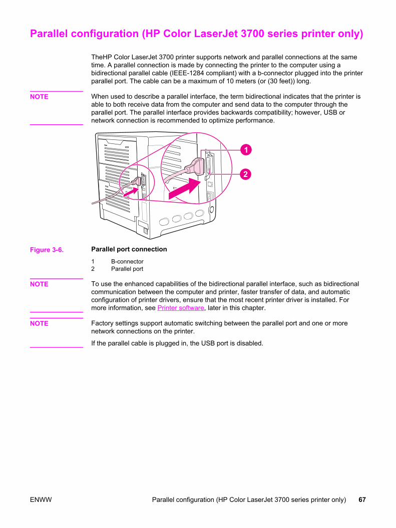
Parallel configuration (HP Color LaserJet 3700 series printer only)
TheHP Color LaserJet 3700 printer supports network and parallel connections at the sametime. A parallel connection is made by connecting the printer to the computer using abidirectional parallel cable (IEEE-1284 compliant) with a b-connector plugged into the printerparallel port. The cable can be a maximum of 10 meters (or (30 feet)) long.
NOTE When used to describe a parallel interface, the term bidirectional indicates that the printer isable to both receive data from the computer and send data to the computer through theparallel port. The parallel interface provides backwards compatibility; however, USB ornetwork connection is recommended to optimize performance.
Figure 3-6. Parallel port connection
1 B-connector2 Parallel port
NOTE To use the enhanced capabilities of the bidirectional parallel interface, such as bidirectionalcommunication between the computer and printer, faster transfer of data, and automaticconfiguration of printer drivers, ensure that the most recent printer driver is installed. Formore information, see Printer software, later in this chapter.
NOTE Factory settings support automatic switching between the parallel port and one or morenetwork connections on the printer.
If the parallel cable is plugged in, the USB port is disabled.
ENWW Parallel configuration (HP Color LaserJet 3700 series printer only) 67

Network configuration
NOTE The network configuration feature is available for the HP Color LaserJet 3700 series printerwhen an EIO device is installed.
You might need to configure certain network parameters on the printer. You can configurethese parameters from the printer control panel, the embedded Web server, or for mostnetworks, from the HP Web Jetadmin software or the HP Toolbox.
NOTE For more information about using the embedded Web server, see Using the embedded Webserver in the user guide.
For a complete list of supported networks and for instructions on configuring networkparameters from software, see the HP Jetdirect Print Server Administrator’s Guide. Theguide comes with printers in which an HP Jetdirect print server is installed.
68 Chapter 3 Installation and configuration ENWW
Enhanced I/O (EIO) configuration (HP color LaserJet 3700 seriesprinter only)
This printer comes equipped with one enhanced input/output (EIO) slot. This slot holdscompatible external devices, such as the HP Jetdirect print server network cards or otherdevices.
EIO network cards can maximize printer performance when printing from a network. Inaddition, they provide the ability to place the printer anywhere on a network. This eliminatesthe need to attach the printer directly to a server or to a workstation, and allows you to placethe printer closer to the network users.
If the printer is configured through an EIO network card, configure that card through thecontrol panel Configure device menu.
HP Jetdirect print serversAn HP Jetdirect print server (network card) can be installed in the printer EIO slot. Theseprint server cards support multiple network protocols and operating systems. HP Jetdirectprint servers facilitate network management, allowing you to connect a printer directly to yournetwork at any location. HP Jetdirect print servers also support Simple NetworkManagement Protocol (SNMP), which provides network managers with remote printermanagement and troubleshooting through HP Web Jetadmin software.
NOTE Installation of these cards and network configuration should be performed by a networkadministrator. Configure the card either through the control panel, the printer installationsoftware, or with HP Web Jetadmin software.
NOTE See to the HP Jetdirect print server documentation for information on which external devicesor EIO network cards are supported.
Available enhanced I/O interfacesHP Jetdirect print servers (network cards) provide software solutions for:
● Novell NetWare Network
● Microsoft Windows and Windows NT networks
● Apple Mac OS (AppleTalk)
● UNIX (HP-UX and Solaris)
● Linux (Red Hat and SuSE)
● Internet printing
For a summary of available network software solutions, see the HP Jetdirect Print ServerAdministrator’s Guide, or visit HP Customer Care online at http://www.hp.com/support/net_printing.
ENWW Enhanced I/O (EIO) configuration (HP color LaserJet 3700 series printer only) 69

NetWare networksWhen using Novell NetWare products with an HP Jetdirect print server, Queue Server modeprovides improved printing performance over Remote Printer mode. The HP Jetdirect printserver supports Novell Directory Services (NDS), as well as bindery modes. For moreinformation, see the HP Jetdirect Print Server Administrator’s Guide.
For Windows 98, Me, NT 4.0, 2000, and XP systems, use the printer installation utility forprinter setup on a NetWare network.
Windows and Windows NT networksFor Windows 98, Me, NT 4.0, 2000, and XP systems, use your printer installation utility forprinter setup on a Microsoft Windows network. The utility supports printer setup for eitherpeer-to-peer or client-server network operation.
AppleTalk networksUse the HP Toolbox to set up the printer on an EtherTalk or LocalTalk network. For moreinformation, see the HP Jetdirect Print Server Administrator’s Guide included with printersequipped with the HP Jetdirect print server.
UNIX/Linux networksUse the HP Jetdirect printer installer for UNIX utility to set up the printer on HP-UX or SunSolaris networks.
For setup and management on UNIX or Linux networks, use HP Web Jetadmin.
To obtain HP software for UNIX/Linux networks, visit HP Customer Care online athttp://www.hp.com/support/net_printing. For other installation options supported bytheHP Jetdirect print server, see the HPJ etdirect Print Server Administrator’s Guideincluded with printers equipped with the HP Jetdirect print server.
70 Chapter 3 Installation and configuration ENWW

Printer software
Included with the printer is a CD-ROM containing the printing system software. The softwarecomponents and printer drivers on this CD-ROM help you use the printer to its fullestpotential. See the getting started guide for installation instructions.
NOTE For the latest information about the printing system software components, view the Readmefiles on the CD-ROM.
This section summarizes the software included on the CD-ROM. The printing systemincludes software for end users and network administrators operating in the followingoperating environments:
● Microsoft Windows 98, Me, and NT 4.0
● Microsoft Windows 2000, XP 32-bit, and XP 64-bit
● Apple Mac OS version 9.1 and later, and Mac OS X version 10.1 and later
NOTE For a list of the network environments supported by the network administrator softwarecomponents, see Network configuration.
For a list of printer drivers, updated HP printer software, and product support information forthe HP Color LaserJet 3500 series printer, go to http://www.hp.com/support/clj3500. For theHP Color LaserJet 3550 series printer, go to http://www.hp.com/support/clj3550. For theHP Color LaserJet 3700 series printer, go to http://www.hp.com/support/clj3700.
Printer driversPrinter drivers access the printer features and allow the computer to communicate with theprinter. The following printer drivers are included with the printer on a CD-ROM.
Table 3-1. Printer drivers for the HP Color LaserJet 3500/3550 series printer
Operating system1 JetReady 4.0
Windows 98, Me
Windows NT 4.0
NOTE
Windows NT does not support USB.
Windows 2000
Windows XP (32-bit)
Windows XP (64-bit)
Windows Server 2003 (32-bit)
Windows Server 2003 (64-bit)
Macintosh OS1Not all printer features are available from all drivers or operating systems. See the onlineHelp in your driver for availability of features.
ENWW Printer software 71
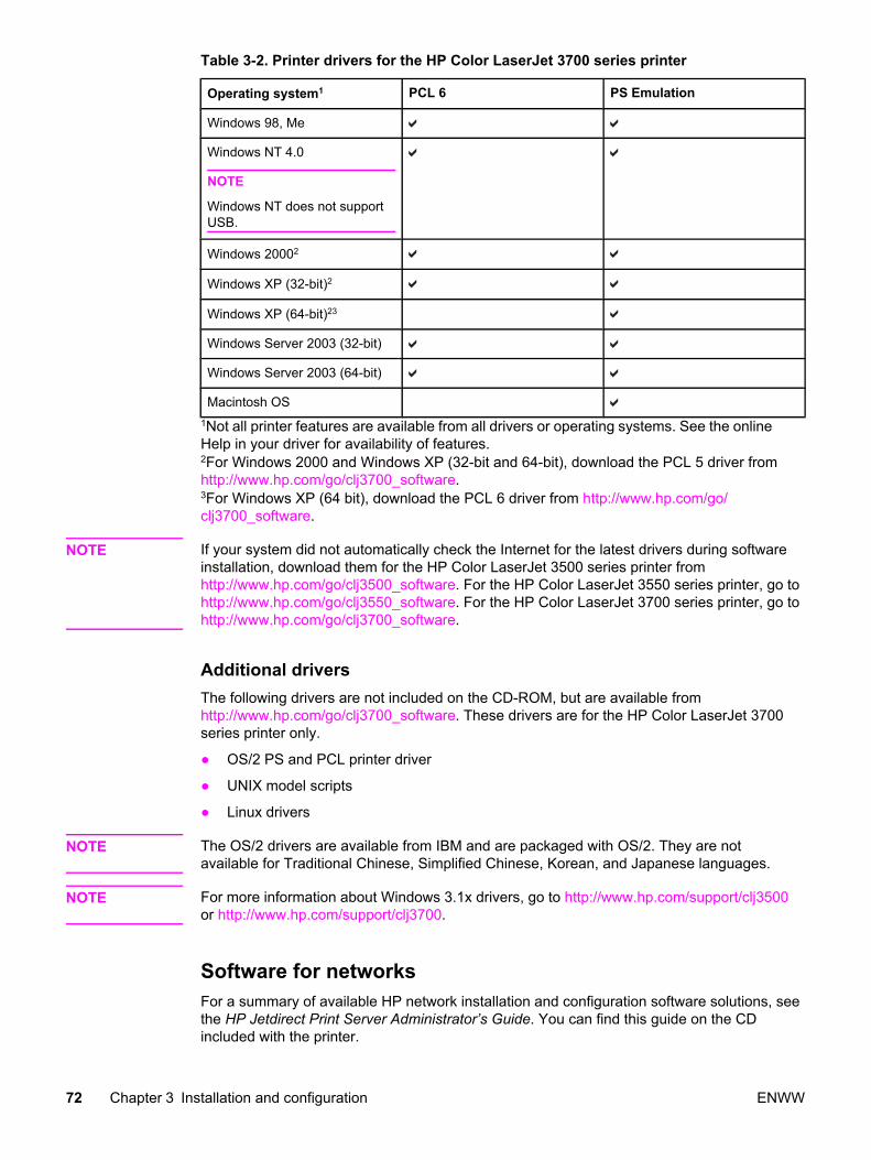
Table 3-2. Printer drivers for the HP Color LaserJet 3700 series printer
Operating system1 PCL 6 PS Emulation
Windows 98, Me
Windows NT 4.0
NOTE
Windows NT does not supportUSB.
Windows 20002
Windows XP (32-bit)2
Windows XP (64-bit)23
Windows Server 2003 (32-bit)
Windows Server 2003 (64-bit)
Macintosh OS1Not all printer features are available from all drivers or operating systems. See the onlineHelp in your driver for availability of features.2For Windows 2000 and Windows XP (32-bit and 64-bit), download the PCL 5 driver fromhttp://www.hp.com/go/clj3700_software.3For Windows XP (64 bit), download the PCL 6 driver from http://www.hp.com/go/clj3700_software.
NOTE If your system did not automatically check the Internet for the latest drivers during softwareinstallation, download them for the HP Color LaserJet 3500 series printer fromhttp://www.hp.com/go/clj3500_software. For the HP Color LaserJet 3550 series printer, go tohttp://www.hp.com/go/clj3550_software. For the HP Color LaserJet 3700 series printer, go tohttp://www.hp.com/go/clj3700_software.
Additional driversThe following drivers are not included on the CD-ROM, but are available fromhttp://www.hp.com/go/clj3700_software. These drivers are for the HP Color LaserJet 3700series printer only.
● OS/2 PS and PCL printer driver
● UNIX model scripts
● Linux drivers
NOTE The OS/2 drivers are available from IBM and are packaged with OS/2. They are notavailable for Traditional Chinese, Simplified Chinese, Korean, and Japanese languages.
NOTE For more information about Windows 3.1x drivers, go to http://www.hp.com/support/clj3500or http://www.hp.com/support/clj3700.
Software for networksFor a summary of available HP network installation and configuration software solutions, seethe HP Jetdirect Print Server Administrator’s Guide. You can find this guide on the CDincluded with the printer.
72 Chapter 3 Installation and configuration ENWW

HP Web JetadminHP Web Jetadmin allows you to manage HP Jetdirect-connected printers within your intranetusing a browser. HP Web Jetadmin is a browser-based management tool and should beinstalled only on the network administrator computer. It can be installed and run on a varietyof systems.
To download a current version of HP Web Jetadmin and, for the latest list of supported hostsystems, visit HP Customer Care Online at http://www.hp.com/go/webjetadmin.
When installed on a host server, any client can access HP Web Jetadmin using a supportedWeb browser (such as Microsoft Internet Explorer 4.x or Netscape Navigator 4.x or later) bybrowsing to the HP Web Jetadminhost.
HP Web Jetadmin 6.5 and above have the following features:
● Task-oriented user interface provides configurable views, saving network managerssignificant time.
● Customizable user profiles let network administrators include only the function viewed orused.
● Instant e-mail notification of hardware failure, low supplies, and other printer problemsnow route to different people.
● Remote installation and management from anywhere using only a standard Web browser.
● Advanced autodiscovery locates peripherals on the network, so the networkadministrator does not need to manually enter each printer into a database.
● Simple integration into enterprise management packages.
● Quickly find peripherals based on parameters such as IP address, color capability, andmodel name.
● Easily organize peripherals into logical groups, with virtual office maps for easynavigation.
For the latest information about HP Web Jetadmin, go to http://www.hp.com/go/webjetadmin.
UNIXThe HP Jetdirect Printer Installer for UNIX is a simple printer installation utility for HP-UX andSolaris networks. It is available for download from HP Customer Care Online athttp://www.hp.com/support/net_printing.
LinuxFor information about Linux support, go to http://www.hp.com/go/linux.
UtilitiesThe HP Color LaserJet 3500/3550 series printer and the HP Color LaserJet 3700 seriesprinter are equipped with several utilities that make it easy to monitor and manage the printeron a network.
ENWW Printer software 73
HP ToolboxThe HP Toolbox is an application that you can use for the following tasks:
● Check the printer status.
● Configure the printer settings.
● View troubleshooting information.
● View online documentation.
● Print internal printer pages.
You can view the HP Toolbox when the printer is directly connected to your computer orwhen it is connected to a network. You must have performed a complete softwareinstallation to use the HP Toolbox.
Embedded Web server (available for the HP Color LaserJet 3700 seriesprinter)This printer is equipped with an embedded Web server that allows access to informationabout the printer and network activities. A Web server provides an environment in whichWeb programs may run, much in the same way that an operating system, such as Windows,provides an environment for programs to run on your PC. The output from these programscan then be displayed by a Web browser, such as Microsoft Internet Explorer or NetscapeNavigator.
An embedded Web server resides on a hardware device (such as a printer) or in firmware,rather than as software that is loaded on a network server.
The advantage of an embedded Web server is that it provides an interface to the printer thatanyone with a network-connected PC and a standard Web browser can access. There is nospecial software to install or configure, but you must have a supported Web browser on yourcomputer. To access the embedded Web server, type the IP address for the printer in theaddress line of the browser. (To find the IP address, print a configuration page. For moreinformation about printing a configuration page, see the user guide.)
Features
The HP embedded Web server allows you to view printer and network card status andmanage printing functions from your PC. With the HP embedded Web server, you can do thefollowing:
● View printer status information.
● Determine the remaining life on all supplies and order new ones.
● View and change tray configurations.
● View and change the printer control panel menu configuration.
● View and print internal pages.
● Receive notification of printer and supplies events.
● Add or customize links to other Web sites.
● Select the language in which to display the embedded Web server pages.
● View and change network configuration.
● View support content that is printer-specific and specific to the printer’s current state.
For a complete explanation of the features and functionality of the embedded Web server,see the user guide.
74 Chapter 3 Installation and configuration ENWW
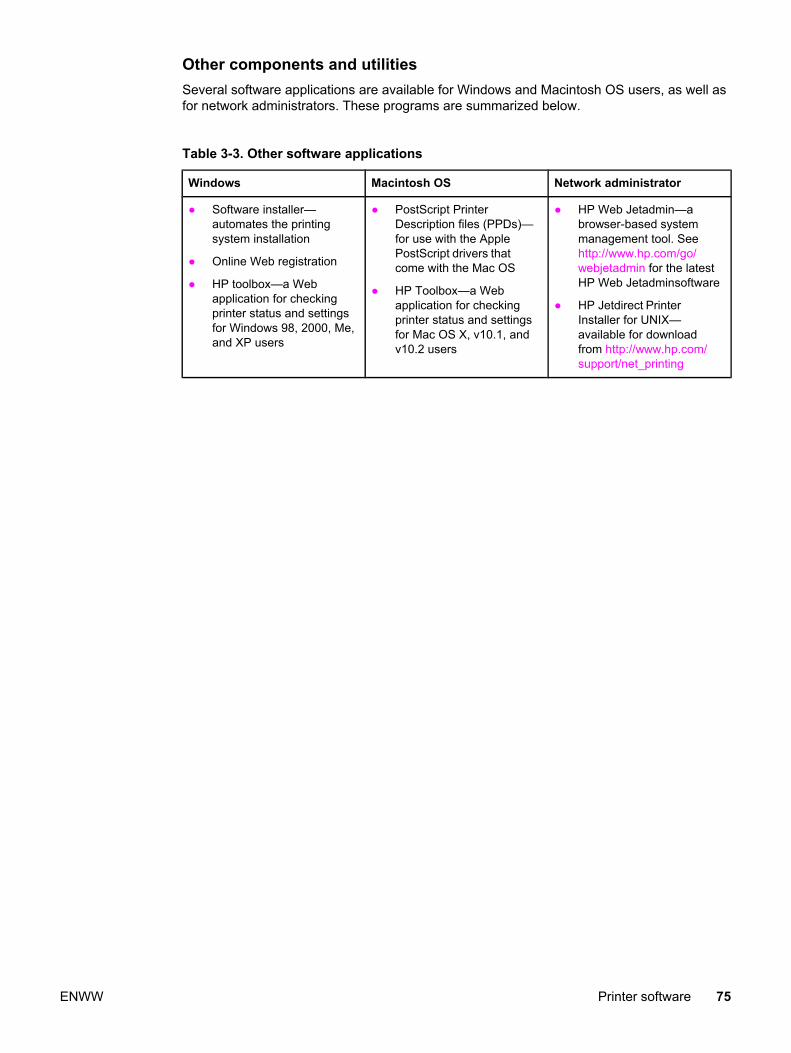
Other components and utilitiesSeveral software applications are available for Windows and Macintosh OS users, as well asfor network administrators. These programs are summarized below.
Table 3-3. Other software applications
Windows Macintosh OS Network administrator
● Software installer—automates the printingsystem installation
● Online Web registration
● HP toolbox—a Webapplication for checkingprinter status and settingsfor Windows 98, 2000, Me,and XP users
● PostScript PrinterDescription files (PPDs)—for use with the ApplePostScript drivers thatcome with the Mac OS
● HP Toolbox—a Webapplication for checkingprinter status and settingsfor Mac OS X, v10.1, andv10.2 users
● HP Web Jetadmin—abrowser-based systemmanagement tool. Seehttp://www.hp.com/go/webjetadmin for the latestHP Web Jetadminsoftware
● HP Jetdirect PrinterInstaller for UNIX—available for downloadfrom http://www.hp.com/support/net_printing
ENWW Printer software 75
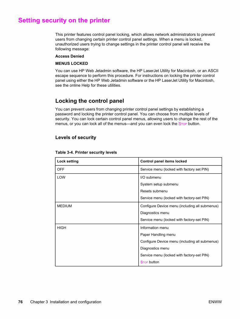
Setting security on the printer
This printer features control panel locking, which allows network administrators to preventusers from changing certain printer control panel settings. When a menu is locked,unauthorized users trying to change settings in the printer control panel will receive thefollowing message:
Access Denied
MENUS LOCKED
You can use HP Web Jetadmin software, the HP LaserJet Utility for Macintosh, or an ASCIIescape sequence to perform this procedure. For instructions on locking the printer controlpanel using either the HP Web Jetadmin software or the HP LaserJet Utility for Macintosh,see the online Help for these utilities.
Locking the control panelYou can prevent users from changing printer control panel settings by establishing apassword and locking the printer control panel. You can choose from multiple levels ofsecurity. You can lock certain control panel menus, allowing users to change the rest of themenus, or you can lock all of the menus—and you can even lock the STOP button.
Levels of security
Table 3-4. Printer security levels
Lock setting Control panel items locked
OFF Service menu (locked with factory set PIN)
LOW I/O submenu
System setup submenu
Resets submenu
Service menu (locked with factory-set PIN)
MEDIUM Configure Device menu (including all submenus)
Diagnostics menu
Service menu (locked with factory-set PIN)
HIGH Information menu
Paper Handling menu
Configure Device menu (including all submenus)
Diagnostics menu
Service menu (locked with factory-set PIN)
STOP button
76 Chapter 3 Installation and configuration ENWW

Use HP Web Jetadmin software, HP LaserJet Utility for Macintosh, or an ASCII escapesequence to set security. HP software, which comes on the software CD-ROM, is easier touse than an ASCII escape sequence. For instructions about locking the control panel byusing either HP Web Jetadmin software or the HP LaserJet Utility for Macintosh, go to theonline Help for that software.
Using an ASCII PJL escape sequence to set securityIf you decide to use the ASCII escape sequence, you must use an MS-DOS® or WindowsASCII editor to create the commands. The commands must also be sent to the printer byusing a DOS COPY command or an ASCII file download utility. The PJL TechnicalReference Manual is located on CD-ROM, part number 5961-0976. Order a copy of thismanual from the HP website at http://www.hp.com.
NOTE In the following examples, "EC" represents the escape character. For more information onusing escape characters, see the PJL Technical Reference Manual.
To lock or unlock the printer control panel if a password has not been set, send the followingASCII sequence to the printer:
EC%-12345X@PJL JOB
@PJL DEFAULT CPLOCK=NONE (or MINIMUM, MODERATE, or MAXIMUM)
@PJL EOJ
EC%-12345X
To set the password, send the following ASCII sequence to the printer:
EC%-12345X@PJL JOB
@PJL DEFAULT PASSWORD=[numeric password (0 to 65535)]
@PJL EOJ
EC%-12345X
To lock or unlock the control panel if the password has been set, send the following ASCIIsequence to the printer:
EC%-12345X@PJL JOB PASSWORD=(numeric password)
@PJL DEFAULT CPLOCK=NONE (or MINIMUM, MODERATE, or MAXIMUM)
@PJL EOJ
EC%-12345X
ENWW Setting security on the printer 77

Printer memory for the HP Color LaserJet 3700 series printer
The printer has three DIMM slots. The bottom slot is for the firmware DIMM.
NOTE For maximum flexibility in DIMM support, the formatter is designed with three 168-pin DIMMslots and a fourth 100-pin DIMM slot.
Use these DIMM slots to upgrade the printer with the following items:
● More printer memory—DIMMs are available in 64, 128, and 256 MB
● Flash memory DIMMs—available in 4 MB; unlike standard printer memory, flash DIMMscan be used to permanently store downloaded items in the printer, even when the printeris off
● DIMM-based accessory fonts, macros, and patterns
● Other DIMM-based printer languages and printer options
● Memory expansion, which can support up to 448 MB of memory
You might want to add more memory to the printer if you often print complex graphics orPostScript documents, or if you use many downloaded fonts. Additional memory also allowsthe printer to print multiple, collated copies at the maximum speed.
NOTE Single in-line memory modules (SIMMs) used on previous HP LaserJet printers are notcompatible with this printer.
NOTE To order DIMMs, see Ordering parts in chapter 8.
Before ordering additional memory, see how much memory is currently installed by printing aconfiguration page.
1. Press MENU to enter the MENUS.
2. Press to highlight Information.
3. Press to select Information.
4. Press to highlight PRINT CONFIGURATION.
5. Press to print the configuration page.
78 Chapter 3 Installation and configuration ENWW

Installing memory and font DIMMs
You can install more memory for the printer, and you can also install a font DIMM to allowthe printer to print characters for languages such as Chinese or the Cyrillic alphabet.
NOTE Static electricity can damage DIMMs. When handling DIMMs, either wear an antistatic wriststrap, or frequently touch the surface of the DIMM antistatic package and then touch baremetal on the printer.
1. Turn the printer off.
2. Disconnect all power and interface cables.
ENWW Installing memory and font DIMMs 79

3. Open the DIMM access door by gently prying it with a flat-bladed screwdriver. Removethe door by pulling the door toward the back of the printer.
4. Loosen the screws that hold the formatter door to the printer and remove the formatterdoor.
5. Remove the DIMM from the antistatic package. Locate the alignment notches on thebottom edge of the DIMM.
80 Chapter 3 Installation and configuration ENWW
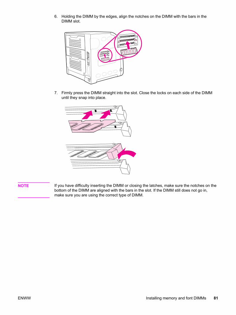
6. Holding the DIMM by the edges, align the notches on the DIMM with the bars in theDIMM slot.
7. Firmly press the DIMM straight into the slot. Close the locks on each side of the DIMMuntil they snap into place.
NOTE If you have difficulty inserting the DIMM or closing the latches, make sure the notches on thebottom of the DIMM are aligned with the bars in the slot. If the DIMM still does not go in,make sure you are using the correct type of DIMM.
ENWW Installing memory and font DIMMs 81

8. Align the formatter door in the tracks at the bottom of the slot, and turn the screws tosecure the formatter door to the printer.
9. Replace the DIMM access door by inserting the tabs on the door into the slots on theprinter. Swing the door shut.
10. Reconnect the power cable and the USB/parallel cable.
82 Chapter 3 Installation and configuration ENWW
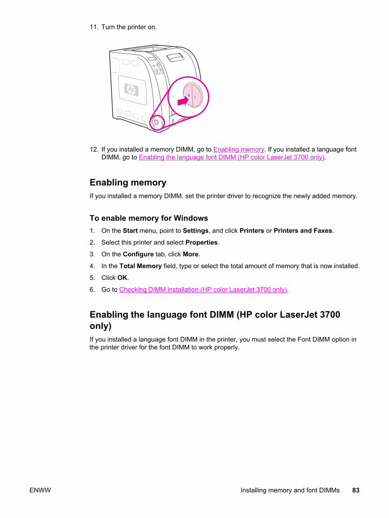
11. Turn the printer on.
12. If you installed a memory DIMM, go to Enabling memory. If you installed a language fontDIMM, go to Enabling the language font DIMM (HP color LaserJet 3700 only).
Enabling memoryIf you installed a memory DIMM, set the printer driver to recognize the newly added memory.
To enable memory for Windows1. On the Start menu, point to Settings, and click Printers or Printers and Faxes.
2. Select this printer and select Properties.
3. On the Configure tab, click More.
4. In the Total Memory field, type or select the total amount of memory that is now installed.
5. Click OK.
6. Go to Checking DIMM installation (HP color LaserJet 3700 only).
Enabling the language font DIMM (HP color LaserJet 3700only)If you installed a language font DIMM in the printer, you must select the Font DIMM option inthe printer driver for the font DIMM to work properly.
ENWW Installing memory and font DIMMs 83
To enable fonts from the PCL 6 printer driver for Windows1. On the Start menu, point to Settings, and click Printers.
2. Select this printer and select Properties.
3. On the Configure tab, click More.
4. Select the Font DIMM check box.
5. In the Configure Font DIMMs dialog box, click Add to add the font file.
6. In the Add Font DIMM dialog box, browse to the location of the font file, select the fontfile, and click OK.
7. In the Configure Font DIMMs dialog box, select the installed DIMM.
8. Click OK.
9. Print a configuration page.
Checking DIMM installation (HP color LaserJet 3700 only)Check that the DIMMs are installed correctly and working.
To check DIMM installation1. Turn the printer on. Check that the Ready light is on after the printer has gone through
the startup sequence. If an error message appears, the DIMM may have beenincorrectly installed.
2. Print a configuration page.
3. Check the Installed Personalities and Options section on the configuration page andcompare it with the configuration page printed before the DIMM installation.
4. If the amount of recognized memory has not increased: The DIMM may not be installedcorrectly. Repeat the installation procedure. The DIMM may be defective. Try a newDIMM.
84 Chapter 3 Installation and configuration ENWW

Installing an HP Jetdirect print server card in the HP colorLaserJet 3700 series printer
You can install an HP Jetdirect print server card in the base model printer, which comes withan open EIO slot.
To install the HP Jetdirect print server card1. Turn the printer off.
2. Disconnect all power and interface cables.
ENWW Installing an HP Jetdirect print server card in the HP color LaserJet 3700 series printer 85

3. Locate the EIO slot. Loosen and remove the two retaining screws holding the EIO slotcover to the printer and remove the cover. You will not need these screws and coveragain.
4. Firmly insert the HP Jetdirect print server card into the EIO slot. Insert and tighten theretaining screws that came with the print server card.
5. Connect the network cable.
86 Chapter 3 Installation and configuration ENWW
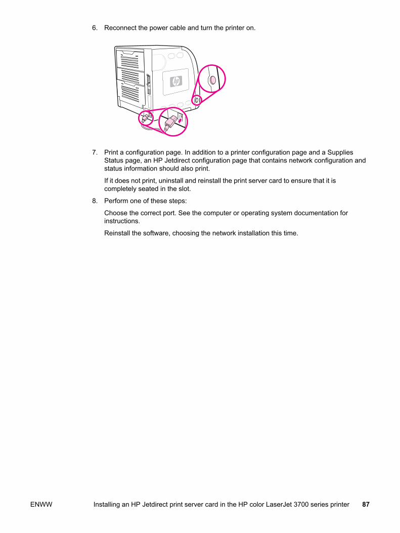
6. Reconnect the power cable and turn the printer on.
7. Print a configuration page. In addition to a printer configuration page and a SuppliesStatus page, an HP Jetdirect configuration page that contains network configuration andstatus information should also print.
If it does not print, uninstall and reinstall the print server card to ensure that it iscompletely seated in the slot.
8. Perform one of these steps:
Choose the correct port. See the computer or operating system documentation forinstructions.
Reinstall the software, choosing the network installation this time.
ENWW Installing an HP Jetdirect print server card in the HP color LaserJet 3700 series printer 87

Installing an HP Jetdirect en3700 external print server
1. Attach the HP Jetdirect en3700 external print server to a 10Base-T or to a 100Base-Tlocal network by plugging the network cable into the network port on the rear panel.
2. Attach the print server to the printer using the USB cable. Insert the DC power cord fromthe power module into the power connector on the rear panel, and then insert into apower outlet.
88 Chapter 3 Installation and configuration ENWW

3. The 10 or the 100 LED turns on, indicating a network connection, and the power/statusLED blinks. After 15 seconds, the power/status LED light and the USB printer LED lightappear green. The power/status LED will blink if there is network activity.
4. Press the test button on the back of the external print server to print an HP Jetdirectconfiguration page. Note the IP address for reference.
ENWW Installing an HP Jetdirect en3700 external print server 89

90 Chapter 3 Installation and configuration ENWW
4 Printer maintenance
Chapter contents
This chapter contains the following sections.
Chapter contents .....................................................................................................................91Cleaning the printer and accessories ......................................................................................92
Cleaning spilled toner .......................................................................................................92Managing supplies ..................................................................................................................94
Supplies life ......................................................................................................................94Approximate replacement intervals for supplies for the HP Color LaserJet 3500
series printer ..................................................................................................................94Approximate replacement intervals for supplies for the HP Color LaserJet
3550/3700 series printer ................................................................................................94Locating supplies and parts ....................................................................................................96Replacing supply items ...........................................................................................................97
Replacing the transfer unit ................................................................................................99Replacing the fuser and pickup roller .............................................................................103
ENWW Chapter contents 91
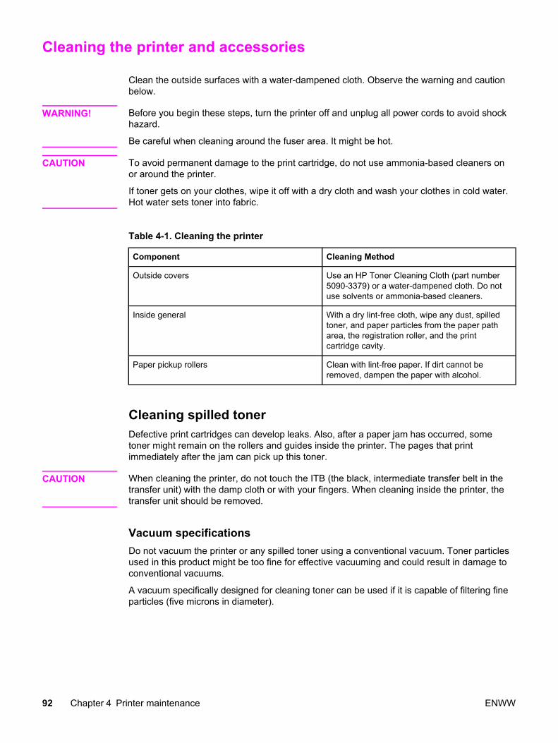
Cleaning the printer and accessories
Clean the outside surfaces with a water-dampened cloth. Observe the warning and cautionbelow.
WARNING! Before you begin these steps, turn the printer off and unplug all power cords to avoid shockhazard.
Be careful when cleaning around the fuser area. It might be hot.
CAUTION To avoid permanent damage to the print cartridge, do not use ammonia-based cleaners onor around the printer.
If toner gets on your clothes, wipe it off with a dry cloth and wash your clothes in cold water.Hot water sets toner into fabric.
Table 4-1. Cleaning the printer
Component Cleaning Method
Outside covers Use an HP Toner Cleaning Cloth (part number5090-3379) or a water-dampened cloth. Do notuse solvents or ammonia-based cleaners.
Inside general With a dry lint-free cloth, wipe any dust, spilledtoner, and paper particles from the paper patharea, the registration roller, and the printcartridge cavity.
Paper pickup rollers Clean with lint-free paper. If dirt cannot beremoved, dampen the paper with alcohol.
Cleaning spilled tonerDefective print cartridges can develop leaks. Also, after a paper jam has occurred, sometoner might remain on the rollers and guides inside the printer. The pages that printimmediately after the jam can pick up this toner.
CAUTION When cleaning the printer, do not touch the ITB (the black, intermediate transfer belt in thetransfer unit) with the damp cloth or with your fingers. When cleaning inside the printer, thetransfer unit should be removed.
Vacuum specificationsDo not vacuum the printer or any spilled toner using a conventional vacuum. Toner particlesused in this product might be too fine for effective vacuuming and could result in damage toconventional vacuums.
A vacuum specifically designed for cleaning toner can be used if it is capable of filtering fineparticles (five microns in diameter).
92 Chapter 4 Printer maintenance ENWW
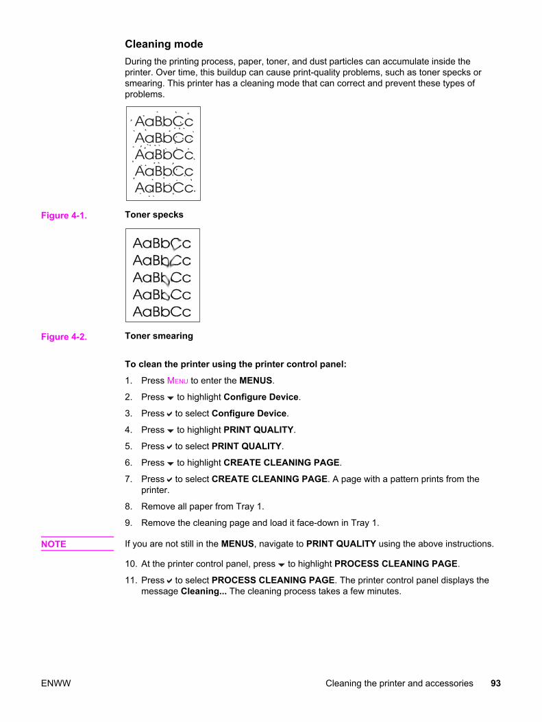
Cleaning modeDuring the printing process, paper, toner, and dust particles can accumulate inside theprinter. Over time, this buildup can cause print-quality problems, such as toner specks orsmearing. This printer has a cleaning mode that can correct and prevent these types ofproblems.
Figure 4-1. Toner specks
Figure 4-2. Toner smearing
To clean the printer using the printer control panel:
1. Press MENU to enter the MENUS.
2. Press to highlight Configure Device.
3. Press to select Configure Device.
4. Press to highlight PRINT QUALITY.
5. Press to select PRINT QUALITY.
6. Press to highlight CREATE CLEANING PAGE.
7. Press to select CREATE CLEANING PAGE. A page with a pattern prints from theprinter.
8. Remove all paper from Tray 1.
9. Remove the cleaning page and load it face-down in Tray 1.
NOTE If you are not still in the MENUS, navigate to PRINT QUALITY using the above instructions.
10. At the printer control panel, press to highlight PROCESS CLEANING PAGE.
11. Press to select PROCESS CLEANING PAGE. The printer control panel displays themessage Cleaning... The cleaning process takes a few minutes.
ENWW Cleaning the printer and accessories 93

Managing supplies
Using, storing, and monitoring print cartridges can help ensure quality printer output.
Supplies lifeThe life of the print cartridge depends on usage patterns and the amount of toner that printjobs require. For example, when printing text at 5% coverage, an HP print cartridge lasts anaverage of 4,000 or 6,000 pages, depending on the printer model. (A typical business letteris about 5% coverage.)
Cartridge life expectancy is reduced by frequently printing many one- or two-page jobs,heavy coverage, and automatic duplexing. At any time, you can verify the life expectancy bychecking the print cartridge life. For more information on how to check the life of the printcartridge, see the user guide.
Approximate replacement intervals for supplies for theHP Color LaserJet 3500 series printerThe following table lists the estimated replacement intervals for supplies and the printercontrol panel messages that prompt when to replace each item.
Table 4-2. Approximate replacement intervals
Item Printer message Page count Approximate timeperiod1
Black cartridge REPLACE BLACKCARTRIDGE
6,000 pages2 6 months
Color cartridge REPLACE <COLOR>CARTRIDGE
4,000 pages2 4 months
Image transfer kit REPLACETRANSFER KIT
60,000 pages3 60 months
Image fuser kit REPLACE FUSER KIT 60,000 pages3 60 months1Approximate life is based on 1,000 pages per month.2Approximate A4-/letter-size page count is based on approximately 5% coverage ofindividual colors.3Usage conditions and print patterns may cause results to vary.
To order supplies online, go to http://www.hp.com/support/clj3500.
Approximate replacement intervals for supplies for theHP Color LaserJet 3550/3700 series printerThe following table lists the estimated replacement intervals for supplies and the printercontrol panel messages that prompt when to replace each item.
94 Chapter 4 Printer maintenance ENWW

Table 4-3. Approximate replacement intervals
Item Printer message Page count Approximate timeperiod1
Print cartridges REPLACE BLACKCARTRIDGE
6,000 pages2 4 months
Color cartridge REPLACE <COLOR>CARTRIDGE
6,000 pages2 4 months
Image transfer kit REPLACETRANSFER KIT
75,000 pages3 50 months
Image fuser kit REPLACE FUSER KIT 75,000 pages3 50 months1Approximate life is based on 1,500 pages per month.2Approximate A4/letter-size page count is based on approximately 5% coverage of individualcolors.3Usage conditions and print patterns may cause results to vary.
To order supplies online, go to http://www.hp.com/support/clj3700 or http://www.hp.com/support/clj3550
ENWW Managing supplies 95

Locating supplies and parts
Supplies and parts are identified by labeling and by blue plastic handles.
The following graphic shows the location of each supply item and part.
Figure 4-3. Supply item and part locations
1 Fuser2 Print cartridges3 Transfer unit (ITB)4 Pickup roller
96 Chapter 4 Printer maintenance ENWW

Replacing supply items
Carefully follow the guidelines in this section when replacing printer supplies or parts.
Replace a print cartridge when the printer control panel displays a REPLACE <COLOR>CARTRIDGE message. The control panel display will also indicate the color that should bereplaced (unless a genuine HP print cartridge is not currently installed).
1. Lift the front door handle and pull down the front door.
CAUTION Do not place anything on the transfer unit and do not touch the transfer unit, which is locatedon the inside of the front door. If the ITB (intermediate transfer belt) on the transfer unit ispunctured, print quality problems may result.
2. Remove the used print cartridge from the printer.
ENWW Replacing supply items 97
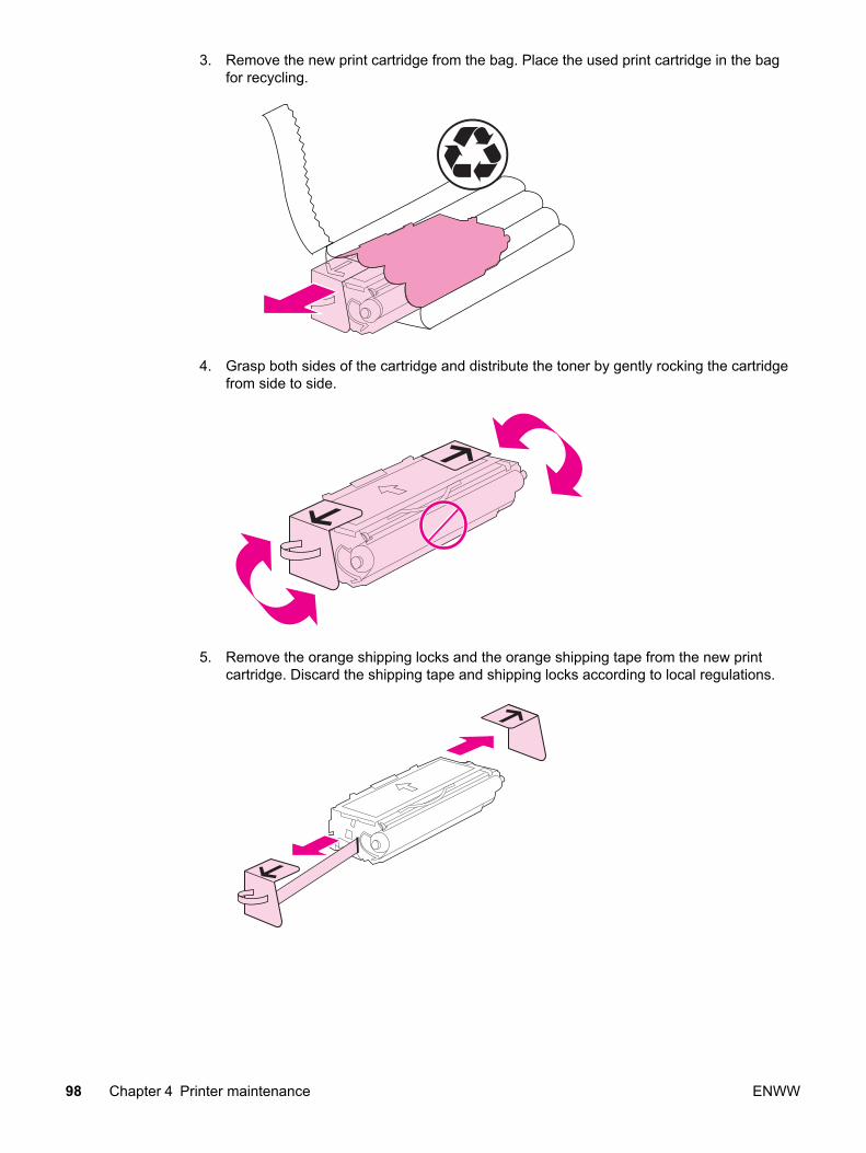
3. Remove the new print cartridge from the bag. Place the used print cartridge in the bagfor recycling.
4. Grasp both sides of the cartridge and distribute the toner by gently rocking the cartridgefrom side to side.
5. Remove the orange shipping locks and the orange shipping tape from the new printcartridge. Discard the shipping tape and shipping locks according to local regulations.
98 Chapter 4 Printer maintenance ENWW

6. Align the print cartridge with the tracks inside the printer, and using the blue handle,insert the print cartridge until it is firmly seated.
7. Firmly close the front door.
After a short calibration time, the control panel should display Ready.
NOTE If a cartridge is in the wrong slot or the wrong type for the printer, the control panel willdisplay the message, INCORRECT <COLOR> or Incorrect supplies.
8. Installation is complete. Place the used print cartridge in the box in which the newcartridge arrived. See the enclosed recycling guide for recycling instructions.
9. If you are using a non-HP print cartridge, check the printer control panel for furtherinstructions.
For additional help, go to http://www.hp.com/support/clj3500 for the HP Color LaserJet 3500series printer, to http://www.hp.com/support/clj3550 for the HP Color LaserJet 3550 seriesprinter or to http://www.hp.com/support/clj3700 for the HP Color LaserJet 3700 series printer.
Replacing the transfer unitReplace the transfer unit when the printer control panel displays REPLACE TRANSFERKIT. The image transfer kit contains a replacement transfer unit for this printer.
WARNING! Remove any jewelry or any other metal items from your body to avoid electric shock.
ENWW Replacing supply items 99
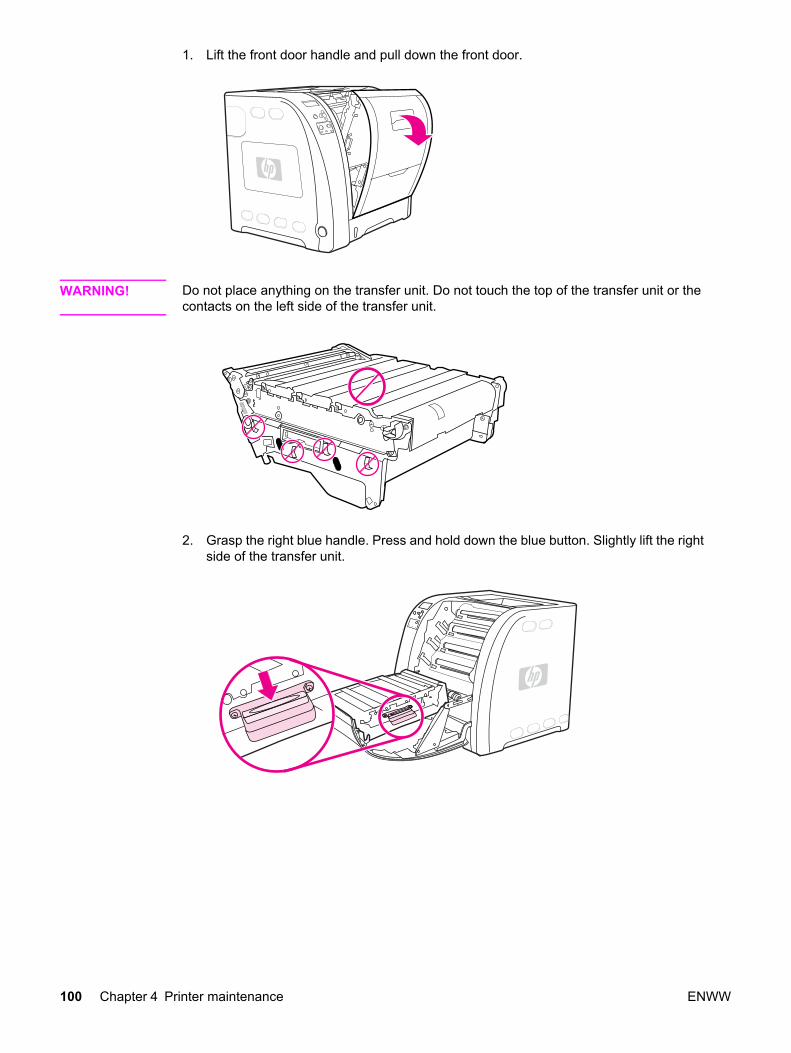
1. Lift the front door handle and pull down the front door.
WARNING! Do not place anything on the transfer unit. Do not touch the top of the transfer unit or thecontacts on the left side of the transfer unit.
2. Grasp the right blue handle. Press and hold down the blue button. Slightly lift the rightside of the transfer unit.
100 Chapter 4 Printer maintenance ENWW

3. Grasp the left blue handle and lift to remove the transfer unit from the printer.
NOTE For information on how to properly dispose of the used transfer unit, go to http://www.hp.com/recycle.
4. Using handles, remove the new transfer unit from the bag. Use the blue handles on bothsides to hold the transfer unit.
5. Place the new transfer unit on a flat surface. Remove the orange shipping locks.
ENWW Replacing supply items 101
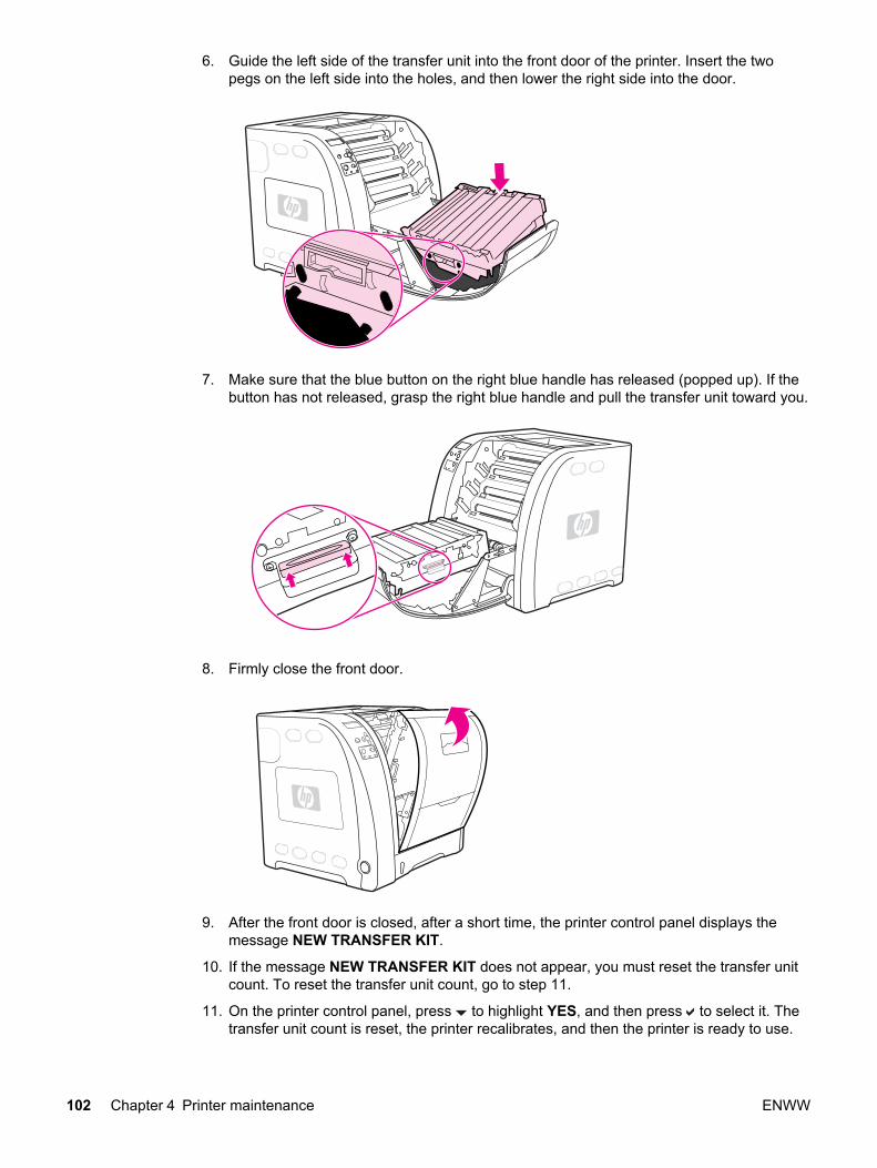
6. Guide the left side of the transfer unit into the front door of the printer. Insert the twopegs on the left side into the holes, and then lower the right side into the door.
7. Make sure that the blue button on the right blue handle has released (popped up). If thebutton has not released, grasp the right blue handle and pull the transfer unit toward you.
8. Firmly close the front door.
9. After the front door is closed, after a short time, the printer control panel displays themessage NEW TRANSFER KIT.
10. If the message NEW TRANSFER KIT does not appear, you must reset the transfer unitcount. To reset the transfer unit count, go to step 11.
11. On the printer control panel, press to highlight YES, and then press to select it. Thetransfer unit count is reset, the printer recalibrates, and then the printer is ready to use.
102 Chapter 4 Printer maintenance ENWW

NOTE If the old transfer unit was not at end-of-life when it was replaced (for example, if it wasdamaged), the transfer unit count must be reset using the printer control panel.
Replacing the transfer unit when it is not at end-of-lifeIf you replace the transfer unit when it is not at the end-of-life, for instance if it is defective,you will need to reset the transfer unit count and then calibrate the printer, through thecontrol panel.
To reset the transfer unit count, do the following:
1. Press MENU to enter the MENUS.
2. Press to highlight Configure Device.
3. Press to select Configure Device.
4. Press to highlight RESETS.
5. Press to select RESETS.
6. Press to highlight RESET SUPPLIES.
7. Press to select RESET SUPPLIES.
8. Press to highlight NEW TRANSFER KIT.
9. Press to select NEW TRANSFER KIT.
10. Press to highlight YES.
11. Press to select YES.
To calibrate the printer, do the following:
1. Press MENU to enter the MENUS.
2. Press to highlight Configure Device.
3. Press to select Configure Device.
4. Press to highlight PRINT QUALITY.
5. Press to select PRINT QUALITY.
6. Press to highlight CALIBRATE NOW.
7. Press to select CALIBRATE NOW.
8. Wait for the printer to calibrate.
The transfer unit count is reset and the printer is ready to use.
Replacing the fuser and pickup rollerReplace the fuser when the printer control panel displays REPLACE FUSER KIT. Theimage fuser kit contains a replacement fuser and a Tray 2 pickup roller for this printer. Afterreplacing the fuser, you must also replace the pickup roller. Instructions for replacing thepickup roller follow the instructions for replacing the fuser.
ENWW Replacing supply items 103

To replace the fuser1. Turn the printer off.
WARNING! The fuser might be hot. Wait 10 minutes before proceeding.
2. Open the lower rear door (rear output bin).
3. Slide out the lower rear door (rear output bin) tray extender.
104 Chapter 4 Printer maintenance ENWW
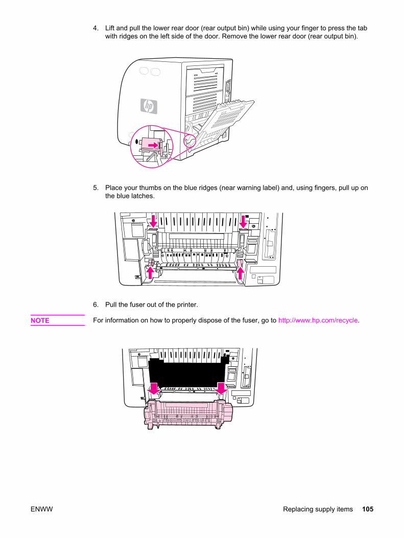
4. Lift and pull the lower rear door (rear output bin) while using your finger to press the tabwith ridges on the left side of the door. Remove the lower rear door (rear output bin).
5. Place your thumbs on the blue ridges (near warning label) and, using fingers, pull up onthe blue latches.
6. Pull the fuser out of the printer.
NOTE For information on how to properly dispose of the fuser, go to http://www.hp.com/recycle.
ENWW Replacing supply items 105

7. Remove the new fuser from the bag.
8. Hold the fuser with your thumbs on the blue ridges and fingers on the blue latches. Pushboth sides of the fuser into the printer.
9. Press the black ridges on the front of the fuser until the fuser clicks into place.
106 Chapter 4 Printer maintenance ENWW

10. Rotate the green levers to the up position.
11. To reattach the lower rear door (rear output bin), hold the door at a 45° angle, and fit thepeg into the round hole on the right side.
ENWW Replacing supply items 107
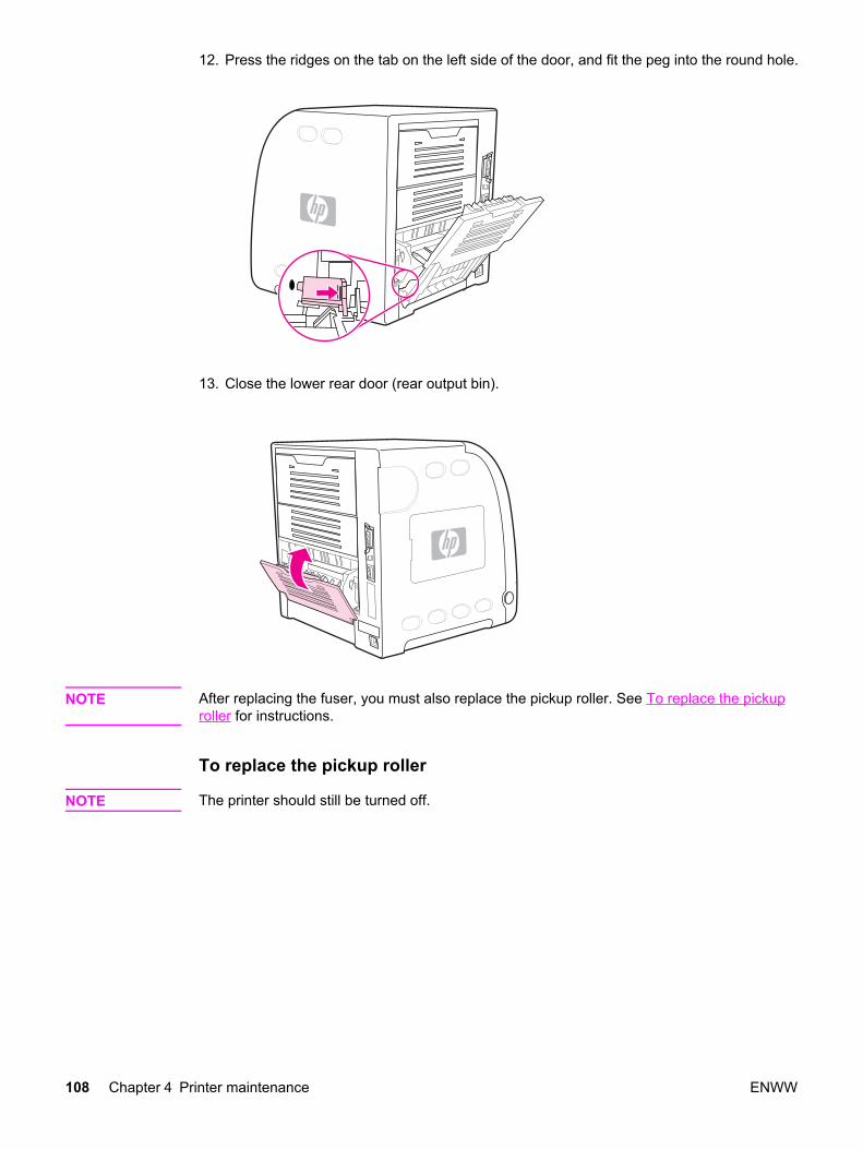
12. Press the ridges on the tab on the left side of the door, and fit the peg into the round hole.
13. Close the lower rear door (rear output bin).
NOTE After replacing the fuser, you must also replace the pickup roller. See To replace the pickuproller for instructions.
To replace the pickup roller
NOTE The printer should still be turned off.
108 Chapter 4 Printer maintenance ENWW

1. Remove Tray 2 and place it on a flat surface.
2. Use one finger to push on the blue side of the pickup roller until the peg comes out ofthe right hole.
3. Pull down gently on the pickup roller to remove the left peg of the pickup roller from theprinter.
ENWW Replacing supply items 109

4. Remove the new pickup roller from the bag.
NOTE For information on how to properly dispose of the used pickup roller, go to http://www.hp.com/recycle.
5. Hold the blue side of the pickup roller, and insert the left peg into the round hole in theprinter.
6. Push in on the pickup roller while lifting up on the right side of the pickup roller, so thepin goes into the hole.
110 Chapter 4 Printer maintenance ENWW
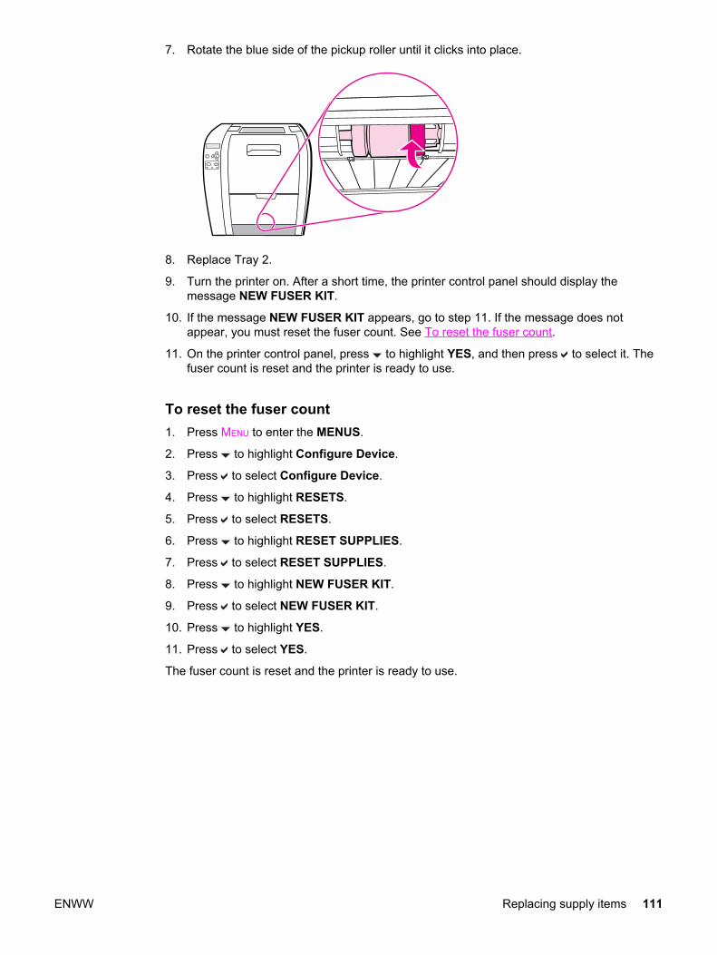
7. Rotate the blue side of the pickup roller until it clicks into place.
8. Replace Tray 2.
9. Turn the printer on. After a short time, the printer control panel should display themessage NEW FUSER KIT.
10. If the message NEW FUSER KIT appears, go to step 11. If the message does notappear, you must reset the fuser count. See To reset the fuser count.
11. On the printer control panel, press to highlight YES, and then press to select it. Thefuser count is reset and the printer is ready to use.
To reset the fuser count1. Press MENU to enter the MENUS.
2. Press to highlight Configure Device.
3. Press to select Configure Device.
4. Press to highlight RESETS.
5. Press to select RESETS.
6. Press to highlight RESET SUPPLIES.
7. Press to select RESET SUPPLIES.
8. Press to highlight NEW FUSER KIT.
9. Press to select NEW FUSER KIT.
10. Press to highlight YES.
11. Press to select YES.
The fuser count is reset and the printer is ready to use.
ENWW Replacing supply items 111

112 Chapter 4 Printer maintenance ENWW

5 Theory of operation
Chapter contents
This chapter contains the following sections.
Chapter contents ...................................................................................................................113Basic operation .....................................................................................................................114
Operation sequence .......................................................................................................114Power-on sequences ......................................................................................................116
Engine control system ...........................................................................................................119DC controller PCB ..........................................................................................................119Low-voltage power supply circuit ...................................................................................126Low-voltage power supply circuit ...................................................................................131
Laser/scanner system ...........................................................................................................139Laser control ...................................................................................................................140Scanner motor control ....................................................................................................144
Image formation system ........................................................................................................146Print process ...................................................................................................................147Developing section .........................................................................................................156Cartridge cleaning control ...............................................................................................163Transfer section ..............................................................................................................164ITB cleaning control ........................................................................................................167Waste toner full detection ...............................................................................................167Transfer (ITB) unit detection ...........................................................................................168Transfer unit life detection ..............................................................................................169ITB self-aligning mechanism ..........................................................................................170Primary transfer roller engaging/disengaging control ....................................................171Secondary transfer roller engaging/disengaging control ................................................172Secondary transfer roller engaging/disengaging detection ............................................173Color misregistration control ...........................................................................................174Image stabilization control ..............................................................................................177
Pickup/feed system ...............................................................................................................182Pickup/feed unit ..............................................................................................................184Fuser/delivery unit ..........................................................................................................189Duplexing feed unit (HP 3700 printer only) ....................................................................192Jam detection .................................................................................................................195
Paper feeder ..........................................................................................................................197Pickup/delivery sequence ...............................................................................................198Paper jam detection ........................................................................................................199
ENWW Chapter contents 113

Basic operation
The HP Color LaserJet 3500/3550 and 3700 series printer functions are divided into foursystems:
1. Engine control system
2. Laser/scanner system
3. Image formation system
4. Pickup/feed system
Upon receipt of printing commands from the external device via the formatter, the enginecontrol system provides control for the laser/scanner system, the image formation system,and the pickup/feed system and performs print operations. The engine control systemreceives status from each system and sends the necessary information back to the formatter.
Figure 5-1. Basic system operation
NOTE The terms fixing and fuser refer to the same operation (or assembly) and are usedinterchangeably in this document. Also, ITB unit and transfer unit refer to the same assemblyand are used interchangeably throughout this document.
Operation sequenceA microcomputer in the engine control system controls the operation sequence for theprinter. Table 5-1. Basic operation sequence describes the main operational periods fromthe point when the printer is turned on until a print operation is completed and each motorstops rotating.
114 Chapter 5 Theory of operation ENWW
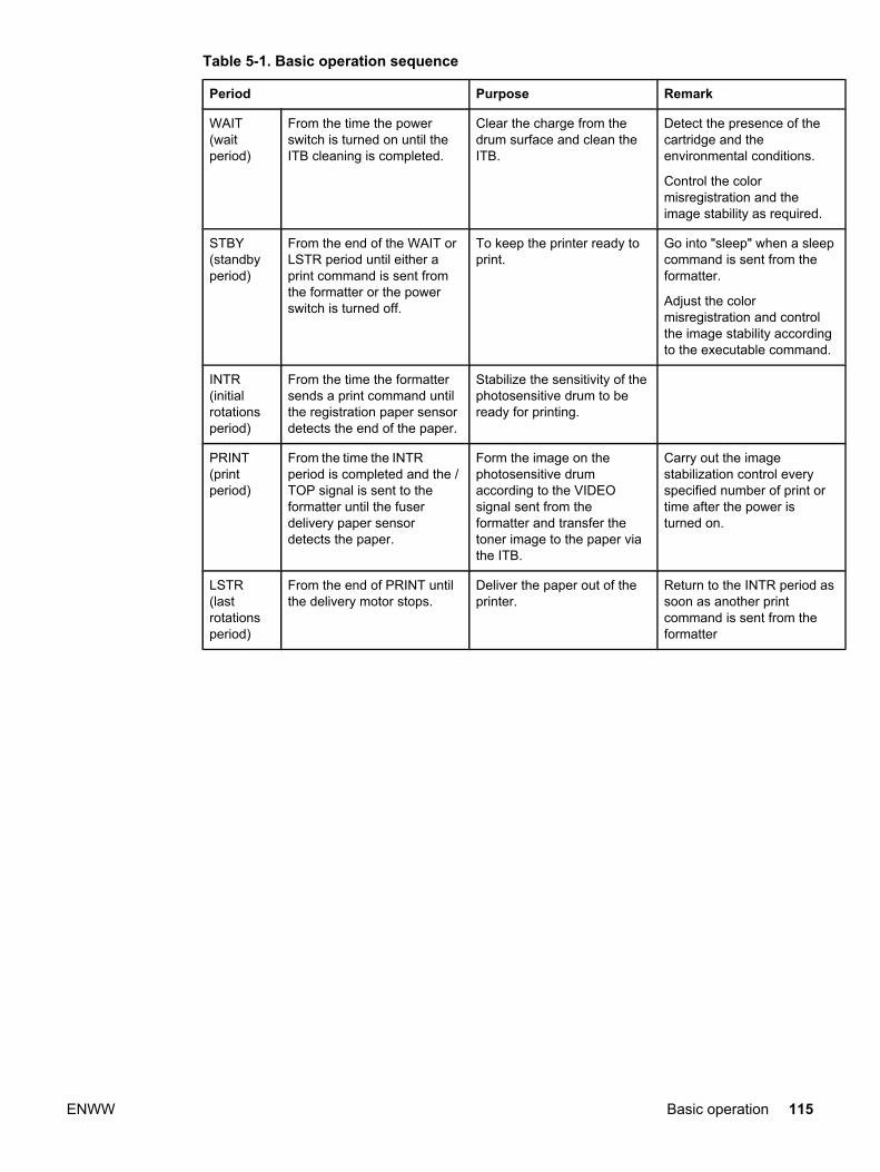
Table 5-1. Basic operation sequence
Period Purpose Remark
WAIT(waitperiod)
From the time the powerswitch is turned on until theITB cleaning is completed.
Clear the charge from thedrum surface and clean theITB.
Detect the presence of thecartridge and theenvironmental conditions.
Control the colormisregistration and theimage stability as required.
STBY(standbyperiod)
From the end of the WAIT orLSTR period until either aprint command is sent fromthe formatter or the powerswitch is turned off.
To keep the printer ready toprint.
Go into "sleep" when a sleepcommand is sent from theformatter.
Adjust the colormisregistration and controlthe image stability accordingto the executable command.
INTR(initialrotationsperiod)
From the time the formattersends a print command untilthe registration paper sensordetects the end of the paper.
Stabilize the sensitivity of thephotosensitive drum to beready for printing.
PRINT(printperiod)
From the time the INTRperiod is completed and the /TOP signal is sent to theformatter until the fuserdelivery paper sensordetects the paper.
Form the image on thephotosensitive drumaccording to the VIDEOsignal sent from theformatter and transfer thetoner image to the paper viathe ITB.
Carry out the imagestabilization control everyspecified number of print ortime after the power isturned on.
LSTR(lastrotationsperiod)
From the end of PRINT untilthe delivery motor stops.
Deliver the paper out of theprinter.
Return to the INTR period assoon as another printcommand is sent from theformatter
ENWW Basic operation 115

Power-on sequencesThe figure below shows the sequence from the time the power is switched on until STBYperiod.
�
Figure 5-2. Power-on sequence
Figure notes
1. See Developing engaging/disengaging unit, later in this chapter.
2. See Secondary transfer roller engaging/disengaging control.
3. The sequences inside the dotted-line box are performed when required.
116 Chapter 5 Theory of operation ENWW

4. The color misregistration control controls the correction of both horizontal and verticalmisregistration. See Color misregistration control, later in this chapter, for moreinformation.
5. The image stabilization control controls the correction of the high-voltage bias outputvalue and VIDEO signal PWM value for a stable image. See Image stabilization control,later in this chapter, for more information.
ENWW Basic operation 117

6. The automatic paper delivery system is activated if a residual paper is detected.
Eng
agin
g
Eng
agin
g
PR
NT
ST
BY
1 2 3 4 5 6 7 8 9 10 11 12 13 14 15 16 17 18 19 20 21 22
WA
ITIN
TR
LST
R
XX
XX
XX
XX
XX
XX
Fix
ing
tem
pera
ture
con
trol
Fan
(FA
N1)
Fee
d m
otor
(M
1)
Del
iver
y m
otor
(M
2)
Dru
m m
otor
(M
3)
Dev
elop
ing
mot
or (
M4)
Sca
nner
mot
or
Pic
k-up
sol
enoi
d (S
L1, S
L2)
Sec
onda
ry tr
ansf
er e
ngag
ing
sole
noid
(S
L4)
Reg
istr
atio
n cl
utch
(C
L1)
Dev
elop
ing
enga
ging
clu
tch
(CL3
)
Reg
istr
atio
n pa
per
sens
or (
PS
4)
Fixi
ng d
eliv
ery
pape
r sen
sor (
PS
7)
Face
-dow
n de
liver
y pa
per s
enso
r (PS
10)
/TO
P s
igna
l
Prim
ary
char
ging
bia
s
Dev
elop
ing
bias
Prim
ary
tran
sfer
bia
s (y
ello
w)
Prim
ary
tran
sfer
bia
s (m
agen
ta)
Prim
ary
tran
sfer
bia
s (c
yan)
Prim
ary
tran
sfer
bia
s (b
lack
)
Sec
onda
ry tr
ansf
er b
ias
Seq
uenc
e
Dis
enga
ging
Cle
anin
g bi
as
War
m-u
p te
mpe
ratu
re c
ontr
ol 1
Bet
wee
n-sh
eets
tem
pera
ture
con
trol
Nor
mal
spe
ed
XX
XX
Dis
enga
ging
XX
XX
XX
XX
War
m-u
p te
mpe
ratu
re c
ontr
ol 2
Prin
t tem
pera
ture
con
trol
Dou
ble
spee
d
Prin
t com
man
d
XX
XX
XX
XX
XX
XX
XX
(Uni
t: se
cond
)
Bet
wee
n-sh
eets
bia
s
Prin
t bia
s
Prin
t bia
s
Cle
anin
g bi
asB
etw
een-
shee
ts b
ias
Figure 5-3. Timing diagram
118 Chapter 5 Theory of operation ENWW

Engine control system
The engine control system functions as the brain of the printer. It controls the laser/scannersystem, the image formation system, and the pickup/feed system according to thecommands received from the formatter.
The engine control system consists of the following:
● DC controller printed circuit board (PCB) assembly
● High-voltage power supply PCB
● Low-voltage power supply PCB
The block diagram below illustrates the engine control system. Each circuit is described inthe following paragraphs.
Figure 5-4. Engine control system
NOTE Components described as a PCB may consist of a single circuit board or a circuit board plusother parts, such as cables and sensors.
DC controller PCBThe DC controller PCB is controlled by the CPU on the DC controller. It controls theoperation sequences of this printer.
The following is the sequence of the DC controller PCB:
1. The power switch is turned on, the DC controller is supplied with the DC power from thelow-voltage power supply unit.
2. The CPU starts to control the operations of the printer.
3. When the printer enters the STBY period, the CPU sends signals to drive each load(such as the laser diode, the motors, and the solenoids) based on the print commandand the image data received from the formatter.
The block diagram of this circuit is illustrated in Figure 5-5. DC controller circuit.
ENWW Engine control system 119
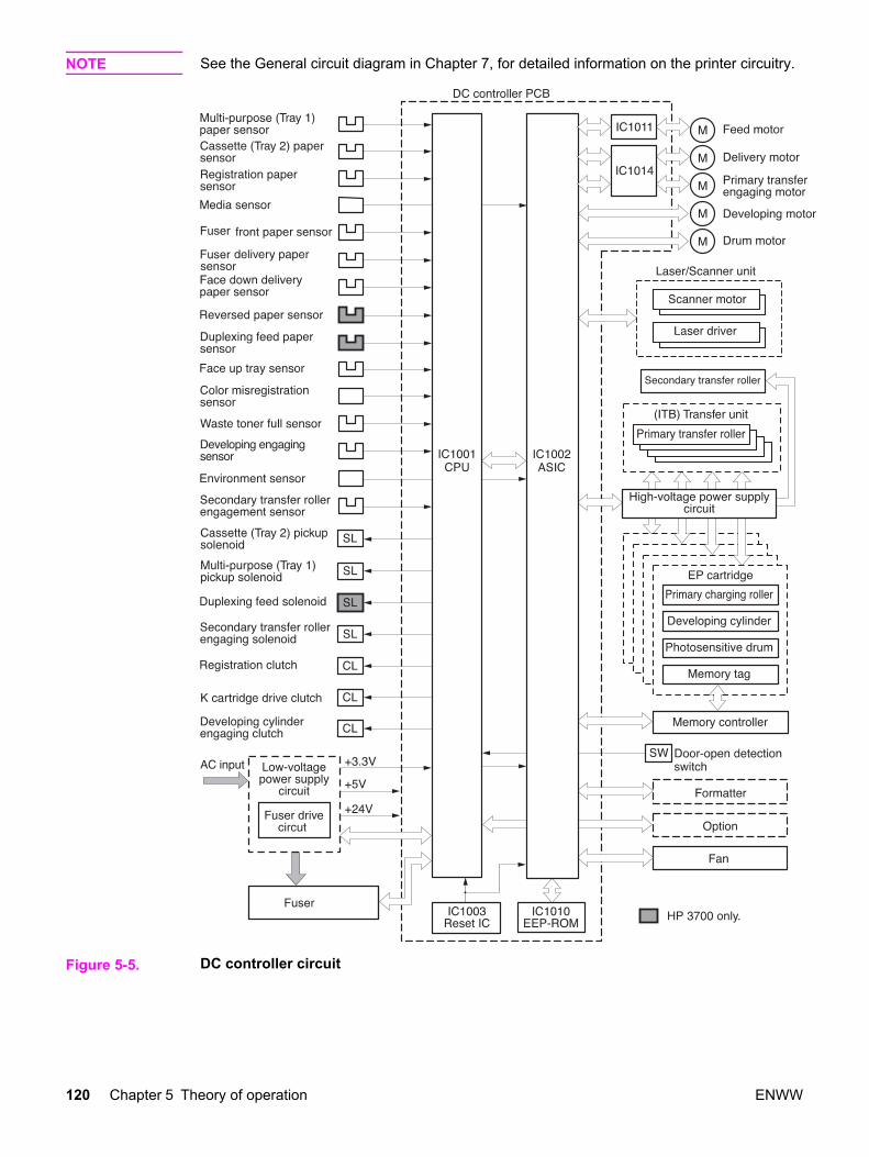
NOTE See the General circuit diagram in Chapter 7, for detailed information on the printer circuitry.
Figure 5-5. DC controller circuit
120 Chapter 5 Theory of operation ENWW

Block functionsCPU (IC1001)
The 16-bit single-chip microcomputer that constitutes the CPU incorporates ROM and RAMand controls the following operations of the printer according to the control programs storedin the ROM:
1. Printer engine sequence
2. Fuser heater drive circuit/fuser safety monitor circuit
3. Solenoids
4. Clutches
5. Sensors/switches
ASIC (IC1002)
The application specific IC (ASIC) is used to interface to the IC, the memory, the externaldevices, and so on. It controls the following operations of the printer according to thecommands from the CPU:
1. Laser/scanner
2. Communication with the formatter
3. High-voltage power supply circuit
4. Each motor’s drive
5. Fan motor’s drive
6. Writing and reading data to and from the EEP-ROM
7. Memory tag
Reset IC (IC1003)
The IC1003 monitors +3.3V voltage and resets the CPU and ASIC when the power is turnedon.
EEP-ROM (IC1010)
EEP-ROM stores various backup data.
Feeder motor driver IC (IC1011)
IC1011 controls the feed motor. (See Motors, solenoids, and clutches, below for details.)
Delivery motor driver IC (IC1014)
IC1014 controls the delivery motor and primary transfer engaging motor. (See Motors,solenoids, and clutches, below for details.)
Motors, solenoids, and clutchesThis printer has seven motors, four solenoids (three for the HP Color LaserJet 3500/3550series printer), and three clutches for paper feed and image formation. The specifications ofsuch motors, solenoids, and clutches are listed in the following tables.
The motors with failure detector are discussed in Failure detection.
ENWW Engine control system 121

Table 5-2. Motor Functions
Name Function Type Direction ofrotation
Speed switching Failuredetection
M1 Feedmotor
Drives the pick-uproller, feed roller,duplexing feed roller,and fuser.
Stepping motor Clockwise 4-speed (full, 1/2,1/3, 1/4)
No
M2Deliverymotor
Drives the feed roller,developing engagingclutch (CL3)/driveassembly, and outputdelivery rollers.
Stepping motor Clockwise/counter-clockwise
5-speed (full, 1/2,1/3, 1/4, double)
No
M3 Drummotor
Drives four colorsphotosensitive drums,ITB, Black developingcylinder.
DC motor Clockwise/counter-clockwise
4-speed (full, 1/2,1/3, 1/4)
Yes
M4Developingmotor
Drives the yellow (Y),magenta (M), andcyan (C), developingcylinders.
DC motor Clockwise 4-speed (full, 1/2,1/3, 1/4)
Yes
M5 Primarytransferrollerengagingmotor
Engages anddisengages theprimary transfer roller.
Stepping motor Clockwise/counter-clockwise
No No
FAN1 Fan Exhausts heat aroundthe fuser, scannerassembly, and printcartridges.
DC motor No Yes
122 Chapter 5 Theory of operation ENWW
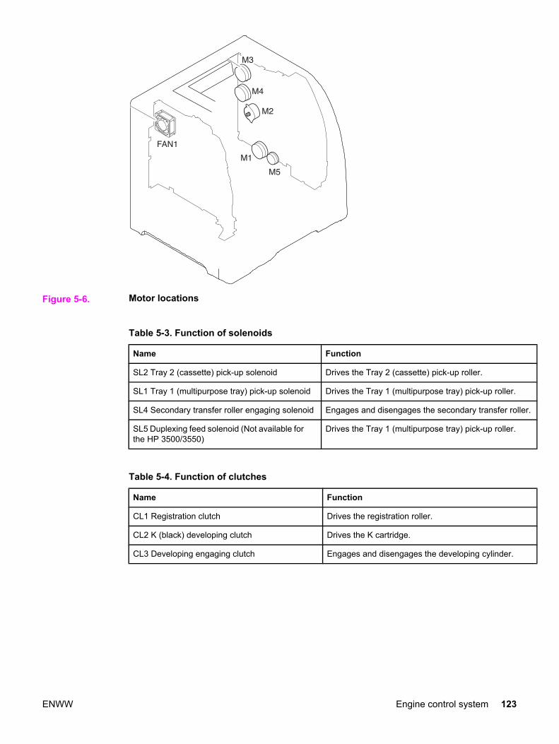
Figure 5-6. Motor locations
Table 5-3. Function of solenoids
Name Function
SL2 Tray 2 (cassette) pick-up solenoid Drives the Tray 2 (cassette) pick-up roller.
SL1 Tray 1 (multipurpose tray) pick-up solenoid Drives the Tray 1 (multipurpose tray) pick-up roller.
SL4 Secondary transfer roller engaging solenoid Engages and disengages the secondary transfer roller.
SL5 Duplexing feed solenoid (Not available forthe HP 3500/3550)
Drives the Tray 1 (multipurpose tray) pick-up roller.
Table 5-4. Function of clutches
Name Function
CL1 Registration clutch Drives the registration roller.
CL2 K (black) developing clutch Drives the K cartridge.
CL3 Developing engaging clutch Engages and disengages the developing cylinder.
ENWW Engine control system 123

Figure 5-7. Solenoid and clutch locations
Drum motor control
The drum motor control controls the drive of the drum motor (M3).
The drum motor is a three-phase, eight-pole DC motor with a built-in drive circuit. The drummotor drives the four color photosensitive drums, the K (black) developing cylinder, and theITB. The drum motor operates under the control of the DRUM MOTOR ACCELERATIONsignal (/DRMITBACC) and the DRUM MOTOR DECELERATION signal (/DRMITBDEC)from the DC controller.
Figure 5-8. Drum motor control circuit
The DC controller monitors the DRUM MOTOR SPEED DETECTION signal (/DRMITBFG)to control the RPM of the drum motor.
124 Chapter 5 Theory of operation ENWW
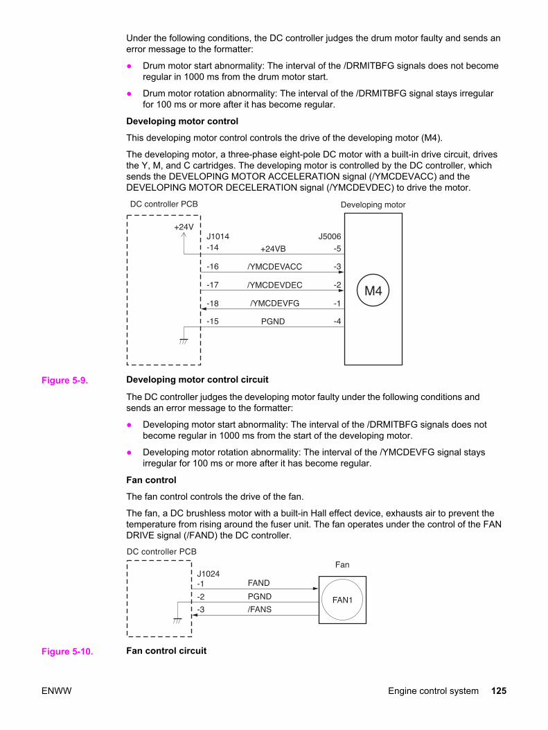
Under the following conditions, the DC controller judges the drum motor faulty and sends anerror message to the formatter:
● Drum motor start abnormality: The interval of the /DRMITBFG signals does not becomeregular in 1000 ms from the drum motor start.
● Drum motor rotation abnormality: The interval of the /DRMITBFG signal stays irregularfor 100 ms or more after it has become regular.
Developing motor control
This developing motor control controls the drive of the developing motor (M4).
The developing motor, a three-phase eight-pole DC motor with a built-in drive circuit, drivesthe Y, M, and C cartridges. The developing motor is controlled by the DC controller, whichsends the DEVELOPING MOTOR ACCELERATION signal (/YMCDEVACC) and theDEVELOPING MOTOR DECELERATION signal (/YMCDEVDEC) to drive the motor.
Figure 5-9. Developing motor control circuit
The DC controller judges the developing motor faulty under the following conditions andsends an error message to the formatter:
● Developing motor start abnormality: The interval of the /DRMITBFG signals does notbecome regular in 1000 ms from the start of the developing motor.
● Developing motor rotation abnormality: The interval of the /YMCDEVFG signal staysirregular for 100 ms or more after it has become regular.
Fan control
The fan control controls the drive of the fan.
The fan, a DC brushless motor with a built-in Hall effect device, exhausts air to prevent thetemperature from rising around the fuser unit. The fan operates under the control of the FANDRIVE signal (/FAND) the DC controller.
Figure 5-10. Fan control circuit
ENWW Engine control system 125

The DC controller monitors the FAN ROTATION DETECTION signal (/FANS) to control theRPM of the fan. The /FANS signal outputs (turn “L”) when the fan rotates at the speed of thespecified RPM: when the DC controller judges the fan normal. The DC controller judges thefan faulty and sends the error message to the formatter when the /FANS signal has not beeninput (turns “H”) for 10 seconds or more.
Low-voltage power supply circuitThe low-voltage power supply circuit converts AC voltage from a power supply receptacle toDC power and supplies the fuser with the power to drive its heater.
The low-voltage power supply circuit has two components:
● Fuser control circuit: controls the temperature of the fuser.
● Low-voltage power supply circuit: generates the DC power required inside the printerand supplies the AC power to the fuser control circuit.
Figure 5-11. Low-voltage power supply circuit
NOTE The terms fixing and fuser refer to the same operation (or assembly) and are usedinterchangeably in this document. Also, ITB unit and transfer unit refer to the same assemblyand are used interchangeably throughout this document.
126 Chapter 5 Theory of operation ENWW

Fuser control circuitThe fuser control circuit controls the temperature of the fuser. The following figure shows theceramic heater fusing method used by this printer.
Figure 5-12. Ceramic heater fusing method
The fuser control circuit has three main components:
● Fuser heater (H1): A ceramic heater that heats the fuser sleeve.
● Thermistors (TH1, TH2): Two thermistors monitor temperature:
● Main thermistor (TH1): Monitors print temperature and between-sheets temperature(contact type).
● Sub thermistor (TH2): Monitors temperature rise at the end, the initial rotationtemperature, and the start-up temperature (contact type).
● Thermoswitch (TP): One thermoswitch is placed on top of the fuser heater (non-contacttype). When the fuser heater is abnormally overheated, the switch opens and cuts offthe power supply to the heater.
The temperatures in the fuser are controlled by the fuser control circuit and the fuser heatersafety circuit according to the commands from the CPU (IC1001) on the DC controller.
Heater temperature control
ENWW Engine control system 127

The heater temperature control controls the drive signals of the fuser heater to monitor andmaintain the surface temperatures of the fuser sleeve and the fuser heater at the targettemperature.
Figure 5-13. Heater temperature control circuit
Two thermistors monitor fuser (fixing) heater temperature:
● Main thermistor (TH1): Monitors the print temperature and the between-sheetstemperature. It is placed in contact with the inside surface of the fuser sleeve andmonitors the sleeve temperature.
● Sub thermistor (TH2): Monitors the temperature rise at the end, the initial rotationtemperature, and the start-up temperature. It is placed in contact with the fuser heater.
As the surface temperature of the fuser heater rises, the resistances of both thermistorsreduce and the voltage of the FUSER HEATER TEMPERATURE DETECTION signals(MAINTH, SUBTH) varies.
The CPU (IC1001) on the DC controller monitors the voltage of these two signals (MAINTH,SUBTH) and accordingly sends the FUSER HEATER DRIVE signal (FSRD) via the ASIC(C1002). Based on this signal, the fuser heater drive circuit controls and maintains the fuserheater at the specified temperature.
This control system is divided into the following five controls.
● Initial rotation temperature control: Prevents damage to the fuser sleeve unit when thepower switch is turned on. The CPU turns on the fuser heater before it drives the feedmotor when the temperature of the heater is below 55˚ C (131˚ F) on switch-on(detected by TH2). It drives the motor after the fuser heater is left on for the prescribedtime period.
● Start-up temperature control: Determines the initial temperature of the fuser heateraccording to its temperature when energized (detected by TH2). When the heater isenergized within 30 seconds after completion of a print, the previous printingtemperature is the start-up temperature.
128 Chapter 5 Theory of operation ENWW

● Print temperature control: Maintains the fuser heater in the printer at the targettemperature. The CPU raises the target temperature in stages in one sprinting processto prevent the fuser sleeve temperature from falling as the paper goes through. Duringprinting of multiple pages, the target temperature also varies in stages depending on thenumber of pages printed.
● Between-sheets temperature control: Keeps the temperature of the fuser heater lowerthan the target temperature during continuous printing. This prevents the temperaturerise of the fuser sleeve between sheets. The between-sheets temperature variesdepending on the paper feed speed and the kind of paper being printed.
● Throughput control: Prevents both ends of the fuser sleeve unit from overheating duringcontinuous printing of narrow paper. For continuous printing, this control decreases thethroughput to slow down the paper pickup speed when the temperature of the subthermistor reads over 260˚ C (500˚ F) and the paper width is narrower than 210 mm(8.27 inches).
Flicker prevention
The flicker prevention mechanism prevents flicker when the user’s printer is connected to thesame AC line as other lighting fixtures. Because the printer’s heater drive circuit uses a triacfor switching AC, flicker can occur when the voltage in the AC line falls due to a userconnecting a printer to the same AC line as other lighting fixtures, increasing the amount ofcurrent passing through the heater.
To prevent flicker, this printer uses a zero crossing circuit to monitor the voltage of the ACline. The CPU monitors the ZERO CROSSING DETECTION signal (ZEROX) to optimize thetiming of energizing the heater.
Protective function
The CPU, fuser heater safety circuit, and thermoswitch prevent overheating of the fuser byinterrupting the current to the heater.
The abnormal temperature rise is prevented by the following parts:
1. CPU
2. Fuser heater safety circuit
3. Thermoswitch
The function of each part is described as follows:
● CPU: The CPU monitors the output voltages of the main and sub thermistors (MAINTH,SUBTH). If the MAINTH voltage goes below approximately 0.92 V (230˚ C, 446˚ F) orthe SUBTH voltage exceeds approximately 2.8 V (280˚ C, 536˚ F), the CPU judges thefuser faulty and initiates the following steps.
● The CPU sets the FUSER HEATER DRIVE signal (FSRD) to stop “L” via ASIC andturns off the heater.
● The CPU sets the RELAY DRIVE signal (RLD) to stop (“H”).
● The fuser heater safety circuit turns the RELAY DRIVE signal (RLD-) to stop (“H”).
● The relay drive circuit cuts the relay (RL301) OFF and interrupts the current to thefuser heater.
● Fuser heater safety circuit: The CPU monitors the output voltages of the main and subthermistors (MAINTH and SUBTH). It cuts the relay (RL301) off and interrupts thecurrent to the fuser heater when the MAINTH voltage is under approximately 1.0 V (240˚C, 464˚ F) or the SUBTH voltage exceeds approximately 3.0 V (290˚ C, 554˚ F).
● Thermoswitch: When the thermoswitch reads a temperature exceeding 250˚ C (482˚ F),it is disconnected, interrupting the current to the fuser heater.
ENWW Engine control system 129

NOTE The thermoswitch is some distance away from the fuser heater. The actual temperature ofthe fuser heater is about 50˚ C (122˚ F) higher than the temperature read by thethermoswitch.
Failure detection
If the CPU judges the fuser faulty, it performs the following tasks:
1. It stops the output of the FUSER DRIVE signal (FSRD) (turn “L”).
2. It sets the RELAY DRIVE signal (RLD) to stop (turn “H”).
3. It sends an error message to the formatter.
The following conditions cause the CPU to judge the fuser to be faulty.
● Set-up failure: The temperature of the main thermistor does reach 40˚ C (104˚), 0˚ C(32˚ F) when power is turned on, within 1.7 seconds from when the heater energizes, orthe temperature of the main thermistor never becomes 5˚ C (41˚ F) lower than the targettemperature during the paper passing.
● Abnormally low temperature of the main thermistor (Break in the main thermistor): Thetemperature of the main thermistor stays at approximately 70˚ C (158˚ F), equivalent toapproximately 3.17 V, or lower for 4.0 seconds or longer.
● Abnormally high temperature of the main thermistor: The temperature of the mainthermistor stays at 230˚ C (446˚ F), equivalent to approximately 0.92 V, or higher for 1.0second or longer.
● Abnormally low temperature of the sub thermistor: The temperature of the sub thermistorstays lower than 90˚ C (194˚ F) for 2.5 seconds or longer.
● Abnormally high temperature of the sub thermistor: The temperature of the subthermistor stays at 280˚ C (536˚ F), equivalent to approximately 2.8 V, or higher for 0.1second or longer.
Fuser detection
The printer detects the presence of the fuser.
The fuser is detected by the DC controller during the WAIT period. The DC controllerdetermines that the fuser unit is not installed if it detects the following two conditions andthen sends an error message to the formatter.
1. The FUSER DELIVERY PAPER DETECTION signal (/AFFPSSNS) indicates thepresence of paper (“L”).
2. The temperature at the sub thermistor does not exceed 40˚ C (104˚ F) after 500 ms offuser temperature control.
130 Chapter 5 Theory of operation ENWW

Low-voltage power supply circuitThis circuit converts AC voltage from the power supply receptacle to DC power and supplyeach load.
Figure 5-14. Low-voltage power supply circuit
When the power switch (SW3001) is turned on, the AC power is supplied to the low-voltagepower supply circuit, where it is converted to +24 V, +5 V, and +3.3 V DC power requiredinside the printer.
ENWW Engine control system 131

The major recipients of the +24 V, +5 V, and +3.3 V DC power are listed below.
● +24 V: motors, solenoids, clutches, high-voltage power supply PCB, memory controllerPCB, and optional parts
● +5 V: laser driver PCB, high-voltage power supply PCB, formatter, and sensors (exceptfor the photo interrupter)
● +3.3 V: formatter, sensor (photo interrupter), ICs inside the control panel, DC controller,and the memory controller
Protective function
The low-voltage power supply circuit has a protective function against overcurrent andovervoltage to prevent failure in the power supply circuit. It automatically breaks the outputvoltage when overcurrent or overvoltage occurs due to an issue, such as a short at the loadside.
CAUTION Turn off the power switch (SW3001) to repair the load side, then turn the power back onafter the repair is complete, since the DC voltage from the low-voltage power supply circuitmay be stopped by this function.
There are two power supply fuses (FU3001, FU3002) in the circuit which have a protectivefunction. The power supply fuse opens and interrupts the current when an overcurrentoccurs in the AC line.
CAUTION To recover the low-voltage power supply after it has been broken for protection, turn thepower off (by switching off or unplugging) and leave the printer off for three minutes or longerbefore turning the power back on.
Safety
For the safety of users and service technicians, the +24 V is divided into two: +24 VA and+24 VB. The +24 VA is supplied from the DC controller all the time, whereas the powersupply of the +24 VB stops when the door-open detection switch (SW1) is cut off. The high-voltage power supply circuit, motors, and solenoids are supplied with the +24 VB. They stopwhen the front cover is opened. This is to protect the users and the service technicians froman electric shock or injury to their hands.
The +24 VB also functions as a DOOR-OPEN DETECTION signal (DOPEN). The CPUjudges the door open when the +24 VB supply stops.
Sleep mode
This function saves the power consumption of the printer. It is controlled by the DC controllerand goes through the following sequence:
1. The DC controller receives a sleep command from the formatter.
2. The DC controller then sends the SLEEP signal (/REM24) to the low-voltage powersupply circuit within the specified time from receipt of such command. (“L” to “H”).
3. When /REM24 signal (“H”) is sent, the low-voltage power supply circuit stops the powersupply of 24V to each load and puts the fuser temperature control, fans, and motors intothe STOP state.
The printer returns to the WAIT period when it receives the command to release the sleepmode from the formatter.
High-voltage power supply circuitThis circuit applies a bias to the primary charging roller, the developing cylinder, thedeveloping blade, the primary and secondary transfer charging rollers, and the pressure roller.
132 Chapter 5 Theory of operation ENWW
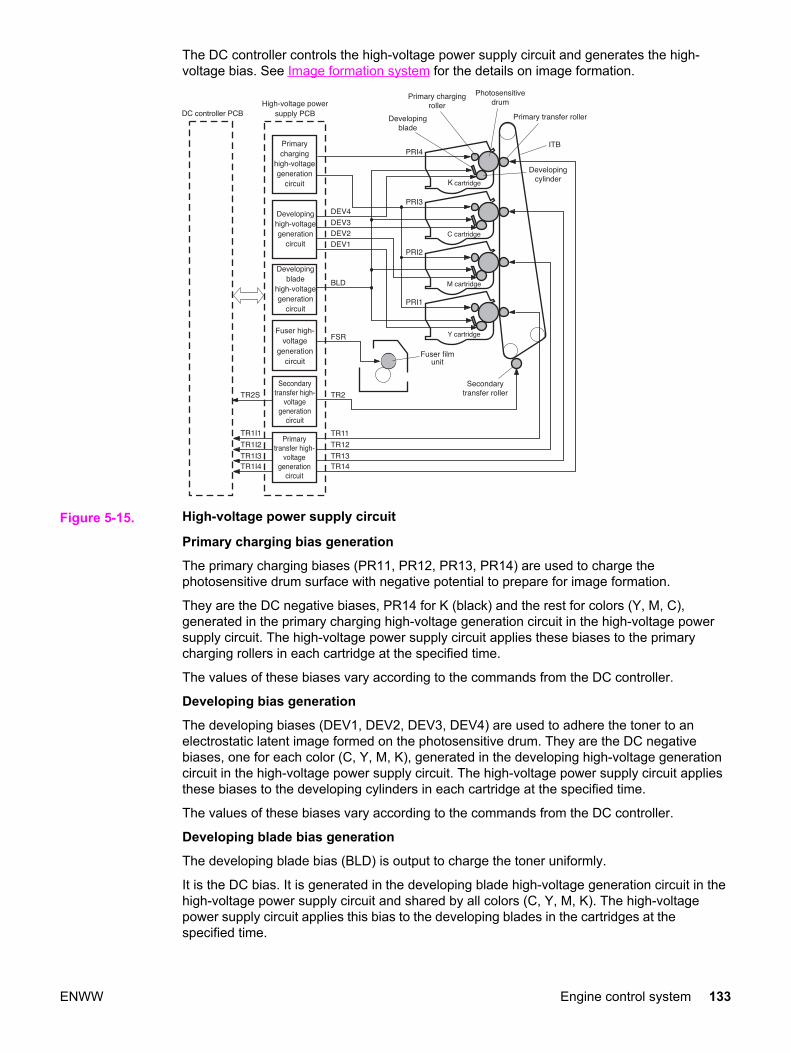
The DC controller controls the high-voltage power supply circuit and generates the high-voltage bias. See Image formation system for the details on image formation.
Figure 5-15. High-voltage power supply circuit
Primary charging bias generation
The primary charging biases (PR11, PR12, PR13, PR14) are used to charge thephotosensitive drum surface with negative potential to prepare for image formation.
They are the DC negative biases, PR14 for K (black) and the rest for colors (Y, M, C),generated in the primary charging high-voltage generation circuit in the high-voltage powersupply circuit. The high-voltage power supply circuit applies these biases to the primarycharging rollers in each cartridge at the specified time.
The values of these biases vary according to the commands from the DC controller.
Developing bias generation
The developing biases (DEV1, DEV2, DEV3, DEV4) are used to adhere the toner to anelectrostatic latent image formed on the photosensitive drum. They are the DC negativebiases, one for each color (C, Y, M, K), generated in the developing high-voltage generationcircuit in the high-voltage power supply circuit. The high-voltage power supply circuit appliesthese biases to the developing cylinders in each cartridge at the specified time.
The values of these biases vary according to the commands from the DC controller.
Developing blade bias generation
The developing blade bias (BLD) is output to charge the toner uniformly.
It is the DC bias. It is generated in the developing blade high-voltage generation circuit in thehigh-voltage power supply circuit and shared by all colors (C, Y, M, K). The high-voltagepower supply circuit applies this bias to the developing blades in the cartridges at thespecified time.
ENWW Engine control system 133
Primary transfer bias generation
The primary transfer biases (TR11, TR12, TR13, TR14) are output to transfer the toner onthe photosensitive drum to the ITB. They are the DC positive biases, one for each color (C,Y, M, K), generated in the primary transfer high-voltage generation circuit in the high-voltagepower supply circuit. The high-voltage power supply circuit applies them to the primarytransfer charging rollers in each cartridge at the specified time.
The values of these biases vary according to the commands from the DC controller.
Secondary transfer bias generation
The secondary transfer bias TR2 is output to transfer the toner on the ITB to paper.
There are two kinds of biases, one DC positive, and the other DC negative. They aregenerated in the secondary transfer high-voltage generation circuit in the high-voltage powersupply. The high-voltage power supply circuit applies them to the secondary transfercharging roller according to the following print sequences.
● Print bias (DC positive): The bias to transfer the toner on the ITB to paper during theprinting process.
● Between-sheets bias (DC positive): The bias to prevent the residual toner on the ITBfrom adhering to the secondary transfer roller during continuous printing.
● Cleaning bias (DC positive/negative): The bias to put the toner adhered to the secondarytransfer roller back to the ITB.
The values of these biases vary according to the commands from the DC controller.
The DC controller adjusts the voltage of the transfer bias constant according to theTRANSFER CURRENT FEED BACK signal (TR2S) sent from the secondary transfer high-voltage generation circuit. The DC controller also controls the rated current.
Fuser bias generation
The fuser bias (FSR) is output to prevent the toner on the paper from adhering to the fusersleeve before fuser process.
It is the DC positive bias generated in the fuser high-voltage generation circuit in the high-voltage power supply circuit. The high-voltage power supply circuit applies this bias to thepressure roller of the fuser unit at the specified time.
134 Chapter 5 Theory of operation ENWW

Video interface controlThe video interface enables communication between the formatter and the DC controller.The formatter uses the video interface to monitor the printer status continuously. It sends theVIDEO signal via the video interface when the printer is ready for printing. The DC controllerturns the laser on/off according to the VIDEO signal.
Figure 5-16. Video interface
Operational description
The VIDEO INTERFACE signal is exchanged as follows during print:
1. When the printer engine is ready for printing, the DC controller notifies the formatterusing a status command (SC) signal.
2. The formatter sends a print command in the form of an SC signal to the DC controllerwhen both the printer engine and the data for one page are ready.
3. The DC controller that drives the scanner motor sends the HORIZONTALSYNCHRONOUS signals (/BD1, /BD2, /BD3, /BD4) to the formatter upon receipt of printcommand.
4. The printer engine picks up paper. It stops the paper at the registration paper sensor(PS4) and sends the VERTICAL SYNCHRONOUS signal (/TOP) to the formatter.
5. The formatter sends the VIDEO signals (VDO1, /VDO1, VDO2, /VDO2, VDO3, /VDO3,VDO4, /VDO4) to the DC controller in synchronization with the /BD1~4 signals uponreceipt of the /TOP signal.
6. The DC controller controls each color’s laser driver circuits and turns on/off the laseraccording to the VDO11~41 signals. This forms a electrostatic latent image on eachcolor’s photosensitive drums.
7. The latent images are developed by toner and transferred onto the ITB in the order of Y(yellow), M (magenta), C (cyan), and K (black).
ENWW Engine control system 135

8. The DC controller re-feeds the paper after a specified time from /TOP signal output andtransfers the toner image from the ITB onto the paper. This aligns the leading edge ofthe paper and the top of the image.
9. The paper, having had the toner image fixed on it, is delivered to the delivery tray whenthe print is completed.
Printing continues when the DC controller receives another print command from theformatter during the first print.
See Image formation system and Pickup/feed system.
Video interface signals
Figure 5-17. Video interface signals
136 Chapter 5 Theory of operation ENWW

The types and purposes of the VIDEO INTERFACE signals are described below.
● VDO1, /VDO1, VDO2, /VDO2, VDO3, /VDO3, VDO4, /VDO4, (VIDEO) signals (formatteroutput): These signals are the information of the image the printer engine is going toprint. The laser drivers turn the laser diode on or off based on these signals. This printerhas four laser units, one for each color. The formatter sends each color’s VIDEO signal(Y=VDO1, /VDO1 M=VDO2, /VDO2 C=VDO3, /VDO3 Bk=VDO4, /VDO4) to the DCcontroller. The VIDEO signal is a differential signal. The laser diode emits light when theVDO signal is “H”, and the /VDO signal is “L”.
NOTE The abbreviations Bk and K are used interchangeably and refer to the black tonerdeveloping operations.
● /TOP (VERTICAL SYNCHRONOUS) signal (formatter input): This signal synchronizesthe vertical (sub) scanning line of the image, which is the reference signal in the verticaldirection of the laser beam. This printer has four drums. When the /TOP signal isreceived, the formatter counts the /BD signals of each color and sends each color’sVIDEO signals corresponding to the specific number of scanning in sequence to the DCcontroller. This synchronizes the leading edge of each color’s image on the drum withthe leading edge of the paper. The figure below illustrates the output timing of theVIDEO signals in response to the /TOP signal.
Figure 5-18. Output timing of the VIDEO signal in response to the /TOP signal
ENWW Engine control system 137

/BD1, /BD2, /BD3, /BD4 (HORIZONTAL SYNCHRONOUS) signals (formatter input): Thissignal synchronizes the horizontal (main) scanning line: the reference signal in the horizontaldirection of the laser beam. When the /TOP signal is received, the formatter counts the /BDsignals of each color and sends each color’s VIDEO signal synchronized with each /BDsignal corresponding to the specific number of scanning in sequence to the DC controller.This justifies the writing position of the image. The figure below illustrates the output timingof the VIDEO signal synchronized with the /BD signal.
Figure 5-19. Output timing of the VIDEO signal synchronized with the /BD signal
● SERIAL CLOCK (SCLK) signal (formatter output): The formatter outputs thissynchronizing clock signal when it sends or receives a status or command to or from theDC controller. The formatter sends a command in synchronization with the falling edgeof the SCLK signal, and receives a status in synchronization with the start-up of theSCLK signal.
● STATUS COMMAND (SC) signal (formatter input and output): This is a bi-directionalsignal to send and receive a serial data between the formatter and the DC controller.The formatter and the DC controller send and receive a status or command with thissignal.
● STATUS CHANGE NOTIFY (/CCRT) signal (formatter input): This signal notifies theformatter of any specific status changes to the printer. The formatter refers to the DCcontroller through SC line to find out which status has changed upon receipt of a CCRTsignal.
● PAPER FEED (/PFED) signal (formatter input): This signal indicates that the printerengine is ready to pick up paper. When a /PFED signal is received (becomes “L”), theformatter sends a pickup command for the optional feeder to the DC controller.
● PAPER DELIVERY (/PDLV) signal (formatter input): This signal indicates the deliverytiming from the printer to the optional feeder. When a /PDLV signal is received (becomes“L”), the formatter sends a delivery command to the DC controller.
● PAPER RE-FEED (/TOPR) signal (formatter input): This signal notifies the formatter thatthe printer is ready to pick-up paper for duplex printing. When a /TOPR signal isreceived (becomes “L”), the formatter sends a duplexing pick-up command to the DCcontroller.
138 Chapter 5 Theory of operation ENWW

Laser/scanner system
The laser/scanner system forms latent images on the photosensitive drum according to theVIDEO signals sent from the formatter. The laser/scanner unit is illustrated below.
Figure 5-20. Laser/scanner unit
The laser/scanner unit is controlled by the DC controller and consists of four laser units andtwo laser driver PCBs (two each of the units sitting on one laser driver), and two scannermotors (one scanner mirror reflects two colors’ laser beams).
The following is the sequence of the printing process:
ENWW Laser/scanner system 139

1. Upon receiving a print command from the formatter, the DC controller outputs theSCANNER MOTOR SPEED CONTROL signals (Y/M: /ACC1, /DEC1 C/Bk: /ACC2, /DEC2) and rotates the scanner motor to rotate two four-faced mirrors.
NOTE The abbreviations Bk and K are used interchangeably and refer to the black developingoperation.
2. When the scanner motor starts rotating, the DC controller outputs LASER CONTROLsignals (CTRL10~40, CTRL11~41) and emits a laser beam to input BD INPUT signals (/BD21, /BD41).
NOTE The DC controller monitors and controls the rotation speed of the scanner motor accordingto the timing the /BDI signals are input to be the specified speed.
3. When the scanner motor rotates at the specified speed, the DC controller passes on theVIDEO signals from the formatter to the laser driver circuit. The laser driver circuit emitsthe laser diode according to the VIDEO signals (/VDO1~4, VDO1~4).
4. The laser beam strikes the four-face mirror rotating at a constant speed through thecollimator lens and the cylindrical lens.
5. The laser beam reflected off the four-face mirror passes through the focus lens andscans on the photosensitive drum at a constant speed.
6. When the photosensitive drum rotates and the laser beam scans on it, both at aconstant speed, a latent image is formed on the photosensitive drum.
NOTE This printer has two scanner motors and generates two /BDI signals. The /BDI signal for Yand M’s scanner motor is generated by the M laser’s reflected light, and the BDI signal for Cand K’s scanner motor, by the K (black) laser’s reflected light.
NOTE This printer scans two lines with one scanner mirror. The scanning direction depends on thecolor. (Y and C: left to right, M and K: right to left)
Laser controlThe laser control instructs the laser driver to turn on/off the laser diode according to theLASER CONTROL signal sent from the DC controller.
140 Chapter 5 Theory of operation ENWW

The laser driver PCB is divided into two. One is for Y/M, and the other for C/K. The Y/M laserdriver PCB only is described here, as both are identical.
Figure 5-21. Laser control block diagram
The DC controller sends the VIDEO signals (VDO, /VDO) for forming images and theLASER CONTROL signals (CTRL0, CTRL1) for switching the operation modes of the laserdriver circuit to each laser driver IC (IC101, IC102). The laser driver IC controls the laseraccording to the combination of the LASER CONTROL signals.
The following table shows the combination of the LASER CONTROL signals for yellow.
Operation mode CTRL0 CTRL1 Description
Standby L L Laser control OFF
Print H L Ready to emit laser by VIDEO signals
Force LD ON L H Force the laser ON
Force LD OFF H H Force the laser OFF
The LASER CONTROL signal is used for the following controls:
● Laser emission control
● Automatic photocurrent control
ENWW Laser/scanner system 141

● Horizontal synchronization control
● Image masking control
The LASER CURRENT OUTPUT signal (PDOUT) is an analog signal generated bytransforming the amount of laser to a current value. The DC controller obtains each laser’slight amount based on the PDOUT signal and passes such information on to the formatter,while the formatter adjusts the PWM (adjusts the laser emission timing according to thehalftone).
Laser emission controlThe laser emission control controls on/off of the laser diode (LD) according to the VIDEOsignals. When the DC controller puts the laser driver circuit into print mode, the laser drivercircuit turns on/off the LD at a specified light amount according to the VIDEO signals (VDO, /VDO) received from the formatter.
Automatic photocurrent control (APC)This control ensures that the amount of light emitted by the LD remains constant. There aretwo APCs, both of which are controlled by the laser driver circuit in the same way.
● Initial APC: Performed at the scanner motor startup; adjusts the amount of laser light.
● Between-lines APC: Performed during the print process; adjusts the amount of laserlight for the next one line before it is written.
The following is the sequence of APC control.
1. When the DC controller puts it into Force LD ON mode, the laser driver circuit forces theLD to emit light.
2. The light amount of the LD is detected by the photo diode (PD) and is converted tovoltage level. Then it is compared with the reference voltage (voltage equivalent to thetarget laser light amount) inside the laser driver IC.
3. The laser driver circuit controls the laser current until the voltage level of the laser lightamount reaches the reference voltage.
4. The laser driver circuit is put to Force LD OFF mode to turn the LD OFF and it stores theadjusted laser light amount in the capacitors (IC103, IC112).
Horizontal synchronous controlThe horizontal synchronous control horizontally aligns the scanning starting position of theimage. This control performs the following steps.
1. The DC controller puts the laser driver circuit into Force LD ON mode during theunblanking interval to force the LD to emit light. (The unblanking interval is the intervalwhen a LD emits light in the non-image area.)
2. The laser beam is reflected from the BD mirror, fixed at the scanning starting position inthe optical path of the laser beam, and sent to the BD circuit in the laser/scanner unit.
3. The BD circuit detects the laser beam, generates a BD INPUT signal (/BD2I), and sendsthe signal to the DC controller.
4. The DC controller generates the HORIZONTAL SYNCHRONOUS signal (Y:/BD1, M:/BD2) based on the /BD2I signal and sends it to the formatter. (The signal /BD21 isgenerated fresh based on the signal BD1, although both signals are output at the sametime.)
142 Chapter 5 Theory of operation ENWW

5. Upon receipt of /BD1 and /BD2 signals, the formatter sends the VIDEO signals (VDO1, /VDO1, VDO2, /VDO2) to the DC controller to align the scanning starting position of theimage horizontally.
Image mask controlThis control prevents laser beam emission in a non-image area except during the unblankinginterval.
The DC controller puts the laser driver circuit to Force LD OFF mode to force the LD OFFwhile the laser beam scans a non-image area except during the unblanking interval. This iscalled the image-masked status, during which the LD does not emit light even when VIDEOsignals (VDO, /VDO) are sent. The timing to start the image mask control depends on thepaper size information sent from the formatter. (This printer cannot detect the Tray 2[cassette] paper size.)
If the paper size measured by the registration paper sensor (PS4) is smaller than the papersize information, the CPU masks the image forcefully to keep the secondary transfer rollerfrom being soiled.
Figure 5-22. Image mask control
Notes on the figure
● The shaded area indicates the area where an image can be written by the laser beam.
● The times T1, T2, and T3 depend on the paper size.
● Time T4 depends on the color.
● The formatter may not send a command to specify the paper size when paper is fedfrom the manual feed tray. In such cases, the T1 and T2 are set for letter size, and theT3 is set for the size detected by the registration paper sensor (PS4), as the printercannot detect the paper width.
ENWW Laser/scanner system 143

Failure detectionThis control monitors any failure of the laser diode.
The laser IC converts the laser current of the LD to voltage during initial APC and sends thePDOUT signal to the CPU. When the voltage of the PDOUT signal is below a specifiedvalue, the CPU judges the laser faulty and informs the formatter.
Scanner motor controlThis control rotates the scanner motor to strike the laser beam at the correct position on thephotosensitive drum.
The scanner motor, which is integral with this drive circuit, is a three-phase, eight-pole DCbrushless motor with a built-in Hall device.
Figure 5-23. Scanner motor control
The DC controller performs this control. The DC controller generates the reference clockbased on the oscillation frequency of the oscillator (X1001). It compares the intervalsbetween the reference clock and the BD INPUT signal (/BD2I) in the frequency comparatorand monitors the RPM of the scanner motor. The DC controller sends the SCANNERMOTOR ACCELERATION signal (/ACC1) or the SCANNER MOTOR DECELERATIONsignal (/DEC1) to the scanner motor driver according to the monitored speed to control therotation speed of the motor.
The following sections describe each control performed by the scanner motor control.
144 Chapter 5 Theory of operation ENWW
Speed controlThe speed control maintains the scanner motor rotation at a specified speed.
The following is the sequence of steps performed by the speed control.
1. The DC controller sends the /ACC1 signal to the scanner driver IC at the scanner motorstartup to rotate the motor.
2. The DC controller forces the laser on and monitors the revolutions of the scanner motorby comparing the intervals between the BD INPUT signal (/BD2I) and the reference clock.
3. When the revolution reaches a specified number of revolutions, the DC controller sendsthe /DEC1 signal and decelerates the scanner motor. The DC controller controls thespeed of the scanner motor by sending the /ACC1 or /DEC1 signal afterwards.
Phase controlThis control prevents vertical color misregistration. It maintains the scanner motor’s rotationat a constant speed to eliminate the rotational variations between the lines. This is achievedby maintaining the phase difference between the two scanner mirrors.
The phase control performs the following steps:
1. When the scanner motor rotates at a constant speed and a specified number ofrevolutions under the speed control, the DC controller generates a phase referenceclock based on the reference clock.
2. The DC controller compares the intervals between the phase reference clock and theBD INPUT signal (/BD2I) with the frequency comparator to detect rotational variationsbetween the lines.
3. The DC controller controls the rotational variations by sending the /ACC1 signal whenthe interval of the /BD2I is slower than the phase reference clock, and sending the /DEC1 when it is faster than the clock.
Failure detectionThe CPU monitors the frequency comparator in the ASIC to check that the scanner motorrotates at the specified number of revolutions.
Under the following conditions, the CPU judges the optical unit faulty. It stops the printerengine and notifies the formatter of the failure.
● Abnormal startup: The scanner motor does not enter SCANNER READY period withinfive seconds from the start.
● Abnormal rotation: The interval of the /BDI signals goes out of the tolerance while thescanner motor rotates steadily and it continues until the accumulative length of timeequals approximately 10 mm (0.4 inch) of print distance.
It is a BD error when an abnormal rotation occurs when the image masking control isreleased. (The BD error will result when the interval of the /BDI signals goes out of toleranceeven once while the scanner motor rotates steadily and the image masking control is off.)
ENWW Laser/scanner system 145

Image formation system
The image formation system, which serves as the nerve center of the printer, forms a tonerimage on paper.
The DC controller controls the image formation system, which consists of units such as thedeveloping section (four cartridges and the developing disengaging unit), the transfer section(transfer unit and secondary transfer roller), and the fuser. The DC controller controls thelaser/scanner unit and the high-voltage power supply circuit to form an image on paperaccording to the VIDEO signals (VDO, /VDO) upon receipt of a print command from theformatter.
Figure 5-24. Image formation system and Figure 5-25. Image formation system (signalpaths) illustrate the image formation system.
NOTE The terms fixing and fuser refer to the same operation (or assembly) and are usedinterchangeably in this document. Also, ITB unit and transfer unit refer to the same assemblyand are used interchangeably throughout this document.
Figure 5-24. Image formation system
146 Chapter 5 Theory of operation ENWW

Figure 5-25. Image formation system (signal paths)
Print processThe print process can be divided into nine steps, which are executed in five blocks. A tonerimage is formed on paper as it goes through each process.
ENWW Image formation system 147

The print process blocks and the steps performed in them are listed below. Refer to Figure5-26. Print process diagram to see the placement of the blocks.
● Electrostatic latent image formation block: Forms an electrostatic latent image on thephotosensitive drum.
● Primary charging
● Laser beam exposure
● Developing block: Makes the electrostatic latent image on the photosensitive drumvisible by applying the toner on top of the image using the contact development method.
● Development
● Transfer block: Transfers a toner image on the photosensitive drum onto paper.
● Primary transfer (The toner images are transferred onto paper in the order yellow(Y), magenta (M), cyan (C), and black (K) in one rotation of the ITB.)
● Secondary transfer
● Separation
148 Chapter 5 Theory of operation ENWW

● Fuser block: Fixes or fuses a toner image on paper.
● Fuser
● Cleaning block: Clears the residual toner on the photosensitive drum and the ITB.
● ITB cleaning
● Drum cleaning
Figure 5-26. Print process diagram
ENWW Image formation system 149

Electrostatic latent image formation blockThis block consists of two steps, where an electrostatic latent image is formed on thephotosensitive drums.
The drum surface carries negative electrical charges in areas that are not exposed to thelaser beam through the steps in this block. The image with negative charges on the drum iscalled an electrostatic latent image, as it is invisible to the human eyes.
Figure 5-27. Electrostatic latent image formation
Step 1: Primary charging
As a preparation to forming a latent image, a uniform negative potential is applied to thephotosensitive drum surface in this step.
The primary charging roller, interlocked to the photosensitive drum, directly charges thedrum. This roller is made of a conductive rubber. The DC bias is placed on the roller toenable it to charge a negative potential on the drum surface.
Figure 5-28. Primary charging
Step 2: Laser beam exposure
150 Chapter 5 Theory of operation ENWW
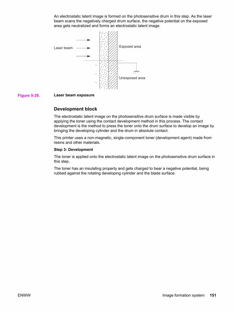
An electrostatic latent image is formed on the photosensitive drum in this step. As the laserbeam scans the negatively charged drum surface, the negative potential on the exposedarea gets neutralized and forms an electrostatic latent image.
Figure 5-29. Laser beam exposure
Development blockThe electrostatic latent image on the photosensitive drum surface is made visible byapplying the toner using the contact development method in this process. The contactdevelopment is the method to press the toner onto the drum surface to develop an image bybringing the developing cylinder and the drum in absolute contact.
This printer uses a non-magnetic, single-component toner (development agent) made fromresins and other materials.
Step 3: Development
The toner is applied onto the electrostatic latent image on the photosensitive drum surface inthis step.
The toner has an insulating property and gets charged to bear a negative potential, beingrubbed against the rotating developing cylinder and the blade surface.
ENWW Image formation system 151
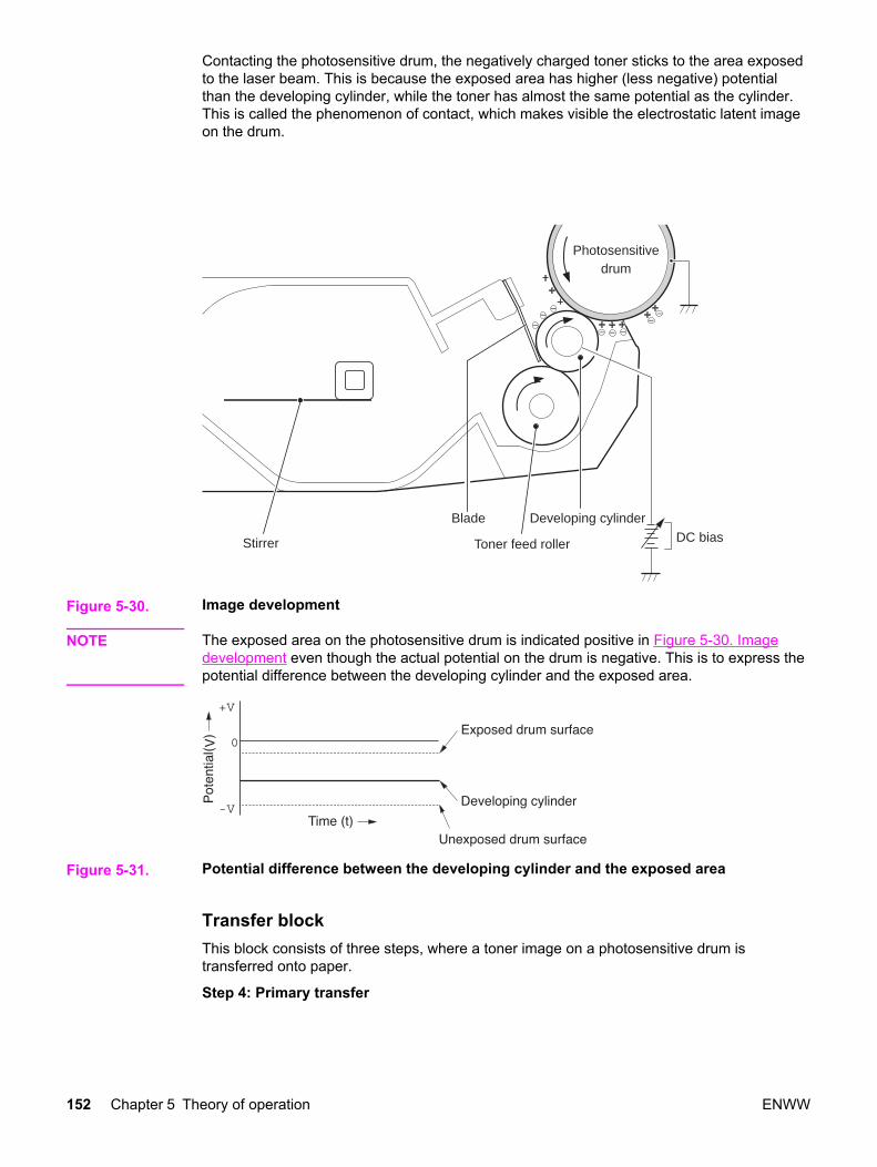
Contacting the photosensitive drum, the negatively charged toner sticks to the area exposedto the laser beam. This is because the exposed area has higher (less negative) potentialthan the developing cylinder, while the toner has almost the same potential as the cylinder.This is called the phenomenon of contact, which makes visible the electrostatic latent imageon the drum.
Blade
Toner feed roller
Developing cylinderDC biasStirrer
Photosensitivedrum
Figure 5-30. Image development
NOTE The exposed area on the photosensitive drum is indicated positive in Figure 5-30. Imagedevelopment even though the actual potential on the drum is negative. This is to express thepotential difference between the developing cylinder and the exposed area.
Figure 5-31. Potential difference between the developing cylinder and the exposed area
Transfer blockThis block consists of three steps, where a toner image on a photosensitive drum istransferred onto paper.
Step 4: Primary transfer
152 Chapter 5 Theory of operation ENWW
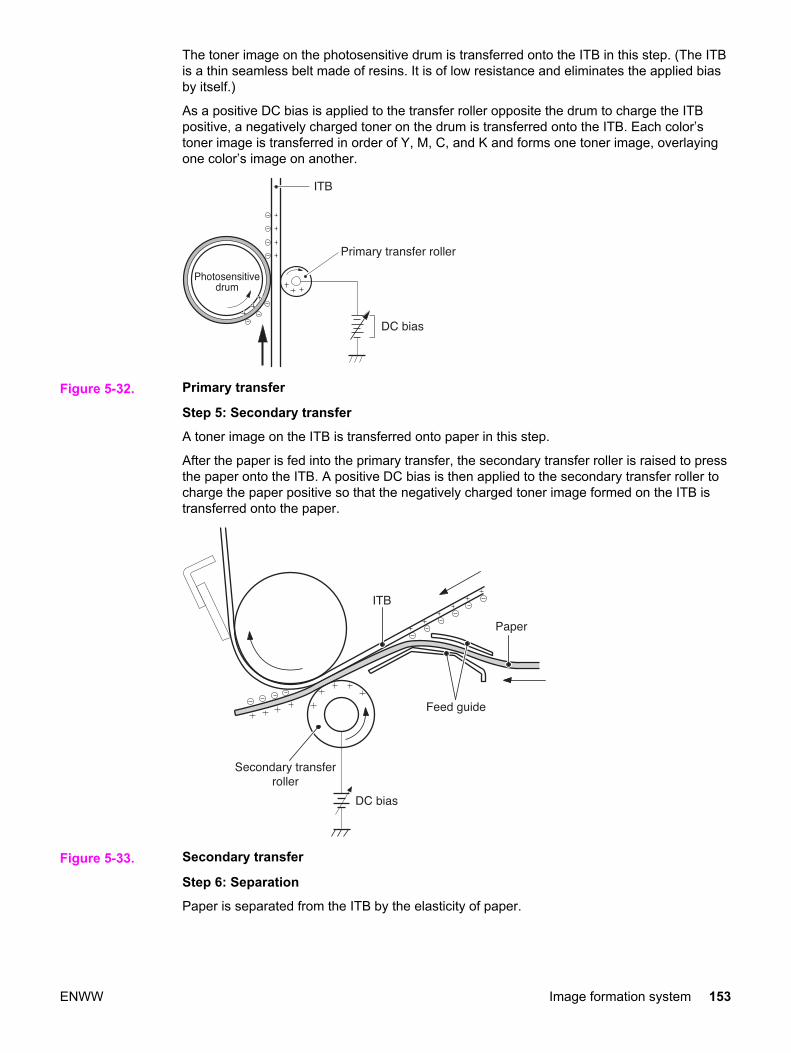
The toner image on the photosensitive drum is transferred onto the ITB in this step. (The ITBis a thin seamless belt made of resins. It is of low resistance and eliminates the applied biasby itself.)
As a positive DC bias is applied to the transfer roller opposite the drum to charge the ITBpositive, a negatively charged toner on the drum is transferred onto the ITB. Each color’stoner image is transferred in order of Y, M, C, and K and forms one toner image, overlayingone color’s image on another.
Figure 5-32. Primary transfer
Step 5: Secondary transfer
A toner image on the ITB is transferred onto paper in this step.
After the paper is fed into the primary transfer, the secondary transfer roller is raised to pressthe paper onto the ITB. A positive DC bias is then applied to the secondary transfer roller tocharge the paper positive so that the negatively charged toner image formed on the ITB istransferred onto the paper.
Figure 5-33. Secondary transfer
Step 6: Separation
Paper is separated from the ITB by the elasticity of paper.
ENWW Image formation system 153

The static charge on the back of the paper is decreased with the static charge eliminator toreduce static cling and make it easy to separate the paper.
Figure 5-34. Separation
Fuser blockA toner image is fixed, or fused, onto paper in this block.
The toner image transferred on top of the paper through the transfer block can be smearedeasily by hands since it is only attracted to paper by static electricity.
The toner image on paper is fused by pressure and heat to permanently print it on paperhere.
Step 7: Fusing
A toner image on the paper is fixed onto paper with on-demand fusing method in this step.
This printer has a low heat-capacity ceramic heater, which warms up quickly and does notrequire power during standby. This allows for a short wait period and thus energy-saving.
154 Chapter 5 Theory of operation ENWW

A positive DC bias is applied to the pressure roller to enhance the power to hold the toner onpaper and prevent the toner from being attracted to the fuser sleeve (offset).
Figure 5-35. Fusing
Cleaning blockThis block consists of two steps and clears the residual toner from the ITB, photosensitivedrum, and the primary charging roller.
During the transfer step, not all toner is transferred from the ITB and the drums onto thepaper but some remains on top of them. This remaining toner is called residual toner (wastetoner). In this block, residual toner is cleared from the ITB and photosensitive drums to keepa clear image in the following prints.
Step 8: ITB cleaning
The residual toner on the ITB is scraped away with a cleaning blade and falls into thecleaner cover. The residual toner in the cleaner cover is collected in the waste tonercontainer adjacent to the ITB afterwards.
Figure 5-36. ITB cleaning
Step 9: Drum cleaning
ENWW Image formation system 155

The residual toner on the drum is scraped away with a cleaning blade and delivered to thewaste toner container inside the cartridge afterwards. This cleans the surface of thephotosensitive drum.
Photosensitive drum�
Cleaning blade�Residual (waste)�
toner�
W�aste toner container�
Figure 5-37. Drum cleaning
Developing sectionThe developing section consists of four cartridges and the developing engaging unit. Thecartridges form a visible toner image on the photosensitive drum, and the developingengaging unit disengages the developing cylinder from the photosensitive drum.
Below are descriptions of the cartridges and the developing engaging unit.
CartridgesEach cartridge, like a monochrome cartridge, consists of a photosensitive drum, primarycharging roller, developing cylinder, stirrer, etc. They are driven by two motors: the drummotor (M3) for the K cartridge, and the developing motor (M4) for the Y, M, and C cartridges.
NOTE The cartridges in this printer are driven by two motors so that the K cartridge can be drivenindependently for monochrome prints, preventing the wear of the photosensitive drum. TheDC controller PCB signals the K developing clutch (CL2) to perform monochrome printing.
The abbreviations Bk and K are used interchangeably and refer to the black developingoperations.
156 Chapter 5 Theory of operation ENWW

Each cartridge has a built-in memory tag, into which the memory controller PCB reads/writesdata.
Figure 5-38. Cartridge diagram
Figure notes:
● M3: Drum motor
● M4: Developing motor
● CL2: K developing clutch
Developing engaging/disengaging unitThe developing engaging unit has a developing engaging lever which shifts up and down asthe developing engaging clutch is engaged or disengaged, being driven by the deliverymotor (M2). This engages or disengages the developing cylinder from the photosensitivedrum.
The developing section performs the following:
ENWW Image formation system 157

1. Memory tag control
2. Cartridge presence detection
3. Cartridge life detection
4. Developing cylinder engaging/disengaging control
5. Developing cylinder engaging/disengaging detection
158 Chapter 5 Theory of operation ENWW

6. The above operations are detailed in the following sections.
NOTE The cartridges are driven by two motors so the K cartridge can be driven independently formonochrome operations thus preventing wear of the other cartridges (photosensitive drums).
Figure 5-39. Developing engaging/disengaging unit
● M2: Delivery motor
● M3: Drum motor
● M4: Developing motor
● CL2: K developing clutch
● Developing engaging clutch
ENWW Image formation system 159
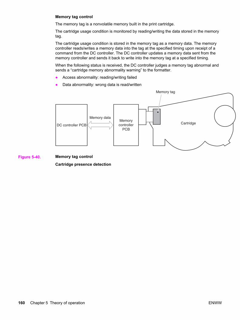
Memory tag control
The memory tag is a nonvolatile memory built in the print cartridge.
The cartridge usage condition is monitored by reading/writing the data stored in the memorytag.
The cartridge usage condition is stored in the memory tag as a memory data. The memorycontroller reads/writes a memory data into the tag at the specified timing upon receipt of acommand from the DC controller. The DC controller updates a memory data sent from thememory controller and sends it back to write into the memory tag at a specified timing.
When the following status is received, the DC controller judges a memory tag abnormal andsends a “cartridge memory abnormality warning” to the formatter.
● Access abnormality: reading/writing failed
● Data abnormality: wrong data is read/written
Figure 5-40. Memory tag control
Cartridge presence detection
160 Chapter 5 Theory of operation ENWW
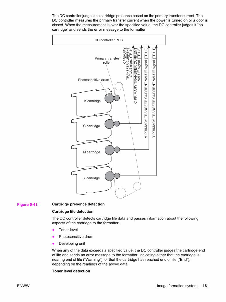
The DC controller judges the cartridge presence based on the primary transfer current. TheDC controller measures the primary transfer current when the power is turned on or a door isclosed. When the measurement is over the specified value, the DC controller judges it “nocartridge” and sends the error message to the formatter.
Figure 5-41. Cartridge presence detection
Cartridge life detection
The DC controller detects cartridge life data and passes information about the followingaspects of the cartridge to the formatter:
● Toner level
● Photosensitive drum
● Developing unit
When any of the data exceeds a specified value, the DC controller judges the cartridge endof life and sends an error message to the formatter, indicating either that the cartridge isnearing end of life ("Warning"), or that the cartridge has reached end of life (“End”),depending on the readings of the above data.
Toner level detection
ENWW Image formation system 161

The DC controller detects the end of toner by monitoring the amount of time it takes for lightto pass through the cartridge during printing.
There is a memory controller PCB with light emitter (LED) and light receiver (PD) on theback of the cartridge. When a print operation starts, the DC controller emits light from theLED with TONER LEVEL DETECTION LED DRIVE signal (TONLED). The light enters thetoner container through the light guide attached to the cartridge. It passes through thecontainer and goes back through the light guide, when the light receiver detects the light.Upon detection of light, the receiver sends the TONER LEVEL DETECTION signal(TONSNS) to the DC controller.
Figure 5-42. Toner level detection
When the toner level is high, the light is interrupted by the toner so it does not reach the lightreceiver, and vice versa when the toner level is low. The DC controller detects the toner levelbased on the light amount and notifies formatter of the detected toner level.
If no light is detected by the light receiver within a specified time during toner level detection,the DC controller judges the “toner level sensor abnormal” and sends an error message tothe formatter.
NOTE All color toner level is detected in full color print, and only K (BK) toner lever, in monochromeprint.
Developing cylinder engaging/disengaging control
This controls the disengagement of the developing cylinder from the photosensitive drum toprevent toner from being developed on the drum during non-transferring time.
The developing cylinder is engaged/disengaged when the DC controller drives thedeveloping engaging clutch (CL3) under a specified condition such as when one print iscompleted. (See Figure 5-39. Developing engaging/disengaging unit.)
The following is the disengaging sequence.
162 Chapter 5 Theory of operation ENWW

1. The DC controller turns ON the developing engaging clutch (CL3).
2. When the CL3 stays engaged for specified time, the drive of delivery motor (M2) raisesthe developing engaging lever up.
3. The developing engaging lever then raises the bottom of the cartridge in the back anddisengages the developing cylinder from the photosensitive drum.
The developing cylinder will engage back with the drum when the DC controller turns ON theCL3 for a specified time to put the developing engaging lever back to its original position.
The developing cylinder disengages under the following conditions:
● Power is turned ON
● Print operation is complete
● During cartridge cleaning (described on the following page)
● During ITB cleaning
Developing cylinder engaging/disengaging detection
This monitors whether or not the developing cylinder is engaged with the photosensitivedrum. The DC controller monitors the developing engaging sensor (PS14) during thedeveloping cylinder engagement/disengagement operation. (See Figure 5-39. Developingengaging/disengaging unit.) The developing engaging lever has a projection on the top thatpushes the developing engaging flag up and shields the PS14 when the developingengaging lever stays lifted up. When the developing cylinders are engaged, the PS14 is notshielded by the flag, so it does not output DEVELOPING ENGAGING DETECTION signal(DEVHPSNS) (Condition “L”). When the lever is lifted up, the PS14 is shielded by the flagand outputs DEVELOPING ENGAGING DETECTION signal (DEVHPSNS) (Condition “H”).
The DC controller judges the “disengagement mechanism faulty” and sends the errormessage to the formatter when the DEVHPSNS signal is not input/output within a specifiedtime during engagement/disengagement operation.
Cartridge cleaning controlThis control is for the primary charging roller cleaning.
As the printer prints pages, toner gets attracted to the primary charging rollers. Accumulatedtoner on the roller can cause some image defects, therefore it needs to be cleared away.
The DC controller sends a command for this control every specified number of pages.
ENWW Image formation system 163

The DC controller disengages the developing cylinder to start this control and apply twonegative biases alternately to the primary charging roller. This attracts the toner away fromthe primary charging roller to the photosensitive drum. The toner on the photosensitive drumis then scraped off the drum by the cleaning blade to be delivered to the waste tonercontainer.
Figure 5-43. Transfer section diagram
Transfer sectionThe transfer section, see the figure on the following page, consists of the transfer unit andthe secondary transfer unit. The transfer unit transfers the toner on the photosensitive drumto the ITB. The secondary transfer unit then transfers the toner on the ITB to the paper.
ITB (transfer) unitThe ITB unit consists of components such as ITB, primary transfer roller, ITB feed roller, andwaste toner full sensor.
As the drum motor (M3) rotates the ITB feed roller, the ITB feed roller rotates the ITB, andthe ITB rotates the primary transfer roller.
The primary transfer roller engaging cam is to engage or disengage the Y, M, and Ccartridge’s primary transfer rollers from the ITB. It is rotated by the primary transfer rollerengaging motor (M5).
The waste toner full sensor detects whether the toner piled up in the waste toner container iffull after the ITB cleaning.
Secondary transfer unitThe secondary transfer unit consists of components, such as the secondary transfer roller,secondary transfer roller engaging cam, and secondary transfer engaging sensor.
The secondary transfer roller transfers the toner on the ITB to the paper. It is interlocked withthe ITB. The secondary transfer roller engaging cam is to engage or disengage thesecondary transfer roller from the ITB. It is rotated by the delivery motor (M1) as thesecondary transfer roller engaging solenoid (SL4) opens or closes.
The secondary transfer roller engaging sensor monitors whether or not the roller is engagedwith the ITB.
The transfer section performs the following:
164 Chapter 5 Theory of operation ENWW

1. ITB cleaning control
2. Waste toner level monitor
3. Primary transfer roller engaging/disengaging control
4. Secondary transfer roller engaging/disengaging control
5. Secondary transfer roller engaging/disengaging detection
ENWW Image formation system 165

The above operations are discussed in the following sections.
Figure 5-44. Transfer section
M1: Feed motorM3: Drum motorM5: Primary transfer engaging motorSL4: Secondary transfer engaging solenoidPS10: Waste toner full sensorPS16: Secondary transfer roller engaging sensor
166 Chapter 5 Theory of operation ENWW
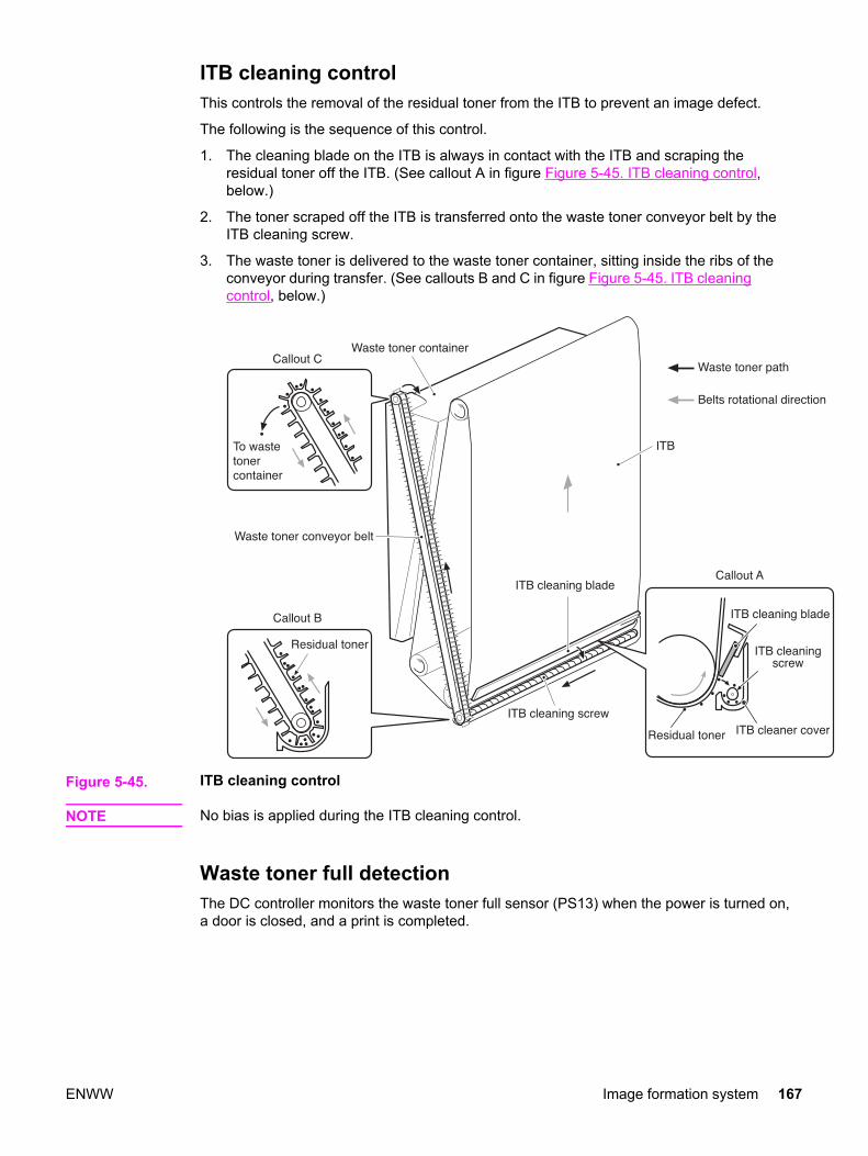
ITB cleaning controlThis controls the removal of the residual toner from the ITB to prevent an image defect.
The following is the sequence of this control.
1. The cleaning blade on the ITB is always in contact with the ITB and scraping theresidual toner off the ITB. (See callout A in figure Figure 5-45. ITB cleaning control,below.)
2. The toner scraped off the ITB is transferred onto the waste toner conveyor belt by theITB cleaning screw.
3. The waste toner is delivered to the waste toner container, sitting inside the ribs of theconveyor during transfer. (See callouts B and C in figure Figure 5-45. ITB cleaningcontrol, below.)
Figure 5-45. ITB cleaning control
NOTE No bias is applied during the ITB cleaning control.
Waste toner full detectionThe DC controller monitors the waste toner full sensor (PS13) when the power is turned on,a door is closed, and a print is completed.
ENWW Image formation system 167

The waste toner container has a light guide and a waste toner level sensor (PS13) on thetop. The light from the light emitter on the PS13 is let in to the waste toner container throughthe light guide attached to the cartridge. It passes through the container and goes backthrough the light guide when the light receiver on the PS13 detects the light. Upon detectionof light, the receiver sends a WASTE TONER FULL DETECTION signal (/WTNSNS) to theDC controller. When the toner level is low, the light will not be interrupted by the toner so itreaches the light receiver, and vice versa when the toner level is high.
The DC controller judges the waste toner full and sends a “Waste toner full warning 1” to theformatter when the light does not reach the receiver on the PS13 (that is, when the /WTNSNS signal is not output). The DC controller then counts the number of prints uponreceipt of warning 1. It sends a “Waste toner full warning 2” after the specified number ofprint, determine it full.
DC controller PCB�
W�A
ST
E �T
�ON
ER
FU
LL� D
ET
EC
TIO
�N�
sign
al (
/WT
NS
NS
)�
<� �W�aste toner not ful�l� �>�
<� �W�aste toner ful�l� �>�
Light�receiver�
Light�emitte�r�
W�aste toner�full sensor�
PS13�
Light guide� W�aste toner container�
W�aste toner�
Figure 5-46. Waste toner full detection
Transfer (ITB) unit detectionThe printer detects the presence of the transfer unit.
The DC controller monitors the waste toner full sensor (PS13) and color misregistrationsensor (PS12) during initial rotation for detection of the ITB unit.
At the start of a print operation, the DC controller lets the PS12 and PS13 emit light. If thetransfer unit is present, the LED light is received at the light receivers on the sensors, andvice versa.
168 Chapter 5 Theory of operation ENWW

If neither the PS12 or the PS13 receives light, the DC controller judges that the “transfer unitis not present, OUT” and sends an error message to the formatter.
Figure 5-47. Transfer unit detection
NOTE If light is received only at one of the light receivers on the PS12 or P13, it will not be judgedas ITB unit OUT, but will be judged as the following errors.
Error in the PS12 only: Color misregistration sensor abnormality or, Error in the PS13 only:Waste toner full warning
Transfer unit life detectionThe printer detects whether the transfer unit is coming to the end of its life.
The DC controller monitors the accumulated rotation time of the drum motor (M3) fordetection of transfer unit life.
The DC controller writes the drum motor rotation time into the EEPROM in the DC controllerevery specified time when the drum motor rotates. The EEPROM, that stores theaccumulated rotation time of the drum motor, judges that the transfer unit is at the end of itslife when the accumulated time exceeds a specified time and sends an error message to theformatter.
Figure 5-48. Transfer unit life detection control
ENWW Image formation system 169

NOTE The accumulated rotation time of the drum motor can be cleared by the formatter.Remember to reset the transfer unit life expectancy value (accumulated rotation time of thedrum motor) using the control panel when replacing the ITB unit.
ITB self-aligning mechanismThis printer automatically aligns the position of the ITB to prevent tearing of the belt due toits misalignment.
The alignment rollers, alignment gear, and alignment arm inside the ITB unit move the ITBfeed roller back and forth to align the belt (see the figure below) as described by thefollowing steps.
1. The ITB has a rib on the back along the left edge of the belt. Inside the ITB unit, twoalignment rollers are positioned at both sides of the rib so that the rib (ITB) will rotate theroller if it is in contact with one of the rollers. If the ITB is drawn leftward or rightwardduring rotation, the rib will touch one of the alignment rollers and turns the roller. (If theITB is drawn rightward, the right roller turns, and if it is drawn leftward, the left rollerturns.)
2. The rotation of the alignment roller turns the alignment gear.
3. The rotation of the alignment gear moves the alignment arm.
4. Being interlocked with the arm, the ITB feed roller moves frontward or backward as thealignment arm moves.
5. The force to feed ITB on each side varies as the ITB feed roller moves back and forth.This brings the ITB back to the original position before it has been drawn left or right andthe misalignment of the ITB is corrected.
170 Chapter 5 Theory of operation ENWW

This mechanism functions whenever the ITB rotates to prevent misalignment of the ITB.
Figure 5-49. ITB self-aligning mechanism
Primary transfer roller engaging/disengaging controlThis controls the disengagement of the primary transfer roller from the photosensitive drumto transfer only K (black) toner onto ITB for monochrome print.
The DC controller sends a control command and drives the primary transfer roller engagingmotor (M5).
The following is the sequence of this control.
1. The primary transfer engaging cam inside the ITB unit is holding the primary transferrollers for Y, M, and C, with the primary transfer roller holder, keeping the ITB in contactwith the photosensitive drums.
2. When a monochrome print starts, the DC controller rotates the primary transfer rollerdisengaging motor (M5) clockwise for a specified time.
3. When the M5 rotates for the specified time, the primary transfer disengaging cam turnsone-quarter of a revolution.
4. As it turns, the cam pushes the primary transfer roller holder down and disengages theY, M, and C rollers from the photosensitive drum.
ENWW Image formation system 171
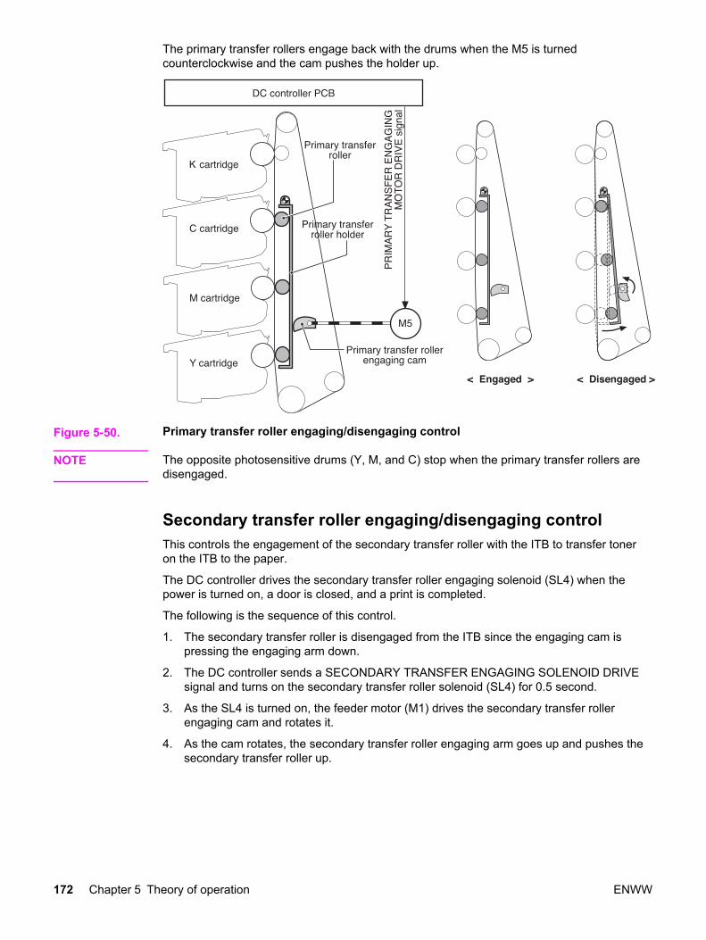
The primary transfer rollers engage back with the drums when the M5 is turnedcounterclockwise and the cam pushes the holder up.
Figure 5-50. Primary transfer roller engaging/disengaging control
NOTE The opposite photosensitive drums (Y, M, and C) stop when the primary transfer rollers aredisengaged.
Secondary transfer roller engaging/disengaging controlThis controls the engagement of the secondary transfer roller with the ITB to transfer toneron the ITB to the paper.
The DC controller drives the secondary transfer roller engaging solenoid (SL4) when thepower is turned on, a door is closed, and a print is completed.
The following is the sequence of this control.
1. The secondary transfer roller is disengaged from the ITB since the engaging cam ispressing the engaging arm down.
2. The DC controller sends a SECONDARY TRANSFER ENGAGING SOLENOID DRIVEsignal and turns on the secondary transfer roller solenoid (SL4) for 0.5 second.
3. As the SL4 is turned on, the feeder motor (M1) drives the secondary transfer rollerengaging cam and rotates it.
4. As the cam rotates, the secondary transfer roller engaging arm goes up and pushes thesecondary transfer roller up.
172 Chapter 5 Theory of operation ENWW

The secondary transfer roller disengages from the ITB when the DC controller turns the SL4again for 0.5 second and rotates the cam a half turn.
Figure 5-51. Secondary transfer roller engaging/disengaging control
Secondary transfer roller engaging/disengaging detectionThe DC controller monitors the secondary transfer roller engaging sensor (PS16) when thesecondary transfer is completed.
The secondary transfer roller engaging cam has the secondary transfer roller engaging flagon its shaft. When the secondary transfer roller is engaged with the ITB, this flag shields thePS16 and the SECONDARY TRANSFER ENGAGING DETECTION signal (T2SNS) isoutput (condition “H”), and vice versa when the roller is disengaged (condition “L”). The DCcontroller monitors the position (engagement) of the roller based on this signal.
ENWW Image formation system 173

The DC controller judges the engagement/disengagement mechanism faulty and sends theerror message to the formatter when the T2SNS signal is not input/output within a specifiedtime during the engagement/disengagement operation.
Figure 5-52. Secondary transfer roller engaging/disengaging detection
Color misregistration controlThis controls the correction of color misregistration caused by the variation of cartridges andthe laser/scanner unit. In particular, this control corrects the following:
● Horizontal scan starting position
● Horizontal scanning scale
● Vertical scan starting position
The DC controller operates this control after a door is closed after replacement of acartridge, or a specified number of pages are printed after replacement of a cartridge, or acommand is received from the formatter.
The following is the sequence of this control.
1. The DC controller writes four colors’ misregistration detection patterns, the referencepattern (right) and the pattern to be measured (left), onto the ITB.
174 Chapter 5 Theory of operation ENWW

2. The DC controller measures each color’s misregistration based on the positions of thepatterns detected by the misregistration detection (See Color misregistration control).
3. The measured information is then sent to the formatter.
4. The formatter controls each color’s VIDEO signals according to such information,making an adjustment to the horizontal scan starting position, horizontal scanning scale,or scan starting position.
A vertical color misregistration is also corrected by the DC controller, without communicatingwith the formatter, through the speed control over the scanner motor in this printer. (SeeColor misregistration control.)
In principle, the DC controller automatically sends a command to the formatter when theprinter meets the above conditions. However, when the above conditions are not met, theformatter can send a command to the DC controller to execute this control.
ENWW Image formation system 175
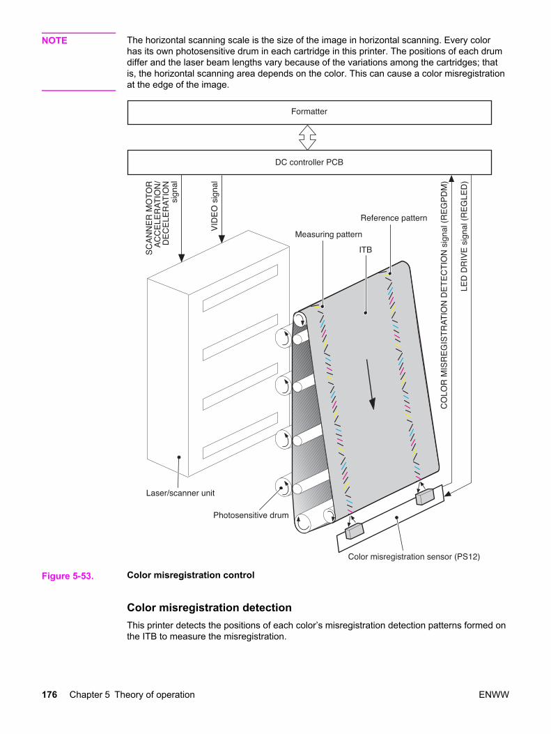
NOTE The horizontal scanning scale is the size of the image in horizontal scanning. Every colorhas its own photosensitive drum in each cartridge in this printer. The positions of each drumdiffer and the laser beam lengths vary because of the variations among the cartridges; thatis, the horizontal scanning area depends on the color. This can cause a color misregistrationat the edge of the image.
Figure 5-53. Color misregistration control
Color misregistration detectionThis printer detects the positions of each color’s misregistration detection patterns formed onthe ITB to measure the misregistration.
176 Chapter 5 Theory of operation ENWW

The DC controller monitors the color misregistration sensors (PS12) during the foregoingcolor misregistration control. There are two units of PS12 on the ITB, each having one lightemitter (LED) and one light receiver (PD).
The following is the sequence of this control.
1. The DC controller sends LED DRIVE signal (REGLED) and lets the LED emit light.
2. The light of the LED is reflected off the ITB and received by the PD on the sensor. Thelight amounts received at the PD differ depending on whether or not the light is reflectedfrom the area the toner is on.
3. The light receiver converts the received light amount to voltage and sends it to the DCcontroller in the form of the COLOR MISREGISTRATION DETECTION signal(REGPDM).
4. The DC controller detects the positions of the detection patterns according to the timethe REGPDM signals vary.
Figure 5-54. Color misregistration detection
The DC controller notifies the formatter of each error when the following errors are foundduring color misregistration detection. The initial value is reset to the new colormisregistration adjustment value whenever an error occurs.
● Color misregistration sensor abnormality warning: No light is received at the lightreceivers.
● Color misregistration measurement out of range warning: The measurement is found tobe out of specified range.
Image stabilization controlThis controls the variation of the image density caused by an environmental change ordeterioration of the photosensitive drum, toner, etc.
ENWW Image formation system 177
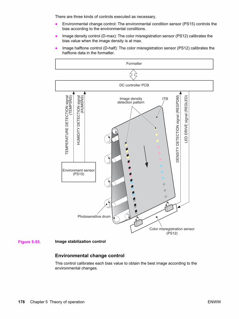
There are three kinds of controls executed as necessary.
● Environmental change control: The environmental condition sensor (PS15) controls thebias according to the environmental conditions.
● Image density control (D-max): The color misregistration sensor (PS12) calibrates thebias value when the image density is at max.
● Image halftone control (D-half): The color misregistration sensor (PS12) calibrates thehalftone data in the formatter.
Figure 5-55. Image stabilization control
Environmental change controlThis control calibrates each bias value to obtain the best image according to theenvironmental changes.
178 Chapter 5 Theory of operation ENWW

The environmental conditions sensor (PS15) on top of the fan detects the temperature andthe humidity. The PS15 sends this information to the DC controller in the form of theTEMPERATURE DETECTION signal (TEMSNS) and the HUMIDITY DETECTION signal(HUMSNS).
The DC controller monitors the environmental conditions of the printer based on these twosignals.
The DC controller controls the following biases to prevent image defects when it detects anenvironmental change upon receipt of these two signals.
● Developing bias
● Primary transfer bias
● Secondary transfer bias
If the environment sensor detects a temperature below -30˚ C or over 80˚ C, the DCcontroller determines this an "environment sensor abnormality" and sends an error messageto the formatter.
Image density control (D-max)This control calibrates the value of the developing bias to stabilize the image density.
The DC controller runs the D-max control under the following conditions:
● Power on
● A door is closed after replacement of cartridge
● A specified time has elapsed since the last rotation of the developing cylinder
● A specified amount of environmental conditions has changed since the last imagedensity control
● A command is received from the formatter
The following is the sequence of this control. (See Figure 5-56. Image density detection onthe following page.)
1. The DC controller forms 2 lines of density detection patterns (1 line each of the identicalpatterns at both sides) in each color on the ITB.
2. The DC controller measures the density of each detection pattern by controlling the colormisregistration sensor. (See Figure 5-56. Image density detection, on the following page)
3. The DC controller adjusts the developing bias according to the density of the detectionpatterns to obtain the correct density.
Image halftone control (D-half)The control is to measure the halftone density sent from the formatter and send themeasurement back to the formatter so that the formatter can perform an ideal halftonecalibration.
The DC controller controls the D-half, following the sequence below, upon receipt of acommand from the formatter.
The following is the sequence of this control.
1. The DC controller forms each color’s density detection patterns on the ITB according tothe image data received from the formatter, at the best developing bias value adjustedunder the D-max control.
ENWW Image formation system 179
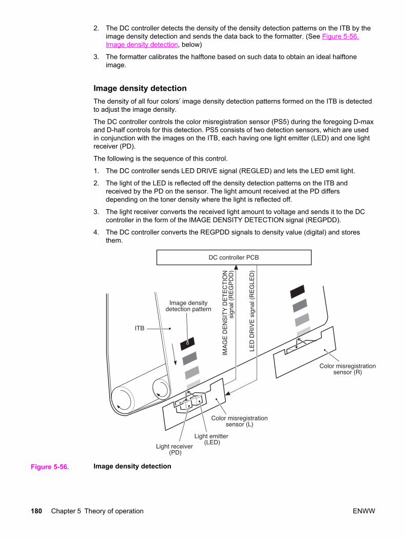
2. The DC controller detects the density of the density detection patterns on the ITB by theimage density detection and sends the data back to the formatter. (See Figure 5-56.Image density detection, below)
3. The formatter calibrates the halftone based on such data to obtain an ideal halftoneimage.
Image density detectionThe density of all four colors’ image density detection patterns formed on the ITB is detectedto adjust the image density.
The DC controller controls the color misregistration sensor (PS5) during the foregoing D-maxand D-half controls for this detection. PS5 consists of two detection sensors, which are usedin conjunction with the images on the ITB, each having one light emitter (LED) and one lightreceiver (PD).
The following is the sequence of this control.
1. The DC controller sends LED DRIVE signal (REGLED) and lets the LED emit light.
2. The light of the LED is reflected off the density detection patterns on the ITB andreceived by the PD on the sensor. The light amount received at the PD differsdepending on the toner density where the light is reflected off.
3. The light receiver converts the received light amount to voltage and sends it to the DCcontroller in the form of the IMAGE DENSITY DETECTION signal (REGPDD).
4. The DC controller converts the REGPDD signals to density value (digital) and storesthem.
Figure 5-56. Image density detection
180 Chapter 5 Theory of operation ENWW

The DC controller notifies the formatter of each error when the following errors are foundduring image density detection. The initial value is reset to the new image densityadjustment value when an error occurs.
● Image density sensor abnormality warning: No light is received at the light receivers.
● Image density out of guaranteed range warning: The measurement is found to be out ofspecified range.
ENWW Image formation system 181

Pickup/feed system
The pickup/feed system, being comprised of various feed rollers, picks up and feeds a sheetof paper.
This printer has two pickup trays (the Tray 2 (cassette) and the Tray 1 (multipurpose), andtwo delivery trays (the face-down tray and the face-up tray).
The Tray 1 (multipurpose tray) paper sensor (PS1) detects the presence of paper on theTray 1 (multipurpose tray) and the Tray 2 (cassette) paper sensor (PS2), and detects thepresence of paper in Tray 2.
The DC controller controls three motors (feed motor: M1, delivery motor: M2, drum motor:M3) and four solenoids (SL1, SL2, SL4, SL5) to drive each feed motor. (SL5 is only for the3700 printer.)
There are 6 photo interrupters (PS4, PS6, PS7, PS8, PS9, PS10) along the paper path tomonitor the arrival or passing of papers. (PS9 and PS10 are only for the 3700 printer.)
Duplex printing is available only on the 3700 printer.
Figure 5-57. Pickup/feed system illustrates the motors, solenoids, switches, and sensors.
182 Chapter 5 Theory of operation ENWW

NOTE The terms fixing and fuser refer to the same operation (or assembly) and are usedinterchangeably in this document. Also, ITB unit and transfer unit refer to the same assemblyand are used interchangeably throughout this document.
Figure 5-57. Pickup/feed system
PS1 Tray 1 (multipurpose tray) paper sensorPS2 Tray 2 (cassette) paper sensorPS4 Registration paper sensorPS5 Media sensorPS6 Fuser front paper sensorPS7 Fuser delivery paper sensorPS8 Face-down delivery unit paper sensorPS9 Reversed paper sensor (3700 printer only)PS10 Duplexing feed delivery paper sensor (3700 printer only)M1 Feed motorM2 Delivery motorM3 Drum motorSL1 Tray 1 (multipurpose tray) pickup solenoidSL2 Tray 2 (cassette) pickup solenoidSL4 Secondary transfer roller engaging solenoidSL5 Duplexing feed solenoid (3700 printer only)CL1 Registration clutch
The pickup/feed system can be divided into the following three blocks.
1. Pickup/feed unit: each pickup source to fuser inlet
ENWW Pickup/feed system 183

2. Fuser/delivery unit: fuser to delivery source
3. Duplexing feed unit (3700 printer only): fuser delivery source to registration roller inlet
Figure 5-58. Pickup/feed system blocks
Pickup/feed unitThe pickup/feed unit, being comprised of the pickup unit and feed unit, picks up paper fromthe Tray 2 (cassette) or Tray 1 (multipurpose tray) pickup tray one-by-one and feeds it intothe printer until it reaches the fuser.
Figure 5-59. Pickup/delivery unit block diagrams the pickup/feed unit.
The following is the pickup/feed sequence of operation.
184 Chapter 5 Theory of operation ENWW

1. The printer controls the fuser heater temperature and drives the scanner motor uponreceipt of a print command from the formatter.
2. When the fuser heater reaches a specified temperature, it drives the feed motor (M1).
3. The solenoid at each paper pickup source is turned on after a specified period from thescanner motor drive start.
● Tray 1 (multipurpose tray): Tray 1 solenoid (SL1)
● Tray 2 (cassette): Tray 2 pickup solenoid (SL2)
As each pickup solenoid is turned on, each pick up roller rotates and picks up paper.The separation pad prevents the double feeding of paper.
As the registration clutch (CL1) is turned on at the same time as solenoids, both theregistration roller and the feed roller rotate the paper fed to the registration roller.
4. When the scanner is ready, the drum motor (M3) drives and rotates the ITB.
5. After a specified period since the drum motor (M3) drive start, the secondary transferroller engaging solenoid (SL4) is turned on and pushes the secondary transfer rolleragainst the ITB to rotate the roller. (See Secondary transfer roller engaging/disengagingcontrol for details)
6. The registration shutter corrects the skew of the paper at the registration roller.
7. When the paper is detected by the registration paper sensor (PS4) after passing theregistration roller, the registration clutch (CL1) is turned off and stops the paper.
8. When the paper end reaches the edge of the image on the ITB, the registration clutch(CL1) is turned on. This allows the paper to be fed.
The feeding speed changes based on the media specified by the formatter. (See Paperfeeder for details)
ENWW Pickup/feed system 185
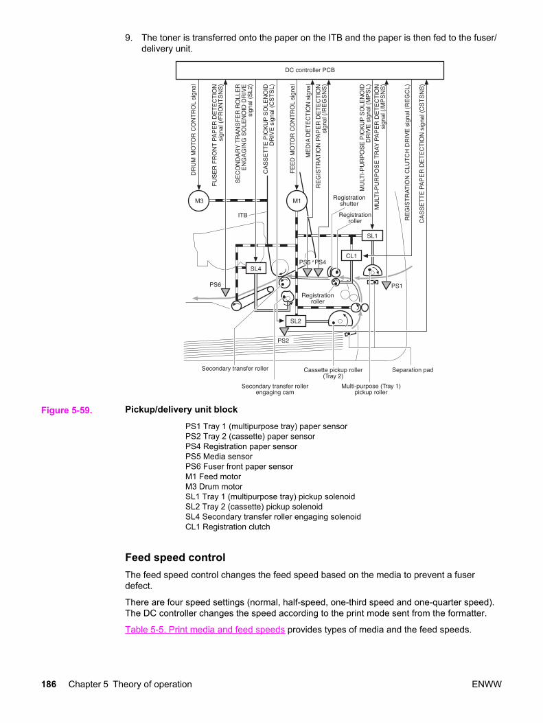
9. The toner is transferred onto the paper on the ITB and the paper is then fed to the fuser/delivery unit.
Figure 5-59. Pickup/delivery unit block
PS1 Tray 1 (multipurpose tray) paper sensorPS2 Tray 2 (cassette) paper sensorPS4 Registration paper sensorPS5 Media sensorPS6 Fuser front paper sensorM1 Feed motorM3 Drum motorSL1 Tray 1 (multipurpose tray) pickup solenoidSL2 Tray 2 (cassette) pickup solenoidSL4 Secondary transfer roller engaging solenoidCL1 Registration clutch
Feed speed controlThe feed speed control changes the feed speed based on the media to prevent a fuserdefect.
There are four speed settings (normal, half-speed, one-third speed and one-quarter speed).The DC controller changes the speed according to the print mode sent from the formatter.
Table 5-5. Print media and feed speeds provides types of media and the feed speeds.
186 Chapter 5 Theory of operation ENWW
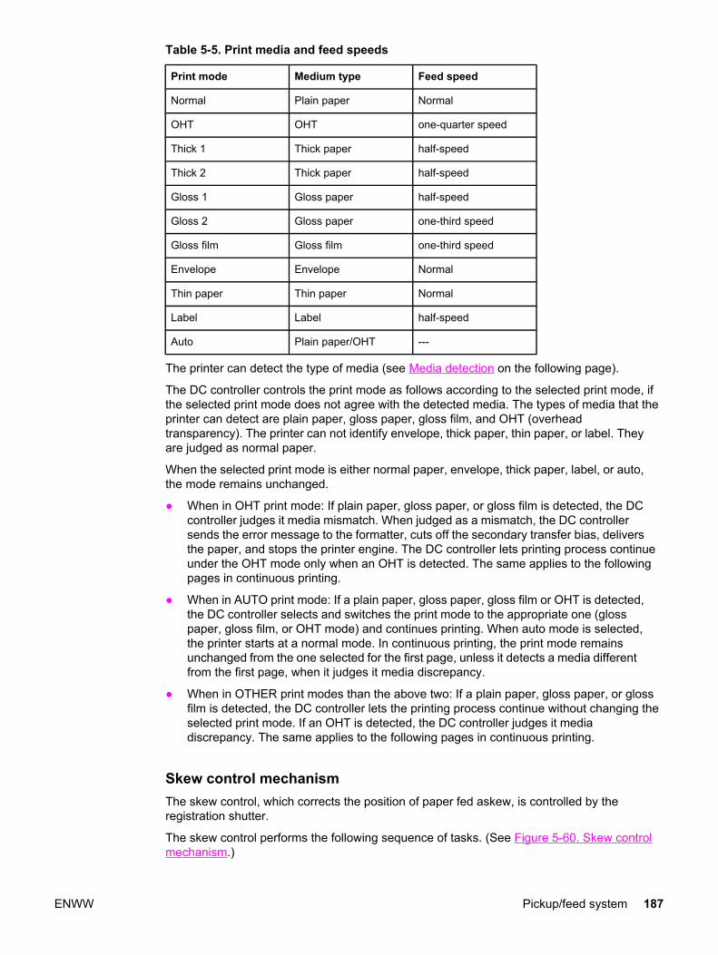
Table 5-5. Print media and feed speeds
Print mode Medium type Feed speed
Normal Plain paper Normal
OHT OHT one-quarter speed
Thick 1 Thick paper half-speed
Thick 2 Thick paper half-speed
Gloss 1 Gloss paper half-speed
Gloss 2 Gloss paper one-third speed
Gloss film Gloss film one-third speed
Envelope Envelope Normal
Thin paper Thin paper Normal
Label Label half-speed
Auto Plain paper/OHT ---
The printer can detect the type of media (see Media detection on the following page).
The DC controller controls the print mode as follows according to the selected print mode, ifthe selected print mode does not agree with the detected media. The types of media that theprinter can detect are plain paper, gloss paper, gloss film, and OHT (overheadtransparency). The printer can not identify envelope, thick paper, thin paper, or label. Theyare judged as normal paper.
When the selected print mode is either normal paper, envelope, thick paper, label, or auto,the mode remains unchanged.
● When in OHT print mode: If plain paper, gloss paper, or gloss film is detected, the DCcontroller judges it media mismatch. When judged as a mismatch, the DC controllersends the error message to the formatter, cuts off the secondary transfer bias, deliversthe paper, and stops the printer engine. The DC controller lets printing process continueunder the OHT mode only when an OHT is detected. The same applies to the followingpages in continuous printing.
● When in AUTO print mode: If a plain paper, gloss paper, gloss film or OHT is detected,the DC controller selects and switches the print mode to the appropriate one (glosspaper, gloss film, or OHT mode) and continues printing. When auto mode is selected,the printer starts at a normal mode. In continuous printing, the print mode remainsunchanged from the one selected for the first page, unless it detects a media differentfrom the first page, when it judges it media discrepancy.
● When in OTHER print modes than the above two: If a plain paper, gloss paper, or glossfilm is detected, the DC controller lets the printing process continue without changing theselected print mode. If an OHT is detected, the DC controller judges it mediadiscrepancy. The same applies to the following pages in continuous printing.
Skew control mechanismThe skew control, which corrects the position of paper fed askew, is controlled by theregistration shutter.
The skew control performs the following sequence of tasks. (See Figure 5-60. Skew controlmechanism.)
ENWW Pickup/feed system 187
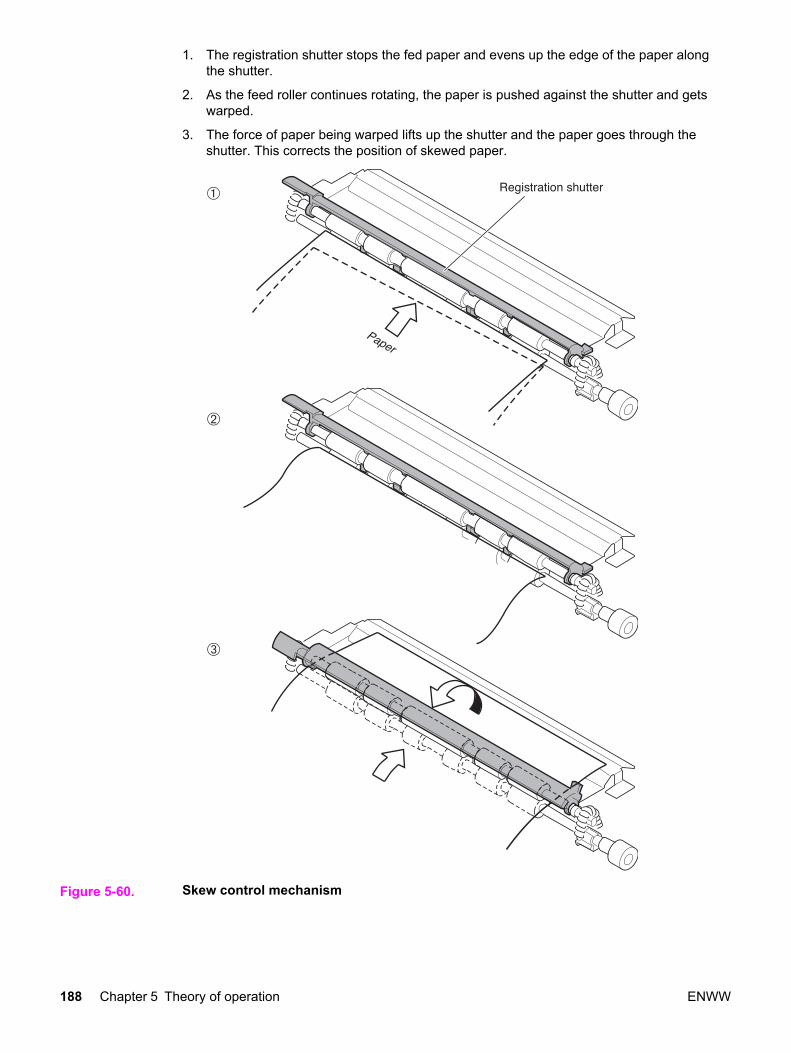
1. The registration shutter stops the fed paper and evens up the edge of the paper alongthe shutter.
2. As the feed roller continues rotating, the paper is pushed against the shutter and getswarped.
3. The force of paper being warped lifts up the shutter and the paper goes through theshutter. This corrects the position of skewed paper.
Figure 5-60. Skew control mechanism
188 Chapter 5 Theory of operation ENWW
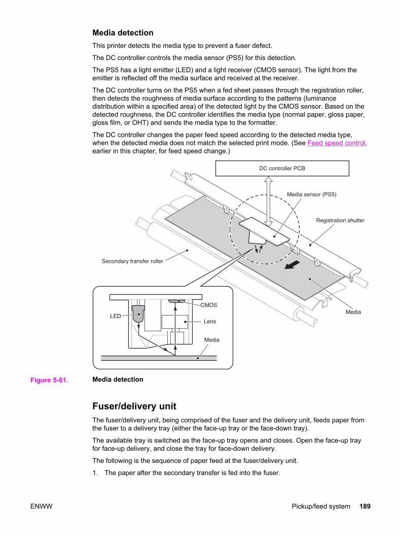
Media detectionThis printer detects the media type to prevent a fuser defect.
The DC controller controls the media sensor (PS5) for this detection.
The PS5 has a light emitter (LED) and a light receiver (CMOS sensor). The light from theemitter is reflected off the media surface and received at the receiver.
The DC controller turns on the PS5 when a fed sheet passes through the registration roller,then detects the roughness of media surface according to the patterns (luminancedistribution within a specified area) of the detected light by the CMOS sensor. Based on thedetected roughness, the DC controller identifies the media type (normal paper, gloss paper,gloss film, or OHT) and sends the media type to the formatter.
The DC controller changes the paper feed speed according to the detected media type,when the detected media does not match the selected print mode. (See Feed speed control,earlier in this chapter, for feed speed change.)
Figure 5-61. Media detection
Fuser/delivery unitThe fuser/delivery unit, being comprised of the fuser and the delivery unit, feeds paper fromthe fuser to a delivery tray (either the face-up tray or the face-down tray).
The available tray is switched as the face-up tray opens and closes. Open the face-up trayfor face-up delivery, and close the tray for face-down delivery.
The following is the sequence of paper feed at the fuser/delivery unit.
1. The paper after the secondary transfer is fed into the fuser.
ENWW Pickup/feed system 189

2. The paper is pressed between the fuser sleeve and the pressure roller to fuse the toneron top and then delivered out of the fuser.
3. When the leading edge of the paper is detected by the fuser delivery paper sensor(PS7), the delivery motor (M2) drives and rotates the delivery roller.
190 Chapter 5 Theory of operation ENWW

4. When the paper end is detected by the fuser delivery paper sensor (PS7), the M2rotates at double-speed and delivers the paper out to the face-down tray at high speed.
NOTE The feed speed is accelerated after paper passes away from the fuser when delivering fromthe face-down tray because the fuser is far from the tray.
Figure 5-62. Fuser/delivery unit
PS7 Fuser delivery paper sensorPS8 Face-down delivery sensorM1 Feed motorM2 Delivery motor
ENWW Pickup/feed system 191

Duplexing feed unit (HP 3700 printer only)The duplexing feed unit reverses the paper after one side is printed and re-feeds it to thepickup/feed unit for printing the other side.
The following is the sequence of paper feed at the duplexing feed unit.
1. The paper passes through the fuser after the front side is printed.
2. The delivery motor (M2) rotates counterclockwise after a specified period of time fromwhen the paper has passed the fuser and delivers the paper to the duplexing feed unit.The paper is reversed here.
3. When the reversed paper sensor (PS9) detects the edge of the reversed paper, theduplexing feed solenoid (SL5) is turned on to rotate the duplexing feed roller.
4. The paper is fed to the duplexing feed unit by the roller, being positioned in line by theoblique roller and the delivery guide.
5. The paper stops at the duplex pickup position, as the edge of the paper reaches thePS10, and the SL5 is turned off.
6. When the duplex pickup is ready, the SL5 is turned on and it feeds the paper into theprinter.
192 Chapter 5 Theory of operation ENWW
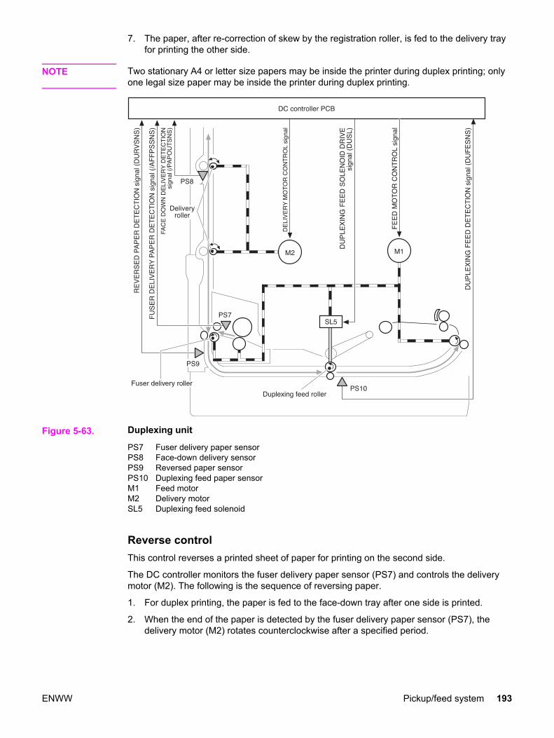
7. The paper, after re-correction of skew by the registration roller, is fed to the delivery trayfor printing the other side.
NOTE Two stationary A4 or letter size papers may be inside the printer during duplex printing; onlyone legal size paper may be inside the printer during duplex printing.
Figure 5-63. Duplexing unit
PS7 Fuser delivery paper sensorPS8 Face-down delivery sensorPS9 Reversed paper sensorPS10 Duplexing feed paper sensorM1 Feed motorM2 Delivery motorSL5 Duplexing feed solenoid
Reverse controlThis control reverses a printed sheet of paper for printing on the second side.
The DC controller monitors the fuser delivery paper sensor (PS7) and controls the deliverymotor (M2). The following is the sequence of reversing paper.
1. For duplex printing, the paper is fed to the face-down tray after one side is printed.
2. When the end of the paper is detected by the fuser delivery paper sensor (PS7), thedelivery motor (M2) rotates counterclockwise after a specified period.
ENWW Pickup/feed system 193

3. As it rotates counterclockwise by the M2, the delivery roller turns the paper around. Thereversed paper is fed to the duplex delivery unit by the guide at the reverse unit.
Figure 5-64. Reverse control
Duplex feed modeThe printer has the following 3 different feed modes for duplex printing. The possible feedmodes depend on the print mode and paper size.
1. 1 sheet feed: Print 1 sheet two-sided page in 1 duplex print operation.
2. 2 sheets feed: Print 2 sheets two-sided page in 1 duplex print operation.
3. Alternate feed: Print two-sided sheets while retaining 3 sheets in process inside theprinter during duplex print operation.
The table below shows the conditions of available duplex feed.
194 Chapter 5 Theory of operation ENWW

Table 5-6. Conditions of available duplex feed
Paper size Print mode Duplex feed mode
A4, Letter Plain paper
Gloss paper
Gloss film
1 sheet feed
Plain paper
Thin paper
2 sheets feed
Alternate feed
Legal Plain paper, Thin paper 1 sheet feed
The duplex feed mode can be selected by command from the formatter. Please note that theduplex print is available only for the media in the print mode (plain, thin, gloss paper, glossfilm) shown in the table.
Jam detectionThis printer has the following sensors to detect the presence and positions of papers:
● Registration paper sensor (PS4)
● Fuser front paper sensor (PS6)
● Fuser delivery paper sensor (PS7)
● Face-down delivery paper sensor (PS8)
● Reversed paper sensor (PS9)
● Duplexing feed paper sensor (PS10)
The microcomputer (CPU) in the DC controller identifies a paper jam by checking whetherthe paper is present at the sensor at the checking time. The checking time is stored in itsmemory. When it judges so, the CPU stops the printer and sends a paper jam notice to theformatter.
The following is the timing of the paper jam detection. The specified time (T) is based on thenormal feed speed (1/1).
1. Pickup delay jam: This printer checks the paper movement at all pickup sources twice, ifnecessary, as the paper pickup can be delayed due to a pickup error.
When paper does not reach the registration paper sensor (PS4) within the allotted timeafter paper pickup, the CPU judges it a pickup delay jam.
2. Pickup stationary jam: When the paper does not pass the registration paper sensor(PS4) within the allotted amount of time after paper is fed from the registration roller, theCPU judges it a pickup stationary jam.
3. Fuser delay jam: When the paper does not reach the fuser delivery paper sensor (PS7)within the allotted amount of time after paper is fed from the registration roller, the CPUjudges it a fuser delay jam.
4. Fuser stationary jam: When the paper does not pass the fuser delivery paper sensor(PS7) within the allotted amount of time after paper has reached the fuser delivery papersensor (PS7), the CPU judges it a fuser stationary jam.
5. Delivery delay jam: When the paper does not pass the sensor through within the allottedamount of time after paper has reached the fuser delivery paper sensor (PS7), the CPUjudges it a delivery delay jam.
ENWW Pickup/feed system 195

6. Delivery stationary jam: When the paper does not reach the face-down paper sensor(PS8) within the allotted amount of time after paper has reached the fuser delivery papersensor (PS7), the CPU judges it a delivery stationary jam.
7. Duplexing feed delay jam (3700 printer only): When the paper does not reach thereversed paper sensor (PS9) within the allotted amount of time after the delivery motorhas started rotating counter-clockwise, the CPU judges it a duplexing feed delay jam.
8. Duplexing feed stationary jam (3700 printer only): When the paper does not pass thesensor within the allotted amount of time since paper has reached the reversed papersensor (PS9), the CPU judges it a duplexing feed stationary jam.
9. Duplexing pickup delay jam (3700 printer only): When the paper does not reach theduplexing feed paper sensor (PS10) within the allotted amount of time after paper hasreached the reversed paper sensor, the CPU judges it a duplexing pickup delay jam.
10. Duplexing pickup stationary jam (3700 printer only): When the paper does not pass thesensor within the allotted amount of time since paper reached the duplexing feed papersensor (PS10), the CPU judges it a duplexing pickup stationary jam.
11. Door open jam: When the front cover is opened during printing operation, the CPUjudges it a door open jam.
12. Residual paper jam: The CPU judges a residual paper jam for two conditions:
● When paper is detected by the registration paper sensor (PS4), the fuser front papersensor (PS6), or the fuser delivery paper sensor (PS7), the CPU judges it theresidual paper jam.
● When paper is detected by the fuser front paper sensor (PS6) or the fuser deliverypaper sensor (PS7), the CPU judges it the residual paper jam.
If paper is detected by sensors other than the PS6 and PS7, the DC controllerdelivers the paper automatically.
NOTE The automatic paper delivery system delivers a residual paper automatically, if possible,when the power is turned on or the printer starts printing. The CPU sends an automaticpaper delivery request to the formatter when it detects a residual paper that can be possiblydelivered automatically. Upon receipt of a command for an automatic delivery from theformatter, the CPU drives each motor and delivers such paper out of the printer.
196 Chapter 5 Theory of operation ENWW

Paper feeder
The paper feeder is an optional unit that is installed at the bottom of the printer. It picks upand delivers a sheet of paper to the printer. Figure 5-65. Paper feeder illustrates the paperpath.
Figure 5-65. Paper feeder
The paper feeder is controlled by the DC controller. The DC controller drives each load(solenoids, clutches) at the required timing via the paper feeder PCB. The paper sensordetects the presence of paper. The paper feeder is supplied with +24V (for solenoids andclutches) and +3.3V (for sensors) of power.
ENWW Paper feeder 197
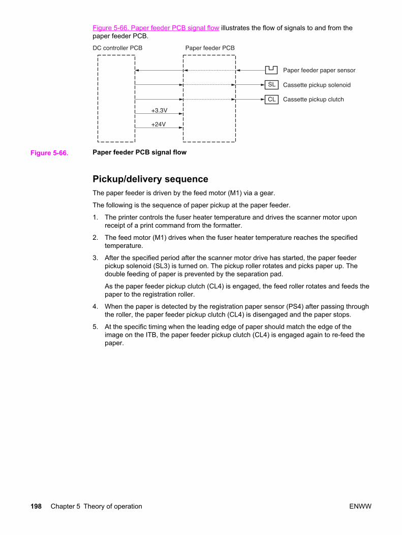
Figure 5-66. Paper feeder PCB signal flow illustrates the flow of signals to and from thepaper feeder PCB.
Figure 5-66. Paper feeder PCB signal flow
Pickup/delivery sequenceThe paper feeder is driven by the feed motor (M1) via a gear.
The following is the sequence of paper pickup at the paper feeder.
1. The printer controls the fuser heater temperature and drives the scanner motor uponreceipt of a print command from the formatter.
2. The feed motor (M1) drives when the fuser heater temperature reaches the specifiedtemperature.
3. After the specified period after the scanner motor drive has started, the paper feederpickup solenoid (SL3) is turned on. The pickup roller rotates and picks paper up. Thedouble feeding of paper is prevented by the separation pad.
As the paper feeder pickup clutch (CL4) is engaged, the feed roller rotates and feeds thepaper to the registration roller.
4. When the paper is detected by the registration paper sensor (PS4) after passing throughthe roller, the paper feeder pickup clutch (CL4) is disengaged and the paper stops.
5. At the specific timing when the leading edge of paper should match the edge of theimage on the ITB, the paper feeder pickup clutch (CL4) is engaged again to re-feed thepaper.
198 Chapter 5 Theory of operation ENWW
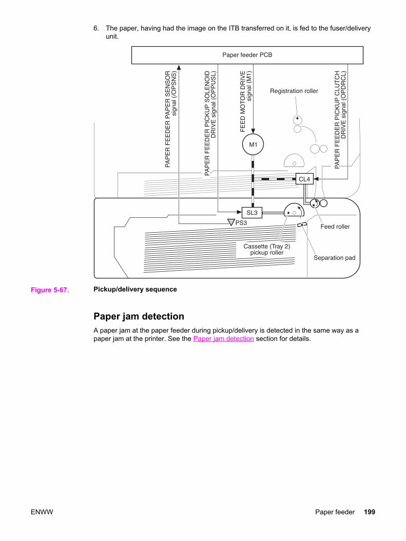
6. The paper, having had the image on the ITB transferred on it, is fed to the fuser/deliveryunit.
Figure 5-67. Pickup/delivery sequence
Paper jam detectionA paper jam at the paper feeder during pickup/delivery is detected in the same way as apaper jam at the printer. See the Paper jam detection section for details.
ENWW Paper feeder 199

200 Chapter 5 Theory of operation ENWW

6 Removal and replacement
Chapter contents
This chapter contains the following sections:
Chapter contents ...................................................................................................................201Introduction ............................................................................................................................204
Removal and replacement strategy ................................................................................204Repair notices .................................................................................................................204Caution regarding electrostatic discharge (ESD) ...........................................................204Required tools .................................................................................................................204Types of screws ..............................................................................................................205
Supplies .................................................................................................................................207Print cartridges and transfer unit ....................................................................................208
Covers ...................................................................................................................................209Front door removal .........................................................................................................209Left cover removal ..........................................................................................................210Left front cover removal ..................................................................................................211Right cover removal ........................................................................................................213Top cover removal ..........................................................................................................214Upper rear door removal ................................................................................................214Rear cover removal ........................................................................................................215Lower rear door (rear output bin) removal .....................................................................215Tray 1 (multipurpose) removal .......................................................................................216
Main Assemblies ...................................................................................................................217Transfer unit removal ......................................................................................................218Print cartridge removal ...................................................................................................219Fuser removal .................................................................................................................220Face-down delivery assembly removal ..........................................................................221Laser/scanner assembly removal ...................................................................................222Image drive assembly removal .......................................................................................223Developing engaging drive assembly removal ...............................................................225Pick-up/feed assembly removal .....................................................................................225
Main assembly parts .............................................................................................................236Tray 1 pick-up roller removal ..........................................................................................237Tray 1 separation pad removal .......................................................................................237Tray 2 pick-up roller removal ..........................................................................................238Tray 2 separation pad removal .......................................................................................238Secondary transfer charging roller removal ...................................................................239Fuser sleeve unit removal ..............................................................................................239Pressure roller removal ..................................................................................................239Main thermistor/sub-thermistor removal .........................................................................239Thermoswitch removal ...................................................................................................239Feed guide unit removal .................................................................................................240
ENWW Chapter contents 201

Swing guide removal, right .............................................................................................242Swing guide removal, left ...............................................................................................245
Switches ................................................................................................................................250Door Switch (SW1) removal ...........................................................................................250Test print switch (SW1001) removal ..............................................................................251Power switch (SW3001) removal ...................................................................................251
Sensors .................................................................................................................................252Tray 1 (multipurpose tray) paper sensor (PS1) removal ................................................253Tray 2 (cassette) paper sensor (PS2) removal ..............................................................253Registration paper sensor (PS4) removal ......................................................................254Media sensor (PS5) removal ..........................................................................................255Fuser front paper sensor (PS6) removal ........................................................................256Fuser delivery paper sensor (PS7) removal ...................................................................256Face-down delivery paper sensor (PS8) removal ..........................................................257Reversed paper sensor (PS9) removal (HP 3700 only) .................................................257Duplex feed delivery paper sensor (PS10) removal (HP 3700 only) .............................258Rear output bin paper sensor (PS11) removal ...............................................................259Color misregistration sensor (PS12) removal ................................................................260Waste toner level sensor (PS13) removal ......................................................................260Developing engaging sensor (PS14) removal ................................................................261Environment sensor (PS15) removal .............................................................................261Secondary transfer roller engaging sensor (PS16) removal ..........................................262
Solenoids and Clutches ........................................................................................................263Tray 1 (multipurpose tray) pick-up solenoid (SL1) removal ...........................................263Tray 2 pick-up solenoid (SL2) removal ...........................................................................264Secondary transfer roller engaging solenoid (SL4) removal ..........................................265Duplex feed solenoid (SL5) removal (HP 3700 only) .....................................................266Registration clutch (CL1) removal ..................................................................................266Black (K) development clutch (CL2 - image drive) removal ...........................................267Developing engaging drive clutch (CL3) removal ..........................................................268
Motor and fans ......................................................................................................................269Feed motor (M1) removal ...............................................................................................269Delivery motor (M2) removal ..........................................................................................271Drum motor (M3) removal ..............................................................................................271Developing motor (M4) removal .....................................................................................273Primary transfer roller engaging motor (M5) removal ....................................................274Exhaust fan (FAN1) removal ..........................................................................................277
Circuit Boards ........................................................................................................................278DC controller PCB removal ............................................................................................278Formatter PCB removal ..................................................................................................279High-voltage power supply PCB removal .......................................................................281Low-voltage power supply PCB removal .......................................................................285Memory controller PCB removal ....................................................................................286Control Panel PCB removal ............................................................................................287
Miscellaneous parts ..............................................................................................................288Swing rod guide, left removal .........................................................................................288Swing rod/lock guide, right removal ...............................................................................288Transfer contact assembly removal ...............................................................................288Developing contact assembly .........................................................................................288
Tray 2 (cassette) parts removal ............................................................................................291Tray 2 (cassette) .............................................................................................................291Cassette (Tray 2) guide, right, removal ..........................................................................291
500-Sheet paper feeder (Tray 3) covers ...............................................................................296Front cover removal - 500-sheet paper feeder ...............................................................296Right cover removal - 500-sheet paper feeder ...............................................................297Left cover removal - 500-sheet paper feeder .................................................................297
202 Chapter 6 Removal and replacement ENWW

500-Sheet paper feeder internal parts ..................................................................................298Pick-up roller removal - 500-sheet paper feeder ............................................................298Separation pad removal - 500-sheet paper feeder ........................................................299Pick-up drive unit removal - 500-sheet paper feeder .....................................................299
500-Sheet paper feeder sensor/solenoid/motor/PCB ...........................................................300500-Sheet paper feeder PCB removal - 500-sheet feeder ............................................300Pick-up clutch (CL4) removal - 500-sheet feeder ...........................................................301Pick-up solenoid (SL3) removal - 500-sheet feeder .......................................................301Paper sensor (PS3) removal - 500-sheet feeder ...........................................................302
ENWW Chapter contents 203

Introduction
Removal and replacement procedures are provided for all replaceable parts in the printer.
Removal and replacement strategyThis chapter explains how to remove and replace major printer components. (HP does notsupport repairing individual subassemblies or troubleshooting to the component level.)
Replacement is generally the reverse of removal. Occasionally, directions for difficult orcritical replacement procedures are included.
WARNING! The information in this section is intended for authorized service personnel only.
Repair notices
WARNING! Turn the printer off, wait five seconds, then unplug the power cord before servicing theprinter. Failure to completely disconnect the printer could result in severe injury.
Never operate or service the printer with the protective cover removed from the laser/scanner assembly. The reflected beam, although invisible, can damage your eyes.
Never operate the printer with any parts removed.
The sheet-metal parts can have sharp edges. Be careful not to cut yourself when handlingsheet-metal parts.
Caution regarding electrostatic discharge (ESD)The printer contains parts that are sensitive to electrostatic discharge (ESD). Watch for theESD reminder shown at the left when removing printer parts. Protect the parts that aresensitive to ESD with protective ESD pouches.
Required toolsBefore servicing the printer, gather the following tools:
● Phillips #2 magnetized screwdriver (152 mm [ (6 inch)] shaft)
● Small flat-blade screwdriver
● Small needle-nose pliers
● ESD strap
● Penlight (optional)
204 Chapter 6 Removal and replacement ENWW

NOTE All components in the HP Color LaserJet 3500/3550 and 3700 series printers use Phillips-head screws that require a #2 Phillips screwdriver. Ensure that you have a Phillipsscrewdriver and not a Posidriv screwdriver. Figure 6-1 (below) shows the difference betweena Phillips and a Posidriv screwdriver. Note that the Phillips tip has more beveled surfaces.
Figure 6-1. Phillips and Posidrive screwdriver comparison
Types of screwsTable 6-1, below, describes the screws used in the printer and provides guidelines to helpdetermine where to use each type of screw. The screws can vary in length depending on thethickness of the material being fastened.
Always note where each type of screw is located and replace each one into its originallocation.
Table 6-1. Common fasteners
Illustration Description Size Part number Use
SCREW, TP M4X6 XA9-1450-000CN
Secures metal frame panelsto metal frame panels.
SCREW, W/WASHER M3X6 XA9-1477-000CN
Secures the drawer, crossmember, to the frame (seeFigure 8-11. Internalcomponents (4 of 4)).
SCREW, W/WASHER, RS M3X6 XA9-1461-000CN
Secures motor (M2) to theframe.
SCREW W/WASHER M3X8 XA9-1420-000CN
Secures metal to metal(ground wire, feed guiderear two screws).
SCREW, W/WASHER M3X12 XA9-1452-000CN
Secures laser/scannerassembly to the metal frame.
ENWW Introduction 205
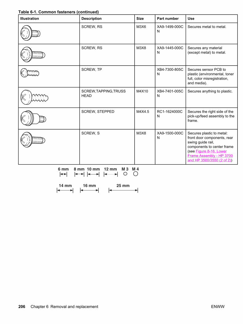
Illustration Description Size Part number Use
SCREW, RS M3X6 XA9-1499-000CN
Secures metal to metal.
SCREW, RS M3X8 XA9-1445-000CN
Secures any material(except metal) to metal.
SCREW, TP XB4-7300-805CN
Secures sensor PCB toplastic (environmental, tonerfull, color misregistration,and media).
SCREW,TAPPING,TRUSSHEAD
M4X10 XB4-7401-005CN
Secures anything to plastic.
SCREW, STEPPED M4X4.5 RC1-1624000CN
Secures the right side of thepick-up/feed assembly to theframe.
SCREW, S M3X8 XA9-1500-000CN
Secures plastic to metal:front door components, rearswing guide rail,components to center frame(see Figure 8-16. LowerFrame Assembly - HP 3700and HP 3500/3550 (2 of 2))
Table 6-1. Common fasteners (continued)
206 Chapter 6 Removal and replacement ENWW

Supplies
The customer replaces print cartridges, the fuser, and the transfer unit as they are depleted.Chapter 4 explains when to replace supplies and provides instructions on replacing them.
NOTE The printer tracks the amount of use on the customer-replaceable supplies by keeping apage count. Swapping supplies between printers might cause a misrepresentation of supplylife values and is not recommended.
If you replace either the fuser or the transfer unit when servicing the printer, and thesesupplies have not yet reached the end of their estimated life, you must reset the page countfor these supplies through the CONFIGURE DEVICE menu on the control panel. See Fuserreplacement configuration and Transfer unit (ITB assembly) replacement configuration forinstructions on resetting the transfer unit and fuser counts.
Table 6-2. Approximate replacement intervals for print cartridges
Supply item Printer message HP 3500/3550Page counts
HP 3700Pagecounts
Approximate timeperiod1
To install
Black (K) printcartridge
REPLACE BLACKCARTRIDGE
6,000 pages2 6,000 pages2 HP 3500=6 months
HP 3550/3700 =4months
See Printcartridgeremoval.
Cyan (C) printcartridge
REPLACE CYANCARTRIDGE
4,000 pages2 6,000 pages2 4 months See Printcartridgeremoval.
Magenta (M)print cartridge
REPLACE MAGENTACARTRIDGE
4,000 pages2 6,000 pages2 4 months See Printcartridgeremoval.
Yellow (Y) printcartridge
REPLACE YELLOWCARTRIDGE
4,000 pages2 6,000 pages2 4 months See Printcartridgeremoval.
1Approximate life is based on: 1,000 pages per month for the HP Color LaserJet 3500 seriesprinter and 1500 pages per month for the HP Color LaserJet 3550/3700 series printer.2Approximate average A4/letter-size page count based on approximately 5 percent coverageof individual colors.
Table 6-3. Approximate replacement intervals for supply items
Supply item Printer message HP 3500Pagecounts
HP 3550/3700Page counts
Approximate timeperiod1
To install
Image transferkit (transfer unit)
REPLACETRANSFER KIT
60,000 pages2 75,000 pages2 HP 3500 =60 months
HP 3550/3700 = 50months
SeeTransferunitremoval.
ENWW Supplies 207

Supply item Printer message HP 3500Pagecounts
HP 3550/3700Page counts
Approximate timeperiod1
To install
Image fuser kit REPLACE FUSER KIT 60,000 pages2 75,000 pages2 HP 3500 =60 months
HP 3550/3700 = 50months
See Fuserremoval.
1Approximate life is based on: 1,000 pages per month for the HP Color LaserJet 3500 seriesprinter and 1500 pages per month for the HP Color LaserJet 3550/3700 series printer.2Usage conditions and print patterns cause results to vary.
CAUTION Hewlett-Packard recommends the use of HP products in this printer. Use of non-HP products can cause problems that require service not covered by the Hewlett-Packardwarranty or service agreements.
Print cartridges and transfer unitIt is recommended that you remove the print cartridges and transfer unit when servicinginternal printer components. Place the print cartridges and transfer unit in a safe place whilethey are out of the printer.
CAUTION Grasp the print cartridges by the blue handles to avoid accidentally touching thephotosensitive drum inside each cartridge.
Do not place any items on the transfer unit or touch the transfer belt. If the belt is puncturedor otherwise damaged, print quality problems will result.
For instructions on removing the transfer unit, see Transfer unit removal and for instructionson removing the print cartridges, see Print cartridge removal.
Table 6-3. Approximate replacement intervals for supply items (continued)
208 Chapter 6 Removal and replacement ENWW

Covers
The following procedures describe removal of the printers external covers.
Figure 6-2. Cover locations
1 Left cover2 Top cover3 Front door4 Tray 1 (multipurpose tray)5 Left front door (includes control panel)6 DIMM cover (HP 3700 only)7 Right cover8 Upper rear door9 Rear cover10 Lower rear door (rear output bin)
Front door removal1. Open the front door.
2. Remove the transfer unit and the print cartridges. See Transfer unit removal and Printcartridge removal.
3. Remove the right cover, see Right cover removal.
4. Remove the left cover, see Left cover removal.
5. Remove two e-clips (1) from the front door rod bracket.
ENWW Covers 209
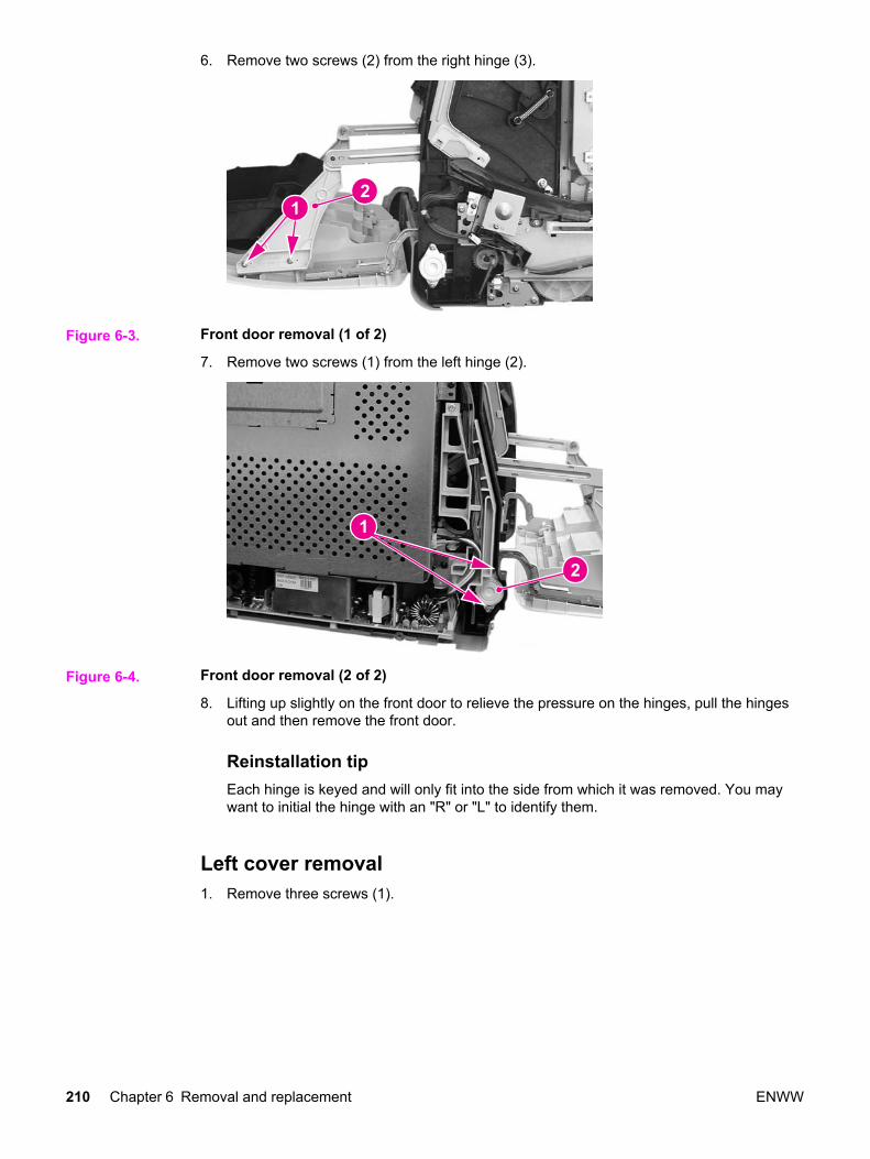
6. Remove two screws (2) from the right hinge (3).
Figure 6-3. Front door removal (1 of 2)
7. Remove two screws (1) from the left hinge (2).
Figure 6-4. Front door removal (2 of 2)
8. Lifting up slightly on the front door to relieve the pressure on the hinges, pull the hingesout and then remove the front door.
Reinstallation tipEach hinge is keyed and will only fit into the side from which it was removed. You maywant to initial the hinge with an "R" or "L" to identify them.
Left cover removal1. Remove three screws (1).
210 Chapter 6 Removal and replacement ENWW

2. Slide the cover back in the direction of the arrow (2) about one inch, and then pull it outaway from the printer to remove it.
Figure 6-5. Left cover removal
Left front cover removal1. Remove left cover. See Left cover removal.
2. Open the front door and remove the transfer unit. See Transfer unit removal.
3. Disconnect the control panel connector (1) and remove one screw (2). Cut the cable tiethat is connected around the cable ferrite bead (3) and the cable harness (4).
Figure 6-6. Left front cover removal (1 of 3)
4. Remove the power switch rod (1) from the power switch button (2).
ENWW Covers 211
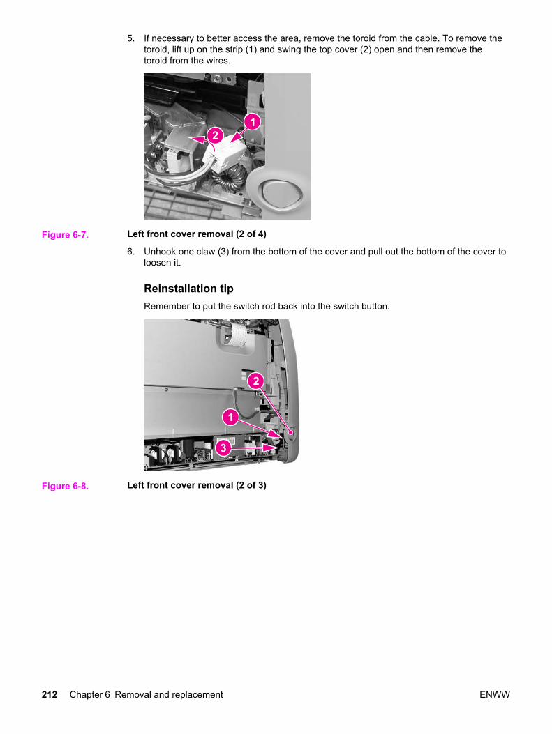
5. If necessary to better access the area, remove the toroid from the cable. To remove thetoroid, lift up on the strip (1) and swing the top cover (2) open and then remove thetoroid from the wires.
Figure 6-7. Left front cover removal (2 of 4)
6. Unhook one claw (3) from the bottom of the cover and pull out the bottom of the cover toloosen it.
Reinstallation tipRemember to put the switch rod back into the switch button.
Figure 6-8. Left front cover removal (2 of 3)
212 Chapter 6 Removal and replacement ENWW

7. Unhook three more claws by pressing in or squeezing, at the indicated locations (1),working up from the bottom, to remove the cover (2) from the printer.
Figure 6-9. Left front cover removal (3 of 3)
Right cover removal1. Open the rear output bin and the upper rear door.
2. Remove three screws (1).
3. Pull down and out on the bottom edge of the cover (2) to release two claws, then pull outon the front edge (3) to release the additional claws and remove the cover (4).
Figure 6-10. Right cover removal
ENWW Covers 213
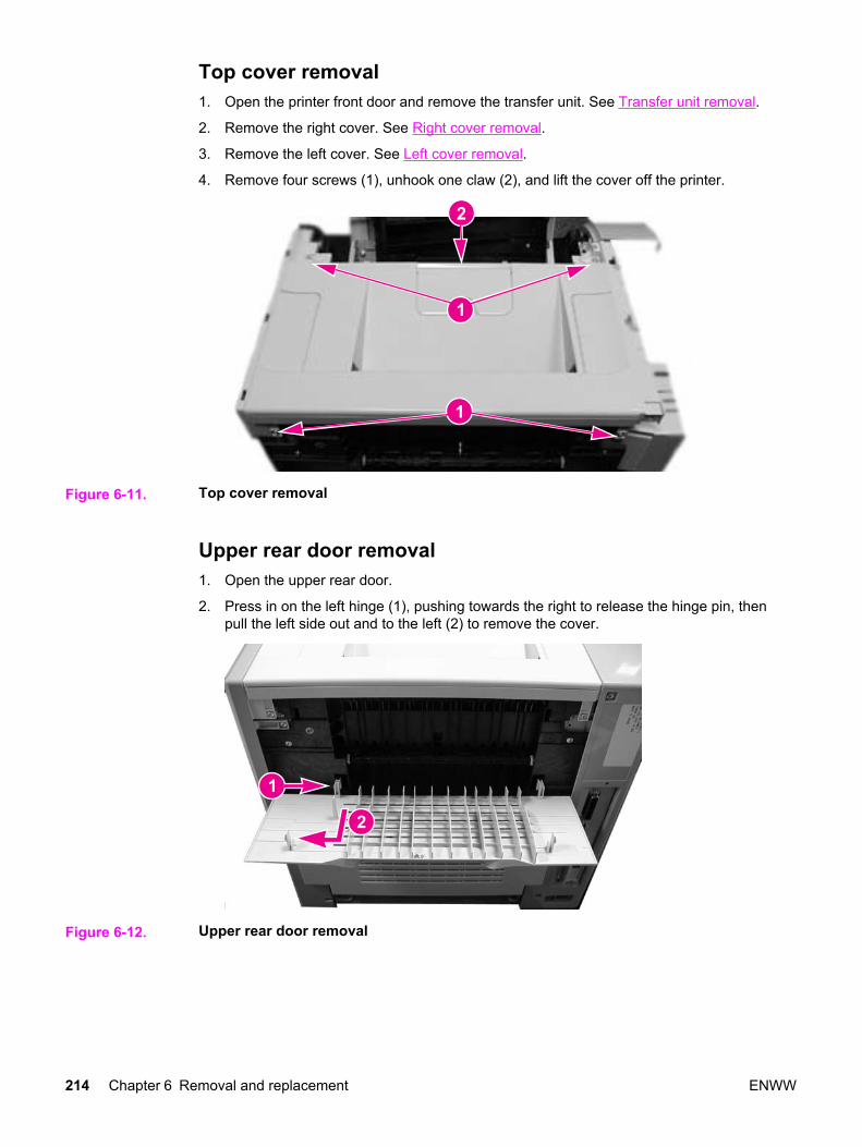
Top cover removal1. Open the printer front door and remove the transfer unit. See Transfer unit removal.
2. Remove the right cover. See Right cover removal.
3. Remove the left cover. See Left cover removal.
4. Remove four screws (1), unhook one claw (2), and lift the cover off the printer.
Figure 6-11. Top cover removal
Upper rear door removal1. Open the upper rear door.
2. Press in on the left hinge (1), pushing towards the right to release the hinge pin, thenpull the left side out and to the left (2) to remove the cover.
Figure 6-12. Upper rear door removal
214 Chapter 6 Removal and replacement ENWW

Rear cover removal1. Release two claws on the right side of the rear cover by inserting a flat-blade
screwdriver into each claw location (1) and twist the screwdriver to release each claw,then pull the cover out and to the right (2) to remove it.
Figure 6-13. Rear cover removal
Lower rear door (rear output bin) removal1. Open the lower rear door.
2. Press in on the left hinge (1) pushing towards the right to release the pin, then pull theleft side of the tray out and to the left (2) to remove it.
Figure 6-14. Lower rear door removal
Reinstallation tipHold the tray at about a 45 degree angle when reinstalling it.
ENWW Covers 215
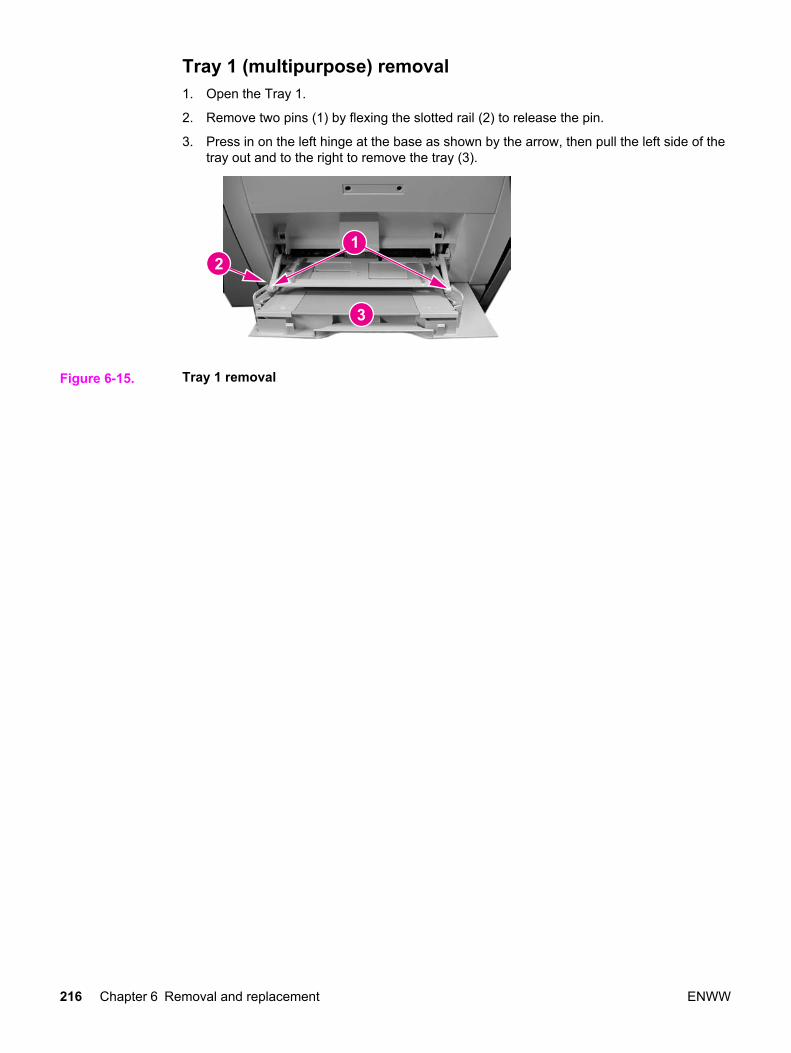
Tray 1 (multipurpose) removal1. Open the Tray 1.
2. Remove two pins (1) by flexing the slotted rail (2) to release the pin.
3. Press in on the left hinge at the base as shown by the arrow, then pull the left side of thetray out and to the right to remove the tray (3).
Figure 6-15. Tray 1 removal
216 Chapter 6 Removal and replacement ENWW

Main Assemblies
The following procedures describe removal of the printer's major internal mechanicalassemblies.
Figure 6-16. Main internal assemblies
1 Fuser2 Developing engaging drive assembly3 Image drive assembly4 Pick-up/feed assembly5 Laser/scanner assembly6 Transfer unit7 Face-down delivery assembly
ENWW Main Assemblies 217

Transfer unit removal
CAUTION Do not touch the surface (5), shown in the figure below, of the image transfer belt (ITB) sinceit can cause an image defect.
NOTE If the transfer unit failed or has been replace for some reason other than reaching its end-of-life (end-of-life is indicated by a control panel message stating that the transfer unit requiresreplacement) then, in addition to replacing the unit, a configuration procedure must beperformed. For information on this configuration, refer to Chapter 8, Replacement partsconfiguration.
1. Open the front door.
218 Chapter 6 Removal and replacement ENWW

2. Hold the blue handles (1) on both sides of the transfer unit. With your right thumb, pressand hold the lever (2) on the right side handle then lift the handle up (3), followed by theleft side (4) to remove the unit.
Figure 6-17. Transfer unit removal
Reinstallation tipWhen reinstalling the transfer unit, align the two pins (1) on the left side of the door withthe two holes (2) in the left side of the transfer unit.
Figure 6-18. Transfer unit installation
Print cartridge removal1. Open the front door.
ENWW Main Assemblies 219
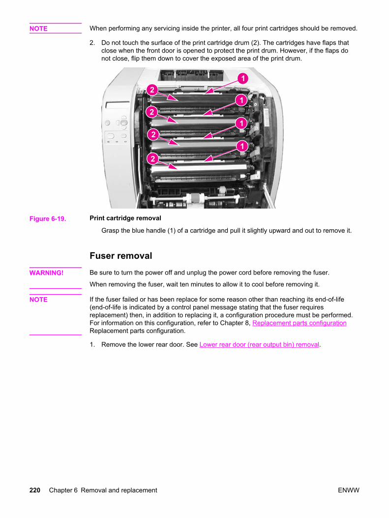
NOTE When performing any servicing inside the printer, all four print cartridges should be removed.
2. Do not touch the surface of the print cartridge drum (2). The cartridges have flaps thatclose when the front door is opened to protect the print drum. However, if the flaps donot close, flip them down to cover the exposed area of the print drum.
Figure 6-19. Print cartridge removal
Grasp the blue handle (1) of a cartridge and pull it slightly upward and out to remove it.
Fuser removal
WARNING! Be sure to turn the power off and unplug the power cord before removing the fuser.
When removing the fuser, wait ten minutes to allow it to cool before removing it.
NOTE If the fuser failed or has been replace for some reason other than reaching its end-of-life(end-of-life is indicated by a control panel message stating that the fuser requiresreplacement) then, in addition to replacing it, a configuration procedure must be performed.For information on this configuration, refer to Chapter 8, Replacement parts configurationReplacement parts configuration.
1. Remove the lower rear door. See Lower rear door (rear output bin) removal.
220 Chapter 6 Removal and replacement ENWW
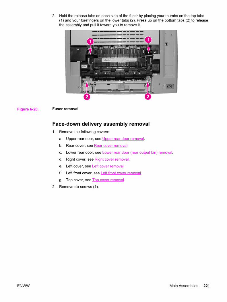
2. Hold the release tabs on each side of the fuser by placing your thumbs on the top tabs(1) and your forefingers on the lower tabs (2). Press up on the bottom tabs (2) to releasethe assembly and pull it toward you to remove it.
Figure 6-20. Fuser removal
Face-down delivery assembly removal1. Remove the following covers:
a. Upper rear door, see Upper rear door removal.
b. Rear cover, see Rear cover removal.
c. Lower rear door, see Lower rear door (rear output bin) removal.
d. Right cover, see Right cover removal.
e. Left cover, see Left cover removal.
f. Left front cover, see Left front cover removal.
g. Top cover, see Top cover removal.
2. Remove six screws (1).
ENWW Main Assemblies 221

3. Pull the face-down assembly out slightly, disconnect one connector (2) from the back,and then remove the assembly (3).
Figure 6-21. Face-down delivery assembly removal
Laser/scanner assembly removal
CAUTION Do not disassemble the laser/scanner assembly. It is not adjustable.
Do not touch the lens on the front of the laser/scanner assembly when holding it.
1. Remove the face-down delivery assembly. See Face-down delivery assembly removal.
2. Remove the exhaust fan (FAN1) assembly. See Exhaust fan (FAN1) removal, step 9.
3. Remove one connector (1) from the left side of the laser/scanner assembly.
222 Chapter 6 Removal and replacement ENWW
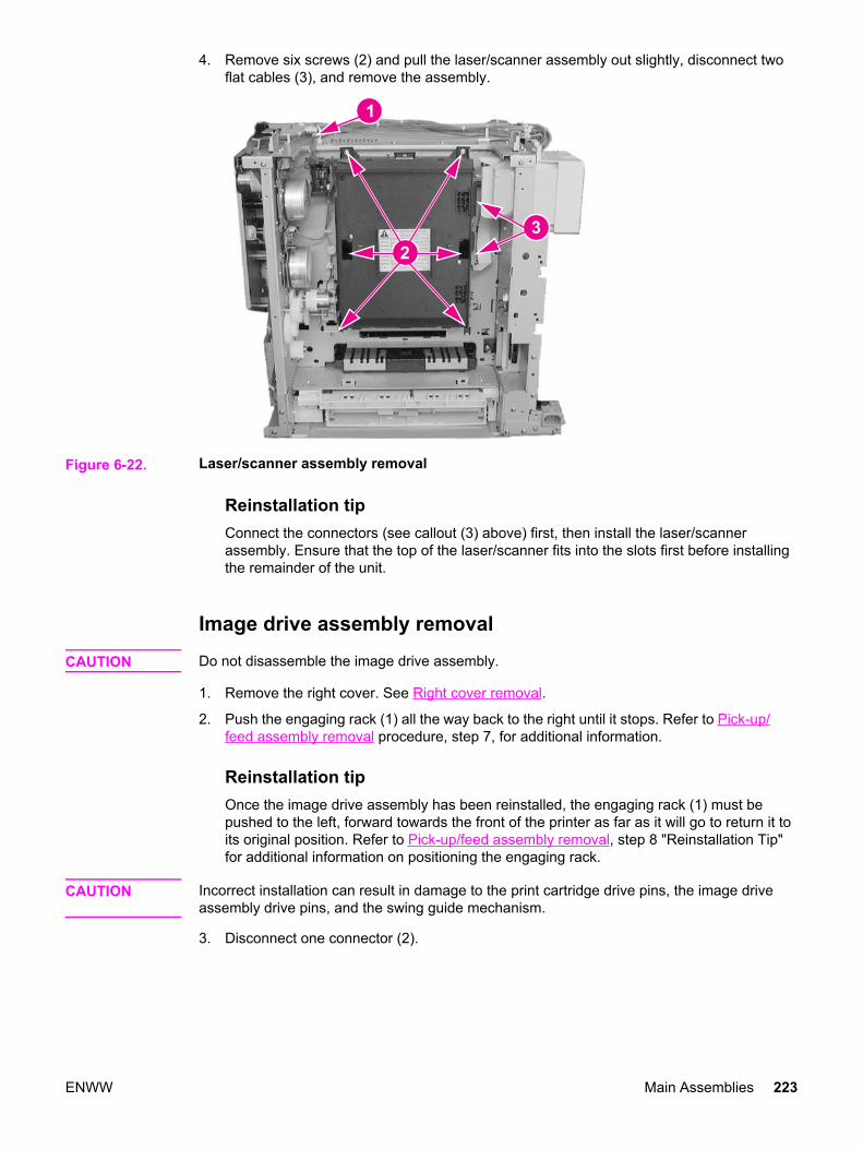
4. Remove six screws (2) and pull the laser/scanner assembly out slightly, disconnect twoflat cables (3), and remove the assembly.
Figure 6-22. Laser/scanner assembly removal
Reinstallation tipConnect the connectors (see callout (3) above) first, then install the laser/scannerassembly. Ensure that the top of the laser/scanner fits into the slots first before installingthe remainder of the unit.
Image drive assembly removal
CAUTION Do not disassemble the image drive assembly.
1. Remove the right cover. See Right cover removal.
2. Push the engaging rack (1) all the way back to the right until it stops. Refer to Pick-up/feed assembly removal procedure, step 7, for additional information.
Reinstallation tipOnce the image drive assembly has been reinstalled, the engaging rack (1) must bepushed to the left, forward towards the front of the printer as far as it will go to return it toits original position. Refer to Pick-up/feed assembly removal, step 8 "Reinstallation Tip"for additional information on positioning the engaging rack.
CAUTION Incorrect installation can result in damage to the print cartridge drive pins, the image driveassembly drive pins, and the swing guide mechanism.
3. Disconnect one connector (2).
ENWW Main Assemblies 223

4. Remove five screws (3) and remove the image drive assembly (4).
Figure 6-23. Image drive assembly removalReinstallation tipWhen replacing the image drive assembly ensure that the engaging pins are in the"engaged" position (1), as shown below. They should not be in the disengaged position(2). If the pins are not in the disengaged position, turn the gear (3) in the direction of thearrow (4) until it stops.Reinstallation tipRemember, replacement procedures are removal procedure steps performed in reverseorder. It is important that step 2, above, be performed after this step (step 4) to maintaincorrect orientation of the gears and pins with respect to the engaging rack mechanism.
Reinstallation tipFor reassembly, remove the right front top cover screw (1). If this screw is not removed itcan prevent the upper left corner of the image drive assembly from seating correctly.
224 Chapter 6 Removal and replacement ENWW
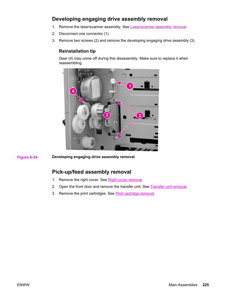
Developing engaging drive assembly removal1. Remove the laser/scanner assembly. See Laser/scanner assembly removal.
2. Disconnect one connector (1).
3. Remove two screws (2) and remove the developing engaging drive assembly (3).
Reinstallation tipGear (4) may come off during this disassembly. Make sure to replace it whenreassembling.
Figure 6-24. Developing engaging drive assembly removal
Pick-up/feed assembly removal1. Remove the right cover. See Right cover removal.
2. Open the front door and remove the transfer unit. See Transfer unit removal.
3. Remove the print cartridges. See Print cartridge removal.
ENWW Main Assemblies 225
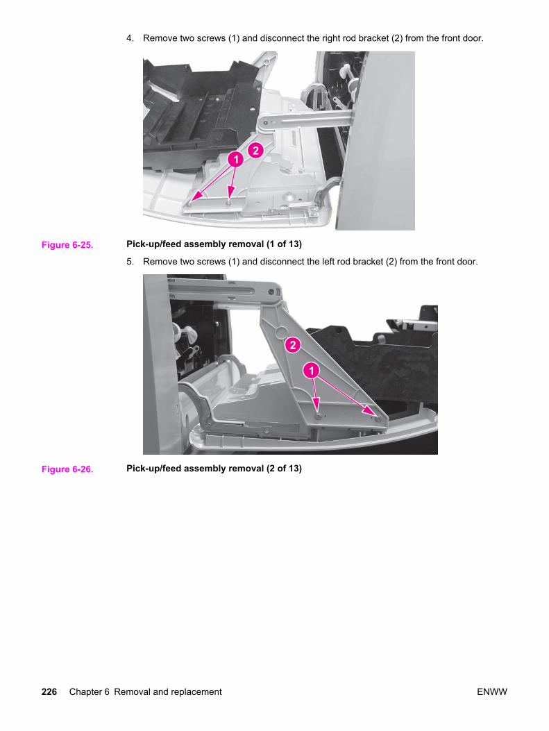
4. Remove two screws (1) and disconnect the right rod bracket (2) from the front door.
Figure 6-25. Pick-up/feed assembly removal (1 of 13)
5. Remove two screws (1) and disconnect the left rod bracket (2) from the front door.
Figure 6-26. Pick-up/feed assembly removal (2 of 13)
226 Chapter 6 Removal and replacement ENWW

6. Remove two screws (1) and remove the right swing rod arm (2).
Figure 6-27. Pick-up/feed assembly removal (3 of 13)
Reinstallation tipWhen installing the swing rod arm assembly, make sure the short rod is positioned asshown below (1).
Figure 6-28. Right swing rod arm reassembly
ENWW Main Assemblies 227

7. Push the engaging rack (1) all the way back, as shown by the arrow (2), until it stops.
Figure 6-29. Pick-up/feed assembly removal (4 of 13)
228 Chapter 6 Removal and replacement ENWW

8. Remove two screws (3) and remove the swing rod/lock guide (4), shown in the abovefigure.Reinstallation tipWhen reassembling the swing rod guide, the engaging rack (callout (1) below) should bepositioned to the back (to the right) with respect to the printer, as shown below. Theengaging rack will normally be in this back position due to the tension of the spring. Also,the gear behind the engaging rack should be turned all the way clockwise (2). Toreinstall the swing rod/lock guide, perform the following steps.
Figure 6-30. Pick-up/feed engaging rack assembly replacement (1 of 2)1. Insert the tab on the front of the swing rod/lock guide (callout (4), above) into the slotin the printer frame (5), and then swing the back into position and install the two screws(3).2. Once the swing rod/lock guide is installed, push the engaging rack all the way forward(1), until it stops. This must be done to ensure that the print cartridge engaging pins arein the disengaged position (as described below).
Figure 6-31. Pick-up/feed engaging rack assembly replacement (2 of 2)The above reassembly procedure ensures that, once the reassembly is complete, theprint cartridge engaging pins are pulled back or disengaged as shown by callout (2)below. Callout (1) shows the pins extended or in the engaged position. If the engagingpins are in the wrong position (if they are engaged) the front door will not closebecause the print cartridge drive shaft will hang up on the engaging pins when the frontdoor is closed. This can result in damage to the engaging pins, print cartridges, or theswing guide closing mechanism.
Figure 6-32. Print cartridge engaging pins replacement
ENWW Main Assemblies 229

9. Disconnect one connector (1), remove two screws (2), remove the clutch plate (3), andremove the clutch (4).
Reinstallation tipWhen reinstalling the clutch, insert the clutch onto the clutch shaft. Make sure that theslotted tab on the clutch fits into the tab (6) on the clutch plate. Also, ensure that thewhite shaft bushing (5), which is keyed, is correctly seated into the notch on the clutchplate.
Figure 6-33. Pick-up/feed assembly removal (5 of 13)
10. Disconnect three connectors (1).
11. Remove the cable (2) from the cable holders (3).
230 Chapter 6 Removal and replacement ENWW
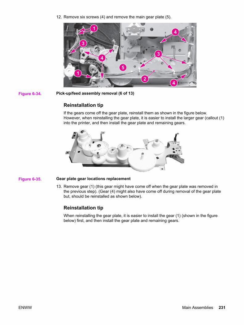
12. Remove six screws (4) and remove the main gear plate (5).
Figure 6-34. Pick-up/feed assembly removal (6 of 13)
Reinstallation tipIf the gears come off the gear plate, reinstall them as shown in the figure below.However, when reinstalling the gear plate, it is easier to install the larger gear (callout (1)into the printer, and then install the gear plate and remaining gears.
Figure 6-35. Gear plate gear locations replacement
13. Remove gear (1) (this gear might have come off when the gear plate was removed inthe previous step). (Gear (4) might also have come off during removal of the gear platebut, should be reinstalled as shown below).
Reinstallation tipWhen reinstalling the gear plate, it is easier to install the gear (1) (shown in the figurebelow) first, and then install the gear plate and remaining gears.
ENWW Main Assemblies 231
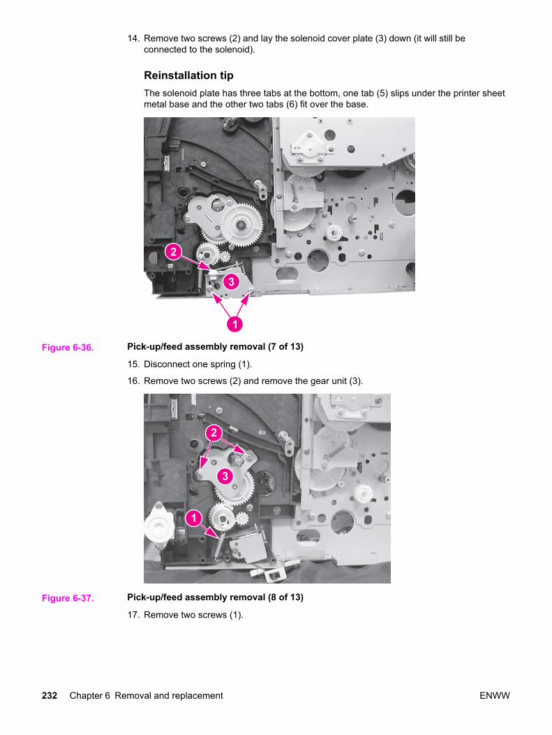
14. Remove two screws (2) and lay the solenoid cover plate (3) down (it will still beconnected to the solenoid).
Reinstallation tipThe solenoid plate has three tabs at the bottom, one tab (5) slips under the printer sheetmetal base and the other two tabs (6) fit over the base.
Figure 6-36. Pick-up/feed assembly removal (7 of 13)
15. Disconnect one spring (1).
16. Remove two screws (2) and remove the gear unit (3).
Figure 6-37. Pick-up/feed assembly removal (8 of 13)
17. Remove two screws (1).
232 Chapter 6 Removal and replacement ENWW

18. Unhook one claw (2) and pull the Tray 2 pick-up gear (3) off the shaft.
Reinstallation tipWhen installing this gear (3) it may be necessary to hold the pick-up feed roller steadywhile inserting the gear onto the shaft.
19. Remove one screw (4) and remove the solenoid cover and solenoid (5).
Figure 6-38. Pick-up/feed assembly removal (9 of 13)
20. Lift the bushing tab (1) up slightly, rotate it in the direction of the arrow (2), and then pullboth the bushing and the Tray 2 pick-up roller shaft (3) out of the printer.
Reinstallation tipWhen reinstalling the shaft (5), it should extend out approximately 17 mm (about (5/8inch)).
21. Lift the bushing tab (4) up slightly, rotate it in the direction of the arrow (5), and then pullboth the bushing and the metal shaft (6) out of the printer. The shaft has a pin throughthe end that requires you rotate the shaft while pulling on it to release it.
Figure 6-39. Pick-up/feed assembly removal (10 of 13)
ENWW Main Assemblies 233

22. Push the right swing guide (1) all the way back.
23. Unhook two claws (2) and remove the connector cover (3). (It may be easier to unhookthe upper claw from the other side of the printer frame.)
24. Release one claw (4) and remove the right swing guide rail (5). (It may be easier tounhook the claw from the other side of the frame.)
Reinstallation tipThe swing guide rail is also secured with a screw, located on the other side of the frame,which was removed in a previous step.
Figure 6-40. Pick-up/feed assembly removal (11 of 13)
25. Release one pin (1) and remove the front left swing guide rail (2). In addition to the pin atthe back of the rail, the front is secured with sticky tape. Apply steady pressure torelease it.
Reinstallation tipWhen reinstalling the swing guide rail, insert the tab at the back in first, and then slidethe front in place. Apply a slight pressure to the front to secure the tape.
Figure 6-41. Pick-up/feed assembly removal (12 of 13)
234 Chapter 6 Removal and replacement ENWW

26. Disconnect three connectors (1).
27. Remove eight screws (2) and un-route the cable (3).
28. For the HP Color LaserJet 3500/3550 series printers, remove the pick-up/feed assembly(5); for the HP Color LaserJet 3700 series printers, release the duplex pan by pulling outon the green button (4), and then remove the pick-up/feed assembly (5).
Figure 6-42. Pick-up/feed assembly removal (13 of 13)
ENWW Main Assemblies 235
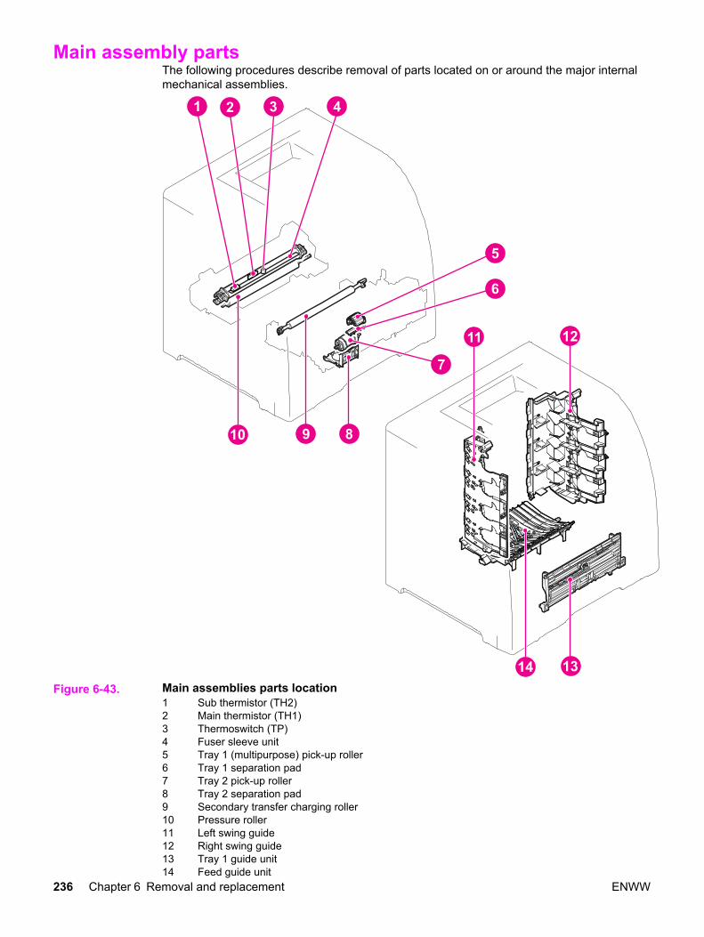
Main assembly partsThe following procedures describe removal of parts located on or around the major internalmechanical assemblies.
Figure 6-43. Main assemblies parts location1 Sub thermistor (TH2)2 Main thermistor (TH1)3 Thermoswitch (TP)4 Fuser sleeve unit5 Tray 1 (multipurpose) pick-up roller6 Tray 1 separation pad7 Tray 2 pick-up roller8 Tray 2 separation pad9 Secondary transfer charging roller10 Pressure roller11 Left swing guide12 Right swing guide13 Tray 1 guide unit14 Feed guide unit
236 Chapter 6 Removal and replacement ENWW

Tray 1 pick-up roller removal1. Remove the transfer unit. See Transfer unit removal.
2. Unhook one claw (1) and slide the idler roller (2) in the direction of the arrow.
3. Rotate the Tray 1 pick-up roller (3) upwards to release it from the shaft and lift the rollerout.
Figure 6-44. Tray 1 pick-up roller removal
NOTE Replace the separation pad whenever you replace the pick-up roller.
.
Tray 1 separation pad removal1. Remove the Tray 1 pick-up roller. See Tray 1 pick-up roller removal, above.
2. Slide the left idler roller (1) in the direction of the arrow (2).
3. Place a flat-blade screwdriver under each slot (3) and twist the screwdriver to pry thepad loose to remove it.
Figure 6-45. Tray 1 separation pad removal
NOTE Replace the pick-up roller whenever you replace the separation pad.
ENWW Main assembly parts 237
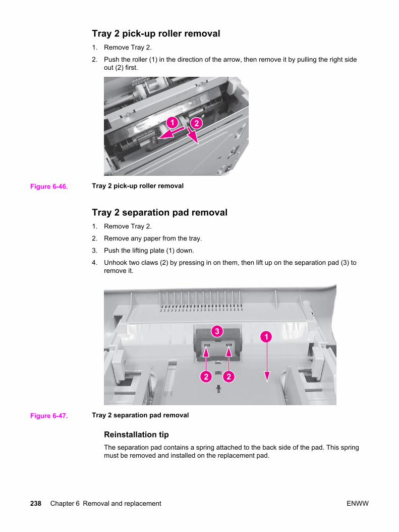
Tray 2 pick-up roller removal1. Remove Tray 2.
2. Push the roller (1) in the direction of the arrow, then remove it by pulling the right sideout (2) first.
Figure 6-46. Tray 2 pick-up roller removal
Tray 2 separation pad removal1. Remove Tray 2.
2. Remove any paper from the tray.
3. Push the lifting plate (1) down.
4. Unhook two claws (2) by pressing in on them, then lift up on the separation pad (3) toremove it.
Figure 6-47. Tray 2 separation pad removal
Reinstallation tipThe separation pad contains a spring attached to the back side of the pad. This springmust be removed and installed on the replacement pad.
238 Chapter 6 Removal and replacement ENWW

Secondary transfer charging roller removal1. Remove the transfer unit and the print cartridges. See Transfer unit removal and Print
cartridge removal.
CAUTION When handling the secondary transfer charging roller, hold the shaft and bushing; do nothold the sponge part of the roller.
2. Lift the blue handle (1) straight up, once the right side is out, continue lifting to releasethe left side and remove the roller (2).
Figure 6-48. Secondary transfer charging roller removal
Reinstallation tipWhen handling the secondary transfer charging roller, hold the shaft ends and bushings;do not hold the sponge part of the roller.
Fuser sleeve unit removalReplacement of the fuser sleeve unit requires replacement of the entire fuser. See Fuserremoval.
Pressure roller removalReplacement of the pressure roller requires replacement of the entire fuser. See Fuserremoval.
Main thermistor/sub-thermistor removalReplacement of the main thermistor and the sub thermistor requires replacement of theentire fuser. See Fuser removal.
Thermoswitch removalReplacement of the thermoswitch requires replacement of the entire fuser. See Fuserremoval.
ENWW Main assembly parts 239

Feed guide unit removal1. Release the right and left rod brackets from the front door. See Pick-up/feed assembly
removal removal procedure, steps 1 through 5.
2. Push the swing guides all the way back.
3. Remove the secondary transfer charging roller. See Secondary transfer charging rollerremoval.
4. Remove the fuser. See Fuser removal.
5. Using both hands, grasp the air duct (2) and apply pressure (by pinching the top andbottom of the duct at the locations indicated by callouts (1) to release two claws (1)located on the bottom rear of the duct. Swing the front of the air duct upwards to removeit.
Figure 6-49. Feed guide unit removal (1 of 2)
240 Chapter 6 Removal and replacement ENWW

6. Push both swing guides all the way back (1), remove four screws (2), and remove thefeed guide (3).
Figure 6-50. Feed guide removal (2 of 2)
Reinstallation tipMake sure that the drive shaft (1) on the feed guide fits correctly into the drive shaft inthe printer (2).
Figure 6-51. Feed guide/printer drive shaft connection
Reinstallation tipMake sure that the two tabs (1) at the rear of the feed guide fit into the slots (2), locatedjust in front of the fuser opening (viewed from the rear of the printer with the fuserremoved).
Figure 6-52. Feed guide unit tab locations
ENWW Main assembly parts 241

Swing guide removal, right1. Open the front door and remove the transfer unit and the print cartridges. See Transfer
unit removal and Print cartridge removal.
2. Remove the top cover. See Top cover removal.
3. Remove the print cartridges. See Print cartridge removal.
4. Remove two screws (1) from the right rod bracket (2) to release the bracket from thedoor.
Figure 6-53. Right swing guide removal (1 of 4)
5. Remove two screws (1) and remove the swing rod arm (2).
Figure 6-54. Right swing guide removal (2 of 4)
242 Chapter 6 Removal and replacement ENWW
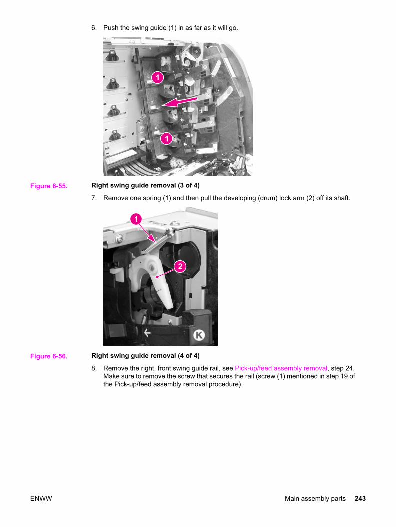
6. Push the swing guide (1) in as far as it will go.
Figure 6-55. Right swing guide removal (3 of 4)
7. Remove one spring (1) and then pull the developing (drum) lock arm (2) off its shaft.
Figure 6-56. Right swing guide removal (4 of 4)
8. Remove the right, front swing guide rail, see Pick-up/feed assembly removal, step 24.Make sure to remove the screw that secures the rail (screw (1) mentioned in step 19 ofthe Pick-up/feed assembly removal procedure).
ENWW Main assembly parts 243

9. Pull the swing guide (1) toward you as far as it will go. Then move it slightly to the left(this allows it to be pulled forward a little more), and pull it forward until it stops. Now,pull the swing guide to the left to remove it. The swing guide should pull out easily. Donot force the guide because it is fragile.
NOTE The swing guide has a retainer (1) that holds the swing guide shaft (2) in place. This retainerprevents the swing guide from being removed until the guide is all the way forward as showin the figure below. (This view is hidden by the image drive assembly and cannot be seenunless that assembly has been removed.)
Figure 6-57. Swing guide shaft removal
Reinstallation tipMake sure the developing (drum) lock arms (1) are in the upright, latched (2) positionbefore reinstalling the swing guide and pushing it back. (In the figure below the top arm(3) is unlatched and the lower arm (1) is correctly latched.) If these arms are in theunlocked position, they will prevent the swing guide from moving back. Also, these armswill occasionally unlatch while pushing the swing guide back, preventing the guide frombeing moved back. If that occurs, pull the swing guide forward, reach behind the guide,and relatch the lock arms.
Figure 6-58. Developing (drum) lock arm position for swing guide installation
244 Chapter 6 Removal and replacement ENWW
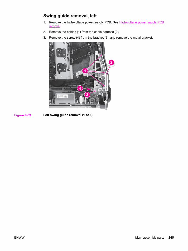
Swing guide removal, left1. Remove the high-voltage power supply PCB. See High-voltage power supply PCB
removal.
2. Remove the cables (1) from the cable harness (2).
3. Remove the screw (4) from the bracket (3), and remove the metal bracket.
Figure 6-59. Left swing guide removal (1 of 6)
ENWW Main assembly parts 245

4. Remove three screws (1) and swing the cable harness (2) to the right. The cableharness does not need to be completely removed to remove the transfer contactassembly. However, if the cable harness needs to be removed, disconnect the cableconnector (3) from the back of the harness to remove the harness.
Reinstallation tipThe power switch rod (4) rides in a slot at the bottom of the cable harness. Whenreinstalling the cable harness, make sure the switch rod is inserted in this slot.
Figure 6-60. Left swing guide removal (2 of 6)
5. Remove one screw (1) and unhook three claws (2) to remove the transfer contactassembly (3).
Reinstallation tipWhen installing the transfer contact assembly, make sure that the plastic tab (4) fitsunder the metal tab (5) and that the door switch (SW1) is in place.
Figure 6-61. Left swing guide removal (3 of 6)
246 Chapter 6 Removal and replacement ENWW

6. Remove two screws (1) and remove the left swing rod arm (2).
Figure 6-62. Left swing guide removal (4 of 6)
7. Push the left swing guide (1) in, as far as it will go (2).
Figure 6-63. Left swing guide removal (5 of 6)
ENWW Main assembly parts 247

8. Remove one spring (1) and remove the developing (drum) lock arm (2).
Figure 6-64. Left swing guide removal (6 of 6)
9. Remove the white left swing guide rail. See Pick-up/feed assembly removal, step 25.
10. Pull the left swing guide (1) toward the front of the printer.
248 Chapter 6 Removal and replacement ENWW

11. Remove the swing guide by pulling it to the right, being careful not to force it. The guidemust be positioned all the way forward to release the catch on the shaft, which will allowthe swing guide to be removed.
Reinstallation tipMake sure the projected part at the bottom of the swing guide is placed into the guide rail.
Reinstallation tipMake sure the developing (drum) lock arms (1) are in the upright, latched (2) position (asshown in the figure below), before reinstalling the swing guide. If these arms are in theunlocked position, they will prevent the swing guide from moving back. Also, whilepushing the swing guide back, these arms will occasionally unlatch, preventing the guidefrom being moved back. If that occurs, reach behind the swing guide and relatch the lockarms.
Figure 6-65. Left swing guide replacement
ENWW Main assembly parts 249

Switches
Figure 6-66. Switch locations
SW1 Door switchSW1001Test print switchSW3001Power switch
Door Switch (SW1) removal1. Refer to the left swing guide removal procedure, steps 1 through 5, and remove the
transfer contact assembly. See Swing guide removal, left.
2. Remove the door switch (1) by sliding it out.
Figure 6-67. Door switch removal
250 Chapter 6 Removal and replacement ENWW

Test print switch (SW1001) removalReplacing the test print switch requires the replacement of the DC controller PCB. See DCcontroller PCB removal.
Power switch (SW3001) removalReplacing the power switch requires replacement of the low-voltage power supply PCB. SeeLow-voltage power supply PCB removal.
ENWW Switches 251
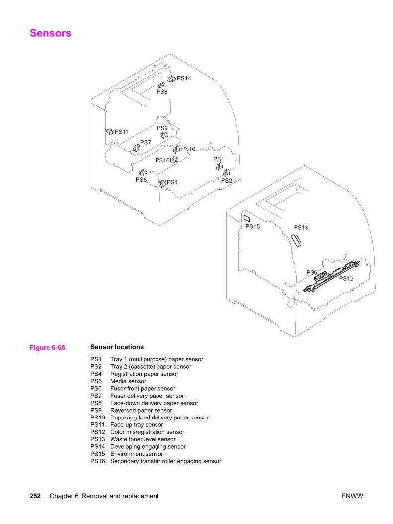
Sensors
Figure 6-68. Sensor locations
PS1 Tray 1 (multipurpose) paper sensorPS2 Tray 2 (cassette) paper sensorPS4 Registration paper sensorPS5 Media sensorPS6 Fuser front paper sensorPS7 Fuser delivery paper sensorPS8 Face-down delivery paper sensorPS9 Reversed paper sensorPS10 Duplexing feed delivery paper sensorPS11 Face-up tray sensorPS12 Color misregistration sensorPS13 Waste toner level sensorPS14 Developing engaging sensorPS15 Environment sensorPS16 Secondary transfer roller engaging sensor
252 Chapter 6 Removal and replacement ENWW

Tray 1 (multipurpose tray) paper sensor (PS1) removalReplacement of the Tray 1 paper sensor requires replacement of the entire pick-up/feedassembly. See Pick-up/feed assembly removal.
Tray 2 (cassette) paper sensor (PS2) removal1. Remove the pick-up/feed assembly. See Pick-up/feed assembly removal.
2. Turn the pick-up/feed assembly over.
3. Remove the Tray 2 pick-up roller (1) by pushing in on the right side (2) of the roller unitand then pull it out and to the right (3) to remove it.
Figure 6-69. Tray 2 paper sensor removal (1 of 3)
Reinstallation tipWhen installing the sensor, connect the connector first, then install the sensor.
4. Unhook the bushing claw (1) by pushing it in, then rotate it in the direction of the arrow(2), and remove both the bushing (3) and black sensor arm (4).
Figure 6-70. Tray 2 paper sensor removal (2 of 3)
Reinstallation tipMake sure that the flag on the sensor arm (4 - in the above figure) fits between the notchin the paper sensor (5 - in the above figure) and moves freely.
ENWW Sensors 253

5. Unhook two claws (1) and pull the paper sensor (2) out, disconnecting the connector (3)once the sensor is pulled away from the assembly.
Figure 6-71. Tray paper sensor removal (3 of 3)
Reinstallation tipWhen reinstalling the sensor, connect the connector first then, install the sensor.
Registration paper sensor (PS4) removal1. Remove the pick-up/feed assembly. See Pick-up/feed assembly removal.
2. Remove one screw (1) and remove the registration paper sensor holder (2).
Figure 6-72. Registration paper sensor removal (1 of 2)
254 Chapter 6 Removal and replacement ENWW

3. Unhook two claws (1), disconnect one connector (2), and remove the registration papersensor (3) from the sensor holder.
Figure 6-73. Registration paper sensor removal (2 of 2)
Media sensor (PS5) removal
NOTE When the media sensor is replaced, in addition to replacing the sensor, a configurationprocedure must be performed. For information on this configuration, refer to Chapter 8,Replacement parts configuration.
1. Remove the color misregistration sensor. See Color misregistration sensor (PS12)removal.
2. Disconnect one connector (1).
3. Swing the front side of the media sensor upward (2), then lift the sensor (4) up, removingit from the two shafts (3).
Figure 6-74. Media sensor removal
ENWW Sensors 255
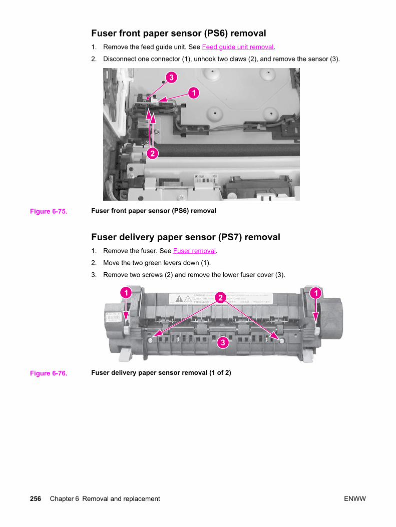
Fuser front paper sensor (PS6) removal1. Remove the feed guide unit. See Feed guide unit removal.
2. Disconnect one connector (1), unhook two claws (2), and remove the sensor (3).
Figure 6-75. Fuser front paper sensor (PS6) removal
Fuser delivery paper sensor (PS7) removal1. Remove the fuser. See Fuser removal.
2. Move the two green levers down (1).
3. Remove two screws (2) and remove the lower fuser cover (3).
Figure 6-76. Fuser delivery paper sensor removal (1 of 2)
256 Chapter 6 Removal and replacement ENWW

4. Disconnect one connector (1), unhook two claws (2), and remove the fuser deliverypaper sensor (3).
Figure 6-77. Fuser delivery paper sensor removal (2 of 2)
Face-down delivery paper sensor (PS8) removal1. Remove the face-down (output bin) delivery assembly. See Face-down delivery
assembly removal.
2. Unhook two claws (1) and remove the face-down delivery paper sensor (2).
Figure 6-78. Face-down (output bin) delivery paper sensor removal
Reversed paper sensor (PS9) removal (HP 3700 only)1. Remove the fuser. See Fuser removal.
2. Remove two screws (1) and remove the reverse guide unit (2).
ENWW Sensors 257
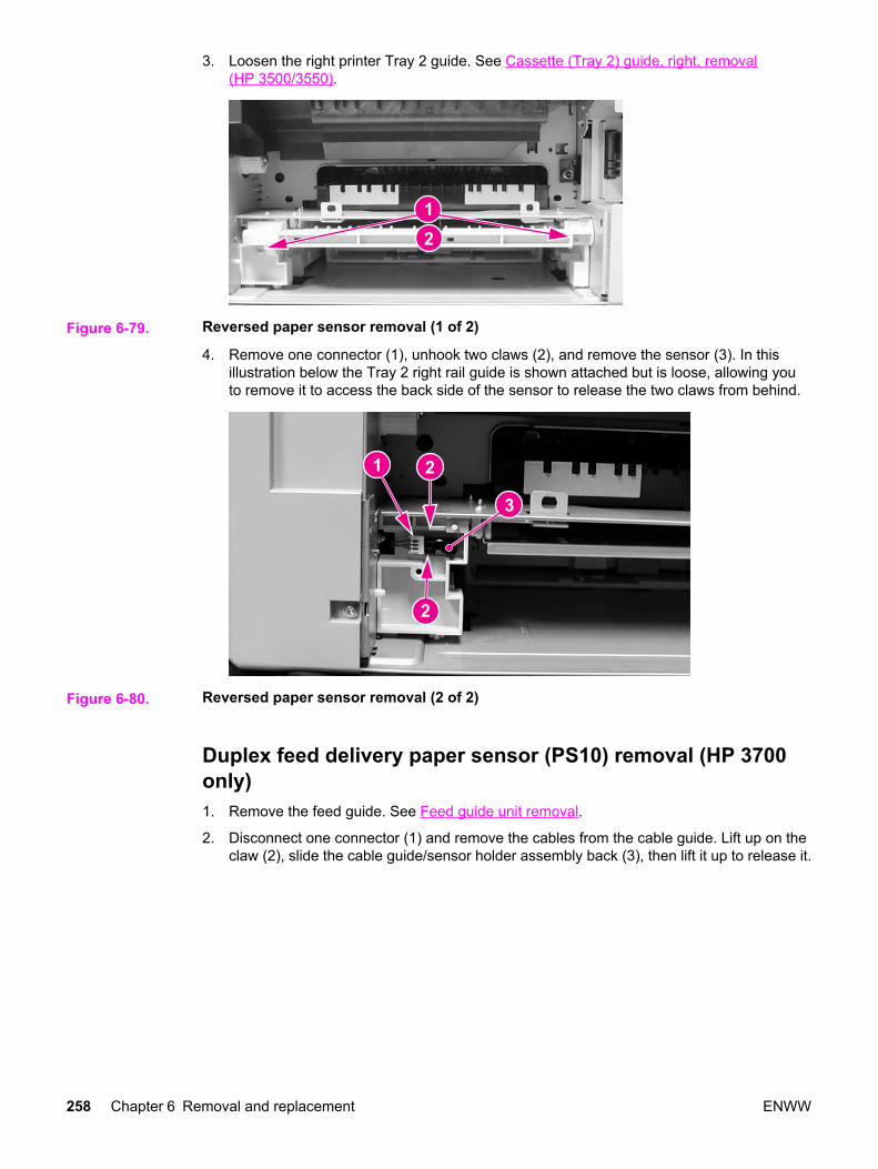
3. Loosen the right printer Tray 2 guide. See Cassette (Tray 2) guide, right, removal(HP 3500/3550).
Figure 6-79. Reversed paper sensor removal (1 of 2)
4. Remove one connector (1), unhook two claws (2), and remove the sensor (3). In thisillustration below the Tray 2 right rail guide is shown attached but is loose, allowing youto remove it to access the back side of the sensor to release the two claws from behind.
Figure 6-80. Reversed paper sensor removal (2 of 2)
Duplex feed delivery paper sensor (PS10) removal (HP 3700only)1. Remove the feed guide. See Feed guide unit removal.
2. Disconnect one connector (1) and remove the cables from the cable guide. Lift up on theclaw (2), slide the cable guide/sensor holder assembly back (3), then lift it up to release it.
258 Chapter 6 Removal and replacement ENWW

3. Unhook two claws from the back and remove the sensor (4).
Figure 6-81. Duplex feed delivery paper sensor removal
Rear output bin paper sensor (PS11) removal1. Remove the face-down delivery assembly. See Face-down delivery assembly removal.
2. Disconnect one connector (1) and unhook two claws (2). To unhook the claws, insert apointed object into the two claw locations (2), (under the sensor at the connector side ofthe sensor), to release the claws, then lift up on the connector side of the sensor (3) toremove it.
Figure 6-82. Rear output bin paper sensor removal
ENWW Sensors 259

Color misregistration sensor (PS12) removal
NOTE When the color misregistration sensor is replaced, in addition to replacing the sensor, aconfiguration procedure must be performed. For information on this configuration, refer toChapter 8, Replacement parts configuration.
1. Refer to the pick-up/feed unit removal procedure, steps 1 through 5, and release theright and left slide rods from the front door. See Pick-up/feed assembly removal.
2. Push the swing guides in as far as they will go.
3. Refer to the pick-up/feed unit removal procedure, steps 22 through 25, and remove theconnector cover and the right and left swing guide rails. See Pick-up/feed assemblyremoval.
4. Disconnect one connector (1).
5. Remove one screw (2), the shaft holder (3), and the spring under the shaft holderlocated directly under the screw (2).
6. Unhook two claws (4) and lift the color misregistration sensor (5) up to remove it.
Figure 6-83. Color misregistration sensor removal
Waste toner level sensor (PS13) removal1. Remove the front left cover. See Left front cover removal.
2. Remove one connector (1) from the DC controller PCB and unroute the cable.
260 Chapter 6 Removal and replacement ENWW
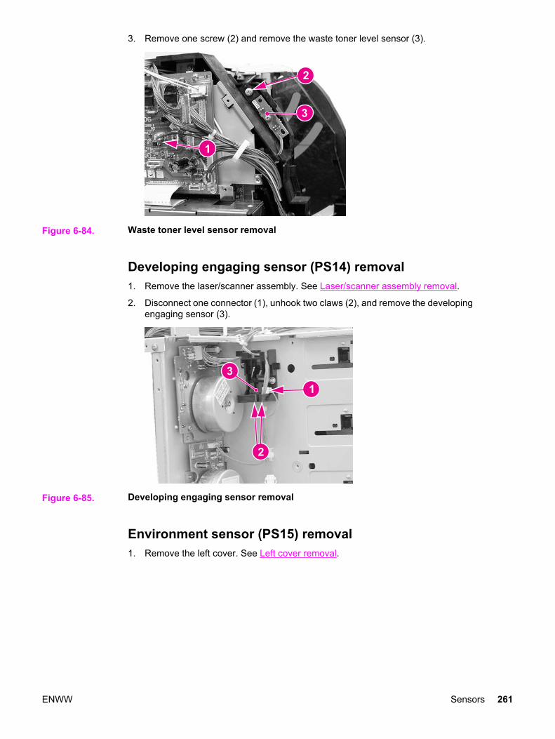
3. Remove one screw (2) and remove the waste toner level sensor (3).
Figure 6-84. Waste toner level sensor removal
Developing engaging sensor (PS14) removal1. Remove the laser/scanner assembly. See Laser/scanner assembly removal.
2. Disconnect one connector (1), unhook two claws (2), and remove the developingengaging sensor (3).
Figure 6-85. Developing engaging sensor removal
Environment sensor (PS15) removal1. Remove the left cover. See Left cover removal.
ENWW Sensors 261

2. Remove one (1) screw and remove the sensor (2). Disconnect the connector (3) whileremoving the sensor.
Figure 6-86. Environmental sensor removal
Secondary transfer roller engaging sensor (PS16) removal1. Remove the pick-up/feed assembly. See Pick-up/feed assembly removal.
2. Turn the assembly upside down.
3. Remove the cable (1) from the cable guides. Using one hand, gently push two claws (2)apart. With your other hand, pull the sensor (3) out by holding the cable connector (4).Disconnect the connector to remove the sensor.
Figure 6-87. Secondary transfer roller engaging sensor removal
262 Chapter 6 Removal and replacement ENWW

Solenoids and Clutches
Figure 6-88. Solenoid and clutch locations
SL1 Tray 1 pick-up solenoidSL2 Tray 2 pick-up solenoid (pick-up/feed assembly)SL3 Tray 3 pick-up solenoid (not shown; see 500-sheet paper feeder)SL4 Secondary transfer roller engaging solenoidSL5 Duplex feed solenoidCL1 Registration clutchCL2 K development clutch (image drive unit)CL3 Developing engaging clutch (developing engaging drive unit)CL4 Tray 3 pick-up clutch (not shown; see 500-sheet paper feeder)
Tray 1 (multipurpose tray) pick-up solenoid (SL1) removal1. Remove the pick-up/feed assembly. See Pick-up/feed assembly removal.
ENWW Solenoids and Clutches 263

2. Remove one screw (1), disconnect one connector (2), and remove the Tray 1 pick-upsolenoid (3).
Figure 6-89. Tray 1 pick-up solenoid removal
Tray 2 pick-up solenoid (SL2) removal1. Remove the right cover. See Right cover removal.
2. Refer to the Pick-up/feed assembly removal procedure, steps 4 and 6 through 10, andremove the paper drive gear plate.
3. Remove two screws (1), disconnect one connector (2), and remove the cover plate (3).
Figure 6-90. Tray 2 pick-up solenoid removal (1 of 2)
264 Chapter 6 Removal and replacement ENWW

4. Remove one screw (1) and remove the solenoid (2).
Figure 6-91. Tray 2 pick-up solenoid removal (2 of 2)
Secondary transfer roller engaging solenoid (SL4) removal1. Remove the pick-up/feed assembly. See Pick-up/feed assembly removal.
2. Remove five screws (1), the gear side plate (2), plate (3), solenoid (4), and theconnector cover (5).
Figure 6-92. Secondary transfer roller engaging solenoid removal (1 of 2)
ENWW Solenoids and Clutches 265
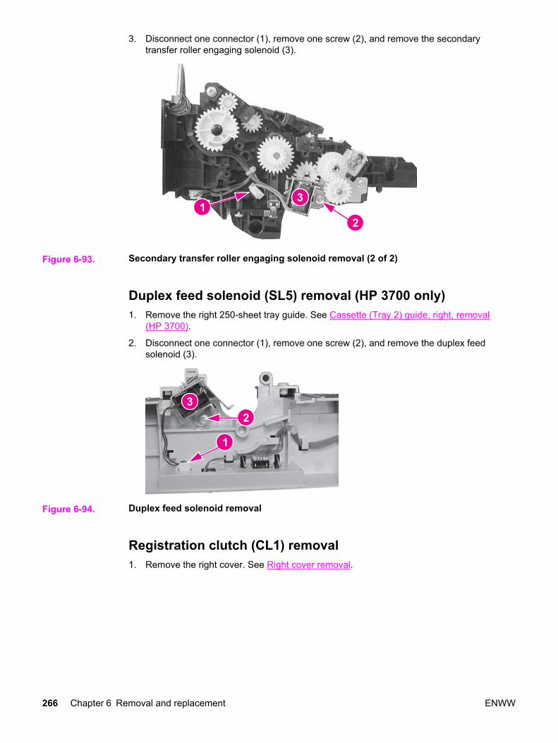
3. Disconnect one connector (1), remove one screw (2), and remove the secondarytransfer roller engaging solenoid (3).
Figure 6-93. Secondary transfer roller engaging solenoid removal (2 of 2)
Duplex feed solenoid (SL5) removal (HP 3700 only)1. Remove the right 250-sheet tray guide. See Cassette (Tray 2) guide, right, removal
(HP 3700).
2. Disconnect one connector (1), remove one screw (2), and remove the duplex feedsolenoid (3).
Figure 6-94. Duplex feed solenoid removal
Registration clutch (CL1) removal1. Remove the right cover. See Right cover removal.
266 Chapter 6 Removal and replacement ENWW
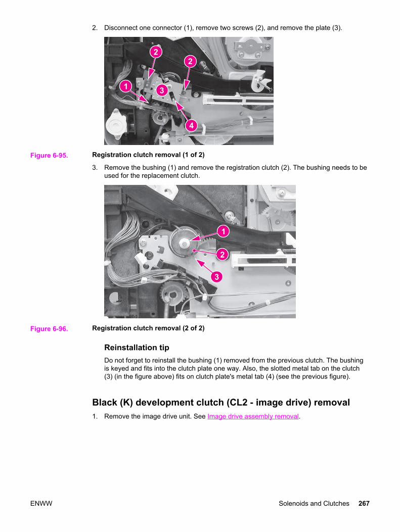
2. Disconnect one connector (1), remove two screws (2), and remove the plate (3).
Figure 6-95. Registration clutch removal (1 of 2)
3. Remove the bushing (1) and remove the registration clutch (2). The bushing needs to beused for the replacement clutch.
Figure 6-96. Registration clutch removal (2 of 2)
Reinstallation tipDo not forget to reinstall the bushing (1) removed from the previous clutch. The bushingis keyed and fits into the clutch plate one way. Also, the slotted metal tab on the clutch(3) (in the figure above) fits on clutch plate's metal tab (4) (see the previous figure).
Black (K) development clutch (CL2 - image drive) removal1. Remove the image drive unit. See Image drive assembly removal.
ENWW Solenoids and Clutches 267
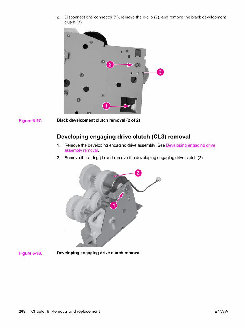
2. Disconnect one connector (1), remove the e-clip (2), and remove the black developmentclutch (3).
Figure 6-97. Black development clutch removal (2 of 2)
Developing engaging drive clutch (CL3) removal1. Remove the developing engaging drive assembly. See Developing engaging drive
assembly removal.
2. Remove the e-ring (1) and remove the developing engaging drive clutch (2).
Figure 6-98. Developing engaging drive clutch removal
268 Chapter 6 Removal and replacement ENWW
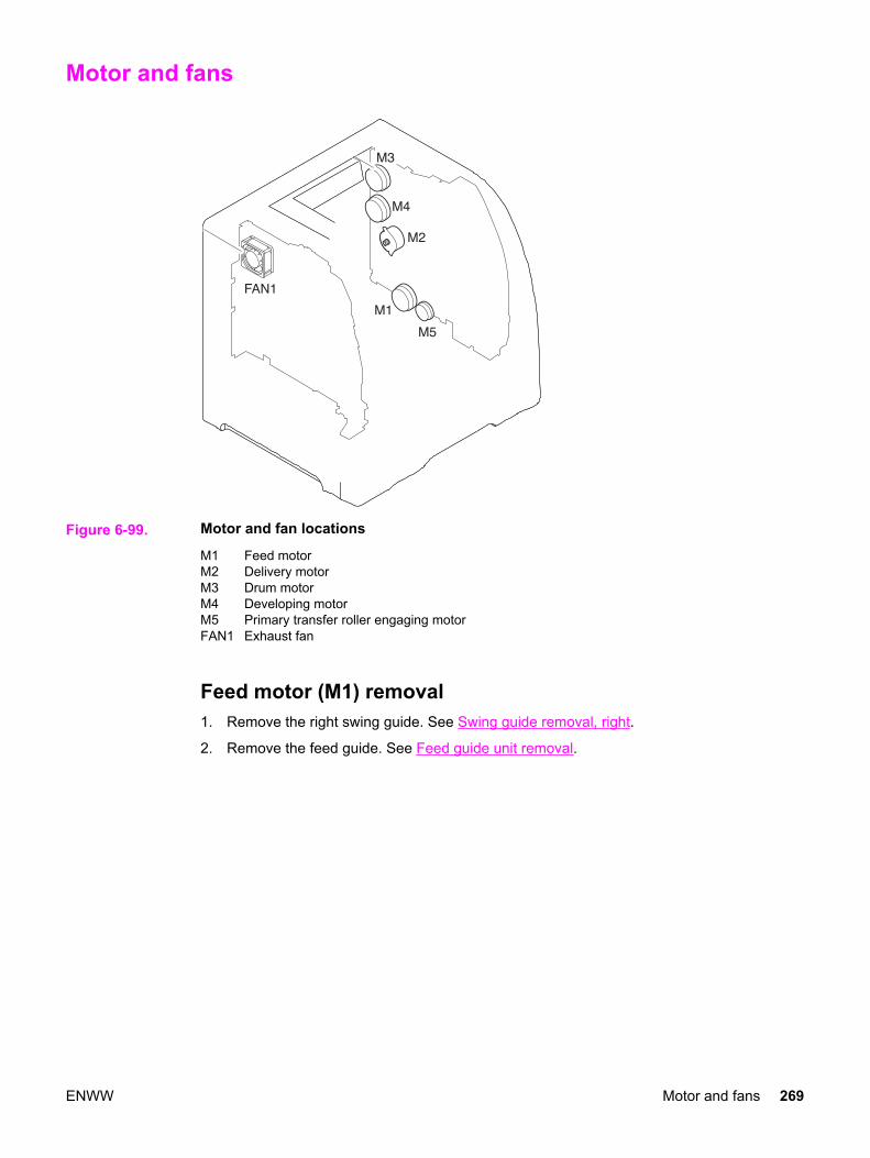
Motor and fans
Figure 6-99. Motor and fan locations
M1 Feed motorM2 Delivery motorM3 Drum motorM4 Developing motorM5 Primary transfer roller engaging motorFAN1 Exhaust fan
Feed motor (M1) removal1. Remove the right swing guide. See Swing guide removal, right.
2. Remove the feed guide. See Feed guide unit removal.
ENWW Motor and fans 269
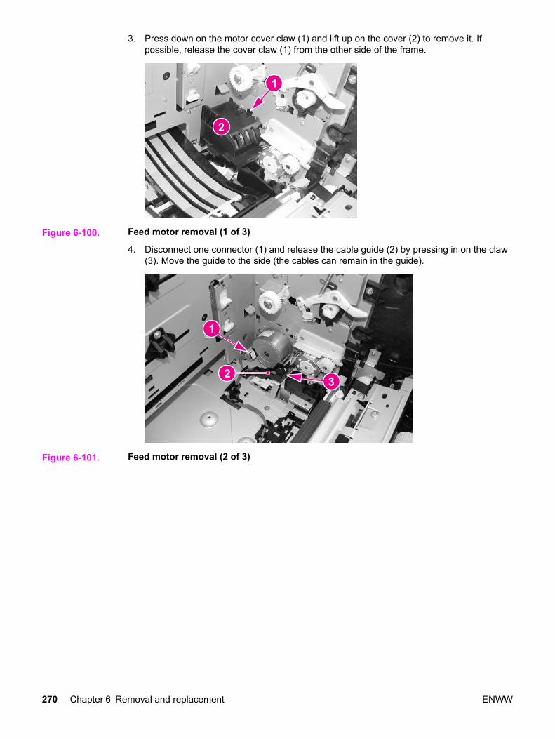
3. Press down on the motor cover claw (1) and lift up on the cover (2) to remove it. Ifpossible, release the cover claw (1) from the other side of the frame.
Figure 6-100. Feed motor removal (1 of 3)
4. Disconnect one connector (1) and release the cable guide (2) by pressing in on the claw(3). Move the guide to the side (the cables can remain in the guide).
Figure 6-101. Feed motor removal (2 of 3)
270 Chapter 6 Removal and replacement ENWW
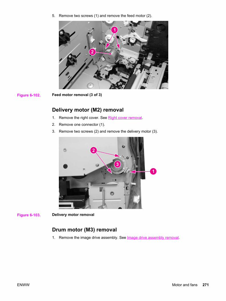
5. Remove two screws (1) and remove the feed motor (2).
Figure 6-102. Feed motor removal (3 of 3)
Delivery motor (M2) removal1. Remove the right cover. See Right cover removal.
2. Remove one connector (1).
3. Remove two screws (2) and remove the delivery motor (3).
Figure 6-103. Delivery motor removal
Drum motor (M3) removal1. Remove the image drive assembly. See Image drive assembly removal.
ENWW Motor and fans 271
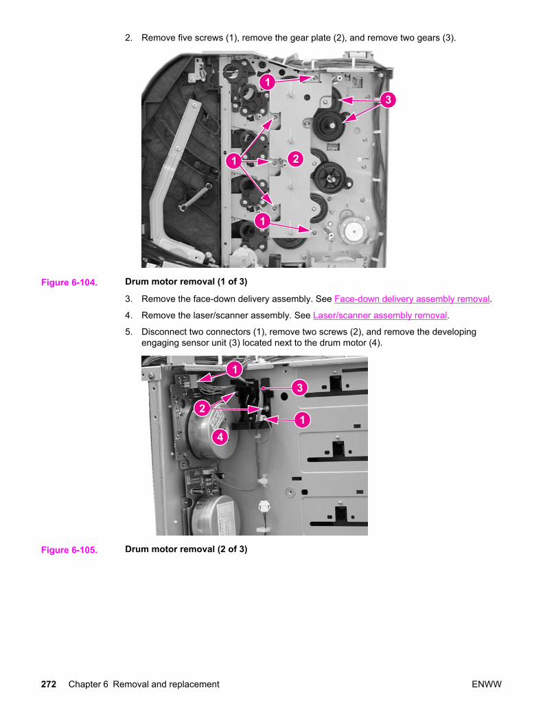
2. Remove five screws (1), remove the gear plate (2), and remove two gears (3).
Figure 6-104. Drum motor removal (1 of 3)
3. Remove the face-down delivery assembly. See Face-down delivery assembly removal.
4. Remove the laser/scanner assembly. See Laser/scanner assembly removal.
5. Disconnect two connectors (1), remove two screws (2), and remove the developingengaging sensor unit (3) located next to the drum motor (4).
Figure 6-105. Drum motor removal (2 of 3)
272 Chapter 6 Removal and replacement ENWW

6. Remove four screws (1) and remove the drum motor (see callout (4) in the previousfigure).
Figure 6-106. Drum motor removal (3 of 3)
Developing motor (M4) removal1. Remove the image drive assembly. See Image drive assembly removal.
2. Remove the face-down delivery assembly. See Face-down delivery assembly removal.
3. Remove the laser/scanner assembly. See Laser/scanner assembly removal.
4. Remove the e-ring (1) and one gear (2).
Figure 6-107. Developing motor removal (1 of 3)
ENWW Motor and fans 273
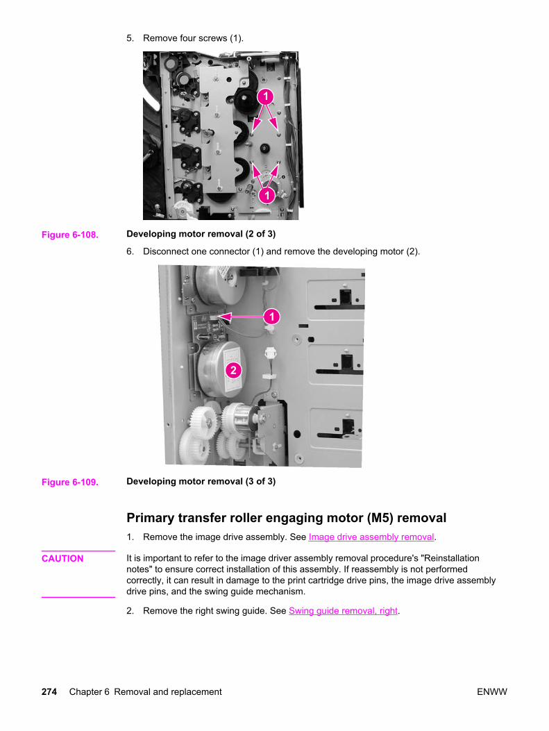
5. Remove four screws (1).
Figure 6-108. Developing motor removal (2 of 3)
6. Disconnect one connector (1) and remove the developing motor (2).
Figure 6-109. Developing motor removal (3 of 3)
Primary transfer roller engaging motor (M5) removal1. Remove the image drive assembly. See Image drive assembly removal.
CAUTION It is important to refer to the image driver assembly removal procedure's "Reinstallationnotes" to ensure correct installation of this assembly. If reassembly is not performedcorrectly, it can result in damage to the print cartridge drive pins, the image drive assemblydrive pins, and the swing guide mechanism.
2. Remove the right swing guide. See Swing guide removal, right.
274 Chapter 6 Removal and replacement ENWW

3. Refer to the pick-up/feed guide assembly removal procedure, steps 1 through 12, andremove the right side gear plate. See Pick-up/feed assembly removal.
CAUTION It is important to refer to the pick-up/feed assembly removal procedure's "Reinstallationnotes" to ensure correct installation of this assembly. If reassembly is not performedcorrectly, it can result in damage to the print cartridge drive pins, the image drive assemblydrive pins, and the swing guide mechanism.
4. Remove the e-clip (1), remove two screws (2), and then remove the gear plate (3).
Reinstallation tipWhen reinstalling the gear plate, ensure that the gear (4) is turned all the waycounterclockwise as shown below. Refer to the above caution for reinstallationinformation.
Figure 6-110. Primary transfer roller engaging motor removal (1 of 4)
5. Remove the one screw (1) from the rear swing guide rail (2) and remove the rail.
6. Pull gear (3) and its shaft out to the left.
ENWW Motor and fans 275

7. Remove the motor cover (4) by pressing down on the tab (5) while pulling the coverslightly to the left and up, then pull it and out to remove it.
Figure 6-111. Primary transfer roller engaging motor removal (2 of 4)
8. Remove the gear (1) and then remove two screws that secure the motor.
Reinstallation tipWhen reinstalling the gear (1), insert the gear with shaft that was removed in theprevious step (callout (3) in the figure above) from inside the printer, through this gear.
Figure 6-112. Transfer roller engaging motor removal (3 of 4)
276 Chapter 6 Removal and replacement ENWW

9. Disconnect one connector (1) and lift the primary transfer roller engaging motor (2) upslightly, and then pull it to the left to remove it.
Figure 6-113. Transfer roller engaging motor (4 of 4)
Exhaust fan (FAN1) removal1. Remove the left cover. See Left cover removal.
2. Remove two connectors (1) from the DC controller PCB.
3. Unhook four claws (2) and pull the fan motor (3) out to remove it.
Figure 6-114. Fan removal
Reinstallation tipBe sure the arrow on the fan points to the outside when reinstalling the exhaust fan.
ENWW Motor and fans 277

Circuit Boards
Figure 6-115. Circuit board locations
1 DC controller PCB2 Memory controller PCB3 High-voltage power supply PCBs4 Low-voltage power supply PCB5 Formatter PCB6 Control panel PCB
DC controller PCB removal
NOTE When the DC controller PCB is replaced, in addition to replacing the PCB, a configurationprocedure must be performed. For information on this configuration, refer to Chapter 8,Replacement parts configuration.
1. Remove the left cover. See Left cover removal.
2. Disconnect all cable connections (19 connectors for the HP Color LaserJet 3500/3550series printer and 20 connectors for the HP Color LaserJet 3700 series printer).
278 Chapter 6 Removal and replacement ENWW
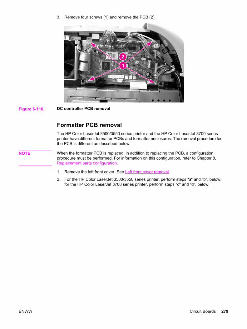
3. Remove four screws (1) and remove the PCB (2).
Figure 6-116. DC controller PCB removal
Formatter PCB removalThe HP Color LaserJet 3500/3550 series printer and the HP Color LaserJet 3700 seriesprinter have different formatter PCBs and formatter enclosures. The removal procedure forthe PCB is different as described below.
NOTE When the formatter PCB is replaced, in addition to replacing the PCB, a configurationprocedure must be performed. For information on this configuration, refer to Chapter 8,Replacement parts configuration.
1. Remove the left front cover. See Left front cover removal.
2. For the HP Color LaserJet 3500/3550 series printer, perform steps "a" and "b", below;for the HP Color LaserJet 3700 series printer, perform steps "c" and "d", below:
ENWW Circuit Boards 279
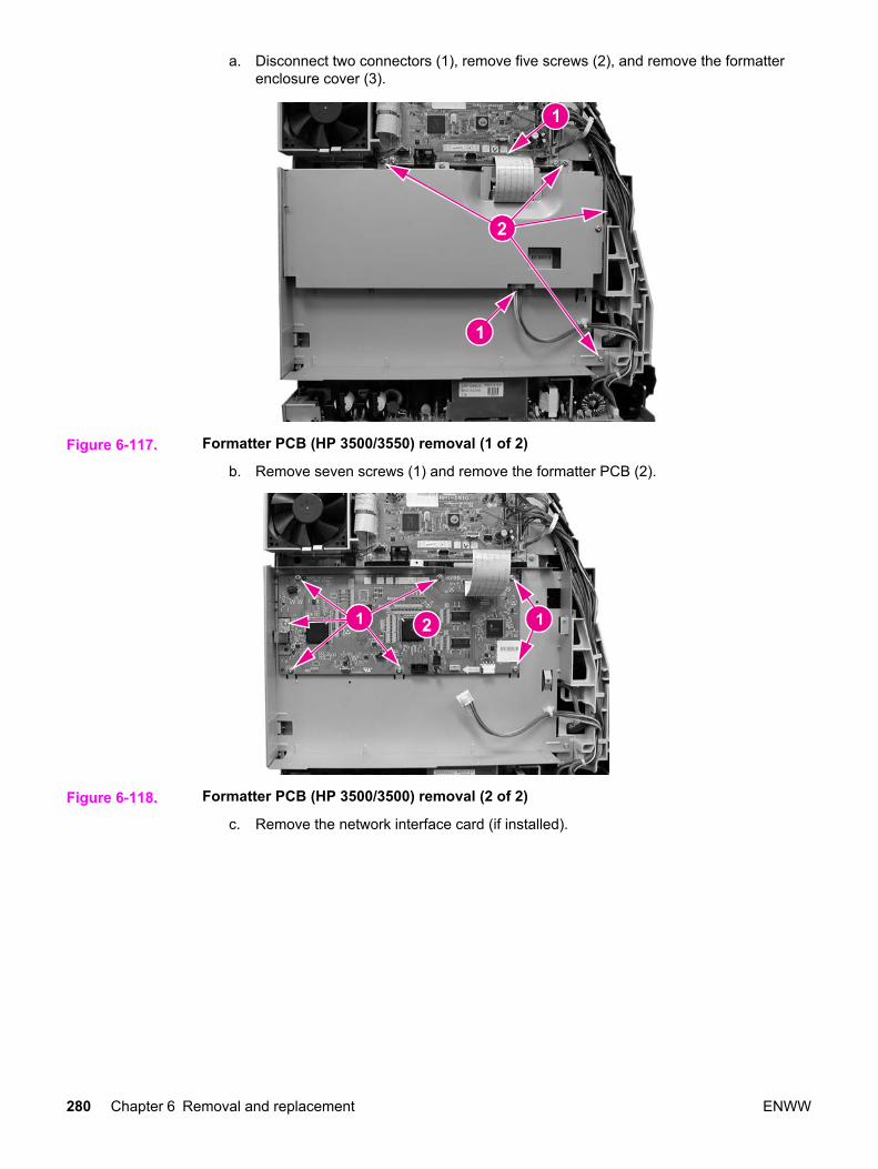
a. Disconnect two connectors (1), remove five screws (2), and remove the formatterenclosure cover (3).
Figure 6-117. Formatter PCB (HP 3500/3550) removal (1 of 2)
b. Remove seven screws (1) and remove the formatter PCB (2).
Figure 6-118. Formatter PCB (HP 3500/3500) removal (2 of 2)
c. Remove the network interface card (if installed).
280 Chapter 6 Removal and replacement ENWW

d. Disconnect one connector (1), remove two screws (2), and remove the formattercover (3).
Figure 6-119. Formatter PCB (HP 3700) removal (1 of 2)
3. Disconnect one connector (1), remove six screws (2), and remove the formatter PCB (3).
Figure 6-120. Formatter PCB (HP 3700) removal (2 of 2)
High-voltage power supply PCB removal1. Remove the top cover. See Top cover removal.
2. Remove the upper rear door. See Upper rear door removal.
3. Remove the rear cover. See Rear cover removal.
4. Remove the lower rear door. See Lower rear door (rear output bin) removal.
ENWW Circuit Boards 281

5. Disconnect two cables (1). (The formatter cage removal for the HP Color LaserJet3500/3550 and 3700 series printers is slightly different. (Refer to the figure below, eitherHP 3500/3550 or the HP 3700 for the specific printer formatter cage being removed.)
6. Remove four screws (2) from the side of the cage.
Figure 6-121. HP 3500/3550 and HP 3700
Figure 6-122. High-voltage power supply PCB removal (1 of 5)
7. Remove the screws from the back of the formatter cage (the HP 3500/3550 is shown forboth the HP 3500/3550 and HP 3700); remove two screws (1) for the HP 3500/3550;remove three screws, (1) and (2), for the HP 3700).
282 Chapter 6 Removal and replacement ENWW

8. Remove the formatter cage (3) (while removing the cage for the HP 3500/3550, releasethe cable tie (4).
Figure 6-123. High-voltage power supply PCB removal (2 of 5)
9. Disconnect two connectors (1), remove two screws (2), press down on the claw (3), andpull the fan assembly (4) out from the printer.
Figure 6-124. High-voltage power supply PCB removal (3 or 5)
10. Disconnect the remaining cable connectors from the PCB (19 connectors for theHP 3500/3550 and 20 for the HP 3700) and remove the cables from three cable clamps(1).
ENWW Circuit Boards 283

11. Remove four screws (2) and remove the DC controller PCB/plate (3) from the printer.While removing the controller PCB/plate, remove the cables from the remaining harnessclamps.
Figure 6-125. High-voltage power supply PCB removal (4 of 5)
12. Remove three screws (1), unhook eight claws (2) (working from the top down), pull outon the bottom sides of the PCB to release two pins (3), and then lift up to release it fromthe lower support (4). Once the PCB is released from the printer, disconnect theconnector (5) as you pull the PCB away from the printer.
Reinstallation tipWhen reinstalling the high-voltage power supply PCB, connect the connector (5) first.Next, install the bottom of the PCB into the bottom support (4), then align the board ontothe two lower pins (3), and working upward, hook the claws (2) on each side of theboard. Ensure that the board is aligned so it fits on the upper alignment pin (6).
6
Figure 6-126. High-voltage power supply PCB removal (5 of 5)
284 Chapter 6 Removal and replacement ENWW
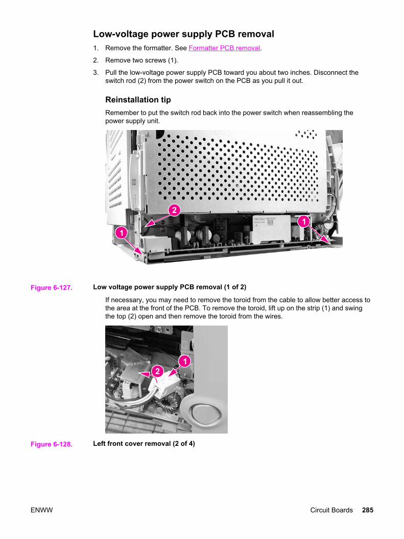
Low-voltage power supply PCB removal1. Remove the formatter. See Formatter PCB removal.
2. Remove two screws (1).
3. Pull the low-voltage power supply PCB toward you about two inches. Disconnect theswitch rod (2) from the power switch on the PCB as you pull it out.
Reinstallation tipRemember to put the switch rod back into the power switch when reassembling thepower supply unit.
Figure 6-127. Low voltage power supply PCB removal (1 of 2)
If necessary, you may need to remove the toroid from the cable to allow better access tothe area at the front of the PCB. To remove the toroid, lift up on the strip (1) and swingthe top (2) open and then remove the toroid from the wires.
Figure 6-128. Left front cover removal (2 of 4)
ENWW Circuit Boards 285

4. Disconnect four connectors (1) and remove the power supply (2).
Figure 6-129. Low voltage power supply PCB removal (2 of 2)
Memory controller PCB removal1. Open the front door, remove the transfer unit, and the print cartridges. See Transfer unit
removal and Print cartridge removal.
2. Disconnect the left rod bracket from the front door by removing two screws from thebracket. See Pick-up/feed assembly removal, step 4.
3. Remove two screws (1) and pull the shield plate (2) out. Adjust the position of the swingguide, as required to access the screws. (The left swing guide has been removed forclarity in illustrating this removal procedure. It is not necessary to remove the swingguide to remove this PCB.)
Figure 6-130. Memory controller PCB removal (1 of 2)
286 Chapter 6 Removal and replacement ENWW
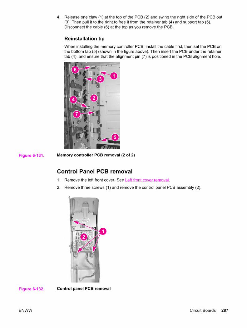
4. Release one claw (1) at the top of the PCB (2) and swing the right side of the PCB out(3). Then pull it to the right to free it from the retainer tab (4) and support tab (5).Disconnect the cable (6) at the top as you remove the PCB.
Reinstallation tipWhen installing the memory controller PCB, install the cable first, then set the PCB onthe bottom tab (5) (shown in the figure above). Then insert the PCB under the retainertab (4), and ensure that the alignment pin (7) is positioned in the PCB alignment hole.
7
Figure 6-131. Memory controller PCB removal (2 of 2)
Control Panel PCB removal1. Remove the left front cover. See Left front cover removal.
2. Remove three screws (1) and remove the control panel PCB assembly (2).
Figure 6-132. Control panel PCB removal
ENWW Circuit Boards 287
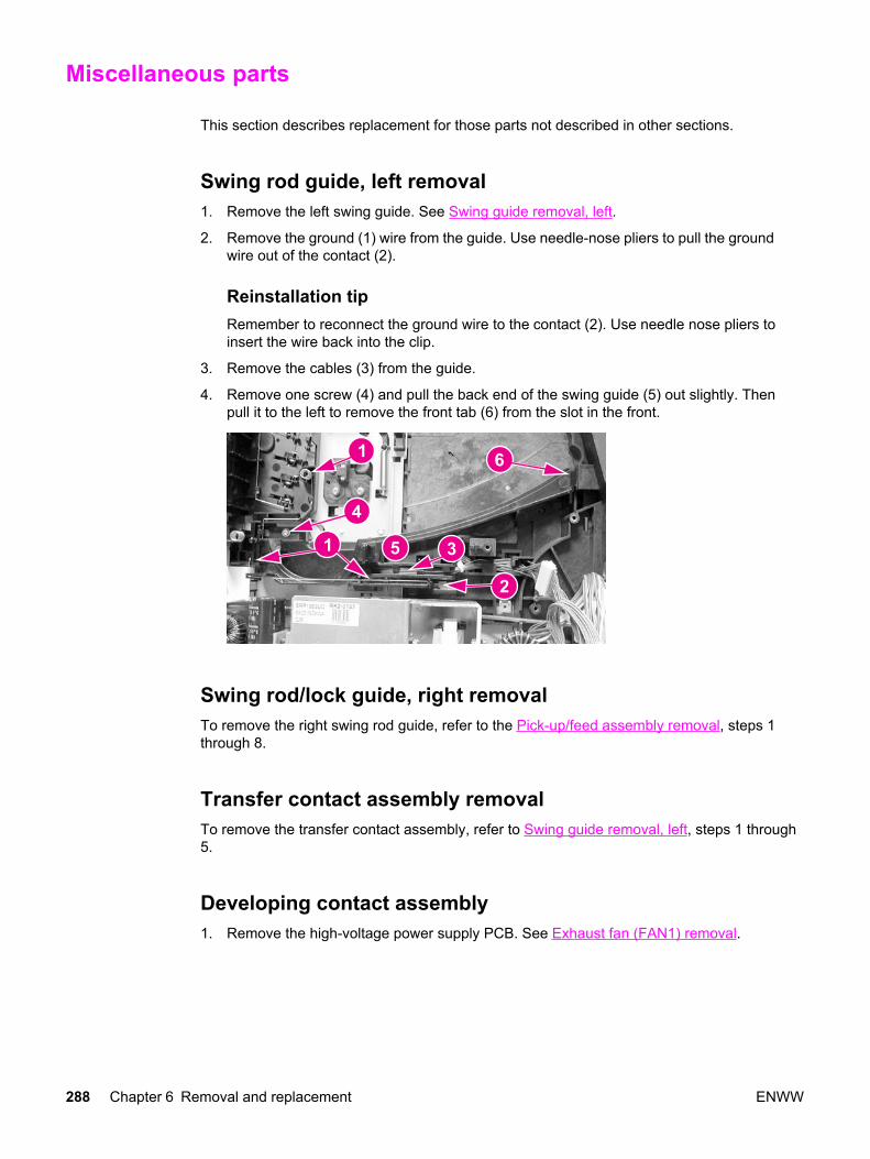
Miscellaneous parts
This section describes replacement for those parts not described in other sections.
Swing rod guide, left removal1. Remove the left swing guide. See Swing guide removal, left.
2. Remove the ground (1) wire from the guide. Use needle-nose pliers to pull the groundwire out of the contact (2).
Reinstallation tipRemember to reconnect the ground wire to the contact (2). Use needle nose pliers toinsert the wire back into the clip.
3. Remove the cables (3) from the guide.
4. Remove one screw (4) and pull the back end of the swing guide (5) out slightly. Thenpull it to the left to remove the front tab (6) from the slot in the front.
Swing rod/lock guide, right removalTo remove the right swing rod guide, refer to the Pick-up/feed assembly removal, steps 1through 8.
Transfer contact assembly removalTo remove the transfer contact assembly, refer to Swing guide removal, left, steps 1 through5.
Developing contact assembly1. Remove the high-voltage power supply PCB. See Exhaust fan (FAN1) removal.
288 Chapter 6 Removal and replacement ENWW

2. Remove three springs (1) from inside, located under the left swing guide. (The left swingguide is not shown for illustration purposes only.) Remove these springs carefully; theyare delicate and can be easily damaged.
Figure 6-133. Developing contact assembly removal (1 of 3)
3. Remove the plastic cover (1) by pressing in on two tabs (2) and pulling the cover out ofthe printer.
Figure 6-134. Developing contact assembly removal (2 of 3)
4. Unhook the cables from the left side cable guides (1) on the contact assembly.
ENWW Miscellaneous parts 289
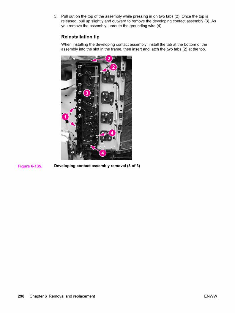
5. Pull out on the top of the assembly while pressing in on two tabs (2). Once the top isreleased, pull up slightly and outward to remove the developing contact assembly (3). Asyou remove the assembly, unroute the grounding wire (4).
Reinstallation tipWhen installing the developing contact assembly, install the tab at the bottom of theassembly into the slot in the frame, then insert and latch the two tabs (2) at the top.
Figure 6-135. Developing contact assembly removal (3 of 3)
290 Chapter 6 Removal and replacement ENWW

Tray 2 (cassette) parts removal
The following section describes the removal procedures for Tray 2 and associated parts,including the right guide in the printer.
Tray 2 (cassette)The separation pad and the end plate are the only replaceable components on the tray.Replacement of any other component requires replacement of the entire tray. Forreplacement of the separation pad, see Tray 2 separation pad removal. For replacement ofthe tray or the end plate, refer to Chapter 8, Parts and diagrams, for the location of the endplate.
Cassette (Tray 2) guide, right, removalThe removal of the right guide is different for the HP Color LaserJet 3500 and 3700 seriesprinters. These procedures are provided below.
Cassette (Tray 2) guide, right, removal (HP 3700)1. Remove the transfer unit and the print cartridges. See Transfer unit removal and Print
cartridge removal.
2. Remove the lower rear door. See Lower rear door (rear output bin) removal.
3. Remove the fuser. See Fuser removal.
4. Remove the paper drive gear plate and the paper drive gear and shaft. See Pick-up/feedassembly removal, steps 1 through 12.
5. Remove the left cover. See Left cover removal.
6. Remove two screws (1) and remove the duplex guide (2) from the back of the printer.
Figure 6-136. Right Tray 2 guide removal (1 of 6)
7. Turn the printer on its back side, carefully.
ENWW Tray 2 (cassette) parts removal 291
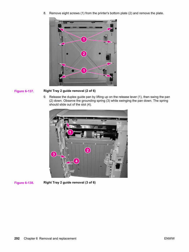
8. Remove eight screws (1) from the printer's bottom plate (2) and remove the plate.
Figure 6-137. Right Tray 2 guide removal (2 of 6)
9. Release the duplex guide pan by lifting up on the release lever (1), then swing the pan(2) down. Observe the grounding spring (3) while swinging the pan down. The springshould slide out of the slot (4).
Figure 6-138. Right Tray 2 guide removal (3 of 6)
292 Chapter 6 Removal and replacement ENWW

10. Lower the duplex guide pan (1) until it is perpendicular with the base of the printer andpull it straight out (2) to remove it.
Reinstallation tipEnsure that the grounding spring (3) on the left side is connected to the contact (4).
Figure 6-139. Right Tray 2 guide removal (4 of 6)
11. Remove two screws (1) from the duplex position guide assembly (2) and remove it.
Figure 6-140. Right Tray 2 guide removal (5 of 6)
ENWW Tray 2 (cassette) parts removal 293

12. Remove two screws (1) and remove the tray guide (2).
Figure 6-141. Right tray guide removal (6 of 6)
Cassette (Tray 2) guide, right, removal (HP 3500/3550)1. Remove Tray 2.
2. Remove two screws (1) and remove the duplex guide (2) from the back of the printer.
Figure 6-142. Right Tray 2 guide removal (1 of 3)
3. Turn the printer on its back.
294 Chapter 6 Removal and replacement ENWW
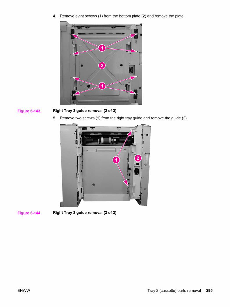
4. Remove eight screws (1) from the bottom plate (2) and remove the plate.
Figure 6-143. Right Tray 2 guide removal (2 of 3)
5. Remove two screws (1) from the right tray guide and remove the guide (2).
Figure 6-144. Right Tray 2 guide removal (3 of 3)
ENWW Tray 2 (cassette) parts removal 295

500-Sheet paper feeder (Tray 3) covers
This section describes the removal and replacement procedures for the 500-sheet paperfeeder covers.
Figure 6-145. 500-Sheet feeder cover locations
1 Right cover2 Left cover3 Front cover
Front cover removal - 500-sheet paper feeder1. Remove Tray 3.
2. Remove the 500-sheet paper feeder right and left covers. See Right cover removal - 500-sheet paper feeder and Left cover removal - 500-sheet paper feeder.
3. Lift up on the top edge of the front cover to release two pins (1), then swing the top outand down (2) to release the bottom hooks and remove the cover (3).
Figure 6-146. 500-Sheet paper feeder front cover removal
296 Chapter 6 Removal and replacement ENWW

Right cover removal - 500-sheet paper feeder1. Remove Tray 3.
2. Lift up to release two pins (1) and pull the top edge of the cover (2) in the direction of thearrow to remove the cover (3).
Figure 6-147. 500-sheet paper feeder right cover removal
Left cover removal - 500-sheet paper feeder1. Remove Tray 3.
2. Lift up on the top edge of the cover to release two pins (1) and pull the edge in thedirection of the arrow (2) to remove the cover (3).
Figure 6-148. 500-sheet paper feeder left cover removal
ENWW 500-Sheet paper feeder (Tray 3) covers 297

500-Sheet paper feeder internal parts
1 500-Sheet paper feeder pick-up roller2 500-Sheet paper feeder pick-up drive unit3 500-Sheet paper feeder separation pad
Pick-up roller removal - 500-sheet paper feeder1. Remove Tray 3.
2. Turn the 500-sheet paper feeder over.
3. Move the left side of the roller unit (1) to the left (2), then pull it out and to the right (3).
Figure 6-149. 500-Sheet paper feeder pick-up roller removal
298 Chapter 6 Removal and replacement ENWW

Separation pad removal - 500-sheet paper feeder1. Remove Tray 3.
2. Push the lifting plate (1) down.
3. Unhook the two claws (2) and remove the separation pad (3).
Figure 6-150. 500-sheet paper feeder separation pad removal
Pick-up drive unit removal - 500-sheet paper feeder1. Remove the right cover. See Right cover removal.
2. Disconnect two connectors (1).
3. Release the cables from the cable guide (2).
4. Remove four screws (3) and remove the pick-up drive unit (4).
Figure 6-151. 500-Sheet paper feeder pick-up drive unit removal
ENWW 500-Sheet paper feeder internal parts 299
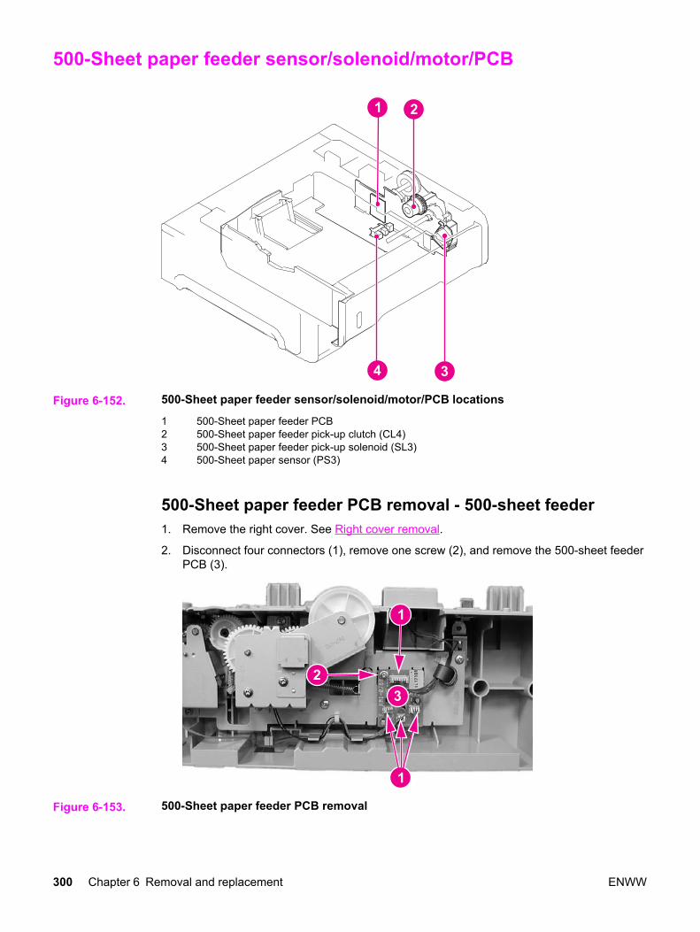
500-Sheet paper feeder sensor/solenoid/motor/PCB
Figure 6-152. 500-Sheet paper feeder sensor/solenoid/motor/PCB locations
1 500-Sheet paper feeder PCB2 500-Sheet paper feeder pick-up clutch (CL4)3 500-Sheet paper feeder pick-up solenoid (SL3)4 500-Sheet paper sensor (PS3)
500-Sheet paper feeder PCB removal - 500-sheet feeder1. Remove the right cover. See Right cover removal.
2. Disconnect four connectors (1), remove one screw (2), and remove the 500-sheet feederPCB (3).
Figure 6-153. 500-Sheet paper feeder PCB removal
300 Chapter 6 Removal and replacement ENWW
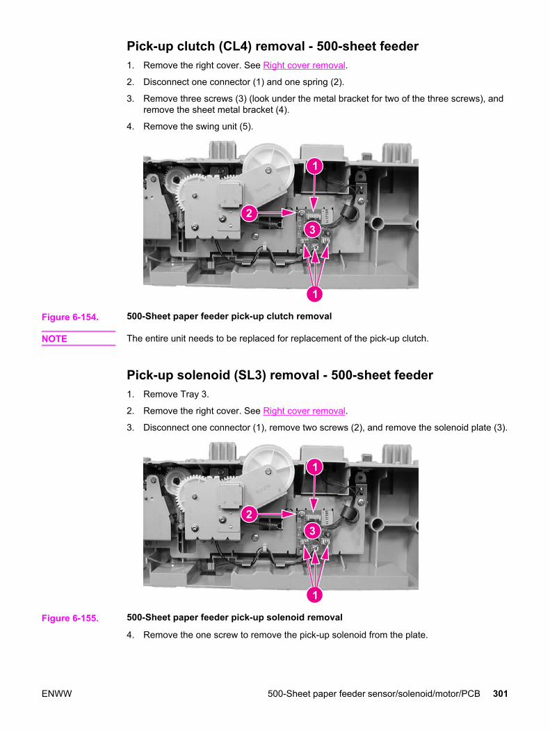
Pick-up clutch (CL4) removal - 500-sheet feeder1. Remove the right cover. See Right cover removal.
2. Disconnect one connector (1) and one spring (2).
3. Remove three screws (3) (look under the metal bracket for two of the three screws), andremove the sheet metal bracket (4).
4. Remove the swing unit (5).
Figure 6-154. 500-Sheet paper feeder pick-up clutch removal
NOTE The entire unit needs to be replaced for replacement of the pick-up clutch.
Pick-up solenoid (SL3) removal - 500-sheet feeder1. Remove Tray 3.
2. Remove the right cover. See Right cover removal.
3. Disconnect one connector (1), remove two screws (2), and remove the solenoid plate (3).
Figure 6-155. 500-Sheet paper feeder pick-up solenoid removal
4. Remove the one screw to remove the pick-up solenoid from the plate.
ENWW 500-Sheet paper feeder sensor/solenoid/motor/PCB 301

Paper sensor (PS3) removal - 500-sheet feeder1. Remove Tray 3.
2. Turn the 500-sheet paper feeder over.
3. Remove two screws (1) and remove the lower front frame (2).
Figure 6-156. 500-Sheet paper feeder front frame removal (1 of 3)
4. Press in on one claw by inserting a flat-blade screwdriver into the slot (1), at the sametime, pry up at slot (2) to release the cover (3), then swing the left side of the cover outto remove it.
Figure 6-157. 500-Sheet feeder paper sensor removal (2 of 3)
5. Disconnect one connector (1), unhook two claws (2), and remove the paper sensor (3).
Figure 6-158. 500-Sheet feeder paper sensor removal (3 of 3)
302 Chapter 6 Removal and replacement ENWW

7 Troubleshooting
Chapter contents
This chapter contains the following sections:
Chapter contents ...................................................................................................................303Introduction ............................................................................................................................306Troubleshooting process .......................................................................................................307
Pre-troubleshooting checklist .........................................................................................307Troubleshooting flowchart ..............................................................................................308Troubleshooting power-on ..............................................................................................310
Printer error troubleshooting .................................................................................................312Status messages ............................................................................................................312Warning messages .........................................................................................................312Error messages ..............................................................................................................312Critical error messages ...................................................................................................312Alphabetical printer messages .......................................................................................312Numerical printer messages ...........................................................................................327
Replacement parts configuration ..........................................................................................352Formatter and DC Controller replaced at the same time ...............................................352Formatter (New) replacement configuration ...................................................................352Formatter (previously installed in another printer) replacement configuration ...............353DC Controller (New) replacement configuration ............................................................353DC Controller (previously installed in another printer) replacement configuration ........354Media sensor (PS5) replacement configuration .............................................................354Color Misregistration Sensor (PS12) replacement configuration ...................................355Laser/scanner Assembly replacement configuration .....................................................355Fuser replacement configuration ....................................................................................355Transfer unit (ITB assembly) replacement configuration ...............................................355
Paper path troubleshooting ...................................................................................................356Paper path jam areas .....................................................................................................357Paper jam error message ...............................................................................................357Paper path areas jam troubleshooting ...........................................................................360Paper jam recovery feature ............................................................................................377Avoiding paper jams .......................................................................................................377General paper path troubleshooting ...............................................................................379Persistent jams ...............................................................................................................380
Image formation troubleshooting ..........................................................................................381Print quality problems associated with media ................................................................381Overhead transparency defect .......................................................................................381Print quality problems associated with the environment ................................................382Print quality problems associated with paper jams ........................................................382Print quality problems associated with toner buildup .....................................................382Print quality troubleshooting pages ................................................................................383
ENWW Chapter contents 303
Calibrating the printer .....................................................................................................383Using Color ...........................................................................................................................384
HP ImageREt 2400 .........................................................................................................384Paper selection ...............................................................................................................384Color options (available for the HP Color LaserJet 3700 series printer) ........................384Standard red-green-blue (sRGB) ...................................................................................384Printing in four-colors [CMYK (available for the HP Color LaserJet 3700 series
printer) .........................................................................................................................385CMYK ink set emulation (PostScript only) .....................................................................385
Managing color ......................................................................................................................386Print in Grayscale ...........................................................................................................386Automatic or manual color adjustment ...........................................................................386Manual color options ......................................................................................................386
Matching colors .....................................................................................................................388Swatch book color matching (HP Color LaserJet 3700 series printer only) ...................388Adjusting color balance ..................................................................................................389
Image defects ........................................................................................................................390Light image ....................................................................................................................391Light color .......................................................................................................................392Dark image ...................................................................................................................392Dark color .......................................................................................................................393Completely blank image .................................................................................................393All black or solid color ....................................................................................................393Dots in vertical lines .......................................................................................................394Dirt on back of paper ......................................................................................................394Dirt on front of paper .......................................................................................................394Vertical lines ..................................................................................................................395White vertical lines ..........................................................................................................395Horizontal line .................................................................................................................396White horizontal line .......................................................................................................396Color missing ..................................................................................................................397Blank spots .....................................................................................................................397Poor fusing ....................................................................................................................397Image distortion ..............................................................................................................398Color misregistration .......................................................................................................398Smearing ........................................................................................................................399Misplaced image .............................................................................................................399Reversed color ................................................................................................................400Snail tracks .....................................................................................................................400
Repetitive defects troubleshooting ........................................................................................401Interface troubleshooting ......................................................................................................403
Communications checks .................................................................................................403EIO troubleshooting ........................................................................................................403AUTOEXEC.BAT standard configurations .....................................................................404Printer Job Language (PJL) commands .........................................................................404@PJL COMMENT ..........................................................................................................405@PJL INFO CONFIG .....................................................................................................405@PJL INFO ID ................................................................................................................405@PJL INFO USTATUS ..................................................................................................405@PJL INFO PAGECOUNT ............................................................................................405@PJL JOB ......................................................................................................................406@PJL EOJ ......................................................................................................................406@PJL ECHO ...................................................................................................................406@PJL USTATUS JOB=ON/OFF ....................................................................................406@PJL USTATUSOFF .....................................................................................................406
Control panel troubleshooting ...............................................................................................407
304 Chapter 7 Troubleshooting ENWW
Printing a menu map ......................................................................................................407Information menu ............................................................................................................407Paper handling menu .....................................................................................................408Configure device menu ...................................................................................................409Print quality menu ...........................................................................................................411System setup menu ........................................................................................................414I/O menu .........................................................................................................................418Resets menu ...................................................................................................................419Diagnostics menu ...........................................................................................................419Service menu ..................................................................................................................420
Tools for troubleshooting ......................................................................................................422Embedded Web server (HP Color LaserJet 3700 series printer only) ...........................422HP Toolbox .....................................................................................................................424Printer configuration page ..............................................................................................428Supplies status page ......................................................................................................429Usage page (HP 3700 only) ...........................................................................................430Event log .........................................................................................................................431
Diagnostics ............................................................................................................................433Diagnostics flowchart ......................................................................................................433Engine diagnostics .........................................................................................................434
Diagnostics from the Control Panel ......................................................................................436Printer display menu .......................................................................................................436Diagnostics test menu ....................................................................................................436Paper Path Test ..............................................................................................................439Component Test – special mode test .............................................................................439Print/Stop Test ................................................................................................................442Information menu ............................................................................................................443Configure device menu/printing menu ............................................................................443Configure device menu/resets menu ..............................................................................443Configure device menu/print quality menu .....................................................................443
Test pages .............................................................................................................................445Engine test page .............................................................................................................445Formatter test page ........................................................................................................445
Engine resets ........................................................................................................................446Cold reset .......................................................................................................................446NVRAM initialization .......................................................................................................446Calibration bypass ..........................................................................................................447Calibrate Now .................................................................................................................447
Service menu ........................................................................................................................448Accessing the Service menu ..........................................................................................448
Diagrams ...............................................................................................................................450Main parts .......................................................................................................................451Switches .........................................................................................................................452Sensors ...........................................................................................................................453Solenoids and clutches ...................................................................................................454Motors and fans ..............................................................................................................455PCBs ...............................................................................................................................456Connector locations ........................................................................................................458500-sheet paper feeder connectors ...............................................................................462General circuit diagram ..................................................................................................463
ENWW Chapter contents 305

Introduction
This troubleshooting chapter assumes the reader has a basic understanding of the colorlaser printing process. Explanations of each mechanical assembly, printer system, and thebasic theory of operation are found in Chapter 5. Do not perform any of thesetroubleshooting processes without fully understanding the function of each mechanism.
This chapter contains the following sections:
● Troubleshooting process includes a pre-troubleshooting checklist and atroubleshooting flowchart. These tools contain information about common printer errorsthat can inhibit proper operation or create print quality problems. These tools alsoinclude recommendations for solving the cause of the error.
● Printer error troubleshooting explains each control panel display message andsuggests recommendations for clearing the cause of each message. When the printermessage indicates a failure for which the root cause is not obvious, use the printer errortroubleshooting section and the troubleshooting tools section found later in this chapterto solve the problem.
● Paper path troubleshooting provides techniques to solve feed problems. Explanationsregarding print media checks, troubleshooting jams, and the differences between jamscaused by media and those caused by the printer are discussed.
● Image formation troubleshooting suggests methods for solving print quality problems.
● Interface troubleshooting provides techniques for isolating communication problems tothe printer hardware, printer configuration, network configuration, or software application.
● Control panel troubleshooting provides procedures for printing a menu map from theprinter control panel. It also describes the control panel menus, the items within eachmenu, and the possible values for the menu items.
● Troubleshooting tools help isolate the cause of printer failures. This section includesexplanations of the printer configuration page and the event log.
● Diagnostics provides instructions on how to access and use the diagnostic toolsincorporated into the printer.
● Service menu provides procedures for entering the service menu and performingservice-oriented tasks. These tasks include counts for entering the serial number,service ID, transfer unit maintenance, fuser maintenance, color page, total page, andclearing the event log.
● Diagrams provides graphical locations and tables for the printer’s internal assembliesand sensors.
306 Chapter 7 Troubleshooting ENWW
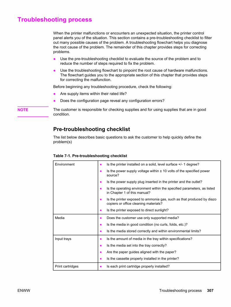
Troubleshooting process
When the printer malfunctions or encounters an unexpected situation, the printer controlpanel alerts you of the situation. This section contains a pre-troubleshooting checklist to filterout many possible causes of the problem. A troubleshooting flowchart helps you diagnosethe root cause of the problem. The remainder of this chapter provides steps for correctingproblems.
● Use the pre-troubleshooting checklist to evaluate the source of the problem and toreduce the number of steps required to fix the problem.
● Use the troubleshooting flowchart to pinpoint the root cause of hardware malfunctions.The flowchart guides you to the appropriate section of this chapter that provides stepsfor correcting the malfunction.
Before beginning any troubleshooting procedure, check the following:
● Are supply items within their rated life?
● Does the configuration page reveal any configuration errors?
NOTE The customer is responsible for checking supplies and for using supplies that are in goodcondition.
Pre-troubleshooting checklist The list below describes basic questions to ask the customer to help quickly define theproblem(s)
Table 7-1. Pre-troubleshooting checklist
Environment ● Is the printer installed on a solid, level surface +/- 1 degree?
● Is the power supply voltage within ± 10 volts of the specified powersource?
● Is the power supply plug inserted in the printer and the outlet?
● Is the operating environment within the specified parameters, as listedin Chapter 1 of this manual?
● Is the printer exposed to ammonia gas, such as that produced by diazocopiers or office cleaning materials?
● Is the printer exposed to direct sunlight?
Media ● Does the customer use only supported media?
● Is the media in good condition (no curls, folds, etc.)?
● Is the media stored correctly and within environmental limits?
Input trays ● Is the amount of media in the tray within specifications?
● Is the media set into the tray correctly?
● Are the paper guides aligned with the paper?
● Is the cassette properly installed in the printer?
Print cartridges ● Is each print cartridge properly installed?
ENWW Troubleshooting process 307

Transfer unit and fuser ● Are the transfer unit and fuser properly installed?
Covers ● Is the front door closed?
Condensation ● Does condensation occur following a temperature change (particularlyin winter following cold storage)? If so, wipe affected parts dry or leavethe printer on for 10 to 20 minutes.
● Was a print cartridge opened soon after being moved from a cold to awarm room? If so, allow the print cartridge to sit at room temperature forone to two hours.
Miscellaneous ● Check for and remove any non-HP components (print cartridges,memory modules, and EIO cards) from the printer.
● If hardware or software configuration has not changed or the problem isnot associated with any specific software, contact the Customer CareCenter (see Chapter 1).
● Remove the printer from the network and ensure that the failure isassociated with the printer before beginning troubleshooting.
● For any print quality issues, calibrate the printer. See Calibrate Now forinstructions.
Troubleshooting flowchart The flowchart on these two pages highlights the general processes to quickly isolate andsolve printer hardware problems.
Each heading depicts a major troubleshooting step. A “yes” answer to the questions allowsyou to proceed to the next major step.
Table 7-1. Pre-troubleshooting checklist (continued)
308 Chapter 7 Troubleshooting ENWW

A “no” answer indicates that additional testing is needed. Proceed to the referenced sectionin this chapter, and follow the instructions. After completing this additional testing, proceed tothe next major step in the troubleshooting flowchart.
ENWW Troubleshooting process 309

NOTE If the printer’s display is blank, but the power-on checks pass, try printing an engine testpage to determine whether the problem is with the engine/display or with the formatter. SeeEngine test page for instructions.
Troubleshooting power-on When you turn on the printer, if it does not make any sound or if the control panel display isblank, check the following items:
1. Verify that the printer is plugged into an active electrical outlet with the correct voltageand not plugged into a surge protector or power strip.
2. Verify that the on/off switch is in the ON position.
3. Make sure the fan is running, indicating the system is operational.
4. Verify that the firmware DIMM (HP 3700 only) and the formatter are seated andoperating properly.
5. Remove any HP Jetdirect or other devices, then try to turn the printer on again.
310 Chapter 7 Troubleshooting ENWW

6. Make sure the control panel display is connected.
7. Check the two fuses on the power supply.
8. If necessary, replace the power supply.
9. If necessary, replace the DC controller.
ENWW Troubleshooting process 311

Printer error troubleshooting
The following tables explain messages that might appear on the printer control panel.Alphabetical printer messages and their meanings are listed in the Table 7-2. Alphabeticalprinter messages table, and numerical printer messages are listed in the Table 7-3.Numerical printer messages table.
NOTE Not all messages are described in the tables; those messages that are not listed are self-explanatory.
Status messages Status messages reflect the current state of the printer. They inform you of normal printeroperation and require no interaction to clear them. They change as the state of the printerchanges. Whenever the printer is ready, not busy, and has no pending warning messages,the status message Ready is displayed if the printer is online.
Warning messages Warning messages inform you of data and print errors. These messages typically alternatewith the Ready or Status messages and remain displayed until the button is pressed. IfCLEARABLE WARNINGS is set to Job status = in the printer’s configuration menu, thesemessages are cleared by the next print job.
Error messages Error messages communicate that some action must be performed, such as adding paper orclearing a paper jam.
Some error messages are auto-continuable. If AUTO CONTINUE=ON is set in the menus,the printer will continue normal operation after displaying an auto-continuable error messagefor 10 seconds.
NOTE Any button pressed during the 10-second display of an auto-continuable error message willoverride the auto-continue feature, and the function of the button pressed will takeprecedence. For example, pressing the STOP button will cancel the job.
Critical error messages Critical error messages inform you of a device failure. Some of these messages can becleared by turning the printer off and then on. These messages are not affected by the autocontinue setting. If a critical error persists, service is required.
The following table lists and describes control panel messages in alphabetical order.
Alphabetical printer messages The following table lists the alphabetical control panel messages. The numerical messagesare listed in the following table.
312 Chapter 7 Troubleshooting ENWW

Table 7-2. Alphabetical printer messages
Message Description Action
Access Denied
MENUS LOCKED
An attempt has been made to modify amenu item while the control panelsecurity mechanism is enabled by theprinter administrator. The message willdisappear shortly, and the printer willreturn to the Ready or BUSY state.
Contact the printer administrator to changesettings.
Perform a cold reset to clear passwords.
Calibrating...<TEST> The printer is calibrating. No action necessary.
Calibrating...
Media sensor is not calibrated
The printer is calibrating the mediasensor.
No action necessary.
Canceling... X
JOB NAME
The printer is in the process of cancelinga job. The message will continue to bedisplayed while the job is stopped, thepaper path flushed, and any remainingincoming data on the active data channelis received and discarded.
No action necessary.
Cannot duplex close rear bin
alternates with
CANNOT DUPLEX
HP 3700 only.
The lower rear door (rear output bin) wasopened during the automatic duplex jobor the printer detected a paper size thatcould not go through the auto-duplexer.
Close the lower rear door (rear output bin)or load paper that is supported forautoduplexing. See Supported mediaweights and sizes, in Chapter 1.
Cannot duplex close rear bin HP 3700dn and 3700dtn only.
A 2-sided print job has been sent to theprinter while the lower rear door (rearoutput bin) is open, or the face-up traysensor is damaged.
1. Close the lower rear door (rear outputbin).
2. Replace the face-up tray sensor lever.
3. Reseat the face-up tray sensorconnector J711 or the sensorconnection on the DC controller PCB.
4. Replace the face-up tray sensor(PS11).
5. Replace the DC controller PCB.
Checking paper path The engine is turning its rollers to checkfor possible paper jams.
No action necessary.
Checking printer The engine is doing an internal test. No action necessary.
CHOSEN PERSONALITY NOTAVAILABLE alternates with
To continue press
The printer encountered a request for apersonality that did not exist in theprinter. The job is aborted and no pageswill be printed.
1. 1. Press to continue.
2. 2. Try a different driver.
CLOSE UPPER REAR DOOR The upper rear door is open. Close the upper rear door.
Cleaning... The printer is in the process of cleaning. No action necessary.
Clearing event log This message is displayed while theevent log is cleared. The printer will backup one screen to Service Menu uponcompletion of printing the page.
No action necessary.
ENWW Printer error troubleshooting 313
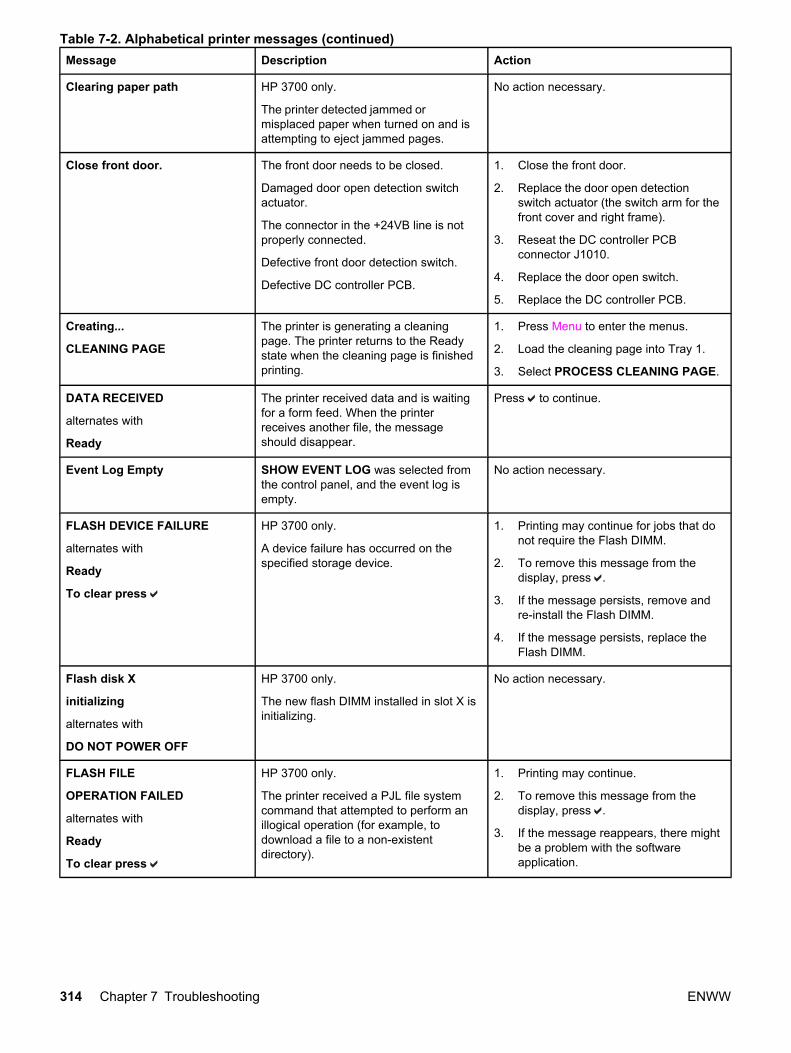
Message Description Action
Clearing paper path HP 3700 only.
The printer detected jammed ormisplaced paper when turned on and isattempting to eject jammed pages.
No action necessary.
Close front door. The front door needs to be closed.
Damaged door open detection switchactuator.
The connector in the +24VB line is notproperly connected.
Defective front door detection switch.
Defective DC controller PCB.
1. Close the front door.
2. Replace the door open detectionswitch actuator (the switch arm for thefront cover and right frame).
3. Reseat the DC controller PCBconnector J1010.
4. Replace the door open switch.
5. Replace the DC controller PCB.
Creating...
CLEANING PAGE
The printer is generating a cleaningpage. The printer returns to the Readystate when the cleaning page is finishedprinting.
1. Press Menu to enter the menus.
2. Load the cleaning page into Tray 1.
3. Select PROCESS CLEANING PAGE.
DATA RECEIVED
alternates with
Ready
The printer received data and is waitingfor a form feed. When the printerreceives another file, the messageshould disappear.
Press to continue.
Event Log Empty SHOW EVENT LOG was selected fromthe control panel, and the event log isempty.
No action necessary.
FLASH DEVICE FAILURE
alternates with
Ready
To clear press
HP 3700 only.
A device failure has occurred on thespecified storage device.
1. Printing may continue for jobs that donot require the Flash DIMM.
2. To remove this message from thedisplay, press .
3. If the message persists, remove andre-install the Flash DIMM.
4. If the message persists, replace theFlash DIMM.
Flash disk X
initializing
alternates with
DO NOT POWER OFF
HP 3700 only.
The new flash DIMM installed in slot X isinitializing.
No action necessary.
FLASH FILE
OPERATION FAILED
alternates with
Ready
To clear press
HP 3700 only.
The printer received a PJL file systemcommand that attempted to perform anillogical operation (for example, todownload a file to a non-existentdirectory).
1. Printing may continue.
2. To remove this message from thedisplay, press .
3. If the message reappears, there mightbe a problem with the softwareapplication.
Table 7-2. Alphabetical printer messages (continued)
314 Chapter 7 Troubleshooting ENWW

Message Description Action
FLASH FILE
SYSTEM IS FULL
alternates with
Ready
To clear press
HP 3700 only.
The printer received a PJL file systemcommand that attempted to storesomething on the file system but wasunsuccessful because the file system isfull.
1. Use HP Web Jetadmin software todelete files from the Flash Memoryand try again.
2. To remove this message from thedisplay, press .
3. See HP Web Jetadmin, Chapter 3.
FLASH IS
WRITE PROTECTED
alternates with
Ready
To clear press
HP 3700 only.
The file system is protected and no newfiles can be written to it.
1. To enable writing to the FlashMemory, turn off write protection usingHP Web Jetadmin.
2. To remove this message from thedisplay, turn the printer off and thenback on. See Chapter 3, HP WebJetadmin
[F]]DEVICE
FAILURE
alternates with
To clear press
HP 3700 only.
Device failure
[FS] DEVICE can be either: FLASHDEVICE or RAM DISK DEVICE
To remove this message from the display,press .
[FS] FILE
OPERATION FAILED
alternates with
To clear press
HP 3700 only.
This message indicates a PJL filesystem command was received thatattempted to perform an illogicaloperation (that is, download a file to anon-existent directory).
[FS] DEVICE can be either: FLASHDEVICE or RAM DISK DEVICE
To remove this message from the display,press .
[FS] FILE
SYSTEM IS FULL
alternates with
To clear press
HP 3700 only.
This message indicates a PJL filesystem command was received thatattempted to store something on a filesystem but was unsuccessful due to thefile system being full.
[FS] DEVICE can be either: FLASHDEVICE or RAM DISK DEVICE
To remove this message from the display,press .
[FS] IS
filesys_is_write_protected_V1_line_2
alternates with
To clear press .
HP 3700 only.
The device is write protected and no newfiles can be written to it.
[FS] DEVICE can be either: FLASHDEVICE or RAM DISK DEVICE
1. To remove this message from thedisplay, press .
Genuine HP supplies installed A new HP cartridge has been installed.The printer returns to the Ready stateafter approximately 10 seconds.
No action necessary.
GENUINE HP SUPPLIES
DESIGNED FOR <PROD>
This genuine HP supply was notdesigned for this printer and is notsupported. Print quality might be affected.
Replace this supply with a genuineHP supply designed for this printer.
Incorrect Access to the menu is restricted. Contact the network administrator.
Table 7-2. Alphabetical printer messages (continued)
ENWW Printer error troubleshooting 315
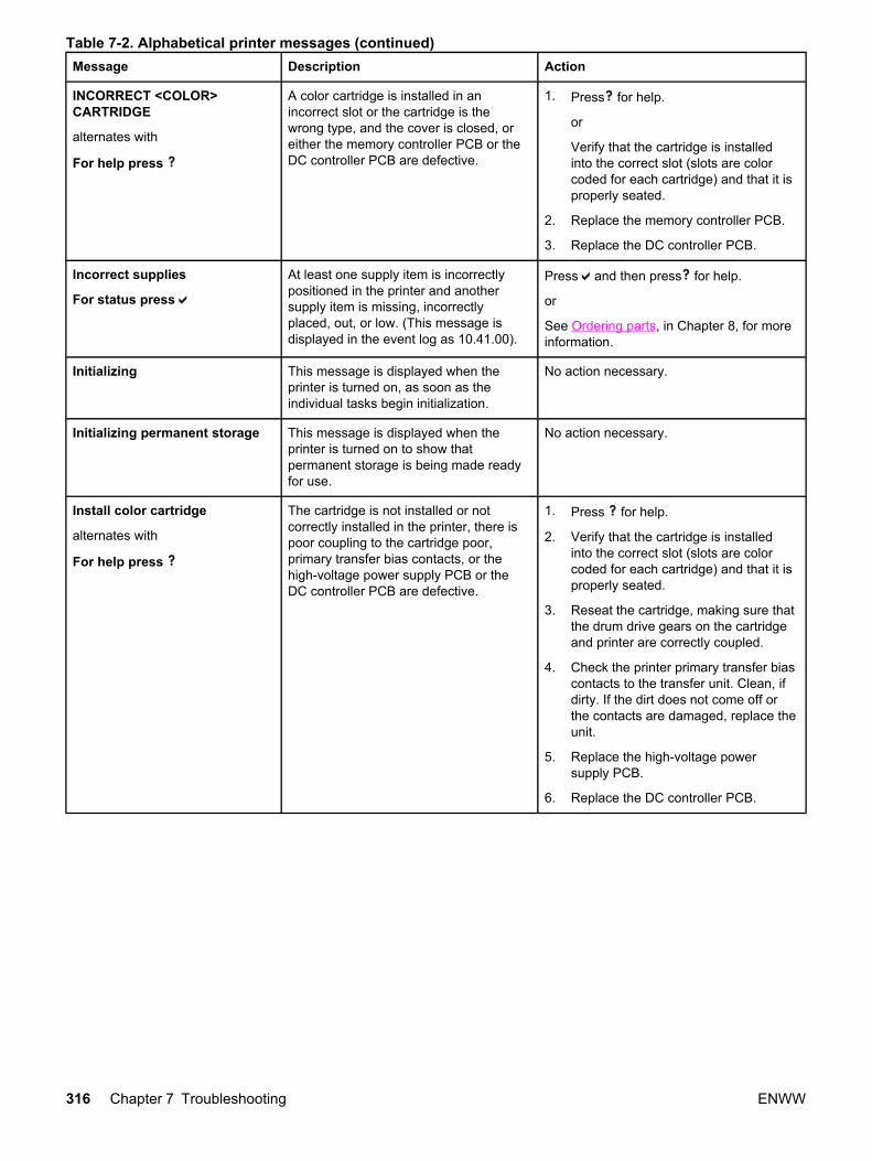
Message Description Action
INCORRECT <COLOR>CARTRIDGE
alternates with
For help press
A color cartridge is installed in anincorrect slot or the cartridge is thewrong type, and the cover is closed, oreither the memory controller PCB or theDC controller PCB are defective.
1. Press for help.
or
Verify that the cartridge is installedinto the correct slot (slots are colorcoded for each cartridge) and that it isproperly seated.
2. Replace the memory controller PCB.
3. Replace the DC controller PCB.
Incorrect supplies
For status press
At least one supply item is incorrectlypositioned in the printer and anothersupply item is missing, incorrectlyplaced, out, or low. (This message isdisplayed in the event log as 10.41.00).
Press and then press for help.
or
See Ordering parts, in Chapter 8, for moreinformation.
Initializing This message is displayed when theprinter is turned on, as soon as theindividual tasks begin initialization.
No action necessary.
Initializing permanent storage This message is displayed when theprinter is turned on to show thatpermanent storage is being made readyfor use.
No action necessary.
Install color cartridge
alternates with
For help press
The cartridge is not installed or notcorrectly installed in the printer, there ispoor coupling to the cartridge poor,primary transfer bias contacts, or thehigh-voltage power supply PCB or theDC controller PCB are defective.
1. Press for help.
2. Verify that the cartridge is installedinto the correct slot (slots are colorcoded for each cartridge) and that it isproperly seated.
3. Reseat the cartridge, making sure thatthe drum drive gears on the cartridgeand printer are correctly coupled.
4. Check the printer primary transfer biascontacts to the transfer unit. Clean, ifdirty. If the dirt does not come off orthe contacts are damaged, replace theunit.
5. Replace the high-voltage powersupply PCB.
6. Replace the DC controller PCB.
Table 7-2. Alphabetical printer messages (continued)
316 Chapter 7 Troubleshooting ENWW

Message Description Action
INSTALL FUSER
For help press
The fuser is either not installed or notcorrectly installed in the printer, theconnector between the fuser and theprinter is not connected properly, there isa break in either the main thermistor orthe fuser heater, or the DC controllerPCB is faulty.
1. Press for help.
2. Make sure the fuser is correctlyseated in its slot. See Fuser removal(in Chapter 6) for more information.
3. Reseat the fuser. Check the connectorJ5013 between the fuser and theprinter. Replace it if damaged.
4. Turn the printer off and remove thefuser. Measure the resistancebetween the fuser connectorsJ5013LA-2 (MAINTH) and J5013LA-1(GND). If it is not within the range of330k to 50k ohms (at ambienttemperature), replace the fuser.
5. Measure the resistance between thefuser connectors J5013L-2 (FSRH)and J5013L-1 (FSRN) with the fuserremoved. If it is not within the range of12 to 52 ohms (at ambienttemperature), replace the fuser.
6. Replace the DC controller PCB.
INSTALL SUPPLIES
For status press
At least one supply item is missing or isnot correctly seated in the printer andanother supply item is missing,incorrectly placed, out, or low. Insert thesupply item or make sure the installedsupply item is fully seated.
Press and then press for help.
or
Refer to http://www.hp.com/support/clj3550 or http://www.hp.com/support/clj3700.
INSTALL TRANSFER UNIT
alternates with
For help press
The transfer unit is either not installed ornot correctly installed in the printer, isdefective, the high-voltage power supplyconnection to the transfer unit isdefective, or the DC controller PCB isdefective.
1. Press for help.
2. Ensure the transfer unit is fully seated,that the contracts are not damaged.See Transfer unit removal (in Chapter6) for more information.
3. Replace the transfer unit.
4. Replace the high-voltage powersupply PCB.
5. Replace the DC controller PCB.
LOAD TRAY X
<TYPE> <SIZE>
alternates with
To use another tray press
Tray X is either empty or configured for atype and size other than what isspecified in the job.
Press for help.
or
Press to print from another tray.
LOAD TRAY X
<TYPE> <SIZE>
alternates with
For help press
Tray X is either empty or configured for atype and size other than specified in thejob. No other tray is available.
Press for help.
Table 7-2. Alphabetical printer messages (continued)
ENWW Printer error troubleshooting 317

Message Description Action
Loading
program X
alternates with
DO NOT POWER OFF
HP 3700 only.
Programs and fonts can be stored on theprinter file system and are loaded intoRAM when the printer is turned on. Thenumber X specifies a sequence numberindicating the current program beingloaded.
No action necessary.
MANUALLY FEED
OUTPUT STACK
alternates with
Then press to
print second sides
The first side of a manual 2-sided printjob has been printed and the printer iswaiting for the output stack to beinserted for the second side to be printed.
Take the output stack out of the output binand reinsert it in Tray 1 to print the secondside of the 2-sided print job.
If no paper is in the manual feedtray:
MANUALLY FEED
<TYPE> <SIZE>
alternates with
To continue press
A job sent requires a specific paper typeand size that is not currently available.
Press to print from the tray.
or
Press for help.
MANUALLY FEED
<TYPE> <SIZE>
alternates with
For help press
Tray 1 is empty and no other tray isavailable. MANUAL FEED was set to ONin the control panel.
Press for help.
Turn MANUAL FEED off in the controlpanel.
MANUALLY FEED
<TYPE> <SIZE>
alternates with
To use another
tray press .
There is no paper in the tray and a printjob sent requires a specific paper typeand size that is not currently availablethrough Tray 1.
Press to print from another tray.
or
Press for help.
Moving solenoid
alternates with
To exit press
STOP key
The printer is executing a ComponentTest and the component selected isSolenoid.
No action necessary.
Moving solenoid
and motor
alternates with
To exit press
STOP key
The printer is executing a ComponentTest and the components selected areSolenoid and Motor.
No action necessary.
Table 7-2. Alphabetical printer messages (continued)
318 Chapter 7 Troubleshooting ENWW

Message Description Action
No job to cancel This message is displayed when theuser presses the Stop key but there isno active job or buffered data to cancel.This message is displayed for twoseconds before the printer is returned tothe READY state.
No action necessary.
NON HP SUPPLY
DETECTED
alternates with
For help press
Not made by HP. This message isdisplayed until an HP supply is installedor is pressed. (This message isdisplayed in the event log as 10.30.xx).
If you believe you purchased anHP supply, please call the HP fraud hotlineat 1-877-219-3183.
Service or repairs required as a result ofusing non-HP supplies is not coveredunder HP warranty.
To continue printing, press . The firstpending job will be cancelled.
If you believe that you installed a genuineHP toner cartridge, wait approximately oneminute to ensure the message does notchange to another error message (such as10.92.XX). If another message appears,troubleshoot this second message. If themessage does not change within oneminute, perform the following steps:
1. If this toner cartridge was previouslyused in another printer and is low ontoner, it will not be recognized as anHP supply, this is the correctmessage. You can use the cartridgeuntil the toner is gone, or replace thecartridge to remove the message. Tocontinue printing, press .
2. If this toner cartridge is a new,genuine HP supply, test the cartridgeusing Diagnostics mode on the printercontrol panel and select DisableCartridge Check. If the messagefollows the cartridge, replace thecartridge and return it to HP.
NON HP SUPPLY
IN USE
alternates with
Ready
The printer has detected that a non-
HP supply is currently installed and (override) was pressed.
If you believe you purchased anHP supply, please call the HP fraud hotlineat 1-877-219-3183.
Service or repairs required as a result ofusing non-HP supplies is not coveredunder HP warranty.
ORDER <COLOR>
CARTRIDGE
alternates with
LESS THAN X PAGES
alternates with
Ready
The identified print cartridge is nearingthe end of its useful life. The printer isready and will continue for the estimatednumber of pages indicated.
Order the identified print cartridge. Printingwill continue until REPLACE <COLOR>CARTRIDGE is shown.
NOTE
Estimated pages remaining is based uponhistorical page coverage with this supply.
See Ordering parts (in Chapter 8) for moreinformation.
Table 7-2. Alphabetical printer messages (continued)
ENWW Printer error troubleshooting 319

Message Description Action
ORDER FUSER KIT
alternates with
LESS THAN X PAGES
alternates with
Ready
For help press
The fuser is near end of life. The printeris ready and will continue for theestimated number of pages indicated.
Order the fuser kit. Printing can continueuntil REPLACE FUSER KIT is shown.
or
Press for help.
See Ordering parts (in chapter 8) for moreinformation.
Order Supplies
alternates with
Ready
More than one supply item is low. 1. Press to identify which suppliesshould be ordered or print a suppliesstatus page.
2. Order the identified supplies. Printingcan continue until REPLACESUPPLIES is reached.
or
Press for help.
3. See Ordering parts (in chapter 8) formore information.
ORDER TRANSFER KIT
alternates with
LESS THAN X PAGES
alternates with
Ready
For help press
The number of pages remaining for thetransfer unit has reached the lowthreshold, and the SUPPLIES LOWsetting in SYSTEM SETUP is set toSTOP.
Order the transfer kit. Printing can continueuntil REPLACE TRANSFER KIT is reached.
Press for help.
See Ordering parts (in chapter 8) for moreinformation.
Paused
alternates with
To return to Ready
press the STOP key
The printer has paused. Press the Stop key to resume printing.
Performing...
PAPER PATH TEST
The printer is performing a Paper PathTest.
No action necessary.
Performing
upgrade
A firmware upgrade is in process. No action necessary.
Do not turn off the printer.
Please wait The printer is in the process of clearingdata.
No action necessary.
Powersave on The printer is in the PowerSave mode.Any button pressed or the receipt of datawill clear PowerSave and execute theaction.
Press any control panel button or thereceipt of data will clear PowerSave.
Printing...
CONFIGURATION
The printer is generating theconfiguration page. The printer will returnto the online Ready state when the pageis completed. No action necessary.
No action necessary.
Table 7-2. Alphabetical printer messages (continued)
320 Chapter 7 Troubleshooting ENWW
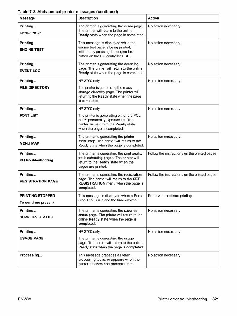
Message Description Action
Printing...
DEMO PAGE
The printer is generating the demo page.The printer will return to the onlineReady state when the page is completed.
No action necessary.
Printing...
ENGINE TEST
This message is displayed while theengine test page is being printed,initiated by pressing the engine testbutton on the DC controller PCB.
No action necessary.
Printing...
EVENT LOG
The printer is generating the event logpage. The printer will return to the onlineReady state when the page is completed.
No action necessary.
Printing...
FILE DIRECTORY
HP 3700 only.
The printer is generating the massstorage directory page. The printer willreturn to the Ready state when the pageis completed.
No action necessary.
Printing...
FONT LIST
HP 3700 only.
The printer is generating either the PCLor PS personality typeface list. Theprinter will return to the Ready statewhen the page is completed.
No action necessary.
Printing...
MENU MAP
The printer is generating the printermenu map. The printer will return to theReady state when the page is completed.
No action necessary.
Printing...
PQ troubleshooting
The printer is generating the print qualitytroubleshooting pages. The printer willreturn to the Ready state when thepages are printed.
Follow the instructions on the printed pages.
Printing...
REGISTRATION PAGE
The printer is generating the registrationpage. The printer will return to the SETREGISTRATION menu when the page iscompleted.
Follow the instructions on the printed pages.
PRINTING STOPPED
To continue press
This message is displayed when a Print/Stop Test is run and the time expires.
Press to continue printing.
Printing...
SUPPLIES STATUS
The printer is generating the suppliesstatus page. The printer will return to theonline Ready state when the page iscompleted.
No action necessary.
Printing...
USAGE PAGE
HP 3700 only.
The printer is generating the usagepage. The printer will return to the onlineReady state when the page is completed.
No action necessary.
Processing... This message precedes all otherprocessing tasks, or appears when theprinter receives non-printable data.
No action necessary.
Table 7-2. Alphabetical printer messages (continued)
ENWW Printer error troubleshooting 321
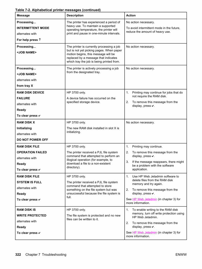
Message Description Action
Processing...
INTERMITTENT MODE
alternates with
For help press
The printer has experienced a period ofheavy use. To maintain a supportedoperating temperature, the printer willprint and pause in one-minute intervals.
No action necessary.
To avoid intermittent mode in the future,reduce the amount of heavy use.
Processing...
<JOB NAME>
The printer is currently processing a jobbut is not yet picking pages. When papermotion begins, this message will bereplaced by a message that indicateswhich tray the job is being printed from.
No action necessary.
Processing...
<JOB NAME>
alternates with
from tray X
The printer is actively processing a jobfrom the designated tray.
No action necessary.
RAM DISK DEVICE
FAILURE
alternates with
Ready
To clear press
HP 3700 only.
A device failure has occurred on thespecified storage device.
1. Printing may continue for jobs that donot require the RAM disk.
2. To remove this message from thedisplay, press .
RAM DISK X
Initializing
alternates with
DO NOT POWER OFF
HP 3700 only.
The new RAM disk installed in slot X isinitializing.
No action necessary.
RAM DISK FILE
OPERATION FAILED
alternates with
Ready
To clear press
HP 3700 only.
The printer received a PJL file systemcommand that attempted to perform anillogical operation (for example, todownload a file to a non-existentdirectory).
1. Printing may continue.
2. To remove this message from thedisplay, press .
3. If the message reappears, there mightbe a problem with the softwareapplication.
RAM DISK FILE
SYSTEM IS FULL
alternates with
Ready
To clear press
HP 3700 only.
The printer received a PJL file systemcommand that attempted to storesomething on the file system but wasunsuccessful because the file system isfull.
1. Use HP Web Jetadmin software todelete files from the RAM diskmemory and try again.
2. To remove this message from thedisplay, press .
See HP Web Jetadmin (in chapter 3) formore information.
RAM DISK IS
WRITE PROTECTED
alternates with
Ready
To clear press
HP 3700 only.
The file system is protected and no newfiles can be written to it.
1. To enable writing to the RAM diskmemory, turn off write protection usingHP Web Jetadmin.
2. To remove this message from thedisplay, press .
See HP Web Jetadmin (in chapter 3) formore information.
Table 7-2. Alphabetical printer messages (continued)
322 Chapter 7 Troubleshooting ENWW
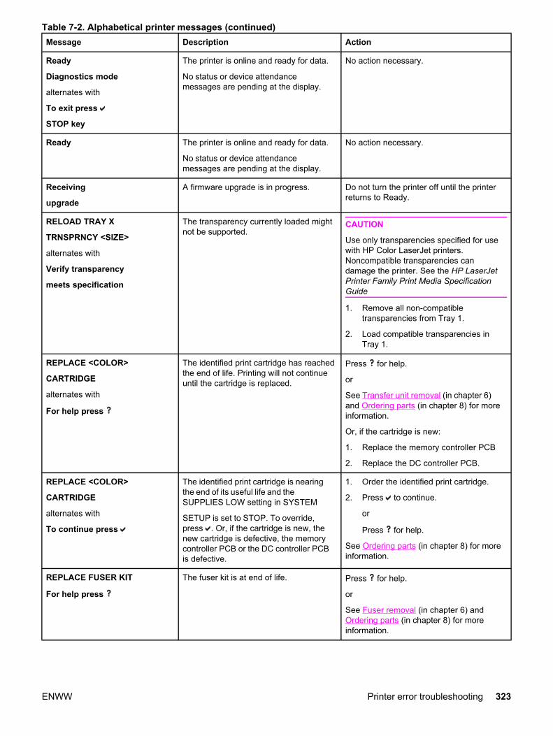
Message Description Action
Ready
Diagnostics mode
alternates with
To exit press
STOP key
The printer is online and ready for data.
No status or device attendancemessages are pending at the display.
No action necessary.
Ready The printer is online and ready for data.
No status or device attendancemessages are pending at the display.
No action necessary.
Receiving
upgrade
A firmware upgrade is in progress. Do not turn the printer off until the printerreturns to Ready.
RELOAD TRAY X
TRNSPRNCY <SIZE>
alternates with
Verify transparency
meets specification
The transparency currently loaded mightnot be supported.
CAUTION
Use only transparencies specified for usewith HP Color LaserJet printers.Noncompatible transparencies candamage the printer. See the HP LaserJetPrinter Family Print Media SpecificationGuide
1. Remove all non-compatibletransparencies from Tray 1.
2. Load compatible transparencies inTray 1.
REPLACE <COLOR>
CARTRIDGE
alternates with
For help press
The identified print cartridge has reachedthe end of life. Printing will not continueuntil the cartridge is replaced.
Press for help.
or
See Transfer unit removal (in chapter 6)and Ordering parts (in chapter 8) for moreinformation.
Or, if the cartridge is new:
1. Replace the memory controller PCB
2. Replace the DC controller PCB.
REPLACE <COLOR>
CARTRIDGE
alternates with
To continue press
The identified print cartridge is nearingthe end of its useful life and theSUPPLIES LOW setting in SYSTEM
SETUP is set to STOP. To override,press . Or, if the cartridge is new, thenew cartridge is defective, the memorycontroller PCB or the DC controller PCBis defective.
1. Order the identified print cartridge.
2. Press to continue.
or
Press for help.
See Ordering parts (in chapter 8) for moreinformation.
REPLACE FUSER KIT
For help press
The fuser kit is at end of life. Press for help.
or
See Fuser removal (in chapter 6) andOrdering parts (in chapter 8) for moreinformation.
Table 7-2. Alphabetical printer messages (continued)
ENWW Printer error troubleshooting 323
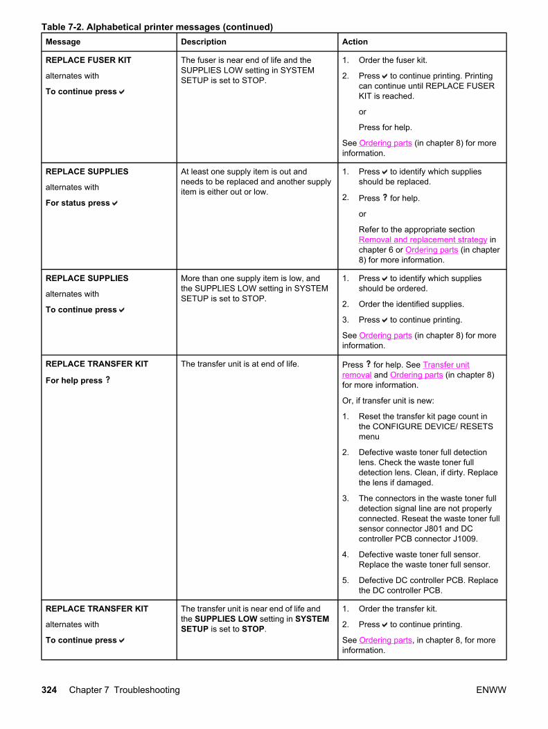
Message Description Action
REPLACE FUSER KIT
alternates with
To continue press
The fuser is near end of life and theSUPPLIES LOW setting in SYSTEMSETUP is set to STOP.
1. Order the fuser kit.
2. Press to continue printing. Printingcan continue until REPLACE FUSERKIT is reached.
or
Press for help.
See Ordering parts (in chapter 8) for moreinformation.
REPLACE SUPPLIES
alternates with
For status press
At least one supply item is out andneeds to be replaced and another supplyitem is either out or low.
1. Press to identify which suppliesshould be replaced.
2. Press for help.
or
Refer to the appropriate sectionRemoval and replacement strategy inchapter 6 or Ordering parts (in chapter8) for more information.
REPLACE SUPPLIES
alternates with
To continue press
More than one supply item is low, andthe SUPPLIES LOW setting in SYSTEMSETUP is set to STOP.
1. Press to identify which suppliesshould be ordered.
2. Order the identified supplies.
3. Press to continue printing.
See Ordering parts (in chapter 8) for moreinformation.
REPLACE TRANSFER KIT
For help press
The transfer unit is at end of life. Press for help. See Transfer unitremoval and Ordering parts (in chapter 8)for more information.
Or, if transfer unit is new:
1. Reset the transfer kit page count inthe CONFIGURE DEVICE/ RESETSmenu
2. Defective waste toner full detectionlens. Check the waste toner fulldetection lens. Clean, if dirty. Replacethe lens if damaged.
3. The connectors in the waste toner fulldetection signal line are not properlyconnected. Reseat the waste toner fullsensor connector J801 and DCcontroller PCB connector J1009.
4. Defective waste toner full sensor.Replace the waste toner full sensor.
5. Defective DC controller PCB. Replacethe DC controller PCB.
REPLACE TRANSFER KIT
alternates with
To continue press
The transfer unit is near end of life andthe SUPPLIES LOW setting in SYSTEMSETUP is set to STOP.
1. Order the transfer kit.
2. Press to continue printing.
See Ordering parts, in chapter 8, for moreinformation.
Table 7-2. Alphabetical printer messages (continued)
324 Chapter 7 Troubleshooting ENWW

Message Description Action
Request accepted
please wait
The printer has accepted a request toprint an internal page, but the current jobmust finish printing before the internalpage will print.
No action necessary.
Resend
upgrade
The firmware upgrade was notcompleted successfully.
Attempt upgrade again. For the HP 3700printer, you might need to use the parallelport to send the upgrade file.
Restoring
factory settings
The printer is restoring factory settings. No action necessary.
Restoring... The printer is restoring settings. No action necessary.
Resetting Kit Count YES was selected in the RESETSUPPLIES menu to reset the counts forany of the supplies that cannot bedetected as new.
No action necessary.
Rotating <COLOR>
motor
alternates with
To exit press
STOP key
A component test is in progress; thecomponent selected is <color>Cartridge motor.
Press Stop when ready to stop this test.
Rotating motor
alternates with
To exit press
STOP key
The printer is executing a Component.
Test and the component selected ismotor
Press STOP when ready to stop this test.
Setting saved A menu selection has been saved. No action necessary.
TRAY X
<TYPE> <SIZE>
alternates with
To change size or
type press
The printer is reporting the currentconfiguration of tray X.
Press to change size or type.
Table 7-2. Alphabetical printer messages (continued)
ENWW Printer error troubleshooting 325
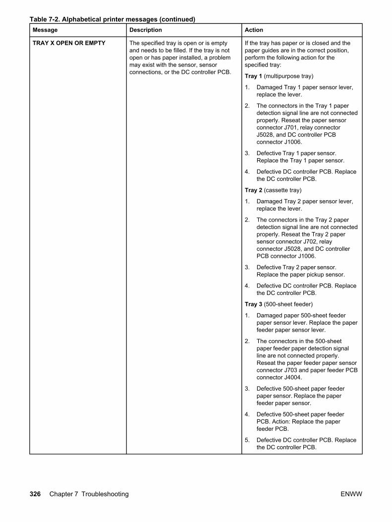
Message Description Action
TRAY X OPEN OR EMPTY The specified tray is open or is emptyand needs to be filled. If the tray is notopen or has paper installed, a problemmay exist with the sensor, sensorconnections, or the DC controller PCB.
If the tray has paper or is closed and thepaper guides are in the correct position,perform the following action for thespecified tray:
Tray 1 (multipurpose tray)
1. Damaged Tray 1 paper sensor lever,replace the lever.
2. The connectors in the Tray 1 paperdetection signal line are not connectedproperly. Reseat the paper sensorconnector J701, relay connectorJ5028, and DC controller PCBconnector J1006.
3. Defective Tray 1 paper sensor.Replace the Tray 1 paper sensor.
4. Defective DC controller PCB. Replacethe DC controller PCB.
Tray 2 (cassette tray)
1. Damaged Tray 2 paper sensor lever,replace the lever.
2. The connectors in the Tray 2 paperdetection signal line are not connectedproperly. Reseat the Tray 2 papersensor connector J702, relayconnector J5028, and DC controllerPCB connector J1006.
3. Defective Tray 2 paper sensor.Replace the paper pickup sensor.
4. Defective DC controller PCB. Replacethe DC controller PCB.
Tray 3 (500-sheet feeder)
1. Damaged paper 500-sheet feederpaper sensor lever. Replace the paperfeeder paper sensor lever.
2. The connectors in the 500-sheetpaper feeder paper detection signalline are not connected properly.Reseat the paper feeder paper sensorconnector J703 and paper feeder PCBconnector J4004.
3. Defective 500-sheet paper feederpaper sensor. Replace the paperfeeder paper sensor.
4. Defective 500-sheet paper feederPCB. Action: Replace the paperfeeder PCB.
5. Defective DC controller PCB. Replacethe DC controller PCB.
Table 7-2. Alphabetical printer messages (continued)
326 Chapter 7 Troubleshooting ENWW
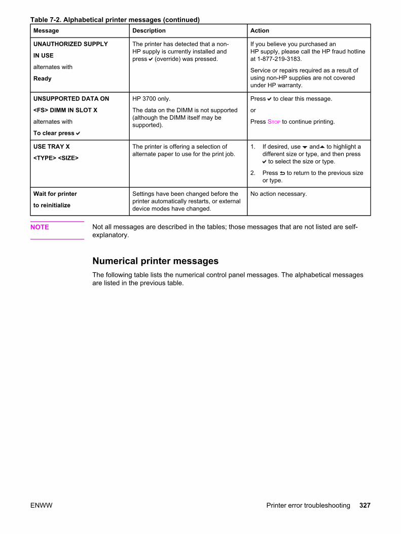
Message Description Action
UNAUTHORIZED SUPPLY
IN USE
alternates with
Ready
The printer has detected that a non-HP supply is currently installed andpress (override) was pressed.
If you believe you purchased anHP supply, please call the HP fraud hotlineat 1-877-219-3183.
Service or repairs required as a result ofusing non-HP supplies are not coveredunder HP warranty.
UNSUPPORTED DATA ON
<FS> DIMM IN SLOT X
alternates with
To clear press
HP 3700 only.
The data on the DIMM is not supported(although the DIMM itself may besupported).
Press to clear this message.
or
Press STOP to continue printing.
USE TRAY X
<TYPE> <SIZE>
The printer is offering a selection ofalternate paper to use for the print job.
1. If desired, use and to highlight adifferent size or type, and then press
to select the size or type.
2. Press to return to the previous sizeor type.
Wait for printer
to reinitialize
Settings have been changed before theprinter automatically restarts, or externaldevice modes have changed.
No action necessary.
NOTE Not all messages are described in the tables; those messages that are not listed are self-explanatory.
Numerical printer messages The following table lists the numerical control panel messages. The alphabetical messagesare listed in the previous table.
Table 7-2. Alphabetical printer messages (continued)
ENWW Printer error troubleshooting 327
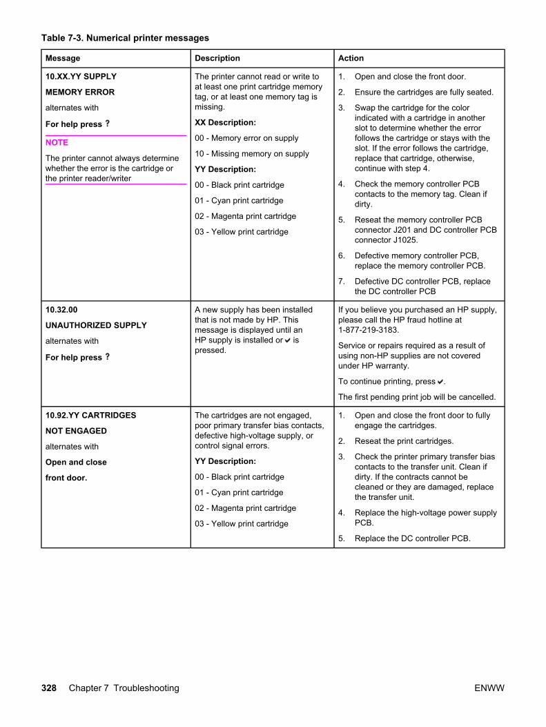
Table 7-3. Numerical printer messages
Message Description Action
10.XX.YY SUPPLY
MEMORY ERROR
alternates with
For help press
NOTE
The printer cannot always determinewhether the error is the cartridge orthe printer reader/writer
The printer cannot read or write toat least one print cartridge memorytag, or at least one memory tag ismissing.
XX Description:
00 - Memory error on supply
10 - Missing memory on supply
YY Description:
00 - Black print cartridge
01 - Cyan print cartridge
02 - Magenta print cartridge
03 - Yellow print cartridge
1. Open and close the front door.
2. Ensure the cartridges are fully seated.
3. Swap the cartridge for the colorindicated with a cartridge in anotherslot to determine whether the errorfollows the cartridge or stays with theslot. If the error follows the cartridge,replace that cartridge, otherwise,continue with step 4.
4. Check the memory controller PCBcontacts to the memory tag. Clean ifdirty.
5. Reseat the memory controller PCBconnector J201 and DC controller PCBconnector J1025.
6. Defective memory controller PCB,replace the memory controller PCB.
7. Defective DC controller PCB, replacethe DC controller PCB
10.32.00
UNAUTHORIZED SUPPLY
alternates with
For help press
A new supply has been installedthat is not made by HP. Thismessage is displayed until anHP supply is installed or ispressed.
If you believe you purchased an HP supply,please call the HP fraud hotline at1-877-219-3183.
Service or repairs required as a result ofusing non-HP supplies are not coveredunder HP warranty.
To continue printing, press .
The first pending print job will be cancelled.
10.92.YY CARTRIDGES
NOT ENGAGED
alternates with
Open and close
front door.
The cartridges are not engaged,poor primary transfer bias contacts,defective high-voltage supply, orcontrol signal errors.
YY Description:
00 - Black print cartridge
01 - Cyan print cartridge
02 - Magenta print cartridge
03 - Yellow print cartridge
1. Open and close the front door to fullyengage the cartridges.
2. Reseat the print cartridges.
3. Check the printer primary transfer biascontacts to the transfer unit. Clean ifdirty. If the contracts cannot becleaned or they are damaged, replacethe transfer unit.
4. Replace the high-voltage power supplyPCB.
5. Replace the DC controller PCB.
328 Chapter 7 Troubleshooting ENWW

Message Description Action
Four color slippage bands occuracross the ITB belt because theright side cleaning blade shippingtab is out of position. This cancause interference with the yellowcartridge, where the cleaning bladeshipping tab contacts the OPCwhite plastic hub and the OPCground contact adjacent to the OPChub. This interference between thecleaning blade and the yellowcartridge prevents the properengagement between the ITB driveroller coupler and the engine ITBresulting in non-engagement of theITB drive roller coupler to theengine which can produce separatecolor toner slippage bands acrossthe ITB belt surface beneath eachtoner cartridge. You may also heara thumping noise and experience avibration in the upper right portion ofthe front cover. Due to theinterference, a paper jam 13.xx.xxerror (13.20.00 on an HP 3700 witha corresponding 13.05.00 paper jamin the event log, or a 13.50.00message for an HP 3500/3550printer).
Perform the following steps to fix theproblem:
1. Right side cleaning tab is out ofposition. (This tab is located on theright side of the ITB, about in themiddle of the ITB assembly .) Push itback into position. If it will not moveback into position, replace the ITBassembly.
2. Check the yellow cartridge for damage(compare it to the magenta cartridge)and replace it if necessary.
3. Verify that the cleaning blade left-handtab lock lever is in the forward position.
4. Verify that the ITB assembly shippinglocks have been removed. Shippinglocks are located at the bottom (towardthe door hinge end) of the ITBassembly on the left and right side.
Table 7-3. Numerical printer messages (continued)
ENWW Printer error troubleshooting 329

Message Description Action
Error occurs at power up and canbe caused by:
● Cartridges not seated correctly.
● Damaged cartridge shutter arm.
● Broken ITB coupling lever onthe front door (front doorengaging tab).
● Broken cartridge alignmentknob.
● Left rail guide out of place ormissing.
● Left arm drum lock is broken.
● ITB gears are not aligned.
Perform the following steps:
1. Open the door and verify the tonercartridges are seated properly.Remove and reinstall the cartridges.
2. Close the door slowly and look insideto see if the toner shutters openproperly while the door is closing. Ifthey are sticking, inspect the cartridgesfor any damage to the wire arm orshutter. Replace the cartridge if itsticks for more than 10 seconds.
3. If the cartridges look OK, go throughthe diagnostic Disable Cartridge checkand change toner cartridges to see ifthe problem follows the cartridge or if itstays with the location.
● Select the .
● Move down through the menu andhighlight Diagnostics.
● Select the .
● Move down through the menu andhighlight Disable Cartridge check.
● Select the .
● Remove the cartridge that is theissue. To determine whichcartridge is the issue, look at thelast two digits of the 10.92.XXerror code: 00 = black, 01 = cyan,02 = magenta, 03 = yellow.
● Place the cartridge with the issuein another color slot, and put thegood cartridge in the troublecartridge slot.
● Close the door. If the 10.92.XXerror is still present, see if it is stillthe same cartridge. (If the blackcartridge was moved to the yellowspot, did the error messagechange from 10.92.00 to10.92.03), or did the error remaina 10.92.00. If the error followedthe cartridge, replace thecartridge, but if it stayed the same,the printer may have a brokencartridge alignment knob andshould be replaced.
Table 7-3. Numerical printer messages (continued)
330 Chapter 7 Troubleshooting ENWW
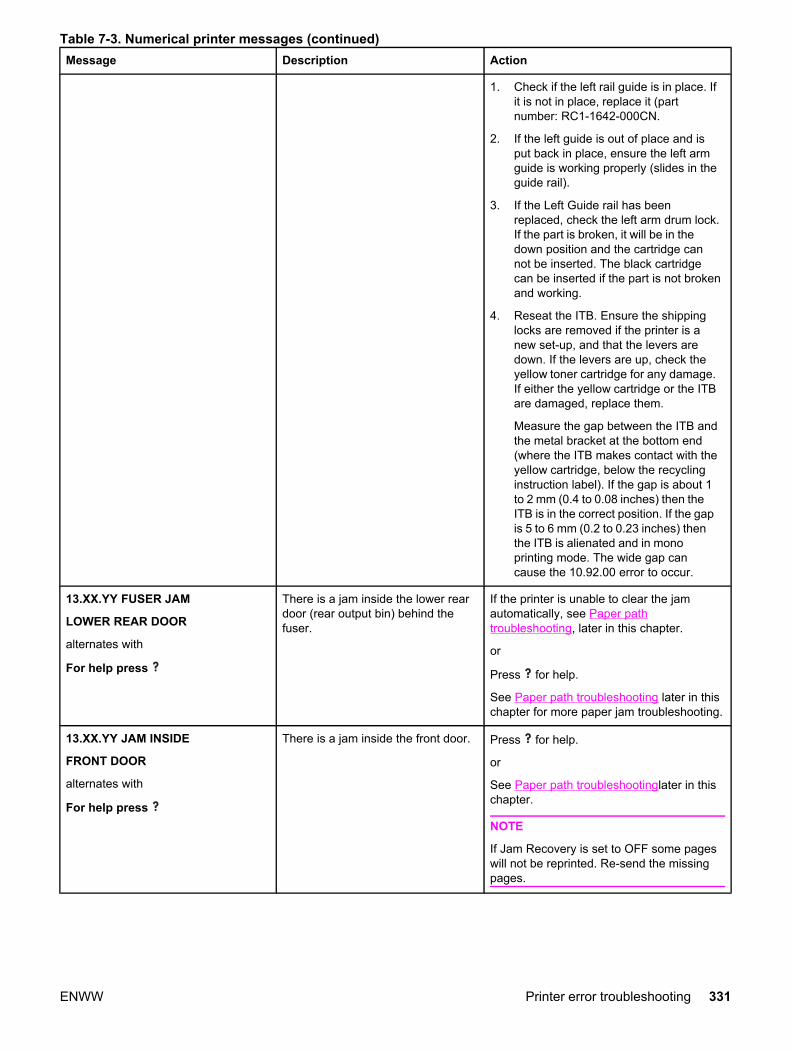
Message Description Action
1. Check if the left rail guide is in place. Ifit is not in place, replace it (partnumber: RC1-1642-000CN.
2. If the left guide is out of place and isput back in place, ensure the left armguide is working properly (slides in theguide rail).
3. If the Left Guide rail has beenreplaced, check the left arm drum lock.If the part is broken, it will be in thedown position and the cartridge cannot be inserted. The black cartridgecan be inserted if the part is not brokenand working.
4. Reseat the ITB. Ensure the shippinglocks are removed if the printer is anew set-up, and that the levers aredown. If the levers are up, check theyellow toner cartridge for any damage.If either the yellow cartridge or the ITBare damaged, replace them.
Measure the gap between the ITB andthe metal bracket at the bottom end(where the ITB makes contact with theyellow cartridge, below the recyclinginstruction label). If the gap is about 1to 2 mm (0.4 to 0.08 inches) then theITB is in the correct position. If the gapis 5 to 6 mm (0.2 to 0.23 inches) thenthe ITB is alienated and in monoprinting mode. The wide gap cancause the 10.92.00 error to occur.
13.XX.YY FUSER JAM
LOWER REAR DOOR
alternates with
For help press
There is a jam inside the lower reardoor (rear output bin) behind thefuser.
If the printer is unable to clear the jamautomatically, see Paper pathtroubleshooting, later in this chapter.
or
Press for help.
See Paper path troubleshooting later in thischapter for more paper jam troubleshooting.
13.XX.YY JAM INSIDE
FRONT DOOR
alternates with
For help press
There is a jam inside the front door. Press for help.
or
See Paper path troubleshootinglater in thischapter.
NOTE
If Jam Recovery is set to OFF some pageswill not be reprinted. Re-send the missingpages.
Table 7-3. Numerical printer messages (continued)
ENWW Printer error troubleshooting 331
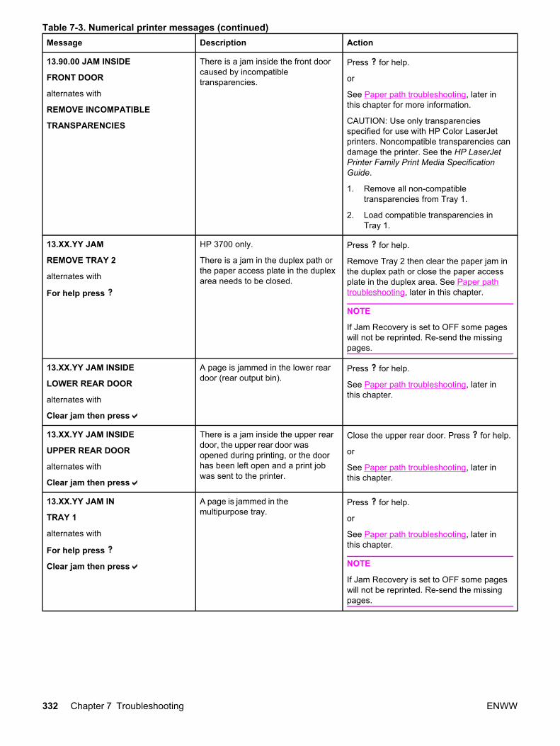
Message Description Action
13.90.00 JAM INSIDE
FRONT DOOR
alternates with
REMOVE INCOMPATIBLE
TRANSPARENCIES
There is a jam inside the front doorcaused by incompatibletransparencies.
Press for help.
or
See Paper path troubleshooting, later inthis chapter for more information.
CAUTION: Use only transparenciesspecified for use with HP Color LaserJetprinters. Noncompatible transparencies candamage the printer. See the HP LaserJetPrinter Family Print Media SpecificationGuide.
1. Remove all non-compatibletransparencies from Tray 1.
2. Load compatible transparencies inTray 1.
13.XX.YY JAM
REMOVE TRAY 2
alternates with
For help press
HP 3700 only.
There is a jam in the duplex path orthe paper access plate in the duplexarea needs to be closed.
Press for help.
Remove Tray 2 then clear the paper jam inthe duplex path or close the paper accessplate in the duplex area. See Paper pathtroubleshooting, later in this chapter.
NOTE
If Jam Recovery is set to OFF some pageswill not be reprinted. Re-send the missingpages.
13.XX.YY JAM INSIDE
LOWER REAR DOOR
alternates with
Clear jam then press
A page is jammed in the lower reardoor (rear output bin).
Press for help.
See Paper path troubleshooting, later inthis chapter.
13.XX.YY JAM INSIDE
UPPER REAR DOOR
alternates with
Clear jam then press
There is a jam inside the upper reardoor, the upper rear door wasopened during printing, or the doorhas been left open and a print jobwas sent to the printer.
Close the upper rear door. Press for help.
or
See Paper path troubleshooting, later inthis chapter.
13.XX.YY JAM IN
TRAY 1
alternates with
For help press
Clear jam then press
A page is jammed in themultipurpose tray.
Press for help.
or
See Paper path troubleshooting, later inthis chapter.
NOTE
If Jam Recovery is set to OFF some pageswill not be reprinted. Re-send the missingpages.
Table 7-3. Numerical printer messages (continued)
332 Chapter 7 Troubleshooting ENWW

Message Description Action
13.XX.YY JAM IN
TRAY X
alternates with
For help press
Clear jam then press
A page is jammed in tray X. Press for help.
or
See Paper path troubleshooting, later inthis chapter.
NOTE
If Jam Recovery is set to OFF some pageswill not be reprinted. Re-send the missingpages.
20 INSUFFICIENT
MEMORY
alternates with
For help press
To continue press
The printer has received more datafrom the computer than fits inavailable memory.
1. Press to continue printing.
NOTE
A loss of data will occur.
2. Reduce the complexity of the print jobto avoid this error.
3. HP 3700 only - Add additional memoryto allow printing of more complex pages.
4. HP 3500/3550 only - on the printerdriver, set Raster Compression on theAdvanced tab to Maximum.
22 EIO X
BUFFER OVERFLOW
alternates with
To continue press
HP 3700 only when an EIO deviceis installed.
The printer EIO card in slot X hasoverflowed its I/O buffer during abusy state.
Press to continue printing.
NOTE
A loss of data will occur.
22 PARALLEL I/O
BUFFER OVERFLOW
alternates with
To continue press
HP 3700 only.
The printer’s parallel buffer hasoverflowed during a busy state.
Press to continue printing.
NOTE
A loss of data will occur.
22 SERIAL I/O
BUFFER OVERFLOW
alternates with
To continue press
HP 3700 only when an EIO deviceis installed.
The printer serial buffer hasoverflowed during a busy state.
Press to continue printing.
NOTE
A loss of data will occur.
22 USB I/O
BUFFER OVERFLOW
alternates with
To continue press
The printer's USB buffer hasoverflowed during a busy state.
Press to continue printing.
NOTE
A loss of data will occur.
40 BAD SERIAL
TRANSMISSION
alternates with
To continue press
HP 3700 only.
A serial data error (parity, framing,or line overrun) has occurred whilethe printer was receiving data.
Press to continue printing.
NOTE
A loss of data will occur.
Table 7-3. Numerical printer messages (continued)
ENWW Printer error troubleshooting 333

Message Description Action
40 EIO X BAD
TRANSMISSION
alternates with
To continue press
HP 3700 only when an EIO deviceis installed.
A connection with the card in theEIO slot has been abnormallybroken.
Press to continue printing.
NOTE
A loss of data will occur.
41.3 UNEXPECTED
SIZE IN TRAY X
alternates with
LOAD TRAY X
<TYPE> <SIZE>
Paper is loaded that is longer orshorter in the feed direction than thesize configured for the tray.
1. Load the paper as instructed.
2. Press to print.
3. If the incorrect size was selected,press STOP to cancel the job or pressfor help.
4. If the incorrect tray was selected, pressSTOP to cancel the job.
5. Configure the trays correctly andresend the job.
Ensure all trays are configured correctly.
41.5 UNEXPECTED
TYPE IN TRAY X
alternates with
LOAD TRAY X
<TYPE> <SIZE>
The printer senses a different papertype in the paper path than what isconfigured in the tray.
1. Load the paper as instructed.
2. Press to print.
3. If the incorrect type was selected,press STOP to cancel the job or pressfor help.
4. Configure the trays correctly andresend the job.
Ensure all trays are configured correctly.
Table 7-3. Numerical printer messages (continued)
334 Chapter 7 Troubleshooting ENWW
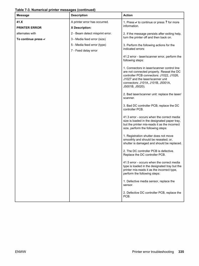
Message Description Action
41.X
PRINTER ERROR
alternates with
To continue press
A printer error has occurred.
X Description:
2 - Beam detect misprint error.
3 - Media feed error (size)
5 - Media feed error (type)
7 - Feed delay error
1. Press to continue or press for moreinformation.
2. If the message persists after exiting help,turn the printer off and then back on.
3. Perform the following actions for theindicated errors:
41.2 error - laser/scanner error, perform thefollowing steps:
1. Connectors in laser/scanner control lineare not connected properly. Reseat the DCcontroller PCB connectors: J1022, J1026,J1027 and the laser/scanner unitconnectors: J101A, J101B, J5001A,J5001B, J5020).
2. Bad laser/scanner unit: replace the laser/scanner.
3. Bad DC controller PCB; replace the DCcontroller PCB.
41.3 error - occurs when the correct mediasize is loaded in the designated paper tray,but the printer mis-reads it as the incorrectsize, perform the following steps:
1. Registration shutter does not movesmoothly and should be reseated; or,shutter is damaged and should be replaced.
2. The DC controller PCB is defective.Replace the DC controller PCB.
41.5 error - occurs when the correct mediatype is loaded in the designated tray but theprinter mis-reads it as the incorrect type,perform the following steps:
1. Defective media sensor, replace thesensor.
2. Defective DC controller PCB, replace thePCB.
Table 7-3. Numerical printer messages (continued)
ENWW Printer error troubleshooting 335

Message Description Action
41.7 error - occurs when a page is jammedin the paper path. See Paper pathtroubleshooting, later in this chapter. If theerror reoccurs, perform the following steps:
1. Check that your paper meets HPspecifications, see the MediaSpecification guide athttp://www.hp.com
2. Check the separation pads andreplace if worn. Replacement partnumbers:
● Tray 1: RC1-0939-000CN
● Tray 2: RC1-0954-000CN
● Tray 3: RC1-0827-000CN
3. Check the pick-up rollers. The Tray 2/3pick roller may be broken or out ofplace. Verify that it is properlypositioned. Pick-up rollers wear withage and rough media. Replacementpart numbers:
● Tray 1: RC1-1535-000CN
● Tray 2/3: RC1-0731000CN
Table 7-3. Numerical printer messages (continued)
336 Chapter 7 Troubleshooting ENWW

Message Description Action
49.XXXX
PRINTER ERROR
alternates with
To continue
turn off then on
A critical firmware error hasoccurred that caused the processoron the formatter to abort operation.This type of error can be caused byinvalid print commands, corruptdata, or invalid operations. In somecases, electrical noise in the cablecan corrupt data duringtransmission to the printer. Othercauses include poor quality parallelcables, poor connections, or home-grown applications. On rareoccasions, the formatter is at fault,which is usually indicated by a79 Service Error.
1. Press STOP to clear the print job from theprinter memory.
2. Turn the printer off and then back on.
3. Try printing a job from a differentsoftware application. If the job prints, goback to the first application and try printinga different file. If the message appears onlywith a certain software application or printjob, contact the software vendor forassistance.
4. HP 3700 only - Try a different driver
5. If the message persists with differentsoftware applications and print jobs,disconnect all cables to the printer thatconnect it to the network or PC.
6. Turn the printer off.
7. HP 3700 only - Remove all memoryDIMMs or third-party
DIMMs from the printer. (Do not remove thefirmware DIMM in the lower slot J1.)
8. For the HP 3700, remove the EIO cardfrom the printer.
9. Turn the printer on.
10. HP 3700 only - If the error no longerexists, install each DIMM and EIO deviceone at a time, making sure to turn theprinter off and back on as you install eachdevice.
11. HP 3700 only - Replace a DIMM or EIOdevice if you determine that it causes theerror.
12. HP 3700 only - Remember to reconnectall cables that connect the printer to thenetwork or computer.
13. HP 3700 only - If the error persists,replace the firmware DIMM.
14. Replace the formatter and calibrate theprinter.
Table 7-3. Numerical printer messages (continued)
ENWW Printer error troubleshooting 337

Message Description Action
50.X FUSER ERROR
alternates with
For help press
A fuser error has occurred.
X Description
1 - low fuser temperature
2 - fuser warmup service
3 - high fuser temperature
4 - faulty fuser
8 - low fuser temperature(subthermistor
9 - high fuser temperature(subthermistor)
WARNING: The fuser is HOT. Turn theprinter off and allow it to cool forapproximately 10 minutes before removingthe fuser.
50.1 error - Fuser failure (Abnormally LowTemperature Main Thermistor), perform thefollowing steps:
1. The connector between the fuser and theprinter is not connected properly. Reseatthe fuser. Check the connector J5013between the fuser and the printer. Replaceit if damaged.
2. Break in the main thermistor. Turn theprinter off and remove the fuser. Measurethe resistance between the fuserconnectors J5013LA-2 (MAINTH) andJ5013LA-1 (GND). If it is not within the rageof 330k ohms to 50k ohms (at ambienttemperature), replace the fuser.
3. Faulty DC controller PCB. Replace theDC controller PCB.
50.2 error - Fuser Failure (Abnormal Warm-up). Perform the following steps:
1. The connector between the fuser and theprinter is not connected properly. Reseatthe fuser. Check the connector J5013between the fuser and the printer. Replaceit if damaged.
2. Break in the main thermistor. Turn theprinter off and remove the fuser. Measurethe resistance between the fuserconnectors J5013LA-2 (MAINTH) andJ5013LA-1 (GND). If it is not within the rageof 330k ohms to 50k ohms (at ambienttemperature), replace the fuser.
3. Break in the fuser heater. Measure theresistance between the fuser connectorsJ5013L-2 (FSRH) and J5013L-1 (FSRN)with the fuser removed. If it is not within therage of 12 ohms to 52 ohms (at ambienttemperature), replace the fuser film unit.
4. Faulty DC controller. PCB Replace theDC controller PCB
Table 7-3. Numerical printer messages (continued)
338 Chapter 7 Troubleshooting ENWW

Message Description Action
50.X FUSER ERROR 50.3 error - Fuser Failure (Abnormally HighTemperature Main Thermistor)
1. The connector between the fuser and theprinter is not connected properly. Reseatthe fuser. Check the connector J5013between the fuser and the printer. Replaceit if damaged.
2. Short in the main thermistor. Turn theprinter off and remove the fuser. Measurethe resistance between the fuserconnectors J5013LA-2 (MAINTH) andJ5013LA-1 (GND). If it is in the rage of330k ohms to 50k ohms (at ambienttemperature), replace the fuser.
3. Faulty DC controller PCB. Replace theDC controller PCB.
50.4 error -
1. Faulty fuser power supply PCB, replacethe low-voltage power supply PCB.
2. Faulty DC controller PCB, replace theDC controller PCB.
3. For the following errors, perform theindicated action.
50.8 error - Fuser Failure (Abnormally LowTemperature Sub Thermistor)
1. The connector between the fuser and theprinter is not connected properly. Reseatthe fuser. Check the connector J5013between the fuser and the printer. Replaceit if damaged.
2. Break in the sub thermistor. Turn theprinter off and remove the fuser. Measurethe resistance between the fuserconnectors J5013LA-4 (SUBTH) andJ5013LA-3 (+3.3V). If it reads 600 ohms orbelow (at ambient temperature), replacethe fuser.
3. Faulty DC controller PCB, replace theDC controller PCB.
Table 7-3. Numerical printer messages (continued)
ENWW Printer error troubleshooting 339

Message Description Action
50.X FUSER ERRORcontinued 50.9 error - Fuser Failure (Abnormally HighTemperature Sub Thermistor)
1. The connector between the fuser and theprinter is not connected properly. Reseatthe fuser. Check the connector J5013between the fuser and the printer. Replaceit if damaged.
2. Short in the sub thermistor. Turn theprinter off and remove the fuser. Measurethe resistance between the fuserconnectors J5013LA-4 (SUBTH) andJ5013LA-3 (+3.3V). If it reads 600 ohms orbelow (at ambient temperature), replacethe fuser.
3. Faulty DC controller PCB, replace theDC controller PCB.
51.XY.
PRINTER ERROR
alternates with
To continue
turn off then on
A laser/scanner error has occurred
X Description:
1 - beam detect error
2 - laser error
Y Description:
0 - no color
K - black
C - cyan
M - magenta
Y - yellow
1. Press to continue.
2. If the message persists, turn the printeroff and then back on.
3. The connectors in the laser/scannercontrol line are not connected properly.Reseat the DC controller PCBconnectors (J1022, J1026, J1027) andthe laser/scanner unit connectors(J101A, J101B, J5001A, J5001B,J5020).
4. Faulty laser/scanner unit, replace thelaser/scanner unit.
5. Faulty DC controller PCB, replace theDC controller PCB.
52.XY
PRINTER ERROR
alternates with
To continue
turn off then on
A laser/scanner motor failure hasoccurred
X Description:
1 - scanner error
2 - scanner startup error
3 - scanner rotation error
Y Description:
0 - no color
K - black
C - cyan
M - magenta
Y - yellow
1. Press to continue.
2. If the message persists, turn the printeroff and then back on.
3. The connectors in the laser/scannercontrol line are not connected properly.Reseat the DC controller PCBconnectors (J1022, J1026, J1027) andthe laser/scanner connectors (J101A,J101B, J5001A, J5001B, J5020).
4. Faulty laser/scanner, replace the laser/scanner.
5. Faulty DC controller PCB, replace theDC controller PCB.
Table 7-3. Numerical printer messages (continued)
340 Chapter 7 Troubleshooting ENWW
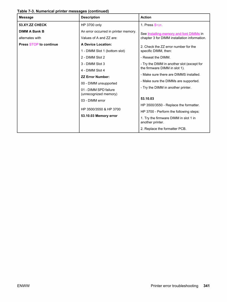
Message Description Action
53.XY.ZZ CHECK
DIMM A Bank B
alternates with
Press STOP to continue
HP 3700 only
An error occurred in printer memory.
Values of A and ZZ are:
A Device Location:
1 - DIMM Slot 1 (bottom slot)
2 - DIMM Slot 2
3 - DIMM Slot 3
4 - DIMM Slot 4
ZZ Error Number:
00 - DIMM unsupported
01 - DIMM SPD failure(unrecognized memory)
03 - DIMM error
HP 3500/3550 & HP 3700
53.10.03 Memory error
1. Press STOP.
See Installing memory and font DIMMs inchapter 3 for DIMM installation information.
2. Check the ZZ error number for thespecific DIMM, then:
- Reseat the DIMM.
- Try the DIMM in another slot (except forthe firmware DIMM in slot 1).
- Make sure there are DIMMS installed.
- Make sure the DIMMs are supported.
- Try the DIMM in another printer.
53.10.03
HP 3500/3550 - Replace the formatter.
HP 3700 - Perform the following steps:
1. Try the firmware DIMM in slot 1 inanother printer.
2. Replace the formatter PCB.
Table 7-3. Numerical printer messages (continued)
ENWW Printer error troubleshooting 341

Message Description Action
54.XX PRINTER
ERROR
A printer command error hasoccurred.
NOTE
Some messages are displayed inthe event log and some aredisplayed on both the control paneland in the event log, as identifiedbelow.
XX Description:
(Event log only messages)
01 - humidity environmental sensorerror
05 - media sensor error
06 - Dmax density sensor out ofrange
11 - yellow density sensor error
12 - magenta density sensor error
13 - cyan density sensor error
14 - black density sensor error
15 - yellow CPR sensor error
16 - magenta CPR sensor error
17 - cyan CPR sensor error
18 - black CPR sensor error
20 - CPR sensor error
(Control panel and event logmessage)
21 - yellow toner remaining sensorerror
22 - magenta toner remainingsensor error
23 - cyan toner remaining sensorerror
24 - black toner remaining sensorerror
31 - Media sensor calibration failure
(Event log only message)
32 - Media sensor is not calibrated(event log only)
1. Turn the printer off and then back on.
2. For the specific error messages, performthe indicated action:
54.01 - Environment Sensor Abnormality
1. The connector in the environmentdetection signal line is not properlyconnected. Reseat the DC controller PCBconnector J1015.
2. Defective environment sensor, replacethe environment sensor.
3. Defective DC controller PCB, replace theDC controller PCB.
54.05 - Media sensor error
1. Perform the steps for error 54.32, below.
2. Replace the media sensor.
3. Replace the DC controller.
54.06
54.11
54.12
54.13
54.14
1. Perform a Calibrate Now procedure.
2. The DC controller is defective, replacethe DC controller PCB.
Table 7-3. Numerical printer messages (continued)
342 Chapter 7 Troubleshooting ENWW

Message Description Action
54.XX PRINTER
ERROR continued
33.0X Scanner Beam Detectadjustment abnormality warning X isthe scanner number:
1 = yellow/magenta scanner
2 = cyan/black scanner
54.15
54.16
54.17
54.18
54.20
Color misregistration sensor abnormality
1. The connectors between the colormisregistration sensor (CPR) and the DCcontroller PCB are not connected properly.Reseat the color misregistration sensor(CPR) connectors (J505A, J505B) and theDC controller PCB connector J1012.
2. Faulty color misregistration sensor(CPR). Replace the color misregistrationsensor (CPR).
3. Faulty DC controller PCB. Replace theDC controller PCB.
54.21 -
54.22 -
54.23 -
54.24 -
Toner (Y/M/C/K) level sensor abnormality
1. The connectors in the toner level sensorcontrol line are not connected properly.Reseat the memory controller PCBconnector J201 and the DC controller PCBconnector J1025.
2. Faulty memory controller PCB. Replacethe memory controller PCB.
3. Faulty DC controller PCB. Replace theDC controller PCB.
54.30.XX (event log only) HP3700only
Halftone calibration error.
XX Description:
06 - magenta data out of range.
07 - yellow data out of range.
08 - black data out of range.
09 - cyan data out of range.
54.30.XX
Perform a CALIBRATE NOW in theCONFIGURE DEVICE / PRINT QUALITYmenu on the printer control panel.
Table 7-3. Numerical printer messages (continued)
ENWW Printer error troubleshooting 343

Message Description Action
54.31 - Media Sensor Abnormality/ After-adjustment Value Out of Spec
1. Try to calibrate the media sensor again.
2. Dirty media sensor. Clean the mediasensor.
3. The connectors in the media detectionsignal line are not properly connected.Reseat the media sensor connector J601,relay connector J5026, and DC controllerPCB connector J1008.
4. Defective media sensor. Replace themedia sensor.
5. Defective DC controller PCB. Replacethe DC controller PCB.
54.XX PRINTER
ERROR continued
for 54.32 error:
The image density adjustmentvalue, color misregistrationadjustment value, and PWMadjustment value (see note below)are stored in the EEPROM(NVRAM) of the formatter.Whenever a formatter or laser/scanner unit is replaced, you mustcalibrate the printer to update thevalues.
a. Image density adjustment (onformatter replacement)
b. Color misregistration adjustment(on formatter replacement)
c. PWM adjustment (on bothformatter and laser/scanner unitreplacement)
NOTE
The PWM adjustment value enablesreproduction of an image in the besttone. The formatter determines thevalue based on the amount of laserlight received from the printer engine.
54.32 -
Electrical Adjustment
When the media sensor is replaced, the
light intensity of the sensor must beadjusted. Follow the procedure below toadjust the light intensity.
1. Turn the printer OFF.
2. Open the front door.
3. While pressing down the engine testprint switch, turn the printer ON.
4. Close the front door.
5. Load paper into Tray 1 (use plain whitepaper for test printing).
6. As the printer goes into READY period,press the engine test print switch and testprint.
7. One sheet of paper will be fed into theprinter from Tray 1 and will be delivered tothe face-down delivery tray.
54.33 -
1. Defective laser/scanner. Replace thelaser/scanner unit.
2. Defective DC controller PCB. Replacethe DC controller PCB.
Table 7-3. Numerical printer messages (continued)
344 Chapter 7 Troubleshooting ENWW
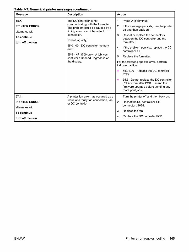
Message Description Action
55.X
PRINTER ERROR
alternates with
To continue
turn off then on
The DC controller is notcommunicating with the formatter.The problem could be caused by atiming error or an intermittentconnection.
(Event log only)
55.01.00 - DC controller memoryerror.
55.5 - HP 3700 only - A job wassent while Resend Upgrade is onthe display.
1. Press to continue.
2. If the message persists, turn the printeroff and then back on.
3. Reseat or replace the connectorsbetween the DC controller and theformatter.
4. If the problem persists, replace the DCcontroller PCB.
5. Replace the formatter.
For the following specific error, performindicated action.
● 55.01.00 - Replace the DC controllerPCB.
● 55.5 - Do not replace the DC controllerPCB or formatter PCB. Resend thefirmware upgrade before sending anymore print jobs.
57.4
PRINTER ERROR
alternates with
To continue
turn off then on
A printer fan error has occurred as aresult of a faulty fan connection, fanor DC controller.
1. Turn the printer off and then back on.
2. Reseat the DC controller PCBconnector J1024.
3. Replace the fan.
4. Replace the DC controller PCB.
Table 7-3. Numerical printer messages (continued)
ENWW Printer error troubleshooting 345
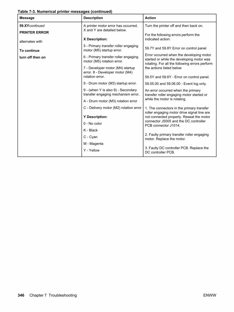
Message Description Action
59.XYcontinued
PRINTER ERROR
alternates with
To continue
turn off then on
A printer motor error has occurred.X and Y are detailed below.
X Description:
5 - Primary transfer roller engagingmotor (M5) startup error.
6 - Primary transfer roller engagingmotor (M5) rotation error.
7 - Developer motor (M4) startuperror. 8 - Developer motor (M4)rotation error.
9 - Drum motor (M3) startup error.
9 - (when Y is also 9) - Secondarytransfer engaging mechanism error.
A - Drum motor (M3) rotation error
C - Delivery motor (M2) rotation error
Y Description:
0 - No color
K - Black
C - Cyan
M - Magenta
Y - Yellow
Turn the printer off and then back on.
For the following errors perform theindicated action:
59.7Y and 59.8Y Error on control panel
Error occurred when the developing motorstarted or while the developing motor wasrotating. For all the following errors performthe actions listed below
59.5Y and 59.6Y - Error on control panel.
59.05.00 and 59.06.00 - Event log only.
An error occurred when the primarytransfer roller engaging motor started orwhile the motor is rotating.
1. The connectors in the primary transferroller engaging motor drive signal line arenot connected properly. Reseat the motorconnector J5005 and the DC controllerPCB connector J1014.
2. Faulty primary transfer roller engagingmotor. Replace the motor.
3. Faulty DC controller PCB. Replace theDC controller PCB.
Table 7-3. Numerical printer messages (continued)
346 Chapter 7 Troubleshooting ENWW

Message Description Action
59.7Y Control Panel Message
59.07.00 - (HP 3700 only; event log only)
59.07.ZZ - (HP 3500/3550 only; event logonly)
ZZ is color:
00 - Black
01 - Cyan
02 - Magenta
03 - Yellow
59.8Y Control Panel Message
59.08.00 - (HP 3700 only; event log only)
59.08.ZZ - (HP 3500/3550 only; event logonly)
ZZ is color:
00 - Black
01 - Cyan
02 - Magenta
03 - Yellow
1. The connectors in the developing motordrive signal line are not connected properly.Reseat the developing motor connectorJ5006 and the DC controller PCBconnector J1019.
2. Faulty developing motor. Replace thedeveloping motor.
3. Faulty DC controller PCB. Replace theDC controller PCB.
Table 7-3. Numerical printer messages (continued)
ENWW Printer error troubleshooting 347

Message Description Action
59.XYcontinued
PRINTER ERROR
alternates with
To continue
turn off then on
59.90 and 59.A0 Errors on control panel
59.09.00 (event log only)
59.10.00 (event log only)
An error occurred when the drum motorstarted or while the drum motor was rotating.
1. The connectors in the drum motor drivesignal line are not connected properly.Reseat the drum motor connector J5002and the DC controller PCB connector J1019.
2. Faulty drum motor. Replace the drummotor.
3. Faulty DC controller PCB. Replace theDC controller PCB.
59.99.00 - (event log only)
An error occurred in the secondary transferengaging mechanism.
1. Faulty secondary transfer engagementsensor. Replace the secondary transferengagement sensor.
2. Faulty secondary transfer engagingsolenoid. Replace the secondary transferengaging solenoid.
3. Faulty feed motor. Replace the feedmotor.
4. Faulty DC controller PCB
Action: Replace the DC controller PCB.
Table 7-3. Numerical printer messages (continued)
348 Chapter 7 Troubleshooting ENWW

Message Description Action
59.C0 Error on control panel
Unable to move the right swing guide armall the way back due to a missing "t". If anyof these "t's" are missing, replace the rightswing guide. These "t's" are white plasticpieces shaped like a "t" inserted into theright swing guide.
59.12.00 (event log only)
An error occurred in the developingengaging mechanism.
1. The movement of the developingengaging lever is not smooth. Make themovement of the lever smooth. Replace thegear for the lever, if damaged.
2. Damage on the drive gears. Check eachdrive gear between the delivery motor andthe developing engaging clutch. Replaceany, if damaged.
59.XY
PRINTER ERROR
alternates with
To continue
turn off then on
3. Faulty developing engaging sensor leverReseat the developing engaging sensorlever to the correct position if its movement
is not smooth or it is out of position.Replace the lever if it is damaged ordeformed.
4. Faulty developing engaging sensor.Replace the developing engaging sensor.
5. The connectors in the developingengaging clutch drive signal line are notconnected properly. Reseat the connectorsJ5014 and J1019 between the developingengaging clutch and the DC controller PCB.
6. The connectors in the delivery motordrive signal line are not connected properly.Reseat the connectors J5004 and J1016between the delivery motor and the DCcontroller PCB
7. Faulty developing engaging clutch.Replace the developing engaging clutch.
8. Faulty delivery motor. Replace thedelivery motor
9. Faulty DC controller PCB. Replace theDC controller PCB.
Table 7-3. Numerical printer messages (continued)
ENWW Printer error troubleshooting 349

Message Description Action
62 NO SYSTEM No system was found. 1. Turn the printer off and then back on.
2. HP 3700 only - reseat the firmwareDIMM. Make sure it is in slot 1 (thebottom slot).
3. Download new firmware (HP 3700 - trydownloading through the parallel port).
4. Replace the firmware DIMM.
64 PRINTER ERROR
For help press
alternates with
To continue
turn off then on
Scan buffer error. 1. Turn the printer off and then back on.
2. Perform a cold reset.
3. HP 3700 only - replace the firmwareDIMM.
4. Replace the formatter PCB.
68.X PERMANENT
STORAGE FULL
alternates with
To continue press
A non-volatile storage device is full.
Press to clear the message.Printing can continue, but therecould be unexpected behavior.
X Description:
0 - for onboard NVRAM
1 - for removable flash disk
1. Press to continue.
2. For the following errors, perform theindicated action.
68.0 - turn the printer off and then back on.If the error persists, execute an NVRAMinitialization.
68.1 - use the HP Web Jetadmin softwareto delete files from the flash disk.
68.X PERMANENT
STORAGE WRITE FAIL
alternates with
To continue press
A non-volatile storage device isfailing to write.
Press to clear the message.Printing can continue, but therecould be unexpected behavior.
X Description:
0 - for onboard NVRAM.
1 - for removable flash disk.
press to continue.
For the following errors, perform theindicated action.
68.0 - turn the printer off and then back on.If the error persists, execute an NVRAMinitialization.
68.1 - use the HP Web Jetadmin softwareto delete files from the flash disk.
68.X STORAGE ERROR
SETTINGS CHANGED
alternates with
To continue press
One or more printer settings savedin the non-volatile storage device isinvalid and has been reset to itsfactory default.
Press to clear the message.Printing can continue, but therecould be unexpected behavior.
X Description:
0 - for onboard NVRAM.
1 - for removable flash disk.
1. Press to continue.
2. Turn the printer off and then back on.
3. Check the printer settings to determinewhich settings have been changed.
79.XXXX
PRINTER ERROR
alternates with
To continue
turn off then on
HP Color LaserJet 3700 seriesprinter only.
A critical hardware error hasoccurred.
1. Turn the printer off and then back on.
2. Reseat the firmware DIMM.
3. Reseat the formatter PCB.
4. Replace the firmware DIMM.
5. Replace the formatter PCB.
Table 7-3. Numerical printer messages (continued)
350 Chapter 7 Troubleshooting ENWW

Message Description Action
8X.YYYY
EIO ERROR
HP Color LaserJet 3700 seriesprinter only.
The EIO accessory card in slot Xhas encountered a critical error.
1. Turn the printer off and then back on.
2. Reseat the EIO card.
3. Replace the EIO card.
99 ERROR (Event log only)
RFU (remote firmware upgrade)failed.
Resend firmware upgrade.
Table 7-3. Numerical printer messages (continued)
ENWW Printer error troubleshooting 351

Replacement parts configuration
When the parts in the list below are replaced, specific tasks need to be performed. Theseparts include:
● Formatter and DC Controller replaced at the same time
● Formatter (new and previously installed in another printer)
● DC Controller (new and previously installed in another printer)
● Media sensor (PS5)
● Color Misregistration Sensor (PS12)
● Laser Scanner Assembly
● Fuser
● Transfer unit (ITB assembly)
Configuration procedures for these parts are described in the following sections.
Formatter and DC Controller replaced at the same time Do not replace both the formatter and the DC Controller at the same time. Replace oneat a time. If the formatter and DC Controller are replaced at the same time in an HP ColorLaserJet 3700 series printer that has the ability to perform duplex printing, this functionalitywill be lost. To determine if the printer can duplex, print a configuration page from theINFORMATION menu and reference Paper Trays and Options. If Duplex Unit is listed, theprinter is able to duplex and the formatter and DC Controller should be replaced one at atime.
If the DC Controller and Formatter are replaced one at a time, then the duplex printingcapability will be transferred to the new DC controller or Formatter.
A printer specific PJL file will be needed to re-enable duplexing in the current printer (will notwork on any other printer), if both the formatter and DC Controller are replaced at the sametime. This file will only work in the current printer. Call for assistance from HP Support toobtain the PJL file. Also, perform the Formatter and DC Controller replacement steps asrequired below.
Formatter (New) replacement configuration The values for Total Mono Pages, Total Color Pages, Serial Number, Service ID, Cold ResetPaper (if needed), and the Fuser Kit Count will need to be reset using the service menu.
NOTE The Transfer Kit count will be unaffected by the replacement of a formatter.
Print a configuration page and a supplies status page in the INFORMATION menu to obtainthe page counts, counts for any of the supplies, serial number, and the born-on date. If aconfiguration page and a supplies status page cannot be printed, this information can beobtained from the Service menu prior to replacing the formatter.
To ensure optimum print quality, the printer will need to be calibrated by performing 3Calibrate Now's using the printer control panel by selecting CONFIGURE DEVICE / PRINTQUALITY / CALIBRATE NOW.
352 Chapter 7 Troubleshooting ENWW

Formatter (previously installed in another printer)replacement configuration When the formatter PCB is being replaced with one that was installed in another printer, anNVRAM initialization will need to be performed. Before doing an NVRAM INIT, print aconfiguration page and a supplies status page in the INFORMATION menu to obtain thepage counts, counts for any of the supplies, serial number, and the born-on date. If aconfiguration page and a supplies status page cannot be printed, this information can beobtained from the Service menu prior to replacing the formatter or performing this action.
1. To perform an NVRAM initialization follow the procedure below.
2. Press and hold the button after powering up until all LEDs are on, then release the button.
3. Press the button once and release.
4. Press Menu once and release. The list of choices will be displayed.
5. Press or until NVRAM INIT is highlighted.
6. Press to invoke an NVRAM INIT.
In addition, the Total Mono Pages, Total Color Pages, Serial Number, Service ID, ColdReset Paper (if needed), and the Fuser Kit Count will need to be reset using the servicemenu. The Transfer Kit count will be unaffected by the replacement of a formatter.
To ensure optimum print quality, the printer will need to be calibrated by performing 3Calibrate Now's using the printer control panel by selecting CONFIGURE DEVICE / PRINTQUALITY / CALIBRATE NOW.
DC Controller (New) replacement configuration To ensure optimum print quality, the printer will need to be calibrated by performing 3Calibrate Now's using the printer control panel by selecting CONFIGURE DEVICE / PRINTQUALITY / CALIBRATE NOW.
Light intensity of the media sensor must be adjusted. Follow the procedure below to adjustthe light intensity.
1. Turn the printer OFF.
2. Open the front cover.
3. While pressing the engine test print switch on the left side of the printer (see Figure7-16. Location of solenoids and clutches), turn the printer ON.
4. Close the front cover.
5. Load plain white paper in the multipurpose tray.
6. As the printer goes into READY period, press the engine test print switch and test print.
7. One sheet of paper will be fed into the printer from the multipurpose tray and will bedelivered to the face-down delivery tray.
ENWW Replacement parts configuration 353

DC Controller (previously installed in another printer)replacement configuration To ensure optimum print quality, the printer needs to be calibrated by performing 3 CalibrateNow's using the printer control panel by selecting CONFIGURE DEVICE / PRINT QUALITY /CALIBRATE NOW, see Calibrate Now.
Light intensity of the media sensor must be adjusted. Follow the procedure below to adjustthe light intensity.
1. Turn the printer OFF.
2. Open the front cover.
3. While pressing the engine test print switch on the left side of the printer (see Figure7-16. Location of solenoids and clutches), turn the printer ON.
4. Close the front cover.
5. Load plain white paper in the multi-purpose tray.
6. As the printer goes into READY period, press the engine test print switch and test print.
7. One sheet of paper will be fed into the printer from the multipurpose tray and will bedelivered to the face-down delivery tray.
The Transfer Kit count is set when it is first placed in a printer by a back up value containedon the formatter. If using a DC Controller that was previously installed in another printer, theTransfer Kit count will be set to the count of the first printer the DC Controller was installedin. The Transfer Kit count cannot be reset in the Service Menu. The Transfer Kit count canbe reset to zero by setting CONFIGURE DEVICE / RESETS / RESET SUPPLIES / NEWTRANSFER KIT = YES. (Resetting the Transfer Kit count to zero after it has been used willresult in using the Transfer Kit past it's specified life which may result in a failure before lowis reached.)
NOTE For the HP Color LaserJet 3700 series printer, a non-duplexing printer can obtain the abilityto duplex if the DC Controller was previously installed in a 3700 printer that had duplexing.
Media sensor (PS5) replacement configuration Light intensity of the media sensor must be adjusted. Follow the procedure below to adjustthe light intensity.
1. Turn the printer OFF.
2. Open the front cover.
3. While pressing down the engine test print switch on the left side of the printer, turn theprinter ON.
4. Close the front cover.
5. Load plain white paper in the multi-purpose tray.
6. As the printer goes into READY period, press the engine test print switch and test print.
7. One piece of paper will be fed into the printer from the multipurpose tray and will bedelivered to the face down delivery tray.
354 Chapter 7 Troubleshooting ENWW

Color Misregistration Sensor (PS12) replacementconfiguration To ensure optimum print quality, the printer will need to be calibrated by performing 3Calibrate Now's using the printer control panel by selecting CONFIGURE DEVICE / PRINTQUALITY / CALIBRATE NOW.
Laser/scanner Assembly replacement configuration To ensure optimum print quality, the printer will need to be calibrated by performing 3Calibrate Now's using the printer control panel by selecting CONFIGURE DEVICE / PRINTQUALITY / CALIBRATE NOW.
Fuser replacement configuration Under normal circumstances, the printer will prompt you to order a new fuser when thecontrol panel reads ORDER FUSER KIT. This message indicates the fuser is nearing its endof life. When you replace a fuser under these circumstances, the control panel will notautomatically prompt you to reset the fuser count. If you continue printing with the ORDERFUSER KIT message it will eventually covert to the REPLACE FUSER KIT message. At thattime printing is stopped and a new fuser must be installed. When you replace a fuser underthese circumstances, the control panel automatically prompts you to reset the fuser countafter you have installed the new fuser.
If you replace the fuser for any reason before the control panel reads REPLACE FUSERKIT, for instance if the fuser is defective, you will need to reset the fuser count manuallythrough the control panel.
The Fuser Kit count can be reset to zero by setting CONFIGURE DEVICE / RESETS /RESET SUPPLIES / NEW FUSER KIT = YES.
Transfer unit (ITB assembly) replacement configuration Under normal circumstances, the printer will prompt you to order a new transfer unit whenthe control panel reads ORDER TRANSFER KIT. This message indicates the transfer unit isnearing its end of life. When you replace a transfer unit under these circumstances, thecontrol panel will not automatically prompt you to reset the transfer unit count. If youcontinue printing with the ORDER TRASFER KIT message it will eventually covert to theREPLACE TRANSFER KIT message. At that time printing is stopped and a new transfer unitmust be installed. When you replace a transfer unit under these circumstances, the controlpanel automatically prompts you to reset the transfer unit count after you have installed thenew transfer unit.
If you replace the transfer unit for any reason before the control panel reads REPLACETRANSFER KIT, for instance if the transfer unit is defective, you will need to calibrate theprinter and reset the transfer unit count manually through the control panel.
To ensure optimum print quality, the printer will need to be calibrated by performing 3Calibrate Now's using the printer control panel by selecting CONFIGURE DEVICE / PRINTQUALITY / CALIBRATE NOW.
The Transfer Kit count can be reset to zero by setting CONFIGURE DEVICE / RESETS /RESET SUPPLIES / NEW TRANSFER KIT = YES.
ENWW Replacement parts configuration 355

Paper path troubleshooting
Jam error messages occur if paper fails to arrive at or clear the paper path sensors in theallowed time. Dedicated paper sensors detect whether paper is present in the sensor and ifpaper is fed normally. When the DC controller detects a jam, it immediately stops the printingprocess and displays the appropriate jam message for the sensor that detects the jam. Thelocation of all paper path sensors is shown in the figure below.
356 Chapter 7 Troubleshooting ENWW
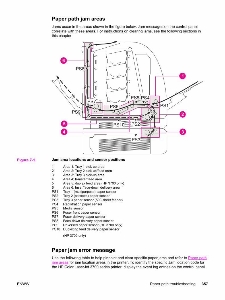
Paper path jam areasJams occur in the areas shown in the figure below. Jam messages on the control panelcorrelate with these areas. For instructions on clearing jams, see the following sections inthis chapter.
Figure 7-1. Jam area locations and sensor positions
1 Area 1: Tray 1 pick-up area2 Area 2: Tray 2 pick-up/feed area3 Area 3: Tray 3 pick-up area4 Area 4: transfer/feed area5 Area 5: duplex feed area (HP 3700 only)6 Area 6: fuser/face-down delivery areaPS1 Tray 1 (multipurpose) paper sensorPS2 Tray 2 (cassette) paper sensorPS3 Tray 3 paper sensor (500-sheet feeder)PS4 Registration paper sensorPS5 Media sensorPS6 Fuser front paper sensorPS7 Fuser delivery paper sensorPS8 Face-down delivery paper sensorPS9 Reversed paper sensor (HP 3700 only)PS10 Duplexing feed delivery paper sensor
(HP 3700 only)
Paper jam error message Use the following table to help pinpoint and clear specific paper jams and refer to Paper pathjam areas for jam location areas in the printer. To identify the specific Jam location code forthe HP Color LaserJet 3700 series printer, display the event log entries on the control panel.
ENWW Paper path troubleshooting 357

Table 7-4. Error messages and associated jam locations
Error message Event logcode
Action Location/Action
Go to jamLocationareas:
13.01.00 (HP 3500/3550)
13.20.00 (HP 3700)
Pick-up delay jam
13.01.00 This printer checks the papermovement at all pickup sourcestwice, if necessary, since thepaper pickup can be delayed dueto a pickup error. When paperdoes not reach the registrationpaper sensor (PS4) within time Tafter paper pickup, the CPUjudges it the pickup delay jam.
If this error occurs and no jamexists, verify that the two pick-upassembly connectors aresecurely seated. To locate theseconnectors, open the front doorand remove the connector cover(part number RC!-1488-000CN)on the lower front right side.
1 - Tray 1 pick-up area
2 - Tray 2 pick-up/feed area
3 - Tray 3 pick-up area
13.02.00 (HP 3500/3550)
13.20.00 (HP 3700)
Pick-up stationary jam
13.02.00 When the paper does not passthe registration paper sensor(PS4) within time T after a paperis fed from the registration roller,the CPU judges it a pickupstationary jam.
After considerable use (150Mpages or more), this jam may bethe result of torn mylar tabs onthe pick-up assembly. If they aretorn, replace the assembly (partnumber RM1-456-000CN).
1 - Tray 1 pick-up area
2 - Tray 2 pick-up/feed area
3 - Tray 3 pick-up area
13.05.00 (HP 3500/3550)
13.20.00 (HP 3700)
Fuser delay jam
13.05.00 When the paper does not reachthe fuser delivery paper sensor(PS7) within time T after a paperis fed from the registration roller,the CPU judges it a fuser delayjam.
4 - transfer/feed area
6 - fuser/face-down deliveryarea
13.06.00 (HP 3500/3550)
13.20.00 (HP 3700)
Fuser stationary jam
13.06.00 When the paper does not passthe fuser delivery paper sensor(PS7) within time T after paperhas reached the fuser deliverypaper sensor (PS7), the CPUjudges it a fuser stationary jam.
6 - fuser/face-down deliveryarea
13.09.00 (HP 3500/3550)
13.20.00 (HP 3700)
Delivery delay jam
13.09.00 When the paper does not reachthe face-down paper sensor(PS8) within time T after paperhas reached the fuser deliverypaper sensor (PS7), the CPUjudges it a delivery stationary jam.
6 - fuser/face-down deliverarea
358 Chapter 7 Troubleshooting ENWW

Error message Event logcode
Action Location/Action
Go to jamLocationareas:
13.0A.00 (HP 3500/3550)
13.20.00 (HP 3700)
Delivery stationary jam
13.0A.00 When the paper does not passthe face down paper sensor(PS8) within time T after paperhas reached the fuser deliverypaper sensor (PS7), the CPUjudges it a delivery stationary jam.
6 - fuser/face-down deliveryarea
13.20.00 (HP 3700 only)
Duplexing feed delay jam
13.10.00 When the paper does not reachthe reversed paper sensor (PS9)within time T after the deliverymotor has started rotatingcounterclockwise, the CPUjudges it a Duplexing feed delayjam.
5 - duplex feedarea
13.20.00 (HP 3700 only)
Duplexing feed stationaryjam
13.11.00 When the paper does not passthrough the sensor within time Tsince a paper has reached thereversed paper sensor (PS9),the CPU judges it a duplexingfeed stationary jam.
5- duplex feedarea
6- fuser/face-down deliveryarea
13.20.00 (HP 3700 only)
Duplexing pick-up delayjam
13.12.00 When the paper does not reachthe duplexing feed paper sensor(PS10) within time T after paperhas reached the reversed papersensor.
5- duplex feedarea
13.20.00 (HP 3700 only)
Duplexing pick-upstationary jam
13.13.00 When the paper does not passthe sensor through within time Tsince a paper has reached theduplexing feed paper sensor(PS10), the CPU judges it theduplexing pickup stationary jam.
5- duplex feedarea
13.20.00 (HP 3500/3550only)
Printer could notautomatically eject paper
13.20.00 Check all areas of the printer fora residual paper jam.
4- transfer/feed area
5- duplex feedarea
6 -Fuser/facedowndelivery area
13.21.00 (HP 3500/3550)
13.20.00 (HP 3700)
Open door jam
13.21.00 When the front door is openduring printing, the CPU judges itthe door open jam.
check all jamlocations
13.90.00
Incompatibletransparencies jam
13.90.00 There is a jam inside the frontdoor caused by incompatibletransparencies.
4- transfer/feed area
Table 7-4. Error messages and associated jam locations (continued)
ENWW Paper path troubleshooting 359

Error message Event logcode
Action Location/Action
Go to jamLocationareas:
Note: Residual paper jam n/a If paper is detected by sensorsother than PS6 and PS7, the DCcontroller delivers the paperautomatically.
check all jamlocations
Paper path areas jam troubleshootingPaper jam troubleshooting information is provided in this section for the six paper areasidentified in Figure 7-1. Jam area locations and sensor positions in this chapter.
Multiple pages are fed
Table 7-5. Causes for multiple pages feeding
Cause Solution
Tray 1 (multipurpose tray) separation pad is worn. Replace the separation pad assembly.
Tray 1 (multipurpose tray) separation pad has adefective spring.
Make sure the spring is set in place. If the springis damaged, replace the separation pad assembly.
Tray 2 separation pad is worn. Replace the separation pad assembly.
Tray 2 separation pad has a defective spring. Make sure the spring is set in place. If the springis damaged, replace the separation pad spring.
Area 1: Tray 1 pick-up jam troubleshootingRemoving paper jams located in the Tray 1 (multipurpose) area requires removing all paperfrom the tray including pulling any jammed paper.
Table 7-6. Causes for jams in the Tray 1 pick-up area
Cause Solution
Dirty, worn, or deformed multi-purposetray pickup roller.
If dirty, clean the roller. If worn or deformed, replace theroller.
Defective separation pad. If dirty, clean the pad. If worn or deformed, replace the pad.
Damaged drive gears. Check the drive gears in the pickup/feed area. If damaged,replace the gear.
Defective multi-purpose tray pickupsolenoid.
Disconnect the multi-purpose tray pickup solenoidconnector J1006 from the DC controller PCB. Measure theresistance between the connector J1006-14 (MPSL) andJ1006-13 (+24VA). If it is not approx. 160 ohms, replace themulti-purpose tray pickup solenoid.
Table 7-4. Error messages and associated jam locations (continued)
360 Chapter 7 Troubleshooting ENWW

Cause Solution
Defective feed motor Replace the feed motor.
Defective DC controller PCB. Replace the DC controller PCB.
Area 2: Tray 2 jam troubleshootingRemoving paper jams located in the Tray 2 (cassette) area requires removing the paper traythen removing any paper stuck in the tray input area. Check the area inside the tray openingto ensure that all paper has been removed.
Table 7-7. Causes for jams in the Tray 2 area
Cause Solution
Worn/Deformed cassette pickup roller. If worn or deformed, replace the roller.
Defective separation pad. If dirty, clean the pad. If worn or deformed, replace the pad.
Dirty/Worn/Deformed feed roller. If dirty, clean the roller. If worn or deformed, replace theroller.
Damaged drive gears. Check the drive gears in the pickup/feed block. If damaged,replace the gears.
Defective cassette pickup solenoid. Disconnect the cassette pickup solenoid connector J1016from the DC controller PCB. Measure the resistancebetween the connector J1016-6 (CSTSL) and J1016-5(+24VA). If it is not approx. 160 ohms, replace the cassettepickup solenoid.
Defective feed motor Replace the feed motor.
Defective DC controller PCB. Replace the DC controller PCB.
Area 3: Tray 3 (500-sheet feeder) area jam troubleshootingRemoving paper jams located in the Tray 3 (optional 500-sheet feeder) area requiresremoving the paper tray then removing any paper stuck in the tray input area. Check thearea inside the tray opening to ensure that all paper has been removed.
Table 7-8. Causes for jams in the fuser/face-down delivery area
Cause Solution
Worn or deformed paper feeder pickuproller.
If worn or deformed, replace the paper feeder pickup roller.
Dirty, worn, or deformed feed roller. If dirty, clean the feed roller. If worn or deformed, replacethe roller.
Damaged drive gears. Check the drive gears in the pickup block. If damaged,replace the gears.
Table 7-6. Causes for jams in the Tray 1 pick-up area (continued)
ENWW Paper path troubleshooting 361

Cause Solution
Defective paper feeder pickup solenoid. Disconnect the paper feeder pickup solenoid connectorJ4002 from the paper feeder. PCB. Measure the resistancebetween the connector J4002-1 (SL) and J4002-2 (+24VA).If it is not approx. 160 ohms, replace the paper feederpickup solenoid.
Defective paper feeder pickup clutch. Disconnect the paper feeder pickup clutch connector J4003from the paper feeder PCB. Measure the resistancebetween the connector J4003-1 (CL) and J4003-2 (+24VA).If it is not approx. 160 ohms, replace the paper feederpickup clutch.
Defective paper feeder PCB. Replace the 500-sheet paper feeder PCB.
Defective DC controller PCB. Replace the DC controller PCB.
Area 4: transfer/feed area jam troubleshooting
Table 7-9. Transfer/feed area
Cause Solution
If the jam has occurred around a feedroller indicates a dirty, worn, deformedregistration roller or registration sub roller.
If dirty, clean the rollers. If worn or deformed, replace thepick-up/feed assembly
If around a registration roller, indicatesdefective registration shutter.
If the movement of the registration shutter is not smooth,make it smooth. If its springs are out of positions, reseatthem. Clean the shutter if dirty. Replace the pick-up feedassembly if deformed.
Dirty/Worn/Deformed registration roller orregistration sub roller.
If dirty, clean the rollers. If worn or deformed, replace thepick-up feed assembly.
Defective registration shutter. If the movement of the registration shutter is not smooth,make it smooth. If its springs are out of positions, reseatthem. Clean the shutter if dirty. Replace the pick-up feedassembly if deformed.
Damaged drive gears. Check the drive gears in the pickup block. If damaged,replace the gears.
Defective registration clutch. Disconnect the registration clutch connector J1016 from theDC controller PCB. Measure the resistance between theconnector J1016-8 (REGCL) and J1016-7 (+24VA). If it isnot approx. 160 ohms, replace the registration clutch.
Defective DC controller PCB. Replace the DC controller PCB.
Front door area jams (area 4)
Table 7-8. Causes for jams in the fuser/face-down delivery area (continued)
362 Chapter 7 Troubleshooting ENWW
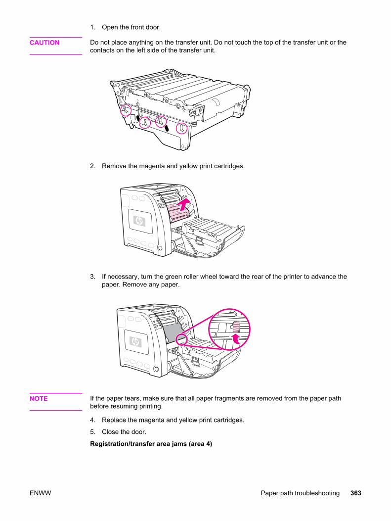
1. Open the front door.
CAUTION Do not place anything on the transfer unit. Do not touch the top of the transfer unit or thecontacts on the left side of the transfer unit.
2. Remove the magenta and yellow print cartridges.
3. If necessary, turn the green roller wheel toward the rear of the printer to advance thepaper. Remove any paper.
NOTE If the paper tears, make sure that all paper fragments are removed from the paper pathbefore resuming printing.
4. Replace the magenta and yellow print cartridges.
5. Close the door.
Registration/transfer area jams (area 4)
ENWW Paper path troubleshooting 363
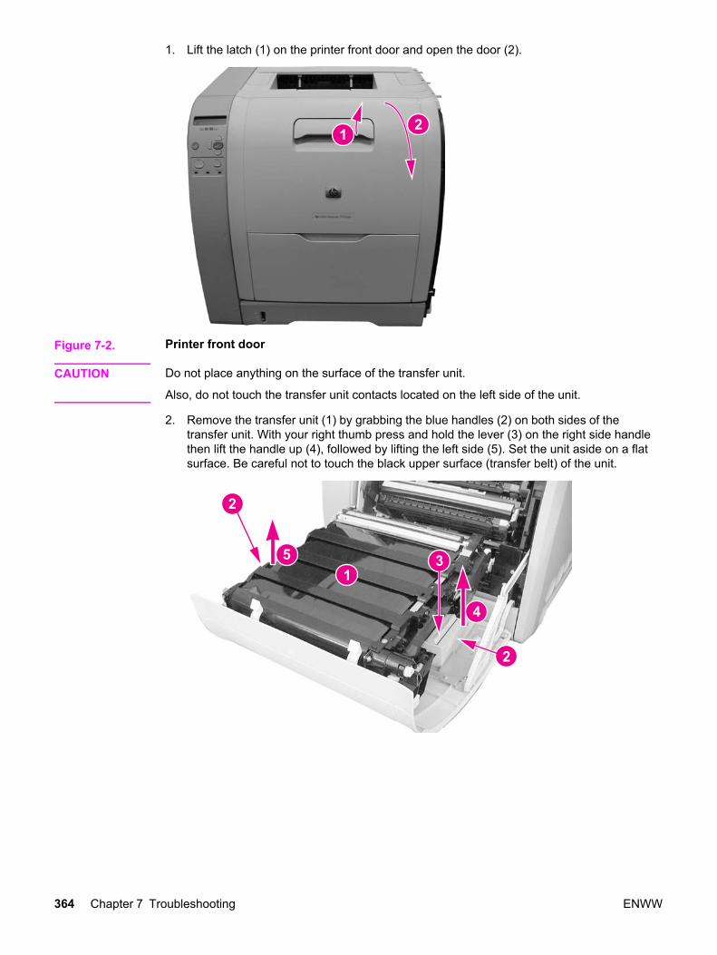
1. Lift the latch (1) on the printer front door and open the door (2).
Figure 7-2. Printer front door
CAUTION Do not place anything on the surface of the transfer unit.
Also, do not touch the transfer unit contacts located on the left side of the unit.
2. Remove the transfer unit (1) by grabbing the blue handles (2) on both sides of thetransfer unit. With your right thumb press and hold the lever (3) on the right side handlethen lift the handle up (4), followed by lifting the left side (5). Set the unit aside on a flatsurface. Be careful not to touch the black upper surface (transfer belt) of the unit.
364 Chapter 7 Troubleshooting ENWW

3. Remove the yellow and magenta cartridges (1) from the printer by grabbing the bluehandle (2) on the cartridge and pulling it upward and out.
4. Close the front door approximately half-way, matching the arrow on the right doorbracket (1) with the arrow on the inside of the printer (2).
5. Remove any visible paper from inside the printer’s transfer area.
ENWW Paper path troubleshooting 365

6. Locate the top flat bar (1) and pull up on the white tab marked with black dots (2) to raisethe bar to a vertical position (3). The bar will remain vertical.
NOTE Do not touch the registration sensor lenses (4).
7. Raise the bottom media sensor bar (1) by pulling on the white tabs marked with theblack dots (2), located on either side of the sensor.
NOTE Do not touch the registration sensor lenses (3) or the media sensor (1).
366 Chapter 7 Troubleshooting ENWW
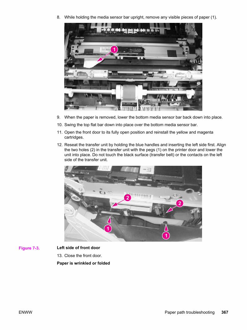
8. While holding the media sensor bar upright, remove any visible pieces of paper (1).
9. When the paper is removed, lower the bottom media sensor bar back down into place.
10. Swing the top flat bar down into place over the bottom media sensor bar.
11. Open the front door to its fully open position and reinstall the yellow and magentacartridges.
12. Reseat the transfer unit by holding the blue handles and inserting the left side first. Alignthe two holes (2) in the transfer unit with the pegs (1) on the printer door and lower theunit into place. Do not touch the black surface (transfer belt) or the contacts on the leftside of the transfer unit.
Figure 7-3. Left side of front door
13. Close the front door.
Paper is wrinkled or folded
ENWW Paper path troubleshooting 367
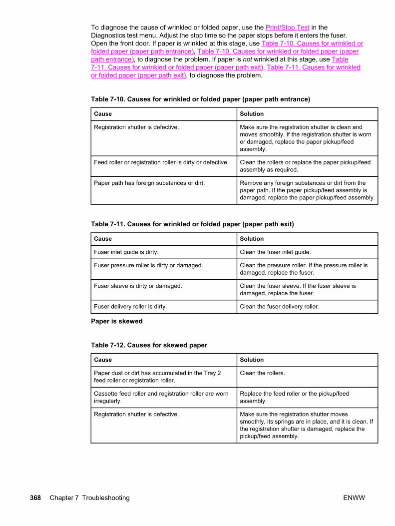
To diagnose the cause of wrinkled or folded paper, use the Print/Stop Test in theDiagnostics test menu. Adjust the stop time so the paper stops before it enters the fuser.Open the front door. If paper is wrinkled at this stage, use Table 7-10. Causes for wrinkled orfolded paper (paper path entrance), Table 7-10. Causes for wrinkled or folded paper (paperpath entrance), to diagnose the problem. If paper is not wrinkled at this stage, use Table7-11. Causes for wrinkled or folded paper (paper path exit), Table 7-11. Causes for wrinkledor folded paper (paper path exit), to diagnose the problem.
Table 7-10. Causes for wrinkled or folded paper (paper path entrance)
Cause Solution
Registration shutter is defective. Make sure the registration shutter is clean andmoves smoothly. If the registration shutter is wornor damaged, replace the paper pickup/feedassembly.
Feed roller or registration roller is dirty or defective. Clean the rollers or replace the paper pickup/feedassembly as required.
Paper path has foreign substances or dirt. Remove any foreign substances or dirt from thepaper path. If the paper pickup/feed assembly isdamaged, replace the paper pickup/feed assembly.
Table 7-11. Causes for wrinkled or folded paper (paper path exit)
Cause Solution
Fuser inlet guide is dirty. Clean the fuser inlet guide.
Fuser pressure roller is dirty or damaged. Clean the pressure roller. If the pressure roller isdamaged, replace the fuser.
Fuser sleeve is dirty or damaged. Clean the fuser sleeve. If the fuser sleeve isdamaged, replace the fuser.
Fuser delivery roller is dirty. Clean the fuser delivery roller.
Paper is skewed
Table 7-12. Causes for skewed paper
Cause Solution
Paper dust or dirt has accumulated in the Tray 2feed roller or registration roller.
Clean the rollers.
Cassette feed roller and registration roller are wornirregularly.
Replace the feed roller or the pickup/feedassembly.
Registration shutter is defective. Make sure the registration shutter movessmoothly, its springs are in place, and it is clean. Ifthe registration shutter is damaged, replace thepickup/feed assembly.
368 Chapter 7 Troubleshooting ENWW

Area 5: Duplex jam troubleshooting
Table 7-13. Causes for jams in the duplex area (HP 3700 (only)
Cause Solution
Scratched/Dented duplex feed guide. If damaged or dented, replace the duplex feed guide.
Worn/Deformed oblique roller. If worn or deformed, replace the oblique roller.
Damaged oblique roller drive gears Check the oblique roller drive gears in the transfer unitblock. Replace the gear if damaged or worn.
Defective duplex feed paper sensor lever. Reseat the duplex feed paper sensor lever if it does notmove smoothly or it is out of position. Replace the lever ifdamaged or deformed.
Defective duplex feed solenoid. Disconnect the duplex feed solenoid connector J1013 fromthe DC controller PCB. Measure the resistance between theconnector J1013-5 (DUSL) and J1013-4 (+24VA). If it is notapproximately 160 ohms, replace the duplex feed solenoid.
Defective DC controller PCB. Replace the DC controller PCB.
Duplex jam area removal (area 5)
NOTE This message appears for HP Color LaserJet 3700dn and 3700dtn printer models only. Theprinter control panel displays the message 13.XX.YY JAM REMOVE TRAY 2.
1. Remove Tray 2.
2. Remove any paper in the top of the tray opening.
ENWW Paper path troubleshooting 369
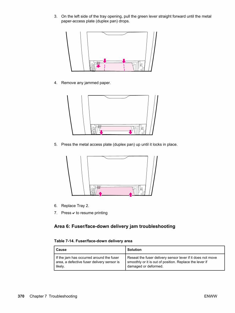
3. On the left side of the tray opening, pull the green lever straight forward until the metalpaper-access plate (duplex pan) drops.
4. Remove any jammed paper.
5. Press the metal access plate (duplex pan) up until it locks in place.
6. Replace Tray 2.
7. Press to resume printing
Area 6: Fuser/face-down delivery jam troubleshooting
Table 7-14. Fuser/face-down delivery area
Cause Solution
If the jam has occurred around the fuserarea, a defective fuser delivery sensor islikely.
Reseat the fuser delivery sensor lever if it does not movesmoothly or it is out of position. Replace the lever ifdamaged or deformed.
370 Chapter 7 Troubleshooting ENWW
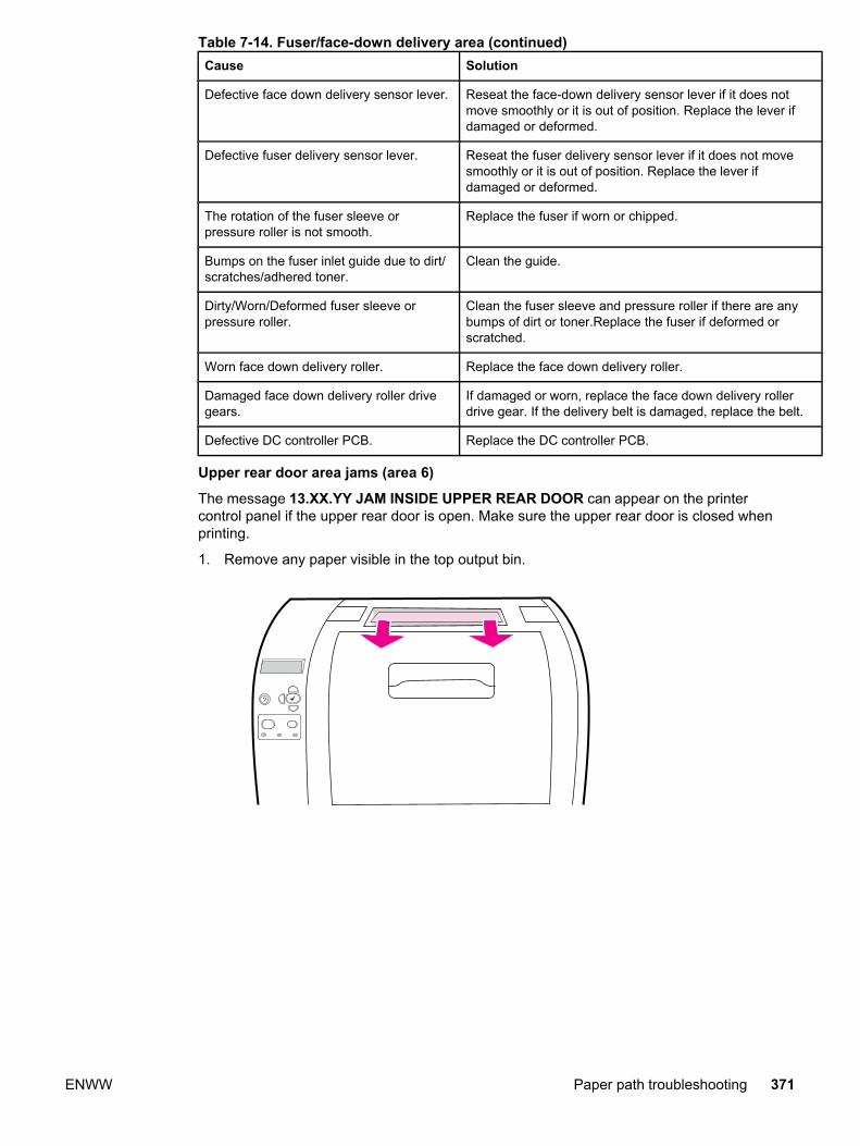
Cause Solution
Defective face down delivery sensor lever. Reseat the face-down delivery sensor lever if it does notmove smoothly or it is out of position. Replace the lever ifdamaged or deformed.
Defective fuser delivery sensor lever. Reseat the fuser delivery sensor lever if it does not movesmoothly or it is out of position. Replace the lever ifdamaged or deformed.
The rotation of the fuser sleeve orpressure roller is not smooth.
Replace the fuser if worn or chipped.
Bumps on the fuser inlet guide due to dirt/scratches/adhered toner.
Clean the guide.
Dirty/Worn/Deformed fuser sleeve orpressure roller.
Clean the fuser sleeve and pressure roller if there are anybumps of dirt or toner.Replace the fuser if deformed orscratched.
Worn face down delivery roller. Replace the face down delivery roller.
Damaged face down delivery roller drivegears.
If damaged or worn, replace the face down delivery rollerdrive gear. If the delivery belt is damaged, replace the belt.
Defective DC controller PCB. Replace the DC controller PCB.
Upper rear door area jams (area 6)
The message 13.XX.YY JAM INSIDE UPPER REAR DOOR can appear on the printercontrol panel if the upper rear door is open. Make sure the upper rear door is closed whenprinting.
1. Remove any paper visible in the top output bin.
?
Table 7-14. Fuser/face-down delivery area (continued)
ENWW Paper path troubleshooting 371

2. Open the upper rear door.
3. Remove any paper.
4. Close the rear door.
5. If no paper is visible, open the lower rear door (rear output bin).
372 Chapter 7 Troubleshooting ENWW

6. Press down on the green levers and remove any paper. Return the green levers to theup position after removing the page.
7. Close the lower rear door.
Fuser area jams (area 6)
1. Open the lower rear door (rear output bin).
NOTE Make sure the green pressure levers are not in the down position. If the green pressurelevers are down, they can cause a jam message to display on the printer control panel.
2. If the paper is visible, press down on the green levers and remove the paper. Return thegreen levers to the up position after removing the paper, and close the lower rear door(rear output bin).
ENWW Paper path troubleshooting 373
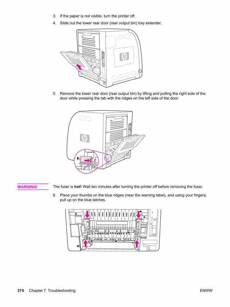
3. If the paper is not visible, turn the printer off.
4. Slide out the lower rear door (rear output bin) tray extender.
5. Remove the lower rear door (rear output bin) by lifting and pulling the right side of thedoor while pressing the tab with the ridges on the left side of the door.
WARNING! The fuser is hot! Wait ten minutes after turning the printer off before removing the fuser.
6. Place your thumbs on the blue ridges (near the warning label), and using your fingers,pull up on the blue latches.
374 Chapter 7 Troubleshooting ENWW
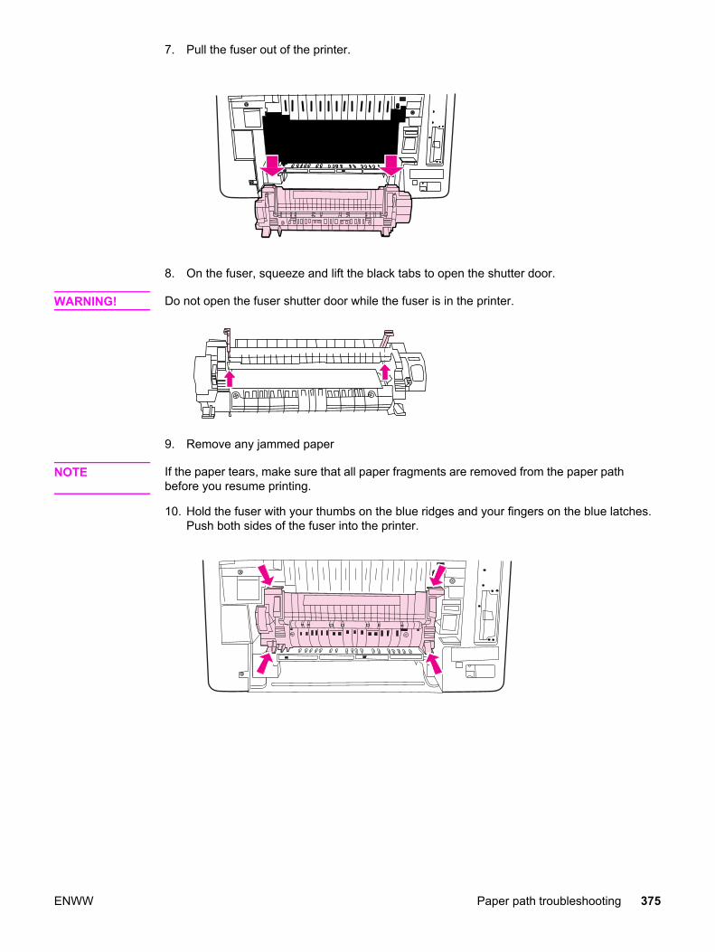
7. Pull the fuser out of the printer.
8. On the fuser, squeeze and lift the black tabs to open the shutter door.
WARNING! Do not open the fuser shutter door while the fuser is in the printer.
9. Remove any jammed paper
NOTE If the paper tears, make sure that all paper fragments are removed from the paper pathbefore you resume printing.
10. Hold the fuser with your thumbs on the blue ridges and your fingers on the blue latches.Push both sides of the fuser into the printer.
ENWW Paper path troubleshooting 375

11. Press the black ridges on the front of the fuser until the fuser clicks into place.
12. To reattach the lower rear door (rear output bin), hold the door at a 45-degree angle,and fit the peg into the round hole on the right side.
13. Press the ridges on the tab on the left side of the door, and fit the peg into the round hole.
14. Close the lower rear door (rear output bin). Turn the printer on.
Lower rear door area jams (area 6)
1. Open the lower rear door (rear output bin).
376 Chapter 7 Troubleshooting ENWW
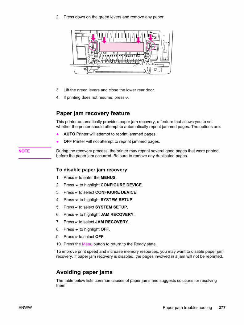
2. Press down on the green levers and remove any paper.
3. Lift the green levers and close the lower rear door.
4. If printing does not resume, press .
Paper jam recovery feature This printer automatically provides paper jam recovery, a feature that allows you to setwhether the printer should attempt to automatically reprint jammed pages. The options are:
● AUTO Printer will attempt to reprint jammed pages.
● OFF Printer will not attempt to reprint jammed pages.
NOTE During the recovery process, the printer may reprint several good pages that were printedbefore the paper jam occurred. Be sure to remove any duplicated pages.
To disable paper jam recovery1. Press to enter the MENUS.
2. Press to highlight CONFIGURE DEVICE.
3. Press to select CONFIGURE DEVICE.
4. Press to highlight SYSTEM SETUP.
5. Press to select SYSTEM SETUP.
6. Press to highlight JAM RECOVERY.
7. Press to select JAM RECOVERY.
8. Press to highlight OFF.
9. Press to select OFF.
10. Press the Menu button to return to the Ready state.
To improve print speed and increase memory resources, you may want to disable paper jamrecovery. If paper jam recovery is disabled, the pages involved in a jam will not be reprinted.
Avoiding paper jamsThe table below lists common causes of paper jams and suggests solutions for resolvingthem.
ENWW Paper path troubleshooting 377
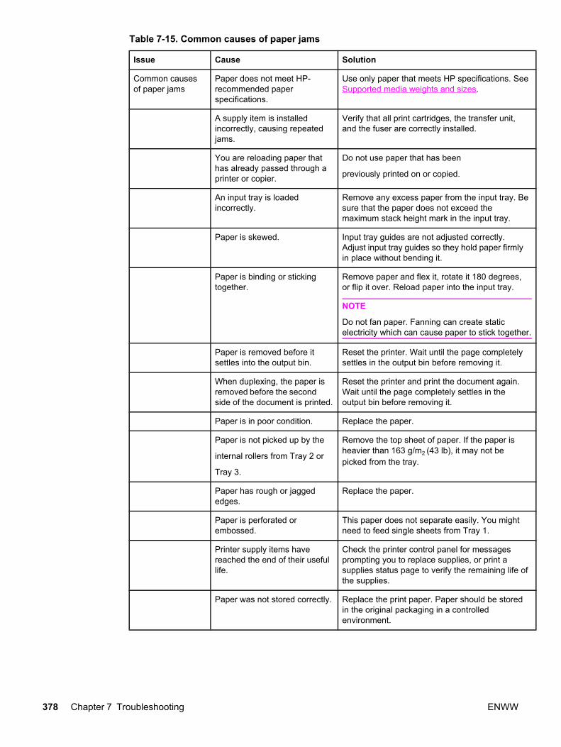
Table 7-15. Common causes of paper jams
Issue Cause Solution
Common causesof paper jams
Paper does not meet HP-recommended paperspecifications.
Use only paper that meets HP specifications. SeeSupported media weights and sizes.
A supply item is installedincorrectly, causing repeatedjams.
Verify that all print cartridges, the transfer unit,and the fuser are correctly installed.
You are reloading paper thathas already passed through aprinter or copier.
Do not use paper that has been
previously printed on or copied.
An input tray is loadedincorrectly.
Remove any excess paper from the input tray. Besure that the paper does not exceed themaximum stack height mark in the input tray.
Paper is skewed. Input tray guides are not adjusted correctly.Adjust input tray guides so they hold paper firmlyin place without bending it.
Paper is binding or stickingtogether.
Remove paper and flex it, rotate it 180 degrees,or flip it over. Reload paper into the input tray.
NOTE
Do not fan paper. Fanning can create staticelectricity which can cause paper to stick together.
Paper is removed before itsettles into the output bin.
Reset the printer. Wait until the page completelysettles in the output bin before removing it.
When duplexing, the paper isremoved before the secondside of the document is printed.
Reset the printer and print the document again.Wait until the page completely settles in theoutput bin before removing it.
Paper is in poor condition. Replace the paper.
Paper is not picked up by the
internal rollers from Tray 2 or
Tray 3.
Remove the top sheet of paper. If the paper isheavier than 163 g/m2 (43 lb), it may not bepicked from the tray.
Paper has rough or jaggededges.
Replace the paper.
Paper is perforated orembossed.
This paper does not separate easily. You mightneed to feed single sheets from Tray 1.
Printer supply items havereached the end of their usefullife.
Check the printer control panel for messagesprompting you to replace supplies, or print asupplies status page to verify the remaining life ofthe supplies.
Paper was not stored correctly. Replace the print paper. Paper should be storedin the original packaging in a controlledenvironment.
378 Chapter 7 Troubleshooting ENWW
General paper path troubleshooting Use the following suggestions to isolate the cause of the problem. Once you have identifiedthe cause, use the tables that follow to find a recommended solution.
NOTE Use the paper path test in the Diagnostics menu to print pages while troubleshooting. SeePaper Path Test section later in this chapter for information about the paper path test.
● View or print the event log and determine if a particular jam error occurs more often thanothers. Try to identify a pattern.
● From the event log, determine the frequency of a particular jam. If a jam occursrepeatedly around the same page count, consider this a single jam that the customertried to clear.
● Try printing from all available input trays to identify whether the problem is isolated toone tray.
● Print the job in both simplex and duplex modes to identify if the problem occurs only inone mode or the other.
● Try printing on paper from an unopened ream that has been stored correctly. If the jamdoes not occur with this media, then the customer’s media might be causing the problem.
● If the jam occurs from when the printer is turned on, check the paper path for small tornpieces of paper. Also check for broken sensors or flags, and check for loose or defectiveconnections.
● If the paper is torn, folded, or wrinkled (typically along the leading edge), inspect thepaper path for items that could be causing the damage.
● If the customer is using non-HP supplies, try replacing those supplies with genuineHP supplies to see if the problem goes away.
● If necessary, instruct the customer on proper media storage, correct loading technique,and printer operation. Make sure the customer knows not to grab paper in the output binduring duplex printing.
Paper path checklist● Verify that media is correctly loaded in the input trays and that all length and width
guides are set correctly.
● Clean the printer. Toner and paper dust in the paper path can inhibit free movement ofmedia through the printer and can block the sensors.
● Use the paper path test in the Diagnostic menu to vary the input selections of the printerto determine if the problem is associated with a particular area of the printer.
● Worn rollers or separation pads can cause multifeeds. Check the condition of the pickuprollers and separation pads.
● Defective paper sensors along the paper path might signal a false jam.
● Scraps of media left in the paper path can cause intermittent jams. Always check thatthe paper path is clear when cleaning the printer and when clearing jams. Also, removethe fuser and carefully check it for jam debris.
ENWW Paper path troubleshooting 379

Persistent jams If jams occur repeatedly, use the information in this section to diagnose the root cause of theproblem. The tables in this section list possible causes and recommended solutions for jamsin each area of the paper path. Items are listed in the order you should investigate. Ingeneral, items at the beginning of the list are relatively minor repairs. Items at the end of thelist are more significant repairs.
Basic troubleshooting for paper jamsThe basic troubleshooting process for paper jams consists of the following:
1. Gather data.
2. Identify the cause of the problem.
3. Fix the problem.
Data collectionTo troubleshoot paper jams, gather the following information:
● the exact paper jam error code displayed on the control panel
● the location of the leading edge of the paper in the paper path
● whether paper is in the paper path when the jam occurs, or if paper is stuck in the inputtray
● whether the jam occurs at power-up or while paper is moving
● whether the paper is damaged, and if it is, where the damage occurs on the paper andwhere in the paper path the paper stops
● whether the jam occurs when feeding from one particular tray
● whether the jam occurs only when duplex printing
● whether a particular type of paper is jamming or not jamming
● whether any of the supplies are non-HP (non-HP supplies are known to cause paperjams)
● whether the customer is storing the paper correctly, overloading the trays, damaging theedge of the paper during loading, or using paper that has already been fed through theprinter
380 Chapter 7 Troubleshooting ENWW
Image formation troubleshooting
The section identifies some things that can result in poor print quality. For additionalinformation, refer to the HP LaserJet Printer Family Print Media Guide.
Print quality problems associated with mediaSome print quality problems arise from use of inappropriate paper.
● Use paper that meets HP paper specifications. See Supported media weights and sizes.
● The surface of the paper is too smooth. Use paper that meets HP paper specifications.See Supported media weights and sizes.
● The driver setting is incorrect. To change the paper type setting, see Type and Size.
● The paper you are using is too heavy for the paper type setting you selected, and thetoner is not fusing to the paper.
● The moisture content of the paper is uneven, too high, or too low. Use paper from adifferent source, from an unopened ream of paper, or dry out the paper (100˚ C for 24hours).
● Some areas of the paper reject toner. Use paper from a different source or from anunopened ream of paper.
● The letterhead you are using is printed on rough paper. Use a smoother, xerographicpaper. If this solves your problem, consult with the supplier of your letterhead to verifythat the paper used meets the specifications for this printer. See Supported mediaweights and sizes, in chapter 1.
● The paper is excessively rough. Use a smoother, xerographic paper.
Overhead transparency defectOverhead transparencies can display any of the image quality problems that any other typeof paper will cause, as well as defects specific to printing on transparencies. In addition,because transparencies are pliable while in the print path, they are subject to being markedby the paper-handling components.
NOTE Allow transparencies to cool for at least 30 seconds before handling them.
● Change the pre-rotation setting in the CONFIGURE DEVICE/PRINT QUALITY/OPTIMIZE/PRE-ROTATION=ON. This will enhance transparency print quality byreducing what looks like “fire marks” by heating up the fuser pressure roller closer to thetemperature of the sleeve.
● Change the transparency mode in the CONFIGURE DEVICE/PRINT QUALITY/PRINTMODES/TRANSPARENCY to B TRNSPRNCY (Best Transparency) mode. This changewill optimize transparency print quality and minimize transparency curl.
ENWW Image formation troubleshooting 381
NOTE If the printer’s media sensor rejects a supported Color LaserJet transparency, make sure thetransparencies are not from an old box. Try transparencies from a new box.
● In the printer driver Paper tab, select Transparency as the paper type. Also, make surethat the tray is correctly configured for transparencies.
● Check that the transparencies meet the specifications for this printer. See Supportedmedia weights and sizes, in chapter 1. For more information on media specifications andordering information, consult the HP LaserJet Printer Family Print Media SpecificationGuide. For the HP Color LaserJet 3500/3550 series printer, go to http://www.hp.com/support/clj3550. For the HP Color LaserJet 3700 series printer, go to http://www.hp.com/support/clj3700. For downloadable manuals, select Manuals.
● The transparencies you are using are not designed for proper toner adhesion. Use onlytransparencies designed for HP Color LaserJet printers.
● Handle transparencies by the edges. Oil from fingers can cause spots and smudges onthe transparencies.
● Small, random, dark areas on the trailing edge of solid fill pages may be caused bytransparencies sticking together in the output bin. Try printing the job in smaller batches.
● The selected colors are undesirable when printed. Select different colors in the softwareapplication or printer driver.
● If you are using a reflective overhead projector, use a standard overhead projectorinstead.
Print quality problems associated with the environmentIf the printer is operating in excessively humid or dry conditions, verify that the printingenvironment is within specifications. See the getting started guide for this printer forinformation on operating environment specifications.
Print quality problems associated with paper jamsMake sure that all paper is cleared from the paper path.
● If the printer recently jammed, print two to three pages to clean the printer.
● If the paper does not pass through the fuser, which causes image defects to appear onsubsequent documents, print two to three pages to clean the printer. However, if theproblem persists, see Print quality troubleshooting pages.
Print quality problems associated with toner buildupOver time, toner and other particles can build up inside the printer. This buildup can causethe following print quality problems:
● marks at even intervals on the printed side of the page
● toner that smears easily
● toner specs on the page
● vertical streaks or bands on the page
To correct these types of problems, clean the printer. See Cleaning the printer andaccessories, in chapter 4.
382 Chapter 7 Troubleshooting ENWW

Print quality troubleshooting pagesUse the built-in print quality troubleshooting pages to help diagnose and solve print qualityproblems.
1. Press MENU to enter the MENUS.
2. Press to highlight DIAGNOSTICS.
3. Press to select DIAGNOSTICS.
4. Press to highlight PQ TROUBLESHOOTING.
5. Press to print the pages.
The printer returns to the Ready state after printing the print quality troubleshooting pages. Ifthe print quality defects are found when you review the print quality troubleshooting pages,perform a printer calibration. See Calibrating the printer.
Calibrating the printer Calibration is a printer function that optimizes print quality. If you experience any print qualityproblems, calibrate the printer.
1. Press MENU to enter the MENUS.
2. Press to highlight CONFIGURE DEVICE.
3. Press to select CONFIGURE DEVICE.
4. Press to highlight PRINT QUALITY.
5. Press to select PRINT QUALITY.
6. Press to highlight CALIBRATE NOW.
7. Press to select CALIBRATE NOW.
ENWW Image formation troubleshooting 383

Using Color
The HP Color LaserJet 3500/3550 series printer and the HP Color LaserJet 3700 seriesprinter offer great color printing as soon as you set up the printer. They provide acombination of automatic color features to generate excellent color results for the generaloffice user. Also, the HP Color LaserJet 3700 series printer provides sophisticated tools forthe professional who is experienced with using color.
The HP Color LaserJet 3500/3550 series printer and HP Color LaserJet 3700 series printerprovide carefully designed and tested color tables to provide smooth, accurate colorrendition of all printable colors.
HP ImageREt 2400HP ImageREt 2400 is a technology that provides the best color print quality without havingto change printer driver settings or make trade-offs between print quality, performance, andmemory.
HP ImageREt 2400 has been improved for this printer. The improvements offer trappingtechnologies, even greater control over dot placement, and more precise control of tonerquality in a dot. These new technologies, coupled with HP's multilevel printing process,result in a 600-by-600 dpi printer that provides 2400 dpi color laser-class quality with millionsof smooth colors.
Paper selectionFor the best color and image quality it is important to select the appropriate paper type fromthe software printer menu or from the printer control panel. See Selecting paper, in chapter 1.
Color options (available for the HP Color LaserJet 3700series printer)Color options automatically enable optimal color output for diverse types of documents.
Color options use object tagging, which allows optimal color and halftone settings to be usedfor different objects (text, graphics, and photos) on a page. The printer driver determineswhich objects are used on a page and uses halftone and color settings that provide the bestprint quality for each object. Object tagging, combined with optimized default settings,produces great color out of the box.
In the Windows environment, the Automatic and Manual color options are on the Color tab inthe printer driver.
Standard red-green-blue (sRGB)Standard red-green-blue (sRGB) is a world-wide color standard originally developed byHP and Microsoft as a common color language for monitors, input devices (scanners anddigital cameras), and output devices (printers and plotters). It is the default color space usedfor HP products, Microsoft operating systems, the World Wide Web, and most officesoftware sold today. The sRGB standard is representative of the typical Windows PCmonitor today and the convergence standard for high-definition television.
384 Chapter 7 Troubleshooting ENWW

NOTE Factors such as the type of monitor you use and the room’s lighting can affect theappearance of colors on your screen. For more information, see Managing color.
The latest versions of Adobe PhotoShop®, CorelDRAW, Microsoft Office, and many otherapplications use sRGB to communicate color. Most importantly, as the default color space inMicrosoft operating systems, sRGB has gained broad adoption as a means to exchangecolor information between applications and devices using a common definition that ensurestypical users will experience greatly improved color matching. The sRGB standard improvesyour ability to match colors between the printer, the PC monitor, and other input devices(scanners and digital cameras) automatically, without the need to become a color expert.
Printing in four-colors [CMYK (available for the HP ColorLaserJet 3700 series printer) Cyan, magenta, yellow, and black (CMYK) are the inks used by a printing press. Theprocess is often called four-color printing. CMYK data files are typically used by andoriginate from graphic arts (printing and publishing) environments. The printer will acceptCMYK colors through the PS printer driver. The printer color-rendering of CMYK is designedto provide rich, saturated colors for text and graphics.
CMYK ink set emulation (PostScript only)The printer’s color rendering of CMYK can be made to emulate several standard OffsetPress ink sets.
● Default. This selection is good for general purpose rendering of CMYK data. It isdesigned to render photographs well, while at the same time providing rich saturatedcolors for text and graphics.
● Specifications for Web Offset Publications (SWOP). Common ink standard in theU.S. and other locations.
● Euroscale. Common ink standard in Europe and other locations.
● Dainippon Ink and Chemical (DIC). Common ink standard in Japan and other locations.
● Device. Emulation is turned off. To render photographs properly with this selection,images require color management in the application or operating system.
Use the SWOP or EURO emulation of CMYK inks to achieve the best match of PANTONE®
four-color (4C) process colors from PANTONE® certified applications, depending on theswatch book used.
ENWW Using Color 385

Managing color
Setting color options to Automatic will typically produce the best possible print quality forcolor documents. However, there may be cases when you want to print a color document ingrayscale (black and white) or wish to change one of the printer's color options.
Using Windows, print in grayscale or change the color options using settings found on theColor tab in the printer driver.
Using a Macintosh computer, print in grayscale or change the color options using the ColorMatching pop-up menu in the Print dialog box.
Print in GrayscaleSelecting the Print in Grayscale option from the printer driver prints a document in black andwhite. This option is useful for printing color documents that will be photocopied or faxed.When Print in Grayscale is selected, the printer goes into monochrome mode (regardless ofwhat the COLOR/BLACK MIX setting is). This mode will reduce wear on the color cartridges.
Automatic or manual color adjustmentThe Automatic color adjustment option optimizes the neutral gray color treatment, halftones,and edge enhancements used for each element in a document. For more information, seeyour printer driver online Help.
NOTE Automatic is the default setting and is recommended for printing all color documents.
The Manual color adjustment option allows you to adjust the neutral gray color treatment,halftones, and edge enhancements for text, graphics, and photographs. To access theManual color options, from the Color tab, select Manual, and then Settings.
Manual color optionsManual color adjustment allows you to adjust the Color (or Color Map) and Halftoningoptions individually for text, graphics, and photographs.
NOTE Some applications convert text or graphics to raster images. In these cases, thePhotographs settings will also control text and graphics.
Halftone options affect the resolution and clarity of your color output. You can selecthalftone settings for text, graphics, and photographs independently. The two halftone optionsare Smooth and Detail.
For the HP Color LaserJet 3700 series printer, the following options are available for theHalftone setting:
● The Smooth option provides better results for large, solid-filled print areas. It alsoenhances photographs by smoothing out fine color gradations. Choose this option whenuniform and smooth area fills are top priority.
● The Detail option is useful for text and graphics that require sharp distinctions amonglines or colors, or images that contain a pattern or a high level of detail. Choose thisoption when sharp edges and details are top priority.
386 Chapter 7 Troubleshooting ENWW

The Neutral Grays setting determines the method used for creating gray colors used in text,graphics, and photographs.
For the HP Color LaserJet 3700 series printer, the following options are available for theNeutral Grays setting:
● Black Only generates neutral colors (grays and black) using only black toner. Thisguarantees neutral colors without a color cast.
● 4-Color generates neutral colors (grays and black) by combining all four toner colors.This method produces smoother gradients and transitions to non-neutral colors, and itproduces the darkest black.
The Edge Control (for the HP Color LaserJet 3500/3550 series printer) setting determineshow edges are rendered. Edge control has two components: adaptive halftoning andtrapping. Adaptive halftoning increases edge sharpness. Trapping reduces the effect of colorplane misregistration by overlapping the edges of adjacent objects slightly.
NOTE Selecting this setting may significantly slow down the HP Color LaserJet 3500/3550 seriesprinter’s speed.
For the HP Color LaserJet 3700 series printer, the following levels of edge control areavailable:
● Maximum is the most aggressive trapping setting. Adaptive halftoning is on for thissetting.
● Normal is the default trapping setting. Trapping is at a medium level and adaptivehalftoning is on.
● Light sets trapping at a minimal level, and adaptive halftoning is on.
● Off turns off both trapping and adaptive halftoning.
For the HP Color LaserJet 3500/3550 series printer, the following levels are available:
● Maximum is the most aggressive trapping setting.
● Normal sets the trapping at a medium level.
● Light sets trapping at a minimal level.
● Off is the default trapping setting. Trapping is turned off.
For the HP Color LaserJet 3700 series printer, the following values are available for the RGBColor settings:
● Default instructs the printer to interpret RGB color as sRGB. The sRGB standard is theaccepted standard of Microsoft and the World Wide Web Consortium (http://www.w3.org).
● Vivid instructs the printer to increase the color saturation in the midtones. Less colorfulobjects are rendered more colorfully. This value is recommended for printing businessgraphics.
● Device instructs the printer to print RGB data in raw device mode. To renderphotographs properly with this selection, you must manage image color in theapplication or operating system.
ENWW Managing color 387
Matching colors
The process of matching printer output color to your computer screen is quite complexbecause printers and computer monitors use different methods of producing color. Monitorsdisplay colors by light pixels using an RGB (red, green, blue) color process, but printersprintcolors using a CMYK (cyan, magenta, yellow, and black) process.
Several factors can influence your ability to match printed colors to those on your monitor.These factors include:
● print media
● printer colorants (inks or toners for example)
● printing process (inkjet, press, or laser technology for example)
● overhead lighting
● personal differences in perception of color
● software applications
● printer drivers
● PC operating system
● monitors
● video cards and drivers
● operating environment (humidity for example)
Keep the above factors in mind when colors on your screen do not perfectly match yourprinted colors.
For most users, the best method for matching colors on your screen to your printer is to printsRGB colors.
Swatch book color matching (HP Color LaserJet 3700 seriesprinter only)The process for matching printer output to preprinted swatch books and standard colorreferences is complex. In general, you can obtain a reasonably good match to a swatchbook if the inks used to create the swatch book are cyan, magenta, yellow, and black. Theseare usually referred to as process color swatch books.
Some swatch books are created from spot colors. Spot colors are specially createdcolorants. Many of these spot colors are outside of the gamut (color range) of the printer.Most spot color swatch books have companion process swatch books that provide CMYKapproximations to the spot color.
Most process swatch books will have a note on what process standards were used to printthe swatch book. In most cases, they will be SWOP, EURO, or DIC. To get optimal colormatching to the process swatch book, select the corresponding ink emulation from theprinter menu. If you cannot identify the process standard, use SWOP ink emulation.
For best matching of PANTONE® four-color (4C) process colors, use the SWOP or EUROemulation for CMYK inks in the HP Color LaserJet 3700 PostScript emulation driver whenprinting from PANTONE®-certified applications.
388 Chapter 7 Troubleshooting ENWW

Adjusting color balanceThis printer features automatic color calibration to provide high-quality color output. Insituations that require critical color control, you can manually adjust the density balance ofthe printer’s four toner colors. The available range for each color is from -5 to +5. The defaultvalue is 0.
CAUTION This procedure should only be performed by your network administrator. Performing thisprocedure changes the color balance of the printer by altering halftones and affects all printjobs.
To adjust color density1. Press to enter the MENUS.
2. Press to highlight CONFIGURE DEVICE MENU.
3. Press to select CONFIGURE DEVICE MENU.
4. Press to highlight PRINT QUALITY.
5. Press to select PRINT QUALITY.
6. Press or to highlight ADJUST COLOR.
7. Press or to highlight the desired color.
8. Press or to highlight the correct density setting.
9. Press to select the density setting.
10. Press to set the density for the next color.
11. After setting the density for each color, press Menu.
ENWW Matching colors 389

Image defects
If specific defects occur repeatedly, print a Print Quality Troubleshooting page (see Printquality troubleshooting pages, in this chapter) and follow the instructions on the first page. Ifyou are unable to resolve the problem, use the information in this section to identify the rootcause of the problem.
Image defects fall into the categories listed in Table 7-16. Image defects. Possible causesand recommended solutions for each of these categories are listed in the tables that follow.In general, the items are listed in order from minor repairs to major repairs. Check the itemsin the order in which they appear.
Table 7-16. Image defects
Image defect Description More information
Light image Image light in all colors. See Table 7-17. Causes forlight images
Light color Image light in a particular color. See Table 7-18. Causes forone color printing light
Dark image Image dark in all colors. See Table 7-19. Causes fordark images
Dark color Image dark in a particular color. See Table 7-20. Causes forone color printing dark
Completely blank No image is printed. See Table 7-21. Causes fora completely blank image
All black/solid color Image is all black or solid color. See Table 7-22. Causes foran all black or solid coloredimage
Dots in vertical lines White dots appear in image. See Table 7-23. Causes forvertical lines of white dots
Dirt on back of paper Dirt on the back of the page. See Table 7-24. Causes fordirt on the back of the paper
Dirt on front of paper Dirt on the front of the page. See Table 7-25. Causes fordirt on the front of the paper
Vertical lines Vertical line appears in image. See Table 7-26. Causes forvertical lines
White vertical lines White vertical line appears in image. See Table 7-27. Causes forwhite vertical lines
Horizontal lines Horizontal line appears in image. See Table 7-28. Causes forhorizontal line
White horizontal lines White horizontal line appears in image. See Table 7-29. Causes forwhite horizonal lines
Missing color Image in a particular color does not comeout in color
See Table 7-30. Causes fora missing color
390 Chapter 7 Troubleshooting ENWW

Image defect Description More information
Blank spots Blank spots appear in image. See Table 7-31. Causes forblank spots
Poor fusing Toner image is not fully fixed on paper. See Table 7-32. Causes forpoor fusing
Distorted Image Image is distorted. See Table 7-32. Causes forpoor fusing
Color misregistration Some color is misregistered. See Table 7-34. Causes forsmearing
Smearing Image smeared in whole or in part. See Table 7-35. Causes forsmearing
Misplaced image Whole image is incorrectly placed. See Table 7-36. Causes fora misplaced image
Reversed color White in image is output in color, andcolor is output in white.
See Table 7-37. Causes forreversed color
Snail tracks Streaks in the page that look like snailtracks. Eventually, the paper may wrinkle.
See Table 7-38. Causes forreversed color
Light image
Table 7-17. Causes for light images
Cause Solution
Image density is not adjusted correctly. Calibrate the printer. See Calibrate Now, later inthis chapter.
The image density is not properly adjusted. Calibrate the printer. See Calibrate Now, later inthis chapter.
Deteriorated transfer unit. If the transfer unit is at the end of its life or itssurface is deteriorated, replace the transfer unit.
Poor secondary transfer bias contacts. On the secondary transfer roller, check the biascontacts to the high-voltage PCB. Clean contacts,if dirty. Replace defective parts with deformed/damaged contacts.
Deformed/Deteriorated secondary transfer chargingroller.
Replace the secondary transfer charging roller.
Defective high-voltage PCB. Replace the high-voltage PCB.
Defective DC controller PCB. Replace the DC controller PCB.
Table 7-16. Image defects (continued)
ENWW Image defects 391

Light colorPrint out a solid filled image of the problem (light) color using an external device. In thecourse of printing, turn the printer off and take the problem color’s cartridge out. Manuallyopen the cartridge shutter. If the toner image on the photosensitive drum is not fullytransferred to the transfer unit, go to step B in the table below. If the toner image on thedrum before transfer is light, go to step A.
Table 7-18. Causes for one color printing light
Cause Solution
A Poor developing bias contacts. Check the developing biascontacts to the high-voltagePCB. Clean contacts, if dirty.Replace defective parts ifcontacts are deformed ordamaged.
Deteriorated cartridge(photosensitive drum).
Replace the cartridge of theproblem (light) color.
Defective high-voltage PCB. Replace the high-voltagePCB.
Defective DC controller PCB. Replace the DC controllerPCB.
B Poor primary transfer bias contacts. On the transfer unit, checkthe primary transfer biascontacts with the high-voltage PCB. Cleancontacts, if dirty. Replacedefective parts if contactsare deformed or damaged.
Deformed/Deteriorated primarytransfer charging roller.
Replace the transfer unit.
Defective high-voltage PCB. Replace the high-voltagePCB.
Defective laser/scanner unit Replace the laser/scannerunit.
Defective DC controller PCB. Replace the DC controllerPCB.
Dark image
Table 7-19. Causes for dark images
Cause Solution
Image density is not adjusted correctly. Calibrate the printer. See Calibrate Now, later inthis chapter.
392 Chapter 7 Troubleshooting ENWW

Cause Solution
Dirty color misregistration sensor lens. Clean the color misregistration sensor lens.
Defective color misregistration sensor. Replace the color misregistration sensor.
Defective environmental sensor. Replace the environmental sensor.
Defective DC controller PCB. Replace the DC controller PCB.
Dark color
Table 7-20. Causes for one color printing dark
Cause Solution
Poor contacts with the primary charging bias,developing bias, or drum grounding.
On the problem (dark) color’s cartridge, check theprimary charging bias and developing biascontacts to the high-voltage PCB, or the drumgrounding contacts. Clean contacts, if dirty.Replace defective parts if contacts are deformedor damaged.
Defective high-voltage PCB. Replace the high-voltage PCB.
Defective DC controller PCB. Replace the DC controller PCB.
Completely blank image
Table 7-21. Causes for a completely blank image
Cause Solution
High-voltage PCB is defective (no developing biasoutput).
Replace the high-voltage PCB.
DC controller PCB is defective. Replace the DC controller PCB. Calibrate theprinter after replacing the DC controller. SeeCalibrate Now, later in this chapter.
All black or solid color
Table 7-22. Causes for an all black or solid colored image
Cause Solution
Poor contacts with the primary charging bias,developing bias, or drum grounding.
On the problem (solid) color’s cartridge, check theprimary charging bias and developing biascontacts to the high-voltage PCB, or the drumgrounding contacts. Clean contacts if dirty.Replace defective parts if contacts are deformedor damaged.
Table 7-19. Causes for dark images (continued)
ENWW Image defects 393

Cause Solution
Defective cartridge (primary charging roller). Replace the problem (solid) color’s cartridge.
High-voltage PCB is defective. Replace the high-voltage PCB.
DC controller PCB is defective. Replace the DC controller PCB. Calibrate theprinter after replacing the DC controller. SeeCalibrate Now, later in this chapter.
Dots in vertical lines
Table 7-23. Causes for vertical lines of white dots
Cause Solution
Deformed/Deteriorated transfer unit or primarytransfer charging roller.
Replace the transfer unit.
Deformed/Deteriorated secondary transfer chargingroller.
Replace the secondary transfer charging roller.
High-voltage PCB is defective. Replace the high-voltage PCB.
DC controller PCB is defective. Replace the DC controller PCB. Calibrate theprinter after replacing the DC controller. SeeCalibrate Now, later in this chapter.
Dirt on back of paperIf defect is repetitive dirt, go to step A; if not, go to step B.
Table 7-24. Causes for dirt on the back of the paper
Cause Solution
A Repetitive dirt (dirty registration roller, pressureroller, feed roller, fuser delivery roller, or facedown delivery sub roller).
Refer to the Table 7-39. Repetitive defect causetable, later in this chapter, to identify the roller withwhich the problem is associated. Clean the dirtyroller. Replace the roller if the dirt does not comeoff.
B Dirty cassette pickup roller, feed guide, fuserinlet guide, and fuser delivery guide.
Clean any dirty places on the rollers. Replace theroller if the dirt does not come off.
Dirt on front of paperIf the defect appears in a particular color, go to step A. If it does not appear in a particularcolor and it is repetitive, go to step B or if it is not repetitive, go to step C.
Table 7-22. Causes for an all black or solid colored image (continued)
394 Chapter 7 Troubleshooting ENWW
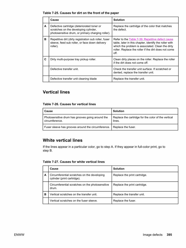
Table 7-25. Causes for dirt on the front of the paper
Cause Solution
A Defective cartridge (deteriorated toner orscratches on the developing cylinder,photosensitive drum, or primary charging roller).
Replace the cartridge of the color that matchesthe defect.
B Repetitive dirt (dirty registration sub roller, fusersleeve, feed sub roller, or face down deliveryroller).
Refer to the Table 7-39. Repetitive defect causetable, later in this chapter, identify the roller withwhich the problem is associated. Clean the dirtyroller. Replace the roller if the dirt does not comeoff.
C Dirty multi-purpose tray pickup roller. Clean dirty places on the roller. Replace the rollerif the dirt does not come off.
Defective transfer unit. Check the transfer unit surface. If scratched ordented, replace the transfer unit.
Defective transfer unit cleaning blade Replace the transfer unit.
Vertical lines
Table 7-26. Causes for vertical lines
Cause Solution
Photosensitive drum has grooves going around thecircumference.
Replace the cartridge for the color of the verticallines.
Fuser sleeve has grooves around the circumference. Replace the fuser.
White vertical linesIf the lines appear in a particular color, go to step A. If they appear in full-color print, go tostep B.
Table 7-27. Causes for white vertical lines
Cause Solution
A Circumferential scratches on the developingcylinder (print cartridge).
Replace the print cartridge.
Circumferential scratches on the photosensitivedrum.
Replace the print cartridge.
B Vertical scratches on the transfer unit. Replace the transfer unit.
Vertical scratches on the fuser sleeve. Replace the fuser.
ENWW Image defects 395
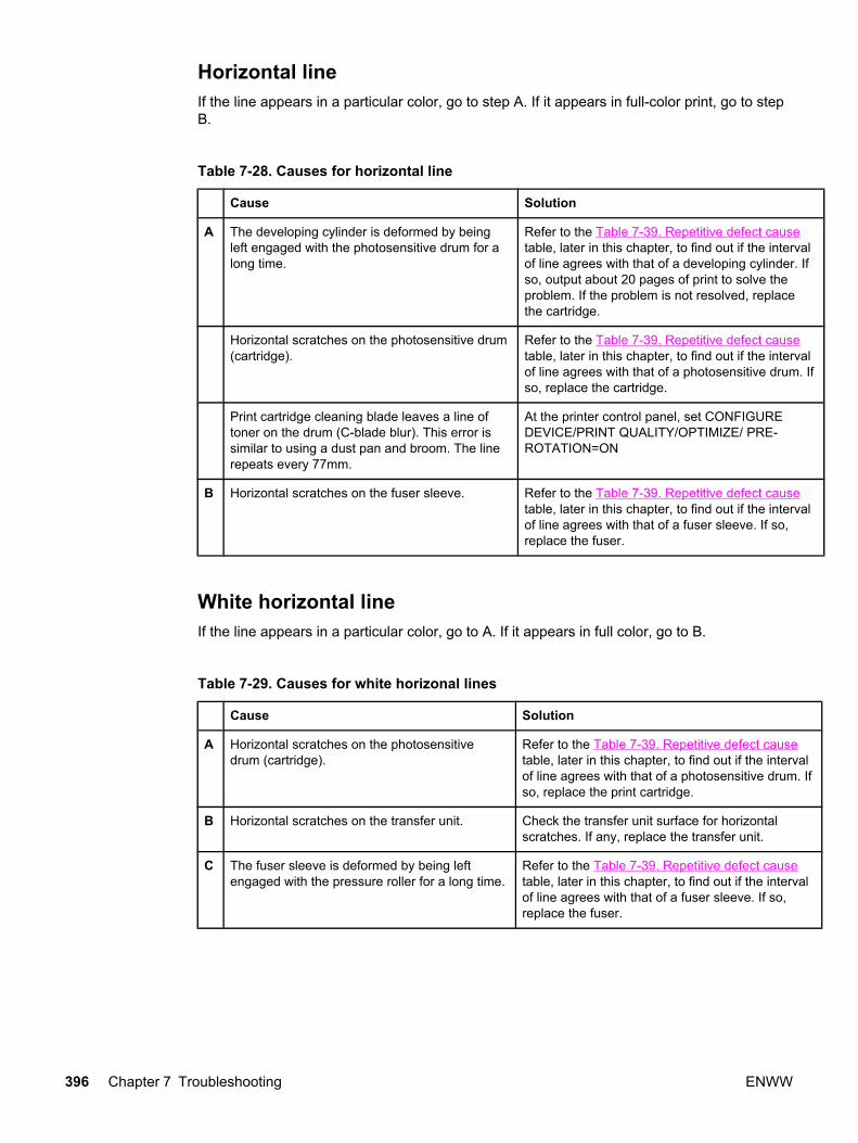
Horizontal lineIf the line appears in a particular color, go to step A. If it appears in full-color print, go to stepB.
Table 7-28. Causes for horizontal line
Cause Solution
A The developing cylinder is deformed by beingleft engaged with the photosensitive drum for along time.
Refer to the Table 7-39. Repetitive defect causetable, later in this chapter, to find out if the intervalof line agrees with that of a developing cylinder. Ifso, output about 20 pages of print to solve theproblem. If the problem is not resolved, replacethe cartridge.
Horizontal scratches on the photosensitive drum(cartridge).
Refer to the Table 7-39. Repetitive defect causetable, later in this chapter, to find out if the intervalof line agrees with that of a photosensitive drum. Ifso, replace the cartridge.
Print cartridge cleaning blade leaves a line oftoner on the drum (C-blade blur). This error issimilar to using a dust pan and broom. The linerepeats every 77mm.
At the printer control panel, set CONFIGUREDEVICE/PRINT QUALITY/OPTIMIZE/ PRE-ROTATION=ON
B Horizontal scratches on the fuser sleeve. Refer to the Table 7-39. Repetitive defect causetable, later in this chapter, to find out if the intervalof line agrees with that of a fuser sleeve. If so,replace the fuser.
White horizontal lineIf the line appears in a particular color, go to A. If it appears in full color, go to B.
Table 7-29. Causes for white horizonal lines
Cause Solution
A Horizontal scratches on the photosensitivedrum (cartridge).
Refer to the Table 7-39. Repetitive defect causetable, later in this chapter, to find out if the intervalof line agrees with that of a photosensitive drum. Ifso, replace the print cartridge.
B Horizontal scratches on the transfer unit. Check the transfer unit surface for horizontalscratches. If any, replace the transfer unit.
C The fuser sleeve is deformed by being leftengaged with the pressure roller for a long time.
Refer to the Table 7-39. Repetitive defect causetable, later in this chapter, to find out if the intervalof line agrees with that of a fuser sleeve. If so,replace the fuser.
396 Chapter 7 Troubleshooting ENWW
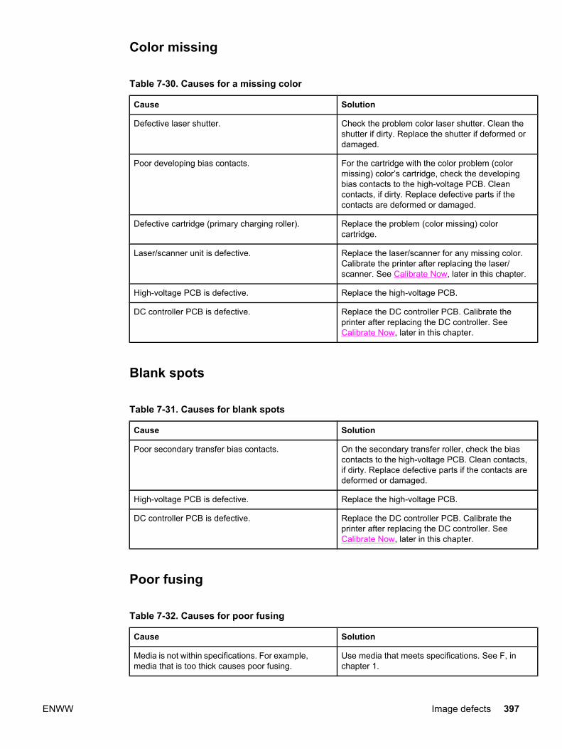
Color missing
Table 7-30. Causes for a missing color
Cause Solution
Defective laser shutter. Check the problem color laser shutter. Clean theshutter if dirty. Replace the shutter if deformed ordamaged.
Poor developing bias contacts. For the cartridge with the color problem (colormissing) color’s cartridge, check the developingbias contacts to the high-voltage PCB. Cleancontacts, if dirty. Replace defective parts if thecontacts are deformed or damaged.
Defective cartridge (primary charging roller). Replace the problem (color missing) colorcartridge.
Laser/scanner unit is defective. Replace the laser/scanner for any missing color.Calibrate the printer after replacing the laser/scanner. See Calibrate Now, later in this chapter.
High-voltage PCB is defective. Replace the high-voltage PCB.
DC controller PCB is defective. Replace the DC controller PCB. Calibrate theprinter after replacing the DC controller. SeeCalibrate Now, later in this chapter.
Blank spots
Table 7-31. Causes for blank spots
Cause Solution
Poor secondary transfer bias contacts. On the secondary transfer roller, check the biascontacts to the high-voltage PCB. Clean contacts,if dirty. Replace defective parts if the contacts aredeformed or damaged.
High-voltage PCB is defective. Replace the high-voltage PCB.
DC controller PCB is defective. Replace the DC controller PCB. Calibrate theprinter after replacing the DC controller. SeeCalibrate Now, later in this chapter.
Poor fusing
Table 7-32. Causes for poor fusing
Cause Solution
Media is not within specifications. For example,media that is too thick causes poor fusing.
Use media that meets specifications. See F, inchapter 1.
ENWW Image defects 397
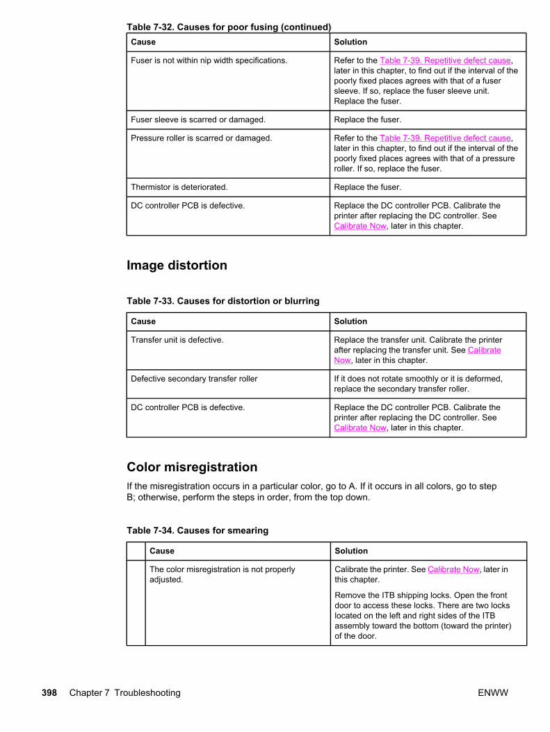
Cause Solution
Fuser is not within nip width specifications. Refer to the Table 7-39. Repetitive defect cause,later in this chapter, to find out if the interval of thepoorly fixed places agrees with that of a fusersleeve. If so, replace the fuser sleeve unit.Replace the fuser.
Fuser sleeve is scarred or damaged. Replace the fuser.
Pressure roller is scarred or damaged. Refer to the Table 7-39. Repetitive defect cause,later in this chapter, to find out if the interval of thepoorly fixed places agrees with that of a pressureroller. If so, replace the fuser.
Thermistor is deteriorated. Replace the fuser.
DC controller PCB is defective. Replace the DC controller PCB. Calibrate theprinter after replacing the DC controller. SeeCalibrate Now, later in this chapter.
Image distortion
Table 7-33. Causes for distortion or blurring
Cause Solution
Transfer unit is defective. Replace the transfer unit. Calibrate the printerafter replacing the transfer unit. See CalibrateNow, later in this chapter.
Defective secondary transfer roller If it does not rotate smoothly or it is deformed,replace the secondary transfer roller.
DC controller PCB is defective. Replace the DC controller PCB. Calibrate theprinter after replacing the DC controller. SeeCalibrate Now, later in this chapter.
Color misregistrationIf the misregistration occurs in a particular color, go to A. If it occurs in all colors, go to stepB; otherwise, perform the steps in order, from the top down.
Table 7-34. Causes for smearing
Cause Solution
The color misregistration is not properlyadjusted.
Calibrate the printer. See Calibrate Now, later inthis chapter.
Remove the ITB shipping locks. Open the frontdoor to access these locks. There are two lockslocated on the left and right sides of the ITBassembly toward the bottom (toward the printer)of the door.
Table 7-32. Causes for poor fusing (continued)
398 Chapter 7 Troubleshooting ENWW

Cause Solution
A Defective cartridge. Check if the photosensitive drum in the problem(misregistered) color’s cartridge rotates smoothly.If not, replace the cartridge.
Worn/Chipped cartridge drive gears. Check drive gears connected into the problem(misregistered) color’s cartridge. If worn orchipped, replace the gear.
B Dirty color misregistration sensor. Clean the lens of the color misregistration sensor.
Defective color misregistration sensor. Replace the color misregistration sensor.
Defective transfer unit. If the transfer unit does not rotate smoothly,replace the transfer unit.
Worn/Chipped drive gears. Check drive gears between the image drive unitand the drum motor. If worn or chipped, replacethe gear.
Defective image drive unit. Replace the image drive unit.
Defective laser/scanner unit. Replace the laser/scanner unit.
Defective DC controller PCB. Replace the DC controller PCB.
Smearing
Table 7-35. Causes for smearing
Cause Solution
Poor contacts to each cartridge and printergrounding.
Clean the grounding contacts on each cartridgeand the printer. If the problem remains aftercleaning, check contacts for deformation ordamage. Replace parts, if deformed or damaged.Make sure all contacts are connected correctly.
The movement of the fuser front paper sensor leveris not smooth.
Reseat the lever to make the movement smooth.
Foreign substances/dirt on the fuser inlet guide. Clean the fuser inlet guide.
Misplaced image
Table 7-36. Causes for a misplaced image
Cause Solution
Paper is skewed. See Table 7-12. Causes for skewed paper toresolve the reason for the skew.
Oblique rollers are worn. (If problem only occurs onthe back side of duplex printing only.)
Replace the oblique rollers.
Table 7-34. Causes for smearing (continued)
ENWW Image defects 399
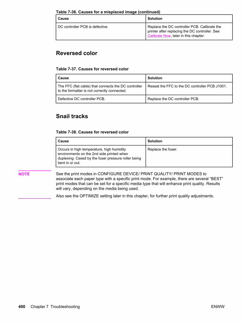
Cause Solution
DC controller PCB is defective. Replace the DC controller PCB. Calibrate theprinter after replacing the DC controller. SeeCalibrate Now, later in this chapter.
Reversed color
Table 7-37. Causes for reversed color
Cause Solution
The FFC (flat cable) that connects the DC controllerto the formatter is not correctly connected.
Reseat the FFC to the DC controller PCB J1001.
Defective DC controller PCB. Replace the DC controller PCB.
Snail tracks
Table 7-38. Causes for reversed color
Cause Solution
Occurs in high temperature, high humidityenvironments on the 2nd side printed whenduplexing. Cased by the fuser pressure roller beingbent in or out.
Replace the fuser.
NOTE See the print modes in CONFIGURE DEVICE/ PRINT QUALITY/ PRINT MODES toassociate each paper type with a specific print mode. For example, there are several “BEST”print modes that can be set for a specific media type that will enhance print quality. Resultswill vary, depending on the media being used.
Also see the OPTIMIZE setting later in this chapter, for further print quality adjustments.
Table 7-36. Causes for a misplaced image (continued)
400 Chapter 7 Troubleshooting ENWW
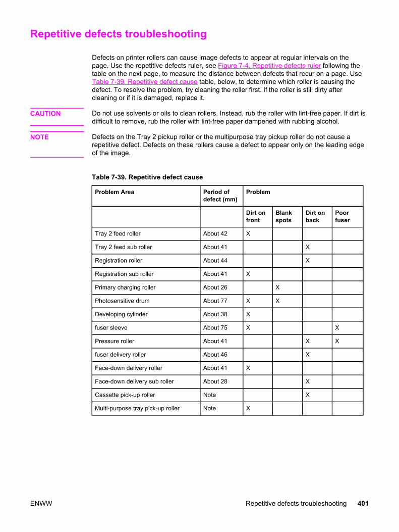
Repetitive defects troubleshooting
Defects on printer rollers can cause image defects to appear at regular intervals on thepage. Use the repetitive defects ruler, see Figure 7-4. Repetitive defects ruler following thetable on the next page, to measure the distance between defects that recur on a page. UseTable 7-39. Repetitive defect cause table, below, to determine which roller is causing thedefect. To resolve the problem, try cleaning the roller first. If the roller is still dirty aftercleaning or if it is damaged, replace it.
CAUTION Do not use solvents or oils to clean rollers. Instead, rub the roller with lint-free paper. If dirt isdifficult to remove, rub the roller with lint-free paper dampened with rubbing alcohol.
NOTE Defects on the Tray 2 pickup roller or the multipurpose tray pickup roller do not cause arepetitive defect. Defects on these rollers cause a defect to appear only on the leading edgeof the image.
Table 7-39. Repetitive defect cause
Problem Area Period ofdefect (mm)
Problem
Dirt onfront
Blankspots
Dirt onback
Poorfuser
Tray 2 feed roller About 42 X
Tray 2 feed sub roller About 41 X
Registration roller About 44 X
Registration sub roller About 41 X
Primary charging roller About 26 X
Photosensitive drum About 77 X X
Developing cylinder About 38 X
fuser sleeve About 75 X X
Pressure roller About 41 X X
fuser delivery roller About 46 X
Face-down delivery roller About 41 X
Face-down delivery sub roller About 28 X
Cassette pick-up roller Note X
Multi-purpose tray pick-up roller Note X
ENWW Repetitive defects troubleshooting 401

NOTE A problem that appears only at the leading edge of image with no repetition.
Figure 7-4. Repetitive defects ruler
NOTE Repetitive defects for the transfer unit normally will appear every other page since thetransfer belt is longer that a page. However, the distance of the repetitive can varydepending on the type of paper fed. It is possible to see a repetitive defect more than onceon the same page.
402 Chapter 7 Troubleshooting ENWW
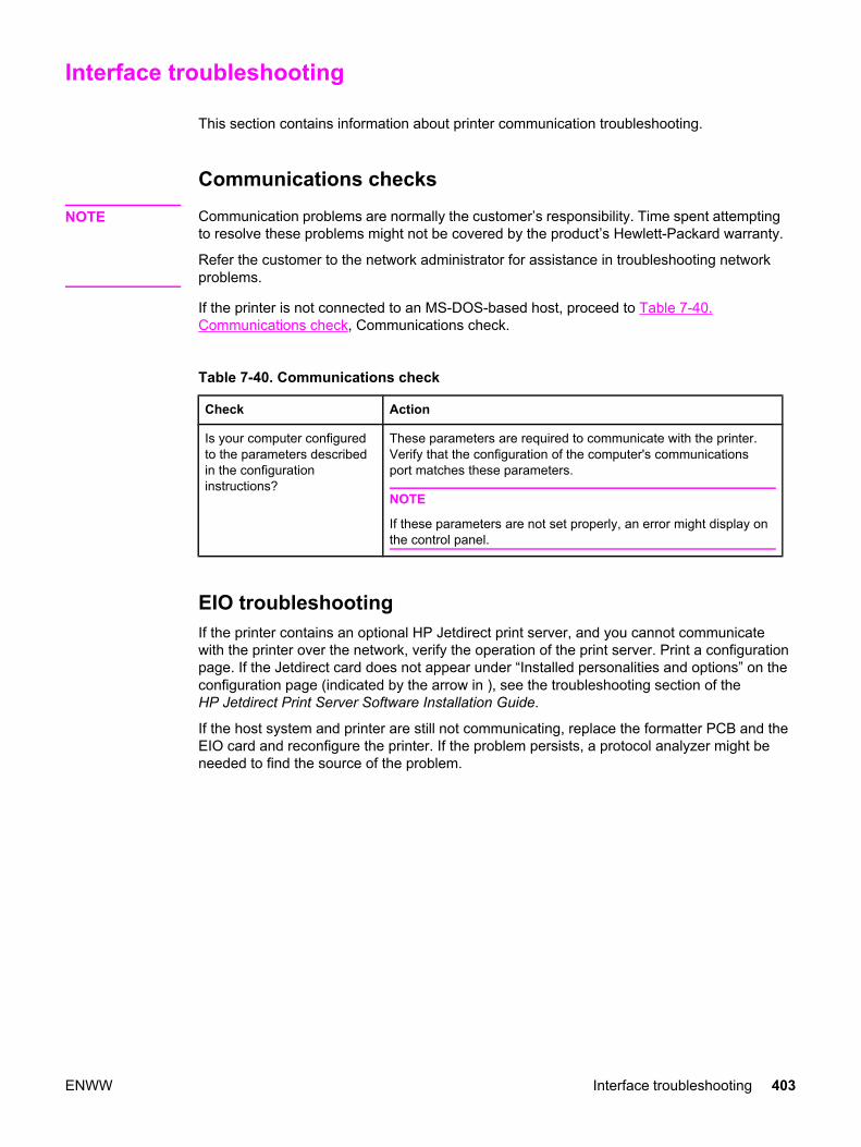
Interface troubleshooting
This section contains information about printer communication troubleshooting.
Communications checks
NOTE Communication problems are normally the customer’s responsibility. Time spent attemptingto resolve these problems might not be covered by the product’s Hewlett-Packard warranty.
Refer the customer to the network administrator for assistance in troubleshooting networkproblems.
If the printer is not connected to an MS-DOS-based host, proceed to Table 7-40.Communications check, Communications check.
Table 7-40. Communications check
Check Action
Is your computer configuredto the parameters describedin the configurationinstructions?
These parameters are required to communicate with the printer.Verify that the configuration of the computer's communicationsport matches these parameters.
NOTE
If these parameters are not set properly, an error might display onthe control panel.
EIO troubleshooting If the printer contains an optional HP Jetdirect print server, and you cannot communicatewith the printer over the network, verify the operation of the print server. Print a configurationpage. If the Jetdirect card does not appear under “Installed personalities and options” on theconfiguration page (indicated by the arrow in ), see the troubleshooting section of theHP Jetdirect Print Server Software Installation Guide.
If the host system and printer are still not communicating, replace the formatter PCB and theEIO card and reconfigure the printer. If the problem persists, a protocol analyzer might beneeded to find the source of the problem.
ENWW Interface troubleshooting 403
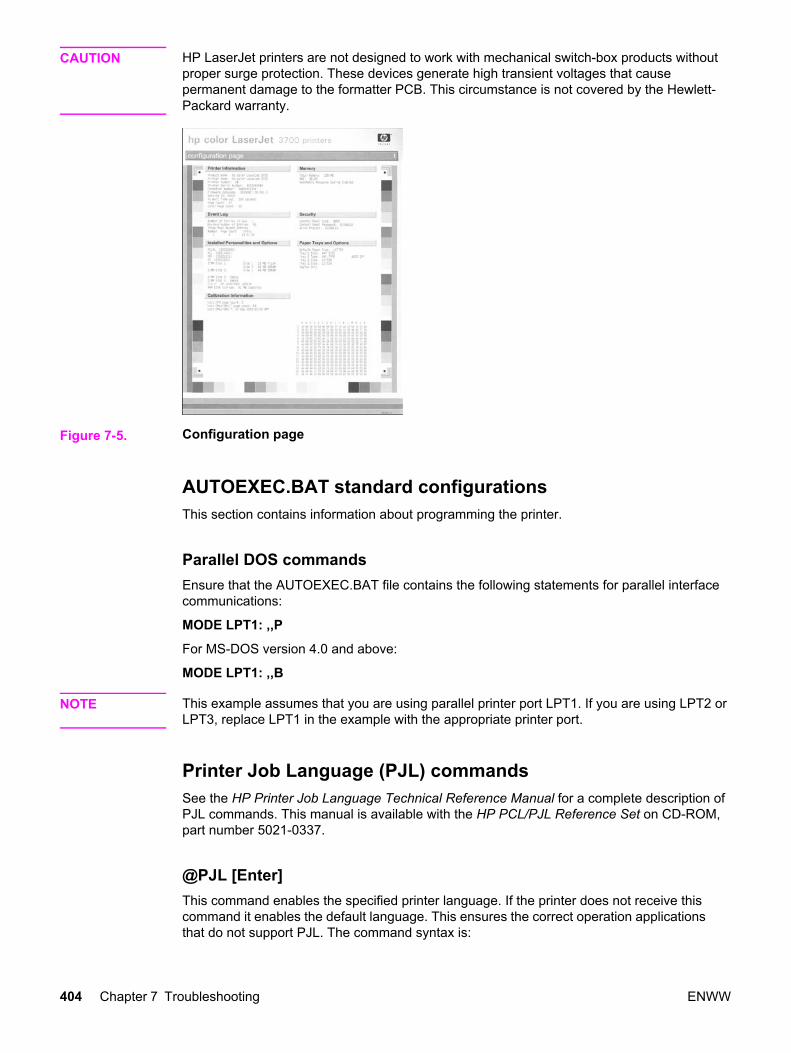
CAUTION HP LaserJet printers are not designed to work with mechanical switch-box products withoutproper surge protection. These devices generate high transient voltages that causepermanent damage to the formatter PCB. This circumstance is not covered by the Hewlett-Packard warranty.
Figure 7-5. Configuration page
AUTOEXEC.BAT standard configurations This section contains information about programming the printer.
Parallel DOS commandsEnsure that the AUTOEXEC.BAT file contains the following statements for parallel interfacecommunications:
MODE LPT1: ,,P
For MS-DOS version 4.0 and above:
MODE LPT1: ,,B
NOTE This example assumes that you are using parallel printer port LPT1. If you are using LPT2 orLPT3, replace LPT1 in the example with the appropriate printer port.
Printer Job Language (PJL) commandsSee the HP Printer Job Language Technical Reference Manual for a complete description ofPJL commands. This manual is available with the HP PCL/PJL Reference Set on CD-ROM,part number 5021-0337.
@PJL [Enter]This command enables the specified printer language. If the printer does not receive thiscommand it enables the default language. This ensures the correct operation applicationsthat do not support PJL. The command syntax is:
404 Chapter 7 Troubleshooting ENWW

@PJL [Enter] LANGUAGE = {PCL/PostScript} [<CR>] <LF>
UEL (universal exit language)This command (also referred to as the universal exit language command) terminates thecurrent printer language and returns control to PJL. It performs the following actions:
● Prints all data received before this command.
● Performs a reset: <esc>E in PCL, <cntrl>D in PostScript.
● Turns control over to PJL.
This command is also a valid HP-GL/2 terminator.
The UEL command must be immediately followed by the “@PJL” command prefix.Characters or control codes other than @PJL (such as <CR> or <LF>), enable the defaultlanguage and process the print job in that language. All jobs must begin and end with theUEL command. Besides entering PJL, the UEL command has the same effect as the<esc>E command. However, the <esc>E command should always be included to ensurebackward compatibility.
@PJL COMMENTThis command designates the current line as a comment, which is ignored. The syntax is:
@PJL COMMENT <words> [<CR>] <LF>
@PJL INFO CONFIGThis command solicits a response to describe the installed options and allows the printer toconfigure the installed options automatically as the applications require.
@PJL INFO IDThis command identifies the printer type to the host for reference when selecting printerdrivers for automatic installation. The command syntax is:
@PJL INFO ID <CR> <LF>
@PJL INFO USTATUSThis command queries the state of unsolicited JOB status. PAGE and TIMED status are notsupported. The syntax is:
@PJL INFO USTATUS <CR> <LF>
@PJL INFO PAGECOUNTThis command returns the number of pages printed by the engine.
ENWW Interface troubleshooting 405

@PJL JOBThis command informs the printer of the start of a PJL job and synchronizes the job statusinformation. The printer counts print jobs, including nested jobs, incrementing the job counterfor the @PJL JOB command and decrementing it for @PJL EOJ.
The printer accepts the NAME= parameter and returns the name string in the unsolicitedJOB start status message (if unsolicited job status is enabled). The printer transmits theunsolicited JOB status message to every I/O channel that has enabled this function. Thismessage’s format is:
@PJL USTATUS JOB <CR><LF>
START<CR><LF>
[NAME=<job name><CR><LF>]
<FF>
The printer resets the nested job counter whenever it switches the source to a different I/Ochannel. This prevents a corrupt job on one channel from disrupting the activities on anotherchannel.
@PJL EOJThis command identifies the end of a print job and is a hint for the I/O switching algorithm.The printer counts nested jobs and recognizes job boundaries when the counter decrementsto zero. The printer ignores isolated EOJ commands. Each EOJ must be preceded by a JOBcommand.
@PJL ECHOThis printer supports the ECHO command which transmits its parameters over the I/Ochannel to the host that issued the command.
@PJL USTATUS JOB=ON/OFFThis command enables or disables the JOB status for the I/O channel that delivers thecommand.
@PJL USTATUSOFFThis command disables the unsolicited JOB status for the I/O channel that delivered thecommand. For this printer, it duplicates the function of @PJL USTATUS JOB=OFF, AND@PJL USTATUS DEVICE=OFF.
NOTE All commands not supported by this printer’s PJL command set are returned with themessage @PJL XXXX<CR><LF>?<CR><LF>.
406 Chapter 7 Troubleshooting ENWW

Control panel troubleshooting
When you press to enter the menus, the high-level menus are displayed in the followingorder:
● INFORMATION
● PAPER HANDLING
● CONFIGURE DEVICE
● DIAGNOSTICS
● SERVICE
A menu map shows how individual items are configured within each of these menus. showsa sample of one page of the menu map. The menu map prints on three pages.
Printing a menu map1. Press Menu to enter the MENUS.
2. Press to highlight INFORMATION.
3. Press to select INFORMATION.
4. Press to highlight PRINT MENU MAP.
5. Press to select PRINT MENU MAP.
Figure 7-6. Printer menu map (HP 3700 shown)
Information menuUse the Information menu to access and print specific printer information.
ENWW Control panel troubleshooting 407

Table 7-41. Information menu
Menu item Description
PRINT MENU MAP Prints the control panel menu map, which shows the layout andcurrent settings of the control panel menu items.
PRINT CONFIGURATION Prints the printer configuration page.
PRINT SUPPLIES AND STATUSPAGE
Prints the estimated remaining life for the supplies; reportsstatistics on total number of pages and jobs processed, printcartridge manufacture date, serial number, page counts, andmaintenance information.
SUPPLIES STATUS Displays the supplies status in a scrollable list.
PRINT USAGE PAGE HP 3700 only
Prints a count of all media sizes that have passed through theprinter; lists whether they were simplex, duplex, monochrome, orcolor; and reports the page count.
PRINT DEMO Prints a demonstration page.
PRINT FILE DIRECTORY HP 3700 only
Prints the name and directory of files stored in the printer.
PRINT PCL FONT LIST HP 3700 only
Prints the available PCL fonts.
PRINT PS FONT LIST HP 3700 only
Prints the available PS (emulated PostScript) fonts.
Paper handling menuThe Paper handling menu allows you to configure input trays by size and type. It is importantto configure the trays with this menu before you print for the first time.
NOTE If you have used previous HP LaserJet printers, you might be accustomed to configuringTray 1 to first mode or cassette mode. To mimic the settings for first mode, configure Tray 1for size = ANY SIZE and type = ANY TYPE. To mimic the settings for cassette mode, seteither the size or type for Tray 1 to a setting other than ANY SIZE or ANY TYPE.
Table 7-42. Paper handling menu
Menu item Value Description
TRAY 1 SIZE A list of availablesizes appears.
Allows you to configure thepaper size for Tray 1. Thedefault value is ANY SIZE.See Supported mediaweights and sizes for acomplete list of availablesizes.
408 Chapter 7 Troubleshooting ENWW

Menu item Value Description
TRAY 1 TYPE A list of availabletypes appears.
Allows you to configure themedia type for Tray 1. Thedefault value is ANY SIZE.See Supported mediaweights and sizes for acomplete list of availabletypes.
TRAY 2 SIZE
TRAY 3 SIZE
A list of availablesizes appears.
Allows you to configure thepaper size for Tray 2 orTray 3. The default size isLetter or A4 depending onthe country/region. SeeSupported media weightsand sizes for a complete listof available sizes.
TRAY 2 TYPE
TRAY 3 TYPE
A list of availabletypes appears.
Allows you to configure thepaper type for Tray 2 orTray 3. The default isPLAIN. See Supportedmedia weights and sizes fora complete list of availabletypes.
Configure device menuThe configure device menu allows you to change or reset the default print settings, to adjustthe print quality, and to change the system configuration and I/O options.
Printing menuThese settings affect only jobs without identified properties. Most jobs identify all of theproperties and override the values set from this menu. This menu can also be used to setdefault paper size and type.
Table 7-43. Printing menu
Menu item Values Description
COPIES 1 - 32000 Allows you to set the defaultnumber of copies. Thedefault number of copies is 1.
DEFAULT PAPER SIZE A list ofavailable sizesappears.
Allows you to set the defaultpaper size.
DEFAULT CUSTOM PAPER SIZE UNIT OFMEASURE
X DIMENSION
Y DIMENSION
Allows you to set the defaultsize for any custom jobwithout dimensions.Available for Tray 1.
Table 7-42. Paper handling menu (continued)
ENWW Control panel troubleshooting 409

Menu item Values Description
DUPLEX OFF
ON
HP 3700dn and 3700dtn only
Allows you to enable ordisable the duplex function(automatic 2-sided printing).The default is OFF. You canoverride this setting in theprinter driver.
DUPLEX BINDING LONG EDGE
SHORT EDGE
Allows you to choosewhether a duplex job will beflipped on the long edge orthe short edge.
OVERRIDE A4/LETTER NO
YES
Allows you to set the printerto print an A4 job on letter-size paper when no A4paper is loaded, or to print aletter-size job on A4 whenno letter-size paper isloaded. The default is NO.
MANUAL FEED NO
OFF
The default is OFF. Settingit to ON makes MANUALFEED the default for jobsthat do not select a tray.You can override this settingin the printer driver.
COURIER FONT REGULAR
DARK
HP 3700 only.
Allows you to select aversion of the Courier font.The default is REGULAR.
WIDE A4 NO
YES
HP 3700 only.
Allows you to change theprintable area of A4 paperso that eighty 10-pitchcharacters may be printedon a single line. The defaultis NO.
PRINT PS ERRORS OFF
ON
HP 3700 only.
Allows you to select to printPS (emulated PostScript)error pages. The default isOFF.
Table 7-43. Printing menu (continued)
410 Chapter 7 Troubleshooting ENWW
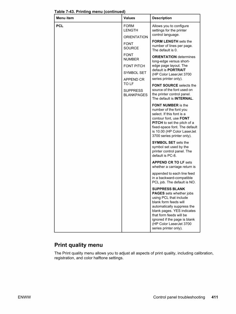
Menu item Values Description
PCL FORMLENGTH
ORIENTATION
FONTSOURCE
FONTNUMBER
FONT PITCH
SYMBOL SET
APPEND CRTO LF
SUPPRESSBLANKPAGES
Allows you to configuresettings for the printercontrol language.
FORM LENGTH sets thenumber of lines per page.The default is 0.
ORIENTATION determineslong-edge versus short-edge page layout. Thedefault is PORTRAIT(HP Color LaserJet 3700series printer only).
FONT SOURCE selects thesource of the font used onthe printer control panel.The default is INTERNAL.
FONT NUMBER is thenumber of the font youselect. If this font is acontour font, use FONTPITCH to set the pitch of afixed-space font. The defaultis 10.00 (HP Color LaserJet3700 series printer only).
SYMBOL SET sets thesymbol set used by theprinter control panel. Thedefault is PC-8.
APPEND CR TO LF setswhether a carriage return is
appended to each line feedin a backward-compatiblePCL job. The default is NO.
SUPPRESS BLANKPAGES sets whether jobsusing PCL that includeblank form feeds willautomatically suppress theblank pages. YES indicatesthat form feeds will beignored if the page is blank(HP Color LaserJet 3700series printer only).
Print quality menuThe Print quality menu allows you to adjust all aspects of print quality, including calibration,registration, and color halftone settings.
Table 7-43. Printing menu (continued)
ENWW Control panel troubleshooting 411

Table 7-44. Print quality menu
Menu item Values Description
ADJUST COLOR CYAN DENSITY
MAGENTA DENSITY
YELLOW DENSITY
BLACK DENSITY
RESTORE COLORVALUES
Allows you to modify thehalftone settings for eachcolor. The default for eachcolor is 0.
SET REGISTRATION PRINT TEST PAGE
SOURCE
ADJUST TRAY 1
ADJUST TRAY 2
ADJUST TRAY 3
Allows 1-sided and 2-sidedimage alignment. The defaultfor SOURCE is TRAY 2. Thedefault for the sub-itemsADJUST TRAY 1, ADJUSTTRAY 2, and ADJUST TRAY3 is 0.
AUTO SENSE MODE EXPANDED SENSING
TRANSPARENCYONLY
If a tray is configured toPLAIN or ANY SIZE, and theprint job does not specify themedia type, the printer willadjust the print quality for thetype of print media it senses.The default is EXPANDEDSENSING, which sensestransparencies, glossy paper,and tough paper.
INK TRANSPARENCY REJECT-GUARDFUSER
ACCEPT-NOTADVISED
REJECT-GUARD FUSERstops the print job when anoncompatible transparencyis detected. This optionprotects the printer fuser fromdamage.
ACCEPTED-NOT ADVISEDallows the job to printnormally even though a non-compatible transparency isbeing used.
The default value is REJECT-GUARD FUSER.
PRINT M0DES A list of availablemodes appears
Allows you to associate eachpaper type with a specificprint mode
412 Chapter 7 Troubleshooting ENWW
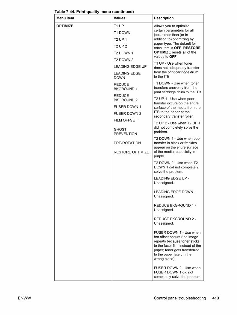
Menu item Values Description
OPTIMIZE T1 UP
T1 DOWN
T2 UP 1
T2 UP 2
T2 DOWN 1
T2 DOWN 2
LEADING EDGE UP
LEADING EDGEDOWN
REDUCEBKGROUND 1
REDUCEBKGROUND 2
FUSER DOWN 1
FUSER DOWN 2
FILM OFFSET
GHOSTPREVENTION
PRE-ROTATION
RESTORE OPTIMIZE
Allows you to optimizecertain parameters for alljobs rather than (or inaddition to) optimizing bypaper type. The default foreach item is OFF. RESTOREOPTIMIZE resets all of thevalues to OFF.
T1 UP - Use when tonerdoes not adequately transferfrom the print cartridge drumto the ITB.
T1 DOWN - Use when tonertransfers unevenly from theprint cartridge drum to the ITB.
T2 UP 1 - Use when poortransfer occurs on the entiresurface of the media from theITB to the paper at thesecondary transfer roller.
T2 UP 2 - Use when T2 UP 1did not completely solve theproblem.
T2 DOWN 1 - Use when poortransfer in black or frecklesappear on the entire surfaceof the media, especially inpurple.
T2 DOWN 2 - Use when T2DOWN 1 did not completelysolve the problem.
LEADING EDGE UP -Unassigned.
LEADING EDGE DOWN -Unassigned.
REDUCE BKGROUND 1 -Unassigned.
REDUCE BKGROUND 2 -Unassigned.
FUSER DOWN 1 - Use whenhot offset occurs (the imagerepeats because toner sticksto the fuser film instead of thepaper; toner gets transferredto the paper later, in thewrong place).
FUSER DOWN 2 - Use whenFUSER DOWN 1 did notcompletely solve the problem.
Table 7-44. Print quality menu (continued)
ENWW Control panel troubleshooting 413

Menu item Values Description
OPTIMIZEcontinued FILM OFFSET - Use whenfuser electrostatic offsetoccurs (like fuser hot offsetbut is caused by anelectrostatic charge on thefuser film).
GHOST PREVENTION - Usewhen positive ghost appears.
PRE-ROTATION - Use whena repetitive horizontal lineoccurs every 77 mm due to aprint cartridge drumstoppage; or, use to reducenon-uniform color areas inoverhead transparencies.
RESTORE OPTIMIZE -Restores default values
CALIBRATE NOW n/a Performs all printercalibrations to optimize printquality.
CREATE CLEANING PAGE n/a Prints a cleaning page to beused for cleaning the fuserroller. This page containsinstructions for processingthe cleaning page. SeeCleaning the printer andaccessories for moreinformation.
PROCESS CLEANING PAGE n/a After the cleaning page isloaded in Tray 1, this menuitem allows the printer toprocess the cleaning page.The cleaning process takes afew moments. See Cleaningthe printer and accessoriesfor more information.
System setup menuThe system setup menu allows you to make changes to default settings for general printerconfiguration, such as PowerSave Time, printer personality (language), and jam recovery.
Table 7-44. Print quality menu (continued)
414 Chapter 7 Troubleshooting ENWW
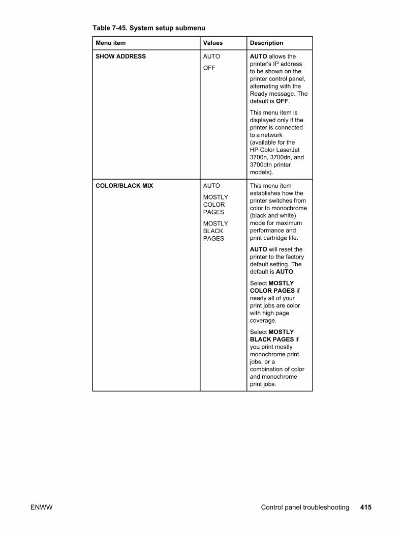
Table 7-45. System setup submenu
Menu item Values Description
SHOW ADDRESS AUTO
OFF
AUTO allows theprinter's IP addressto be shown on theprinter control panel,alternating with theReady message. Thedefault is OFF.
This menu item isdisplayed only if theprinter is connectedto a network(available for theHP Color LaserJet3700n, 3700dn, and3700dtn printermodels).
COLOR/BLACK MIX AUTO
MOSTLYCOLORPAGES
MOSTLYBLACKPAGES
This menu itemestablishes how theprinter switches fromcolor to monochrome(black and white)mode for maximumperformance andprint cartridge life.
AUTO will reset theprinter to the factorydefault setting. Thedefault is AUTO.
Select MOSTLYCOLOR PAGES ifnearly all of yourprint jobs are colorwith high pagecoverage.
Select MOSTLYBLACK PAGES ifyou print mostlymonochrome printjobs, or acombination of colorand monochromeprint jobs.
ENWW Control panel troubleshooting 415

Menu item Values Description
TRAY BEHAVIOR USEREQUESTEDTRAY
MANUALLYFEEDPROMPT
PS DEFERMEDIA
Allows you to specifysettings for the trayselection behavior.(This setting allowsyou to configure thetrays to behave liketrays in someprevious HP printers.)
The default for USEREQUESTED TRAYis EXCLUSIVELY.
The default forMANUALLY FEEDPROMPT isALWAYS.
PS DEFER MEDIAaffects how paper ishandled whenprinting from anAdobe PS printdriver. ENABLEDuses HP's paperhandling. Disableduses the Adobe PSpaper handling. Thedefault is ENABLED.
POWERSAVE TIME 2 MINUTE
15 MINUTES
30 MINUTES
1 HOUR
4 HOURS
15 HOURS
Reduces powerconsumption whenthe printer has beeninactive for anextended period.
Allows you to set thelength of time theprinter remainsinactive before goinginto PowerSavemode. The default is30 MINUTES.
DISPLAY BRIGHTNESS 1 - 10 Allows you to adjustthe brightness of theprinter's controlpanel. The default is5.
PERSONALITY AUTO
PCL
PS
Sets the defaultpersonality toautomatic switching,PCL, or PostScriptemulation. Thedefault is AUTO.
Table 7-45. System setup submenu (continued)
416 Chapter 7 Troubleshooting ENWW

Menu item Values Description
CLEARABLE WARNINGS ON
JOB
Allows you to set theamount of time that aclearable warning isdisplayed on theprinter control panel.The default is JOB,which is displayeduntil is pressed.ON is displayed untilthe end of the jobthat generated thewarning.
AUTO CONTINUE ON
OFF
Determines printerbehavior when thesystem generates anAuto Continuableerror. The default isON.
ON automaticallycontinues printingafter 10 seconds.
OFF pauses printing.Press to continueprinting.
SUPPLIES LOW CONTINUE
STOP
Sets low suppliesreporting options.The default isCONTINUE.
STOP pausesprinting when a lowsupply is reported.Press to continueprinting.
JAM RECOVERY AUTO ON
OFF
Sets whether theprinter will attempt toreprint pages after ajam. The default isAUTO.
Table 7-45. System setup submenu (continued)
ENWW Control panel troubleshooting 417
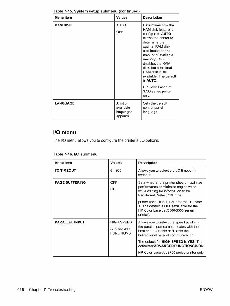
Menu item Values Description
RAM DISK AUTO
OFF
Determines how theRAM disk feature isconfigured. AUTOallows the printer todetermine theoptimal RAM disksize based on theamount of availablememory. OFFdisables the RAMdisk, but a minimalRAM disk is stillavailable. The defaultis AUTO.
HP Color LaserJet3700 series printeronly.
LANGUAGE A list ofavailablelanguagesappears.
Sets the defaultcontrol panellanguage.
I/O menuThe I/O menu allows you to configure the printer’s I/O options.
Table 7-46. I/O submenu
Menu item Values Description
I/O TIMEOUT 5 - 300 Allows you to select the I/O timeout inseconds.
PAGE BUFFERING OFF
ON
Sets whether the printer should maximizeperformance or minimize engine wearwhile waiting for information to betransferred. Select ON if the
printer uses USB 1.1 or Ethernet 10 baseT. The default is OFF (available for theHP Color LaserJet 3500/3550 seriesprinter).
PARALLEL INPUT HIGH SPEED
ADVANCEDFUNCTIONS
Allows you to select the speed at whichthe parallel port communicates with thehost and to enable or disable thebidirectional parallel communication.
The default for HIGH SPEED is YES. Thedefault for ADVANCED FUNCTIONS is ON.
HP Color LaserJet 3700 series printer only.
Table 7-45. System setup submenu (continued)
418 Chapter 7 Troubleshooting ENWW

Menu item Values Description
EIO 1 Possiblevalues are:
TCP/IP
IPX/SPX
APPLETALK
DLC/LLC
SECURE WEB
RESETSECURITYLINK SPEED
HP 3700 only
Allows you to configure EIO devicesinstalled in the EIO slot.
See Enhanced I/O (EIO) configuration(HP color LaserJet 3700 series printeronly), in chapter 3 for more information.
Resets menuThe Resets menu allows you to reset factory settings to, disable and enable PowerSave,and update the printer after new supplies are installed.
Table 7-47. Resets submenu
Menu item Values Description
RESTORE FACTORY SETTINGS None. Allows you to clear the page buffer,remove all perishable personality data,reset the printing environment, and returnall default settings to factory defaults.However, this menu does not restoreHP Jetdirect network settings to factorydefault values.
POWERSAVE ON
OFF
Allows you to enable and disablePowerSave. The default is ON.
RESET SUPPLIES NEWTRANSFERKIT
NEW FUSERKIT
Allows you to inform the printer that a newtransfer kit or new fuser kit has beeninstalled. The page count for the newsupply will be set to 0.
Diagnostics menuThe Diagnostics menu allows you to run tests that can help you identify and solve problemswith the printer.
Table 7-48. Diagnostics menu
Menu item Description
PRINT EVENT LOG Prints an event log that displays the last 50 entries in theprinter’s event log, starting with the most recent.
Table 7-46. I/O submenu (continued)
ENWW Control panel troubleshooting 419

Menu item Description
SHOW EVENT LOG Displays the last 50 events on the control panel display,starting with the most recent.
PQ TROUBLESHOOTING Prints a series of print quality assessment pages that helptroubleshoot any print quality problems.
DISABLE CARTRIDGE CHECK Allows you to print with one or more print cartridgesremoved to help troubleshoot many print problems.
PAPER PATH SENSORS Shows the values of the sensors. Values are updated aspaper passes each sensor. Jobs can be initiated from thecontrol panel or sent from the computer
PAPER PATH TEST Used to isolate the cause of paper jams.
MANUAL SENSOR TEST Allows you to test the paper path sensors and switches forcorrect operation.
COMPONENT TEST Activates individual parts independently to isolate noise,leaking, and other hardware issues.
PRINT/STOP TEST Isolates print quality faults more accurately by stopping theprinter in mid print cycle. This allows you to see where theimage begins to degrade.
Note, this causes a jam that may need to be removed.
Service menuThe Service menu is PIN protected for added security. Only authorized service people haveaccess to the service menu. When you select SERVICE from the list of menus, you areprompted to enter your 8-digit PIN number. The PIN for the HP Color LaserJet 3500/3550printer is 10350003 and for the HP Color LaserJet 3700 printer is 10370003.
1. Press or until the first digit of the PIN is displayed.
2. Press to save the digit. The display will replace the digit with an asterisk.
3. Repeat steps 1 and 2 until all eight digits are entered.
4. Press at any time to move to the previous digit.
Use the Service menu to reset counts, clear the event log, enter the serial number, enter thedate the printer was first used, and reset the default paper size.
Table 7-49. Service menu
Menu item Values Description
CLEAR EVENT LOG Allows you to clear the printer’s internalevent log
TOTAL MONO PAGES Range: 0 -9999999
Allows you to reset the page count afterreplacing the formatter. The page countshould reflect the number of pages printedon the print engine rather than theformatter.
Table 7-48. Diagnostics menu (continued)
420 Chapter 7 Troubleshooting ENWW

Menu item Values Description
TOTAL COLOR PAGES Range: 0 -9999999
Allows you to reset the page count afterreplacing the formatter. The page countshould reflect the number of pages printedon the print engine rather than theformatter.
REFURBISH PAGE COUNT Range: 0 -9999999
Allows the page count to be reset to theoriginal refurbished page count when theprinter is repaired.
TRANSFER KIT COUNT Range, for the:
HP 3500/3550:0 - 60000
HP 3700/3550:0 - 75,000
This item automatically resets to zerowhen the transfer unit is replaced and theuser selects the choice to reset thetransfer count.
NOTE
This value is now stored on the DCcontroller instead of the formatter. Thetransfer kit count will not change theactual page count of the transfer kit. Thetransfer kit count can only be reset to zeroin the resets menu.
FUSER KIT COUNT Range, for the:
HP 3500: 0 -60,000
HP 3700/3550:0 - 75,000
Allows you to reset the page count of thecurrent fuser if the value is lost. This itemautomatically resets to zero when thefuser is replaced and the user selects thechoice to reset the fuser count.
SERIAL NUMBER XXXXXXXXXX Allows you to update the serial number ifyou replace the formatter.
SERVICE ID YYDDD If you replace the formatter, this itemallows you to set the date to the date theprinter was first used, rather than the datethe new formatter was installed. SeeService ID, in this chapter for informationon the date format.
COLD RESET PAPER LETTER
A4
If the customer uses default paper size ofA4 (used in Europe), this item allows youto reset the default if you replace theformatter.
Table 7-49. Service menu (continued)
ENWW Control panel troubleshooting 421
Tools for troubleshooting
This section contains information about the Printer's embedded Web server.
Embedded Web server (HP Color LaserJet 3700 series printeronly) Using the embedded Web server (HP Color LaserJet 3700 series printer only)
When the printer is directly connected to a computer, use the HP Toolbox to view web pagesfor the printer status.
When the printer is connected to the network, the embedded Web server is automaticallyavailable. You may access the embedded Web server from Windows 95 and later. Theembedded Web server allows you to view printer and network status and to manage printingfunctions from your computer instead of from the printer control panel. Below are examplesof what you can do using the embedded Web server:
● View printer control status information
● Set the type of paper loaded in each tray
● Determine the remaining life on all supplies and order new supplies
● Change the tray configurations view
● Change the printer control panel menu confiuration
● Print internal pages
● Receive notification of printer and supplies events
● Change the network configuration
● View support content that is specific to the current state of the printer
To use the embedded Web server, you must have Microsoft Internet Explorer 4 and later, orNetscape Navigator 4 and later. The embedded Web server works when the printer isconnected to an IP-based network. The embedded Web server does not support IPX-basedor AppleTalk printer connections. Internet access is not require to open and use theembedded Web server.
Embedded Web server access through a network connectionIn a supported Web browser on your computer, type the IP address for the printer in theaddress/URL field. (To find the IP address, print a configuration page. For more informationabout printing a configuration page, see Printer configuration page.)
NOTE Once you open the URL, you can bookmark it so that you can return to it quickly in the future.
1. The embedded Web server has three tabs that contain settings and information aboutthe printer: the Information tab, the Settings tab, and the Network tab. Click the tab thatyou want to view.
2. See the following sections for more information about each tab.
422 Chapter 7 Troubleshooting ENWW
Information tab The Information pages group consists of the following pages.
● Device Status. This page displays the printer status and shows the life remaining ofHP supplies, with 0 percent indicating that a supply is empty. The page also shows thetype and size of print paper set for each tray. To change the default settings, clickChange Settings.
● Configuration page.This page shows the information found on the printer Configurationpage.
● Supplies Status. This page shows the life remaining of HP supplies, with 0 percentindicating that a supply is empty. This page also provides supplies part numbers. Toorder new supplies, click Order Supplies in the Other Links area on the left side of thewindow. To visit any website, you must have Internet access.
● Event log.This page shows a list of all printer events and errors.
● Usage page. This page shows a summary of the number of pages the printer hasprinted, grouped by size and type.
● Device Information.This page also shows the printer network name, address, andmodel information. To change these entries, click Device Information on the Settings tab.
● Control Panel.Displays messages from the printers control panel, for example Ready orPowerSave.
Settings tab This tab allows you to configure the printer from your computer. The Settings tab can bepassword protected. If this printer is networked, always consult with the printer administratorbefore changing settings on this tab.
The Settings tab contains the following pages.
● Configure Device. Configure all printer settings from this page. This page contains thetraditional menus found on printers using a control panel display. These menus includeInformation, Paper Handling, Configure Device, and Diagnostics.
● Alerts. Network only. Set up to receive e-mail alerts for various printer and suppliesevents.
● E-mail.Network only. Used in conjunction with the Alerts page to set up incoming andoutgoing e-mail, as well as to set e-mail alerts.
● Security. Set a password that must be entered to gain access to the Settings andNetworking tabs. Enable and disable certain features of the embedded Web server.
● Other links. Add or customize a link to another website. This link is displayed in theOther Links area on all embedded Web server pages. These permanent links alwaysappear in the Other Links area: HP Instant Support™, Order Supplies, and ProductSupport.
● Device Information.Name the printer and assign an asset number to it. Enter the nameand e-mail address for the primary contact who will receive information about the printer.
● Language.Determine the language in which to display the embedded Web serverinformation.
● Time Services. Allows time synchronization with a network time server.
ENWW Tools for troubleshooting 423

Networking tab This tab allows the network administrator to control network-related settings for the printerwhen it is connected to an IP-based network. This tab will not appear if the printer is directlyconnected to a computer, or if the printer is connected to a network using anything otherthan an HP Jetdirect print server card.
Other linksThis section contains links that connect you to the Internet. You must have Internet access inorder to use any of these links. If you use a dial-up connection and did not connect whenyou first opened the embedded Web server, you must connect before you can visit theseweb sites. Connecting might require that you close the embedded Web server and reopen it.
● HP Instant Support TM. Connects you to the HP website to help you find solutions.This service analyzes your printer error log and configuration information to providediagnostic and support information specific to your printer.
● Order Supplies. Click this link to connect to the HP website and order genuineHP supplies, such as print cartridges and paper.
● Product Support. Connects to the support site for the HP Color LaserJet 3500/3550series printer and the HP Color LaserJet 3700 series printer. Then, you can search forhelp regarding general topics.
HP ToolboxThe HP Toolbox is a Web application that you can use for the following tasks:
● Check the printer status.
● Configure the printer settings.
● View troubleshooting information.
● View online documentation.
● Set up pop-up alerts (Windows only).
You can view the HP Toolbox when the printer is directly connected to your computer orwhen it is connected to a network. You must perform a complete software installation to usethe HP Toolbox.
NOTE You do not have to have Internet access to open and use the HP Toolbox. However, if youclick a link in the Other Links area, you must have Internet access to go to the siteassociated with the link. See Other links for more information.
Supported operating systemsThe HP toolbox is supported for the following operating systems:
● Windows 98, 2000, Me, and XP
● Mac OS 10.2 or later
Supported browsersTo use the HP toolbox, you must have one of the following browsers:
424 Chapter 7 Troubleshooting ENWW
For Windows
● Microsoft Internet Explorer 5.2 or later
● Netscape Navigator 6 or later
● Opera Software ASA Opera™
For Macintosh
● Microsoft Internet Explorer 5.2 or later
● Netscape Navigator 6 or later
● All pages can be printed from the browser.
To view HP ToolboxOn the Start menu, select Programs, and then HP toolbox. Double-click the Status Clienticon.
The HP toolbox opens in a Web browser.
NOTE Once you open the URL, you can bookmark it so that you can return to it quickly in the future.
HP toolbox sectionsThe HP toolbox software contains the following sections:
● Status tab
● Troubleshooting tab
● Alerts tab
● Documentation tab
● Advanced Printer Settings window
Each page in HP toolbox contains links to the HP website for product registration, productsupport, and for ordering supplies. You must have Internet access to use any of these links.If you use a dial-up connection and did not connect when you first opened the HP toolbox,you must connect before you can visit these web sites.
Status tab
The Status tab has links to the following main pages:
● Device Status. View printer status information. This page will indicate printer conditions,such as a paper jam or an empty tray. After you correct a problem with the printer, clickthe Refresh button to update the device status.
● Supplies Status. View detailed supplies status, such as the percentage of tonerremaining in the print cartridge and the number of pages printed with the current printcartridge. This page also has links to order supplies and to find recycling information.
● Print Info. Print the configuration page and various other information pages that areavailable for the printer, such as the supplies status page and the demo page.
Troubleshooting tab
The Troubleshooting tab provides links to various printer troubleshooting information, suchas how to clear a paper jam, how to resolve print quality problems, and how to resolve otherproblems with the printer.
ENWW Tools for troubleshooting 425

Alerts tab
● The Alerts tab allows you to configure the printer to automatically notify you of printeralerts. The Alerts tab has links to the following main pages:
● Set up status alerts
● Set up e-mail alerts (available for the HP Color LaserJet 3500/3550 series printer only)
● Administrative settings
Set up status alerts page
On the Set up status alerts page, you can choose to turn alerts on or off, specify when theprinter should send an alert, and choose from two different types of alerts:
● a pop-up message
● a task bar icon
Click Apply to activate the settings.
Set up e-mail alerts page
On the Set up e-mail alerts page, you can set the e-mail addresses you want to have alertssent to and specify what kind of alerts should go to which e-mail address. You can have upto four e-mail destinations concerning the following alerts:
● Supplies
● Service
● Paper path
● Advisory
You must set up an SMTP server to send e-mail alerts.
Administrative settings page
On the Administrative settings page, you can set the frequency of how often the HP toolboxchecks for printer alerts. Three settings are available:
● once per minute (every 60 seconds)
● twice per minute (every 30 seconds)
● twenty times per minute (every 3 seconds)
If you want to reduce network I/O traffic, reduce the frequency that the printer checks foralerts.
Documentation tabThe Documentation tab contains links to these information sources:
● User Guide. Contains the information about the printer usage, warranty, specifications,and support that you are currently reading. The user guide is available in both HTMLand PDF format.
● Install Notes. Contains late-breaking information about the printer.
426 Chapter 7 Troubleshooting ENWW

Advanced Printer Settings windowWhen you click the Advanced Printer Settings link, a new window opens. The AdvancedPrinter Settings window has the following tabs:
● Information tab
● Settings tab
● Network tab
Information tab
The Information tab provides quick links to the following information:
● Device status
● Configuration
● Supplies status
● Device information
● Event log
● Usage page (HP Color LaserJet 3700 series printer only)
● Print Info pages
Settings tab
The Settings tab has links to several pages that allow you to view and change the printer’sconfiguration.
NOTE Software settings can override settings made in HP toolbox.
● Configure Device. Configure all printer settings from this page. This page contains thetraditional menus found on printers using a control panel display. These menus includeInformation, Paper Handling, Configure Device, and Diagnostics.
● Device Information.Name the printer and assign an asset number to it. Enter the nameand e-mail address for the primary contact who will receive information about the printer.
Network tab
The Network tab allows the network administrator to control network-related settings for theprinter when it is connected to an IP-based network. This tab will not appear if the printer isdirectly connected to a computer, or if the printer is connected to a network using anythingother than an HP Jetdirect print server.
HP toolbox linksThe HP toolbox links at the left of the screen provide links to the following options:
● Select a device. Select from all HP toolbox-enabled devices.
● View current alerts.View the current alerts for all set up printers. (You must be printingto view current alerts.)
● Text only page. View HP toolbox as a site map linking to text-only pages.
ENWW Tools for troubleshooting 427
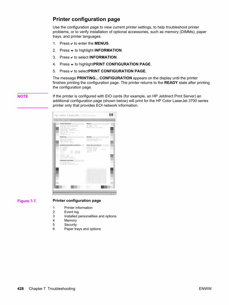
Printer configuration page Use the configuration page to view current printer settings, to help troubleshoot printerproblems, or to verify installation of optional accessories, such as memory (DIMMs), papertrays, and printer languages.
1. Press to enter the MENUS.
2. Press to highlight INFORMATION.
3. Press to select INFORMATION.
4. Press to highlightPRINT CONFIGURATION PAGE.
5. Press to selectPRINT CONFIGURATION PAGE.
The message PRINTING... CONFIGURATION appears on the display until the printerfinishes printing the configuration page. The printer returns to the READY state after printingthe configuration page.
NOTE If the printer is configured with EIO cards (for example, an HP Jetdirect Print Server) anadditional configuration page (shown below) will print for the HP Color LaserJet 3700 seriesprinter only that provides EOI network information.
Figure 7-7. Printer configuration page
1 Printer information2 Event log3 Installed personalities and options4 Memory5 Security6 Paper trays and options
428 Chapter 7 Troubleshooting ENWW
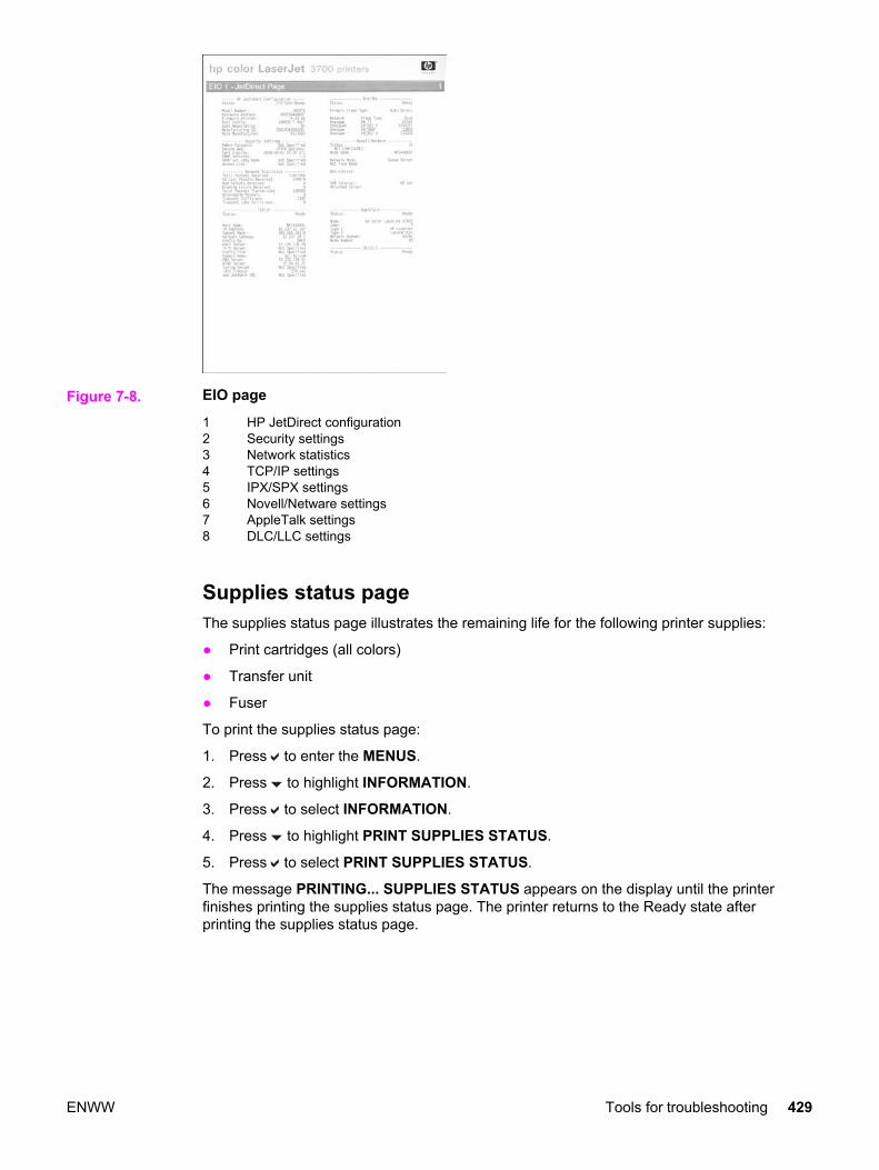
Figure 7-8. EIO page
1 HP JetDirect configuration2 Security settings3 Network statistics4 TCP/IP settings5 IPX/SPX settings6 Novell/Netware settings7 AppleTalk settings8 DLC/LLC settings
Supplies status page The supplies status page illustrates the remaining life for the following printer supplies:
● Print cartridges (all colors)
● Transfer unit
● Fuser
To print the supplies status page:
1. Press to enter the MENUS.
2. Press to highlight INFORMATION.
3. Press to select INFORMATION.
4. Press to highlight PRINT SUPPLIES STATUS.
5. Press to select PRINT SUPPLIES STATUS.
The message PRINTING... SUPPLIES STATUS appears on the display until the printerfinishes printing the supplies status page. The printer returns to the Ready state afterprinting the supplies status page.
ENWW Tools for troubleshooting 429
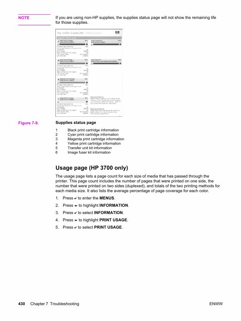
NOTE If you are using non-HP supplies, the supplies status page will not show the remaining lifefor those supplies.
Figure 7-9. Supplies status page
1 Black print cartridge information2 Cyan print cartridge information3 Magenta print cartridge information4 Yellow print cartridge information5 Transfer unit kit information6 Image fuser kit information
Usage page (HP 3700 only) The usage page lists a page count for each size of media that has passed through theprinter. This page count includes the number of pages that were printed on one side, thenumber that were printed on two sides (duplexed), and totals of the two printing methods foreach media size. It also lists the average percentage of page coverage for each color.
1. Press to enter the MENUS.
2. Press to highlight INFORMATION.
3. Press to select INFORMATION.
4. Press to highlight PRINT USAGE.
5. Press to select PRINT USAGE.
430 Chapter 7 Troubleshooting ENWW

The message PRINTING... USAGE appears on the display until the printer finishes printingthe usage page. The printer returns to the Ready state after printing the usage page.
Figure 7-10. Usage page
1 Printer identification information2 Usage totals3 Percent of coverage broken down by color
Event log The event log lists the printer events, including printer jams, service errors, and other printerconditions.
1. Press to enter the MENUS.
2. Press to highlight DIAGNOSTICS.
3. Press to select DIAGNOSTICS.
4. Press to highlight PRINT EVENT LOG.
5. Press to select PRINT EVENT LOG.
ENWW Tools for troubleshooting 431

The message PRINTING... EVENT LOG appears on the display until the printer finishesprinting the event log. The printer returns to the Ready state after printing the event log.
Figure 7-11. Event log
1 Current page count and printer serial number2 Event number (the most recent is at the top of the list)3 Error code4 Page count at which the event occurred5 Description of the event
432 Chapter 7 Troubleshooting ENWW

Diagnostics
Additional diagnostic information is provided in this section.
Diagnostics flowchartUse this flowchart to help identify the cause of high-level printer problems. These problemsare indicated by abnormalities in the printer’s power-on sequence. The LED that theflowchart refers to is on the formatter. Figure 7-13. Formatter LED on the next page indicateswhere this LED is located. This is a "heartbeat" LED that blinks on and off when theformatter is operating properly.
Figure 7-12. Diagnostics flowchart
ENWW Diagnostics 433

Figure 7-13. Formatter LED
Engine diagnostics This section provides an overview of the engine diagnostics incorporated into the HP ColorLaserJet 3500/3550 and 3700 series printer. The printer contains extensive internaldiagnostics that help in troubleshooting print quality issues, paper path issues, noise issues,component issues, and timing issues.
Diagnostics modeSome of the diagnostic tests automatically put the printer into a special diagnostics mode.The special diagnostics mode allows the printer to perform actions that it normally could notbecause the printer would enter an error state. Always follow the control panel directions inthe Diagnostic menu to properly exit the special diagnostics mode and return the printer to anormal state.
Diagnostics that put the printer into special diagnostics modeThere are four diagnostic tests that put the printer into a special state:
● Disable cartridge check
● Paper path sensor test
● Manual sensor test
● Component test
While the printer is in the special diagnostics mode, the display should read:
Ready Diagnostics Mode
To exit press Stop KEY
434 Chapter 7 Troubleshooting ENWW

When the printer is in the special diagnostics mode, the four tests listed above appear in themenu and are available to be run. To access other diagnostic tests or to leave the specialstate, press the STOP button, and then select Exit diagnostics. The printer will reset itself,and then return to the normal state.
NOTE A good understanding of how the printer operates is required to use the engine diagnosticssuccessfully. Before proceeding with these diagnostic tests, be sure you understand theinformation in Chapter 5 of this manual.
Diagnostics testsDifferent tests can be used to isolate different types of issues. For component or noiseisolation, you can run the diagnostics with the left, right, and rear covers removed. Do notoperate the printer with the front door open. Operating the printer with the front door openwill cause the gears on the right side of the printer to become out of sync with the front door.Upon closing the front door, the gears on the right side and print cartridges can be damaged.
WARNING! Take caution when performing printer diagnostics to avoid risk of injury. Only trained servicepersonnel should access and run the diagnostics with the covers removed. Never touch anyof the power supplies with the printer turned on.
ENWW Diagnostics 435

Diagnostics from the Control Panel
This section provides information about performing the printer diagnostics.
Printer display menuControl Panel Fuel Gauges used to determine if cyan, magenta, yellow, or the black printcartridge is in a low or out condition.
Diagnostics test menuPrint Event Log
This item prints an event log that displays the last 50 entries in the printer’s event log,starting with the most recent.
Show Event Log
This item displays on the control panel the last 50 events in the event log, starting with themost recent.
PQ Troubleshooting
This item prints a series of print quality assessment pages that help troubleshoot print qualityproblems.
Disable Cartridge Check – special mode test
This diagnostic test allows you to print internal pages or sends an external job to the printerwith one or more print cartridges removed or swapped. Because the cartridges are notkeyed, the diagnostic test can be run with one to four cartridges removed or swapped toanother location. Consumable supply errors are ignored while in this mode. Once in thismode, you can navigate the menus and print internal pages or send an external print job tothe printer. This diagnostic test can be used to isolate print quality problems related toindividual cartridges and to isolate individual cartridge problems such as noise.
NOTE Do not remove or swap cartridges before entering the disable cartridge check diagnostic.After entering the test, you can remove or swap cartridges.
While performing the disable cartridge check, you can navigate the menus and print internalpages as desired from the control panel. Use the button to access the menus as younormally would. You can also send external print jobs to the printer.
To exit this diagnostic, press the STOP button and then select EXIT diagnostics.
Paper Path Sensors – special mode test
This test allows you to test the printer’s sensors for proper operation. Each sensor isrepresented by a letter, as indicated in the table below. A one below the letter on the displayindicates paper is present. This test allows you to print internal pages or send an externaljob to the printer. This test will also test the new Media sensor (PS5) which senses OHT,Gloss, Gloss Film, and Plain paper.
Manual Sensor Test – special mode test
This test allows you to manually test paper path sensors and the door open switch. Eachsensor is represented by a letter, as indicated in the tables below.
436 Chapter 7 Troubleshooting ENWW

NOTE The reversed paper sensor (PS9) and duplexing feed delivery paper sensor (PS10) are forthe HP Color LaserJet 3700 series printer only
Figure 7-14. Location of sensors
PS1 Tray 1 paper sensorPS2 Tray 2 (cassette) paper sensorPS3 Tray 3 paper sensor (see 500-sheet paper feeder)PS4 Registration paper sensorPS5 Media sensorPS6 Fuser front paper sensorPS7 Fuser delivery paper sensorPS8 Face-down delivery paper sensorPS9 Reversed paper sensor (HP 3700 only)PS10 Duplexing feed delivery paper sensorPS11 Face-up tray sensorPS12 Color misregistration sensorPS13 Waste toner level sensorPS14 Developing engaging sensorPS15 Environmental conditions sensorPS16 Secondary transfer roller engaging sensor
ENWW Diagnostics from the Control Panel 437
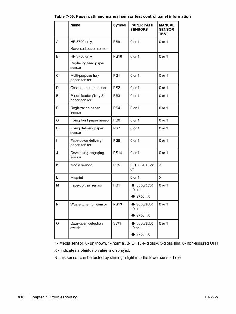
Table 7-50. Paper path and manual sensor test control panel information
Name Symbol PAPER PATHSENSORS
MANUALSENSORTEST
A HP 3700 only
Reversed paper sensor
PS9 0 or 1 0 or 1
B HP 3700 only
Duplexing feed papersensor
PS10 0 or 1 0 or 1
C Multi-purpose traypaper sensor
PS1 0 or 1 0 or 1
D Cassette paper sensor PS2 0 or 1 0 or 1
E Paper feeder (Tray 3)paper sensor
PS3 0 or 1 0 or 1
F Registration papersensor
PS4 0 or 1 0 or 1
G Fixing front paper sensor PS6 0 or 1 0 or 1
H Fixing delivery papersensor
PS7 0 or 1 0 or 1
I Face-down deliverypaper sensor
PS8 0 or 1 0 or 1
J Developing engagingsensor
PS14 0 or 1 0 or 1
K Media sensor PS5 0, 1, 3, 4, 5, or6*
X
L Misprint 0 or 1 X
M Face-up tray sensor PS11 HP 3500/3550- 0 or 1
HP 3700 - X
0 or 1
N Waste toner full sensor PS13 HP 3500/3550- 0 or 1
HP 3700 - X
0 or 1
O Door-open detectionswitch
SW1 HP 3500/3550- 0 or 1
HP 3700 - X
0 or 1
* - Media sensor: 0- unknown, 1- normal, 3- OHT, 4- glossy, 5-gloss film, 6- non-assured OHT
X - indicates a blank; no value is displayed.
N: this sensor can be tested by shining a light into the lower sensor hole.
438 Chapter 7 Troubleshooting ENWW
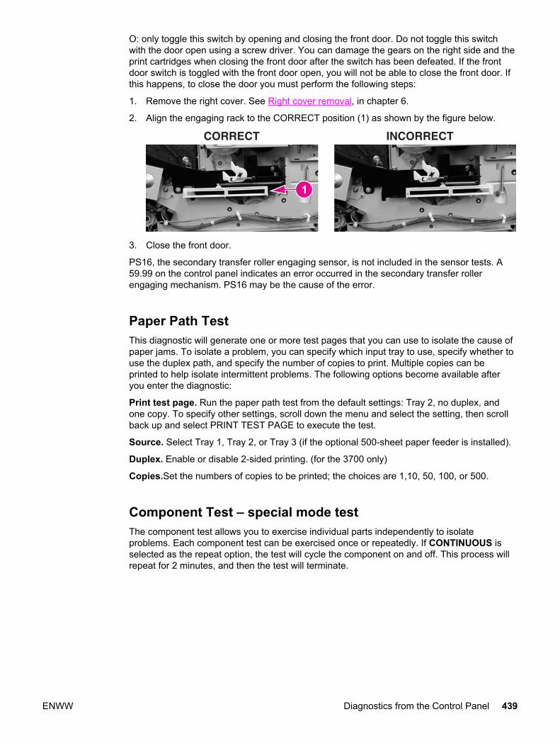
O: only toggle this switch by opening and closing the front door. Do not toggle this switchwith the door open using a screw driver. You can damage the gears on the right side and theprint cartridges when closing the front door after the switch has been defeated. If the frontdoor switch is toggled with the front door open, you will not be able to close the front door. Ifthis happens, to close the door you must perform the following steps:
1. Remove the right cover. See Right cover removal, in chapter 6.
2. Align the engaging rack to the CORRECT position (1) as shown by the figure below.
3. Close the front door.
PS16, the secondary transfer roller engaging sensor, is not included in the sensor tests. A59.99 on the control panel indicates an error occurred in the secondary transfer rollerengaging mechanism. PS16 may be the cause of the error.
Paper Path TestThis diagnostic will generate one or more test pages that you can use to isolate the cause ofpaper jams. To isolate a problem, you can specify which input tray to use, specify whether touse the duplex path, and specify the number of copies to print. Multiple copies can beprinted to help isolate intermittent problems. The following options become available afteryou enter the diagnostic:
Print test page. Run the paper path test from the default settings: Tray 2, no duplex, andone copy. To specify other settings, scroll down the menu and select the setting, then scrollback up and select PRINT TEST PAGE to execute the test.
Source. Select Tray 1, Tray 2, or Tray 3 (if the optional 500-sheet paper feeder is installed).
Duplex. Enable or disable 2-sided printing. (for the 3700 only)
Copies.Set the numbers of copies to be printed; the choices are 1,10, 50, 100, or 500.
Component Test – special mode testThe component test allows you to exercise individual parts independently to isolateproblems. Each component test can be exercised once or repeatedly. If CONTINUOUS isselected as the repeat option, the test will cycle the component on and off. This process willrepeat for 2 minutes, and then the test will terminate.
ENWW Diagnostics from the Control Panel 439
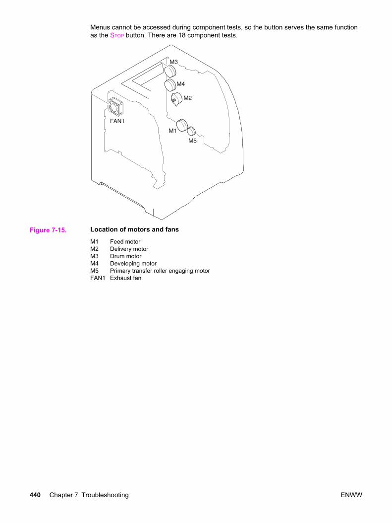
Menus cannot be accessed during component tests, so the button serves the same functionas the STOP button. There are 18 component tests.
Figure 7-15. Location of motors and fans
M1 Feed motorM2 Delivery motorM3 Drum motorM4 Developing motorM5 Primary transfer roller engaging motorFAN1 Exhaust fan
440 Chapter 7 Troubleshooting ENWW

Figure 7-16. Location of solenoids and clutches
SL1 Tray 1 pick-up solenoidSL2 Tray 2 pick-up solenoid (pick-up/feed assembly)SL4 Secondary transfer roller engaging solenoidSL5 Duplex feed solenoidCL1 Registration clutchCL2 K development clutch (image drive unit)CL3 Developing engaging clutch (developing engaging drive unit)
The following 18 tests are available in the component test menu:
1. TRANSFER MOTORS
Drives the drum motor (M3) and developing motor (M4) for 10 seconds which rotates theITB belt, CMYK print cartridge OPC drums, and CMY developers.
2. DRUM AND DRUM MOTOR
Drives the drum motor (M3) for 10 seconds which rotates the ITB belt and the CMYKprint cartridge OPC drums.
3. BLACK LASER SCANNER
Drives the scanner motor (cyan/black) for 10 seconds.
4. CYAN LASER SCANNER
Drives the scanner motor (cyan/black) for 10 seconds.
5. MAGENTA LASER SCANNER
Drives the scanner motor (magenta/yellow) for 10 seconds.
6. YELLOW LASER SCANNER
Drives the scanner motor (magenta/yellow) for 10 seconds.
7. DEVELOPER MOTORS
Drives the developer motor (M4) which rotates the C,M,Y print cartridge developers.
ENWW Diagnostics from the Control Panel 441

8. ALIENATION MOTOR
Drives the delivery motor (M2) and the developing engaging clutch (CL3) which rotatesthe rear output paper path rollers and engages/disengages the CMYK print cartridgedeveloper rollers. This test does not rotate the print cartridge developer rollers.
9. TRANSFER 1 MOTOR
Drives the primary transfer roller engaging motor (M5) which engages/disengages theCMYK ITB primary charging rollers.
10. MP TRAY SOLENOID
Drives the feed motor (M1) and the multi purpose pickup solenoid (SL1) which pickspaper from the Tray 1.
11. TRAY 2 SOLENOID
Drives the feed motor (M1) and the cassette Tray 2 pickup solenoid (SL2) which pickspaper from Tray 2.
12. FUSER MOTOR
Drives the feed motor (M1) and registration clutch (CL1) for 10 seconds which rotatesthe fuser, paper path rollers, and Tray 3 drive rollers.
13. DUPLEX MOTOR (3700 only)
Drives the delivery motor (M2) which rotates the rear output paper path rollers.
14. TRANSFER 2 SOLENOID
Drives the feed motor (M1) and the secondary transfer roller engaging solenoid (SL4)which rotates the fuser, paper path rollers, Tray 3 drive rollers, and engages thesecondary transfer roller which raises it about 1/2 inch.
15. DUPLEX SOLENOID
Drives the feed motor (M1) and the duplexing feed solenoid drive (SL5) which rotatesthe fuser, paper path rollers, and duplexing feed roller. Remove Tray 2 to see the gearturning on the right side of the duplex area inside Tray 2.
16. BLACK DEVELOPER DRIVE
Drives the drum motor (M3) and black print cartridge drive clutch (CL2) for 10 secondswhich rotates the ITB belt, CMYK print cartridge OPC drums, and black developer.
17. TRAY 3 DRIVE
Drives the feed motor (M1) and paper feeder pick-up clutch (CL4) for 10 seconds whichrotates the fuser, paper path rollers, and Tray 3 drive rollers.
18. TRAY 3 SOLENOID
Drives the feed motor (M1) and paper feeder pickup solenoid (SL3) which picks paperfrom Tray 3.
Print/Stop TestThis diagnostic test can be used to isolate the cause of problems, such as image formationdefects and jams, within the engine. This test allows you to stop the paper anywhere alongthe printer's paper path. The test can be programmed to stop printing internal pages or anexternal print job when the paper reaches a certain position. The test can also beprogrammed to stop from 0 to 60,000 mS. If the timer is set to a value that is greater than ittakes to print the job, there are two ways to recover the printer.
442 Chapter 7 Troubleshooting ENWW

After the print job completes, press STOP to return to the diagnostic menu before the timertimes out.
After the timer times out, press STOP. You will have to cycle the door switch by opening andclosing the front door to restart the engine and return it to a normal state. When the timertrips, the display shows the message PRINTING STOPPED, PRESS Check TOCONTINUE. Pressing will print the previously selected job. If you do not want the previousjob to print, press STOP first, and then press the button.
NOTE Do not attempt to execute a Print/Stop test while the printer is calibrating; a power cycle willbe required. If you encounter a jam message during testing, cycle the door switch.
Information menuFrom the information menu, the following pages can be printed.
Print Menu Map. prints the control panel menu map, which shows the layout and currentsettings of the control panel menu items.
Print Configuration used to help troubleshoot printer problems or to verify installation ofoptional accessories such as memory (DIMMs), paper trays, and printer languages.
Print Supplies Status Page prints a page that indicates remaining life of supplies.
Supplies Status displays on the control panel the remaining life of supplies.
Print Usage Page HP 3700 only. Indicates page count for each tray and the size and typeof media printed.
Print Demo used to test print quality by printing a demo page.
Print File Directory HP 3700 only. Prints the name and directory of files stored in the printersuch as a RAM disk.
Print PCL Font test page HP 3700 only. Prints available PCL fonts.
Print PS Font List HP 3700 only. Prints the available PS (emulated PostScript) fonts.
Configure device menu/printing menuPrint PS Errors HP 3700 only. Allows you to print the PS error pages.
Configure device menu/resets menuRestore Factory Settings allows you to clear the page buffer, remove all perishablepersonality data, reset the printing environment, and return all default settings to factorydefaults.
Reset Supplies New Transfer Kit or New Fuser Kit – Allows you to inform the printer that anew transfer kit or new fuser kit has been installed which will reset the page count of thatsupply to zero.
Configure device menu/print quality menuCalibrate Now used to calibrate the printer to maintain optimum print quality. It executes allprinter calibrations: DMAX, DHALF, color plane registration, and drum phase adjustment.
Adjust Color, Print Modes, and OptimizeThese can be used to optimize print quality.
ENWW Diagnostics from the Control Panel 443

Set Registration Allows 1 sided and 2 sided image alignment.
Create Cleaning Page used to generate a cleaning page to clean spots off the fuser rollers.
Process Cleaning Page used to feed a cleaning page to clean spots off the fuser rollers.
444 Chapter 7 Troubleshooting ENWW
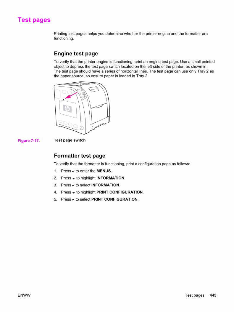
Test pages
Printing test pages helps you determine whether the printer engine and the formatter arefunctioning.
Engine test page To verify that the printer engine is functioning, print an engine test page. Use a small pointedobject to depress the test page switch located on the left side of the printer, as shown in .The test page should have a series of horizontal lines. The test page can use only Tray 2 asthe paper source, so ensure paper is loaded in Tray 2.
Figure 7-17. Test page switch
Formatter test pageTo verify that the formatter is functioning, print a configuration page as follows:
1. Press to enter the MENUS.
2. Press to highlight INFORMATION.
3. Press to select INFORMATION.
4. Press to highlight PRINT CONFIGURATION.
5. Press to select PRINT CONFIGURATION.
ENWW Test pages 445
Engine resets
This section provides information about the printer's cold reset and the NVRAM initialization.
Cold reset A cold reset unlocks menus that have been locked and resets variables in the control panel.However, it does not clear the values in the Service menu (such as the serial number andpage counts).
To perform a cold reset1. Turn the printer on.
2. As the printer performs its power-on sequence, press and hold until all three lights onthe control panel are lit.
3. When SELECT LANGUAGE appears on the display, press until COLD RESETappears on the display.
4. Press . The printer will perform a cold reset and then continue its power-on sequence.
NVRAM initialization
CAUTION Initializing NVRAM will reset the serial number, the event log, the page counts, thecalibration settings, and the EIO card (HP 3700 only). Use the Service menu to restore theserial number and page counts. You will also need to reconfigure any computers that print tothis printer to recognize the printer. Initialize NVRAM only when absolutely necessary. Inmost situations, use a Cold reset to reset printer variables but still retain the needed valuesin the Service menu.
Before initializing NVRAM, print a configuration page and a supplies status page or go to theservice menu to gather the following information:
● total page count and color page count
● fuser kit count
● serial number
To initialize NVRAM1. Turn the printer on and watch the control panel display.
2. When the display begins showing the memory count, press and hold until all threelights on the control panel are lit.
3. Press .
4. Press Menu. The display should show SKIP DISK LOAD.
5. Press until NVRAM INIT is highlighted.
6. Press . The printer will initialize NVRAM and then continue its power-on sequence.
446 Chapter 7 Troubleshooting ENWW

Calibration bypass During certain diagnostic procedures, you will need to bypass the automatic calibration thatis performed whenever the printer is turned on.
To bypass calibration1. Turn the printer on and watch the control panel display.
2. When the display begins showing the memory count, press and hold until all threelights on the control panel are lit.
3. Press .
4. Press Menu. The display should show SKIP DISK LOAD.
5. Press until SKIP CALIBRATION is highlighted.
6. Press . The printer will skip calibration and then continue its power-on sequence.
Calibrate Now Use the following procedure to calibrate the printer whenever you replace the DC controller,the formatter, the color misregistration sensor (PS12), the transfer unit, or the laser/scanner.
1. Press to enter the MENUS.
2. Press to highlight configure device.
3. Press to select configure device.
4. Press to highlight PRINT quality.
5. Press to select PRINT quality.
6. Press to highlight CALIBRATE NOW.
7. Press to select CALIBRATE NOW.
8. Wait for the printer to calibrate.
ENWW Engine resets 447

Service menu
This section provides information about accessing the service menu and its operation.
Accessing the Service menuThe Service menu is PIN protected for added security. Only authorized service people haveaccess to the Service menu. When you select SERVICE from the list of menus, you areprompted to enter your 8-digit PIN number. The PIN for the HP Color LaserJet 3500/3550series printer is 10350003 and for the HP Color LaserJet 3700 series printer is 10370003.
1. Press or until the first digit of the PIN is displayed.
2. Press to save the digit. The display will replace the digit with an asterisk.
3. Repeat steps 1 and 2 until all eight digits are entered.
4. Press at any time to move to the previous digit.
Clear event logThis item allows you to clear the printer’s internal event log.
Total page countThe page count stored in NVRAM and printed on the configuration page represents thenumber of pages that the formatter has formatted (not including engine test prints). If youinstall a new formatter when repairing a printer, use this menu item to reset the page countto the previous value. In this way, the page count reflects the number of pages printed by theengine rather than starting over for the new formatter. The page count is broken into twocategories: total mono pages and total color pages.
Transfer kit countThis value can be changed in the service menu but it will not change the value of thetransfer kit. This value is initially set to zero at the factory. This value is automatically reset tozero when a customer installs a new transfer kit and sets NEW TRANSFER KIT to YES inthe Resets menu.
If only the formatter is replaced, the transfer kit page count will not be lost.
Fuser kit countThis item allows you to reset the fuser count if the value is lost, such as when you replacethe formatter. This value is initially set to zero at the factory. Enter a value up to 60,000 forthe hp 3500 and 75,000 for the HP 3700/3550. This value is automatically reset to zerowhen a customer installs a new transfer kit and sets NEW FUSER KIT to YES in the Resetsmenu.
Serial numberIf you replace the formatter, use this item to reset the serial number of the printer.
448 Chapter 7 Troubleshooting ENWW
Service IDThis item allows the date that the printer was first used to be shown through the controlpanel, eliminating the need for customers to keep paper receipts for proof of warranty.Because the printer does not have an internal clock, the service ID date’s availability isdependent on the printer being connected to a source that can provide the date, such as theinstaller, the driver, or the embedded Web server. In cases where the printer is notconnected to a date source, the service ID will not be available, and the control panel willdisplay 000000.
Restoring the Service IDIf you replace the formatter, the date is lost. Use this menu item to reset the date to theoriginal date the printer was first used. The date format is YYDDD. Calculate the date asfollows:
1. To calculate YY, subtract 1990 from the calendar year. For instance, if the printer wasfirst used in 2002, calculate YY as follows: 2002 – 1990 = 12. YY = 12.
2. To calculate DDD, use the following formula: 30(calendar month – 1) + calendar day =DDD. If the calendar day is 31, use 30 instead. For instance, if the printer was first usedon October 17, calculate DDD as follows:
3. Subtract 1 from 10 (October is the tenth month of the year): 10 – 1 = 9.
4. Multiply 9 by 30: 9 x 30 = 270.
5. Add 17 to 270: 270 + 17 = 287. Thus, DDD = 287.
Converting the Service ID to an actual dateYou can use the printer’s Service ID number to determine whether the printer is still underwarranty. Convert the Service ID into the installation date as follows:
1. Add 1990 to YY to get the actual year that the printer was installed.
2. Divide DDD by 30. If there is a remainder, add 1 to the result. This is the month.
3. The remainder from the calculation in step 2 is the date.
Using the Service ID 12287 as an example, the date conversion is as follows:
1. 12 + 1990 = 2002, so the year is 2002.
2. 287 divided by 30 = 9 with a remainder of 17. Since there is a remainder, add 1 to 9 toget 10, which represents October.
3. The remainder in step 2 is 17, so that is the date.
4. The complete date is 17-October-2002.
NOTE A 6-day grace period is built into the date system.
Cold reset paperWhen you perform a cold reset, the paper size stored in NVRAM is reset to the defaultfactory setting. If you replace a formatter board in a country/region such as Europe that usesA4 as the standard paper size, use this menu to reset the default paper size to A4. LETTERand A4 are the only available values.
ENWW Service menu 449

Diagrams
This section contains printer diagrams for locating parts for troublshooting.
450 Chapter 7 Troubleshooting ENWW
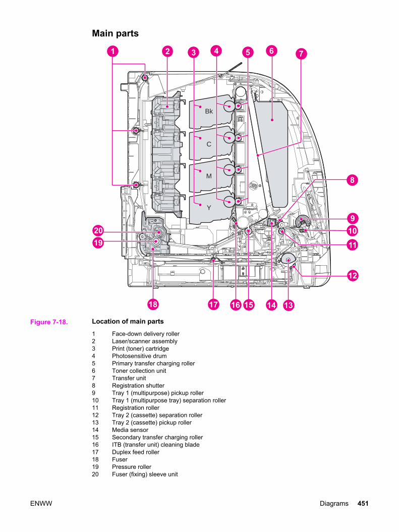
Main parts
Bk
C
M
Y
Figure 7-18. Location of main parts
1 Face-down delivery roller2 Laser/scanner assembly3 Print (toner) cartridge4 Photosensitive drum5 Primary transfer charging roller6 Toner collection unit7 Transfer unit8 Registration shutter9 Tray 1 (multipurpose) pickup roller10 Tray 1 (multipurpose tray) separation roller11 Registration roller12 Tray 2 (cassette) separation roller13 Tray 2 (cassette) pickup roller14 Media sensor15 Secondary transfer charging roller16 ITB (transfer unit) cleaning blade17 Duplex feed roller18 Fuser19 Pressure roller20 Fuser (fixing) sleeve unit
ENWW Diagrams 451

Switches
Figure 7-19. Location of switches
SW1 Door switchSW1001Test print switchSW3001Power switch
452 Chapter 7 Troubleshooting ENWW
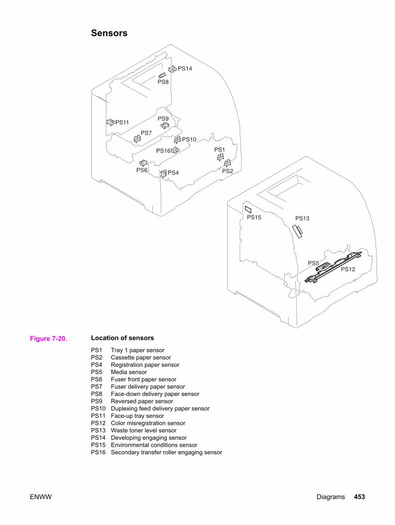
Sensors
Figure 7-20. Location of sensors
PS1 Tray 1 paper sensorPS2 Cassette paper sensorPS4 Registration paper sensorPS5 Media sensorPS6 Fuser front paper sensorPS7 Fuser delivery paper sensorPS8 Face-down delivery paper sensorPS9 Reversed paper sensorPS10 Duplexing feed delivery paper sensorPS11 Face-up tray sensorPS12 Color misregistration sensorPS13 Waste toner level sensorPS14 Developing engaging sensorPS15 Environmental conditions sensorPS16 Secondary transfer roller engaging sensor
ENWW Diagrams 453

Solenoids and clutches
Figure 7-21. Location of solenoids and clutches
SL1 Tray 1 pick-up solenoidSL2 Tray 2 pick-up solenoid (pick-up/feed assembly)SL4 Secondary transfer roller engaging solenoidSL5 Duplex feed solenoidCL1 Registration clutchCL2 K development clutch (image drive unit)CL3 Developing engaging clutch (developing engaging drive unit)
454 Chapter 7 Troubleshooting ENWW
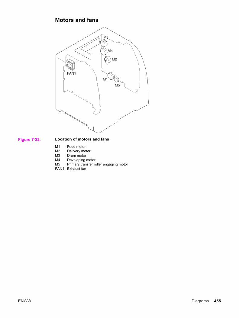
Motors and fans
Figure 7-22. Location of motors and fans
M1 Feed motorM2 Delivery motorM3 Drum motorM4 Developing motorM5 Primary transfer roller engaging motorFAN1 Exhaust fan
ENWW Diagrams 455

PCBs
Figure 7-23. PCB locations
1 DC controller PCB2 Memory controller PCB3 High-voltage power supply PCBs4 Low-voltage power supply PCB5 Formatter PCB6 Control panel PCB
456 Chapter 7 Troubleshooting ENWW

J1025 J1022
J101
5
J1023 J1005
J102
4
J102
7J1
026
J1031
SW1001 J1028
J1001 J1002
J100
4J1
003
J100
8
J100
9
J101
1
J100
6
J1010
CP1015
J1028
J1014J1016J1012J1019
J1013
Figure 7-24. Location of DC controller PCB connectors (HP 3700)
J1025 J1022
J101
5
J1023 J1005
J102
4
J102
7J1
026
J1031
SW1001 J1028
J1001 J1002
J100
4J1
003
J100
8
J100
9
J101
1
J100
6
J1010
CP1015
J1029
J1014J1016J1012J1019
Figure 7-25. Location of DC controller PCB connectors (HP 3500/3550)
ENWW Diagrams 457
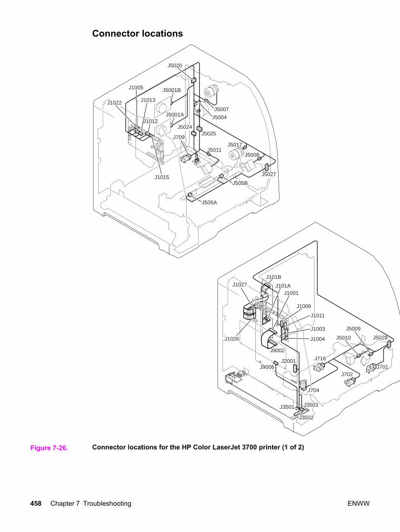
Connector locations
J1022
J5027
J5017
J5008J5011
J5025J5024
J709
J5001B
J5001A
J505A
J505B
J5020
J1005
J1013
J1012
J1015
J1006
J716
J704
J702J701
J5028J5010
J5009
J9002
J3503
J1001
J1011
J1003
J1004
J101B
J101A
J1026
J1027
J2001
J3502
J3501
J9006
J5004
J5007
Figure 7-26. Connector locations for the HP Color LaserJet 3700 printer (1 of 2)
458 Chapter 7 Troubleshooting ENWW
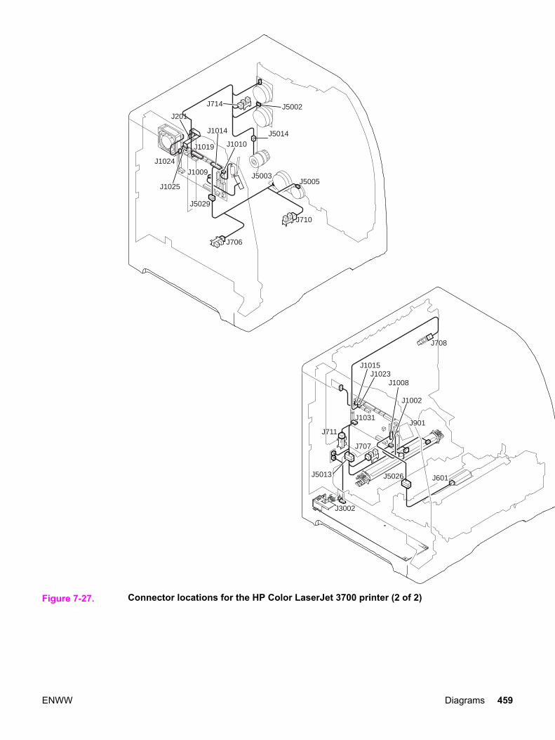
J1014
J710
J706
J5005J5003
J5029
J1010
J1009
J1024
J201
J1025
J1015
J708
J1008J1023
J1031
J707
J711
J3002
J5013 J5026 J601
J1002
J714 J5002
J5014
J1019
J901
Figure 7-27. Connector locations for the HP Color LaserJet 3700 printer (2 of 2)
ENWW Diagrams 459

J1022
J5027
J5017
J5008
J5024
J5001B
J5001A
J505A
J505B
J5020
J1005
J1012
J1015
J5004
J5007
J1006
J716
J704
J702J701
J5028J5010
J5009
J9002
J3503
J1001
J1011
J1003
J1004
J101B
J101A
J1026
J1027
J2001
J3502
J3501
J9006
Figure 7-28. Connector locations for the HP Color LaserJet 3500/3550 printer (1 of 2)
460 Chapter 7 Troubleshooting ENWW

J1014
J706
J5005J5003
J5029
J1010
J1009
J1024
J201
J1025
J1015
J708
J1008J1023
J1031
J707
J711
J3002
J5013 J5026 J601
J1002
J714 J5002
J5014
J1019
J901
Figure 7-29. Connector locations for the HP Color LaserJet 3500/3550 printer (2 of 2)
ENWW Diagrams 461

500-sheet paper feeder connectors
J4001
J4004
J4003
J4002
J5012LAJ5012LB
J703
Figure 7-30. Connector locations for the 500-sheet paper feeder
462 Chapter 7 Troubleshooting ENWW

General circuit diagramThe circuit diagram for the printer is provided in the following two figures. In addition, the 500-sheet feeder is also provided following the general circuit diagrams.
Figure 7-31. General circuit diagram (1 of 2)
ENWW Diagrams 463
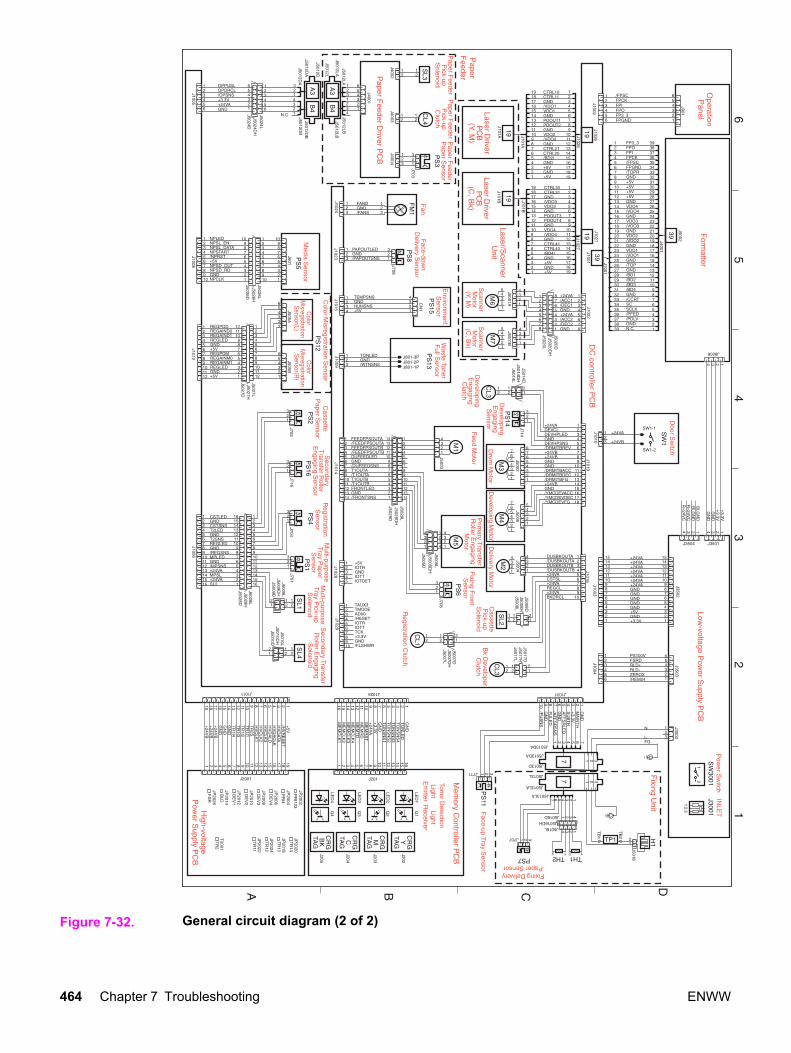
Figure 7-32. General circuit diagram (2 of 2)
464 Chapter 7 Troubleshooting ENWW
8 Parts and diagrams
Chapter contents
This chapter contains the following sections.
Chapter contents ...................................................................................................................465Introduction ............................................................................................................................466Ordering parts .......................................................................................................................467
Supplies and accessories ...............................................................................................467Replacement parts configuration ....................................................................................473
Illustrations and parts lists .....................................................................................................478
ENWW Chapter contents 465

Introduction
The figures in this chapter show the major subassemblies in the printer and their componentparts. A table (materials list) follows each exploded assembly diagram. Each table lists thereference designator (item number), the associated part number, and the description of eachpart.
NOTE When looking for a part number, pay careful attention to the voltage listed in the descriptioncolumn to ensure that the part number selected is for the correct printer model.
NOTE In this manual, the abbreviation "PCB" stands for "printed circuit board assembly."Components described as a PCB may consist of a single circuit board or a circuit board plusother parts, such as cables and sensors.
466 Chapter 8 Parts and diagrams ENWW
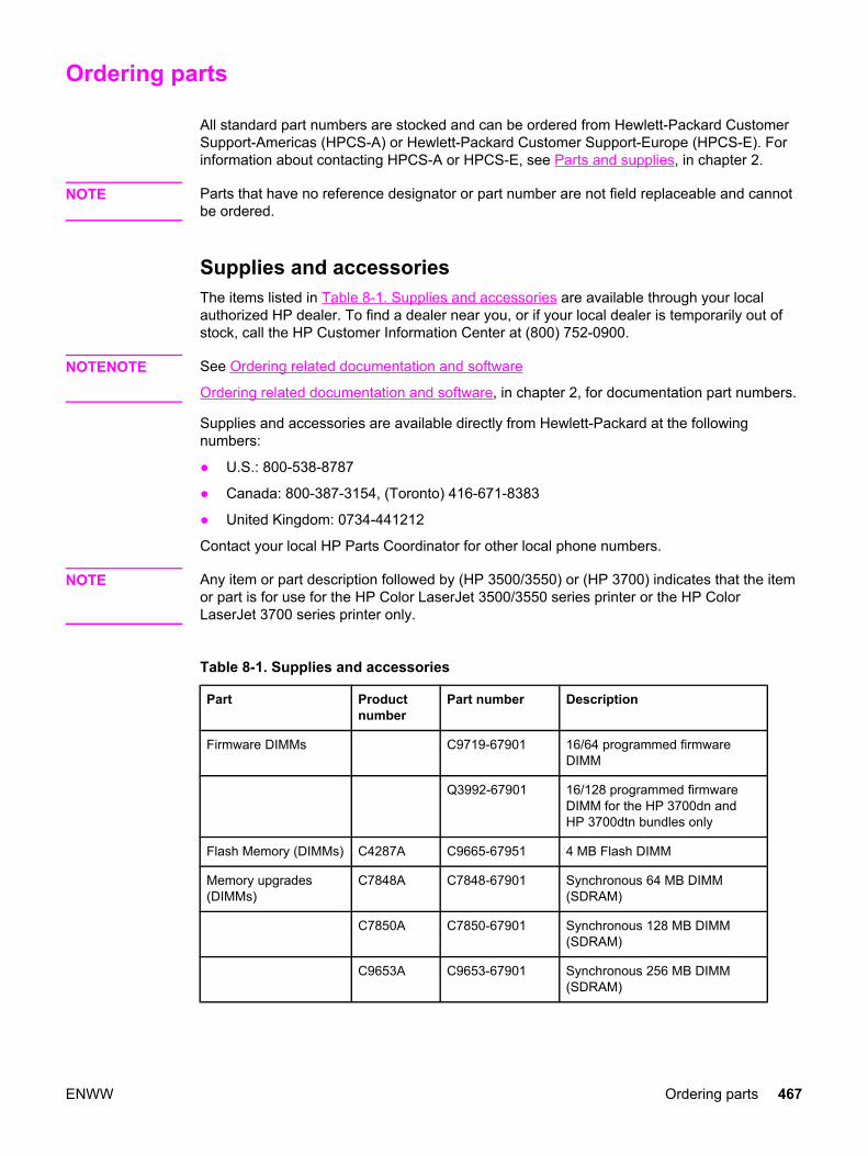
Ordering parts
All standard part numbers are stocked and can be ordered from Hewlett-Packard CustomerSupport-Americas (HPCS-A) or Hewlett-Packard Customer Support-Europe (HPCS-E). Forinformation about contacting HPCS-A or HPCS-E, see Parts and supplies, in chapter 2.
NOTE Parts that have no reference designator or part number are not field replaceable and cannotbe ordered.
Supplies and accessoriesThe items listed in Table 8-1. Supplies and accessories are available through your localauthorized HP dealer. To find a dealer near you, or if your local dealer is temporarily out ofstock, call the HP Customer Information Center at (800) 752-0900.
NOTENOTE See Ordering related documentation and software
Ordering related documentation and software, in chapter 2, for documentation part numbers.
Supplies and accessories are available directly from Hewlett-Packard at the followingnumbers:
● U.S.: 800-538-8787
● Canada: 800-387-3154, (Toronto) 416-671-8383
● United Kingdom: 0734-441212
Contact your local HP Parts Coordinator for other local phone numbers.
NOTE Any item or part description followed by (HP 3500/3550) or (HP 3700) indicates that the itemor part is for use for the HP Color LaserJet 3500/3550 series printer or the HP ColorLaserJet 3700 series printer only.
Table 8-1. Supplies and accessories
Part Productnumber
Part number Description
Firmware DIMMs C9719-67901 16/64 programmed firmwareDIMM
Q3992-67901 16/128 programmed firmwareDIMM for the HP 3700dn andHP 3700dtn bundles only
Flash Memory (DIMMs) C4287A C9665-67951 4 MB Flash DIMM
Memory upgrades(DIMMs)
C7848A C7848-67901 Synchronous 64 MB DIMM(SDRAM)
C7850A C7850-67901 Synchronous 128 MB DIMM(SDRAM)
C9653A C9653-67901 Synchronous 256 MB DIMM(SDRAM)
ENWW Ordering parts 467

Part Productnumber
Part number Description
Accessories Q2486A Q2486-67901 Optional 500-sheet paper feeder(Tray 3) Internal (EIO)connectivity for the HP ColorLaserJet 3700 series printer
Internal (EIO) I/O PCB
(Exchange part)
Connectivity for theHP Color LaserJet3700 series printer
J6057A J6057-69001 HP Jetdirect 615n internal printserver (10/100-TX, Ethernet, HI-Speed USB 2.0)
J4167A HP Jetdirect 610n print server(Token Ring)
J6058A HP Jetdirect 680n 802.11bwireless print server
J4135A HP Jetdirect connectivity card(USB, serial, and LocalTalk)
External (EX) I/O PCB
Exchange
Connectivity for theHP Color LaserJet3500/3550 seriesprinter
J7942A J7942-69001 HP Jetdirect en3700 externalprint server (10/100base Tx,USB 2.0 HI-speed) exchange
J6061A HP Jetdirect 380x 802.11bwireless print server (USB 1.1)
J6035B HP Jetdirect 175x print server(fast Ethernet, 10/100base Tx,USB 1.1)
J6072A HP bt1300 Bluetooth wirelessprinter adapter (for USB orparallel)
External (EX)connectivity for theHP Color LaserJet3700 series printer
J3264A J7942-69001 HP Jetdirect 500x print server(Token Ring)
J3265A HP Jetdirect 500x print server(fast Ethernet)
J3258B HP Jetdirect 170x print server(Ethernet)
J7942A HP Jetdirect en3700 externalprint server (10/100base Tx, Hi-Speed USB 2.0)
J6061A HP Jetdirect 380x 802.11bwireless print server (USB 1.1)
Table 8-1. Supplies and accessories (continued)
468 Chapter 8 Parts and diagrams ENWW

Part Productnumber
Part number Description
J6035B HP Jetdirect 175x print server(fast Ethernet 10/100base Tx,USB 1.1)
J6072A HP bt1300 Bluetooth wirelessprinter adapter (for USB orparallel)
Supplies for theHP Color LaserJet3500/3550 seriesprinter
Q2670A Black print cartridge for theHP Color LaserJet 3500/3550series printer
Q2671A Cyan print cartridge for theHP Color LaserJet 3500/3550series printer
Q2672A Yellow print cartridge for theHP Color LaserJet 3500/3550series printer
Q2673A Magenta print cartridge for theHP Color LaserJet 3500/3550series printer
Q3658A Q3658-69001 Image transfer kit
Q3655A Q3655-69001 Image fuser kit (110-127V)
Q3656A Q3656-69001 Image fuser kit (220-240V)
Supplies for the 3700series printer
Q2670A Black print cartridge for theHP Color LaserJet 3700 seriesprinter
Q2681A Cyan print cartridge for theHP Color LaserJet 3700 seriesprinter
Q2682A Yellow print cartridge for theHP Color LaserJet 3700 seriesprinter
Q2683A Magenta print cartridge for theHP Color LaserJet 3700 seriesprinter
Q3658A Q3658-69001 Image transfer kit
Q3655A Q3655-69001 Image fuser kit (110-127V)
Q3656A Q3656-69001 Image fuser kit (220-240V)
Cables C cable IEEE-1284 compliant parallelcable, 3 m (approximately 10feet) long, with 25-pin male/micro 36-pin male ("C" size)connector
C6518A 8120-8485 USB (2-meter standard)
Table 8-1. Supplies and accessories (continued)
ENWW Ordering parts 469
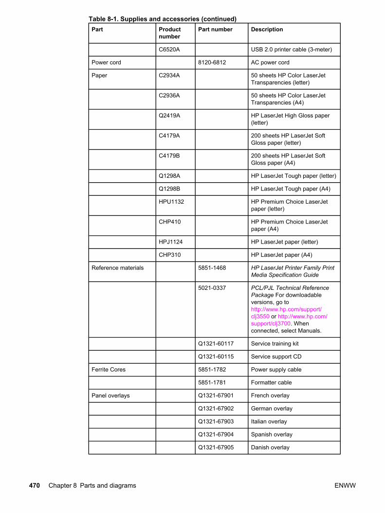
Part Productnumber
Part number Description
C6520A USB 2.0 printer cable (3-meter)
Power cord 8120-6812 AC power cord
Paper C2934A 50 sheets HP Color LaserJetTransparencies (letter)
C2936A 50 sheets HP Color LaserJetTransparencies (A4)
Q2419A HP LaserJet High Gloss paper(letter)
C4179A 200 sheets HP LaserJet SoftGloss paper (letter)
C4179B 200 sheets HP LaserJet SoftGloss paper (A4)
Q1298A HP LaserJet Tough paper (letter)
Q1298B HP LaserJet Tough paper (A4)
HPU1132 HP Premium Choice LaserJetpaper (letter)
CHP410 HP Premium Choice LaserJetpaper (A4)
HPJ1124 HP LaserJet paper (letter)
CHP310 HP LaserJet paper (A4)
Reference materials 5851-1468 HP LaserJet Printer Family PrintMedia Specification Guide
5021-0337 PCL/PJL Technical ReferencePackage For downloadableversions, go tohttp://www.hp.com/support/clj3550 or http://www.hp.com/support/clj3700. Whenconnected, select Manuals.
Q1321-60117 Service training kit
Q1321-60115 Service support CD
Ferrite Cores 5851-1782 Power supply cable
5851-1781 Formatter cable
Panel overlays Q1321-67901 French overlay
Q1321-67902 German overlay
Q1321-67903 Italian overlay
Q1321-67904 Spanish overlay
Q1321-67905 Danish overlay
Table 8-1. Supplies and accessories (continued)
470 Chapter 8 Parts and diagrams ENWW
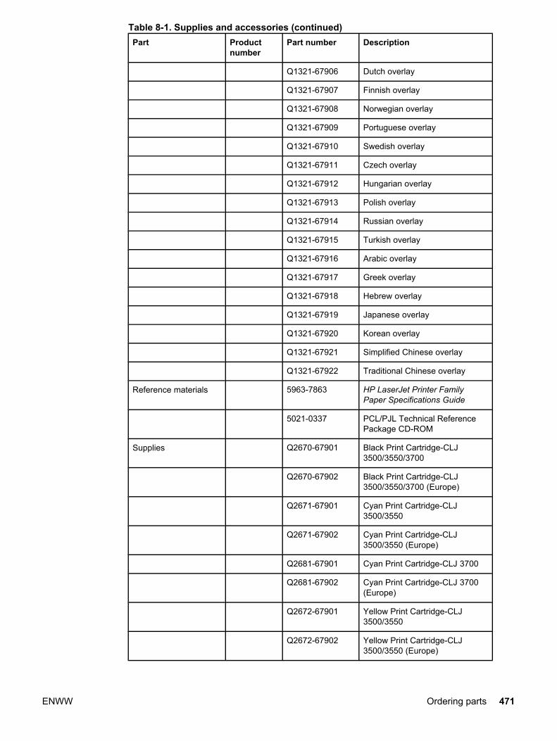
Part Productnumber
Part number Description
Q1321-67906 Dutch overlay
Q1321-67907 Finnish overlay
Q1321-67908 Norwegian overlay
Q1321-67909 Portuguese overlay
Q1321-67910 Swedish overlay
Q1321-67911 Czech overlay
Q1321-67912 Hungarian overlay
Q1321-67913 Polish overlay
Q1321-67914 Russian overlay
Q1321-67915 Turkish overlay
Q1321-67916 Arabic overlay
Q1321-67917 Greek overlay
Q1321-67918 Hebrew overlay
Q1321-67919 Japanese overlay
Q1321-67920 Korean overlay
Q1321-67921 Simplified Chinese overlay
Q1321-67922 Traditional Chinese overlay
Reference materials 5963-7863 HP LaserJet Printer FamilyPaper Specifications Guide
5021-0337 PCL/PJL Technical ReferencePackage CD-ROM
Supplies Q2670-67901 Black Print Cartridge-CLJ3500/3550/3700
Q2670-67902 Black Print Cartridge-CLJ3500/3550/3700 (Europe)
Q2671-67901 Cyan Print Cartridge-CLJ3500/3550
Q2671-67902 Cyan Print Cartridge-CLJ3500/3550 (Europe)
Q2681-67901 Cyan Print Cartridge-CLJ 3700
Q2681-67902 Cyan Print Cartridge-CLJ 3700(Europe)
Q2672-67901 Yellow Print Cartridge-CLJ3500/3550
Q2672-67902 Yellow Print Cartridge-CLJ3500/3550 (Europe)
Table 8-1. Supplies and accessories (continued)
ENWW Ordering parts 471

Part Productnumber
Part number Description
Q2682-67901 Yellow Print Cartridge-CLJ 3700
Q2682-67901 Yellow Print Cartridge-CLJ 3700(Europe)
Q2673-67901 Magenta Print Cartridge-CLJ3500/3550
Q2673-67902 Magenta Print Cartridge-CLJ3500/3550 (Europe)
Q2683-67901 Magenta Print Cartridge-CLJ3700
Q2683-67902 Magenta Print Cartridge-CLJ3700 (Europe)
5090-3379 Toner cleaning cloth
NOTE The only difference between the print cartridges listed above is that the Europe-only printcartridges have different languages on the instruction sheet inside the box.
Table 8-2. Common fasteners
Illustration Description Size Part number Use
SCREW, TP M4X6 XA9-1450-000CN Secures metal framepanels to metal framepanels.
SCREW, W/WASHER
M3X6 XA9-1477-000CN Secures the drawer, crossmember, to the frame(see Figure 8-11. Internalcomponents (4 of 4)).
SCREW, W/WASHER, RS
M3X6 XA9-1461-000CN Secures motor (M2) to theframe.
SCREW W/WASHER
M3X8 XA9-1420-000CN Secures metal to metal(ground wire, feed guiderear two screws)
SCREW, W/WASHER
M3X12 XA9-1452-000CN Secures laser/scannerassembly to the metalframe.
SCREW, RS M3X6 XA9-1499-000CN Secures metal to metal.
SCREW, RS M3X8 XA9-1445-000CN secures any material(except metal) to metal
Table 8-1. Supplies and accessories (continued)
472 Chapter 8 Parts and diagrams ENWW

Illustration Description Size Part number Use
SCREW, TP XB4-7300-805CN Secures sensor PCB toplastic (environmental,toner full, colormisregistration, andmedia).
SCREW,TAPPING,TRUSS HEAD
M4X10 XB4-7401-005CN Secures anything toplastic.
SCREW,STEPPED
M4X4.5 RC1-1624000CN Secures the right side ofthe pick-up/feed assemblyto the frame.
SCREW, S M3X8 XA9-1500-000CN Secures plastic to metal:front door components,rear swing guide rail,components to centerframe (see Figure 8-16.Lower Frame Assembly -HP 3700 andHP 3500/3550 (2 of 2))
Replacement parts configurationWhen the parts in the list below are replaced, specific tasks need to be performed. Theseparts include:
● Formatter and DC Controller replaced at the same time
● Formatter (new and previously installed in another printer)
● DC Controller (new and previously installed in another printer)
● Media sensor (PS5)
● Color Misregistration Sensor (PS12)
● Laser Scanner Assembly
● Fuser
● Transfer unit (ITB assembly)
Configuration procedures for these parts are described in the following sections.
Table 8-2. Common fasteners (continued)
ENWW Ordering parts 473

Formatter and DC Controller replaced at the same timeDo not replace both the formatter and the DC Controller at the same time. Replace oneat a time. If the formatter and DC Controller are replaced at the same time in an HP ColorLaserJet 3700 series printerthat has the ability to perform duplex printing, this functionalitywill be lost. To determine if the printer can duplex, print a configuration page from theInformation menu and reference Paper Trays and Options. If Duplex Unit is listed, theprinter is able to duplex and the formatter and DC Controller should be replaced one at atime.
If the DC Controller and Formatter are replaced one at a time, then the duplex printingcapability will be transferred to the new DC controller or Formatter.
A printer specific PJL file will be needed to re-enable duplexing in the current printer (will notwork on any other printer), if both the formatter and DC Controller are replaced at the sametime. This file will only work in the current printer. Call for assistance from HP Support toobtain the PJL file. Also, perform the Formatter and DC Controller replacement steps asrequired below.
Formatter (New) replacement configurationThe values for Total Mono Pages, Total Color Pages, Serial Number, Service ID, Cold ResetPaper (if needed), and the Fuser Kit Count will need to be reset using the service menu.
NOTE The Transfer Kit count will be unaffected by the replacement of a formatter.
Print a configuration page and a supplies status page in the Information menu to obtain thepage counts, counts for any of the supplies, serial number, and the born-on date. If aconfiguration page and a supplies status page cannot be printed, this information can beobtained from the Service menu prior to replacing the formatter.
To ensure optimum print quality, the printer will need to be calibrated by performing 3Calibrate Now's using the printer control panel by selecting Configure Device / PRINTQUALITY / CALIBRATE NOW.
Formatter (previously installed in another printer) replacementconfigurationWhen the formatter PCB is being replaced with one that was installed in another printer, anNVRAM initialization will need to be performed. Before doing an NVRAM INIT, print aconfiguration page and a supplies status page in the Information menu to obtain the pagecounts, counts for any of the supplies, serial number, and the born-on date. If a configurationpage and a supplies status page cannot be printed, this information can be obtained fromthe Service menu prior to replacing the formatter or performing this action.
1. To perform an NVRAM initialization follow the procedure below.
2. Press and hold the button after powering up until all LEDs are on, then release the button.
3. Press the button once and release.
4. Press MENU once and release. The list of choices will be displayed.
5. Press or until NVRAM INIT is highlighted.
6. Press to invoke an NVRAM INIT.
474 Chapter 8 Parts and diagrams ENWW
In addition, the Total Mono Pages, Total Color Pages, Serial Number, Service ID, ColdReset Paper (if needed), and the Fuser Kit Count will need to be reset using the servicemenu. The Transfer Kit count will be unaffected by the replacement of a formatter.
To ensure optimum print quality, the printer will need to be calibrated by performing 3Calibrate Now's using the printer control panel by selecting Configure Device / PRINTQUALITY / CALIBRATE NOW.
DC Controller (New) replacement configurationTo ensure optimum print quality, the printer will need to be calibrated by performing 3Calibrate Now's using the printer control panel by selecting Configure Device / PRINTQUALITY / CALIBRATE NOW.
Light intensity of the media sensor must be adjusted. Follow the procedure below to adjustthe light intensity.
1. Turn the printer OFF.
2. Open the front cover.
3. While pressing the engine test print switch on the left side of the printer (see Figure7-16. Location of solenoids and clutches), turn the printer ON.
4. Close the front cover.
5. Load plain white paper in the Tray 1.
6. As the printer goes into Ready period, press the engine test print switch and test print.
7. One sheet of paper will be fed into the printer from the Tray 1 and will be delivered to theface-down delivery tray.
DC Controller (previously installed in another printer) replacementconfigurationTo ensure optimum print quality, the printer needs to be calibrated by performing 3 CalibrateNow's using the printer control panel by selecting Configure Device / PRINT QUALITY /CALIBRATE NOW, see Calibrate Now, in chapter 7.
Light intensity of the media sensor must be adjusted. Follow the procedure below to adjustthe light intensity.
1. Turn the printer OFF.
2. Open the front cover.
3. While pressing the engine test print switch on the left side of the printer (see Figure7-16. Location of solenoids and clutches), turn the printer ON.
4. Close the front cover.
5. Load plain white paper in the Tray 1.
6. As the printer goes into Ready period, press the engine test print switch and test print.
7. One sheet of paper will be fed into the printer from the Tray 1 and will be delivered to theface-down delivery tray.
ENWW Ordering parts 475
The Transfer Kit count is set when it is first placed in a printer by a back up value containedon the formatter. If using a DC Controller that was previously installed in another printer, theTransfer Kit count will be set to the count of the first printer the DC Controller was installedin. The Transfer Kit count cannot be reset in the Service Menu. The Transfer Kit count canbe reset to zero by setting Configure Device / RESETS / RESET SUPPLIES/ NEWTRANSFER KIT = YES. (Resetting the Transfer Kit count to zero after it has been used willresult in using the Transfer Kit past its specified life which may result in a failure before low isreached.)
NOTE For the HP Color LaserJet 3700 series printer, a non-duplexing printer can obtain the abilityto duplex if the DC Controller was previously installed in an HP Color LaserJet 3700 seriesprinter that had duplexing.
Media sensor (PS5) replacement configuration Light intensity of the media sensor must be adjusted. Follow the procedure below to adjustthe light intensity.
1. Turn the printer OFF.
2. Open the front cover.
3. While pressing down the engine test print switch on the left side of the printer, turn theprinter ON.
4. Close the front cover.
5. Load plain white paper in the Tray 1.
6. As the printer goes into Ready period, press the engine test print switch and test print.
7. One piece of paper will be fed into the printer from the Tray 1 and will be delivered to theface down delivery tray.
Color Misregistration Sensor (PS12) replacement configurationTo ensure optimum print quality, the printer will need to be calibrated by performing 3Calibrate Now's using the printer control panel by selecting Configure Device / PRINTQUALITY / CALIBRATE NOW.
Laser/scanner Assembly replacement configuration To ensure optimum print quality, the printer will need to be calibrated by performing 3Calibrate Now's using the printer control panel by selecting Configure Device / PRINTQUALITY / CALIBRATE NOW.
Fuser replacement configuration Under normal circumstances, the printer will prompt you to order a new fuser when thecontrol panel reads ORDER FUSER KIT. This message indicates the fuser is nearing its endof life. When you replace a fuser under these circumstances, the control panel will notautomatically prompt you to reset the fuser count. If you continue printing with the ORDERFUSER KIT message it will eventually covert to the REPLACE FUSER KIT message. At thattime printing is stopped and a new fuser must be installed. When you replace a fuser underthese circumstances, the control panel automatically prompts you to reset the fuser countafter you have installed the new fuser.
476 Chapter 8 Parts and diagrams ENWW

If you replace the fuser for any reason before the control panel reads REPLACE FUSERKIT, for instance if the fuser is defective, you will need to reset the fuser count manuallythrough the control panel.
The Fuser Kit count can be reset to zero by setting Configure Device / RESETS / RESETSUPPLIES / NEW FUSER KIT = YES.
Transfer unit (ITB assembly) replacement configurationUnder normal circumstances, the printer will prompt you to order a new transfer unit whenthe control panel reads ORDER TRANSFER KIT. This message indicates the transfer unit isnearing its end of life. When you replace a transfer unit under these circumstances, thecontrol panel will not automatically prompt you to reset the transfer unit count. If youcontinue printing with the ORDER TRANSFER KIT message it will eventually covert to theREPLACE TRANSFER KIT message. At that time printing is stopped and a new transferunit must be installed. When you replace a transfer unit under these circumstances, thecontrol panel automatically prompts you to reset the transfer unit count after you haveinstalled the new transfer unit.
If you replace the transfer unit for any reason before the control panel reads REPLACETRANSFER KIT, for instance if the transfer unit is defective, you will need to calibrate theprinter and reset the transfer unit count manually through the control panel.
To ensure optimum print quality, the printer will need to be calibrated by performing 3Calibrate Now's using the printer control panel by selecting Configure Device / PRINTQUALITY / CALIBRATE NOW.
The Transfer Kit count can be reset to zero by setting Configure Device / RESETS /RESET SUPPLIES / NEW TRANSFER KIT = YES.
ENWW Ordering parts 477

Illustrations and parts listsThe following illustrations and parts tables list the field replaceable units (FRUs) for thisprinter. At the end of this chapter are two tables listing all of the parts shown in this chapter.Alphabetical parts list lists the parts in alphabetical order, and Numerical parts list lists theparts in numerical order by part number. Both tables list the appropriate figure in this chapterwhere the part can be found.
Figure 8-1. Main parts (1 of 3)
478 Chapter 8 Parts and diagrams ENWW
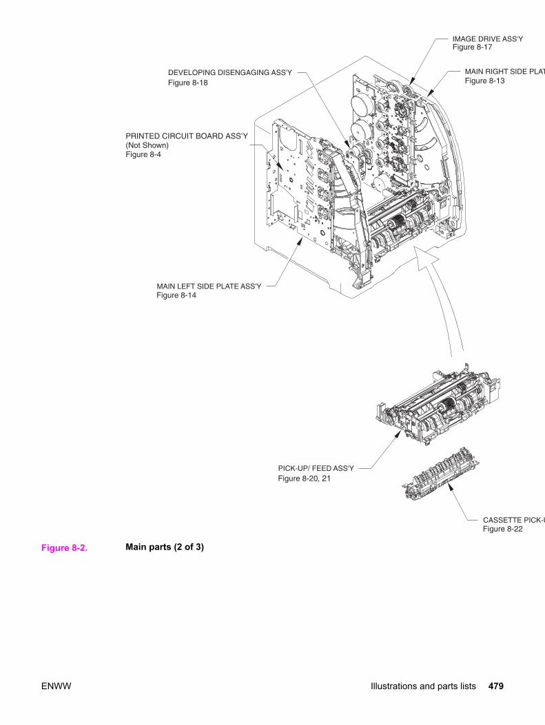
Figure 8-2. Main parts (2 of 3)
ENWW Illustrations and parts lists 479

Figure 8-3. Main parts (3 of 3) 500-sheet paper feeder
Figure 8-4. PCB locations (1 of 2)
480 Chapter 8 Parts and diagrams ENWW

Table 8-3. PCB locations
Ref Description Part number Qty
1 DC controller PCB (HP3500)
DC controller PCB (HP 3550)
DC controller PCB (HP3700)
RM1-0510-000CN
RM1-2324-000CN
RM1-0506-000CN
1
2 Memory controller PCB RM1-0508-000CN 1
3 High-voltage power supply PCBs RM1-0505-000CN 1
4 Low-voltage power supply PCB (110-127V)
Low-voltage power supply PCB (220-240V)
RK2-0157-000CNRK2-0158-000CN
1
5 Formatter PCB (HP3500/3550)
Formatter PCB (HP3700)
Formatter Kit (HP3700)
Q1319-69001
Q1321-69001
Q1321-67924
1
6 Control panel PCB RM1-0511-000CN 1
ENWW Illustrations and parts lists 481

Figure 8-5. Paper Feeder PCB Assembly Location Diagram (2 of 2) R90 - 1
482 Chapter 8 Parts and diagrams ENWW

Table 8-4. Paper feeder PCB Assembly Location diagram
Ref Description Part number Qty
1 Paper feeder PCB RM1-0768-000 1
ENWW Illustrations and parts lists 483

Figure 8-6. External covers and panels
484 Chapter 8 Parts and diagrams ENWW
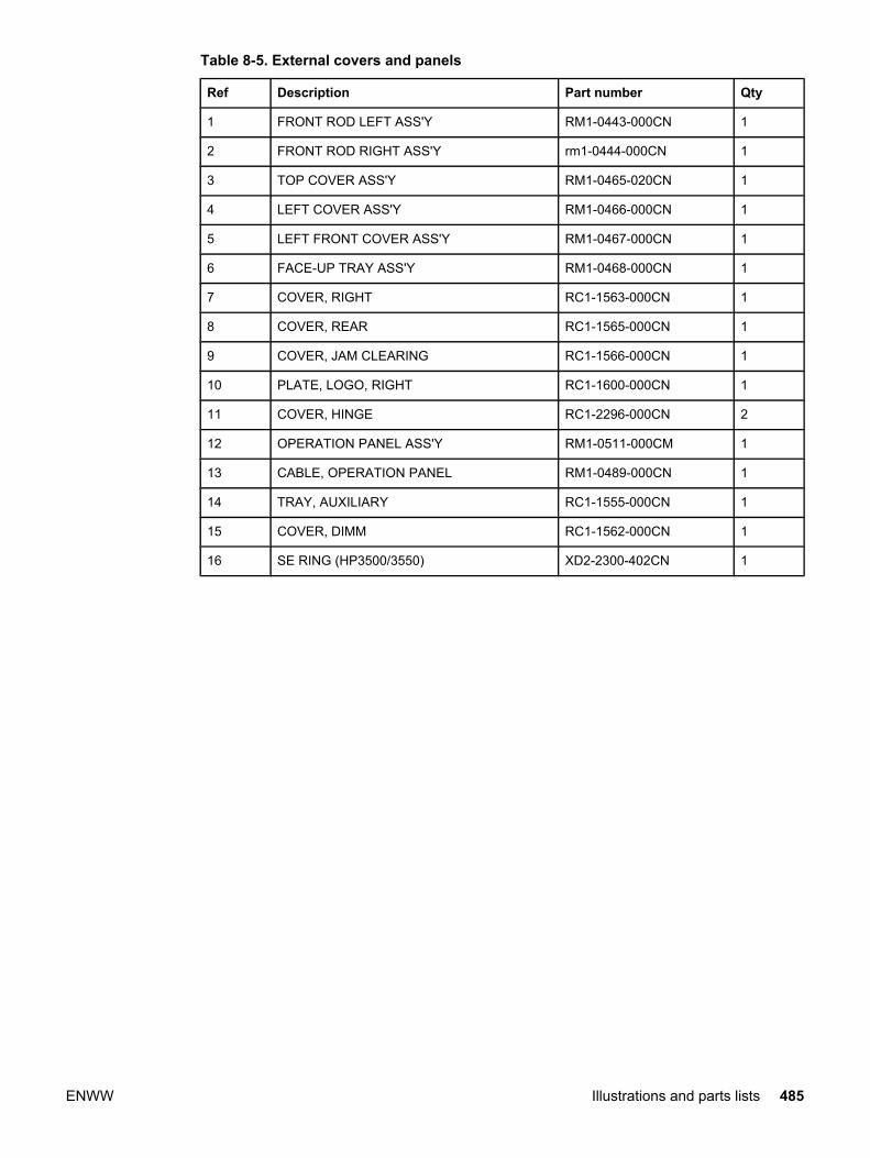
Table 8-5. External covers and panels
Ref Description Part number Qty
1 FRONT ROD LEFT ASS'Y RM1-0443-000CN 1
2 FRONT ROD RIGHT ASS'Y rm1-0444-000CN 1
3 TOP COVER ASS'Y RM1-0465-020CN 1
4 LEFT COVER ASS'Y RM1-0466-000CN 1
5 LEFT FRONT COVER ASS'Y RM1-0467-000CN 1
6 FACE-UP TRAY ASS'Y RM1-0468-000CN 1
7 COVER, RIGHT RC1-1563-000CN 1
8 COVER, REAR RC1-1565-000CN 1
9 COVER, JAM CLEARING RC1-1566-000CN 1
10 PLATE, LOGO, RIGHT RC1-1600-000CN 1
11 COVER, HINGE RC1-2296-000CN 2
12 OPERATION PANEL ASS'Y RM1-0511-000CM 1
13 CABLE, OPERATION PANEL RM1-0489-000CN 1
14 TRAY, AUXILIARY RC1-1555-000CN 1
15 COVER, DIMM RC1-1562-000CN 1
16 SE RING (HP3500/3550) XD2-2300-402CN 1
ENWW Illustrations and parts lists 485

Figure 8-7. Front door assembly
486 Chapter 8 Parts and diagrams ENWW

Table 8-6. Front door assembly
Ref Description Part number Qty
FRONT DOOR ASSEMBLY RM1-0463-000CN 1
1 MULTI-PURPOSE TRAY ASS'Y RM1-0464-000CN 1
2 ROD, FRONT COVER, LEFT RC1-1158-000CN 1
3 ROD, FRONT COVER, RIGHT RC1-1159-000CN 1
4 LEVER, INTERLOCK SWITCH RC1-1176-000CN 1
5 LEVER, ITB COUPLIN, 1 RC1-1247-000CN 1
6 LINK, MP HINGE, LEFT RC1-1575-000CN 1
7 LINK, MP HINGE, RIGHT RC1-1576-000CN 1
8 COVER, MP TRAY RC1-1574-000CN 1
9 TRAY, EXPANSION, 1 RC1-2318-000CN 1
10 TRAY, EXPANSION, 2 RC1-2319-000CN 1
11 SPRING, TENSION RC1-1407-000CN 2
ENWW Illustrations and parts lists 487
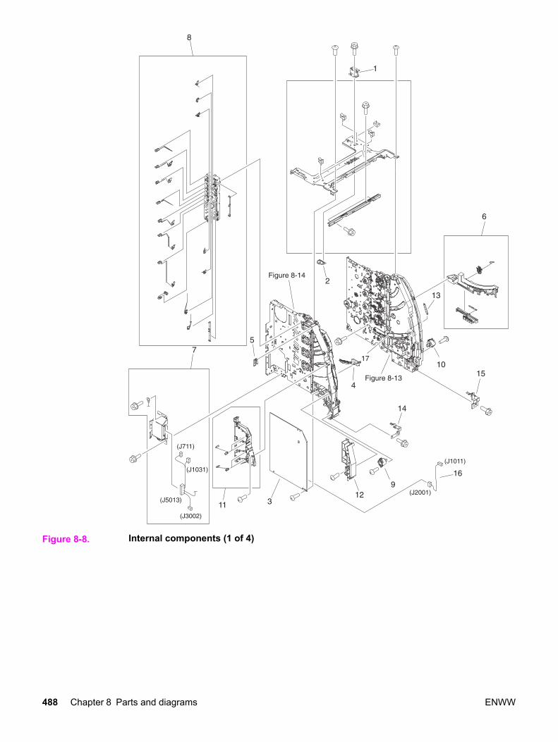
Figure 8-8. Internal components (1 of 4)
488 Chapter 8 Parts and diagrams ENWW

Table 8-7. Internal components (1 of 4)
Ref Description Part number Qty
1 PLATE, JOINT, RIGHT RC1-1603-000CN 1
2 COVER, SCREW RC1-1605-000CN 1
3 HIGH-VOLTAGE PCB ASS'Y RM1-0505-000CN 1
4 RAIL, SWING, LEFT FRONT RC1-1642-000CN 1
5 ARM, INTERLOCK SWITCH RC1-1175-000CN 1
6 LOCK GUIDE RIGHT ASS'Y RM1-0438-000CN 1
7 DRAWER CROSSMEMBER ASS'Y RM1-0440-000CN 1
8 DEVELOPING CONTACT ASS'Y RM1-0446-000CN 1
9 DAMPER UNIT, HINGE, LEFT RC1-1572-000CN 1
10 DAMPER UNIT, HINGE, RIGHT RC1-1573-000CN 1
11 TRANSFER CONTACT ASS'Y RM1-0445-000CN 1
12 GUIDE, HARNESS RC1-1342-000CN 1
13 SPRING, TENSION RC1-1515-000CN 1
14 STOPPER, FRONT HINGE, LEFT RL1-0215-000CN 1
15 STOPPER, HINGE, RIGHT RL1-0216-000CN 1
16 CABLE, HIGH VOLTAGE RM1-0485-000CN 1
17 RAIL, SWING, RIGHT FRONT RC1-1661-000CN 1
ENWW Illustrations and parts lists 489

Figure 8-9. Internal components (2 of 4)
490 Chapter 8 Parts and diagrams ENWW

Table 8-8. Internal components (2 of 4)
Ref Description Part number Qty
1 GEAR, 31T/19T RC1-1284-000CN 1
2 GEAR, 54T/17T RC1-1300-000CN 1
3 GEAR, 79T RC1-1302-000CN 1
4 BUSHING RC1-3249-000CN 1
5 COVER, MOTOR RC1-1353-000CN 1
6 COVER, CONNECTOR RC1-1488-000CN 1
7 GEAR, 25T RC1-1497-000CN 1
8 SHAFT, DRIVE RC1-1500-000CN 1
9 PLATE, MOUNTING RC1-1355-000CN 1
10 RING, E XD9-0136-000CN 2
11 BUSHING RC1-1630-000CN 1
12 PLATE, GROUNDING RC1-1649-000CN 1
14 MOUNT, REGISTRATION CLUTCH RC1-1186-000CN 1
15 CASSETTE PICK-UP ROLLER ASS'Y RM1-0731-000CN 1
16 RING, E XD9-0134-000CN 1
17 GEAR, 43T RC1-1294-000CN 1
18 GEAR, 27T RC1-1295-000CN 1
19 GEAR, 50T/90T RC1-1224-000CN 1
20 LOW-VOLTAGE PCB ASS'Y (110-127V) RK2-0157-000CN 1
20 LOW-VOLTAGE PCB ASS'Y (220-240V) rk2-0158-000CN 1
21 PLATE, PAPER FEEDER DRIVE RL1-0193-000CN 1
22 GUIDE, CABLE RC1-2334-000CN 1
23 GEAR, 39T RC1-1281-000CN 1
24 GEAR, 26T/47T RC1-1283-000CN 1
25 GEAR, 45T/25T RC1-1286-000CN 1
26 HOLDER, GEAR RC1-1287-000CN 1
27 GEAR, 38T RC1-1288-000CN 1
28 GEAR, 104T/25T RC1-1291-000CN 1
29 SPRING, TENSION RC1-1292-000CN 1
30 GEAR, 20T RC1-1493-000CN 1
31 GEAR, 26T/22T/20T RC1-1298-000CN 1
32 COVER, CASSETTE RC1-1665-000CN 1
ENWW Illustrations and parts lists 491

Ref Description Part number Qty
34 SUPPORT, PICK-UP GEAR RL1-0217-000CN 1
35 RING, E XD9-0137-000CN 1
36 CABLE, CPR CONNECTING RM1-0482-000CN 1
37 CABLE, FORMATTER POWER SUPPLY(HP3700)
RM1-0483-000CN 1
37 CABLE, FORMATTER POWER SUPPLY(HP 3500/3550)
RM1-0498-000CN 1
38 CABLE, LEFT FRONT RM1-0488-000CN 1
39 CLUTCH, ELECROMAGNETIC RK2-0247-000CN 1
40 CLAMP, CABLE WT2-5841-000CN 9
41 CONNECTOR, 2P VS1-5057-002CN 1
42 SOLENOID RK2-0141-000CN 1
Table 8-8. Internal components (2 of 4) (continued)
492 Chapter 8 Parts and diagrams ENWW

ENWW Illustrations and parts lists 493

Figure 8-10. Internal components (3 of 4)
494 Chapter 8 Parts and diagrams ENWW

Table 8-9. Internal components (3 of 4)
Ref Description Part number Qty
1 GUIDE, ROD, LEFT RC1-1156-000CN 1
2 SENSOR UNIT, HUMIDITY WP2-5156-000CN 1
3 SPRING, GROUNDING RC1-1177-000CN 1
4 DEV. DISENGAGING DRIVE ASS'Y RM1-0419-000CN 1
5 SHEET, CABLE RETAINING RC1-2437-000CN 1
6 CABLE, ENVIRONMENT SENSOR RM1-0493-000CN 1
7 GEAR, 120T/17T RC1-1252-000CN 1
8 SWING ROD LEFT ASS'Y RM1-0441-000CN 1
9 SWING ROD RIGHT ASS'Y RM1-0442-000CN 1
10 DUCT, FAN RC1-1345-000CN 1
11 DUCT, AIR, FRONT RC1-1350-000CN 1
12 FAN (HP3700) RK2-0017-000CN 1
12 FAN, (HP3500/3550) RK2-0153-000CN 1
13 CLAMP, CABLE WT2-5841-000CN 4
14 ARM, DRUM LOCK, LEFT RC1-1170-000CN 1
15 SPRING, TENSION RC1-1184-000CN 1
16 SPRING, TENSION RC1-1628-000CN 3
17 ARM, DRUM LOCK, RIGHT RC1-1361-000CN 1
18 SPRING, TENSION RC1-1547-000CN 1
ENWW Illustrations and parts lists 495

Figure 8-11. Internal components (4 of 4)
496 Chapter 8 Parts and diagrams ENWW
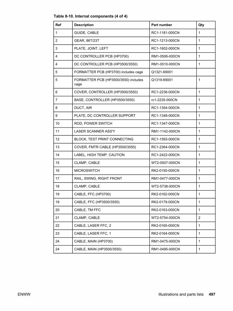
Table 8-10. Internal components (4 of 4)
Ref Description Part number Qty
1 GUIDE, CABLE RC1-1181-000CN 1
2 GEAR, 86T/23T RC1-1213-000CN 1
3 PLATE, JOINT, LEFT RC1-1602-000CN 1
4 DC CONTROLLER PCB (HP3700) RM1-0506-000CN 1
4 DC CONTROLLER PCB (HP3500/3550) RM1-0510-000CN 1
5 FORMATTER PCB (HP3700) includes cage Q1321-69001
5 FORMATTER PCB (HP3500/3550) includescage
Q1319-69001 1
6 COVER, CONTROLLER (HP3500/3550) RC1-2236-000CN 1
7 BASE, CONTROLLER (HP3500/3550) rc1-2235-000CN 1
8 DUCT, AIR RC1-1354-000CN 1
9 PLATE, DC CONTROLLER SUPPORT RC1-1348-000CN 1
10 ROD, POWER SWITCH RC1-1347-000CN 1
11 LASER SCANNER ASS'Y RM1-1142-000CN 1
12 BLOCK, TEST PRINT CONNECTING RC1-1593-000CN 1
13 COVER, FMTR CABLE (HP3500/3550) RC1-2364-000CN 1
14 LABEL, HIGH TEMP. CAUTION RC1-2422-000CN 1
15 CLAMP, CABLE WT2-0507-000CN 1
16 MICROSWITCH RK2-0150-000CN 1
17 RAIL, SWING, RIGHT FRONT RM1-0477-000CN 1
18 CLAMP, CABLE WT2-5738-000CN 1
19 CABLE, FFC (HP3700) RK2-0162-000CN 1
19 CABLE, FFC (HP3500/3550) RK2-0179-000CN 1
20 CABLE, TM FFC RK2-0163-000CN 1
21 CLAMP, CABLE WT2-5754-000CN 2
22 CABLE, LASER FFC, 2 RK2-0165-000CN 1
23 CABLE, LASER FFC, 1 RK2-0164-000CN 1
24 CABLE, MAIN (HP3700) RM1-0475-000CN 1
24 CABLE, MAIN (HP3500/3550) RM1-0495-000CN 1
ENWW Illustrations and parts lists 497

Figure 8-12. Center frame assembly
498 Chapter 8 Parts and diagrams ENWW

Table 8-11. Center Frame Assembly
Ref Description Part number Qty
1 BUSHING RC1-1243-000CN 1
2 PHOTO-INTERRUPTER, TLP 1241 WG8-5362-000CN 1
3 CLAMP, CABLE WT2-5841-000CN 1
4 MEMORY CONTROLLER PCB ASS'Y RM1-0508-000CN 1
5 SPRING, TORSION RC1-1328-000CN 1
6 HOLDER, SENSOR RC1-1329-000CN 1
7 FLAG, SENSOR RC1-1330-000CN 1
8 HOLDER, MEMORY CONTROLLER PCB RC1-1343-000CN 1
9 PLATE, SHIELD RC1-1349-000CN 1
10 COVER, LASER SHUTTER RC1-1640-000CN 4
ENWW Illustrations and parts lists 499

Figure 8-13. Main Right Side Plate Assembly / Motors
500 Chapter 8 Parts and diagrams ENWW

Table 8-12. Main Right Side Plate Assembly / Motors
Ref Description Part number Qty
1 LEVER, SWING LOCK, RIGHT RC1-1148-000CN 1
2 SPRING, TENSION RC1-1149-000CN 1
3 MOTOR (M5) RK2-0139-000CN 1
4 GEAR, 59T RC1-1231-000CN 2
5 BUSHING RC1-1218-000CN 4
6 GEAR, 74T RC1-3240-000CN 1
7 GEAR, 90T/28T RC1-1229-000CN 1
8 GEAR, 74T RC1-1230-000CN 4
9 GEAR, 69T RC1-1233-000CN 1
10 GEAR, 29T RC1-1234-000CN 4
11 PLATE, REINFORCEMENT RC1-1242-000CN 4
12 BUSHING RC1-1243-000CN 2
13 BUSHING RC1-1244-000CN 4
14 ARM, DRUM LOCK, RIGHT RC1-1246-000CN 1
15 LEVER, I.T.B. COUPLING RC1-1248-000CN 1
16 SPRING, TENSION RC1-1259-000CN 4
17 SPRING, TENSION RC1-1260-000CN 1
18 MOTOR (M1) RK2-0137-000CN 1
19 PLATE, DRIVE RC1-1277-000CN 1
20 MOTOR (M2) RK2-0138-000CN 1
21 BUSHING RC1-1310-000CN 1
22 ARM, DRUM LOCK, RIGHT RC1-1362-000CN 1
23 SPRING, GROUNDING RC1-1537-000CN 3
24 ARM, DRUM LOCK, RIGHT RC1-1545-000CN 1
25 STOPPER, ARM, RIGHT RC1-1546-000CN 1
26 DEVELOPING MOTOR ASS'Y (M4) RM1-0737-000CN 1
27 SPRING, TENSION RC1-1548-000CN 3
28 PLATE, GROUNDING RC1-1629-000CN 1
29 RAIL, SWING, RIGHT REAR RC1-1662-000CN 1
30 PLATE, GROUNDING RC1-2294-000CN 1
31 CONNECTOR, SNAP TIGHT VS1-6910-012CN 1
32 STOPPER, ARM, RIGHT RC1-2339-000CN 2
ENWW Illustrations and parts lists 501
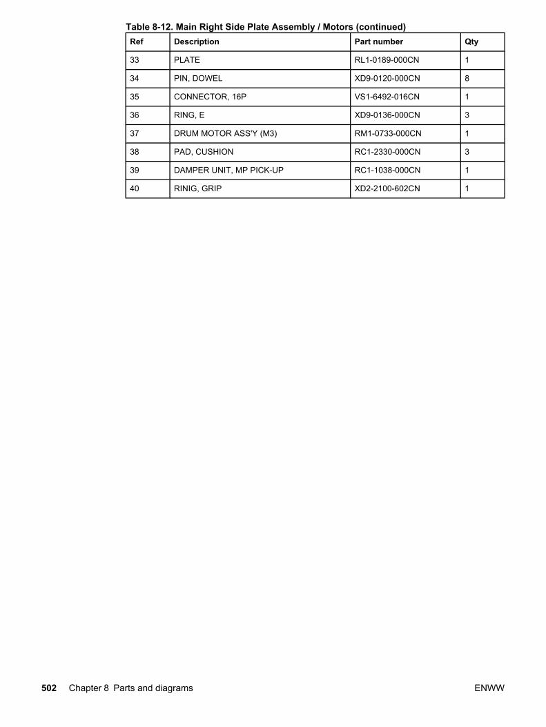
Ref Description Part number Qty
33 PLATE RL1-0189-000CN 1
34 PIN, DOWEL XD9-0120-000CN 8
35 CONNECTOR, 16P VS1-6492-016CN 1
36 RING, E XD9-0136-000CN 3
37 DRUM MOTOR ASS'Y (M3) RM1-0733-000CN 1
38 PAD, CUSHION RC1-2330-000CN 3
39 DAMPER UNIT, MP PICK-UP RC1-1038-000CN 1
40 RINIG, GRIP XD2-2100-602CN 1
Table 8-12. Main Right Side Plate Assembly / Motors (continued)
502 Chapter 8 Parts and diagrams ENWW

ENWW Illustrations and parts lists 503

Figure 8-14. Main Left Side Plate Assembly
504 Chapter 8 Parts and diagrams ENWW

Table 8-13. Main Left Side Plate Assembly
Ref Description Part number Qty
1 HOLDER, SENSOR RC1-1049-000CN 1
2 LENS RC1-1050-000CN 2
3 PLATE, CONTACT RC1-1151-000CN 1
4 PLATE, CONTACT RC1-1152-000CN 1
5 PLATE, CONTACT RC1-1153-000CN 1
6 PLATE, CONTACT RC1-1155-000CN 1
7 ARM, DRUM LOCK, LEFT RC1-1169-000CN 1
8 CONNECTOR, SNAP TIGHT, W VS1-6492-010CN 1
9 SENSOR UNIT, TCU FULL DETECT RM1-0509-000CN 1
10 SPRING, TENSION RC1-1185-000CN 3
11 ARM, DRUM LOCK, LEFT RC1-1622-000CN 1
12 ARM, DRUM LOCK, LEFT RC1-1623-000CN 1
13 STRAP, DAMPER RC1-1625-000CN 3
14 STOPPER, ARM, LEFT RC1-1626-000CN 1
15 STOPPER, ARM, LEFT RC1-1627-000CN 2
16 PAD, CUSHION RC1-2330-000CN 3
17 RAIL, SWING, LEFT REAR RC1-1641-000CN 1
18 LEVER, SWING LOCK, LEFT RC1-1647-000CN 1
19 SPRING, TENSION RC1-1648-000CN 1
20 PAD, CUSHION RC12331-000CN 3
21 PHOTO-INTERRUPTER, TLP1241 WG8-5362-000CN 1
ENWW Illustrations and parts lists 505
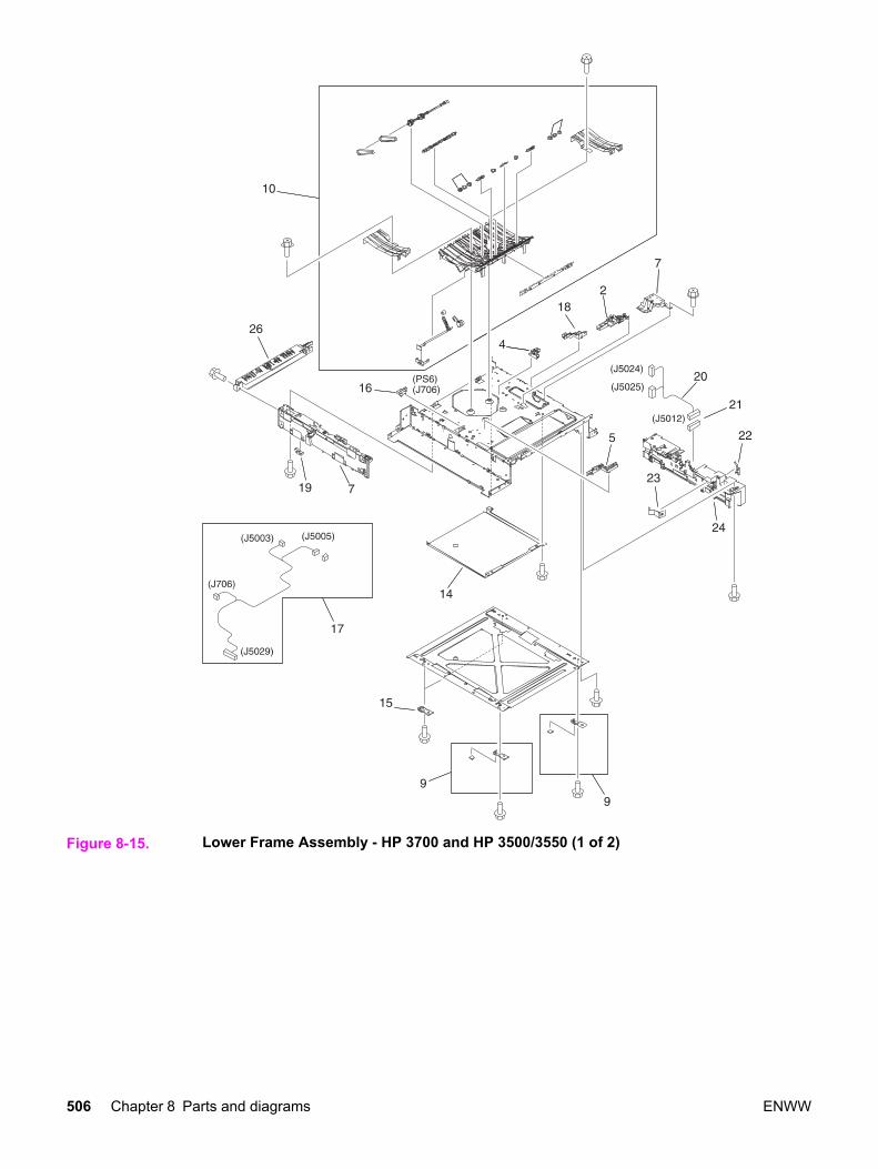
Figure 8-15. Lower Frame Assembly - HP 3700 and HP 3500/3550 (1 of 2)
506 Chapter 8 Parts and diagrams ENWW

ENWW Illustrations and parts lists 507

Figure 8-16. Lower Frame Assembly - HP 3700 and HP 3500/3550 (2 of 2)
508 Chapter 8 Parts and diagrams ENWW

Ref Description Part number Qty
1 CLUTCH, MECHANICAL RB2-6324-000CNN 1
2 HOLDER, SENSOR RC1-1496-000CN 1
3 LEVER, SENSOR RC1-1514-000CN 1
4 GUIDE, CABLE RC1-2322-000CN 1
5 GUIDE, CABLE RC1-2323-000CN 1
6 GUIDE, CASSETTE, LEFT RC1-1491-000CN 1
7 MOUNT, SOLENOID (HP3700) RL1-0203-000CN 1
7 MOUNT, SOLENOID (HP3500/3550) RC1-1511-000CN 1
8 DUPLEX GUIDE ASS'Y (HP3700) RM1-0458-000CN 1
9 FOOT ASS'Y RM1-0459-000CN 2
10 PAPER FEED ASS'Y RM1-0460-000CN 1
11 DUPLEX FEED GUIDE ASS'Y (HP3700) RM1-0461-000CN 1
12 POSITION GUIDE ASS'Y (HP3700) RM1-0462-000CN 1
13 CASSETTE GUIDE RIGHT ASS'Y RM1-0736-000CN 1
14 COVER, LOWER FRAME (HP3700) RC1-2237-000CN 1
15 SUPPORT, FOOT, REAR RC1-2428-000CN 2
16 PHOTO-INTERRUPTER, TLP1241 (HP3700) WG8-5362-000CN 3
16 PHOTO-INTERRUPTER, TLP1241(HP3500/3550)
WG8-5362-000CN 1
17 CABLE, FRAME, LOWER (HP3700) RM1-0478-000CN 1
17 CABLE, FRAME, LOWER (HP3500/3550) RM1-0497-000CN 1
18 GUIDE, CABLE RC1-1306-000CN 1
19 PLATE, CONNECTING RC1-1637-000CN 1
20 CABLE, OPTION CONNECTING (HP3700) RM1-0476-000CN 1
20 CABLE, OPTION CONNECTING(HP3500/3550)
RM1-0496-000CN 1
21 CONNECTOR, 6P (HP3500/3550) VS1-6176-006CN 1
22 PLATE, GROUNDING (HP3500/3550) RC1-1509-000CN 1
23 SPRING, LEAF (HP3500/3550) RC1-1508-000CN 1
24 GUIDE, CASSETTE, RIGHT (HP3500) RC1-1492-000CN 1
25 SOLENOID RK2-0143-000CN 1
26 GUIDE, DUPLEXING (HP3700) RC1-1613-000CN 1
ENWW Illustrations and parts lists 509
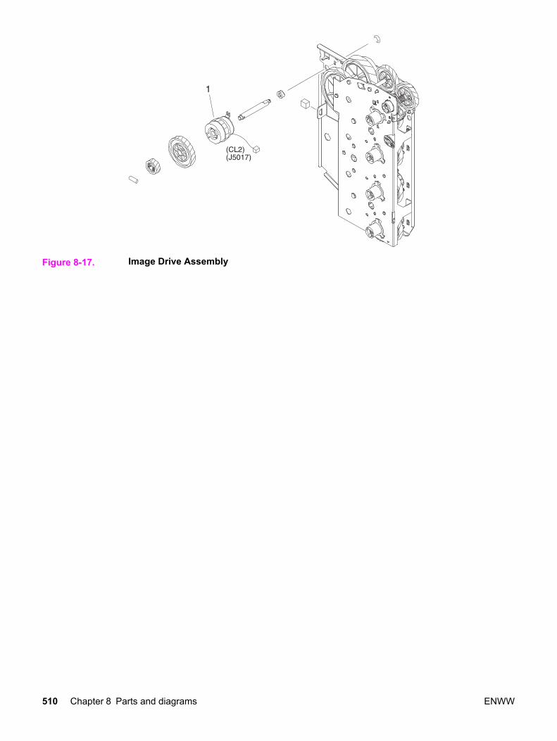
Figure 8-17. Image Drive Assembly
510 Chapter 8 Parts and diagrams ENWW

Table 8-14. Image drive assembly
Ref Description Part number Qty
IMAGE DRIVE ASSEMBLY RM1-0415-040CN 1
1 CLUTCH, ELECTROMAGNETIC RK2-0248-000CN 1
ENWW Illustrations and parts lists 511
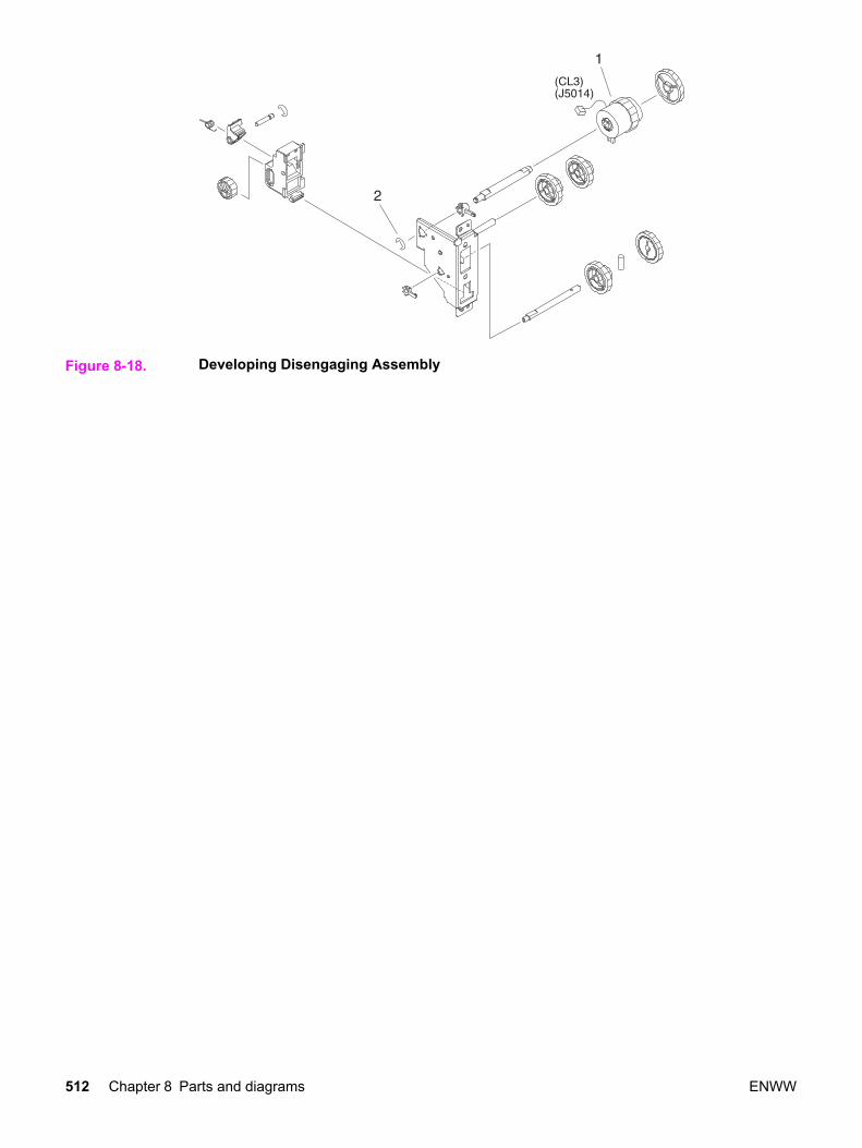
Figure 8-18. Developing Disengaging Assembly
512 Chapter 8 Parts and diagrams ENWW

Table 8-15. Developing Disengaging Assembly
Ref Description Part number Qty
DEVELOPING DISENGAGING ASSEMBLY RM1-0434-000CN 1
1 CLUTCH, ELECTROMAGNETIC RK2-0176-000CN 1
2 RING, E XD9-0135-000CN 1
ENWW Illustrations and parts lists 513
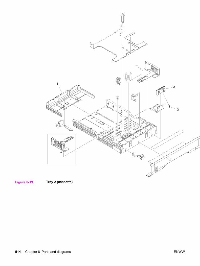
Figure 8-19. Tray 2 (cassette)
514 Chapter 8 Parts and diagrams ENWW

Table 8-16. Tray 2 (cassette)
Ref Description Part number Qty
TRAY 2 (CASSETTE) RM1-0470-000CN 1
1 PLATE, END RB2-3003-040CN 1
2 SPRING, COMPRESSION RS6-2021-000CN 1
3 PAD, SEPARATION RC1-0954-000CN 1
ENWW Illustrations and parts lists 515
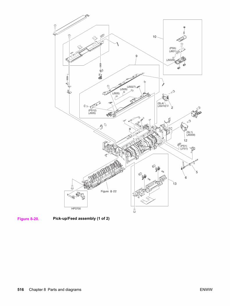
Figure 8-20. Pick-up/Feed assembly (1 of 2)
516 Chapter 8 Parts and diagrams ENWW

ENWW Illustrations and parts lists 517

Figure 8-21. Pick-up/Feed assembly (2 of 2)
518 Chapter 8 Parts and diagrams ENWW

Table 8-17. Pick-up/Feed assembly
Ref Description Part number Qty
PICK-UP/FEED ASS'Y (HP3700) RM1-0449-000CN 1
PICK-UP/FEED ASS'Y (HP3500/3550) RM1-0760-000CN 1
1 SEPARATION PAD ASS'Y RM1-0739-000CN 1
2 SOLENOID RK2-0145-000CN 1
3 TRANSFER ROLLER ASS'Y RM1-0740-000CN 1
4 CLUTCH, MECHANICAL RC1-1433-000CN 1
5 LEVER, SENSOR RC1-1456-000CN 1
6 SPRING, TORSION RC1-1464-000CN 1
7 PAD, SEPARATION RC1-0939-000 1
8 ROLLER, PICK-UP RC1-1535-000CN 1
9 COLOR MIS-REG. SENSOR ASS'Y RM1-0451-000CN 1
10 MEDIA SENSOR ASS'Y RM1-0452-000CN 1
11 PHOTO-INTERRUPTER, TLP1241 WG8-5362-000CN 3
12 SOLENOID RK2-0141-000CN 1
13 PICK-UP FEED ASSY RM1-0456-000CN 1
ENWW Illustrations and parts lists 519

Figure 8-22. Tray 2 (cassette) pick-up assembly
520 Chapter 8 Parts and diagrams ENWW

Table 8-18. Tray 2 (cassette) pick-up assembly
Ref Description Part number Qty
1 PHOTO-INTERRUPTER, TLP1241 WG8-5362-000CN 1
ENWW Illustrations and parts lists 521

Figure 8-23. Face-down delivery assembly
522 Chapter 8 Parts and diagrams ENWW

Table 8-19. Face-down delivery assembly
Ref Description Part number Qty
FACE-DOWN DELIVERY ASSEMBLY RM1-0469-000CN 1
1 PHOTO-INTERRUPTER, TLP1241 WG8-5362-000CN 1
ENWW Illustrations and parts lists 523
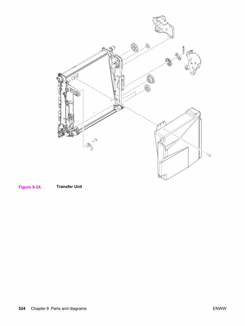
Figure 8-24. Transfer Unit
524 Chapter 8 Parts and diagrams ENWW

Table 8-20. Transfer unit
Ref Description Part number Qty
1 TRANSFER UNIT Q3658-69001 1
ENWW Illustrations and parts lists 525

Figure 8-25. Right Swing Frame Assembly
526 Chapter 8 Parts and diagrams ENWW

Table 8-21. Right Swing Frame Assembly
Ref Description Part number Qty
1 RIGHT SWING FRAME ASS'Y RM1-0437-000CN 1
ENWW Illustrations and parts lists 527

Figure 8-26. Left Swing Frame Assembly
528 Chapter 8 Parts and diagrams ENWW

Table 8-22. Left swing frame assembly
Ref Description Part number Qty
LEFT SWING FRAME ASS'Y RM1-0439-000CN 1
ENWW Illustrations and parts lists 529
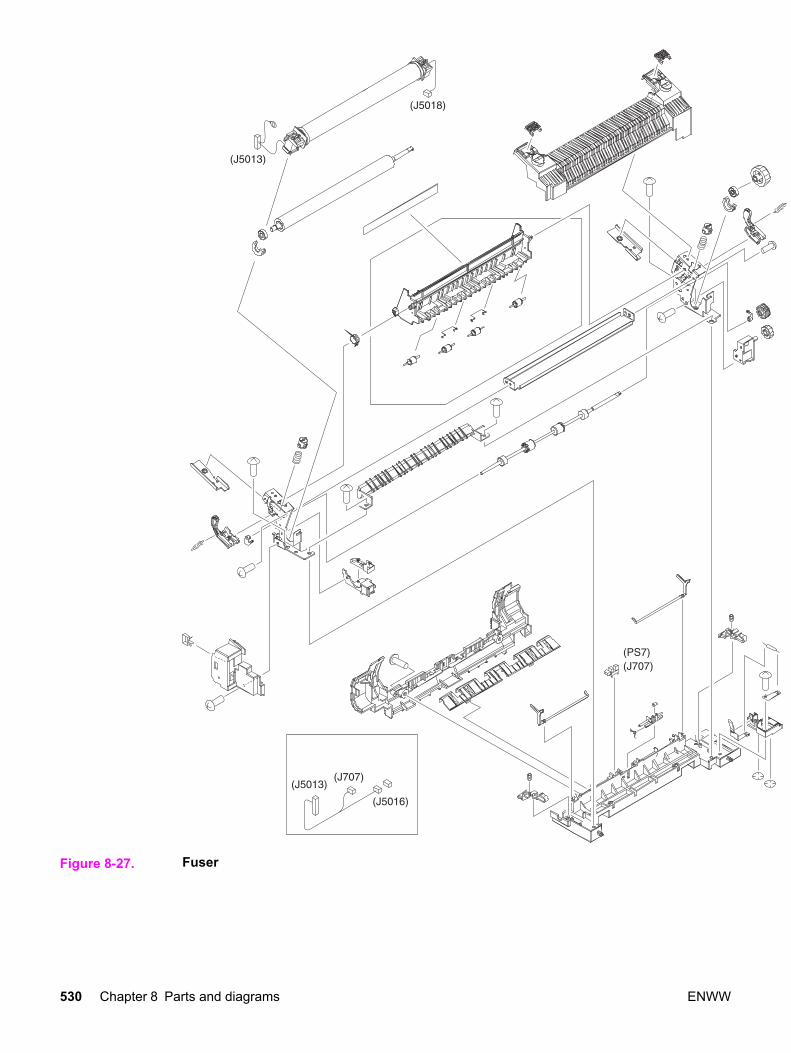
Figure 8-27. Fuser
530 Chapter 8 Parts and diagrams ENWW

Table 8-23. Fuser assembly
Ref Description Part number Qty
FUSER (110-127V) Q3655-69001 1
FUSER (220-240V) Q3656-69001 1
ENWW Illustrations and parts lists 531
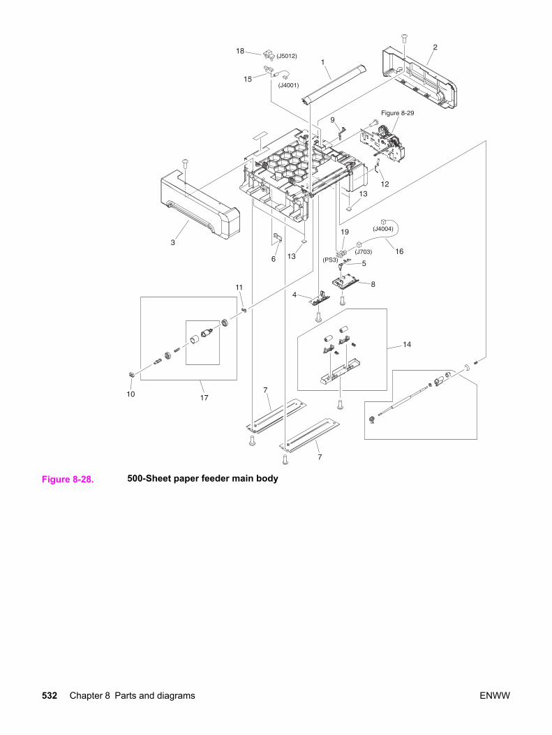
Figure 8-28. 500-Sheet paper feeder main body
532 Chapter 8 Parts and diagrams ENWW
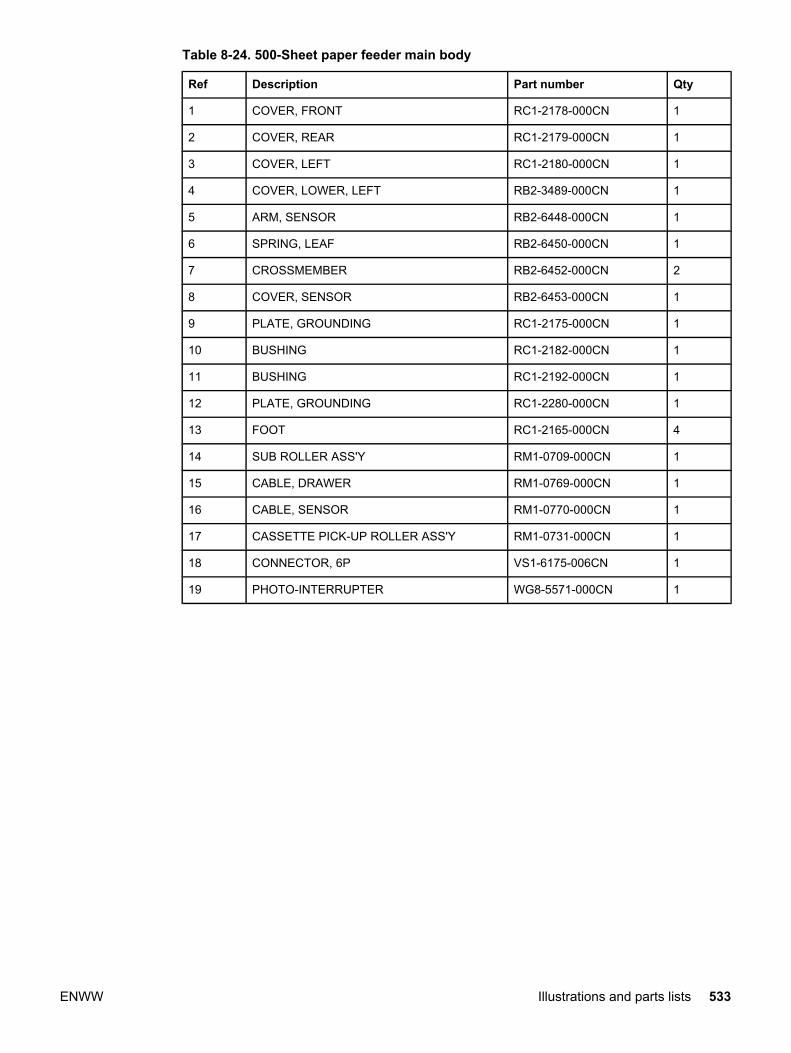
Table 8-24. 500-Sheet paper feeder main body
Ref Description Part number Qty
1 COVER, FRONT RC1-2178-000CN 1
2 COVER, REAR RC1-2179-000CN 1
3 COVER, LEFT RC1-2180-000CN 1
4 COVER, LOWER, LEFT RB2-3489-000CN 1
5 ARM, SENSOR RB2-6448-000CN 1
6 SPRING, LEAF RB2-6450-000CN 1
7 CROSSMEMBER RB2-6452-000CN 2
8 COVER, SENSOR RB2-6453-000CN 1
9 PLATE, GROUNDING RC1-2175-000CN 1
10 BUSHING RC1-2182-000CN 1
11 BUSHING RC1-2192-000CN 1
12 PLATE, GROUNDING RC1-2280-000CN 1
13 FOOT RC1-2165-000CN 4
14 SUB ROLLER ASS'Y RM1-0709-000CN 1
15 CABLE, DRAWER RM1-0769-000CN 1
16 CABLE, SENSOR RM1-0770-000CN 1
17 CASSETTE PICK-UP ROLLER ASS'Y RM1-0731-000CN 1
18 CONNECTOR, 6P VS1-6175-006CN 1
19 PHOTO-INTERRUPTER WG8-5571-000CN 1
ENWW Illustrations and parts lists 533

Figure 8-29. 500-Sheet paper feeder paper pick-up drive assembly
534 Chapter 8 Parts and diagrams ENWW

Table 8-25. 500-Sheet paper feeder paper pick-up drive assembly
Ref Description Part number Qty
PAPER PICK-UP DRIVE ASS'Y RM1-0701-000CN 1
1 SWING ASS'Y RM1-0707-000CN 1
2 PAPER FEEDER DRIVER PCB ASS'Y RM1-0768-000CN 1
ENWW Illustrations and parts lists 535

Figure 8-30. 500-Sheet paper feeder tray (Tray 3)
536 Chapter 8 Parts and diagrams ENWW

Table 8-26. 500-Sheet paper feeder tray (Tray 3)
Ref Description Part number Qty
PAPER TRAY 3, 500-SHEET FEEDER RM1-0705-000CN 1
1 PLATE, END RB2-6469-000CN 1
2 SPRING, COMPRESSION RC1-2191-000CN 1
3 PAPER SEPARATION PAD ASS'Y RM1-0827-000CN 1
ENWW Illustrations and parts lists 537

Alphabetical parts list
Table 8-27. Alphabetical parts list
Description Part number Table and page
ARM, DRUM LOCK, LEFT RC1-1170-000CN Table 8-9 on page 495
ARM, DRUM LOCK, LEFT RC1-1169-000CN Table 8-13 on page505
ARM, DRUM LOCK, LEFT RC1-1622-000CN Table 8-13 on page505
ARM, DRUM LOCK, LEFT RC1-1623-000CN Table 8-13 on page505
ARM, DRUM LOCK, RIGHT RC1-1361-000CN Table 8-9 on page 495
ARM, DRUM LOCK, RIGHT RC1-1246-000CN Table 8-12 on page501
ARM, DRUM LOCK, RIGHT RC1-1362-000CN Table 8-12 on page501
ARM, DRUM LOCK, RIGHT RC1-1545-000CN Table 8-12 on page501
ARM, INTERLOCK SWITCH RC1-1175-000CN Table 8-7 on page 489
ARM, SENSOR RB2-6448-000CN Table 8-24 on page533
BASE, CONTROLLER (HP3500/3550) rc1-2235-000CN Table 8-10 on page497
BLOCK, TEST PRINT CONNECTING RC1-1593-000CN Table 8-10 on page497
BUSHING RC1-3249-000CN Table 8-8 on page 491
BUSHING RC1-1630-000CN Table 8-8 on page 491
BUSHING RC1-1243-000CN Table 8-11 on page499
BUSHING RC1-1218-000CN Table 8-12 on page501
BUSHING RC1-1243-000CN Table 8-12 on page501
BUSHING RC1-1244-000CN Table 8-12 on page501
BUSHING RC1-1310-000CN Table 8-12 on page501
BUSHING RC1-2182-000CN Table 8-24 on page533
BUSHING RC1-2192-000CN Table 8-24 on page533
538 Chapter 8 Parts and diagrams ENWW
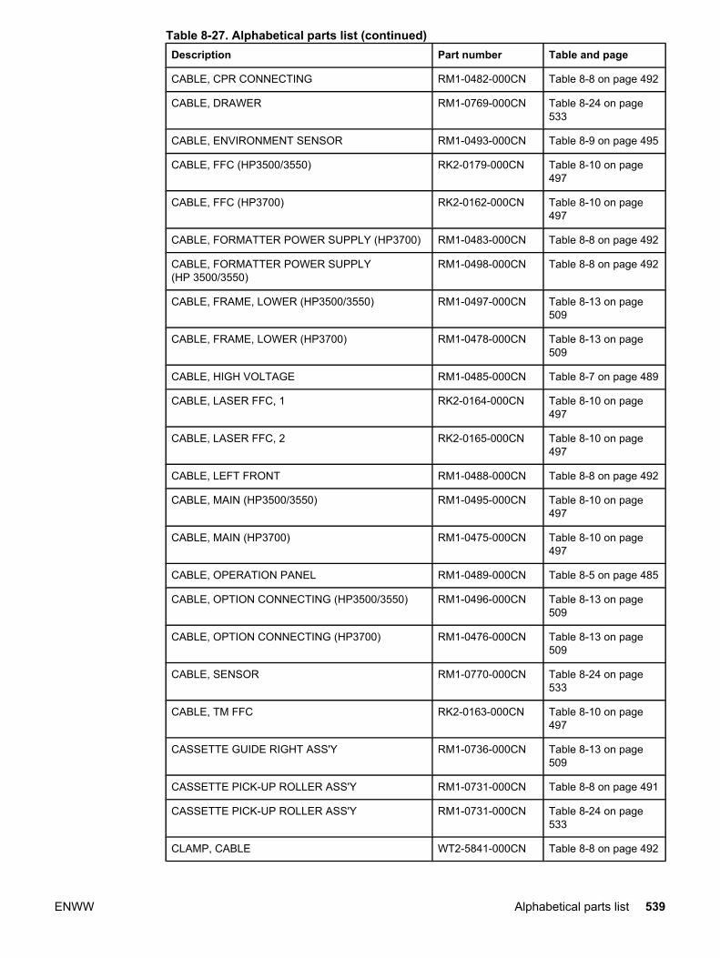
Description Part number Table and page
CABLE, CPR CONNECTING RM1-0482-000CN Table 8-8 on page 492
CABLE, DRAWER RM1-0769-000CN Table 8-24 on page533
CABLE, ENVIRONMENT SENSOR RM1-0493-000CN Table 8-9 on page 495
CABLE, FFC (HP3500/3550) RK2-0179-000CN Table 8-10 on page497
CABLE, FFC (HP3700) RK2-0162-000CN Table 8-10 on page497
CABLE, FORMATTER POWER SUPPLY (HP3700) RM1-0483-000CN Table 8-8 on page 492
CABLE, FORMATTER POWER SUPPLY(HP 3500/3550)
RM1-0498-000CN Table 8-8 on page 492
CABLE, FRAME, LOWER (HP3500/3550) RM1-0497-000CN Table 8-13 on page509
CABLE, FRAME, LOWER (HP3700) RM1-0478-000CN Table 8-13 on page509
CABLE, HIGH VOLTAGE RM1-0485-000CN Table 8-7 on page 489
CABLE, LASER FFC, 1 RK2-0164-000CN Table 8-10 on page497
CABLE, LASER FFC, 2 RK2-0165-000CN Table 8-10 on page497
CABLE, LEFT FRONT RM1-0488-000CN Table 8-8 on page 492
CABLE, MAIN (HP3500/3550) RM1-0495-000CN Table 8-10 on page497
CABLE, MAIN (HP3700) RM1-0475-000CN Table 8-10 on page497
CABLE, OPERATION PANEL RM1-0489-000CN Table 8-5 on page 485
CABLE, OPTION CONNECTING (HP3500/3550) RM1-0496-000CN Table 8-13 on page509
CABLE, OPTION CONNECTING (HP3700) RM1-0476-000CN Table 8-13 on page509
CABLE, SENSOR RM1-0770-000CN Table 8-24 on page533
CABLE, TM FFC RK2-0163-000CN Table 8-10 on page497
CASSETTE GUIDE RIGHT ASS'Y RM1-0736-000CN Table 8-13 on page509
CASSETTE PICK-UP ROLLER ASS'Y RM1-0731-000CN Table 8-8 on page 491
CASSETTE PICK-UP ROLLER ASS'Y RM1-0731-000CN Table 8-24 on page533
CLAMP, CABLE WT2-5841-000CN Table 8-8 on page 492
Table 8-27. Alphabetical parts list (continued)
ENWW Alphabetical parts list 539
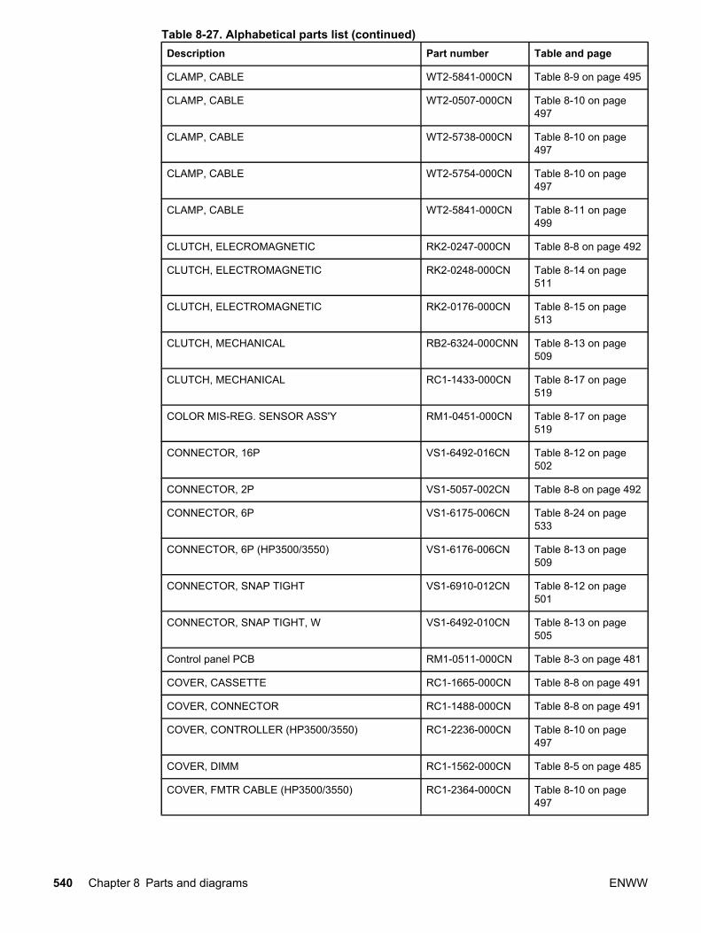
Description Part number Table and page
CLAMP, CABLE WT2-5841-000CN Table 8-9 on page 495
CLAMP, CABLE WT2-0507-000CN Table 8-10 on page497
CLAMP, CABLE WT2-5738-000CN Table 8-10 on page497
CLAMP, CABLE WT2-5754-000CN Table 8-10 on page497
CLAMP, CABLE WT2-5841-000CN Table 8-11 on page499
CLUTCH, ELECROMAGNETIC RK2-0247-000CN Table 8-8 on page 492
CLUTCH, ELECTROMAGNETIC RK2-0248-000CN Table 8-14 on page511
CLUTCH, ELECTROMAGNETIC RK2-0176-000CN Table 8-15 on page513
CLUTCH, MECHANICAL RB2-6324-000CNN Table 8-13 on page509
CLUTCH, MECHANICAL RC1-1433-000CN Table 8-17 on page519
COLOR MIS-REG. SENSOR ASS'Y RM1-0451-000CN Table 8-17 on page519
CONNECTOR, 16P VS1-6492-016CN Table 8-12 on page502
CONNECTOR, 2P VS1-5057-002CN Table 8-8 on page 492
CONNECTOR, 6P VS1-6175-006CN Table 8-24 on page533
CONNECTOR, 6P (HP3500/3550) VS1-6176-006CN Table 8-13 on page509
CONNECTOR, SNAP TIGHT VS1-6910-012CN Table 8-12 on page501
CONNECTOR, SNAP TIGHT, W VS1-6492-010CN Table 8-13 on page505
Control panel PCB RM1-0511-000CN Table 8-3 on page 481
COVER, CASSETTE RC1-1665-000CN Table 8-8 on page 491
COVER, CONNECTOR RC1-1488-000CN Table 8-8 on page 491
COVER, CONTROLLER (HP3500/3550) RC1-2236-000CN Table 8-10 on page497
COVER, DIMM RC1-1562-000CN Table 8-5 on page 485
COVER, FMTR CABLE (HP3500/3550) RC1-2364-000CN Table 8-10 on page497
Table 8-27. Alphabetical parts list (continued)
540 Chapter 8 Parts and diagrams ENWW

Description Part number Table and page
COVER, FRONT RC1-2178-000CN Table 8-24 on page533
COVER, HINGE RC1-2296-000CN Table 8-5 on page 485
COVER, JAM CLEARING RC1-1566-000CN Table 8-5 on page 485
COVER, LASER SHUTTER RC1-1640-000CN Table 8-11 on page499
COVER, LEFT RC1-2180-000CN Table 8-24 on page533
COVER, LOWER FRAME (HP3700) RC1-2237-000CN Table 8-13 on page509
COVER, LOWER, LEFT RB2-3489-000CN Table 8-24 on page533
COVER, MOTOR RC1-1353-000CN Table 8-8 on page 491
COVER, MP TRAY RC1-1574-000CN Table 8-6 on page 487
COVER, REAR RC1-1565-000CN Table 8-5 on page 485
COVER, REAR RC1-2179-000CN Table 8-24 on page533
COVER, RIGHT RC1-1563-000CN Table 8-5 on page 485
COVER, SCREW RC1-1605-000CN Table 8-7 on page 489
COVER, SENSOR RB2-6453-000CN Table 8-24 on page533
CROSSMEMBER RB2-6452-000CN Table 8-24 on page533
DAMPER UNIT, HINGE, LEFT RC1-1572-000CN Table 8-7 on page 489
DAMPER UNIT, HINGE, RIGHT RC1-1573-000CN Table 8-7 on page 489
DAMPER UNIT, MP PICK-UP RC1-1038-000CN Table 8-12 on page502
DC controller PCB (HP3500) DC controller PCB (HP3550) DC controller PCB (HP3700)
RM1-0510-000CNRM1-2324-000CNRM1-0506-000CN
Table 8-3 on page 481
DC CONTROLLER PCB (HP3500/3550) RM1-0510-000CN Table 8-10 on page497
DC CONTROLLER PCB (HP3700) RM1-0506-000CN Table 8-10 on page497
DEV. DISENGAGING DRIVE ASS'Y RM1-0419-000CN Table 8-9 on page 495
DEVELOPING CONTACT ASS'Y RM1-0446-000CN Table 8-7 on page 489
DEVELOPING DISENGAGING ASSEMBLY RM1-0434-000CN Table 8-15 on page513
Table 8-27. Alphabetical parts list (continued)
ENWW Alphabetical parts list 541

Description Part number Table and page
DEVELOPING MOTOR ASS'Y (M4) RM1-0737-000CN Table 8-12 on page501
DRAWER CROSSMEMBER ASS'Y RM1-0440-000CN Table 8-7 on page 489
DRUM MOTOR ASS'Y (M3) RM1-0733-000CN Table 8-12 on page502
DUCT, AIR RC1-1354-000CN Table 8-10 on page497
DUCT, AIR, FRONT RC1-1350-000CN Table 8-9 on page 495
DUCT, FAN RC1-1345-000CN Table 8-9 on page 495
DUPLEX FEED GUIDE ASS'Y (HP3700) RM1-0461-000CN Table 8-13 on page509
DUPLEX GUIDE ASS'Y (HP3700) RM1-0458-000CN Table 8-13 on page509
FACE-DOWN DELIVERY ASSEMBLY RM1-0469-000CN Table 8-19 on page523
FACE-UP TRAY ASS'Y RM1-0468-000CN Table 8-5 on page 485
FAN (HP3700) RK2-0017-000CN Table 8-9 on page 495
FAN, (HP3500/3550) RK2-0153-000CN Table 8-9 on page 495
FLAG, SENSOR RC1-1330-000CN Table 8-11 on page499
FOOT RC1-2165-000CN Table 8-24 on page533
FOOT ASS'Y RM1-0459-000CN Table 8-13 on page509
Formatter PCB (HP3500/3550) Formatter PCB(HP3700) Formatter Kit (HP3700)
Q1319-69001Q1321-69001Q1321-67924
Table 8-3 on page 481
FORMATTER PCB (HP3500/3550) includes cage Q1319-69001 Table 8-10 on page497
FORMATTER PCB (HP3700) includes cage Q1321-69001 Table 8-10 on page497
FRONT DOOR ASSEMBLY RM1-0463-000CN Table 8-6 on page 487
FRONT ROD LEFT ASS'Y RM1-0443-000CN Table 8-5 on page 485
FRONT ROD RIGHT ASS'Y rm1-0444-000CN Table 8-5 on page 485
FUSER (110-127V) Q3655-69001 Table 8-23 on page531
FUSER (220-240V) Q3656-69001 Table 8-23 on page531
GEAR, 104T/25T RC1-1291-000CN Table 8-8 on page 491
Table 8-27. Alphabetical parts list (continued)
542 Chapter 8 Parts and diagrams ENWW
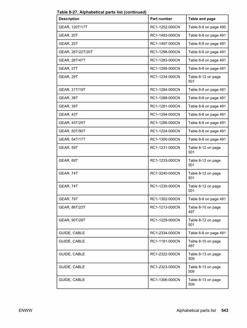
Description Part number Table and page
GEAR, 120T/17T RC1-1252-000CN Table 8-9 on page 495
GEAR, 20T RC1-1493-000CN Table 8-8 on page 491
GEAR, 25T RC1-1497-000CN Table 8-8 on page 491
GEAR, 26T/22T/20T RC1-1298-000CN Table 8-8 on page 491
GEAR, 26T/47T RC1-1283-000CN Table 8-8 on page 491
GEAR, 27T RC1-1295-000CN Table 8-8 on page 491
GEAR, 29T RC1-1234-000CN Table 8-12 on page501
GEAR, 31T/19T RC1-1284-000CN Table 8-8 on page 491
GEAR, 38T RC1-1288-000CN Table 8-8 on page 491
GEAR, 39T RC1-1281-000CN Table 8-8 on page 491
GEAR, 43T RC1-1294-000CN Table 8-8 on page 491
GEAR, 45T/25T RC1-1286-000CN Table 8-8 on page 491
GEAR, 50T/90T RC1-1224-000CN Table 8-8 on page 491
GEAR, 54T/17T RC1-1300-000CN Table 8-8 on page 491
GEAR, 59T RC1-1231-000CN Table 8-12 on page501
GEAR, 69T RC1-1233-000CN Table 8-12 on page501
GEAR, 74T RC1-3240-000CN Table 8-12 on page501
GEAR, 74T RC1-1230-000CN Table 8-12 on page501
GEAR, 79T RC1-1302-000CN Table 8-8 on page 491
GEAR, 86T/23T RC1-1213-000CN Table 8-10 on page497
GEAR, 90T/28T RC1-1229-000CN Table 8-12 on page501
GUIDE, CABLE RC1-2334-000CN Table 8-8 on page 491
GUIDE, CABLE RC1-1181-000CN Table 8-10 on page497
GUIDE, CABLE RC1-2322-000CN Table 8-13 on page509
GUIDE, CABLE RC1-2323-000CN Table 8-13 on page509
GUIDE, CABLE RC1-1306-000CN Table 8-13 on page509
Table 8-27. Alphabetical parts list (continued)
ENWW Alphabetical parts list 543

Description Part number Table and page
GUIDE, CASSETTE, LEFT RC1-1491-000CN Table 8-13 on page509
GUIDE, CASSETTE, RIGHT (HP3500) RC1-1492-000CN Table 8-13 on page509
GUIDE, DUPLEXING (HP3700) RC1-1613-000CN Table 8-13 on page509
GUIDE, HARNESS RC1-1342-000CN Table 8-7 on page 489
GUIDE, ROD, LEFT RC1-1156-000CN Table 8-9 on page 495
HIGH-VOLTAGE PCB ASS'Y RM1-0505-000CN Table 8-7 on page 489
High-voltage power supply PCBs RM1-0505-000CN Table 8-3 on page 481
HOLDER, GEAR RC1-1287-000CN Table 8-8 on page 491
HOLDER, MEMORY CONTROLLER PCB RC1-1343-000CN Table 8-11 on page499
HOLDER, SENSOR RC1-1329-000CN Table 8-11 on page499
HOLDER, SENSOR RC1-1049-000CN Table 8-13 on page505
HOLDER, SENSOR RC1-1496-000CN Table 8-13 on page509
IMAGE DRIVE ASSEMBLY RM1-0415-040CN Table 8-14 on page511
LABEL, HIGH TEMP. CAUTION RC1-2422-000CN Table 8-10 on page497
LASER SCANNER ASS'Y RM1-1142-000CN Table 8-10 on page497
LEFT COVER ASS'Y RM1-0466-000CN Table 8-5 on page 485
LEFT FRONT COVER ASS'Y RM1-0467-000CN Table 8-5 on page 485
LEFT SWING FRAME ASS'Y RM1-0439-000CN Table 8-22 on page529
LENS RC1-1050-000CN Table 8-13 on page505
LEVER, I.T.B. COUPLING RC1-1248-000CN Table 8-12 on page501
LEVER, INTERLOCK SWITCH RC1-1176-000CN Table 8-6 on page 487
LEVER, ITB COUPLIN, 1 RC1-1247-000CN Table 8-6 on page 487
LEVER, SENSOR RC1-1514-000CN Table 8-13 on page509
LEVER, SENSOR RC1-1456-000CN Table 8-17 on page519
Table 8-27. Alphabetical parts list (continued)
544 Chapter 8 Parts and diagrams ENWW
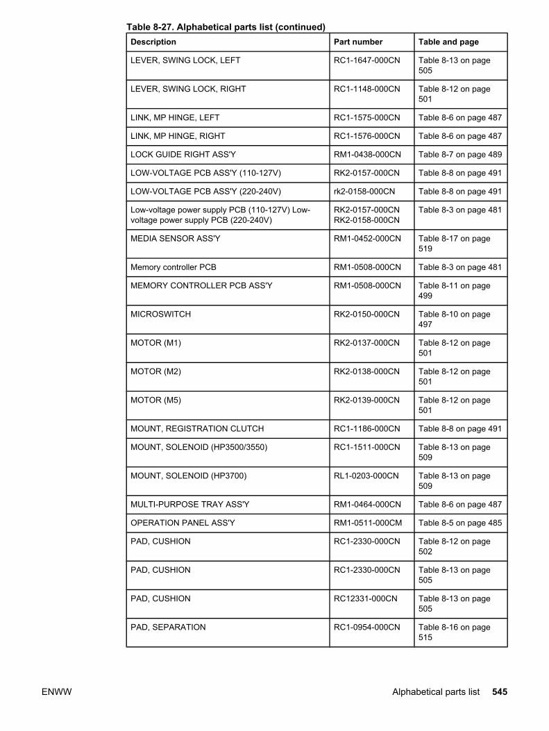
Description Part number Table and page
LEVER, SWING LOCK, LEFT RC1-1647-000CN Table 8-13 on page505
LEVER, SWING LOCK, RIGHT RC1-1148-000CN Table 8-12 on page501
LINK, MP HINGE, LEFT RC1-1575-000CN Table 8-6 on page 487
LINK, MP HINGE, RIGHT RC1-1576-000CN Table 8-6 on page 487
LOCK GUIDE RIGHT ASS'Y RM1-0438-000CN Table 8-7 on page 489
LOW-VOLTAGE PCB ASS'Y (110-127V) RK2-0157-000CN Table 8-8 on page 491
LOW-VOLTAGE PCB ASS'Y (220-240V) rk2-0158-000CN Table 8-8 on page 491
Low-voltage power supply PCB (110-127V) Low-voltage power supply PCB (220-240V)
RK2-0157-000CNRK2-0158-000CN
Table 8-3 on page 481
MEDIA SENSOR ASS'Y RM1-0452-000CN Table 8-17 on page519
Memory controller PCB RM1-0508-000CN Table 8-3 on page 481
MEMORY CONTROLLER PCB ASS'Y RM1-0508-000CN Table 8-11 on page499
MICROSWITCH RK2-0150-000CN Table 8-10 on page497
MOTOR (M1) RK2-0137-000CN Table 8-12 on page501
MOTOR (M2) RK2-0138-000CN Table 8-12 on page501
MOTOR (M5) RK2-0139-000CN Table 8-12 on page501
MOUNT, REGISTRATION CLUTCH RC1-1186-000CN Table 8-8 on page 491
MOUNT, SOLENOID (HP3500/3550) RC1-1511-000CN Table 8-13 on page509
MOUNT, SOLENOID (HP3700) RL1-0203-000CN Table 8-13 on page509
MULTI-PURPOSE TRAY ASS'Y RM1-0464-000CN Table 8-6 on page 487
OPERATION PANEL ASS'Y RM1-0511-000CM Table 8-5 on page 485
PAD, CUSHION RC1-2330-000CN Table 8-12 on page502
PAD, CUSHION RC1-2330-000CN Table 8-13 on page505
PAD, CUSHION RC12331-000CN Table 8-13 on page505
PAD, SEPARATION RC1-0954-000CN Table 8-16 on page515
Table 8-27. Alphabetical parts list (continued)
ENWW Alphabetical parts list 545

Description Part number Table and page
PAD, SEPARATION RC1-0939-000 Table 8-17 on page519
PAPER FEED ASS'Y RM1-0460-000CN Table 8-13 on page509
PAPER FEEDER DRIVER PCB ASS'Y RM1-0768-000CN Table 8-25 on page535
Paper feeder PCB RM1-0768-000 Table 8-4 on page 483
PAPER PICK-UP DRIVE ASS'Y RM1-0701-000CN Table 8-25 on page535
PAPER SEPARATION PAD ASS'Y RM1-0827-000CN Table 8-26 on page537
PAPER TRAY 3, 500-SHEET FEEDER RM1-0705-000CN Table 8-26 on page537
PHOTO-INTERRUPTER WG8-5571-000CN Table 8-24 on page533
PHOTO-INTERRUPTER, TLP 1241 WG8-5362-000CN Table 8-11 on page499
PHOTO-INTERRUPTER, TLP1241 WG8-5362-000CN Table 8-13 on page505
PHOTO-INTERRUPTER, TLP1241 WG8-5362-000CN Table 8-17 on page519
PHOTO-INTERRUPTER, TLP1241 WG8-5362-000CN Table 8-18 on page521
PHOTO-INTERRUPTER, TLP1241 WG8-5362-000CN Table 8-19 on page523
PHOTO-INTERRUPTER, TLP1241 (HP3500/3550) WG8-5362-000CN Table 8-13 on page509
PHOTO-INTERRUPTER, TLP1241 (HP3700) WG8-5362-000CN Table 8-13 on page509
PICK-UP FEED ASSY RM1-0456-000CN Table 8-17 on page519
PICK-UP/FEED ASS'Y (HP3500/3550) RM1-0760-000CN Table 8-17 on page519
PICK-UP/FEED ASS'Y (HP3700) RM1-0449-000CN Table 8-17 on page519
PIN, DOWEL XD9-0120-000CN Table 8-12 on page502
PLATE RL1-0189-000CN Table 8-12 on page502
PLATE, CONNECTING RC1-1637-000CN Table 8-13 on page509
Table 8-27. Alphabetical parts list (continued)
546 Chapter 8 Parts and diagrams ENWW

Description Part number Table and page
PLATE, CONTACT RC1-1151-000CN Table 8-13 on page505
PLATE, CONTACT RC1-1152-000CN Table 8-13 on page505
PLATE, CONTACT RC1-1153-000CN Table 8-13 on page505
PLATE, CONTACT RC1-1155-000CN Table 8-13 on page505
PLATE, DC CONTROLLER SUPPORT RC1-1348-000CN Table 8-10 on page497
PLATE, DRIVE RC1-1277-000CN Table 8-12 on page501
PLATE, END RB2-3003-040CN Table 8-16 on page515
PLATE, END RB2-6469-000CN Table 8-26 on page537
PLATE, GROUNDING RC1-1649-000CN Table 8-8 on page 491
PLATE, GROUNDING RC1-1629-000CN Table 8-12 on page501
PLATE, GROUNDING RC1-2294-000CN Table 8-12 on page501
PLATE, GROUNDING RC1-2175-000CN Table 8-24 on page533
PLATE, GROUNDING RC1-2280-000CN Table 8-24 on page533
PLATE, GROUNDING (HP3500/3550) RC1-1509-000CN Table 8-13 on page509
PLATE, JOINT, LEFT RC1-1602-000CN Table 8-10 on page497
PLATE, JOINT, RIGHT RC1-1603-000CN Table 8-7 on page 489
PLATE, LOGO, RIGHT RC1-1600-000CN Table 8-5 on page 485
PLATE, MOUNTING RC1-1355-000CN Table 8-8 on page 491
PLATE, PAPER FEEDER DRIVE RL1-0193-000CN Table 8-8 on page 491
PLATE, REINFORCEMENT RC1-1242-000CN Table 8-12 on page501
PLATE, SHIELD RC1-1349-000CN Table 8-11 on page499
POSITION GUIDE ASS'Y (HP3700) RM1-0462-000CN Table 8-13 on page509
RAIL, SWING, LEFT FRONT RC1-1642-000CN Table 8-7 on page 489
Table 8-27. Alphabetical parts list (continued)
ENWW Alphabetical parts list 547
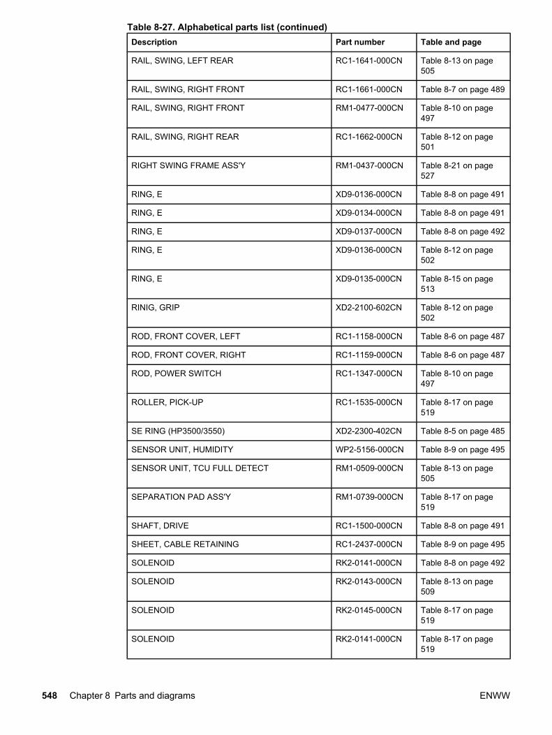
Description Part number Table and page
RAIL, SWING, LEFT REAR RC1-1641-000CN Table 8-13 on page505
RAIL, SWING, RIGHT FRONT RC1-1661-000CN Table 8-7 on page 489
RAIL, SWING, RIGHT FRONT RM1-0477-000CN Table 8-10 on page497
RAIL, SWING, RIGHT REAR RC1-1662-000CN Table 8-12 on page501
RIGHT SWING FRAME ASS'Y RM1-0437-000CN Table 8-21 on page527
RING, E XD9-0136-000CN Table 8-8 on page 491
RING, E XD9-0134-000CN Table 8-8 on page 491
RING, E XD9-0137-000CN Table 8-8 on page 492
RING, E XD9-0136-000CN Table 8-12 on page502
RING, E XD9-0135-000CN Table 8-15 on page513
RINIG, GRIP XD2-2100-602CN Table 8-12 on page502
ROD, FRONT COVER, LEFT RC1-1158-000CN Table 8-6 on page 487
ROD, FRONT COVER, RIGHT RC1-1159-000CN Table 8-6 on page 487
ROD, POWER SWITCH RC1-1347-000CN Table 8-10 on page497
ROLLER, PICK-UP RC1-1535-000CN Table 8-17 on page519
SE RING (HP3500/3550) XD2-2300-402CN Table 8-5 on page 485
SENSOR UNIT, HUMIDITY WP2-5156-000CN Table 8-9 on page 495
SENSOR UNIT, TCU FULL DETECT RM1-0509-000CN Table 8-13 on page505
SEPARATION PAD ASS'Y RM1-0739-000CN Table 8-17 on page519
SHAFT, DRIVE RC1-1500-000CN Table 8-8 on page 491
SHEET, CABLE RETAINING RC1-2437-000CN Table 8-9 on page 495
SOLENOID RK2-0141-000CN Table 8-8 on page 492
SOLENOID RK2-0143-000CN Table 8-13 on page509
SOLENOID RK2-0145-000CN Table 8-17 on page519
SOLENOID RK2-0141-000CN Table 8-17 on page519
Table 8-27. Alphabetical parts list (continued)
548 Chapter 8 Parts and diagrams ENWW
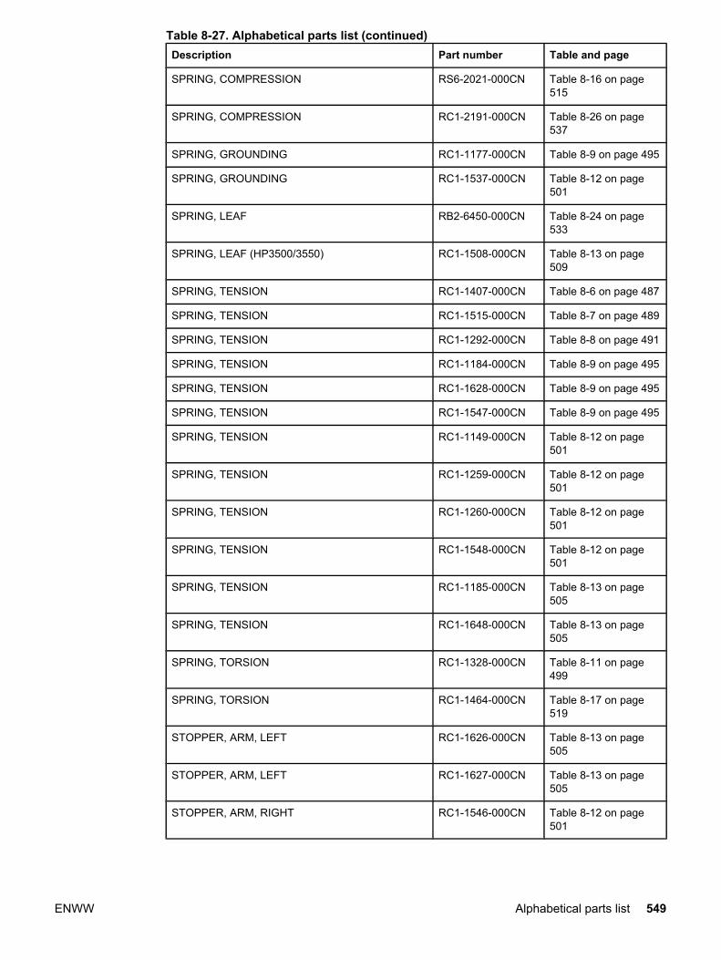
Description Part number Table and page
SPRING, COMPRESSION RS6-2021-000CN Table 8-16 on page515
SPRING, COMPRESSION RC1-2191-000CN Table 8-26 on page537
SPRING, GROUNDING RC1-1177-000CN Table 8-9 on page 495
SPRING, GROUNDING RC1-1537-000CN Table 8-12 on page501
SPRING, LEAF RB2-6450-000CN Table 8-24 on page533
SPRING, LEAF (HP3500/3550) RC1-1508-000CN Table 8-13 on page509
SPRING, TENSION RC1-1407-000CN Table 8-6 on page 487
SPRING, TENSION RC1-1515-000CN Table 8-7 on page 489
SPRING, TENSION RC1-1292-000CN Table 8-8 on page 491
SPRING, TENSION RC1-1184-000CN Table 8-9 on page 495
SPRING, TENSION RC1-1628-000CN Table 8-9 on page 495
SPRING, TENSION RC1-1547-000CN Table 8-9 on page 495
SPRING, TENSION RC1-1149-000CN Table 8-12 on page501
SPRING, TENSION RC1-1259-000CN Table 8-12 on page501
SPRING, TENSION RC1-1260-000CN Table 8-12 on page501
SPRING, TENSION RC1-1548-000CN Table 8-12 on page501
SPRING, TENSION RC1-1185-000CN Table 8-13 on page505
SPRING, TENSION RC1-1648-000CN Table 8-13 on page505
SPRING, TORSION RC1-1328-000CN Table 8-11 on page499
SPRING, TORSION RC1-1464-000CN Table 8-17 on page519
STOPPER, ARM, LEFT RC1-1626-000CN Table 8-13 on page505
STOPPER, ARM, LEFT RC1-1627-000CN Table 8-13 on page505
STOPPER, ARM, RIGHT RC1-1546-000CN Table 8-12 on page501
Table 8-27. Alphabetical parts list (continued)
ENWW Alphabetical parts list 549

Description Part number Table and page
STOPPER, ARM, RIGHT RC1-2339-000CN Table 8-12 on page501
STOPPER, FRONT HINGE, LEFT RL1-0215-000CN Table 8-7 on page 489
STOPPER, HINGE, RIGHT RL1-0216-000CN Table 8-7 on page 489
STRAP, DAMPER RC1-1625-000CN Table 8-13 on page505
SUB ROLLER ASS'Y RM1-0709-000CN Table 8-24 on page533
SUPPORT, FOOT, REAR RC1-2428-000CN Table 8-13 on page509
SUPPORT, PICK-UP GEAR RL1-0217-000CN Table 8-8 on page 492
SWING ASS'Y RM1-0707-000CN Table 8-25 on page535
SWING ROD LEFT ASS'Y RM1-0441-000CN Table 8-9 on page 495
SWING ROD RIGHT ASS'Y RM1-0442-000CN Table 8-9 on page 495
TOP COVER ASS'Y RM1-0465-020CN Table 8-5 on page 485
TRANSFER CONTACT ASS'Y RM1-0445-000CN Table 8-7 on page 489
TRANSFER ROLLER ASS'Y RM1-0740-000CN Table 8-17 on page519
TRANSFER UNIT Q3658-69001 Table 8-20 on page525
TRAY, AUXILIARY RC1-1555-000CN Table 8-5 on page 485
TRAY, EXPANSION, 1 RC1-2318-000CN Table 8-6 on page 487
TRAY, EXPANSION, 2 RC1-2319-000CN Table 8-6 on page 487
TRAY 2 (CASSETTE) RM1-0470-000CN Table 8-16 on page515
Table 8-27. Alphabetical parts list (continued)
550 Chapter 8 Parts and diagrams ENWW

Numerical parts list
Table 8-28. Numerical parts list
Part number Description Table and page
Q1319-69001 FORMATTER PCB (HP3500/3550) includes cage Table 8-10 on page 497
Q1319-69001Q1321-69001Q1321-67924
Formatter PCB (HP3500/3550) Formatter PCB(HP3700) Formatter Kit (HP3700)
Table 8-3 on page 481
Q1321-69001 FORMATTER PCB (HP3700) includes cage Table 8-10 on page 497
Q3655-69001 FUSER (110-127V) Table 8-23 on page 531
Q3656-69001 FUSER (220-240V) Table 8-23 on page 531
Q3658-69001 TRANSFER UNIT Table 8-20 on page 525
RB2-3003-040CN PLATE, END Table 8-16 on page 515
RB2-3489-000CN COVER, LOWER, LEFT Table 8-24 on page 533
RB2-6324-000CNN CLUTCH, MECHANICAL Table 8-13 on page 509
RB2-6448-000CN ARM, SENSOR Table 8-24 on page 533
RB2-6450-000CN SPRING, LEAF Table 8-24 on page 533
RB2-6452-000CN CROSSMEMBER Table 8-24 on page 533
RB2-6453-000CN COVER, SENSOR Table 8-24 on page 533
RB2-6469-000CN PLATE, END Table 8-26 on page 537
RC1-0939-000 PAD, SEPARATION Table 8-17 on page 519
RC1-0954-000CN PAD, SEPARATION Table 8-16 on page 515
RC1-1038-000CN DAMPER UNIT, MP PICK-UP Table 8-12 on page 502
RC1-1049-000CN HOLDER, SENSOR Table 8-13 on page 505
RC1-1050-000CN LENS Table 8-13 on page 505
RC1-1148-000CN LEVER, SWING LOCK, RIGHT Table 8-12 on page 501
RC1-1149-000CN SPRING, TENSION Table 8-12 on page 501
RC1-1151-000CN PLATE, CONTACT Table 8-13 on page 505
RC1-1152-000CN PLATE, CONTACT Table 8-13 on page 505
RC1-1153-000CN PLATE, CONTACT Table 8-13 on page 505
RC1-1155-000CN PLATE, CONTACT Table 8-13 on page 505
RC1-1156-000CN GUIDE, ROD, LEFT Table 8-9 on page 495
RC1-1158-000CN ROD, FRONT COVER, LEFT Table 8-6 on page 487
RC1-1159-000CN ROD, FRONT COVER, RIGHT Table 8-6 on page 487
RC1-1169-000CN ARM, DRUM LOCK, LEFT Table 8-13 on page 505
ENWW Numerical parts list 551
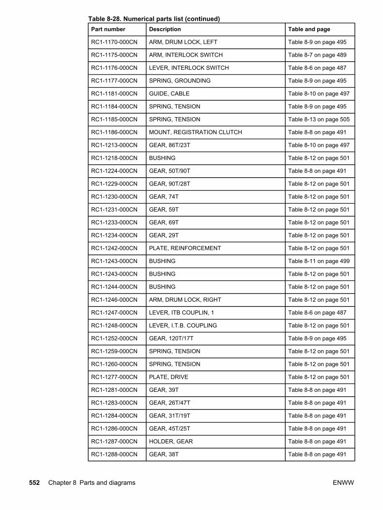
Part number Description Table and page
RC1-1170-000CN ARM, DRUM LOCK, LEFT Table 8-9 on page 495
RC1-1175-000CN ARM, INTERLOCK SWITCH Table 8-7 on page 489
RC1-1176-000CN LEVER, INTERLOCK SWITCH Table 8-6 on page 487
RC1-1177-000CN SPRING, GROUNDING Table 8-9 on page 495
RC1-1181-000CN GUIDE, CABLE Table 8-10 on page 497
RC1-1184-000CN SPRING, TENSION Table 8-9 on page 495
RC1-1185-000CN SPRING, TENSION Table 8-13 on page 505
RC1-1186-000CN MOUNT, REGISTRATION CLUTCH Table 8-8 on page 491
RC1-1213-000CN GEAR, 86T/23T Table 8-10 on page 497
RC1-1218-000CN BUSHING Table 8-12 on page 501
RC1-1224-000CN GEAR, 50T/90T Table 8-8 on page 491
RC1-1229-000CN GEAR, 90T/28T Table 8-12 on page 501
RC1-1230-000CN GEAR, 74T Table 8-12 on page 501
RC1-1231-000CN GEAR, 59T Table 8-12 on page 501
RC1-1233-000CN GEAR, 69T Table 8-12 on page 501
RC1-1234-000CN GEAR, 29T Table 8-12 on page 501
RC1-1242-000CN PLATE, REINFORCEMENT Table 8-12 on page 501
RC1-1243-000CN BUSHING Table 8-11 on page 499
RC1-1243-000CN BUSHING Table 8-12 on page 501
RC1-1244-000CN BUSHING Table 8-12 on page 501
RC1-1246-000CN ARM, DRUM LOCK, RIGHT Table 8-12 on page 501
RC1-1247-000CN LEVER, ITB COUPLIN, 1 Table 8-6 on page 487
RC1-1248-000CN LEVER, I.T.B. COUPLING Table 8-12 on page 501
RC1-1252-000CN GEAR, 120T/17T Table 8-9 on page 495
RC1-1259-000CN SPRING, TENSION Table 8-12 on page 501
RC1-1260-000CN SPRING, TENSION Table 8-12 on page 501
RC1-1277-000CN PLATE, DRIVE Table 8-12 on page 501
RC1-1281-000CN GEAR, 39T Table 8-8 on page 491
RC1-1283-000CN GEAR, 26T/47T Table 8-8 on page 491
RC1-1284-000CN GEAR, 31T/19T Table 8-8 on page 491
RC1-1286-000CN GEAR, 45T/25T Table 8-8 on page 491
RC1-1287-000CN HOLDER, GEAR Table 8-8 on page 491
RC1-1288-000CN GEAR, 38T Table 8-8 on page 491
Table 8-28. Numerical parts list (continued)
552 Chapter 8 Parts and diagrams ENWW
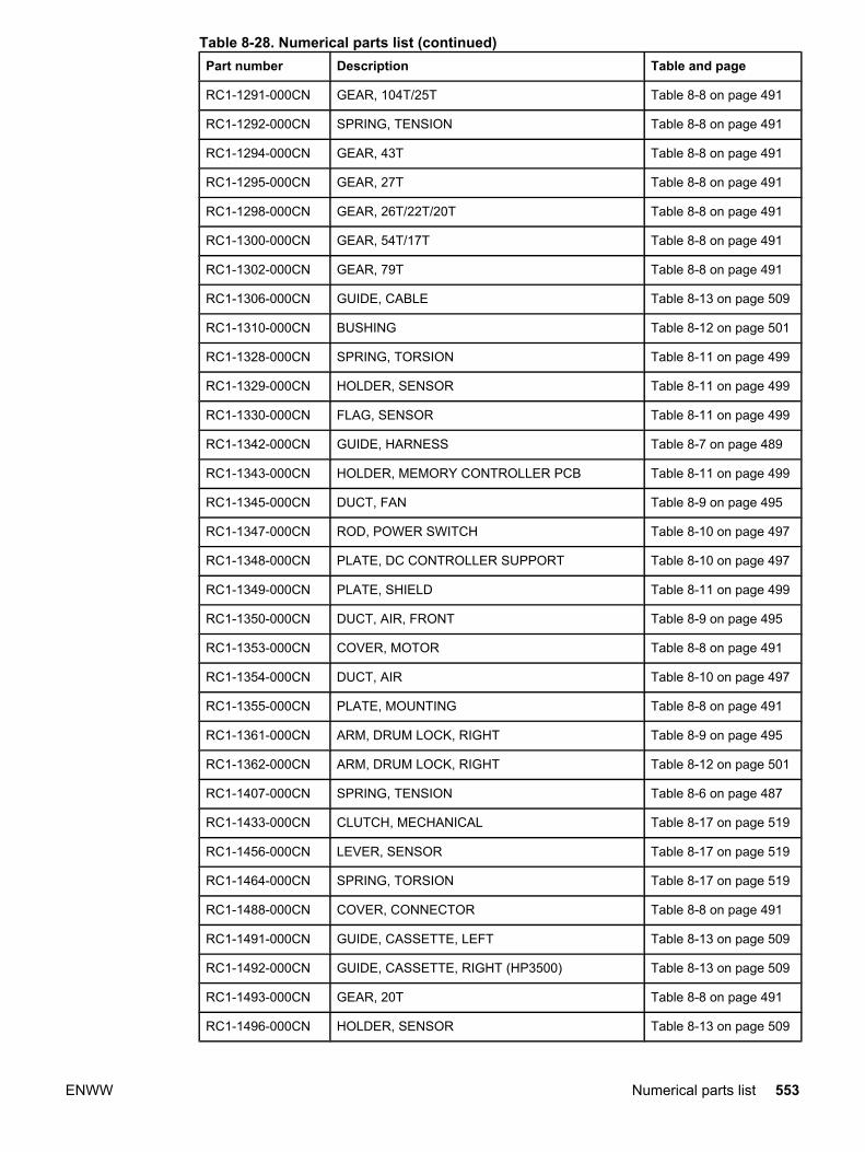
Part number Description Table and page
RC1-1291-000CN GEAR, 104T/25T Table 8-8 on page 491
RC1-1292-000CN SPRING, TENSION Table 8-8 on page 491
RC1-1294-000CN GEAR, 43T Table 8-8 on page 491
RC1-1295-000CN GEAR, 27T Table 8-8 on page 491
RC1-1298-000CN GEAR, 26T/22T/20T Table 8-8 on page 491
RC1-1300-000CN GEAR, 54T/17T Table 8-8 on page 491
RC1-1302-000CN GEAR, 79T Table 8-8 on page 491
RC1-1306-000CN GUIDE, CABLE Table 8-13 on page 509
RC1-1310-000CN BUSHING Table 8-12 on page 501
RC1-1328-000CN SPRING, TORSION Table 8-11 on page 499
RC1-1329-000CN HOLDER, SENSOR Table 8-11 on page 499
RC1-1330-000CN FLAG, SENSOR Table 8-11 on page 499
RC1-1342-000CN GUIDE, HARNESS Table 8-7 on page 489
RC1-1343-000CN HOLDER, MEMORY CONTROLLER PCB Table 8-11 on page 499
RC1-1345-000CN DUCT, FAN Table 8-9 on page 495
RC1-1347-000CN ROD, POWER SWITCH Table 8-10 on page 497
RC1-1348-000CN PLATE, DC CONTROLLER SUPPORT Table 8-10 on page 497
RC1-1349-000CN PLATE, SHIELD Table 8-11 on page 499
RC1-1350-000CN DUCT, AIR, FRONT Table 8-9 on page 495
RC1-1353-000CN COVER, MOTOR Table 8-8 on page 491
RC1-1354-000CN DUCT, AIR Table 8-10 on page 497
RC1-1355-000CN PLATE, MOUNTING Table 8-8 on page 491
RC1-1361-000CN ARM, DRUM LOCK, RIGHT Table 8-9 on page 495
RC1-1362-000CN ARM, DRUM LOCK, RIGHT Table 8-12 on page 501
RC1-1407-000CN SPRING, TENSION Table 8-6 on page 487
RC1-1433-000CN CLUTCH, MECHANICAL Table 8-17 on page 519
RC1-1456-000CN LEVER, SENSOR Table 8-17 on page 519
RC1-1464-000CN SPRING, TORSION Table 8-17 on page 519
RC1-1488-000CN COVER, CONNECTOR Table 8-8 on page 491
RC1-1491-000CN GUIDE, CASSETTE, LEFT Table 8-13 on page 509
RC1-1492-000CN GUIDE, CASSETTE, RIGHT (HP3500) Table 8-13 on page 509
RC1-1493-000CN GEAR, 20T Table 8-8 on page 491
RC1-1496-000CN HOLDER, SENSOR Table 8-13 on page 509
Table 8-28. Numerical parts list (continued)
ENWW Numerical parts list 553

Part number Description Table and page
RC1-1497-000CN GEAR, 25T Table 8-8 on page 491
RC1-1500-000CN SHAFT, DRIVE Table 8-8 on page 491
RC1-1508-000CN SPRING, LEAF (HP3500/3550) Table 8-13 on page 509
RC1-1509-000CN PLATE, GROUNDING (HP3500/3550) Table 8-13 on page 509
RC1-1511-000CN MOUNT, SOLENOID (HP3500/3550) Table 8-13 on page 509
RC1-1514-000CN LEVER, SENSOR Table 8-13 on page 509
RC1-1515-000CN SPRING, TENSION Table 8-7 on page 489
RC1-1535-000CN ROLLER, PICK-UP Table 8-17 on page 519
RC1-1537-000CN SPRING, GROUNDING Table 8-12 on page 501
RC1-1545-000CN ARM, DRUM LOCK, RIGHT Table 8-12 on page 501
RC1-1546-000CN STOPPER, ARM, RIGHT Table 8-12 on page 501
RC1-1547-000CN SPRING, TENSION Table 8-9 on page 495
RC1-1548-000CN SPRING, TENSION Table 8-12 on page 501
RC1-1555-000CN TRAY, AUXILIARY Table 8-5 on page 485
RC1-1562-000CN COVER, DIMM Table 8-5 on page 485
RC1-1563-000CN COVER, RIGHT Table 8-5 on page 485
RC1-1565-000CN COVER, REAR Table 8-5 on page 485
RC1-1566-000CN COVER, JAM CLEARING Table 8-5 on page 485
RC1-1572-000CN DAMPER UNIT, HINGE, LEFT Table 8-7 on page 489
RC1-1573-000CN DAMPER UNIT, HINGE, RIGHT Table 8-7 on page 489
RC1-1574-000CN COVER, MP TRAY Table 8-6 on page 487
RC1-1575-000CN LINK, MP HINGE, LEFT Table 8-6 on page 487
RC1-1576-000CN LINK, MP HINGE, RIGHT Table 8-6 on page 487
RC1-1593-000CN BLOCK, TEST PRINT CONNECTING Table 8-10 on page 497
RC1-1600-000CN PLATE, LOGO, RIGHT Table 8-5 on page 485
RC1-1602-000CN PLATE, JOINT, LEFT Table 8-10 on page 497
RC1-1603-000CN PLATE, JOINT, RIGHT Table 8-7 on page 489
RC1-1605-000CN COVER, SCREW Table 8-7 on page 489
RC1-1613-000CN GUIDE, DUPLEXING (HP3700) Table 8-13 on page 509
RC1-1622-000CN ARM, DRUM LOCK, LEFT Table 8-13 on page 505
RC1-1623-000CN ARM, DRUM LOCK, LEFT Table 8-13 on page 505
RC1-1625-000CN STRAP, DAMPER Table 8-13 on page 505
RC1-1626-000CN STOPPER, ARM, LEFT Table 8-13 on page 505
Table 8-28. Numerical parts list (continued)
554 Chapter 8 Parts and diagrams ENWW
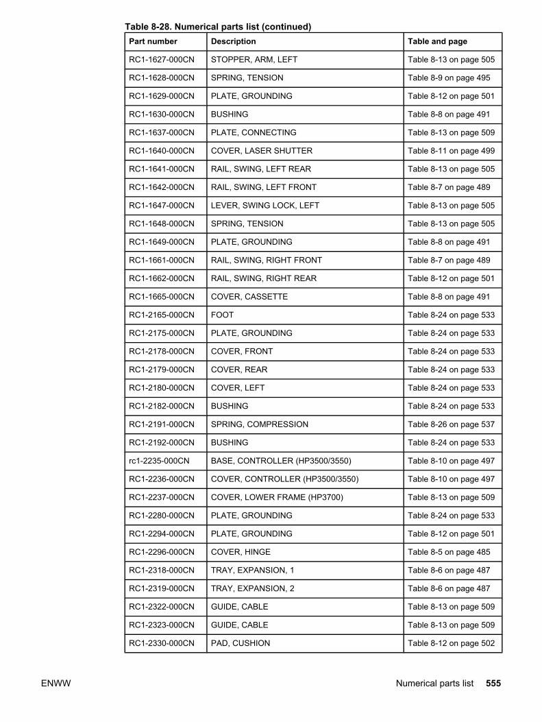
Part number Description Table and page
RC1-1627-000CN STOPPER, ARM, LEFT Table 8-13 on page 505
RC1-1628-000CN SPRING, TENSION Table 8-9 on page 495
RC1-1629-000CN PLATE, GROUNDING Table 8-12 on page 501
RC1-1630-000CN BUSHING Table 8-8 on page 491
RC1-1637-000CN PLATE, CONNECTING Table 8-13 on page 509
RC1-1640-000CN COVER, LASER SHUTTER Table 8-11 on page 499
RC1-1641-000CN RAIL, SWING, LEFT REAR Table 8-13 on page 505
RC1-1642-000CN RAIL, SWING, LEFT FRONT Table 8-7 on page 489
RC1-1647-000CN LEVER, SWING LOCK, LEFT Table 8-13 on page 505
RC1-1648-000CN SPRING, TENSION Table 8-13 on page 505
RC1-1649-000CN PLATE, GROUNDING Table 8-8 on page 491
RC1-1661-000CN RAIL, SWING, RIGHT FRONT Table 8-7 on page 489
RC1-1662-000CN RAIL, SWING, RIGHT REAR Table 8-12 on page 501
RC1-1665-000CN COVER, CASSETTE Table 8-8 on page 491
RC1-2165-000CN FOOT Table 8-24 on page 533
RC1-2175-000CN PLATE, GROUNDING Table 8-24 on page 533
RC1-2178-000CN COVER, FRONT Table 8-24 on page 533
RC1-2179-000CN COVER, REAR Table 8-24 on page 533
RC1-2180-000CN COVER, LEFT Table 8-24 on page 533
RC1-2182-000CN BUSHING Table 8-24 on page 533
RC1-2191-000CN SPRING, COMPRESSION Table 8-26 on page 537
RC1-2192-000CN BUSHING Table 8-24 on page 533
rc1-2235-000CN BASE, CONTROLLER (HP3500/3550) Table 8-10 on page 497
RC1-2236-000CN COVER, CONTROLLER (HP3500/3550) Table 8-10 on page 497
RC1-2237-000CN COVER, LOWER FRAME (HP3700) Table 8-13 on page 509
RC1-2280-000CN PLATE, GROUNDING Table 8-24 on page 533
RC1-2294-000CN PLATE, GROUNDING Table 8-12 on page 501
RC1-2296-000CN COVER, HINGE Table 8-5 on page 485
RC1-2318-000CN TRAY, EXPANSION, 1 Table 8-6 on page 487
RC1-2319-000CN TRAY, EXPANSION, 2 Table 8-6 on page 487
RC1-2322-000CN GUIDE, CABLE Table 8-13 on page 509
RC1-2323-000CN GUIDE, CABLE Table 8-13 on page 509
RC1-2330-000CN PAD, CUSHION Table 8-12 on page 502
Table 8-28. Numerical parts list (continued)
ENWW Numerical parts list 555

Part number Description Table and page
RC1-2330-000CN PAD, CUSHION Table 8-13 on page 505
RC1-2334-000CN GUIDE, CABLE Table 8-8 on page 491
RC1-2339-000CN STOPPER, ARM, RIGHT Table 8-12 on page 501
RC1-2364-000CN COVER, FMTR CABLE (HP3500/3550) Table 8-10 on page 497
RC1-2422-000CN LABEL, HIGH TEMP. CAUTION Table 8-10 on page 497
RC1-2428-000CN SUPPORT, FOOT, REAR Table 8-13 on page 509
RC1-2437-000CN SHEET, CABLE RETAINING Table 8-9 on page 495
RC1-3240-000CN GEAR, 74T Table 8-12 on page 501
RC1-3249-000CN BUSHING Table 8-8 on page 491
RC12331-000CN PAD, CUSHION Table 8-13 on page 505
RK2-0017-000CN FAN (HP3700) Table 8-9 on page 495
RK2-0137-000CN MOTOR (M1) Table 8-12 on page 501
RK2-0138-000CN MOTOR (M2) Table 8-12 on page 501
RK2-0139-000CN MOTOR (M5) Table 8-12 on page 501
RK2-0141-000CN SOLENOID Table 8-8 on page 492
RK2-0141-000CN SOLENOID Table 8-17 on page 519
RK2-0143-000CN SOLENOID Table 8-13 on page 509
RK2-0145-000CN SOLENOID Table 8-17 on page 519
RK2-0150-000CN MICROSWITCH Table 8-10 on page 497
RK2-0153-000CN FAN, (HP3500/3550) Table 8-9 on page 495
RK2-0157-000CN LOW-VOLTAGE PCB ASS'Y (110-127V) Table 8-8 on page 491
RK2-0157-000CNRK2-0158-000CN
Low-voltage power supply PCB (110-127V) Low-voltage power supply PCB (220-240V)
Table 8-3 on page 481
rk2-0158-000CN LOW-VOLTAGE PCB ASS'Y (220-240V) Table 8-8 on page 491
RK2-0162-000CN CABLE, FFC (HP3700) Table 8-10 on page 497
RK2-0163-000CN CABLE, TM FFC Table 8-10 on page 497
RK2-0164-000CN CABLE, LASER FFC, 1 Table 8-10 on page 497
RK2-0165-000CN CABLE, LASER FFC, 2 Table 8-10 on page 497
RK2-0176-000CN CLUTCH, ELECTROMAGNETIC Table 8-15 on page 513
RK2-0179-000CN CABLE, FFC (HP3500/3550) Table 8-10 on page 497
RK2-0247-000CN CLUTCH, ELECROMAGNETIC Table 8-8 on page 492
RK2-0248-000CN CLUTCH, ELECTROMAGNETIC Table 8-14 on page 511
RL1-0189-000CN PLATE Table 8-12 on page 502
Table 8-28. Numerical parts list (continued)
556 Chapter 8 Parts and diagrams ENWW
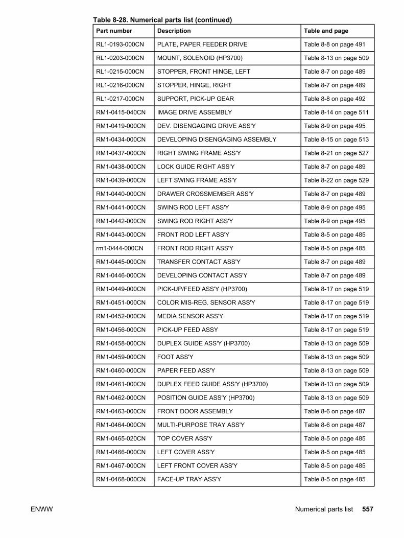
Part number Description Table and page
RL1-0193-000CN PLATE, PAPER FEEDER DRIVE Table 8-8 on page 491
RL1-0203-000CN MOUNT, SOLENOID (HP3700) Table 8-13 on page 509
RL1-0215-000CN STOPPER, FRONT HINGE, LEFT Table 8-7 on page 489
RL1-0216-000CN STOPPER, HINGE, RIGHT Table 8-7 on page 489
RL1-0217-000CN SUPPORT, PICK-UP GEAR Table 8-8 on page 492
RM1-0415-040CN IMAGE DRIVE ASSEMBLY Table 8-14 on page 511
RM1-0419-000CN DEV. DISENGAGING DRIVE ASS'Y Table 8-9 on page 495
RM1-0434-000CN DEVELOPING DISENGAGING ASSEMBLY Table 8-15 on page 513
RM1-0437-000CN RIGHT SWING FRAME ASS'Y Table 8-21 on page 527
RM1-0438-000CN LOCK GUIDE RIGHT ASS'Y Table 8-7 on page 489
RM1-0439-000CN LEFT SWING FRAME ASS'Y Table 8-22 on page 529
RM1-0440-000CN DRAWER CROSSMEMBER ASS'Y Table 8-7 on page 489
RM1-0441-000CN SWING ROD LEFT ASS'Y Table 8-9 on page 495
RM1-0442-000CN SWING ROD RIGHT ASS'Y Table 8-9 on page 495
RM1-0443-000CN FRONT ROD LEFT ASS'Y Table 8-5 on page 485
rm1-0444-000CN FRONT ROD RIGHT ASS'Y Table 8-5 on page 485
RM1-0445-000CN TRANSFER CONTACT ASS'Y Table 8-7 on page 489
RM1-0446-000CN DEVELOPING CONTACT ASS'Y Table 8-7 on page 489
RM1-0449-000CN PICK-UP/FEED ASS'Y (HP3700) Table 8-17 on page 519
RM1-0451-000CN COLOR MIS-REG. SENSOR ASS'Y Table 8-17 on page 519
RM1-0452-000CN MEDIA SENSOR ASS'Y Table 8-17 on page 519
RM1-0456-000CN PICK-UP FEED ASSY Table 8-17 on page 519
RM1-0458-000CN DUPLEX GUIDE ASS'Y (HP3700) Table 8-13 on page 509
RM1-0459-000CN FOOT ASS'Y Table 8-13 on page 509
RM1-0460-000CN PAPER FEED ASS'Y Table 8-13 on page 509
RM1-0461-000CN DUPLEX FEED GUIDE ASS'Y (HP3700) Table 8-13 on page 509
RM1-0462-000CN POSITION GUIDE ASS'Y (HP3700) Table 8-13 on page 509
RM1-0463-000CN FRONT DOOR ASSEMBLY Table 8-6 on page 487
RM1-0464-000CN MULTI-PURPOSE TRAY ASS'Y Table 8-6 on page 487
RM1-0465-020CN TOP COVER ASS'Y Table 8-5 on page 485
RM1-0466-000CN LEFT COVER ASS'Y Table 8-5 on page 485
RM1-0467-000CN LEFT FRONT COVER ASS'Y Table 8-5 on page 485
RM1-0468-000CN FACE-UP TRAY ASS'Y Table 8-5 on page 485
Table 8-28. Numerical parts list (continued)
ENWW Numerical parts list 557

Part number Description Table and page
RM1-0469-000CN FACE-DOWN DELIVERY ASSEMBLY Table 8-19 on page 523
RM1-0470-000CN TRAY 2 (CASSETTE) Table 8-16 on page 515
RM1-0475-000CN CABLE, MAIN (HP3700) Table 8-10 on page 497
RM1-0476-000CN CABLE, OPTION CONNECTING (HP3700) Table 8-13 on page 509
RM1-0477-000CN RAIL, SWING, RIGHT FRONT Table 8-10 on page 497
RM1-0478-000CN CABLE, FRAME, LOWER (HP3700) Table 8-13 on page 509
RM1-0482-000CN CABLE, CPR CONNECTING Table 8-8 on page 492
RM1-0483-000CN CABLE, FORMATTER POWER SUPPLY (HP3700) Table 8-8 on page 492
RM1-0485-000CN CABLE, HIGH VOLTAGE Table 8-7 on page 489
RM1-0488-000CN CABLE, LEFT FRONT Table 8-8 on page 492
RM1-0489-000CN CABLE, OPERATION PANEL Table 8-5 on page 485
RM1-0493-000CN CABLE, ENVIRONMENT SENSOR Table 8-9 on page 495
RM1-0495-000CN CABLE, MAIN (HP3500/3550) Table 8-10 on page 497
RM1-0496-000CN CABLE, OPTION CONNECTING (HP3500/3550) Table 8-13 on page 509
RM1-0497-000CN CABLE, FRAME, LOWER (HP3500/3550) Table 8-13 on page 509
RM1-0498-000CN CABLE, FORMATTER POWER SUPPLY(HP 3500/3550)
Table 8-8 on page 492
RM1-0505-000CN High-voltage power supply PCBs Table 8-3 on page 481
RM1-0505-000CN HIGH-VOLTAGE PCB ASS'Y Table 8-7 on page 489
RM1-0506-000CN DC CONTROLLER PCB (HP3700) Table 8-10 on page 497
RM1-0508-000CN Memory controller PCB Table 8-3 on page 481
RM1-0508-000CN MEMORY CONTROLLER PCB ASS'Y Table 8-11 on page 499
RM1-0509-000CN SENSOR UNIT, TCU FULL DETECT Table 8-13 on page 505
RM1-0510-000CN DC CONTROLLER PCB (HP3500/3550) Table 8-10 on page 497
RM1-0510-000CNRM1-2324-000CNRM1-0506-000CN
DC controller PCB (HP3500) DC controller PCB(HP 3550) DC controller PCB (HP3700)
Table 8-3 on page 481
RM1-0511-000CM OPERATION PANEL ASS'Y Table 8-5 on page 485
RM1-0511-000CN Control panel PCB Table 8-3 on page 481
RM1-0701-000CN PAPER PICK-UP DRIVE ASS'Y Table 8-25 on page 535
RM1-0705-000CN PAPER TRAY 3, 500-SHEET FEEDER Table 8-26 on page 537
RM1-0707-000CN SWING ASS'Y Table 8-25 on page 535
RM1-0709-000CN SUB ROLLER ASS'Y Table 8-24 on page 533
RM1-0731-000CN CASSETTE PICK-UP ROLLER ASS'Y Table 8-8 on page 491
Table 8-28. Numerical parts list (continued)
558 Chapter 8 Parts and diagrams ENWW
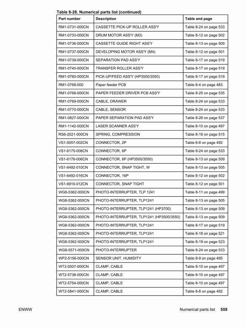
Part number Description Table and page
RM1-0731-000CN CASSETTE PICK-UP ROLLER ASS'Y Table 8-24 on page 533
RM1-0733-000CN DRUM MOTOR ASS'Y (M3) Table 8-12 on page 502
RM1-0736-000CN CASSETTE GUIDE RIGHT ASS'Y Table 8-13 on page 509
RM1-0737-000CN DEVELOPING MOTOR ASS'Y (M4) Table 8-12 on page 501
RM1-0739-000CN SEPARATION PAD ASS'Y Table 8-17 on page 519
RM1-0740-000CN TRANSFER ROLLER ASS'Y Table 8-17 on page 519
RM1-0760-000CN PICK-UP/FEED ASS'Y (HP3500/3550) Table 8-17 on page 519
RM1-0768-000 Paper feeder PCB Table 8-4 on page 483
RM1-0768-000CN PAPER FEEDER DRIVER PCB ASS'Y Table 8-25 on page 535
RM1-0769-000CN CABLE, DRAWER Table 8-24 on page 533
RM1-0770-000CN CABLE, SENSOR Table 8-24 on page 533
RM1-0827-000CN PAPER SEPARATION PAD ASS'Y Table 8-26 on page 537
RM1-1142-000CN LASER SCANNER ASS'Y Table 8-10 on page 497
RS6-2021-000CN SPRING, COMPRESSION Table 8-16 on page 515
VS1-5057-002CN CONNECTOR, 2P Table 8-8 on page 492
VS1-6175-006CN CONNECTOR, 6P Table 8-24 on page 533
VS1-6176-006CN CONNECTOR, 6P (HP3500/3550) Table 8-13 on page 509
VS1-6492-010CN CONNECTOR, SNAP TIGHT, W Table 8-13 on page 505
VS1-6492-016CN CONNECTOR, 16P Table 8-12 on page 502
VS1-6910-012CN CONNECTOR, SNAP TIGHT Table 8-12 on page 501
WG8-5362-000CN PHOTO-INTERRUPTER, TLP 1241 Table 8-11 on page 499
WG8-5362-000CN PHOTO-INTERRUPTER, TLP1241 Table 8-13 on page 505
WG8-5362-000CN PHOTO-INTERRUPTER, TLP1241 (HP3700) Table 8-13 on page 509
WG8-5362-000CN PHOTO-INTERRUPTER, TLP1241 (HP3500/3550) Table 8-13 on page 509
WG8-5362-000CN PHOTO-INTERRUPTER, TLP1241 Table 8-17 on page 519
WG8-5362-000CN PHOTO-INTERRUPTER, TLP1241 Table 8-18 on page 521
WG8-5362-000CN PHOTO-INTERRUPTER, TLP1241 Table 8-19 on page 523
WG8-5571-000CN PHOTO-INTERRUPTER Table 8-24 on page 533
WP2-5156-000CN SENSOR UNIT, HUMIDITY Table 8-9 on page 495
WT2-0507-000CN CLAMP, CABLE Table 8-10 on page 497
WT2-5738-000CN CLAMP, CABLE Table 8-10 on page 497
WT2-5754-000CN CLAMP, CABLE Table 8-10 on page 497
WT2-5841-000CN CLAMP, CABLE Table 8-8 on page 492
Table 8-28. Numerical parts list (continued)
ENWW Numerical parts list 559
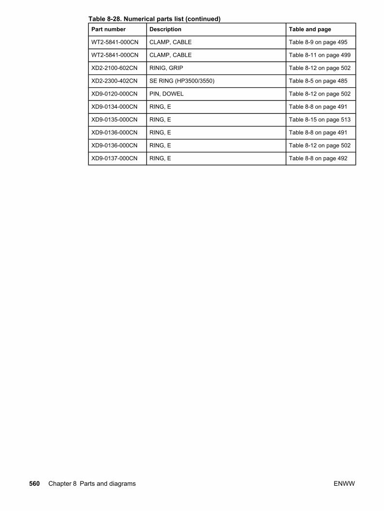
Part number Description Table and page
WT2-5841-000CN CLAMP, CABLE Table 8-9 on page 495
WT2-5841-000CN CLAMP, CABLE Table 8-11 on page 499
XD2-2100-602CN RINIG, GRIP Table 8-12 on page 502
XD2-2300-402CN SE RING (HP3500/3550) Table 8-5 on page 485
XD9-0120-000CN PIN, DOWEL Table 8-12 on page 502
XD9-0134-000CN RING, E Table 8-8 on page 491
XD9-0135-000CN RING, E Table 8-15 on page 513
XD9-0136-000CN RING, E Table 8-8 on page 491
XD9-0136-000CN RING, E Table 8-12 on page 502
XD9-0137-000CN RING, E Table 8-8 on page 492
Table 8-28. Numerical parts list (continued)
560 Chapter 8 Parts and diagrams ENWW
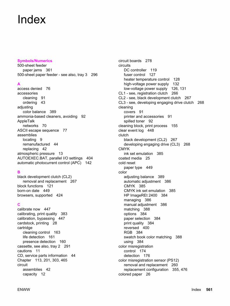
Index
Symbols/Numerics500-sheet feeder
paper jams 361500-sheet paper feeder - see also, tray 3 296
Aaccess denied 76accessories
cleaning 91ordering 43
adjustingcolor balance 389
ammonia-based cleaners, avoiding 92AppleTalk
networks 70ASCII escape sequence 77assemblies
locating 9remanufactured 44replacing 42
atmospheric pressure 13AUTOEXEC.BAT, parallel I/O settings 404automatic photocurrent control (APC) 142
Bblack development clutch (CL2)
removal and replacement 267block functions 121born-on date 449browsers, supported 424
Ccalibrate now 447calibrating, print quality 383calibration, bypassing 447cardstock, printing 28cartridge
cleaning control 163life detection 161presence detection 160
cassette, see also, tray 2 291cautions 11CD, service parts information 44Chapter 113, 201, 303, 465circuit
assemblies 42capacity 12
circuit boards 278circuits
DC controller 119fuser control 127heater temperature control 128high-voltage power supply 132low-voltage power supply 126, 131
CL1 - see, registration clutch 266CL2 - see, black development clutch 267CL3 - see, developing engaging drive clutch 268cleaning
covers 91printer and accessories 91spilled toner 92
cleaning block, print process 155clear event log 448clutch
black development (CL2) 267developing engaging drive (CL3) 268
CMYKink set emulation 385
coated media 25cold reset
paper type 449color
adjusting balance 389automatic adjustment 386CMYK 385CMYK ink set emulation 385HP ImageREt 2400 384managing 386manual adjustment 386matching 388options 384paper selection 384print quality 384reversed 400RGB 384swatch book color matching 388using 384
color misregistrationcontrol 174detection 176
color misregistration sensor (PS12)removal and replacement 260replacement configuration 355, 476
colored paper 26
ENWW Index 561

commandsDOS 404PJL 404
Commercial Service and Support OrganizationAmerica (CSSO-A) 43Europe (CSSO-E) 43
compact disc, service parts information 44components
replacing 42configuration
color misregistration sensor (PS12) replacement355, 476
DC controller PCB replacement 353, 354, 475DC controller, previously installed, replacement
353, 474enhanced I/O (EIO) 69formatter PCB and DC controller PCB replacement
at same time 352, 474formatter PCB replacement 352, 474fuser replacement 355, 476laser/scanner assembly replacement 355, 476media sensor (PS5) replacement 354media sensor (PS5)replacement 476network 68parallel 67transfer unit replacement 355, 477USB 66
configuration pageprinting 428
connectorslocating 458
control paneldiagnostics 436error messages 312locking 76overlays, part numbers 470troubleshooting 407
control panel PCBremoval and replacement 287
controlscartridge cleaning 163color misregistration 174developing cylinder engaging/disengaging 162developing motor 125drum motor 124environmental 178fan 125feed speed 186heater temperature 127horizontal synchronous 142image density (D-max) 179image halftone (D-half) 179image mask 143image stabilization 177ITB (transfer) unit 167laser 140laser emission 142
memory tag 160phase 145primary transfer roller engaging/disengaging 171reverse 193scanner motor 144secondary transfer roller engaging/disengaging 172speed 145video interface 135
country/region of origin, determining 22cover, left, 500-sheet paper feeder
removal and replacement 297cover, right, 500-sheet paper feeder
removal and replacement 297crooked images 368CSSO-A (Commercial Service and Support
Organization-America) 43CSSO-E (Commercial Service and Support
Organization-Europe) 43cutouts 24
DDC controller
circuit 119function 119replacement configuration 353, 355, 475, 476replacement configuration, previously installed
354, 475DC controller PCB
removal and replacement 278delivery motor (M2)
removal and replacement 271Deskjet transparencies
avoiding 26detection
cartridge life 161cartridge presence 160color misregistration 176developing cylinder engaging/disengaging 163failure 130failure, laser diode 144failure, scanner motor 145image density 180ITB (transfer) unit 168jams 199media 189toner level 161transfer roller engaging/disengaging, secondary
173transfer unit life 169waste toner full 167
developing cylinder engaging/disengagingcontrol 162detection 163
562 Index ENWW

developing disengagingassembly, part numbers 506, 508
developing engaging drive assemblyremoval and replacement 225
developing engaging drive clutch (CL3)removal and replacement 268
developing engaging sensor (PS14)removal and replacement 261
developing motor (M4)removal and replacement 273
developing motor control 125developing motor control circuit 125developing section
cartridges 156engaging/disengaging unit 157memory tag control 160
development block, print process 151diagnostics
control panel 436engine 434manual sensor test 436mode 434paper path sensors 436print/stop test 442procedure 433using 42
dimensionsprinter 15
DIMMsinstalling 79
disable cartridge check 436documentation
ordering 45door switch
location 452removal and replacement 250
DOS commands, parallel I/O 404drivers
printer 45drum drive unit
part numbers 505drum motor (M3)
removal and replacement 271drum motor control 124drum motor control circuit 124duplex feed delivery paper sensor
removal and replacement 258duplex feed mode 194duplex feed solenoid (SL5)
removal and replacement 266duplexing
does not work, re-enabling 352, 474feed unit (HP 3700) 192
duty cycle 15
EEIO
troubleshooting 403electrical specifications 12electrostatic discharge, caution 204electrostatic latent image formation block, print process
150embedded Web server
information tab 423network connection 422networking tab 424settings tab 423software 74
embossed media 25enabling
language font DIMM 83enhanced I/O (EIO) configuration 69environment sensor (PS15)
removal and replacement 261environmental
change control 178location requirements 11specifications 13stewardship program 31
error messagesalphabetical list 312numerical list 327paper jams 357
errors 312ESD - see electrostatic discharge 204event log
display on control panel 436printing 431, 436
exchange program 44exhaust fan (FAN1)
removal and replacement 277extended warranty information 46
Fface-down - see, output bin 221face-down delivery assembly
removal and replacement 221face-down delivery paper sensor
removal and replacement 257failure detection
laser diode 144scanner motor 145
fan controlcircuit 125
fasteners 472feed guide
removal and replacement 240feed motor (M1)
removal and replacement 269feed speed control 186flicker prevention mechanism 129
ENWW Index 563

font DIMMsinstalling 79
formatter PCBremoval and replacement 279replacement configuration 352, 474replacement configuration, previously installed
353, 474front cover, 500-sheet paper feeder
removal and replacement 296front door
removal and replacement 209fuel gages 436functions
block 121failure detection 130flicker prevention 129fuser detection 130motors 121protective 129, 132
fusercount, resetting 448covers 91life 207removal and replacement 220replacing 103warranty 21
fuser block, print process 154fuser control circuit 127fuser delivery paper sensor (PS)
removal and replacement 256fuser detection 130fuser front paper sensor (PS6)
removal and replacement 256fuser sleeve
removal and replacement 239fuser/delivery unit 189fusing problems 397
Gglossy paper
printing 26grayscale printing 386
Hheater temperature control 127heavy paper, printing 28high-voltage power supply circuit 132high-voltage power supply PCB
removal and replacement 281horizontal synchronous control 142HP ImageREt 2400 384HP Jetdirect external print server
installing 88HP Jetdirect print server card
function 69installing 85
HP Support Assistant 44
HP toolbox 74, 424HP Web Jetadmin 73humidity
site requirements 13site requirments 11storing supplies 13
Iimage
distortion 398formation system 146halftone control (D-half) 179mask control 143stabilization control 177
image defectsall black or solid color 393blank images 393blank spots 397color misregistration 398color missing 397dark color 392dark images 392distortion 398from dirt on paper 394horizontal lines 396light color 392light images 391misplaced images 399reversed color 400smearing 399snail tracks 400vertical dots 394vertical lines 395
image densitycontrol (D-max) 179detection 180
image drive assemblyremoval and replacement 223
information menu 407information tab, embedded Web server 423inkjet transparenices
avoiding 26input trays
supported media 16installing
DIMMs 79HP Jetdirect external print server 85, 88memory 79print cartridges 55
intermediate transfer belt - see, ITB 218internal components
part numbers 489isolating problems 42
564 Index ENWW

ITB(transfer) unit 164(transfer) unit, secondary 164replacing 99replacing before end of life 103see, transfer unit 218
Jjam - see, paper jams 357
KKorean EMI statement 37
Llanguage
changing on display 63control panel overlay 63overlays 63printer job (PJL) 404
language font DIMMenabling 83
laser control 140laser emission control 142laser safety statements
United States 37laser/scanner
system 139unit 139
laser/scanner assemblyremoval and replacement 222replacement configuration 355, 476
left coverremoval and replacement 210
left front coverremoval and replacement 211
levelssecurity 76
Linuxsoftware 73
loading paperprocedure 57, 59, 61
locatingparts and supplies 96
locking control panelsettings 76
low-voltage power supply circuit 126, 131low-voltage power supply PCB
removal and replacement 285lower rear door
removal and replacement 215
MM1 - see, feed motor 269M2 - see, delivery motor 271M3 - see, drum motor 271M4 - developing motor (M4) 273M5 - transfer roller engaging motor 274
maintenanceagreements 46printer 91
managingcolor 386supplies 94
manual color adjustment 386manual sensor test 436matching colors 388Material Safety Data Sheet (MSDS) 32mechanisms
flicker prevention 129skew control 187
mediacolored paper 26detection 189glossy paper 26heavy paper 28loading, tray 59, 61loading, tray 3 57nonsupported 24preprinted forms and letterhead 28recycled paper 29selecting 24selection 384sizes 16special 26transparencies 26weight 29weights 16
media sensor (PS5)removal and replacement 255replacement configuration 354, 476
memoryenabling 83font DIMMs 79installing 79printer 78
memory controller PCBremoval and replacement 286
memory tag control 160menu map
printing 407menus
locking 76messages
alphabetical list 312critical error 312error 312numerical list 327status 312warning 312
model numbers 22
ENWW Index 565
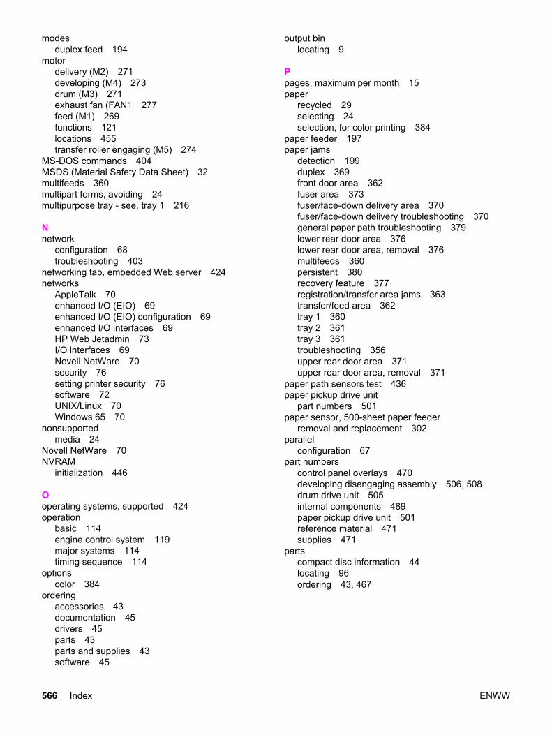
modesduplex feed 194
motordelivery (M2) 271developing (M4) 273drum (M3) 271exhaust fan (FAN1 277feed (M1) 269functions 121locations 455transfer roller engaging (M5) 274
MS-DOS commands 404MSDS (Material Safety Data Sheet) 32multifeeds 360multipart forms, avoiding 24multipurpose tray - see, tray 1 216
Nnetwork
configuration 68troubleshooting 403
networking tab, embedded Web server 424networks
AppleTalk 70enhanced I/O (EIO) 69enhanced I/O (EIO) configuration 69enhanced I/O interfaces 69HP Web Jetadmin 73I/O interfaces 69Novell NetWare 70security 76setting printer security 76software 72UNIX/Linux 70Windows 65 70
nonsupportedmedia 24
Novell NetWare 70NVRAM
initialization 446
Ooperating systems, supported 424operation
basic 114engine control system 119major systems 114timing sequence 114
optionscolor 384
orderingaccessories 43documentation 45drivers 45parts 43parts and supplies 43software 45
output binlocating 9
Ppages, maximum per month 15paper
recycled 29selecting 24selection, for color printing 384
paper feeder 197paper jams
detection 199duplex 369front door area 362fuser area 373fuser/face-down delivery area 370fuser/face-down delivery troubleshooting 370general paper path troubleshooting 379lower rear door area 376lower rear door area, removal 376multifeeds 360persistent 380recovery feature 377registration/transfer area jams 363transfer/feed area 362tray 1 360tray 2 361tray 3 361troubleshooting 356upper rear door area 371upper rear door area, removal 371
paper path sensors test 436paper pickup drive unit
part numbers 501paper sensor, 500-sheet paper feeder
removal and replacement 302parallel
configuration 67part numbers
control panel overlays 470developing disengaging assembly 506, 508drum drive unit 505internal components 489paper pickup drive unit 501reference material 471supplies 471
partscompact disc information 44locating 96ordering 43, 467
566 Index ENWW
parts orderinginternet 43
passwordssetting 76
PCBcontrol panel 287DC controller 278formatter 279high-voltage power supply 281low-voltage power supply 285memory controller 286replacement configuration requirements 352, 473
PCB, 500-sheet paper feederremoval and replacement 300
PCBslocating 456
perforations 24phase control 145phone numbers
Commercial Service and Support Organizations 43pick-up clutch, 500-sheet paper feeder
removal and replacement 301pick-up drive unit, 500-sheet paper feeder
removal and replacement 299pick-up roller, 500-sheet paper feeder
removal and replacement 298pick-up solenoid, 500-sheet paper feeder
removal and replacement 301pick-up/feed assembly
removal and replacement 225pickup/delivery sequence 198pickup/feed
system 182unit 184
PIN 448PJL (Printer Job Language)
Technical Reference Manual 77PJL - see, printer job language 404postcard, sprinting 28power
connections 62consumption 12rating information 22
power supplyhigh-voltage circuit 132low-voltage circuit 126, 131
power switchremoval and replacement 251
power-ontroubleshooting 310
PowerSavedisabling 65power consumption 12
PowerSave Timeusing 65
pressureatmospheric 13
pressure rollerremoval and replacement 239
primary transfer roller engaging/disengagingcontrol 171
printcleaning block 155development block 151electrostatic latent image formation 150fuser block 154process 147, 150, 151, 152, 154, 155transfer block 152
print cartridgechanging 97fuel gauge 436installing 55life 207removal and replacement 219safety data sheet 32
print qualitycalibrating the printer 383general 381printing evaluation pages 436troubleshooting process 381troubleshooting transparencies 381
print quality troubleshootingenvironmental problems 382pages 383paper jams 382toner buildup 382
print serverHP Jetdirect 69installing 85
print/stop test 442printer
assemblies 9calibration 447cleaning 91configuration 47configurations 3, 5connecting power 62duty cycle 15features 6installation 47maintenance 91memory 78package contents 48setting network security 76software 71specifications 15testing operation 64troubleshooting errors 312unpacking 50
ENWW Index 567

printer componentsremoval and replacement 201
printer coversremoval and replacement 209
printer driversadditional 72ordering 45software 71
printer features 6Printer Job Language (PJL)
commands 404Technical Reference Manual 77
printingfour colors 385grayscale 386menu map 407
process, print 147production number 22protective functions 129, 132PS1 - see, tray 1 paper sensor 253PS10 - see, duplex feed delivery paper sensor 258PS11 - see, rear output bin paper sensor 259PS12 - see, color misregistration sensor 260PS13 - see, waste toner level sensor 260PS14 - see, developing engaging sensor 261PS15 - see, environment sensor 261PS16 - see, secondary transfer roller engaging sensor
262PS2 - see, tray 2 paper sensor 253PS4 - see, registration paper sensor 254PS5 - see, media sensor 255PS6 - see, fuser front paper sensor 256PS7 - see, fuser delivery paper sensor 256PS8 - see, face down delivery paper sensor 257PS9 - see, reversed paper sensor 257punched paper 24
Rrear cover
removal and replacement 215rear output bin - see, lower rear door 215rear output bin paper sensor
removal and replacement 259recovery feature, paper jam 377recycled paper 29recycling, print cartridge 32reference materials, part numbers 471registration clutch (CL1)
removal and replacement 266registration paper sensor (PS4)
removal and replacement 254regulatory information, power rating 22remanufactured assemblies 44removal and replacement
black development clutch (CL2) 267color misregistration sensor (PS12) 260control panel PCB 287
DC controller PDB 278delivery motor (M2) 271developing engaging drive assembly 225developing engaging drive clutch (CL3) 268developing engaging sensor (PS14) 261developing motor M4) 273door switch 250drum motor M3) 271duplex feed delivery paper sensor 258duplex feed solenoid (SL5) 266environment sensor (PS15) 261exhaust fan (FAN1) 277face-down delivery assembly 221face-down delivery paper sensor 257feed guide 240feed motor (M1 269formatter PCB 279front cover, 500-sheet paper feeder 296front door 209fuser 220fuser delivery paper sensor (PS7) 256fuser front paper sensor (PS6) 256fuser sleeve 239high-voltage power supply PCB 281image drive assembly 223laser/scanner assembly 222left cover 210left cover, 500-sheet paper feeder 297left front cover 211low-voltage power supply PCB 285lower rear door 215media sensor (PS5) 255memory controller PCB 286paper sensor, 500-sheet paper feeder 302PCB, 500-sheet paper feeder 300pick-up clutch, 500-sheet paper feeder 301pick-up roller, 500-sheet paper feeder 298pick-up solenoid, 500-sheet paper feeder 301pick-up/feed assembly 225power switch 251pressure roller 239print cartridge 219printer covers 209rear cover 215rear output bin paper sensor (PS11) 259registration clutch (CL1) 266registration paper sensor (PS4) 254reversed paper sensor (PS9) 257right cover 213right cover, 500-sheet paper feeder 297secondary transfer charging roller 239secondary transfer roller engaging sensor (PS16)
262secondary transfer roller engaging solenoid (SL4)
265separation pad, 500-sheet paper feeder 299strategy 204
568 Index ENWW

swing guide, left 245swing guide, right 242test print switch 251thermistor, main 239thermistor, sub 239thermoswitch 239transfer roller engaging motor (M5) 274transfer unit 218tray 1 216tray 1 paper sensor (PS1) 251, 253tray 1 pick-up roller 237tray 1 pick-up solenoid 263tray 1 separation pad 237Tray 2 291tray 2 end plate 291tray 2 guide, right (HP 3700) 291, 294tray 2 paper sensor (PS2) 253tray 2 pick-up roller 238tray 2 pick-up solenoid 264tray 2 separation pad 238upper rear door 214waste toner level sensor (PS13) 260
repair notices 204repetitive defects 401replacement
color misregistration sensor (PS12) configuration355, 476
DC controller PCB configuration 353, 354, 475formatter PCB 352, 474formatter PCB and DC controller at same time
352, 474formatter PCB configuration 352, 353, 474fuser configuration 355, 476laser/scanner assembly configuration 355, 476media sensor (PS5) configuration 354media sensor (PS5)configuration 476screws 205transfer unit configuration 355, 477
replacement parts, miscellaneous 288replacing
fuser 103pickup roller 108
resetcold 446
Restoring the Service ID 449reverse control 193reversed paper sensor (PS9)
removal and replacement 257RGB 384right cover
removal and replacement 213
Ssafety information 37safety statements
laser safety for Finland 38scanner motor control 144
screwstypes of 205
screws, types 472secondary transfer charging roller
removal and replacement 239secondary transfer roller engaging sensor (PS16)
removal and replacement 262secondary transfer roller engaging solenoid (SL4)
removal and replacement 265secondary transfer roller engaging/disengaging
control 172detection 173
securitylevels 76network 76
selectingpaper 24
sensorslocations 453
separation pad, 500-sheet paper feederremoval and replacement 299
serial numberformatter, resetting 448
serial numbers 22service
agreements 46approach 42ID 449next-day on-site 46on-site 46parts information CD 44
service menuaccessing 448PIN 448
settingslocking 76network security 76
settings tab, embedded Web server 423site requirements
location 11printer 11
sizesupported 16
skew control mechanism 187SL1 - see, tray 1 pick-up solenoid 263SL2 - see, tray 2 pick-up solenoid 264SL4 - see, secondary transfer roller engaging solenoid
265SL5 - see, duplex feed solenoid 266snail tracks 400software
embedded Web server 74for networks 72HP toolbox 74Linux 73ordering 45
ENWW Index 569

printer drivers 71UNIX 73utilities 73
solenoidduplex feed (SL5) 266locations 454secondary transfer roller engaging solenoid (SL4)
265special media, printing 26specifications
electrical 12environmental 13media 16preprinted paper 25print media 16printer 15site requirements 11space requirements 11
speed control 145spilled toner
cleaning 92standby mode
power consumption 12status messages 312storing
printer 13supplies 13
subassemblies 42supplies
locating 96managing 94ordering 43, 467part numbers 471replacing 94, 207status page, printing 429storing 13
Support AssistantHP 44
swatch book color matching 388swing guide, left
removal and replacement 242, 245switch
see, door switch 250see, power switch 251see, test print switch 251
switch boxes 404switches, locating 452systems
image formation 146laser/scanner 139
Ttechnical reference guides 45
temperatureink requirements 25maximum change rate 14site requirements 11, 13storing supplies 13
test pageprinting 445
test print switchremoval and replacement 251
testing the printer 64tests - see, diagnostics 435theory of operation
basic 114engine control system 119
thermistor, mainremoval and replacement 239
thermistor, subremoval and replacement 239
thermoswitchremoval and replacement 239
timing sequence 114toner
cleaning spilled 92toner level detection 161tools, required for service 204total page count, resetting 448transfer block, print process 152transfer kit
resetting count 99, 448transfer roller engaging motor (M5)
removal and replacement 274transfer section 164transfer unit
life 207removal and replacement 218replacement configuration 355, 477replacing 99resetting count 448warranty 21
transfer unit (ITB)cleaning control 167detection 168secondary 164
transfer unit lifedetection 169
transparenciesHP-supported 16, 24printing 26
tray 1loading paper 61paper jams 360removal and replacement 216
570 Index ENWW

tray 1 paper sensorremoval and replacement 253
tray 1 pick-up rollerremoval and replacement 237
tray 1 pick-up solenoidremoval and replacement 263
tray 1 separation padremoval and replacement 237
tray 2end plate, removal and replacement 291loading paper 59removal and replacement 291
tray 2 guide, right (HP 3500)removal and replacement 294
tray 2 guide, right (HP 3700)removal and replacement 291
tray 2 paper sensorremoval and replacement 253
tray 2 pick-up rollerremoval and replacement 238
tray 2 pick-up solenoidremoval and replacement 264
tray 2 separation padremoval and replacement 238
tray 3loading paper 57
tray 3 - see also, 500-sheet paper feeder 296trays, input
supported media 16troubleshooting
all black or solid color 393alphabetical printer messages 312blank images 393blank spots 397calibrating the printer 383checklist 307color misregistration 398color missing 397control panel diagnostics 407critical error messages 312dark color 392dark images 392diagnostics 434dirt on paper 394duplex jams 369EIO 403embedded Web server 422error messages 312event log 431front door area jams 362fuser area jams 373general process 308general, paper path 379horizontal lines 396image defects 390image formation 381light color 392
light images 391lower rear door area jams 376misplaced images 399multifeeds 360networks 403numerical printer messages 327paper jam error messages 357paper path 356poor fusing 397power-on 310print quality 381print quality, environmental problems 382print quality, overhead transparency 381print quality, paper jams 382printer errors 312process 307registration/transfer area jams 363repetitive defects 401reversed color 400skewed paper 368smearing 399snail tracks 400status messages 312toner buildup 382transfer/feed area jams 362tray 2 paper jams 361tray 3 paper jams 361upper rear door area jams 371vertical dots 394vertical lines 395warning messages 312wrinkled paper 367
UUEL (universal exit language) 405UNIX
software 73UNIX/Linux
networks 70unpacking the printer 50upper rear door
removal and replacement 214usage page, printing 430USB
configuration 66using
PowerSave Time 65utilities
other 75software 73
Vvacuuming 92ventilation 11video interface control 135
ENWW Index 571

voltagepower consumption 12
Wwarranty
extended 46fuser 21print cartridge 20statement 19transfer unit 21
waste toner full detection 167waste toner level sensor (PS13)
removal and replacement 260Websites
printer specifications 13websites
Material Safety Data Sheet (MSDS) 32printer specifications 15product and support information 44service part information 44
weightmedia 16, 29
Windows networks 65 70wrinkled paper 367
572 Index ENWW


© 2004 Hewlett-Packard Development Company, L.P.
www.hp.com
Q5990-90939
*Q5990-90939**Q5990-90939*