Lexmark Optra C Printer
326
5045-001 Lexmark Optra™ C Lexmark and Lexmark with diamond design are trademarks of Lexmark International, Inc., registered in the United States and/or other countries. • Table of Contents • Index • Safety and Notices • Trademarks • Start Diagnostics • Manuals Menu
-
Upload
khangminh22 -
Category
Documents
-
view
1 -
download
0
Transcript of Lexmark Optra C Printer

5045-001
Lexmark Optra™ C
Lexmark and Lexmark with diamonddesign are trademarks of LexmarkInternational, Inc., registered in theUnited States and/or other countries.
• Table of Contents
• Index
• Safety and Notices
• Trademarks
• Start Diagnostics
• Manuals Menu

Second Edition (March, 1996)
The following paragraph does not apply to the united kingdom or any countrywhere such provisions are inconsistent with local law : LEXMARKINTERNATIONAL, INC. PROVIDES THIS PUBLICATION “AS IS” WITHOUTWARRANTY OF ANY KIND, EITHER EXPRESS OR IMPLIED, INCLUDING,BUT NOT LIMITED TO, THE IMPLIED WARRANTIES OF MERCHANTABILITYOR FITNESS FOR A PARTICULAR PURPOSE. Some states do not allowdisclaimer of express or implied warranties in certain transactions, therefore,this statement may not apply to you.
This publication could include technical inaccuracies or typographical errors.Changes are periodically made to the information herein; these changes will beincorporated in later editions of the publication. Improvements or changes in theproducts or the programs described in this publication may be made at anytime. Publications are not stocked at the address given below; requests forpublications should be made to your point of purchase.
Comments may be addressed to Lexmark International, Inc., DepartmentD22A/035-3, 740 New Circle Road, Lexington, Kentucky 40550, U.S.A.Lexmark may use or distribute any of the information you supply in any way itbelieves appropriate without incurring any obligation to you.
©Copyright Lexmark International, Inc. 1995, 1996. All Rights Reserved .
UNITED STATES GOVERNMENT RESTRICTED RIGHTS
This software and documentation are provided with RESTRICTED RIGHTS.Use, duplication or disclosure by the Government is subject to restrictions asset forth in subparagraph (c)(1)(ii) of the Rights in Technical Data and ComputerSoftware clause at DFARS 252.227-7013 and in applicable FAR provisions:Lexmark International, Inc., Lexington, KY 40550.
5045-001

5045-001
Contents
Preface . . . . . . . . . . . . . . . . . . . . . . . . . . . . . . . . . . . . . . . . . . . . . . . xNotices and Safety Information . . . . . . . . . . . . . . . . . . . . . . . . . . .xi
Laser Notice . . . . . . . . . . . . . . . . . . . . . . . . . . . . . . . . . . . . . . . xiTrademarks. . . . . . . . . . . . . . . . . . . . . . . . . . . . . . . . . . . . . . . xixSafety Information. . . . . . . . . . . . . . . . . . . . . . . . . . . . . . . . . . xxii
General Information . . . . . . . . . . . . . . . . . . . . . . . . . . . . . . . . . . .1-1Power Consumption . . . . . . . . . . . . . . . . . . . . . . . . . . . . . . . . 1-1Options . . . . . . . . . . . . . . . . . . . . . . . . . . . . . . . . . . . . . . . . . . 1-1Maintenance Approach. . . . . . . . . . . . . . . . . . . . . . . . . . . . . . 1-2Tools . . . . . . . . . . . . . . . . . . . . . . . . . . . . . . . . . . . . . . . . . . . . 1-5Abbreviations . . . . . . . . . . . . . . . . . . . . . . . . . . . . . . . . . . . . . 1-6
Diagnostic Information . . . . . . . . . . . . . . . . . . . . . . . . . . . . . . . .2-1Diagnostic/Maintenance Approach . . . . . . . . . . . . . . . . . . . . . 2-1Start . . . . . . . . . . . . . . . . . . . . . . . . . . . . . . . . . . . . . . . . . . . . 2-4
Operator Codes . . . . . . . . . . . . . . . . . . . . . . . . . . . . . . . . 2-5Power-On Self Test (POST). . . . . . . . . . . . . . . . . . . . . . . 2-8Error Message Table . . . . . . . . . . . . . . . . . . . . . . . . . . . 2-10Symptom Table . . . . . . . . . . . . . . . . . . . . . . . . . . . . . . . 2-12
Service Checks. . . . . . . . . . . . . . . . . . . . . . . . . . . . . . . . . . . 2-14Error (46) Toner Cartridge Not Installed Correctly . . . . . 2-14Error (111/112) Fuser, Warm-Up/Temperature Low . . . 2-15Error (113) Fuser Temperature High . . . . . . . . . . . . . . . 2-16Error (114) Fuser Failure . . . . . . . . . . . . . . . . . . . . . . . . 2-16Error (115) Fuser Heater Off . . . . . . . . . . . . . . . . . . . . . 2-17Error (116) Fuser Unit Missing . . . . . . . . . . . . . . . . . . . . 2-17Error (117) Fuser Pump Failure . . . . . . . . . . . . . . . . . . . 2-18Error (121/125) Laser Board Failure . . . . . . . . . . . . . . . 2-20Error (122) Laser Failure . . . . . . . . . . . . . . . . . . . . . . . . 2-20Error (123/124) Mirror Motor Start-up or Rotation . . . . . 2-21Error (126/131) Transfer Drum Motor Failure. . . . . . . . . 2-22Error (130) Service Motor Error . . . . . . . . . . . . . . . . . . . 2-22Error (132/133) Main Motor (M2) Start-Up or Rotation. . 2-23Error (134) Controller Fan Motor Failure . . . . . . . . . . . . 2-23Error (135) Fuser Unit Fan Motor Failure . . . . . . . . . . . . 2-24Error (136) Electrical Unit Fan Motor Failure . . . . . . . . . 2-24Error (141) Power Supply Failure (LVPS 110V or 220V) 2-25Error (142) Engine Board Memory Failure . . . . . . . . . . . 2-25Error (143) 5 V / 24 V Supply Failure . . . . . . . . . . . . . . . 2-26Error (144) Temperature/Humidity Sensor Failure . . . . . 2-26Error (145) Density Sensor Failure. . . . . . . . . . . . . . . . . 2-26
Contents iii

5045-001
Service Checks (continued)Error (146) Printer Communication Failure . . . . . . . . . . 2-27Error (147) Engine Board IC Failure . . . . . . . . . . . . . . . 2-27Error (148) Developer Unit Rotation Failure . . . . . . . . . 2-28Error (149) Developer Unit Pressure Failure . . . . . . . . . 2-29Error (152) Tray 2 Power Failure. . . . . . . . . . . . . . . . . . 2-29No AC Power/Dead Machine. . . . . . . . . . . . . . . . . . . . . 2-30No DC Power. . . . . . . . . . . . . . . . . . . . . . . . . . . . . . . . . 2-31No Pickup (Manual Feed) . . . . . . . . . . . . . . . . . . . . . . . 2-31No Pickup (Cassette Feed) . . . . . . . . . . . . . . . . . . . . . . 2-32No Pickup (Optional Paper Feeder Pickup). . . . . . . . . . 2-32Registration Roller Does Not Rotate . . . . . . . . . . . . . . . 2-33High-Voltage Power Supply Output. . . . . . . . . . . . . . . . 2-33Pickup / Feed System Theory . . . . . . . . . . . . . . . . . . . . 2-34
Paper Feed Troubleshooting . . . . . . . . . . . . . . . . . . . . . . . . 2-38Pickup Unit . . . . . . . . . . . . . . . . . . . . . . . . . . . . . . . . . . 2-38Transfer Drum Unit . . . . . . . . . . . . . . . . . . . . . . . . . . . . 2-40Fuser/Delivery Unit . . . . . . . . . . . . . . . . . . . . . . . . . . . . 2-41Fuser . . . . . . . . . . . . . . . . . . . . . . . . . . . . . . . . . . . . . . . 2-42Multi-Feed . . . . . . . . . . . . . . . . . . . . . . . . . . . . . . . . . . . 2-43Wrinkles. . . . . . . . . . . . . . . . . . . . . . . . . . . . . . . . . . . . . 2-44Leading-Edge Fold . . . . . . . . . . . . . . . . . . . . . . . . . . . . 2-44Skewing . . . . . . . . . . . . . . . . . . . . . . . . . . . . . . . . . . . . . 2-45
Error Codes - 9XX . . . . . . . . . . . . . . . . . . . . . . . . . . . . . . . . 2-46Error (900) Software Error . . . . . . . . . . . . . . . . . . . . . . . 2-46Error (941) Service ROM SIMM . . . . . . . . . . . . . . . . . . 2-46Error (939, 942, 943, 944) Service RIP Board. . . . . . . . 2-46Error (945) Service RIP Board. . . . . . . . . . . . . . . . . . . . 2-46Error (946) Service RIP Board. . . . . . . . . . . . . . . . . . . . 2-47Error (947) Service RIP Board. . . . . . . . . . . . . . . . . . . . 2-47Error (948) Service RIP Board. . . . . . . . . . . . . . . . . . . . 2-47Error (949) Service RIP Board. . . . . . . . . . . . . . . . . . . . 2-47Error (950) Service RIP Board. . . . . . . . . . . . . . . . . . . . 2-48Error (953) Service RIP Board. . . . . . . . . . . . . . . . . . . . 2-48Error (955) Service Video RAM Error . . . . . . . . . . . . . . 2-48Error (956) Service L2 Cache Error. . . . . . . . . . . . . . . . 2-48Error (960) Service Memory Error . . . . . . . . . . . . . . . . . 2-48Error (961) Bad / Missing DRAM . . . . . . . . . . . . . . . . . . 2-49Error (970/979) INI Failure. . . . . . . . . . . . . . . . . . . . . . . 2-49Error (977) Service Network Board . . . . . . . . . . . . . . . . 2-49
iv

5045-001
Print Quality . . . . . . . . . . . . . . . . . . . . . . . . . . . . . . . . . . . . . 2-50Print Quality Start Of Call . . . . . . . . . . . . . . . . . . . . . . . . 2-50Horizontal Variation (“Jitter”) Example . . . . . . . . . . . . . . 2-52
Print Quality Troubleshooting . . . . . . . . . . . . . . . . . . . . . . . . 2-54Background . . . . . . . . . . . . . . . . . . . . . . . . . . . . . . . . . . 2-54Black Horizontal Lines . . . . . . . . . . . . . . . . . . . . . . . . . . 2-54Black Vertical Lines . . . . . . . . . . . . . . . . . . . . . . . . . . . . 2-55Blur at Bottom of Page . . . . . . . . . . . . . . . . . . . . . . . . . . 2-55Laser Failures. . . . . . . . . . . . . . . . . . . . . . . . . . . . . . . . . 2-56Low Color Coverage or Usage . . . . . . . . . . . . . . . . . . . . 2-56Oil Soaking . . . . . . . . . . . . . . . . . . . . . . . . . . . . . . . . . . . 2-57Random Oil Spots on Page . . . . . . . . . . . . . . . . . . . . . . 2-58Spew . . . . . . . . . . . . . . . . . . . . . . . . . . . . . . . . . . . . . . . 2-58Vertical Streaks . . . . . . . . . . . . . . . . . . . . . . . . . . . . . . . 2-59
Print Quality Service Checks . . . . . . . . . . . . . . . . . . . . . . . . 2-61Black Service Check . . . . . . . . . . . . . . . . . . . . . . . . . . . 2-61Blank Page Service Check. . . . . . . . . . . . . . . . . . . . . . . 2-62Blank Spots Service Check . . . . . . . . . . . . . . . . . . . . . . 2-63Color Aberration Service Check . . . . . . . . . . . . . . . . . . . 2-63Dark Image Service Check. . . . . . . . . . . . . . . . . . . . . . . 2-64Dirt On Back Of Paper Service Check . . . . . . . . . . . . . . 2-65Dirty Print Service Check . . . . . . . . . . . . . . . . . . . . . . . . 2-66Distortion Service Check . . . . . . . . . . . . . . . . . . . . . . . . 2-67Horizontal Voids Service Check . . . . . . . . . . . . . . . . . . . 2-67Light Image Service Check . . . . . . . . . . . . . . . . . . . . . . 2-68Poor Fusing Service Check . . . . . . . . . . . . . . . . . . . . . . 2-69Spacing Table Service Check . . . . . . . . . . . . . . . . . . . . 2-69Streaking Service Check . . . . . . . . . . . . . . . . . . . . . . . . 2-70Toner Scattered Service Check . . . . . . . . . . . . . . . . . . . 2-71Vertical Lines Service Check . . . . . . . . . . . . . . . . . . . . . 2-72Vertical Voids Service Check . . . . . . . . . . . . . . . . . . . . . 2-73
Diagnostic Aids . . . . . . . . . . . . . . . . . . . . . . . . . . . . . . . . . . . . . .3-1Basic Engine Test . . . . . . . . . . . . . . . . . . . . . . . . . . . . . . 3-1Diagnostics Mode. . . . . . . . . . . . . . . . . . . . . . . . . . . . . . . 3-2Diagnostics Mode Menu Structure . . . . . . . . . . . . . . . . . . 3-3
Diagnostics Mode Tests . . . . . . . . . . . . . . . . . . . . . . . . . . . . . 3-4Button Test . . . . . . . . . . . . . . . . . . . . . . . . . . . . . . . . . . . . 3-4Compressor . . . . . . . . . . . . . . . . . . . . . . . . . . . . . . . . . . . 3-4Defaults . . . . . . . . . . . . . . . . . . . . . . . . . . . . . . . . . . . . . . 3-5Disk Test/Clean . . . . . . . . . . . . . . . . . . . . . . . . . . . . . . . . 3-5Error Log . . . . . . . . . . . . . . . . . . . . . . . . . . . . . . . . . . . . . 3-6Flash Test. . . . . . . . . . . . . . . . . . . . . . . . . . . . . . . . . . . . . 3-6
Contents v

5045-001
Diagnostics Mode Tests (continued)LCD Test . . . . . . . . . . . . . . . . . . . . . . . . . . . . . . . . . . . . . 3-7Memory Tests . . . . . . . . . . . . . . . . . . . . . . . . . . . . . . . . . 3-7Page Count . . . . . . . . . . . . . . . . . . . . . . . . . . . . . . . . . . . 3-7Permanent Page Count . . . . . . . . . . . . . . . . . . . . . . . . . . 3-8Print Test 1 . . . . . . . . . . . . . . . . . . . . . . . . . . . . . . . . . . . 3-8Print Test 2 . . . . . . . . . . . . . . . . . . . . . . . . . . . . . . . . . . . 3-9Print Test 3 . . . . . . . . . . . . . . . . . . . . . . . . . . . . . . . . . . . 3-9Quick Disk Test . . . . . . . . . . . . . . . . . . . . . . . . . . . . . . . 3-10Wrap Tests . . . . . . . . . . . . . . . . . . . . . . . . . . . . . . . . . . 3-11
Other Tests . . . . . . . . . . . . . . . . . . . . . . . . . . . . . . . . . . . . . 3-12Density Adjustment Panel . . . . . . . . . . . . . . . . . . . . . . . 3-12LAN Information. . . . . . . . . . . . . . . . . . . . . . . . . . . . . . . 3-21
Repair Information . . . . . . . . . . . . . . . . . . . . . . . . . . . . . . . . . . . . 4-1Handling ESD-Sensitive Parts . . . . . . . . . . . . . . . . . . . . . . . . 4-1Adjustments . . . . . . . . . . . . . . . . . . . . . . . . . . . . . . . . . . . . . . 4-2Service Information . . . . . . . . . . . . . . . . . . . . . . . . . . . . . . . . 4-2
Releasing Plastic Latches . . . . . . . . . . . . . . . . . . . . . . . . 4-2Screws. . . . . . . . . . . . . . . . . . . . . . . . . . . . . . . . . . . . . . . 4-2
Removal Procedures . . . . . . . . . . . . . . . . . . . . . . . . . . . . . . . 4-3Attraction Roller Drive Assembly . . . . . . . . . . . . . . . . . . . 4-3Cassette Paper Pickup Drive Motor . . . . . . . . . . . . . . . . 4-4Registration Roller Drive Clutch . . . . . . . . . . . . . . . . . . . 4-4Cassette Paper Pickup PCB . . . . . . . . . . . . . . . . . . . . . . 4-5Cassette Paper Pickup Assembly . . . . . . . . . . . . . . . . . . 4-5Cassette Paper Pickup D-rollers . . . . . . . . . . . . . . . . . . . 4-6Cassette Paper Pickup Roller Assembly, Front. . . . . . . . 4-6Cassette Paper Pickup Roller Assembly, Rear . . . . . . . . 4-6Cassette Paper Pickup Solenoid . . . . . . . . . . . . . . . . . . . 4-7Corona Assembly . . . . . . . . . . . . . . . . . . . . . . . . . . . . . . 4-7Cover Removals . . . . . . . . . . . . . . . . . . . . . . . . . . . . . . . 4-8DC Controller PCB . . . . . . . . . . . . . . . . . . . . . . . . . . . . 4-14Density Adjustment Panel . . . . . . . . . . . . . . . . . . . . . . . 4-23Density Sensor . . . . . . . . . . . . . . . . . . . . . . . . . . . . . . . 4-23Developing Rotary Assembly . . . . . . . . . . . . . . . . . . . . 4-24Discharge Roller Drive Assembly . . . . . . . . . . . . . . . . . 4-25Drive Gear Solenoid Assembly . . . . . . . . . . . . . . . . . . . 4-26Drum Cleaner Assembly . . . . . . . . . . . . . . . . . . . . . . . . 4-27Drum Lift Assembly . . . . . . . . . . . . . . . . . . . . . . . . . . . . 4-28Fuser Assembly. . . . . . . . . . . . . . . . . . . . . . . . . . . . . . . 4-29Fuser Oil Bottle Case Assembly . . . . . . . . . . . . . . . . . . 4-30Fuser Hot Rollers. . . . . . . . . . . . . . . . . . . . . . . . . . . . . . 4-31
vi

5045-001
Removal Procedures (continued)Fuser Thermo Switch . . . . . . . . . . . . . . . . . . . . . . . . . . . 4-32Fuser Cleaner Assembly . . . . . . . . . . . . . . . . . . . . . . . . 4-33Fuser Oil Apply Assembly . . . . . . . . . . . . . . . . . . . . . . . 4-34Fuser Thermistor . . . . . . . . . . . . . . . . . . . . . . . . . . . . . . 4-35Fuser Lamps . . . . . . . . . . . . . . . . . . . . . . . . . . . . . . . . . 4-37Fuser Oil Applying Input Assembly . . . . . . . . . . . . . . . . 4-39Fuser Delivery Assembly . . . . . . . . . . . . . . . . . . . . . . . . 4-39High Voltage Power Supply . . . . . . . . . . . . . . . . . . . . . . 4-40High Voltage Converter . . . . . . . . . . . . . . . . . . . . . . . . . 4-40Low Voltage Power Supply . . . . . . . . . . . . . . . . . . . . . . 4-41Main Drive Motor and Board . . . . . . . . . . . . . . . . . . . . . 4-41Mechanical Controller PCB . . . . . . . . . . . . . . . . . . . . . . 4-42Multipurpose Feeder Paper Pickup, D-Roller. . . . . . . . . 4-42Multipurpose Feeder Paper Sensor . . . . . . . . . . . . . . . . 4-42Multipurpose Feeder U-Turn Roller Assembly . . . . . . . . 4-43Multipurpose Feeder D-Roller Solenoid . . . . . . . . . . . . . 4-43Paper Delivery Assembly . . . . . . . . . . . . . . . . . . . . . . . . 4-44Printhead and Printhead Board . . . . . . . . . . . . . . . . . . . 4-45Printer Drive Assembly. . . . . . . . . . . . . . . . . . . . . . . . . . 4-48Rotary Manual Feed Assembly . . . . . . . . . . . . . . . . . . . 4-49Rear Cooling Fan . . . . . . . . . . . . . . . . . . . . . . . . . . . . . . 4-49Rear Cooling Duct . . . . . . . . . . . . . . . . . . . . . . . . . . . . . 4-50Transfer Drum Motor and Developer Drive Motor . . . . . 4-50Transfer Drum and Holder Assembly . . . . . . . . . . . . . . . 4-51Transfer Drum Separation Claw. . . . . . . . . . . . . . . . . . . 4-52Transfer Drum Knob Assembly . . . . . . . . . . . . . . . . . . . 4-52Transfer Drum Attraction Roller . . . . . . . . . . . . . . . . . . . 4-53Transfer Drum Sheet . . . . . . . . . . . . . . . . . . . . . . . . . . . 4-54Transfer Drum Front and Rear Slide Assemblies. . . . . . 4-55Transfer Drum Discharge Roller. . . . . . . . . . . . . . . . . . . 4-55Transfer Drum HV Contact Assembly . . . . . . . . . . . . . . 4-55Transfer Drum Gripper Assembly. . . . . . . . . . . . . . . . . . 4-56Transfer Drum Solenoid . . . . . . . . . . . . . . . . . . . . . . . . . 4-57Transfer Drum Sensors . . . . . . . . . . . . . . . . . . . . . . . . . 4-58Transfer Drum Assembly . . . . . . . . . . . . . . . . . . . . . . . . 4-59Transfer Drum Cleaning Drive Assembly . . . . . . . . . . . . 4-61Toner Cartridge Ejector . . . . . . . . . . . . . . . . . . . . . . . . . 4-62Upper Cooling Fan . . . . . . . . . . . . . . . . . . . . . . . . . . . . . 4-63Upper Output Drive Assembly . . . . . . . . . . . . . . . . . . . . 4-63Video Controller Board . . . . . . . . . . . . . . . . . . . . . . . . . . 4-63
Optional Paper Feeder Removals . . . . . . . . . . . . . . . . . . . . 4-64
Contents vii

5045-001
Locations . . . . . . . . . . . . . . . . . . . . . . . . . . . . . . . . . . . . . . . . . . . 5-1Switches . . . . . . . . . . . . . . . . . . . . . . . . . . . . . . . . . . . . . 5-2Sensors . . . . . . . . . . . . . . . . . . . . . . . . . . . . . . . . . . . . . . 5-4Clutches and Solenoids. . . . . . . . . . . . . . . . . . . . . . . . . . 5-7Motors and Fuser Heaters. . . . . . . . . . . . . . . . . . . . . . . . 5-9PCBs . . . . . . . . . . . . . . . . . . . . . . . . . . . . . . . . . . . . . . . 5-11Connector Locations . . . . . . . . . . . . . . . . . . . . . . . . . . . 5-14DC Controller Board Connector Locations . . . . . . . . . . 5-17DC Controller Board Connector Locations (Graphic) . . 5-18Mechanical Controller Board Connector Locations . . . . 5-24Mechanical Controller Board Connectors (Graphic) . . . 5-25Paper Pickup Board. . . . . . . . . . . . . . . . . . . . . . . . . . . . 5-30Terminal Board . . . . . . . . . . . . . . . . . . . . . . . . . . . . . . . 5-32Optional Paper Feeder (Driver Board). . . . . . . . . . . . . . 5-33Optional Paper Feeder (Miscellaneous) . . . . . . . . . . . . 5-34High Voltage Power Supply PCB . . . . . . . . . . . . . . . . . 5-34Separation HVT PCB. . . . . . . . . . . . . . . . . . . . . . . . . . . 5-35Ejection Sensing PCB . . . . . . . . . . . . . . . . . . . . . . . . . . 5-35Cassette Size Sensing PCB . . . . . . . . . . . . . . . . . . . . . 5-35Paper Feed Driver PCB. . . . . . . . . . . . . . . . . . . . . . . . . 5-36Fuser Connector (J21). . . . . . . . . . . . . . . . . . . . . . . . . . 5-37
Preventive Maintenance . . . . . . . . . . . . . . . . . . . . . . . . . . . . . . . 6-1Safety Inspection Guide . . . . . . . . . . . . . . . . . . . . . . . . . 6-1Lubrication Specifications . . . . . . . . . . . . . . . . . . . . . . . . 6-2Lubricants and Cleaners . . . . . . . . . . . . . . . . . . . . . . . . . 6-2Maintenance, Customer Checks . . . . . . . . . . . . . . . . . . . 6-3
Parts Catalog . . . . . . . . . . . . . . . . . . . . . . . . . . . . . . . . . . . . . . . . 7-1How To Use This Parts Catalog. . . . . . . . . . . . . . . . . . . . . . . 7-1
Covers . . . . . . . . . . . . . . . . . . . . . . . . . . . . . . . . . . . . . . . . 7-2Major Components . . . . . . . . . . . . . . . . . . . . . . . . . . . . . . 7-4Toner (used) Reservoir/ HV. . . . . . . . . . . . . . . . . . . . . . . . 7-6Major Assemblies (Top/Bottom) . . . . . . . . . . . . . . . . . . . . 7-8DC Controller / Video Controller Board . . . . . . . . . . . . . . 7-10Laser . . . . . . . . . . . . . . . . . . . . . . . . . . . . . . . . . . . . . . . . 7-12Drive, Main . . . . . . . . . . . . . . . . . . . . . . . . . . . . . . . . . . . 7-14Density Adjustment Panel . . . . . . . . . . . . . . . . . . . . . . . . 7-16Bottom Plate . . . . . . . . . . . . . . . . . . . . . . . . . . . . . . . . . . 7-18Door Switch, Upper . . . . . . . . . . . . . . . . . . . . . . . . . . . . . 7-20Door Switch, Lower . . . . . . . . . . . . . . . . . . . . . . . . . . . . . 7-22Ejector Lever . . . . . . . . . . . . . . . . . . . . . . . . . . . . . . . . . . 7-24Solenoid Plate . . . . . . . . . . . . . . . . . . . . . . . . . . . . . . . . . 7-26Cleaning Belt Drive Solenoid. . . . . . . . . . . . . . . . . . . . . . 7-28
viii

5045-001
Parts Catalog (continued)Rotary Manual Feed. . . . . . . . . . . . . . . . . . . . . . . . . . . . .7-30Printer Drive . . . . . . . . . . . . . . . . . . . . . . . . . . . . . . . . . . .7-32Transfer Drum Cleaning Drive . . . . . . . . . . . . . . . . . . . . .7-34Discharge Roller Drive . . . . . . . . . . . . . . . . . . . . . . . . . . .7-36Drum Lift. . . . . . . . . . . . . . . . . . . . . . . . . . . . . . . . . . . . . .7-38Attraction Roller Drive . . . . . . . . . . . . . . . . . . . . . . . . . . .7-40Paper Drive . . . . . . . . . . . . . . . . . . . . . . . . . . . . . . . . . . .7-42Universal Cassette . . . . . . . . . . . . . . . . . . . . . . . . . . . . . .7-44Paper Pickup . . . . . . . . . . . . . . . . . . . . . . . . . . . . . . . . . .7-46Cassette Paper Pickup Asm. . . . . . . . . . . . . . . . . . . . . . .7-48Multipurpose Feeder Pickup Asm . . . . . . . . . . . . . . . . . .7-52Paper, Side Exit Asm . . . . . . . . . . . . . . . . . . . . . . . . . . . .7-54Developing Rotary Asm . . . . . . . . . . . . . . . . . . . . . . . . . .7-56Transfer Drum Mounting Asm . . . . . . . . . . . . . . . . . . . . .7-58Transfer Drum . . . . . . . . . . . . . . . . . . . . . . . . . . . . . . . . .7-60Density Sensor Asm. . . . . . . . . . . . . . . . . . . . . . . . . . . . .7-64Transfer Drum Cleaning . . . . . . . . . . . . . . . . . . . . . . . . . .7-66Fuser . . . . . . . . . . . . . . . . . . . . . . . . . . . . . . . . . . . . . . . .7-68Video Controller Board . . . . . . . . . . . . . . . . . . . . . . . . . . .7-72Optional Paper Feeder (Main Body). . . . . . . . . . . . . . . . .7-74Optional Paper Feeder (Front) . . . . . . . . . . . . . . . . . . . . .7-76Paper Pickup Asm (Base) . . . . . . . . . . . . . . . . . . . . . . . .7-80Paper Pickup Asm (Rear). . . . . . . . . . . . . . . . . . . . . . . . .7-82Options . . . . . . . . . . . . . . . . . . . . . . . . . . . . . . . . . . . . . . .7-84
Wiring Diagram . . . . . . . . . . . . . . . . . . . . . . . . . . . . . . . . . . . . . . .8-1Index . . . . . . . . . . . . . . . . . . . . . . . . . . . . . . . . . . . . . . . . . . . . . . . X-1
Contents ix

x
5045-001
Preface
This manual is divided into the following chapters:
• “General Information ” contains a general description of theprinter and the maintenance approach used to repair it. Specialtools, test equipment, and options are listed.
• “Diagnostic Information ” contains error code table, symptomtable, and service checks used to isolate failing field replaceableunits (FRUs).
• “Diagnostic Aids ” contains tests and checks used to locate orrepeat symptoms of printer problems.
• “Repair Information ” provides instructions for making printeradjustments and removing and installing FRUs.
• “Connector Locations ” uses illustrations to identify the majorcomponents and test points on the printer.
• “Preventive Maintenance ” contains safety inspection guide-lines, lubrication specifications, and maintenance information toprevent problems and maintain optimum performance.
• “Parts Catalog ” contains illustrations and part numbers for indi-vidual FRUs.

5045-001
Notices and Safety Information
References in this publication to products, programs, or services donot imply that the manufacturer intends to make these available in allcountries in which it operates. Any reference to a product, program,or service is not intended to state or imply that only that product, pro-gram, or service may be used. Any functionally equivalent product,program, or service that does not infringe any existing intellectualproperty rights may be used instead. Evaluation and verification ofoperation in conjunction with other products, programs, or services,except those expressly designated by the manufacturer, are theuser’s responsibility.
Laser Notice
The printer is certified in the U.S. to conform to the requirements ofDHHS 21 CFR Subchapter J for Class I (1) laser products, and else-where is certified as a Class I laser product conforming to therequirements of IEC 825.
Class I laser products are not considered to be hazardous. Theprinter contains internally a Class IIIb (3b) laser that is nominally a 5milliwatt gallium arsenide laser operating in the wavelength region of770-795 nanometers. The laser system and printer are designed sothere is never any human access to laser radiation above a Class Ilevel during normal operation, user maintenance, or prescribedservice condition.
Notices and Safety Information xi
5045-001
Laser
Der Drucker erfüllt gemäß amtlicher Bestätigung der USA dieAnforderungen der Bestimmung DHHS (Department of Health andHuman Services) 21 CFR Teil J für Laserprodukte der Klasse I (1).In anderen Ländern gilt der Drucker als Laserprodukt der Klasse I,der die Anforderungen der IEC (International ElectrotechnicalCommission) 825 gemäß amtlicher Bestätigung erfüllt.
Laserprodukte der Klasse I gelten als unschädlich. Im Inneren desDruckers befindet sich ein Laser der Klasse IIIb (3b), bei dem essich um einen Galliumarsenlaser mit 5 Milliwatt handelt, der Wellender Länge 770-795 Nanometer ausstrahlt. Das Lasersystem und derDrucker sind so konzipiert, daß im Normalbetrieb, bei der Wartungdurch den Benutzer oder bei ordnungsgemäßer Wartung durch denKundendienst Laserbestrahlung, die die Klasse I übersteigen würde,Menschen keinesfalls erreicht.
Avis relatif à l’utilisation de laser
Pour les Etats-Unis : cette imprimante est certifiée conforme auxprovisions DHHS 21 CFR alinéa J concernant les produits laser deClasse I (1). Pour les autres pays : cette imprimante répond auxnormes IEC 825 relatives aux produits laser de Classe I.
Les produits laser de Classe I sont considérés comme des produitsnon dangereux. Cette imprimante est équipée d’un laser de ClasseIIIb (3b) (arséniure de gallium d’une puissance nominale de 5milliwatts) émettant sur des longueurs d’onde comprises entre 770et 795 nanomètres. L’imprimante et son système laser sont conçuspour impossible, dans des conditions normales d’utilisation,d’entretien par l’utilisateur ou de révision, l’exposition à desrayonnements laser supérieurs à des rayonnements de Classe I .
xii

5045-001
Avvertenze sui prodotti laser
Questa stampante è certificata negli Stati Uniti per essere conformeai requisiti del DHHS 21 CFR Sottocapitolo J per i prodotti laser diclasse 1 ed è certificata negli altri Paesi come prodotto laser diclasse 1 conforme ai requisiti della norma CEI 825.
I prodotti laser di classe non sono considerati pericolosi. Lastampante contiene al suo interno un laser di classe IIIb (3b)all’arseniuro di gallio della potenza di 5mW che opera sullalunghezza d’onda compresa tra 770 e 795 nanometri. Il sistemalaser e la stampante sono stati progettati in modo tale che lepersone a contatto con la stampante, durante il normalefunzionamento, le operazioni di servizio o quelle di assistenzatecnica, non ricevano radiazioni laser superiori al livello della classe1.
Avisos sobre el láser
Se certifica que, en los EE.UU., esta impresora cumple losrequisitos para los productos láser de Clase I (1) establecidos en elsubcapítulo J de la norma CFR 21 del DHHS (Departamento deSanidad y Servicios) y, en los demás países, reúne todas lascondiciones expuestas en la norma IEC 825 para productos láser deClase I (1).
Los productos láser de Clase I no se consideran peligrosos. Laimpresora contiene en su interior un láser de Clase IIIb (3b) dearseniuro de galio de funcionamiento nominal a 5 milivatios en unalongitud de onda de 770 a 795 nanómetros. El sistema láser y laimpresora están diseñados de forma que ninguna persona puedaverse afectada por ningún tipo de radiación láser superior al nivel dela Clase I durante su uso normal, el mantenimiento realizado por elusuario o cualquier otra situación de servicio técnico.
Notices and Safety Information xiii

5045-001
Declaração sobre Laser
A impressora está certificada nos E.U.A. em conformidade com osrequisitos da regulamentação DHHS 21 CFR Subcapítulo J para aClasse I (1) de produtos laser. Em outros locais, está certificadacomo um produto laser da Classe I, em conformidade com osrequisitos da norma IEC 825.
Os produtos laser da Classe I não são considerados perigosos.Internamente, a impressora contém um produto laser da Classe IIIb(3b), designado laser de arseneto de potássio, de 5 milliwatts,operando numa faixa de comprimento de onda entre 770 e 795nanómetros. O sistema e a impressora laser foram concebidos deforma a nunca existir qualquer possiblidade de acesso humano aradiação laser superior a um nível de Classe I durante a operaçãonormal, a manutenção feita pelo utilizador ou condições deassistência prescritas.
Laserinformatie
De printer voldoet aan de eisen die gesteld worden aan eenlaserprodukt van klasse I. Voor de Verenigde Staten zijn deze eisenvastgelegd in DHHS 21 CFR Subchapter J, voor andere landen inIEC 825.
Laserprodukten van klasse I worden niet als ongevaarlijkaangemerkt. De printer is voorzien van een laser van klasse IIIb(3b), dat wil zeggen een gallium arsenide-laser van 5 milliwatt meteen golflengte van 770-795 nanometer. Het lasergedeelte en deprinter zijn zo ontworpen dat bij normaal gebruik, bij onderhoud ofreparatie conform de voorschriften, nooit blootstelling mogelijk isaan laserstraling boven een niveau zoals voorgeschreven is voorklasse 1.
xiv

5045-001
Lasermeddelelse
Printeren er godkendt som et Klasse I-laserprodukt, ioverenstemmelse med kravene i IEC 825.
Klasse I-laserprodukter betragtes ikke som farlige. Printerenindeholder internt en Klasse IIIB (3b)-laser, der nominelt er en 5milliwatt galliumarsenid laser, som arbejder på bølgelængdeområdet770-795 nanometer. Lasersystemet og printeren er udformetsåledes, at mennesker aldrig udsættes for en laserstråling overKlasse I-niveau ved normal drift, brugervedligeholdelse ellerobligatoriske servicebetingelser.
Huomautus laserlaitteesta
Tämä kirjoitin on Yhdysvalloissa luokan I (1) laserlaitteiden DHHS21 CFR Subchapter J -määrityksen mukainen ja muualla luokan Ilaserlaitteiden IEC 825 -määrityksen mukainen.
Luokan I laserlaitteiden ei katsota olevan vaarallisia käyttäjälle.Kirjoittimessa on sisäinen luokan IIIb (3b) 5 milliwatingalliumarsenidilaser, joka toimii aaltoalueella 770 - 795 nanometriä.Laserjärjestelmä ja kirjoitin on suunniteltu siten, että käyttäjä eialtistu luokan I määrityksiä voimakkaammalle säteilylle kirjoittimennormaalin toiminnan, käyttäjän tekemien huoltotoimien tai muidenhuoltotoimien yhteydessä.
VARO! Avattaessa ja suojalukitus ohitettaessa olet alttiinanäkymättömälle lasersäteilylle. Älä katso säteeseen.
VARNING! Osynlig laserstrålning när denna del är öppnad ochspärren är urkopplad. Betrakta ej strålen.
Notices and Safety Information xv

5045-001
Laser-notis
Denna skrivare är i USA certifierad att motsvara kraven i DHHS 21CFR, underparagraf J för laserprodukter av Klass I (1). I andraländer uppfyller skrivaren kraven för laserprodukter av Klass I enligtkraven i IEC 825.
Laserprodukter i Klass I anses ej hälsovådliga. Skrivaren har eninbyggd laser av Klass IIIb (3b) som består av en laserenhet avgallium-arsenid på 5 milliwatt som arbetar i våglängdsområdet 770-795 nanometer. Lasersystemet och skrivaren är utformade så att detaldrig finns risk för att någon person utsätts för laserstrålning överKlass I-nivå vid normal användning, underhåll som utförs avanvändaren eller annan föreskriven serviceåtgärd.
Laser-melding
Skriveren er godkjent i USA etter kravene i DHHS 21 CFR,underkapittel J, for klasse I (1) laserprodukter, og er i andre landgodkjent som et Klasse I-laserprodukt i samsvar med kravene i IEC825.
Klasse I-laserprodukter er ikke å betrakte som farlige. Skrivereninneholder internt en klasse IIIb (3b)-laser, som består av engallium-arsenlaserenhet som avgir stråling i bølgelengdeområdet770-795 nanometer. Lasersystemet og skriveren er utformet slik atpersoner aldri utsettes for laserstråling ut over klasse I-nivå undervanlig bruk, vedlikehold som utføres av brukeren, eller foreskrevneserviceoperasjoner.
xvi

5045-001
Avís sobre el Làser
Segons ha estat certificat als Estats Units, aquesta impressoracompleix els requisits de DHHS 21 CFR, apartat J, pels producteslàser de classe I (1), i segons ha estat certificat en altres llocs, és unproducte làser de classe I que compleix els requisits d’IEC 825.
Els productes làser de classe I no es consideren perillosos. Aquestaimpressora conté un làser de classe IIIb (3b) d’arseniür de gal.li,nominalment de 5 mil.liwats, i funciona a la regió de longitud d’onade 770-795 nanòmetres. El sistema làser i la impressora han sigutconcebuts de manera que mai hi hagi exposició a la radiació làserper sobre d’un nivell de classe I durant una operació normal, durantles tasques de manteniment d’usuari ni durant els serveis quesatisfacin les condicions prescrites.
Japanese Laser Notice
Notices and Safety Information xvii

5045-001
Chinese Laser Notice
Korean Laser Notice
xviii

5045-001
Trademarks
Optra and Lexmark are trademarks of Lexmark International, Inc.,registered in the United States and/or other countries.
AppleTalk and LocalTalk are trademarks of Apple Computer, Inc.,registered in the United States and other countries.
PCL® is a registered trademark of the Hewlett-Packard Company.PCL 5 is Hewlett-Packard Company’s designation of a set of printercommands (language) and functions included in its printer products.This printer is intended to be compatible with the PCL 5 language.This means the printer recognizes PCL 5 commands used in variousapplications programs, and that the printer emulates the functionscorresponding to the commands.
Details relating to compatibility are included in the TechnicalReference manual.
Other trademarks are the property of their respective owners.
Notices and Safety Information xix

5045-001
Other trademarks are the property of their respective owners.
xx

5045-001
Notices and Safety Information xxi

5045-001
Safety Information
• This product is designed, tested and approved to meet strictglobal safety standards with the use of specific Lexmarkcomponents. The safety features of some parts may not alwaysbe obvious. Lexmark is not responsible for the use of otherreplacement parts.
• The maintenance information for this product has beenprepared for use by a professional service person and is notintended to be used by others.
• There may be an increased risk of electric shock and personalinjury during disassembly and servicing of this product.Professional service personnel should understand this and takenecessary precautions.
Consignes de Sécurité
• Ce produit a été conçu, testé et approuvé pour respecter lesnormes strictes de sécurité globale lors de l'utilisation decomposants Lexmark spécifiques. Les caractéristiques desécurité de certains éléments ne sont pas toujours évidentes.Lexmark ne peut être tenu responsable de l'utilisation d'autrespièces de rechange.
• Les consignes d'entretien et de réparation de ce produits'adressent uniquement à un personnel de maintenancequalifié.
• Le démontage et l'entretien de ce produit pouvant présentercertains risques électriques, le personnel d'entretien qualifiédevra prendre toutes les précautions nécessaires.
xxii

5045-001
Norme di sicurezza
• Il prodotto è stato progettato, testato e approvato in conformità aseveri standard di sicurezza e per l’utilizzo con componentiLexmark specifici. Le caratteristiche di sicurezza di alcune partinon sempre sono di immediata comprensione. Lexmark non èresponsabile per l’utilizzo di parti di ricambio di altri produttori.
• Le informazioni riguardanti la manutenzione di questo prodottosono indirizzate soltanto al personale di assistenza autorizzato.
• Durante lo smontaggio e la manutenzione di questo prodotto, ilrischio di subire scosse elettriche e danni alla persona è piùelevato. Il personale di assistenza autorizzato, deve, quindi,adottare le precauzioni necessarie.
Sicherheitshinweise
• Dieses Produkt und die zugehörigen Komponenten wurdenentworfen und getestet, um beim Einsatz die weltweit gültigenSicherheitsanforderungen zu erfüllen. Die sicherheitsrelevantenFunktionen der Bauteile und Optionen sind nicht immeroffensichtlich. Sofern Teile eingesetzt werden, die nicht vonLexmark sind, wird von Lexmark keinerlei Verantwortung oderHaftung für dieses Produkt übernommen.
• Die Wartungsinformationen für dieses Produkt sindausschließlich für die Verwendung durch einenWartungsfachmann bestimmt.
• Während des Auseinandernehmens und der Wartung desGeräts besteht ein zusätzliches Risiko eines elektrischenSchlags und körperlicher Verletzung. Das zuständigeFachpersonal sollte entsprechende Vorsichtsmaßnahmentreffen.
Notices and Safety Information xxiii

5045-001
Pautas de Seguridad
• Este producto se ha diseñado, verificado y aprobado paracumplir los más estrictos estándares de seguridad globalusando los componentes específicos de Lexmark. Puede quelas características de seguridad de algunas piezas no seansiempre evidentes. Lexmark no se hace responsable del uso deotras piezas de recambio.
• La información sobre el mantenimiento de este producto estádirigida exclusivamente al personal cualificado demantenimiento.
• Existe mayor riesgo de descarga eléctrica y de dañospersonales durante el desmontaje y la reparación de lamáquina. El personal cualificado debe ser consciente de estepeligro y tomar las precauciones necesarias.
Informações de Segurança
• Este produto foi concebido, testado e aprovado para satisfazeros padrões globais de segurança na utilização de componentesespecíficos da Lexmark. As funções de segurança de algunsdos componentes podem não ser sempre óbvias. A Lexmarknão é responsável pela utilização de outros componentes desubstituição.
• As informações de segurança relativas a este produtodestinam-se a profissionais destes serviços e não devem serutilizadas por outras pessoas.
• Risco de choques eléctricos e ferimentos graves durante adesmontagem e manutenção deste produto. Os profissionaisdestes serviços devem estar avisados deste facto e tomar oscuidados necessários.
xxiv

5045-001
Informació de Seguretat
• Aquest producte està dissenyat, comprovat i aprovat per tald'acomplir les estrictes normes de seguretat globals amb lautililització de components específics de Lexmark. Lescaracterístiques de seguretat d'algunes peces pot ser que nosempre siguin òbvies. Lexmark no es responsabilitza de l'usd'altres peces de recanvi.
• La informació pel manteniment d’aquest producte estàorientada exclusivament a professionals i no està destinada aningú que no ho sigui.
• El risc de xoc elèctric i de danys personals pot augmentardurant el procés de desmuntatge i de servei d’aquest producte.El personal professional ha d’estar-ne assabentat i prendre lesmesures convenients.
Notices and Safety Information xxv

5045-001
xxvi

5045-001
1. General Information
The Optra™ C is a 600 dpi Color Laser printer designed to attach toIBM-compatible PC’s and to most types of computer networks. Theone model is available with standard PostScript Level 2 emulationand PCL 5 emulation:
Power Consumption
Options
The following options are available. Some options are not availablein every country. Contact your point of purchase for options availablein your country.
Memory upgrade options of 2MB, 4MB, 8MB, 16MB and 32MB.
Flash memory options of 1MB, 2MB and 4MB
Integrated network options
Token-Ring
Ethernet
Second drawer option (tray 2)
Internal disk option
A4 Full ColorA4 MonoColor
A4 Full ColorFine Mode
Print speed inpages per minute
3 12 2.5
Max. A/C draw 110 V 1.1kWMax. A/C draw 220 V 1.0kW
General Information 1-1

5045-001
Maintenance Approach
The diagnostic information in this manual leads you to the correctfield replaceable unit (FRU) or part. Use the error code charts,symptom index, service checks, and diagnostic aids to determinethe symptom and repair the failure.
This printer can be serviced without being connected to a hostcomputer.
After you complete the repair, perform tests as needed to verify therepair.
When the message “80 scheduled maintenance” appears, replacethe following parts:
Note: At 60k prints or less, depending on the number oftransparencies.
Fuser Assembly (see assembly 32-1)Air Filter (see assembly 1-24)Ozone Filter (see assembly 7-30)Separation Corona (see assembly 30-5)Drum Cleaning Assembly (see assembly 31-1)
Also, it is recommended the following parts be replaced at theindicated intervals:
100k - Multipurpose Tray Pickup Roller (see assembly 25-3)100k - Separation Pad (see assembly 25-5)100k - Rear Feed Roller (see assembly 24-7)100k - Front Feed Roller (see assembly 24-4)200k - Cassette Pickup Roller (see assembly 24-2)
1-2

5045-001
Service Checkpoints
Fuser Unit
Cassette Pickup Unit
Transfer Drum Holder Unit
Point Tool/Solvent Remarks
Delivery Guide MEK Clean lightly to removetoner.
Separation ClawUnit
MEK Clean carefully, the tipbreaks easily.
Entrance Guide MEK Clean
Point Tool/Solvent Remarks
Feed RollerSeparationRoller
Damp towel oralcohol
Clean
Point Tool/Solvent Remarks
Transfer Sheet Lint free paper Clean, do not use water orsolvents and do notcontaminate with solvents oroil.
General Information 1-3

5045-001
Drum Cartridge
Manual Feeding Tray Pickup Unit
Density Sensor Unit
Point Tool/Solvent Remarks
Photoconductor Toner Clean, do not use water orsolvents and do notcontaminate with solvents oroil. When removing thedrum store it in the drumcover.
Point Tool/Solvent Remarks
Separation Pad Dry towel Clean
Point Tool/solvent Remarks
Density SensorWindow
Specialtybrush
Clean
SeparationCharging Unit
Specialtybrush
Clean
1-4

5045-001
Tools
The removal and adjustment procedures described in this manualrequire the following tools and equipment:
• Magnetic tip Phillips screwdrivers large and small• Flat-blade screwdriver• Fuse puller• Analog or digital volt ohmmeter• Oil syringe and bottle• Drop cloth• Grease• Cleaning tissue• Magnifier• Gloves• Retaining ring pliers• Ruler
Refer to the parts catalog for part numbers of special tools. Whentaking voltage readings, always use frame ground unless anotherground is specified.
General Information 1-5

5045-001
Abbreviations
ASIC Application-Specific Integrated CircuitCSU Customer SetupDRAM Dynamic Random Access MemoryEPROM Erasable Programmable Read Only MemoryEP Electrophotographic ProcessESD Electrostatic DischargeFRU Field Replaceable UnitHVPS High Voltage Power SupplyLAN Local Area NetworkLASER Light Amplification by Stimulated Emission of
RadiationLCD Liquid Crystal DisplayLED Light-Emitting DiodeLVPS Low Voltage Power SupplyNVRAM Nonvolatile Random Access MemoryOEM Original Equipment ManufacturerPICS Problem Isolation ChartsPIXEL Picture ElementPOR Power-On ResetPOST Power-On Self TestPQET Print Quality Enhancement TechnologyRIP Raster Image ProcessorROS Read-Only StorageSRAM Static Random Access MemoryUPR Used Parts ReplacementVAC Volts alternating currentVDC Volts direct current
1-6

5045-001
2. Diagnostic Information
Diagnostic/Maintenance Approach
This printer can be serviced without being connected to a hostcomputer.
This printer will display both operator correctable errors and serviceerrors on the front (operator) panel. In addition, there are testsavailable from the density adjustment panel on the back of themachine that bypass the video controller board. These basic enginefunction tests to enable you to eliminate potential software problems.These tests are covered in Chapter 3, “Diagnostic Aids”.
Using the diagnostic information in this manual leads you to thecorrect field replaceable unit (FRU), or part. Before replacing anentire FRU, determine if just the defective part is available in theparts section, Chapter 7. Always replace the smallest possible part.Use the error code charts, symptom index, service checks and thediagnostic aids chapter to determine the symptom and repair thefailure. After you complete the repair, perform the appropriate teststo verify the repair.
DO NOT swap parts as a diagnostic technique. Certain parts workas a system and unnecessary swapping of these parts may lead toprint quality.
Diagnostic Information 2-1

5045-001
DC Controller Board Information
The DC controller board (DCCB) controls the printer. When thePRINT signal is received from the video controller board, the DCCBsends the print sequence command to the mechanical controllerboard (MCB) which starts controlling the various loads.
The DC controller board retains important information in EEPROMconcerning drum life, oil out warnings, registration adjustments, andso on. In addition, this board contains proprietary information andshould be replaced ONLY when directed by the appropriate servicecheck.
The DC controller board also provides:
• Laser/Scanner control• Image stabilization control (environmental, toner quality,
photoconductor drum life)• Fuser temperature control• Power-OFF time measurement• Various detection functions• Video interface control
2-2

5045-001
Mechanical Controller Board Information
The mechanical controller board (MCB) controls the various loads inresponse to signals received from the DC controller board (DCCB).The MCB then returns the status signals to the DCCB. The MCBcontrols the pick-up PCB, the high voltage power supply PCB, andthe paper feeder driver PCB by way of the serial communication.
The mechanical controller board also provides:
• Drive for the various motors and fan motors• Control of the toner carousel, fuser transfer drum and peripheral
units• Toner stirring, toner low detection and toner cartridge detection• Photosensitive drum life detection• Waste toner collect system control• Power saving mode control
Note: There are two non-replaceable fuses on the MCB. They arelabeled FU2001 and FU2002. If a short occurs on the varioussolenoids, or if you ground the wrong side, these fuses could open.
Diagnostic Information 2-3

5045-001
Start
Use the error message table, symptom table, service checks, in thischapter and the diagnostic aids in Chapter 3 to determine thecorrective action to repair a printer.
If the operator panel is blank, black or appears unusual, unplug thevideo controller board and run the engine print tests using theDensity Adjustment Panel. Go to Chapter 3 “Diagnostic Aids” to startthe call since the operator panel or video controller board may havea defect.
If an error is displayed, locate it in the following “error messagetable” and take the appropriate action.
If your machine does not have an error code and does not completePower-On Self Test (POST), go to POST and the POST symptomtable. If your machine makes it through POST without an error butyou have a symptom, go to the symptom table, locate your symptomand take the appropriate action.
If an error message appears while you are working on the printer, goto the error message table and take the indicated action.
Note: Some of the following service checks require voltage and/orcontinuity readings. For continuity readings, turn off and unplug theprinter or optional sheet feeder. For voltage measurements, closethe front door and be sure the door micro switch is in the closedposition.
WARNING: It is possible for the printer to enter POST or print testswith all covers removed (except the front cover) and the door switchclosed.
2-4

5045-001
Operator Codes
The following code numbers are operator instructions andmessages. In some cases, no action is required; others areoperator-correctable; and others may require service. An error codemay require up to one minute to appear. Some symptoms may notgenerate an error code. Locate your symptom in the table and takethe indicated action.
Code Symptom
20 - 25 Paper JamWhen experiencing repeated or non resetable paper jam codes,go to “Paper Feed Troubleshooting” on page 2-38.
26 Incorrect Paper SizeEnsure that the size of the paper being fed matches the size ofthe paper selected in the paper setup menu, and the gates in thecassette. Also check the cassette size sensing PCB and theejection sensing PCB. Refer to the Block Wiring Diagram Sheet.
27 Change PaperThe LCD displays the following paper sizes:(Letter, Legal, B5, A4)
28 Load PaperEnsure there is paper in the tray(s). If paper is present, check theoperation of the cassette paper sensor, PS301.
30 Door OpenThere is only one door open switch. It is located above the LVPS.It is a mechanical “and gate”. The front door, fuser access doorand paper feed mechanism must all be closed to actuate thisswitch. Remove the rear cover and EMC shield. Trace the motionof the interlocks and repair as necessary.
31 - 34 Cartridge Missing
If all cartridges are incorrectly reported missing, check:
• The toner low detect PCB (Beam)• The toner low detect PCB (Receiver)• The density sensor ribbon cable
35 Cartridge Eject Handle OutCheck the mechanical operation of the cartridge eject lever. If thisis OK, check the ejection sensing PCB for damage to the ejectionsensing switch.
Diagnostic Information 2-5

5045-001
41 Waste Bottle Full
Check for:
• Full bottle• Improper installation• Missing bottle• Broken interlock• Toner on window of bottle (Use a clean, dry rag to clean the
window. Do not use finger.)
42 Oil Bottle Empty/Missing
Check to ensure the bottle is not empty. If the bottle has oil,remove the fuser and verify the float ball in the oil bottle case isfollowing the level of the oil. Check the operation of the oil sensorPCB in the machine, (it is not in the fuser).
43 Photoconductor Unit Missing
Ensure that the photoconductor unit is completely seated in themachine. Check the continuity from J1004-5 on the HVPS to thespring that contacts the pad on the rear of the photoconductor.There is a resistor of approximately ± 9K ohms in this line.
44 Fuser Life Exhausted
Remove the fuser from the printer. Remove the yellow cover fromthe top of the fuser and verify that the cleaning web is exhausted.A notch at the life limit of the web allows an arm to drop, whichblocks a sensor located on the printer, (not the fuser) near the exitdrive mechanism. If the web is exhausted, drain the fuser oil andreplace the fuser. If the arm has prematurely dropped, (or if thecustomer has pushed it down), reset the arm on top of the weband reinstall the fuser.Note: Fuser replacement is the responsibility of the customer.
45 Paper Feed Mechanism Missing
Either the paper feed mechanism has not been securely latchedinto the machine or there is a problem with the self dockingconnector.
Code Symptom
2-6

5045-001
46 Toner Cartridge Not Correctly Installed
If there is a problem with one or more toner cartridges,check the following:
1. The latch at the rear that keeps the cartridge cover locked.2. The hook at the rear that locks the cartridge into the rotary
assembly.3. The three color-keyed locating pins in the front of the cartridge
(that face to the rear).4. If a good cartridge causes Code 46 to display, see “Error (46)
Toner Cartridge Not Installed Correctly” on page 2-14.
80 Scheduled Maintenance - see Code 44.
83 Photoconductor Unit Life Warning
The photoconductor is nearing end-of-life. Do not replace thephotoconductor with another used unit for troubleshootingpurposes. If a new unit is installed and the code 83 messageremains, carefully check the density sensor ribbon cable.
84 Oil Bottle Low - see Code 42.
85 - 88 Toner Low
Remove and gently shake the cartridges. This may allowadditional usage. At this point, print quality may have degradedand background will become more pronounced (end-of-life).
If this code applies to one cartridge which is known to be new,check the two windows on the cartridge for damage or debris.
If the machine reports all cartridges low, check the toner lowdetect PCT (Beam) and toner low detect PCB (Receive). Refer tothe Block Wiring Diagram Sheet.
Code Symptom
Diagnostic Information 2-7

5045-001
Power-On Self Test (POST)
When you turn the printer on, it performs a Power-On Self Test(POST). Check for correct POST functioning by observing thefollowing:
1. All Operator Panel segments turn on from the top row downthen clear.
2. Diamonds fill the display and then clear.3. The Fuser Lamps and Fans turn on and “Performing Self Test”
appears on the display.
Note: If there is a fault with the printer, the machine will termi-nate the POST within 10 seconds, the machine beeps, and theError Code will be displayed within 35 seconds.
4. The Developing Rotary Assembly Drive Motor turns on androtates the assembly to the first homing position.
5. The Developing Rotary Assembly is indexed one position at atime looking for missing cartridges. If a cartridge is missing, theDeveloping Rotary Assembly stops at that position and promptsthe operator to load the cartridge, POST continues.
6. The Main Drive Motor turns on and drives the Fuser Exitmechanism (depending upon the temperature of the Fuser).
7. The Transfer Drum Drive Motor is energized, the Transfer DrumEngagement and Cleaning Brush Engagement solenoids pickwithin 10 seconds, and 5 seconds later, the Cleaning BrushMotor is energized.
8. The Display reads “Busy”.9. Each Cartridge in turn is pressed into the development position,
stirred and checked for low toner.10. The Laser Scan Motor is energized.11. Each cartridge in turn is indexed into the development position,
and pressed against the PC.12. Each cartridge (starting with Magenta) lays down a series of
small (< 1 “) squares of toner directly on the Transfer Drum forcalibration purposes. These patches start at MAXIMUM densityand drop to half tones. The black patches are laid down on thewhite portion of the drum.
2-8

5045-001
13. After the patches are read by the Density Sensor, the CleaningBrush mechanism is pressed against the drum and theCleaning Brush Motor is energized.
14. The calibration process is repeated this time starting atMINIMUM density and going to MAXIMUM density. At the endof this cycle the Cleaning Brush Mechanism is pressed and theCleaning Brush Motor is energized.
15. Drive motors stop, all fans stay on.
Note: If any of the supplies need attention, a message will bedisplayed at this time.
16. The Display reads “Ready”.
Diagnostic Information 2-9

5045-001
Error Message Table
Error Message Action
46 Toner cartridge notcorrectly installed
See “Error (46) Toner Cartridge NotInstalled Correctly” on page 2-14.
111 Fuser, warm-upTemperature low
See “Error (111/112) Fuser, Warm-Up/Temperature Low” on page 2-15.
112 Fuser, warm-upTemperature low
See “Error (111/112) Fuser, Warm-Up/Temperature Low” on page 2-15.
113 Thermistor short See “Error (113) Fuser TemperatureHigh” on page 2-16.
114 Fuser See “Error (114) Fuser Failure” onpage 2-16.
115 Fuser upper heater /Thermoswitch
See “Error (115) Fuser Heater Off”on page 2-17.
116 Fuser unit missing See “Error (116) Fuser Unit Missing”on page 2-17.
117 Fuser pump failure See “Error (117) Fuser PumpFailure” on page 2-18.
121 Laser board failure See “Error (121/125) Laser BoardFailure” on page 2-20.
125 Laser board failure See “Error (121/125) Laser BoardFailure” on page 2-20.
122 Laser failure See “Error (122) Laser Failure” onpage 2-20.
123 Mirror motor start-upor rotation
See “Error (123/124) Mirror MotorStart-up or Rotation” on page 2-21.
124 Mirror motor start-upor rotation
See “Error (123/124) Mirror MotorStart-up or Rotation” on page 2-21.
126 Transfer drum motorfailure
See “Error (126/131) Transfer DrumMotor Failure” on page 2-22.
130 Service motor error See “Error (130) Service MotorError” on page 2-22.
131 Transfer drum motorfailure
See “Error (126/131) Transfer DrumMotor Failure” on page 2-22.
2-10

5045-001
132 Main motor start-up orrotation
See “Error (132/133) Main Motor(M2) Start-Up or Rotation” on page2-23.
133 Main motor start-up orrotation
See “Error (132/133) Main Motor(M2) Start-Up or Rotation” on page2-23.
134 Controller fan motorfailure
See “Error (134) Controller FanMotor Failure” on page 2-23.
135 Fuser unit fan motorfailure
See “Error (135) Fuser Unit FanMotor Failure” on page 2-24.
136 Electrical unit fan motorfailure
See “Error (136) Electrical Unit FanMotor Failure” on page 2-24.
141 Power supply failure See “Error (141) Power SupplyFailure (LVPS 110V or 220V)” onpage 2-25.
142 Engine board memoryfailure
See “Error (142) Engine BoardMemory Failure” on page 2-25.
143 5v / 24v Supply failure See “Error (143) 5 V / 24 V SupplyFailure” on page 2-26.
144 Temperature / humiditysensor failure
See “Error (144) Temperature/Humidity Sensor Failure” on page2-26.
145 Density sensor failure See “Error (145) Density SensorFailure” on page 2-26.
146 Printer communicationfailure
See “Error (146) PrinterCommunication Failure” on page2-27.
147 Engine board IC failure See “Error (147) Engine Board ICFailure” on page 2-27.
148 Developer unit rotationfailure
See “Error (148) Developer UnitRotation Failure” on page 2-28.
149 Developer unit pressurefailure
See “Error (149) Developer UnitPressure Failure” on page 2-29.
152 Power failure See “Error (152) Tray 2 PowerFailure” on page 2-29.
Error Message Action
Diagnostic Information 2-11

5045-001
Symptom Table
Symptom Action
Background Go to “Background” on page 2-54
Black Go to “Black Service Check” onpage 2-61
Blank Page Go to “Blank Page Service Check”on page 2-62
Blank Spots Go to “Blank Spots Service Check”on page 2-63
Color Aberration Go to “Color Aberration ServiceCheck” on page 2-63
Dark Image Go to “Dark Image Service Check”on page 2-64
Dead Machine Go to “No AC Power/DeadMachine” on page 2-30
Dirt On Back Of Paper Go to “Dirt On Back Of PaperService Check” on page 2-65
Dirty Go to “Dirty Print Service Check”on page 2-66
Distortion Go to “Distortion Service Check” onpage 2-67
Folds On Top Of Paper Go to “Leading-Edge Fold” on page2-44
Horizontal Voids Go to “Horizontal Voids ServiceCheck” on page 2-67
Light Image Go to “Light Image Service Check”on page 2-68
Multiple Sheet Feeds Go to “Multi-Feed” on page 2-43
No Cassette Feed Go to “No Pickup (Cassette Feed)”on page 2-32
No DC Power Go to “No DC Power” on page 2-31
No High Voltage Go to “High-Voltage Power SupplyOutput” on page 2-33
2-12

5045-001
No Manual Feed Go to “No Pickup (Manual Feed)”on page 2-31
No Optional Feeder Paper Pickup Go to “No Pickup (Manual Feed)”on page 2-31
Paper Feed Problems In PickupArea
Go to “Paper FeedTroubleshooting” on page 2-38
Paper Feed Problems In DrumArea
Go to “Transfer Drum Unit” on page2-40
Paper Feed Problems In Fuser andDelivery AreaCode 25, Paper Jam Message WillNot Reset
Go to “Fuser/Delivery Unit” on page2-41
Poor Fusing Go to “Poor Fusing Service Check”on page 2-69
Registration Roller Not Turning Go to “Registration Roller Does NotRotate” on page 2-33
Skew Go to “Skewing” on page 2-45
Streaking Go to “Streaking Service Check” onpage 2-70
Toner Scatter Go to “Toner Scattered ServiceCheck” on page 2-71
Vertical Lines Go to “Vertical Lines ServiceCheck” on page 2-72
White Vertical Lines Go to “Vertical Lines ServiceCheck” on page 2-72
Wrinkled Paper Go to “Wrinkles” on page 2-44
Symptom Action
Diagnostic Information 2-13

5045-001
Service Checks
Error (46) Toner Cartridge Not Installed Correctly
FRU Action
1 Cartridge(s) Check for broken locating pins. If the cartridgeappears OK, try a different one or set.
2 Carousel brake Check the brake clutch (Asm 16, Ref 9) forcontinuity. Check the wiring to the mechanicalcontroller board.
3 Mechanicalcontroller PCB.
Replace the mechanical controller PCB.
2-14

5045-001
Error (111/112) Fuser, Warm-Up/Temperature Low
FRU Action
1 Poor connection Check the connections of DC controller PCBconnector J112 and mechanical controller PCBconnector J2007. Reconnect them.
2 Thermistor/wiring
Turn the power switch OFF, remove the fuser unit,and measure the resistance between fuser unitconnectors J21-5 and J21-6, see “Fuser Connector(J21)” on page 5-37. Is it between 180 Ohms and280 Ohms (normal temperature)? Check the wiringbetween DC controller connector J112 and thethermistor, and if it is normal, replace the thermistor.
3 Fuser upperheater/thermoswitch
Is there continuity between fuser unit connectorsThermoswitch J21-1 and J21-2 when the fuser unitis removed? See “Fuser Connector (J21)” on page5-37. Check the continuity of both the fuser upperheater and the thermoswitch, and replace defectiveparts.
4 Fuser lowerheater/thermoswitch
Is there continuity between fuser unit connectorsThermoswitch J21-3 and J21-4 when the fuser unitis removed? See “Fuser Connector (J21)” on page5-37. Check the continuity of both the fuser lowerheater and the thermoswitch, and replace defectiveparts.
5 Thermistormounting
Is the thermistor uniformly connected to the fuserlower roller?
6 Thermistorsoiled
Is the thermistor surface contacting the fuser rollersoiled? Clean it.
7 Power supplyunit (lowvoltage)
DC controllerPCB/Mechanicalcontroller PCB
Replace the power supply unit. If the problemremains, replace and check as follows:
1. DC controller PCB, see “DC Controller BoardInformation” on page 2-2.
2. Mechanical controller PCB.
Diagnostic Information 2-15

5045-001
Error (113) Fuser Temperature High
Error (114) Fuser Failure
Note: Error 114 is stored in the DC Controller Board memory. It willnot allow the machine to POR for 30 minutes. The memory can bereset to see if the error returns. To reset the memory do thefollowing:
1. Turn the machine off.2. Short JP101 to ground with a volt meter lead, and remove the
lead.3. Turn the machine on and see if the error appears.4. If it reappears, perform steps 1 and 2, then replace the fuser
assembly.
FRU Action
1 Thermistorshort
Turn the power switch OFF, and remove the fuserunit. Measure the resistance between fuser unitconnectors J21-5 and J21-6, see “Fuser Connector(J21)” on page 5-37. Is it 1 Ohm or less? Check thewiring between DC controller PCB connector J112and the thermistor, and if it is normal, replace thethermistor.
2 DC controllerPCB
Mechanicalcontroller PCB
Replace and check as follows:
1. DC controller PCB, see “DC Controller BoardInformation” on page 2-2.
2. Mechanical controller PCB.
FRU Action
1 Fuser Replace the fuser unit.
2-16
5045-001
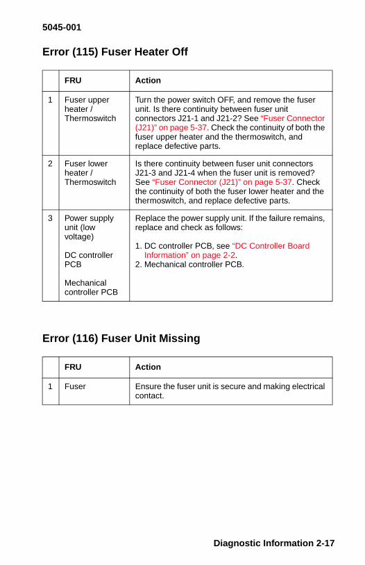
Error (115) Fuser Heater Off
Error (116) Fuser Unit Missing
FRU Action
1 Fuser upperheater /Thermoswitch
Turn the power switch OFF, and remove the fuserunit. Is there continuity between fuser unitconnectors J21-1 and J21-2? See “Fuser Connector(J21)” on page 5-37. Check the continuity of both thefuser upper heater and the thermoswitch, andreplace defective parts.
2 Fuser lowerheater /Thermoswitch
Is there continuity between fuser unit connectorsJ21-3 and J21-4 when the fuser unit is removed?See “Fuser Connector (J21)” on page 5-37. Checkthe continuity of both the fuser lower heater and thethermoswitch, and replace defective parts.
3 Power supplyunit (lowvoltage)
DC controllerPCB
Mechanicalcontroller PCB
Replace the power supply unit. If the failure remains,replace and check as follows:
1. DC controller PCB, see “DC Controller BoardInformation” on page 2-2.
2. Mechanical controller PCB.
FRU Action
1 Fuser Ensure the fuser unit is secure and making electricalcontact.
Diagnostic Information 2-17

5045-001
Error (117) Fuser Pump Failure
Note: This printer must be absolutely level. If it is tipped more than1 degree to the right and/or rear, the suction pump will not functioncorrectly and the printer will report a 117 fuser error.
Before starting the diagnostic procedure, do the following:
1. Be sure the printer is level.2. Turn the printer off and remove the oil bottle.3. Use the suction tool to remove as much oil as possible from the
reservoir.4. Pump the fuser manual lever 30 or 40 times.5. Repeat steps 3 and 4 until no additional oil is pumped into the
reservoir.6. Reinstall the oil bottle, close the covers and turn the printer on.7. The printer should complete POST. If a 117 error is reported
while running test pages, continue with the following servicecheck.
If you level the printer and the 117 error does not re-appear within 25pages, end the call.
Use of a spray contact cleaner in most instances will allow normalfunctioning of the fuser sensors, which have been contaminated withsilicone oil. The only cleaner currently approved by Lexmark is CRCbrand industrial contact cleaner # 03130.
2-18

5045-001
In addition to the cautions on the Material Safety Data Sheet(MSDS) label attached to the can, observe the following guidelines:
• When spraying either fuser sensor (PS9 or PS10), place a pieceof absorbent material below the sensor to catch the excessspray.
• Use the supplied nozzle and direct the spray into the smallapertures in the inside walls of the sensors.
• Spray quickly (approximately 1 second applications).
This spray leaves no residue, contains no CFCs and is plastic safe.Do Not use a substitute spray that has not been tested and is notplastic safe.
FRU Action
1 Float Ensure the oil float is not catching on its housing andis free to move.
2 Poorconnection/Dirty Sensor
Check the connections on the oil overflow sensorconnector J29, fuser unit connector J21, (see “FuserConnector (J21)” on page 5-37) and mechanicalcontroller PCB connector J2009. Reconnect themand replace sensor PS10.
3 Fuser unit oilsupply route
Is the hose between the oil supply bottle and thegear pump plugged up? Clean or replace the parts.
4 Fuser unit
Mechanicalcontroller PCB
DC controllerPCB
Replace the fuser unit. If the problem remains,replace and check as follows:
1. Mechanical controller PCB.2. DC controller PCB, see “DC Controller Board
Information” on page 2-2.
Diagnostic Information 2-19

5045-001
Error (121/125) Laser Board Failure
Note: A 125 error may occur due to temperature extremes and maybe of a temporary nature.
Check the error log.
• If it is a one time occurrence, POR the printer to see if it resets.• If it has occurred multiple times, replace the laser FRU.
Error (122) Laser Failure
FRU Action
1 Laser/scannerunit
DC controllerPCB
Check the connections on the DC controllerconnectors J102, J110, and J111. Go to the“Horizontal Voids Service Check” on page 2-67.
Check the connections on the laser driver PCBconnectors J401 and J402.
Check the connection on the PCB connector J451.Replace and check as follows:
1. Laser/scanner unit.2. DC controller PCB, refer to
“DC Controller Board Information” on page 2-2.
FRU Action
1 Laser/scannerunit
DC controllerPCB
Check the DC controller PCB connectors J110 andJ111. Check the connections on the laser driverPCB connectors J401 and J402.
Replace and check as follows:
1. Laser/scanner unit.2. DC controller PCB, see “DC Controller Board
Information” on page 2-2.
2-20

5045-001
Error (123/124) Mirror Motor Start-up or Rotation
FRU Action
1 Poor connection Check the connection on the DC controller PCBconnector J102. Reconnect it.
2 Power supplyunit (lowvoltage)
Are there approximately 24 V dc between DCcontroller PCB connectors J102-10 (24 V) andJ102-5 (GND)? Check whether +24 V dc is beingsupplied between DC controller PCB connectorsJ101-4 (24 V) and J101-3 (GND). If it is not, replacethe power supply unit.
3 Laser/scannerunit
DC controllerPCB
Test print a page. Does the voltage between DCcontroller PCB connectors J102-8 and J102-7(GND) change from about 5 V dc to OV?
If yes, replace the laser/scanner unit.
If no, replace the DC controller PCB,see “DC Controller Board Information” on page 2-2.
Diagnostic Information 2-21

5045-001
Error (126/131) Transfer Drum Motor Failure
Error (130) Service Motor Error
FRU Action
1 Poor connection Check the connection on the mechanical controllerPCB connector J2015. Reconnect it.
2 Door switch Turn the machine off and unplug the power cord.Disconnect connector J7 from the power supply unit.When you turn the door switch (SW2) ON, is therecontinuity between connectors J7-1 (+24VB) andJ7-2 (+24VA)? Replace the door switch.
3 Drum motor
Mechanicalcontroller PCB
Watch the drum motor during POST. Does it rotate?Replace and check as follows:
1. Drum motor.2. Mechanical controller PCB.
4 Transfer drumtop sensor
DC controllerPCB
Check the connection on the transfer drum topsensor connector J43. Replace and check asfollows:
1. Transfer drum top sensor.2. DC controller PCB, see “DC Controller Board
Information” on page 2-2.
FRU Action
1 Mechanicalcontroller PCB
Replace the mechanical controller PCB.
2-22

5045-001
Error (132/133) Main Motor (M2) Start-Up or Rotation
Error (134) Controller Fan Motor Failure
FRU Action
1 Poor connection Check the connection on the mechanical controllerPCB connector J2013. Reconnect it.
2 Door switch Turn the machine off and disconnect the power cord.Disconnect connector J7 from the power supply unit.When you turn the door switch (SW2) ON, is therecontinuity between connectors J7-1 (+24VB) andJ7-2 (+24VA)? Replace the door switch.
3 Main motor
Mechanicalcontroller PCB
About one minute after turning the power switch ON,does the voltage between mechanical controllerPCB connectors J2013-3 and J2013-4 (GND)change from about 5 V dc to OV? If yes, replace themain motor. If not, replace the mechanical controllerPCB.
FRU Action
1 Connection Check the connection of mechanical controller PCBconnector J2010. Reconnect it.
2 Controller fan
MechanicalController PCB
Turn the machine off. Disconnect mechanicalcontroller PCB connector J2010. Immediately afterturning the power switch ON, does the voltagebetween mechanical controller PCB connectorsJ2010-3 and J2010-1 (GND) change from OV toabout 22 V dc?
If yes, replace the controller fan.
If no, replace the mechanical controller PCB.
Diagnostic Information 2-23

5045-001
Error (135) Fuser Unit Fan Motor Failure
Error (136) Electrical Unit Fan Motor Failure
FRU Action
1 Poor connection Check the connection of mechanical controller PCBconnector J2012. Reconnect it.
2 Fuser unit fan
Mechanicalcontroller PCB
Turn the machine off. Disconnect mechanicalcontroller PCB connector J2012. Immediately afterturning the power switch ON, does the voltagebetween mechanical controller PCB connectorsJ2012-3 and J2012-1 (GND) change from OV toabout 24 V dc?
If yes, replace the fuser unit fan.
If no, replace the mechanical controller PCB.
FRU Action
1 Poor connection Check the connection of mechanical controller PCBconnector J2019. Reconnect it.
2 Electrical unitfan
Mechanicalcontroller PCB
Turn the machine off. Disconnect mechanicalcontroller PCB connector J2019. Immediately afterturning the power switch ON, does voltage betweenmechanical controller PCB connectors J2019-3 andJ2019-1 (GND) change from OV to about 24 V dc?
If yes, replace the mechanical unit fan.If no, replace the mechanical controller PCB.
2-24

5045-001
Error (141) Power Supply Failure (LVPS 110V or 220V)
Error (142) Engine Board Memory Failure
FRU Action
1 Wrong fuserunit(New fuser ormachine)
Turn the power switch OFF, and remove the fuserunit. Do the power supply rated voltage and fuserunit rated voltage correspond? Replace the fuserunit so that it corresponds to the power supply ratedvoltage.
2 Fuser upperheater /thermoswitch
Is there continuity between fuser unit connectorsJ21-1 and J21-2 when the fuser unit is removed?Check the continuity of both the fuser upper heaterand the thermoswitch, and replace defective parts.
3 Fuser lowerheater /thermoswitch
Is there continuity between fuser unit connectorsJ21-3 and J21-4 when the fuser unit is removed?Check the continuity of both the fuser lower heaterand the thermoswitch, and replace defective parts.
4 Power supplyunit (lowvoltage)
DC controllerPCB
Mechanicalcontroller PCB
Replace and check as follows:
1. Power supply unit.2. DC controller PCB, see “DC Controller Board
Information” on page 2-2.3. Mechanical controller PCB.
FRU Action
1 DC controllerPCB
Replace the DC controller PCB, see “DC ControllerBoard Information” on page 2-2.
Diagnostic Information 2-25

5045-001
Error (143) 5 V / 24 V Supply Failure
Error (144) Temperature/Humidity Sensor Failure
Error (145) Density Sensor Failure
FRU Action
1 Power supplyunit (lowvoltage)
DC controllerPCB
Check the connections on the DC controller PCBconnector J101 and power supply unit connector J4.Replace and check as follows:
1. Power supply unit.2. DC controller PCB see “DC Controller Board
Information” on page 2-2.
FRU Action
1 Temperature/humidity sensorunit
Mechanicalcontroller PCB
DC controllerPCB
Check the connections on the temperature/humiditysensor unit connector J73, connector J15, andmechanical controller PCB connector J2005.Replace and check as follows:
1. Temperature/humidity sensor unit.2. Mechanical controller PCB.3. DC controller PCB, see “DC Controller Board
Information” on page 2-2.
FRU Action
1 Density sensorunit / cable
DC controllerPCB
Check the connections on the density sensor unitPCB connector J501 and DC controller PCBconnector J103.
Replace and check as follows:
1. Cable.2. Density sensor unit.3. DC controller PCB, see “DC Controller Board
Information” on page 2-2.
2-26

5045-001
Error (146) Printer Communication Failure
Error (147) Engine Board IC Failure
FRU Action
1 Paper feeder(printer)
Check to ensure the paper feeder is latched in place,and the self docking connector is not damaged.
2 Mechanicalcontroller
DC controllerPCB
Check the connections on the DC controller PCBconnector J112 and mechanical controller PCBconnector J2007. Replace and check as follows:
1. Mechanical controller PCB.2. DC controller PCB. see “DC Controller Board
Information” on page 2-2.
FRU Action
1 DC controllerPCB
Replace the DC controller PCB, see “DC ControllerBoard Information” on page 2-2.
Diagnostic Information 2-27

5045-001
Error (148) Developer Unit Rotation Failure
FRU Action
1 Poor connection Check the connection on the mechanical controllerPCB connector J2016. Reconnect it.
2 Door switch Turn the machine off and disconnect the power cord.Disconnect connector J7 from the power supply unit.When you turn the door switch (SW2) ON, is therecontinuity between connectors J7-1 (+24VB) and J7-2 (+24VA)? Replace the door switch.
3 Developingrotary brakeclutch
Developing unitdrive clutch
Mechanicalcontroller PCB
Developing unitmotor
Mechanicalcontroller PCB
Watch the developer unit motor during POST. Doesit rotate? If yes, replace and check as follows:
1. Developing rotary brake clutch.2. Developing unit drive clutch.3. Mechanical controller PCB.
If no, replace and check as follows:
1. Developing unit motor.2. Mechanical controller PCB.
4 Developingrotary positionsensor
Mechanicalcontroller PCB
Check the connections on the mechanical controllerPCB connector J2006 and developing rotaryposition sensor connector J60. Clean the sensor. If itis not possible to clean it, replace and check asfollows:
1. Developing rotary position sensor.2. Mechanical controller PCB.
2-28

5045-001
Error (149) Developer Unit Pressure Failure
Error (152) Tray 2 Power Failure
FRU Action
1 Poor connection Check the connection on the mechanical controllerPCB connector J2016.
2 Door switch Turn the machine off and disconnect the power cord.Disconnect connector J7 from the power supply unit.When you turn the door switch (SW2) ON, is therecontinuity between connectors J7-1 (+24VB) and J7-2 (+24VA)? Replace the door switch.
3 Developing unit Watch the developer unit motor during POST. Doesthe developing unit motor rotate? Replace andcheck as follows:
1. Developing unit motor.2. Mechanical controller PCB.
4 Developingrotary positionsensor
Toner cartridgeposition sensor
Mechanicalcontroller PCB
Check the connections on the mechanical controllerPCB connector J2006, toner cartridge positionsensor connector J59 and developing rotary positionsensor position sensor J60. Replace and check asfollows:
1. Toner cartridge position sensor.2. Developing rotary position sensor.3. Mechanical controller PCB.
FRU Action
1 Poor connection Check the connections on the paper feeder driverPCB connector J355 and power supply unitconnector J361. Reconnect them.
2 Power supplyunitPaper feederdriver PCBMechanicalcontroller PCBDC controllerPCB
Replace the paper feeder power supply unit.Replace and check as follows:1. Paper feeder driver PCB.2. Mechanical controller PCB.
If the problem remains, replace the DC controllerPCB.See “DC Controller Board Information” on page 2-2.
Diagnostic Information 2-29

5045-001
No AC Power/Dead Machine
FRU Action
1 On/Off switchconnector
Be sure connector J6, see “Connector Locations” onpage 5-14, is connected into the LVPS. Thisconnector will sometimes fall off the LVPS whenworking in this area.
2 Power supply Check voltage at the outlet. Inform the user thatrated voltage is not supplied at the outlet.
3 Power cord Is the power cord firmly plugged into the printer, thepaper feeder and the outlet? Replug it.
4 Circuit breaker(CB1)
Is the circuit breaker OFF? Press the button to resetthe breaker. If the circuit breaker turns OFF againimmediately after turning the power switch ON,check whether the AC power supply line is shorted.
Note: This circuit breaker, labeled CB1 is in theLVPS, directly above the power cord connector. Thebutton can be viewed without removing the powersupply from the machine. Look in the lowest holetoward the front of the machine. This hole is oblong.
5 Wiring, powersupply unit
Unplug the power cord. Check the continuity of theON/Off switch. Check the AC line wiring. Replacethe power supply unit.
2-30

5045-001
No DC Power
No Pickup (Manual Feed)
FRU Action
1 AC powersupply
Unplug the power cable. Is AC power being suppliedto this cable? Check AC power.
2 Wiring
DC load
Turn the power switch OFF, and disconnectconnectors J3, J4, and J5. Plug in the power cable,and turn the power switch ON. Are the abovementioned power supply unit connectors correctlyoutputting DC power? Take care not to cause ashort. Turn the power switch OFF, connect 1 of thedisconnected connectors, and turn the power switchON. Repeat this for all the connectors, andinvestigate the connector operating the protectioncircuit, checking the wiring from that connector andthe DC load.
3 FusePower supplyunit
Is the power supply unit fuse blown? Replace thefuse. Replace the power supply unit.
FRU Action
1 Gear Is the pickup motor drive properly transmitted by thegears? Check the gears, and replace any damagedones.
2 Pickup motor
Pickup PCB
Does the pickup motor rotate?
Check the connection of pickup PCB connectorJ304, and if it is normal:
Replace the pickup motor.
Replace the pickup PCB.
3 Pickup PCB
Manual feedsolenoid
Turn the power switch OFF, remove the pickup unit,and disconnect the connector J33. Measure theresistance between cable connectors J33-1 andJ33-2. Is it about 100 Ohms? If yes, replace thepickup PCB. If no, replace the manual feed solenoid.
Diagnostic Information 2-31

5045-001
No Pickup (Cassette Feed)
No Pickup (Optional Paper Feeder Pickup)
FRU Action
1 Gear Is the pickup motor drive properly transmitted by thegears? Check the gears, and replace any damagedones.
2 Pickup motor
Pickup PCB
Does the pickup motor rotate?
1. Check the connection of pickup PCB connectorJ304, and if it is normal replace the pickup motor.
2. Replace the pickup PCB.
3 Pickup PCB
Cassette feedsolenoid
Turn the power switch OFF, remove the pickup unit,and disconnect pickup PCB connector J303.Measure the resistance between cable connectorsJ303-1 and J303-2. Is it about 100 Ohms?
If yes, replace the pickup PCB.
If no, replace the cassette feed solenoid.
FRU Action
1 Gear train Is the paper feeder motor drive properly transmittedby the gears? Check the gears, and replace anydamaged ones.
2 Paper feedermotor
Paper feederdriver PCB
Does the paper feeder motor rotate?
Check the connection of paper feeder driver PCBconnector J353, and if it is normal replace the paperfeeder motor.
Replace the feeder driver PCB.
3 Paper feederdriver PCB
Cassette feedsolenoid
Turn the power switch OFF, remove the paperfeeder, and disconnect J354. Measure theresistance between cable connectors J354-1 andJ354-2. Is it about 130 Ohms? If yes, replace thepaper feeder driver PCB. If no, replace the cassettefeed solenoid.
2-32

5045-001
Registration Roller Does Not Rotate
High-Voltage Power Supply Output
FRU Action
1 Gear train Is the pickup motor drive properly transmitted by thegears? Check the gears, and replace any damagedones.
2 Pickup PCB
Registrationroller clutch
Turn the power switch OFF, remove the pickup unit,and disconnect the connector J34. Measure theresistance between cable connectors J34-1 andJ34-2. Is it about 145 Ohms?If yes, replace the pickup PCB.If no, replace the registration roller clutch.
FRU Action
1 High voltagecontacts
Are the high-voltage contact terminals soiled orburnt? Clean the high-voltage contacts.
2 High-voltagepower supplyPCB
Mechanicalcontroller PCB
DC controllerPCB
Does the trouble disappear when you replace thehigh-voltage power supply PCB? Replace the high-voltage power supply PCB. If not, replace and checkas follows:
1. Mechanical controller PCB.2. DC controller PCB, see “DC Controller Board
Information” on page 2-2.
Diagnostic Information 2-33

5045-001
Pickup / Feed System Theory
When the /PRNT signal is sent to the DC controller by the videocontroller and the scanner motor is put in the READY state, the DCcontroller issues the print sequence command to the mechanicalcontroller, which then starts printing. After a sheet of paper is pickedup by the cassette pickup roller or the manual feeding pickup roller, itis fed by the feed rollers. Any skew of the paper is corrected by theregistration roller and it stops at the leading edge detection position.The temporarily stopped paper is fed so that its leading edge willmatch the gripper on the transfer drum as well as the leading edgeof the image on the photosensitive drum. Subsequently, the paperpasses through the transfer, separation, fuser, and delivery units tothe face-down or face-up tray.
2-34

5045-001
The paper feed route can be divided into 3 sections:
1. Pickup unit,2. Transfer drum unit,3. Fusing/delivery unit.
Diagnostic Information 2-35

5045-001
OHP Sheet Detection (transparency)
When an OHP sheet is used for this printer, the dedicated one mustbe used with a white band at its leading edge. The followingdeterminations are made by measuring the time period that lightemitted from the paper top sensor (PS303) is shielded by this band,and whether it is:
• The dedicated OHP sheet, any other OHP, or paper.• Placed with the proper side up.• Placed with the proper edge leading.
If any non-dedicated OHP sheet is used or the dedicated OHP sheetis placed with the wrong side up or the wrong end leading, themechanical controller will notify the DC controller which will signify itas a jam.
The white band disappears when heated in the fusing process.
2-36

5045-001
Diagnostic Information 2-37

5045-001
Paper Feed Troubleshooting
Pickup Unit
(Codes 20 - 21, Paper Jam)
FRU Action
1 Paper Is recommended paper being used? Advisethe customer to use recommended paper.
2 Paper Is the paper deformed with curls or waves?Replace the paper. Advise the user on thestorage method.
3 Paper Did it occur in the manual feed unit? Checkfrom Step 8.
4 Paper Did it occur in the cassette feed unit? Checkfrom Step 11.
5 Registration Is the registration roller clutch operatingproperly? Check the registration roller clutch.
6 Registration Is the registration roller worn, deformed orsoiled? Clean the roller if it is soiled. If wornor deformed, replace appropriate parts.
7 Prism Is the paper top sensor prism soiled? Cleanit. Replace it if it cannot be cleaned or it isflawed. If it is OK, replace the pickup PCB.
8 OHP sheet Is dedicated OHP sheet being used, and is itloaded correctly? Advise the user to usededicated OHP sheet, and to set it correctly.
9 Excessivepaper in manualfeeding tray
Is more paper in the manual feeding tray thanprescribed? Advise the user not to put morethan the suggested amount of paper in thetray.
10 Pickup roller
Faulty pickup
Does the pickup roller rotate during printing?If yes, replace the pickup roller. If no, see “NoPickup (Manual Feed)”
11 Cassette Is the cassette set properly? Set it properly.
12 Paper setincorrectly
Is the paper correctly set against the cassetteclaw? Set it correctly.
2-38

5045-001
13 Paper Is the paper folded? Replace the paper.
14 Excessivepaper incassette
Is more print paper in the cassette thansuggested? Advise the user not to put morethan the suggested amount of paper in thecassette.
15 Cassettepickup roller,Separationroller, Feedroller, Faultypickup
Is the cassette pickup roller, the separationroller, or the feed roller worn or deformed? Ifyes, replace the respective roller. If no, check“No Pickup (Cassette Feed)” on page 2-32 or“No Pickup (Optional Paper Feeder Pickup)”on page 2-32.
FRU Action
Diagnostic Information 2-39

5045-001
Transfer Drum Unit
(Codes 22 - 23, Paper Jam)
FRU Action
1 Gripper Is the gripper damaged? Replace the gripper.
2 Gripper Does the gripper properly open and hold thepaper? Check whether:
• The gripper hold-down spring is deformedor disconnected.
• The gripper lever is bent.• The operation of the gripper drive
mechanism within the transfer drum issmooth.
• The gripper solenoid connector isdisconnected or the solenoid is defective.
3 Attractionsensor
Check for binds. Refer to “Transfer Drum” onpage 7-60, assembly 29-3.
4 Separationsensor
Check for binds. Refer to “Transfer Drum” onpage 7-60, assembly 29-3.
5 Attraction roller If the attraction roller is worn or deformed,replace the attraction roller.
6 Discharge roller If the discharge roller is worn or deformed,replace the discharge roller.
7 High-voltagecontact
If the high-voltage contact of the attractionroller or the discharge roller is soiled or burnt,clean the high-voltage contact. Replace it if itcannot be cleaned.
8 Spring (2 each) If the springs pressing the attraction roller orthe discharge roller against the transfer drumare stretched, or missing, replace the relativespring.
9 Transfer sheet
High-voltagepower supplyPCB
If the transfer sheet is soiled or deformed,replace the transfer sheet. If not, replace thehigh-voltage power supply PCB.
CAUTION: Do not touch the sheet withyour bare hands .
2-40

5045-001
Fuser/Delivery Unit
(Code 25, Paper Jam)
Note: Printers and replacement FRUs may experience roughhandling during shipping, causing the exit sensor (PS9) to becontaminated with oil. As this sensor operates “active low”, the oilmay defuse the IR beam enough to prevent correct operation.Therefore, replace PS9.
Use of a spray contact cleaner in most instances will allow normalfunctioning of the fuser sensors, which have been contaminated withsilicone oil. The only cleaner currently approved by Lexmark is CRCbrand industrial contact cleaner # 03130. In addition to the cautionson the Material Safety Data Sheet (MSDS) label attached to the can,observe the following guidelines:
• When spraying either fuser sensor (PS9 or PS10), place a pieceof absorbent material below the sensor to catch the excessspray.
• Use the supplied nozzle and direct the spray into the smallapertures in the inside walls of the sensors.
• Spray quickly (approximately 1 second applications).
This spray leaves no residue, contains no CFCs and is plastic safe.Do Not use a substitute spray that has not been tested and is notplastic safe.
Diagnostic Information 2-41

5045-001
Fuser
FRU Action
1 Fuser rollerDrive unit
Do the fuser rollers rotate smoothly? Checkthe fuser roller drive unit.
2 Fuser rollers Is the fuser upper roller or the fuser lowerroller deformed or flawed? If yes, replacethem.
3 Fuser entranceguide
Is the entrance guide soiled? Is there a guideprotrusion due to a flaw or toner adhesion?Clean the entrance guide.
4 Nip width Is the fuser roller engagement correct?Replace the fuser unit.
5 Cleaning belt Is the cleaning belt being wound correctly?Check the fuser cleaner unit.
6 Fuserseparationguide
Is the fuser separation guide soiled? Or isthere a protrusion due to a flaw or toneradhesion? Clean the guide.
7 Delivery papersensor lever
Does the delivery paper sensor lever movesmoothly? Adjust it so that it moves smoothly.
8 Delivery papersensor (PS9)
Does the delivery paper sensor operatecorrectly? Replace the sensor.
9 Oil applying unitDelivery driveunit
Is the fuser delivery roller rotating smoothly?Is the face-down delivery roller rotatingsmoothly? If yes, check the operation of theoil applying unit. If no, check the delivery driveunit, and replace the damaged part.
2-42

5045-001
Multi-Feed
* See “Cassette Paper Pickup Asm” on page 7-48, (Asm 24). Thesesprings are not referenced, but attach to the same plastic assemblythat reference number 7 uses.
FRU Action
1 Paper Is recommended paper being used? Advise the userto use recommended paper.
2 Location Does it occur in the manual feeding tray? Check step5. (Cassette, check step 4).
3 Cassette Is the print paper placed properly against thecassette claw? Place the paper correctly.
4 SeparationrollerSpring(s) *
Is the separation roller worn or deformed? If yes,replace the separation roller. If no, replace thespring(s) pulling the separation roller.
5 Separation padSpring(see Chapter 7,Asm 25-5)
Is the separation pad surface worn? Replace theseparation pad. If no, replace the separation padspring.
Diagnostic Information 2-43

5045-001
Wrinkles
Leading-Edge Fold
FRU Action
1 Paper Is recommended paper being used? Advise the userto use recommended paper.
2 Paper Do the wrinkles disappear when you use newpaper? As the paper probably was moist, advise theuser on the correct storage method.
3 Pickup unit Open the front cover while the paper is between thepickup and fuser units. Is the paper wrinkled? Or isthe paper being transported with a skew? Check thepickup unit.
4 Paper guide Is toner or other foreign matter on the paper guide?Clean the guide.
5 Fuser entranceguideFuser unit
Is the fuser entrance guide soiled? Clean the guide.If no, replace the fuser unit.
FRU Action
1 Paper Is recommended paper being used? Advise the userto use recommended paper.
2 Paper Is the paper curled or otherwise deformed? Replacethe paper. Advise the user on the correct storagemethod.
3 Excessivepaper (manual)
Is more paper placed at the pickup slot thansuggested? Advise the user not to place more thanthe suggested amount of paper.
4 Paper setting(cassette)
Is the paper set properly against the cassette claw?Set the paper correctly.
5 Cassette claw Is the cassette claw deformed? Replace thecassette claw. If no, check the paper feed unit, andreplace any flawed or deformed parts.
2-44

5045-001
Skewing
FRU Action
1 Paper Is recommended paper being used? Advise the userto use recommended paper.
2 Cassette Is the cassette set properly? Set it correctly.
3 Excessivepaper(manual)
Is more paper place at the pickup slot thansuggested? Advise the user not to set more than thesuggested amount of paper.
4 Paper setting(cassette)
Is the paper set properly against the cassette? Setthe paper correctly.
5 Paper setting Is the paper placed against the manual feeding trayabutment? Properly set the paper on the manualfeeding tray.
6 Cassette claw Is the cassette claw deformed? Replace thecassette claw.
7 Paper dust,trash
Registrationroller
Is paper dust or trash collected at the registrationroller or feed guide? Clean.
If no, replace the cassette paper assembly.
Diagnostic Information 2-45

5045-001
Error Codes - 9XX
Error (900) Software Error
Error (941) Service ROM SIMM
Error (939, 942, 943, 944) Service RIP Board
Error (945) Service RIP Board
Description Action
1 This can occur when:
• The paper being fed is adifferent size than selectedby the Setup Menu.
• Turning the machine offand failing to wait at least10 seconds beforeswitching it back on.
Feed the correct size paper.
After turning the machine off, waitat least 10 seconds before turningback on.
Before replacing the videocontroller board, turn the printeroff and firmly reseat the board.
Description Action
1 Code/Font Replace the ROM SIMM.
Description Action
1 29K processorfailure
Replace the Video Controller Board.
Description Action
1 ASIC 1 failure Replace the Video Controller Board.
2-46

5045-001
Error (946) Service RIP Board
Error (947) Service RIP Board
Error (948) Service RIP Board
Error (949) Service RIP Board
Description Action
1 ASIC 2 failure Replace the Video Controller Board.
Description Action
1 ASIC 3 failure Replace the Video Controller Board.
Description Action
1 Compress/Decompressfailure
Replace the Video Controller Board.
Description Action
1 Decompressfailure
Replace the Video Controller Board.
Diagnostic Information 2-47

5045-001
Error (950) Service RIP Board
Error (953) Service RIP Board
Error (955) Service Video RAM Error
Error (956) Service L2 Cache Error
Error (960) Service Memory Error
Description Action
1 SRAM failure Replace the Video Controller Board.
Description Action
1 NVRAM failure Replace the Video Controller Board.
Description Action
1 Video RAMfailure
Replace the Video Controller Board.
Description Action
1 L2 Cache error Replace the Video Controller Board.
Description Action
1 Bad or missingDRAM in thebase DRAM slot
Replace the base DRAM.
2-48

5045-001
Error (961) Bad / Missing DRAM
Error (970/979) INI Failure
Error (977) Service Network Board
Description Action
1 Bad or missingDRAM in theoptional DRAMslot
Replace the optional DRAM.
Description Action
1 INA failure Replace INA.
Description Action
1 Bad networkboard
This error message indicates a bad Network boardis installed in the Network board slot. The systemprocessor has detected that an INA board isinstalled but cannot establish communications withit. The X after the Network Board will identify whichnetwork board is having a problem. Network Board 1always refers to the INA board in the bottom slot andNetwork Board 2 always refers to the INA board inthe top slot.
Diagnostic Information 2-49

5045-001
Print Quality
Before you perform the following service checks, do the following:
• Be sure the paper or transparencies are the recommendedfinish and weight. If the paper weight is incorrect (too stiff), itmay not provide 100% adhesion to the transfer drum. Thetrailing edge will not be attracted to the drum and will “flap” oneach revolution causing blurs and smears at the bottom of thepage. This may eventually transfer stray toner on to the back orfront of the paper.
• Be sure the printer and supplies are used in the properenvironmental range.
• If in doubt about a printer driver or other customer application,use the test prints described in the diagnostic aids.
• Use the following start of call test to determine where thesymptom exists.
Cartridge End-of-Life
When printing a large number of pages with a low percentage ofcolor coverage, it is possible for the cartridge to wear out beforeusing all the toner. Regardless of the amount of toner used, theinternal rollers must make the same number of revolutions.Maximum cartridge life is approximately 5500 pages. Depending oncolor usage, it is possible to exceed this limit and still have a largequantity of toner remaining in the cartridge. This condition will leadto streaking and background, which will be covered elsewhere in thisservice check.
Print Quality Start Of Call
Refer to the Density Adjustment Panel (DAP) section, see “DensityAdjustment Panel” on page 3-12. Run the following three testsdescribed on page 3-12. Each test will isolate different print qualityconditions as described. Before starting, be sure all color densitysettings on the DAP are set to nominal.
2-50

5045-001
Gradation Test
This test shows the presence of horizontal voids. Do not confuse avoid (which is a missing laser scan line) with small horizontalvariations in density called “jitter”, (see example on following page).
• If voids are present, go to “Horizontal Voids Service Check” onpage 2-67.
• If severe “jitter” is visible, replace the affected cartridge,(especially if the “jitter” is greater for one color).
• If the “jitter” is consistent across all four colors, replace thephotoconductor.
Note: Some “jitter” normally occurs due to gear train vibrations.
Diagnostic Information 2-51

5045-001
Horizontal Variation (“Jitter”) Example
(Color may vary depending upon your monitor or system.)
2-52

5045-001
Solid Color Test
This test indicates which cartridge(s) is/are contributing tobackground problems. It also shows which of the four cartridges hasreached end-of-life. The test produces a solid band of each color,approximately 2 1/4 inches (60 mm) long. Each color should be auniform color with no vertical streaks. If streaks are present, replacethe cartridge. Cartridges that streak contribute to background.
Solid White Test
This test shows the amount of background. Background is mostvisible as a white border 5/16 inch (8 mm) from the top edge of thepaper. Background is possible in any color (or combination ofcolors), although it appears gray to the naked eye. Although a wornphotoconductor contributes to background, background is primarilydue to a cartridge condition. Photoconductor scratches show as ablack vertical line.
Diagnostic Information 2-53
5045-001
Print Quality Troubleshooting
Background
Symptom:A slight tint to the entire page starting approximately8 mm from the top edge of the page. It may appear to be gray, butcould be any combination of primary colors.
Cause:Cool, dry environments or used cartridges nearing end of life.
Resolution:Increase environmental temperature and humidity. Replacing all fourtoner cartridges reduces background, if they are nearing end of life.Call your country support function for assistance prior to replacingparts.
Black Horizontal Lines
Symptom:Horizontal lines of any length and width across the page repeating at129 mm intervals.
Cause:Improper removal or installation of the photoconductor. The drumrelease arm must be lowered prior to removal or installation of thephotoconductor.
Resolution:Replace the photoconductor.
2-54

5045-001
Black Vertical Lines
Symptom:Thin vertical black lines of any length, anywhere on the page.
Cause:Worn out or damaged photoconductor. This may be caused by thephotoconductor reaching end-of-life or damage resulting from asevere paper jam.
Resolution:Replace the photoconductor. Do not use a used photoconductor fordiagnostic purposes. The printer determines photoconductor life byits electrical characteristics. Swapping used photoconductors mayresult in inaccurate photoconductor life, which may result incustomer dissatisfaction or a service call.
Blur at Bottom of Page
Symptom:A horizontal defect approximately 17 mm from the bottom of thepage. This defect is composed of vertical streaks, smears or a blur.In severe cases, there may also be a blur 17 mm from the top of thepage.
Cause:Certain weight and composition papers (mostly cotton), are notadhering to the transfer drum. This causes the trailing edge to “flap”,contacting the developer roller in the cartridge or thephotoconductor.
Resolution:Change paper types.
Diagnostic Information 2-55
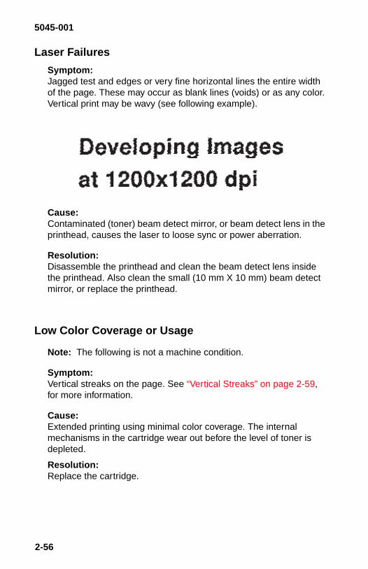
5045-001
Laser Failures
Symptom:Jagged test and edges or very fine horizontal lines the entire widthof the page. These may occur as blank lines (voids) or as any color.Vertical print may be wavy (see following example).
Cause:Contaminated (toner) beam detect mirror, or beam detect lens in theprinthead, causes the laser to loose sync or power aberration.
Resolution:Disassemble the printhead and clean the beam detect lens insidethe printhead. Also clean the small (10 mm X 10 mm) beam detectmirror, or replace the printhead.
Low Color Coverage or Usage
Note: The following is not a machine condition.
Symptom:Vertical streaks on the page. See “Vertical Streaks” on page 2-59,for more information.
Cause:Extended printing using minimal color coverage. The internalmechanisms in the cartridge wear out before the level of toner isdepleted.
Resolution:Replace the cartridge.
2-56

5045-001
Oil Soaking
Symptom:Certain printers may demonstrate a condition that makes the top(leading) edge of the first page appear to have been dipped in oil.This oil stain is not to be confused with random oil spots. Thesoaking may be so small as to be unnoticeable, except in certainareas across the leading edge of the page. It may be as severe ascovering the top 3/4 of the page. This occurs with printers that areleft idle for long periods with “Power Saver” off. The factory default is“Power Saver” ON, set for 30 minutes. This means that the printerwill enter power saver mode within 30 minutes after a job prints.Some customers object to this feature, as it requires additional timeto heat the fuser prior to printing. This is minimized by setting powersaver to the maximum (120 minutes) before the printer cools down.
Resolution:
• Scroll through the menus to “Advanced Setup”, then scrollthrough to “Power Saver 2”.
• Turn it ON (default OFF). “Power Saver 2” works only with‘Power Saver” ON. (default). “Power Saver 2” turns on the fuserevery 59 minutes, to keep it close to target temperature. Thistime interval is not adjustable. Early levels of microcode do nothave this feature.
• Call your country support function for assistance, prior toreplacing parts.
Diagnostic Information 2-57

5045-001
Random Oil Spots on Page
This condition usually occurs following a long idle period or powersaver mode.
Symptom:Random oil spots on paper may cause customer complaints.
Cause:
• Failure of machine to evenly distribute silicon oil over both fuserrollers.
• Oil dissolved in rubber silicon returning to surface.• Carry out of debris under lower doctor blade.
Resolution:
• Advise the customer to use the fuser cleaning page, accessiblefrom the main menu. Note: This does not work coming out of“Power Saver Mode”, it works only on power up.
• If the customer prefers to use a “Power Saver Mode”, advisethem to use Power Saver 2 mode. This turns on the fuser everyhour.
• Power Saver 2 does not operate unless Power Saver 1 isenabled.
• If maximum printer accessibility is an issue, set Power Saver 1to 120 minutes.
Spew
See the “Toner Scattered Service Check” on page 2-71, for detailedinformation regarding spew.
2-58

5045-001
Vertical StreaksNote: Run the “Gradation Test” from the density adjustment panel.
Symptom:Severe vertical voids in the text, or graphics, (see example onfollowing page). This may occur on a single color, every color, or anycombination.
Cause:Cartridge(s) nearing end-of-life. This condition can occur regardlessof the amount of toner remaining in the cartridge. For additionalinformation, see “Low Color Coverage or Usage” on page 2-56.
Resolution:Replace the affected cartridge(s).
Diagnostic Information 2-59

5045-001
Vertical Streaks Example
(Color may vary depending upon your monitor or system.)
2-60

5045-001
Print Quality Service Checks
Black Service Check
FRU Action
1 Photoconductor Replace the photoconductor. If problem remains,check the primary charging contact spring, thephotoconductor contact, the primary chargingcontact plate and spring.
3 High-voltagecable / resistor
Check the continuity between the photoconductordrum contact and the high-voltage PCB J1004-3. Itshould be approximately 9K ohms. Replace high-voltage cable or contact if necessary.
4 High-voltagepower supplyPCB,Mechanicalcontroller PCB
If the problem remains, check and replace asnecessary the high-voltage power supply PCB or themechanical controller PCB.
Diagnostic Information 2-61

5045-001
Blank Page Service Check
FRU Action
1 Front coverback panel
Check the shutter open-close boss for damage,replace the front cover back panel if necessary.
2 Laser beamshutter, shutterarm
Check the shutter and the shutter arm for properoperation, replace if necessary.
3 High-voltagecable / resistor
Check the continuity between the developing biascontact plate and the high-voltage PCB J1004-1. Itshould be approximately 9K ohms. Replace high-voltage cable or contact if necessary.
4 High-voltagepower supplyPCB,Mechanicalcontroller PCB
Check the toner cartridge contact. If the problemremains, check and replace as necessary the high-voltage power supply PCB or the mechanicalcontroller PCB.
5 Transfer Check to ensure the transfer drum is free to move upduring the print process. This can be done bymanually rotating the drum lift mechanism(Asm 19-1).
2-62

5045-001
Blank Spots Service Check
Color Aberration Service Check
FRU Action
1 Paper Is recommended paper being used? Print withrecommended paper. If the outcome is good, askthe user to use recommended paper.
2 Paper Is the paper damp? Replace the paper.
3 Toner cartridge Does it appear for a specific color only? Replace thetoner cartridge of the color for which it appears.
4 Transfer sheet Check the transfer sheet for dirt or damage. Replacethe transfer sheet.Caution : Do not touch the transfer sheet with barehands.
5 Photoconductor Check the photoconductor for dirt or damage.Replace the drum cartridge, but only if it isdamaged. Do not replace the drum as atroubleshooting technique. If a defect is present onthe developer or primary charging roller, it willrepeat. Refer to the spacing table.
FRU Action
1 Gripper
Gripper spring
Is the transfer drum gripper damaged or is thegripper spring deformed? Replace the damagedpart.
2 Transfer sheet Is the transfer sheet gouged or torn off? Replace thetransfer sheet.Caution : Do not touch the transfer sheet with barehands.
3 Gear
Transfer Drum
Is the photoconductor drum gear or the transferdrum gear worn or loose? Check for uniformity orchattering of the transfer drum rotation.
Diagnostic Information 2-63

5045-001
Dark Image Service Check
FRU Action
1 Density sensorunit
Operate the density adjustment panel to adjust thedensity. Clean the density sensor lens. If theproblem remains, replace the density sensor unit.
2 High-voltagepower supplyPCB,Mechanicalcontroller PCB
Clean the transfer drum ground contact and thephotoconductor contact. If the problem remains,clean the primary charge contact. If the problemremains, check and replace as necessary the high-voltage power supply PCB or the mechanicalcontroller PCB.
2-64
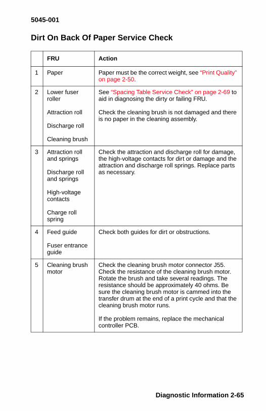
5045-001
Dirt On Back Of Paper Service Check
FRU Action
1 Paper Paper must be the correct weight, see “Print Quality”on page 2-50.
2 Lower fuserroller
Attraction roll
Discharge roll
Cleaning brush
See “Spacing Table Service Check” on page 2-69 toaid in diagnosing the dirty or failing FRU.
Check the cleaning brush is not damaged and thereis no paper in the cleaning assembly.
3 Attraction rolland springs
Discharge rolland springs
High-voltagecontacts
Charge rollspring
Check the attraction and discharge roll for damage,the high-voltage contacts for dirt or damage and theattraction and discharge roll springs. Replace partsas necessary.
4 Feed guide
Fuser entranceguide
Check both guides for dirt or obstructions.
5 Cleaning brushmotor
Check the cleaning brush motor connector J55.Check the resistance of the cleaning brush motor.Rotate the brush and take several readings. Theresistance should be approximately 40 ohms. Besure the cleaning brush motor is cammed into thetransfer drum at the end of a print cycle and that thecleaning brush motor runs.
If the problem remains, replace the mechanicalcontroller PCB.
Diagnostic Information 2-65

5045-001
Dirty Print Service Check
FRU Action
1 Fuser cleaningbelt
Check the cleaning belt for proper operation andcondition. Replace if necessary.
2 Fuser upperrollerPhotoconductorToner cartridgeAttraction roller
See “Spacing Table Service Check” on page 2-69 toaid in diagnosing the dirty or failing FRU.
3 Poor attraction/discharge
Is recommended print paper being used? Advise theuser to use recommended paper.
4 Poor attraction/discharge
Is the attraction roller or the discharge rollerdeformed or soiled? Replace the affected roller.
5 Poor attraction/discharge
Is the high-voltage contact of the attraction roller orthe discharge roller soiled or burnt? Clean thecontact. Replace it if it cannot be cleaned.
6 Poor attraction/discharge
Are the springs pressing the attraction roller or thedischarge roller against the transfer drum stretched?Replace the spring(s).
7 Paper Paper must be the correct weight. Check for soiledpaper being used. Clean the feed guide or the fuserentrance guide.
8 Paper path Check the entire paper path for paper (especially thephotoconductor and cleaning brush assembly).
2-66

5045-001
Distortion Service Check
Horizontal Voids Service Check
FRU Action
1 Poor connection Is the connection good between DC controller PCBconnector J208 and connectors J102, J110 andJ111?
2 Laser/scannerunit
DC controllerPCB
Is the connection good between laser/scanner unitand DC controller connectors J401, J402, J451 andJ701? Replace and check in the following order:1 Laser/scanner unit2 DC controller PCB, see “DC Controller BoardInformation” on page 2-2.
FRU Action
1 Photoconductorortoner cartridge
If a white horizontal line appears in a repeatingpattern, see “Spacing Table Service Check” on page2-69 and repair or replace the indicated part.
2 Laser / Scannerunit
If a white horizontal line appears randomly, clean thesmall 1/4 inch square (10 mm) beam detect mirror inthe printhead, or replace the assembly.
Diagnostic Information 2-67

5045-001
Light Image Service Check
Be sure the printer is not installed in an unusually hot or coldenvironment, see the User’s Reference. If the problem is with onecolor, try a new toner cartridge of that color.
FRU Action
1 Density sensorunit
Operate the density adjustment panel to adjust thedensity. Clean the density sensor lens, if the problemremains perform the remaining checks beforereplacing the density sensor unit.
2 High-voltagecable resistors(approximately9K Ohms)
Check the continuity between the transfer drumcontacts and the high-voltage PCB. Replace thehigh-voltage cable or the contact if necessary.
3 High-voltagepower supplyPCB,Mechanicalcontroller PCB
Clean the developer bias contact and the tonercartridge contact. If the problem remains, continuewith this service check.
4 High-voltagepower supplyPCB,Mechanicalcontroller PCB
Check and replace as necessary the high-voltagepower supply PCB or the mechanical controllerPCB.
If the problem remains, replace the transfer sheet.
2-68

5045-001
Poor Fusing Service Check
Spacing Table Service Check
FRU Action
1 Fuser upperroller
Does the defect appear vertical and in a line? Checkfor flaws on the upper and lower rollers.
2 Fuser lowerroller
Is the fuser lower roller soiled? Clean the roller.Replace it if you cannot clean it.
3 Oil applying unit Is oil uniformly applied to the fuser upper roller?Check the operation of the oil applying unit.
4 Print paper Print with recommended paper. If the outcome isgood, ask the user to use recommended paper.
5 Fuser unit Fuser nip width cannot be adjusted. Replace thefuser unit.
FRUDefectspacing
Dirt BlankDirt onback
Fusing
Fuser, upperroller
134 mm X X
Fuser, lowerroller
134 mm X X
Photoconductor 129 mm X
Developer 50 mm X X
Primary chargeroll
38 mm X X
Attraction roll 50 mm X X
Discharge roll 50 mm X
Cleaning brush 94 mm X
Diagnostic Information 2-69

5045-001
Streaking Service Check
Streaking is described as small particles or streaks pointingdownward from multicolored, horizontal lines. It appears as if thelines were “squashed” together. This should not be confused withcartridge streaking.
FRU Action
1 PaperIs the paperdamp?
Replace the paper.
2 Separationvoltage
Is the corona wire broken? Does it improve whenyou forcibly turn OFF the separation voltage from thedensity adjustment panel? If the problem remains,go to step 3.
3 Separationcharging unit
Fuser unit
Replace and check as follows:
1. Separation charging unit2. Fuser unit
4 Paper Path Check the entire paper path for debris, especiallythe photoconductor and cleaning brush assembly.
5 Cleaning brush Check to ensure the cleaning brush disengagesfrom the transfer drum, at the end of a print cycle.
2-70

5045-001
Toner Scattered Service Check
Note: This condition is also known as “spew”. It appears as a haloaround dense characters. This condition is worsened by cool, dryconditions.
Note: If a halo is observed surrounding blue characters on thepage, instruct the customer to try “Vivid Mode”. See Chapter 7 in theUser’s Reference Manual.
FRU Action
1 Paper Is recommended paper being used? Print withrecommended paper. If the outcome is good, askthe user to use recommended paper.
2 Separationvoltage
Is the corona wire broken? Does it improve whenyou forcibly turn ON the separation voltage from thedensity adjustment panel? If the problem remains,go to step 3.
3 Separationcharging unit
Temperaturehumidity sensor
Fuser unit
If streaking appeared on the print image afterperforming step 2, replace the paper with a new lot.
If the condition remains, replace and check asfollows:
1. Separation charging unit.2. Temperature humidity sensor.3. Fuser unit.
Diagnostic Information 2-71

5045-001
Vertical Lines Service Check
Note: Also see “Vertical Streaks” on page 2-59.
* It is possible to damage the photoconductor by running largequantities of the same image, containing dense vertical or horizontallines. This is similar to how a CRT is “burned”, by the same screen,over time. Normally, the output changes sufficiently to prevent this.
FRU Action
1 Toner cartridge In which colors do the vertical lines appear?Replace the cartridges of the colors affected.
Note : This can occur when cartridges are used atvery low color coverage percentages, for extended(greater than 4K page) intervals. See “Low ColorCoverage or Usage” on page 2-56.
2 Separationcorona
Do you see improvement after cleaning theseparation wire corona wire?
3 PhotoconductorSee * below
Remove the photoconductor. Is the circumference ofthe photoconductor flawed? Replace thephotoconductor, only if it is damaged.
4 Fuser unit Is toner collected near the fuser entrance guide?Replace the fuser entrance guide.
5 Fuser unit Is the circumference of the fuser upper roller flawed?After eliminating the cause of the flaw, replace theroller.
6 Fuser unit Is the cleaning belt winding mechanism operatingabnormally? Check whether the oil applyingmechanism is abnormal.
2-72

5045-001
Vertical Voids Service Check
* It is possible to damage the photoconductor by running largequantities of the same image, containing dense vertical or horizontallines. This is similar to how a CRT is “burned”, by the same screen,over time. Normally, the output changes sufficiently to prevent this.
FRU Action
1 Toner cartridge Does a white vertical line appear for all colors?Remove the cartridge of the color for which itappears from the printer. Shake the cartridge andput it back in the printer. Replace the cartridge if theline reappears.
2 SeparationCorona wire
Does you see improvement after cleaning theseparation corona wire?
3 Photoconductor*
Remove the photoconductor. Is the circumference ofthe photoconductor flawed? Replace thephotoconductor, only if it is damaged.
4 Fuser unit Is the fuser entrance guide soiled? Clean the guide.
5 Fuser unit Is the circumference of the fuser upper rollerdamaged? After eliminating the cause of thedamage, replace the roller.
6 Fuser unit Is the cleaning belt winding mechanism operatingabnormal? Replace the defective part.
7 Fuser unit Is the oil applying mechanism abnormal? Replacethe defective part.
8 Mirror Is there dirt or paper dust on the mirror in the laser/scanner unit? Replace the laser/scanner unit.
9 Foreign matter Is foreign matter attached to the printer laseremission hole? Check whether parts are makingcontact while the print paper is winding on thetransfer drum.
Diagnostic Information 2-73

5045-001
3. Diagnostic Aids
This printer has three different methods of running diagnostics.
The printer can run internal diagnostics tests. These tests are in thesame format as the other Optra models and are described in thischapter. These tests work in conjunction with the “Power-On SelfTest (POST)” on page 2-8.
The printer may be tested without the video controller board. Thebasic engine test will isolate a failure to either the engine or thevideo controller board.
If the printer is configured with the optional sheet feeder or any of theinternal options, remove the option(s) and run one of the threediagnostic methods to determine where the problem is located.
There are six internal engine tests accessible by the “DensityAdjustment Panel” on page 3-12. The tests run with or without thevideo controller board.
Basic Engine Test
This test eliminates the video controller board as the source of amalfunction.
1. Turn the printer off.2. Disconnect the controller board by sliding it to the rear 1 inch.
The display will not function now.3. Remove the small access cover on the left side cover.4. To prevent a short or damage to the machine, use an insulated
jumper and jumper pin 8 to pin 3 of connector J109, connectingpin 8 first. See “DC Controller Board Connector Locations(Graphic)” on page 5-18.
5. Turn the printer on, and observe the POST sequence “Power-On Self Test (POST)” on page 2-8. If the printer completesPOST, the basic engine is functioning properly.
3-1

5045-001
Diagnostics Mode
To run the printer diagnostic tests, you must put the printer inDiagnostics mode. The Video Controller board must be plugged intothe connector board (normal state).
Note: Entering the Diagnostic mode clears NVRAM.
To enter Diagnostics mode:
1. Turn the printer off.2. Press and hold the Ready and Return buttons while turning the
printer on.3. Release the buttons when [Performing Self Test] is displayed.
The printer performs the Power-On Self Test.4. You can exit Diagnostics mode without a POR by selecting
[Reset Printer].
Diagnostic Aids 3-2

5045-001
Diagnostics Mode Menu Structure
The following is the Diagnostics mode menu structure, The indenteditems are submenus available under the main menu items, which arein capital letters on the operator panel. Menu items referring tooptions will only be present if those options are installed. Menus withmore than four items will use [MORE] on the fourth operator panelbutton to access the next screen of selections.
PRINT TESTS
Print Test 1Print Test 2Print Test 3
HARDWARE TESTS
LCD TestButton TestWrap Tests
ParallelSerial
Memory TestsDRAMROMVRAM
L 2 Cache TestCompressor Test
PAGE COUNTS
Page CountPermanent Page Count
DEVICE TESTS (If Installed)
Disk Test/CleanQuick Disk TestFlash Test
PRINTER SETUP
DefaultsERROR LOG
RESET PRINTER
3-3

5045-001
Diagnostics Mode Tests
Button Test
To test the operator panel buttons:
1. Enter Diagnostics mode.2. Select [HARDWARE TESTS].3. Select [Button Test].4. Press each button. [Closed] is displayed until the button is
released. Then [Open] is displayed.5. Press Return to return to the Diagnostics mode main menu.
Compressor
This Test allows one time or continuous testing of the Compressor/Decompress portion of the video controller board.
To test the compressor:
1. Enter Diagnostics mode.2. Select Compressor Test.3. Select Single or Continuous.4. Press Return to return to the Diagnostics mode main menu.
Diagnostic Aids 3-4

5045-001
Defaults
Allows setting the following defaults to U.S. or Non-U.S. values.
To set the defaults:
1. Enter Diagnostics mode.2. Select [PRINTER SETUP].3. Select [Defaults].4. Select [U.S.] or [NON U.S.].5. Press Return to return to the Diagnostics mode main menu.
Disk Test/Clean
This is a 90 minute test that should be performed only on a disk thatcontains bad data and is therefore unusable.
This test destroys all data on the disk by doing a multi-pass write/read on every block of the disk. Bad blocks are flagged and removedfrom use. If over 2000 bad blocks are found, the test stops and thedisplay indicates the disk must be replaced.
A message describing test progress is displayed during the test.
To test or clean the disk:
1. Enter Diagnostics mode.2. Select [DEVICE TESTS].3. Select [Disk Test/Clean].4. Select [CONTINUE] to start the test, or [CANCEL] to return to
Diagnostics mode main menu.5. Select [CANCEL] to interrupt the test.6. Press Return to return to the Diagnostics mode main menu.
U.S. NON U.S.
Letter size paper A4 paper
Symbol Set Roman-8 Symbol Set PC-850
3-5

5045-001
Error Log
The list of the six most recent errors is displayed. The newest error isdisplayed in position one. In a full log, position six is the oldest error.If more than six errors are received, the oldest error is discarded. If aposition is all zeros, not enough errors have occurred to fill up the logto that position. When a new error is received a check is done to seeif that error is identical to the last error received. If so, it is notrecorded. Identical errors may appear in the log if there wereintervening errors.
The following error messages are stored in the error log.
• 20 - 25 Paper Jam• All 1XX and 9XX messages
To run the error log:
1. Enter Diagnostics mode.2. Select [ERROR LOG].3. Select [CLEAR] and then [CONTINUE] to clear the error log.4. Press Return to return to the Diagnostics mode main menu.
Flash Test
This test causes the file system to write and read data on the flash totest the flash device. This test destroys all data on the flash. Theflash is formatted at the end of the test.
To test the flash:
1. Enter Diagnostics mode.2. Select [DEVICE TESTS].3. Select [Flash Test].
The operator panel displays [Passed] or [Failed].4. Press Return to return to the Diagnostics mode main menu.
Diagnostic Aids 3-6

5045-001
LCD Test
To test the operator panel display:
1. Enter Diagnostics mode.2. Select [HARDWARE TESTS].3. Select [LCD Test].4. Select [Single] or [Continuous].5. The display goes through a continuous sequence of turning pels
on and off.6. Press Return to stop continuous LCD test.7. Press Return to return to the Diagnostics mode main menu.
Memory Tests
To run the memory test:
1. Enter Diagnostics mode.2. Select [HARDWARE TESTS].3. Select [Memory Test].4. Select either [DRAM], [ROM] or [NVRAM].5. Select [Single] or [Continuous].6. The display indicates [PASSED], or [FAILED].7. Select [CANCEL] to stop continuous memory test.8. Press Return to return to the Diagnostics mode main menu.
Page Count
To view or set the page count:
1. Enter Diagnostics mode.2. Select [PAGE COUNTS].3. Select [Page Count].4. Choose any number between 0000000 and 9999999 by
selecting [Next] to move the cursor under each digit. Select [+] or[-] to select the number you want in each digit.
5. Select [SAVE] to save the page count displayed.
3-7

5045-001
Permanent Page Count
The permanent page count can be only displayed. It cannot bemodified or reset by the customer or servicer.
To view or set the page count:
1. Enter Diagnostics mode.2. Select [PAGE COUNTS].3. Select [Permanent Page Count].4. Press Return to return to the Diagnostics mode main menu.
Print Test 1
Print Test 1 generates a two page test. One page is comprised ofthin, repeating horizontal lines of each color. The other pageconsists of the same type of line in a vertical pattern. This test usespaper from tray 1 only.
To run Print Test 1:
1. Enter Diagnostics mode.2. Select [PRINT TESTS].3. Select [Print Test 1].4. Select [Single].5. Press Return to return to the main Diagnostics mode main
menu.
Diagnostic Aids 3-8

5045-001
Print Test 2
Print Test 2 generates ten printouts: Four pages of each color at highdensity, four pages of each color at medium density and two pagesof multi color that fade away. All of these can be used to evaluatebanding or other print quality problems.
To run Print Test 2:
1. Enter Diagnostics mode.2. Select [PRINT TESTS].3. Select [Print Test 2].4. Select [Single] or [Continuous].5. Press Return to return to the main Diagnostic main menu.
Print Test 3
This test generates two printouts: These pages differ in density butboth have: (machine serial number, software level, page count andamount of RAM).
To run Print Test 3:
1. Enter Diagnostics mode.2. Select [PRINT TESTS].3. Select [Print Test 3].4. Select [Single].5. Press Return to return to the Diagnostics mode main menu.
3-9

5045-001
Quick Disk Test
This test performs a non-destructive write/read on one block pertrack on the disk. The test will read one block on each track, save thedata, and proceed to write and read four test patterns to the bytes inthe block. If the block is good then the saved data will be writtenback out to the disk.
The Quick Disk Test does not destroy data on the disk; existing datais read and stored prior to the testing of each track, and thenrewritten after the track is tested.
To run the Quick Disk Test:
1. Enter Diagnostics mode.2. Select [DEVICE TESTS].3. Select [Quick Disk Test].4. The display will indicate [Test Passed] or [Test Failed].5. Press Return to return to Diagnostics mode main menu.
Diagnostic Aids 3-10

5045-001
Wrap Tests
The Wrap Tests check the circuits used to communicate with thehost computer.
To run the Wrap Test:
1. Turn the printer off.2. Disconnect the interface cable.3. Install the wrap plug in one of the interface cable connectors.
• Install P/N 1319128 for the parallel test.• Install P/N 1329048 (25-pin) for the serial test.
4. Enter Diagnostics mode.5. Select [HARDWARE TESTS].6. Select [Wrap Test].7. Select [Parallel] for the parallel port or [Serial] for the 25-pin
serial port.8. Select [Single] or [Continuous].9. Select [CANCEL] to stop continuous.
A [Passed] message indicates the printer connection to the printercable connector is good.
A [Failed] message indicates a defective video controller board.
Note: Ignore the number displayed after a failure is displayed.
10. Press Return to return to the Diagnostics mode main menu.11. Turn the printer off, then remove the wrap plug from the
interface connector.
3-11

5045-001
Other Tests
Density Adjustment Panel
On the rear of the printer, the density adjustment panel is used fordensity adjustment, test pattern selection, and service technicianprinter adjustment.
Diagnostic Aids 3-12

5045-001
1. TEST PRINT key. Press the key to print a test pattern.2. ENTER key. Press the key to input the currently selected value.3. +/- key. Use when changing the density or selecting a print test
pattern.4. COLOR SELECT key. Press the key to the desired color to
change the density.5. Density gauge Indicates the currently selected color density or
test print pattern.6. M LED (COLOR SELECT indicator). Lights when magenta has
been selected.7. C LED (COLOR SELECT Indicator). Lights when cyan has
been selected.8. Y LED (COLOR SELECT indicator). Lights when yellow has
been selected.9. Bk LED (COLOR SELECT indicator). Lights when black has
been selected.
3-13

5045-001
Density Adjustment
1. Press the COLOR SELECT key and select the color of yourchoice. The LEDs light indicating the selected color and thatdensity.
2. Select the density by the + key or - key. When the selecteddensity differs from that currently set in the printer, the Densitygauge LED flashes.
3. Save the density by the ENTER key. The Density gauge LEDlights and the printer density changes.
Diagnostic Aids 3-14

5045-001
When the printer is turned ON, or the density adjustment panel isnot operated for at least 30 seconds, it enters the OFF state. WhenOFF, the COLOR SELECT LEDs go OFF and only the Densitygauge DEFAULT LED (middle) lights if all the colors are set at thefactory-shipping value, or otherwise all LEDs will go OFF. If only the+ and - keys are pressed for at least 5 seconds, all color densitiesare initialized to DEFAULT and the panel enters the OFF state.
If the individual color densities are changed from the default position,these values will Not be lost when the printer is turned off. Theymust be manually set back to the default value.
Test Pattern Selection
1. Press the ENTER key 8 times while holding down the COLORSELECT key. All COLOR SELECT LEDs flash to indicate theshift to the test print pattern setting mode:
3-15

5045-001
2. Decide on a test print pattern by using the + key or - key. Whenthe test print pattern differs from that currently selected in theprinter, the Density gauge LED will flash. The correspondencebetween the Density gauge LEDs and each test print pattern isas follows.
3. Determine the test print pattern by the ENTER key. The Densitygauge LED lights and the print test pattern changes.
Diagnostic Aids 3-16

5045-001
Separation Voltage Control Designation
1. While holding down the COLOR SELECT key, press the ENTERkey 3 times. The "Y" and "Bk" COLOR SELECT LEDs flash toindicate that the Separation voltage control designation modehas been entered.
2. Select the separation voltage control method by the + keyor - key. When the chosen method differs from that currentlyselected in the printer, the Density gauge LED will flash. Thecorrespondence between the Density gauge LEDs and eachseparation voltage control method is as follows.
3-17

5045-001
3. Determine the separation voltage control method by the ENTERkey. The Density gauge LED lights and the printer changes theseparation voltage control method.
Diagnostic Aids 3-18

5045-001
Service Technician Adjustment
Initialize as the service technician adjustment mode, and thatfunction operates instead of the density adjustment function. At thistime, the "Bk" indicator flashes to indicate the service technicianadjustment function if the panel is not OFF.
1. Press the power switch while holding down the TEST PRINTkey to initialize the service technician adjustment mode.
2. Press the COLOR SELECT key and select an adjustment item.The LEDs for the currently selected adjustment item and thatadjustment value flash. The correspondence between theCOLOR SELECT LEDs and each adjustment item is as follows.
3-19

5045-001
3. Decide on an adjustment value by using + key or - key. Whenthe adjustment value differs from that currently set in the printer,the Density gauge LED flashes. The relationship between eachadjustment item and value is as follows.a. For leading edge registration adjustment. The adjustment
value changes by 0.3 mm each time the LED is switched bypressing of the + key or - key.
b. For cassette or manual feeding tray edge registration adjust-ment. The adjustment value changes by 0.425 mm eachtime the LED is switched by pressing of the + key or - key.
4. Determine the adjustment value by the ENTER key. The Densitygauge LED flashes and the printer adjustment value changes.
When the printer is turned ON, or the density adjustment panel isnot operated for at least 30 seconds, it enters the OFF state. WhenOFF, the COLOR SELECT LEDs go OFF, and only the Densitygauge DEFAULT LED (middle) lights if all adjustment values are atthe ROM default value, or otherwise all go OFF. Press only the + and- keys for at least 5 seconds to initialize all adjustment values asDEFAULT and the panel enters the OFF state.
Diagnostic Aids 3-20

5045-001
LAN Information
The printer may be connected to one of the following LAN types:
Token-Ring
Ethernet 10BASE-T
Ethernet 10BASE2
LocalTalk
The Network external connectors are shown below. The printer testpage also indicates to which type of LAN the printer is connected.
3-21

5045-001
4. Repair Information
This chapter contains adjustments and removal procedures.Whenever parts are replaced, make sure that all adjustments arecorrect by running diagnostics procedures and checkingadjustments as needed.
Handling ESD-Sensitive Parts
Many electronic products use parts that are known to be sensitive toelectrostatic discharge (ESD). To prevent damage to ESD-sensitiveparts, follow the instructions below in addition to all the usualprecautions, such as turning off power before removing logic boards:
• Keep the ESD-sensitive part in its original shipping container (a special“ESD bag”) until you are ready to install the part into the machine.
• Make the least-possible movements with your body to prevent anincrease of static electricity from clothing fibers, carpets, and furniture.
• Put the ESD wrist strap on your wrist. Connect the wrist band to thesystem ground point. This discharges any static electricity in your bodyto the machine.
• Hold the ESD-sensitive part by its edge connector shroud (cover); donot touch its pins. If you are removing a pluggable module, use thecorrect tool.
• Do not place the ESD-sensitive part on the machine cover or on ametal table; if you need to put down the ESD-sensitive part for anyreason, first put it into its special bag.
• Machine covers and metal tables are electrical grounds. They increasethe risk of damage because they make a discharge path from yourbody through the ESD-sensitive part. (Large metal objects can bedischarge paths without being grounded.)
• Prevent ESD-sensitive parts from being accidentally touched by otherpersonnel. Install machine covers when you are not working on themachine, and do not put unprotected ESD-sensitive parts on a table.
• If possible, keep all ESD-sensitive parts in a grounded metal cabinet(case).
• Be extra careful in working with ESD-sensitive parts when cold-weather heating is used because low humidity increases staticelectricity.
Repair Information 4-1
5045-001
Adjustments
Density Adjustment Panel
See “Density Adjustment Panel” on page 3-12.
There are no mechanical adjustments.
Service Information
Releasing Plastic Latches
Many of the parts are held in place with plastic latches. To removesuch parts, press the hook end of the latch away from the part towhich it is latched.
Screws
This printer is screw intensive. All screws are phillips head. Inaddition, all parts are pinned, so re-assembly requires nomechanical adjustments. Parts are attached by color-coded screws.
• When a metal part is fastened to another metal part, the screws aresilver.
• When plastic is fastened to metal, the screws are gold.• When plastic is secured to plastic (or metal to plastic) the screws are
either black or silver and have self-tapping threads.
As you disassemble the machine, keep each FRU separate andkeep the screws for that FRU with the FRU. This will preventconfusion due to different screw lengths.
4-2

5045-001
Removal Procedures
The removals in this section are arranged in alphabetical order.
To install parts, reverse the removal procedure, giving attention toany special conditions listed.
When reinstalling the drive gear solenoid assembly removed in step9, rotate the main drive motor (M2) counterclockwise after installingthe 4 screws. This ensures that all the gears latch up. Rotate themotor until all the gears latch up and the motor turns freely.
Attraction Roller Drive Assembly
For cover removals, see “Cover Removals” on page 4-8.
1. Remove the top cover2. Remove the left side cover.3. Remove the rear cover.4. Remove the EMC shield from the rear of the machine.5. Open the multipurpose paper pickup door.6. Release the two green cassette latches and slide the tray out as
far as possible.7. Remove the connector cover (Asm 8-24) and disconnect the
connector.8. Remove the LVPS.9. Disconnect connector (J2014) from the mechanical controller
PCB.10. Remove the four mounting screws to the drive gear solenoid
assembly and remove the assembly. Disconnect the remaining2 pin connector from the frame.
11. Remove the two screws from the attraction roller drive assemblyand remove the assembly.
Repair Information 4-3

5045-001
Cassette Paper Pickup Drive Motor
See Assembly 24-9.
1. Open the multipurpose paper pickup door.2. Release the two green cassette latches.3. Slide the cassette out enough to remove the two retaining
brackets and remove the cassette assembly.4. Remove the two screws and the motor drive cover.5. Remove the wires from the retainer and remove the wire
retainer.6. Tip the cassette back and remove the three bottom cover
screws and the cover.7. Disconnect the motor connector from the PCB.8. Remove the two motor mounting screws and the motor.
Registration Roller Drive Clutch
See Assembly 24-11.
1. Open the multipurpose paper pickup door.2. Release the two green cassette latches.3. Slide the cassette out enough to remove the two retaining
brackets and remove the cassette assembly.4. Remove the two screws and the motor drive cover.5. Remove the wires from the retainer and remove the wire
retainer.6. Tip the cassette back and remove the three bottom cover
screws and the cover.7. Disconnect the clutch connector from the cable harness.8. Remove the E-clip and the clutch assembly.
4-4

5045-001
Cassette Paper Pickup PCB
See Assembly 24-13.
1. Open the multipurpose paper pickup door.2. Release the two green cassette latches.3. Slide the cassette out enough to remove the two retaining
brackets and remove the cassette assembly.4. Tip the cassette back and remove the three bottom cover
screws and the cover.5. Disconnect the connectors from the PCB.6. Remove the two connector mounting bracket screws and the
bracket.7. Remove the two PCB screws and the PCB.
Cassette Paper Pickup Assembly
See Assembly 24-1.
1. Open the multipurpose paper pickup door.2. Release the two green cassette latches.3. Slide the cassette out enough to remove the two retaining
brackets and remove the cassette assembly.4. Remove the three cassette cover mounting screws.5. Remove the cover.6. Remove the two bottom cover trim screws and trim.7. Remove left pivot plate mounting screw and the pivot plate.8. Remove the two gear train cover screws and the cover.9. Disconnect the paper sensor and solenoid connector.
10. Remove the static spring from the right side of lock slide shaft.11. Remove the E- clip from arm stud and remove the link.12. Separate the cassette paper pickup assembly from the
multipurpose tray assembly.
Repair Information 4-5

5045-001
Cassette Paper Pickup D-rollers
See Assembly 24-2.
1. Open the multipurpose paper pickup door.2. Release the two green cassette latches.3. Slide the cassette out enough to remove the two retaining
brackets and remove the cassette assembly.4. Tip the cassette back and remove the three bottom cover
screws and the cover.5. Turn the D-roller shaft until the rubber portion is facing away
from you and push the D-roller off the shaft.
Cassette Paper Pickup Roller Assembly, Front
See Assembly 24-8.
1. Open the multipurpose paper pickup door.2. Release the two green cassette latches.3. Slide the cassette out enough to remove the two retaining
brackets and remove the paper pickup assembly.4. Remove the front roller assembly mounting screw and remove
the roller.
Cassette Paper Pickup Roller Assembly, Rear
See Assembly 24-7.
1. Open the multipurpose paper pickup door.2. Release the two green cassette latches.3. Slide the cassette out enough to remove the two retaining
brackets and remove the paper pickup assembly.4. Remove the center screw in the lower guide and remove the
roller assembly.
4-6

5045-001
Cassette Paper Pickup Solenoid
See Assembly 24-10.
1. Open the multipurpose paper pickup door.2. Release the two green cassette latches.3. Slide the cassette out enough to remove the two retaining
brackets and remove the cassette assembly.4. Remove the two screws and the motor drive cover.5. Tip the cassette back and remove the three bottom cover
screws and the cover.6. Disconnect the motor connector from J303 and remove the
cable from the clamps.7. Remove the solenoid mounting screw and the solenoid.
Corona Assembly
See Assembly 30-5.
1. Open the top cover.2. Squeeze the latch at the front end of the corona housing, push
the corona housing to the rear and lift out.
Repair Information 4-7

5045-001
Cover Removals
Remove the power cord before continuing.
1. Open the fuser door and remove the two screws [A] securingthe top cover.
4-8

5045-001
2. Open the front cover and lift the top access cover.
Repair Information 4-9

5045-001
3. With the top access cover raised, unsnap the plastic link [A].Remove the top cover trim [B]. Remove the top cover by liftingthe right side slightly, while moving the top cover to the right.
4-10

5045-001
4. Remove the two screws [A] and remove the left cover.
Repair Information 4-11

5045-001
5. Release the two latches [A] and remove the rear cover.
4-12

5045-001
6. Remove the nine screws [A] and remove the EMC shield.
Repair Information 4-13

5045-001
DC Controller PCB
Note: Do not replace this board unless directed to do so by an errorcode 147 Engine Board IC Failure. Other errors may call for the DCcontroller to be replaced as part of the ordered FRU replacement.
1. Remove the top cover, left cover, rear cover and the rear EMCshield and the video controller board. For cover removals, see“Cover Removals” on page 4-8.
2. Disconnect the fan connector [A] (J2010) from the mechanicalcontroller PCB.
4-14

5045-001
3. Remove the nine screws [A] from the connector board cover(Asm 5-2) and remove the cover.
Repair Information 4-15

5045-001
4. Disconnect the three cables [A] from the connector board.
4-16

5045-001
5. Remove the seven screws [A] securing the controller housing tothe machine and remove the housing. During reassembly, besure to thread the flat cable through the toroid before mountingthe housing.
Repair Information 4-17

5045-001
6. Release the ZIF connector [A] (J2007) on the mechanicalcontroller PCB and remove the cable.
4-18

5045-001
7. Release the ZIF connectors (J103, J110 and J111) on the DCcontroller PCB and remove the cables. Do not remove J112.
Repair Information 4-19

5045-001
8. Disconnect the remaining cables going to the board. Do notdisconnect J108 or J112 unless you are replacing the PCB.These are not ZIF connectors.
4-20

5045-001
9. Remove the two screws [A] securing the cable guard and slidethe guard slightly toward the center of the machine and removeit.
Repair Information 4-21

5045-001
10. Remove the four board mounting screws [A] and the board.
4-22

5045-001
Density Adjustment Panel
See Assembly 8-27.
For cover removals, see “Cover Removals” on page 4-8.
1. Remove the top cover.2. Remove the left side cover and the rear cover.3. Disconnect the wire cable from the density adjustment panel.4. Remove the screw that retains the fan grill and panel bezel and
remove the bezel.5. Remove the two panel mounting screws and remove the panel.
Density Sensor
See Assembly 30-6.
1. Open the top cover and disconnect the link.2. Position the sensor so it is facing up and disconnect the springs
at the top end.3. Lower the sensor to unlock the cable connector at the sensor
end and disconnect the ribbon cable.4. Remove the E-clip and slide the sensor assembly forward to
remove it from the machine.
Repair Information 4-23

5045-001
Developing Rotary Assembly
See Assembly 27-1.
For cover removals, see “Cover Removals” on page 4-8.
1. Remove the top cover.2. Remove the left side cover and the rear cover.3. Open the front door and remove the two screws from the
operator panel.4. Disconnect the connector from the operator panel and remove
the front cover. Be careful not to damage the hook (Asm 15-3).5. Remove the four toner cartridges.6. Remove the EMC shield from the rear of the machine.7. Disconnect (J1004) from the HVPS.8. Remove the four mechanical controller PCB mounting screws
and the PCB.9. Disconnect all the cables at the mechanical controller PCB (19
connectors).10. Remove the lower fan and ducts.11. Remove the three screws from the mechanical controller PCB
mounting bracket and remove the mechanical controller PCBand bracket.
12. Disconnect the sensor at the rear axle of the developing rotaryassembly and the sensor directly above it.
13. Remove the three screws and the sensor bracket.14. Remove the black cartridge press gear.15. Remove the three screws from the developing rotary shaft rear
bearing plate and remove the plate.16. Remove the five screws from the two front panels and remove
the panels.17. Remove the three screws from the front developing rotary
bearing and remove the bearing.18. Remove the developing rotary assembly from the left side of the
machine.
4-24

5045-001
Reassembling Tips:
1. Install the front bearing first. Locate the bearing in position.While applying slight inward pressure to the bearing, rotate thecenter shaft until the pin in the bearing lines up with the slot inthe center shaft.
2. Before installing the sensor bracket, rotate the drum drive gearso the tab is in the 12 o’clock position.
3. Be sure the tabs on the rotary knob are lined up with the slots inthe front panel before securing the panel.
4. When installing the ducts, be sure the HVPS wires areseparated in the wire guides on this lower duct.
Discharge Roller Drive Assembly
See Assembly 18-1.
For cover removals, see “Cover Removals” on page 4-8.
1. Remove the top cover.2. Remove the left side cover and the rear cover.3. Remove the EMC shield from the rear of the machine.4. Open the multipurpose paper pickup door.5. Release the two green cassette latches and slide the tray out as
far as possible.6. Remove the connector cover (Asm 8-24) and disconnect the
connector.7. Remove the LVPS.8. Disconnect connector (J2014) from the mechanical controller
PCB.9. Remove the four mounting screws to the drive gear solenoid
assembly and remove the assembly. Disconnect the remaining2-pin connector from the frame.
10. Remove the two screws from the discharge roller driveassembly and remove the assembly.
Repair Information 4-25

5045-001
Drive Gear Solenoid Assembly
See Assembly 13.
For cover removals, see “Cover Removals” on page 4-8.
1. Remove the top cover.2. Remove the left side cover and the rear cover.3. Remove the rear EMC shield.4. Open the multipurpose paper pickup door.5. Release the two green cassette latches and slide the tray out as
far as possible.6. Remove the connector cover (see Assembly 8-24) and
disconnect the connector.7. Remove the LVPS.8. Disconnect the 2 pin connector and the J2014 connector from
the mechanical controller PCB.9. Remove the four mounting screws
10. Remove the drive gear solenoid assembly.
Note: When reinstalling this assembly, turn the main drive motor(M2) counterclockwise after installing the 4 solenoid assemblymounting screws, this ensures that all 4 solenoid have latched uptheir corresponding gears. Turn M2 until all 4 gears are latched up.
4-26

5045-001
Drum Cleaner Assembly
See Assembly 31-1.
1. Open the multipurpose paper pickup door.2. Release two green latches and slide the paper feeder out as far
as possible.3. Unsnap and remove the small, black plastic cover located at the
right side of the cleaning assembly.4. Disconnect the two pin connector located under the cover.5. Rotate the latch located on the left side of the cleaner assembly
toward you and up 90 degrees.6. Pull the left side of the cleaning assembly toward you and out of
the machine.
Note: When reinstalling this assembly, first insert the two locatingpins on the rear end of the assembly into the two holes in the rearframe.
Repair Information 4-27

5045-001
Drum Lift Assembly
Note: This assembly lifts the transfer drum into the photoconductor.
See Assembly 19-1.
For cover removals, see “Cover Removals” on page 4-8.
1. Remove the transfer drum assembly.2. Remove the top cover.3. Remove the left side cover and the rear cover.4. Remove the EMC shield from the rear of the machine.5. Open the multipurpose paper pickup door.6. Release the two green cassette latches and slide the tray out as
far as possible.7. Remove the connector cover (Asm 8-24) and disconnect the
connector.8. Remove the LVPS.9. Disconnect connector (J2014) from the mechanical controller
PCB.10. Remove the four mounting screws to the drive gear solenoid
assembly and remove the assembly. Disconnect the remaining2-pin connector from the frame.
11. Remove the two screws from the drum drive assembly andremove the assembly.
4-28

5045-001
Fuser Assembly
See Assembly 32-1.
1. Open the multipurpose paper pick up door.2. Release two green paper pickup cassette latches and slide the
assembly out.3. Open the fuser access door.4. Release the fuser access door strap (push down and pull out on
the top of the latch and slide up).5. Pivot the fuser door down until the right hand interlock stud lines
up with the keyway fuser bracket and remove the access door.6. Remove the two screws (captive).7. Remove the oil bottle.8. Using the two knobs slide the fuser out as far as the slides will
allow and lift off of slide.
Note: Lift the fuser out slowly and evenly to prevent oil frombeing spilled. If the fuser is to be changed or moved, the oilmust be removed.
a. Locate the oil suction kit (a suction tool and oil storage bot-tle) shipped with the printer.
b. Extract the oil from the oil bottle compartment with the suc-tion tool and put it into the oil storage bottle.
c. Drain the oil from the fuser oil pan into the oil bottle compart-ment by pumping the release lever about 50 times.
d. Repeat steps b and c three or four times.e. Put the cap on the oil storage bottle and pack separately.
Clean and store the suction tool. To reuse the oil in the stor-age bottle after you move the printer, pour it back into the oilbottle you were using. Install this bottle in its compartment.
Repair Information 4-29

5045-001
Fuser Oil Bottle Case Assembly
See Assembly 32-7.
1. Remove the fuser assembly.2. Place the fuser on a flat surface.
Note: Do not tilt the fuser. It contains oil that can spill.
3. Use the hypodermic syringe tool (11A2440) to withdraw the oilfrom the bottle case. Also remove the square cap from the oiltray and withdraw the oil from the oil tray. Store the oil withdrawnin the oil storage bottle tool (11A2441).
4. Pinch or stop up the tube between the oil bottle case and the oiltray to prevent oil from leaking out.
5. Place the fuser assembly on a shop towel or paper to catch anyspilled oil.
6. Remove the two screws from the protective cover and removethe cover.
7. Disconnect the oil return line from the top of the bottle case.8. Cut the tie off the tube between the oil bottle case and the oil
tray and disconnect the tube.9. Remove the four oil bottle case mounting screws and remove
the case from the fuser.
4-30

5045-001
Fuser Hot Rollers
See Assembly 32-12, 32-13.
1. Remove the fuser assembly.2. Place the fuser on a flat surface.
Note: Do not tilt the fuser. It contains oil that can spill.
3. Follow the steps in the Fuser Lamps Removal procedure andremove the lamps.
4. Remove the fuser oil apply assembly.5. Remove the screws from the HV mount located at the rear left
corner of the fuser and remove the mount.
Note: Do not remove the brown gear mounting bracket. If thebracket is removed for another reason (such as a broken gear), thebracket is difficult to reinstall. The reduced diameter end of the shaftengages a hole in a floating inner plate. This provides proper hot rollpressure engagement. To check for proper installation of thisbracket, view the fuser from the input side. The bracket must be ver-tical. The side play of the brown gear is minimal when the bracket isproperly installed.
6. Remove the screw from the lower hot roller grounding terminallocated at the front of the fuser and remove the terminal andgrounding ring.
7. Remove the grounding ring from the rear of the upper hot roller.8. Remove the four outer grip rings from the hot rollers (one on
each end of the rollers).9. Slide the gear and bearings off the upper hot roller and remove
the roller.10. Using a grip ring pliers, slide the grip ring on the rear of the
lower hot roller back far enough to allow the bearing to clear theplate and remove the lower hot roller.
Note: During reassembly the hot roller pressure springs have tocompressed slightly to allow the insertion of the upper hot roller. Todo this place a screwdriver blade between the fuser delivery assem-bly mounting pins and the lower hot roller bearing mounting plates.
Repair Information 4-31

5045-001
Fuser Thermo Switch
See Assembly 32-14.
1. Remove the fuser assembly.2. Place the fuser on a flat surface.
Note: Do not tilt the fuser. It contains oil that can spill.
3. Remove the two screws from the input guide located on thelower left side of the fuser.
4. Remove the screw from the thermo switch.5. Disconnect the thermo switch connector and remove the switch.
Note: When reassembling the input guide, make sure the two oilducts are lined up inside the guide.
4-32

5045-001
Fuser Cleaner Assembly
See Assembly 32-8.
Note: Replace this assembly only if it breaks or malfunctions. Whenthe machine has printed 60,000 pages or less, depending upon theratio of paper to transparence, the fuser and other items must bereplaced in order to maintain maximum print quality.
1. Remove the fuser assembly.2. Place the fuser on a flat surface.
Note: Do not tilt the fuser. It contains oil that can spill.
3. Remove the two screws from the protective cover and removethe cover.
4. Remove the four screws from the top of the fuser cleanerassembly (two on each side).
5. Remove the two screws from the front and one screw from therear of the fuser cleaner assembly.
6. Remove the screw from the rear knob and remove the knob.7. Remove the screw from the shield surrounding the knob and
remove the shield.8. Remove the two screws from the heater/terminal block cover
located at the rear of the fuser and remove the cover.9. Remove the two screws from the terminal block bracket.
10. Take the fuser lamp cables out of the cable holder located at thetop right of the fuser.
11. Remove the two screws from the delivery guide located at thetop right of the fuser and remove the guide.
12. Lift the fuser cleaner assembly off the fuser.
Repair Information 4-33

5045-001
Fuser Oil Apply Assembly
See Assembly 32-5.
1. Remove the fuser assembly.2. Place the fuser on a flat surface.
Note: Do not tilt the fuser. It contains oil that can spill.
3. Remove the two extension springs from the fuser oil applyhousing (one at the front and one at the rear).
4. Remove the four screws from the oil bottle case assembly andpull the assembly out far enough to remove the screw from theoil apply locator pin.
5. Work the oil apply assembly out of the fuser.
4-34

5045-001
Fuser Thermistor
See Assembly 32-15.
1. Remove the fuser assembly.2. Place the fuser on a flat surface.
Note: Do not tilt the fuser. It contains oil that can spill.
3. Remove the two screws from the protective cover and removethe cover.
4. Remove the screw from the rear knob and remove the knob.5. Remove the screw from the shield surrounding the knob and
remove the shield.6. Remove the two screws from the delivery guide located at the
top right of the fuser and remove the guide.7. Remove the two screws from the heater/terminal block cover
located at the rear of the fuser and remove the cover.8. Remove the two screws from the terminal block bracket.9. Take the fuser lamp cables out of the cable holder located at the
top right of the fuse.10. Remove the four screws from the top of the fuser cleaner
assembly (two on each side).11. Remove the two screws from the front and one screw from the
rear of the fuser cleaner assembly and remove the assembly.
Repair Information 4-35

5045-001
Note: Steps 12 through 14 may be skipped if an offset screwdriveris used to remove the screws behind the oil bottle case.
12. Use the hypodermic syringe tool (11A2440) to withdraw the oilfrom the bottle case. Also remove the square cap from the oiltray and withdraw the oil from the oil tray. Store the oil withdrawnin the oil storage bottle tool (11A2441).
13. Pinch or stop up the tube between the oil bottle case and the oiltray to prevent oil from leaking out.
14. Place the fuser assembly on a shop towel or paper to catch anyspilled oil.
15. Remove the four screws from the oil bottle case and remove thecase.
16. Remove the screws from lamp wires.17. Remove the two screws from the copper terminal jumper and
remove the jumper from the thermistor block.18. Open the fuser delivery assembly.19. Remove the two screws from the thermistor block. Slide the
block up and out of the fuser.
4-36

5045-001
Fuser Lamps
See Assembly 32-2.
1. Remove the fuser assembly.2. Place the fuser on a flat surface.
Note: Do not tilt the fuser. It contains oil that can spill.
3. Remove the two screws from the protective cover and removethe cover.
4. Remove the screw from the rear knob and remove the knob.5. Remove the screw from the shield surrounding the knob and
remove the shield.6. Remove the two screws from the delivery guide located at the
top right of the fuser and remove the guide.7. Remove the two screws from the heater/terminal block cover
located at the rear of the fuser and remove the cover.8. Remove the two screws from the terminal block bracket.9. Take the fuser lamp cables out of the cable holder located at the
top right of the fuser.10. Remove the four screws from the top of the fuser cleaner
assembly (two on each side).11. Remove the two screws from the front and one screw from the
rear of the fuser cleaner assembly and remove the assembly.
Repair Information 4-37

5045-001
Note: Steps 12 through 14 may be skipped if an off-set screwdriveris used to remove the screws behind the oil bottle case.
12. Use the hypodermic syringe tool (11A2440) to withdraw the oilfrom the bottle case. Also remove the square cap from the oiltray and withdraw the oil from the oil tray. Store the oil withdrawnin the oil storage bottle tool (11A2441).
13. Pinch or stop up the tube between the oil bottle case and the oiltray to prevent oil from leaking out.
14. Place the fuser assembly on a shop towel or paper to catch anyspilled oil.
15. Remove the four screws from the oil bottle case and remove thecase.
16. Remove the screws from lamp wires.17. Using a small screwdriver or a paper clip, remove the white
lamp wires from the terminal block. The wire terminal lockingclip is on the inside part of the wire terminal.
18. Remove the two screws from the lamp holder located at the rearof the fuser and remove the holder.
19. Slide the lamps out the back of the fuser assembly.Note: Do not touch the lamps. Body oils can cause the lamp life todegrade.
4-38

5045-001
Fuser Oil Applying Input Assembly
See Assembly 32-4.
1. Remove the fuser assembly.2. Place the fuser on a flat surface.
Note: Do not tilt the fuser. It contains oil that can spill.
3. Remove the spring from the oil applying input assembly.4. Remove the E-clip from the oil applying input assembly.5. Remove the screw from the HV mount located at the rear left
corner of the fuser and remove the mount. Do not remove thebrown idle gear plate.
6. Remove the screw immediately above the oil applying inputassembly and remove the assembly.
Fuser Delivery Assembly
See Assembly 32-6.
1. Remove the fuser assembly.2. Place the fuser on a flat surface.
Note: Do not tilt the fuser. It contains oil that can spill.
3. Remove the screw from the rear knob and remove the knob.4. Remove the screw from the shield surrounding the knob and
remove the shield.5. Remove the fuser delivery assembly bias spring.6. Remove the screw from the pin bracket at the rear of the fuser
delivery assembly.7. Back out the pin and lift the fuser delivery assembly out of the
fuser.
Repair Information 4-39

5045-001
High Voltage Power Supply
See Assembly 2-26.
For cover removals, see “Cover Removals” on page 4-8.
1. Remove the top cover.2. Remove the left side cover and the rear cover.3. Remove the EMC shield.4. Open the multipurpose paper pickup door, release the two
green latches and slide the tray out as far as possible.5. Remove the connector cover (8-24) and disconnect the
connector.6. Remove the LVPS.7. Disconnect the four lower power supply connectors.8. Remove the screw that secures the ground strap.9. Remove the two HVPS mounting screws and remove the
HVPS.
High Voltage Converter
See Assembly 3-16.
For cover removals, see “Cover Removals” on page 4-8.
1. Remove the top cover.2. Remove the left side cover and the rear cover.3. Remove the EMC shield from the rear of the machine.4. Remove the mechanical controller PCB and its mounting
bracket.5. Remove the upper fan and fan duct.6. Remove the three screws mounting the leads to the HV
converter.7. Remove the mounting screw from the HV converter.8. Slide the converter to the left and out of the machine
4-40

5045-001
Low Voltage Power Supply
See Assembly 7-4.
For cover removals, see “Cover Removals” on page 4-8.
1. Remove the top cover.2. Remove the left side cover and the rear cover.3. Remove the EMC shield from the rear of the machine.4. Open the multipurpose paper pickup door, release the two
green latches and slide the tray out as far as possible.5. Remove the connector cover (Asm 8-24) and disconnect the
connector.6. Disconnect the six connectors from the power supply. (The
larger power supply connectors have a latch that must bedepressed in order to disconnect them.)
7. Remove the five power supply mounting screws.
Main Drive Motor and Board
See Assembly 7-6.
For cover removals, see “Cover Removals” on page 4-8.
1. Remove the top cover.2. Remove the left side cover and the rear cover.3. Remove the EMC shield from the rear of the machine.4. Disconnect J2013 from the mechanical controller PCB.5. Remove the four mounting screws and the motor/ board
assembly.
Repair Information 4-41

5045-001
Mechanical Controller PCB
See Assembly 7-32.
For cover removals, see “Cover Removals” on page 4-8.
1. Remove the top cover.2. Remove the left side cover and the rear cover.3. Remove the EMC shield from the rear of the machine.4. Disconnect all connectors (19) on the mechanical controller
PCB. (There is a ZIF connector (J2007) on top that must beproperly unlatched).
5. Remove the four board mounting screws and the board.
Multipurpose Feeder Paper Pickup, D-Roller
See Assembly 25-3.
1. Open the multipurpose paper pickup door.2. Slide the tray out as far as possible.3. Remove the D-roller shield.4. Remove the D-roller clip and the D-roller.
Note: When installing a new D-roller, the flat of the hole shouldbe facing out to the end of the shaft.
Multipurpose Feeder Paper Sensor
See Assembly 25-9.
1. Open the multipurpose paper pickup door.2. Slide the tray out as far as possible.3. Remove the screw and the solenoid cover.4. Remove the sensor mounting screw.5. Disconnect the cable from the sensor.6. Remove the sensor flag.7. Unlatch the sensor mounting clips and remove the sensor from
the mounting plate.
4-42

5045-001
Multipurpose Feeder U-Turn Roller Assembly
See Assembly 25-6.
1. Open the multipurpose paper pickup door.2. Release the two green cassette latches.3. Slide the tray out as far as possible.4. Remove the screw and the gear train cover.5. Remove the gear from the right side of the U-turn roller shaft.6. Remove the spring and bellcrank from the shaft.7. Remove the E-rings and bearings from the U-turn roller shaft
and remove the U-turn roller assembly.
Multipurpose Feeder D-Roller Solenoid
See Assembly 25-8.
1. Open the multipurpose paper pickup door.2. Release the two green cassette latches.3. Slide the tray out as far as possible.4. Remove the screw and the gear train cover.5. Disconnect the solenoid connector.6. Remove the screw and the solenoid.
Repair Information 4-43

5045-001
Paper Delivery Assembly
See Assembly 26-1.
For cover removals, see “Cover Removals” on page 4-8.
1. Remove the top cover.2. Open the fuser access door.3. Remove the connector from the front of the paper delivery
assembly.4. Remove the screw from the paper drive assembly and remove
the assembly.5. Pull up on the rear of the paper delivery assembly and slide the
assembly to the rear out of the frame.
Note: Take care when working around the sensor and the flag onthe front of the paper delivery assembly. The sensor signals theprinter it is time for the 60K maintenance.
4-44

5045-001
Printhead and Printhead Board
See Assembly 6-2.
For cover removals, see “Cover Removals” on page 4-8. Also see“DC Controller PCB” on page 4-14.
1. Remove the top cover.2. Disconnect the fan connector (J2010) from the mechanical
controller PCB.3. Remove the nine screws from the connector board cover
(Asm 5-2) and remove the cover.4. Disconnect the three cables from the connector board.5. Remove the seven screws securing the controller housing to the
machine and remove the housing.
Note: During reassembly, be sure to thread the flat cable throughthe toroid before mounting the housing.
6. Release the ZIF connector (J2007) on the mechanical controllerPCB and remove the cable.
7. Release the ZIF connectors (J103, J110 and J111) on the DCcontroller PCB and remove the cables.
8. Disconnect the remaining cables going to the board. Do notdisconnect J108 or J112, these are not ZIF connectors.
9. Remove the two screws securing the cable guard and slide theguard slightly toward the center of the machine and remove it.
10. Remove the four board mounting screws and the board.
Repair Information 4-45

5045-001
11. Remove the screws [A] from the two grounding straps.
4-46

5045-001
12. Remove the four printhead mounting screws [A] and lift theprinthead out of the machine.
Repair Information 4-47

5045-001
Printer Drive Assembly
See Assembly 16-1.
For cover removals, see “Cover Removals” on page 4-8.
1. Remove the top cover.2. Remove the left side cover and the rear cover.3. Remove the EMC shield from the rear of the machine.4. Remove the mechanical controller PCB and its mounting
bracket *.5. Remove the LVPS.6. Remove the upper fan and fan duct.7. Remove the HV converter. To remove the converter, remove the
3 screws from the leads and remove the converter mountingscrew. Slide the converter to the left out of the machine.
8. Remove the four screws securing the main drive motor andboard assembly and remove the assembly.
9. Remove the paper exit drive assembly.10. Remove the six silver screws from the printer drive assembly.
Do not remove the black screw.
Note: When reinstalling the drive assembly, make sure it fits flushon the rear frame. Check the bottom of the assembly and ensurethere is not an air gap. The LED assembly must fit through it’s hole inthe rear of the frame.
* Note: When reinstalling the mechanical controller PCB mountingbracket, be sure all four copper contacts are touching their contactpoints. Be sure to get the two top latches properly engaged.
4-48

5045-001
Rotary Manual Feed Assembly
See Assembly 15-1.
For cover removals, see “Cover Removals” on page 4-8.
1. Open the top cover and the front cover.2. Remove the left side cover and rear cover.3. Remove the EMC shield from the rear of the machine.4. Disconnect J1004 from the HVPS.5. Remove the lower fan and ducts.6. Remove the mechanical controller PCB.7. Remove the 3 screws and work the mechanical controller PCB
mounting base up and out of the machine.8. Remove the set screw and knob from rotator.9. Remove the 4 rotator assembly mounting screws and pull the
assembly out the back of the machine.
Rear Cooling Fan
See Assembly 7-7 and 7-8.
For cover removals, see “Cover Removals” on page 4-8.
1. Remove the top cover.2. Remove the left side cover and the rear cover.3. Remover the EMC shield form the rear of the machine.4. Disconnect the fan connector at the mechanical controller PCB.5. Release the 2 latches on the duct work that secures the fan and
pull straight out.
Repair Information 4-49

5045-001
Rear Cooling Duct
See Assembly 7-2 and 7-3.
For cover removals, see “Cover Removals” on page 4-8.
1. Remove the top cover.2. Remove the left side cover and the rear cover.3. Remove the EMC shield form the rear of the machine.4. Disconnect the lower fan connector from the mechanical
controller PCB.5. Disconnect J1004 from the HVPS.6. Remove the top duct screw.7. Unsnap the outer portion that mounts the fan from the inner.
There are 4 latches that hold these halves together.8. With the outer portion removed, remove the lower duct
mounting screw.9. Lift the inner duct slightly until the mounting tabs clear the slots
in the frame and remove the duct.
Transfer Drum Motor and Developer Drive Motor
See Assembly 16-6 and 16-7.
For cover removals, see “Cover Removals” on page 4-8.
1. Remove the top cover.2. Remove the left side cover and the rear cover.3. Remove the EMC shield from the rear of the machine.4. Unplug the motor connector from the mechanical controller
PCB.5. Remove the 4 mounting screws and the motor.
4-50

5045-001
Transfer Drum and Holder Assembly
See Assembly 29-1.
Note: This procedure removes the transfer drum assembly from thetransfer drum holder assembly.
1. Remove the transfer drum and holder assembly.2. Remove the 4 screws from the two transfer drum holder covers
and remove the covers.3. Remove the screw from the drum knob assembly and remove
the knob.4. Remove the spring and three screws from the separation claw
and remove the claw.5. Remove the two springs from the attraction roller holder.6. Remove the connector shield from the back of the holder front
plate.7. Disconnect the three connectors in the holder front plate.8. Remove the two screws from the waste toner cartridge lock
bracket located on the transfer drum holder front plate andremove the bracket.
9. Remove the extension spring from the transfer drum holder rearplate.
10. Remove the front and rear levers from the transfer drum holderplates. The rear lever is mounted to a stud in the plate. The frontlever is mounted with a pin. Remove the screw from the pin andremove the pin.
11. Remove the two screws from the pin located at the bottom rightcorner of the transfer drum holder front plate and remove thepin.
12. Lift the transfer drum assembly out of the transfer drum holderassembly.
Repair Information 4-51

5045-001
Transfer Drum Separation Claw
See Assembly 29-6.
1. Remove the transfer drum and holder assembly.2. Remove the spring from the separation claw.3. Remove the three screws from the separation claw and remove
the claw.
Note: During reassembly, place the solenoid link in the claw beforeinstalling the claw on the drum.
Transfer Drum Knob Assembly
See Assembly 28-5.
For cover removals, see “Cover Removals” on page 4-8.
1. Open the front cover.2. Remove the 4 screws from the two transfer drum holder covers
and remove the covers.3. Remove the screw from the drum knob assembly and remove
the knob.
4-52

5045-001
Transfer Drum Attraction Roller
See Assembly 28-9.
1. Remove the transfer drum and holder assembly.2. Remove the spring at each end of the attraction roller holder.3. Remove the screw from the attraction roller mounting pin
located on the lower left corner of the transfer drum holder frontplate and remove the pin.
4. Remove the attraction roller holder from the transfer drumholder.
5. Place a screwdriver blade through the holes in each end of theattraction roller holder and push the attraction roller out of theholder.
6. Remove the guide roller from each end of the attraction roller.
CAUTION: Do not touch the attraction roller with your bare hands.
Repair Information 4-53

5045-001
Transfer Drum Sheet
See Assembly 28-8.
1. Remove the transfer drum and holder assembly.2. Remove the two springs from the attraction roller holder.3. Remove the two springs from the discharge roller holder.4. Remove the two extension springs holding the one end of the
transfer drum sheet to the transfer drum.5. Rotate the drum while peeling the sheet off the drum surface.6. Remove the two screws from the gripper springs and remove
the springs and holders.7. Remove the sheet from the drum.8. Use alcohol to clean the surface where the two-sided tape was
applied to the gripper assembly.9. Use cotton gloves to handle the replacement transfer sheet.
10. When mounting the transfer sheet, make sure the holes in thesheet mount securely in the 3 designated projections of thegripper assembly.
11. Make sure the transfer sheet does not slack or float in the centeror at the edges.
4-54

5045-001
Transfer Drum Front and Rear Slide Assemblies
See Assembly 28-2, 28-4.
1. Remove the transfer drum assembly.2. Remove the two screws from the front or rear slide assembly
and remove the slide.
Transfer Drum Discharge Roller
See Assembly 29-12.
1. Remove the transfer drum and holder assembly.2. Remove the spring at each end of the discharge roller holder.3. Place a screwdriver blade through the holes in each end of the
discharge roller holder and push the discharge roller out of theholder.
4. Remove the nylon guide roller from each end of the dischargeroller.
CAUTION: Do not touch the discharge roller with your bare hands.
Transfer Drum HV Contact Assembly
See Assembly 28-3.
1. Remove the transfer drum assembly.2. Remove the screw from the attraction roller mounting pin
located on the lower left corner of the transfer drum holder frontplate and remove the pin.
3. Remove the attraction roller holder from the transfer drumholder.
4. Remove the three screws from the HV contact assembly andremove the assembly.
Repair Information 4-55

5045-001
Transfer Drum Gripper Assembly
See Assembly 29-2.
Note: Also order a transfer sheet, since damage to the sheet mayoccur when removing it from the gripper assembly.
1. Remove the transfer drum and holder assembly.2. Remove the two springs from the attraction roller holder.3. Remove the two springs from the discharge roller holder.4. Remove the two extension springs holding the one end of the
transfer drum sheet to the transfer drum.
Note: Use cotton gloves to handle the transfer sheet.
5. Rotate the drum while peeling the sheet off the drum surface.6. Remove the two screws from the gripper springs and remove
the springs and holders.7. Remove the sheet from the drum.8. Pry off the two round plastic screw caps from the gripper
assembly.9. Remove the two screws from the gripper assembly and remove
the assembly from the drum.
Note: When reassembling, be sure the extension on the gripper rodis under the roller inside the drum.
4-56

5045-001
Transfer Drum Solenoid
See Assembly 29-5.
1. Remove the transfer drum and holder assembly.2. Remove the two springs from the attraction roller holder.3. Remove the two springs from the discharge roller holder.4. Remove the two extension springs holding the one end of the
transfer drum sheet to the transfer drum.
Note: Use cotton gloves to handle the transfer sheet.
5. Rotate the drum while peeling the sheet off the drum surface.6. Pry off the two round plastic screw caps from the gripper
assembly.7. Remove the two screws from the gripper assembly and lay the
assembly back. Do not remove the transfer sheet from thegripper assembly. Also, be careful to not damage the transfersheet.
8. Rotate the drum to expose the solenoid connector anddisconnect the connector.
9. Rotate the drum to expose the solenoid mounting screws.Remove the two screws from the solenoid and remove thesolenoid from the drum.
Repair Information 4-57

5045-001
Transfer Drum Sensors
See Assembly 29-3.
Note: This sensor is used in two places on the transfer drumassembly. One of the sensors is on the inside of the drum and oneon the outside of the drum. To remove the sensor on the inside of thedrum, follow the removal procedure to remove the transfer drumsolenoid (Asm 29-5) and remove the sensor. To remove the sensorfrom the outside of the drum, use the procedures that follow:
1. Remove the transfer drum and holder assembly.2. The sensor is located in the middle of the separation claw.
Remove the cover from the sensor.3. Disconnect the connector from the sensor.4. Pry the four sensor latches from the cover and remove the
sensor.
4-58

5045-001
Transfer Drum Assembly
See Assembly 29-1.
1. Open the front cover.2. Remove the paper cassette.3. Remove the waste toner bottle.4. Remove the photoconductor unit.
Note: Use the cover saved during installation to protect the photo-conductor from light.
5. Remove the upper front trim panel screw and remove the panel(you may have to raise the top cover slightly).
6. Disconnect the transfer drum connector under the bar codelabel.
7. Remove the 5 silver phillips head screws from the drumassembly. The gold screws are used to retain the plastic trimpanel.
8. Open the multipurpose paper pickup door.9. Release the two green cassette latches and slide the tray out as
far as possible.10. Push the drum release lever down.11. Slide the drum out the front of the machine.
Repair Information 4-59

5045-001
4-60

5045-001
Transfer Drum Cleaning Drive Assembly
See Assembly 17-1.
For cover removals, see “Cover Removals” on page 4-8.
1. Remove the top cover.2. Remove the left side cover and the rear cover.3. Remove the EMC shield from the rear of the machine.4. Open the multipurpose paper pickup door.5. Release the two green cassette latches and slide the tray out as
far as possible.6. Remove the connector cover (Asm 8-24) and disconnect the
connector.7. Remove the LVPS.8. Disconnect connector (J2014) from the mechanical controller
PCB.9. Remove the four mounting screws from the drive gear solenoid
assembly and remove the assembly. Disconnect the remaining2-pin connector from the frame.
10. Remove the four screws from the main drive motor and boardassembly and remove the assembly.
11. Remove the three screws from the transfer drum drive assemblyand remove the assembly.
Note: One of the screws is accessed through a hole in the printerdrive assembly.
Repair Information 4-61

5045-001
Toner Cartridge Ejector
See Assembly 12-1.
For cover removals, see “Cover Removals” on page 4-8.
1. Remove the two screws from the operator panel and remove theoperator panel.
2. Remove the front door.3. Remove the top cover.4. Remove the left cover.5. Remove one of the toner cartridges.6. Remove the screw and the upper right hand front panel.7. Remove the four screws and the left front panel.8. At the left, rear of the ejector assembly there is a latch which
goes into the bottom frame. Push this latch toward the center ofthe machine to release it.
9. Push the ejector to the rear and lift up.10. Disconnect the connector (either at the ejector board or on the
rear frame of the machine).11. Slide the ejector out of the front of the machine. Do not damage
the switch on the ejection sensing PCB located directly belowthe front of the ejector.
Note: When reinstalling, line the handle up with the handle guidebefore pressing the latches in place.
4-62

5045-001
Upper Cooling Fan
See Assembly 7-7.
For cover removals, see “Cover Removals” on page 4-8.
1. Remove the top cover.2. Remove the screw that retains the fan grill operator panel bezel
and remove the bezel.3. Pry away the ESD shield from the fan housing. It is snapped on
in 3 places.4. Disconnect the fan connector from the engine board.5. Unsnap the fan from its duct.
Upper Output Drive Assembly
See Assembly 21-1.
For cover removals, see “Cover Removals” on page 4-8.
1. Remove the top cover.2. Remove the screw that mounts the delivery drive assembly and
remove the assembly.
Video Controller Board
Note: Observe ESD precautions.
See Assembly 7-32.
1. Turn the printer off.2. Loosen the 2 board retaining thumbscrews.3. Slide the board out.
Repair Information 4-63

5045-001
Optional Paper Feeder Removals
The Optional Paper Feeder unit must be removed in order to performthe following removals.
1. Disconnect the power cord.2. Remove the two lock pins.
Note: Two persons should be used to lift the printer from the sheetfeeder.
Cassette Feed Solenoid
See Assembly 35-20.
1. Remove the front pickup unit.2. Remove the screw and the solenoid.
Cassette Size Sensing Board
See Assembly 36-2.
1. Remove the cassette.2. Open the Open/Close Door.3. Remove the left cover.4. Disengage the claw securing the left rail and remove the rail.5. Remove the screw and the holder cover.6. Disconnect the connector and remove the leaf spring to remove
the assembly.7. Disengage the claw securing the board to the assembly.
4-64

5045-001
External Covers
See Assembly 34.
1. Remove the cassette tray.2. Open the Open/Close cover.3. Remove the three screws and the front cover.4. Remove the two screws and the rear cover.5. Remove the two screws and the left cover.6. Remove the one screw and the right cover.7. Remove the two E-clips and the two screws and right Open/
Close cover hinge, the connecting plate and remove the Open/Close door.
Feed Roller (Unit 1)
See Assembly 35-16.
1. Remove the cassette.2. Open the Open/Close Door.3. Remove the screw and the Feed Roller Unit 1.4. Disengage the claw securing the gear, then remove the gear,
shaft, and roller.
Front Pickup Unit
See Assembly 35-4.
1. Remove the cassette.2. Remove the front cover.3. Remove the Open/Close cover.4. Remove the six screws and gear cover.5. Remove the seven screws, the E-clip and disconnect the three
connectors.6. Remove the pickup unit.
Repair Information 4-65

5045-001
Paper Feeder Circuit Board
See Assembly 36-6.
1. Remove the rear cover.2. Remove the six screws and the gear cover.3. Disconnect the three connectors under the gear cover.4. Remove the three mounting screws and carefully slide the
board and its mount out enough to disconnect the threeconnectors on the board.
5. Remove the four mounting screws to remove the board from itsmount.
Note: The Open/Close Door must be open when reinstalling theboard and the mount, to prevent interference with the switch rod andswitch. Check the side registration and switch setting on the newboard with the old board.
Paper Feed Roller (Unit 2)
See Assembly 35-7.
1. Remove the front pickup unit.2. Remove the two E-clips, the two bearings and the gear.3. Remove the feed roller.
Paper Pickup Motor
See Assembly 35-19.
1. Remove the front pickup unit.2. Remove the two screws and the motor.
4-66

5045-001
Paper Sensor Board
See Assembly 35-17.
1. Remove the front pickup unit.2. Disconnect the connector and disengage the claw holding the
board.
Pickup Roller(s)
See Assembly 35-3.
1. Remove the front pickup unit.2. Disengage the claw securing the pickup roller to the shaft and
remove the roller.
Note: Always replace the rollers as a set.
Pickup Sensor
See Assembly 35-5.
1. Remove the front pickup unit.2. Remove the screw securing the guide.3. Disengage the claw securing the sensor.4. Disconnect the connector and remove the sensor.
Power Supply
See Assembly 36-5.
1. Remove the rear cover.2. Open the Open/Close door.3. Remove the four screws and carefully pull the power supply out
enough to disconnect the connector.4. Remove the power supply.
Repair Information 4-67

5045-001
Separation Roller Unit
See Assembly 37-4.
1. Remove the cassette.2. Open the Open/Close Door.3. Remove the screw securing the separation roller unit and
remove the separation unit.4. Remove the E-clip and the bushing to remove the separation
roller.
4-68

5045-001
5. Locations
1 Developing rotary unit 14 Fuser upper roller2 Toner cartridge 15 Fuser lower roller3 Laser / scanner unit 16 Fuser delivery roller4 Photosensitive drum 17 Manual feed tray5 Primary charging roller 18 Manual feed pickup roller6 Drum cartridge 19 Separation pad7 Cleaning unit 20 Cleaning brush8 Gripper 21 Cassette pickup D-rollers9 Separation charging unit 22 Discharge roller
10 Separation claw 23 Registration rollers11 Oil applying roller 24 Transfer drum12 Cleaning belt 25 Attraction roller13 Top exit delivery roller 26 Cassette
Locations 5-1

5045-001
Switches
5-2

5045-001
Switches
* Part of a larger FRU, not serviced individually
Name ASM - Index Function
SW1 3 - 9 Power switch
SW2 11 - 6 Door switch
SW1601 3 - 8 * Ejection sensing switch
SW2001 7 - 32 * Reset switch for mechanicalcontroller PCB
CSW1 3 - 8 * Cassette-size sensing switch 1
CSW2 3 - 8 * Cassette-size sensing switch 2
CSW3 3 - 8 * Cassette-size sensing switch 3
SW301 36 - 6 * Side registration adjustment switch(paper feeder)
SW302 36 - 6 * Right door switch (paper feeder)
CSW301 36 - 2 * Cassette-size sensing switch l(paper feeder)
CSW302 36 - 2 * Cassette-size sensing switch 2(paper feeder)
CSW303 36 - 2 * Cassette-size sensing switch 3(paper feeder)
Locations 5-3

5045-001
Sensors
5-4

5045-001
Sensors
Name ASM - Index Function
PS1 25 - 9 Manual feeding paper sensor
PS2 25 - 9 Manual feeding paper size sensor
PS3 8 - 8 Toner cartridge position sensor
PS4 8 - 7 Developing rotary position sensor
PS5 26 - 3 Cleaning belt sensor
PS6 29 - 3 Attraction sensor, see “TransferDrum (Cont.)” on page 7-62
PS7 29 - 3 Separation sensor, see “TransferDrum” on page 7-60
PS8 29 - 11 Transfer drum top sensor
PS9 32 - 17 Delivery paper sensor
PS10 32 - 18 0il overflow sensor
PS302 24 - 13 * Registration paper sensor
PS352 35 - 35 Pickup sensor (Paper feeder)
PS301 24 - 13 * Cassette paper sensor
PS351 35 - 17 Cassette paper sensor (Paperfeeder}
PS303 24 - 13 * Paper top sensor
PS11 6 - 23 RCV16 - 2 BEAM
Toner sensor
PS12 3 - 10 Waste toner sensor
PS13 5 - 14 Oil sensor
PS14 30 - 6 Density sensor
TH 32 - 15 Detects the fuser lower roller surfacetemperature
Table continued on next page.
Locations 5-5

5045-001
* Part of PCB
TP1 32 - 14 Detects the fuser upper rollerabnormal temperature
TP2 32 - 14 Detects the fuser lower rollerabnormal temperature
T/H 2 - 22 Temperature / humidity sensor
Name ASM - Index Function
5-6
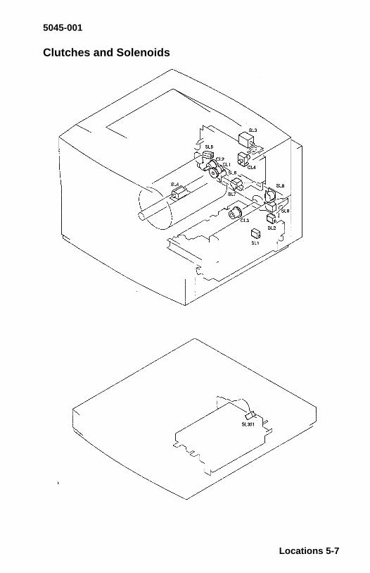
5045-001
Clutches and Solenoids
Locations 5-7
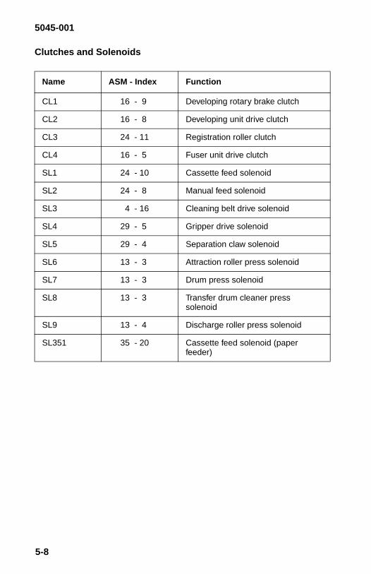
5045-001
Clutches and Solenoids
Name ASM - Index Function
CL1 16 - 9 Developing rotary brake clutch
CL2 16 - 8 Developing unit drive clutch
CL3 24 - 11 Registration roller clutch
CL4 16 - 5 Fuser unit drive clutch
SL1 24 - 10 Cassette feed solenoid
SL2 24 - 8 Manual feed solenoid
SL3 4 - 16 Cleaning belt drive solenoid
SL4 29 - 5 Gripper drive solenoid
SL5 29 - 4 Separation claw solenoid
SL6 13 - 3 Attraction roller press solenoid
SL7 13 - 3 Drum press solenoid
SL8 13 - 3 Transfer drum cleaner presssolenoid
SL9 13 - 4 Discharge roller press solenoid
SL351 35 - 20 Cassette feed solenoid (paperfeeder)
5-8
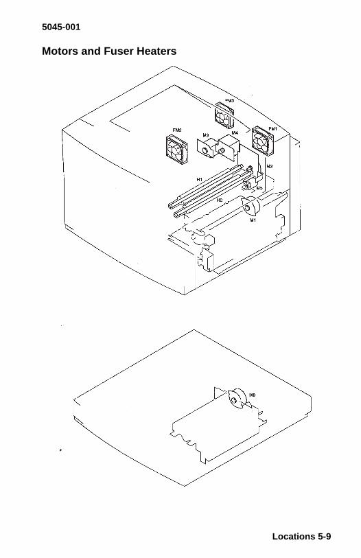
5045-001
Motors and Fuser Heaters
Locations 5-9

5045-001
Motors and Fuser Heaters
Name ASM - Index Function
M1 24 - 9 Pickup motor
M2 7 - 6 Main motor
M3 16 - 7 Developing unit motor
M4 16 - 6 Drum motor
M5 31 - 2 Cleaning brush motor
M6 35 - 19 Paper feeder motor
FM1 7 - 7 Fuser unit fan
FM2 7 - 8 Electrical unit fan
FM3 5 - 24 Controller fan
H1 32 - 2/11 Fuser upper roller heater(110 V or 220 V)
H2 32 - 2/11 Fuser lower roller heater(110 V or 220 V)
5-10

5045-001
PCBs
Locations 5-11

5045-001
PCBs
NameASM -Index
Function
1 DC Controller PCB 5 - 29 Controls printer functions(Laser/scanner control, Imagestabilization control, fuser unittemperature control, videointerface control, other variousdetection functions).
2 High-voltage powersupply PCB
2 - 26 Applies voltage in sequentialcorrespondence with primarycharging, developing, transfer,discharging, attraction, andseparation.
3 Separation HVT PCB 3 - 15 Supplies separation output tothe fuser unit and theseparation charging unit /corona.
4 Mechanical controllerPCB
7 - 32 Controls the various loads andvarious detection functions(motors. developing unit, fuserunit, transfer drum peripherals,pick-up/high voltage/paperfeeder, etc.).
5 Pick-up PCB 24 - 13 Controls the pick-up systemloads.
6 Terminal PCB 5 - 23 Relays signals between the DCcontroller and the videocontroller.
7 Cassette size-sensingPCB
3 - 8 Detects the cassette size.
8 Toner-low detectbeam PCB
16 - 2 Detects the toner amount(Emitting unit).
9 Toner-low detectreceive PCB
6 - 23 Detects the toner amount(Receiving unit).
10 Waste-toner sensingPCB
3 - 10 Detects the waste toner bottleis full.
11 Oil-sensing PCB 5 - 14 Detects the oil amount.
5-12

5045-001
12 Ejection-sensingPCB
3 - 8 Detects pulling of the ejectionlever.
13 Video controller PCB 33 - 1 Processes input/output databetween the printer and theexternal device.
14 Paper feeder driverPCB
36 - 6 Drives the solenoids and themotors in the optional paperfeed.
15 Cassette papersensor PCB
35 - 17 Detects the optional cassette Isout of paper.
NameASM -Index
Function
Locations 5-13

5045-001
Connector Locations
5-14

5045-001
Connector Locations
Locations 5-15

5045-001
Connector Locations
5-16

5045-001
DC Controller Board Connector Locations
Name Function
J 101 LVPS
J 102 Laser Beam Detect / Motor
J 103 Density Sensor
J 104 Toner Low Detect (receive)
J 105 Transfer Drum
J 106 Cleaning Belt Sensor / Oil Sensor
J 107 Waste Toner Sensing/ Cassette Size Sensing/ Ejection Sensing
J 108 Terminal Board and Display
J 109 Not Used
J 110 Laser Driver Board
J 111 Laser Driver Board
J 112 Mechanical Controller
J 113 Not Used
J 114 Density Adjustment Panel
Locations 5-17

5045-001
DC Controller Board Connector Locations (Graphic)
5-18

5045-001
DC Controller Board Connectors (J101, J102, J103)
Note: A “/” before a signal name indicates “Active Low” or “GroundShot Operated”.
J 101 J 102 J 103
LVPS Laser Beam Detect Density Sensor1 GND 1 BDCHK 1 +5 V2 +5 V 2 GND 2 DSNS3 GND 3 /BD 3 /DENSEL4 +24 VB 4 +5 V 4 GND5 PCONT Laser Beam Motor 5 /D06 POFF 5 GND 6 /D17 DOPN 6 SCNCLK 7 /D2
7 GND 8 /D38 /SCNON 9 /D49 /SCNRDY 10 /D5
10 +24 VB 11 /D611 +24 VB 12 /D7
13 /DENB14 +24 V15 Not Used
Locations 5-19

5045-001
DC Controller Board Connectors (J104, J105, J106)
J 104 J 105 J 106
Toner LowDetect
Transfer Drum Cleaning BeltSensor
(receive) Top Sensor 1 LEDDRV1 TNSNS 13 +5 V 2 GND2 GND 12 GND 3 WEBSNS3 RET (+5 V) 11 /TOPREG Oil Sensor
Separation Claw 4 LEDDRVDrive Solenoid 5 GND
10 +24 VA 6 OILSNS9 /SPSLON
Separation Senor8 SEPSNS7 GND6 LEDON
Gripper Drive Sole-noid
5 +24 VA4 /GRIPON
Attraction Sensor3 ATTSNS2 GND1 LEDON
5-20

5045-001
DC Connector Board Connectors (J107, J108, J109)
J 107 J 108 J 109
Waste TowerSensing
Terminal Board Not Used
1 LEDON Video Interface2 GND 1 through 373 HTSNS
Cassette SizeSensing / Ejection
Sensing4 GND5 /C SIZE 16 /C SIZE 27 /C SIZE 3
Locations 5-21

5045-001
DC Controller Board Connectors (J110, J111, J112)
J 110 J 111 J 112
Laser Drive Board Laser Drive Board MechanicalController Board
1 + 12 V 1 M6 1 Not Used2 + 12 V 2 GND 2 GND3 + 12 V 3 M5 3 GND4 GND 4 M4 4 +24 V5 PDIN 5 M3 5 Not Used6 GND 6 M2 6 +5 V7 LLCNT 7 M1 7 HUMSNS8 GND 8 GND 8 GND9 DV1 (GND) 9 SCK1 9 TMPSNS
10 GND 10 GND 10 GND11 DV2 11 M9(GND) 11 GND12 GND 12 GND 12 /SCK13 DV3 13 M8 13 /RX14 GND 14 GND 14 /TX15 DV4 15 M7 15 /SRST16 GND 16 GND 16 SEPON17 DV5 17 NHD 17 GRIPON18 GND 18 GND 18 SEPSNS19 DV6 19 +5 V 19 /TOPREG20 GND 20 +5 V 20 ATTSNS21 DV7 21 +5 V 21 TNSNS22 GND 22 /LSON 22 /FXSNS23 DV8 23 /VDOE 23 GND24 GND 24 THI25 DV9 25 GND
26 /FXUON27 /FXLON28 /FXENB29 /FXROF30 SFSNS31 FXSTS
5-22

5045-001
DC Controller Board Connectors (J113, J114)
J 113 J 114
Not Used Density Adjustment Panel1 /TST22 /LCK3 /DSCK4 /SDO5 /SDI6 GND7 +5 V8 /DSPEN
Locations 5-23

5045-001
Mechanical Controller Board Connector Locations
Name Function
J2001 LVPS
J2002 Paper Pickup Board
J2003 Optional Sheet Feed
J2004 HVPS
J2005 Temperature / Humidity Sensor
J2006 Rotary Position / Cartridge Position Sensor
J2007 DC Controller Board
J2008 LVPS
J2009 Cleaning Belt Drive Solenoid and Fuser
J2010 Controller Fan
J2011 Fuser Drive Clutch
J2012 Fuser Fan
J2013 Main Drive Motor
J2014 Solenoid Plate / Cleaning Brush Motor
J2015 Drum Motor
J2016 Developer Motor
J2017 Toner Low Detect (beam) / Developer UnitDrive Clutch / Developer Unit Brake
J2018 Not Used
J2019 Electrical Unit Fan
J2020 Not Used
J2021 Not Used
J2022 Separation High Voltage Unit
5-24

5045-001
Mechanical Controller Board Connectors (Graphic)
Locations 5-25

5045-001
Mechanical Controller Board (J2001, J2002, J2003)
Mechanical Controller Bd (J2004, J2005, J2006)
J2001 J2002 J2003
Low Voltage PowerSupply
Paper PickupBoard
Optional SheetFeed
1 +24 VB 1 TXD 1 RES2 GND 2 RXD 2 SEL3 +5 V 3 CLK 3 Not Used4 GND 4 GND 4 +5 V5 +24 VA 5 +5 V 5 GND
6 PGND 6 CLK7 +24 VC 7 RXD8 RES 8 TXD
J2004 J2005 J2006
High VoltagePower Supply
Temperature /Humidity Sensor
Toner CartridgePosition Sensor
1 TXD 1 GND 1 +5 VSAVE2 RXD 2 TMPSNS 2 GND3 CLK 3 GND 3 DEVCAM4 SEL 4 HUMSNS Rotary Position
Sensor5 RES 5 +5 VU 4 +5 VSAVE6 +5 V 5 GND7 GND 6 DEVHP8 +24 V9 PGND
5-26

5045-001
Mechanical Controller Bd (J2007, J2008, J2009)
J2007 J2008 J2009
DC ControllerBoard
Low Voltage PowerSupply
Cleaning Belt DriveSolenoid / Fuser
1 Not Used 1 FXSTS Fuser2 PGND 2 SFSNS 1 THI3 PGND 3 FXTYP 2 (THIRET) GND4 +24 VA 4 THI 3 /FXSNS5 Not Used 5 /FXROF 4 GND6 +5 V 6 /FXENB 5 FXTYP7 HUMSEN 7 /FXLON 6 +5 V8 GND 8 /FXUON Drive Solenoid9 TMPSNS 9 GND 7 /WEBSL
10 GND 8 +24 VA11 SGND Fuser12 SCK 9 +5 VSAVE13 TXD 10 GND14 RXD 11 POUT15 /DRESIN 12 +5 VSAVE16 SEPON 13 GND17 GRIPON 14 OILFUL18 SEPSNS19 TOPREG20 ATTSNS21 TNSNS22 /FXSNS23 THIRET (GND)24 THI25 GND26 /FXUON27 /FXLON28 /FXENB29 /FXROF30 SFSNS31 FXSTS
Locations 5-27

5045-001
Mechanical Controller Bd (J2010, J2011, J2012)
Mechanical Controller Bd (J2013, J2014, J2015)
J2010 J2011 J2012
Controller Fan Fuser Drive Clutch Fuser Fan1 GND 1 /FXON 1 GND2 /FANLK3 2 +24 VA 2 FANLK13 FAND3 3 FAND1
J2013 J2014 J2015
Main Drive Motor Solenoid Plate /Cleaning Brush
Motor
Drum Motor
1 MLOW Attraction RollerSolenoid
1 CA
2 /MRDY 1 /ATTSLON 2 CB3 /MON 2 +24 VA 3 AO4 GND Drum Press
Solenoid4 /AO
5 GND 3 /DDSLON 5 BO6 +24 VA 4 +24 VA 6 /BO7 +24 VA Transfer Drum
Clean PressSolenoid
5 /TDCSLON6 +24 VACleaning Brush
Motor7 /TDCON8 +24 VA
Discharge RollerPress Solenoid9 /SCSLON
10 +24 VA
5-28

5045-001
Mechanical Controller Bd (J2016, J2017, J2018)
Mechanical Controller Bd (J2019, J2020, J2021)
Mechanical Controller Bd (J2022)
J2016 J2017 J2018
Developer Motor Toner Low Detect(beam) /
Developing RotaryBrake Clutch /
Developing UnitDrive Clutch
Not Used
1 CA Brake Clutch2 CB 1 /DEVBRK3 AO 2 +24 VA4 /AO 3 /DEVON5 BO 4 +24 VA6 /BO Toner Beam
5 TONLED6 GND7 NOT USED
J2019 J2020 J2021
Electrical Unit Fan Not Used Not Used1 GND2 FANLK23 FAND2
J2022
Separation High Voltage Unit1 GND2 ON/OFF3 +24 VA
Locations 5-29

5045-001
Paper Pickup Board
Name Function
J301 Mechanical Controller Board
J302 Manual Feed Size Sensor / Manual FeedPaper Sensor / Manual Feed Solenoid /Registration Roller Clutch
J303 Cassette Feed Solenoid
J304 Pickup Motor
J305 Paper Top Sensor
5-30

5045-001
Paper Pickup Board Connectors (J301, J302, J303)
Paper Pickup Board Connectors (J304, J305)
J301 J302 J303
MechanicalController Board
Manual Feed SizeSensor / Manual
Feed Paper Sensor /Manual Feed
Solenoid Sensor /Registration Roller
Clutch
Cassette FeedSolenoid
1 TXD Size Sensor 1 CPFED2 RXD 1 LEDDRV2 2 +24 VC3 CLK 2 GND4 GND 3 MPSSNS5 +5 V Paper Sensor6 PGND 4 LEDDRV27 +24 VC 5 GND8 RES 6 MPPSNS
Manual FeedSolenoid
7 MPFED8 +24 VC
Registration RollerClutch
9 +24 VC10 /REGFED
J304 J305
Pickup Motor Paper Top Sensor1 CB 1 LEDDRV12 CA 2 VREG3 BO 3 TOPSNS4 /BO5 AO6 /AO
Locations 5-31

5045-001
Terminal Board
Terminal Board Connectors (J801, J802, J803)
Terminal Board Connectors (J804)
Name Function
J801 Video Controller Board
J802 DC Controller Board
J803 Display Panel
J804 Power Supply
J801 J802 J803
Video ControllerBoard
DC Controller Panel Display
1 through 96Video Interface
1 through 37Video Interface
A1 GRD
A3 PCLKA5 FP1RQB14 +5 VB9 PDATA
J804
Power Supply1 GND2 GND3 GND4 +5 V5 +5 V6 +5 V
5-32
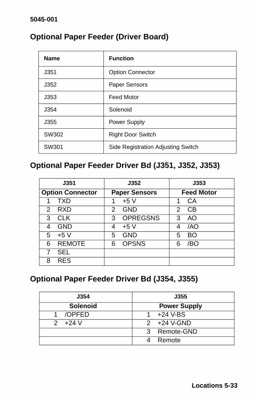
5045-001
Optional Paper Feeder (Driver Board)
Optional Paper Feeder Driver Bd (J351, J352, J353)
Optional Paper Feeder Driver Bd (J354, J355)
Name Function
J351 Option Connector
J352 Paper Sensors
J353 Feed Motor
J354 Solenoid
J355 Power Supply
SW302 Right Door Switch
SW301 Side Registration Adjusting Switch
J351 J352 J353
Option Connector Paper Sensors Feed Motor1 TXD 1 +5 V 1 CA2 RXD 2 GND 2 CB3 CLK 3 OPREGSNS 3 AO4 GND 4 +5 V 4 /AO5 +5 V 5 GND 5 BO6 REMOTE 6 OPSNS 6 /BO7 SEL8 RES
J354 J355
Solenoid Power Supply1 /OPFED 1 +24 V-BS2 +24 V 2 +24 V-GND
3 Remote-GND4 Remote
Locations 5-33

5045-001
Optional Paper Feeder (Miscellaneous)
High Voltage Power Supply PCB
Name Function
J312 Size Sensing PCB
PS351 Cassette Paper Sensor
J359 Paper Sensor Connector
SL351 Cassette Feed Solenoid
PS352 Pickup Sensor
J358 Pickup Sensor Connector
5-34
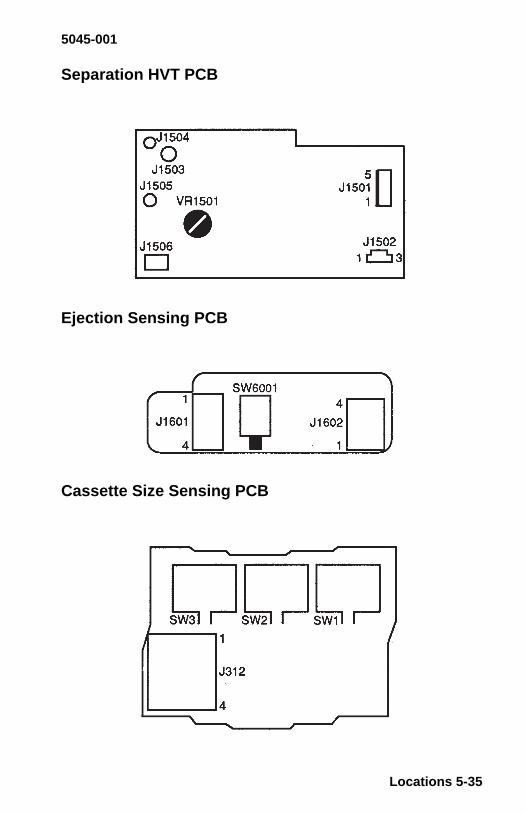
5045-001
Separation HVT PCB
Ejection Sensing PCB
Cassette Size Sensing PCB
Locations 5-35

5045-001
Paper Feed Driver PCB
5-36

5045-001
Fuser Connector (J21)
Locations 5-37

5045-001
6. Preventive Maintenance
This chapter describes procedures for printer preventive mainte-nance. Following these recommendations can help prevent prob-lems and maintain optimum performance.
Safety Inspection Guide
The purpose of this inspection guide is to aid you in identifyingunsafe conditions.
Use good judgment to identify possible safety conditions not coveredby this inspection guide. Refer to the safety reminders for a generalchecklist.
If any unsafe conditions exist, find out how serious the hazard couldbe and if you can continue before you correct the hazard.
Check the following items:
• Damaged, missing, or altered parts, especially in the area of theOn/Off switch and the power supply
• Damaged, missing, or altered covers, especially in the area ofthe top cover and the power supply cover
• Possible safety exposure from any non-Lexmark attachments
6-1
5045-001
Lubrication Specifications
Use Grease (part 1321875) as needed.
Do not over grease the parts, but make sure new parts have ade-quate lubrication.
Use of a spray contact cleaner in most instances will allow normalfunctioning of the fuser sensors which have been contaminated withsilicone oil. The only cleaner currently approved by Lexmark is CRCbrand industrial contact cleaner # 03130. In addition to the cautionson the Material Safety Data Sheet (MSDS) label attached to the can,observe the following guidelines:
• When spraying either fuser sensor (PS9 or PS10), place a pieceof absorbent material below the sensor to catch the excessspray.
• Use the supplied nozzle and direct the spray into the smallapertures in the inside walls of the sensors.
• Spray quickly (approximately 1 second applications).
This spray leaves no residue, contains no CFCs and is plastic safe.Do Not use a substitute spray that has not been tested and is notplastic safe.
Lubricants and Cleaners
Alcohol or Isopropyl Clean: Plastic,rubber and externalparts.
Follow manufacturesdirections.
MEK Clean: Oil and tonerstains.
Followmanufacturer’sdirections.
Lubricating Oil Apply between gearand shaft.
#10 oil
Lubricating Grease Apply to gear. #23 greaseSpray Cleaner Clean fuser sensors CRC # 31030
Preventive Maintenance 6-2

5045-001
Maintenance, Customer Checks
Maintenance points that should be performed by the customer tomaintain the printer at the optimum level are listed below. All othermaintenance procedures are to be performed by a trained servicetechnician.
Item Action
Toner Cartridge Shake or replace the cartridge.
Drum Cartridge Replace
Waste Toner Bottle Replace
Oil Replace
Registration roller unit (cassettepickup unit)
Clean the paper dust between themetal registration roller and thesheet. Use a damp cloth and dry theunit.
Separation Charging Unit Clean the corona wire with the brushincluded with the printer.
Density Sensor Clean the lens with the brushincluded with the printer.
6-3

7. Parts Catalog
How To Use This Parts Catalog
• SIMILAR ASSEMBLIES: If two assemblies contain a majority ofidentical parts, they are broken down on the same list. Commonparts are shown by one index number. Parts peculiar to one orthe other of the assemblies are listed separately and identifiedby description.
• AR: (As Required) in the Units column indicates that the quan-tity is not the same for all machines.
• NP: (Non-Procurable) in the Units column indicates that the partis non-procurable and that the individual parts or the next higherassembly should be ordered.
• NR: (Not Recommended) in the Units column indicates that thepart is procurable but not recommended for field replacement,and that the next higher assembly should be ordered.
• R: (Restricted) in the Units column indicates that the part has arestricted availability.
• NS: (Not Shown) in the Asm-Index column indicates that thepart is procurable but is not pictured in the illustration.
• PP: (Parts Packet) in the Description column indicates that thepart is contained in a parts packet.
• INDENTURE: The indenture is marked by a series of dotslocated before the parts description. The indenture indicates therelationship of a part to the next higher assembly. For example:
INDENTURE RELATIONSHIP OF PARTS(No dot) MAIN ASSEMBLY(One dot) • Detail parts or subassembly of a main assembly(Two dot) • • Detail part or subassembly of a one-dot subas-sembly
Parts Catalog 7-1

Assembly 1: Covers
7-2

Asm-Index
PartNumber Units Description
1-1 11A2747 1 Cover, Pick Up, Lower
-2 11A2140 1 Cover, Tray
-3 11A2319 1 Cover, Bezel-4 11A2320 1 Cover, Rear
-5 11A2321 1 Cover, LH Side
-6 11A2322 1 Cover, Top
-7 11A2323 1 Cover, Multipurpose Door
-8 11A2324 1 Cover, Multipurpose Feeder Asm-9 11A2325 1 Multipurpose Feeder Asm
-12 11A2327 1 Cover, Front
-13 11A2328 1 Latch Plate
-14 11A2329 1 Cover, Inner-15 Screw, PP 11A2331
-16 Screw, PP 11A2340
-17 11A2330 1 Cover Latch
-18 11A2416 1 Cover Label
-20 11A2436 1 Front Bezel-21 11A2417 1 Cover, Face Down Asm
-22 11A2418 1 Cover, Delivery Asm
-23 11A2419 1 Cover, Filter
-24 11A2421 1 Filter, Air
-25 11A2422 1 Cover, Board Connector-26 11A2423 1 Cover, Trim For Top Cover
-28 11A2435 1 OP Panel Asm
-29 11A2739 1 Corona Cleaning Brush
Parts Catalog 7-3

Assembly 2: Major Components
7-4

Asm-Index
PartNumber Units Description
2-1 11A2424 1 Knob, Manual-2 1 Bushing, PP 11A2379
-3 1 Bushing, Front, PP 11A2379-4 1 Bushing, Rear, PP 11A2379
-5 11A2425 1 Lever, Release
-6 2 Bushing, PP 11A2379
-7 11A2717 1 Holder
-8 1 Spring, PP 11A2354-NS 11A2741 1 Label, Caution, H.V.
-22 11A2426 1 Sensor Temperature & Humidity
-24 11A2427 1 Cable Temperature & Humidity
-26 11A2428 1 Power Supply, H.V.-28 Screw, PP 11A2331
-29 Screw, PP 11A2331
-30 Screw, PP 11A2340
-31 See “Ejector Lever” on page 7-24
-32 See “Density Sensor Asm” on page 7-64-33 See “Rotary Manual Feed” on page 7-30
-34 See “Attraction Roller Drive” on page 7-40
-35 See “Drum Lift” on page 7-38
-36 See “Door Switch, Upper” on page 7-20
-37 See “Door Switch, Lower” on page 7-22-38 See “Transfer Drum Cleaning Drive” on
page 7-34
-39 See “Solenoid Plate” on page 7-26
-40 See “Discharge Roller Drive” on page 7-36
-41 See “Transfer Drum Mounting Asm” onpage 7-58
-42 See “Developing Rotary Asm” on page7-56
Parts Catalog 7-5

Assembly 3: Toner (used) Reservoir/ HV
7-6

Asm-Index
PartNumber Units Description
3-1 1 Bolt, PP 11A2340
-2 11A2429 1 Cover, Conn.
-3 11A2431 1 Panel, Guide-4 11A2432 1 Hinge Upper, Door
-5 11A2433 1 Stopper Spring
-6 11A2031 1 Cover, Switch
-7 1 Spring, PP 11A2354
-8 11A2032 1 Size Sensor Asm, includes Ejection SensorBoard
-9 11A2033 1 Switch, Main
-10 11A2034 1 Sensor, Waste Toner Asm
-11 11A2035 1 Button, Switch
-12 11A2036 1 Hinge, Lower Door-13 Screw, PP 11A2331
-14 Screw, PP 11A2331
-15 11A2037 1 PCB, H.V. Separator
-16 11A2038 1 Converter H.V.
Parts Catalog 7-7

Assembly 4: Major Assemblies (Top/Bottom)
7-8

Asm-Index
PartNumber Units Description
4-1 11A2039 1 Stop, Left
-2 11A2040 1 Cover, W/ Label
-3 11A2041 1 Foot, Front-4 11A2042 1 Cover, Bottle
-5 1 Connector, 3P, PP 11A2389
-6 1 Clamp, Cord, PP 11A2389
-7 1 Clamp, PP 11A2389
-8 2 Clip, PP 11A2389-9 Screw, PP 11A2331
-10 11A2043 1 Cross-member
-11 Screw, PP 11A2331
-12 11A2044 1 Latch, Roller-13 Screw, PP 11A2340
-14 See “Paper, Side Exit Asm” on page 7-54
-15 See “Paper Drive” on page 7-42
-16 See “Cleaning Belt Drive Solenoid” onpage 7-28
-17 See “Transfer Drum Cleaning” on page7-66
-18 See “Paper Pickup” on page 7-46
-19 11A2719 1 Shield, Rear
-20 11A2720 1 Handle, Oil Bottle
-21 11A2737 1 Screw, Pivot-22 11A2746 1 Stud, Pivot
Parts Catalog 7-9

Assembly 5: DC Controller / Video Controller Board
7-10

Asm-Index
PartNumber Units Description
5-1 11A2045 1 Holder, Cable
-2 11A2046 1 Cover, Upper Plate
-3 11A2047 1 Mount, DC Controller-4 11A2048 1 Mount, DC Controller
-5 11A2049 1 Cover, DC Controller
-NS 11A2742 1 Ferrite Core (mounts to #5)
-6 11A2050 1 Mount, DC Controller
-7 11A2051 1 Cable-8 11A2052 1 Cable
-9 11A2053 1 Cable
-10 11A2054 1 Cable
-11 11A2055 1 Cable, DC Rear-12 11A2056 1 Cable, DC Front
-13 11A2057 1 Cable, Density Adj. Panel
-14 11A2058 1 Sensor, Oil Asm
-15 11A2059 2 Guide, Rail
-16 11A2060 1 Plate, Cover-17 11A2061 1 Plate, RH
-18 11A2062 1 Plate, Fan Duct
-19 11A2063 1 Crossmember
-20 11A2064 2 Guide, Rail
-21 11A2065 1 Duct, Fan-22 11A2066 1 Plate, LH
-23 11A2067 1 Connector PCB
-24 11A2068 1 Fan, Video Controller
-25 Screw, PP 11A2331-26 11A2069 1 Bracket, Opt Conn.
-27 11A2070 1 Cover, Cable
-28 Screw, PP 11A2331
-29 11A2071 1 PCB, DC Controller
-30 11A2721 1 Holder, Ferrite Core-31 11A2713 1 Ferrite Core
-32 See “Video Controller Board” on page7-72.
Parts Catalog 7-11
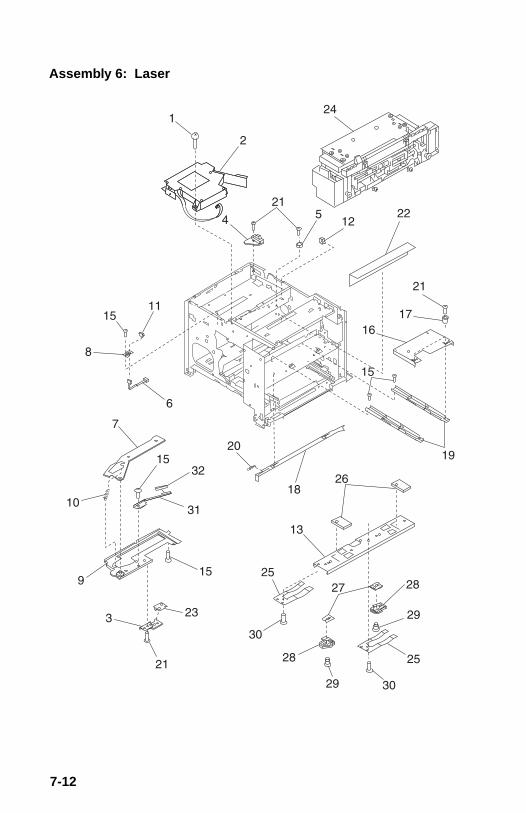
Assembly 6: Laser
7-12

Asm-Index
PartNumber Units Description
6-1 Screw, PP 11A2331
-2 11A2072 1 Printhead
-3 11A2073 1 Holder, Sensor-5 11A2074 1 Stopper, Laser, PCB
-6 11A2075 1 Cable, Toner Sensor
-7 11A2076 1 Shutter, Laser
-8 11A2077 1 Mount, Panel
-9 11A2078 1 Bracket, Shutter-10 1 Spring, PP 11A2354
-11 1 Connector 3 Pin, PP 11A2389
-12 1 Clip, Cable, PP 11A2389
-13 11A2079 1 Rail, PC Cartridge-15 Screw, PP 11A2331
-16 11A2081 1 Plate, Slide
-17 11A2082 2 Guide, Fuser
-18 11A2083 1 Rod, ON/Off
-19 11A2084 2 Rail Asm-20 1 Spring, PP 11A2354
-21 Screw, PP 11A2331
-22 11A2085 1 Sheet, Caution
-23 11A2086 1 PCB, Sensor, Toner Empty (Receive)
-24 See “Fuser” on page 7-68-25 11A2552 2 Spring, Leaf
-26 11A2553 2 Damper
-27 11A2554 2 Damper
-28 11A2555 2 Spacer, Rail-29 Screw, PP 11A2331
-30 Screw, PP 11A2331
-31 11A2550 1 Spring, Leaf
-32 11A2551 1 Damper
Parts Catalog 7-13

Assembly 7: Drive, Main
7-14

Asm-Index
PartNumber Units Description
7-1 11A2087 1 Duct Fuser Fan Asm
-2 11A2088 1 Duct, Upper Fan
-3 11A2089 1 Duct, Lower Fan-4 11A2090 1 LVPS 110 V
-4 11A2091 1 LVPS 220 V
-6 11A2092 1 Motor, Main Drive
-7 11A2093 1 Fan, Fuser
-8 11A2094 1 Fan, DC Controller, Laser-9 11A2095 1 Gear, Cartridge Press
-10 1 Connector, Snap Tite, PP 11A2389
-11 1 Connector, 5 Pin Male, PP 11A2389
-12 11A2096 1 Mount, HV Terminal-13 11A2097 3 Spring, Leaf
-14 11A2098 1 Cable, Transfer HV
-15 11A2099 1 Cable, Discharge
-16 11A2100 5 Resistor
-17 Screw, PP 11A2340-18 11A2101 1 Mount, Mechanical Controller
-19 11A2102 1 Plate, HV Contact
-20 11A2103 1 Plate, HV Contact
-21 11A2104 2 Plate, HV Contact
-22 11A2105 1 Grd, Right-23 11A2106 1 Grd, Left
-24 11A2107 1 Sheet, Mech Controller, Insulator
-25 11A2108 1 Cable, HV
-26 Screw, PP 11A2331-27 Screw, PP 11A2331
-28 Screw, PP 11A2331
-29 11A2109 1 Cable, Clutch, Brake
-30 11A2110 1 Filter, Ozone
-31 Screw, PP 11A2331-32 11A2111 1 Board, Mech Controller
-33 See “Printer Drive” on page 7-32
Parts Catalog 7-15

Assembly 8: Density Adjustment Panel
7-16

Asm-Index
PartNumber Units Description
8-1 11A2112 1 Cover, Cleaning
-2 11A2113 1 Stopper, Right
-3 1 Clamp, Cable, PP 11A2389-4 11A2114 1 Plate, Sensor
-5 11A2115 1 Cable, Rotary
-6 1 Bushing, PP 11A2379
-7 11A2116 1 Sensor, Photo
-8 11A2117 1 IC TLP1230, Sensor-9 Screw, W/Washer, PP 11A2340
-10 11A2118 1 Holder, Contact
-11 11A2119 1 Contact
-12 Screw, PP 11A2340-13 11A2120 1 Foot, Rear
-14 11A2121 1 Crossmember
-15 11A2122 1 Mount, Positioning
-16 11A2123 2 Guide, Drive Mounting
-17 Screw, W/Washer, PP 11A2340-18 1 Conn., 2 Pin, PP 11A2389
-19 1 Clip, PP 11A2389
-20 1 Edge Saddle, PP 11A2389
-21 Screw, PP 11A2331
-22 Screw, PP 11A2331-23 Screw, PP 11A2340
-24 11A2124 1 Rail, Cleaner
-25 11A2125 1 Mount, Panel
-26 11A2126 1 Bezel, Density Adj-27 11A2127 1 Panel, Density Adj PCB
-28 Screw, PP 11A2331
-29 Screw, PP 11A2331
Parts Catalog 7-17

Assembly 9: Bottom Plate
7-18

Asm-Index
PartNumber Units Description
9-1 11A2128 1 Plate, Left, Slide Out
-2 11A2129 4 Guide, Slide
-3 11A2130 1 Shield, Conn.-4 11A2131 1 Rail, Cassette Rt
-5 11A2132 1 Rail, Cassette Lft
-6 11A2133 1 Crossmember Rail
-7 11A2134 1 Foot, Front
-8 11A2135 1 Grip, Front, Right-9 11A2136 1 Grip, Rear, Right
-10 11A2137 1 Support, Rock Pin
-11 11A2138 1 Plate, Right, Slide Out
-12 11A2139 1 Cable, Bottom-13 Clip, PP 11A2389
-14 Screw, PP 11A2331
-15 Screw, PP 11A2331
-16 11A2748 2 Grip, Front and Rear, Left
-17 Screw, PP 11A2340-18 Screw, PP 11A2340
Parts Catalog 7-19

Assembly 10: Door Switch, Upper
7-20

Asm-Index
PartNumber Units Description
10-1 11A2141 1 Arm, Door 1
-2 11A2142 1 Arm, Door 2
-3 11A2143 1 Guide, Cable-4 11A2144 1 Mount, Switch Upper
-5 11A2145 1 Cable, Control
-6 1 Spring, PP 11A2354
-7 Screw, PP 11A2331
-8 Screw, PP 11A2331-9 E-Ring, PP 11A2373
Parts Catalog 7-21

Assembly 11: Door Switch, Lower
7-22

Asm-Index
PartNumber Units Description
11-1 11A2146 1 Arm, Rocker
-2 11A2147 1 Plate, Insulating Switch
-3 11A2148 1 Mount, Switch Lower-4 11A2149 1 Plate, Slide
-5 11A2150 1 Cable, Switch
-6 11A2151 1 Switch
-7 1 Spring, PP 11A2354
-8 Screw, PP 11A2340-9 1 Spring, PP 11A2354
-10 11A2152 1 Arm, Push Upper
-11 11A2153 1 Arm, Push Lower
-12 E-RIng, PP 11A2373
Parts Catalog 7-23

Assembly 12: Ejector Lever
7-24

Asm-Index
PartNumber Units Description
12-1 11A2740 1 Ejector Asm
-2 11A2154 1 •Ejector
-3 11A2155 1 •Guide-4 11A2156 1 •Hook
-5 11A2157 1 •Oil Damper
-6 1 •Spring, PP 11A2354
Parts Catalog 7-25

Assembly 13: Solenoid Plate
7-26

Asm-Index
PartNumber Units Description
13-1 11A2158 1 Mount, Solenoid
-2 11A2159 1 Cable
-3 11A2160 3 Solenoid-4 11A2161 1 Solenoid
-5 3 Conn. 2 Pin, PP 11A2389
-6 1 Conn. 3 Pin, PP 11A2389
-7 Clip, PP 11A2389
-8 Clip, PP 11A2389-9 Screw, PP 11A2331
Parts Catalog 7-27

Assembly 14: Cleaning Belt Drive Solenoid
7-28

Asm-Index
PartNumber Units Description
14-1 11A2162 1 Lever, Solenoid
-2 11A2163 1 Mount, Solenoid
-3 11A2164 1 Solenoid-4 1 Conn. 2 Pin, PP 11A2389
-5 E-Ring, PP 11A2373
-6 Screw, PP 11A2340
Parts Catalog 7-29

Assembly 15: Rotary Manual Feed
7-30

Asm-Index
PartNumber Units Description
15-1 11A2165 1 Feeder, Rotary Manual Asm
-2 11A2167 1 •Shaft
-3 11A2166 1 •Hook, Lock
Parts Catalog 7-31

Assembly 16: Printer Drive
7-32

Asm-Index
PartNumber Units Description
16-1 11A2168 1 Drive Asm complete
-2 11A2169 1 • Toner Empty Sensor (Beam)
-3 11A2170 1 • Bearing Asm, Rotary Unit-4 11A2171 1 • Bearing Asm, Transfer Drum
-5 11A2172 1 • Clutch Asm, Fuser Drive
-6 11A2173 1 • Motor Asm, Transfer Drum
-7 11A2174 1 • Motor Asm, Rotary Unit
-8 11A2175 1 • Clutch Asm, Rotary Unit-9 11A2176 1 • Clutch Asm, Brake
-10 1 • Bearing, PP 11A2379
Parts Catalog 7-33

Assembly 17: Transfer Drum Cleaning Drive
7-34

Asm-Index
PartNumber Units Description
17-1 11A2177 1 Transfer Drum Clean Drive Asm
-2 11A2178 1 •Coupler
Parts Catalog 7-35

Assembly 18: Discharge Roller Drive
7-36

Asm-Index
PartNumber Units Description
18-1 11A2179 1 Discharge Roller Drive Asm
-2 11A2180 1 •Cam
Parts Catalog 7-37

Assembly 19: Drum Lift
7-38

Asm-Index
PartNumber Units Description
19-1 11A2181 1 Drum Lift Asm
-2 11A2182 2 •Cam
Parts Catalog 7-39

Assembly 20: Attraction Roller Drive
7-40

Asm-Index
PartNumber Units Description
20-1 11A2183 1 Attraction Roller Drive Asm
-2 11A2184 1 •Cam
Parts Catalog 7-41

Assembly 21: Paper Drive
7-42

Asm-Index
PartNumber Units Description
21-1 11A2185 1 Delivery Drive Asm
-2 11A2186 1 • Belt
Parts Catalog 7-43
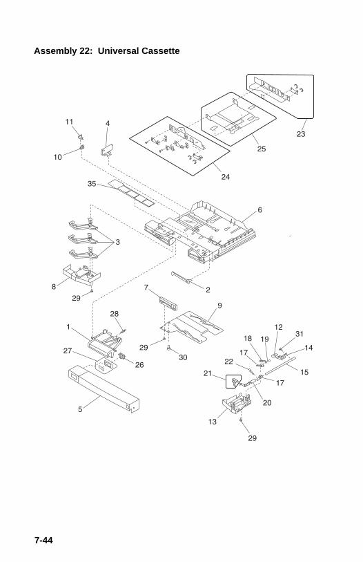
Assembly 22: Universal Cassette
7-44

Asm-Index
PartNumber Units Description
22-1 11A2187 1 Lever, Release Lock
-2 11A2188 1 Arm, Release
-3 11A2189 3 Lever, Size-4 11A2190 1 Panel, Limit Rear
-5 11A2191 1 Cover, Cassette
-6 11A2192 1 Body Cassette
-7 11A2193 1 Cam, Size
-8 11A2194 1 Cover, Size-9 11A2195 1 Plate, Cam
-10 11A2196 1 Button, Release
-11 11A2197 1 Cover, Release
-12 11A2198 1 Cap, Lifting-13 11A2199 1 Cover, Lower
-14 11A2200 1 Plate
-15 11A2201 1 Rod
-16 11A2202 1 Lever, Rod
-17 11A2203 1 Lever, Tension-18 11A2204 1 Block, Pressure
-19 11A2205 1 Shaft, Tension
-20 11A2206 1 Arm, Sensor
-21 11A2207 1 Block, Display Asm
-22 1 Spring, PP 11A2354-23 11A2208 1 Plate, Rear Asm
-24 11A2209 1 Plate, Front Asm
-25 11A2210 1 Plate, Lift Asm
-26 11A2211 1 Knob, Size-27 11A2212 1 Plate, Size
-28 1 Spring, PP 11A2354
-29 1 Screw, PP 11A2331
-30 1 Screw, PP 11A2340
-31 1 Screw, PP 11A2331-32 11A2730 3 Spring, Lever
-35 11A2728 1 Label, Universal
Parts Catalog 7-45

Assembly 23: Paper Pickup
7-46

Asm-Index
PartNumber Units Description
23-1 11A2213 1 Cover, Motor
-2 11A2214 1 Mount, Pivot
-3 1 Spring, PP 11A2364-4 1 Spring, PP 11A2364
-5 1 Spring, PP 11A2364
-6 1 Screw, PP 11A2331
-7 1 Screw, PP 11A2331
-8 11A2215 1 Cover-9 See “Cassette Paper Pickup Asm” on page
7-48
-10 See “Multipurpose Feeder Pickup Asm” onpage 7-52
Parts Catalog 7-47

Assembly 24: Cassette Paper Pickup Asm
7-48

Asm-Index
PartNumber Units Description
24-1 11A2216 1 Cassette Paper Pickup Asm
-3 11A2219 1 •Shaft Asm
-5 11A2221 2 •Lever, Lock Slide-7 11A2223 1 •Roller, Asm Rear
-9 11A2225 1 •Motor, Paper Pickup Asm
-10 11A2226 1 •Solenoid
-11 11A2227 1 •Clutch
-12 •Spring, Lever Lock, PP 11A2364
Parts Catalog 7-49

Assembly 24: Paper Pickup Cassette (cont.)
7-50

Asm-Index
PartNumber Units Description
24-1 11A2216 1 Cassette Paper Pickup Asm
-2 11A2218 1 •Roller Asm
-4 11A2220 2 •Roller-6 11A2222 1 •Guide Asm
-8 11A2224 1 •Roller Asm
-13 11A2228 1 •PCB Paper Pickup Asm
Parts Catalog 7-51

Assembly 25: Multipurpose Feeder Pickup Asm
7-52

Asm-Index
PartNumber Units Description
25-1 11A2217 1 Multipurpose Paper Pickup Asm
-2 11A2229 1 • Clip, Roller
-3 11A2230 1 • Roller, Pickup-4 11A2231 1 • Guide, Upper Asm
-5 11A2232 1 • Pad, Main
-6 11A2233 1 • Roller, U-turn Asm
-7 11A2234 1 • Base Asm
-8 11A2235 1 • Solenoid-9 11A2117 2 • Sensor
Parts Catalog 7-53

Assembly 26: Paper, Side Exit Asm
7-54

Asm-Index
PartNumber Units Description
26-1 11A2236 1 Delivery Asm
-2 11A2237 1 • Frame Asm, Without Rollers
-3 11A2117 1 • Sensor, Cleaning Belt
Parts Catalog 7-55

Assembly 27: Developing Rotary Asm
7-56

Asm-Index
PartNumber Units Description
27-1 11A2238 1 Rotary Asm
-2 11A2239 1 •Rotary Disc
-3 11A2240 1 •Rotary Center Asm
Parts Catalog 7-57

Assembly 28: Transfer Drum Mounting Asm
7-58

Asm-Index
PartNumber Units Description
28-1 11A2241 1 Transfer Drum Holder Asm
-2 11A2243 1 •Slide, Front Asm
-3 11A2244 1 •Contact, HV Asm-4 11A2245 1 •Slide, Rear Asm
-5 11A2246 1 •Knob, Manual Asm
-6 11A2242 1 •Lever, Operation
-7 •“Transfer Drum” on page 7-60
-8 11A2415 1 Sheet, Transfer Drum-9 11A2703 1 Roller, Attraction
-10 11A2704 1 Brkt., Used Toner Sensor
-11 11A2705 1 Arm, Lock, Used Toner
-12 Spring, PP 11A2364-13 11A2707 1 Arm, Lock, Cartridge
-14 Spring, PP 11A2364
Parts Catalog 7-59

Assembly 29: Transfer Drum
7-60

Asm-Index
PartNumber Units Description
29-1 11A2247 1 Drum, Transfer Asm
-3 11A2117 1 •Sensor
-4 11A2700 1 •Solenoid-6 11A2702 1 •Claw, Separation
-7 11A2709 1 •Arm, Sensing
-8 •Spring, PP 11A2354
-9 11A2711 1 •Cover, Sensor
-10 11A2712 1 •Cover, Sensor-11 11A2116 1 •Sensor
-14 11A2454 1 •Roller, Discharge
-15 11A2452 2 •Roller, Static
Parts Catalog 7-61

Assembly 29: Transfer Drum (Cont.)
7-62

Asm-Index
PartNumber Units Description
29-1 11A2247 1 Drum, Transfer Asm
-2 11A2248 1 • Gripper, Paper Asm
-3 11A2117 1 • Sensor-5 11A2701 1 • Solenoid
-13 11A2453 2 • Cap, Plastic
Parts Catalog 7-63

Assembly 30: Density Sensor Asm
7-64

Asm-Index
PartNumber Units Description
30-1 11A2249 1 Support, Corona
-2 11A2250 1 Link
-3 11A2251 1 Plate Sen/Sep-4 11A2252 1 Plate, Sensor
-5 11A2253 1 Corona, Separation Asm
-6 11A2254 1 Sensor, Density
-7 1 Spring, PP 11A2364
-8 Screw, PP 11A2340-9 Screw, PP 11A2331
-10 11A2255 1 Cover
-11 11A2256 1 Cable
-12 1 E-Ring, PP 11A2373-13 1 E-Ring, PP 11A2373
Parts Catalog 7-65

Assembly 31: Transfer Drum Cleaning
7-66

Asm-Index
PartNumber Units Description
31-1 11A2257 1 Transfer Drum Clean Asm
-2 11A2259 1 •Motor
-3 11A2258 1 •Brush-4 11A2732 1 •Blade
Parts Catalog 7-67

Assembly 32: Fuser
7-68

Asm-Index
PartNumber Units Description
32-1 11A2260 1 Fuser 110 V Asm
-3 11A2267 1 • Oil Tray Asm
-5 11A2270 1 • Fuser Oil Apply Asm-8 11A2271 1 • Fuser Cleaner Asm
-10 11A2261 1 • Fuser Asm 220 V
-15 11A2266 1 • Thermistor
-16 11A2733 1 • Cover Asm
-17 11A2117 1 • Sensor, Exit-18 11A2117 1 • Sensor, Oil Full
-NS 11A2455 1 Oil Syringe (Tool)
-NS 11A2456 1 Oil Bottle (Tool)
Parts Catalog 7-69

Assembly 32: Fuser Asm (Cont.)
7-70

Asm-Index
PartNumber Units Description
32-1 11A2260 1 Fuser Asm 110 V
-2 11A2268 2 •Lamp 110 V
-4 11A2265 1 •Oil Applying Input Asm-6 11A2273 1 •Fuser Delivery Asm
-7 11A2274 1 •Oil Bottle Case Asm
-10 11A2261 1 Fuser 220 V Asm
-11 11A2269 2 •Lamp 220 V
-12 11A2262 1 •Roller, Upper-13 11A2263 1 •Roller, Lower
-14 11A2264 1 •Thermo Switch
Parts Catalog 7-71

Assembly 33: Video Controller Board
7-72
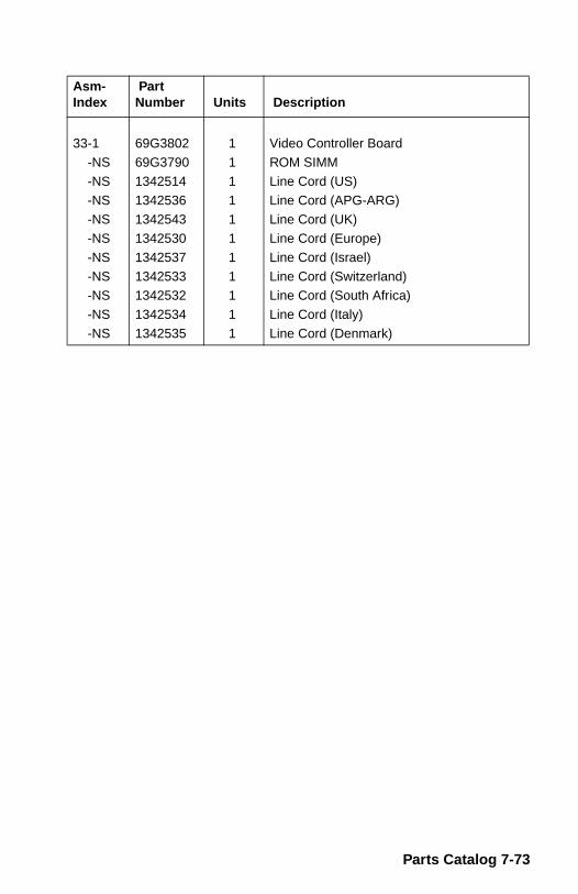
Asm-Index
PartNumber Units Description
33-1 69G3802 1 Video Controller Board
-NS 69G3790 1 ROM SIMM
-NS 1342514 1 Line Cord (US)-NS 1342536 1 Line Cord (APG-ARG)
-NS 1342543 1 Line Cord (UK)
-NS 1342530 1 Line Cord (Europe)
-NS 1342537 1 Line Cord (Israel)
-NS 1342533 1 Line Cord (Switzerland)-NS 1342532 1 Line Cord (South Africa)
-NS 1342534 1 Line Cord (Italy)
-NS 1342535 1 Line Cord (Denmark)
Parts Catalog 7-73

Assembly 34: Optional Paper Feeder (Main Body)
7-74

Asm-Index
PartNumber Units Description
34-1 11A2277 2 Lock Lever Link
-1A 11A2286 2 Link
-2 11A2278 1 Left Cover-3 11A2279 1 Right Cover
-4 11A2280 1 Front Cover
-5 11A2281 1 Rear Cover
-6 11A2282 1 Cover, Open/Close
-7 11A2283 1 Gear Cover-8 11A2284 1 Hinge, Cover Right
-9 11A2285 1 Hinge, Cover Left
-10 11A2287 1 Switch Rod Plate
-11 Screw, PP 11A2331-12 Screw, PP 11A2331
-13 Screw, PP 11A2331
-14 5 E- Ring, PP 11A2373
-15 Screw, PP 11A2331
-16 See “Paper Pickup Asm (Base)” on page7-80
-17 See “Optional Paper Feeder (Front)” onpage 7-76
-18 See “Paper Pickup Asm (Rear)” on page7-82
Parts Catalog 7-75

Assembly 35: Optional Paper Feeder (Front)
7-76

Asm-Index
PartNumber Units Description
35-1 11A2218 1 Roller Assembly
-2 11A2289 1 Spring Collar
-4 11A2291 1 Plate-5 11A2292 1 Crossmember
-6 11A2293 1 Motor Mount
-7 11A2294 1 Paper Feed Roller
-8 11A2295 1 Front Drive Roller Shaft
-9 11A2296 1 Pickup Roller Shaft-10 11A2297 1 Release Roller
-11 11A2298 2 Upper Paper Guide
-12 11A2299 1 Sensor Arm
-13 11A2300 1 Sensor Mount-14 11A2301 1 Right Pickup Frame
-15 11A2302 1 Left Pickup Frame
-16 11A2303 1 Front Roller Asm
-17 11A2304 1 Photo Sensor PCB
-18 11A2305 1 Photo Sensor Cable-19 11A2306 1 Motor
-20 11A2307 1 Solenoid
-21 3 Bushing, PP 11A2379
-22 3 Bushing, PP 11A2379
Parts Catalog 7-77

Assembly 35: Optional Paper Feeder (Front)(Cont.)
7-78

Asm-Index
PartNumber Units Description
35-23 1 Gear, PP 11A2402
-24 1 Gear, PP 11A2402
-25 1 Gear, PP 11A2402-26 1 Gear, PP 11A2402
-27 1 Gear, PP 11A2402
-28 1 Gear, PP 11A2402
-29 1 Gear, PP 11A2402
-30 1 Gear, PP 11A2402-31 1 Gear, PP 11A2402
-32 1 Gear, PP 11A2402
-33 1 Gear, PP 11A2402
-34 1 Spring, PP 11A2364-35 11A2117 1 IC / TPL1320, Sensor
-36 3 Cable Clip, PP 11A2389
-37 1 Cable Clip, PP 11A2389
-38 Screw, PP 11A2331
-39 Screw, PP 11A2331-41 2 Dowel Pin, PP 11A2379
-42 1 Dowel Pin, PP 11A2379
-43 7 E- Ring, PP 11A2373
-44 1 E- Ring, PP 11A2373
-45 Screw, PP 11A2331-46 Screw, PP 11A2340
Parts Catalog 7-79

Assembly 36: Paper Pickup Asm (Base)
7-80

Asm-Index
PartNumber Units Description
36-1 11A2308 1 Paper Pickup Asm Base
-2 11A2309 1 •Cassette Size Sensor Asm
-3 11A2310 1 •Cable-4 11A2311 1 •Power Supply Cable
-5 11A2312 1 •Power Supply PCB
-6 11A2414 1 •Paper Feed PCB
Parts Catalog 7-81

Assembly 37: Paper Pickup Asm (Rear)
7-82

Asm-Index
PartNumber Units Description
37-1 11A2313 1 Paper Pickup Asm Rear
-2 11A2314 1 •Lock Lever, Right
-3 11A2315 1 •Lock Lever, Left-4 11A2316 1 •Rear Roller Asm
-5 11A2317 2 •Roller
-6 11A2318 2 •Roller Holder
-7 2 •Spring, PP 11A2364
-8 2 •Latch Spring, PP 11A2364-13 •Screw, PP 11A2331
Parts Catalog 7-83

Assembly 38: Options
* Standard, works in either slot.
Asm-Index
PartNumber Units Description
1364921 Memory SIMM 2MB1364877 Memory SIMM 4MB
1364876 Memory SIMM 8MB *
1364875 Memory SIMM 16MB
1364874 Memory SIMM 32MB
1364923 Flash Memory 1MB1364922 Flash Memory 2MB
1364879 Flash Memory 4MB
1364873 Hard Drive 40MB
1381856 Hard Drive 100M
1402217 Token-Ring1402218 Ethernet 10BASE T
1446702 Ethernet 10BASE2
7-84

5045-001
Parts Catalog 7-85

Blo
ck W
irin
g D
iag
ram
Atta
chm
ent t
o O
ptra
C 5
045-
001
Ser
vice
Man
ual (
9/95
)

5045-001
Index
AAbbreviations 1-6Adjustments 4-2
Density Adjustment Panel 4-2Attraction Roller Drive 4-3
BBlank Page 2-61Button Test 3-4
CCassette Feed Solenoid 4-64Cassette Paper Pickup
Drive Motor 4-4D-rollers 4-6Roller Asm, Front 4-6Roller Asm, Rear 4-6Solenoid 4-7
Cassette Paper Pickup Asm 4-5Cassette Paper Pickup PCB 4-5Cassette Size Sensing Board 4-64Cleaners 6-2Clutches 5-7Connections
Network 3-21Connector Locations 5-1, 5-14Corona Assembly 4-7Cover Removals 4-8
DDark Image 2-63DC Controller Board 5-17DC Controller Board Information
2-2, 2-3DC Controller PCB 4-14Default Settings 3-5Density Adjustment Panel 4-2, 4-23Density Sensor 4-23Developing Rotary Asm 4-24Device Tests 3-3
Diagnostic AidsBasic Engine Test 3-1Diagnostics Mode 3-2Diagnostics Mode Menu 3-3
Diagnostic Approach 2-1Diagnostic Information 2-1Diagnostics Mode 3-2Diagram, wiring 8-1Dirt On Back Of Paper 2-65Discharge Roller Drive 4-25Disk Test/Clean 3-5Distortion 2-66Drive Gear Solenoid 4-26Drum Cleaner 4-27Drum Lift Asm 4-28
EError Codes
111 Fuser Temp Low 2-15111/112 Fuser Warm-Up 2-15112 Fuser Temp Low 2-15113 Fuser Temp High 2-16114 Fuser Failure 2-16115 Fuser Heater Off 2-17116 Fuser Unit Missing 2-17117 Fuser Pump Failure 2-18121 Laser Board Failure 2-20122 Laser Failure 2-20123 Mirror Motor Rotation 2-21125 Laser Board Failure 2-20126 Transfer Drum Motor 2-22130 Service Motor Error 2-22131 Transfer Drum Motor 2-22132 Main Motor 2-23133 Main Motor 2-23134 Controller Fan Motor 2-23135 Fuser Fan Motor 2-24136 Electrical Fan Motor 2-24141 Power Supply Failure 2-25142 Engine Board Memory 2-25143 Power Supply 2-26144 Humidity Sensor 2-26145 Density Sensor 2-26
X-1

5045-001
Error Codes (continued)146 Communication 2-27147 Engine Board 2-27148 Developer Rotation 2-28149 Developer Pressure 2-29152 Tray 2 Power Failure 2-2946 Cartridge Installation 2-14900 Software Error 2-46941 Service ROM SIMM 2-46944 Service RIP Board 2-46945 Service RIP Board 2-46946 Service RIP Board 2-47947 Service RIP Board 2-47948 Service RIP Board 2-47949 Service RIP Board 2-47950 Service RIP Board 2-48953 Service RIP Board 2-48955 Service RIP Board 2-48956 Service RIP Board 2-48960 Service RIP Board 2-48961 Bad DRAM 2-49970 / 979 INI Failure 2-49977 Service Network Bd 2-49Mirror Motor Rotation 2-21
Error Message Table 2-10ESD-Sensitive Parts 4-1External Covers 4-65
FFeed Roller (Unit 1) 4-65Flash Test 3-6Front Pickup Unit 4-65Fuser Assembly 4-29Fuser Cleaner Asm 4-33Fuser Delivery Asm 4-39Fuser Heaters 5-9Fuser Hot Rollers 4-31Fuser Lamps 4-37Fuser Oil Apply Asm 4-34Fuser Oil Applying Input Asm 4-39Fuser Oil Bottle Case Asm 4-30Fuser Thermo Switch 4-32Fuser/Delivery Unit 2-41
HHardware Tests 3-3High Voltage Converter 4-40High Voltage Power Supply 4-40Horizontal Voids 2-67HV Power Supply Output 2-33
LLAN
Information 3-21Latches 4-2LCD Test 3-7Leading-edge Fold 2-44Low Voltage Power Supply 4-41Lubricants 6-2Lubrication Specifications 6-2
MMain Drive Motor and Board 4-41Maintenance Approach 2-1Maintenance, Customer Checks 6-3Mechanical Controller Board 5-24Mechanical Controller PCB 4-42Memory Tests 3-7Menu Structure
Diagnostics Mode 3-3Message
Error Message Table 2-10Motors 5-9Multi-Feed 2-43Multipurpose Feeder
D-Roller 4-42D-Roller Solenoid 4-43Paper Sensor 4-42U-Turn Roller 4-43
NNetwork Connectors 3-21No DC Power 2-31No Pickup 2-32
OOHP Sheet Detection 2-36Operator Codes 2-5Optional Paper Feeder 4-64
X-2

5045-001
PPage Count 3-7Page Count Tests 3-3Paper Delivery Asm 4-44Paper Feed Roller (Unit 2) 4-66Paper Feed Troubleshooting 2-38Paper Pickup Motor 4-66Paper Sensor Board 4-67Parts
Attraction Roller Drive 7-40Bottom Plate 7-18Cleaning Belt Solenoid 7-28Covers 7-2DC Controller 7-10Density Adjust Panel 7-16Density Sensor Asm 7-64Developing Rotary Asm 7-56Discharge Roller Drive 7-36Door Switch, Lower 7-22Door Switch, Upper 7-20Drive, Main 7-14Drum Lift 7-38Ejector Lever 7-24Fuser 7-68Laser 7-12Major Assemblies (Top) 7-8Major Components 7-4Multipurpose Feeder 7-52Opt Paper Fdr (Front) 7-76Optional Paper Feeder 7-74Paper Drive 7-42Paper Pickup Asm 7-46, 7-80Paper Pickup Asm (Rear) 7-82Paper, Side Exit Asm 7-54Printer Drive 7-32Rotary Manual Feed 7-30Solenoid Plate 7-26Toner Reservoir HV 7-6Transfer Drum 7-60Transfer Drum Clean Drv 7-34Transfer Drum Cleaning 7-66Transfer Drum Mount 7-58Universal Cassette 7-44Video Control Bd 7-10Video Controller Board 7-72
Parts Catalog 7-1PCBs 5-11Permanent Page Count 3-8Pickup / Feed System Theory 2-34Pickup Roller(s) 4-67Pickup Sensor 4-67Poor Fusing 2-69POST - Power-On Self Test 2-8Power Supply 4-67Preventive Maintenance 6-1Print Quality
Background 2-54Black Horizontal Lines 2-54Black Vertical Lines 2-55Blur at Bottom of Page 2-55Laser Failures 2-56Low Color 2-56Random Oil Spots 2-58Service Checks 2-61Solid Color Test 2-53Solid White Test 2-53Spew 2-58Start of Call 2-50Troubleshooting 2-54Vertical Streaks 2-59
Print Quality TestsCartridge End-of-Life 2-50Gradation Test 2-51
Print Quality Troubleshooting 2-54Print Test 1 3-8Print Test 2 3-9Print Test 3 3-9Print Tests 3-3Printer Drive Asm 4-48Printer Setup Tests 3-3Printhead and Printhead Board 4-45
QQuick Disk Test 3-10
X-3

5045-001
RRear Cooling Duct 4-50Rear Cooling Fan 4-49Registration Roller
Does Not Rotate 2-33Registration Roller Drive Clutch 4-4Removals
Attraction Roller Drive 4-3Cassette Paper Pickup
Drive Clutch 4-4Drive Motor 4-4D-rollers 4-6Front Roller 4-6PCB 4-5Pickup Asm 4-5Rear Roller 4-6Solenoid 4-7
Corona 4-7Cover 4-8DC Controller PCB 4-14Density Adjustment Panel 4-23Density Sensor 4-23Developing Rotary Asm 4-24Discharge Roller Drive 4-25Drive Gear Solenoid 4-26Drum Cleaner Asm 4-27Drum Lift Asm 4-28Fuser
Cleaner Asm 4-33Delivery Asm 4-39Fuser Asm 4-29Hot Rollers 4-31Lamps 4-37Oil Apply Asm 4-34Oil Bottle Case Asm 4-30Oil Input 4-39Thermistor 4-35Thermo Switch 4-32
HV Converter 4-40HV Power Supply 4-40LV Power Supply 4-41Main Drive Motor & Board 4-41Mechanical Controller PCB 4-42
Multipurpose FeederD-Roll Solenoid 4-43D-Roller 4-42Paper Pickup 4-42Paper Sensor 4-42U-Turn Roller 4-43
Optional Paper Feeder 4-64Cassette Sensing Bd 4-64Cassette Solenoid 4-64Circuit Board 4-66External Covers 4-65Feed Roller 4-65Front Pickup Unit 4-65Paper Delivery Asm 4-44Paper Feed Roller 4-66Pickup Motor 4-66Pickup Roller(s) 4-67Pickup Sensor 4-67Power Supply 4-67Sensor Board 4-67Separation Roller 4-68
Printer Drive Asm 4-48Printhead and Board 4-45Rear Cooling Duct 4-50Rear Cooling Fan 4-49Rotary Manual Feed Asm 4-49Toner Cartridge Ejector 4-62Transfer Drum
Attraction Roller 4-53Cleaning Drive Asm 4-61Discharge Roller 4-55Front & Rear 4-55Gripper Asm 4-56Holder Asm 4-51HV Contact Asm 4-55Knob Asm 4-52Motors 4-50Sensors 4-58Separation Claw 4-52Sheet 4-54Solenoid 4-57Transfer Drum Asm 4-59
Upper Cooling Fan 4-63Upper Output Drive Asm 4-63Video Controller Board 4-63
Rotary Manual Feed Asm 4-49
X-4

5045-001
SSafety Inspection Guide 6-1Screws 4-2Sensors 5-4Service Checks
Cartridge Installation 2-14Communication Failure 2-27Controller Fan Motor 2-23Dead Machine 2-30Density Sensor Failure 2-26Developer Unit Pressure 2-29Developer Unit Rotation 2-28Electrical Fan Motor 2-24Engine Board IC Failure 2-27Engine Board Memory 2-25Fuser
Failure 2-16Heater Off 2-17Pump Failure 2-18Temp High 2-16Temp Low 2-15Unit Missing 2-17Warm-Up 2-15
Fuser Fan Motor 2-24Humidity Sensor 2-26HV Power Supply Output 2-33Laser Board Failure 2-20Laser Failure 2-20Main Motor
Rotation 2-23Start-up 2-23
Mirror Motor 2-21No AC Power 2-30No DC Power 2-31No Pickup
Cassette Feed 2-32Manual Feed 2-31Option Paper Fdr 2-32
Power Sup 110/220 V 2-25Power Sup 5/24 V 2-26
Print Quality 2-50, 2-61Black 2-61Blank Page 2-62Blank Spots 2-63Color Aberration 2-63Dark Image 2-64Dirt On Back Of Paper 2-65Dirty Print 2-66Distortion 2-67Horizontal Voids 2-67Light Image 2-68Poor Fusing 2-69Spacing Table 2-69Streaking 2-70Toner Scattered 2-71Vertical Lines 2-72Vertical Voids 2-73
Registration Roller 2-33Temperature Sensor 2-26Transfer Drum Motor 2-22Tray 2 Power Failure 2-29
Service Information 4-2Skewing 2-45Solenoids 5-7Spacing Table 2-66Streaking 2-70Switches 5-2Symptom Table 2-12
X-5

5045-001
TTests
Button Test 3-4Compressor 3-4Defaults 3-5Density Adjustment Panel 3-12Disk Test/Clean 3-5Error Log 3-6Flash Test 3-6LAN Information 3-21LCD Test 3-7Memory 3-7Page Count 3-7Permanent Page Count 3-8Print Test 1 3-8Print Test 2 3-9Print Test 3 3-9Quick Disk Test 3-10Wrap Tests 3-11
Toner Cartridge Ejector 4-62Toner Scattered 2-71Tools 1-5Transfer Drum
Assembly 4-59Cleaning Drive 4-61Developer Drive 4-50Discharge Roller 4-55Front & Rear Slide 4-55Gripper Asm 4-56HV Contact Asm 4-55Motor 4-50Sensors 4-58Solenoid 4-57
Transfer Drum and Holder Asm 4-51Transfer Drum Attraction Roller 4-53Transfer Drum Knob Asm 4-52Transfer Drum Separation Claw
4-52Transfer Drum Sheet 4-54Transfer Drum Unit 2-40Troubleshooting
Paper Feed 2-38Print Quality 2-54
UUpper Cooling Fan 4-63Upper Output Drive Asm 4-63
VVertical Lines 2-72Vertical Voids 2-73Video Controller Board 4-63
WWiring diagram 8-1Wrap Tests 3-11Wrinkles 2-44
X-6