colorlj5.pdf - Printer Parts Exchange
228
May 1998 Edition HP Color LaserJet and HP Color Laser Jet 5/5M Printer Quick Reference Service Guide
-
Upload
khangminh22 -
Category
Documents
-
view
2 -
download
0
Transcript of colorlj5.pdf - Printer Parts Exchange

May 1998 Edition
HP Color LaserJet andHP Color Laser Jet 5/5M PrinterQuick Reference Service Guide
Copyright© 1998Hewlett-Packard Co.Printed in USA
Manual Part No.5041-9258
*5041-9258**5041-9258*
5041-9258
HP
Color LaserJet and H
P C
olor LaserJet 5/5M P
rinter Quick R
eference
Printed on at least50% Total Recycled Fiber withat least 10% Post-Consumer Paper


HP Color LaserJet and HP Color LaserJet 5/5M Printer Quick Reference Service Guide

Hewlett-Packard Company11311 Chinden BoulevardBoise, Idaho 83714 U.S.A.
© Copyright Hewlett-Packard Company 1998
All Rights Reserved. Reproduction, adaptation, or translation without prior written permission is prohibited, except as allowed under the copyright laws.
Publication number5041-9258
First edition, May 1998
Warranty
The information contained in this document is subject to change without notice.
Hewlett-Packard makes no warranty of any kind with respect to this information. HEWLETT-PACKARD SPECIFICALLY DISCLAIMS THE IMPLIED WARRANTY OF MERCHANTABILITY AND FITNESS FOR A PARTICULAR PURPOSE.
Hewlett-Packard shall not be liable for any direct, indirect, incidental, consequential, or other damage alleged in connection with the furnishing or use of this information.
Trademark credits
Adobe and PostScript are registered trademarks of Adobe Systems, Inc., which may be registered in certain jurisdictions.
Microsoft® is a U.S. registered trademark of Microsoft Corporation.
MS-DOS® is a U.S. registered trademark of Microsoft Corporation.
UNIX is a registered trademark in the United States and other countries, licensed exclusively through X/Open Company Limited.

Ordering other manuals
This HP Color LaserJet and HP Color LaserJet 5/5M Printer Quick Reference Service Guide has been created to help the HP LaserJet service engineer quickly troubleshoot common printer problems. While this reference is intended to provide information the service engineer will need for on-site repair of HP LaserJet color products, it is not intended to replace the service manual for any HP LaserJet color product. For detailed information about the HP LaserJet color products described in this guide, see the user guide or service manual for that product.
Service manuals for HP LaserJet products are available from Hewlett-Packard. The phone number for the Service Parts Order Desk is:
(800) 227-8164 (U.S. only)
If you are located outside of the U.S., contact your local HP Sales and Service Office. See “Training and support resources” in chapter 9.
Supported products
NoteThis guide will be updated as the service needs change, as new products are introduced, or as information becomes available.
Name used in this guide
Modelnumber
Maximum pages per month
Service manual part number
HP Color LaserJet/HP Color LaserJet 5/5M
C3100AC3961A/C3962A/
30K C3100-90916/C3961-90955
EN iii

Contents
1 Troubleshooting control panel messages . . . . . . . . . . . . . 1
2 Cleaning and maintenance. . . . . . . . . . . . . . . . . . . . . . . 73
3 Service Mode and diagnostics . . . . . . . . . . . . . . . . . . . . 85
4 Media specifications . . . . . . . . . . . . . . . . . . . . . . . . . . . 115
5 Printer options and replaceable parts. . . . . . . . . . . . . . 121
6 Parts and part locations . . . . . . . . . . . . . . . . . . . . . . . . 125
7 Image quality . . . . . . . . . . . . . . . . . . . . . . . . . . . . . . . . 145
8 Wiring diagrams . . . . . . . . . . . . . . . . . . . . . . . . . . . . . . 197
9 Training and support resources . . . . . . . . . . . . . . . . . . 205
A Acronyms and abbreviations. . . . . . . . . . . . . . . . . . . . . 213
iv EN

1 Tcm
EN
roubleshooting ontrol panel essages
Overview
This chapter contains the following sections:
Pretroubleshooting checklist . . . . . . . . . . . . . . . . . . . . . . . . . . . . . . 2
Contains a list of questions to address before troubleshooting printer problems
Basic troubleshooting process . . . . . . . . . . . . . . . . . . . . . . . . . . . . 4
Includes a flowchart that provides help in solving printer hardware problems
Control panel messages . . . . . . . . . . . . . . . . . . . . . . . . . . . . . . . . . . 5
Provides a list of control panel messages along with solutions. Alphabetical messages are listed first, followed by numerical messages. Self-explanatory messages are not included.
Aids to troubleshooting. . . . . . . . . . . . . . . . . . . . . . . . . . . . . . . . . . 61
Provides tools to help isolate the cause of many printer failures, including troubleshooting by part swapping and a self-test printout
Troubleshooting paper feed problems. . . . . . . . . . . . . . . . . . . . . . 68
Provides preventive and troubleshooting techniques for paper and paper path jams
NoteIf you need more detailed information, see the printer service manual.
Overview 1

Pretroubleshooting checklist
WARNING!Always unplug the printer before servicing. Current is present in the main body cooling fan (M4), the noise filter board (Color LaserJet only), the AC driver board (Color LaserJet only), and the DC power supply whenever the printer is plugged in.
Before troubleshooting any specific printer problem, check the following:
• Has the printer been maintained on a regular basis (as described in Chapter 2, “Cleaning and maintenance”)? – Note the location of spilled or accumulated toner before
troubleshooting. Toner contamination may be an indication of another problem.
NoteThe customer is responsible for ensuring that the maintenance units are in good condition.
• Are all of the maintenance units within their rated life?
• Is the customer using media as specified in Chapter 4, “Media specifications” and the HP LaserJet Family Paper Specification Guide?
• Is the media stored correctly and within environmental limits?
• Is the printer installed on a solid, level surface?
• Has the line voltage been checked to make sure that it does not vary more than 20% from the nominal rated value specified on the power rating label?– Large motors used near the printer can cause temporary voltage
changes.
• Is the operating environment within the parameters listed in the printer service manual?
• Is the printer protected from substances such as office cleaning materials and the ammonia gas that is produced by diazo copiers?
2 Chapter 1 – Troubleshooting control panel messages EN

1
• Is the printer protected from direct sunlight?
• Have all non-HP components (toner, typeface cartridges, memory boards, and MIO cards) been removed from the printer?
CAUTIONUsing non-HP components, such as toner, may cause permanent damage to the printer.
• Has the printer hardware or software configuration changed? Or could the problem be associated with any specific software?– Contact the Customer Care Center for software-related problems
(see Chapter 9, “Training and support resources”).
• Could the problem be related to network configuration changes?– Remove the printer from the network and make sure that the
failure is associated with the printer before beginning troubleshooting.
EN Pretroubleshooting checklist 3

Basic troubleshooting process
The troubleshooting flowchart shown below highlights the process that most quickly solves printer hardware problems. During its power-on sequence, the printer verifies that its components are operating correctly. If the printer fails to turn on correctly, use the steps shown in the flowchart to troubleshoot the failure.
NoteUser-accessible parts are blue-coded in the Color LaserJet and purple-coded in the Color LaserJet 5/5M.
Troubleshooting flowchart
4 Chapter 1 – Troubleshooting control panel messages EN

1
Control panel messages
Alphabetical messages
• Remove the cover over the display and look in the upper right-hand corner of the vacuum florescent display (VFD). The dot should be dark. If it is white, the vacuum in the display has been lost. Replace the front panel.
• Turn off the printer. Then unplug and plug in the printer before turning the printer on again.
• Check the 5 VDC on Fuse 1 on the control PCA, as shown in “Voltage checks” in the printer service manual. The 5 VDC may be missing.
• Reseat the display connections.
• Reseat the formatter.
• Check the fuses and connectors and listen for running fans and motors when turning the printer on. – If no fans or motors are running, there is no AC voltage to the
unit.
• Check the voltage at the test connector.
• Replace the formatter.
• Do not interrupt this installation sequence.
• This message is displayed when pressing and holding [Enter] while turning the printer on. When the power-on self-test is completed, the display language menu is available for configuration. This message is not localized.
Blank display
Config language
EN Control panel messages 5

• This message indicates that the printer has detected a new drum and is waiting for the user to enter the number that is printed on the bar-code label on the front of the drum. Press the [+] and [-] keys to enter this information. The number xxx is a whole number between 1 and 127.
NoteThe drum number (or drum ID) should match the number shown on the self-test printout. (See “Understanding the self-test printout” on page 64.)
NoteIf the incorrect number was entered when the Drum inst./drum number = xxx message appeared, it can be corrected now.
• To display this message, press and hold [Form Feed] while power-cycling the printer.
• When the power-on self-test is completed, the error log is available to use. See Chapter 7 in the printer service manual for instructions on entering the Error Log Mode. This message is not localized.
• Use extended diagnostics to test the printer when formatter, memory (DRAM only), and MIO-related errors persist. The extended diagnostics test exercises the ability of the formatter to communicate across the MIO and with the memory. To perform the extended diagnostics tests, see “Extended diagnostics” on page 110.
Drum inst./drum number = xxx
Error log
Extended diagnostics
6 Chapter 1 – Troubleshooting control panel messages EN

1
Color LaserJet only• The font cartridge was removed while the printer was online. – This error occurs whether or not the cartridge was being
accessed. – Power cycle the printer to clear this error.
• This message occurs when NVRAM must be initialized because one or more values are incorrect.
• After the initialization is complete, the printer self-test message appears.
NoteThis message should only appear when the printer is turned on. It should never appear during normal printer operation.
NoteDo not interrupt this installation sequence.
• The new developer sequence has started. – The installation sequence lasts about 3 minutes for the black
developer and 9 minutes for the color developer.
Color LaserJet only
• The printer is not reading some (or all) of the indicated cartridges.– To clear this error, reinsert the specified font cartridge and press
[Online].
• If the message persists, the indicated cartridge is bad and should be replaced.
FE font cart err/cycle power
Initializing NVRAM
Installing new developer
No fonts top/bottom/both font cartridge
EN Control panel messages 7

• Re-enter the drum number for verification. – Press the [+] and [-] keys to change the displayed number. If the
incorrect number was entered when the Drum inst. drum number + xxx message appeared, it can be corrected now.
– This verifies that the correct number was entered.
Color LaserJet only
• Any or all of the font cartridges were removed while the printer was offline and contained buffered data.
• Clear this error by reinserting the specified cartridge(s) and pressing [Online].
• Service Mode is used to test printer functions by issuing commands to the control PCA through the control panel. For more information on this display panel message, see “Accessing Service Mode” on page 87.
Please verify drum number = xxx
Reinsert top/bottom/both font cartridge
Service Mode
8 Chapter 1 – Troubleshooting control panel messages EN

1
Numerical messages
• The paper tray is not installed, or the tray is empty. – Load paper. – Check the paper-size detect board. – Check that the switch actuators (on the tray) are not damaged.
• The paper-out photosensor (PS8) senses an empty tray.
• If paper is in the tray, the sensor arm could be stuck or broken. Troubleshoot PS8 as follows:
1 Remove the paper tray and open the top cover.
2 Check that the paper-size switch actuators on the tray are not damaged.
3 Check that PS8 is free throughout its entire range of travel and is properly located in its mount.
4 Check that connector CN802 (on the controller) is fully seated.
5 If the error persists, perform the PS8 Service Mode Test as described below.
PS8 Service Mode test• PS8, the paper-out photosensor, can be tested in Service Mode as
follows:
1 Enter Service Mode (see “Accessing Service Mode” on page 87) and select the Status Test Mode.
2 Enter the PS8 test address (10) and press [Enter].
3 With no tray installed, the display will read 0 for paper tray empty.
4 Open the printer, lift the paper guide, and move the sensor shaft through its range of motion.
5 The display should change from low to high (0 to 1) as the photosensor is activated. If it does not change, check that the PS8 connector on the high-voltage power supply (HVPS) is fully seated, as shown in the figure below. (The connectors are on the back of the HVPS.)
6 Replace the photosensor.
11.x Front tray empty
11.4 Front tray empty
EN Control panel messages 9

Photosensor PS8 connections on HVPS (HVPS inverted)
• Check that the rear feed unit (RFU) is installed and that it has paper in it.
• Remove the RFU and check that the connector is not damaged.
• Remove and reseat the RFU if paper is present.
NoteDo not remove or install the RFU when the power is on. The printer only checks for the presence of the RFU when the printer is turned on.
11.X Rear tray empty
10 Chapter 1 – Troubleshooting control panel messages EN

1
• The printer’s top or side door is open or the door sensor has failed.– Close the top or side door or replace the door sensor.
• One of the two interlock switches (MS2 or MS3) may be defective. If the following test proves that the switches are defective, replace the interlock switch assembly as shown in Chapter 6 of the printer service manual.
NotePower cycle the printer and re-close both doors to confirm the message before troubleshooting.
Test the interlock switch
WARNING!Do not inhibit the free movement of the interlock switch. If this mechanism is blocked, voltage may be present when the top cover is open.
1 Open and close the top cover. If the message remains, open and close the side door.
2 Open the side door and push the interlock mechanism with a flat-blade screwdriver (see “Testing the interlock switches” on page 7-21 of the service manual), while running test 41 from Service Mode (see Chapter 3).
3 If the message persists, remove the top cover and check that the switch linkage is not bent.
4 Check that the switch connectors are in good repair. Toggle the switches by pressing down on the metal tab over the switches.
5 If the linkage is not damaged, remove the switch assembly and test it with an ohmmeter.
6 Replace the assembly if it is defective.
12 Close top or side door
EN Control panel messages 11

NoteThe locations of all sensors are identified on page 139.
• Paper is detected in the out of limit area of the print drum. The drum-winding jam sensor indicates that paper is beginning to wrap around the print drum.– Turn the paper stack over end-to-end.– Check that the paper meets HP paper specifications for the
printer.– Check that media is not being re-fed into the printer.– Check that the drum-wrap sensor is not blocked by opening the
side door and checking for paper wrapped around the drum.
• If no paper is seen, calibrate the drum-winding jam sensor by entering into Service Mode (see “Accessing Service Mode” on page 87“) and running test 47.
• See “Troubleshooting paper feed problems” on page 68.
NoteThe locations of all sensors are identified on page 139.
• Print media is jammed in the exit assembly because it failed to clear the exit sensor (PS1) in the allotted time.– Check that the sensor flag moves freely and that the sensor is
free of paper dust.– Check that media is not in the sensor when the printer is turned
on.– Test the operation of the sensors by entering Service Mode (see
“Accessing Service Mode” on page 87“) and running test 22.
• See “Troubleshooting paper feed problems” on page 68.
13.1 Clear drum winding jam
13.2 Clear output jam
12 Chapter 1 – Troubleshooting control panel messages EN

1
NoteThe locations of all sensors are identified on page 139.• The printer detects a paper jam in the front tray area.– Clear the front tray area.
• The paper failed to arrive at PS7 within the allotted time after SL1 (the paper feed solenoid) was engaged.– Inspect the input and registration area for media. Transparencies
can be especially difficult to see.– Test the operation of the sensors by entering Service Mode (see
“Accessing Service Mode” on page 87“) and running test 20.
• See “Troubleshooting paper feed problems” on page 68.
• Paper did not arrive at PS1 (exit sensor) in the allotted time. (See the diagram on page 141 for the location of PS1.)– Check that PS1 is free throughout its entire range of travel and
that media is not at the sensor when the printer is turned on.– Check for paper dust in the sensor.– Check to see if media has cleared the registration plate. If media
is present, check the operation of the registration plate solenoid by running test 25 from the status and test section of the printer service manual.
• Check to see if the transfer assembly is installed correctly.
• Test the interlock switch. (For instructions, see the section called “To test the interlock switch” under error message 12 on page 11.)
• See “Troubleshooting paper feed problems” on page 68.
13.4 Clear front tray input jam
13.5 Clear fuser jam (CLJ)13.5 Clear paper jam (CLJ5)
EN Control panel messages 13

• The printer detects paper in the rear input area. – Clear the RFU.
• The sensor (PS4) did not activate within the allotted time after M7 started. (See the diagram on page 142 for the location of PS4.)– Repair the sensor. – Check that PS4 is not blocked.
• Sensor PS4, the RFU paper sensor, failed to detect paper media within the allotted time.– Check that the sensor is not stuck.– Check if media has been picked from the tray.
• Verify that the RFU is properly adjusted for the loaded media.
• See “Troubleshooting paper feed problems” on page 68.
NoteThe locations of all sensors are identified on page 140.
• The printer detects a paper jam at the rear input area. This message indicates that the paper was picked, but did not arrive at the registration area (PS7), in the allotted time.– Clear the jam and check the paper feed rollers.– Check that sensor PS4 is not defective and that it is free
throughout its travel.
• See “Troubleshooting paper feed problems” on page 68.
• Paper is jammed in the paper registration area. – Open the printer and remove the jammed paper.
• Paper may be on PS7 when the printer is turned on. (See the diagram on page 141 for the location of PS7.)– Check that PS7 is free.
• See “Troubleshooting paper feed problems” on page 68.
13.6 Clear rear tray input jam
13.7 Clear rear tray paper jam
13.8 Clear paper jam
14 Chapter 1 – Troubleshooting control panel messages EN

1
• Media was detected in the printer during warm up.– Open the top cover and clear any media found inside the printer.– If no media is found in the printer, check all sensors by running
the tests described under error messages 13.1, 13.2, 13.4, and 13.5.
• Verify that all paper path sensors are not blocked and that the detection flags are free throughout their travel.
• See “Troubleshooting paper feed problems” on page 68.
• Remove the toner collection box from the OPC drum assembly and inspect the flexible diaphragm (in the top surface of the collection box). – If the diaphragm has been pushed above the collection box
surface by accumulated toner, the box is full. In this case, the collection box must be replaced. Do not attempt to push the diaphragm down to correct this condition.
• The excess toner collection box is monitored by PS3. (See the diagram on page 141 for the location of PS3.) Perform the sensor checks below to isolate the problem.
Toner collection box full sensor tests1 Power cycle the printer.
2 Open the top cover and lower the print drum.
3 Pull the toner collection box out of the drum assembly.
4 Verify that the toner-full flag is moving freely (it should raise up as you are pulling the toner collection box out of the assembly and drop down once the collection box is removed).
5 Check to see if the toner collection box is full. If the toner collection box is full, the diaphragm will be pushed out. If it is pushed out, then the collection box is full and needs to be replaced.
13.8 Internal paper jam during warm-up
14.5 Replace collection box16.5 Replace collection box
EN Control panel messages 15

CAUTIONDo not try to continue using the toner collection box by pushing the diaphragm down.
6 Check that the PS3 sensor is fully seated, clean, and connected properly. (See the diagram on page 141 for the location of PS3.)
If these tests are not effective, perform the PS3 Service Mode test described below.
NoteIf the collection box is overfilled, the printer may need a thorough cleaning. In addition, the excess toner auger (inside the print drum) may be compacted or broken. The print drum may have to be replaced.
PS3 Service Mode test
NoteThe PS3 sensor flag is not accessible to toggle by hand. You must have an empty collection box to perform this test.
1 Power cycle the printer and enter the Service Mode (see “Accessing Service Mode” in Chapter 3.)
2 Select the status and test Mode of the Service menu.
3 Enter the PS3 test address (55), and press [Enter].
4 Install the empty collection box. If the display is high (1), the sensor is stuck or defective.
5 If the display is low (0), pull out the collection box about an inch to make the sensor flag rise. If the display does not change from 0 to 1, the sensor flag is stuck or broken or the sensor (PS3) is dislodged or defective.
6 Check connector CN904 on the toner sensor PCA (Color LaserJet only).
16 Chapter 1 – Troubleshooting control panel messages EN

1
• If this message does not clear when the coating pad kit is replaced,the fusible link in the coating pad may not be contacting the leaf spring in the fusing assembly or a coating kit with a blown fuse has been installed.– Reseat the coating pad.
Color LaserJet only
• If a new style fusing assembly with a purple handle has been installed, then the fusible-link contacts are not making proper electrical contact with the contact fusing spring assembly.– Reseat the cleaning roller.
CAUTIONThe printer should continue to print when returned online. The fuser and main drive may be damaged if the oil pad and cleaning roller are not replaced as soon as possible.
• See “14.5 Replace collection box.”
• The printer failed to detect either the black developer (for the 17.1 message) or the color developer (for the 17.2 message).– If the developer is not installed, install it.
1 Power cycle the printer.
2 If the message persists, remove the suspected developer and inspect the blade connectors that insert into the toner sensor PCA. Check that they are clean and straight. Also check the toner sensor PCA connectors.
3 Re-install the developer.
14.6 Replace coating kit
16.5 Replace collection box
17.1 Install developer17.2 Install developer
EN Control panel messages 17

Toner sensor PCA connections (circled)
4 Check all the connectors on the toner sensor PCA. Ensure that they are all fully seated.
5 Check the wiring behind the power supply drawer for nicks or cuts that may cause the signal line to short to ground. Reseat the connectors if any are suspect.
6 Replace the toner sensor PCA if necessary.
7 If steps 1 through 6 do not resolve the problem, replace the developer.
• The fuser is not installed, or the printer failed to detect the fuser.
1 Power cycle the printer.
2 If the message persists, remove and reseat the fuser.
3 Check that the fuser connectors are not damaged (no bent or broken pins).
4 Check that nothing prevents the fuser from fully seating into its plug.
5 Check the connector (CN105) at the control PCA.
17.4 Install fuser
18 Chapter 1 – Troubleshooting control panel messages EN

1
6 Replace the fuser.
7 Replace the control PCA if necessary.
• The toner collection box or the print drum is not installed or is not detected. The switches that post this message are inside the print drum cartridge and cannot be tested directly.
1 Power cycle the printer to clear the message.
With the printer turned off and unplugged, inspect the print drum connector (see the figure under “17.8 Reinstall drum”). Ensure that the connections are not bent and that both the male and female ends are in good repair and clean.
2 Ensure that nothing inhibits the print drum from fully seating into the connection.
3 Check that CN101 on the control PCA and CN 254 on top of the developer bias supply are fully seated.
4 Reseat the collection box and listen for an audible click.
5 If the collection box does not click into place, the leaf spring inside the housing may be defective. Replace the print drum.
6 Remove the drum and very carefully clean the inside of the sensor, using a cotton swab and isopropyl alcohol.
7 Re-install the drum.
17.6 Install collection box
EN Control panel messages 19

• The protective shipping cover for the print drum has not been removed.– Remove the drum cover (see the printer service manual for
instructions) or clear the drum wrap sensor.
• If the error persists, perform the status and test checks (see the printer service manual) to test the drum wrap sensor.
• If the error still persists, perform the drum reflectance calibration (Service Mode status and test address 47). Also see the procedures for the 66.1 Jam sensor service message.
• This message indicates that the drum-winding sensor output is abnormal during printing (see 66.1 Jam sensor error message).
• A jam sensor could be broken or defective, or a connection could be loose.
1 Remove the print drum and inspect both sides of the connector as shown in the “Print drum connector” figure below.
2 Re-install the print drum. Check that nothing prevents the print drum from being fully seated into the printer.
NoteIf the drum assembly is for a Color LaserJet 5/5M (the assembly will be purple-coded), you will need to make sure the corona cleaning lever on the drum is fully seated to the right.
3 Power cycle the printer.
4 Run test 47 in Service Mode (see Chapter 3 for information on accessing Service Mode).
5 Replace the drum cartridge assembly.
17.7 Remove drum cover
17.8 Reinstall drum
20 Chapter 1 – Troubleshooting control panel messages EN

1
Print drum connector (circled).
• The fuser did not warm up correctly. – Reseat the fuser.
• The fuser connection is not stable.
WARNING!The fuser is HOT. Turn off the printer to allow the fuser to cool for at least 30 minutes before beginning this procedure.
– Power cycle the printer to clear the message.
• If the message persists:– Remove the fuser. Check that all the connectors are straight and
clean.– Reseat the fuser, being certain that all the connectors make
contact.
• If the message persists, replace the fuser.
17.9 Reinstall fuser
EN Control panel messages 21

• The paper-charging brush or the bias roller in the transfer assembly is arcing. – Power cycle the printer.– Clean the transfer corona wire (see Chapter 2, “Cleaning and
maintenance”).– Check connector CN701 on the control PCA and connector
CN702 on the HVPS.– Replace the transfer assembly and try another test print.– Replace the HVPS.
• The printer sensed a high-voltage leak in the print drum neutralizing corona. – Power cycle the printer to clear this error.– Remove and reinstall the print drum. Try a test print.– Check connector CN731 on the control PCA and connector
CN730 on the HVPS.– Check the neutralizing corona contact for damage or
contamination. (see the “Neutralizing corona contacts” figure below.)
– Replace the print drum.– Replace the HVPS.
• The neutralizing corona may have arced. – Clean the printer.
18.1 Clean transfer corona wire
18.2 Reinstall drum
22 Chapter 1 – Troubleshooting control panel messages EN

1
Neutralizing corona contacts (circled)
• The printer detected a high-voltage leak in the developer bias power supply. (Although this is a developer bias fault, the print drum is often the root cause of this failure.)
• The developer is not turning.
1 Remove each developer and check their pin contacts.
2 Check that each of the high voltage contacts on the developer bias assembly is clean and located correctly.
3 Print several self-tests and look for repetitive defects. Replace the print drum if repetitive defects appear.
4 Remove the print drum and check its surface for any bright metallic spots, dents, or defects that may indicate an arcing point (anywhere in the green area). Replace the print drum if any defects are found.
5 Check CN601 on the developer bias supply and CN600 on the control PCA.
6 Try a test print.
18.3 Reinsert developers
EN Control panel messages 23

• If the message persists, replace the print drum followed by the color developer and the black developer if necessary.
7 Replace the developer bias power supply.
• There is a high-voltage leak in the transfer belt, print drum, or HVPS. – Power cycle the printer.
NoteIf the problem will not repeat dependably, print transparencies in color. Transparencies print at a slower speed with a higher transfer current.
• Clean the transfer corona (see Chapter 2, “Cleaning and maintenance”).
• Check that the print drum contacts are clean.
• Remove the transfer belt assembly and print a test page.
• If a 13.x Paper jam message appears when printing without the transfer assembly installed, the high-voltage leak is associated with the transfer assembly. – Check the transfer assembly contacts for proper alignment,
corrosion, etc. before replacing them.
• If the error persists, reseat the print drum. Then replace the print drum followed by the HVPS if necessary.
18.4 Clean transfer corona
24 Chapter 1 – Troubleshooting control panel messages EN

1
Note18.5 Reinsert developers is for black developers.18.6 Reinsert developers is for color developers.NoteDo not replace developers until the actual cause has been identified. Replace the developers only if they are proven defective.
• The printer does not sense the changing output from the toner concentration sensor that occurs with normal toner movement within the developers.– The developer is not selected.– The developer drive gears are not engaging the developer.– The developer drive gears do not rotate.– The developer is not rotating.
• Reinsert the developer.
NoteIf new developers are installed in the printer, toner compaction may cause the toner concentration sensor to give an abnormal reading. Remove the new developer, shake it as described in Chapter 4 of the printer service manual, and reinstall.
• Perform the following procedure to troubleshoot the 18.5 and 18.6 message:
1 Remove the developers and check that the drive and gears are not worn and that no teeth are missing.
2 Remove the developer assemblies and print drum. Move the top cover up and down. Check that the developer drive gears extend and retract and are free throughout their travel. With the top cover partially closed, press each developer drive gear and check that each has firm spring pressure.
3 Rotate the gears on each developer assembly by hand (this requires some force). Check that they all have similar resistance. If the gears will not turn, replace the developer.
4 Shake the developer as shown in chapter 4 of the service manual. Toner may be compacted inside the developer.
18.5 Reinsert developers18.6 Reinsert developers
EN Control panel messages 25

5 Examine the connectors on the developer and the toner sensor PCA for damaged pins or connectors.
6 If symptoms still persist, follow the procedures listed below.
Service Mode tests• Use Service Mode to check that the developers are rotating. This
test is especially useful because the status Mode displays the toner concentration value while the developer augers rotate. To perform this test, follow the steps below.
CAUTIONDo not perform this test with the RFU installed. Performing this test with the RFU installed and the toner hopper cover removed will damage the toner feed augers.
1 Enter Service Mode (see “Accessing Service Mode” in Chapter 3).
2 From the Status and Test Mode, select address 08.
3 Select subtest 0 for the 18.5 message, or address 1, 2, or 3 for the 18.6 message. Once selected, press [Online] to start the test. When the test starts, the control panel displays the toner concentration value for the selected developer. If the developer drive gear rotates, the toner concentration sensor value displayed on the control panel should fluctuate slightly.
4 If the gears do not rotate, check the developer rotation as follows:
A Remove the RFU, if installed.
B Remove the toner hopper cover.
C Run the Service Mode test again.
D Watch the developer drive gears at the rear of the printer. They should turn when the test is started. Make sure you are looking at the developer drive gear and the developer gear during this test. (The black drive gear is the most difficult to see.)
E If the gears do not rotate, perform the mechanism alignment checks.
5 If the gears rotate and the toner concentration sensor value does not fluctuate, check the electrical connections between the developer and the control PCA.
26 Chapter 1 – Troubleshooting control panel messages EN

1
6 If the electrical connections are OK, replace the toner sensor PCA.
7 If the message persists, replace the developer.
Mechanism alignment checks• Misalignment between the developer drive assembly, the toner
hopper assembly, and the printer frame may cause 18.5 and 18.6 errors. Check the following items for alignment when troubleshooting this error.
1 Remove the developer and check to see if the developer casing is bent. To do so, follow these instructions:
A Place the developer on a flat surface with the back of the developer toward you.
B Push the developer forward inside the casing.
C If the developers do not move forward until the bias contact pin is against the casing on the left side, the casing is bent.
D Replace the developer assembly.
5 The printer frame has detents that position the developer drive assembly correctly on the printer frame. Ensure that the assembly is properly seated on these detents. Improper seating will misalign the developer drive assembly with the developers and the toner hopper assembly. If misaligned, loosen the screws, align the developer drive assembly on the detents, and then tighten the screws.
6 The developer drive assembly aligns with the toner hopper assembly through an alignment pin located on the developer drive assembly. Check that the alignment pin is straight and that the toner hopper is fully seated. If the alignment pin is bent, replace the developer drive assembly.
7 If the alignment pin is not damaged, remove the screws that hold the toner hopper in place, and then:
A Slide the toner hopper towards the left side of the printer (to the right when viewed from the rear of the printer).
EN Control panel messages 27

B Check the gear cluster on the toner hopper for bent sheet metal. If the toner hopper select shaft is out of its bushing or if the bush-ing is not mounted correctly in the sheet metal, the sheet metal may be bent. If the gear cluster is damaged, replace the toner hopper assembly.
C Check to see if the activation arms for the toner hopper lockout fingers are against the select cams. If the arms are on the cams, check the toner hopper lock solenoid (SL6), located on the left side of the toner hopper, for binding and correct operation.
D If the toner hopper assembly is functioning correctly, slide the assembly back into position. Align it with the developer drive assembly being careful not to damage the gear cluster. Reinstall the toner hopper screws.
• A printer consumable has exceeded its maximum life. Press [Online] to continue. The printer will continue to print, but print quality will degrade until the indicated consumable is replaced.
CAUTIONThe main drive gears could become damaged if the fuser is allowed to remain past its maximum life in the printer.
• If the indicated consumable has been replaced:
1 Reseat the consumable.
2 Check both sides of the connector for bent pins.
3 Power cycle the printer.
4 Verify that the fuse for the consumable is not blown. The drum, developers, transfer, fuser, and coating kit are fused. If the fuse is blown when a new consumable is installed in the printer, the consumable will not be detected as a “new” part.
NoteDo not return a consumable to stock once the fuse is blown.
5 Try another of the indicated consumables.
6 Check the self-test print for any value that is inconsistent with the perceived actual cumulative usage. If a value is suspect, investigate the possibility of a NVRAM problem. If necessary, contact your local response center.
19.x User maintenance
28 Chapter 1 – Troubleshooting control panel messages EN

1
• More data has been received from the host than fits in internalmemory. – Press [Online] to continue printing. Only the data that fits in
printer memory is printed.
• If the message persists, install more memory.
• The printer has run out of memory. Imaging the current job cannot continue until the engine clears memory. – Press [Online] to clear memory. This results in data loss.
• If this error persists, install additional memory.
• The computer is not obeying the pacing mechanism of the MIO link. This causes the printer’s receiving buffer to overflow during a busy state.
• The MIO card cannot accept data. – Print the self-test page for more information. – The MIO card could be defective.
• If the message persists, reseat the MIO card and ensure it is properly connected to the network. If necessary, replace the MIO card.
20 Memory overflow
21 Memory out
22 I/O config error
23 MIO not ready
EN Control panel messages 29

• The printer is adding toner to the developers. If this message is displayed frequently, check for faint print. If several pages of heavy toner coverage are being printed, this message may not indicate an error. If the message persists, the toner feed auger may not be turning or a toner sensor may be defective.
1 Power cycle the printer.
2 Check the toner level in the toner hopper assembly by manually opening each hopper. If any of the hoppers are completely empty, the toner sensor for the empty hopper may be defective. Use the Service Mode status and test (address 01) to test the toner level sensors.
NoteThe toner sensors on the hoppers are piezo-electric. When the toner falls below the level of the sensor, the sensor output is audible. However, the high-pitched sound may be out of hearing range for some people.
3 If the hoppers have enough toner to cover the sensor, and the message persists, check the toner hopper auger operation as follows:
A Remove the RFU.
B Manually open the hoppers and watch the paddles while printing the demo page.
C If the paddles turn, the problem is in the hopper augers. Replace the toner hopper assembly.
D If the paddles do not turn, print the demo page 10 times. Watch that the toner hopper supply shaft rotates, that the hopper select shaft engages the hopper clutch, and that the toner supply augers turn.
E If the toner supply shaft does not rotate, perform the toner supply solenoid test as described below.
24 Busy moving toner
30 Chapter 1 – Troubleshooting control panel messages EN

1
Toner supply solenoid test
Test the toner supply solenoid (SL3) and supply augers as follows:
1 Enter the Service Mode (see “Accessing Service Mode” in Chapter 3) and select test address 52.
2 Remove the RFU and the back cover. Listen for the solenoid to actuate.
• The printer encountered a PostScript error indicated by XX. – Press [Online] to continue. The current job is canceled.
NoteFor PostScript errors, look at the program that is being sent, rather than at the printer unless every PostScript file comes up with the same error.
• An attempt was made to add an item to a dictionary that is full. This may be a driver incompatibility problem. – Select a different PostScript driver and resend the print job.
• An attempt was made to place too many dictionaries on the dictionary stack. This may be a driver incompatibility problem.– Select a different PostScript driver and resend the print job.
• An attempt was made to remove more dictionaries from the dictionary stack than were available. This may be a driver incompatibility problem. – Select a different PostScript driver and resend the print job.
30 PostScript error xx
30 PostScript error 00
30 PostScript error 01
30 PostScript error 02
EN Control panel messages 31

• The execution stack is too large. Procedure invocation is nested deeper than PostScript allows. This may be a driver incompatibility problem.– Select a different PostScript driver and resend the print job.
• An attempt was made to access an array, dictionary, file, or string object incorrectly.
• An incorrect exit was executed.
• An incorrect access string specification to the file operator occurred.
• The operand to make font or set font is not a well formed font dictionary.
• An incorrect restore was attempted.
• An error occurred during the execution of one or more of the file operators.
• A PostScript implementation limit was exceeded.
30 PostScript error 03
30 PostScript error 04
30 PostScript error 05
30 PostScript error 06
30 PostScript error 07
30 PostScript error 08
30 PostScript error 09
30 PostScript error 10
32 Chapter 1 – Troubleshooting control panel messages EN

1
• An operator requiring a current point was exceeded while thecurrent path was empty.
• A numeric operand’s value is out of range.
• An attempt was made to push too many objects on the operand stack.
• An attempt was made to pop an item from an empty operand stack.
• The PostScript scanner encountered text that does not conform to the PostScript syntax rules.
• The PostScript interpreter timed out waiting for the user to manually feed paper, waiting for data from the computer, or because a job took too long to complete.
• An operand was encountered that is not the correct type, such as a number when a string is required.
• A name was encountered that cannot be found since it was previously undefined.
30 PostScript error 11
30 PostScript error 12
30 PostScript error 13
30 PostScript error 14
30 PostScript error 15
30 PostScript error 16
30 PostScript error 17
30 PostScript error 18
EN Control panel messages 33

• A file identified by a name string operand of the file or run operators cannot be found or opened.
• An overflow, underflow, or meaningless result of a numeric calculation (such as division by zero) occurred.
• A clear-to-mark or count-to-mark operator could not find the required mark on the stack.
• An operator object was executed for which the interpreter has no built in action.
• An error occurred in virtual memory.
• The systemdict quit operator was executed causing the PostScript interpreter to re-initialize virtual memory. All non-persistent information was lost.
• A PostScript firmware failure occurred. This is associated with normal error handling and not with hardware.
• A “setpagedevice” request cannot be satisfied.
30 PostScript error 19
30 PostScript error 20
30 PostScript error 21
30 PostScript error 22
30 PostScript error 23
30 PostScript error 24
30 PostScript error 25
30 PostScript error 26
34 Chapter 1 – Troubleshooting control panel messages EN
1
• An external interrupt request was received by the PostScriptinterpreter.
• A named resource sought by the findresource operator does not exist.
• A data error has occurred while receiving data from the computer. Press [Online] to continue printing. Check the connection between the printer and computer.
• The printer does not recognize the language it is being switched to.– This message remains in the display until it receives a valid
language.
• The printer senses that the fuser temperature is incorrect for the application. The voltage read at the upper fusing roller thermistor momentarily exceeded the limit. Leave the printer on for 20 minutes (this gives the internal clock time to count down and reset) and then power cycle the printer to clear this message. This message can also be reset by going into the service Mode, register adjust, and setting address 47 to 00. If the message persists:
• Check that the fuser connector is in good repair (no bent or broken pins).
• Open and close both doors during the warm-up period. If the message appears immediately, replace the fuser.
• Make certain the fuser can be fully seated into the printer and that toner has not accumulated around the fuser area.
30 PostScript error 27
30 PostScript error 28
40 I/O data error
48 Invalid job/aborting job
50.x Fuser service
EN Control panel messages 35

• Check the connectors on the fuser, and check the connectors in the printer that interface with these fuser connectors.
• Check connector CN105. CN105 is labeled on the control PCA. (See the main wiring diagram in Chapter 8).
• Replace the fusing assembly.
• The fuser temperature is too high for the application. – Leave the power on for 20 minutes while the printer counts down,
then power cycle the printer to clear this error or use address 47 in the register adjust section of the Service Mode to reset this message.
– Check the fuser connections.
• The fuser temperature is too low for the application. – Leave the power on for 20 minutes while the printer counts down,
then power cycle the printer to clear this error or use address 47 in the register adjust section of the Service Mode to reset this message.
– Check the fuser connections.
• The fuser temperature sensor is open. – Leave the power on for 20 minutes while the printer counts down,
then power cycle the printer to clear this error or use address 47 in the register adjust section of the Service Mode to reset this message.
– Check the fuser connections.
50.1 Fuser service error
50.2 Fuser service error
50.3 Fuser service error
36 Chapter 1 – Troubleshooting control panel messages EN

1
• There is a fuser temperature error caused by erratic sensor values.– Leave the power on for 20 minutes, and then power cycle the printer to clear this error or use address 47 in the register adjust section of the Service Mode to reset this message.
• This error indicates a failure to read the NVRAM on the control PCA. To troubleshoot this problem:
1 Power cycle the printer.
2 If for some reason the NVRAM was removed from its socket, ensure that there are no bent pins and that they are all in their correct position.
3 If the error persists, contact your local response center for assistance in evaluating NVRAM viability.
• A developer with a blown fuse is being installed into a new printer.
• The NVRAM data could be corrupt. – The printer checks an address in NVRAM for the status of the
engine. If the status returned is new, then the printer checks the developers to see if the fuses are new (closed). If the fuses have been blown, then the 52.2 error is displayed. To check if the fuses are blown on the developers use an ohmmeter across pins 5 and 6 on the color developer, and pins 4 and 6 on the black developer (see the main wiring diagram in Chapter 8). (Pin 1 is at the bottom of each connector.) If either developer has a blown fuse, replace the developer.
• If the printer is new, replace the developer. If the printer is not new, troubleshoot as 52.1 Engine NVRAM error.
50.4 Fuser service error
52.1 Engine NVRAM error
52.2 Engine NVRAM error
EN Control panel messages 37

• The printer has detected a laser diode error. – Power cycle the printer.
• If the error persists, reseat connectors CN300 and CN101. (See Chapter 8, “Wiring diagrams” for the locations of these connectors.)
• If the connectors are in good repair, replace the laser scanner assembly.
• The laser signal is unstable.
1 Press [Online] to continue.
2 Power cycle the printer.
3 Open, then close the side door.
4 Check the side door interlock.
The engine reported one of five types of failures or errors as listed below. Try to clear the errors by pressing [Online]. If the message persists, perform the appropriate procedure described below for the applicable 54 error message.
• The scanner motor (M6) did not reach the correct speed in the allotted time. – Power cycle the printer.
• If the motor spins up and the error persists, perform the following procedure.
1 Check CN104 and CN350 on the optics assembly.
2 Inspect the wires behind the power supply drawer for nicks or cuts on the insulation.
3 Measure the 24V DC.
53 Laser error
53 Laser error/service
54.x Engine error/service error
54.1 Engine error/service
38 Chapter 1 – Troubleshooting control panel messages EN

1
4 Replace the laser scanner assembly.
5 Replace the control PCA.
• The printer detected an error in the 24V DC supply. – Power cycle the printer to clear the error.
• If the error persists, check the 24V DC line.– If the 24V DC voltage is missing, replace the DC power supply.
NoteThe actual measured voltage should be approximately 22V DC.
• A defective or misaligned interlock switch can also cause this error.– Use a screwdriver to push the interlock mechanism in the
direction shown in the printer service manual, page 7-21, Figure 7-4.
• If the message clears, adjust the tab on the side door which operates the interlock mechanism.
• If the message persists, turn off the printer and check the interlock mechanism, connectors, and cabling.
• Check fuse F5 on the DC power supply and fuse F2 on the control PCA.
NoteDo not replace any developers until the cause of the error is identified. Replacing developers without identifying the cause of the error will only mask the problem and could lead to another service call from the customer.
• A toner concentration error occurs when the toner concentration sensor reading is at a minimum or maximum value. This error can be caused by:– a defective toner concentration sensor– failure of the toner hopper sensor or toner supply mechanism– too much or too little toner in the developer
54.2 Engine error/service
54.3 Engine error/service
EN Control panel messages 39

– a defective toner sensor PCA– incorrect NVRAM values. Incorrect NVRAM values can be
caused by:
• not installing the correct NVRAM on the control PCA
• installing the NVRAM incorrectly
• a defective NVRAM
• installing a used developer.
Incorrect NVRAM values usually cause too much toner to be delivered to the developer. Failure of the toner hopper sensor or toner supply mechanism is usually associated with not enough toner being delivered to the developer. To determine the cause of this error follow the steps below:
1 Power cycle the printer.
2 Run several self-test pages to see if the error returns. You should be able to print at least one self-test page before the 54.3 error message reappears.
3 If the error returns, look at the self-test page and check for faded or bold colors.
4 If a color looks faded, the problem will most likely be associated with a defective toner hopper sensor or the toner supply mechanism. If any color looks bold, then too much toner may have been added to a developer.
5 To identify which developer is reporting the error, run the toner concentration test shown below. A value of 127 or 63 on the front panel is an indicator for the developer reporting the error.
6 See “Faint print” on page 157 for the procedure to troubleshoot a problem with faded print.
7 If a color looks bold on the self-test page, the problem can be caused by one of the following:
– an incorrect NVRAM value– the wrong NVRAM was installed on the control PCA– a developer, which is not the most recent one to be initialized by
the printer, has been installed
40 Chapter 1 – Troubleshooting control panel messages EN

1
• The NVRAM values correspond to the last developer that was initialized in the printer. Even if the developer currently installed was initialized in the printer, if it was not the last developer initialized, the NVRAM values are not correct.
8 If the wrong developer was installed, reinstall the correct developer.
9 If the wrong NVRAM was installed, reinstall the correct NVRAM.
10 If the correct NVRAM or the correct developer(s) is not available, a new developer(s) must be initialized in the printer.
11 For other NVRAM associated problems, contact your local response center.
Toner concentration test
NoteThe toner concentration test is useful whenever the printed page displays characteristics of having either low toner concentration or high toner concentration. The procedures to correct low and high toner concentration are discussed later in this chapter.
1 Print a self-test page and note the relative humidity reading.
2 Power cycle the printer and enter the Service MODE (see “Accessing Service Mode” in Chapter 3). Select the Register Adjust function of the Service Mode (see Chapter 3 for instructions on the register adjust function) to obtain the data values contained in the NVRAM addresses listed below.
NVRAM addresses
Color Black Yellow Magenta Cyan
Address 30 29 28 33 32 31 36 35 34 39 38 37
DataExample:
AA00
BB16
CC23
AA00
BB08
CC28
AA00
BB08
CC28
AA00
BB08
CC15
Pagecount
AABBCC AABBCC AABBCC AABBCC
EN Control panel messages 41

3 Press the [Form Feed] and [Reset] keys to select the desired NVRAM address. When the desired NVRAM address is displayed, press [Enter] to display the value held at that address. For example, if the displayed NVRAM address is 29 and the value held at that address is 18, then the display will read: Current Value
029 ReadOnly 18
Record the address and the value it contains. To clear this display and toggle back to Enter Address xxx, press [Enter] again. Repeat this procedure until the NVRAM values for all of the addresses in the “NVRAM addresses” table have been obtained and recorded.
4 The current cumulative page counts for each of the developers can now be constructed from the data you have obtained. See the following examples:
Examples:
Address: 30=00, Address 29-16 and Address 28-23. The black page count is 001623.
Address 33=00. Address 32=08 and Address 31=28. The yellow page count is 000828.
Address 36=00. Address 35=08 and Address 34=28. The magenta page count is 000828.
Address 39=00. Address 38=08 and Address 37=15. The cyan page count is 000815.
NoteDo not use the black and color page counts from the self-test page (these counts indicate the total cumulative page counts for the printer, which are usually different than the page counts for the developers).
5 Power cycle the printer and enter Service Mode again. Select the status and test function from the Engine Service Status/Test Mode.
6 Follow the Status and Test Mode flow charts (pages 88 and 90 until you come to the Enter Address AB display. Press [Form Feed] several times to increment to AB = 08 (see the toner concentration values table on page 43).This sets the system to select test number 08 (developer rotation).
42 Chapter 1 – Troubleshooting control panel messages EN

1
7 Press [Enter] to display: Enter Subset #
08 0
Enter the value of the subset # that is appropriate for the developer; select the number from the target toner concentration table below.
8 Press [Enter] to display:Online to Start
AB x YYY
When [Online] is pressed, the developer will rotate and updated values of YYY will be displayed. After allowing the rotation/update to run for at least 30 seconds, record the YYY value that is being displayed. While the rotation/update is in progress, the following message displays:Reset to Cancel
AB x YYY
Make sure to record the displayed YYY value for the appropriate developer. Press [Reset] to end the rotation/update.
9 Use the following table to convert the number displayed on the control panel to the actual concentration value.
Toner concentration values
10 Using the Internal Humidity reading from the self-test page and the page count for the developer (from NVRAM), locate the target toner concentration value for each developer from the target toner concentration table.
11 If the toner concentration value (derived from step 10) is more than 12 points lower than the target value, then the toner concentration in the developer is too low. If the toner concentration value is more than 12 points higher than the target value, then the toner concentration value is too high. Try the following techniques for correcting low or high toner concentration problems.
Displayed value ( YYY) Actual toner concentration value
Less than 64 Same as displayed value
64 or larger 64 minus the displayed value
EN Control panel messages 43

Correcting toner concentration levels
Low toner level
Effective resolution of a low toner concentration problem requires correction of the root cause. Here are some likely causes:
• Poor distribution of the toner mix in the developer cartridge at the time of its initial use in the printer.– It is possible that shipment or storage of the developer resulted in
some toner/carrier segregation. This can result in erroneous calibration of the toner-concentration sensor when the new developer is initialized in the printer. Toner/carrier segregation can result in toner-rich compaction in the concentration-sensor zone. This presents a worst-case condition for sensor calibration error. Properly shaking new developer before initialization, as prescribed in the installation instructions and in the user guide for the printer will usually prevent this condition. Correcting an improper initialization is not practical. If print quality is noticeably deficient, replace the developer.
• Use of a replacement developer that has not been properly initialized in this printer.– This can cause a toner concentration error. Short-term use of a
previously initialized developer for troubleshooting is acceptable, but the original (properly initialized) developer should be reinstalled after troubleshooting is completed; otherwise, install a new developer.
• Compaction of toner in the replenishment mechanism (auger assembly or feed-in port).– This can result in toner depletion.
• Empty auger tubes.– If service efforts have resulted in replacing the toner hopper
assembly, the toner auger tubes may not have been filled. To correct this problem:
1 Use Test 19 in Service Mode to unlock the hoppers.
2 Fill the hoppers with toner, if necessary.
3 Manually rotate (downwards) the large white gear on the side of each hopper to fill the auger tubes. Do this while holding the auger tube shutter open at the developer end of the auger tube with something in place to catch any toner that escapes, such as a tissue or index card.
44 Chapter 1 – Troubleshooting control panel messages EN

1
• Incomplete toner fill in the auger tubes.– Ensure a complete toner fill in the auger tube associated with
any developer (which has been revealed by the Toner Concentration Test). This can be accomplished in the manner described above (step 3).
• Incomplete toner concentration test.– After completing any corrective action(s) for low toner
concentration, such as described above, run the Toner Concentration Test again. Remember, it takes some time for the replenished toner to be uniformly distributed through the developer; the test should be allowed to run for at least 30 seconds before making the front panel reading (YYY value). If the resulting YYY value is in the range 000 to 100, the printer will return to normal toner concentration on its own during regular operation. If it “errors out” or if the displayed value is greater than 100, manually feed toner (step 3, above) and repeat the Toner Concentration Test. Failure to improve toner concentration values with these measures may indicate failure of the toner concentration detection circuitry or the toner replenishment mechanisms. Installation of a new developer may appear to correct the problem, but if the detection system, replenishment system, or both are malfunctioning, the problem can return.
High toner level• Recovering from this toner condition is not as easy as recovering
from a low toner level. It is important that the root problem for this condition has been clearly identified; otherwise, the problem will be masked for only a short time and the original problem will eventually occur again.
1 Print a solid fill page for the color generating the error. Continue to print this page until the error no longer appears.
2 If far too much toner is in the developer, the developer will need to be replaced.
EN Control panel messages 45

Target toner concentration
Target toner concentration
Developercount
Relative humidity
20% or less 20-29% 30-39% 40-59% >60%
K YMC
K YMC
K YMC
K YMC
K YMC
>0 4 4 3 3 2 2 2 1 2 0
>40 8 8 6 6 4 4 4 2 4 0
>80 12 12 9 9 6 6 6 3 6 0
>120 15 15 11 11 8 8 8 4 8 0
>160 18 18 13 14 9 9 9 5 9 0
>230 21 21 15 16 11 10 11 6 11 0
>310 24 24 17 18 12 12 12 6 12 0
>400 27 27 19 20 14 13 14 7 14 0
>500 30 30 22 23 16 14 16 8 16 0
>650 33 33 24 25 17 16 17 9 17 0
>800 36 36 26 27 19 17 19 9 19 0
>1000 39 39 28 29 20 19 20 10 20 0
>1250 42 42 30 32 22 20 22 11 22 0
>1500 45 45 32 34 23 22 23 12 23 0
>1750 48 48 35 36 25 23 25 12 25 0
>2000 50 50 38 36 26 24 26 11 26 0
>2750 47 47 34 35 24 23 24 10 24 0
>3500 44 44 32 33 23 21 23 9 23 0
>4250 41 41 30 31 21 20 21 8 21 0
>5000 38 38 27 29 20 18 20 6 20 0
>5750 35 35 25 26 18 17 18 4 18 -2
>6500 32 32 23 24 17 15 17 2 17 -4
46 Chapter 1 – Troubleshooting control panel messages EN

1
• A pressure cam home position sensor (PS2) error has occurred. The pressure cam did not sense the home position within 4 seconds after the initial rotation of the pressure cam. – Power cycle the printer.
• The cam sensor (PS2) did not detect home position. This message can also occur with general printer disassembly involving the control PCA or the developer bias supply. – Since PS2 is located on the back of the developer bias supply,
make sure it is reconnected if the developer bias supply was removed. (See page 139 for the location of PS2.)
– Make sure that the connector (CN802) on the control PCA is fully seated.
>7000 28 28 20 21 16 13 16 0 16 -6
>7500 28 28 20 18 15 12 15 -2 15 -8
>8000 28 28 20 18 15 10 14 -4 14 -10
>8500 28 28 20 18 15 8 13 -6 13 -12
>9000 28 28 20 18 15 8 12 -6 12 -14
>9500 28 28 20 18 15 8 11 -6 11 -16
>10000 28 28 20 18 15 8 10 -6 10 -18
>14000 28 28 20 18 15 8 9 -6 9 -20
54.4 Engine error/service
54.4 Cam home position sensor
Target toner concentration (continued)
Developercount
Relative humidity
20% or less 20-29% 30-39% 40-59% >60%
K YMC
K YMC
K YMC
K YMC
K YMC
EN Control panel messages 47

• Other symptoms include the following:– complete or partially blank pages– smeared vertical line on the front of the page– smeared toner image on the back of the page
NoteThis message might appear as a result of the drive gears being installed incorrectly causing a loss of cam timing. Follow the cam timing procedure in Chapter 6 of the printer service manual to correct the cam timing problem.
• To troubleshoot the 54.4 message:
1 Open the top cover and locate the tab that activates the AC interlock switch. The tab is located to the right and below the black developer and is part of the developer drive assembly. If the tab is bent, bend the tab until it is aligned with the plunger.
2 If the tab is straight, turn the printer on while checking the 24V DC at the test connector, which is located on the rear of the printer.
NoteThe actual measured voltage will be approximately 22V DC.
3 If no voltage is present, check the interlock switches on the left side of the printer and verify that they are working correctly. Replace the switch mechanism if defective.
4 If the switch mechanism is okay and the voltage does not reach 22V when the printer is turned on, replace the DC power supply.
5 If the DC voltage is OK, remove the right-side cover and watch the AC motor (M2) to see if it turns as you turn on the printer.
6 If M2 does not turn, turn off the printer and unplug the power cord. Disconnect the connector to M2 and connect a voltmeter.
WARNING!With the printer turned on, there is 120/240V AC at this connector. Do not cross the leads of your meter or touch them with your hand. Doing so will cause damage to the printer or result in electrical shock.
7 Plug the power cord into the printer and turn the printer on. Watch to see if the AC voltage is supplied.
48 Chapter 1 – Troubleshooting control panel messages EN
1
8 If power is available replace M2.
9 If no power is available, replace the AC power supply in the Color LaserJet or the DC power supply in the Color LaserJet 5/5M.
10 If the power supply does not solve the problem, follow the procedures for the cam service Mode test to verify that the sensor is operating correctly.
11 Run test 53 in service Mode to verify that the solenoid is operating. You should be able to hear when the solenoid turns on or off. Replace the solenoid if defective. A good solenoid should have a resistance value of approximately 56 ohms.
12 If the solenoid is okay when the resistance is measured and everything else noted above has been checked, replace the control PCA.
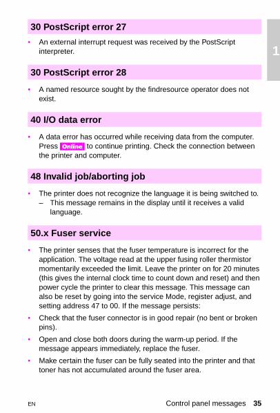
Cam Service Mode test1 Enter the status and test section of the Service Mode (see
“Accessing Service Mode” in Chapter 3).
2 Select address 51.
3 Open the top cover, remove the print drum, and release the cam solenoid (SL4), as shown in the figure below.
4 Turn the gear train slowly, and watch the control panel display. The status display will change from 000 to 001 when the cam home sensor is activated.
If the home sensor reading does not change, check the following:
• The developer bias supply is fully seated.
• The cam home sensor is mounted in the printer frame correctly.
• The sensor connector is in good repair.
• If all of the above are okay, replace the sensor PS2. (See page 141 for the location of PS2.)
• When checking the cam home solenoid, run a demo page. With the top cover removed, check that the solenoid releases. If it does not, replace solenoid (SL4) and its clutch, and then check the cam timing as shown in Chapter 6 of the printer service manual.
EN Control panel messages 49

Releasing the pressure cam home solenoid
• A developer home position sensor (PS6) error has occurred. The developing switch position sensor did not detect the home position within 4 seconds after the initial motion of the pressure cam.
• The printer failed to detect the developer cam home position within 4 seconds after the initial rotation of the pressure cam.
• The sensor (PS6) is defective. (See page 141 for the location of PS6.)
NoteIf this message occurs after general printer disassembly around the control PCA, the sensor PS6 may be disconnected. See chapter 5 under “Sensors” in the printer service manual to locate PS6, and check that it is plugged in both at the sensor and at the control PCA (CN802).
54.5 Engine error/service
54.5 Developer home position sensor
50 Chapter 1 – Troubleshooting control panel messages EN

1
54.5 Service Mode test1 Select the Service Mode Status and test address 51 and check that
the developer drive motor rotates.
2 If the developer drive motor (M2) does not rotate, check the connectors. If the connectors are proper and M2 still does not rotate, replace M2.
3 If the developer drive motor rotates, use the status Mode test (50) to test the developer home sensor. (It may be necessary to turn the gear train by hand to activate this sensor.) The display changes from 00 to 01 when the sensor is activated.
4 If the sensor does not activate, check that the sensor is properly connected at both ends.
5 If the connections are correct and the sensor is properly mounted, replace the sensor, PS6.
• All 55.X messages indicate that the formatter and the control PCA have failed in some aspect of their communication. When troubleshooting this message:– Reseat the formatter into its connector and perform a test print.– If the message persists, remove the formatter, and check that
none of the formatter connector pins are bent or broken. (This is not a probable cause if the control PCA or formatter have never been removed.)
– Check the 5V fuse on the control PCA. If the fuse is blown, attempt to determine why the fuse blew, then correct the condition.
– If the message persists, replace the formatter, followed by the control PCA if necessary.
55.X Engine CMD error
EN Control panel messages 51

• The printer failed to register the beam detect pulse, or the beam detect pulse is missing.
1 Power cycle the printer to clear this error.
2 Check the wiring harness behind the power supply drawer for nicks and cuts.
3 Wrap with insulation tape to prevent the wires from grounding.
4 If the error persists, replace the laser scanner assembly, followed by the control PCA if necessary.
5 Reseat all the connectors to the laser scanner assembly.
• The laser index pulse is absent.– Open and then close the side door and power cycle the printer.
• There is a cooling fan error. – One of the cooling fans is not connected.– One of the cooling fans is defective.
• Either the main body fan, formatter cooling fan, DC power supply fan, or fuser cooling fan is not running or is running at an incorrect speed. – Power cycle the printer to clear this error. If the error persists:
• Reseat all fan connectors on the relay board.
• Ensure that the wiring harness is in good condition, and that the wires are fully seated into the connector.
• Check that nothing inhibits the fan rotation.
• Replace the defective fan assembly.
NoteThe formatter cooling fan and DC power supply fan are only for the Color LaserJet.
56 Laser index service
57 Fan motor service error
52 Chapter 1 – Troubleshooting control panel messages EN

1
• The RFU was removed or installed while the power was on.– Power cycle the printer to clear this error.
• The RFU was installed or removed while the printer was turned on.– Power cycle the printer to clear this error.
CAUTIONInstalling or removing the rear feed unit with the printer turned on may damage the electronics within the unit.
• If the message persists after power cycling, replace the RFU.
• Check the blade connectors on the RFU and inspect their matching connectors on the printer. Check that the pins are straight and that none of the connectors are damaged. If the printer has been disassembled, ensure that none of the wires are damaged (pinched).
NoteThe 60.X through 63.X Service errors occur only during the power-on sequence.
• The firmware detects a bad CRC (cyclical redundancy check) in a SIMM. (The bad SIMM is indicated by the X.) The printer completes its power-on sequence without initializing (and therefore using) the defective SIMM, but uses all base RAM and usable SIMMs. The 60.X message appears in the display when the power-on sequence is complete. Full memory capability is not available.
• Multiple ROMs (such as two PostScript ROMs or two Epson ROMs) have been installed. Troubleshoot this message as follows:
1 Power cycle the printer to clear this error.
2 If the error persists, reseat the indicated SIMM and try to print.
3 Replace the indicated SIMM.
59 Manual feed service error
59 Alternate feed service
60.X SIMM error/SIMM service error
EN Control panel messages 53

– If the SIMM is detected when the printer is turned on, the bad SIMM can be ignored.
4 Replace the formatter.
• The size or speed of the SIMM that is installed is incompatible with the formatter. If this SIMM is detected when the printer is turned on, the printer does not use the incompatible SIMM, but uses all base RAM as well as usable SIMMs. The 61.X message appears in the display when the power-on sequence is complete. Full memory capability is not available. Troubleshoot this message as follows:
1 Power cycle the printer to clear this error.
2 If the message persists, reseat the indicated SIMM and try to print.
3 Finally, if the message persists, replace the indicated SIMM with a compatible SIMM.
• A checksum error has occurred in the ROM. The X indicates which ROM generated the error. If x=0, the error is in the code ROMs. If x=1, the error is in the lower 4M ROMs. If x=2, the error is in the upper 4M ROMs. Power cycle the printer to clear this error. If the error persists, replace the formatter. The individual ROMs are not replaceable.
NoteIndicate the failure Mode on the return slip when exchanging the formatter PCA.
• This message indicates an error in the internal ROM. – Power cycle the printer to clear this error.
• If the error persists, replace the formatter.
61.X SIMM compatibility
62.x Internal ROM service
62 Internal ROM service error
54 Chapter 1 – Troubleshooting control panel messages EN

1
• This message indicates the printer detected an error in the baseDRAM. – Power cycle the printer to clear this error. – If the error persists, replace the formatter PCA.
• When this error message is displayed, pressing any control panel key displays more information about this error
NoteIndicate the failure Mode on the return slip when exchanging the formatter PCA.
• This message indicates a faulty SIMM expansion memory module.
• If the error occurs when the printer is turned on, press [Continue].
• If this error occurs after the printer is turned on, unplug the printer and remove the defective SIMMs as indicated by the control panel display.
NoteWhen a SIMM expansion card is removed, the printer can continue to operate, but may not be able to print all jobs that require greater memory. The printer still uses the base memory plus all the installed SIMMs.
• The printer has detected a video direct access error. Power cycle the printer to clear this error. If the error persists:
1 Run the job that caused the error, then wait about 3 minutes for the timeout to repeat.
2 If the error message reappears, run a self-test, and wait another three minutes. If the message persists, reseat, then replace the formatter PCA, followed by the control PCA, if necessary.
3 If no error appeared after running the job, run the error log to see the occurrence rate.
63.0 DRAM service error
63.X SIMM error
64.X DMA timeout service error
EN Control panel messages 55

4 If the error occurs frequently:
– Reseat, then replace the formatter.– Check the 5V DC line for noise.– Check the 5V DC voltage at the control PCA.– Replace the control PCA, if necessary.
• The printer detected a video DMA error.– Power cycle the printer to clear the error.
• If the error persists, run the extended diagnostic test to determine the cause. See “Extended diagnostics” on page 110.
Drum reflectance calibration procedure• The printer must initially and periodically calibrate the electronics
against the value of print drum reflectance. The sensor on the jam detect PCA senses media wrapping on the drum and the value of print drum reflectance. The print drum reflectance changes over time. False jams may occur if the print drum reflectance is not recalibrated. This message occurs when the printer calibrates the print drum reflectance during new drum installation, or during the course of normal, periodic print drum recalibration. To troubleshoot this error:
1 Power cycle the printer and enter the Service Mode (See Chapter 3).
2 Enter test code 47 and press [Enter]. The printer will begin the drum calibration process.
3 If the message persists after performing the drum reflectance calibration, the drum reflectance is out of specification. This may be caused by a faulty yellow developer. Ensure that a solid yellow strip is being deposited on the drum during the calibration process.To do so, interrupt the calibration process by opening the cover while the printer is turned on to inspect the yellow calibration strip on the drum.
4 Clean the drum-wrap sensor as described below.
5 Replace the print drum.
66.1 Jam sensor service error
56 Chapter 1 – Troubleshooting control panel messages EN

1
• An abnormal drum-wrap value was detected while the sensor was being calibrated. – Clear this error by reinstalling the drum, or power-cycling the
printer.
Cleaning the drum wrap sensor• The drum-wrap sensor may be cleaned if necessary. Perform this
task only if the printer has become dirty from a neglect of periodic maintenance.
CAUTIONBe careful not to damage the print drum. To prevent scratching, place the print drum on the cleaning cloth provided in the collection kit. Also, do not blow on the print drum.
1 Remove the print drum from the printer and place it on the cleaning cloth provided in the collection kit.
2 Place a sheet of paper between the print drum and the sensor.
3 Remove the screw located at the top of the print drum.
4 Remove the print drum neutralizing corona housing.
5 Release the sensor board from its retainers, being careful not to damage the print drum.
6 Ensure that connectors CN970 and CN971 are fully seated.
7 Use the toner cloth provided in the toner collection box kit to clean the sensor.
NoteRun the reflectance calibration service Mode status and test (address 47) procedure after cleaning the drum-wrap sensor.
EN Control panel messages 57

• A recoverable error has been detected in the formatter NVRAM.– Press [Online] to clear the error, then verify the control panel
settings. One or more of the control panel settings may have been reset to the factory defaults during error recovery.
• Run the extended diagnostics test before replacing any components. See “Extended diagnostics” on page 110.
• Replace the formatter if the error occurs whenever the printer is turned on.
• A general formatter NVRAM failure has occurred. – Power cycle the printer to clear the error.
• If the error persists, run the extended diagnostic tests to determine the cause. See “Extended diagnostics” on page 110.
• This message refers to the formatter NVRAM, not the NVRAM chip on the DC controller board.
• All of the control panel values have been reset to their factory defaults. If this message appears whenever the printer is turned on, part of the formatter NVRAM is defective.– Check that the [Online] key is not stuck. If the [Online] key is okay,
replace the formatter.– Run the extended diagnostics tests before replacing any
components. See “Extended diagnostics” on page 110.– If the message persists, replace the formatter.
68 NVRAM error
68 NVRAM service error
68 Cold reset
58 Chapter 1 – Troubleshooting control panel messages EN

1
• If this error is associated with a specific job, there could be a defectin the software code that created the job. – Run a self-test to check that the error is not generated by the
printer. If the error is isolated to the user’s print job, refer the user to the software manufacturer.
• An unrecoverable error occurred in the formatter PCA firmware.– Run the extended diagnostic tests to get more information about
this message. Then, power cycle the printer to clear this error.
• Replace the formatter if the error persists.– Be sure to include the failure code which accompanied the
message on the control panel when returning the formatter.
NoteIt is extremely rare that a formatter causes a 79 Service error.
• This error indicates that an unrecoverable MIO error has occurred. The XXX meaning is listed in the technical reference manual that came with the MIO card. – Power cycle the printer to clear this error. – If the error persists, replace the MIO card.
NoteRun the extended diagnostic tests before replacing any components. See “Extended diagnostics” on page 110. Be sure to put the entire error code (including the numbers in parentheses) on the return slip when returning the MIO card. Also, be sure to include the failure code which accompanied the message on the control panel when returning the MIO card.
79 Service error
80 Service
EN Control panel messages 59

• An unrecoverable error occurred in the PostScript SIMM. – Power cycle the printer to clear this error.
• Run the extended diagnostic tests before replacing any components. See “Extended diagnostics” on page 110.
• If the message persists, replace the PostScript SIMM.– Be sure to include the failure code which accompanied the
message on the control panel when returning the PostScript SIMM.
89 Service
60 Chapter 1 – Troubleshooting control panel messages EN

1
Aids to troubleshooting
Troubleshooting by swapping partsThe printer records the age of most of the user-replaceable maintenance units. All new maintenance units (except the toner collection kit) have fusible links. When a new maintenance unit is installed, the printer senses its fusible link and blows the fuse. The control PCA resets the counter for the maintenance unit to zero. When the developers or print drum are replaced, the control PCA restarts the page-dependent firmware algorithms which control the printer operating point. Also, when the print drum is replaced, the drum-winding sensor is calibrated.
The fusible links and the associated firmware algorithms affect service and troubleshooting strategy as follows:
• The maintenance units cannot be removed and used as a new unit in another printer.
• If a new maintenance unit is installed, the control PCA resets its counters and determines the optimum operating point for the installed unit. If another unit with no fusible link (such as a print drum or developer from another printer) is installed, the operating point will not be correct. The correct operating point is especially critical for the print drum and developers.
Swapping partsThe following procedures use maintenance units known to be in good working condition to help troubleshoot maintenance units problems. Ensure that the original (or a new) maintenance unit is installed after performing each procedure. Do not leave a test unit installed.
EN Aids to troubleshooting 61

Print drumA test print drum, which has the fusible link already blown, can be installed to verify failures such as repetitive print defects. Do not print more than 50 pages with the test drum. The test print drum may cause 13.1 CLEAR DRUM WINDING JAM errors. If this occurs, use the Service Mode status and test address 47 to calibrate the drum-winding sensor. It is necessary to recalibrate this sensor when installing the original drum. If the print defect is confirmed and a new print drum is installed, the drum-winding calibration process is automatically performed as part of the installation algorithm. Do not leave the test print drum installed after troubleshooting.
DeveloperA test developer in which the fusible link has already blown can be used to troubleshoot print problems such as white lines. Do not print more than 50 pages with the test developer. If the print defect is shown to be unrelated to the developer, be sure to reinstall the original developer. If the defect is related to the original developer, use the installation procedures shown in Chapter 4 of the service manual to install the new developer. Do not leave the test developer installed after troubleshooting.
Transfer belt, fuser, and coating kitTest units in which the fusible link has already blown can be installed briefly to verify print defects. Do not print more than 200 pages with these units. If a print defect is not verified, reinstall the original unit. If a defect is verified, replace the defective unit as described in Chapter 4 of the service manual. Do not leave the test components installed after troubleshooting.
62 Chapter 1 – Troubleshooting control panel messages EN

1
Voltage checks
The illustration below shows the most readily accessible voltage test points of the printer.
Voltage test points
CAUTIONBe careful not to damage the printer when inserting test probes in the connector.
NoteThe actual voltage measured for 24V will be approximately 22V.
9 118 1026 19
PGND+5V
+24V
Pin #22Pin #8Pin #20
EN Aids to troubleshooting 63

Understanding the self-test printout
PCL self-test page (Color LaserJet)
(See the table on page 67 for a description of the numbered elements.)
12 3
4
5
6
7
8
11
10
9
12
64 Chapter 1 – Troubleshooting control panel messages EN

1
PostScript self-test page (Color LaserJet 5/5M)
(See the table on page 67 for a description of the numbered elements.)
1 2 3
4
5
6
78
12
11
EN Understanding the self-test printout 65

PCL self-test page (Color LaserJet 5/5M)
(See the table on page 67 for a description of the numbered elements.)
1 2 3
4
5
6
7
8
9
11
66 Chapter 1 – Troubleshooting control panel messages EN

1
Self-test page elements
1 Printing menu: Shows the configuration of the print menu.
2 Config menu: Lists the current printer configuration.
3 Parallel menu: Lists the configuration for the parallel I/O port. This is not the same as the MIO configuration. The advanced functions feature enables the bidirectional I/O.
4 Consumable life: Lists the percent of the maximum life used by each of the printer maintenance units. use this section when performing printer maintenance, and when deciding how to troubleshoot specific printer failures. The consumable counters show how many of each maintenance units have been installed in the printer throughout its life.
5 MIO configuration: Shows the configuration of the MIO.
6 Installed memory and page count: Displays the memory recognized by the printer, and the page count. Black pages and color pages are listed separately. Add the numbers to get the total page count.
7 Serial number and firmware datecode: The serial number is used when replacing the formatter PCA. If possible, run the self-test page before replacing the formatter. The firmware datecode is used by HP to identify the printer’s program level.
8 Options: Shows the installed and recognized optional printer components.
9 Print test pattern: (displayed on PCL self-test page only) Tests the print drum for random defects.
10 REt setting: (displayed on Color LaserJet self-test page only) Shows the current REt setting. Use the lines to adjust the REt setting such that the horizontal and vertical lines match. Inaccurate REt settings cause horizontal and vertical bands in the lines.
11 Color bars: Demonstrates that each of the primary and process colors are enabled.
12 Internal humidity: Shows the humidity inside of the printer as read by the internal humidly sensor.
EN Understanding the self-test printout 67

Troubleshooting paper feed problems
Paper problemsPaper problems can be difficult to detect. The following series of steps will help isolate paper-induced problems versus printer problems:
• Isolate a paper path.
• Isolate a brand of paper.
• Isolate a type of paper.
• Evaluate paper-use practices.
• Evaluate environmental conditions.
Here are some simple tips:
• Turn the paper over and print on the other side. Doing so often corrects excess paper curl.
• Rotate the paper 180° (end-to-end) to feed a different leading edge. This can help correct multi-sheet feeding problems.
Paper jamsWhen troubleshooting paper jams, remember that jams are posted as a result of timing errors. That is, paper fails to arrive at (or fails to clear) the paper path sensor in the allotted time. The paper path timing is set by the control PCA. Stuck or defective sensors will cause the paper path timing to post a jam message when the printer is turned on, as will scraps of paper caught in the paper path. See the figure on page 69 to locate the paper path sensors. The paper jam message code identifies the sensor which failed to change state within the required time.
NoteCheck that the paper path sensors are free throughout their full range of travel. All interlock switches must be operational in order for the printer to clear paper jam messages.
68 Chapter 1 – Troubleshooting control panel messages EN

1
Paper path sensors
• Check that the transfer corona cleaner is pushed all the way to the right. Paper jams occur when this knob is out of place.
• Clean the printer. Toner and paper dust in the paper path inhibit free movement of media through the printer and block the sensors.
• Vary the input and output selections of the printer to determine if the problem is associated with a particular area of the printer.
• Worn separation pads on the paper tray cause last page multifeeds. Check the condition of the pickup rollers and separation pads when troubleshooting multifeeds. Bent separation tabs cause misfeeds and multifeeds. Replace the tray if necessary.
1 Manual feed sensor (RFU) 5 PS8 paper out sensor (main tray)
2 Paper-out sensor (RFU autofeed) 6 Drum wrap sensor board
3 RFU paper in path sensor 7 PS1 paper exit sensor
4 PS7 paper registration sensor
1
3
4
5
67
2
EN Troubleshooting paper feed problems 69

• Defective paper tray switches may cause paper jams by indicating the wrong size paper to the formatter.
• Scraps of paper left in the paper path may cause intermittent paper jams. Always check that the paper path is clear when cleaning the printer and when clearing paper jams. Also, remove the fuser and carefully check it for jammed paper.
• If the optional RFU is installed, check that the paper is loaded correctly. Check that the correct paper size is selected and that the paper is not slumped.
• Curl on the trailing edge of transparencies is caused by improper face-up output bin position. Make sure the face-up output bin is pulled out all the way. It tilts up slightly when in its proper position.
Reduce curl of black-only transparencies by printing to the face-up output bin and by keeping the transparencies in a presentation sleeve.
CAUTIONDuplexing (printing on both sides of the page) is not supported and could damage the printer. Duplexing causes paper jams at the input and exit areas.
70 Chapter 1 – Troubleshooting control panel messages EN

1
Multifeeds from the front input tray
• Check that the media meets the specifications for this printer. Rough paper and lightweight media multi-feed more frequently.
• Ensure that the media is not sticking together in the paper stack.
• Check the condition of the media. Look for damaged paper or ragged edges.
• Check the paper stack tabs in the paper tray (see Figure 7-17 on page 7-68 in the service manual). Replace the paper tray if the tabs are bent or burred.
• Check the paper-size adjustment lever to ensure it is snug against the media without pinching.
• Check that the media is fully under the paper stack tabs. Do not overload the paper tray. The paper tray can hold approximately 250 sheets of 20-pound paper (a 1-inch stack).
EN Troubleshooting paper feed problems 71

Feed problems from the rear feed unit (RFU)
• Check that the media meets the specifications for this printer.
• Check that the RFU is not overloaded. The RFU can hold 250 sheets of 20-pound paper (a 1-inch stack).
• Check the paper-size adjustment for the rear input tray and the manual feed input.
– The guides should be snug against the media without pinching.– The paper adjustment knob for the rear input tray should be set
for the correct media before the media is loaded. If necessary, fine adjustments can be made after the media is in the tray.
• Check that media is not slumped forward in the rear input tray. The top cover or the rear tray must be fully opened when loading media.
• Check that the media is neatly stacked in the rear input tray.
• When manually feeding, push the media slightly into the pickup roller nip, especially when using legal and tabloid size paper.
• The pickup rollers should be cleaned with a cloth moistened with isopropyl alcohol.
72 Chapter 1 – Troubleshooting control panel messages EN

2 Cm
EN
leaning andaintenance
Overview
This chapter gives information on cleaning and maintaining the printer, and on identifying consumables.
Overview 73

Cleaning locations and tool
The following illustration shows the areas of the printer that require periodic cleaning and the location of the provided laser optics cleaning tool.
Areas that require periodic cleaning
* New style drum (C3967A) only.
1 Toner hopper area 4 Laser optics cleaning tool
2 Laser optics glass 5 Transfer corona wire
3 Drum corona wire *
1
2 3
54
74 Chapter 2 – Cleaning and maintenance EN

2
Regular maintenance procedures
Overall print quality largely depends on keeping critical components of the printer clean. Some of the more sensitive printer components need to be cleaned regularly (approximately every 2,000 pages) to ensure the highest possible print quality. Use the procedure that follows to clean these three components:
• optics glass
• drum corona
• transfer corona
CAUTIONRemove all jewelry and watches before continuing. The drum can be easily scratched, causing damage. Do not expose the print drum to direct light for extended periods. Exposure to light can permanently damage the drum.
1 Press the top cover release button (1) and open the top cover (2).
1
2
EN Regular maintenance procedures 75

2 Pull the drum lock lever at the left edge of the drum toward you. Lower the drum until it is horizontal.
CAUTIONBe careful not to contaminate the cleaning tool pad with the oil from your hands or other contaminants.
3 Locate the laser optics cleaning tool.
4 Insert the cleaning tool above the drum with the padded portion down and towards the glass, and with the cupped portion against the chrome rod (1). Press the pad on the cleaning tool firmly against
1
76 Chapter 2 – Cleaning and maintenance EN

2
the right end of the optics glass. Slide the cleaning tool to the left side of the printer, and then slide it back to the right. Repeat several times, then return the cleaning tool to its storage place.
5 Find the drum cleaning handle located toward the back-right corner of the main drum.
6 Slide the cleaning handle slowly and smoothly to the left end of the drum and completely back to the right home position. (This
EN Regular maintenance procedures 77

procedure should take approximately 3-5 seconds.) Repeat as necessary.
7 Raise the drum until it locks into place.
NoteThe drum corona cleaning handle is only on the new style drum (C3967A).
CAUTIONBefore closing the printer, be sure that the drum corona cleaning handle and transfer corona cleaning knob are reseated in thefull-right position.
8 Locate the transfer corona cleaning knob located between the transfer belt and the fuser on the right side of the printer.
CAUTIONDo not touch the transfer belt surface. Oil from your hands and debris can reduce the life span of the belt and affect print quality.
9 Slide the cleaning knob slowly and smoothly to the left end of the drum and completely back to the right home position. (This procedure should take approximately 3-5 seconds.) Repeat as necessary.
78 Chapter 2 – Cleaning and maintenance EN

2
10 When you add toner, clean the toner reservoir area. Add toner only when prompted by a control panel message.
• Push the optional rear feed unit away from the printer. Then open the toner reservoir cover and use the cover to hold the rear feed unit away from the printer.
• With the cleaning cloth from the toner collection kit, wipe off any dust or toner on the area between the individual toner doors.
CAUTIONDo not drop excess toner into the manual feed area. Toner in the manual feed area can result in manual feed problems.
• Close the toner reservoir cover.
• Return the optional rear feed unit to its upright position against the back of the printer.
EN Regular maintenance procedures 79

Replacement of maintenance units
The printer prompts you from the control panel when it is time to replace a maintenance unit. The following table lists the approximate time intervals for replacing maintenance units. For proper printer operation, use only HP maintenance units. (See Chapter 8 in the service manual.)
* This time period assumes you are printing 2,000 pages per month. If your print quantities differ, adjust the time period accordingly.
** Approximate page count based on 5% coverage of individual toner colors
*** HP Color LaserJet printer
**** HP Color LaserJet 5/5M printer
***** The page count for the drum increments once for every standard black and white or monochrome page and twice for each multiple color page, legal, tabloid, or A3-size page.
Approximate replacement intervals
Unit Printer message Page count** Time period*
Toner TONER OUT [CMYK] ADD [color] 2200 pages 1 to 2 months
Toner collection box filter
14.5 REPLACE COLLECTION KIT Varies with toner usage.
4 to 6 months
Coating pad, cleaning roller
14.6 REPLACE (CLJ)*** COATING PAD KIT
Varies with toner usage.
4 to 6 months
Coating roller, cleaning roller
14.6 Replace Coating Kit (CLJ5/5M)****
Varies with transparency usage
4 to 6 months
Black developer
19.1 BLACK DEVEL. USER MAINTENANCE
40,000 pages 15 months
Color developer 19.2 COLOR DEVEL. USER MAINTENANCE
40,000 pages 15 months
Transfer belt 19.5 TRANS BELT USER MAINTENANCE
60,000 pages 30 months
Fuser 19.4 FUSER USER MAINTENANCE
80,000 pages 40 months
Print drum 19.3 DRUM USER MAINTENANCE
60,000 pages***** 30 months
80 Chapter 2 – Cleaning and maintenance EN

2
Identifying consumables
The following illustration shows the location of the consumables.
Consumable locations (CLJ 5/5M)
* The toner collection box and ozone filter are included in the collection kit.
** The cleaning roller and coating roller are included in the coating kit.
1 Color developer 4 Coating roller** 7 Fuser
2 Print drum 5 Ozone filter** 8 Transfer belt
3 Toner collection box *
6 Cleaning roller 9 Black developer
1
2
3
4
5
6
789
EN Identifying consumables 81

NoteDo not install an old-style coating pad kit into a new style fuser. See the “Supplies compatibility” table on page 83.
NoteAll original maintenance items for the HP Color LaserJet printer have blue handles and tabs that indicate user access or lift points. With the exception of the toner area, the maintenance items in the HP Color LaserJet 5/5M printer should have purple handles and tabs.
82 Chapter 2 – Cleaning and maintenance EN

2
Supplies compatibility
The following supplies for the HP Color LaserJet 5/5M printers are fully backward-compatible with the HP Color LaserJet printer. However, the original set of HP Color LaserJet printer supplies should not be used in HP Color LaserJet 5/5M printers.
* Products in bold-faced type are new supplies introduced with the HP Color LaserJet 5/5M printers.
HP Color LaserJet and HP Color LaserJet 5/5M
Product number
Product name Comment Compatible with
HP Color LaserJet
HP Color LaserJet 5/5M
Toner Supplies
C3105A Black toner bottle full compatibility • •
C3102A Cyan toner bottle full compatibility • •
C3103A Yellow toner bottle full compatibility • •
C3104A Magenta toner bottle full compatibility • •
C3120A Toner collection kit full compatibility • •
C3106A Coating pad kit compatible with C3911A fuser unit only
•
C3964A Coating kit* compatible with C3969A fuser unit only
• •
Imaging Units
C3107A Black developer HP Color LaserJet compatibility ONLY
•
C3965A Black developer* full compatibility • •
C3108A Color developer HP Color LaserJet compatibility ONLY
•
C3966A Color developer* full compatibility • •
C3109A Print drum HP Color LaserJet compatibility ONLY
•
C3967A Print drum full compatibility • •
C3110A Transfer assembly HP Color LaserJet compatibility ONLY
•
C3968A Transfer assembly* full compatibility • •
C31111 Opt. 110 or 220A
Fuser 110 = 110V Opt. 220 = 220V)
HP Color LaserJet compatibility ONLY
•
C3969A Opt 110 or 220
Fuser*(Opt 110 = 110VOpt 220 = 220V)
full compatibility • •
EN Supplies compatibility 83

84 Chapter 2 – Cleaning and maintenance EN

3 Sd
ervice Mode andiagnostics
EN Overview 85
Overview
Service Mode allows service personnel to verify and manipulate internal printer settings and diagnostics. Service Mode should be used only by authorized service personnel.

86 Chapter 3 – Service Mode and diagnostics EN
Service Mode menu
Service Mode is used to test printer functions by issuing commands to the control board through the control panel. The menu items are:
• Register adjust allows the service engineer to change the factory-set NVRAM values that control the placement of the image on the page. In this mode, detailed developer counter information is also available for troubleshooting toner concentration problems. Enter this mode as shown in the “Keystroke sequence to enter Service Mode” on page 87 and “Keystroke sequence to enter Register Adjust Mode” on page 90. See the “Register adjust addresses” table on page 91.
• Status requests indicates the state of an input to the control board. Generally, this test applies to sensor requests and switches. These commands have a control panel indication (or digital value, either high or low) of the state of the selected input. Inputs that can be checked with the Service Mode are listed in the “Status and test address” table on page 94.
• Operation commands control the output of the control board to the selected component. (Motors and developers are examples of selectable components.) The command addresses are listed in the “Status and test address” on page 94. Issuing an output command starts the function shown in the output list.
NoteSome outputs will stop automatically after a preset time.
• Subtests of the operation command are used for components with multiple assemblies, functions, or modes. These subtests are identified by a subtest number. Subtest numbers allow the operator to select a particular item when several selections are possible. The subtest numbers are listed in the table on page 97.

get
EN Service Mode menu 87
3
Accessing Service Mode
1 Turn off the printer.
2 Press and hold [Online], [Form Feed], and [Item] (simultaneously) while turning the printer on. Continue holding the keys until all the control panel lights are illuminated and the control panel display is blank.
3 Press [Item], and then press [Enter].
The display will flash SERVICE MODE. Allow the printer to complete its self-test and boot cycle.
Keystroke sequence to enter Service Mode
1 1 1
2
5
43

88 Chapter 3 – Service Mode and diagnostics EN
Service Mode flow chart
A B

EN Register Adjust Mode 89
3
Register Adjust Mode
The Register Adjust Mode allows the service engineer access to the NVRAM address. Changing the value of this address allows the paper registration to be adjusted. This mode also provides detailed developer counter information that is needed for troubleshooting toner concentration.
NoteThis mode does not affect the operation of solenoids or sensors. Use the Status and Test Mode on page 92 to monitor and test the solenoids and sensors.
Accessing the Register Adjust Mode1 Enter Service Mode as described in the previous section.
2 Repeatedly press [Menu] to display ENGINE SERVICE.
3 Press [Item] to display REGISTER ADJUST.
4 Press [Enter] to activate the Register Adjust Mode.
5 Use [Online], [Form Feed], and [Reset] to increment the address digits until the desired address is displayed.
6 Press [Enter] to obtain the address value.
7 Use [Form Feed] and [Reset] to change the address value to the desired value.
8 Press [Enter] to save the new value.
9 If the address is invalid or appears as read-only, press [Enter] to select a new address.
10 Power cycle the printer to continue normal operation.

90 Chapter 3 – Service Mode and diagnostics EN
Keystroke sequence to enter Register Adjust Mode
A

EN Register Adjust Mode 91
3
Register Adjust Mode addresses
This table lists the accessible addresses in the control NVRAM.
* These are read-only values.** This register can be reset to 00 to clear 50.X Fuser errors without waiting for the fuser error
timeout.*** Default values
Register adjust addresses
Address Initialvalue
Function
28 00* Black developing unit counter (10s & 1s digit). Range = 00-99
29 00* Black developing unit counter (1000s & 100s digit). Range= 00-99
30 00* Black developing unit counter (100,000s & 10,000s digit. Range=00-99
31 00* Yellow developing unit counter (10s & 1s digit). Range = 00-99
32 00* Yellow developing unit counter (1000s & 100s digit). Range= 00-99
33 00* Yellow developing unit counter (100000s & 10000s digit). Range = 00-99
34 00* Magenta developing unit counter (10s & 1s digit). Range = 00-99
35 00* Magenta developing unit counter (1000s & 100s digit). Range = 00-99
36 00* Magenta developing unit counter (100000s & 10000s digit). Range = 00-99
37 00* Cyan developing unit counter (10s & 1s digit). Range = 00-99
38 00* Cyan developing unit counter (1000s & 100s digit). Range = 00-99
39 00* Cyan developing unit counter (100000s & 10000s digit). Range = 00-99
47 00** Fuser error code (00 - 01)
74 48*** Leading edge margin adjustment for RFU auto-feed. Range = 35-65
75 43*** Side margin (start of scan) adjustment for RFU auto-feed. Range = 01-99
76 48*** Leading edge margin adjustment for manual feed. Range = 35-65
77 43*** Side margin (start of scan) adjustment for manual feed.Range = 01-99
78 48*** Leading edge margin adjustment for main tray. Range = 35-65
79 43*** Side margin (start of scan) adjustment for main tray. Range = 01-99

92 Chapter 3 – Service Mode and diagnostics EN
Status and Test Mode
Selecting the status and test addresses
The Status and Test Mode allows the service engineer access to individual printer components. Access the Status and Test Mode from the Service Mode menu. Enter Service Mode as shown on page 87 and then complete the following steps:
1 Repeatedly press [Menu] to display ENGINE SERVICE. The first selection is REGISTER ADJUST.
2 Press [Item] to select the Status and Test Mode.
3 Press [Enter] to activate the Status and Test Mode.
4 Use [Online] and [Form Feed] to increment the address digits until the desired address is displayed.
B

EN Status and Test Mode 93
3
5 Press [Enter] to activate the displayed address.
6 If necessary, input the subtest number by pressing [Online] until the desired subtest number is displayed.
7 When ONLINE TO START is displayed, the printer is in Status Mode. The number on the right is the status value for the address that was entered in step 5. This value is updated once every second.
8 Press [Reset] to cancel the Status Mode.
9 Press [Online] to activate the Test Mode. The printer starts the test for the address entered in step 5.
10 Press [Reset] to cancel the Test Mode.
Status and test addressesThe addresses listed in the “Status and test address” table on page 94 select the function shown in the status column or enable the test listed in the test column. Status shows the state of the switch, sensor, or other component that the control board responds to. Subtest numbers also apply to some of the tests (such as developer tests). Subtest numbers select a particular subtest (such as black developer) when more than one function is possible. Subtest numbers are listed separately on page 97.
NoteStatus and test codes are not coded together and therefore may not match. Many status outputs and test functions share an address. For instance, when address 20 is entered, the display shows the status of the registration sensor. Pressing [Online] activates the paper-feed solenoid.

94 Chapter 3 – Service Mode and diagnostics EN
Status and test address
Address Status Test
01 Toner level detection. Shows logic of the toner level detect sensor for the selected color.1=toner present, 0=toner empty
08 Toner concentration sensor signal for the selected color. The initial value is 63. Starting the test displays the current concentration offset value.
Rotates the developing unit for the selected color. You should hear the developer rotate when this test is run.
10 Paper empty (main tray). Indicates the state of the paper-out sensor (PS8).1=paper present, 0=paper empty
13 Rear input empty sensor (RFU).1=paper empty, 0=paper present
14 Paper empty sensor (RFU manual feed).1=paper not present, 0=paper present
15 Paper size signal (tray). Indicates the detected tray size: lgl=0, ledger (tabloid)=1, Ltr=2, Exec=4, A3=5, A4=6, No tray=7
16 Paper size signal (RFU). Indicates the state of the RFU paper size sensor: 1=A4, 2=exec, 3=ltr.
19* Unlocks all toner hoppers
20* Registration sensor signal. (PS7) Indicates the state of the registration sensor.1=paper detected, 0=paper not detected
Turns on the paper tray solenoid (SL1)
21 Rear feed unit paper-in-path sensor. Detects media in the RFU.
22 Paper exit sensor signal, indicates the logic states of the paper exit sensor. (PS1) 1=paper not detected, 0=paper detected
25* Turns on the registration solenoid (SL2)
* This address has an automatic shut-off to protect the component from extended use.

EN Status and Test Mode 95
3
28 Turns on the RFU drive motor
29* Turns on the face-up and face-down solenoid (SL3)
30* Turns on the exit roller position select solenoid (SL7)
37 Changes the fuser fan to high speed
40 Turns on the main motor. (The top cover must be closed.)
41 Door switch signal, indicates the state of both the door switches (top cover and side door). 1=door closed, 0=door open
42 Changes the main fan rotation to high speed.
45 Turns on the fuser heat lamp (monitors the fuser thermistor voltage value). A cold fuser should display a value of about 120 +/- 8. A fully heated fuser should be about 25 +/- 8.
47 Calibrates the drum wrap sensor.
50 Developer select sensor signal; Indicates the state of the developer select sensor signal. 1=home position detected,0=home position not detected
Turns on the developer select motor. The developer select motor turns to the home position. 1 is briefly displayed when the home position is sensed.
51 Pressure cam home position sensor signal. Indicates the state of the pressure cam home position sensor. 1=home position detected, 0=home position not detected
Turns on the developer drive motor
52* RFU installation signal. Indicates the state of the RFU installation signal.1=not installed, 0=installed
Turns on the toner supply solenoid (SL5)
* This address has an automatic shut-off to protect the component from extended use.
Status and test address (continued)
Address Status Test

96 Chapter 3 – Service Mode and diagnostics EN
53* Displays the engine ROM version. Turns on the pressure cam solenoid (SL4)
54 Excess toner collection box installed, indicates the state of the collection box and drum cartridge installed sensor. 1=not installed, 0=installed
Releases the cleaning blade from the print drum
55 Excess toner collection box full. Indicates the state of the collection box sensor signal. 1=collection box full 0=collection box not full
56 Drum cartridge new detect signal. Indicates the state of the drum cartridge new sensor. 1=used, 0=new
57 Indicates the state of the black developer unit new sensor. 1=used, 0=new
58 Color developer unit new detect signalIndicates the state of the color developer unit new signal. 1=used, 0=used
59 OHT sensor signal. Indicates the level of the OHT sensor signal in 128 levels.
Turns on the overhead transparency sensor LED
62 Transfer assembly unit new detect signalIndicates the state of the transfer assembly new signal. 1=used, 0=new
63 Fuser unit new detect signalIndicates the state of the fuser unit new signal. 1=used, 0=new
67(CLJ)
Oil pad new detect signalIndicates the state of the oil pad new signal. 1=used, 0=new
67(CLJ5)
Cleaning roller new detect signalIndicates the state of the cleaning roller new signal. 1=used, 0=new
Status and test address (continued)
Address Status Test

EN Status and Test Mode 97
3
SubtestsSubtests allow the service engineer to check both the input and output of the listed components and subassemblies. When using this mode, first enter the test address and then the subtest number.
Subtest number list
Address Subtest # Status/response
01 0 Checks the state of the black toner level sensor
1 Checks the state of the yellow toner level sensor
2 Checks the state of the magenta toner level sensor
3 Checks the state of the cyan toner level sensor
08 0 Shows the current level of the black toner concentration sensor. Rotates the black developing unit
1 Shows the current level of the yellow toner concentration sensor. Rotates the yellow developing unit
2 Shows the current level of the magenta toner concentration sensor. Rotates the magenta developing unit
3 Shows the current level of the cyan toner concentration sensor. Rotates the cyan developing unit
19 0 Unlocks the black toner hopper
1 Unlocks the yellow toner hopper
2 Unlocks the magenta toner hopper
3 Unlocks the cyan toner hopper
28 1 Turns on the RFU motor

98 Chapter 3 – Service Mode and diagnostics EN
Humidity sensor testThe humidity sensor controls several operating parameters. It is important to know the room humidity to test that the sensor is working properly. Note that air-conditioned areas have different humidity levels (probably lower) than the air outside. Use these steps to run the humidity test:
1 Perform a control panel self-test. Check the “internal humidity” line (see “Understanding the self-test printout” on page 64) to determine if the printer’s internal humidity is close to the room humidity.
NotePrinter humidity is usually 2 percent to 5 percent lower than the room humidity. If the variation is larger than this, the humidity sensor may be defective.
2 Remove the toner hopper cover to expose the humidity sensor mounted on the toner sensor board (See page 128 for the location of the toner hopper cover). Print another self-test.
3 Turn the printer off.
40 0 Rotates the main motor at full speed. The main motor is driven by index pulses (locked to the scanner).
1 Rotates the main motor at half speed. The main motor is driven by index pulses (locked to the scanner).
2 Rotates the main motor at 1/6 speed. The main motor is driven by index pulses (locked to the scanner).
3 Rotates the main motor at full speed. The main motor is driven by CPU pulses.
4 Rotates the main motor at half speed. The main motor is driven by CPU pulses.
5 Rotates the main motor at 1/6 speed. The main motor is driven by CPU pulses.
Subtest number list (continued)
Address Subtest # Status/response

EN Status and Test Mode 99
3
4 Breathe on the humidity sensor. This should raise the humidity of the sensor above the room humidity.
5 Immediately turn the printer on and print another self-test.
6 Compare the two humidity values. If the second value is not higher, replace the humidity sensor.
15 Engine testThe 15 ENGINE TEST prints a color grid pattern page, independent of the formatter PCA. This test can be printed even if the formatter or control panel is not working. Use this test to help isolate functional problems. The photograph below shows the location of the test print switch. To perform an engine test, use a non-metallic object to press in the test switch. The 15 ENGINE TEST printout is shown later in this chapter.
NoteThe formatter must be installed to run the engine test on the HP Color LaserJet printer.
15 Engine test print switch

100 Chapter 3 – Service Mode and diagnostics EN
15 Engine test printout
NoteFor a color version of the 15 Engine test printout, see the printer service manual.

EN Status and Test Mode 101
3
Half self-test
The electrophotographic process can be divided into the following stages:
• charging (charge corona)
• exposing (laser modulation)
• developing (formation of the toner image on the drum)
• transferring (toner placement on the page)
• fusing
• cleaning (physical and electrostatic)
The half self-test checks that the image is being written and developed onto the print drum before it is transferred to the page. This test determines whether image formation problems are associated with development of the image or in a later process.
To perform the half self-test:1 Perform an 05 self-test.
2 Listen for the registration solenoid engaging and wait one second before turning off or opening the printer. The leading edge of the page should be on the transfer belt.
3 Open the printer and inspect the image on the print drum.
If a sharp and clear image is fully developed on the print drum, assume the first four steps of the image formation process are working. Troubleshoot the failure as a transfer problem or a problem that occurs later (such as a fuser problem).
If no image is developed on the drum or the image is poorly developed, perform the drum rotation functional test (see page 102).
NoteIt may take several test attempts to stop the page at the correct moment.

102 Chapter 3 – Service Mode and diagnostics EN
Drum rotation functional testThe print drum must turn for the print process to work. The print drum receives its drive from the main motor assembly. If the drive gears are worn or the gears do not mesh correctly, the print drum may not turn. Check the drum rotation:
1 With the printer turned on, open the top cover.
2 With a fine-point felt pen, mark the silver area of the aluminum cylinder of the print drum. Note the position of the mark.
3 Close the top cover. The start-up sequence should rotate the drum and move the mark.
4 Open the printer about one second after start-up and check that the mark has moved. If it has not, the problem is either gear engagement or main motor rotation.
5 The spring-loaded drum drive gear (shown below) may be stuck in the retracted position. Check that the spring is not broken and that the gear is free throughout its full range of travel. Toner may accumulate around the gear and spring, inhibiting the gear from engaging. Find the cause of any accumulated toner before returning the printer to service. Thoroughly clean the printer and replace the springs if necessary.
Spring-loaded drum drive gear
2
1

EN Status and Test Mode 103
3
Toner contamination in the transfer areaIf a large amount of toner is accumulated in the transfer area, you must identify the source of the toner as soon as possible.
NoteAccumulated toner causes print-quality problems and may lead to additional service calls.
To identify the source of accumulated toner:
1 Ensure that all maintenance units are within their rated life. Replace any that have exceeded their maximum life as listed on the self-test page.
2 Check the position of the transfer corona cleaner. Ensure it is all the way to the right.
3 Visually examine the transfer belt (do not touch it). If it is contaminated with toner, the transfer belt’s internal cleaning system may not be working.
– Check the high-voltage contacts (the springs in the plastic housing). They should be within 1 millimeter of the top of the housing.
– Replace the transfer assembly if it is excessively dirty.
4 Examine the developers. Replace any developer that shows signs of excessive leakage.
5 Examine the toner collection box. Check the auger and seals. Replace the print drum and the toner collection box if toner is leaking here. If the toner collection box is overfilled, see the procedure given for “14.5 Replace collection box and “16.5 Replace collection box” in Chapter 1.
6 Perform a self-test and examine the print drum. Replace the drum if toner is being developed in the background or the non-image areas.

104 Chapter 3 – Service Mode and diagnostics EN
Color balance adjustment(Color LaserJet 5/5M)
NoteAdjusting the color balance will change your printer hardware. Perform all of the troubleshooting methods before attempting the following procedure.
1 Print a self-test page.The self-test page displays the last set of saved color settings and provides a record of your initial settings before any adjustments. The factory setting for each color is 0 (other possible setting include -2,-1, and 2).
2 Turn the printer off.
Color balance test page
3 Print a color balance test page. While holding down the [Menu] and [Enter] keys on the front panel, turn the printer on. The printer display should read COLOR BALANCE TEST PAGE. (If this is not shown in the display, press [Item] until it is.) Press [Enter] to print the Color Balance test page. The test pageconsists of two color bars (black and cyan) and a box of color balance circles (see the color balance test page shown above).

EN Color balance adjustment (Color LaserJet 5/5M) 105
3
4 Adjust the black (K+/K-) density setting.Examine the black bar from a distance of 6 feet (2m). If the two center arrows (see item 1 in the following illustration) blend into the background of the black bar, the black density does not need to be adjusted (continue with the cyan setting). If one set of arrows (left or right of center) is more visible on the black strip, do the following:
• Press [Item] to get the K density display.
• If the four arrows on the right (see item 2 in the following illustration) are more visible, the density needs to be increased. Press the [+] key once.
• If the four arrows on the left (as shown in the following graphic) are more visible, the density needs to be decreased. Press the [-] key once.
• Press [Enter] when finished.
Adjusting black and cyan density settings
5 Adjust the cyan (C+/C-) density setting.
• Press [Item] to get the C density display.
• Repeat the last three items in step 4, this time using the cyan bar.
1 23

106 Chapter 3 – Service Mode and diagnostics EN
6 Reprint the color balance test page.Press [Item] until COLOR BALANCE TEST PAGE is displayed on the front panel. Press [Enter]. A new test page will print. Examine the black and cyan bars. If the two center arrows blend into their respective backgrounds, go to step 9. Otherwise repeat steps 4 and 5 (the maximum color density setting is +2 and the minimum is 2).
Adjust magenta and yellow density setting
7 Adjust the magenta and yellow density settings.
• Examine the color balance circles from a distance of 6 feet (2 m). Determine which circle blends in best with the background.
• Make note of the magenta (M) and yellow (Y) density adjustments (for example, M+, Y+ for item 5 in the previous illustration) for that circle.
• If the center circle (See item 4 in the previous illustration) blends into the background better than any other circle, the magenta and yellow densities do not need to be adjusted (go to step 10).
5
4

EN Color balance adjustment (Color LaserJet 5/5M) 107
3
8 Using the density adjustment values from step 7, adjust magenta and yellow densities as follows:
• Press [Item] to select M density. Press [+] once, or press [–] once to increase or decrease the M density value. Press [Enter] when complete.
• Press [Item] to select Y density. Press [+] once or press [–] once to increase or decrease the Y density value. Press [Enter] when complete.
9 Reprint the color balance test page. Press [Item] until COLOR BALANCE TEST PAGE is displayed on the front panel. Press [Enter]. A new test page will print.
10 Press [Online] to continue (the maximum density setting is +2 and the minimum is -2).

108 Chapter 3 – Service Mode and diagnostics EN
Cold reset
Cold reset clears all data from the print buffer and returns the printing menu and the configuration menu to the factory default settings (see Table 7-8 on page 7-117 of the printer service manual).
To perform a cold reset1 Press [Online] while powering on the printer.
2 Release [Online] when the control panel lights are on. The display will read 08 COLD RESET.
3 The cold reset is complete when the display reads 05 SELFTEST.

EN Error log 109
3
Error log
The printer retains the last 50 errors in its error log. These errors are limited to service errors (50-89) and paper jam entries.
Error Log ModeError Log Mode displays the error log as one of the menu items and makes the error log available for immediate review.
To place the printer in Error Log Mode:1 Hold down [Form Feed] while turning on the printer.
2 The printer will go through its normal cycle and will display the 00 PCL READY message.
3 Take the printer off-line to view the error log entries.
4 Press [Menu] until ERROR LOG appears (the first error log entry is displayed). Then press [+] or [-] to scroll through the error log entries, or press [Enter] to print the error log.
The first example, shown below in the Error log example table, displays a 50.1 error as it appears in the error log. The code appears on the control panel display as 01 500001 000561. The order of information displayed is the same as the table. The first error in the list is the most recent.
Error log example
Error number Error type Sub-error Page count (total)
01 50 0001 000561
02 54 0001 000320

110 Chapter 3 – Service Mode and diagnostics EN
Extended diagnostics
Extended diagnostics is a troubleshooting program that tests the MIO, formatter PCA, memory, and communication channels. Use extended diagnostics to test the printer when formatter, memory (DRAM only), and MIO-related errors persist. These tests should be run in all cases where one of the PCAs listed above is suspected as the cause of control panel error messages. These tests quickly isolate the problem to a specific PCA and will help reduce printer downtime.
NoteExtended diagnostics are especially effective for isolating intermittent communication failures. Extended diagnostics also verify suspected failures in formatters, MIO cards, or memory. Run extended diagnostics whenever a failure code appears that is associated with one of these assemblies.
The results of extended diagnostics appear in an error log separate from the log kept for running hardware errors such as paper jams. This log is available only in the Extended Diagnostics Mode. All entries are lost when the printer is turned off.
NoteCompletion of the extended diagnostic test indicates that the test passed.

EN Extended diagnostics 111
3
Initiating the extended diagnostic test
1 Turn the printer off.
2 Press and hold [Reset], [Menu], and [+] simultaneously, while turning the printer on. (The control panel will be blank if this is done correctly.)
3 Press [Item] and then press [Enter].
• The control panel reads EXTENDED DIAGNOSTICS.
• EXTENDED DIAGNOSTICS MODE is displayed briefly, all the lights turn off, and the EXT DIAG MENU is displayed.
NoteThe printer must be fully warmed-up (ready to print) and have a paper tray (with paper) installed in order to successfully complete these tests.
Color LaserJet printers with A4 size paper must have the printing portion of the extended diagnostics disabled. If the printing portion is enabled, extended diagnostics will fail.
Extended diagnostic test optionsEach test selection can be enabled or disabled. Selected tests can be run once or continuously. The online light flashes while the tests are running. Flashing indicator lights indicate an error was detected and logged. The extended diagnostic test selections are listed in the flowchart shown later in this chapter. The options are:
• Repeat Y/N* Use this selection for continuously repeating the test suite. It is especially useful when troubleshooting intermittent failures in any of the tested assemblies.
• ON FAULT=BREAK*/CONT/PAUSE This selection sets the Interrupt Mode when failures occur.
• BREAK logs the first detected failure and stops the tests.

112 Chapter 3 – Service Mode and diagnostics EN
• CONT logs all failures and continues testing until [Reset] is pressed. When repeat is set to no, CONT continues testing until all selected tested have executed. When the test in process completes, if errors were detected (indicated by a flashing ERROR light), the FAULT LOG MENU is displayed. If no errors occurred, the extended diagnostics menu is displayed.
• PAUSE logs the failure and stops the test. The tests continue when [Enter] is pressed.
• MODE=FIELD*/PRODUCTION Do not use the Production Mode.
• CACHE=AUTO*/OFF/ON Do not change the default setting. The automode tests the cache with a separate test and automatically turns the cache ON when it passes its test.
• PRINTING=ON*/OFF The printing subtests test all primary and process colors, then turns off one color at a time. The tests exercise the ability of the formatter to control the print engine.
• FORMATTER=Y*/N The default (Y) tests formatter functionality. This is the recommended mode.
• MIO CMN=Y*/N - N (ND*), Y (ND) The MIO CMN (common) test is the default. N disables this test. MIO common means these tests are generic to any MIO configured for this printer. (ND) indicates that no MIO was detected at power on. However the test may still be enabled to run by selecting Y (ND).
• MIO DPT= N*/Y - N(ND), Y(ND) This selection enables the MIO dependent tests. (ND) indicates that no MIO was detected at power on. However the test may still be enabled by selecting Y (ND). This test requires a loopback connector .
• SIMMs=Y*/N - N(ND), Y(ND) This selection enables the DRAM tests. (ND) indicates that no DRAM was detected at power ON. If ND appears in the display at power on and DRAM is installed, the memory may be defective. Before replacing the memory, check that the formatter connectors are fully seated and in good repair.

EN Extended diagnostics 113
3
Extended diagnostics flowchart

114 Chapter 3 – Service Mode and diagnostics EN
Solenoid test diagnostics
For solenoid and sensor functions and locations, see Chapter 6, page 139.
Solenoid test diagnostics
Solenoid Address Description Comment
SL1 20 paper feed
SL2 25 registration
SL3 52 toner supply
SL4 53 transfer cam Listen for solenoid as it is energized.
SL5 29 face-up/face-down Listen for solenoid as it is energized.
SL6 19subset #0subset #1subset #2subset #3
toner lockblackyellowmagentacyan
Open toner hopper cover door. Observe the individual hopper fingers move as the subtest is initiated.
SL7 30 paper exit (used for transparencies)
Listen for solenoid as it is energized.
Motors/fans test diagnostic
Address Description Comment
M7 28 rear feed unit
M1 40 main motor
M3 50 developer select short rotation
M2 51 developer drive

4 M
EN
edia specifications
Overview
Use media that meet the specifications listed on the following pages. By doing so, you will minimize the incidents of paper jams, prevent premature wear to the printer, and reduce repair costs. Hewlett-Packard recommends testing print media before buying it in large quantities.
NoteFor complete paper specifications for all LaserJet printers, see the HP LaserJet Printer Family Paper Specification Guide.
Overview 115

Media supported by front input tray
The media size for each front input tray is labeled on the front-right corner of the tray. The printer detects the size of media in the input trays.
The printer automatically detects transparencies.
CAUTIONUsing unsupported media, specifically envelopes and labels, may cause printer damage. The table below lists the sizes and types of media supported by each input tray.
* Up to 250 sheets or 25.4 mm (1 in), depending on paper weight and type.** Use only HP supported transparencies (HP part number C2934A, letter size; C2936A,
A4 size)
Supported media
Tray Media type Media size Number of sheets
Media weight
Front Input Tray
Paper Letter/A4ExecutiveLegalTabloid (B-size)/A3
250* 75.2 to 90.2 g/m2
20 to 24 lb
Front Input Tray
Transparencies Letter/A4 50 0.13 mm(0.005 in.) thick **
Rear Feed Unit (optional)
Paper Letter/A4 250* 75.2 to 90.2 g/m2
20 to 24 lb
Rear Feed Unit (optional)
Transparencies Letter/A4 50 0.13 mm0.005 in thick **
Manual feed (optional)
Paper Letter/A4ExecutiveLegalTabloid (B-size)/A3
Single 75.2 to 90.2 g/m2
20 to 24 lb
Manual feed (optional)
Transparencies Letter/A4 Single 0.005 in thick *
116 Chapter 4 – Media specifications EN

4
Print media checklist
• Rough paper causes poor transfer and smeared print problems. Check that the paper meets HP specifications for smoothness.
• When in doubt about supported media, use HP multi-purpose paper.
NoteHP Glossy media is supported on the Color LaserJet 5/5M. Glossy (shiny) paper is specifically not supported on the Color LaserJet because it cannot tolerate the temperatures required to fuse the toner.
• Envelopes are specifically not supported. Attempting to feed labels or envelopes from the input trays or manual feed slot can cause printer damage.
• Labels are specifically not supported. Attempting to feed labels or envelopes from the input trays or manual feed slot can cause printer damage.
• Use only 75.2 to 90.2 g/m2 (20- to 24-pound) media.
• Paper that has absorbed moisture causes paper-feed problems.
• Duplexing is specifically not supported. Do not attempt to re-feed paper or to print on both sides of a page.
• Damaged paper, paper with ragged edges, or paper having edges that stick together will cause paper jams.
• Use only HP-supported transparencies (HP part number C2934A for letter size; C2936A for A4).
• No more than 50 transparencies should be loaded into any tray.
• Not all pre-printed letterhead inks and paper are compatible. Some inks could contaminate the fuser or other points in the paper path.
NoteTransparencies created on this printer appear darker when used on reflective-type transparency projectors.
EN Print media checklist 117

CAUTIONDuplexing (printing on both sides of the page) or feeding paper that has already been through a laser printer or copier can cause paper jams. Duplex printing is not supported and will damage the printer.
If your printer is having trouble with paper jams, multi-feeds, or misfeeds, use HP-brand paper: HP 75.2 g/m2 (20 lb) Multi-Purpose Paper, part number 9300-2092; HP 90.2 g/m2 (24 lb) LaserJet Paper, part number 9300-2091.
118 Chapter 4 – Media specifications EN

4
General tips
Paper curlPaper curl results from both the heating process used to bond the print image (toner) to the paper and from the path that the paper must negotiate through the printer.
Take the following actions to help reduce paper curl:
1 Turn the paper over in the input tray. Some paper packages (reams) have an arrow indicating the preferred printing side. Experiment to determine which orientation yields the least curl.
2 Try a different output paper path (if available for your printer). Using the face-up output path may yield more acceptable results than the standard face-down output bin.
3 Protect the paper from adverse environmental conditions prior to use. Paper designed for laser printing has an initial moisture content of 4-6 percent which is maintained as long as it is stored properly. Once the paper has been removed from its packaging it will dry out or absorb additional moisture, depending on the environment. Excess moisture in the paper will increase the amount of curl.
4 Try a different type or brand of paper. Not all paper is designed for laser printing.
5 Heavy toner coverage may result in more curl.
Much of the paper curl that is induced by the laser printer fusing process will tend to relax within the first 24 hours following printing. However, the curl on the leading edge of the page may remain longer because the leading edge tends to remain in contact with the fusing roller for longer periods.
EN General tips 119

Preventing printer malfunctions caused by transparencies
NoteTo ensure proper performance, use media specifically designed for the HP Color LaserJet or HP Color LaserJet 5/5M.
Use these tips to prevent printer malfunctions caused by transparencies:
• Use media designed for the HP Color LaserJet printers.
• Use the straightest paper path to avoid curling and other problems.
• Use transparencies with the correct resistivity.
• Use transparencies that meet HP specifications for fusing compatibility.
• Remove each printed sheet from the tray and place it on a flat surface before printing the next sheet.
120 Chapter 4 – Media specifications EN

5 Pr
EN
rinter options and eplaceable parts
Overview
This chapter provides information on printer options and replaceable parts including product name, product number, product description, and service part numbers.
Overview 121

Maintenance units, accessories, and supplies
All standard part numbers are stocked and can be ordered from PSD Materials North America or PSD Materials Europe.
NoteParts that have no reference designator or part number are not field replaceable and cannot be ordered.
The following items are available through your local authorized HP dealer. To find a dealer near you (or if your local dealer is temporarily out of stock), call the HP Customer Information Center at 1-800-752-0900
NoteSee “Ordering Related Documentation” in Chapter 1 of the Service Manual for documentation part numbers.
Consumable parts and accessories are available directly from Hewlett-Packard at the following numbers:
• U.S.: 1-800-538-8787
• Canada: 1-800-387-3154 (Toronto: 1-416-671-8383)
• United Kingdom: 0734-441212
Contact your local HP Parts Coordinator for other local phone numbers.
122 Chapter 5 – Printer options and replaceable parts EN

5
Consumables and accessories
*Compatible with fusing assembly C3969 only.
CAUTIONUse only HP SIMMs.
Part No Description Part No Description
C3967-67901 Drum cartridge C3116A Executive-size tray
C3966-67901 Color developer C3117A A3-size tray
C3965-67901 Black developer C3118A 11x17-size (tabloid) tray
C3968-67901 Transfer assembly C3112-69001 PostScript Level II (C3100A only)
C3969-69001 Fusing assembly (110V)
C3963-69001 PostScript Level II (C3961A only)
C3969-69002 Fusing assembly (220V)
D2150-69001 1Mbyte SIMM
*C3964-67901 Coating kit D2381-63001 2 Mbyte SIMM
C3120A Toner collection kit D2156-69001 4 Mbyte SIMM
C3102A Cyan toner D2152-69001 8 Mbyte SIMM
C3103A Yellow toner D2747-69501 16 Mbyte SIMM
C3104A Magenta toner D2298-69001 32 Mbyte SIMM
C3105A Black toner J2550-69013 EtherNet (10Base-T)
C3119-69001 Rear feed unit J2552-69013 EtherNet combo
C3113A Letter-size tray J2552-69013 HP JetDirect LocalTalk
C3114A Legal-size tray J2555-69013 Token ring
C3115A A4-size tray
EN Maintenance units, accessories, and supplies 123

Miscellaneous parts
* HP Color LaserJet Printer** HP Color LaserJet 5/5M Printer*** HP Color LaserJet 5 Printer**** HP Color LaserJet 5M Printer
Part No Qty Description
C3112-69001 1 PostScript Level II SIMM (CLJ only*)
C3963-69001 1 PostScript Level II SIMM (CLJ 5/5M only**)
D2150-69001 1 1 mbyte SIMM
D2381-63001 1 2 mbyte SIMM
D2156-69001 1 4 mbyte SIMM
D2152-69001 1 8 mbyte SIMM
C2747-69501 1 16 mbyte SIMM
D2298-69001 1 32 mbyte SIMM
J2550-69001 1 Ethernet (10Base-T)
J2552-69001 1 Ethernet Combo
J2555-69002 1 Token Ring
J2371-69001 1 Ethernet MPS (10Base-T only)
J2372-69001 1 Ethernet MPS (10Base-T & BNC)
J2373-69001 1 Token Ring
J2341-69001 1 HP JetDirect LocalTalk
07BA12640KC 2 RFU Bracket Cover
C3099-60102 1 Shipping Material (need C3100-67905)
C3100-67905 1 Shipping Preparation Kit
07BA-1380KC 1 Optics Cleaning Tool
C3100-40003 1 Name Plate (CLJ*)
C3961-40001 1 Name Plate (CLJ 5***)
C3962-40001 1 Name Plate (CLJ 5M****)
124 Chapter 5 – Printer options and replaceable parts EN

6 Pp
EN
arts and art locations
Overview
The following tables list the product, product number, product description, and service part number for each printer. Parts can be ordered through HP Parts Direct Ordering at (800) 227-8164 (U.S. only). For additional product support, see chapter 9 and the inside back cover.
Overview 125

Common hardware
Common fasteners used in the printer
Drawing Description Size Part number
Pan head M3X4M3x6
00Z183041KC 00Z183061KC
Trus head M3X4M3X6M3x8M3X12
00Z193041KC 00Z193061KC 00Z193081KC 00Z193122KC
Captive washer M3X12M4x6
00Z163121KC 00Z164061KC
Bind head self-tap
M3x6 00Z253061KC
126 Chapter 6 – Parts and part locations EN

6
Common orderable partsService parts
Parts Color LaserJet Color LaserJet 5/5M
Control panel assembly
07BP-7000KC 07BP-7000KC
Developer drive assembly (110V)
07BA-1552KC 07BM-1552KC
Developer drive assembly (220V)
07BB-1552KC 07BP-1552KC
Formatter C3100-69002 C3960-69002
Laser scanner assembly
C3100-69010 C3100-69010
Paper pick rollers 07BA-4062KC 07BA-4062KC
Rear feed unit C3119-60001 C3119-60001
Registration plate 07AA401114KC 07AA40114KC
Registration solenoid (SL2)
07BA-4310KC 07BA-4310KC
Toner hopper assembly
07BM-3911KC 07BM-3911KC
PostScript SIMM C3112-69001 C3963-69001
Paper exit assembly 07BA-5005KC 07BA-5005KC
Developer bias supply 07BA-7323KC 07BM-7320KC
DC controller C3100-69001 C3961-69002
High-voltage power supply
07BM-7310KC 07BM-7310KC
EN Common hardware 127

External covers
Location of external covers
1 2 2A
3
3B3A
6
6A
4
5
128 Chapter 6 – Parts and part locations EN

6
External covers
Item number Description Part number
1 Cover, toner hopper 07BA-1162KC
2 Cover, right side 07BA-1150KC
2A Door, SIMM access 07BA-1450KC
3 Cover, top 07BA-1441KC
3A Top cover button 07BA12135KC
3B Paper stop 07BA12582KC
4 Door, developer access 07BA-3160KC
5 Cover, left side 07BA-1370KC
6 Cover, front 07BA-1130KC
6A Door, front 07BA-1430KC
EN Common hardware 129

Major assemblies
Location of maintenance units and consumables
1
2
3
4
5
6
7
89
1
2 3
4 5
6
789
130 Chapter 6 – Parts and part locations EN

6
* HP Color LaserJet printer** The coating kit includes the cleaning roller and coating roller.*** The collection kit includes the toner collection box and ozone filter.
NoteDo not install an old-style (blue) coating pad kit into a new-style fuser.
Major assemblies
Item number
Product number
Description Part number
1 C3108A Color developer C3966-67901
2 C3109A Print drum (CLJ only*)
2 C3967A Print drum (full compatibility) C3767-67901
3 C3120A Toner collection kit***
4 C3964A Coating kit** (CLJ only*) C3964-67901
5 N/A Ozone filter (included with toner collection kit, above)
6 N/A Cleaning roller (included with coating kit, above)
7 C3111 Fusing assembly (110 V)Fusing assembly (220 V)
C3969-69001C3969-69002
8 C3968A Transfer belt assembly C3968-67901
9 C3965A Black developer C3965-67901
C3115A Paper tray - A4
C3113A Paper tray- letter
C3105A Toner, black
C3102A Toner, cyan
C3104A Toner, magenta
C3103A Toner, yellow
EN Common hardware 131

Electrical components
Motors, solenoids, and heater
3
4
5
9
14 15 16 17
23
27
31
132 Chapter 6 – Parts and part locations EN

6
Electrical components
Motor, solenoids, heater, boards, and others
1
2
6
7
8
10
1112
13
18
19
20
21
22
24
25
26
28
29
30
34
35
32, 33
36
37
38
EN Common hardware 133

Electrical components—switches and sensors
Item number
Switches and sensors
Description Part numbers
1 SW1 Main switch N/A
2 SW2 AC door switch 07BA86010KC
3 MS1 Interlock SW1 07BA-1070KC
4 MS2 Interlock SW2 07BA-1070KC
5 MS3 Interlock SW3 07BA-1070KC
6 PS1 Paper exit PS 684285520KC
7 PS2 Belt cam home position PS 684285520KC
8 PS3 Toner collecting box full detecting PS
684285520KC
9 PS4 Bypass feed no paper PS(not a replaceable part)
684285520KC
10 PS5 OHT detecting PS 07BA85545KC
11 PS6 Developer cam position PS 684285520KC
12 PS7 Paper feed PS 684285520KC
13 PS8 No paper PS 684285520KC
14 YTLD Toner level detecting sensor (Y) 07AA88223KC
15 MTLD Toner level detecting sensor (M) 07AA88223KC
16 CTLD Toner level detecting sensor (C) 07AA88223KC
17 BKTLD Toner level detecting sensor (Bk) 07AA88223KC
134 Chapter 6 – Parts and part locations EN

6
Electrical components—motor, solenoids, heater, and others
Item number
Switches and sensors
Description Part numbers
18 M1 Main motor assembly 07BM-1504KC
19 M2 Developer drive assembly (110 V)
07BM-1552KC
19 M2 Developer drive assembly (220 V)
07BP-1552KC
20 M3 Developing control motor 07BA-1610KC
21 M4 Main body cooling fan 07BM-1081KC
22 M5 Formatter cooling fan (CLJ only)*
07BA-80534KC
23 M7 Bypass feed motor N/A
24 M8 Power supply cooling fan 07BA80522KC
25 M9 Fuser cooling fan 07BA-1340KC
26 SL1 Pick roller solenoid 07BA-418OKC
27 SL2 Registration solenoid 07BA-4310KC
28 SL3 Toner supply solenoid 07AA82532KC
29 SL4 Cam solenoid 07BA-1640KC*HP Color LaserJet printer
EN Common hardware 135

*HP Color LaserJet printer**HP Color LaserJet 5/5M printer
Item number
Boards and others
Description Part numbers
30 CB Control board (CLJ only) C3100-69002
30 CB Control board (CLJ5/5M only) C3961-69002
31 TSB Toner detect PCA 07BA-9696KC
32 DVRLB(A) Developer bias supply 07BA-7323KC
33 DVRLB(B) Developer bias supply (CLJ 5/5M only**)
07BM-7320KC
34 HVPS High-voltage power supply (CLJ only*)
07BM-7310KC
35 HVPS High-voltage power supply (CLJ 5/5M only**)
07BM-7310KC
36 DCPS DC power supply (110V) (CLJ only*)
07BA84518KC
36 DCPS DC power supply (220V) (CLJ only*)
07BB84518KC
36 DCPS DC power supply (110V) (CLJ 5/5M only**)
07BM-1012KC
36 DCPS DC power supply (220V) (CLJ 5/5m only**)
07BP-1012KC
37 ACPS AC power supply (110V) (CLJ only*)
07BA-9206KC
37 ACPS AC Power supply (220V) (CLJ only*)
07BB-9205KC
38 NF Noise filter (110V) (CLJ only*) 07BA84525KC
38 NF Noise filter (220V) (CLJ only*) 07BB84525KC
Electrical components—motor, solenoids, heater, and others
136 Chapter 6 – Parts and part locations EN

6
Notes
EN Notes 137
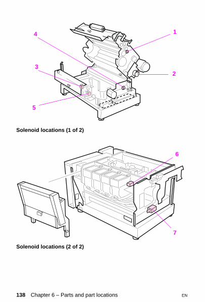
Solenoid locations (1 of 2)
Solenoid locations (2 of 2)
15
4
32
1
7
6
138 Chapter 6 – Parts and part locations EN
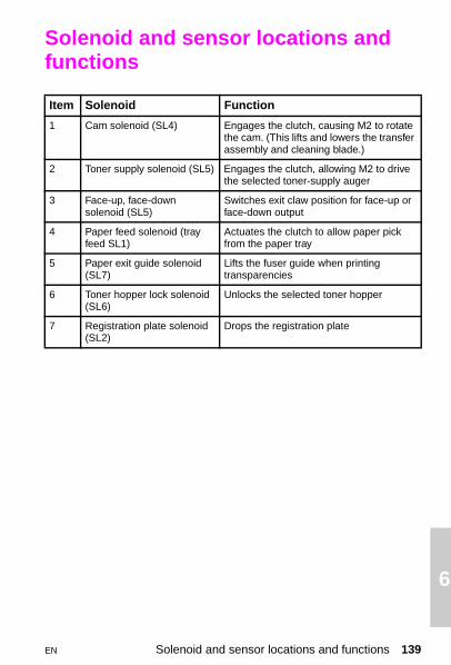
6
Solenoid and sensor locations and functions
Item Solenoid Function
1 Cam solenoid (SL4) Engages the clutch, causing M2 to rotate the cam. (This lifts and lowers the transfer assembly and cleaning blade.)
2 Toner supply solenoid (SL5) Engages the clutch, allowing M2 to drive the selected toner-supply auger
3 Face-up, face-down solenoid (SL5)
Switches exit claw position for face-up or face-down output
4 Paper feed solenoid (tray feed SL1)
Actuates the clutch to allow paper pick from the paper tray
5 Paper exit guide solenoid (SL7)
Lifts the fuser guide when printing transparencies
6 Toner hopper lock solenoid (SL6)
Unlocks the selected toner hopper
7 Registration plate solenoid (SL2)
Drops the registration plate
EN Solenoid and sensor locations and functions 139

Sensor locations and functions
(See locations on the following pages)
Item Sensor Function
1 PS2 Belt/cam home position sensor(senses the transfer belt and drum cleaning blades home position)
2 PS3 Collection box full sensor
3 PS5 Transparency detection sensor
4 PS6 Developer select home sensor (senses the developer select position)
5 PS7 Paper-feed (registration) sensor
6 PS8 Paper-out sensor
7 PS1 Paper-exit sensor. (detects media in the exit assembly)
9 Black Sensor
senses black toner empty
10 Cyan Sensor
senses cyan toner empty
11 Magenta Sensor
senses magenta toner empty
12 Yellow Sensor
senses yellow toner empty
13 PS4 RFU paper-out sensor(senses media in the RFU)
14 Humidity sensors
15 Paper-size sensors (CN103, B4-B7)
16 & 17 Fuser temperature sensors (TH2 and TH1)
18 Toner concentration sensor (1 for each developer)
19 Drum wrap sensor
20 RFU paper-in-path sensor
21 RFU manual feed sensor.
140 Chapter 6 – Parts and part locations EN

6
Belt cam home position sensor
Internal sensor locations
1
2
3
45
6
7
EN Solenoid and sensor locations and functions 141

Rear sensor locations
Fuser sensor locations
14
15
21
20 13
12 1110
9
1617
142 Chapter 6 – Parts and part locations EN

6
Toner concentration sensor (1 for each developer)
Drum wrap sensor
18
19
EN Solenoid and sensor locations and functions 143

144 Chapter 6 – Parts and part locations EN

7 I
EN
mage quality
Overview
This chapter provides examples of image defects and a list of remedies.
Overview 145

Troubleshooting image formation
NoteBefore beginning to troubleshoot image formation, check that the media meets the specifications listed in the HP LaserJet Printer Family Paper Specification Guide. It is recommended that you use HP multipurpose paper (20-lb), part number 9300-2091.
Print density test and color checksUse the self-test page to check the print density (the black levels). The self-test page has solid black-filled areas that demonstrate the ability to print black at full density. The self-test page also tests the ability to print each primary and process color. To print the self-test page:
1 Take the printer off-line.
2 Press [Menu] until PCL TEST MENU appears.
3 Press [Item] until PCL SELF TEST appears.
4 Press [Enter] to start the self-test.
In addition to items listed above, the self-test:
• helps isolate the problem to the software or the printer hardware.
• shows that all colors print.
• checks that the room humidity is within specifications.
The following media-related items are responsible for many image formation and print quality defects:
• rough paper
• heavy paper
• transparencies out of the specified thickness range
• paper that has absorbed moisture from the atmosphere
• room environment (humidity too high or too low)
146 Chapter 7 – Image quality EN

7
Understanding color variationsThe printed page might not match the computer screen, and the colors printed on successive pages might not match each other. While color variations are inherent in this printing method, they also can indicate changes in the printing environment, print media, or printer components.
Common causes of color variationThe following list outlines the major causes of color variations between computers, applications, and output devices.
• Halftone patterns produced on monitors are different from the types of patterns used in the print jobs. The differences in the halftone patterns can cause variations in the printed output.
• The printed output differs from the image on the monitor because the monitor and the print media have different reference values of black and white.The monitor screen has charcoal gray for the black level, and the white on the monitor screen is actually blue. Black on print media is limited only by the fill capability of the printer, and most good quality paper has a very high white level. In addition, phosphor (used in color monitors) and toner have entirely different spectral characteristics and different color rendering capabilities. Differences between the display and the printed output are common. Blues generally match better than reds.
• The color of the ambient light changes the perception of color (on both the monitor and the printed page). Fluorescent light lacks many colors present in incandescent light, and the color range of natural light is broader than any artificial light. When comparing color, choose a standard light source for reference and understand that the perceived color will change as the light changes.
• Long-term color variations occur as the paper ages. The color of the page will change with time. Use high-quality paper, and protect the paper from sunlight to help minimize discoloration.
EN Troubleshooting image formation 147
• Environmental changes can cause color variation. The development process places a high potential across an air gap to attract toner to the print drum. Changes in relative humidity vary the point at which the toner travels to the print drum. The printer has a humidity sensor that adjusts operating parameters as the humidity changes. This humidity sensor minimizes the effect of environmental changes.
• Print components become fatigued. All consumable components have a finite life span. As these items reach the end of their useful life, their ability to produce consistent print quality diminishes.
• Drums that have been overexposed to ambient light will not produce proper colors.
Color selection processThe actual color is selected in the software application, but the operating system can convert or modify some characteristics of the color before sending the information to the driver. Some applications will bypass the printer driver altogether.
The driver can modify color characteristics depending upon the selected output mode.
Any color characteristics not addressed by the driver or software applications are set to the printer default. The default color might not match the selection.
Matching screen colorsMatching of input, on-screen, and output colors is a very sophisticated process. The input device (scanner, keyboard, or mouse), software application, and output device each influence or limit the ability to select and produce printed color output.
To improve color matching between the printed output and the monitor:
• Turn off any color-matching features in the software application.
• Avoid light colors which the software application can interpret as white.
• Avoid dark colors which the software application can interpret as black.
148 Chapter 7 – Image quality EN

7
• Select the custom colors option in the driver (manual color) and change the halftoning options to vary the shading and quality of the colors.
• Use the color calibration system in the printer driver to match the printer to the characteristics of the monitor. This is available through the manual colors option.
• Drums that have been overexposed to ambient light will not produce proper colors.
Inconsistent colorsSome degree of color variation among printers is to be expected. However, if the color of successive printouts is inconsistent, follow the procedure given below:
• Verify that the same colors are selected for each printout.
• Verify that the software application is working correctly by printing a color file from another application.
• Verify that the same paper is used for each printout. Differences in paper could affect color output.
• Verify that the printer is working correctly by printing a self-test page and verifying that the colors are not faded or bold.
Carryout (loose carrier)Diagnose carryout (loose carrier on the page) by feeling the page for the gritty-feeling carrier. Loose carrier on the page indicates a poor connection to the print drum charging grid. Check the drum contacts. Pull the spring contacts up to within 1 mm (0.039 in) from the top of the plastic housing. If the carryout persists, replace the print drum.
EN Troubleshooting image formation 149

Troubleshooting image quality problems
The following information describes various print problems and their causes. Use this information to assist in identifying, troubleshooting, and correcting the problems. Examples of image defects begin on page 173.
• Make sure that the paper meets HP media specifications.
• Check that the humidity reading shown on the self-test is within specifications.
• Check the connection between the drum and the high-voltage power supply (HVPS) for contamination.
• Replace any developer that has exceeded its maximum life.
• The toner concentration is temporarily too high. This can happen if both the fuser and developer are new. This condition corrects itself after about 100 pages.
• The transfer belt is not fully engaged with the print drum.
• Replace the HVPS.
– Feel the page for gritty carrier. Loose carrier on the page indicates a poor connection to the print drum charging grid.
– Check the print drum connectors. Pull the spring contacts up to within 1 mm (0.039 in) of the top of the plastic housing.
• If the problem persists, replace the print drum.
Background toner scatter
150 Chapter 7 – Image quality EN

7
Banding can be caused by old maintenance units and by worn or damaged contaminated gears.• Check the age of the maintenance units. Replace any that have exceeded their maximum life.
• Clean the transfer belt gears and the main motor gears.
• Use a halftone pattern such as the one provided in the ColorSmart selection in the printer driver. Banding is more apparent in some halftone patterns than in others.
CAUTIONReinstalling the drum and closing the top cover without the corona cleaning tool fully seated to the right can damage the drum gear and cause banding.
Medium period banding is caused by developer sleeve runout.
• Check for slipping of the developer drive clutch in the developer drive assembly.
CAUTIONReinstalling the drum and closing the top cover without the corona cleaning tool fully seated to the right can damage the drum gear and cause banding.
Banding (large)
Banding (medium)
EN Troubleshooting image quality problems 151

Small period banding could be caused by gear noise in the main drive gears or in the spring-loaded gear.
• Clean the main drive gears and the spring-loaded pinion.
• If the problem persists after performing these procedures, change halftone patterns in the graphic.
NoteMedium and small period banding is more pronounced in process colors.
CAUTIONReinstalling the drum and closing the top cover without the corona cleaning tool fully seated to the right will damage the drum gear and cause banding.
Totally black (or brown/orange pages in color applications) can result from the failure of the print drum charging system. If the page is not totally black, or the image clears up in a few pages, the print drum charging system could be shorting intermittently. The HVPS could also be failing. The page could be streaked with color, with the text readable through the color.
• Check that the print drum does not have toner accumulated under the housing. Carefully clean the housing if necessary. (Use the cloth provided in the collection kit.)
• Check that the transfer assembly is clean, with no areas contaminated to the point of shorting. Carefully clean the transfer assembly area if necessary.
• Run at least 10 pages of the self-test. If the defect persists, replace the print drum.
• Check the HVPS connections. Ensure that they are clean and in good repair. Stretch the high-voltage spring contacts to within 1 millimeter from the top of the plastic housing.
Banding (small)
Black or dark brown/orange page
152 Chapter 7 – Image quality EN

7
• Loose carrier on the page indicates a poor ground connection on the print drum high-voltage circuit. Clean the printer and reinstall the print drum. If the carryout persists, replace the print drum.
• Check the connectors between the formatter and control board for bent or misaligned pins.
Black, brown, and/or orange stripes (horizontally or vertically) across the page are caused by light leaking into the printer and onto the print drum. Check the covers to make sure they fit properly. Generally the print drum will recover from exposure to room light, but the useful life of the print drum could be reduced. This defect is usually graduated along the page, with no clear starting or stopping point.
• If the brown/orange defect is not limited to a definite horizontal stripe, it could be necessary to replace the print drum. Print drum failure is also characterized by a black page.
CAUTIONAmbient room light can permanently damage the print drum. Store the print drum in total darkness to protect the photosensitive coating.
NoteThis can indicate a high-voltage power supply problem. Check the HVPS.
Black/brown/orange bands
EN Troubleshooting image quality problems 153
Partially blank pages can result when the developer spacing rollers do not seat firmly against the print drum. When the top cover is closed, the load springs press the developer sleeves against the print drum. If this spacing is incorrect, less toner is attracted to the print drum, resulting in faint print. Check that the developers move freely (front to back) in the developer housing.
• Check that the cam timing is correct (see page 6-38 in the printer service manual). If the gear train has not been disassembled, check that none of the gears are broken, causing the timing to change.
• Check the print drum drive gear engagement. Listen for the sound of slipping (grinding) gears. Inspect the print drum drive gears for signs of wear. See the drum rotation functional test shown in the service manual. Replace the print drum and the drive gears if necessary.
• Check for 18.5 and 18.6 Reinsert developer errors. These errors indicate that the developer is not rotating.
• If the page is completely blank, the transfer cam solenoid could be stuck or broken. In this case, the image will not be transferred to the media. Use the service mode test address (53) to test the transfer cam solenoid.
• In addition, watch for the following:
– Ensure that the media meets HP specifications. – Check for media multifeeds. Use the continuous self-test to prove
that the printer feeds paper reliably. Rough media or light media could multifeed, resulting in blank pages.
– Check for host communication problems or problems in network configuration.
– Check banner pages and form feed commands in the software.– Make sure that the number of lines per page is correct. Too many
lines per page result in creeping text. In this condition, each successive page begins its print further down the page. Part of each page will be blank.
– A laser scanner failure has occurred. (This will have an associated message.)
– A high-voltage failure has occurred.
Blank or partially blank page
154 Chapter 7 – Image quality EN

7
Sequence of blank page testsTo troubleshoot blank pages, perform the following steps:
1 Run a half self-test as shown in Chapter 3. If the image is developed on the print drum, the laser scanner and developer systems are working. Check the following:
• The transfer assembly is functional.
• The cam timing is correct.
• The HVPS is operational.
2 If no image is present, refer to the high-voltage checks section for information on troubleshooting developer high-voltage failures. Also check that:
• The print drum rotates correctly.
• 18.5 or 18.6 errors have not occurred.
• The developer spacers are free.
3 With the Service Mode (test address 53), check that the transfer assembly cam solenoid is working.
• If the image is developed on the print drum and the output is blurry or faded, the transfer corona voltage could be missing. Replace the HVPS followed by the transfer assembly if necessary.
EN Troubleshooting image quality problems 155

Cleaning blade failures are characterized by light smears in the horizontal axis of the page. This failure is more pronounced on toner-filled and multicolor pages.
• Replace the print drum.
(See also “Smeared print”)
This defect could be caused by black toner being deposited on yellow areas. Black developers that are used past their maximum life could contaminate color developers.
• Check that the printer is kept within the environmental specifications described in Chapter 2 of the service manual.
• Print a self-test page to check that the humidity is within the specifications listed in Chapter 2 of the service manual. If possible, verify the humidity sensor reading. (See also the “Humidity Sensor Test” in Chapter 7 of the service manual.)
– Replace the humidity sensor (located on the toner sensor board) if necessary.
• Check the developer age as shown on the self-test page. Change the developers, if necessary.
• Print a solid yellow page, followed by a page with black and yellow print.
– If the problem appears on the second page, perform the toner concentration test for yellow listed under 54.3 Toner concentration error in Chapter 1. If the value is within range, replace the black developer. Then run at least 10 pages of solid yellow.
NoteIf dark yellow print occurs on transparencies only, see “Transparency defects” later in this chapter.
Cleaning blade failure
Dark yellow print
156 Chapter 7 – Image quality EN

7
• Manually check the toner hoppers to see if any are empty. An emptytoner hopper without the message to add toner indicates a failed toner hopper sensor.
– Replace the sensor and add toner.
• Check the toner supply augers for correct operation.
– Remove the toner hopper cover.– Inspect the augers from the hopper to the developers for kinks or
bulges.– Rotate the large gear on the side of each hopper one turn,
checking to make sure the auger inside the tube turns.– Remove the developers and check the ends of each auger tube
for clogged toner. Remove any toner that could be packed into the end of the tube.
– Check the toner hopper select mechanism and the toner supply mechanism for proper operation by running multiple demo pages while watching these mechanisms. If either mechanism fails to operate, see “18.5 and 18.6 Mechanism Alignment Checks” on page 7-34 of the service manual.
• The print drum might not be fully discharged during the writing process due to accumulated toner on the laser scanner assembly window. This reduces the laser power that discharges the print drum, causing faint print in all colors.
– Lower the print drum and clean the optics window with the tool provided.
• Poor transfer causes faint print in irregular areas of the output.
– Remove the transfer assembly. Ensure that the connections are clean and that nothing inhibits the transfer assembly from fully seating.
– Perform the half self-test (described in Chapter 3) to determine whether the failure is associated with the transfer assembly.
– If the image is fully developed on the drum, then the problem is shown to be in the transfer assembly.
• Replace the print drum.
Faint print
EN Troubleshooting image quality problems 157

Ghosting appears on the page as a latent image of previously printed material along with the text or graphic that was printed last. It also could look like a repetitive defect. This defect occurs when using a print drum past its maximum life. Consumable life information appears on the self-test page.
• If the print drum is within its maximum life, thoroughly clean the printer. If it is past its maximum life, replace the print drum.
Check that the user is not printing the same pattern repeatedly. Repeat patterns shorten the life of the print drum.
• Check for toner dust on the laser scanner window.
– Clean the laser scanner window as shown in the service manual.
• Check for charging corona/grid contamination. Sharp, crooked, or random horizontal lines indicate contamination.
– Clean the print drum corona wire. This applies only to new style (purple-coded) drum.
• Check for debris in the fusing assembly.
• Check for contamination of the transfer assembly.
– Clean the transfer corona wire.– Replace the transfer assembly.
Ghosting
Horizontal lines (all colors)
158 Chapter 7 – Image quality EN

7
NoteWhen the lines run horizontally (across the page), they are banding; when the lines vertically (down the page), they are streaking.Horizontal white lines on black and white output occur when relatively large foreign particles become stuck between the black developer sleeve and the metering rod. The foreign matter prevents toner from coating the developer roller. Remove the developer to see if it has a clean stripe where the foreign matter is wedged. To remedy this problem:
1 Remove the developer from the printer.
2 Locate the drive gear for the failing developer and turn the gear counterclockwise as you face it. If the failure persists, replace the developer.
Horizontal lines on colored media occur for the same reason as described above. The lines occur in primary and process color. For example, a particle in the magenta developer will create a white (or light) line in magenta areas. In colors that use magenta, the magenta will be missing, leaving a yellow line in a red area or a cyan line in what should be a blue area. The Developer defect colors table, below, shows the result of a defect in each of the four developers.
Horizontal white lines (one color)
Developer defect colors
#/Developer Black Yellow Magenta Cyan Red Green Blue
1 Black X
2 Yellow X X X
3 Magenta X X X
4 Cyan X X X
EN Troubleshooting image quality problems 159

The specification for image skew is less than 1.5 mm (0.059 in) over a 250 mm (9.843 in) span. Image skew could be caused by burrs on the paper registration plate or by paper not feeding from the paper tray correctly.
• Check that media does not stick together at the edges. Ensure that the paper meets HP media specifications.
• Ensure that the paper tray side adjustment lever is adjusted properly against the edge of the media.
• Check the paper stack tabs in the paper tray.
• Carefully examine the printed output for signs of nicking or folding. These marks could indicate problems elsewhere in the print path.
– Remove the cover and examine the guides. Ensure that the cover is properly installed.
• Check the paper pickup rollers for signs of wear, such as glazing and cracking.
– Replace the pickup rollers, if necessary.
• Check the paper tray transport roller for wear, proper spring position, and even pressure from side-to-side.
NoteCheck both sets of transport rollers. One set is accessed from the lower back cover. The other is next to the overhead transparency sensor and registration plate.
• Check the registration plate for burrs.
– Ensure that the registration plate is not bent or damaged. Ensure that it moves freely up and down. Replace the registration plate if any of these defects are found.
Image skew
160 Chapter 7 – Image quality EN
7
Improperly sized images can be caused by defective paper tray microswitches. The paper tray microswitches tell the formatter what size media is installed. This information is used to format the print image to the installed paper size. If the paper tray microswitches are defective, the PostScript image will be formatted incorrectly.Paper tray size functional test
Use the status and test feature of the Service Mode to check the function of the paper tray size switches. See the status and test address table in Chapter 3 for information on this test. To test the paper tray switches:
– Power cycle the printer and enter the Service Mode as shown in Chapter 3.
– Select the status and test mode function of the Service Mode.– Enter the paper-size switch test code (15 for tray, 16 for the RFU)
and press [Enter].– The logic state of the switches is displayed on the control panel.– Remove the paper tray and depress each of the paper tray size
switches. The control panel display should change as shown in the status and test address table in Chapter 3.
Check the paper tray size indicator tabs on the paper tray.
Incorrect registration is characterized by the image being offset from the left side of the page.
• Check for problems in the paper registration mechanisms.
• Check the cam timing. Refer to Chapter 6 in the service manual for information on cam timing.
• If the registration error is small and consistent on every page, small changes in registration can be made with the REGIST ADJUST feature of the Service Mode. See Chapter 3 for information on REGIST ADJUST.
Improperly sized image (PostScript only)
Incorrect registration (late or early print)
EN Troubleshooting image quality problems 161

NoteThe REGIST ADJUST function should not be used until all other causes are eliminated and the offset is consistent on every page.
Incorrect registration is characterized by the entire image being offset from the leading edge of the page. This will be the left edge for letter, A4, and executive media. It will be the top of the page for legal, tabloid, and A3. Before troubleshooting incorrect registration as an engine problem, check the margins and image placement in the software application. If the same file consistently prints in the wrong location on the page, suspect a software problem. If the file is a PostScript file, see Improperly sized image earlier in this chapter.
• If the image is late on the page, the paper is arriving at the drum/transfer interface too soon. Troubleshoot this problem as follows:
– Inspect the registration plate for burrs.– Ensure that the registration plate moves freely throughout its
range of motion. If the registration plate sticks anywhere in its motion, check the solenoid linkage. Replace the solenoid and linkage if necessary.
– Check that the registration plate moves all the way up. If it moves only part way up, the paper can cross the registration plate too soon. When the solenoid plunger is released from the solenoid, it should touch the rubber stopper behind the linkage and the registration plate will be in the uppermost position.
• If the incorrect registration is very small and is off by the same amount on each page, small adjustments are possible. Enter the Register adjust mode of the service mode (as described in Chapter 3) and proceed as follows:
– Enter the desired register adjust address. See the “Register adjust addresses” table on page 91. Addresses 74 and 76 control the leading edge margin for each of the paper sources. The allowable range for values is 35 to 65. For each one-count change, the leading edge of the print moves 0.74 mm (0.029 in) relative to the media. Higher values move the image closer to the leading edge of the media.
Incorrect registration
162 Chapter 7 – Image quality EN

7
– Address 75, 77, and 79 control the start of the laser scan. The allowable range of values is 01 to 99. For each increment of one, the start of the laser scan moves 0.088 mm relative to the media (the scan starts at the left side of the printer). Higher values move the print closer to the top of a letter, A4, or executive page. For legal, tabloid, or A3 size paper, the print starts closer to the right.
Toner accumulation on the paper charging brush causes the leading and trailing edge of the printed output to be smeared with loose toner.
• Clean the printer (including the paper-charging brush).
• If the media size has been changed (such as from legal or executive to letter), print 5 to 10 pages to clear the smearing.
• If a paper jam has occurred recently, or the printer had a multifeed, print 5 to 10 pages to clear the smearing.
• Replace the paper-charging brush if this defect persists. Print 20 to 30 self-test pages to verify the repair.
• Check that the media meets HP specifications.
• Printing in low humidity also causes poor transfer.
– Perform the humidity sensor tests.
• Clean the transfer corona wire and reseat the transfer assembly. Oxide buildup on the transfer corona wire adversely affects how the printer transfers the developed image to the page.
• Select ColorSmart from the driver menu. Business blue, included in the ColorSmart menu, has more constant transfer characteristics.
• Change halftone patterns. Some halftone patterns make poor transfer more visible.
• Replace the transfer assembly if necessary.
Leading or trailing edge smear
Mottled process colors (poor transfer)
EN Troubleshooting image quality problems 163

Poor fusing is characterized by loose toner on the printed page. Unfused or poorly fused toner can be easily wiped off the page. This is usually most obvious on the trailing edge (the right edge) of the page.
• Check that the media is within the weight and smoothness specifications listed in the HP LaserJet Printer Family Paper Specification Guide.
• Check that the printer does not multifeed. If more than one sheet enters the fuser, the toner on the top sheet might not fuse. (See the multifeed information in Chapter 4.)
(See also Background scatter.)
This defect appears as small rings or circles on the printed page. Ring marks can be caused by small particles in the developer.
• Run the demo page for 20 to 30 pages to isolate the problem to a specific color.
– Replace the developer that exhibits the problem.
• Check the environment for sources of contamination. For example, printing in an area that is subject to fine metal particulates, metal filings, or metallic debris will cause ring marks.
• Sudden rises in ring mark frequency can indicate wear in a component. Keep this in mind when troubleshooting ring mark defects in printers that have no history of ring marks.
• Check the age of the developers and replace any that are past their maximum life.
Poor fusing
Ring marks
164 Chapter 7 – Image quality EN

7
(See also “Cleaning blade failure” and “Leading or trailing edge smear.”)• Check that the paper path is clean.
– Check to see if the media is being bent during paper pick. If the media retains the bend as it enters the fuser, the print in the area of the bend can smear.
– Ensure that the media is correctly loaded in the paper tray. If the defect persists, turn the paper stack over and end-to-end.
– Try another media type. Check that the media meets HP specifications.
• Check that the fuser does not have toner buildup on the inputs. Clean any loose toner accumulated around the fuser.
• Inspect the pretransfer brush. Replace it if there is any toner buildup.
• Severely smeared print can indicate that media is stuck under the cleaning blade inside the print drum. If this is the case, the drum wrap sensor is defective and the surface of the print drum could be damaged. Run the half self-test. If the print is smeared on the drum surface, replace the drum.
Speckled print (or toner popping) can be caused by excess moisture in the print media. Verify the cause of this defect by printing with a properly stored ream of paper.
• Check that the media is stored in a dry area and is not opened until it is ready to be used.
• Be sure that the printer is not in a humid area.
• If the defect persists, run a self-test page and check the humidity sensor reading.
Smeared print
Speckled print
EN Troubleshooting image quality problems 165

This defect is differentiated from repetitive defects by:
• random occurrences
• raised pieces of irregularly shaped, poorly fused toner on the page that can sometimes be removed by wiping or with a fingernail
Stray toner or irregular raised spots on the page occurs when excess toner accumulates around the fuser and is eventually deposited on the media during fusing.
• Check for toner accumulation around the fusing assembly.
• Clean the assembly if necessary.
• Check the paper weight and smoothness. Rough paper can stick together causing multifeeds. The extra thickness of multiple sheets of paper can cause poor fusing which deposits toner on the fuser rollers. This toner comes off on later pages as stray toner. Poor fusing can also occur when printing on heavy paper.
• Check the coating roller seating.
– Clean any accumulated toner off the pad and the corresponding position on the fuser pressure roller.
• Run a self-test and check the age of the coating roller.
– Replace the coating roller if necessary.
• Reseat the cleaning roller and the coating roller.
• Check the error log for fusing errors. If the fuser does not heat properly, the unfused toner accumulates around the fuser and is deposited on the page as stray toner.
CAUTIONIf many multifeeds have occurred or the printer consistently prints on heavy paper (over 90 g/m2 or 24 lbs), it could be necessary to replace the fuser.
Stray toner
166 Chapter 7 – Image quality EN

7
Overhead transparencies (OHT) can display any of the image quality defects shown in the colored sample pages. In addition, because transparencies are pliable while in the print path, they are subject to being marked by the media-handling components.• If transparencies show lines and creases in the printed sheet, compare the defect against the template to help isolate the cause to a specific component.
• If horizontal streaks appear on the output (when viewed in portrait orientation), run a self-test to check the age of the coating roller.
– Replace if necessary.
• Check that the transparencies meet the specifications listed in the HP Paper Specification Guide. Also check that they are the supported HP part number (C2934A for letter and C2936A for A4).
• For dull transparencies, contact your local response center.
• Dark transparency output can be caused by a defective transparency sensor (PS5). Use the Service mode status and test (address 59) to test the OHT sensor. If this sensor is defective, the printer will not recognize transparencies and will print at the faster paper speed.
• Reprint transparencies if they have spots or smudges. Be careful not to touch the surface of the media. Skin oils can contaminate transparencies, causing spots and smudges.
• Small random dark areas on the trailing edge of solid fill pages can be caused by transparencies sticking together in the face-up bin.
– Try printing the job in smaller batches.
NoteAllow transparencies to cool at least 30 seconds before handling them.
Transparencies created on the printer cannot be used on reflective-type (portable) transparency projectors.
Transparency defects
EN Troubleshooting image quality problems 167

Causes of transparency curl• Ensure that the face-up bin is pulled completely out and is tilted up.
If the bin is pulled only partially out, the transparencies are subject to curling.
• If the curl of black-only transparencies printed to the face-down bin is unacceptable, these transparencies can be printed to the face-up bin by changing the media output selection from the software or from the control panel.
Repetitive defects on transparenciesOverhead transparencies that have repetitive defects spaced about 94 mm (3.7 in) apart indicate a defect on the upper fuser roller.
1 Turn the power off and unplug the printer; allow 30 minutes for the fuser to cool and then remove the fuser.
2 Remove the leveling roller and the oil pad.
3 Turn the fuser gears and inspect the surface of the upper fusing roller. If the roller has surface defects (gouges) replace the fusing assembly.
NoteLengthwise wrinkles on the roller surface are normal.
Specific marks on pageMarks can appear at specific locations on transparencies as follows:
Upper registration roller marks. These marks always occur at the top of a landscape letter page. They appear only on transparencies, almost never on paper. This defect is caused as the registration rollers rotate on the media when it is pressed against the registration shutter. The friction and pressure of the rollers on the media leave lightly scuffed areas that transfer color differently.
• Roller marks can be helped by cleaning the rollers with a soft, alcohol-dampened cloth.
• Ensure that the registration rollers are not damaged or abraded. Replace if necessary.
168 Chapter 7 – Image quality EN

7
• Check that the upper registration rollers have equal spring pressure on the right and left sides.
• If no problem is found with the rollers or springs and the marks are very light, take no further action. Changing the spring force will cause paper path errors, registration problems, and paper jams.
Second feed roller marks. These marks occur in the same location around the center of the page. They sometimes occur on the back of the page.
• Perform the checks listed in the previous list for upper registration roller marks.
Star wheel marks. Small dots or dashes sometimes appear in one or both of the locations shown on the print defect template. These defects occur when the trailing edge of the page touches the small spurs on the lower surface of the print drum housing. They are normally small and intermittent.
• Replacing maintenance units, such as the fuser or transfer assembly, sometimes increases the frequency of this defect.
Exit roller mark. These four lines on the back of the transparency can be eliminated by cleaning the four exit rollers with a damp cloth. The lines on the back of the transparencies are easily wiped away with a dry cloth.
Repetitive defectsMost repetitive defects are caused by imperfections in the print drum or fuser roller. Print drum defects occur in the same vertical position on the page, but might not appear on each consecutive page. Defects caused by print drum imperfections appear as black or white marks on the page.
• Run at least four consecutive test pages to determine if the defect repeats in the same vertical orientation.
• Inspect the print drum for damage. Replace the print drum if it is scratched or dented.
• Check to see if paper dust is adhering to the print drum. These defects usually appear as white marks in the dark printed areas of the page.
EN Troubleshooting image quality problems 169

– Remove this dust with 70% isopropyl alcohol applied with the cloth supplied in the collection box kit. Try this only if the print defect is unacceptable and the only other alternative is replacing the print drum.
CAUTIONDo not expose the print drum to strong light, and be careful not to scratch or get fingerprints on the drum surface during cleaning. Do not blow on the print drum.
• Portions of the print drum could have been exposed to light. Light on sections of the print drum causes dark sections in the printed output. If the exposure was minimal, these defects can clear up over time. The life of the print drum is shortened by exposure to strong light.
Overhead transparencies that have repetitive defects spaced about 94 mm (3.7 in) apart indicate a defect on the upper fuser roller.
• Turn the printer off and allow 30 minutes for the fuser to cool. Then remove the fuser.
• Remove the cleaning roller and the coating roller.
• Turn the fuser gears and inspect the surface of the upper fusing roller. If the roller has surface defects (gouges), replace the fusing assembly.
NoteLengthwise wrinkles on the roller surface are normal. Uniform lines and creases in transparencies can be caused by rollers or other print path components. Use the template provided in the “Overhead Transparency Defects” section of the service manual to isolate the defect to a specific print path component.
Repetitive defects caused by the transfer belt
Repetitive defects can also be caused by defects in the transfer belt.
• Remove the transfer assembly and inspect the entire belt surface. Use the transfer assembly gears to rotate the belt throughout its travel.
170 Chapter 7 – Image quality EN

7
Wavy characters are caused by scanner wobble. Mechanical instability in the scanner mechanism or the optics can cause wavy characters.• Reprint the job to ensure that the problem persists.
• Replace the laser scanner assembly.
• Check the developers for contamination.
• Clean the optics window.
• Check for oxide buildups on the print drum charging corona wire.
• Clean the charging corona if a new style (purple-coded) drum is installed.
• Replace the print drum if this problem persists.
• The print drum has reached its maximum life. Replace the print drum.
(See also Horizontal lines.)
Wavy characters
Yellow or black streaks
EN Troubleshooting image quality problems 171

Repetitive image defect rulerUse the ruler shown below to measure the approximate distances between repetitive image defects.
172 Chapter 7 – Image quality EN

7
Image defects
Background toner scatter (see page 150)
EN Troubleshooting image quality problems 173

Banding-large, medium, or small (see page 151)
174 Chapter 7 – Image quality EN

7
Black or dark brown-orange page (see page 152)
EN Troubleshooting image quality problems 175

Black streaks (see page 171)
176 Chapter 7 – Image quality EN

7
Black/brown/orange bands (see page 153)
EN Troubleshooting image quality problems 177

Blank or partially blank page (see page 154)
178 Chapter 7 – Image quality EN

7
Cleaning blade failure (see page 156)
EN Troubleshooting image quality problems 179

Dark yellow print (see page 156)
180 Chapter 7 – Image quality EN

7
Faint print (see page 157)
EN Troubleshooting image quality problems 181

Ghosting (see page 158)
182 Chapter 7 – Image quality EN

7
Horizontal lines-all colors (see page 158)
EN Troubleshooting image quality problems 183

Horizontal lines-one color (see page 159)
184 Chapter 7 – Image quality EN

7
Image skew (see page 160)
EN Troubleshooting image quality problems 185

Improperly sized image (see page 161)
186 Chapter 7 – Image quality EN

7
Incorrect registration (see page 162)
EN Troubleshooting image quality problems 187

Leading/trailing edge smear (see page 163)
188 Chapter 7 – Image quality EN
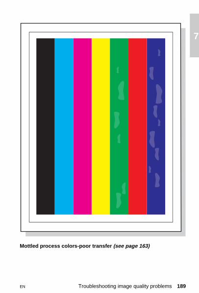
7
Mottled process colors-poor transfer (see page 163)
EN Troubleshooting image quality problems 189

Poor fusing (see page 164)
190 Chapter 7 – Image quality EN

7
Ring marks (see page 164)
EN Troubleshooting image quality problems 191

Smeared print (see page 165)
192 Chapter 7 – Image quality EN

7
Speckled print (see page 165)
EN Troubleshooting image quality problems 193

Stray toner (see page 166)
194 Chapter 7 – Image quality EN

7
Streaks (see page 171)
EN Troubleshooting image quality problems 195

Wavy characters (see page 171)
196 Chapter 7 – Image quality EN

8 W
EN
iring diagrams
Overview
This chapter provides wiring diagrams and information on the control board fuses for the printers supported in this guide.
Overview 197

Wiring Diagrams
(Color LaserJet)
198 Chapter 8 – Wiring diagrams EN

8
(Color LaserJet)
EN Wiring diagrams 199

(Color LaserJet 5/5M)
200 Chapter 8 – Wiring diagrams EN

8
(Color LaserJet 5/5M)
EN Wiring diagrams 201

Control board fuses
The following table identifies the fuses on the control board for both the HP Color LaserJet printer and the HP Color LaserJet 5/5M printer. The table also shows what is in line with the fuse and the most likely failure if one is blown (open). Use an ohmmeter to check the status of the fuses. Since the fuses cannot be replaced individually, make sure that the cause of the blown fuse is identified and resolved before replacing the control board.
Control board fuses
Name Drives Fault indicators
F1 5V to and from the control board
F2 24V to and from the control board
ICP1 Cam solenoid (SL4) and 1st paper feed solenoid (SL1)
13.4 Clear front tray input jam (will not pick up paper from the paper tray)
ICP2 Toner supply solenoid (SL3) and registration plate solenoid
(SL2) Will generate either a 54.5 Developer Home Position Error or 13.5 Paper Jam
ICP3 Rear feed unit motor (M7) 13.6 Clear rear tray input jam
ICP4 Developing control motor (M3) 54.5 Developer home position sensor error
ICP5 Face-up/face-down solenoid (SL5) and toner hopper lock solenoid (SL6)
Paper will only exit to either the top or bottom tray, or toner hopper lock fingers will not open
ICP6 Paper exit guide solenoid (SL7) May cause smearing on transparencies or wrinkled paper as it exits fuser
202 Chapter 8 – Wiring diagrams EN

8
Control board layout
Color LaserJet control board connector layout
EN Wiring diagrams 203

Color LaserJet 5 control board connector layout
204 Chapter 8 – Wiring diagrams EN

9 Tr
EN
raining and support esources
Overview
This chapter provides information on obtaining training, support, and materials.
Overview 205

How to get training
Lecture/lab training (U.S. only)Service technicians who want individual, hands-on training can attend regularly scheduled lecture/lab training classes. These classes are offered throughout the country. To receive the latest schedule, callHP FIRST at (800) 333-1917, or see the HP website (www.hp.com/go/resellertraining) and request document ID number 9104. The latest schedule will immediately be sent to the fax number of your choice. Class schedule and registration information can also be obtained by calling the centralized registration center at (512) 434-1520.
Self-paced training kits
Product Description Part number
All LaserJet Printers Basic Hardware Training Course (prerequisite for all LaserJet service training)
Paper Specifications for LaserJet Printers
5961-0880
5961-0711 (NTSC) 5961-0712 (PAL)
206 Chapter 9 – Training and support resources EN

9
Support resources—North America
HP Customer Care Reseller Sales and Service Support CenterThe HP Customer Care Reseller Sales and Service Support Center is available for technical support to assist service technicians. The support center can be reached at (800) 544-9976 (U.S.).
HP FIRST fax systemHP FIRST (Fax Information Retrieval Support Technology) is a phone-in fax service that provides technical information to HP LaserJet users as well as to service personnel. Receiving a fax requires a group-3 facsimile machine or fax card. Service-related information includes the following:
• Service notes (HP authorized dealers)
• Application notes
• Product data sheets
• Material safety data sheets (MSDS)
• Typeface and accessory information
• Printer support software information
• Toner information
• Forms for requesting drivers and the software matrix
HP FIRST, U.S.Call HP FIRST at (800) 333-1917 (U.S.).
EN Support resources—North America 207

To retrieve service notes
(Authorized dealers and HP customer engineers [CEs] ONLY)
1 Dial (800) 333-1917 (U.S.) from any touch-tone phone.
2 Select (1) for technical support.
3 Select (3) for a password customer.
4 Enter the password: 737842.
5 Follow the voice prompts to enter a document ID number or to select the index.
6 Follow the voice prompts to enter your fax number or the fax number of your customer.
NoteDelivery time depends on the length and complexity of the document.
HP end-user support options
Local support assistanceThe user’s first source of assistance should be their local dealer or service center. HP continuously provides local computer dealers and service centers with the latest information regarding products and services. To locate the nearest authorized dealer or service center, phone (800) 243-9816 (U.S.) or (800) 387-3867 (Canada).
HP FIRST 24-hour support informationPhone (800) 333-1917 to access the HP FIRST (fax information retrieval support technology) system for 24-hour automated support services. Faxed user support information includes notes for common software applications, and troubleshooting tips. Users may request up to three documents per call.
208 Chapter 9 – Training and support resources EN
9
Electronic information servicesFor 24-hour access to information via modem, we suggest:
• CompuServe – The CompuServe HP Peripherals forum (GO HPPER) provides printer drivers and interactive sharing of technical communication. To subscribe, call CompuServe, Inc. at (800) 524-3388. Note : CompuServe is not an official HP support channel, but the forum is maintained and supported by users.
• Internet – Printer drivers and product and support information can be obtained from the HP Customer Care Online at http://www.hp.com/cposupport/eschome.html or from the HP anonymous file transfer protocol (FTP) site 192.6.71.2 or ftp-boi.external.hp.com. The site is available to anyone with FTP access to the Internet. Access through the World Wide Web is available at URL http://www.hp.com/go/support or http://www.hp.com/go/resellertraining/.
Printer drivers by mailTo obtain printer drivers, contact the software application manufacturer. HP distributes printer drivers for a few of the most popular applications. Call (970) 339-7009, 6 days a week, 24 hours a day (closed Sundays). Shipping and handling charges may apply on some printer drivers.
Telephone assistance – in warrantyCall the HP Customer Care Center at (208) 323-2551 Monday through Friday from 6 am to 10 pm, Saturday 9 am to 4 pm (Mountain Time) free of charge during the warranty period. However, your standard ong-distance phone charges still apply. Have your system nearby and your serial number ready when calling.
EN HP end-user support options 209

Telephone assistance – post-warranty
Post-warranty telephone assistance is available to answer your product usage questions at the HP Customer Care Center. Call (900) 555-1500 ($2.50 per minute, U.S. only) or call (800) 999-1148 ($25 per call, Visa or MasterCard, U.S. and Canada) Monday through Friday from 7 am to 6 pm and Saturday from 9 am to 3 pm (Mountain Time). Charges begin only when you connect with a support technician. *Prices subject to change.
Hardware repair servicesTo locate a local authorized repair center for hardware repair needs, call (800) 243-9816. HP also offers a variety of service contract options to complement the standard warranty by calling (800) 743-8308 (U.S.) or (800) 268-1221 (Canada).
Additional service phone numbers are listed at the back of this manual.
210 Chapter 9 – Training and support resources EN

9
Support resources—Asia Pacific and Europe
HP Customer Care Centers in Asia Pacific
Country Customer Care Center
Service Center
Singapore 65-2725300
Hong Kong 800-96-7729
Vietnam 84 8 823453084 8 8294485
84 4 9431718
Indonesia 62-21-3518788
Phillippines 632-829-5387632-829-5388632-829-5389
Thailand 66-2-661 3900
Malaysia 6-03-7953788Fax: 6-03-7954423
India 91-11-6826035
China 86-10-5645858 86-10-62351040-655486-10-62385047
Taiwan 886-2-2717-0055
Korea 02-3270-070002-3270-0740
Australia 03-8877-8000
EN Support resources—Asia Pacific and Europe 211

HP FIRST, Europe
Call HP FIRST at one of the following numbers:
For English service outside the above countries, call(31) (20) 681-5792.
United Kingdom (44) (134) 0800-960271
Netherlands (31) (20) 0800-222420
Belgium (Dutch) (32) (2) 0800-11906
Germany (49) (13) 081-0061
Switzerland (German) (41) (1) 0800-551527
Austria (43) (1) 0660-8128
212 Chapter 9 – Training and support resources EN

A Aa
EN
cronyms and bbreviations
Acronyms and abbreviationsAC Alternating currentAUTOCONT Automatic continueBNC A 10-Base 2 connector used with coaxial cablesCFG Configuration on control panelDC Direct currentDCPS Direct current power supplyMS-DOS Disk operating systemDPI Dots per inchDTR Data terminal readyDTR line Data terminal ready lineECU Engine control unitEP ElectrophotographicEPH External paper handlingFRU Field replacement unitFTP File transfer protocolHP FIRST Hewlett-Packard fax information retrieval support
technologyHP-GL/2 Hewlett-Packard graphics languageHTML Hypertext markup languageHV High voltageHVPS High-voltage power supplyI/O Input/outputIR InfraredIrDA Infrared Data AssociationIRQ Interrupt requestJEIDA A type of memory moduleJOBID Print job identification JP Job packLAN Local area network
Acronyms and abbreviations 213

LED Light-emitting diodeLVPS Low-voltage power supplyLC pickup roller Lower-cassette pick-up rollerMB MegabyteMEM MemoryMIO Modular input/outputMP pickup roller Multipurpose tray pick-up rollerMP Tray Multipurpose trayMSDS Material safety data sheetsNF Noise filterNTSC National Television Standard CommitteeNVRAM Nonvolatile random-access memoryOhm A unit of measure of electrical resistanceOHT Overhead transparencyPAL Phase alternation line formatPCA Printed-circuit assemblyPCB Printed-circuit boardPCL Printer command languagePC pickup roller Paper-cassette pickup rollerPIU Paper input unitPJL Printer job languagePS PhotosensorPSD Product Support DivisionRAM Random-access memoryRFU Rear Feed UnitRIP Raster image processROM Read-only memorySIMM Single inline memory moduleSL SolenoidSMODE Service ModeSPEC SpecificationTCP/IP Transmission control protocol/Internet protocolTS ThermoswitchUNIX Network operating system using TCP/IP protocolURL Universal resource locatorVDC Volts direct currentVFD Vacuum fluorescent display
Acronyms and abbreviations (continued)
214 Appendix A – Acronyms and abbreviations EN

Index
Aaccessing
register adjust mode 89service mode 87
accessories, part numbers 123
Bbelt cam home position sensor,
locating 141
Ccam service mode test 49cleaning
drum wrap sensor 57laser optics cleaning tool 74locations in printer 74
cold reset, performing 108color balance, adjusting 104consumables
identifying 81part numbers 123
control boardconnector layout 203, 204fuses 202
control panel messages 5
Ddevelopers, replacing 80drum reflectance calibration 56drum rotation test 102drum wrap sensor
cleaning 57locating 143
duplexing 70
Eerror log mode 109extended diagnostics 110
Ffront input tray
preventing multi-feeds 71supported media 116
fuser sensor, locating 142fuses, function 202
Hhalf self-test, performing 101hardware repair services 209HP Customer Care Center 209HP FIRST 207HP paper training video 120HP Parts Direct Ordering 125humidity sensor test 98
Iidentifying consumables 81Image defects 173interlock switch, testing 11internal sensor locations 141
Llaser optics cleaning tool 74locating
sensors 139solenoids 139
EN Index – 215

Mmaintenance units, replacing 80mechanism alignment checks 27media
paper curl 119sizes 116troubleshooting problems 68types 116weights 116
multi-feeds, preventing 71
Nneutralizing corona contacts 23NVRAM addresses 41NVRAM values, changing 86
Ppaper jams, troubleshooting 68paper path sensors 69paper problems, detecting 68paper-out photosensor, testing 9part swapping 61printer
cleaning 74compatible supplies 83consumables 123line voltage 2maintaining 75operation commands 86protecting 2register adjust 86replacing maintenance units 80replacing toner 80storage 2testing 86troubleshooting 2, 4wiring diagrams 198
printer driversobtaining 209ordering 209
productpart descriptions 125part locations 125parts 125servicing 209support 207
PS3 service mode test 16PS8 service mode test 9
Rrear feed unit, preventing multi-
feeds 72rear sensor locations 142register adjust mode
accessing 89addresses and values 91keystroke sequence 90
Sself-paced training kits 206self-test page
Color LaserJet 64PCL (Color LaserJet 5/5M) 66PostScript 65
sensorsfunctions 140locations 139
service modeaccessing 87flow chart 88menu 86
service notes, retrieving 208SIMMs, ordering 124solenoid locations 139
216 – Index EN

Ind
ex
subtest number list 97supplies, compatibility 83supply augers, testing 31support information, obtaining 209support resources 207Ttarget toner concentration 46testing
cam solenoid 49drum rotation 102half self-test 101humidity sensor 98interlock switch 11paper tray switches 161PS3 sensor 16sensors 86SL3 31supply augers 31toner collection box sensor 15toner concentration 41toner supply solenoid 31voltage 63
toner collection box, testing 15toner concentration levels,
correcting 44toner concentration sensor,
locating 143toner concentration test 41toner concentration values 43toner contamination, identifying
103toner sensor PCA connections 18toner supply solenoid test 31toner, replacing 80
trainingobtaining 206self-paced training kits 206
training class schedules 206troubleshooting
flowchart 4paper jams 68paper problems 68using extended diagnostics 110using part swapping 61using test components 61
Vvoltage test points 63
Wwarranty assistance 209
wiring diagrams 198
EN Index – 217

218 – Index EN

Service Websites
HP Customer Care OnlineSoftware drivers, support documentation, and frequently asked questions
http://www.hp.com/go/support
HP Technical Training (North America)Classes and schedules
http://www.hp.com/go/resellertraining
PartsParts information
http://outfield.external.hp.com/spi/welcome.htm
For support resources in Europe and Asia Pacific, see page 211.

Service Phone Numbers
All numbers listed are for North America only.
HP Customer Care Reseller Sales and Service Support CenterDealer pre/post sales and service support
(800) 544-9976 U.S. Only (800) 363-6594 Canada
Customer Care CenterUser technical-support questions, LaserJet fax
(208) 323-2551
HP FIRST – Fax Information Retrieval SystemService notes, sales information, user help, software information
(208) 344-4809 (800) 333-1917 U.S. Only
Customer Information CenterSales dealer locations, literature, and specifications
(800) 752-0900 U.S. Only
HP Driver Distribution CenterPrinter drivers and software application notes orders
(970) 339-7009 U.S. Only
Customer Support Sales CenterAuthorized repair locations
(800) 243-9816 U.S. Only
Parts Direct Ordering / SMOService parts, supplies, and accessories orders
(800) 227-8164 U.S. Only
Parts IdentificationService part number identification
(916) 783-0804
HP Customer Care CenterOnline technical assistance
(800) 477-5526 HP Only
Corvallis Customer Service CenterExpress exchange and customer return services
(916) 785-1200


May 1998 Edition
HP Color LaserJet andHP Color Laser Jet 5/5M PrinterQuick Reference Service Guide
Copyright© 1998Hewlett-Packard Co.Printed in USA
Manual Part No.5041-9258
*5041-9258**5041-9258*
5041-9258
HP
Color LaserJet and H
P C
olor LaserJet 5/5M P
rinter Quick R
eference
Printed on at least50% Total Recycled Fiber withat least 10% Post-Consumer Paper