1 DATECS ESC/POS Printer EP-60
29
1 DATECS ESC/POS Printer EP-60 PROGRAMMER'S MANUAL Detailed Description of the Commands
-
Upload
khangminh22 -
Category
Documents
-
view
1 -
download
0
Transcript of 1 DATECS ESC/POS Printer EP-60

1 DATECS
ESC/POS Printer EP-60 PROGRAMMER'S MANUAL Detailed Description of the Commands

2
General Outline
The EP-60H is a compact-sized, line thermal printer developed for variety of applications. It can be used as a data communication terminal, POS terminal, kitchen terminal, etc.
It can be used in variety of applications because:
it is compact and light; the thermal printing mechanism combines both high speed and low noise printing; it has high exploitation reliability due to the mechanical endurance of the thermal printing
head; prints variety of barcodes there is an independent power supply (AC adapter)
Shipping And Package You will find these accessories shipped along with the printer: thermal-paper roll, user’s
manual and an AC adapter. The printer must be installed on flat and stable surfaces – desk, table, counter. The printer
must not be installed near a heater or in a place exposed to direct sunlight. A high-humidity or heavily contaminated environment must be avoided.
Cover Opening After installing the paper roll you must feed the paper approx. 2-3 centimeters using the LF
button.
Print Mechanism Jam When a paper jam occurs the printer must be switched of immediately and blocking paper
must be removed. Warning!!!
The printing mechanism is HOT after printing. Wait before opening the cover until it cools down, to prevent burn injury.
A special attention must be paid to printing head protection during transportation or
when storing for a longer period of time.

3
Auto Cutter Jam If the auto cutter is jammed, use the Line Feed button to try to release the cutter. When you
press the button the printer will try to re-initialize the cutter and retard it in home position. However if the cutter jam cannot be resolved this way, release it manually until the printer is able to retard it in home position.
LEDs “Power” – a green LED. Lights continuously when the printer is powered on. “Power” – a green LED. Flashes if the printing head has overheated. “Error” – a red LED. Flashes red when the printer is out of paper, lights red constantly if the
cover is open. “Error” – a red LED. Flashes about five times a second if there is an auto cutter jam.
Button LF (Line Feed) Pressing this button feeds the paper until it is released. The button must be pressed to continue printing after out of paper error. Pressing the button will try to retard the auto cutter in home position, if the cutter is jammed. If a manual macro execution is selected the button must be pressed for each macro execution. Holding down the button while the printer is switched on prints the self-test when the button
is released.
DIP Switches
Sw1 Sw2 Sw3 Baud rate (bps) OFF OFF OFF 1200 ON OFF OFF 2400 OFF ON OFF 4800 ON ON OFF 9600 OFF OFF ON 19200 ON OFF ON 38400 OFF ON ON 57600 ON ON ON 115200
OFF ON Sw4 Auto cutter disabled Auto cutter enabled Sw5 Standard commands Extended commands
Sw6 Sw7 Sw8 Code page OFF OFF OFF Uses the flash setting, ESC t enabled ОFF OFF ON USA CP437 OFF ON OFF Bulgarian CP856 OFF ON ON Russian CP866 ON OFF OFF Latvian ON OFF ON Lithuanian ON ON OFF Polish ON ON ON Uses the flash setting, ESC t disabled

4
Note: If the code table is selected using the DIP switches, ESC t command is disabled and the code table cannot be changed by a command.
In the Chinese version of the printer only Sw8 is defined for changing the code table:
Sw6 Sw7 Sw8 Code page N/A OFF USA CP437 N/A ON Chinese GB2312
In the Arabic version of the printer only Sw8 is defined for changing the code table:
Sw6 Sw7 Sw8 Code page N/A OFF USA CP437 N/A ON Farsi Code Table
Serial Interface Cable Attachment Turn off the printer before attaching the cable. After connecting the connectors screw the two
screws.
Serial Interface
Baud rate 1200, 2400, 4800, 9600, 19200, 38400, 57600, 115200 bps Serial port parameters 1 start bit, 8 data bits, 1 stop bit, no parity Signal characteristics RS232C
Mark – logical 1 (-3V до –12V) Space – logical 0 (+3V до +12V)
Input-output Signals RD Serial input data signal TD Serial output data signal GND Ground
Signal Description 1. Start bit One “Space” level bit. Indicates the beginning of data byte. 2. Data bits Eight consequent bits. First is the least significant bit. 3. Stop bit One “Mark” level bit. Indicates the end of the byte.

5
Dataflow Control The printer supports only software (XON/XOFF) protocol. Data reception is disabled when
the buffer is close to its upper limit. Reception is re-enabled when the number of bytes in the buffer is below some limit. The printer sends special control characters – XON (11h) to enable and XOFF (13h) to disable transmission.
TECHNICAL CHARACTERISTICS
Print method Line thermal printing
Printing width 54 mm or 432 dots
Dot density 8 dots/mm (both horizontal and vertical)
Printing speed up to 130 mm/sec
Columns 36 columns (12 х 24 font A)
48 columns (9 х 16 font B)
Barcodes Code39, Code93, EAN13, EAN8, UPC-A, UPC-E, Interleaved 2 of 5, Codabar, Code128, PDF417
Paper Thermal paper rolls 60 mm in width and 60 or 80 mm in diameter
Interface Serial /RS232С/
Input Buffer 32 КВ
Power suply 12V/DC
Weight 500 g
Dimensions 145 x 156 x 190 mm

6
Command List v 1.00
1 BEL Sounds the beeper 07H 2 HT Horizontal tab command 09H 3 LF Printing and paper feed 0AH 4 CR Print command 0DH 5 ESC RS Sounds the beeper 1BH 1EH 6 ESC SP Setting the right space amount of the character 1BH 20H n 7 ESC # Setting the Euro symbol position 1BH 23H n 8 ESC $ Specifying the absolute positions 1BH 24H n1 n2 9 ESC % Selecting user character set 1BH 25H n
10 ESC & Define user characters 1BH 26H m n1 n2 11 ESC ! Collective specifying printing mode 1BH 21H n 12 ESC * Specifying the bit image mode 1BH 2AH m n1n2[d]k 13 ESC - Specifying/cancelling underline 1BH 2DH n 14 ESC . Self test / demo 15 ESC , Printing diagnostic information 1BH 54H 16 ESC 2 Specifying 1/6-inch line feed rate 1BH 32H 17 ESC 3 Setting line feed rate of minimum pitch 1BH 33H n 18 ESC 8 Temporary store current print settings 1BH 38H 19 ESC 9 Restore saved printer settings 1BH 39H 20 ESC = Data input control 1BH 3DH n 21 ESC > Set Factory Defaults 1BH 3EH n 22 ESC @ Initializing the Printer 1BH 40H 23 ESC D Setting horizontal tab position 1BH 44H [n]k 00H 24 ESC E Specifying/cancelling highlighting 1BH 45H n 25 ESC G Specifying/cancelling double printing 1BH 47H n 26 ESC I Specifying/cancelling italic printing 1BH 49H n 27 ESC J Printing and feeding paper n/203 inch 1BH 4AH n 28 ESC M Selecting character font A or B 1BH 4DH n 29 ESC R Setting the international character set 30 ESC V Specifying/canceling 90°-right-turned characters 1BH 56H n 31 ESC X Select maximal printing speed 32 ESC Y Selecting intensity level 1BH 59H n 33 ESC Z Transmits identification string 1BH 5AH 34 ESC \ Specifying the relative positions 1BH 5CH n1 n2 35 ESC _ Restore factory settings 1BH 5FH 36 ESC ` Transmits current battery voltage and the print head temperature 1BH 60H 37 ESC a Aligning the characters 1BH 61H n 38 ESC c5 Enabling/disabling the panel switches 1BH 63H 35H n 39 ESC d Printing and feeding the paper by n lines 1BH 64H n 40 ESC i Cutting the paper 41 ESC m Cutting the paper 42 ESC p Generating a drawer-kick pulse
7
43 ESC t Selecting the character code table 44 ESC v Transmitting the printer status 1BH 76H n 45 ESC x Reversing the print direction 1BH 78H n 46 ESC { Specifying/canceling the inverted characters 1BH 7BH n 47 GS ( A Printing a self-test 48 GS B Specifying/canceling the black/white inverted printing 49 GS L Setting the left margin 1DH 4CH n1 n2 50 GS V Cutting the paper 51 GS k Printing the bar code 1DH 6BH n [d] 52 GS w Selecting the horizontal size (scale factor) of bar code 1DH 77H n 53 GS h Selecting the height of the bar code 1DH 68H n 54 GS H Selecting of print position of HRI code 1DH 48H n 55 GS f Selecting the font of HRI code 1DH 66H n 56 GS p Setting bar code PDF-417 parameters 1DH 70H 57 GS v 0 Printing raster bit image 58 GS * Defining the downloaded bit image 1DH2An1n2[d]n1xn2 59 GS / Printing the downloaded bit image 1DH 2FH m 60 GS : Starting/ending macro definition 1DH 3AH 61 GS ^ Executing the macro 1DH 5EH n1 n2 n3 62 FS p Printing the downloaded NV bit image 63 FS q Defining the downloaded bit image

8
Detailed Description
1. BEL Sounds the beeper [Code] [07h] [Outline] Sounds the beeper.
2. HT Horizontal Tab Command [Code] [09h] [Outline] Shifts the printing position to the next horizontal tab position.
• Ignored when the next horizontal tab position has not been set. • The horizontal tab position is set by ESC D. • Initial setting of the horizontal tab position is each 8 characters in
9th, 17th, 25th, columns. [See Also] ESC D
3. LF Printing and Paper Feed Command [Code] [0Ah] [Outline] Prints data inside the input buffer and feeds lines based on the line feed amount having been set. The head of the line becomes the next print starting position. [See Also] ESC 2, ESC 3
4. CR Print Command [Code] [0Dh] This command is ignored.
5. ESC RS Sounds the beeper [Code] [1Bh] + [1Eh] [Outline] Sounds the beeper.
6. ESC SP n Setting the right space amount of the character [Code] [1Bh] + [20h] + n [Range] {0 <= n <= 20h} [Outline] The rightward space amount is set in dot unit (1/203 inch unit). [Caution] The rightward space amount in double width mode is made double of the set volume. [Default] n = 0
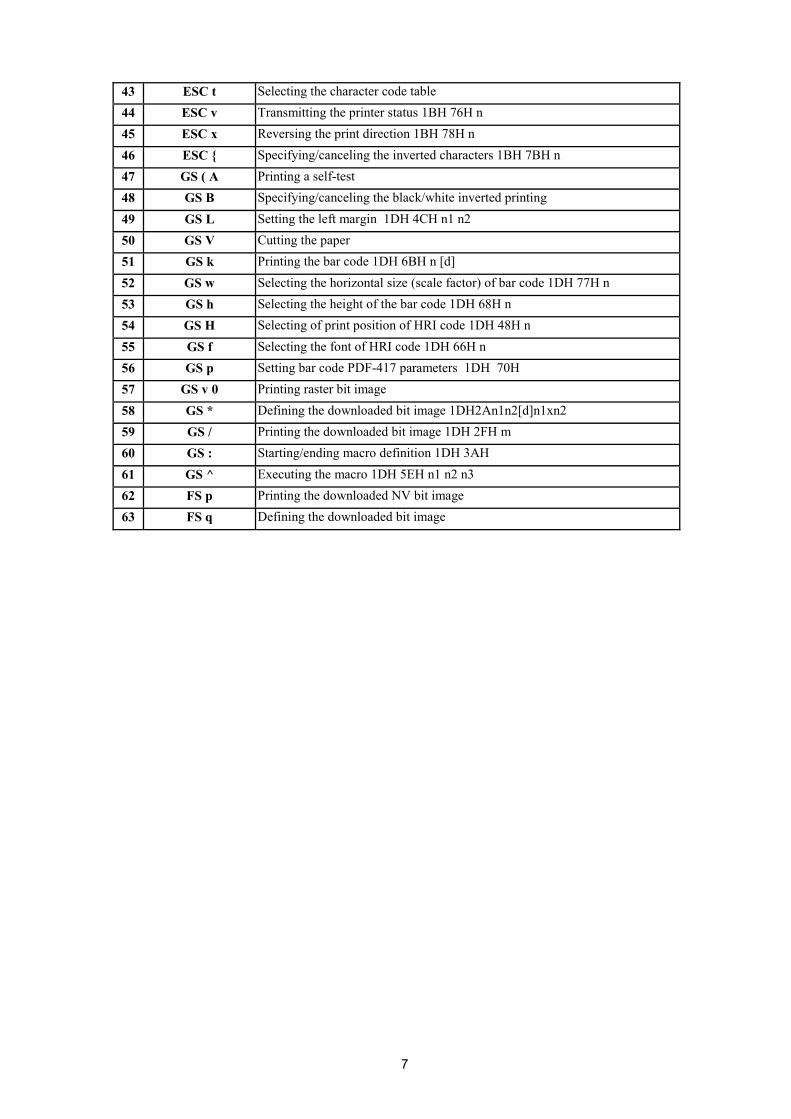
7. ESC # n Setting the Euro symbol position [Code] [1Bh] + [23h] + n [Range] {0 <= n <= FFh}
9
[Outline] This command is provided because most of the old OEM/DOS code pages do not have the euro symbol mapped. This command shows the direct position of the euro symbol in the code table. If n is given value less than 20h the Euro symbol will not be shown.
[Caution] When the code page is changed the Euro symbol position is cleared! The Euro symbol position must be re-entered any time the code page is changed (see below).
Any symbol of the code table could be remapped, with no restrictions. The user must take care not to remap some of the most commonly used symbols.
Some of the code pages supported by the printer (Windows code pages) include the Euro symbol, using the command in such case will result in Euro symbol appearing twice in the code table.
Code pages 20, 21, 22 and 23 (CP858, CP852 + Euro, CP808 and CP857 + Euro) are not hard-coded code pages, i.e. they do not have the Euro Symbol built in. They are produced by giving the Euro symbol position the proper value. If the command is used with some of these pages the Euro symbol position will be changed, i.e. it will not appear twice.
The command ESC > stores the Euro symbol position for further use as a default value. [Default] n = 0 (Not selected) if code page = 20 (CP858), n = D5h; if code page = 21 (CP852 + Euro), n = AAh; if code page = 22 (CP808), n = F2h; if code page = 23 (CP857 + Euro), n = D5h.
8. ESC $ n1 n2 Specifying the Absolute Positions [Code] [1Bh] + [24h] + n1 + n2 [Range] {0 <= n1 <= FFh} {0 <= n2 <= 2} {0 <= n1+n2*256 <= 432} [Outline] The printing start position is specified in the number of dots (1/203 inch unit) from the beginning
of line. • The number of dots is divided by 256, whose quotient is taken as n2 and the residual as n1. • Therefore, the printing start position is equal to n1 + n2 x 256 from the beginning of line..
[Caution] • Specifying beyond the line end is ignored. [Default] • The initial value is not specified. [See Also] ESC \ 9. ESC % n Select/cancel user defined characters [Code] [1Bh] + [25h] + n
• Only bit 0 of n is defined Value 0: Selected Value 1: Not selected
[See also] ESC &
10. ESC & s n1 n2 [a [d] s x a] k ESC & m n1 n2 [ d ] k Define user characters There are two different types of this command selected by switch 5’s position. If switch 5 is OFF: [Code] [1Bh] + [26h] + s + n + m + [a1 + D1] + … + [ am-n+1 +Dm-n+1] [Range] { s = 3 } { 20h <= n <= FFh } { n <= m <= FFh } { 0 <= a <= 12 } { 0 <= Di <= FFh} [Outline] Defines a group of downloaded characters where: „s“ is the number of bytes in vertical direction – always three.

10
„n“ indicates the start character code and „m“ indicates the end character code. To define only one character set n=m.
„a“ is the number of dots in horizontal direction. „Di“ is the data to be defined. The number of data for each symbol is s x a. Each symbol defines
with three bytes of data in vertical direction followed by the next three bytes that define the next one-dot column, etc.
The downloaded font is cleared by ESC @ and ESC _ commands and when the printer is switched off.
[Default] The default downloaded font is equal to the default character set. However the downloaded font is not reset when the code page is chaged, thus it remains the same as the previous code page.
If switch 5 is ON: [Code] [1Bh] + [26h] + а + n1 + n2 + D11 + … + D(m-n+1)k [Range] { m = 0-3 Subcommand} {20h <= n1 <= FFh } {n1 <= n2 <= FFh } {k = (n2-n1+1)*48 for m=2 and k = (n2-n1+1)*16 for m=3 } [Outline] Defines a group of user characters. m=0: Copy internal character set A to user character set A (Parameters n1, n2 and d are omitted } m=1: Copy internal character set B to user character set B (Parameters n1, n2 and d are omitted } m=2: Define character group with ASCII codes between >=n1 and <=n2 for character set A
(12x24). Every character is 48 bytes, two bytes for each line. Only the first nibble of the second byte is used.
m=3: Define character group with ASCII codes between >=n1 and <=n2 for character set B (9x16). Every character is 16 bytes.
n1 is the ASCII code of the first and n2 is the ASCII code of the last of (n2-n1+1) consecutive symbols. To define a single symbol n1=n2.
d is the data that defines the symbols. Every Font A symbol consists of 48 bytes while every Font B symbol consists of 16 bytes.
A Font A symbol is defined left to right, top to bottom, two bytes for each horizontal line, as only the four most significant bits of the second byte are used. Every bit denotes one dot. A bit set to ‘1’ means black dot. The most significant bit is the starting.
Every horizontal line of Font B symbol consists of one byte, as the ninth point is always white. The most significant bit is the starting.
The user-defined characters are kept after printer off. [See Also] ESC %
11. ESC ! n Collective Specifying Printing Mode [Code] [1Вh] + [21h] + n [Range] {0 <= n <= FFh} [Outline] Printing mode is assigned. Each n bit indicates the following:
Bit Function Value 0 Value 1 0 Character Font Font A Font B 1 Undefined 2 Undefined 3 High-lighting Canceled Specified 4 Double height Canceled Specified 5 Double width Canceled Specified 6 Undefined 7 Underline Canceled Specified
[Caution] • With double height and double width being specified simultaneously, double wide and double
high characters are consisted.

11
• An underline is attached to the full character width, which, however, is not attached to the part having been skipped by the horizontal tab. Neither is it attached to 9-right-turned characters.
• The underline width is as having been specified by <ESC - >. (The default setting is 1 dot width) • In case that double wide character and normal character exist in same one line, the layout of
underline is consistent one. [Default] n = 0 [See Also] ESC E, ESC –
12. ESC * m n1 n2 [ d ] k Specifying the Bit Image Mode [Code] [1Bh] + [2Ah] + m + n1 + n2 + D1+ … + Dk [Range] {m= 0, 1, 32, 33 bit image mode (See the table below.)}
{0 <= n1 <= FFh} {0 <= n2 <= 3} {0 <=d <=FFh) {k = n1 + 256 X n2 (m = 0, 1) {k = (n1+256 X n2) X 3} (m = 32, 33)
[Outline] According to the number of dots specified in n1, n2, specify the bit image of mode m. • The total number of dots printed in the bit image is equal to n1 + (256 x n2). • When bit image data have been input in excess of dot position of one line (384 dots) , the excess data are discarded. • d is bit image data, the bits subject to printing are taken as "1" and those not as "0". • The bit image modes specified by m are shown as follows:
Vertical Direction Horizontal Direction m Mode Dots Dot Density Dot Density Max. Dots 0 8-dot single density 8 67 DPI 101 DPI 216 1 8-dot double density 8 67 DPI 203 DPI 432 32 24-dot single density 24 203 DPI 101 DPI 216 33 24-dot double density 24 203 DPI 203 DPI 432
[Caution] • When the values set in m (bit image mode) are out of the above range, the data following after n1
is processed as normal printing data. • After completion of bit image printing, printer returns to normal data processing mode.
The command has another variant with four new modes: ESC * m n[ d ] k ESC * m n a f [ d ] k Specifying the Bit Image Mode (Sending graphics data horizontally) [Code] [1Bh] + [2Ah] + m + n + { a + [00h] } +D1 + … +Dk [Range] {m = 16, 17, 18, 20 bit image mode }
{0 <= n <= 40h} {0 <= d <= FFh} {k = n * 24 * 48} (m = 16) {k = n * 24 * 48} (m = 17) { After decompression } {k = n * h * 48} (m = 18) { After decompression } {k = n * 24 * 48} (m = 20) { After decompression } {0 <= a <= 24 (Used only for mode 18.)} {f = 0 (Used only for mode 18.)}
[Outline] In these graphics modes is sent a graphics block with variable width n*8 dots and height 24 dots for modes 16,17 and a dots for mode 18. In mode 17 data is compressed, and the bytes count specified is before the compression. In mode 16 the same data is without compression. Mode 20 is similar to mode 17, but every byte is mirrored before putting in the print buffer (bits 0 and 7, 1 and 6, 2 and 5, 3 and 4 change places). All modes are high resolution (203 x 203 DPI).

12
• When bit image data have been input in excess of dot position of one line (432 dots) , the excess data are discarded. • d is bit image data, the bits subject to printing are taken as "1" and those not as "0".
[Caution] • When the values set in m (bit image mode) are out of the above range, the data following after n is processed as normal printing data. • After completion of bit image printing, printer returns to normal data processing mode.
[Compression procedure for mode 17 and 18] A simple RLE encoding like this in PCX files is used. If two most significant bits of the byte are
set, the 6 LSB contain a repeat counter (1-63), and the next byte contains the data to be repeated. A single data byte with 2 MSB set must be sent as two bytes.
13. ESC – n Specifying/ Canceling Underline [Code] [1Bh] + [2Dh] + n [Range] {0 <= n <= 2} [Outline] Specifying/canceling an underline.
• Types of underlines by n value are shown below: 0 Canceling an underline. 1 Specifying an underline for 1-dot width. 2 Specifying an underline for 2-dots width.
[Caution] • An underline is attached to the full character width. It is, however, not attached to the part having been skipped by horizontal tab command. • An underline is not attached to a 90°- right-turned characters.
[See Also] ESC !
14. ESC . Selftest. [Code] [1Bh] + [2Eh] [Outline] Prints character table, character samples with different attributes and diagnostic information. [See also] ESC ,
15. ESC , Printing diagnostic information [Code] [1Bh] + [2Ch] [Outline] Printing current intensity level, temperature, code tables, communication mode, protocol and serial
port speed if a serial communication board is installed. [See also] ESC .
16. ESC 2 Specifying 1/6-inch line feed rate [Code] [1Bh] + [32h] [Outline] The line feed rate per line is specified by 1/6 inch.
17. ESC 3 n Setting line feed rate of minimum pitch [Code] [1Bh] + [33h] + n [Range] {0 <= n <= FFh} [Outline] The line feed rate per line is specified by n/203 inch. [Default] The initial value is n = 34 (1/6 inch) (22H), being 4.23 mm line feed rate.

13
18. ESC 8 Temporary store current print settings [Code] [1Bh] + [38h] [Outline] Use command ‘ESC 9’ to restore the parameters. The parameters stored are:
double height/width symbols, rotated by 90º degrees symbols, font size, underline, emphasize, italic style, downloaded font active, rotated by 180º degrees symbols, black and white inverse symbols, reverse print direction (from right to left), Chinese/Arabic code table selected (only in the Chinese/Arabic printer version), print density, printing speed, left margin, printing width, line height, intercharacter space, country, code page, Euro symbol position, barcode width, barcode height, barcode HRI position.
[Caution] The printer uses this command when printing full and short self-tests. So if a self-test is printed, the printer will store the print settings active at the time the printing starts.
19. ESC 9 Restore the previously saved settings [Code] [1Bh] + [39h] [Outline] This command restores the setting saved with ESC 8. If such a command has never been issued,
the printer restores the settings as they were at printer power on.
20. ESC = n Data Input Control [Code] [1Bh] + [3D] + n [Range] {0 <= n <= FFh} [Outline] Selecting equipment in which data input from the host is effective.
• Only bit 0 is defined Value 0: Selected Value 1: Not selected
• When the printer has not been selected, this printer abandons all the received data until it is selected by this command.
[Caution] • Even when the printer has not been selected, it can become BUSY state through printer operation. • When the printer is deselected, this printer discards all the data until it is selected with this command.
[Default] • The initial value of n is "1".
21. ESC > n Set Factory Defaults [Code] [1Bh] + [3Eh] + n [Range] {0 <= n <= FFh} [Outline] This command writes the current code tables, the intensity level and the current printing speed into
the flash memory. These values will be retrieved at first power up or after a power failure. • Value of n doesn’t matter. It is left for compatibility purpose. [Default] • The initial values are: code tables 0 (US American CP437), intensity level 100%, maximum
printing speed.
22. ESC @ Restore saved to nonvolatile RAM settings [Code] [1Bh] + [40h] [Outline] Clears data stored in the print buffer and brings various settings to the initial state. [Caution] • Data inside the internal input buffer are not cleared.

14
• The current code tables, print intensity and printing speed are not reset. • If switch 5 is OFF, the command clears the downloaded font and bit image too. [See also] ESC ^ and ESC _
23. ESC D [ n ] k NUL Setting Horizontal Tab Position [Code] [1Bh] + [44h] + n1 + … + nk + [00h] [Range] {0 <= n <= FFh} {0 <= k <= 20h}. [Outline] Specifying a horizontal tab position.
• "n" indicates the no. of columns from the beginning to the horizontal tab position. At this time, n= set position 1 is to be specified. For example, to set the position at 9th column, n=8 is to be specified. • k denotes the number of horizontal tab positions you want to set. • The tab position is set at position where it is "character width x n" from the line beginning. The character width, at this time, includes the rightward space amount. In double wide characters, it is made double of the ordinary case. • Tab positions can be specified are maximum 32. Specifying exceeding this is ignored. • <n> k, which denotes a setting position, is input in the increasing order and ends at <00>H. • ESC D NUL clears all the set tab positions. Following clearing, horizontal tab command is ignored.
[Caution] When the data, <n> k, is equal to or smaller than its preceding data, <n>k-1, it is assumed that tab setting is finished. If this is the case, the next data onward will be processed as normal data. When the data, <n> k, exceeds a 1-line print area, set the horizontal tab position, assuming "Set digit position = Maximum print digits + 1." The horizontal tab position does not change even if the character width is altered after setting the horizontal tab position.
[Default] • Initial value is specified for each eight characters(9 th .17 th .25 th column). [See Also] HT
24. ESC E n Specifying/canceling highlighting [Code] [1Bh] + [45h] + n [Range] {0 <= n <= FFh} [Outline] Specifying/canceling the highlighting characters.
• "n" is valid only for the lowest bit (n0). • Control by the lowest bit (n0) is shown as follows:
0 Canceling highlighting. 1 Specifying highlighting.
• This is effective to all characters of font A. • Characters of font B are not highlighted. • Dot configuration of a highlighted character includes one extra dot added at its side.
[Caution] • The print result of Double printing and highlight character printing is completely same. [See Also] ESC !
25. ESC G n Specifying/canceling Double Printing (ESC G n) [Code] [1Bh] + [47h] + n [Range] {0 <= n <= FFh} [Outline] Specifying/canceling the double printing.
• "n" is valid only for the lowest bit (n0). • Control by n is shown as follows.
0 Canceling double printing. 1 Specifying double printing.
• This is effective to all characters of font A. • Characters of font B are not highlighted.
[Caution] • The print result of Double printing and highlight character printing is completely same. [See Also] ESC E

15
26. ESC I n Specifying/cancelling italic printing (ESC I n) [Code] [1Bh] + [49h] + n [Range] {0 <= n <= FFh} [Outline] Specifying/canceling the double printing.
• "n" is valid only for the lowest bit (n0). • Control by n is shown as follows.
0 Canceling italic printing. 1 Specifying italic printing.
27. ESC J n Printing and feeding paper n/203 inch [Code] [1Bh] + [4Ah] + n [Range] {0 <= n <= FFh} [Outline] Prints data inside the print buffer and feeds paper by n/203 inch. Since an actual mechanical pitch
is 1/203 inch, it is internally converted approximate to the value specified with this command. • Specified volume does not remain. • The beginning of the line is to be considered as the next printing start position. • Initial value is not defined.
28. ESC M n Specifying/canceling highlighting [Code] [1Bh] + [4Dh] + n [Range] {0 <= n <= FFh} [Outline] Selects character font.
• "n" is valid only for the lowest bit (n0). • Control by the lowest bit (n0) is shown as follows:
0 Selection of font A (12x24). 1 Selection of font B (9x16).
[Caution] ESC ! can also select fonts, but the setting made by the command processed last is valid. [See also] ESC ! 29. ESC R n Selecting international character set [Code] [1Bh] + [52h] + n [Range] {0 <= n <= 10} [Outline] Depending on the value of „n“, one of the following character sets is selected:
Character Set n Country 23h 24h 40h 5Bh 5Ch 5Dh 5Eh 60h 7Bh 7Ch 7Dh 7Eh
0 U.S.A. # $ @ [ \ ] ^ ` { | } ~ 1 France # $ à º ¢ § ^ ` é ù è ¨ 2 Germany # $ § Ä Ö Ü ^ ` ä ö ü ß 3 U.K. £ $ @ [ \ ] ^ ` { | } ~ 4 Denmark I # $ @ Æ Ø Å ^ ` æ ø å ~ 5 Sweden # $ É Ä Ö Å Ü é ä ö å ü 6 Italy # $ @ º \ é ^ ù à ò è ì 7 Spain I Pt $ @ ¡ Ñ ¿ ^ ` ¨ ñ } ~ 8 Japan # $ @ [ ¥ ] ^ ` { | } ~ 9 Norway # ¤ É Æ Ø Å Ü é æ ø å ü
10 Denmark II # $ É Æ Ø Å Ü é æ ø å ü

16
30. ESC V n Specifying/Canceling 90º -right- turned Characters [Code] [1Bh] + [56h] + n [Range] {0 <= n <= 1}. [Outline] Specifying/canceling characters 90º -right- turned character.
• "n" means the followings. 0 Canceling 90º -right- turned Characters 1 Specifying 90º -right- turned Characters
[Caution] • No underlines are attached to 90º -right- turned characters . [Default] • The initial value of n is "0". 31. ESC X n Select maximum printing speed [Code] [1Bh] + [58h] + n [Range] {0 <= n <= 3} {‘0’ <= n <= ‘3’} [Outline] Selects the maximum printing speed according to the value of ‘n’: 0 or ‘0’ about 130 mm/s 1 or ‘1’ about 118 mm/s 2 or ‘2’ about 106 mm/s 3 or ‘3’ about 94 mm/s These values are approximate. The real maximum speed depends on the print intensity and the
printing head’s temperature. [Default] The default value is 0 – maximal printing speed. 32. ESC Y n Selecting the intensity level [Code] [1Bh] + [59h] + n [Range] {0 <= n <= 5} [Outline] Set the intensity level.
• "n" means the followings. 0 Set intensity 70 % 1 Set intensity 80 % 2 Set intensity 90 % 3 Set intensity 100 % 4 Set intensity 120 % 5 Set intensity 150 %
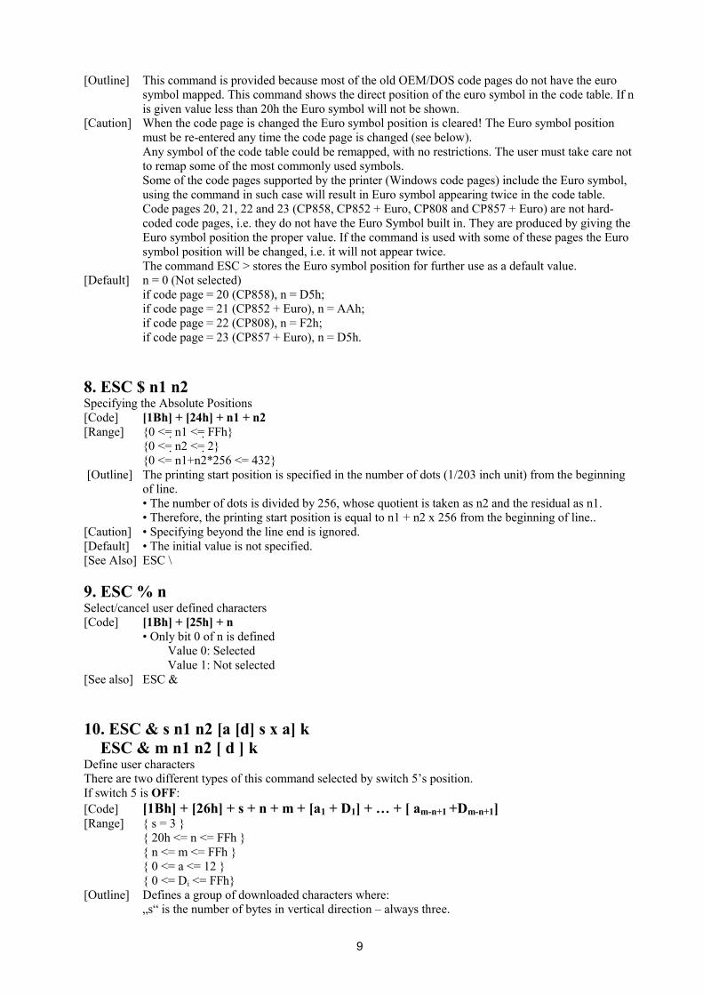
[Caution] • Higher intensities can cause a lower printing speed. [Default] • The initial value of n is 3. 33. ESC Z Transmits identification string. [Code] [1Bh] + [5Ah] [Outline] The printer transmits 32 bytes of information with the following structure: 1 – 22: Printer name complemented with space up to 22 symbols. 23 – 25: Firmware version – 3 digits (in ASCII format). 26 – 26: Language version – 2 letters. 28 – 32: 5 bytes flags. Each bit describes a printer feature, as ‘1’ means that the feature is
present, while ‘0’ means its absence. Bits are described as follows:
17
Bit Meaning 28.0 Supports IrDA mode 28.1 Supports magnetic card reader 28.2 Supports simultaneous reading of three tracks from a magnetic card 28.3 ASCII codes above 127 contain Katakana symbols 28.4 Supports JIS and Shift-JIS symbols 28.5 Prints when ESC . and ESC T, and transmits when ESC ` the temperature in º Fahrenheit 28.6 Not Used 28.7 Reserved – always 1 29.0 Supports downloadable fonts and firmware 29.1 Korean support 29.2 Black mark support 29.3 Bar code reader support 29.4 USB A installed 29.5 USB B installed 29.6 Not Used 29.7 Reserved – always 1 30.0 Not Used 30.1 Not Used 30.2 Not Used 30.3 Not Used 30.4 Not Used 30.5 Not Used 30.6 Not Used 30.7 Reserved – always 1 31.0 Not Used 31.1 Not Used 31.2 Not Used 31.3 Not Used 31.4 Not Used 31.5 Not Used 31.6 Not Used 31.7 Reserved – always 1 32.0 Not Used 32.1 Not Used 32.2 Not Used 32.3 Not Used 32.4 Not Used 32.5 Not Used 32.6 Not Used 32.7 Reserved – always 1
34. ESC \ n1 n2 Specifying the Relative Positions [Code] [1Bh] + [5Ch] + n1 + n2 [Range] {0 <= n1 <= FFh} {0 <= n2 <= FFh} [Outline] The printing start position is specified in the number of dots(1/203 inch unit) from the current
position. • Rightward direction is taken as plus and leftward direction as minus. • To specify N dot in minus (left) direction, use a complement of N for assignment. – N dots = 65536 – N • The number of dots is divided by 256, whose quotient is taken as n2 and the residual as n1. • There are 432 dots per line (positions from 0 to 431).
[Caution] • Specifying exceeding the beginning of the line or the end of the line is ignored. [Default] • The initial value is not specified. [See Also] ESC $

18
35. ESC _ Restore factory defaults and save them to nonvolatile RAM [Code] [1Bh] + [5Fh] [Outline] Select font A, no bold, no underline, etc. Restore tab defaults. The parameters are read from the
flash memory. Downloaded font and downloaded bit image are cleared. Copy internal fonts A and B to user fonts. DIP switches are read again.
Data in the input buffer is not cleared. [See also] ESC @ 36. ESC ` Transmits the current power supply voltage and the print head temperature. [Code] <1B>H<60>H [Outline] The printer transmits two bytes data. First byte is the power supply voltage given as 0.1 mV plus
20h. the second byte is the print head temperature, in degrees Celsius, plus 20h. [Example] If the battery voltage is 6.4 V, and the print head temperature is 33°C, the printer will transmit
<60h><41h>, which is <40h+20h><21h+20h> or <64+32><33+32>. 37. ESC a n Aligning the characters [Code] [1Bh] + [61h] + n [Range] {0 <= n <= 2} {4 <= n <=6 } [Outline] This command is extended and has the following format: All the printed text data, the bar code or the raster bit image (GS v0) within one line are aligned in
the specified position. If used before printing a bar code with this command can be specified vertical direction for printing the bar code. • Depending on n value, positional alignment is carried out as in the table below:
0 Left end alignment 1 Centering 2 Right end alignment 4 Left end aligned vertical bar code 5 Centered vertical bar code 6 Right end aligned vertical bar code
[Default] • The initial value of n is "0". 38. ESC c5 n Enabling/Disabling Panel Switches [Code] [1Bh] + [63h] + [35h] + n [Range] {0 <= n <= FFh} [Outline] Selecting the LF switch valid/invalid.
• "n" is valid only in the lowest bit (n0). • "n" bit means the followings.
0 LFSW valid. 1 LFSW invalid.
[Caution] When the panel switch is disabled with this command, the LF switch is disabled. Therefore, the paper cannot be fed by operating the LF switch.
[Default] • The initial value of n is "0". 39. ESC d n Printing and Feeding the paper by n lines [Code] [1Bh] + [64h] + n [Range] {0 <= n <= FFh} [Outline] Prints data inside the buffer and feeds paper by n lines.

19
• Specified line does not remain. • The beginning of the line is to be considered as the next printing start position.
[Default] • The initial value is not defined. 40. ESC i Cutting the paper [Code] [1Bh] + [69h] [Outline] Performs a paper feed, so the last printed line remains after the auto cutter’s edge and then cuts the
paper. This command is valid only at the beginning of the line. 41. ESC m Cutting the paper [Code] [1Bh] + [6Dh] [Outline] The command is exactly the same as ESC i. 42. ESC p Generating a drawer-kick pulse [Code] [1Bh] + [70h] + m + n1 + n2 [Range] { 0 <= m <= 255 } { 0 <= n1 <= 255 } { 0 <= n2 <= 255 } [Outline] The value of m is ignored. The printer generates a 2*n1 milliseconds long pulse and 2*n2 milliseconds long rest after the
pulse. n2 must be at least four times greater than n1 or the command will be discarded. 43. ESC t Selecting the character code table [Code] [1Bh] + [74h] + n [Range] { 0 <= n <= 19 } [Outline] Selects the code table for ASCII codes 80h-FFh. In the international version of the printer one of the following supported code tables is selected
according to the value of n:
n Code Table 0 USA (CP437) 1 Litva 2 West Europe Latin I (CP850) 3 Brasil (CP860) 4 Poland 5 Bulgarian (CP856) 6 Central Europe Latin II (CP852) 7 Russian (CP866) 8 Turkish (CP857) 9 Windows English Latin I (CP1252) 10 Baltic (CP775) 11 Latvia 12 Greek (CP737) 13 Hebrew (CP862) 14 Windows Central European Latin II (CP1250) 15 Windows Cyrilic (CP1251)

20
16 Windows Greek (CP1253) 17 Windows Turkish (CP1254) 18 Windows Hebrew (CP1255) 19 Windows Baltic (CP1257) 20 West Europe Latin I + Euro (CP858) 21 Central Europe Latin II + Euro (CP852 + Euro) 22 Russian + Euro (CP808) 23 Turkish + Euro (CP857 + Euro)
In the Chinese version of the printer one of the following supported code tables is selected
according to the value of n:
n Code Table 0 USA (CP437) 1 Chinese GB2312
[Caution] In the international version of the printer when the code page is set by the DIP switches the
command is disabled and a code page other than this one cannot be set. In the Chinese version of the printer the code table can be changed regardless of the DIP switch
setting. Code pages 20, 21, 22 and 23 (CP858, CP852 + Euro, CP808 and CP857 + Euro) are not hard-
coded code pages, i.e. they do not have the Euro Symbol built in. They are produced by giving the Euro symbol position the proper value. If ESC # is used with some of these pages the Euro symbol position will be changed, i.e. it will not appear twice.
Even if the code page is set by the DIP switches the command ESC > will store this code page into the flash for further use.
The command <ESC t 14h> is equal to the combination of commands <ESC t 02h> + <ESC # D5h>.
The command <ESC t 15h> is equal to the combination of commands <ESC t 06h> + <ESC # AAh>.
The command <ESC t 16h> is equal to the combination of commands <ESC t 07h> + <ESC # F2h>.
The command <ESC t 17h> is equal to the combination of commands <ESC t 08h> + <ESC # D5h>.
[Default] The default value is 0 – USA CP437 code page. 44. ESC v Transmitting the printer status [Code] [1Bh] + [76h] [Outline] Current printer status is transmitted.. Status sent out consists of 1 byte whose content is as in the table below.
Bit Function Value 0 Value 1 0 Not defined 1 Not defined 2 Paper end With paper Without paper 3 Head temperature Normal Overheated 4 Not defined 5 Auto cutter state No cutter error Auto cutter error 6 Not defined 7 Not defined
21
45. ESC x n Reversing the print direction [Code] [1Bh] + [78h] + n [Outline] This command changes the characters’ print direction from left to right to right to left. The
character itself is not mirrored horizontally. The command is intended for languages that use right to left scripting, like Hebrew and Arabic. Only the lowest bit of “n” is valid with the following meaning: 0 – left to right printing 1 – right to left printing [Caution] The command changes only the print direction of the characters - all graphics and bar codes are
unaffected. This command is ignored in the Chinese version of the printer. The command reverses all print attributes of the line and the characters, though the characters
themselves are not mirrored horizontally. Though the command allows mixing reversed and non-reversed characters in one line the print
results could be unsatisfactory and unreliable. [Default] The default value is 0 – left to right printing. 46. ESC { n Specifying/Canceling the Inverted Characters [Code] [1Bh] + [7Bh] + n [Range] {0 <= n <= FFh} [Outline] Specifying/canceling inverted characters.
• "n" is valid only for the lowest bit (n0). • Bit n (n0) means the followings.
0 Canceling inverted characters. 1 Specifying inverted characters.
[Caution] • Inverted printing means printing the line at 180º turned. • Valid is the last value specified in a line.
[Default] • The initial value of n is "0". 47. GS (A pL pH n m Printing a self-test [Code] [1Dh] + [28h] + [41h] + pL + pH + n + m [Range] { 0 <= pL <= 255 } { 0 <= pH <= 255} { 0 <= n <= 255 } { 2 <= m <= 3 } [Outline] This command is included for compatibility purposes. A “short” or “long” test is printed
depending on the value of m. m = 2 – printing a “long” test (ESC .) m = 3 – printing diagnostic information (“short” test) (ESC ,) 48. GS B n Specifying/canceling the black/white inverted printing [Code] [1Dh] + [42h] + n [Range] { 0 <= n <= 255 } [Outline] According to the least significant bit of n (n0) the following modes are possible: n0 = 0 – Black/white inverted printing is canceled n0 = 1 – Black/white inverted printing is specified The space skipped by tab command or by positioning commands (ESC $, ESC \) is not affected. Both built-in and downloaded character sets are inverted by this command. The black/white inversion works on the right space defined by ESC SP command. [Default] The initial value is n=0

22
49. GS L n1 n2 Setting the left margin [Code] [1Dh] + [4Ch] + n1 + n2 [Range] {0 <= n1 <= FFh} {0 <= n2 <= FFh} {n1+256*n2 < 432} [Outline] Sets the position in dots (1/203 inches) from which each line starts. This command works only if
entered at the beginning of the line. The start position is equal to n1+256*n2 dots from the left end of the printable area.
[Caution] If a value that exceeds the length of the print area is set the left margin is set to 0. [Default] Default value is 0. 50. (1)GS V m (2)GS V m n Cutting the paper [Code] (1) [1Dh] + [56h] + m (2) [1Dh] + [56h] + m + n [Range] (1) {m=1, m=49} (2) {m=66} {0 <= n <= 255} [Outline] Depending on the value of m one of the following actions is performed: - if m=1 or m=49 (‘1’) a paper feed, so the last printed line remains after the auto cutter’s edge is
performed. Then the paper is cut. - if m=66 (‘B’) the paper is fed by n/8 mm and the cut. In both cases the paper is first fed to the cut position so the last printed line remains after the
cutter’s edge. This means that in case (2) the paper is fed by “cut position + n/8” millimeters total. 51. (1) GS k m [ d ] k NUL (2) GS k m n [ d ] k (3) GS k m a [ d ] k NUL (4) GS k m a xL xH [ d ] k Printing the bar code [Code] (1) [1Dh] + [6Bh] + m + Di + [00h]
(2) [1Dh] + [6Bh] + m + n + Di (3) [1Dh] + [6Bh] + m + a + Di + [00h] (4) [1Dh] + [6Bh] + m + a + xL + xH + Di
[Range] (1) {0 <= m <= 6} (2) {65 <= m <= 73} (3) {m=9; a=0,1} (4) {m=74; 256*xH+xL<=3000; a=0,1} [Outline] Specifying a type of bar code and printing bar codes.
• The beginning of line is considered as the next printing start position. • Depending on the value of m, the following bar code can be selected. d indicates a bar code data to be printed and k indicates the number of character to be printed. n indicates indicates number of characters when 65 <= m <= 73. a is a setting for PDF-417 bar code. Setting a=0 will make the printer to automatically choose PDF-417 compression modes, while a=1 will force byte compression mode. xL and xH indicates the number of bytes for PDF-417 bar code when m=74. The number of bytes is equal to 256*xH+xL. m determines bar code type and it is one of the following:

23
m (1) Bar code type Length Range of ‘d’
0 UPC-A 11 48 <= Di <= 57 1 UPC-E 11 48 <= Di <= 57 2 EAN13 (JAN13) 12 48 <= Di <= 57 3 EAN 8 (JAN8) 7 48 <= Di <= 57 4 CODE 39 - 48 <= Di <= 57, 65 <= Di <= 90, 32, 36, 37, 43, 45, 46, 47 5 ITF - 48 <= Di <= 57 6 CODABAR (NW-7) - 48 <= Di <= 57, 65 <= Di <= 68, 36, 43, 45, 46, 47, 58 7 CODE 93 - 1 <= Di <= 127 8 CODE 128 - 1 <= Di <= 127 9 PDF-417 - 1 <= Di <= 255
M (2) Bar code type Length Range of ‘d’
65 UPC-A 11 48 <= Di <= 57 66 UPC-E 11 48 <= Di <= 57 67 EAN13 (JAN13) 12 48 <= Di <= 57 68 EAN 8 (JAN8) 7 48 <= Di <= 57 69 CODE 39 - 48 <= Di <= 57, 65 <= Di <= 90, 32, 36, 37, 43, 45, 46, 47 70 ITF - 48 <= Di <= 57 71 CODABAR (NW-7) - 48 <= Di <= 57, 65 <= Di <= 68, 36, 43, 45, 46, 47, 58 72 CODE 93 - 0 <= Di <= 127 73 CODE 128 - 0 <= Di <= 127 74 PDF-417 - 0 <= Di <= 255
[Caution] • When data being held in the print buffer, this command is ignored. • Regardless of the specified feed pitch, this command feeds the paper that is required to print a bar code. • If the character code d cannot be printed in the respective bar code system, the bar code so far will be printed, processing the subsequent data as normal data. • When a bar code whose number of characters to be printed is fixed has been selected, the number of characters k have to be always made equal to the number of characters to be printed. (The bar code is not printed when not matching.) • When the horizontal direction exceeds one line length, the bar code is not printed.
[Default] • The initial value is not specified. [CODE 128 additional information]
Code 128 covers all ASCII codes from 0 to 127, and it has three tables A, B and C that can be used in the same bar code.
Table A: contains ASCII symbols with codes 0 to 95 and control symbols FNC1, FNC2, FNC3, FNC4, SHIFT, CODEB, CODEC.
Table B: contains symbols with ASCII codes from 32 to 127 and control characters FNC1, FNC2, FNC3, FNC4, SHIFT, CODEA, CODEC.
Table C: It is used for coding bar code areas that consist only of numerals. Each symbol gives two digits that are coded with ASCII codes from 0 to 99. Control characters FNC1, CODEA, CODEB are also available. The bar code must start with one of the symbols CODEA, CODEB or CODEC, that determines which table will be used. If it is necessary the current table could be changed later by inserting one of these symbols in to the bar code. The symbol following SHIFT character is considered to be from table B, if table A is current, or from table A, if table B is current. If a symbol that is not valid for the current table is used, the whole bar code is not printed. Control symbols are assigned two bytes as follows:
Code system Symbol
Decimal Hexadecimal Text FNC1 123, 49 7B, 31 {1 FNC2 123, 50 7B, 32 {2 FNC3 123, 51 7B, 33 {3

24
FNC4 123, 52 7B, 34 {4 CODEA 123, 65 7B, 41 {A CODEB 123, 66 7B, 42 {B CODEC 123, 67 7B, 43 {C SHIFT 123, 83 7B, 53 {S
{ 123, 123 7B, 7B {{ 52. GS w n Selecting the horizontal size (Scale factor) of the bar code [Code] [1Dh] + [77h] + n [Range] {2 <= n <= 4} [Outline] Selecting bar code width.
n denotes the number of dots in fine element width. [Default] • The initial value of this width is "3". 53. GS h n Selecting the height of the Bar Code [Code] [1Dh] + [68h] + n [Range] {1 <= n <= FFh} [Outline] Selecting bar code height.
n denotes the number of dots in the vertical direction. [Default] • The initial value of n is "162". 54. GS H n Selecting of Printing Position of HRI Code [Code] [1Dh] + [48h] + n [Range] {0 <= n <= 3} [Outline] Selecting printing position of HRI code in printing bar codes.
• "n" means the followings. 0 No printing 1 Above the bar code 2 Below the bar code 3 Both above and below the bar code
The HRI code refers to the bar code-turned characters so that you can read them. [Caution] The HRI code is printed in the font selected with GS f. Specify before the GS k command. [Defult] • The initial value of n is "0". [See Also] GS f 55. GS f n Selecting the font of HRI code [Code] [1Dh] + [66h] + n [Range] n = 0, 1 [Outline] Selecting the font of HRI code in printing bar code.
The type of font can be printed by selecting n is as follows. 0 Font A 1 Font B
The HRI code refers to the bar code-turned characters so that you can read them. [Caution] The HRI code is printed at the position specified with GS h on page 63. [Default] The initial value of n is “0 ”. [See Also] GS H

25
56. GS p n1 n2 n3 Setting bar code PDF-417 parameters [Code] [1Dh] + [70h] + n1 + n2 + n3 [Range] {0 <= n1 <= 255} {0 <= n2 <= 30} {n3=0; 3 <= n3 <= 90} [Outline] n1 selects PDF-417 security level. Setting a security level higher than eight forces the printer to
automatically adjusts the security level according the following table:
EC level EC Codewords Auto Select Level 0 2 1 4 0-31 2 8 32-63 3 16 64-127 4 32 128-255 5 64 256-511 6 128 512-928 7 256 8 512
• Only real data codewords in the security level calculation (any pad codewords are ignored). n2 – number of data columns. If n2=0 the number of data columns is automatically calculated. n3 – number of rows. If n3=0 the number of rows is automatically calculated. [Caution] If any value is out of range this value remains unchanged. Thus the other values are changed. [Default] The initial value of n1 is “9 ” (auto select). The initial value of n2 is “0 ” (auto select). The initial value of n3 is “0 ” (auto select). [See Also] GS k 57. GS v0 Printing of raster bit image [Code] [1Dh] + [76h] + [30h] + m + xL + xH + yL + yH + D1 + … + Dn [Range] {0 <= m <= 3; 48 <= m <= 51} {0 <= xL <= 255} {0 <= xH <= 255} {0 <= yL <= 255} {0 <= yH <= 255} {0 <= Di <= 255} [Outline] The value of xH is ignored. Although yH could be from 0 to 255 the high four bits are ignored, so yH could actually be from 0
to 15. xL is the number of bytes in horizontal direction (xL*8 dots). The number of dots in horizontal direction is equal to yL+yH*256. The number of data bytes k=xL * (yL+yH*256). However k must not be equal to 0 or the bit
image will be discarded. m defines the printing mode of the bit image according to the following table:

26
m Mode Dot density in vertical direction
Dot density in horizontal direction
0 Normal 203 DPI 203 DPI 1 Double width 203 DPI 101 DPI 2 Double hight 101 DPI 203 DPI 3 Quadruple 101 DPI 101 DPI
The bit image is defined line by line from left to right. The most significant bit of each byte is the
leftmost dot and the least significant bit is rightmost dot. The data that exceeds the printing width of the line is discarded. The raster bit image could be positioned using the commands ESC \, ESC $ and GS L. The raster bit image could be justified using the ESC a command. If this command is executed during a macro definition, the macro definition is finished and the
command is executed. 58. GS * Defining the Download Bit Image There are two variants of this command depending of the position of switch 5. If switch 5 is OFF: [Code] [1Dh] + [2Ah] + n1 + n2 + D1 + … + Dn [Range] {0 <= n1 <= 255} {0 <= n2 <= 68} {0 <= Di <= 255} [Outline] n1 denotes the horizontal size of the bit image n2 denotes the vertical size of the bit image There are n1*n2*8 bytes of data in order from top to bottom and from left to right, n1 bytes in
each vertical column of dots. This command defines a bit image with number of dots determined by n1 and n2. There are n1*8
dots in horizontal direction and n2*8 number of dots in vertical direction. If n1 is 0 the downloaded bit image is cleared. The command GS / is used to print downloaded bit image. If switch 5 is ON: [Code] [1Dh] + [2Ah] + n1 + n2 { + n21 + n22 } + D1 + … + DN [Range] {0 <= n1 <= 7Fh} {0 <= n2 <= F8h} {0 <= Di <= FFh} {1 <= n21+256*n22 <= 544} [Outline] If n2 is 0 two more bytes are read. These two bytes then determine the vertical size of the bit
image. The vertical size then is N= n21+256*n22 rows. If N is the vertical size of the bit image, N=n2 or N= n21+256*n22. Di is the bit image’s data. The number of data bytes is n1*N. There are n1 bytes in the first row
then n1 bytes in the second, etc. There are N rows in the bit image, and the number of dots in the bit image is n1*N*8. Each data bit defines one dot, value of “1” corresponds to black.
If n1 is 0 the downloaded bit image is cleared. The downloaded bit image remains effective even if the printer is switched off. [See Also] GS / 59. GS / m Printing the Download, Bit Image [Code] [1Dh] + [2Fh] + m [Range] {0 <= m <= 3} [Outline] Prints download bit image in a mode specified by m.

27
m Mode Name Dots in Vertical Direction
Dots in Horizontal Direction
0 Normal mode 203 DPI 203 DPI 1 Double wide mode 203 DPI 101 DPI 2 Double high mode 101 DPI 203 DPI 3 DW / DH mode 101 DPI 101 DPI
[Caution] • When data exist inside the print buffer, this command is ignored.
• When a download bit image has not been defined, this command is ignored. • A portion of a download bit image exceeding one line length is not printed.
[Default] • The initial value is not specified. [See Also] GS * 60. GS : Starting / Ending Macro Definition [Code] [1Dh] + [3Ah] [Outline] Specifying starting / ending macro definition. Means termination when received while defining a
macro. [Caution] Maximum content available for macro definition is 3823 bytes. A portion exceeding 3823 bytes is
not defined. • Even with ESC @ (initialization of the printer) having been executed, defined content is not cleared. Therefore, it is possible to include ESC @ into the content of macro definition. • Normal printing operation is carried out even while in macro definition
[Default] • Initially, Macro is not specified. [See Also] GS ^ 61. GS ^ n1 n2 n3 Executing the Macro [Code] [1Dh] + [5Eh] + n1 + n2 + n3 [Range] {0 <= n1 <= FFh} {0 <= n2 <= FFh} {0 <= n3 <= 1}. [Outline] Executing contents defined in macro. • "n1~n3" indicate as follows:
n1 : The number of times of macro execution n2 : Waiting time on macro execution
Waiting time of n2 x 100 msec is given for every execution. n3 : Macro execution mode
0 Continuous execution 1 Execution by LFSW
Continuous execution: The Macro is executed n1 times continuously at the time intervals specified by n2. Execution by FEED Switch: After waiting for lapse of time specified by n2, the LF switch is waited to be pressed. When it is pressed, the macro is executed once. This action is repeated n1 times.
[Caution] • When this command is received while in macro definition, suspension of macro definition is indicated. At this time, the defined content is cleared. • No execution takes place when macro is held undefined or n1=0. • While in macro execution with n3=1, paper feed with the LF SW is not available.
[Default] • Initially, this command is not specified. [See Also] GS : 62. FS p n m Printing the downloaded NV bit image [Code] [1Ch] + [70h] + n + m

28
[Range] {0 <= n <= FFh} {0 <= m <= 3} {48 <= m <= 51} [Outline] Printing the downloaded NV bit image defined by FS q command.
m Mode Name Dots in Vertical Direction
Dots in Horizontal Direction
0, 48 Normal mode 203 DPI 203 DPI 1, 49 Double wide mode 203 DPI 101 DPI 2, 50 Double high mode 101 DPI 203 DPI 3, 51 DW / DH mode 101 DPI 101 DPI
“n” is discarded - the printer supports only one NV bit image. “m” is the bit image printing mode. 63. FS q n [xL xH yL yH D1 D2 … Dk] Defining the downloaded NV bit image There are two variants of this command depending of the position of switch 5. If switch 5 is OFF: [Code] [1Ch] + [71h] + n + xL + xH + yL + yH + D1 + D2 + … + Dk [Range] {0 <= n <= FFh} {0 <= xL <= FFh} {0 <= xH <= FFh} {0 <= yL <= FFh} {0 <= yH <= FFh} {0 <= D <= FFh} [Outline] This command defines the specified NV (non volatile) bit image. The bit image is stored into the
flash. “n” is ignored – the printer supports only one bit image. xL and xH denote the horizontal size of the NV bit image as (xL + xH × 256) × 8 dots. yL and yH denote the vertical size of the NV bit image as (yL + yH × 256) × 8 dots. Total amount of data defining the bit image is (xL + xH × 256) × (yL + yH × 256) × 8 bytes. [Details] The maximum printable size of the NV bit image is 432 × 512 dots. This corresponds to (xL + xH
× 256) < 54 and (yL + yH × 256) < 64. The exceeding data is read but discarded. The order of the data is from top to bottom and then from left to right, (yL + yH × 256) bytes in
each vertical column of dots. The printer will become busy before each writing cycle in the NV memory. Any data sent while
the printer is busy may not be processed and therefore could be lost. xL = xH = yL = yH = 0 clears the downloaded bit image. If switch 5 is ON: [Code] [1Ch] + [71h] + n + xL + xH + yL + yH + D1 + D2 + … + Dk [Range] {0 <= n <= FFh} {0 <= xL <= FFh} {0 <= xH <= FFh} {0 <= yL <= FFh} {0 <= yH <= FFh} {0 <= D <= FFh} [Outline] This command defines the specified NV (non volatile) bit image. The bit image is stored into the
flash. “n” is ignored – the printer supports only one bit image. xL and xH denote the horizontal size of the NV bit image as (xL + xH × 256) × 8 dots. yL and yH denote the vertical size of the NV bit image as (yL + yH × 256) dots. Total amount of data defining the bit image is (xL + xH × 256) × (yL + yH × 256) bytes.

29
[Details] The maximum printable size of the NV bit image is 432 × 512 dots. This corresponds to (xL + xH × 256) < 54 and (yL + yH × 256) < 512.
The exceeding data is read but discarded. The order of the data is from left to right and then from top to bottom, (xL + xH × 256) bytes in
each horizontal row of dots. The printer will become busy before each writing cycle in the NV memory. Any data sent while
the printer is busy may not be processed and therefore could be lost. xL = xH = yL = yH = 0 clears the downloaded bit image.