User Guide (Printer) - FUJIFILM Business Innovation
185
Document Centre 400/350/250 Series User Guide (Printer) All Contents and Index entries are in hypertext link. Click on them to be transported to the corresponding page.
-
Upload
khangminh22 -
Category
Documents
-
view
1 -
download
0
Transcript of User Guide (Printer) - FUJIFILM Business Innovation

Document Centre
400/350/250 Series
User Guide (Printer)All Contents and Index entries are in hypertext link.
Click on them to be transported to the corresponding page.

AppleTalk, EtherTalk, TrueType, Apple and Macintosh are trademarks of Apple Computer, Inc.registered in the US and other countries.
Adobe, Adobe Type Connection, Adobe Type Manager, PostScript, PostScript 3, and the PostScriptlogo are trademarks of Adobe Systems Incorporated.
Helvetica, Palatino, Times are trademarks of Linotype-Hell, AG.Microsoft, MS-DOS, Windows, Windows NT are registered trademarks of Microsoft Corporation in
the U.S. and other countries.NetWare is a registered trademark of Novell, Inc.
UNIX is a trademark of X/Open Company Ltd.All product/brand names are trademarks or registered trademarks of the respective holders.Permission has been obtained from Microsoft Corporation for use of software screen shots.
This manual is copyrighted with all rights reserved. Under the copyright laws, this manual may not be copied,in whole or part without the written consent of the publisher.
Parts of this manual are subject to change without prior notice.
We welcome any comments on ambiguities, errors, omissions, or missing pages.
Never attempt any procedure on the machine that is not specifically described in this manual.Unnauthorized operation can cause faults or accidents. Fuji Xerox is not liable for any problems resulting fromunauthorized operation of the equipment.
XEROX is a registered trademark. The Document Company and Ethernet are trademarks which may be registered in certain
jurisdictions.CentreWare is a trademark.
Important

i
Preface
Welcome to Xerox Document Centre 400/350/250 series.
Written with the new user in mind, this User Guide (Printer) provides all the necessary information aboutoperating the printer functions of the printer as well as installing the printer drivers. To get the most out ofthe machine, please read this manual before using it.
This guide is written with the assumption that you are familiar with the basic knowledge and way ofoperating the different operating systems. Refer to the manuals of these products for information onthem.
Note that this guide is written for users operating the Document Centre 400/350/250 series with a clientcomputer installed with an English edition operating system. Unless otherwise indicated, this guide iswritten for use with English edition operating system only.
After reading, keep this guide handy for a quick reference should you encounter any difficulties whenusing the machine.
In this manual, safety instructions are described with the symbol . Always read and follow these instructionsbefore performing the required procedure.
This product is in the Class B category based on the standard of Voluntary Control Council for Interference fromInformation Technology Equipment (VCCI)*. If the machine is used near a radio or television receiver in adomestic environment, it may cause radio interference. Install and use the machine according to the instructions.
* This regulation applies only to Japan.
This equipment conforms to the guidelines of the Japan Business Machine Makers Association on theharmonic effects by copiers and other reproduction devices. These guidelines conform to the guides on theharmonic suppressors of electronic appliances and general-purpose machines.

ii
Types of Manuals
The types of manuals available for the Document Centre 400/350/250 series are as follows:
Manual bundled with the main unit (i.e. the copier)
• User Guide (Copier)
Explains the handling of the copier and the copier functions.
Manuals bundled with the fax kit/fax-installed unit
• User Guide (Facsimile)
Explains the fax functions.
• Quick Reference
A simple manual which gives a summary of some of the fax functions which haveraised the most queries in the past.
Manual bundled with the printer kit/printer-installed unit
• User Guide (Printer) - i.e. this manual
Explains the printer functions, the printer control panel operations as well as the installation/configuration of the PCL printer drivers.
Manuals bundled with the optional accessories
Manuals on the handling and use of the accessories.

iii
Using This Guide
Organization
The following is a summary of each chapter:
Chapter 1 Overview of the Printer
This chapter explains the interface connections, special features, printer functions andpowering on/off.
Chapter 2 Setting Up
This chapter explains the cable connections and the increase/allocation of memory.
Chapter 3 Useful Operations
This chapter explains the operations that you need to know about using the printerfunctions such as as cancelling printing/fax transmission, outputting and the main framecontrol panel operations during printing/transmission.
Chapter 4 Installing/Configuring the Printer Drivers
This chapter explains how to install printer drivers, set the printer properties, printand fax from an application in different OS environments.
Chapter 5 Mode Menu/Common Menu
This chapter explains about the two menus, Mode menu and Common menu and theirmenu items.
Chapter 6 Precautions and Limitations
This chapter explains the precautions and limitations of using the printer.
Chapter 7 Troubleshooting
This chapter explains how to solve problems when the printer is not functioningproperly. When problems occur, read this first before treating it as a breakdown.

iv
Appendix
This section provides information on the printing area, connector and allocation signals, thedifferent items of the Print Utility, paper jams at the mail box as well as the PostScript 3Kit.
Glossary
This section explains the meanings of the terms used in this guide.
System Charts
This section contains the system charts of the menus. Refer to these charts to makechanges to the settings after you have understood the printer operations.

v
Conventions
1. In this manual, a host device refers to a personal computer or workstation and"Xerox DC 400/350/250" refers to "Xerox Document Centre 400/350/250".
2. The following icons are used in this guide:
Instructions or important information for preventing equipment damage.
For your information. This indicates additional information on procedures ofoperations and features.
Indicates sources of references.
3. The following conventions are used in this guide.
" " : Double quotes are used to indicate names of windows, menus, dialog boxes,icons, files, tabs, fields and input contents.For example: The "Select a Printer" dialog box appears.
Bold Face : Bold face characters refer to selections made like options on the screen, hardor soft buttons, and keys from the keyboard.For example: Press Esc.

vi
Contents
Preface ................................................................................................................................................................ iTypes of Manuals .............................................................................................................................................. iiUsing This Guide .............................................................................................................................................. iiiContents ........................................................................................................................................................... viSafety Precautions ............................................................................................................................................. ix
Chapter 1 Overview of the Printer
1.1 Getting Ready to Print ............................................................................................................................ 2
1.2 Special Features of the Printer ................................................................................................................ 4
1.3 Main Components and Their Functions ................................................................................................ 51.3.1 Parts of the printer configuration ................................................................................................ 51.3.2 Control panel .............................................................................................................................. 71.3.3 CD-ROM ................................................................................................................................... 12
1.4 Precautions on Switching On/Off ......................................................................................................... 13
Chapter 2 Setting Up
2.1 Connecting Cable (Parallel/Serial Interface) ......................................................................................... 162.1.1 Connecting interface cable ....................................................................................................... 16
2.2 Using the Ethernet Interface ................................................................................................................ 202.2.1 Installing the Ethernet interface card ........................................................................................ 202.2.2 Connecting the Ethernet interface ............................................................................................ 21
2.3 Increase/Allocation of Memory ........................................................................................................... 232.3.1 Uses .......................................................................................................................................... 232.3.2 Suggested values ...................................................................................................................... 23
Chapter 3 Useful Operations
3.1 Flow of Printing/Fax Transmission ....................................................................................................... 263.1.1 For Windows ............................................................................................................................ 263.1.2 For DOS (printing only) ............................................................................................................ 27
3.2 Cancelling Printing/Fax Transmission .................................................................................................. 283.2.1 Cancelling from host device ...................................................................................................... 283.2.2 Cancelling jobs in process ........................................................................................................ 293.2.3 Cancelling all jobs in the printer ................................................................................................ 293.2.4 Cancelling fax transmission from touch panel display .............................................................. 30
3.3 Outputting ............................................................................................................................................ 313.3.1 Forced outputting of remaining print data ................................................................................ 313.3.2 Outputting all jobs in the printer ............................................................................................... 32
3.4 Main Frame Control Panel Operations During Printing/Transmission ................................................. 33
3.5 Removing Documents Output to the Stacker Tray ............................................................................... 34
3.6 Outputting Lists/Reports ..................................................................................................................... 353.6.1 Types of lists/reports ................................................................................................................ 353.6.2 Printing lists/reports ................................................................................................................. 35
3.7 Printer Functions .................................................................................................................................. 37

vii
Chapter 4 Installing/Configuring the Printer Drivers
4.1 About the Printer Drivers ..................................................................................................................... 404.1.1 The PCL 5e/PCL 6 printer drivers .............................................................................................. 404.1.2 Installation/configuration methods ........................................................................................... 404.1.3 Settings on the Xerox DC 400/350/250 printer ........................................................................... 40
4.2 Installing/Uninstalling the Printer Drivers ............................................................................................ 414.2.1 For a local Xerox DC 400/350/250 printer .................................................................................. 414.2.2 For a network Xerox DC 400/350/250 printer ............................................................................. 434.2.3 Uninstalling the printer drivers ................................................................................................. 44
4.3 Configuring the Printer Drivers ............................................................................................................ 464.3.1 Accessing the printer properties dialog box ............................................................................. 464.3.2 Setting the printer properties .................................................................................................... 49
4.4 Printing/Faxing ..................................................................................................................................... 734.4.1 Printing from an application ...................................................................................................... 734.4.2 Faxing from an application ........................................................................................................ 73
Chapter 5 Mode Menu/Common Menu
5.1 Mode Menu and Common Menu ......................................................................................................... 805.1.1 About menu .............................................................................................................................. 805.1.2 Mode menu ............................................................................................................................... 815.1.3 Common menu .......................................................................................................................... 82
5.2 Mode Menu Items ................................................................................................................................ 845.2.1 List of Mode Menu items .......................................................................................................... 845.2.2 Setting a Mode Menu ............................................................................................................... 89
5.3 Common Menu Items ........................................................................................................................... 905.3.1 List of Common Menu items ..................................................................................................... 905.3.2 Setting a Common Menu ......................................................................................................... 103
Chapter 6 Precautions and Limitations
6.1 Precautions and Limitations ................................................................................................................ 106
Chapter 7 Troubleshooting
7.1 When Problems Occur ........................................................................................................................ 110
7.2 Messages ............................................................................................................................................ 1147.2.1 Messages about printer condition ........................................................................................... 1147.2.2 Messages about operation mistakes and breakdowns ............................................................ 1167.2.3 Messages about staple finisher ............................................................................................... 121
7.3 When the Print Quality is Poor............................................................................................................ 123
Appendix
A Printing Area ....................................................................................................................................... 128
B Connector and Allocation Signals ...................................................................................................... 129B.1 Parallel Interface ....................................................................................................................... 129B.2 Serial Interface ......................................................................................................................... 131

viii
C Print Utility .......................................................................................................................................... 133C.1 Types and Paper Sizes ............................................................................................................. 133C.2 PCL6 Settings ........................................................................................................................... 134C.3 Printer Settings ........................................................................................................................ 136C.4 Error History ............................................................................................................................ 138C.5 Print History ............................................................................................................................. 140C.6 Job Template Server Settings ................................................................................................... 143C.7 PCL6 Font List ......................................................................................................................... 145C.8 PS Font List .............................................................................................................................. 148
D Mail Box Paper Jams ............................................................................................................................ 151
E PostScript 3 Kit .................................................................................................................................... 152
E.1 Setting Up the Printer ............................................................................................................... 152E.2 Precautions and Limitations ..................................................................................................... 154
Glossary .......................................................................................................................................................... 156
System Charts (Mode Menu Items) ................................................................................................................ 158
System Charts (Common Menu Items) ........................................................................................................... 161
Index ............................................................................................................................................................ 168

ix
Safety Precautions
Read these safety notes before using the printer functions of this machine.
Conventions and symbols
is used to alert operators to an operating procedure, practice or condition that, if notstrictly observed, can result in severe injury or loss of life.
CAUTION is used to alert operators to an operating procedure, practice or condition that, if notstrictly observed, might result in safety hazards to personnel or damage to the equipment.
This symbol is used to alert operators to a specificoperating procedure that requires close attention.Read and follow instructions carefully to ensure thetask is accomplished safely.
This symbol is used to alert operators to a specificoperating procedure that must not be performed.Read and follow instructions carefully.
This symbol is used to alert operators to a specificoperating procedure that should be emphasised foroperating safety. Read and follow instructionscarefully.
Precaution for power and earth connection
CAUTION
When connecting interface cable, make sure that the power of the main frame and host device isswitched off to prevent the possibility of electricity shock.
Heated Flammable Electric Pinchedsurface shock fingers
Prohibited! No fire Do not Do not tear down touch
Instructions Unplug Ground/Earth

x
Precaution for switching off the power
When switching off the power for Xerox DC 400/350/250 series models with fax functions,check that the Document In Memory indicator light on the main frame control panel is off.If the power is switched off while the light is on, document data spooled in the memory willbe erased.
• After being charged for 72 hours, this machine is able to keep the contents inmemory for three hours.
• If the Document In Memory indicator light is lit, check if there is any "Receiveddocument". If yes, follow the instruction on display and output it. Otherwise, outputthe list of stored document and check the contents.
When the power is switched off, print data remaining in the printer kit and informationspooled in the memory of the printer kit will be erased. Before switching off the powerduring operation, check that the message "Ready" is shown on the display of the controlpanel.
The memory used by the printer belongs to the printer kit, which is different fromthose used by the copy and fax functions. However, when the power is switched off,data will be erased from the memory.

1.1 Getting Ready to Print........................................................................... 2
1.2 Special Features of the Printer .............................................................. 4
1.3 Main Components and Their Functions................................................ 5
1.4 Precautions on Switching On/Off ....................................................... 13
Overview of thePrinter

2
1
1.1 Getting Ready to Print
This section explains the procedure for setting up the printer. The flow of operations is as follows:
Check that the printer is switched off before handling it. If not, there is a danger of electric shock.
Connect the cable and allocate memory.
"Chapter 2 Setting Up"
Carry out the necessary installation andsetting to the host device.
The printer control panel also needs to beset.
"Chapter 4 Installing/Configuring thePrinter Drivers"
When connecting to thehost device directly
Parallel
Serial

3
Overview
of the Printer
1
1.1 Getting Ready to Print
When the printer is used via a network, it is necessary to set thedifferent types of servers and printer control panels.
"Network Print Environment User Guide" regarding these settings.
It is suggested that the memory be increased.
When connecting to
network

4
1
1.2 Special Features of thePrinter
This printer kit can be used as a network-compatible printer that can be connected directly to thenetwork.
It can be installed with multi-emulation.
The special features of the printer are as follows:
• It is installed with PCL 6 emulation. PostScript emulation is an optional feature.• Printing can be specified without having to take into consideration the printer language as there is an
automatic printer language detection feature (applicable only when more than one emulation isinstalled).
• High quality printing can be achieved with its 400/600 dpi laser-style resolution.Also, it comes with an image-enhancement feature which can increase resolution and produce smoothprinting without any notches (equivalent to 2400 dpi).
• Besides the standard parallel and serial interfaces, it can be used in network (multi-protocol)environment through the installation of interface card.
• All the interfaces installed can receive data at the same time.• Double-sided printing can be done by installing a duplex unit.• Multiple-copies sorting can be achieved through the electronic sorting feature (when installing the hard
disk). Also, there is no need to rearrange pages as pages can be output with the printed side facing upwithout interrupting the page order.
• Direct fax mailing from the network host installation can be done by using the printer with the faxfeature. Also, data read from the main frame can be imported from the network host installation.
• DPI is the abbreviation of Dot Per Inch and is the unit that indicates the number of dots thatcan be printed within a one-inch area. It is used as a unit indicating resolution.
• Protocol is the essential communcation regulation for carrying out data transmission.

5
Overview
of the Printer
1
1.3 Main Components andTheir Functions
The names of the various parts of the printer are provided below. For other parts, see "1-1 Main Compo-nents and Their Functions" of the User Guide (Copier).
1.3.1 Parts of the printer configuration
Front view
Main frame control panelUtilise this when using the copier and fax functions of the machine. If necessary, it will displaythe message, "Printing" when the printer function is being used.
Printer control panelUtilise this when using the printer function of the machine.
Mail boxThis output device is an optional item. With the mail box attached, documents can be output to aspecified bin to prevent documents output from multiple users from being mixed up.
Main frame
control panel
Printer control
panel
Mail box

6
1
1.3 Main Components and Their Functions
Rear view
Ventilation openingVentilation opening for the cooling fan.
Serial interface connectorConnects printer to host device by a RS-232C interface cable.
Parallel interface connectorConnects printer to host device by a centronics/IEEE 1284-compliant interface cable.
Slot for expansion interfaceFor attaching optional interface cable.
Printer control panel
The printer control panel is shown below. Check the position of the LED, Display and thevarious keys.
“1.3.2 Control panel”
Ventilation opening
Serial interface connector Parallel interface connector
Slot for expansion interface
LED Display Keys

7
Overview
of the Printer
1
1.3 Main Components and Their Functions
1.3.2 Control panel
Parts
The control panel consists of the LED, Display and the keys.
LED Display Keys
LED
LED indicates printer state by turning on, blinking and turning off light. Data Processing
Print Processing
Error
LED stands for Light Emitting Diode.
Data ProcessingIndicates the state of data processing by green light.
• Light on
Ready to receive data.
• Blink
Receiving data.
• Light off
Unable to receive data.
When data cannot be received, it could be due to instances when you have accessed theCommon menu by pressing or the Pause Mode by .
"Chapter 5 Mode Menu/Common Menu" for details on the menu operations. Also, forinformation on the Pause Mode, refer to "3.2.3 Cancelling all jobs in the printer" and"3.3.2 Outputting all jobs in the printer".

8
1
1.3 Main Components and Their Functions
Print ProcessingIndicates the state of print/fax processing by green light.
• Light on
Processing print/fax data.
• Blink
Waiting for data during printing process.
• Light off
Not processing print/fax data.
ErrorIndicates state of printer abnormality by red light.
• Light on
A problem that can be handled by the user, such as paper jam.
• Blink
A problem that cannot be handled by the user. Contact the Xerox Customer SupportCentre.
• Light off
No problem. The printer is functioning properly.
"7.2 Messages" for information on the messages displayed when there is an error.
Display
The display shows messages indicating the printer state as well as its setting state.
Depending on whether the options are installed, the state of the setting and theprinter model, some messages may not be displayed.
For the Print screenWhile printing/faxing or waiting for data, the display will show the Print screen whichindicates the state of the printer as well as of the ongoing data processing.
Printer stateIndicates the state of the printer. Messages include "Please wait", "Ready", "Printing","Cancelling" and "Data wait".
"7.2 Messages" regarding the messages.
ModeIndicates the type of print mode. At the moment, only "PCL6" is available.

9
Overview
of the Printer
1
1.3 Main Components and Their Functions
Input PortIndicates the input port that receives data. Messages include "Parallel", "Serial","EtherTalk", "lpd/PD" and "NetWare".
TrayIndicates the paper tray for printing. Messages include "Tray 1", "Tray 2", "Tray 3", "Tray4", "BPT", "HCF1", "HCF2" and "Auto".
For the Mode Menu screenThe screen to fix setting for emulation processing.
To display the Mode Menu screen, press .
"5.2.2 Setting a Mode Menu"
For the Common Menu screenThe screen to set items common to all print modes.
To display the Common Menu screen, press .
The Port Setting screen is displayed as follows:
"5.3.2 Setting a Common Menu"
Keys
There are nine keys on the printer control panel:

10
1
1.3 Main Components and Their Functions
Displays in order, menu, menu item, item and candidate value.
"5.1 Mode Menu and Common Menu"
Displays menu, menu item, item and candidate value in the reverse orderof .
Moves from menu to menu item, menu item to item, item to candidatevalue.
Also, moves the cursor value of the candidate value to the right one placeat a time.
Moves from menu item to menu, item to menu item, candidate value toitem.
Also, moves the cursor of the candidate value to the left one place at atime.
Moves cursor when at the top extreme left of the display to thebottom extreme right as well as when at the bottom extreme left tothe top extreme right.
Moves to pause state. At this state, no data can be received and noprinting can be processed.
"3.2.3 Cancelling all jobs in the printer" and "3.3.2 Outputtingall jobs in the printer" for details on the pause state.
Eject
Remaining data will be forcibly processed and printed. Also, when usedtogether with , all print jobs in the printer will be processed andprinted.
Set
Sets the candidate value of the menu operation. Also carries outoperations like Print Utility, Echo Back Mode.
"3.3 Outputting" for details on the outputting operations.

11
Overview
of the Printer
1
1.3 Main Components and Their Functions
Moves to Common Menu operation.
At this state, the printer will not be able to receive dataautomatically. During print procesing, is not accessible.
Returns from the Common Menu to the "Print/Fax Ready" printscreen.
When both and are pressed together, the printing ofjobs in process will be cancelled.
During the pause state, when both and are pressedtogether, jobs which have finished receiving data for all interfaceswill be discarded.
"5.3 Common Menu Items" for details on the Common Menu.
Moves to Mode Menu operation.
Returns from the Mode Menu to the "Print/Fax Ready" printscreen.
When both and are pressed together, the printing ofjobs in process will be cancelled.
During the pause state, when both and are pressedtogether, jobs which have finished receiving data for all interfaceswill be discarded.
"5.2 Mode Menu Items" for details on the Mode Menu.
Cancels Power Save (Sleep Mode/Off Mode).
Light on
Indicates that Power Save is on. Nothing can be shown in Display.
Light off
Indicates that Power Save is off. Display shows "Please wait" or "Print/Fax Ready".
After Power Save is off, LED, display and key operations resumestheir functions.
"5.3 Common Menu Items" regarding the setting of lightingtiming of Power Save.

12
1
1.3 Main Components and Their Functions
1.3.3 CD-ROM
There are two CD-ROMs included with this manual. One for the printer kit and the otherfor the optional PostScript 3 kit. Before installing, read the Readme.txt first.
When you are not able to install from the CD-ROM because of the environment thatyou are in, copy the contents onto a floppy disk first before carrying out theinstallation.
The files included in the CD-ROMs are as follows:
CD-ROM for the printer kit: “PCL Driver/Network Utility (Windows®)”
• PCL 5e printer driver (for Windows 3.1, Windows 95/98, Windows NT 4.0)
• PCL 6 printer driver (for Windows 3.1, Windows 95/98, Windows NT 4.0)
• NWU (Netware Utility) (for MS-DOS, Windows 3.1, Windows 95/98)
• PD (PrintDirect) (for Windows 95/98)
• DP (Direct Print Utility) (for Windows 95/98)
• SCN (Network Scanner Utility) (for Windows 95/98, Windows NT 4.0)
• DW (DocuWorks patch from 3.0E to 3.02E) (for Windows 95/98, Windows NT 4.0)
• ACROBAT (Adobe Acrobat Reader)
(for Windows 3.1, Windows 95/98, Windows NT 4.0)
• Manual (Printer User Guide, Scanner User Guide, Network Print Environment User Guide) (in pdf format)
• Readme.txt
CD-ROM for the PostScript 3 kit: “PostScript® Driver Library (Macintosh®/Windows®)”
• AdobePS (Adobe PS printer drivers and PPD files)
(for Windows 95/98, Windows NT 4.0, Macintosh)
• ATM (Adobe Type Manager) (for Windows 95/98, Windows NT 4.0, Macintosh)
• SFONT (Adobe PS 3 Screen Font) (TrueType/Type 1)
(for Windows 95/98, Windows NT 4.0, Macintosh)
• ACROBAT (Adobe Acrobat Reader)
(for Windows 95/98, Windows NT 4.0, Macintosh)
• AdobePS (Adobe PS printer drivers and PPD files)
(for Windows 95/98J, Windows NT 4.0J)
• MS_PS_J (PPD and INF files for Microsoft PostScript) (for Windows 95J/98J, Windows NT 4.0J)
• Fuji Xerox PS Utility (Macintosh Utility)
• FX Namer (FX Namer Utility)
• Manual (PS Driver User Guide) (in pdf format)
• Readme.txt
All the above files in each of the two CD-ROMs are classified by the OS that they aremeant to be used for.

13
Overview
of the Printer
1
1.4 Precautions on SwitchingOn/Off
·
• After you have turned off the power, wait at least five seconds before turning it on again.• After the message "Print/Fax Ready" is displayed, wait at least five seconds before turning power off.
Besides the above occasions, the printer hard disk may be in use. Note that when you are accessing theprinter hard disk and the power is switched off, the hard disk may not be usable again.
For machine without the fax function, "Print Ready" will be displayed.

This page is intentionally left blank.

2.1 Connecting Cable (Parallel/Serial Interface) ....................................... 16
2.2 Using the Ethernet Interface .................................................................. 20
2.3 Increase/Allocation of Memory .......................................................... 23
Setting Up

16
2.1 Connecting Cable (Parallel/Serial Interface)
2.1.1 Connecting interface cable
Connect the printer and host device by using parallel interface, serial interface andEthernet interface.
CAUTION When connecting the interface cable, switch off the power supply to prevent possibleelectric shock.
The printer can be connected to the parallel interface, serial interface and Ethernetinterface at the same time. Also, print data from all the connected interfaces can bereceived.
For the Ethernet interface, an optional interface card is required. See "2.2 Using theEthernet Interface" when you want to use the Ethernet interface.
Parallel interface connection
The procedure for connection by parallel interface is explained here.
When connecting to a host device using parallel interface, the optional parallelinterface cable provided by our company is needed. For details, consult the XeroxCustomer Support Centre.
Insert the interface cable connector to theparallel interface connector and secure itby the wire clips on both sides.
Connect the other end of the interfacecable connector to the host device.
Switch on the printer.
If necessary, set the following items by the printer control panel:• PDL Mode (Default: PCL 6*)
• PJL Switch (Default: ON)
• Auto Eject Time (Default: 30 sec)
• Bidirectional (Default: ON)
"Chapter 5 Mode Menu/Common Menu" for details on the individual item and thesetting method.
• For normal usage, there is no need to change the default settings of all the itemsexcept Bi-directional.For Bi-directional, you may need to make changes according to the OS of eachhost device. For details, refer to "Chapter 4 Installing/Configuring the PrinterDrivers".
• * If the optional PostScript software kit is installed, factory setting will be Auto.

17
Setting Up
2
2.1 Connecting Cable (Parallel/Serial Interface)
Serial interface connection
The procedure for connection by serial interface is explained here.
• When connecting to a host device using serial interface, a RS-232C cable isrequired. This cable is not provided as an option by our company. Refer to"Appendix B.2 Serial Interface" to prepare the cable (EMI product).
• The serial port is set to inactive when it is shipped out. Change it to active after thecable is connected.
Insert the interface cable connector to theserial interface connector and secure it.
For the interface cable, use theshielded cable (EMI product) made foryour host device.
Connect the other end of the interface cableconnector to the host device.
Switch on the printer.
Follow the procedure on the next page to activate the serial port from the printer controlpanel:
When messages other than "Ready to Print/Fax" is displayed after Step 10 on thenext page, refer to "7.2 Messages".

18
2.1 Connecting Cable (Parallel/Serial Interface)
(When the power is on.)
(Display of Maintenance Mode)
(10) Press .
(1) Press .
(4) Press or a few times.
(6) Press or a few times.
(Serial port activated)
(3) Press .
(5) Press .
(Display of port status item)
(7) Press .
(8) Press or .
(9) Press .
(Returns to the state when power is on. Receiving data possible.)
(2) Press or a few times.
19
Setting Up
2
2.1 Connecting Cable (Parallel/Serial Interface)
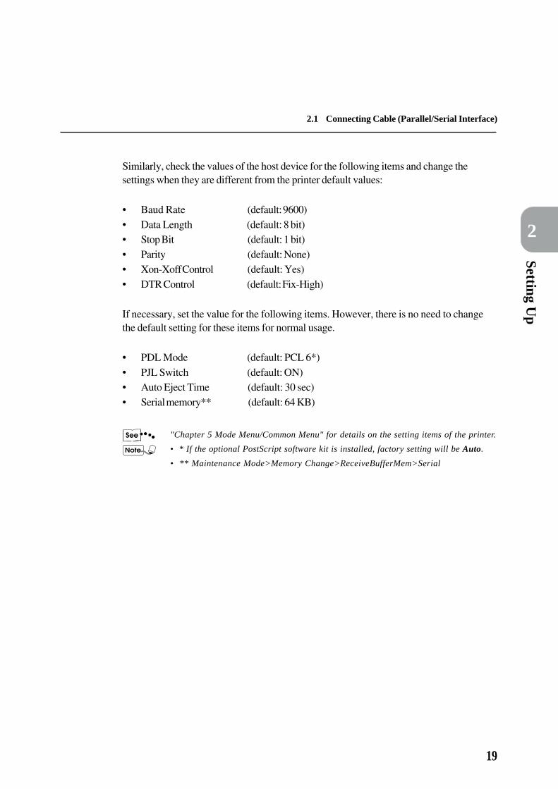
Similarly, check the values of the host device for the following items and change thesettings when they are different from the printer default values:
• Baud Rate (default: 9600)• Data Length (default: 8 bit)• Stop Bit (default: 1 bit)• Parity (default: None)• Xon-Xoff Control (default: Yes)• DTR Control (default: Fix-High)
If necessary, set the value for the following items. However, there is no need to changethe default setting for these items for normal usage.
• PDL Mode (default: PCL 6*)• PJL Switch (default: ON)• Auto Eject Time (default: 30 sec)• Serial memory** (default: 64 KB)
"Chapter 5 Mode Menu/Common Menu" for details on the setting items of the printer.
• * If the optional PostScript software kit is installed, factory setting will be Auto.
• ** Maintenance Mode>Memory Change>ReceiveBufferMem>Serial

20
2.2 Using the Ethernet Interface
If you want to use the Ethernet interface, you need to install the optional interface card (100Base-TX,10Base-T or 10Base-5) first. This section explains the procedure for installing the Ethernet interface cardand for connecting by the Ethernet interface.
2.2.1 Installing the Ethernet interface card
Check that the display window indicates "Ready". Turn the power off and then unplug thepower cord.
CAUTION Make sure the power is switched off and the machine unplugged before you begin theinstallation. Otherwise, there is a danger of electric shock.
The printing data left inside the printer or the printer memory will be erased whenthe power is off.
Remove the two screws from the slot for theexpansion interface card and then take awaythe shield cover.
Keep the removed screws and shieldcover.
Insert the interface card into either the leftor right slot and fix it with the two screws.
Make sure the card is inserted right inso that it touches the connector at theend of the slot.

21
Setting Up
2
2.2 Using the Ethernet Interface
2.2.2 Connecting the Ethernet interface
Connecting by the Ethernet interface will enable the following environments to be used:• 100Base-TX
• 10Base-T
• 10Base-5
100Base-TX and 10Base-T are set to switch automatically. When using 10Base-5environment, be sure to set the Ethernet values from the printer control panel afterconnecting the cable.
The procedure for connection by Ethernet interface is as follows:
Connect the interface cable to the Ethernetinterface connector.
Do not connect the interface cable tothe two Ethernet interface connectorstogether as this will cause poortransmission or breakdown.
For the interface cable, use the cablesuited to the network.
Switch on the power of the printer.
When connecting connector for 10Base-5, follow the procedure on the next page and setthe value of Ethernet setting to 10Base-5. When connecting TX/T connector, also refer tothe procedure on next page and change the setting if you would like to fix the transmissionspeed for 100Base-TX or 10Base-T.After setting Ethernet, change the setting from the printer or host device, depending on theenvironment setting that you are in.
The Network Print Environment User Guide for the setting method.

22
2.2 Using the Ethernet Interface
(When the power is on)
(Display of Maintenance Mode)
(8) Press .
(1) Press .
(4) Press or a few times.
(6) Press or a few times.
(3) Press .
(5) Press .
(Display of Ethernet setting)
(7) Press .
(Returns to the state when power is on. Receiving data possible.)
(Setting Ethernet to 10Base-5)
(2) Press or a few times.

23
Setting Up
2
2.3 Increase/Allocation ofMemory
This sections explains how to allocate memory when increasing it.
2.3.1 Uses
Memory is meant for the following uses:• System
• Receive buffer
• Page buffer
• PCL 6 memory
• PS memory
2.3.2 Suggested values
System
Area used by the printer system, with the capacity remaining unchangeable.
Receive buffer
A receive buffer is prepared for each port to receive data from multiple ports. There arevarious types of receive buffer:• Parallel memory
• Serial memory
• lpd spool
• NetWare memory
• AppleTalk memory
Parallel memory
This is a receive buffer for parallel interface use. In general, the default values aresufficient but if necessary, increase the capacity. When the capacity is increased, theprocessing might become faster. When the parallel interface is not in use, inactivate it andallocate the memory for other purposes.
Serial memory
This is a receive buffer for serial interface use. In general, the default values are sufficientbut if necessary, increase the capacity. When the capacity is increased, the processingmight become faster. When the serial interface is not in use, inactivate it and allocate thememory for other purposes.

24
2.3 Increase/Allocation of Memory
lpd spool
Area for lpd, FX PrintDirect and Direct Print Utility spool use. When the hard disk isconnected, it is possible to select the spool point from the memory and hard disk, as well asto stop spooling. Even when the spooling is stopped, the receive buffer is needed.When you want to ensure that the area for spooling use is more than 32 MB, it isrecommended that the hard disk be connected.
NetWare memory
Receive buffer for NetWare use. In general, the default values are sufficient but ifnecessary, increase the capacity.
AppleTalk memory
Receive buffer for AppleTalk use. It is recommended that you maintain many areas of thismemory if possible.
Page buffer
Area for drawing the actual print image. It is possible to allocate this area from theremaining area after all the other uses have been allocated. To confirm the page buffercapacity, print the printer settings list and then check the actual page buffer. If the pagebuffer is too small, it will affect the performance and duplex printing may be rejected.If you are using the PostScript language, refer to “E.2 Precautions and Limitations”.
PCL 6 memory
Area for the use of PCL 6. This memory is to store the interim data for creating the printimage. By increasing the memory capacity, the printing speed may be increased.
PS memory
Area for use by the PostScript software. By increasing the memory capacity, printingspeed may be increased.

3.1 Flow of Printing/Fax Transmission ...................................................... 26
3.2 Cancelling Printing/Fax Transmission.................................................. 28
3.3 Outputting ............................................................................................. 31
3.4 Main Frame Control Panel Operations During Printing/Transmission .....
............................................................................................................. 33
3.5 Removing Documents Output to the Stacker Tray................................. 34
3.6 Outputting Lists/Reports ....................................................................... 35
3.7 Printer Functions .................................................................................. 37
Useful Operations

26
Activate application software used by thehost device
Operate menuIf necessary
Specify printing/faxing from application,etc.
Stop printing/faxing
Output
If necessary
If necessary
3.1.1 For Windows
The basic flow of printing/fax transmission from Windows environment is as follows:(This may differ depending on the host device and system configuration used.)
Refer to the manual of the application regarding its operation.
Before sending print/fax data from the host device, check thefollowing:
(1)Port status in Common Menu > Maintenance Mode > Port Status(2)Print mode of the port in Common Menu > Port Setting > PDL Mode
"5.3 Common Menu Items"
Refer to the manual of the application regarding its operation.
"4.4 Printing/Faxing" for details on faxing.
"3.2 Cancelling Printing/Fax Transmission"
"3.3 Outputting"
3.1 Flow of Printing/FaxTransmission
End

27
3.1 Flow of Printing/Fax Transmission
Useful O
perations
3
3.1.2 For DOS (printing only)
The basic flow when printing from the DOS environment is as follows:(This may differ depending on the host device and system configuration used.)
Refer to the manual of the application regarding its operation.
Before sending print/fax data from the host device, check thefollowing:
(1)Port status in Common Menu > Maintenance Mode > Port Status(2)Print mode of the port in Common Menu > Port Setting > PDL
Mode
"5.3 Common Menu Items"
(3)Printing method (e.g. scale) by the PDL Mode
"5.2 Mode Menu Items"
Refer to the manual of the application regarding its operation.
"3.2 Cancelling Printing/Fax Transmission"
"3.3 Outputting"
Activate application software to be usedby the host device
Operate menu
Specify printing from application etc.
Stop printing
Output
End
If necessary
If necessary
If necessary

28
3.2 Cancelling Printing/FaxTransmission
This section explains about the cancellation of printing/fax transmission.
To cancel printing/fax transmission, first of all cancel instructions from the host device.
After cancelling from the host device, carry out one of the following operations:
• Cancelling jobs in process (see 3.2.2)• Cancelling all jobs in the printer (see 3.2.3)• Cancelling fax transmission from touch panel display (see 3.2.4)
3.2.1 Cancelling from host device
The procedure to cancel printing instructions from the host device is explained here.Refer to the following based on the type of OS that you are using:
Windows® 95/Windows® 98
Cancelling from Windows® 95/Windows® 98:
Display the "Printers" window.
(Start > Settings > Printers)
Double-click the appropriate printer icon.
In the displayed window, click the appropriatedocument name and from the “Document”menu, select Cancel Printing.
Windows® 3.1
Cancelling from Windows® 3.1:
Double-click Printer Manager from the"Main" window.
In the displayed window, click the appropriatedocument name and from the “Document”menu, select Delete Document.

29
3.2 Cancelling Printing/Fax Transmission
Useful O
perations
3
Windows NT® 4.0
Cancelling from Windows NT® 4.0:
Display the "Printers" window.
(Start > Settings > Printers)
Double-click the appropriate printer icon.
In the displayed window, click the appropriatedocument name and from the “Document”menu, select Cancel.
3.2.2 Cancelling jobs in process
To cancel jobs in process from the printer, press and of the the printer controlpanel together. However, the page which is being printed will still be printed and output.
3.2.3 Cancelling all jobs in the printer
To cancel printing all jobs received by the printer.This operation can stop the receiving of data and empty the buffer.
• All data will be erased when this operation is executed.• Buffer is the storing location of data sent from the host device.
There is also a way to execute all the jobs in the printer and print them out.See "3.3.2 Outputting all jobs in the printer" for details on the printing method.
The operation procedure is as follows:
When the display is at a state as shown on theleft, press .
The machine assumes pause mode.When is pressed, the printerwill automatically be unable toreceive data.

30
3.2 Cancelling Printing/Fax Transmission
Press and together.
The cancellation of printing will be processed.
When the processing is complete, "Pause" willbe shown.
Press .
"Print/Fax Ready" will be shown.
3.2.4 Cancelling fax transmission from touch panel display
Jobs that are being faxed and fax transmission jobs that have been arranged arecancelled by using the touch panel display. See the User Guide (Facsimile) for details onthe cancellation method.

31
Useful O
perations
3
3.3 Outputting
This section explains the two types of outputting:
• Forced outputting of remaining print data (see 3.3.1)• Outputting all jobs in the printer (see 3.3.2)
3.3.1 Forced outputting of remaining print data
For the PCL 6 emulation mode, data will not be output until a full page of data is collected.If the last piece of data ends at the middle of a page, it will wait for the next data until thepresent Auto Eject Time has passed and "Data wait" will be shown on the display.The operation of forcibly printing data in the printer without waiting for the Auto EjectTime to pass in such instance is known as forced outputing.The procedure is as follows:
For parallel and serial interfaces, the next job sent when the display shows "Datawait" might not be printed properly.Send the next job after forced outputting or when Auto Eject Time is over.
"5.3 Common Menu Items" regarding Auto Eject Time.
When the display is at the state as shown onthe left, press .
Printing will commence.
When printing is done, "Print/Fax Ready"will be shown.

32
3.3 Outputting
3.3.2 Outputting all jobs in the printer
To execute and print all jobs received in the printer.This operation can stop the receiving of data and empty the buffer.The procedure is as follows:
There is also a way to erase all jobs in the printer. Refer to "3.2.3 Cancelling all jobsin the printer" regarding the way to erase.
When the display is at the state as shown onthe left, press .
The Pause mode is activated.
When is pressed, the printer willautomatically be unable to receive data.
Press .
The printing starts.
When all the jobs have been executed andprinted, "Pause" will be shown.
For parallel and serial interfaces, data might be received in the midst of a jobdepending on the timing when is pressed in Step .In this case, all data following this will be recognised as a new job after ispressed and then processed as a new job after the pause state is released in Step .
Press .
"Print/Fax Ready" will be shown.
After the pause state is released here, data that have been treated as a new job willnot be printed properly if the PDL Mode is set to AUTO.
"5.3 Common Menu Items" regarding the PDL Mode setting.

33
Useful O
perations
3
3.4 Main Frame Control PanelOperations During Printing/Transmission
This section explains about the method of operating the main frame control panel during printing/transmission. The touch panel display during printing will be as follows:
• When Close is selected on the screen below, the start arrangement of the next copy/fax operations canbe carried out without cancelling any printer operations. Also, you can press Job Status > Stop,choose "Printer" job, press Stop to stop and then carry out the copy/fax operation. The job that hasbeen stopped will be automatically resumed.
• Print jobs cannot be stopped by the Main Frame Control Panel.
Printer
Printing in progress...
Close
The main frame control panel operations during printing/transmission are as follows:
Main frame control panel operations Printer actions
Pressing Interrupt during printing. When Interrupt is pressed, the printing will be stopped
temporarily and the copy/fax functions can be used. When
Interrupt is pressed again, the interrupt mode will be disabled
and printing will resume.
Pressing Job Status > Stop, select job and Stop. Printing will be temporarily stopped and the copy/fax
functions can be used. The interrupted printing will be
resumed automatically. Fax transmission will be stopped.

34
3.5 Removing DocumentsOutput to the Stacker Tray
When removing documents output to the Stacker Tray, be sure to press the Pause/Restart button of theStaple Finisher to stop the Finisher operations temporarily.
The procedure is as follows:
Press Pause/Restart.Check that the Stacker Tray has lowered allthe trays completely before removing thedocuments output to the stacker tray.
During printing of documents that areto be stapled, when Pause/Restart or
of the main body is pressed, thestacker tray will be lowered once thedocuments that are being printed areoutput.
Press Pause/Restart again.
The Staple Finisher will resume operation.The temporarily stopped state will becancelled automatically about 60seconds later and printing will resume.

35
Useful O
perations
3
3.6 Outputting Lists/Reports
This section explains about the types of lists/reports and how to print them.
3.6.1 Types of lists/reports
Besides printing data sent from the host device, this machine is equipped withseveral other printing functions, known as Print Utility.The Print Utility of this machine are as follows:
• PCL 6 Settings
• Printer Settings
• Error History
• Print History
• Job Template Server Settings
• PCL 6 Font List
• PS Font List (available when the optional software kit is installed)
Print Utility is executed at a resolution of 400 dpi.
"Appendix C Print Utility" for details on the contents of Print Utility.
3.6.2 Printing lists/reports
The procedure to print the Print Utility items is shown on the next page:
36
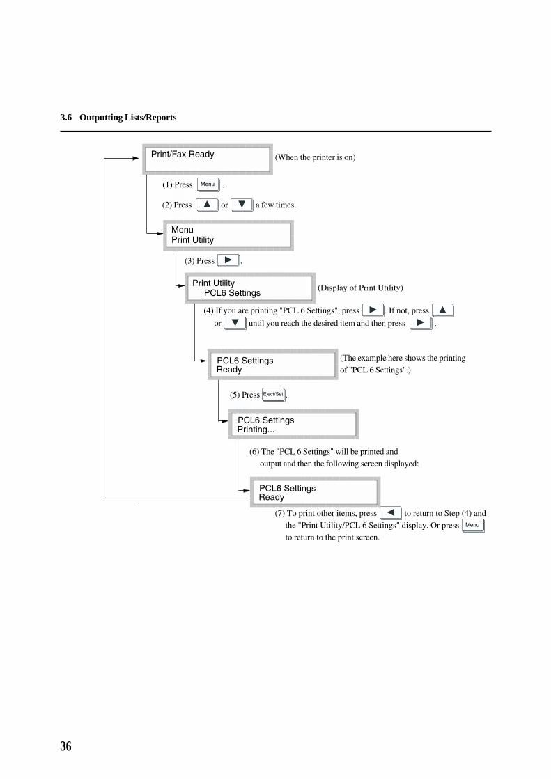
3.6 Outputting Lists/Reports
(When the printer is on)
(Display of Print Utility)
(1) Press .
(3) Press .
(4) If you are printing "PCL 6 Settings", press . If not, press
or until you reach the desired item and then press .
(6) The "PCL 6 Settings" will be printed andoutput and then the following screen displayed:
(5) Press .
(2) Press or a few times.
(The example here shows the printingof "PCL 6 Settings".)
(7) To print other items, press to return to Step (4) andthe "Print Utility/PCL 6 Settings" display. Or press to return to the print screen.

37
Useful O
perations
3
3.7 Printer Functions
This section explains about the relations between the printing function and the copying/faxing functions.
Auto Tray SwitchWhen printing is done by auto paper supply, the Auto Tray Switch feature will usually beactivated. This feature is independent of the copying/faxing function setting.
Paper Tray PriorityFor the printing function, the trays are allocated priority as follows: Tray 1, Tray 2,Tray 3 and then Tray 4 (Tray 1 has the highest priority). This feature is independentof the copying/faxing function setting.When the High-Capacity Feeder is installed, the allocated priority is: Hi-Cap. Feeder 1,Hi-Cap. Feeder 2, Tray 1 and Tray 2.
Printing PriorityPrinting will be prioritised according to the setting made from the main frame controlpanel. The priority can be chosen from the following: Printer Document, Fax ReceiveDocument, Auto-Output Report.
User Guide (Facsimile) for the setting method.
Copy/fax functions and their relation with printer function
Operating the main frame control panel• No printing can be done when operating the main frame control panel. However,
printing instructions can be received from the host device.• When a certain time* has passed after operating the main frame control panel,
documents specified from the host device will be printed.
TransmittingDocument with printing instruction specified from the host device will be printed accordingto the order received.
CopyingOutputting received document
• Printing cannot be done during copying and outputting received document. However,printing instructions can be received from the host device.
• After all the documents of copying and outputting received document are ejected,documents with printing instructions from the host device will be printed.

38
3.7 Printer Functions
InterruptingPrinting cannot be done during the interrupt mode. However, printing instructions can bereceived from the host device.Press Interrupt to end the interrupt mode and printing will be processed. Even during theinterrupt mode, the printing process will resume if no operations are carried out after acertain time.
* : This time setting is done from the main frame control panel. See the User Guide (Facsimile) forthe setting method.

Installing/Configuring thePrinter Drivers
4.1 About the Printer Drivers .................................................................... 40
4.2 Installing/Uninstalling the Printer Drivers ............................................ 41
4.3 Configuring the Printer Drivers .......................................................... 46
4.4 Printing/Faxing ..................................................................................... 73
40
4
This section gives an overview of the printer drivers.
4.1.1 The PCL 5e/PCL 6 printer drivers
The PCL 5e/PCL 6 printer drivers are installed on the Windows operating systems toprovide a standard interface between an application program and the Xerox DC 400/350/250 printer device. By installing these printer drivers, print jobs can be converted intothe PJL and PCL 5e/PCL 6 printer languages and then print through the printer device.These drivers are also equipped with the direct fax feature which sends fax directly fromyour PC through the printer.These printer drivers are system specific, each will only run on either Windows 3.1/95/98or Windows NT 4.0. There are altogether six printer drivers included:• PCL 5e printer driver for Windows 3.1• PCL 5e printer driver for Windows 95/98• PCL 5e printer driver for Windows NT 4.0• PCL 6 printer driver for Windows 3.1• PCL 6 printer driver for Windows 95/98• PCL 6 printer driver for Windows NT 4.0
4.1.2 Installation/configuration methods
The methods of installing/configuring the PCL 5e and PCL 6 printer drivers as well as theprocedures for printing/faxing using these drivers are basically the same. Regardless of theoperating system (OS) you are in, the basic steps are similar except for the look of someof the graphics. Therefore, only one printer driver will be used to discuss these operationsin this chapter but any differences among the PCL 5e and PCL 6 printer drivers will bepointed out.
4.1.3 Settings on the Xerox DC 400/350/250 printer
Make sure the PJL switch for the interface is turned to ON. If the PJL switch is turned toOFF, the following functions will be disabled:• JOB/EOJ-Job separator• Fax function• Collate• Job offset• Staple function• Resolution• Image enhancement• Economode• PCL XL emulation
4.1 About the Printer Drivers
41
Installing/Configuring the P
rinter Drivers
4
This section describes the procedure for installing and uninstalling the printer drivers.
Two methods of installation are described here, one for a local network printer and the other for a networkprinter. If you have installed an earlier version of the printer driver, uninstall it first by following theprocedure in 4.2.3 before installing the new version.
4.2.1 For a local Xerox DC 400/350/250 printer
Local printer refers to a printer that is directly connected to your computer.
Procedure
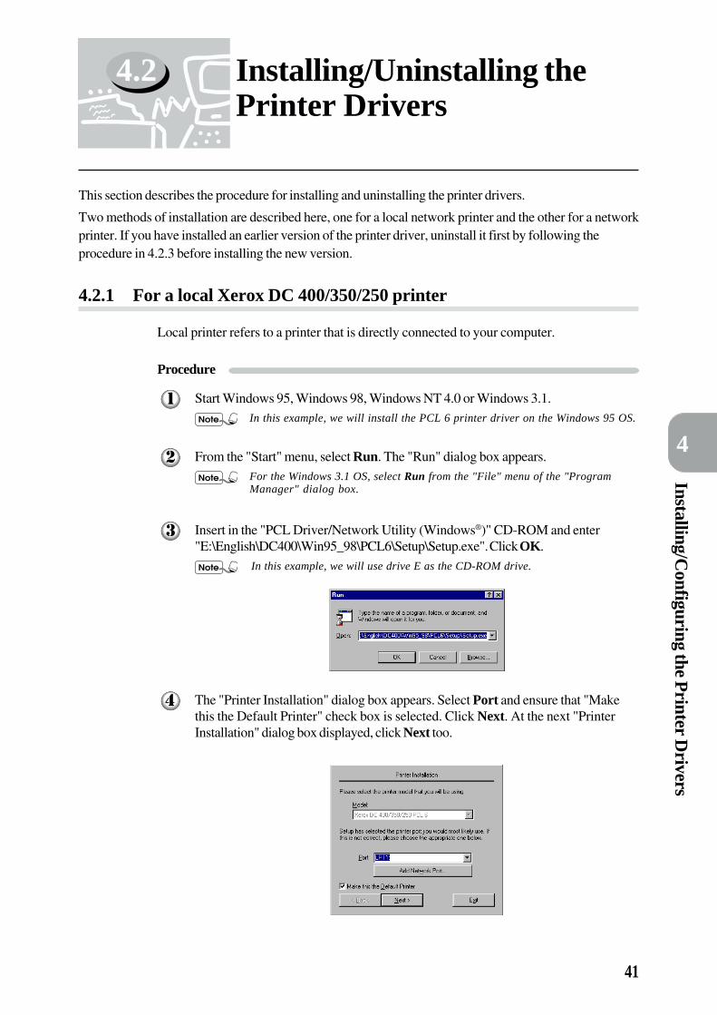
Start Windows 95, Windows 98, Windows NT 4.0 or Windows 3.1.In this example, we will install the PCL 6 printer driver on the Windows 95 OS.
From the "Start" menu, select Run. The "Run" dialog box appears.For the Windows 3.1 OS, select Run from the "File" menu of the "ProgramManager" dialog box.
Insert in the "PCL Driver/Network Utility (Windows®)" CD-ROM and enter"E:\English\DC400\Win95_98\PCL6\Setup\Setup.exe". Click OK.
In this example, we will use drive E as the CD-ROM drive.
The "Printer Installation" dialog box appears. Select Port and ensure that "Makethis the Default Printer" check box is selected. Click Next. At the next "PrinterInstallation" dialog box displayed, click Next too.
4.2 Installing/Uninstalling thePrinter Drivers

42
4
4.2 Installing/Uninstalling the Printer Drivers
The "End User Licence Agreement" dialog box appears. Read through the licenceagreement carefully. If you have no objections to it, click on the checkbox for "Iaccept the terms of the above Licence Agreement" and then click Next.
The "Ready to Start Copying" dialog box appears. Click Finish to start theinstallation.
After the installation is completed, a dialog box as shown below appears.
Click Restart Windows Now, Exit to Windows or Printer Setup as needed.
"4.3 Configuring the Printer Drivers" on how to configure the printer driver.
• Restart Windows for the effect to take place.
• You may run the "Setup.exe" program to install the Windows 95/98 printerdriver as an alternate driver on the Windows NT server (workstation) afteryou have installed the printer driver for Windows NT 4.0. In this case, asthere is no need to restart Windows, click Exit to Windows. When down-loading the alternate Windows 95/98 driver installed in Windows NT on theWindows 95/98 client computer, use the "Add Printer Wizard" dialog box.

43
Installing/Configuring the P
rinter Drivers
4
4.2 Installing/Uninstalling the Printer Drivers
4.2.2 For a network Xerox DC 400/350/250 printer
Network printer refers to printer that is connected to your computer through a network.
Procedure
Follow Steps to of "4.2.1 For a local Xerox DC 400/350/250 printer" to
display the "Printer Installation" dialog box.In this example, we will install the PCL 6 printer driver on the Windows 95 OS.
Click Add Network Port. The "Add Network Printer Port" dialog boxappears. Select the network printer from "Network Neighborhood".
If you do not know the network address of the network printer, consult yoursystem administrator.
Click OK. The "Printer Installation" dialog box showing the network path of thenetwork printer appears.
Follow Steps to of "4.2.1 For a local Xerox DC 400/350/250 printer" to
complete the installation procedure.
44
4
4.2 Installing/Uninstalling the Printer Drivers
4.2.3 Uninstalling the printer drivers
In this example, we will uninstall the PCL 6 printer driver on the Windows 95 OS.
• For drivers installed by the "Setup.exe" program, use the "Unsetup.exe" programto uninstall.
• For Windows 95/Windows 98 alternate drivers installed in Windows NT server(workstation), use the "Unsetup.exe" program to uninstall the Windows 95/Windows 98 drivers and then activate the "Unsetup.exe" program of the WindowsNT driver.
• To uninstall the alternate drivers downloaded using the "Add Printer Wizard"dialog box at the client computer, open the "Printers" window and erase theapplicable printer icons.
Procedure
From the "Start" menu, select Run. In the "Run" dialog box displayed, clickBrowse.
For the Windows 3.1 OS, select Run from the "File" menu of the "ProgramManager" dialog box.
Insert in the "PCL Driver/Network Utility" CD-ROM and select the CD-ROMdrive in the "Browse" dialog box. Next, double-click Win95_98, PCL6, Setup andthen select Unsetup.exe. Click Open to close the "Browse" dialog box.
• For the Windows 3.1 OS, click OK to close the "Browse" dialog box.
• When uninstalling any PCL 5e/PCL 6 driver, remember to use the"Unsetup.exe" program of the correct driver and of the same version as the"Setup.exe" program used for installation.
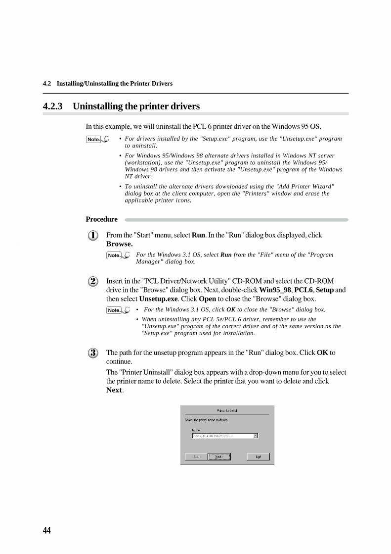
The path for the unsetup program appears in the "Run" dialog box. Click OK tocontinue.
The "Printer Uninstall" dialog box appears with a drop-down menu for you to selectthe printer name to delete. Select the printer that you want to delete and clickNext.

45
Installing/Configuring the P
rinter Drivers
4
4.2 Installing/Uninstalling the Printer Drivers
If you are uninstalling a driver from the Windows NT 4.0 OS, the following leftdialog box will be displayed instead and clicking Next will display the followingright dialox box with the "Model" name. Click Next to continue.
A "Ready to Start Deleting" dialog box appears.
Click Finish to start the uninstalling process. When the process is completed, clickRestart Windows Now to ensure that the driver is completely removed from thesystem.

46
4
4.3 Configuring the PrinterDrivers
This section describes how to configure the printer driver from the printer properties dialog box. Thisdialog box will appear if you click Printer Setup on the "Installation Sucessful" screen. If, however, youhave quit the printer setup program and are trying to re-access the dialog box, follow the procedure in"4.3.1 Accessing the printer properties dialog box" to display the dialog box first.
This dialog box includes multiple tabs such as "Printer" and "Paper/Output" to set up printing conditions.First, you need to set appropriate options on the "Printer" tab before configuring on the other tabs.Otherwise, the other tabs may not show options appropriate to your machine.
For Windows NT 4.0 drivers: You have to define settings on both the "Printer" and "Fonts" tabs (for thePCL 5e driver) or just on the "Printer" tab (for the PCL 6 driver) from this "Properties" dialog box beforeaccessing the "Default" dialog box to define the other properties.
For details of all the different properties, refer to "4.3.2 Setting the printer properties".
4.3.1 Accessing the printer properties dialog box
For Windows 95/Windows 98
Click the Start menu, select Settings and then Printers. The "Printers" windowappears.
In this example, we will use the PCL 6 driver for the Windows 95 OS.
Click the appropriate Xerox DC 400/350/250 printer icon.
Select Properties from the "File" menu to display the following "Properties" dialogbox.

47
Installing/Configuring the P
rinter Drivers
4
4.3 Configuring the Printer Drivers
For Windows 3.1
In the "Program Manager" dialog box, double-click Main, followed by ControlPanel, and then Printers. The "Printers" window appears.
In this example, we will use the PCL 6 driver.
Ensure that you have selected the appropriate Xerox DC 400/350/250 printer iconin Installed Printers, and then click Setup to display the following setup dialogbox.

48
4
4.3 Configuring the Printer Drivers
For Windows NT 4.0
Accessing the printer properties dialog box
Follow the procedure for Windows 95/Windows 98 to display the following"Properties" dialog box.
For the PCL 5e driver: To define settings on the "Printer" and "Fonts" tabs.
For the PCL 6 driver: To define settings on the "Printer" tab.In this example, we will use the PCL 5e driver.
Accessing the document defaults dialog box
Follow Step 1 and Step 2 of the procedure for Windows 95/Windows 98 to selectthe Xerox DC 400/350/250 printer icon.
Select Document Defaults from the "File" menu to display the following "Default"dialog box to define settings on the other tabs.

49
Installing/Configuring the P
rinter Drivers
4
4.3 Configuring the Printer Drivers
4.3.2 Setting the printer properties
Through the printer properties (and document default) dialog box, the printer driver willprovide an interface for you to ensure that the driver settings match those of the physicalprinter and to select printer option settings for the different properties. The settings madehere will be the default printer configuration for printing the subsequent job. Although anapplication may change the page setup each time a job is printed, it will not affect thesedefault settings. Changes to these configurations can only be made through these dialogboxes. Not all properties are, however, available for the six different drivers. The followingtable lists out the properties available for each driver as well as the items of each propertynot commonly available to all the drivers:
PCL 5e PCL 6
Property Win 3.1 Win 95/98 Win NT 4.0 Win 3.1 Win 95/98 Win NT 4.0
Printer
* Device Halftoning × × × ×
* Error Report × × ×
Paper/Output
Output Options
* CentreWare Supports × ×
* EMF Spooling × × × ×
Graphics
* Grey Scale × × ×
* Halftoning × × ×
* Halftone Color Adjustment × × × ×
Overlays
* Download Now × × ×
Fonts × × ×
Layout × × ×
Watermarks × × ×
Fax Option
Advanced × × × ×
: available; ×: not available
*: items of the property that may/may not be available to the driver

50
4
4.3 Configuring the Printer Drivers
Before listing out the different properties, here is a summary of them:
• Printer
The settings here is used to configure the printer hardware options. Optional device itemsthat are physically installed on the printer must be indicated here to the driver that they areavailable for use e.g. Duplex Unit, Offset Catch Device etc.
• Paper/Output
This property controls several aspects of how the the printer works with paper and how ithandles a print job. Settings include Job Type (i.e. Print or Fax), Paper Size, Paper Source,Image Orientation, Copies, Output Destination, etc.
• Output Options
Includes settings on how the printed output is to be processed by the printer options, suchas collation if hard disk has been installed on printer, Job Offset if OCT is available onprinter etc.
• Graphics
Settings contained here controls the quality of printed output as well as how the Graphicsand TrueType fonts will be processed and printed.
• Overlays
Allows you to create, use and delete page overlays for the printer.
• Fonts (for PCL 5e drivers only)
Use this to install soft (disk-based) fonts and scalable typefaces on the printer.
• Layout (for PCL 6 drivers only)
The layout property provides a few "job finishing" features to modify the printed layout ofa document like N-Up printing, Booklet Printing, Fit to Page, Scaling, Logical On Physical.
• Watermarks (for PCL 6 drivers only)
A Watermark is a light image printed in the background on a page. The PCL 6 driverallows text (as watermark) to be printed in the background or foreground and placedacross the first page or all pages of a document. This property dialog allows you to create,delete and modify such watermarks.
• Fax Option
Allows you to specify fax attributes like fax resolution and whether to generatetransmission report or to include a header for faxing.Unlike the properties of the other tabs, the description of the properties of this tab is in"4.4.2 Faxing from an application".
• Advanced (for Windows NT 4.0 drivers only)
Displays a hierarchical list of control items that relate to document property. It presents asummary of the document default settings of the driver and allows user to change settingof each item by selecting them here.

51
Installing/Configuring the P
rinter Drivers
4
4.3 Configuring the Printer Drivers
Printer
The "Printer" tab defines the current hardware configuration of the printer. The optionaldevices that are physically installed on the printer must be indicated here that they areavailable for use.
The "Sharing" tab appears when the print sharing feature is turned on in the"Network" dialog box which is accessed by double-clicking the "Network" icon inthe Control Panel.
Paper Source OptionsSpecify the optional paper source that is attached to your printer besides the default papersource device, Tray 1. The printer image and the Paper Source drop-down list in the"Paper/Output" tab will change accordingly once this is updated.
Bypass Tray
Select this if your printer is installed with this manual feeder which is able to handlevarious paper sizes.
If this is not checked, Bypass Tray (Manual) will not be available for PaperSource on the "Paper/Output" tab.
Select Tray Body:
Provides two options of which either and only one must be installed in the printer:
• 3-Tray Cabinet (default)
Select this if your printer is installed with this input tray cabinet which allowspaper to be fed from three trays (Tray 2, Tray 3, Tray 4).
• High Capacity Feeder
Select this if your printer is installed with this input tray cabinet which allowspaper to be fed from one tray (Tray 2) and two high capacity feeders (Hi-Cap.Feeder 1, Hi-Cap Feeder 2).
• If 3-Tray Cabinet is not checked, Tray 3 and Tray 4 will not be available forPaper Source on the "Paper/Output" tab.
• If High Capacity Feeder is not checked, Hi-Cap. Feeder 1 and Hi-Cap.Feeder 2 will not be available for Paper Source on the "Paper/Output" tab.

52
4
4.3 Configuring the Printer Drivers
Paper Output OptionsSpecify the optional output tray that can be attached to your printer for additional capacityover the standard output tray.
Side Output Tray
Select this if your printer is installed with this face-up tray.
Staple Finisher
Select this if your printer is installed with this attachment of three finisher trays(Stacker Tray 1- Stacker Tray 3). It is equipped with the Offset Catch Device andthe stapler. Cannot be installed together with the Mail Box.
Mail Box
Select this if your printer is installed with this attachment of 10 output bins. Cannotbe installed together with the Staple Finisher.
• If Side Output Tray is not checked, Side Output Tray will not be available forPaper Output on the "Paper/Output" tab.
• If Staple Finisher is not checked, Stacker-Auto and Stacker Tray 1 - StackerTray 3 will not be available for Paper Output on the "Paper/Output" tab.
• If Mail Box is not checked, Mail Box Bin 1 - Mail Box Bin 10 will not beavailable for Paper Output on the "Paper/Output" tab.
Offset Catch DeviceSelect this if your printer is installed with the job offset device which supports both "OffsetPer Job" and "Offset Per Set" functions. Only the standard Centre Tray and the stackertrays can be equipped with the job offset device. Default is off.
If this is not checked, the job offset settings will not be available for Job Offset onthe "Output Options" tab.
Duplex Unit (Inverter)Select this if your printer is installed with a duplex unit to perform 2-sided printing. Defaultis off.
If this is not checked, the duplex printing options on the "Paper/Output" tab willnot be available.
Hard DiskSelect this if your printer is installed with a hard disk which enables the printer to supportjob collation. Default is off.
If this is not checked, Collate and the staple positions on the "Output Options" tabwill not be available.
Fax UnitSelect this if your printer is installed with a fax unit to send a fax job. Default is off.
If this is not checked, Fax will not be available for Job Type on the "Paper/Output"tab.
ISDN/G4 KitSelect this if your fax module has a G4 kit which allows ISDN communication. Enabledonly if Fax Unit is selected. Default is off.
If this is not checked, G4-Auto will not be available for Communication Mode onthe "Comm. Setting" dialog box which is displayed when Comm. Settings on the"Fax Recipient" dialog box is pressed.

53
Installing/Configuring the P
rinter Drivers
4
4.3 Configuring the Printer Drivers
Paper Detected by TraySelect one of the following two paper sizes which are mutual exclusively detected by theprinter:
• B4 (257 × 364 mm) (default)
• Legal (8.5 × 14")
The selected paper size will be available for selection under Paper Size on the "Paper/Output" tab while the unselected one will not be available.
If you want to change the paper detection from B4 (257×364 mm) to Legal (8.5×14") orvice versa, please contact the Xerox Customer Support Centre.
Make sure that the "Paper Detected by Tray" setting is consistent with the physicalcabinet tray setting. Otherwise, trouble with printing may arise.
Error Report (for PCL 6 drivers only)
Specify whether or not errors are to be reported when printing a PCL 6 job. Optionsinclude:
• No Reporting
The printer will not generate any error report.
• Error Page (default)
Error page will be printed when the printer encounters error in printing the job.
Device Halftoning (for Windows NT 4.0 drivers only)
Click this button to display the "Device Color/Halftone Properties" dialog box to define thecolour and halftone properties for the printing device.
Windows NT 4.0

54
4
4.3 Configuring the Printer Drivers
Paper/Output
The "Paper/Output" tab has option settings that determine the print environment in which ajob is printed. Notice that there are image displays of Job Type, Paper Size, ImageOrientation and Duplex Print to the left of these drop-down lists, which will changeaccording to the selections made. There is also a display of the printer with clickable imageareas of the paper input and output devices. You can either click on these displays orchoose from the combo boxes to make selections.
Job TypeSpecify the type of job you are handling:
• Fax (available only if Fax Unit is selected on the "Printer" tab.)
CopiesSpecify the number of copies to print. The valid range is 1-999 copies. Default is 1.
Paper SizeSpecify the paper size to use for the print data. Options include:
• A4 (210 × 297 mm) (default)
• 8.5 × 11" (Letter)
• B5 (182 × 257 mm)
• B4 (257 × 364 mm)
(when Fax is selected for Job Type on the "Printer" tab: available at all times;when Print is selected: available in either one of the following conditions:(a) B4 (257 × 364 mm) is selected for Paper Detected by Tray on "Printer" tab; or
(b) 8.5 × 14" (Legal) for Paper Detected by Tray and Bypass Tray for PaperSource Options are selected on the "Printer" tab)

55
Installing/Configuring the P
rinter Drivers
4
4.3 Configuring the Printer Drivers
• 8.5 × 13" (Folio)
• 8.5 × 14" (Legal)
(when Fax is selected for Job Type on the "Printer" tab: available at all times;when Print is selected: available in either one of the following conditions:(a) 8.5 × 14" (Legal) is selected for Paper Detected by Tray on "Printer" tab; or
(b) B4 (257 × 364 mm) for Paper Detected by Tray and Bypass Tray for PaperSource Options are selected on the "Printer" tab)
• 8K (267 × 388 mm)
• A3 (297 × 420 mm)
• 11 × 17" (Ledger)
• A5 (148 × 210 mm)
• Postcard (100 × 148 mm)
(when Fax is selected for Job Type on the "Printer" tab: available at all times;when Print is selected: available when Bypass Tray is selected for Paper SourceOptions on the "Printer" tab)
• Booklet on A4 (for PCL 6 drivers only) (available only when Print for Job Type and Duplex Unit (Inverter) are selected on the "Printer" tab)
• Booklet on Letter (for PCL 6 drivers only) (available at the same conditions as Booklet on A4)
• Booklet on A3 (for PCL 6 drivers only) (available at the same conditions as Booklet on A4)
• Booklet on Ledger (for PCL 6 drivers only) (available at the same conditions as Booklet on A4)
• Custom Paper Size
A user defined size ranging from 100 × 148 mm (min.) to 297 × 431 mm (max.).
(when Fax is selected for Job Type on "Printer" tab: available at all times;when Print is selected: available when Bypass Tray is selected for Paper SourceOptions on the "Printer" tab)
Paper SourceSpecify the tray to use. Options include:
• Auto Tray (default)
Paper will be automatically selected.
• Tray 1 - Tray 4
Paper will be fed from the specified trays. Tray 3 and Tray 4 are available only if3-Tray Cabinet is selected for Paper Source Options on the "Printer" tab.
• Hi-Cap. Feeder 1 - Hi-Cap. Feeder 2
Paper will be fed from the specified high capacity feeder. Available only if HighCapacity Feeder is selected for Paper Source Options on the "Printer" tab.
• Bypass Tray (Manual)
Paper will be fed from the bypass tray. Available only if Bypass Tray is selected forPaper Source Options on the "Printer" tab.

56
4
4.3 Configuring the Printer Drivers
The paper sizes available for each paper source are as follows:
Paper Size Auto Tray/Tray 1 Tray 2-Tray 4 HCF 1-HCF 2 Bypass Tray
8.5 × 11" (Letter)
A4
B5
B4 ×
8.5 × 13" (Folio) ×
8.5 × 14" (Legal) ×
8K ×
A3 ×
11 × 17" (Ledger) ×
A5 × ×
Booklet on A4* ×
Booklet on Letter* ×
Booklet on A3* × ×
Booklet on Ledger* × ×
Postcard × × ×
Custom × × ×
• : supported; ×: not supported; HCF: High Capacity Feeder
• * For PCL 6 drivers only: not available for any of the paper source if Fit to Page orLogical On Physical is selected for Layout Mode on the "Layout" tab.
Paper OutputSpecify an output destination. Options include:
• Centre Tray (default)
Printouts are sent to the centre tray with the printed side facing down.
• Side Output Tray
Printouts are sent to the side output tray with the printed side facing up. Availableonly if Side Output Tray is selected for Paper Output Options on the "Printer" tab.
• Mail Box Bin 1 - Mail Box Bin 10
Printouts are sent to the specified bin(s) with the printed side facing down. Useful forpreventing a mixed up of documents sent by different users. Available only if MailBox is selected for Paper Output Options on the "Printer" tab.
• Stacker-Auto
Printouts are sent to a stacker tray automatically selected by the printer with theprinted side facing down. Available only if Staple Finisher is selected for PaperOutput Options on the "Printer" tab.
• Stacker Tray 1- Stacker Tray 3
Printouts are sent to the specified stacker tray with the printed side facing down.Available only if Staple Finisher is selected for Paper Output Options on the"Printer" tab.
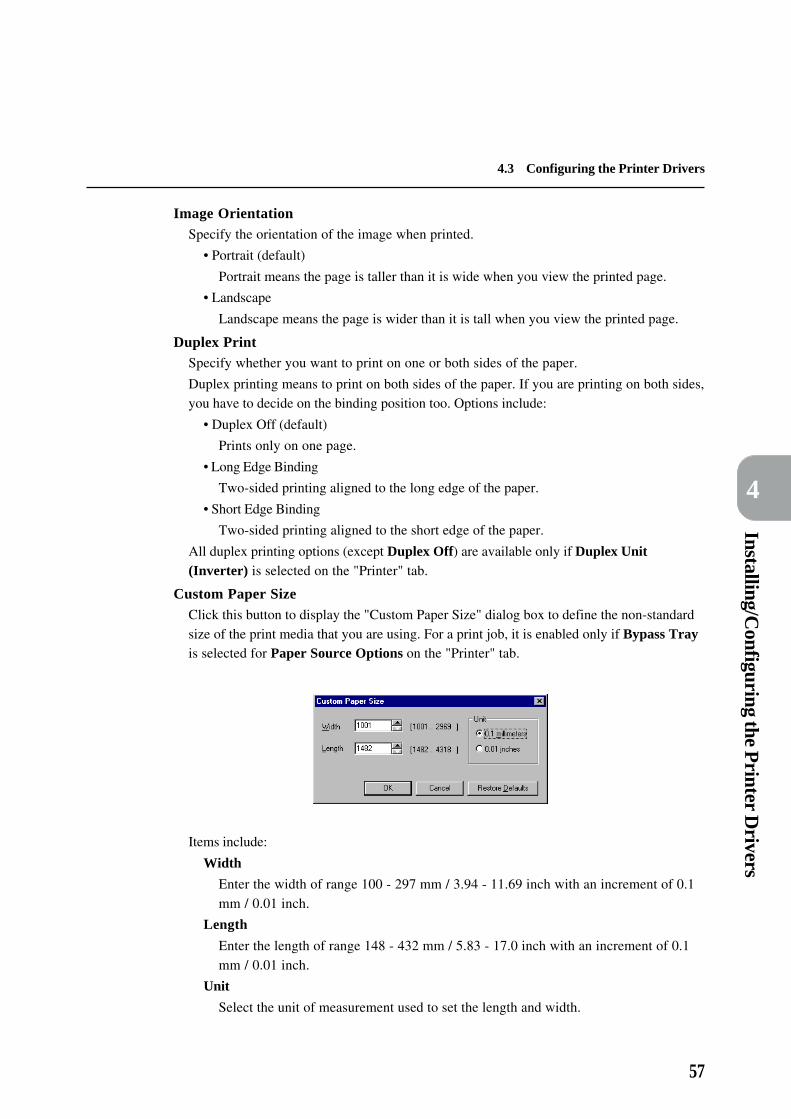
57
Installing/Configuring the P
rinter Drivers
4
4.3 Configuring the Printer Drivers
Image OrientationSpecify the orientation of the image when printed.
• Portrait (default)
Portrait means the page is taller than it is wide when you view the printed page.
• Landscape
Landscape means the page is wider than it is tall when you view the printed page.
Duplex PrintSpecify whether you want to print on one or both sides of the paper.
Duplex printing means to print on both sides of the paper. If you are printing on both sides,you have to decide on the binding position too. Options include:
• Duplex Off (default)
Prints only on one page.
• Long Edge Binding
Two-sided printing aligned to the long edge of the paper.
• Short Edge Binding
Two-sided printing aligned to the short edge of the paper.
All duplex printing options (except Duplex Off) are available only if Duplex Unit(Inverter) is selected on the "Printer" tab.
Custom Paper SizeClick this button to display the "Custom Paper Size" dialog box to define the non-standardsize of the print media that you are using. For a print job, it is enabled only if Bypass Trayis selected for Paper Source Options on the "Printer" tab.
Items include:
Width
Enter the width of range 100 - 297 mm / 3.94 - 11.69 inch with an increment of 0.1mm / 0.01 inch.
Length
Enter the length of range 148 - 432 mm / 5.83 - 17.0 inch with an increment of 0.1mm / 0.01 inch.
Unit
Select the unit of measurement used to set the length and width.

58
4
4.3 Configuring the Printer Drivers
Output Options
The "Output Options" tab has some advanced features for sending a print job. Notice thatthere are image displays of Collate Settings, Staple Position Settings and Use DocumentMonitor which will change according to the selections made.You can either click on thesedisplays or choose from the drop-down lists to make selections.
Job Offset SettingsThis feature provides a means of identifying one print job from others in the printer outputtray by outputting jobs in an in-out manner.
Job Offset
Options include:
• None (default)
No job offset i.e. to turn off the printer offset mechanism.
• Offset Per Job
Apply printer offset mechanism for each print job.
• Offset Per Set
Apply printer offset mechanism at the beginning of each set (or copy) of job.This option is meant for printing two or more copies of a print job. When thisoption is selected for printing only one copy of a job, it has the same outputeffect as Offset Per Job.
If Collate is selected for Collate Settings, each set printed will be output tothe Centre Tray or any of the stacker tray in an in-out manner. If Collate isnot selected, the printouts will be arranged by their page number in an in-outmanner.
All job offsets (except None) are available in either one of the following conditions:
(a) Offset Catch Device is selected on the "Printer" tab and Centre Tray is selectedfor Paper Output on the "Paper/Output" tab; or
(b) Staple Finisher is selected on the "Printer" tab and either Stacker-Auto or oneof the three stacker trays is selected for Paper Output on the "Paper/Output" tab.
Windows 95/98 Windows NT 4.0

59
Installing/Configuring the P
rinter Drivers
4
4.3 Configuring the Printer Drivers
Collate SettingsSpecify how you want your document to be arranged.
Collate
Click on the check box to collate or uncollate your documents. Enabled only if all ofthe following conditions are met:(1) Hard Disk is selected on the "Printer" tab; &(2) more than one copy is selected for Copies on the "Paper/Output" tab.Default is on.
Staple Position SettingsSpecify where to staple your printed document. Paper sizes that can be stapled include A5,B5, A4, 8.5 × 11", B4, A3, 8.5 × 13", 8.5 × 14", 8K and 11 × 17".
Staple Position
Options include:
• None (default)
Staple function off.
• Top Left Corner
Apply one staple at the top-left corner of paper.
• Top Double
Apply two staples at the top edge of paper.
• Top Right Corner
Apply one staple at the top-right corner of paper.
• Left Double
Apply two staples at the left edge of paper.
• Right Double
Apply two staples at the right edge of paper.
• Bottom Left Corner
Apply one staple at the bottom-left corner of paper.
• Bottom Double
Apply two staples at the bottom edge of paper.
• Bottom Right Corner
Apply one staple at the bottom-right corner of paper.
All staple positions (except None) are available only if all of the following conditionsare met:
(1) Staple Finisher is selected for Paper Output Options on the "Printer" tab;
(2) Hard Disk is selected on the "Printer" tab;
(3) Stacker-Auto or one of the three stacker trays is selected for Paper Output onthe "Paper/Output" tab; &
(4) 1 is selected for Copies on the "Paper/Output" tab or more than 1 copy is selectedfor Copies and Collate is selected for Collate Settings.
The Staple Finisher can staple up to a maximum of 50 sheets.

60
4
4.3 Configuring the Printer Drivers
First SheetEnables you to select for the first sheet of your document, a paper source different fromthe rest of the output sheets as selected in Paper Source on the "Paper/Output" tab. Notethat the paper size used for this different paper source must be the same as the document.
Different Paper Source
This check box must be selected before the drop-down list of paper source options isenabled. Disabled in any one of the following conditions:
(a) Postcard or Custom Paper Size is selected for Paper Size on the "Paper/Output"tab;
(b) N-Ups is selected for Layout Mode on the "Layout" tab and more than 1-Up isselected for Pages Per Sheet (for PCL 6 drivers only); or
(c) Booklet Printing is selected for Layout Mode on the "Layout" tab (for PCL 6drivers only).
Default is off.
The options available for the different paper source are identical to the settings of PaperSource on the "Paper/Output" tab. Default is Auto Tray.
CentreWare Supports (for all except Windows 3.1 drivers)
The Document Monitor tool must be installed on the computer in order for the followingcheck boxes to be enabled:
Use Document Monitor
The Document Monitor is a CentreWare software tool that enables network users tomonitor and track the status of documents (print/fax jobs) being processed by theXerox Document Centre System. Enabled if CentreWare is installed. Default is off.
Enable Raster/EMF Spooled Jobs (for Windows NT 4.0 drivers only)
A raster print job or an EMF spooled job on Windows NT 4.0 system may not besuccessfully monitored by the Document Monitor. This option allows users tospecify Raster and/or EMF settings. Enabled if Use Document Monitor is selected.Default is off.
Metafile (EMF) Spooling (for Windows NT 4.0 drivers only)
Specifies the format in which to store printing information on your disk while a job iswaiting to be printed. Turning this control on will enable the EMF disk file format.Otherwise, RAW format will be used. Enabled in either one of the following conditions:(a) Vector is selected for Graphics Mode on the "Graphics" tab; or(b) Enable Raster/EMF Spooled Jobs is selected for CentreWare Supports.
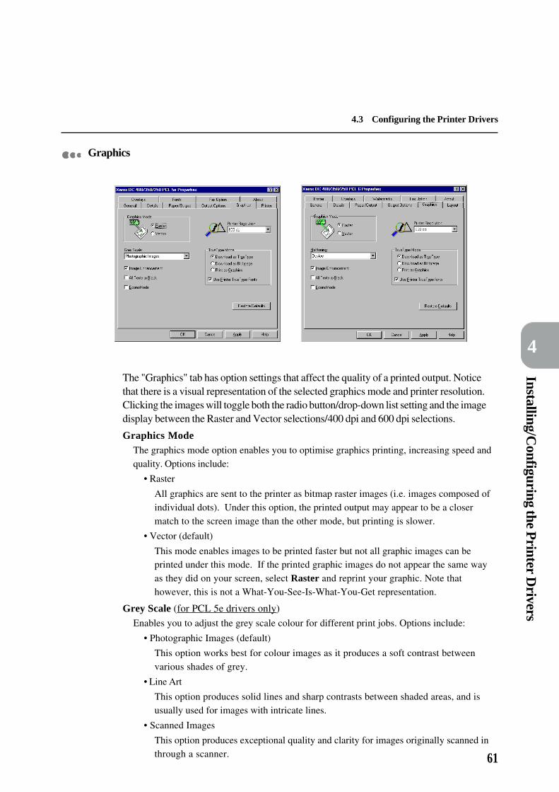
61
Installing/Configuring the P
rinter Drivers
4
4.3 Configuring the Printer Drivers
Graphics
The "Graphics" tab has option settings that affect the quality of a printed output. Noticethat there is a visual representation of the selected graphics mode and printer resolution.Clicking the images will toggle both the radio button/drop-down list setting and the imagedisplay between the Raster and Vector selections/400 dpi and 600 dpi selections.
Graphics ModeThe graphics mode option enables you to optimise graphics printing, increasing speed andquality. Options include:
• Raster
All graphics are sent to the printer as bitmap raster images (i.e. images composed ofindividual dots). Under this option, the printed output may appear to be a closermatch to the screen image than the other mode, but printing is slower.
• Vector (default)
This mode enables images to be printed faster but not all graphic images can beprinted under this mode. If the printed graphic images do not appear the same wayas they did on your screen, select Raster and reprint your graphic. Note thathowever, this is not a What-You-See-Is-What-You-Get representation.
Grey Scale (for PCL 5e drivers only)
Enables you to adjust the grey scale colour for different print jobs. Options include:
• Photographic Images (default)
This option works best for colour images as it produces a soft contrast betweenvarious shades of grey.
• Line Art
This option produces solid lines and sharp contrasts between shaded areas, and isusually used for images with intricate lines.
• Scanned Images
This option produces exceptional quality and clarity for images originally scanned inthrough a scanner.

62
4
4.3 Configuring the Printer Drivers
Halftoning (for PCL 6 drivers only)
Halftone refers to a type of pattern that is applied to the printed image. By using acombination of black dots, these patterns produce a grey appearance on the printed image.This Halftoning feature is designed to process images (e.g. photographs) but not thecomputer generated art (e.g. clip art). The appearance of the printed image will be differedby the Halftone settings.
Note the different settings available for the different PCL 6 drivers.
For Windows 3.1 and Windows 95/98 PCL 6 drivers:
• Device (default)
Image objects will be rendered by default halftoning attributes.
• Line Art
Provides solid lines and sharp contrasts between shaded areas and it is used forimages with intricate lines.
• Fine
Provides smooth shades of grey.
• Coarse
Provides rough greyscale with high contrasts for images that will be scanned/copied.
• Diffusion
Creates the appearance of grey scales by randomly placing individual dots of ink. Bestfor photographic images but requires more processing time. Available only if Rasteris selected for Graphics Mode.
For the Windows NT 4.0 PCL 6 driver:
• Device (default)
Image objects will be rendered by default halftoning attributes. Available only ifVector is selected for Graphics Mode.
• System
Enables the System Halftoning. Click Halftone Colour Adjustment for systemhalftone colour adjustmnent.
Image EnhancementEnhances the quality of the output image. Default is on.
All Texts to BlackPrints all coloured text (except white) in black. If this is not specified, colours will beprinted in varying degree of greys. Default is off.
EconoModeUsed to reduce the amount of toner the printer uses by using less toner on each page.When EconoMode is on, text and graphics are printed in grey rather than black. It issuitable for printing of drafts. Default is off.
Printer ResolutionSpecify the resolution for printing at either 400 dpi or 600 dpi. A higher resolution usuallyproduces a better quality output but it takes a longer time to print. Default is 600 dpi.

63
Installing/Configuring the P
rinter Drivers
4
4.3 Configuring the Printer Drivers
TrueType ModeThe drivers are capable to download the Windows TrueType fonts in three different ways:
• Download as True Type (default)
Prints text by downloading the complete character set of TrueType fonts in an outlineform that the printer can deal with directly. Downloaded fonts are vector-based,scalable typefaces.
• Download as Bit Image
Prints text by downloading each TrueType character as an individual bitmap font.Downloaded fonts are raster-based, non-scalable typefaces.
• Print as Graphics
Prints text as graphic images. The printed output may appear to be a closer match tothe screen image than the other options, though it may print slower. Enabled only ifRaster is selected for Graphics Mode.
Use Printer TrueType fonts
When this is on, the printer prints by using the printer-resident fonts instead of bydownloading fonts to the printer, unless the required fonts are not present in theprinter. This will speed up the printing process and give the printer its bestperformance. Default is on. Disabled if Print as Graphics is selected for True TypeMode.
Halftone Colour Adjustment (for Windows NT 4.0 drivers only)
Click this button to display the "Halftone Color Adjustment" dialog box for setting thecolour adjustment values that are used to adjust the colour of bitmap images for printing.Colour adjustments affect certain attributes of the image, such as contrast and brightness.For the Windows NT 4.0 PCL 6 driver: enabled only if System is selected for Halftoning.
The "Negative" check box in the "Halftone Color Adjustment" dialog box specifieswhether or not the colours of bitmap images are inverted. Inverting coloursproduces a negative image of the bitmap.
Windows NT 4.0

64
4
4.3 Configuring the Printer Drivers
Overlays
The "Overlays" tab allows you to create, use and delete page overlays for your printer. APage Overlay is a group of PCL commands and/or data created, downloaded and stored inthe printer by you. Once stored in the printer, a page overlay can be invoked upon requestand eliminates the need to download the same information over again, thus savingtransmission time. For example, if you want to print a company letterhead on every letterthat you are sending, you have to first create a page overlay for this letterhead and store itin the printer. Then, whenever you want to print letters with this letterhead, simply send apage overlay command to the printer to print.
Load OverlayWhen you want to use file from an external source as an overlay, click this button toinform the overlay manager of the file and its location.
If you source an external file from a floppy disk and then remove the disk fromthe disk drive, the file will no longer be available as an overlay. If you intend to usethis file regularly, it is recommended that you copy the file to your system local diskbefore using this button.
Create OverlayCreates and stores a Page Overlay from a file containing the overlay that you want.
You have to first open the file with the overlay that you want, then, select the "Print"command from the "File" menu. When the "Print" dialog appears, select the XeroxDC 400/350/250 printer and click Properties. Then, select the "Overlays" tab in theprinter properties dialog box. Click Create Overlay, and enter a name for theoverlay in the "File name" box. You may select another pathname other than thedefault pathname (C:\pageover). Click OK when you have finished. When aconfirmation dialog box appears, click Yes to confirm the operation. This will storethe overlay in your computer disk. If you click No, this operation will be aborted.

65
Installing/Configuring the P
rinter Drivers
4
4.3 Configuring the Printer Drivers
Delete OverlayTo delete an overlay, select it in the "Overlay" list box, and click Delete Overlay. ClickYes to confirm deletion and No to abort the action.
Download Now (for PCL 5e drivers only)
Allows you to permanently download overlays to the printer. Using overlays that arealready resident on the printer may improve printing performance. You can downloadoverlays to memory.
Delete AllDeletes all overlays from any or all of the destinations.
Query Page OverlayWhen this is selected, a message box requesting for confirmation will appear whenever apage overlay command is sent to the printer. If this option is off, the selected page overlayfile will be sent directly to the printer.
This option is not active if No Overlay is selected or if the currently selected overlayhas been permanently downloaded to the printer.
Selected Overlay statusDisplays information on the selected overlay.
Overlay Creation statusDisplays information regarding the creation of overlays.
Fonts (for PCL 5e drivers only)
This tab dialog allows you to install fonts to your printer.(For PCL 6 drivers: a Font Installer is included for managing PCL fonts, which will beenabled when the driver is invoked through the Windows Control Panel.)
Windows 95/98 Windows NT 4.0

66
4
4.3 Configuring the Printer Drivers
For Windows 3.1 and Windows 95/98 drivers:
Add FontsClick to install new fonts to your printer. A window appears for you to specify the sourcelocation of the fonts. Enter the location. When a list of fonts appears in the list box on theright, select the font that you want to install and click Add. Follow the on-screeninstruction to complete the operation.
Copy Fonts to New PortIf you are using more than one Xerox DC 400/350/250 printers, or if you change the portwhich your printer is connected to, you can move or copy your installed fonts to the otherprinter on that port by clicking this button.
Print Font ListingPrints a list of available printer fonts.
MoveMoves the selected fonts to the specified destination (i.e. printer or port).
CopyCopies the selected fonts to the specified destination (i.e. printer or port).
DeleteIf you are no longer using a font, you can delete it from your Windows applications or/andyour hard disk.
EditIf you have purchased a disk-based font which has the same name as a font you arealready using, you should change the name of either font by clicking this button after youhave selected that font.
• Permanent
Downloading a font permanently ensures a font stays in your printer memory until theprinter is turned off. This is especially useful for a frequently used font. You can generallyprint faster when you install fonts as permanent but it can also limit the amount of printermemory available for printing graphics and complex page.
• Temporary
If you install a font as temporary, the font is loaded into your printer memory only whenyou want to print a document with that font. This works well, for instance, when yourarely use a font, when you need your printer memory for printing graphics, when you areusing a variety of fonts in one document, or when you are printing to a shared printer.
For the Windows NT 4.0 driver:
<<Downloads one or more available fonts.
>>Deletes a font from the list of downloaded fonts.
Font SummaryPrints the list of currently downloaded fonts.

67
Installing/Configuring the P
rinter Drivers
4
4.3 Configuring the Printer Drivers
Layout (for PCL 6 drivers only)
The Layout property provides five job finishing features for you to modify the printedlayout of a document. Notice that an image is displayed for each type of layout modeselected and which also indicates the current page orientation.
Layout ModeProvides a list of the options of job finishing features:
• N-Ups (default)
• Booklet Printing
• Fit To Page
• Scaling
• Logical On Physical
Selecting each of the features will display one of the following corresponding options:
N-Up Printing (available when N-Ups is selected for Layout Mode)
The N-Up function allows more than one document page to beprinted on a same physical page by dividing the physical page intoN smaller physical pages. Each document page is then reducedand translated to fit into the new smaller physical page. In thisway, multiple pages are printed onto a single physical page.
Pages Per SheetLists the possible N pages per sheet for the N-Up printing function: 1, 2, 4, 6, 9, 16.Default is 1.

68
4
4.3 Configuring the Printer Drivers
Page BorderTo provide options of printing each document page with a page border on thephysical page:
• None (default)
No page border is drawn.
• Grid
A rectangle is drawn to divide each document page.
• Shadow
A rectangle with drop shadow effect is drawn around each document page.
Enabled when more than 1-Up is selected for Pages Per Sheet.
No Rotation on Same Sheet
Specify how N-Up document pages of different orientation are to be handled on thesame physical page by comparing other document pages with the first documentpage. When this is not selected, document pages with different orientation from thefirst document page will be rotated to match its orientation, with minimum sizereduction. When this is selected, document pages with different orientation from thefirst document page will not be rotated but will be scaled down in order to fit into thesame physical page. Enabled when more than 1-Up is selected for Pages Per Sheet.Default is off.
Booklet Printing (available when Booklet Printing is selected for Layout Mode)
This function allows the document to be printed as a booklet. Itensures that the document pages will be re-ordered and printed2-Up and that the output sheets when folded and stacked willhave the correct page order.
When this feature is chosen in Layout Mode, the following dialog box will be displayed.
Click OK to proceed. There are two types of booklet printing:
• Scale To Booklet (default)
Document pages will be scaled down and printed 2-Up on each side of the paper withthe paper size of the document. Unlike Use Booklet Paper Size, this option allowsyou to do a simple booklet printing without having to know the booklet paper size touse in order to prevent the document being truncated when printed as a booklet.
• Use Booklet Paper Size
Document pages will be printed 2-Up without scaling on the specified target papersize. Selecting any one of the booklet paper size here will change the current papersize setting in the driver to the booklet size automatically.

69
Installing/Configuring the P
rinter Drivers
4
4.3 Configuring the Printer Drivers
The options available for the the different booklet paper size are:
• Booklet on Letter (default)
• Booklet on Ledger
• Booklet on A4
• Booklet on A3
Available only when Use Booklet Paper Size is selected.
Fit To Page (available when Fit To Page is selected for Layout Mode)
This function allows document to be printed on a specified papersize that is different from the original page size of the documentby scaling the document page to fit onto the specified page size.
Fit to Paper Size
Lists the possible paper sizes that can be used. The options available for the paper sizeare similar to the settings of Paper Size on the "Paper/Output" tab. The "Fit to Page"function can output to all paper sizes. Default is A4 (210 × 297 mm).
Scaling (available when Scaling is selected for Layout Mode)
This function allows enlargement or reduction of each documentpage to be printed.
Scale Factor (%)
Define a scale factor of between 50 to 400 % for enlargement (>100 %) or reduction(<100 %) of your page. Default is 100 %.
Page Position
Specify the position where the document page is to be printed on the output:
• Top Left
• Top Right
• Center (default)
• Bottom Left
• Bottom Right
Logical On Physical (available when Logical On Physical is selected for LayoutMode)
This function allows you to print on a paper size that is differentfrom the page size designated for your document without scalingthe page image. It is intended to print a document onto a biggerpaper size than its original size. When the paper size is smaller,the printout may not be of the expected result.

70
4
4.3 Configuring the Printer Drivers
Target Paper Size
Lists the possible paper sizes that can be used. The options available for the paper sizeare similar to the settings of Paper Size on the "Paper/Output" tab. Default is A4(210 × 297 mm).
Page Position
Specify the position where the document page is to be printed on the output:
• Top Left
• Top Right
• Center (default)
• Bottom Left
• Bottom Right
Page Border
To provide options of printing each document page with a page border on thephysical page:
• None (default)
No page border is drawn.
• Shadow
A rectangle with drop shadow effect is drawn around each document page.
Watermarks (for PCL 6 drivers only)
This property dialog allows you to create, edit and delete watermarks, which are lightimages printed in the background on a page.

71
Installing/Configuring the P
rinter Drivers
4
4.3 Configuring the Printer Drivers
The procedure to create a watermark is as follows:
Specify the text for the watermark in Text (maximum 100 characters).
Select Fonts to display the "Font" dialog box and specify the font, font style andsize. Font style includes regular, italic, bold and bold italic; size ranges from 6-900.
Select Color to display the "Color" dialog box and specify/create the requiredcolour.
Specify the position and angle of the text by adjusting the "Angle" scrollbar (-90 to+90 degrees) and the scrollbar just below the preview window* which moves thex and y position values. These position values are in the 1/100ths (0.01) of an inchand are offsets from the page centre. To reset the position to the paper origin,press Center Watermark.
Click Add to add the new watermark to the "Watermark" list.
The procedure to edit a watermark is as follows:
Select an existing watermark from the "Watermark" drop-down list.
Make changes to it as required.
Click Update to replace the previous version or Add to save a modified version of
the watermark.
The procedure to delete a watermark is as follows:
Select an existing watermark from the "Watermark" drop-down list.
Click Delete to remove the watermark from the list.
To print a watermark, the options available include:
In Background
Selecting this prints the watermark underneath the primary texts and graphics in thedocument; otherwise the watermark will be printed on top of all images in the docu-ment. Disabled if As Outline Only is selected.
On First Page Only
Selecting this prints watermark on the first page of the document only; otherwise thewatermark will be printed on all pages.
As Outline Only
Selecting this prints the text outline of the watermark which is always printed on topof all document images. Disabled if In Background is selected.

72
4
4.3 Configuring the Printer Drivers
Advanced (for Windows NT 4.0 drivers only)
The NT drivers will display a hierarchical list of control items that relate to documentproperty. It presents a summary of the document default settings of the driver and allowsuser to change setting of each item by selecting them here. A control corresponding to theselected item will be available for user input. The settings include only items from the"Paper/Output", "Output Options" and "Graphic" tabs.

73
Installing/Configuring the P
rinter Drivers
4
4.4 Printing/Faxing
This section describes the procedures to send print and fax jobs from an application.
4.4.1 Printing from an application
Procedure
From the "File" menu of the application, select Print.
In the "Print" dialog box displayed ("Print Setup" for Windows 3.1), check thatthe printer used is the Xerox DC 400/350/250 printer. If not, select it from theprinter name drop-down list.
Click Properties (Options for Windows 3.1) to display the properties dialogbox.
Make the necessary changes to the different properties (see "4.3 Configuring thePrinter Drivers"). Note that the changes made to these settings will be the defaultprinter configuration for printing the subsequent jobs of the application.
To make settings for the present job without changing the default settings, changethe page setup by using the relevant menu options from the "File" menu (e.g.Document setup).
Close the properties dialog box.
Click OK in the "Print" dialog box to start printing.This Xerox DC 400/350/250 printer allows you to print the PostScript languageby using the PostScript 3 Kit. For details, see "Appendix E PostScript 3 Kit".
4.4.2 Faxing from an application
To be able to fax from your Xerox DC 400/350/250 printer, you must attach a faxunit to it and then on the "Printer" tab, select Fax Unit. The driver will then enable theproperties for faxing (Fax Recipient and Fax Option) and disable option settings that arenot applicable to it e.g. only options like Image Orientation and Paper Size on the"Paper/Output" tab are enabled for fax job selection.Follow the procedure below to send a fax job but refer to the sections following it, FaxRecipient and Fax Option for details on the different options available.
Procedure
From the "File" menu of the application, select Print.
In the "Print" dialog box displayed ("Print Setup" for Windows 3.1), check that theprinter used is the Xerox DC 400/350/250 printer. If not, select it from the printername drop-down list.

74
4
4.4 Printing/Faxing
Click Properties (Options for Windows 3.1) to display the properties dialog box.
Select Fax for Job Type on the "Paper/Output" tab.
Make the necessary specification in the various properties tabs available and thenclick OK to close the properties dialog box and to display the "Print" dialog box.
Click OK. The "Fax Recipient" dialog box appears.
Input the information for Name and Fax Number, and then click Add to List. Orif you have previously saved the list of recipients, select it from Recipient List todisplay the recipients' information. You can also access the list of recipients fromfiles other than the one specified in the "Recipient List" box, by clicking Open File.
Click OK to send the fax. The "Fax Job Confirmation" dialog box appears.
Click OK to confirm sending the fax job or Abort to cancel it. You may also selectDelay Send to specify the time for the fax job to be sent later.

75
4.4 Printing/Faxing
Installing/Configuring the P
rinter Drivers
4
Fax Recipient
Recipients are the individuals or groups to whom the fax is to be sent. The Xerox DC 400/350/250 printer is capable of sending a fax job to a group of recipients of no more than 50.The "Fax Recipient" dialog box enables you to specify the information of a fax recipientand to define a list of recipients who will receive the same fax job.
NameEnter the name of the individual or the relay station to which you are sending the fax. Thecharacters used should not exceed 30 characters. Valid characters include ASCII printablecode from 20H (space) to 7AH ('z'). The reserved codes of the driver are '{', '}' and '|'.
Fax NumberEnter the fax number of the individual or the relay station to which you are sending thefax. A fax number can contain up to 30 characters including letters, numbers, '-' andcharacters for DTMF command. Entry of characters '[', ']', '{', '}', '|', ',' and spaces arenot permitted.
When dialing the fax number, the letter will be translated into a number as follows:
ABC�2, DEF�3, GHI�4, JKL�5, MNO�6, PQRS�7, TUV�8, WXYZ�9.
Recipient's fax number must be specified before the fax job from an application canbe sent.
Add to ListTo send a fax, you have to enter the fax number and optional name in the respective fields,and then click Add To List. The fax address is only confirmed when it is entered in thelist. You can add a maximum of 50 recipients to the list.
If you did not click Add To List after entering the name and fax number, therecipient's particular will not be valid.
Remove From ListRemoves the selected entry in Recipient List.
Recipient List FileDisplays the path of the current recipient list file.
If the recipient list file is created by an older version driver, the following dialog box will bedisplayed when you try to open it with this new driver that you are using:
If you click No, the file will not be converted and the previous dialog box will be activeagain. If you click Yes, a "Save Conversion As" dialog box will be displayed. Specify anew file name with extension ".afd" and then click OK. A new recipient list file will becreated with this new name and the previous file will remain as it is.
Note that recipient list file created by the following versions of the different printer drivers(or later versions) cannot be opened by any earlier version of the drivers:

76
4
4.4 Printing/Faxing
• version 1.0.2b of PCL 5e drivers for Window 3.1x, Windows 95/98, Windows NT 4.0;
• version 1.0.5b of PCL 6 drivers for Window 3.1x, Windows 95/98;
• version 1.0.1 of PCL 6 driver for Windows NT 4.0.
The following dialog box will be displayed if you try to do so:
If you cannot read the recipient list file with the driver that you are using now, obtain alater version of the driver than the one mentioned above.
New FileClick this to open a new file to store recipient data.
Open FileClick this to open an existing file that contains recipient data.
Save File AsClick this to copy the current recipient list file in another name.
Recipient ListYou may select any of the recipient lists from the drop-down list. To create a recipient list,enter the name and fax number of the recipients whom you want to include in a list in the"Recipient List" box, and click Save List As.
Recipient InfoSelect a recipient in the list box, then click this button. A dialog box displaying informationof the selected recipient appears. You may enter or edit information regarding this recipient,such as his name, company, fax number, voice number, and e-mail address here.
Comm. SettingsClick this to specify the communication settings of the selected recipient in the displayed"Comm. Setting" dialog box.
Communication Mode
Select a communication protocol for sending the fax job from the drop-down list.The options are: G3-Auto, G3-Overseas and G4-Auto.(G4-Auto is available only if ISDN/G4 Kit is selected on the "Printer" tab.)
Secure Send
Secure Send mode sends a fax job to a particular mailbox at the receiving end. Whenthis is selected, the following options will be available. For security purpose, you mayassign a password to access the designated mailbox using the "Password" control.
Mailbox ID: Enter the mailbox ID of the mailbox at the receiving end(1-200).
Password: Assign a 4-digit password for a fax job under Secure Sendmode.

77
4.4 Printing/Faxing
Installing/Configuring the P
rinter Drivers
4
Relay Send
Relay Send mode sends a fax job to a particular relay station, and from there, the faxjob are distributed to the various receiving destinations. You may send to a maximumof 20 destinations via a relay station. By turning this mode on, you are setting up theselected recipient as a relay station. When this is selected, the following options willbe available.
Relay Station ID: Enter the ID of the relay station to which you are sending arelay fax job (1-99).
Print at Relay Station:Select this option to print the fax job at the relay station.
Group Sending: Select this option if you are entering a group sent ID inDestination ID below.
Destination ID: Enter the destination ID of the recipient who is going toreceive a relay fax job via the specified relay station. Afterspecifying the recipient's destination ID, press Add To toadd it to Destination List. The default destination ID is 1-99 but when Group Sending is selected, it becomes 1-9.
Destination List: It shows the confirmed destinations that will receive therelay fax job. You may specify up to 20 destinations here.A group ID is prefixed with a "#".
Add To: This button is used to transfer the specified destination IDfrom Destination ID to Destination List.
Remove: This button is used to remove the selected destination IDfrom Destination List.
Save List AsClick this button to copy the current recipient list in another name. The "Save RecipientList" dialog box appears and you can enter a recipient list name of up to 30 characters inList Name to identify the list.
Delete ListTo delete a recipient list, select the list from the Recipient List and then click Delete List.A dialog box requesting for confirmation appears.
When Secure Send is selected When Relay Send is selected

78
4
4.4 Printing/Faxing
Fax Option
The "Fax Option" tab enables you to specify the fax attributes such as the fax resolution tobe used by the Xerox DC 400/350/250 printer when sending a fax job.
The options on this "Fax Option" tab are enabled only if all of the followingconditions are met:(1) Fax Unit is selected on the "Printer" tab; &(2) Fax is selected for Job Type on the "Paper/Output" tab.
Fax ResolutionSelect any of the resolution options to specify a resolution for fax transmission:
• Normal - 100 × 200 dpi
• Fine - 200 × 200 dpi (default)
• Super Fine - 400 × 400 dpi
Fax transmitted at a higher resolution takes a longer transmission time.
Transmission ReportSelect whether or not to generate a report for fax transmission:
• Report Always
A transmission report is always generated after fax transmission is completed.
• Report On Error (default)
A transmission report is generated only when you have a transmission failure.
• No Report
No transmission report will be generated by the printer.
Send HeaderSelect this check box to include a send header when sending a fax job. Default is on.

Mode Menu/Common Menu
5.1 Mode Menu and Common Menu ........................................................... 80
5.2 Mode Menu Items ................................................................................. 84
5.3 Common Menu Items ............................................................................ 90

80
5
5.1 Mode Menu and CommonMenu
This section explains about the types and levels of menu.
5.1.1 About menu
There are two types of menus: Mode menu and Common menu.
During the Power Save mode, nothing will be shown in Display. Switch off the PowerSave mode before carrying on.
Common Menu
Mode Menu
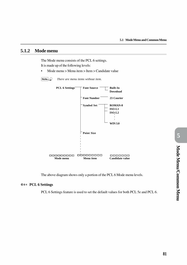
81
Mode M
enu/Com
mon M
enu
5
5.1 Mode Menu and Common Menu
5.1.2 Mode menu
The Mode menu consists of the PCL 6 settings.It is made up of the following levels:
• Mode menu > Menu item > Item > Candidate value
There are menu items without item.
PCL 6 Settings Font Source Built-InDownload
Font Number 23 Courier
Symbol Set ROMAN-8ISO-L1ISO-L2
WIN 3.0
Point Size
The above diagram shows only a portion of the PCL 6 Mode menu levels.
PCL 6 Settings
PCL 6 Settings feature is used to set the default values for both PCL 5e and PCL 6.
Mode menu Menu item Candidate value

82
5
5.1 Mode Menu and Common Menu
5.1.3 Common menu
Common menu consists of Port Setting, Print Utility and Maintenance Mode. It is a screento set items common to all print modes.Common menu is made up of the following levels:
• Common menu > Menu item > Item > Candidate value
The above diagram shows only a portion of the Maintenance Mode from the Commonmenu.
Printer Settings Jam Recovery OFFON
Alarm OFF
Echo Back Mode
Memory Change Receive Parallel 64KB BufferMem
Serial 64KBPS Memory
Common menu Menu item Item Candidate value
Maintenance Mode

83
Mode M
enu/Com
mon M
enu
5
5.1 Mode Menu and Common Menu
Port Setting
The Port Setting menu is used to set the necessary conditions for the printer interfacetypes connected to the host device as well as for their communications.
When ports which print from Common Menu > Maintenance Mode > Port Status areset to stop, various settings of the port cannot be set.
"5.3 Common Menu Items" for the items and operations that can be set by the PortSetting menu.
Print Utility
The Print Utility menu is used to print and check internal information of the printer such asprinter setting information, error log table, print log table and fonts-related information.
"3.6 Outputting List/Report" for items and operations that can be set by the PrintUtility.
Maintenance Mode
The Maintenance Mode menu is used to set printer settings (alarm time/system clock etc),echo back, memory change, port status, initialization of the hard disk etc.
"5.3 Common Menu Items" for the items and operations that can be set by theMaintenance Mode menu.

84
5
5.2 Mode Menu Items
This section explains the values that can be set in each of the Mode Menu items and the setting method.
5.2.1 List of Mode Menu items
PCL 6 Settings
Menu item Explanation
Font Source Indicates the set of fonts to be used.The candidate values are as follows:• Built-In (Default)
Internal/resident fonts (fonts that are provided with the printer) will be used.• Download
Downloaded permanent fonts (permanent soft fonts that are supplied on flexible discs)will be used. It will not be displayed if there are no downloaded fonts.
• Permanent fonts are removed from user memory whenever the printer isturned off.
• Once downloaded, a soft font occupies a portion of user memory (RAM).Number of soft fonts that can be stored in user memory is limited only by theamount of available user memory.
If Download is selected and then all downloaded fonts are deleted from theprinter, the selection will be ignored and the default will be used.
Font Number Sets the font to be the default.The range of setting is between 0-45 (for Built-In). Each unit is 1. Default is 23 (Courier).
• The setting takes on default value when the NVRam is initialised.• For Built-In: default is 23.
For Download: default is 1.
If the number selected is not in the range of available fonts, the selectionwill be ignored and the default value will be used.
Symbol Set Sets the specific set of symbols provided by a font with each symbol set defined with aspecific application in mind.There are 34 internal symbol sets altogether, like:• ROMAN-8 (Default)• WIN 3.0• ISO-69 etc
Available only to all True Type typeface, and to the four Bistream Dutch801 SWC (CG Times), the four Bistream Swiss 742 SWC (Univers), the fourBistream Fixed Pitch 810 Courier SWC (Courier), and the three FixedPitch 850 Letter Gothic 12 pitch/text SWC (Letter Gothic) typefaces.
Proper selection of Symbol Set is important in printing the required output.

85
Mode M
enu/Com
mon M
enu
5
5.2 Mode Menu Items
Menu Item Explanation
Point Size Sets the height of the font in points.The range of setting is between 4 to 50. Default is 12 and each unit is 0.25.
• The point size item available depends on the fonts source and font numberselected.
• The values set are changeable by commands.• The setting takes on default value when the NVRam is initialized.• This item is ignored in the selection of a fixed-space scalable font. It is
saved and available when a bitmap font or a proportionately-spacedscalable font is selected.
Pitch Sets the pitch of the font in character per inch.The range of setting is between 6 to 24. Default is 10.00. Each unit is 1.00 when the cursor isat the units position and 0.01 when the cursor is at the second decimal point position.
Pitch is the horizontal spacing of a fixed-space (bitmap or scalable) font interms of number of characters per inch.This characteristic is ignored when selecting a proportionately-spaced(bitmap or scalable) font but is saved in the font select table and availablewhen fixed spaced font is selected.
Copies Sets the number of output copy.The range of setting is between 1-999 copies. Default is 1 and each unit is 1.
• When there is a specific number of output from the host device, this valuecan be displayed and printed out. Also, it can be changed on the setting ofthe operator panel. However, number of specified output from Netware, lpdand AppleTalk cannot be changed to the operator panel.
• If there is instruction from the host device regarding the number of outputcopy, that value will be reflected and printed. After printing, the setting ofthe control panel will be overwritten by that value.
• However, for number of output copy specified by Netware, lpd, AppleTalkport, the value of the control panel will not be overwritten after printing.
Hex Dump Turns on/off the Hex(adecimal) Dump mode. Turning on the Hex Dump mode allows data thatare sent to the printer to be printed in plain ASCII format.The candidate values are ON and OFF. Default is OFF.
• Turning on the Hex Dump mode allows data that are sent to the printer tobe printed in plain ASCII format. It will not be interpreted by the emulation.Hex Dump is used for troubleshooting.
• Hex Dump is supported in the Parallel, Serial, lpd/PD and Netware inter-faces.

86
5
5.2 Mode Menu Items
Menu Item Explanation
Resolution Sets the resolution of the printer.The candidate values are 400 and 600. Default is 600.
Resolution refers to the number of dots per inch (dpi) of toner that theprinter places on the page. The higher the resolution, the better quality(clearer) the page.For best results, use 600 dpi for graphics and fonts that are designedspecifically for printers that print at 600 dpi resolution. For faster printingand smaller memory requirements (and a lower quality), use 400 dpiinstead.
Tray Sets the paper tray that supplies paper.The candidate values are as follows:• Auto-Tray (Default)*
Supplies paper from a selected tray among trays which have been loaded with the papersize set in the "Paper size" selection. However, the bypass tray (BPT) cannot be set forautomatic paper supply. It is the factory default if the 1-tray or 3-tray module is installed.
• Tray 1Supplies paper from tray 1. This is the factory default if the 1-tray or 3-tray module is notinstalled.
• Tray 2*Supplies paper from tray 2. This value is displayed when the 1-tray module is installed.
• Tray 3/HCF 1*Supplies paper from tray 3. This value is displayed when the 3-tray cabinet is installed.
• Tray 4/HCF 2*Supplies paper from tray 4. This value is displayed when the 3-tray cabinet is installed.
• Bypass Tray*Supplies paper from bypass tray (BPT). In this case, the paper size specified in "Papersize" selection must be loaded in the BPT. This value is displayed when the BPT moduleis installed.
• When Auto Tray is selected and the same size of papers are set in the samedirection in multiple trays, the paper tray retrieved will be in the order ofTray 1, Tray 2, Tray 3 and then Tray 4.When High Capacity Feeder (HCF) is installed, the paper tray retrievedwill be in the order of HCF1, HCF2, Tray 1 and then Tray 2.
• The values set are changeable by commands.• The setting takes on default value when the NV/Ram is initialized.
• When Tray 1 to Tray 4 are selected, the “Paper size” selection cannot beset as the paper loaded in these trays become the paper sizes.
• When Bypass Tray is selected, press to move the cursor to “Papersize”, then press or to select BPT size.
• When Bypass Tray is set and wrong paper size is confirmed, a messagerequesting the specified paper size will appear in the control panel.
*optional

87
Mode M
enu/Com
mon M
enu
5
5.2 Mode Menu Items
Menu Item Explanation
Duplex* Sets two-sided printing.The candidate values are OFF and ON which includes Short Edge and Long Edge.Default value is OFF.
• The values set are changeable by commands.• The setting takes on default value when the NVRam is initialized.
• BPT-supplied paper cannot be used for two-sided printing. Also, even ifBypass Tray is set for Tray when two-sided printing is specified, theprinting will be in one-sided.
• Even if two-sided printing is specified, the printing result may be differentwhen the following settings are performed which cause insufficient memory:
(1) When Paper size (A3) and Resolution (600 dpi) are set, it willfirst print as A3/600 dpi in two-sided. If this printing cannot bedone, it will print as A3/400 dpi in one-sided.
(2) When Paper size (A3) and Resolution (400 dpi) are set and if itcannot be done, it will print as A3/400 dpi in one-sided.
In the above case, either terminate the state of the ports that are not beingused or install the additional RAM module.
Orientation Sets the orientation for printing for PCL 6 only.The candidate values are Portrait and Landscape. Default is Portrait.
• The values set are changeable by commands.• The setting takes on default value when the NVRam is initialized.
Form Lines Sets the page length (printing area) of one page.The range of setting is between 5-128 lines with 1 line per unit. Default is 64.
• The values set are changeable by commands.• The setting takes on default value when the NVRam is initialized.
Image Enhance Enables or disables image enhancement. Image enhancement is to raise the resolution and toproduce smooth print of sharp edges.The candidate values are ON and OFF. Default is ON.
• The values set are changeable by commands.• The setting takes on default value when the NVRam is initialized.
Economode Turns the Economode on and off.The candidate values are OFF and ON. Default is OFF.
• Economode causes the printer to use lesser amount of toner. As a result,pages printed with Economode turned on will be lighter than pages printedwith Economode turned off.
• This feature can be used to print draft-quality documents so as to extend thelife of your toner cartridge.
• Economode will not affect the speed or performance of your printer.• The setting takes on default value when the NVRam is initialized.
*optional

88
5
5.2 Mode Menu Items
Menu Item Explanation
Output Tray Sets to output with printed page facing up or down.The candidate values are as follows:• Centre Tray (Default)
Outputs with the printed side facing down. Also, when printing double-sided pages, theodd-numbered pages will be facing down.
• Side Tray*Outputs with printed side facing up. In addition, during double-sided printing, the odd-numbered pages will be facing down.
• Stacker Auto*• Stacker Tray 1 to Stacker Tray 3*• Mail box (Bin 1) to Mail box (Bin 10)*
• The values set are changeable by commands.• The setting takes on default value when the NVRam is initialized.
Override Size Turns the Override Size on and off.The candidate values are OFF and ON. Default is OFF.
• The Override Size feature allows paper size switching if there is a paper-sizemismatch when the requested paper size is not available in the printer.Enabling this feature will allow the job to be printed on a best-fit papersize. However, there might be an image loss while using this feature.
• To ensure minimal image loss when the job is printed on another paper size,the selection of the best-fit paper size is based on the following rules:
1. switching between A4 and Letter
2. switching between B4 and Legal
3. switching among 8K, A3 and Ledger in the following sequence:
- 8K to A3 to Ledger
- A3 to Ledger to 8K
- Ledger to A3 to 8K• When this feature is not enabled, users will have to load the requested
paper size.
*optional

89
Mode M
enu/Com
mon M
enu
5
5.2 Mode Menu Items
(1) Press to move to the Mode Menu (PCL 6 Settings).
(3) Press or to display the required menu item*. For this example, we
choose Symbol Set.
(6) Press to save the selection. An * appears next to your selection,
indicating it is now the default value.
(2) Press to display the menu items in PCL 6 Settings.
(4) Press to display the candidate values in PCL 6 Settings.
(5) Press or to display the required candidate value. For this
example, we choose ISO-69.
(7) Press to move back to the Mode Menu (PCL 6 Settings). Then
press again to move back to the print screen (Print/Fax Ready).
In general:
Press to display the next
level.
Press or to display
the items within the same level.
(* The menu items, Tray and Duplex have one morelevel i.e.an item level after the menu item level.)
5.2.2 Setting a Mode Menu
The procedure to set a Mode Menu (PCL 6 Settings) which generally has three levels(Mode Menu > Menu item > Candidate value) is as follows:

90
5
5.3 Common Menu Items
This section explains the values that can be set in each of the Common Menu items and the setting method.
5.3.1 List of Common Menu items
The values that can be set in the Common Menu are divided into and explained in PortSetting, Print Utility and Maintenance Mode.
Port Setting
Menu Item Explanation
Parallel To be set when using the parallel port:• PDL Mode - Note (1), Look (1)
Sets the PDL mode.The candidate values are as follows:
• Auto (Default)*Automatic determination of which language is used to record the data received fromthe host and execute appropriate printing output according to the data.
• PCL 6Processes data received from the host device as PCL 6 language.
• PostScript 3*Processes data received from the host device as PostScript language.
• PJL Switch - Look (2)Sets the PJL commands sent from the host device to valid or invalid.The candidate values are as follows:
• ON (Default)Accepts PJL commands.
• OFFIgnores PJL commands.
• Auto Eject TimeSets the time to automatically print and output any remaining data in the printer when itis in a continuous state of not receiving data.The range of setting is between 5-1275 seconds with 5 seconds per unit. Default is 30seconds.
• Adobe Protocol*Sets the Adobe protocol which is the PostScript protocol connection for parallel/serialinterface.The candidate values are as follows:
• Standard (Default)Standard Protocol - This is set when the communication protocol is in ASCII format.
• BinaryBinary Communications Protocol - This is set when the communication protocol is inbinary format. Depending on data, the printer processing may be faster than AdobeStandard Protocol.
• TBCPTagged Binary Communications Protocol - This is set when the communicationprotocol is a mixture of ASCII and binary format and switched by a specific controlcode.
* Optional

91
Mode M
enu/Com
mon M
enu
5
5.3 Common Menu Items
Sets the bidirectional communication setting.The candidate values are as follows:
• ON (Default)Enables bidirectional communication.
• OFFDisables bidirectional communication.
Serial To be set when using the serial port:• PDL Mode - Note (1), Look (1)
Sets the PDL mode.The candidate values are as follows:
• Auto (Default)*Automatic determination of which language is used to record the data received fromthe host and execute appropriate printing output according to the data.
• PCL 6Processes data received from the host device as PCL 6 language.
• PostScript 3*Processes data received from the host device as PostScript language.
• PJL Switch - Look (2)Sets the PJL commands sent from the host device to valid or invalid.The candidate values are as follows:
• ON (Default)Accepts PJL commands.
• OFFIgnores PJL commands.
• Auto Eject TimeSets the time to automatically print and output any remaining data in the printer when itis in a continuous state of not receiving data.The range of setting is between 5-1275 seconds with 5 seconds per unit. Default is 30seconds.
• Adobe Protocol*Sets the Adobe protocol which is the PostScript protocol connection for parallel/serialinterface.The candidate values are as follows:
• Standard (Default)Standard Protocol - This is set when the communication protocol is in ASCII format.
• BinaryBinary Communications Protocol - This is set when the communication protocol is inbinary format. Depending on data, the printer processing may be faster than AdobeStandard Protocol.
• TBCPTagged Binary Communications Protocol - This is set when the communicationprotocol is a mixture of ASCII and binary format and switched by a specific controlcode.
* Optional
Menu Item Explanation
Parallel (con't...) • Bidirectional

92
5
5.3 Common Menu Items
Menu Item Explanation
Serial (con't...) • Baud RateSets the transmission speed of data for serial interface.The candidate values are as follows:
• 9600 (Default)Transmission of 9600 bits of data in 1 second.
• 19200Transmission of 19200 bits of data in 1 second.
• 1200Transmission of 1200 bits of data in 1 second.
• 2400Transmission of 2400 bits of data in 1 second.
• 4800Transmission of 4800 bits of data in 1 second.
• Data LengthSets the data length of the serial interface.The candidate values are as follows:
• 8 Bit (Default)Sets the data length to 8 bit.
• 7 BitSets the data length to 7 bit.
• Stop BitSets the length of stop bit for serial interface.The candidate values are as follows:
• 1 Bit (Default)Sets the length of the stop bit to 1 bit.
• 2 BitSets the length of the stop bit to 2 bit.
• ParitySets the parity check method for serial interface.Parity check is a checking process that determines whether the data has been sentcorrectly from the sending party to the receiving party.The candidate values are as follows:
• None (Default)Does not execute parity check. Parity bid will not be attached when transmittingdata.
• OddExecutes odd number parity check. Odd number parity will be attached whentransmitting data.
• EvenExecutes even number parity check. Even number parity will be attached whentransmitting data.
* Optional

93
Mode M
enu/Com
mon M
enu
5
5.3 Common Menu Items
Menu Item Explanation
Serial (con't...) • Xon-Xoff ControlSets the Xon-Xoff Control (software flow control) for serial interface.When the buffer of the receiving side is almost full, Xon-Xoff control returns Xoff codeto the transmitting side and stops data transmission temporarily. After that, when thereceiving buffer is free to a certain extent by internal processing, Xon code is returnedand data transmission is resumed.The candidate values are as follows:
• Yes (Default)Enables Xon-Xoff control.
• NoDisables Xon-Xoff control.
• When the flow control is to be disabled, set Xon-Xoff Control to No and DTRControl to Fix-High or Fix-Low.
• Use DTR control when binary data is included in the receive data.
• DTR ControlSets the operation (hardware flow control) of DTR signal for serial interface.DTR (Data Terminal Ready) is a hardware signal that determines whether the printer isable to receive data from the host device.The candidate values are as follows:
• Fix-High (Default)Always sets DTR signal to high regardless of whether or not it is able to receivedata.
• Fix-LowAlways sets DTR signal to low regardless of whether or not it is able to receive data.
• Active-HighSets DTR signal to high when it is able to receive data and to low when it is unableto receive data.
• Active-LowSets DTR signal to low when it is able to receive data and to high when it is unableto receive data.
• The input of DTR signal is only valid when it is set to Active-High.• When the flow control is to be disabled, set DTR Control to Fix-High or
Fix-Low and Xon-Xoff Control to No.
• When hardware flow control is to be executed, it is necessary to have acable that connects the control signal line correctly. For more details, referto "Appendix B.2 Serial Interface".
* Optional
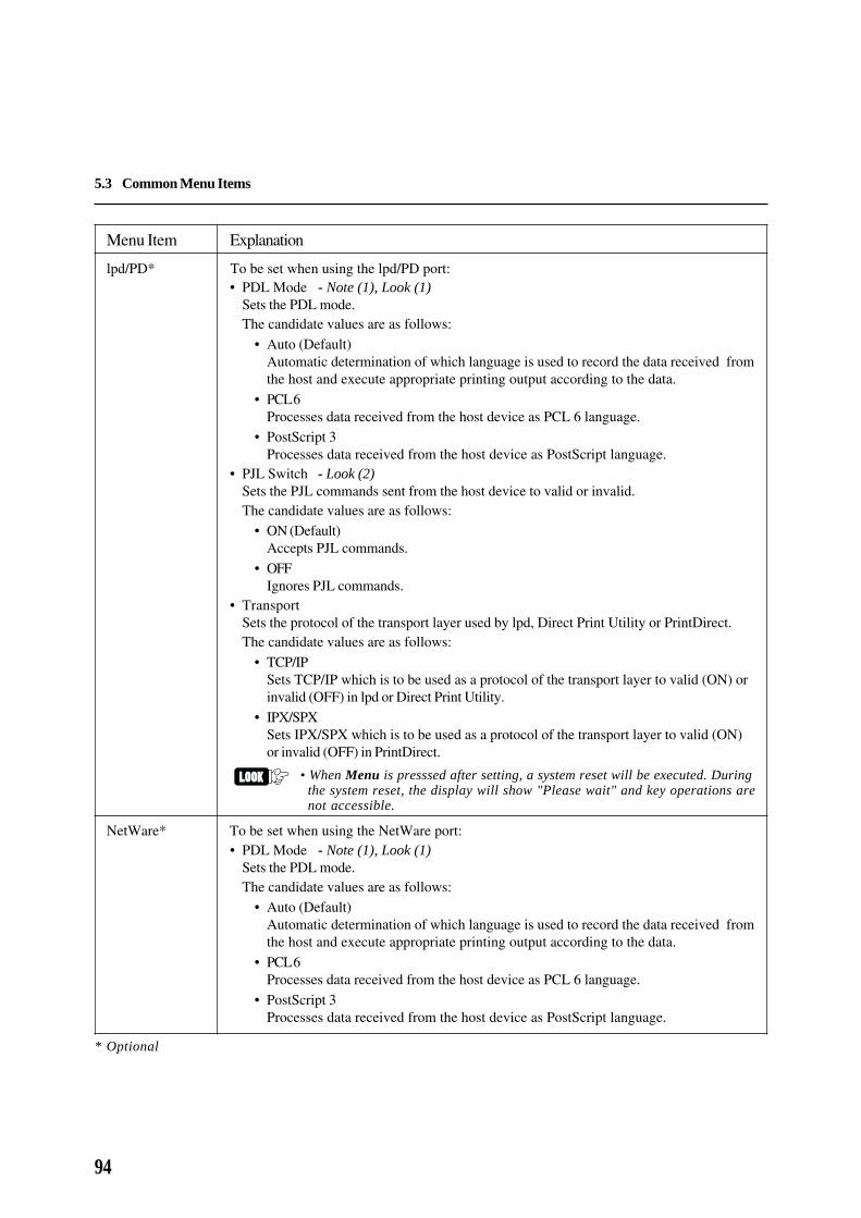
94
5
5.3 Common Menu Items
Menu Item Explanation
lpd/PD* To be set when using the lpd/PD port:• PDL Mode - Note (1), Look (1)
Sets the PDL mode.The candidate values are as follows:
• Auto (Default)Automatic determination of which language is used to record the data received fromthe host and execute appropriate printing output according to the data.
• PCL 6Processes data received from the host device as PCL 6 language.
• PostScript 3Processes data received from the host device as PostScript language.
• PJL Switch - Look (2)Sets the PJL commands sent from the host device to valid or invalid.The candidate values are as follows:
• ON (Default)Accepts PJL commands.
• OFFIgnores PJL commands.
• TransportSets the protocol of the transport layer used by lpd, Direct Print Utility or PrintDirect.The candidate values are as follows:
• TCP/IPSets TCP/IP which is to be used as a protocol of the transport layer to valid (ON) orinvalid (OFF) in lpd or Direct Print Utility.
• IPX/SPXSets IPX/SPX which is to be used as a protocol of the transport layer to valid (ON)or invalid (OFF) in PrintDirect.
• When Menu is presssed after setting, a system reset will be executed. Duringthe system reset, the display will show "Please wait" and key operations arenot accessible.
NetWare* To be set when using the NetWare port:• PDL Mode - Note (1), Look (1)
Sets the PDL mode.The candidate values are as follows:
• Auto (Default)Automatic determination of which language is used to record the data received fromthe host and execute appropriate printing output according to the data.
• PCL 6Processes data received from the host device as PCL 6 language.
• PostScript 3Processes data received from the host device as PostScript language.
* Optional
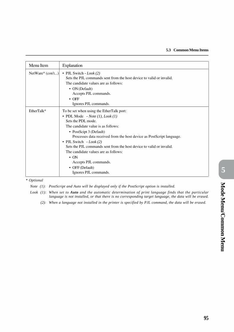
95
Mode M
enu/Com
mon M
enu
5
5.3 Common Menu Items
Menu Item Explanation
NetWare* (con't...) • PJL Switch - Look (2)Sets the PJL commands sent from the host device to valid or invalid.The candidate values are as follows:
• ON (Default)Accepts PJL commands.
• OFFIgnores PJL commands.
EtherTalk* To be set when using the EtherTalk port:• PDL Mode - Note (1), Look (1)
Sets the PDL mode.The candidate value is as follows:
• PostScipt 3 (Default)Processes data received from the host device as PostScript language.
• PJL Switch - Look (2)Sets the PJL commands sent from the host device to valid or invalid.The candidate values are as follows:
• ONAccepts PJL commands.
• OFF (Default)Ignores PJL commands.
* Optional
Note (1): PostScript and Auto will be displayed only if the PostScript option is installed.
Look (1): When set to Auto and the automatic determination of print language finds that the particularlanguage is not installed, or that there is no corresponding target language, the data will be erased.
(2): When a language not installed in the printer is specified by PJL command, the data will be erased.
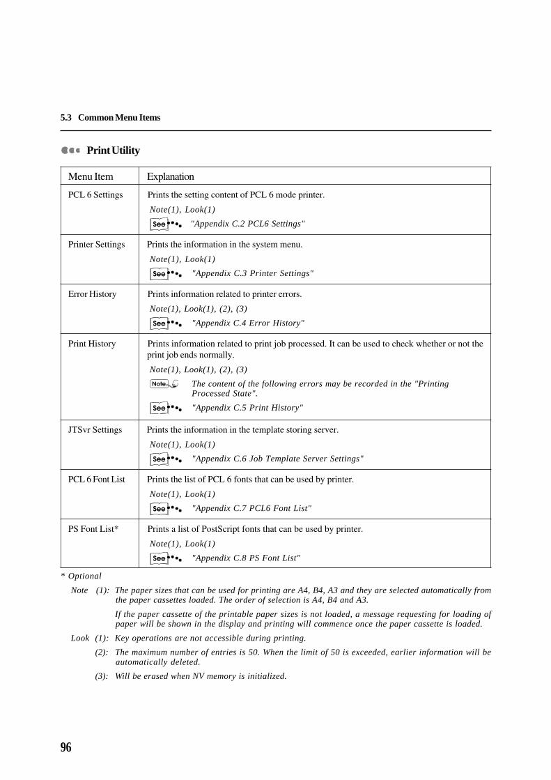
96
5
5.3 Common Menu Items
Print Utility
Menu Item Explanation
PCL 6 Settings Prints the setting content of PCL 6 mode printer.
Note(1), Look(1)
"Appendix C.2 PCL6 Settings"
Printer Settings Prints the information in the system menu.
Note(1), Look(1)
"Appendix C.3 Printer Settings"
Error History Prints information related to printer errors.
Note(1), Look(1), (2), (3)
"Appendix C.4 Error History"
Print History Prints information related to print job processed. It can be used to check whether or not theprint job ends normally.
Note(1), Look(1), (2), (3)
The content of the following errors may be recorded in the "PrintingProcessed State".
"Appendix C.5 Print History"
JTSvr Settings Prints the information in the template storing server.
Note(1), Look(1)
"Appendix C.6 Job Template Server Settings"
PCL 6 Font List Prints the list of PCL 6 fonts that can be used by printer.
Note(1), Look(1)
"Appendix C.7 PCL6 Font List"
PS Font List* Prints a list of PostScript fonts that can be used by printer.
Note(1), Look(1)
"Appendix C.8 PS Font List"
* Optional
Note (1): The paper sizes that can be used for printing are A4, B4, A3 and they are selected automatically fromthe paper cassettes loaded. The order of selection is A4, B4 and A3.
If the paper cassette of the printable paper sizes is not loaded, a message requesting for loading ofpaper will be shown in the display and printing will commence once the paper cassette is loaded.
Look (1): Key operations are not accessible during printing.
(2): The maximum number of entries is 50. When the limit of 50 is exceeded, earlier information will beautomatically deleted.
(3): Will be erased when NV memory is initialized.

97
Mode M
enu/Com
mon M
enu
5
5.3 Common Menu Items
Maintenance Mode
Menu Item Explanation
Printer Settings • Jam RecoverySets the treatment of print data when paper jammed in the printer.The candidate values are as follows:
• OFFDiscards print data during paper jam and does not print again. This setting reducesthe processing time for printing.
• ON (Default)Retains print data during paper jam and prints again.
• AlarmSets the length of the warning alarm when printer fails.The candidate values are as follows:
• OFF (Default)The alarm will not sound even if there is a failure.
• ContinuousWhen there is a printer failure, the alarm will keep sounding until action is taken.
• 2 sec to 90 secSets the alarm time from 2 sec to 90 sec with 2 sec per unit. The alarm will stop afterthe time frame set even if no action is taken against the printer failure.
• System Clock
Sets the system clock. System clock refers to the printer built-in clock. It is used whenprinting date/time of Print Utility.
The setting is "YY/MM/DD hh:mm" where YY is the setting for the year (last 2 digits)between 00-99, MM is the month between 01-12, DD is the day between 01-31, hh is thehour between 00-23 and mm is the minute between 00-59.
• AutoPrintHistorySets whether or not to automatically eject the print history. Print history is the printedinformation regarding the print job processed.The candidate values are as follows:
• OFF (Default)Does not automatically eject print history.
• ONAutomatically prints information that have not been automatically ejected when thememory area is full.
Echo Back Mode Outputs data received from the parallel port to the serial port as it is.
• Basically all the input interfaces cannot receive data when the printer is inMaintenance Mode. However, during the Echo Back Mode only, input fromparallel port is allowed.
• For parallel and serial communication conditions (e.g. Baud rate), it isnecessary to make the setting beforehand.
• When this function is used, the parallel/serial ports need to be in theactivated state.
Key operations are not accessible during the receiving of data.
* Optional

98
5
5.3 Common Menu Items
Menu Item Explanation
Memory Changes • PCL 6 MemorySets the capacity of the memory for the use of PCL 6. When the memory capacity isincreased, the printing speed may be increased, complicated document can be printed,and a good image quality can be obtained.The range of setting is between 2.00-16.00 MB with 0.25 MB per unit. Default is 4.50 MB.
• When Menu is pressed after the setting, a system reset will be executed."Diagnostics in progress" will be displayed during the system reset and keyoperations are not accessible.
• All the data stored in the various memory domains will be cleared by reset.• The maximum value of the memory capacity that can be set changes
according to the free memory capacity.
• PS Memory*Sets the capacity of the memory for use by PostScript software. The printing speed maybe increased when the memory capacity is increased.The range of setting is between 2.00-16.00 MB with 0.25 MB per unit. Default is 4.50 MB.
• When Menu is pressed after the setting, a system reset will be executed."Diagnostics in progress" will be displayed during the system reset and keyoperations are not accessible.
• All the data stored in the various memory domains will be cleared by reset.• The maximum value of the memory capacity that can be set changes
according to the free memory capacity.
• Receive Buffer MemorySets the memory capacity of the receive buffer for the respective interfaces.Receive buffer is the temporary storage location of the data sent from the host device.The memory capacity of the buffer can be changed according to the status and objectiveof the usage. Also, the increase of memory capacity for the buffer can speed up therelease of the host device of each interface.The ranges of settings are as follows:
• For Parallel, Serial, NetWare*, AppleTalk memory*64 KB - 1024 KB with 32 KB per unit; default: 64 KB (NetWare default: 224 KB)
• For lpd/PD Spool*Hard Disk: 64 KB - 1024 KB with 32 KB per unitMemory: 0.50 MB - 32.00 MB with 0.25 MB per unit; default: 1 MBNone: 64 KB - 1024 KB with 32 KB per unit; default: 224 KB
• When Menu is pressed after the setting, a system reset will be executed."Please wait" will be displayed during the system reset and key operationsare not accessible.
• In the following cases, items will not be displayed:
When the interface card is not installed"lpd", "NetWare" will not be displayed when the interface card (forEthernet 10BASE-5) is not installed.
When Port Status is set to OFFWhen Port Status is set to OFF, the corresponding item will not bedisplayed.
• Depending on the data volume sent from the host device, the releasing timefor the host device may not be changed even if the memory capacity isincreased.
* Optional

99
Mode M
enu/Com
mon M
enu
5
5.3 Common Menu Items
Menu Item Explanation
Memory Changes • Receive Buffer Memory (For lpd/PD Spool)
• After removing the additional RAM module and switching on the power, thefollowing process will be executed automatically if memory becomesinsufficient compared with the previous memory setting:
(1) Change and allocate the setting values of the various memories (e.g.Receive buffer memory).
(2) If allocation in (1) is not possible, stop the status of port related toEthernet and reallocate.
To increase the memory capacity of the receive buffer, either stop the statusof port not in use or install the additional RAM module.
Port Status Sets the state of the various ports when the power is switched on.
• ParallelSets to activate/inactivate the parallel port when the power is on.The candidate values are as follows:
• Enabled (Default)Activates the parallel port when the power is on.
• DisabledInactivates the parallel port when the power is on.
• SerialSets to activate/inactivate the serial port when the power is on.The candidate values are as follows:
• EnabledActivates the serial port when the power is on.
• Disabled (Default)Inactivates the serial port when the power is on.
• lpd/PD*Sets to activate/inactivate the lpd/PD port when the power is on.The candidate values are as follows:
• EnabledActivates the port in use by lpd/PD when the power is on.
• Disabled (Default)Inactivates the port in use by lpd/PD when the power is on. If transport is not set, itwill automatically move to the transport setting menu when Disabled is selected.
This item is displayed when the interface card (for Ethernet 100BASE TX/5) is installed.
• NetWare*Sets to activate/inactivate the NetWare port when the power is on.The candidate values are as follows:
• EnabledActivates the port in use by NetWare when the power is on.
• Disabled (Default)Inactivates the port in use by NetWare when the power is on.
This item is displayed when the interface card (for Ethernet 100BASE TX/5) is installed.
* Optional
(con’t...)

100
5
5.3 Common Menu Items
Sets to activate/inactivate the Salutation port when the power is on.The candidate values are as follows:
• EnabledActivates the port in use by Salutation when the power is on. Select this when usingthe network scanner driver.
• Disabled (Default)Inactivates the port in use by Salutation when the power is on.
This item is displayed when the interface card (for Ethernet 100BASE TX/5) is installed.
• ftp Client*Sets to activate/inactivate the ftp Client port when the power is on.The candidate values are as follows:
• EnabledActivates the port in use by ftp Client when the power is on. Select this when usingthe CentreWare Scan Service.
• Disabled (Default)Inactivates the port in use by ftp Client when the power is on.
This item is displayed when the interface card (for Ethernet 100BASE TX/5) is installed.
• EtherTalk*Sets to activate/inactivate the EtherTalk port when the power is on.The candidate values are as follows:
• EnabledActivates the port in use by EtherTalk when the power is on.
• Disabled (Default)Inactivates the port in use by EtherTalk when the power is on.
This item is displayed when the interface card (for Ethernet 100BASE TX/5) is installed.
Initialisation Executes the initialisation of NV memory and hard disk. It can also execute system reset. NVmemory is the nonvolatile memory that maintains the printer setting contents even after thepower has been switched off.
• Initialise NVRamExecutes initialisation of NV memory.
• Init Hard Disk* (when the internal hard disk is installed)Executes initialisation of the hard disk.
• System ResetExecutes system reset.
• The following processes are carried out when system reset is executed:- Read setting content registered in the start up memory.- Clear all data stored in the various memory domains.
• The self-performed system reset during menu operation takes some time toreturn to ready-to-print state.
• When the external additional hard disk is installed, the form/log data willnot be cleared as they are stored in the hard disk.
* Optional
(con’t...)
Menu Item Explanation
Port Status • Salutation*

101
Mode M
enu/Com
mon M
enu
5
5.3 Common Menu Items
Menu Item Explanation
Initialisation • System Reset
• If the initialisation of the hard disk is executed, all the data stored in thedisk will be erased.
• Key operations are not accessible during initialisation.• When Menu is pressed after initialisation, system reset will automatically
be executed. "Please wait" will be displayed during system reset and keyoperations will not be received.
Agent* Sets the activation/inactivation of agent.By activating the agent, you can use the CentreWare software with which you can managemultiple printers and get information on them from a distance.
• Start IPXActivates or inactivates the agent which uses IPX as a protocol of the transport layer.When you use the CentreWare software in the NetWare environment, activate the agentfrom this menu.The candidate values are as follows:
• ONActivates the agent which uses the IPX protocol.
• OFF (Default)Inactivates the agent which uses the IPX protocol.
• Start UDPActivates or inactivates the agent which uses UDP as a protocol of the transport layer.When you use the CentreWare software in the Windows NT environment, activate theagent from this menu.The candidate values are as follows:
• ONActivates the agent which uses the UDP protocol.
• OFF (Default)Inactivates the agent which uses the UDP protocol.
• Community SignupSpecifies the Community Name for enabling the settings from the CentreWare softwareto this machine.This menu will be displayed when Start IPX or Start UDP is set to ON.Press or to set the name of the community by using characters (0-9, a-z, A-Z).
Ethernet Setup* Sets the ethernet setting to the different values.
• AUTO (T/TX) (Default)Sets automatically the ethernet setting.
• 100BASE-TXUses the 100BASE-TX ethernet connection.
• 10BASE-TUses the 10BASE-T ethernet connection.
• 10BASE-5Uses the 10BASE-5 ethernet connection.
* Optional
(con’t...)

102
5
5.3 Common Menu Items
Sets the necessary information for using TCP/IP protocol. Item options include:• IP Address
Sets the printer IP address.
The candidate values are "aaa.bbb.ccc.ddd" where aaa, bbb, ccc, ddd are each a 3-digit value of 000 - 255 with 001 per unit.
• SubNet MaskSets the subnet mask.The candidate values are "aaa.bbb.ccc.ddd" where aaa, bbb, ccc, ddd are each oneof the following values: 000, 128, 192, 224, 240, 248, 252, 254, 255.
• Gateway AddressSets the Gateway address (default AP address).
The candidate values are "aaa.bbb.ccc.ddd" where aaa, bbb, ccc, ddd are each a 3-digit value of 000 - 255 with 001 per unit.
If the values are not entered correctly when setting the subnet mask (likeentering “0” as a value), the setting will return to the previously set figureeven though you press and it will not be possible to move on to othersettings until the correct values have been set.
• IPX/SPX SettingSets the operation frame type of IPX/SPX.The candidate values are as follows (with the interface card for Ethernet 100BASE TX/5being used):
• AUTO (Default)Sets automatically the frame type.
• Ether IIUses the Ethernet II specification frame type.
• 802.3Uses the IEEE802.3 specification frame type.
• 802.2Uses the IEEE802.3/802.2 specification frame type.
• SNAPUses the IEEE802.3/802.2/SNAP specification frame type.
* Optional
Menu Item Explanation
Protocol Setting* • TCP/IP Setting

103
Mode M
enu/Com
mon M
enu
5
5.3 Common Menu Items
(1) Press to move to the Common Menu.
(2) Press or to display the required Common Menu. For this example, we
choose Port Setting. Press to display the menu items in Port Setting.
(4) Press to display the items in Serial.
(8) Press to save the selection. An * appears next to
your selection indicating it is now the default value.
(3) Press or to display the required menu item. For this example, we
choose Serial.
(5) Press or to display the required item. For this example, we
choose Auto Eject Time.
(6) Press to display the candidate values in Auto Eject Time.
(7) Press or to display the required candidate value.
For this example, we choose to change the time to 20 sec.
(9) Press to move back to the print screen
(Print/Fax Ready).
In general:
Press to display the next
level.
Press or to display
the items within the same level.
5.3.2 Setting a Common Menu
The procedure to set a Common Menu (Port Setting, Print Utility, Maintenance Mode)which generally has four levels (Common Menu > Menu item > Item > Candidate value) isas follows:

This page is intentionally left blank.
Precautions andLimitations
6.1 Precautions and Limitations ............................................................... 106

106
6
6.1 Precautions and Limitations
This section explains the precautions and limitations of using this printer.
When switching on power
When Printing is displayed immediately after switching on the printer even no data havebeen sent, press Stop.
When cancelling printing
When the printing is not allowed to end normally such as by cancelling printing, thecommand information sent from the host will not be reflected in the control panel.
When installing hard disk
• When installing the hard disk, the "lpd/PD" item of Common Menu > Maintenance Mode >Memory Change > ReceiveBufferMem will not be displayed. Also, the printer will not save anymemory at this time.
• When the hard disk is initialized, all the data registered in it will be erased.
• Depending on the option of the additional RAM module, the number of files registered in thehard disk that can be called up at one time is restricted by the additional memory capacity.
• When the hard disk and the additional RAM module are installed with a large number of filesregistered in the hard disk, the printer might not be able to start up if the additional RAMmodule is removed.
In this situation, either switch off the power and remove the hard disk or install the additionalRAM module.
When the printing result is different from the setting
Due to insufficient memory capacity, the following printing results which differ fromthe setting might happen. In these cases, it is recommended that memory allocation bechanged or memory be increased.• Set at 600 dpi but printed at 400 dpi.
• Set at two-sided printing but printed on one side only.
• Job is stopped. (When a page processing cannot be carried on in the page buffer, the jobincluding that page will be stopped.)
• The message “Job Halted. (Insufficient XXXXX Memory)” or “Insufficient XXXXX Memory.The process is aborted.” is printed in the “Printing Status” column of the Print History Listing.
• The message “PCL XL error” is printed on paper. (This message is also printed when an illegalcommand is executed.)

107
Precautions and L
imitations
6
6.1 Precautions and Limitations
When using the fax driver
• When the settings of this machine and the printer driver are different, the setting of the printerdriver takes priority.
• The short dial registered in this machine cannot be specified from the host device.
• From the host device, you can fax up to a maximum of 50 recipients. To fax up to a maximumof 100 recipients from this machine, the total fax transmissions, consisting of the advance faxinstructions made by dialing from the touch panel display plus the fax instructions from thehost device, are limited to 100 recipients. In this case, multiple transmissions (of differentdocuments) to an identical recipient is treated as one recipient but different transmission modes(e.g. G3 Auto, International transmission, G4 Auto) using a similar telephone number will betreated as different recipients.
• The memory overflow may be shown as K0-05 in the “Status” column of the Activity Report and“Fax Module Error (20-K005)” in the “Printing Status” column of the Print History Listing. In thiscase, install the optional hard disk kit for the fax function.

This page is intentionally left blank.

Troubleshooting
7.1 When Problems Occur........................................................................ 110
7.2 Messages ............................................................................................ 114
7.3 When the Print Quality is Poor ........................................................... 123
110
7
No power.
7.1 When Problems Occur
Check the conditions of the printer again before treating it as a breakdown.
If the problem cannot be solved by the suggested treatment below, proceed to "7.2 Messages" and"7.3 When the Print Quality is Poor" to carry out the appropriate treatment.
This printer uses precision parts and high voltage.Never open any panels or covers that are secured with screws unless specifically instructed inthis user guide. There is a danger of electric shock as there are internal parts of highvoltage. If you have to carrry out any disassembling operation of panels and covers, make sureyou follow the instructions in the relevant user guides.
Never try to alter the printer configuration or modify any parts as it may cause fire or smoke.
Turn on the printer breaker switchand power switch.
Turn off the power switch andcheck that the power cord isplugged in properly.Then turn on the power switch.
Check that the power source is110 V or 220 V (volt), 15 A(ampere).Check that the power capacitymatches the printer highestconsumption power (1500 W).
Are the printer breaker switchand power switch turned on?
Is the power cord securelyconnected?
Is the power voltage suitable?
Condition Cause Treatment

Troubleshooting
7
7.1 When Problems Occur
111
Cannot print. Is the Data Processing LED off?
Is there any message beingshown on the display?
When the printer and the hostdevice are connected by aparallel interface cable, the hostdevice is not responding tobidirectional communication.
The printer is in the pause state orthe menu setting state. Treataccordingly as follows:• "Pause"
Press to release thepause state.
• OthersPress to release themenu setting state.
"1.3.2 Control panel"
Treat according to the messagedisplayed.
"7.2 Messages"
By default, the birectionalcommunication setting of theprinter is set to ON. If the hostdevice is not responding tobidirectional communication,printing cannot be done. In thiscase, turn the bidirectionalcommunication setting to OFFfrom the printer control panel andthen print again.
"5.3 Common Menu Items"
DataProcessing
PrintProcessing
Error
Condition Cause Treatment

112
7
7.1 When Problems Occur
Printing has beenspecified but thePrint ProcessingLED does not lightup.
Printingspecification hasbeen sent to thebypass tray but noprinting is done.
No printing is sentbut display shows"Printing".
Turn the switch off and check theinterface cable connection.
Turn the printer power switch offand check the installation status ofthe interface card.
Check the port status of theinterface.
"5.3 Common Menu Items"
Check the operating environmentof the host device such as theprinter driver.
Turn the power switch off andinstall the additional RAM moduleto increase the memory.
Insert in the correct size paper andsend printing again.
User Guide (Copier)
Just wait for five minutes or press and together to stop
printing.
Condition Cause Treatment
If the memory is insufficient,the printer will automaticallyinactivate the interface andthen activate itself again.
When switching on the powerof the printer, check whetherthe host device is switched on.
Is the interface cable securelyconnected?
If the interface card is used, hasit been correctly set?
Is the interface card activated?
Is the operating environment ofthe host device correctly set?
Is the memory sufficient?
Are the specified paper sizebeing used?
Is the power of the host deviceturned on after the printer hasbeen on?

Troubleshooting
7
7.1 When Problems Occur
113
Poor print quality.
The correctcharacters are notprinted (printinggarbage).
The Print ProcessingLED is on orblinking but nopaper is output.
Paper tray is stuck.
When printing has not been correctly processed, the information will be saved in thePrint History.
When printing has not been processed, make use of the Print History feature to checkthe print processing condition. Print data that cannot be correctly processed mightbe discarded.
"3.6 Outputting List/Report" for details on how to print the Print History.
Refer to "7.3 When the Print Qualityis Poor" and treat accordingly.
1. Check the printer-resident fonts bythe "PCL Font List" and the fontindication of the driver.2. Try to use the font downloadedfrom the driver.
Stop printing or force the remainingdata to be output.
"3.2 Cancelling Printing/FaxTransmission"
"3.3 Outputting"
Switch off the power withoutforcefully moving the paper tray.After a few seconds, switch it on.Check that the printer is in thestate to receive data and then pushin/pull out paper tray.
Condition Cause Treatment
There might be an image error.
The printer is printing with non-standard built-in fonts.
There is data remaining in theprinter.
During printing, has the coverbeen opened or the powerswitched off?

114
7
7.2 Messages
This section explains the different messages that appear on the display.
7.2.1 Messages about printer condition
When the printer is in normal condition, "Normal Message" and "Notice Message" will bedisplayed.
Message Type Status
Normal The printer system is being diagnosed orinitialised. This message is displayed when thepower is on or when the system is reset. Aftera while, it will change to "Ready".
Normal The printer is ready to receive print/fax datafrom the host device.
Normal The main frame is in operation or the mainframe control panel is being used. Wait awhile.
When the main frame operation has ended,press Clear All on the main frame controlpanel.
Normal The printer is being warmed up to print/fax thedata received.
Print/fax data can be received from thehost device.
Normal Printing in progress.Print/fax data can be received from thehost device.
Normal The printer is waiting for print data.Print/fax data can be received from thehost device.
Normal The printer is waiting for fax data.Print/fax data can be received from thehost device.
• *: number xxxx: port status XXXX: mode
• When the fax feature is not installed, the message "Print/Fax Ready" becomes "Print Ready".

Troubleshooting
7
7.2 Messages
115
Message Type Status
Normal Outputting print data or processing fax data.Print/fax data can be received from thehost device.
Normal Printing/transmitting data is being cancelled.Print/fax data can be received from thehost device.
Normal In the pause state after pressing .To release the pause state, press again.
Print/fax data can be received from thehost device.
Normal The Power Save mode is off.
Normal All the remaining print/fax data in the printer isbeing output.
Print/fax data can be received from thehost device.
Normal All the remaining print/fax data in the printer isbeing cancelled.
Print/fax data can be received from thehost device.
Normal The PCL6 settings information is being printed.Print/fax data can be received from thehost device.
Notice The toner of drum/toner cartridge is about to beused up. Get ready a new drum/toner cartridge.
User Guide (Copier)
Print/fax data can be received from thehost device or print processing.
• *: number xxxx: port status XXXX: mode
• When the fax feature is not installed, the message "Print/Fax Ready" becomes "Print Ready".

116
7
7.2 Messages
7.2.2 Messages about operation mistakes and breakdowns
Messages about operation mistakes and breakdowns are as follows:
• If the message is not attended to after a period of time, the print data remaining inthe printer might be cancelled. Ensure that the message is not left unattended for along period of time.
• The print data remaining in the printer and information stored in the printermemory are not secured.
The printer comes with a feature to set alarm time. See "5.3 Common Menu Items" fordetails on setting the alarm time.
Message Cause/Treatment
Cause: The paper tray is not loaded properly.
Treatment: Load the paper tray correctly.
User Guide (Copier)
Cause: No paper is loaded in tray *. Or the paper trayis not correctly loaded.
Treatment: Press and together to stop printingand then load paper in tray * correctly.
User Guide (Copier)
Cause: Paper of xxxx size is not found in BPT.
Treatment: Load paper of xxxx size in the BPT.
Cause: A4, B4 or A3 paper is not loaded.
Treatment: Load A4, B4 or A3 paper.
This message may appear during the printing of PrintUtility which is restricted to these paper sizes.
User Guide (Copier) and "Appendix C Print Utility"
Cause: A5 paper cannot be loaded into tray *.
Treatment: Replace the A5 paper in tray * with paper ofother sizes.
Cause: The assigned A5 paper is not loaded in tray.
Treatment: Load A5 paper into Tray 1.The A5 paper can be loaded only in Tray 1.
*: number xxxx: paper sizes or paper sizes and orientation

Troubleshooting
7
7.2 Messages
117
Message Cause/Treatment
Cause: Tray * is out of order.
Treatment: Switch off the power and then on again. If themessage appears again, contact the XeroxCustomer Support Centre.
Cause: The upper left cover is open.
Treatment: Close the upper left cover firmly.
Cause: The lower left cover is open.
Treatment: Close the lower left cover firmly.
Cause: The duplex unit is open.
Treatment: Close the duplex unit firmly.
Cause: The toner of the drum/toner cartridge is used up.
Treatment: Replace it with a new drum/toner cartridge.
User Guide (Copier)
Cause: The drum/toner cartridge is not properlyloaded.
Treatment: Load the drum/toner cartridge properly.
User Guide (Copier)
Cause: Paper jams.
Treatment: Follow the instruction displayed by the main setcontrol panel and the printer to remove thepaper.
Cause: The cover of the mail box is open.
Treatment: Close the cover of the mail box.
This message appears when the mail box is installed.
Cause: Paper jams.
Treatment: Follow the instruction displayed by the mainunit control panel and the printer to remove thepaper.
*: number xxxx: paper sizes or paper sizes and orientation

118
7
7.2 Messages
Message Cause/Treatment
Cause: Paper jam has occurred in the bypass tray.
Treatment: Remove paper jam according to instructions onthe control panel.
Cause: Paper jam has occurred in the mail box.
Treatment: Remove paper jam according to instructions onthe control panel
"Appendix D Mail Box Paper Jams"
Cause: Paper jam has occurred in tray *.
Treatment: Pull out tray * and remove jammed paper.
User Guide (Copier)
Cause: The maximum capacity of mail box bin * isexceeded.
Treatment: Remove copies from mail box bin *.
Cause: The maximum capacity of each of the mail boxhas been exceeded or paper is left in each bin.
Treatment: Remove copies from each of the mail box bins.
Cause: When the battery voltage of the NV memory islowered, the system setting memory will beerased from the memory.
Treatment: Press Eject/Set to initialize the system.
"5.3 Common Menu Items"
Cause: The setting of the system clock is incorrect.
Treatment: Press Eject/Set to set the system clock.
"5.3 Common Menu Items"
Cause: A failure occurs in the optional hard disk or theoptional hard disk is not formatted.
Treatment: Press Eject/Set to initialize the optional hard disk.
"5.3 Common Menu Items"
*: number xxxx: paper sizes or paper sizes and orientation
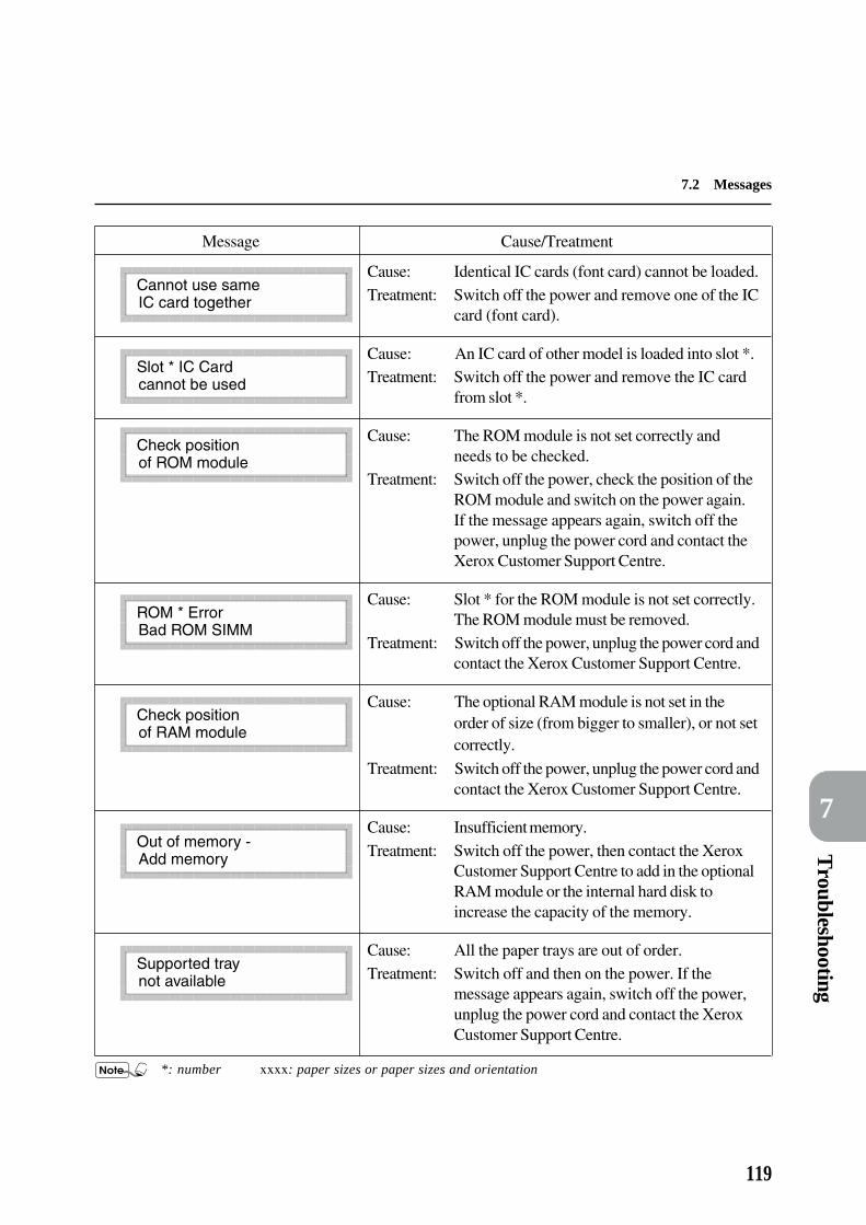
Troubleshooting
7
7.2 Messages
119
Message Cause/Treatment
Cause: Identical IC cards (font card) cannot be loaded.
Treatment: Switch off the power and remove one of the ICcard (font card).
Cause: An IC card of other model is loaded into slot *.Treatment: Switch off the power and remove the IC card
from slot *.
Cause: The ROM module is not set correctly andneeds to be checked.
Treatment: Switch off the power, check the position of theROM module and switch on the power again.If the message appears again, switch off thepower, unplug the power cord and contact theXerox Customer Support Centre.
Cause: Slot * for the ROM module is not set correctly.The ROM module must be removed.
Treatment: Switch off the power, unplug the power cord andcontact the Xerox Customer Support Centre.
Cause: The optional RAM module is not set in theorder of size (from bigger to smaller), or not setcorrectly.
Treatment: Switch off the power, unplug the power cord andcontact the Xerox Customer Support Centre.
Cause: Insufficient memory.
Treatment: Switch off the power, then contact the XeroxCustomer Support Centre to add in the optionalRAM module or the internal hard disk toincrease the capacity of the memory.
Cause: All the paper trays are out of order.
Treatment: Switch off and then on the power. If themessage appears again, switch off the power,unplug the power cord and contact the XeroxCustomer Support Centre.
*: number xxxx: paper sizes or paper sizes and orientation

120
7
7.2 Messages
Message Cause/Treatment
Cause: An error has occurred.
Treatment: Switch off and then on the power. If themessage appears again, switch off the power,unplug the power cord and contact the XeroxCustomer Support Centre.
Cause: An error has occurred.
Treatment: Switch off and then on the power. If themessage appears again, copy down themessages displayed at U *-*. Switch off thepower, unplug the power cord and contact theXerox Customer Support Centre.
Cause: An error has occurred. The interface cable isnot connected.
Treatment: Switch off the power and connect the interfacecable. Switch on the power and if the messageappears again, switch off the power, unplug thepower cord and contact the Xerox CustomerSupport Centre.
Cause: An error has occurred.Treatment: Switch off and then on the power. If the
message appears again, copy down themessages displayed at N *-*. Switch off thepower, unplug the power cord and contact theXerox Customer Support Centre.
*: number xxxx: paper sizes or paper sizes and orientation

Troubleshooting
7
7.2 Messages
121
Message Cause/Treatment
Cause: Cover # (A, B or C) is not properly closed.Treatment: Check for any jammed paper and then close the
cover.
Cause: Cover D is not properly closed.Treatment: Check for any jammed paper and then close the
cover.
Cause: The front cover of the finisher is not properlyclosed.
Treatment: Close the front cover properly.
Cause: The finisher is not properly attached to the printer.
Treatment: Slide the finisher back to the printer.
Cause: Paper is jammed in stacker tray * (1, 2 or 3).Treatment: Remove paper from the stacker tray.
Cause: The finisher failed.
Treatment: Press and together.
Cause: The stacker tray * (1, 2 or 3) failed.Treatment: Press and together.
Cause: This message appears if you press the Pause/Restart button when the stacker trays are beingmoved up or down.
Treatment: Wait for the trays to stop moving.
Cause: This message appears if you press the Pause/Restart button to stop the Finisher operations.
Treatment: Remove any paper from the stacker trays andpress the Pause/Restart button to resume.
*: number #: letter (A, B, C or D)
7.2.3 Messages about staple finisher
Messages about the optional staple finisher are as follows:

122
7
7.2 Messages
Message Cause/Treatment
Cause: Paper is jammed at # (Cover A or D).Treatment: Open Cover A or D, remove paper and close
the cover.
Cause: Paper is jammed at cover # (B or C).
Treatment: Open cover # (B or C).
Cause: This message appears immediately after theabove message.
Treatment: Remove paper from cover # and close the cover.
Cause: Staple has run out.
Treatment: Add staple.
Cause: The staple cartridge is not in the finisher.Treatment: Set up the staple cartridge.
Cause: There is a foreign object under the finisher.
Treatment: Remove the foreign object.
Cause: There is a foreign object in the stacker tray.Treatment: Remove the foreign object.
Cause: Staple is jammed.
Treatment: Open front cover.
Cause: This message appears immediately after theabove message.
Treatment: Remove the jammed staple and close the cover.

Troubleshooting
7
123
Printing is not clear(faded, not sharp).
Black spots printed.
Black stripes printed.
The paper has excessive moisture.
The drum/toner cartridge isdefective or damaged.
The toner in the drum/tonercartridge has been used up.
The paper used is not suitable.
The drum/toner cartridge isdefective or damaged.
The drum/toner cartridge isdefective or damaged.
Replace with new paper.User Guide (Copier)
Replace with a new drum/tonercartridge.
User Guide (Copier)
Replace with a new drum/tonercartridge.
User Guide (Copier)
Load the suitable paper.User Guide (Copier)
Replace with a new drum/tonercartridge.
User Guide (Copier)
Replace with a new drum/tonercartridge.
User Guide (Copier)
7.3 When the Print Quality isPoor
When the print quality is poor, carry out the necessary treatment according to the condition as close to thoselisted below as possible.
If the print quality does not improve after the treatment, contact the Xerox Customer Support Centre.
Condition Cause Treatment

124
7
7.3 When the print quality is poor
Condition Cause Treatment
Stains at equalintervals.
White spots in theprinted black portion.
Smudges whenscrubbed withfingers.
Page is printedcompletely black.
The transportation route for thepaper is stained.
The drum/toner cartridge isdefective or damaged.
The paper used is not suitable.
The drum/toner cartridge isdefective or damaged.
The paper has moisture.
The paper used is not suitable.
The front cover is not completelyclosed.
The drum/toner cartridge isdefective or damaged.
May be due to high voltageproblem.
Print a few pages.
Replace with a new drum/tonercartridge.
User Guide (Copier)
Load the suitable paper.User Guide (Copier)
Replace with a new drum/tonercartridge.
User Guide (Copier)
Replace with new paper.User Guide (Copier)
Replace with suitable paper.User Guide (Copier)
Close the front cover. Check that thetwo sides of the cover are locked.
Replace with a new drum/tonercartridge.
User Guide (Copier)
Contact the Xerox Customer SupportCentre.

Troubleshooting
7
7.3 When the print quality is poor
125
Condition Cause Treatment
The toner seal of the drum/tonercartridge is not pulled out.
Multiple sheets of paper are fed atonce (double feeding).
The toner in the drum/tonercartridge has been used up.
The drum/toner cartridge isdefective or damaged.
May be due to high voltageproblem.
The paper has moisture.
The paper used is not suitable.
The toner seal is not pulled outcompletely.
Remove the seal from the drum/tonercartridge.
User Guide (Copier)
Fan the paper and load them again.User Guide (Copier)
Replace with a new drum/tonercartridge.
User Guide (Copier)
Replace with a new drum/tonercartridge.
User Guide (Copier)
Contact the Xerox Customer SupportCentre.
Replace with new paper.User Guide (Copier)
Replace with suitable paper.User Guide (Copier)
Replace with a new drum/tonercartridge.
User Guide (Copier)
Nothing is printed.
Character void.

126
7
7.3 When the print quality is poor
Condition Cause Treatment
The paper used is not suitable.
The paper has curled corners.
The paper has moisture.
The drum/toner cartridge is notcorrectly set.
The seal is not completely pulledout.
The drum/toner cartridge isdefective or damaged.
Toner in the drum/toner cartridgehas been used up.
The guide clips of the paper trayare not set in the correct positions.
Paper has wrinkles.Printing smeared.
Vertical white strips.
Printing is slanted.
Replace with suitable paper.User Guide (Copier)
Replace with suitable paper.User Guide (Copier)
Replace with new paper.User Guide (Copier)
Adjust and set it correctly.User Guide (Copier)
Replace with a new drum/tonercartridge.
User Guide (Copier)
Replace with a new drum/tonercartridge.
User Guide (Copier)
Replace with a new drum/tonercartridge.
User Guide (Copier)
Adjust and set the side guide and endguide correctly.
User Guide (Copier)

Appendix
Appendix A Printing Area ........................................................................ 128
Appendix B Connector and Allocation Signals ........................................ 129
Appendix C Print Utility ........................................................................... 133
Appendix D Mail Box Paper Jams............................................................ 151
Appendix E PostScript 3 Kit .................................................................... 152

128
The printing area of each paper size is about the area remaining after subtracting 4 mmfrom all edges of the paper.
a
printing area b
Paper Size PCL 6 PostScript
400 dpi 600 dpi 400 dpi 600 dpi
A3 SEF 4552 × 6488 6828 × 9736 4552 × 6488 6828 × 9736
B4 SEF 3928 × 5600 5892 × 8404 3928 × 5600 5892 × 8404
A4 SEF 3184 × 4544 4776 × 6820 3184 × 4544 4776 × 6820
B5 SEF 2744 × 3920 4116 × 5884 2744 × 3920 4116 × 5884
A5 SEF 2208 × 3176 3312 × 4768 2208 × 3176 3312 × 4768
A4 LEF 4552 × 3176 6828 × 4768 4552 × 3176 6828 × 4768
B5 LEF 3928 × 3736 5892 × 4108 3928 × 3736 5892 × 4108
A5 LEF 3184 × 2200 4776 × 3304 3184 × 2200 4776 × 3304
Ledger (11"×17") SEF 4280 × 6672 6420 × 10012 4280 × 6672 6420 ×10012
Legal 14"(8.5"×14") SEF 3280 × 5472 4920 × 8212 3280 × 5472 4920 × 8212
Legal 13"(8.5"×13") SEF 3280 × 5072 4920 × 7612 3280 × 5072 4920 × 7612
Letter (8.5"×11") SEF 3280 × 4272 4920 × 6412 3280 × 4272 4920 × 6412
Letter (8.5"×11") LEF 4280 × 3264 6420 × 4912 4280 × 3264 6420 × 4912
Postcard 1456 × 2200 2184 × 3304 1456 × 2200 2184 × 3304
8K SEF 4080 × 6000 6120 × 9000 4080× 6000 6120 × 9000
Custom (max.) 4552 × 6672 6828× 10012 4552 × 6672 6828 × 10012
Custom (min.) 1456 ×2200 2184 × 3304 1456 × 2200 2184× 3304
Unit: dot
A Printing Area
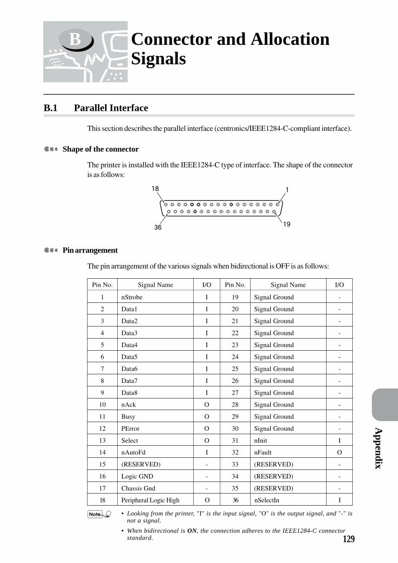
129
Appendix
B.1 Parallel Interface
This section describes the parallel interface (centronics/IEEE1284-C-compliant interface).
Shape of the connector
The printer is installed with the IEEE1284-C type of interface. The shape of the connectoris as follows:
Pin arrangement
The pin arrangement of the various signals when bidirectional is OFF is as follows:
Pin No. Signal Name I/O Pin No. Signal Name I/O
1 nStrobe I 19 Signal Ground -
2 Data1 I 20 Signal Ground -
3 Data2 I 21 Signal Ground -
4 Data3 I 22 Signal Ground -
5 Data4 I 23 Signal Ground -
6 Data5 I 24 Signal Ground -
7 Data6 I 25 Signal Ground -
8 Data7 I 26 Signal Ground -
9 Data8 I 27 Signal Ground -
10 nAck O 28 Signal Ground -
11 Busy O 29 Signal Ground -
12 PError O 30 Signal Ground -
13 Select O 31 nInit I
14 nAutoFd I 32 nFault O
15 (RESERVED) - 33 (RESERVED) -
16 Logic GND - 34 (RESERVED) -
17 Chassis Gnd - 35 (RESERVED) -
18 Peripheral Logic High O 36 nSelectIn I
• Looking from the printer, "I" is the input signal, "O" is the output signal, and "-" isnot a signal.
• When bidirectional is ON, the connection adheres to the IEEE1284-C connectorstandard.
B Connector and AllocationSignals

130
Appendix B Connector and Allocation Signals
Meaning of the signals
When the bidirectional is OFF:
• nStrobe(Pin No.1)
The synchronous signal for the reading of Data 1-8; needs the LOW active pulse.
• Data1-8(Pin No.2-9)
For the 8-bit parallel data input, Data 1 is LSB (lowest bit) and Data 8 is MSB (uppermost bit).
• nAck(Pin No.10)
A LOW active pulse signal which indicates that the received data has been taken in.
• Busy(Pin No.11)
A HIGH active signal which indicates that the printer is unable to receive data.
• PError(Pin No.12)
A HIGH active signal which indicates that there is no more paper.
• Select(Pin No.13)
A HIGH active signal which indicates that it is possible to receive data.
• nAutoFd(Pin No.14)
The signal when the bidirectional is ON.
• Chassic Gnd(Pin No.17)
Connected to frame ground.
• Peripheral Logic High(Pin No.18)
+5V voltage on the host side.
• Signal Ground(Pin No.19-30)
Connected to the various signal ground.
• nInit(Pin No.31)
The LOW active pulse signal which requests for the initialization of the printer.
• nFault(Pin No.32)
The LOW active signal which indicates that errors such as paper jams have occurred in theprinter.
• nSelectIn(Pin No.36)
The signal when the bidirectional is ON.
When the bidirectional is ON:
All connection adheres to the IEEE1284-C connector standard.

131
Appendix
Appendix B Connector and Allocation Signals
B.2 Serial Interface
This section describes the serial interface (RS-232C interface).
Shape of the connector
This printer is installed with the RS-232C interface. The shape of the connector is asfollows:
Pin arrangement
The pin arrangement of the various signals is as follows:
Pin No. Signal Name I/O
1 Frame GND (FG) -
2 Transmitted data (TXD) O
3 Received data (RXD) I
4 Request to send (RTS) O
5 Clear to send (CTS) I
6 Data set ready (DSR) I
7 Signal GND (SG) -
8 - 10 (Reserved) -
11 - 17 Not Connected (NC) -
18 (Reserved) -
19 Not Connected (NC) -
20 Data terminal ready (DTR) O
21 - 25 Not Connected (NC) -
Looking fom the printer, "I" is the input signal and "O" is the output signal.
1
14
13
25

132
Appendix B Connector and Allocation Signals
Meaning of the signals
• FG(Pin No.1)
Connected to frame ground.
• TXD(Out)(Pin No.2)
Signal for transmitting data.
• RXD(In)(Pin No.3)
Signal for receiving data.
• RTS(Out)(Pin No.4)
A HIGH active signal which indicates that the printer is requesting for transmission. BecomesHIGH when the power of the printer is ON, and remains HIGH until the power is OFF.
• CTS(In)(Pin No.5)
A HIGH active signal which indicates that the host device can receive data. Printer will ignorethis signal.
• DSR(In)(Pin No.6)
A signal which indicates that the host device can receive data. The purpose of DSR changesaccording to the settings.
• SG(Pin No.7)
Connected to signal ground.
• (Reserved)(Pin No. 8-10,18)
Not in use.
• NC(Pin No.11-17,19,21-25)
Not connected.
• DTR(Out)(Pin No.20)
A signal which indicates that the printer can operate. The operation of DTR changes accordingto the settings.
Cable configurations
When the hardware flow control was selected, the serial interface cable configurationsfor host to printer are as follows:
Host PrinterPin No. 1 1 Pin No.
2 23 34 45 56 67 7
20 20

133
Appendix
C.1 Types and Paper Sizes
This section explains the types of Print Utility and the necessary paper sizes for printingthem.
Types
Besides printing data sent from the host device, the printer is also equipped with severalprinter functions. These are known as Print Utility.The Print Utility of this machine are as follows:• PCL6 Settings
• Printer Settings
• Error History
• Print History
• Job Template Server Settings
• PCL6 Font List
• PS Font List
The Print Utility is printed by a resolution of 400 dpi.
Paper sizes
To print the Print Utility, the following paper sizes must be set in the paper tray:• A3
• B4
• A4
When multiple paper sizes are used in multiple paper trays, the paper will be selectedin the order of A4, B4 and then A3.When all the paper trays are not loaded with any usable paper sizes, a messageindicating the correct size to use will be shown in the display and printing will commenceonce the paper tray is loaded.
C Print Utility

134
Appendix C Print Utility
C.2 PCL6 Settings
About PCL6 Settings
Prints the setting content of PCL 6 mode printer.
Printing result
The following items will be printed:
• Font Source
• Font Number
• Symbol Set
• Point Size
• Pitch
• No. of Copies
• Hex Dump
• Resolution
• Tray
• Duplex
• Orientation
• Form Lines
• Image Enhance
• Economode
• Output Tray
• Override Size
The result of the printing is shown on the next page.

135
Appendix
Appendix C Print Utility
136
Appendix C Print Utility
C.3 Printer Settings
About Printer Settings
Prints the information in the system menu.
Printing result
The following items will be printed:
• Printer Internal Data
• Maintenance Mode Settings
• Printer Options
• Memory Distribution
• Host Interface Setup
• Multi Function
The result of the printing is shown on the next page.

137
Appendix
Appendix C Print Utility

138
Appendix C Print Utility
C.4 Error History
About Error History
Prints information related to printer errors.
Printing result
The following items will be printed:
• Date
• Time
• Error Code
• Error Type
The result of the printing is shown on the next page.

139
Appendix
Appendix C Print Utility

140
Appendix C Print Utility
C.5 Print History
About Print History
Prints information related to print job processed. It can be used to check whether or notthe print job ends normally.
Printing result
The following items will be printed in the "Printing Status" column:
Printing Content Remarks
PSERR (Error Type) Error Type includes PostScript error types like "configuration
error" or "undefined".
Offending Command includes operators that cause errors.
RS-232C (Error Type) Printed when there is an error in the setting of serial interface.
Error Type includes types of error.
Treatment: Check the setting of serial interface.
Error (x x x x x x x x) Printed when print languages not installed are received. Error
code is recorded in x x x x x x x x.
Automatic Judgement Error Printed when printer language cannot be judged automatically
while Common Menu > Port Setting > Emulation Mode is set to
AUTO.
Treatment: Set the print language to match data by the print mode
setting.
Numeric Operation Error Printed when values exceeding the printer limit are used in the
print data.
Treatment: Remove the above-mentioned data.
Normal Ending 0 Page Printed in the following cases:
a. when data (control data) that can change the printer setting is
received from the host device.
b. when processing just ends while there are defects like gram-
matical errors in data and the print image cannot be correctly
formed.
Treatment for b:
Check the data contents according to Hex Dump of Mode Menu >
PCL6 Settings.
File Read Error (x x x) Printed when there are errors in the hard disk files. The file name is
recorded in x x x.
Treatment: Delete files that have errors or initialize the hard disk.

141
Appendix
Appendix C Print Utility
Remarks
Lossy compression. Job is very complexed, display list
takes up too much memory or decomposer will perform
lossy compression. Job can still be printed but image
cannot be guaranteed.
Treatment: Increase the PCL memory and print again.
Pages are broken due to memory shortage. This typically
happens when the PCL memory has already been
consumed for other purposes leaving little memory to
format the page. This leads to the situation where the
pages have to be broken mid-way and page data are
printed in many pages and image loss will occur.
Treatment: Increase the PCL memory and print again.
Printed when there is a PCL XL syntax error like
"IllegalAttribute", "IllegalAttributeCombination". If there
are more than one PCL XL syntax errors in the same job,
only the first error encountered will be logged in. The
maximum length of the PCL XL error code is 31 bytes.
Printed when there is a PJL command with syntax error. For
example, if the invalid command, "@PJL JOBINFOX
JOBNAME = ABCDEFGHIJKLMN" is ordered to printer,
the printing status should display the following:
PJL Error (JOBINFOX JOBNAME = ABCDEFGHIJK)
The PJL prefix - @PJL - will not be included and the
maximum length is 31 bytes. The PJL syntax error falls
into three categories:
1. unrecognised commands and command modifiers;
2. unsupported option; &
3. out-of-range value.
The result of the printing is shown on the next page.
Printing Content
Job Completed (PCL6 Memory
Low, Page Simplified)
Job Halted (Insufficient PCL6
Memory)
PCL XL Error (error code)
PJL Error (the PJL command with
syntax error)

142
Appendix C Print Utility

143
Appendix
Appendix C Print Utility
C.6 Job Template Server Settings
About Job Template Server Settings
Prints information about the storing server.
Printing result
The following items will be printed:
• Total Printed Pages
• System ROM Version
• Server Name (of the template storing server)
• Directory (of the template storing server)
• Login User (of the template storing server)
• Polling Interval (of the template storing server)
The result of the printing is shown on the next page.

144
Appendix C Print Utility

145
Appendix
Appendix C Print Utility
C.7 PCL6 Font List
About PCL6 Font List
Prints the list of PCL 6 fonts that can be used by printer.
Printing result
The result of the printing is shown on the next page.

146
Appendix C Print Utility
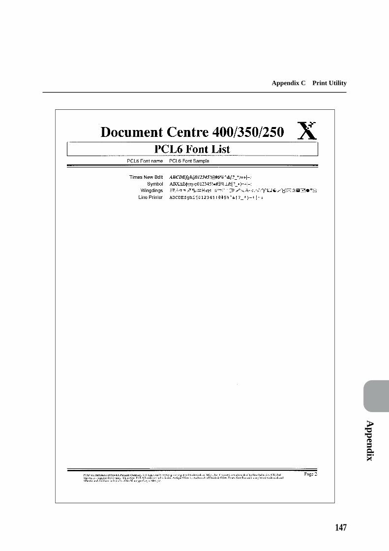
147
Appendix
Appendix C Print Utility

148
Appendix C Print Utility
C.8 PS Font List
About PS Font List
Prints a list of PostScript fonts that can be used in printer.It can be printed if the optional PostScript kit is installed.
Printing result
The result of the printing is shown on the next page.

149
Appendix
Appendix C Print Utility

150
Appendix C Print Utility

151
Appendix
D Mail Box Paper Jams
When the message on the left appears during printing,follow the procedure below to remove the jammed paper:
Clear the paper jam with the power on. If the power is off, print data remaining inside the printer and informa-tion stored in the printer memory will be erased.
This message is displayed when the optional mail box is installed.
Pull the release lever to open the cover ofthe mail box slowly.
Pull out jammed paper in the direction ofthe arrow.
Close the cover of the mail box.
Release lever

152
E PostScript 3 Kit
This section describes the settings and precautions for using the optional PostScript 3 Kit to print in thePostScript language with the Xerox DC 400/350/250 printer.
E.1 Setting Up the Printer
To carry out a print job using the the PostScript language, you have to install the PostScriptprogramme ROM and then make settings from the printer control panel according to theoperating system that you are in.
Usable Common Menus
The following common menus become available when the PostScript ROM is installed onthe printer:

153
Appendix
Appendix E PostScript 3 Kit
Common Menu settings
Make the following settings from the printer control panel according to the operatingenvironment you are in. In the "Port Setting" menu, specify the type of the printer interfaceconnected to the host device for using the PostScript language as well as the necessaryrequirements for the communication. In the "Maintenance Mode" menu, change thememory capacity for using the PostScript environment.
Port SettingFor Parallel, Serial, lpd/PD, NetWare, EtherTalk
• PDL ModeSpecify PostScript 3 for the PDL mode.In the case of EtherTalk, PostScript 3 is the default.
For Parallel, Serial• Adobe Protocol
The PostScript protocol to be selected when in parallel or serial connection.Options available are:
• Standard: Selected when the protocol is in the ASCII format (default).• Binary: Selected when the protocol is in the binary format.
Depending on the data, the printing speed might be faster than whenselecting Standard.
• TBCP: Selected when the protocol exists in both ASCII and binary formatsand to switch between them by the specific control code.
• Set according to the data format output from the host device driver.
• For general use, select the default value, Standard.
• When the print mode of the parallel or serial interface is other thanPostScript 3, the setting here becomes invalid.
Maintenance ModeFor Memory Change
• PS MemoryTo set the memory capacity for using the PostScript language. The printing speedmay become faster by increasing the memory capacity for the PostScript software.The value ranges from 2 to 16 MB with 0.25 MB per unit. However, the maximumvalue varies according to the free memory capacity.
Print UtilityFor PS Font List
To print the list of PostScript fonts available in the printer.
"Appendix C.8 PS Font List"

154
Appendix E PostScript 3 Kit
E.2 Precautions and Limitations
When using the printer, pay attention to the following points:
When the printing result is different from the setting
The printing result may be different from the setting when the memory capacity of thepage buffer is insufficient. The following flowchart shows how the the print job isprocessed for data on a two-sided page in 600 dpi resolution.
Is the page buffer secured for one-sided page of
the data?
Does the compressed size of the two-sided
page data exceed the limitation of the buffer
size?
Lower the resolution to 400 dpi.
Is the page buffer secured for one-sided
page of the data?
Print the data on one
side in 400 dpi.
Does the compressed size of the two-sided
page data exceed the limitation of the buffer
size?
Print the data on two
sides in 600 dpi.
Abort the job.
NOYES
YES
YES
NO
NO
Print the data on one
side in 400 dpi.
Print the data on two
sides in 400 dpi.
YES NO
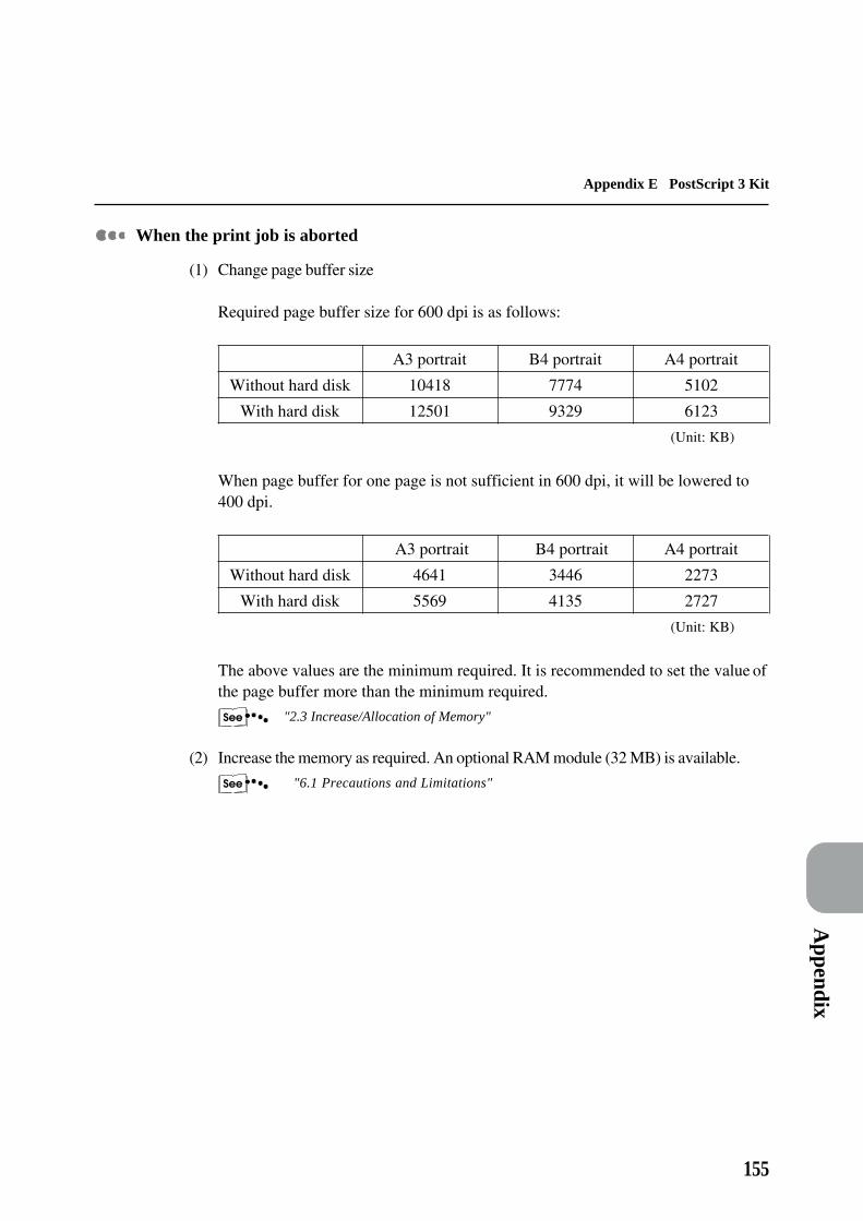
155
Appendix
Appendix E PostScript 3 Kit
When the print job is aborted
(1) Change page buffer size
Required page buffer size for 600 dpi is as follows:
A3 portrait B4 portrait A4 portrait
Without hard disk 10418 7774 5102
With hard disk 12501 9329 6123
(Unit: KB)
When page buffer for one page is not sufficient in 600 dpi, it will be lowered to400 dpi.
A3 portrait B4 portrait A4 portrait
Without hard disk 4641 3446 2273
With hard disk 5569 4135 2727
(Unit: KB)
The above values are the minimum required. It is recommended to set the value ofthe page buffer more than the minimum required.
"2.3 Increase/Allocation of Memory"
(2) Increase the memory as required. An optional RAM module (32 MB) is available.
"6.1 Precautions and Limitations"

156
Glossary
[A3]420 × 297 mm paper.
[A4]297 × 210 mm paper.
[A5]210 × 148 mm paper.
[ACK]The signal indicating that the printer is ready toreceive data from the host device or that data iscorrectly received.
[Adobe protocol]Communication protocol of PostScript printer inserial/parallel connection.
[B4]364 × 257 mm paper.
[B5]257 × 182 mm paper.
[Buffer]The place where data received by the host deviceis stored.
[Busy]Signal indicating that the printer is not able toreceive data from the host device.
[Common Menu]Makes up of port setting, print utility,maintenance mode of which settings other thanemulation are made.
[CPI]Stands for Character Per Inch, which is thenumber of characters that can be printed within awidth of 1 inch.
[CR]Stands for Carriage Return, which is the changeof line.
[Cut paper]Standard types of paper like A4, B5 etc.
[DPI]Stands for Dot Per Inch, which is the number ofdots that can be printed within a width of 1 inch.Used as the unit for resolution.
[DL]Stands for Double Letter. Also known as Ledger.17 × 11" (432 × 279 mm) paper size.
[DTR Control]Stands for Data Terminal Ready, which is thehardware signal that indicates whether the printercan receive data from the host device.
[Emulation]The ability of the printer to perform the featuresof other printers.
[Folio]13 × 8.5" (330 × 216 mm) paper.
[Hard clip area]The actual rectangular area on the paper whichcan be printed.
[Image Enhance]Feature which makes the border between blackand white smooth, with rough edges reduced,giving the appearance of a higher resolution.
[Job]A group of print data. The stopping and outputof printing are conducted on a job basis. Formode menu changes, the new settings will beeffective from the next job.

Glossary
157
Glossary Glossary
[LED]Stands for Light Emitting Diode.
[LG]14 × 8.5" (356 × 216 mm) paper. Also known asLegal.
[LT]11 × 8.5" (279 × 216 mm) paper. Also known asLetter.
[Mode Menu]Menu for setting the conditions pertaining to thePCL 6 emulation mode.
[N-up]Feature for printing the data of N pages on asingle sheet of paper.
[NV Memory]Non-volatile memory which allows the settingsof the printer to be maintained even when poweris off.
[Page buffer]The actual place where print data is retrieved andstored. The page buffer memory is secured afterthe printer memory is allocated to memories suchas form memory, receive buffer memory etc., andit cannot be set using the control panel. Thememory capacity of the page buffer can bechecked using Common Menu > Print Utility[System Config].
[Parity check]The checking of whether the data sent is beingreceived.
[Plotter coordinates]The coordinates of the plotter.
[PostScript]Page description language of Adobe SystemsIncorporated.
[Power Saver]The feature which saves the power consumptionby lowering the temperature of the printer's fuser.The power saver mode is automatically activatedwhen the time set has elapsed after the previousprint job.
[Printing area]The actual area on paper which can be printed.
[Protocol]The rules of communication necessary forcarrying out data transmission.
[RAM]Stands for Random Access Memory, which is thememory device where information can beretrieved as well as recorded.
[ROM]Stands for Read Only Memory, which is thememory device specific for the retrieval ofinformation.
[Scaling]The enlargement and reduction of the input size(document size) by matching the output size(paper size).
[Scaling Point]The limit of the specification of the plotting area.
[8K]267 × 388 mm paper. Also called as Pakai.
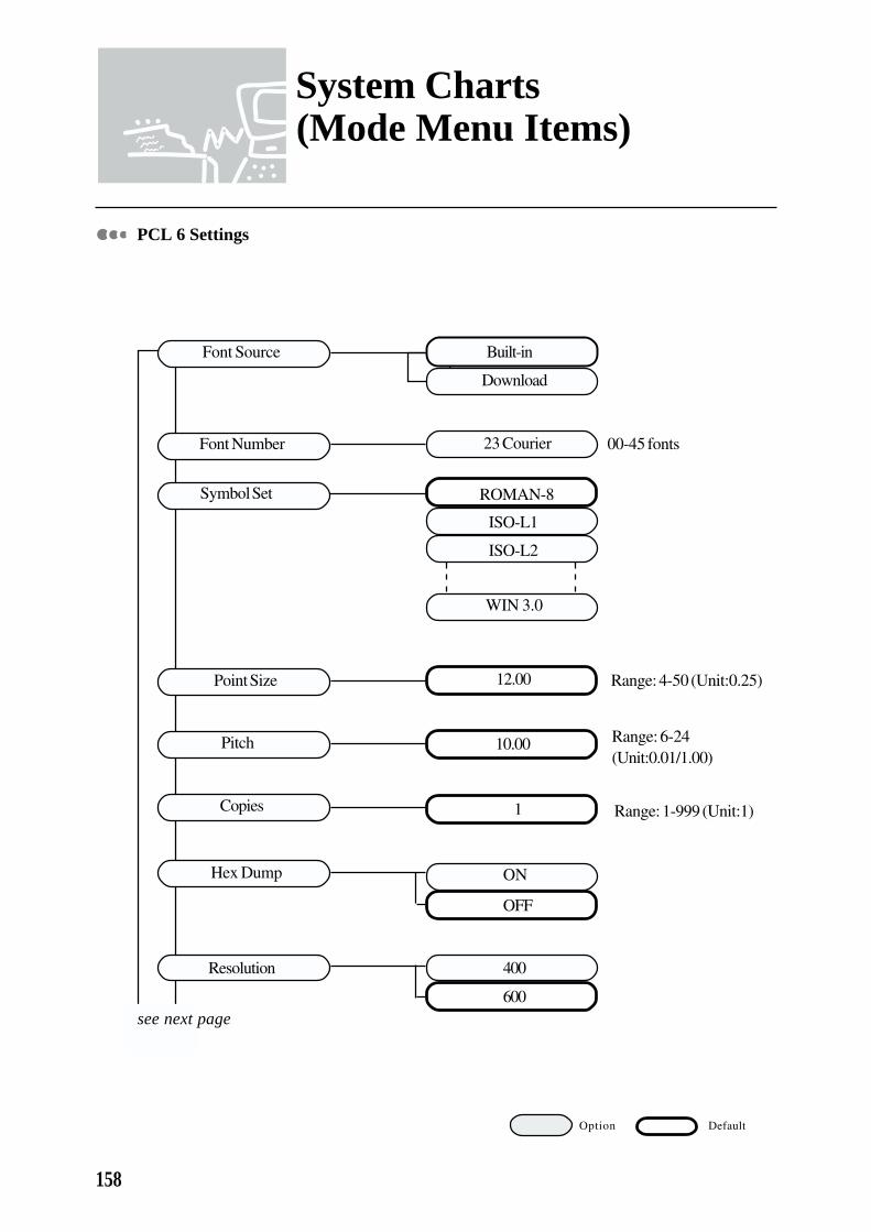
158
System Charts (Mode Menu Items)
PCL 6 Settings
Option Default
00-45 fonts
Range: 4-50 (Unit:0.25)
Range: 6-24(Unit:0.01/1.00)
Range: 1-999 (Unit:1)
Font Number
Symbol Set
Point Size
Pitch
Copies
Hex Dump
Resolution
Built-in
Download
23 Courier
ISO-L1
ISO-L2
ROMAN-8
WIN 3.0
12.00
10.00
1
ON
OFF
400
600see next page
Font Source

System C
harts
159
System Charts (Mode Menu Items)
Option Default
Note:(1) *Postcard is only for Bypass Tray.(2) *A5 is only for Tray 1 and Bypass Tray.(3) HCF supports only A4, LT and B5.
Range: 5-128 (Unit:1)
Tray
Forms Lines
Image Enhance
Tray 1
Tray 2
Tray 3/HCF 1Tray 4/HCF 2
Bypass Tray
Auto Tray
LG
LT
B5
B4
A4
Folio
267×388 mm
11×17
*A5
*Postcard
A3
OFF Long-Edge
Duplex ON Short-Edge
Orientation
64
Landscape
Portrait
OFF
ON
OFF
from previous page
see next page

160
System Charts (Mode Menu Items)
Option Default
Economode
Override Size
ON
OFF
OFF
ON
OFF
Output Tray Centre Tray
Side Tray
Stacker - Auto
Stacker Tray 1
Stacker Tray 2
Stacker Tray 3
Mail Box (Bin#1)
Mail Box (Bin#10)
from previous page

System C
harts
161
System Charts (Common Menu Items)
Port Setting
Range: 5-1275 (Unit:5)
Auto
PCL 6
PostScript 3
PDL Mode
30 sec
Option
PJL Switch
Auto Eject Time
ON
OFF
Auto
PCL 6
PostScript 3
ON
OFF
Range: 5-1275 (Unit:5)
30 sec
Parallel
Serial
TBCP
ON
OFF
PDL Mode
PJL Switch
Auto Eject Time
Bidirectional
Adobe Protocol Standard
Binary
Default
see next page

162
System Charts (Common Menu Items)
Option Default
(con't...)TBCP
9600
19200
1200
2400
4800
8 Bits
7 Bits
1 Bit
2 Bits
None
Odd
Even
Yes
No
Fix-High
Fix-LowActive-High
Active-Low
Serial
DTR Control
Xon-XoffControl
Parity
Stop Bit
Data Length
Adobe Protocol Standard
Binary
from previous page
see next page
Baud Rate

System C
harts
163
System Charts (Common Menu Items)
Option Default
PDL Mode
PJL Switch
Transport
OFF
ON
Auto
PCL 6
PostScript 3
OFF
ON
TCP/IP
IPX/SPX
NetWare
lpd/PD
EtherTalk
from previous page
PJL Switch
OFF
ON
PDL Mode Auto
PCL 6
PostScript 3
PJL Switch ON
PDL Mode PostScript 3
OFF

164
System Charts (Common Menu Items)
Print Utility
Ready
Ready
Ready
Ready
Ready
Ready
ReadyPS Font List
PCL 6 Font List
JTSvr Settings
Print History
Error History
Printer Settings
PCL 6 Settings
Option

System C
harts
165
System Charts (Common Menu Items)
Maintenance Mode
see next page
ON
Ready to Receive
Serial
lpd/PD
NetWare
PCL 6 Memory
PS Memory
ReceiveBufferMem Parallel
4.50 MB
4.50 MB
AppleTalk memory
64 KB
Jam Recovery OFF
Continuous
AutoPrintHistory
System Clock
OFF
ON
2 sec
90 sec
YY/MM/DD hh:mm
OFF
Alarm
Printer Settings
Echo Back Mode
Memory Changes
Option Default
(Unit:2 sec)
Range: 2.00-16.00 MB (Unit:0.25 MB)
Range: 2.00-16.00 MB (Unit:0.25 MB)
Range: 64-1024 KB (Unit:32 KB)
see next page

166
System Charts (Common Menu Items)
(con't...)Memory Change>ReceiveBuffer Mem>lpd/PD>
Harddisk
Memory
None 224 KB
Serial
Parallel
EtherTalk
Enabled
Disabled
Enabled
Disabledlpd/PD
ftp Client
Salutation
NetWare
Initalise NVRam
System Reset
Ready to Init
Init Hard Disk
Start IPX
Community Signup
OFF
ONStart UDP
100BASE-TX
10BASE-5
10BASE-T
Option Default
Port Status
Initialisation
Agent
Ethernet Setup
Range: 64-1024 KB (Unit:32 KB)
Range: 64-1024 KB (Unit:32 KB)
Range: 0.50-32.00 MB(Unit:0.25 MB)
OFF
Enabled
Disabled
AUTO (T/TX)
1 MB
see next page
from previous page
Ready to Init
Ready to Init

System C
harts
167
System Charts (Common Menu Items)
Protocol Setting TCP/IP Setting
Ether II
802.2
802.3
IPX/SPX Setting
SNAP
IP Address
XXX.XXX.XXX.XXX
XXX.XXX.XXX.XXX
SubNet Mask
Gateway Address
XXX.XXX.XXX.XXX
Option Default
AUTO
Range: 000-255 (Unit:001)
Range: 000-255 (Unit:001)
Range: 000-255 (Value:000,128,192,224,240,248,252,254,255)
from previous page

168
Index
Number
3-Tray Cabinet --------------------------------------- 51, 55
A
"Advanced" tab ------------------------------------------72
All Texts to Black -----------------------------------------62
AppleTalk memory ---------------------------------------24
Auto Eject Time -------------------------------------------19
Auto Tray Switch -----------------------------------------37
B
Baud rate ---------------------------------------------------19
Booklet Printing -------------------------------------------68
Bypass Tray ------------------------------------------ 51, 55
C
Cancelling Printing/Fax Transmission -----------------28
Cancelling all jobs in the printer ----------------------29Cancelling fax transmission from touch panel display
--------------------------------------------------------30Cancelling from host device --------------------------28Cancelling jobs in process ----------------------------29
Centre Tray ------------------------------------------------56
CentreWare Supports ------------------------------------60
Collate Settings -------------------------------------------59
Control panel
Operating -----------------------------------------------37Operations ----------------------------------------------33
Copies ------------------------------------------------------54
Copying ----------------------------------------------------37
Custom Paper Size ----------------------------------------57
D
Data length ------------------------------------------------19
Device Halftoning ----------------------------------------53
Document defaults dialog box --------------------------48
Document Monitor ---------------------------------------60
DTR control -----------------------------------------------19
Duplex Print -----------------------------------------------57
Duplex Unit (Inverter) ------------------------------------52
E
EconoMode -----------------------------------------------62
Enable Raster/EMF Spooled Jobs ----------------------60
Error Report -----------------------------------------------53
Ethernet Interface -----------------------------------------20
Ethernet interface
Connecting, ---------------------------------------------21Ethernet interface card --------------------------------20
F
"Fax Option" tab ------------------------------------------78
"Fonts" tab ------------------------------------------------65
Fax Recipient ----------------------------------------------75
Fax Unit ----------------------------------------------------52
Faxing ------------------------------------------------------73
First Sheet -------------------------------------------------60
Fit To Page ------------------------------------------------69
Flow of Printing/Fax Transmission ---------------------26
G
"Graphics" tab --------------------------------------------61
Graphics Mode --------------------------------------------61
Grey Scale -------------------------------------------------61
H
Halftone Color Adjustment------------------------------63
Halftoning -------------------------------------------------62
Hard Disk --------------------------------------------------52
High Capacity Feeder ------------------------------- 51, 55
I
Image Enhancement --------------------------------------62
Image Orientation -----------------------------------------57
Interrupting ------------------------------------------------38
ISDN/G4 Kit -----------------------------------------------52

Index
169
Index
J
Job Offset Settings ---------------------------------------58
Job Type ---------------------------------------------------54
L
"Layout" tab ----------------------------------------------67
Layout Mode ----------------------------------------------67
List
Printing --------------------------------------------------35Types of list --------------------------------------------35
Logical On Physical --------------------------------------69
lpd spool ---------------------------------------------------24
M
Mail Box ----------------------------------------------- 52, 56
Metafile (EMF) Spooling --------------------------------60
N
N-Up Printing ---------------------------------------------67
NetWare memory -----------------------------------------24
O
"Output Options" tab ------------------------------------58
"Overlays" tab --------------------------------------------64
Offset Catch Device --------------------------------------52
Outputting
Forced outputting of remaining print data ----------31Outputting all jobs in the printer ---------------------32
P
"Paper/Output" tab ---------------------------------------54
"Printer" tab -----------------------------------------------51
Page buffer ------------------------------------------------24
Paper Detected by Tray ----------------------------------53
Paper Output ----------------------------------------------56
Paper Output Options ------------------------------------52
Paper Size --------------------------------------------------54
Paper Source ----------------------------------------------55
Paper Source Options ------------------------------------51
Paper Tray Priority ----------------------------------------37
Parallel interface
Connection ---------------------------------------------16Parallel memory -------------------------------------------23
Parity -------------------------------------------------------19
PCL 6 memory ---------------------------------------------24
PJL switch -----------------------------19, 90, 91, 94, 95
Print mode specification ---------------------------------19
Printer driver
configuring ---------------------------------------------46Installing for a local printer ---------------------------41Installing for a network printer -----------------------43Uninstalling ---------------------------------------------44
Printer drivers ---------------------------------------------40
Printer properties dialog box
Accessing in Windows 3.1 ---------------------------47Accessing in Windows 95/Windows 98 ------------46Accessing in Windows NT 4.0 -----------------------48
Printer Resolution ----------------------------------------62
Printing -----------------------------------------------------73
Printing Priority -------------------------------------------37
PS memory -------------------------------------------------24
R
Receive buffer ---------------------------------------------23
AppleTalk memory -------------------------------------24lpd spool ------------------------------------------------24NetWare memory ---------------------------------------24Parallel memory -----------------------------------------23Serial memory -------------------------------------------23
Report
Printing --------------------------------------------------35Types of report -----------------------------------------35
S
Scaling -----------------------------------------------------69
Serial interface
Connection ---------------------------------------------17Serial memory ---------------------------------------- 19, 23
Side Output Tray ------------------------------------ 52, 56
Stacker tray
Removing documents ---------------------------------34

170
Index
Staple Finisher --------------------------------------- 52, 56
Staple Position Settings----------------------------------59
Stop bit -----------------------------------------------------19
System -----------------------------------------------------23
T
Transmitting -----------------------------------------------37
TrueType Mode ------------------------------------------63
U
Use Document Monitor ----------------------------------60
Use Printer TrueType fonts -----------------------------63
W
"Watermarks" tab ----------------------------------------70
X
Xon-Xoff control -----------------------------------------19
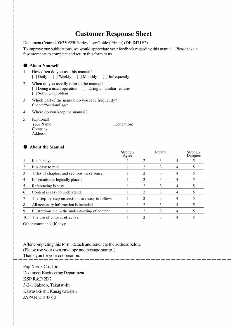
Customer Response SheetDocument Centre 400/350/250 Series User Guide (Printer) (DE-0471E2)To improve our publications, we would appreciate your feedback regarding this manual. Please take afew moments to complete and return this form to us.
!!!!! About Yourself1. How often do you use this manual?
[ ] Daily [ ] Weekly [ ] Monthly [ ] Infrequently
2. When do you usually refer to the manual?[ ] Doing a usual operation [ ] Using unfamiliar features[ ] Solving a problem
3. Which part of the manual do you read frequently?Chapter/Section/Page:
4. Where do you keep the manual?
5. (Optional)Your Name: Occupation:Company:Address:
!!!!! About the ManualStrongly Neutral StronglyAgree Disagree
1. It is handy. 1 2 3 4 5
2. It is easy to read. 1 2 3 4 5
3. Titles of chapters and sections make sense. 1 2 3 4 5
4. Information is logically placed. 1 2 3 4 5
5. Referencing is easy. 1 2 3 4 5
6. Content is easy to understand. 1 2 3 4 5
7. The step-by-step instructions are easy to follow. 1 2 3 4 5
8. All necessary information is included. 1 2 3 4 5
9. Illustrations aid in the understanding of content. 1 2 3 4 5
10. The use of color is effective 1 2 3 4 5
Other comments (if any):
After completing this form, detach and send it to the address below.(Please use your own envelope and postage stamp. )Thank you for your cooperation.
Fuji Xerox Co., Ltd.Document Engineering DepartmentKSP R&D 2D73-2-1 Sakado, Takatsu-kuKawasaki-shi, Kanagawa-kenJAPAN 213-0012

This page is intentionally left blank.

Document Centre 400/350/250User Guide (Printer)
Fuji Xerox Co., Ltd.2-17-22 Akasaka, Minato-kuTokyo 107-0052, Japan DE-0471E2 (Edition 3)
Copyright® 1999 by Fuji Xerox Co., Ltd.Printed in Japan