
WS2 Series Printer Operator Manual - SATO
108
WS2 Series Printer Operator Manual WS208 / WS212 WS2_Operator_Manual_ENG_06 © 2020 SATO Corporation. All rights reserved.
-
Upload
khangminh22 -
Category
Documents
-
view
0 -
download
0
Transcript of WS2 Series Printer Operator Manual - SATO

WS2 Series Printer
Operator Manual
WS208 / WS212
WS2_Operator_Manual_ENG_06
© 2020 SATO Corporation. All rights reserved.

i
FCC ID
In a domestic environment this product may cause radio interference in
which case the user may be required to take adequate measures.
FCC Warning
This equipment has been tested and found to comply with the limits for a
Class A digital device, pursuant to Part 15 of the FCC Rules. These limits are
designed to provide reasonable protection against harmful interference
when the equipment is operated in a commercial environment. This
equipment generates, uses, and can radiate radio frequency energy, and if
not installed and used in accordance with the instructions in this manual, it
may cause harmful interference to radio communications. Operation of this
equipment in a residential area is likely to cause harmful interference in
which case the user will be required to correct the interference at his own
expense.
This device complies with Part 15 of the FCC Rules. Operation is subject to
the following two conditions: (1) this device may not cause harmful
interference, and (2) this device must accept any interference
received, including interference that may cause undesired operation.
FCC Statement for Optional RF module
This device complies with RF radiation exposure limits set forth for an
uncontrolled environment.
The antenna used for this transmitter must be installed to provide a
separation distance of at least 20 cm from all people and must not be
collocated or operating in conjunction with any other antenna or
transmitter.

ii
WARNING
Changes or modifications not expressly approved by the party responsible
for compliance could void the user's authority to operate the equipment.
(for USA only)
Liability Disclaimer
SATO Corporation takes steps to assure that the company’s published
engineering specifications and manuals are correct; however, errors do
occur. SATO reserves the right to correct any such errors and disclaims any
resulting liability. In no event shall SATO or anyone else involved in the
creation, production, or delivery of the accompanying product (including
hardware and software) be liable for any damages whatsoever (including,
without limitation, damages for loss of business profits, business
interruption, loss of business information, or other pecuniary loss) arising
out of the use of or the results of use of or inability to use such product,
even if SATO has been advised of the possibility of such damages.
Caution
Any changes or modifications not expressly approved by the party
responsible for compliance could void the user's authority to operate the
equipment.

iii
Contents 1 Introduction ........................................................................................................... 1
1.1 Features ....................................................................................................... 1
1.2 Unpacking .................................................................................................... 2
1.3 Understand your printer ............................................................................. 3
1.3.1 Perspective view ............................................................................ 3
1.3.2 Back view ....................................................................................... 4
1.3.3 Interior view ................................................................................... 5
1.4 Printer lights ................................................................................................ 6
1.4.1 Status lights .................................................................................... 6
1.4.2 System mode .................................................................................. 8
2 Get started ............................................................................................................. 9
2.1 Attach the power cord ................................................................................ 9
2.2 Turn on/off your printer ............................................................................ 10
2.2.1 Turn on your printer ..................................................................... 10
2.2.2 Turn off your printer .................................................................... 10
2.3 Load media ................................................................................................ 11
2.3.1 Prepare media .............................................................................. 11
2.3.2 Place a media roll ......................................................................... 12
2.3.3 Test media feed ............................................................................ 15
2.4 Media types ............................................................................................... 16
2.5 Media sensing ........................................................................................... 18
2.5.1 Transmissive sensor ..................................................................... 18
2.5.2 Reflective sensor .......................................................................... 19
3 Printer operation .................................................................................................. 20
3.1 Printing Media Calibration & Configuration ............................................. 20
3.2 Self test ...................................................................................................... 21
Option Parts ......................................................................................... 28
3.3 Reset your printer ..................................................................................... 32
3.4 Communications ....................................................................................... 33
3.4.1 Interfaces and Requirements ....................................................... 33
4 Maintenance ........................................................................................................ 34
4.1 Cleaning ..................................................................................................... 34
4.1.1 Printhead ...................................................................................... 34
4.1.2 Media housing ............................................................................. 35
4.1.3 Sensor........................................................................................... 35
4.1.4 Platen roller .................................................................................. 36

iv
5 Troubleshooting ................................................................................................... 37
5.1 Printer issues ............................................................................................. 37
5.2 Media issues .............................................................................................. 38
5.3 Other issues ............................................................................................... 39
6 Set Up Interface Connection by SATO WS2 Printer Utility ................................... 40
6.1 Install SATO WS2 Printer Utility ................................................................. 40
6.2 Work with SATO WS2 Printer Utility.......................................................... 42
6.2.1 Menu bar ...................................................................................... 43
6.2.2 Toolbar ......................................................................................... 45
6.2.3 Navigation pane ........................................................................... 49
6.3 Update firmware ....................................................................................... 79
6.3.1 Update via the USB Client or COM port ....................................... 80
6.3.2 Update via the LAN or Multi-LAN port ......................................... 85
6.4 Update firmware via the USB host ............................................................ 90
6.5 Update firmware in Atmel mode .............................................................. 90
7 Specifications ....................................................................................................... 94
7.1 Printer........................................................................................................ 94
7.2 Media ........................................................................................................ 95
7.3 Electrical and operating environment ............................................................. 95
7.4 Physical dimension .................................................................................... 95
7.5 Fonts, Barcodes, and Graphics .................................................................. 96
7.6 Ethernet .................................................................................................... 99
7.7 Wireless LAN (Option) ............................................................................... 99
7.8 Bluetooth (Option) .................................................................................. 101
7.9 Ports ........................................................................................................ 102
7.9.1 USB ............................................................................................. 102
7.9.2 Ethernet ..................................................................................... 103

1 Introduction
1
1 Introduction
Thank you for purchasing an SATO WS2 Series industrial barcode printer.
This manual provides information about how to set up and operate your
printer, load media and solve common problems. Illustrations are provided
to help you quickly become familiar with the printer.
1.1 Features
■ Clamshell design, easy loading The WS2 series features a user-friendly clamshell design that allows users
to simply open the cover and loading media.
■ Compact size Small footprint design, the compact WS2 series fits into tight spaces and
supports a wide range of applications.
■ Enhanced connectivity The WS2 series has built-in USB host, USB device, and Ethernet.
1 Introduction
2
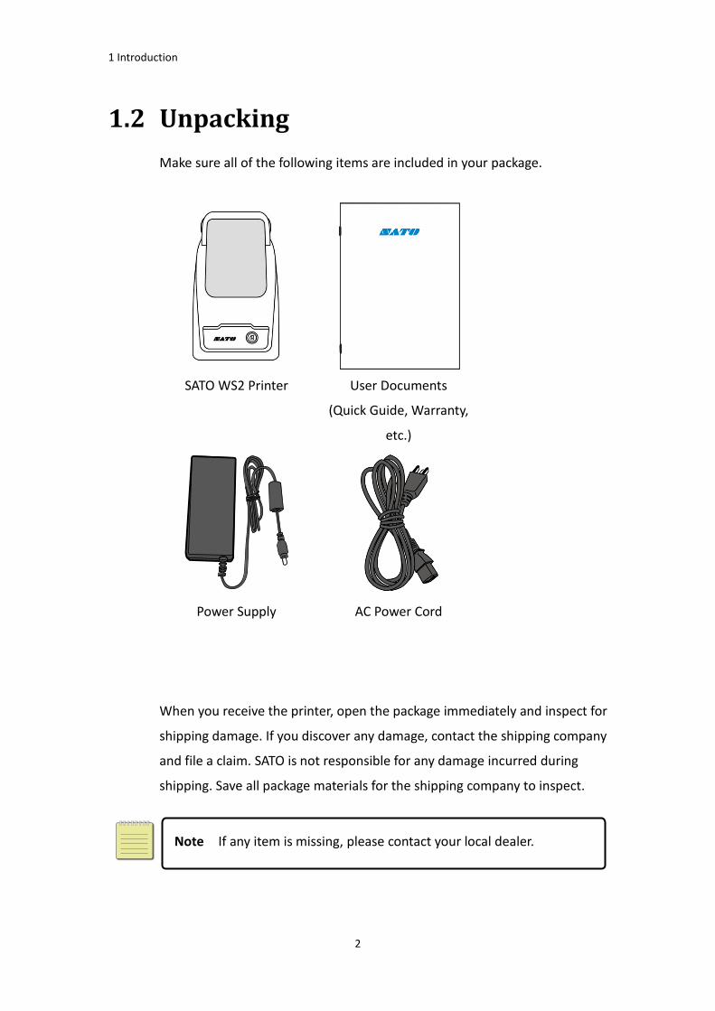
1.2 Unpacking
Make sure all of the following items are included in your package.
SATO WS2 Printer User Documents
(Quick Guide, Warranty,
etc.)
Power Supply
AC Power Cord
When you receive the printer, open the package immediately and inspect for
shipping damage. If you discover any damage, contact the shipping company
and file a claim. SATO is not responsible for any damage incurred during
shipping. Save all package materials for the shipping company to inspect.
Note If any item is missing, please contact your local dealer.

1 Introduction
3
1.3 Understand your printer
1.3.1 Perspective view
LED Indicator
LED 2
LED 1
Feed Button
Cover Latch
Top Cover

1 Introduction
4
1.3.2 Back view
Caution To avoid injury, be careful not to trap your fingers in the Paper
Slot while opening or closing the Top Cover.
Ethernet
USB A USB B
Power Jack
Power Switch

1 Introduction
5
1.3.3 Interior view
Printhead
Platen Roller
Media Roll Holders
Reflective Sensor
Media Guides
See-through Sensor
1 Introduction
6
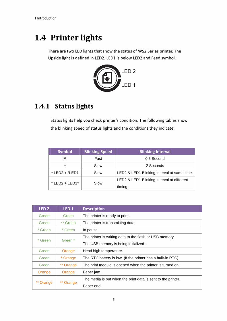
1.4 Printer lights
There are two LED lights that show the status of WS2 Series printer. The
Upside light is defined in LED2. LED1 is below LED2 and Feed symbol.
1.4.1 Status lights
Status lights help you check printer’s condition. The following tables show
the blinking speed of status lights and the conditions they indicate.
Symbol Blinking Speed Blinking Interval
** Fast 0.5 Second
* Slow 2 Seconds
* LED2 + *LED1 Slow LED2 & LED1 Blinking Interval at same time
* LED2 + LED1* Slow LED2 & LED1 Blinking Interval at different
timing
LED 2 LED 1 Description
Green Green The printer is ready to print.
Green ** Green The printer is transmitting data.
* Green * Green In pause.
* Green Green * The printer is writing data to the flash or USB memory.
The USB memory is being initialized.
Green Orange Head high temperature.
Green * Orange The RTC battery is low. (If the printer has a built-in RTC)
Green ** Orange The print module is opened when the printer is turned on.
Orange Orange Paper jam.
** Orange ** Orange The media is out when the print data is sent to the printer.
Paper end.
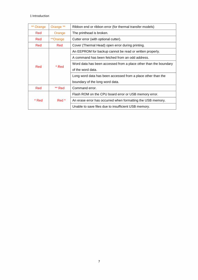
1 Introduction
7
** Orange Orange ** Ribbon end or ribbon error (for thermal transfer models)
Red Orange The printhead is broken.
Red **Orange Cutter error (with optional cutter).
Red Red Cover (Thermal Head) open error during printing.
Red * Red
An EEPROM for backup cannot be read or written properly.
A command has been fetched from an odd address.
Word data has been accessed from a place other than the boundary
of the word data.
Long word data has been accessed from a place other than the
boundary of the long word data.
Red ** Red Command error.
* Red Red *
Flash ROM on the CPU board error or USB memory error.
An erase error has occurred when formatting the USB memory.
Unable to save files due to insufficient USB memory.

1 Introduction
8
1.4.2 System mode
The system mode consists of status light color combinations. It contains a
list of commands for you to select and run.
To enter the system mode and run the command, do the following:
1. Turn off the printer.
2. Press and hold the FEED button, and turn on the printer.
3. Both status lights glow solid Orange for a few seconds. Next, they turn to
green shortly, and then turn to other colors.
4. When status lights show the color combination you need, release the
FEED button immediately.
5. Press the FEED button to run the command.
The following table is the command list of the system mode.
LED 1 LED 2 Command
Green Red Transmissive Sensor Calibration (Section 3.1)
Green Orange Reflective Sensor Calibration (Section 3.1)
Red Red Resetting Your Printer (Section 3.3)
Red Orange Reserved
Red Green Reserved
Orange Red Reserved
Orange Green Self-Test (Section 3.2)

2 Get started
9
2 Get started
This chapter describes how to set up your printer.
Caution Do not use your printer in areas exposed to splashing water or
any other liquid.
Caution Do not drop your printer, or place it in an area subject to
humidity, vibration or shock.
2.1 Attach the power cord
1. Make sure the power switch is set to the OFF position.
2. Insert the power supply’s connector into the printer power jack.
3. Insert the AC power cord into the power supply.
4. Plug the other end of the AC power cord into the wall socket.
Important Use only power supplies listed in the user instructions.
Warning Do not plug the AC power cord with wet hands, or operate the
printer and the power supply in an area where they may get wet. Serious
injury may result from these actions!

2 Get started
10
2.2 Turn on/off your printer
When your printer is connected to a host (a computer), it is good to turn on
the printer before turning on the host, and turn off the host before turning
off the printer.
2.2.1 Turn on your printer
1. To turn on your printer, turn on the Power Switch as below. The “I” is the
ON position.
2. Both status lights glow solid Orange for a few seconds, then turns to
solid green.
Note If you connect the printer to the internet or insert a USB drive
before turning on the printer, it will take longer for the printer to enter
the online mode after you turn it on.
2.2.2 Turn off your printer
1. Make sure LED is solid green before turning off the printer.
2. To turn off your printer, turn off the Power Switch as below. The “O” is
the OFF position.
Caution Do not turn off your printer during data transmission.

2 Get started
11
2.3 Load media
There are various types and sizes for the media roll. Load the applicable media
to satisfy your need.
2.3.1 Prepare media
The inside wound and outside wound media roll can be loaded into the printer
the same way. In case the media roll is dirty during shipping, handling or storage,
remove the outside length of the media. It helps avoid dragging adhesive and
dirty media between the printhead and platen roller.
Inside Wound Outside Wound

2 Get started
12
2.3.2 Place a media roll
1. Pull the head latch to open the top cover of the printer.
2. Pull the Media Roll Holders to slide them outward, and place the media roll
between the holders. Make sure the print side is up, and the media roll is
clamped tightly by the holders.

2 Get started
13
3. Pull the media until it reaches out of the printer. Thread the media under the
media guides.
4. Close the top cover on both sides.

2 Get started
14
Flexibility
If you usually use the same width media or fanfold media, scroll the “Media
Roll Holder Wheel” to adjust width to the same media guide.
Media Holder Stop Adjustment

2 Get started
15
2.3.3 Test media feed
1. Turn on the printer, and press the FEED button to feed a label.
2. Flip the media and tear it along the edge of the front cover.

2 Get started
16
2.4 Media types
Your printer supports various media types, including non-continuous media,
continuous media, and fanfold media. The following table provides details
about them.
Media Type Looks Like Description
Non-Continuous
Media
Non-continuous media is the typical media for
bar code printing. Labels and tags are made of
various materials, such as paper, fabric or
cardstock, and are separated by gaps, holes,
notches or black marks. Many labels are
self-adhesive with liners, while some are
linerless.

2 Get started
17
Media Type Looks Like Description
Continuous
Media
Continuous media does not have gaps, holes,
notches or black marks. It allows you to print
data anywhere on the media. A cutter may be
used for splitting labels.
Fanfold Media
Fanfold media is in continuous form, but it can
be used as non-continuous media, because its
labels are separated by folds. Some fanfold
media also has black marks or liners.
Tag Media
Tag media is usually made from a heavy paper,
with central hole to index. It does not have
adhesive or a liner, and it is typically
perforated between tags. The media may also
have black marks or other separations

2 Get started
18
2.5 Media sensing
WS2 printer offers reflective sensor. It used for detecting specific media
types.
2.5.1 Transmissive sensor
The transmissive sensor is fixed and placed near the center line with 6.27
mm offset of the printhead. It is used for detecting gaps across the entire
width of the label.
Single Column
Max 6mm

2 Get started
19
2.5.2 Reflective sensor
The reflective sensor is movable within the entire width of the media. It
detects gaps, notches and black marks not located at the center of the
media.
Multi Columns Notch
Black Mark
Flip the media so the black-mark side is facing down to align with the sensor.
Max 6mm
Max 6mm
Min 2mm Max 6mm

3 Printer operation
20
3 Printer operation
This chapter provides information about printer operation.
3.1 Printing Media Calibration &
Configuration You need to calibrate the media sensor to print properly. WS printers
provide transmissive and reflective sensor calibration. Take the following
steps to use them.
Doing calibration directly
1. Make sure the media is properly loaded, the print module is closed
2. Press and hold “FEED” button 3 seconds until LED2 turns to orange and
LED1 turns to green. Media calibration start. Release “FEED” key
Go to System mode doing calibration
1. Make sure the media is properly loaded, the print module is closed
2. Set the power switch to the OFF position.
3. Press and hold the FEED button, and turn on the printer.
4. Both status lights glow solid Orange for a few seconds. Next, they turn to
green shortly, and then turn to other colors. Do one of the following to
select the sensor:
If you want to calibrate the transmissive sensor, when LED 1 turns
to green and LED 2 turns to red, release the FEED button
immediately.
If you want to calibrate the reflective sensor, when LED 1 turns to
green and LED 2 turns to orange, release the FEED button
immediately.
5. Press the FEED button. The media calibration is complete after the
printer feeds 3-4 labels and stops.

3 Printer operation
21
3.2 Self test
The printer can run a self test to print a configuration label, which helps you
understand current settings of the printer.
1. Turn off the printer.
2. Press and hold the FEED button, and turn on the printer.
3. Both status lights glow solid Orange for a few seconds. Next, they turn to
green shortly, and then turn to other colors. When LED 2 turns to green
and LED 1 turns to Orange, release the FEED button.
4. Press the FEED button to print a configuration label.
Your configuration label should look like this:

3 Printer operation
22
SZPL

3 Printer operation
23
1. Version Information
The firmware version and its build date.
2. Standard RAM
Display SDRAM size.
3. Available RAM
RAM is able to be used.
4. Flash Type
The flash memory type and size.
5. Available Flash
Flash is able to be used.
6. No of DL soft fonts (FLASH)
The number of fonts is downloaded in Flash.
7. No of DL soft fonts (RAM)
The number of fonts is downloaded in RAM.
8. No of DL soft fonts (HOST)
The number of fonts is downloaded in USB HOST.
9. H. Position Adjust
Move the print position horizontally.
10. Sensor Type
Two kinds of media sensor type, reflective sensor and see-through sensor.
11. Label-less Calibration Value
Check if a label-less calibration has been performed on the printer. If not,
the value is 0000.
12. RTC Time
The default format is month/day/year (hour:minute:second). If your printer
has a built-in RTC, the RTC time shows here.
13. Max Label Height
The max label length you can print at a time. For 200 dpi models, it is 100
inches; for 300 dpi models, it is 50 inches.
14. Print Width
Display the print width in dots.
15. Lab Len (Top to Top)
For non-continues media, it is the length between the tops of two labels.
16. Speed

3 Printer operation
24
Printing speed unit is inch per second (ips).
17. ABS. Darkness
Display the current darkness. You can use the SZPL command ~SD to define
it.
18. Trim. Darkness
Display the adjustment of the current darkness. You can use the SZPL
command ^MD to define it.
19. Print Method
It is either thermal transfer (TT) or direct thermal (DT) printing. TT requires
ribbons and DT doesn't.
20. Print Length
Display total print length.
21. Cut Count
It counts the times the cutter cuts.
22. Caret Control Char
The control character your printer is using.
23. Delimiter Control Char
The control character your printer is using.
24. Tilde Control Char
The control character your printer is using.
25. Code page
The character set table.
26. Media
The media type in use.
27. Calibration mode
Intelli Mode: Just install labels, latch print module, press FEED button once,
and then the printer will feed 1-2 labels to detect next gap / black mark
before printing. The printer will feed 1-2 labels automatically before printing,
if FEED button is not pressed.
28. Reprint After Error
When it is enabled, your printer reprints the label after the error fixed if it is
printed incorrectly due to the error.
29. Backfeed Enabled/Disabled
3 Printer operation
25
Enable or disable backfeed during the printing process. When it is enabled,
the printer moves the paper forward in a predefined length 1 second after
printing, and pulls the paper back in a predefined length once the printing
begins again. When it is disabled, the printer won’t move the paper at all.
30. Cutter Enabled/Disabled
Enable or disable the cutter during the printing process.
31. Peeler Enabled/Disabled
Enable or disable the dispenser during the printing process.
32. Cutter/Peeler Offset
Move the cutting line or the peeling position forward or backward. The
value in the angle brackets is the offset unit.
33. IP Address
Display printer current IP address in. The default value is “192.168.1.1”.
34. Subnet Mask
Display printer subnet mask. The default value is “255.255.255.0.”
35. Gateway
Display printer gateway. The default value is “0.0.0.0.”
36. MAC Address
The unique address assigned to the printer that connects to the internet.
37. DHCP
When DHCP is enabled, it assigns a dynamic IP address to the printer
automatically.
38. DHCP Client ID
It is an arbitrary value sent to the DHCP server to reserve an IP address for the
printer.
39. DHCP Host Name
It is the name of a DHCP client. The host name allows up to 32 alphanumeric
characters.
40. SNMP
When it is enabled, the host gets or sets parameters registered as SNMP
entities.
41. Socket Communication
When it is enabled, the host communicates with the printer via the socket.

3 Printer operation
26
42. Socket Port
Display printer port number.
43. IPv6 Mode
It determines how you get the IPv6 address of your printer. There are three
modes: MANUAL, DHCPv6 or AUTO.
44. IPv6 Type
It is the IPv6 address type of your printer. There are four types: NONE,
NORMAL, EUI and ANY.
45. IPv6 Address
Display printer current IPv6 address.
46. Link Local
The IPv6 address that used in a network segment. It is allocated
automatically.
47. Product SN
Display printer serial number.
48. USB SN
Display printer USB host serial number.
49. CG Enable
Printer is able to use True Type font.
50. TPH and Cutter Offset
This is for developers to debug.
51. Reflective Sensor Gap Calibration
This is for developers to debug.
52. See-Through Sensor Gap Calibration
This is for developers to debug.
53. Reflective Sensor Profile
This is for developers to debug.
54. See-Through Sensor Profile
This is for developers to debug.
55. Ribbon Voltage Delta
This is for developers to debug.
56. Reflective Sensor Offset
This is for developers to debug.
57. See-Through Sensor Offset

3 Printer operation
27
This is for developers to debug.
58. See-Through Sensor Automatic Gain Control
This is for developers to debug.
59. SW
Display status of the dip switch.
60-68. Font Image
You can use them as the reference to check your label font.
69-74. TPH Test Pattern
You can use them to check broken pins on the printhead.

3 Printer operation
28
Option Parts
If your printer has a Wi-Fi module, your SZPL configuration label will contain
the following entries:
FW Version
Display WLAN board firmware version.
Date
Display WLAN board firmware version date.
IP Address
Display the IP address of your printer. When DHCP is enabled, it shows the
automatically assigned IP address; when DHCP is disabled, it shows the
manually specified IP address.
Subnet mask
Display the current IPv4 subnet mask of your printer in Wi-Fi module.
Gateway
Display the gateway of your printer. When DHCP is enabled, it shows the
automatically assigned gateway; when DHCP is disabled, it shows the
manually specified gateway.
Mac address
The unique address assigned to your printer that connects to the internet.
DHCP
When DHCP is enabled, it assigns an IP address to your printer
automatically.
DHCP Hostname
Display the name of a DHCP client in Wi-Fi module.
Socket Port
Display the socket number of the printer in Wi-Fi module.
SSID
Short for service set identifier. It is the name of a wireless local area
network.
Mode
There are ad-hoc and infrastructure mode. Refer to Print Tool Network type
description from Technical manual.
Country Code

3 Printer operation
29
Display the country or region in Wi-Fi module.
Channel
Display the Wi-Fi channel.
Network Authentication
There are six modes. Refer to Printer Tool Network authentication
description from Technical manual.
WEP
Display the printer WEP encryption is on or off.

3 Printer operation
30
SDPL

3 Printer operation
31
SEPL

3 Printer operation
32
3.3 Reset your printer
By resetting your printer, you can return your printer to the state it was in
when you receive it. This can help you solve some problems caused by
settings changed during the printing.
Do the following to reset your printer:
1. Turn off the printer.
2. Press and hold the FEED button, and turn on the printer.
3. Both status lights glow solid Orange for a few seconds. Next, they turn to
green shortly, and then turn to other colors. When both lights turn to
red, release the FEED button immediately.
4. Press and hold the FEED button over 3 seconds and release it. Both
status lights blink red three times, and turn to solid Orange for a few
seconds. After the printer is reset, LED 1 goes out while LED 2 turns to
solid green.
Important In step 4, if you do not hold the FEED button long enough,
LED 1 will blink Orange three times while LED 2 goes out. It means the
printer is not reset.

3 Printer operation
33
3.4 Communications
3.4.1 Interfaces and Requirements
This printer comes with USB type A and type B interface, an ethernet.
USB Interface Requirements
The Universal Serial Bus (USB) interface is compatible with your existing PC hardware.
The USB’s “plug and play” design makes installation easy. Multiple printers can share
a single USB port/hub. The different usage of type A and B are as below.
USB type A USB Flash drive, USB keyboard or USB Scanner.
USB type B PC to set printer.
Ethernet Module Status Indicators
The indicators with two different colors help users understand status of Ethernet:
LED
Status Description
Both Off No Ethernet link detected.
Blinking The printer waits for printer ready.
It will take about few seconds to be ready.
Green Speed LED On: 100 Mbps link
Off: 10 Mbps link
Orange Link/Activity LED
On: link up
Off: link down
Blinking: activity

4 Maintenance
34
4 Maintenance
This chapter describes routine cleaning procedure.
4.1 Cleaning
To maintain print quality and prolong the printer’s life, you need to perform
some routine maintenance. Daily maintenance should be done for high
volume printing, and weekly for low volume printing.
Caution Always turn off the printer before cleaning.
4.1.1 Printhead
It is essential to keep printhead clean if you want the best print quality. We
strongly recommend that you clean the printhead when you load a new
media roll. If the printer is operated in critical environment, or the print
quality declines, you need to clean the printhead more frequently.
Keep in mind these things before you clean:
■ Keep the water away in case of corrosion on heating elements.
■ If you just finish printing, wait until the printhead cools down.
■ Do not touch the printhead with bare hands or hard objects.
Cleaning steps:
1. Moisten a soft cloth or a cotton swab with ethyl alcohol.
2. Gently wipe the printhead in one direction. That is, wipe it only from left
to right or vice versa. Do not wipe back-and-forth, in case dust or dirt
attaches to the printhead again.
4 Maintenance
35
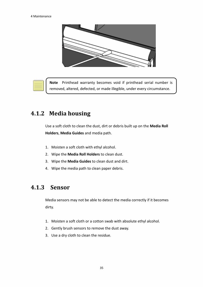
Note Printhead warranty becomes void if printhead serial number is
removed, altered, defected, or made illegible, under every circumstance.
4.1.2 Media housing
Use a soft cloth to clean the dust, dirt or debris built up on the Media Roll
Holders, Media Guides and media path.
1. Moisten a soft cloth with ethyl alcohol.
2. Wipe the Media Roll Holders to clean dust.
3. Wipe the Media Guides to clean dust and dirt.
4. Wipe the media path to clean paper debris.
4.1.3 Sensor
Media sensors may not be able to detect the media correctly if it becomes
dirty.
1. Moisten a soft cloth or a cotton swab with absolute ethyl alcohol.
2. Gently brush sensors to remove the dust away.
3. Use a dry cloth to clean the residue.

4 Maintenance
36
4.1.4 Platen roller
The platen roller is also important for print quality. Dirty platen roller may
damage the printhead. Clean the platen roller right away if the adhesive,
dirt or dust accumulates on it.
1. Moisten a soft cloth with absolute ethyl alcohol.
2. Gently wipe the platen roller to remove the dust and adhesive.

5 Troubleshooting
37
5 Troubleshooting
This chapter provides the information about printer problems and solutions.
5.1 Printer issues
The printer is not turned on
Did you attach the AC power cord?
Make sure the power supply’s connector is inserted into the printer power jack.
Check the power connection from the wall socket to the printer. Test the power
cord and the socket with other electrical devices.
Disconnect the printer from the wall socket, and connect it again.
The printer turns itself off
■ Turn on the printer again.
■ Make sure the power supply’s connector and the power cord are plugged
properly.
■ Make sure the power supply and the power cord are not damaged.
■ Use the applicable power supply.
■ If the printer keeps turning itself off, check the socket and make sure it
has enough power for the printer.
The printer does not feed the media out
The media is not loaded correctly. See Section 2.3, “Loading Media” to reload
the media.
If there is a paper jam, clear it.
5 Troubleshooting
38
5.2 Media issues
The media is out
Load a new media roll.
The paper is jammed
Open the printer and clear the jammed paper.
Make sure the paper is held properly by the Media Guides.
The printing position is not correct
Did you use the correct media type for printing?
The media is not loaded correctly. See Section 2.3, “Loading Media” to reload
the media.
The media sensor needs to be calibrated. See Section 3.1, “Media Sensor
Calibration” to calibrate the sensor.
The media sensor is dirty. Clean the media sensor.
Nothing is printed
The media is not loaded correctly. See Section 2.3, “Loading Media” to reload
the media.
The print data might not be sent successfully. Make sure the interface is set
correctly in the printer driver, and send the print data again.
The print quality is poor
The printhead is dirty. Clean the printhead.
The platen roller is dirty. Clean the platen roller.
Adjust the print darkness, or lower the print speed.
The media is incompatible for Direct Thermal. Use the compatible media
instead.
The media is incompatible for the printer.

5 Troubleshooting
39
5.3 Other issues
There are broken lines in the printed label
The printhead is dirty. Clean the printhead.
An error occurred when writing data to the USB memory
Did you insert the USB drive?
Make sure the USB drive is plugged tightly into the port.
The USB drive might be broken. Replace it with another one.
The printer is unable to save files due to insufficient USB memory
Delete the files on your USB drive to free some space, or replace your USB drive
with an empty one.
The cutter is experiencing issues
If there is a paper jam, clear it.
The cutter has become loose. Fix the cutter in position and tighten it.
The cutter blade is not sharp anymore. Replace your cutter with a new one.
The printhead temperature is extremely high
The printhead temperature is controlled by the printer. If it is extremely high,
the printer will stop printing automatically, until the printhead is cool down.
After that, the printer will resume printing automatically, if there is any
unfinished print job.
The printhead is broken
■ Contact your local dealer for assistance.

6 Set Up Interface Connection by SATO WS2 Printer Utility
40
6 Set Up Interface Connection by
SATO WS2 Printer Utility
SATO WS2 Printer Utility provides a user-friendly interface to configure your printer. You
can define properties, update firmware and send commands in SATO WS2 Printer Utility.
6.1 Install SATO WS2 Printer Utility
1. Insert the DVD into your DVD drive.
2. Locate the installation file on the DVD and click it.
3. In the SATO WS2 Printer Utility dialog box, click Next.

6 Set Up Interface Connection by SATO WS2 Printer Utility
41
4. In this dialog box, follow the instructions to choose the installation path, and
then click Next.
5. In this dialog box, click Next.

6 Set Up Interface Connection by SATO WS2 Printer Utility
42
6. After the installation of SATO WS2 Printer Utility is complete, click Close.
6.2 Work with SATO WS2 Printer Utility
Start SATO WS2 Printer Utility. Its interface looks like this:
6 Set Up Interface Connection by SATO WS2 Printer Utility
43
■ Menu bar It includes SATO WS2 Printer Utility menus.
■ Toolbar It provides ports, port settings, emulation languages, printer dpi and printer status.
■ Navigation Pane You can switch between the listed items to view their tabs.
■ Properties Pane You can view and manage printer properties or perform tasks.
6.2.1 Menu bar
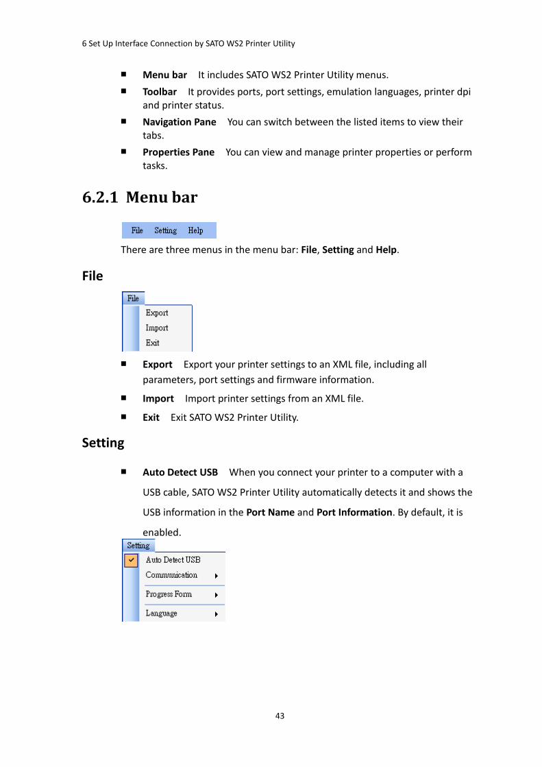
There are three menus in the menu bar: File, Setting and Help.
File
■ Export Export your printer settings to an XML file, including all
parameters, port settings and firmware information.
■ Import Import printer settings from an XML file.
■ Exit Exit SATO WS2 Printer Utility.
Setting
■ Auto Detect USB When you connect your printer to a computer with a
USB cable, SATO WS2 Printer Utility automatically detects it and shows the
USB information in the Port Name and Port Information. By default, it is
enabled.

6 Set Up Interface Connection by SATO WS2 Printer Utility
44
■ Communication
It includes Write Timeout and Read Timeout. They determine how long your
computer (or other devices) waits printer’s response when it attempts to write
or read data to your printer. The default value is 15 seconds, meaning that the
computer waits 15 seconds, and displays an error message if it doesn’t receive
any response.
■ Progress Form
When Add Date/Time information is enabled, the current date and time are
added into the message in the Download Firmware dialog box.
■ Language
It is the language of SATO WS2 Printer Utility interface. You can select
Windows’s System Default, English or Simplified Chinese. By default, it uses
your system default.
Help
■ Contents The help content of SATO WS2 Printer Utility. You can press F1
to display it.
■ About The version and copyright information about SATO WS2 Printer
Utility.
6 Set Up Interface Connection by SATO WS2 Printer Utility
45
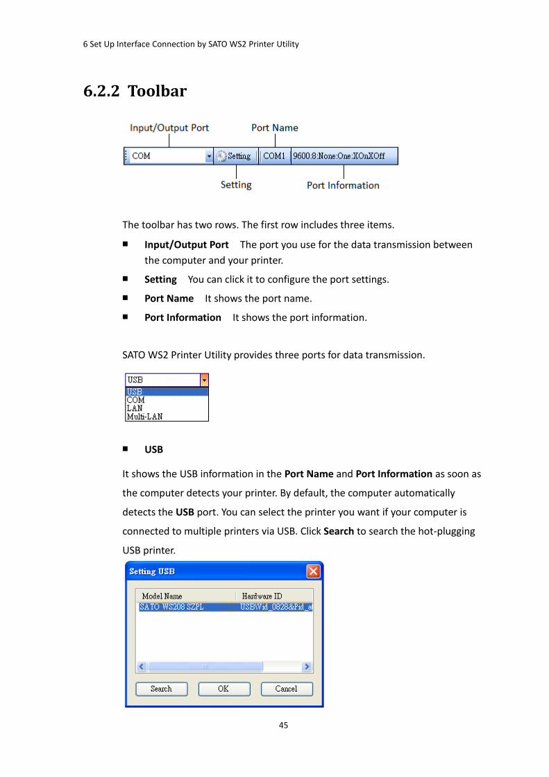
6.2.2 Toolbar
The toolbar has two rows. The first row includes three items.
■ Input/Output Port The port you use for the data transmission between
the computer and your printer.
■ Setting You can click it to configure the port settings.
■ Port Name It shows the port name.
■ Port Information It shows the port information.
SATO WS2 Printer Utility provides three ports for data transmission.
■ USB
It shows the USB information in the Port Name and Port Information as soon as
the computer detects your printer. By default, the computer automatically
detects the USB port. You can select the printer you want if your computer is
connected to multiple printers via USB. Click Search to search the hot-plugging
USB printer.

6 Set Up Interface Connection by SATO WS2 Printer Utility
46
■ COM
It is the serial port and related to the COM tab in Parameter Setting. The
settings of the COM port need to be the same as those in the COM tab, except
for Port Name, which lets you select the COM port you want if your computer is
connected to multiple printers via COM. If you want to reset all of COM settings,
click Default.
■ LAN
It is the Ethernet port and related to the LAN tab in Parameter Setting. It
supports IPv4 and IPv6 addresses. For more information about setting up a
network connection, see Set up LAN connection, Set up IPv6 connection and Set
up WLAN connection.

6 Set Up Interface Connection by SATO WS2 Printer Utility
47
■ Multi-LAN
It allows you to perform tasks on network printers. For example, you can add
other printers’ IP addresses in Multi-LAN setting, and update firmware for all
printers at once. If any error has occurred during the connection, Printer Tool
skips that IP address and tries the next one. Before you use the Multi-LAN port,
you need to set up a network connection. For further details, see Set up LAN
connection, Set up IPv6 connection and Set up WLAN connection.
The second row of the toolbar includes six items.
■ Printer Model Printer models.
■ Printer Emulation The emulation language of your printer. The emulation
you choose affects the tabs displayed in the Properties pane.
■ Printer DPI The print resolution of your printer. It provides 203 dpi and
300 dpi.
■ Sync Get the current settings of Printer Model, Printer Emulation and
Printer DPI from your printer.
■ Get Status Detect if your printer is ready for use.
■ Printer Status It shows the result of Get Status.

6 Set Up Interface Connection by SATO WS2 Printer Utility
48
Printer status
Status Description
ON LINE (Ready) The top cover (head) was closed in the online mode.
HEAD OPEN The top cover (head) was opened in the online mode.
ON LINE (Operating) The printer is operating.
ACCESSED BY OTHER Exclusively accessed by other host.
PAUSE In pause.
ON LINE (Waiting for
Stripping) Waiting for stripping.
COMMAND ERROR A command error was found while analyzing the command.
COMMS ERROR A parity error, overrun error or framing error occurred
during the RS-232C transmission.
PAPER JAM A paper jam occurred during paper feed.
CUTTER ERROR The cutter is experiencing issues.
NO PAPER The label has run out.
HEAD OPEN ERROR Attempt to feed or issue the label with the top cover (head)
open.
HEAD ERROR A broken pin has been found on the thermal head.
EXCESS HEAD TEMP The thermal head temperature has become excessively high.
NO PAPER (Last
label has been
issued)
The last label has been issued properly and the label has run
out.
LOW BATTERY RTC battery is low (future option).
MEMORY WRITE
ERROR
An error has occurred while writing data into the flash ROM
or USB memory.
FORMAT ERROR An erase error has occurred in formatting the flash ROM or
USB memory.
MEMORY FULL Saving failed because of the insufficient capacity of the flash
ROM or USB memory.
SAVING In font or PC command save mode. (to flash ROM or to USB
memory)
The flash ROM or USB memory is being initialized.
SAVING ERROR An EEPROM for backup cannot be read or written properly.
UPDATING
FIRMWARE NOW The printer is updating firmware.
BLUETOOTH ERROR Bluetooth initialization error.

6 Set Up Interface Connection by SATO WS2 Printer Utility
49
Status Description
Bluetooth setting parameter error.
WIRELESSLAN
ERROR
WirelessLAN initialization error.
WirelessLAN setting parameter error.
UPDATING
FIRMWARE ERROR An error occurred during the firmware update.
UNKNOWN The status is unknown.
6.2.3 Navigation pane
The Navigation pane includes four items: Parameter Setting, Download, Tool
and Auto Discover. Each item has its own tabs, and each tab has a Send, Get,
Add or Delete button (Some of them only have Send). Send is to send your
settings to your printer; Get is to get the current settings of your printer; Add is
to add file to the list object; Delete is to delete file from the list object. You can
also right-click in the Properties pane and select Send, Get, Add or Delete in the
shortcut menu. Each time you click Send, your printer restarts to apply the
change.
Important You can send data via all ports, but can only get data via the USB,
COM and LAN ports.

6 Set Up Interface Connection by SATO WS2 Printer Utility
50
Parameter Setting
Parameter Setting is used to configure printer settings. It includes six tabs:
General, COM, LAN, IPv6, WLAN and Bluetooth.
General
The General tab provides general printer settings. It is related to the emulation
language you choose. Each language provides its own properties.
■ SDPL, SEPL, SZPL and AUTO
SDPL, SEPL, SZPL and AUTO provides settings grouped in the Supply, Control,
Action, Label and Position Adjustment area.

6 Set Up Interface Connection by SATO WS2 Printer Utility
51
Property Name Description
Sensor Type It is the media sensor you are using. It includes I-MARK,
GAP and None. When you perform media calibration, the
sensor is set to the one you select.
Ribbon Sensor Thermal Transfer Your printer uses the ribbon sensor to
detect the ribbon, it is mean Thermal Transfer (TT).
Direct Thermal Disable the ribbon sensor, it is mean
Direct Thermal (DT).
Feed Key It defines the action of the FEED button.
Feed Your printer feeds a blank label each time the
button is pressed.
Reprint Your printer reprints the last label each time the
button is pressed.
Head Check(Power
on)
Enable Your printer checks broken pins on the printhead
automatically once your printer is turned on.
Disable Disable the auto head check.
Auto Calibration ON (Power on) Your printer automatically calibrates
media using a media sensor once it restarts or is turned
on.
ON (Head close) Your printer automatically calibrates
media using a media sensor every time you close the print
module when the printer is turned on.
ON (Power on and Head close) Your printer
automatically calibrates media using a media sensor after
power on and every time you close the print module
when the printer is turned on.
OFF You need to manually calibrate media using a
media sensor as you change the media, or your printer
won’t work properly.
Reprint After Error Enable Your printer when caused by the error condition.
The label is reprinted as soon as the error condition is
corrected.
Disable Disable the reprint after error.
Print Darkness Adjust the darkness relative to the current darkness
setting. The range is 0 ~ +30, and the value is adjustable in
increments of ± 1.
Print Speed Determine the media speed during printing. The range is

6 Set Up Interface Connection by SATO WS2 Printer Utility
52
Property Name Description
+2 ~ +6, and the value is adjustable in increments of ± 1
ips.
Cutter Enable If the printer has a cutter module. The label will
be cut after printing.
Disable Disable the cutting action after printing.
Dispenser Enable If the printer has a dispenser module. The label
will be peel after printing. Once the label has been
removed from dispenser, the printer will begin to print
next label again.
Disable Disable the paper detect before printing, then
the printer will print without waiting.
Backfeed Enable The printer will pull the paper backward into the
printer so that the first printing position is on the
predefined length behind thermal print head.
Disable Disable the paper backfeed action when start
printing.
Unit(Label) mm Change the unit of label to millimeter.
inch Change the unit of label to inch.
Width Set the print width.
Height Set the length of the label when using continuous media.
Unit(Position
Adjustment)
mm Change the unit of Position Adjustment to
millimeter.
Inch Change the unit of Position Adjustment to inch.
dots Change the unit of Position Adjustment to dots.
Horizontal Offset Move the print position horizontally. The positive number
is left, and the negative number is right.
Vertical Offset Move the print position vertically. The positive number is
forward, and the negative number is backward.
Tear Off Offset Adjust the rest position of the media after a label is
printed, which changes the position at which the label is
torn or cut.
Cutter/Dispenser
Offset
Adjust the cutter/dispenser offset position at which the
label is peel or cut.

6 Set Up Interface Connection by SATO WS2 Printer Utility
53
mm/inch/dot conversion process in Position Adjustment is as follows;
1. Input to the form in Setting Tool
Unit Value Setting condition
mm The value is adjustable in increments of ± 0.1 mm and rounded to the 1st
decimal place.
inch The value is adjustable in increments of ± 0.01 inch and rounded to the 2nd
decimal place.
dot The value is adjustable in increments of ± 1 dot and rounded to an integer
place.
2. Units Conversion process
1) When sending the value to the printer
The setting value is transmitted as dot information to the printer.
Case Conversion process Calculation (Setting value = A ) Rounding method
Case 1 mm ⇒ dot 203dpi A / 25.4 × 203
Rounded down to an integer
place
300dpi A / 25.4 × 300
Case 2 inch ⇒ dot 203dpi A × 203
300dpi A × 300
2) When getting the value from the printer
The setting value is transmitted as dot information from the printer.
Case Conversion process Calculation (Getting value = B ) Rounding method
Case 3 dot ⇒ mm
203dpi B × 25.4 / 203 Rounded down to the 1st
decimal place. e.g. 2.183 ->
2.1 300dpi B × 25.4 / 300
Case 4 dot ⇒ inch
203dpi B / 203 Rounded down to the 2nd
decimal place. e.g. 2.117 ->
2.11 300dpi B / 300
"mm/inch ⇔ dot" conversion always has a calculation difference in converting
units. These are cases where the setting value entered in the Setting Tool may
change slightly due to requirements of the conversion process.
e.g. In case of 3.2 mm setting :
3.2 / 25.4 × 203 = 25.5 ⇒25 dot (Sending value to the printer)
25 × 25.4 / 203 = 3.12 ⇒3.1 mm (Getting value from the printer)

6 Set Up Interface Connection by SATO WS2 Printer Utility
54
COM
The COM tab provides the settings of the RS-232C port. When you use COM as
your port, make sure the settings in the COM tab are the same as the port
settings, or your printer won’t work properly.
Property Name Description
Baud Rate The rate of signals transmitted per second. The larger the
number, the faster the data transmission.
Data Length The length of the data transmitted. It can be set to 7 or 8
bits.
Parity It can be set to Odd, Even or None. A parity bit is added
to a string of data bits to check if the data is correct.
Odd The total number of “ones” in the data plus the
parity bit is an odd number.
Even The total number of “ones” in the data plus parity
bit is an even number.
None No parity check is used.
Stop Bit The stop bit is at the end of a string of data bits. It is used
in asynchronous transmission to let the receiver know
that the string of data bits being transmitted is end.
Flow Control Flow control is used to control the data flow between the
computer and your printer.
XON/XOFF (DC1/DC3) It is software flow control that
uses control characters to handle data transmission.
When your printer is unable to process the data the
computer send, it sends an XOFF signal to tell the

6 Set Up Interface Connection by SATO WS2 Printer Utility
55
computer to stop sending data; once your printer is able
to accept data, it sends an XON signal to notify the
computer to resume sending data.
RTS It is hardware flow control that uses dedicated
wires to handle data transmission. When the computer is
ready to send data to your printer, it sends a Request to
Send (RTS) signal to your printer. If your printer is able to
accept the data, it sends a Clear to Send (CTS) signal to
the computer. That is, the computer starts sending data
when it sees CTS on; it stops sending when it sees CTS off.
None No control is used for the handshake.
LAN
The LAN tab provides network settings, including TCP/IP, Current TCP/IP,
Protocol, Server, WINS and SNMP Trap.
Property Name Description
IP Address (TCP/IP) The static IP address of your printer.
Subnet Mask (TCP/IP) The manually specified subnet mask of your
printer.
Gateway (TCP/IP) The manually specified gateway of your printer.
IP Address (Current TCP/IP) The current IP address of your printer.
Subnet Mask (Current
TCP/IP) The current subnet mask of your printer.

6 Set Up Interface Connection by SATO WS2 Printer Utility
56
Property Name Description
Gateway (Current TCP/IP) The current gateway of your printer.
Socket Enable The host communicates with your
printer via the socket.
Disable Disable the socket.
Port Number The LAN port number of your printer.
SNMP Enable The host gets or sets parameters
registered as SNMP entities.
Disable Disable SNMP.
DHCP Enable The DHCP server assigns an IP address,
the subnet mask and the gateway to your printer
automatically. By default, it is enabled.
Disable You need to specify an IP address, the
subnet mask and the gateway to your printer
manually.
Host Name It is the name of a DHCP client. The host name
allows up to 32 alphanumeric characters. You can
leave it blank or type a name you want. By
default, there is no host name.
Client ID It is an arbitrary value sent to the DHCP server to
reserve an IP address for your printer. Client ID
allows up to 32 hexadecimal characters. If you
leave it blank, your printer automatically assigns
“FFFFFFFFFFFFFFFFFFFFFFFFFFFFFFFF” as the
client ID.
Server IP Address If you have WINS server in your local network,
type IP address in. WS2 only accept one WINS
server.
NetBIOS Name NetBIOS Name only works on WINS server. Name
the printer to replace IP address. It allows up to
15 characters and uppercase only.
Trap 1 Trap is a message type of SNMP. When Trap 1 is
enabled and its IP address is set correctly, your
printer alerts the computer of the specified IP
address as your printer is experiencing problems.
Trap 2 Same as Trap 1.

6 Set Up Interface Connection by SATO WS2 Printer Utility
57
Set up LAN connection
If you want to use the LAN or Multi-LAN port to transfer data, you need to set
up the network connection in the LAN tab.
1. Connect your printer and computer to a network device (hub, switch or
router) with Ethernet cables.
2. In the Input/Output Port list, click USB or COM.
3. In the Navigation pane, click Parameter Setting, and click the LAN tab.
4. Do one of the following to configure your TCP/IP settings:
∙ If you have a static IP address, fill the IP Address, Subnet Mask and Gateway
box under TCP/IP according to your network settings and click Send.

6 Set Up Interface Connection by SATO WS2 Printer Utility
58
∙ If you don’t have a static IP address, make sure DHCP is enabled and click
Send.
5. After your printer restarts, click Get to get the TCP/IP information of your
printer. If you are using a static IP address, you’ll get the same TCP/IP
settings as it is in the previous step; if you are using DHCP, The DHCP server
will automatically populate the IP Address, Subnet Mask and Gateway
boxes under Current TCP/IP.
6. In the Input/Output Port list, click LAN, and click Setting.
7. In the Setting LAN dialog box, do one of the following to configure your IP
address:
∙ If you are using a static IP address, in the IP Address box, enter the IP
address under TCP/IP in the LAN tab, and then click OK.

6 Set Up Interface Connection by SATO WS2 Printer Utility
59
∙ If you are using a dynamic IP address provided by DHCP, in the IP Address
box, enter the IP address under Current TCP/IP in the LAN tab, and then
click OK.
Note When DHCP is enabled and your printer is idle for a long time, the IP
address of your printer may change. Click Get to get the new IP address if you
find the current IP address is not working.
IPv6
The IPv6 tab provides IPv6 settings, including IPv6 and Current IPv6.
Property Name Description
Mode It determines how you get the IPv6 address of your printer.
MANUAL Specify an IPv6 address manually.
DHCPv6 An IPv6 address is assigned by a Dynamic Host
Configuration Protocol for IPv6 (DHCPv6) server.
AUTO It uses a stateless address that doesn’t require a
DHCPv6 server to allocate an IP address. A host generates an
IPv6 address from router advertisements and a MAC
address. Stateless auto-configuration supports plug and play
functionality, which allows the printer to generate an IPv6
address by itself once it connects to an IPv6 network.

6 Set Up Interface Connection by SATO WS2 Printer Utility
60
Property Name Description
Address Type It is the IPv6 address type of your printer.
NONE The system won’t use the address you specified to
generate an IPv6 address. It sets 0000::0000 as the IPv6
address.
NORMAL It uses a 128-bit unicast address that you
specified.
EUI It is 64-bit Extended Unique Identifier (EUI-64) that
generates the second half of a unicast IPv6 address (last 64
bits) from a MAC address. You can also specify the second
half of the address by entering the interface ID.
ANY It uses a 128-bit anycast address that you specify. The
printer needs to remember that the current address is an
anycast address, since its format is the same as a unicast
address.
IP Address (IPv6) The static IPv6 address of your printer.
Interface ID Short for interface identifier. It is used to identify the
network interface of a host. You can specify the interface ID
here.
IP Address
(Current IPv6)
The current IPv6 address of your printer.
Link-Local Address It is used for communications on a local network. The
address always starts with FE80.
Set up IPv6 connection Before you set up IPv6, make sure your have IPv6 connectivity.
1. Do one of the following to configure your IPv6 settings:
• If you have a static IPv6 address, in the Mode list, click MANUAL; in the IP
Address box, enter your IPv6 address, and click Send.
• If you don’t have a static IPv6 address, in the Mode list, click DHCPv6; in

6 Set Up Interface Connection by SATO WS2 Printer Utility
61
the Address Type list, click Normal, and click Send.
2. After your printer restarts, click Get to get its IPv6 information. If you are
using a static IPv6 address, you’ll get the same settings as it is in the previous
step; if you are using DHCPv6, the DHCPv6 server will automatically populate
the IP Address and Link-Local Address boxes under Current IPv6.
3. In the Input/Output Port list, click LAN, and click Setting.

6 Set Up Interface Connection by SATO WS2 Printer Utility
62
4. In the Setting LAN dialog box, do one of the following to configure your IP
address:
∙ If you are using a static IP address, in the IP Address box, enter the IP
address under IPv6 in the IPv6 tab and click OK.
∙ If you are using a dynamic IP address provided by DHCPv6, in the IP
Address box, enter the IP address under Current IPv6 in the IPv6 tab and
click OK.
Note If your IPv6 address has consecutive zeros, you can use a
double-colon to compress them. For example, if your address is
2607:f0d0:1002:0051:0000:0000:0000:0006, you can shorten it like this:
2607:f0d0:1002:0051::0006. Remember that the double-colon can
appear only once in the address. The leading zeros in a section can also
be removed, so the shortest version of your address can be written as
2607:f0d0:1002:51::6.
WLAN The WLAN tab provides wireless network settings, including IPv4, Current IPv4,
Authentication, Information, WEP, WPA, Initialization, Protocol, Current
Protocol, Server and EAP.

6 Set Up Interface Connection by SATO WS2 Printer Utility
63
Property Name Description
IP Address (IPv4) The static IPv4 address of your printer.
Subnet Mask (IPv4) The manually specified IPv4 subnet mask of your
printer.
Gateway (IPv4) The manually specified IPv4 gateway of your printer.
IP Address (Current IPv4) The current IPv4 address of your printer.
Subnet Mask (Current IPv4) The current IPv4 subnet mask of your printer.
Gateway (Current IPv4) The current IPv4 gateway of your printer.
RSSI Short for received signal strength indicator. It
measures your Wi-Fi signal strength. The bigger the
number, the stronger the signal.
Network Authentication Open It allows any device to authenticate to an
access point (AP) and gain access to a network, but
only the device with the correct WEP key can receive
encrypted data while the AP uses WEP encryption.
WPA-Personal WPA-Personal uses Pre-Shared Key
(PSK) authentication, in which all users use the same
password to access a network. WPA is designed to
replace WEP. It uses RC4 encryption as WEP, but
provides extra security through TKIP.
WPA2-Personal WPA2-Personal includes all features
of WPA-Personal, but it uses AES encryption to
enhance security.
802.1X 802.1X is an IEEE standard that provides
EAP-based authentication methods for network access
control. It enhances security by centralizing user
identification, authentication and key management.
WPA-Enterprise WPA-Enterprise offers centralized
control over a network. It requires an 802.1X
authentication server (RADIUS server) to validate
users. Each user needs to enter individual username
and password to access a network. It uses TKIP and
RC4 algorithm to encrypt data.
WPA2-Enterprise WPA2-Enterprise includes all
features of WPA-Enterprise, but it uses AES encryption
to enhance security.
WEP ON Turn on WEP encryption.
OFF Turn off WEP encryption.

6 Set Up Interface Connection by SATO WS2 Printer Utility
64
Property Name Description
WEP Key Index The default key of WEP. You can set four keys and
choose one of them as the default.
WEP Input Type The type of your WEP key.
ASCII If your key is generated in ASCII, select this.
ASCII includes the English alphabet, numbers and
punctuation symbols.
HEX If your key is generated in hexadecimal (HEX),
select this. HEX includes the numbers 0 to 9 and the
letters A to F.
WEP Key 1-4 You can store four 128-bit WEP keys.
WPA Encryption It shows encryption methods depending on your
network authentication.
AUTO It allows the access point to use either TKIP or
AES encryption.
TKIP It is available for WPA-Personal and
WPA-Enterprise. TKIP stands for Temporal Key
Integrity Protocol. It is part of 802.11i standard of
Wireless LAN. It enhances the security of WEP. TKIP
uses 128-bit encryption. It dynamically changes keys
for each packet using a rekeying mechanism, providing
a strong protection against attackers.
AES It is available for WPA2-Personal and
WPA2-Enterprise. AES stands for Advanced Encryption
Standard. It uses a serial of mathematical operations
that repeatedly rearrange data to encrypt it.
Note 802.11n can only use AES encryption.
WPA Pre-shared Key It is a key shared between two parties that use a
secure channel for communication. Anyone who
knows the key can access the network. The length can
be 1-63 alphanumeric characters excluding double
quotation marks (“). Pre-shared key authentication is
for home or small offices.
Module Restore Default It resets all values in the Wi-Fi module.
Network Type It determines how you connect your printer to a
network.
Infrastructure If you connect through an access
point, select this.

6 Set Up Interface Connection by SATO WS2 Printer Utility
65
Property Name Description
Ad hoc If you connect through a device which has
connected to a network, select this. In Ad hoc mode,
you can only use Open authentication.
Region The country or region.
Channel The Wi-Fi channel. You need to use the same channel
as other devices for communication. The available
channel varies according to your region.
SSID The service set identifier. It is the name of a wireless
network.
Port Number The wireless LAN port number of your printer.
Channel (Current) The current Wi-Fi channel.
SSID (Current) The current service set identifier.
DHCP Auto It tries to get an IP address from a DHCP server
first. If failed, it uses the specified one.
Enable It keeps trying to get an IP address from a
DHCP server until it succeeds.
Disable It uses the specified IP address.
Host Name It is the name of a DHCP client. The host name allows
up to 32 alphanumeric characters. You can leave it
blank or type a name you want. By default, there is no
host name.
EAP Method It is available for 802.1X, WPA-Enterprise and
WPA2-Enterprise authentication.
EAP-LEAP LEAP stands for Lightweight Extensible
Authentication Protocol. It changes the WEP key for
each session, preventing attackers retrieving data by
cracking the key.
EAP-TLS TLS stands for Transport Layer Security.
EAP-TLS requires both a client and a server to
exchange digital certificates to authenticate each
other. It uses Public Key Infrastructure (PKI) to protect
communication. A server and a client need to obtain
certificates from a certification authority (CA), and use
these certificates to validate each other’s identity.
EAP-TTLS TTLS stands for Tunneled Transport Layer
Security. It has two stages. First, a server sends its
certificate to a client after it received an

6 Set Up Interface Connection by SATO WS2 Printer Utility
66
Property Name Description
authentication request. This certificate is used to
create an encrypted tunnel (TLS tunnel) between the
server and the client. Second, both sides exchange
attribute-value pairs (AVP) through this tunnel.
PEAP Short for Protected Extensible Authentication
Protocol. Similar to EAP-TTLS, it creates an encrypted
tunnel between a server and a client in the first stage.
After that, it starts the second EAP exchange through
this tunnel.
EAP-FAST FAST stands for Flexible Authentication via
Secure Tunneling. Similar to PEAP, it has two stages.
First, it uses a Protected Access Credentials (PACs) to
create an encrypted tunnel. Second, it authenticates
the client to the server within the tunnel.
EAP Username The username for EAP authentication. It accepts 1-63
alphanumeric characters.
EAP Password The password for EAP authentication. It accepts 1-32
alphanumeric characters.
Set up WLAN connection
Before you set up a wireless LAN connection, make sure your computer has
connected to a wireless network.
1. In the Input/Output Port list, click USB or COM.

6 Set Up Interface Connection by SATO WS2 Printer Utility
67
2. In the Navigation pane, click Parameter Setting, and click the WLAN tab.
3. In the SSID box, enter the network name you’ve connected, and do one of
the following to enter your password:

6 Set Up Interface Connection by SATO WS2 Printer Utility
68
∙ If you’re using Open and WEP is on, choose your WEP password type in the
WEP Input Type list. Next, enter your WEP password in one of the WEP Key
box, and select the key you want to use from the WEP Key Index list.
∙ If you’re using WPA-Personal or WPA2 Personal, enter your password in the
WPA Pre-shared Key box.
∙ If you’re using 802.1X, WPA-Enterprise or WPA2 Enterprise, choose your
EAP authentication method in the EAP Method list, and enter your
username and password in EAP User Name and EAP Password boxes
respectively. If you’re using TTLS mode, you can choose the TTLS encryption
method from the TTLS Method list.

6 Set Up Interface Connection by SATO WS2 Printer Utility
69
4. Do one of the following to configure your IPv4 settings:
∙ If you have a static IP address, fill the IP Address, Subnet Mask and Gateway
box under IPv4 according to your network settings, make sure DHCP is
disabled, and click Send.
∙ If you don’t have a static IP address, make sure DHCP is enabled and click
Send.
5. After your printer restarts, click Get to get the IPv4 information of your
printer. If you are using a static IP address, you’ll get the same settings as it is
in the previous step; if you are using DHCP, the DHCP server will
automatically populate the IP Address, Subnet Mask and Gateway boxes
under Current IPv4.
6. In the Input/Output Port list, click LAN, and click Setting.

6 Set Up Interface Connection by SATO WS2 Printer Utility
70
7. In the Setting LAN dialog box, do one of the following to configure your IP
address:
∙ If you are using a static IP address, in the IP Address box, enter the IP
address under IPv4 in the WLAN tab and click OK.
∙ If you are using a dynamic IP address provided by DHCP, in the IP Address
box, enter the IP address under Current IPv4 in the WLAN tab and click OK.
Bluetooth
The Bluetooth tab provides Bluetooth settings.
Property Name Description
Pincode The Bluetooth PIN code of your printer. The
new PIN code takes effect when you
reconnect your printer to your computer.
Device Name
The Bluetooth device name of your printer.
The new device name takes effect after you
reconnect your printer to your computer.
BD Address The Bluetooth MAC address of your printer.
Inquiry Control It determines how your printer is detected by
other Bluetooth devices.

6 Set Up Interface Connection by SATO WS2 Printer Utility
71
Property Name Description
Response is made at any time Your printer
is always detectable.
No response Your printer is not detectable.
Response only within 60sec after a power on
Your printer is detectable in 60 seconds after
it is turned on.
Reset parameter setting
If you want to reset Parameter Setting, do this:
1. In Parameter Setting, right-click in the blank area in any tab.
2. In the shortcut menu, do one of the following to reset Parameter Setting:
∙ If you want to restore all of the settings to their default values, click
Restore to Default.

6 Set Up Interface Connection by SATO WS2 Printer Utility
72
∙ If you want to restore the settings of the current tab to their default values,
click Restore Display to Default.
Download
Download is used to download files to your printer. Tabs in Download are
related to the emulation language you choose. Remember that you need to set
up a network connection before you use the LAN or Multi-LAN port for the data
transfer. For further details, see Set up LAN connection, Set up IPv6 connection
and Set up WLAN connection.
Firmware
The Firmware tab displays in all emulation modes. It is used to update firmware.
For information about update firmware in SATO WS2 Printer Utility, see Update
firmware in SATO WS2 Printer Utility.

6 Set Up Interface Connection by SATO WS2 Printer Utility
73
General
The General tab displays in all emulation modes. It is used to send command
files to your printer and perform tasks. Command files only run in their
corresponding emulations. For example, SZPL command files only run in SZPL
emulation.
To run commands on your printer:
1. Type your commands in any text editor, such as Notepad or Wordpad.
2. Save your commands as text files (.txt).
3. In the Input/Output Port list, click the port you want to use.
4. Click Download in the Navigation pane.

6 Set Up Interface Connection by SATO WS2 Printer Utility
74
5. Under the General tab, right-click in the blank area and click Add.
6. In the Open dialog box, browse to the folder that contains command files,
select them and click Open. The command files you select must correspond
to the emulation language you use.

6 Set Up Interface Connection by SATO WS2 Printer Utility
75
7. In the list, select the file you want to use. You can only select one file at a
time.
8. Click Send to run the command on your printer.
Note If you send a command file and your printer doesn’t respond, it is
possible that the emulation language is not set correctly. Click Sync to get the
current setting of Printer Emulation.

6 Set Up Interface Connection by SATO WS2 Printer Utility
76
Tool
Tool is used to send specific commands to your printer.
Single Command
The Single Command tab which provides commands below.

6 Set Up Interface Connection by SATO WS2 Printer Utility
77
■ Reboot Printer Restart your printer.
■ Reset To Default Setting Reload factory settings.
■ Test Print Run a self test to print a configuration label.
■ Change Emulation Change the emulation language for your printer.
■ Media Calibration Change the media sensor for your printer.
■ Ribbon Calibration It calibrates the ribbon so that your print start
position will be more accurate.
• RESET Turn off Ribbon Calibration.
• ON Turn on Ribbon Calibration. Enter the pitch and gap of your label
in the scale boxes. For example, if the pitch of your label is 100 mm,
enter 100 in the box; the gap of your label is 5 mm, enter 5 in the box.
Auto Discover
Auto Discover is used to find barcode printer. You can so easy and fast to find
printer.

6 Set Up Interface Connection by SATO WS2 Printer Utility
78
Printer
The Printer tab provides to search and control printer. Select a printer can
rapidly change to control it.
Auto Discover: Auto Discover will show USB and LAN connected printer. It is
based on SNMP protocol and using broadcast to search in private network.
Click Auto Discover, It will display Model Name, Port Information(IP address)
and Port number.
Active Device: Select a device and click Active Device. Toolbar will be changed.
If you click Sync and Status in the toolbar, then toolbar will be update. You can
rapidly switch the printer by this function or select multiple printers to setup
under Multi-LAN port.

6 Set Up Interface Connection by SATO WS2 Printer Utility
79
Web Control:
If printer firmware supports web control, click Web Control to open a Web
page. Default Login name and password is admin. You can also type the IP
address to open printer web setting tool in your browser. Printer web setting
tool is based on Print Tool. Each model may have a bit different setting
because of the spec.
6.3 Update firmware
Firmware is the code stored permanently in hardware. It instructs your printer to do its
tasks. Benefits of updating firmware include new features, enhanced functionality and
improved performance.
Caution Do not open the print module, disconnect your printer from the
computer or cut your printer power during the firmware update.

6 Set Up Interface Connection by SATO WS2 Printer Utility
80
Update firmware in SATO WS2 Printer Utility
This section describes how to update printer firmware in SATO WS2 Printer Utility.
6.3.1 Update via the USB Client or COM port
1. Connect your printer and the computer with a USB or a serial cable.
2. Make sure the print module is closed.
3. Turn on your printer, and start SATO WS2 Printer Utility.
4. In the Input/Output Port list, click USB or COM, and do one of the following:
∙ If you are using the USB port, the Port Name and Port Information
automatically shows the USB information. You don’t need to do anything.
∙ If you are using the COM port, click Setting, and change the settings as you
want. For example, you can change Baud Rate to a higher value to speed
up the data transmission. Make sure the port settings are the same as
those in the COM tab in Parameter Setting, or your printer won’t work
properly.

6 Set Up Interface Connection by SATO WS2 Printer Utility
81
5. In the Navigation pane, click Download, and click the Firmware tab.
6. Right-click in the blank area and click Add.

6 Set Up Interface Connection by SATO WS2 Printer Utility
82
7. In the Open dialog box, browse to the folder that contains the firmware files.
Select all of them and click Open.
8. If you want to update specific files, select the check boxes of those files; if
you want to update all of the firmware files, right-click in the blank area in
the list, and click Select All.

6 Set Up Interface Connection by SATO WS2 Printer Utility
83
9. Click Send to send the firmware files to your printer. During the transmission
LED 1 blinks green. In the Download Firmware dialog box, the message
shows the file your printer is downloading, and the progress bar indicates
the progress of downloading.
10. When the data transmission is complete, your printer starts to update its
firmware. During the update LED 2 turns to red and orange alternatively,
while LED 1 turns to solid green. In the Download Firmware dialog box, the
message shows that your printer is updating the firmware.

6 Set Up Interface Connection by SATO WS2 Printer Utility
84
11. Printer will restart automatically after the message “Firmware Update,
Succeed” appears.
12. When the update is complete, the message “Firmware Update Complete”
appears. Click Close to close the dialog box, or click Save Log to save the
firmware update log.
Note Sometimes you’ll find LED 2 keeps turning to red and orange
alternatively after the message “Done” appears. It means your printer is
updating the other copy of firmware. There are two copies of firmware stored
in your printer: master and backup. They are used to restore each other in case
the firmware is lost or corrupted. By default, the master is the primary copy.
Your printer uses the backup if the master doesn’t work.

6 Set Up Interface Connection by SATO WS2 Printer Utility
85
6.3.2 Update via the LAN or Multi-LAN port
Before you update the firmware via the LAN or Multi-LAN port, you need to set
up a network connection. For details, see Set up LAN connection, Set up IPv6
connection and Set up WLAN connection.
1. Connect your printer and computer to a network device (hub, switch or
router) with Ethernet cables.
2. Make sure the print module is closed.
3. Turn on your printer, and start SATO WS2 Printer Utility.
4. In the Input/Output Port list, click LAN or Multi-LAN, and do one of the
following:
∙ If you are using the LAN port, the Port Name and Port Information will
show the LAN settings after you set up a network connection.
LAN
IPv6
WLAN
∙ If you are using the Multi-LAN port, click Setting. In the Setting Multi-LAN
dialog box, in the IP Address box, enter your printer’s IP address and click
Add. If you want to update the firmware of multiple printers, keep adding
their IP addresses, and then click OK.

6 Set Up Interface Connection by SATO WS2 Printer Utility
86
5. In the Navigation pane, click Download, and click the Firmware tab.
6. Right-click in the blank area and click Add.
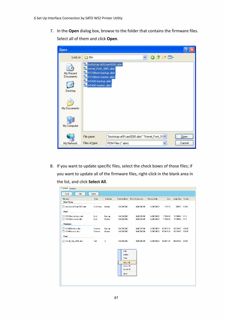
6 Set Up Interface Connection by SATO WS2 Printer Utility
87
7. In the Open dialog box, browse to the folder that contains the firmware files.
Select all of them and click Open.
8. If you want to update specific files, select the check boxes of those files; if
you want to update all of the firmware files, right-click in the blank area in
the list, and click Select All.

6 Set Up Interface Connection by SATO WS2 Printer Utility
88
9. Click Send to send the firmware files to your printer. During the transmission
LED 1 blinks green. In the Download Firmware dialog box, the message
shows the file your printer is downloading, and the progress bar indicates
the progress of downloading.
10. When the data transmission is complete, your printer starts to update its
firmware. During the update LED 2 turns to red and orange alternatively,
while LED 1 turns to solid green. In the Download Firmware dialog box, the
message shows that your printer is updating the firmware.

6 Set Up Interface Connection by SATO WS2 Printer Utility
89
11. Printer will restart automatically after the message “Firmware Update,
Succeed” appears.
12. When the update is complete, the message “Firmware Update Complete”
appears. At the same time, your printer restarts itself. Click Close to close
the dialog box, or click Save Log to save the firmware update log.

6 Set Up Interface Connection by SATO WS2 Printer Utility
90
6.4 Update firmware via the USB host
The USB host is a USB type A port for a USB flash drive, which can be used to quickly
update the firmware.
1. Create a folder named “Firmware” in your USB flash drive, and copy the
firmware files to it. The file “WS2-master.abin” needs to be in the folder.
Note The firmware file may have different name as you get it.
2. Make sure the print module is closed, and turn off your printer.
3. Turn ON the printer power (or reboot the printer) after insert your USB flash
drive to the printer. The printer starts to update the firmware.
Note You cannot update firmware even if insert your USB flash drive to the
printer after turn ON the printer power (or reboot the printer).
4. During the update LED 2 blinks green a few times, and turns to red and
orange alternatively. When the update is complete, LED 2 goes out.
Caution Do not remove the USB flash drive during the update.
6.5 Update firmware in Atmel mode
Typically, firmware can be updated in SATO WS2 Printer Utility without problems,
but there are rare cases SATO WS2 Printer Utility cannot handle. If any
unexpected conditions keep you from update firmware in SATO WS2 Printer
Utility, you need to update it in Atmel mode.
Step 1. Enter Atmel mode
This part describes how to enter Atmel mode.
1. Turn off your printer.
2. Turn over your printer.
3. Loosen and remove three screws from the base.
4. Lift the base and unplug all the cables.
5. Locate the DIP switch on the main board. Set
Switch 1 and 2 to the OFF position (down).

6 Set Up Interface Connection by SATO WS2 Printer Utility
91
Step 2. Update your firmware
This part describes how to update your firmware in Atmel mode.
1. Plug all the cables back into the main board.
2. Turn on your printer. Both LEDs won’t glow. This is normal.
3. Start SATO WS2 Printer Utility. In the Navigation pane, click Download, and
click the Firmware tab.
4. Right-click in the blank area and click Add.

6 Set Up Interface Connection by SATO WS2 Printer Utility
92
5. In the Open dialog box, browse to the folder that contains WS2 firmware
files. Select all of them and click Open.
6. Right-click in the blank area in the list, and click Select All to select all of the
check boxes.
Note If you want to execute a firmware file without saving it into the flash
memory, select the Download to memory and execute check box and click
Send.

6 Set Up Interface Connection by SATO WS2 Printer Utility
93
7. Click Send to send the firmware files to your printer. When the update is
complete, the message “Done” appears. Click Close to close the dialog box,
or click Save Log to save the firmware update log.
Step 3. Exit Atmel mode
This part describes how to exit Atmel mode.
1. Turn off your printer.
2. Set DIP Switch 1 and 2 to the ON position (up). If it’s inconvenient to set DIP
Switch while cables are connected, unplug all the cables to do this.
3. Reinstall the base and the secure it with three screws.
4. Turn over your printer.
5. Turn on your printer.

7 Specifications
94
7 Specifications
This chapter provides specifications for the printer. Specifications are subject
to change without notice.
7.1 Printer
Model WS208 WS212
Print method Direct Thermal
Resolution 203 dpi (8 dots/mm) 300 dpi (12 dots/mm)
Media Alignment Centered
Operation Mode Standard: Continuous mode, Tear-off mode
Optional: Cutter mode, Peeler mode
Sensor
Reflective Sensor (Movable)
Media Transmissive sensor x 1 (fixed, 6.27mm offset)
Head Open Switch
Operation interface LED indicator x 2, Button x 1
Print Speed
2, 3, 4, 5, 6, 7 inches/sec
(50.8, 76.2, 101.6, 127, 152.4, 177.8
mm/sec)
2 &3ips for peel off mode
2, 3, 4, 5 inches/sec
(50.8, 76.2, 101.6, 127
mm/sec)
2 &3ips for peel off mode
Printable Area Max. length 100”(2540mm) Max. length 50”(1270mm)
Printing Width Max. 54.1mm Max. 56.8mm
Print Ratio Average print ratio within 15 % or less (whole print layout area)
Full width with 1mm pitch is required
Interface USB hosts(Type A), USB device(Type B) , Ethernet
Programming
Language SDPL+SEPL+SZPL
Accessories Peeler, Full Cutter
On-Board Memory
Standard Memory (Flash ROM): 16 MB
User Memory: 8 MB
Standard Memory (SDRAM): 32 MB
USB storage up to 32 GB (FAT32 format only)
CPU Type 32 bit RISC microprocessor

7 Specifications
95
Software---Label
editing
Windows Driver (Windows Vista/ Win 7/ Win 8/ Win 10),
BarTender® from Seagull Scientific, Nice Label
Software--- Utility Printer Tool
Agency Listing CB, CE, FCC, RCM, CB, cTUVus
7.2 Media
Properties Description
Media Size Max. width: 60mm, Min. width: 12mm
Max length 100" (2540 mm), Min length 0.4" (10mm)
Thickness: 0.00236”~0.00787” (0.06mm~0.2mm)
5”(127mm) OD on a 1”/1.5” (25.4/38 mm) ID core
4.5”(115mm) OD on a 0.5” (12.7mm) ID core
Min. width: 12mm for partial cutter options.
Min. length: 25mm for cutter and peeler options.
Media Type Direct Thermal Label
Direct Thermal Tag
Roll Paper (Inside Wound or Outside Wound)
Fanfold Paper
7.3 Electrical and operating environment
Properties Range
Power Supply Voltage: AC 100 V ~ 240 V ± 10 % (full range)
Frequency: 50 Hz - 60 Hz ± 5 %
Temperature Operating: 41℉~104℉(5 °C ~ 40 °C)
Storage: -4℉~140℉(-20 °C ~ 60 °C)
Humidity Operating: 25 %RH ~ 85 %RH (non-condensing)
Storage: 10 %RH ~ 90 %RH (non-condensing)
7.4 Physical dimension
Dimension Size and Weight
Size W 116 mm x H 170 mm x D 215 mm
Weight 1.05 kg (excluding media and accessories)

7 Specifications
96
7.5 Fonts, Barcodes, and Graphics
The specifications of fonts, bar codes and graphics depends on the printer emulation.
The emulations SDPL, SEPL, and SZPL are printer programming languages, through
which the host can communicate with your printer.
Printer Programming Language SDPL
Programming Language SDPL
Internal fonts
9 fonts with different point size
6 fonts with ASD smooth font.
Courier font with different symbol sets.
Symbol sets
(Code pages)
Courier font symbol set: Roman-8, ECMA-94, PC, PC-A,
PC-B, Legal, and PC437 (Greek), Russian.
Soft fonts Downloadable soft fonts by Print Tool
Font size 1x1 to 24x24 times
Character rotation 0, 90, 180, 270 degree, 4 direction rotation
Graphics PCX, BMP, IMG, GDI and HEX format files
1D Barcodes
Codabar、Code 128 subset A/B/C、Code 39、Code 93、
EAN-13、EAN-8、GS1 Data bar (RSS) 、Interleaved 2 of 5
(Standard/with modulo 10 checksum/ with human
readable check digit/ with modulo 10 checksum &
shipping bearer bars) 、Plessey、Postnet、UCC/EAN-128、
UCC/EAN-128 K-MART、UCC/EAN-128 Random weight、
UPC2、UPC5、UPC-A、UPC-E、FIM、HBIC、Telepen
2D Barcodes PDF417, Micro PDF, Maxi Code, GS1 Data Matrix, Data
Matrix (ECC200), QR Code, Composite Symbologies, Aztec

7 Specifications
97
Printer Programming Language SEPL
Programming Language SEPL
Internal fonts 5 fonts with different point size
Symbol sets
(Code pages)
8 bits code page : 437, 850, 852, 860, 863, 865, 857, 861,
862, 855, 866, 737, 851, 869, 1252,
1250, 1251, 1253, 1254, 1255
7 bits code page: USA, BRITISH, GERMAN,
FRENCH, DANISH, ITALIAN,
SPANISH, SWEDISH and
SWISS
Soft fonts Downloadable soft fonts by Print Tool
Font size 1x1 to 24x24 times
Character rotation 0, 90, 180, 270 degree, 4 direction rotation
Graphics PCX , Binary Raster, BMP and GDI
1D Barcodes
Codabar、Code128 subset A/B/C、Code 128 auto、Code
128 UCC (shipping container code)、Code 39、Code 39
with check sum digit 、Code 93、EAN-13、EAN-13 2/5 digit
add-on、EAN-8 (Standard, 2 /5digit add-on) 、 GS1 Data
bar (RSS) 、 Interleave 2 of 5、Interleaved 2 of 5 with
check sum、Interleaved 2 of 5 with human readable check
digit、Matrix 2 of 5、Postnet 、UCC/EAN code 128
(GS1-128) 、UPC-Interleaved 2 of 5、UPC-A、UPCA 2/5
digit add-on、UPC-E、UPCE 2/5 digit add-on、
German Postcode
2D Barcodes PDF417, Micro PDF, Maxi Code, GS1 Data Matrix, Data Matrix (ECC200), QR Code, Composite Symbologies, Aztec

7 Specifications
98
Printer Programming Language SZPL
Programming Language SZPL
Internal fonts
8 (A~H) fonts with different point size.
8 AGFA fonts: 7 (P~V) fonts with fixed different point size
(not scalable). 1 (0) font with scaling point size.
CG Triumvirate Bold Internal TTF font.
Symbol sets
(Code pages)
USA1, USA2, UK, HOLLAND,
DENMARK/NORWAY, SWEDEN/FINLAND,
GERMAN, FRANCE1, FRANCE2, ITALY,
SPAIN, MISC, JAPAN, IBM850, Multibyte Asian Encodings,
UTF-8, UTF-16 Big-Endian, UTF-16 Little-Endian, Code
page 1250, 1251, ,1252, 1253, 1254
Soft fonts Downloadable soft fonts by Print Tool
Font size 1x1 to 10x10
Character rotation 0, 90, 180, 270 degree, 4 direction rotation
Graphics GRF, Hex and GDI
1D Barcodes
Codabar、 Code 11、Code128 subset A/B/C、Code39、
Code 39 with check sum digit、 Code 93、EAN-13、EAN-8、
GS1 Data bar (RSS)、Industrial 2 of 5、Interleave 2 of 5、
Interleaved 2 of 5 with check sum、
Interleaved 2 of 5 with human readable check digit、
MSI、Plessey、Postnet、 UPC-A、UPC-E、Logmars 、
Standard 2 of 5
2D Barcodes PDF417, Micro PDF, Maxi Code, GS1 Data Matrix, Data
Matrix (ECC200), QR Code, Composite Symbologies, Aztec

7 Specifications
99
7.6 Ethernet
Properties Description
Port RJ-45
Speed 10Base-T/100Base-T (Auto Detecting)
Protocol ARP, IP, ICMP, UDP, TCP, HTTP, DHCP,
Socket, LPR, IPv4, IPV6, SNMPv2
Mode TCP Server/Client, UDP Client
Technology HP Auto-MDIX, Auto-Negotiation
7.7 Wireless LAN (Option)
Properties Wireless LAN I/F
Hardware Protocol IEEE802.11b/g/n
Enabled Device WS2 Series
Destination USA Europe
Frequency
(Center Channel)
2412 ~ 2462 MHz 2412 ~ 2472 MHz
Channel 1 ~ 11 ch 1 ~ 13 ch
Spacing 5 MHz
Transmission Speed/
Modulation
IEEE
802.11b
Transmission
Method
Conforming to IEEE
802.11b DSSS method
Channel Depending on the country
Data Transmission
Speed/Modulation
11/5.5 Mbps: CCK
2 Mbps: DQPSK
1 Mbps: DBPSK
IEEE
802.11g
Transmission
Method
Conforming to IEEE
802.11g OFDM method
DSSS method
Channel Depending on the country
Data Transmission
Speed/Modulation
54/48 Mbps: 64 QAM
36/24 Mbps: 16 QAM
18/12 Mbps: QPSK
9/6 Mbps: BPSK
IEEE
802.11n
Transmission
Method
Conforming to
IEEE802.11n OFDM
method

7 Specifications
100
Properties Wireless LAN I/F
Channel US)1-11ch
(JP/DE)1-13ch
Data Transmission
Speed/Modulation
20MHz : 6.5M / 7.2M /
13M / 14.4M / 19.5M /
21.7M / 26M /28.9M /
39M / 43.3M / 52M /
57.8M / 58.5M / 65M /
72.2M(Auto-sensing)
Antenna External antenna
Aerial power 802.11b Max +15 dBm
802.11g Max +17 dBm
802.11n Max +17 dBm
Software Connection mode Infrastructure, Adhoc
Default IP Address 192.168.1.1
Default Subnet Mask 255.255.255.0
Default ESSID SATO_PRINTER
Default DHCP Enable
Security IEEE 802.11i
Cryptography WEP (64/128bit), TKIP (WPA), AES (WPA2)
Authorization Shared Key, Open System, PSK, PEAP, TLS,TTLS, LEAP,
EAP-FAST
Protocol TCP/IP, Socket, LPD(LPR), DHCP
Wireless LAN
Parameter and
Status Monitor
Parameter: Command (Printer Utility)

7 Specifications
101
7.8 Bluetooth (Option)
Properties Bluetooth I/F
Standard Bluetooth 4.2 Enable device WS2 Series Connection Form Only one-to-one connection is supported. Support Profile / Function
GAP, SDP, SPP and GATT profiles
Class of radio transmission
CLASS 2
Transmission method Bi-directional (Half-duplex) Flow Control Credit based flow control Operating mode Slave Mode Transmission Distance 10m without obstacles (360 degrees) RF Frequency Range 2402 ~ 2480MHz Class 2 output power +1.5 dBm (typical) Applicable countries FCC,CE, IC
※ Please check with your local SATO sales representative, whether Bluetooth
option is available in your region.

7 Specifications
102
7.9 Ports
This section provides information about IO port specifications for the
printer.
7.9.1 USB
There are two common USB connectors. Typically, type A is found on hosts
and hubs; type B is found on devices and hubs. The figure below shows their
pinouts.
Type A Type B
Pin Signal Description
1 VBUS +5V
2 D- Differential data signaling pair -
3 D+ Differential data signaling pair +
4 Ground Ground

7 Specifications
103
7.9.2 Ethernet
The Ethernet uses RJ-45 cable, which is 8P8C (8-Position 8-Contact). The
figure below shows its pinout.
1 2 3 4 5 6 7 8Pin Signal
1 Transmit+
2 Transmit-
3 Receive+
4 Reserved
5 Reserved
6 Receive-
7 Reserved
8 Reserved